Embed Size (px)
Citation preview
A Simple Learning Strategy for High-Speed Quadrocopter Multi-Flips
Sergei Lupashin, Angela Schollig, Michael Sherback, Raffaello D’Andrea
Abstract— We describe a simple and intuitive policy gradientmethod for improving parametrized quadrocopter multi-flipsby combining iterative experiments with information froma first-principles model. We start by formulating an N-flipmaneuver as a five-step primitive with five adjustable pa-rameters. Optimization using a low-order first-principles 2Dvertical plane model of the quadrocopter yields an initial setof parameters and a corrective matrix. The maneuver is thenrepeatedly performed with the vehicle. At each iteration thestate error at the end of the primitive is used to update themaneuver parameters via a gradient adjustment. The method isdemonstrated at the ETH Zurich Flying Machine Arena testbedon quadrotor helicopters performing and improving on flips,double flips and triple flips.
I. INTRODUCTIONOur objective is to use a low-order, first-principles model
of a quadrocopter in order to be able to perform and improveupon single, double and triple flips. In particular we desirea formulation of a flip primitive such that it is able to returnthe quadrocopter exactly to its initial state, plus a 2πNradians change in rotation about one of its principal axes.In addition, we seek an approach that avoids complex onlinecomputations and does not require or attempt to track an apriori known feasible trajectory.
Miniature quadrotor helicopters in both indoor and outdoorenvironments are a popular and challenging autonomousaerial research platform. Several established quadrocopterresearch groups exist, focusing both on indoor and outdoorapplications and utilizing home-built as well as off-the-shelf vehicles, for example [1], [2], [3]. Most research hasso far been focused on near-hover mode operation usingsimplified linear models, with a variety of extensions such asautonomous long-term operation [1] and various controllerdesign methodologies such as in [3], [4]. More recentlyseveral groups began exploring aggressive maneuvers suchas fast translation [5] and outdoor backflips [6].
firstprinciples
model
perform flipinitial
parameterset
correctionmatrix
final error
correction
Fig. 1. Overview of the described approach
The authors are with the Institute for Dynamic Systems and Con-trol (IDSC), ETH Zurich, Sonneggstr. 3, 8092 Zurich, Switzerland{sergeil,aschoellig,michaesh,rdandrea}@ethz.ch.
Associated video and relevant source code can be found online athttp://www.idsc.ethz.ch/people/staff/lupashin-s
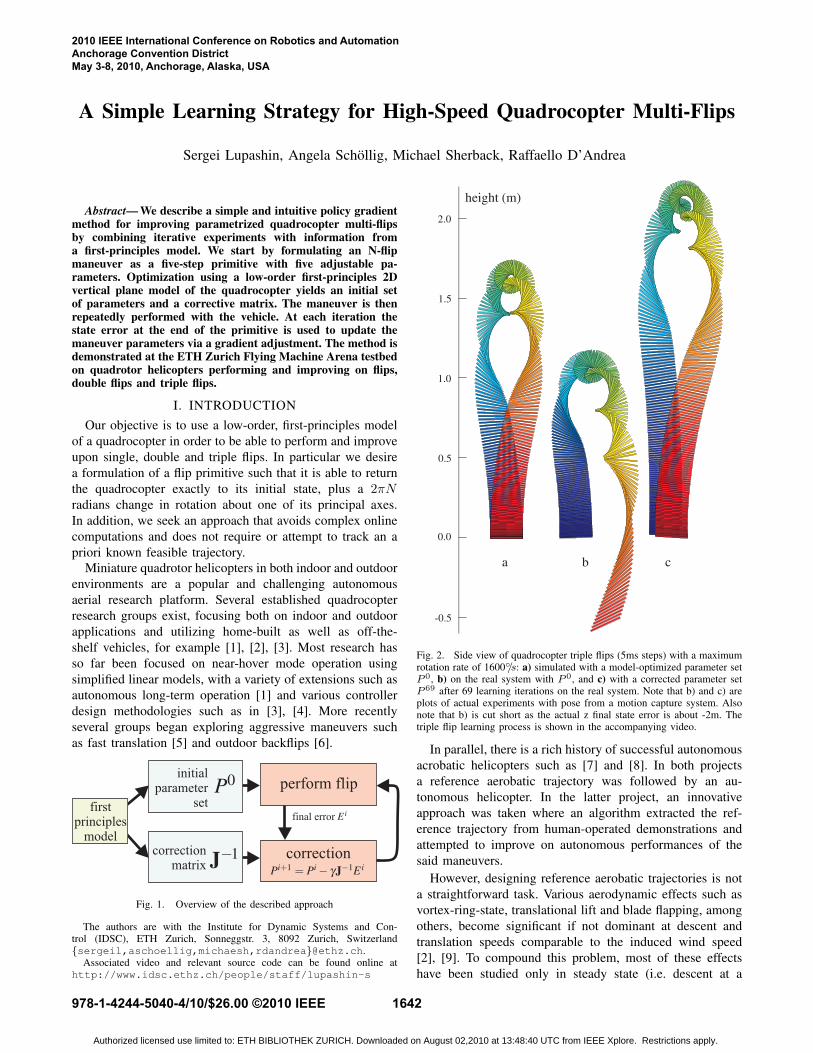
Fig. 2. Side view of quadrocopter triple flips (5ms steps) with a maximumrotation rate of 1600◦/s: a) simulated with a model-optimized parameter setP 0, b) on the real system with P 0, and c) with a corrected parameter setP 69 after 69 learning iterations on the real system. Note that b) and c) areplots of actual experiments with pose from a motion capture system. Alsonote that b) is cut short as the actual z final state error is about -2m. Thetriple flip learning process is shown in the accompanying video.
In parallel, there is a rich history of successful autonomousacrobatic helicopters such as [7] and [8]. In both projectsa reference aerobatic trajectory was followed by an au-tonomous helicopter. In the latter project, an innovativeapproach was taken where an algorithm extracted the ref-erence trajectory from human-operated demonstrations andattempted to improve on autonomous performances of thesaid maneuvers.
However, designing reference aerobatic trajectories is nota straightforward task. Various aerodynamic effects such asvortex-ring-state, translational lift and blade flapping, amongothers, become significant if not dominant at descent andtranslation speeds comparable to the induced wind speed[2], [9]. To compound this problem, most of these effectshave been studied only in steady state (i.e. descent at a
2010 IEEE International Conference on Robotics and AutomationAnchorage Convention DistrictMay 3-8, 2010, Anchorage, Alaska, USA
978-1-4244-5040-4/10/$26.00 ©2010 IEEE 1642
Authorized licensed use limited to: ETH BIBLIOTHEK ZURICH. Downloaded on August 02,2010 at 13:48:40 UTC from IEEE Xplore. Restrictions apply.
constant rate with constant angle of attack, etc), while forfast aggressive aerodynamic maneuvers we are concernedwith transients. Furthermore, even after decades of dedicatedresearch on modeling helicopter aerodynamics, some of therotor phenomena encountered in aerobatic maneuvers onlyhave empirical models, most well-known of these being thevortex ring/turbulent wake rotor operating mode [9]. It’salso not practical for a human pilot to fly a demonstrativeacrobatic maneuver that depends on millisecond-accuracycontrol input switches.
There is a strong argument for using simple modelswith minimal parameters that need to be identified. Forexample, while much research recently has been focused onextremely precise modeling of propeller effects in quadro-copters [10], the identification of all parameters requiresdevoted, carefully-designed experiments with an extremelycautious treatment of measurement errors, unwanted aerody-namic effects, etc. On the other hand, it has been demon-strated that a very straightforward approach where only themost essential parameters are learned yields good hoverperformance, for example by [11].
The outline of the method used to design and improve onthe flips is shown in Fig. 1. A result of running the methodon triple flips is shown in Fig. 2. In overview, the approachdescribed in this paper consists of the following: First, weformulate the flip primitive as a five-step maneuver usingfive free parameters. Then we use a numerical optimizercombined with a 2D model and a rough initial guess tofind a parameter set that causes the model to reach thedesired final state. We approximate the effect of parameterperturbations about this parameter set by numerically cal-culating a Jacobian matrix. The inverse Jacobian is usedto adjust the parameters in an iterative fashion based onthe final state error produced by running the primitive onthe actual quadrocopters. A step size parameter is used toprovide robustness to model errors and noise as well as tocontrol convergence behavior.
The rest of this paper is organized as follows: we introducethe 2D model of the quadrocopter and define the vehicle’scontrol envelope in Section II. We formulate the flip ma-neuver and specify the free parameters in Section III. Themethod for correcting parameters from one experiment tothe next is described in Section IV. Finally, we describe theexperimental setup and the vehicle used in Section V, showexperimental results in Section VI, and conclude the paperin Section VII.
II. 2D QUADROCOPTER MODEL
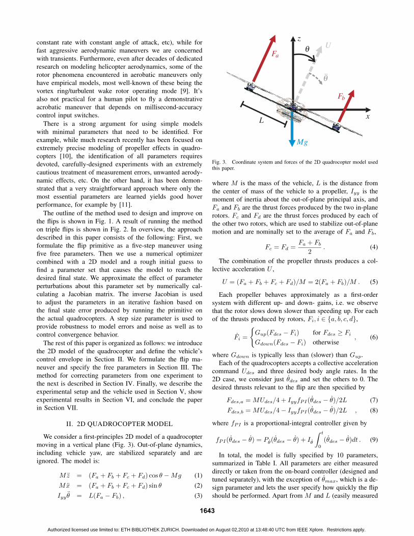
We consider a first-principles 2D model of a quadrocoptermoving in a vertical plane (Fig. 3). Out-of-plane dynamics,including vehicle yaw, are stabilized separately and areignored. The model is:
Mz = (Fa + Fb + Fc + Fd) cos θ −Mg (1)Mx = (Fa + Fb + Fc + Fd) sin θ (2)Iyy θ = L(Fa − Fb) , (3)
Fig. 3. Coordinate system and forces of the 2D quadrocopter model usedthis paper.
where M is the mass of the vehicle, L is the distance fromthe center of mass of the vehicle to a propeller, Iyy is themoment of inertia about the out-of-plane principal axis, andFa and Fb are the thrust forces produced by the two in-planerotors. Fc and Fd are the thrust forces produced by each ofthe other two rotors, which are used to stabilize out-of-planemotion and are nominally set to the average of Fa and Fb,
Fc = Fd =Fa + Fb
2. (4)
The combination of the propeller thrusts produces a col-lective acceleration U ,
U = (Fa + Fb + Fc + Fd)/M = 2(Fa + Fb)/M . (5)
Each propeller behaves approximately as a first-ordersystem with different up- and down- gains, i.e. we observethat the rotor slows down slower than speeding up. For eachof the thrusts produced by rotors, Fi, i ∈ {a, b, c, d},
Fi =
{Gup(Fdes − Fi) for Fdes ≥ FiGdown(Fdes − Fi) otherwise
, (6)
where Gdown is typically less than (slower) than Gup.Each of the quadrocopters accepts a collective acceleration
command Udes and three desired body angle rates. In the2D case, we consider just θdes and set the others to 0. Thedesired thrusts relevant to the flip are then specified by
Fdes,a =MUdes/4 + IyyfPI(θdes − θ)/2L (7)
Fdes,b =MUdes/4− IyyfPI(θdes − θ)/2L , (8)
where fPI is a proportional-integral controller given by
fPI(θdes − θ) = Pθ(θdes − θ) + Iθ
∫ t
0
(θdes − θ)dt . (9)
In total, the model is fully specified by 10 parameters,summarized in Table I. All parameters are either measureddirectly or taken from the on-board controller (designed andtuned separately), with the exception of θmax, which is a de-sign parameter and lets the user specify how quickly the flipshould be performed. Apart from M and L (easily measured
1643
Authorized licensed use limited to: ETH BIBLIOTHEK ZURICH. Downloaded on August 02,2010 at 13:48:40 UTC from IEEE Xplore. Restrictions apply.
angularacceleration
collectiveacceleration reserved for
feedback anduncertainties
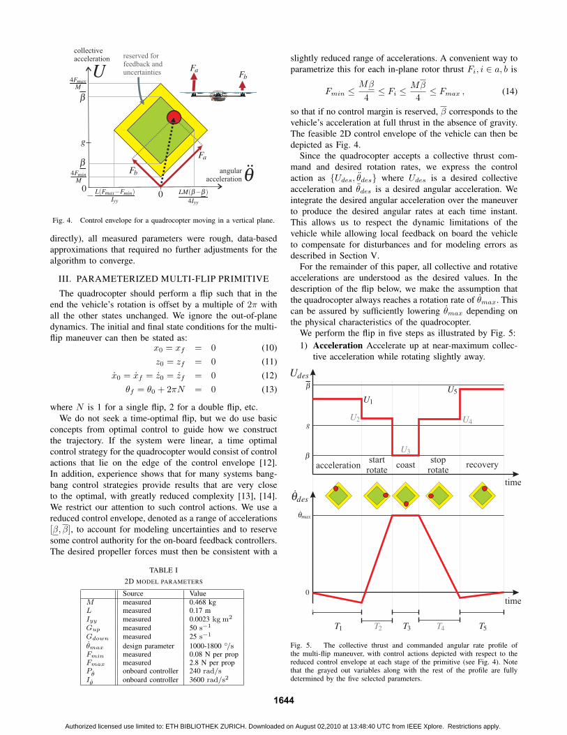
Fig. 4. Control envelope for a quadrocopter moving in a vertical plane.
directly), all measured parameters were rough, data-basedapproximations that required no further adjustments for thealgorithm to converge.
III. PARAMETERIZED MULTI-FLIP PRIMITIVE
The quadrocopter should perform a flip such that in theend the vehicle’s rotation is offset by a multiple of 2π withall the other states unchanged. We ignore the out-of-planedynamics. The initial and final state conditions for the multi-flip maneuver can then be stated as:
x0 = xf = 0 (10)z0 = zf = 0 (11)
x0 = xf = z0 = zf = 0 (12)θf = θ0 + 2πN = 0 (13)
where N is 1 for a single flip, 2 for a double flip, etc.We do not seek a time-optimal flip, but we do use basic
concepts from optimal control to guide how we constructthe trajectory. If the system were linear, a time optimalcontrol strategy for the quadrocopter would consist of controlactions that lie on the edge of the control envelope [12].In addition, experience shows that for many systems bang-bang control strategies provide results that are very closeto the optimal, with greatly reduced complexity [13], [14].We restrict our attention to such control actions. We use areduced control envelope, denoted as a range of accelerations[β, β], to account for modeling uncertainties and to reservesome control authority for the on-board feedback controllers.The desired propeller forces must then be consistent with a
TABLE I2D MODEL PARAMETERS
Source ValueM measured 0.468 kgL measured 0.17 mIyy measured 0.0023 kg m2
Gup measured 50 s−1
Gdown measured 25 s−1
θmax design parameter 1000-1800 ◦/sFmin measured 0.08 N per propFmax measured 2.8 N per propPθ onboard controller 240 rad/sIθ onboard controller 3600 rad/s2
slightly reduced range of accelerations. A convenient way toparametrize this for each in-plane rotor thrust Fi, i ∈ a, b is
Fmin ≤Mβ
4≤ Fi ≤
Mβ
4≤ Fmax , (14)
so that if no control margin is reserved, β corresponds to thevehicle’s acceleration at full thrust in the absence of gravity.The feasible 2D control envelope of the vehicle can then bedepicted as Fig. 4.
Since the quadrocopter accepts a collective thrust com-mand and desired rotation rates, we express the controlaction as {Udes, θdes} where Udes is a desired collectiveacceleration and θdes is a desired angular acceleration. Weintegrate the desired angular acceleration over the maneuverto produce the desired angular rates at each time instant.This allows us to respect the dynamic limitations of thevehicle while allowing local feedback on board the vehicleto compensate for disturbances and for modeling errors asdescribed in Section V.
For the remainder of this paper, all collective and rotativeaccelerations are understood as the desired values. In thedescription of the flip below, we make the assumption thatthe quadrocopter always reaches a rotation rate of θmax. Thiscan be assured by sufficiently lowering θmax depending onthe physical characteristics of the quadrocopter.
We perform the flip in five steps as illustrated by Fig. 5:1) Acceleration Accelerate up at near-maximum collec-
tive acceleration while rotating slightly away.
time
time
accelerationstart
rotatecoast
stoprotate
recovery
Fig. 5. The collective thrust and commanded angular rate profile ofthe multi-flip maneuver, with control actions depicted with respect to thereduced control envelope at each stage of the primitive (see Fig. 4). Notethat the grayed out variables along with the rest of the profile are fullydetermined by the five selected parameters.
1644
Authorized licensed use limited to: ETH BIBLIOTHEK ZURICH. Downloaded on August 02,2010 at 13:48:40 UTC from IEEE Xplore. Restrictions apply.
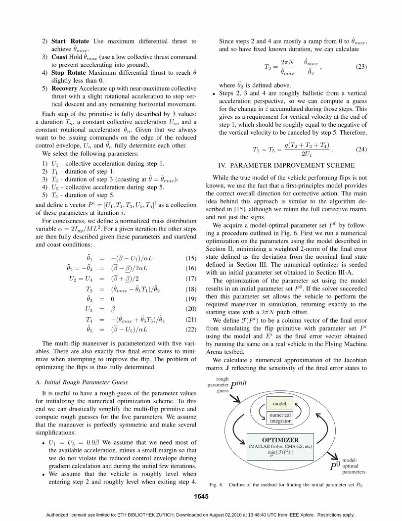
2) Start Rotate Use maximum differential thrust toachieve θmax.
3) Coast Hold θmax (use a low collective thrust commandto prevent accelerating into ground).
4) Stop Rotate Maximum differential thrust to reach θslightly less than 0.
5) Recovery Accelerate up with near-maximum collectivethrust with a slight rotational acceleration to stop ver-tical descent and any remaining horizontal movement.
Each step of the primitive is fully described by 3 values:a duration Tn, a constant collective acceleration Un, and aconstant rotational acceleration θn. Given that we alwayswant to be issuing commands on the edge of the reducedcontrol envelope, Un and θn fully determine each other.
We select the following parameters:1) U1 - collective acceleration during step 1.2) T1 - duration of step 1.3) T3 - duration of step 3 (coasting at θ = θmax).4) U5 - collective acceleration during step 5.5) T5 - duration of step 5.
and define a vector P i = [U1, T1, T3, U5, T5]i as a collection
of these parameters at iteration i.For conciseness, we define a normalized mass distribution
variable α = 2Iyy/ML2. For a given iteration the other stepsare then fully described given these parameters and start/endand coast conditions:
θ1 = −(β − U1)/αL (15)θ2 = −θ4 = (β − β)/2αL (16)
U2 = U4 = (β + β)/2 (17)
T2 = (θmax − θ1T1)/θ2 (18)θ3 = 0 (19)U3 = β (20)
T4 = −(θmax + θ5T5)/θ4 (21)θ5 = (β − U5)/αL (22)
The multi-flip maneuver is parameterized with five vari-ables. There are also exactly five final error states to mini-mize when attempting to improve the flip. The problem ofoptimizing the flips is thus fully determined.
A. Initial Rough Parameter Guess
It is useful to have a rough guess of the parameter valuesfor initializing the numerical optimization scheme. To thisend we can drastically simplify the multi-flip primitive andcompute rough guesses for the five parameters. We assumethat the maneuver is perfectly symmetric and make severalsimplifications:
• U1 = U5 = 0.9β We assume that we need most ofthe available acceleration, minus a small margin so thatwe do not violate the reduced control envelope duringgradient calculation and during the initial few iterations.
• We assume that the vehicle is roughly level whenentering step 2 and roughly level when exiting step 4.
Since steps 2 and 4 are mostly a ramp from 0 to θmax,and so have fixed known duration, we can calculate
T3 =2πN
θmax− θmax
θ2, (23)
where θ2 is defined above.• Steps 2, 3 and 4 are roughly ballistic from a vertical
acceleration perspective, so we can compute a guessfor the change in z accumulated during those steps. Thisgives us a requirement for vertical velocity at the end ofstep 1, which should be roughly equal to the negative ofthe vertical velocity to be canceled by step 5. Therefore,
T1 = T5 =g(T2 + T3 + T4)
2U1. (24)
IV. PARAMETER IMPROVEMENT SCHEME
While the true model of the vehicle performing flips is notknown, we use the fact that a first-principles model providesthe correct overall direction for corrective action. The mainidea behind this approach is similar to the algorithm de-scribed in [15], although we retain the full corrective matrixand not just the signs.
We acquire a model-optimal parameter set P 0 by follow-ing a procedure outlined in Fig. 6. First we run a numericaloptimization on the parameters using the model described inSection II, minimizing a weighted 2-norm of the final errorstate defined as the deviation from the nominal final statedefined in Section III. The numerical optimizer is seededwith an initial parameter set obtained in Section III-A.
The optimization of the parameter set using the modelresults in an initial parameter set P 0. If the solver succeededthen this parameter set allows the vehicle to perform therequired maneuver in simulation, returning exactly to thestarting state with a 2πN pitch offset.
We define F(P i) to be a column vector of the final errorfrom simulating the flip primitive with parameter set P i
using the model and Ei as the final error vector obtainedby running the same on a real vehicle in the Flying MachineArena testbed.
We calculate a numerical approximation of the Jacobianmatrix J reflecting the sensitivity of the final error states to
numericalintegrator
roughparameter
guess
model-optimalparameters
Fig. 6. Outline of the method for finding the initial parameter set P0.
1645
Authorized licensed use limited to: ETH BIBLIOTHEK ZURICH. Downloaded on August 02,2010 at 13:48:40 UTC from IEEE Xplore. Restrictions apply.

the parameters about the model’s optimal parameter set P 0.Since the final error F(P 0) = 0,
F(P 0 + P ) ≈ F(P 0) +∂F
∂PP = 0+ JP , (25)
where, as noted above, F(·) is the output of running the 2Dquadrocopter model. This expresses a linear approximationof the effects of a parameter perturbation P .
For problems where the size of the final state equals thenumber of parameters and where the Jacobian is invertible,the corrective matrix from final error to parameter spaceis simply the inverse of the Jacobian J−1. To improve themaneuvers in the real world we use the inverse Jacobianmatrix at each iteration combined with a step size γ,
P i+1 = P i − γJ−1Ei , (26)
where Ei is the final state error vector from running anexperiment using the parameter set P i and γ is a step sizebetween 0 and 1. The step size γ can be used to trade offconvergence rate for noise rejection.
V. EXPERIMENTAL SETUP
We tested our approach in the ETH Zurich Flying Ma-chine Arena on our customized quadrocopters. The systemis highly modular in both design and implementation, sowe describe the quadrocopter and the off-board hardwareseparately.
A. The Flying Vehicle
The quadrotor vehicles used for the following experimentsare highly modified Ascending Technologies X3D ’Hum-mingbird’ quadrocopters. We replaced the onboard sensorsand central electronics completely while keeping the originalpropulsion system, the motor controllers, and the frame.The design and physical properties of the standard X3Dquadrocopter are described in detail in [16].
The standard firmware on the motor controllers was up-graded to speed-control firmware from the standard torque-control version. The motor controllers accept commandsdiscretized to 200 steps at update rates greater than 1 kHz.We derived a function from command to nominal hover-condition thrust experimentally. Rotor speed control allowsus to largely ignore effects of battery voltage and internalresistance, including transients, except for extremely highcommands where the achievable rotor speed is limited bythe current voltage.
In order to have better control over the onboard algorithmsand to have access to better-quality and higher-range rategyro data we replaced the central electronics with our owndesign. An overview of the onboard controller is shown inFig. 7. We used the following angular rate sensors: a dual-axis IDG650 ±2000◦/s rate gyro for pitch and roll and asingle-axis ISZ-650 ±2000◦/s rate gyro for sensing yaw rate.
The onboard control loop samples the rate gyros andcomputes new motor commands at 800 Hz. The attitude ratecontrol loops are decoupled from one another. A PI controllerproduces a differential thrust command based on the current
pitch rate and the current desired pitch rate command. Theroll rate is controlled similarly. Yaw rate is controlled viaa proportional controller without an integral gain. Propellerwear trim factors allow for precise balancing of the quadro-copter. The outputs of the controller are combined as shownin Fig. 7 and constrained between maximum and minimumcommand values before being sent to the motor controllers.
Each vehicle is equipped with two radio systems: a one-way 35 MHz analog hobbyist pulse-position-modulation(PPM) receiver and a bidirectional 2.4 GHz IEEE 802.15.4 orIEEE 802.11b transceiver for non-time-critical communica-tion such as data feedback or onboard parameter reads/writes.
Commands are usually received by the vehicle via the35 MHz radio at approximately 50 Hz. During open-loopmaneuvers, commands are instead generated on-the-fly via afunction that uses the current onboard maneuver parameters.In the case of the flip, the open-loop command profilecorresponds exactly to that shown in Fig. 5, sampled at 800Hz.
The approach of generating commands directly onboardthe vehicles allows us to update the desired angle rates andcollective thrust commands every 1.25ms with virtually nocommunication delays. While this approach assures goodmaneuver repeatability, it does add some difficulty to off-board detection of when exactly the vehicle begins and endsthe open loop maneuver and switches to normal control.We have found that a good understanding of communicationdelays is vital to measuring the final state error accurately.
B. The ETH Flying Machine Arena
The ETH Flying Machine Arena (FMA) is a 10×10×10mspace built for research involving small flying vehicles. Theoverall organization of the system is similar to [1]. The spaceis equipped with a motion capture system for localizationand a set of protective nets to reduce the occurrence ofcatastrophic crashes. We use a Vicon motion capture sys-tem with 8 cameras to achieve redundant retro-reflectivemarker localization at 200 Hz with millimeter accuracy. Eachquadrocopter carries a unique arrangement of three such
MotorController
2.4GHzXbee Radio
OnboardCommandGenerator
35MHzPPM Radio
OnboardParameters
+-
front(+x)
RateGyros
++
++
thrust to cmdmap
+-
+-
++
++
+-
P
PI
PI
MotorController
back(-x)
MotorController
left(+y)
MotorController
right(-y)
Fig. 7. Logical layout of the onboard controller. The variables p, q, and rrefer to roll, pitch, and yaw body rates, respectively. In the case of the flipmaneuver as described above, qdes = θdes, while pdes = rdes = 0.
1646
Authorized licensed use limited to: ETH BIBLIOTHEK ZURICH. Downloaded on August 02,2010 at 13:48:40 UTC from IEEE Xplore. Restrictions apply.
multicast UDP
35MHzradios
2.4GHzlinks
estimator
controller
loggerGUI
Vicon system
bridge
quadrocopters
bridge
bridge
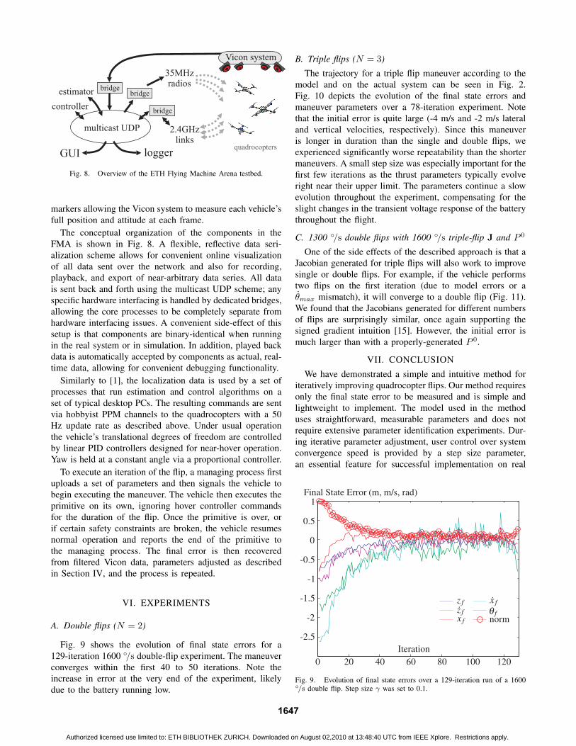
Fig. 8. Overview of the ETH Flying Machine Arena testbed.
markers allowing the Vicon system to measure each vehicle’sfull position and attitude at each frame.
The conceptual organization of the components in theFMA is shown in Fig. 8. A flexible, reflective data seri-alization scheme allows for convenient online visualizationof all data sent over the network and also for recording,playback, and export of near-arbitrary data series. All datais sent back and forth using the multicast UDP scheme; anyspecific hardware interfacing is handled by dedicated bridges,allowing the core processes to be completely separate fromhardware interfacing issues. A convenient side-effect of thissetup is that components are binary-identical when runningin the real system or in simulation. In addition, played backdata is automatically accepted by components as actual, real-time data, allowing for convenient debugging functionality.
Similarly to [1], the localization data is used by a set ofprocesses that run estimation and control algorithms on aset of typical desktop PCs. The resulting commands are sentvia hobbyist PPM channels to the quadrocopters with a 50Hz update rate as described above. Under usual operationthe vehicle’s translational degrees of freedom are controlledby linear PID controllers designed for near-hover operation.Yaw is held at a constant angle via a proportional controller.
To execute an iteration of the flip, a managing process firstuploads a set of parameters and then signals the vehicle tobegin executing the maneuver. The vehicle then executes theprimitive on its own, ignoring hover controller commandsfor the duration of the flip. Once the primitive is over, orif certain safety constraints are broken, the vehicle resumesnormal operation and reports the end of the primitive tothe managing process. The final error is then recoveredfrom filtered Vicon data, parameters adjusted as describedin Section IV, and the process is repeated.
VI. EXPERIMENTS
A. Double flips (N = 2)
Fig. 9 shows the evolution of final state errors for a129-iteration 1600 ◦/s double-flip experiment. The maneuverconverges within the first 40 to 50 iterations. Note theincrease in error at the very end of the experiment, likelydue to the battery running low.
B. Triple flips (N = 3)
The trajectory for a triple flip maneuver according to themodel and on the actual system can be seen in Fig. 2.Fig. 10 depicts the evolution of the final state errors andmaneuver parameters over a 78-iteration experiment. Notethat the initial error is quite large (-4 m/s and -2 m/s lateraland vertical velocities, respectively). Since this maneuveris longer in duration than the single and double flips, weexperienced significantly worse repeatability than the shortermaneuvers. A small step size was especially important for thefirst few iterations as the thrust parameters typically evolveright near their upper limit. The parameters continue a slowevolution throughout the experiment, compensating for theslight changes in the transient voltage response of the batterythroughout the flight.
C. 1300 ◦/s double flips with 1600 ◦/s triple-flip J and P 0
One of the side effects of the described approach is that aJacobian generated for triple flips will also work to improvesingle or double flips. For example, if the vehicle performstwo flips on the first iteration (due to model errors or aθmax mismatch), it will converge to a double flip (Fig. 11).We found that the Jacobians generated for different numbersof flips are surprisingly similar, once again supporting thesigned gradient intuition [15]. However, the initial error ismuch larger than with a properly-generated P 0.
VII. CONCLUSION
We have demonstrated a simple and intuitive method foriteratively improving quadrocopter flips. Our method requiresonly the final state error to be measured and is simple andlightweight to implement. The model used in the methoduses straightforward, measurable parameters and does notrequire extensive parameter identification experiments. Dur-ing iterative parameter adjustment, user control over systemconvergence speed is provided by a step size parameter,an essential feature for successful implementation on real
Fig. 9. Evolution of final state errors over a 129-iteration run of a 1600◦/s double flip. Step size γ was set to 0.1.
1647
Authorized licensed use limited to: ETH BIBLIOTHEK ZURICH. Downloaded on August 02,2010 at 13:48:40 UTC from IEEE Xplore. Restrictions apply.
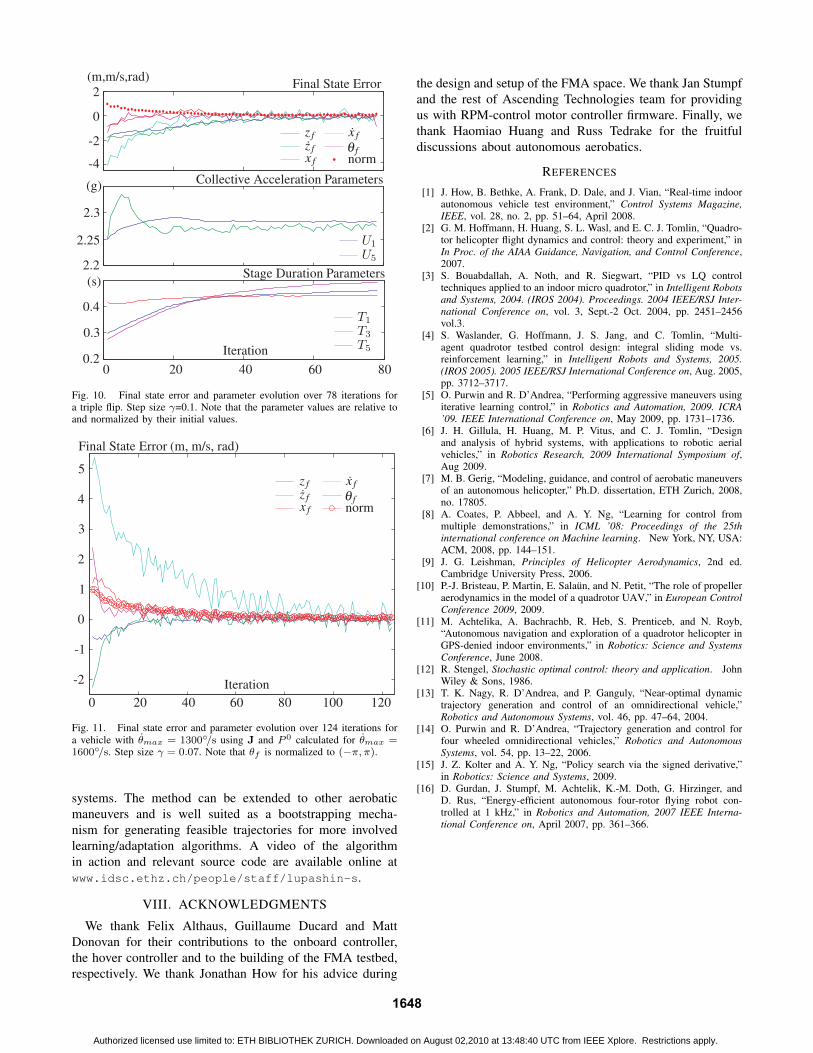
Fig. 10. Final state error and parameter evolution over 78 iterations fora triple flip. Step size γ=0.1. Note that the parameter values are relative toand normalized by their initial values.
Fig. 11. Final state error and parameter evolution over 124 iterations fora vehicle with θmax = 1300◦/s using J and P 0 calculated for θmax =1600◦/s. Step size γ = 0.07. Note that θf is normalized to (−π, π).
systems. The method can be extended to other aerobaticmaneuvers and is well suited as a bootstrapping mecha-nism for generating feasible trajectories for more involvedlearning/adaptation algorithms. A video of the algorithmin action and relevant source code are available online atwww.idsc.ethz.ch/people/staff/lupashin-s.
VIII. ACKNOWLEDGMENTS
We thank Felix Althaus, Guillaume Ducard and MattDonovan for their contributions to the onboard controller,the hover controller and to the building of the FMA testbed,respectively. We thank Jonathan How for his advice during
the design and setup of the FMA space. We thank Jan Stumpfand the rest of Ascending Technologies team for providingus with RPM-control motor controller firmware. Finally, wethank Haomiao Huang and Russ Tedrake for the fruitfuldiscussions about autonomous aerobatics.
REFERENCES
[1] J. How, B. Bethke, A. Frank, D. Dale, and J. Vian, “Real-time indoorautonomous vehicle test environment,” Control Systems Magazine,IEEE, vol. 28, no. 2, pp. 51–64, April 2008.
[2] G. M. Hoffmann, H. Huang, S. L. Wasl, and E. C. J. Tomlin, “Quadro-tor helicopter flight dynamics and control: theory and experiment,” inIn Proc. of the AIAA Guidance, Navigation, and Control Conference,2007.
[3] S. Bouabdallah, A. Noth, and R. Siegwart, “PID vs LQ controltechniques applied to an indoor micro quadrotor,” in Intelligent Robotsand Systems, 2004. (IROS 2004). Proceedings. 2004 IEEE/RSJ Inter-national Conference on, vol. 3, Sept.-2 Oct. 2004, pp. 2451–2456vol.3.
[4] S. Waslander, G. Hoffmann, J. S. Jang, and C. Tomlin, “Multi-agent quadrotor testbed control design: integral sliding mode vs.reinforcement learning,” in Intelligent Robots and Systems, 2005.(IROS 2005). 2005 IEEE/RSJ International Conference on, Aug. 2005,pp. 3712–3717.
[5] O. Purwin and R. D’Andrea, “Performing aggressive maneuvers usingiterative learning control,” in Robotics and Automation, 2009. ICRA’09. IEEE International Conference on, May 2009, pp. 1731–1736.
[6] J. H. Gillula, H. Huang, M. P. Vitus, and C. J. Tomlin, “Designand analysis of hybrid systems, with applications to robotic aerialvehicles,” in Robotics Research, 2009 International Symposium of,Aug 2009.
[7] M. B. Gerig, “Modeling, guidance, and control of aerobatic maneuversof an autonomous helicopter,” Ph.D. dissertation, ETH Zurich, 2008,no. 17805.
[8] A. Coates, P. Abbeel, and A. Y. Ng, “Learning for control frommultiple demonstrations,” in ICML ’08: Proceedings of the 25thinternational conference on Machine learning. New York, NY, USA:ACM, 2008, pp. 144–151.
[9] J. G. Leishman, Principles of Helicopter Aerodynamics, 2nd ed.Cambridge University Press, 2006.
[10] P.-J. Bristeau, P. Martin, E. Salaun, and N. Petit, “The role of propelleraerodynamics in the model of a quadrotor UAV,” in European ControlConference 2009, 2009.
[11] M. Achtelika, A. Bachrachb, R. Heb, S. Prenticeb, and N. Royb,“Autonomous navigation and exploration of a quadrotor helicopter inGPS-denied indoor environments,” in Robotics: Science and SystemsConference, June 2008.
[12] R. Stengel, Stochastic optimal control: theory and application. JohnWiley & Sons, 1986.
[13] T. K. Nagy, R. D’Andrea, and P. Ganguly, “Near-optimal dynamictrajectory generation and control of an omnidirectional vehicle,”Robotics and Autonomous Systems, vol. 46, pp. 47–64, 2004.
[14] O. Purwin and R. D’Andrea, “Trajectory generation and control forfour wheeled omnidirectional vehicles,” Robotics and AutonomousSystems, vol. 54, pp. 13–22, 2006.
[15] J. Z. Kolter and A. Y. Ng, “Policy search via the signed derivative,”in Robotics: Science and Systems, 2009.
[16] D. Gurdan, J. Stumpf, M. Achtelik, K.-M. Doth, G. Hirzinger, andD. Rus, “Energy-efficient autonomous four-rotor flying robot con-trolled at 1 kHz,” in Robotics and Automation, 2007 IEEE Interna-tional Conference on, April 2007, pp. 361–366.
1648
Authorized licensed use limited to: ETH BIBLIOTHEK ZURICH. Downloaded on August 02,2010 at 13:48:40 UTC from IEEE Xplore. Restrictions apply.