Embed Size (px)
Citation preview

1
Abstract To achieve the increased security levels in ports prescribed by IMO it has become necessary to inspect both harbour facilities under water and also to scan visiting ships hulls beneath the waterline. To conduct this in a time-effective yet still qualitative manner the need of a new vessel with unique performance characteristics was evident. The vessel should be able to reach its target by a fast surface approach and then submerge to perform various tasks while under water. This thesis was aimed at designing such a vessel, capable of a surface speed in excess of 25 knots in seastate three and also having the ability to in a submerged state perform various duties. The vessel, The SEAL HI, was designed to carry a load of 500 kg which throughout this report consists of the three crew members with additional gear, and in a submerged state the vessel is to achieve a minimum speed of 3 knots. The vessel is diesel and battery powered and operates submerged in a fully flooded state. The operators can at any time and depth leave the vehicle to perform additional tasks or closer inspection. The craft is designed to operate down to 15 meters for transport or inspection missions. The project consists of developing a new hull suitable for the vessel and determining what type of propulsion systems that should be used. This includes stability, resistance and seakeeping calculations for the vessel when on the surface and in addition to this the major problems concerning stability and manoeuvrability for the submerged vessel are addressed. A vessel such as the SEAL HI has several application areas and could very well be commissioned by the Coast Guard, Harbour Authorities, Oil Companies or any other organizations that require a vessel with surface and sub-surface capabilities and a quick response time. The result of this report is the conceptual design of a vessel that meets all of the design requirements stated above and in agreement with the design specifications in appendix. The SEAL HI will have a length of 6.2 m and a beam of 1.94 m and to get a gentle planing hump the deadrise angle was set to 15°. The vessel will have a range of 50 Nm and maximum submerged time of about 2.5 hours, both corresponding to the design specifications. Classification regarding stability, class C – inshore, is possible for the vessel at the surface and in addition to this the vessel is statically stable both in skim mode and in fully submerged mode.
Figure 1. Illustration of the SEAL HI in the semi submerged skim mode.

2
Table of Contents Abstract..................................................................................................................................1 1. Introduction ........................................................................................................................3 2. Hull ....................................................................................................................................5
2.1 General Dimensions......................................................................................................6 2.2 Seakeeping and Porpoising ...........................................................................................6 2.3 Hull Results ..................................................................................................................8
3 Propulsion, surface ..............................................................................................................9 3.1 Enclosure......................................................................................................................9 3.2 Engine ..........................................................................................................................9
3.2.1 Modification of DH 200-V4 .................................................................................10 3.2.2 Modification of D3-160........................................................................................12
3.3 Waterjet vs. Stern Drive..............................................................................................12 3.3.1 Modification of the Volvo Penta DP-S .................................................................12
4 Propulsion, Submerged......................................................................................................13 4.1 Thrusters.....................................................................................................................13 4.2 Manoeuvring and Thruster Placement .........................................................................14 4.3 Loads Due to Slamming..............................................................................................16 4.4 Thrusters Results ........................................................................................................18
5 Payloads ............................................................................................................................19 5.1 Battery Pack ...............................................................................................................19 5.2 Air Supply ..................................................................................................................20 5.3 Crew...........................................................................................................................20 5.4 Fuel ............................................................................................................................20
6 Weight/Volume Calculations .............................................................................................21 7 Stability Calculations.........................................................................................................21
7.1 Stability, Surface.........................................................................................................21 7.2 Stability, Submerged...................................................................................................22
7.2.1 Trim Tanks ..........................................................................................................23 7.3 Stability Results ..........................................................................................................24
8 Range and Endurance ........................................................................................................26 9 Onboard Sensors................................................................................................................26 10 Summary .........................................................................................................................27 References............................................................................................................................29 Appendix..............................................................................................................................30

3
1. Introduction To achieve the increased security levels in ports prescribed by IMO it has become necessary to inspect both harbour facilities under water and also to scan visiting ships hull beneath the waterline. To conduct this in a time-effective yet still qualitative manner the need of a new vessel with unique performance characteristics was evident. The vessel should be able to reach its target by a fast surface approach and during this approach it was designed to be powered by a diesel engine. For the surface propulsion system two different concepts and engines were investigated. When the vessel reaches the desired location the speed is reduced to approximately 8 knots and valves in the bottom of the hull are opened. This floods the entire hull and superstructure and the craft is left floating on two buoyancy tanks, see figure 2. The vessel is now in a skim mode where it can be propelled either by electrical thrusters or by the diesel engine, which can still be operated thanks to a snorkel. To initiate a dive all valves to the main engine are closed and then trim tanks are flooded until the vessel is neutral in the water. Thus the vehicle operates submerged in a fully flooded state and from this point the vessel is simply driven alongside the subject of inspection and the onboard sensors analyse the structure and present the information to the crew on a display. While under water the SEAL HI is propelled by two electrical thrusters mounted to a wing on either side of the cockpit, see figure 2. In a submerged state the vessel has a calculated top speed of almost 5 knots but to increase the range the cruise speed was set to 3.5 knots. The crew can at any time and depth leave the vehicle to perform additional tasks or closer inspection. The vessel was designed to operate down to 15 meters for transport or inspection missions. When satisfied with the inspection the crew can reach their next target either by returning to the surface for a fast surface approach or by continuing under water if the next object is nearby. To once again benefit of the fast surface capabilities the vessel returns to the surface where the trim tanks are emptied of all water. The vessel is now in skim mode again and it is possible to start the diesel engine. To drain the hull and superstructure the hull is fitted with self-bailing valves in the aft and also powerful bilge pumps. Once the diesel engine is started the vessel is slowly accelerated while the hull is emptied, mainly through the self-bailing valves. Eventually the vessel will reach planing speed and then the bilge pumps drain the remaining water. It is possible to drain the hull by using only the bilge pumps but this will take longer time. This thesis was aimed at conceptually designing a craft capable of surface speeds in excess of 25 knots and still having the ability to in a submerged state perform various duties. The SEAL was designed to carry a total load of 500 kg which throughout this report consists of the three crew members with their additional gear. Though the divers bring their own scuba gear the vessel was designed with its own air supply to provide divers and pneumatic mechanisms with the required air. The onboard air was calculated to be sufficient for 2.5 hr at 5 meters depth. The design specifications put up for the SEAL HI state that the vessel is to be able to operate without any restrictions in wind speeds up to 8 m/s corresponding to seastate 3 [1]. The project consisted of developing a new hull suitable for the vessel and determining what type of propulsion systems that should be used. This included stability, resistance and seakeeping calculations for the vessel when at the surface and in addition to this the major problems concerning stability and manoeuvrability for the submerged vessel were to be addressed and solved. The SEAL HI will have a length of 6.2 m and a beam of 1.94 m and to get a gentle planing hump the deadrise angle was set to 15°. Classification regarding stability, class C – inshore, is possible for the vessel at the surface and in addition to this the vessel is statically stable both in skim mode and in fully submerged mode.

4
To prevent water from entering and to reduce structural loads on different volumes it was considered beneficial to pressurize the volumes in question. The pressurization schematically works as if a second stage of a scuba gear was attached to the various volumes. These are then kept at a pressure that is slightly higher than the ambient. In this report the concept of pressurizing various volumes is used extensively and when mentioned it always refers to the concept explained above. Since the SEAL HI is a smaller version of the projected military vessel DGB 2003 [2] many of the problems associated with this kind of construction have already been addressed and solved for that vessel. Therefore some of the solutions and components used on DGB 2003 are incorporated directly or after modification to the SEAL HI. For example the valves at the bottom of the hull are designed for DGB 2003 but will also be fitted on the SEAL HI. With four of these valves the vessel will need approximately 3 minutes to initiate a dive.
Figure 2. Schematic view of the vessel and placement of the major components.
Nomenclature T = propeller thrust, lb ∆0 = weight of boat, lb Df = viscous component of drag, lb τ = running trim, deg CG = centre of gravity LCG = distance from transom to longitudinal centre of gravity, ft ε = inclination of thrust relative to keel, deg N = resultant of pressure forces acting normal to bottom, lb a = distance between Df and CG, ft f = distance between T and CG, ft c = distance between N and CG, ft β = deadrise angle, deg b = beam, ft
d = draft at transom, ft M = moment, Nm
R = resistance, N P = effect, W v = vessel speed, m/s CD = drag coefficient A = projected area, m2 CF = boundary layer drag coefficient S = wet area, m2
•ϕ = angular velocity, deg/s
••ϕ = angular acceleration, deg/s2
••z = vertical acceleration, m/s2
Maxσ = load on material, MPa

5
2. Hull When calculations concerning the hull were initiated a very rough estimate of weight and size was made. A reference library of existing boats with similar geometry was collected and used for comparison during calculations. A computer program was developed that reads specified geometric properties for a hull and then calculates the required power for different speeds. The program uses Matlab [3] as platform and was developed exclusively for this project. Matlab is a mathematical tool that is very helpful when dealing with iterative calculations and also provides means for displaying results. The calculations and formulas are simply converted to a short program that can then be solved by the computer. To account for an agitated seastate the program was extended to also predict the added resistance and vertical accelerations associated with a specified seastate. To predict the power needed to achieve the specified top speed theories produced by Savitsky were used [4]. Savitskys method is a semi empiric method that estimates the required power for a specified speed in smooth water. For a given speed the calculations yield the running trim and resistance for which the hull is at equilibrium. The hull is represented by a prism and does not account for the tapering or the change in deadrise towards the bow. It is also assumed that the vessels hull-geometry, weight and location of the centre of gravity are known. A planing hull is kept on top of the water almost entirely by dynamic forces and thus the calculations were initiated by finding the equations for lift and drag produced by the prism. Naturally the lift and centre of pressure depends on the area on which the water exerts pressure and also the running trim, thus an equation for this relationship must also be included. The procedure starts out by stating the three equilibrium equations that should be solved simultaneously together with the equations for lift, drag and centre of pressure produced by the prism.
( ) τεττ sinsincos0 fDTN −++=∆
( ) ττετ cossincos fDNT +=+
0=−+ TfaDNc f Since an analytical solution of these equations is very laborious it was recommended to rewrite the equations and solve the problem numerically. Derivation of the final equation can be found in [4] but is omitted here. Essentially the final equation to be solved is
( )( ) ( ) 0sincos
sinsin10 =−+�
�
���
� −+⋅−∆ faDfc
fττ
εττ
where �0 is the weight of the vessel, τ is the running trim, c is the longitudinal difference between the centre of pressure from the water and the centre of gravity, Df is the friction drag and other parameters are as defined in figure 3. The equation is then solved iteratively to find the values forτ, Df and c. When the equation is satisfied the hull is in equilibrium and resistance and power are easily evaluated. For the interested reader a more detailed description of the theory can be found in [4]. To evaluate a hulls performance in a seaway

6
methods developed by both Savitsky-Brown [5] and Hoggard-Jones [6] were used. The results from these methods varied widely so in accordance with suggestions made in [6, p. 45] the Savitsky-Brown equation was used to calculate impact accelerations and Hoggard-Jones equation was used to estimate the added resistance due to waves. All reference crafts were put through the program to produce comparable results. After completing a calculation the program displays the values of limiting parameters to ensure that the user confirms that calculations are valid. This also includes an examination of the hull approximation to see if the simplifying assumptions are reasonable.
Figure 3. Dimensions and parameters as defined by Savitsky. Results from the resistance calculations were compared with results extracted from the commercial software HullSpeed and the agreement was rather good for high and low speeds, see figure 4. For speeds around the planing hump the two curves differ with about 20% but since no extensive information of what methods are used in HullSpeed were found the disagreement was hard to comment on. An interesting phenomena is that if the curve for added resistance due to waves was included in the comparison the agreement around the hump is better. The graph from HullSpeed has been incorporated in figure 4 as the dotted line.
2.1 General Dimensions Since the SEAL HI will be fitted with a diesel engine as apposed to a petrol engine due to fire safety reasons and in addition to this will be heavily loaded the general dimensions for the craft were initially chosen to produce a gentle planing hump. To get a reasonable start guess the hull was sketched in a CAD program with all preliminary components placed in the hull to verify that there would be enough space. A systematic series was then produced where the length and chine beam were varied for different transom deadrise angles. These hulls were run through the Matlab program to evaluate their smooth water performance and drag characteristics. This produced a series of hulls with similar length and beam but with different deadrise angles, all of which had a reasonable hump in the speed-drag plot.
2.2 Seakeeping and Porpoising With the series of hulls now at hand porpoising stability and seakeeping characteristics were evaluated. This was achieved by running the remaining hulls through the extended version of the Matlab program. Since a higher deadrise yield lower accelerations in an agitated sea but a higher drag in smooth water there had to be a tradeoff between the smooth water performance and seakeeping characteristics. When choosing the deadrise angle the main consideration was the drag characteristics and not the accelerations. This was motivated by the fact that the hull will by very heavily loaded and thus the planing hump could be a problem. Also, in an

7
attempt to be realistic, the crew is seated far forward and carries scuba gear, which probably means that the pilot will reduce the speed before any serious slamming occurs. To verify that the position of the centre of gravity did not lead to porpoising at high speeds the hulls characteristics were plotted in a graph together with the porpoising limits for two different deadrise angles. Figure 4 shows results plotted from the Matlab program. During the seakeeping calculations the specific wave height was set to 1 meter since this is the wave height corresponding to a wind of 8 m/s in open water. The top-left graph in figure 4 shows the trim angle as a function of the boat speed. The top-right and bottom-left graphs show the resistance and required power respectively both plotted against the boat speed and with a propulsive efficiency of 0.5. The bottom right plot was made to verify that no porpoising would occur. It is easy to imagine several more curves for different deadrise angles between the ones shown and the requirement is simply that the curve coming from the far right must not cross the curve for the deadrise in question.
Figure 4. Results from resistance and seakeeping calculations. Calculations are valid for a significant wave height of 1 m and for a hull with geometric properties as in figure 6.
RAW indicates the added resistance due to waves.
8
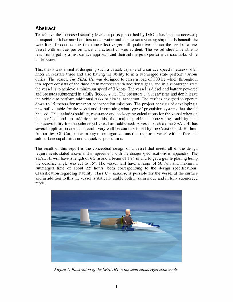
Figure 5. Vertical accelerations at the centre of gravity calculated for a significant wave height of 1 m and for a hull with geometric properties as in section 2.3.
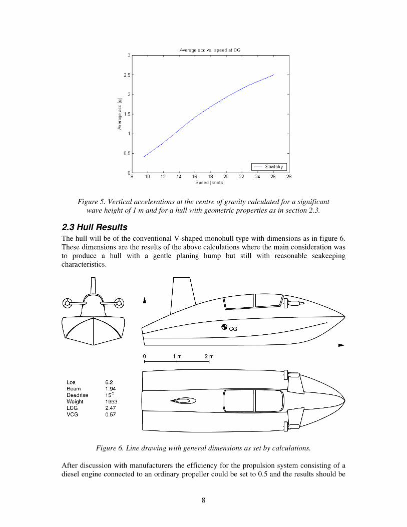
2.3 Hull Results The hull will be of the conventional V-shaped monohull type with dimensions as in figure 6. These dimensions are the results of the above calculations where the main consideration was to produce a hull with a gentle planing hump but still with reasonable seakeeping characteristics.
Figure 6. Line drawing with general dimensions as set by calculations. After discussion with manufacturers the efficiency for the propulsion system consisting of a diesel engine connected to an ordinary propeller could be set to 0.5 and the results should be

9
on the safe side. From figure 4 it is now possible to get a first estimate of the requirements for the engine. It is noticeable that around 20 knots the resistance does not increase with the speed in the same extent that it does for both lower and higher speeds. This region should therefore be suitable for cruising speed, achieving good range while in a reasonable time. To save weight it was decided that the hull would be built as a sandwich construction with a glass fibre reinforced Divinysell core. After discussion with experienced boat builders the core thickness and density was set to 20 mm, 250 kg/m3 at the bottom panels around the engine and 10 mm, 130 kg/m3 for the rest of the hull. These values are important factors in the weight and volume calculations performed in section 6. These values had to be re-evaluated for the propulsion concept consisting of the Volvo Penta D3-160 engine fitted in an enclosure as stated in 3.1. The hull construction was modified to consist of a 5 mm, 250 kg/m3 core reinforced by carbon fibre for the whole hull.
3 Propulsion, surface As previously stated the SEAL HI will be fitted with a diesel engine to reduce fire and explosion hazards. This together with the calculations performed in the previous section make out the preliminary requirements for the main engine. In this section two different engines are evaluated and the propulsion method is specified.
3.1 Enclosure To eliminate the buoyancy produced by having the engine placed in a dry compartment it was decided to investigate the possibility of having an engine fitted without an enclosure. This concept could be achieved by pressurizing the engines inlet, exhaust and other cavities exposed to the outside pressure when in a submerged state. To eliminate the problems with an electric start system the engine could be fitted with a start system powered by the onboard pressurized air. The other option was to manufacture an enclosure with a tight fit in an attempt to reduce the added buoyancy. The enclosure would then exist of a bottom part that is permanently fixed to the hull and contain the connections for exhaust, cooling water, fuel and electronic systems. The top part of the enclosure should be permanently fixed to the snorkel to reduce the amount of couplings and also be fitted with an inspection lid to simplify basic maintenance. To reduce the weight the enclosure should be pressurized and thus reduce the structural loads which then leads to a lighter design. The enclosure adds extra buoyancy and weight and is therefore considered as a second choice.
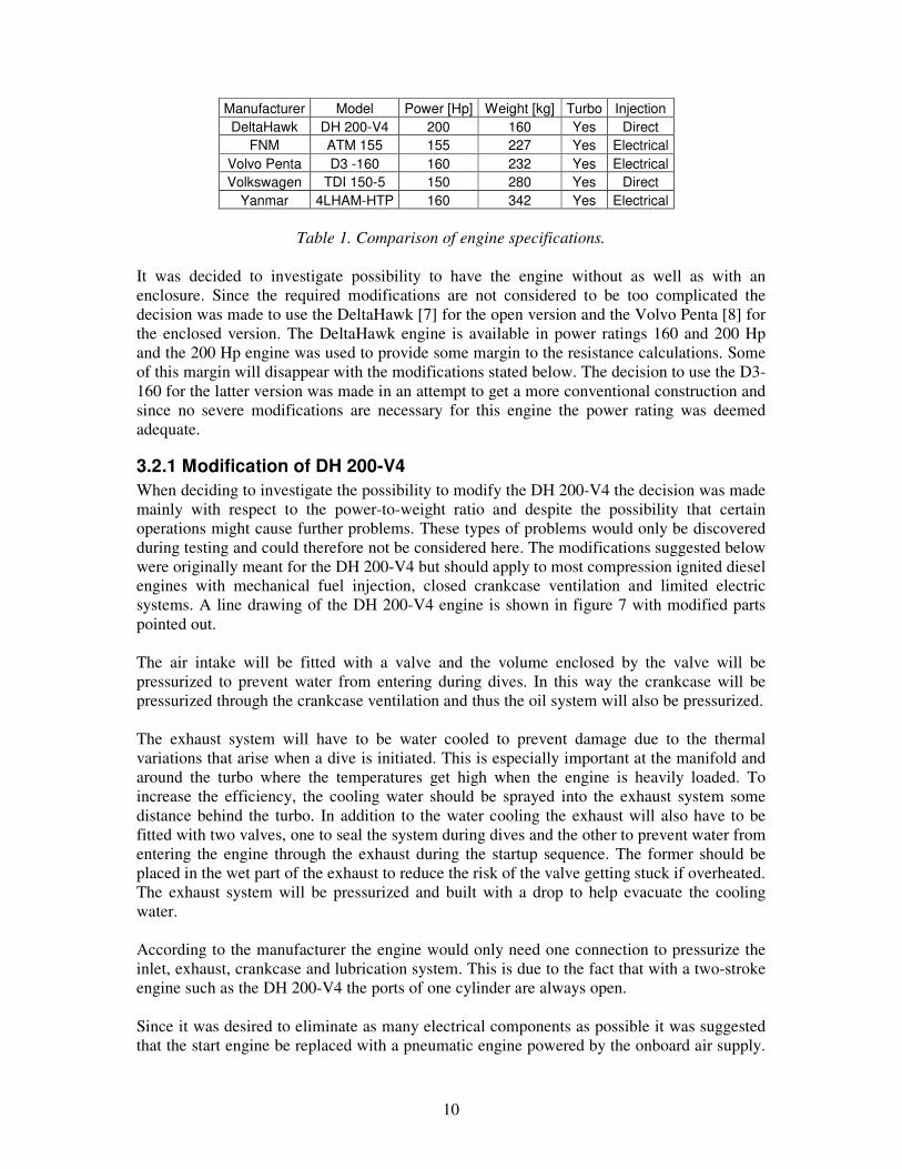
3.2 Engine After an evaluation of available engines it was concluded that in the range from 120 to 200 Hp there were a number of engines suitable for the vessel though desired characteristics such as mechanical fuel injection and a small amount of electrical systems reduced this amount significantly. Analysis of what modifications were required to fit an engine without an enclosure led to two suitable options. Either to use a conventional marine diesel or to modify an engine originally designed to be fitted in an aircraft. The benefits of the airplane engine are the low weight and the small amount of electrical systems. The negative aspect is the turbo and exhaust that must stand being submerged directly after extensive use. A comparison between some conventional marine diesels and the DeltaHawk aircraft engine is shown in table 1.
10
Manufacturer Model Power [Hp] Weight [kg] Turbo Injection DeltaHawk DH 200-V4 200 160 Yes Direct
FNM ATM 155 155 227 Yes Electrical Volvo Penta D3 -160 160 232 Yes Electrical Volkswagen TDI 150-5 150 280 Yes Direct
Yanmar 4LHAM-HTP 160 342 Yes Electrical
Table 1. Comparison of engine specifications. It was decided to investigate possibility to have the engine without as well as with an enclosure. Since the required modifications are not considered to be too complicated the decision was made to use the DeltaHawk [7] for the open version and the Volvo Penta [8] for the enclosed version. The DeltaHawk engine is available in power ratings 160 and 200 Hp and the 200 Hp engine was used to provide some margin to the resistance calculations. Some of this margin will disappear with the modifications stated below. The decision to use the D3-160 for the latter version was made in an attempt to get a more conventional construction and since no severe modifications are necessary for this engine the power rating was deemed adequate.
3.2.1 Modification of DH 200-V4 When deciding to investigate the possibility to modify the DH 200-V4 the decision was made mainly with respect to the power-to-weight ratio and despite the possibility that certain operations might cause further problems. These types of problems would only be discovered during testing and could therefore not be considered here. The modifications suggested below were originally meant for the DH 200-V4 but should apply to most compression ignited diesel engines with mechanical fuel injection, closed crankcase ventilation and limited electric systems. A line drawing of the DH 200-V4 engine is shown in figure 7 with modified parts pointed out. The air intake will be fitted with a valve and the volume enclosed by the valve will be pressurized to prevent water from entering during dives. In this way the crankcase will be pressurized through the crankcase ventilation and thus the oil system will also be pressurized. The exhaust system will have to be water cooled to prevent damage due to the thermal variations that arise when a dive is initiated. This is especially important at the manifold and around the turbo where the temperatures get high when the engine is heavily loaded. To increase the efficiency, the cooling water should be sprayed into the exhaust system some distance behind the turbo. In addition to the water cooling the exhaust will also have to be fitted with two valves, one to seal the system during dives and the other to prevent water from entering the engine through the exhaust during the startup sequence. The former should be placed in the wet part of the exhaust to reduce the risk of the valve getting stuck if overheated. The exhaust system will be pressurized and built with a drop to help evacuate the cooling water. According to the manufacturer the engine would only need one connection to pressurize the inlet, exhaust, crankcase and lubrication system. This is due to the fact that with a two-stroke engine such as the DH 200-V4 the ports of one cylinder are always open. Since it was desired to eliminate as many electrical components as possible it was suggested that the start engine be replaced with a pneumatic engine powered by the onboard air supply.

11
Atlas Copco supplies several suitable pneumatic engines in the right power range [9] and once the engine has been replaced the mechanics from the original start engine could be mounted onto the new engine axel. Problems associated with a pneumatic start engine are the limited onboard air supply and the vast air consumption of the engine. For air consumption calculations see section 5.2. The other choice was to build an enclosure around the original start engine but this system was deemed not desirable due to the electricity and complications associated with sealing the enclosure. At this stage the pneumatic solution was chosen over the electric even though this meant extra weight and a limited number of starts, one of the reasons being that this system also provides the divers with an emergency air tank. Another issue was that a belt drives both supercharger and water pump. Experienced personnel state that it should not be a problem, though if there would be a loss of friction when the construction is submerged the suggestion would be to change to a serrated belt and corresponding belt pulleys. Apart from pressurizing parts of the engine all electrical sensors such as thermometer and pressure sensors would have to be replaced with mechanical dittos. With the same motivation the generator would be removed and the 12 VDC batteries for the onboard electronics would be recharged at the same time as the main battery pack. To eliminate the risk of seawater entering the freshwater cooling reservoir this should also be included in the pressurized system. Also details like the oil stick should be threaded and fitted with a seal.
Figure 7. Line drawing of DH 200-V4 with modified areas marked. Illustration with courtesy of DeltaHawk [7].
It should also be mentioned that the DH 200-V4 has three different accessory pads providing up to 10 Hp each. This might very well prove to be a convenient source of power for the bilge pumps if it is decided that they are not to be electric. Last but not least the manufacturer state that around 15% of the heat developed by the engine is considered to dissipate with the airflow around the engine when fitted in an airplane. With this in mind the heat exchanger for the water cooling system would probably have to be upgraded.
12
3.2.2 Modification of D3-160 Even though D3-160 is a conventional marine engine it might prove to be challenging to mount it in a very tight enclosure, for example the exhaust system might have to be modified to provide a reasonable working environment for the engine. If mounted in an enclosure the original starting system could still be used and the extra air bottle needed for the pneumatic start engine would be replaced with an Optima YT 2.7 battery. The concept with an enclosure is also what is used on the DGB 2003 [1] and thus the concept will be thoroughly tested. When designing the actual enclosure this must be done in a way that ensures easy access to the engine during maintenance.
3.3 Waterjet vs. Stern Drive Since the top speed for the craft is around 25 knots the efficiency of a conventional propeller mounted to a stern drive or fix axle exceeds that of a waterjet throughout the whole speed range [10]. The solution with a fixed axle and propeller was discarded due to the added resistance in the submerged state and also the poor manoeuvrability at slow speeds. Added resistance for the stern drive can be minimized since the whole construction can be tilted. The benefits of the waterjet would be that it might simplify the installation, require less modification than a stern drive and also the resistance under water would be lower. On the other hand the waterjet weighs more than a stern drive and as stated earlier the efficiency is not as good as for a stern drive at these speeds. With this motivation it was decided to fit the SEAL HI with a conventional stern drive. To survive repeated dives the stern drive needs to be modified in a manner similar to the engine to prevent water from penetrating. The Volvo Penta DP-S drive was chosen as this unit displays good characteristics and data for this drive was readily available.
3.3.1 Modification of the Volvo Penta DP-S Most stern drives have similar constructions so even though the modifications stated here are specific for the Volvo Penta DP-S stern drive they should apply to units from other manufacturers with only slight modifications. A schematic view of the DP-S drive is shown in figure 8 where the cooling water is represented by the blue area-1, the exhaust by the red-2 and pressurized volumes are indicated by yellow-3. The exhausts from the engine are led through the gear unit as on the original construction without modification since this is a separate volume. It might prove hard to mount the desired valves to the drive and in that case the exhaust system would be rebuilt so that it does not include the drive. The intake for the cooling water would not need any modifications since this is also a separate volume. To ensure the reliability of the stern drive the rest of the gear unit would have to be pressurized. This connection should be made through the already existing top oil plug so that no new holes would have to be made. The original seals should be sufficient even after modification since there will be a slightly higher pressure inside the gear unit than in the surrounding water. The area that proved to be most challenging was the universal joint that must be run in a dry environment. Originally the U-joint is placed inside a rubber bellow with clamps at both ends to keep the water out and the suggestion was to use the same solution but having the rubber bellow pressurized. This should enable the unit to be used in skim mode and prevent water from entering during repeated dives.

13
The already fitted hydraulic pistons should be tested to investigate if they can stand the reversed pressure difference and if not, they are to be fitted with additional seals or replaced.
Figure 8. Schematic view of the stern drive unit.
4 Propulsion, Submerged When submerged the SEAL HI will be propelled by two electric thrusters powered by a battery pack. The vessels cruising speed and demands on maneuverability set the requirements for the thrusters. Since a full analysis of the movement equation was considered to be too complex to invest time in at this stage a rough estimate was used to get an initial value of the required power.
4.1 Thrusters To achieve the prescribed 3 knots in submerged state an estimate of the resistance was made. The vessel was approximated with an ellipsoid with half axis 1.5 m and 2.7 m yielding a cross section area of 1.82 m2, which is consistent with the cross section area of the CAD model. With these assumptions it is possible to estimate the power requirements for the thrusters. The equation and values used in these calculations were
( )SCACvR FD += 2
21 ρ (1)
where 54.1=v m/s, 30=S m3 taken from the CAD model, ( ) 351
105.4Re074.0 −−⋅== lFC
for a turbulent boundary layer [12] and 19.0=DC [12]. This set the demand on the thrusters that they must produce a total thrust of at least 590 N. It was decided to use the same thrusters as for the DGB 2003 since these are already evaluated and found to be suitable for that construction. The thrusters to be used are two Tecnadyne Model 2010 [13] each producing a thrust of 910 N and thus a total thrust of 1820 N which by far exceeds the above stated demands. The reason to use thrusters with this much extra power was motivated by the uncertainty of CD in (1). If, for example, CD =0.4 the required thrust would be 1050 N. In the following calculations CD is set to 0.3 with the motivation that the superstructure will be

14
shaped to give as low drag as possible but will still include the snorkel and wing-thruster configurations which all add to the resistance. With CD = 0.3 the calculated resistance became 850 N at 3 knots and 1500 N at 4 knots and thus the speed requirement of minimum 3 knots was considered not to pose a problem.
4.2 Manoeuvring and Thruster Placement One of the main design specifications was the ability to manoeuvre in limited spaces. The SEAL HI turns by having the thrusters working in opposite directions and thus does not require the forward speed that a vessel with traditional rudders would. To adjust the depth when not moving forward the trim tanks are used and if the vessel is under way the wings and thrusters can be pitched for increased depth control. The port and starboard thruster can be pitched in different directions to produce a rolling moment that could be used to improve the vessels turning rate while under way. The thrusters are mounted onto a wing on either side of the cockpit and the pitch is controlled by electric servos. To limit the strain on the servo the rotation axis for the wing-thruster configuration should be placed in line with the centre of gravity for the wing-thruster configuration. In this way the forces associated with slamming in a rough sea are supported by the axle bearings and fittings rather than the servo. To minimize the hydrodynamic forces on the servo the rotation axis should be placed approximately at the quarter cord line of the wing-thruster configuration but these forces are negligible compared to forces produced by slamming. The servos are to be powered by the same battery pack as the thrusters via a converter. To get a rough estimate of the vessels performance under water some simple calculations were made under the assumption that the vessel consists only of a flooded hull and superstructure. The vessels ability to manoeuvre in roll or pitch was based on a comparison of the moment produced by the thrusters and the static stability of the vessel. For yawing manoeuvres there is no static stability and thus the calculations had to be taken a step further. Limitations in geometric parameters used in these calculations are illustrated in figure 9. Due to the rough nature of these calculations the hydrodynamic influence of the wings was ignored.
Figure 9. Geometric properties used in performance calculations. Values state the different lever arms used to calculate the pitching, rolling and yawing moments.
Calculations concerning yaw started by examining the equation of movement
ϕϕϕ KDIM ++=•••

15
where M is the applied moment, I is the moment of inertia, D is the dampening and K is associated to the static stability of the system and is excluded since there is no static stability for a yawing motion. Here � represents the angle measured from the vessel at equilibrium and in the equation are also the first and second order derivatives with respect to time. Since no realistic value was known for the dampening the problem was simplified and described as if in vacuum which yielded
••= ϕIM .
This equation was then integrated twice with respect to time and solved for ϕ and thus becomes
00
2
2ϕϕϕ ++
⋅⋅=
•t
ItM
. (2)
To be able to extract numerical values from (2) initial conditions were required. These were set to
00 =•
ϕ
00 =ϕ
which means that the vessel starts facing straight ahead and has no initial angular velocity. With initial conditions as above and now solved for t (2) becomes
MI
tϕ⋅⋅= 22 . (3)
Here M is the moment produced by the thrusters around CG and ϕ was set to π/2 which represents the angle the vessel has turned (90°). I is the moment of inertia around the z-axis and was calculated in a CAD program and found to be, 16000≈I m4. The moment of inertia was multiplied by a factor 1.2 in an attempt to mimic the effect of the surrounding water that is set in motion by the vessel and also to reduce the effects due to the loss of dampening. With values for available thrust, 910 N forward and 520 N when reversed, (3) was solved for t and the results are presented in table 2.
Roll Dive Climb Yaw Max Produced Moment [Nm] 970 1550 400 1100 Max Rightening Moment [Nm] 1990 1990 1990 --- Time to turn 90° [s] --- --- --- ~7 Turn radius @ 3 knots [m] --- --- --- ~4.5
Table 2. Estimates of manoeuvring performances.
Results in table 2 should be reviewed with care since considerable simplifications have been made during calculation of times and turn radius. Worth noting though is that the concept of

16
controlling the SEAL HI under water in the manner described here should be examined closer with for example model testing. The vessels ability to sink or rise along a vertical axle is investigated in section 7.2.1 where dimensioning of the trim tanks is presented.
4.3 Loads Due to Slamming The loads produced by slamming were calculated in the Matlab program mentioned earlier and were shown in figure 5. The graph states that the vessel experiences an additional acceleration of 2.5 g at the centre of gravity. To investigate if the demands on the structure are manageable the results were transformed to a solid mechanics problem. The weight of the wing-thruster configuration was set to 15 kg and the corresponding load is represented by P in figure 10. For simplicity the wing-thruster configuration was assumed to consist of an axle that acts as a beam and thus supports all loads and is then covered by a symmetric wing profile. During the analysis the axle was assumed to be supported as shown in figure 10.
Figure 10. Schematic drawing of the setup used to calculate the loads on the wing-thruster configuration.
With this setup the problem was solved with ordinary solid mechanics procedures yielding the reaction forces RA and RB by solving for equilibrium. The results were then transferred to shear force and moment diagrams and according to figure 11 the point with the highest strain is B.

17
Figure 11. Shear forces and moments as calculated for the wing-thruster configuration when experiencing a total acceleration of 3.5 g.
Since the cross-section is symmetric the maximum load experienced by the axel was calculated via
MaxMax
Max ztr
Mπ
σ3
= (4)
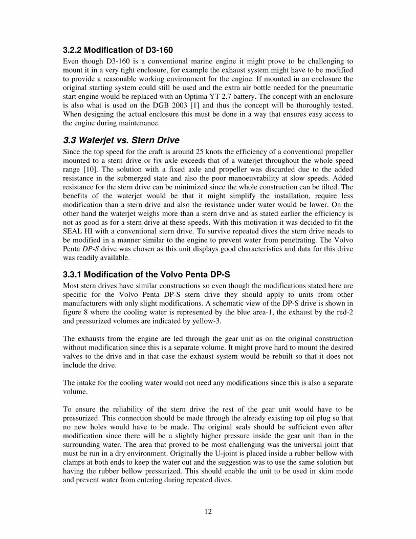
By choosing a stainless steel pipe as supporting axel and further on, by choosing the geometric properties according to figure 10 (4) yields that the loads at B due to slamming are acceptable, 170 MPa. In addition to these calculations the structures natural frequency was also examined to investigate the risk of resonance during unfavourable sea conditions. The wing-thruster configuration was approximated by a beam with no weight and a point mass at the free end as shown in figure 12. According to [14] the movement equation for this system could be described by
03
3=+
••z
mLEI
z
following the procedure in [14] the natural frequency could be derived through
853
3==
mLEI
eϖ Hz.
Geometric and material properties used above correspond to those for a stainless steel pipe as in figure 10. When calculating frequencies exerted by the sea onto the hull both following and head seas were considered. Periods and wavelengths for seastate 1 and 3 were extracted from a table based on Pierson-Moskowitz sea spectrum [1]. The frequencies experienced by the hull are found in table 3 and when compared to the natural frequency for the wing-thruster configuration, 85 Hz, it is evident that there is no risk of resonance during these conditions.
18
Figure 12. Schematic drawing of the setup used to calculate the natural frequencies for the wing-thruster configuration.
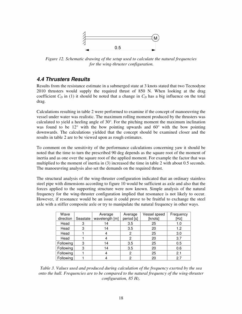
4.4 Thrusters Results Results from the resistance estimate in a submerged state at 3 knots stated that two Tecnodyne 2010 thrusters would supply the required thrust of 850 N. When looking at the drag coefficient CD in (1) it should be noted that a change in CD has a big influence on the total drag. Calculations resulting in table 2 were performed to examine if the concept of manoeuvring the vessel under water was realistic. The maximum rolling moment produced by the thrusters was calculated to yield a heeling angle of 30°. For the pitching moment the maximum inclination was found to be 12° with the bow pointing upwards and 60° with the bow pointing downwards. The calculations yielded that the concept should be examined closer and the results in table 2 are to be viewed upon as rough estimates. To comment on the sensitivity of the performance calculations concerning yaw it should be noted that the time to turn the prescribed 90 deg depends as the square root of the moment of inertia and as one over the square root of the applied moment. For example the factor that was multiplied to the moment of inertia in (3) increased the time in table 2 with about 0.5 seconds. The manoeuvring analysis also set the demands on the required thrust. The structural analysis of the wing-thruster configuration indicated that an ordinary stainless steel pipe with dimensions according to figure 10 would be sufficient as axle and also that the forces applied to the supporting structure were now known. Simple analysis of the natural frequency for the wing-thruster configuration implied that resonance is not likely to occur. However, if resonance would be an issue it could prove to be fruitful to exchange the steel axle with a stiffer composite axle or try to manipulate the natural frequency in other ways.
Wave direction Seastate
Average wavelength [m]
Average period [s]
Vessel speed [knots]
Frequency [Hz]
Head 3 14 3.5 25 1.0 Head 3 14 3.5 20 1.2 Head 1 4 2 25 3.0 Head 1 4 2 20 3.7
Following 3 14 3.5 25 0.5 Following 3 14 3.5 20 0.6 Following 1 4 2 25 2.1 Following 1 4 2 20 2.7
Table 3. Values used and produced during calculation of the frequency exerted by the sea
onto the hull. Frequencies are to be compared to the natural frequency of the wing-thruster configuration, 85 Hz.

19
The reaction forces at A and B in figure 10 were found to be 875 N and 1400 N respectively. These forces are not large enough to impose special restrictions on the structure but should off course be considered when designing the mounts for the wing-thruster configuration. The maximum strain on the axle is due to bending and was calculated to 170 MPa which can easily be supported by an ordinary stainless steel axle with dimensions as in figure 10.
5 Payloads In this section different loads are specified and their weights calculated. The estimated weight and centre of gravity of all fixed equipment and structures are listed in appendix.
5.1 Battery Pack To supply the power needed to propel the SEAL HI under water with the thrusters previously chosen the battery pack is required to produce 260 V. To achieve this voltage while considering weight and endurance the pack was decided to consist of 22 Optima YT 2.7 batteries connected in series. These batteries were chosen because they are low-weight, small and yet still reasonably powerful. For the range calculations it was assumed that the craft would constantly use an amount of electric power equivalent of that needed to propel the craft at a speed of 3.5 knots. In the previous section the resistance at 3 knots was calculated to 850 N and in the same way the resistance for 3.5 knots was calculated to 1130 N. The decision to increase the cruise speed with half a knot was made to ensure that the vessel could at least keep the prescribed 3 knots throughout the whole submerged range. With the assumption that the propulsive efficiency from battery to forward thrust is � = 0.7 it is possible to calculate the required current according to
2.117.02608.11130 =
⋅⋅==�==
ηη
URv
IUIRvP A
where R is the resistance of the vessel, v the speed in m/s and U the voltage. According to the manufacturers discharge charts the Optima YT 2.7 can stand a constant load of 11.2 A during 3.5 hours minutes without dropping the voltage to less than 11.5 V. To protect the batteries from water and the outside pressure they were placed in an enclosure with a tight fit. The similar concept will be used for the DGB 2003 and thus the construction will be thoroughly tested before being fitted onboard the SEAL HI. The batteries will be placed in two separate enclosures that will be ventilated during recharging to evacuate any hazardous gas that may be produced. The enclosures are pressurized and keeps the inside pressure slightly higher than the ambient. This solution was decided on after preliminary testing of the batteries ventilation valves. The weak point is the over-pressure valve, designed to release a high pressure from within the battery the valve does not stand a reversed pressure difference. To solve this the ventilation outlets should be fitted with a one-way valve and thus keep the inside of the battery at atmospheric pressure. A construction where the whole battery is pressurized is not suitable since the inner climate of the selected battery type must not be changed. The ventilation valve on the battery mentioned above is fitted on the battery by the manufacturer only as a safety precaution in case the battery is not correctly recharged and does not ventilate the battery during normal circumstances.

20
There will also be another two batteries to power the GPS, depth finder, lanterns and other electrical equipment. In total the battery pack and enclosure has a weight of 290 kg.
5.2 Air Supply To get an estimate of the amount of air needed onboard the SEAL HI it was assumed that the three divers have an air consumption of 30 l/min at the surface. This is equivalent to the consumption assumed for an average diver. It was also assumed that the main parts of the submerged operations are to be carried out at a depth of 5 meters. It should be noted that the air used for opening the valves at the bottom of the hull and also to pressurize both engine and trim tanks is not considered in the following calculations. With these assumptions and the use of two 50 liters, 200 bar air bottles the calculations yield a maximum submerged time of 2.5 hours. The depth was estimated as an average depth during an inspection and since the divers are seated in the vessel and not subject to physical strain the calculations were considered to have the necessary safety margin. For the version without an enclosure around the main engine not only the crew is in need of air, the new start engine also requires pressurized air to start the diesel engine. A pneumatic engine with a power rating of around 1.6 kW consumes approximately 36 l/s and demands a minimum pressure of 6 bars [9]. With the assumption that the start engine is running for 10 s during an average start it is possible to start the engine ten times without returning to shore on a 20 liter 200 bar air bottle. It was suggested that that the start bottle initially be separated from the crew bottles and in this way preventing accidental usage of starting capacity and at the same time provide a reserve for the crew in an emergency situation. In total, the onboard air supply consists of two 50 liter air bottles with a total weight of 170 kg when full and 144 kg empty. For the version with no enclosure around the main engine there would be an additional 20 liter 200 bar bottle weighing 42 kg full and 37 kg empty.
5.3 Crew The SEAL HI was designed to carry a crew of three fully equipped divers and their gear at a total weight of 500 kg. The divers are to have neutral buoyancy during the diving phase and in this way the crew is considered as load only when in surface mode. If equipment with high density would be brought onboard additional buoyancy should also be fitted onboard to ensure underwater performance and stability.
5.4 Fuel During the following calculations figure 15 to 18 in appendix have been used to extract values for fuel consumption at different effects. In the design specification it was stated that the SEAL HI should have a range at the surface of at least 50 Nm. To calculate the amount of fuel needed it was assumed that the cruise speed was 20 knots. Resistance calculations set the required power at this speed to 95 Hp with a propulsive efficiency of 0.5. Fuel consumption curves for the DH 160-V4 stated that the required power is achieved at ~2200 rpm and these curves were used since there none were available for the DH 200-V4. At this rpm the DH 160-V4 has a fuel consumption of 21 liters per hour and this value was modified to 24 liters per hour for the DH 200-V4. With these values the fuel tank must hold at least 60 liters but was designed with a 10 litre reserve and thus have a total volume of 70 liters.

21
For the D3-160 the same calculations were performed and it was concluded that the D3-160 has a fuel consumption of 20 liters per hour at this effect. Since the fuel consumption for the two different engines are rather similar the tank volume was set to 70 liters for both versions.
6 Weight/Volume Calculations The Matlab program used to calculate the hull resistance was also designed to calculate the vessels centre of gravity by reading a list consisting of the vessels different components. For components with complex geometries the centre of gravity and volume was calculated in a CAD program and these values were then entered into the list of components. Weight calculations were performed for the vessel in both surface mode and in submerged mode. Results from these calculations were used in the stability and resistance calculations and a full list of the included components can be found in appendix. Volume calculations were performed in the same way and were repeated for the vessel with empty air and fuel tanks. Placement of the different components was done in a manner of trail and error and was continuously checked against the CAD model to ensure that there was room for everything. The main problem consisted of getting a centre of gravity that yield acceptable surface characteristics and at the same time have the centre of buoyancy straight above it and the buoyancy tanks fitted within a hydrodynamic superstructure. The vessels total weight with full tanks was calculated to 1953 kg if fitted with the DH 200-V4 and 2111 kg with the D3-160. In table 4 below the centre of gravity and buoyancy is stated for the different configurations considered. When submerged it would be a matter of using the trim tanks to achieve a neutral trim as the air and diesel is consumed. As stated in section 2 the hull construction had to be modified when fitted with the D3-160 engine in an enclosure. This is due to the increased buoyancy produced by the enclosure and without changing to a thinner core in the hull the vessel would not be able to dive. Other modifications to the weight of different components can be found in appendix.
Mode Engine Fuel & Air CG [x,y,z] BG [x,y,z] Surface DH 200-V4 Full 2.47,0,0.57 --- Surface D3-160 Full 2.40,0,0.56 ---
Submerged DH 200-V4 Full 2.24,0,0.42 2.24,0,0.56 Submerged D3-160 Full 2.16,0,0.43 2.16,0,0.53 Submerged DH 200-V4 Empty 2.27,0,0.44 2.27,0,0.57 Submerged D3-160 Empty 2.18,0,0.44 2.18,0,0.54
Table 4. Centre of gravity and buoyancy measured from the aft perpendicular.
7 Stability Calculations Design requirements stated that the vessel must be statically stable in both surface and submerged mode. The estimated weight and volume of all fixed components used in calculations are listed in appendix. In this section the different concepts used to achieve stability are discussed and calculations presented.
7.1 Stability, Surface Stability calculations for the vessel in surface mode were performed in a computer program for ordinary hydrostatic calculations and the requirements used were those set by DNV to comply with the CE-classification [15]. It was decided that the vessel should be classed as category C, inshore, since this category includes seastates specified in the design

22
specifications. Though designed with the requirements for CE-classification in mind there might be issues when interpreting how the rules and limitations should be applied to certain areas. A highly specialized vessel such as the SEAL HI will inevitably include characteristics that might be viewed upon as unfavourable with respect to a potentional classification. The requirements and results stated in table 5 show that the vessel is statically stable but has a freeboard that does not meet the requirements in [15]. Increasing the freeboard would yield a larger volume to flood and empty during transition from surface to submerged mode or vice versa. It would also increase the submerged resistance significantly and with this the issue is not discussed further here. It should be noted that the last three lines in table 5 concern the vessel in a swamped state, which is addressed in section 7.2.
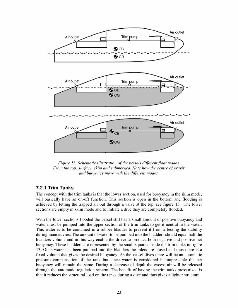
7.2 Stability, Submerged Calculations concerning static stability in submerged state were performed in another extension to the Matlab program mentioned earlier. This extension calculates the volume of the two tanks positioned at the centreline so that a neutral trim is achieved. The position and volume of each tank was initially guessed and then adjusted in an iterative manner with respect to both stability calculations and the geometry of the superstructure. Since any disturbance from equilibrium on the vessel would be due to underwater currents or driver-induced, both of which were considered to be minor or at least deliberate, the demand on the rightening moment was not that hard. The rightening moment was calculated for a disturbed state corresponding to a heeling angle of 60° and the results are found in table 5. The submerged state corresponds to the swamped state in [15] and thus must fulfill the stability criteria represented by the last three lines in table 5. To enable the vessel to float in a skim mode where the pilots head is above water the trim tanks were extended downwards. This lowers the centre of buoyancy and since stability in the submerged state is achieved by having the centre of buoyancy as high above the centre of gravity as possible the stability is decreased, see figure 13. The skim mode is where the vessel has the least stability and care should therefore be taken to minimize the time spent in this mode. In figure 13 the different modes are schematically illustrated and the shaded areas represent flooded volumes. Note that in the middle, skim mode, the extension of the trim tanks are dry where as in the submerged mode they are flooded and the vessel is neutral in the water.
23
Figure 13. Schematic illustration of the vessels different float modes. From the top: surface, skim and submerged. Note how the centre of gravity
and buoyancy move with the different modes.
7.2.1 Trim Tanks The concept with the trim tanks is that the lower section, used for buoyancy in the skim mode, will basically have an on-off function. This section is open in the bottom and flooding is achieved by letting the trapped air out through a valve at the top, see figure 13. The lower sections are empty in skim mode and to initiate a dive they are completely flooded. With the lower sections flooded the vessel still has a small amount of positive buoyancy and water must be pumped into the upper section of the trim tanks to get it neutral in the water. This water is to be contained in a rubber bladder to prevent it from affecting the stability during manoeuvres. The amount of water to be pumped into the bladders should equal half the bladders volume and in this way enable the driver to produce both negative and positive net buoyancy. These bladders are represented by the small squares inside the trim tanks in figure 13. Once water has been pumped into the bladders the inlets are closed and thus there is a fixed volume that gives the desired buoyancy. As the vessel dives there will be an automatic pressure compensation of the tank but since water is considered incompressible the net buoyancy will remain the same. During a decrease of depth the excess air will be released through the automatic regulation system. The benefit of having the trim tanks pressurized is that it reduces the structural load on the tanks during a dive and thus gives a lighter structure.

24
To achieve a neutral trim angle while submerged the water contained in the bladders is pumped from the aft to the bow or vice versa. In this way the vessels amount of buoyancy is kept constant while the centre of buoyancy is moved aft or forward, giving the desired change in trim. To get an estimate of the required volume of the rubber bladders it was assumed that the vessel sinks/rises with a constant velocity. With this assumption (1) could be modified and solved for the velocity according to below.
ACR
vACvRD
D ρρ 2
21 2 =�=
The value CD = 1 was taken from [12] and is actually valid for a circular disc with a radius of 1.8 meters at a Reynolds number of 4108.10 ⋅ but since no better assumptions were available this value was used. A is the projected bottom area, 10 m2, and R is the negative/positive buoyancy produced when both rubber bladders are completely filled/emptied and was set to 490 N corresponding to a total volume of 50 liters. With these values the vessel was found to sink with 0.3 m/s if not moving in any other direction. Naturally the system would not yield an instant response but this way of controlling the depth should only be used if manoeuvring is restricted by nearby obstacles.
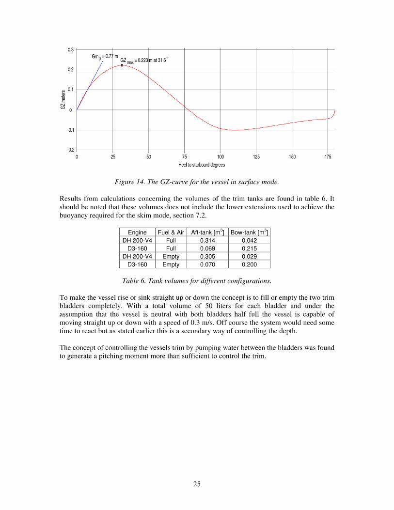
7.3 Stability Results According to the results presented in table 5 the static stability of the vessel is greater than what is required by [15] for CE classification. The requirements are met also for the swamped state and thus the low freeboard is the only problem for a classification according to the author’s interpretation of the rules. A graph with the calculated GZ-curve is shown in figure 14. Referring to reasons stated in section 7.1 the freeboard issue is not examined further here.
Rule DNV ref Load Required Actual Pass Mean freeboard 213 --- �0.5 m 0.3 m No
No flooding 215 590 Nm No flooding No flooding Yes Min mean freeboard 216 1100 Nm �0.1 m 0.21 m Yes
GZ30° 217 --- �0.2 m 0.22 m Yes GZmax 217 --- �25° 31.6° Yes
GZ positive to 60° 217 --- �60° 78° Yes Max heel angle 218 735 Nm �15° 2.8° Yes Must not sink 265 3845 N Float Float Yes
Must not capsize 271 246 Nm --- --- Yes Positive stability to 60° 273 --- Positive 1500 Nm Yes
Table 5. Requirements and results concerning stability calculations. Note
that the last three lines are valid for swamped state.
25
Figure 14. The GZ-curve for the vessel in surface mode.
Results from calculations concerning the volumes of the trim tanks are found in table 6. It should be noted that these volumes does not include the lower extensions used to achieve the buoyancy required for the skim mode, section 7.2.
Engine Fuel & Air Aft-tank [m3] Bow-tank [m3] DH 200-V4 Full 0.314 0.042
D3-160 Full 0.069 0.215 DH 200-V4 Empty 0.305 0.029
D3-160 Empty 0.070 0.200
Table 6. Tank volumes for different configurations. To make the vessel rise or sink straight up or down the concept is to fill or empty the two trim bladders completely. With a total volume of 50 liters for each bladder and under the assumption that the vessel is neutral with both bladders half full the vessel is capable of moving straight up or down with a speed of 0.3 m/s. Off course the system would need some time to react but as stated earlier this is a secondary way of controlling the depth. The concept of controlling the vessels trim by pumping water between the bladders was found to generate a pitching moment more than sufficient to control the trim.
26
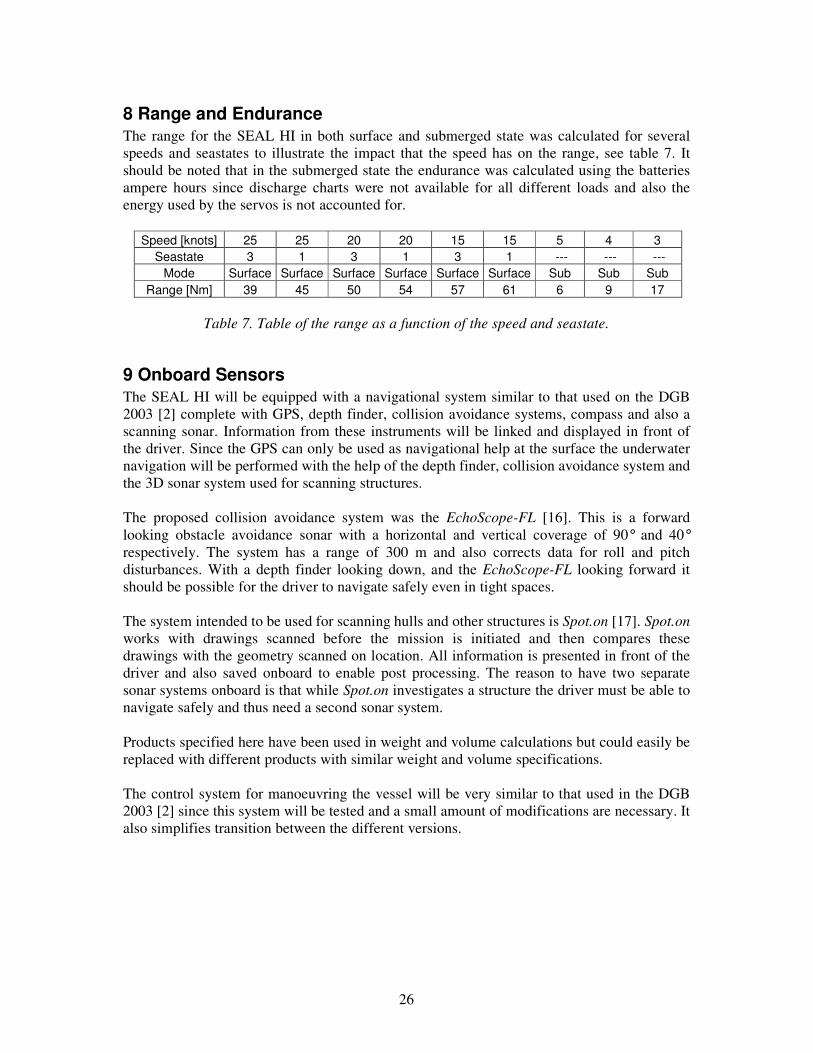
8 Range and Endurance The range for the SEAL HI in both surface and submerged state was calculated for several speeds and seastates to illustrate the impact that the speed has on the range, see table 7. It should be noted that in the submerged state the endurance was calculated using the batteries ampere hours since discharge charts were not available for all different loads and also the energy used by the servos is not accounted for.
Speed [knots] 25 25 20 20 15 15 5 4 3 Seastate 3 1 3 1 3 1 --- --- ---
Mode Surface Surface Surface Surface Surface Surface Sub Sub Sub Range [Nm] 39 45 50 54 57 61 6 9 17
Table 7. Table of the range as a function of the speed and seastate.
9 Onboard Sensors The SEAL HI will be equipped with a navigational system similar to that used on the DGB 2003 [2] complete with GPS, depth finder, collision avoidance systems, compass and also a scanning sonar. Information from these instruments will be linked and displayed in front of the driver. Since the GPS can only be used as navigational help at the surface the underwater navigation will be performed with the help of the depth finder, collision avoidance system and the 3D sonar system used for scanning structures. The proposed collision avoidance system was the EchoScope-FL [16]. This is a forward looking obstacle avoidance sonar with a horizontal and vertical coverage of 90° and 40° respectively. The system has a range of 300 m and also corrects data for roll and pitch disturbances. With a depth finder looking down, and the EchoScope-FL looking forward it should be possible for the driver to navigate safely even in tight spaces. The system intended to be used for scanning hulls and other structures is Spot.on [17]. Spot.on works with drawings scanned before the mission is initiated and then compares these drawings with the geometry scanned on location. All information is presented in front of the driver and also saved onboard to enable post processing. The reason to have two separate sonar systems onboard is that while Spot.on investigates a structure the driver must be able to navigate safely and thus need a second sonar system. Products specified here have been used in weight and volume calculations but could easily be replaced with different products with similar weight and volume specifications. The control system for manoeuvring the vessel will be very similar to that used in the DGB 2003 [2] since this system will be tested and a small amount of modifications are necessary. It also simplifies transition between the different versions.

27
10 Summary In accordance with the design specification the vessels maximum load is 500 kg and with this load the vessel is capable of speeds in excess of 25 knots in seastate 3. At the surface the vessel is powered by a diesel engine and the two engines considered in this report are the Volvo Penta D3-160 and the modified aircraft engine Delta Hawk 200-V4. The DH 200-V4 is mounted without an enclosure and thus eliminates a lot of weight but adds complexity in pressurizing cavities in the engine and rebuilding the exhaust-, cooling- and start-system. The D3-160 on the other hand uses the more conventional solution of placing the engine in an enclosure and thus reduce the amounts of modifications necessary but adds more than 150 kg to the vessels total weight. Both engine concepts are intended to be fitted with a Volvo Penta DP-S stern drive. Calculations in section 2 yielded that the power from either engine should be sufficient for a hull with dimensions as in figure 6. The hull it self will be a sandwich construction with a core of Divinycell. Core thickness and fibre material vary for the two different engine concepts and are stated in section 2. The vessel has a static stability sufficient for CE classification, category C, in surface mode. The only issue for a classification would be that the freeboard is too low, though this might be evaded through the fact that the vessel does not take on water even though the freeboard is submerged. The skim mode is where the vessel has the least static stability and care should be taken to minimize the time spent in this mode. While submerged the vessel has good static stability and since the crew is considered to be neutral in the water any number of crewmembers can leave the vessel without affecting the stability. Manoeuvring the vessel at the surface is no different than for an ordinary powerboat with a stern drive. Under water the vessel can be controlled in yaw and depth even when not moving forward and if using the thrusters the driver can induce both rolling and pitching moments to increase the maneuverability when moving forward. Since it is possible to induce negative buoyancy via the trim system the crew can leave the vessel on the sea bottom. In case of underwater currents the vessel would probably drift with the current and to prevent this the vessel should be equipped with means for anchorage. Though this function is not investigated in full some ideas are presented here. The anchor could consist of a screw that is screwed into the sea bottom from within the hull or alternatively an ordinary “Bruce” anchor fitted in the bow. In both cases the requirement is that the bottom is soft and in the latter case the anchor would be dropped in an ordinary fashion and then fixated by the vessel pulling it into the bottom. The vessel should off course be parked with the bow towards the predominant direction of the current. Visibility while under water is not prioritized since most of the time the vessel will be commissioned in waters with poor visibility such as harbours. The driver navigates with the help of 3D-sonars and depth finders, specified in section 9, coupled to a digital sea chart. The concept is the same as for the DGB 2003 [2] so the system will be thoroughly tested. In the same manner the housing for most of the electronics onboard the vessel will also have been tested in the DGB 2003. The reason to not have a windscreen is that the volume will be needed for the forward buoyancy tank to get good stability in skim and submerged mode. Though this contradicts the design specification stating that in skim mode the driver should have un-obscured visibility while seated, it is thought reasonable since the driver will be

28
equipped with an adjustable seat, enabling him/her to drive in a more upright position while in skim or surface mode and thus ensuring good visibility. The maximum depth is set to 15 m in the design specifications and this depth is not considered to be a problem for the concepts stated in this report. In fact, most systems would stand grater depths but then at the cost of a shorter submerged time since divers and pressurized systems consume more air with increased depth. The vessels range and endurance both meet the specified requirements with a fuel tank of 70 liters, including a 10 liter reserve. The battery pack consists of 22 Optima 2.7 YT batteries coupled in series and fitted in a pressurized box.

29
References [1] Seastate website: www.oceandata.com/support/Sea%20State%20Table.htm [2] DGB 2003, www.theseal.se [3] Mathworks website: www.mathworks.com [4] Savitsky, Daniel, Hydrodynamic design of planing hulls, Marine Technology 1964 [5] Brown, P. Ward and Savitsky, Daniel, Procedures for hydrodynamic evaluation of planing hulls in smooth and rough water, Marine Technology 1976 [6] Koelbel, Joseph G. and Savitsky, Daniel, Sea keeping of hard chine planing hulls, Society of Naval Architects and Marine Engineers, June 1993 [7] DeltaHawk web site: www.deltahawkengines.com [8] Volvos motor spec [9] Atlas Copco website: www.atlascopco.com [10] Dyne, G and Widmark, C, Waterjet propulsion, The Royal Institution for Naval Architects, 1998 [11] Garme, Karl, Fartygs motstånd, KTH 2003 [12] Massey, Bernard, Mechanics of fluids, Seventh edition 1998 [13] Tecnadyne website: www.technadyne.com [14] Sundström Bengt, Svängningar i Kontinuerliga System, KTH 1994 [15] Tentative Rules for Certification and Classification of Boats 1997 [16] Coda octopus website: www.codaoctopus.com [17] Tapiren website: www.tapiren.com/spot.asp
30
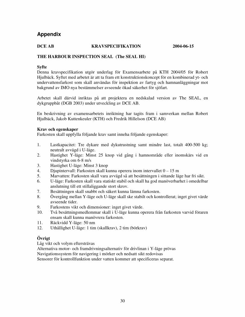
Appendix DCE AB KRAVSPECIFIKATION 2004-06-15 THE HARBOUR INSPECTION SEAL (The SEAL HI) Syfte Denna kravspecifikation utgör underlag för Examensarbete på KTH 2004/05 för Robert Hjulbäck. Syftet med arbetet är att ta fram ett konstruktionskoncept för en kombinerad yt- och undervattensfarkost som skall användas för inspektion av fartyg och hamnanläggningar mot bakgrund av IMO nya bestämmelser avseende ökad säkerhet för sjöfart. Arbetet skall därvid inriktas på att projektera en nedskalad version av The SEAL, en dykgruppbåt (DGB 2003) under utveckling av DCE AB. En beskrivning av examensarbetets inriktning har tagits fram i samverkan mellan Robert Hjulbäck, Jakob Kuttenkeuler (KTH) och Fredrik Hillelson (DCE AB) Krav och egenskaper Farkosten skall uppfylla följande krav samt inneha följande egenskaper: 1. Lastkapacitet: Tre dykare med dykutrustning samt mindre last, totalt 400-500 kg;
neutralt avvägd i U-läge. 2. Hastighet Y-läge: Minst 25 knop vid gång i hamnområde eller inomskärs vid en
vindstyrka om 6-8 m/s 3. Hastighet U-läge: Minst 3 knop 4. Djupintervall: Farkosten skall kunna operera inom intervallet 0 – 15 m 5. Marvatten: Farkosten skall vara avvägd så att besättningen i sittande läge har fri sikt. 6. U-läge: Farkosten skall vara statiskt stabil och skall ha god manöverbarhet i omedelbar
anslutning till ett stillaliggande stort skrov. 7. Besättningen skall snabbt och säkert kunna lämna farkosten. 8. Övergång mellan Y-läge och U-läge skall ske stabilt och kontrollerat; inget givet värde
avseende tider. 9. Farkostens vikt och dimensioner: inget givet värde. 10. Två besättningsmedlemmar skall i U-läge kunna operera från farkosten varvid föraren
ensam skall kunna manövrera farkosten. 11. Räckvidd Y-läge: 50 nm 12. Uthållighet U-läge: 1 tim (skallkrav), 2 tim (börkrav) Övrigt Låg vikt och volym eftersträvas Alternativa motor- och framdrivningsalternativ för drivlinan i Y-läge prövas Navigationssystem för navigering i mörker och nedsatt sikt redovisas Sensorer för kontrollfunktion under vatten kommer att specificeras separat.

31
Figure 15. Power versus rpm for the DeltaHawk DH 160 V4 with courtesy of [7].
Figure 16. Fuel consumption for the DeltaHawk DH 160 V4 with courtesy of [7].

32
Figure 17. Power versus rpm for the Volvo Penta D3-160.
Figure 18. Fuel consumption for the D3-160.

33
Weights and volumes used in calculations for the version equipped with the DH 200 V4. Weight 1953 kg Chine beam 1.74 m LCG 2.47 m VCG 0.57 m LWL 5.8 m Deadrise @ ½ LWL 17º Item CGx CGy CGz CBx CBy CBz Weight Volume Aft tank 1.6 0 1.01 1.6 0 1.01 40 0.314 Bow tank 5 0 1.2 5 0 1.2 15 0.042 Hull 2.65 0 0.3 2.75 0 0.3 200 0.25 Superstructure 3 0 1 2.6 0 0.9 80 0.1 SB Thruster 4.8 0.7 1.3 4.8 0.7 1.3 10 0.003 BB Thruster 4.8 -0.7 1.3 4.8 -0.7 1.3 10 0.003 Wings and mountings 4.8 0 1.3 4.8 0 1.3 40 0.02 Steering servos 4.8 0 0.4 4.8 0 0.4 10 0.005 Main engine 0.41 0 0.36 0.5 0 0.45 170 0.05 Larger cooling system 0.8 0 0.35 0.8 0 0.35 5 0.005 Extra water cooling 0.7 0 0.35 0.4 0 0.3 10 0.005 Driveshaft joints 0.1 0 0.3 0.1 0 0.3 5 0.001 Volvo Penta DP-S -0.25 0 0 -0.25 0 0 45 0.01 Battery pack 1.8 0 0.24 1.81 0 0.24 290 0.22 Fuel 1.2 0 0.2 1.2 0 0.2 60 0.07 Hydraulic steering 4.2 0 1 4.2 0 1 20 0.001 Compressed air, breathing 3.13 0 0.22 3.13 0 0.22 170 0.11 Compressed air, starting 0.95 0 0.22 0.95 0 0.22 42 0.023 Air system, couplings, hoses 3.1 0 0.65 3.1 0 0.65 5 0.003 Emergency lift bag 0.5 0 0.7 0.5 0 0.7 5 0.005 Scanning system 1.5 0 0.5 1.5 0 0.5 10 0.05 Multipurpose display 4.5 0 1.1 4.5 0 1.1 3 0.005 Electrical system 4.6 0 0.7 4.6 0 0.7 20 0.005 Adjustable driver seat 3.6 0 0.7 3.6 0 0.7 5 0.002 Aft cleats 0.3 0 0.5 0 0 0 2 0 Bow cleats and tow ring 6 0 0.75 0 0 0 3 0 Bilge pumps 0.2 0 0.2 0.2 0 0.2 10 0.005 Self-bailing device 0 0 0.1 0 0 0 5 0.001 Navigational system 4.5 0 0.3 4.5 0 0.3 10 0.008 Control panel 4.4 0 0.9 4.4 0 0.9 3 0.002 Unspecified 3 0 0.5 3 0 0.6 150 0.1 Cargo 3.15 0 1 0 0 0 500 0

34
Weights and volumes used in calculations for the version equipped with the Volvo Penta D3-160. Weight 2111 kg Chine beam 1.74 m LCG 2.40 m VCG 0.56 m LWL 5.8 m Deadrise @ ½ LWL 17º Item CGx CGy CGz CBx CBy CBz Weight Volume Aft tank 1.6 0 1.01 1.6 0 1.01 40 0.069 Bow tank 5 0 1.2 5 0 1.2 15 0.215
Hull 2.85 0 0.3 3.1 0 0.3 250 0.12 Superstructure 3 0 1 2.6 0 0.9 80 0.1 SB Thruster 4.8 0.7 1.3 4.8 0.7 1.3 10 0.003 BB Thruster 4.8 -0.7 1.3 4.8 -0.7 1.3 10 0.003 Wings and mountings 4.8 0 1.3 4.8 0 1.3 40 0.02 Steering servos 4.8 0 0.4 4.8 0 0.4 10 0.005
Main engine incl enclosure 0.5 0 0.4 0.5 0 0.4 335 0.49 Driveshaft joints 0.1 0 0.3 0.1 0 0.3 5 0.001 Volvo Penta DP-S -0.25 0 0 -0.25 0 0 45 0.01 Battery pack 1.8 0 0.24 1.81 0 0.24 290 0.22 Fuel 1.2 0 0.2 1.2 0 0.2 60 0.07 Hydraulic steering 4.2 0 1 4.2 0 1 20 0.001 Compressed air, breathing 3.13 0 0.22 3.13 0 0.22 170 0.11 Air system, couplings, hoses 3.1 0 0.65 3.1 0 0.65 5 0.003 Emergency lift bag 0.5 0 0.7 0.5 0 0.7 5 0.005 Scanning system 1.5 0 0.5 1.5 0 0.5 10 0.05 Multipurpose display 4.5 0 1.1 4.5 0 1.1 3 0.005 Electrical system 4.6 0 0.7 4.6 0 0.7 20 0.005 Adjustable driver seat 3.6 0 0.7 3.6 0 0.7 5 0.002 Aft cleats 0.3 0 0.5 0 0 0 2 0 Bow cleats and tow ring 6 0 0.75 0 0 0 3 0 Bilge pumps 0.2 0 0.2 0.2 0 0.2 10 0.005 Self-bailing device 0 0 0.1 0 0 0 5 0.001 Navigational system 4.5 0 0.3 4.5 0 0.3 10 0.008 Control panel 4.4 0 0.9 4.4 0 0.9 3 0.002 Unspecified 3 0 0.5 3 0 0.6 150 0.1 Cargo 3.15 0 1 0 0 0 500 0