Embed Size (px)
Citation preview
ARTILLERY TRENDS
DECEMBER U. S. ARMY ARTILLERY 1964 AND MISSILE SCHOOL
Instructional Aid Number 32
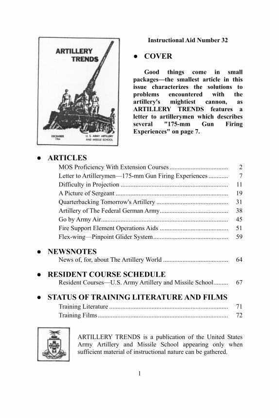
● COVER
Good things come in small packages—the smallest article in this issue characterizes the solutions to problems encountered with the artillery's mightiest cannon, as ARTILLERY TRENDS features a letter to artillerymen which describes several "175-mm Gun Firing Experiences" on page 7.
● ARTICLES MOS Proficiency With Extension Courses .................................... 2 Letter to Artillerymen—175-mm Gun Firing Experiences ............ 7 Difficulty in Projection .................................................................. 11 A Picture of Sergeant ..................................................................... 19 Quarterbacking Tomorrow's Artillery ............................................ 31 Artillery of The Federal German Army.......................................... 38 Go by Army Air.............................................................................. 45 Fire Support Element Operations Aids .......................................... 51 Flex-wing—Pinpoint Glider System.............................................. 59
● NEWSNOTES News of, for, about The Artillery World ........................................ 64
● RESIDENT COURSE SCHEDULE Resident Courses—U.S. Army Artillery and Missile School......... 67
● STATUS OF TRAINING LITERATURE AND FILMS Training Literature ......................................................................... 71 Training Films................................................................................ 72
ARTILLERY TRENDS is a publication of the United States Army Artillery and Missile School appearing only when sufficient material of instructional nature can be gathered.
1
MOS PROFICIENCY WITH EXTENSION COURSES
The field artillery extension course program offers a number of sub-courses which will contribute to proficiency in military occupational specialties (MOS) peculiar to the artillery branch. For ARTILLERY TRENDS readers, a list of those subcourses pertinent to the artillery is provided in this article for unit reference and individual use.
These lists are based on the MOS "Skills and Knowledges" requirements in AR 611-201 and the subject matter areas specified in the appropriate DA Pamphlet. The lists are broken down into specific MOS skill levels so that if an individual is qualified to a particular skill level, he need only to take those subcourses pertinent to the next higher skill level. The individual who has recently changed to a new artillery branch peculiar MOS, however, should consider all of the subcourses pertinent to the lower skill levels. Subcourses are shown by title to permit the individual to refresh himself in a subject area pertinent to a lower skill level, if he so desires.
It is emphasized that these subcourses are pertinent only to those areas of proficiency associated with the artillery subjects specified in the DA Pamphlet for a specific MOS. Artillery subject requirements are lessened in the higher skill levels and administrative requirements predominate. Thus, artillery subcourses do not provide a great deal of assistance in skill levels .8 and .9.
For some military personnel, the subcourses will provide much more assistance in preparing for MOS evaluation tests, than a review of manuals pertinent to the subject area, since the material is presented in an organized manner and practical test exercises are given to illustrate the application of specific principles. It must not be construed, however, that the completion of the subcourses listed for a particular MOS will, in any way, guarantee a satisfactory grade on the MOS evaluation test.
Individuals scheduled for MOS evaluation (.6 and higher skill levels) will generally have a minimum of eight months to prepare for the tests. This should allow sufficient time for scheduling and completing the recommended subcourses in addition to reviewing other references recommended in the appropriate DA Pamphlet.
Enrollment in these subcourses is accomplished on DA Form 145 (Army Extension Course Enrollment Application) forwarded, in one copy to the Commandant, U.S. Army Artillery and Missile School, ATTN: NRID, Fort Sill, Oklahoma 73504. The MOS and skill level for which subcourses are desired or the specific subcourse numbers should be shown in item 10 of DA Form 145.
The following lists of subcourses are recommended for study by individuals in specific MOS groups.
2
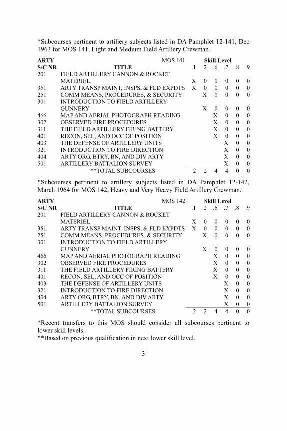
*Subcourses pertinent to artillery subjects listed in DA Pamphlet 12-141, Dec 1963 for MOS 141, Light and Medium Field Artillery Crewman.
ARTY MOS 141 Skill Level S/C NR TITLE .1 .2 .6 .7 .8 .9 201 FIELD ARTILLERY CANNON & ROCKET
MATERIEL X 0 0 0 0 0 351 ARTY TRANSP MAINT, INSPS, & FLD EXPDTS X 0 0 0 0 0 251 COMM MEANS, PROCEDURES, & SECURITY X 0 0 0 0 301 INTRODUCTION TO FIELD ARTILLERY
GUNNERY X 0 0 0 0 466 MAP AND AERIAL PHOTOGRAPH READING X 0 0 0 302 OBSERVED FIRE PROCEDURES X 0 0 0 311 THE FIELD ARTILLERY FIRING BATTERY X 0 0 0 401 RECON, SEL, AND OCC OF POSITION X 0 0 0 403 THE DEFENSE OF ARTILLERY UNITS X 0 0 321 INTRODUCTION TO FIRE DIRECTION X 0 0 404 ARTY ORG, BTRY, BN, AND DIV ARTY X 0 0 501 ARTILLERY BATTALION SURVEY X 0 0 **TOTAL SUBCOURSES 2 2 4 4 0 0
*Subcourses pertinent to artillery subjects listed in DA Pamphlet 12-142, March 1964 for MOS 142, Heavy and Very Heavy Field Artillery Crewman.
ARTY MOS 142 Skill Level S/C NR TITLE .1 .2 .6 .7 .8 .9 201 FIELD ARTILLERY CANNON & ROCKET
MATERIEL X 0 0 0 0 0 351 ARTY TRANSP MAINT, INSPS, & FLD EXPDTS X 0 0 0 0 0 251 COMM MEANS, PROCEDURES, & SECURITY X 0 0 0 0 301 INTRODUCTION TO FIELD ARTILLERY
GUNNERY X 0 0 0 0 466 MAP AND AERIAL PHOTOGRAPH READING X 0 0 0 302 OBSERVED FIRE PROCEDURES X 0 0 0 311 THE FIELD ARTILLERY FIRING BATTERY X 0 0 0 401 RECON, SEL, AND OCC OF POSITION X 0 0 0 403 THE DEFENSE OF ARTILLERY UNITS X 0 0 321 INTRODUCTION TO FIRE DIRECTION X 0 0 404 ARTY ORG, BTRY, BN, AND DIV ARTY X 0 0 501 ARTILLERY BATTALION SURVEY X 0 0 **TOTAL SUBCOURSES 2 2 4 4 0 0
*Recent transfers to this MOS should consider all subcourses pertinent to lower skill levels. **Based on previous qualification in next lower skill level.
3

*Subcourses pertinent to Artillery subjects listed in DA Pamphlet 12-147, Dec 1963 for MOS 147, Field Artillery Rocket Crewman.
ARTY MOS 147 Skill Level S/C NR TITLE .1 .2 .6 .7 .8 .9 201 FIELD ARTILLERY CANNON & ROCKET
MATERIEL X 0 0 0 0 0 395 MAINT OF MSL & RKT HANDLING EQUIP X 0 0 0 0 0 466 MAP AND AERIAL PHOTOGRAPH READING X 0 0 0 0 251 COMM MEANS, PROCEDURES, & SECURITY X 0 0 0 0 302 OBSERVED FIRE PROCEDURES X 0 0 0 469 ORG & EMPL OF FA ROCKET AND MSLE UNITS X 0 0 0 403 THE DEFENSE OF ARTILLERY UNITS X 0 0 0 401 REC, SEL, AND OCC OF POSITION X 0 0 321 INTRODUCTION TO FIRE DIRECTION X 0 0 501 ARTILLERY BATTALION SURVEY X 0 0 351 ARTY TRANSP MAINT, INSPS, & FLD EXPDTS X 0 0
**TOTAL SUBCOURSES 2 2 3 4 0 0
*Subcourses pertinent to artillery subjects listed in DA Pamphlet 12-152, Dec 1963 for MOS 152, Field Artillery Operations and Intelligence Assistant. ARTY MOS 152 Skill Level S/C NR TITLE .1 .6 .7 .8 .9 301 INTRODUCTION TO FIELD ARTILLERY
GUNNERY X 0 0 0 0 321 INTRODUCTION TO FIRE DIRECTION X 0 0 0 0 322 FIRE DIRECTION PROCEDURES, GENERAL X 0 0 0 0 466 MAP AND AERIAL PHOTOGRAPH READING X 0 0 0 404 ARTY ORG, BTRY, BN, AND DIV ARTY X 0 0 0 537 SURVEY OPERATIONS AND PLANNING X 0 0 0 302 OBSERVED FIRE PROCEDURES X 0 0 0 323 FIRE DIRECTION PROCEDURES, UNOBSERVED FIRE X 0 0 402 ARTILLERY INTELLIGENCE X 0 0 276 ARTY COMM PRINCIPLES & SYSTEMS X 0 501 ARTILLERY BATTALION SURVEY X 0 403 THE DEFENSE OF ARTILLERY UNITS X 0 409 ORG AND EMPL OF CORPS AND ARMY ARTY X
**TOTAL SUBCOURSES 3 4 2 3 1
*Recent transfers to this MOS should consider all subcourses pertinent to lower skill levels. **Based on previous qualification in the next lower skill level.
4
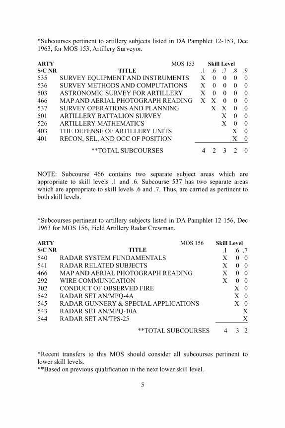
*Subcourses pertinent to artillery subjects listed in DA Pamphlet 12-153, Dec 1963, for MOS 153, Artillery Surveyor.
ARTY MOS 153 Skill Level S/C NR TITLE .1 .6 .7 .8 .9 535 SURVEY EQUIPMENT AND INSTRUMENTS X 0 0 0 0 536 SURVEY METHODS AND COMPUTATIONS X 0 0 0 0 503 ASTRONOMIC SURVEY FOR ARTILLERY X 0 0 0 0 466 MAP AND AERIAL PHOTOGRAPH READING X X 0 0 0 537 SURVEY OPERATIONS AND PLANNING X X 0 0 501 ARTILLERY BATTALION SURVEY X 0 0 526 ARTILLERY MATHEMATICS X 0 0 403 THE DEFENSE OF ARTILLERY UNITS X 0 401 RECON, SEL, AND OCC OF POSITION X 0
**TOTAL SUBCOURSES 4 2 3 2 0
NOTE: Subcourse 466 contains two separate subject areas which are appropriate to skill levels .1 and .6. Subcourse 537 has two separate areas which are appropriate to skill levels .6 and .7. Thus, are carried as pertinent to both skill levels.
*Subcourses pertinent to artillery subjects listed in DA Pamphlet 12-156, Dec 1963 for MOS 156, Field Artillery Radar Crewman.
ARTY MOS 156 Skill Level S/C NR TITLE .1 .6 .7 540 RADAR SYSTEM FUNDAMENTALS X 0 0 541 RADAR RELATED SUBJECTS X 0 0 466 MAP AND AERIAL PHOTOGRAPH READING X 0 0 292 WIRE COMMUNICATION X 0 0 302 CONDUCT OF OBSERVED FIRE X 0 542 RADAR SET AN/MPQ-4A X 0 545 RADAR GUNNERY & SPECIAL APPLICATIONS X 0 543 RADAR SET AN/MPQ-10A X 544 RADAR SET AN/TPS-25 X
**TOTAL SUBCOURSES 4 3 2
*Recent transfers to this MOS should consider all subcourses pertinent to lower skill levels. **Based on previous qualification in the next lower skill level.
5
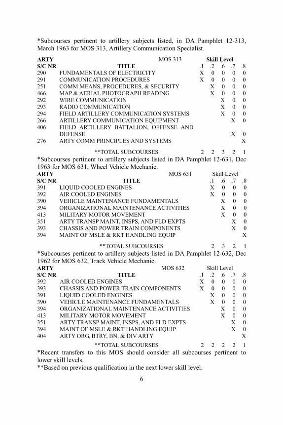
*Subcourses pertinent to artillery subjects listed, in DA Pamphlet 12-313, March 1963 for MOS 313, Artillery Communication Specialist.
ARTY MOS 313 Skill Level S/C NR TITLE .1 .2 .6 .7 .8 290 FUNDAMENTALS OF ELECTRICITY X 0 0 0 0 291 COMMUNICATION PROCEDURES X 0 0 0 0 251 COMM MEANS, PROCEDURES, & SECURITY X 0 0 0 466 MAP & AERIAL PHOTOGRAPH READING X 0 0 0 292 WIRE COMMUNICATION X 0 0 293 RADIO COMMUNICATION X 0 0 294 FIELD ARTILLERY COMMUNICATION SYSTEMS X 0 0 266 ARTILLERY COMMUNICATION EQUIPMENT X 0 406 FIELD ARTILLERY BATTALION, OFFENSE AND
DEFENSE X 0 276 ARTY COMM PRINCIPLES AND SYSTEMS X
**TOTAL SUBCOURSES 2 2 3 2 1 *Subcourses pertinent to artillery subjects listed in DA Pamphlet 12-631, Dec 1963 for MOS 631, Wheel Vehicle Mechanic. ARTY MOS 631 Skill Level S/C NR TITLE .1 .6 .7 .8391 LIQUID COOLED ENGINES X 0 0 0392 AIR COOLED ENGINES X 0 0 0390 VEHICLE MAINTENANCE FUNDAMENTALS X 0 0394 ORGANIZATIONAL MAINTENANCE ACTIVITIES X 0 0413 MILITARY MOTOR MOVEMENT X 0 0351 ARTY TRANSP MAINT, INSPS, AND FLD EXPTS X 0393 CHASSIS AND POWER TRAIN COMPONENTS X 0394 MAINT OF MSLE & RKT HANDLING EQUIP X
**TOTAL SUBCOURSES 2 3 2 1*Subcourses pertinent to artillery subjects listed in DA Pamphlet 12-632, Dec 1962 for MOS 632, Track Vehicle Mechanic. ARTY MOS 632 Skill Level S/C NR TITLE .1 .2 .6 .7 .8 392 AIR COOLED ENGINES X 0 0 0 0 393 CHASSIS AND POWER TRAIN COMPONENTS X 0 0 0 0 391 LIQUID COOLED ENGINES X 0 0 0 390 VEHICLE MAINTENANCE FUNDAMENTALS X 0 0 0 394 ORGANIZATIONAL MAINTENANCE ACTIVITIES X 0 0 413 MILITARY MOTOR MOVEMENT X 0 0 351 ARTY TRANSP MAINT, INSPS, AND FLD EXPTS X 0 394 MAINT OF MSLE & RKT HANDLING EQUIP X 0 404 ARTY ORG, BTRY, BN, & DIV ARTY X **TOTAL SUBCOURSES 2 2 2 2 1 *Recent transfers to this MOS should consider all subcourses pertinent to lower skill levels. **Based on previous qualification in the next lower skill level.
6
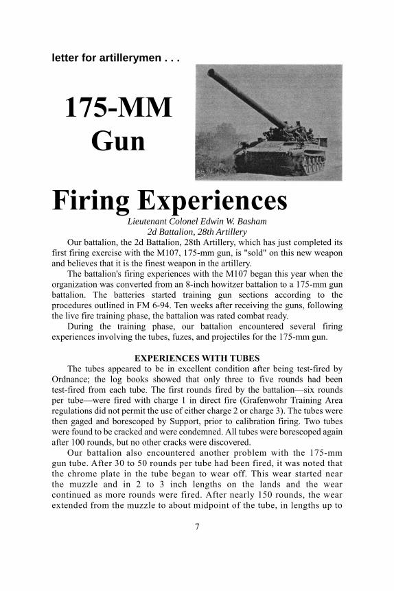
letter for artillerymen . . .
175-MM Gun
Firing Experiences Lieutenant Colonel Edwin W. Basham
2d Battalion, 28th Artillery Our battalion, the 2d Battalion, 28th Artillery, which has just completed its
first firing exercise with the M107, 175-mm gun, is "sold" on this new weapon and believes that it is the finest weapon in the artillery.
The battalion's firing experiences with the M107 began this year when the organization was converted from an 8-inch howitzer battalion to a 175-mm gun battalion. The batteries started training gun sections according to the procedures outlined in FM 6-94. Ten weeks after receiving the guns, following the live fire training phase, the battalion was rated combat ready.
During the training phase, our battalion encountered several firing experiences involving the tubes, fuzes, and projectiles for the 175-mm gun.
EXPERIENCES WITH TUBES The tubes appeared to be in excellent condition after being test-fired by
Ordnance; the log books showed that only three to five rounds had been test-fired from each tube. The first rounds fired by the battalion—six rounds per tube—were fired with charge 1 in direct fire (Grafenwohr Training Area regulations did not permit the use of either charge 2 or charge 3). The tubes were then gaged and borescoped by Support, prior to calibration firing. Two tubes were found to be cracked and were condemned. All tubes were borescoped again after 100 rounds, but no other cracks were discovered.
Our battalion also encountered another problem with the 175-mm gun tube. After 30 to 50 rounds per tube had been fired, it was noted that the chrome plate in the tube began to wear off. This wear started near the muzzle and in 2 to 3 inch lengths on the lands and the wear continued as more rounds were fired. After nearly 150 rounds, the wear extended from the muzzle to about midpoint of the tube, in lengths up to
7
8 inches. Although no more than five percent of the chrome plate had deteriorated, even in the worst tube, it was a disturbing sight for one who had not seen this effect before. Ordnance personnel stated that wear was normal and did not affect the serviceability of the tube.
The U.S. Army Materiel Command estimated full service life of the 175-mm gun tube is 400 rounds. Some of the tubes in the battalion have fired as many as 160 rounds with various charges and, based on pullover gage measurements, these tubes still have an estimated 370 full service rounds remaining. Each tube has its own characteristics concerning the relation between tube wear and the number of rounds fired.
EXPERIENCES WITH TUBE DROOP* The 175-mm gun tube has about 2 mils of droop; that is, the muzzle end
lays about 2 mils less than the breech end. The exact amount of tube droop is marked on the breech ring. Our guns habitually were laid by gunners' quadrants placed on the quadrant seats located on the sight mount, which is fixed to the left trunnion. This mount is so adjusted by Ordnance that it is not necessary to take tube droop into consideration.
After six rounds had been fired, it appeared that tube droop had increased because of heating of the tube, as the tube just forward of the chamber became too hot to be touched. During registrations, it was noted that rounds started falling short of the target after four rounds had been fired. At the completion of firing 10 rounds, the fall-of-shot seemed to be consistent. As a result of this experience, our FDC habitually entered fire for effect by adding 1/2 fork to the trial elevation. This procedure resulted in valid registrations, was quicker, and usually saved three rounds.
EXPERIENCES WITH FUZES Our only fuze experience was with Fuze XM572, which has both quick
and delay action. In firing 1,000 rounds, we experienced one dud and one premature burst. The burst occurred at a range of 1,000 meters during a heavy rain storm, and as a result, subsequent firing during heavy rain was forbidden. The fuzes are packed in metal boxes that resemble 50-caliber machinegun ammunition boxes. Gun sections preferred this method of packaging fuzes to individually sealed fuzes.
*It is true that some droop does exist. However, according to the Gunnery Department, USAAMS, the numerals on the breech ring include both machining inaccuracies and tube droop which existed at the time the breech ring and tube were assembled. The phenomenon of rounds falling progressively shorter can be attrabuted to a term more generally referred to as "tube conditioning." Tests conducted by the U.S. Army Artillery Board revealed that tube droop of .2 mil could be expected after the tube became heated with "tube conditioning"; that is, chamber and tube temperature, coppering and cleanliness of the tube accounting for the remainder of the dispersion encountered.
8
The fragmentation of the 175-mm projectile was impressive. The fuze action appeared to be superquick; that is, the fireball was often observed even on relatively soft ground and fragments were seen 100 meters right and left of the impact point. The dust cloud raised on dry ground was about the size of a football field.
Fuze delay gave good ricochet action on average terrain. The ricochet burst was always low or close to the ground; often, it was difficult to judge whether the burst was air or graze. The ricochet burst usually had a distinct fireball and produced excellent fragmentation up to 200 meters right and left of the burst. True mine action was observed only upon impact in soft ground. When striking water, fuze delay caused a geyser of water about 200 feet high. Our observers habitually used fuze delay to attack dug-in targets.
EXPERIENCES WITH PROJECTILES The 175-mm projectile is unusual in that, it has a plastic obturation ring to
the rear of the rotating band. This plastic ring acts as a gas check. The plastic breaks away from the projectile shortly after the round leaves the tube. Sections of the plastic were found about 50 meters forward of the muzzle. On one occasion, a round was allowed to sit in a hot tube for several minutes, and the plastic fused to the chamber. This was discovered when the following round would not ram. The gun section had to use a scraping tool to clean the fused plastic out of the chamber before firing could be resumed.
EXPERIENCES WITH DISPERSION** Our first impression was that dispersion with the 175-mm gun was almost
unacceptable. Then it was observed that dispersion decreased, as gun sections became more proficient in emplacement and more experienced in firing. Even when the most experienced gunners fired the M107 from the best position, firing was erratic with charge 1. The round-to-round distribution was as much as 400 meters. We quit shooting charge 1, except for direct fire.
We concluded that the 175-mm gun firing charge 2 at a range of 14,000 meters was almost as accurate as the 8-inch howitzer. Chiefs of section were required to emplace their guns with little or no cant, with all road wheels on the ground and with the spade set deep. A mechanical scoop was often used to prepare positions. Experienced gun sections were required for accurate shooting.
Charge 3 was fired for calibration only. The fall-of-shot was plotted, and round-to-round variation was less than 100 meters at 20,000-meter ranges. The gun reacted well to charge 3, and equipment showed no adverse effect from shock.
**The Gunnery Department, USAAMS, says a new charge 1, the XM124 (Green Bag) has recently been tested. Tests indicate the new charge will reduce the dispersion to about the same as the 105-mm howitzer when firing charges 6 and 7.
9
Because of round-to-round dispersion and velocity error between guns, it was found to be more economical to adjust fire on area targets by using a pair of guns. When adjusting with a single gun, observers often could not sense range, and it took six to eight rounds to establish a 100-meter bracket. When firing with the center platoon, observers were usually able to enter fire for effect after three volleys and sometimes after two volleys. The effect on the target was usually better when the adjustment was made by a platoon of guns.
EXPERIENCES WITH MET DATA Met messages are a must for the 175-mm gun. Met effects are so severe
that corrections should be computed for will-adjust missions. Density is the most severe effect, and on days when temperature (and consequently density) changed rapidly, a four-hour-old met message was not valid. At a range of 14,000 meters, a one-percent change in air density caused a 60-meter change in range. Changes in air density of one percent were often observed between two-hour-old messages, two and three percent changes were discovered when using four-hour-old messages.
BATTALION IMPRESSIONS The gun sections like the 175-mm gun very much. They find it easy to
service and easy to lay. There are, naturally, many small details that the gun sections did not like, but over all, they love this newest, and longest, "slim-jim" gun.
——————●—————— 175-MM GUN INSTRUCTIONAL MATERIAL
To supplement training and instruction, the USAAMS offers a two-hour class entitled "Towed 8-Inch Howitzer; Self-Propelled 8-Inch Howitzer and 175-MM Gun" (Can 83/85), which provides an orientation of the characteristics, nomenclature, functioning, sight tests, adjustments, and maintenance of the towed and self-propelled 8-inch howitzer and 175-mm gun. The class consists of an instructor's manuscript with sufficient material for ten students. To obtain this class, write to Commandant, U.S. Army Artillery and Missile School, ATTN: AKPSINI/RC, Fort Sill, Oklahoma 73504.
——————●——————
APO NUMBERS CHANGE According to the Department of Defense, all Army and Air Force post
office addresses (APOs) will be changed on 1 January 1965 to a numbering system modeled after the ZIP code numbers of the U.S. Post Office Department. The purpose of the APO change is to speed routing and sorting of mail with resultant reduction of delivery time. During the transition period, mail addressed to the old APO numbers will continue to be delivered.
The present APO numbers of one to three digits will be changed under the new system into five digit APO numbers. All New York APOs will run from 09001 through 09499. San Francisco APOs will go from 96201 through 96599. Seattle will have APOs 98701 through 98789 and 98792 through 98799.
10

Difficulty In
Projection Major Louis T. Dechert
USACDC, Communications/Electronics Agency "Today's military leaders cannot have scientific knowledge alone. They must be students of warfare with an imagination capable of projecting forward the principles of the past to the specific requirements of the future."
General Maxwell D. Taylor In last year's world series of baseball, two base runners tried to occupy the
same base at the same time, reminiscent of the humorous demand heard frequently—Who's on first? Like baseball, counterinsurgency operations may develop problems which also could foster the demand, Who's on first? Perhaps a better expression would be "what is the situation," "how did we get in it," or "where do we go from here?"
Possibly, difficulties arise in counterinsurgency operations because the time-honored, combat-tested, and battle-proven logic expressed in the principles of war are not projected into the vital conduct of counterinsurgency operations. An understanding of this contention requires a look at counterinsurgency operations and a definition of the principles as they relate to counterinsurgency operations. These considerations will be the scope of this article.
COUNTER INSURGENCY To the master of english grammar, the words counter insurgency constitute
a violation of good grammar. Counterinsurgency is one word. However, this misuse is an aid in explanation. Counterinsurgency means to counter an insurgency movement. According to the Army Dictionary, an insurgency movement is "a condition resulting from a revolt or insurrection against a constituted government which falls short of Civil War." Counterinsurgency operations are "military, paramilitary, political, economic, psychological, and civil actions taken by a government to defeat subversive insurgency." Insurgency movements and other varied forms of aggression are not features of this decade or this century alone. Our own nation was founded through a successful revolution. However, all revolutions are not so dedicated to freedom as the American revolution.
CLIMATE OF INSURGENCY A certain climate or combination of ingredients must be present in
order for an insurgency movement to be born and mature. These ingredients consist of a ruling group, an opposition group, causes (real or
11
imaginary), and opportunity. A closer examination of imagined or real causes supporting an insurgency movement reveals causes classified as political, economic, social, religious, aesthetic, and intellectual. An effective counterinsurgency campaign must destroy the opportunity ingredient and remove the causes, if real, and expose their falsity, if imagined. Insurgency movements generally fall into three phases. Phase I is the phase of organization and preparation. Destroying an insurgency movement during this phase is the least expensive and most effective. That is, it is during this phase that denial of opportunity and removal of causes is most effective and relatively simple.
Phase II is the operational phase. Now the insurgency movement has both overt and covert support. In the initial stages of this phase, small, widely-scattered attacks of a terrorist or harassing nature occur. In the latter stages, large insurgent units operate in a nearly conventional manner. Stopping the insurgency is now relatively costly and complex.
Phase III is the consolidation phase. The insurgents have won, the revolutionary government has attained recognition and perhaps acceptance—at any rate recognition and acceptance by the major power behind the insurgency. The only way they now can be defeated is by the defeated counterinsurgency forces undertaking an insurgent movement themselves or by a third power engaging the successful insurgents in open warfare, generally including invasion.
GENERAL DOCTRINE Several guidelines of counterinsurgency doctrine are available. First and
foremost, the conduct of counterinsurgency operations is a national (the affected nation) and political problem. Military operations can only buy time to effect necessary actions (nonmilitary) aimed at removing the causes of the insurgency. Obviously if the insurgency movement is allowed to reach the latter stages of Phase II prior to taking counteraction, counterinsurgency-type military operations cannot buy enough time. "Existence within a country of significant political, economic, or social weaknesses will, if ignored, defeat the best military effort." (U.S. Army Special Warfare School).
U.S. Army Field Manual 31-15, "Operations Against Irregular Forces," is sound doctrine for conducting counterinsurgency operations. It establishes this premise: "The ultimate objective of operations against an irregular force is to eliminate the irregular force and prevent its resurgence." This field manual develops four tasks to be performed in accomplishing this objective.
● Establish an effective intelligence system. ● Physically separate the insurgent from the people. ● Destroy the insurgent forces. ● Effect necessary political, economic, and social actions to remove
the causes of the insurgency. According to FM 31-15, specific principles of operations applicable in
accomplishing these tasks are: ● Direction of the military and civil effort at each level is vested in a
single authority, either military or civil.
12
● Military actions are conducted in consonance with specified civil rights, liberties, and objectives.
● Operations are planned to be predominantly offensive operations. ● Police, combat, and civic action operations are conducted
simultaneously. ● Task forces employed against guerrilla elements are organized to have
a higher degree of aggressiveness and mobility than the guerrilla elements. In addition to these tasks for counterinsurgency operations and the brief
explanation of counterinsurgency doctrine, an examination of the basic nine principles of war is needed before projecting the principles into counterinsurgency operations.
PRINCIPLES OF WAR The principles of war to be projected into current counterinsurgency operations
are a collection of nine basic military guides which may be taken as fundamental truths governing or affecting military operations. They are described in FM 100-5 as follows:
● Principle of Objective. Every military operation must be directed toward a clearly defined, decisive, and attainable objective. The ultimate military objective of war is the destruction of the enemy's armed forces and his will to fight. The objective of each operation must contribute to this ultimate objective.
● Principle of the Offensive. Offensive action is necessary to achieve decisive results and to maintain freedom of action. It permits the commander to exercise initiative and impose his will upon the enemy; to set the pace and determine the course of battle; to exploit enemy weaknesses and rapidly changing situations; and to meet unexpected developments.
● Principle of Mass. Superior combat power must be concentrated at the critical time and place for a decisive purpose.
● Principle of Economy of Force . . . the measured allocation of available combat power to the primary task as well as secondary tasks . . . in order to insure sufficient combat power at the point of decision.
● Principle of Maneuver. The object of maneuver is to dispose a force in such a manner as to place the enemy at a relative disadvantage . . . It is the antithesis of permanence of location and implies avoidance of stereotyped patterns of operations.
● Principle of Unity of Command. The decisive application of full combat power requires unity of command. Unity of command obtains unity of effort by coordinated action of all forces toward a common goal. While coordination may be attained by cooperation, it is best achieved by vesting a single commander with requisite authority.
● Principle of Security. Security is essential to the preservation of combat power. Security is achieved by measures taken to preveht surprise, preserve freedom of action, and deny the enemy information of friendly forces. Since risk is inherent in war, application of the principle of security does not imply undue caution and the avoidance of calculated
13
risk. Security is frequently enhanced by bold seizure and retention of the initiative, which denies the enemy the opportunity to interfere.
● Principle of Surprise. Surprise results from striking an enemy at a time, place, and in a manner for which he is not prepared . . . Factors contributing to surprise include speed, deception, application of unexpected combat power, effective intelligence and counterintelligence . . . and variations in tactics and methods of operations.
● Principle of Simplicity. Direct, simple plans and clear, concise orders minimize misunderstanding and confusion.
Now that the ground has been prepared with the discussions of counterinsurgency operations and an explanation of the principles of war, these principles can be projected into counterinsurgency operations.
OBJECTIVE This principle has often been cited as the "master principle" for it
ultimately exercises a modifying or overriding influence on all the other principles. Most military men readily understand this principle and realize that it is vital to success.
The difficulty in projection of the principle of the objective could arise from two primary sources. The first source of difficulty could be found in the nature of a supporting nation's counterinsurgency operational doctrine. Under this doctrine, all programs supporting the host nation are controlled by a country team. Problems may arise because the nonmilitary members of the team, often located several thousand miles away from the host country, may not appreciate the importance of the objective principle.
The second source of difficulty could lie with the assisted nation itself. Since the assisting nation is only helping the host nation in its counterinsurgency effort, there is a danger of the host nation pursuing one objective and the various agencies of the assisting nation another objective (or many other objectives if the principle is not applied).
The ultimate objective of counterinsurgency operations is to eliminate the insurgency and prevent its resurgence. All agencies to be employed in assisting another nation confronted with an insurgency should develop programs in consonance with this ultimate objective. This serious study and planning should be done prior to committing resources, military strength, and prestige. All agencies of the nation providing assistance as well as those of the host nation should recognize and support the objective. One aid in gaining the host nation's support is by integrating its efforts into the assisting nation's efforts when the initial studies are begun.
The importance of this principle in counterinsurgency operations cannot be overemphasized. Military operations against the insurgent can only buy time in which to take the political, economic, and social measures necessary to destroy the insurgency. This time, too short at best, might be wasted if an objective is not determined, stated, agreed upon, and vigorously enforced.
14

OFFENSIVE One of the principal military problems in conducting counterinsurgency
operations is taking the initiative away from the insurgents. The only way to gain the initiative is through offensive action. For this reason FM 31-15 insists that, as one of the principles of operations against irregular forces, "operations are planned to be predominantly offensive operations." The use of offensive action could assist in asserting or reasserting government control over its citizens, separating the citizens from the insurgents, protecting the citizens, and of course destroying the insurgents, their bases, and their supplies. As these events occur, a chain reaction begins whereby the events themselves aid the intelligence and counterintelligence activities of the counterinsurgency forces, in turn enabling them to gain more control over the citizens, protect them more effectively, etc., thereby reinforcing and increasing the effectiveness of the intelligence and counterintelligence effort, keeping the chain reaction operating.
Sometimes, it is unimaginably difficult to move a counterinsurgency force from the defense to the offense. There may be excuses why the forces cannot assume the offensive—the people need to be protected, facilities must be guarded, etc. These arguments should be swept away, for it is undoubtedly true that in counterinsurgency operations the best defense is a strong offense.
The guerrilla is a very illusive target. Offensive action against him may not establish contact or destroy a single guerrilla for an extended period, even several months. The temptation to dismiss the offensive and consider it a failure could be strong. The offensive may be strenuous and often unrewarding work. However, if a force continually engages in offensive actions the enemy must continually engage in eluding the offensive efforts instead of being allowed to muster, plan, train, rehearse, and employ his forces against friendly defensive positions as would otherwise be the case.
MASS Destroying the insurgent is not a small matter in terms of combat power. In
Algeria over 400,000 troops were employed to combat a guerrilla force of approximately 20,000—20 to 1 odds. In Malaya the odds were 15 to 1. However, the ingredients of combat power are not limited to personnel resources alone. Superior combat power is generated by possessing greater mobility and displaying more aggressiveness than the enemy. It is enhanced by controlling the initiative through offensive action. Countless small, mobile, offensive operations completely dominating the area will ultimately develop the situation to the point where the critical time and place for decisive action can be determined and the task of destroying the insurgents concluded.
ECONOMY OF FORCE Economy of force in counterinsurgency operations is directly related
to the preceding discussion of the objective and the offensive. In the objective/economy relationship, the objective of the counterinsurgency
15
operation and its direct supporting tasks should be allocated the bulk of the resources and effort available. Military, political, civil action, propaganda, economic, and social programs should be measured against the objective and receive allocation of resources and effort in the proportion that they contribute toward attaining the objective.
The offensive/economy relationship is clear. There will be military requirements for security forces and defensive forces. These requirements should receive only minimum allocation of means. The offensive forces are the forces that will ultimately succeed in destroying the insurgent and need to receive first priority and the bulk of all resources and effort available.
MANEUVER The application of this principle has been indirectly explained in the
discussions of the offensive and mass principles. Specific applications to counterinsurgency operations are principally two.
First, all offensive operations imply maneuver. They all place the insurgents at a disadvantage because they deny them the initiative in the area of the operations.
Second, security is gained by applying this principle. In most counterinsurgency operations, almost any guerrilla success, from ambush to destroying helicopters, can be credited to a habitual or "stereotyped" pattern. The reason for this is obvious when you appreciate that the guerrillas rely so heavily upon actions initiated by themselves. And, the guerrillas only initiate actions where an absolute probability for their own success exists. They insure this probability by careful intelligence study of their target, careful planning, concentration of forces, and extensive rehearsals. Obviously, maneuver destroys the effectiveness of these elaborate preparations.
A mention of the program of protected villages or "strategic hamlets" is necessary under this principle. This program could offer the enemy a considerable number of lucrative targets, because it is a violation of the principle of maneuver—stereotyped patterns are developed on a national scale. These programs have several advantages, but they could offer a source for possible failure unless their adoption is balanced by the determined application of the principle of the offensive.
UNITY OF COMMAND Reaching the understanding and agreement as detailed in the objective
discussion is basic to establishing unity of command. Unity of command must exist within all counterinsurgency efforts. Establishing a country team would not necessarily establish a unity of command within efforts in the host country.
The only way the principle of the objective may be enforced is by the application, in fact, of the principle. FM 100-5 warns "while coordination may be attained by cooperation, it is best achieved by vesting a single commander with requisite authority."
SECURITY The paragraph from FM 100-5 dealing with the principle of security
16
already quoted cannot be stated in any better manner for application to counterinsurgency operations. A prerequisite to success is security. This should be truer in counterinsurgency operations than in any other type of operation because of the nature of the enemy and the battle conditions. The counterinsurgency forces can never be certain who their enemies are. However, strong emphasis is applicable to the last sentence quoted: "Security is frequently enhanced by bold seizure and retention of the initiative, which denies the enemy the opportunity to interfere." Counterinsurgency forces can become preoccupied with security to the exclusion of the offensive altogether. Such a condition could result from taking counsel of their own fears and mentally building the insurgent into a giant whereas he is actually severely handicapped. His advantages lie in possessing the initiative and the support (forced or voluntary) of the population. Offensive operations destroy these advantages.
SURPRISE This principle of war, like security, needs no alteration or detailed discussion
for projecting into counterinsurgency operations. Note that here again offensive action is the rule ("results from striking the enemy") and variation in tactics and patterns of operation are required as previously detailed in the maneuver discussion.
SIMPLICITY Simplicity is important in all military operations. Offensive counterinsurgency
operations will be executed primarily by small units, over a long period of time under isolated or semi-isolated conditions. Therefore, plans should be deliberate and thorough, yet simple enough for these small units to understand and execute. A real advantage which the counterinsurgency force possesses is the availability of combat support—tactical air, artillery, engineers, etc. The insurgent has little support of this type. Plans for maximizing this advantage need to be detailed and simple enough that small units can effectively obtain and apply this combat support potential when required. Lack of such planning could be a serious deficiency in counterinsurgency operations.
In some cases, the armed forces of the host nation may require considerable military training before they can function as an effective military force. This condition could be prevalent in underdeveloped nations—the most likely targets for insurgency. Planning and operations need to be kept simple and at the same time, a training requirement is needed to produce forces capable of effectively executing these operations.
CONCLUSIONS As asserted originally, problems in counterinsurgency operations may be largely
due to a lack of applying the guiding principles of successful military operations. The discussion of the principles has included not only the military forces involved in counterinsurgency operations but also the nonmilitary agencies participating in such operations. This is necessary because of the interdependence of the political, social, economic, and military efforts required to destroy the insurgents and prevent their resurgence. Military operations should generally support the other components
17
of a counterinsurgency operation, and the converse should be true for nonmilitary efforts.
Sometimes, an unconventional attitude is assumed toward counterinsurgency operations because "conventional forces are inadequate or incapable of conducting counterinsurgency operations." A special type soldier may not be needed to win in a counterinsurgency operation, when a clear appreciation of the basic principles is projected into a counterinsurgency environment. Military and nonmilitary persons should project these principles into the social, economic, political, and military phases of counterinsurgency operations.
The U.S. Army doctrine for counterinsurgency operations as expressed in FM 31-15 is sound and will defeat any insurgency. Indeed, this doctrine was in some cases written by personnel instrumental in developing and assisting insurgent movements to success in various countries around the world. The experiences of successful counterinsurgency operations such as in Malaya and the Philippines have been included in the doctrine. This doctrine, when applied, will help to win in any counterinsurgency war.
There is no such thing as the "unconventional soldier" or the "unconventional war." The conventional have the flexibility for "projecting forward the principles of the past to the specific requirements of the future."
——————●——————
GEM FOR ARTILLERY OBSERVERS A device, consisting of a commercial strobelight, can be used to
supplement and vary flash observer training at the unit level. Battery A, 2d Target Acquisition Battalion, 25th Artillery uses a commercial photoflash unit of the stroboscopic type as a substitute for smoke puffs. Although the strobelight used is a Heiland Model 64B, operqted by three flashlight batteries, practically any commercial strobelight will serve the same purpose.
A pulse of light equivalent to 60,000 watts of electric lights was produced, and it lasted for 1/2000th of a second. This was easily observed by flash observation posts at a distance of 1,000 meters in broad daylight. After the first flash, observer teams obtained a rough orientation on the flash. After the second flash, one or two observer teams derived accurate data. All observer teams obtained accurate data on the third flash.
In addition to the savings in training ammunition, a distinct training advantage was achieved because of the extremely short duration of the light pulse. If a flash observer blinked, he missed the flash completely.
The initial cost of a strobelight is high (in the vicinity of $50.00), but strobelights are built to last for many years. The only significant cost of continued operation is replacement of the batteries, and this cost is low. Many strobelight models operate on readily available BA-30 batteries.
—Captain Martin H. Irons
18

A Picture Of Sergeant
The first successful military launching of the Sergeant missile in July 1962
was the "beginning of the end" of the era of liquid-fueled, complex-operated missile systems. The Sergeant missile system had been "endowed" with many impressive built-in characteristics—reliability, ruggedness, accuracy, simplicity of operation, immunity to known countermeasures, and a high degree of mobility. In addition to these characteristics, the Sergeant system has the feature of flexibility, which is derived from its ground support equipment. The ground support equipment (GSE) is flexible enough to permit all-weather, all-terrain operation, a quick reaction time, and rapid employment and displacement.
To give the readers of ARTILLERY TRENDS a clear and detailed description of the Sergeant and its ground support equipment, this article will "picture" the three major items of GSE located in a Sergeant firing battery—the launching station (LS), the Sergeant missile, and the organizational maintenance test station (OMTS).
Launching Station The launching station might be called the "backbone" of the Sergeant
missile system. The station, which is used to assemble, program, orient, erect, and automatically fire the missile, consists of four major components (fig 1)—the firing set (FS), the azimuth orientation system (AOS), the gas turbine generator set (GTGS), and the launcher. Length: 383 inches Width: 94.5 inches Height: 131 inches Weight: 16,900 poundsClearance: 13 inches Emplacement: 10% slope Prime Mover: 5-ton, 6×6 Length + Prime Mover 560 inches
Figure 1. Components of
launching station.
19

Firing Set CWO Harry D. McNeight and CWO Clarence Bowman
Guided Missile Department The first component of the launching station, the firing set, is primarily
used for programming and automatically firing the Sergeant missile. Located on the forward end of the launching station, the firing set enclosure (fig 2) houses all the electronic components necessary to effect a successful launching. The firing set is provided with two complete firing systems, consisting of 32 assemblies, which insure 100 percent backup in case of failure. External characteristics of the firing set are: length, 72 inches; width, 86 inches; height 64 inches; and weight, 3,000 pounds. The FS has an internal alley-type operating space (3 feet by 6 feet), which is capable of holding two persons.
An integral part of the firing set is the remote firing cable reel assembly (fig 2), which contains a built-in firing box. This remote assembly allows the operator complete control of the final minutes of the automatic countdown from an external position, which is a maximum of 250 feet from the launching station.
Figure 2. External view of the firing set (left). Firing Box assembly
and cable reel (right). A computer within the firing set is used to program the missile for
launching. The computer is a special-purpose, straight binary-type, digital computer, which gives the firing set the ability to transform digital input data into analog control data. The computer allows the set to program this input data into the missile in proper sequence during the controlled data input periods of the automatic countdown.
Using the operator control panel and the monitor control panel (fig 3), which are integral parts of the computer, the firing set operator exercises control over the set. The operator control panel allows the firing set operator to place firing data into the computing system through the use of a numerical keyboard. Numerical indicator lights on the panel confirm to the operator the values he is inserting, and the lights also
20
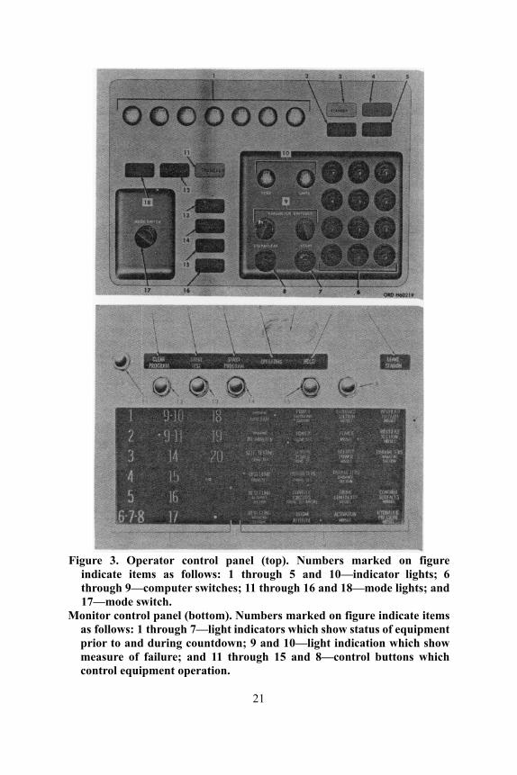
Figure 3. Operator control panel (top). Numbers marked on figure
indicate items as follows: 1 through 5 and 10—indicator lights; 6 through 9—computer switches; 11 through 16 and 18—mode lights; and 17—mode switch.
Monitor control panel (bottom). Numbers marked on figure indicate items as follows: 1 through 7—light indicators which show status of equipment prior to and during countdown; 9 and 10—light indication which show measure of failure; and 11 through 15 and 8—control buttons which control equipment operation.
21

depict the values the operator has stored in the computer memory circuit. In addition to these accomplishments, the operator control panel provides for a precheck of the computer.
The monitor control panel contains light indicators which inform the operator of equipment status, indicates to him any failure, and depict the location of a failure, should one occur. These indications are vital during the automatic countdown and to the system's hold capability, for instant command holds are controlled by the operator through the monitor control panel.
When the monitor control panel indicates X-3 minutes in the automatic countdown, the operator leaves the FS enclosure and goes to the remote firing position where he monitors the final minutes of the automatic countdown. During the final seconds, the missile is elevated to its standard firing elevation of 75 degrees and traversed to its firing azimuth. When the countdown reaches X-0, the missile is fired.
Azimuth Orientation System
Lieutenant Gerald L. Dougherty Guided Missile Department
The second component of the launching station is the azimuth orientation system (AOS). The AOS (fig 4), used to orient the Sergeant missile on its firing azimuth, is composed of three main items—the azimuth orientation unit (AOU), the reference theodolite, and the traverse target equipment. The AOU (fig 4) is a modifed T2 theodolite which is located on the rear of the launching station. When the missile is assembled on
Figure 4. Azimuth orientation system (left). Azimuth orientation unit (right).
22
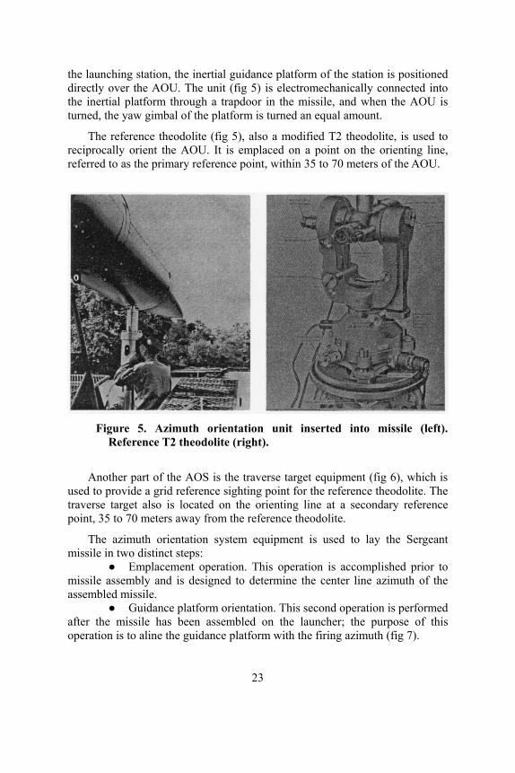
the launching station, the inertial guidance platform of the station is positioned directly over the AOU. The unit (fig 5) is electromechanically connected into the inertial platform through a trapdoor in the missile, and when the AOU is turned, the yaw gimbal of the platform is turned an equal amount.
The reference theodolite (fig 5), also a modified T2 theodolite, is used to reciprocally orient the AOU. It is emplaced on a point on the orienting line, referred to as the primary reference point, within 35 to 70 meters of the AOU.
Figure 5. Azimuth orientation unit inserted into missile (left).
Reference T2 theodolite (right).
Another part of the AOS is the traverse target equipment (fig 6), which is used to provide a grid reference sighting point for the reference theodolite. The traverse target also is located on the orienting line at a secondary reference point, 35 to 70 meters away from the reference theodolite.
The azimuth orientation system equipment is used to lay the Sergeant missile in two distinct steps:
● Emplacement operation. This operation is accomplished prior to missile assembly and is designed to determine the center line azimuth of the assembled missile.
● Guidance platform orientation. This second operation is performed after the missile has been assembled on the launcher; the purpose of this operation is to aline the guidance platform with the firing azimuth (fig 7).
23
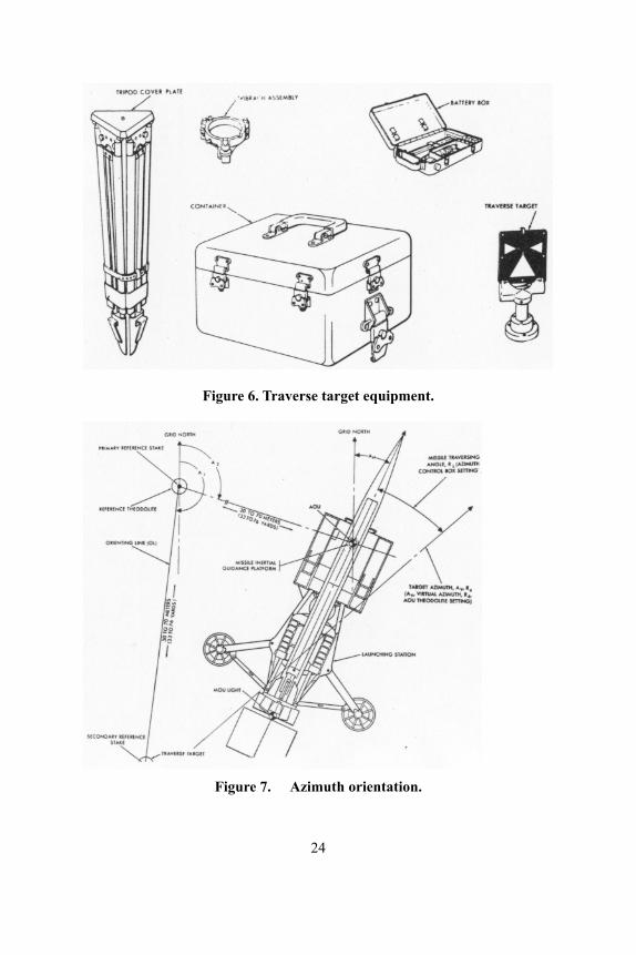
Figure 6. Traverse target equipment.
Figure 7. Azimuth orientation.
24

Gas Turbine Engine Generator Set
Lieutenant Stephen B. Matthews Guided Missile Department
The third component of the launching station is the gas turbine engine generator set (GTGS). In order for the Sergeant missile system to perform its mission, electrical power in various forms is required. The gas turbine engine generator set (fig 8) is the source of this power, and it has proved to be rugged, reliable, and practically maintenance free. Length: 79 1/2 inches Width: 36 1/2 inches Height: 30 inches Weight: 850 pounds 120/208 volts 400 CPS AC 30 Kilowatts 40 KVA Battery—24 volt lead acid
Figure 8. Gas turbine engine generator set. Turbine engines are lighter in weight and more compact than conventional
power plants; therefore, little installation space is required. Full output power is available 30 seconds after starting, and the GTGS can operate effectively on a variety of liquid fuels; preferred fuels are combat gasoline and aviation gasoline. The GTGS also is used as the power source on the organizational maintenance test station; therefore, it allows interchangeability of power sources within the Sergeant firing battery.
The turbine engine is rated at 70 horsepower, and it consumes approximately 14 gallons per hour, but fuel consumption rarely presents problems since the fuel tank, carried by the launching station, has a capacity of 96 gallons, or approximately 7 hours fuel supply.
Launcher Lieutenant Eugene D. Bergen and Lieutenant Terrance Grimball
Guided Missile Department The fourth component of the launching station, the launcher, provides the
platform for assembling and firing the Sergeant missile. The launcher consists of a semitrailer and a superstructure.
The semitrailer (fig 9) incorporates a hydraulic system which is used to extend three hydraulic jacks. These jacks establish a three-point suspension system and provide a stable platform on which the missile is assembled and fired. Also, the three-point suspension allows emplacement
25
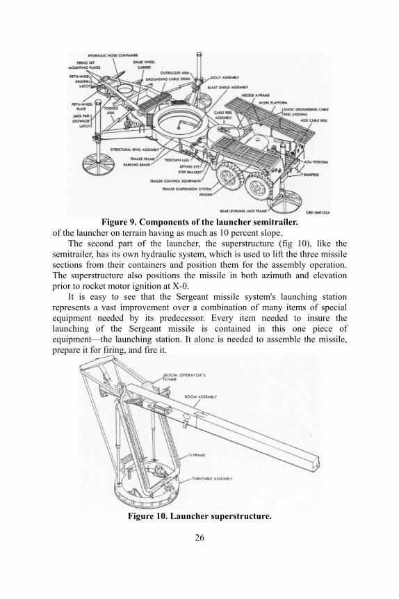
Figure 9. Components of the launcher semitrailer.
of the launcher on terrain having as much as 10 percent slope. The second part of the launcher, the superstructure (fig 10), like the
semitrailer, has its own hydraulic system, which is used to lift the three missile sections from their containers and position them for the assembly operation. The superstructure also positions the missile in both azimuth and elevation prior to rocket motor ignition at X-0.
It is easy to see that the Sergeant missile system's launching station represents a vast improvement over a combination of many items of special equipment needed by its predecessor. Every item needed to insure the launching of the Sergeant missile is contained in this one piece of equipment—the launching station. It alone is needed to assemble the missile, prepare it for firing, and fire it.
Figure 10. Launcher superstructure.
26
Sergeant Missile CWO James E. Watson Guided
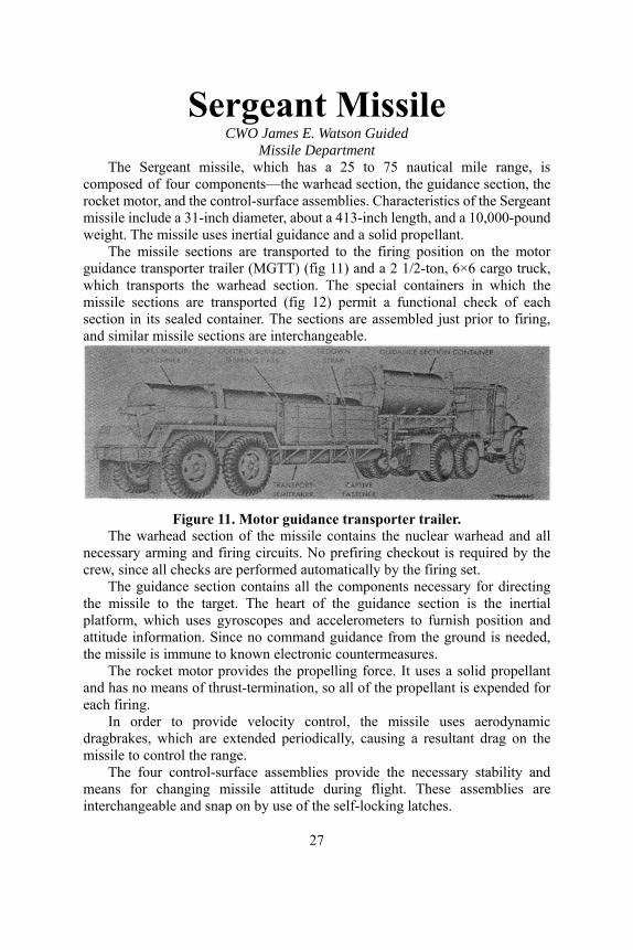
Missile Department The Sergeant missile, which has a 25 to 75 nautical mile range, is
composed of four components—the warhead section, the guidance section, the rocket motor, and the control-surface assemblies. Characteristics of the Sergeant missile include a 31-inch diameter, about a 413-inch length, and a 10,000-pound weight. The missile uses inertial guidance and a solid propellant.
The missile sections are transported to the firing position on the motor guidance transporter trailer (MGTT) (fig 11) and a 2 1/2-ton, 6×6 cargo truck, which transports the warhead section. The special containers in which the missile sections are transported (fig 12) permit a functional check of each section in its sealed container. The sections are assembled just prior to firing, and similar missile sections are interchangeable.
Figure 11. Motor guidance transporter trailer.
The warhead section of the missile contains the nuclear warhead and all necessary arming and firing circuits. No prefiring checkout is required by the crew, since all checks are performed automatically by the firing set.
The guidance section contains all the components necessary for directing the missile to the target. The heart of the guidance section is the inertial platform, which uses gyroscopes and accelerometers to furnish position and attitude information. Since no command guidance from the ground is needed, the missile is immune to known electronic countermeasures.
The rocket motor provides the propelling force. It uses a solid propellant and has no means of thrust-termination, so all of the propellant is expended for each firing.
In order to provide velocity control, the missile uses aerodynamic dragbrakes, which are extended periodically, causing a resultant drag on the missile to control the range.
The four control-surface assemblies provide the necessary stability and means for changing missile attitude during flight. These assemblies are interchangeable and snap on by use of the self-locking latches.
27
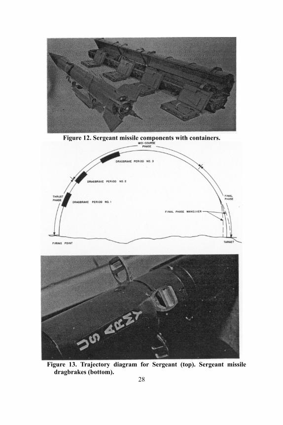
Figure 12. Sergeant missile components with containers.
Figure 13. Trajectory diagram for Sergeant (top). Sergeant missile
dragbrakes (bottom). 28
The Sergeant missile is prepared for automatic firing by the firing set operator, using a 20-minute countdown. When fired, it follows a modified ballistic trajectory divided into three phases—initial, midcourse, and final (fig 13). The initial phase begins at X-0 when the rocket motor is ignited and lasts until motor burnout. The midcourse phase begins at motor burnout and lasts until a few seconds prior to impact, and, during this phase, range control is accomplished by dragbrake action (fig 13). The final phase starts a few seconds before impact and lasts until impact. Maneuver corrections are made at this time to eliminate any remaining range error.
Trajectory control is accomplished by an in-flight comparison of the actual trajectory with a preflight programmed trajectory.
OMTS Cwo Ulysses W. Allen, CWO Howard G. Mueller,
and CWO Robert A. Zimmer Guided Missile Department
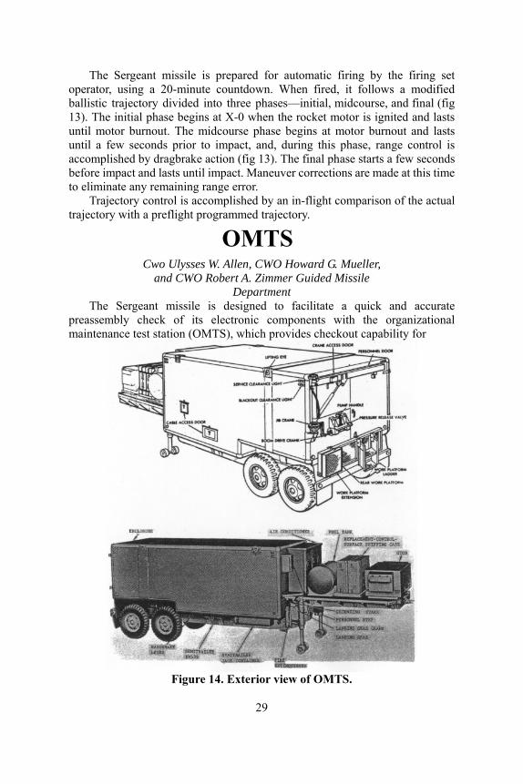
The Sergeant missile is designed to facilitate a quick and accurate preassembly check of its electronic components with the organizational maintenance test station (OMTS), which provides checkout capability for
Figure 14. Exterior view of OMTS.
29

the Sergeant assemblies. The OMTS (fig 14) is a van-type enclosure mounted on a semitrailer which houses a GTGS power supply, necessary test equipment, and replacement components. Three air conditioners, mounted on the forward wall of the van body, provide heating, cooling, and ventilation for the electronic test assemblies.
The interior of the van (fig 15) is designed to carry the electronic test assemblies on the forward left wall. OMTS electronic assemblies are capable of automatic self-testing and performing preassembly checks of the missile section and the four control-surface assemblies. Approximately 30 minutes is needed to complete the preassembly tests on the Sergeant missile.
Where replacement assemblies are needed, they are provided from the spares carried in the OMTS. Spare test assemblies are carried on the right forward wall, and spare missile assemblies are mounted on the remaining wall space. An assembly which fails is evacuated to higher maintenance levels.
The OMTS allows a greater assurance of missile reliability, as well as a repair capability at the battalion level.
Figure 15. Interior of OMTS.
—————●————— The USAAMS has available instructional material for teaching a one-hour
class on the Sergeant missile (T 4700). The class consists of an instructor's manuscript with necessary transparencies and material for ten students.
30
Quarterbacking Tomorrow's Artillery
A Brief Look at The USACDC Artillery Agency
Colonel Robert B. Partridge Commanding Officer
U.S.A. Combat Developments Command Artillery Agency Training, organizing, equipping, and employing today's gridiron giants has
become a multi-million dollar business. But, this is insignficant when compared with the yearly effort—financial, physical, and mental—expended to insure that future Army forces will be properly trained, organized, equipped, and employed. At Fort Sill, "The Artillery Center of the World." subelements of three major Army commands play their part in the accomplishment of the artillery portion of this mission.
The U.S. Army Artillery and Missile School, an element of USCONARC, is charged with training all field artillerymen in the Army. This is a mission for today and tomorrow. The U.S. Army Artillery Board, on behalf of the U.S. Army Materiel Command, is charged with testing the weapons and equipment with which these artillerymen will fight. This is a mission for tomorrow. Finally, the U.S. Army Combat Developments Command Artillery Agency develops doctrine and organization, initiates materiel requirements, and monitors their development and evaluation. These are the tools with which these well-trained artillerymen will accomplish their mission for the next 20 years. This is a mission for the future.
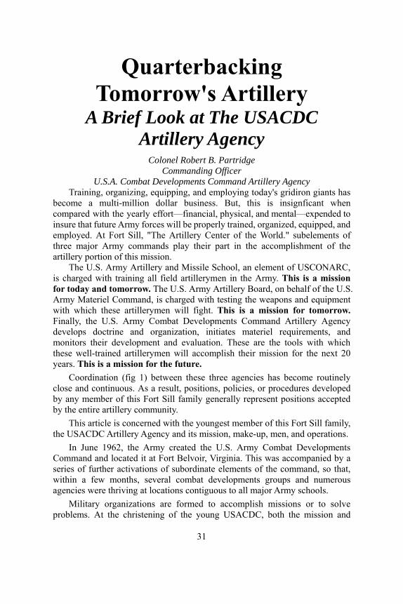
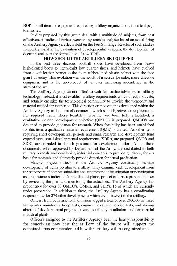
Coordination (fig 1) between these three agencies has become routinely close and continuous. As a result, positions, policies, or procedures developed by any member of this Fort Sill family generally represent positions accepted by the entire artillery community.
This article is concerned with the youngest member of this Fort Sill family, the USACDC Artillery Agency and its mission, make-up, men, and operations.
In June 1962, the Army created the U.S. Army Combat Developments Command and located it at Fort Belvoir, Virginia. This was accompanied by a series of further activations of subordinate elements of the command, so that, within a few months, several combat developments groups and numerous agencies were thriving at locations contiguous to all major Army schools.
Military organizations are formed to accomplish missions or to solve problems. At the christening of the young USACDC, both the mission and
31
the problem were simply stated: Provide the answers to these three questions— ● How should the Army fight? ● How should the Army be organized? ● How should the Army be equipped?
Just as all military missions are subdivided and sublet, the answer to these three questions, as they pertain to field artillery, became the nucleus of the mission of the USACDC Artillery Agency at Fort Sill.
Figure 1. Local coordination parallels corresponding Army
command level. Since all military organizations are obliged to both act and react, a look at
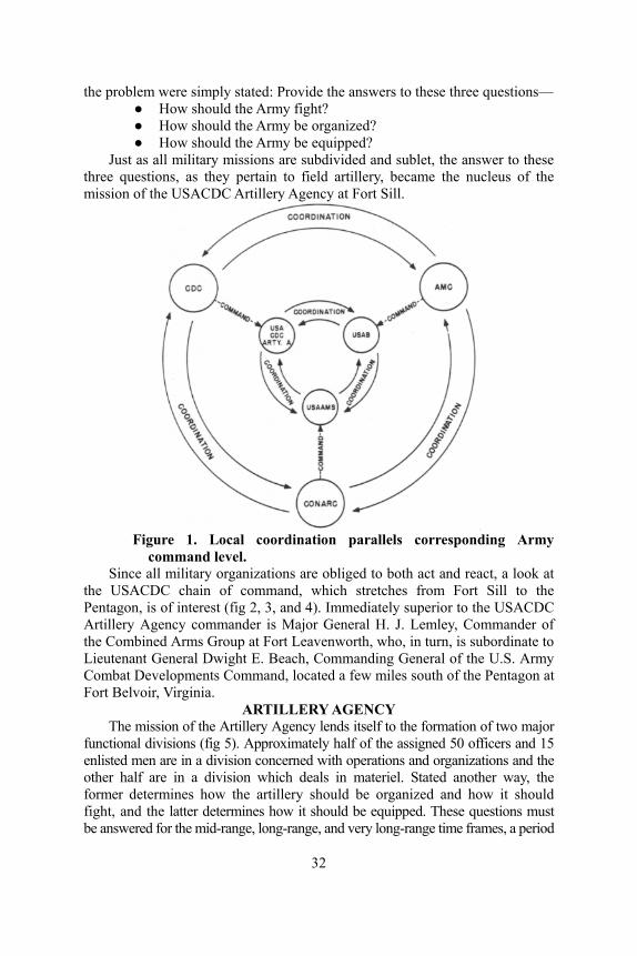
the USACDC chain of command, which stretches from Fort Sill to the Pentagon, is of interest (fig 2, 3, and 4). Immediately superior to the USACDC Artillery Agency commander is Major General H. J. Lemley, Commander of the Combined Arms Group at Fort Leavenworth, who, in turn, is subordinate to Lieutenant General Dwight E. Beach, Commanding General of the U.S. Army Combat Developments Command, located a few miles south of the Pentagon at Fort Belvoir, Virginia.
ARTILLERY AGENCY The mission of the Artillery Agency lends itself to the formation of two major
functional divisions (fig 5). Approximately half of the assigned 50 officers and 15 enlisted men are in a division concerned with operations and organizations and the other half are in a division which deals in materiel. Stated another way, the former determines how the artillery should be organized and how it should fight, and the latter determines how it should be equipped. These questions must be answered for the mid-range, long-range, and very long-range time frames, a period
32
Figure 2. Organization of the Department of Army.
Figure 3. Organization of USACDC.
which spans the length of one human generation or 20 years. In order to answer the three basic questions, the Artillery Agency depends
largely on three basic types of information. These are a knowledge of the opposition, a knowledge of how the U.S. Army will fight, and a dependable prediction of what will be feasible and available in the way of artillery materiel. Generally speaking, this same information is essential to success in any form of competition whether it be combat or football. Let us examine this three-fold mission more closely.
HOW SHOULD THE ARTILLERY FIGHT Just as any successful football coach appreciates the importance of
scouting every team he expects to play, the Artillery Agency recognizes
33

Figure 4. Organization of combined arms group.
Figure 5. Organization of USACDC Artillery Agency.
the necessity of assembling all available information about the potential enemy for a given time frame. This information is compiled from an analysis of Department of Defense and Department of Army studies prepared specifically for this purpose. For use in various studies, the Artillery Agency constructs target arrays of enemy formations on typical terrain in such detail that each individual tank, armored personnel carrier, and artillery piece in a corps-size unit is accounted for and accurately and tactically positioned.
A guard or a tackle must fully understand how a complete play will be developed and executed before he can appreciate his individual assignment. Similarly, before an artillery operational and organizational concept can be developed, the Artillery Agency must be provided with a comparable plan for the Army as a whole. This information is available
34
from broad general studies drafted by USACDC or DA specifically for this purpose for each time period.
Ultimately, before a coach can develop a sequence of plays which will be successful one Saturday after another, he must have a true appreciation of the material available on the bench. In his case, the material is gridiron talent. In the case of the artillery combat developer, this materiel consists of the myriad of items in the shopping list of feasible artillery hardware found in the "Long Range Technological Forecast" published by the Department of Army. He must budget his resources carefully, shop judiciously, and design his organizations to exploit the best from the equipment which can be built and which he thinks he can afford.
At the Artillery Agency, all of this information is compiled and evaluated, and then forms the basis for long-range and very long-range conceptual studies. As time overtakes these studies, those for the very long-range time period become long-range studies. Eventually, the concepts begin to evolve into doctrine for employment of units with the new equipment and, at the appropriate time, are set forth in field manuals prepared by the Artillery Agency.
In the past year, the Artillery Agency has been involved in the production of 15 major studies, one of which required over 40 man-months of effort for completion. The concepts developed in such studies, and eventually proven in troop tests, find their way into the 17 different artillery field manuals for which the Artillery Agency is responsible.
HOW SHOULD THE ARTILLERY BE ORGANIZED Manning levels are as critical to a football manager as they are to an
artillery commander. Within the authorized limit of players, the coach must select, train, and organize a mix of talent that will insure a winning combination. With the general organization of his team established, he builds into his repertoire of plays the flexibility which will allow him to task-organize both his forward wall and his backfield to meet each situation as it develops.
In the same manner, when the Artillery Agency considers the organization of batteries and battalions of the future, it faces the continuing problem of manpower ceilings. It also must insure that developmental organizations will mesh readily into the overall Army structure for the period. At the same time, units must be designed to provide the fire support required by the maneuver forces predicted for the period. From battery through field army artillery, the Artillery Agency designs organizations with the necessary flexibility and self-sufficiency to permit an action varying from an end-run through the rice paddies in Southeast Asia to a successful line-plunge against a modern armored force on the plains of Europe.
Tables of Organization and Equipment are prepared when organizational concepts and the hardware begin to take shape. At the present time the Artillery Agency is responsible for the preparation of more than 100 TOE's. Hand in hand with this goes the determination of an appropriate basis of issue. The Artillery Agency is responsible for recommending
35
BOI's for all items of equipment required by artillery organizations, from tent pegs to missiles.
Studies prepared by this group deal with a multitude of subjects, from cost effectiveness studies of various weapons systems to analyses based on actual firing on the Artillery Agency's effects field on the Fort Sill range. Results of such studies frequently assist in the evaluation of developmental weapons, the development of doctrine, and even the formulation of new TOE's.
HOW SHOULD THE ARTILLERY BE EQUIPPED In the past three decades, football shoes have developed from heavy
high-cleated boots to lightweight low quarter shoes, and helmets have evolved from a soft leather bonnet to the foam rubber-lined plastic helmet with the face guard of today. This evolution was the result of a search for safer, more effective equipment and is the end-product of an ever increasing ascendency in the state-of-the-art.
The Artillery Agency cannot afford to wait for routine advances in military technology. Instead, it must establish artillery requirements which direct, motivate, and actually energize the technological community to provide the weaponry and material needed for the period. This direction or motivation is developed within the Artillery Agency in the form of documents which state objectives or requirements. For required items whose feasibility have not yet been fully established, a qualitative materiel development objective (QMDO) is prepared. QMDO's are designed to provide guidance for research. When feasibility has been established for this item, a qualitative materiel requirement (QMR) is drafted. For other items requiring short developmental periods and small research and development fund expenditures, small developmental requirements (SDR's) are prepared. QMR's and SDR's are intended to furnish guidance for development effort. All of these documents, when approved by Department of the Army, are distributed to both military arsenals and developing industrial concerns to provide guidance, form a basis for research, and ultimately provide direction for actual production.
Materiel project officers in the Artillery Agency continually monitor development of items peculiar to artillery. They examine each development from the standpoint of combat suitability and recommend it for adoption or nonadoption as circumstances indicate. During the test phase, project officers represent the user by reviewing the plan and monitoring the actual test. The Artillery Agency has proponency for over 80 QMDO's, QMR's, and SDR's, 15 of which are currently under preparation. In addition to these, the Artillery Agency has a coordinating responsibility for 270 other developments which are of interest to the artillery.
Officers from both functional divisions logged a total of over 200,000 air miles last quarter monitoring troop tests, engineer tests, and service tests, and staying abreast of developmental progress at various military installations and commercial industrial plants.
Officers assigned to the Artillery Agency bear the heavy responsibility for conceiving how best the artillery of the future will support the combined arms commander and how the artillery will be organized and
36
equipped to provide such support. In the process, they are afforded an unusual opportunity to contribute their own thinking, philosophy, and experience to the creation of a better artillery for the future. In this light, serving in the Artillery Agency is not only professionally broadening but is personally satisfying.
It is important to understand, however, that new ideas do not stem solely from those assigned to the USACDC command. The most important source of new concepts must continue to be the men and officers of the field artillery who, from day to day, actively work in artillery organizations, applying today's doctrinal concepts and using present materiel. In this light, suggestions from the entire artillery family are earnestly solicited.
In summation, the Artillery Agency has no way of knowing in what part of the world the next big international bowl game will be held nor can it even be sure of the rules under which it will be played. One aspect, however, is certain. The field artillerymen who will form a part of the U.S. Army team must be provided the best doctrine, organization, and equipment of any in the world. The U.S. Army Combat Developments Command Artillery Agency intends to insure that they get the best.
—————●————— TOW
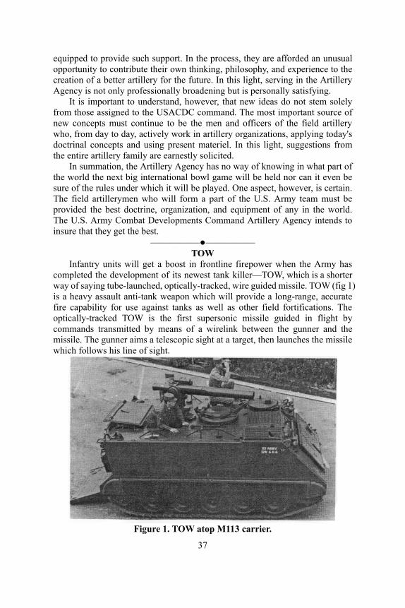
Infantry units will get a boost in frontline firepower when the Army has completed the development of its newest tank killer—TOW, which is a shorter way of saying tube-launched, optically-tracked, wire guided missile. TOW (fig 1) is a heavy assault anti-tank weapon which will provide a long-range, accurate fire capability for use against tanks as well as other field fortifications. The optically-tracked TOW is the first supersonic missile guided in flight by commands transmitted by means of a wirelink between the gunner and the missile. The gunner aims a telescopic sight at a target, then launches the missile which follows his line of sight.
Figure 1. TOW atop M113 carrier.
37

Lieutenant Colonel Richard M. Jennings 1st
Battalion, 9th Artillery The "Great Gun" of the Imperial City of Nurnberg presented an awesome
sight as it rolled on a military siege expedition in the year 1388. "It weighed 56 hundredweight, fired (a stone) about 5 1/2 hundredweight, and was drawn by twelve horses. The cradle for the gun was drawn on a wagon by sixteen horses. Other utensils—a winch, shovels, ropes, and the baggage of the master of the cannon—needed two wagons. Eight knaves with breastplates and iron hats served the piece." This huge early German cannon barrel, "Chriemhild" by name, was one of the first gunpowder artillery weapons in Europe.
Since early beginnings, German artillery has played a significant role in military history. The Brandenburg Artillery Corps, founded in 1676, developed into the Prussian Royal Artillery and contributed to the victories of Frederick the Great. In World War I, "Big Berthas" crumbled the walls of the French forts, and "Long Heinrich" lobbed his shells into Paris. Although the tank and dive bomber combination perhaps outshone the artillery in the blitzkrieg campaigns of World War II, many Americans can still remember the effect of the famed 88-mm gun and the V2 rocket.
NEW GERMAN ARMY EMPHASIZES FIREPOWER The new Army of the Federal Republic of Germany stresses the
importance of firepower and the artillery arm. The "Bundeswehr" theorists regard fire and maneuver as the two main elements of combat, these elements standing in a changing relationship to one another. Fire does not have a supporting relationship to maneuver, according to the German Army Operations Manual; rather, the two elements complement each other and, when properly coordinated, bring combat to its highest effectiveness.
The artillery is regarded as the decisive source of firepower on the battlefield and as an important contributor to reconnaissance. The ability
38
of the artillery to concentrate combat power and to shift it rapidly over great widths and depths on the battlefield without time-consuming changes of position makes the artillery "the most decisive means at intermediate and higher command levels of influencing the outcome of a battle."
ARTILLERY ORGANIZATION The Artillery Branch of the present German Army corresponds generally to
the American concept of field artillery. The Nike and HAWK air defense missiles and the Pershing missiles belong to the German Air Force. The 40-mm air defense cannon (and probably Mauler in the future) belongs to the Air Defense Branch of the Army.
The German Artillery Branch is classified into three categories—the firing artillery, the reconnaissance artillery, and the topographic troops—which correspond to the main characteristics of the artillery, fire and reconnaissance. The firing artillery is subdivided into rocket (missile) artillery, armored artillery, field artillery, mountain artillery, and airborne artillery.
The German Army itself, facing with NATO the masses of Soviet armor in central Europe, is trained primarily for armored combat in a nuclear environment. The basic major unit is the armored or mechanized brigade, complete with combined arms and logistical elements and capable of limited independent action. The divisions of the Bundeswehr are primarily tactical headquarters for three brigades, whereas the German corps perform most of the logistical functions which the U.S. field army performs. The emphasis is on armored mobility to exploit the effects of nuclear weapons.
Each brigade has an organic artillery battalion. Most of the artillery battalions of the armored and mechanized brigades today are equipped with two to three firing batteries of armored 155-mm howitzers (U.S.,M44), armored 105-mm howitzers (U.S.,M52), and improved 105-mm howitzers. The improved 105-mm howitzer, with an elongated tube fitted with a muzzle brake and with other modifications for firing charge 8, achieves a range of 14,500 meters. The sighting system for direct fire has also been improved. These 105-mm howitzers are not towed but rather are transported in the bed of an equipment carrier and are placed in and out of action with a hydraulic lift (fig 1). The mountain and airborne infantry brigades use the Italian mountain 105-mm howitzer.
Beginning in 1965, the majority of the artillery battalions of the armored and mechanized brigades will contain two batteries of armored 155-mm howitzers (U.S.,M109) and one battery of multiple rocket launchers. The German Army distinctly prefers the heavier punch of the 155-mm to the 105-mm. The slow rate of fire of the 155-mm will be accelerated by the substitution of a sliding wedge breechblock in place of the interrupted-screw-type breechblock of the U.S. piece. Some battalions will contain two batteries of improved 105-mm howitzers and one battery of multiple rocket launchers.
39
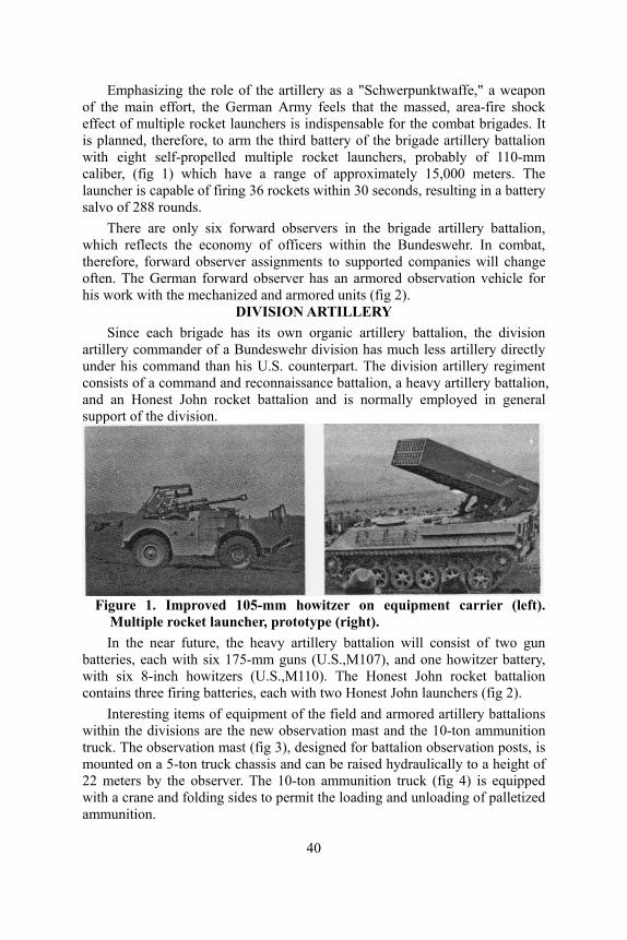
Emphasizing the role of the artillery as a "Schwerpunktwaffe," a weapon of the main effort, the German Army feels that the massed, area-fire shock effect of multiple rocket launchers is indispensable for the combat brigades. It is planned, therefore, to arm the third battery of the brigade artillery battalion with eight self-propelled multiple rocket launchers, probably of 110-mm caliber, (fig 1) which have a range of approximately 15,000 meters. The launcher is capable of firing 36 rockets within 30 seconds, resulting in a battery salvo of 288 rounds.
There are only six forward observers in the brigade artillery battalion, which reflects the economy of officers within the Bundeswehr. In combat, therefore, forward observer assignments to supported companies will change often. The German forward observer has an armored observation vehicle for his work with the mechanized and armored units (fig 2).
DIVISION ARTILLERY Since each brigade has its own organic artillery battalion, the division
artillery commander of a Bundeswehr division has much less artillery directly under his command than his U.S. counterpart. The division artillery regiment consists of a command and reconnaissance battalion, a heavy artillery battalion, and an Honest John rocket battalion and is normally employed in general support of the division.
Figure 1. Improved 105-mm howitzer on equipment carrier (left).
Multiple rocket launcher, prototype (right). In the near future, the heavy artillery battalion will consist of two gun
batteries, each with six 175-mm guns (U.S.,M107), and one howitzer battery, with six 8-inch howitzers (U.S.,M110). The Honest John rocket battalion contains three firing batteries, each with two Honest John launchers (fig 2).
Interesting items of equipment of the field and armored artillery battalions within the divisions are the new observation mast and the 10-ton ammunition truck. The observation mast (fig 3), designed for battalion observation posts, is mounted on a 5-ton truck chassis and can be raised hydraulically to a height of 22 meters by the observer. The 10-ton ammunition truck (fig 4) is equipped with a crane and folding sides to permit the loading and unloading of palletized ammunition.
40
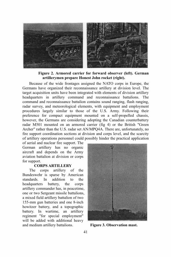
Figure 2. Armored carrier for forward observer (left). German
artillerymen prepare Honest John rocket (right). Because of the wide frontages assigned the NATO corps in Europe, the
Germans have organized their reconnaissance artillery at division level. The target acquisition units have been integrated with elements of division artillery headquarters in artillery command and reconnaissance battalions. The command and reconnaissance battalion contains sound ranging, flash ranging, radar survey, and meteorological elements, with equipment and employment procedures largely similar to those of the U.S. Army. Following their preference for compact equipment mounted on a self-propelled chassis, however, the Germans are considering adopting the Canadian counterbattery radar M501 mounted on an armored carrier (fig 4) or the British "Green Archer" rather than the U.S. radar set AN/MPQ4A. There are, unfortunately, no fire support coordination sections at division and corps level, and the scarcity of artillery operations personnel could possibly hinder the practical application of aerial and nuclear fire support. The German artillery has no organic aircraft and depends on the Army aviation battalion at division or corps for support.
CORPS ARTILLERY The corps artillery of the
Bundeswehr is sparse by American standards. In addition to the headquarters battery, the corps artillery commander has, in peacetime, one or two Sergeant missile battalions, a mixed field artillery battalion of two 155-mm gun batteries and one 8-inch howitzer battery, and a topographic battery. In wartime, an artillery regiment "for special employment" will be added with additional heavy and medium artillery battalions. Figure 3. Observation mast.
41
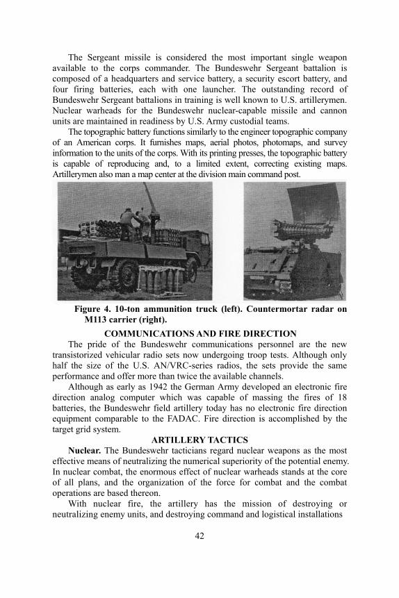
The Sergeant missile is conside e most important single weapon available to the corps commander. The Bundeswehr Sergeant battalion is composed of a headquarters and service battery, a security escort battery, and four firing batteries, each with one launcher. The outstanding record of Bundeswehr Sergeant battalions in training is well known to U.S. artillerymen. Nuclear warheads for the Bundeswehr nuclear-capable missile and cannon units are maintained in readiness by U.S. Army custodial teams.
The topographic battery functions similarly to the engineer topographic company of an American corps. It furnishes maps, aerial photos, photomaps, and survey information to the units of the corps. With its printing presses, the topographic battery is capable of reproducing and, to a limited extent, correcting existing maps. Artillerymen also man a map center at the division main command post.
red th
Figure 4. 10-ton ammunition truck (left). Countermortar radar on
M113 carrier (right). COMMUNICATIONS AND FIRE DIRECTION
The pride of the Bundeswehr communications personnel are the new transistorized vehicular radio sets now undergoing troop tests. Although only half the size of the U.S. AN/VRC-series radios, the sets provide the same performance and offer more than twice the available channels.
Although as early as 1942 the German Army developed an electronic fire direction analog computer which was capable of massing the fires of 18 batteries, the Bundeswehr field artillery today has no electronic fire direction equipment comparable to the FADAC. Fire direction is accomplished by the target grid system.
ARTILLERY TACTICS Nuclear. The Bundeswehr tacticians regard nuclear weapons as the most
effective means of neutralizing the numerical superiority of the potential enemy. In nuclear combat, the enormous effect of nuclear warheads stands at the core of all plans, and the organization of the force for combat and the combat operations are based thereon.
With nuclear fire, the artillery has the mission of destroying or neutralizing enemy units, and destroying command and logistical installations
42
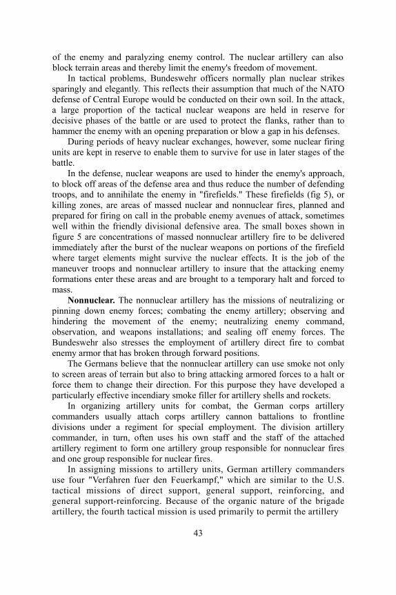
of
rather than to ham
s approach, to block off areas of the defense area and thus reduce the number of defending troops, and to annihilate the enemy in "firefields." These firefields (fig 5), or killing zones, are areas of massed nuclear and nonnuclear fires, planned and prepared for firing on call in the probable enemy avenues of attack, sometimes well within the friendly divisional defensive area. The small boxes shown in figure 5 are concentrations of massed nonnuclear artillery fire to be delivered immediately after the burst of the nuclear weapons on portions of the firefield where target elements might survive the nuclear effects. It is the job of the maneuver troops and nonnuclear artillery to insure that the attacking enemy formations enter these areas and are brought to a temporary halt and forced to mass.
Nonnuclepinnihinderin the enemy; neutralizing enemy command, observation, forces. The Bun
rces to a halt or forc
regiment for special employment. The division artillery commander, in turn, ofte the staff of the attached artil
pport, general support, reinforcing, and gen
the enemy and paralyzing enemy control. The nuclear artillery can also block terrain areas and thereby limit the enemy's freedom of movement.
In tactical problems, Bundeswehr officers normally plan nuclear strikes sparingly and elegantly. This reflects their assumption that much of the NATO defense of Central Europe would be conducted on their own soil. In the attack, a large proportion of the tactical nuclear weapons are held in reserve for decisive phases of the battle or are used to protect the flanks,
mer the enemy with an opening preparation or blow a gap in his defenses. During periods of heavy nuclear exchanges, however, some nuclear firing
units are kept in reserve to enable them to survive for use in later stages of the battle.
In the defense, nuclear weapons are used to hinder the enemy'
ar. The nonnuclear artillery has the missions of neutralizing orng down enemy forces; combating the enemy artillery; observing and
g the movement of
and weapons installations; and sealing off enemy deswehr also stresses the employment of artillery direct fire to combat
enemy armor that has broken through forward positions. The Germans believe that the nonnuclear artillery can use smoke not only
to screen areas of terrain but also to bring attacking armored foe them to change their direction. For this purpose they have developed a
particularly effective incendiary smoke filler for artillery shells and rockets. In organizing artillery units for combat, the German corps artillery
commanders usually attach corps artillery cannon battalions to frontline divisions under a
n uses his own staff and lery regiment to form one artillery group responsible for nonnuclear fires
and one group responsible for nuclear fires. In assigning missions to artillery units, German artillery commanders
use four "Verfahren fuer den Feuerkampf," which are similar to the U.S. tactical missions of direct su
eral support-reinforcing. Because of the organic nature of the brigade artillery, the fourth tactical mission is used primarily to permit the artillery
43
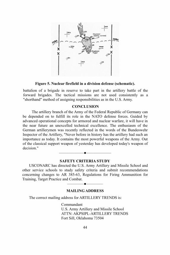
Figure 5. Nuclear firefield in a division defense (schematic).
battalion of a brigade in reserve to take part in the artillery battle of the forward brigades. The tactical missions are not used consistently as a "shorthand" method of assigning responsibilities as in the U.S. Army.
CONCLUSION The artillery branch of the Army of the Federal Republic of Germany can
be depended on to fulfill its role in the NATO defense forces. Guided by advanced operational concepts for armored and nuclear warfare, it will have in the near future an unexcelled technical excellence. The enthusiasm of the German artillerymen was recently reflected in the words of the Bundeswehr Inspector of the Artillery, "Never before in history has the artillery had such an importance as today. It contains the most powerful weapons of the Army. Out of the classical support weapon of yesterday has developed today's weapon of decision."
——————●——————
SAFETY CRITERIA STUDY USCONARC has directed the U.S. Army Artillery and Missile School and
other service schools to study safety criteria and submit recommendations concerning changes to AR 385-63, Regulations for Firing Ammunition for Training, Target Practice and Combat.
————●————
MAILING ADDRESS
The correct mailing address for ARTILLERY TRENDS is:
Commandant U.S. Army Artillery and Missile School ATTN: AKPSIPL-ARTILLERY TRENDS Fort Sill, Oklahoma 73504
44
Go By Army Air Major Edison V. Hoey
Tactics/Combined Arms Department "The necessity to move artillery units by air into marginally trafficable or
untrafficable areas, together with rapid advances in cargo helicopter capability, dictates that artillery units should receive extensive training in airmobile operations . . . Commanders and staff officers who are airmobile conscious will be amply rewarded for the time and effort spent in training their units in helicopter operations when and if committed . . ." (ARTILLERY TRENDS, February 1964). Extensive training and preparation for he opter operations means t ty who receives able to
of being air transported and delivered b assault landing into territory not he
of aviatio such as helicopter vulnerability, maintena g the lift capability of a helicopter. The latter artilleryman, and it is the
ll affect the maximum allowable load of that helicopter. Any change ill directly affect, and may change, the payload of a hel ne of three elements in the maximum allowable load o o are crew and fuel. When a he ht is entered in the record book that a e aircraft. As the helicopter ages, it receives additional pain rt particles, all of which add weight sometimes amounts' to several hund
lichat a commander of an artillery unit with an airmobile capabili orders today to participate in an airmobile operation will be
effectively participate in that operation tomorrow. Artillery units that may be involved in helicopter operations must be phase
I air transportable. Briefly, this means that the units must be capable y parachute and/or
n addition, the artild by friendly forces. I llery units involved must be capable of effective employment immediately after landing. The aircraft, normally helicopters, must be capable of landing on unprepared strips.
Artillery units that possess this airmobile capability, such as a towed 105-mm howitzer battery, Little John battery or 115-mm area toxic rocket battery, must be prepared and trained for these helicopter operations. How can an artillery unit prepare for such operations?
An understanding of aviation and the use of this combat support "tool" must be acquired by all the personnel of the unit. This understanding includes knowledge n capabilities and limitations,
nce downtime, and factors affectin is of primary importance to the
subject of this article.
LIFT CAPABILITY FACTORS
The basic weight of a helicopter wis in the basic weight wicopter. This payload is o
f the aircraft; the other twlicopter is manufactured, it is weighed, and this basic weig
ccompanies tht and modifications and collects dust and di to the aircraft. This change in basic weightred pounds per year on a medium transport
45
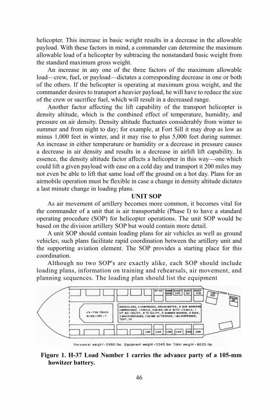
helicopter. This i the allowable payload. With th the maximum allowable load o ic weight from the standard maximum gros
An increase in a aximum allowable load
n on training and rehearsals, air movement, and planning sequences. equipment
ncrease in basic weight results in a decrease inese factors in mind, a commander can determinef a helicopter by subtracing the nonstandard bas
s weight. ny one of the three factors of the m
—crew, fuel, or payload—dictates a corresponding decrease in one or both of the others. If the helicopter is operating at maximum gross weight, and the commander desires to transport a heavier payload, he will have to reduce the size of the crew or sacrifice fuel, which will result in a decreased range.
Another factor affecting the lift capability of the transport helicopter is density altitude, which is the combined effect of temperature, humidity, and pressure on air density. Density altitude fluctuates considerably from winter to summer and from night to day; for example, at Fort Sill it may drop as low as minus 1,000 feet in winter, and it may rise to plus 5,000 feet during summer. An increase in either temperature or humidity or a decrease in pressure causes a decrease in air density and results in a decrease in airlift lift capability. In essence, the density altitude factor affects a helicopter in this way—one which could lift a given payload with ease on a cold day and transport it 200 miles may not even be able to lift that same load off the ground on a hot day. Plans for an airmobile operation must be flexible in case a change in density altitude dictates a last minute change in loading plans.
UNIT SOP As air movement of artillery becomes more common, it becomes vital for
the commander of a unit that is air transportable (Phase I) to have a standard operating procedure (SOP) for helicopter operations. The unit SOP would be based on the division artillery SOP but would contain more detail.
A unit SOP should contain loading plans for air vehicles as well as ground vehicles; such plans facilitate rapid coordination between the artillery unit and the supporting aviation element. The SOP provides a starting place for this coordination.
Although no two SOP's are exactly alike, each SOP should include loading plans, informatio
The loading plan should list the
Figure 1. H-37 Load Number 1 carries the advance party of a 105-mm
howitzer battery.
46
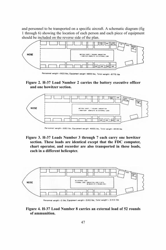
and personnel to be transported on a specific aircraft. A schematic diagram (fig 1 through 6) showing the location of each person and each piece of equipment should be included on the reverse side of the plan.
Figure 2. H-37 Load Number 2 carries the battery executive officer and one howitzer section.
Figure 3. H-37 Loads Number 3 through 7 each carry one howitzer section. These loads are identical except that the FDC computer, chart operator, and recorder are also transported in these loads, each in a different helicopter.
Figure 4. H-37 Load Number 8 carries an external load of 52 rounds
47
of ammunition.
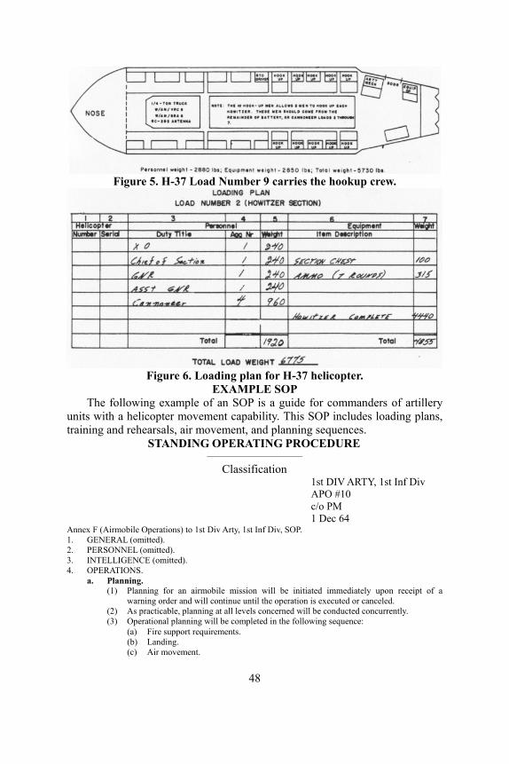
Figure 5. H-37 Load Number 9 carries the hookup crew.
Figure 6. Loading plan for H-37 helicopter.
EXAMPLE SOP The following example of an SOP is a guide for commanders of artillery
untrai
ification 1st DIV ARTY, 1st Inf Div APO #10 c/o PM 1 Dec 64
Annex F (Airmobile Operations) to 1st Div Arty, 1st Inf Div, SOP. 1. GENERAL (omitted). 2. PERSONNEL (omitted). 3. INTELLIGENCE (omitted). 4. OPERATIONS.
a. Planning. (1) Planning for an airmobile mission will be initiated immediately upon receipt of a
warning order and will continue until the operation is executed or canceled. (2) As practicable, planning at all levels concerned will be conducted concurrently. (3) Operational planning will be completed in the following sequence:
ement.
its with a helicopter movement capability. This SOP includes loading plans, ning and rehearsals, air movement, and planning sequences.
STANDING OPERATING PROCEDURE —————————
Class
(a) Fire support requirements. (b) Landing. (c) Air mov
48
(d) Loading. (4) Planning involving the division artillery will be centralized at division artillery headquarters.
Plans for operations involving a smaller force will be coordinated and approved by this headquarters.
(5) Except when accomplished by higher headquarters, this headquarters will ac-accomplish the following planning for all airmobile operations (subordinate units participate in planning): (a) Determine the size and composition of the artillery force required to support the
scheme of maneuver. (b) Allocate transport aircraft for the operation and notify subordinate units of allowabl
(6) Transport aviation unit commanders will assist transported units in planning movement. b. Training and Rehearsals.
(1) Training in airmobile operations will be integrated into appropriate training phases. Request for transport aircraft to this headquarters one week in advance. (See current master training program.)
(2) Prior to executing an airmobile operation, participating personnel will receive instructions in the following: (a) Conduct of airmobile operations. (b) Indoctrination in psychological problems inherent in airmobile operations. (c) Familiarization with loading, lashing, and unloading of type aircraft to be employed. (d) Safety procedures during loading, flight, and unloading. (e) Assembly techniques. (f) Escape and evasion tactics.
(3) Situation permitting, rehearsals will be conducted by participating units on terrain similar to proposed abjective area. Maximum use will be made of sand-tables and terrain models in conjunction with large-scale oblique photos and maps of objective area.
c. Loading. (1) Loading a(2) Seria nt, landing, and fire
support requirements.
xecution of loading
(5) It is t The troop commander will supervise its loadi
(6) Cargo or equipment to be tr will be secured in cargo nets, special slings, or slung in pallets for transit b ese loads to the aircraft will be accomplished by personn rs.
(7) When loading personnel or cargo into an aircraft, the r will insure that— (a) All of the safety measures prescribed for mov about the particular type
aircraft are observed. licopter from the direction of the
at the pilot can see them approaching. licopters, no persons will go near the tail rotor.
ers, all personnel and equipment will be kept well below the are of ain rotor.
loading, a designated individual will board the aircraft, prior to placing any
(9) determine
d to be lashed are properly secured. eated and has his safety belt fastened.
door is closed and locked, or safety strap across door is properly fastened, as directed for the operation.
e cargo load.
(c) Approve loading areas to be used by participating units.
reas will be approved by this headquarters. ls will be broken down into flights as required by the moveme
(3) Aircraft will arrive at approved loading sites, by flights, at the latest possible time. Individual aircraft within flights will be marked according to prior agreement before arrival. Marking is the responsibility of the transport aviation units.
(4) Supporting transport aviation units will assist in the planning for and eby providing technical advice and supervision.
he pilot's responsibility to see that the aircraft is safe for flight. ng.
ansported externally y use of the cargo sling on the helicopter. Attachment of th
hose listed as passengeel other than tandetroop comm
ement in and
(b) In loading helicopters, all personnel approach the henose so th
(c) In loading he(d) In loading helicopt
the m(8) When
equipment in it, to assist in receiving equipment into the cargo compartment. After all equipment and personnel have been loaded, the troop commander willthat— (a) The equipment and cargo are in their proper places. (b) The cargo and equipment require(c) Each man is s(d) Cargo compartment
49
(10) ncy signals will be conducted by aviation unit representative prior to
(11) ll notify the pilot verbally.
lashings (if applicable) are checked frequently to determine that cargo is
(b) fety belts secured and do not smoke unless authorized.
rization. d. Air Move
serial commanders. e.
(1) fy the troop commander when the aircraft is four minutes out from the i ill alert members of the unit to be prepared to
(2) i r es the clearance signal with
troops has the troops release their safety belts and able. He will then open the cargo door and have the
(3) signated by the commander will close the cargo compartment door and will signal the pilot that the
er to prevent any delay in other takeoff or landing procedures. 5. LOGISTICACKNOWLEDDistribution: OFFICIAL
Thea soldier to intensificationeed an iequipment no thousands of eclearly visibl r
Three tytroops. They are—
mountedThe Crew Served W
pounds and served weapons such as machine gun d
● M ipounds, is tri
Briefing on emergeloading. When the troop commander has checked to insure that all cargo and personnel are secured, he wi
(12) During flight, the pilot is in command of the aircraft. During flight, the troop commander will insure that— (a) Cargo
properly secured. The troops keep their sa
(c) The troops stay seated and do not move around in the cargo compartment without proper autho
ment. (1) Air control points (minimum of an IP and RP) will be designated to assist in control of
the air movement. (2) Time of takeoff, arrival at air control points, and landing, will be as specified in air
movement plan, insofar as possible. Inability to comply with specified control times will be reported by
Unloading. The pilot will notiland ng site. The troop commander wunload. In a rmobile operations, no movement will be made in the cargo compartment untilclea ance has been obtained from the pilot. After the pilot givthe alarm bell, the commander of thehas the cargo unlashed if applictroops and equipment unloaded in reverse order from that in which the aircraft was loaded. After all troops and cargo have been unloaded from the aircraft, a man detroopcompartment is empty.
(4) The troop commander will insure that members of his unit will clear the unloading site in a safe, expeditious mannS (omitted).
GE A THOMPSON
S3 Col —————●—————
NEW NIGHT VISION Army has developed a new vision device which will improve the ability of
see and shoot an enemy at night. The new device, called image n, uses natural light from the moon, stars, or skyglow and does not
art ficial light source such as is needed for the infra-red night vision w used by the Army. By intensifying the natural light source
tim s, an image of enemy personnel or equipment is produced that is ough the eye piece of the intensifier. e th
pes of equipmnt using this principle are planned for use by combat
● The Starlight scope which weighs less than six pounds and can be on standard military rifles or used as a hand-held device. ● eapons Night Vision Sight weighs less than 20
can be mounted on standard military crew-s an recoilless rifles.
ed um Range Night Observation Device weighs slightly more than 40 pod mounted, and will be used for battlefield surveillance.
50
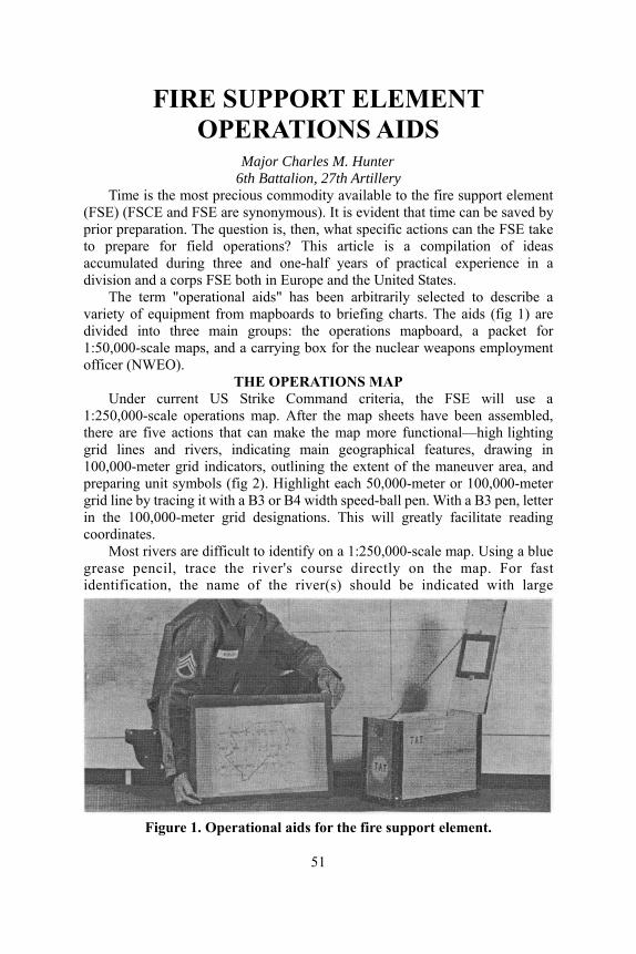
FIRE SUPPORT ELEMENT OPERATIONS AIDS
attalion, 27th Artillery Time is the
(FSE) (FSCE aprio question is, then, what specific actions can the FSE take to prepaccumudivision and
een arbitrarily selected to describe a varidivided into1:50,000 aofficer (NW
Under 1:250,000-sthere ar vgrid lines 100,000preparing un eter
a B3 or B4 width speed-ball pen. With a B3 pen, letter rid is will greatly facilitate reading
Most rivers are diffic -scale map. Using a blue grease pencil, trace the y on the map. For fast
Major Charles M. Hunter 6th B
most precious commodity available to the fire support element nd FSE are synonymous). It is evident that time can be saved by
r preparation. Theare for field operations? This article is a compilation of ideas lated during three and one-half years of practical experience in a
a corps FSE both in Europe and the United States. m "operational aids" has bThe ter
ety of equipment from mapboards to briefing charts. The aids (fig 1) are three main groups: the operations mapboard, a packet for le maps, and a c-sc arrying box for the nuclear weapons employment EO).
THE OPERATIONS MAP current US Strike Command criteria, the FSE will use a cale operations map. After the map sheets have been assembled,
e fi e actions that can make the map more functional—high lighting and rivers, indicating main geographical features, drawing in
-meter grid indicators, outlining the extent of the maneuver area, and it symbols (fig 2). Highlight each 50,000-meter or 100,000-m
grid line by tracing it within the 100,000-meter g designations. Thcoordinates.
ult to identify on a 1:250,000river's course directl
identification, the name of the river(s) should be indicated with large
Figure 1. Operational aids for the fire support element.
51
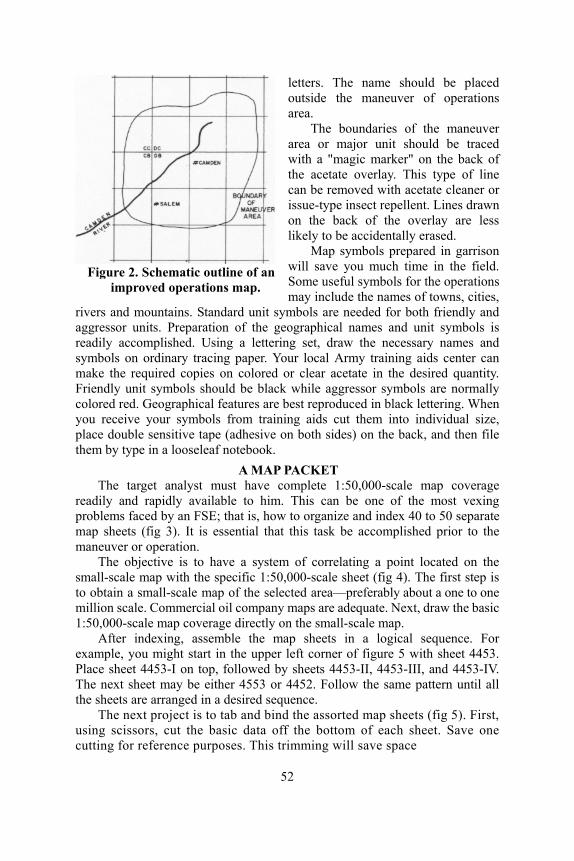
letters. The name should boutside the maneuver of oparea.
The boundaries
e placed erations
of the maneuver r unit should be traced
marker" on the back of
red in garrison
reparation of the geographical names and unit symbols is readily accomplished. U e necessary names and sym
read
maneuver or operation. The objective is to have a system of correlating a point located on the
small-scale map with the specific 1:50,000-scale sheet (fig 4). The first step is to obtain a small-scale map of the selected area—preferably about a one to one million scale. Commercial oil company maps are adequate. Next, draw the basic 1:50,000-scale map coverage directly on the small-scale map.
After indexing, assemble the map sheets in a logical sequence. For example, you might start in the upper left corner of figure 5 with sheet 4453. Place sheet 4453-I on top, followed by sheets 4453-II, 4453-III, and 4453-IV. The next sheet may be either 4553 or 4452. Follow the same pattern until all the sheets are arranged in a desired sequence.
The next project is to tab and bind the assorted map sheets (fig 5). First, using scissors, cut the basic data off the bottom of each sheet. Save onecutting fo
area or majowith a "magic the acetate overlay. This type of line can be removed with acetate cleaner or issue-type insect repellent. Lines drawn on the back of the overlay are less likely to be accidentally erased.
Map symbols prepawill save you much time in the field. Some useful symbols for the operations may include the names of towns, cities,
rivers and mountains. Standard unit symbols are needed for both friendly and aggressor units. P
Figure 2. Schematic outline of an improved operations map.
sing a lettering set, draw thbols on ordinary tracing paper. Your local Army training aids center can
make the required copies on colored or clear acetate in the desired quantity. Friendly unit symbols should be black while aggressor symbols are normally colored red. Geographical features are best reproduced in black lettering. When you receive your symbols from training aids cut them into individual size, place double sensitive tape (adhesive on both sides) on the back, and then file them by type in a looseleaf notebook.
A MAP PACKET The target analyst must have complete 1:50,000-scale map coverage ily and rapidly available to him. This can be one of the most vexing
problems faced by an FSE; that is, how to organize and index 40 to 50 separate map sheets (fig 3). It is essential that this task be accomplished prior to the
r reference purposes. This trimming will save space
52
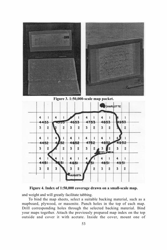
Figure 3. 1:50,000-scale map packet.
Figure 4. Index of 1:50,000 coverage drawn on a small-scale map.
and weight and will greatly facilitate tabbing. To bind the map sheets, select a suitable backing material, such as a
mapboard, plywood, or masonite. Punch holes in the top of each map. Dri
ount one of
ll corresponding holes through the selected backing material. Bind your maps together. Attach the previously prepared map index on the top outside and cover it with acetate. Inside the cover, m
53
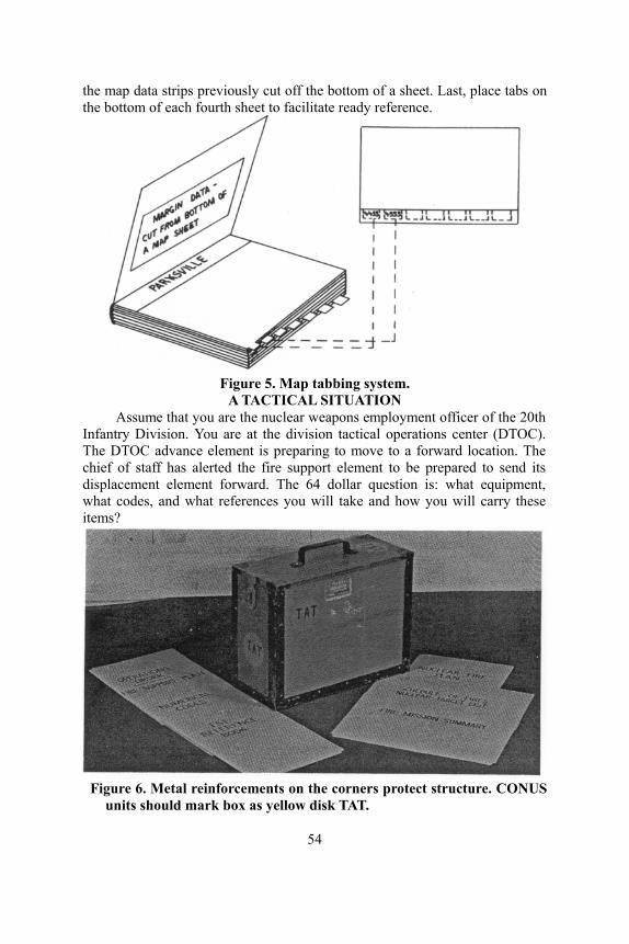
the map data strips previously cut off the bottom of a sheet. Last, place tabs on the bottom of each fourth sheet to facilitate ready reference.
Figure 5. Map tabbing system.
A TACTICAL SITUATION Assume that you are the nuclear weapons employment officer of the 20th
Infantry Division. You are at the division tactical operations center (DTOC). The DTOC advance element is preparing to move to a forward location. The chief of staff has alerted the fire support element to be prepared to send its displacement element forward. The 64 dollar question is: what equipment, what codes, and what references you will take and how you will carry these items?
Figure 6. Metal reinforcements on the corners protect structure. CONUS
units should mark box as yellow disk TAT.
54
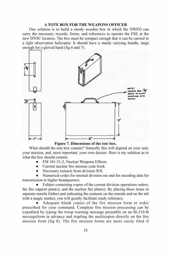
A TOTE BOX FOR THE WEAPONS OFFICER One solution is to build a sturdy wooden box in which the NWEO can
carry the necessary records, forms, and references to operate the FSE at the new DTOC location. The box must be compact enough that it can be carried in a light observation helicopter. It should have a sturdy carrying handle, large enough for a gloved hand (fig 6 and 7).
Figure 7. Dimensions of the tote box.
What should the tote box contain? Naturally this will depend on your unit, your mission, and, most important, your own desires. Here is my solution as to what the box should contain.
● FM 101-31-2, Nuclear Weapons Effects. ● Current nuclear fire mission code book. ● Necessary extracts from division SOI. ● Numerical codes for internal division use and for encoding data for
transmission to higher headquarters. ● Folders containing copies of the current division operations orders,
the fire support plan(s), and the nuclear fire plan(s). By placing these items in separate manila folders and indicating the contents on the outside and on the tab with a magic marker, you will greatly facilitate ready reference.
● Adequate blank copies of the fire mission form or order prescribed for your command. Complete fire mission processing can beemmis s are more easily filed if
xpedited by typing the troop warning message preamble on an M-210-B essageform in advance and stapling the multicopies directly on the fire
sion form (fig 8). The fire mission form
55

punched and d be used to sep
erience has shown that a standard three-ring notebook with plastic inserts is an excellent means of organizing and filing the needed information. Data that are needed in the reference notebook include the coordinates (clear and coded) of each nuclear-capable unit, communication data by battalion to include the unit designation, the FM and AM call words, and a line by line explanation of the troop warning message format, ammunition data to list the types of projectiles that are available for each weapon system in the field army or task force, and maximum and minimum ranges for all weapons and missile systems including the Nike Hercules in a surface-to-surface role. This is a partial list of what you might desire to include in your FSE reference book.
● Allocation and positioning folder. This folder (fig 9) is designed to reflect current nuclear weapons assets, record ammunition expenditures, and indicate current positioning. At division-level FSE, one folder is normally adequate for both ta mmander and as aread
the nuclear schedule of fires, wi s and other required data, the wor e le of fires and included in the oper
ort Sill Form 743).
placed in a standard three-hole binder. Dividers shoularate various type forms.
● The reference notebook. The FSE has a continuous need to rapidly locate a vast amount of specific and precise data for internal operations and to
answer questions from various members of the staff. Exp
Figure 8. The troop warning message.
sks. The folder can be used to brief the co y reference during fire planning. Covering the charts with acetate will
permit making grease pencil entries. ● Nuclear schedule of fires/nuclear target list. The use of blank forms,
indicating data required for nuclear fire planning andrll save the FSE time. By typing the headquarte
uksh et (fig 10) can be converted into a schedations orders. ● Target analysis sheets. (F● Fire mission summary folder. One of the more nerve-racking
aspects of FSE field operations is preparing for staff briefings. You must know what type weapons were expended and when. This task becomes more complex the higher the level of the FSE. Mimeographed sheets placed in a folder with an acco fastener make a satisfactory record holder (fig 11).
● A graduated ruler to determine gun-target range. In its simplest form, this device can be an issue-type ruler which a draftsman has graduated into increments and at a scale comparable to your maps.
56
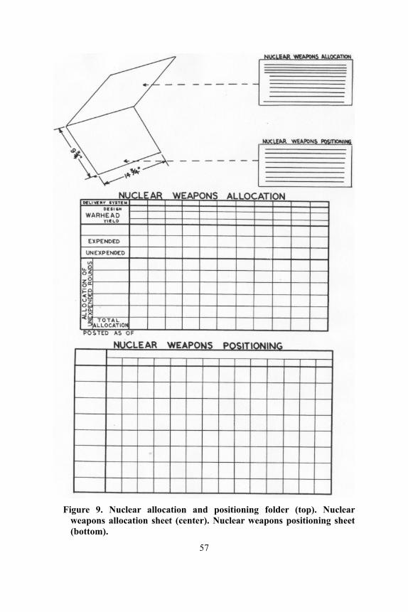
Figure 9. Nuclear allocation and positioning folder (top). Nuclear
weapons allocation sheet (center). Nuclear weapons positioning sheet (bottom).
57
Figure 10. Worksheet for scheduling nuclear fires.
SUMMARY Of necessity, some of the operational aids described in this article were
given only a functional description for security reasons. The subject of security is vital to every member of the fire support element. This includes document security as well as communications security. It is incumbent upon every member of the FSE to properly mark and to adequately safeguard defense information.
The operational aids described in this article represent an initial effort at unit level to make the fire support element more efficient.
—————●—————
FIRE SUPPORT COORDINATION CLASS To provide students with a general knowledge of a fire support
coordination center and a tactical operations center, the USAAMS has available a two-hour class entitled "Fire Support Coordination, FSCC and TOC" (T 3200). The class consists of an instructor's manuscript with applicabletransparencies and material for ten students. This instructional material can beobATT
Figure 11. Nuclear fire mission summary
sheet.
tained by writing to Commandant, U.S. Army Artillery and Missile School, N: AKPSINI/RC, Fort Sill, Oklahoma 73504.
58
Flex-wing . . .
Pinpoint Glider System Captain Robert L. Graham
Headquarters, 19th Aviation Battalion The enemy had been driven from the hill, and the infantry battalion was
nders were pushing their men nce reports of enemy infantry unterattack. The direct support antry attack of the hill had met pporting artillery batteries had er artillery battalions were out unition vehicles would return ack on the supported infantry rt. Th
consolidating on the objective. Company commahard in the new positions as there were intelligebattalions, reinforced by armor, massing for a coartillery battalion was having its problems. The infwith stiffer resistance than anticipated; thus the sunearly exhausted their supply of ammunition. Othof range and heavily engaged. The battalion ammwithin the hour. However, the pending counterattpositions demanded adequate defensive fire supporequest to division artillery was forwarded to thAerial resupply was the only alternative that would
Instead of using three medium transpo har tcarg s. Little time was lost in loading awith its gliders in tow. As the helicopter passed o t battery position, a cargo glider load of amm tronically guided to the battery; the sa e helic
der system to its logistic
e emergency ammunition e division support command. be timely.
elicopters for resupply of the owing two remote controlled nd dispatching the helicopter ver the firs
rttillery battalion, it was decided to use one
o glider
unition was released and elecme process was repeated at the second battery area. Thquickly unloaded after arriving at the third batteryopter was . It was none
too soon; no sooner had the ammunition been distributed to the guns, then the battalion began receiving fire missions. The counterattacking enemy was disrupted short of the new infantry positions by devastating artillery fire. Employment of remote controlled cargo gliders had enabled the artillery to be quickly and effectively resupplied with critical ammunition.
Impossible resupply? Currently, the answer is yes, but in the near future, the Army could add this air cargo gli
59
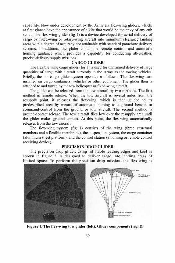
c r development by the Army are flex-wing gliders, which, at first glance he appearance of a kite that would be the envy of any cub scout. The flex-wing glider (fig 1) is a device developed for aerial delivery of cargo by fixed-wing or rotary-wing aircraft into minimum clearance landing areas with a degree of accuracy not attainable with standard parachute delivery systems. In addition, the glider contains a remote control and automatic homing guidance which provides a capability for conducting all-weather, precise-delivery supply missions.
CARGO GLIDER The flexible wing cargo glider (fig 1) is used for unmanned delivery of large
quantities of cargo with aircraft currently in the Army as the towing vehicles. Briefly, the air cargo glider system operates as follows: The flex-wings are installed on cargo containers, vehicles or other equipment. The glider then is attached to and towed by the tow helicopter or fixed-wing aircraft.
The glider ods. The first method is rem iles from the resupply point, it relea is then guided to its predescribed area ound beacon or com
the flex-wing is
apability. Now undehave t
can be released from the tow aircraft by two methote release. When the tow aircraft is several m
ses the flex-wing, which by means of automatic homing to a gr
mand-control from the ground or tow aircraft. The second method is ground-contact release. The tow aircraft flies low over the resupply area until the glider makes ground contact. At this point, the flex-wing automatically releases from the tow aircraft.
The flex-wing system (fig 1) consists of the wing (three structural members and a flexible membrane), the suspension system, the cargo container (aluminum sheet platform), and the control station (a homing or remote control receiving device).
PRECISION DROP GLIDER The precision drop glider, using inflatable leading edges and keel as
shown in figure 2, is designed to deliver cargo into landing areas of limited space. To perform the precision drop mission,
Figure 1. The flex-wing tow glider (left). Glider components (right).
60

Figure 2. Deployment sequence for glider launch.
61
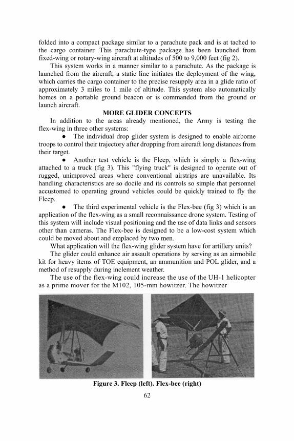
folded into a compact package similar to a parachute pack and is at tached to the cargo container. This parachute-type package has been launched from fixed-wing or rotary-wing aircraft at altitudes of 500 to 9,000 feet (fig 2).
This system works in a manner similar to a parachute. As the package is launched from the aircraft, a static line initiates the deployment of the wing, which carries the cargo container to the precise resupply area in a glide ratio of approximately 3 miles to 1 mile of altitude. This system also automatically homes on a portable ground beacon or is commanded from the ground or launch aircraft.
MORE GLIDER CONCEPTS In addition to the areas already mentioned, the Army is testing the
flex-wing in three other systems: ● The individual drop glider system is designed to enable airborne
troops to control their trajectory after dropping from aircraft long distances from their target.
● Another test vehicle is the Fleep, which is simply a flex-wing attached to a truck (fig 3). This "flying truck" is designed to operate out of rugged, unimproved areas where conventional airstrips are unavailable. Its handling characteristics are so docile and its controls so simple that personnel accustomed to operating ground vehicles could be quickly trained to fly the Fleep.
● The third experimental vehicle is the Flex-bee (fig 3) which is an application of the flex-wing as a small reconnaissance drone system. Testing of this system will include visual positioning and the use of data links and sensors other than cameras. The Flex-bee is designed to be a low-cost system which could be moved about and emplaced by two men.
What application will the flex-wing glider system have for artillery units? The glider could enhance air assault operations by serving as an airmobile
kit for heavy items of TOE equipment, an ammunition and POL glider, and a method of resupply during inclement weather.
The use of the flex-wing could increase the use of the UH-1 helicopter as a prime mover for the M102, 105-mm howitzer. The howitzer
Figure 3. Fleep (left). Flex-bee (right)
62

could be attached to the glider, which would be towed by the helicopter. Under favorable conditions a reduced crew would be transported inside the towing UH-1.
The flex-wing glider also provides discrete delivery of personnel and equipment to prescribed locations with an accuracy and assurance which heretofore were unattainable by conventional parachute.
The drone system, Flex-bee, which is being designed for Marine Corps use, provides a lightweight, economical, and simple vehicle system for reconnaissance, surveillance, and target acquisition devices.
The flex-wing glid ted in these and other area
raft could provide the Army with a versatile vehicle
GEM FOR FORWARD OBSERVERS To
35 as a reference, six Artillery Forward Observer's Fire Support Overlay
ractor, a straightedge, and a coo with
et are non-TOE items, they are use
One of the most unique items contained in the packet is the Artillery Forward Observer's Fire Support Overlay Pad designed by the Eighth Army to enable the observer to produce sufficient copies of his fire support plan quickly and efficiently. This pad, which is 8 inches by 4 3/4 inches, consists of six, 1:50,000-scale paper overlays separated by carbon paper and enclosed in a paper cover. Instructions for using the pad are as follows:
1. Trace the fire plan from a 1:50,000-scale map on first overlay paper without removing the overlay from the pad.
2. Retrace the fire plan with a hard pencil to make three clear copies. 3. Retrace the fire plan on fourth copy to make two additional copies. 4. Distribute copies to the supported company commander, the
platoon leaders, and e copy.
er system will continue to be tess of application. This system of pinpoint landings by remote control from
the ground and tow or launch aircfor enhancing logistic capabilities.
—————●—————
standardize and simplify artillery forward observer procedures, the Eighth U.S. Army has developed and adopted an artillery forward observer's packet, which contains information and material considered useful for prompt and effective control of artillery fire. This standardized observer's packet, which is contained in a map case (FSN 8460-368-4281), includes one copy of FM 6-1
Pads (EA Form 1051), one M210-A Message Book, one observed fire fan, a hard and a soft pencil, plotting pins, one china-marking pencil, and one notebook (FSN 7510-281-2691) containing elementary data and essential guidance.
Graphical aids for the packet consist of a protrdinate square. Also included in the packet are such variable items as a map positions, concentrations, and final protective fires, a terrain sketch of the
target area, and any other supporting data peculiar to the terrain and situation. Although all the items listed for the pack
ful to an FO and, as such, are suited for inclusion in unit SOPs, if desired. OVERLAY PAD
the artillery battalion. The FO retains on
63

THE ARTILLERY
WORLD SCHOOL COURSE CHANGES
MAINTENANCE In the Army's program of consolidating and standardizing certain common
courses for the artillery, armor, and infantry, a new common-area course, the Organizational Maintenance Officer Course (OMOC) is being taught at Fort Knox. This 10-week cou r Course at Fort Sill and equivalent courses which have been elim
Number Re
rse replaces the Motor Office at Fort Benning and Fort Knox, all of
inated. The purpose of the OMOC is to provide commissioned officers with a working knowledge in the supervision of organizational maintenance of conventional materiel (all materiel except guided missiles, aircraft, medical, and ammunition). The prerequisite for the course is a company grade officer who has credit for the pertinent branch basic course and whose actual or anticipated assignment is to supervise the organizational maintenance of conventional materiel.
For reader information and planning purposes the schedule for the OMOC is provided:
Class port Close5-65 7 Jan 65 20 Mar 65 6-65 28 Jan 65 10 Apr 657-65 25 Feb 65 7 May 658-65 11 Mar 65 21 May 65
COMMUNICATIONS It is expected that in the near future, the 13-week Radio Maintenance
Course will be conducted un chedule 11-311 as advanced indi
re of 100 or higher, one yea h
er completion of the course for activ uCourses sect
Whizations to
attend the course.
64
der Army Subject Svidual training. This course, which is currently being taught at the
USAAMS, replaced the Artillery Radio Maintenance Course on 1 July 1964. Courses similar to the Radio Maintenance Course are to be conducted by the U.S. Army Armor School and the U.S. Army Infantry School as well as the Southeastern Signal School located at Fort Gordon.
Prerequisites for the course are aptitude area EL scor of igh school algebra or a standard score of 45 or higher on GED test
number 5, and 13 months of service remaining afte d ty students. A schedule of classes for the course is in the Resident
ion of this issue. le this course is Advanced Individual Training (AIT), National Guard
and Reserve unit commanders may select personnel from their organi
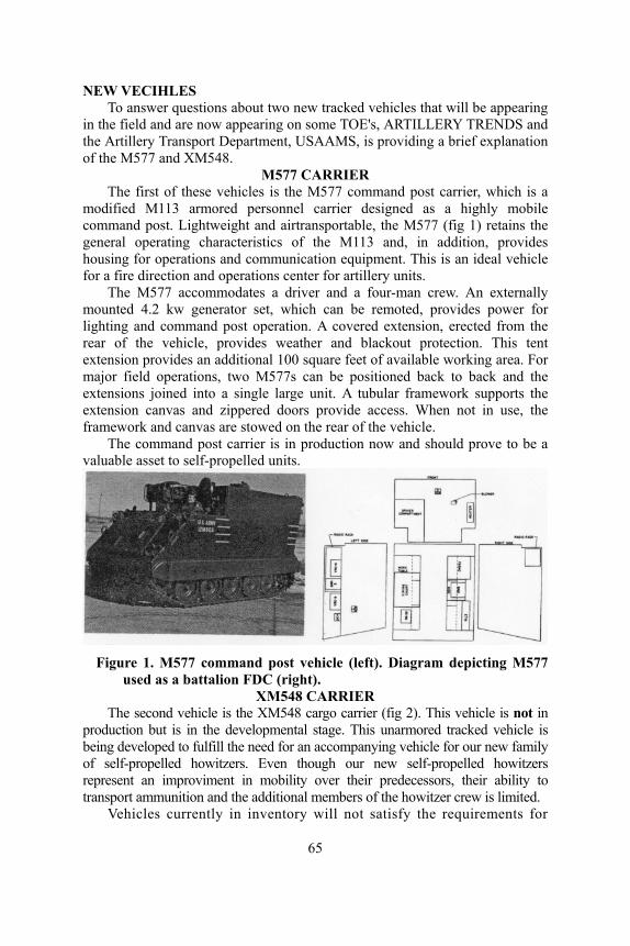
NEW VECIHLES To answer questions about two new tracked will be appearing
in the field and are now appearing o S and the Artillery Transport Department, nation of the M577 and XM548.
M577 CARThe first of these vehicles is the M5 ich is a
odified M113 armored personnel car hly mobile transportable, the M577 (fig 1) retains the
general operating characteri and, in addition, provides hou
carrier is in production now and should prove to be a valu
vehicles that n some TOE's, ARTILLERY TREND USAAMS, is providing a brief expla
RIER 77 command post carrier, whrier designed as a higm
command post. Lightweight and airstics of the M113
sing for operations and communication equipment. This is an ideal vehicle for a fire direction and operations center for artillery units.
The M577 accommodates a driver and a four-man crew. An externally mounted 4.2 kw generator set, which can be remoted, provides power for lighting and command post operation. A covered extension, erected from the rear of the vehicle, provides weather and blackout protection. This tent extension provides an additional 100 square feet of available working area. For major field operations, two M577s can be positioned back to back and the extensions joined into a single large unit. A tubular framework supports the extension canvas and zippered doors provide access. When not in use, the framework and canvas are stowed on the rear of the vehicle.
The command postable asset to self-propelled units.
Figure 1. M577 command post vehicle (left). Diagram depicting M577
used as a battalion FDC (right). XM548 CARRIER
The second vehicle is the XM548 cargo carrier (fig 2). This vehicle is not in production but is in the developmental stage. This unarmored tracked vehicle is being developed to fulfill the need for an accompanying vehicle for our new family of self-propelled howitzers. Even though our new self-propelled howitzers represent an improviment in mobility over their predecessors, their ability to transport ammunition and the additional members of the howitzer crew is limited.
Vehicles currently in inventory will not satisfy the requirements for
65

an accompanying vehicle because they do not possess the operational cha
lso a member of the M113 family and will use many components of the M113.
age space for the proj
racteristics equal to the weapon they support or because they lack sufficient payload capacity for their role. Therefore, the XM548, an unarmored tracked cargo carrier with a 6-ton payload is in the process of being tested and evaluated. The XM548 is a
With its payload of 6-tons, the XM548 can carry a crew of four in the cab. Also, the vehicle can swim and is airtransportable. An I-beam and hoist are component parts of the vehicle to facilitate the loading of ammunition pallets. An XM548 can carry 200 rounds of 105-mm ammunition, 80 rounds of 155-mm ammunition, 36 rounds of 175-mm ammunition, or 36 rounds of 8-inch ammunition. All four arrangements provide stor
ectile fuzes. The 175-mm and the 8-inch arrangements provide space for seating six men on portable seats located in the cargo area.
Additional features of the XM548 are a winch in the front of the vehicle and a standard mount for a 50-caliber machinegun which is attached to the cab of the vehicle.
Since the XM548 cargo carrier is in the test and evaluation stage, it will not be appearing in the field in the immediate future.
Figure 2. XM548 cargo carrier.
—————●—————
66

Resident Courses
U. S. Army Artillery and Missile School Career active duty artillery officers are selected to attend the officer career
courses by the Artillery Section, Officers Assignment Division, DCSPGRS, Dep
4 for admission to U.S
20-21, "Army School Catalog." All courses which exceed 20 weeks are attended in a permanent change of station (PCS) status and those 20 weeks or less in length are attended in temporary duty (TDY) status.
Listed are the officer and enlisted resident courses scheduled to be taught at the USAAMS during the period 1 January 1965 to 30 June 1965.
LETTER INDICATES CATEGORY OF STUDENTS
artment of the Army. Applications for admission to resident courses should not be sent to the School. Officers of the Active Army who desire to attend specialist (MOS) resident courses at the USAAMS may apply through channels. Army Reserve officers not on active duty may make application for attendance for any course (providing they meet all prerequisites) in accordance with the provisions of AR 140-220. Only active status members of the Army Reserve are eligible for selection. National Guard officers not on active duty should make application on National Guard Bureau Form 6
. Army Artillery and Missile School resident courses to the Chief, Army National Guard Bureau, ATTN: Schools Division, Washington 25, D. C.
CURRENT RESIDENT COURSE SCHEDULE A complete summary of the purposes and prerequisites for all courses
conducted at the USAAMS is published in DA Pam
A—commissioned officers B—commissioned and warrant officers D—commissioned and enlisted N—warrant officers and enlisted R—enlisted
Digit indicates branch: Courses within a school: 6—FA course ficer career course C—of5—engineer course 23—associate career course7—infantry course
Figure 1. Explanation of the digits and letters comprising a typical course number. The example shown is the Associate Field Artillery Officer Career Course.
67
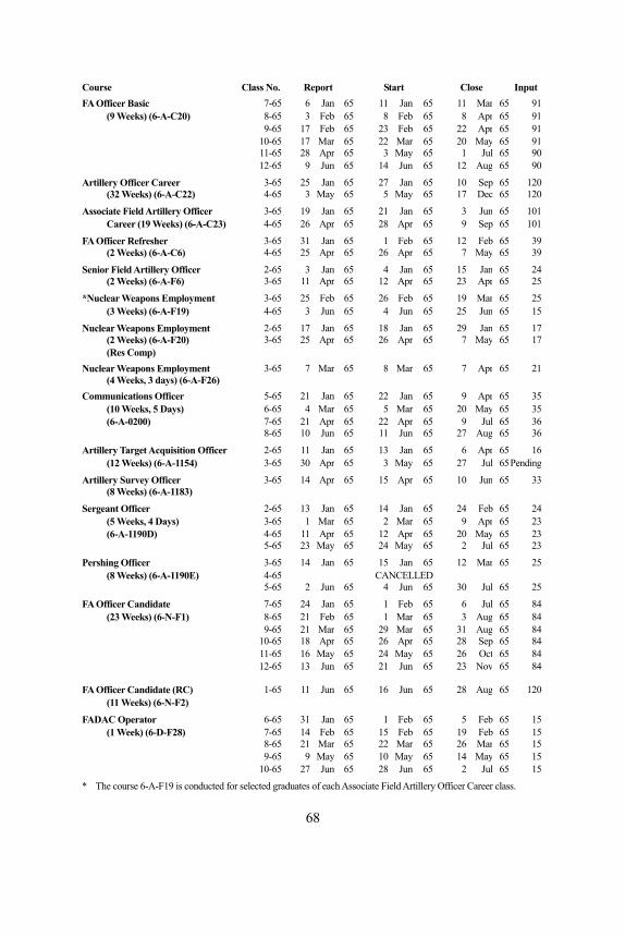
Course Close Input FA Officer Basic
Class No. Report Start 7-65 6 Jan 65 11 Jan 65 11 Mar 65 91
(9 Weeks) (6-A-C 8 Ap20) 8-65 3 Feb 65 8 Feb 65 r 65 91 9-65 17 Feb 65 23 Feb 65 22 Apr 6
10-65 17 Ma5 91
r 65 22 Mar 65 20 May 65 91 11-65 28 Apr 65 3 May 65 1 Jul 65 90 12-65 9 Jun 65 14 Jun 65 12 Aug 65 90
Artillery Officer Career 3-65 25 Jan 65 27 Jan 65 10 Sep 65 120(32 Weeks) (6-A-C22) 4-65 3 May 65 5 May 65 17 Dec 65 120
Associate Field Artillery Officer 3-65 19 Jan 65 21 Jan 65 3 Jun 65 101Career (19 Weeks) (6-A-C23) 4-65 26 Apr 65 28 Apr 65 9 Sep 65 101
FA Officer Refresher 3-65 31 Jan 65 1 Feb 65 12 Feb 65 39(2 Weeks) (6-A-C6) 4-65 25 Apr 65 26 Apr 65 7 May 65 39
Senior Field Artillery Officer 2-65 3 Jan 65 4 Jan 65 15 Jan 65 24(2 Weeks) (6-A-F6) 3-65 11 Apr 65 12 Apr 65 23 Apr 65 25
*Nuclear Weapons Employment 3-65 25 Feb 65 26 Feb 65 19 Mar 65 25(3 Weeks) (6-A-F19) 4-65 3 Jun 65 4 Jun 65 25 Jun 65 15
Nuclear Weapons Employment 2-65 17 Jan 65 18 Jan 65 29 Jan 65 17(2 Weeks) (6-A-F20) 3-65 25 Apr 65 26 Apr 65 7 May 65(Res Comp)
17
Nuclear Weapons Employment 3-65 7 Mar 65 8 Mar 65 7 Apr 65 21(4 Weeks, 3 days) (6-A-F26)
Communications Officer 5-65 21 Jan 65 22 Jan 65 9 Apr 65 35(10 Weeks, 5 Days) 6-65 4 Mar 65 5 Mar 65 20 May 65 35(6-A-0200) 7-65 21 Apr 65 22 Apr 65 9 Jul 65 36
8-65 10 Jun 65 11 Jun 65 27 Aug 65 36
Artillery Target Acquisition Officer 2-65 11 Jan 65 13 Jan 65 6 Apr 65 16(12 Weeks) (6-A-1154) 3-65 30 Apr 65 3 May 65 27 Jul 65Pending
Artillery Survey Officer 3-65 14 Apr 65 15 Apr 65 10 Jun 65 33(8 Weeks) (6-A-1183)
Sergeant Officer 2-65 13 Jan 65 14 Jan 65 24 Feb 63-65 1 Ma
5 24(5 Weeks, 4 Days) r 65 2 Mar 65 9 Apr 65 23(6-A-1190D) 4-65 11 Apr 65 12 Apr 65 20 May 65 23
5-65 23 May 65 24 May 65 2 Jul 65 23
Pershing Officer 3-65 14 Jan 65 15 Jan 65 12 Mar 65 25(8 Weeks) (6-A-1190E)
4-65 CANCELLED5-65 2 Jun 65 4 Jun 65 30 Jul 65 25
FA Officer Candidate 7-65 24 Jan 65 18-65 21 Feb 65 1 M
Feb 65 6 Jul 65 84(23 Weeks) (6-N-F1) ar 65 3 Aug 65 84
5 21 Ma9-6 r 65 29 Mar 65 31 Aug 65 84 18 Ap10-65 r 65 26 Apr 65 28 Sep 65 84 11-65 16 May 65 24 May 65 26 Oct 65 84 13 Ju12-65 n 65 21 Jun 65 23 Nov 65 84
FA Officer C 1-65 11 Juandidate (RC) n 65 16 Jun 65 28 Aug 65 120(11 We
FADAC Ope 6-65 31 Ja
eks) (6-N-F2)
rator n 65 15(1 Week 7-65 14 65 15 Feb 65 19 Feb 65 15
8-65 21
1 Feb 65 5 Feb 65) (6-D-F28) Feb
Mar 65 22 Mar 65 26 Mar 65 15 9-65 9 May 65 10 May 65 14 May 65
10-65 27 Ju15
n 65 28 Jun 65 2 Jul 65
course 6-A-F19 is conducted for selected graduates of each Associate Field Artillery Officer Career class.
15
* The
68
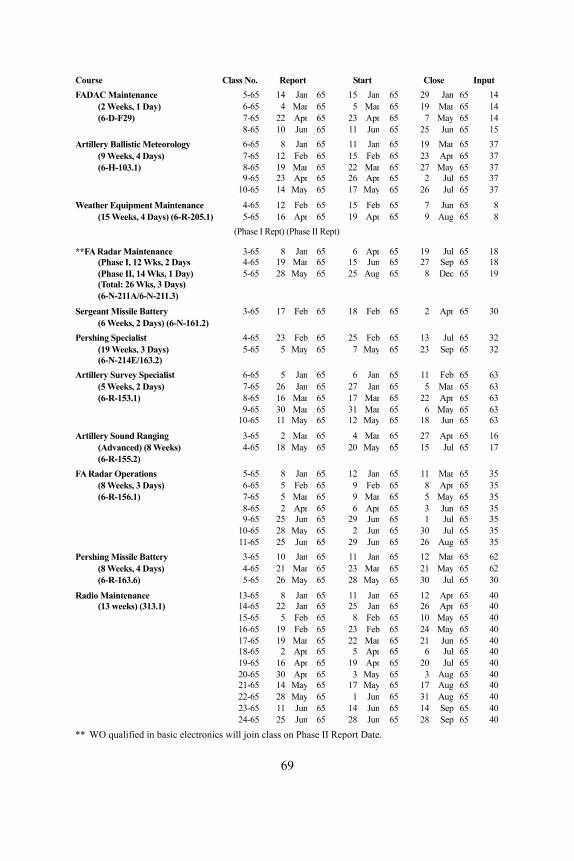
Course Class No. Report Start Close Input FADAC Maintenance 5-65 14 Jan 65 15 Jan 65 29 Jan 65 14
(2 Weeks, 1 Day) 6-65 4 Mar 65 5 Mar 65 19 Mar 65 14(6-D-F29) 7-65 22 Apr 65 23 Apr 65 7 May 65 14
8-65 10 Jun 65 11 Jun 65 25 Jun 65 15Artillery Ballistic Meteorology 6-65 8 Jan 65 11 Jan 65 19 Mar 65 37
(9 Weeks, 4 Days) 7-65 12 Feb 65 15 Feb 65 23 Apr 65 37(6-H-103.1) 8-65 19 Mar 65 22 Mar 65 27 May 65 37
9-65 23 Apr 65 26 Apr 65 2 Jul 65 37 10-65 14 May 65 17 May 65 26 Jul 65 37
Weather Equipment Maintenance 4-65 12 Feb 65 15 Feb 65 7 Jun 65 8(15 Weeks, 4 Days) (6-R-205.1) 5-65 16 Apr 65 19 Apr 65 9 Aug 65 8
(Phase I Rept) (Phase II Rept)
**FA R adar Maintenance 3-65 8 Jan 65 6 Apr 65 19 Jul 65 18(Phase I, 12 Wks, 2 Days 4-65 19 Mar 65 15 Jun 65 27 Sep 65 18(Phase II, 14 Wks, 1 Day) 5-65 28 May 65 25 Aug 65 8 Dec 65 19(Total: 26 Wks, 3 Days)
Serge
(6-N-211A/6-N-211.3)
ant Missile Battery 3-65 17 Feb 65 18 Feb 65 2 Apr 65 30(6 Weeks, 2 Days) (6-N-161.2)
5-65 5 MaPershing Specialist 4-65 23 Feb 65 25 Feb 65 13 Jul 65 32
(19 Weeks, 3 Days) y 65 7 May 65 23 Sep 65 32
Artillery Survey Specialist (6-N-214E/163.2)
6-65 5 Jan 65 6 Jan 65 11 Feb 65 63(5 Weeks, 2 Days) 7-65 26 Jan 65 27 Jan 65 5 Mar 65 63(6-R-153.1) 8-65 16 Mar 65 17 Mar 65 22 Apr 65 63
9-65 30 Mar 65 31 Mar 65 6 May 65 63 10-65 11 May 65 12 May 65 18 Jun 65 63
Artillery Sound Ranging 3-65 2 Mar 65 4 Mar 65 27 Apr 65 16(Advanced) (8 Weeks) 4-65 18 May 65 20 May 65 15 Jul 65 17(6-R-155.2)
FA Radar Operations 5-65 8 Jan 65 12 Jan 65 11 Mar 65 35(8 Weeks, 3 Days) 6-65 5 Feb 65 9 Feb 65 8 Apr 65 35(6-R-156.1) 7-65 5 Mar 65 9 Mar 65 5 May 65 35
8-65 2 Apr 65 6 Apr 65 3 Jun 65 35 9-65 25 Jun 65 29 Jun 65 1 Jul 65 35 10-65 28 May 65 2 Jun 65 30 Jul 65 35 11-65 25 Jun 65 29 Jun 65 26 Aug 65 35Pershing Missile Battery 3-65 10 Jan 65 11 Jan 65 12 Mar 65 62
(8 Weeks, 4 Days) 4-65 21 Mar 65 23 Mar 65 21 May 65 62(6-R-163.6) 5-65 26 May 65 28 May 65 30 Jul 65 30
Radio Maintenance 13-65 8 Jan 65 11 Jan 65 12 Apr 65 40(13 weeks) (313.1) 14-65 22 Jan 65 25 Jan 65 26 Apr 65 40
15-65 5 Feb 65 8 Feb 65 10 May 65 40 16-65 19 Feb 65 23 Feb 65 24 May 65 40 17-65 19 Mar 65 22 Mar 65 21 Jun 65 40 18-65 2 Apr 65 5 Apr 65 6 Jul 65 40 19-65 16 Apr 65 19 Apr 65 20 Jul 65 40 20-65 30 Apr 65 3 May 65 3 Aug 65 40 21-65 14 May 65 17 May 65 17 Aug 65 40 22-65 28 May 65 1 Jun 65 31 Aug 65 40 23-65 11 Jun 65 14 Jun 65 14 Sep 65 40 24-65 25 Jun 65 28 Jun 65 28 Sep 65 40** WO qualified in basic electronics will join class on Phase II Report Date.
69
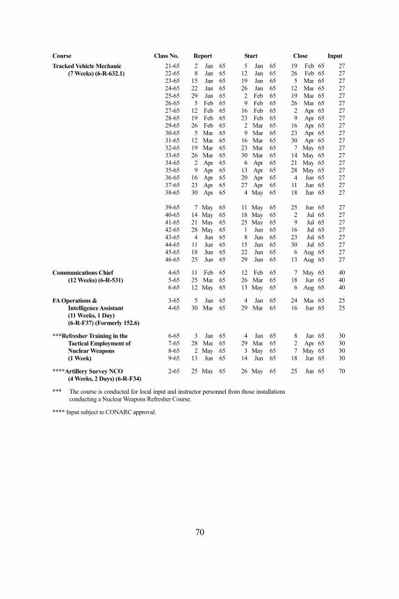
Course Class No. Report Start Close Input Tracked Vehicle Mechanic 21-65 2 Jan 65 5 Jan 65 19 Feb 65 27
(7 Weeks) (6-R-632.1) 22-65 8 Jan 65 12 Jan 65 26 Feb 65 27 23-65 15 Jan 65 19 Jan 65 5 Mar 65 27 24-65 22 Jan 65 26 Jan 65 12 Mar 65 27 25-65 29 Jan 65 2 Feb 65 19 Mar 65 27 26-65 5 Feb 65 9 Feb 65 26 Mar 65 27 27-65 12 Feb 65 16 Feb 65 2 Apr 65 27 28-65 19 Feb 65 23 Feb 65 9 Apr 65 27 29-65 26 Feb 65 2 Mar 65 16 Apr 65 27 30-65 5 Mar 65 9 Mar 65 23 Apr 65 27 31-65 12 Mar 65 16 Mar 65 30 Apr 65 2
37
2-65 19 Mar 65 23 Mar 65 7 May 65 2
7 33-65 26 Mar 65 30 Mar 65 14 May 65 27
34-65 2 Apr 65 6 Apr 65 21 May 65 27 3 5-65 9 Apr 65 13 Apr 65 28 May 65 27
36-65 16 Apr 65 20 Apr 65 4 Jun 65 27 37-65 23 Apr 65 27 Apr 65 11 Jun 65 27 38-65 30 Apr 65 4 May 65 18 Jun 65 27 39-65 7 May 65 11 May 65 25 Jun 65 27
4 0-65 14 May 65 18 May 65 2 Jul 65 27 41-65 Ma21 y 65 25 May 65 9 Jul 65 27 42-65 Ma28 y 65 1 Jun 65 16 Jul
465 27
3-65 4 Jun 65 8 Jun 65 23 Jul 65 27 4 14-65 1 Jun 65 15 Jun 65 30 Jul 65 27 45-65 18 Jun 65 22 Jun 65 6 Aug 65 27
4 2 6-65 5 Jun 65 29 Jun 65 13 Aug 65 27
Communications Chief 4-65 11 Feb 65 12 Feb 65 7 May 65 40 (12 Weeks) (6-R-531) 5-65 25 Mar 65 26 Mar 65 18 Jun 65 40
6-65 12 May 65 13 May 65 6 Aug 65 40
FA Operations & 3-65 5 Jan 65 4 Jan 65 24 Mar 65 25 Intelligence Assistant 4-65 30 Mar 65 29 Mar 65 16 Jun 65 25
(11 Weeks, 1(6-R-F37) (F
Day) orm
***R
erly 152.6)
the
efresher Training in 6-65 3 Jan 65 4 Jan 65 8 Jan 65 30 Tactical Employment of 27-65 8 Mar 65 29 Mar 65 2 Apr 65 30 Nuclear Weapons 8-65 2 May 65 3 May 65 7 May 65 30 (1 Week) 9-65 13 Jun 65 14 Jun 65 18 Jun 65 30
****Artillery Survey NCO 2-65 25 May 65 26 May 65 25 Jun 65 70 (4 Weeks, 2 Days) (6-R-F34)
ted for local input stru n from l ns r Weapons Refresher Course.
*** ucThe course is cond Nuclea
and in ctor perso nel those insta latioconducting a
**** Input subject to CONARC approval.
70
STATUS OF LITERAT R D FILMS
TRAINING TURE
1. The following traini te d atio siy the U.S. Army Artillery M i ool or . m mbevelopments Command Ar y y
A. FIELD MANUALS (FM 6-3-2 Op ns n Dir
(FADAC), Free Rocket a n. FM 6-3-2A(S) Gu ec o put M ann i
wit clear m nitioFM 6-115 Fie till hlig t . FM 6-140 Fie ti lion erieFM 6-141 Do ve nnu e
We s,B. ARMY SUBJECT SCHEDULES (ASUBJSCD):
ASubjScd 6-3 Ca n Instr .
Arm raining Program e Artillery Units. ATP 6-302 Fiel ti i le h Lit
JohFiel ti r t A Ba i
ure submitted for publication: Artillery SuFiel ti unFiel til e rol
6-20-1 Fiel ti yFiel ti lion . Field Artillery Rocket, Honest John with Launche
tzer M1, Towed. 5-mm Howitzer M109, Self-Propelled.
FM 6-94 175-mm Gun M107, Self-Propelled and 8-inch Howitzer M110, Self-Propelled.
FM 6-161 Radar Set, AN/MPQ-4A. ASubjScd 6-4 Combat Intelligence. ASubjScd 6-23 Sound Ranging Set, GR-8. ASubjScd 6-153 Artillery Surveyor, MOS 153.0. ASubjScd 6-155 Sound Ranging Crewman, MOS 155.0. ASubjScd 6-163 Field Artillery Missile Crewman (Pershing), MOS
163.0/.1.
TRAININGU E AN
LITERA
ng li rature is un er prepar n or revi on b and iss le Sch the U.S Ar y Co at D tiller Agenc :
FM): eratio of Gu ection Computer M18
Applic tion Dir tion C m er 18, C on Applicat on h Nu Am u n. ld Ar ery Searc ht Bat eryld Ar llery Batta s and Batt s. ctrine for Effecti Use of No cl ar Artillery apon Part II.
nnoneer and Launcher Crewma uctionC. ARMY TRAINING PROGRAMS (ATP):
ATP 6-100 y T for Fi ld d Ar llery M ssi Units, Honest Jo n and tle n.
ATP 6-575 d Ar llery Ta ge cquisition ttal on. 2. Training literat
FM 6-2 rvey. FM 6-10 d Ar llery Comm ications. FM 6-15 d Ar l
llerery M teo ogy.
FM d Ar Tactics. FM 6-39 d Ar llery Batta , PershingFM 6-60 r
M289. FM 6-81 155-mm HowiFM 6-88 15
71
3. TrainiFM
(CFMFM 6-40-1A (S) ry.
*FM 6-40-2 (C)
*FM 6--7 -10
rument Operator.
-152
der production and schedul ease dur
The rtilleryCom lery Battalion. The ssile AFiel Target ADef Field APers le Syste ounted Operations. Weapons of the Field Me tance wPer e Asse2. ms elease during
calendaHelFire aOpe3.
Center:Fire Direction Procedu I. Precision Fire (TF 6-3448), Part II. Area
Fire (TF 6-3449), and Part III. Observed Fire (TF 6-3450). Operation of the Surveying Instru t Azimuth Gyro Artillery.
72
ng literature recently printed: 6-40 Field Artillery Cannon Gunnery. hanges 2)
6-40-1 Field Artillery Rocket Gunnery. Field Artillery Rocket Gunne
Field Artillery Missile Gunnery. FM 6-40-3 Field Artillery M18 Computer, Gunnery. FM 6-77 105-mm M52, Self Propelled.
(Changes 1) FM 6-93 8-inch M55, Self-Propelled. FM 6-122 Artillery Sound and Flash Ranging.
Battlefield Illumination. FM 20-60 FM 21-13 The Soldier's Guide.
Army Ephemeris. TM 6-300-65 40-2 (C) to supersede FM 6-50. ASubjScd 6 Dutie of Battery Recorder and Computer. ASubjScd 6 Field Artillery Radar Operators.
FA Instruments anASubjScd 6-16 d Duties of InstASubjScd 6-32 Field Artillery Command Post Exercises. ASubjScd 6-42 Difficult Traction and Field Expedients. ASubjScd 6-147 Field Artillery Rocket Crewman, MOS 147.1. ASubjScd 6 Field Artillery Operations and Intelligence Assistant,
MOS 152.1. Flash RASubjScd 6-154 anging Crewman, MOS 154.0.
TRAINING FILMS 1. The following training films are currently un
ed for re ing calendar yearl 1965: Sergeant A Guided Missile System. munication Systems of the Direct Support Artil
Pershing Mi zimuth Laying Procedure. d Artillery cquisition Battalion. ense of the rtillery Battery (Active and Passive).
m—Airhing Missi Transported and Track MArtillery (Color TF 6-2804).
asuring Dis ith DME, MC-8. shing Missil mbly—Mounted.
scheduled for production and rTraining filr year 1965: icopter Artillery RSOP—Part I and II. Support Coordin tion for the Infantry Division. ration of the Gun Direction Computer, M18. Training films recently released to Audio Visual Communications
res—Part
men