Embed Size (px)
Citation preview
Page |
Project:
OAKLAND’S PARK GRADE SEPARATION
Document:
DETAILED DESIGN REPORT
For:
DEPARTMENT OF PLANNING, TRANSPORT AND INFRASTRUCTURE (DPTI)
By:
DPC ENGINEERING
Ref:
0617-001
Doc No: DPC-DD001[00]
Date: 14/06/17
Revision: 04
DPC Engineering
Mawson Lakes Blvd MAWSON LAKES, SA, 5095
T. +61 (0) 8 8525 5278
W. DPCengineering.com.au
Project: Oaklands Park Grade Separation
Client: DPTI
Date: 14/06/17
DPC Engineering | Mawson Lakes Blvd MAWSON LAKES, SA, 5095
| (08) 8525 5278 | DPC Engineeringengineering.com.au
Page | i
REVISION HISTORY
Revision Date Filename DPC-DD001
00 21/05/2017 Description Initial draft document
Prepared by Checked by Approved by
Name Jia Shi - -
01 28/05/17 Description Add construction plan
Prepared by Checked by Approved by
Name Kavvithiran S
Rajendhiran Jia Shi -
01.1 6/06/2017 Description Add executive summary and introduction
Prepared by Edited by Checked by
Name Kavvithiran S
Rajendhiran Jia Shi -
02.1 09/06/2017 Description Add Services sections
Prepared by Edited by Checked by
Name Marc Vieceli Jia Shi Kavvithiran S
Rajendhiran
02.2 10/06/2017 Description Add Urban sections
Prepared by Edited by Checked by
Name Dino Lorenzo
Anzellotti Jia Shi
Kavvithiran S
Rajendhiran
02.3 10/06/2017 Description Add Geotechnical sections
Prepared by Edited by Checked by
Name Qunwei Zheng Jia Shi Kavvithiran S
Rajendhiran
02.4 10/06/2017 Description Add Transportation sections
Prepared by Edited by Checked by
Name Prem Dhakal Lal Jia Shi Kavvithiran S
Rajendhiran
Project: Oaklands Park Grade Separation
Client: DPTI
Date: 14/06/17
DPC Engineering | Mawson Lakes Blvd MAWSON LAKES, SA, 5095
| (08) 8525 5278 | DPC Engineeringengineering.com.au
Page | ii
02.5 10/06/2017 Description Add Environmental sections
Prepared by Edited by Checked by
Name Joel Emmanuel
Egel Jia Shi
Kavvithiran S
Rajendhiran
02.6 11/06/2017 Description Add Structural sections
Prepared by Edited by Checked by
Name Vinikumari Tandel Jia Shi Kavvithiran S
Rajendhiran
03 11/06/2017 Description Format editing & final costing
Prepared by Checked by Approved by
Name Jia Shi Kavvithiran S
Rajendhiran -
03.1 11/06/2017 Description Check table/figure no, add appendices
Prepared by Checked by Approved by
Name Jia Shi Kavvithiran S
Rajendhiran -
04 12/06/2017 Description Final editing and issue for submission
Prepared by Checked by Approved by
Name Jia Shi Kavvithiran S
Rajendhiran Jia Shi
Project: Oaklands Park Grade Separation
Client: DPTI
Date: 14/06/17
DPC Engineering | Mawson Lakes Blvd MAWSON LAKES, SA, 5095
| (08) 8525 5278 | DPC Engineeringengineering.com.au
Page | iii
DOCUMENT DECLARATION STATEMENT
This document has been developed by students from the University of South Australia as part of a
Civil Engineering Design Project. This document and any associated works relating to it is for the
purposes of academic study only and does not represent the views or opinions of the end client
(Department of Planning Transport and Infrastructure).
Project: Oaklands Park Grade Separation
Client: DPTI
Date: 14/06/17
DPC Engineering | Mawson Lakes Blvd MAWSON LAKES, SA, 5095
| (08) 8525 5278 | DPC Engineeringengineering.com.au
Page | iv
DECLARATION
University Declaration
We declare the following to be our own work, unless otherwise referenced, as defined by the
University’s policy on plagiarism. This report is a part of a university project and is not an official
document.
DPC Declaration
DPC Engineering is commitment to reaching the upmost level of integrity, accountability innovation
and safety for all of our clients and stakeholders.
Our mission is to provide a product for our clients that meets or exceeds their expectations, while
generating sustainable returns for our stakeholders. We aim to service the industry with regards to
improvements in safety and design processes.
DPC Engineering understands that every project is different and every project must be approached
in a suitable manner so as to meet the client’s needs. DPC Engineering strives to achieve just this.
Sincerely,
Jia Shi Kavvithiran S Rajendhiran
Project Manager Assistant Project Manager
Project: Oaklands Park Grade Separation
Client: DPTI
Date: 14/06/17
DPC Engineering | Mawson Lakes Blvd MAWSON LAKES, SA, 5095
| (08) 8525 5278 | DPC Engineeringengineering.com.au
Page | v
EXECUTIVE SUMMARY
DPC Engineering presents this detailed design document for Oaklands Park Grade Separation
Project in South Australia. The purpose of this document is to propose a detailed design for this
project that will overcome current traffic issues and accommodate future traffic volume. Diagonal
and Morphett Roads are the major roads that involved in this project. These roads connect between
most of the western and southern suburbs with Adelaide city centre. Both major roads intersect with
Seaford Rail Line which creates significant traffic issues due to the increase in the traffic volume.
Besides that, rapid development in Marion area also contributes significantly to the traffic issues.
Several stages were completed beforehand to produce a detailed design for a concept that will be
most feasible for the project. The first step undertaken in this process was creating an initial
evaluation of four different concepts to choose a suitable structure to solve the identified issues. Two
options namely railway and road overpass were narrowed done in this stage and a depth
evaluation and research of both concepts were done in the feasibility stage. Thereafter, railway
overpass concept was chosen as the most feasible option for this project based on depth research
from various department of DPC Engineering and detailed design were carried out and presented in
this document.
DPC Engineering assigned each department in the company to undergo detailed design for railway
overpass concept to implement in the Oaklands Park Grade Separation Project. Department of
Planning, Transport and Infrastructure (DPTI) as the main client of this project, the railway overpass
concept was designed according to their requirement and expectation. Supplementary
stakeholder’s requirements were also taken into consideration during the detailed design stage to
meet their expectation. Various upgrade including environmental consideration and community
preferences were also outlined in this document. The total costing to build this structure in Oaklands
Park would be approximately 58 million dollars.

Project: Oaklands Park Grade Separation
Client: DPTI
Date: 14/06/17
DPC Engineering | Mawson Lakes Blvd MAWSON LAKES, SA, 5095
| (08) 8525 5278 | DPC Engineeringengineering.com.au
Page | vi
This page has been left intentionally blank
Project: Oaklands Park Grade Separation
Client: DPTI
Date: 14/06/17
DPC Engineering | Mawson Lakes Blvd MAWSON LAKES, SA, 5095
| (08) 8525 5278 | DPC Engineeringengineering.com.au
Page | vii
Contents
1 Introduction ....................................................................................................................................................... 1
2 Transportation ................................................................................................................................................... 3
2.1 Scope of work .......................................................................................................................................... 4
2.2 Approach to Final Drawing ................................................................................................................... 4
2.2.1 Railway Alignment .............................................................................................................................. 4
2.2.2 Road Alignment .................................................................................................................................. 5
2.2.3 Benefits .................................................................................................................................................. 6
2.3 SIDRA analysis ........................................................................................................................................... 7
2.3.1 Layout of Upgraded Intersection ..................................................................................................... 7
2.3.2 Overall Network layout ...................................................................................................................... 8
2.3.3 Input data from SIDRA ........................................................................................................................ 9
2.3.4 SIDRA analysis result .......................................................................................................................... 10
2.3.5 Level of services ................................................................................................................................. 17
2.3.6 Degree of saturations ....................................................................................................................... 19
2.3.7 Queue Distance Average ............................................................................................................... 20
2.3.8 Discussion and recommendation .................................................................................................. 21
2.4 Traffic management ............................................................................................................................. 22
2.4.1 Traffic control plan ............................................................................................................................ 22
2.4.2 Traffic diversion .................................................................................................................................. 23
2.4.3 Public transport .................................................................................................................................. 25
2.4.4 Detour plan ........................................................................................................................................ 26
2.4.5 Pedestrians and cyclists ................................................................................................................... 29
2.4.6 Carpark ............................................................................................................................................... 30
2.4.7 Signage ............................................................................................................................................... 32
2.4.8 Traffic light ........................................................................................................................................... 36
2.4.9 Lighting ................................................................................................................................................ 37
2.4.10 Lane marking ................................................................................................................................. 38
2.4.11 Risk assessment .............................................................................................................................. 39
Project: Oaklands Park Grade Separation
Client: DPTI
Date: 14/06/17
DPC Engineering | Mawson Lakes Blvd MAWSON LAKES, SA, 5095
| (08) 8525 5278 | DPC Engineeringengineering.com.au
Page | viii
2.5 Cost estimation ...................................................................................................................................... 40
2.6 Recommendation for Construction ................................................................................................... 41
2.7 Reference ............................................................................................................................................... 42
3 Structural Design ............................................................................................................................................. 44
3.1 Introduction ............................................................................................................................................ 45
3.2 Package 01: Rail Bridge ....................................................................................................................... 46
3.2.1 Structure Overview ........................................................................................................................... 46
3.2.2 Load Calculations ............................................................................................................................. 46
3.2.3 Considerations ................................................................................................................................... 49
3.2.4 Elements .............................................................................................................................................. 52
3.2.5 Costing ................................................................................................................................................ 56
3.3 Package 02: Rail Platform .................................................................................................................... 58
3.3.1 Load Calculations ............................................................................................................................. 58
3.3.2 Considerations ................................................................................................................................... 59
3.3.3 Elements .............................................................................................................................................. 60
3.3.4 Costing ................................................................................................................................................ 70
3.4 Package 03: Rail Platform access structures ................................................................................... 72
3.4.1 Load Calculations: ............................................................................................................................ 72
3.4.2 Lift Shaft: .............................................................................................................................................. 72
3.5 Package 04: Centre Median Barriers ................................................................................................ 73
3.5.1 Considerations: .................................................................................................................................. 74
3.5.2 Costing ................................................................................................................................................ 75
3.6 Package 05: Electrification Structure ................................................................................................ 76
3.6.1 Structure type ..................................................................................................................................... 76
3.6.2 Electrical Components..................................................................................................................... 76
3.6.3 Design Criteria .................................................................................................................................... 76
3.6.4 Consideration..................................................................................................................................... 78
3.7 Reference ............................................................................................................................................... 80
4 Geotechnical Design .................................................................................................................................... 84
Project: Oaklands Park Grade Separation
Client: DPTI
Date: 14/06/17
DPC Engineering | Mawson Lakes Blvd MAWSON LAKES, SA, 5095
| (08) 8525 5278 | DPC Engineeringengineering.com.au
Page | ix
4.1 Scope of work ........................................................................................................................................ 85
4.2 Investigations and geotechnical conditions ................................................................................... 86
4.3 CFA Pile Foundation Design ................................................................................................................ 86
4.3.1 Design concept ................................................................................................................................. 86
4.3.2 Design method .................................................................................................................................. 87
4.3.3 Design actions and loads ................................................................................................................ 88
4.3.4 Soil profile for pile footing design ................................................................................................... 88
4.3.5 Detailed Design ................................................................................................................................. 90
4.4 Retaining wall and backfill supporting system design ................................................................... 96
4.4.1 Design concept ................................................................................................................................. 96
4.4.2 Design method .................................................................................................................................. 96
4.4.3 Backfilling design ............................................................................................................................... 98
4.4.4 Retaining wall detailed design ..................................................................................................... 101
4.5 Pavement design ................................................................................................................................ 106
4.5.1 Design concept for pavement ..................................................................................................... 106
4.5.2 Design method ................................................................................................................................ 106
4.5.3 Traffic data analysis ........................................................................................................................ 107
4.5.4 Pavement Layers Design ............................................................................................................... 108
4.5.5 CIRCLY design approach .............................................................................................................. 110
4.6 Ballasted track design ........................................................................................................................ 113
4.6.1 Design concept and method ....................................................................................................... 113
4.6.2 Formation capping level ............................................................................................................... 114
4.6.3 Track supporting system ................................................................................................................. 115
4.6.4 Ballast design and profile .............................................................................................................. 115
4.7 Costing estimation .............................................................................................................................. 118
4.8 Reference ............................................................................................................................................. 119
5 Services ........................................................................................................................................................... 123
5.1 Package 01: Early Services Interface & Relocations .................................................................... 124
5.1.1 SA Power Networks ......................................................................................................................... 124
Project: Oaklands Park Grade Separation
Client: DPTI
Date: 14/06/17
DPC Engineering | Mawson Lakes Blvd MAWSON LAKES, SA, 5095
| (08) 8525 5278 | DPC Engineeringengineering.com.au
Page | x
5.1.2 APA Gas ............................................................................................................................................ 130
5.1.3 SA Water ........................................................................................................................................... 136
5.1.4 Wastewater Reticulation ............................................................................................................... 140
5.1.5 NBN & Communications ................................................................................................................ 142
5.2 Package 02: Rail Platform .................................................................................................................. 145
5.2.1 Design Assumptions & Considerations ........................................................................................ 145
5.2.2 Electrical Infrastructure ................................................................................................................... 145
5.2.3 SA Water ........................................................................................................................................... 151
5.2.4 Fire Service System Design ............................................................................................................. 155
5.2.5 Passenger Information System ...................................................................................................... 157
5.2.6 Control Room ................................................................................................................................... 159
5.2.7 Costing .............................................................................................................................................. 162
5.3 Package 03: Miscellaneous............................................................................................................... 163
5.3.1 Traffic Signalling ............................................................................................................................... 163
5.3.2 Traffic Signal Controller .................................................................................................................. 164
5.3.3 Stormwater ....................................................................................................................................... 164
5.4 Drawings Reference List: .................................................................................................................... 172
5.4.2 Rail Platform ...................................................................................................................................... 172
5.4.3 Misc. ................................................................................................................................................... 172
5.5 Reference ............................................................................................................................................. 173
6 Urban Design and Community .................................................................................................................. 174
6.1 Introduction .......................................................................................................................................... 174
6.2 Demographics ..................................................................................................................................... 174
6.3 Existing Conditions ............................................................................................................................... 175
6.4 Important Sites ..................................................................................................................................... 176
6.5 Stakeholders ......................................................................................................................................... 178
6.6 Community Engagement .................................................................................................................. 179
6.6.1 Mass media (television and radios) ............................................................................................. 179
6.6.2 Website information ........................................................................................................................ 179
Project: Oaklands Park Grade Separation
Client: DPTI
Date: 14/06/17
DPC Engineering | Mawson Lakes Blvd MAWSON LAKES, SA, 5095
| (08) 8525 5278 | DPC Engineeringengineering.com.au
Page | xi
6.6.3 Public Information Events .............................................................................................................. 180
6.6.4 Street stalls ........................................................................................................................................ 180
6.6.5 Social media .................................................................................................................................... 181
6.6.6 Sign boards ....................................................................................................................................... 181
6.7 Land Acquisition .................................................................................................................................. 182
6.8 Conceptual Design – Key Structural Focuses ................................................................................ 185
6.8.1 Facade .............................................................................................................................................. 185
6.8.2 Staircase & Elevator ........................................................................................................................ 187
6.8.3 Barriers/Safety screens ................................................................................................................... 189
6.8.4 Retaining wall ................................................................................................................................... 191
6.8.5 Shading Structures .......................................................................................................................... 193
6.8.6 Toilets ................................................................................................................................................. 194
6.8.7 Lanes & Greenway ......................................................................................................................... 197
6.9 Conceptual Design – Key Facility services ..................................................................................... 199
6.9.1 Lighting .............................................................................................................................................. 199
6.9.2 Benches ............................................................................................................................................. 200
6.9.3 TV Screens & Ticket Machines ...................................................................................................... 202
6.9.4 Community Spaces ........................................................................................................................ 203
6.9.5 Drinking Fountains ........................................................................................................................... 203
6.9.6 Art work ............................................................................................................................................. 204
6.10 General Safety ..................................................................................................................................... 205
6.11 Incentives .............................................................................................................................................. 205
6.12 Costing .................................................................................................................................................. 206
6.13 Urban Planning– Structural Design of Barriers ................................................................................ 208
6.13.1 Overview ....................................................................................................................................... 208
6.13.2 Loads ............................................................................................................................................. 208
6.13.3 Design elements, Design method and summary of results ................................................. 208
6.14 Urban Planning – Structural Design of Shelter ................................................................................ 211
6.14.1 Overview ....................................................................................................................................... 211
Project: Oaklands Park Grade Separation
Client: DPTI
Date: 14/06/17
DPC Engineering | Mawson Lakes Blvd MAWSON LAKES, SA, 5095
| (08) 8525 5278 | DPC Engineeringengineering.com.au
Page | xii
6.14.2 Loads ............................................................................................................................................. 211
6.14.3 Design elements, Design method and summary of results ................................................. 211
6.15 References: ........................................................................................................................................... 214
7 Environmental ............................................................................................................................................... 216
7.1 Environmental Management System Structure ............................................................................. 217
7.2 Management System Overview....................................................................................................... 218
7.2.1 Scope of EMS ................................................................................................................................... 218
7.2.2 Purpose of EMS ................................................................................................................................ 218
7.2.3 Management System ..................................................................................................................... 218
7.2.4 Project Specific Policy .................................................................................................................... 219
7.2.5 Environmental Policy ...................................................................................................................... 219
7.2.6 Continual Improvement................................................................................................................. 220
7.2.7 EMP Reviews ..................................................................................................................................... 221
7.2.8 Objectives ......................................................................................................................................... 221
7.3 ENVIRONMENTAL MANAGEMENT PLAN – SUBPLANS .................................................................... 222
7.3.1 Significant Environmental Hazards Identification...................................................................... 222
7.3.2 Water Quality Management ........................................................................................................ 222
7.3.3 Soil Quality Management .............................................................................................................. 225
7.3.4 Air Quality management ............................................................................................................... 228
7.3.5 Flora Management ......................................................................................................................... 231
7.3.6 Fauna Management ...................................................................................................................... 237
7.3.7 Noise and Vibration Management ............................................................................................. 239
7.3.8 Waste Management ...................................................................................................................... 245
7.3.9 Energy Usage Management......................................................................................................... 249
7.3.10 Hazardous Materials ................................................................................................................... 252
7.4 Additional Environmental Innovations and Design ...................................................................... 256
7.4.1 Solar Panels....................................................................................................................................... 256
7.5 Implementation Costing .................................................................................................................... 258
7.5.1 Water Quality Management ........................................................................................................ 258
Project: Oaklands Park Grade Separation
Client: DPTI
Date: 14/06/17
DPC Engineering | Mawson Lakes Blvd MAWSON LAKES, SA, 5095
| (08) 8525 5278 | DPC Engineeringengineering.com.au
Page | xiii
7.5.2 Soil Quality management .............................................................................................................. 258
7.5.3 Air Quality Management ............................................................................................................... 259
7.5.4 Flora Management ......................................................................................................................... 259
7.5.5 Fauna Management ...................................................................................................................... 260
7.5.6 Noise and Vibration Management ............................................................................................. 260
7.5.7 Waste Management ...................................................................................................................... 261
7.5.8 Energy Usage Management......................................................................................................... 261
7.5.9 Hazardous Materials ....................................................................................................................... 262
7.5.10 Solar Panels .................................................................................................................................. 262
7.5.11 Cost Summary .............................................................................................................................. 263
7.6 References ............................................................................................................................................ 264
8 Construction Plan ......................................................................................................................................... 268
8.1 Introduction .......................................................................................................................................... 268
8.2 2nd review of 60 hours rail shutdown ................................................................................................ 268
8.3 Project Staging ..................................................................................................................................... 269
8.3.1 Staging for Railway overpass ........................................................................................................ 269
8.3.2 Staging for Road ............................................................................................................................. 273
8.4 Project Sequencing ............................................................................................................................ 273
8.5 Safety ..................................................................................................................................................... 279
9 Costings .......................................................................................................................................................... 280
Appendix A: Transportation – SIDRA Outputs ..................................................................................................... A
Appendix B: Structural Calculations – Rail Bridge .............................................................................................. B
Appendix C: Structural Calculations – Rail Platform ........................................................................................ C
Appendix D: Structural Calculations – Beam ..................................................................................................... D
Appendix E: Structural Calculations – Column .................................................................................................. E
Appendix F: Structural Calculations – Footing .................................................................................................... F
Appendix G: Geotechnical .................................................................................................................................. G
Appendix H: Services ............................................................................................................................................... H
Appendix I: Urban – Barrier Hand Calculation .....................................................................................................I
Project: Oaklands Park Grade Separation
Client: DPTI
Date: 14/06/17
DPC Engineering | Mawson Lakes Blvd MAWSON LAKES, SA, 5095
| (08) 8525 5278 | DPC Engineeringengineering.com.au
Page | xiv
Appendix J: Shelter Hand Calculation ................................................................................................................. J
LIST OF FIGURES
Figure 1: Prunus Street and Diagonal Road Intersection layout ..................................................................... 7
Figure 2: Cole’s Intersection layout (Diagonal road and Morphett Road) .................................................. 8
Figure 3: Swimming centre intersection layout (Diagonal Road and Morphett Road) ............................. 8
Figure 4: The overall Network of upgrade road ................................................................................................. 9
Figure 5: Traffic volume Data input in SIDRA ..................................................................................................... 10
Figure 6: Level of Service with colour code ...................................................................................................... 11
Figure 7: The Degree of Saturation with colour code ..................................................................................... 11
Figure 8: The figure of Queuing Distance Average with colour code ......................................................... 12
Figure 9: Level of Service with colour code ...................................................................................................... 13
Figure 10: The Degree of Saturation with colour code ................................................................................... 13
Figure 11: The figure of Queuing Distance Average with colour code....................................................... 14
Figure 12: Level of Service with colour code .................................................................................................... 15
Figure 13: The Degree of Saturation with colour code ................................................................................... 16
Figure 14: The figure of Queuing Distance Average with colour code....................................................... 16
Figure 15: The Level of Service for the overall Network .................................................................................. 18
Figure 16: The degree of saturation of overall Network ................................................................................. 19
Figure 17: Queue Distance Average of Overall Network .............................................................................. 20
Figure 18: The Traffic diversion plan drawing (source: google map) .......................................................... 24
Figure 19: Alternative Detour plan during construction period (Source: Google map) .......................... 25
Figure 20: The route of detour for substitute bus service, Northside (source: google map) ................... 27
Figure 21: The route of detour for substitute bus service, Southside (source: google map) ................... 27
Figure 22: Layouts for angle parking spaces (AS 2890.1, Cl 2.4.1) ................................................................ 31
Figure 23: Example of an angle parking space with shared area on one side only (AS2890.6, Cl 2.2.1)
................................................................................................................................................................................... 31
Figure 24: The standard size signage for post constructions period. (Source AS1742.1, Cl 2.4.1) .......... 34
Figure 25: Some standard size post construction signage. (Source AS1743.1, Cl 2.4.2) ........................... 35
Figure 26: Standard dimensions of traffic light (Source AS2144, Cl 4.1.4) ................................................... 36
Figure 27: Dimensions controlling overall size of vehicular lanterns (Source AS2144, Cl 4.1.5) ............... 37
Figure 28: Dimension detail of lane lines............................................................................................................ 38
Figure 29: Dimension detail of turning line ........................................................................................................ 38
Figure 30: Dimension detail of outline marking ................................................................................................ 39
Figure 31: Proposed bridge structure cross section ......................................................................................... 46
Figure 32: Axel Loads ............................................................................................................................................. 48
Project: Oaklands Park Grade Separation
Client: DPTI
Date: 14/06/17
DPC Engineering | Mawson Lakes Blvd MAWSON LAKES, SA, 5095
| (08) 8525 5278 | DPC Engineeringengineering.com.au
Page | xv
Figure 33: Axel Load Spacings ............................................................................................................................. 48
Figure 34: Air Temperatures .................................................................................................................................. 50
Figure 35: BMD, Headstock/Columns ................................................................................................................. 54
Figure 36: SFD, Headstock/Column .................................................................................................................... 54
Figure 37: Critical headstock Section Design ................................................................................................... 55
Figure 38: Axial Load Columns ............................................................................................................................ 56
Figure 39: Bending moment for slab from spacegass .................................................................................... 61
Figure 40: Cross sectional view of the slab over its 1m span ......................................................................... 63
Figure 41: Bending Moment for beams from spacegass ............................................................................... 64
Figure 42: Beam Reinforcement, cross sectional view ................................................................................... 65
Figure 43: Interaction Diagram ............................................................................................................................ 67
Figure 44: Column Reinforcement, Cross sectional view ............................................................................... 68
Figure 45: Footing reinforcement, Cross sectional view ................................................................................. 69
Figure 46: Lift Shaft Model ..................................................................................................................................... 72
Figure 47: Centre Median Barrier location on the map ................................................................................. 73
Figure 48: Centre Median Barrier, Rigid Barrier, Type F, AS/NZ 3845:1999 ................................................... 74
Figure 49: CAF pile foundation plan view ......................................................................................................... 91
Figure 50: Pile reinforcement ............................................................................................................................... 92
Figure 51: Pile cap bottom reinforcement (unit in meters) ............................................................................ 93
Figure 52: Pile cap top reinforcement mesh (unit in meters) ........................................................................ 93
Figure 53: Pile footing system reinforcement schedule .................................................................................. 94
Figure 54: Pile footing installation process ......................................................................................................... 95
Figure 55: 3D illustration of retaining wall ........................................................................................................... 96
Figure 56: Smooth steel rollers (Source: Compare factory) ......................................................................... 100
Figure 57: Sheepsfoot Roller (Source: the county of Lincoln – Road) ........................................................ 100
Figure 58: Retaining walls need to be designed............................................................................................ 101
Figure 59: Cross section of retaining wall in the project ............................................................................... 102
Figure 60: Final design for Underneath Cantilever Retaining wall (meter) ............................................... 103
Figure 61: Diagram of cantilever wall with key (meter) ................................................................................ 103
Figure 62: Retaining wall detailed reinforcement schedule ........................................................................ 105
Figure 63: Typical heavy duty flexible pavement .......................................................................................... 110
Figure 64: Final pavement design layers for Morphett Road ...................................................................... 112
Figure 65: Pavement Design Layers for Prunus Street.................................................................................... 113
Figure 66: Formation capping materials particle size distribution............................................................... 114
Figure 67: Ballast aggregate particle size distribution ................................................................................... 116
Figure 68: Typical track cross section and ballast profile ............................................................................. 116
Figure 69: Final ballast design profile (unit in mm) ......................................................................................... 117
Project: Oaklands Park Grade Separation
Client: DPTI
Date: 14/06/17
DPC Engineering | Mawson Lakes Blvd MAWSON LAKES, SA, 5095
| (08) 8525 5278 | DPC Engineeringengineering.com.au
Page | xvi
Figure 70: Trenching (it shows a typical SAPN conduit and cable arrangement) .................................. 125
Figure 71: Trench Elements ................................................................................................................................. 132
Figure 72: Min Identification of Cover of Trench ............................................................................................ 137
Figure 73: Asphalt Surface Layer above Trench ............................................................................................ 138
Figure 74: Shelter Design on the Platform ........................................................................................................ 153
Figure 75: Linear Trench Drainage .................................................................................................................... 154
Figure 76: Linear Trench Drain (RECYFIX Standard) ....................................................................................... 155
Figure 77: Fire Sprinkler (Firequip 2016) ............................................................................................................. 156
Figure 78: 5kg CO2 Fire Extinguishers (Australia Fire Safety, 2012) .............................................................. 156
Figure 79: Mounting to a canopy beam (Technical Standard Part 129016) ........................................... 157
Figure 80: Mounting to a lighting pole (Technical Standard Part 129016)................................................ 158
Figure 81: Travel time for paved surfaces........................................................................................................ 166
Figure 82: Travel time of stormwater - John Argue 1986............................................................................... 167
Figure 83: IFD table of Oakland’s Park ............................................................................................................. 168
Figure 84: Duration in hours or minutes for Oakland Park area ................................................................... 168
Figure 85: Area Considered for Existing site conditions (Google maps 2017) .......................................... 175
Figure 86: Important sites (Google maps 2017) .............................................................................................. 176
Figure 87: DPC Engineering Website (DPC Engineering, 2017) ................................................................... 179
Figure 88: Example Public Information Event (DPC Engineering Feasibility Report 2017) ...................... 180
Figure 89: Street stalls (DPC Engineering Feasibility Report 2017) ............................................................... 180
Figure 90: Social media (DPC Engineering Feasibility Report 2017) ........................................................... 181
Figure 91: Signage (roadsky, 2017) ................................................................................................................... 182
Figure 92: Land Acquisition (Google Maps) ................................................................................................... 183
Figure 93: Aquatic centre design (SA Aquatic 2017) .................................................................................... 185
Figure 94: Facade Concept drawing #1 (DPC URBAN PLANNING 2017) ................................................. 186
Figure 95: Facade Concept drawing #2 (DPC URBAN PLANNING 2017) ................................................. 186
Figure 96: Elevator concept design #1 (DPC Urban Planning 2017) ......................................................... 188
Figure 97: Elevator concept design #2 (DPC Urban Planning 2017) ......................................................... 188
Figure 98 :Barrier concept design #1 (DPC Urban Planning 2017) ............................................................. 190
Figure 99: Barrier concept design #2 (DPC Urban Planning 2017) ............................................................. 190
Figure 100: Retaining wall concept design #1 (DPC Urban Planning 2017) ........................................... 191
Figure 101: Retaining wall concept design #2 (DPC Urban Planning 2017) ............................................ 192
Figure 102: Shelter concept design #1 (DPC Urban Planning 2017) .......................................................... 193
Figure 103: Shelter concept design #2 (DPC Urban Planning 2017) .......................................................... 193
Figure 104: Toilet concept design #1 (DPC Urban Planning 2017) ............................................................. 195
Figure 105: Toilet concept design #2 (DPC Urban Planning 2017) ............................................................. 195
Figure 106: Greenway concept design #1 (DPC Urban Planning 2017) ................................................... 197
Project: Oaklands Park Grade Separation
Client: DPTI
Date: 14/06/17
DPC Engineering | Mawson Lakes Blvd MAWSON LAKES, SA, 5095
| (08) 8525 5278 | DPC Engineeringengineering.com.au
Page | xvii
Figure 107: Greenway concept design #2 (DPC Urban Planning 2017) ................................................... 198
Figure 108: Lighting concept design #1 (DPC Urban Planning 2017) ........................................................ 199
Figure 109: Lighting concept design #2 (DPC Urban Planning 2017) ........................................................ 199
Figure 110: Bench concept design #1 (DPC Urban Planning 2017) .......................................................... 201
Figure 111: Bench concept design #2 (DPC Urban Planning 2017) .......................................................... 201
Figure 112: TV screen concept design #1 (DPC Urban Planning 2017) .................................................... 202
Figure 113: Community Space (DPC Transport Alignment 2017) ............................................................... 203
Figure 114: Drinking fountain concept design #1 (DPC Urban Planning 2017) ....................................... 204
Figure 115: Engineering Drawing of Barrier (DPC Urban Planning 2017) ................................................... 209
Figure 116: Engineering Drawing of Column Reinforcement (DPC Urban Planning 2017) .................... 210
Figure 117: Engineering Drawing of Shelter Column (DPC Urban Planning 2017)................................... 212
Figure 118: Engineering Drawing of Shelter (DPC Urban Planning 2017) .................................................. 213
Figure 119: DPC Engineering Continuous Improvement Cycle .................................................................. 221
Figure 120: An example of use of green walls (Designerpages 2011) ....................................................... 231
Figure 121: Location of current flora (Google Maps 2017) .......................................................................... 232
Figure 122: Example of Jacaranda trees (Fast-Growing-Trees 2017) ......................................................... 233
Figure 123: Example of Japanese Elm trees (Jeff, W 2015, Youtube) ........................................................ 233
Figure 124: Example of Zoysia Macrantha grass ............................................................................................ 234
Figure 125: Locations of revegetation (Google Maps 2017) ....................................................................... 235
Figure 126: Noise sensitive residential and commercial areas (Google Maps 2017) ............................. 240
Figure 127: Oaklands park railway station (Google Maps 2017) ................................................................ 242
Figure 128: Noise management program ....................................................................................................... 243
Figure 129: PLEXIGLASS sound stop noise barriers (Plastral 2017) ................................................................ 245
Figure 130: Hierarchy of waste control ............................................................................................................ 248
Figure 131: Plan view of rail over pass with area required for the solar panels ....................................... 257
Figure 132: Rail overpass proposed construction site ................................................................................... 269
Figure 133: Detours for overpass construction over Morphett road .......................................................... 272
Figure 134: Proposed project sectors ............................................................................................................... 274
Figure 135: Sector 1 sequencing ....................................................................................................................... 275
Figure 136: Sector 2 sequencing ....................................................................................................................... 276
Figure 137: Sector 3 sequencing ....................................................................................................................... 277
Project: Oaklands Park Grade Separation
Client: DPTI
Date: 14/06/17
DPC Engineering | Mawson Lakes Blvd MAWSON LAKES, SA, 5095
| (08) 8525 5278 | DPC Engineeringengineering.com.au
Page | xviii
LIST OF TABLES
Table 1: Elements of railway line considered from Austroad and DPTI Standard ....................................... 5
Table 2: Elements of road alignment considered from Austroads and DPTI Standard .............................. 6
Table 3: Results Summary Prunus Intersection................................................................................................... 11
Table 4: Result Summary of Coles intersection ................................................................................................. 13
Table 5: Result summary of swimming centre intersection ............................................................................ 15
Table 6: Summary Table of colour code ........................................................................................................... 17
Table 7: List of affect bus services and bus stop .............................................................................................. 26
Table 8: The Detail route for substitute bus services ........................................................................................ 28
Table 9: The Detail route for substitute bus services ........................................................................................ 29
Table 10: Exclusive bicycle lane dimensions in urban areas ......................................................................... 30
Table 11: Rail bridge costing ................................................................................................................................ 56
Table 12: Critical Points for Interaction Diagram ............................................................................................. 66
Table 13: Reinforcement Costing for Platforms ................................................................................................ 70
Table 14: Concrete costing for Platforms .......................................................................................................... 70
Table 15: Labour costing for platforms ............................................................................................................... 70
Table 16: Engineer's Cost for platform ................................................................................................................ 71
Table 17: Costing for Centre Median Barriers ................................................................................................... 75
Table 18: Simplified soil profile for pile footing design ..................................................................................... 89
Table 19: Soil classification (AS4675-2002) ......................................................................................................... 98
Table 20: Unit weight of soil (AS4678-2002) ....................................................................................................... 99
Table 21: Dimensions for side wall design for different height level ........................................................... 104
Table 22: Typical design periods ....................................................................................................................... 107
Table 23: CIRCLY design layers and cumulative damage factor .............................................................. 111
Table 24: CIRCLY design layers and cumulative damage factor .............................................................. 112
Table 25: Cost estimation for geotechnical .................................................................................................... 118
Table 26: Vertical Separation between Services (Adopted from TS 085 Clause 10.6) ........................... 125
Table 27: Horizontal Separation between Services (Adopted from TS 085 Clause 10.6) ....................... 126
Table 28: Conduit Sizes – Straight Lengths (Adopted from TS 085 Clause 11.5) ....................................... 128
Table 29: Conduit Sizes – Straight Lengths (Adopted from TS 085 Clause 11.5) ....................................... 129
Table 30: Costing of SA Power Networks Relocation .................................................................................... 130
Table 31: Minimum Cover ................................................................................................................................... 131
Table 32: Trench Element Values ...................................................................................................................... 132
Table 33: Selected Pipe and Trench ................................................................................................................ 133
Table 34: Materials for Plastic Pipes .................................................................................................................. 133
Table 35: Trench Depth Identification .............................................................................................................. 134
Table 36: Cost of APA .......................................................................................................................................... 136
Project: Oaklands Park Grade Separation
Client: DPTI
Date: 14/06/17
DPC Engineering | Mawson Lakes Blvd MAWSON LAKES, SA, 5095
| (08) 8525 5278 | DPC Engineeringengineering.com.au
Page | xix
Table 37: Selection of Min Cover of Trench .................................................................................................... 138
Table 38: Selected Pipe and Trench ................................................................................................................ 138
Table 39: Costing of SA Water ........................................................................................................................... 140
Table 40: Selected Pipe and Trench ................................................................................................................ 141
Table 41: Costing of Wastewater ...................................................................................................................... 142
Table 42: Clearance from other underground utility and carrier services ................................................ 143
Table 43: Costing of NBN .................................................................................................................................... 144
Table 44: Electrical characteristics of an isolation transformer (Technical Standard Part 129014) ..... 146
Table 45: Required lighting levels for an open station (Technical Standard Part 129014) .................... 148
Table 46: Luminaires for railway station (Technical Standard Part 129014) .............................................. 149
Table 47: Lighting Situation (Technical Standard Part 129014) ................................................................... 149
Table 48: Design Criteria and Flow Rate Requirements of Water Supply ................................................. 152
Table 49: Platform services costing ................................................................................................................... 162
Table 50: Stormwater initial catchments area ............................................................................................... 166
Table 51: Catchment rainfall intensity .............................................................................................................. 169
Table 52: Frequency conversion factor - Argue, et al 1986, table 5.5 ....................................................... 169
Table 53: Effective runoff coefficient for 100 years ARI ................................................................................ 169
Table 54: Catchments flow rate, Q .................................................................................................................. 169
Table 55: Pipe Diameter ...................................................................................................................................... 170
Table 56: Stormwater Entry Pits .......................................................................................................................... 171
Table 57: Stormwater costing ............................................................................................................................ 171
Table 58: Business and residential properties that need to be acquired: ................................................ 183
Table 59: Incentives ............................................................................................................................................ 205
Table 60: Costing estimation for land acquisition .......................................................................................... 206
Table 61: Conceptual Design Elements Costing ............................................................................................ 206
Table 62: Community Engagement Costing .................................................................................................. 207
Table 63: Design elements for barrier (DPC Urban Planning 2017) ............................................................ 208
Table 64: Design Summary for Barrier ............................................................................................................... 209
Table 65: Design elements for Shelter (DPC Urban Planning 2017) ............................................................ 211
Table 66: Design Summary for Barrier ............................................................................................................... 212
Table 67: Identified environmental hazards.................................................................................................... 222
Table 68: Relevant legislation for water management ................................................................................ 223
Table 69: Water quality mitigations .................................................................................................................. 224
Table 70: Targets for water management ...................................................................................................... 225
Table 71: Relevant legislation for soil management ..................................................................................... 226
Table 72: Soil impact mitigations ....................................................................................................................... 227
Table 73: Targets for soil quality management .............................................................................................. 228
Project: Oaklands Park Grade Separation
Client: DPTI
Date: 14/06/17
DPC Engineering | Mawson Lakes Blvd MAWSON LAKES, SA, 5095
| (08) 8525 5278 | DPC Engineeringengineering.com.au
Page | xx
Table 74: Relevant legislation for air quality management ......................................................................... 229
Table 75: Air quality mitigations ......................................................................................................................... 230
Table 76: Targets for fauna management ...................................................................................................... 231
Table 77: Relevant legislation for flora management .................................................................................. 236
Table 78: Flora management mitigations ....................................................................................................... 236
Table 79: Targets for flora management ......................................................................................................... 237
Table 80: Relevant legislation for fauna management ................................................................................ 237
Table 81: Fauna control ...................................................................................................................................... 238
Table 82: Targets for fauna management ...................................................................................................... 239
Table 83: Noise and vibration sensitive areas ................................................................................................. 239
Table 84: Relevant Legislation for noise and vibration management....................................................... 241
Table 85: Noise and vibration control .............................................................................................................. 243
Table 86: Target for noise and vibration during operation .......................................................................... 244
Table 87: Source of the waste ........................................................................................................................... 246
Table 88: Relevant legislation for waste management ................................................................................ 247
Table 89: waste management control ............................................................................................................ 248
Table 90: Targets for waste management ...................................................................................................... 249
Table 91: Source of energy ................................................................................................................................ 250
Table 92: Relevant legislation for energy management .............................................................................. 250
Table 93: Energy efficiency control .................................................................................................................. 251
Table 94: Targets for energy efficiency ............................................................................................................ 252
Table 95: Relevant legislation for hazardous materials management ...................................................... 253
Table 96: Hazardous materials control ............................................................................................................. 254
Table 97: Targets for hazardous materials management ............................................................................ 255
Table 98: Water Quality management cost ................................................................................................... 258
Table 99: Soil quality management cost ......................................................................................................... 258
Table 100: Air quality management cost ........................................................................................................ 259
Table 101: Flora management cost ................................................................................................................. 259
Table 102: Fauna management cost............................................................................................................... 260
Table 103: Noise and Vibration management cost ...................................................................................... 260
Table 104: Waste management cost ............................................................................................................... 261
Table 105: Energy use management cost ...................................................................................................... 261
Table 106: Hazardous materials management cost ..................................................................................... 262
Table 107: Solar panels cost ............................................................................................................................... 262
Table 108: Project total costing breakdown ................................................................................................... 280
Project: Oaklands Park Grade Separation
Client: DPTI
Date: 14/06/17
DPC Engineering | Mawson Lakes Blvd MAWSON LAKES, SA, 5095
| (08) 8525 5278 | DPC Engineeringengineering.com.au
Page | 1
1 INTRODUCTION
Oaklands Park Grade Separation Project contributes a significant role in the 30 years Great Adelaide
Plan. This project upgrades the intersection of Diagonal and Morphett Road with Seaford Rail Line.
The particular intersection was mainly highlighted by Department of Planning, Transport, and
Infrastructure (DPTI) because there was a significant rise in the traffic issues. Besides that, the project
was initiated in 2008 by the state government and the costing was estimated between $100 to &110
million. The intersection causing major delays to the users and affects the businesses around the
area. Previous surveys show that 4000 vehicles cross the intersection and railway boom gate closes
up to 130 times daily which causes significant traffic issues. Hence DPC Engineering was assigned by
the client to design a most feasible concept that will be able to solve current traffic issues and also
future traffic volume.
DPC Engineering has adopted the railway overpass concept after the completion of the initial
evaluation and feasible stage. In the detailed design stage, DPC Engineering will produce a
detailed report, architectural and engineering drawings of all physical components that involved in
the project. This project involves multi-disciplinary of engineering sectors including structural, water,
and transport departments. Hence, the sectors involved in this project have designed all the
physical components via report and drawings. Besides that, a pre-construction plan final costing for
this project will also be exhibited.
DPTI as the owner of the project required several expectations that have to be meeting by the
project implementation as listed below.
Reduce current traffic issues.
Accommodate future traffic volume.
Design to increase the number of Seaford Rail Line services.
Enhance public transport coordination.
Enhance safety for cyclists and pedestrians.
Besides that, supplementary clients that involve in this project are Marion City Council and residents
around the project's site. DPC Engineering will consider all the expectation and will provide the best
solution to implement the expectations. Each department of DPC
Engineering will follow the legislations and procedures set by the company and design the concept
in accordance with the Australian industry’s standards.
Project: Oaklands Park Grade Separation
Client: DPTI
Date: 14/06/17
DPC Engineering | Mawson Lakes Blvd MAWSON LAKES, SA, 5095
| (08) 8525 5278 | DPC Engineeringengineering.com.au
Page | 2
TRANSPORTATION
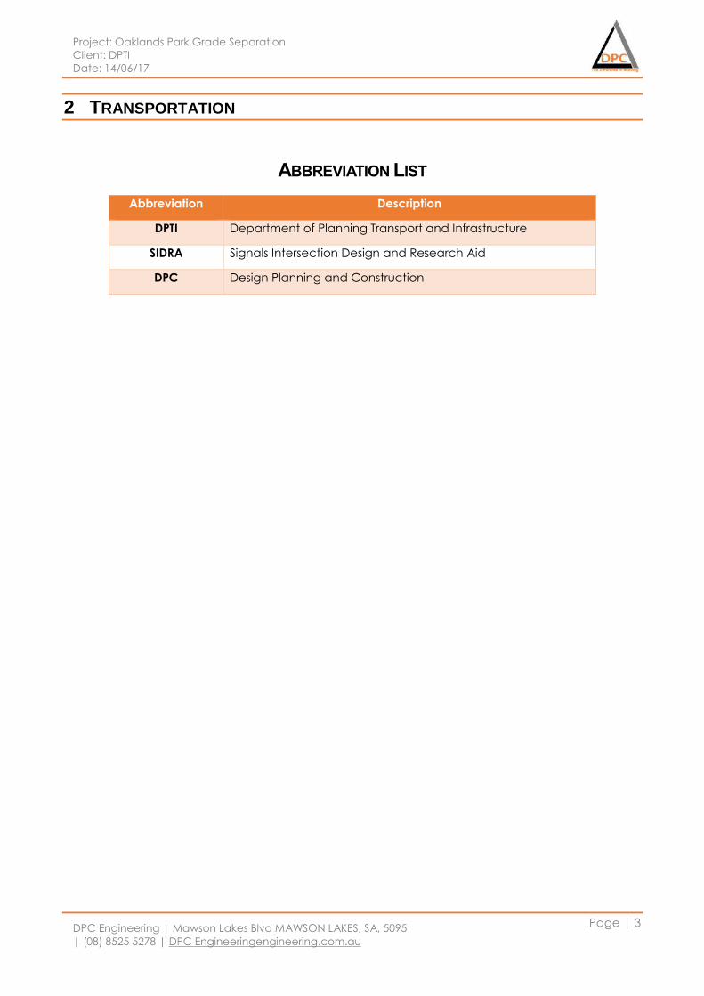
Project: Oaklands Park Grade Separation
Client: DPTI
Date: 14/06/17
DPC Engineering | Mawson Lakes Blvd MAWSON LAKES, SA, 5095
| (08) 8525 5278 | DPC Engineeringengineering.com.au
Page | 3
2 TRANSPORTATION
ABBREVIATION LIST
Abbreviation Description
DPTI Department of Planning Transport and Infrastructure
SIDRA Signals Intersection Design and Research Aid
DPC Design Planning and Construction
Project: Oaklands Park Grade Separation
Client: DPTI
Date: 14/06/17
DPC Engineering | Mawson Lakes Blvd MAWSON LAKES, SA, 5095
| (08) 8525 5278 | DPC Engineeringengineering.com.au
Page | 4
2.1 Scope of work
The Oakland Park Grade separation is one of the major projects which includes Rail overpass and
the diagonal road upgrade. The scope of the work that transport team will be responsible for this
project is listed below.
The AutoCAD drawing which includes alignments for new upgraded roads and overpass
The AutoCAD drawing for car-park at the train stations
Overpass detailed drawing with alignments
Detailed drawing Upgraded Road including bus stops.
Make Sure all designs are according to Australian Standard and AUSROADS Guide
Analysis the performance of the new Upgraded roads using SIDRA software
SIDRA analysis report outcome include Level of service based on delay for the Network
SIDRA analysis report outcome include level of service all three upgraded intersection
Discussion on SIDRA analyses outcome recommendation and Limitation
Traffic management during construction and post-construction the
Traffic control plan
Provide an alternate route for public services such as train and busses.
Alternate route for public commuters
Maintain the safety protocol at 100% for road user
Proper signage along the route
The Standard specification used are listed in Table 1 and 2.
2.2 Approach to Final Drawing
The railway and road grade separation was required to avoid the delay of traffic due to the railway
crossing. The four possible options were proposed during the tender stage, railway overpass, railway
underpass, road overpass and road underpass. Furthermore, during early feasibility stage, the DPC
company analysed the all four possible options to overcome with 2 feasible options, railway
overpass and road overpass. In addition, each department did further investigation on those two
options and finalise our one possible solution for Oakland Park Grade Separation, which is railway
overpass. Thereafter, transport team designed final railway and road alignment based on the
client’s requirement during the final design stage.
2.2.1 Railway Alignment
From the feasibility study of this project, transport team has determined few recommendations that
can be applied to the final design of this project. The total length of railway track would be
approximately 730 metres, which about 540 metres will be in the grade of 2.2 percentage. The
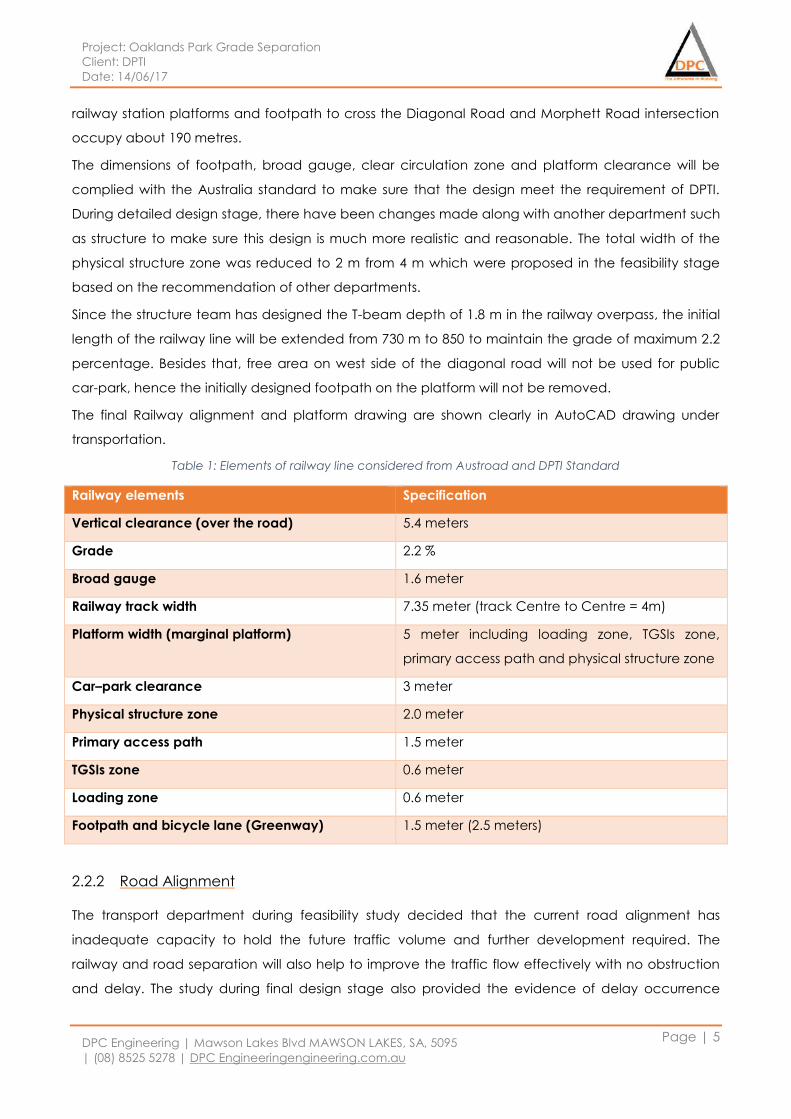
Project: Oaklands Park Grade Separation
Client: DPTI
Date: 14/06/17
DPC Engineering | Mawson Lakes Blvd MAWSON LAKES, SA, 5095
| (08) 8525 5278 | DPC Engineeringengineering.com.au
Page | 5
railway station platforms and footpath to cross the Diagonal Road and Morphett Road intersection
occupy about 190 metres.
The dimensions of footpath, broad gauge, clear circulation zone and platform clearance will be
complied with the Australia standard to make sure that the design meet the requirement of DPTI.
During detailed design stage, there have been changes made along with another department such
as structure to make sure this design is much more realistic and reasonable. The total width of the
physical structure zone was reduced to 2 m from 4 m which were proposed in the feasibility stage
based on the recommendation of other departments.
Since the structure team has designed the T-beam depth of 1.8 m in the railway overpass, the initial
length of the railway line will be extended from 730 m to 850 to maintain the grade of maximum 2.2
percentage. Besides that, free area on west side of the diagonal road will not be used for public
car-park, hence the initially designed footpath on the platform will not be removed.
The final Railway alignment and platform drawing are shown clearly in AutoCAD drawing under
transportation.
Table 1: Elements of railway line considered from Austroad and DPTI Standard
Railway elements Specification
Vertical clearance (over the road) 5.4 meters
Grade 2.2 %
Broad gauge 1.6 meter
Railway track width 7.35 meter (track Centre to Centre = 4m)
Platform width (marginal platform) 5 meter including loading zone, TGSIs zone,
primary access path and physical structure zone
Car–park clearance 3 meter
Physical structure zone 2.0 meter
Primary access path 1.5 meter
TGSIs zone 0.6 meter
Loading zone 0.6 meter
Footpath and bicycle lane (Greenway) 1.5 meter (2.5 meters)
2.2.2 Road Alignment
The transport department during feasibility study decided that the current road alignment has
inadequate capacity to hold the future traffic volume and further development required. The
railway and road separation will also help to improve the traffic flow effectively with no obstruction
and delay. The study during final design stage also provided the evidence of delay occurrence
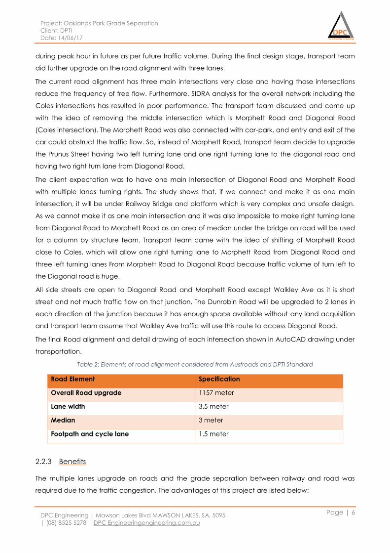
Project: Oaklands Park Grade Separation
Client: DPTI
Date: 14/06/17
DPC Engineering | Mawson Lakes Blvd MAWSON LAKES, SA, 5095
| (08) 8525 5278 | DPC Engineeringengineering.com.au
Page | 6
during peak hour in future as per future traffic volume. During the final design stage, transport team
did further upgrade on the road alignment with three lanes.
The current road alignment has three main intersections very close and having those intersections
reduce the frequency of free flow. Furthermore, SIDRA analysis for the overall network including the
Coles intersections has resulted in poor performance. The transport team discussed and come up
with the idea of removing the middle intersection which is Morphett Road and Diagonal Road
(Coles intersection). The Morphett Road was also connected with car-park, and entry and exit of the
car could obstruct the traffic flow. So, instead of Morphett Road, transport team decide to upgrade
the Prunus Street having two left turning lane and one right turning lane to the diagonal road and
having two right turn lane from Diagonal Road.
The client expectation was to have one main intersection of Diagonal Road and Morphett Road
with multiple lanes turning rights. The study shows that, if we connect and make it as one main
intersection, it will be under Railway Bridge and platform which is very complex and unsafe design.
As we cannot make it as one main intersection and it was also impossible to make right turning lane
from Diagonal Road to Morphett Road as an area of median under the bridge on road will be used
for a column by structure team. Transport team came with the idea of shifting of Morphett Road
close to Coles, which will allow one right turning lane to Morphett Road from Diagonal Road and
three left turning lanes From Morphett Road to Diagonal Road because traffic volume of turn left to
the Diagonal road is huge.
All side streets are open to Diagonal Road and Morphett Road except Walkley Ave as it is short
street and not much traffic flow on that junction. The Dunrobin Road will be upgraded to 2 lanes in
each direction at the junction because it has enough space available without any land acquisition
and transport team assume that Walkley Ave traffic will use this route to access Diagonal Road.
The final Road alignment and detail drawing of each intersection shown in AutoCAD drawing under
transportation.
Table 2: Elements of road alignment considered from Austroads and DPTI Standard
Road Element Specification
Overall Road upgrade 1157 meter
Lane width 3.5 meter
Median 3 meter
Footpath and cycle lane 1.5 meter
2.2.3 Benefits
The multiple lanes upgrade on roads and the grade separation between railway and road was
required due to the traffic congestion. The advantages of this project are listed below:
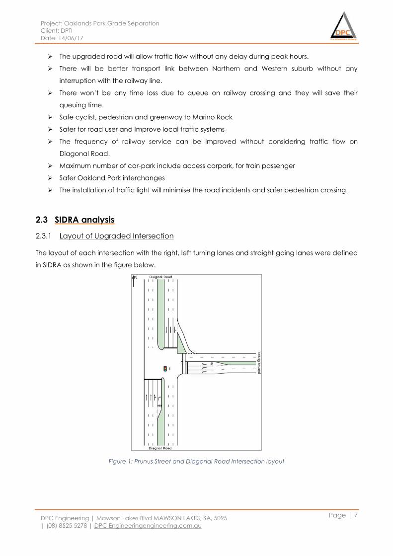
Project: Oaklands Park Grade Separation
Client: DPTI
Date: 14/06/17
DPC Engineering | Mawson Lakes Blvd MAWSON LAKES, SA, 5095
| (08) 8525 5278 | DPC Engineeringengineering.com.au
Page | 7
The upgraded road will allow traffic flow without any delay during peak hours.
There will be better transport link between Northern and Western suburb without any
interruption with the railway line.
There won’t be any time loss due to queue on railway crossing and they will save their
queuing time.
Safe cyclist, pedestrian and greenway to Marino Rock
Safer for road user and Improve local traffic systems
The frequency of railway service can be improved without considering traffic flow on
Diagonal Road.
Maximum number of car-park include access carpark, for train passenger
Safer Oakland Park interchanges
The installation of traffic light will minimise the road incidents and safer pedestrian crossing.
2.3 SIDRA analysis
2.3.1 Layout of Upgraded Intersection
The layout of each intersection with the right, left turning lanes and straight going lanes were defined
in SIDRA as shown in the figure below.
Figure 1: Prunus Street and Diagonal Road Intersection layout
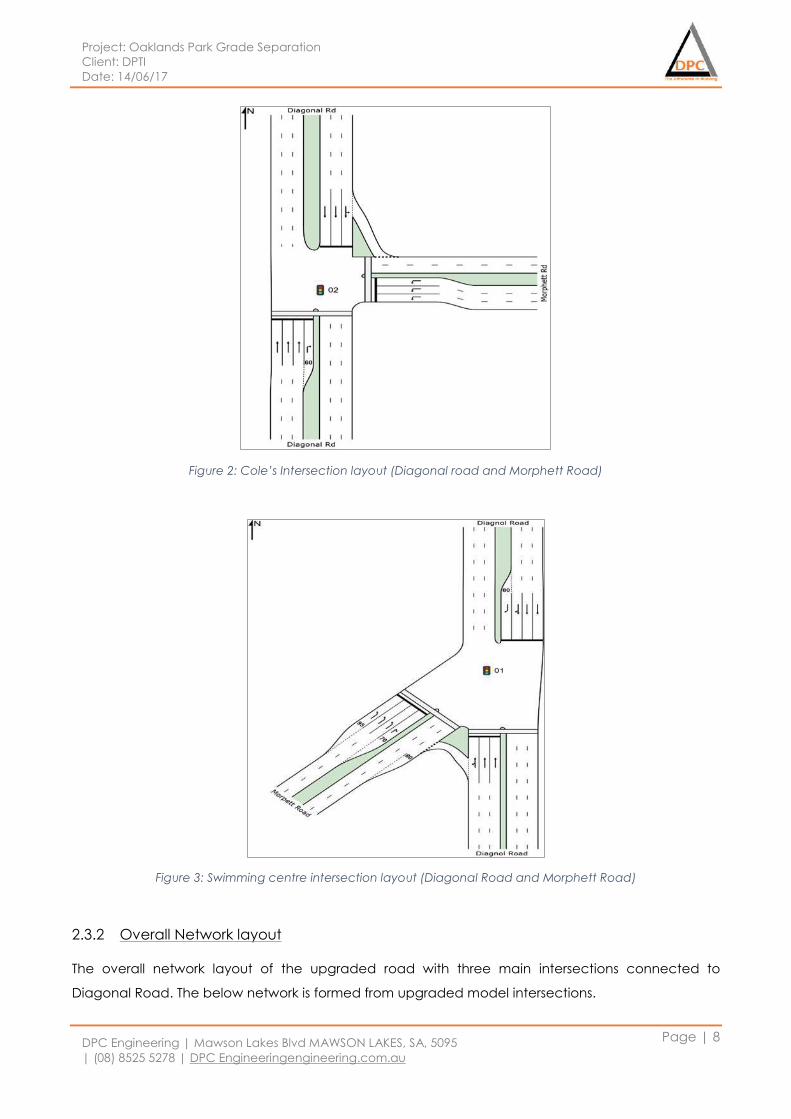
Project: Oaklands Park Grade Separation
Client: DPTI
Date: 14/06/17
DPC Engineering | Mawson Lakes Blvd MAWSON LAKES, SA, 5095
| (08) 8525 5278 | DPC Engineeringengineering.com.au
Page | 8
Figure 2: Cole’s Intersection layout (Diagonal road and Morphett Road)
Figure 3: Swimming centre intersection layout (Diagonal Road and Morphett Road)
2.3.2 Overall Network layout
The overall network layout of the upgraded road with three main intersections connected to
Diagonal Road. The below network is formed from upgraded model intersections.
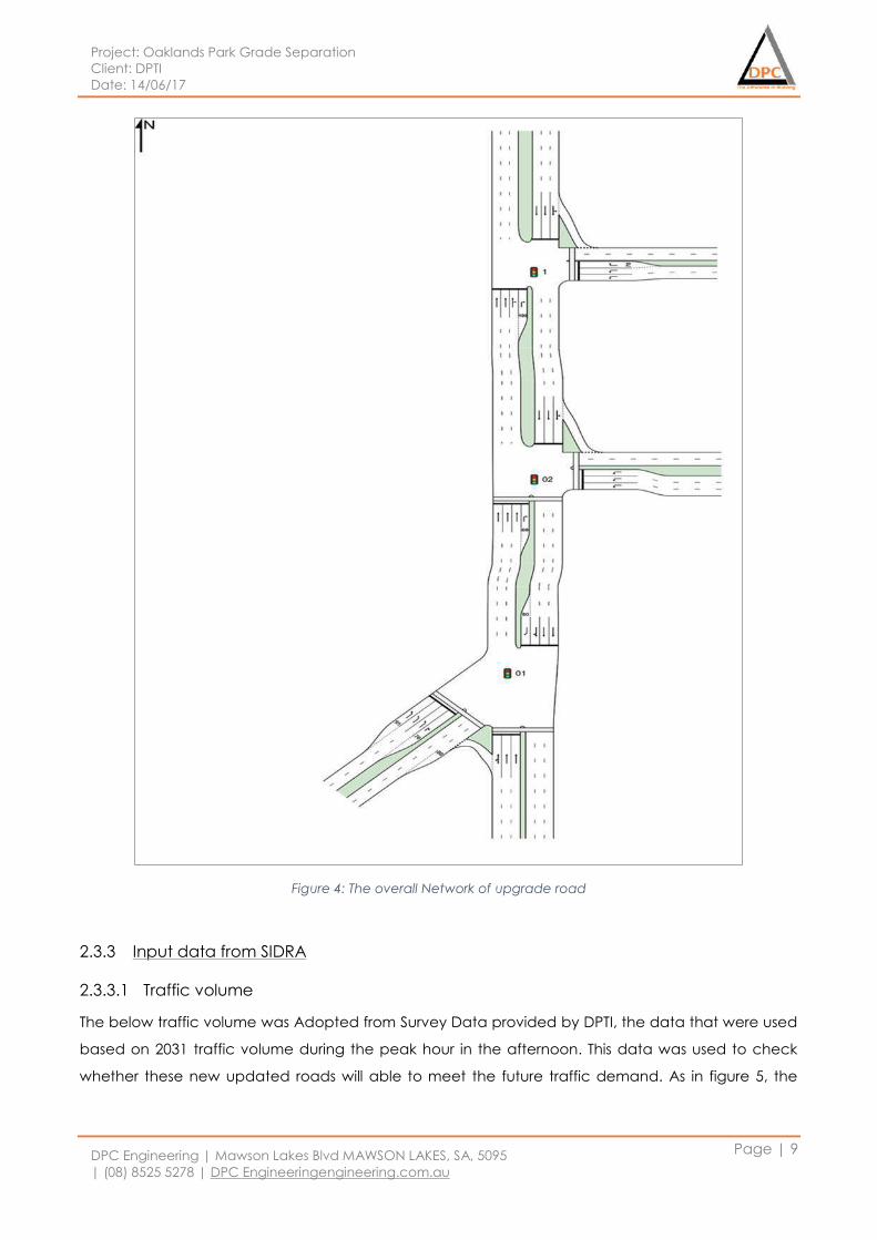
Project: Oaklands Park Grade Separation
Client: DPTI
Date: 14/06/17
DPC Engineering | Mawson Lakes Blvd MAWSON LAKES, SA, 5095
| (08) 8525 5278 | DPC Engineeringengineering.com.au
Page | 9
Figure 4: The overall Network of upgrade road
2.3.3 Input data from SIDRA
2.3.3.1 Traffic volume
The below traffic volume was Adopted from Survey Data provided by DPTI, the data that were used
based on 2031 traffic volume during the peak hour in the afternoon. This data was used to check
whether these new updated roads will able to meet the future traffic demand. As in figure 5, the
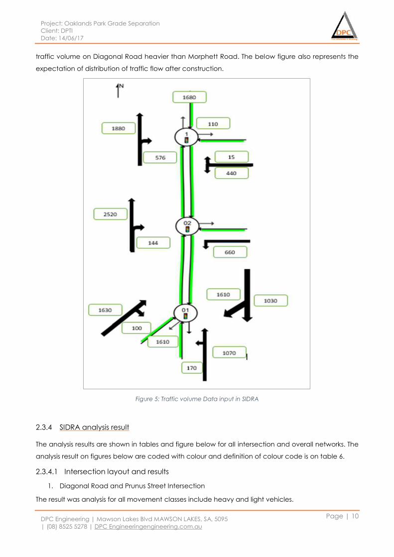
Project: Oaklands Park Grade Separation
Client: DPTI
Date: 14/06/17
DPC Engineering | Mawson Lakes Blvd MAWSON LAKES, SA, 5095
| (08) 8525 5278 | DPC Engineeringengineering.com.au
Page | 10
traffic volume on Diagonal Road heavier than Morphett Road. The below figure also represents the
expectation of distribution of traffic flow after construction.
Figure 5: Traffic volume Data input in SIDRA
2.3.4 SIDRA analysis result
The analysis results are shown in tables and figure below for all intersection and overall networks. The
analysis result on figures below are coded with colour and definition of colour code is on table 6.
2.3.4.1 Intersection layout and results
1. Diagonal Road and Prunus Street Intersection
The result was analysis for all movement classes include heavy and light vehicles.
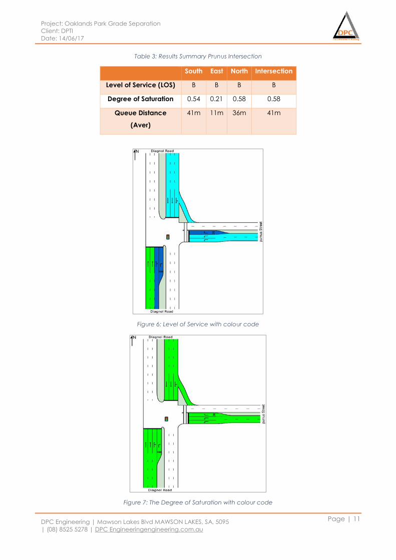
Project: Oaklands Park Grade Separation
Client: DPTI
Date: 14/06/17
DPC Engineering | Mawson Lakes Blvd MAWSON LAKES, SA, 5095
| (08) 8525 5278 | DPC Engineeringengineering.com.au
Page | 11
Table 3: Results Summary Prunus Intersection
South East North Intersection
Level of Service (LOS) B B B B
Degree of Saturation 0.54 0.21 0.58 0.58
Queue Distance
(Aver)
41m 11m 36m 41m
Figure 6: Level of Service with colour code
Figure 7: The Degree of Saturation with colour code
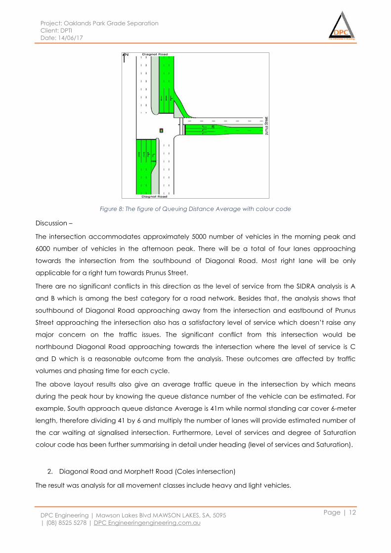
Project: Oaklands Park Grade Separation
Client: DPTI
Date: 14/06/17
DPC Engineering | Mawson Lakes Blvd MAWSON LAKES, SA, 5095
| (08) 8525 5278 | DPC Engineeringengineering.com.au
Page | 12
Figure 8: The figure of Queuing Distance Average with colour code
Discussion –
The intersection accommodates approximately 5000 number of vehicles in the morning peak and
6000 number of vehicles in the afternoon peak. There will be a total of four lanes approaching
towards the intersection from the southbound of Diagonal Road. Most right lane will be only
applicable for a right turn towards Prunus Street.
There are no significant conflicts in this direction as the level of service from the SIDRA analysis is A
and B which is among the best category for a road network. Besides that, the analysis shows that
southbound of Diagonal Road approaching away from the intersection and eastbound of Prunus
Street approaching the intersection also has a satisfactory level of service which doesn’t raise any
major concern on the traffic issues. The significant conflict from this intersection would be
northbound Diagonal Road approaching towards the intersection where the level of service is C
and D which is a reasonable outcome from the analysis. These outcomes are affected by traffic
volumes and phasing time for each cycle.
The above layout results also give an average traffic queue in the intersection by which means
during the peak hour by knowing the queue distance number of the vehicle can be estimated. For
example, South approach queue distance Average is 41m while normal standing car cover 6-meter
length, therefore dividing 41 by 6 and multiply the number of lanes will provide estimated number of
the car waiting at signalised intersection. Furthermore, Level of services and degree of Saturation
colour code has been further summarising in detail under heading (level of services and Saturation).
2. Diagonal Road and Morphett Road (Coles intersection)
The result was analysis for all movement classes include heavy and light vehicles.
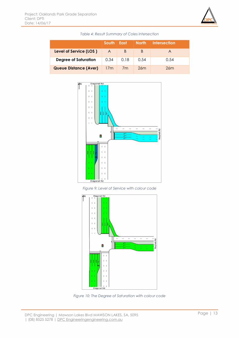
Project: Oaklands Park Grade Separation
Client: DPTI
Date: 14/06/17
DPC Engineering | Mawson Lakes Blvd MAWSON LAKES, SA, 5095
| (08) 8525 5278 | DPC Engineeringengineering.com.au
Page | 13
Table 4: Result Summary of Coles intersection
South East North Intersection
Level of Service (LOS ) A B B A
Degree of Saturation 0.34 0.18 0.54 0.54
Queue Distance (Aver) 17m 7m 26m 26m
Figure 9: Level of Service with colour code
Figure 10: The Degree of Saturation with colour code
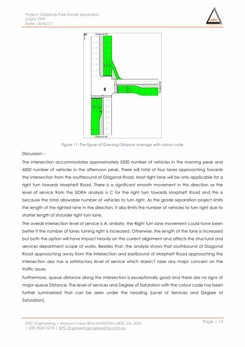
Project: Oaklands Park Grade Separation
Client: DPTI
Date: 14/06/17
DPC Engineering | Mawson Lakes Blvd MAWSON LAKES, SA, 5095
| (08) 8525 5278 | DPC Engineeringengineering.com.au
Page | 14
Figure 11: The figure of Queuing Distance Average with colour code
Discussion –
The intersection accommodates approximately 5500 number of vehicles in the morning peak and
6000 number of vehicles in the afternoon peak. There will total of four lanes approaching towards
the intersection from the southbound of Diagonal Road. Most right lane will be only applicable for a
right turn towards Morphett Road. There is a significant smooth movement in this direction as the
level of service from the SIDRA analysis is C for the right turn towards Morphett Road and this is
because the total allowable number of vehicles to turn right. As the grade separation project limits
the length of the rightest lane in the direction, it also limits the number of vehicles to turn right due to
shorter length of shoulder right turn lane.
The overall intersection level of service is A, similarly, the Right turn lane movement could have been
better if the number of lanes turning right is increased. Otherwise, the length of the lane is increased
but both the option will have impact heavily on the current alignment and affects the structural and
services department scope of works. Besides that, the analysis shows that southbound of Diagonal
Road approaching away from the intersection and eastbound of Morphett Road approaching the
intersection also has a satisfactory level of service which doesn’t raise any major concern on the
traffic issues.
Furthermore, queue distance along the intersection is exceptionally good and there are no signs of
major queue Distance. The level of services and Degree of Saturation with the colour code has been
further summarised that can be seen under the heading (Level of Services and Degree of
Saturation).
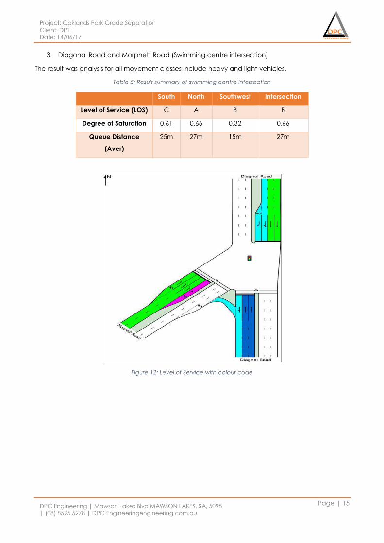
Project: Oaklands Park Grade Separation
Client: DPTI
Date: 14/06/17
DPC Engineering | Mawson Lakes Blvd MAWSON LAKES, SA, 5095
| (08) 8525 5278 | DPC Engineeringengineering.com.au
Page | 15
3. Diagonal Road and Morphett Road (Swimming centre intersection)
The result was analysis for all movement classes include heavy and light vehicles.
Table 5: Result summary of swimming centre intersection
Figure 12: Level of Service with colour code
South North Southwest Intersection
Level of Service (LOS) C A B B
Degree of Saturation 0.61 0.66 0.32 0.66
Queue Distance
(Aver)
25m 27m 15m 27m
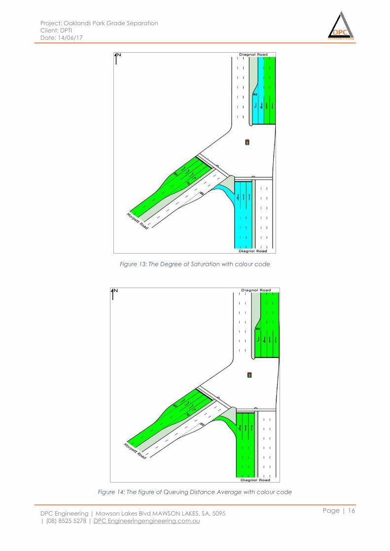
Project: Oaklands Park Grade Separation
Client: DPTI
Date: 14/06/17
DPC Engineering | Mawson Lakes Blvd MAWSON LAKES, SA, 5095
| (08) 8525 5278 | DPC Engineeringengineering.com.au
Page | 16
Figure 13: The Degree of Saturation with colour code
Figure 14: The figure of Queuing Distance Average with colour code
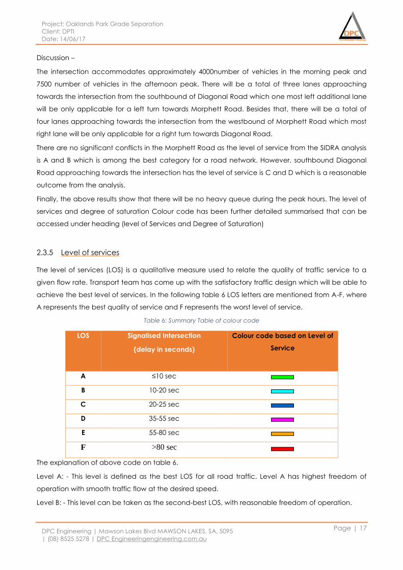
Project: Oaklands Park Grade Separation
Client: DPTI
Date: 14/06/17
DPC Engineering | Mawson Lakes Blvd MAWSON LAKES, SA, 5095
| (08) 8525 5278 | DPC Engineeringengineering.com.au
Page | 17
Discussion –
The intersection accommodates approximately 4000number of vehicles in the morning peak and
7500 number of vehicles in the afternoon peak. There will be a total of three lanes approaching
towards the intersection from the southbound of Diagonal Road which one most left additional lane
will be only applicable for a left turn towards Morphett Road. Besides that, there will be a total of
four lanes approaching towards the intersection from the westbound of Morphett Road which most
right lane will be only applicable for a right turn towards Diagonal Road.
There are no significant conflicts in the Morphett Road as the level of service from the SIDRA analysis
is A and B which is among the best category for a road network. However, southbound Diagonal
Road approaching towards the intersection has the level of service is C and D which is a reasonable
outcome from the analysis.
Finally, the above results show that there will be no heavy queue during the peak hours. The level of
services and degree of saturation Colour code has been further detailed summarised that can be
accessed under heading (level of Services and Degree of Saturation)
2.3.5 Level of services
The level of services (LOS) is a qualitative measure used to relate the quality of traffic service to a
given flow rate. Transport team has come up with the satisfactory traffic design which will be able to
achieve the best level of services. In the following table 6 LOS letters are mentioned from A-F, where
A represents the best quality of service and F represents the worst level of service.
Table 6: Summary Table of colour code
LOS Signalised Intersection
(delay in seconds)
Colour code based on Level of
Service
A ≤10 sec
B 10-20 sec
C 20-25 sec
D 35-55 sec
E 55-80 sec
F >80 sec
The explanation of above code on table 6.
Level A: - This level is defined as the best LOS for all road traffic. Level A has highest freedom of
operation with smooth traffic flow at the desired speed.
Level B: - This level can be taken as the second-best LOS, with reasonable freedom of operation.
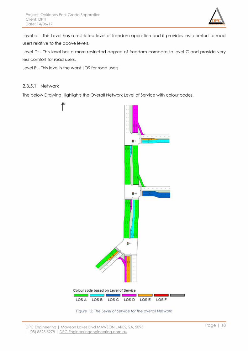
Project: Oaklands Park Grade Separation
Client: DPTI
Date: 14/06/17
DPC Engineering | Mawson Lakes Blvd MAWSON LAKES, SA, 5095
| (08) 8525 5278 | DPC Engineeringengineering.com.au
Page | 18
Level c: - This Level has a restricted level of freedom operation and it provides less comfort to road
users relative to the above levels.
Level D: - This level has a more restricted degree of freedom compare to level C and provide very
less comfort for road users.
Level F: - This level is the worst LOS for road users.
2.3.5.1 Network
The below Drawing Highlights the Overall Network Level of Service with colour codes.
Figure 15: The Level of Service for the overall Network
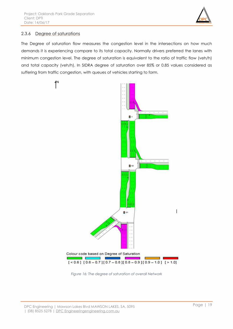
Project: Oaklands Park Grade Separation
Client: DPTI
Date: 14/06/17
DPC Engineering | Mawson Lakes Blvd MAWSON LAKES, SA, 5095
| (08) 8525 5278 | DPC Engineeringengineering.com.au
Page | 19
2.3.6 Degree of saturations
The Degree of saturation flow measures the congestion level in the intersections on how much
demands it is experiencing compare to its total capacity. Normally drivers preferred the lanes with
minimum congestion level. The degree of saturation is equivalent to the ratio of traffic flow (veh/h)
and total capacity (veh/h). In SIDRA degree of saturation over 85% or 0.85 values considered as
suffering from traffic congestion, with queues of vehicles starting to form.
Figure 16: The degree of saturation of overall Network
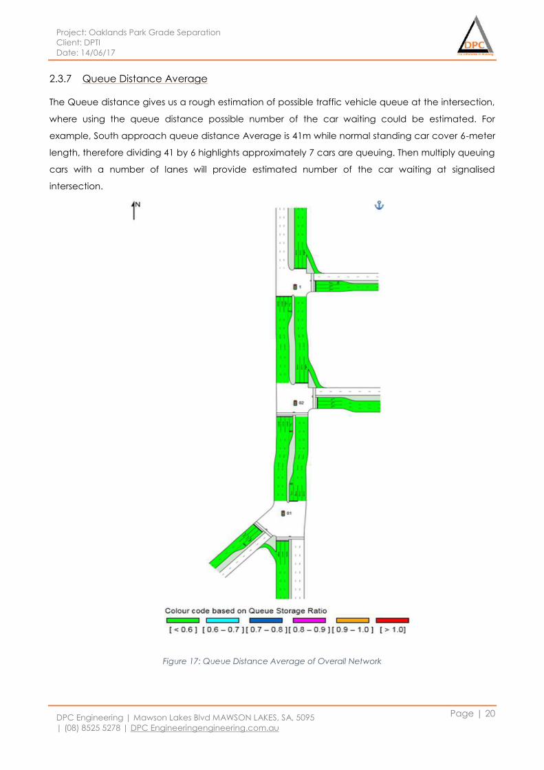
Project: Oaklands Park Grade Separation
Client: DPTI
Date: 14/06/17
DPC Engineering | Mawson Lakes Blvd MAWSON LAKES, SA, 5095
| (08) 8525 5278 | DPC Engineeringengineering.com.au
Page | 20
2.3.7 Queue Distance Average
The Queue distance gives us a rough estimation of possible traffic vehicle queue at the intersection,
where using the queue distance possible number of the car waiting could be estimated. For
example, South approach queue distance Average is 41m while normal standing car cover 6-meter
length, therefore dividing 41 by 6 highlights approximately 7 cars are queuing. Then multiply queuing
cars with a number of lanes will provide estimated number of the car waiting at signalised
intersection.
Figure 17: Queue Distance Average of Overall Network
Project: Oaklands Park Grade Separation
Client: DPTI
Date: 14/06/17
DPC Engineering | Mawson Lakes Blvd MAWSON LAKES, SA, 5095
| (08) 8525 5278 | DPC Engineeringengineering.com.au
Page | 21
2.3.8 Discussion and recommendation
SIDRA Software is used to create Intersection model with respect given traffic volume provided by
DPTI. SIDRA software is one of the best tools to estimate the modelled Intersection capacity. Firstly,
the Individual intersection was modelled to check the level of services where the results show that
level service is A and B which mean smooth traffic movement at the intersections based on the
code definition provided by SIDRA.
Secondly, the intersections were formed into a network where the whole network was analysed. The
output of the results shows that mixed range of colour code mostly A, B, C and D while summarises
the overall network level of service it highly C level which means there will be some delay but it will
not make road uncomfortable to take the risk. Furthermore, the performance level could be
improved by implying proper phases modelling and coordination with the individual intersection.
2.3.8.1 Recommendation
The newly upgraded intersections were formed into a network which is approximately 575m. Where
three sets of signalised traffic systems have been designed, we recommend Coles intersection shall
not be designed as signalised intersection due to close distance of approximately 210 meter
another traffic signal close to swimming centre designed. As this design, will not be cost effective it
will also require precise coordination close by signalised intersection.
2.3.8.2 Limitation
SIDRA software is a good tool to estimate the possible level of performance of the intersection and
Roads but their limitation includes in the results. There are many factors that slow down traffic on the
roads was SIDRA is not capable of counter those factors. For example, type of drivers on the road as
we aware everyone will not be driving 60Km/h consistently as there will be drivers will be driving quite
slow range of 45 to 55km/h especially senior aged driver and new drivers which have an impact on
slowing down traffic.
Project: Oaklands Park Grade Separation
Client: DPTI
Date: 14/06/17
DPC Engineering | Mawson Lakes Blvd MAWSON LAKES, SA, 5095
| (08) 8525 5278 | DPC Engineeringengineering.com.au
Page | 22
2.4 Traffic management
Within DPC engineering the TCP (Traffic control plan) has been generated to make sure that the
impacts of traffic on the road from commencing stages of this projects will be minimised. Under this
traffic control plan, alternative plans for the public bus and railway services and detour plans for the
normal vehicle on the road has been defined. An electronic signs board will be employed to
provide early notices and information future road closure and it will be also used to guide all the
road users to comply with the detour plan. The traffic controllers will be employed to provide the
guidance using radio communications to road users and additional road signs will be placed to
make sure that traffic flow efficiently.
The successful outcomes which would be expected from this plan have been laid as below:
Provide the safe access for all the road users
Maintain the free flow of the traffic
Make sure that successful access to the alternative bus and railway service for a local
resident.
2.4.1 Traffic control plan
The traffic control plan for different stages has been generated to counter the negative effects
which have been imposed on the traffic by taking into different factors into account.
The expected outcome of this Traffic control plan:
Free flow of the traffic on or near the projection area by executing traffic control plan for
different stages
Safe access for the local resident for the local business
2.4.1.1 Commencing stages
In the commencing stages, DPC Engineering will work with Adelaide Metro to notify the local
passengers about the alternative bus and railway services.
As per the information, that has provided in the previous study, there is a larger of the amount of the
vehicles will be transported by the diagonal road and Morphett Road. Therefore, this is a great
necessity to control the traffic volume, namely the diversion plan, during the period of the
construction to avoid the congestion problem during the construction.
To control the traffic volume on the diagonal road and Morphett Road there will be no access to the
vehicle whose destination is not in the project area. The traffic from both directions will be diverted
to the nearby south - north connecting road which are Marion Road on the east and Brighton Rd on
the west. By implementing this diversion plan the negative impacts such as the congestion problems
will be minimised during the construction phase. To achieve this, the message boards will be placed
Project: Oaklands Park Grade Separation
Client: DPTI
Date: 14/06/17
DPC Engineering | Mawson Lakes Blvd MAWSON LAKES, SA, 5095
| (08) 8525 5278 | DPC Engineeringengineering.com.au
Page | 23
in the diagonal road and Morphett Road in the northbound and southbound to give out information
about these restrictions and guide the traffic to designed path.
Moreover, there is another two-diversion path, one in the Bowker Street in the northbound and two
lanes on the Stopford Road and Trot Grove in the southbound, to further decrease the traffic volume
in the project area during the construction stages and the message signs will be placed to inform
drivers to comply with the changes.
2.4.1.2 Demolishing stages
During the demolishing stages, one signal lane on the Westside of diagonal road and south side of
Prunus Street will be closed for the demolishing purpose and upgrading purpose in the later stages
as well. By closing one single lane on the diagonal road and Prunus Street the impacts on the road
will be minimised and the impacts to access the local business will be minimised.
2.4.1.3 During the constructing stages
During the constructing stage, the rest of lanes on the diagonal road and Prunus Street will
be kept as open for all the vehicle to access.
Avoiding working in the peak hours in the morning and afternoon, which are from 7:00 am to
9:30 am and 3:00 pm and 7:00 pm from previous feasibility studies.
A detailed detour plan indicated in figure 19 below on the intersection has also been
generated for during the construction work on the railway line. This optional detour will be
arranged via Kildonan Rd, Ulva Ave, first ave and Dunrobin Rd. moreover, this traffic detour
will be performed incorporate with local government, residents, business owners and DPTI.
During the construction, we also recommended that electronic message will be deployed to
guide all the road users to comply with the detour plan and diversion plan mentioned
before.
A group of traffic controllers holding the signs, on the construction site will also be employed
to make sure that traffic flow will be smooth.
When the project is completed, all the requirements set during the demolishing stages and
construction stage to manage the traffic will be removed.
2.4.2 Traffic diversion
The traffic diversion is one of the main solutions for management of traffic during construction
periods. This will help to keep work environment safer from a road accident or any kind of incident
on construction area. The traffic diversion to the non-arterial road could cause traffic congestion
and delay so proper management planning and right routes required to have no impact on another
road while diverting traffic.
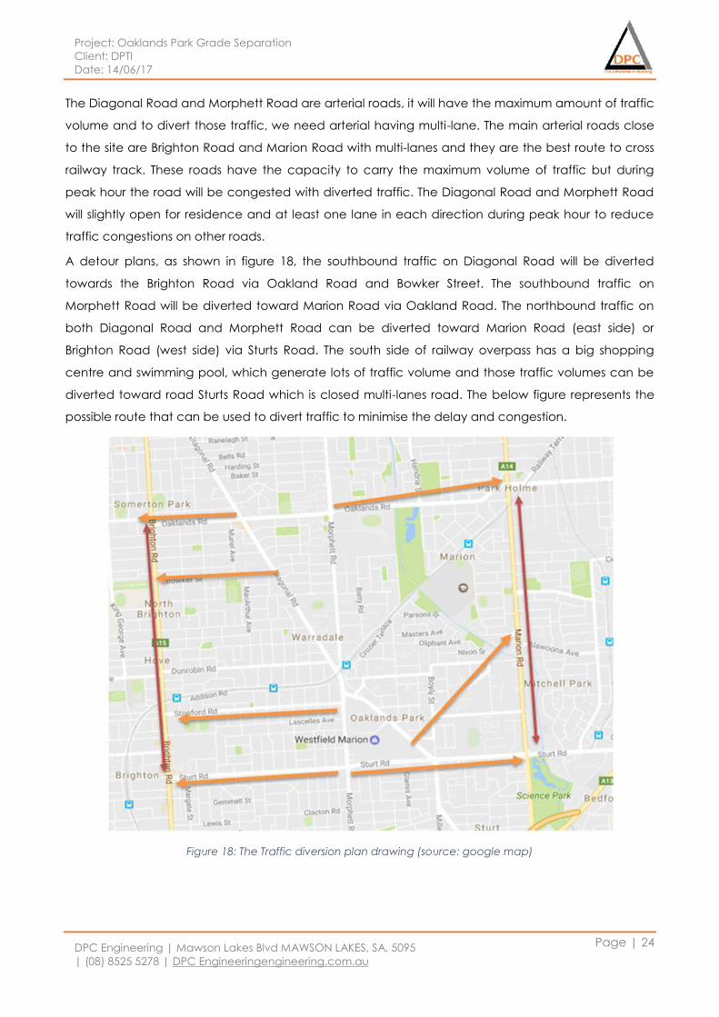
Project: Oaklands Park Grade Separation
Client: DPTI
Date: 14/06/17
DPC Engineering | Mawson Lakes Blvd MAWSON LAKES, SA, 5095
| (08) 8525 5278 | DPC Engineeringengineering.com.au
Page | 24
The Diagonal Road and Morphett Road are arterial roads, it will have the maximum amount of traffic
volume and to divert those traffic, we need arterial having multi-lane. The main arterial roads close
to the site are Brighton Road and Marion Road with multi-lanes and they are the best route to cross
railway track. These roads have the capacity to carry the maximum volume of traffic but during
peak hour the road will be congested with diverted traffic. The Diagonal Road and Morphett Road
will slightly open for residence and at least one lane in each direction during peak hour to reduce
traffic congestions on other roads.
A detour plans, as shown in figure 18, the southbound traffic on Diagonal Road will be diverted
towards the Brighton Road via Oakland Road and Bowker Street. The southbound traffic on
Morphett Road will be diverted toward Marion Road via Oakland Road. The northbound traffic on
both Diagonal Road and Morphett Road can be diverted toward Marion Road (east side) or
Brighton Road (west side) via Sturts Road. The south side of railway overpass has a big shopping
centre and swimming pool, which generate lots of traffic volume and those traffic volumes can be
diverted toward road Sturts Road which is closed multi-lanes road. The below figure represents the
possible route that can be used to divert traffic to minimise the delay and congestion.
Figure 18: The Traffic diversion plan drawing (source: google map)
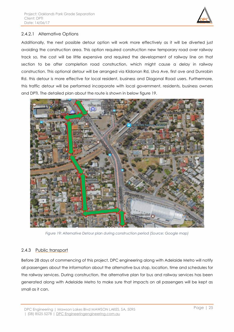
Project: Oaklands Park Grade Separation
Client: DPTI
Date: 14/06/17
DPC Engineering | Mawson Lakes Blvd MAWSON LAKES, SA, 5095
| (08) 8525 5278 | DPC Engineeringengineering.com.au
Page | 25
2.4.2.1 Alternative Options
Additionally, the next possible detour option will work more effectively as it will be diverted just
avoiding the construction area. This option required construction new temporary road over railway
track so, the cost will be little expensive and required the development of railway line on that
section to be after completion road construction, which might cause a delay in railway
construction. This optional detour will be arranged via Kildonan Rd, Ulva Ave, first ave and Dunrobin
Rd. this detour is more effective for local resident, business and Diagonal Road users. Furthermore,
this traffic detour will be performed incorporate with local government, residents, business owners
and DPTI. The detailed plan about the route is shown in below figure 19.
Figure 19: Alternative Detour plan during construction period (Source: Google map)
2.4.3 Public transport
Before 28 days of commencing of this project, DPC engineering along with Adelaide Metro will notify
all passengers about the information about the alternative bus stop, location, time and schedules for
the railway services. During construction, the alternative plan for bus and railway services has been
generated along with Adelaide Metro to make sure that impacts on all passengers will be kept as
small as it can.
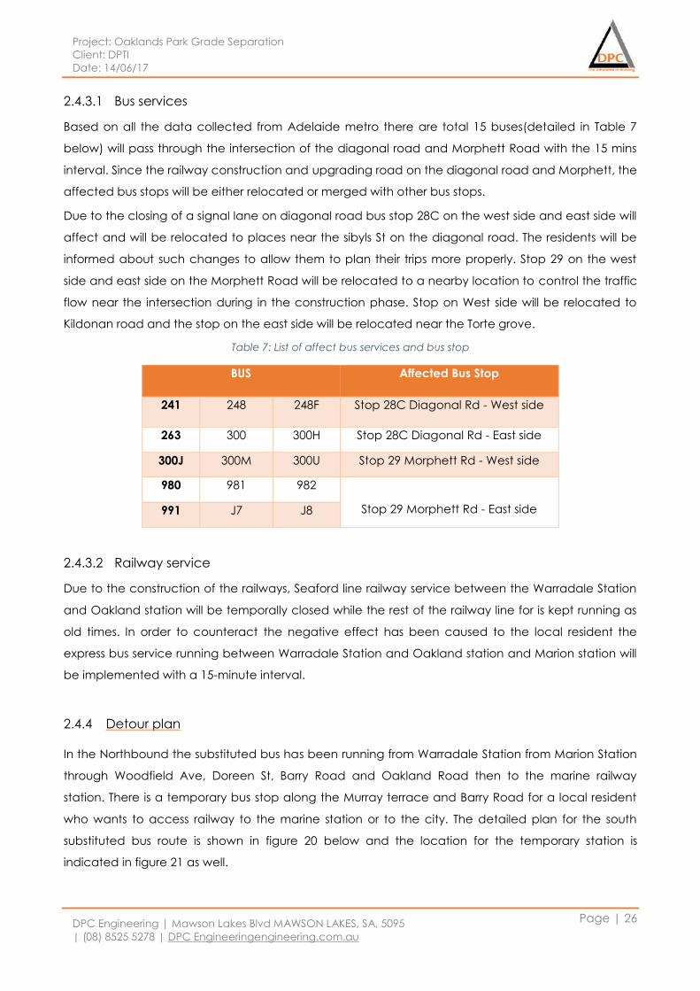
Project: Oaklands Park Grade Separation
Client: DPTI
Date: 14/06/17
DPC Engineering | Mawson Lakes Blvd MAWSON LAKES, SA, 5095
| (08) 8525 5278 | DPC Engineeringengineering.com.au
Page | 26
2.4.3.1 Bus services
Based on all the data collected from Adelaide metro there are total 15 buses(detailed in Table 7
below) will pass through the intersection of the diagonal road and Morphett Road with the 15 mins
interval. Since the railway construction and upgrading road on the diagonal road and Morphett, the
affected bus stops will be either relocated or merged with other bus stops.
Due to the closing of a signal lane on diagonal road bus stop 28C on the west side and east side will
affect and will be relocated to places near the sibyls St on the diagonal road. The residents will be
informed about such changes to allow them to plan their trips more properly. Stop 29 on the west
side and east side on the Morphett Road will be relocated to a nearby location to control the traffic
flow near the intersection during in the construction phase. Stop on West side will be relocated to
Kildonan road and the stop on the east side will be relocated near the Torte grove.
Table 7: List of affect bus services and bus stop
BUS Affected Bus Stop
241 248 248F Stop 28C Diagonal Rd - West side
263 300 300H Stop 28C Diagonal Rd - East side
300J 300M 300U Stop 29 Morphett Rd - West side
980 981 982
Stop 29 Morphett Rd - East side 991 J7 J8
2.4.3.2 Railway service
Due to the construction of the railways, Seaford line railway service between the Warradale Station
and Oakland station will be temporally closed while the rest of the railway line for is kept running as
old times. In order to counteract the negative effect has been caused to the local resident the
express bus service running between Warradale Station and Oakland station and Marion station will
be implemented with a 15-minute interval.
2.4.4 Detour plan
In the Northbound the substituted bus has been running from Warradale Station from Marion Station
through Woodfield Ave, Doreen St, Barry Road and Oakland Road then to the marine railway
station. There is a temporary bus stop along the Murray terrace and Barry Road for a local resident
who wants to access railway to the marine station or to the city. The detailed plan for the south
substituted bus route is shown in figure 20 below and the location for the temporary station is
indicated in figure 21 as well.
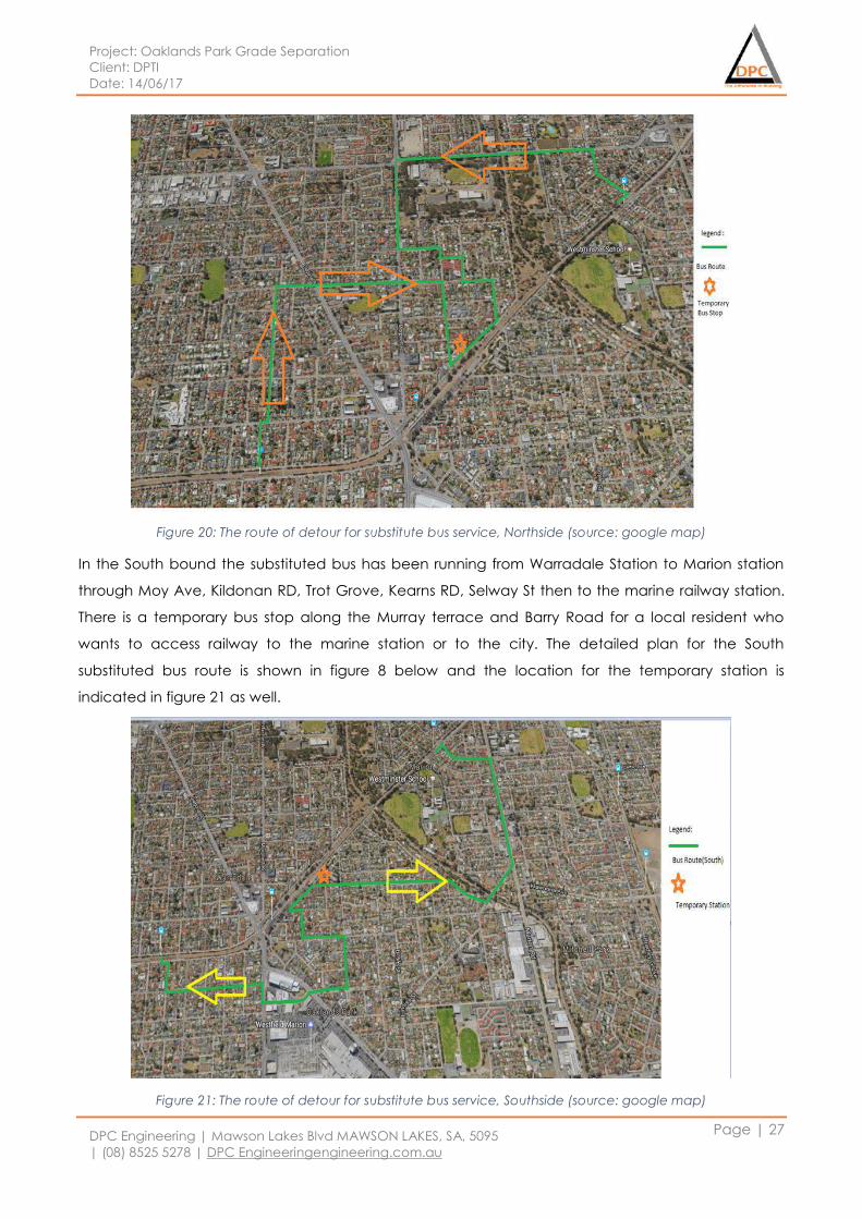
Project: Oaklands Park Grade Separation
Client: DPTI
Date: 14/06/17
DPC Engineering | Mawson Lakes Blvd MAWSON LAKES, SA, 5095
| (08) 8525 5278 | DPC Engineeringengineering.com.au
Page | 27
Figure 20: The route of detour for substitute bus service, Northside (source: google map)
In the South bound the substituted bus has been running from Warradale Station to Marion station
through Moy Ave, Kildonan RD, Trot Grove, Kearns RD, Selway St then to the marine railway station.
There is a temporary bus stop along the Murray terrace and Barry Road for a local resident who
wants to access railway to the marine station or to the city. The detailed plan for the South
substituted bus route is shown in figure 8 below and the location for the temporary station is
indicated in figure 21 as well.
Figure 21: The route of detour for substitute bus service, Southside (source: google map)
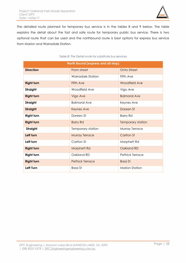
Project: Oaklands Park Grade Separation
Client: DPTI
Date: 14/06/17
DPC Engineering | Mawson Lakes Blvd MAWSON LAKES, SA, 5095
| (08) 8525 5278 | DPC Engineeringengineering.com.au
Page | 28
The detailed route planned for temporary bus service is in the tables 8 and 9 below. The table
explains the detail about the fast and safe route for temporary public bus service. There is two
optional route that can be used and the northbound route is best options for express bus service
from Marion and Warradale Station.
Table 8: The Detail route for substitute bus services
North Bound (express and all stop)
Direction From street Onto Street
Warradale Station Fifth Ave
Right turn Fifth Ave Woodfield Ave
Straight Woodfield Ave Vigo Ave
Right turn Vigo Ave Balmoral Ave
Straight Balmoral Ave Keynes Ave
Straight Keynes Ave Doreen St
Right turn Doreen St Barry Rd
Right turn Barry Rd Temporary station
Straight Temporary station Murray Terrace
Left turn Murray Terrace Carlton St
Left turn Carlton St Morphett Rd
Right turn Morphett Rd Oakland RD
Right turn Oakland RD Pethick Terrace
Right turn Pethick Terrace Bassi St
Left Turn Bassi St Marion Station
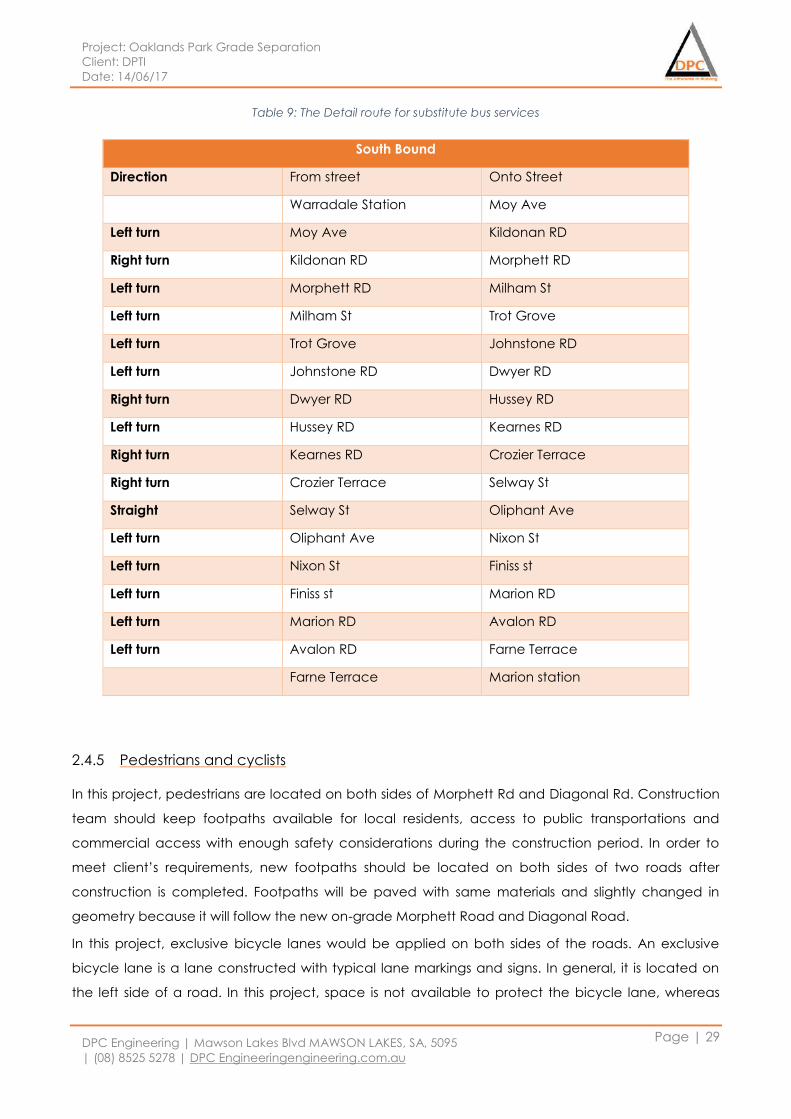
Project: Oaklands Park Grade Separation
Client: DPTI
Date: 14/06/17
DPC Engineering | Mawson Lakes Blvd MAWSON LAKES, SA, 5095
| (08) 8525 5278 | DPC Engineeringengineering.com.au
Page | 29
Table 9: The Detail route for substitute bus services
2.4.5 Pedestrians and cyclists
In this project, pedestrians are located on both sides of Morphett Rd and Diagonal Rd. Construction
team should keep footpaths available for local residents, access to public transportations and
commercial access with enough safety considerations during the construction period. In order to
meet client’s requirements, new footpaths should be located on both sides of two roads after
construction is completed. Footpaths will be paved with same materials and slightly changed in
geometry because it will follow the new on-grade Morphett Road and Diagonal Road.
In this project, exclusive bicycle lanes would be applied on both sides of the roads. An exclusive
bicycle lane is a lane constructed with typical lane markings and signs. In general, it is located on
the left side of a road. In this project, space is not available to protect the bicycle lane, whereas
South Bound
Direction From street Onto Street
Warradale Station Moy Ave
Left turn Moy Ave Kildonan RD
Right turn Kildonan RD Morphett RD
Left turn Morphett RD Milham St
Left turn Milham St Trot Grove
Left turn Trot Grove Johnstone RD
Left turn Johnstone RD Dwyer RD
Right turn Dwyer RD Hussey RD
Left turn Hussey RD Kearnes RD
Right turn Kearnes RD Crozier Terrace
Right turn Crozier Terrace Selway St
Straight Selway St Oliphant Ave
Left turn Oliphant Ave Nixon St
Left turn Nixon St Finiss st
Left turn Finiss st Marion RD
Left turn Marion RD Avalon RD
Left turn Avalon RD Farne Terrace
Farne Terrace Marion station
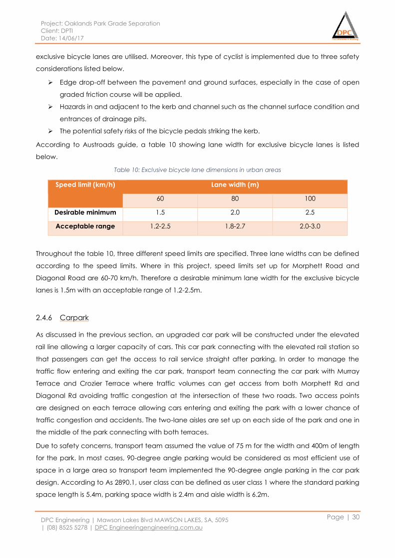
Project: Oaklands Park Grade Separation
Client: DPTI
Date: 14/06/17
DPC Engineering | Mawson Lakes Blvd MAWSON LAKES, SA, 5095
| (08) 8525 5278 | DPC Engineeringengineering.com.au
Page | 30
exclusive bicycle lanes are utilised. Moreover, this type of cyclist is implemented due to three safety
considerations listed below.
Edge drop-off between the pavement and ground surfaces, especially in the case of open
graded friction course will be applied.
Hazards in and adjacent to the kerb and channel such as the channel surface condition and
entrances of drainage pits.
The potential safety risks of the bicycle pedals striking the kerb.
According to Austroads guide, a table 10 showing lane width for exclusive bicycle lanes is listed
below.
Table 10: Exclusive bicycle lane dimensions in urban areas
Speed limit (km/h) Lane width (m)
60 80 100
Desirable minimum 1.5 2.0 2.5
Acceptable range 1.2-2.5 1.8-2.7 2.0-3.0
Throughout the table 10, three different speed limits are specified. Three lane widths can be defined
according to the speed limits. Where in this project, speed limits set up for Morphett Road and
Diagonal Road are 60-70 km/h. Therefore a desirable minimum lane width for the exclusive bicycle
lanes is 1.5m with an acceptable range of 1.2-2.5m.
2.4.6 Carpark
As discussed in the previous section, an upgraded car park will be constructed under the elevated
rail line allowing a larger capacity of cars. This car park connecting with the elevated rail station so
that passengers can get the access to rail service straight after parking. In order to manage the
traffic flow entering and exiting the car park, transport team connecting the car park with Murray
Terrace and Crozier Terrace where traffic volumes can get access from both Morphett Rd and
Diagonal Rd avoiding traffic congestion at the intersection of these two roads. Two access points
are designed on each terrace allowing cars entering and exiting the park with a lower chance of
traffic congestion and accidents. The two-lane aisles are set up on each side of the park and one in
the middle of the park connecting with both terraces.
Due to safety concerns, transport team assumed the value of 75 m for the width and 400m of length
for the park. In most cases, 90-degree angle parking would be considered as most efficient use of
space in a large area so transport team implemented the 90-degree angle parking in the car park
design. According to As 2890.1, user class can be defined as user class 1 where the standard parking
space length is 5.4m, parking space width is 2.4m and aisle width is 6.2m.
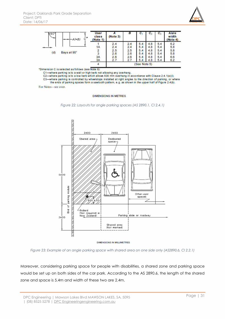
Project: Oaklands Park Grade Separation
Client: DPTI
Date: 14/06/17
DPC Engineering | Mawson Lakes Blvd MAWSON LAKES, SA, 5095
| (08) 8525 5278 | DPC Engineeringengineering.com.au
Page | 31
Figure 22: Layouts for angle parking spaces (AS 2890.1, Cl 2.4.1)
Figure 23: Example of an angle parking space with shared area on one side only (AS2890.6, Cl 2.2.1)
Moreover, considering parking space for people with disabilities, a shared zone and parking space
would be set up on both sides of the car park. According to the AS 2890.6, the length of the shared
zone and space is 5.4m and width of these two are 2.4m.
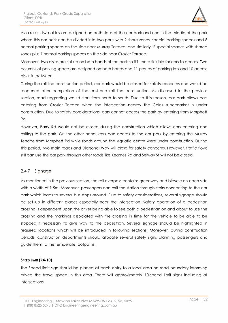
Project: Oaklands Park Grade Separation
Client: DPTI
Date: 14/06/17
DPC Engineering | Mawson Lakes Blvd MAWSON LAKES, SA, 5095
| (08) 8525 5278 | DPC Engineeringengineering.com.au
Page | 32
As a result, two aisles are designed on both sides of the car park and one in the middle of the park
where this car park can be divided into two parts with 2 share zones, special parking spaces and 8
normal parking spaces on the side near Murray Terrace, and similarly, 2 special spaces with shared
zones plus 7 normal parking spaces on the side near Crozier Terrace.
Moreover, two aisles are set up on both hands of the park so it is more flexible for cars to access. Two
columns of parking space are designed on both hands and 11 groups of parking lots and 10 access
aisles in between.
During the rail line construction period, car park would be closed for safety concerns and would be
reopened after completion of the east-end rail line construction. As discussed in the previous
section, road upgrading would start from north to south. Due to this reason, car park allows cars
entering from Crozier Terrace when the intersection nearby the Coles supermarket is under
construction. Due to safety considerations, cars cannot access the park by entering from Morphett
Rd.
However, Barry Rd would not be closed during the construction which allows cars entering and
exiting to the park. On the other hand, cars can access to the car park by entering the Murray
Terrace from Morphett Rd while roads around the Aquatic centre were under construction. During
this period, two main roads and Diagonal Way will close for safety concerns. However, traffic flows
still can use the car park through other roads like Kearnes Rd and Selway St will not be closed.
2.4.7 Signage
As mentioned in the previous section, the rail overpass contains greenway and bicycle on each side
with a width of 1.5m. Moreover, passengers can exit the station through stairs connecting to the car
park which leads to several bus stops around. Due to safety considerations, several signage should
be set up in different places especially near the intersection. Safety operation of a pedestrian
crossing is dependent upon the driver being able to see both a pedestrian on and about to use the
crossing and the markings associated with the crossing in time for the vehicle to be able to be
stopped if necessary to give way to the pedestrian. Several signage should be highlighted in
required locations which will be introduced in following sections. Moreover, during construction
periods, construction departments should allocate several safety signs alarming passengers and
guide them to the temperate footpaths.
SPEED LIMIT (R4-10)
The Speed limit sign should be placed at each entry to a local area on road boundary informing
drivers the travel speed in this area. There will approximately 10-speed limit signs including all
intersections.
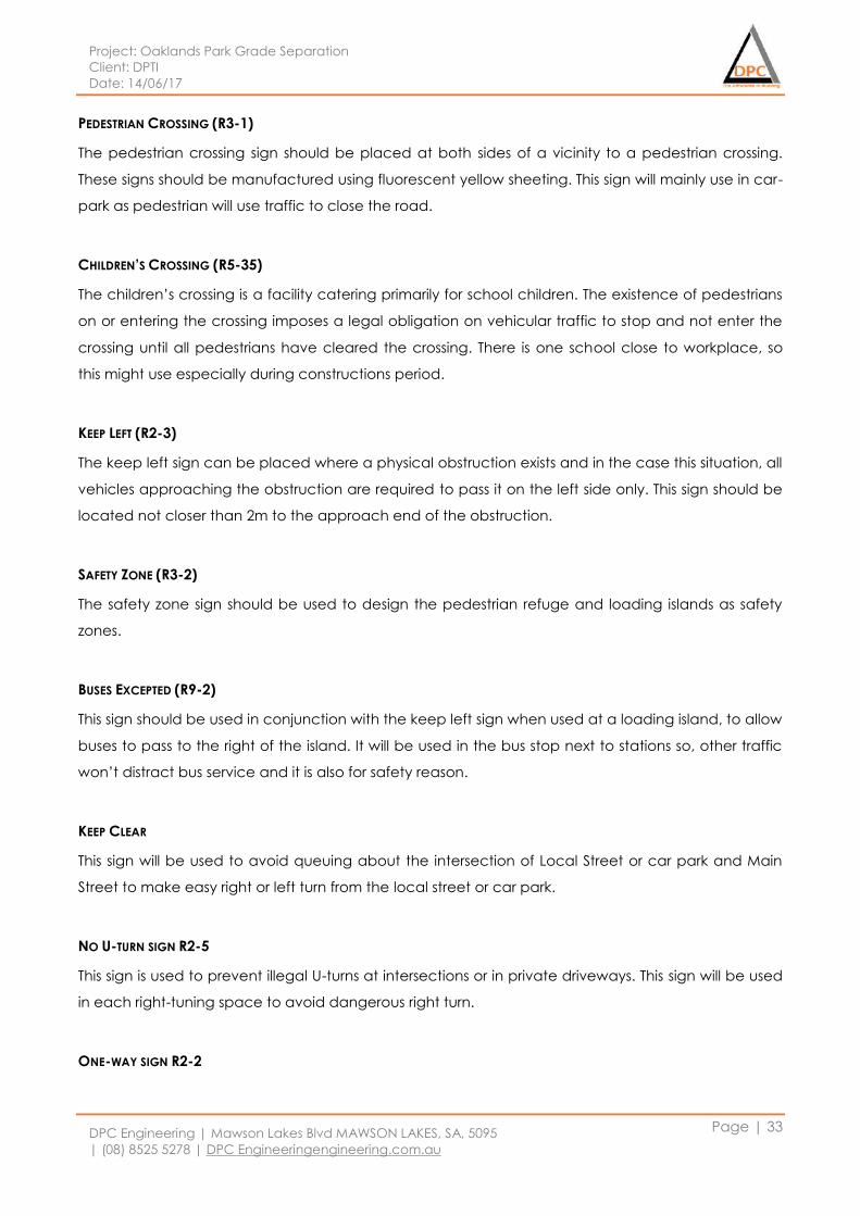
Project: Oaklands Park Grade Separation
Client: DPTI
Date: 14/06/17
DPC Engineering | Mawson Lakes Blvd MAWSON LAKES, SA, 5095
| (08) 8525 5278 | DPC Engineeringengineering.com.au
Page | 33
PEDESTRIAN CROSSING (R3-1)
The pedestrian crossing sign should be placed at both sides of a vicinity to a pedestrian crossing.
These signs should be manufactured using fluorescent yellow sheeting. This sign will mainly use in car-
park as pedestrian will use traffic to close the road.
CHILDREN’S CROSSING (R5-35)
The children’s crossing is a facility catering primarily for school children. The existence of pedestrians
on or entering the crossing imposes a legal obligation on vehicular traffic to stop and not enter the
crossing until all pedestrians have cleared the crossing. There is one school close to workplace, so
this might use especially during constructions period.
KEEP LEFT (R2-3)
The keep left sign can be placed where a physical obstruction exists and in the case this situation, all
vehicles approaching the obstruction are required to pass it on the left side only. This sign should be
located not closer than 2m to the approach end of the obstruction.
SAFETY ZONE (R3-2)
The safety zone sign should be used to design the pedestrian refuge and loading islands as safety
zones.
BUSES EXCEPTED (R9-2)
This sign should be used in conjunction with the keep left sign when used at a loading island, to allow
buses to pass to the right of the island. It will be used in the bus stop next to stations so, other traffic
won’t distract bus service and it is also for safety reason.
KEEP CLEAR
This sign will be used to avoid queuing about the intersection of Local Street or car park and Main
Street to make easy right or left turn from the local street or car park.
NO U-TURN SIGN R2-5
This sign is used to prevent illegal U-turns at intersections or in private driveways. This sign will be used
in each right-tuning space to avoid dangerous right turn.
ONE-WAY SIGN R2-2
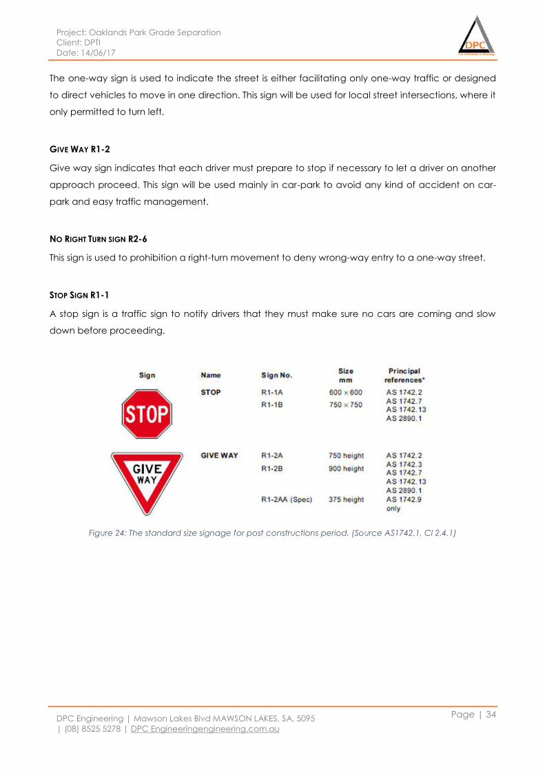
Project: Oaklands Park Grade Separation
Client: DPTI
Date: 14/06/17
DPC Engineering | Mawson Lakes Blvd MAWSON LAKES, SA, 5095
| (08) 8525 5278 | DPC Engineeringengineering.com.au
Page | 34
The one-way sign is used to indicate the street is either facilitating only one-way traffic or designed
to direct vehicles to move in one direction. This sign will be used for local street intersections, where it
only permitted to turn left.
GIVE WAY R1-2
Give way sign indicates that each driver must prepare to stop if necessary to let a driver on another
approach proceed. This sign will be used mainly in car-park to avoid any kind of accident on car-
park and easy traffic management.
NO RIGHT TURN SIGN R2-6
This sign is used to prohibition a right-turn movement to deny wrong-way entry to a one-way street.
STOP SIGN R1-1
A stop sign is a traffic sign to notify drivers that they must make sure no cars are coming and slow
down before proceeding.
Figure 24: The standard size signage for post constructions period. (Source AS1742.1, Cl 2.4.1)
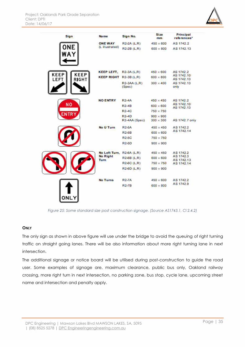
Project: Oaklands Park Grade Separation
Client: DPTI
Date: 14/06/17
DPC Engineering | Mawson Lakes Blvd MAWSON LAKES, SA, 5095
| (08) 8525 5278 | DPC Engineeringengineering.com.au
Page | 35
Figure 25: Some standard size post construction signage. (Source AS1743.1, Cl 2.4.2)
ONLY
The only sign as shown in above figure will use under the bridge to avoid the queuing of right turning
traffic on straight going lanes. There will be also information about more right turning lane in next
intersection.
The additional signage or notice board will be utilised during post-construction to guide the road
user. Some examples of signage are, maximum clearance, public bus only, Oakland railway
crossing, more right turn in next intersection, no parking zone, bus stop, cycle lane, upcoming street
name and intersection and penalty apply.
Project: Oaklands Park Grade Separation
Client: DPTI
Date: 14/06/17
DPC Engineering | Mawson Lakes Blvd MAWSON LAKES, SA, 5095
| (08) 8525 5278 | DPC Engineeringengineering.com.au
Page | 36
2.4.8 Traffic light
After upgrading the Morphett Road and Diagonal Road intersection, redesign and relocation of
traffic lights are required. According to AS 2144, the nominal diameter of the exposed faces of the
lens or apparent light source shall be either 200mm or 300mm. Lanterns shall be provided with
facilities to enable them to be effectively secured between two parallel lantern mounting straps. The
spacing between two straps can be specified in the following figure. Unless otherwise specified,
each lantern shall be supplied with two mounting straps having dimension L as follows:
For 200mm diameter vehicular lanterns, L=150mm.
For 300mm diameter vehicular lanterns, and for pedestrian and two-aspect bicycle lanterns,
L=260mm
Figure 26: Standard dimensions of traffic light (Source AS2144, Cl 4.1.4)
According to AS 2144, the size and shape of a vehicular lantern shall be such that:
Two lanterns can be mounted side-by-side in accordance with the arrangement illustrated in
figure 27;
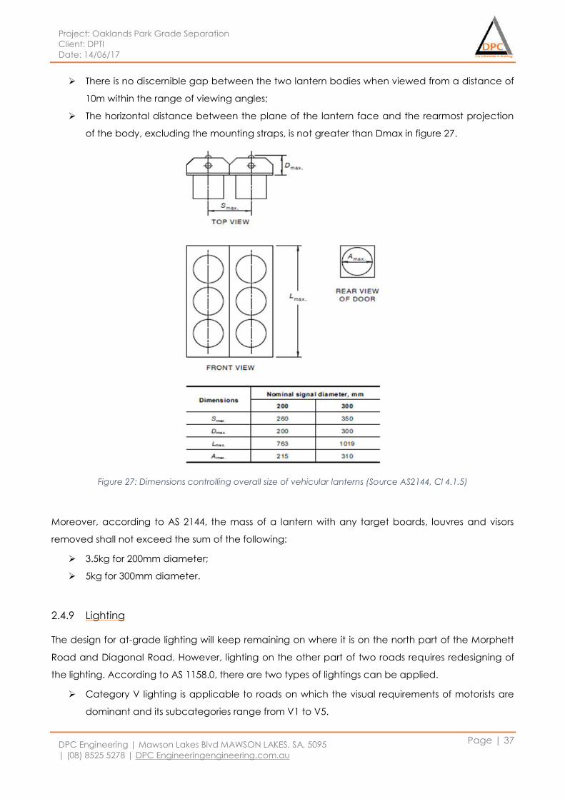
Project: Oaklands Park Grade Separation
Client: DPTI
Date: 14/06/17
DPC Engineering | Mawson Lakes Blvd MAWSON LAKES, SA, 5095
| (08) 8525 5278 | DPC Engineeringengineering.com.au
Page | 37
There is no discernible gap between the two lantern bodies when viewed from a distance of
10m within the range of viewing angles;
The horizontal distance between the plane of the lantern face and the rearmost projection
of the body, excluding the mounting straps, is not greater than Dmax in figure 27.
Figure 27: Dimensions controlling overall size of vehicular lanterns (Source AS2144, Cl 4.1.5)
Moreover, according to AS 2144, the mass of a lantern with any target boards, louvres and visors
removed shall not exceed the sum of the following:
3.5kg for 200mm diameter;
5kg for 300mm diameter.
2.4.9 Lighting
The design for at-grade lighting will keep remaining on where it is on the north part of the Morphett
Road and Diagonal Road. However, lighting on the other part of two roads requires redesigning of
the lighting. According to AS 1158.0, there are two types of lightings can be applied.
Category V lighting is applicable to roads on which the visual requirements of motorists are
dominant and its subcategories range from V1 to V5.
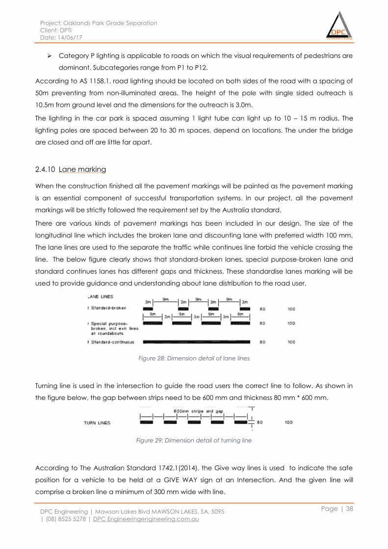
Project: Oaklands Park Grade Separation
Client: DPTI
Date: 14/06/17
DPC Engineering | Mawson Lakes Blvd MAWSON LAKES, SA, 5095
| (08) 8525 5278 | DPC Engineeringengineering.com.au
Page | 38
Category P lighting is applicable to roads on which the visual requirements of pedestrians are
dominant. Subcategories range from P1 to P12.
According to AS 1158.1, road lighting should be located on both sides of the road with a spacing of
50m preventing from non-illuminated areas. The height of the pole with single sided outreach is
10.5m from ground level and the dimensions for the outreach is 3.0m.
The lighting in the car park is spaced assuming 1 light tube can light up to 10 – 15 m radius. The
lighting poles are spaced between 20 to 30 m spaces, depend on locations. The under the bridge
are closed and off are little far apart.
2.4.10 Lane marking
When the construction finished all the pavement markings will be painted as the pavement marking
is an essential component of successful transportation systems. In our project, all the pavement
markings will be strictly followed the requirement set by the Australia standard.
There are various kinds of pavement markings has been included in our design. The size of the
longitudinal line which includes the broken lane and discounting lane with preferred width 100 mm.
The lane lines are used to the separate the traffic while continues line forbid the vehicle crossing the
line. The below figure clearly shows that standard-broken lanes, special purpose-broken lane and
standard continues lanes has different gaps and thickness. These standardise lanes marking will be
used to provide guidance and understanding about lane distribution to the road user.
Figure 28: Dimension detail of lane lines
Turning line is used in the intersection to guide the road users the correct line to follow. As shown in
the figure below, the gap between strips need to be 600 mm and thickness 80 mm * 600 mm.
Figure 29: Dimension detail of turning line
According to The Australian Standard 1742.1(2014), the Give way lines is used to indicate the safe
position for a vehicle to be held at a GIVE WAY sign at an Intersection. And the given line will
comprise a broken line a minimum of 300 mm wide with line.

Project: Oaklands Park Grade Separation
Client: DPTI
Date: 14/06/17
DPC Engineering | Mawson Lakes Blvd MAWSON LAKES, SA, 5095
| (08) 8525 5278 | DPC Engineeringengineering.com.au
Page | 39
Segments 600 mm long separated by 600 mm gaps. It shall be placed in a similar position to that
specified for a stop line.
The outline marking of splays, medians, islands, safety bars and shoulders shall be a single
Continuous line. The detailed dimension is shown below.
Figure 30: Dimension detail of outline marking
According to Australian Standard 1742.1(2014),Stop lines is a continuous line that shall be marked
across the traffic lanes approaching a Traffic control device at which traffic is required to stop. It
shall be a minimum of 300 mm wide at a STOP sign and shall be parallel to the line of the intersecting
road.
2.4.11 Risk assessment
Risk assessment is a significant method in any sectors to identify situations that may cause damage
to, particularly people. There are few steps that can be undertaken to assess a risk in any workplace.
1. Identify the hazards
Any situation can be identified as a hazard if anything that could hurt a human being.
2. Assess the risk
Assessing the risks that have identified enables a judgement of how likely the hazard would
take place and how extent can it harm a human being.
3. Control the risks
There are few ways can be used to control the risks
Elimination
Substitution
Isolation
Safeguards
PPE Usage
4. Reviewing risk controls
The risk controlling principles has to be monitored throughout the process to ensure the
control management to be effective.
The risk assessment methods that have been listed above will enable transport department to
manage the construction and traffic to take place with minimal or eliminating risks occurrence
throughout the project.
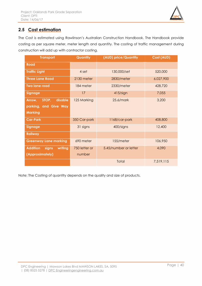
Project: Oaklands Park Grade Separation
Client: DPTI
Date: 14/06/17
DPC Engineering | Mawson Lakes Blvd MAWSON LAKES, SA, 5095
| (08) 8525 5278 | DPC Engineeringengineering.com.au
Page | 40
2.5 Cost estimation
The Cost is estimated using Rawlinson’s Australian Construction Handbook. The Handbook provide
costing as per square meter, meter length and quantity. The costing of traffic management during
construction will add up with contractor costing.
Transport Quantity (AUD) price/Quantity Cost (AUD)
Road
Traffic Light 4 set 130,000/set 520,000
Three Lane Road 2130 meter 2830/meter 6,027,900
Two lane road 184 meter 2330/meter 428,720
Signage 17 415/sign 7,055
Arrow, STOP, disable
parking, and Give Way
Marking
125 Marking 25.6/mark 3,200
Car-Park 350 Car-park 1168/car-park 408,800
Signage 31 signs 400/signs 12,400
Railway
Greenway Lane marking 690 meter 155/meter 106,950
Addition signs writing
(Approximately)
750 letter or
number
5.45/number or letter 4,090
Total 7,519,115
Note: The Costing of quantity depends on the quality and size of products.
Project: Oaklands Park Grade Separation
Client: DPTI
Date: 14/06/17
DPC Engineering | Mawson Lakes Blvd MAWSON LAKES, SA, 5095
| (08) 8525 5278 | DPC Engineeringengineering.com.au
Page | 41
2.6 Recommendation for Construction
The traffics during constructions period must be diverted to another road. The massive amount of
traffic diversion on another road for long period can cause daily delays as per the capacity of the
road. The impact of construction on traffic management can be minimised and maintain. There are
some recommendations to minimise those impacts:
The construction start from each end of railway line; this will have minimum impact on road and
traffic can flow easily. At the same time, demolishing process should start which will consequence
the road closure on one side but another side will be free so one lane traffic flow can be operated.
The road construction also needs to start from each end and side of the road. While upgrading one
side of the road, another side will be free, where we can allow traffic flow. The next possible options
are to start construction from Prunus Street till railway intersections and after its completion, the
Morphett Road constructions can begin, by doing so, one road will be free to carry the maximum
amount of traffic volume and minimise the traffic diversion period.
The construction at railway crossing (Railway Bridge and road) should be held at the same period as
it is the main point and during these constructions period, most traffic needs to be diverted to
another road. The construction on this point should be either at the beginning or last of construction
period for easy traffic management as it discussed above.
Project: Oaklands Park Grade Separation
Client: DPTI
Date: 14/06/17
DPC Engineering | Mawson Lakes Blvd MAWSON LAKES, SA, 5095
| (08) 8525 5278 | DPC Engineeringengineering.com.au
Page | 42
2.7 Reference
1. Australian Standard 1742.1-2014. 2014; Manual of uniform traffic control device – General
introduction and index of signs, Committee MS-012, Road Signs and Traffic
2. Australian Standard 1744-2015. 2015; Standard alphabets for road signs, Committee MS-012,
Road Signs and Traffic.
3. Australian Standard 2144-2014. 2014; Traffic signal lanterns (p. 154), Committee MS-012, Road
Signs and Traffic.
4. Australian Standard 2890.1-2009. 2009; Parking facilities – Off-street car parking. Committee
MS-012, Road Signs and Traffic.
5. Australian Standard 2890.6-2009. 2009; Parking facilities – Off-street car parking for people
with disabilities. Committee MS-012, Road Signs and Traffic.
6. Austroads, Sydney 2016, Guide to Road Design Part 3: Geometric Design.
7. City of Marion, 2016, Oaklands Crossing Survey Findings
8. Department of Transport, Energy and Infrastructure (DTEI) 2011, Traffic Analysis Report, South
Australia.
9. DPTI, 2011, Oakland’s Park Road Capacity Improvements Planning Investigations in 2010 &
2011.
10. DPTI, 2015, Oaklands Park Ultimate and Interim Options Review.
11. DPTI, 2012, Oaklands Park Grade Separation Planning Study.
12. DPTI, 2013, Public Transport Services Technical Standard Part 129003.
13. Kuldeep, Z, & Rob. T, 2013, Public Transport Services Engineering Management System
Technical Standard part 129003, AR-PW-PM-SPE-00129003 (D062).
14. Rawlinsons Australian Construction Handbook 2016, 34th edn, Rawlinsons Publishing, Perth,
Western Australia, pp. 679-683.
Project: Oaklands Park Grade Separation
Client: DPTI
Date: 14/06/17
DPC Engineering | Mawson Lakes Blvd MAWSON LAKES, SA, 5095
| (08) 8525 5278 | DPC Engineeringengineering.com.au
Page | 43
STRUCTURES
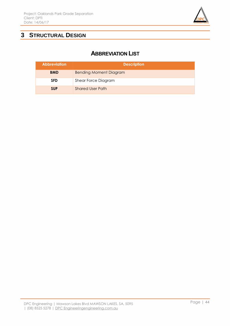
Project: Oaklands Park Grade Separation
Client: DPTI
Date: 14/06/17
DPC Engineering | Mawson Lakes Blvd MAWSON LAKES, SA, 5095
| (08) 8525 5278 | DPC Engineeringengineering.com.au
Page | 44
3 STRUCTURAL DESIGN
ABBREVIATION LIST
Abbreviation Description
BMD Bending Moment Diagram
SFD Shear Force Diagram
SUP Shared User Path
Project: Oaklands Park Grade Separation
Client: DPTI
Date: 14/06/17
DPC Engineering | Mawson Lakes Blvd MAWSON LAKES, SA, 5095
| (08) 8525 5278 | DPC Engineeringengineering.com.au
Page | 45
3.1 Introduction
The Structures department has designed a Rail Overpass for Oakland Parks Grade Separation. The
overall structure was divided into five packages to assist with the completion of the design. The
packages designed below are designed In accordance with the Australian Standards and require
guidelines. To ensure the durability and serviceability of the structure, future considerations of up to
100years have been taken. Various assumptions have also been taken due to the complexity and
the time constraints of the overall project. Majority of the loads and calculations for the Rail Bridge
was using SpaceGass whereas the Rail Platform was designed using hand calculations.
Package 1 – Rail Bridge, consists of overall dead and live loads of the bridge. The package was
further divided into dead and live load elements which include; Rail Bridge Deck, Ballast, Super-Tee,
Parapets, Head stock and columns. Pile caps are used for the foundation for this structure.
Package 2 – Rail Platform, designed as independent structure from the bridge itself. The Platform is a
self-supported structure and the foundation of the structure is designed a footing. Two symmetrical
platform are created on either sides of the Bridge. This package includes slabs, beams, column and
services.
Package 3 – Rail Platform Access Structures, for this package a lift shaft is designed. This structure
supports the hydraulic elevator which is installed for pedestrian access.
Package 4 – Centre Median Barriers, these are located under the bridge to protect the columns
which are placed directly in the centre of the road. This particular structure was not manually
designed, but an appropriate barrier was selected using the Australian Standards and given criteria.
Package 5 – Electrification Structures, includes the electrical components for the structure such as
Insulators, overhead wiring, pantograph, cantilever arms and masts.
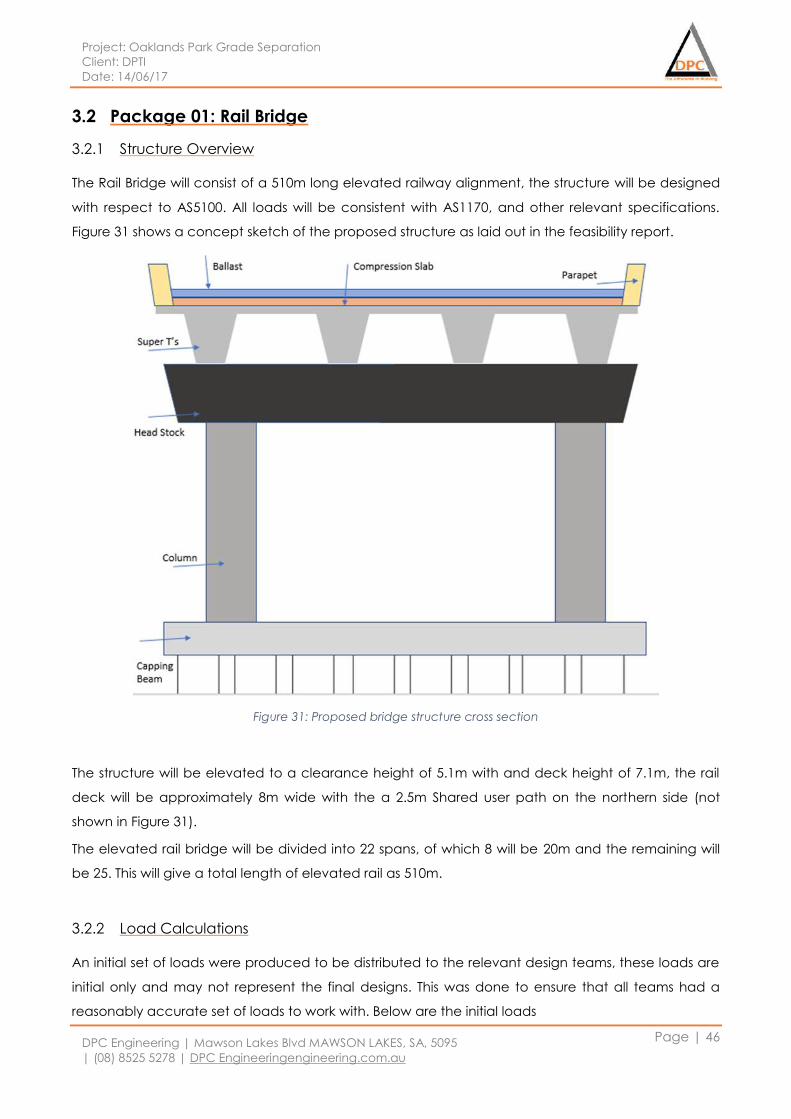
Project: Oaklands Park Grade Separation
Client: DPTI
Date: 14/06/17
DPC Engineering | Mawson Lakes Blvd MAWSON LAKES, SA, 5095
| (08) 8525 5278 | DPC Engineeringengineering.com.au
Page | 46
3.2 Package 01: Rail Bridge
3.2.1 Structure Overview
The Rail Bridge will consist of a 510m long elevated railway alignment, the structure will be designed
with respect to AS5100. All loads will be consistent with AS1170, and other relevant specifications.
Figure 31 shows a concept sketch of the proposed structure as laid out in the feasibility report.
Figure 31: Proposed bridge structure cross section
The structure will be elevated to a clearance height of 5.1m with and deck height of 7.1m, the rail
deck will be approximately 8m wide with the a 2.5m Shared user path on the northern side (not
shown in Figure 31).
The elevated rail bridge will be divided into 22 spans, of which 8 will be 20m and the remaining will
be 25. This will give a total length of elevated rail as 510m.
3.2.2 Load Calculations
An initial set of loads were produced to be distributed to the relevant design teams, these loads are
initial only and may not represent the final designs. This was done to ensure that all teams had a
reasonably accurate set of loads to work with. Below are the initial loads
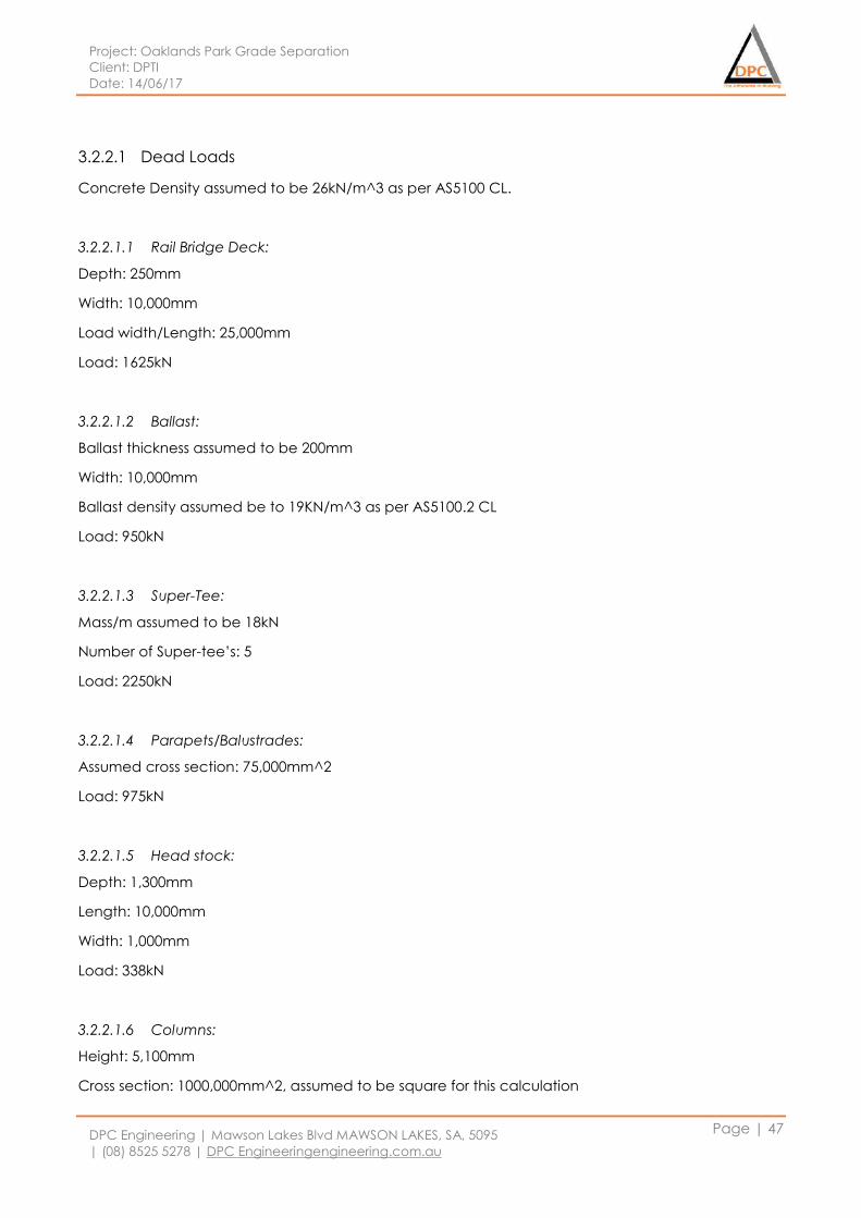
Project: Oaklands Park Grade Separation
Client: DPTI
Date: 14/06/17
DPC Engineering | Mawson Lakes Blvd MAWSON LAKES, SA, 5095
| (08) 8525 5278 | DPC Engineeringengineering.com.au
Page | 47
3.2.2.1 Dead Loads
Concrete Density assumed to be 26kN/m^3 as per AS5100 CL.
3.2.2.1.1 Rail Bridge Deck:
Depth: 250mm
Width: 10,000mm
Load width/Length: 25,000mm
Load: 1625kN
3.2.2.1.2 Ballast:
Ballast thickness assumed to be 200mm
Width: 10,000mm
Ballast density assumed be to 19KN/m^3 as per AS5100.2 CL
Load: 950kN
3.2.2.1.3 Super-Tee:
Mass/m assumed to be 18kN
Number of Super-tee’s: 5
Load: 2250kN
3.2.2.1.4 Parapets/Balustrades:
Assumed cross section: 75,000mm^2
Load: 975kN
3.2.2.1.5 Head stock:
Depth: 1,300mm
Length: 10,000mm
Width: 1,000mm
Load: 338kN
3.2.2.1.6 Columns:
Height: 5,100mm
Cross section: 1000,000mm^2, assumed to be square for this calculation
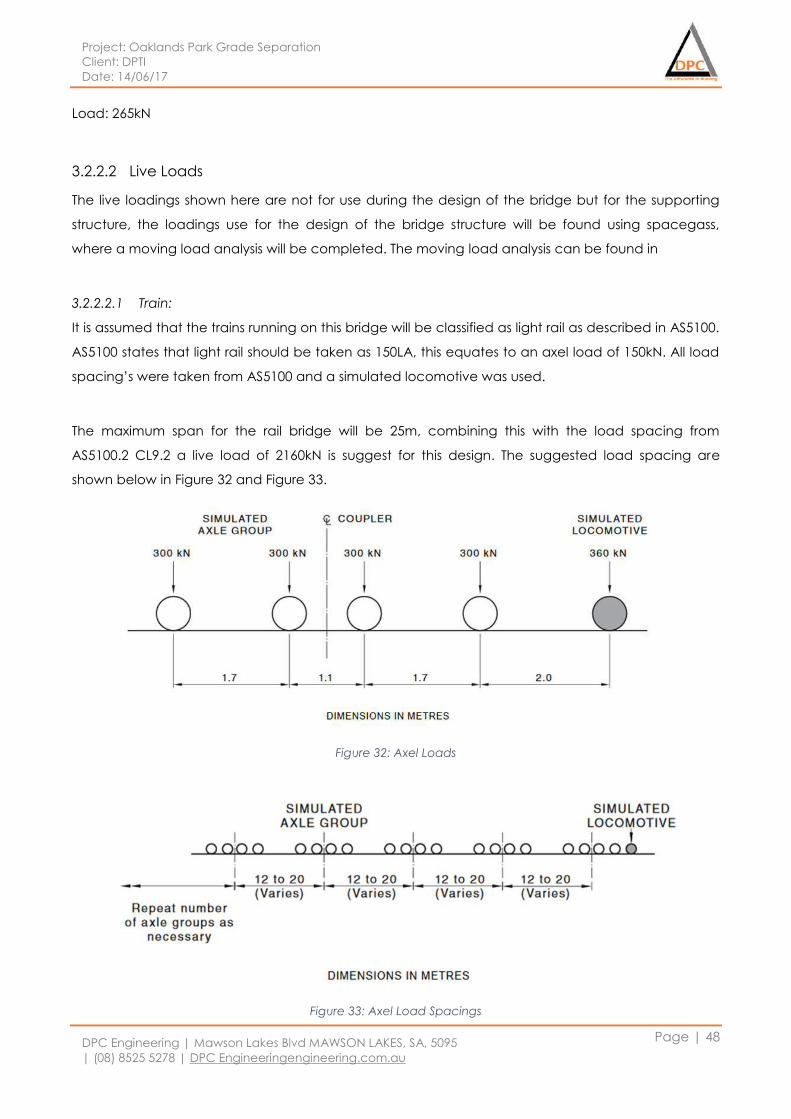
Project: Oaklands Park Grade Separation
Client: DPTI
Date: 14/06/17
DPC Engineering | Mawson Lakes Blvd MAWSON LAKES, SA, 5095
| (08) 8525 5278 | DPC Engineeringengineering.com.au
Page | 48
Load: 265kN
3.2.2.2 Live Loads
The live loadings shown here are not for use during the design of the bridge but for the supporting
structure, the loadings use for the design of the bridge structure will be found using spacegass,
where a moving load analysis will be completed. The moving load analysis can be found in
3.2.2.2.1 Train:
It is assumed that the trains running on this bridge will be classified as light rail as described in AS5100.
AS5100 states that light rail should be taken as 150LA, this equates to an axel load of 150kN. All load
spacing’s were taken from AS5100 and a simulated locomotive was used.
The maximum span for the rail bridge will be 25m, combining this with the load spacing from
AS5100.2 CL9.2 a live load of 2160kN is suggest for this design. The suggested load spacing are
shown below in Figure 32 and Figure 33.
Figure 32: Axel Loads
Figure 33: Axel Load Spacings

Project: Oaklands Park Grade Separation
Client: DPTI
Date: 14/06/17
DPC Engineering | Mawson Lakes Blvd MAWSON LAKES, SA, 5095
| (08) 8525 5278 | DPC Engineeringengineering.com.au
Page | 49
3.2.2.2.2 1Braking/Traction Loads:
AS5100 Mentions, breaking/Traction loads, it is assumed that these are non-critical and have not
been taken into account in any of the design calculations. They are shown below for completeness
but not used in the final designs.
3.2.2.2.3 Collision Loads:
Collision loads have been taken from AS5100.2 CL 10.2. It will be assumed that the entirety of these
loads are taken by the crash barriers installed around the columns.
3.2.2.2.4 Wind Loads:
Wind loads have been calculated on the following parameters:
Adelaide Region A1
Ultimate Wind speed v2000: 48m/s
SLS With permanent effects v20: 37m/s
Height: assumed 10m (conservative)
Terrain Cat: 3
Mz,cat: 0.83
Md: 1
Ms: 1
Mt: 1
Vdes, ultimate: 40m/s equating to 0.96kPa
Loaded area: 62.5m^2
Cfig: 0.4 assumed façade to be hemispherical table F1 AS1170.2
Load 25m span: 24kN per 25m span
Total Load: 460kN
3.2.3 Considerations
3.2.3.1 Fatigue:
The fatigue of the bridge should be considered due to the cyclic live loading from trains, however
due to the nature of the project these calculation will be assumed to be non-critical and that the
bridge will not experience fatigue.
3.2.3.2 Thermal Expansion
AS5100.2 TABLE 18.2(A) gives the max and min air temperatures for shade shown below in Figure 34.
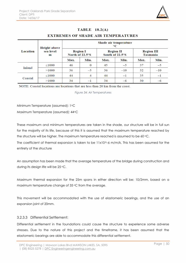
Project: Oaklands Park Grade Separation
Client: DPTI
Date: 14/06/17
DPC Engineering | Mawson Lakes Blvd MAWSON LAKES, SA, 5095
| (08) 8525 5278 | DPC Engineeringengineering.com.au
Page | 50
Figure 34: Air Temperatures
Minimum Temperature (assumed): 1oC
Maximum Temperature (assumed): 44oC
These maximum and minimum temperatures are taken in the shade, our structure will be in full sun
for the majority of its life, because of this it is assumed that the maximum temperature reached by
the structure will be higher. The maximum temperature reached is assumed to be 60 oC.
The coefficient of thermal expansion is taken to be 11x10^-6 m/m/k. This has been assumed for the
entirety of the structure
An assumption has been made that the average temperature of the bridge during construction and
during its design life will be 25 oC.
Maximum thermal expansion for the 25m spans in either direction will be: 10/2mm, based on a
maximum temperature change of 35 oC from the average.
This movement will be accommodated with the use of elastomeric bearings, and the use of an
expansion joint of 20mm.
3.2.3.3 Differential Settlement:
Differential settlement in the foundations could cause the structure to experience some adverse
stresses. Due to the nature of this project and the timeframe, it has been assumed that the
elastomeric bearings are able to accommodate this differential settlement.
Project: Oaklands Park Grade Separation
Client: DPTI
Date: 14/06/17
DPC Engineering | Mawson Lakes Blvd MAWSON LAKES, SA, 5095
| (08) 8525 5278 | DPC Engineeringengineering.com.au
Page | 51
3.2.3.4 Earth Quake Loadings:
The structure is located in relative proximity to a fault line, however due to the nature of the project it
has been assumed that any loadings resulting from an earthquake are non-critical.
3.2.3.5 Vibration and Noise
As noted by the environmental team, the noise and vibration of the track during operation may
have adverse effects on the surrounding businesses and residents due to the elevated nature of the
rail line. An architectural screen will be attached to the bridge structure along its length, it is
assumed that this will damp any noise made by the trains to an acceptable level. Vibrations will be
damped through the previously mentions elastomeric bearings. An acoustic resonance evaluation
of the structure will not be completed, as it is assumed that these measures will have the desired
effects.
3.2.3.6 Approach Slabs
It has been assumed that any lateral loads transferred to the superstructure during the approach of
any rail traffic will be non-critical and shall thus be ignored for this design.
3.2.3.7 Durability and serviceability
3.2.3.7.1 Superstructure
The superstructure has been designed in accordance of the durability requirements of AS5100,
requirements as follows:
Design Life: 100 years
Exposure classification: B1 (as5100)
Concrete Strength
o 40mPa (in suite elements),
o 65mPa (super-tee)
Concrete Cover
o In suite Elements – 40mm
o Precast Elements – 40mm
The replacement of elements such as elastomeric bearings should be considered and designed,
however it is assumed that there will be enough space for jacking points to be installed and that the
structure is able to withstand these loads.
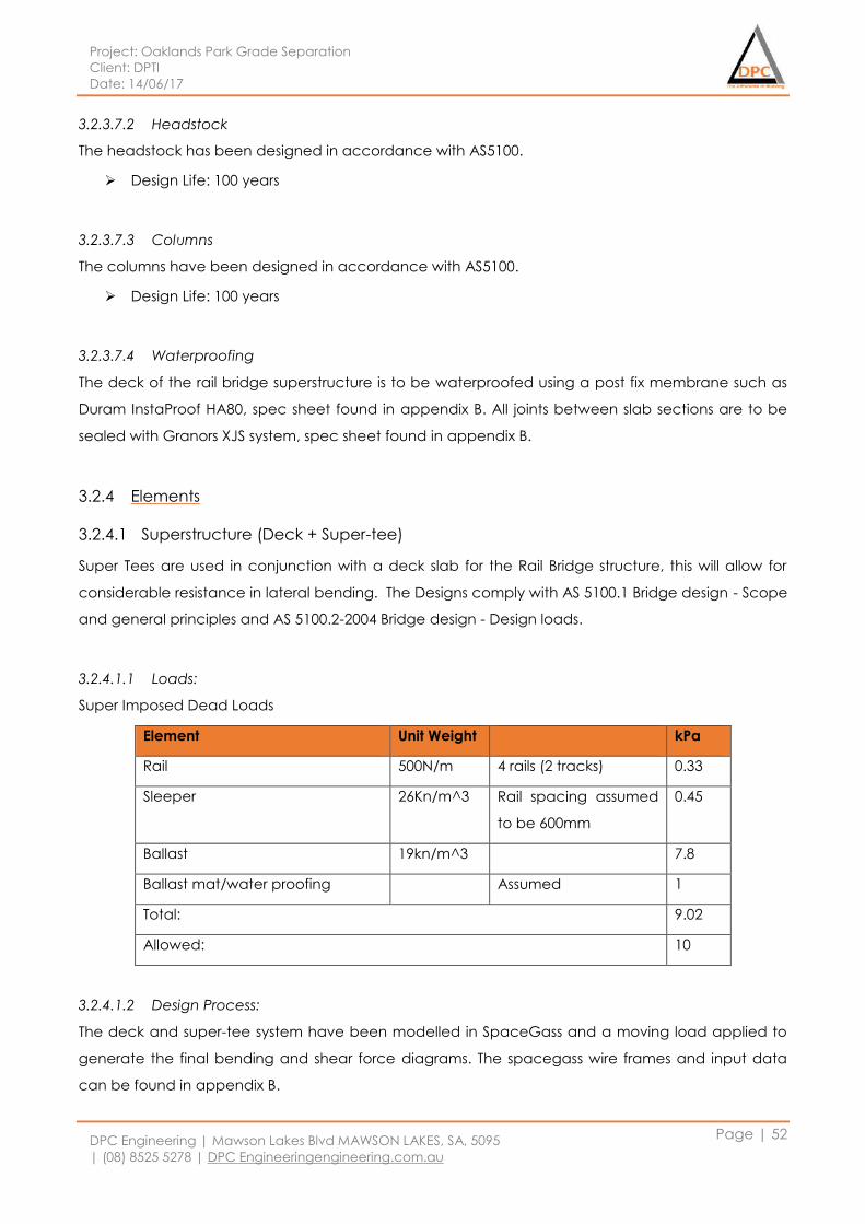
Project: Oaklands Park Grade Separation
Client: DPTI
Date: 14/06/17
DPC Engineering | Mawson Lakes Blvd MAWSON LAKES, SA, 5095
| (08) 8525 5278 | DPC Engineeringengineering.com.au
Page | 52
3.2.3.7.2 Headstock
The headstock has been designed in accordance with AS5100.
Design Life: 100 years
3.2.3.7.3 Columns
The columns have been designed in accordance with AS5100.
Design Life: 100 years
3.2.3.7.4 Waterproofing
The deck of the rail bridge superstructure is to be waterproofed using a post fix membrane such as
Duram InstaProof HA80, spec sheet found in appendix B. All joints between slab sections are to be
sealed with Granors XJS system, spec sheet found in appendix B.
3.2.4 Elements
3.2.4.1 Superstructure (Deck + Super-tee)
Super Tees are used in conjunction with a deck slab for the Rail Bridge structure, this will allow for
considerable resistance in lateral bending. The Designs comply with AS 5100.1 Bridge design - Scope
and general principles and AS 5100.2-2004 Bridge design - Design loads.
3.2.4.1.1 Loads:
Super Imposed Dead Loads
Element Unit Weight kPa
Rail 500N/m 4 rails (2 tracks) 0.33
Sleeper 26Kn/m^3 Rail spacing assumed
to be 600mm
0.45
Ballast 19kn/m^3 7.8
Ballast mat/water proofing Assumed 1
Total: 9.02
Allowed: 10
3.2.4.1.2 Design Process:
The deck and super-tee system have been modelled in SpaceGass and a moving load applied to
generate the final bending and shear force diagrams. The spacegass wire frames and input data
can be found in appendix B.
Project: Oaklands Park Grade Separation
Client: DPTI
Date: 14/06/17
DPC Engineering | Mawson Lakes Blvd MAWSON LAKES, SA, 5095
| (08) 8525 5278 | DPC Engineeringengineering.com.au
Page | 53
1. Input Parameters
Dead Loads:
Ballast: as shown in section 3.2.2.1.2
Deck: Self weight used in Spacegass (concrete density of 26kN/m^3)
Super-Tee: Self weight used in Spacegass (concrete density of 26kN/m^3)
Live Loads:
Train loads (moving): the live loads were taken from AS5100.2 CL9.2 as shown in Figure 32 and
Figure 33 and assumed speed of 50km/hr (13.89m/s).
Pedestrians: The pedestrian loads are taken from AS5100.2 Cl8.2, 5kPa was used and it had
been assumed there will be no access for a vehicle of any nature.
SpaceGass parameters:
1 train moving in each direction, 2 carriage
150 load cases evaluated, 0.1 second intervals
A train speed of 15m/s
150LA rail traffic as per as5100.2 light rail
2. Results:
The loads were input into spacegass and load cases applied, the finial critical load cases were
taken using the envelope function and thus used in the final designs. Appendix B shows the
calculations, these were completed in an excel spreadsheet of which can be supplied.
3.2.4.1.3 Final Design:
The final design for the rail bridge superstructure is 5 t5 super-s’s, 4 with a flange width of 2000mm
(type 1) and 1 (supporting the SUP) with a 2500mm flange width (type 2). The super-t’s were
designed for a 25m span, however the same design will be carried forward for the 20m spans,
drawing DPC-Structures-Package 01-Rail Bridge-Super-Tee-008-rev shows the super-t’s and drawing
DPC-Structures-Package 01-Rail Bridge-Deck Reinforcement-009-rev shows the deck reinforcement.
The deck will be reinforced with N16 bars at 100 cts on the top and bottom.
3.2.4.2 Headstock
The Headstock is designed to transfer all loads from the rail bridge deck through to the columns and
thus to the footings. The headstock will experience a sustained dead load from the rail bridge and
all of it ancillaries, it will also experience the live loadings from the Rail traffic.
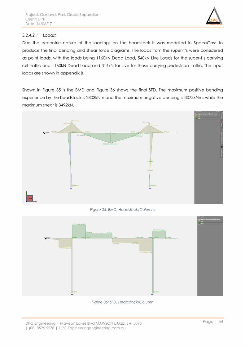
Project: Oaklands Park Grade Separation
Client: DPTI
Date: 14/06/17
DPC Engineering | Mawson Lakes Blvd MAWSON LAKES, SA, 5095
| (08) 8525 5278 | DPC Engineeringengineering.com.au
Page | 54
3.2.4.2.1 Loads:
Due the eccentric nature of the loadings on the headstock it was modelled in SpaceGass to
produce the final bending and shear force diagrams. The loads from the super-t’s were considered
as point loads, with the loads being 1160kN Dead Load, 540kN Live Loads for the super-t’s carrying
rail traffic and 1160kN Dead Load and 314kN for Live for those carrying pedestrian traffic. The input
loads are shown in appendix B.
Shown in Figure 35 is the BMD and Figure 36 shows the final SFD. The maximum positive bending
experience by the headstock is 2803kNm and the maximum negative bending is 3073kNm, while the
maximum shear is 3492kN.
Figure 35: BMD, Headstock/Columns
Figure 36: SFD, Headstock/Column
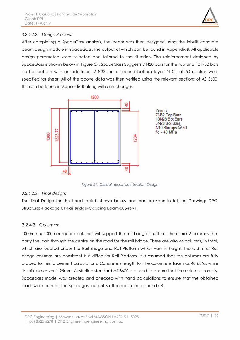
Project: Oaklands Park Grade Separation
Client: DPTI
Date: 14/06/17
DPC Engineering | Mawson Lakes Blvd MAWSON LAKES, SA, 5095
| (08) 8525 5278 | DPC Engineeringengineering.com.au
Page | 55
3.2.4.2.2 Design Process:
After completing a SpaceGass analysis, the beam was then designed using the inbuilt concrete
beam design module in SpaceGass. The output of which can be found in Appendix B. All applicable
design parameters were selected and tailored to the situation. The reinforcement designed by
SpaceGass is Shown below in Figure 37. SpaceGass Suggests 9 N28 bars for the top and 10 N32 bars
on the bottom with an additional 2 N32’s in a second bottom layer. N10’s at 50 centres were
specified for shear. All of the above data was then verified using the relevant sections of AS 3600,
this can be found in Appendix B along with any changes.
Figure 37: Critical headstock Section Design
3.2.4.2.3 Final design:
The final Design for the headstock is shown below and can be seen in full, on Drawing: DPC-
Structures-Package 01-Rail Bridge-Capping Beam-005-rev1.
3.2.4.3 Columns:
1000mm x 1000mm square columns will support the rail bridge structure, there are 2 columns that
carry the load through the centre on the road for the rail bridge. There are also 44 columns, in total,
which are located under the Rail Bridge and Rail Platform which vary in height, the width for Rail
bridge columns are consistent but differs for Rail Platform. It is assumed that the columns are fully
braced for reinforcement calculations. Concrete strength for the columns is taken as 40 MPa, while
its suitable cover is 25mm. Australian standard AS 3600 are used to ensure that the columns comply.
Spacegass model was created and checked with hand calculations to ensure that the obtained
loads were correct. The Spacegass output is attached in the appendix B.
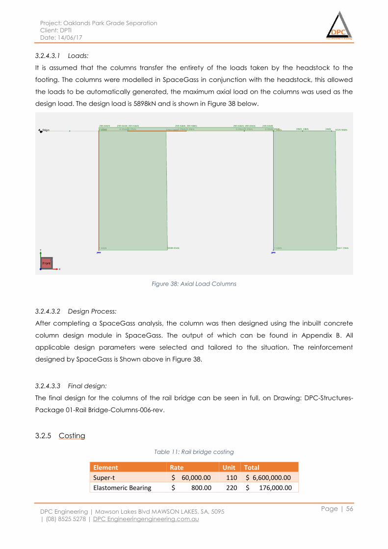
Project: Oaklands Park Grade Separation
Client: DPTI
Date: 14/06/17
DPC Engineering | Mawson Lakes Blvd MAWSON LAKES, SA, 5095
| (08) 8525 5278 | DPC Engineeringengineering.com.au
Page | 56
3.2.4.3.1 Loads:
It is assumed that the columns transfer the entirety of the loads taken by the headstock to the
footing. The columns were modelled in SpaceGass in conjunction with the headstock, this allowed
the loads to be automatically generated, the maximum axial load on the columns was used as the
design load. The design load is 5898kN and is shown in Figure 38 below.
Figure 38: Axial Load Columns
3.2.4.3.2 Design Process:
After completing a SpaceGass analysis, the column was then designed using the inbuilt concrete
column design module in SpaceGass. The output of which can be found in Appendix B. All
applicable design parameters were selected and tailored to the situation. The reinforcement
designed by SpaceGass is Shown above in Figure 38.
3.2.4.3.3 Final design:
The final design for the columns of the rail bridge can be seen in full, on Drawing: DPC-Structures-
Package 01-Rail Bridge-Columns-006-rev.
3.2.5 Costing
Table 11: Rail bridge costing
Element Rate Unit Total
Super-t $ 60,000.00 110 $ 6,600,000.00
Elastomeric Bearing $ 800.00 220 $ 176,000.00
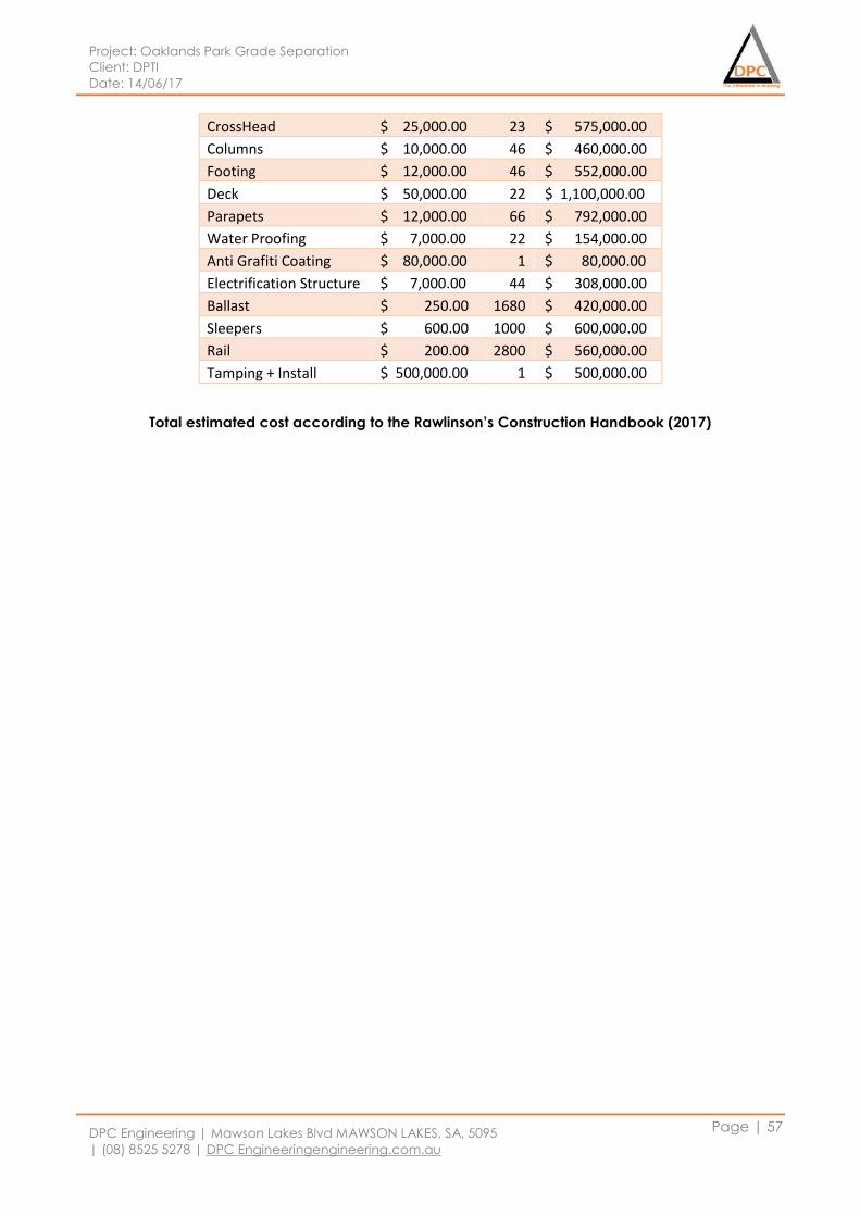
Project: Oaklands Park Grade Separation
Client: DPTI
Date: 14/06/17
DPC Engineering | Mawson Lakes Blvd MAWSON LAKES, SA, 5095
| (08) 8525 5278 | DPC Engineeringengineering.com.au
Page | 57
CrossHead $ 25,000.00 23 $ 575,000.00
Columns $ 10,000.00 46 $ 460,000.00
Footing $ 12,000.00 46 $ 552,000.00
Deck $ 50,000.00 22 $ 1,100,000.00
Parapets $ 12,000.00 66 $ 792,000.00
Water Proofing $ 7,000.00 22 $ 154,000.00
Anti Grafiti Coating $ 80,000.00 1 $ 80,000.00
Electrification Structure $ 7,000.00 44 $ 308,000.00
Ballast $ 250.00 1680 $ 420,000.00
Sleepers $ 600.00 1000 $ 600,000.00
Rail $ 200.00 2800 $ 560,000.00
Tamping + Install $ 500,000.00 1 $ 500,000.00
Total estimated cost according to the Rawlinson’s Construction Handbook (2017)
Project: Oaklands Park Grade Separation
Client: DPTI
Date: 14/06/17
DPC Engineering | Mawson Lakes Blvd MAWSON LAKES, SA, 5095
| (08) 8525 5278 | DPC Engineeringengineering.com.au
Page | 58
3.3 Package 02: Rail Platform
Railway platform will be an elevated structure with length, width and height as 160 m, 5m and 8.5
meters respectively. According to the transport team at DPC engineering, a railway platform will be
provided for each direction of the bridge. Both the platforms will have same design as it is assumed
that the loads acting on these platforms will be similar. Railway Platform will be constructed entirely
from reinforced concrete. Platform will be supported by square columns with span of 10 meters at
long side. Band beams with depth of 0.8 meters and width of 1 meter will support slab for its long
span. All the design elements are designed with a capacity to accommodate future upgrade in the
structure like double storied platform for two storied train. Railway Platform will be a self-supported
structure, independent from Railway Bridge. It is assumed that the structure will have sufficient lateral
bracing provided by lift shaft.
3.3.1 Load Calculations
3.3.1.1 Dead Loads
3.3.1.1.1 Slab:
Slab Depth-225 mm
Slab Width-5000 mm
Load Width- 10,000 mm
Load- 67.5 KN
3.3.1.1.2 Beam:
Beam Depth- 800 mm
Beam Width- 1000 mm
Load Width- 2500 mm
Load- 69 KN
3.3.1.1.3 Columns:
Column Height- 7,700 mm
Column Cross section- 500mm x 500mm
Load- 46.2 KN
3.3.1.1.4 Services
It is assumed that the structure will experience dead load from services equal to 1 KPa
Project: Oaklands Park Grade Separation
Client: DPTI
Date: 14/06/17
DPC Engineering | Mawson Lakes Blvd MAWSON LAKES, SA, 5095
| (08) 8525 5278 | DPC Engineeringengineering.com.au
Page | 59
3.3.1.2 Live Loads
The Platform will mainly be subjected to live loads due to passengers. According to AS 1170.1,
suitable live load for this classification is 5 KPa.
3.3.2 Considerations
3.3.2.1 Thermal Expansion
The coefficient of thermal expansion is taken to be 11x10^-6 m/m/k. This has been assumed for the
entirety of the structure
An assumption has been made that the average temperature of the bridge during construction and
during its design life will be 25 oC.
This movement will be accommodated with the use of an expansion joint of 20mm at every 40 m of
the platform.
3.3.2.2 Differential Settlement
It is assumed that the possible differential settlement will be accommodated by the footings.
3.3.2.3 Earth Quake Loadings
The structure is located in relative proximity to a fault line, however due to the nature of the project it
has been assumed that any loadings resulting from an earthquake are non-critical.
3.3.2.4 Fatigue:
The fatigue of Railway Platform is considered due to cyclic loads from pedestrians. It is assumed that
these loads are not critical enough for platform to experience fatigue.
3.3.2.5 Vibration:
Railway platform will be an independent structure. Since there is no connection between main
railway bridge and platform, it is assumed that the railway platform will not have vibration due to
movement of train.
Project: Oaklands Park Grade Separation
Client: DPTI
Date: 14/06/17
DPC Engineering | Mawson Lakes Blvd MAWSON LAKES, SA, 5095
| (08) 8525 5278 | DPC Engineeringengineering.com.au
Page | 60
3.3.2.6 Durability and Serviceability:
3.3.2.6.1 Slab
The platform slab has been designed in accordance of the durability requirements of AS3600,
requirements as follows:
Design Life: 100 years
Concrete Strength: 40 MPa
Cover: 25mm
3.3.2.6.2 Beam
Platform beams has been designed in accordance with A3600.
Design Life: 100 years
Concrete Strength: 40 MPa
Cover: 25mm
Long term and short term deflection are taken into consideration.
3.3.2.6.3 Columns
The columns have been designed in accordance with AS3600.
Design Life: 100 years
Concrete Strength: 40 MPa
Cover: 25mm
3.3.2.6.4 Footing
The Footings has been designed in accordance with AS3600.
Design Life: 100 years
Concrete Strength: 25 MPa
Cover: 50mm
3.3.3 Elements
3.3.3.1 Slab
Slab thickness estimated by structural team at DPC engineering will be 225mm. According to AS3600
‘exposure classification table 4.3’ and the figure 4.3 climate zones, Oaklands Park is located in Non-
industrial and temperate climatic zone as exposure classification A2. By looking at AS3600 Table4.4,
the minimum concrete strength( 𝑓′𝑐) is 25Mpa. For this project, assuming concrete strength as below.
𝐶𝑜𝑛𝑐𝑟𝑒𝑡𝑒 𝑆𝑡𝑟𝑒𝑛𝑔𝑡ℎ: 𝑓′𝑐 = 40𝑀𝑃𝑎
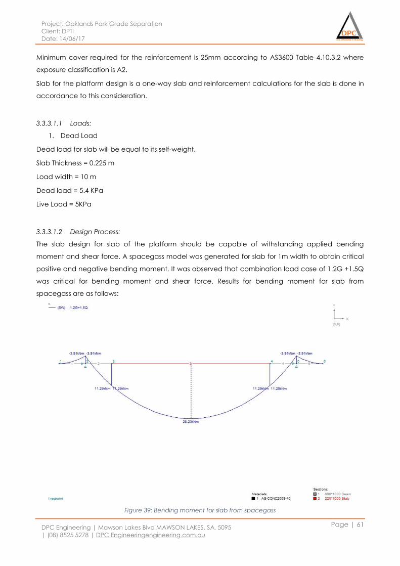
Project: Oaklands Park Grade Separation
Client: DPTI
Date: 14/06/17
DPC Engineering | Mawson Lakes Blvd MAWSON LAKES, SA, 5095
| (08) 8525 5278 | DPC Engineeringengineering.com.au
Page | 61
Minimum cover required for the reinforcement is 25mm according to AS3600 Table 4.10.3.2 where
exposure classification is A2.
Slab for the platform design is a one-way slab and reinforcement calculations for the slab is done in
accordance to this consideration.
3.3.3.1.1 Loads:
1. Dead Load
Dead load for slab will be equal to its self-weight.
Slab Thickness = 0.225 m
Load width = 10 m
Dead load = 5.4 KPa
Live Load = 5KPa
3.3.3.1.2 Design Process:
The slab design for slab of the platform should be capable of withstanding applied bending
moment and shear force. A spacegass model was generated for slab for 1m width to obtain critical
positive and negative bending moment. It was observed that combination load case of 1.2G +1.5Q
was critical for bending moment and shear force. Results for bending moment for slab from
spacegass are as follows:
Figure 39: Bending moment for slab from spacegass
Project: Oaklands Park Grade Separation
Client: DPTI
Date: 14/06/17
DPC Engineering | Mawson Lakes Blvd MAWSON LAKES, SA, 5095
| (08) 8525 5278 | DPC Engineeringengineering.com.au
Page | 62
Maximum negative bending moment is at the middle of the support is -3.91 kNm, and the maximum
positive bending moment is 28.23 kNm at the middle of the slab.
Top Reinforcing Design:
Critical Negative bending moment is considered to design top reinforcement, M*=3.9 KN.m. On
calculating area of steel in accordance to beam dimensions (1000mm wide x 800mm Deep)
minimum required area was found to be 1219 mm2.
N12 bars @75cts were selected since it was closest upsize area. Moment capacity of beam was
calculated to be 438 KN.m which is considerable greater than maximum Negative bending moment
applied on beam and hence it is OK to select this bar size.
Hence we will adopt N12bars @ 75cts
It was found that the slab reinforcement was sufficient to withstand shear force and hence no
ligatures are required for slab.
Bottom Reinforcing Design:
To design bottom reinforcement, the critical positive bending moment will be considered, M* =
28.2KN.m. Calculations were similar to that of top reinforcement. Since critical positive bending
moment is at the middle of the slab span, slab thickness of 225mm will be considered. N12 bars @
275cts were suitable for the bottom reinforcement of the slab, since bending moment capacity of
N12 bars was more than the critical positive bending Moment.
3.3.3.1.3 Final design:
On considering the bending moment and shear force design, it was found that
Top reinforcement of the slab will be N12 bars S 75 T
Bottom reinforcement for slab will be N12 bars S 275 B
It is recommended that ligatures shouldn’t be added to the slab since slab has sufficient capacity to
withstand shear. It is impractical to install ligatures in slab because of less available space.
Figure 40 shows reinforcement details on the slab from the section view for 1 m width
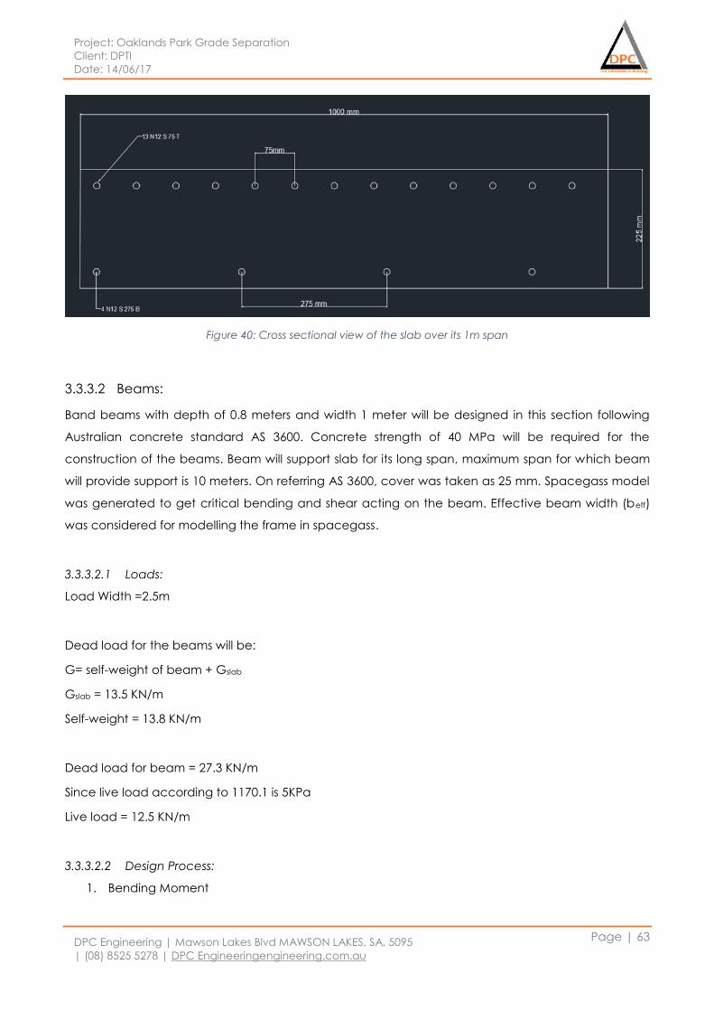
Project: Oaklands Park Grade Separation
Client: DPTI
Date: 14/06/17
DPC Engineering | Mawson Lakes Blvd MAWSON LAKES, SA, 5095
| (08) 8525 5278 | DPC Engineeringengineering.com.au
Page | 63
Figure 40: Cross sectional view of the slab over its 1m span
3.3.3.2 Beams:
Band beams with depth of 0.8 meters and width 1 meter will be designed in this section following
Australian concrete standard AS 3600. Concrete strength of 40 MPa will be required for the
construction of the beams. Beam will support slab for its long span, maximum span for which beam
will provide support is 10 meters. On referring AS 3600, cover was taken as 25 mm. Spacegass model
was generated to get critical bending and shear acting on the beam. Effective beam width (beff)
was considered for modelling the frame in spacegass.
3.3.3.2.1 Loads:
Load Width =2.5m
Dead load for the beams will be:
G= self-weight of beam + Gslab
Gslab = 13.5 KN/m
Self-weight = 13.8 KN/m
Dead load for beam = 27.3 KN/m
Since live load according to 1170.1 is 5KPa
Live load = 12.5 KN/m
3.3.3.2.2 Design Process:
1. Bending Moment
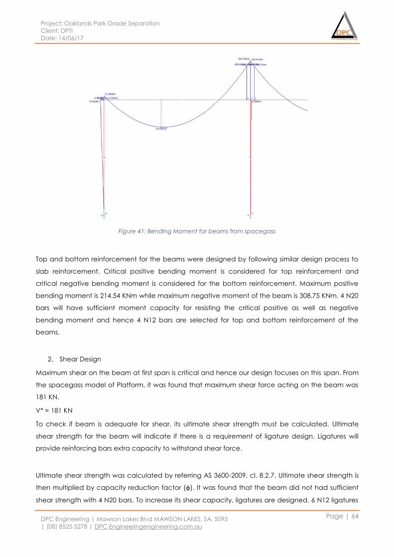
Project: Oaklands Park Grade Separation
Client: DPTI
Date: 14/06/17
DPC Engineering | Mawson Lakes Blvd MAWSON LAKES, SA, 5095
| (08) 8525 5278 | DPC Engineeringengineering.com.au
Page | 64
Figure 41: Bending Moment for beams from spacegass
Top and bottom reinforcement for the beams were designed by following similar design process to
slab reinforcement. Critical positive bending moment is considered for top reinforcement and
critical negative bending moment is considered for the bottom reinforcement. Maximum positive
bending moment is 214.54 KNm while maximum negative moment of the beam is 308.75 KNm. 4 N20
bars will have sufficient moment capacity for resisting the critical positive as well as negative
bending moment and hence 4 N12 bars are selected for top and bottom reinforcement of the
beams.
2. Shear Design
Maximum shear on the beam at first span is critical and hence our design focuses on this span. From
the spacegass model of Platform, it was found that maximum shear force acting on the beam was
181 KN.
V* = 181 KN
To check if beam is adequate for shear, its ultimate shear strength must be calculated. Ultimate
shear strength for the beam will indicate if there is a requirement of ligature design. Ligatures will
provide reinforcing bars extra capacity to withstand shear force.
Ultimate shear strength was calculated by referring AS 3600-2009, cl. 8.2.7. Ultimate shear strength is
then multiplied by capacity reduction factor (φ). It was found that the beam did not had sufficient
shear strength with 4 N20 bars. To increase its shear capacity, ligatures are designed. 6 N12 ligatures
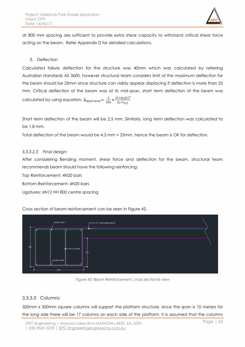
Project: Oaklands Park Grade Separation
Client: DPTI
Date: 14/06/17
DPC Engineering | Mawson Lakes Blvd MAWSON LAKES, SA, 5095
| (08) 8525 5278 | DPC Engineeringengineering.com.au
Page | 65
at 800 mm spacing are sufficient to provide extra shear capacity to withstand critical shear force
acting on the beam. Refer Appendix D for detailed calculations.
3. Deflection
Calculated failure deflection for the structure was 40mm which was calculated by referring
Australian standards AS 3600, however structural team considers limit of the maximum deflection for
the beam should be 25mm since structure can visibly appear displacing if deflection is more than 25
mm. Critical deflection of the beam was at its mid-span, short term deflection of the beam was
calculated by using equation, ∆short term= 5
384×
(𝐺+𝜓𝑠𝑄)𝐿4
𝐸𝑐×𝐼𝑒𝑓𝑓
Short term deflection of the beam will be 2.5 mm. Similarly, long term deflection was calculated to
be 1.8 mm.
Total deflection of the beam would be 4.3 mm < 25mm, hence the beam is OK for deflection.
3.3.3.2.3 Final design:
After considering Bending moment, shear force and deflection for the beam, structural team
recommends beam should have the following reinforcing:
Top Reinforcement: 4N20 bars
Bottom Reinforcement: 4N20 bars
Ligatures: 6N12 HH 800 centre spacing
Cross section of beam reinforcement can be seen in Figure 42.
Figure 42: Beam Reinforcement, cross sectional view
3.3.3.3 Columns:
500mm x 500mm square columns will support the platform structure, since the span is 10 meters for
the long side there will be 17 columns on each side of the platform. It is assumed that the columns
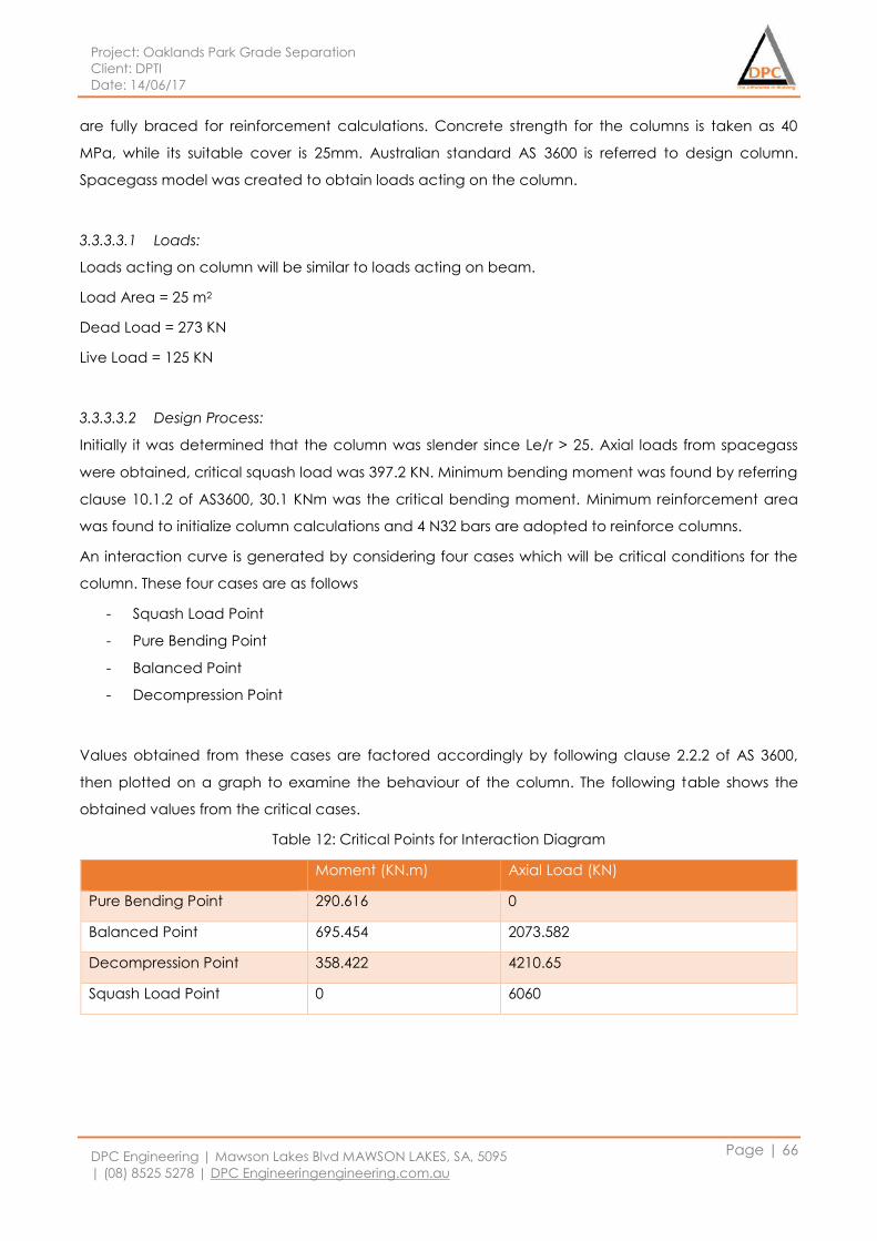
Project: Oaklands Park Grade Separation
Client: DPTI
Date: 14/06/17
DPC Engineering | Mawson Lakes Blvd MAWSON LAKES, SA, 5095
| (08) 8525 5278 | DPC Engineeringengineering.com.au
Page | 66
are fully braced for reinforcement calculations. Concrete strength for the columns is taken as 40
MPa, while its suitable cover is 25mm. Australian standard AS 3600 is referred to design column.
Spacegass model was created to obtain loads acting on the column.
3.3.3.3.1 Loads:
Loads acting on column will be similar to loads acting on beam.
Load Area = 25 m2
Dead Load = 273 KN
Live Load = 125 KN
3.3.3.3.2 Design Process:
Initially it was determined that the column was slender since Le/r > 25. Axial loads from spacegass
were obtained, critical squash load was 397.2 KN. Minimum bending moment was found by referring
clause 10.1.2 of AS3600, 30.1 KNm was the critical bending moment. Minimum reinforcement area
was found to initialize column calculations and 4 N32 bars are adopted to reinforce columns.
An interaction curve is generated by considering four cases which will be critical conditions for the
column. These four cases are as follows
- Squash Load Point
- Pure Bending Point
- Balanced Point
- Decompression Point
Values obtained from these cases are factored accordingly by following clause 2.2.2 of AS 3600,
then plotted on a graph to examine the behaviour of the column. The following table shows the
obtained values from the critical cases.
Table 12: Critical Points for Interaction Diagram
Moment (KN.m) Axial Load (KN)
Pure Bending Point 290.616 0
Balanced Point 695.454 2073.582
Decompression Point 358.422 4210.65
Squash Load Point 0 6060
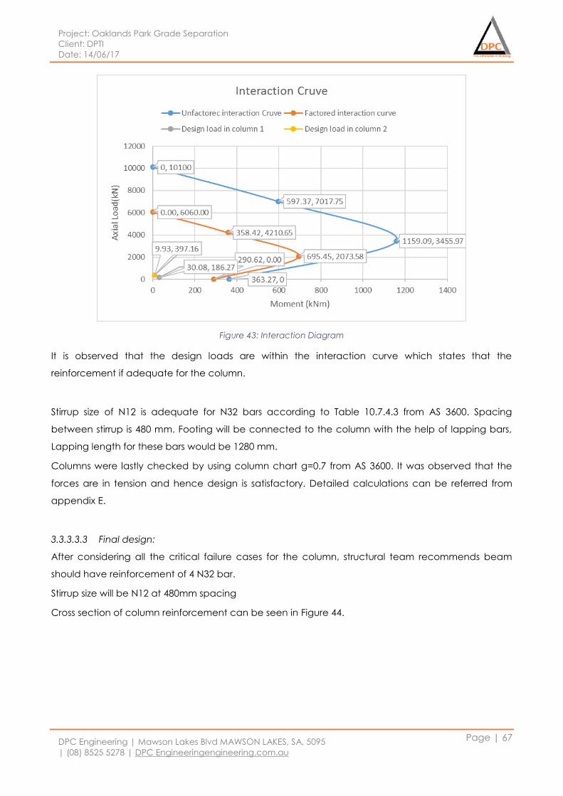
Project: Oaklands Park Grade Separation
Client: DPTI
Date: 14/06/17
DPC Engineering | Mawson Lakes Blvd MAWSON LAKES, SA, 5095
| (08) 8525 5278 | DPC Engineeringengineering.com.au
Page | 67
Figure 43: Interaction Diagram
It is observed that the design loads are within the interaction curve which states that the
reinforcement if adequate for the column.
Stirrup size of N12 is adequate for N32 bars according to Table 10.7.4.3 from AS 3600. Spacing
between stirrup is 480 mm. Footing will be connected to the column with the help of lapping bars,
Lapping length for these bars would be 1280 mm.
Columns were lastly checked by using column chart g=0.7 from AS 3600. It was observed that the
forces are in tension and hence design is satisfactory. Detailed calculations can be referred from
appendix E.
3.3.3.3.3 Final design:
After considering all the critical failure cases for the column, structural team recommends beam
should have reinforcement of 4 N32 bar.
Stirrup size will be N12 at 480mm spacing
Cross section of column reinforcement can be seen in Figure 44.
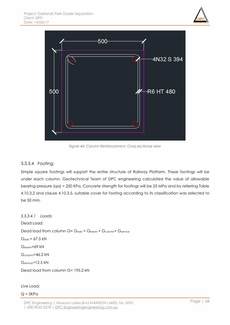
Project: Oaklands Park Grade Separation
Client: DPTI
Date: 14/06/17
DPC Engineering | Mawson Lakes Blvd MAWSON LAKES, SA, 5095
| (08) 8525 5278 | DPC Engineeringengineering.com.au
Page | 68
Figure 44: Column Reinforcement, Cross sectional view
3.3.3.4 Footing:
Simple square footings will support the entire structure of Railway Platform. These footings will be
under each column. Geotechnical Team of DPC engineering calculated the value of allowable
bearing pressure (qa) = 250 KPa. Concrete strength for footings will be 25 MPa and by referring Table
4.10.3.2 and clause 4.10.3.5, suitable cover for footing according to its classification was selected to
be 50 mm.
3.3.3.4.1 Loads:
Dead Load:
Dead load from column G= Gslab + Gbeam + Gcolumn+ Gservice
Gslab = 67.5 kN
Gbeam=69 kN
Gcolumn=46.2 kN
Gservice=12.5 kN
Dead load from column G= 195.2 kN
Live Load:
Q = 5KPa
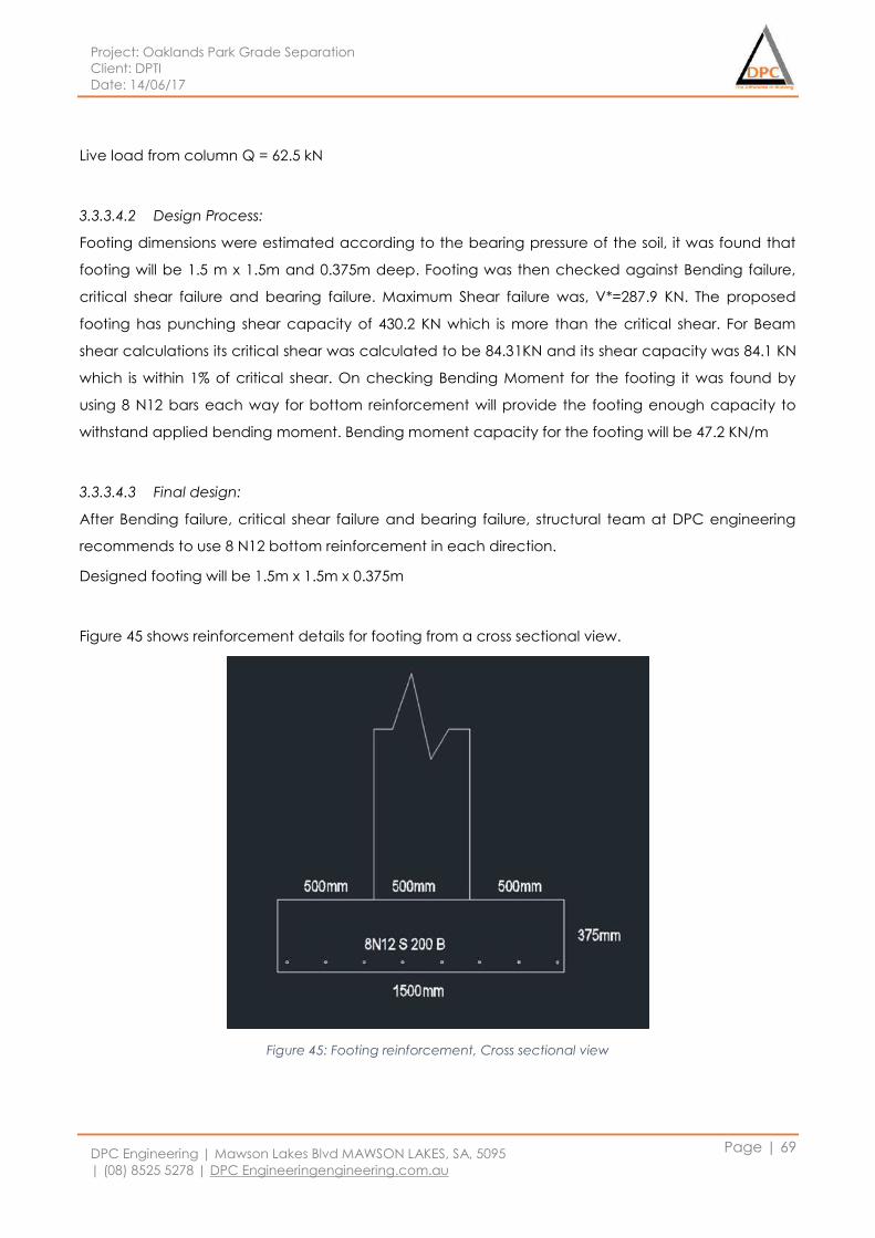
Project: Oaklands Park Grade Separation
Client: DPTI
Date: 14/06/17
DPC Engineering | Mawson Lakes Blvd MAWSON LAKES, SA, 5095
| (08) 8525 5278 | DPC Engineeringengineering.com.au
Page | 69
Live load from column Q = 62.5 kN
3.3.3.4.2 Design Process:
Footing dimensions were estimated according to the bearing pressure of the soil, it was found that
footing will be 1.5 m x 1.5m and 0.375m deep. Footing was then checked against Bending failure,
critical shear failure and bearing failure. Maximum Shear failure was, V*=287.9 KN. The proposed
footing has punching shear capacity of 430.2 KN which is more than the critical shear. For Beam
shear calculations its critical shear was calculated to be 84.31KN and its shear capacity was 84.1 KN
which is within 1% of critical shear. On checking Bending Moment for the footing it was found by
using 8 N12 bars each way for bottom reinforcement will provide the footing enough capacity to
withstand applied bending moment. Bending moment capacity for the footing will be 47.2 KN/m
3.3.3.4.3 Final design:
After Bending failure, critical shear failure and bearing failure, structural team at DPC engineering
recommends to use 8 N12 bottom reinforcement in each direction.
Designed footing will be 1.5m x 1.5m x 0.375m
Figure 45 shows reinforcement details for footing from a cross sectional view.
Figure 45: Footing reinforcement, Cross sectional view
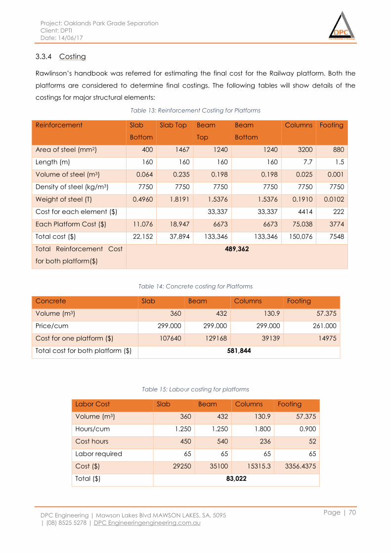
Project: Oaklands Park Grade Separation
Client: DPTI
Date: 14/06/17
DPC Engineering | Mawson Lakes Blvd MAWSON LAKES, SA, 5095
| (08) 8525 5278 | DPC Engineeringengineering.com.au
Page | 70
3.3.4 Costing
Rawlinson’s handbook was referred for estimating the final cost for the Railway platform. Both the
platforms are considered to determine final costings. The following tables will show details of the
costings for major structural elements:
Table 13: Reinforcement Costing for Platforms
Reinforcement Slab
Bottom
Slab Top Beam
Top
Beam
Bottom
Columns Footing
Area of steel (mm2) 400 1467 1240 1240 3200 880
Length (m) 160 160 160 160 7.7 1.5
Volume of steel (m3) 0.064 0.235 0.198 0.198 0.025 0.001
Density of steel (kg/m3) 7750 7750 7750 7750 7750 7750
Weight of steel (T) 0.4960 1.8191 1.5376 1.5376 0.1910 0.0102
Cost for each element ($) 33,337 33,337 4414 222
Each Platform Cost ($) 11,076 18,947 6673 6673 75,038 3774
Total cost ($) 22,152 37,894 133,346 133,346 150,076 7548
Total Reinforcement Cost
for both platform($)
489,362
Table 14: Concrete costing for Platforms
Concrete Slab Beam Columns Footing
Volume (m3) 360 432 130.9 57.375
Price/cum 299.000 299.000 299.000 261.000
Cost for one platform ($) 107640 129168 39139 14975
Total cost for both platform ($) 581,844
Table 15: Labour costing for platforms
Labor Cost Slab Beam Columns Footing
Volume (m3) 360 432 130.9 57.375
Hours/cum 1.250 1.250 1.800 0.900
Cost hours 450 540 236 52
Labor required 65 65 65 65
Cost ($) 29250 35100 15315.3 3356.4375
Total ($) 83,022
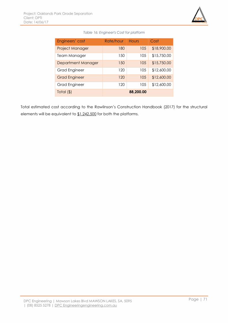
Project: Oaklands Park Grade Separation
Client: DPTI
Date: 14/06/17
DPC Engineering | Mawson Lakes Blvd MAWSON LAKES, SA, 5095
| (08) 8525 5278 | DPC Engineeringengineering.com.au
Page | 71
Table 16: Engineer's Cost for platform
Engineers’ cost Rate/hour Hours Cost
Project Manager 180 105 $18,900.00
Team Manager 150 105 $15,750.00
Department Manager 150 105 $15,750.00
Grad Engineer 120 105 $12,600.00
Grad Engineer 120 105 $12,600.00
Grad Engineer 120 105 $12,600.00
Total ($) 88,200.00
Total estimated cost according to the Rawlinson’s Construction Handbook (2017) for the structural
elements will be equivalent to $1,242,500 for both the platforms.
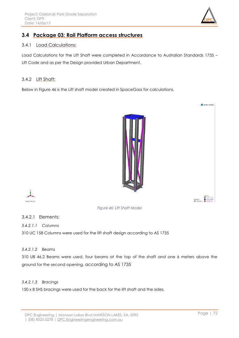
Project: Oaklands Park Grade Separation
Client: DPTI
Date: 14/06/17
DPC Engineering | Mawson Lakes Blvd MAWSON LAKES, SA, 5095
| (08) 8525 5278 | DPC Engineeringengineering.com.au
Page | 72
3.4 Package 03: Rail Platform access structures
3.4.1 Load Calculations:
Load Calculations for the Lift Shaft were completed in Accordance to Australian Standards 1735 –
Lift Code and as per the Design provided Urban Department.
3.4.2 Lift Shaft:
Below in Figure 46 is the Lift shaft model created in SpaceGass for calculations.
Figure 46: Lift Shaft Model
3.4.2.1 Elements:
3.4.2.1.1 Columns
310 UC 158 Columns were used for the lift shaft design according to AS 1735
3.4.2.1.2 Beams
310 UB 46.2 Beams were used, four beams at the top of the shaft and one 6 meters above the
ground for the second opening, according to AS 1735
3.4.2.1.3 Bracings
150 x 8 SHS bracings were used for the back for the lift shaft and the sides.
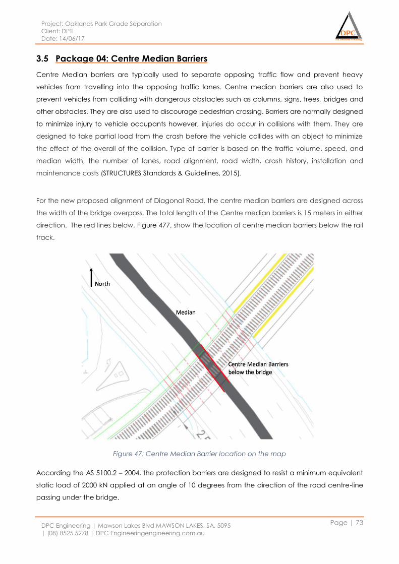
Project: Oaklands Park Grade Separation
Client: DPTI
Date: 14/06/17
DPC Engineering | Mawson Lakes Blvd MAWSON LAKES, SA, 5095
| (08) 8525 5278 | DPC Engineeringengineering.com.au
Page | 73
3.5 Package 04: Centre Median Barriers
Centre Median barriers are typically used to separate opposing traffic flow and prevent heavy
vehicles from travelling into the opposing traffic lanes. Centre median barriers are also used to
prevent vehicles from colliding with dangerous obstacles such as columns, signs, trees, bridges and
other obstacles. They are also used to discourage pedestrian crossing. Barriers are normally designed
to minimize injury to vehicle occupants however, injuries do occur in collisions with them. They are
designed to take partial load from the crash before the vehicle collides with an object to minimize
the effect of the overall of the collision. Type of barrier is based on the traffic volume, speed, and
median width, the number of lanes, road alignment, road width, crash history, installation and
maintenance costs (STRUCTURES Standards & Guidelines, 2015).
For the new proposed alignment of Diagonal Road, the centre median barriers are designed across
the width of the bridge overpass. The total length of the Centre median barriers is 15 meters in either
direction. The red lines below, Figure 477, show the location of centre median barriers below the rail
track.
Figure 47: Centre Median Barrier location on the map
According the AS 5100.2 – 2004, the protection barriers are designed to resist a minimum equivalent
static load of 2000 kN applied at an angle of 10 degrees from the direction of the road centre-line
passing under the bridge.
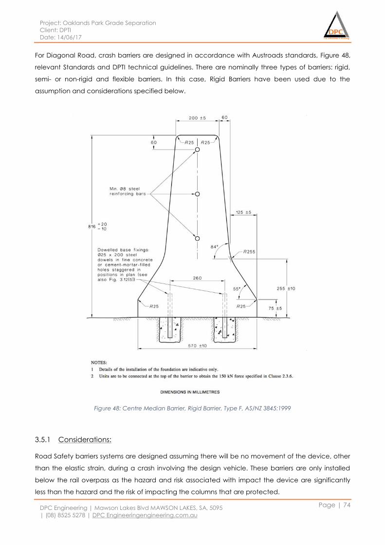
Project: Oaklands Park Grade Separation
Client: DPTI
Date: 14/06/17
DPC Engineering | Mawson Lakes Blvd MAWSON LAKES, SA, 5095
| (08) 8525 5278 | DPC Engineeringengineering.com.au
Page | 74
For Diagonal Road, crash barriers are designed in accordance with Austroads standards, Figure 48,
relevant Standards and DPTI technical guidelines. There are nominally three types of barriers: rigid,
semi- or non-rigid and flexible barriers. In this case, Rigid Barriers have been used due to the
assumption and considerations specified below.
Figure 48: Centre Median Barrier, Rigid Barrier, Type F, AS/NZ 3845:1999
3.5.1 Considerations:
Road Safety barriers systems are designed assuming there will be no movement of the device, other
than the elastic strain, during a crash involving the design vehicle. These barriers are only installed
below the rail overpass as the hazard and risk associated with impact the device are significantly
less than the hazard and the risk of impacting the columns that are protected.
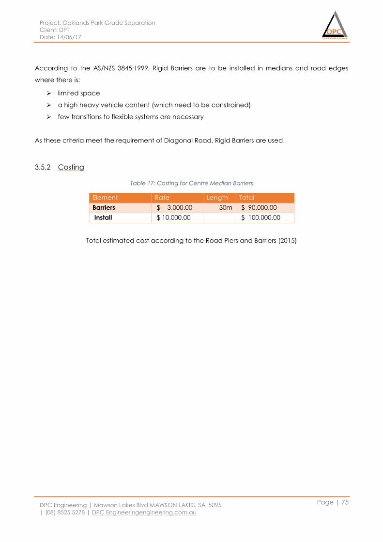
Project: Oaklands Park Grade Separation
Client: DPTI
Date: 14/06/17
DPC Engineering | Mawson Lakes Blvd MAWSON LAKES, SA, 5095
| (08) 8525 5278 | DPC Engineeringengineering.com.au
Page | 75
According to the AS/NZS 3845:1999, Rigid Barriers are to be installed in medians and road edges
where there is:
limited space
a high heavy vehicle content (which need to be constrained)
few transitions to flexible systems are necessary
As these criteria meet the requirement of Diagonal Road, Rigid Barriers are used.
3.5.2 Costing
Table 17: Costing for Centre Median Barriers
Element Rate Length Total
Barriers $ 3,000.00 30m $ 90,000.00
Install $ 10,000.00 $ 100,000.00
Total estimated cost according to the Road Piers and Barriers (2015)
Project: Oaklands Park Grade Separation
Client: DPTI
Date: 14/06/17
DPC Engineering | Mawson Lakes Blvd MAWSON LAKES, SA, 5095
| (08) 8525 5278 | DPC Engineeringengineering.com.au
Page | 76
3.6 Package 05: Electrification Structure
3.6.1 Structure type
The selection of the structure for the overhead wiring support structures will be depend on several
factors for example configuration of the track, ground and environmental condition, adjacent
vegetation and sighting of signal for the trains drives. There are few types of the structures that are
considered to be used for the electrification structure for the Oakland Railway Overpass which are
single mast, portal structures, twin track cantilever structure, structure with anchors and balance
weight anchors. However for this project we will be using single mast. The structure will be built from a
universal column with a fix base. The fixity is provided by holding down bolts in a reinforce concrete
footing
3.6.2 Electrical Components
Insulators
Overhead wiring (catenary and contact wire)
Pantograph
Cantilever arms
Masts
3.6.3 Design Criteria
3.6.3.1 Australian Standards
AS 1158 Lighting for Roads and Public Spaces Set
AS 1680 Interior and Workspace Lighting
AS 1735.2 Lifts, escalators and moving walks – Passenger and goods lifts - Electric
As 1742.3 Manual of uniform traffic control devices - Traffic control for works on roads
AS 2239 Galvanic (Sacrificial) Anodes for Cathodic Protection
AS 2293.1 Emergency Escape Lighting and Exit Signs for Buildings – System Design, Installation
and Operation
AS 2648.1 Underground marking tape - Non-detectable tape
AS 3000 Electrical Installations (Wiring Rules)
AS 3008.1.1 Electrical Installations - Selection of Cables - Cables for Alternating Voltages up to
and Including 0.6/1 kV - Typical Australian Installation Conditions
AS 3013 Electrical Installations – Classification of the fire and mechanical performance of
wiring system elements.
Project: Oaklands Park Grade Separation
Client: DPTI
Date: 14/06/17
DPC Engineering | Mawson Lakes Blvd MAWSON LAKES, SA, 5095
| (08) 8525 5278 | DPC Engineeringengineering.com.au
Page | 77
3.6.3.2 Design standard
The design of the overhead wiring structure will be accordance to the relevant Australian standard.
For concrete footing will be designed base on Australian standard AS3600- Concrete Structures and
the design of the overhead wiring structure shall be done accordance with the requirement of
RailCorp Engineering Manual TMC 331 -Overhead wiring design.
3.6.3.3 Design Life
The overhead wiring structure will be designed for serviceable of 100 years
3.6.3.4 Design Load
The permanent load that used in designing the overhead wiring structures are to be accordance to
with AS 1170 - Structural design actions. The following of the overheard wiring structure will be
considered as permanent action.
Static weight load
Radial load
Regulated tension
Maximum fixed anchor tension
Weight stack load.
Meanwhile the wind load will be determined in accordance with AS11700 -Structural design action.
The ultimate regional wind speed shall determine using appropriate average recurrence interval
using important level and design working life from AS1170.2-Wind action
3.6.3.5 Works program
In this electrification structure it will include the installation of the mast and a 25kV of alternate
current for the overhead system. However, to support this alternate current a substation that is
connected to the SA Power Networks 66kV need to be constructed. Apart from that, the relocation
of existing services electricity cables mostly 11kV also need to take into consideration.
3.6.3.6 Spacing
The height of the single mast will be 8 metres tall and will support 4 wires. The return conductor and
earth wire will be attached directly to the mast. The contact wire and catenary wire will be held
above the track using cantilevered attached to the mast. The spacing of the overheard wiring will
depend on environment factor for example wind and curvature of the track. However in this project
the spacing of the wiring support will be 50 metres.
Project: Oaklands Park Grade Separation
Client: DPTI
Date: 14/06/17
DPC Engineering | Mawson Lakes Blvd MAWSON LAKES, SA, 5095
| (08) 8525 5278 | DPC Engineeringengineering.com.au
Page | 78
3.6.4 Consideration
3.6.4.1 Overlaps
The typical length of overhead wire is 1600metres.Overlaps occurs when one length of the overhead
wire comes to end and a new length of overhead wire start. To ensure the continuity of the wiring
the first overhead wiring does not come to end where the new overhead wire start but it runs
parallel over distance 50metres.So to support two set of overhead wire overlap twin mast are
installed two metres apart at both ends of the overlap.
3.6.4.2 Safety
The safety of the rail network of an electrified system are the most important thing during
construction and operation. Safety infrastructures need to be installed and safety measures should
be enforced to avoid any unexpected incidents. Some of the safety precautions that can be
considered are.
Signage across the network to reinforce safety messages to the passengers and pedestrians.
Screening at road bridges and pedestrian to restrict people from being able to come into
contact with the overhead wires.
Access to the station will be dedicated pedestrians paths only.
3.6.4.3 Footing
The main loads that carried by the overhead wiring system will be mainly lateral forces and moments
rather than vertical forces. There are a few types of footing that can be considered for this project
as shown below.
Regular (box shaped excavated footing)
Piled
Footing in Rock
The choice of the footing is determined by construction requirement and site condition. Pile footing
is the most economical option in generally however due to site factor such as in ground services or
machine access issue often lead to the use of regular footing. In this Oakland Railway Park rock
footing will be more feasible because of limited spaces.

Project: Oaklands Park Grade Separation
Client: DPTI
Date: 14/06/17
DPC Engineering | Mawson Lakes Blvd MAWSON LAKES, SA, 5095
| (08) 8525 5278 | DPC Engineeringengineering.com.au
Page | 79
3.6.4.4 Cost Estimation components for electrification structures
3.6.4.4.1 Overhead Wiring including Poles
Overhead traction power wiring, including all associated support structures, catenary wiring
and power supply
Trackside posts, gantries and fittings associated with the support of over track wiring
Catenary and power wiring and associated tensioning systems within or outside of tunnels
Transformers, switchgear, insulators, earthing, bonding, registration equipment
Under track crossings for overhead wiring installation
3.6.4.4.2 Power Supply and Distribution
Incoming raw power supply to sub-stations
Substations
High and low voltage power distribution along corridor
Transformers for supply to overhead wiring
Trackside installations associated with Power Distribution
Project: Oaklands Park Grade Separation
Client: DPTI
Date: 14/06/17
DPC Engineering | Mawson Lakes Blvd MAWSON LAKES, SA, 5095
| (08) 8525 5278 | DPC Engineeringengineering.com.au
Page | 80
3.7 Reference
1. Authority, A. S. (2014) Overhead Wiring Standards for the Electrification of New Routes.
Available at: http://www.asa.transport.nsw.gov.au/sites/default/files/asa/railcorp-
legacy/disciplines/electrical/ep-08-00-00-01-sp.pdf.
2. Authority, A. S. (2015) Technical Note - TN 024 : 2015. Available at:
http://www.asa.transport.nsw.gov.au/sites/default/files/asa/railcorp-
legacy/disciplines/civil/tmc-331.pdf.
3. Baxter, A. (2015) Network Rail A Guide to Overhead Electrification. Available at:
http://www.bathnes.gov.uk/sites/default/files/sitedocuments/Planning-and-Building-
Control/Planning/nr_a_guide_to_overhead_electrification.pdf.
4. Hutchison, D. (2014) INFRASTRUCTURE Reviewed. Available at:
https://dpti.sa.gov.au/__data/assets/pdf_file/0004/113827/PTS_Standards_129014_Railway_St
ations_-_Electrical_Infrastructure.PDF.
5. Note, T., Authority, A. S., Ci, H. R. and Cl, H. R. (2015) Technical Note - TN 016 : 2015. Available
at: http://www.asa.transport.nsw.gov.au/sites/default/files/asa/asa-standards/tn-016-
2015.pdf.
6. Stapleton, J. and Hitch, R. (2011) Esc 330 overhead wiring structures and signal gantries.
Available at: http://www.asa.transport.nsw.gov.au/sites/default/files/asa/railcorp-
legacy/disciplines/civil/esc-330.pdf.
7. Wiring, O. and Structures, S. (1800) rail electrification. Available at:
http://www.infrastructure.sa.gov.au/__data/assets/pdf_file/0011/95726/2013-04-03-Rail-
Electrification-overhead-wiring-support_structures_fact_sheet.pdf.
8. Australian Standards 1158, Lighting for Roads and Public Spaces Set, Joint Technical
Committee LG/2, Road Lighting
9. Australian Standards/New Zealand Standard 1680.0:2009, Interior and Workspace Lighting,
Technical Committee LG-001, Interior and Workplace Lighting.
Project: Oaklands Park Grade Separation
Client: DPTI
Date: 14/06/17
DPC Engineering | Mawson Lakes Blvd MAWSON LAKES, SA, 5095
| (08) 8525 5278 | DPC Engineeringengineering.com.au
Page | 81
10. Australian Standards AS 1735.2 – 1997, Lifts, escalators and moving walks – Passenger and
goods lifts – Electric, Committee ME/4, Lift Installations.
11. Australian Standards 1724.3- 2009, Manual of uniform traffic control devices -MANUAL OF
UNIFORM TRAFFIC CONTROL DEVICES, Standards Australia Committee MS-012, Traffic Control
Devices.
12. Australian Standards 2239, Galvanic (Sacrificial) Anodes for Cathodic Protection, COMMITTEE
MT-014, STEEL IN CONCRETE STRUCTURES.
13. Australian Standards 2293.1 – 2005, Emergency Escape Lighting and Exit Signs for Buildings,
Committee LG-007, Installation and Operation
14. Australian Standard 2648.1 – 1995, Underground marking, Technical COMMITTEE PL/30, Plastics
Underground Warning Strips
15. Australian Standards/ New Zealand Standards 3000 - 2007, Electrical Installations, Technical
COMMITTEE EL-001, WIRING RULES.
16. AUSTRALIAN STRUCTURES/ NEW ZEALAND STANDARDS 3013 – 1990, ELECTRICAL INSTALLATIONS, Technical
COMMITTEE EL/37, Special Wiring Systems.
17. AUSTRALIAN STANDARDS 5100 – 2004, BRIDGE DESIGN STANDARDS, COMMITTEE BD-090, Bridge Design.
18. AUSTRALIAN STANDARDS 5100.2 – 2004, BRIDGE DESIGN – DESIGN LOADS, COMMITTEE BD-090, Bridge
Design.
19. AUSTRALIAN STANDARDS 1170 – 2011, STRUCTURAL DESIGN ACTIONS, COMMITTEE BD-006, General Design
Requirements.
20. AUSTRALIAN STANDARDS 1170.2 – 2011, STRUCTURAL DESIGN ACTIONS PART 2 – WIND LOADS, COMMITTEE BD-
006, General Design Requirements.
21. AUSTRALIAN STANDARDS 3600 – 2009, Concrete Structures, COMMITTEE BD-002, CONCRETE STRUCTURES.
22. Australian Standards 1735 – 1997, Lifts, escalators and moving walks – Passenger and goods
lifts – Electric, Committee ME/4, Lift Installations.

Project: Oaklands Park Grade Separation
Client: DPTI
Date: 14/06/17
DPC Engineering | Mawson Lakes Blvd MAWSON LAKES, SA, 5095
| (08) 8525 5278 | DPC Engineeringengineering.com.au
Page | 82
23. Australian Standards 3845 -1999, Road Safety Barriers Systems, COMMITTEE CE/33, ROAD SAFETY
BARRIER SYSTEMS.

Project: Oaklands Park Grade Separation
Client: DPTI
Date: 14/06/17
DPC Engineering | Mawson Lakes Blvd MAWSON LAKES, SA, 5095
| (08) 8525 5278 | DPC Engineeringengineering.com.au
Page | 83
GEOTECHNICAL
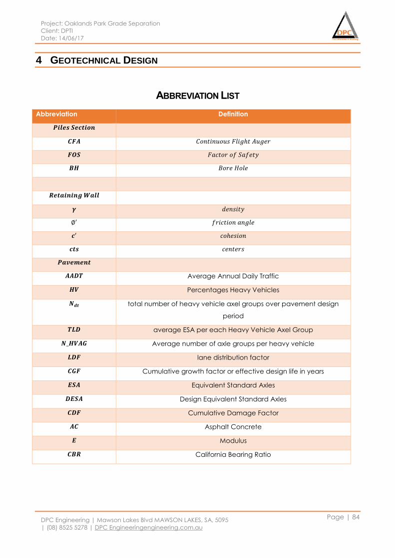
Project: Oaklands Park Grade Separation
Client: DPTI
Date: 14/06/17
DPC Engineering | Mawson Lakes Blvd MAWSON LAKES, SA, 5095
| (08) 8525 5278 | DPC Engineeringengineering.com.au
Page | 84
4 GEOTECHNICAL DESIGN
ABBREVIATION LIST
Abbreviation Definition
𝑷𝒊𝒍𝒆𝒔 𝑺𝒆𝒄𝒕𝒊𝒐𝒏
𝑪𝑭𝑨 𝐶𝑜𝑛𝑡𝑖𝑛𝑢𝑜𝑢𝑠 𝐹𝑙𝑖𝑔ℎ𝑡 𝐴𝑢𝑔𝑒𝑟
𝑭𝑶𝑺 𝐹𝑎𝑐𝑡𝑜𝑟 𝑜𝑓 𝑆𝑎𝑓𝑒𝑡𝑦
𝑩𝑯 𝐵𝑜𝑟𝑒 𝐻𝑜𝑙𝑒
𝑹𝒆𝒕𝒂𝒊𝒏𝒊𝒏𝒈 𝑾𝒂𝒍𝒍
𝜸 𝑑𝑒𝑛𝑠𝑖𝑡𝑦
∅′ 𝑓𝑟𝑖𝑐𝑡𝑖𝑜𝑛 𝑎𝑛𝑔𝑙𝑒
𝒄′ 𝑐𝑜ℎ𝑒𝑠𝑖𝑜𝑛
𝒄𝒕𝒔 𝑐𝑒𝑛𝑡𝑒𝑟𝑠
𝑷𝒂𝒗𝒆𝒎𝒆𝒏𝒕
𝑨𝑨𝑫𝑻 Average Annual Daily Traffic
𝑯𝑽 Percentages Heavy Vehicles
𝑵𝒅𝒕 total number of heavy vehicle axel groups over pavement design
period
𝑻𝑳𝑫 average ESA per each Heavy Vehicle Axel Group
𝑵_𝑯𝑽𝑨𝑮 Average number of axle groups per heavy vehicle
𝑳𝑫𝑭 lane distribution factor
𝑪𝑮𝑭 Cumulative growth factor or effective design life in years
𝑬𝑺𝑨 Equivalent Standard Axles
𝑫𝑬𝑺𝑨 Design Equivalent Standard Axles
𝑪𝑫𝑭 Cumulative Damage Factor
𝑨𝑪 Asphalt Concrete
𝑬 Modulus
𝑪𝑩𝑹 California Bearing Ratio
Project: Oaklands Park Grade Separation
Client: DPTI
Date: 14/06/17
DPC Engineering | Mawson Lakes Blvd MAWSON LAKES, SA, 5095
| (08) 8525 5278 | DPC Engineeringengineering.com.au
Page | 85
4.1 Scope of work
Geotechnical team is a professional team from DPC engineering company conducting
geotechnical aspects designs, in the Oaklands Park Grade Separation Project, geotechnical team is
responsible for the geotechnical related design, such as CFA pile footing design, retaining wall
design, pavement design, and ballast design.
The whole superstructure were supporting by columns above ground, the loads are transferring
through columns then to ground, the geotechnical design team is responsible for dealing with the
loads from columns and design proper structure to transfer loads into ground so that providing a
footing that will safety support the superstructure all through its design life and perform its intended
function, the design team selected CFA pile footing system to transfer load into ground, the footing
system consists of pile caps and piles deep into ground, and the pile caps were designed under
Australia Standard AS3600:2009, concrete structure, and plies were designed under Australia
Standard AS2159:2009, piling design and installation,
The bridge approaching part is 330 meters long, refer to transportation department and urban
planning department management strategies, 150 meters of the approaching part is designed to
be supporting some soil based structures at both ends of the structure, which is from ground level
until 3 meters clearance under the approaching part. Geotechnical team evaluated the planning
strategy and selected backfill and retaining wall system to support the structure, as indicated in
feasibility study report, cantilever retaining wall will be used in the project, at the design part,
detailed design suggestion about backfill and retaining wall design will be given, in the design part,
Australia Standard AS4678:2002, earth retaining structures was used, at the same time, Australia
Standard AS3600:2009, concrete structure was used to design reinforcement for retaining wall.
As a new traffic management scheme was develop by transportation department, the main roads
will be widened from two lanes to threes and new intersection alignment plan at Morphett Rd and
Diagonal Rd, so that the new constructed road area needs a pavement design solution to providing
traffic a safe road condition, basing on traffic volume and latest pavement design technology, the
design team selected flexible pavement solution for the project.
At the same time, as new railway bridge built, the geotechnical design team is responsible for ballast
design under rail to providing a comfortable base for rail traffic, the outcome of ballast design will
present ballast materials as long as dimension of the ballast.
Costing remains fundamental to a part of design work, after all the design solution are confirmed,
the design team will present the total costing of the geotechnical design basing on DPC Engineering
Company management regulations.
Accordingly, the design team will work with cad drawing manger delivering design drawings and all
the drawings can be found in the drawing document separately.
Project: Oaklands Park Grade Separation
Client: DPTI
Date: 14/06/17
DPC Engineering | Mawson Lakes Blvd MAWSON LAKES, SA, 5095
| (08) 8525 5278 | DPC Engineeringengineering.com.au
Page | 86
4.2 Investigations and geotechnical conditions
The aim of site investigation is to obtain adequate information on the physical conditions in the
vicinity of the structure including the topography, site layout, nature of soil, foundation bearing
capacity and the ground water conditions, together with information on any adjacent structures
and services that may be affected, also, investigation includes an assessment of the regional
geotechnical conditions where may impact on proposed development.
Based on the structures being designed, attention will be paid to the properties of the soil in the
immediate vicinity of the structure as well as underneath the structure, also, the structure type and
size are relating to the depth of investigation, also, careful attention will be paid to the geology
condition, including geological defects and discontinuities, bedding planes, joints and faults. At the
same time, soil conditions like expansive soil should be accounted, as expansive soil is prone to large
volume changes including swelling at wet condition and shrinking at dry condition, the suction
change of expansive soil is the direct reason lead to ground movement that could affect structure
stability.
The geotechnical investigation was organized by client and done by Parsons Brinckerhoff at year
2011 which providing the ground conditions and the factual information on the subsurface soil
profile will be used to obtain the adequate information for related geotechnical design. At the other
hand, the site investigation results into idealized models that is the basis for all the following
geotechnical design, a geotechnical model will describe sub-surface profile as a series of layers,
determine the key geotechnical parameter for design, assign values for these key geotechnical
parameters for each layer and groundwater be included in the model.
4.3 CFA Pile Foundation Design
4.3.1 Design concept
CFA pile is a reinforced concrete pile which is used to support high building and bridge producing
heavy vertical loads. Bored pile is a cast-in-site concrete. Drilled shafts are cast by using bored piling
machine which has specially designed drilling tools, buckets and grabs, used to remove the soil and
rock. Normally, it can be used by drilling into 50 meters depth of soil. One of the key advantages of a
CFA pile system is that it won’t produce a lot of vibration and the noise level is also reduced when
compared to traditional piling systems.
The main advantages of bored piles or drilled shafts over conventional footing or other types of
poles are:
Piles of variable lengths can be extended through soft compressible or swelling soils, into
suitable bearing material.
Piles can be extended to depths below frost penetration, and seasonal moisture variation
Project: Oaklands Park Grade Separation
Client: DPTI
Date: 14/06/17
DPC Engineering | Mawson Lakes Blvd MAWSON LAKES, SA, 5095
| (08) 8525 5278 | DPC Engineeringengineering.com.au
Page | 87
Large excavations and subsequent backfill are minimized
Less disruption to adjacent soil
Absence of vibration will not disturb adjacent piles or structures
Extremely high capacity can be obtained by expanding the base of the shaft up to three
times the shaft diameter, thus eliminating construction of caps over multiple pile groups
For many design situations, bored piles offer higher capacities with potentially better
economic than driven piles
Bored piling is populate to be used in construction as a foundation, especially for Bridge work and
tall buildings as well. Bored piling work has to be done by specialist bored piling contractor, normal
piling contractor cannot execute there type of work without experience and knowledge about
bored piles (Rodriguez 2017).
Continuous Flight Auger (CFA) Piling is a type of bored pile, the design team will use CFA piling
system in the design. This piling is a non-displacement piling system which produce less noise and it is
very fast and economical. CFA piling is a cast in-situ process which is suited for soft ground where
deep casing or use of drilling support fluids might otherwise be needed. CFA piles can be installed
faster than conventional bored piles and produce less noise and vibration if compared to driven
piles.
4.3.2 Design method
The design process are based on Australian Standard AS2159-2009: piling design and installation,
and design objective is to provide a footing that will safely support the superstructure over its design
life.
The footing must be durable, of adequate strength and its performance be compatible with the
superstructure so that it remains serviceable and can perform its intended function.
Basing on geotechnical consideration, the design team will design the pile footing for strength,
meanwhile, the design will take into account pile and soil interaction and values of soil parameters
are related to the design, so that, in the design part, a simplified soil profile and soil parameters are
developed.
Refer to the geotechnical design principles recommended by AS2159-2009, the design team will
check:
Ultimate geotechnical capacity 𝑅𝑢, and be satisfied to 𝑅𝑢 ≥ 𝐸𝑑, where 𝐸𝑑 is the design action
effect. And the design team will use factor of safety to evaluate design performance.
𝐹𝑎𝑐𝑡𝑜𝑟 𝑜𝑓 𝑆𝑎𝑓𝑒𝑡𝑦: 𝐹𝑆 =𝑈𝑙𝑡𝑖𝑚𝑎𝑡𝑒 Design Capacity
𝐷𝑒𝑠𝑖𝑔𝑛 𝐴𝑐𝑡𝑖𝑜𝑛
𝑇ℎ𝑒 𝐹𝑆 𝑛𝑜𝑟𝑚𝑎𝑙𝑙𝑦 𝑏𝑒𝑡𝑤𝑒𝑒𝑛 2 𝑎𝑛𝑑 3.5 𝑓𝑜𝑟 𝑝𝑖𝑙𝑒 𝑓𝑜𝑢𝑛𝑑𝑎𝑡𝑖𝑜𝑛𝑠
Geotechnical strength design, the design geotechnical strength 𝑅𝑑,𝑔 should not less than 𝐸𝑑,
Project: Oaklands Park Grade Separation
Client: DPTI
Date: 14/06/17
DPC Engineering | Mawson Lakes Blvd MAWSON LAKES, SA, 5095
| (08) 8525 5278 | DPC Engineeringengineering.com.au
Page | 88
the design action effect, and geotechnical strength is calculated from geotechnical
strength reduction factor multiplied by the ultimate geotechnical strength. The geotechnical
strength reduction factor was calculated using a risk assessment procedure.
Group piles efficiency check, as pile groups are used under each column, a group piles
efficiency check will be conducted by the design team to ensure a safe design, in the
process, the each pile group was treated a singular mega pile.
All the design process and calculations will be in Appendix G.
4.3.3 Design actions and loads
The design of pile for ultimate strength and geotechnical strength limit states shall take account of
appropriate action effects arising from the:
All actions specified in AS 5100.2 and other relevant actions (Done by Structure Team)
Permanent actions of pile and pile cap
Ground movement, include NEGATIVE FRICTION, EXPANSIVE SOIL AND VERTTICAL AND
LATERAL EARTH MOVEMENTS that may arise from various sources
Handling
Installation (for CFA pile)
Any other addition loads and actions that may be applied (impact, dynamic loading, water
pressure and scour)
Load combination for strength design are factored loads that produces the most adverse effect on
the pile in accordance with AS 1170.0 which are done by Structure team. And the design actions for
serviceability design of piles shall be taken from the appropriate combinations of actions for short-
term situations and long-term situations in accordance with AS 1170.0
4.3.4 Soil profile for pile footing design
Basing on geotechnical investigation report and borehole data provided by client, the complete
engineering borehole logs with descriptions of the encountered materials are studied by design
team.
OPHB06 - OPHB08, OPHB12 and OPHB13 are locates at pile footing design area, based on the
summary subsurface conditions, SAND/CLAY was present to a maximum depth of 24.8m in these
boreholes. The SAND/CLAY was dense to very dense/very stiff to hard. Approximately below 12.0m
of the boreholes, a significant proportion of medium to high plasticity sandy/silty CLAY was found.
The presence of sand lenses is reduced and the gravel content is increased below 6.5m depth.
Between 14.5 and 29.7m, soft/low density material was exposed with the presence of firm to
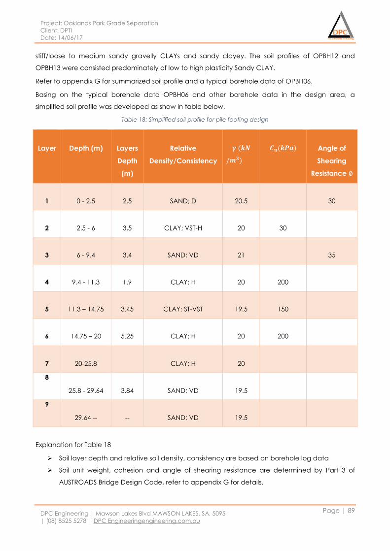
Project: Oaklands Park Grade Separation
Client: DPTI
Date: 14/06/17
DPC Engineering | Mawson Lakes Blvd MAWSON LAKES, SA, 5095
| (08) 8525 5278 | DPC Engineeringengineering.com.au
Page | 89
stiff/loose to medium sandy gravelly CLAYs and sandy clayey. The soil profiles of OPBH12 and
OPBH13 were consisted predominately of low to high plasticity Sandy CLAY.
Refer to appendix G for summarized soil profile and a typical borehole data of OPBH06.
Basing on the typical borehole data OPBH06 and other borehole data in the design area, a
simplified soil profile was developed as show in table below.
Table 18: Simplified soil profile for pile footing design
Layer
Depth (m)
Layers
Depth
(m)
Relative
Density/Consistency
𝜸 (𝒌𝑵
/𝒎𝟑)
𝑪𝒖(𝒌𝑷𝒂)
Angle of
Shearing
Resistance ∅
1
0 - 2.5
2.5
SAND; D
20.5
30
2
2.5 - 6
3.5
CLAY; VST-H
20
30
3
6 - 9.4
3.4
SAND; VD
21
35
4
9.4 - 11.3
1.9
CLAY; H
20
200
5
11.3 – 14.75
3.45
CLAY; ST-VST
19.5
150
6
14.75 – 20
5.25
CLAY; H
20
200
7
20-25.8
CLAY; H
20
8
25.8 - 29.64
3.84
SAND; VD
19.5
9
29.64 --
--
SAND; VD
19.5
Explanation for Table 18
Soil layer depth and relative soil density, consistency are based on borehole log data
Soil unit weight, cohesion and angle of shearing resistance are determined by Part 3 of
AUSTROADS Bridge Design Code, refer to appendix G for details.
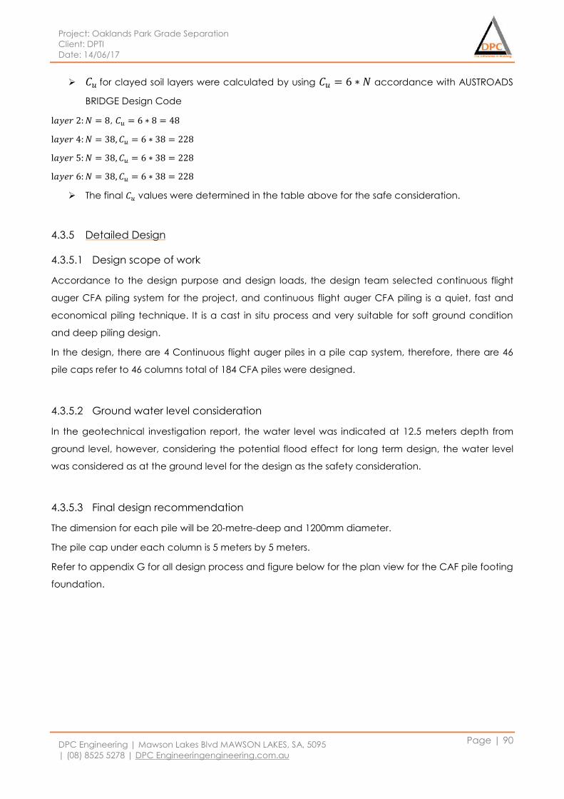
Project: Oaklands Park Grade Separation
Client: DPTI
Date: 14/06/17
DPC Engineering | Mawson Lakes Blvd MAWSON LAKES, SA, 5095
| (08) 8525 5278 | DPC Engineeringengineering.com.au
Page | 90
𝐶𝑢 for clayed soil layers were calculated by using 𝐶𝑢 = 6 ∗ 𝑁 accordance with AUSTROADS
BRIDGE Design Code
l𝑎𝑦𝑒𝑟 2: 𝑁 = 8, 𝐶𝑢 = 6 ∗ 8 = 48
l𝑎𝑦𝑒𝑟 4: 𝑁 = 38, 𝐶𝑢 = 6 ∗ 38 = 228
l𝑎𝑦𝑒𝑟 5: 𝑁 = 38, 𝐶𝑢 = 6 ∗ 38 = 228
l𝑎𝑦𝑒𝑟 6: 𝑁 = 38, 𝐶𝑢 = 6 ∗ 38 = 228
The final 𝐶𝑢 values were determined in the table above for the safe consideration.
4.3.5 Detailed Design
4.3.5.1 Design scope of work
Accordance to the design purpose and design loads, the design team selected continuous flight
auger CFA piling system for the project, and continuous flight auger CFA piling is a quiet, fast and
economical piling technique. It is a cast in situ process and very suitable for soft ground condition
and deep piling design.
In the design, there are 4 Continuous flight auger piles in a pile cap system, therefore, there are 46
pile caps refer to 46 columns total of 184 CFA piles were designed.
4.3.5.2 Ground water level consideration
In the geotechnical investigation report, the water level was indicated at 12.5 meters depth from
ground level, however, considering the potential flood effect for long term design, the water level
was considered as at the ground level for the design as the safety consideration.
4.3.5.3 Final design recommendation
The dimension for each pile will be 20-metre-deep and 1200mm diameter.
The pile cap under each column is 5 meters by 5 meters.
Refer to appendix G for all design process and figure below for the plan view for the CAF pile footing
foundation.
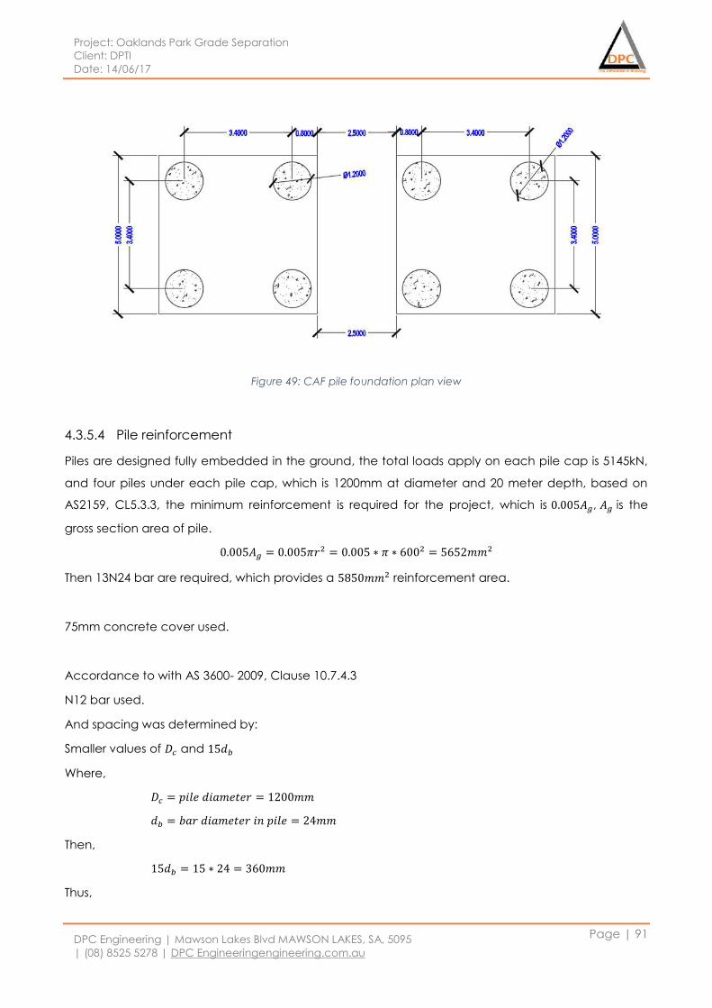
Project: Oaklands Park Grade Separation
Client: DPTI
Date: 14/06/17
DPC Engineering | Mawson Lakes Blvd MAWSON LAKES, SA, 5095
| (08) 8525 5278 | DPC Engineeringengineering.com.au
Page | 91
Figure 49: CAF pile foundation plan view
4.3.5.4 Pile reinforcement
Piles are designed fully embedded in the ground, the total loads apply on each pile cap is 5145kN,
and four piles under each pile cap, which is 1200mm at diameter and 20 meter depth, based on
AS2159, CL5.3.3, the minimum reinforcement is required for the project, which is 0.005𝐴𝑔, 𝐴𝑔 is the
gross section area of pile.
0.005𝐴𝑔 = 0.005𝜋𝑟2 = 0.005 ∗ 𝜋 ∗ 6002 = 5652𝑚𝑚2
Then 13N24 bar are required, which provides a 5850𝑚𝑚2 reinforcement area.
75mm concrete cover used.
Accordance to with AS 3600- 2009, Clause 10.7.4.3
N12 bar used.
And spacing was determined by:
Smaller values of 𝐷𝑐 and 15𝑑𝑏
Where,
𝐷𝑐 = 𝑝𝑖𝑙𝑒 𝑑𝑖𝑎𝑚𝑒𝑡𝑒𝑟 = 1200𝑚𝑚
𝑑𝑏 = 𝑏𝑎𝑟 𝑑𝑖𝑎𝑚𝑒𝑡𝑒𝑟 𝑖𝑛 𝑝𝑖𝑙𝑒 = 24𝑚𝑚
Then,
15𝑑𝑏 = 15 ∗ 24 = 360𝑚𝑚
Thus,
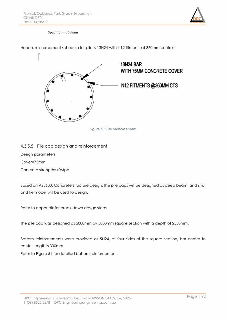
Project: Oaklands Park Grade Separation
Client: DPTI
Date: 14/06/17
DPC Engineering | Mawson Lakes Blvd MAWSON LAKES, SA, 5095
| (08) 8525 5278 | DPC Engineeringengineering.com.au
Page | 92
Spacing = 360mm
Hence, reinforcement schedule for pile is 13N24 with N12 fitments at 360mm centres.
Figure 50: Pile reinforcement
4.3.5.5 Pile cap design and reinforcement
Design parameters:
Cover=75mm
Concrete strength=40Mpa
Based on AS3600, Concrete structure design, the pile caps will be designed as deep beam, and strut
and tie model will be used to design.
Refer to appendix for break down design steps.
The pile cap was designed as 5000mm by 5000mm square section with a depth of 2550mm.
Bottom reinforcements were provided as 5N24, at four sides of the square section, bar center to
center length is 300mm.
Refer to Figure 51 for detailed bottom reinforcement.
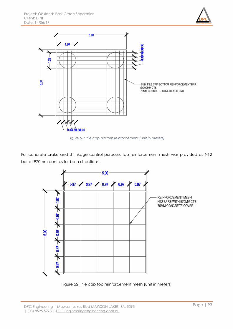
Project: Oaklands Park Grade Separation
Client: DPTI
Date: 14/06/17
DPC Engineering | Mawson Lakes Blvd MAWSON LAKES, SA, 5095
| (08) 8525 5278 | DPC Engineeringengineering.com.au
Page | 93
Figure 51: Pile cap bottom reinforcement (unit in meters)
For concrete crake and shrinkage control purpose, top reinforcement mesh was provided as N12
bar at 970mm centres for both directions.
Figure 52: Pile cap top reinforcement mesh (unit in meters)
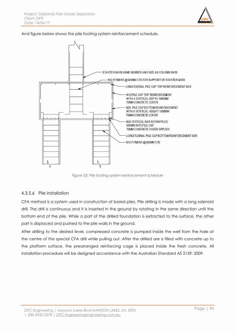
Project: Oaklands Park Grade Separation
Client: DPTI
Date: 14/06/17
DPC Engineering | Mawson Lakes Blvd MAWSON LAKES, SA, 5095
| (08) 8525 5278 | DPC Engineeringengineering.com.au
Page | 94
And figure below shows the pile footing system reinforcement schedule.
Figure 53: Pile footing system reinforcement schedule
4.3.5.6 Pile installation
CFA method is a system used in construction of bored piles. Pile drilling is made with a long solenoid
drill. The drill is continuous and it is inserted in the ground by rotating in the same direction until the
bottom end of the pile. While a part of the drilled foundation is extracted to the surface, the other
part is displaced and pushed to the pile walls in the ground.
After drilling to the desired level, compressed concrete is pumped inside the well from the hole at
the centre of the special CFA drill while pulling out. After the drilled are is filled with concrete up to
the platform surface, the prearranged reinforcing cage is placed inside the fresh concrete. All
installation procedure will be designed accordance with the Australian Standard AS 2159: 2009.
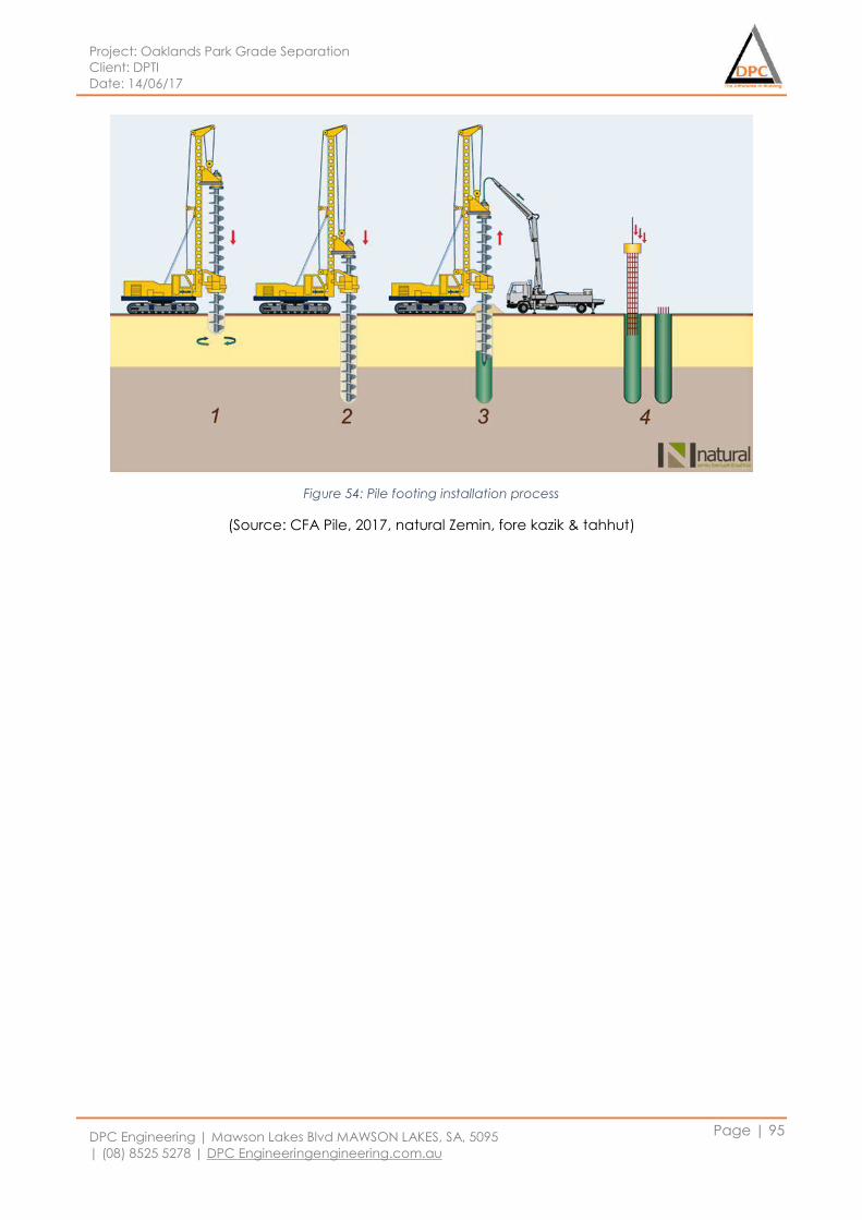
Project: Oaklands Park Grade Separation
Client: DPTI
Date: 14/06/17
DPC Engineering | Mawson Lakes Blvd MAWSON LAKES, SA, 5095
| (08) 8525 5278 | DPC Engineeringengineering.com.au
Page | 95
Figure 54: Pile footing installation process
(Source: CFA Pile, 2017, natural Zemin, fore kazik & tahhut)
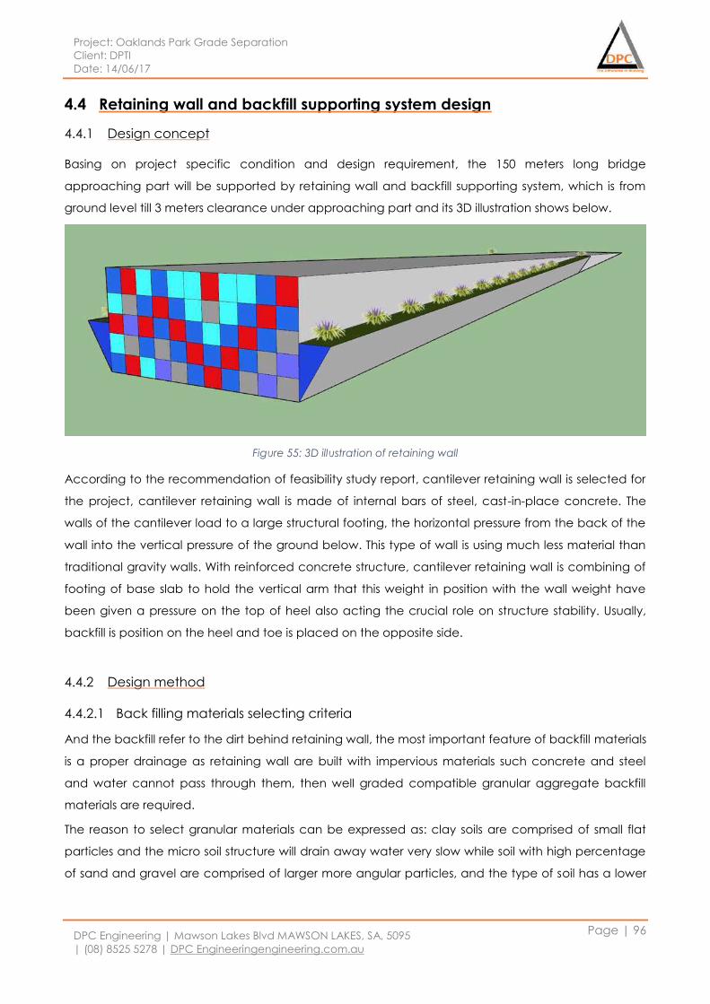
Project: Oaklands Park Grade Separation
Client: DPTI
Date: 14/06/17
DPC Engineering | Mawson Lakes Blvd MAWSON LAKES, SA, 5095
| (08) 8525 5278 | DPC Engineeringengineering.com.au
Page | 96
4.4 Retaining wall and backfill supporting system design
4.4.1 Design concept
Basing on project specific condition and design requirement, the 150 meters long bridge
approaching part will be supported by retaining wall and backfill supporting system, which is from
ground level till 3 meters clearance under approaching part and its 3D illustration shows below.
Figure 55: 3D illustration of retaining wall
According to the recommendation of feasibility study report, cantilever retaining wall is selected for
the project, cantilever retaining wall is made of internal bars of steel, cast-in-place concrete. The
walls of the cantilever load to a large structural footing, the horizontal pressure from the back of the
wall into the vertical pressure of the ground below. This type of wall is using much less material than
traditional gravity walls. With reinforced concrete structure, cantilever retaining wall is combining of
footing of base slab to hold the vertical arm that this weight in position with the wall weight have
been given a pressure on the top of heel also acting the crucial role on structure stability. Usually,
backfill is position on the heel and toe is placed on the opposite side.
4.4.2 Design method
4.4.2.1 Back filling materials selecting criteria
And the backfill refer to the dirt behind retaining wall, the most important feature of backfill materials
is a proper drainage as retaining wall are built with impervious materials such concrete and steel
and water cannot pass through them, then well graded compatible granular aggregate backfill
materials are required.
The reason to select granular materials can be expressed as: clay soils are comprised of small flat
particles and the micro soil structure will drain away water very slow while soil with high percentage
of sand and gravel are comprised of larger more angular particles, and the type of soil has a lower
Project: Oaklands Park Grade Separation
Client: DPTI
Date: 14/06/17
DPC Engineering | Mawson Lakes Blvd MAWSON LAKES, SA, 5095
| (08) 8525 5278 | DPC Engineeringengineering.com.au
Page | 97
cohesive properties but it can drain water away rapidly, the features of these soil provides a more
stable soil mass and reduce hydrostatic pressure in saturated.
4.4.2.2 Cantilever retaining wall design method
In the cantilever retaining wall design proves, three failure types will be checked, such as overturning
check, base sliding check and ultimate bearing capacity.
Overturning refers to the tipping over of the retaining wall rotating about the toe of the retaining
structure, the overturning force is from backfill soil passive pressure acting on the wall stem while the
stabilizing force is the sum of structure total weight and vertical soil pressure acting on wall,
overturning failure happens when stabilizing force is smaller than overturning force.
Base sliding refers to the outward movement of the bottom of the retaining wall as the resultant
lateral force generated by earth pressure and water pressure, the force resisting base sliding is the
friction between wall footing and soil layer underneath, increasing the front to back dimension of
the wall can increase resisting force and keep the structure safe.
Bearing capacity is referring to the ability of the foundation soil support the weight of the retaining
wall, the footing base of retaining wall is regarded and analyzed as shallow foundations method,
increasing the structure base area would help to increase soil bearing capacity and to increase the
depth of retaining wall would increasing the ability of soil bearing capacity underneath.
The factor of safety will be used to evaluate the three design components for the project to ensure
the final design is safe and performing the structure contented function.
For overturning component design:
𝐹𝑎𝑐𝑡𝑜𝑟 𝑜𝑓 𝑆𝑎𝑓𝑒𝑡𝑦: 𝐹𝑜𝑆 =𝑟𝑒𝑠𝑖𝑠𝑡𝑖𝑛𝑔 𝑚𝑜𝑚𝑒𝑛𝑡
𝑜𝑣𝑒𝑟𝑡𝑢𝑟𝑛𝑖𝑛𝑔 𝑚𝑜𝑚𝑒𝑛𝑡
And FoS should greater than 2.5 to satisfy design criteria.
For base sliding component design:
𝐹𝑎𝑐𝑡𝑜𝑟 𝑜𝑓 𝑆𝑎𝑓𝑒𝑡𝑦: 𝐹𝑜𝑆 =𝑠𝑙𝑖𝑑𝑖𝑛𝑔 𝑟𝑒𝑠𝑖𝑠𝑡𝑖𝑛𝑔 𝑓𝑜𝑟𝑐𝑒
𝑠𝑙𝑖𝑑𝑖𝑛𝑔 𝑓𝑜𝑟𝑐𝑒
And FoS should greater than 1.5 to satisfy design criteria.
For bearing capacity component design:
𝐹𝑎𝑐𝑡𝑜𝑟 𝑜𝑓 𝑆𝑎𝑓𝑒𝑡𝑦: 𝐹𝑜𝑆 =𝑎𝑙𝑙𝑜𝑤𝑎𝑏𝑙𝑒 𝑏𝑒𝑎𝑟𝑖𝑛𝑔 𝑝𝑟𝑒𝑠𝑠𝑢𝑟𝑒
𝑓𝑜𝑟𝑐𝑒 𝑝𝑒𝑟 𝑎𝑟𝑒𝑎
And FoS should greater than 1.5 to satisfy design criteria.
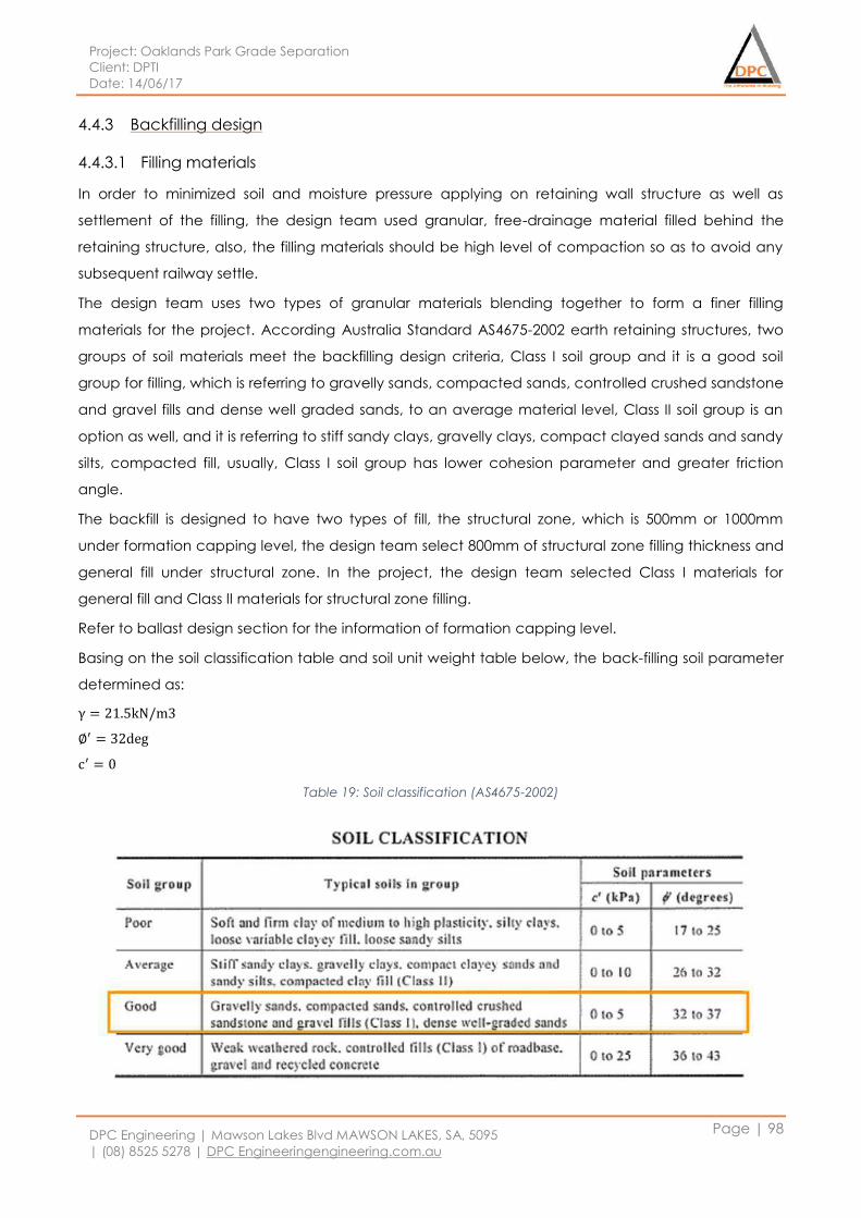
Project: Oaklands Park Grade Separation
Client: DPTI
Date: 14/06/17
DPC Engineering | Mawson Lakes Blvd MAWSON LAKES, SA, 5095
| (08) 8525 5278 | DPC Engineeringengineering.com.au
Page | 98
4.4.3 Backfilling design
4.4.3.1 Filling materials
In order to minimized soil and moisture pressure applying on retaining wall structure as well as
settlement of the filling, the design team used granular, free-drainage material filled behind the
retaining structure, also, the filling materials should be high level of compaction so as to avoid any
subsequent railway settle.
The design team uses two types of granular materials blending together to form a finer filling
materials for the project. According Australia Standard AS4675-2002 earth retaining structures, two
groups of soil materials meet the backfilling design criteria, Class I soil group and it is a good soil
group for filling, which is referring to gravelly sands, compacted sands, controlled crushed sandstone
and gravel fills and dense well graded sands, to an average material level, Class II soil group is an
option as well, and it is referring to stiff sandy clays, gravelly clays, compact clayed sands and sandy
silts, compacted fill, usually, Class I soil group has lower cohesion parameter and greater friction
angle.
The backfill is designed to have two types of fill, the structural zone, which is 500mm or 1000mm
under formation capping level, the design team select 800mm of structural zone filling thickness and
general fill under structural zone. In the project, the design team selected Class I materials for
general fill and Class II materials for structural zone filling.
Refer to ballast design section for the information of formation capping level.
Basing on the soil classification table and soil unit weight table below, the back-filling soil parameter
determined as:
γ = 21.5kN/m3
∅′ = 32deg
c′ = 0
Table 19: Soil classification (AS4675-2002)
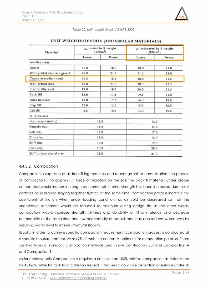
Project: Oaklands Park Grade Separation
Client: DPTI
Date: 14/06/17
DPC Engineering | Mawson Lakes Blvd MAWSON LAKES, SA, 5095
| (08) 8525 5278 | DPC Engineeringengineering.com.au
Page | 99
Table 20: Unit weight of soil (AS4678-2002)
4.4.3.2 Compaction
Compaction is expulsion of air from filling materials and rearrange soil to consolidation, the process
of compaction is to applying a force or vibration on the soil, the backfill materials under proper
compacted would increase strength as internal soil internal strength has been increased due to soil
particles be realigned staying together tighter, at the same time, compaction process increase soil
coefficient of friction when under loading condition, as air void be decreased so that the
undesirable settlement would be reduced to minimum during design life. In the other words,
compaction would increase strength, stiffness and durability of filling materials and decrease
permeability at the same time and low permeability of backfill materials can reduce water press by
reducing water level to ensure structural stability.
Usually, in order to achieve specific compaction requirement, compaction process is conducted at
a specific moisture content, within 2% of moisture content is optimum for compaction purpose. There
are two types of standard compaction methods used in civil construction, such as Compaction A
and Compaction B.
As for cohesive soils Compaction A requires a not less than 100% relative compaction as determined
by AS1289, while for rock fill or cohesion less soil, it requires a no visible deflection of surface under 10

Project: Oaklands Park Grade Separation
Client: DPTI
Date: 14/06/17
DPC Engineering | Mawson Lakes Blvd MAWSON LAKES, SA, 5095
| (08) 8525 5278 | DPC Engineeringengineering.com.au
Page | 100
tones vibratory rollers after 6-8 passes. Compaction B requires not less than 95% relative compaction
as determined by AS1289.
In the project, Compaction B is recommended for general fill and Compaction A for structural zone.
For compaction purpose, heavy compaction equipment such as smooth steel rollers, sheepsfoot
roller can be used
Figure 56: Smooth steel rollers (Source: Compare factory)
Figure 57: Sheepsfoot Roller (Source: the county of Lincoln – Road)
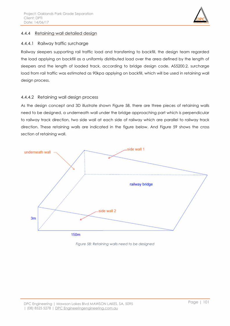
Project: Oaklands Park Grade Separation
Client: DPTI
Date: 14/06/17
DPC Engineering | Mawson Lakes Blvd MAWSON LAKES, SA, 5095
| (08) 8525 5278 | DPC Engineeringengineering.com.au
Page | 101
4.4.4 Retaining wall detailed design
4.4.4.1 Railway traffic surcharge
Railway sleepers supporting rail traffic load and transferring to backfill, the design team regarded
the load applying on backfill as a uniformly distributed load over the area defined by the length of
sleepers and the length of loaded track, according to bridge design code, AS5200.2, surcharge
load from rail traffic was estimated as 90kpa applying on backfill, which will be used in retaining wall
design process.
4.4.4.2 Retaining wall design process
As the design concept and 3D illustrate shown Figure 58, there are three pieces of retaining walls
need to be designed, a underneath wall under the bridge approaching part which is perpendicular
to railway track direction, two side wall at each side of railway which are parallel to railway track
direction. These retaining walls are indicated in the figure below. And Figure 59 shows the cross
section of retaining wall.
Figure 58: Retaining walls need to be designed
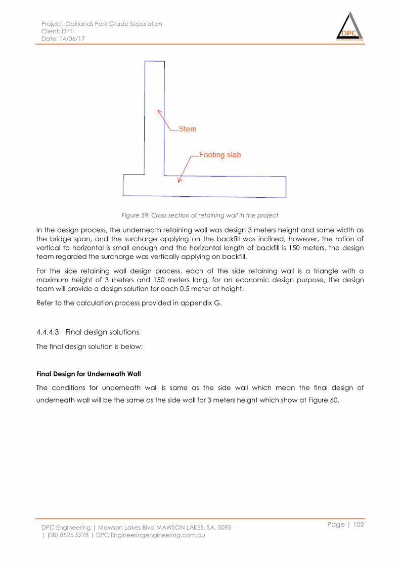
Project: Oaklands Park Grade Separation
Client: DPTI
Date: 14/06/17
DPC Engineering | Mawson Lakes Blvd MAWSON LAKES, SA, 5095
| (08) 8525 5278 | DPC Engineeringengineering.com.au
Page | 102
Figure 59: Cross section of retaining wall in the project
In the design process, the underneath retaining wall was design 3 meters height and same width as
the bridge span, and the surcharge applying on the backfill was inclined, however, the ration of
vertical to horizontal is small enough and the horizontal length of backfill is 150 meters, the design
team regarded the surcharge was vertically applying on backfill.
For the side retaining wall design process, each of the side retaining wall is a triangle with a
maximum height of 3 meters and 150 meters long, for an economic design purpose, the design
team will provide a design solution for each 0.5 meter at height.
Refer to the calculation process provided in appendix G.
4.4.4.3 Final design solutions
The final design solution is below:
Final Design for Underneath Wall
The conditions for underneath wall is same as the side wall which mean the final design of
underneath wall will be the same as the side wall for 3 meters height which show at Figure 60.
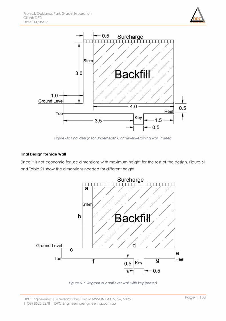
Project: Oaklands Park Grade Separation
Client: DPTI
Date: 14/06/17
DPC Engineering | Mawson Lakes Blvd MAWSON LAKES, SA, 5095
| (08) 8525 5278 | DPC Engineeringengineering.com.au
Page | 103
Figure 60: Final design for Underneath Cantilever Retaining wall (meter)
Final Design for Side Wall
Since it is not economic for use dimensions with maximum height for the rest of the design. Figure 61
and Table 21 show the dimensions needed for different height
Figure 61: Diagram of cantilever wall with key (meter)
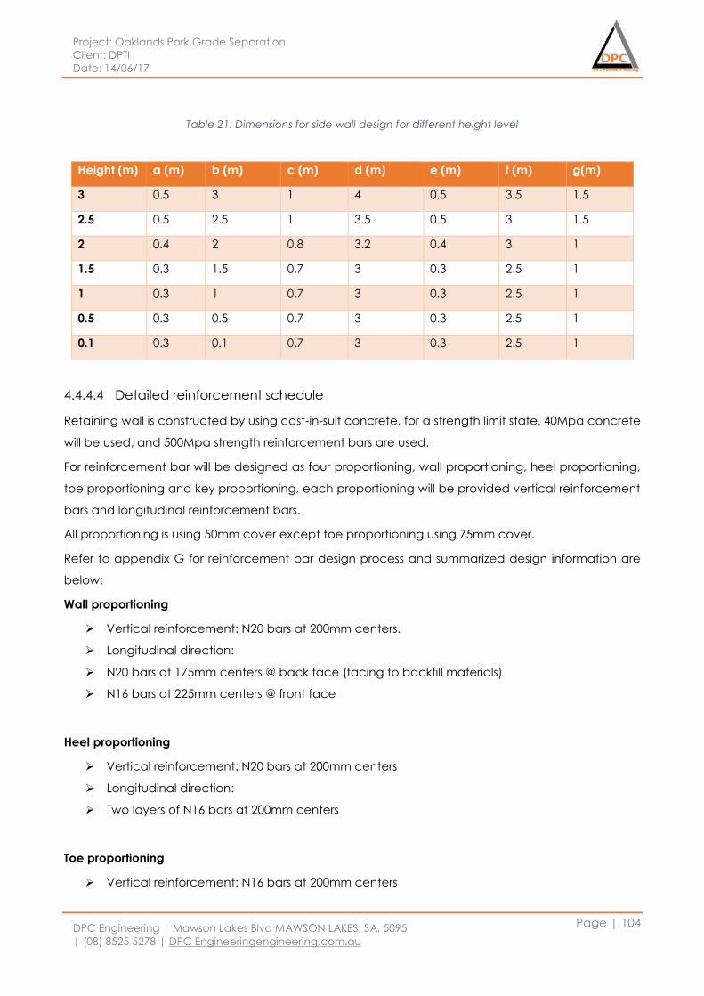
Project: Oaklands Park Grade Separation
Client: DPTI
Date: 14/06/17
DPC Engineering | Mawson Lakes Blvd MAWSON LAKES, SA, 5095
| (08) 8525 5278 | DPC Engineeringengineering.com.au
Page | 104
Table 21: Dimensions for side wall design for different height level
4.4.4.4 Detailed reinforcement schedule
Retaining wall is constructed by using cast-in-suit concrete, for a strength limit state, 40Mpa concrete
will be used, and 500Mpa strength reinforcement bars are used.
For reinforcement bar will be designed as four proportioning, wall proportioning, heel proportioning,
toe proportioning and key proportioning, each proportioning will be provided vertical reinforcement
bars and longitudinal reinforcement bars.
All proportioning is using 50mm cover except toe proportioning using 75mm cover.
Refer to appendix G for reinforcement bar design process and summarized design information are
below:
Wall proportioning
Vertical reinforcement: N20 bars at 200mm centers.
Longitudinal direction:
N20 bars at 175mm centers @ back face (facing to backfill materials)
N16 bars at 225mm centers @ front face
Heel proportioning
Vertical reinforcement: N20 bars at 200mm centers
Longitudinal direction:
Two layers of N16 bars at 200mm centers
Toe proportioning
Vertical reinforcement: N16 bars at 200mm centers
Height (m) a (m) b (m) c (m) d (m) e (m) f (m) g(m)
3 0.5 3 1 4 0.5 3.5 1.5
2.5 0.5 2.5 1 3.5 0.5 3 1.5
2 0.4 2 0.8 3.2 0.4 3 1
1.5 0.3 1.5 0.7 3 0.3 2.5 1
1 0.3 1 0.7 3 0.3 2.5 1
0.5 0.3 0.5 0.7 3 0.3 2.5 1
0.1 0.3 0.1 0.7 3 0.3 2.5 1
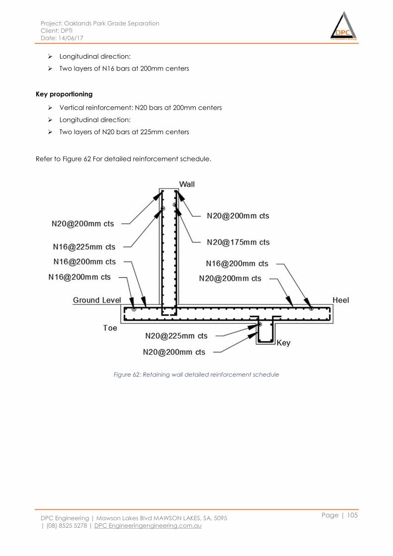
Project: Oaklands Park Grade Separation
Client: DPTI
Date: 14/06/17
DPC Engineering | Mawson Lakes Blvd MAWSON LAKES, SA, 5095
| (08) 8525 5278 | DPC Engineeringengineering.com.au
Page | 105
Longitudinal direction:
Two layers of N16 bars at 200mm centers
Key proportioning
Vertical reinforcement: N20 bars at 200mm centers
Longitudinal direction:
Two layers of N20 bars at 225mm centers
Refer to Figure 62 For detailed reinforcement schedule.
Figure 62: Retaining wall detailed reinforcement schedule
Project: Oaklands Park Grade Separation
Client: DPTI
Date: 14/06/17
DPC Engineering | Mawson Lakes Blvd MAWSON LAKES, SA, 5095
| (08) 8525 5278 | DPC Engineeringengineering.com.au
Page | 106
4.5 Pavement design
4.5.1 Design concept for pavement
Pavement is one of the important component in Geotechnical design. Pavement is a structure
comprising of superimposed layers of prepared materials over the natural soil whose essential
capacity to distribute the vehicles load to the soil sub-grade. Our goal is to design the pavement
ought to have the capacity to provide surface of satisfactory vehicles users quality, sufficient skid
resistance, light reflecting attributes and low noise pollution. Ultimately is to achieve the transmitted
stresses causes by vehicle wheel load are achieving the requirements reduction to prevent the
surpass of bearing capacity of the sub-grade.
Pavement Design Consideration for Specific Project Area:
Satisfactory thickness to distribute stress load caused by wheel vehicles according to
requirements of the sub-grade soil
Fundamentally strong to withstand a wide range of stresses forced upon it
Satisfactory coefficient of erosion to anticipate skidding of vehicles
Satisfactory smooth surface to provide comfort pavement condition
Achieve minimum noise pollution from moving vehicles
Well-protected sub-grade soil with impenetrable surface pavement.
Reducing visibility impact with dust proof surface
Long life design with economy maintenance cost
4.5.2 Design method
4.5.2.1 Traffic data analysis method
Based on Oaklands Park Road Traffic Analysis Report provided by Planning & Design, Transport
Services Division, DTEI, several important roads within the construction area is being targeted. In
order to perform the pavement design, traffic data analysis is relatively important such as average
annual design traffic, percentage of heavy vehicles and so on. Pavement design is enormously
impacted by the measure of vehicles and in this way the examination of traffic volume is the need in
the plan. The traffic volumes is generated and can be found in appendix G.
The average of AADT for particular road is calculated and designation of pavement are selected
based on estimated critical %HV and critical average AADT with the motivation to achieve cost
efficiency in pavement design. From the summarized traffic volume data, the highest Average
Annual Daily Traffic, AADT is 60100 vehicles per day with 2020 trucks which are heavy vehicles.
Therefore, the pavement design will priority on the most critical road which are Diagonal road with
the highest AADT. Besides that, as a lower traffic volume at Prunus Street, another separate design
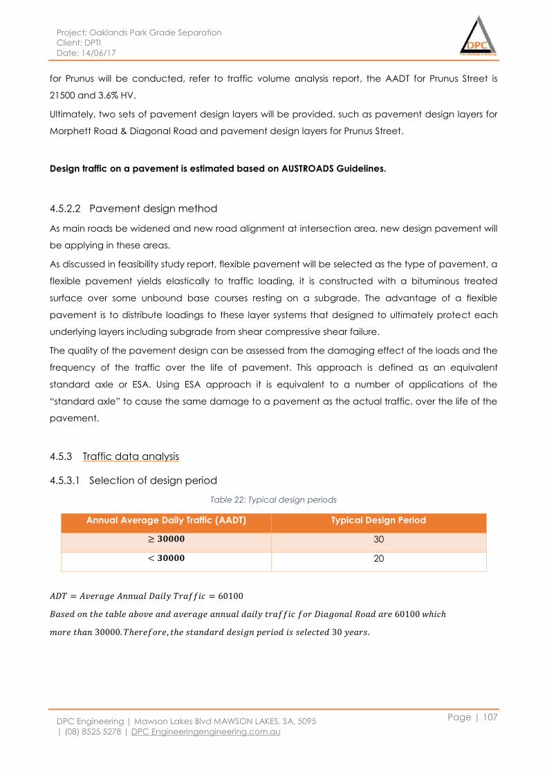
Project: Oaklands Park Grade Separation
Client: DPTI
Date: 14/06/17
DPC Engineering | Mawson Lakes Blvd MAWSON LAKES, SA, 5095
| (08) 8525 5278 | DPC Engineeringengineering.com.au
Page | 107
for Prunus will be conducted, refer to traffic volume analysis report, the AADT for Prunus Street is
21500 and 3.6% HV.
Ultimately, two sets of pavement design layers will be provided, such as pavement design layers for
Morphett Road & Diagonal Road and pavement design layers for Prunus Street.
Design traffic on a pavement is estimated based on AUSTROADS Guidelines.
4.5.2.2 Pavement design method
As main roads be widened and new road alignment at intersection area, new design pavement will
be applying in these areas.
As discussed in feasibility study report, flexible pavement will be selected as the type of pavement, a
flexible pavement yields elastically to traffic loading, it is constructed with a bituminous treated
surface over some unbound base courses resting on a subgrade. The advantage of a flexible
pavement is to distribute loadings to these layer systems that designed to ultimately protect each
underlying layers including subgrade from shear compressive shear failure.
The quality of the pavement design can be assessed from the damaging effect of the loads and the
frequency of the traffic over the life of pavement. This approach is defined as an equivalent
standard axle or ESA. Using ESA approach it is equivalent to a number of applications of the
“standard axle” to cause the same damage to a pavement as the actual traffic, over the life of the
pavement.
4.5.3 Traffic data analysis
4.5.3.1 Selection of design period
Table 22: Typical design periods
Annual Average Daily Traffic (AADT) Typical Design Period
≥ 𝟑𝟎𝟎𝟎𝟎 30
< 𝟑𝟎𝟎𝟎𝟎 20
𝐴𝐷𝑇 = 𝐴𝑣𝑒𝑟𝑎𝑔𝑒 𝐴𝑛𝑛𝑢𝑎𝑙 𝐷𝑎𝑖𝑙𝑦 𝑇𝑟𝑎𝑓𝑓𝑖𝑐 = 60100
𝐵𝑎𝑠𝑒𝑑 𝑜𝑛 𝑡ℎ𝑒 𝑡𝑎𝑏𝑙𝑒 𝑎𝑏𝑜𝑣𝑒 𝑎𝑛𝑑 𝑎𝑣𝑒𝑟𝑎𝑔𝑒 𝑎𝑛𝑛𝑢𝑎𝑙 𝑑𝑎𝑖𝑙𝑦 𝑡𝑟𝑎𝑓𝑓𝑖𝑐 𝑓𝑜𝑟 𝐷𝑖𝑎𝑔𝑜𝑛𝑎𝑙 𝑅𝑜𝑎𝑑 𝑎𝑟𝑒 60100 𝑤ℎ𝑖𝑐ℎ
𝑚𝑜𝑟𝑒 𝑡ℎ𝑎𝑛 30000. 𝑇ℎ𝑒𝑟𝑒𝑓𝑜𝑟𝑒, 𝑡ℎ𝑒 𝑠𝑡𝑎𝑛𝑑𝑎𝑟𝑑 𝑑𝑒𝑠𝑖𝑔𝑛 𝑝𝑒𝑟𝑖𝑜𝑑 𝑖𝑠 𝑠𝑒𝑙𝑒𝑐𝑡𝑒𝑑 30 𝑦𝑒𝑎𝑟𝑠.
Project: Oaklands Park Grade Separation
Client: DPTI
Date: 14/06/17
DPC Engineering | Mawson Lakes Blvd MAWSON LAKES, SA, 5095
| (08) 8525 5278 | DPC Engineeringengineering.com.au
Page | 108
4.5.3.2 Design traffic equivalent standard axles
In pavement design, the first step is to calculate the design traffic. The simplest approach is the
Equivalent Standard Axel (ESA) method. Different type of axle configurations carry different standard
loads are converted to one ESA. The design traffic can then be represented as a single number
which is the number of applications of the ESA to cause the same damage to a pavement road as
for the actual traffic, over its entire design life. For an axel configuration with non-standard load, the
ESA can be calculated as below:
𝐸𝑆𝐴 = (non − standard axel load ÷ standard axel load)4 (1)
As for a small vehicle which has axel load much less than the standard axel load, the ESA will be very
small due to the power of 4 from above equation. Thus the small vehicles are unlikely to cause
significant damage in comparison with heavy vehicles which likely to have larger than standard axel
load. As a general approach, the design ESA is calculated as:
𝐷𝐸𝑆𝐴 = 𝑁𝑑𝑡×𝑇𝐿𝐷 (2)
Where:
𝑁𝑑𝑡 is the total number of heavy vehicle axel groups over pavement design period
TLD is the average ESA per each Heavy Vehicle Axel Group (HVAG)
And the total number of heavy vehicle axel groups over pavement design period is calculated by
𝑁𝑑𝑡 = 365×𝐴𝐴𝐷𝑇×𝐷𝐹×(%𝐻𝑉)×𝑁𝐻𝑉𝐴𝐺×𝐿𝐷𝐹×𝐶𝐺𝐹
Where
AADT = Average annual daily traffic count
DF = Direction factor
%HV = Percentage of heavy vehicles
𝑁𝐻𝑉𝐴𝐺 = Average number of axle groups per heavy vehicle
LDF = lane distribution factor
CGF = Cumulative growth factor or effective design life in years
Basing on traffic data, the design equivalent standard axle is 3.3×10⁷
4.5.4 Pavement Layers Design
4.5.4.1 Wearing Surface
The main function of the wearing surface is to endure the common loading and environmental
effect such as moisture, dust and minor vehicles oil leakage during pavement usage. Main
motivation is to provide a protected and functional riding surface with diminished moisture and
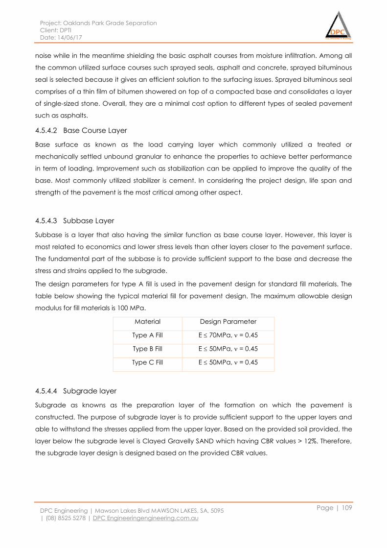
Project: Oaklands Park Grade Separation
Client: DPTI
Date: 14/06/17
DPC Engineering | Mawson Lakes Blvd MAWSON LAKES, SA, 5095
| (08) 8525 5278 | DPC Engineeringengineering.com.au
Page | 109
noise while in the meantime shielding the basic asphalt courses from moisture infiltration. Among all
the common utilized surface courses such sprayed seals, asphalt and concrete, sprayed bituminous
seal is selected because it gives an efficient solution to the surfacing issues. Sprayed bituminous seal
comprises of a thin film of bitumen showered on top of a compacted base and consolidates a layer
of single-sized stone. Overall, they are a minimal cost option to different types of sealed pavement
such as asphalts.
4.5.4.2 Base Course Layer
Base surface as known as the load carrying layer which commonly utilized a treated or
mechanically settled unbound granular to enhance the properties to achieve better performance
in term of loading. Improvement such as stabilization can be applied to improve the quality of the
base. Most commonly utilized stabilizer is cement. In considering the project design, life span and
strength of the pavement is the most critical among other aspect.
4.5.4.3 Subbase Layer
Subbase is a layer that also having the similar function as base course layer. However, this layer is
most related to economics and lower stress levels than other layers closer to the pavement surface.
The fundamental part of the subbase is to provide sufficient support to the base and decrease the
stress and strains applied to the subgrade.
The design parameters for type A fill is used in the pavement design for standard fill materials. The
table below showing the typical material fill for pavement design. The maximum allowable design
modulus for fill materials is 100 MPa.
Material Design Parameter
Type A Fill E 70MPa, = 0.45
Type B Fill E 50MPa, = 0.45
Type C Fill E 50MPa, = 0.45
4.5.4.4 Subgrade layer
Subgrade as knowns as the preparation layer of the formation on which the pavement is
constructed. The purpose of subgrade layer is to provide sufficient support to the upper layers and
able to withstand the stresses applied from the upper layer. Based on the provided soil provided, the
layer below the subgrade level is Clayed Gravelly SAND which having CBR values > 12%. Therefore,
the subgrade layer design is designed based on the provided CBR values.
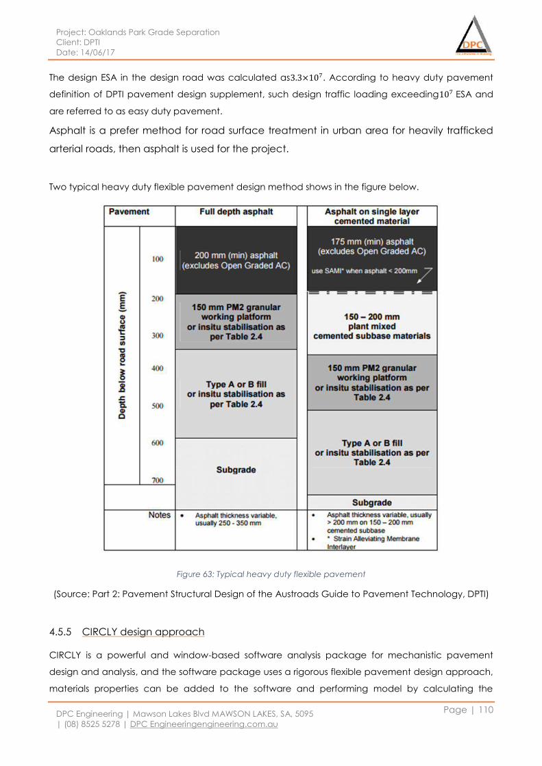
Project: Oaklands Park Grade Separation
Client: DPTI
Date: 14/06/17
DPC Engineering | Mawson Lakes Blvd MAWSON LAKES, SA, 5095
| (08) 8525 5278 | DPC Engineeringengineering.com.au
Page | 110
The design ESA in the design road was calculated as3.3×107. According to heavy duty pavement
definition of DPTI pavement design supplement, such design traffic loading exceeding107 ESA and
are referred to as easy duty pavement.
Asphalt is a prefer method for road surface treatment in urban area for heavily trafficked
arterial roads, then asphalt is used for the project.
Two typical heavy duty flexible pavement design method shows in the figure below.
Figure 63: Typical heavy duty flexible pavement
(Source: Part 2: Pavement Structural Design of the Austroads Guide to Pavement Technology, DPTI)
4.5.5 CIRCLY design approach
CIRCLY is a powerful and window-based software analysis package for mechanistic pavement
design and analysis, and the software package uses a rigorous flexible pavement design approach,
materials properties can be added to the software and performing model by calculating the

Project: Oaklands Park Grade Separation
Client: DPTI
Date: 14/06/17
DPC Engineering | Mawson Lakes Blvd MAWSON LAKES, SA, 5095
| (08) 8525 5278 | DPC Engineeringengineering.com.au
Page | 111
cumulative damage included by the traffic spectrum. The cumulative damage factor will be
generated to evaluate design model.
4.5.5.1 Morphett and Diagonal Road
Table 23: CIRCLY design layers and cumulative damage factor
Layer Title Thickness CIRCLY
CDF
𝟏
𝑪𝑫𝑭 =Design DESA Target DESA
1 AC20 Mix Size 80km/h 150
2 Cemented E=3500MPa 200
3 Subgrade CBR 3 =
Aniso
175
4 Type A Fill E<70 400
5 Subgrade CBR 15 Aniso 150 2.62×10⁻⁸ 3.82×10⁷ 3.3×10⁷
Table above showing the final design for critical DESA condition. From the analysis proven that
Morphett Road consider to be heavy duty traffic flow with target DESA is 3.3×10⁷. Therefore, the
material use and thickness requirement is slightly higher. 150mm layer of asphalt layer is consider to
be stronger material and applied on the upper layer to withstand most of the vehicles loading. Due
to heavy duty pavement design, cemented material is selected and with thickness 200 to withstand
and achieve the target DESA. Other layer such as subgrade and type A fill is applied to support the
upper layer in an economic efficient design. From the CIRCLY software analysis and calculation, the
design DESA of Morphett pavement structure had achieved the target DESA requirement as
3.82×10⁷ > 3.30×10⁷. Figure below showing the final design pavement for critical DESA condition.
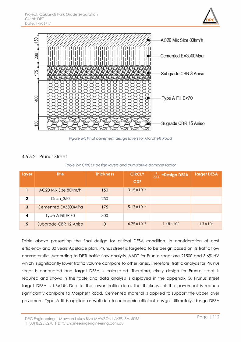
Project: Oaklands Park Grade Separation
Client: DPTI
Date: 14/06/17
DPC Engineering | Mawson Lakes Blvd MAWSON LAKES, SA, 5095
| (08) 8525 5278 | DPC Engineeringengineering.com.au
Page | 112
Figure 64: Final pavement design layers for Morphett Road
4.5.5.2 Prunus Street
Table 24: CIRCLY design layers and cumulative damage factor
Layer Title Thickness CIRCLY
CDF
𝟏
𝑪𝑫𝑭 =Design DESA Target DESA
1 AC20 Mix Size 80km/h 150 3.15×10⁻¹
2 Gran_350 250
3 Cemented E=3500MPa 175 5.17×10⁻³
4 Type A Fill E<70 300
5 Subgrade CBR 12 Aniso 0 6.75×10⁻⁸ 1.48×10⁷ 1.3×10⁷
Table above presenting the final design for critical DESA condition. In consideration of cost
efficiency and 30 years Adelaide plan, Prunus street is targeted to be design based on its traffic flow
characteristic. According to DPTI traffic flow analysis, AADT for Prunus street are 21500 and 3.6% HV
which is significantly lower traffic volume compare to other lanes. Therefore, traffic analysis for Prunus
street is conducted and target DESA is calculated. Therefore, circly design for Prunus street is
required and shows in the table and data analysis is displayed in the appendix G. Prunus street
target DESA is 1.3×10⁷. Due to the lower traffic data, the thickness of the pavement is reduce
significantly compare to Morphett Road. Cemented material is applied to support the upper layer
pavement. Type A fill is applied as well due to economic efficient design. Ultimately, design DESA
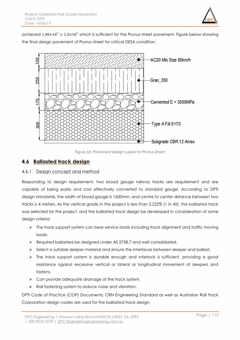
Project: Oaklands Park Grade Separation
Client: DPTI
Date: 14/06/17
DPC Engineering | Mawson Lakes Blvd MAWSON LAKES, SA, 5095
| (08) 8525 5278 | DPC Engineeringengineering.com.au
Page | 113
achieved 1.48×10⁷ > 1.3×10⁷ which is sufficient for the Prunus street pavement. Figure below showing
the final design pavement of Prunus street for critical DESA condition.
Figure 65: Pavement Design Layers for Prunus Street
4.6 Ballasted track design
4.6.1 Design concept and method
Responding to design requirement, two broad gauge railway tracks are requirement and are
capable of being easily and cost effectively converted to standard gauge. According to DPTI
design standards, the width of broad gauge is 1600mm, and centre to center distance between two
tracks is 4 meters. As the vertical grade in the project is less than 2.222% (1 in 45), the ballasted track
was selected for the project, and the ballasted track design be developed in consideration of some
design criteria:
The track support system can bear service loads including track alignment and traffic moving
loads.
Required ballasted be designed under AS 2758.7 and well consolidated.
Select a suitable sleeper material and ensure the interfaces between sleeper and ballast.
The track support system is durable enough and interlock is sufficient, providing a good
resistance against excessive vertical or lateral or longitudinal movement of sleepers and
fastens.
Can provide adequate drainage of the track system.
Rail fastening system to reduce noise and vibration.
DPTI Code of Practice (COP) Documents, CRN Engineering Standard as well as Australian Rail Track
Corporation design codes are used for the ballasted track design.
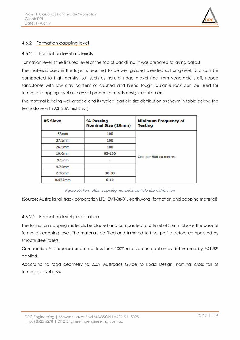
Project: Oaklands Park Grade Separation
Client: DPTI
Date: 14/06/17
DPC Engineering | Mawson Lakes Blvd MAWSON LAKES, SA, 5095
| (08) 8525 5278 | DPC Engineeringengineering.com.au
Page | 114
4.6.2 Formation capping level
4.6.2.1 Formation level materials
Formation level is the finished level at the top of backfilling, it was prepared to laying ballast.
The materials used in the layer is required to be well graded blended soil or gravel, and can be
compacted to high density, soil such as natural ridge gravel free from vegetable staff, ripped
sandstones with low clay content or crushed and blend tough, durable rock can be used for
formation capping level as they soil properties meets design requirement.
The material is being well-graded and its typical particle size distribution as shown in table below, the
test is done with AS1289, test 3.6.1)
Figure 66: Formation capping materials particle size distribution
(Source: Australia rail track corporation LTD, EMT-08-01, earthworks, formation and capping material)
4.6.2.2 Formation level preparation
The formation capping materials be placed and compacted to a level of 30mm above the base of
formation capping level. The materials be filled and trimmed to final profile before compacted by
smooth steel rollers.
Compaction A is required and a not less than 100% relative compaction as determined by AS1289
applied.
According to road geometry to 2009 Austroads Guide to Road Design, nominal cross fall of
formation level is 3%.
Project: Oaklands Park Grade Separation
Client: DPTI
Date: 14/06/17
DPC Engineering | Mawson Lakes Blvd MAWSON LAKES, SA, 5095
| (08) 8525 5278 | DPC Engineeringengineering.com.au
Page | 115
4.6.3 Track supporting system
4.6.3.1 Track class
Based on design requirement and 30 year greater Adelaide plan, the track class is defined as Main
Line 1, which will provides a maximum axle loads 25 tones, and maximum operation speed 115km/h
for passenger train, 80 km/h for freight train.
4.6.3.2 Rail type
According to rail length used and the rail type is determined using Continuously Welded Rail (CWR),
60kk rail is used.
4.6.3.3 Sleeper type and size
As rail type is CWR, the sleepers are decided using concrete sleeper, and resilient fastenings system
used. Sleepers are determined to be designed for heavy duty purpose. The length of sleepers using
2500mmm, width at base as 250mm and 230mm for depth, and the spacing of sleeper is determined
as 600mm.
4.6.4 Ballast design and profile
4.6.4.1 Ballast material and grading
Ballast is a free draining coarse aggregate used to support railway track, the proposed ballast
materials must be angular rock which will provide a good interlock and a less deformation, one of
the best option for ballast is crushed aggregate, the materials can provide track stability, drainage,
and distribution of the loads carried into the ground underneath.
Rail ballast is using single size aggregate, generally has a nominal size of 63mm, the grading
requirement is expressed as particle size distribution, as shown in table below.
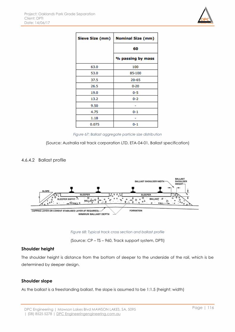
Project: Oaklands Park Grade Separation
Client: DPTI
Date: 14/06/17
DPC Engineering | Mawson Lakes Blvd MAWSON LAKES, SA, 5095
| (08) 8525 5278 | DPC Engineeringengineering.com.au
Page | 116
Figure 67: Ballast aggregate particle size distribution
(Source: Australia rail track corporation LTD, ETA-04-01, Ballast specification)
4.6.4.2 Ballast profile
Figure 68: Typical track cross section and ballast profile
(Source: CP – TS – 960, Track support system, DPTI)
Shoulder height
The shoulder height is distance from the bottom of sleeper to the underside of the rail, which is be
determined by sleeper design.
Shoulder slope
As the ballast is a freestanding ballast, the slope is assumed to be 1:1.5 (height: width)
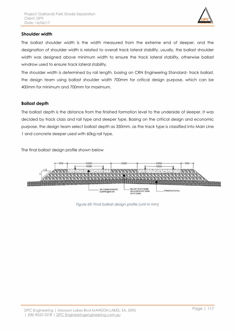
Project: Oaklands Park Grade Separation
Client: DPTI
Date: 14/06/17
DPC Engineering | Mawson Lakes Blvd MAWSON LAKES, SA, 5095
| (08) 8525 5278 | DPC Engineeringengineering.com.au
Page | 117
Shoulder width
The ballast shoulder width is the width measured from the extreme end of sleeper, and the
designation of shoulder width is related to overall track lateral stability, usually, the ballast shoulder
width was designed above minimum width to ensure the track lateral stability, otherwise ballast
windrow used to ensure track lateral stability.
The shoulder width is determined by rail length, basing on CRN Engineering Standard- track ballast,
the design team using ballast shoulder width 700mm for critical design purpose, which can be
400mm for minimum and 700mm for maximum.
Ballast depth
The ballast depth is the distance from the finished formation level to the underside of sleeper. It was
decided by track class and rail type and sleeper type. Basing on the critical design and economic
purpose, the design team select ballast depth as 350mm, as the track type is classified into Main Line
1 and concrete sleeper used with 60kg rail type.
The final ballast design profile shown below
Figure 69: Final ballast design profile (unit in mm)
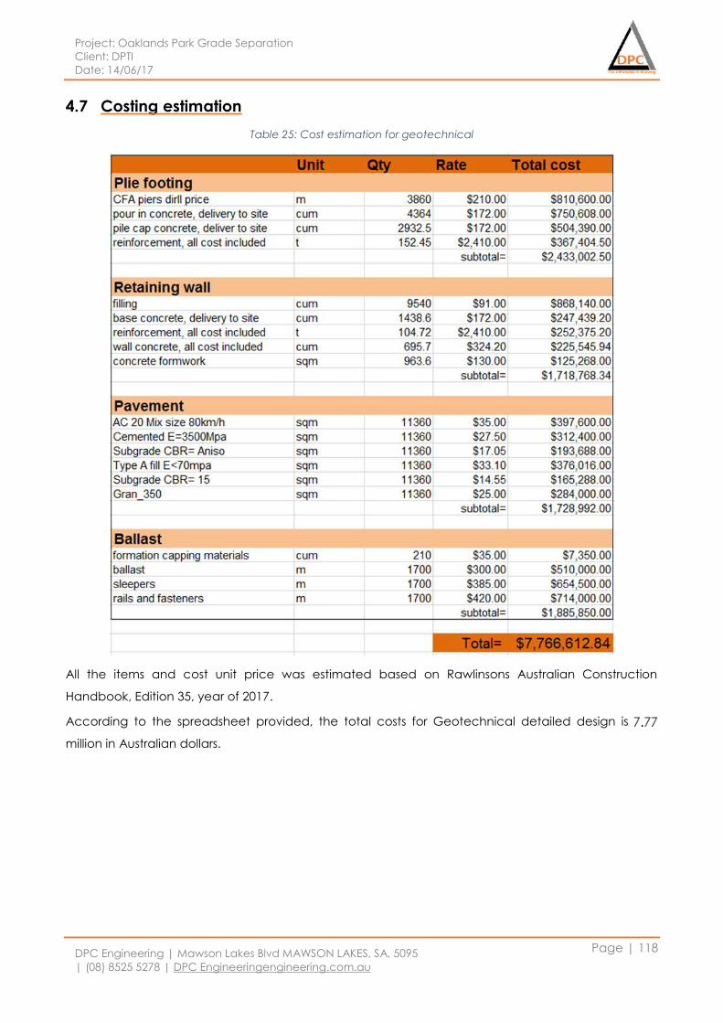
Project: Oaklands Park Grade Separation
Client: DPTI
Date: 14/06/17
DPC Engineering | Mawson Lakes Blvd MAWSON LAKES, SA, 5095
| (08) 8525 5278 | DPC Engineeringengineering.com.au
Page | 118
4.7 Costing estimation
Table 25: Cost estimation for geotechnical
All the items and cost unit price was estimated based on Rawlinsons Australian Construction
Handbook, Edition 35, year of 2017.
According to the spreadsheet provided, the total costs for Geotechnical detailed design is 7.24
million in Australian dollars.
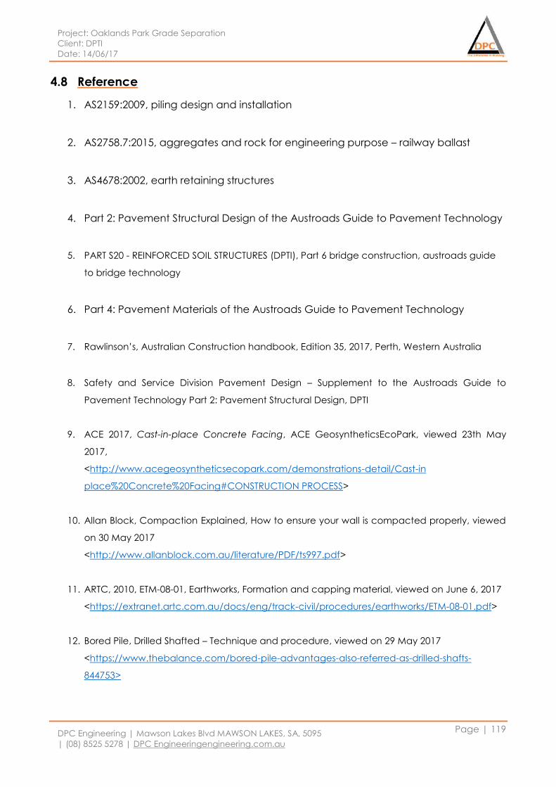
Project: Oaklands Park Grade Separation
Client: DPTI
Date: 14/06/17
DPC Engineering | Mawson Lakes Blvd MAWSON LAKES, SA, 5095
| (08) 8525 5278 | DPC Engineeringengineering.com.au
Page | 119
4.8 Reference
1. AS2159:2009, piling design and installation
2. AS2758.7:2015, aggregates and rock for engineering purpose – railway ballast
3. AS4678:2002, earth retaining structures
4. Part 2: Pavement Structural Design of the Austroads Guide to Pavement Technology
5. PART S20 - REINFORCED SOIL STRUCTURES (DPTI), Part 6 bridge construction, austroads guide
to bridge technology
6. Part 4: Pavement Materials of the Austroads Guide to Pavement Technology
7. Rawlinson’s, Australian Construction handbook, Edition 35, 2017, Perth, Western Australia
8. Safety and Service Division Pavement Design – Supplement to the Austroads Guide to
Pavement Technology Part 2: Pavement Structural Design, DPTI
9. ACE 2017, Cast-in-place Concrete Facing, ACE GeosyntheticsEcoPark, viewed 23th May
2017,
<http://www.acegeosyntheticsecopark.com/demonstrations-detail/Cast-in
place%20Concrete%20Facing#CONSTRUCTION PROCESS>
10. Allan Block, Compaction Explained, How to ensure your wall is compacted properly, viewed
on 30 May 2017
<http://www.allanblock.com.au/literature/PDF/ts997.pdf>
11. ARTC, 2010, ETM-08-01, Earthworks, Formation and capping material, viewed on June 6, 2017
<https://extranet.artc.com.au/docs/eng/track-civil/procedures/earthworks/ETM-08-01.pdf>
12. Bored Pile, Drilled Shafted – Technique and procedure, viewed on 29 May 2017
<https://www.thebalance.com/bored-pile-advantages-also-referred-as-drilled-shafts-
844753>
Project: Oaklands Park Grade Separation
Client: DPTI
Date: 14/06/17
DPC Engineering | Mawson Lakes Blvd MAWSON LAKES, SA, 5095
| (08) 8525 5278 | DPC Engineeringengineering.com.au
Page | 120
13. Bryan Duevel 2014, Retaining Wall Design for the Railroad Infrastructure: What Makes Its
Design and Construction Unique, viewed 15 May 2017
<https://www.arema.org/files/library/2014_Conference_Proceedings/Retaining_Wall_Design_
for_the_Railroad_Infrastructure.pdf>
14. CFA Pile, 2017, natural Zemin, fore kazik & tahhut, viewed on 29 May 2017
<http://www.naturalzemin.com/en/services/cfa-pile/>
15. Chapter7, Underground Installation of PE piping, viewed 23th May 2017 Page 274-280,
<https://plasticpipe.org/pdf/chapter07.pdf>
16. Design and installation guidelines for retaining walls, enviro grid, geo products, viewed on 29
May 2017
<http://www.geoproducts.org/editoruploads/documents/retaining%20walls%200811s.pdf>
17. Dr. Mohammed E. Haque,P.E, Retaining wall, viewed 16 May 2017,
<http://people.tamu.edu/~mhaque/cosc421/Rwalls.pdf>
18. DPTI, 2008, CP-TS-960 – Track Support Systems,
<http://www.dpti.sa.gov.au/__data/assets/pdf_file/0019/125470/CP-TS-960_-
_Track_Support_Systems.pdf>
19. John Holland 2016, Engineering Standard, Track, CRN CS 240, Ballast, viewed on June 6, 2017
<http://jhrcrn.com.au/media/2163/crn-cs-240-v1-2.pdf>
20. John Holland 2016, Engineering Standard, Track, CRN CS 200, Track system, viewed on June
6, 2017
<http://www.jhrcrn.com.au/media/2804/crn-cs-200-v1-4.pdf>
21. John 2013, Three Reasons Why Retaining Walls Fail, Cselandscapearechitect, viewed 16 May
2017
<http://www.cselandscapearchitect.com/2013/04/15/three-reasons-why-retaining-walls-
fail/>
22. Rahul 2013, Retaining walls, InslideShare, viewed 15 May 2017
<https://www.slideshare.net/rahulagrawal05/retaining-walls-21085895>

Project: Oaklands Park Grade Separation
Client: DPTI
Date: 14/06/17
DPC Engineering | Mawson Lakes Blvd MAWSON LAKES, SA, 5095
| (08) 8525 5278 | DPC Engineeringengineering.com.au
Page | 121
23. Ritesh Chinchawade 2013, Mode of failure of retaining walls, viewed 15 May 2017
<https://www.slideshare.net/riteshac1/modes-of-failure-of-retaining-walls?next_slideshow=1>
24. Technical Note 75, Aggregate for railway ballast, the requirements of AS 2758.7-2009, viewed
on June 6, 2017
<http://www.ccaa.com.au/imis_prod/documents/Library%20Documents/Tech%20Note%207
5%20Railway%20Ballast%20LR.pdf
25. UMR, part 4 Cantilever walls, viewed 15 May 2017
<http://web.mst.edu/~rogersda/umrcourses/ge441/online_lectures/retention_structures/GE4
41-Lecture6-4.pdf>
26. University of the west of England 2017, Bearing capacity, viewed 16 May 2017
<http://environment.uwe.ac.uk/geocal/foundations/founbear.htm>

Project: Oaklands Park Grade Separation
Client: DPTI
Date: 14/06/17
DPC Engineering | Mawson Lakes Blvd MAWSON LAKES, SA, 5095
| (08) 8525 5278 | DPC Engineeringengineering.com.au
Page | 122
SERVICES
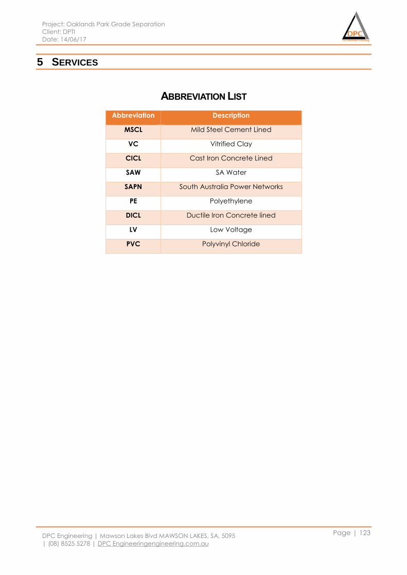
Project: Oaklands Park Grade Separation
Client: DPTI
Date: 14/06/17
DPC Engineering | Mawson Lakes Blvd MAWSON LAKES, SA, 5095
| (08) 8525 5278 | DPC Engineeringengineering.com.au
Page | 123
5 SERVICES
ABBREVIATION LIST
Abbreviation Description
MSCL Mild Steel Cement Lined
VC Vitrified Clay
CICL Cast Iron Concrete Lined
SAW SA Water
SAPN South Australia Power Networks
PE Polyethylene
DICL Ductile Iron Concrete lined
LV Low Voltage
PVC Polyvinyl Chloride
Project: Oaklands Park Grade Separation
Client: DPTI
Date: 14/06/17
DPC Engineering | Mawson Lakes Blvd MAWSON LAKES, SA, 5095
| (08) 8525 5278 | DPC Engineeringengineering.com.au
Page | 124
5.1 Package 01: Early Services Interface & Relocations
5.1.1 SA Power Networks
5.1.1.1 Design Assumptions & Considerations
Electrical network is owned by South Australian Power Network. In our project site, all the electricity
light poles, cables, low voltage in service cables and exits will be relocated. There are no works
involving high voltage assets within this project scope. As it is an overpass underground relocations
have been proposed for in service cables, this allows only light poles to be installed, which is more
aesthetically pleasing. All the new installation and relocations will be carried out in reference to the
Australian standards. All the component and materials used will be chosen with help of standards
and SAPN specifications.
Within the electrical scope of works, we will be removing light poles and low voltage poles. All
electrical services will be upgraded to the most recent DPTI material spec; Pits will be installed as
required and all electrical poles within the project scope are to be moved underground.
Light pole locations under the bridge in the car park and intersection has been designed by
transport department, power to these have been provided through the electrical network from the
transformer room.
SAPN network in relocation and upgrading has been designed with help of Australian standards and
SAPN network rules. Used standards are following:
i) SAPN Technical Standard TS085: Trenching and Conduit standards for underground
ii) AS/NZS 2053 Conduits and fittings for electrical installations
iii) AS/NZS 1477 PVC pipes and fittings for pressure
iv) AS/NZS 2032 Installation of PVC pipe systems
5.1.1.2 Low Voltage (LV)
Trenching
All trenches used in the lay and backfill of all electrical services, including but not limited to all
ground relocations and the railway platform will be installed in accordance to SAPN Technical
Standard TS085: Trenching and Conduit Standard for Underground Distribution Cable Networks
clause 10.1. Refer relevant drawing for a typical trench layout. The design requirements are as
shown below:
The trench is designed to be as straight as possible with firm and smooth base
A minimum separation of 25mm is required for the installation of multiple conduits in all
directions between SAPN conduits. The purpose of this is to ensure the bedding sand is fully
encompasses the conduit during back filling and reduce compaction issues in the future.
(Refer to Figure 70).
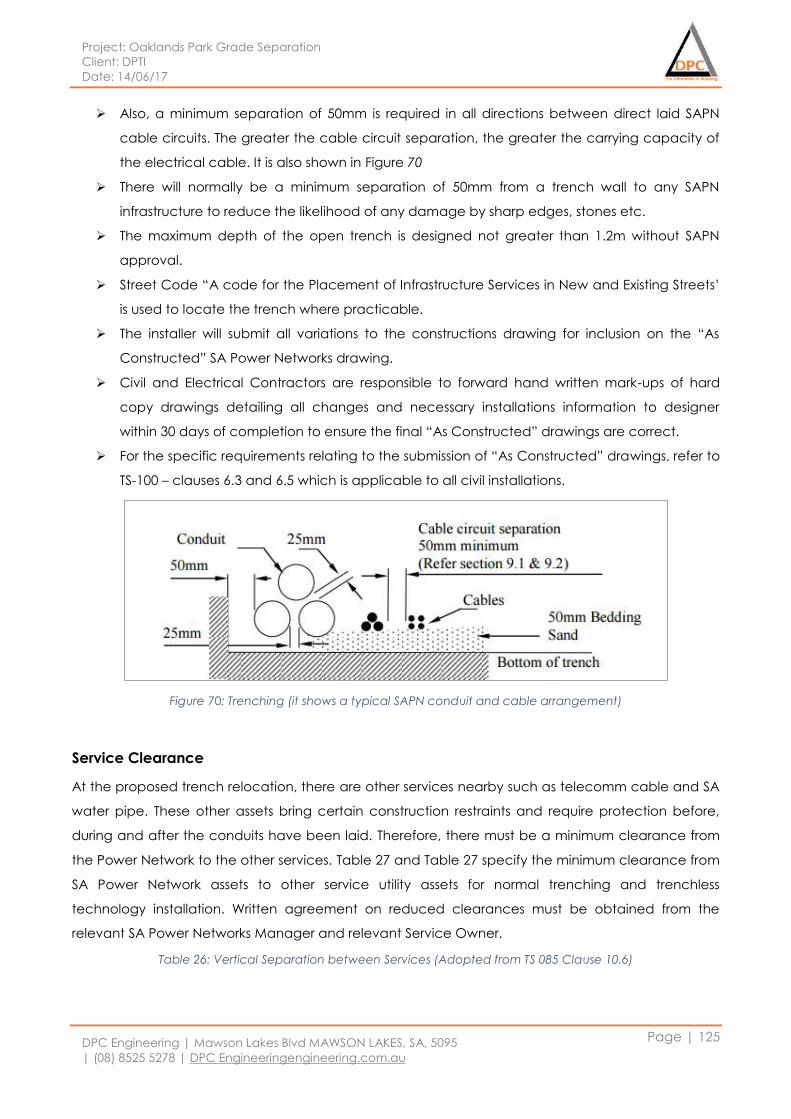
Project: Oaklands Park Grade Separation
Client: DPTI
Date: 14/06/17
DPC Engineering | Mawson Lakes Blvd MAWSON LAKES, SA, 5095
| (08) 8525 5278 | DPC Engineeringengineering.com.au
Page | 125
Also, a minimum separation of 50mm is required in all directions between direct laid SAPN
cable circuits. The greater the cable circuit separation, the greater the carrying capacity of
the electrical cable. It is also shown in Figure 70
There will normally be a minimum separation of 50mm from a trench wall to any SAPN
infrastructure to reduce the likelihood of any damage by sharp edges, stones etc.
The maximum depth of the open trench is designed not greater than 1.2m without SAPN
approval.
Street Code “A code for the Placement of Infrastructure Services in New and Existing Streets’
is used to locate the trench where practicable.
The installer will submit all variations to the constructions drawing for inclusion on the “As
Constructed” SA Power Networks drawing.
Civil and Electrical Contractors are responsible to forward hand written mark-ups of hard
copy drawings detailing all changes and necessary installations information to designer
within 30 days of completion to ensure the final “As Constructed” drawings are correct.
For the specific requirements relating to the submission of “As Constructed” drawings, refer to
TS-100 – clauses 6.3 and 6.5 which is applicable to all civil installations.
Figure 70: Trenching (it shows a typical SAPN conduit and cable arrangement)
Service Clearance
At the proposed trench relocation, there are other services nearby such as telecomm cable and SA
water pipe. These other assets bring certain construction restraints and require protection before,
during and after the conduits have been laid. Therefore, there must be a minimum clearance from
the Power Network to the other services. Table 27 and Table 27 specify the minimum clearance from
SA Power Network assets to other service utility assets for normal trenching and trenchless
technology installation. Written agreement on reduced clearances must be obtained from the
relevant SA Power Networks Manager and relevant Service Owner.
Table 26: Vertical Separation between Services (Adopted from TS 085 Clause 10.6)
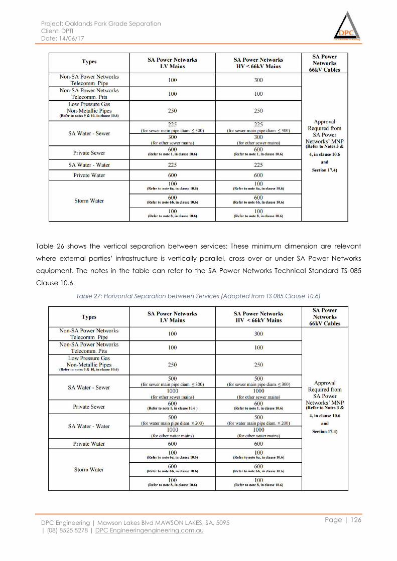
Project: Oaklands Park Grade Separation
Client: DPTI
Date: 14/06/17
DPC Engineering | Mawson Lakes Blvd MAWSON LAKES, SA, 5095
| (08) 8525 5278 | DPC Engineeringengineering.com.au
Page | 126
Table 26 shows the vertical separation between services: These minimum dimension are relevant
where external parties’ infrastructure is vertically parallel, cross over or under SA Power Networks
equipment. The notes in the table can refer to the SA Power Networks Technical Standard TS 085
Clause 10.6.
Table 27: Horizontal Separation between Services (Adopted from TS 085 Clause 10.6)
Project: Oaklands Park Grade Separation
Client: DPTI
Date: 14/06/17
DPC Engineering | Mawson Lakes Blvd MAWSON LAKES, SA, 5095
| (08) 8525 5278 | DPC Engineeringengineering.com.au
Page | 127
Table 27 shows the horizontal separation between services: Horizontal separation will be dependent
on the extent that the external plant is parallel with the SA Power Networks infrastructure. In
accordance with the NICC-404, only hand digging is permissible for any excavation within 0.1m of
any SA Power Networks assets. The notes in the table can refer to the SA Power Networks Technical
Standard TS 085 Clause 10.6.
Conduit Sizing
The type of conduits are selected based on consideration of all factors which may affect the
operation of the conduit such as temperature of operation as well as future provisions, extension
requirements and external loading. In addition to construction, extra care will be taken while joining
conduits. This is because different grades have different internal diameters and resultant raised
internal edge has the potential to damage the outer layer of cable during cable pulling.
The conduits are designed in compliance to AS/NZS Standards as shown below:
Conduits and couplings used will be UPVC material and meet the requirements of AS/NZS
2053 Parts 1 and 2 for Rigid Plain designation
The conduit will be marked with the type, conduit size and class such as “Electrical Ducting
100mm 6.0 Class”
Without the approval of MNSP, no lower grade form of rigid conduit is allowed.
All the conduits must meet the requirements of AS/NZS 1477 for the Test for Impact at 20
degrees Celsius
The conduits colour must be orange except for Telecoms, which shall be ‘White’.
The installation and handling rigid LD PVC conduit must be in accordance with PIPA website
which provides information on “Solvent Cement Jointing of PVC Pipe”. Other than that, it
must be in accordance with AS/NZS 2032: Section 3.3.11-Bending of PVC pipes which
recommends a minimum radius of 150 x outside diameter for non-pressure (electrical) pipes.
The following tables specify the minimum conduit sizes for various cable sizes and rated voltage.
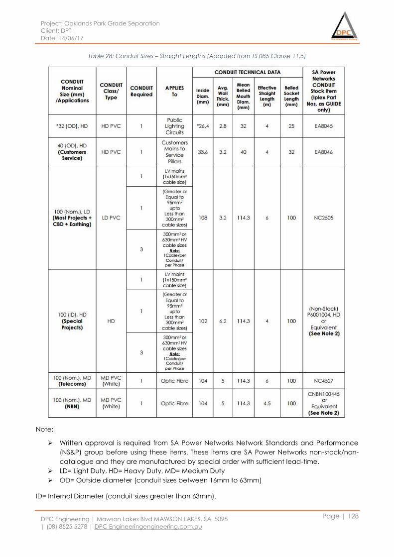
Project: Oaklands Park Grade Separation
Client: DPTI
Date: 14/06/17
DPC Engineering | Mawson Lakes Blvd MAWSON LAKES, SA, 5095
| (08) 8525 5278 | DPC Engineeringengineering.com.au
Page | 128
Table 28: Conduit Sizes – Straight Lengths (Adopted from TS 085 Clause 11.5)
Note:
Written approval is required from SA Power Networks Network Standards and Performance
(NS&P) group before using these items. These items are SA Power Networks non-stock/non-
catalogue and they are manufactured by special order with sufficient lead-time.
LD= Light Duty, HD= Heavy Duty, MD= Medium Duty
OD= Outside diameter (conduit sizes between 16mm to 63mm)
ID= Internal Diameter (conduit sizes greater than 63mm).
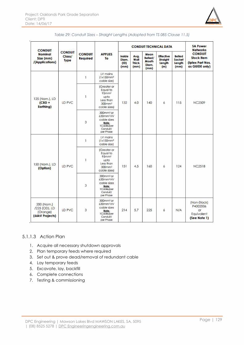
Project: Oaklands Park Grade Separation
Client: DPTI
Date: 14/06/17
DPC Engineering | Mawson Lakes Blvd MAWSON LAKES, SA, 5095
| (08) 8525 5278 | DPC Engineeringengineering.com.au
Page | 129
Table 29: Conduit Sizes – Straight Lengths (Adopted from TS 085 Clause 11.5)
5.1.1.3 Action Plan
1. Acquire all necessary shutdown approvals
2. Plan temporary feeds where required
3. Set out & prove dead/removal of redundant cable
4. Lay temporary feeds
5. Excavate, lay, backfill
6. Complete connections
7. Testing & commissioning
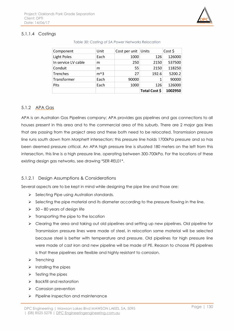
Project: Oaklands Park Grade Separation
Client: DPTI
Date: 14/06/17
DPC Engineering | Mawson Lakes Blvd MAWSON LAKES, SA, 5095
| (08) 8525 5278 | DPC Engineeringengineering.com.au
Page | 130
5.1.1.4 Costings
Table 30: Costing of SA Power Networks Relocation
5.1.2 APA Gas
APA is an Australian Gas Pipelines company; APA provides gas pipelines and gas connections to all
houses present in this area and to the commercial area of this suburb. There are 2 major gas lines
that are passing from the project area and these both need to be relocated. Transmission pressure
line runs south down from Morphett intersection; this pressure line holds 1700kPa pressure and so has
been deemed pressure critical. An APA high pressure line is situated 180 meters on the left from this
intersection, this line is a high pressure line, operating between 300-700kPa. For the locations of these
existing design gas networks, see drawing *SER-REL01*.
5.1.2.1 Design Assumptions & Considerations
Several aspects are to be kept in mind while designing the pipe line and those are:
Selecting Pipe using Australian standards.
Selecting the pipe material and its diameter according to the pressure flowing in the line.
50 – 80 years of design life
Transporting the pipe to the location
Clearing the area and taking out old pipelines and setting up new pipelines. Old pipeline for
Transmission pressure lines were made of steel, in relocation same material will be selected
because steel is better with temperature and pressure. Old pipelines for high pressure line
were made of cast iron and new pipeline will be made of PE. Reason to choose PE pipelines
is that these pipelines are flexible and highly resistant to corrosion.
Trenching
Installing the pipes
Testing the pipes
Backfill and restoration
Corrosion prevention
Pipeline inspection and maintenance
Component Unit Cost per unit Units Cost $
Light Poles Each 1000 126 126000
In service LV cable m 250 2150 537500
Conduit m 55 2150 118250
Trenches m^3 27 192.6 5200.2
Transformer Each 90000 1 90000
Pits Each 1000 126 126000
Total Cost $ 1002950
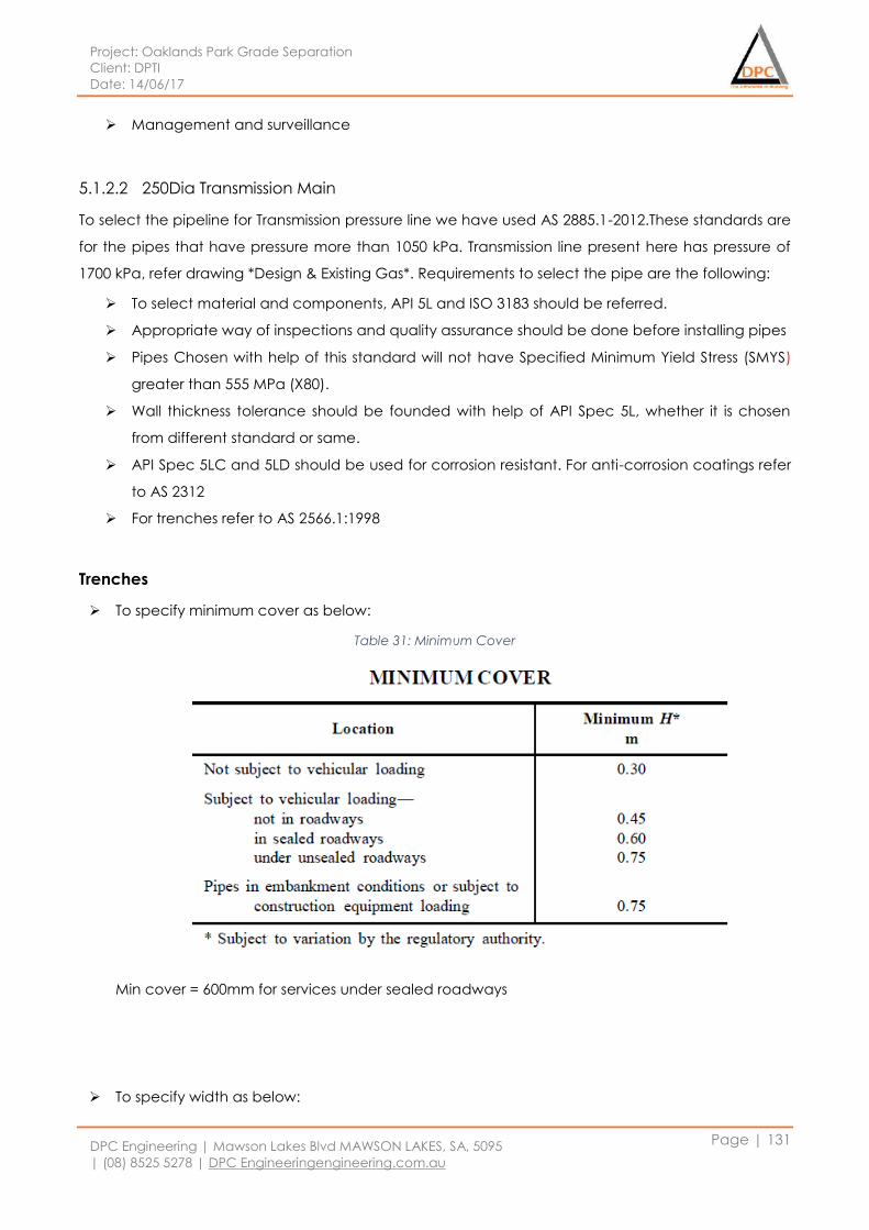
Project: Oaklands Park Grade Separation
Client: DPTI
Date: 14/06/17
DPC Engineering | Mawson Lakes Blvd MAWSON LAKES, SA, 5095
| (08) 8525 5278 | DPC Engineeringengineering.com.au
Page | 131
Management and surveillance
5.1.2.2 250Dia Transmission Main
To select the pipeline for Transmission pressure line we have used AS 2885.1-2012.These standards are
for the pipes that have pressure more than 1050 kPa. Transmission line present here has pressure of
1700 kPa, refer drawing *Design & Existing Gas*. Requirements to select the pipe are the following:
To select material and components, API 5L and ISO 3183 should be referred.
Appropriate way of inspections and quality assurance should be done before installing pipes
Pipes Chosen with help of this standard will not have Specified Minimum Yield Stress (SMYS)
greater than 555 MPa (X80).
Wall thickness tolerance should be founded with help of API Spec 5L, whether it is chosen
from different standard or same.
API Spec 5LC and 5LD should be used for corrosion resistant. For anti-corrosion coatings refer
to AS 2312
For trenches refer to AS 2566.1:1998
Trenches
To specify minimum cover as below:
Table 31: Minimum Cover
Min cover = 600mm for services under sealed roadways
To specify width as below:
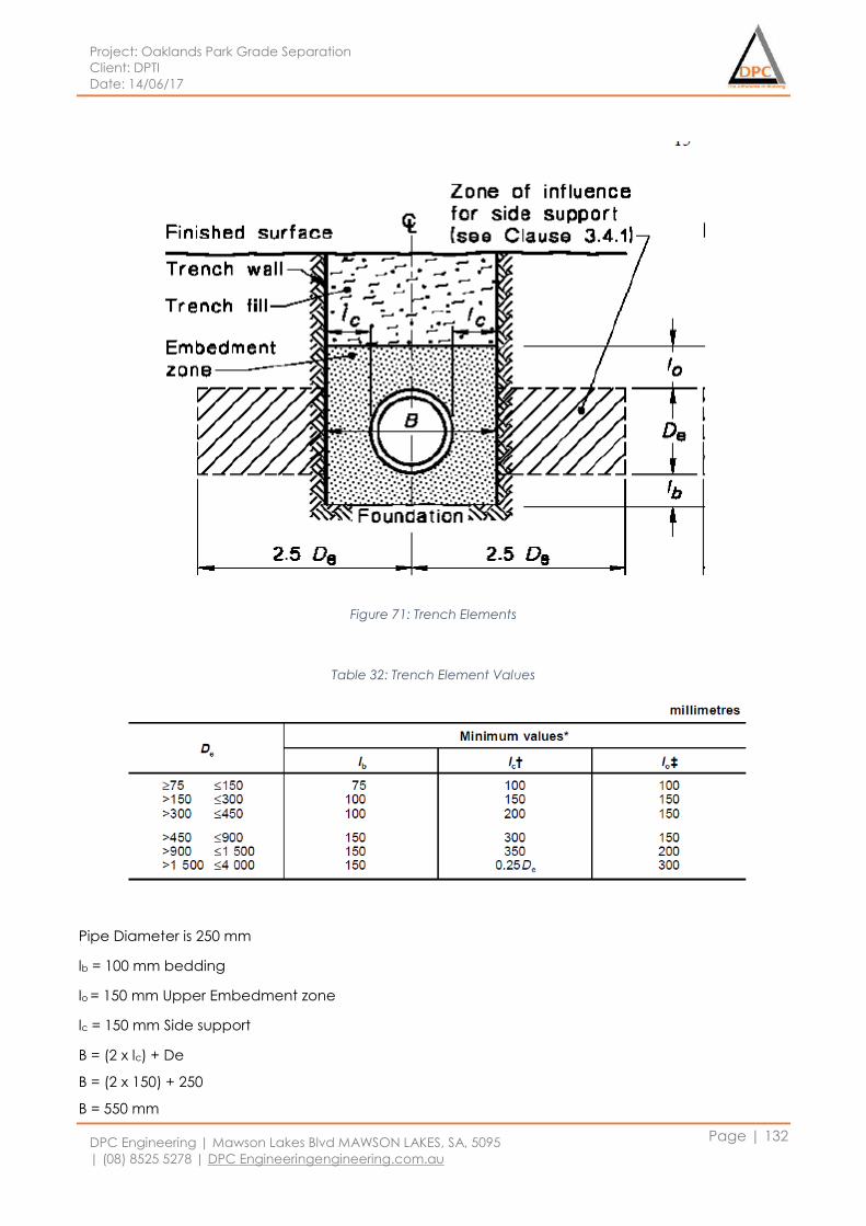
Project: Oaklands Park Grade Separation
Client: DPTI
Date: 14/06/17
DPC Engineering | Mawson Lakes Blvd MAWSON LAKES, SA, 5095
| (08) 8525 5278 | DPC Engineeringengineering.com.au
Page | 132
Figure 71: Trench Elements
Table 32: Trench Element Values
Pipe Diameter is 250 mm
lb = 100 mm bedding
lo = 150 mm Upper Embedment zone
lc = 150 mm Side support
B = (2 x lc) + De
B = (2 x 150) + 250
B = 550 mm
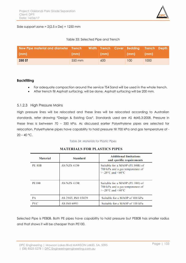
Project: Oaklands Park Grade Separation
Client: DPTI
Date: 14/06/17
DPC Engineering | Mawson Lakes Blvd MAWSON LAKES, SA, 5095
| (08) 8525 5278 | DPC Engineeringengineering.com.au
Page | 133
Side support zone = 2(2.5 x De) = 1250 mm
Table 33: Selected Pipe and Trench
Backfilling
For adequate compaction around the service TS4 Sand will be used in the whole trench.
After trench fill Asphalt surfacing, will be done, Asphalt surfacing will be 200 mm.
5.1.2.3 High Pressure Mains
High pressure lines will be relocated and these lines will be relocated according to Australian
standards, refer drawing *Design & Existing Gas*. Standards used are AS 4645.3:2008. Pressure in
these lines is between 70 – 350 kPa. As discussed earlier Polyethylene pipes are selected for
relocation. Polyethylene pipes have capability to hold pressure till 700 kPa and gas temperature of -
20 – 40 °C.
Table 34: Materials for Plastic Pipes
Selected Pipe is PE80B. Both PE pipes have capability to hold pressure but PE80B has smaller radius
and that shows it will be cheaper than PE100.
New Pipe material and diameter
(mm)
Trench Width
(mm)
Trench Cover
(mm)
Bedding
(mm)
Trench Depth
(mm)
250 ST 550 mm 600 100 1000
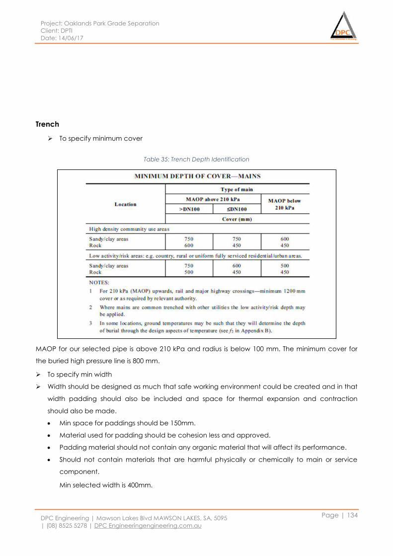
Project: Oaklands Park Grade Separation
Client: DPTI
Date: 14/06/17
DPC Engineering | Mawson Lakes Blvd MAWSON LAKES, SA, 5095
| (08) 8525 5278 | DPC Engineeringengineering.com.au
Page | 134
Trench
To specify minimum cover
Table 35: Trench Depth Identification
MAOP for our selected pipe is above 210 kPa and radius is below 100 mm. The minimum cover for
the buried high pressure line is 800 mm.
To specify min width
Width should be designed as much that safe working environment could be created and in that
width padding should also be included and space for thermal expansion and contraction
should also be made.
Min space for paddings should be 150mm.
Material used for padding should be cohesion less and approved.
Padding material should not contain any organic material that will affect its performance.
Should not contain materials that are harmful physically or chemically to main or service
component.
Min selected width is 400mm.
Project: Oaklands Park Grade Separation
Client: DPTI
Date: 14/06/17
DPC Engineering | Mawson Lakes Blvd MAWSON LAKES, SA, 5095
| (08) 8525 5278 | DPC Engineeringengineering.com.au
Page | 135
Backfilling
For adequate compaction around the service Sand TS4 will be used for the trench fill.
5.1.2.4 Action Plan
Gas pipelines present in the project area are transmission pressure line and high pressure line. Both
gas lines will be relocated before start of the work and both gas lines has been relocated in such
way that the gas should not be stopped while the overpass structure work goes on. Gas lines have
been relocated away from overpass columns and away from the interruption of foundation of
column. Transmission pressure pipeline material is not being changed, this aids connection works.
Whereas high pressure lines material has been changed from Cast Iron to Polyethylene. At first of
relocations, it is important to perform relocation of water lines before the gas lines as they are not
only the deeper service but also carry more overall demand in terms of commercial and residential
use.
1. Acquire all relevant approvals and permits, develop drawings package for site
2. Site inspection, cleaning & mobilisation
3. Lay temporary feed for any affected areas surrounding works
4. Install traffic management
5. Excavate, lay backfill
6. Tie ins & Cutovers
7. Permanent reinstatement
Transmission Pressure main
Method applied for installation: Trenching
Duration to relocate: 18 Days, majority of works to occur at night in linear metre instalments due to
nature of location and traffic requirements
Total Length of Relocated pipe: 366 meters
High pressure main
Method applied for installation: Trenching
Duration to relocate: 11 Day, only day works involved.
Total Length of Relocated pipe: 414 meters
Project: Oaklands Park Grade Separation
Client: DPTI
Date: 14/06/17
DPC Engineering | Mawson Lakes Blvd MAWSON LAKES, SA, 5095
| (08) 8525 5278 | DPC Engineeringengineering.com.au
Page | 136
5.1.2.5 Costings
Table 36: Cost of APA
5.1.3 SA Water
Water is one of the major service that needs to be relocated in this project. Project area has main
water lines passing through it, these water lines are connected to commercial and residential area
around the project site. Relocation of these water lines are to be undertaken at the start of the
project so that supply water services to the surrounding areas are not stopped. As the whole
intersection is being redesigned and the rail area under the rail overpass is redesigned, there are
some changes done at the connection of Murray terrace and Morphett Road. The relocation of the
water lines are designed in such way that it can support the current development in this area during
construction, and once the new alignment has been constructed it holds enough capacity for
future requirements in the greater Adelaide 30 year plan. Refer drawings *SA Water Design & Existing
alignment* which outline the existing water mains and shows the proposed new alignment. The
pipes under consideration are constructed of CICL and MSCL.
Current CICL pipelines are of three different diameters. Diameters are 150mm, 200mm and 250mm.
The largest water main on the project is a 750 diameter MSCL which will require a small relocation
out of the alignment of the foundations of the overpass structure.
Transmission Pressure line
Material & Works Unit Cost per unit Units Cost $
Site Preparation - remove bitumen paving sqm 3.85 50.325 193.7513
Trench m^3 201 171.105 34392.11
Backfilling - stabilised sand m^3 135 171.105 23099.18
250 Steel m 100 366 36600
Labour ( 4 men crew plus plant) m 8000 18 144000
High Pressure line
Material & Works Unit Cost per unit Units Cost
Site Preparation sqm 0.69 41.4 28.566
Trench m^3 201 228.528 45934.13
Backfilling - stabilised sand m^3 135 228.528 30851.28
PE80B m 120 414 49680
Labour ( 4 men crew plus plant) m 8000 11 88000
Total Cost $ 452779
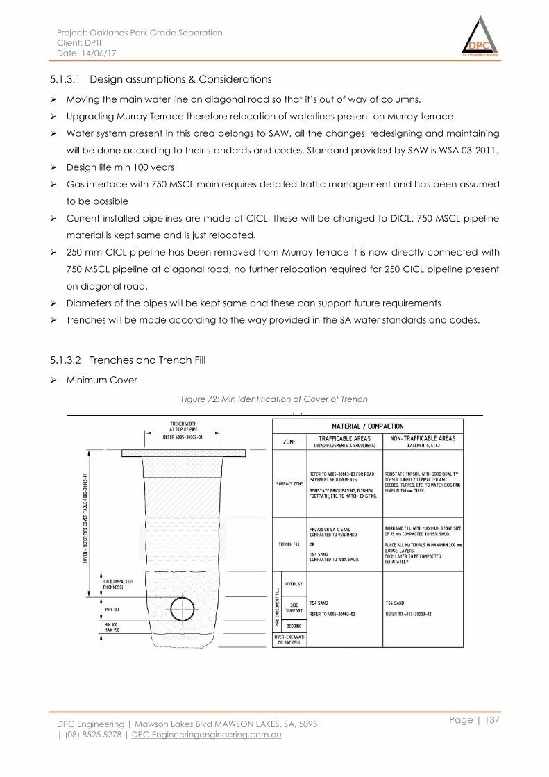
Project: Oaklands Park Grade Separation
Client: DPTI
Date: 14/06/17
DPC Engineering | Mawson Lakes Blvd MAWSON LAKES, SA, 5095
| (08) 8525 5278 | DPC Engineeringengineering.com.au
Page | 137
5.1.3.1 Design assumptions & Considerations
Moving the main water line on diagonal road so that it’s out of way of columns.
Upgrading Murray Terrace therefore relocation of waterlines present on Murray terrace.
Water system present in this area belongs to SAW, all the changes, redesigning and maintaining
will be done according to their standards and codes. Standard provided by SAW is WSA 03-2011.
Design life min 100 years
Gas interface with 750 MSCL main requires detailed traffic management and has been assumed
to be possible
Current installed pipelines are made of CICL, these will be changed to DICL. 750 MSCL pipeline
material is kept same and is just relocated.
250 mm CICL pipeline has been removed from Murray terrace it is now directly connected with
750 MSCL pipeline at diagonal road, no further relocation required for 250 CICL pipeline present
on diagonal road.
Diameters of the pipes will be kept same and these can support future requirements
Trenches will be made according to the way provided in the SA water standards and codes.
5.1.3.2 Trenches and Trench Fill
Minimum Cover
Figure 72: Min Identification of Cover of Trench
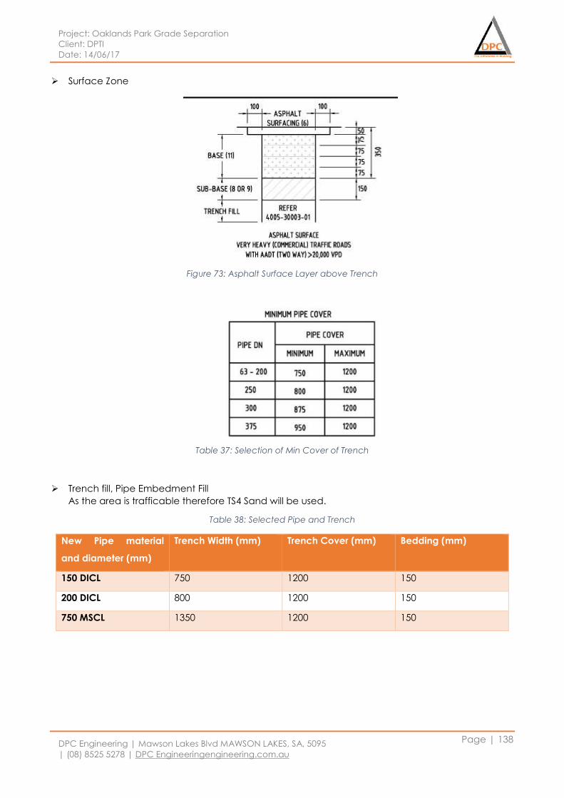
Project: Oaklands Park Grade Separation
Client: DPTI
Date: 14/06/17
DPC Engineering | Mawson Lakes Blvd MAWSON LAKES, SA, 5095
| (08) 8525 5278 | DPC Engineeringengineering.com.au
Page | 138
Surface Zone
Figure 73: Asphalt Surface Layer above Trench
Table 37: Selection of Min Cover of Trench
Trench fill, Pipe Embedment Fill
As the area is trafficable therefore TS4 Sand will be used.
Table 38: Selected Pipe and Trench
New Pipe material
and diameter (mm)
Trench Width (mm) Trench Cover (mm) Bedding (mm)
150 DICL 750 1200 150
200 DICL 800 1200 150
750 MSCL 1350 1200 150
Project: Oaklands Park Grade Separation
Client: DPTI
Date: 14/06/17
DPC Engineering | Mawson Lakes Blvd MAWSON LAKES, SA, 5095
| (08) 8525 5278 | DPC Engineeringengineering.com.au
Page | 139
5.1.3.3 Action Plan
There are 4 SA water pipelines present in the project area each have different diameter but same
material. Except 250 CICL all 3 of them will be relocated before start of the work so that residential
and commercial area don’t face any water problems while the overpass work goes on. Relocation
have been designed with careful consideration of structure, development of interchange and other
services present in area. SA water relocations are to be done before any other service relocation.
CICL pipelines has been changed to DICL because these are better than old one and are
approved by SA water whereas main 750 MSCL will remain same.
1. Plan & lay temporary feeds for any affected areas surrounding works
2. Acquire all relevant approvals and permits, develop drawings package for site
3. Site inspection, cleaning & mobilisation
4. Install traffic management
5. Excavate, lay backfill
6. Permanent reinstatement
7. Tie ins & Cutovers
150 DICL
Method applied for installation: Trenching
Duration to relocate: 7 Days of night works. Night works will be carried out on Morphett Road. 3 Days
of day on Murray terrace. Total Days 10.
Length of Relocated pipe: 215 meters
200 DICL
Method applied for installation: Trenching
Duration to relocate: 1 Day of day work.
Length of Relocated pipe: 25 meters
750 MSL
Method applied for installation: Trenching
Duration to relocate: 16 Days, only night works because of main road.
Length of Relocated pipe: 315 meters
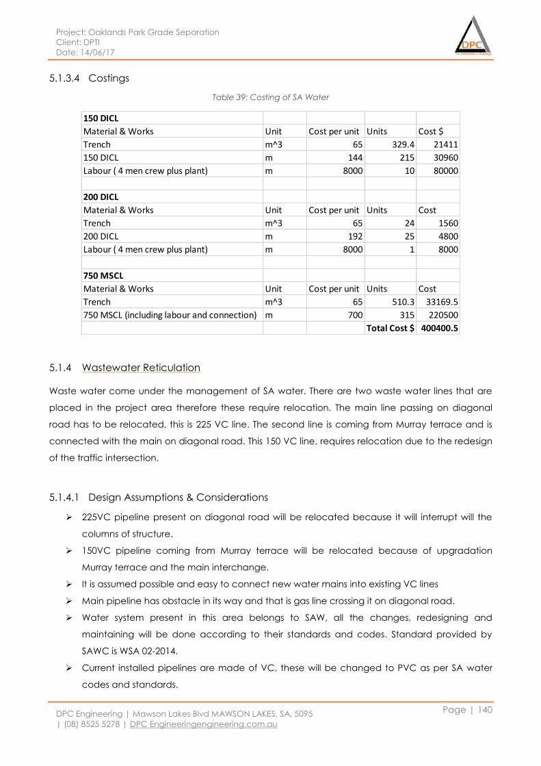
Project: Oaklands Park Grade Separation
Client: DPTI
Date: 14/06/17
DPC Engineering | Mawson Lakes Blvd MAWSON LAKES, SA, 5095
| (08) 8525 5278 | DPC Engineeringengineering.com.au
Page | 140
5.1.3.4 Costings
Table 39: Costing of SA Water
5.1.4 Wastewater Reticulation
Waste water come under the management of SA water. There are two waste water lines that are
placed in the project area therefore these require relocation. The main line passing on diagonal
road has to be relocated, this is 225 VC line. The second line is coming from Murray terrace and is
connected with the main on diagonal road. This 150 VC line, requires relocation due to the redesign
of the traffic intersection.
5.1.4.1 Design Assumptions & Considerations
225VC pipeline present on diagonal road will be relocated because it will interrupt will the
columns of structure.
150VC pipeline coming from Murray terrace will be relocated because of upgradation
Murray terrace and the main interchange.
It is assumed possible and easy to connect new water mains into existing VC lines
Main pipeline has obstacle in its way and that is gas line crossing it on diagonal road.
Water system present in this area belongs to SAW, all the changes, redesigning and
maintaining will be done according to their standards and codes. Standard provided by
SAWC is WSA 02-2014.
Current installed pipelines are made of VC, these will be changed to PVC as per SA water
codes and standards.
150 DICL
Material & Works Unit Cost per unit Units Cost $
Trench m^3 65 329.4 21411
150 DICL m 144 215 30960
Labour ( 4 men crew plus plant) m 8000 10 80000
200 DICL
Material & Works Unit Cost per unit Units Cost
Trench m^3 65 24 1560
200 DICL m 192 25 4800
Labour ( 4 men crew plus plant) m 8000 1 8000
750 MSCL
Material & Works Unit Cost per unit Units Cost
Trench m^3 65 510.3 33169.5
750 MSCL (including labour and connection) m 700 315 220500
Total Cost $ 400400.5
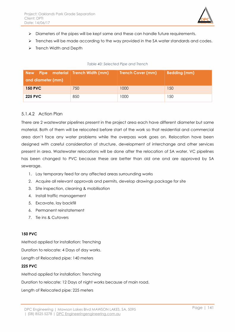
Project: Oaklands Park Grade Separation
Client: DPTI
Date: 14/06/17
DPC Engineering | Mawson Lakes Blvd MAWSON LAKES, SA, 5095
| (08) 8525 5278 | DPC Engineeringengineering.com.au
Page | 141
Diameters of the pipes will be kept same and these can handle future requirements.
Trenches will be made according to the way provided in the SA water standards and codes.
Trench Width and Depth
Table 40: Selected Pipe and Trench
New Pipe material
and diameter (mm)
Trench Width (mm) Trench Cover (mm) Bedding (mm)
150 PVC 750 1000 150
225 PVC 850 1000 150
5.1.4.2 Action Plan
There are 2 wastewater pipelines present in the project area each have different diameter but same
material. Both of them will be relocated before start of the work so that residential and commercial
area don’t face any water problems while the overpass work goes on. Relocation have been
designed with careful consideration of structure, development of interchange and other services
present in area. Wastewater relocations will be done after the relocation of SA water. VC pipelines
has been changed to PVC because these are better than old one and are approved by SA
sewerage.
1. Lay temporary feed for any affected areas surrounding works
2. Acquire all relevant approvals and permits, develop drawings package for site
3. Site inspection, cleaning & mobilisation
4. Install traffic management
5. Excavate, lay backfill
6. Permanent reinstatement
7. Tie ins & Cutovers
150 PVC
Method applied for installation: Trenching
Duration to relocate: 4 Days of day works.
Length of Relocated pipe: 140 meters
225 PVC
Method applied for installation: Trenching
Duration to relocate: 12 Days of night works because of main road.
Length of Relocated pipe: 225 meters
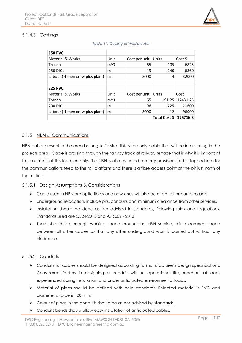
Project: Oaklands Park Grade Separation
Client: DPTI
Date: 14/06/17
DPC Engineering | Mawson Lakes Blvd MAWSON LAKES, SA, 5095
| (08) 8525 5278 | DPC Engineeringengineering.com.au
Page | 142
5.1.4.3 Costings
Table 41: Costing of Wastewater
5.1.5 NBN & Communications
NBN cable present in the area belong to Telstra. This is the only cable that will be interrupting in the
projects area. Cable is crossing through the railway track at railway terrace that is why it is important
to relocate it at this location only. The NBN is also assumed to carry provisions to be tapped into for
the communications feed to the rail platform and there is a fibre access point at the pit just north of
the rail line.
5.1.5.1 Design Assumptions & Considerations
Cable used in NBN are optic fibres and new ones will also be of optic fibre and co-axial.
Underground relocation, include pits, conduits and minimum clearance from other services.
Installation should be done as per advised in standards, following rules and regulations.
Standards used are C524-2013 and AS S009 - 2013
There should be enough working space around the NBN service, min clearance space
between all other cables so that any other underground work is carried out without any
hindrance.
5.1.5.2 Conduits
Conduits for cables should be designed according to manufacturer’s design specifications.
Considered factors in designing a conduit will be operational life, mechanical loads
experienced during installation and under anticipated environmental loads.
Material of pipes should be defined with help standards. Selected material is PVC and
diameter of pipe is 100 mm.
Colour of pipes in the conduits should be as per advised by standards.
Conduits bends should allow easy installation of anticipated cables.
150 PVC
Material & Works Unit Cost per unit Units Cost $
Trench m^3 65 105 6825
150 DICL m 49 140 6860
Labour ( 4 men crew plus plant) m 8000 4 32000
225 PVC
Material & Works Unit Cost per unit Units Cost
Trench m^3 65 191.25 12431.25
200 DICL m 96 225 21600
Labour ( 4 men crew plus plant) m 8000 12 96000
Total Cost $ 175716.3
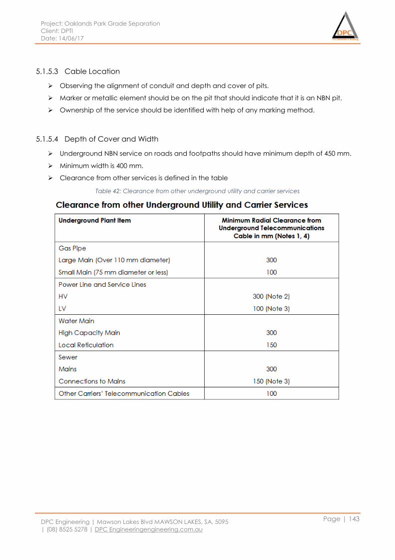
Project: Oaklands Park Grade Separation
Client: DPTI
Date: 14/06/17
DPC Engineering | Mawson Lakes Blvd MAWSON LAKES, SA, 5095
| (08) 8525 5278 | DPC Engineeringengineering.com.au
Page | 143
5.1.5.3 Cable Location
Observing the alignment of conduit and depth and cover of pits.
Marker or metallic element should be on the pit that should indicate that it is an NBN pit.
Ownership of the service should be identified with help of any marking method.
5.1.5.4 Depth of Cover and Width
Underground NBN service on roads and footpaths should have minimum depth of 450 mm.
Minimum width is 400 mm.
Clearance from other services is defined in the table
Table 42: Clearance from other underground utility and carrier services
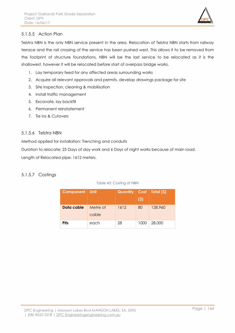
Project: Oaklands Park Grade Separation
Client: DPTI
Date: 14/06/17
DPC Engineering | Mawson Lakes Blvd MAWSON LAKES, SA, 5095
| (08) 8525 5278 | DPC Engineeringengineering.com.au
Page | 144
5.1.5.5 Action Plan
Telstra NBN is the only NBN service present in the area. Relocation of Telstra NBN starts from railway
terrace and the rail crossing of the service has been pushed west. This allows it to be removed from
the footprint of structure foundations. NBN will be the last service to be relocated as it is the
shallowest, however it will be relocated before start of overpass bridge works.
1. Lay temporary feed for any affected areas surrounding works
2. Acquire all relevant approvals and permits, develop drawings package for site
3. Site inspection, cleaning & mobilisation
4. Install traffic management
5. Excavate, lay backfill
6. Permanent reinstatement
7. Tie ins & Cutovers
5.1.5.6 Telstra NBN
Method applied for installation: Trenching and conduits
Duration to relocate: 25 Days of day work and 6 Days of night works because of main road.
Length of Relocated pipe: 1612 meters.
5.1.5.7 Costings
Table 43: Costing of NBN
Component Unit Quantity Cost
($)
Total ($)
Data cable Metre of
cable
1612 80 128,960
Pits each 28 1000 28,000
Project: Oaklands Park Grade Separation
Client: DPTI
Date: 14/06/17
DPC Engineering | Mawson Lakes Blvd MAWSON LAKES, SA, 5095
| (08) 8525 5278 | DPC Engineeringengineering.com.au
Page | 145
5.2 Package 02: Rail Platform
5.2.1 Design Assumptions & Considerations
It is a design assumption that the solar panels (arrays) incorporated into the platform are integrated
into the design electrical network and it is connected to the network via twin core cable at the
locations still under consideration. It is also assumed there is enough space requirements in the
control room to house the hardware needed for the solar system (inverter, combiner box, main
breaker box, cabling etc).
5.2.2 Electrical Infrastructure
Existing DPTI Standard pits and conduits will be utilised on site wherever practicable and must
comply with the following:
Utility services required to transverse the railway corridor must be via the overpass structure
A minimum distance of 300mm must be maintained between the footing of structure and
conduit trenches
All electrical cables and conduits should be concealed within the shelter structural
framework.
If the conduits cannot be concealed within the structure, cabling must be fixed to the
exterior of structure within a galvanised duct in a continuous run to a minimum height of 3m.
5.2.2.1 Power Distribution Network
According to the Engineering Standard Part 129014, the power supply used at a railway station will
be a 400V, 3-phase, 50Hz power system. The designed electrical network must be capable of
supporting this system. AS 3000: Electrical Installations (Wiring Rules) is used to calculate the
maximum electrical power demand at the Oakland’s Park Railway Station. To cater for future or
unknown loads/demands, there must be a minimum of 30% additional capacity in the power
system. The power distribution network will include the components as shown below:
Isolation Transformer
The purpose of isolation transformer is to isolate the railway traction supply earthing from the local
Electricity Supply Authority earthing Multiple-Earthed-Neutral system. Other than that, isolation
transformer must be separated at least 3m away from ETSA Distribution Substation. The isolation
transformer used for the train station must comply with the requirements of:
AS 61558.1: Safety of Power Transformers, Power Supplies, Reactors and Similar Products –
General requirements and test
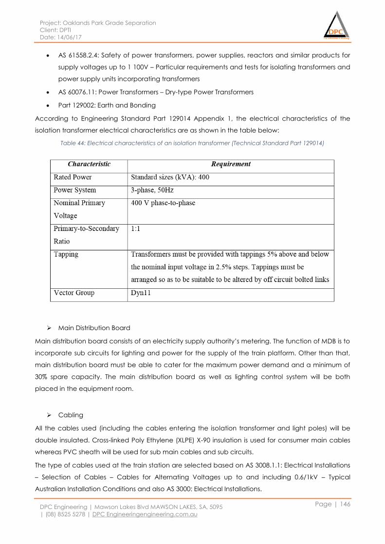
Project: Oaklands Park Grade Separation
Client: DPTI
Date: 14/06/17
DPC Engineering | Mawson Lakes Blvd MAWSON LAKES, SA, 5095
| (08) 8525 5278 | DPC Engineeringengineering.com.au
Page | 146
AS 61558.2.4: Safety of power transformers, power supplies, reactors and similar products for
supply voltages up to 1 100V – Particular requirements and tests for isolating transformers and
power supply units incorporating transformers
AS 60076.11: Power Transformers – Dry-type Power Transformers
Part 129002: Earth and Bonding
According to Engineering Standard Part 129014 Appendix 1, the electrical characteristics of the
isolation transformer electrical characteristics are as shown in the table below:
Table 44: Electrical characteristics of an isolation transformer (Technical Standard Part 129014)
Main Distribution Board
Main distribution board consists of an electricity supply authority’s metering. The function of MDB is to
incorporate sub circuits for lighting and power for the supply of the train platform. Other than that,
main distribution board must be able to cater for the maximum power demand and a minimum of
30% spare capacity. The main distribution board as well as lighting control system will be both
placed in the equipment room.
Cabling
All the cables used (including the cables entering the isolation transformer and light poles) will be
double insulated. Cross-linked Poly Ethylene (XLPE) X-90 insulation is used for consumer main cables
whereas PVC sheath will be used for sub main cables and sub circuits.
The type of cables used at the train station are selected based on AS 3008.1.1: Electrical Installations
– Selection of Cables – Cables for Alternating Voltages up to and including 0.6/1kV – Typical
Australian Installation Conditions and also AS 3000: Electrical Installations.
Project: Oaklands Park Grade Separation
Client: DPTI
Date: 14/06/17
DPC Engineering | Mawson Lakes Blvd MAWSON LAKES, SA, 5095
| (08) 8525 5278 | DPC Engineeringengineering.com.au
Page | 147
Sub Circuits
Each sub circuit must be specified clearly on the switchboard single line diagram. Sub circuits
required in the railway station are listed as shown below:
Lighting
Power outlets for shelter
Heated Mirrors
Control Room
Toilet Facility
Passenger Information System
Security System
Lift
Power monitoring system
The Power Monitoring System (PMS) used at the railway station will be connected to a system called
central monitoring system. All the metering devices within the switchboards will be connected to
power monitoring system and the cables will be reticulated through communications conduits.
5.2.2.2 Lighting System
The lighting system at Oakland’s Park Rail Overpass will be designed to minimise glare to both users
and train drivers. Also, it is designed to reduce the impact of light spill to neighbouring properties by
not exceeding the light level requirement. Other than that, the light fitting locations must be
coordinated with CCTV cameras to optimise CCTC images. According to Technical Standard Part
129014 Clause 6.2, different areas at the train station will have different levels and they must meet
the requirements indicated in the table as shown below.
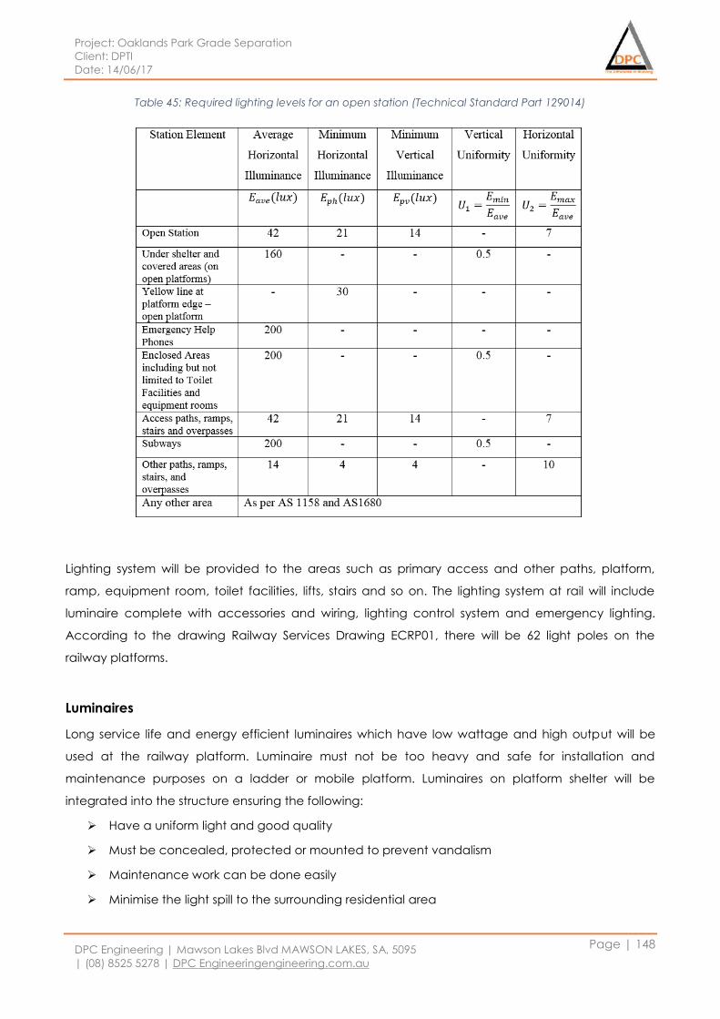
Project: Oaklands Park Grade Separation
Client: DPTI
Date: 14/06/17
DPC Engineering | Mawson Lakes Blvd MAWSON LAKES, SA, 5095
| (08) 8525 5278 | DPC Engineeringengineering.com.au
Page | 148
Table 45: Required lighting levels for an open station (Technical Standard Part 129014)
Lighting system will be provided to the areas such as primary access and other paths, platform,
ramp, equipment room, toilet facilities, lifts, stairs and so on. The lighting system at rail will include
luminaire complete with accessories and wiring, lighting control system and emergency lighting.
According to the drawing Railway Services Drawing ECRP01, there will be 62 light poles on the
railway platforms.
Luminaires
Long service life and energy efficient luminaires which have low wattage and high output will be
used at the railway platform. Luminaire must not be too heavy and safe for installation and
maintenance purposes on a ladder or mobile platform. Luminaires on platform shelter will be
integrated into the structure ensuring the following:
Have a uniform light and good quality
Must be concealed, protected or mounted to prevent vandalism
Maintenance work can be done easily
Minimise the light spill to the surrounding residential area
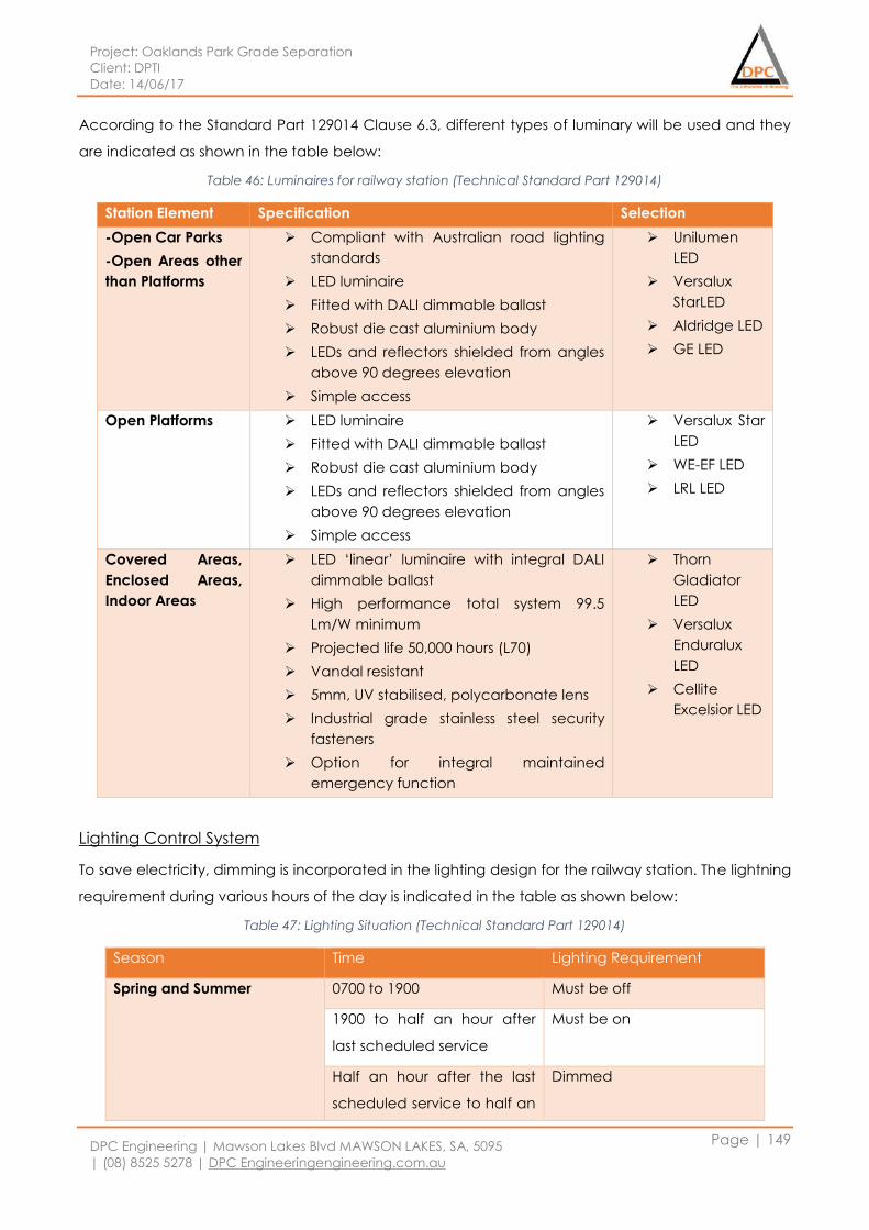
Project: Oaklands Park Grade Separation
Client: DPTI
Date: 14/06/17
DPC Engineering | Mawson Lakes Blvd MAWSON LAKES, SA, 5095
| (08) 8525 5278 | DPC Engineeringengineering.com.au
Page | 149
According to the Standard Part 129014 Clause 6.3, different types of luminary will be used and they
are indicated as shown in the table below:
Table 46: Luminaires for railway station (Technical Standard Part 129014)
Station Element Specification Selection
-Open Car Parks
-Open Areas other
than Platforms
Compliant with Australian road lighting
standards
LED luminaire
Fitted with DALI dimmable ballast
Robust die cast aluminium body
LEDs and reflectors shielded from angles
above 90 degrees elevation
Simple access
Unilumen
LED
Versalux
StarLED
Aldridge LED
GE LED
Open Platforms LED luminaire
Fitted with DALI dimmable ballast
Robust die cast aluminium body
LEDs and reflectors shielded from angles
above 90 degrees elevation
Simple access
Versalux Star
LED
WE-EF LED
LRL LED
Covered Areas,
Enclosed Areas,
Indoor Areas
LED ‘linear’ luminaire with integral DALI
dimmable ballast
High performance total system 99.5
Lm/W minimum
Projected life 50,000 hours (L70)
Vandal resistant
5mm, UV stabilised, polycarbonate lens
Industrial grade stainless steel security
fasteners
Option for integral maintained
emergency function
Thorn
Gladiator
LED
Versalux
Enduralux
LED
Cellite
Excelsior LED
Lighting Control System
To save electricity, dimming is incorporated in the lighting design for the railway station. The lightning
requirement during various hours of the day is indicated in the table as shown below:
Table 47: Lighting Situation (Technical Standard Part 129014)
Season Time Lighting Requirement
Spring and Summer
0700 to 1900 Must be off
1900 to half an hour after
last scheduled service
Must be on
Half an hour after the last
scheduled service to half an
Dimmed
Project: Oaklands Park Grade Separation
Client: DPTI
Date: 14/06/17
DPC Engineering | Mawson Lakes Blvd MAWSON LAKES, SA, 5095
| (08) 8525 5278 | DPC Engineeringengineering.com.au
Page | 150
hour before the first
scheduled service
Autumn and Winter
0800 to 1700 Must be off
1700 to half an hour after
last scheduled service
Must be on
Half an hour after the last
scheduled service to half an
hour before first scheduled
service
Dimmed
Emergency Lighting
Emergency lighting are installed based on AS 2293.1: Emergency Escape Lighting and Exit Signs for
Buildings – System Design, Installation and Operation. Emergency luminaires will be part of the
normal light fittings. When the main power fail, emergency light will be supported by Uninterruptible
Power Supply (UPS) via a fire rated cabling system throughout the station. The battery autonomy in
the UPS is anticipated to provide the emergency and escape lighting for 3 hours. An average
lighting level of 1 lux will be provided under emergency conditions.
5.2.2.3 Lift
Lift will be designed, supplied and installed in accordance to PTS Standard Part 129004. The lift car
will be a standard size of carrying 21 people, minimum size of 1600mm wide and 2100 deep to carry
a stretcher and provide a 180 degree wheelchair turning space.
Interior Lighting
A minimum of 200 lux illumination will be provided in the lift car at all times. All the light fittings will be
accessible within the lift car and protected by vandal proof diffusers.
Uninterruptible Power Supply (UPS)
A battery powered UPS will be installed at the railway station to provide 240V AC power during
failure of mains power supply. UPS will have sufficient capacity to operate for another 30 minutes of
the lift car air conditioning system and an additional 90 minutes of the lift car lights, car alarm bell
and lift shaft smoke detection. It require at least 8 eight hours for recovery after restoration of mains
power.
Project: Oaklands Park Grade Separation
Client: DPTI
Date: 14/06/17
DPC Engineering | Mawson Lakes Blvd MAWSON LAKES, SA, 5095
| (08) 8525 5278 | DPC Engineeringengineering.com.au
Page | 151
Lift Fire Detection/Protection
Smoke detectors or heat sensors will be installed at the top of the lift shaft in proximity to the hoist
machine and lift control equipment. They are powered from the lift mains electricity supply and APS
will be used in case of loss of mains power. Smoke detection system installed will be able to maintain
the service for a minimum period of two hours during the failure of main power supply.
5.2.2.4 Security System – CCTV and Emergency Phone
CCTV facilities will be provided to ensure the safety of the passengers at the railway platform. The
CCTV system at the railway platform will monitor the passenger flows, emergency situations, station
security as well as day to day station operations.
Placement of CCTV cameras will be the priority on a platform over any other facility. The camera
layouts will require coordination with lighting, sources of glare, auxiliary power supply and also CCTV
rack within the control room. The coverage of the CCTV will include the station entry/exit, lifts,
passenger information system, emergency help points as well as staircase. CCTV is an essential
station service. Therefore, it must continue to remain operational during a power outage.
The fixtures and mounting requirements are as shown below in accordance to ESB 004: RailCorp
Engineering Standard- Stations and Buildings.
Must be placed in clearly vulnerable vandal locations
Mounted at a minimum height of 2600mm off the finished floor level
CCTV conduit must be vandal resistant or concealed
CCTV concealed conduit runs will be coordinated with other services conduits during design
and construction phase.
The way CCTV cameras mounted must avoid birds nesting.
CCTV must be placed where access for maintenance is considered easy and safe for
technicians.
Avoid the use of expanded metal mesh security cages for CCTV protection.
24-hour emergency help phones will also be provided at platform 1 and platform 2. CCTV will be
activated immediately when using an emergency phone to record the area around the phone.
5.2.3 SA Water
5.2.3.1 Water and Amenities Supply
The water supply is designed according to Engineering Standard ESB004: Station Services and
Systems, AS3500: National Plumbing and Drainage Code and Building Code of Australia (BCA). As
there are no toilets to present on the actual rail platform, only a supply pipe to the water fountains
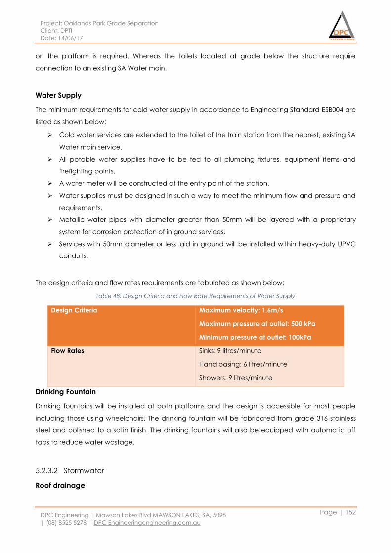
Project: Oaklands Park Grade Separation
Client: DPTI
Date: 14/06/17
DPC Engineering | Mawson Lakes Blvd MAWSON LAKES, SA, 5095
| (08) 8525 5278 | DPC Engineeringengineering.com.au
Page | 152
on the platform is required. Whereas the toilets located at grade below the structure require
connection to an existing SA Water main.
Water Supply
The minimum requirements for cold water supply in accordance to Engineering Standard ESB004 are
listed as shown below:
Cold water services are extended to the toilet of the train station from the nearest, existing SA
Water main service.
All potable water supplies have to be fed to all plumbing fixtures, equipment items and
firefighting points.
A water meter will be constructed at the entry point of the station.
Water supplies must be designed in such a way to meet the minimum flow and pressure and
requirements.
Metallic water pipes with diameter greater than 50mm will be layered with a proprietary
system for corrosion protection of in ground services.
Services with 50mm diameter or less laid in ground will be installed within heavy-duty UPVC
conduits.
The design criteria and flow rates requirements are tabulated as shown below:
Table 48: Design Criteria and Flow Rate Requirements of Water Supply
Design Criteria Maximum velocity: 1.6m/s
Maximum pressure at outlet: 500 kPa
Minimum pressure at outlet: 100kPa
Flow Rates Sinks: 9 litres/minute
Hand basing: 6 litres/minute
Showers: 9 litres/minute
Drinking Fountain
Drinking fountains will be installed at both platforms and the design is accessible for most people
including those using wheelchairs. The drinking fountain will be fabricated from grade 316 stainless
steel and polished to a satin finish. The drinking fountains will also be equipped with automatic off
taps to reduce water wastage.
5.2.3.2 Stormwater
Roof drainage

Project: Oaklands Park Grade Separation
Client: DPTI
Date: 14/06/17
DPC Engineering | Mawson Lakes Blvd MAWSON LAKES, SA, 5095
| (08) 8525 5278 | DPC Engineeringengineering.com.au
Page | 153
Figure 74: Shelter Design on the Platform
The figure above shows the design of the shelter by urban department. Stormwater is not allowed to
drain onto the track. Where there is an incline shelter on the platform, a gutter system will collect
and direct rainwater through downpipes into a drainage system (Refer drawing *Platform
Stormwater*. The figure above shows the design of the shelter by urban department. The drainage
systems designed must be able to prevent leakage into or onto the structure, an additional benefit
of the rearward slab cross fall is the rollaway protection for prams, wheelchairs, baggage etc.
Gutters
Custom designed fabricated steel plate section will be used for roof gutters. The gutters is designed
and installed to drain to downpipes, support point loads from ladder support of 100kg and support a
minimum hanging point load of 100kg.
Downpipes
Hot rolled CHS steel section with 3mm minimum wall thickness will be used for downpipes which will
be alight with structure columns and not climbable. The diameter for the downpipes will be 100mm.
Flying downpipes must be designed to support point loads from ladder support of 100kg and a
minimum hanging point load of 100kg. The rainwater will be drained to the new stormwater system
for the overpass through the downpipes.
Platform Drainage
It is important to ensure the walking surface on the platform is flat enough to allow for safe travel but
it must be designed with a slight crossfall to allow for efficient drainage. The platform is designed to
slope away from the rail track, this has two advantages in it allows for a single line grate system as
shown below, but also incorporates safety features such as rollaway protection for prams and
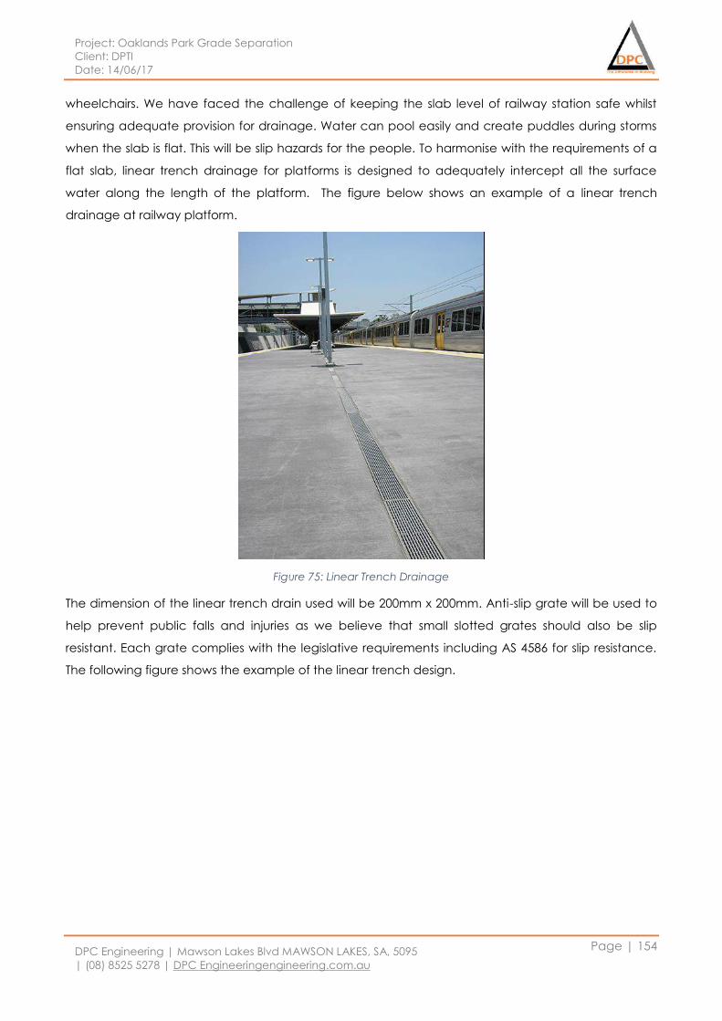
Project: Oaklands Park Grade Separation
Client: DPTI
Date: 14/06/17
DPC Engineering | Mawson Lakes Blvd MAWSON LAKES, SA, 5095
| (08) 8525 5278 | DPC Engineeringengineering.com.au
Page | 154
wheelchairs. We have faced the challenge of keeping the slab level of railway station safe whilst
ensuring adequate provision for drainage. Water can pool easily and create puddles during storms
when the slab is flat. This will be slip hazards for the people. To harmonise with the requirements of a
flat slab, linear trench drainage for platforms is designed to adequately intercept all the surface
water along the length of the platform. The figure below shows an example of a linear trench
drainage at railway platform.
Figure 75: Linear Trench Drainage
The dimension of the linear trench drain used will be 200mm x 200mm. Anti-slip grate will be used to
help prevent public falls and injuries as we believe that small slotted grates should also be slip
resistant. Each grate complies with the legislative requirements including AS 4586 for slip resistance.
The following figure shows the example of the linear trench design.
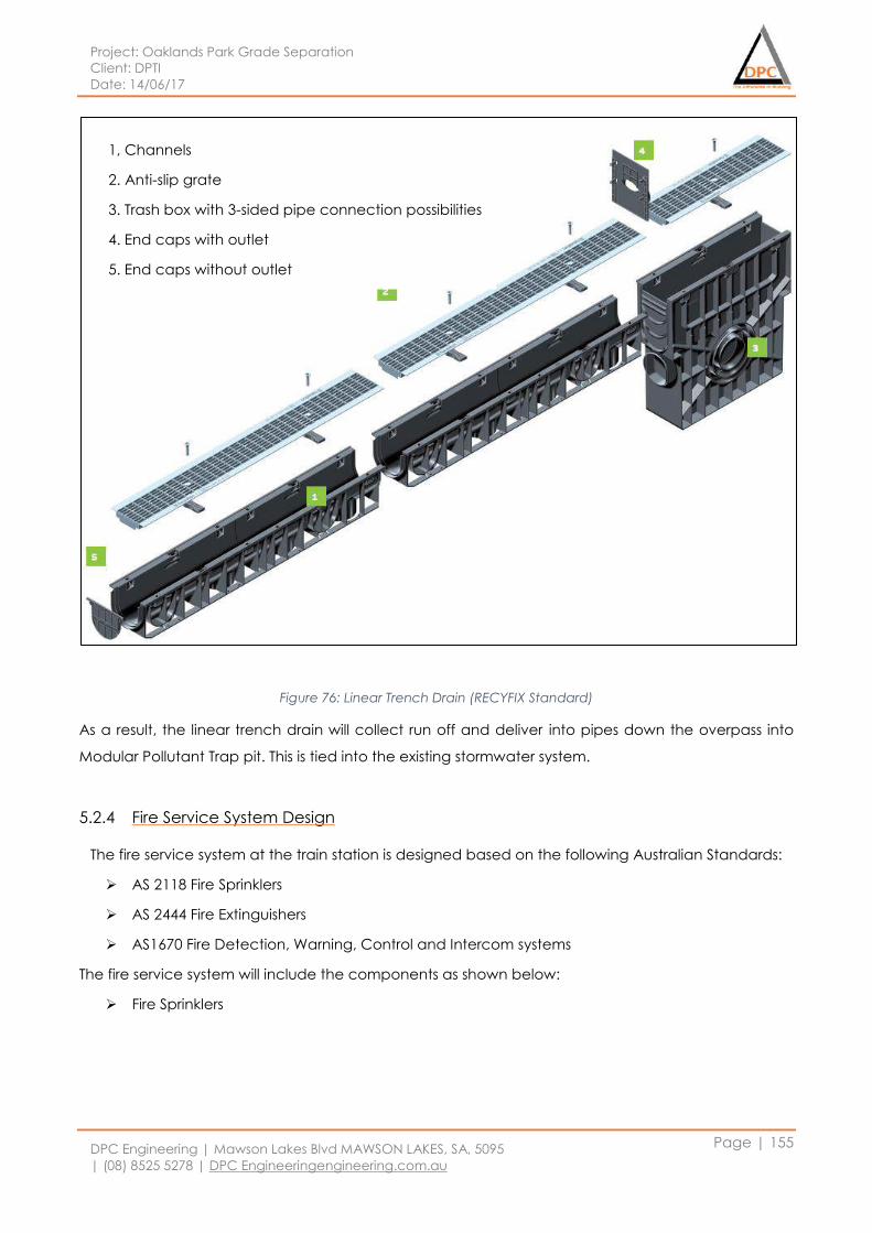
Project: Oaklands Park Grade Separation
Client: DPTI
Date: 14/06/17
DPC Engineering | Mawson Lakes Blvd MAWSON LAKES, SA, 5095
| (08) 8525 5278 | DPC Engineeringengineering.com.au
Page | 155
Figure 76: Linear Trench Drain (RECYFIX Standard)
As a result, the linear trench drain will collect run off and deliver into pipes down the overpass into
Modular Pollutant Trap pit. This is tied into the existing stormwater system.
5.2.4 Fire Service System Design
The fire service system at the train station is designed based on the following Australian Standards:
AS 2118 Fire Sprinklers
AS 2444 Fire Extinguishers
AS1670 Fire Detection, Warning, Control and Intercom systems
The fire service system will include the components as shown below:
Fire Sprinklers
1, Channels
2. Anti-slip grate
3. Trash box with 3-sided pipe connection possibilities
4. End caps with outlet
5. End caps without outlet
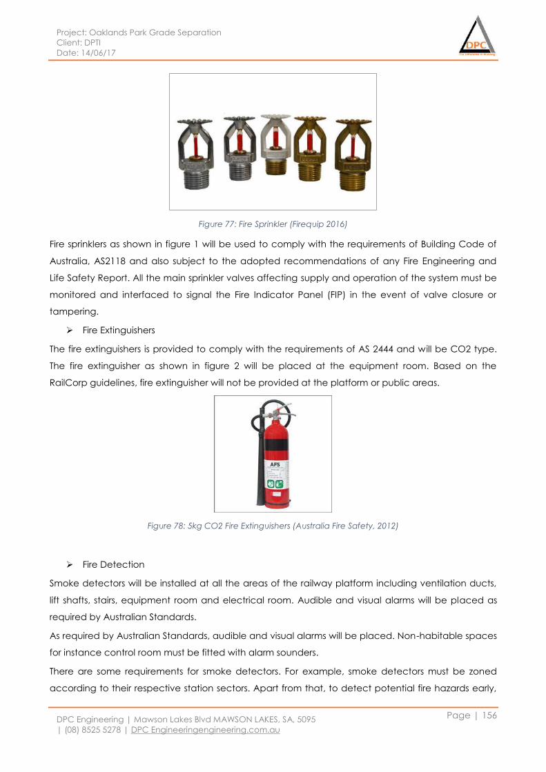
Project: Oaklands Park Grade Separation
Client: DPTI
Date: 14/06/17
DPC Engineering | Mawson Lakes Blvd MAWSON LAKES, SA, 5095
| (08) 8525 5278 | DPC Engineeringengineering.com.au
Page | 156
Figure 77: Fire Sprinkler (Firequip 2016)
Fire sprinklers as shown in figure 1 will be used to comply with the requirements of Building Code of
Australia, AS2118 and also subject to the adopted recommendations of any Fire Engineering and
Life Safety Report. All the main sprinkler valves affecting supply and operation of the system must be
monitored and interfaced to signal the Fire Indicator Panel (FIP) in the event of valve closure or
tampering.
Fire Extinguishers
The fire extinguishers is provided to comply with the requirements of AS 2444 and will be CO2 type.
The fire extinguisher as shown in figure 2 will be placed at the equipment room. Based on the
RailCorp guidelines, fire extinguisher will not be provided at the platform or public areas.
Figure 78: 5kg CO2 Fire Extinguishers (Australia Fire Safety, 2012)
Fire Detection
Smoke detectors will be installed at all the areas of the railway platform including ventilation ducts,
lift shafts, stairs, equipment room and electrical room. Audible and visual alarms will be placed as
required by Australian Standards.
As required by Australian Standards, audible and visual alarms will be placed. Non-habitable spaces
for instance control room must be fitted with alarm sounders.
There are some requirements for smoke detectors. For example, smoke detectors must be zoned
according to their respective station sectors. Apart from that, to detect potential fire hazards early,
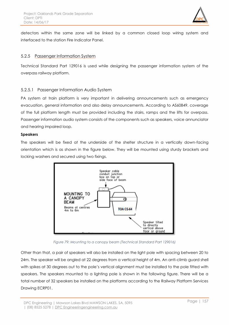
Project: Oaklands Park Grade Separation
Client: DPTI
Date: 14/06/17
DPC Engineering | Mawson Lakes Blvd MAWSON LAKES, SA, 5095
| (08) 8525 5278 | DPC Engineeringengineering.com.au
Page | 157
detectors within the same zone will be linked by a common closed loop wiring system and
interfaced to the station Fire Indicator Panel.
5.2.5 Passenger Information System
Technical Standard Part 129016 is used while designing the passenger information system of the
overpass railway platform.
5.2.5.1 Passenger Information Audio System
PA system at train platform is very important in delivering announcements such as emergency
evacuation, general information and also delay announcements. According to AS60849, coverage
of the full platform length must be provided including the stairs, ramps and the lifts for overpass.
Passenger information audio system consists of the components such as speakers, voice annunciator
and hearing impaired loop.
Speakers
The speakers will be fixed at the underside of the shelter structure in a vertically down-facing
orientation which is as shown in the figure below. They will be mounted using sturdy brackets and
locking washers and secured using two fixings.
Figure 79: Mounting to a canopy beam (Technical Standard Part 129016)
Other than that, a pair of speakers will also be installed on the light pole with spacing between 20 to
24m. The speaker will be angled at 22 degrees from a vertical height of 4m. An anti-climb guard shell
with spikes at 30 degrees out to the pole’s vertical alignment must be installed to the pole fitted with
speakers. The speakers mounted to a lighting pole is shown in the following figure. There will be a
total number of 32 speakers be installed on the platforms according to the Railway Platform Services
Drawing ECRP01.
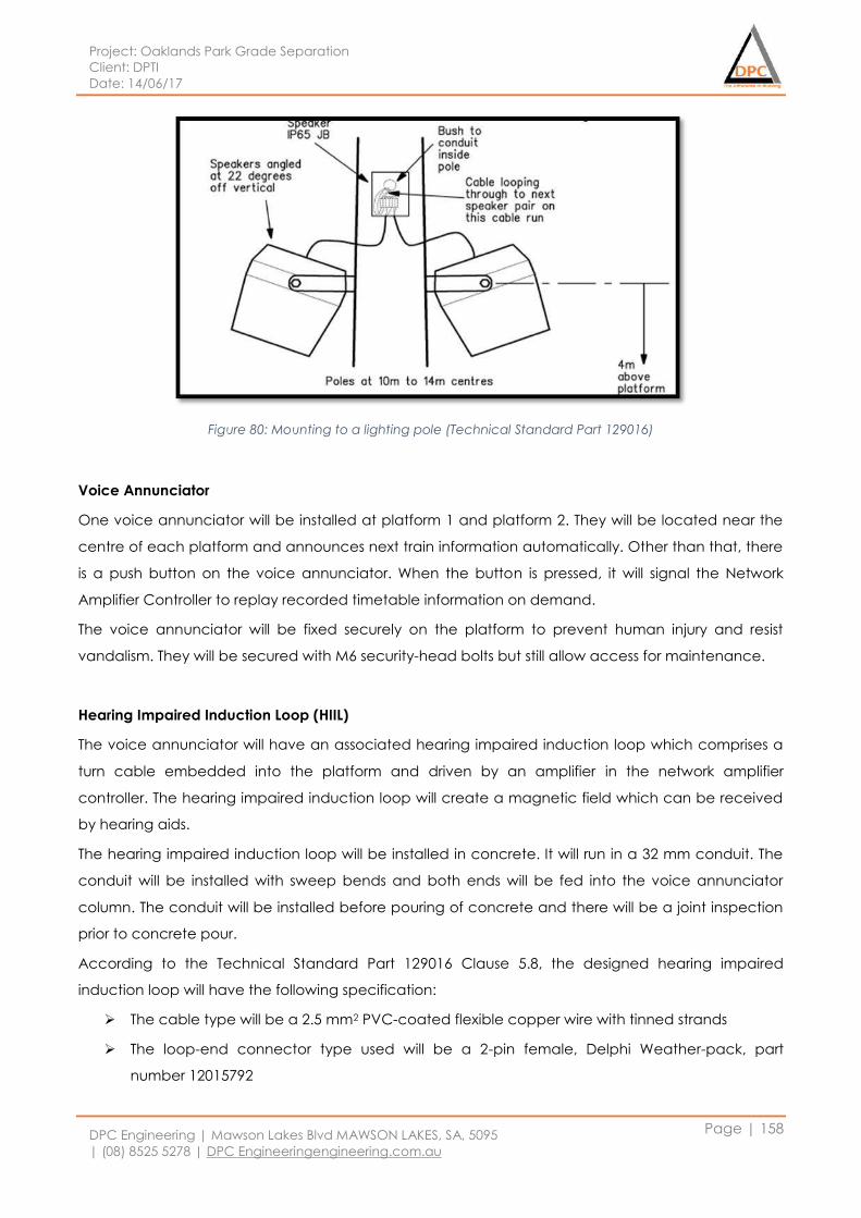
Project: Oaklands Park Grade Separation
Client: DPTI
Date: 14/06/17
DPC Engineering | Mawson Lakes Blvd MAWSON LAKES, SA, 5095
| (08) 8525 5278 | DPC Engineeringengineering.com.au
Page | 158
Figure 80: Mounting to a lighting pole (Technical Standard Part 129016)
Voice Annunciator
One voice annunciator will be installed at platform 1 and platform 2. They will be located near the
centre of each platform and announces next train information automatically. Other than that, there
is a push button on the voice annunciator. When the button is pressed, it will signal the Network
Amplifier Controller to replay recorded timetable information on demand.
The voice annunciator will be fixed securely on the platform to prevent human injury and resist
vandalism. They will be secured with M6 security-head bolts but still allow access for maintenance.
Hearing Impaired Induction Loop (HIIL)
The voice annunciator will have an associated hearing impaired induction loop which comprises a
turn cable embedded into the platform and driven by an amplifier in the network amplifier
controller. The hearing impaired induction loop will create a magnetic field which can be received
by hearing aids.
The hearing impaired induction loop will be installed in concrete. It will run in a 32 mm conduit. The
conduit will be installed with sweep bends and both ends will be fed into the voice annunciator
column. The conduit will be installed before pouring of concrete and there will be a joint inspection
prior to concrete pour.
According to the Technical Standard Part 129016 Clause 5.8, the designed hearing impaired
induction loop will have the following specification:
The cable type will be a 2.5 mm2 PVC-coated flexible copper wire with tinned strands
The loop-end connector type used will be a 2-pin female, Delphi Weather-pack, part
number 12015792
Project: Oaklands Park Grade Separation
Client: DPTI
Date: 14/06/17
DPC Engineering | Mawson Lakes Blvd MAWSON LAKES, SA, 5095
| (08) 8525 5278 | DPC Engineeringengineering.com.au
Page | 159
The cable-end connector type used will be a 2-pin male, Delphi Weather-pack, part number
12015793
The loop length will be between 12 m to a maximum of 14m
Other than that, it is important to test the area of each proposed voice annunciator/loop position
with a Loop Field Strength Meter during the design phase to determine the amount of electrical
interference at the location.
5.2.5.2 Passenger Information Display
According to PTS Technical Standard Part 129016, for platform over 120m long, two passenger
information displays will be installed on each platform as per drawing *CCTV Platform*. Passenger
Information Display will be mounted to a support bracket suspended from the canopy structure
above, with a down tilt angle of 10 degrees. The position of the passenger information display must
be co-ordinated with CCTV to ensure it can viewed by a CCTC camera if its tamper alarm is
activated. They will be located around the main platform waiting area which is toward the centre of
the platform. Other than that, the bottom surface of the passenger information display must not be
lower than 2700mm above platform level or higher than 3000mm above platform level. According
to the Railway Services Drawing ECRP01, there will be a total number of 4 passenger information
display installed on the platform.
According to the Technical Standard Part 129016 Clause 6.2, the passenger information display will
comprise the following components:
Timetable information stored in the network amplifier controller and updated over the PIS
WAN IP network
100 base T Ethernet and 100base-FX network switch
DVI splitter
DVI cord per monitor with
Passenger information display power and tamper alarm cabling
5.2.6 Control Room
A suitable control must be provided to securely house the infrastructure required for train station
such as electrical infrastructure, security system and passenger information system. Refer drawing
*Control Room layout* for the layout of the proposed control room to be located under the platform
as part of the embankment structure.
5.2.6.1 Security
To ensure the safety of the control room, the walls and doors of the control room will be constructed
capable of withstanding malicious vandal attack. There will be no access to the control room by
Project: Oaklands Park Grade Separation
Client: DPTI
Date: 14/06/17
DPC Engineering | Mawson Lakes Blvd MAWSON LAKES, SA, 5095
| (08) 8525 5278 | DPC Engineeringengineering.com.au
Page | 160
removing panels or in-wall air conditioners. The walls will be constructed with masonry or concrete
whereas the door will be made with solid timber and steel clad.
The entrance door to the security system enclosure within the control room will also be fitted with a
lock. The external door of the control room will be fitted with weather and dust seals in order to
prevent ingress of water or contaminants into the room. A lock keyed will also be fitted to the
external door to suit a Principal supplied “K11/K12” Security Key. There will be a self-closing
mechanism installed to the door so that it will be lock automatically from the outside but it can still
be opened without the use of a key from inside.
5.2.6.2 Power Supply
The power will be supplied to the control room. The following circuits will be provided in the control
room in accordance to Technical Standard Part 129017 Clause 3.11.
15 A rack pendant outlet #1 (CCTV Rack main – Non-RCD)
15 A rack pendant outlet #2 (CCTV Rack backup-Non-RCD)
15 A rack pendant outlet #3 (PA/ICT Rack main-Non-RCD)
15 A rack pendant outlet #4 (PA/ICT Rack backup-Non-RCD)
Wall convenience general power outlets (RCD protected)
Security alarm panel general power outlet (Non-RCd)
Lighting
The average equipment demand under normal steady state power supply condition is estimated at
1500 VA excluding lighting. A 6mm2 G/Y cable will be provided from a Communications Earth
Terminal at the main distribution board to each of the CCTV rack, PI rack and also the main
distribution frame.
5.2.6.3 Main Distribution Frame
A public carrier network boundary facility (Main Distribution Frame) will be located in the control
room. There will be a cable tray support pathway to the ER perimeter wall cable tray, to the public
carrier entrance cable penetrations and also to the site distribution pathways.
5.2.6.4 Telstra Service
A 10 pair Telstra point of entry cable will be provided from the nearest point of Telstra service
connection. According to the Technical Standard Part 129017 Clause 3.13, the services as shown
below will be wired to the Main Distribution Frame and carried on this cable as Public Switched
Telephone Network (PSTN) services.
Emergency Help Phone – one line per telephone

Project: Oaklands Park Grade Separation
Client: DPTI
Date: 14/06/17
DPC Engineering | Mawson Lakes Blvd MAWSON LAKES, SA, 5095
| (08) 8525 5278 | DPC Engineeringengineering.com.au
Page | 161
Lift car Emergency Help Phone
Security alarm panel dialler
Police Security Services Branch (PSSB) link Digital Subscriber Line (DSL) service
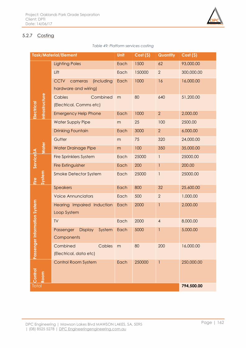
Project: Oaklands Park Grade Separation
Client: DPTI
Date: 14/06/17
DPC Engineering | Mawson Lakes Blvd MAWSON LAKES, SA, 5095
| (08) 8525 5278 | DPC Engineeringengineering.com.au
Page | 162
5.2.7 Costing
Table 49: Platform services costing
Task/Material/Element Unit Cost ($) Quantity Cost ($)
Ele
ctr
ica
l
Infr
ast
ruc
ture
Lighting Poles Each 1500 62 93,000.00
Lift Each 150000 2 300,000.00
CCTV cameras (including
hardware and wiring)
Each 1000 16 16,000.00
Cables Combined
(Electrical, Comms etc)
m 80 640 51,200.00
Emergency Help Phone Each 1000 2 2,000.00
SA
Wa
ter
Water Supply Pipe m 25 100 2500.00
Drinking Fountain Each 3000 2 6,000.00
Gutter m 75 320 24,000.00
Water Drainage Pipe m 100 350 35,000.00
Fir
e
Se
rvic
e
Sy
ste
m
Fire Sprinklers System Each 25000 1 25000.00
Fire Extinguisher Each 200 1 200.00
Smoke Detector System Each 25000 1 25000.00
Pa
sse
ng
er
Info
rma
tio
n S
yst
em
Speakers Each 800 32 25,600.00
Voice Annunciators Each 500 2 1,000.00
Hearing Impaired Induction
Loop System
Each 2000 1 2,000.00
TV Each 2000 4 8,000.00
Passenger Display System
Components
Each 5000 1 5,000.00
Combined Cables
(Electrical, data etc)
m 80 200 16,000.00
Co
ntr
ol
Ro
om
Control Room System Each 250000 1 250,000.00
Total 794,500.00
Project: Oaklands Park Grade Separation
Client: DPTI
Date: 14/06/17
DPC Engineering | Mawson Lakes Blvd MAWSON LAKES, SA, 5095
| (08) 8525 5278 | DPC Engineeringengineering.com.au
Page | 163
5.3 Package 03: Miscellaneous
5.3.1 Traffic Signalling
5.3.1.1 Design Assumptions & Considerations
It is assumed that there are three resultant intersections to be signalised based on the
recommendations from the Traffic Signal Operation Performance Report (TSOPR) carried out as per
section 4 and 6.2 of DPTI TS100 Traffic signal design standards. Refer drawing *Traffic Signals* for the
alignment of the new signal network including Comms and power supply at the newly signalised
intersections.
Traffic signal performance analysis must be undertaken, including:
capacity analysis to guide the design and operational requirements of traffic signals;
modelling using current and specified future design flows, and
Detailed assessment of the traffic impacts of alternative traffic management arrangements
to be used during construction of the project.
The following design and operational requirements must be achieved:
lane, phasing and coordination requirements at traffic signals that ensures the safe and
efficient operation of road network for the current and future design flows, as specified;
traffic signals integration within DPTI’s current systems used to monitor and control traffic
signal operation; and
The needs of all road users (e.g. buses, heavy vehicles, freight, cycles, and pedestrians) are
taken into account.
5.3.1.2 Conduiting
The proposed signal network construction, including trench work, conduit layout and associated pit
design will comply with the following DPTI specifications:
(a) Part 206 “Under-road Boring”
(b) Part 207 “Trench Excavation and Backfill”
(c) Part 208 “Reinstatement of Existing Pavements”
(d) Part 253 "Supply and Installation of Conduits and Pits".
5.3.1.3 Intersections
The new intersections are designed to incorporate Extra Low Voltage network (ELV) equipment
approved by DPTI with allowance for spare conduits as outlined in 7.1, 7.3 and 7.4 of TS100. The new
traffic signal controllers used in the intersection are designed to conform to specification TSC/4 of
Transport for New South Wales in addition to DPTI approval. S7.7 of TS100 details location
Project: Oaklands Park Grade Separation
Client: DPTI
Date: 14/06/17
DPC Engineering | Mawson Lakes Blvd MAWSON LAKES, SA, 5095
| (08) 8525 5278 | DPC Engineeringengineering.com.au
Page | 164
determining of traffic signal controllers. Similarly, the location of traffic signal poles must take into
account various constraints such as site layout and function of intersection, refer section 7.11.5 Traffic
Signal Poles.
5.3.2 Traffic Signal Controller
All new traffic signal controllers must conform to Transport for New South Wales Road and Marine
Services, NSW specification TSC/4 and be approved by DPTI.
The location of the traffic signal controller must be determined using the following criteria:
minimisation of obstruction to pedestrians;
minimisation of visual obstruction to drivers;
minimisation of the risk of accidental damage by traffic;
provision of a safe and easy access for maintenance personnel and associated vehicles;
permits maintenance staff to have a clear view of the whole of the intersection from the
controller as far as is practicable;
orientation so that the cabinet door(s) open away from the centre of the intersection; and
Close location to the power supply and telecommunications service.
The programming of the traffic controllers is part of DPTIs scope, however DPC nor DPTI will provide
the hardware required, Programmable Controller Personality Module (PCPM). CCTV cameras are to
be installed where S7.8 of TS100 dictates and are to be installed in an external housing on top of the
traffic signal cabinet. All level and pedestrian/bicycle detection crossings are to be designed to
sections 7.11.3 and 7.11.4 of TS100 relating to requirements, location, geometry and restraints of
these crossings. All records of construction required by DPTI as stated in section 8, TS100 will be
provided.
5.3.3 Stormwater
5.3.3.1 Design Assumptions & Considerations
In this detailed design brief report, since it is the railway overpass, it is necessary to consider the
design of the stormwater system on the bridge with the road to ensure the possibility of resisting any
floods and to maintain adequate rainfall capacity in the area. The main aim is to ferry the
stormwater runoff from the overpass as quickly as possible to minimise flood danger and damage.
The secondary aim is to limit the entering of pollutants into the receiving waters. These designs will be
connected to the existing stormwater system along Murray Terrace, and then become part of the
existing network. The new stormwater system will be described in further detail below and the
alignment can be found under drawing *Stormwater*. It is a design assumption that the existing
stormwater system in effect during a 1 in 100 ARI storm event has the capacity to withstand the new
Project: Oaklands Park Grade Separation
Client: DPTI
Date: 14/06/17
DPC Engineering | Mawson Lakes Blvd MAWSON LAKES, SA, 5095
| (08) 8525 5278 | DPC Engineeringengineering.com.au
Page | 165
inflow from the proposed rail overpass. The delivery of new stormwater inflow from the rail overpass
to the existing network is carried down stormwater pipes or grades
In order to keep the existing stormwater system in that area, a drainage pipe will be designed on the
bridge to connect the rainwater to the ground stormwater drainage system. Assume a 300mm
dimeter as a drain pipe.
The stormwater drainage system needs to be controlled from the following sources to collect,
process and store runoff: Rainfall, flood control and accidental leak. In order to design a new
rainwater system on the bridge, two sub-catchments are divided so as to produce a preliminary
pipe size and use the DRAINS software, develop appropriate rainwater systems. The stormwater
system will be designed to flow along the slope to the bridge and then into the original rainwater
drainage system as the rain flows north and south.
5.3.3.2 Distances between other services
According from AS/NZS 3725:2007, the minimum distance between stormwater systems designs of
pipes with other services designed is 50 mm, the required compaction is able to get the pipe around
the filling material. Due to the size of the pipe and the required work design, it is necessary to design
around the layout of the stormwater pipe.
5.3.3.3 Minimum depths/cover
The minimum depth of stormwater system design is 600mm as a reinforced concrete pipes. And for
PVC and steel pipes of the stormwater system design as a cover are requires for 750 mm and 400
mm. During the construction period according to the provisions of DPTI, to carry out construction.
5.3.3.4 Pipes, Pits, Junction Boxes and Access covers
All pipes, concrete rainwater inlet pits, junction boxes, access covers and grates and culverts are
designed and constructed according from the Australian/ New Zealand standard and DPTI
specifications for design and construction:
AS/NZS 3725:2007 - Design for Installation of Buried Concrete Pipes;
AS 3996:2006 - Access covers and grates;
AS 3735 - Concrete structures retaining liquids;
DPTI Road Design Standards and Guidelines – Stormwater Design - DD 300;
Storm Drainage Design in small urban catchments – John Argue, 1986.
The pipeline and pits for this project design of the specific requirements are:
Minimum pipe grade of 0.5%
Minimum pipe diameter of 375mm
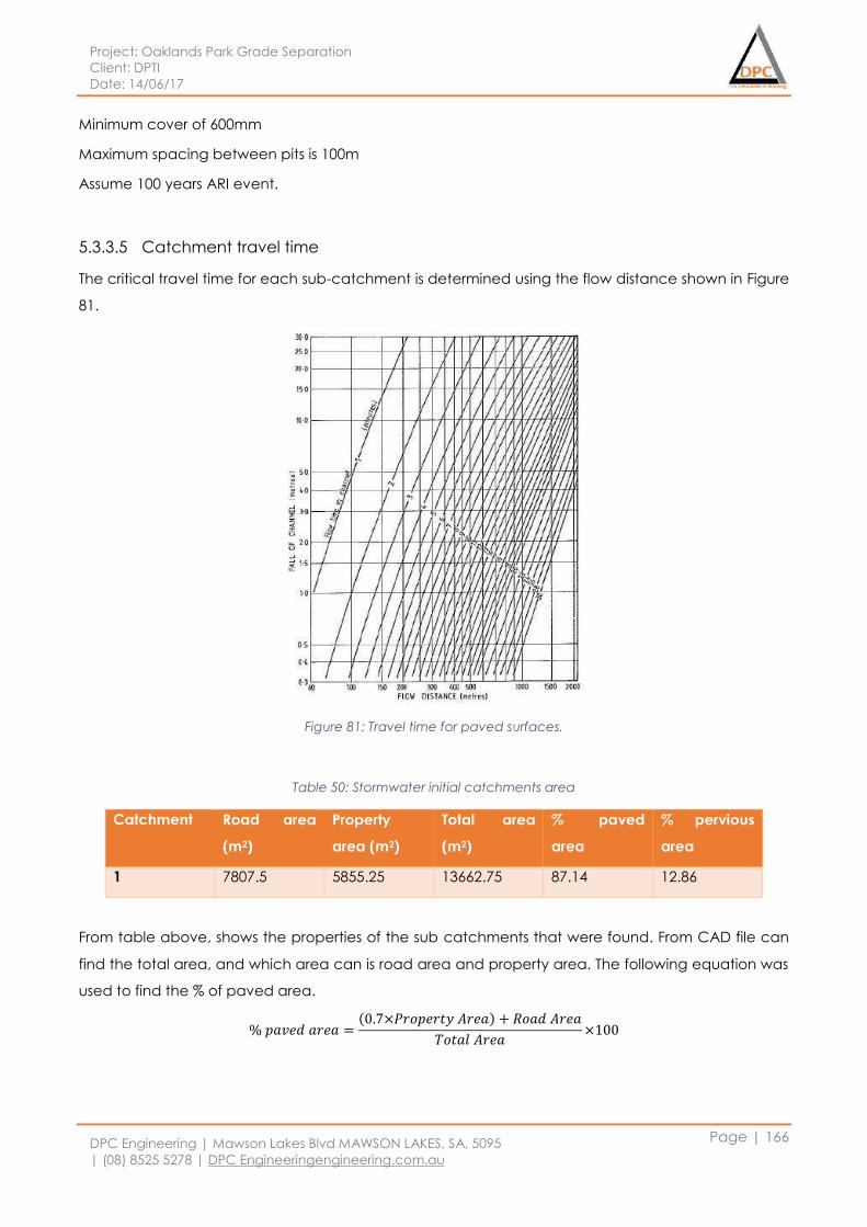
Project: Oaklands Park Grade Separation
Client: DPTI
Date: 14/06/17
DPC Engineering | Mawson Lakes Blvd MAWSON LAKES, SA, 5095
| (08) 8525 5278 | DPC Engineeringengineering.com.au
Page | 166
Minimum cover of 600mm
Maximum spacing between pits is 100m
Assume 100 years ARI event.
5.3.3.5 Catchment travel time
The critical travel time for each sub-catchment is determined using the flow distance shown in Figure
81.
Figure 81: Travel time for paved surfaces.
Table 50: Stormwater initial catchments area
Catchment Road area
(m2)
Property
area (m2)
Total area
(m2)
% paved
area
% pervious
area
1 7807.5 5855.25 13662.75 87.14 12.86
From table above, shows the properties of the sub catchments that were found. From CAD file can
find the total area, and which area can is road area and property area. The following equation was
used to find the % of paved area.
% 𝑝𝑎𝑣𝑒𝑑 𝑎𝑟𝑒𝑎 =(0.7×𝑃𝑟𝑜𝑝𝑒𝑟𝑡𝑦 𝐴𝑟𝑒𝑎) + 𝑅𝑜𝑎𝑑 𝐴𝑟𝑒𝑎
𝑇𝑜𝑡𝑎𝑙 𝐴𝑟𝑒𝑎×100
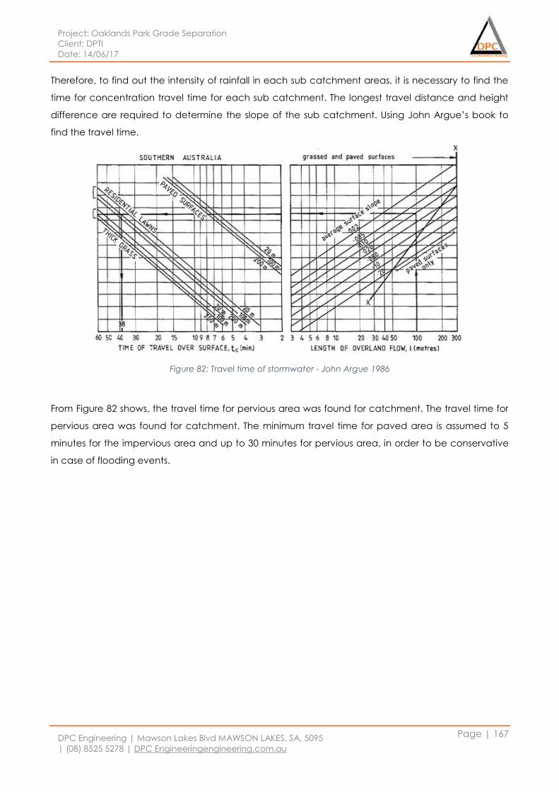
Project: Oaklands Park Grade Separation
Client: DPTI
Date: 14/06/17
DPC Engineering | Mawson Lakes Blvd MAWSON LAKES, SA, 5095
| (08) 8525 5278 | DPC Engineeringengineering.com.au
Page | 167
Therefore, to find out the intensity of rainfall in each sub catchment areas, it is necessary to find the
time for concentration travel time for each sub catchment. The longest travel distance and height
difference are required to determine the slope of the sub catchment. Using John Argue’s book to
find the travel time.
Figure 82: Travel time of stormwater - John Argue 1986
From Figure 82 shows, the travel time for pervious area was found for catchment. The travel time for
pervious area was found for catchment. The minimum travel time for paved area is assumed to 5
minutes for the impervious area and up to 30 minutes for pervious area, in order to be conservative
in case of flooding events.
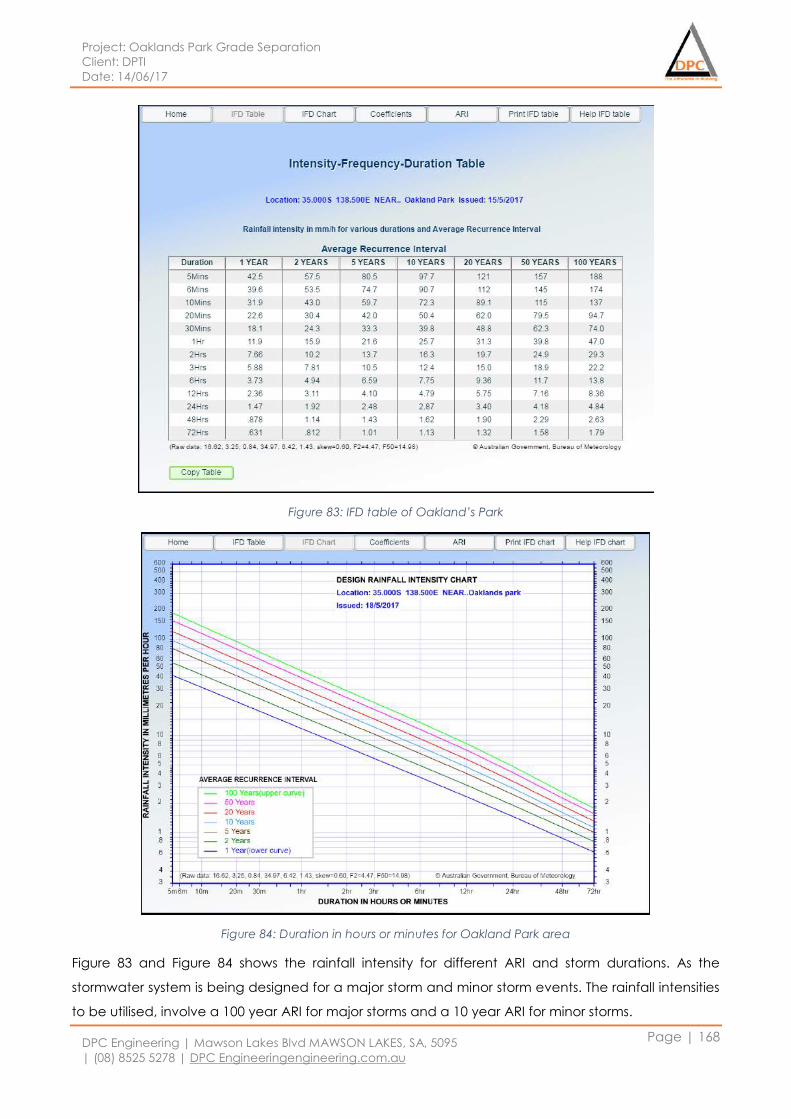
Project: Oaklands Park Grade Separation
Client: DPTI
Date: 14/06/17
DPC Engineering | Mawson Lakes Blvd MAWSON LAKES, SA, 5095
| (08) 8525 5278 | DPC Engineeringengineering.com.au
Page | 168
Figure 83: IFD table of Oakland’s Park
Figure 84: Duration in hours or minutes for Oakland Park area
Figure 83 and Figure 84 shows the rainfall intensity for different ARI and storm durations. As the
stormwater system is being designed for a major storm and minor storm events. The rainfall intensities
to be utilised, involve a 100 year ARI for major storms and a 10 year ARI for minor storms.
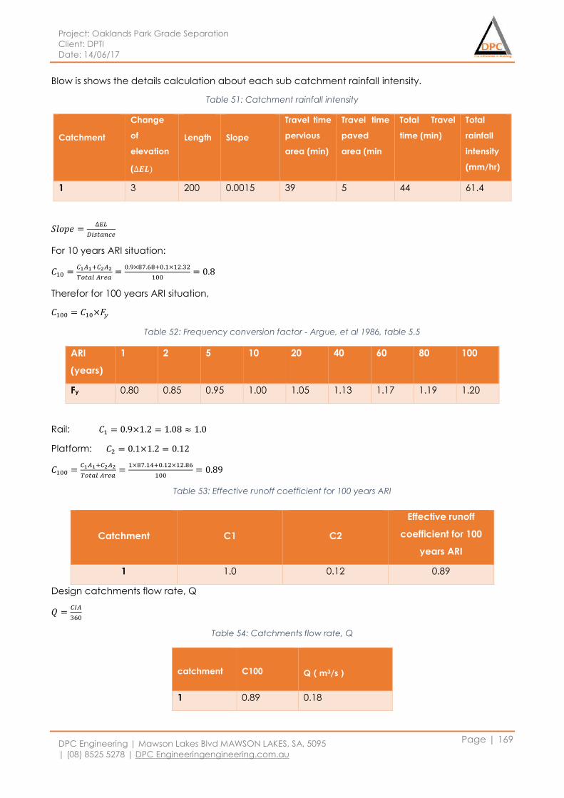
Project: Oaklands Park Grade Separation
Client: DPTI
Date: 14/06/17
DPC Engineering | Mawson Lakes Blvd MAWSON LAKES, SA, 5095
| (08) 8525 5278 | DPC Engineeringengineering.com.au
Page | 169
Blow is shows the details calculation about each sub catchment rainfall intensity.
Table 51: Catchment rainfall intensity
Catchment
Change
of
elevation
(∆𝑬𝑳)
Length
Slope
Travel time
pervious
area (min)
Travel time
paved
area (min
Total Travel
time (min)
Total
rainfall
intensity
(mm/hr)
1 3 200 0.0015 39 5 44 61.4
𝑆𝑙𝑜𝑝𝑒 =∆𝐸𝐿
𝐷𝑖𝑠𝑡𝑎𝑛𝑐𝑒
For 10 years ARI situation:
𝐶10 =𝐶1𝐴1+𝐶2𝐴2
𝑇𝑜𝑡𝑎𝑙 𝐴𝑟𝑒𝑎=
0.9×87.68+0.1×12.32
100= 0.8
Therefor for 100 years ARI situation,
𝐶100 = 𝐶10×𝐹𝑦
Table 52: Frequency conversion factor - Argue, et al 1986, table 5.5
ARI
(years)
1 2 5 10 20 40 60 80 100
Fy 0.80 0.85 0.95 1.00 1.05 1.13 1.17 1.19 1.20
Rail: 𝐶1 = 0.9×1.2 = 1.08 ≈ 1.0
Platform: 𝐶2 = 0.1×1.2 = 0.12
𝐶100 =𝐶1𝐴1+𝐶2𝐴2
𝑇𝑜𝑡𝑎𝑙 𝐴𝑟𝑒𝑎=
1×87.14+0.12×12.86
100= 0.89
Table 53: Effective runoff coefficient for 100 years ARI
Design catchments flow rate, Q
𝑄 =𝐶𝐼𝐴
360
Table 54: Catchments flow rate, Q
catchment
C100
Q(m3/s)
1 0.89 0.18
Catchment
C1
C2
Effective runoff
coefficient for 100
years ARI
1 1.0 0.12 0.89
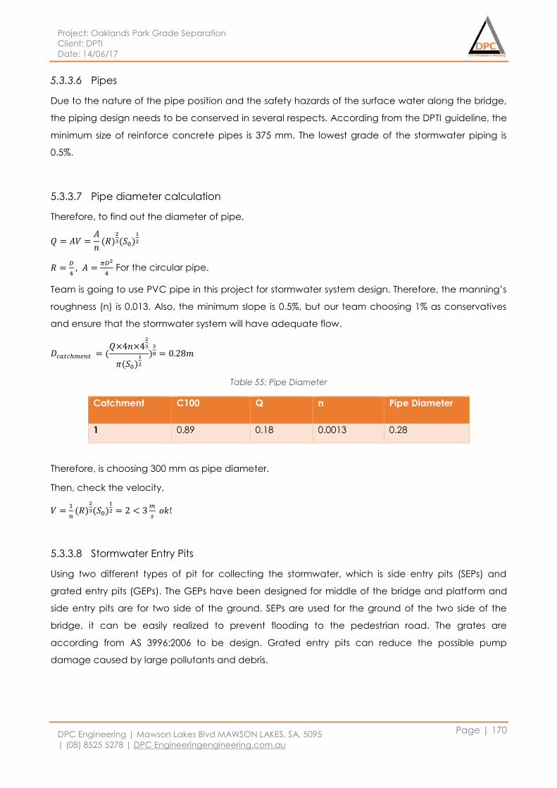
Project: Oaklands Park Grade Separation
Client: DPTI
Date: 14/06/17
DPC Engineering | Mawson Lakes Blvd MAWSON LAKES, SA, 5095
| (08) 8525 5278 | DPC Engineeringengineering.com.au
Page | 170
5.3.3.6 Pipes
Due to the nature of the pipe position and the safety hazards of the surface water along the bridge,
the piping design needs to be conserved in several respects. According from the DPTI guideline, the
minimum size of reinforce concrete pipes is 375 mm. The lowest grade of the stormwater piping is
0.5%.
5.3.3.7 Pipe diameter calculation
Therefore, to find out the diameter of pipe,
𝑄 = 𝐴𝑉 =𝐴
𝑛(𝑅)
2
3(𝑆0)1
2
𝑅 =𝐷
4, 𝐴 =
𝜋𝐷2
4 For the circular pipe.
Team is going to use PVC pipe in this project for stormwater system design. Therefore, the manning’s
roughness (n) is 0.013. Also, the minimum slope is 0.5%, but our team choosing 1% as conservatives
and ensure that the stormwater system will have adequate flow.
𝐷𝑐𝑎𝑡𝑐ℎ𝑚𝑒𝑛𝑡 = (𝑄×4𝑛×4
2
3
𝜋(𝑆0)1
2
)3
8 = 0.28𝑚
Table 55: Pipe Diameter
Catchment C100 Q n Pipe Diameter
1 0.89 0.18 0.0013 0.28
Therefore, is choosing 300 mm as pipe diameter.
Then, check the velocity,
𝑉 =1
𝑛(𝑅)
2
3(𝑆0)1
2 = 2 < 3𝑚
𝑠 𝑜𝑘!
5.3.3.8 Stormwater Entry Pits
Using two different types of pit for collecting the stormwater, which is side entry pits (SEPs) and
grated entry pits (GEPs). The GEPs have been designed for middle of the bridge and platform and
side entry pits are for two side of the ground. SEPs are used for the ground of the two side of the
bridge, it can be easily realized to prevent flooding to the pedestrian road. The grates are
according from AS 3996:2006 to be design. Grated entry pits can reduce the possible pump
damage caused by large pollutants and debris.
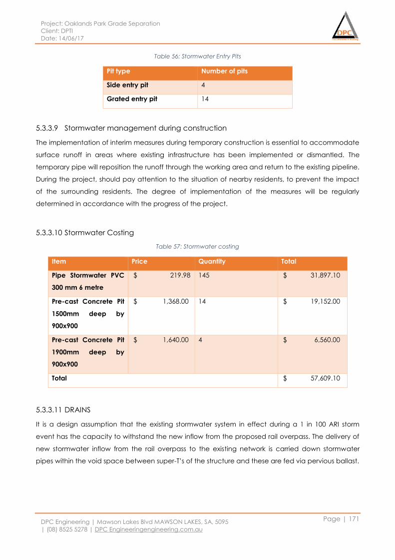
Project: Oaklands Park Grade Separation
Client: DPTI
Date: 14/06/17
DPC Engineering | Mawson Lakes Blvd MAWSON LAKES, SA, 5095
| (08) 8525 5278 | DPC Engineeringengineering.com.au
Page | 171
Table 56: Stormwater Entry Pits
Pit type Number of pits
Side entry pit 4
Grated entry pit 14
5.3.3.9 Stormwater management during construction
The implementation of interim measures during temporary construction is essential to accommodate
surface runoff in areas where existing infrastructure has been implemented or dismantled. The
temporary pipe will reposition the runoff through the working area and return to the existing pipeline.
During the project, should pay attention to the situation of nearby residents, to prevent the impact
of the surrounding residents. The degree of implementation of the measures will be regularly
determined in accordance with the progress of the project.
5.3.3.10 Stormwater Costing
Table 57: Stormwater costing
Item Price Quantity Total
Pipe Stormwater PVC
300 mm 6 metre
$ 219.98 145 $ 31,897.10
Pre-cast Concrete Pit
1500mm deep by
900x900
$ 1,368.00 14 $ 19,152.00
Pre-cast Concrete Pit
1900mm deep by
900x900
$ 1,640.00 4 $ 6,560.00
Total $ 57,609.10
5.3.3.11 DRAINS
It is a design assumption that the existing stormwater system in effect during a 1 in 100 ARI storm
event has the capacity to withstand the new inflow from the proposed rail overpass. The delivery of
new stormwater inflow from the rail overpass to the existing network is carried down stormwater
pipes within the void space between super-T’s of the structure and these are fed via pervious ballast.
Project: Oaklands Park Grade Separation
Client: DPTI
Date: 14/06/17
DPC Engineering | Mawson Lakes Blvd MAWSON LAKES, SA, 5095
| (08) 8525 5278 | DPC Engineeringengineering.com.au
Page | 172
5.4 Drawings Reference List:
5.4.1.1 Relocations
1. Plan view of existing and design services – project extent
2. Plan view of existing and design services – detailed
3. Cross section of typical trench – each service
4. Cross section of typical road crossing – wherever crossing
5.4.2 Rail Platform
1. Plan view of rail platform showing skeleton structure + services – all services
2. Plan view of rail platform showing services – detailed
3. Cross section of stormwater drainage into overpass drainage + Mod Grease Trap
4. Control Room drawing
5.4.3 Misc.
1. Stormwater design network tie in to existing
2. Traffic signalling plan view project extent + detailed
3. Greenway drawing
Project: Oaklands Park Grade Separation
Client: DPTI
Date: 14/06/17
DPC Engineering | Mawson Lakes Blvd MAWSON LAKES, SA, 5095
| (08) 8525 5278 | DPC Engineeringengineering.com.au
Page | 173
5.5 Reference
1. Public Transport Services 2013, Design-Stations-Passenger Information Systems, Technical
Standard Part 129016, Department of Planning, Transport and Infrastructure, South Australia.
2. Public Transport Services 2013, Stations – Platforms, Technical Standard Part 129003, Department
of Planning, Transport and Infrastructure, South Australia.
3. Public Transport Services 2014, Design-Stations-Electrical Infrastructure, Technical Standard Part
129014, Department of Planning, Transport and Infrastructure, South Australia.
4. Public Transport Services 2013, Stations – Earthing and Bonding, Technical Standard Part 129002,
Department of Planning, Transport and Infrastructure, South Australia
5. Public Transport Services 2013, Stations – Equipment Room, Technical Standard Part 129017,
Department of Planning, Transport and Infrastructure, South Australia.
6. Public Transport Services 2013, Design – Stations- Overpasses, Technical Standard Part 129004,
Department of Planning, Transport and Infrastructure, South Australia
7. Track and Civil Infrastructure 2013, Code of Practice Volume 2: Drainage, CP-TS-958,
Government of South Australia, South Australia.
Project: Oaklands Park Grade Separation
Client: DPTI
Date: 14/06/17
DPC Engineering | Mawson Lakes Blvd MAWSON LAKES, SA, 5095
| (08) 8525 5278 | DPC Engineeringengineering.com.au
Page | 174
6 URBAN DESIGN AND COMMUNITY
6.1 Introduction
Upon completion of the feasibility study, DPC Engineering, has narrowed the four initial design
options down to a singular focus, which is the rail overpass for the detailed design. The Urban
Planning department has begun detailing the specific requirements needed to ensure the success
of the rail overpass, starting with the initial scoping document. This document has provided a map,
for the expected course of action the department will take during the final design stage, and
supplements this report. The following section of this report aims to cater for the communities and
stakeholders within the area of the project.
The Urban Planning department at DPC engineering, will achieve this by developing plans for the
use of land around the project, while considering the political, zoning and legal issues related to the
project. Additionally, the urban team will provide a strong input into the final design of the project,
by providing a conceptual model, that will provide direction for the various departments in their
design, whilst ensuring synergy with the existing design of current area. Lastly the urban team will
implement a strong and positive interface with the public, providing community engagement
measures to determine their needs and limitations, whilst gathering data, environmental studies and
economic reports to review the design.
6.2 Demographics
The final design, construction and operation of the rail overpass will have a strong impact on the
residents, businesses and commuters of the surrounding area. That being, the people of Warradale
and Oaklands Park, and to a greater extent the Marion council, will need to be consulted with to
minimize any negative impacts that the project could potentially raise during the construction and
operation of the rail overpass. To do this information from the City of Marion’s social atlas, which
gives the total population of Marion as 81479, will be utilized to assess the impact on the general
population of the area. Where the specific population of Warradale and Oaklands Park, (4578 and
3251 respectively), will be used to assess the immediate area of the project. It is a target of the
department to achieve a 50% participation rate in the feedback surveys as the project goes on.
Other data such as the average age (42 years old), house ownership details (Warradale area is
39.4%, and Oaklands Park area is 26.2%), and the rent percentages of the area, give insight on how
to best approach land acquisition for the project. Additionally, data on how to best reach the
community and other important demographic details can be assisted with the following information.
That is, the unemployment rate is only 10% of the two regions together, hence, a large percentage
of individuals that need to get to work. Furthermore, the percentage of people in the Warradale
area, who choose to get to work by car is 67.5% and, in Oaklands Park it is 64.2%. This means that
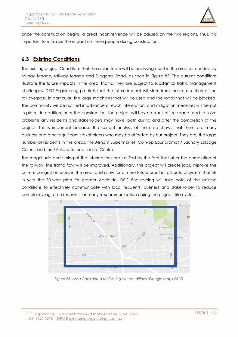
Project: Oaklands Park Grade Separation
Client: DPTI
Date: 14/06/17
DPC Engineering | Mawson Lakes Blvd MAWSON LAKES, SA, 5095
| (08) 8525 5278 | DPC Engineeringengineering.com.au
Page | 175
once the construction begins, a great inconvenience will be caused on the two regions. Thus, it is
important to minimize the impact on these people during construction.
6.3 Existing Conditions
The existing project Conditions that the urban team will be analysing is within the area surrounded by
Murray terrace, railway terrace and Diagonal Road, as seen in Figure 85. The current conditions
illustrate the future impacts in this area, that is, they are subject to substantial traffic management
challenges. DPC Engineering predicts that the future impact will stem from the construction of the
rail overpass, in particular, the large machines that will be used and the roads that will be blocked.
The community will be notified in advance of each interruption, and mitigation measures will be put
in place. In addition, near the construction, the project will have a small office space used to solve
problems any residents and stakeholders may have, both during and after the completion of the
project. This is important because the current analysis of the area shows that there are many
business and other significant stakeholders who may be affected by our project. They are; the large
number of residents in the areas, the Alsham Supermarket, Coin-op Laundromat / Laundry Splodge
Corner, and the SA Aquatic and Leisure Centre.
The magnitude and timing of the interruptions are justified by the fact that after the completion of
the railway, the traffic flow will be improved. Additionally, this project will create jobs, improve the
current congestion issues in the area, and allow for a more future proof infrastructural system that fits
in with the 30-year plan for greater Adelaide. DPC Engineering will take note of the existing
conditions to effectively communicate with local residents, business and stakeholder to reduce
complaints, agitated residents, and any miscommunication during the projects life cycle.
Figure 85: Area Considered for Existing site conditions (Google maps 2017)
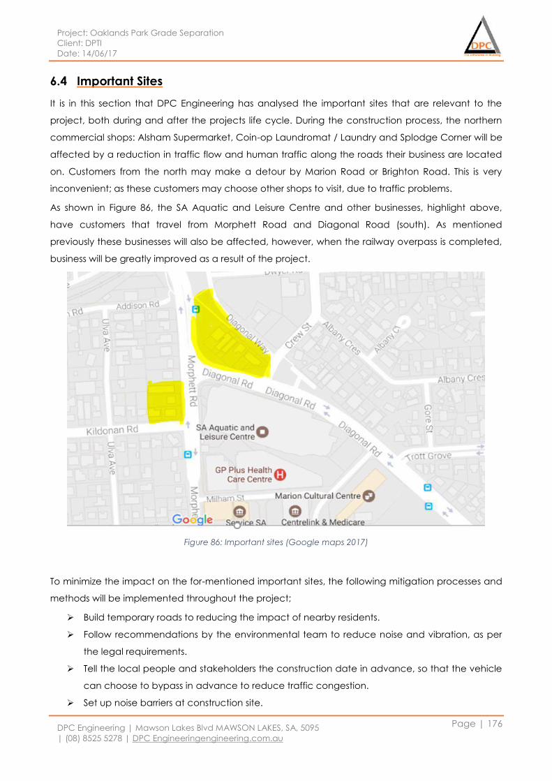
Project: Oaklands Park Grade Separation
Client: DPTI
Date: 14/06/17
DPC Engineering | Mawson Lakes Blvd MAWSON LAKES, SA, 5095
| (08) 8525 5278 | DPC Engineeringengineering.com.au
Page | 176
6.4 Important Sites
It is in this section that DPC Engineering has analysed the important sites that are relevant to the
project, both during and after the projects life cycle. During the construction process, the northern
commercial shops: Alsham Supermarket, Coin-op Laundromat / Laundry and Splodge Corner will be
affected by a reduction in traffic flow and human traffic along the roads their business are located
on. Customers from the north may make a detour by Marion Road or Brighton Road. This is very
inconvenient; as these customers may choose other shops to visit, due to traffic problems.
As shown in Figure 86, the SA Aquatic and Leisure Centre and other businesses, highlight above,
have customers that travel from Morphett Road and Diagonal Road (south). As mentioned
previously these businesses will also be affected, however, when the railway overpass is completed,
business will be greatly improved as a result of the project.
Figure 86: Important sites (Google maps 2017)
To minimize the impact on the for-mentioned important sites, the following mitigation processes and
methods will be implemented throughout the project;
Build temporary roads to reducing the impact of nearby residents.
Follow recommendations by the environmental team to reduce noise and vibration, as per
the legal requirements.
Tell the local people and stakeholders the construction date in advance, so that the vehicle
can choose to bypass in advance to reduce traffic congestion.
Set up noise barriers at construction site.

Project: Oaklands Park Grade Separation
Client: DPTI
Date: 14/06/17
DPC Engineering | Mawson Lakes Blvd MAWSON LAKES, SA, 5095
| (08) 8525 5278 | DPC Engineeringengineering.com.au
Page | 177
Reasonable adjustment of transport vehicle time and mechanical operation time, where
feasible.
Follow up with communication processes, information events and show status updates on
our website.
After the completion of the railway, the north-south traffic capacity will improve. In addition, the
project can create an open space below the overpass to increase parking capacity. Furthermore,
pedestrian convenience will be improved, stairs and elevators will be built in the overpass. Bicycle
lanes will also be added on the north-south direction. Ultimately, the overall community travel will be
greatly improved. These will inherently improve the surrounding areas for the businesses and
community, and the urban teams input into these areas can be seen further down in the report.
Project: Oaklands Park Grade Separation
Client: DPTI
Date: 14/06/17
DPC Engineering | Mawson Lakes Blvd MAWSON LAKES, SA, 5095
| (08) 8525 5278 | DPC Engineeringengineering.com.au
Page | 178
6.5 Stakeholders
Given the sheer size of this project, it is no surprise that there are a large number of key stakeholders
within this project. It is an uppermost priority that DPC Engineering will work closely with all the
stakeholders, and update information to them as necessary. As DPC Engineering values their input, it
will be our company aspiration to get as much feedback to improve the project as practicable. The
following are a list of the key stakeholders within this project;
Primary stakeholders;
Department of planning, transport and infrastructure
South Australian state government
City of Marion
National parks and wildlife advisory council
Kaurna nation cultural heritage association
State aquatic centre
Secondary stakeholders;
Local home owners
Local tenants
Local business owners
Local employment agency
Local workers
Nearby clubs
Public transport user
Road user
Cyclist
Pedestrians
And airport traffic
Prior, during and after the construction stages meetings will be conducted with the stakeholders and
their opinions and feedback will be noted. Those opinions and feedback will be taken in to
consideration and changes will be made to satisfy the stakeholders and community.
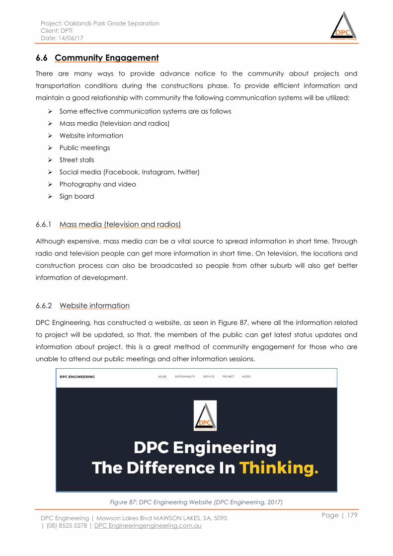
Project: Oaklands Park Grade Separation
Client: DPTI
Date: 14/06/17
DPC Engineering | Mawson Lakes Blvd MAWSON LAKES, SA, 5095
| (08) 8525 5278 | DPC Engineeringengineering.com.au
Page | 179
6.6 Community Engagement
There are many ways to provide advance notice to the community about projects and
transportation conditions during the constructions phase. To provide efficient information and
maintain a good relationship with community the following communication systems will be utilized;
Some effective communication systems are as follows
Mass media (television and radios)
Website information
Public meetings
Street stalls
Social media (Facebook, Instagram, twitter)
Photography and video
Sign board
6.6.1 Mass media (television and radios)
Although expensive, mass media can be a vital source to spread information in short time. Through
radio and television people can get more information in short time. On television, the locations and
construction process can also be broadcasted so people from other suburb will also get better
information of development.
6.6.2 Website information
DPC Engineering, has constructed a website, as seen in Figure 87, where all the information related
to project will be updated, so that, the members of the public can get latest status updates and
information about project. this is a great method of community engagement for those who are
unable to attend our public meetings and other information sessions.
Figure 87: DPC Engineering Website (DPC Engineering, 2017)
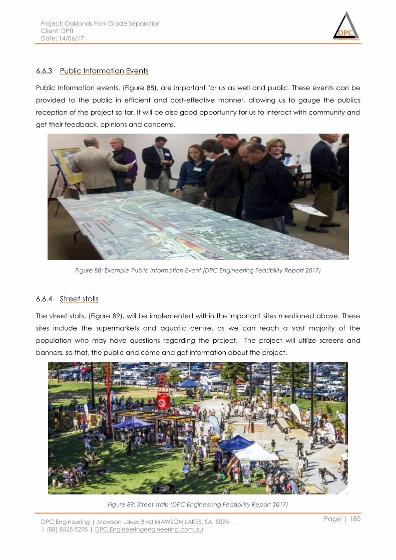
Project: Oaklands Park Grade Separation
Client: DPTI
Date: 14/06/17
DPC Engineering | Mawson Lakes Blvd MAWSON LAKES, SA, 5095
| (08) 8525 5278 | DPC Engineeringengineering.com.au
Page | 180
6.6.3 Public Information Events
Public Information events, (Figure 88), are important for us as well and public. These events can be
provided to the public in efficient and cost-effective manner, allowing us to gauge the publics
reception of the project so far. It will be also good opportunity for us to interact with community and
get their feedback, opinions and concerns.
Figure 88: Example Public Information Event (DPC Engineering Feasibility Report 2017)
6.6.4 Street stalls
The street stalls, (Figure 89), will be implemented within the important sites mentioned above. These
sites include the supermarkets and aquatic centre, as we can reach a vast majority of the
population who may have questions regarding the project. The project will utilize screens and
banners, so that, the public and come and get information about the project.
Figure 89: Street stalls (DPC Engineering Feasibility Report 2017)
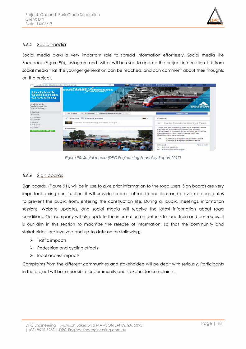
Project: Oaklands Park Grade Separation
Client: DPTI
Date: 14/06/17
DPC Engineering | Mawson Lakes Blvd MAWSON LAKES, SA, 5095
| (08) 8525 5278 | DPC Engineeringengineering.com.au
Page | 181
6.6.5 Social media
Social media plays a very important role to spread information effortlessly. Social media like
Facebook (Figure 90), Instagram and twitter will be used to update the project information. It is from
social media that the younger generation can be reached, and can comment about their thoughts
on the project.
Figure 90: Social media (DPC Engineering Feasibility Report 2017)
6.6.6 Sign boards
Sign boards, (Figure 91), will be in use to give prior information to the road users. Sign boards are very
important during construction, it will provide forecast of road conditions and provide detour routes
to prevent the public from, entering the construction site. During all public meetings, information
sessions, Website updates, and social media will receive the latest information about road
conditions. Our company will also update the information on detours for and train and bus routes. It
is our aim in this section to maximize the release of information, so that the community and
stakeholders are involved and up-to-date on the following;
Traffic impacts
Pedestrian and cycling effects
local access impacts
Complaints from the different communities and stakeholders will be dealt with seriously. Participants
in the project will be responsible for community and stakeholder complaints.
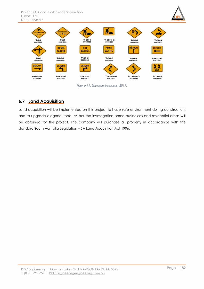
Project: Oaklands Park Grade Separation
Client: DPTI
Date: 14/06/17
DPC Engineering | Mawson Lakes Blvd MAWSON LAKES, SA, 5095
| (08) 8525 5278 | DPC Engineeringengineering.com.au
Page | 182
Figure 91: Signage (roadsky, 2017)
6.7 Land Acquisition
Land acquisition will be implemented on this project to have safe environment during construction,
and to upgrade diagonal road. As per the investigation, some businesses and residential areas will
be obtained for the project. The company will purchase all property in accordance with the
standard South Australia Legislation – SA Land Acquisition Act 1996.
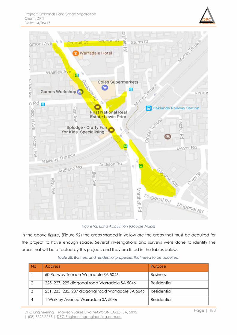
Project: Oaklands Park Grade Separation
Client: DPTI
Date: 14/06/17
DPC Engineering | Mawson Lakes Blvd MAWSON LAKES, SA, 5095
| (08) 8525 5278 | DPC Engineeringengineering.com.au
Page | 183
Figure 92: Land Acquisition (Google Maps)
In the above figure, (Figure 92) the areas shaded in yellow are the areas that must be acquired for
the project to have enough space. Several investigations and surveys were done to identify the
areas that will be affected by this project, and they are listed in the tables below.
Table 58: Business and residential properties that need to be acquired:
No Address Purpose
1 60 Railway Terrace Warradale SA 5046 Business
2 225, 227, 229 diagonal road Warradale SA 5046 Residential
3 231, 233, 235, 237 diagonal road Warradale SA 5046 Residential
4 1 Walkley Avenue Warradale SA 5046 Residential
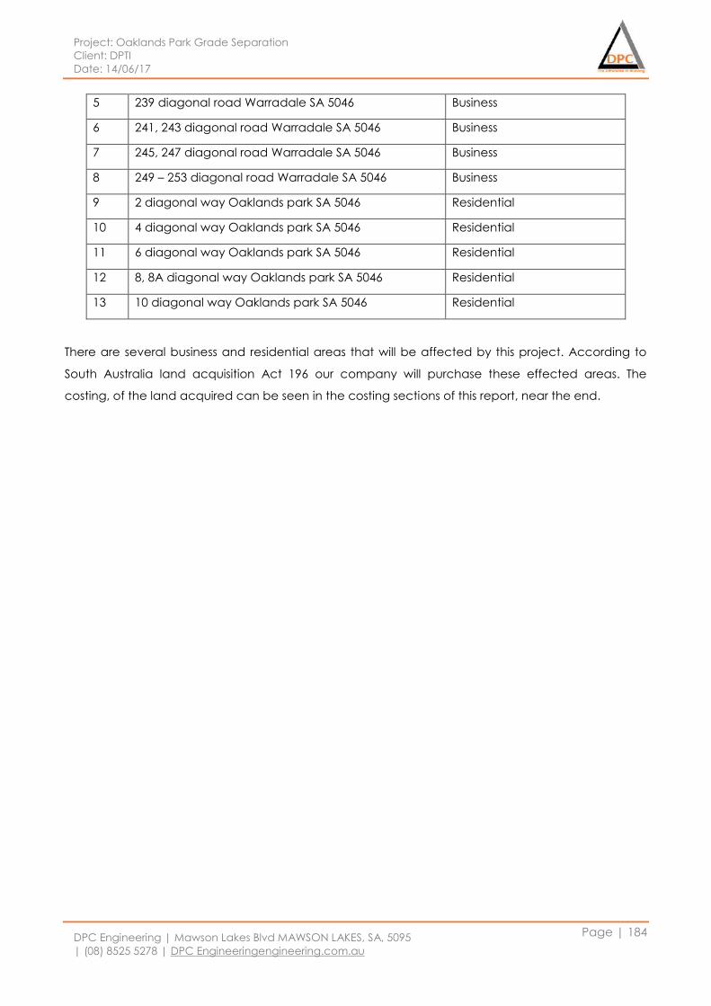
Project: Oaklands Park Grade Separation
Client: DPTI
Date: 14/06/17
DPC Engineering | Mawson Lakes Blvd MAWSON LAKES, SA, 5095
| (08) 8525 5278 | DPC Engineeringengineering.com.au
Page | 184
5 239 diagonal road Warradale SA 5046 Business
6 241, 243 diagonal road Warradale SA 5046 Business
7 245, 247 diagonal road Warradale SA 5046 Business
8 249 – 253 diagonal road Warradale SA 5046 Business
9 2 diagonal way Oaklands park SA 5046 Residential
10 4 diagonal way Oaklands park SA 5046 Residential
11 6 diagonal way Oaklands park SA 5046 Residential
12 8, 8A diagonal way Oaklands park SA 5046 Residential
13 10 diagonal way Oaklands park SA 5046 Residential
There are several business and residential areas that will be affected by this project. According to
South Australia land acquisition Act 196 our company will purchase these effected areas. The
costing, of the land acquired can be seen in the costing sections of this report, near the end.
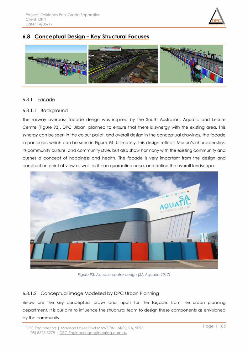
Project: Oaklands Park Grade Separation
Client: DPTI
Date: 14/06/17
DPC Engineering | Mawson Lakes Blvd MAWSON LAKES, SA, 5095
| (08) 8525 5278 | DPC Engineeringengineering.com.au
Page | 185
6.8 Conceptual Design – Key Structural Focuses
6.8.1 Facade
6.8.1.1 Background
The railway overpass facade design was inspired by the South Australian, Aquatic and Leisure
Centre (Figure 93). DPC Urban, planned to ensure that there is synergy with the existing area. This
synergy can be seen in the colour pallet, and overall design in the conceptual drawings, the façade
in particular, which can be seen in Figure 94. Ultimately, this design reflects Marion’s characteristics,
its community culture, and community style, but also show harmony with the existing community and
pushes a concept of happiness and health. The facade is very important from the design and
construction point of view as well, as it can quarantine noise, and define the overall landscape.
Figure 93: Aquatic centre design (SA Aquatic 2017)
6.8.1.2 Conceptual image Modelled by DPC Urban Planning
Below are the key conceptual draws and inputs for the façade, from the urban planning
department. It is our aim to influence the structural team to design these components as envisioned
by the community.
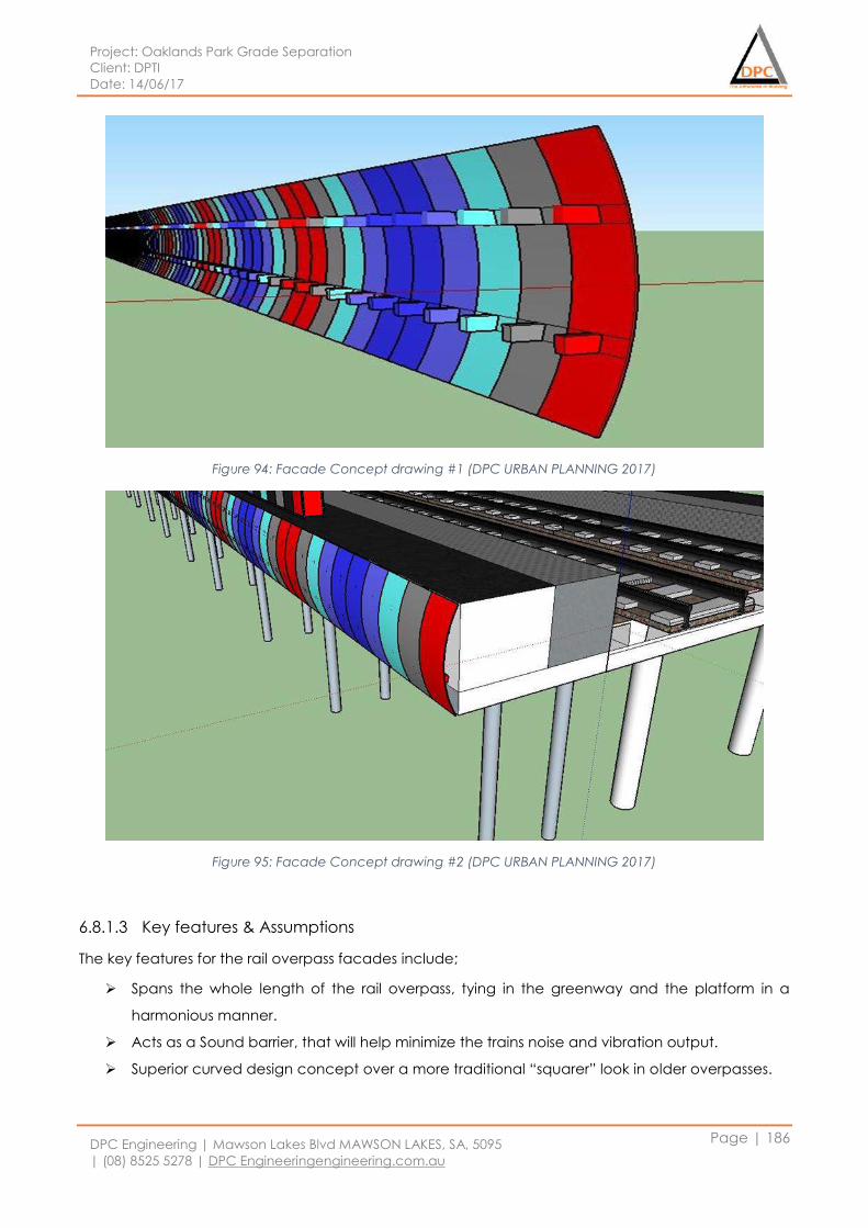
Project: Oaklands Park Grade Separation
Client: DPTI
Date: 14/06/17
DPC Engineering | Mawson Lakes Blvd MAWSON LAKES, SA, 5095
| (08) 8525 5278 | DPC Engineeringengineering.com.au
Page | 186
Figure 94: Facade Concept drawing #1 (DPC URBAN PLANNING 2017)
Figure 95: Facade Concept drawing #2 (DPC URBAN PLANNING 2017)
6.8.1.3 Key features & Assumptions
The key features for the rail overpass facades include;
Spans the whole length of the rail overpass, tying in the greenway and the platform in a
harmonious manner.
Acts as a Sound barrier, that will help minimize the trains noise and vibration output.
Superior curved design concept over a more traditional “squarer” look in older overpasses.
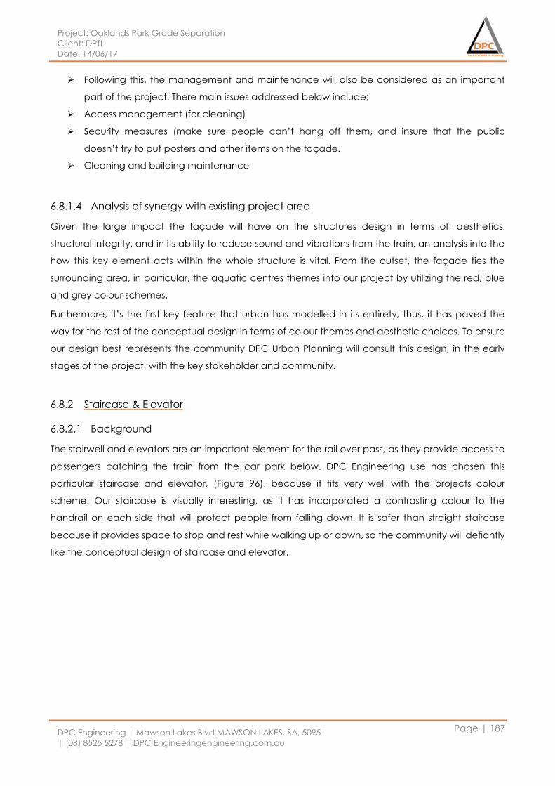
Project: Oaklands Park Grade Separation
Client: DPTI
Date: 14/06/17
DPC Engineering | Mawson Lakes Blvd MAWSON LAKES, SA, 5095
| (08) 8525 5278 | DPC Engineeringengineering.com.au
Page | 187
Following this, the management and maintenance will also be considered as an important
part of the project. There main issues addressed below include;
Access management (for cleaning)
Security measures (make sure people can’t hang off them, and insure that the public
doesn’t try to put posters and other items on the façade.
Cleaning and building maintenance
6.8.1.4 Analysis of synergy with existing project area
Given the large impact the façade will have on the structures design in terms of; aesthetics,
structural integrity, and in its ability to reduce sound and vibrations from the train, an analysis into the
how this key element acts within the whole structure is vital. From the outset, the façade ties the
surrounding area, in particular, the aquatic centres themes into our project by utilizing the red, blue
and grey colour schemes.
Furthermore, it’s the first key feature that urban has modelled in its entirety, thus, it has paved the
way for the rest of the conceptual design in terms of colour themes and aesthetic choices. To ensure
our design best represents the community DPC Urban Planning will consult this design, in the early
stages of the project, with the key stakeholder and community.
6.8.2 Staircase & Elevator
6.8.2.1 Background
The stairwell and elevators are an important element for the rail over pass, as they provide access to
passengers catching the train from the car park below. DPC Engineering use has chosen this
particular staircase and elevator, (Figure 96), because it fits very well with the projects colour
scheme. Our staircase is visually interesting, as it has incorporated a contrasting colour to the
handrail on each side that will protect people from falling down. It is safer than straight staircase
because it provides space to stop and rest while walking up or down, so the community will defiantly
like the conceptual design of staircase and elevator.
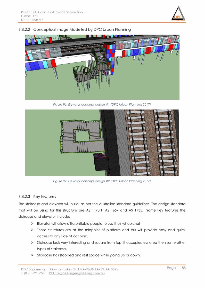
Project: Oaklands Park Grade Separation
Client: DPTI
Date: 14/06/17
DPC Engineering | Mawson Lakes Blvd MAWSON LAKES, SA, 5095
| (08) 8525 5278 | DPC Engineeringengineering.com.au
Page | 188
6.8.2.2 Conceptual image Modelled by DPC Urban Planning
Figure 96: Elevator concept design #1 (DPC Urban Planning 2017)
Figure 97: Elevator concept design #2 (DPC Urban Planning 2017)
6.8.2.3 Key features
The staircase and elevator will build, as per the Australian standard guidelines. The design standard
that will be using for this structure are AS 1170.1, AS 1657 and AS 1735. Some key features the
staircase and elevator Include;
Elevator will allow differentiable people to use their wheelchair
These structures are at the midpoint of platform and this will provide easy and quick
access to any side of car park.
Staircase look very interesting and square from top, it occupies less area then some other
types of staircase.
Staircase has stopped and rest space while going up or down.
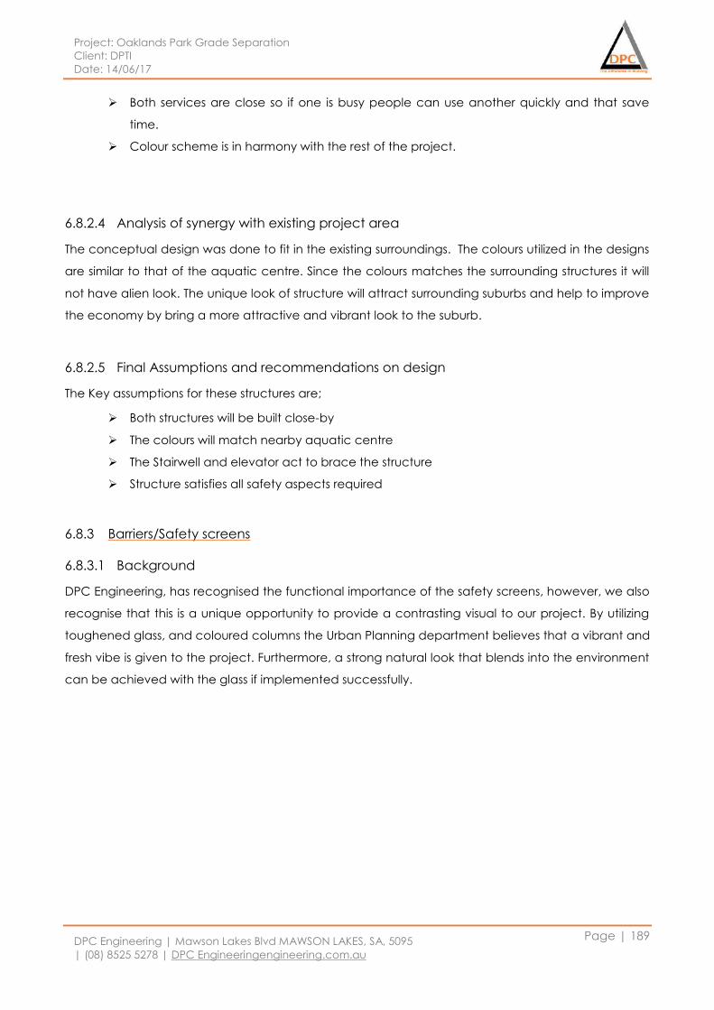
Project: Oaklands Park Grade Separation
Client: DPTI
Date: 14/06/17
DPC Engineering | Mawson Lakes Blvd MAWSON LAKES, SA, 5095
| (08) 8525 5278 | DPC Engineeringengineering.com.au
Page | 189
Both services are close so if one is busy people can use another quickly and that save
time.
Colour scheme is in harmony with the rest of the project.
6.8.2.4 Analysis of synergy with existing project area
The conceptual design was done to fit in the existing surroundings. The colours utilized in the designs
are similar to that of the aquatic centre. Since the colours matches the surrounding structures it will
not have alien look. The unique look of structure will attract surrounding suburbs and help to improve
the economy by bring a more attractive and vibrant look to the suburb.
6.8.2.5 Final Assumptions and recommendations on design
The Key assumptions for these structures are;
Both structures will be built close-by
The colours will match nearby aquatic centre
The Stairwell and elevator act to brace the structure
Structure satisfies all safety aspects required
6.8.3 Barriers/Safety screens
6.8.3.1 Background
DPC Engineering, has recognised the functional importance of the safety screens, however, we also
recognise that this is a unique opportunity to provide a contrasting visual to our project. By utilizing
toughened glass, and coloured columns the Urban Planning department believes that a vibrant and
fresh vibe is given to the project. Furthermore, a strong natural look that blends into the environment
can be achieved with the glass if implemented successfully.
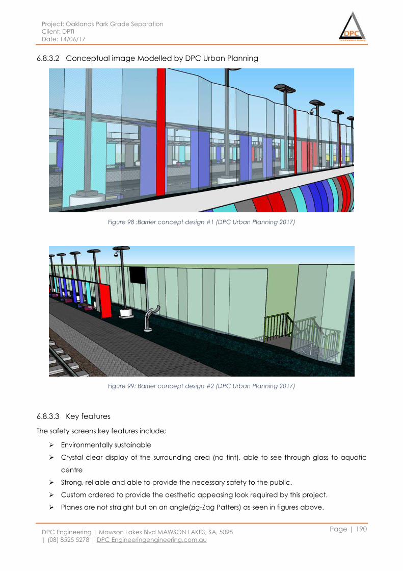
Project: Oaklands Park Grade Separation
Client: DPTI
Date: 14/06/17
DPC Engineering | Mawson Lakes Blvd MAWSON LAKES, SA, 5095
| (08) 8525 5278 | DPC Engineeringengineering.com.au
Page | 190
6.8.3.2 Conceptual image Modelled by DPC Urban Planning
Figure 98 :Barrier concept design #1 (DPC Urban Planning 2017)
Figure 99: Barrier concept design #2 (DPC Urban Planning 2017)
6.8.3.3 Key features
The safety screens key features include;
Environmentally sustainable
Crystal clear display of the surrounding area (no tint), able to see through glass to aquatic
centre
Strong, reliable and able to provide the necessary safety to the public.
Custom ordered to provide the aesthetic appeasing look required by this project.
Planes are not straight but on an angle(zig-Zag Patters) as seen in figures above.
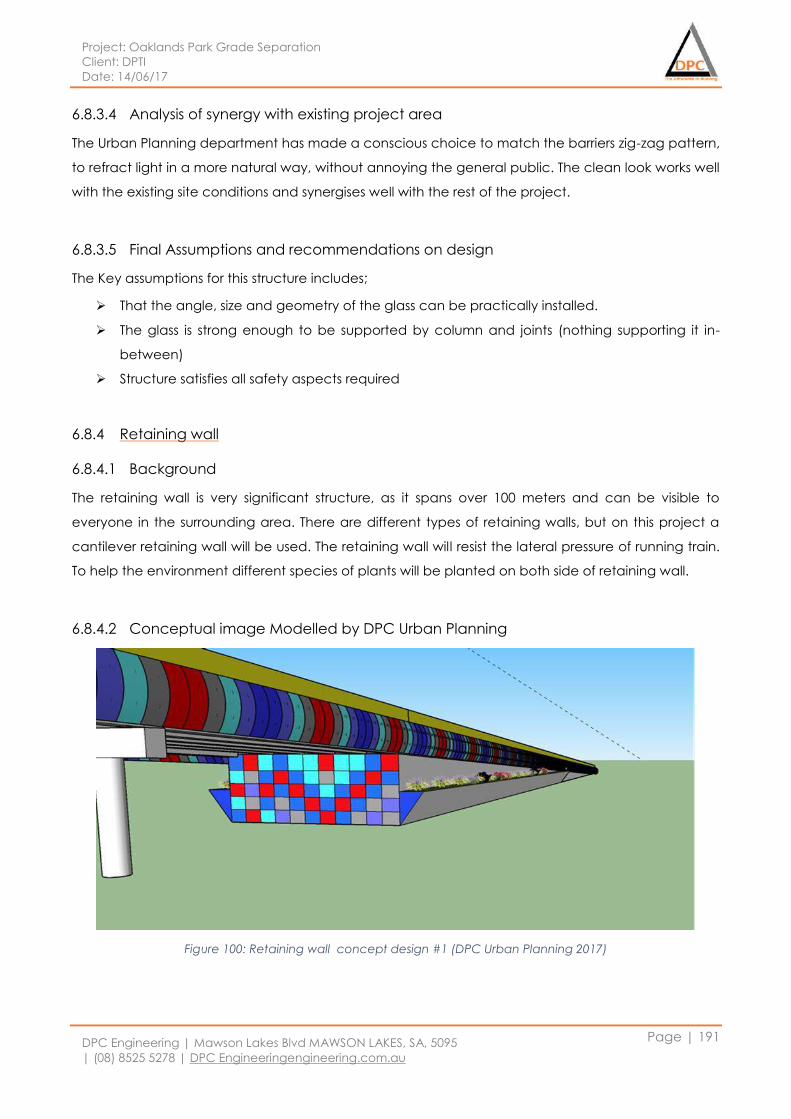
Project: Oaklands Park Grade Separation
Client: DPTI
Date: 14/06/17
DPC Engineering | Mawson Lakes Blvd MAWSON LAKES, SA, 5095
| (08) 8525 5278 | DPC Engineeringengineering.com.au
Page | 191
6.8.3.4 Analysis of synergy with existing project area
The Urban Planning department has made a conscious choice to match the barriers zig-zag pattern,
to refract light in a more natural way, without annoying the general public. The clean look works well
with the existing site conditions and synergises well with the rest of the project.
6.8.3.5 Final Assumptions and recommendations on design
The Key assumptions for this structure includes;
That the angle, size and geometry of the glass can be practically installed.
The glass is strong enough to be supported by column and joints (nothing supporting it in-
between)
Structure satisfies all safety aspects required
6.8.4 Retaining wall
6.8.4.1 Background
The retaining wall is very significant structure, as it spans over 100 meters and can be visible to
everyone in the surrounding area. There are different types of retaining walls, but on this project a
cantilever retaining wall will be used. The retaining wall will resist the lateral pressure of running train.
To help the environment different species of plants will be planted on both side of retaining wall.
6.8.4.2 Conceptual image Modelled by DPC Urban Planning
Figure 100: Retaining wall concept design #1 (DPC Urban Planning 2017)
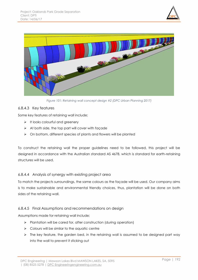
Project: Oaklands Park Grade Separation
Client: DPTI
Date: 14/06/17
DPC Engineering | Mawson Lakes Blvd MAWSON LAKES, SA, 5095
| (08) 8525 5278 | DPC Engineeringengineering.com.au
Page | 192
Figure 101: Retaining wall concept design #2 (DPC Urban Planning 2017)
6.8.4.3 Key features
Some key features of retaining wall include;
It looks colourful and greenery
At both side, the top part will cover with façade
On bottom, different species of plants and flowers will be planted
To construct the retaining wall the proper guidelines need to be followed, this project will be
designed in accordance with the Australian standard AS 4678, which is standard for earth-retaining
structures will be used.
6.8.4.4 Analysis of synergy with existing project area
To match the projects surroundings, the same colours as the façade will be used. Our company aims
is to make sustainable and environmental friendly choices, thus, plantation will be done on both
sides of the retaining wall.
6.8.4.5 Final Assumptions and recommendations on design
Assumptions made for retaining wall include;
Plantation will be cared for, after construction (during operation)
Colours will be similar to the aquatic centre
The key feature, the garden bed, in the retaining wall is assumed to be designed part way
into the wall to prevent it sticking out
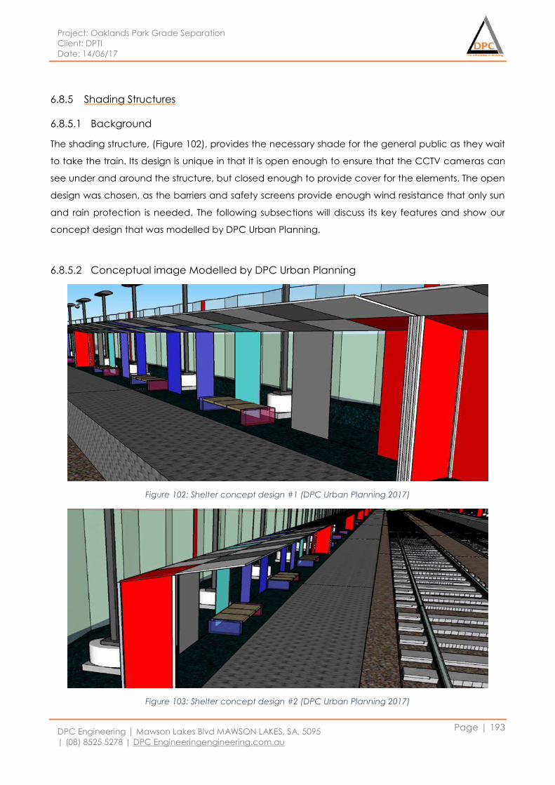
Project: Oaklands Park Grade Separation
Client: DPTI
Date: 14/06/17
DPC Engineering | Mawson Lakes Blvd MAWSON LAKES, SA, 5095
| (08) 8525 5278 | DPC Engineeringengineering.com.au
Page | 193
6.8.5 Shading Structures
6.8.5.1 Background
The shading structure, (Figure 102), provides the necessary shade for the general public as they wait
to take the train. Its design is unique in that it is open enough to ensure that the CCTV cameras can
see under and around the structure, but closed enough to provide cover for the elements. The open
design was chosen, as the barriers and safety screens provide enough wind resistance that only sun
and rain protection is needed. The following subsections will discuss its key features and show our
concept design that was modelled by DPC Urban Planning.
6.8.5.2 Conceptual image Modelled by DPC Urban Planning
Figure 102: Shelter concept design #1 (DPC Urban Planning 2017)
Figure 103: Shelter concept design #2 (DPC Urban Planning 2017)
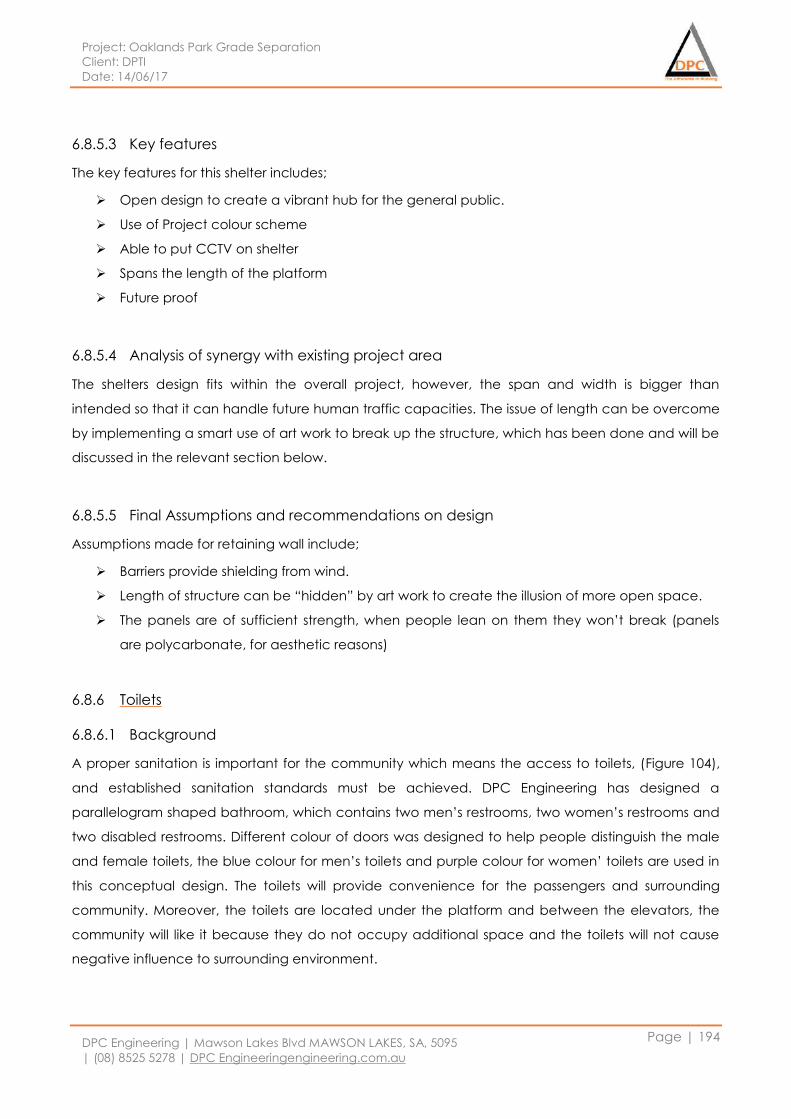
Project: Oaklands Park Grade Separation
Client: DPTI
Date: 14/06/17
DPC Engineering | Mawson Lakes Blvd MAWSON LAKES, SA, 5095
| (08) 8525 5278 | DPC Engineeringengineering.com.au
Page | 194
6.8.5.3 Key features
The key features for this shelter includes;
Open design to create a vibrant hub for the general public.
Use of Project colour scheme
Able to put CCTV on shelter
Spans the length of the platform
Future proof
6.8.5.4 Analysis of synergy with existing project area
The shelters design fits within the overall project, however, the span and width is bigger than
intended so that it can handle future human traffic capacities. The issue of length can be overcome
by implementing a smart use of art work to break up the structure, which has been done and will be
discussed in the relevant section below.
6.8.5.5 Final Assumptions and recommendations on design
Assumptions made for retaining wall include;
Barriers provide shielding from wind.
Length of structure can be “hidden” by art work to create the illusion of more open space.
The panels are of sufficient strength, when people lean on them they won’t break (panels
are polycarbonate, for aesthetic reasons)
6.8.6 Toilets
6.8.6.1 Background
A proper sanitation is important for the community which means the access to toilets, (Figure 104),
and established sanitation standards must be achieved. DPC Engineering has designed a
parallelogram shaped bathroom, which contains two men’s restrooms, two women’s restrooms and
two disabled restrooms. Different colour of doors was designed to help people distinguish the male
and female toilets, the blue colour for men’s toilets and purple colour for women’ toilets are used in
this conceptual design. The toilets will provide convenience for the passengers and surrounding
community. Moreover, the toilets are located under the platform and between the elevators, the
community will like it because they do not occupy additional space and the toilets will not cause
negative influence to surrounding environment.
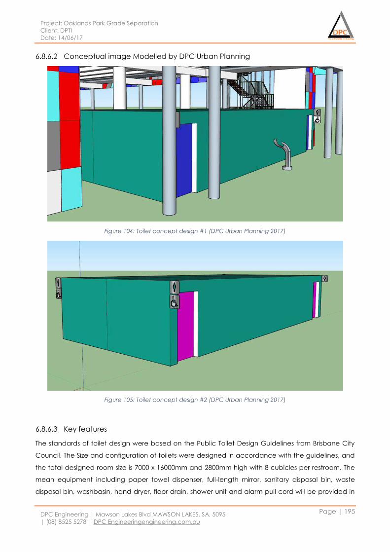
Project: Oaklands Park Grade Separation
Client: DPTI
Date: 14/06/17
DPC Engineering | Mawson Lakes Blvd MAWSON LAKES, SA, 5095
| (08) 8525 5278 | DPC Engineeringengineering.com.au
Page | 195
6.8.6.2 Conceptual image Modelled by DPC Urban Planning
Figure 104: Toilet concept design #1 (DPC Urban Planning 2017)
Figure 105: Toilet concept design #2 (DPC Urban Planning 2017)
6.8.6.3 Key features
The standards of toilet design were based on the Public Toilet Design Guidelines from Brisbane City
Council. The Size and configuration of toilets were designed in accordance with the guidelines, and
the total designed room size is 7000 x 16000mm and 2800mm high with 8 cubicles per restroom. The
mean equipment including paper towel dispenser, full-length mirror, sanitary disposal bin, waste
disposal bin, washbasin, hand dryer, floor drain, shower unit and alarm pull cord will be provided in
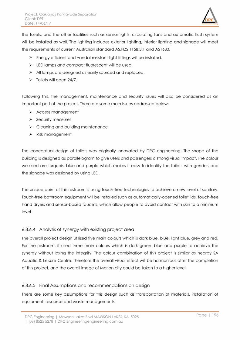
Project: Oaklands Park Grade Separation
Client: DPTI
Date: 14/06/17
DPC Engineering | Mawson Lakes Blvd MAWSON LAKES, SA, 5095
| (08) 8525 5278 | DPC Engineeringengineering.com.au
Page | 196
the toilets, and the other facilities such as sensor lights, circulating fans and automatic flush system
will be installed as well. The lighting includes exterior lighting, interior lighting and signage will meet
the requirements of current Australian standard AS.NZS 1158.3.1 and AS1680.
Energy efficient and vandal-resistant light fittings will be installed.
LED lamps and compact fluorescent will be used.
All lamps are designed as easily sourced and replaced.
Toilets will open 24/7.
Following this, the management, maintenance and security issues will also be considered as an
important part of the project. There are some main issues addressed below:
Access management
Security measures
Cleaning and building maintenance
Risk management
The conceptual design of toilets was originally innovated by DPC engineering. The shape of the
building is designed as parallelogram to give users and passengers a strong visual impact. The colour
we used are turquois, blue and purple which makes it easy to identify the toilets with gender, and
the signage was designed by using LED.
The unique point of this restroom is using touch-free technologies to achieve a new level of sanitary.
Touch-free bathroom equipment will be installed such as automatically-opened toilet lids, touch-free
hand dryers and sensor-based faucets, which allow people to avoid contact with skin to a minimum
level.
6.8.6.4 Analysis of synergy with existing project area
The overall project design utilized five main colours which is dark blue, blue, light blue, grey and red.
For the restroom, it used three main colours which is dark green, blue and purple to achieve the
synergy without losing the integrity. The colour combination of this project is similar as nearby SA
Aquatic & Leisure Centre, therefore the overall visual effect will be harmonious after the completion
of this project, and the overall image of Marion city could be taken to a higher level.
6.8.6.5 Final Assumptions and recommendations on design
There are some key assumptions for this design such as transportation of materials, installation of
equipment, resource and waste managements.
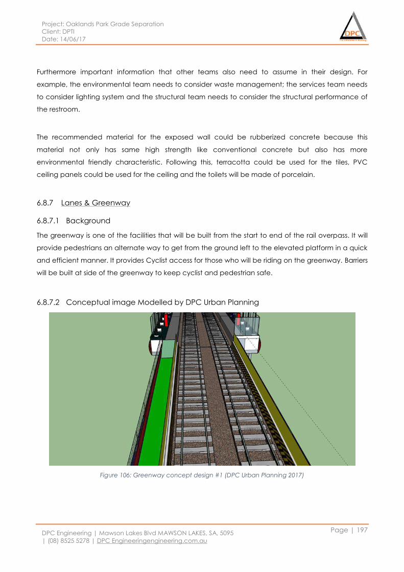
Project: Oaklands Park Grade Separation
Client: DPTI
Date: 14/06/17
DPC Engineering | Mawson Lakes Blvd MAWSON LAKES, SA, 5095
| (08) 8525 5278 | DPC Engineeringengineering.com.au
Page | 197
Furthermore important information that other teams also need to assume in their design. For
example, the environmental team needs to consider waste management; the services team needs
to consider lighting system and the structural team needs to consider the structural performance of
the restroom.
The recommended material for the exposed wall could be rubberized concrete because this
material not only has same high strength like conventional concrete but also has more
environmental friendly characteristic. Following this, terracotta could be used for the tiles, PVC
ceiling panels could be used for the ceiling and the toilets will be made of porcelain.
6.8.7 Lanes & Greenway
6.8.7.1 Background
The greenway is one of the facilities that will be built from the start to end of the rail overpass. It will
provide pedestrians an alternate way to get from the ground left to the elevated platform in a quick
and efficient manner. It provides Cyclist access for those who will be riding on the greenway. Barriers
will be built at side of the greenway to keep cyclist and pedestrian safe.
6.8.7.2 Conceptual image Modelled by DPC Urban Planning
Figure 106: Greenway concept design #1 (DPC Urban Planning 2017)
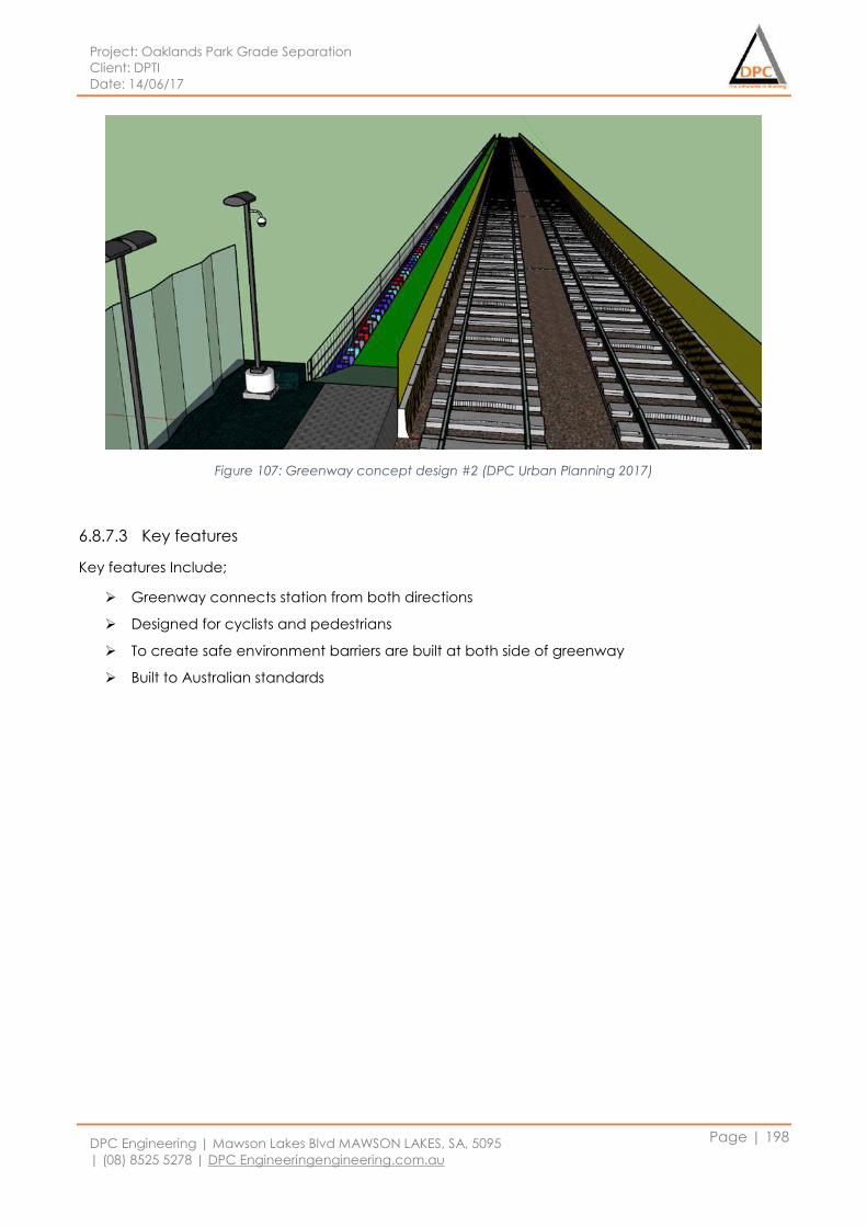
Project: Oaklands Park Grade Separation
Client: DPTI
Date: 14/06/17
DPC Engineering | Mawson Lakes Blvd MAWSON LAKES, SA, 5095
| (08) 8525 5278 | DPC Engineeringengineering.com.au
Page | 198
Figure 107: Greenway concept design #2 (DPC Urban Planning 2017)
6.8.7.3 Key features
Key features Include;
Greenway connects station from both directions
Designed for cyclists and pedestrians
To create safe environment barriers are built at both side of greenway
Built to Australian standards
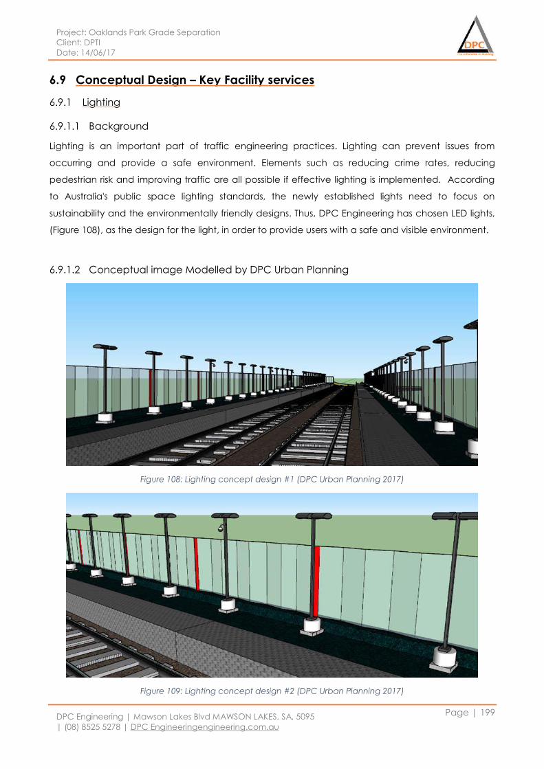
Project: Oaklands Park Grade Separation
Client: DPTI
Date: 14/06/17
DPC Engineering | Mawson Lakes Blvd MAWSON LAKES, SA, 5095
| (08) 8525 5278 | DPC Engineeringengineering.com.au
Page | 199
6.9 Conceptual Design – Key Facility services
6.9.1 Lighting
6.9.1.1 Background
Lighting is an important part of traffic engineering practices. Lighting can prevent issues from
occurring and provide a safe environment. Elements such as reducing crime rates, reducing
pedestrian risk and improving traffic are all possible if effective lighting is implemented. According
to Australia's public space lighting standards, the newly established lights need to focus on
sustainability and the environmentally friendly designs. Thus, DPC Engineering has chosen LED lights,
(Figure 108), as the design for the light, in order to provide users with a safe and visible environment.
6.9.1.2 Conceptual image Modelled by DPC Urban Planning
Figure 108: Lighting concept design #1 (DPC Urban Planning 2017)
Figure 109: Lighting concept design #2 (DPC Urban Planning 2017)
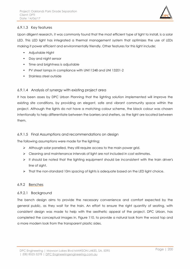
Project: Oaklands Park Grade Separation
Client: DPTI
Date: 14/06/17
DPC Engineering | Mawson Lakes Blvd MAWSON LAKES, SA, 5095
| (08) 8525 5278 | DPC Engineeringengineering.com.au
Page | 200
6.9.1.3 Key features
Upon diligent research, it was commonly found that the most efficient type of light to install, is a solar
LED. This LED light has integrated a thermal management system that optimizes the use of LEDs
making it power efficient and environmentally friendly. Other features for this light include;
• Adjustable Hight
• Day and night sensor
• Time and brightness is adjustable
• PV street lamps in compliance with UNI11248 and UNI 13201-2
• Stainless steel outside
6.9.1.4 Analysis of synergy with existing project area
It has been asses by DPC Urban Planning that the lighting solution implemented will improve the
existing site conditions, by providing an elegant, safe and vibrant community space within the
project. Although the lights do not have a matching colour scheme, the black colour was chosen
intentionally to help differentiate between the barriers and shelters, as the light are located between
them.
6.9.1.5 Final Assumptions and recommendations on design
The following assumptions were made for the lighting;
Although solar panelled, they still require access to the main power grid.
Cleaning and maintenance intervals of light are not included in cost estimates.
It should be noted that the lighting equipment should be inconsistent with the train driver's
line of sight.
That the non-standard 10m spacing of lights is adequate based on the LED light choice.
6.9.2 Benches
6.9.2.1 Background
The bench design aims to provide the necessary convenience and comfort expected by the
general public, as they wait for the train. An effort to ensure the right quantity of seating, with
consistent design was made to help with the aesthetic appeal of the project. DPC Urban, has
completed the conceptual images in, Figure 110, to provide a natural look from the wood top and
a more modern look from the transparent plastic sides.
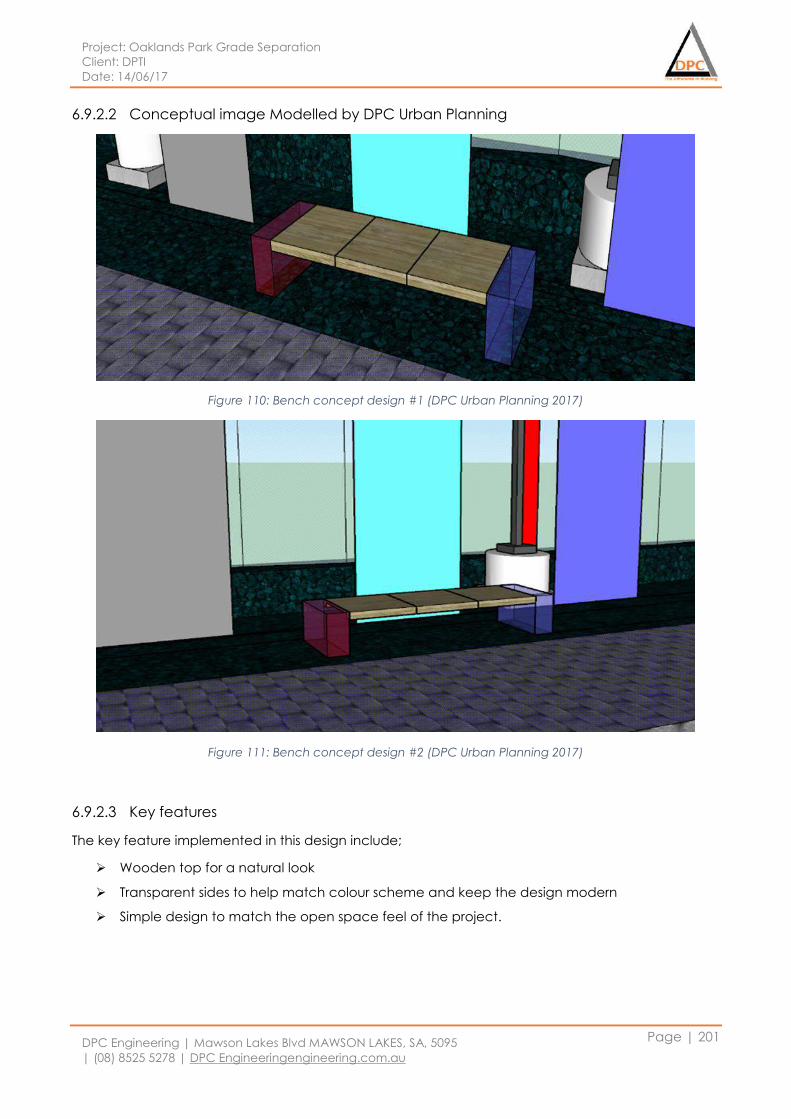
Project: Oaklands Park Grade Separation
Client: DPTI
Date: 14/06/17
DPC Engineering | Mawson Lakes Blvd MAWSON LAKES, SA, 5095
| (08) 8525 5278 | DPC Engineeringengineering.com.au
Page | 201
6.9.2.2 Conceptual image Modelled by DPC Urban Planning
Figure 110: Bench concept design #1 (DPC Urban Planning 2017)
Figure 111: Bench concept design #2 (DPC Urban Planning 2017)
6.9.2.3 Key features
The key feature implemented in this design include;
Wooden top for a natural look
Transparent sides to help match colour scheme and keep the design modern
Simple design to match the open space feel of the project.
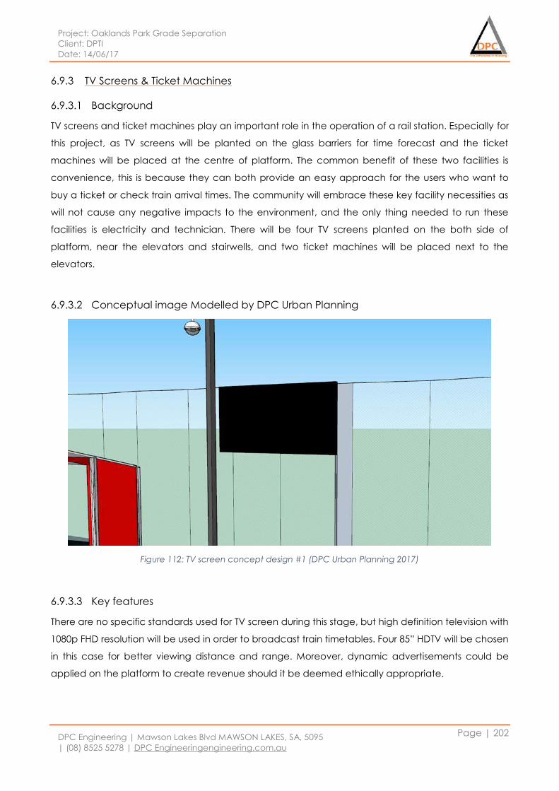
Project: Oaklands Park Grade Separation
Client: DPTI
Date: 14/06/17
DPC Engineering | Mawson Lakes Blvd MAWSON LAKES, SA, 5095
| (08) 8525 5278 | DPC Engineeringengineering.com.au
Page | 202
6.9.3 TV Screens & Ticket Machines
6.9.3.1 Background
TV screens and ticket machines play an important role in the operation of a rail station. Especially for
this project, as TV screens will be planted on the glass barriers for time forecast and the ticket
machines will be placed at the centre of platform. The common benefit of these two facilities is
convenience, this is because they can both provide an easy approach for the users who want to
buy a ticket or check train arrival times. The community will embrace these key facility necessities as
will not cause any negative impacts to the environment, and the only thing needed to run these
facilities is electricity and technician. There will be four TV screens planted on the both side of
platform, near the elevators and stairwells, and two ticket machines will be placed next to the
elevators.
6.9.3.2 Conceptual image Modelled by DPC Urban Planning
Figure 112: TV screen concept design #1 (DPC Urban Planning 2017)
6.9.3.3 Key features
There are no specific standards used for TV screen during this stage, but high definition television with
1080p FHD resolution will be used in order to broadcast train timetables. Four 85” HDTV will be chosen
in this case for better viewing distance and range. Moreover, dynamic advertisements could be
applied on the platform to create revenue should it be deemed ethically appropriate.
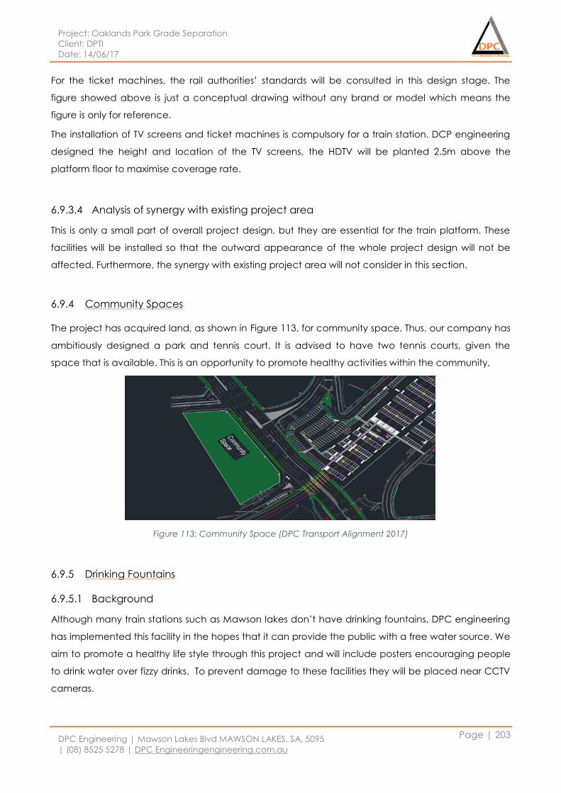
Project: Oaklands Park Grade Separation
Client: DPTI
Date: 14/06/17
DPC Engineering | Mawson Lakes Blvd MAWSON LAKES, SA, 5095
| (08) 8525 5278 | DPC Engineeringengineering.com.au
Page | 203
For the ticket machines, the rail authorities’ standards will be consulted in this design stage. The
figure showed above is just a conceptual drawing without any brand or model which means the
figure is only for reference.
The installation of TV screens and ticket machines is compulsory for a train station. DCP engineering
designed the height and location of the TV screens, the HDTV will be planted 2.5m above the
platform floor to maximise coverage rate.
6.9.3.4 Analysis of synergy with existing project area
This is only a small part of overall project design, but they are essential for the train platform. These
facilities will be installed so that the outward appearance of the whole project design will not be
affected. Furthermore, the synergy with existing project area will not consider in this section.
6.9.4 Community Spaces
The project has acquired land, as shown in Figure 113, for community space. Thus, our company has
ambitiously designed a park and tennis court. It is advised to have two tennis courts, given the
space that is available. This is an opportunity to promote healthy activities within the community.
Figure 113: Community Space (DPC Transport Alignment 2017)
6.9.5 Drinking Fountains
6.9.5.1 Background
Although many train stations such as Mawson lakes don’t have drinking fountains, DPC engineering
has implemented this facility in the hopes that it can provide the public with a free water source. We
aim to promote a healthy life style through this project and will include posters encouraging people
to drink water over fizzy drinks. To prevent damage to these facilities they will be placed near CCTV
cameras.
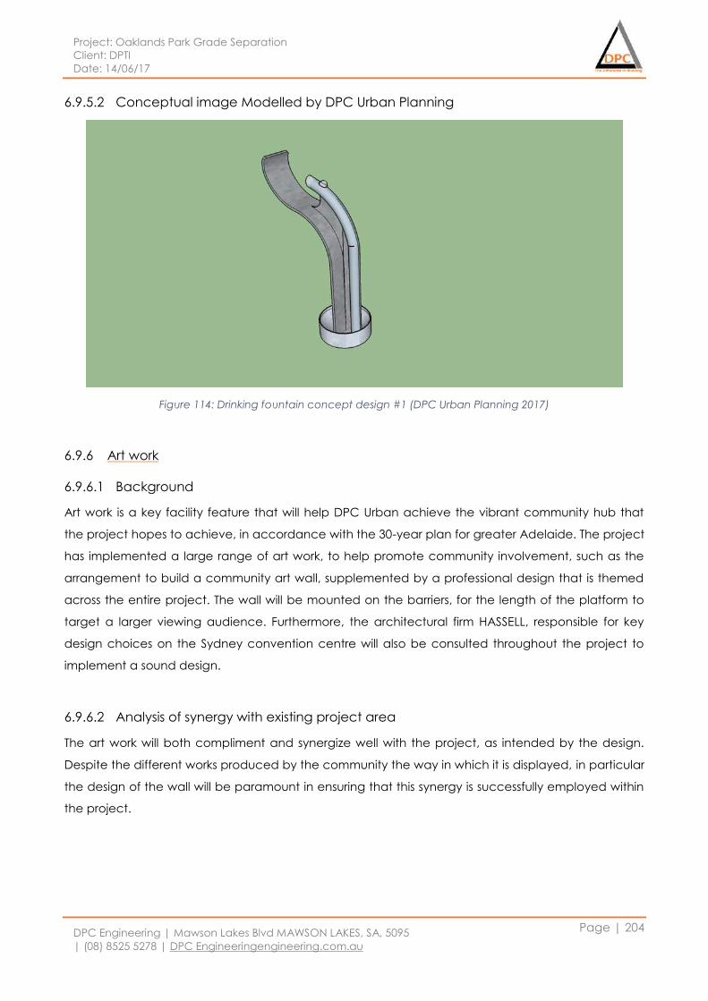
Project: Oaklands Park Grade Separation
Client: DPTI
Date: 14/06/17
DPC Engineering | Mawson Lakes Blvd MAWSON LAKES, SA, 5095
| (08) 8525 5278 | DPC Engineeringengineering.com.au
Page | 204
6.9.5.2 Conceptual image Modelled by DPC Urban Planning
Figure 114: Drinking fountain concept design #1 (DPC Urban Planning 2017)
6.9.6 Art work
6.9.6.1 Background
Art work is a key facility feature that will help DPC Urban achieve the vibrant community hub that
the project hopes to achieve, in accordance with the 30-year plan for greater Adelaide. The project
has implemented a large range of art work, to help promote community involvement, such as the
arrangement to build a community art wall, supplemented by a professional design that is themed
across the entire project. The wall will be mounted on the barriers, for the length of the platform to
target a larger viewing audience. Furthermore, the architectural firm HASSELL, responsible for key
design choices on the Sydney convention centre will also be consulted throughout the project to
implement a sound design.
6.9.6.2 Analysis of synergy with existing project area
The art work will both compliment and synergize well with the project, as intended by the design.
Despite the different works produced by the community the way in which it is displayed, in particular
the design of the wall will be paramount in ensuring that this synergy is successfully employed within
the project.
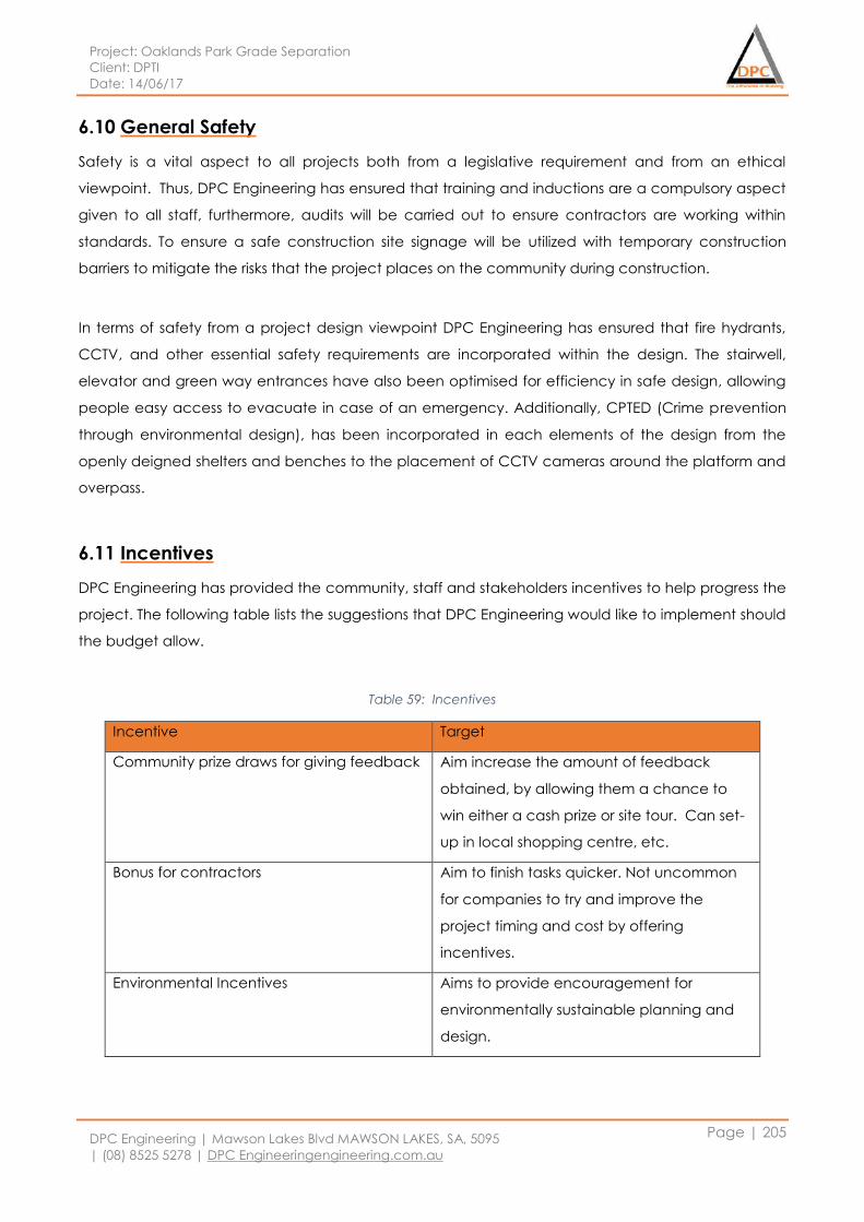
Project: Oaklands Park Grade Separation
Client: DPTI
Date: 14/06/17
DPC Engineering | Mawson Lakes Blvd MAWSON LAKES, SA, 5095
| (08) 8525 5278 | DPC Engineeringengineering.com.au
Page | 205
6.10 General Safety
Safety is a vital aspect to all projects both from a legislative requirement and from an ethical
viewpoint. Thus, DPC Engineering has ensured that training and inductions are a compulsory aspect
given to all staff, furthermore, audits will be carried out to ensure contractors are working within
standards. To ensure a safe construction site signage will be utilized with temporary construction
barriers to mitigate the risks that the project places on the community during construction.
In terms of safety from a project design viewpoint DPC Engineering has ensured that fire hydrants,
CCTV, and other essential safety requirements are incorporated within the design. The stairwell,
elevator and green way entrances have also been optimised for efficiency in safe design, allowing
people easy access to evacuate in case of an emergency. Additionally, CPTED (Crime prevention
through environmental design), has been incorporated in each elements of the design from the
openly deigned shelters and benches to the placement of CCTV cameras around the platform and
overpass.
6.11 Incentives
DPC Engineering has provided the community, staff and stakeholders incentives to help progress the
project. The following table lists the suggestions that DPC Engineering would like to implement should
the budget allow.
Table 59: Incentives
Incentive Target
Community prize draws for giving feedback Aim increase the amount of feedback
obtained, by allowing them a chance to
win either a cash prize or site tour. Can set-
up in local shopping centre, etc.
Bonus for contractors Aim to finish tasks quicker. Not uncommon
for companies to try and improve the
project timing and cost by offering
incentives.
Environmental Incentives Aims to provide encouragement for
environmentally sustainable planning and
design.
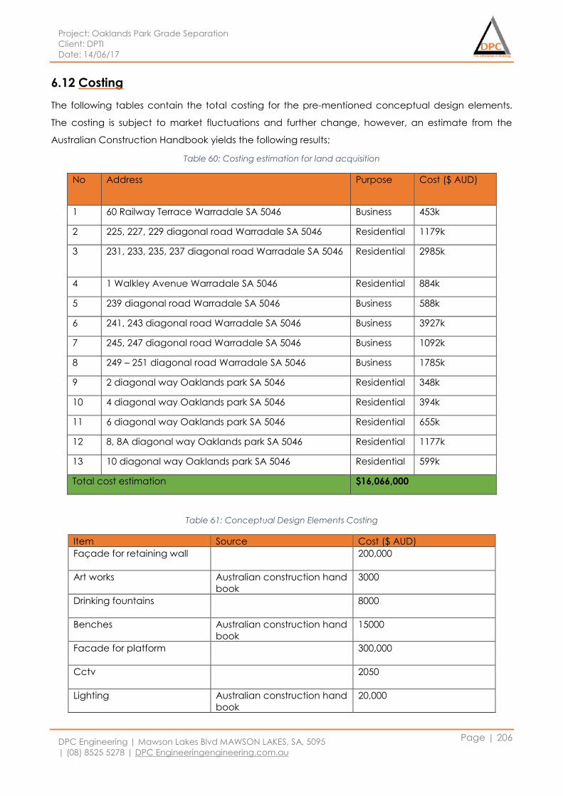
Project: Oaklands Park Grade Separation
Client: DPTI
Date: 14/06/17
DPC Engineering | Mawson Lakes Blvd MAWSON LAKES, SA, 5095
| (08) 8525 5278 | DPC Engineeringengineering.com.au
Page | 206
6.12 Costing
The following tables contain the total costing for the pre-mentioned conceptual design elements.
The costing is subject to market fluctuations and further change, however, an estimate from the
Australian Construction Handbook yields the following results;
Table 60: Costing estimation for land acquisition
No Address Purpose Cost ($ AUD)
1 60 Railway Terrace Warradale SA 5046 Business 453k
2 225, 227, 229 diagonal road Warradale SA 5046 Residential 1179k
3 231, 233, 235, 237 diagonal road Warradale SA 5046 Residential 2985k
4 1 Walkley Avenue Warradale SA 5046 Residential 884k
5 239 diagonal road Warradale SA 5046 Business 588k
6 241, 243 diagonal road Warradale SA 5046 Business 3927k
7 245, 247 diagonal road Warradale SA 5046 Business 1092k
8 249 – 251 diagonal road Warradale SA 5046 Business 1785k
9 2 diagonal way Oaklands park SA 5046 Residential 348k
10 4 diagonal way Oaklands park SA 5046 Residential 394k
11 6 diagonal way Oaklands park SA 5046 Residential 655k
12 8, 8A diagonal way Oaklands park SA 5046 Residential 1177k
13 10 diagonal way Oaklands park SA 5046 Residential 599k
Total cost estimation $16,066,000
Table 61: Conceptual Design Elements Costing
Item Source Cost ($ AUD)
Façade for retaining wall
200,000
Art works Australian construction hand
book
3000
Drinking fountains
8000
Benches Australian construction hand
book
15000
Facade for platform
300,000
Cctv
2050
Lighting Australian construction hand
book
20,000
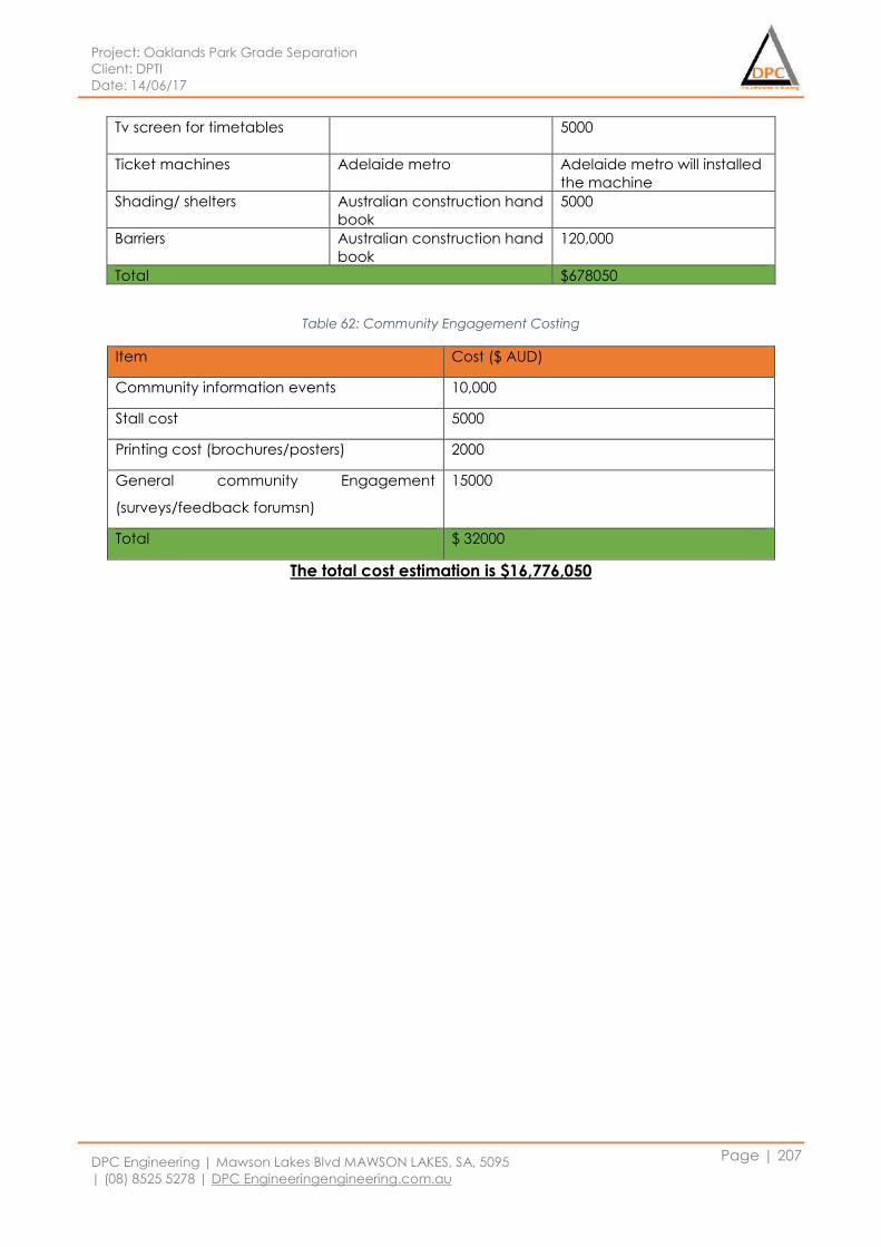
Project: Oaklands Park Grade Separation
Client: DPTI
Date: 14/06/17
DPC Engineering | Mawson Lakes Blvd MAWSON LAKES, SA, 5095
| (08) 8525 5278 | DPC Engineeringengineering.com.au
Page | 207
Tv screen for timetables
5000
Ticket machines Adelaide metro Adelaide metro will installed
the machine
Shading/ shelters Australian construction hand
book
5000
Barriers Australian construction hand
book
120,000
Total $678050
Table 62: Community Engagement Costing
Item Cost ($ AUD)
Community information events 10,000
Stall cost 5000
Printing cost (brochures/posters) 2000
General community Engagement
(surveys/feedback forumsn)
15000
Total $ 32000
The total cost estimation is $16,776,050
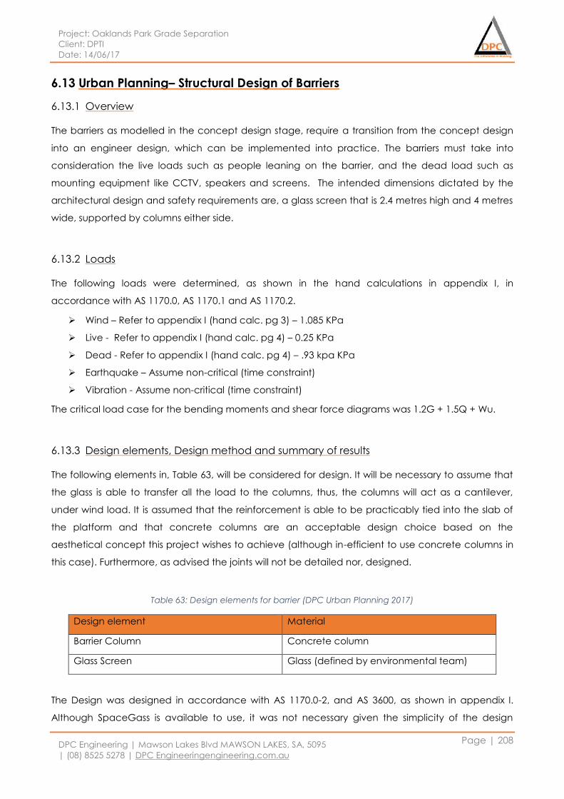
Project: Oaklands Park Grade Separation
Client: DPTI
Date: 14/06/17
DPC Engineering | Mawson Lakes Blvd MAWSON LAKES, SA, 5095
| (08) 8525 5278 | DPC Engineeringengineering.com.au
Page | 208
6.13 Urban Planning– Structural Design of Barriers
6.13.1 Overview
The barriers as modelled in the concept design stage, require a transition from the concept design
into an engineer design, which can be implemented into practice. The barriers must take into
consideration the live loads such as people leaning on the barrier, and the dead load such as
mounting equipment like CCTV, speakers and screens. The intended dimensions dictated by the
architectural design and safety requirements are, a glass screen that is 2.4 metres high and 4 metres
wide, supported by columns either side.
6.13.2 Loads
The following loads were determined, as shown in the hand calculations in appendix I, in
accordance with AS 1170.0, AS 1170.1 and AS 1170.2.
Wind – Refer to appendix I (hand calc. pg 3) – 1.085 KPa
Live - Refer to appendix I (hand calc. pg 4) – 0.25 KPa
Dead - Refer to appendix I (hand calc. pg 4) – .93 kpa KPa
Earthquake – Assume non-critical (time constraint)
Vibration - Assume non-critical (time constraint)
The critical load case for the bending moments and shear force diagrams was 1.2G + 1.5Q + Wu.
6.13.3 Design elements, Design method and summary of results
The following elements in, Table 63, will be considered for design. It will be necessary to assume that
the glass is able to transfer all the load to the columns, thus, the columns will act as a cantilever,
under wind load. It is assumed that the reinforcement is able to be practicably tied into the slab of
the platform and that concrete columns are an acceptable design choice based on the
aesthetical concept this project wishes to achieve (although in-efficient to use concrete columns in
this case). Furthermore, as advised the joints will not be detailed nor, designed.
Table 63: Design elements for barrier (DPC Urban Planning 2017)
Design element Material
Barrier Column Concrete column
Glass Screen Glass (defined by environmental team)
The Design was designed in accordance with AS 1170.0-2, and AS 3600, as shown in appendix I.
Although SpaceGass is available to use, it was not necessary given the simplicity of the design
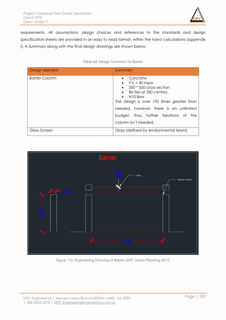
Project: Oaklands Park Grade Separation
Client: DPTI
Date: 14/06/17
DPC Engineering | Mawson Lakes Blvd MAWSON LAKES, SA, 5095
| (08) 8525 5278 | DPC Engineeringengineering.com.au
Page | 209
requirements. All assumptions, design choices and references to the standards and design
specification sheets are provided in an easy to read format, within the hand calculations (appendix
I). A Summary along with the final design drawings are shown below.
Table 64: Design Summary for Barrier
Design element Summary
Barrier Column Concrete
F’c = 40 mpa
350 * 350 cross section
R6 ties at 350 centres.
N10 Bars
The design is over 100 times greater than
needed, however, there is an unlimited
budget, thus, further iterations of the
column isn’t needed.
Glass Screen Glass (defined by environmental team)
Figure 115: Engineering Drawing of Barrier (DPC Urban Planning 2017)
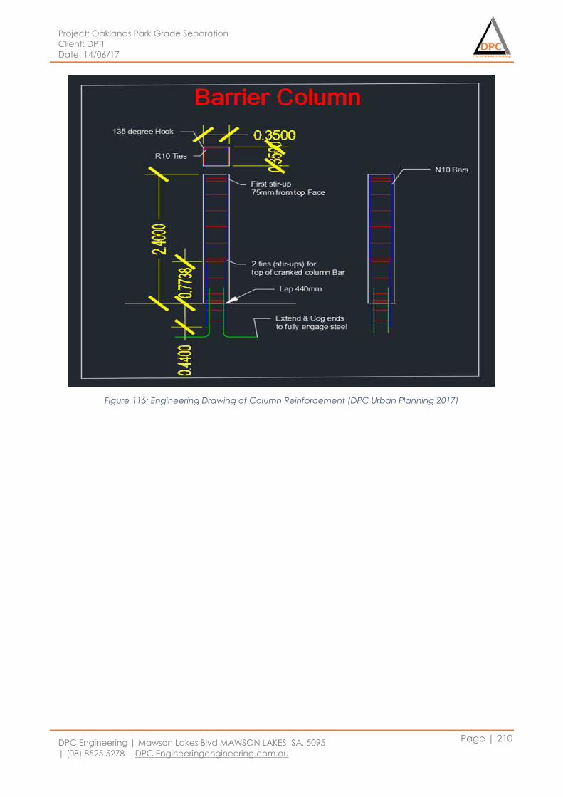
Project: Oaklands Park Grade Separation
Client: DPTI
Date: 14/06/17
DPC Engineering | Mawson Lakes Blvd MAWSON LAKES, SA, 5095
| (08) 8525 5278 | DPC Engineeringengineering.com.au
Page | 210
Figure 116: Engineering Drawing of Column Reinforcement (DPC Urban Planning 2017)
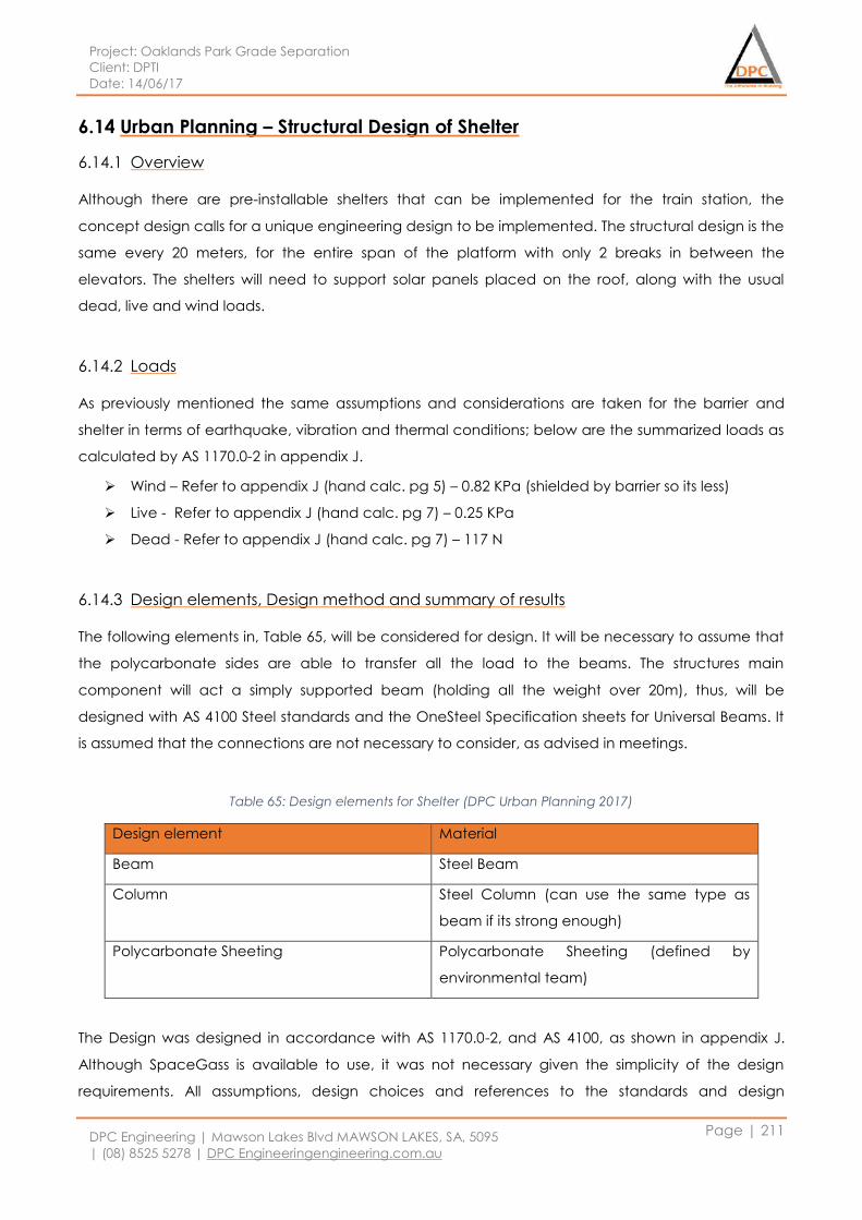
Project: Oaklands Park Grade Separation
Client: DPTI
Date: 14/06/17
DPC Engineering | Mawson Lakes Blvd MAWSON LAKES, SA, 5095
| (08) 8525 5278 | DPC Engineeringengineering.com.au
Page | 211
6.14 Urban Planning – Structural Design of Shelter
6.14.1 Overview
Although there are pre-installable shelters that can be implemented for the train station, the
concept design calls for a unique engineering design to be implemented. The structural design is the
same every 20 meters, for the entire span of the platform with only 2 breaks in between the
elevators. The shelters will need to support solar panels placed on the roof, along with the usual
dead, live and wind loads.
6.14.2 Loads
As previously mentioned the same assumptions and considerations are taken for the barrier and
shelter in terms of earthquake, vibration and thermal conditions; below are the summarized loads as
calculated by AS 1170.0-2 in appendix J.
Wind – Refer to appendix J (hand calc. pg 5) – 0.82 KPa (shielded by barrier so its less)
Live - Refer to appendix J (hand calc. pg 7) – 0.25 KPa
Dead - Refer to appendix J (hand calc. pg 7) – 117 N
6.14.3 Design elements, Design method and summary of results
The following elements in, Table 65, will be considered for design. It will be necessary to assume that
the polycarbonate sides are able to transfer all the load to the beams. The structures main
component will act a simply supported beam (holding all the weight over 20m), thus, will be
designed with AS 4100 Steel standards and the OneSteel Specification sheets for Universal Beams. It
is assumed that the connections are not necessary to consider, as advised in meetings.
Table 65: Design elements for Shelter (DPC Urban Planning 2017)
Design element Material
Beam Steel Beam
Column Steel Column (can use the same type as
beam if its strong enough)
Polycarbonate Sheeting Polycarbonate Sheeting (defined by
environmental team)
The Design was designed in accordance with AS 1170.0-2, and AS 4100, as shown in appendix J.
Although SpaceGass is available to use, it was not necessary given the simplicity of the design
requirements. All assumptions, design choices and references to the standards and design
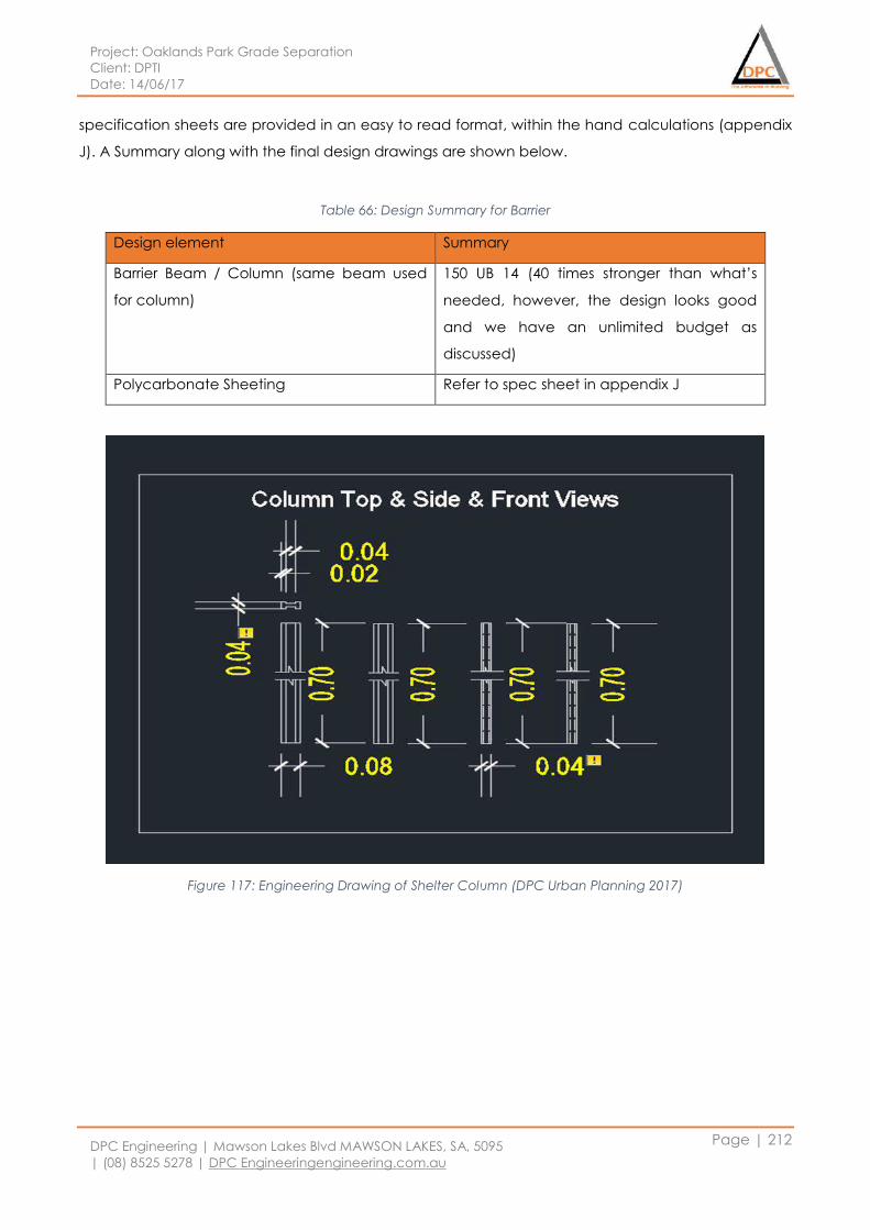
Project: Oaklands Park Grade Separation
Client: DPTI
Date: 14/06/17
DPC Engineering | Mawson Lakes Blvd MAWSON LAKES, SA, 5095
| (08) 8525 5278 | DPC Engineeringengineering.com.au
Page | 212
specification sheets are provided in an easy to read format, within the hand calculations (appendix
J). A Summary along with the final design drawings are shown below.
Table 66: Design Summary for Barrier
Design element Summary
Barrier Beam / Column (same beam used
for column)
150 UB 14 (40 times stronger than what’s
needed, however, the design looks good
and we have an unlimited budget as
discussed)
Polycarbonate Sheeting Refer to spec sheet in appendix J
Figure 117: Engineering Drawing of Shelter Column (DPC Urban Planning 2017)
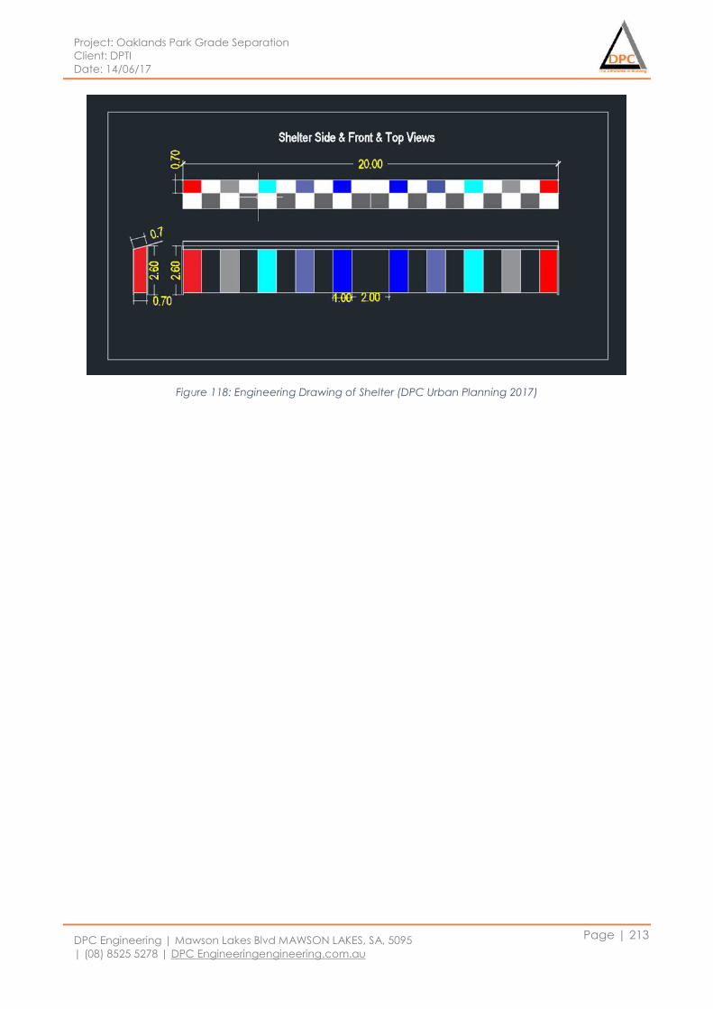
Project: Oaklands Park Grade Separation
Client: DPTI
Date: 14/06/17
DPC Engineering | Mawson Lakes Blvd MAWSON LAKES, SA, 5095
| (08) 8525 5278 | DPC Engineeringengineering.com.au
Page | 213
Figure 118: Engineering Drawing of Shelter (DPC Urban Planning 2017)
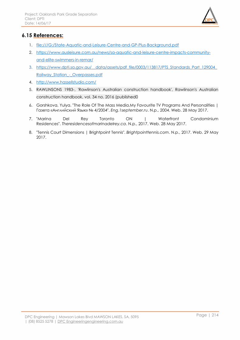
Project: Oaklands Park Grade Separation
Client: DPTI
Date: 14/06/17
DPC Engineering | Mawson Lakes Blvd MAWSON LAKES, SA, 5095
| (08) 8525 5278 | DPC Engineeringengineering.com.au
Page | 214
6.15 References:
1. file:///G:/State-Aquatic-and-Leisure-Centre-and-GP-Plus-Background.pdf
2. https://www.ausleisure.com.au/news/sa-aquatic-and-leisure-centre-impacts-community-
and-elite-swimmers-in-remar/
3. https://www.dpti.sa.gov.au/__data/assets/pdf_file/0003/113817/PTS_Standards_Part_129004_
Railway_Station_-_Overpasses.pdf
4. http://www.hassellstudio.com/
5. RAWLINSONS 1983-, 'Rawlinson's Australian construction handbook', Rawlinson's Australian
construction handbook, vol. 34 no. 2016 (published0
6. Gorshkova, Yulya. "The Role Of The Mass Media.My Favourite TV Programs And Personalities |
Газета «Английский Язык» № 4/2004". Eng.1september.ru. N.p., 2004. Web. 28 May 2017.
7. "Marina Del Rey Toronto ON | Waterfront Condominium
Residences". Theresidencesofmarinadelrey.ca. N.p., 2017. Web. 28 May 2017.
8. "Tennis Court Dimensions | Brightpoint Tennis". Brightpointtennis.com. N.p., 2017. Web. 29 May
2017.

Project: Oaklands Park Grade Separation
Client: DPTI
Date: 14/06/17
DPC Engineering | Mawson Lakes Blvd MAWSON LAKES, SA, 5095
| (08) 8525 5278 | DPC Engineeringengineering.com.au
Page | 215
ENVIRONMENTAL
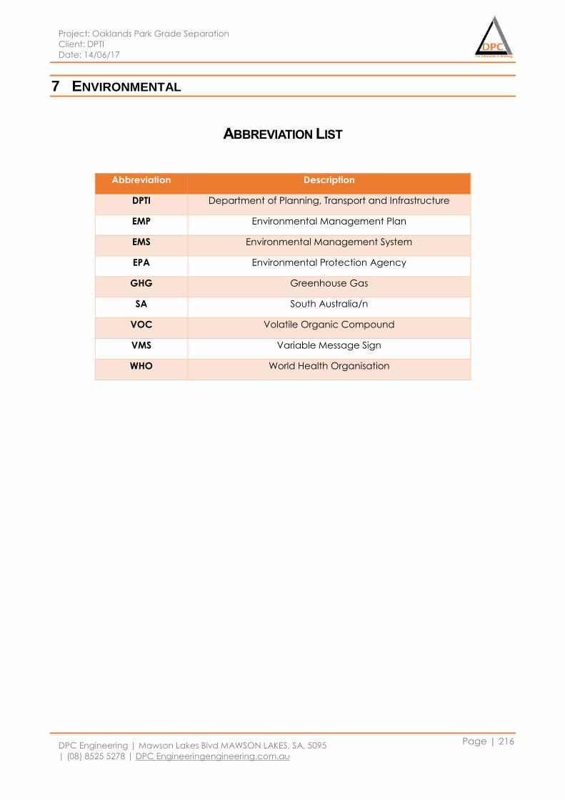
Project: Oaklands Park Grade Separation
Client: DPTI
Date: 14/06/17
DPC Engineering | Mawson Lakes Blvd MAWSON LAKES, SA, 5095
| (08) 8525 5278 | DPC Engineeringengineering.com.au
Page | 216
7 ENVIRONMENTAL
ABBREVIATION LIST
Abbreviation Description
DPTI Department of Planning, Transport and Infrastructure
EMP Environmental Management Plan
EMS Environmental Management System
EPA Environmental Protection Agency
GHG Greenhouse Gas
SA South Australia/n
VOC Volatile Organic Compound
VMS Variable Message Sign
WHO World Health Organisation
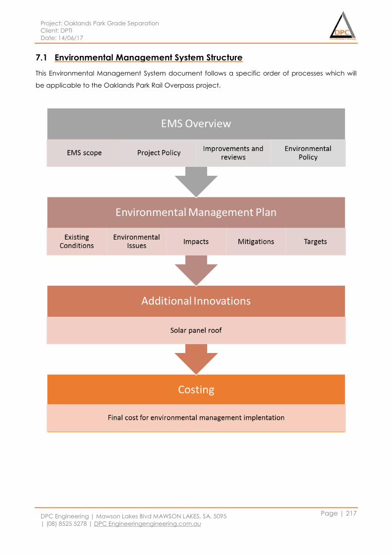
Project: Oaklands Park Grade Separation
Client: DPTI
Date: 14/06/17
DPC Engineering | Mawson Lakes Blvd MAWSON LAKES, SA, 5095
| (08) 8525 5278 | DPC Engineeringengineering.com.au
Page | 217
7.1 Environmental Management System Structure
This Environmental Management System document follows a specific order of processes which will
be applicable to the Oaklands Park Rail Overpass project.
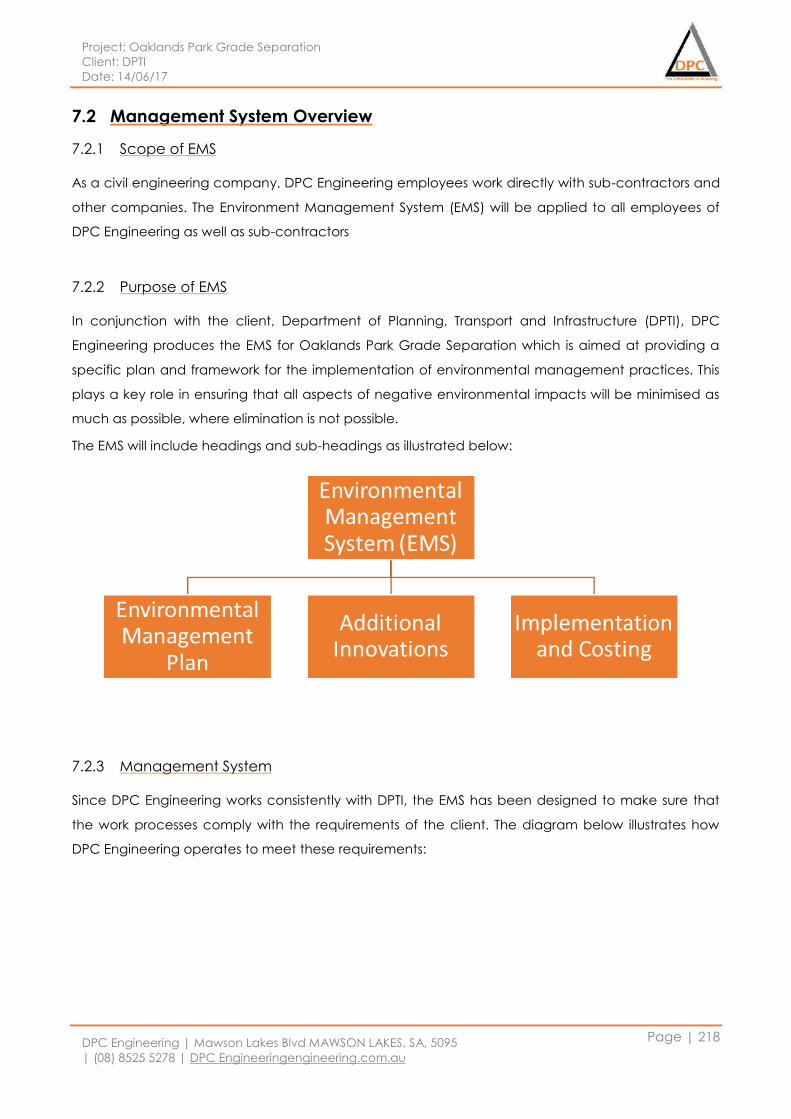
Project: Oaklands Park Grade Separation
Client: DPTI
Date: 14/06/17
DPC Engineering | Mawson Lakes Blvd MAWSON LAKES, SA, 5095
| (08) 8525 5278 | DPC Engineeringengineering.com.au
Page | 218
7.2 Management System Overview
7.2.1 Scope of EMS
As a civil engineering company, DPC Engineering employees work directly with sub-contractors and
other companies. The Environment Management System (EMS) will be applied to all employees of
DPC Engineering as well as sub-contractors
7.2.2 Purpose of EMS
In conjunction with the client, Department of Planning, Transport and Infrastructure (DPTI), DPC
Engineering produces the EMS for Oaklands Park Grade Separation which is aimed at providing a
specific plan and framework for the implementation of environmental management practices. This
plays a key role in ensuring that all aspects of negative environmental impacts will be minimised as
much as possible, where elimination is not possible.
The EMS will include headings and sub-headings as illustrated below:
7.2.3 Management System
Since DPC Engineering works consistently with DPTI, the EMS has been designed to make sure that
the work processes comply with the requirements of the client. The diagram below illustrates how
DPC Engineering operates to meet these requirements:
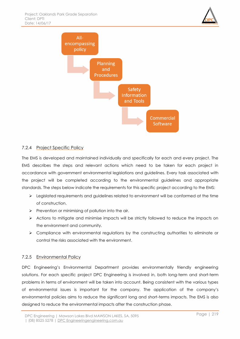
Project: Oaklands Park Grade Separation
Client: DPTI
Date: 14/06/17
DPC Engineering | Mawson Lakes Blvd MAWSON LAKES, SA, 5095
| (08) 8525 5278 | DPC Engineeringengineering.com.au
Page | 219
7.2.4 Project Specific Policy
The EMS is developed and maintained individually and specifically for each and every project. The
EMS describes the steps and relevant actions which need to be taken for each project in
accordance with government environmental legislations and guidelines. Every task associated with
the project will be completed according to the environmental guidelines and appropriate
standards. The steps below indicate the requirements for this specific project according to the EMS:
Legislated requirements and guidelines related to environment will be conformed at the time
of construction.
Prevention or minimising of pollution into the air.
Actions to mitigate and minimise impacts will be strictly followed to reduce the impacts on
the environment and community.
Compliance with environmental regulations by the constructing authorities to eliminate or
control the risks associated with the environment.
7.2.5 Environmental Policy
DPC Engineering’s Environmental Department provides environmentally friendly engineering
solutions. For each specific project DPC Engineering is involved in, both long-term and short-term
problems in terms of environment will be taken into account. Being consistent with the various types
of environmental issues is important for the company. The application of the company’s
environmental policies aims to reduce the significant long and short-terms impacts. The EMS is also
designed to reduce the environmental impacts after the construction phase.
Project: Oaklands Park Grade Separation
Client: DPTI
Date: 14/06/17
DPC Engineering | Mawson Lakes Blvd MAWSON LAKES, SA, 5095
| (08) 8525 5278 | DPC Engineeringengineering.com.au
Page | 220
By improving the environmental quality of the project, DPC Engineering complies with environmental
laws, legislations and policies. For each individual project, appropriate training will be held for
employees working under the supervision of the environmental and other related departments.
DPC Engineering’s Environmental Department team will focus on the following aspects:
Compliance with environmental laws, legislations and policies from the South Australian
government.
Preventing or minimising pollution including GHG emissions, reducing the construction waste,
and practicing efficient usage of water, electricity and other resources.
Clearly identifying the objectives and targets of the project.
Conveying the environmental policies as well as the EMS to workers on the project including
DPC Engineering employees.
Improving the awareness of environmental responsibilities through appropriate training.
Frequently supervising the company’s environmental performance and efficiency
achievements and reporting it to the local government, and contractors.
7.2.6 Continual Improvement
DPC Engineering acknowledges that people are not perfect, and therefore their policies are not
perfect. Also, laws and legislations are constantly changing to ensure that its systems remain relevant
and effective for every project involving environmental management. That’s why DPC engineering
takes responsibility for ensuring its management strategies are up-to-date with the latest
requirements, and its people are informed about any changes to the existing systems. DPC
Engineering does this by following a simple 4 step model shown by Figure 119:
1. Plan – ideas, objectives and processes.
2. Action – Implement ideas, objectives and processes.
3. Review – Monitoring and evaluate ideas, objectives and processes.
4. React – Improve the current systems based on new ideas, objectives and processes arising
from the reviewing stage
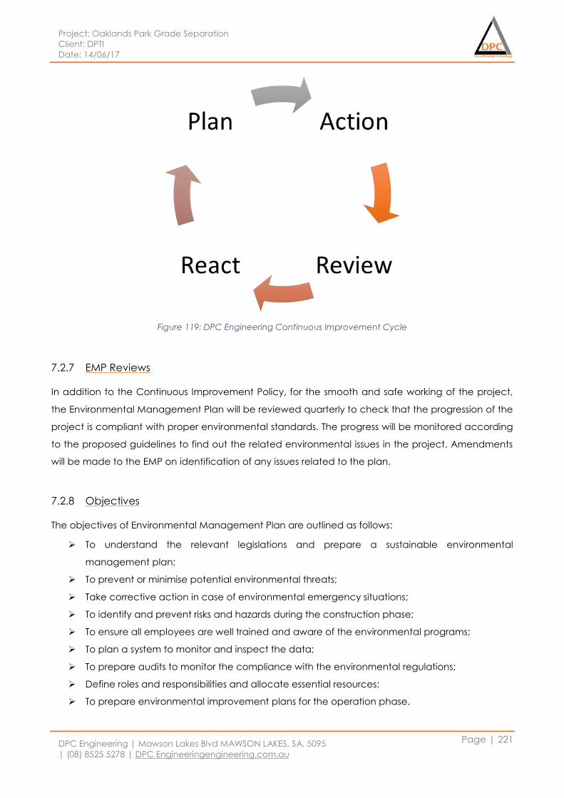
Project: Oaklands Park Grade Separation
Client: DPTI
Date: 14/06/17
DPC Engineering | Mawson Lakes Blvd MAWSON LAKES, SA, 5095
| (08) 8525 5278 | DPC Engineeringengineering.com.au
Page | 221
Figure 119: DPC Engineering Continuous Improvement Cycle
7.2.7 EMP Reviews
In addition to the Continuous Improvement Policy, for the smooth and safe working of the project,
the Environmental Management Plan will be reviewed quarterly to check that the progression of the
project is compliant with proper environmental standards. The progress will be monitored according
to the proposed guidelines to find out the related environmental issues in the project. Amendments
will be made to the EMP on identification of any issues related to the plan.
7.2.8 Objectives
The objectives of Environmental Management Plan are outlined as follows:
To understand the relevant legislations and prepare a sustainable environmental
management plan;
To prevent or minimise potential environmental threats;
Take corrective action in case of environmental emergency situations;
To identify and prevent risks and hazards during the construction phase;
To ensure all employees are well trained and aware of the environmental programs;
To plan a system to monitor and inspect the data;
To prepare audits to monitor the compliance with the environmental regulations;
Define roles and responsibilities and allocate essential resources;
To prepare environmental improvement plans for the operation phase.
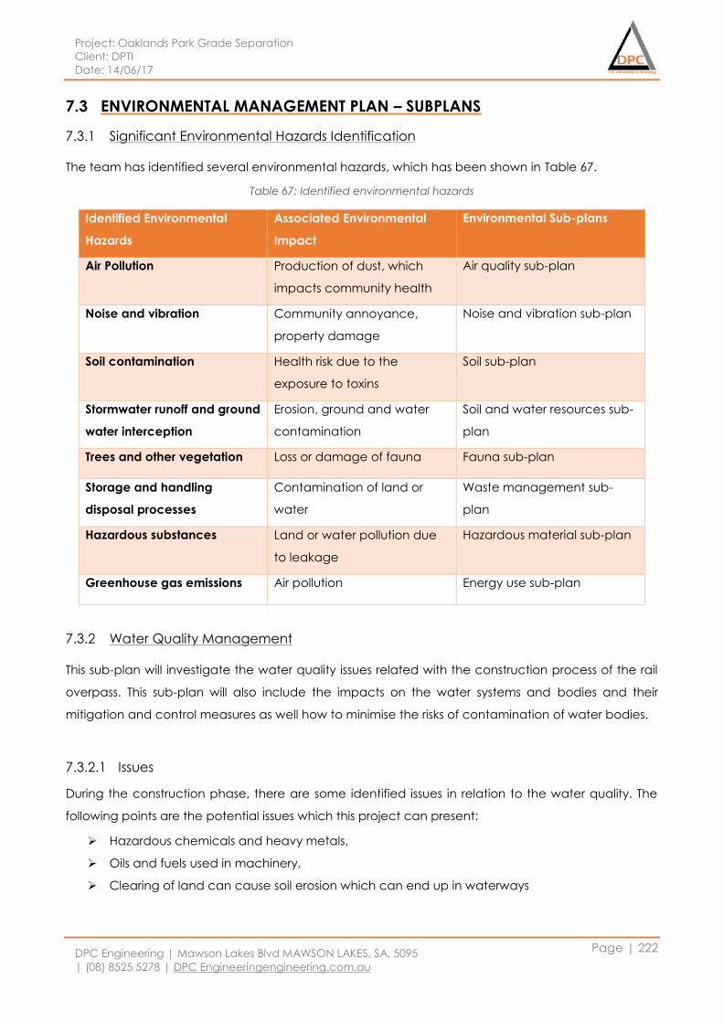
Project: Oaklands Park Grade Separation
Client: DPTI
Date: 14/06/17
DPC Engineering | Mawson Lakes Blvd MAWSON LAKES, SA, 5095
| (08) 8525 5278 | DPC Engineeringengineering.com.au
Page | 222
7.3 ENVIRONMENTAL MANAGEMENT PLAN – SUBPLANS
7.3.1 Significant Environmental Hazards Identification
The team has identified several environmental hazards, which has been shown in Table 67.
Table 67: Identified environmental hazards
Identified Environmental
Hazards
Associated Environmental
Impact
Environmental Sub-plans
Air Pollution Production of dust, which
impacts community health
Air quality sub-plan
Noise and vibration Community annoyance,
property damage
Noise and vibration sub-plan
Soil contamination Health risk due to the
exposure to toxins
Soil sub-plan
Stormwater runoff and ground
water interception
Erosion, ground and water
contamination
Soil and water resources sub-
plan
Trees and other vegetation Loss or damage of fauna Fauna sub-plan
Storage and handling
disposal processes
Contamination of land or
water
Waste management sub-
plan
Hazardous substances Land or water pollution due
to leakage
Hazardous material sub-plan
Greenhouse gas emissions Air pollution Energy use sub-plan
7.3.2 Water Quality Management
This sub-plan will investigate the water quality issues related with the construction process of the rail
overpass. This sub-plan will also include the impacts on the water systems and bodies and their
mitigation and control measures as well how to minimise the risks of contamination of water bodies.
7.3.2.1 Issues
During the construction phase, there are some identified issues in relation to the water quality. The
following points are the potential issues which this project can present:
Hazardous chemicals and heavy metals,
Oils and fuels used in machinery,
Clearing of land can cause soil erosion which can end up in waterways
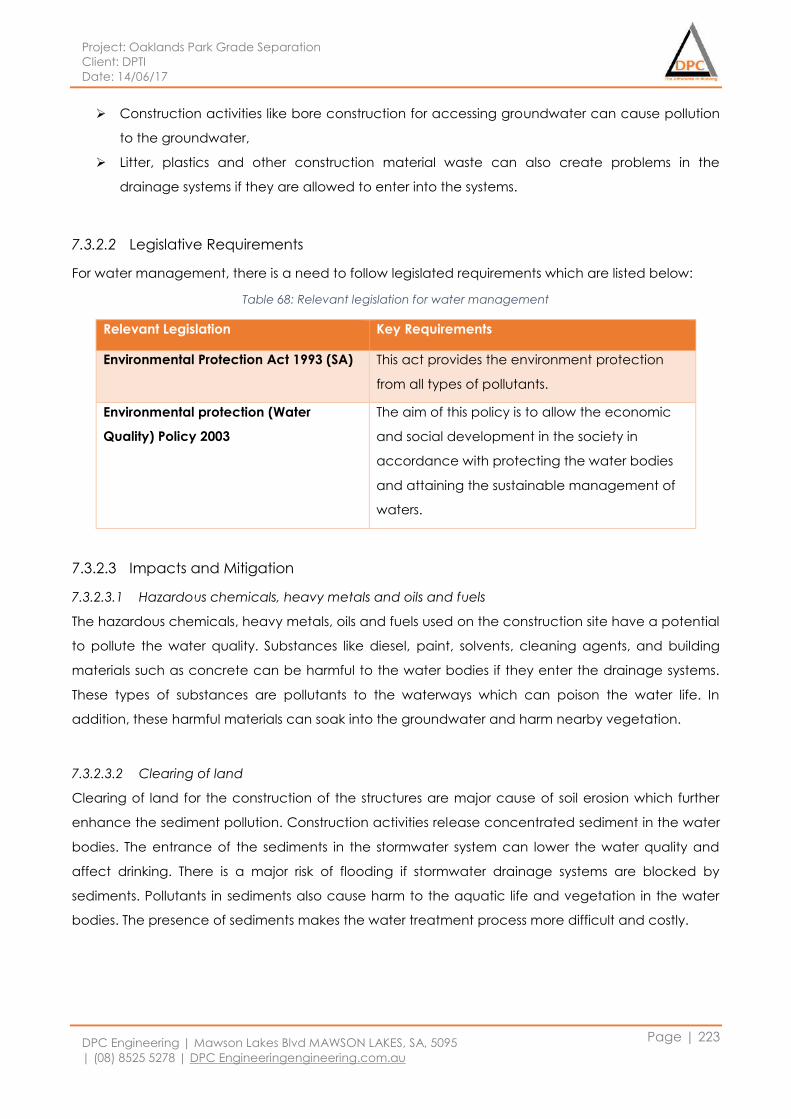
Project: Oaklands Park Grade Separation
Client: DPTI
Date: 14/06/17
DPC Engineering | Mawson Lakes Blvd MAWSON LAKES, SA, 5095
| (08) 8525 5278 | DPC Engineeringengineering.com.au
Page | 223
Construction activities like bore construction for accessing groundwater can cause pollution
to the groundwater,
Litter, plastics and other construction material waste can also create problems in the
drainage systems if they are allowed to enter into the systems.
7.3.2.2 Legislative Requirements
For water management, there is a need to follow legislated requirements which are listed below:
Table 68: Relevant legislation for water management
Relevant Legislation Key Requirements
Environmental Protection Act 1993 (SA) This act provides the environment protection
from all types of pollutants.
Environmental protection (Water
Quality) Policy 2003
The aim of this policy is to allow the economic
and social development in the society in
accordance with protecting the water bodies
and attaining the sustainable management of
waters.
7.3.2.3 Impacts and Mitigation
7.3.2.3.1 Hazardous chemicals, heavy metals and oils and fuels
The hazardous chemicals, heavy metals, oils and fuels used on the construction site have a potential
to pollute the water quality. Substances like diesel, paint, solvents, cleaning agents, and building
materials such as concrete can be harmful to the water bodies if they enter the drainage systems.
These types of substances are pollutants to the waterways which can poison the water life. In
addition, these harmful materials can soak into the groundwater and harm nearby vegetation.
7.3.2.3.2 Clearing of land
Clearing of land for the construction of the structures are major cause of soil erosion which further
enhance the sediment pollution. Construction activities release concentrated sediment in the water
bodies. The entrance of the sediments in the stormwater system can lower the water quality and
affect drinking. There is a major risk of flooding if stormwater drainage systems are blocked by
sediments. Pollutants in sediments also cause harm to the aquatic life and vegetation in the water
bodies. The presence of sediments makes the water treatment process more difficult and costly.
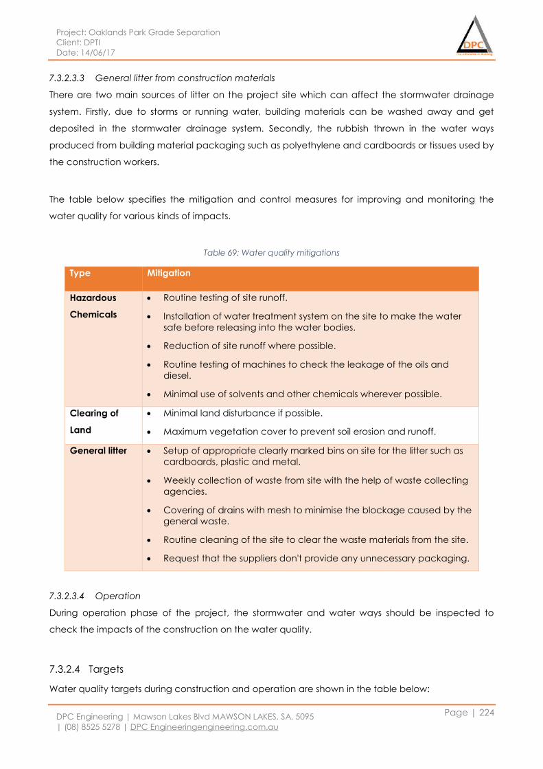
Project: Oaklands Park Grade Separation
Client: DPTI
Date: 14/06/17
DPC Engineering | Mawson Lakes Blvd MAWSON LAKES, SA, 5095
| (08) 8525 5278 | DPC Engineeringengineering.com.au
Page | 224
7.3.2.3.3 General litter from construction materials
There are two main sources of litter on the project site which can affect the stormwater drainage
system. Firstly, due to storms or running water, building materials can be washed away and get
deposited in the stormwater drainage system. Secondly, the rubbish thrown in the water ways
produced from building material packaging such as polyethylene and cardboards or tissues used by
the construction workers.
The table below specifies the mitigation and control measures for improving and monitoring the
water quality for various kinds of impacts.
Table 69: Water quality mitigations
Type Mitigation
Hazardous
Chemicals
Routine testing of site runoff.
Installation of water treatment system on the site to make the water
safe before releasing into the water bodies.
Reduction of site runoff where possible.
Routine testing of machines to check the leakage of the oils and
diesel.
Minimal use of solvents and other chemicals wherever possible.
Clearing of
Land
Minimal land disturbance if possible.
Maximum vegetation cover to prevent soil erosion and runoff.
General litter Setup of appropriate clearly marked bins on site for the litter such as
cardboards, plastic and metal.
Weekly collection of waste from site with the help of waste collecting
agencies.
Covering of drains with mesh to minimise the blockage caused by the
general waste.
Routine cleaning of the site to clear the waste materials from the site.
Request that the suppliers don't provide any unnecessary packaging.
7.3.2.3.4 Operation
During operation phase of the project, the stormwater and water ways should be inspected to
check the impacts of the construction on the water quality.
7.3.2.4 Targets
Water quality targets during construction and operation are shown in the table below:
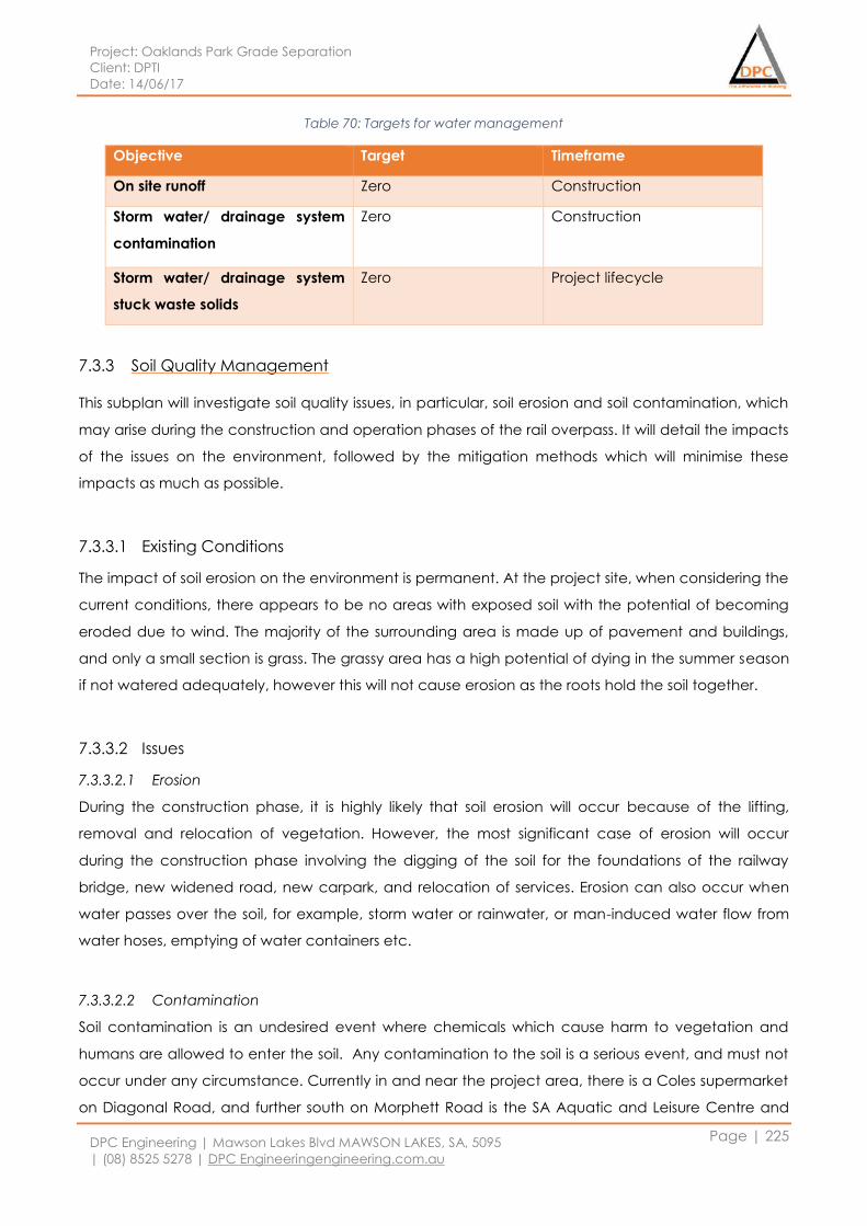
Project: Oaklands Park Grade Separation
Client: DPTI
Date: 14/06/17
DPC Engineering | Mawson Lakes Blvd MAWSON LAKES, SA, 5095
| (08) 8525 5278 | DPC Engineeringengineering.com.au
Page | 225
Table 70: Targets for water management
Objective Target Timeframe
On site runoff Zero Construction
Storm water/ drainage system
contamination
Zero Construction
Storm water/ drainage system
stuck waste solids
Zero Project lifecycle
7.3.3 Soil Quality Management
This subplan will investigate soil quality issues, in particular, soil erosion and soil contamination, which
may arise during the construction and operation phases of the rail overpass. It will detail the impacts
of the issues on the environment, followed by the mitigation methods which will minimise these
impacts as much as possible.
7.3.3.1 Existing Conditions
The impact of soil erosion on the environment is permanent. At the project site, when considering the
current conditions, there appears to be no areas with exposed soil with the potential of becoming
eroded due to wind. The majority of the surrounding area is made up of pavement and buildings,
and only a small section is grass. The grassy area has a high potential of dying in the summer season
if not watered adequately, however this will not cause erosion as the roots hold the soil together.
7.3.3.2 Issues
7.3.3.2.1 Erosion
During the construction phase, it is highly likely that soil erosion will occur because of the lifting,
removal and relocation of vegetation. However, the most significant case of erosion will occur
during the construction phase involving the digging of the soil for the foundations of the railway
bridge, new widened road, new carpark, and relocation of services. Erosion can also occur when
water passes over the soil, for example, storm water or rainwater, or man-induced water flow from
water hoses, emptying of water containers etc.
7.3.3.2.2 Contamination
Soil contamination is an undesired event where chemicals which cause harm to vegetation and
humans are allowed to enter the soil. Any contamination to the soil is a serious event, and must not
occur under any circumstance. Currently in and near the project area, there is a Coles supermarket
on Diagonal Road, and further south on Morphett Road is the SA Aquatic and Leisure Centre and
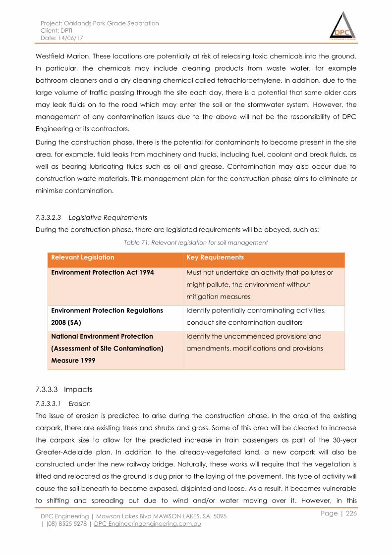
Project: Oaklands Park Grade Separation
Client: DPTI
Date: 14/06/17
DPC Engineering | Mawson Lakes Blvd MAWSON LAKES, SA, 5095
| (08) 8525 5278 | DPC Engineeringengineering.com.au
Page | 226
Westfield Marion. These locations are potentially at risk of releasing toxic chemicals into the ground.
In particular, the chemicals may include cleaning products from waste water, for example
bathroom cleaners and a dry-cleaning chemical called tetrachloroethylene. In addition, due to the
large volume of traffic passing through the site each day, there is a potential that some older cars
may leak fluids on to the road which may enter the soil or the stormwater system. However, the
management of any contamination issues due to the above will not be the responsibility of DPC
Engineering or its contractors.
During the construction phase, there is the potential for contaminants to become present in the site
area, for example, fluid leaks from machinery and trucks, including fuel, coolant and break fluids, as
well as bearing lubricating fluids such as oil and grease. Contamination may also occur due to
construction waste materials. This management plan for the construction phase aims to eliminate or
minimise contamination.
7.3.3.2.3 Legislative Requirements
During the construction phase, there are legislated requirements will be obeyed, such as:
Table 71: Relevant legislation for soil management
Relevant Legislation Key Requirements
Environment Protection Act 1994 Must not undertake an activity that pollutes or
might pollute, the environment without
mitigation measures
Environment Protection Regulations
2008 (SA)
Identify potentially contaminating activities,
conduct site contamination auditors
National Environment Protection
(Assessment of Site Contamination)
Measure 1999
Identify the uncommenced provisions and
amendments, modifications and provisions
7.3.3.3 Impacts
7.3.3.3.1 Erosion
The issue of erosion is predicted to arise during the construction phase. In the area of the existing
carpark, there are existing trees and shrubs and grass. Some of this area will be cleared to increase
the carpark size to allow for the predicted increase in train passengers as part of the 30-year
Greater-Adelaide plan. In addition to the already-vegetated land, a new carpark will also be
constructed under the new railway bridge. Naturally, these works will require that the vegetation is
lifted and relocated as the ground is dug prior to the laying of the pavement. This type of activity will
cause the soil beneath to become exposed, disjointed and loose. As a result, it becomes vulnerable
to shifting and spreading out due to wind and/or water moving over it. However, in this
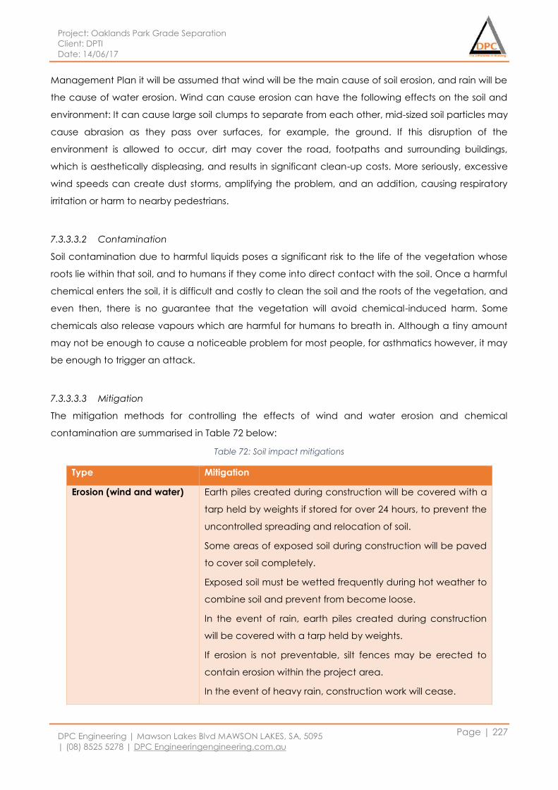
Project: Oaklands Park Grade Separation
Client: DPTI
Date: 14/06/17
DPC Engineering | Mawson Lakes Blvd MAWSON LAKES, SA, 5095
| (08) 8525 5278 | DPC Engineeringengineering.com.au
Page | 227
Management Plan it will be assumed that wind will be the main cause of soil erosion, and rain will be
the cause of water erosion. Wind can cause erosion can have the following effects on the soil and
environment: It can cause large soil clumps to separate from each other, mid-sized soil particles may
cause abrasion as they pass over surfaces, for example, the ground. If this disruption of the
environment is allowed to occur, dirt may cover the road, footpaths and surrounding buildings,
which is aesthetically displeasing, and results in significant clean-up costs. More seriously, excessive
wind speeds can create dust storms, amplifying the problem, and an addition, causing respiratory
irritation or harm to nearby pedestrians.
7.3.3.3.2 Contamination
Soil contamination due to harmful liquids poses a significant risk to the life of the vegetation whose
roots lie within that soil, and to humans if they come into direct contact with the soil. Once a harmful
chemical enters the soil, it is difficult and costly to clean the soil and the roots of the vegetation, and
even then, there is no guarantee that the vegetation will avoid chemical-induced harm. Some
chemicals also release vapours which are harmful for humans to breath in. Although a tiny amount
may not be enough to cause a noticeable problem for most people, for asthmatics however, it may
be enough to trigger an attack.
7.3.3.3.3 Mitigation
The mitigation methods for controlling the effects of wind and water erosion and chemical
contamination are summarised in Table 72 below:
Table 72: Soil impact mitigations
Type Mitigation
Erosion (wind and water)
Earth piles created during construction will be covered with a
tarp held by weights if stored for over 24 hours, to prevent the
uncontrolled spreading and relocation of soil.
Some areas of exposed soil during construction will be paved
to cover soil completely.
Exposed soil must be wetted frequently during hot weather to
combine soil and prevent from become loose.
In the event of rain, earth piles created during construction
will be covered with a tarp held by weights.
If erosion is not preventable, silt fences may be erected to
contain erosion within the project area.
In the event of heavy rain, construction work will cease.
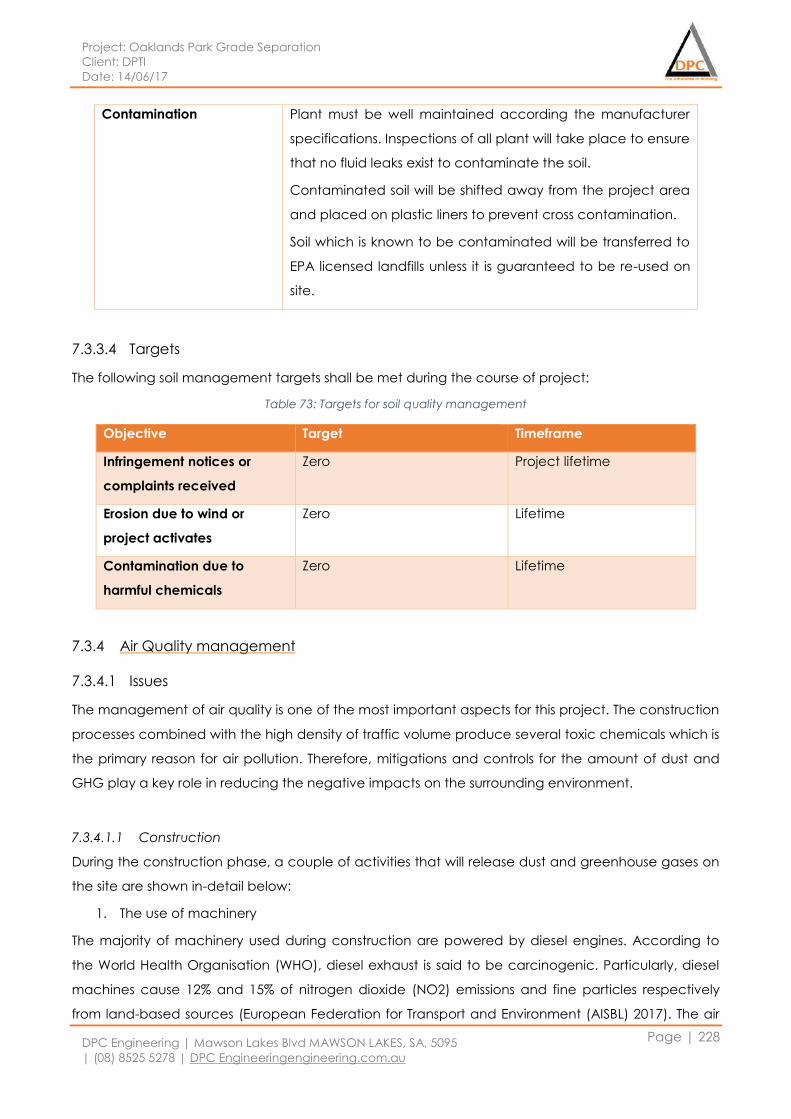
Project: Oaklands Park Grade Separation
Client: DPTI
Date: 14/06/17
DPC Engineering | Mawson Lakes Blvd MAWSON LAKES, SA, 5095
| (08) 8525 5278 | DPC Engineeringengineering.com.au
Page | 228
Contamination Plant must be well maintained according the manufacturer
specifications. Inspections of all plant will take place to ensure
that no fluid leaks exist to contaminate the soil.
Contaminated soil will be shifted away from the project area
and placed on plastic liners to prevent cross contamination.
Soil which is known to be contaminated will be transferred to
EPA licensed landfills unless it is guaranteed to be re-used on
site.
7.3.3.4 Targets
The following soil management targets shall be met during the course of project:
Table 73: Targets for soil quality management
Objective Target Timeframe
Infringement notices or
complaints received
Zero Project lifetime
Erosion due to wind or
project activates
Zero Lifetime
Contamination due to
harmful chemicals
Zero Lifetime
7.3.4 Air Quality management
7.3.4.1 Issues
The management of air quality is one of the most important aspects for this project. The construction
processes combined with the high density of traffic volume produce several toxic chemicals which is
the primary reason for air pollution. Therefore, mitigations and controls for the amount of dust and
GHG play a key role in reducing the negative impacts on the surrounding environment.
7.3.4.1.1 Construction
During the construction phase, a couple of activities that will release dust and greenhouse gases on
the site are shown in-detail below:
1. The use of machinery
The majority of machinery used during construction are powered by diesel engines. According to
the World Health Organisation (WHO), diesel exhaust is said to be carcinogenic. Particularly, diesel
machines cause 12% and 15% of nitrogen dioxide (NO2) emissions and fine particles respectively
from land-based sources (European Federation for Transport and Environment (AISBL) 2017). The air

Project: Oaklands Park Grade Separation
Client: DPTI
Date: 14/06/17
DPC Engineering | Mawson Lakes Blvd MAWSON LAKES, SA, 5095
| (08) 8525 5278 | DPC Engineeringengineering.com.au
Page | 229
pollution from the use of diesel machines can result in health issues such as cardiovascular and
respiratory illnesses for local residents (Concerned Scientists 2016).
2. Transportation of machinery, materials and waste
The transportation of machinery, materials and waste causes a significant environmental impact
due to the fuel consumption from vehicles. This results in air pollution, comprising of particulates and
nitrous oxides which are known as two of the major contributors to global warming.
3. Use of Solvents
It is announced that the use of solvents is identified as one of the major contributors to VOC
emissions, which are said to be a trans-boundary air pollutant. In Europe for example, solvent use
contributes to approximately 25% of the total anthropogenic emissions of VOCs (Environmental
Protection Agency (EPA) 2013). In regard to the project, solvents can be used during the painting of
the structure. As a consequence, is identified as a main cause of air pollution.
4. Waste Materials from site
According to the Department of Sustainability, Environment, Water, Population and Communities
from Australian Government, building materials take up nearly a half of the solid waste generated
worldwide. Dust from waste materials, which were a result of the demolition of old structures, are
produced, which negatively impacts the air pollution of the environment.
5. Wind erosion
Wind erosion is recognized as one of the seriously environmental problems. It damages in land and
natural vegetation by removing soils from one place and depositing them to other places. This
contributes to the creation of a huge amount of dusts. As a consequence, it causes the dryness and
the deterioration of soil structure, the losses in nutrient and productivity and air pollution.
7.3.4.1.2 Legislative Requirements
The legislated requirements for the management of air quality during the construction phase are
shown in the table below:
Table 74: Relevant legislation for air quality management
Relevant Legislation Key Requirements
National Environment Protection Measure
for Ambient Air 2003
Carbon monoxide, nitrogen dioxide, sulphur
dioxide and particulate matter must not
exceed the diameter of 10μm or less or
2.5μm or less.
National Environment Protection Measure
for Air Toxics 2004
The specification of the concentration of air
toxins from specific sources is required.
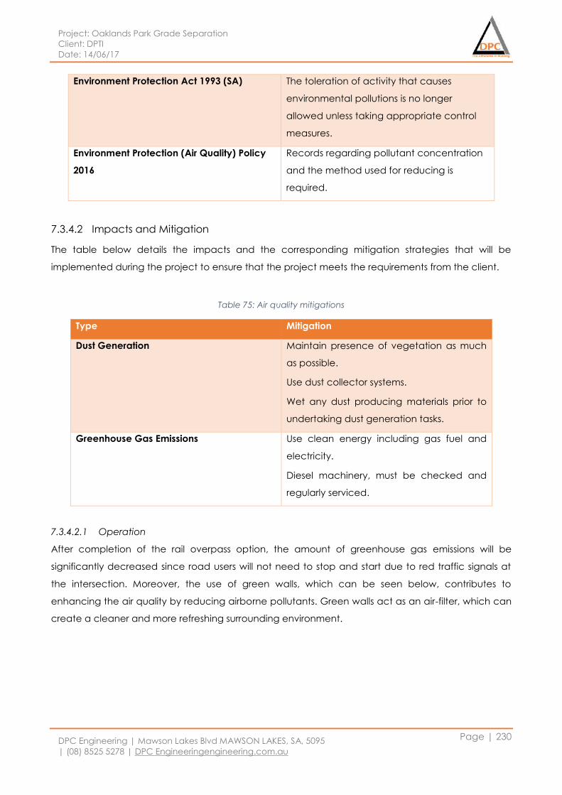
Project: Oaklands Park Grade Separation
Client: DPTI
Date: 14/06/17
DPC Engineering | Mawson Lakes Blvd MAWSON LAKES, SA, 5095
| (08) 8525 5278 | DPC Engineeringengineering.com.au
Page | 230
Environment Protection Act 1993 (SA) The toleration of activity that causes
environmental pollutions is no longer
allowed unless taking appropriate control
measures.
Environment Protection (Air Quality) Policy
2016
Records regarding pollutant concentration
and the method used for reducing is
required.
7.3.4.2 Impacts and Mitigation
The table below details the impacts and the corresponding mitigation strategies that will be
implemented during the project to ensure that the project meets the requirements from the client.
Table 75: Air quality mitigations
Type Mitigation
Dust Generation
Maintain presence of vegetation as much
as possible.
Use dust collector systems.
Wet any dust producing materials prior to
undertaking dust generation tasks.
Greenhouse Gas Emissions Use clean energy including gas fuel and
electricity.
Diesel machinery, must be checked and
regularly serviced.
7.3.4.2.1 Operation
After completion of the rail overpass option, the amount of greenhouse gas emissions will be
significantly decreased since road users will not need to stop and start due to red traffic signals at
the intersection. Moreover, the use of green walls, which can be seen below, contributes to
enhancing the air quality by reducing airborne pollutants. Green walls act as an air-filter, which can
create a cleaner and more refreshing surrounding environment.
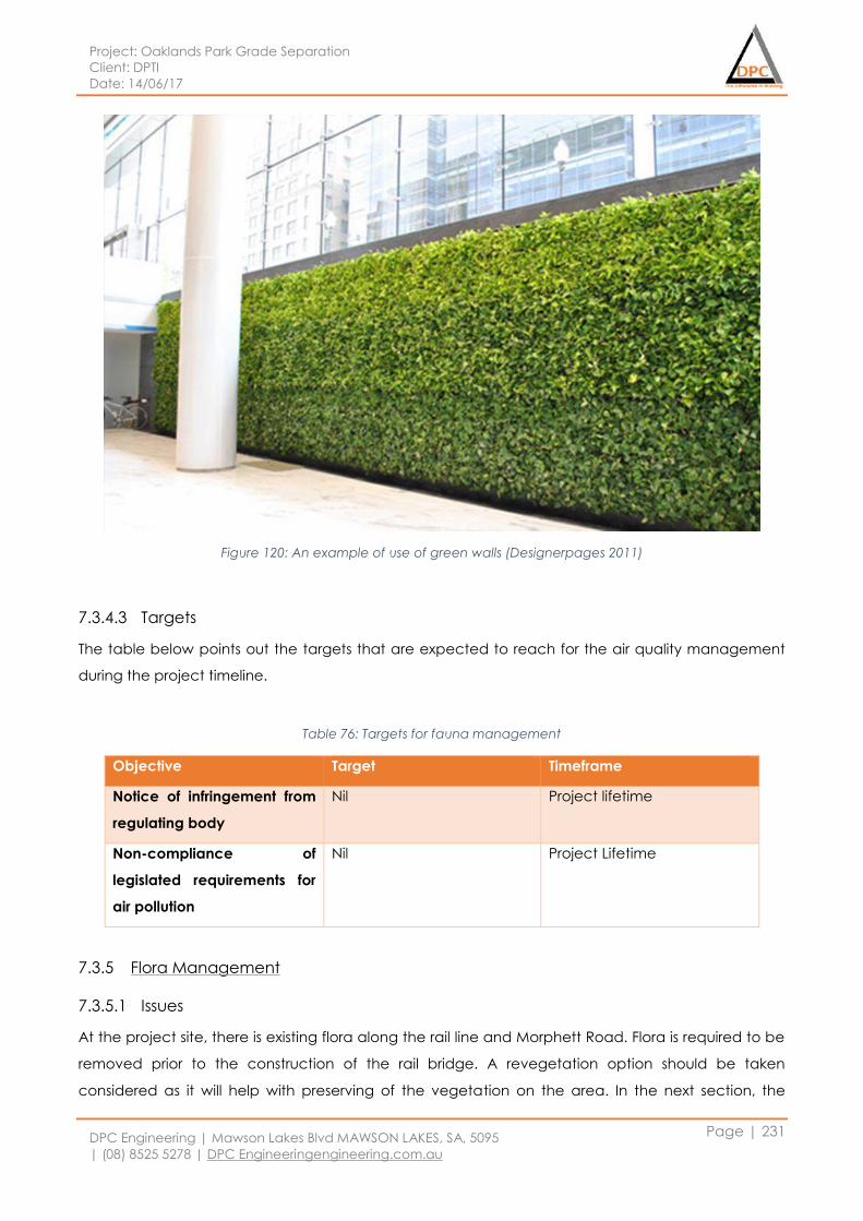
Project: Oaklands Park Grade Separation
Client: DPTI
Date: 14/06/17
DPC Engineering | Mawson Lakes Blvd MAWSON LAKES, SA, 5095
| (08) 8525 5278 | DPC Engineeringengineering.com.au
Page | 231
Figure 120: An example of use of green walls (Designerpages 2011)
7.3.4.3 Targets
The table below points out the targets that are expected to reach for the air quality management
during the project timeline.
Table 76: Targets for fauna management
Objective Target Timeframe
Notice of infringement from
regulating body
Nil Project lifetime
Non-compliance of
legislated requirements for
air pollution
Nil Project Lifetime
7.3.5 Flora Management
7.3.5.1 Issues
At the project site, there is existing flora along the rail line and Morphett Road. Flora is required to be
removed prior to the construction of the rail bridge. A revegetation option should be taken
considered as it will help with preserving of the vegetation on the area. In the next section, the
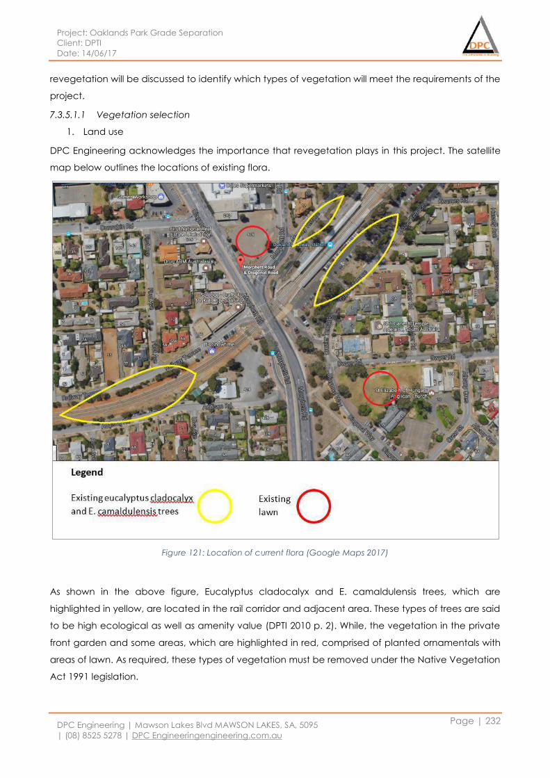
Project: Oaklands Park Grade Separation
Client: DPTI
Date: 14/06/17
DPC Engineering | Mawson Lakes Blvd MAWSON LAKES, SA, 5095
| (08) 8525 5278 | DPC Engineeringengineering.com.au
Page | 232
revegetation will be discussed to identify which types of vegetation will meet the requirements of the
project.
7.3.5.1.1 Vegetation selection
1. Land use
DPC Engineering acknowledges the importance that revegetation plays in this project. The satellite
map below outlines the locations of existing flora.
Figure 121: Location of current flora (Google Maps 2017)
As shown in the above figure, Eucalyptus cladocalyx and E. camaldulensis trees, which are
highlighted in yellow, are located in the rail corridor and adjacent area. These types of trees are said
to be high ecological as well as amenity value (DPTI 2010 p. 2). While, the vegetation in the private
front garden and some areas, which are highlighted in red, comprised of planted ornamentals with
areas of lawn. As required, these types of vegetation must be removed under the Native Vegetation
Act 1991 legislation.
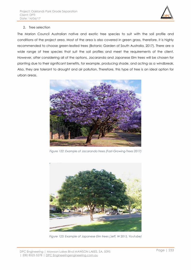
Project: Oaklands Park Grade Separation
Client: DPTI
Date: 14/06/17
DPC Engineering | Mawson Lakes Blvd MAWSON LAKES, SA, 5095
| (08) 8525 5278 | DPC Engineeringengineering.com.au
Page | 233
2. Tree selection
The Marion Council Australian native and exotic tree species to suit with the soil profile and
conditions of the project area. Most of the area is also covered in green grass, therefore, it is highly
recommended to choose green-leafed trees (Botanic Garden of South Australia, 2017). There are a
wide range of tree species that suit the soil profiles and meet the requirements of the client.
However, after considering all of the options, Jacaranda and Japanese Elm trees will be chosen for
planting due to their significant benefits, for example, producing shade, and acting as a windbreak.
Also, they are tolerant to drought and air pollution. Therefore, this type of tree is an ideal option for
urban areas.
Figure 122: Example of Jacaranda trees (Fast-Growing-Trees 2017)
Figure 123: Example of Japanese Elm trees (Jeff, W 2015, Youtube)
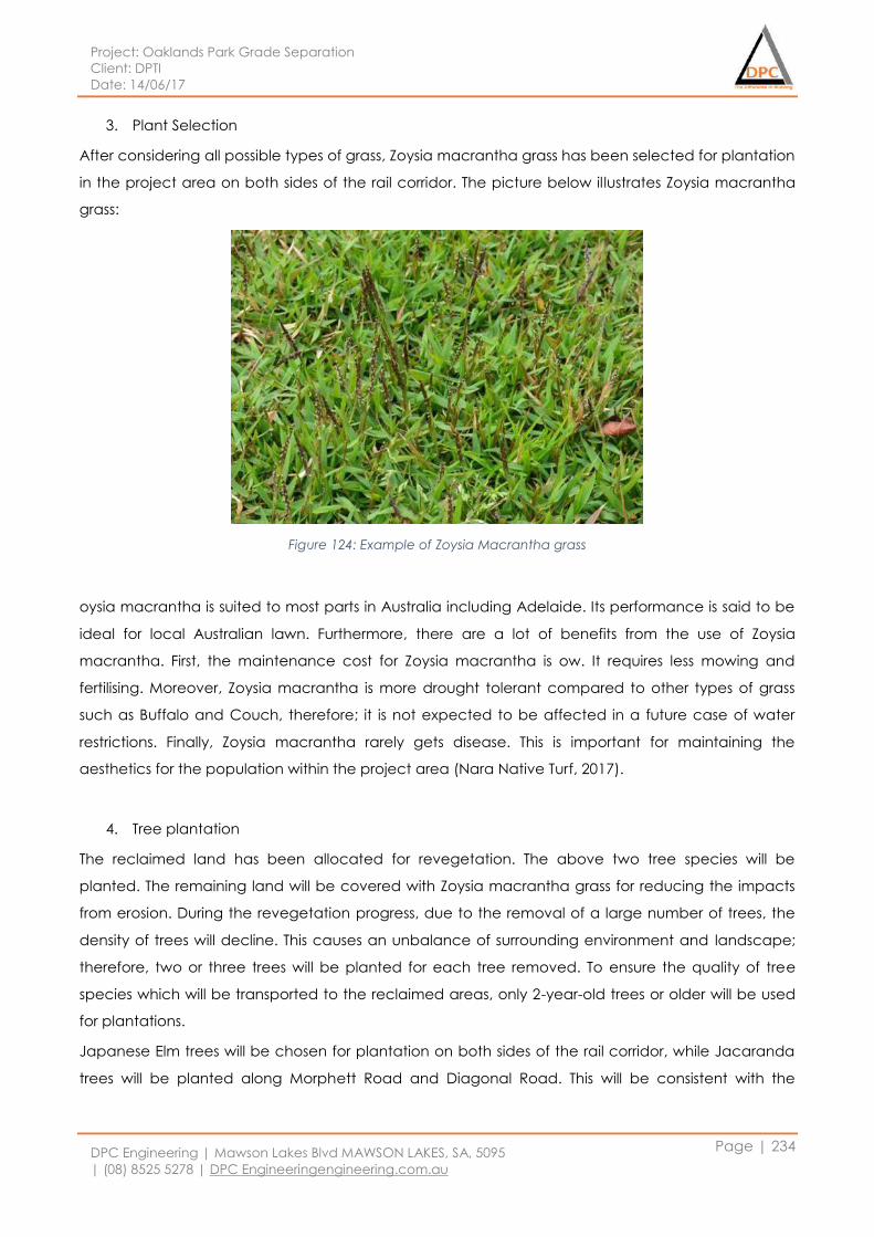
Project: Oaklands Park Grade Separation
Client: DPTI
Date: 14/06/17
DPC Engineering | Mawson Lakes Blvd MAWSON LAKES, SA, 5095
| (08) 8525 5278 | DPC Engineeringengineering.com.au
Page | 234
3. Plant Selection
After considering all possible types of grass, Zoysia macrantha grass has been selected for plantation
in the project area on both sides of the rail corridor. The picture below illustrates Zoysia macrantha
grass:
Figure 124: Example of Zoysia Macrantha grass
oysia macrantha is suited to most parts in Australia including Adelaide. Its performance is said to be
ideal for local Australian lawn. Furthermore, there are a lot of benefits from the use of Zoysia
macrantha. First, the maintenance cost for Zoysia macrantha is ow. It requires less mowing and
fertilising. Moreover, Zoysia macrantha is more drought tolerant compared to other types of grass
such as Buffalo and Couch, therefore; it is not expected to be affected in a future case of water
restrictions. Finally, Zoysia macrantha rarely gets disease. This is important for maintaining the
aesthetics for the population within the project area (Nara Native Turf, 2017).
4. Tree plantation
The reclaimed land has been allocated for revegetation. The above two tree species will be
planted. The remaining land will be covered with Zoysia macrantha grass for reducing the impacts
from erosion. During the revegetation progress, due to the removal of a large number of trees, the
density of trees will decline. This causes an unbalance of surrounding environment and landscape;
therefore, two or three trees will be planted for each tree removed. To ensure the quality of tree
species which will be transported to the reclaimed areas, only 2-year-old trees or older will be used
for plantations.
Japanese Elm trees will be chosen for plantation on both sides of the rail corridor, while Jacaranda
trees will be planted along Morphett Road and Diagonal Road. This will be consistent with the
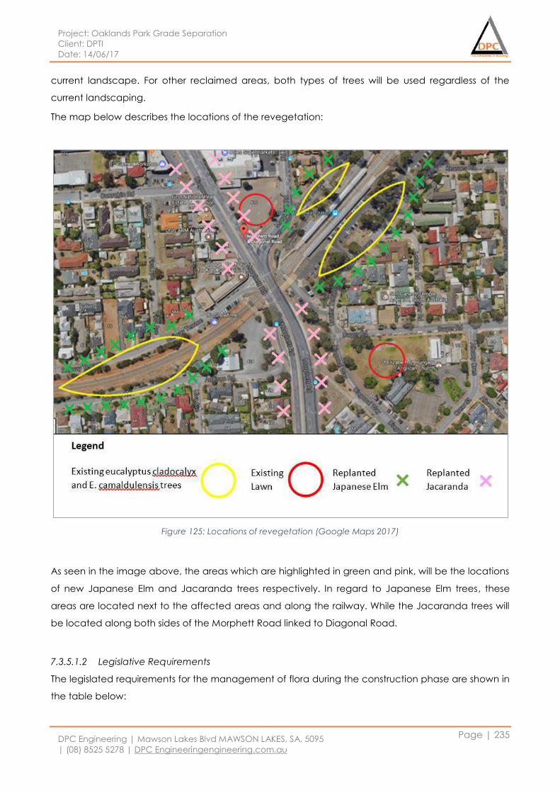
Project: Oaklands Park Grade Separation
Client: DPTI
Date: 14/06/17
DPC Engineering | Mawson Lakes Blvd MAWSON LAKES, SA, 5095
| (08) 8525 5278 | DPC Engineeringengineering.com.au
Page | 235
current landscape. For other reclaimed areas, both types of trees will be used regardless of the
current landscaping.
The map below describes the locations of the revegetation:
Figure 125: Locations of revegetation (Google Maps 2017)
As seen in the image above, the areas which are highlighted in green and pink, will be the locations
of new Japanese Elm and Jacaranda trees respectively. In regard to Japanese Elm trees, these
areas are located next to the affected areas and along the railway. While the Jacaranda trees will
be located along both sides of the Morphett Road linked to Diagonal Road.
7.3.5.1.2 Legislative Requirements
The legislated requirements for the management of flora during the construction phase are shown in
the table below:
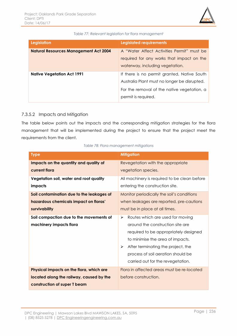
Project: Oaklands Park Grade Separation
Client: DPTI
Date: 14/06/17
DPC Engineering | Mawson Lakes Blvd MAWSON LAKES, SA, 5095
| (08) 8525 5278 | DPC Engineeringengineering.com.au
Page | 236
Table 77: Relevant legislation for flora management
Legislation Legislated requirements
Natural Resources Management Act 2004 A “Water Affect Activities Permit” must be
required for any works that impact on the
waterway, including vegetation.
Native Vegetation Act 1991 If there is no permit granted, Native South
Australia Plant must no longer be disrupted.
For the removal of the native vegetation, a
permit is required.
7.3.5.2 Impacts and Mitigation
The table below points out the impacts and the corresponding mitigation strategies for the flora
management that will be implemented during the project to ensure that the project meet the
requirements from the client.
Table 78: Flora management mitigations
Type Mitigation
Impacts on the quantity and quality of
current flora
Revegetation with the appropriate
vegetation species.
Vegetation soil, water and root quality
impacts
All machinery is required to be clean before
entering the construction site.
Soil contamination due to the leakages of
hazardous chemicals impact on floras’
survivability
Monitor periodically the soil’s conditions
when leakages are reported, pre-cautions
must be in place at all times.
Soil compaction due to the movements of
machinery impacts flora
Routes which are used for moving
around the construction site are
required to be appropriately designed
to minimise the area of impacts.
After terminating the project, the
process of soil aeration should be
carried out for the revegetation.
Physical impacts on the flora, which are
located along the railway, caused by the
construction of super T beam
Flora in affected areas must be re-located
before construction.
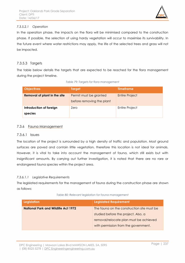
Project: Oaklands Park Grade Separation
Client: DPTI
Date: 14/06/17
DPC Engineering | Mawson Lakes Blvd MAWSON LAKES, SA, 5095
| (08) 8525 5278 | DPC Engineeringengineering.com.au
Page | 237
7.3.5.2.1 Operation
In the operation phase, the impacts on the flora will be minimised compared to the construction
phase. If possible, the selection of using hardy vegetation will occur to maximise its survivability. In
the future event where water restrictions may apply, the life of the selected trees and grass will not
be impacted.
7.3.5.3 Targets
The table below details the targets that are expected to be reached for the flora management
during the project timeline.
Table 79: Targets for flora management
Objectives Target Timeframe
Removal of plant in the site Permit must be granted
before removing the plant
Entire Project
Introduction of foreign
species
Zero Entire Project
7.3.6 Fauna Management
7.3.6.1 Issues
The location of the project is surrounded by a high density of traffic and population. Most ground
surfaces are paved and contain little vegetation, therefore this location is not ideal for animals.
However, it is vital to take into account the management of fauna, which still exists but with
insignificant amounts. By carrying out further investigation, it is noted that there are no rare or
endangered fauna species within the project area.
7.3.6.1.1 Legislative Requirements
The legislated requirements for the management of fauna during the construction phase are shown
as follows:
Table 80: Relevant legislation for fauna management
Legislation Legislated Requirement
National Park and Wildlife Act 1972 The fauna on the construction site must be
studied before the project. Also, a
removal/relocate plan must be achieved
with permission from the government.

Project: Oaklands Park Grade Separation
Client: DPTI
Date: 14/06/17
DPC Engineering | Mawson Lakes Blvd MAWSON LAKES, SA, 5095
| (08) 8525 5278 | DPC Engineeringengineering.com.au
Page | 238
7.3.6.2 Impacts and Mitigation
Although there are no rare or endangered fauna species within the project area, some impacts exist
during the construction phase. The table below summarises these impacts and the corresponding
mitigations:
Table 81: Fauna control
Type Mitigation
Fauna displacement
A fauna inspection report will be
developed and will assess bird life and
other inhabitants in either trees or
bushes.
Consult with wildlife experts for advice
with minimising the impacts on fauna.
Chemical poisoning of fauna caused by the
use of hazardous materials
Limitations in the use of hazardous
materials must be applied. The
attendance of experts is required while
using hazardous materials.
Store chemicals safely and correctly.
Noise pollution from construction site
impacts on the fauna
Fauna must be removed or relocated
before starting construction.
Apply appropriate precautions in order
to minimise noise on the construction
site.
7.3.6.2.1 Operation
In the operation phase, the impacts on fauna must be minimised. Concrete barriers will be used
between land-based fauna and the construction site, and the speed for travelling vehicles will be
reduced. As a result, the safety of fauna in surrounding areas will be significantly improved.
Regarding bird-life, their flight can be hindered by the use of fences in the construction site.
Therefore, it is highly recommended that fences with opaque coloured panels be used instead of
clear ones to maintain clear visibility.
7.3.6.3 Targets
The table below points out the targets that are expected to be reached for the fauna management
during the project timeline.
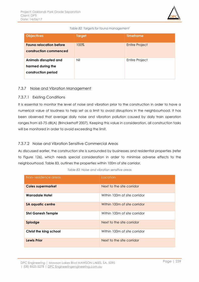
Project: Oaklands Park Grade Separation
Client: DPTI
Date: 14/06/17
DPC Engineering | Mawson Lakes Blvd MAWSON LAKES, SA, 5095
| (08) 8525 5278 | DPC Engineeringengineering.com.au
Page | 239
Table 82: Targets for fauna management
Objectives Target Timeframe
Fauna relocation before
construction commenced
100% Entire Project
Animals disrupted and
harmed during the
construction period
Nil Entire Project
7.3.7 Noise and Vibration Management
7.3.7.1 Existing Conditions
It is essential to monitor the level of noise and vibration prior to the construction in order to have a
numerical value of loudness to help set as a limit to avoid disruptions in the neighbourhood. It has
been observed that average daily noise and vibration pollution caused by daily train operation
ranges from 65-75 dB(A) (Brinckerhoff 2007). Keeping this value in consideration, all construction tasks
will be monitored in order to avoid exceeding the limit.
7.3.7.2 Noise and Vibration Sensitive Commercial Areas
As discussed earlier, the construction site is surrounded by businesses and residential properties (refer
to Figure 126), which needs special consideration in order to minimise adverse effects to the
neighbourhood. Table 83, outlines the properties within 100m of site corridor.
Table 83: Noise and vibration sensitive areas
Non- residence areas Location
Coles supermarket Next to the site corridor
Warradale Hotel Within 100m of site corridor
SA aquatic centre Within 100m of site corridor
Shri Ganesh Temple Within 100m of site corridor
Splodge Next to the site corridor
Christ the king school Within 100m of site corridor
Lewis Prior Next to the site corridor
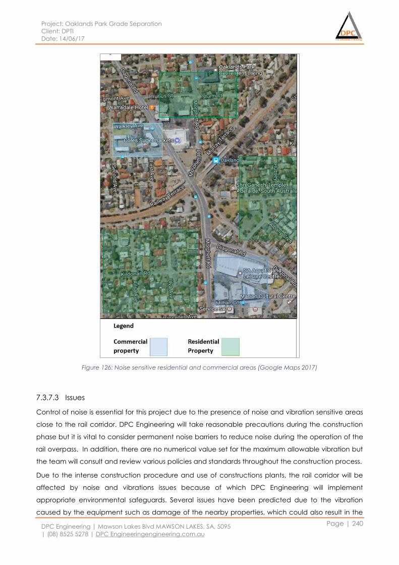
Project: Oaklands Park Grade Separation
Client: DPTI
Date: 14/06/17
DPC Engineering | Mawson Lakes Blvd MAWSON LAKES, SA, 5095
| (08) 8525 5278 | DPC Engineeringengineering.com.au
Page | 240
Figure 126: Noise sensitive residential and commercial areas (Google Maps 2017)
7.3.7.3 Issues
Control of noise is essential for this project due to the presence of noise and vibration sensitive areas
close to the rail corridor. DPC Engineering will take reasonable precautions during the construction
phase but it is vital to consider permanent noise barriers to reduce noise during the operation of the
rail overpass. In addition, there are no numerical value set for the maximum allowable vibration but
the team will consult and review various policies and standards throughout the construction process.
Due to the intense construction procedure and use of constructions plants, the rail corridor will be
affected by noise and vibrations issues because of which DPC Engineering will implement
appropriate environmental safeguards. Several issues have been predicted due to the vibration
caused by the equipment such as damage of the nearby properties, which could also result in the
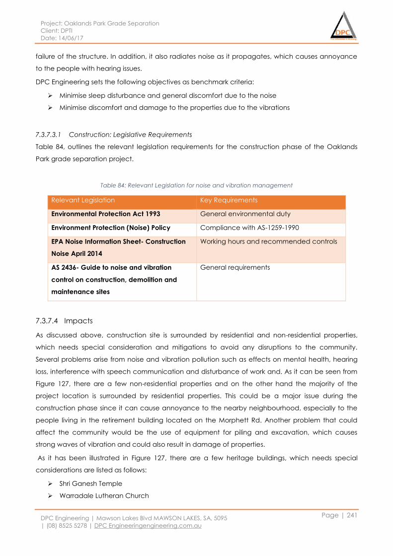
Project: Oaklands Park Grade Separation
Client: DPTI
Date: 14/06/17
DPC Engineering | Mawson Lakes Blvd MAWSON LAKES, SA, 5095
| (08) 8525 5278 | DPC Engineeringengineering.com.au
Page | 241
failure of the structure. In addition, it also radiates noise as it propagates, which causes annoyance
to the people with hearing issues.
DPC Engineering sets the following objectives as benchmark criteria:
Minimise sleep disturbance and general discomfort due to the noise
Minimise discomfort and damage to the properties due to the vibrations
7.3.7.3.1 Construction: Legislative Requirements
Table 84, outlines the relevant legislation requirements for the construction phase of the Oaklands
Park grade separation project.
Table 84: Relevant Legislation for noise and vibration management
Relevant Legislation Key Requirements
Environmental Protection Act 1993 General environmental duty
Environment Protection (Noise) Policy Compliance with AS-1259-1990
EPA Noise Information Sheet- Construction
Noise April 2014
Working hours and recommended controls
AS 2436- Guide to noise and vibration
control on construction, demolition and
maintenance sites
General requirements
7.3.7.4 Impacts
As discussed above, construction site is surrounded by residential and non-residential properties,
which needs special consideration and mitigations to avoid any disruptions to the community.
Several problems arise from noise and vibration pollution such as effects on mental health, hearing
loss, interference with speech communication and disturbance of work and. As it can be seen from
Figure 127, there are a few non-residential properties and on the other hand the majority of the
project location is surrounded by residential properties. This could be a major issue during the
construction phase since it can cause annoyance to the nearby neighbourhood, especially to the
people living in the retirement building located on the Morphett Rd. Another problem that could
affect the community would be the use of equipment for piling and excavation, which causes
strong waves of vibration and could also result in damage of properties.
As it has been illustrated in Figure 127, there are a few heritage buildings, which needs special
considerations are listed as follows:
Shri Ganesh Temple
Warradale Lutheran Church
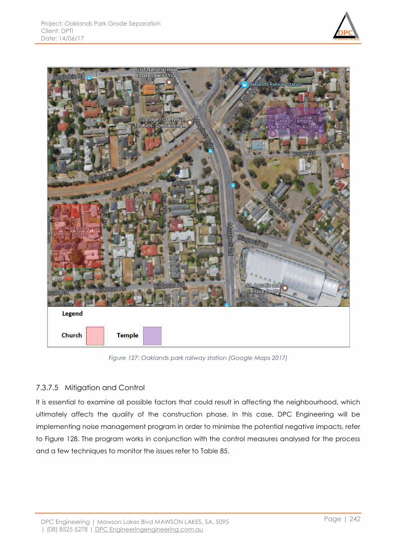
Project: Oaklands Park Grade Separation
Client: DPTI
Date: 14/06/17
DPC Engineering | Mawson Lakes Blvd MAWSON LAKES, SA, 5095
| (08) 8525 5278 | DPC Engineeringengineering.com.au
Page | 242
Figure 127: Oaklands park railway station (Google Maps 2017)
7.3.7.5 Mitigation and Control
It is essential to examine all possible factors that could result in affecting the neighbourhood, which
ultimately affects the quality of the construction phase. In this case, DPC Engineering will be
implementing noise management program in order to minimise the potential negative impacts, refer
to Figure 128. The program works in conjunction with the control measures analysed for the process
and a few techniques to monitor the issues refer to Table 85.
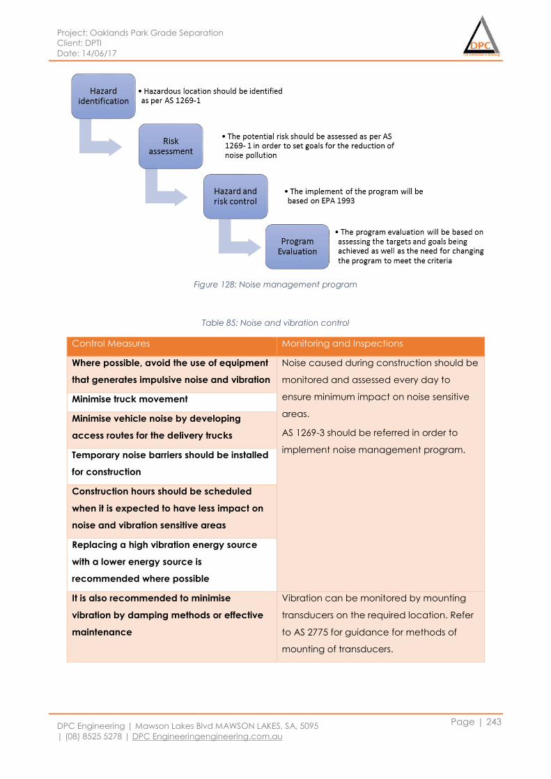
Project: Oaklands Park Grade Separation
Client: DPTI
Date: 14/06/17
DPC Engineering | Mawson Lakes Blvd MAWSON LAKES, SA, 5095
| (08) 8525 5278 | DPC Engineeringengineering.com.au
Page | 243
Figure 128: Noise management program
Table 85: Noise and vibration control
Control Measures Monitoring and Inspections
Where possible, avoid the use of equipment
that generates impulsive noise and vibration
Noise caused during construction should be
monitored and assessed every day to
ensure minimum impact on noise sensitive
areas.
AS 1269-3 should be referred in order to
implement noise management program.
Minimise truck movement
Minimise vehicle noise by developing
access routes for the delivery trucks
Temporary noise barriers should be installed
for construction
Construction hours should be scheduled
when it is expected to have less impact on
noise and vibration sensitive areas
Replacing a high vibration energy source
with a lower energy source is
recommended where possible
It is also recommended to minimise
vibration by damping methods or effective
maintenance
Vibration can be monitored by mounting
transducers on the required location. Refer
to AS 2775 for guidance for methods of
mounting of transducers.
Project: Oaklands Park Grade Separation
Client: DPTI
Date: 14/06/17
DPC Engineering | Mawson Lakes Blvd MAWSON LAKES, SA, 5095
| (08) 8525 5278 | DPC Engineeringengineering.com.au
Page | 244
7.3.7.5.1 Vehicle Movement
DPC Engineering will undertake appropriate measures to minimise noise and vibration caused due
to the movement of vehicles. The team will construct an alternate route to minimise disruptions of
the public, considering sensitive noise and vibration receivers.
7.3.7.5.2 Operation
Table 86 shows noise and vibration control during the operation phase of the structure.
Table 86: Target for noise and vibration during operation
Objective Target Timeframe
Noise levels during
operation
Not to exceed the level prior
to construction
From the beginning of the
construction till 6 months of
the operation
7.3.7.5.3 Noise barriers
As a permanent solution to minimise noise after the construction phase and during the operation,
DPC Engineering has investigated a few aspects of the noise barrier types and designs for this
project. The aim is to design an environmental friendly barrier, which reduces the carbon footprint
and serves both the community as well as the environment.
For this purpose, the team has considered two options for the noise barrier:
The two options have several advantages and disadvantages because of which it is essential to
assess both options and choose one to design for this stage. Timber has several environmental
benefits such as reducing carbon emissions since it is absorbed by it. But it is vital to consider
durability and maintenance of the structure as well, due to which timber has been observed to be
less durable compared to transparent barriers.
Glass barriers could be beneficial for this structure since it increases road safety by allowing sunlight
to pass and not casting shadow on the road. It is also very resistant to extreme weather conditions as
well as it is visually pleasing. The cost of the installation is also minimised since the installation has
been proved to be easy. It is essential to consider various transparent barrier materials since the
design requires a specific material which is not only environmental friendly but also feasible to
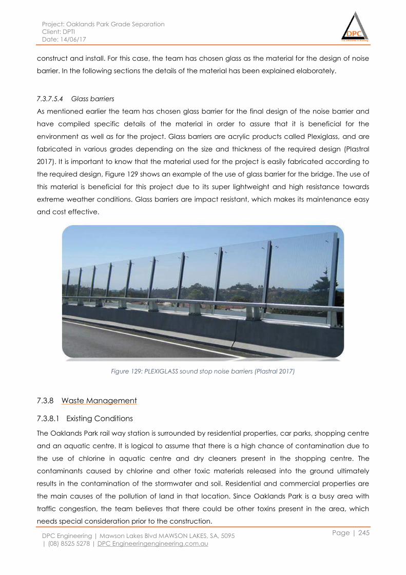
Project: Oaklands Park Grade Separation
Client: DPTI
Date: 14/06/17
DPC Engineering | Mawson Lakes Blvd MAWSON LAKES, SA, 5095
| (08) 8525 5278 | DPC Engineeringengineering.com.au
Page | 245
construct and install. For this case, the team has chosen glass as the material for the design of noise
barrier. In the following sections the details of the material has been explained elaborately.
7.3.7.5.4 Glass barriers
As mentioned earlier the team has chosen glass barrier for the final design of the noise barrier and
have compiled specific details of the material in order to assure that it is beneficial for the
environment as well as for the project. Glass barriers are acrylic products called Plexiglass, and are
fabricated in various grades depending on the size and thickness of the required design (Plastral
2017). It is important to know that the material used for the project is easily fabricated according to
the required design, Figure 129 shows an example of the use of glass barrier for the bridge. The use of
this material is beneficial for this project due to its super lightweight and high resistance towards
extreme weather conditions. Glass barriers are impact resistant, which makes its maintenance easy
and cost effective.
Figure 129: PLEXIGLASS sound stop noise barriers (Plastral 2017)
7.3.8 Waste Management
7.3.8.1 Existing Conditions
The Oaklands Park rail way station is surrounded by residential properties, car parks, shopping centre
and an aquatic centre. It is logical to assume that there is a high chance of contamination due to
the use of chlorine in aquatic centre and dry cleaners present in the shopping centre. The
contaminants caused by chlorine and other toxic materials released into the ground ultimately
results in the contamination of the stormwater and soil. Residential and commercial properties are
the main causes of the pollution of land in that location. Since Oaklands Park is a busy area with
traffic congestion, the team believes that there could be other toxins present in the area, which
needs special consideration prior to the construction.

Project: Oaklands Park Grade Separation
Client: DPTI
Date: 14/06/17
DPC Engineering | Mawson Lakes Blvd MAWSON LAKES, SA, 5095
| (08) 8525 5278 | DPC Engineeringengineering.com.au
Page | 246
7.3.8.2 Issues
Waste management is a critical issue during construction phase of the project because of which it is
essential to apply reasonable measures to minimise its impacts on the surrounding.
Some general waste stream has been identified and are outlined as follows:
Construction and demolition waste
Concretes, Asphalts, Metals and timbers
Fauna and Flora
Contaminated soil
Clean fill
Grease and oils
Hazardous waste
Rubber and plastics
Wastewater
All wastes mentioned will be recovered, disposed or recycled following the guidelines complying
with South Australian Environmental Protection Act 1993. The construction of the rail overpass bridge
can be challenging in terms of minimising waste impacts on the surroundings. One of the main issues
will be in regards to the leakage into the land and stormwater, which could result in soil and water
contamination. Once the waste has been infiltrated into water and soil, it would be difficult to
mitigate and stop the contamination, that’s why it is vital to regularly monitor soil and water in order
to minimise further propagation of the contaminants.
In order to successfully minimise negative impacts on the environment, DPC Engineering will be
considering an environmental management plan through which appropriate mitigations will be
applied. The plan includes monitoring the types of the wastes and tracking the volumes and disposal
of waste locations. This will ensure all waste is recovered and disposed properly and the plan for
future waste can be undertaken. DPC Engineering aims to maximise recycling waste and minimise
wastewater and soil contamination as well as waste generation.
7.3.8.2.1 Construction
The team has identified some general waste, which has been outlined in Table 87. The sources of the
waste have been identified by assessing the work flow of the project.
Table 87: Source of the waste
Source Hazard Risk
Construction Stage Generation of waste Soil and water contamination
Machinery maintenance Generation of grease and oil Soil and water contamination
Operation and maintenance Generation of waste Soil and water contamination
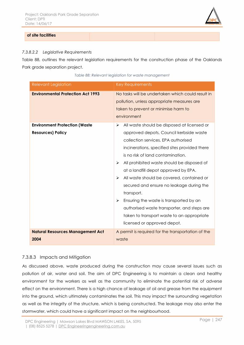
Project: Oaklands Park Grade Separation
Client: DPTI
Date: 14/06/17
DPC Engineering | Mawson Lakes Blvd MAWSON LAKES, SA, 5095
| (08) 8525 5278 | DPC Engineeringengineering.com.au
Page | 247
of site facilities
7.3.8.2.2 Legislative Requirements
Table 88, outlines the relevant legislation requirements for the construction phase of the Oaklands
Park grade separation project.
Table 88: Relevant legislation for waste management
Relevant Legislation Key Requirements
Environmental Protection Act 1993 No tasks will be undertaken which could result in
pollution, unless appropriate measures are
taken to prevent or minimise harm to
environment
Environment Protection (Waste
Resources) Policy
All waste should be disposed at licensed or
approved depots, Council kerbside waste
collection services, EPA authorised
incinerations, specified sites provided there
is no risk of land contamination.
All prohibited waste should be disposed of
at a landfill depot approved by EPA.
All waste should be covered, contained or
secured and ensure no leakage during the
transport.
Ensuring the waste is transported by an
authorised waste transporter, and steps are
taken to transport waste to an appropriate
licensed or approved depot.
Natural Resources Management Act
2004
A permit is required for the transportation of the
waste
7.3.8.3 Impacts and Mitigation
As discussed above, waste produced during the construction may cause several issues such as
pollution of air, water and soil. The aim of DPC Engineering is to maintain a clean and healthy
environment for the workers as well as the community to eliminate the potential risk of adverse
effect on the environment. There is a high chance of leakage of oil and grease from the equipment
into the ground, which ultimately contaminates the soil. This may impact the surrounding vegetation
as well as the integrity of the structure, which is being constructed. The leakage may also enter the
stormwater, which could have a significant impact on the neighbourhood.
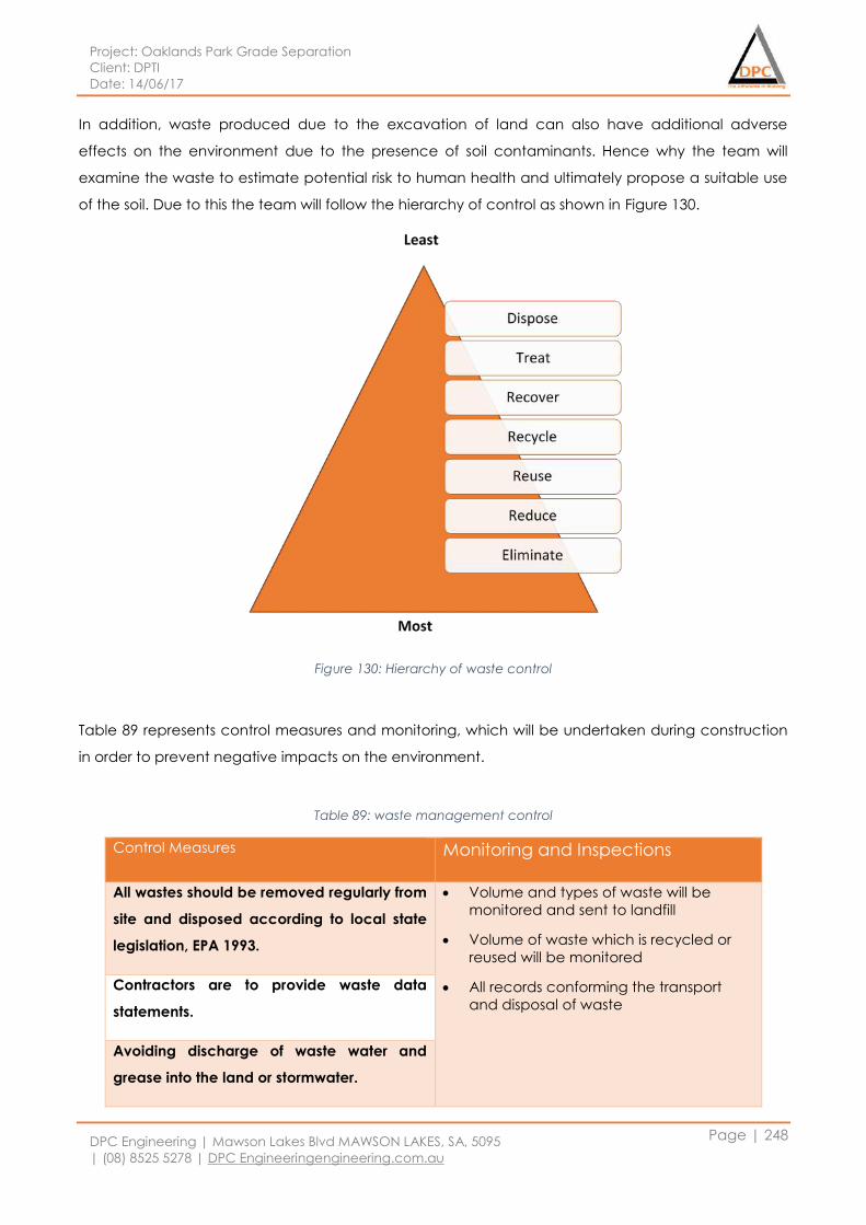
Project: Oaklands Park Grade Separation
Client: DPTI
Date: 14/06/17
DPC Engineering | Mawson Lakes Blvd MAWSON LAKES, SA, 5095
| (08) 8525 5278 | DPC Engineeringengineering.com.au
Page | 248
In addition, waste produced due to the excavation of land can also have additional adverse
effects on the environment due to the presence of soil contaminants. Hence why the team will
examine the waste to estimate potential risk to human health and ultimately propose a suitable use
of the soil. Due to this the team will follow the hierarchy of control as shown in Figure 130.
Figure 130: Hierarchy of waste control
Table 89 represents control measures and monitoring, which will be undertaken during construction
in order to prevent negative impacts on the environment.
Table 89: waste management control
Control Measures Monitoring and Inspections
All wastes should be removed regularly from
site and disposed according to local state
legislation, EPA 1993.
Volume and types of waste will be
monitored and sent to landfill
Volume of waste which is recycled or
reused will be monitored
All records conforming the transport
and disposal of waste
Contractors are to provide waste data
statements.
Avoiding discharge of waste water and
grease into the land or stormwater.
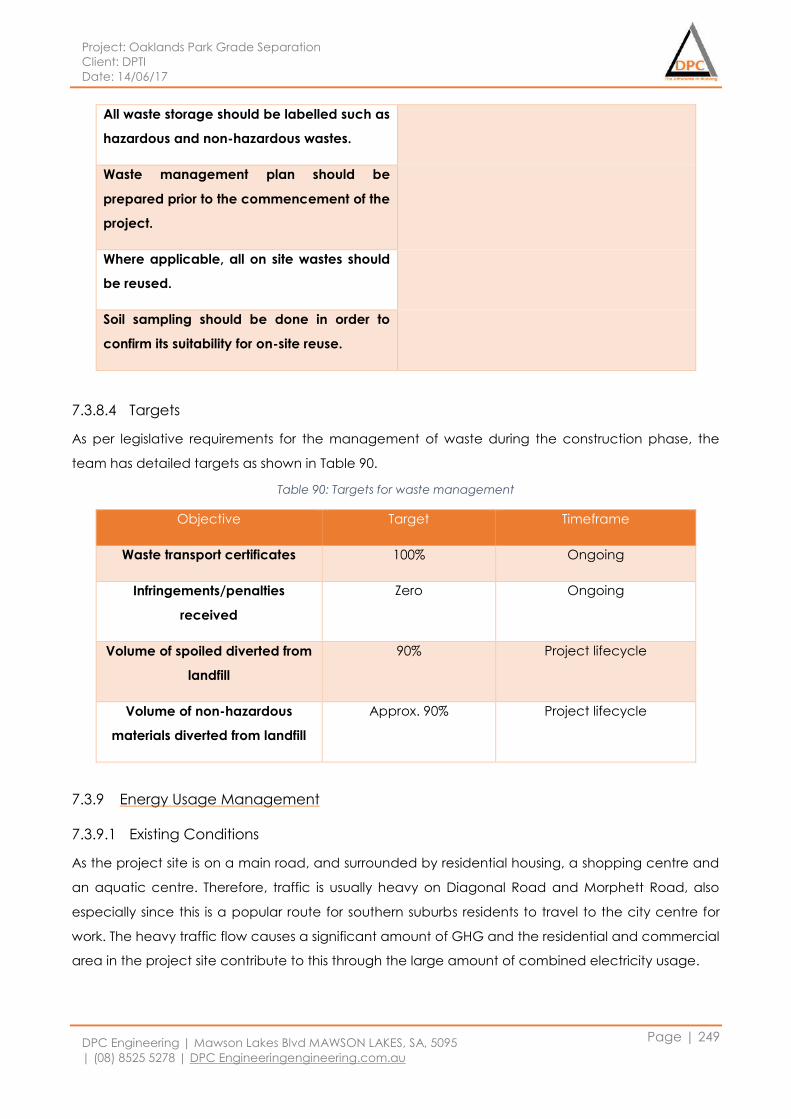
Project: Oaklands Park Grade Separation
Client: DPTI
Date: 14/06/17
DPC Engineering | Mawson Lakes Blvd MAWSON LAKES, SA, 5095
| (08) 8525 5278 | DPC Engineeringengineering.com.au
Page | 249
All waste storage should be labelled such as
hazardous and non-hazardous wastes.
Waste management plan should be
prepared prior to the commencement of the
project.
Where applicable, all on site wastes should
be reused.
Soil sampling should be done in order to
confirm its suitability for on-site reuse.
7.3.8.4 Targets
As per legislative requirements for the management of waste during the construction phase, the
team has detailed targets as shown in Table 90.
Table 90: Targets for waste management
Objective Target Timeframe
Waste transport certificates 100% Ongoing
Infringements/penalties
received
Zero Ongoing
Volume of spoiled diverted from
landfill
90% Project lifecycle
Volume of non-hazardous
materials diverted from landfill
Approx. 90% Project lifecycle
7.3.9 Energy Usage Management
7.3.9.1 Existing Conditions
As the project site is on a main road, and surrounded by residential housing, a shopping centre and
an aquatic centre. Therefore, traffic is usually heavy on Diagonal Road and Morphett Road, also
especially since this is a popular route for southern suburbs residents to travel to the city centre for
work. The heavy traffic flow causes a significant amount of GHG and the residential and commercial
area in the project site contribute to this through the large amount of combined electricity usage.
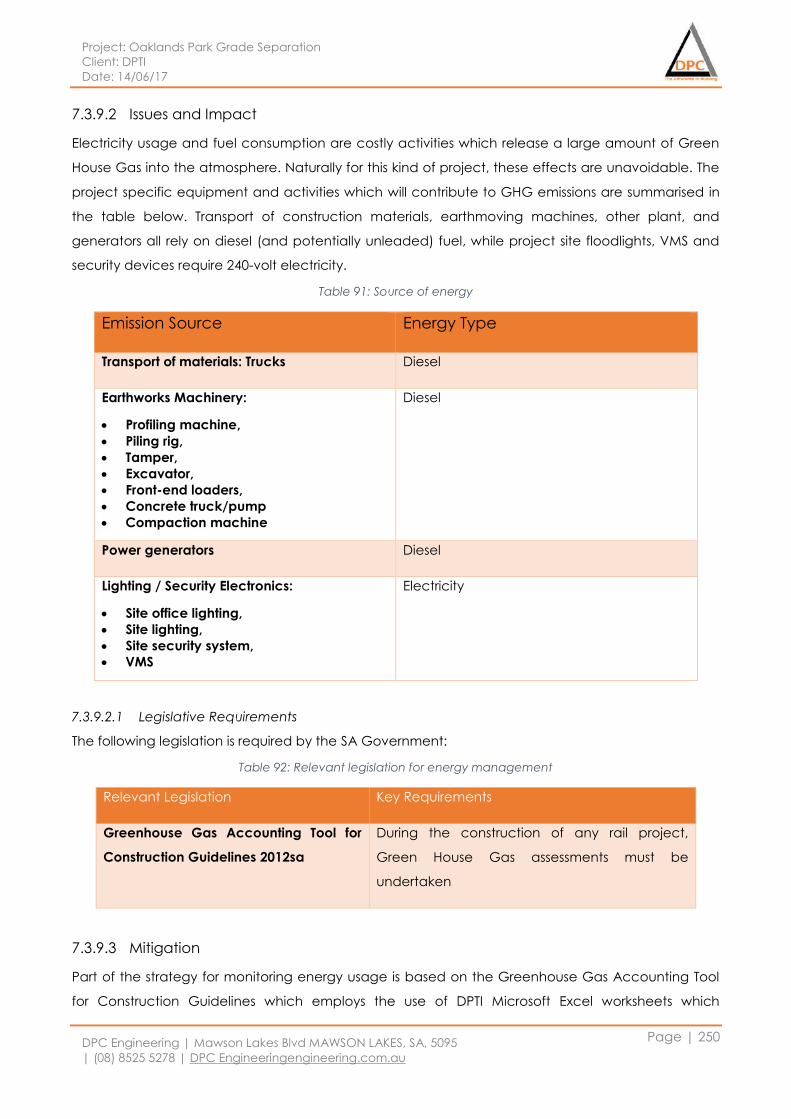
Project: Oaklands Park Grade Separation
Client: DPTI
Date: 14/06/17
DPC Engineering | Mawson Lakes Blvd MAWSON LAKES, SA, 5095
| (08) 8525 5278 | DPC Engineeringengineering.com.au
Page | 250
7.3.9.2 Issues and Impact
Electricity usage and fuel consumption are costly activities which release a large amount of Green
House Gas into the atmosphere. Naturally for this kind of project, these effects are unavoidable. The
project specific equipment and activities which will contribute to GHG emissions are summarised in
the table below. Transport of construction materials, earthmoving machines, other plant, and
generators all rely on diesel (and potentially unleaded) fuel, while project site floodlights, VMS and
security devices require 240-volt electricity.
Table 91: Source of energy
Emission Source Energy Type
Transport of materials: Trucks Diesel
Earthworks Machinery:
Profiling machine,
Piling rig,
Tamper,
Excavator,
Front-end loaders,
Concrete truck/pump
Compaction machine
Diesel
Power generators Diesel
Lighting / Security Electronics:
Site office lighting,
Site lighting,
Site security system,
VMS
Electricity
7.3.9.2.1 Legislative Requirements
The following legislation is required by the SA Government:
Table 92: Relevant legislation for energy management
Relevant Legislation Key Requirements
Greenhouse Gas Accounting Tool for
Construction Guidelines 2012sa
During the construction of any rail project,
Green House Gas assessments must be
undertaken
7.3.9.3 Mitigation
Part of the strategy for monitoring energy usage is based on the Greenhouse Gas Accounting Tool
for Construction Guidelines which employs the use of DPTI Microsoft Excel worksheets which
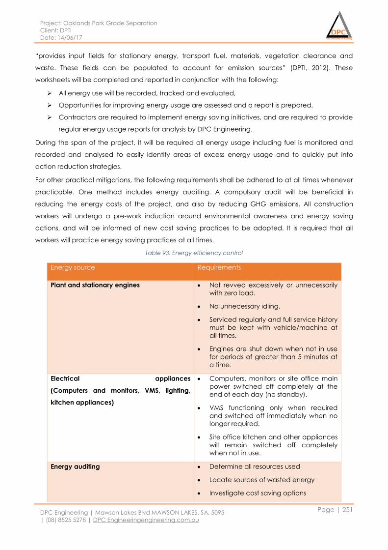
Project: Oaklands Park Grade Separation
Client: DPTI
Date: 14/06/17
DPC Engineering | Mawson Lakes Blvd MAWSON LAKES, SA, 5095
| (08) 8525 5278 | DPC Engineeringengineering.com.au
Page | 251
“provides input fields for stationary energy, transport fuel, materials, vegetation clearance and
waste. These fields can be populated to account for emission sources” (DPTI, 2012). These
worksheets will be completed and reported in conjunction with the following:
All energy use will be recorded, tracked and evaluated,
Opportunities for improving energy usage are assessed and a report is prepared,
Contractors are required to implement energy saving initiatives, and are required to provide
regular energy usage reports for analysis by DPC Engineering.
During the span of the project, it will be required all energy usage including fuel is monitored and
recorded and analysed to easily identify areas of excess energy usage and to quickly put into
action reduction strategies.
For other practical mitigations, the following requirements shall be adhered to at all times whenever
practicable. One method includes energy auditing. A compulsory audit will be beneficial in
reducing the energy costs of the project, and also by reducing GHG emissions. All construction
workers will undergo a pre-work induction around environmental awareness and energy saving
actions, and will be informed of new cost saving practices to be adopted. It is required that all
workers will practice energy saving practices at all times.
Table 93: Energy efficiency control
Energy source Requirements
Plant and stationary engines Not revved excessively or unnecessarily
with zero load.
No unnecessary idling.
Serviced regularly and full service history
must be kept with vehicle/machine at
all times.
Engines are shut down when not in use
for periods of greater than 5 minutes at
a time.
Electrical appliances
(Computers and monitors, VMS, lighting,
kitchen appliances)
Computers, monitors or site office main
power switched off completely at the
end of each day (no standby).
VMS functioning only when required
and switched off immediately when no
longer required.
Site office kitchen and other appliances
will remain switched off completely
when not in use.
Energy auditing Determine all resources used
Locate sources of wasted energy
Investigate cost saving options
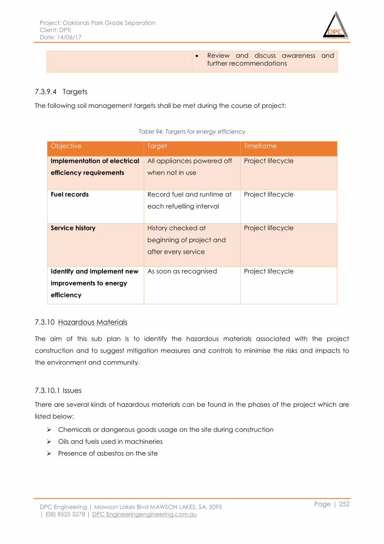
Project: Oaklands Park Grade Separation
Client: DPTI
Date: 14/06/17
DPC Engineering | Mawson Lakes Blvd MAWSON LAKES, SA, 5095
| (08) 8525 5278 | DPC Engineeringengineering.com.au
Page | 252
Review and discuss awareness and
further recommendations
7.3.9.4 Targets
The following soil management targets shall be met during the course of project:
Table 94: Targets for energy efficiency
Objective Target Timeframe
Implementation of electrical
efficiency requirements
All appliances powered off
when not in use
Project lifecycle
Fuel records Record fuel and runtime at
each refuelling interval
Project lifecycle
Service history History checked at
beginning of project and
after every service
Project lifecycle
Identify and implement new
improvements to energy
efficiency
As soon as recognised Project lifecycle
7.3.10 Hazardous Materials
The aim of this sub plan is to identify the hazardous materials associated with the project
construction and to suggest mitigation measures and controls to minimise the risks and impacts to
the environment and community.
7.3.10.1 Issues
There are several kinds of hazardous materials can be found in the phases of the project which are
listed below:
Chemicals or dangerous goods usage on the site during construction
Oils and fuels used in machineries
Presence of asbestos on the site
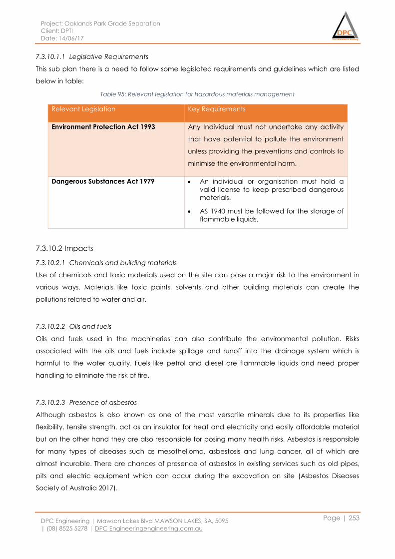
Project: Oaklands Park Grade Separation
Client: DPTI
Date: 14/06/17
DPC Engineering | Mawson Lakes Blvd MAWSON LAKES, SA, 5095
| (08) 8525 5278 | DPC Engineeringengineering.com.au
Page | 253
7.3.10.1.1 Legislative Requirements
This sub plan there is a need to follow some legislated requirements and guidelines which are listed
below in table:
Table 95: Relevant legislation for hazardous materials management
Relevant Legislation Key Requirements
Environment Protection Act 1993 Any Individual must not undertake any activity
that have potential to pollute the environment
unless providing the preventions and controls to
minimise the environmental harm.
Dangerous Substances Act 1979 An individual or organisation must hold a
valid license to keep prescribed dangerous
materials.
AS 1940 must be followed for the storage of
flammable liquids.
7.3.10.2 Impacts
7.3.10.2.1 Chemicals and building materials
Use of chemicals and toxic materials used on the site can pose a major risk to the environment in
various ways. Materials like toxic paints, solvents and other building materials can create the
pollutions related to water and air.
7.3.10.2.2 Oils and fuels
Oils and fuels used in the machineries can also contribute the environmental pollution. Risks
associated with the oils and fuels include spillage and runoff into the drainage system which is
harmful to the water quality. Fuels like petrol and diesel are flammable liquids and need proper
handling to eliminate the risk of fire.
7.3.10.2.3 Presence of asbestos
Although asbestos is also known as one of the most versatile minerals due to its properties like
flexibility, tensile strength, act as an insulator for heat and electricity and easily affordable material
but on the other hand they are also responsible for posing many health risks. Asbestos is responsible
for many types of diseases such as mesothelioma, asbestosis and lung cancer, all of which are
almost incurable. There are chances of presence of asbestos in existing services such as old pipes,
pits and electric equipment which can occur during the excavation on site (Asbestos Diseases
Society of Australia 2017).
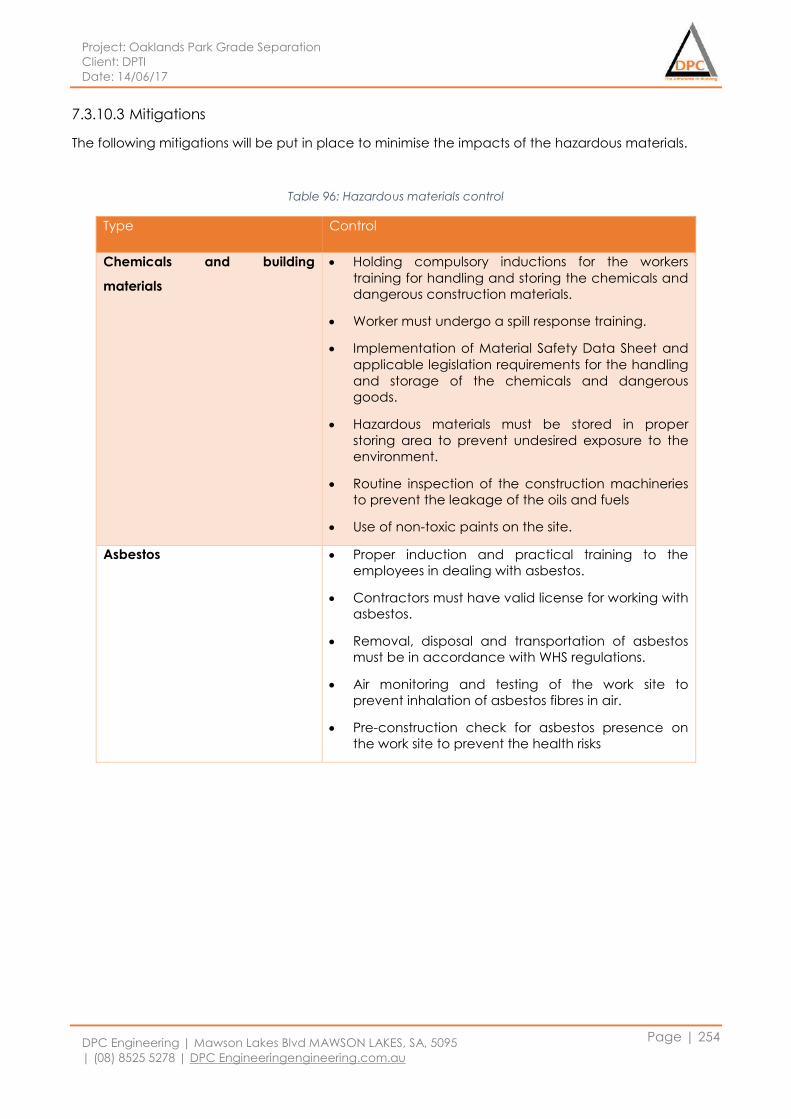
Project: Oaklands Park Grade Separation
Client: DPTI
Date: 14/06/17
DPC Engineering | Mawson Lakes Blvd MAWSON LAKES, SA, 5095
| (08) 8525 5278 | DPC Engineeringengineering.com.au
Page | 254
7.3.10.3 Mitigations
The following mitigations will be put in place to minimise the impacts of the hazardous materials.
Table 96: Hazardous materials control
Type Control
Chemicals and building
materials
Holding compulsory inductions for the workers
training for handling and storing the chemicals and
dangerous construction materials.
Worker must undergo a spill response training.
Implementation of Material Safety Data Sheet and
applicable legislation requirements for the handling
and storage of the chemicals and dangerous
goods.
Hazardous materials must be stored in proper
storing area to prevent undesired exposure to the
environment.
Routine inspection of the construction machineries
to prevent the leakage of the oils and fuels
Use of non-toxic paints on the site.
Asbestos Proper induction and practical training to the
employees in dealing with asbestos.
Contractors must have valid license for working with
asbestos.
Removal, disposal and transportation of asbestos
must be in accordance with WHS regulations.
Air monitoring and testing of the work site to
prevent inhalation of asbestos fibres in air.
Pre-construction check for asbestos presence on
the work site to prevent the health risks
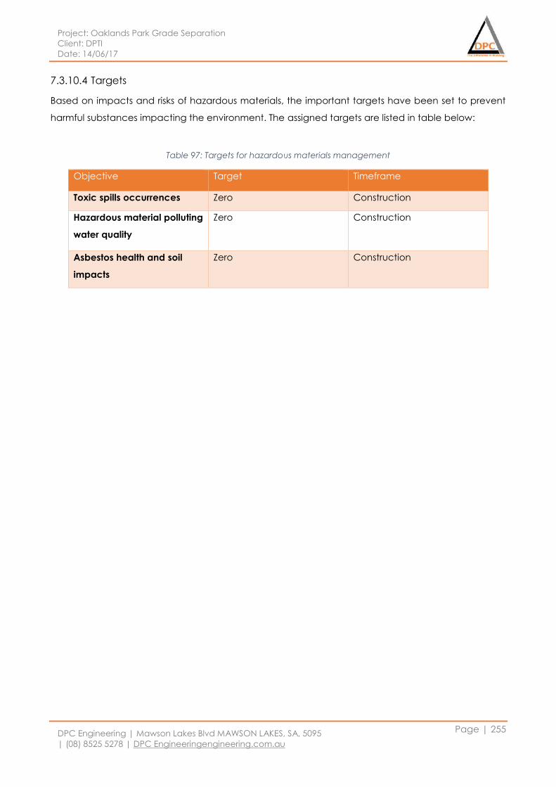
Project: Oaklands Park Grade Separation
Client: DPTI
Date: 14/06/17
DPC Engineering | Mawson Lakes Blvd MAWSON LAKES, SA, 5095
| (08) 8525 5278 | DPC Engineeringengineering.com.au
Page | 255
7.3.10.4 Targets
Based on impacts and risks of hazardous materials, the important targets have been set to prevent
harmful substances impacting the environment. The assigned targets are listed in table below:
Table 97: Targets for hazardous materials management
Objective Target Timeframe
Toxic spills occurrences Zero Construction
Hazardous material polluting
water quality
Zero Construction
Asbestos health and soil
impacts
Zero Construction
Project: Oaklands Park Grade Separation
Client: DPTI
Date: 14/06/17
DPC Engineering | Mawson Lakes Blvd MAWSON LAKES, SA, 5095
| (08) 8525 5278 | DPC Engineeringengineering.com.au
Page | 256
7.4 Additional Environmental Innovations and Design
DPC Engineering has put an effort on reducing global warming pollution by analysing the idea of
using solar panels for the rail bridge. The aim of this concept is to overcome the future energy
expenses of the rail overpass as well as reducing carbon emissions.
There are several aspects to this design such as:
Type of solar system to be used
Initial costs
Average daily output
Installation
It is vital to consider all the above aspects in order to be able to predict any future and present
complexities regarding the design. The following sections illustrates all details of the solar panels and
its benefits for the project.
7.4.1 Solar Panels
The team has investigated various aspects in order to confirm the idea of using solar panels will be
beneficial for the project and the community. Initially, one of the main aspect considered was the
type of the solar panel, which led to the question of its average daily output and how much it would
cost to install the panels. Each of the aspect has been investigated one at a time, to ensure all
factors has been examined and all gaps have been filled to avoid future problems.
The design has been further examined and finally the team has agreed to use LG NEON R solar
panels for the project. According to the manufacturer, the solar panel is very strong and resistant to
wind and cyclones as well as it provides maximum output per m2 compared to other 260W solar
panels (LG 2017). Some of the specific features of the NEON R solar panel has been detailed as
follows:
Proven field performance
Cyclone wind load resistance
Corrosion resistance certifications
Multi –ribbons and low light induced degradation have proven to increase power
7.4.1.1 Solar Panel System
Due to the large scope of the project, the panels should be strong enough to generate power for
the rail station. The power generated by the solar panels depends on the type of solar system which
are also referred as solar modules and generally ranges from 1.5 KWH-100KWH. The selection of the
solar system depends on the location and the estimated usage. Due to this, the team has evaluated
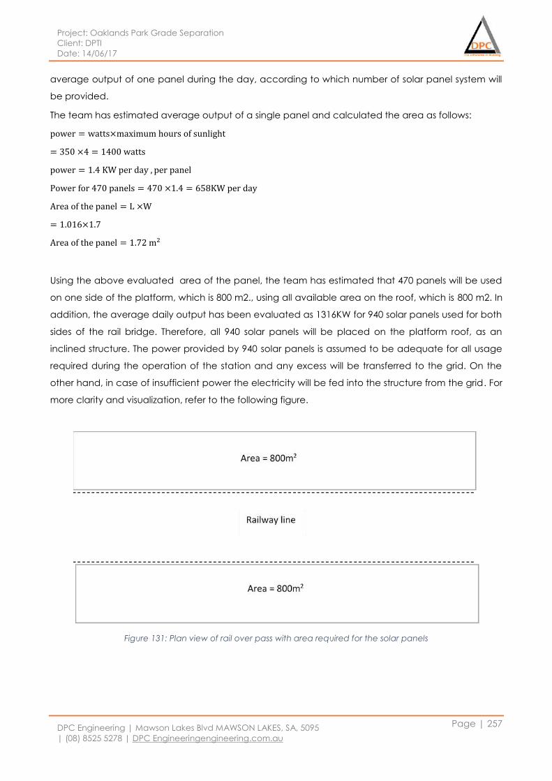
Project: Oaklands Park Grade Separation
Client: DPTI
Date: 14/06/17
DPC Engineering | Mawson Lakes Blvd MAWSON LAKES, SA, 5095
| (08) 8525 5278 | DPC Engineeringengineering.com.au
Page | 257
average output of one panel during the day, according to which number of solar panel system will
be provided.
The team has estimated average output of a single panel and calculated the area as follows:
power = watts×maximum hours of sunlight
= 350 ×4 = 1400 watts
power = 1.4 KW per day , per panel
Power for 470 panels = 470 ×1.4 = 658KW per day
Area of the panel = L ×W
= 1.016×1.7
Area of the panel = 1.72 m2
Using the above evaluated area of the panel, the team has estimated that 470 panels will be used
on one side of the platform, which is 800 m2., using all available area on the roof, which is 800 m2. In
addition, the average daily output has been evaluated as 1316KW for 940 solar panels used for both
sides of the rail bridge. Therefore, all 940 solar panels will be placed on the platform roof, as an
inclined structure. The power provided by 940 solar panels is assumed to be adequate for all usage
required during the operation of the station and any excess will be transferred to the grid. On the
other hand, in case of insufficient power the electricity will be fed into the structure from the grid. For
more clarity and visualization, refer to the following figure.
Figure 131: Plan view of rail over pass with area required for the solar panels
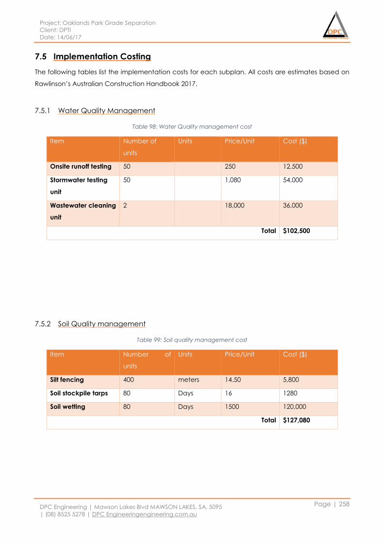
Project: Oaklands Park Grade Separation
Client: DPTI
Date: 14/06/17
DPC Engineering | Mawson Lakes Blvd MAWSON LAKES, SA, 5095
| (08) 8525 5278 | DPC Engineeringengineering.com.au
Page | 258
7.5 Implementation Costing
The following tables list the implementation costs for each subplan. All costs are estimates based on
Rawlinson’s Australian Construction Handbook 2017.
7.5.1 Water Quality Management
Table 98: Water Quality management cost
Item Number of
units
Units Price/Unit Cost ($)
Onsite runoff testing 50 250 12,500
Stormwater testing
unit
50 1,080 54,000
Wastewater cleaning
unit
2 18,000 36,000
Total $102,500
7.5.2 Soil Quality management
Table 99: Soil quality management cost
Item Number of
units
Units Price/Unit Cost ($)
Silt fencing 400 meters 14.50 5,800
Soil stockpile tarps 80 Days 16 1280
Soil wetting 80 Days 1500 120,000
Total $127,080
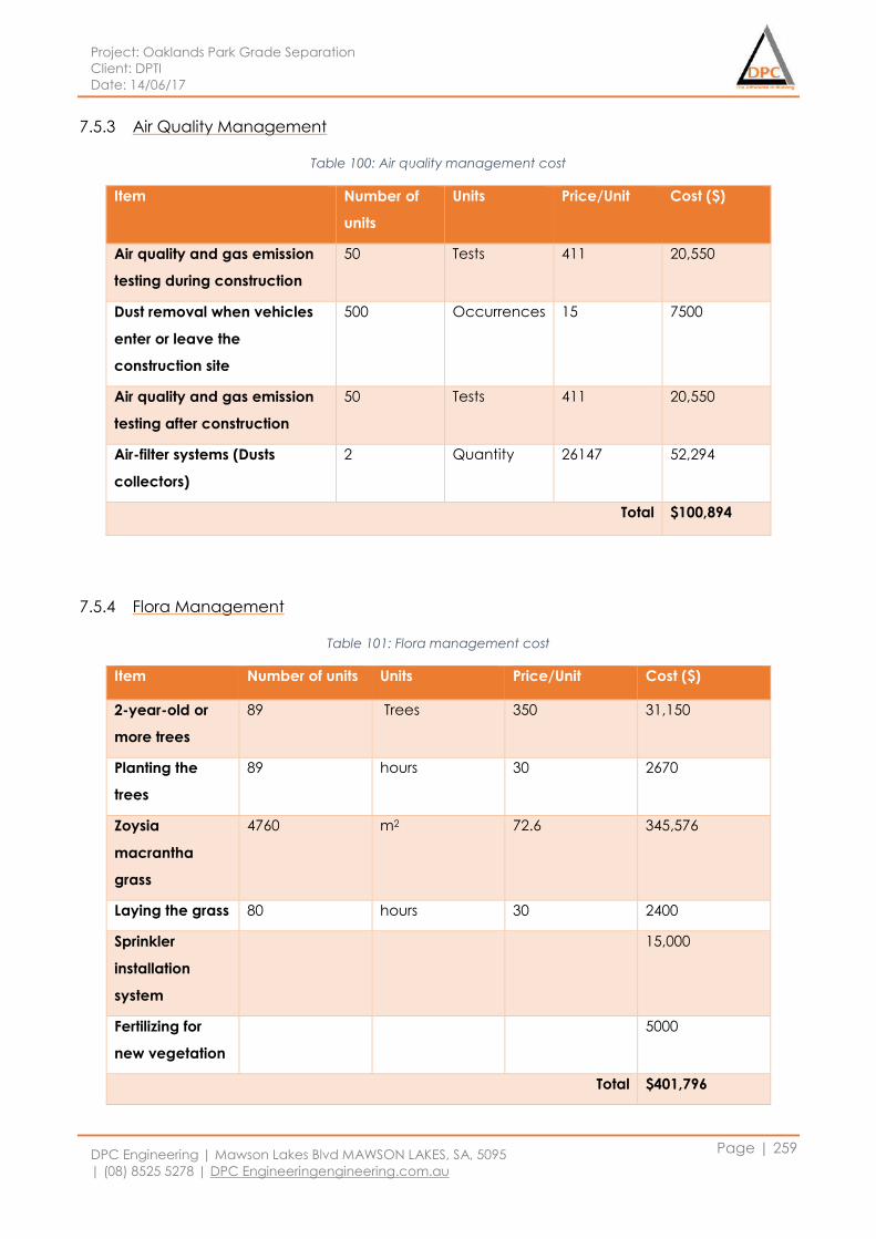
Project: Oaklands Park Grade Separation
Client: DPTI
Date: 14/06/17
DPC Engineering | Mawson Lakes Blvd MAWSON LAKES, SA, 5095
| (08) 8525 5278 | DPC Engineeringengineering.com.au
Page | 259
7.5.3 Air Quality Management
Table 100: Air quality management cost
Item Number of
units
Units Price/Unit Cost ($)
Air quality and gas emission
testing during construction
50 Tests 411 20,550
Dust removal when vehicles
enter or leave the
construction site
500 Occurrences 15 7500
Air quality and gas emission
testing after construction
50 Tests 411 20,550
Air-filter systems (Dusts
collectors)
2 Quantity 26147 52,294
Total $100,894
7.5.4 Flora Management
Table 101: Flora management cost
Item Number of units Units Price/Unit Cost ($)
2-year-old or
more trees
89 Trees 350 31,150
Planting the
trees
89 hours 30 2670
Zoysia
macrantha
grass
4760 m2 72.6 345,576
Laying the grass 80 hours 30 2400
Sprinkler
installation
system
15,000
Fertilizing for
new vegetation
5000
Total $401,796
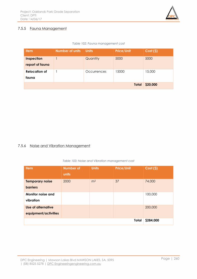
Project: Oaklands Park Grade Separation
Client: DPTI
Date: 14/06/17
DPC Engineering | Mawson Lakes Blvd MAWSON LAKES, SA, 5095
| (08) 8525 5278 | DPC Engineeringengineering.com.au
Page | 260
7.5.5 Fauna Management
Table 102: Fauna management cost
Item Number of units Units Price/Unit Cost ($)
Inspection
report of fauna
1 Quantity 5000 5000
Relocation of
fauna
1 Occurrences 15000 15,000
Total $20,000
7.5.6 Noise and Vibration Management
Table 103: Noise and Vibration management cost
Item Number of
units
Units Price/Unit Cost ($)
Temporary noise
barriers
2000 m2 37 74,000
Monitor noise and
vibration
100,000
Use of alternative
equipment/activities
200,000
Total $284,000
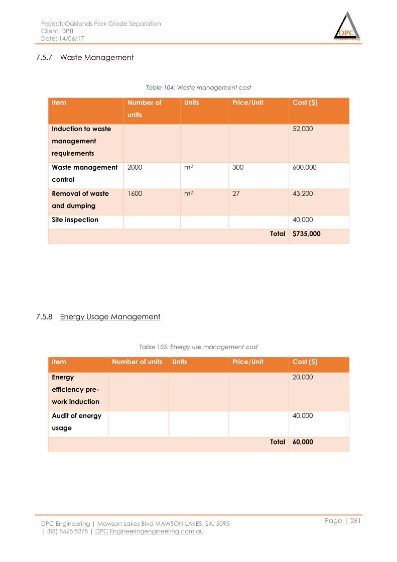
Project: Oaklands Park Grade Separation
Client: DPTI
Date: 14/06/17
DPC Engineering | Mawson Lakes Blvd MAWSON LAKES, SA, 5095
| (08) 8525 5278 | DPC Engineeringengineering.com.au
Page | 261
7.5.7 Waste Management
Table 104: Waste management cost
Item Number of
units
Units Price/Unit Cost ($)
Induction to waste
management
requirements
52,000
Waste management
control
2000 m2 300 600,000
Removal of waste
and dumping
1600 m2 27 43,200
Site inspection 40,000
Total $735,000
7.5.8 Energy Usage Management
Table 105: Energy use management cost
Item Number of units Units Price/Unit Cost ($)
Energy
efficiency pre-
work induction
20,000
Audit of energy
usage
40,000
Total 60,000
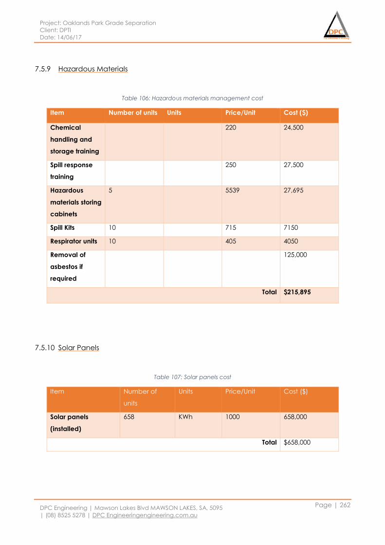
Project: Oaklands Park Grade Separation
Client: DPTI
Date: 14/06/17
DPC Engineering | Mawson Lakes Blvd MAWSON LAKES, SA, 5095
| (08) 8525 5278 | DPC Engineeringengineering.com.au
Page | 262
7.5.9 Hazardous Materials
Table 106: Hazardous materials management cost
Item Number of units Units Price/Unit Cost ($)
Chemical
handling and
storage training
220 24,500
Spill response
training
250 27,500
Hazardous
materials storing
cabinets
5 5539 27,695
Spill Kits 10 715 7150
Respirator units 10 405 4050
Removal of
asbestos if
required
125,000
Total $215,895
7.5.10 Solar Panels
Table 107: Solar panels cost
Item Number of
units
Units Price/Unit Cost ($)
Solar panels
(installed)
658 KWh 1000 658,000
Total $658,000
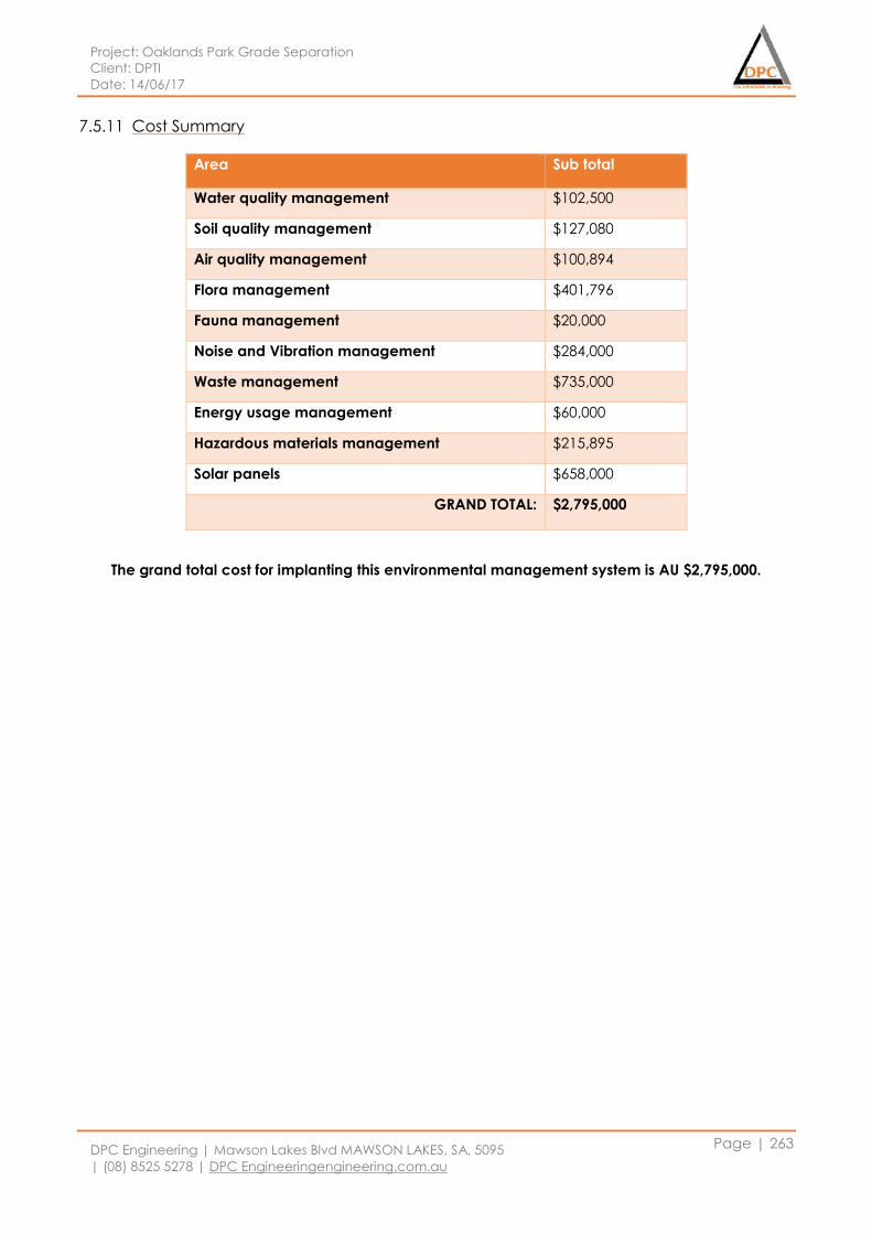
Project: Oaklands Park Grade Separation
Client: DPTI
Date: 14/06/17
DPC Engineering | Mawson Lakes Blvd MAWSON LAKES, SA, 5095
| (08) 8525 5278 | DPC Engineeringengineering.com.au
Page | 263
7.5.11 Cost Summary
Area Sub total
Water quality management $102,500
Soil quality management $127,080
Air quality management $100,894
Flora management $401,796
Fauna management $20,000
Noise and Vibration management $284,000
Waste management $735,000
Energy usage management $60,000
Hazardous materials management $215,895
Solar panels $658,000
GRAND TOTAL: $2,795,000
The grand total cost for implanting this environmental management system is AU $2,795,000.
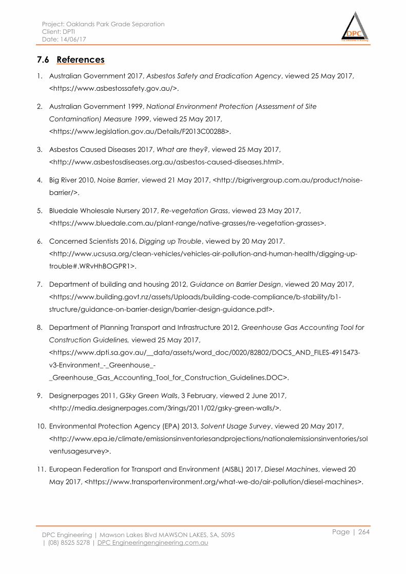
Project: Oaklands Park Grade Separation
Client: DPTI
Date: 14/06/17
DPC Engineering | Mawson Lakes Blvd MAWSON LAKES, SA, 5095
| (08) 8525 5278 | DPC Engineeringengineering.com.au
Page | 264
7.6 References
1. Australian Government 2017, Asbestos Safety and Eradication Agency, viewed 25 May 2017,
<https://www.asbestossafety.gov.au/>.
2. Australian Government 1999, National Environment Protection (Assessment of Site
Contamination) Measure 1999, viewed 25 May 2017,
<https://www.legislation.gov.au/Details/F2013C00288>.
3. Asbestos Caused Diseases 2017, What are they?, viewed 25 May 2017,
<http://www.asbestosdiseases.org.au/asbestos-caused-diseases.html>.
4. Big River 2010, Noise Barrier, viewed 21 May 2017, <http://bigrivergroup.com.au/product/noise-
barrier/>.
5. Bluedale Wholesale Nursery 2017, Re-vegetation Grass, viewed 23 May 2017,
<https://www.bluedale.com.au/plant-range/native-grasses/re-vegetation-grasses>.
6. Concerned Scientists 2016, Digging up Trouble, viewed by 20 May 2017.
<http://www.ucsusa.org/clean-vehicles/vehicles-air-pollution-and-human-health/digging-up-
trouble#.WRvHhBOGPR1>.
7. Department of building and housing 2012, Guidance on Barrier Design, viewed 20 May 2017,
<https://www.building.govt.nz/assets/Uploads/building-code-compliance/b-stability/b1-
structure/guidance-on-barrier-design/barrier-design-guidance.pdf>.
8. Department of Planning Transport and Infrastructure 2012, Greenhouse Gas Accounting Tool for
Construction Guidelines, viewed 25 May 2017,
<https://www.dpti.sa.gov.au/__data/assets/word_doc/0020/82802/DOCS_AND_FILES-4915473-
v3-Environment_-_Greenhouse_-
_Greenhouse_Gas_Accounting_Tool_for_Construction_Guidelines.DOC>.
9. Designerpages 2011, GSky Green Walls, 3 February, viewed 2 June 2017,
<http://media.designerpages.com/3rings/2011/02/gsky-green-walls/>.
10. Environmental Protection Agency (EPA) 2013, Solvent Usage Survey, viewed 20 May 2017,
<http://www.epa.ie/climate/emissionsinventoriesandprojections/nationalemissionsinventories/sol
ventusagesurvey>.
11. European Federation for Transport and Environment (AISBL) 2017, Diesel Machines, viewed 20
May 2017, <https://www.transportenvironment.org/what-we-do/air-pollution/diesel-machines>.
Project: Oaklands Park Grade Separation
Client: DPTI
Date: 14/06/17
DPC Engineering | Mawson Lakes Blvd MAWSON LAKES, SA, 5095
| (08) 8525 5278 | DPC Engineeringengineering.com.au
Page | 265
12. Euro Solar 2016, Solar Packages, viewed 21 May 2017,
<https://www.eurosolar.com.au/products/?gclid=Cj0KEQjw9YTJBRD0vKClruOsuOwBEiQAGkQjPy
Je1v67DQ9s-LAyaE7YjMnr0kbnXVWPNcVveRxp4iYaAhC88P8HAQ>.
13. Fast-Growing-Trees 2017, Fast Growing Tree with Purple Spring Blooms and Rich Fall Color, viewed
2 June 2017, <https://www.fast-growing-trees.com/jacaranda-tree.htm>.
14. Google Maps 2017, Intersection between Morphett Road, Diagonal Road and Railway Terrace,
viewed 2 June 2017,
<https://www.google.com.au/maps/place/Morphett+Rd,+South+Australia/@-
35.008796,138.5408341,17z/data=!4m5!3m4!1s0x6ab0da60eb63b745:0xc86fa8aabcf3b27!8m2!3d-
35.0005412!4d138.5395974>.
15. Huanyu Noise Barriers 2013, Transparent Noise Barriers, viewed 20 May 2017,
<http://www.noisebarriers.org/noisebarrier/transparent-sound-barrier.html>.
16. Jeff, W 2015, Zelkova serrata - Sawleaf Zelkova, Japanese Zelkova, video, YouTube, 26 April,
viewed 2 June 2017, <https://www.youtube.com/watch?v=J1rf-5OdoCM>.
17. LG 2017, Durable Solar Panels, viewed 21 May 2017,
<https://www.lgenergy.com.au/products/solar-panels/lg-neon-r-r>.
18. National Environment Protection Council 2017, National Environment Protection (Assessment of
Site Contamination) Measure, viewed 25 May 2017,
<http://www.nepc.gov.au/nepms/assessment-site-contamination>.
19. Nara Native Turf 2017, Why is Nara Native Turf So Good, viewed 23 May 2017,
<http://naranativeturf.com.au/find-out-why.html>.
20. Parsons Brinckernhoff 2007, Oaklands Railway Station Noise Monitoring Noise Levels Prior to
Construction, Civil Engineering Design Project LearnOnline, University of South Australia, viewed
25 May 2017
21. Plastral 2017, PLEXIGLASS Sound Stop Noise Barriers, viewed 20 May 2017,
<https://www.plastral.com.au/product/plexiglas-soundstop-noise-barriers/>.
22. Pollution from Construction 2017, viewed 20 April 2017,
<http://www.sustainablebuild.co.uk/PollutionFromConstruction.html>.
23. Queensland Government 2008, Environmental Protection Regulation 2008, viewed 25 May 2017,
<https://www.legislation.qld.gov.au/LEGISLTN/CURRENT/E/EnvProtR08.pdf>.
24. Rawlinsons Quantity Surveyors and Construction Cost Consultants 2017, Rawlinsons Australian
Construction Handbook, 31st edn, Rawlinsons Publishing, Perth, Western Australia.

Project: Oaklands Park Grade Separation
Client: DPTI
Date: 14/06/17
DPC Engineering | Mawson Lakes Blvd MAWSON LAKES, SA, 5095
| (08) 8525 5278 | DPC Engineeringengineering.com.au
Page | 266
25. Safe Work Australia 2011, How to manage and control asbestos in the workplace-code of
practice, viewed 22 May 2017,
<https://www.safework.sa.gov.au/uploaded_files/CoPManageControlAsbestosWorkplace.pdf>.
26. South Australian Government 1994, Environmental Protection Act 1994, viewed 25 May 2017,
<https://www.legislation.sa.gov.au/LZ/C/R/ENVIRONMENT%20PROTECTION%20REGULATIONS%202
009/CURRENT/2009.227.UN.PDF>.
27. The National Soil Erosion Research Laboratory 2017, Wind Erosion, viewed 20 May 2017,
<http://milford.nserl.purdue.edu/weppdocs/overview/wndersn.html>.
28. Victoria Government 2017, Environmental Guidelines for Major Construction Sites 2017: EPA
publication, Melbourne, Victoria 3000, viewed 26 May 2017,
<http://www.epa.vic.gov.au/~/media/Publications/480.pdf>.
29. What is Sediment Pollution 2017, Mid-America Regional Council, Kansas City, Missouri, viewed 26
May 2017, <https://cfpub.epa.gov/npstbx/files/ksmo_sediment.pdf>.
Project: Oaklands Park Grade Separation
Client: DPTI
Date: 14/06/17
DPC Engineering | Mawson Lakes Blvd MAWSON LAKES, SA, 5095
| (08) 8525 5278 | DPC Engineeringengineering.com.au
Page | 267
CONSTRUCTION MANAGEMENT
Project: Oaklands Park Grade Separation
Client: DPTI
Date: 14/06/17
DPC Engineering | Mawson Lakes Blvd MAWSON LAKES, SA, 5095
| (08) 8525 5278 | DPC Engineeringengineering.com.au
Page | 268
8 CONSTRUCTION PLAN
8.1 Introduction
Construction planning is an essential and critical activity in any projects within the engineering
sector. Elements such as choice of machinery and technology usage, tasks that will be carried out,
estimation of required spaces, identifying the connection between the tasks, and duration to
complete each task will have to be taken into consideration while carrying out a construction plan.
Even though the construction planning is followed concurrently throughout a project, unexpected
events such as weather condition or accidents will affect the project progress and makes it a critical
task for all occupancies during construction. The Oaklands Park Grade Separation Project involves
public as a major stakeholder in this upgrade. Hence DPC Engineering has proposed a preliminary
construction plan in order to carry out the project in a safe manner and comply with community
engagement policies. Please note the purpose of this plan is to demonstrate our design is practically
feasible and consideration of safety in design. However, construction related issues are far greater
than what have been identified in this plan. Further development will be required together with
head contractor for a more comprehensive construction plan.
8.2 2nd review of 60 hours rail shutdown
From feasibility study, DPC has proved the maximum 60 hours track shutdown requirement is hard to
achieve and proposed the temporary close train services between Marion and Warradale station
during the entire construction period of rail overpass. As this will cause major impacts to the public
transportation users. This requirement has been reviewed again prior to further detail design to see if
there is any alternative construction methodology can reduce the hours of shutdown. The following
issues have been identified in a construction point of view:
It is impossible to build alternative railway overpass route parallel to existing railway line due
to the space limitation of current available site
To provide enough space to build railway overpass route while maintaining existing train
service requires more land acquisition (all residential lands along railway). This will require
significantly large change of current residential area planning and not economical
The overall construction duration will be longer. Upon finish new railway overpass, the old
railway line needs to be demolished with new planning to the land. This will continue causing
traffic delay at the intersection of the roads even after the overpass is completed
Stringent safety requirements are the major concern when carry out construction near
railway line. Hefty fine will incur if train was stopped due to construction related issues.
Community safety when access to railway station near construction site during construction
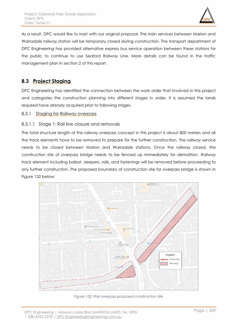
Project: Oaklands Park Grade Separation
Client: DPTI
Date: 14/06/17
DPC Engineering | Mawson Lakes Blvd MAWSON LAKES, SA, 5095
| (08) 8525 5278 | DPC Engineeringengineering.com.au
Page | 269
As a result, DPC would like to insist with our original proposal. The train services between Marion and
Warradale railway station will be temporary closed during construction. The transport department of
DPC Engineering has provided alternative express bus service operation between these stations for
the public to continue to use Seaford Railway Line. More details can be found in the traffic
management plan in section 2 of this report.
8.3 Project Staging
DPC Engineering has identified the connection between the work order that involved in this project
and categories the construction planning into different stages in order. It is assumed the lands
required have already acquired prior to following stages.
8.3.1 Staging for Railway overpass
8.3.1.1 Stage 1: Rail line closure and removals
The total structure length of the railway overpass concept in this project is about 800 meters and all
the track elements have to be removed to prepare for the further construction. The railway service
needs to be closed between Marion and Warradale stations. Once the railway closed, the
construction site of overpass bridge needs to be fenced up immediately for demolition. Railway
track element including ballast, sleepers, rails, and fastenings will be removed before proceeding to
any further construction. The proposed boundary of construction site for overpass bridge is shown in
Figure 132 below:
Figure 132: Rail overpass proposed construction site
Project: Oaklands Park Grade Separation
Client: DPTI
Date: 14/06/17
DPC Engineering | Mawson Lakes Blvd MAWSON LAKES, SA, 5095
| (08) 8525 5278 | DPC Engineeringengineering.com.au
Page | 270
8.3.1.2 Stage 2: Services relocation
The services department has identified a wide range of services that will be affected by this project
which will be relocated after the railway track removals are done. The list of affected services
includes:
National Broadband Network (NBN)
APA Gas Transmission Services
SA Water Pipelines
South Australia Power Network Cables
The service contractors need to start their relocation works as soon as the removal of railway tracks
have completed. For detailed relocations, refer to section 5 of this report.
8.3.1.3 Stage 3: Piling
The geotechnical department has reviewed the existing soil profile in Marion area and computed
the required number of the piles that will be driven into the ground and the location of these piles.
Piling may be undertaken together with service relocation to shorten the over duration of
construction programme. However, coordination will be required between service contractor and
piling contractor to avoid common conflict. This will be reviewed again by the head contractor. The
pile construction shall be undertaken concurrently from either side of the overpass and build toward
the middle at the Morphett road intersection.
8.3.1.4 Stage 4: Embankment & Retaining Wall
Embankment for both ends of the railway overpass structure may be constructed concurrently with
service relocation and piling if there is no conflict between these works. The length of the
embankment is approximately 150 meters on each side and retaining wall height would be 3 meters.
The retaining wall will adopt in-situ reinforced concrete.
8.3.1.5 Stage 5: Installation of substructure of the bridge
At this stage, capping beams, columns and headstocks will be constructed or installed. The capping
beam will be in-situ reinforced concrete; while both columns and headstocks will be precast
concrete. The capping beams can only be constructed after the piles have gained enough
strength. The precast columns and headstocks will be stored in precast yard and transport to site
when needed; and can only be placed after the concrete of capping beams reach enough
strength. Due to the relatively narrow site, mobile crane will be adopted for all liftings. The most
challenging area will be the overpass structures in the middle of the Morphett road. Temporary
Project: Oaklands Park Grade Separation
Client: DPTI
Date: 14/06/17
DPC Engineering | Mawson Lakes Blvd MAWSON LAKES, SA, 5095
| (08) 8525 5278 | DPC Engineeringengineering.com.au
Page | 271
roads will be used to divert traffics to avoid the road closure during the construction of this part of
the overpass. The transportation department has provided a detour plan for the traffic during the
construction that takes place at the proposed railway bridge site. This will be discussed in detail in
section 8.3.1.11.
8.3.1.6 Stage 6: Installation of superstructure of the bridge
Once the substructure is in place, the super T beam and railway deck will be installed. The super T
beams are precast and decking will be poured in-situ. Due to the size and weight of super T beams,
dual lift crane is proposed for lifting. It is anticipated there will be enough space for lifting equipment
on east side of Morphett road where all the carparks are (as the site storage area in Figure 132); but
will be tight on the west side of the Morphett road. It is possible to lift from the adjacent residential
roads: Railway terrace and Addison road. But the trees along the site boundary need to be
chopped off for clear access and extra safety shall be provided during lifting as it’s very close to
residential houses. The environmental team has addressed the tree removal issues and proposed
mitigation strategy in their subplans.
8.3.1.7 Stage 7: Platform and new tracks installation
Once the main structure of the overpass is completed and concrete slab deck gain sufficient
strength, new tracks are ready to be placed. The platform is a separate structure to the overpass
bridge which can be constructed while placing the tracks. It is assumed the foundation piles have
been placed during stage 3.
8.3.1.8 Stage 8: Stairs, lift shaft and storage rooms
These structures will be attached to the platform once the base structure of platform is completed.
Other amenities will be installed at the same time
8.3.1.9 Stage 9: Services reconnection
The electricity, gas and water services need to be connected from existing service lines to the new
station. Electrification structures shall be constructed and connected for the train operations. This
can be carried out concurrently with stage 8 if there is no conflict.
8.3.1.10 Stage 10: Architectural screens
Noise barriers, anti-suicide screens and architectural façade panels will be installed in this stage.
Most of these items will be able to install from the decking except for the façade panels. These
modular panels will need to be bolted on via a scissor lift from the ground level.
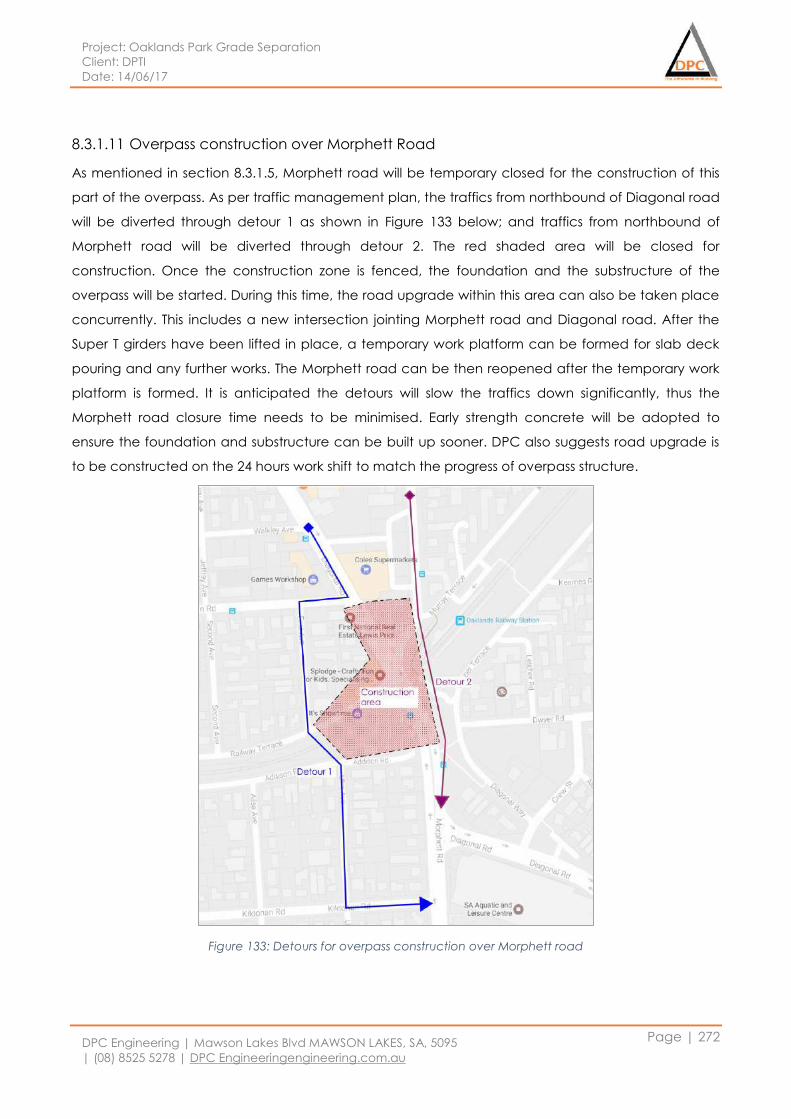
Project: Oaklands Park Grade Separation
Client: DPTI
Date: 14/06/17
DPC Engineering | Mawson Lakes Blvd MAWSON LAKES, SA, 5095
| (08) 8525 5278 | DPC Engineeringengineering.com.au
Page | 272
8.3.1.11 Overpass construction over Morphett Road
As mentioned in section 8.3.1.5, Morphett road will be temporary closed for the construction of this
part of the overpass. As per traffic management plan, the traffics from northbound of Diagonal road
will be diverted through detour 1 as shown in Figure 133 below; and traffics from northbound of
Morphett road will be diverted through detour 2. The red shaded area will be closed for
construction. Once the construction zone is fenced, the foundation and the substructure of the
overpass will be started. During this time, the road upgrade within this area can also be taken place
concurrently. This includes a new intersection jointing Morphett road and Diagonal road. After the
Super T girders have been lifted in place, a temporary work platform can be formed for slab deck
pouring and any further works. The Morphett road can be then reopened after the temporary work
platform is formed. It is anticipated the detours will slow the traffics down significantly, thus the
Morphett road closure time needs to be minimised. Early strength concrete will be adopted to
ensure the foundation and substructure can be built up sooner. DPC also suggests road upgrade is
to be constructed on the 24 hours work shift to match the progress of overpass structure.
Figure 133: Detours for overpass construction over Morphett road
Project: Oaklands Park Grade Separation
Client: DPTI
Date: 14/06/17
DPC Engineering | Mawson Lakes Blvd MAWSON LAKES, SA, 5095
| (08) 8525 5278 | DPC Engineeringengineering.com.au
Page | 273
8.3.2 Staging for Road
8.3.2.1 Stage 1: Building temporary roads
Temporary roads shall be constructed whenever available to prepare for the Morphett road closure
as detailed in section 8.3.1.11. The challenge will be the road construction across the construction
zone under the railway overpass between Railway terrace and Addison road of detour 1; and
between Murray terrace and southbound of Morphett road of detour 2. It is important to ensure the
temporary road construction won’t slow down the progress of main overpass construction and
maintain safety for traffics across the construction zone.
8.3.2.2 Stage 2: Traffic diversions
Throughout this project, the transport department has proposed with traffic control plan and traffic
diversion plan to make sure the road users have a reasonable connectivity from major roads to
minor roads located in the Marion area. This stage has to be carried out throughout the project and
risk management plan also will be developed that can be applied according to different situation.
8.3.2.3 Stage 3: Building new roads
The new roads construction will be spilt into two sub-stages. The road upgrade at Morphett road and
Diagonal road intersection and surrounds will be undertaken during the Morphett road closure. The
rest of the northbound of Diagonal road as well as the Prunus street will be constructed after the
Morphett road reopened. The Diagonal road will be closed into two lanes (one lane each way) for
the upgrade. The traffics will be expected to be carried by the Morphett road through the new
Morphett road and Diagonal road intersection. It is also important to ensure Diagonal road and
Prunus street upgrade won’t occur at the same time, so the traffic can be diverted into one or the
other.
8.3.2.4 Stage 4: Amenities installation and testing
This stage will install all amenities which include traffic signs and signals. Amenities along the roads
can be installed along with stage 3 of the road construction.
8.4 Project Sequencing
The project construction involves railway bridge and surrounding major road upgrade, thus the
construction site is relatively large. DPC engineering proposes to divide the overall construction zone
into 3 sectors as shown in below figure. The purpose of it is to minimise the traffic congestion during
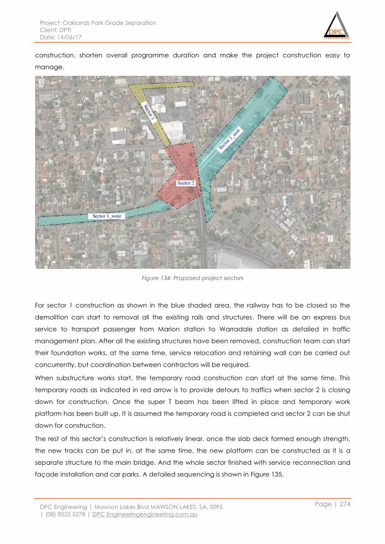
Project: Oaklands Park Grade Separation
Client: DPTI
Date: 14/06/17
DPC Engineering | Mawson Lakes Blvd MAWSON LAKES, SA, 5095
| (08) 8525 5278 | DPC Engineeringengineering.com.au
Page | 274
construction, shorten overall programme duration and make the project construction easy to
manage.
Figure 134: Proposed project sectors
For sector 1 construction as shown in the blue shaded area, the railway has to be closed so the
demolition can start to removal all the existing rails and structures. There will be an express bus
service to transport passenger from Marion station to Warradale station as detailed in traffic
management plan. After all the existing structures have been removed, construction team can start
their foundation works, at the same time, service relocation and retaining wall can be carried out
concurrently, but coordination between contractors will be required.
When substructure works start, the temporary road construction can start at the same time. This
temporary roads as indicated in red arrow is to provide detours to traffics when sector 2 is closing
down for construction. Once the super T beam has been lifted in place and temporary work
platform has been built up. It is assumed the temporary road is completed and sector 2 can be shut
down for construction.
The rest of this sector’s construction is relatively linear, once the slab deck formed enough strength,
the new tracks can be put in, at the same time, the new platform can be constructed as it is a
separate structure to the main bridge. And the whole sector finished with service reconnection and
façade installation and car parks. A detailed sequencing is shown in Figure 135.
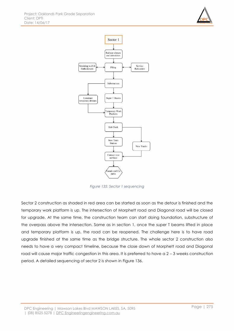
Project: Oaklands Park Grade Separation
Client: DPTI
Date: 14/06/17
DPC Engineering | Mawson Lakes Blvd MAWSON LAKES, SA, 5095
| (08) 8525 5278 | DPC Engineeringengineering.com.au
Page | 275
Figure 135: Sector 1 sequencing
Sector 2 construction as shaded in red area can be started as soon as the detour is finished and the
temporary work platform is up. The intersection of Morphett road and Diagonal road will be closed
for upgrade. At the same time, the construction team can start doing foundation, substructure of
the overpass above the intersection. Same as in section 1, once the super T beams lifted in place
and temporary platform is up, the road can be reopened. The challenge here is to have road
upgrade finished at the same time as the bridge structure. The whole sector 2 construction also
needs to have a very compact timeline, because the close down of Morphett road and Diagonal
road will cause major traffic congestion in this area. It is preferred to have a 2 – 3 weeks construction
period. A detailed sequencing of sector 2 is shown in Figure 136.
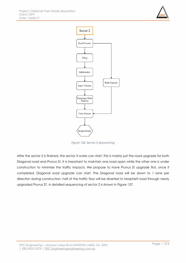
Project: Oaklands Park Grade Separation
Client: DPTI
Date: 14/06/17
DPC Engineering | Mawson Lakes Blvd MAWSON LAKES, SA, 5095
| (08) 8525 5278 | DPC Engineeringengineering.com.au
Page | 276
Figure 136: Sector 2 sequencing
After the sector 2 is finished, the sector 3 works can start. This is mainly just the road upgrade for both
Diagonal road and Prunus St. It is important to maintain one road open while the other one is under
construction to minimise the traffic impacts. We propose to have Prunus St upgrade first, once it
completed, Diagonal road upgrade can start. The Diagonal road will be down to 1 lane per
direction during construction, half of the traffic flow will be diverted to Morphett road through newly
upgraded Prunus ST. A detailed sequencing of sector 2 is shown in Figure 137.
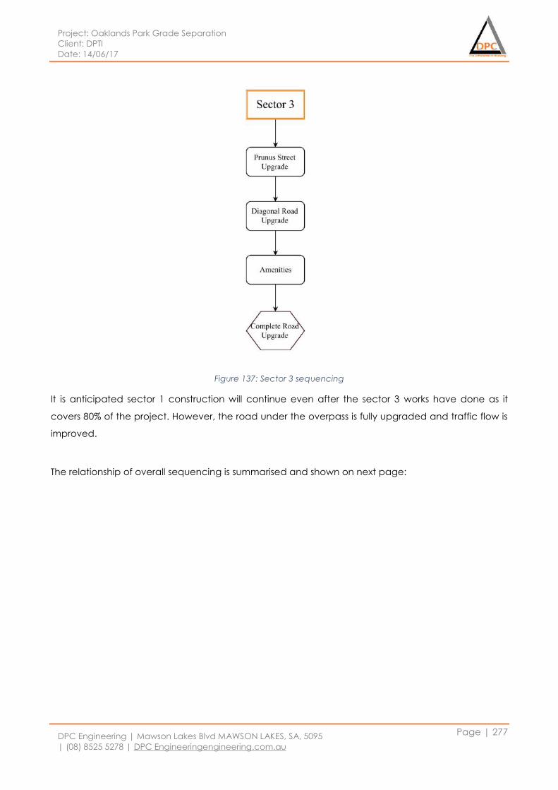
Project: Oaklands Park Grade Separation
Client: DPTI
Date: 14/06/17
DPC Engineering | Mawson Lakes Blvd MAWSON LAKES, SA, 5095
| (08) 8525 5278 | DPC Engineeringengineering.com.au
Page | 277
Figure 137: Sector 3 sequencing
It is anticipated sector 1 construction will continue even after the sector 3 works have done as it
covers 80% of the project. However, the road under the overpass is fully upgraded and traffic flow is
improved.
The relationship of overall sequencing is summarised and shown on next page:
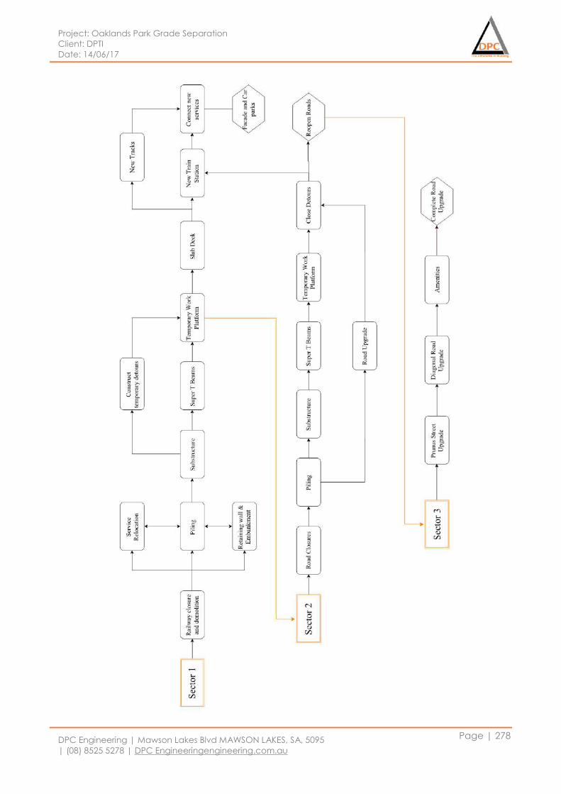
Project: Oaklands Park Grade Separation
Client: DPTI
Date: 14/06/17
DPC Engineering | Mawson Lakes Blvd MAWSON LAKES, SA, 5095
| (08) 8525 5278 | DPC Engineeringengineering.com.au
Page | 278

Project: Oaklands Park Grade Separation
Client: DPTI
Date: 14/06/17
DPC Engineering | Mawson Lakes Blvd MAWSON LAKES, SA, 5095
| (08) 8525 5278 | DPC Engineeringengineering.com.au
Page | 279
8.5 Safety
In Australia under the construction work understanding the work health and safety regulation ACT
2012, to create a safe work environment is a mandatory safety obligation. Due to the high risk of
work-related injuries and health issues work health and safety regulation is priority nominated for the
construction industries. Several investigations mentioned that main cause of the injuries and illness
could be risk taking, not using the right equipment and using alcohol and drugs. It is the main duty of
construction and other work industries to provide health and safety training as induction for
employees and make sure all workers have a white card. In this project safety measures before
construction, during construction and after construction will be considered. The management of
work health and safety are described below:
Informing the affected community along the route about road upgrade and procedure by
holding meetings with them.
Sending a letter about progress, changes and route restrictions along work site.
The road signs and advertisement will be used to provide information road closed during the
construction period and to divert traffic.
From health and safety team to provide information about health and safety procedure and
does a regular site visit to make sure health and safety procedure has used in a construction
site and make sure worker has a white card.
The team will make sure that workers are wearing personal protective equipment (PPE) and
highly visibility clothing.
Identifying the risk and hazard and do risk assessment for risk mitigation.
Allocate the dumping area for disposal of waste material used in construction to reduce the
health issue.
Put a barrier around construction area to avoid entrance of uninvited people like children.
The weekly information meeting with workers and health and safety team to provide any
changes in safety procedure.
Report any incident or accident happen in construction, to health and safety team and take
immediate action eliminate it and provide health care if needed.
Report any hazard like naked wear and spoil of chemical.
Use appropriate PPE to reduce the consequence of having falls, slips or trips on a
construction site.
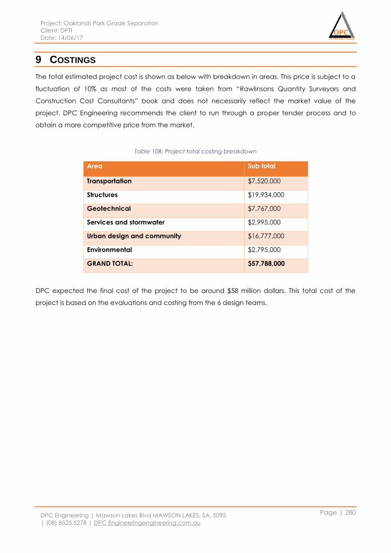
Project: Oaklands Park Grade Separation
Client: DPTI
Date: 14/06/17
DPC Engineering | Mawson Lakes Blvd MAWSON LAKES, SA, 5095
| (08) 8525 5278 | DPC Engineeringengineering.com.au
Page | 280
9 COSTINGS
The total estimated project cost is shown as below with breakdown in areas. This price is subject to a
fluctuation of 10% as most of the costs were taken from “Rawlinsons Quantity Surveyors and
Construction Cost Consultants” book and does not necessarily reflect the market value of the
project. DPC Engineering recommends the client to run through a proper tender process and to
obtain a more competitive price from the market.
Table 108: Project total costing breakdown
Area Sub total
Transportation $7,520,000
Structures $19,934,000
Geotechnical $7,767,000
Services and stormwater $2,995,000
Urban design and community $16,777,000
Environmental $2,795,000
GRAND TOTAL: $57,788,000
DPC expected the final cost of the project to be around $58 million dollars. This total cost of the
project is based on the evaluations and costing from the 6 design teams.