Embed Size (px)
Citation preview
ELSEVIER Engineering Geology 41 (1996) 239-256
ENGENEEX~NG GEOLOGY
Heat-induced moisture movement in a clay barrier I. Experimental modelling of borehole emplacement
A.P.S. Selvadurai Department of Civil Engineering and Applied Mechanics, McGill University, Montreal Que. H3A 2K6, Canada
Received 30 March 1994; accepted 8 August 1994
Abstract
The paper presents the results of a series of large-scale laboratory experiments which were conducted to study the heat-induced moisture movement in a bentonitic clay buffer region. In the experimental investigations, hygro-thermal phenomena are induced by a cylindrical heater which is placed within the compacted buffer material located in a borehole centrally situated in a granite block. The paper summarizes the experimental methodologies and presents results for the time-dependent distribution of temperatures within the granite block and the residual moisture distribution within the buffer at the termination of the experiment.
1. Introduction
Extensive accounts of the deep rock repository configurations that have been proposed for the disposal of high level nuclear fuel waste are given by Laughton et al. (1986), Chapman and McKinley (1987), OECD (1988), Gnirk (1993), and Simons and Baumgartner (1994). Several cur- rent proposals for deep disposal facilities involve the following components. The first is the vault system which is constructed to a specific shape in the rock formation with known physical, mechan- ical and hydrogeologic characteristics. The second involves the sealed containers which house the heat emitting radioactive waste, including long narrow containers which could be placed in bore- holes drilled into the floor of the vault system. The third component is the bentonite clay~luartz sand buffer which, in its compacted state, will surround the waste containers. The fourth component in the disposal vault system is the backfill material which
0013-7952/96/$15.00 © 1996 Elsevier Science B.V. All rights reserved SSDI 0013-7952 ( 95 ) 00034-0
fills the major part of the galleries in the disposal vault system. The major function of the backfill is to control the movement of water within the disposal galleries. Other engineered barriers such as shaft backfilling, borehole plugging, etc., also form an integral part of the system of engineered barriers that form a typical vault sealing pro- gramme (Lopez, 1987; Gray, 1993; Johnson et al., 1994a,b).
Many concepts for the disposal of highly radio- active wastes advocate the use of bentonitic clays as engineered geological barriers (Crme et al., 1985; Chapman and McKinley, 1987; Lopez, 1987; Pusch et al., 1980; Pusch, 1990). The ability of bentonitic clays to act as a geochemical filter for the sorption of radionuclides is an important con- sideration in its choice as an engineered barrier. Such radionuclide migration can occur as a result of the eventual natural disintegration of the waste containers. The composition of the clay buffer and the chemical characteristics of its constituents

240 A.P.S. Selvadurai/Engineering Geology 41 (1996) 239 256
should be selected in such a way that the conflicting constraints of the various functional requirements pertaining to heat conduction, swelling, radionu- clide migration, strength and creep can be satisfied simultaneously. Research into aspects such as heat conduction, radionuclide migration, creep and other mechanical interactions of clay buffer materi- als are discussed by Cheung and Chan (1983a,b), Cheung et al. (1983), Lopez (1985), Radhakrishna (1985), Selvadurai et al. (1985), Yong and Boonsinsuk (1985), Yong et al. (1985, 1986, 1990), Cheung (1990), Graham et al. (1990), Selvadurai and Pang (1990) and Gray (1993). Experimental modelling of the thermal performance of buffer materials is also discussed by Radhakrishna et al. (1990).
This paper focusses on an experimental study which investigates the heat-induced moisture movement in a bentonite clay buffer which is compacted within a borehole located in a granite block. The heating of the buffer-rockmass system is achieved by a cylindrical heater which is installed within the compacted buffer. The granite block is instrumented with arrays of thermocouples which measure temperature distributions along its planes of symmetry. The surface temperature at the mid- section of the heater is maintained at a constant value. The paper presents the experimental results for the time-dependent distribution of temperature within the granite block and the moisture distribu- tion patterns within the buffer which are observed at the termination of an experiment. Several types of hygro-thermal interface conditions at the buffer- rockmass interface are studied. These include direct contact between the buffer and the granite rock, separation of the buffer and the granite rock by an impermeable flexible membrane and the provision of an impermeable membrane-geotextile filter liner combination which prevents any mois- ture migration to the granite rock but allows moisture influx to the buffer region.
2. The granite block experimental facility
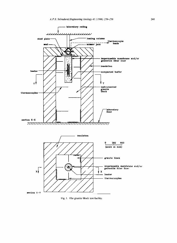
A granite block with cross-sectional dimensions 918x926mm and height 2446mm contains a central borehole of diameter 262 mm and depth
975 mm. In order to measure the temperature distributions within the granite block, it was instru- mented with arrays of thermocouples. For the installation of the thermocouples, cylindrical cavi- ties measuring approximately 24 mm in diameter and of variable length are drilled into the granite block. The locations of these thermocouples are shown in Fig. 1. The thermocouples are located in such a way that the temperature distributions along the planes of symmetry can be determined. The thermocouple assemblies which were installed in the granite block were fabricated in the form of cylindrical cartridges made of a mixture of a high viscosity aluminum epoxy (DEVCON) and crushed granite aggregate. The typical diameter of a thermocouple cartridge was 21.5 mm and the lengths varied to suit the location and cavity dimensions. Each thermocouple in a cartridge was individually tested by the application of local heating. The thermocouple probe assemblies were installed in the cylindrical cavities in the granite block by using a technique which minimized the possible effects of air entrainment. The cylindrical cavity in the granite was filled with approximately 15 cm 3 of an epoxy which contained a viscosity reducing agent. The thinned epoxy was placed at the end of the cavity with the aid of a hypodermic needle. The thermocouple cartridge was gradually forced into the rock cavity and a plexiglass plate was employed to retain the epoxy in place.
The instrumented granite block contained 187 thermocouples in 15 arrays. These were used to determine the temperature distributions within the granite block across the two planes of symmetry. The arrays of thermocouples are monitored at specified time intervals via a computerized data acquisition system (Selvadurai et al., 1986) which is housed in a temperature-controlled environment. The cylindrical surface of the borehole in the granite block was cleaned to remove any grease and other deleterious matter. In certain experi- ments, the borehole is sealed with a metal plate and a silicone sealer. The lower surface of the plate which is in contact with the silicone seal is lined with stainless steel to prevent corrosion. The leads of the heater unit, which included the power supply and controlling thermocouple wires, are routed through the plate via a specially designed
A. P. S. Selvadurai/Engineering Geology 41 (1996) 239-256 241
laboratory eel l ln l l
uple
~embrane a n d / o r • liner
there
rer
a ~ t l
V
section Y-Y
insulation
0 300 600 I i ,
(scale in mm)
grani te block
impermeable m e m b r a n e a n d / o r geotextile filter liner
hea te r
thermoeouples
Fig. 1. The granite block test facility.
242 A.P.S. Selvadurai/Engineering Geology 41 (1996) 239 256
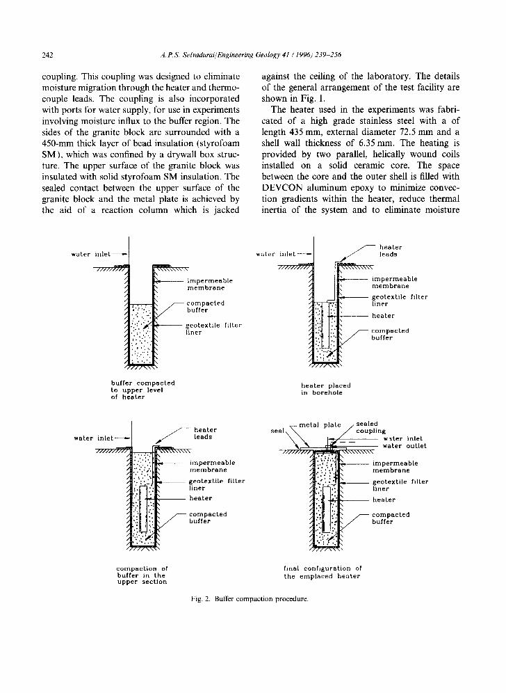
coupling. This coupling was designed to eliminate moisture migration through the heater and thermo- couple leads. The coupling is also incorporated with ports for water supply, for use in experiments involving moisture influx to the buffer region. The sides of the granite block are surrounded with a 450-mm thick layer of bead insulation (styrofoam SM), which was confined by a drywall box struc- ture. The upper surface of the granite block was insulated with solid styrofoam SM insulation. The sealed contact between the upper surface of the granite block and the metal plate is achieved by the aid of a reaction column which is jacked
against the ceiling of the laboratory. The details of the general arrangement of the test facility are shown in Fig. 1.
The heater used in the experiments was fabri- cated of a high grade stainless steel with a of length 435 mm, external diameter 72.5 mm and a shell wall thickness of 6.35 mm. The heating is provided by two parallel, helically wound coils installed on a solid ceramic core. The space between the core and the outer shell is filled with DEVCON aluminum epoxy to minimize convec- tion gradients within the heater, reduce thermal inertia of the system and to eliminate moisture
water i n l e t ~
/ / /
J / / / / / / / / / / / / / / /,
x - ~ \ \ \ \ \ mpe rmeable membrane
compacted butter
geotextile tilter liner
butter compacted to upper level of heater
water inlet ~
7 / / / / / / / / /
U- / / / / / \ \ \ \
•///'• heater leads
impermeable ~ membrane ~'- geotextile filter
liner
- - - - heater
compacted buffer
heater placed in borehole
water inlet ~ / / / / / / / / / /
°° i ."
~ eater leads
~ geotextile tilter [:;:~. liner L_: a- heater
b u t t e r
v- metal plate / sealed seal\ ~ J coupling , , \ . ter i n l e t
water outlet /////>H/~\~,xx\\\\\\ L~" ( [~ [~ impermea ble
m e m b r a ° o
~',.',. ,~J|- geotextile tilter l i . e r
:"~' heater , ' . " I!!1 i:!i
c o m p a c t i o n o f b u f f e r i n t h e upper section
final configuration of the emplaced heater
Fig. 2. Buffer compaction procedure.

A.P.S. Selvadurai/Engineering Geology 41 (1996) 239-256 243
~ w a t e r Lank
heater leads
thermocouple- 1 leads
compacted buffer
thermocouplea
water inflow
sand filler"'--
° Q t I
O0
controller end power source
coupling ~ u u m pump
~wat--er °utf l ' - ' °W~-- 0 " - -
i granite block ] water trap - - heater leads
- - heater impermeable membrane geotextlle filter
. liner buffer
¢;'
.~: :'i " ".',:'.
impermeable membrane
geotextile filter liner granite block
Fig. 3. Buffer-rock interface arrangement for experiment involving moisture influx.
influx of buffer moisture. The heater contains four thermocouples which are located approximately 1 mm from its outer surface. The heater is powered by an independent power source and the surface temperature at the mid-section of the heater is regulated by a closed loop controller.
3. Experimental procedures
The hygro-thermal behaviour of the clay buffer is significantly influenced by the extent to which water influx takes to the buffer region. The exact specification of the groundwater influx conditions to the buffer region will be governed by the hydro- geological characteristics of the repository site, the degree of porosity of the rock mass, the degree of
fracturing in the rock, the method of compaction of the buffer material in the borehole configuration and the dewatering and grouting techniques that have been adopted for the construction of a deep rock repository. The influence of these factors can lead to a wide variety of moisture influx conditions at a borehole environment. These can include the following: (a) moisture efltux from the buffer region which represents a relatively dry porous host rock in which water is not present, (b) moisture containment within the borehole boundary, which represents a borehole within a very dense unfractured rock, (c) moisture supply to the buffer-rock interface which represents a borehole region with rocks of high porosity or high degree of fracturing that maintains the buffer-rock interface in a moist condition, under
244 A.P.S. Selvadurai/Engmeering Geology 41 (1996) 239-256
12C . . . . . . .
t • the rmocouple A
! t he rmoeoup le B
80 - - therrnoeouple C 2
? ~ j ~ - ~ - - bu t le r
" hea te r " A
0 500 1000 1500 2000 2500
T i m e ( h o u r s )
Fig. 4. Time history of the surface temperatures of the heater.
virtually zero pressure and (d) pressurized water supply to the buffer-rock interface, which repre- sents the development of full hydrostatic head within the repository. In this research programme, attention is primarily focussed on three types of interface conditions which either permit or prevent moisture migration from the buffer to the granite rock. In the first experiment, a close fitting imper- meable liner is incorporated at the buffer-rock interface. This liner is also sealed at the surface of the compacted buffer to completely eliminate mois- ture migration from the buffer to the granite or moisture loss to the atmosphere. The precise defi- nition of moisture control at the interface between the buffer and the granite rock enables the accurate theoretical and numerical modelling of the experi- ment. In the second experiment, the interface is incorporated with both an impermeable liner and a thin highly permeable geotextile liner (thickness approximately 3 mm in its uncompressed state). The geotextile liner is placed adjacent to the buffer. It also houses a water entry point at the base of the borehole which permits complete saturation of the geotextile liner. The upper surface of the buffer is also incorporated with a geotextile liner and the impermeable membrane is used to seal the buffer against moisture loss to the atmosphere. This
interface condition attempts to model a situation where a saturated rock mass can provide an unlim- ited supply of moisture to the partially saturated buffer region under virtually a zero hydrostatic head. In the third experiment, the buffer material is compacted in direct contact with the granite rock. Although, in this instance, the upper surface of the borehole is sealed with a cover plate, mois- ture migration can occur from the buffer to the relatively dry granite rock.
The buffer mixture was placed in a sealed con- tainer for a period of seven days to allow moisture redistribution and equalization. The target opti- mum moisture content was 18%; preliminary tests prior to compaction of the bentonite mixture indi- cated moisture contents which varied between 17.5% and 18.0%. The impermeable membrane was first installed in the borehole and contact with the borehole wall was maintained with a flexible plastic sheet. The bentonite mixture was com- pacted in the borehole using a modified Proctor hammer. The average height of a compacted layer of the bentonite mixture varied between 20 to 25 mm. Prior to the placement of each new layer, the surface of the already compacted bentonite mixture was roughened to minimize the develop- ment of planes of distinct discontinuities which would facilitate the moisture migration process. The bentonite was compacted to a depth of approximately 600 mm. This level corresponded to the upper level of the heater location and it was selected to minimize the drilling needed to place the heater and for the ease of routing the leads from the power source and the controlling thermo- couples. The drilling of the compacted bentonite was performed by using a 75 mm diameter cutting edge. During the drilling procedure, the buffer material debris was removed by a vacuum cleaning device. The entire drilling procedure lasted approx- imately 24 h and whenever possible the compacted buffer was kept sealed to minimize moisture loss.
The base of the cylindrical cavity in the buffer was filled with a thin layer of silica sand to provide a fiat base for the heater. The heater was placed within the cavity in the compacted buffer. The diameter of the cavity is such that the heater fits in the cavity without a noticeable gap. The heater leads were placed in a groove made in the surface
A. P.S. Selvadurai/Engineering Geology 41 (1996) 239-256 245
188 HRS • o ,
, f " i. : : : ( ,4
I r ' J " . . . ' l ] . ".
?
:"
X \ J
/ f x ~
~ H ~ - - ~
~ " - - ' , - - - ~ B
C, ~ ~ . _ = . _ . . G J
. . . . " . ' .
, ,
• ~ ° ' °
' ' i . ,
x, , " i ° ° ° . • , , , . , • • , o
i . . . ' °
Z ' " ' i ' '
: ! i ! jg .
~ r ~
!
/
G
~ r J
D ~
LEGEND
R 2 8 . EEO
B 2 5 . 0 B 0
C 3 8 . ~ 8
D 3 5 . ~
K 4 B . ~ F 45.EmB
G 5 8 . E 8 8
14 55 . m m
I 6 8 . 0 0 0
.T 8 5 . 8 B B
K 7B, mla
L 75t mla
H 8O.BEB
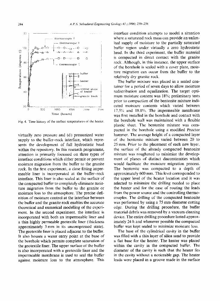
Fig. 5. Temperature contours within the granite block. Buffer in direct contact with the rock. (The legend corresponds to temperatures in °C).
of the compacted buffer and routed along the surface of the borehole. The remaining section of the buffer was compacted to within 25 mm of the upper surface of the granite block. The imperme- able membrane was cut to the required size and the ends sealed with a silicone compound. The locations where the heater leads exit the imperme- able membrane were also sealed with the silicone compound to provide a virtually impermeable seal. The region above the sealed section of the mem- brane is filled with a layer of silica sand to provide a soft medium to accommodate leads from the
heater. The stainless steel plate was lowered into place and the heater connector installed with the rubber O-ring seal. A 12-ram bead of silicone sealant was placed on the surface of the granite block to provide a further waterproof barrier between the plate and the rock surface. The various stages in the compaction of the buffer and the installation of the heater are shown in Fig. 2. A portable power supply was used to test the heater in its in situ condition and to ascertain the integrity of the controlling thermocouples and other sensors.
246 A.P. S, Selvadurai/Engineering Geology 41 (1996) 239 256
t88 HRS 508 HRS 1008 ~ 2 ~ HRS
( t)
\
I
O
~ , , , , o ,
I'": " " : ' ° " ' t , ' , ° • '
. ' . . : t : . '
":.(,'..,;,,:',.. .,',." : ' , : ""
* *
G
/
r ~ /
J ~ K
~ D ~ " , . , - -9 -~'
G /
C
~ r
: " a' ' ; . "
:::' i': :,i" :.: : .. : ' . '
/ . " i '
. . " , o /
!
..-._.~(J
v C - ~
LEGEND
g 2 @ . l a ~
B 2 5 . 1 a ~
C 30. DaB
D 3 5 . 1 a ~ E: 40.cram
F" 4 5 . |
G $ O . ~
H 55.~1m
$ 6 S . ~
70.gg@
L 7 S . ~
M 8 8 . 8 8 0
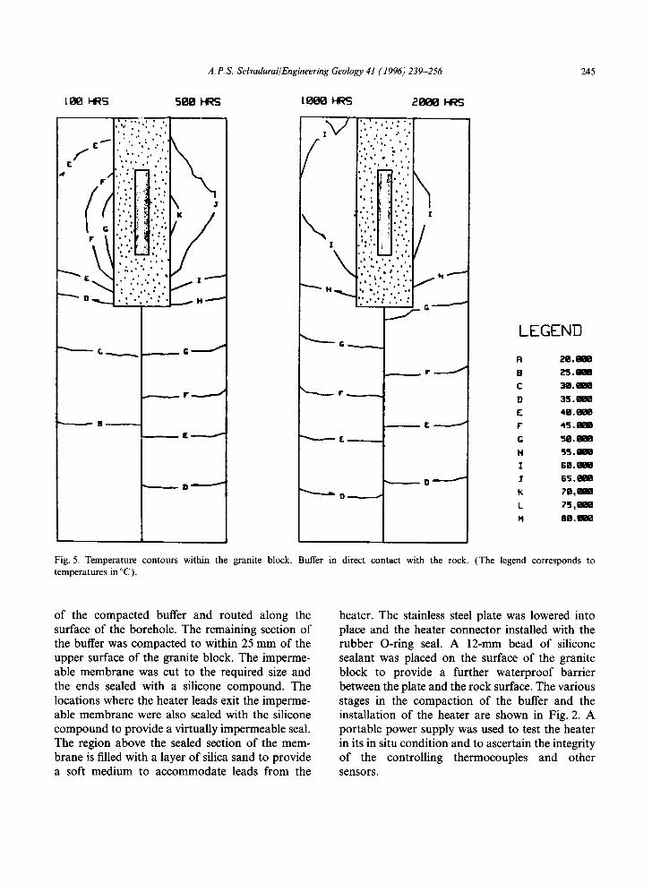
Fig. 6. Temperature contours within the granite block. Impermeable membrane at the buffer-rock interface, (The legend corresponds to temperatures in °C).
The second series of tests which involve the combined use of an impermeable membrane and the geotextile filter liner also followed procedures similar to those outlined in the previous paragraph. To facilitate its installation, the geotextile filter lining is fabricated in the form of a cylindrical tube with dimensions virtually identical to that of the impermeable membrane. A thin flexible tubing (3 rnm in diameter) is attached to the outer surface of the geotextile liner. The tube terminates at the base of the geotextile lining (base of 0orehole), which allows saturation of the lining from the
base. The compaction of the buffer follows the procedures indicated previously. The surface of the compacted buffer also contains a geotextile lining and a water outlet is installed at this loca- tion. A nominal vacuum (approximately 5-10 kPa) is applied to the water outlet to remove air from the system and to saturate the geotextile lining (Fig. 3). The water entry port is connected to a water reservoir the level of which is kept constant. No attempt was made to measure the amount of water entering the sample; the geotextile filter lining is kept in a saturated condition by the

A. P.S. Selvadurai/Engineering Geology 41 (1996) 239-256 247
l ~ ~S 5 ~ ~S l ~ S 2880HRS
f
\ ¢
• • • o • i
: , : ." , ' - ,
I
/ f. J j G ~
/ I J
°, ,, • \ • , i ~ ~ '
• b I t ' " i " %
b •
o h • • • ~ • • ,
" * I I ~ • 2 i:'.".i" :".'. ,':..,,,. : , . . ~
G _ _ j H ~ " - ' ~ H
~- £_
.._..~.. G J
..... r ~
£ ~
D ~
LEGEND
R ~8.Be8
C 3 0 . ~
/) 35.tm0 E q o . ~
F' 4 5 . ~
G 50.
1,4 5 5 . ~
I S O . ¢ ~
$ 6 5 . ~ B
K ?0.
L ?5.aa8 H 8 1 1 . ~
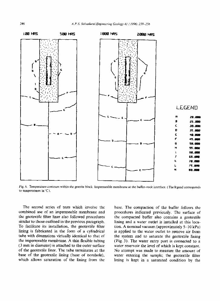
Fig. 7. Temperature contours within the granite block. Impermeable membrane-geotextile liner combination at the buffer rock interface with moisture influx. (The legend corresponds to temperatures in °C).
periodic application of the nominal vacuum. There was no evidence of compression of the geotextile liner to an extent which would inhibit moisture influx at the interface.
The third experiment involving the direct contact between the buffer and the granite block was performed to provide an indication of the hygro- thermal effects that are associated with an extreme situation involving a dry porous rock mass. This provides a basis for comparison with the first two categories of tests which accommodate more
favourable hygro-thermal boundary conditions at the buffer-rock interface.
4. Experimental results
Three experiments were performed in the granite block test facility using the techniques and pro- cedures outlined previously. In these experiments, the buffer material was compacted to a moist unit weight (~:) of approximately 19.5kN/m 3 at a
248 A, P.S. Selvadurai/Engineering Geology 41 (1996) 239 256
80
,~...-a heater / - ~ thermocouple - -
I" . . . . . . . . . . . . - - ,'8 "-'4 ] of heater
granite block
....... ( dimensions in mm)
70
6O
5O "m
@ 40
m..,
2O
o o 1 ~ , ~ 2
# ¢ 4
101 0 4()0 8()0 12'00 1600 2000 24()0
T i m e ( h o u r s )
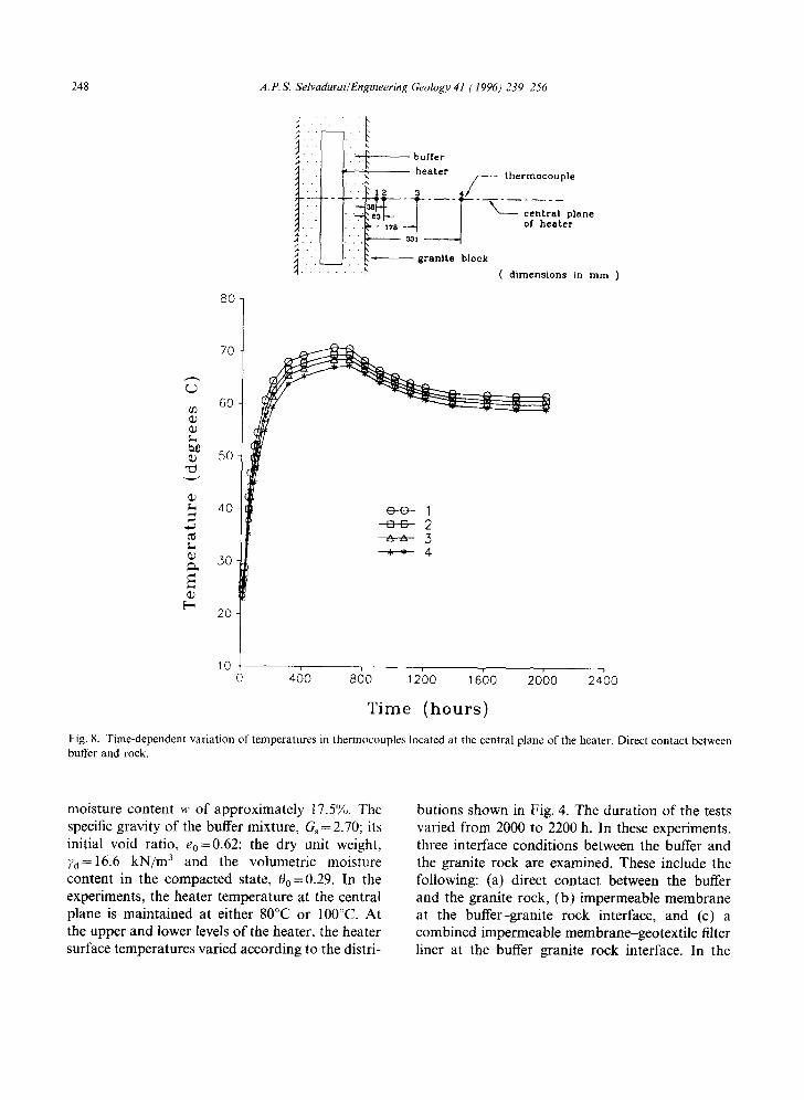
Fig. 8. Time-dependent variation of temperatures in thermocouples located at the central plane of the heater. Direct contact between buffer and rock.
moisture content w of approximately 17.5°/,,. The specific gravity of the buffer mixture, Gs = 2.70; its initial void ratio, eo=0.62; the dry unit weight, 7a=16.6 kN/m 3 and the volumetric moisture content in the compacted state, 0o=0.29. In the experiments, the heater temperature at the central plane is maintained at either 80°C or 100°C. At the upper and lower levels of the heater, the heater surface temperatures varied according to the distri-
butions shown in Fig. 4. The duration of the tests varied from 2000 to 2200 h. In these experiments, three interface conditions between the buffer and the granite rock are examined. These include the following: (a) direct contact between the buffer and the granite rock, (b) impermeable membrane at the buffer-granite rock interface, and (c) a combined impermeable membrane-geotextile filter liner at the buffer-granite rock interface. In the

A.P.S. Selvadurai/Engineering Geology 41 (1996)239-256 249
80-
70-
~" 60-
50-
40-
30- u.
20
[.-, lo-
I - - s x l s o f b e a t e r
!i! iii iii . . . . I . . . . . • I r a n i t e b l o c k
~ t h e r m o c o u p l e
864
1371
( d i m e n s i o n s in m m )
tc I I I I ld
¢ d
C C C 0 0 []
0 0 460 860 12bo ,6bo 20bo 24b0
Time (hours)
Fig. 9. Time-dependent variation of temperatures in thermo- couples located at axis of granite block. Direct contact between buffer and rock.
test category (c), the outer boundary of the buffer region is supplied with moisture, throughout the duration of the test.
The results derived from the experimental inves- tigations can be presented in a variety of ways. At this stage, however, it is convenient to present separately the results derived from the three tests. The temperature distributions determined at the thermocouples located in the granite rock can be used to develop the time-dependent temperature contours within the block. It is assumed that the pattern of heat conduction in the rock exhibits symmetry about the planes containing the thermo-
couples. Owing to this simplification all temper- ature data are utilized to develop the temperature contours for one half of the cross-section of the granite block. The Figs. 5-7 illustrate the time- dependent distribution of heat conduction within the granite block for the three types of buffer-rock interface conditions. For each case, comparisons are provided for four different values of lapsed time. It is also instructive to present the time- dependent distributions of temperature determined from thermocouples which are located in the gran- ite block at approximately the mid-section level of the heater and along the axis of the heater. In certain experiments, thermocouples were also installed at the interface between the buffer and the granite rock. The relevant results for the time- dependent temperature distributions are shown in Figs. 8-13.
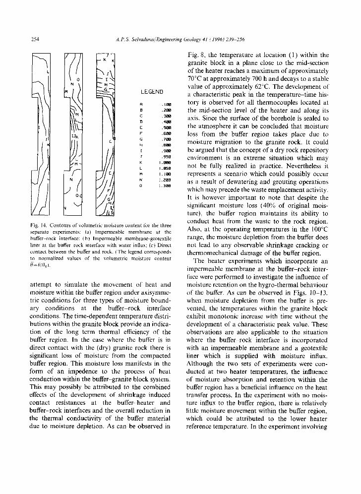
Upon completion of an experiment, the test facility was allowed to cool down and reach ther- mal equilibrium with the surroundings. The cool- ing down period lasted approximately 100 h. The cover plate was removed and samples of the com- pacted buffer were retrieved from various loca- tions. The procedure for the sample retrieval was as follows: first, the buffer was removed to the required depth using a drill; samples were then retrieved from locations beyond the drilled zone using a 12-mm diameter stainless steel tubing. In each case approximately 300 to 350 samples were retrieved from different locations of the buffer to determine the residual moisture content achieved as a result of the heat-induced moisture migration and/or moisture influx. The distributions of the normalized volumetric moisture content (i.e., cur- rent volumetric moisture content/initial volumetric moisture content) for the three experiments are shown in Fig. 14.
During the sample retrieval process, the condi- tion of the buffer was also inspected for thermo- mechanical damage in the form of cracking and/or the development of surfaces or zones of separation at the interface between the buffer and the granite block. The interface condition between the buffer and the heater was also inspected to ascertain the influence of moisture movement on the contact conditions at the interface. The contours for the normalized volumetric moisture content can be
250 A.P.S. Selvadurai/Engineering Geology 41 (1996) 239-256
60
ii,"iL iil buffer
beater thermocouples
~ ~ l I ~---- centra| p|ane ~,s of beater
impermeable membrane ( dimensions in mm )
55
50
~n
Q) L 45
40
~" 35
~ 3O
25
O 0 1 DD 2 -*-a, 3 # # 4
m m
2 0 . 0 460 6bo 20 0
Time ( h o u r s )
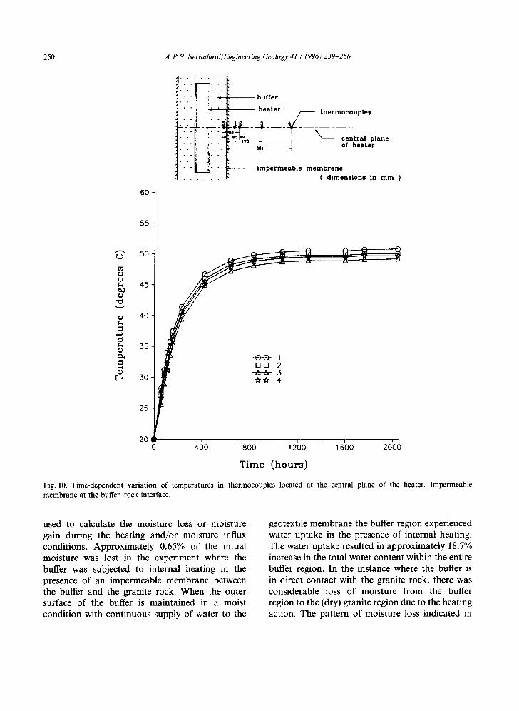
Fig. 10. Time-dependent variation of temperatures in thermocouples located at the central plane of the heater. Impermeable membrane at the buffer-rock interface.
used to calculate the moisture loss or moisture gain during the heating and/or moisture influx conditions. Approximately 0.65% of the initial moisture was lost in the experiment where the buffer was subjected to internal heating in the presence of an impermeable membrane between the buffer and the granite rock. When the outer surface of the buffer is maintained in a moist condition with continuous supply of water to the
geotextile membrane the buffer region experienced water uptake in the presence of internal heating. The water uptake resulted in approximately 18.7% increase in the total water content within the entire buffer region. In the instance where the buffer is in direct contact with the granite rock, there was considerable loss of moisture from the buffer region to the (dry) granite region due to the heating action. The pattern of moisture loss indicated in
A. P.S. Selvadurai/Engineering Geology 41 (1996) 239-256 251
"G
L
U
"U
L
e~
E [ -
60
55
50
45
40
3..5
30
2..5
20
15
10
I. axis of heater
• : . [ . [ . [ .~ /~ - - - - - - - '~ Ilronlte block .I1.,,,,7,, , , , .
/ ;- '-q -'1 . . : - . . IF / )
864
1371~j ( dimensions In mm )
~ 0 0 - 4 3
C ~ - 4 3
o o ~ O 0 o o ~
0
o
o
0 41~0 8{~0 1 2C)0 16()0 20()0 24C~0
T ime ( h o u r s )
buffer
impermeable membrane
Fig. 11. Time-dependent variation of temperatures in thermocouples located at the axis of the granite block. Impermeable membrane at the buffer-rock interface.
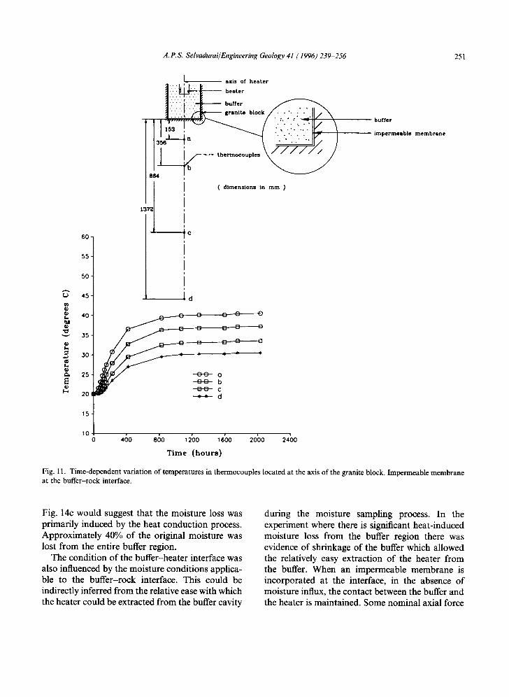
Fig. 14c would suggest that the moisture loss was primarily induced by the heat conduction process. Approximately 40% of the original moisture was lost from the entire buffer region.
The condition of the buffer-heater interface was also influenced by the moisture conditions applica- ble to the buffer-rock interface. This could be indirectly inferred from the relative ease with which the heater could be extracted from the buffer cavity
during the moisture sampling process. In the experiment where there is significant heat-induced moisture loss from the buffer region there was evidence of shrinkage of the buffer which allowed the relatively easy extraction of the heater from the buffer. When an impermeable membrane is incorporated at the interface, in the absence of moisture influx, the contact between the buffer and the heater is maintained. Some nominal axial force
252 A.P.S. Selvadurai/Engineering Geology 41 (1996) 239 256
80
-iii-- t b°,,er - . - t heater thermoeouple
.'.'.. i i [ geotextile liner
. . . . i- impermeable liner ( dimensions in mm)
@
v
CD E-,
70
60
50
40
30
o o 1 DD 2 ,~.a, 5 - ~ 4
20
104- 0 s(~o 10~00 1500 2000 25;o
T i m e ( h o u r s )
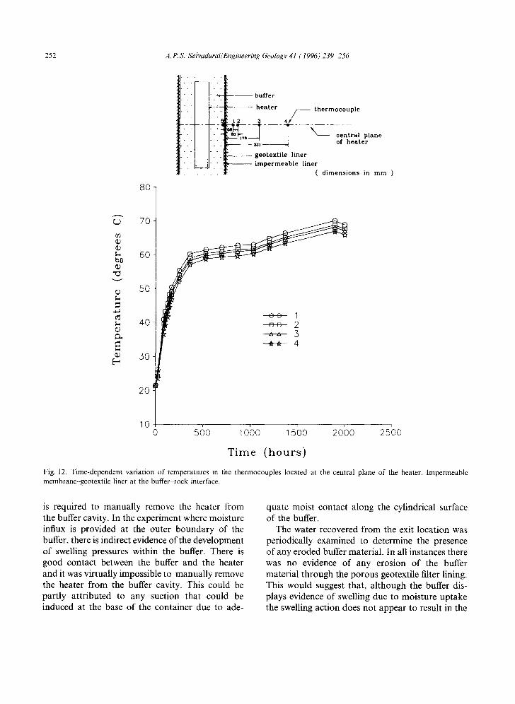
Fig. 12. Time-dependent variation of temperatures in the thermocouples located at the central plane of the heater. Impermeable membrane-geotextile liner at the buffer-rock interface.
is required to manually remove the heater from the buffer cavity. In the experiment where moisture influx is provided at the outer boundary of the buffer, there is indirect evidence of the development of swelling pressures within the buffer. There is good contact between the buffer and the heater and it was virtually impossible to manually remove the heater from the buffer cavity. This could be partly attributed to any suction that could be induced at the base of the container due to ade-
quate moist contact along the cylindrical surface of the buffer.
The water recovered from the exit location was periodically examined to determine the presence of any eroded buffer material. In all instances there was no evidence of any erosion of the buffer material through the porous geotextile filter lining. This would suggest that, although the buffer dis- plays evidence of swelling due to moisture uptake the swelling action does not appear to result in the

A. P.S. Selvadurai/Engineering Geology 41 (1996) 239-256 253
[-.
80
70
60
50
40
30 ¸
20:
I Itxlau of healer ] : : ~ h.ater
:::::.":i::-,;~L-- . " ~ " " h,oo'./......-HI/\ I1 ;I?F / \
- ' 1 . . . . . g )
ta-,J ( d i m e n s i o n s in m m )
~e
buf fer
geotexUle l iner
i m p e r m e a b l e m e m b r a n e
Ld
~" • d
10 0 5(~0 1000 1500 2000 25'00
T i m e ( h o u r s )
Fig. 13. Time-dependent variation of temperatures in the thermocouples located at the axis of the granite block. Impermeable membrane-geotextile liner at the buffer-rock interface.
penetration of the material into the filter fabric. Such penetration action would have resulted in both a reduction in the ability to saturate the filter zone and in the presence of eroded buffer material in the collected samples of water from the exit region.
5. Conclusions
Full-scale in situ testing of the hygro-thermal behaviour of a buffer in a borehole emplacement
environment is both time consuming and expensive. The objective of the present research programme was to develop a large-scale laboratory test facility which could simulate the behaviour of a compacted buffer material in a borehole emplace- ment environment. Laboratory investigations have an added advantage that the local field in the vicinity of the borehole can be accurately defined in terms of the thermal and moisture boundary conditions which can be duplicated in theoretical and computational developments. The experiments
2 5 4 ,4. P.S. Selvadurai/Engineering Geology 41 (1996) 239 256
LEGEND
FI . 1 8 8
B . 2 ~
C . 3 0 8
D . 4 0 8
E . 5 0 8
F . 6 ( ~
G .7e l8
H .81~B
I . 9 5 e
K 1 . 8 0 8
L 1 .@SB
M 1 . 1 8 8
N I . E ~
0 1 .3~1
Fig. 14. Contours of volumetric moisture content ['or the three separate experiments: (a) Impermeable membrane at the buffer-rock interface; (b) Impermeable membrane-geotextile liner at the buffer rock interface with water influx; (c) Direct contact between the buffer and rock. (The legend corresponds to normalized values of the volumetric moisture content if= 0/0 o).
attempt to simulate the movement of heat and moisture within the buffer region under axisymme- tric conditions for three types of moisture bound- ary conditions at the buffer-rock interface conditions. The time-dependent temperature distri- butions within the granite block provide an indica- tion of the long term thermal efficiency of the buffer region. In the case where the buffer is in direct contact with the (dry) granite rock there is significant loss of moisture from the compacted buffer region. This moisture loss manifests in the form of an impedence to the process of heat conduction within the buffer-granite block system. This may possibly be attributed to the combined effects of the development of shrinkage induced contact resistances at the buffer-heater and buffer-rock interfaces and the overall reduction in the thermal conductivity of the buffer material due to moisture depletion. As can be observed in
Fig. 8, the temperature at location (1) within the granite block in a plane close to the mid-section of the heater reaches a maximum of approximately 70°C at approximately 700 h and decays to a stable value of approximately 62°C. The development of a characteristic peak in the temperature-time his- tory is observed for all thermocouples located at the mid-section level of the beater and along its axis. Since the surface of the borehole is sealed to the atmosphere it can be concluded that moisture loss from the buffer region takes place due to moisture migration to the granite rock. It could be argued that the concept of a dry rock repository environment is an extreme situation which may not be fully realized in practice. Nevertheless it represents a scenario which could possibly occur as a result of dewatering and grouting operations which may precede the waste emplacement activity. It is however important to note that despite the significant moisture loss (40% of original mois- ture), the buffer region maintains its ability to conduct heat from the waste to the rock region. Also, at the operating temperatures in the 100°C range, the moisture depletion from the buffer does not lead to any observable shrinkage cracking or thermomechanical damage of the buffer region.
The heater experiments which incorporate an impermeable membrane at the buffer-rock inter- face were performed to investigate the influence of moisture retention on the hygro-thermal behaviour of the buffer. As can be observed in Figs. 10-13, when moisture depletion from the buffer is pre- vented, the temperatures within the granite block exhibit monotonic increase with time without the development of a characteristic peak value. These observations are also applicable to the situation where the buffer rock interface is incorporated with an impermeable membrane and a geotextile liner which is supplied with moisture influx. Although the two sets of experiments were con- ducted at two heater temperatures, the influence of moisture absorption and retention within the buffer region has a beneficial influence on the heat transfer process. In the experiment with no mois- ture influx to the buffer region, there is relatively little moisture movement within the buffer region, which could be attributed to the lower heater reference temperature. In the experiment involving
A.P.S. Selvadurai/Engineering Geology 41 (1996) 239-256 255
moisture uptake it is evident that appreciable moisture uptake is present even with a high thermal gradient across the central horizontal plane of the heater. The buffer material was also inspected to establish the possible development of swelling of the buffer in the axial direction. There was no apparent buffer swelling in the axial direction. The very low hydraulic gradients causing water circula- tion at the buffer-rock interface does not appear to result in any erosion of the buffer.
Acknowledgements
The development of the test facility described in this paper was supported by Operating, Equipment and Strategic Grants awarded by the Natural Sciences and Engineering Research Council of Canada. The work described in the paper was also supported by Research Contracts awarded by Atomic Energy of Canada Limited (AECL). The technical assistance for the development of the test facility was provided by the following personnel: K.C. McMartin, Manager of Civil Engineering Laboratories, S.D. Conley, Instrumentation Engineer and technical assistants G. Biggs, J. Fearn and L. McLeod at Carlton University, Ottawa.
References
Chapman, N.A. and McKinley, I.G., 1987. The Geological Disposal of Nuclear Waste. Wiley, New York, N.Y.
Cheung, S.C.H., 1990. A new interpretation of measured ionic diffusion coefficients in compacted bentonite based materials. Eng. Geol., 28: 369-378.
Cheung, S.C.H. and Chan, T., 1983a. Computer simulation of contaminant transport. Proc. Computer Simulation Conference, Vancouver, Vol. I: 470-475.
Cheung, S.C.H. and Chan, T., 1983b. Parameter sensitivity analysis of near-field radionuclide transport in buffer material and rock, for an underground nuclear fuel waste vault. Atomic Energy of Canada Report, AECL 7801.
Cheung, S.C.H., Oscarson, D.W. and Lopez, R.S., 1983. Factors influencing mass diffusion in bentonite and mixtures of bentonite and sand. In: Scientific Basis for Nuclear Waste Management. Proc. Mater. Res. Soc., 26: 711-718.
Crme, B., Johnston, P. and MOiler, A., Editors, 1985. Design and Instrumentation of In Situ Experiments in Underground Laboratories for Radioactive Waste Disposal. Proc.
Workshop, jointly Organized by Commission of European Community and OECD Nuclear Energy Agency, Brussels. Balkema, Rotterdam.
Gnirk, P., 1993a. OECD/NEA International Stripa Project. Overview Volume II: Natural Barriers. SKB, Stockholm, Sweden.
Graham, J., Saadat, F. and Gray, M.N., 1990. High pressure triaxial testing on the Canadian reference buffer material. Eng. Geol., 28: 391-403.
Gray, M.N., 1993b. OECD/NEA International Stripa Project. Overview Volume III: Engineered Barriers. SKB, Stockholm, Sweden.
Johnson, L.H., LeNeveu, D.M., Shoesmith, D.W., Oscarson, D.W., Gray, M.N., Lemire, R.J. and Garisto, N.C., 1994a. The Disposal of Canada's Nuclear Fuel Waste: The Vault Model for Postclosure Assessment. AECL Res. Rep. AECL-10714: COG-93-4, Whiteshell Laboratories, Pinawa, Man.
Johnson, L.H., Tait, J.C., Shoesmith, D.W., Crosthwaite, J.L. and Gray, M.N., 1994b. The Disposal of Canada's Nuclear Fuel Waste: Engineered Barriers Alternatives. AECL Res. Rep., AECL-10718:COG-93 8, Whiteshell Laboratories, Pinawa, Man.
Laughton, A.S., Roberts, L.E.J., Wilkinson, D. and Gray, D.A., Editors, 1986. The Disposal of Long-Lived and Highly Radioactive Wastes. Proc. R. Soc. Disc. Meet., R. Soc., London.
Lopez, R.S., 1985. Review of vault sealing research. Proc. 19th Information Meeting of the Nuclear Fuel Waste Management Program, Toronto, Ont. Atomic Energy of Canada Rep. TR350, Vol. III: 499-512.
Lopez, R.S., 1987. The Vault Sealing Program. Proc. Workshop December 1-2 1983, Toronto, Ont. Atomic Energy of Canada, Limited Tech. Rep. TR339.
OECD, 1988. Geological disposal of radioactive waste: In situ research and investigations in OECD countries. Report prepared by NEA Advisory Group, OECD, Paris.
Pusch, R. Editor, 1990. Proc. OECD Workshop on Artificial Clay Barriers for High Level Radioactive Waste Repositories. Eng. Geol., 28: 230-462.
Pusch, R., Jacobsson, A. and Bergstrom, A., 1980. Bentonite- based buffer substances for isolating radioactive waste products at great depths in rock. In: Underground Disposal of Radioactive Wastes, Vol. I, IAEA-SM-243/22.
Radhakrishna, H.S., 1985. Near field thermal analysis of the nuclear waste disposal vault. Proc. 19th Information Meeting of the Nuclear Fuel Waste Management Program, Toronto, Ont. Atomic Energy of Canada Limited Tech. Rep., TR350, Vol. III: 609-618.
Radhakrishna, H.S., Lau, K.C. and Crawford, A.M., 1990. Experimental modelling of the near field thermal regime in a nuclear fuel waste disposal vault. Eng. Geol., 28: 337-351.
Selvadurai, A.P.S. and Pang, S., 1990. Mechanics of the interaction between a nuclear waste container and a buffer during discontinuous rock movement. Eng. Geol., 28: 405-417.
Selvadurai, A.P.S., Lopez, R.S. and Hartley, G.A., 1985.
256 A.P.S. Selvadurai/Engineering Geology 41 (1996) 239-256
Geotechnical modelling of buffer-container-rockmass inter- action in a nuclear waste disposal vault. Proc. l lth Int. Conf. Soil Mechanics and Foundation Engineering, San Francisco, Calif., Vol. 3: 1299-1305.
Selvadurai, A.P.S., McMartin, K.C. and Conley, S.D., 1986. A computer-aided experimental technique for the study of heat transfer processes in buffer regions of a nuclear waste disposal vault. Proc. 1st Can. Conf. Computer Applications in Civil Engineering/Micro-computers. Hamilton, Ont., Vol. 2: 212-228.
Simmons, G.R. and Baumgartner, P., 1994. The Disposal of Canada's Nuclear Fuel Waste: Engineering for a Disposal Facility. AECL Res. Rep., AECL-10715: COG-93-5, Whiteshell Laboratories, Pinawa, Man.
Yong, R.N. and Boonsinsuk, P., 1985. Buffer creep studies. Proc. 17th Information Meeting of the Canadian Nuclear Fuel Waste Management Program; Engineered Barriers and Wasteforms, Toronto, Ont.
Yong, R.N., Boonsinsuk, P. and Yiotis, D., 1985. Creep behaviour of a buffer material for nuclear fuel waste vault. Can. Geotech. J., 22:541 550.
Yong, R.N., Boonsinsuk, P., Wong, G., 1986. Formulation of backfill material for a nuclear fuel waste disposal vault. Can. Geotech. J., 23: 216-228.
Yong, R.N., Mohamed, A.M.O. and Xu, D.-M., 1990. Coupled heat-mass transport effects on moisture redistribution predic- tion in clay barriers. Eng. Geol., 28:315 324.