Embed Size (px)
Citation preview
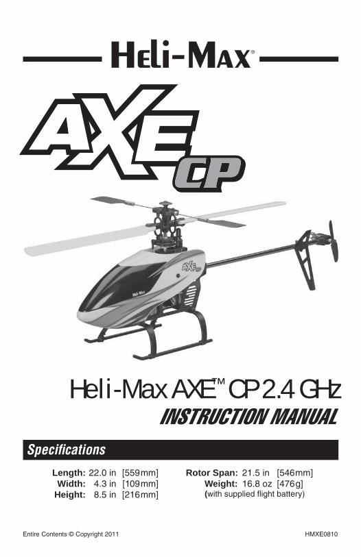
Length: 22.0 in [559mm] Width: 4.3 in [109mm] Height: 8.5 in [216mm]
Rotor Span: 21.5 in [546mm] Weight: 16.8 oz [476g] (with supplied flight battery)
Specifications
Entire Contents © Copyright 2011 HMXE0810
INSTRUCTION MANUALHeli-Max AXE™ CP 2.4 GHz
2
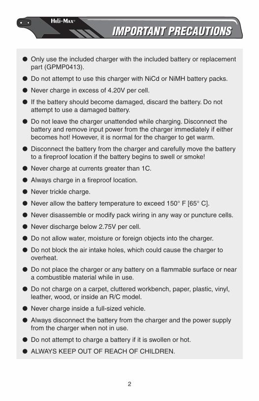
IMPORTANT PRECAUTIONSIMPORTANT PRECAUTIONS
● Only use the included charger with the included battery or replacement part (GPMP0413).
● Do not attempt to use this charger with NiCd or NiMH battery packs.
● Never charge in excess of 4.20V per cell.
● If the battery should become damaged, discard the battery. Do not attempt to use a damaged battery.
● Do not leave the charger unattended while charging. Disconnect the battery and remove input power from the charger immediately if either becomes hot! However, it is normal for the charger to get warm.
● Disconnect the battery from the charger and carefully move the battery to a fi reproof location if the battery begins to swell or smoke!
● Never charge at currents greater than 1C.
● Always charge in a fi reproof location.
● Never trickle charge.
● Never allow the battery temperature to exceed 150° F [65° C].
● Never disassemble or modify pack wiring in any way or puncture cells.
● Never discharge below 2.75V per cell.
● Do not allow water, moisture or foreign objects into the charger.
● Do not block the air intake holes, which could cause the charger to overheat.
● Do not place the charger or any battery on a fl ammable surface or near a combustible material while in use.
● Do not charge on a carpet, cluttered workbench, paper, plastic, vinyl, leather, wood, or inside an R/C model.
● Never charge inside a full-sized vehicle.
● Always disconnect the battery from the charger and the power supply from the charger when not in use.
● Do not attempt to charge a battery if it is swollen or hot.
● ALWAYS KEEP OUT OF REACH OF CHILDREN.
3
WARRANTYWARRANTYHeli-Max® guarantees this kit to be free from defects in both material and workmanship at the date of purchase. This warranty does not cover any component parts damaged by use or modifi cation. In no case shall Heli-Max’s liability exceed the original cost of the purchased kit. Further, Heli-Max reserves the right to change or modify this warranty without notice.
In that Heli-Max has no control over the fi nal assembly or material used for fi nal assembly, no liability shall be assumed nor accepted for any damage resulting from the use by the user of the fi nal user-assembled product. By the act of using the user-assembled product, the user accepts all resulting liability.
If the buyer is not prepared to accept the liability associated with the use of this product, the buyer is advised to return this kit immediately in new and unused condition to the place of purchase.
To make a warranty claim, send the defective part or item to Hobby Services at this address.
Hobby Services3002 N. Apollo Dr., Suite 1Champaign, IL 61822USA
Include a letter stating your name, return shipping address, as much contact information as possible (daytime telephone number, fax number, e-mail address), a detailed description of the problem and a photocopy of the purchase receipt. Upon receipt of the package the problem will be evaluated as quickly as possible.
READ THROUGH THIS MANUAL BEFORE STARTING CONSTRUCTION. IT CONTAINS IMPORTANT INSTRUCTIONS AND WARNINGS CONCERNING THE ASSEMBLY AND USE OF THIS MODEL.
4
TABLE OF CONTENTSTABLE OF CONTENTS
INTRODUCTION . . . . . . . . . . . . . . . . . . . . . . . . . . . . . . . . . . . . . . . . . . . . . . .4SAFETY PRECAUTIONS . . . . . . . . . . . . . . . . . . . . . . . . . . . . . . . . . . . . . . . .4ADDITIONAL ITEMS REQUIRED . . . . . . . . . . . . . . . . . . . . . . . . . . . . . . . . . .6KIT INSPECTION. . . . . . . . . . . . . . . . . . . . . . . . . . . . . . . . . . . . . . . . . . . . . . .6KIT CONTENTS . . . . . . . . . . . . . . . . . . . . . . . . . . . . . . . . . . . . . . . . . . . . . . . .6BATTERY AND CHARGER . . . . . . . . . . . . . . . . . . . . . . . . . . . . . . . . . . . . . . .7ASSEMBLY INSTRUCTIONS . . . . . . . . . . . . . . . . . . . . . . . . . . . . . . . . . . . . .8GET THE MODEL READY TO FLY . . . . . . . . . . . . . . . . . . . . . . . . . . . . . . . .12PREFLIGHT . . . . . . . . . . . . . . . . . . . . . . . . . . . . . . . . . . . . . . . . . . . . . . . . . .13CONTROLS . . . . . . . . . . . . . . . . . . . . . . . . . . . . . . . . . . . . . . . . . . . . . . . . . .14FLYING. . . . . . . . . . . . . . . . . . . . . . . . . . . . . . . . . . . . . . . . . . . . . . . . . . . . . .19MAINTENANCE & REPAIRS. . . . . . . . . . . . . . . . . . . . . . . . . . . . . . . . . . . . .21ORDERING PARTS . . . . . . . . . . . . . . . . . . . . . . . . . . . . . . . . . . . . . . . . . . . .27EXPLODED VIEW . . . . . . . . . . . . . . . . . . . . . . . . . . . . . . . . . . . . . . . . . . . . .29PARTS IMAGES. . . . . . . . . . . . . . . . . . . . . . . . . . . . . . . . . . . . . . . . . . . . . . .32
INTRODUCTIONINTRODUCTIONThank you for purchasing the Heli-Max AXE™ CP 2.4GHz RTF Helicopter. We are certain you will get many hours of enjoyment out of this model. If you should have any questions or concerns please feel free to contact us at:
For the latest technical updates or manual corrections for the AXE CP 2.4GHz RTF visit the Heli-Max web site at :
www.helimax-rc.com.
Open the “Helicopters” link, and then select the AXE CP 2.4GHz RTF. If there is new technical information or changes to this model a “tech notice” box will appear in the upper left corner of the page.
SAFETY PRECAUTIONSSAFETY PRECAUTIONSFailure to follow these safety precautions may result in severe injury to yourself and others.
1. Keep your face and body as well as all spectators away from the plane of rotation of the rotors whenever the battery is connected.
5
2. Keep these items away from the rotors: loose clothing, shirt sleeves, ties, scarfs, long hair or loose objects such as pencils or screwdrivers that may fall out of shirt or jacket pockets into the rotors.
3. The spinning blades of a model helicopter can cause serious injury. When choosing a fl ying site for your AXE CP 2.4GHz RTF, stay clear of buildings, trees and power lines. AVOID fl ying in or near crowded areas. DO NOT fl y close to people, children or pets. Maintain a safe pilot-to-helicopter distance while fl ying.
4. Your AXE CP 2.4GHz RTF should not be considered a toy, but rather a sophisticated, working model that functions very much like a full-size helicopter. Because of its performance capabilities, the AXE CP 2.4GHz RTF, if not assembled and operated correctly, could possibly cause injury to yourself or spectators and damage to property.
5. You must assemble the model according to the instructions. Do not alter or modify the model, as doing so may result in an unsafe or unfl yable model. In a few cases the instructions may differ slightly from the photos. In those instances the written instructions should be considered as correct.
6. You must correctly install all R/C and other components so that the model operates correctly on the ground and in the air.
7. You must check the operation of the model before every fl ight to insure that all equipment is operating and that the model has remained structurally sound. Be sure to check linkages or other connectors often and replace them if they show any signs of wear or fatigue.
8. If you are not an experienced pilot or have not fl own this type of model before, we recommend that you get the assistance of an experienced pilot in your R/C club for your fi rst fl ights. If you’re not a member of a club, your local hobby shop has information about clubs in your area whose membership includes experienced pilots.
We, as the manufacturer, provide you with a top quality, thoroughly tested helicopter and instructions, but ultimately the quality and fl yability of your fi nished model depends on how you build it; therefore, we cannot in any way guarantee the performance of your completed model, and no representations are expressed or implied as to the performance or safety of your completed model.
Remember: Take your time and follow the instructions to build a safe and enjoyable model.
6
ADDITIONAL ITEMS REQUIREDADDITIONAL ITEMS REQUIRED
❏ Four “AA” Alkaline Batteries for the Transmitter (FUGP7300)
KIT INSPECTIONKIT INSPECTION
Before starting assembly, take an inventory of the AXE CP 2.4GHz RTF to make sure it is complete, and inspect the parts to make sure they are of acceptable quality. If any parts are missing or are not of acceptable quality, or if you need assistance with assembly, contact Product Support. When reporting defective or missing parts, use the part names exactly as they are written in the Kit Contents list.
Heli-Max Product Support Phone: (217) 398-8970, ext. 53002 N. Apollo Drive, Suite 1 Fax: (217) 398-7721Champaign, IL 61822
E-mail: [email protected]
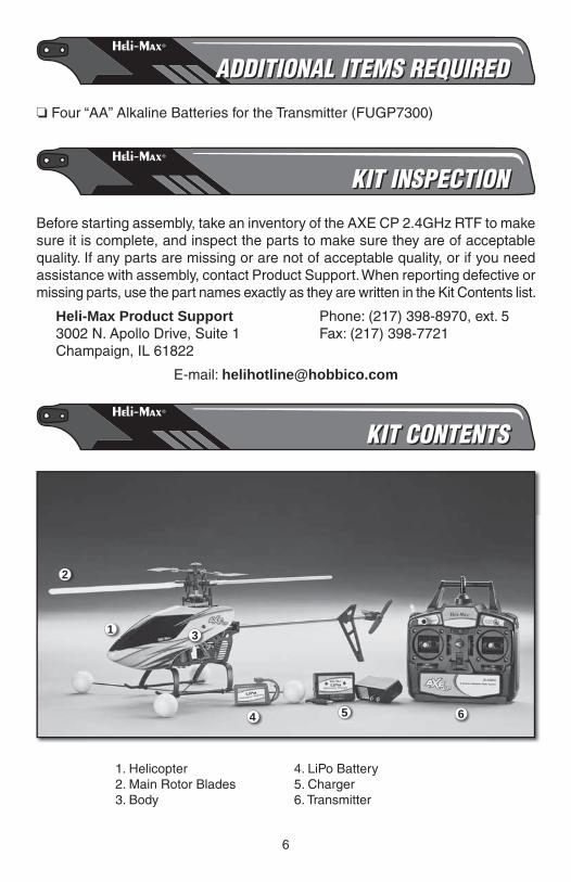
KIT CONTENTSKIT CONTENTS
1
2
4
3
65
1. Helicopter2. Main Rotor Blades3. Body
4. LiPo Battery5. Charger6. Transmitter

7
BATTERY & CHARGERBATTERY & CHARGER
HMXP1004 3S LiPo CHARGER SPECIFICATIONS
Input voltage: 12V DC Battery types, # cells: 3 lithium-polymer cells connected in Series (11.1V LiPo) Charge termination: Voltage detection Minimum battery capacity: 800mAh Status indicator: two LEDs Input connectors: polarized DC power jack for DC input Output connectors: one balance plug Case size: 1.8 x 1 x 2.6 in [45 x 25 x 66mm] Weight: 1.3 oz [41g]
GPMP0413 BATTERY SPECIFICATIONS
Capacity: 1050mAh Number of Cells in Series: 3 Rated Voltage: 11.1V Max. Charge Voltage: 12.6V Min. Discharge Voltage: 8.25V
Ma ximum Recommended Charge Current: 1050mA
Co nt. Discharge Current: 14.25A (15C) Pack Dimensions: 2.2 x 1.26 x 1.1 in [56 x 32 x 28mm] Weight: 3.42 oz [97g]
8
ASSEMBLY INSTRUCTIONSASSEMBLY INSTRUCTIONS
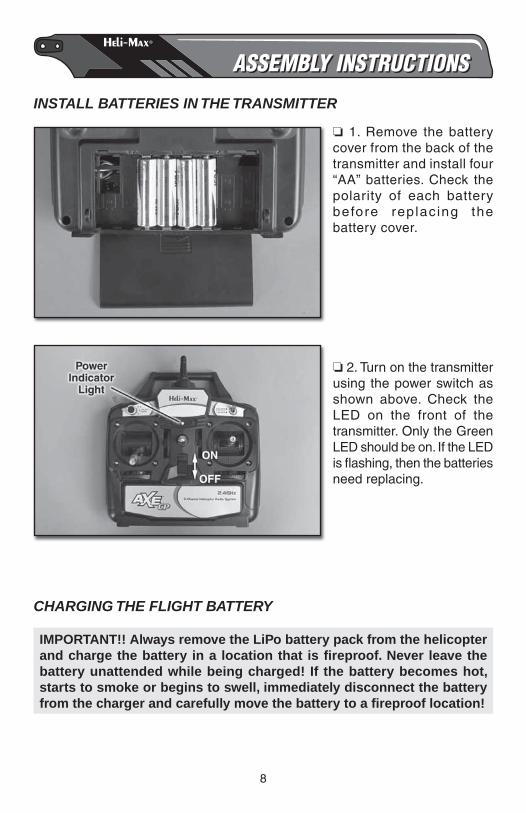
INSTALL BATTERIES IN THE TRANSMITTER
❏ 1. Remove the battery cover from the back of the transmitter and install four “AA” batteries. Check the polarity of each battery before replac ing the battery cover.
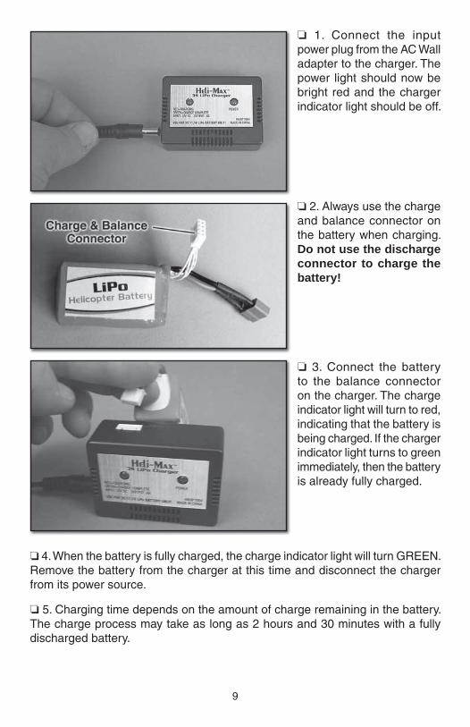
❏ 2. Turn on the transmitter using the power switch as shown above. Check the LED on the front of the transmitter. Only the Green LED should be on. If the LED is fl ashing, then the batteries need replacing.
CHARGING THE FLIGHT BATTERY
IMPORTANT!! Always remove the LiPo battery pack from the helicopter and charge the battery in a location that is fi reproof. Never leave the battery unattended while being charged! If the battery becomes hot, starts to smoke or begins to swell, immediately disconnect the battery from the charger and carefully move the battery to a fi reproof location!
9
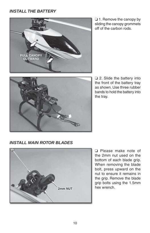
❏ 1. Connect the input power plug from the AC Wall adapter to the charger. The power light should now be bright red and the charger indicator light should be off.
❏ 2. Always use the charge and balance connector on the battery when charging. Do not use the discharge connector to charge the battery!
❏ 3. Connect the battery to the balance connector on the charger. The charge indicator light will turn to red, indicating that the battery is being charged. If the charger indicator light turns to green immediately, then the battery is already fully charged.
❏ 4. When the battery is fully charged, the charge indicator light will turn GREEN. Remove the battery from the charger at this time and disconnect the charger from its power source.
❏ 5. Charging time depends on the amount of charge remaining in the battery. The charge process may take as long as 2 hours and 30 minutes with a fully discharged battery.
10
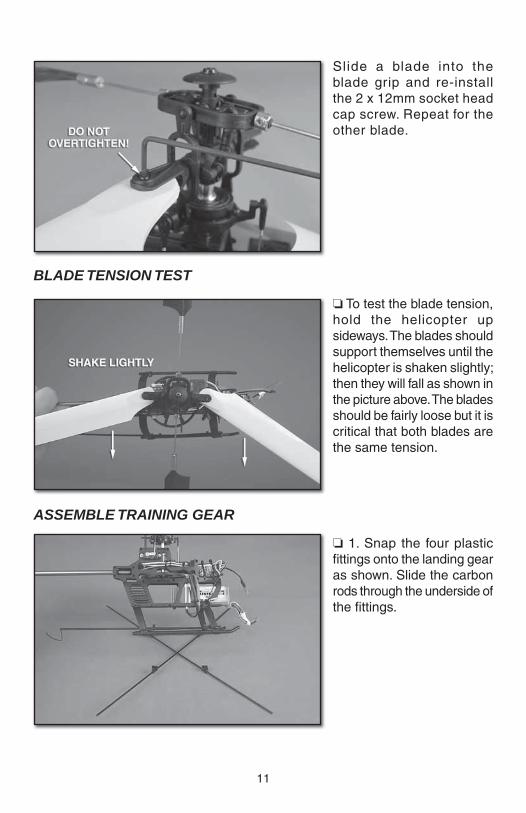
INSTALL THE BATTERY
❏ 1. Remove the canopy by sliding the canopy grommets off of the carbon rods.
❏ 2. Slide the battery into the front of the battery tray as shown. Use three rubber bands to hold the battery into the tray.
INSTALL MAIN ROTOR BLADES
❏ Please make note of the 2mm nut used on the bottom of each blade grip. When removing the blade bolt, press upward on the nut to ensure it remains in the grip. Remove the blade grip bolts using the 1.5mm hex wrench.
11
Slide a blade into the blade grip and re-install the 2 x 12mm socket head cap screw. Repeat for the other blade.
BLADE TENSION TEST
❏ To test the blade tension, hold the helicopter up sideways. The blades should support themselves until the helicopter is shaken slightly; then they will fall as shown in the picture above. The blades should be fairly loose but it is critical that both blades are the same tension.
ASSEMBLE TRAINING GEAR
❏ 1. Snap the four plastic fi ttings onto the landing gear as shown. Slide the carbon rods through the underside of the fi ttings.
12
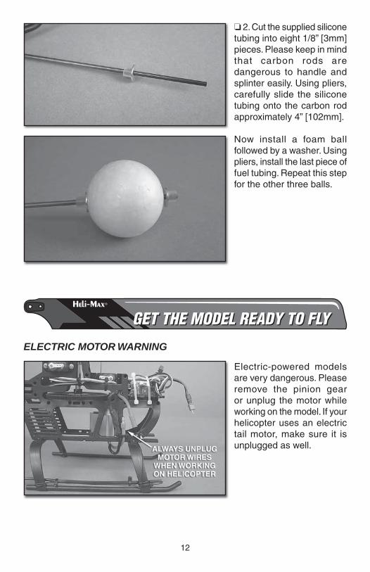
❏ 2. Cut the supplied silicone tubing into eight 1/8” [3mm] pieces. Please keep in mind that carbon rods are dangerous to handle and splinter easily. Using pliers, carefully slide the silicone tubing onto the carbon rod approximately 4” [102mm].
Now install a foam ball followed by a washer. Using pliers, install the last piece of fuel tubing. Repeat this step for the other three balls.
GET THE MODEL READY TO FLYGET THE MODEL READY TO FLY
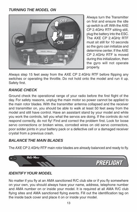
ELECTRIC MOTOR WARNING
Electric-powered models are very dangerous. Please remove the pinion gear or unplug the motor while working on the model. If your helicopter uses an electric tail motor, make sure it is unplugged as well.
13
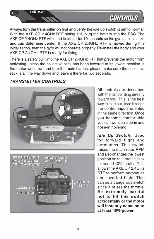
TURNING THE MODEL ON
Always turn the Transmitter on fi rst and ensure the idle up switch is off. With the AXE CP 2.4GHz RTF sitting still, plug the battery into the ESC. The AXE CP 2.4GHz RTF must sit still for 10 seconds so the gyro can initialize and determine center. If the AXE CP 2.4GHz RTF is moved during this initialization, then the gyro will not operate properly.
Always step 15 feet away from the AXE CP 2.4GHz RTF before fl ipping any switches or operating the throttle. Do not hold onto the model and run it up. Safety fi rst.
RANGE CHECK
Ground check the operational range of your radio before the fi rst fl ight of the day. For safety reasons, unplug the main motor so power cannot be applied to the main rotor blades. With the transmitter antenna collapsed and the receiver and transmitter on, you should be able to walk at least 50 feet away from the model and still have control. Have an assistant stand by your model and while you work the controls, tell you what the servos are doing. If the controls do not respond correctly, do not fl y! Find and correct the problem fi rst. Look for loose servo connections or broken wires, corroded wires on old servo connectors, poor solder joints in your battery pack or a defective cell or a damaged receiver crystal from a previous crash.
BALANCE THE MAIN BLADES
The AXE CP 2.4GHz RTF main rotor blades are already balanced and ready to fl y.
PREFLIGHTPREFLIGHT
IDENTIFY YOUR MODEL
No matter if you fl y at an AMA sanctioned R/C club site or if you fl y somewhere on your own, you should always have your name, address, telephone number and AMA number on or inside your model. It is required at all AMA R/C club fl ying sites and AMA sanctioned fl ying events. Fill out the identifi cation tag on the inside back cover and place it on or inside your model.
14
CONTROLSCONTROLSAlways turn the transmitter on fi rst and verify the idle up switch is set to normal. With the AXE CP 2.4GHz RTF sitting still, plug the battery into the ESC. The AXE CP 2.4GHz RTF will need to sit still for 10 seconds so the gyro can initialize and can determine center. If the AXE CP 2.4GHz RTF is moved during this initialization, then the gyro will not operate properly. Re-install the body and your AXE CP 2.4GHz RTF is ready for fl ying.
There is a safety built into the AXE CP 2.4GHz RTF that prevents the motor from activating unless the collective stick has been lowered to its lowest position. If the motor won’t run and turn the main blades, please make sure the collective stick is all the way down and leave it there for two seconds.
TRANSMITTER CONTROLS
All controls are described with the tail pointing directly toward you. This is the best way to start out since it keeps the control inputs oriented in the same direction. Once you become comfortable you can work on side-in and nose-in hovering.
Idle Up Switch: Used for forward fl ight and aerobatics. This switch raises the main rotor RPM and also changes the lowest position on the throttle stick to around 40% throttle. This allows the AXE CP 2.4GHz RTF to perform aerobatics and inverted flight. This can be a dangerous switch since it raises the throttle. Be extremely careful not to hit this switch accidentally or the motor will instantly come on to at least 40% power.
15
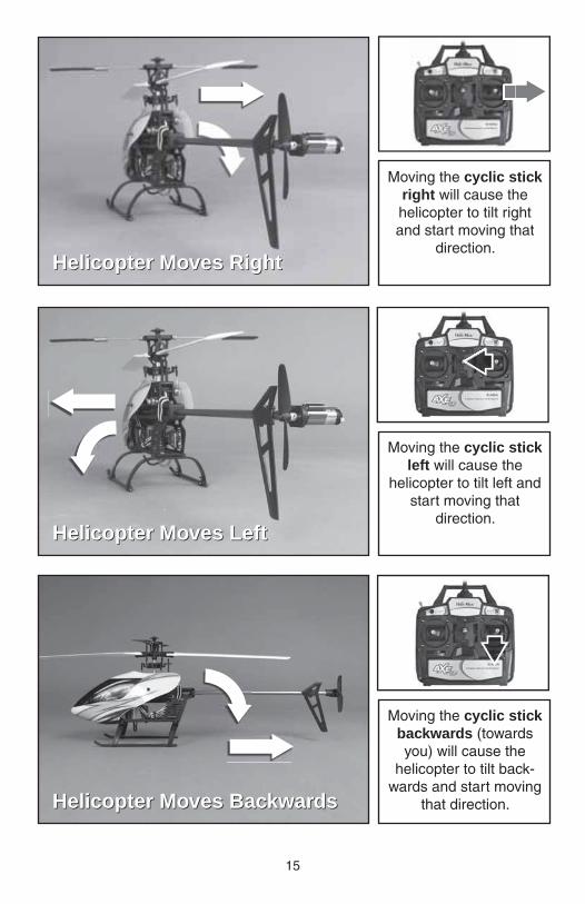
Moving the cyclic stick right will cause the helicopter to tilt right and start moving that
direction. Helicopter Moves RightHelicopter Moves Right
Moving the cyclic stick left will cause the
helicopter to tilt left and start moving that
direction.Helicopter Moves LeftHelicopter Moves Left
Moving the cyclic stick backwards (towards you) will cause the
helicopter to tilt back-wards and start moving
that direction.Helicopter Moves BackwardsHelicopter Moves Backwards
16
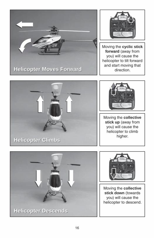
Moving the cyclic stick forward (away from you) will cause the
helicopter to tilt forward and start moving that
direction.Helicopter Moves ForwardHelicopter Moves Forward
Moving the collective stick up (away from you) will cause the helicopter to climb
higher.Helicopter ClimbsHelicopter Climbs
Moving the collective stick down (towards you) will cause the
helicopter to descend.
Helicopter DescendsHelicopter Descends
17
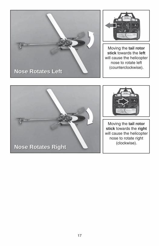
Moving the tail rotor stick towards the left
will cause the helicopter nose to rotate left
(counterclockwise).Nose Rotates LeftNose Rotates Left
Moving the tail rotor stick towards the right will cause the helicopter
nose to rotate right (clockwise).
Nose Rotates RightNose Rotates Right
18
TRACKING THE MAIN BLADES
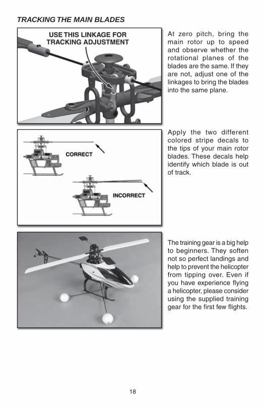
At zero pitch, bring the main rotor up to speed and observe whether the rotational planes of the blades are the same. If they are not, adjust one of the linkages to bring the blades into the same plane.
Apply the two different colored stripe decals to the tips of your main rotor blades. These decals help identify which blade is out of track.
The training gear is a big help to beginners. They soften not so perfect landings and help to prevent the helicopter from tipping over. Even if you have experience fl ying a helicopter, please consider using the supplied training gear for the fi rst few fl ights.
19
FLYINGFLYINGTAKEOFF
During your fi rst fl ights it is important to have light winds and a helper to keep an eye on things around you. Also, if you are fl ying from grass, make sure it’s cut low as this will allow the helicopter to slide around without catching. Also make sure there are no obstacles in your fl ying area to distract you.
Slowly add power and observe the model. If you feel it needs trimming, do so before lift off. You will fi nd that model helicopters never allow you to return the sticks to center. Simply hold the sticks as needed to keep a steady hover. Please don’t fi ght the trim too much as it is a normal thing to experience, Winds have a large effect on model helicopters. Please wait for calmer days and slowly work into windy days.
You will notice the cyclic controls lag slightly behind your inputs. This is perfectly normal and something you become accustomed to. It is normal to drift around some in a hover, until you get used to fl ying the model. The cyclic controls on the AXE CP 2.4GHz RTF are fairly sensitive so only small movements are necessary.
HOVERING
Once the helicopter is in the air simply try to keep the helicopter in one spot. This will take some practice and wind has a big effect on the stability of the helicopter. Be patient and slowly progress. Trying to rush the learning process can be costly.
LANDING
Level the helicopter into a steady hover and slowly decrease power until the helicopter settles onto the ground.
Always unplug the battery whenyou are fi nished with your fl ight.
BASIC MANEUVERS
Once you are comfortable with hovering at different orientations and landing, it’s time to move on to more advanced maneuvers.
Slow Pirouettes: Add a small amount of tail rotor (left or right) and try rotating the helicopter slightly sideways and see if you can hold it there. If you become uncomfortable bring the tail back towards you. Once you are comfortable, try moving the helicopter to the side and turning back. Then fl y back to the other side in straight lines.
20
You can try rotating the helicopter around 360°, which is called a pirouette. The helicopter can drift during this maneuver so make certain you have plenty of room when you fi rst start practicing.
Nose-In Hovering: After pirouettes it’s time to move onto nose-in hovering. The best bet is to wait for a calm day. Take off and climb to 15 feet, practice half pirouettes from tail-in to nose-in hovering, and try to lengthen the delay between transitions. This will allow you to practice nose-in and still gives you a chance to get out of trouble. As you improve you’ll remain nose-in for longer periods of time.
Forward Flight: Now it’s time to work into basic forward fl ight. Just take the basic hovering maneuvers listed above and slowly fl y out farther and faster and always bring the helicopter back after one pass. Practice controlled slow fl ight in close as well. The more time you spend practicing here the easier things will be later on.
AEROBATICS
So you are getting comfortable in fast forward fl ight? Well, now it’s time to slowly progress into aerobatics. Once you are in forward fl ight start using the idle up switch which raises the rotor RPM for aerobatics and allows the AXE CP 2.4GHz RTF to fl y inverted. Also, in wind it may be diffi cult to descend to land without the idle up on.
Chandelles: Your fi rst step is chandelles. Fly straight across in front of you and pull up to a 45° angle. Now at the top, when the helicopter slows down to a stop, apply left or right tail rotor to bring the nose around 180° and continue back down the 45° angle. As you progress with the maneuver you can pull a greater angle than 45°, but 90° would be considered a stall turn.
Loops: Once you become comfortable with the chandelles and stall turns it’s time to move onto the loop. The key to the loop is to enter with plenty of speed. Start pulling aft cyclic to enter the loop and as the model transitions to inverted at the top of the loop pull back on the throttle (towards negative (–) collective). This will help maintain altitude. As the model returns back to vertical add some positive (+) collective to maintain the speed. One of the most common mistakes made on loops is using too much negative (–) collective at the top.
Flips: Be certain to start with plenty of altitude. From an upright hover slowly add in full forward cyclic and as the model approaches vertical bring the collective stick back to center. Now as the model continues to inverted you will need to start adding in negative (–) collective (or pull the collective stick back towards yourself). As the model transitions back to vertical again bring the collective stick back to the middle and start adding in positive (+) collective as the model returns back to upright. It’s simply a matter of timing. The most important thing is, do not throw the sticks around as this can cause the head speed to drop and may cause the tail to drift.
21
Inverted Hovering: Keep in mind fl ying a helicopter inverted is very diffi cult but can be learned. One of the main problems is 3 out of 4 of the controls are reversed (forward/aft cyclic, collective and tail rotor). You have to mentally reverse these while fl ying. It will take some practice.
Take the loop you learned above and just hold the inverted portion for short periods of time. As you become accustomed to the reversed controls, you will extend the time inverted. It is very diffi cult and will take some practice. Also, make sure you have plenty of altitude for recovery if needed.
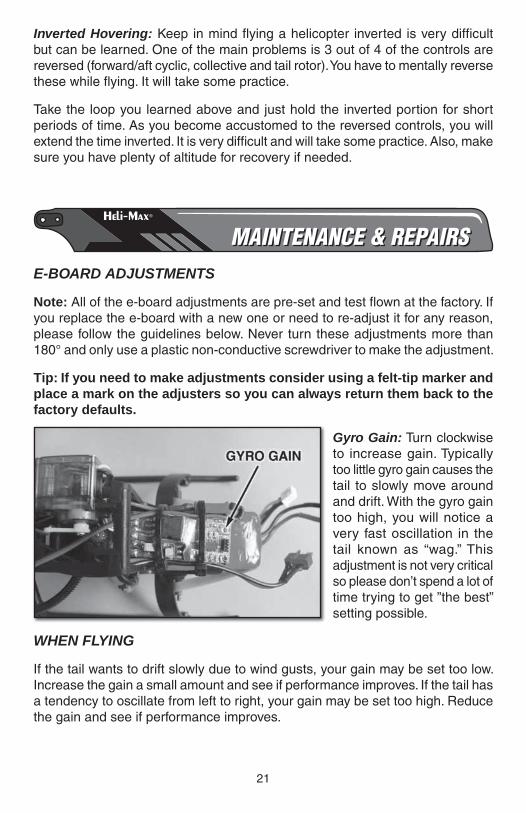
MAINTENANCE & REPAIRSMAINTENANCE & REPAIRSE-BOARD ADJUSTMENTS
Note: All of the e-board adjustments are pre-set and test fl own at the factory. If you replace the e-board with a new one or need to re-adjust it for any reason, please follow the guidelines below. Never turn these adjustments more than 180° and only use a plastic non-conductive screwdriver to make the adjustment.
Tip: If you need to make adjustments consider using a felt-tip marker and place a mark on the adjusters so you can always return them back to the factory defaults.
Gyro Gain: Turn clockwise to increase gain. Typically too little gyro gain causes the tail to slowly move around and drift. With the gyro gain too high, you will notice a very fast oscillation in the tail known as “wag.” This adjustment is not very critical so please don’t spend a lot of time trying to get ”the best” setting possible.
WHEN FLYING
If the tail wants to drift slowly due to wind gusts, your gain may be set too low. Increase the gain a small amount and see if performance improves. If the tail has a tendency to oscillate from left to right, your gain may be set too high. Reduce the gain and see if performance improves.
22
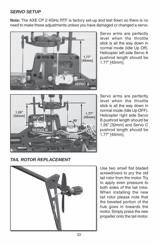
SERVO SETUP
Note: The AXE CP 2.4GHz RTF is factory set-up and test fl own so there is no need to make these adjustments unless you have damaged or changed a servo.
Servo arms are perfectly level when the throttle stick is all the way down in normal mode (Idle Up Off). Helicopter left side Servo A pushrod length should be 1.77” [45mm].
Servo arms are perfectly level when the throttle stick is all the way down in normal mode (Idle Up OFF). Helicopter right side Servo B pushrod length should be 1.26” [32mm] and Servo C pushrod length should be 1.77” [45mm].
TAIL ROTOR REPLACEMENT
Use two small fl at bladed screwdrivers to pry the old tail rotor from the motor. Try to apply even pressure to both sides of the tail rotor. When installing the new tail rotor please note that the beveled portion of the hub goes in towards the motor. Simply press the new propeller onto the tail motor.
23
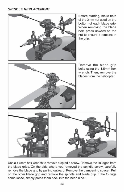
SPINDLE REPLACEMENT
Before starting, make note of the 2mm nut used on the bottom of each blade grip. When removing the blade bolt, press upward on the nut to ensure it remains in the grip.
Remove the blade grip bolts using the 1.5mm hex wrench. Then, remove the blades from the helicopter.
Use a 1.5mm hex wrench to remove a spindle screw. Remove the linkages from the blade grips. On the side where you removed the spindle screw, carefully remove the blade grip by pulling outward. Remove the dampening spacer. Pull on the other blade grip and remove the spindle and blade grip. If the O-rings come loose, simply press them back into the head block.
24
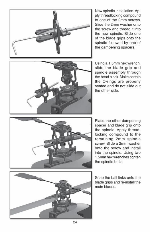
New spindle installation. Ap-ply threadlocking compound to one of the 2mm screws. Slide the 2mm washer onto the screw and thread it into the new spindle. Slide one of the blade grips onto the spindle followed by one of the dampening spacers.
Using a 1.5mm hex wrench, slide the blade grip and spindle assembly through the head block. Make certain the O-rings are properly seated and do not slide out the other side.
Place the other dampening spacer and blade grip onto the spindle. Apply thread-locking compound to the remaining 2mm spindle screw. Slide a 2mm washer onto the screw and install into the spindle. Using two 1.5mm hex wrenches tighten the spindle bolts.
Snap the ball links onto the blade grips and re-install the main blades.
25
MAIN SHAFT REMOVAL
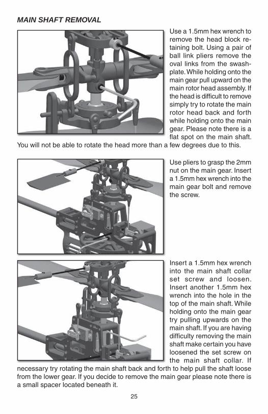
Use a 1.5mm hex wrench to remove the head block re-taining bolt. Using a pair of ball link pliers remove the oval links from the swash-plate. While holding onto the main gear pull upward on the main rotor head assembly. If the head is diffi cult to remove simply try to rotate the main rotor head back and forth while holding onto the main gear. Please note there is a fl at spot on the main shaft.
You will not be able to rotate the head more than a few degrees due to this.
Use pliers to grasp the 2mm nut on the main gear. Insert a 1.5mm hex wrench into the main gear bolt and remove the screw.
Insert a 1.5mm hex wrench into the main shaft collar set screw and loosen. Insert another 1.5mm hex wrench into the hole in the top of the main shaft. While holding onto the main gear try pulling upwards on the main shaft. If you are having diffi culty removing the main shaft make certain you have loosened the set screw on the main shaft collar. If
necessary try rotating the main shaft back and forth to help pull the shaft loose from the lower gear. If you decide to remove the main gear please note there is a small spacer located beneath it.
26
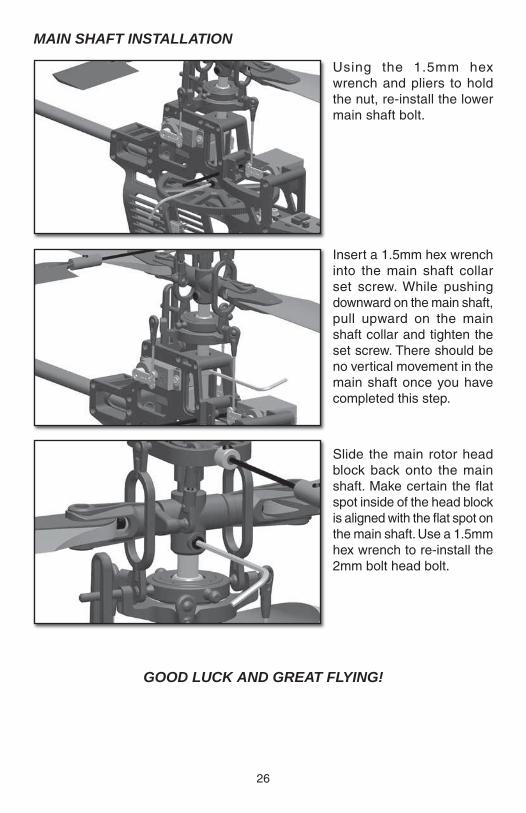
MAIN SHAFT INSTALLATION
Using the 1.5mm hex wrench and pliers to hold the nut, re-install the lower main shaft bolt.
Insert a 1.5mm hex wrench into the main shaft collar set screw. While pushing downward on the main shaft, pull upward on the main shaft collar and tighten the set screw. There should be no vertical movement in the main shaft once you have completed this step.
Slide the main rotor head block back onto the main shaft. Make certain the fl at spot inside of the head block is aligned with the fl at spot on the main shaft. Use a 1.5mm hex wrench to re-install the 2mm bolt head bolt.
GOOD LUCK AND GREAT FLYING!

27
ORDERING PARTSORDERING PARTSReplacement parts for the Heli-Max AXE CP 2.4GHz RTF are available using the order numbers in the Parts List on page 28. The fastest, most economical service can be provided by your hobby dealer.
To locate a hobby dealer, visit the Hobbico web site at www.hobbico.com. Choose “Where to Buy” at the bottom of the menu on the left side of the page. Follow the instructions provided on the page to locate a U.S., Canadian or International dealer.
Parts may also be ordered directly from Hobby Services by calling (217) 398-0007, or via facsimile at (217) 398-7721, but full retail prices and shipping and handling charges will apply. Illinois and Nevada residents will also be charged sales tax. If ordering via fax, include a Visa® or MasterCard® number and expiration date for payment.
Mail parts orders Hobby Services and payments by 3002 N. Apollo Drive, Suite 1 personal check to: Champaign, IL 61822
Be certain to specify the order number exactly as listed in the Parts List. Payment by credit card or personal check only; no C.O.D.
If additional assistance is required for any reason contact Product Support by e-mail at [email protected], or by telephone at (217) 398-8970.
28
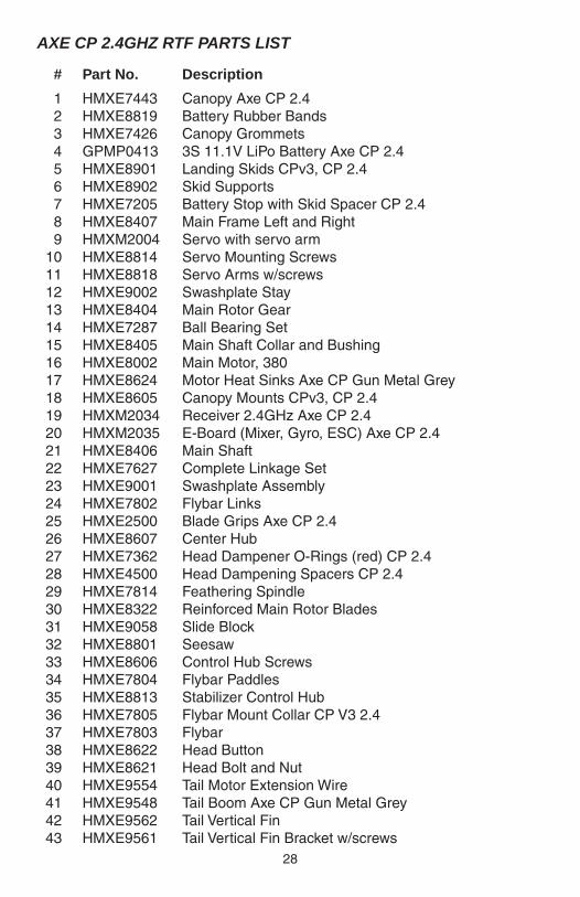
AXE CP 2.4GHZ RTF PARTS LIST
# Part No. Description
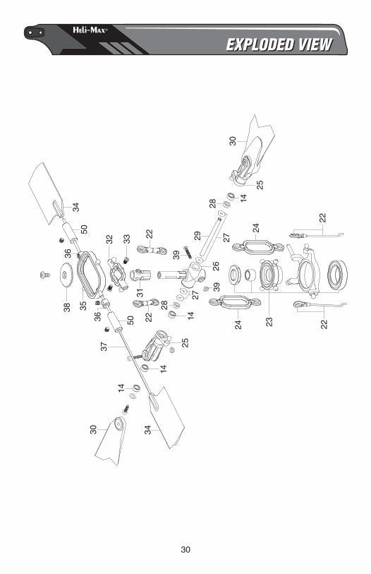
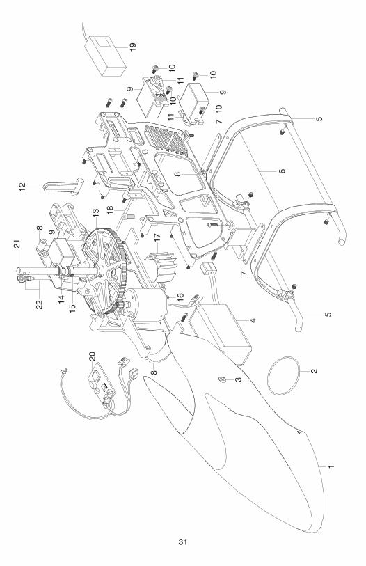
1 HMXE7443 Canopy Axe CP 2.4 2 HMXE8819 Battery Rubber Bands 3 HMXE7426 Canopy Grommets 4 GPMP0413 3S 11.1V LiPo Battery Axe CP 2.4 5 HMXE8901 Landing Skids CPv3, CP 2.4 6 HMXE8902 Skid Supports 7 HMXE7205 Battery Stop with Skid Spacer CP 2.4 8 HMXE8407 Main Frame Left and Right 9 HMXM2004 Servo with servo arm 10 HMXE8814 Servo Mounting Screws 11 HMXE8818 Servo Arms w/screws 12 HMXE9002 Swashplate Stay 13 HMXE8404 Main Rotor Gear 14 HMXE7287 Ball Bearing Set 15 HMXE8405 Main Shaft Collar and Bushing 16 HMXE8002 Main Motor, 380 17 HMXE8624 Motor Heat Sinks Axe CP Gun Metal Grey 18 HMXE8605 Canopy Mounts CPv3, CP 2.4 19 HMXM2034 Receiver 2.4GHz Axe CP 2.4 20 HMXM2035 E-Board (Mixer, Gyro, ESC) Axe CP 2.4 21 HMXE8406 Main Shaft 22 HMXE7627 Complete Linkage Set 23 HMXE9001 Swashplate Assembly 24 HMXE7802 Flybar Links 25 HMXE2500 Blade Grips Axe CP 2.4 26 HMXE8607 Center Hub 27 HMXE7362 Head Dampener O-Rings (red) CP 2.4 28 HMXE4500 Head Dampening Spacers CP 2.4 29 HMXE7814 Feathering Spindle 30 HMXE8322 Reinforced Main Rotor Blades 31 HMXE9058 Slide Block 32 HMXE8801 Seesaw 33 HMXE8606 Control Hub Screws 34 HMXE7804 Flybar Paddles 35 HMXE8813 Stabilizer Control Hub 36 HMXE7805 Flybar Mount Collar CP V3 2.4 37 HMXE7803 Flybar 38 HMXE8622 Head Button 39 HMXE8621 Head Bolt and Nut 40 HMXE9554 Tail Motor Extension Wire 41 HMXE9548 Tail Boom Axe CP Gun Metal Grey 42 HMXE9562 Tail Vertical Fin 43 HMXE9561 Tail Vertical Fin Bracket w/screws
29
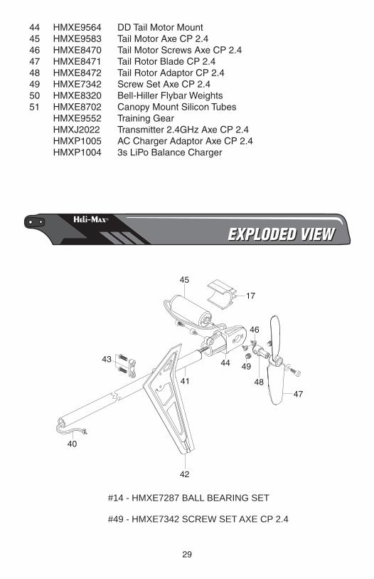
44 HMXE9564 DD Tail Motor Mount 45 HMXE9583 Tail Motor Axe CP 2.4 46 HMXE8470 Tail Motor Screws Axe CP 2.4 47 HMXE8471 Tail Rotor Blade CP 2.4 48 HMXE8472 Tail Rotor Adaptor CP 2.4 49 HMXE7342 Screw Set Axe CP 2.4 50 HMXE8320 Bell-Hiller Flybar Weights 51 HMXE8702 Canopy Mount Silicon Tubes HMXE9552 Training Gear HMXJ2022 Transmitter 2.4GHz Axe CP 2.4 HMXP1005 AC Charger Adaptor Axe CP 2.4 HMXP1004 3s LiPo Balance Charger
EXPLODED VIEWEXPLODED VIEW
#14 - HMXE7287 BALL BEARING SET
#49 - HMXE7342 SCREW SET AXE CP 2.4
43
40
44
41
45
46
17
4748
49
42
30
25
14
14
30 34
37
3538
36
50
36
22
32 33
14
28
29
2231
50
39
27
2627
39
22222324
24
28
25
1430
34
EXPLODED VIEWEXPLODED VIEW
31
9
21
8
141522
8
16
20
7
17
4
6
579
1010
8
9
1110
1011
19
13 18
12
5
2
3
1
32
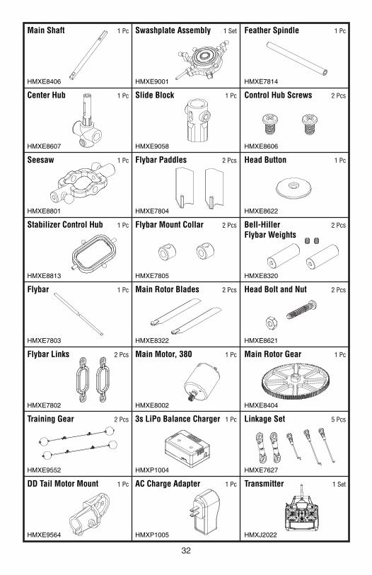
Main Shaft 1 Pc
HMXE8406
Center Hub 1 Pc
HMXE8607
Seesaw 1 Pc
HMXE8801
Stabilizer Control Hub 1 Pc
HMXE8813
Flybar 1 Pc
HMXE7803
Flybar Links 2 Pcs
HMXE7802
Training Gear 2 Pcs
HMXE9552
DD Tail Motor Mount 1 Pc
HMXE9564
Swashplate Assembly 1 Set
HMXE9001
Slide Block 1 Pc
HMXE9058
Flybar Paddles 2 Pcs
HMXE7804
Flybar Mount Collar 2 Pcs
HMXE7805
Main Rotor Blades 2 Pcs
HMXE8322
Main Motor, 380 1 Pc
HMXE8002
3s LiPo Balance Charger 1 Pc
HMXP1004
AC Charge Adapter 1 Pc
HMXP1005
Feather Spindle 1 Pc
HMXE7814
Control Hub Screws 2 Pcs
HMXE8606
Head Button 1 Pc
HMXE8622
Bell-HillerFlybar Weights
2 Pcs
HMXE8320
Head Bolt and Nut 2 Pcs
HMXE8621
Main Rotor Gear 1 Pc
HMXE8404
Linkage Set 5 Pcs
HMXE7627
Transmitter 1 Set
HMXJ2022
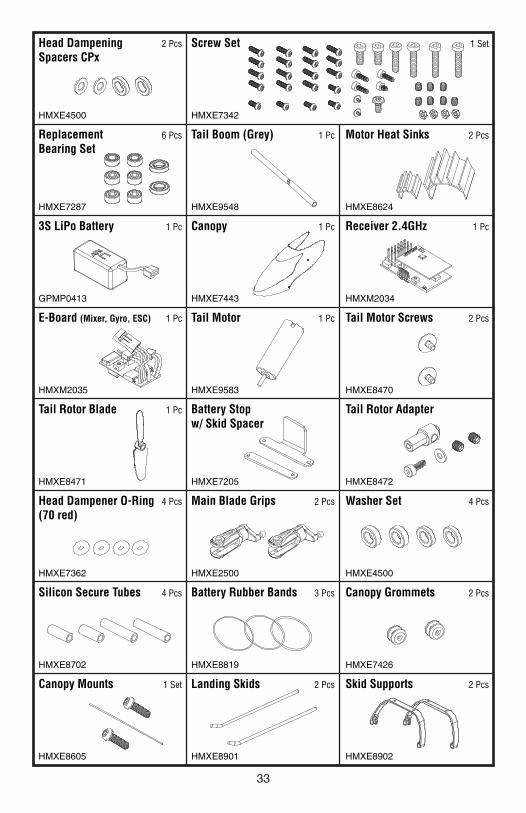
33
Head DampeningSpacers CPx
2 Pcs
HMXE4500
ReplacementBearing Set
6 Pcs
HMXE7287
3S LiPo Battery 1 Pc
GPMP0413
E-Board (Mixer, Gyro, ESC) 1 Pc
HMXM2035
Tail Rotor Blade 1 Pc
HMXE8471
Head Dampener O-Ring(70 red)
4 Pcs
HMXE7362
Silicon Secure Tubes 4 Pcs
HMXE8702
Canopy Mounts 1 Set
HMXE8605
Screw Set
HMXE7342
Tail Boom (Grey) 1 Pc
HMXE9548
Canopy 1 Pc
HMXE7443
Tail Motor 1 Pc
HMXE9583
Battery Stopw/ Skid Spacer
HMXE7205
Main Blade Grips 2 Pcs
HMXE2500
Battery Rubber Bands 3 Pcs
HMXE8819
Landing Skids 2 Pcs
HMXE8901
1 Set
Motor Heat Sinks 2 Pcs
HMXE8624
Receiver 2.4GHz 1 Pc
HMXM2034
Tail Motor Screws 2 Pcs
HMXE8470
Tail Rotor Adapter
HMXE8472
Washer Set 4 Pcs
HMXE4500
Canopy Grommets 2 Pcs
HMXE7426
Skid Supports 2 Pcs
HMXE8902
34
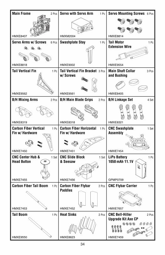
Main Frame 2 Pcs
HMXE8407
Servo Arms w/ Screws 6 Pcs
HMXE8818
Tail Vertical Fin 1 Pc
HMXE9562
B/H Mixing Arms 2 Pcs
HMXE8319
Carbon Fiber VerticalFin w/ Hardware
1 Pc
HMXE7450
CNC Center Hub &Head Button
1 Set
HMXE7455
Carbon Fiber Tail Boom 1 Pc
HMXE7453
Tail Boom 1 Pc
HMXE9550
Servo with Servo Arm 1 Pc
HMXM2004
Swashplate Stay 1 Pc
HMXE9002
Tail Vertical Fin Bracketw/ Screws
3 Pcs
HMXE9561
B/H Main Blade Grips 2 Pcs
HMXE8318
Carbon Fiber HorizontalFin w/ Hardware
1 Pc
HMXE7451
CNC Slide Block& Seesaw
1 Set
HMXE7456
Carbon Fiber FlybarPaddles
2 Pcs
HMXE7452
Heat Sinks 2 Pcs
HMXE8623
Servo Mounting Screws 6 Pcs
HMXE8814
Tail MotorExtension Wire
1 Pc
HMXE9554
Main Shaft Collarand Bushing
3 Pcs
HMXE8405
B/H Linkage Set 4 Set
HMXE8321
CNC SwashplateAssembly
1 Set
HMXE7454
LiPo Battery1050 mAh 11.1V
1 Pc
GPMP0709
CNC Flybar Carrier 1 Pc
HMXE7657
CNC Bell-HillerUpgrade Kit Axe CP
2 Pcs
HMXE7459

35
This model belongs to:
Name
Address
City, State, Zip
Phone Number
AMA Number

Entire Contents © 2011 Hobbico,® Inc. All rights reserved. HMXE0810