Embed Size (px)
Citation preview
Immersion Cell
(with Small Volume Vessel)
User Guide
65-190-027 Rev. C
Page 1 of 13 65-190-027 Rev. C ©2012 Hanson Research Corp.
Congratulations on the purchase of your Hanson Immersion Cell(s). While we are
certain you will enjoy the Hanson experience, we also understand that from time to
time you may have a question or technical issue requiring our assistance. Please
feel free to contact us at any time. We’re happy to help!
Online: www.hansonresearch.com
Tech Support Request Form: www.hansonresearch.com/tsr
E-Mail: [email protected]
Phone: 800.821.8165 or 818.882.7266
Fax: 818.882.9470
Corporate Headquarters:
Hanson Research Corporation
9810 Variel Avenue
Chatsworth, CA 91311 USA
©2012 Hanson Research Corp. 65-190-027 Rev. C Page 2 of 13
1. Introduction ...............................................................................................................................................3
1.1 The Immersion Cell .................................................................................................................................5
1.1.1. Immersion Cell Features .................................................................................................................3
1.1.2. Immersion Cell Options ...................................................................................................................3
1.1.3. Immersion Cell Tools .......................................................................................................................4
2. Installation .................................................................................................................................................5
2.1 Components .............................................................................................................................................6
2.2 Immersion Cell Assembly .......................................................................................................................6
2.3 Immersion Cell Installation .....................................................................................................................6
2.4 Immersion Cell Removal ........................................................................................................................6
2.5 Installing the Immersion Cell in a Dissolution Tester .........................................................................6
2.5.1. For Use with a Vision Elite 8 Tester ..............................................................................................7
2.5.2. For Use with a Vision Classic 6 Tester .........................................................................................8
2.5.3. For Use with an SR8-Plus Tester ..................................................................................................9
3. Accessory Options ............................................................................................................................... 11
4. Specifications ........................................................................................................................................ 12
Page 3 of 13 65-190-027 Rev. C ©2011 Hanson Research Corp.
1. Introduction
1.1. The Immersion Cell
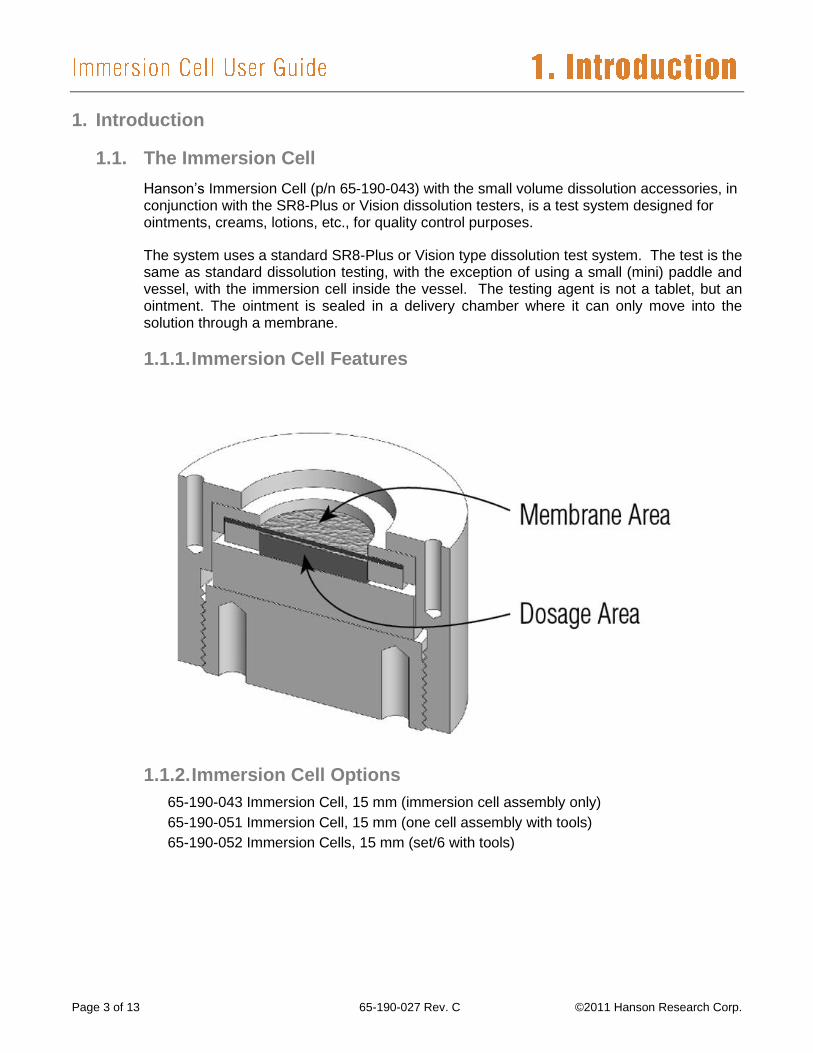
Hanson’s Immersion Cell (p/n 65-190-043) with the small volume dissolution accessories, in conjunction with the SR8-Plus or Vision dissolution testers, is a test system designed for ointments, creams, lotions, etc., for quality control purposes.
The system uses a standard SR8-Plus or Vision type dissolution test system. The test is the same as standard dissolution testing, with the exception of using a small (mini) paddle and vessel, with the immersion cell inside the vessel. The testing agent is not a tablet, but an ointment. The ointment is sealed in a delivery chamber where it can only move into the solution through a membrane.
1.1.1. Immersion Cell Features
1.1.2. Immersion Cell Options
65-190-043 Immersion Cell, 15 mm (immersion cell assembly only)
65-190-051 Immersion Cell, 15 mm (one cell assembly with tools)
65-190-052 Immersion Cells, 15 mm (set/6 with tools)
©2012 Hanson Research Corp. 65-190-027 Rev. C Page 4 of 13
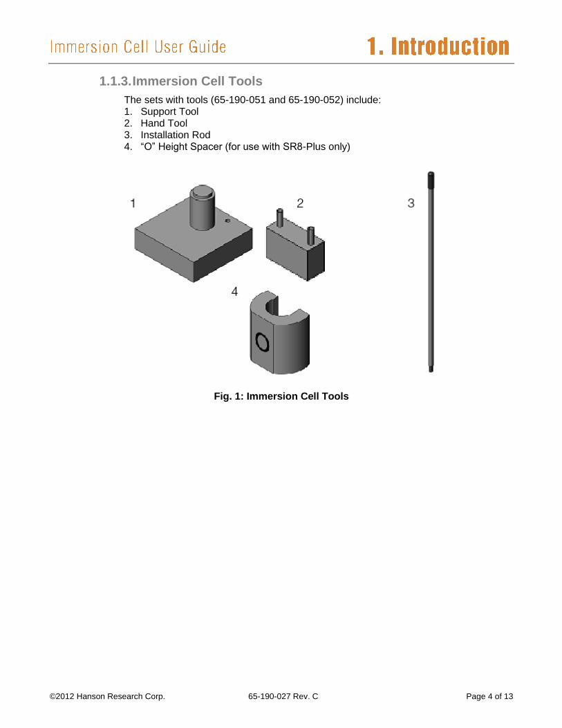
1.1.3. Immersion Cell Tools
The sets with tools (65-190-051 and 65-190-052) include: 1. Support Tool 2. Hand Tool 3. Installation Rod 4. “O” Height Spacer (for use with SR8-Plus only)
Fig. 1: Immersion Cell Tools
Page 5 of 13 65-190-027 Rev. C ©2012 Hanson Research Corp.
2. Installation
The immersion cell can be installed in the flat-bottom small volume vessel on the Hanson Vision
Classic 6, Vision Elite 8, or SR8-Plus dissolution tester. As an added option, manual sampling
probes can be added for sampling.
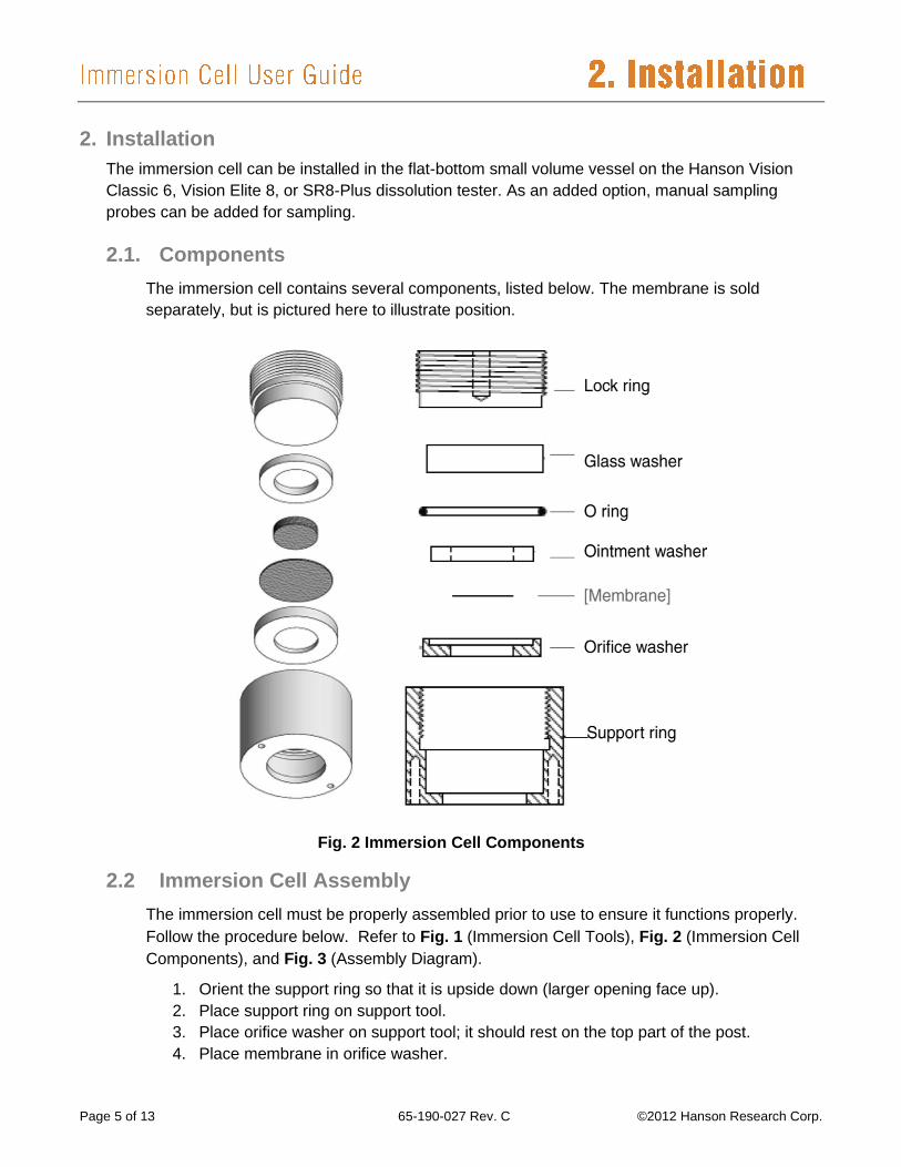
2.1. Components
The immersion cell contains several components, listed below. The membrane is sold
separately, but is pictured here to illustrate position.
2.2 Immersion Cell Assembly
The immersion cell must be properly assembled prior to use to ensure it functions properly.
Follow the procedure below. Refer to Fig. 1 (Immersion Cell Tools), Fig. 2 (Immersion Cell
Components), and Fig. 3 (Assembly Diagram).
1. Orient the support ring so that it is upside down (larger opening face up).
2. Place support ring on support tool.
3. Place orifice washer on support tool; it should rest on the top part of the post.
4. Place membrane in orifice washer.
Fig. 2 Immersion Cell Components
©2012 Hanson Research Corp. 65-190-027 Rev. C Page 6 of 13
5. Place ointment washer on top of the orifice washer; the two should fit together to hold
the membrane in place. Squeeze these together, making sure to keep membrane
wrinkles to a minimum.
6. Apply dose to the membrane, inside the circular area in the middle of the ointment
washer. Spread to evenly fill the dosage area.
7. Place O ring over washers.
8. Place glass washer on top of ointment washer and O ring.
9. Lift support ring, keeping slight pressure on glass washer.
10. Washers will move to the bottom of support ring; lift the entire assembly off the support
tool, pushing down gently on the glass washer to ensure the assembly sits at the
bottom of the support ring.
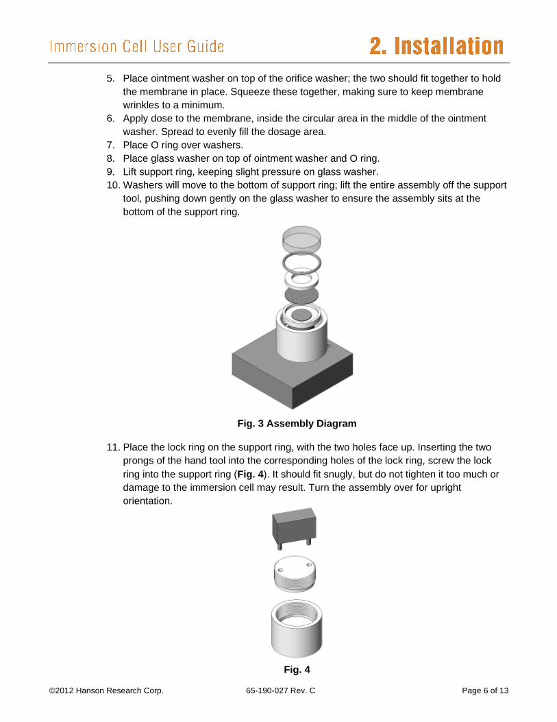
11. Place the lock ring on the support ring, with the two holes face up. Inserting the two
prongs of the hand tool into the corresponding holes of the lock ring, screw the lock
ring into the support ring (Fig. 4). It should fit snugly, but do not tighten it too much or
damage to the immersion cell may result. Turn the assembly over for upright
orientation.
Fig. 3 Assembly Diagram
Fig. 4
Page 7 of 13 65-190-027 Rev. C ©2012 Hanson Research Corp.
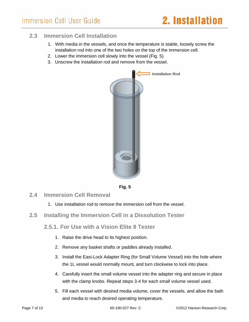
2.3 Immersion Cell Installation
1. With media in the vessels, and once the temperature is stable, loosely screw the
installation rod into one of the two holes on the top of the immersion cell.
2. Lower the immersion cell slowly into the vessel (Fig. 5).
3. Unscrew the installation rod and remove from the vessel.
2.4 Immersion Cell Removal
1. Use installation rod to remove the immersion cell from the vessel.
2.5 Installing the Immersion Cell in a Dissolution Tester
2.5.1. For Use with a Vision Elite 8 Tester
1. Raise the drive head to its highest position.
2. Remove any basket shafts or paddles already installed.
3. Install the Easi-Lock Adapter Ring (for Small Volume Vessel) into the hole where
the 1L vessel would normally mount, and turn clockwise to lock into place.
4. Carefully insert the small volume vessel into the adapter ring and secure in place
with the clamp knobs. Repeat steps 3-4 for each small volume vessel used.
5. Fill each vessel with desired media volume, cover the vessels, and allow the bath
and media to reach desired operating temperature.
Fig. 5
Installation Rod
©2012 Hanson Research Corp. 65-190-027 Rev. C Page 8 of 13
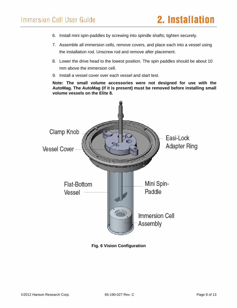
6. Install mini spin-paddles by screwing into spindle shafts; tighten securely.
7. Assemble all immersion cells, remove covers, and place each into a vessel using
the installation rod. Unscrew rod and remove after placement.
8. Lower the drive head to the lowest position. The spin paddles should be about 10
mm above the immersion cell.
9. Install a vessel cover over each vessel and start test.
Note: The small volume accessories were not designed for use with the
AutoMag. The AutoMag (if it is present) must be removed before installing small
volume vessels on the Elite 8.
Fig. 6 Vision Configuration
Page 9 of 13 65-190-027 Rev. C ©2012 Hanson Research Corp.
2.5.2. For Use with a Vision Classic 6 Tester
1. Raise the spindle shaft to about 1” below the fixed drive head (removing any
basket shafts or paddles already in place).
2. Install the Easi-Lock Adapter Ring (for Small Volume Vessel) into the hole where
the 1L vessel would normally mount, and turn clockwise to lock into place.
3. Carefully insert the small volume vessel into the adapter ring and secure in place
with the clamp knobs. Repeat steps 2-3 for each small volume vessel used.
4. Fill each vessel with desired media volume, cover the vessels, and allow the bath
and media to reach desired operating temperature.
5. Install mini spin-paddles by screwing into spindle shafts; tighten securely.
6. Assemble all immersion cells, remove covers, and place each into a vessel using
the installation rod. Unscrew rod and remove after placement.
7. Lower the mini spin-paddles to 10 mm above the immersion cell.
8. Install a vessel cover over each vessel and start test.
2.5.3. For Use with an SR8-Plus Tester
1. Raise the drive head to its highest position.
2. Install the adapter ring into the hole where the 1L vessel would normally mount,
and secure with the clamp knobs on the base plate.
3. Carefully insert the small volume vessel into the adapter ring and secure in place
with the clamp knobs. Repeat steps 2-3 for each small volume vessel used.
4. Install mini spin-paddles in drive head, with about 2 in. showing above the top of
the drive head.
5. Adjust the paddle height:
a. Adjust the lock collars on each of the two guide rods to 1” above the rod mount
(see Fig. 7).
b. Lower the drive head to its lowest position (touching the lock collars).
c. Lower each paddle until it touches the bottom of the vessel, then lock each
paddle shaft in position.
d. Raise the drive head to its highest position and insert the O height spacer
above the lock collar on one of the guide posts.
©2012 Hanson Research Corp. 65-190-027 Rev. C Page 10 of 13
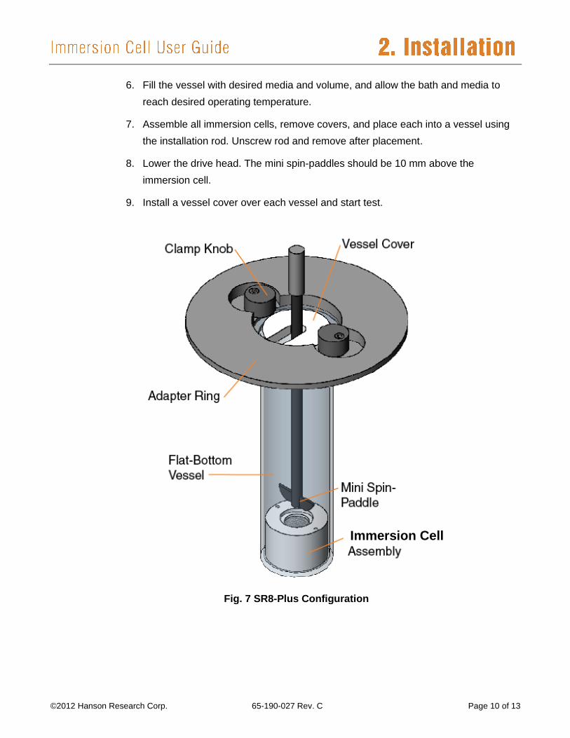
6. Fill the vessel with desired media and volume, and allow the bath and media to
reach desired operating temperature.
7. Assemble all immersion cells, remove covers, and place each into a vessel using
the installation rod. Unscrew rod and remove after placement.
8. Lower the drive head. The mini spin-paddles should be 10 mm above the
immersion cell.
9. Install a vessel cover over each vessel and start test.
Fig. 7 SR8-Plus Configuration
Immersion Cell
Page 11 of 13 65-190-027 Rev. C ©2012 Hanson Research Corp.
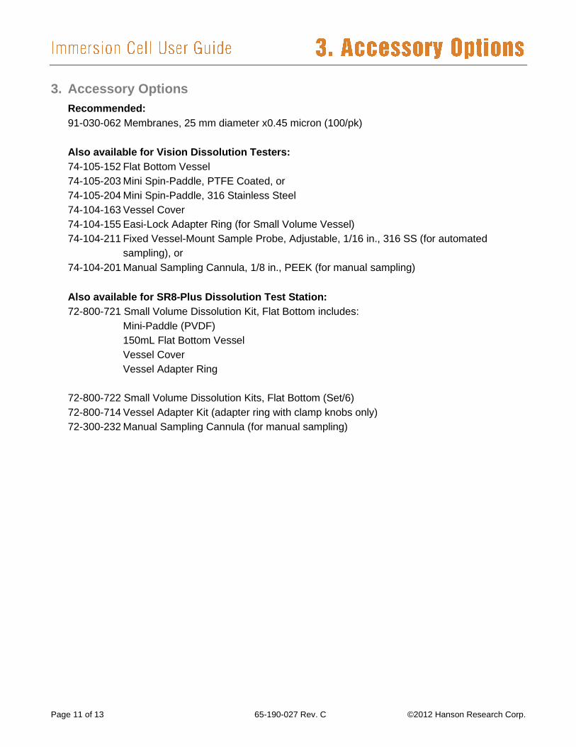
3. Accessory Options
Recommended:
91-030-062 Membranes, 25 mm diameter x0.45 micron (100/pk)
Also available for Vision Dissolution Testers:
74-105-152 Flat Bottom Vessel
74-105-203 Mini Spin-Paddle, PTFE Coated, or
74-105-204 Mini Spin-Paddle, 316 Stainless Steel
74-104-163 Vessel Cover
74-104-155 Easi-Lock Adapter Ring (for Small Volume Vessel)
74-104-211 Fixed Vessel-Mount Sample Probe, Adjustable, 1/16 in., 316 SS (for automated
sampling), or
74-104-201 Manual Sampling Cannula, 1/8 in., PEEK (for manual sampling)
Also available for SR8-Plus Dissolution Test Station:
72-800-721 Small Volume Dissolution Kit, Flat Bottom includes:
Mini-Paddle (PVDF)
150mL Flat Bottom Vessel
Vessel Cover
Vessel Adapter Ring
72-800-722 Small Volume Dissolution Kits, Flat Bottom (Set/6)
72-800-714 Vessel Adapter Kit (adapter ring with clamp knobs only)
72-300-232 Manual Sampling Cannula (for manual sampling)
©2012 Hanson Research Corp. 65-190-027 Rev. C Page 12 of 13
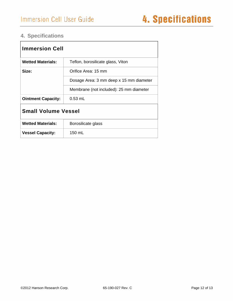
4. Specifications
Immersion Cell
Wetted Materials: Teflon, borosilicate glass, Viton
Size: Orifice Area: 15 mm
Dosage Area: 3 mm deep x 15 mm diameter
Membrane (not included): 25 mm diameter
Ointment Capacity: 0.53 mL
Small Volume Vessel
Wetted Materials: Borosilicate glass
Vessel Capacity: 150 mL

Page 13 of 13 65-190-027 Rev. C ©2012 Hanson Research Corp.
Hanson Research (HRC) products are warranted for one full year including parts and labor. Service
contracts and Preventive Maintenance contracts are available for post-warranty support. International
dealer warranties may vary. HRC makes no warranty, expressed or implied, for glassware,
consumables, or products not manufactured by HRC, as evidenced by nameplate on the item or other
designation. HRC will give responsible assistance to buyer in obtaining from the respective
manufacturer whatever adjustment is reasonable in light of manufacturer’s own warranty. HRC shall be
released from any and all obligations under any warranty, either expressed or implied, if the product
covered is repaired or modified by other than its own personnel, or made without written authorization
from HRC. There are no other warranties, expressed or implied, and HRC shall not be liable under any
circumstances for consequential damages.