Embed Size (px)
Citation preview

APPARECCHIATURA ELETTRONICA pag. 2
MANUALE D’INSTALLAZIONE ED USO
ELECTRONIC EQUIPMENT pag. 4
INSTALLATION AND OPERATION MANUAL
APPAREILLAGE ELECTRONIQUE pag. 6
MANUEL D’ INSTALLATION ET D’ UTILISATION
ELEKTRONIK pag. 8
INSTALLATIONS UND BEDIENUNGS
CENTRALITA ELECTRÓNICA pag. 10
MANUAL DE INSTALACIÓN Y USO
I
GB
F
DE
E
Instrucciones de instalación y reglaje.Intructions de montage et de reglage.Istruzioni per l’installazione e la regolazione.Installation and ajustament instructions.Einbau-und einstellanleitung.
P-504 E
https://appceso.com

- 2 -
L’apparecchiatura elettronica mod. P-504 E prevista per l’automazione di serrande basculanti e portoni è conforme ai sensi delle direttive
73/23/CEE (Bassa tensione), 89/336/CEE (compatibilità elettromagnetica) e consente un’installazione nel rispetto delle normative di sicurezza vigenti.
Completa per gamma di funzionamenti (semiautomatico, automatico e uomo presente) e regolazioni (tempo lavoro, tempo pausa e potenza motore);
Versatile per le opzioni selezionabili (prelampeggio, uscita lampeggiante gestita direttamente dalla centrale, uscita per luce cortesia);
Sicura in quanto unisce alla regolazione della potenza motore e all'ingresso dedicato al dispositivo di sicurezza la funzione reverser;
Facile da installare grazie ai leds di controllo, ai morsetti estraibili e alla serigrafa presente sul circuito stampato.
GENERALITÀ
1) Predisporre a monte dell’installazione un interruttore differenziale o magnetotermico da 10 A. L’interruttore deve garantire una separazione omnipolare con distanza di apertura dei contatti minima di 3 mm.
2) Fissare il contenitore in posizione verticale e garantire che al termine dell'installazione sia rispettato l'iniziale grado di protezione IP 54 (mod. BSx/B ).
3) Differenziare e separare i cavi di "potenza" (sez. minima 1,5 mm 2) da quelli di segnale (sez. minima 0,5 mm 2).
4) Cortocircuitare gli ingressi N.C. (STOP, PhOTO, FCC, FCA ) non utilizzati.
5) Disporre in serie gli eventuali contatti collegati allo stesso ingresso N.C.
6) Disporre in parallelo tutti i contatti collegati all’ingresso START (N.O.).
7) Eseguire i collegamenti come di seguito indicato aiutandosi con la serigrafa presente su circuito stampato.
INSTALLAZIONE
COLLEGAMENTI
REVERSER (vedere NOTA e DIP 5)30 = +6Vdc
31 = Ingresso segnale32 = GND
FOTOCELLULAAgisce solo durante la chiusura arrestando il moto e riaprendo.
STARTPer il funzionamento di questo ingresso vedere DIP 3.
STOPL’azionamento d i questo pulsante/contatto provoca l’arresto immediato di ogni movimento e l’esclusione della uf nzione richiusura automatica.
FINE CORSA (vedere nota)Finecorsa di apertura 20-22Finecorsa di chiusura 21-22N.B. Scambiare i collegamenti ai morsetti 21-22 per invertire i fnecorsa.
8
19
E
PhOTO
GND
N.C.
8
9
E
START
GND
N.O.
7
8E
STOP
GND
N.C.
20
21
22
FCA
FCC
GND
N.C.
N.C.
3130
32
verde
white
brown3x0,5mm2
10 ÷12m max.
14
155Wmax
24V~GND
24 VAC
44
45200Wmax
230V~USER
40
250Hz
230VP
N
5
6
4
M
~
230V~
500VA max
ALIMENTAZIONEIngresso LINEA con protezione interna mediante fusibile (5x20) da 5A
LUCE CORTESIAUscita attiva durante il moto e per altri 60” a partire da ogni arresto.
MOTORE 4 - Apre; 5 - Comune; 6 - ChiudeCollegare il condensatore ai morsetti 4 - 6N.B. Scambiare i collegamenti ai morsetti 4-6 per invertire i versi di marcia.
LAMPEGGIANTEPer il funzionamento di questa uscita vedere DIP 4 e DIP 6.
USCITA 24V~Prevista per alimentazione accessori(Fotocellule, ricevente, ecc.)Protezione interna con fusibile (5 x 20) da 500 mA.
11
12
N
P80Wmax
230V~
ALIMENTAZIONE: 230 V ~ 50 Hz
USCITA MOTORE: 230 V ~ / 500 W Max.
USCITA PER ALIMENTAZIONE ACCESSORI: 24 Vac / 200 mA Max.
USCITA PER DISPOSITIVO LAMPEGGIANTE: 230 V ~ / 80 W Max.
USCITA “USER” LUCE CORTESIA: 230 V ~ / 200W Max.
TEMPO LAVORO: 4”÷90”
TEMPO PAUSA: 4”÷110”
REGOLAZIONE POTENZA: 30÷98%
TEMPERATURA DI FUNZIONAMENTO: -15°÷ +60°
GRADO DI PROTEZIONE: IP 54 (mod. BSX/B)
INGOMBRO MAx (mm): 200x275x130 (mod. BSX/B)
CARATTERISTICHE TECNICHE
bianco
marrone
P-504 E
https://appceso.com
- 3 -
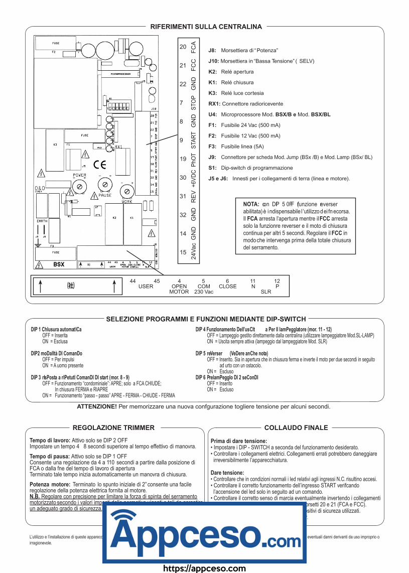
J8: Morsettiera di “Potenza”
J10: Morsettiera in “Bassa Tensione” ( SELV)
K2: Relé apertura
K1: Relé chiusura
K3: Relé luce cortesia
RX1: Connettore radioricevente
U4: Microprocessore Mod. BSX/B e Mod. BSX/BL
F1: Fusibile 24 Vac (500 mA)
F2: Fusibile 12 Vac (500 mA)
F3: Fusibile linea (5A)
J9: Connettore per scheda Mod. Jump (BSx /B) e Mod. Lamp (BSx/ BL)
S1: Dip-switch di programmazione
J5 e J6: Innesti per i collegamenti di terra (linea e motore).
20
21
22
7
8
9
19
30
31
32
14
15
FC
AF
CC
GN
DS
TO
PG
ND
STA
RT
PhO
T+
6V
DC
RE
VG
ND
GN
D24V
ac
40 41 1 2 44 45 4 5 6 11 12NO COM P N USER OPEN COM CLOSE N P MICRO LINE 230 Vac MOTOR 230 Vac SLR
RIFERIMENTI SULLA CENTRALINA
SELEZIONE PROGRAMMI E FUNZIONI MEDIANTE DIP-SWITCH
DIP 1 ChIusura automatICa OFF = Inserita ON = Esclusa
DIP2 moDalItà DI ComanDo OFF = Per impulsi ON = A uomo presente
DIP 3 rIsPosta a rIPetutI ComanDI DI start (mor. 8 - 9) OFF = Funzionamento “condominiale”: APRE; solo a FCA CHIUDE; In chiusura FERMA e RIAPRE ON = Funzionamento “passo - passo” APRE - FERMA - CHIUDE - FERMA
NOTA: con DIP 5 0FF (funzione reverser abilitata) è i ndispensabile l 'utilizzo dei fnecorsa. Il FCA arresta l'apertura mentre il FCC arresta solo la funzionre reverser e il moto di chiusura continua per altri 5 secondi. Regolare il FCC in modo che intervenga prima della totale chiusura del serramento.
DIP 4 FunzIonamento Dell’usCIt a Per Il lamPeggIatore (mor. 11 - 12) OFF = Lampeggio gestito direttamente dalla centralina (utilizzare lampeggiatore Mod.SL-LAMP) ON = Uscita sempre attiva (lampeggio dal lampeggiatore Mod. SLR)
DIP 5 reVerser (VeDere anChe nota) OFF = Inserito. Sia in apertura che in chiusura ferma e inverte il moto per due secondi in seguito ad urto con un ostacolo. ON = EsclusoDIP 6 PrelamPeggIo DI 2 seConDI OFF = Inserito ON = Escluso
ATTENZIONE! Per memorizzare una nuova confgurazione togliere tensione per alcuni secondi.
REGOLAZIONE TRIMMER
Tempo di lavoro: Attivo solo se DIP 2 OFFImpostare un tempo 4 ÷ 8 secondi superiore al tempo effettivo di manovra.
Tempo di pausa: Attivo solo se DIP 1 OFFConsente una regolazione da 4 a 110 secondi a partire dalla posizione di FCA o dalla fne del tempo di lavoro di aperturaTerminato tale tempo inizia automaticamente un manovra di chiusura.
Potenza motore: Terminato lo spunto iniziale di 2” consente una facile regolazione della potenza elettrica fornita al motore.N.B. Regolare con precisione per limitare la forza di spinta del serramento motorizzato secondo i valori imposti dalle normative vigenti e tali da garantire un adeguato grado di sicurezza.
COLLAUDO FINALE
Prima di dare tensione:• Impostare i DIP - SWITCH a seconda del funzionamento desiderato.• Controllare i collegamenti elettrici. Collegamenti errati potrebbero daneggiare irreversibilmente l’apparecchiatura.
Dare tensione:• Controllare che in condizioni normali i led relativi agli ingressi N.C. risultino accesi.• Controllare il corretto funzionamento dell’ingresso START verifcando l’accensione del led solo in seguito ad un comando.• Controllare il corretto senso di marcia eventualmente invertendo i collegamenti ai morsetti 4 e 6 (apertura e chisura) e ai morsetti 20 e 21 (FCA e FCC).• Verifcare il corretto funzionamento dei dispositivi di sicureza utilizzati.• Eseguire con cura le regolazioni sui trimmer.
L’utilizzo e l’installazione di queste apparecchiature deve rispettare rigorosamente le indicazioni fornite dal costruttore che non può essere considerato responsabile per eventuali danni derivanti da uso improprio o
irragionevole.
? ざ
? ざ
https://appceso.com

- 4 -
1) Install a 10Amp RCD or circuit breaker upstream from the installation. The switch must have, for the poles, a minimum 3 mm opening distance between the contacts.
2) Fix the container in an upright position and make sure that, when installation has been completed, the initial protection level IP54 is complied with (BSx/B model).
3) Differentiate and separate the “power” cables (minimum cross sectio of 1.5 mm2) from the signalling ones (minimum cross section of 0.5 mm2).
4) Short circuit the NC inputs (STOP, PhOTO, FCC, FCA) not being used.
5) Arrange in series any contacts connected to the same N.C. input.
6) Arrange in parallel all the contacts connected to the START input (N.O.).
7) Make the connections as described below, using the serigraphy on the printed circuit to help you.
The electronic P-504 E , for the automation of up-and-over doors and main doors, complies with the EEC directives
73/23 (Low Voltage) and 89/336 (EMC) and allows installation in observance of the current safety rules and regulations.
Complete for functioning (semiautomatic, automatic and hold to run control) and adjustment (working time, pause time and motor power) ranges.
Flexible for the choice of options (pre-fashing, fash light output controlled directly by the control unit, output for a courtesy light).
Safe in that it combines motor power adjustment and the output for the safety device with the reverser function.
Easy to install thanks to the control LEDs, pull out terminals and to the serigraphy on the printed circuit.
GENERAL
INSTALLATON
CONNECTIONS
REVERSER (see NOTE and DIP5)30 = +6Vdc31 = signal input32 = GND
PHOTOCELLIt works only during closing, stopping movement and reopening.
STARTSee DIP3 for the functioning of this input
STOPUsing t his p ush b utton/contact, a ll m ovement i s s topped immediately and the automatic reclosing function is excluded.
LIMIT SWITCHES (see note)Opening limit switch (FCA) 20-22Closing limit switch (FCC) 21-22N.B. S wap c onnections o n t erminals 2 1-22 t o r everse the limit switches
8
19
E
PhOTO
GND
N.C.
8
9
E
START
GND
N.O.
7
8E
STOP
GND
N.C.
20
21
22
FCA
FCC
GND
N.C.
N.C.
3130
32
green
white
brown3x0,5mm2
10 ÷12m max.
14
155Wmax
24V~GND
24 VAC
44
45200Wmax
230V~USER
40
250Hz
230VP
N
5
6
4
M
~
230V~
500VA max
POWER LINE Input with internal protection (5x20 5A fuse)
COURTESY LIGHTOutput active during movement and for a further 60 seconds after each stop.
MOTOR4 - Open; 5 - Common; 6 - CloseConnect the capacitor to terminals 4-6N.B. S wap c onnections o n t erminals 4 -6 to reverse direction
FLASHING LIGHTSee DIP4 and DIP6 of r ht e uf nctioning of ht is output.
24 V - OUTPUTFor powering the accessories (Photocells, receiver, etc.)Internal protection (5x20 500 mA fuse)
11
12
N
P80Wmax
230V~
TECHNICAL FEATURESSUPPLY VOLTAGE: 230 V ~ 50 Hz
MOTOR OUTPUT: 230 V ~ / 500 W Max.
ACCESSORIES POWER OUTPUT: 24 Vac / 200 mA Max.
FLAShING LIGhT OUTPUT: 230 V ~ / 80 W Max.
“USER” OUTPUT FOR ThE COURTESY LIGhT: 230 V ~ / 200W Max.
WORKING TIME: 4”÷90”
PAUSE TIME: 4”÷110”
POWER ADJUSTMENT: 30÷98%
WORKING TEMPERATURE: -15°÷ +60°
IP NUMBER: IP 54 (mod. BSX/B)
MAxIMUM OVERALL DIMENSIONS (mm): 200x275x130 (mod. BSX/B)
white
brown
P-504 E
https://appceso.com
- 5 -
? ざ
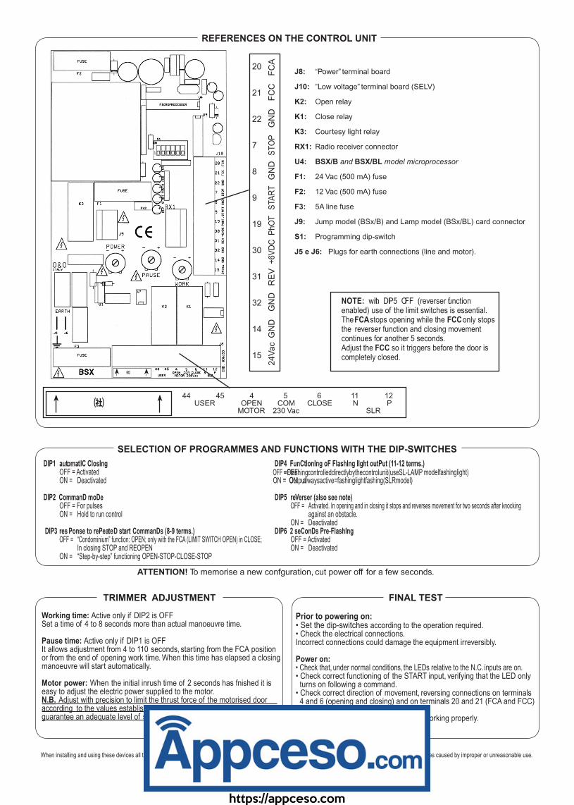
J8: “Power” terminal board
J10: “Low voltage” terminal board (SELV)
K2: Open relay
K1: Close relay
K3: Courtesy light relay
RX1: Radio receiver connector
U4: BSX/B and BSX/BL model microprocessor
F1: 24 Vac (500 mA) fuse
F2: 12 Vac (500 mA) fuse
F3: 5A line fuse
J9: Jump model (BSx/B) and Lamp model (BSx/BL) card connector
S1: Programming dip-switch
J5 e J6: Plugs for earth connections (line and motor).
20
21
22
7
8
9
19
30
31
32
14
15
FC
AF
CC
GN
DS
TO
PG
ND
STA
RT
PhO
T+
6V
DC
RE
VG
ND
GN
D24V
ac
40 41 1 2 44 45 4 5 6 11 12NO COM P N USER OPEN COM CLOSE N P MICRO LINE 230 Vac MOTOR 230 Vac SLR
REFERENCES ON THE CONTROL UNIT
SELECTION OF PROGRAMMES AND FUNCTIONS WITH THE DIP-SWITCHES
DIP1 automatIC ClosIng OFF = Activated ON = Deactivated
DIP2 CommanD moDe OFF = For pulses ON = Hold to run control
DIP3 res Ponse to rePeateD start CommanDs (8-9 terms.) OFF = “Condominium” function: OPEN; only with the FCA (LIMIT SWITCH OPEN) in CLOSE; In closing STOP and REOPEN ON = “Step-by-step” functioning OPEN-STOP-CLOSE-STOP
NOTE: wiht DPI 5 OFF (reverser uf nction enabled) use of the limit switches is essential. The FCA stops opening while the FCC only stops the reverser function and closing movement continues for another 5 seconds.Adjust the FCC so it triggers before the door is completely closed.
DIP4 FunCtIonIng oF FlashIng lIght outPut (11-12 terms.)=OFlFaFshingcontrolleddirectlybythecontrolunit(useSL-LAMP modelfashinglight)= OONutpuatlwaysactive=fashinglightfashing(SLRmodel)
DIP5 reVerser (also see note) OFF =
OFF =
Activated. In opening and in closing it stops and reverses movement for two seconds after knocking against an obstacle. ON =
ON =
DeactivatedDIP6 2 seConDs Pre-FlashIng OFF = Activated ON = Deactivated
ATTENTION! To memorise a new confguration, cut power off for a few seconds.
TRIMMER ADJUSTMENT
Working time: Active only if DIP2 is OFFSet a time of 4 to 8 seconds more than actual manoeuvre time.
Pause time: Active only if DIP1 is OFFIt allows adjustment from 4 to 110 seconds, starting from the FCA position or from the end of opening work time. When this time has elapsed a closing manoeuvre will start automatically.
Motor power: When the initial inrush time of 2 seconds has fnished it is easy to adjust the electric power supplied to the motor.N.B. Adjust with precision to limit the thrust force of the motorised door according to the values established by current standards and such to guarantee an adequate level of safety.
FINAL TEST
Prior to powering on:• Set the dip-switches according to the operation required.• Check the electrical connections. Incorrect connections could damage the equipment irreversibly.
Power on:• Check that, under normal conditions, the LEDs relative to the N.C. inputs are on.• Check correct functioning of the START input, verifying that the LED only turns on following a command.• Check correct direction of movement, reversing connections on terminals 4 and 6 (opening and closing) and on terminals 20 and 21 (FCA and FCC) if necessary.• Make sure the safety devices used are working properly.• Carefully adjust the trimmers.
When installing and using these devices all the instructions provided by the manufacturer must be followed; the manufacturer will not be held responsible for any damages caused by improper or unreasonable use.
? ざ
https://appceso.com
- 6 -
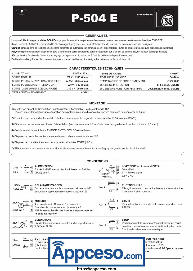
1) Montez en amont de l’installation un interrupteur différentiel ou un disjoncteur de 10A. L’interrupteur doit garantir une séparation omnipolaire avec une distance d’ouverture minimum des contacts de 3 mm.
2) Fixez le conteneur verticalement de telle façon à respecter le degré de protection initial IP 54 (modèle BSx/B).
3) Différenciez et séparez les câbles d’alimentation (section minimum 1,5 mm2) de ceux de signalement (section minimum 0,5 mm2).
4) Court-circuitez les entrées N.F. (STOP, PhOTO, FCC, FCA) inutilisées.
5) Disposez en série les contacts éventuellement reliés à la même entrée N.F.
6) Disposez en parallèle tous les contacts reliés à l’entrée START (N.O.).
7) Effectuez les branchements comme illustré ci-dessous en vous basant sur la sérigraphie gravée sur le circuit imprimé.
L’appareil électronique modèles P-504 E conçu pour l’automation de portes coulissantes et non coulissantes est conforme aux directives 73/23/CEE
(basse tension), 89/336/CEE (compatibilité électromagné-tique) et permet une installation dans le respect des normes de sécurité en vigueur.
Complet par sa gamme de fonctionnements (semi-automatique, automatique et homme présent) et de réglages (durée de travail, durée de pause et puissance du moteur).
Polyvalent par ses fonctions disponibles (pré-clignotement, sortie clignotante gérée directement par le boîtier de commande, sortie pour éclairage d’accès).
Sûr car il unit la fonction de l’inverseur au réglage de la puissanc du moteur et à l’entrée dédiée au dispositif de sécurité.
Facile à installer grâce aux leds de contrôle, aux bornes extractibles et à la sérigraphie présente sur le circuit imprimé.
GENERALITES
MONTAGE
CONNEXIONS
INVERSEUR (voir note et DIP 5)30 = +6Vdc31 = Entrée signal32 = GND
PHOTOCELLULEElle agit seulement pendant la fermeture en arrêtant le mouvement et en rouvrant. .
STARTPour le fonctionnement de cette entrée, reportez-vous à DIP3.
STOPL’actionnement de ce bouton/contact provoque l’arrêt immédiat de tout mouvement et la désactivation de la fonction de refermeture automatique.
MICRO-INTERRUPTEUR (voir note)Micro-interrupteur d’ouverture 20-22Micro-interrupteur de fermeture 21-22N.B. I nversez l es f ls d es b ornes 2 1-22 p our i nverser les micro-interrupteurs.
8
19
E
PhOTO
GND
N.C.
8
9
E
START
GND
N.O.
7
8E
STOP
GND
N.C.
20
21
22
FCA
FCC
GND
N.C.
N.C.
3130
32
vert
white
brown3x0,5mm2
10 ÷12m max.
14
155Wmax
24V~GND
24 VAC
44
45200Wmax
230V~USER
40
250Hz
230VP
N
5
6
4
M
~
230V~
500VA max
ALIMENTATIONEntrée LIGNE avec protection interne par fusibles (5x20) de 5A.
ECLAIRAGE D’ACCESSortie active pendant le mouvement et pendant 60 secondes supplémentaires après chaque arrêt.
MOTEUR4 - Ouverture 5 - Commun 6 - FermetureBranchez le condenseur aux bornes 4 - 6.N.B. Inversez les fls des bornes 4-6 pour inverser le sens de marche.
CLIGNOTANTPour le fonctionnement de cette sortie, reportez-vous à DIP4 et DIP6.
SORTIE 24VPrévue pour ’lalimentation des accessoires (Photocellules, récepteur, etc.). Protection interne par fusibles (5x20) de 500 mA.
11
12
N
P80Wmax
230V~
ALIMENTATION: 230 V ~ 50 Hz
SORTIE MOTEUR 230 V ~ / 500 W Max.
SORTIE POUR ALIMENTATION ACCESSOIRES 24 Vac / 200 mA Max.
SORTIE POUR DISPOSITIF CLIGNOTANT 230 V ~ / 80 W Max.
SORTIE “USER” LUMIÈRE DE COURTOISIE 230 V ~ / 200W Max.
TEMPS DE FONCTIONNEMENT 4”÷90”
TEMPS DE PAUSE: 4”÷110”
RÉGLAGE PUISSANCE 30÷98%
TEMPÉRATURE DE FONCTIONNEMENT -15°÷ +60°
DEGRÉ DE PROTECTION IP 54 (mod. BSX/B)
DIMENSIONS hORS TOUT MAx (mm) 200x275x130 (mod. BSX/B)
CARACTÉRISTIQUES TECHNIQUES
blanc
marron
P-504 E
https://appceso.com
- 7 -
? ざ
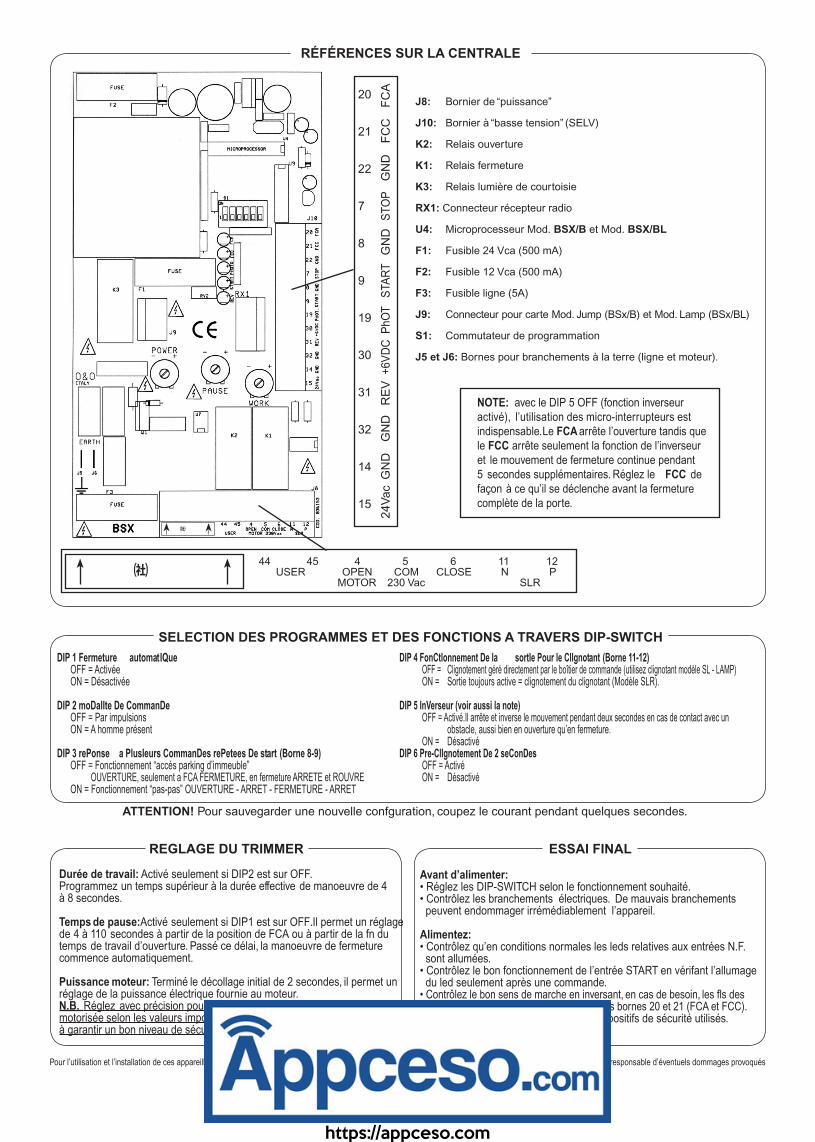
J8: Bornier de “puissance”
J10: Bornier à “basse tension” (SELV)
K2: Relais ouverture
K1: Relais fermeture
K3: Relais lumière de courtoisie
RX1: Connecteur récepteur radio
U4: Microprocesseur Mod. BSX/B et Mod. BSX/BL
F1: Fusible 24 Vca (500 mA)
F2: Fusible 12 Vca (500 mA)
F3: Fusible ligne (5A)
J9: Connecteur pour carte Mod. Jump (BSx/B) et Mod. Lamp (BSx/BL)
S1: Commutateur de programmation
J5 et J6: Bornes pour branchements à la terre (ligne et moteur).
20
21
22
7
8
9
19
30
31
32
14
15
FC
AF
CC
GN
DS
TO
PG
ND
STA
RT
PhO
T+
6V
DC
RE
VG
ND
GN
D24V
ac
40 41 1 2 44 45 4 5 6 11 12NO COM P N USER OPEN COM CLOSE N P MICRO LINE 230 Vac MOTOR 230 Vac SLR
SELECTION DES PROGRAMMES ET DES FONCTIONS A TRAVERS DIP-SWITCH
DIP 1 Fermeture automatIQue OFF = Activée ON = Désactivée
DIP 2 moDalIte De CommanDe OFF = Par impulsions ON = A homme présent
DIP 3 rePonse a PlusIeurs CommanDes rePetees De start (Borne 8-9) OFF = Fonctionnement “accés parking d’immeuble” OUVERTURE, seulement a FCA FERMETURE, en fermeture ARRETE et ROUVRE ON = Fonctionnement “pas-pas” OUVERTURE - ARRET - FERMETURE - ARRET
NOTE: avec le DIP 5 OFF (fonction inverseur activé), l’utilisation des micro-interrupteurs es tindispensable. Le FCA arrête l’ouverture tandis que le FCC arrête seulement la fonction de l’inverseur et le mouvement de fermeture continue pendant 5 secondes supplémentaires. Réglez le FCC de façon à ce qu’il se déclenche avant la fermeture complète de la porte.
DIP 4 FonCtIonnement De la sortIe Pour le ClIgnotant (Borne 11-12) OFF = Clignotement géré directement par le boîtier de commande (utilisez clignotant modèle SL - LAMP) ON = Sortie toujours active = clignotement du clignotant (Modèle SLR).
DIP 5 InVerseur (voir aussi la note) OFF = Activé.Il arrête et inverse le mouvement pendant deux secondes en cas de contact avec un obstacle, aussi bien en ouverture qu’en fermeture. ON = DésactivéDIP 6 Pre-ClIgnotement De 2 seConDes OFF = Activé ON = Désactivé
ATTENTION! Pour sauvegarder une nouvelle confguration, coupez le courant pendant quelques secondes.
REGLAGE DU TRIMMER
Durée de travail: Activé seulement si DIP2 est sur OFF.Programmez un temps supérieur à la durée effective de manoeuvre de 4 à 8 secondes.
Temps de pause: Activé seulement si DIP1 est sur OFF. Il permet un réglage de 4 à 110 secondes à partir de la position de FCA ou à partir de la fn du temps de travail d’ouverture. Passé ce délai, la manoeuvre de fermeture commence automatiquement.
Puissance moteur: Terminé le décollage initial de 2 secondes, il permet un réglage de la puissance électrique fournie au moteur.N.B. Réglez avec précision pour limiter la force de poussée de la porte motorisée selon les valeurs imposées par la législation en vigueur de façon à garantir un bon niveau de sécurité.
ESSAI FINAL
Avant d’alimenter:• Réglez les DIP-SWITCH selon le fonctionnement souhaité.• Contrôlez les branchements électriques. De mauvais branchements peuvent endommager irrémédiablement l’appareil.
Alimentez:• Contrôlez qu’en conditions normales les leds relatives aux entrées N.F. sont allumées.• Contrôlez le bon fonctionnement de l’entrée START en vérifant l’allumage du led seulement après une commande.• Contrôlez le bon sens de marche en inversant, en cas de besoin, les fls des bornes 4 et 6 (ouverture et fermeture) et des bornes 20 et 21 (FCA et FCC).• Contrôlez le bon fonctionnement des dispositifs de sécurité utilisés.• Réglez soigneusement le trimmer.
Pour l’utilisation et l’installation de ces appareillages doivent être scrupuleusement respectées les indications fournies par le constructeur; ce dernier ne pouvant être tenu responsable d’éventuels dommages provoqués
par une utilisation imprope ou ne respectent pas les instructions susmentionnées.
RÉFÉRENCES SUR LA CENTRALE
? ざ
https://appceso.com

- 8 -
1) Vor der Installation einen Fehlerstromschutzschalter oder einen Überstromselbstschalter 10 A vorsehen. Der Schalter muß eine Öffnung an allen Polen mit Distanz der Kontakte von mindestens 3 mm bei der Öffnung garantieren.
2) Den Behälter in vertikaler Position fxieren. Nach Abschluß der Installation muß die ursprüngliche Schutzart IP 54 (Mod. BSX/B) gewährleistet sein.
3) Die “Leistungs-”Kabel (Mindestquerschnitt 1,5 mm2) von den Signal-Kabeln (Mindestquerschnit 0,5 mm2) unterscheiden und trennen.
4) Die nicht verwendeten N.C.- Eingänge (STOP, PhOTO, FCC=Schließungsen-dschalter, FCA=Öffnungsendschalter) kurzschließen.
5) Die eventuellen, mit dem gleichen N.C.-Eingang verbundenen Kontakte in Reihenschaltung anordnen.
6) Alle mit dem Eingang START (N.O.) verbundenen Kontakte in Parallelschaltung anordnen.
7) Die Anschlüsse wie in der Folge angegeben und unter Zuhilfenahme der Seriegraphie auf der gedruckten Schaltung ausführen.
die für die Automatisierung von Kipptüren und Toren vorgesehen ist, entspricht den Direktiven 73/23/CEE (Niederspannung),
89/336/CEE (elektromagnetische Kompatibilität) und ermöglicht eine Installation unter Einhaltung der geltenden Sicherheitsnormativen. Sie ist:
Komplett durch das Betriebsspektrum (halbautomatisch, automatisch und mit Totmannschaltung) und die Einstellungen (Arbeitszeit, Pausenzeit, Motorleistung);
Flexibel durch die wählbaren Optionen (Vorblinken, Blinkleuchten-Ausgang direkt von der Einheit gesteuert, Ausgang für selbsttätige Beleuchtung);
Sicher, da sie die Reverser-Funktion mit der Motorleistungsregulierung und dem Ausgang, welcher der Sicherheitsvorrichtung gewidmet ist, vereint;
Leicht zu installieren dank ihrer Kontroll-LEDs, den herausnehmbaren Klemmen und der Seriegraphie auf der gedruckten Schaltung.
ALLGEMEINES
INSTALLATION
ANSCHLÜSSE
REVERSER (siehe ANMERKUNG und DIP 5)30 = +6Vdc (Gleichstrom)31 = Signaleingang32 = GND (Erdung)
FOTOZELLEAgiert nur während der Schließung, durch Anhalten der Bewegung und Wiederöffnung.
STARTFür das Funktionieren dieses Eingangs siehe DIP 3.
STOPDie Betätigung dieses Kontakts/Tasters bewirkt das unmittelbare Anhalten jeder Bewegung und den Ausschluß der Funktion des automatisches Wiederschließens.
ENDSCHALTER (siehe Anmerkung)Öffnungsendschalter 20-22Schließungsendschalter 21-22N.B. Die Anschlüsse an den Klemmen 21-22 austauschen, um die Endschalter umzukehren.
8
19
E
PhOTO
GND
N.C.
8
9
E
START
GND
N.O.
7
8E
STOP
GND
N.C.
20
21
22
FCA
FCC
GND
N.C.
N.C.
3130
32
grün
white
brown3x0,5mm2
10 ÷12m max.
14
155Wmax
24V~GND
24 VAC
44
45200Wmax
230V~USER
40
250Hz
230VP
N
5
6
4
M
~
230V~
500VA max
VERSORGUNGEingang LEITUNG mit ni nerem Schutz durch Sicherung (5x20) mit 5A
SELBSTTÄTIGE BELEUCHTUNGAusgang, der während der Bewegung und für weitere 60 Sec. ab jedem Stoppen aktiv ist.
MOTOR4 - Öffnet; 5 - Gemeinsam; 6 - Schließt.Den Kondensator an die Klemmen 4-6 anschließen.N.B. Die Anschlüsse an den Klemmen 4-6 umtauschen, um die Bewegungsrichtung umzukehren.
BLINKLEUCHTEFür das Funktionieren dieses Ausgangs siehe DIP 4 und DIP 6.
AUSGANG 24 V~Vorgesehen üf r die Versorgung des Zubehörs (Fotozellen, Empfänger etc.)Innerer Schutz durch Sicherung (5x20) mit 500 mA
11
12
N
P80Wmax
230V~
STROMVERSORGUNG: 230 V ~ 50 Hz
MOTORAUSGANG Max. 230 V ~ / 500 W
FÜR ZUBEhÖRVERSORGUNG Max. 24 Vac / 200 mA
AUSGANG FÜR BLINKER Max. 230 V ~ / 80 W
AUSGANG FÜR “USER” INNENLEUChTE Max. 230 V ~ / 200W
BETRIEBSZEIT 4”÷90”
PAUSENZEIT: 4”÷110”
LEISTUNGSEINSTELLUNG 30÷98%
BETRIEBSTEMPERATUR -15°÷ +60°
SChUTZGRAD IP 54 (mod. BSX/B)
GESAMTABMESSUNGEN (mm) 200x275x130 (mod. BSX/B)
TECHNISCHE EIGENSCHAFTEN
weiß
braun
P-504 E
https://appceso.com
- 9 -
? ざ
20
21
22
7
8
9
19
30
31
32
14
15
FC
AF
CC
GN
DS
TO
PG
ND
STA
RT
PhO
T+
6V
DC
RE
VG
ND
GN
D24V
ac
40 41 1 2 44 45 4 5 6 11 12NO COM P N USER OPEN COM CLOSE N P MICRO LINE 230 Vac MOTOR 230 Vac SLR
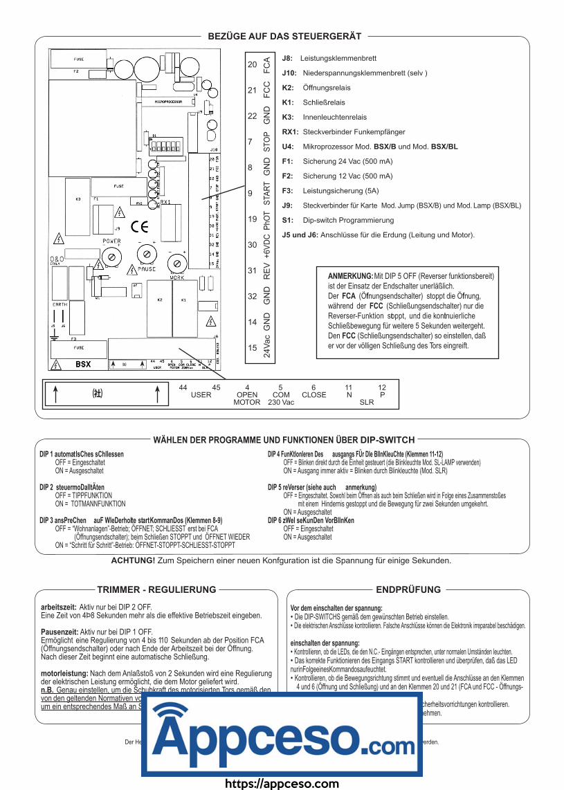
WÄHLEN DER PROGRAMME UND FUNKTIONEN ÜBER DIP-SWITCH
DIP 1 automatIsChes sChlIessen OFF = Eingeschaltet ON = Ausgeschaltet
DIP 2 steuermoDalItÄten OFF = TIPPFUNKTION ON = TOTMANNFUNKTION
DIP 3 ansPreChen auF WIeDerholte startKommanDos (Klemmen 8-9) OFF = “Wohnanlagen”-Betrieb; ÖFFNET; SCHLIESST erst bei FCA (Öffnungsendschalter); beim Schließen STOPPT und ÖFFNET WIEDER ON = “Schritt für Schritt”-Betrieb: ÖFFNET-STOPPT-SCHLIESST-STOPPT
ANMERKUNG: Mit DIP 5 OFF (Reverser funktionsbereit) ist der Einsatz der Endschalter unerläßlich.Der FCA (Öffnungsendschalter) stoppt die Öffnung, während der FCC (Schließungsendschalter) nur die Reverser-Funktion stoppt, und die kontinuierliche Schließbewegung für weitere 5 Sekunden weitergeht. Den FCC (Schließungsendschalter) so einstellen, daß er vor der völligen Schließung des Tors eingreift.
DIP 4 FunKtIonIeren Des ausgangs FÜr DIe BlInKleuChte (Klemmen 11-12) OFF = Blinken direkt durch die Einheit gesteuert (die Blinkleuchte Mod. SL-LAMP verwenden) ON = Ausgang immer aktiv = Blinken durch Blinkleuchte (Mod. SLR)
DIP 5 reVerser (siehe auch anmerkung) OFF = Eingeschaltet. Sowohl beim Öffnen als auch beim Schließen wird in Folge eines Zusammenstoßes mit einem Hindernis gestoppt und die Bewegung für zwei Sekunden umgekehrt. ON = AusgeschaltetDIP 6 zWeI seKunDen VorBlInKen OFF = Eingeschaltet ON = Ausgeschaltet
ACHTUNG! Zum Speichern einer neuen Konfguration ist die Spannung für einige Sekunden.
TRIMMER - REGULIERUNG
arbeitszeit: Aktiv nur bei DIP 2 OFF.Eine Zeit von 4Þ8 Sekunden mehr als die effektive Betriebszeit eingeben.
Pausenzeit: Aktiv nur bei DIP 1 OFF.Ermöglicht eine Regulierung von 4 bis 110 Sekunden ab der Position FCA (Öffnungsendschalter) oder nach Ende der Arbeitszeit bei der Öffnung.Nach dieser Zeit beginnt eine automatische Schließung.
motorleistung: Nach dem Anlaßstoß von 2 Sekunden wird eine Regulierung der elektrischen Leistung ermöglicht, die dem Motor geliefert wird.n.B. Genau einstellen, um die Schubkraft des motorisierten Tors gemäß den von den geltenden Normativen vorgeschriebenen Werten zu beschränken und um ein entsprechendes Maß an Sicherheit zu garantieren.
ENDPRÜFUNG
Vor dem einschalten der spannung:• Die DIP-SWITCHS gemäß dem gewünschten Betrieb einstellen.• Die elektrischen Anschlüsse kontrollieren. Falsche Anschlüsse können die Elektronik irreparabel beschädigen.
einschalten der spannung:• Kontrollieren, ob die LEDs, die den N.C.- Eingängen entsprechen, unter normalen Umständen leuchten.• Das korrekte Funktionieren des Eingangs START kontrollieren und überprüfen, daß das LED nurinFolgeeinesKommandosaufeuchtet.• Kontrollieren, ob die Bewegungsrichtung stimmt und eventuell die Anschlüsse an den Klemmen 4 und 6 (Öffnung und Schließung) und an den Klemmen 20 und 21 (FCA und FCC - Öffnungs- und Schließungsendschalter) umkehren.• Die korrekte Funktionstüchtigkeit der verwendeten Sicherheitsvorrichtungen kontrollieren.• Die Regulierung des Trimmers äußerst sorgfältig vornehmen.
Bei der Verwendung und Installation dieses Geräts sind die herstellerweisungen streng zu befolgen.
Der Hersteller kann für eventuelle Schäden durch unsachgerechte oder unvernünftige Verwendung nicht haftbar gemecht werden.
BEZÜGE AUF DAS STEUERGERÄT
J8: Leistungsklemmenbrett
J10: Niederspannungsklemmenbrett (selv )
K2: Öffnungsrelais
K1: Schließrelais
K3: Innenleuchtenrelais
RX1: Steckverbinder Funkempfänger
U4: Mikroprozessor Mod. BSX/B und Mod. BSX/BL
F1: Sicherung 24 Vac (500 mA)
F2: Sicherung 12 Vac (500 mA)
F3: Leistungsicherung (5A)
J9: Steckverbinder für Karte Mod. Jump (BSX/B) und Mod. Lamp (BSX/BL)
S1: Dip-switch Programmierung
J5 und J6: Anschlüsse für die Erdung (Leitung und Motor).
? ざ
https://appceso.com
- 10 -
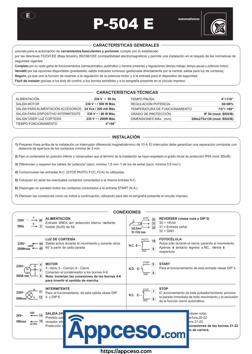
1) Preparen línea arriba de la instalación un interruptor diferencial magnetotérmico de 10 A. El interruptor debe garantizar una separación omnipolar con distancia de apertura de los contactos mínima de 3 mm.
2) Fijen el contenedor en posición inferior y comprueben que al término de la instalación se haya respetado el grado inicial de protección IP54 (mod. BSx/B).
3) Diferencien y separen los cables de “potencia” (secc. mínima 1,5 mm 2) de los de señal (secc. mínima 0,5 mm 2).
4) Cortocircuiten las entradas N.C. (STOP, PhOTO, FCC, FCA) no utilizadas.
5) Coloquen en serie los eventuales contactos conectados a la misma entrada N.C.
6) Dispongan en paralelo todos los contactos conectados a la entrada START (N.A.).
7) Efectúen las conexiones como se indica a continuación, utilizando para ello la serigrafía presente el circuito impreso.
previsto para la automación de cerramientos basculantes y portones , cumple con lo establecido
por las directivas 73/23/CEE (Baja tensión), 89/336/CEE (compatibilidad electromagnética) y permite una instalación en el respeto de las normativas de
seguridad vigentes.
Completo por su vasta gama de funcionamientos (semiautomático, automático y hombre presente) y regulaciones (tiempo trabajo, tiempo pausa y potencia motor) .
Versátil por las opciones disponibles (predestello, salida indicador luminoso gestionada directamente por la central, salida para luz de cortesía);
Seguro, ya que une la función de reverser a la regulación de la potencia motor y a la entrada para el dispositivo de seguridad.
Fácil de instalar gracias a los leds de control, a los bornes extraibles y a la serigrafía presente en el circuito impreso.
CARACTERÍSTICAS GENERALES
INSTALACIÓN
CONEXIONES
REVERSER (véase nota y DIP 5)30 = +6Vdc31 = Entrada señal32 = GND
FOTOCÉLULAActúa sólo durante el cierre, parando el movimiento.Apenas el contacto regresa a N.C., manda al reapertura.
STARTPara el funcionamiento de esta entrada véase DIP 3.
STOPEl accionamiento de este pulsador/contacto provoca la parada inmediata de todo movimiento y la exclusión de la función cierre automático.
FIN DE CARRERA (véase nota)Fin de carrera de apertura 20-22Fin de carrera de cierre 21-22Nota: Inviertan las conexiones de los bornes 21-22 para invertir los fnes de carrera.
8
19
E
PhOTO
GND
N.C.
8
9
E
START
GND
N.O.
7
8E
STOP
GND
N.C.
20
21
22
FCA
FCC
GND
N.C.
N.C.
3130
32
green
white
brown3x0,5mm2
10 ÷12m max.
14
155Wmax
24V~GND
24 VAC
44
45200Wmax
230V~USER
40
250Hz
230VP
N
5
6
4
M
~
230V~
500VA max
ALIMENTACIÓNEntrada LÍNEA con protección ni terna mediante fusible (5x20) de 5A
LUZ DE CORTESÍASalida activa durante el movimiento y durante otros 60” a partir de cada parada
MOTOR4 - Abre; 5 - Común; 6 - CierreConecten el condensador a los bornes 4-6Nota: Inviertan las conexiones de los bornes 4-6 para invertir el sentido de marcha.
INTERMITENTEPara el funcionamiento de esta salida véase DIP 4 y DIP 6
SALIDA 24V - (SELV)Prevista para alimentación accesorios (Fotoélulas, receptor, etc.)Protección interna con fusible (5x20) de 500 mA.
11
12
N
P80Wmax
230V~
ALIMENTACIÓN: 230 V ~ 50 Hz
SALIDA MOTOR 230 V ~ / 500 W Máx.
SALIDA PARA ALIMENTACIÓN ACCESORIOS 24 Vca / 200 mA Máx.
SALIDA PARA DISPOSITIVO INTERMITENTE 230 V ~ / 80 W Máx.
SALIDA “USER” LUZ CORTESÍA 230 V ~ / 200W Máx.
TIEMPO FUNCIONAMIENTO 4”÷90”
TEMPO PAUSA: 4”÷110”
REGULACIÓN POTENCIA 30÷98%
TEMPERATURA DE FUNCIONAMIENTO -15°÷ +60°
GRADO DE PROTECCIÓN IP 54 (mod. BSX/B)
DIMENSIONES MÁx. (mm) 200x275x130 (mod. BSX/B)
CARACTERÍSTICAS TÉCNICAS
P-504 E
https://appceso.com
- 11 -
? ざ
20
21
22
7
8
9
19
30
31
32
14
15
FC
AF
CC
GN
DS
TO
PG
ND
STA
RT
PhO
T+
6V
DC
RE
VG
ND
GN
D24V
ac
40 41 1 2 44 45 4 5 6 11 12NO COM P N USER OPEN COM CLOSE N P MICRO LINE 230 Vac MOTOR 230 Vac SLR
REFERENCIAS EN LA UNIDAD DE CONTROL
SELECCIÓN PROGRAMAS Y FUNCIONES MEDIANTE DIP-SWITCH
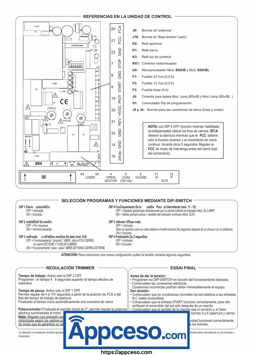
DIP 1 CIerre automÁtICo OFF = Activada ON = Excluida
DIP 2 moDalIDaD De manDo OFF = Por impulsos ON = Hombre presente
DIP 3 resPuesta a rePetIDos manDos De start (mor. 8-9) OFF = Funcionamiento “conjunto”: ABRE, sólo a FCA CIERRE; en cierre DETIENE Y VUELVE A ABRIR ON = Funcionamiento “paso - paso” ABRE-DETIENE-CIERRA-DETIENE
NOTA: con DIP 5 OFF (función reverser habilitada) es indispensable utilizar los fnes de carrera. El FCA detiene la abertura mientras que el FCC detiene sólo la función reverser y el movimiento de cierre continuo durante otros 5 segundos. Regulen el FCC de modo de intervenga antes del cierre total del cerramiento.
DIP 4 FunCIonamIento De la salIDa Para el IntermItente (mor. 11 - 12) OFF = Destello gestionado directamente por la central (utilicen el indicador Mod. SL-LAMP) ON = Salida siempre activa = destello del indicador luminoso (Mod. SLR)
DIP 5 reVerser (VÉase nota) OFF = Activado. Tanto en apertura como en cierre detiene e invierte durante dos segundos después de un choque con un obstáculo. ON = ExcluidoDIP 6 PreDestello De 2 segunDos OFF = Activado ON = Excluido
ATENCIÓN! Para memorizar una nueva confguración quiten la tensión durante algunos segundos.
REGULACIÓN TRIMMER
Tiempo de trabajo: Activo sólo si DIP 2 OFF.Programen un tiempo 4 ÷ 8 segundos superior al tiempo efectivo de maniobra.
Tiempo de pausa: Activo sólo si DIP 1 OFFPermite regular de 4 a 110 segundos a partir de la posición de FCA o del fnal del tiempo de trabajo de apertura.Finalizado el tiempo inicia automáticamente una maniobra de cierre.
Potencia motor: Finalizado el período inicial de 2”, permite regular la potencia eléctrica suministrada al motor.Nota: Regulen con precisión para limitar la fuerza de empuje de la verja motorizada según los valores programados por las normativas vigentes y de modo que se garantice un adecuado grado de seguridad.
ESSAI FINAL
Antes de dar la tensión:• Programen los DIP-SWITCH en función del funcionamiento deseado.• Comprueben las conexiones eléctricas. Conexiones incorrectas podrían dañar irreversiblemente el equipo.Den tensión:• Comprueben que en condiciones normales los led relativos a las entradas N.C. estén encendidos.• Comprueben que la entrada START funcione correctamente, para ello verifquen el encendido del led sólo después de un mando.• Comprueben que el sentido de la marcha sea el correcto y, si fuera necesario, inviertan las conexiones de los bornes 4 y 6 (apertura y cierre) y de los bornes 20 y 21 (FCA y FCC).• Comprueben que los dispositivos de seguridad funcionen correctamente.• Efectúen atentamente las regulaciones de los trimmer.
La utilización y la instalación de estos aparatos debe respetar r gurosamente las indicaciones suministradas por el fabricante, que no puede ser considerado rensponsable por eventuales daños derivados de un uso impropio o
irrazonable.
J8: Bornes de “potencia”
J10: Bornes en “Baja tensión” (selv)
K2: Relé apertura
K1: Relé cierre
K3: Relé luz de cortesía
RX1: Conector radiorreceptor
U4: Microprocesador Mod. BSX/B y Mod. BSX/BL
F1: Fusible 24 Vca (0,5 A)
F2: Fusible 12 Vca (0,5 A)
F3: Fusible línea (5 A)
J9: Conector para tarjeta Mod. Jump (BSx/B) y Mod. Lamp (BSx/BL )
S1: Conmutador Dip de programación
J5 y J6: Bornes para las conexiones de tierra (línea y motor).
? ざ
https://appceso.com
NOTENOTESREMARQUESANMERKUNGENNOTAS
INSTALLATOREINSTALLERINSTALLATEURINSTALLATEURINSTALATOR
https://appceso.com