Embed Size (px)
DESCRIPTION
Transverse coherence and polarization measurement of 131 nm coherent femtosecond pulses from a seeded FEL. J. Schwenke, E. Mansten, F. Lindau, N. Cutic, and S. Werin MAX-lab, Lund University, Lund, Sweden. Overview. Test FEL setup Measurement of transverse coherence - PowerPoint PPT Presentation
Citation preview
FEL2011, Shanghai
Transverse coherence and polarization measurement of 131 nm coherent femtosecond pulses from a seeded FEL
J. Schwenke, E. Mansten, F. Lindau, N. Cutic, and S. Werin
MAX-lab, Lund University, Lund, Sweden
FEL2011, Shanghai
Overview
• Test FEL setup
• Measurement of transverse coherence
• Measurement of polarization state
• Summary
2
FEL2011, Shanghai
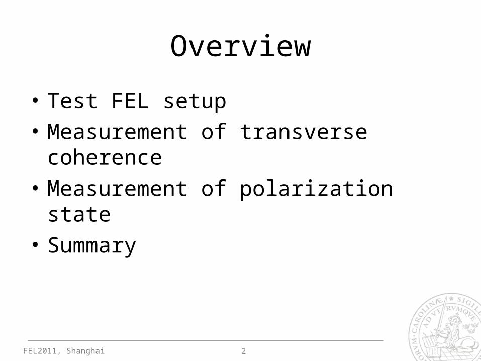
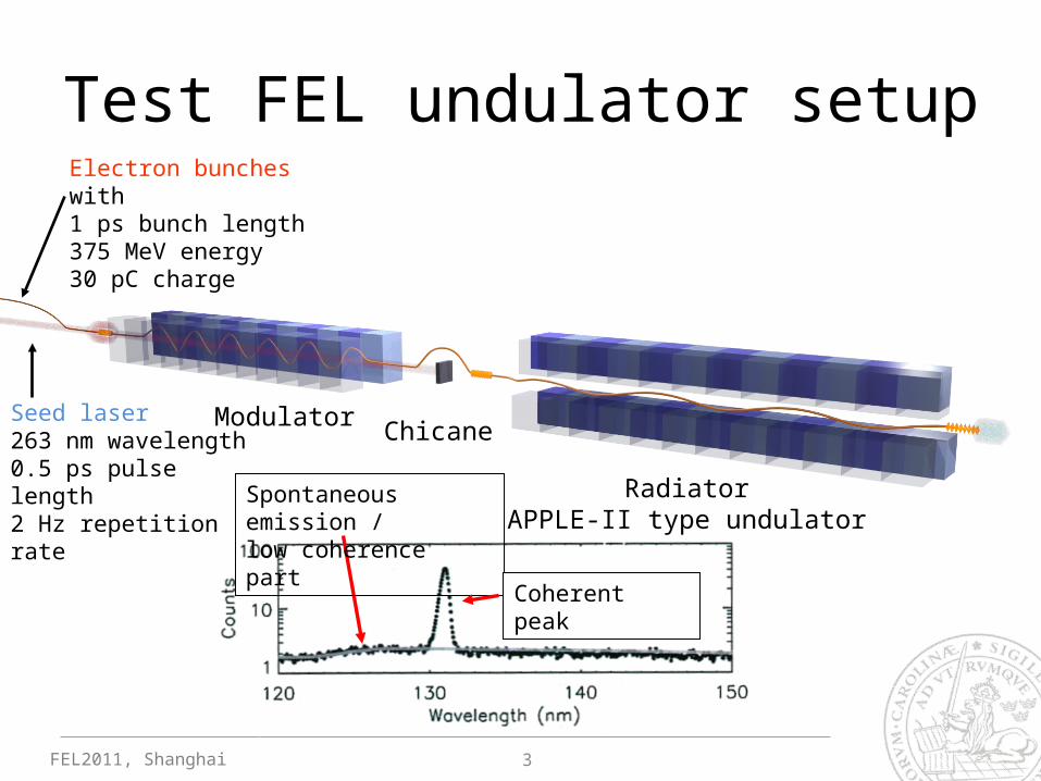
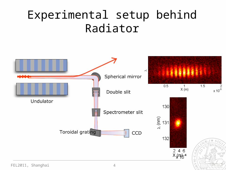
Test FEL undulator setup
Modulator
RadiatorAPPLE-II type undulator
ChicaneSeed laser263 nm wavelength0.5 ps pulse length2 Hz repetition rate
Electron bunches with 1 ps bunch length375 MeV energy30 pC charge
Spontaneous emission /low coherence part
Coherent peak
3
FEL2011, Shanghai
Experimental setup behind Radiator
4
FEL2011, Shanghai
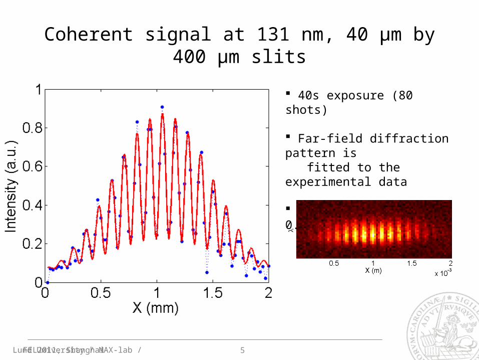
40s exposure (80 shots)
Far-field diffraction pattern is fitted to the experimental data
Fringe visibility υ = 0.67
Coherent signal at 131 nm, 40 µm by 400 µm slits
Lund University / MAX-lab / 5
FEL2011, Shanghai
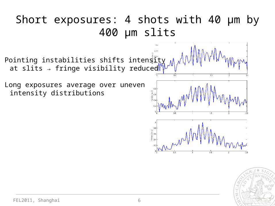
Short exposures: 4 shots with 40 µm by 400 µm slits
Pointing instabilities shifts intensity at slits → fringe visibility reduced
Long exposures average over uneven intensity distributions
6
FEL2011, Shanghai
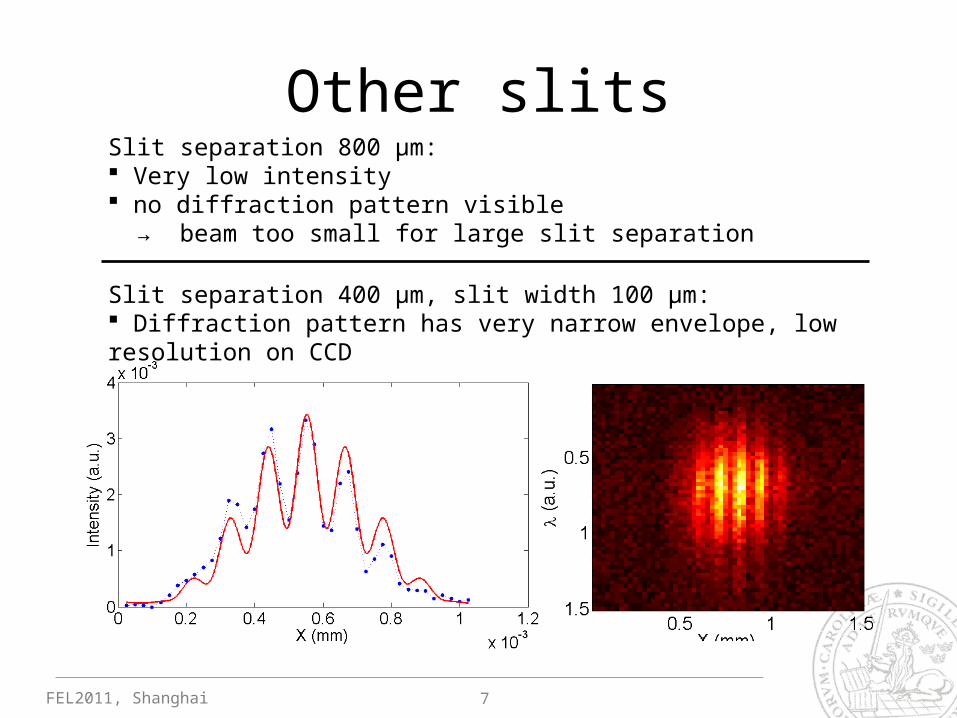
Other slitsSlit separation 800 µm: Very low intensity no diffraction pattern visible → beam too small for large slit separation
Slit separation 400 µm, slit width 100 µm: Diffraction pattern has very narrow envelope, low resolution on CCD
7
FEL2011, Shanghai
Conclusions
• High degree of coherence, fringe visibility 0.67
• Fringe visibility deteriorated because of stability issues, averaging over many shots
8
FEL2011, Shanghai
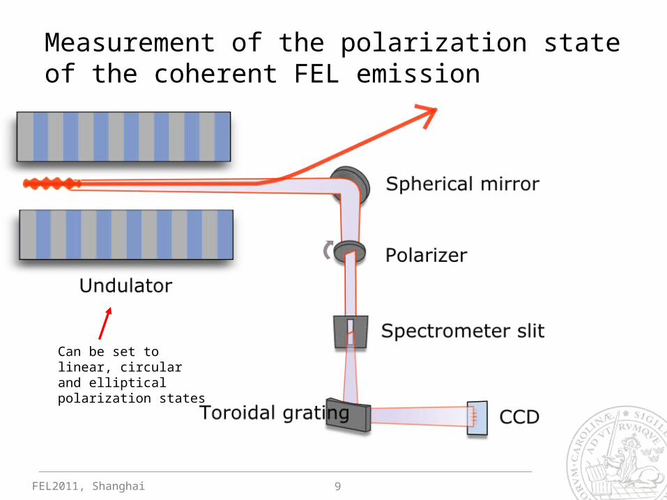
Measurement of the polarization state of the coherent FEL emission
Can be set to linear, circular and elliptical polarization states
9
FEL2011, Shanghai
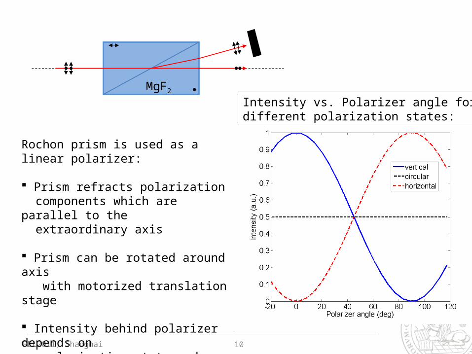
Rochon prism is used as a linear polarizer:
Prism refracts polarization components which are parallel to the extraordinary axis
Prism can be rotated around axis with motorized translation stage
Intensity behind polarizer depends on polarization state and polarizer angle
10
Intensity vs. Polarizer angle for different polarization states:
MgF2
FEL2011, Shanghai
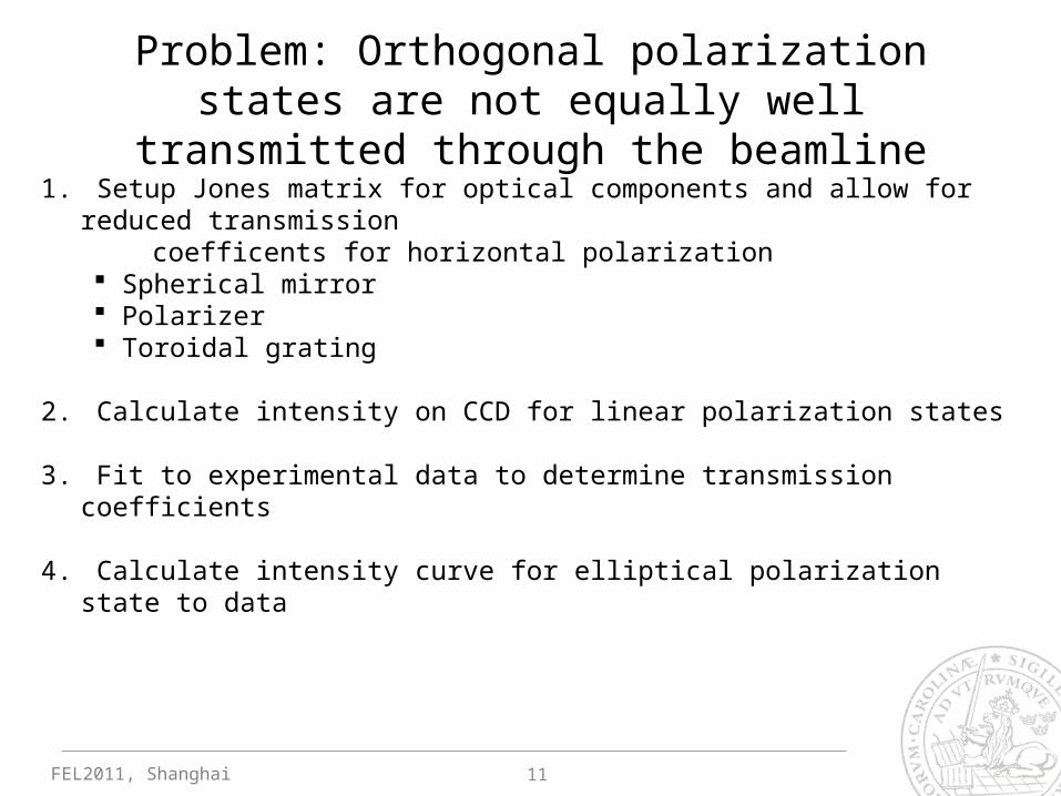
Problem: Orthogonal polarization states are not equally well transmitted through the beamline
1. Setup Jones matrix for optical components and allow for reduced transmission coefficents for horizontal polarization
Spherical mirror Polarizer Toroidal grating
2. Calculate intensity on CCD for linear polarization states
3. Fit to experimental data to determine transmission coefficients
4. Calculate intensity curve for elliptical polarization state to data
11
FEL2011, Shanghai
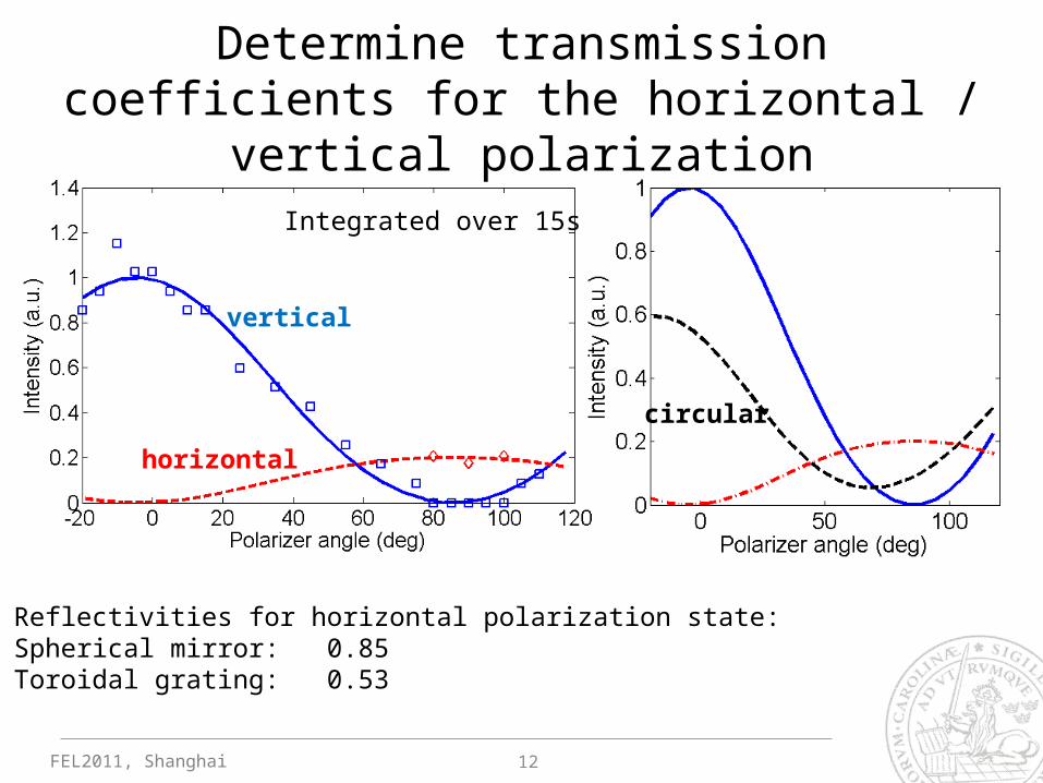
Determine transmission coefficients for the horizontal / vertical polarization
12
Reflectivities for horizontal polarization state:Spherical mirror: 0.85Toroidal grating: 0.53
vertical
horizontal
circular
Integrated over 15s
FEL2011, Shanghai
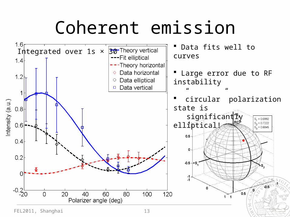
Coherent emission Data fits well to curves
Large error due to RF instability
”circular” polarization state is significantly elliptical!
13
Integrated over 1s × 30
FEL2011, Shanghai
Summary
• Demonstrated coherence of the seeded FEL emission: fringe visibility of υ = 0.67 was observed
• Used a Rochon prism as a polarizer at 131 nm to measure polarization state, polarization state was found to be elliptical.. possible reasons: Misalignment of the electron trajectory
• Very few changes made to existing setup!
14
FEL2011, Shanghai
~ blank~
15
FEL2011, Shanghai
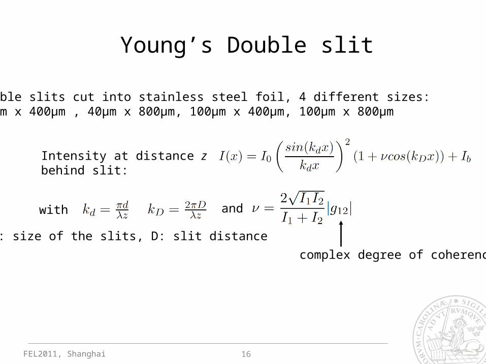
Intensity at distance z behind slit:
with
d: size of the slits, D: slit distance
complex degree of coherence
Young’s Double slit
16
Double slits cut into stainless steel foil, 4 different sizes:40µm x 400µm , 40µm x 800µm, 100µm x 400µm, 100µm x 800µm
and
FEL2011, Shanghai
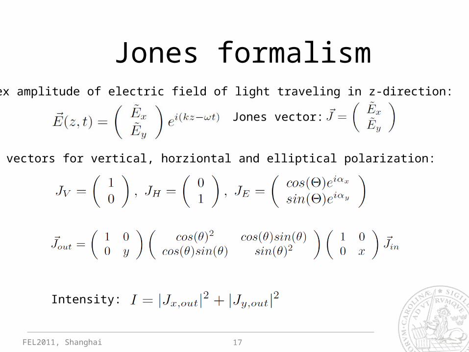
Jones formalism
Jones vector:
Complex amplitude of electric field of light traveling in z-direction:
Jones vectors for vertical, horziontal and elliptical polarization:
Intensity:
17