Embed Size (px)
Citation preview
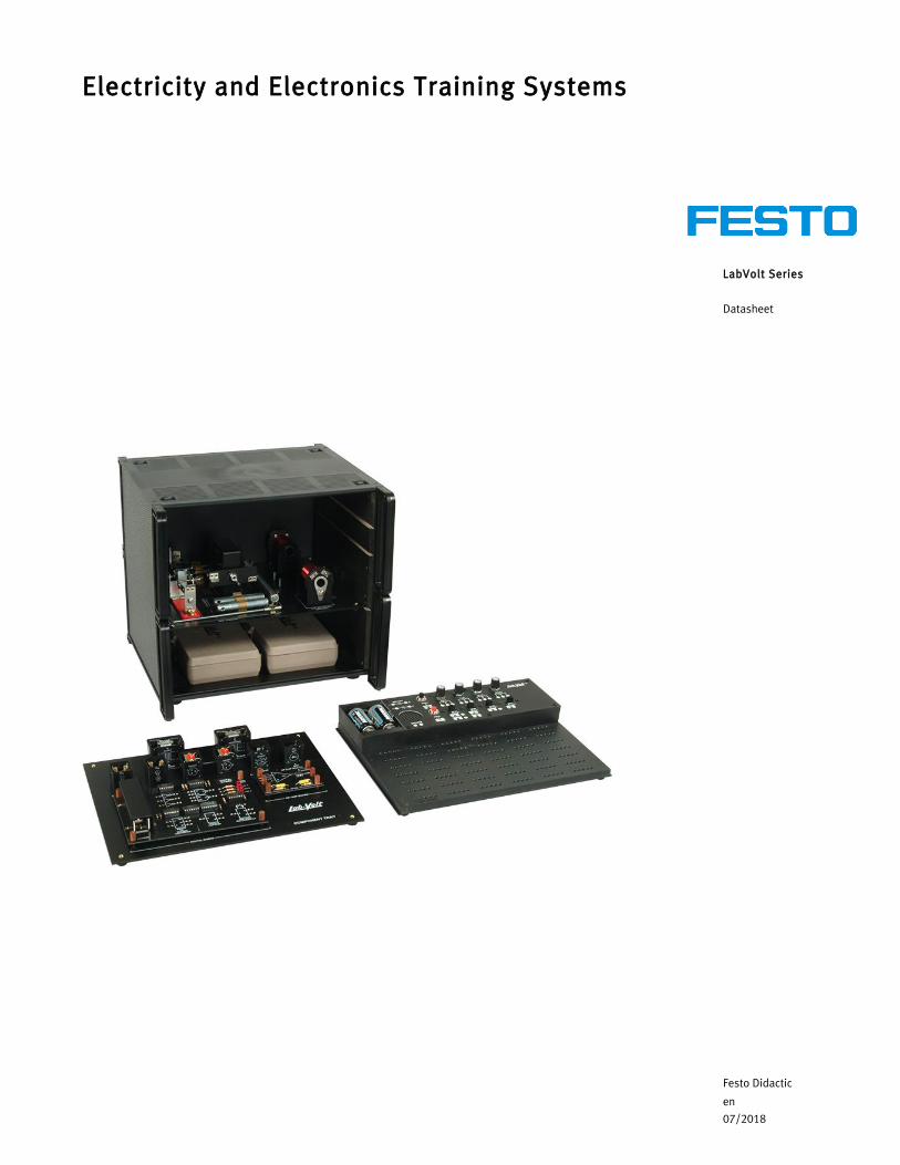
LabVolt Series
Datasheet
Electricity and Electronics Training Systems
Festo Didactic
en
07/2018
Electricity and Electronics Training Systems, LabVolt Series
2 © Festo Didactic
Table of ContentsGeneral Description_______________________________________________________________________2Features & Benefits _______________________________________________________________________2List of Available Training Systems ___________________________________________________________2Optional Equipment_______________________________________________________________________3Optional Manual(s) _______________________________________________________________________3Equipment Description ____________________________________________________________________3Optional Equipment Description __________________________________________________________ 16
General DescriptionThe Preparatory Electricity and Electronics Trainer (PEET) provides both entry-level job skill training and career awareness training in a complete program. It is ideally suited to training programs that focus on fundamental skills development. The PEET system offers eight different preparatory electricity and electronics trainers, which support a combination of instructional modules: Fundamentals of AC/DC, Basic Electronics, and Motors and Generators.
The PEET system is designed to accommodate a wide variety of training needs. Each module may be ordered by model number as part of a system. Each module comes with a student manual. An instructor’s guide, a pretest, and a posttest are also available separately. The student laboratory manual, written at a basic level, states clear behavioral objectives and makes extensive use of two-color graphics. Student manuals provide laboratory exercises for in-depth application of theories learned. A short essay test follows each exercise, and an appendix allow students to check their answers to the questions. Each unit is followed by a multiple-choice test. Answers for unit tests are found in the optional instructor’s guide, along with resource information and suggestions for lesson planning and program administration.
PEET hardware includes the unique Konnect-All student experimental board. Designed especially for training purposes, this bread-board allows students to build circuits easily. The Konnect-All board is molded from high-impact plastic and accepts lead sizes from 0.305 to 2.77 mm (0.012 to 0.109 in). Printed circuit assemblies are supplied with some modules to speed the breadboarding.
The Laboratory Instruments, Model 438, is an optional module that can be added to the PEET system. It contains equipment required to perform many laboratory procedures. Consisting of an ac/dc power supply, electronic VOM, sine/square-wave generator, and dc meter, this module is strongly recommended as an accompaniment to the PEET system. It fulfills all PEET instrumentation requirements and is available in a cabinet matching that of the Electricity and Electronics Training Systems. The Laboratory Instruments module is frequently referred to in the student manual, both in text and illustration.
Features & Benefits• Konnect-All experiment board to facilitate circuit• Printed circuit assemblies with some modules• Flexible combination of modules
List of Available Training Systems
Qty DescriptionModel number
1 Electricity and Electronics Training System - All Modules _______________________________________ 556-101 Electricity and Electronics Training System - Module 1 _________________________________________ 556-201 Electricity and Electronics Training System - Module 1 and 2 ____________________________________ 556-301 Electricity and Electronics Training System - Module 1 and 3 ____________________________________ 556-40
Electricity and Electronics Training Systems, LabVolt Series
© Festo Didactic 3
Optional Equipment
Qty DescriptionModel number
1 Laboratory Instruments __________________________________________________________________ 438-001 Locking Cover, 305 x 330 mm (12 x 13 in) ___________________________________________________ 1204-00
Optional Manual(s)
Qty DescriptionModel number
1 Electricity and Electronics Training System (Manuals on CD-ROM) ______________________________ 16604-A01 Basic Electronics (Student Manual) _______________________________________________________ 16814-001 Motors and Generators (Student Manual) __________________________________________________ 16815-001 Fundamentals of AC/DC (Student Manual) _________________________________________________ 16817-001 Basic Electronics (Student Manual) _______________________________________________________ 16818-001 Fundamentals of AC/DC (Student Manual) _________________________________________________ 16821-001 Basic Electronics (Student Manual) _______________________________________________________ 16822-001 Motors and Generators (Student Manual) __________________________________________________ 16823-00
Equipment Description
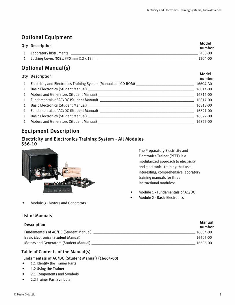
Electricity and Electronics Training System - All Modules 556-10
The Preparatory Electricity and Electronics Trainer (PEET) is a modularized approach to electricity and electronics training that uses interesting, comprehensive laboratory training manuals for three instructional modules:
• Module 1 - Fundamentals of AC/DC• Module 2 - Basic Electronics
• Module 3 - Motors and Generators
List of Manuals
DescriptionManual number
Fundamentals of AC/DC (Student Manual) _____________________________________________________ 16604-00Basic Electronics (Student Manual) ___________________________________________________________ 16605-00Motors and Generators (Student Manual) ______________________________________________________ 16606-00
Table of Contents of the Manual(s)
Fundamentals of AC/DC (Student Manual) (16604-00)• 1.1 Identify the Trainer Parts• 1.2 Using the Trainer• 2.1 Components and Symbols• 2.2 Trainer Part Symbols
Electricity and Electronics Training Systems, LabVolt Series
4 © Festo Didactic
• 2.3 Using Schematics• 3.1 General Safety Rules• 3.2 Electrical Safety Rules• 4.1 What is Matter• 4.2 Atoms and Molecules• 4.3 Electric Charges• 4.4 Laws of Electric Charges• 5.1 What is Voltage• 5.2 What is Current• 5.3 What is Resistance• 6.1 Producing Electricity by Chemicals• 6.2 Making Electricity From Magnetism• 6.3 Using Heat to Produce Electricity• 6.4 Electricity From Solar Cells• 6.5 Power Supplies as a Source of Electricity• 7.1 Conductors• 7.2 Insulators• 8.1 The Closed Circuit• 8.2 The Open Circuit• 8.3 Switch Controlled Circuits• 9.1 Voltage in Series Circuits• 9.2 Voltage in Parallel Circuits• 9.3 Voltage in Series-Parallel Circuits• 10.1 Current in Series Circuits• 10.2 Current in a Parallel Circuit• 10.3 Current in a Series-Parallel Circuit• 11.1 Ohm's Law and Resistance• 11.2 Ohm's Law and Current• 11.3 Ohm's Law and Voltage• 11.4 Ohm's Law and Power• 12.1 Types of Resistors• 12.2 Variable Resistors• 12.3 Resistor Color Code• 12.4 Resistor Dissipation• 13.1 Resistance in a Series Resistor Circuit• 13.2 Current in a Series Resistor Circuit• 13.3 Voltage in a Series Resistor Circuit• 13.4 Power in a Series Resistor Circuit• 14.1 Resistance in a Parallel Resistor Circuit• 14.2 Voltages in a Parallel Resistor Circuit• 14.3 Current in a Parallel Resistor Circuit• 14.4 Power in a Parallel Resistor Circuit• 15.1 Resistance in a Series-Parallel Resistor Circuit• 15.2 Voltage in a Series-Parallel Resistor Circuit• 15.3 Current in a Series-Parallel Resistor Circuit• 15.4 Power in a Series-Parallel Resistor Circuit
Electricity and Electronics Training Systems, LabVolt Series
© Festo Didactic 5
• 16.1 What is Magnetism• 16.2 Fields around a Magnet• 16.3 Making a Magnet• 17.1 What is an Electromagnet• 17.2 The Circuit Breaker• 17.3 The Solenoid/Door Chime• 17.4 The Relay• 17.5 The Buzzer• 18.1 What is AC• 18.2 Generating AC• 18.3 Define and Measure Peak AC• 18.4 Define and Measure Effective AC• 19.1 What the Capacitor Is• 19.2 Capacitors in a Series Circuit• 19.3 Capacitors in a Parallel Circuit• 19.4 Capacitors and Frequency Change• 20.1 The Inductor• 20.2 Inductors in a Series Circuit• 20.3 Inductors in a Parallel Circuit• 20.4 Inductors and Changing Frequency• 21.1 Making and Reading Graphs• 21.2 Inductors and Capacitors in a Series AC Circuit• 21.3 Inductors and Capacitors in a Parallel AC Circuit• 22.1 Transformer Action• 22.2 Step-Up or Step-Down Transformer• 22.3 Transformer Types
Basic Electronics (Student Manual) (16605-00)• 1.1 Biasing the P-N Junction• 1.2 Diode Types• 1.3 Light Emitting Diodes• 2.1 The Half-Wave Rectifier• 2.2 The Full-Wave Rectifier• 2.3 The Bridge Rectifier• 3.1 Filters and How They Work• 3.2 Improving Filter Action• 4.1 The Voltage Divider Circuit• 4.2 Divider Circuits In Power Supplies• 5.1 Zener Diode Characteristics• 5.2 Zener Diode Regulation• 6.1 Basic Circuits• 6.2 The Negative Voltage Supply• 6.3 Multi-Voltage Supplies• 7.1 The Basic Transistor-NPN• 7.2 The PNP Transistor• 7.3 Transistor Biasing
Electricity and Electronics Training Systems, LabVolt Series
6 © Festo Didactic
• 8.1 The Common-Base Circuit• 8.2 Common-Base Bias• 8.3 Common-Base Working Circuit• 9.1 Common-Emitter Configuration• 9.2 Common-Emitter Control• 9.3 Common-Emitter Characteristics• 10.1 Common-Collector Configuration• 10.2 Common-Collector Characteristics• 11.1 Amplifier Basics• 11.2 Classes of Amplification• 11.3 The Two-Transistor Amplifier• 11.4 The Push-Pull Amplifier• 12.1 Oscillator Basics• 12.2 Tuned Circuit Review• 12.3 The LC Oscillator• 13.1 JFET Basics• 13.2 JFET Amplifier• 13.3 MOSFET Basics• 13.4 MOSFET Amplifier• 14.1 SCR Basics• 14.2 An SCR Switch• 14.3 An SCR Control• 15.1 The Op-Amp• 15.2 Feedback• 15.3 Summing Amplifier• 15.4 Voltage Comparator• 15.5 Alternating Current and Operational Amplifiers• 16.1 Binary-Decimal Conversion• 16.2 Binary Numbers as Electrical Signals• 17.1 Symbol and Truth Table• 17.2 Inverter Operation• 18.1 The Basic OR Circuit• 18.2 The Diode OR Circuit• 18.3 The NOR Circuit• 19.1 The Basic AND Circuit• 19.2 The Diode AND Circuit• 19.3 The NAND Circuit• 19.4 The IC NAND• 20.1 The RS Flip Flop• 20.2 The Toggle Flip Flop• 20.3 One-Shot Basics• 20.4 The Integrated Circuit One Shot• 21.1 The Decimal-to-Binary Converter• 21.2 The Binary-to-Decimal Converter• 21.3 A Real-Time Converter
Motors and Generators (Student Manual) (16606-00)
Electricity and Electronics Training Systems, LabVolt Series
© Festo Didactic 7
• 1-1 What Is Magnetism?• 1-2 Magnetic Fields• 1-3 What Is An Electromagnet?• 2-1 Motor Basics• 2-2 The Permanent Magnet Motor• 2-3 Series DC (Universal) Motor• 2-4 The Compound Motor• 2-5 Generator Action• 3-1 The Universal Motor• 3-2 The Synchronous Motor• 4-1 DC Motor Control
SpecificationsParameter Value
Physical Characteristics
Dimensions (H x W x D) 311 x 330 x 305 mm (12.25 x 13 x 12 in)
Shipping Dimensions (H x W x D) 482.6 x 482.6 x 482.6 mm (19 x 19 x 19 in)
Net Weight 6.15 kg (16.5 lb)
Shipping Weight 13.15 kg (29 lb)
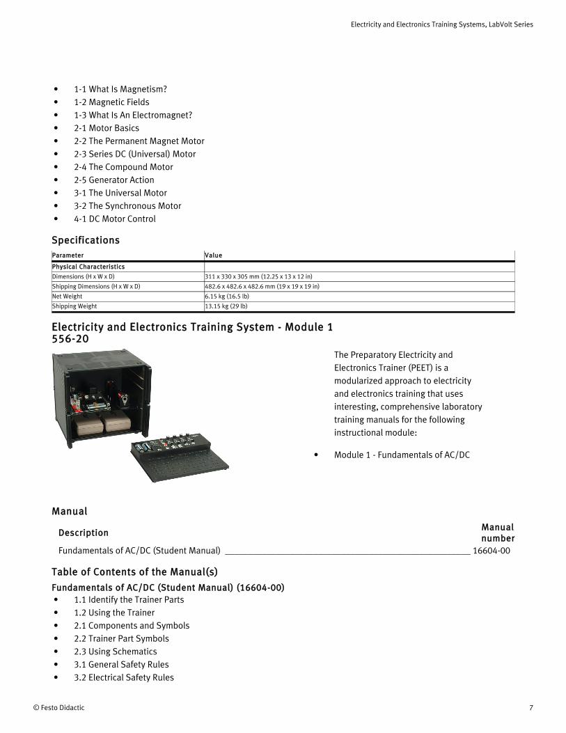
Electricity and Electronics Training System - Module 1 556-20
The Preparatory Electricity and Electronics Trainer (PEET) is a modularized approach to electricity and electronics training that uses interesting, comprehensive laboratory training manuals for the following instructional module:
• Module 1 - Fundamentals of AC/DC
Manual
DescriptionManual number
Fundamentals of AC/DC (Student Manual) _____________________________________________________ 16604-00
Table of Contents of the Manual(s)
Fundamentals of AC/DC (Student Manual) (16604-00)• 1.1 Identify the Trainer Parts• 1.2 Using the Trainer• 2.1 Components and Symbols• 2.2 Trainer Part Symbols• 2.3 Using Schematics• 3.1 General Safety Rules• 3.2 Electrical Safety Rules
Electricity and Electronics Training Systems, LabVolt Series
8 © Festo Didactic
• 4.1 What is Matter• 4.2 Atoms and Molecules• 4.3 Electric Charges• 4.4 Laws of Electric Charges• 5.1 What is Voltage• 5.2 What is Current• 5.3 What is Resistance• 6.1 Producing Electricity by Chemicals• 6.2 Making Electricity From Magnetism• 6.3 Using Heat to Produce Electricity• 6.4 Electricity From Solar Cells• 6.5 Power Supplies as a Source of Electricity• 7.1 Conductors• 7.2 Insulators• 8.1 The Closed Circuit• 8.2 The Open Circuit• 8.3 Switch Controlled Circuits• 9.1 Voltage in Series Circuits• 9.2 Voltage in Parallel Circuits• 9.3 Voltage in Series-Parallel Circuits• 10.1 Current in Series Circuits• 10.2 Current in a Parallel Circuit• 10.3 Current in a Series-Parallel Circuit• 11.1 Ohm's Law and Resistance• 11.2 Ohm's Law and Current• 11.3 Ohm's Law and Voltage• 11.4 Ohm's Law and Power• 12.1 Types of Resistors• 12.2 Variable Resistors• 12.3 Resistor Color Code• 12.4 Resistor Dissipation• 13.1 Resistance in a Series Resistor Circuit• 13.2 Current in a Series Resistor Circuit• 13.3 Voltage in a Series Resistor Circuit• 13.4 Power in a Series Resistor Circuit• 14.1 Resistance in a Parallel Resistor Circuit• 14.2 Voltages in a Parallel Resistor Circuit• 14.3 Current in a Parallel Resistor Circuit• 14.4 Power in a Parallel Resistor Circuit• 15.1 Resistance in a Series-Parallel Resistor Circuit• 15.2 Voltage in a Series-Parallel Resistor Circuit• 15.3 Current in a Series-Parallel Resistor Circuit• 15.4 Power in a Series-Parallel Resistor Circuit• 16.1 What is Magnetism• 16.2 Fields around a Magnet• 16.3 Making a Magnet• 17.1 What is an Electromagnet
Electricity and Electronics Training Systems, LabVolt Series
© Festo Didactic 9
• 17.2 The Circuit Breaker• 17.3 The Solenoid/Door Chime• 17.4 The Relay• 17.5 The Buzzer• 18.1 What is AC• 18.2 Generating AC• 18.3 Define and Measure Peak AC• 18.4 Define and Measure Effective AC• 19.1 What the Capacitor Is• 19.2 Capacitors in a Series Circuit• 19.3 Capacitors in a Parallel Circuit• 19.4 Capacitors and Frequency Change• 20.1 The Inductor• 20.2 Inductors in a Series Circuit• 20.3 Inductors in a Parallel Circuit• 20.4 Inductors and Changing Frequency• 21.1 Making and Reading Graphs• 21.2 Inductors and Capacitors in a Series AC Circuit• 21.3 Inductors and Capacitors in a Parallel AC Circuit• 22.1 Transformer Action• 22.2 Step-Up or Step-Down Transformer• 22.3 Transformer Types
SpecificationsParameter Value
Physical Characteristics
Dimensions (H x W x D) 311 x 330 x 305 mm (12.25 x 13 x 12 in)
Shipping Dimensions (H x W x D) 482.6 x 482.6 x 482.6 mm (19 x 19 x 19 in)
Net Weight 6.15 kg (16.5 lb)
Shipping Weight 13.15 kg (29 lb)
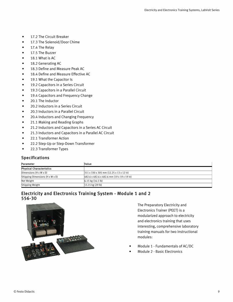
Electricity and Electronics Training System - Module 1 and 2 556-30
The Preparatory Electricity and Electronics Trainer (PEET) is a modularized approach to electricity and electronics training that uses interesting, comprehensive laboratory training manuals for two instructional modules:
• Module 1 - Fundamentals of AC/DC• Module 2 - Basic Electronics
Electricity and Electronics Training Systems, LabVolt Series
10 © Festo Didactic
List of Manuals
DescriptionManual number
Fundamentals of AC/DC (Student Manual) _____________________________________________________ 16604-00Basic Electronics (Student Manual) ___________________________________________________________ 16605-00
Table of Contents of the Manual(s)
Fundamentals of AC/DC (Student Manual) (16604-00)• 1.1 Identify the Trainer Parts• 1.2 Using the Trainer• 2.1 Components and Symbols• 2.2 Trainer Part Symbols• 2.3 Using Schematics• 3.1 General Safety Rules• 3.2 Electrical Safety Rules• 4.1 What is Matter• 4.2 Atoms and Molecules• 4.3 Electric Charges• 4.4 Laws of Electric Charges• 5.1 What is Voltage• 5.2 What is Current• 5.3 What is Resistance• 6.1 Producing Electricity by Chemicals• 6.2 Making Electricity From Magnetism• 6.3 Using Heat to Produce Electricity• 6.4 Electricity From Solar Cells• 6.5 Power Supplies as a Source of Electricity• 7.1 Conductors• 7.2 Insulators• 8.1 The Closed Circuit• 8.2 The Open Circuit• 8.3 Switch Controlled Circuits• 9.1 Voltage in Series Circuits• 9.2 Voltage in Parallel Circuits• 9.3 Voltage in Series-Parallel Circuits• 10.1 Current in Series Circuits• 10.2 Current in a Parallel Circuit• 10.3 Current in a Series-Parallel Circuit• 11.1 Ohm's Law and Resistance• 11.2 Ohm's Law and Current• 11.3 Ohm's Law and Voltage• 11.4 Ohm's Law and Power• 12.1 Types of Resistors• 12.2 Variable Resistors• 12.3 Resistor Color Code• 12.4 Resistor Dissipation
Electricity and Electronics Training Systems, LabVolt Series
© Festo Didactic 11
• 13.1 Resistance in a Series Resistor Circuit• 13.2 Current in a Series Resistor Circuit• 13.3 Voltage in a Series Resistor Circuit• 13.4 Power in a Series Resistor Circuit• 14.1 Resistance in a Parallel Resistor Circuit• 14.2 Voltages in a Parallel Resistor Circuit• 14.3 Current in a Parallel Resistor Circuit• 14.4 Power in a Parallel Resistor Circuit• 15.1 Resistance in a Series-Parallel Resistor Circuit• 15.2 Voltage in a Series-Parallel Resistor Circuit• 15.3 Current in a Series-Parallel Resistor Circuit• 15.4 Power in a Series-Parallel Resistor Circuit• 16.1 What is Magnetism• 16.2 Fields around a Magnet• 16.3 Making a Magnet• 17.1 What is an Electromagnet• 17.2 The Circuit Breaker• 17.3 The Solenoid/Door Chime• 17.4 The Relay• 17.5 The Buzzer• 18.1 What is AC• 18.2 Generating AC• 18.3 Define and Measure Peak AC• 18.4 Define and Measure Effective AC• 19.1 What the Capacitor Is• 19.2 Capacitors in a Series Circuit• 19.3 Capacitors in a Parallel Circuit• 19.4 Capacitors and Frequency Change• 20.1 The Inductor• 20.2 Inductors in a Series Circuit• 20.3 Inductors in a Parallel Circuit• 20.4 Inductors and Changing Frequency• 21.1 Making and Reading Graphs• 21.2 Inductors and Capacitors in a Series AC Circuit• 21.3 Inductors and Capacitors in a Parallel AC Circuit• 22.1 Transformer Action• 22.2 Step-Up or Step-Down Transformer• 22.3 Transformer Types
Basic Electronics (Student Manual) (16605-00)• 1.1 Biasing the P-N Junction• 1.2 Diode Types• 1.3 Light Emitting Diodes• 2.1 The Half-Wave Rectifier• 2.2 The Full-Wave Rectifier• 2.3 The Bridge Rectifier• 3.1 Filters and How They Work
Electricity and Electronics Training Systems, LabVolt Series
12 © Festo Didactic
• 3.2 Improving Filter Action• 4.1 The Voltage Divider Circuit• 4.2 Divider Circuits In Power Supplies• 5.1 Zener Diode Characteristics• 5.2 Zener Diode Regulation• 6.1 Basic Circuits• 6.2 The Negative Voltage Supply• 6.3 Multi-Voltage Supplies• 7.1 The Basic Transistor-NPN• 7.2 The PNP Transistor• 7.3 Transistor Biasing• 8.1 The Common-Base Circuit• 8.2 Common-Base Bias• 8.3 Common-Base Working Circuit• 9.1 Common-Emitter Configuration• 9.2 Common-Emitter Control• 9.3 Common-Emitter Characteristics• 10.1 Common-Collector Configuration• 10.2 Common-Collector Characteristics• 11.1 Amplifier Basics• 11.2 Classes of Amplification• 11.3 The Two-Transistor Amplifier• 11.4 The Push-Pull Amplifier• 12.1 Oscillator Basics• 12.2 Tuned Circuit Review• 12.3 The LC Oscillator• 13.1 JFET Basics• 13.2 JFET Amplifier• 13.3 MOSFET Basics• 13.4 MOSFET Amplifier• 14.1 SCR Basics• 14.2 An SCR Switch• 14.3 An SCR Control• 15.1 The Op-Amp• 15.2 Feedback• 15.3 Summing Amplifier• 15.4 Voltage Comparator• 15.5 Alternating Current and Operational Amplifiers• 16.1 Binary-Decimal Conversion• 16.2 Binary Numbers as Electrical Signals• 17.1 Symbol and Truth Table• 17.2 Inverter Operation• 18.1 The Basic OR Circuit• 18.2 The Diode OR Circuit• 18.3 The NOR Circuit• 19.1 The Basic AND Circuit• 19.2 The Diode AND Circuit
Electricity and Electronics Training Systems, LabVolt Series
© Festo Didactic 13
• 19.3 The NAND Circuit• 19.4 The IC NAND• 20.1 The RS Flip Flop• 20.2 The Toggle Flip Flop• 20.3 One-Shot Basics• 20.4 The Integrated Circuit One Shot• 21.1 The Decimal-to-Binary Converter• 21.2 The Binary-to-Decimal Converter• 21.3 A Real-Time Converter
SpecificationsParameter Value
Physical Characteristics
Dimensions (H x W x D) 311 x 330 x 305 mm (12.25 x 13 x 12 in)
Shipping Dimensions (H x W x D) 482.6 x 482.6 x 482.6 mm (19 x 19 x 19 in)
Net Weight 6.15 kg (16.5 lb)
Shipping Weight 13.15 kg (29 lb)
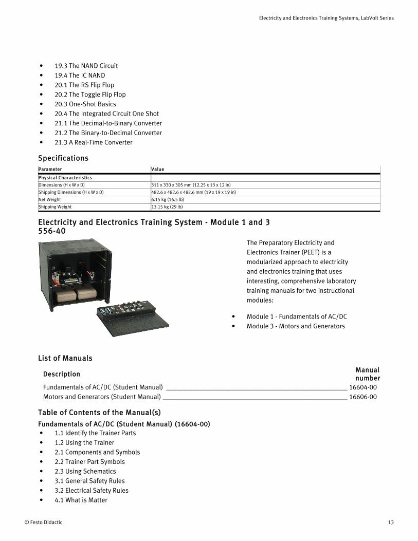
Electricity and Electronics Training System - Module 1 and 3 556-40
The Preparatory Electricity and Electronics Trainer (PEET) is a modularized approach to electricity and electronics training that uses interesting, comprehensive laboratory training manuals for two instructional modules:
• Module 1 - Fundamentals of AC/DC• Module 3 - Motors and Generators
List of Manuals
DescriptionManual number
Fundamentals of AC/DC (Student Manual) _____________________________________________________ 16604-00Motors and Generators (Student Manual) ______________________________________________________ 16606-00
Table of Contents of the Manual(s)
Fundamentals of AC/DC (Student Manual) (16604-00)• 1.1 Identify the Trainer Parts• 1.2 Using the Trainer• 2.1 Components and Symbols• 2.2 Trainer Part Symbols• 2.3 Using Schematics• 3.1 General Safety Rules• 3.2 Electrical Safety Rules• 4.1 What is Matter
Electricity and Electronics Training Systems, LabVolt Series
14 © Festo Didactic
• 4.2 Atoms and Molecules• 4.3 Electric Charges• 4.4 Laws of Electric Charges• 5.1 What is Voltage• 5.2 What is Current• 5.3 What is Resistance• 6.1 Producing Electricity by Chemicals• 6.2 Making Electricity From Magnetism• 6.3 Using Heat to Produce Electricity• 6.4 Electricity From Solar Cells• 6.5 Power Supplies as a Source of Electricity• 7.1 Conductors• 7.2 Insulators• 8.1 The Closed Circuit• 8.2 The Open Circuit• 8.3 Switch Controlled Circuits• 9.1 Voltage in Series Circuits• 9.2 Voltage in Parallel Circuits• 9.3 Voltage in Series-Parallel Circuits• 10.1 Current in Series Circuits• 10.2 Current in a Parallel Circuit• 10.3 Current in a Series-Parallel Circuit• 11.1 Ohm's Law and Resistance• 11.2 Ohm's Law and Current• 11.3 Ohm's Law and Voltage• 11.4 Ohm's Law and Power• 12.1 Types of Resistors• 12.2 Variable Resistors• 12.3 Resistor Color Code• 12.4 Resistor Dissipation• 13.1 Resistance in a Series Resistor Circuit• 13.2 Current in a Series Resistor Circuit• 13.3 Voltage in a Series Resistor Circuit• 13.4 Power in a Series Resistor Circuit• 14.1 Resistance in a Parallel Resistor Circuit• 14.2 Voltages in a Parallel Resistor Circuit• 14.3 Current in a Parallel Resistor Circuit• 14.4 Power in a Parallel Resistor Circuit• 15.1 Resistance in a Series-Parallel Resistor Circuit• 15.2 Voltage in a Series-Parallel Resistor Circuit• 15.3 Current in a Series-Parallel Resistor Circuit• 15.4 Power in a Series-Parallel Resistor Circuit• 16.1 What is Magnetism• 16.2 Fields around a Magnet• 16.3 Making a Magnet• 17.1 What is an Electromagnet
Electricity and Electronics Training Systems, LabVolt Series
© Festo Didactic 15
• 17.2 The Circuit Breaker• 17.3 The Solenoid/Door Chime• 17.4 The Relay• 17.5 The Buzzer• 18.1 What is AC• 18.2 Generating AC• 18.3 Define and Measure Peak AC• 18.4 Define and Measure Effective AC• 19.1 What the Capacitor Is• 19.2 Capacitors in a Series Circuit• 19.3 Capacitors in a Parallel Circuit• 19.4 Capacitors and Frequency Change• 20.1 The Inductor• 20.2 Inductors in a Series Circuit• 20.3 Inductors in a Parallel Circuit• 20.4 Inductors and Changing Frequency• 21.1 Making and Reading Graphs• 21.2 Inductors and Capacitors in a Series AC Circuit• 21.3 Inductors and Capacitors in a Parallel AC Circuit• 22.1 Transformer Action• 22.2 Step-Up or Step-Down Transformer• 22.3 Transformer Types
Motors and Generators (Student Manual) (16606-00)• 1-1 What Is Magnetism?• 1-2 Magnetic Fields• 1-3 What Is An Electromagnet?• 2-1 Motor Basics• 2-2 The Permanent Magnet Motor• 2-3 Series DC (Universal) Motor• 2-4 The Compound Motor• 2-5 Generator Action• 3-1 The Universal Motor• 3-2 The Synchronous Motor• 4-1 DC Motor Control
SpecificationsParameter Value
Physical Characteristics
Dimensions (H x W x D) 311 x 330 x 305 mm (12.25 x 13 x 12 in)
Shipping Dimensions (H x W x D) 482.6 x 482.6 x 482.6 mm (19 x 19 x 19 in)
Net Weight 6.15 kg (16.5 lb)
Shipping Weight 13.15 kg (29 lb)
Electricity and Electronics Training Systems, LabVolt Series
16 © Festo Didactic
Optional Equipment Description
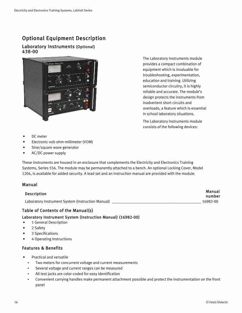
Laboratory Instruments (Optional) 438-00
The Laboratory Instruments module provides a compact combination of equipment which is invaluable for troubleshooting, experimentation, education and training. Utilizing semiconductor circuitry, it is highly reliable and accurate. The module’s design protects the instruments from inadvertent short circuits and overloads, a feature which is essential in school laboratory situations.
The Laboratory Instruments module consists of the following devices:
• DC meter• Electronic volt-ohm-millimeter (VOM)• Sine/square wave generator• AC/DC power supply
These instruments are housed in an enclosure that complements the Electricity and Electronics Training Systems, Series 556. The module may be permanently attached to a bench. An optional Locking Cover, Model 1204, is available for added security. A lead set and an instruction manual are provided with the module.
Manual
DescriptionManual number
Laboratory Instrument System (Instruction Manual) _____________________________________________ 16982-00
Table of Contents of the Manual(s)
Laboratory Instrument System (Instruction Manual) (16982-00)• 1 General Description• 2 Safety• 3 Specifications• 4 Operating Instructions
Features & Benefits
• Practical and versatileTwo meters for concurrent voltage and current measurementsSeveral voltage and current ranges can be measuredAll test jacks are color-coded for easy identificationConvenient carrying handles make permanent attachment possible and protect the instrumentation on the front panel
Electricity and Electronics Training Systems, LabVolt Series
© Festo Didactic 17
• Safe and durableAll components, switches and terminals are mounted to resist tamperingProtection mechanisms, such as internal semiconductor devices, are included against overvoltage and improper current connections
Optional Equipment
Qty DescriptionModel number
1 Locking Cover, 305 x 330 mm (12 x 13 in) ___________________________________________________ 1204-00
Locking Cover, 305 x 330 mm (12 x 13 in) (Optional) 1204-00The Locking Cover consists of a 305 x 330 mm (12 x 13 in) cover that can be affixed to certain training modules. It completely covers the module front panel, making it inaccessible to students, and prevents damage to the module components during storage periods. The Locking Cover can be locked in place using a lock-and-key mechanism.
SpecificationsParameter Value
Physical Characteristics
Intended Location Affixed to the front panel of a training module
Dimensions (H x W ) 305 x 330 mm (12 x 13 in)
Net Weight TBE
Electricity and Electronics Training Systems, LabVolt Series
18 © Festo Didactic
Reflecting the commitment of Festo Didactic to high quality standards in product, design, development, production, installation, and service, our manufacturing and distribution facility has received the ISO 9001 certification.
Festo Didactic reserves the right to make product improvements at any time and without notice and is not responsible for typographical errors. Festo Didactic recognizes all product names used herein as trademarks or registered trademarks of their respective holders. © Festo Didactic Inc. 2018. All rights reserved.
Festo Didactic SE
Rechbergstrasse 373770 DenkendorfGermany
P. +49(0)711/3467-0F. +49(0)711/347-54-88500
Festo Didactic Inc.
607 Industrial Way WestEatontown, NJ 07724United States
P. +1-732-938-2000F. +1-732-774-8573
Festo Didactic Ltée/Ltd
675 rue du CarboneQuébec QC G2N 2K7Canada
P. +1-418-849-1000F. +1-418-849-1666
www.labvolt.com
www.festo-didactic.com