Embed Size (px)
Citation preview
POWERLINE COMMUNICATIONS SYSTEMS: OVERVIEW AND ANALYSIS
by
NISHANT SAGAR
A thesis submitted to the
Graduate School-New Brunswick
Rutgers, The State University of New Jersey
In partial fulfillment of the requirements
For the degree of
Master of Science
Graduate Program in Electrical and Computer Engineering
Written under the direction of
Professor David G. Daut
And approved by
________________________
________________________
________________________
________________________
New Brunswick, New Jersey
May, 2011
ii
ABSTRACT OF THE THESIS
POWERLINE COMMUNICATIONS SYSTEMS: OVERVIEW AND ANALYSIS
By NISHANT SAGAR
Thesis Director:
Professor David G. Daut
The electric power distribution grid is a medium over which fast and reliable communication
services can be provided. Power Line Communications (PLC) systems provide an alternative to
wireless communications in the transmission of data within buildings and vehicles. In recent years,
increased interest in PLC systems for both commercial and residence applications has resulted in
the development of standards for use of the electric power grid as a communications channel
conveying messages in addition to power. The types of applications range from simple
inexpensive services centered around networked household appliances, where data rates are on
the order of kilobits per second, to Internet access via the electrical outlet wall socket, where data
rates are on the order of megabits per second. Currently, PLC systems can accommodate high-
iii
speed networking that includes broadband Internet access, voice over-IP, and the interconnectivity
of home entertainment devices.
The development of a Power Line Communications system presents a significant challenge for the
communications engineer due to the unusual channel characteristics that affect high-speed signal
transmission. The electric power grid is designed for, and operated at, 50/60 Hz throughout the
world. Furthermore, the topology of a local electric power grid network is often very irregular
resulting in significant dispersion of the transmitted message signals.
This thesis presents an overview of the major features and characteristics of PLC systems, the
fundamental properties of powerline channels, and an analysis of PLC system performance in the
presence of realistic powerline channel conditions.
The development of a powerline communication system requires detailed knowledge of the
electric power grid channel properties, such as the frequency transfer function and the interference
processes, in order to choose a suitable transmission method. The noise interference and channel
multipath effects are the main impairments to the performance of PLC systems. This thesis
presents appropriate channel models for use in the design of PLC systems. In particular, the Bit
Error Rate (BER) performance of a single-carrier Binary Phase Shift Keying (BPSK) system
operating over a multipath channel is analyzed and compared with the performance obtained with
a multi-carrier data transmission scheme.

iv
Acknowledgements
I would like to thank my advisor, Professor David G. Daut, for his sound advice and
encouragement throughout the development of this thesis. I am also indebted to Professor Pedda
Sannuti and Professor Sophocles Orfanidis, both of whom took time to discuss the ideas in this
thesis with me, and provided many helpful suggestions.
v
Table of Contents
Abstract …………………………………………………………………………………………………ii
Acknowledgements…………………………………………………………………………………...iv
List of Tables……………………………………………………………………………………………x
List of llustrations……………………………………………………………………………………...xi
1. Introduction
1.1 Powerline Communications: An Introduction…………………..…………….....1
1.2 Power Distribution Grid………………………………………………….…………2
1.2.1 European Power Supply Network……..…………………………..4
1.2.2 United States Power Supply Network………………..…………...6
1.2.3 Japanese Power Supply Network……………………..………..…9
1.3 Existing and Emerging Standards and Regulations…………………………...10
1.3.1 Electromagnetic Compatibility ……………………..…………....10
1.3.2 European Union Standard (EN 50065)………………….…...….15
1.3.3 United States Standard (IEEE P1901)……………………...…...17
1.3.4 Federal Communications Commission ……………….…..….…18
1.3.5 HomePlug Powerline Alliance…………………………..….….…20
1.3.6 Other Standards related to Powerline Communications………22
1.4 Current State-of-the-Art ………………………………………………………….23
1.5 Thesis Outline……………………………………………………………………..24
2 Data Communication Techniques…………….…………………………………………………….26
2.1 Baseband Digital Signals…………………………………………………………26
2.1.1 Line Coding……………………………………..…………..……..26
vi
2.1.2 Multilevel Line Coding……………………….……….…..……….29
2.1.3 Network synchronization…………………………………….……29
2.2 Signal Modulation Techniques…………………………………………………..31
2.2.1 Amplitude Modulation…………………..…………………..…….31
2.2.2 Frequency Modulation and Phase Modulation………........……32
2.3 Digital Transmission of Information……………………………………….……..33
2.3.1 Shift Modulation……………………………..………………...…..34
2.3.2 Bit Rate and Modulation Rate…………………………….………35
2.3.3 Higher Order Modulation ………………………………....……...36
2.4 Spread Spectrum Systems………………………………………………………38
2.4.1 Direct Sequence Spread Spectrum (DS-SS)………….…….....38
2.4.2 Frequency Hopping Spread Spectrum (FH-SS)………….…….39
2.5 Error Reduction Techniques…………………………………………….……….40
2.6 Medium Access Methods………………………………………………………...41
2.6.1 Polling………………………………….…………………...……...41
2.6.2 Contention……………………….…………………………...……42
2.6.3 Token Passing………………………………….……………...….42
2.7 Conclusions……………………………………………………………………….42
3 Home Networking over Powerlines…………………………………………………………………44
3.1 Home Networking and Automation……………………………………………...44
3.2 Home Networking Challenges………………………………………….………..45
3.3 Home Networking Technologies………………………………………………...46
3.3.1 Structured Wiring Technologies…………………..…………..…48
vii
3.3.2 Existing Wiring Technologies…………………….…….……..….48
3.3.3 Wireless Networking……………………………….………..……50
3.4 Powerline Networking…………………………………………………………….52
3.4.1 In-House and Access Powerline Technologies…………….......53
3.4.2 Components of an In-House Powerline Network……..……..…56
3.4.3 Advantages of In-House Powerline Networking………..……....58
3.4.4 Disadvantages of In-House Powerline Networking………….....59
3.4.5 Technical Obstacles of an In-House Powerline Network… …..60
3.5 Typical Applications of Home Networking………………………………………60
3.6 Conclusions………………………………………………………………………..64
4 Communication over Powerlines……………………………………………………………………65
4.1 Powerline Channel Model………………………………………………………..66
4.2 Approaches for Modeling the Powerline Channel……………………………..68
4.2.1 Top-Down Approach……………..…………………………….....68
4.2.2 Bottom-Up Approach………………..…………………..………..69
4.3 Channel Capacity…………………………………………………………………70
4.4 A Multipath Model for Powerline Channels……………………………………..71
4.5 Powerline Channel Noise Scenario……………………………………………..74
4.6 Powerline Reference Channels………………………………………………….75
4.7 Modulation Schemes for Powerline Channel Systems Design……………….77
4.7.1 Single Carrier Modulation………………………………..…..…...78
4.7.2 Spread Spectrum Techniques…………………………..…….....79
4.7.3 Orthogonal Frequency Division Multiplexing…………..…….... 83
viii
4.7.3.1 Principles of OFDM Transmission……….….…84
4.7.3.2 OFDM System Architecture………………...…..87
4.8 Conclusions………………………………………………………………………..91
5 Powerline Communication Technologies…………………………………………………………. 92
5.1 LonWorks (Local Operation Networks)…………………………………………92
5.1.1 LonWorks Technology………………………………..………..…95
5.1.2 LonWorks System Components……………………….…...……97
5.1.3 Summary…………………….…………………………..…..……100
5.2 Consumer Electronic Bus (CEBus)…………………………………………….100
5.2.1 CEBus Technology……………………………………...……….102
5.2.2 CEBus Protocol……………………………………………....….102
5.2.3 CEBus Packet Structure…………………………………....…...104
5.2.4 Summary………………………………………………...…..……105
5.3 Passport and Plug-in PLX………………………………………………………106
5.4 X-10……………………………………………………………………………….108
5.4.1 X-10 Transmission Theory…………………………..…..……...110
5.4.2 Summary……………………………………….…………....……111
5.5 Power Packet……………………………………………………………….……112
5.5.1 Power Packet Technology……….…………..……………..…..113
5.5.2 Summary………………….……………..……………..…………116
5.6 Cogency’s HomePlug Technology……………………………..……………...118
5.7 Conclusions……………………………………………………….….………….120
ix
6 Powerline Communications Systems Analysis
6.1 The Powerline Channel Model……………………...………………………….121
6.2 Overall System Configuration……………………..……………………………131
6.3 Performance Evaluation…………………...……………………………………135
6.4 Conclusions………………………………………………………………………138
7 Summary and Conclusions………………………………………………………………….……..139
8 References…………………………………………………………………………………………..142
x
List of Tables
1.1 CENELEC frequency range usage…………………………………………………………….17
3.1 Comparison of broadband home networking approaches…………………………………..47
3.2 Home networking technologies using existing wiring……………………………………….50
3.3 Wireless home networking technologies……………………………………………………..51
4.1 Channel capacity in megabits per second under transmission power spectral density
limitations…………………………………………………………………………………………77
4.2 A comparison of different transmission methods for powerline communication…………..85
5.1 Wireline channel characteristics……..………………………………………………………...98
6.1 Modal parameters for the powerline channel transfer function……………………………122
6.2 Parameters of a four-path cahnnel model describing the test network……...……………124
6.3 Parameters of a15-path channel model……………………...………………………………128
6.4 Parameter sets for Reference Channel RC1………………………………..………………133
6.5 Parameter sets for Reference Channel RC2……………………………….……………….134
xi
List of Illustrations
1.1 Voltage layers of a typical power distribution grid…………………………………..…………4
1.2 European low voltage distribution grid with transformer inductances and loads……………6
1.3 U.S. split phase system with MV/LV transformer and loads…………………………………..7
1.4 PLC system architecture adopting the hybrid approach………………………………………8
2.1 Comparison of Digital Line Code waveforms………...……………………………………….28
2.2 Amplitude and Frequency Modulation…………………………………………………………33
2.3 Shift modulation for digitally transmitted information…………………………………………34
2.4 On/Off modulation of light in an optical fiber……………………………………….………….35
2.5 A PSK modulated signal having four distinct states………………………………………….36
2.6 A 16 QAM signaling scheme with 16 modulation states…………………………………….37
2.7 Spectrum analyzer display of a Direct Sequence (DS) Spread Spectrum signal………....39
2.8 Spectrum of a Frequency Hopping (FH) Spread Spectrum signal…………………………40
3.1 Typical HomePNA Network…………………………………………………………………….49
3.2 Configuration of powerline networks………………………….……………………………….52
3.3 Transformer bypass path……………………………………………………………………….54
3.4 Powerline Access Technology (MV) Network………………………………………………...57
3.5 Powerline In-House Technology (LV) Network……………………………………………….57
3.6 A typical In-House powerline networking scenario………..………………………………….58
4.1 Structure of a European low-voltage access network line and associated channel
characteristics……………………………………………………………………………………67
xii
4.2 Noise processes present on powerlines………………………………………………………74
4.3 Magnitude of the frequency responses for four reference channels………………….…….76
4.4 Direct Sequence Spread Spectrum transceiver and the CDMA principle………….……...81
4.5 Frequency spectrum comparison of FDM and OFDM……………………………………….86
4.6 Block diagram of a typical OFDM system: a) Transmitter b) Receiver………………..…...88
5.1 Centralized Control Architecture Model……………………………………………………….94
5.2 LonWorks Distributed Control Architecture…………………………………………………...94
5.3 Anatomy of some LonWorks devices……………………………………………………….....99
5.4 CEBus protocol “stack”………………………………………………………………………..103
5.5 CEBus Packet Structure………………………………………………………………………104
5.6 Timing relationship of X-10 signals…………………………………………………………..110
5.7 Power line cycles for X-10 code transmission………………………………………………111
5.8 X-10 Control Capabilities……………………………………………………………………...112
5.9 OFDM symbol creation by IFFT………………………………………………………………114
5.10 PowerPacket Frame Format…………………………………………………………………..115
6.1 Multipath signal propagation: cable with one tap……………………………………………123
6.2 Test network: measurement and simulation with N=4 paths; a) amplitude response b)
phase details, and c) impulse response …………………………………………………….125
6.3 Detailed channel model with 44 paths a) Amplitude response b) Phase details c) Impulse
Response……………………………………………………………………………………….126
6.4 Reference channel model with 15 paths: a) Amplitude response, b) Phase details, and c)
Impulse r.esponse……………………………………………………………………………..128
6.5 Amplitude response of the test model………………………………………………………..129
xiii
6.6 Phase details of the test model……………………………………………………………….130
6.7 Impulse response of the test model…………………………………………………………..130
6.8 SCM System block diagram…………………………………………………………………..132
6.9 Frequency and impulse responses of Reference Channel 1 (RC1)………………..……..133
6.10 Frequency and impulse responses of Reference Channel 2 (RC2)…………………..…..134
6.11 Block diagram of the PLC system used for Matlab/Simulink simulation………………….135
6.12 BER performance of single carrier BPSK system under PLC multipath effects……..…..136
6.13 BER performance of OFDM system under multipath effects………………………………137
1
1. Introduction
1.1 Powerline Communications: An introduction
Currently in age of Information Technology, the present focus is both on creation as well as
dissemination of information. In order to be able to reach the end users of information, the popular
technologies currently being used include telephone wires, Ethernet cabling, fiber optic cabling, as
well as wireless and satellite technologies. However, each of these information transmission
techniques has its limitations involving cost and availability to reach the maximum number of users.
Over the past few years, the increasing ubiquity of the Internet is creating a rapidly growing
demand for larger bandwidth to the home and office. This search for new ways of transferring
information has introduced Powerline Carrier (PLC) Communications, or more recently Broadband
over Powerline (BPL), systems as an innovative format to exchange information. BPL systems use
existing electrical powerlines as a transmission medium to provide high-speed communications
capabilities by coupling radio frequency (RF) energy onto the powerline. The benefits of
implementing this emerging technology are significant, starting from the fact that there is no need
for new infrastructure, which is both time consuming and expensive to install. In addition, bearing in
mind that no new wires are required, powerline communications techniques have become even
more appealing. The advantage of using electric powerlines as the data transmission medium is
that every building and home is already equipped with the powerlines that are connected to the
power grid. The power line carrier (PLC) communication systems use the existing AC electrical
wiring as the network medium to provide high speed network access points almost anywhere there
2
is an AC outlet. In most cases, building a home network using the existing AC electrical wiring is
easier than trying to run wires, more secure and more reliable than radio wireless systems like
802.11a/b/g, and relatively inexpensive as well. For most small office home office (SOHO)
applications, PLC provides a convenient solution to current networking problems.
For many years, systems have been built to communicate low bandwidth analog and digital
information over residential, commercial and high voltage power lines. Powerlines have been
exclusively considered for the transmission of electricity in the past. However, with the emergence
of modern networking technologies including broadband, there is a need for the utility and service
providers to discover solutions that are able to deliver the services to the consumers at minimum
cost and maximum performance. Only recently have companies turned serious attention to
communicating over power lines for the purpose of data networking. The potential of the powerline
as a ubiquitous medium to be able to deliver not only electricity or control signals, but even full
duplex high-speed data and multimedia content, is being explored now. Since the developments in
the field of powerline networking are fairly new, information about PLC techniques is largely
dispersed. There is a lack of cohesive reference material that summarizes the existing
technologies, available solutions, and technology trends in the field of powerline carrier
communications.
1.2 Power Distribution Grid
The power distribution grid represents an omnipresent widely branched hierarchical structure.
Generally, power outlets are found in every room of a building, hence a local area network is
basically available and ready for use. Moreover, the structure of the entire low-voltage distribution
grid, including outdoor supply cables, is most appropriate for data/Internet access, offering both
3
last mile and last meter solutions.
For high-speed indoor networking, powerlines possess the key feature of being able to connect
any point of interest with no need for new wires. Since indoor and outdoor power supply wiring are
very different, usually different power line communications (PLC) systems for each of the wiring
structures are required. They are denoted as indoor and access systems, respectively. However,
some systems are able to communicate throughout the whole network, and do not distinguish
between indoor and outdoor domains. Contrary to telephone wiring, the power line grid is a shared
medium, so all end users have to share the available channel capacity. Besides the broadband
applications there also exist narrowband applications of PLC covering frequencies in the kilohertz
range. Such applications are used for switching and mains signaling purposes.
The transmission losses encountered over a power line grow with the square of the current (I2), so
it is important to keep the current (I) as low as possible, especially for long distances. A well-
known optimizing technique is to choose as high a voltage as possible. This basic idea
automatically generates a network hierarchy in terms of voltage: for long distance transportation
very high voltage is used, which is stepped down to lower levels for shorter distances. Thus, similar
power distribution grid structures are found all over the world.
High voltage (HV) power lines or even extremely high voltage (EHV) lines emanate from
power plants and represent a wide-meshed long-distance nationwide network. The term
HV applies to voltages over 36 kV, while voltages over 300 kV are denoted EHV. The EHV
and HV levels establish a transmission network strictly for power, since no customer
premises are directly connected to the lines.
The task of the next lower transmission level is bringing electrical power into cities, towns,
and villages. Here medium voltage (MV) is used, constituting a finer meshed network in
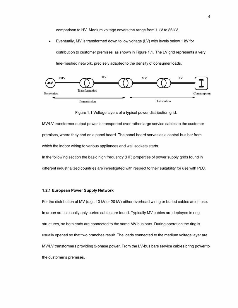
4
comparison to HV. Medium voltage covers the range from 1 kV to 36 kV.
Eventually, MV is transformed down to low voltage (LV) with levels below 1 kV for
distribution to customer premises as shown in Figure 1.1. The LV grid represents a very
fine-meshed network, precisely adapted to the density of consumer loads.
Figure 1.1 Voltage layers of a typical power distribution grid.
MV/LV transformer output power is transported over rather large service cables to the customer
premises, where they end on a panel board. The panel board serves as a central bus bar from
which the indoor wiring to various appliances and wall sockets starts.
In the following section the basic high frequency (HF) properties of power supply grids found in
different industrialized countries are investigated with respect to their suitability for use with PLC.
1.2.1 European Power Supply Network
For the distribution of MV (e.g., 10 kV or 20 kV) either overhead wiring or buried cables are in use.
In urban areas usually only buried cables are found. Typically MV cables are deployed in ring
structures, so both ends are connected to the same MV bus bars. During operation the ring is
usually opened so that two branches result. The loads connected to the medium voltage layer are
MV/LV transformers providing 3-phase power. From the LV-bus bars service cables bring power to
the customer’s premises.

5
An MV/LV transformer provides up to 630 kVA, which is sufficient to supply several hundred
households with power. Typically between 3 and 10 service cables emerge from one transformer
substation, forming a tree-like structure. Sometimes rings and mesh topologies are also found. If
necessary, large buildings or industrial plants are supplied directly with MV.
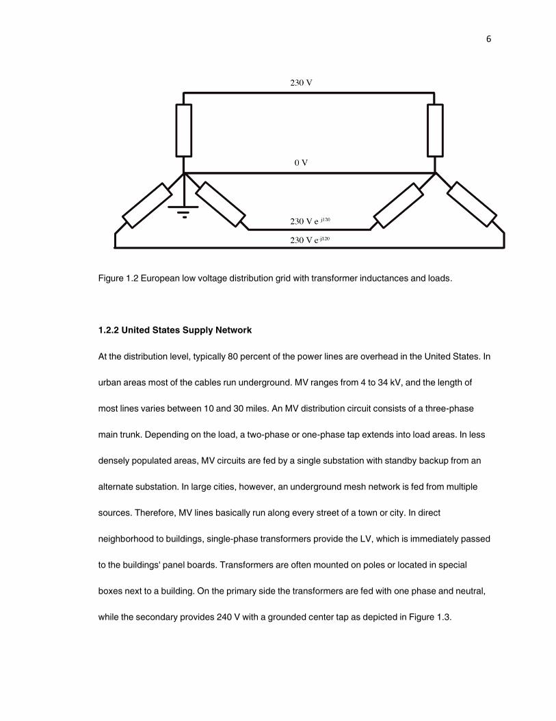
The LV windings of a transformer usually represent a Y-configuration, the center of which is
grounded as shown in Figure 1.2. From phase-to-phase the voltage is 400 V, and 230 V from
phase-to-neutral. In most European countries all three phases and the neutral are brought to the
customer’s panel board. Thus, the service cables include four conductors. Indoor PLC signals are
injected between phase and neutral because not every building is equipped with a protective earth
conductor. If there is a protective earth conductor available, it is short-circuited with the neutral
conductor at the house service connection point. Thus, without modification of the grid structure it
is impossible to use neutral and protective earth as signal conductors in the indoor domain.
The power distribution network of Great Britain differs slightly from that of continental Europe. The
MV distribution operates at 6.6 or 11 kV. But an important difference with respect to service cables
is the fact that, in general, only one phase and the neutral supply a building. Consequently, PLC
signals must be injected between a phase and the neutral in the access domain.
A further difference concerns cable construction. While in continental Europe most cables contain
four sectors, mostly sheathed concentric structures are found in Great Britain. Either the three
phase conductors within the sheath have a concentric cross-section, or each phase conductor
forms a 120 sector.
6
Figure 1.2 European low voltage distribution grid with transformer inductances and loads.
1.2.2 United States Supply Network
At the distribution level, typically 80 percent of the power lines are overhead in the United States. In
urban areas most of the cables run underground. MV ranges from 4 to 34 kV, and the length of
most lines varies between 10 and 30 miles. An MV distribution circuit consists of a three-phase
main trunk. Depending on the load, a two-phase or one-phase tap extends into load areas. In less
densely populated areas, MV circuits are fed by a single substation with standby backup from an
alternate substation. In large cities, however, an underground mesh network is fed from multiple
sources. Therefore, MV lines basically run along every street of a town or city. In direct
neighborhood to buildings, single-phase transformers provide the LV, which is immediately passed
to the buildings' panel boards. Transformers are often mounted on poles or located in special
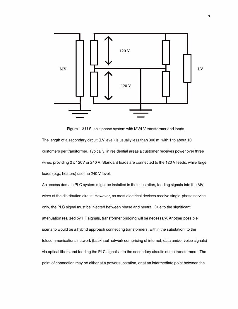
boxes next to a building. On the primary side the transformers are fed with one phase and neutral,
while the secondary provides 240 V with a grounded center tap as depicted in Figure 1.3.
7
Figure 1.3 U.S. split phase system with MV/LV transformer and loads.
The length of a secondary circuit (LV level) is usually less than 300 m, with 1 to about 10
customers per transformer. Typically, in residential areas a customer receives power over three
wires, providing 2 x 120V or 240 V. Standard loads are connected to the 120 V feeds, while large
loads (e.g., heaters) use the 240 V level.
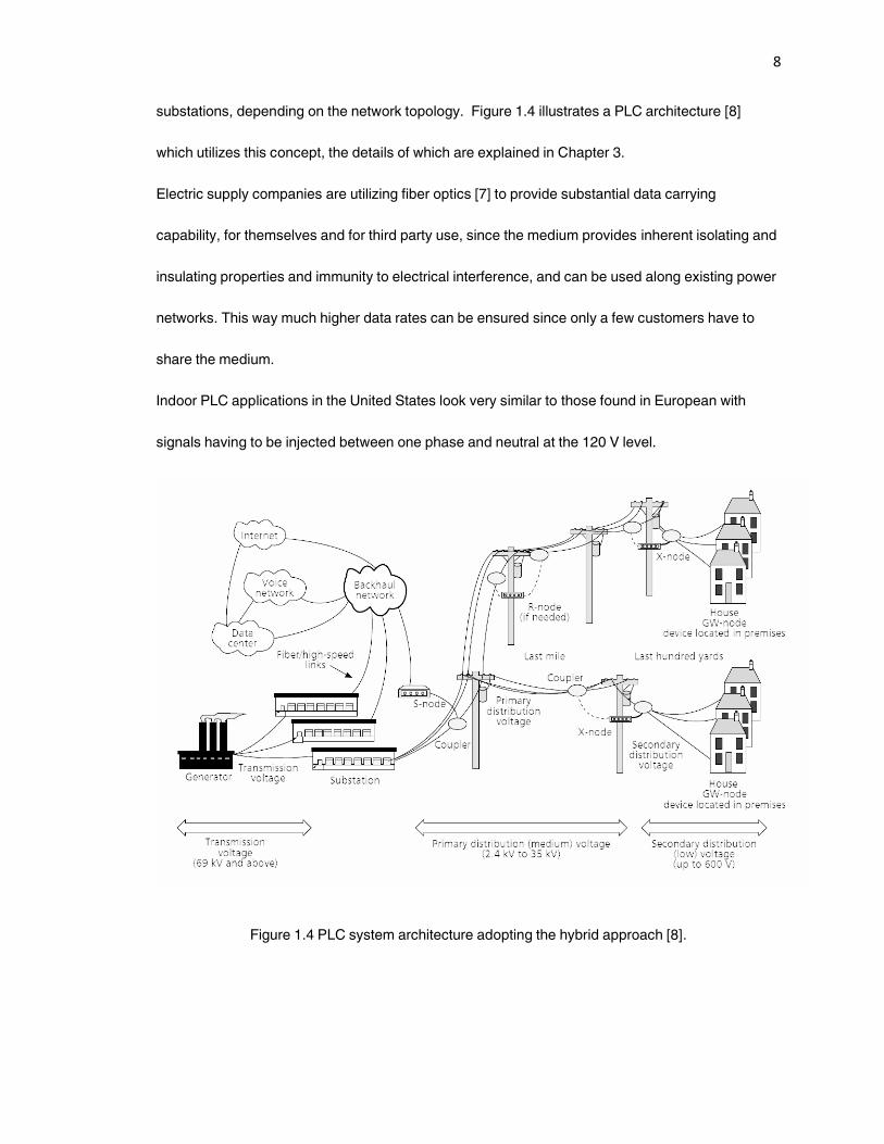
An access domain PLC system might be installed in the substation, feeding signals into the MV
wires of the distribution circuit. However, as most electrical devices receive single-phase service
only, the PLC signal must be injected between phase and neutral. Due to the significant
attenuation realized by HF signals, transformer bridging will be necessary. Another possible
scenario would be a hybrid approach connecting transformers, within the substation, to the
telecommunications network (backhaul network comprising of internet, data and/or voice signals)
via optical fibers and feeding the PLC signals into the secondary circuits of the transformers. The
point of connection may be either at a power substation, or at an intermediate point between the
8
substations, depending on the network topology. Figure 1.4 illustrates a PLC architecture [8]
which utilizes this concept, the details of which are explained in Chapter 3.
Electric supply companies are utilizing fiber optics [7] to provide substantial data carrying
capability, for themselves and for third party use, since the medium provides inherent isolating and
insulating properties and immunity to electrical interference, and can be used along existing power
networks. This way much higher data rates can be ensured since only a few customers have to
share the medium.
Indoor PLC applications in the United States look very similar to those found in European with
signals having to be injected between one phase and neutral at the 120 V level.
Figure 1.4 PLC system architecture adopting the hybrid approach [8].
9
1.2.3 Japanese Power Supply Network
The structure of the Japanese power supply grid is very similar to that of the United States power
network. However, the HV level uses more than 22 kV, and at the MV level (i.e., from substation to
transformer) 6.6 kV is the usual voltage applied. Similar to the United States, transformers are
mounted on top of poles feeding two-phase secondary circuits with a neutral line, which is
connected to a ground rod. Thus, the customer receives power over two or three wires at 100 or
200 V. Over 90 percent of the Japanese power supply network is comprised of overhead wiring.
Mid- to large-scale housing units have their own MV/LV transformers inside the building. The
typical length of an LV circuit is about 50-200 m. Up to 30 households are supplied by one
transformer.
The number of households fed by one MV transformer substation is higher than in the United
States. Thus, if PLC were deployed on the MV level, numerous customers would have to share the
available system capacity. It is possible that unacceptably low data rates might result. Therefore, in
Japan PLC would be most efficient to use on the LV distribution grid. As optical fibers are deployed
along side of most Japanese MV lines, a powerful backbone network is already available there.
Similar to the United States, most indoor loads are supplied from 100 V feeds, so once again the
PLC signal must be injected between phase and neutral.
The previous sections reveal that the availability of the power distribution grids of industrialized
countries generally exhibit excellent features for PLC-based fast data transmission, in order to
establish cost-effective and competitive last mile solutions for everyone. In the following section
the existing and emerging standards and regulations regarding PLC transmission are investigated.
10
1.3 Existing and Emerging Standards and Regulations
In this section the standards and regulations pertaining to the powerline communications are
highlighted. Lack of centralized standardization has been one of the major factors behind the late
deployment of powerline networks.
Due to the fact that PLC has to operate over a network with limited symmetry, a strong necessity
for regulation arises to guarantee electromagnetic compatibility (EMC), especially in the context of
how PLV may affect wireless services, and vice versa. This section discusses the current status of
international standardization processes and presents the regulation initiatives underway in
different countries.
1.3.1 Electromagnetic Compatibility
Electromagnetic Compatibility (EMC) resulting from the presence of wireless services is one of the
crucial factors when PLC technology is commonly deployed. This section will present an overview
in order to enlighten the highly complex connections, which in the past have led to various
regulation issues.
At the outset, it should be noted that the cables comprising any power supply grid have been
designed for nothing but electrical low-loss power transportation at frequencies of either 50 Hz or
60 Hz. Using them for PLC purposes means they will have to carry signals at frequencies between
9 kHz and 30 MHz. In these frequency ranges power cables become leaky, which means a part of
the high-frequency signal power emanates in the form of electromagnetic radiation. Thus, power
cables can be considered linear antennas with low efficiency.
Whenever PLC signals overlay the frequency ranges of used wireless services, interference may
occur, the degree of which strongly depends on transmission power and distance as well as on the
11
specific structure of the wiring. If, say, a broadcast radio receiver is located next to a power cable,
disturbance is very likely, while at a distance of several meters almost no impact may be noticed.
The fraction of injected signal power emitted in the form of radiation is determined by the symmetry
of the network or its cables, respectively. Symmetry is defined in terms of the impedance between
conductors and ground. If for a two-wire line the impedance between each conductor and ground
is equal, the line is regarded as symmetrical or balanced. Balanced lines are necessary to achieve
signal propagation in the desired differential mode, whereas lack of symmetry leads to an
unwanted common mode. Common mode currents flow in parallel on both conductors, while the
return portions take their way in the ground. Generally, common mode currents are responsible for
the existence of electromagnetic radiation. Differential mode currents, on the other hand, are equal
in magnitude and flow in opposite directions on the signal conductors. A highly symmetrical line is
characterized by a large ratio of differential-to-common mode current, so such a line will exhibit
only very weak electromagnetic radiation.
In order to minimize unwanted electromagnetic radiation from interfering with a PLC system, the
following two basic steps are recommended:
Step 1.) The given symmetry of those power lines used for HF signal transportation should be
exploited as far as possible or even improved by network conditioning.
On one hand, HF filters may he installed at the ends of lines in order to keep PLC signals on the
desired propagation paths and prevent them from entering attached devices or conductors that
have high radiation efficiency. Such filtering turns out to be very effective, but also costly.
Therefore, many electric utilities refuse to install any kind of filters. Nevertheless, in the future very
high-speed approaches to critical network structures filtering may be the only way to reduce
electromagnetic radiation to permissible levels.
12
On the other hand, appropriate selection of conductors immediately leads to exploitation of the
‚natural‛ symmetry, which is found, for example, in four-sector supply cables. Since in continental
Europe usually three phases are used to supply a building, the PLC signal may be injected
between two phases. Using two phases for HF signal transportation leads to significantly higher
symmetry than injecting the signal between a phase and neutral. However, this solution is limited
to the access domain, and unfortunately, is not applicable to indoor networks. Due to the
widespread use of four-sector cables, the German access domain appears much better suited to
PLC than, say, networks in Great Britain, where usually only one phase and the neutral conductor
supply a household service connection point.
As already mentioned, indoor networks unfortunately will not exhibit such natural symmetry, so
signal injection must be established between the phase and neutral wires. Currently, however,
investigations are underway to check injection possibilities between neutral and protective earth
where less electromagnetic radiation is expected due to the greater amount of symmetry that is
present.
Step 2.) Reduce the power spectral density (PSD) of PLC data transmission signals. Since PLC
signal emissions are measured within a limited bandwidth, reducing PSD of PLC signals
immediately leads to lower electromagnetic radiation levels, although the total
transmission power remains unchanged. Therefore, it is advantageous to use broadband
modulation schemes, which equally spread the transmitted power over large frequency
ranges. The efficiency of this kind of spreading is, however, limited by the low-pass
frequency response characteristics of the power line.
This section has outlined important aspects of needed EMC between PLC and wireless services.
In practice, the necessary symmetry needed for reduced EMC is rather limited within the power

13
supply grid. As a consequence, complete avoidance of unwanted electromagnetic radiation is
simply infeasible. Moreover, besides for PLC, the symmetry of any communications network is
limited (e.g., for telephone networks and cable TV as well as for computer LANs), so a certain
amount of potential electromagnetic radiation must be assigned to each of them.
The current status of regulation encountered within various regions and countries is presented as
follows.
EUROPE
Comité International Spécial des Perturbations Radioélectriques (CISPR) is the committee that
establishes standards for controlling electromagnetic interference in electrical and electronic
devices, and is a part of the International Electrotechnical Commission (IEC). CISPR activities are
always closely observed by European regulatory bodies. This is because CISPR publications are
intended to become harmonized European laws. After passing a voting process in CENELEC
(Comité Européen de Normalisation Électrotechnique), which is a European standardization body,
CISPR publications become stringent law for each member country of the European Union.
Since the PLC standardization process in CISPR is still underway and not completed, national
regulatory authorities (e.g., in Great Britain and Germany) have already instituted national
legislation even at the risk of contradicting the outcomes of an eventual European harmonization
process.
During 2001 the European Commission issued a mandate to CENELEC [5] and the European
Telecommunications Standards Institute (ETSI) for elaborating a new standard for electromagnetic
emissions from telecommunication networks. It can be expected that the new standard will specify
limits of magnetic field levels at a distance of 3 m from the network under test.
14
The new European law is only used in case of compliance (interference). This means that the
disturbing modem must be switched off if a listener of a radio service complains.
For very low-speed PLC systems, a frequency range from 3 kHz to148.5 kHz is available,
according to standard EN50065 [6], which has been in force since 1991. The frequency range is
divided into four bands (denoted A, B, C, and D) with detailed transmission signal amplitude
limitations and usage. Due to the very restricted bandwidth, the maximum data rates attainable
are in the range of 100 kbps.
UNITED STATES
In the United States the use of PLC is regulated by the Federal Communications Commission
(FCC) Part 15 [4], which distinguishes between low-speed applications for signaling and switching
purposes and high-speed data transmission.
Low-speed systems are allowed to operate at frequencies below 490 kHz. Compared to the
European limitations currently under discussion, FCC Part 15 can he regarded as highly generous
for high-speed PLC systems, and the FCC regulation is not obstructing the spread of PLC
technology within the United States.
JAPAN
In Japan, the use of PLC systems is permitted in the frequency range 10 kHz - 450 kHz by the
national Radio Law and its supplementary provisions. This frequency range is obviously useful for
low-speed PLC systems (i.e., basically for mains signaling, switching, or simple control and
supervision tasks). Furthermore, similar to Europe, sub-bands are specified within the frequency
range with detailed rules for use and the limitation of signal transmission levels.
15
PLC systems operating at higher frequencies (e.g., up to 30 MHz) are currently not permitted.
Japan is carefully watching the progress of the regulations being developed within CISPR, so as to
possibly adopt the outcomes in order to allow PLC systems to operate at higher frequencies in the
near future.
Eventually PLC data transmission systems may evolve into a technology of worldwide interest.
Hence, the regulation of such a new technology is currently an important matter being considered
by many international bodies. Given the tremendous effort actually being made towards
embedding PLC into existing EMC rules as a new communications technology, it can be expected
that in the near future widespread, legal deployment of PLC systems is possible worldwide.
1.3.2 EU Standard (EN 50065)
For Western Europe (i.e. the countries forming the European Union plus Iceland, Norway and
Switzerland) the regulations concerning RPC (Residential Power Circuit) are described in
CENELEC standard EN 50065 entitled ‚Signaling on low-voltage electrical installations in the
frequency range 3 kHz to 148.5 kHz.‛ In Part 1 of this EN-standardization-paper, entitled ‚General
requirements, frequency bands and electromagnetic disturbances‛ [1], the allowed frequency band
and output voltage for communications over the RPC are specified. The frequency range, which is
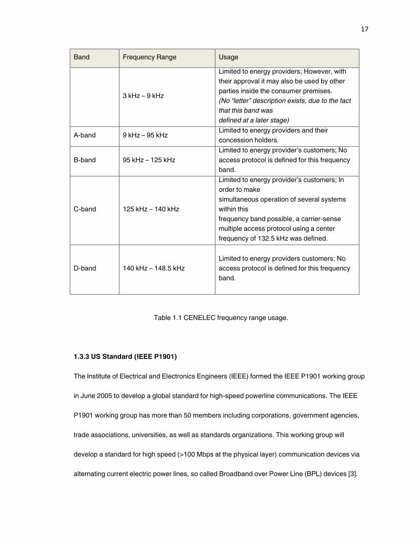
allowed for communications, ranges from 3 kHz to 148.5 kHz and is subdivided into five sub-bands
( four sub-bands are denoted A, B, C and D). The usage of these sub-bands is described in Table
1.1 and their detailed specifications are as follows:
● For the frequency band from 3 kHz – 9 kHz: The transmitter should be connected to a 50 Ω // (50
μH + 1.6 Ω) RPC -simulation-circuit. In principle the transmitter output voltage should not exceed
134 dB (μV) ≈ 5 V.

16
● For the frequency band from 9 kHz – 95 kHz: The transmitter should be connected to a 50 Ω //
(50 μH + 5 Ω) RPC-simulation-circuit. Different maximum transmitter output voltages apply for a
narrow-band (i.e., a 20 dB bandwidth of less than 5 kHz in width) and Broad-Band transmitters
(i.e., a 20 dB bandwidth of more than 5 kHz in width).
● For Narrow-Band signals the maximum allowed peak voltage at 9 kHz equals 134 dB (μV) ≈ 5 V,
exponentially decreasing to 120 dB (μV) ≈ 1 V at 95 kHz. However, for Broad-Band signals, the
maximum allowed peak voltage equals 134 dB (μV).
Furthermore, in any frequency band of 200 Hz in width, the maximum transmitter output voltage
should not exceed 120 dB (μV).
● For the frequency band from 95 kHz - 148.5 kHz: the transmitter output voltage should not
exceed 116 dB (μV) ≈ 0.63 V. In certain cases an exception can be made allowing 134 dB (μV).
CENELEC has started working on a new standard for frequencies up to 30 MHz. This will allow
high-speed digital access to consumer’s premises via the electric utility wiring. The details of which
are described in [2].
17
Band Frequency Range Usage
3 kHz – 9 kHz
Limited to energy providers; However, with
their approval it may also be used by other
parties inside the consumer premises.
(No “letter” description exists, due to the fact
that this band was
defined at a later stage)
A-band 9 kHz – 95 kHz Limited to energy providers and their
concession holders.
B-band 95 kHz – 125 kHz
Limited to energy provider’s customers; No
access protocol is defined for this frequency
band.
C-band 125 kHz – 140 kHz
Limited to energy provider’s customers; In
order to make
simultaneous operation of several systems
within this
frequency band possible, a carrier-sense
multiple access protocol using a center
frequency of 132.5 kHz was defined.
D-band 140 kHz – 148.5 kHz
Limited to energy providers customers; No
access protocol is defined for this frequency
band.
Table 1.1 CENELEC frequency range usage.
1.3.3 US Standard (IEEE P1901)
The Institute of Electrical and Electronics Engineers (IEEE) formed the IEEE P1901 working group
in June 2005 to develop a global standard for high-speed powerline communications. The IEEE
P1901 working group has more than 50 members including corporations, government agencies,
trade associations, universities, as well as standards organizations. This working group will
develop a standard for high speed (>100 Mbps at the physical layer) communication devices via
alternating current electric power lines, so called Broadband over Power Line (BPL) devices [3].
18
The standard will use transmission frequencies below 100 MHz. This standard will be usable by all
classes of BPL devices, including BPL devices used for the first-mile/last-mile connection (<1500m
to the premise) to broadband services as well as BPL devices used in buildings for LANs and other
data distribution (<100m between devices). This standard will focus on the balanced and efficient
use of the power line communications channel by all classes of BPL devices, defining detailed
mechanisms for coexistence and interoperability between different BPL devices, and ensuring that
desired bandwidth and quality of service may be delivered. The standard will address the
necessary security issues so as to ensure the privacy of communications between users and allow
the use of BPL for security sensitive services. This standard is limited to the physical layer and the
medium access sub-layer of the data link layer, as defined by the International Organization for
Standardization (ISO) Open Systems Interconnection (OSI) Basic Reference Model. The effort will
begin with an architecture investigation, and this will form the basis for detailed scope of task
groups that will work within P1901 to develop the components of the final standard.
The working group has created, reviewed and completed draft version 4.01 of the standard on
August 2010. Draft 4.01 was submitted to the IEEE-SA Standards Board for consideration as an
IEEE standard. On September 30, 2010, the IEEE-SA Standards board approved the IEEE Std
1901-2010 as an IEEE standard for Broadband over Powerline Networks.
1.3.4 Federal Communications Commission
The Federal Communications Commission (FCC) is an independent agency of the United States
government working in areas of broadband, the spectrum, the media, public safety and homeland
security. The FCC is responsible for regulating all non-federal government use of the radio
spectrum (including radio and television broadcasting), and all interstate telecommunications
19
(wire, satellite and cable) as well as all international communications that originate and terminate in
the United States.
Broadband over Powerline (BPL) is the term coined by the FCC for new (BPL) modems used to
deliver IP-based broadband services on electric powerlines. On April 23, 2003, the FCC adopted a
notice of enquiry (NOI) [9] seeking public comment and expressing enthusiasm about the potential
of the BPL technology to enable electric powerlines to function as a ‚third‛ wire in the home, and
create competition with the copper telephone wire line and cable television coaxial cable wire line.
Numerous organizations weighed in with comments both in support and opposition.
One of the immediate concerns of the FCC over the widespread use of BPL products is the impact
in terms of radio frequency noise. The FCC is more concerned about the interference potential of
BPL signals transmitted on exposed, overhead medium voltage power lines. Interference issues
between unlicensed devices, including BPL modems, and other electronic devices are governed
by Part 15 of the FCC rules. All electronic devices sold in the United Sates have to meet RF
emissions limits set by the FCC.
On October 14, 2004, the FCC adopted rules to facilitate the deployment of ‚Access BPL‛ that is,
use of BPL to deliver broadband services to homes and businesses. Furthermore, in August 2006,
the FCC adopted a memorandum opinion and an order on broadband over powerlines, giving the
go-ahead to promote broadband services to all Americans [10]. Moreover, at that time, the FCC
chief Kevin Martin said that BPL "holds great promise as a ubiquitous broadband solution that
would offer a viable alternative to cable, digital subscriber line, fiber, and wireless broadband
solutions", and that BPL was one of the agency's "top priorities" [11]. Hence, the FCC was able to
propose rules which would govern BPL in a manner similar to the rules applicable to personal
computers and other digital devices.
20
1.3.5 HomePlug Powerline Alliance
Founded in 2000 by 13 industry leaders (3Com, AMD, Cisco Systems, Compaq, Conexant, Enikia,
Intel, Intellon, Motorola, Panasonic, Radio Shack, SONICblue, and Texas Instruments) the
HomePlug Powerline Alliance enables and promotes the rapid availability and adoption of cost
effective, interoperable and standards-based home powerline networks and products.
Members of the HomePlug alliance tested the technology in an extensive field trial of 500 homes
throughout North America. Based on the success of this field trial, the completion of the HomePlug
1.0 Specification was announced in June 2001.The first publicly available HomePlug products
were demonstrated in early 2002 at the CES and CeBIT exhibitions. At these shows, HomePlug
member companies unveiled HomePlug-compliant home networking products such as bridging
and routing devices, network interface cards, and combination 802.11b access point/powerline.
The HomePlug 1.0 protocol is highlighted in [13] and [69] as follows: HomePlug 1.0 uses a
Physical Layer (PHY) protocol based on equally spaced, 128-carrier Orthogonal Frequency
Division Multiplexing (OFDM) from 4.5 MHz to 21 MHz, in conjunction with concatenated Viterbi
and Reed Solomon coding with interleaving for payload data and turbo product codes for control
data. A total of 84 carriers are used to transmit data. Modulation formats such as BPSK, DBPSK,
DQPSK or ROBO (a robust form of DBPSK) are used for data and a cyclic prefix is used for
synchronization.
A pair of nodes first determines which subcarriers are usable, and what form of modulation and
error correction should be applied to the channel. This ‘tone map’ is used for subsequent
communication between the nodes. Broadcast packets and frame delimiters use all subcarriers
21
with robust modulation and forward error correction codes so that all nodes are able to interpret
them, the rest of a unicast frame uses the higher speed specified by the tone map.
The presence of large attenuation prevents the detection of collisions, so HomePlug 1.0 uses
CSMA/CA for its MAC protocol. Powerline modules determine if the medium is idle or not, using
virtual carrier sense (VCS). If it has been idle for Extended InterFrame Space (EIFS), the station
can send the segment without contention. If it is busy, it waits for CIFS (Contention InterFrame
Space) or RIFS (Response InterFrame Space) after the end of the current transmission. The
delimiter informs the listening node’s VCS when the transmission will end and whether a response
is expected, for synchronization. The receiver sends ACK, NACK (or NAC), or FAIL after RIFS
when it is needed, taking top priority. ACK indicates successful delivery, while NACK (or NAC)
indicates an error detected at the receiving end. FAIL indicates that the receiver was unable to
buffer the segment. Otherwise, stations wait until the end of the CIFS period. Then they use two
priority resolution slots to select the highest priority level traffic waiting. Nodes with this traffic
contend for the medium during the contention window using a randomly selected delay. Initially,
there are eight contention resolution slots, and upon collision, nodes increase this to 16, then 32,
according to a backoff schedule. Large contention windows are used to avoid costly collisions. In
the case of frame control errors or collision, stations must wait for EIFS.
The HomePlug PHY occupies the band from about 4.5 MHz to 21 MHz. The PHY includes reduced
transmitter power spectral density in the amateur radio bands to minimize the risk of radiated
electromagnetic energy from the power line interfering with these systems. The raw bit rate using
DQPSK modulation with all carriers active is 20 Mbps. The bit rate delivered to the MAC by the
PHY layer is about 14 Mbps [69].
22
The HomePlug Powerline Alliance is a not-for-profit corporation established to provide a forum for
the creation of open specifications for high-speed home power line networking products and
services.
Products conforming to the HomePlug standards are designated as ‚HomePlug-certified products‛
[14] and they are entitled to use the official ‚HomePlug certification mark‛. HomePlug, which has
grown to more than 90 member companies, has chosen Intellon’s PowerPacket technology [68] as
the baseline upon which the alliance’s first industry specification is build. HomePlug devices
account for more than 80 percent of the world’s broadband powerline communications market and
over 45 million devices have shipped to date.
1.3.6 Other Standards related to Powerline Communications
Other regulatory standards pertaining to powerline carrier communications include:
● The IEC 870 international standard on telecontrol, teleprotection and associated
telecommunications for electrical power systems, as well as the IEC 1107 and 1142 standards
pertaining to equipment for electrical energy measurement and load control [78].
● The CENELEC ENG1107 standard specifies equipment for electrical energy measurement and
load control [79].
● The Consumer Electronics Association (CEA) R7 Home Network Committee [15] [30] ensures
that the current and future Home Networks can coexist within a home and share information
through the use of industry standard interfaces.
● The International Electrotechnical Commission (IEC) has standardized the distribution line
communications (DLC) through Technical Committee No 57 (Power System Control and
23
Associated Communications), Working Group 9 (Distribution automation using distribution line
carrier systems). All systems discussed in IEC TC57/WG9 use frequencies below 150 kHz [17].
● The PLCforum [40] is a leading international Association that represents the interests of
manufacturers, energy utilities and research organizations active in the field of access and in-home
PLC technologies. Since its creation in Interlaken (Switzerland) at the start of 2000, the number of
members and permanent guests has increased and today totals more than 60.
● ETSI (the European Telecommunications Standards Institute) [18] is a non-profit organization
whose mission is to produce the telecommunications standards that will be used for the decades
to come throughout Europe and beyond. Based in Sophia Antipolis (France), ETSI unites nearly
700 members from 50 countries inside and outside Europe, and represents administrations,
network operators, manufacturers, service providers, technical bodies and users. ETSI technical
specifications on Powerline Telecommunications (PLT) are highlighted in [19] [20] and [21].
1.4 Current State-of-the-Art
PLC technology can be used for home networking applications to interconnect networked
peripherals such as home computers, as well as any home entertainment devices that have
an Ethernet port. Consumers can buy powerline adapter sets at most electronics retailers and use
those to establish a wired connection using the existing electrical wiring in the home. These
powerline adapters plug into a wall and then are connected to the home’s router via Ethernet
cable. Additional adapters can be plugged in at any other outlet to give instant networking and
Internet access to an Ethernet-equipped device.
24
The most established and widely deployed powerline networking standard for these powerline
adapter products is from the HomePlug Powerline Alliance. HomePlug AV is the most current of
the HomePlug specifications and was adopted by the IEEE P1901 group as a baseline technology
for their standard, published December 30, 2010.
PLC systems have long been a favorite at many electric utility industries because it allows them to
reliably move data over an infrastructure that they control. Interest in this application has grown
substantially because there is a growing demand in obtaining up-to-the-minute data from all
metered points in order to better control and operate the system. PLC is one of the technologies
being used in Advanced Metering Infrastructures (AMI) systems [76]. AMI are systems that
measure, collect and analyze energy usage, and communicate with metering devices such as
electricity meters, gas meters, heat meters, and water meters; either upon request, or according to
a set schedule.
Powerline technology can also enable in-vehicle network communication of data, voice, music and
video signals by digital means over direct current (DC) battery powerline. Advanced digital
communication techniques tailored to overcome hostile and noisy environment are implemented in
a small size silicon device. One power line can be used for multiple independent networks.
Prototypes are successfully operational in vehicles, using automotive compatible protocols such
as CAN-bus [46].
1.5 Thesis Outline
The remainder of this thesis is organized as follows. In Chapter 2, an overview of various digital
data communication techniques relevant to this study are presented which are useful for the PLC
25
system modeled in Chapter 6. In Chapter 3 the potential of home networking and automation is
explored along with limitations and applications. Various economic and technical aspects of home
networking are presented and the available technologies compared. A special focus is given to the
powerline networking and a technical description of the powerline networking technology is
presented. This chapter gives a general overview and applications of powerline networking
technologies being used in practice. In Chapter 4 the powerline as a communication channel is
discussed. Different approaches for modeling the powerline channel are described. An
introduction to a multipath channel model is presented. The channel is described in more detail in
Chapter 6. Various transmission impairments and factors governing the powerline for data
transmission are studied. Modulation schemes mentioned in Chapter 2 are described in more
detail which are used in practical PLC systems. Chapter 5 presents a technical discussion of all the
major technologies in the powerline networking area is presented. The technologies are studied in
depth and their major working principles and characteristics are highlighted. In Chapter 6 a
candidate PLC communications system is described and modeled. The multipath channel model
introduced in Chapter 4 is described in detail and used for the performance evaluation of the
candidate PLC system model. The characteristics of the reference channels used in our system
are also analyzed and compared with those found in literaturel. In this chapter we study and
evaluate the performance characteristics of powerlines as a communication channel for data
transmission. We also compare the simulated PLC system performance results with those
reported in literature and draw conclusions. Chapter 7 presents the conclusions of this study.
26
2. Data Communication Techniques
This chapter focuses on various, albeit a limited number of, data transmission techniques
commonly used in practice. The presentation is intended to give only a general review of some
basic data communication signaling methods.
Analog and digital formats are means used to move information across any medium. The physical
layer of a system is responsible for transportation of a raw bit stream from one node to another. For
actual data transmission, various physical media can be used (including magnetic media, twisted
pair, baseband coaxial cable, broadband coaxial cable, fiber optic, powerline, wireless or radio,
microwave, satellite etc.). However, for the purpose of this work, focus is placed on the data
transmission techniques related to the powerline environment.
2.1 Baseband Digital Signals
A baseband waveform has a spectral magnitude characteristic that is nonzero for frequencies in
the vicinity of f = 0, and it has negligible spectral content elsewhere.
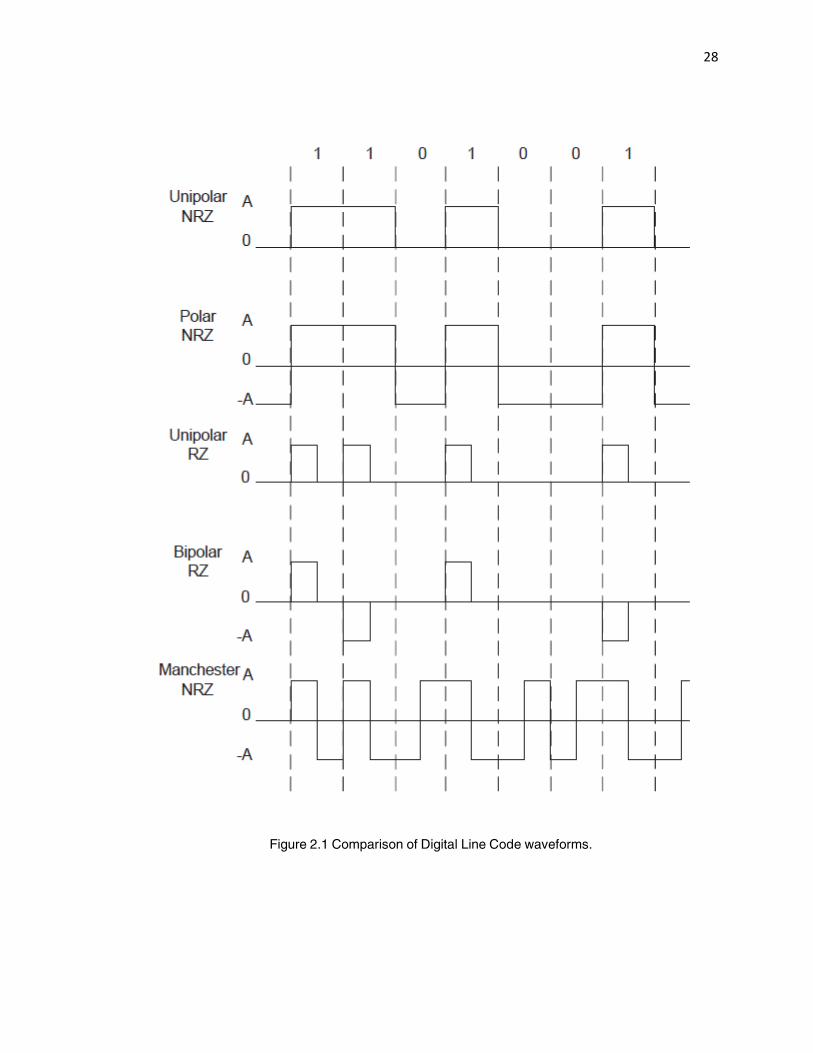
2.1.1 Line Coding
Line coding is a method of making signal regeneration more reliable. Binary 1’s and 0’s may be
represented in various serial-bit signaling formats know as line codes. The two major categories of
line codes are return-to-zero (RZ) and non-return-to-zero (NRZ). With RZ coding the waveform
returns to a zero volt level during a portion (usually one-half) of the bit interval. The waveform for
the line code is further classified according to the rule that is used to assign voltage levels to
represent binary data. Following are some of the waveform types:

27
Unipolar Signaling: In positive logic unipolar signaling, a binary 1 is represented by a high voltage
level (positive voltage) and a binary 0 is represented by a zero voltage level. This type of signaling
is also called as on-off keying.
Polar Signaling: Binary 1’s and 0’s are represented by positive and negative voltage levels each
having the same magnitude.
Bipolar Signaling: Binary 1’s are represented by alternately positive or negative values. The binary
0 is represented by a zero level.
Manchester Signaling: Each binary 1 is represented by a positive half-bit period pulse which is
followed by a negative half-bit period pulse. Similarly, a binary 0 is represented by a negative half-
bit period pulse followed by a positive half-bit period pulse. Manchester signaling is very popular
because it combines the clock and the message into one signal. Manchester signaling is also
known as the split phase encoding.
Figure 2.1 presents a graphical, time-domain comparison of the various line coding formats
described above. Each of the line codes has certain advantages and disadvantages associated
with it. For example, the unipolar NRZ line code has the advantage of using electronic circuits that
only require one power supply, but it has the disadvantage of requiring channels that are DC
coupled (i.e. frequency response down to f=0) since the signal has a non-zero DC value. The
Manchester code combines the data and clock signal, which is beneficial for receiver
synchronization. The Manchester code, however, occupies a significantly larger bandwidth
because of the greater number of transitions involved at each signaling interval.
28
Figure 2.1 Comparison of Digital Line Code waveforms.
29
2.1.2 Multilevel Line Coding
The line codes described in the previous section only use two logical levels. If the signal has more
than two possible values, then the signal is known as a multilevel signal. One way to reduce
signaling bandwidth is to convert a binary signal to a multilevel signal. In practice, filtered multilevel
signals are often used to modulate a carrier for transmission of digital information over a
communication channel that possesses a relatively narrow bandwidth.
2.1.3 Network Synchronization
Synchronization is imperative in a digital transmission system. Any digital network requires that
synchronization between the sender and receiver must be maintained. Synchronization signals are
clock-type signals that are necessary within a receiver (or repeater) for detection of the data from
the input signals. If the timing of arrival or transmission is misaligned, then the information will be
distorted. Regardless of whether voice, data, video, or image traffic is present, the correct recovery
of a digital stream of 1’s and 0’s at the receiver is contingent on proper signal timing being
established between the two ends.
The clock-signals have a precise frequency and phase relationship with respect to the received
input signal, and they are delayed when compared to the clock signals at the transmitter since
there is propagation delay through the channel.
There are number of ways to synchronize signals within a digital network. Communication of digital
data usually needs at least three types of synchronization signals to be employed:
• bit sync is used to distinguish one bit interval from another;
• frame sync is needed to distinguish groups of data;
30
• carrier sync is required for band pass signaling used in conjunction with coherent detection at the
receiver.
Systems are designed so that the synchronization is derived either directly from the transmitted
signal or from a separate channel that is used only to transmit the sync information. Systems with
bit synchronizers that derive the sync directly from the corrupted signal need a sufficient number of
alternating 1’s and 0’s in the data to be able to maintain the synchronization. The loss of
synchronization that may occur when long strings of 1’s or 0’s is transmitted can be prevented by
adopting one of the following alternatives:
• Bit interleaving (i.e., scrambling): in this case the source data with strings of 1’s and 0’s are
scrambled to produce data with alternating 1’s and 0’s;
• Bit stuffing: if a certain number of 1’s or 0’s (e.g., 5) are transmitted repeatedly in succession,
then the transmitter automatically inserts a bit of opposite value. The receiver later removes such
bits that were stuffed into the data stream;
• Changing to a completely different type of line code that does not require alternating data for bit
sync. Manchester NRZ can be used, but it requires a channel with twice the bandwidth of that
needed for a polar NRZ line code.
Clocking or timing differences between the transmitter and receiver can exist. Therefore, while the
receiver is expecting a bit that the transmitter has not sent, a slip occurs. Slips are likely to be
present because of multiple factors in any network. This can result from the two clocks at the
transmitter and receiver end being off or from problems that can occur along the link. Problems
along the link can be accommodated however, using pulse stuffing or other techniques. Each
31
device along the link has a buffer capability, creating a simple means of maintaining
synchronization. Pulse stuffing can be done independently for each multiplexer along the way,
enhancing overall reliability of the network, with the disadvantage of creating an undesirable
overhead at each multiplexer.
2.2 Signal Modulation Techniques
Modulation is a technique that enables an information signal to be transferred by changing the
characteristics of an electric signal carrier. Modulation is used both for analog and digital
information. In the case of analog information, the carrier is affected continuously (soft transitions).
In the case of digital information, the carrier is affected in a step-by-step fashion (state changes).
The operational unit in a communication system performing modulation and the corresponding
demodulation is called a modem. In analog transmission of information, both amplitude modulation
and frequency modulation are used.
2.2.1 Amplitude Modulation
Amplitude Modulation (AM) is the simplest form of modulation. The amplitude of the carrier wave is
varied in accordance with the voltage characteristic of the modulating signal (which may be analog
or digital). An AM signal can be represented mathematically according to the relationship
)1.2(cos)](1[)( ttmAtScc
where, m(t) is the modulating signal, ωc is the carrier frequency, and Ac is a constant.
Amplitude modulation is used to transmit analog voice (300 - 3,400 Hz) modulated on radio
frequencies around 450 MHz in the mobile radio system NMT 450 (a 1G analog cellular radio
32
technology employing frequency division multiple access (FDMA) to derive 200 channels with a
width of 25 kHz), and to transmit TV images in cable-TV networks. The bandwidth of an AM signal
is twice the bandwidth of the modulating signal. That is because amplitude modulation results in
two sidebands on either side of the carrier frequency. The frequencies above the carrier frequency
constitute the upper sideband, and frequencies below constitute the lower sideband. Single Side
Band (SSB) modulation techniques exist that suppress one of the sidebands with the resulting
SSB-AM signal having the same bandwidth as the modulating, or message, signal.
2.2.2 Frequency Modulation and Phase Modulation
Frequency modulation (FM) is used for broadcasting on the FM radio band, the sound channel for
TV, and certain mobile communication systems. Phase modulation (PM) and frequency
modulation are special cases of angle-modulation signaling. An angle-modulated signal is
represented by
)2.2()](cos[)( ttAtscc
where, is the instantaneous phase conveying the message signal.
For PM, the phase is directly proportional to the modulating signal
)3.2()()( tmDtp
where is the modulating signal and is the phase-sensitivity of the phase modulator
For FM, the phase is proportional to the integral of given according to
)4.2()()(
t
fdmDt
33
where, is the frequency deviation constant, and now the instantaneous frequency of the carrier
waveform conveys the message signal.
In particular, instantaneous frequency varies about the assigned carrier frequency directly
proportional to the modulating signal .
The instantaneous frequency is the frequency that is present at a particular instant of time and
should not be confused with the term frequency as used in the spectrum of the FM signal. Thus the
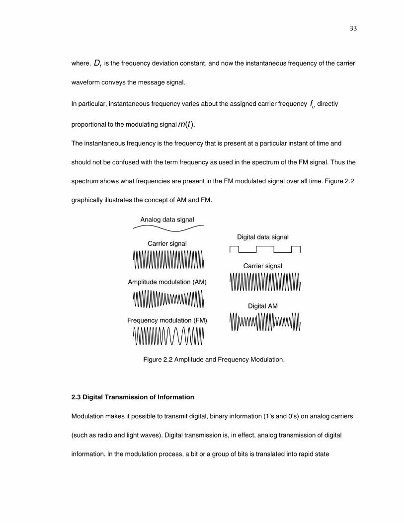
spectrum shows what frequencies are present in the FM modulated signal over all time. Figure 2.2
graphically illustrates the concept of AM and FM.
Figure 2.2 Amplitude and Frequency Modulation.
2.3 Digital Transmission of Information
Modulation makes it possible to transmit digital, binary information (1’s and 0’s) on analog carriers
(such as radio and light waves). Digital transmission is, in effect, analog transmission of digital
information. In the modulation process, a bit or a group of bits is translated into rapid state
34
changes, such as amplitude or phase changes of a carrier waveform. Digitally modulated band
pass signals are generated by using AM, PM, FM, or QAM (quadrature amplitude modulation)
signaling. For digitally modulated signals, the modulating signal, m(t) is a digital signal given by a
particular binary or multilevel line code. The basic modulation methods include: amplitude shift
keyed (ASK) modulation; frequency shift keyed (FSK) modulation; and phase shift keyed (PSK)
modulation.
In many cases, the purpose of modulation is to represent as many bits of information as possible
per hertz of a carrier waveform. Such carriers include a band pass filtered telephone line (300 Hz -
3400 Hz) or a limited radio frequency band.
2.3.1 Shift Modulation
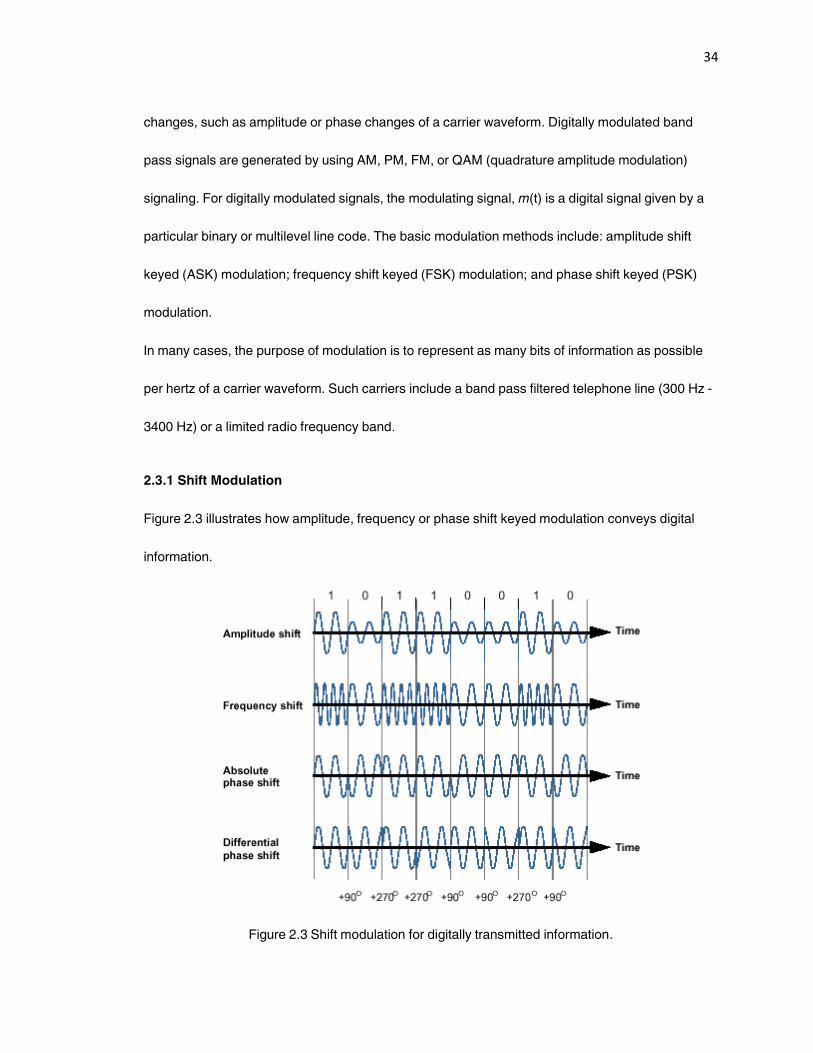
Figure 2.3 illustrates how amplitude, frequency or phase shift keyed modulation conveys digital
information.
Figure 2.3 Shift modulation for digitally transmitted information.
35
In PSK modulation, the phase is shifted either differentially relative to the previous phase (for
example, +90° for bit 0, and +270° for bit 1), or absolutely, in which case each modulation state is
represented by a specific phase (0° for bit 0, and +180° for bit 1) relative to an initial phase (one
that is known both by the transmitter and the receiver). The differential PSK technique permits less
complicated demodulation equipment, and is therefore, more common.
An uncomplicated variant of amplitude modulation is used for optical fiber transmission: light on
(full amplitude) or light off (no amplitude). On-Off keying (OOK) is a popular form of an AM signal.
The approach is to let the carrier waveform represent a binary 1, and the absence of the carrier
waveform represents a binary 0. Since OOK is an AM-type signaling scheme, the required
bandwidth of an OOK signal is 2 times the bit rate. That is, the transmission bandwidth, Bt of the
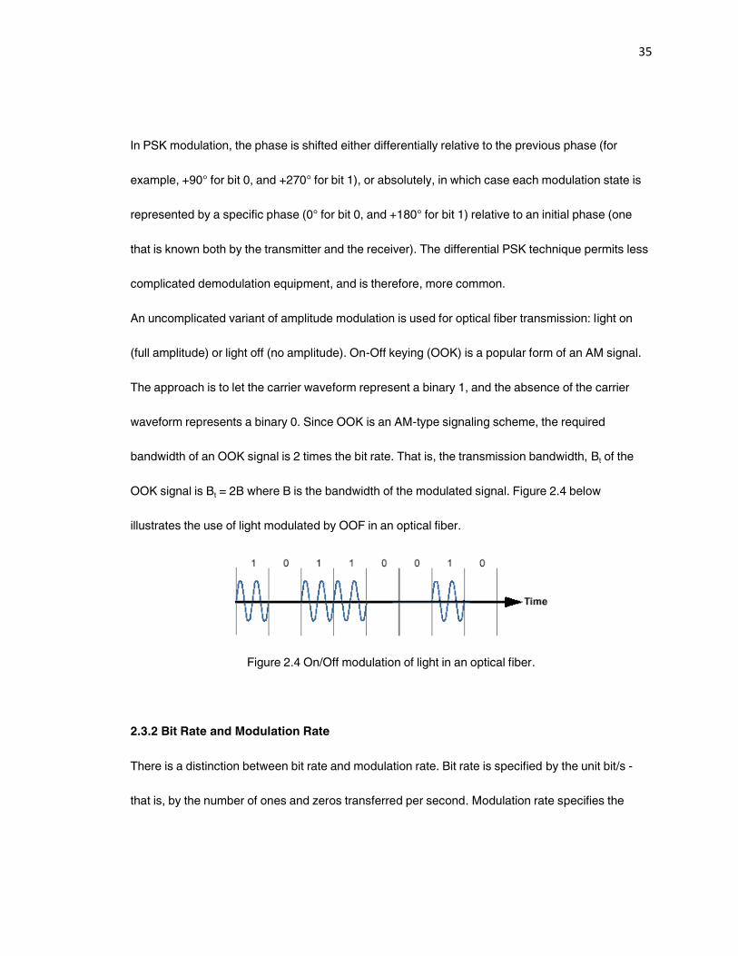
OOK signal is Bt = 2B where B is the bandwidth of the modulated signal. Figure 2.4 below
illustrates the use of light modulated by OOF in an optical fiber.
Figure 2.4 On/Off modulation of light in an optical fiber.
2.3.2 Bit Rate and Modulation Rate
There is a distinction between bit rate and modulation rate. Bit rate is specified by the unit bit/s -
that is, by the number of ones and zeros transferred per second. Modulation rate specifies the
36
number of possible state changes per unit of time. The unit baud, which is a less complicated way
of expressing "modulation states per second,” is used for modulation rate.
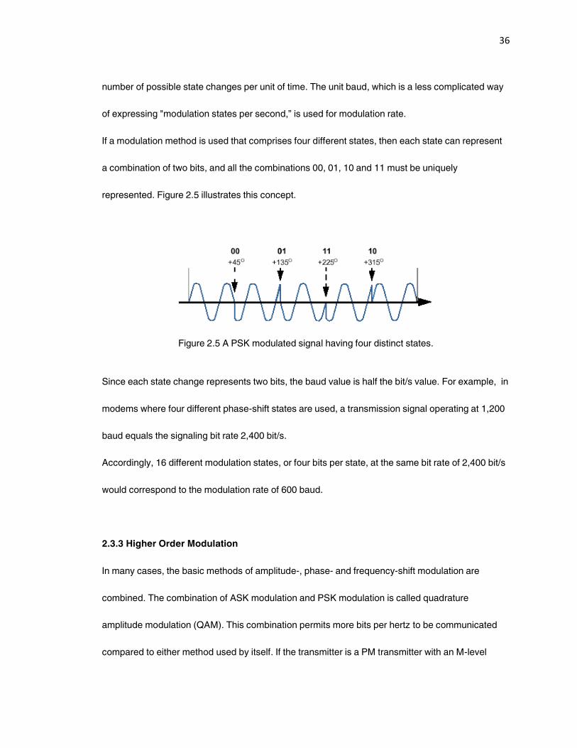
If a modulation method is used that comprises four different states, then each state can represent
a combination of two bits, and all the combinations 00, 01, 10 and 11 must be uniquely
represented. Figure 2.5 illustrates this concept.
Figure 2.5 A PSK modulated signal having four distinct states.
Since each state change represents two bits, the baud value is half the bit/s value. For example, in
modems where four different phase-shift states are used, a transmission signal operating at 1,200
baud equals the signaling bit rate 2,400 bit/s.
Accordingly, 16 different modulation states, or four bits per state, at the same bit rate of 2,400 bit/s
would correspond to the modulation rate of 600 baud.
2.3.3 Higher Order Modulation
In many cases, the basic methods of amplitude-, phase- and frequency-shift modulation are
combined. The combination of ASK modulation and PSK modulation is called quadrature
amplitude modulation (QAM). This combination permits more bits per hertz to be communicated
compared to either method used by itself. If the transmitter is a PM transmitter with an M-level
37
digital modulation signal, M-ary phase-shift keying (MPSK) is generated at the transmitter output. A
plot of the permitted values of the complex envelope would contain M points, one value for each of
the M multilevel values, corresponding to the M phases that the signal is permitted to have. The
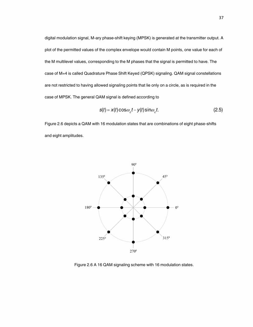
case of M=4 is called Quadrature Phase Shift Keyed (QPSK) signaling. QAM signal constellations
are not restricted to having allowed signaling points that lie only on a circle, as is required in the
case of MPSK. The general QAM signal is defined according to
)5.2(.sin)(cos)()( ttyttxtscc
Figure 2.6 depicts a QAM with 16 modulation states that are combinations of eight phase-shifts
and eight amplitudes.
Figure 2.6 A 16 QAM signaling scheme with 16 modulation states.

38
2.4 Spread Spectrum Systems
Spread Spectrum (SS) uses wide band, noise-like signals to communicate message signals which
makes the signals hard to detect. Spread signals are intentionally made to be much wider band
than the information they are carrying to make them more noise-like. Spread Spectrum signals are
harder to jam (intentionally interfere with) than narrowband signals. The features of low probability
of intercept (LPI) and anti-jam (AJ) features are why Spread Spectrum techniques have been used
by the military for many years [22].
Many types of SS systems exist. To qualify as a SS system, two system criteria should be met.
Firstly, the bandwidth of the transmitted signal, s(t), needs to be much greater than that of the
message m(t). Secondly, the relatively wide bandwidth of s(t) must be caused by an independent
modulating waveform c(t), called the spreading signal. The signal c(t) must be known by the
receiver in order for the message signal to be detected.
The two most common types of SS modulation techniques are Direct Sequence (DS) and
Frequency Hopping (FH).
2.4.1 Direct Sequence Spread Spectrum (DS-SS)
The basic principle of direct sequence spread spectrum (DS-SS) is to spread the signal over a
larger frequency band by multiplexing it with a signature, or code, signal. The system works over a
fixed channel. To spread the signal, each bit of the packet to be transmitted is pre-modulated by a
code. At the receiver, the original signal is recovered by receiving the entire spread signal and
demodulating using the same code waveform c(t). Any narrowband interferer will appear much
39
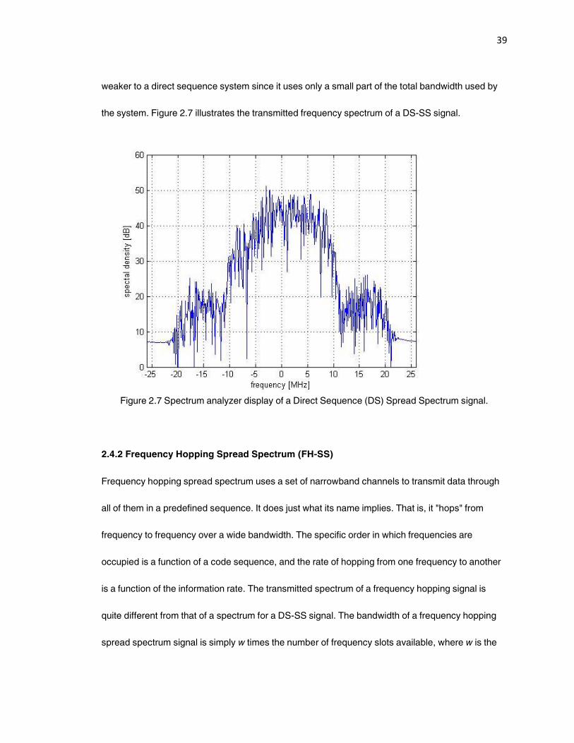
weaker to a direct sequence system since it uses only a small part of the total bandwidth used by
the system. Figure 2.7 illustrates the transmitted frequency spectrum of a DS-SS signal.
Figure 2.7 Spectrum analyzer display of a Direct Sequence (DS) Spread Spectrum signal.
2.4.2 Frequency Hopping Spread Spectrum (FH-SS)
Frequency hopping spread spectrum uses a set of narrowband channels to transmit data through
all of them in a predefined sequence. It does just what its name implies. That is, it "hops" from
frequency to frequency over a wide bandwidth. The specific order in which frequencies are
occupied is a function of a code sequence, and the rate of hopping from one frequency to another
is a function of the information rate. The transmitted spectrum of a frequency hopping signal is
quite different from that of a spectrum for a DS-SS signal. The bandwidth of a frequency hopping
spread spectrum signal is simply w times the number of frequency slots available, where w is the
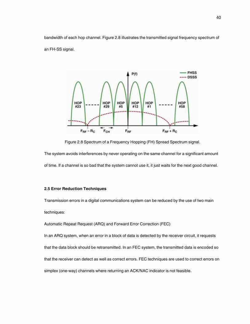
40
bandwidth of each hop channel. Figure 2.8 illustrates the transmitted signal frequency spectrum of
an FH-SS signal.
Figure 2.8 Spectrum of a Frequency Hopping (FH) Spread Spectrum signal.
The system avoids interferences by never operating on the same channel for a significant amount
of time. If a channel is so bad that the system cannot use it, it just waits for the next good channel.
2.5 Error Reduction Techniques
Transmission errors in a digital communications system can be reduced by the use of two main
techniques:
Automatic Repeat Request (ARQ) and Forward Error Correction (FEC)
In an ARQ system, when an error in a block of data is detected by the receiver circuit, it requests
that the data block should be retransmitted. In an FEC system, the transmitted data is encoded so
that the receiver can detect as well as correct errors. FEC techniques are used to correct errors on
simplex (one-way) channels where returning an ACK/NAC indicator is not feasible.
41
The choice between using the ARQ or the FEC technique depends on the particular application.
ARQ is often used in computer communication system because it is relatively inexpensive to
implement, and there is usually a full-duplex (two-way) channel so that the receiving end can either
transmit back an acknowledgement (ACK) for correctly received data, or a request for
retransmission (NAC) when there is an error in received data. FEC is preferred in systems with
large transmission delays because if the ARQ were used, the effective data rate would be small
and the transmitter would have long idle periods while waiting for the ACK/NAC indicator.
2.6 Medium Access Methods
As all the devices on a communication network share the same physical medium, techniques are
required in order to prevent different devices from transmitting at the same time. These techniques
are collectively known as the Medium Access methods. Based on [23], this section describes three
Medium Access methods: Polling, Contention and Token Passing.
2.6.1 Polling
In a polling system, one device works as the network master and all other devices function as
slaves to this master. The master queries each device in turn as to whether it has any data to
transmit. If the answer is yes, the device is permitted to transmit data. If, however, the answer is no,
then the master moves on and asks or polls the next slave device.
42
2.6.2 Contention
Contention is the opposite of polling. In a contention system if one device has to transmit, it does
so. The latest generation of contention based medium access methods is called as Carrier Sense
Multiple Access with Collision Detection or Collision Avoidance (CSMA/CD or CSMA/CA). Under
CSMA/CD when a station wants to transmit data, the station first listens to the medium to see if any
other transmission is going on. If the medium is quiet, the station goes ahead with the
transmission. If the medium is busy, the station waits for a random time and listens again. It is
possible for two stations to transmit at the same time (sense the wire at the same time, conclude
that the network is idle, and begin transmitting simultaneously), resulting in a collision. By using
CSMA/CD the station can recognize collision and take corrective action.
2.6.3 Token Passing
Token passing uses a “token”, which is a small frame of data, to grant a device permission to
transmit over the medium. Whichever station has the token can put data on the medium. When a
station is done transmitting, it releases the token and the next station willing to transmit acquires
the token. If polling and contention define the extremes of total control and total anarchy, the token
passing medium access method exists somewhere in the middle of the spectrum.
2.7 Conclusions
This chapter presented the basic concepts of a digital communications system for data
communication.

43
The transmission of data over electric power line presents various challenges. The terms and
techniques discussed in this chapter will be used in subsequent sections in this thesis. Enabling
data communication over powerlines is a careful combination of various approaches. Certain
modifications and enhancements to conventional signaling techniques are used to accommodate
the characteristics of the PLC communications medium.
44
3. Home Networking over Powerlines
In the present digital age of information technology, the demand for sending digital voice, video,
and Internet data to and around a home, office or other building increases continuously. Installation
of wires to support this is an expensive, disruptive and time-consuming process. In the context of a
home networking environment, ‚no new wires‛ is the term applied to those technologies that utilize
the existing wiring systems to distribute high-speed data and video throughout the home (or small
office).
Phoneline and powerline systems are two dominant ‚no new wires‛ technologies. With the recent
trend of deregulation and privatization of electric utility providers, these businesses can now be
classified into three major types: power generation, transmission, and local distribution. The local
distribution arena is highly competitive and presents numerous challenges and opportunities to the
electric utility providers, including the provision of new services in addition to the electric power
and building brand recognition. The electric utility providers can take advantage of the existing
wiring infrastructure for provision of certain services. Telecommunication carriers, for example, are
interested in a reliable way to move their content and services to the various devices in the home.
Home networks are a way to achieve this.
3.1 Home Networking and Automation
With present broadband networks establishing new benchmarks in terms of speed and reliability,
there is a rapidly growing small office home office (SOHO) networking scenario, where a consumer
has two or more PCs, printers, scanners, or digital home entertainment devices. The need for
enabling all these devices to communicate with each other as well as the Internet, along with the
45
control of home appliances by the consumer are some of the driving factors demanding a home
networking solution.
3.2 Home Networking Challenges
Commercial networks are being designed specifically to carry data between computers. They
typically use fiber optic, twisted pair, or coaxial cables to minimize noise and interference over the
communication medium on the network. Most homes today do not have dedicated high-speed
network cabling installed. The labor costs associated with the installation of such dedicated
cabling is very high for the homeowners to fund on their own. Home environments present some
novel and unusual challenges that have not been primary concerns in network deployments until
now. For home networking to be successful, solutions must exist that utilize the existing wiring
infrastructures [50] [25]. Hence, the challenges for companies that are creating home networking
technologies are based on the following criteria:
• Existing wiring infrastructure should be utilized by the technology
• Ease of installation and maintenance
• Ease of use and simplicity (use of existing standards and software platforms)
• Quality of service (QoS) mechanism should be included providing low latency for telephony and
other voice application
• Data rates of 10 Mbps or higher should be supported to allow consumers distribute multimedia in
real time
• Extensibility
• Data type versatility (audio, video, etc.)
• Should provide automatic security to protect against intrusion and leakage of data
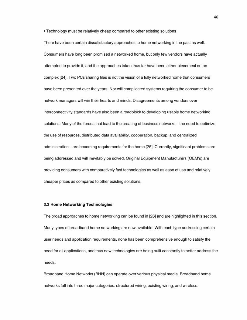
46
• Technology must be relatively cheap compared to other existing solutions
There have been certain dissatisfactory approaches to home networking in the past as well.
Consumers have long been promised a networked home, but only few vendors have actually
attempted to provide it, and the approaches taken thus far have been either piecemeal or too
complex [24]. Two PCs sharing files is not the vision of a fully networked home that consumers
have been presented over the years. Nor will complicated systems requiring the consumer to be
network managers will win their hearts and minds. Disagreements among vendors over
interconnectivity standards have also been a roadblock to developing usable home networking
solutions. Many of the forces that lead to the creating of business networks – the need to optimize
the use of resources, distributed data availability, cooperation, backup, and centralized
administration – are becoming requirements for the home [25]. Currently, significant problems are
being addressed and will inevitably be solved. Original Equipment Manufacturers (OEM’s) are
providing consumers with comparatively fast technologies as well as ease of use and relatively
cheaper prices as compared to other existing solutions.
3.3 Home Networking Technologies
The broad approaches to home networking can be found in [26] and are highlighted in this section.
Many types of broadband home networking are now available. With each type addressing certain
user needs and application requirements, none has been comprehensive enough to satisfy the
need for all applications, and thus new technologies are being built constantly to better address the
needs.
Broadband Home Networks (BHN) can operate over various physical media. Broadband home
networks fall into three major categories: structured wiring, existing wiring, and wireless.
47
• Structured wiring requires the installation of new cabling in the walls. Both the cabling
(typically unshielded twisted pair [UTP] or optical fiber) and its installations are defined by
standards highlighted in [27].
• Existing wiring makes use of electrical, telephone, or coaxial wiring already installed in the
walls.
• Wireless avoids the use of wires by transmitting data bearing signals through the air.
Table 3.1 presents comparisons of these approaches.
Table 3.1 Comparison of broadband home networking approaches.
Differentiator Structured wiring Existing wiring Wireless
Best uses New construction and
remodeling
Interconnecting
stationary devices
Mobile devices such
as laptops, palmtops
and webpads
Cost High (for installation) Low Low
Useful lifetime Very long Relatively short Short
Number and location
of ‘outlets’ Wherever needed
Multiple electrical
outlets in every room;
many rooms with
telephone outlets; few
rooms with coax
outlets
Ideally throughout the
home
Current data rate
(Mbps) 100 10-14 54
Future data rate
(Mbps) 1000 or more 30-250 100 or more
Security Highly secure Less secure Less secure
Standardization Well defined global
standards Competing standards Competing standards
48
3.3.1 Structured Wiring Technologies
Structured wiring provides high bandwidth and excellent security. To handle the full range of
current applications, a complete installation requires several cabling types, including UTP for
telephone and data, and coaxial cable for video. Fast Ethernet at 100 Mbps over UTP is widely
used for data applications. While having sufficient bandwidth for video, it does not currently include
any form of Quality of Service (QoS) support. With the introduction of HD video to the home, it is
believed that the home backbone network required will be based on structured wiring to
interconnect sections of the home. The Electronic Industries Alliance (EIA) and Consumer
Electronics Association (CEA) are developing the R-7.4 VHN Home Network Standard for this
purpose [30].
3.3.2 Existing Wiring Technologies
As structured wiring is relatively expensive to install within an existing home, various companies
are now developing technologies based on the existing wiring in the walls of the home.
Phoneline technologies use the existing telephone wiring. The Home Phone Networking Alliance
(HomePNA) [28] has defined a 3.1 specification that reaches an unprecedented data rate of 320
Mbps. As the only home networking industry specification capable of reaching above 100 Mbps
and with inherent deterministic Quality of Service (QoS), HomePNA technology complements
wireless networking technologies providing the ideal high speed backbone for a home multimedia
network requiring a fast and reliable channel to distribute multiple, feature-rich digital audio and
video applications throughout a home. The International Telecommunication Union (ITU) has
already approved global phoneline networking standard recommendation G.9954 based on the
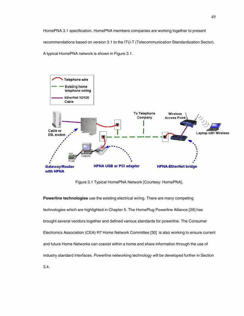
49
HomePNA 3.1 specification. HomePNA members companies are working together to present
recommendations based on version 3.1 to the ITU-T (Telecommunication Standardization Sector).
A typical HomePNA network is shown in Figure 3.1.
Figure 3.1 Typical HomePNA Network [Courtesy: HomePNA].
Powerline technologies use the existing electrical wiring. There are many competing
technologies which are highlighted in Chapter 5. The HomePlug Powerline Alliance [29] has
brought several vendors together and defined various standards for powerline. The Consumer
Electronics Association (CEA) R7 Home Network Committee [30] is also working to ensure current
and future Home Networks can coexist within a home and share information through the use of
industry standard interfaces. Powerline networking technology will be developed further in Section
3.4.
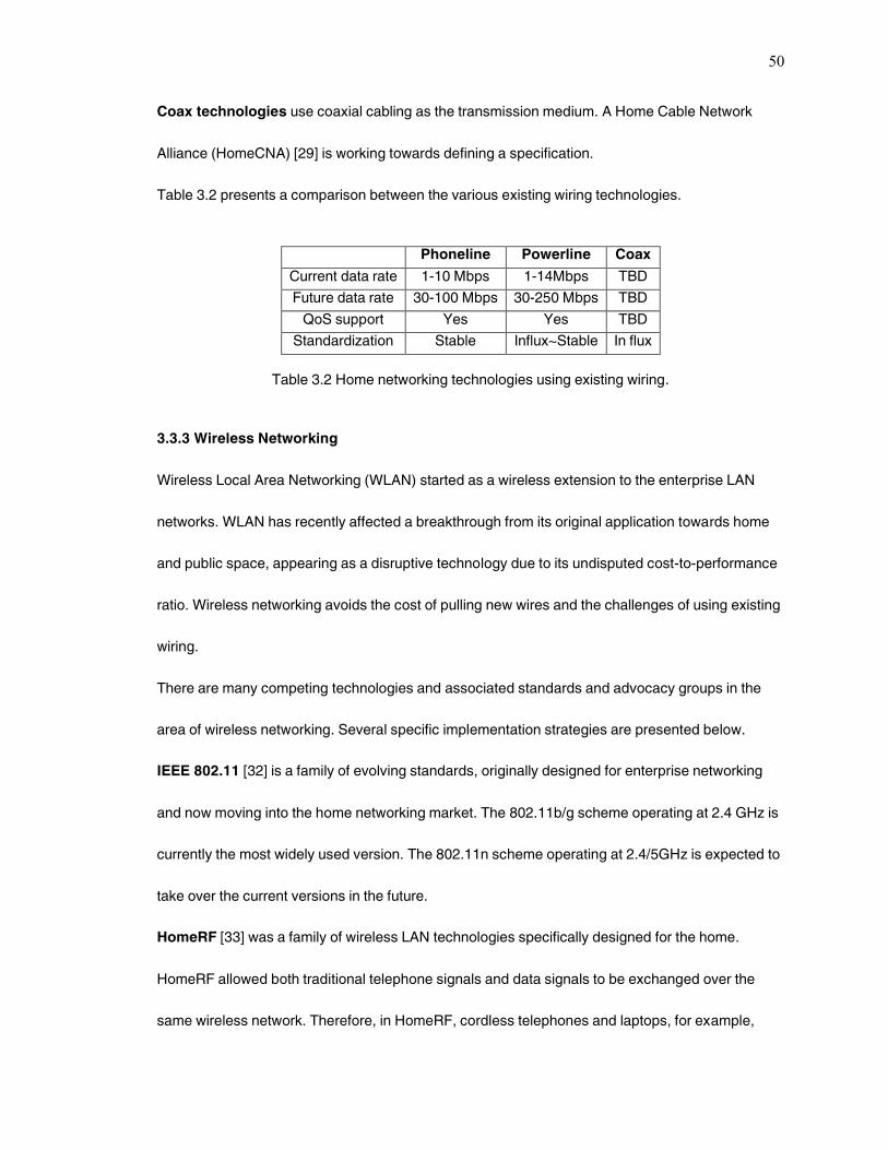
50
Coax technologies use coaxial cabling as the transmission medium. A Home Cable Network
Alliance (HomeCNA) [29] is working towards defining a specification.
Table 3.2 presents a comparison between the various existing wiring technologies.
Phoneline Powerline Coax
Current data rate 1-10 Mbps 1-14Mbps TBD
Future data rate 30-100 Mbps 30-250 Mbps TBD
QoS support Yes Yes TBD
Standardization Stable Influx~Stable In flux
Table 3.2 Home networking technologies using existing wiring.
3.3.3 Wireless Networking
Wireless Local Area Networking (WLAN) started as a wireless extension to the enterprise LAN
networks. WLAN has recently affected a breakthrough from its original application towards home
and public space, appearing as a disruptive technology due to its undisputed cost-to-performance
ratio. Wireless networking avoids the cost of pulling new wires and the challenges of using existing
wiring.
There are many competing technologies and associated standards and advocacy groups in the
area of wireless networking. Several specific implementation strategies are presented below.
IEEE 802.11 [32] is a family of evolving standards, originally designed for enterprise networking
and now moving into the home networking market. The 802.11b/g scheme operating at 2.4 GHz is
currently the most widely used version. The 802.11n scheme operating at 2.4/5GHz is expected to
take over the current versions in the future.
HomeRF [33] was a family of wireless LAN technologies specifically designed for the home.
HomeRF allowed both traditional telephone signals and data signals to be exchanged over the
same wireless network. Therefore, in HomeRF, cordless telephones and laptops, for example,
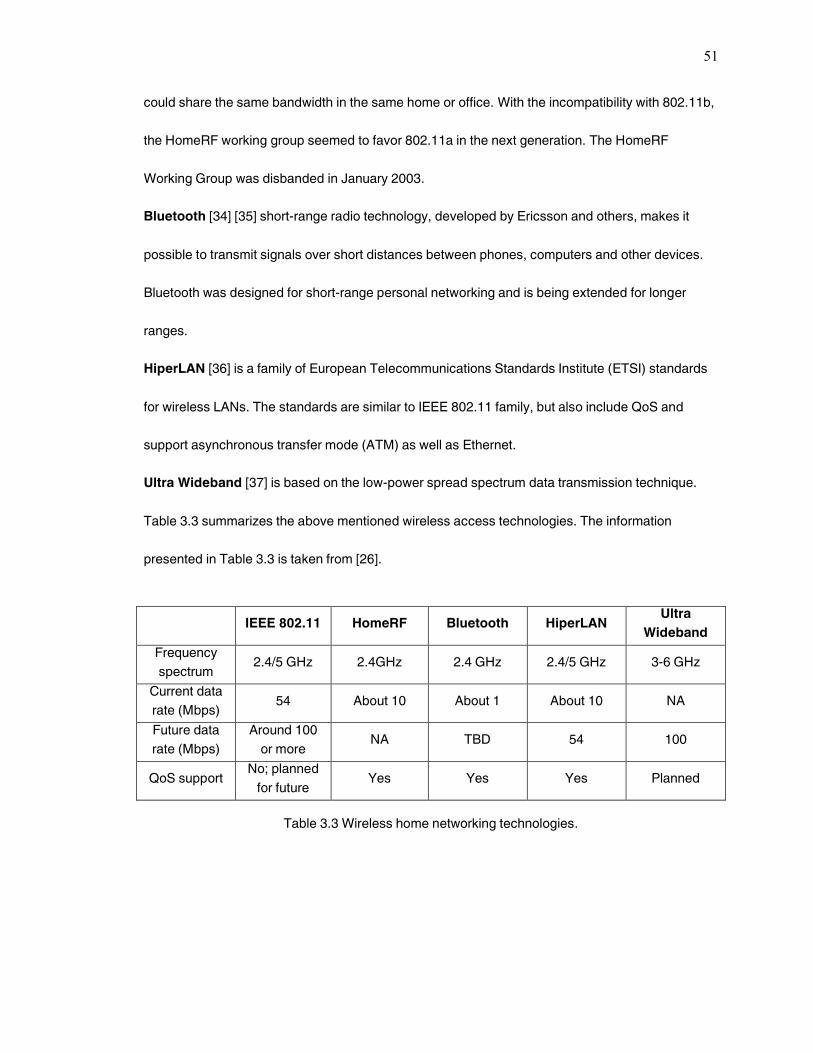
51
could share the same bandwidth in the same home or office. With the incompatibility with 802.11b,
the HomeRF working group seemed to favor 802.11a in the next generation. The HomeRF
Working Group was disbanded in January 2003.
Bluetooth [34] [35] short-range radio technology, developed by Ericsson and others, makes it
possible to transmit signals over short distances between phones, computers and other devices.
Bluetooth was designed for short-range personal networking and is being extended for longer
ranges.
HiperLAN [36] is a family of European Telecommunications Standards Institute (ETSI) standards
for wireless LANs. The standards are similar to IEEE 802.11 family, but also include QoS and
support asynchronous transfer mode (ATM) as well as Ethernet.
Ultra Wideband [37] is based on the low-power spread spectrum data transmission technique.
Table 3.3 summarizes the above mentioned wireless access technologies. The information
presented in Table 3.3 is taken from [26].
IEEE 802.11 HomeRF Bluetooth HiperLAN Ultra
Wideband
Frequency
spectrum 2.4/5 GHz 2.4GHz 2.4 GHz 2.4/5 GHz 3-6 GHz
Current data
rate (Mbps) 54 About 10 About 1 About 10 NA
Future data
rate (Mbps)
Around 100
or more NA TBD 54 100
QoS support No; planned
for future Yes Yes Yes Planned
Table 3.3 Wireless home networking technologies.
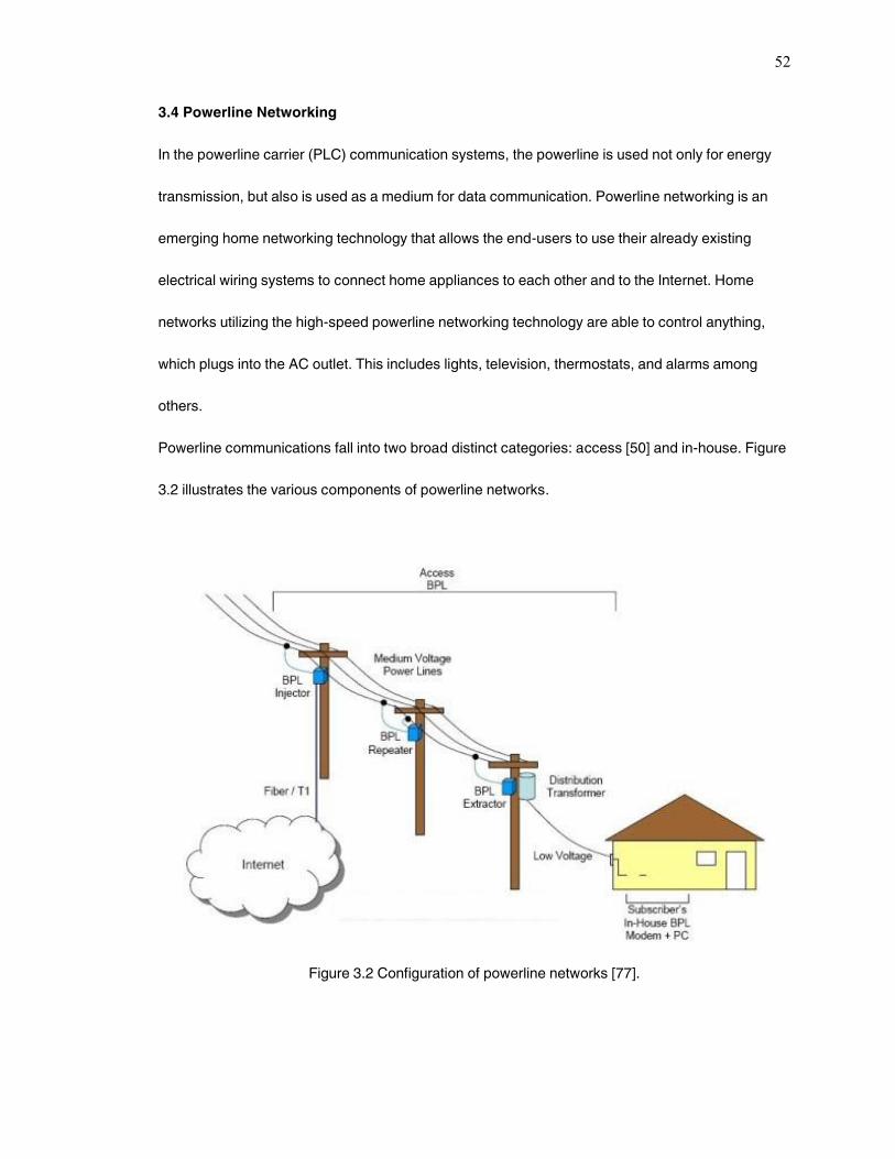
52
3.4 Powerline Networking
In the powerline carrier (PLC) communication systems, the powerline is used not only for energy
transmission, but also is used as a medium for data communication. Powerline networking is an
emerging home networking technology that allows the end-users to use their already existing
electrical wiring systems to connect home appliances to each other and to the Internet. Home
networks utilizing the high-speed powerline networking technology are able to control anything,
which plugs into the AC outlet. This includes lights, television, thermostats, and alarms among
others.
Powerline communications fall into two broad distinct categories: access [50] and in-house. Figure
3.2 illustrates the various components of powerline networks.
Figure 3.2 Configuration of powerline networks [77].
53
3.4.1 In-House and Access Powerline Technologies
The access powerline systems utilize three components of the electric power distribution network.
The first is the medium voltage line, carrying typically 1000 to 40,000 volts, over which an electric
utility brings power from a substation to a residential neighborhood. The second component is the
bypass of the low-voltage transformer in the residential neighborhood that steps down the line
voltage to the 220/110 volts needed for residential use. The third component of the existing power
distribution system is the low voltage distribution from the transformer to residential electrical
outlets, including the exterior service cable, circuit breaker panel, and interior wiring. Access
powerline technologies (or Access broadband over powerline (Access BPL)) are responsible for
sending high-speed data and voice signals outdoors over the medium voltage powerline from a
point where there is a connection to a telecommunications network. This point of connection may
be at a power substation or at an intermediate point between substations, depending on the
network topology. Near the distribution point to a residential neighborhood, a coupler or bridge
circuit module is installed to enable the transfer of high-frequency digital signals across the low
voltage distribution transformer. The reason for using a coupler or bridge circuit is that the low
voltage transformer, which is intended to conduct 60 Hz power signals, is a poor conduit for high-
frequency digital signals. The advantages of this transformer bypass path are its low cost and ease
of instillation and maintenance, Also, the bypass will not degrade the overall reliability of the
electrical distribution system. The transformer bypass path, as shown in Figure 3.3, is composed
of an MV inductive coupler, a transformer X-node, and an LV coupler. Finally, the high-speed
communication signals are brought to the home over the exterior service power cable from the
bridge across the distribution transformer, either directly, or via an access powerline adaptor
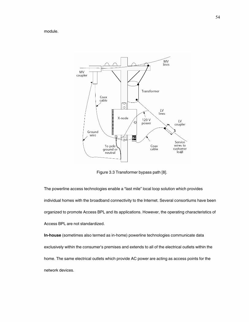
54
module.
Figure 3.3 Transformer bypass path [8].
The powerline access technologies enable a ‚last mile‛ local loop solution which provides
individual homes with the broadband connectivity to the Internet. Several consortiums have been
organized to promote Access BPL and its applications. However, the operating characteristics of
Access BPL are not standardized.
In-house (sometimes also termed as in-home) powerline technologies communicate data
exclusively within the consumer’s premises and extends to all of the electrical outlets within the
home. The same electrical outlets which provide AC power are acting as access points for the
network devices.
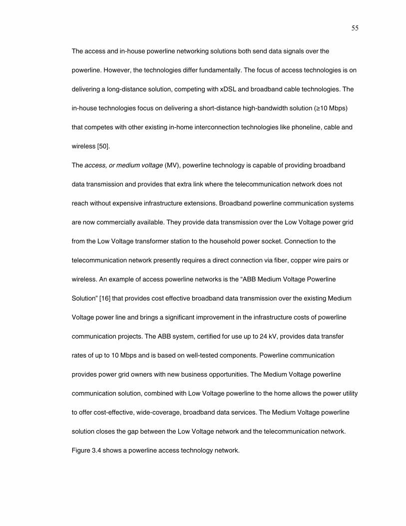
55
The access and in-house powerline networking solutions both send data signals over the
powerline. However, the technologies differ fundamentally. The focus of access technologies is on
delivering a long-distance solution, competing with xDSL and broadband cable technologies. The
in-house technologies focus on delivering a short-distance high-bandwidth solution (≥10 Mbps)
that competes with other existing in-home interconnection technologies like phoneline, cable and
wireless [50].
The access, or medium voltage (MV), powerline technology is capable of providing broadband
data transmission and provides that extra link where the telecommunication network does not
reach without expensive infrastructure extensions. Broadband powerline communication systems
are now commercially available. They provide data transmission over the Low Voltage power grid
from the Low Voltage transformer station to the household power socket. Connection to the
telecommunication network presently requires a direct connection via fiber, copper wire pairs or
wireless. An example of access powerline networks is the ‚ABB Medium Voltage Powerline
Solution‛ [16] that provides cost effective broadband data transmission over the existing Medium
Voltage power line and brings a significant improvement in the infrastructure costs of powerline
communication projects. The ABB system, certified for use up to 24 kV, provides data transfer
rates of up to 10 Mbps and is based on well-tested components. Powerline communication
provides power grid owners with new business opportunities. The Medium Voltage powerline
communication solution, combined with Low Voltage powerline to the home allows the power utility
to offer cost-effective, wide-coverage, broadband data services. The Medium Voltage powerline
solution closes the gap between the Low Voltage network and the telecommunication network.
Figure 3.4 shows a powerline access technology network.
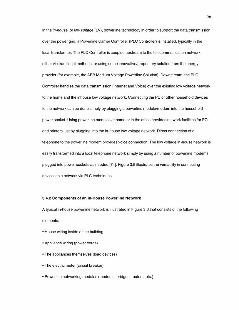
56
In the in-house, or low voltage (LV), powerline technology in order to support the data transmission
over the power grid, a Powerline Carrier Controller (PLC Controller) is installed, typically in the
local transformer. The PLC Controller is coupled upstream to the telecommunication network,
either via traditional methods, or using some innovative/proprietary solution from the energy
provider (for example, the ABB Medium Voltage Powerline Solution). Downstream, the PLC
Controller handles the data transmission (Internet and Voice) over the existing low voltage network
to the home and the inhouse low voltage network. Connecting the PC or other household devices
to the network can be done simply by plugging a powerline module/modem into the household
power socket. Using powerline modules at home or in the office provides network facilities for PCs
and printers just by plugging into the in-house low voltage network. Direct connection of a
telephone to the powerline modem provides voice connection. The low voltage in-house network is
easily transformed into a local telephone network simply by using a number of powerline modems
plugged into power sockets as needed [74]. Figure 3.5 illustrates the versatility in connecting
devices to a network via PLC techniques.
3.4.2 Components of an In-House Powerline Network
A typical in-house powerline network is illustrated in Figure 3.6 that consists of the following
elements:
• House wiring inside of the building
• Appliance wiring (power cords)
• The appliances themselves (load devices)
• The electric meter (circuit breaker)
• Powerline networking modules (modems, bridges, routers, etc.)
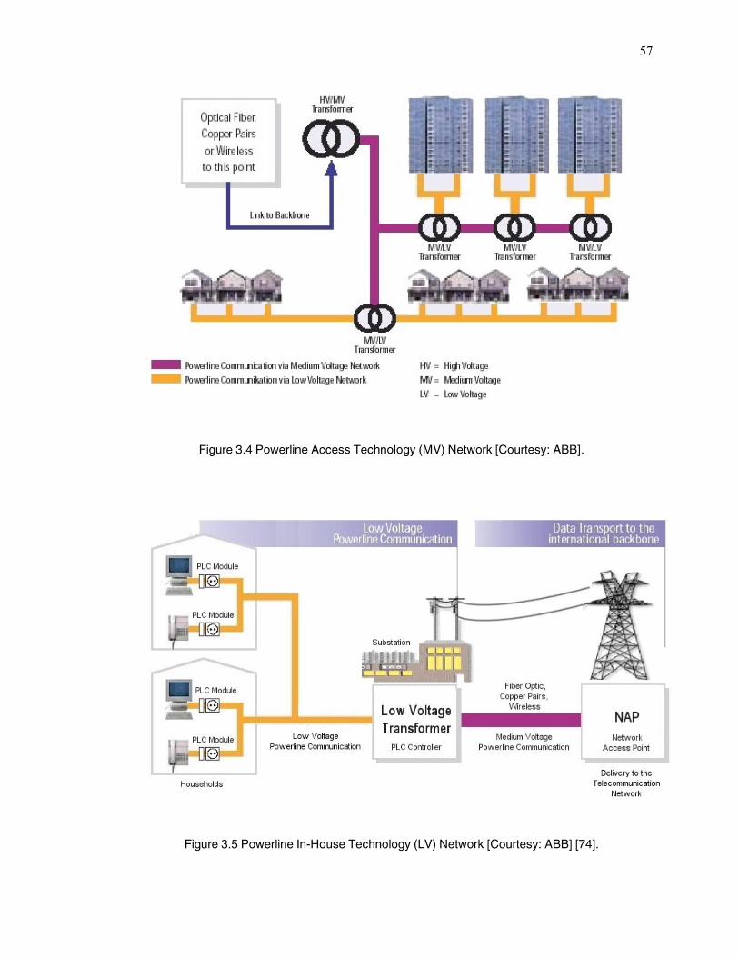
57
Figure 3.4 Powerline Access Technology (MV) Network [Courtesy: ABB].
Figure 3.5 Powerline In-House Technology (LV) Network [Courtesy: ABB] [74].
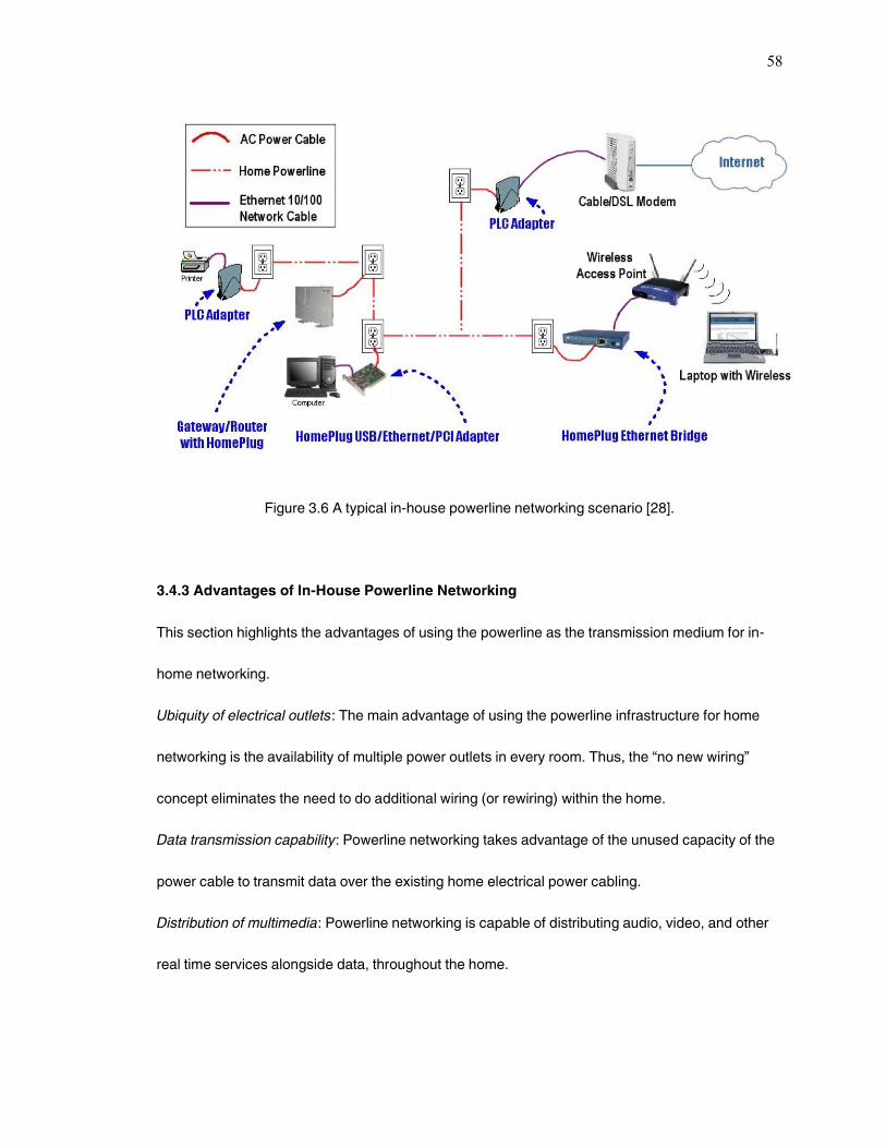
58
Figure 3.6 A typical in-house powerline networking scenario [28].
3.4.3 Advantages of In-House Powerline Networking
This section highlights the advantages of using the powerline as the transmission medium for in-
home networking.
Ubiquity of electrical outlets: The main advantage of using the powerline infrastructure for home
networking is the availability of multiple power outlets in every room. Thus, the ‚no new wiring‛
concept eliminates the need to do additional wiring (or rewiring) within the home.
Data transmission capability: Powerline networking takes advantage of the unused capacity of the
power cable to transmit data over the existing home electrical power cabling.
Distribution of multimedia: Powerline networking is capable of distributing audio, video, and other
real time services alongside data, throughout the home.
59
Speed: With the technological advancements, powerline networking is capable of distributing data
at 40Mbps to 80 Mbps speed and future data transmission rates include 300 Mbps, making it an
advancing technology with a future.
3.4.4 Disadvantages of In-House Powerline Networking
This section highlights some of the major disadvantages associated with In-house powerline
networks.
Noise: The relatively large amount of electrical noise on the electrical powerlines limits practical
data transmission speeds to somewhat lower values than normal.
Noise Sources: Vacuum cleaners, light dimmers, electric lamps, kitchen appliances, and electric
drills are examples of noise generating sources that affect the performance of a powerline-based
home network.
Minimum Security levels: HomePlug certified products have a built-in 56-bit DES encryption,
however it is not turned on by default. Thus, powerline communication channels do not necessarily
provide a secure media.
Data attenuation: Presence of various elements on the powerline network makes data attenuation
a considerable issue in powerline networking.
High costs of residential appliances: In comparison to the phoneline network equipment, the
powerline networking modules are more costly. The cost issue needs to be addressed so as to
make powerline communication a preferred technology for home networking.
Lack of standardization: Regularity issues in some international markets are also preventing the
development of global standard for distributing data over existing in-house powerline systems.
60
3.4.5 Technical Obstacles of an In-House Powerline Network
The powerline network is prone to various technical obstacles when it comes to transferring data at
considerable speeds. The typical data and communication networks (like corporate LANs) use
dedicated wiring to interconnect devices. But powerline networks, from their inception, were never
intended for transmitting data. Instead, the networks were optimized to efficiently distribute power
to the electrical outlets throughout a building at frequencies typically between 50-60 Hz [50]. Thus,
all the original designs of electrical networks never really considered using the powerline medium
for communicating data signals at other frequencies.
Due to this reason, the powerline is a more difficult communications medium than other types of
isolated wiring (like for example, the Category 5 cabling used in Ethernet data networks). The
physical topology of the electrical network, the physical properties of the electrical cabling, the
appliances connected, and the behavioral characteristics of the electric current itself all combine to
create technical obstacles associated with a powerline network that is to be used for high-speed
data transmission.
3.5 Typical Applications of Home Networking
The typical applications of Home Networking can be broadly classified into five categories:
resource sharing, communications, home control, home scheduling, and
entertainment/information.
Resource Sharing
Home networking allows all users in the household to access the Internet and various applications
at the same time. Additionally, files (not simply data, but also audio and video depending on the
speed of the network) can be swapped, and peripherals such as printers and scanners can be
61
shared. Furthermore, the need for having more than one Internet access point, printer, scanner,
and/or software packages in a home/private networking scenario is eliminated. Home networking
technologies can successfully be used to distribute IP-based data across the home with
considerable speeds.
Communications
Home networking allows easier and more efficient communication between users within the
household and better communication management with outside communications. Phone, fax, and
e-mail messages can be routed intelligently in a home network. Access to the Internet can be
attained at multiple places in the home with the use of terminals and Webpads, etc.
Home Control and Automation Systems
Home networking can allow controls within the house, such as temperature and lighting, to be
managed through the network and even remotely through the Internet. The network can also be
used for home security monitoring with network cameras.
Powerlines have been used for home automation for many years. The most important types of
home automation applications include controlling lights, ventilators, security systems, sprinklers,
and temperature levels within the home. The home control networking systems market is
undergoing a significant transition from closed-loop solutions to open, IP-aware solutions. Home
control and automation systems are normally based on one of the three major powerline
technologies namely, CEBus, LonWorks, or X-10. These technologies are discussed in depth in
later sections of this thesis.
Home Scheduling
A home network would allow families to keep one master schedule that could be updated from
different access points within the house and remotely through the Internet.

62
Entertainment and Provision of Information
Home networks enable a plethora of options for sharing entertainment and information in the
home.
Networked multi-user games can be played as well as PC-hosted television games. Digital video
networking will allow households to route the video from direct-broadcast satellite (DBS) and
DVDs to different set-top boxes, PCs, and other visual display devices in the home. Streaming
media such as Internet radio broadcasts can be sent to stereo systems located within the home as
well as PCs for archiving purpose.
Table 3.4 lists some of the home networking applications, what they can do for the consumer, how
they are delivered, and their level of availability [24]. Some of these are based on future scenarios,
and some have been delayed because of the slowdown in current economic sector related to the
IT industry.
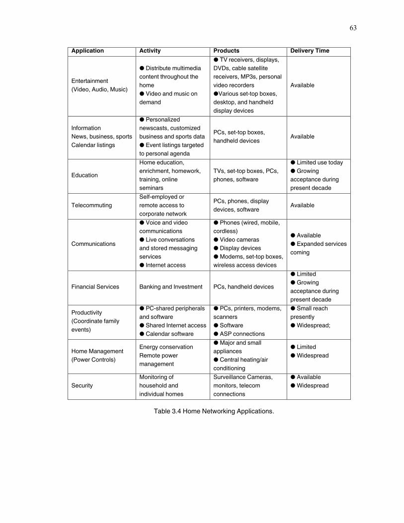
63
Application Activity Products Delivery Time
Entertainment
(Video, Audio, Music)
● Distribute multimedia
content throughout the
home
● Video and music on
demand
● TV receivers, displays,
DVDs, cable satellite
receivers, MP3s, personal
video recorders
●Various set-top boxes,
desktop, and handheld
display devices
Available
Information
News, business, sports
Calendar listings
● Personalized
newscasts, customized
business and sports data
● Event listings targeted
to personal agenda
PCs, set-top boxes,
handheld devices Available
Education
Home education,
enrichment, homework,
training, online
seminars
TVs, set-top boxes, PCs,
phones, software
● Limited use today
● Growing
acceptance during
present decade
Telecommuting
Self-employed or
remote access to
corporate network
PCs, phones, display
devices, software Available
Communications
● Voice and video
communications
● Live conversations
and stored messaging
services
● Internet access
● Phones (wired, mobile,
cordless)
● Video cameras
● Display devices
● Modems, set-top boxes,
wireless access devices
● Available
● Expanded services
coming
Financial Services Banking and Investment PCs, handheld devices
● Limited
● Growing
acceptance during
present decade
Productivity
(Coordinate family
events)
● PC-shared peripherals
and software
● Shared Internet access
● Calendar software
● PCs, printers, modems,
scanners
● Software
● ASP connections
● Small reach
presently
● Widespread;
Home Management
(Power Controls)
Energy conservation
Remote power
management
● Major and small
appliances
● Central heating/air
conditioning
● Limited
● Widespread
Security
Monitoring of
household and
individual homes
Surveillance Cameras,
monitors, telecom
connections
● Available
● Widespread
Table 3.4 Home Networking Applications.

64
3.6 Conclusions
This chapter presented the various existing home networking technologies highlighting the
advantages and salient features associated with each technology. The choice of a suitable home
networking and automation technology is a combination of several factors governing the need and
requirements of the consumer. The fundamental concept of powerline networking was also
presented in this chapter along with the pros and cons associated with the technology. Powerline
networking offers several advantages over other available home networking technologies. Among
the most significant advantages are the availability of power outlets in abundance within every
home, the elimination of laying new wiring, the reliability and quality of service, and data speeds of
14 Mbps enabling delivery of information including data as well as multimedia throughout the
SOHO scenario.
65
4. Communication over powerlines
Due to its omnipresence, the electric power distribution grid offers a tremendous potential for
extended fast and reliable communication services. Currently, the exploitation has just started and
still is far from complete. Various fields of applications can be envisioned, starting, for example,
with simple inexpensive services embodied into household appliances, where data rates of only
several kilobits per second or less are sufficient. A next level might be Internet access via the wall
socket, where data transfer speed is in the lower megabit range up to high-speed networking that
includes fast Internet access, voice over IP, and home entertainment (i.e., streaming audio and
video at data rates in excess of 10 Mb/s). Another important field of research is the use of the
medium voltage network for data communication purposes. The medium voltage network can be
used as a backbone to connect the low-voltage transformer stations to the Internet if conventional
backbone networks, like fiber optic cables, are missing. Clearly, the development of appropriate
power line communication (PLC) systems turns out to be a severe challenge for the
communications engineer, having to deal with very unusual channels that were neither designed,
nor intended for signal transmission at high frequencies.
The development of power line communication systems requires detailed knowledge of the
channel properties, such as transfer function, interference scenario, and channel capacity in order
to choose suitable transmission methods. This chapter presents appropriate power line channel
models, which form the basis for the design of a channel emulator. Such a device turns out to be
extremely helpful for various tests and the comparison of performance of different communication
systems. A basic estimation of the power line channel capacity clearly demonstrates their
enormous potential for high-speed communication purposes. Eventually, an evaluation of different
modulation schemes is carried to optimize PLC system design.
66
This chapter starts with an overview of the fundamental properties of power line channels and will
successively point out recommendations for PLC system design. A well proven channel model,
including the very peculiar interference scenario of typically affecting powerline networks is also
presented.
4.1 Powerline Channel Model
The idea of using the electric power distribution grid for communication purposes is not new at all.
For many decades power supply companies have been using their networks for data transmission.
The main purposes, however, have been management, control, and supervision of power plant
and distribution facility operation, tasks calling for rather low data rates in the kilobits per second
range. Especially in Europe, a significant change occurred when the last telecommunication
monopolies were ended in the beginning of 1998. As a result of this process the low-voltage power
distribution network became very interesting. The use of this medium made it possible to compete
against the former monopolists in providing data services over the so-called last mile. The ideas
centered around using the cables between the transformer substation and customers as an access
medium for high-speed Internet services, and exploiting intrabuilding installations as fast local area
networks for various purposes. But many obstacles blocked the way to fast and easy solutions. On
one hand, power lines exhibit strong branching, which considerably impairs the signal quality due
to the presence of a large number of reflection points. On the other hand, the strong cross-coupling
effects between the wires in a cable must be taken into account.
A typical European low-voltage access network link is depicted in Fig. 4.1. A data transmitter,
which may be connected to the Internet, say, via optical fiber, is placed in the transformer
substation. The power line channel can be characterized as a star-shaped bus structure with a
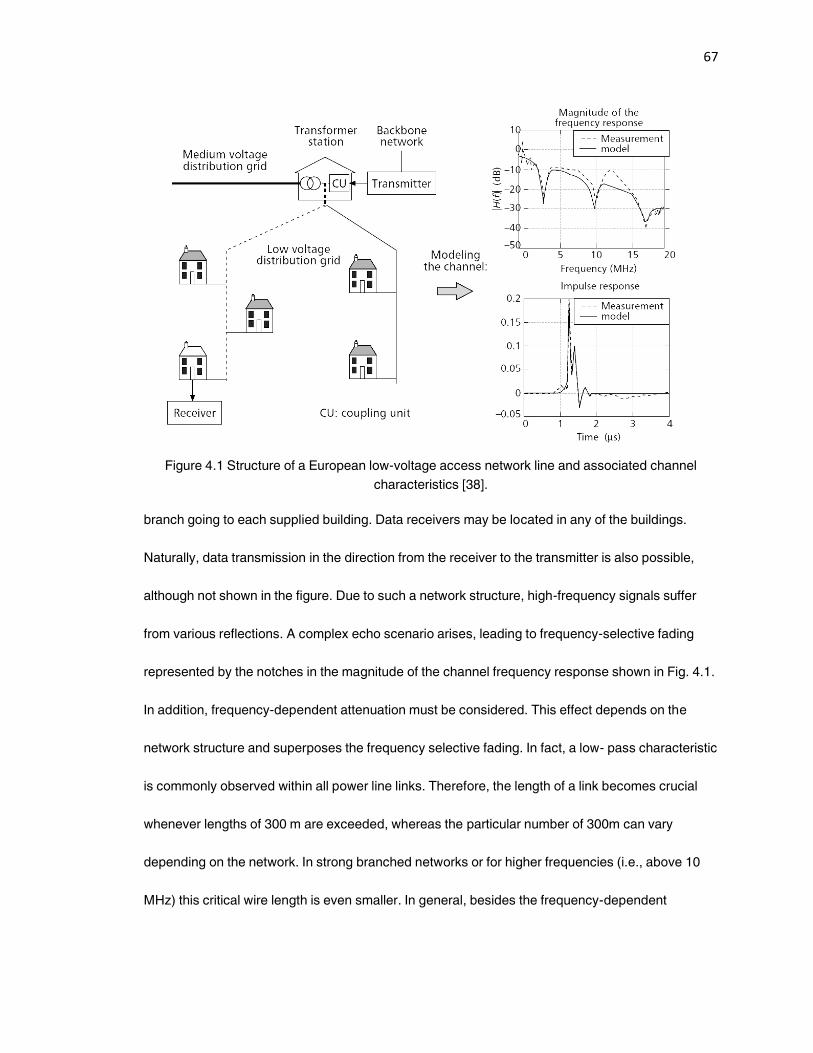
67
Figure 4.1 Structure of a European low-voltage access network line and associated channel
characteristics [38].
branch going to each supplied building. Data receivers may be located in any of the buildings.
Naturally, data transmission in the direction from the receiver to the transmitter is also possible,
although not shown in the figure. Due to such a network structure, high-frequency signals suffer
from various reflections. A complex echo scenario arises, leading to frequency-selective fading
represented by the notches in the magnitude of the channel frequency response shown in Fig. 4.1.
In addition, frequency-dependent attenuation must be considered. This effect depends on the
network structure and superposes the frequency selective fading. In fact, a low- pass characteristic
is commonly observed within all power line links. Therefore, the length of a link becomes crucial
whenever lengths of 300 m are exceeded, whereas the particular number of 300m can vary
depending on the network. In strong branched networks or for higher frequencies (i.e., above 10
MHz) this critical wire length is even smaller. In general, besides the frequency-dependent
68
attenuation caused by the cable material, the degree of branching is responsible for increasing
attenuation, as each house service point absorbs a certain amount of transmitted power.
4.2 Approaches for Modeling the Powerline Channel
Channel modeling consists of investigating the characteristics of the power network as a
communication channel. PLC channels suffer from a number of technical problems, chief among
them are:
Frequency-varying and time-varying attenuations of the medium;
Dependence of the channel model on location, network topology and connected loads;
High interference due to noisy loads;
High non-white background noise;
Various forms of impulsive noise; and,
Electromagnetic compatibility (EMC) issues that limit available transmitted power.
Two main approaches that can be utilized for modeling a powerline channel are described below.
4.2.1 Top-Down Approach
The Top-Down, or empirically based, approach is the most commonly used. This approach
considers the communication channel to be a 'black box' and obtains the system parameters using
experimental measurements of the powerline network. This approach describes the transfer
characteristics of a channel by a transfer function. Using this approach in a multipath channel
environment, the model characteristics can be established using experimental results. The major
advantages of this approach are that little computation is needed and it is easy to implement. The

69
major disadvantage stems from the fact that the channel model is vulnerable to errors in
measurements.
4.2.2 Bottom-Up Approach
The Bottom-Up, or deterministically based, approach starts from the theoretical derivation of model
parameters. This approach describes the behavior of a network by a large number of distributed
components using matrices (scattering parameter matrices or four pole impedance and
admittance matrices). Detailed knowledge of all components (cables, joints, connected devices)
within a network is required for accurately setting up these matrices.
Developing a deterministic model basically means finding the transfer function theoretically without
taking actual measurements of the transmission line. It is based on the intrinsic parameters (cable
parameters, load impedances, etc.) of the network to establish a transfer function description of
the channel.
These models generally require detailed knowledge about the components of the network to
determine the elements of matrices.
The major advantage of this approach is its increased flexibility and versatility due to the fact that
all the parameters of the network are formulated analytically, making it easy to predict the changes
in the transfer function when a different multipath network configurations are under consideration.
The major disadvantages of the Bottom-Up Approach are 1.) increased computational effort is
required compared to Top-Down Approach; and, 2.) there are a large number of parameters which
cannot be determined with sufficient precision.
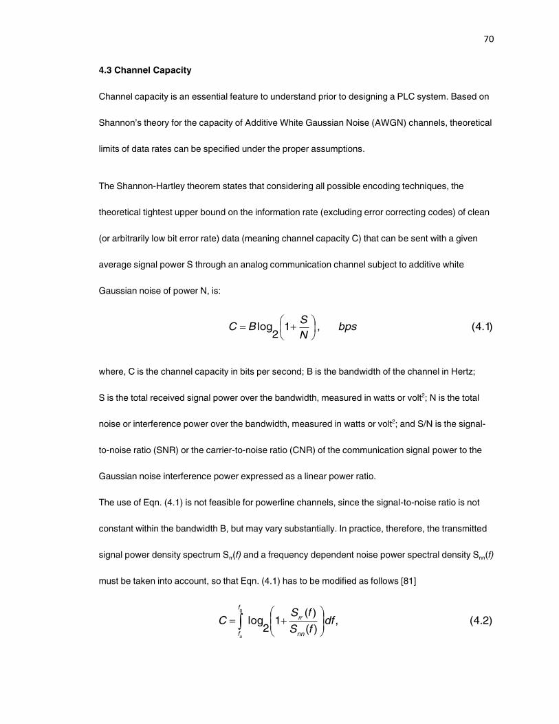
70
4.3 Channel Capacity
Channel capacity is an essential feature to understand prior to designing a PLC system. Based on
Shannon’s theory for the capacity of Additive White Gaussian Noise (AWGN) channels, theoretical
limits of data rates can be specified under the proper assumptions.
The Shannon-Hartley theorem states that considering all possible encoding techniques, the
theoretical tightest upper bound on the information rate (excluding error correcting codes) of clean
(or arbitrarily low bit error rate) data (meaning channel capacity C) that can be sent with a given
average signal power S through an analog communication channel subject to additive white
Gaussian noise of power N, is:
)1.4(,12
log bpsN
SBC
where, C is the channel capacity in bits per second; B is the bandwidth of the channel in Hertz;
S is the total received signal power over the bandwidth, measured in watts or volt2; N is the total
noise or interference power over the bandwidth, measured in watts or volt2; and S/N is the signal-
to-noise ratio (SNR) or the carrier-to-noise ratio (CNR) of the communication signal power to the
Gaussian noise interference power expressed as a linear power ratio.
The use of Eqn. (4.1) is not feasible for powerline channels, since the signal-to-noise ratio is not
constant within the bandwidth B, but may vary substantially. In practice, therefore, the transmitted
signal power density spectrum Srr(f) and a frequency dependent noise power spectral density Snn(f)
must be taken into account, so that Eqn. (4.1) has to be modified as follows [81]
)2.4(,)(
)(1
2log
0
dffS
fSC
nn
rr
f
fu
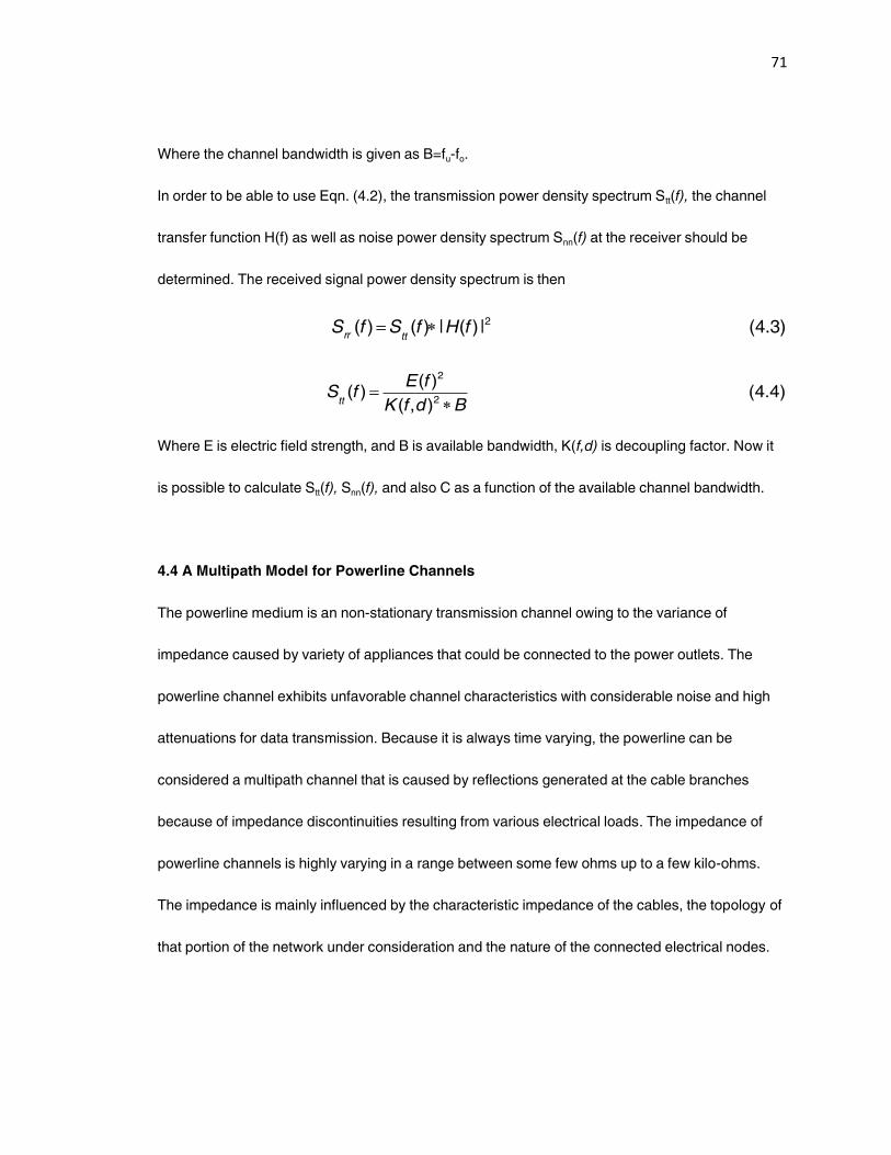
71
Where the channel bandwidth is given as B=fu-fo.
In order to be able to use Eqn. (4.2), the transmission power density spectrum Stt(f), the channel
transfer function H(f) as well as noise power density spectrum Snn(f) at the receiver should be
determined. The received signal power density spectrum is then
)3.4(|)(|)()( 2fHfSfSttrr
)4.4(),(
)()(
2
2
BdfK
fEfS
tt
Where E is electric field strength, and B is available bandwidth, K(f,d) is decoupling factor. Now it
is possible to calculate Stt(f), Snn(f), and also C as a function of the available channel bandwidth.
4.4 A Multipath Model for Powerline Channels
The powerline medium is an non-stationary transmission channel owing to the variance of
impedance caused by variety of appliances that could be connected to the power outlets. The
powerline channel exhibits unfavorable channel characteristics with considerable noise and high
attenuations for data transmission. Because it is always time varying, the powerline can be
considered a multipath channel that is caused by reflections generated at the cable branches
because of impedance discontinuities resulting from various electrical loads. The impedance of
powerline channels is highly varying in a range between some few ohms up to a few kilo-ohms.
The impedance is mainly influenced by the characteristic impedance of the cables, the topology of
that portion of the network under consideration and the nature of the connected electrical nodes.
72
The powerline medium as a communication channel introduces attenuation and phase shift into
the transmitted signals. A powerline channel model is described to discuss the dominate features
that affect the signals that are transmitted over it, namely, the attenuation and delay.
A powerline medium is characterized by impedance discontinuities. The transmitted signals are
thus reflected several times resulting in a multipath transmission.The powerline channel can
generally be considered as a multipath channel. The multipath nature of powerline channels arises
from the presence of several branches and impedance mismatches that cause many signal
reflections.
The propagation of signals over powerline introduces an attenuation, which increases with the
length of the line and the frequency. In addition to the frequency dependent fading that
characterizes the powerline channel, deep narrrowband notches occur in the transfer function,
which may be spread over the whole frequency range. These notches are caused by multiple
reflections at locations of cable equipment impedance discontinuities. The length of the impulse
response and the number of the reflected energy peaks that occur can vary considerably
depending on the particular powerline network environment. This frequency dependent attenuation
behavior can be described using an 'echo model' for the channel behavior.
Multipath propagation approaches, which are suitable for describing the transmission behavior of
power line channels, have been proposed by Philipps and Zimmermann [73][80]. Philipps's echo
model describes the channel impulse response as a superposition of N Dirac pulses representing
the superposition of signals from N different paths. Each of these impulses is multiplied by a
complex factor i
and delayed by timei
. The factori
represents the product of reflection and
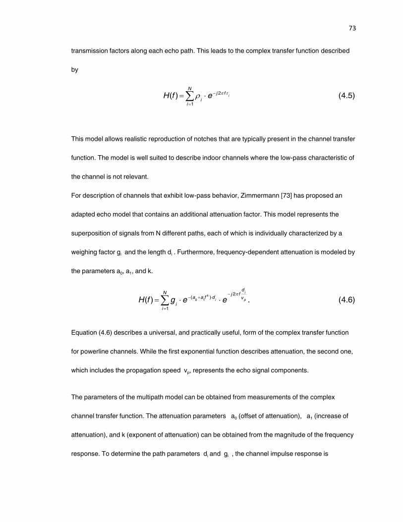
73
transmission factors along each echo path. This leads to the complex transfer function described
by
)5.4()( 2
1
ifj
N
ii
efH
This model allows realistic reproduction of notches that are typically present in the channel transfer
function. The model is well suited to describe indoor channels where the low-pass characteristic of
the channel is not relevant.
For description of channels that exhibit low-pass behavior, Zimmermann [73] has proposed an
adapted echo model that contains an additional attenuation factor. This model represents the
superposition of signals from N different paths, each of which is individually characterized by a
weighing factor gi and the length di . Furthermore, frequency-dependent attenuation is modeled by
the parameters a0, a1, and k.
)6.4(.)(1
2)(
10
N
i
v
dfj
dfaa
ip
i
i
k
eegfH
Equation (4.6) describes a universal, and practically useful, form of the complex transfer function
for powerline channels. While the first exponential function describes attenuation, the second one,
which includes the propagation speed vp, represents the echo signal components.
The parameters of the multipath model can be obtained from measurements of the complex
channel transfer function. The attenuation parameters a0 (offset of attenuation), a1 (increase of
attenuation), and k (exponent of attenuation) can be obtained from the magnitude of the frequency
response. To determine the path parameters di and gi , the channel impulse response is
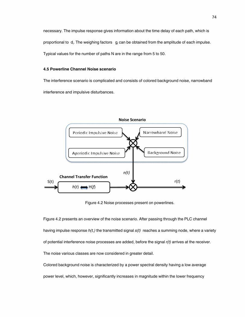
74
necessary. The impulse response gives information about the time delay of each path, which is
proportional to di. The weighing factors gi can be obtained from the amplitude of each impulse.
Typical values for the number of paths N are in the range from 5 to 50.
4.5 Powerline Channel Noise scenario
The interference scenario is complicated and consists of colored background noise, narrowband
interference and impulsive disturbances.
Figure 4.2 Noise processes present on powerlines.
Figure 4.2 presents an overview of the noise scenario. After passing through the PLC channel
having impulse response h(t,) the transmitted signal s(t) reaches a summing node, where a variety
of potential interference noise processes are added, before the signal r(t) arrives at the receiver.
The noise various classes are now considered in greater detail.
Colored background noise is characterized by a power spectral density having a low average
power level, which, however, significantly increases in magnitude within the lower frequency
h(t) H(f)
S(t)
n(t)
r(t) Channel Transfer Function
Noise Scenario
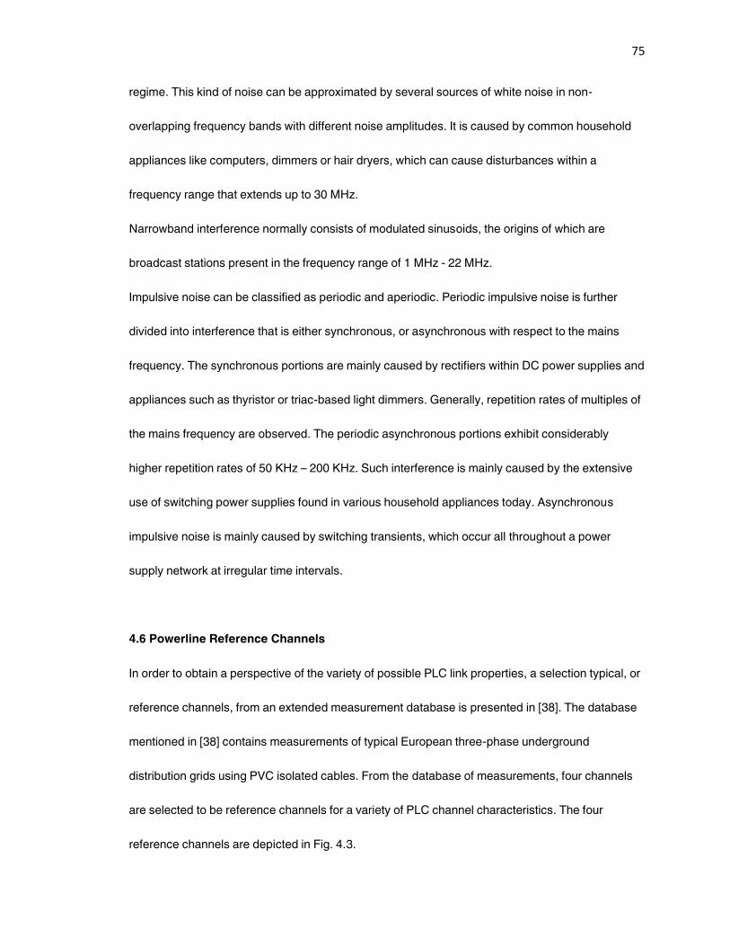
75
regime. This kind of noise can be approximated by several sources of white noise in non-
overlapping frequency bands with different noise amplitudes. It is caused by common household
appliances like computers, dimmers or hair dryers, which can cause disturbances within a
frequency range that extends up to 30 MHz.
Narrowband interference normally consists of modulated sinusoids, the origins of which are
broadcast stations present in the frequency range of 1 MHz - 22 MHz.
Impulsive noise can be classified as periodic and aperiodic. Periodic impulsive noise is further
divided into interference that is either synchronous, or asynchronous with respect to the mains
frequency. The synchronous portions are mainly caused by rectifiers within DC power supplies and
appliances such as thyristor or triac-based light dimmers. Generally, repetition rates of multiples of
the mains frequency are observed. The periodic asynchronous portions exhibit considerably
higher repetition rates of 50 KHz – 200 KHz. Such interference is mainly caused by the extensive
use of switching power supplies found in various household appliances today. Asynchronous
impulsive noise is mainly caused by switching transients, which occur all throughout a power
supply network at irregular time intervals.
4.6 Powerline Reference Channels
In order to obtain a perspective of the variety of possible PLC link properties, a selection typical, or
reference channels, from an extended measurement database is presented in [38]. The database
mentioned in [38] contains measurements of typical European three-phase underground
distribution grids using PVC isolated cables. From the database of measurements, four channels
are selected to be reference channels for a variety of PLC channel characteristics. The four
reference channels are depicted in Fig. 4.3.
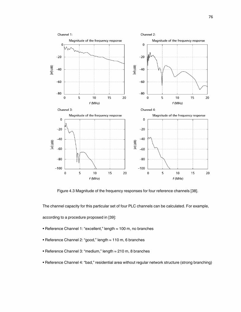
76
Figure 4.3 Magnitude of the frequency responses for four reference channels [38].
The channel capacity for this particular set of four PLC channels can be calculated. For example,
according to a procedure proposed in [39]:
• Reference Channel 1: ‚excellent,‛ length ≈ 100 m, no branches
• Reference Channel 2: ‚good,‛ length ≈ 110 m, 6 branches
• Reference Channel 3: ‚medium,‛ length ≈ 210 m, 8 branches
• Reference Channel 4: ‚bad,‛ residential area without regular network structure (strong branching)
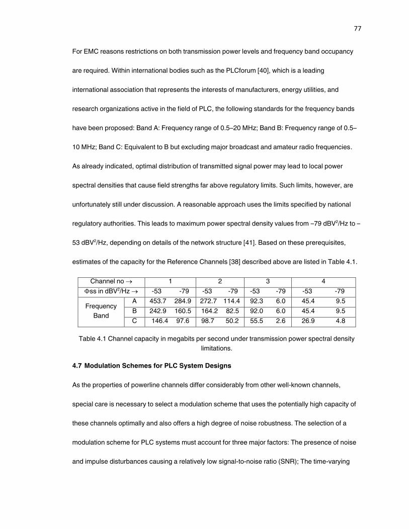
77
For EMC reasons restrictions on both transmission power levels and frequency band occupancy
are required. Within international bodies such as the PLCforum [40], which is a leading
international association that represents the interests of manufacturers, energy utilities, and
research organizations active in the field of PLC, the following standards for the frequency bands
have been proposed: Band A: Frequency range of 0.5–20 MHz; Band B: Frequency range of 0.5–
10 MHz; Band C: Equivalent to B but excluding major broadcast and amateur radio frequencies.
As already indicated, optimal distribution of transmitted signal power may lead to local power
spectral densities that cause field strengths far above regulatory limits. Such limits, however, are
unfortunately still under discussion. A reasonable approach uses the limits specified by national
regulatory authorities. This leads to maximum power spectral density values from –79 dBV2/Hz to –
53 dBV2/Hz, depending on details of the network structure [41]. Based on these prerequisites,
estimates of the capacity for the Reference Channels [38] described above are listed in Table 4.1.
Channel no 1 2 3 4
ss in dBV2/Hz -53 -79 -53 -79 -53 -79 -53 -79
Frequency
Band
A 453.7 284.9 272.7 114.4 92.3 6.0 45.4 9.5
B 242.9 160.5 164.2 82.5 92.0 6.0 45.4 9.5
C 146.4 97.6 98.7 50.2 55.5 2.6 26.9 4.8
Table 4.1 Channel capacity in megabits per second under transmission power spectral density
limitations.
4.7 Modulation Schemes for PLC System Designs
As the properties of powerline channels differ considerably from other well-known channels,
special care is necessary to select a modulation scheme that uses the potentially high capacity of
these channels optimally and also offers a high degree of noise robustness. The selection of a
modulation scheme for PLC systems must account for three major factors: The presence of noise
and impulse disturbances causing a relatively low signal-to-noise ratio (SNR); The time-varying
78
frequency-selective nature of the channel; and, Regulatory constraints with regard to
electromagnetic compatibility that limit the transmitted power.
A choice should be made of either a robust solution which provides sufficient quality for a wide
range of variations of the model parameters, or an adaptive solution. The problem is further
complicated in the home environment by the need to make powerline-based home networking cost
competitive with other wired or wireless solutions.
The following modulation schemes are basically applicable for use in powerline communication.
4.7.1 Single Carrier Modulation
Most basic modulation schemes make use of a single carrier at a frequency f0. Information is
encoded in amplitude, phase, or frequency changes of the carrier. Dependent on this rate of
change, a more or less wideband signal of bandwidth B is generated around f0. A modulation
scheme can be characterized, for example, by its spectral efficiency. The spectral efficiency figure
indicates the number of bits per second the scheme can encode into a 1 Hz bandwidth. Due to
limited spectral resources, PLC technology must always aim at maximum spectral efficiency.
Unfortunately, basic single carrier modulation cannot offer more than 1 bits/sec/Hz. Moreover,
implementing high data rates results in the generation of contiguous wideband transmission
signals, generally centered around the carrier. Due to notches in the channel frequency response
and the low-pass character of the channel, such signals are seriously affected. Hence, only
relatively poor performance can usually be achieved. Since the powerline channel introduces
strong intersymbol interference (ISI), powerful detection and equalization techniques are needed
to mitigate the effects of ISI. Thus, the advantage of simplicity in the implementation of single
carrier modulation is no longer valid. However, single carrier modulation is used in applications
79
such as In-vehicle networks. A controller area network (CAN) – based powerline transceiver is
described in [46] and [47] that supports single carrier modulation, as well as baseband ASK
modulation achieving bit rates up to 250 kbps.
4.7.2 Spread Spectrum Techniques
Bandwidth spreading modulation techniques were originally developed solely for military
communication purposes, in order to obtain robustness against intentional disturbers and
eavesdropping. In the past, the technology was characterized as requiring complex
implementation and considerable costs. The rapid development of integrated-circuit complexity,
however, has made spread spectrum technique (SST) available for almost any application.
Spread spectrum techniques seem to be a good choice for PLC systems due to their immunity
against frequency selective attenuation and all kinds of narrowband interference. An additional
interesting feature of SST, especially with regard to EMC, is the lower power spectral density of the
transmitted signals as compared to single-carrier modulation schemes.
Spread spectrum techniques cope with frequency-selective channels by using a code sequence
that spreads narrowband signals over a wider bandwidth. One such technique is direct sequence
spread spectrum (DS-SS). Its application to wireless channels takes advantage of its robustness to
narrowband interference and its low powersignal density spectrum. The latter feature is particularly
attractive because several regulatory issues limit the transmitted power of powerline modems.
To take full advantage of the interference suppression of SST, a sizable bandwidth expansion is
needed, which may severely limit the maximum data rate for a given transmission bandwidth.
Moreover, channel equalization is needed. On the other hand, SST lends itself to multiple access

80
techniques such as code division multiple access (CDMA), which allows several users, possibly
with different rate demands, to access and utilize the PLC channel simultaneously.
A particular feature of CDMA is multiple access without the need for global coordination or
synchronization. As illustrated in Figure 4.4, a single carrier is used within a communication cell,
and an individual spreading code pi(t) is assigned to each participant. Each spreading code is
orthogonal to the codes assigned to all other users. First, the message signal st(t) is conventionally
modulated on to a carrier having frequency f0. In this way a spectrum Sk(f) of approximately double
the bandwidth of the message signal is produced around f0. In a subsequent modulator (multiplier)
fast 0/1800 phase hops are inserted, according to the binary pseudonoise sequence p1(t). This
produces a transmission signal exhibiting a bandwidth that corresponds approximately to twice the
clock frequency of the pseudonoise sequence.
At the receiver the same sequence p(t-τ) must be available, synchronized to the received signal,
i.e., delayed by the signal propagation time τ between transmitter and receiver. In a first mixer the
rapid phase hops are then removed and the spectrum Sk(f) is restored; a conventional
demodulation follows for recovery of the message. Another participant, to whom the orthogonal
spreading code p2(t) has been assigned, cannot perform the mentioned spectral compression, i.e.,
the received spectrum SR(f) remains almost unchanged (shaded box in the lower part of Fig. 4.4). If
a narrowband interferer, e.g., in the form of a broadcast radio station, appears at the input to the
receiver, then it is subjected to the spreading process, so that only a small portion corresponding
to the message bandwidth Sk(f) can impair recovery of the desired signal.
CDMA assigns the entire frequency band to each participant alternatively, so that the access does
not have to be coordinated. Each active participant, however, introduces some kind of background
noise for all others. The more participants become active, the higher the probability of mutual
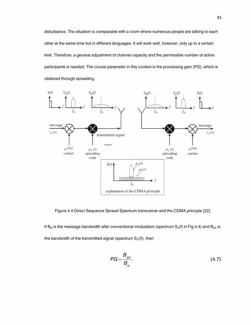
81
disturbance. The situation is comparable with a room where numerous people are talking to each
other at the same time but in different languages. It will work well, however, only up to a certain
limit. Therefore, a general adjustment of channel capacity and the permissible number of active
participants is needed. The crucial parameter in this context is the processing gain (PG), which is
obtained through spreading.
Figure 4.4 Direct Sequence Spread Spectrum transceiver and the CDMA principle [22].
If BM is the message bandwidth after conventional modulation (spectrum Sk(f) in Fig 4.4) and BSP is
the bandwidth of the transmitted signal (spectrum ST(f)), then
)7.4(.
N
SP
B
BPG
82
PG should be between 10 and 100 to obtain an efficient system for practical applications. The
higher PG is, the more participants can access the channel at the same time. However, as a
general rule, the number of participants must always remain smaller than PG; otherwise
robustness against interference is lost and the signal quality may deteriorate to an unacceptable
level for all users, even without additional interference.
With PG being sufficiently high, however, each user who becomes active contributes only a small
amount of interference as seen by other users communicating at the same time on the channel.
This particular feature of a properly designed CDMA system is also denoted ‚graceful
degradation‛. This feature of CDMA has been applied to the American mobile phone standard IS-
95 and for Universal Mobile Telecommunication System (UMTS). Unfortunately, the main
advantages of CDMA cannot be exploited for PLC for various reasons, including the lack of large
contiguous spectrum portions. The resulting fissured spectrum is bad for CDMA. However, an
application of spread spectrum technology using the DS-CDMA technique has been proposed
which is effective in improving the noise-resisting ability of the communication system [82]. The
method also solved the major problem encountered in PLC systems of security by using random
pseudo noise. It has also been noted in [82] that decreasing of the spread spectrum carrier
frequency band and amplification of the transmission power can effectively counter line
attenuation.
Apart from CDMA, two further aspects must also be mentioned which will rule out most kinds of
wideband single-carrier schemes for use in PLC systems:
Single-carrier broadband schemes do not exhibit high spectral efficiency; i.e., the
transmission of a digital data stream with the symbol rate rs requires a bandwidth of at
least 2rs , which means that the following total bandwidth must be available for N users
83
)8.4(2sSP
rNB
The powerline channel does not provide flat transmission characteristics over large
bandwidths within the available spectrum. The channel generally exhibits lowpass and
strong frequency-selective fading effects.
The second statement means that rather complex equalization would be required at the receiver.
Clear disadvantages for single-carrier schemes may arise under the following circumstances:
Poor transmission characteristics possessed by the powerline channel
Interference scenario, in particular when considering all kinds of impulsive noise
Expected frequency allocation and transmission power level limitations
For these reasons, much attention has been focused on multicarrier techniques, in particular
OFDM.
4.7.3 Orthogonal Frequency Division Multiplexing
Orthogonal Frequency Division Multiplexing (OFDM) is a well proven multicarrier technique in
applications such as digital audio broadcasting (DAB), terrestrial digital video broadcasting
(DVBT), and asymmetric digital subscriber line (ADSL). Similar to the bandwidth spreading
modulation types, OFDM exhibits robustness against various kinds of interference and enables
multiple access. In contrast to standard SST, the spectrum used by OFDM is segmented into
numerous narrow subchannels. A data stream is transmitted by frequency-division multiplexing
(FDM) using N orthogonal carriers, centered in the subchannels. Due to the narrowband property
of each subchannel, attenuation and group delay are constant within each channel. Thus,
equalization is easy and can be performed by using a one-tap technique. Orthogonality of all
84
carriers leads to outstanding spectral efficiency, which was already identified as a key element for
the success of high-speed PLC systems.
As the data stream having rate rd is distributed to N individual carriers, a symbol rate rs = rd/(m ⋅ N)
will result which is substantially slower than the data rate. Moreover, for each carrier a different
modulation method dependent on the subchannel quality can be chosen. The factor m in the
equation for symbol rate rs indicates the number of bits assigned to a carrier, for example, m = 2 for
quaternary phase shift keying (QPSK). Due to the increased symbol duration, transmission is
much less sensitive to multipath propagation than any single carrier modulation, so equalization
will not necessarily be required for OFDM. Nevertheless, the overall complexity of an OFDM
system is comparable to that of single carrier solutions which include wideband equalization.
A substantial advantage of OFDM is its adaptability. As already indicated above, it is possible to
choose the optimum modulation scheme individually for each subchannel. In addition, frequency
ranges excluded from use for PLC due to either regulatory rules, or bad quality can easily be
avoided by zeroing the corresponding carriers.
In the future it is expected that OFDM will become the most favorable modulation scheme for use
in PLC systems covering a wide range of applications. Table 4.2 compares the pros and cons of
OFDM with possible PLC modulation schemes that could be used in PLC systems.
4.7.3.1 Principles of OFDM transmission
The total signal bandwidth, in a classical parallel data system, can be divided into N non-
overlapping frequency subchannels. Each subchannel is modulated with a separate symbol and
then the N subchannels are frequency multiplexed. The general practice of avoiding spectral
overlap of subchannels was applied to eliminate inter-carrier interference (ICI). This is shown in
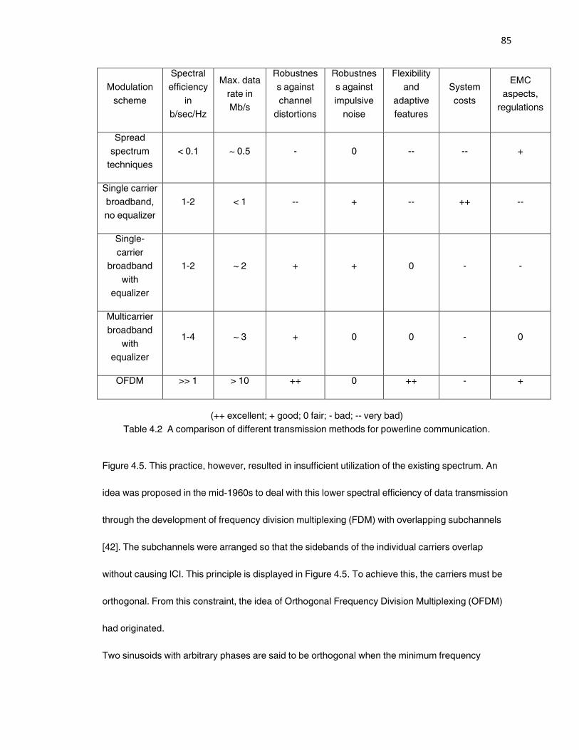
85
Modulation
scheme
Spectral
efficiency
in
b/sec/Hz
Max. data
rate in
Mb/s
Robustnes
s against
channel
distortions
Robustnes
s against
impulsive
noise
Flexibility
and
adaptive
features
System
costs
EMC
aspects,
regulations
Spread
spectrum
techniques
< 0.1 ~ 0.5 - 0 -- -- +
Single carrier
broadband,
no equalizer
1-2 < 1 -- + -- ++ --
Single-
carrier
broadband
with
equalizer
1-2 ~ 2 + + 0 - -
Multicarrier
broadband
with
equalizer
1-4 ~ 3 + 0 0 - 0
OFDM >> 1 > 10 ++ 0 ++ - +
(++ excellent; + good; 0 fair; - bad; -- very bad)
Table 4.2 A comparison of different transmission methods for powerline communication.
Figure 4.5. This practice, however, resulted in insufficient utilization of the existing spectrum. An
idea was proposed in the mid-1960s to deal with this lower spectral efficiency of data transmission
through the development of frequency division multiplexing (FDM) with overlapping subchannels
[42]. The subchannels were arranged so that the sidebands of the individual carriers overlap
without causing ICI. This principle is displayed in Figure 4.5. To achieve this, the carriers must be
orthogonal. From this constraint, the idea of Orthogonal Frequency Division Multiplexing (OFDM)
had originated.
Two sinusoids with arbitrary phases are said to be orthogonal when the minimum frequency
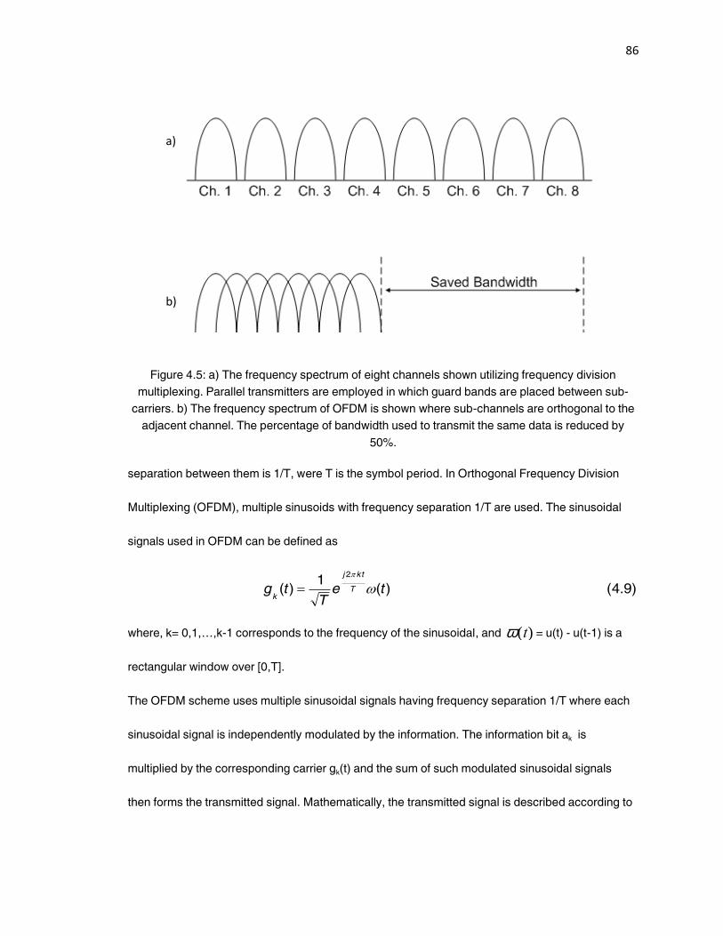
86
Figure 4.5: a) The frequency spectrum of eight channels shown utilizing frequency division
multiplexing. Parallel transmitters are employed in which guard bands are placed between sub-
carriers. b) The frequency spectrum of OFDM is shown where sub-channels are orthogonal to the
adjacent channel. The percentage of bandwidth used to transmit the same data is reduced by
50%.
separation between them is 1/T, were T is the symbol period. In Orthogonal Frequency Division
Multiplexing (OFDM), multiple sinusoids with frequency separation 1/T are used. The sinusoidal
signals used in OFDM can be defined as
)9.4()(1
)(2
teT
tg T
tkj
k
where, k= 0,1,…,k-1 corresponds to the frequency of the sinusoidal, and
w(t) = u(t) - u(t-1) is a
rectangular window over [0,T].
The OFDM scheme uses multiple sinusoidal signals having frequency separation 1/T where each
sinusoidal signal is independently modulated by the information. The information bit ak is
multiplied by the corresponding carrier gk(t) and the sum of such modulated sinusoidal signals
then forms the transmitted signal. Mathematically, the transmitted signal is described according to
a)
b)
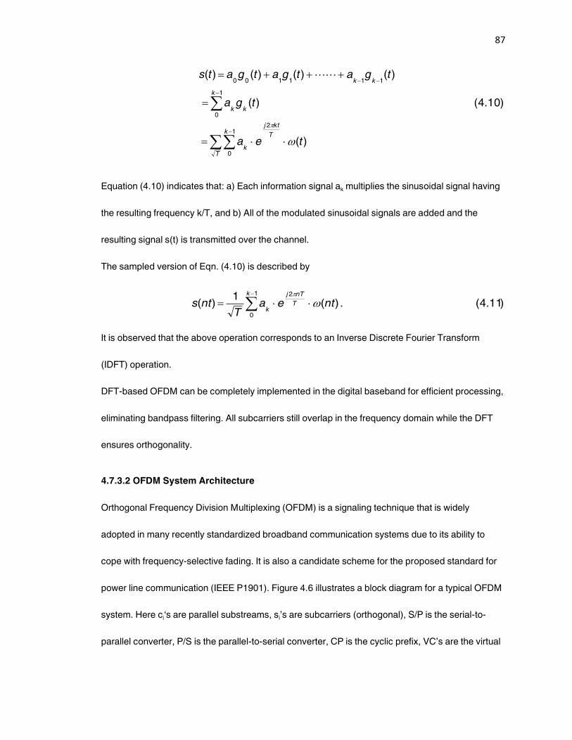
87
)(
)10.4()(
)()()()(
21
0
1
0
111100
tea
tga
tgatgatgats
T
ktj
T
k
k
k
kk
kk
Equation (4.10) indicates that: a) Each information signal ak multiplies the sinusoidal signal having
the resulting frequency k/T, and b) All of the modulated sinusoidal signals are added and the
resulting signal s(t) is transmitted over the channel.
The sampled version of Eqn. (4.10) is described by
1
0
2
)11.4(.)(1
)(k
T
nTj
kntea
Tnts
It is observed that the above operation corresponds to an Inverse Discrete Fourier Transform
(IDFT) operation.
DFT-based OFDM can be completely implemented in the digital baseband for efficient processing,
eliminating bandpass filtering. All subcarriers still overlap in the frequency domain while the DFT
ensures orthogonality.
4.7.3.2 OFDM System Architecture
Orthogonal Frequency Division Multiplexing (OFDM) is a signaling technique that is widely
adopted in many recently standardized broadband communication systems due to its ability to
cope with frequency-selective fading. It is also a candidate scheme for the proposed standard for
power line communication (IEEE P1901). Figure 4.6 illustrates a block diagram for a typical OFDM
system. Here ci‘s are parallel substreams, si’s are subcarriers (orthogonal), S/P is the serial-to-
parallel converter, P/S is the parallel-to-serial converter, CP is the cyclic prefix, VC’s are the virtual
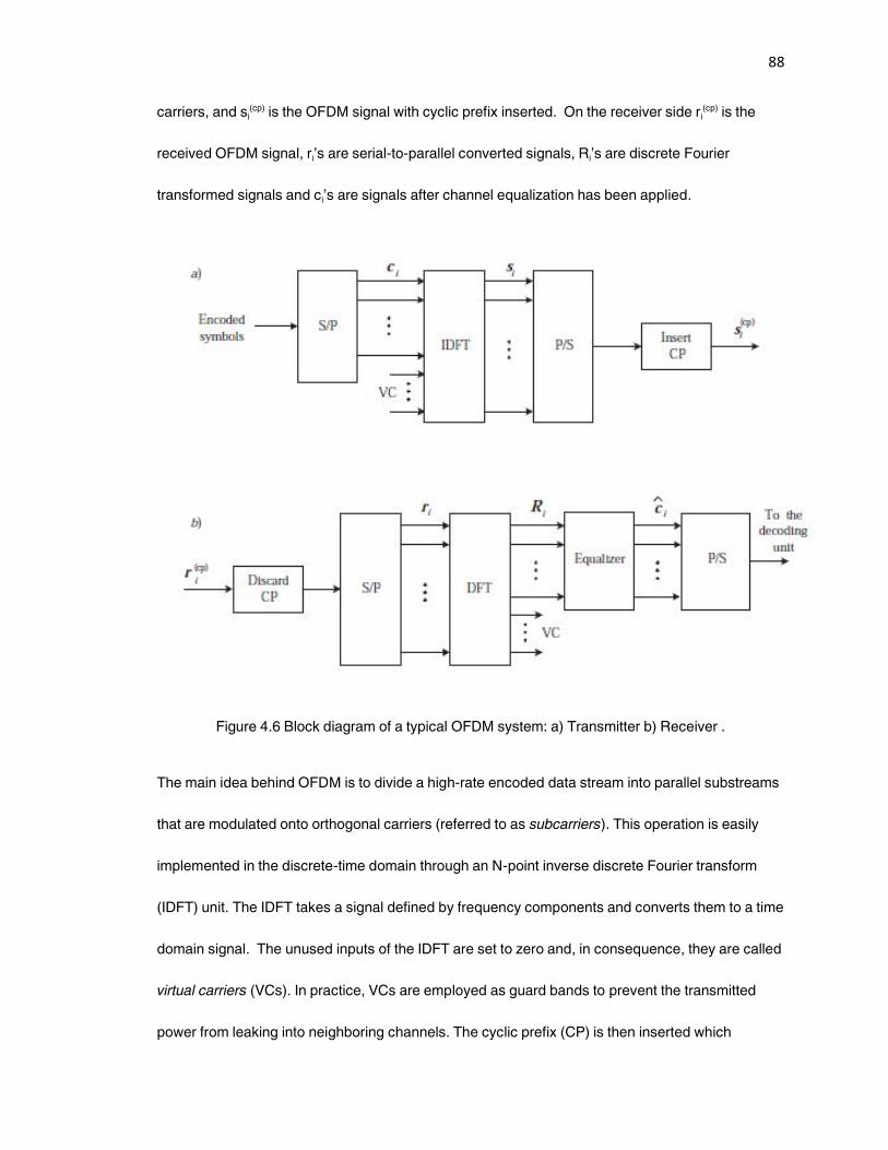
88
carriers, and si(cp) is the OFDM signal with cyclic prefix inserted. On the receiver side ri
(cp) is the
received OFDM signal, ri’s are serial-to-parallel converted signals, Ri’s are discrete Fourier
transformed signals and ci’s are signals after channel equalization has been applied.
Figure 4.6 Block diagram of a typical OFDM system: a) Transmitter b) Receiver .
The main idea behind OFDM is to divide a high-rate encoded data stream into parallel substreams
that are modulated onto orthogonal carriers (referred to as subcarriers). This operation is easily
implemented in the discrete-time domain through an N-point inverse discrete Fourier transform
(IDFT) unit. The IDFT takes a signal defined by frequency components and converts them to a time
domain signal. The unused inputs of the IDFT are set to zero and, in consequence, they are called
virtual carriers (VCs). In practice, VCs are employed as guard bands to prevent the transmitted
power from leaking into neighboring channels. The cyclic prefix (CP) is then inserted which
89
effectively converts the linear convolution effectively performed by channel to simulate a channel
performing cyclic convolution ensuring orthogonality over a time dispersive channel and
eliminating ISI completely between subcarriers as long as CP remains longer than the impulse
response of the channel. However, the CP induces a loss in the effective data rate that is
achievable. However, the resulting zero ICI generally compensates for the reduction. The cyclic
extension is added to the data stream after the IDFT is computed. By modulating the original data
onto N subcarriers, OFDM increases the symbol duration by a factor of N, thereby making the
transmitted signal more robust against frequency-selective fading.
An important advantage of the OFDM transmission technique as compared to single carrier
systems is seen in the context of frequency-selective channels. The orthogonality of the OFDM
subcarriers is maintained after transmission over the channel and the effect of ICI is reduced to a
multiplication of each subcarrier by a complex transfer factor. Therefore, equalizing the signal is
very simple, whereas equalization may not be feasible in the case of conventional single carrier
transmission occupying the same bandwidth. Equalization can be used to further suppress ISI and
ICI. These interferences are a result of channel impulse response or timing and frequency errors
such as channel distortion, synchronization error, or phase error.
Thus, OFDM is a special form of wideband multicarrier modulation in which multiple symbols are
transmitted in parallel using different sub-carriers with overlapping frequency bands that are
mutually orthogonal. An equivalent wideband frequency bandwidth is separated into a number of
narrowband signals. The time dispersion caused by multipath delay is reduced because the
symbol duration of a narrowband signal will be larger than that of a wideband transmission
scheme. The overlapping multicarrier techniques can implement the same number of channels as
in a conventional FDM system but with a reduced amount of bandwidth. In conventional FDM,
90
adjacent channels are separated using a frequency guard band. In order to utilize the overlapping
technique, the crosstalk between adjacent channels is reduced by maintaining orthogonality
between the sub-carriers.
In OFDM, each subcarrier has an integer number of cycles within a given time interval T, and the
number of cycles by which each adjacent subcarrier differs is exactly one. This implementation
establishes orthogonality among the subcarriers. The subcarriers are data modulated using either
phase shift keying or quadrature amplitude modulation. The amplitude spectrum of each
modulated subcarrier using either PSK or QAM has a sin(f)/f shape. At the peak spectral response
of each subcarrier all other subcarrier spectral responses are identically zero.
Following data modulation, symbols are fed through a serial-to-parallel conversion process. Each
PSK or QAM symbol is assigned a subcarrier and an inverse DFT, contributed by Weinstein and
Ebert in 1971 [43], is performed to produce a time domain signal. OFDM deals with multipath delay
spread by dividing a wideband signal into N narrowband channels where N is the number of sub-
carriers. However, if the delay spread is longer than the symbol duration, multipath will affect
performance. A guard time is introduced to eliminate ISI caused by delay spread. As a rule, the
guard time is usually two to four times larger than the expected delay spread. To reduce ICI,
OFDM symbols are cyclically extended into the guard interval, as pointed out by Peled and Ruiz in
[44]. This cyclic extension ensures that an OFDM symbol will have an integer number of cycles in
the DFT interval as long as the delay is less than the guard time.
At the receiver after the analog-to digital conversion stage, time and frequency synchronization
between the transmitter and receiver is very crucial to the performance of an OFDM link. A wide
variety of techniques have been proposed for estimating and adjusting both the symbol timing and
carrier frequency. To demodulate the sub-carriers using PSK or QAM modulations, an accurate
91
reference phase and amplitude of the signal constellation on each sub-carrier are required.
4.8 Conclusions
In this section, approaches to designing a powerline communications channel have been
presented. The development of a powerline communications system requires detailed knowledge
of the channel properties in order to choose suitable transmission method. Appropriate powerline
reference channel models have been identified which form the basis for the design of a PLC
system. Furthermore, a basic estimation of the powerline channel capacity clearly demonstrates
their enormous potential for high speed communication. A detailed discussion of the noise
component present in a typical PLC channel had also presented.
Basic modulation techniques such as PSK and FSK can be used for low data rate communication
on powerlines. Other more advanced techniques such as OFDM can be used when higher data
rates are desired. OFDM was adopted by the HomePlug Powerline Alliance because of its
robustness to noise, and the fact that it is a parallel data transmission method using a number of
parallel frequency division multiplexed sub-bands. Since the useful bandwidth in the powerline
channel is under 25 MHz, the applicability of spread spectrum modulation is considered to be
limited. Using a single carrier modulation on the powerline is possible but equalizers may be
needed to reduce the delay spread effect, and the associated cost is relatively high. The
knowledge gained from this section has aided in the design of the PLC system for which the
performance analysis is described in Chapter 6.
92
5. Powerline Communication Technologies
This chapter presents a review of several underlying technologies in the powerline networking
arena. The technologies and standards used presently in the Powerline Communications are
investigated in depth. These include LonWorks, X-10, OFDM, Passport, CEBus and the HomePlug
standard. We then focus on the technologies that are being deployed based on the standards. The
advantages and benefits of using powerlines as the medium for data transmission within homes
are also considered along with other important factors such as the quality of service, data
transmission rates, as well as various limitations of the technology. The description of present day
technologies follows.
5.1 LonWorks (Local Operation Networks)
The LonWorks technology, developed by Echelon [48], and available as an open standard to all
manufacturers, displaces the proprietary centralized systems with open, highly distributed, and
interoperable systems for control applications. Every automatic control system (industrial or
application) is comprised of the same basic components: sensors, actuators, application
programs, communication networks, human-machine interfaces and network management tools.
Rapid technology advancements demands changes in all types of system architectures, including
those of control systems. The LonWorks technology makes possible information-based control
systems, rather than the old-style command-based control systems.
Figure 5.1 shows the centralized architecture that up until recently has been typical of most control
systems in commercial and industrial applications.
Typically there may be tens of thousands of sensors and actuators (I/O points) that are wired to a
93
sub-panel, which in turn is connected to the controller panel via a proprietary master/slave
communication bus. The controller panel contains a high-performance microprocessor that runs a
custom application program which implements the control logic for all the I/O ports connected to it.
The system may have a proprietary Human Machine Interface(HMI) with an interface to allow
standard HMI tools to connect to the system [49]. The system typically resembles the legacy
mainframes and minicomputer systems of past decades.
The highly distributed, peer-to-peer architecture made possible by LonWorks technology is shown
in Figure 5.2. There are no centralized controllers. The LonWorks devices (also called as nodes)
communicate with any other node in the system using a standard communication protocol on
whatever physical medium is best (twisted pair, AC powerline, radio frequency, fiber optic cable,
infrared). With each node having its own simple application program, the control logic is distributed
throughout the system. Node application is customized by setting configuration parameters rather
than by custom programming. Every sensor or actuator in the system can be a node. HMI and
network management tools are available for different users. Each user has access to all points in
the system through the common communication protocol.
LonWorks technology provides the concept of network variables (NVs), which makes it easy for
manufacturers to design devices which system integrators can incorporate readily into an
established interoperable, information-based control system. The benefits to the consumer (end-
user or system integrator) of the LonWorks enabled flat control architecture are: compatibility,
easy-to-use HMI and network-management tools reduced wiring costs, short system design cycle,
reliability, multi-vendor maintenance options, and the ease of implementing new functionality.

94
Figure 5.1 Centralized Control Architecture Model [Courtesy: Echelon] [48].
Figure 5.2 LonWorks Distributed Control Architecture [Courtesy: Echelon].
95
5.1.1 LonWorks Technology
This section highlights the key elements of the LonWorks technology and the components
comprising the LonWorks system. A description of the salient features of LonTalk communication
protocol and a discussion of the LonWorks Network Services (LNS) are also presented.
The LonWorks technology is comprised of the major elements: Neuron Chip control processors
and transceivers; LonTalk communication protocol; and, LonWorks Network Services (LNS).
Neuron Chip control processor is the physical core of every LonWorks device. It is a system-on-
chip with multiple microprocessors, read-write and read-only memory (RAM and ROM),
communication and I/O interface ports. The ROM contains an OS, the LonTalk communication
protocol and an I/O function library. The chip has non-volatile RAM for configuration data and for
the application program, both of which are downloaded over the communication network. Each
Neuron Chip contains a unique 48-bit code, called the Neuron ID. Available in a large family with
different speeds, memory type and capacity, and interfaces, the Neuron Chips are jointly designed
by Echelon and its semiconductor partners Motorola and Toshiba. A transceiver is an electronic
module that provides the physical interface between the communications port of the Neuron Chip
and a physical channel which transports the digital communication packets to other devices. All
devices connected to a specific channel must have compatible transceivers operating at the same
bit rate.
Transceivers are available from Echelon and other manufacturers for a variety of media, including
single twisted pair, powerline, RF, infrared, fiber optics and coax. Bit rates depend on the media
and transceiver design; a maximum of 1.25 Mbps can be achieved on a single twisted pair [49].
The Neuron Chip control processors and transceivers comprise the hardware components used in
LonWorks devices, and are specifically designed to offer the most cost-effective solution available
96
for network enabling and embedding intelligence into home control devices [50].
The LonTalk communications protocol is a layered, packet-based, serial peer-to-peer
communications protocol. Adhering to the layered architectural requirements of the International
Standards Organization (ISO), the LonTalk protocol is designed for the specific requirements of
control systems, rather than data processing systems. Devices on a channel take turns
transmitting packets. Each packet is a variable number of bytes in length and contains the
application-level information together with addressing and other network information. Every device
on a channel looks at every packet transmitted on the channel to determine if it is an addressee. If
so, the packet is processed to determine if it contains data for the node’s application program or
whether it is a network management packet. The data in an application packet is provided to the
application program and, if appropriate, an acknowledgement message is sent to the sending
device. A network management packet is processed appropriately with no involvement required
from the application protocol. The LonTalk protocol is media-independent, allowing LonWorks
systems to communicate over any physical transport media. The program implementation of the
protocol called LonTalk firmware is contained within ROM in every Neuron Chip; providing a
number of modifiable configuration parameters to make tradeoffs in performance, security, and
reliability for a particular application; a portion of non-volatile RAM in the Neuron Chip is reserved
for these parameters [49]. A comprehensive summary of the LonTalk protocol is given in [68]
and a very detailed bits-and-bytes level discussion is available in [51]. The LonTalk communication
protocol is permanently embedded in each LonWorks device. LonTalk has been approved as an
open industry standard by the American National Standards Institute (ANSI)-EIA 709.1 [50].
LonWorks Network Services (LNS) is a client-server architecture that provides the foundation for
interoperable LonWorks network tools. LNS enables the component-based software design of a
97
new generation of tools that can work together to install, maintain, monitor, and control LonWorks
networks. It also makes it easy to integrate control systems with other information systems. The
architecture supports clients based on any platform; servers are currently based on Windows 95,
Windows NT, and the Neuron Chip. An overview of the LonWorks Network Services is presented
in [52]. The LNS is the basis for easy-to-use, interoperable network management and HMI tools,
and it also provides a range of network services to appliances that are connected to the control
system.
5.1.2 LonWorks System Components
A typical LonWorks system consists of three types of components: LonWorks devices; Channels;
and, Network tools.
Each LonWorks device, or node, attached to the network contains at least one Neuron Chip and
one transceiver in a appropriate mechanical package, as well as a suitable power supply.
Depending on device functionality, there may also be embedded sensors and actuators, I/O
interfaces to external legacy sensors and actuators, or interfaces to host processors such as PC’s.
To accommodate complex applications, some versions of the Neuron Chips have a high-speed
parallel interface allowing any microprocessor (for example, Motorola 68000 series) to execute the
application program, while using the Neuron Chip, with a special microprocessor interface
application, as its network communications processor. Alternatively, the open LonTalk protocol
can be ported to run directly on any processor; and in that case the Neuron Chip is not required by
all devices, rather all such devices are assigned a unique Neuron ID.
A channel is a specific physical communication medium to which a group of LonWorks devices are
attached by transceivers designed specifically to operate on that channel. Each type of channel
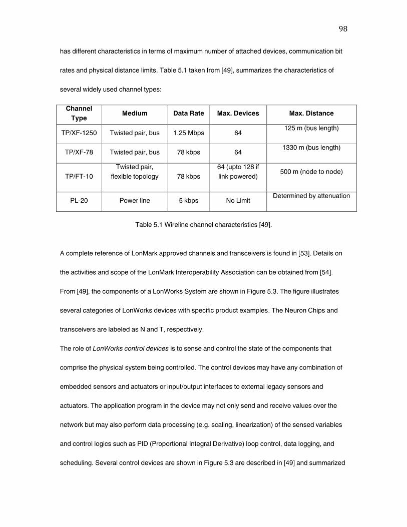
98
has different characteristics in terms of maximum number of attached devices, communication bit
rates and physical distance limits. Table 5.1 taken from [49], summarizes the characteristics of
several widely used channel types:
Channel
Type Medium Data Rate Max. Devices Max. Distance
TP/XF-1250 Twisted pair, bus 1.25 Mbps 64 125 m (bus length)
TP/XF-78 Twisted pair, bus 78 kbps 64 1330 m (bus length)
TP/FT-10
Twisted pair,
flexible topology
78 kbps
64 (upto 128 if
link powered)
500 m (node to node)
PL-20 Power line 5 kbps No Limit Determined by attenuation
Table 5.1 Wireline channel characteristics [49].
A complete reference of LonMark approved channels and transceivers is found in [53]. Details on
the activities and scope of the LonMark Interoperability Association can be obtained from [54].
From [49], the components of a LonWorks System are shown in Figure 5.3. The figure illustrates
several categories of LonWorks devices with specific product examples. The Neuron Chips and
transceivers are labeled as N and T, respectively.
The role of LonWorks control devices is to sense and control the state of the components that
comprise the physical system being controlled. The control devices may have any combination of
embedded sensors and actuators or input/output interfaces to external legacy sensors and
actuators. The application program in the device may not only send and receive values over the
network but may also perform data processing (e.g. scaling, linearization) of the sensed variables
and control logics such as PID (Proportional Integral Derivative) loop control, data logging, and
scheduling. Several control devices are shown in Figure 5.3 are described in [49] and summarized
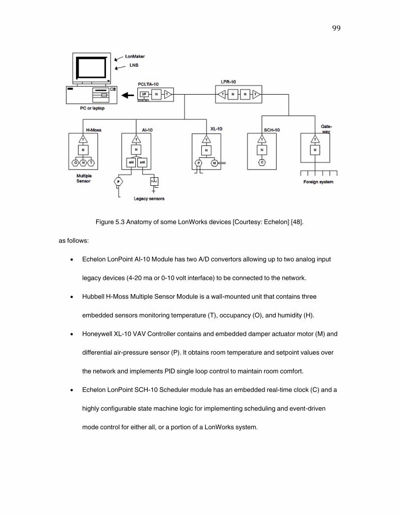
99
Figure 5.3 Anatomy of some LonWorks devices [Courtesy: Echelon] [48].
as follows:
Echelon LonPoint AI-10 Module has two A/D convertors allowing up to two analog input
legacy devices (4-20 ma or 0-10 volt interface) to be connected to the network.
Hubbell H-Moss Multiple Sensor Module is a wall-mounted unit that contains three
embedded sensors monitoring temperature (T), occupancy (O), and humidity (H).
Honeywell XL-10 VAV Controller contains and embedded damper actuator motor (M) and
differential air-pressure sensor (P). It obtains room temperature and setpoint values over
the network and implements PID single loop control to maintain room comfort.
Echelon LonPoint SCH-10 Scheduler module has an embedded real-time clock (C) and a
highly configurable state machine logic for implementing scheduling and event-driven
mode control for either all, or a portion of a LonWorks system.

100
5.1.3 Summary
LonWorks is an ‚open‛ technology and is accessible to all. A typical node in a LonWorks control
network performs a simple task. Devices such as proximity sensors, switches, motion detectors,
and sprinkler systems may all be nodes on a home network. LonWorks control networks can easily
be integrated with the Internet. This built-in capability allows for seamless networking between IP-
based devices and control devices. LonWorks powerline-based systems also support remote
monitoring of home appliances through standard Web browsers.
5.2 Consumer Electronic Bus (CEBus)
The Consumer Electronic Bus (CEBus), is the Electronic Industry Association’s (EIA) open
standard (EIA-600) describing a method of communication between electronic products in the
home using five different media: powerline, twisted pair, coax, broadcast RF, and infrared [55]. The
CEBus is basically a local-area network for home automation. CEBus is a complete packet
oriented, connectionless, peer-to-peer network utilizing Carrier Sense Multiple Access/Carrier
Detect Contention Resolution (CSMA/CDCR) protocol. CEBus is a communications and product
interoperability standard designed primarily for consumer products [56]. The first version of CEBus
was released as IS-60 (Interim Standard 60) in 1992 for industry review, and was revised in 1993
and 1994. After that it was released as an EIA open standard (EIA-600).
The CEBus based products consist of two fundamental components: a transceiver and a
microcontroller. Data packets are transmitted by the transceiver at about 10 Kbps [50]. The CEBus
protocol uses a peer-to-peer communications model so that any node on the network has access
to media at any time. The CEBus standard includes commands such as volume up, fast forward,
rewind, pause, skip, and temperature up or down one degree. These commands are based on the

101
application-to application communication language called the CEBus Common Application
Language (CAL).
The CEBus Industry Council's (CIC) mission is to provide information to the design and
development community about CEBus and CEBus Home Plug & Play. The Council involves all
applicable industries and organizations in the development of interoperable products which offer
the homeowner a multiple of products to choose from that can communicate with each other and
work as a system. These products can ask each other questions, answer question, and provide
unsolicited status reports based on what they see and know about the home's environment. These
messages are passed back and forth through the home's power lines, telephone wires, television
cable, infrared signals and radio signals.
CEBus allows products to share information such as time, temperature, occupancy state, status of
equipment, and so on. The data allows redundant product functions to be centralized, the removal
of cumbersome user interface from many products, and easy delivery of outside service
information directly to products. With CEBus, equipment can simply ‚place‛ information on the
network where it is picked up by other devices that can use the same information to their
advantage. Information can originate in the home or from service providers outside the home.
In a network, two ingredients are basic to successful communication: transparent movement of
data between nodes and/or systems; and ensuring that the data arriving for the destination node
and/or system is in a meaningful form that can be immediately recognized and processed. The
CEBus standard defines only those functions required to facilitate communications; it does not
describe the specific implementation, design, or technologies to be used. Those are left to the
innovation of the system developer. However, a full range of multi-vendor interoperability issues
are definitely addressed by the standard, including items such as connectors.
102
5.2.1 CEBus Technology
CEBus uses spread spectrum technology to overcome communication impediments found within
the home’s electrical powerline. Spread spectrum signaling works by spreading a transmitted
signal over a range of frequencies, rather than using a single frequency. The CEBus powerline
carrier spreads its signal over a range from 100 kHz to 400 kHz during each bit in the packet [50].
To avoid data collision, CEBus uses the CSMA/CDCR protocol. Similar to HomePNA [28], this
media access control protocol requires an information appliance to wait until the line is clear, which
means that no other packet can be transmitted before it can send a packet.
Each CEBus has two channels: a control channel for real-time, short-packet, control-oriented
functions, and a data channel for intensive data transfer. To ensure reliable, tamper-proof, private
communications, the CEBus standard includes such crucial network protocol features as error
detection, automatic retry, end-to-end acknowledgement, and duplicate packet rejection, as well
as authenticated service to prevent tampering, and encryption to ensure privacy. The CEBus
control channel communication is standardized across all media, with a consistent packet format
and signaling rate, and is used exclusively to control devices and resources of the network,
including data channel allocations. Data channels typically provide selectable bandwidths that can
support high data rates and are used to send data such as audio, video, or computer files over the
network. The characteristic of a data channel can vary greatly depending upon the medium and
connected device requirements. All data channel assignments and functions are managed by
CEBus control messages sent via the control channel.
5.2.2 CEBus Protocol
CEBus uses a peer-to-peer connectionless service, CSMA/CDCR communication protocol
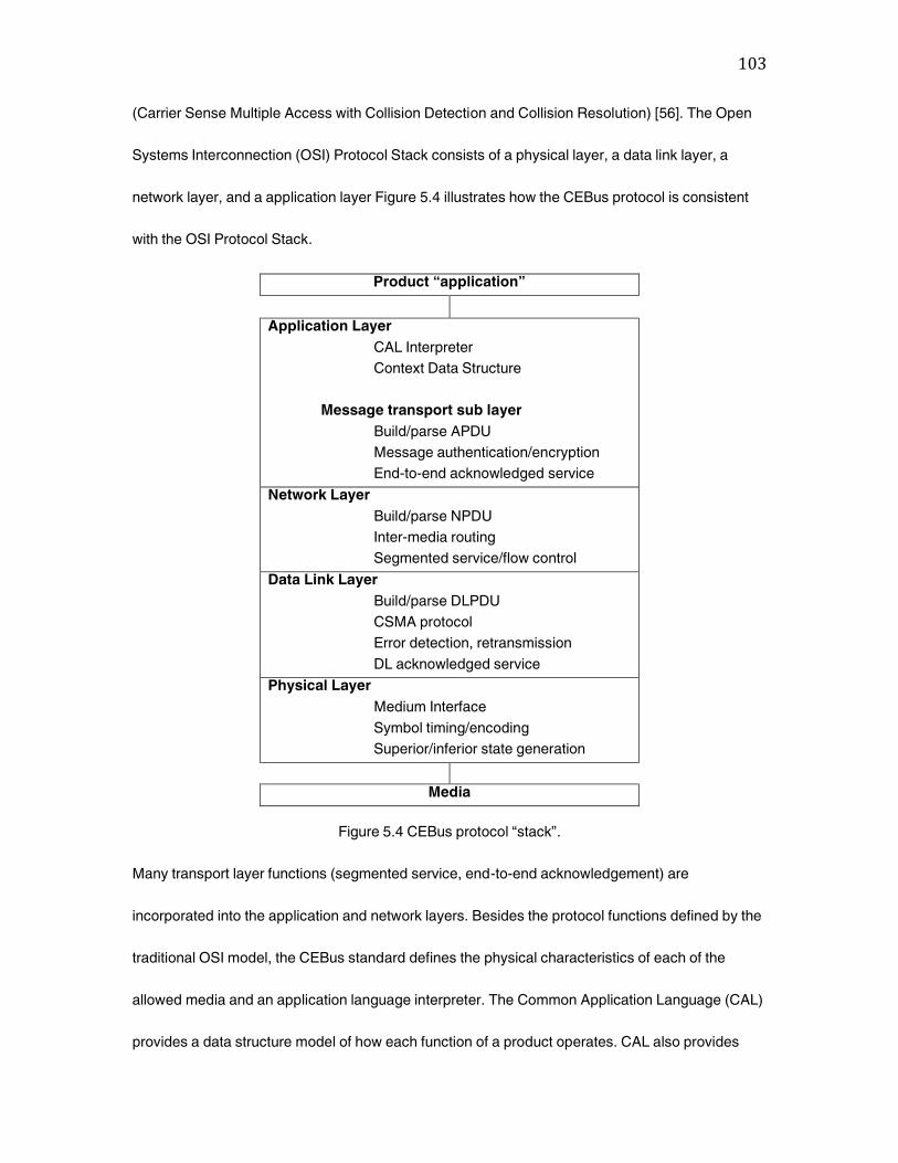
103
(Carrier Sense Multiple Access with Collision Detection and Collision Resolution) [56]. The Open
Systems Interconnection (OSI) Protocol Stack consists of a physical layer, a data link layer, a
network layer, and a application layer Figure 5.4 illustrates how the CEBus protocol is consistent
with the OSI Protocol Stack.
Product “application”
Application Layer
CAL Interpreter
Context Data Structure
Message transport sub layer
Build/parse APDU
Message authentication/encryption
End-to-end acknowledged service
Network Layer
Build/parse NPDU
Inter-media routing
Segmented service/flow control
Data Link Layer
Build/parse DLPDU
CSMA protocol
Error detection, retransmission
DL acknowledged service
Physical Layer
Medium Interface
Symbol timing/encoding
Superior/inferior state generation
Media
Figure 5.4 CEBus protocol ‚stack‛.
Many transport layer functions (segmented service, end-to-end acknowledgement) are
incorporated into the application and network layers. Besides the protocol functions defined by the
traditional OSI model, the CEBus standard defines the physical characteristics of each of the
allowed media and an application language interpreter. The Common Application Language (CAL)
provides a data structure model of how each function of a product operates. CAL also provides
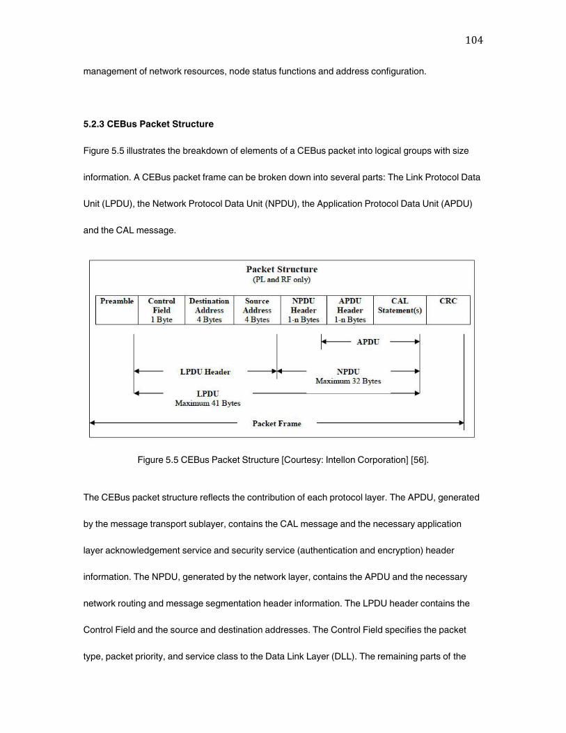
104
management of network resources, node status functions and address configuration.
5.2.3 CEBus Packet Structure
Figure 5.5 illustrates the breakdown of elements of a CEBus packet into logical groups with size
information. A CEBus packet frame can be broken down into several parts: The Link Protocol Data
Unit (LPDU), the Network Protocol Data Unit (NPDU), the Application Protocol Data Unit (APDU)
and the CAL message.
Figure 5.5 CEBus Packet Structure [Courtesy: Intellon Corporation] [56].
The CEBus packet structure reflects the contribution of each protocol layer. The APDU, generated
by the message transport sublayer, contains the CAL message and the necessary application
layer acknowledgement service and security service (authentication and encryption) header
information. The NPDU, generated by the network layer, contains the APDU and the necessary
network routing and message segmentation header information. The LPDU header contains the
Control Field and the source and destination addresses. The Control Field specifies the packet
type, packet priority, and service class to the Data Link Layer (DLL). The remaining parts of the
105
packet are the preamble and the frame check sequence (FCS) or the Cyclic Redundancy Check
(CRC). The CRC is a packet-level error detection field appended by the data link layer. Packets
vary in size from approximately 50 bits (the smallest packet) to about 350 bits (the largest packet),
depending on the size of the CAL message and the content of the layer headers.
All CEBus nodes have a unique address pair: a system address and a node address. The system
address is the same for all nodes in the home, while each node address in a given system is
unique. The purpose of a system address is to logically isolate the nodes in one house from the
nodes in another house, particularly on medium networks that span multiple homes. Messages
from a node in one system network cannot be received by nodes in another system network.
The generation of a CEBus packet is a two-step process. First the data from the host are converted
to symbols. These symbols are then converted to waveforms to be transmitted. Each CEBus
packet consists of a preamble, packet body, and CRC.
Intellon’s spread spectrum power line technology was chosen by EIA as a result of an industry
wide competitive selection. Spread spectrum has wide bandwidth which makes it immune to many
frequency-dependent impairments. This is due to the fact that only a portion of Intellon’s spread
spectrum signal is required for detection. The signal may suffer from many different types of
impairments and still provide error free communication.
5.2.4 Summary
Many CEBus complaint products for home automation are being developed including lighting and
appliance controllers, wireless security systems (utilizing SSC RF Signaling), thermostats, HVAC
controllers, audio/video equipment control, etc. In addition to the consumer level products that are
being used, many utility providers are installing energy management systems at their customer’s
106
premises to perform meter reading, load control, and provide services such as security monitoring.
There are also many commercial applications being implemented, using the CEBus PL and RF
SSC signaling technology, that are not concerned about CEBus compliance. In at least one
European city, public lighting is being controlled with SSC PL communications utilizing the 20 kHz
to 80 kHz chirp signal [58]. CEBus communications over the electric distribution network utilizes
the phase coupling mechanism for power line communications [59]. There have been two serious
impediments to the growth of the powerline carrier (PLC) communications industry, the line noise,
which degrades the communications reliability, and the lack of a standard communication network
protocol [60]. These stumbling blocks have been removed to a greater extent, the first, by the
development of spread spectrum PLC technology, which all but eliminates the noise impediment,
and the second, by the industry wide adoption of the EIA’s CEBus standard. Reference [61]
outlines methods of communication over a powerline namely X-10 and CEBus and also introduces
spread spectrum technology as to increase speed to 100-150 times faster than the X-10 system.
Detailed information on the CEBus standard, development tools, training, existing products and
literature can be found in [57].
5.3 Passport and Plug-in PLX
Intelogis Inc., founded in 1997 and renamed to Inari Inc. in 2000, developed one of the first
powerline technologies, called Passport, which is sometimes also referred to as the original
powerline technology. This section is given as a reference to discuss the Intelogis Passport
powerline technology. Most of the material in this section is based on the findings reported in [62].
Passport relies on frequency-shift keying (FSK) to send data back and forth over the home
electrical wiring. FSK uses two frequencies, one for 1’s and the other for 0’s, to send digital

107
information between the computers on the network. The frequencies used are in a narrow band
above the level of line noise occurrence. A flaw of this somewhat fragile method is that anything
that impinges on either frequency can disrupt the data flow, causing the transmitting computer to
have to resend the data. This can affect the performance of the network, including network
slowdown. Included with the Intelogis Passport kit were line-conditioning power strips which would
be inserted between the wall outlet and the user computer equipment to help reduce the amount of
electrical-line noise. Based on 110-volt electrical system (which made the technology unsuitable to
countries outside of North America), the Intelogis powerline network uses computer’s parallel port
for physical connections. It also requires the installation of software for its modules to work.
Intelogis Passport technology uses client/server network architecture. This architecture is a
centralized administrative system providing information to all of the other devices. The first
computer on which the software is installed becomes the Application Server which controls the
data flow over the network and directs each device to find other devices. Some of the
disadvantages associated with the Intelogis Passport technology are highlighted below:
• Slow connection speeds ( 50 kbps up to 350 kbps)
• Home power usage affects performance
• Powerline Device (Module) size appears to be rather large
• Only works on standard 110-V powerlines
• All data needs to be encrypted for a secure network
• Older powerline wiring degrades performance
Taking a different track to powerline communications, Intelogis technology transmits data in a
frequency band above the noise region. Dubbed as Plug-in PLX technology [63], it uses a
combination of datagram-sensing multiple access (DSMA) and centralized token passing (CTP).
108
DSMA acts in a similar fashion to the multi-node contention resolution of an Ethernet network. A
node, when entering the network for the first time, detects the carrier of the other packets on the
line, sending its own packet only if it is clear to do so. Once all the nodes are known to each other,
the dynamic centrally distributed token passing scheme is instituted which avoids multi-node
contention and collision and thus raises the effective throughput. Intelogis claimed that its
technology permits simultaneous transfer of small control packets and entertainment data (for
example, MPEG-1 Audio Layer 3 music file), without interfering with each other. Plug-in PLX also
conforms to the CEBus CAL [63].
5.4 X-10
X-10 (also referred to as X10) is a communications protocol that allows compatible home
networking products to talk to each other via the existing home electrical wiring. The X-10 code
format was first introduced in 1978 by X-10 Inc., for the Sears Home Control System and the Radio
Shack Plug ‘n’ Power System [64]. The X-10 technology, now 35 years old, was initially developed
to integrate with low cost lighting and appliance control devices.
X-10 compatible devices, which are electrical components directly plugged into wall outlets, can
communicate with each other. But these devices are susceptible to damage by voltage spikes.
Additionally, signal attenuation and line noises generated by household appliances or external
sources can transiently interfere with X-10 communications. With the powerline subnet being
shared among neighboring houses, X-10 commands from one house can interfere with devices in
another house. As a result, reliability remains a major issue in X-10 powerline networking [65].
Complex and unanticipated faults are unavoidable in X-10 networking, and the faults manifest
themselves as anomalous behavior on the powerline in terms of illegal sequences of X-10

109
commands. The X-10 protocol is underspecified with respect to when exactly modules get to be
addressed and unaddressed (i.e., when the modules move from unaddressed state to an
addressed state and vice versa). Only experimentation with various command sequences could
lead to the formulation of rules governing the addressing of X-10 modules and development of a
model for the legal X-10 command sequences. The X-10 powerline communication protocol and a
model-based fault detection system that achieves completeness of coverage for X-10 faults are
discussed in [65].
The vast majority of X-10 communication remains unidirectional only [50]. However, some
capability for bidirectional communication has also been added to it. X-10 controllers send signals
over existing AC wiring to receiver modules. The X-10 modules are adapters connected to outlets
and controlling simple devices. X-10 transmission rate is limited to only 60 bps [50] which makes it
unsuitable for carrying internet type traffic around the house. By using X-10 it is possible to control
lights and virtually any other electrical device from anywhere in the house with no additional wiring.
The X-10 technology and resource forum designs, develops, manufactures, and markets products
that are based on this standard. X-10 Ltd., which designs its own chips for its devices,
manufactures products for companies including IBM, Thomson (GE and RCA brands), Philips
(Magnavox brand), Radio Shack, Leviton, Honeywell, Stanley, Ademco, and ADT among others.
IBM relies on X-10 technology in its Home Director product [63]. According to X-10 group, more
than 100 million units have been shipped by the company [50]. These home automation devices
are called ‚powerline carrier‛ (PLC) devices and are often installed by builders who want to offer
home automation as an additional selling feature. The home automation line consists of
‚controllers‛ that automatically send signals over existing electrical wiring to receiver ‚modules‛,
which in turn control lights, appliances, heating and air conditioning units, etc.
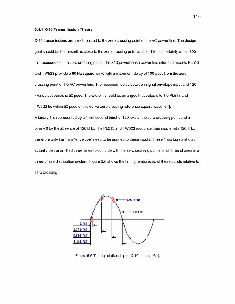
110
5.4.1 X-10 Transmission Theory
X-10 transmissions are synchronized to the zero crossing point of the AC power line. The design
goal should be to transmit as close to the zero crossing point as possible but certainly within 200
microseconds of the zero crossing point. The X10 powerhouse power line interface models PL513
and TW523 provide a 60 Hz square wave with a maximum delay of 100 μsec from the zero
crossing point of the AC power line. The maximum delay between signal envelope input and 120
kHz output bursts is 50 μsec. Therefore it should be arranged that outputs to the PL513 and
TW523 be within 50 μsec of this 60 Hz zero crossing reference square wave [64].
A binary 1 is represented by a 1 millisecond burst of 120 kHz at the zero crossing point and a
binary 0 by the absence of 120 kHz. The PL513 and TW523 modulate their inputs with 120 kHz,
therefore only the 1 ms ‚envelope‛ need to be applied to these inputs. These 1 ms bursts should
actually be transmitted three times to coincide with the zero crossing points of all three phases in a
three phase distribution system. Figure 5.6 shows the timing relationship of these bursts relative to
zero crossing.
Figure 5.6 Timing relationship of X-10 signals [64].
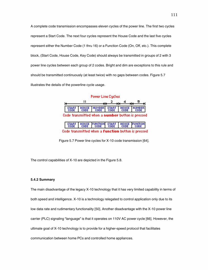
111
A complete code transmission encompasses eleven cycles of the power line. The first two cycles
represent a Start Code. The next four cycles represent the House Code and the last five cycles
represent either the Number Code (1 thru 16) or a Function Code (On, Off, etc.). This complete
block, (Start Code, House Code, Key Code) should always be transmitted in groups of 2 with 3
power line cycles between each group of 2 codes. Bright and dim are exceptions to this rule and
should be transmitted continuously (at least twice) with no gaps between codes. Figure 5.7
illustrates the details of the powerline cycle usage.
Figure 5.7 Power line cycles for X-10 code transmission [64].
The control capabilities of X-10 are depicted in the Figure 5.8.
5.4.2 Summary
The main disadvantage of the legacy X-10 technology that it has very limited capability in terms of
both speed and intelligence. X-10 is a technology relegated to control application only due to its
low data rate and rudimentary functionality [50]. Another disadvantage with the X-10 power line
carrier (PLC) signaling ‚language‛ is that it operates on 110V AC power cycle [66]. However, the
ultimate goal of X-10 technology is to provide for a higher-speed protocol that facilitates
communication between home PCs and controlled home appliances.
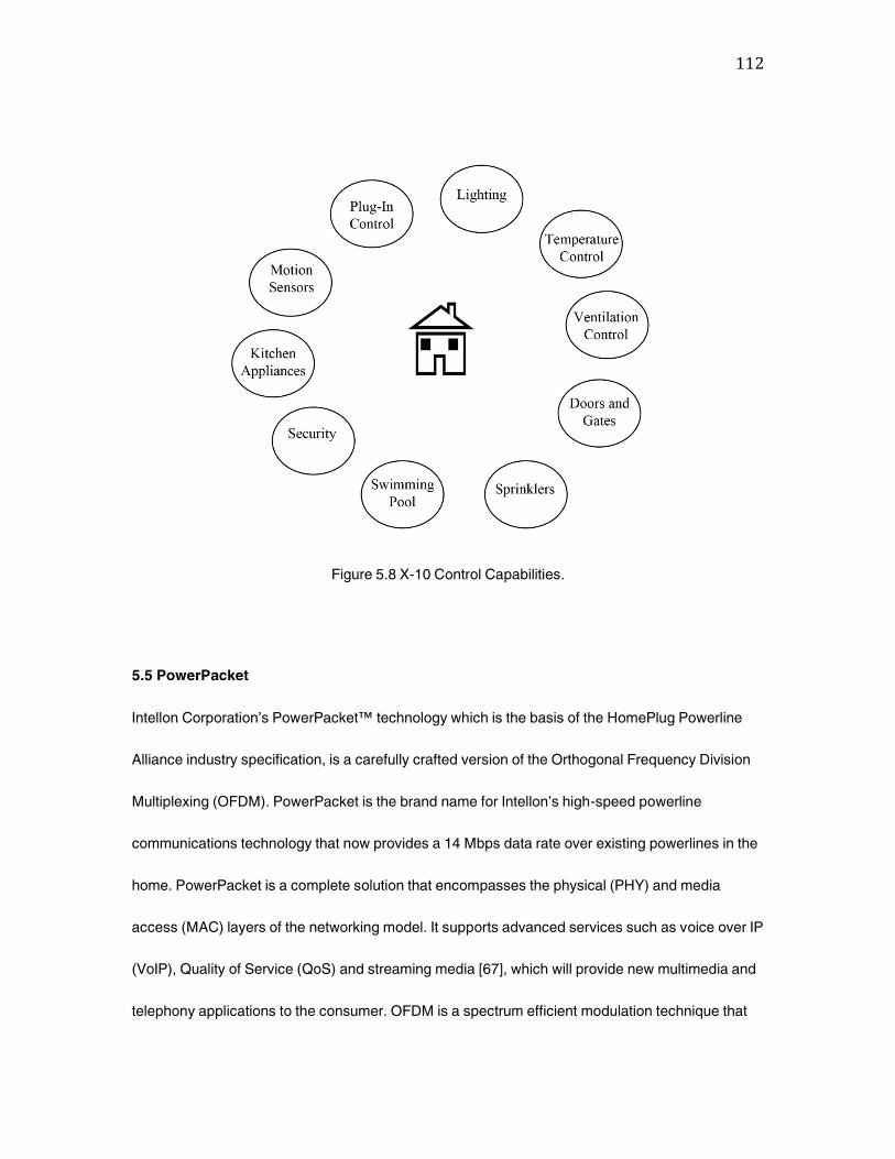
112
Figure 5.8 X-10 Control Capabilities.
5.5 PowerPacket
Intellon Corporation’s PowerPacket™ technology which is the basis of the HomePlug Powerline
Alliance industry specification, is a carefully crafted version of the Orthogonal Frequency Division
Multiplexing (OFDM). PowerPacket is the brand name for Intellon’s high-speed powerline
communications technology that now provides a 14 Mbps data rate over existing powerlines in the
home. PowerPacket is a complete solution that encompasses the physical (PHY) and media
access (MAC) layers of the networking model. It supports advanced services such as voice over IP
(VoIP), Quality of Service (QoS) and streaming media [67], which will provide new multimedia and
telephony applications to the consumer. OFDM is a spectrum efficient modulation technique that
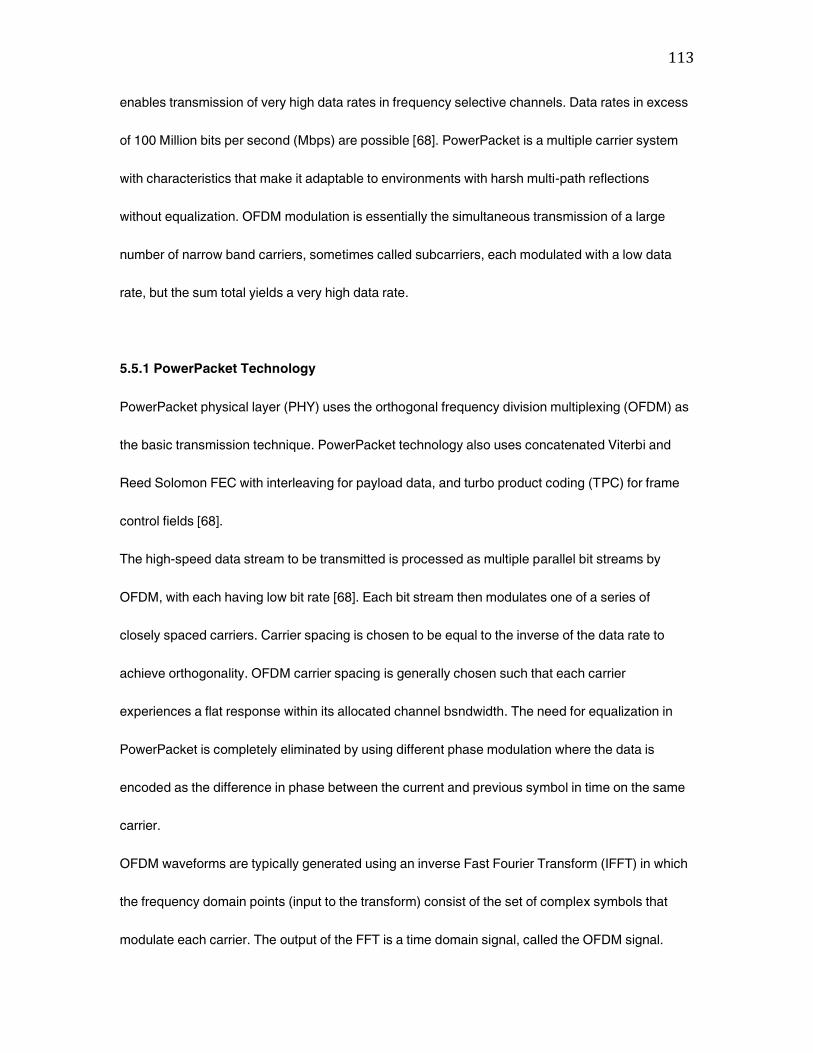
113
enables transmission of very high data rates in frequency selective channels. Data rates in excess
of 100 Million bits per second (Mbps) are possible [68]. PowerPacket is a multiple carrier system
with characteristics that make it adaptable to environments with harsh multi-path reflections
without equalization. OFDM modulation is essentially the simultaneous transmission of a large
number of narrow band carriers, sometimes called subcarriers, each modulated with a low data
rate, but the sum total yields a very high data rate.
5.5.1 PowerPacket Technology
PowerPacket physical layer (PHY) uses the orthogonal frequency division multiplexing (OFDM) as
the basic transmission technique. PowerPacket technology also uses concatenated Viterbi and
Reed Solomon FEC with interleaving for payload data, and turbo product coding (TPC) for frame
control fields [68].
The high-speed data stream to be transmitted is processed as multiple parallel bit streams by
OFDM, with each having low bit rate [68]. Each bit stream then modulates one of a series of
closely spaced carriers. Carrier spacing is chosen to be equal to the inverse of the data rate to
achieve orthogonality. OFDM carrier spacing is generally chosen such that each carrier
experiences a flat response within its allocated channel bsndwidth. The need for equalization in
PowerPacket is completely eliminated by using different phase modulation where the data is
encoded as the difference in phase between the current and previous symbol in time on the same
carrier.
OFDM waveforms are typically generated using an inverse Fast Fourier Transform (IFFT) in which
the frequency domain points (input to the transform) consist of the set of complex symbols that
modulate each carrier. The output of the FFT is a time domain signal, called the OFDM signal.
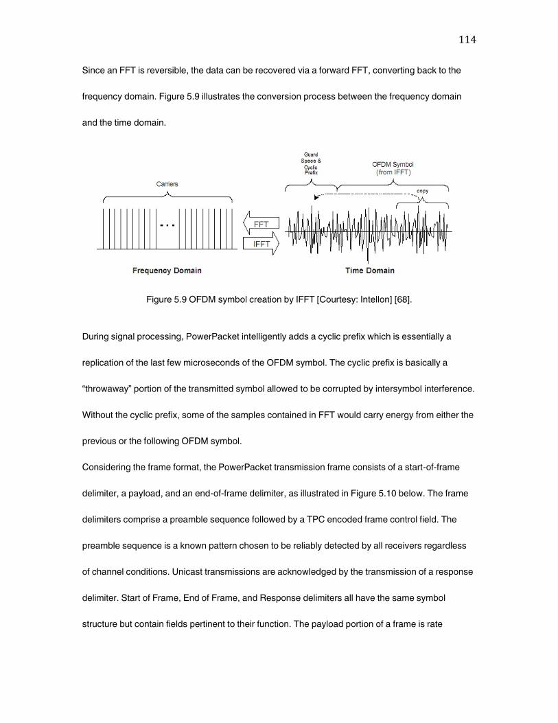
114
Since an FFT is reversible, the data can be recovered via a forward FFT, converting back to the
frequency domain. Figure 5.9 illustrates the conversion process between the frequency domain
and the time domain.
Figure 5.9 OFDM symbol creation by IFFT [Courtesy: Intellon] [68].
During signal processing, PowerPacket intelligently adds a cyclic prefix which is essentially a
replication of the last few microseconds of the OFDM symbol. The cyclic prefix is basically a
‚throwaway‛ portion of the transmitted symbol allowed to be corrupted by intersymbol interference.
Without the cyclic prefix, some of the samples contained in FFT would carry energy from either the
previous or the following OFDM symbol.
Considering the frame format, the PowerPacket transmission frame consists of a start-of-frame
delimiter, a payload, and an end-of-frame delimiter, as illustrated in Figure 5.10 below. The frame
delimiters comprise a preamble sequence followed by a TPC encoded frame control field. The
preamble sequence is a known pattern chosen to be reliably detected by all receivers regardless
of channel conditions. Unicast transmissions are acknowledged by the transmission of a response
delimiter. Start of Frame, End of Frame, and Response delimiters all have the same symbol
structure but contain fields pertinent to their function. The payload portion of a frame is rate
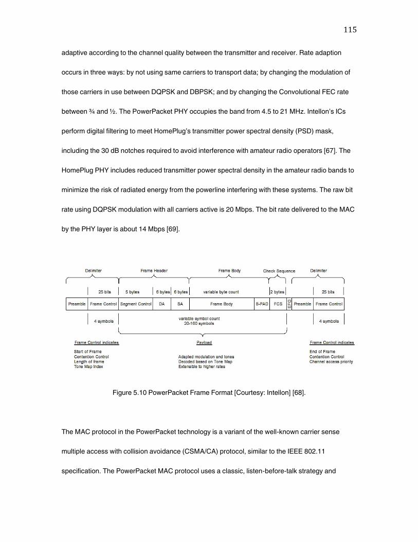
115
adaptive according to the channel quality between the transmitter and receiver. Rate adaption
occurs in three ways: by not using same carriers to transport data; by changing the modulation of
those carriers in use between DQPSK and DBPSK; and by changing the Convolutional FEC rate
between ¾ and ½. The PowerPacket PHY occupies the band from 4.5 to 21 MHz. Intellon’s ICs
perform digital filtering to meet HomePlug’s transmitter power spectral density (PSD) mask,
including the 30 dB notches required to avoid interference with amateur radio operators [67]. The
HomePlug PHY includes reduced transmitter power spectral density in the amateur radio bands to
minimize the risk of radiated energy from the powerline interfering with these systems. The raw bit
rate using DQPSK modulation with all carriers active is 20 Mbps. The bit rate delivered to the MAC
by the PHY layer is about 14 Mbps [69].
Figure 5.10 PowerPacket Frame Format [Courtesy: Intellon] [68].
The MAC protocol in the PowerPacket technology is a variant of the well-known carrier sense
multiple access with collision avoidance (CSMA/CA) protocol, similar to the IEEE 802.11
specification. The PowerPacket MAC protocol uses a classic, listen-before-talk strategy and
116
transmission after a randomly selected delay to avoid collisions [67]. This virtual carrier sense
(VCS) mechanism and contention resolution helps minimize the number of collisions [69]. Addition
of several features enables the protocol to support priority classes, provide fairness, and allows the
control of latency.
Since PowerPacket is rate adaptive, the transmission time for a given packet size varies. Long
transmission times thwart a protocols ability to offer Quality of Service (QoS) since a high priority
frame may be forced to wait for a long, slow transmission to complete. To overcome this problem
PowerPacket requires the segmentation of frames that exceed certain duration. Higher priority
frames can then jump in between the slower transmission’s segments. To reduce the chance for
collision among equal priority members, PowerPacket uses segment bursting, which allows all
segments of packet to be transmitted back-to-back unless interrupted by a higher priority. An
extension of this capability is contention-free access in which a station transmits a limited number
of frames to different destinations without interruption. Contention-free access improves QoS for
certain types of multimedia traffic [67] such as voice-over-IP (VoIP) or streaming media [69].
PowerPacket’s privacy mechanism creates a logical network with all nodes in the network sharing
a common encryption key. Encryption of all frames is performed at the MAC layer by a 56-bit data
encryption standard (DES) algorithm using cipher block chaining. The key management systems
include features that enable the distribution of keys to nodes that lack an I/O capability.
5.5.2 Summary
Intellon’s PowerPacket technology serves as the basis for the HomePlug Powerline Alliance
standard. Using the enhanced OFDM, the rate-adaptive design allows PowerPacket to maintain an

117
Ethernet-class connection throughout the power-line network without losing any data. Some of the
advantages of PowerPacket include the following [62]:
• Fast, data rate of 14 Mbps
• Avoids disruptions in the powerline, maintaining the network’s connections and speeds
• Printer features are not limited
• Compatibility with different Operating Systems
• Embedded circuitry in the device enables only the standard power cord to access an AC
outlet
• Works independently from the line voltage and frequency
• 56-bit DES encryption is included
• Tests show negligible signal degradation due to older wiring
PowerPacket devices connect via a USB or Ethernet cord to the computer or other devices and on
the other end to the AC outlet. PowerPacket uses a peer-to-peer network architecture (which
eliminates the need for consulting a central system first).
The latest generation of PowerPacket is rated at 14 Mbps, which is faster than existing phone-line
and wireless solutions. However, as broadband access and Internet-based content including
streaming audio and video and voice-over-IP (VoIP) become more common, speed requirements
will continue to rise. Along these lines, the Intellon’s OFDM approach to power-line networking is
highly scalable, eventually allowing the technology to surpass 100 Mbps [62]. The exact methods
of scaling the PowerPacket technology to higher speeds are proprietary by Intellon [68], however,
the suggested areas of focus are modulation techniques, protocol enhancements, and circuit
design optimization.
118
5.6 Cogency’s HomePlug Technology
Established in 1997 and based in Toronto, Canada, Cogency Semiconductor Inc. [70] addresses
the technical challenges encountered using powerline for data communications by providing
integrated circuits, offering a robust, cost-effective, high-speed technology solution for networking,
entertainment and computer products. Cogency’s HomePlug technology combines OFDM, signal
coding, and error correction techniques.
Cogency’s technology for powerline networking includes a physical layer (PHY) and Medium
Access Control (MAC) layer. The PHY layer implements the modulation techniques, the coding,
and basic packet formats. The PHY uses packet-based OFDM as the transmission technique. The
MAC uses a CSMA/CA protocol to mediate access between multiple clients [71].
The Cogency MAC/PHY provides per packet equalization and efficient access to the shared
powerline medium. Additionally a proprietary resolution signaling scheme enables latency-
sensitive applications such as voice-over-IP (VoIP) and multi-player gaming.
The Cogency MAC/PHY uses OFDM technology for signal transmission at a high data rate with
few bit errors. OFDM modulation generates a set of tones in the frequency domain. Resistance to
deep, narrow fades is provided by using many carriers. The loss of few tones can be compensated
for with the Forward Error Correction (FEC) coding which redundantly encodes data across all
active tones. Automatic channel adaptation allows the system to respond to current conditions on
the powerline. The tones are modulated using either differential BPSK (76 bits per OFDM symbol)
or QPSK (152 bits per OFDM symbol). For harsh channels or when channel adaptation has not
been performed, the payload data is sent using ROBust OFDM (ROBO) mode. ROBO mode uses
all available tones with differential BPSK modulation on each tone, as well as heavy error
correction and interleaving. ROBO mode is useful for very harsh channels or when establishing
119
initial contact with another device to negotiate the optimum communication scheme. Convolutional
or Reed-Solomon coding are used for payload data. Convolutional coding rates of ½ can be
punctured to achieve a rate of ¾. A combination of coding rate and modulation is used to adjust to
varying channel conditions. Product encoding is used for frame control fields, which ensures that
all devices on the network are able to detect and decode this information. Channel adaptation is
used to specify modulation or coding schemes for payload data. If significant fading occurs,
specific tones can be dropped from the transmission. Data packets can be transmitted in two
modes: to all stations, or to one specific station. Data is encoded on all carriers when transmitting
frame control symbols. Reliability of transmission is ensured by the MAC/PHY layer’s
acknowledgment of Unicast transmission by sending a response delimiter (ACK) to indicate a
successful transmission. A NACK signal is sent to indicate that the packet was received but with
errors. The MAC/PHY uses Automatic Repeat request (ARQ) to guarantee reliability. Receipt of a
NACK (or no response) results in the packet being resent. The MAC/PHY layer can determine the
state of powerline by monitoring the frame delimiters. This is known as ‚carrier sense‛. For
reduction of collisions that occur with random access to the channel, Cogency uses a Carrier
Sense Multiple Access with Collision Avoidance (CSMA/CA) protocol enhanced with priority
signaling. Prioritized access to the channel is achieved by using the Priority Resolution Period.
Cogency’s HomePlug technology provides a robust solution to the powerline networking, providing
reliable data transmission for the home networking environment. The Cogency MAC/PHY layer
adapts automatically to changing conditions on the powerline providing a reliable channel under
the noisiest conditions. Multipath distortion effects are taken care of with the OFDM technology.
Privacy management using 56-bit encryption techniques provides privacy, while priority contention
control ensures timely access for latency-sensitive applications. Cogency’s HomePlug technology
120
provides Ethernet-class data networking and supports VoIP, QoS, and streaming media
applications.
5.7 Conclusions
PLC systems represent a relatively recent and rapidly evolving technology, aimed at the utilization
of the electricity powerlines for the transmission of data. This chapter presented an in-depth
technical analysis of all the existing technologies associated with the powerline carrier
communications systems. Powerlines are inherently the most attractive medium for home
networking due to its universal existence in homes, the abundance of AC outlets and the simplicity
of the power plug. In comparison, the phone line suffers from too few connection points and
wireless connections from congestion at 2.4 GHz, as well as interference [72]. The potential for
powerline to act as a backbone for home networking is great, provided that the powerline is able to
provide reliability, security and robustness to meet the requirements of the most demanding
applications.
As many companies have developed their own (and sometimes proprietary) systems for dealing
with the powerline networking, there was a need for standardization, which was covered in Section
1.4 of this thesis. The four driving needs for a home network are home automation, home
computer, audio and video distribution, and an access network. CEBus aimed at control, makes
HomePlug the ideal choice for home networking scenario. CEBus, X-10, and LonWorks core
technologies are more suited to home control and automation systems. HomePlug certified
products deliver data at 14 Mbps and the flexibility of Intellon’s enhanced OFDM (which is the
basis of HomePlug specification) allows scalability to very high data rates, upto 100 Mbps and
beyond.
121
6. Powerline Communication Systems Analysis
6.1 The powerline channel model
In order to perform computer simulations oriented to the design of communications systems,
models of the channel transfer characteristics are of major interest. For the design and computer-
based performance analysis of modulation schemes, the complex frequency response or the
impulse response of powerline links are required. The development of a powerline communication
system requires measurement-based models of the transfer characteristics of the mains network
suitable for performance analysis by simulation.
A powerline channel model is described using the top down strategy (mentioned in Chapter 4)
considering the communication channel as a black box and described by its frequency transfer
characteristics H(f) in the range from 500 kHz up to 20 MHz using only a very few relevant
parameters. The structure of this model is based on fundamental physical effects, which were
analyzed with numerous measurements [73]. The relevant parameters are derived from frequency
response measurements. The parameter estimation strategy is described in [73].
Only in the case of very simple topologies, such as a power cable with a single branch, the
physical reasons for the observed results (cable loss, reflection, and transmission factors) can be
easily identified. In real network topologies, which are always more complicated, a back-tracing of
measurement results to physical reasons will generally turn out to be impossible. The model
described here will nevertheless describe the frequency response with sufficient precision. The
parameters, however, cannot be directly derived from physical properties of the network.
Equation (4.6) describes a simplified parametric model describing the complex frequency
response of typical powerline channels covering all substantial effects of the transfer
characteristics in the frequency range from 500 KHz to 20 MHz by a small set of parameters which
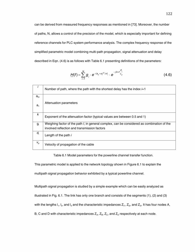
122
can be derived from measured frequency responses as mentioned in [73]. Moreover, the number
of paths, N, allows a control of the precision of the model, which is especially important for defining
reference channels for PLC system performance analysis. The complex frequency response of the
simplified parametric model combining multi-path propagation, signal attenuation and delay
described in Eqn. (4.6) is as follows with Table 6.1 presenting definitions of the parameters:
)6.4()(1
2)(
10
N
i
v
dfj
dfaa
ip
i
i
k
eegfH
i Number of path, where the path with the shortest delay has the index i=1
a0,
a1 Attenuation parameters
k Exponent of the attenuation factor (typical values are between 0.5 and 1)
gi Weighing factor of the path I, in general complex, can be considered as combination of the
involved reflection and transmission factors
di Length of the path i
vp Velocity of propagation of the cable
Table 6.1 Model parameters for the powerline channel transfer function.
This parametric model is applied to the network topology shown in Figure 6.1 to explain the
multipath signal propagation behavior exhibited by a typical powerline channel.
Multipath signal propagation is studied by a simple example which can be easily analyzed as
illustrated in Fig. 6.1. The link has only one branch and consists of the segments (1), (2) and (3)
with the lengths l1, l2, and l3 and the characteristic impedances Zl1, Zl2, and Zl3. It has four nodes A,
B, C and D with characteristic impedances ZA, ZB, ZC, and ZD respectively at each node.
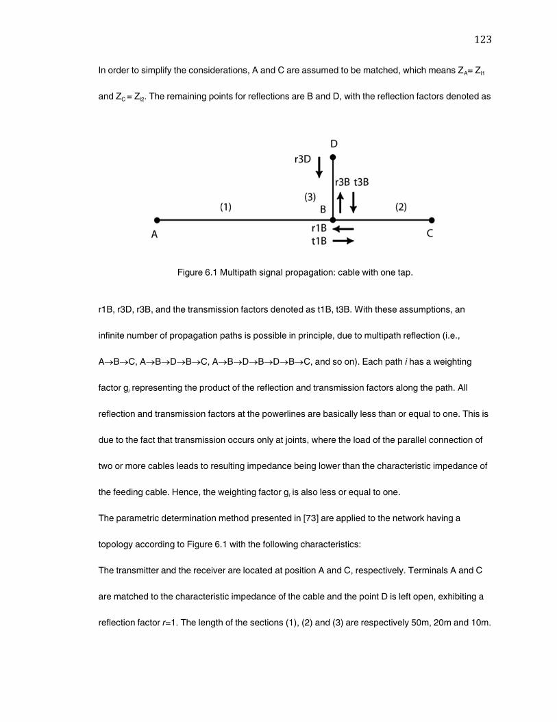
123
In order to simplify the considerations, A and C are assumed to be matched, which means ZA= Zl1
and ZC = Zl2. The remaining points for reflections are B and D, with the reflection factors denoted as
Figure 6.1 Multipath signal propagation: cable with one tap.
r1B, r3D, r3B, and the transmission factors denoted as t1B, t3B. With these assumptions, an
infinite number of propagation paths is possible in principle, due to multipath reflection (i.e.,
ABC, ABDBC, ABDBDBC, and so on). Each path i has a weighting
factor gi representing the product of the reflection and transmission factors along the path. All
reflection and transmission factors at the powerlines are basically less than or equal to one. This is
due to the fact that transmission occurs only at joints, where the load of the parallel connection of
two or more cables leads to resulting impedance being lower than the characteristic impedance of
the feeding cable. Hence, the weighting factor gi is also less or equal to one.
The parametric determination method presented in [73] are applied to the network having a
topology according to Figure 6.1 with the following characteristics:
The transmitter and the receiver are located at position A and C, respectively. Terminals A and C
are matched to the characteristic impedance of the cable and the point D is left open, exhibiting a
reflection factor r=1. The length of the sections (1), (2) and (3) are respectively 50m, 20m and 10m.
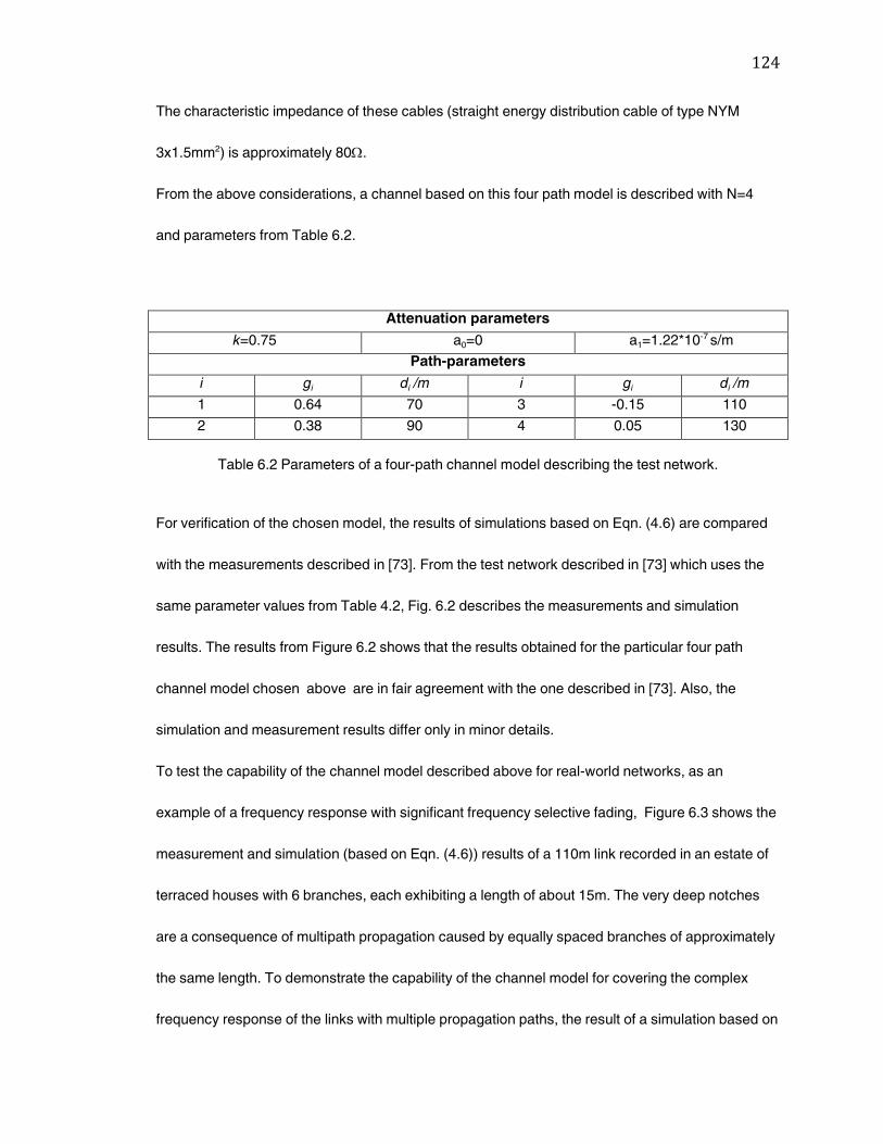
124
The characteristic impedance of these cables (straight energy distribution cable of type NYM
3x1.5mm2) is approximately 80.
From the above considerations, a channel based on this four path model is described with N=4
and parameters from Table 6.2.
Attenuation parameters
k=0.75 a0=0 a1=1.22*10-7 s/m
Path-parameters
i gi di /m i gi di /m
1 0.64 70 3 -0.15 110
2 0.38 90 4 0.05 130
Table 6.2 Parameters of a four-path channel model describing the test network.
For verification of the chosen model, the results of simulations based on Eqn. (4.6) are compared
with the measurements described in [73]. From the test network described in [73] which uses the
same parameter values from Table 4.2, Fig. 6.2 describes the measurements and simulation
results. The results from Figure 6.2 shows that the results obtained for the particular four path
channel model chosen above are in fair agreement with the one described in [73]. Also, the
simulation and measurement results differ only in minor details.
To test the capability of the channel model described above for real-world networks, as an
example of a frequency response with significant frequency selective fading, Figure 6.3 shows the
measurement and simulation (based on Eqn. (4.6)) results of a 110m link recorded in an estate of
terraced houses with 6 branches, each exhibiting a length of about 15m. The very deep notches
are a consequence of multipath propagation caused by equally spaced branches of approximately
the same length. To demonstrate the capability of the channel model for covering the complex
frequency response of the links with multiple propagation paths, the result of a simulation based on
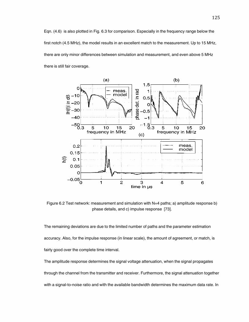
125
Eqn. (4.6) is also plotted in Fig. 6.3 for comparison. Especially in the frequency range below the
first notch (4.5 MHz), the model results in an excellent match to the measurement. Up to 15 MHz,
there are only minor differences between simulation and measurement, and even above 5 MHz
there is still fair coverage.
Figure 6.2 Test network: measurement and simulation with N=4 paths; a) amplitude response b)
phase details, and c) impulse response [73].
The remaining deviations are due to the limited number of paths and the parameter estimation
accuracy. Also, for the impulse response (in linear scale), the amount of agreement, or match, is
fairly good over the complete time interval.
The amplitude response determines the signal voltage attenuation, when the signal propagates
through the channel from the transmitter and receiver. Furthermore, the signal attenuation together
with a signal-to-noise ratio and with the available bandwidth determines the maximum data rate. In
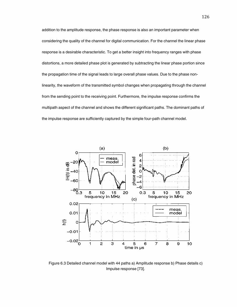
126
addition to the amplitude response, the phase response is also an important parameter when
considering the quality of the channel for digital communication. For the channel the linear phase
response is a desirable characteristic. To get a better insight into frequency ranges with phase
distortions, a more detailed phase plot is generated by subtracting the linear phase portion since
the propagation time of the signal leads to large overall phase values. Due to the phase non-
linearity, the waveform of the transmitted symbol changes when propagating through the channel
from the sending point to the receiving point. Furthermore, the impulse response confirms the
multipath aspect of the channel and shows the different significant paths. The dominant paths of
the impulse response are sufficiently captured by the simple four-path channel model.
Figure 6.3 Detailed channel model with 44 paths a) Amplitude response b) Phase details c)
Impulse response [73].

127
The example clearly points out that the essential effects of signal propagation over powerlines can
be adequately described by a channel model based on Eqn. (4.6). However, for precise results,
sometimes numerous paths (44 in the presented case) with individual weighing factors gi and
lengths di may be needed. Fortunately, on the other hand, a single set of attenuation parameters,
namely k=1, a0=0 and a1=2.5x10⁻⁹ s/m, is normally sufficient. Nevertheless, it must be admitted that
a channel model including a total number of 44 paths and 91 parameters is not easy to handle, and
also the estimation of the parameters is quite difficult.
For PLC system performance analysis, it is desirable to have simplified channel models with only a
small number of paths to represent, not all the details, but the essential dominant effects. A
simplified model of the 110m link described earlier is plotted in Fig. 6.4. The channel model has
been reduced to N=15, covering the main paths for the impulse response. Due to the reduced
number of paths, the frequency response of the model and measurement exhibit some differences
above 4MHz, especially at the locations of deep notches. However, the impulse response is still
quite accurately represented by the model. The parameters of the 15-path model are listed in
Table 6.3. This example clearly demonstrates the accuracy of the channel model applied to a real-
world scenario strongly depends on the number of paths N and on the exact parameter settings.
However, with regard to practical applications, such as simulation-based PLC-system performance
evaluation, it is more important that the channel model represents the essential effects only, i.e.,
using well-defined reference channels. As such reference channels cover the general impairments
of powerline links and do not focus on unimportant details, they may represent useful and effective
tools in practice.
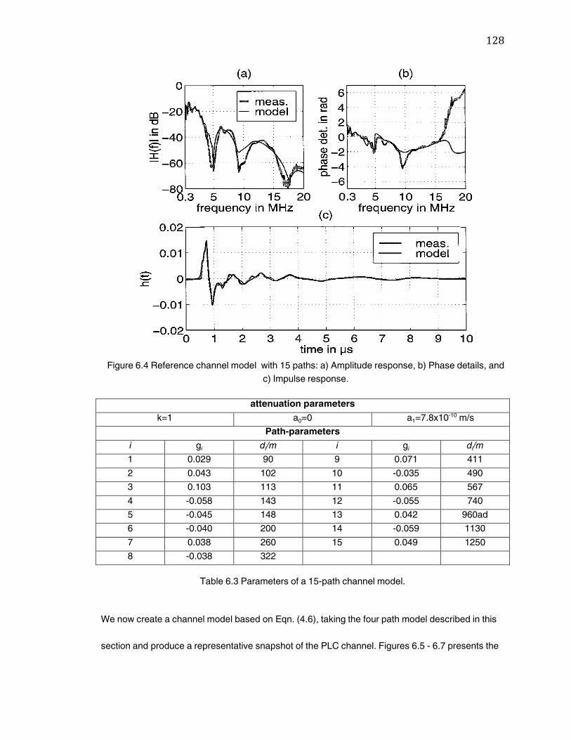
128
Figure 6.4 Reference channel model with 15 paths: a) Amplitude response, b) Phase details, and
c) Impulse response.
attenuation parameters
k=1 a0=0 a1=7.8x10⁻¹⁰ m/s
Path-parameters
i gi di/m i gi di/m
1 0.029 90 9 0.071 411
2 0.043 102 10 -0.035 490
3 0.103 113 11 0.065 567
4 -0.058 143 12 -0.055 740
5 -0.045 148 13 0.042 960ad
6 -0.040 200 14 -0.059 1130
7 0.038 260 15 0.049 1250
8 -0.038 322
Table 6.3 Parameters of a 15-path channel model.
We now create a channel model based on Eqn. (4.6), taking the four path model described in this
section and produce a representative snapshot of the PLC channel. Figures 6.5 - 6.7 presents the
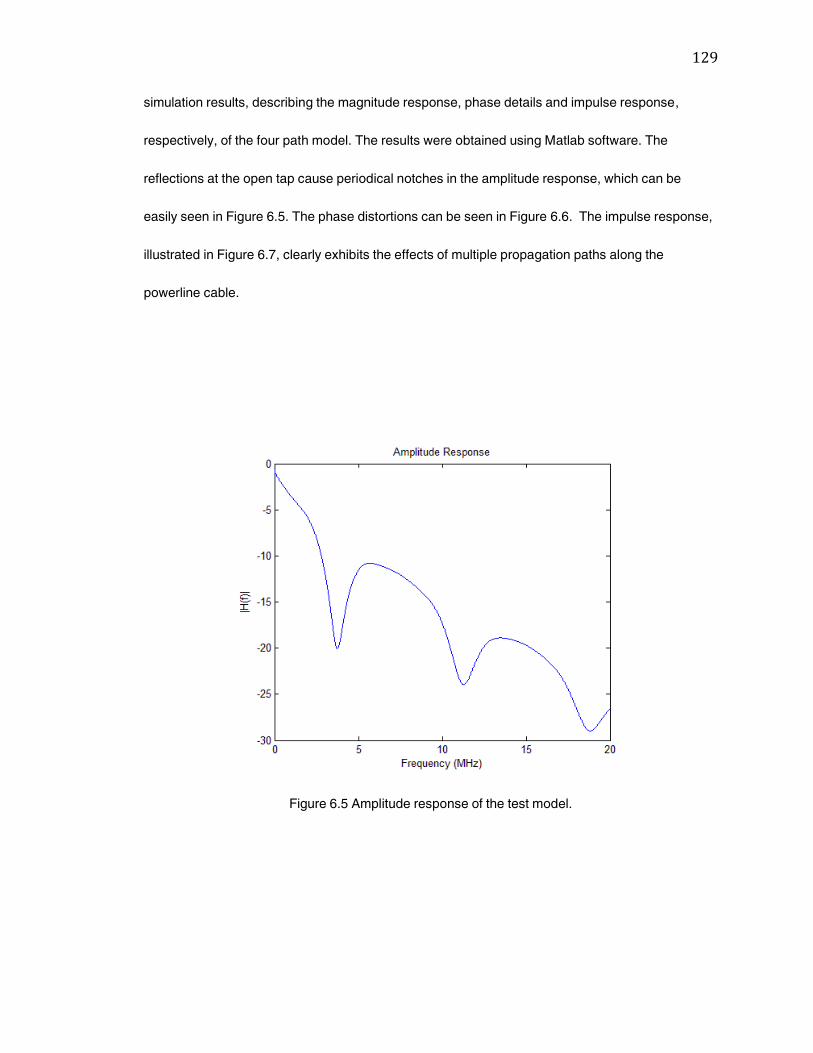
129
simulation results, describing the magnitude response, phase details and impulse response,
respectively, of the four path model. The results were obtained using Matlab software. The
reflections at the open tap cause periodical notches in the amplitude response, which can be
easily seen in Figure 6.5. The phase distortions can be seen in Figure 6.6. The impulse response,
illustrated in Figure 6.7, clearly exhibits the effects of multiple propagation paths along the
powerline cable.
Figure 6.5 Amplitude response of the test model.
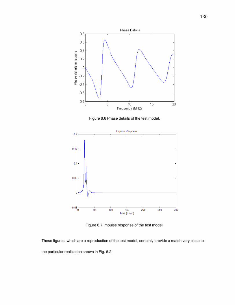
130
Figure 6.6 Phase details of the test model.
Figure 6.7 Impulse response of the test model.
These figures, which are a reproduction of the test model, certainly provide a match very close to
the particular realization shown in Fig. 6.2.
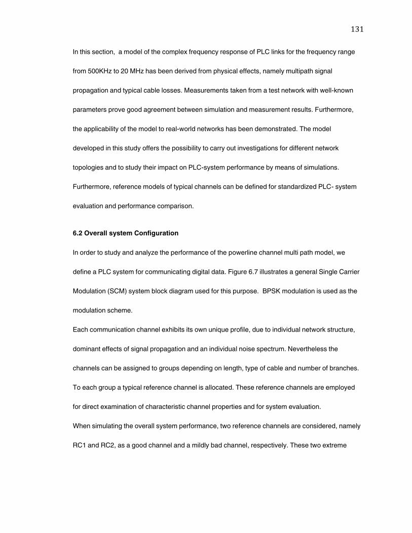
131
In this section, a model of the complex frequency response of PLC links for the frequency range
from 500KHz to 20 MHz has been derived from physical effects, namely multipath signal
propagation and typical cable losses. Measurements taken from a test network with well-known
parameters prove good agreement between simulation and measurement results. Furthermore,
the applicability of the model to real-world networks has been demonstrated. The model
developed in this study offers the possibility to carry out investigations for different network
topologies and to study their impact on PLC-system performance by means of simulations.
Furthermore, reference models of typical channels can be defined for standardized PLC- system
evaluation and performance comparison.
6.2 Overall system Configuration
In order to study and analyze the performance of the powerline channel multi path model, we
define a PLC system for communicating digital data. Figure 6.7 illustrates a general Single Carrier
Modulation (SCM) system block diagram used for this purpose. BPSK modulation is used as the
modulation scheme.
Each communication channel exhibits its own unique profile, due to individual network structure,
dominant effects of signal propagation and an individual noise spectrum. Nevertheless the
channels can be assigned to groups depending on length, type of cable and number of branches.
To each group a typical reference channel is allocated. These reference channels are employed
for direct examination of characteristic channel properties and for system evaluation.
When simulating the overall system performance, two reference channels are considered, namely
RC1 and RC2, as a good channel and a mildly bad channel, respectively. These two extreme
132
Figure 6.8 SCM System block diagram.
channels are considered in order to assess the overall system performance variation under
different channel behaviors. Figures 6.9 and 6.10 show the frequency response and phase
response of RC1 and RC2 used in our system simulation model. These channels show similar
behavior to the reference channels mentioned in Chapter 4.
Channel RC1 is a representative of a good powerline channel. It is based on a link at a length of
approximately 100m without branches. This type of links inherits only few reflection points. In
residential areas with equidistant row houses and house connecting cables of similar lengths, the
frequency response may exhibit deep notches. Channel RC2 is a link of that type at a length of
approximately 110m with 6 branches. With increasing length this regular network structure may
result in very steep frequency responses with deep fading.
Modulator
Channel
Demodulator
SOURCE
DATA
SINK
DATA
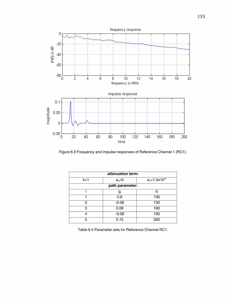
133
Figure 6.9 Frequency and impulse responses of Reference Channel 1 (RC1).
attenuation term:
k=1 a0=0 a1=1.5x10⁻⁹
path parameter:
i gi di
1 0.6 100
2 -0.08 130
3 0.08 160
4 -0.08 190
5 0.15 300
Table 6.4 Parameter sets for Reference Channel RC1.
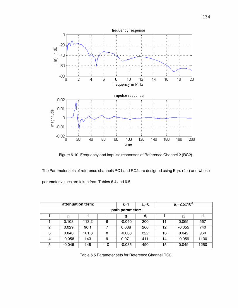
134
Figure 6.10 Frequency and impulse responses of Reference Channel 2 (RC2).
The Parameter sets of reference channels RC1 and RC2 are designed using Eqn. (4.4) and whose
parameter values are taken from Tables 6.4 and 6.5.
attenuation term: k=1 a0=0 a1=2.5x10⁻⁹
path parameter:
i gi di i gi di i gi di
1 0.103 113.2 6 -0.040 200 11 0.065 567
2 0.029 90.1 7 0.038 260 12 -0.055 740
3 0.043 101.8 8 -0.038 322 13 0.042 960
4 -0.058 143 9 0.071 411 14 -0.059 1130
5 -0.045 148 10 -0.035 490 15 0.049 1250
Table 6.5 Parameter sets for Reference Channel RC2.
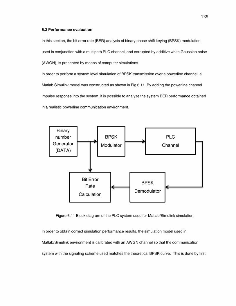
135
6.3 Performance evaluation
In this section, the bit error rate (BER) analysis of binary phase shift keying (BPSK) modulation
used in conjunction with a multipath PLC channel, and corrupted by additive white Gaussian noise
(AWGN), is presented by means of computer simulations.
In order to perform a system level simulation of BPSK transmission over a powerline channel, a
Matlab Simulink model was constructed as shown in Fig 6.11. By adding the powerline channel
impulse response into the system, it is possible to analyze the system BER performance obtained
in a realistic powerline communication environment.
Figure 6.11 Block diagram of the PLC system used for Matlab/Simulink simulation.
In order to obtain correct simulation performance results, the simulation model used in
Matlab/Simulink environment is calibrated with an AWGN channel so that the communication
system with the signaling scheme used matches the theoretical BPSK curve. This is done by first
Binary
number
Generator
(DATA)
PLC
Channel
BPSK
Modulator
BPSK
Demodulator
Bit Error
Rate
Calculation
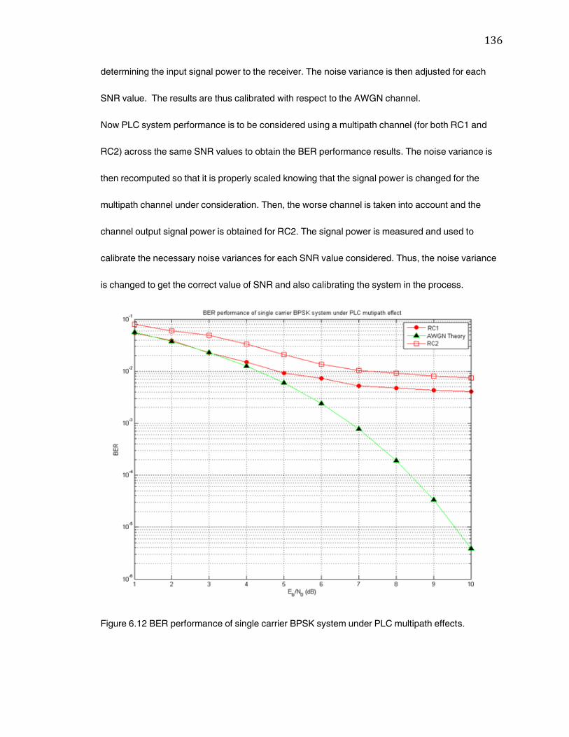
136
determining the input signal power to the receiver. The noise variance is then adjusted for each
SNR value. The results are thus calibrated with respect to the AWGN channel.
Now PLC system performance is to be considered using a multipath channel (for both RC1 and
RC2) across the same SNR values to obtain the BER performance results. The noise variance is
then recomputed so that it is properly scaled knowing that the signal power is changed for the
multipath channel under consideration. Then, the worse channel is taken into account and the
channel output signal power is obtained for RC2. The signal power is measured and used to
calibrate the necessary noise variances for each SNR value considered. Thus, the noise variance
is changed to get the correct value of SNR and also calibrating the system in the process.
Figure 6.12 BER performance of single carrier BPSK system under PLC multipath effects.
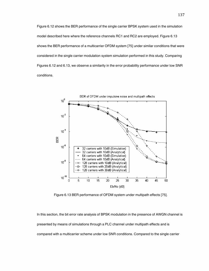
137
Figure 6.12 shows the BER performance of the single carrier BPSK system used in the simulation
model described here where the reference channels RC1 and RC2 are employed. Figure 6.13
shows the BER performance of a multicarrier OFDM system [75] under similar conditions that were
considered in the single carrier modulation system simulation performed in this study. Comparing
Figures 6.12 and 6.13, we observe a similarity in the error probability performance under low SNR
conditions.
Figure 6.13 BER performance of OFDM system under multipath effects [75].
In this section, the bit error rate analysis of BPSK modulation in the presence of AWGN channel is
presented by means of simulations through a PLC channel under multipath effects and is
compared with a multicarrier scheme under low SNR conditions. Compared to the single carrier
138
BPSK scheme used in this work for PLC system performance evaluation, we observe that even the
best system currently used in practice, namely OFDM, exhibits BER performance that plateaus
when transmitting over a PLC channel. This BER error floor of the BER performance is caused by
the PLC channel multipath effect.
6.4 Conclusion
In this chapter, by using an example of BPSK modulation, we have demonstrated that the
performance is markedly compromised by the multipath effect present on the PLC channel. Even
for large SNR, the performance quality is limited. In addition, there is a great variability in channel
structures due to the network topology formed by the power grid. So the error probability
performance is extremely variable across a power grid.

139
7. Summary and Conclusions
There has been a growing interest in the possibility of exploiting the power grid to provide
broadband internet access to residential customers. The attractive feature of this idea is the
presence of a vast infrastructure in the place for power distribution, and the penetration of the
service could be much higher than any other wired alternative. Access to the internet is becoming
as indispensible as access to electrical power. Since devices that access the internet are normally
plugged into an electric outlet, the unification of these two networks seems a compelling option.
Other broadband alternatives such as digital subscriber line and cable modems have only 10
percent of U.S. households, even though 60 percent of households are connected to the internet.
There is a tremendous opportunity for powerline communications to bridge this gap. There is also
growing interest in the prospects of reusing in-building powerline cables to provide a broadband
LAN within the home or office. The major advantage offered by powerline based home networks is
the availability of an existing infrastructure of wires and wall outlets, so new cable installation can
be avoided.
Despite the enormous potential, there is some skepticism about the technology and its
commercial viability. This is due to several technical problems and regulatory issues that
still remained to be solved:
The powerline channel is a very harsh and noisy transmission medium, and also it
is difficult to model accurately.
140
The powerline channel poses unique challenges to the communication system
designer with respect to issues such as choice of appropriate modulation, coding,
and detection schemes.
Regulatory issues naturally arise due to the unshielded nature of powerline
cables, which are both the source, and target, of electromagnetic interference.
Other issues include the presence of transformers, feeder segmentation, and
electrical safety.
Although the many technical and regulatory issues cause some skepticism, there is today
renewed interest in powerline communications. In Europe and United states, power utility
companies are partnering with vendors to conduct field trials. Moreover, in the United
States an industry consortium, HomePlug, has agreed on a specification for indoor
powerline-based home networking. These specifications are also selected as a baseline
technology for the IEEE’s 1901 Broadband Powerline Standard since it is the most widely
deployed technology.
The powerline possesses unique challenges in modem design, channel modeling,
medium access, and many other aspects of communications architecture. Many of these
challenges have only been partially addressed and solved to date. In fact, this thesis has
attempted to focus on providing a general powerline communications systems overview,
as well as a detailed channel model analysis along with assessing its affect on system

141
performance. But a solid communications and information theoretic approach is still
lacking. This thesis will hopefully inspire additional theoretical work that will lay the
foundation for a new generation of communications technology that can enable effective
and reliable data transmission over the electric power grid.
142
References
[1] EN 50 065-1, ‚Signaling on low voltage electrical installations in the frequency range 3 kHz
to 148.5 kHz; Part 1: General requirements, frequency bands and electromagnetic
disturbances,‛ CENELEC, Brussels, 1991.
[2] CENELEC, European Committee for Electrotechnical Standardization,
http://www.cenelec.org/Cenelec/CENELEC+in+action/Horizontal+areas/ICT/SC205A.htm,
accessed May 2010.
[3] IEEE P1901 standard working group,
http://standards.ieee.org/board/nes/projects/1901.pdf, accessed March 2010,
[4] FCC, "Code of Federal Regulations Title 47 Telecommunication: Chapter I FCC Part 15 -
Radio Frequency Devices,'' Washington, DC. 2002.
[5] European Commission, Enterprise Directorate-General. "Standardisation Mandate
Addressed to CEN, CENELEC and ETSI Concerning Electromagnetic Compatibility." Doc.
3312001~Rev.l EN, Brusieli, Belgium. 2001.
[6] CENELEC EN50065-1, "Signaling a low voltage electrical installations in the frequency
range 3kHz to 148.5kHz." CENELEC. Brussels. Belgium. 2002.
[7] W. Kerss, "The hosting of optical fibers on electrical networks,‛ Power Engineering
Journal, vol. 9, no. 6, pp. 272-276, December 1995.
[8] G. Jee, C. Edison, R. Das Rao, Y. Cern, "Demonstration of the technical viability of PLC
systems on medium- and low-voltage lines in the United States," IEEE Communications
Magazine, vol. 41, no. 5, pp. 108- 112, May 2003.
[9] Federal Communications Commission, ‘Notice of Inquiry’ in the matter of inquiry regarding
Carrier Current Systems, including Broadband over Power Lines Systems, ET Docket No.
03-104, April 23, 2003.
[10] Federal Communications Commission, http://www.fcc.gov/, accessed October 2010.
[11] Statement of former FCC Chief Kevin J. Martin,
http://hraunfoss.fcc.gov/edocs_public/attachmatch/DOC-266773A2.pdf, accessed
November 2010.
[12] HomePlug Powerline Alliance, http://www.homeplug.org, accessed January 2010.
[13] M. K. Lee, S. Katar et al., ‚Field performance comparison of IEEE 802.11b and HomePlug
1.0,‛ Proceedings of the 27th Annual IEEE Conference on Local Computer Networks,
LCN’02, IEEE, 2002.
143
[14] HomePlug-certified Products, http://www.homeplug.com/products/, accessed June 2010.
[15] R7-Consumer Electronic Association (CEA) Standards and Protocols,
http://www.caba.org/standard/cea.html, accessed June 2010.
[16] IEEE Standards Online Power Systems Communication Standards,
http://standards.ieee.org/catalog/olis/psystcomm.html, accessed January 2010.
[17] S. Ramseier et al., ‛MV and LV powerline communications: new proposed IEC standards,‛
0-7803-5515-6/99, IEEE, 1999.
[18] ETSI – Telecom Standards, http://www.etsi.org, accessed February 2010.
[19] ‚Powerline telecommunications (PLT): coexistence of access and in-house powerline
Systems,‛ Technical Specification, ETSI TS 101 867 v1.1.1 (2000-11).
[20] ‚Powerline telecommunications (PLT): reference network architecture model PLT phase
1,‛ Technical Specification, ETSI TS 101 896 V1.1.1 (2001-02).
[21] ‚Powerline telecommunications (PLT): quality of service (QoS) requirements for in-house
systems,‛ Technical Report, ETSI TR 102 049 V1.1.1 (2002-05).
[22] ABCs of Spread Spectrum, http://www.sss-mag.com/ss.html, accessed December 2009.
[23] F. Roos, ‚Powerline communication in train control systems,‛ Masters Thesis, Dept. of
Microelectronics and Information Technology, KTH, Stockholm, Sweden 2000.
[24] G. Arlen, ‚Extending the power of broadband,‛ White Paper, Ucentric Systems LLC, 2000.
[25] D. Marples, S. Moyer, ‚In-Home Networking,‛ Guest Tutorial, IEEE Communications
Magazine, Vol. 40 No. 4, April 2002.
[26] S. Teger et al., ‚End-user perspectives on home networking,‛ IEEE Communications
Magazine, vol. 40 no. 4, April 2002.
[27] Cable Testing Standards,
http://www.cabletesting.com/CableTesting/Standards/Overview.htm, accessed March
2010.
[28] HomePNA – Home Phoneline Networking Alliance, http://www.homepna.org.
[29] HomeCNA : Standards & Protocols, http://www.caba.org/standard/homecna.html.
[30] Consumer Electronics Association, R7 Home Network Committee,
144
http://www.ce.org/standards/committees/view_committee_details.asp?DivisionID=13&Co
mmitteeID=100529487.
[31] J. De Vriendt et al., ‚Mobile network evolution: a revolution on the move,‛ IEEE
Communications Magazine, vol. 40 no. 4, April 2002.
[32] IEEE Standards ‚Get IEEE 802‛ ™: Wireless (IEEE 802.11),
http://standards.ieee.org/getieee802/802.11.html, accessed December 2009.
[33] HomeRF Resource Center, http://www.palowireless.com/homerf, accessed February
2010.
[34] The Official Bluetooth Wireless Info Site, http://www.bluetooth.com, accessed February
2010.
[35] Bluetooth Wireless Technology,
http://www.ericsson.com/technology/tech_articles/Bluetooth.shtml, accessed February
2010.
[36] HiperLAN2 Global Forum, http://www.hiperlan2.com/, accessed March 2010.
[37] UWB Ultra Wideband Resource Center, http://www.palowireless.com/uwb, accessed
March 2010.
[38] M. Gotz, M. Rapp and K. Dostert, ‚Power line channel characteristics and their effect on
communication system design,‛ IEEE Communications Magazine, vol. 42, no. 4, pp. 78-86
July 2004.
[39] P. Langfeld, ‚The capacity of typical power line channels and strategies for system
design,” Proc. 5th Int’l. Symp. Power-Line Commun., Malmö, Sweden, pp. 271–78, April 4-
6, 2001.
[40] PLCforum, http://www.plcforum.org, accessed June 2010.
[41] M. Gebhardt, F. Weinmann and K. Dostert, ‚Physical and regulatory constraints for
communication over the power supply grid,” IEEE Communications Magazine, vol. 41, no.
5, pp. 144-158, May 2003.
[42] R. W. Chang, "Synthesis of band-limited orthogonal signals for multichannel data
transmission," Bell Syst. Tech. J., vol. 45, pp. 1775 - 1796, 1966.
[43] S. Weinstein and P. Ebert, ‚Data transmission by frequency-division multiplexing using
the discrete fourier transform,‛ IEEE Transactions on Communications Technology, vol.
19, no. 5, pp. 628-634, October 1971.
145
[44] A. Peled, A. Ruiz, ‚Frequency domain data transmission using reduced computational
complexity algorithms,‛ Acoustics, Speech, and Signal Processing, IEEE International
Conference on ICASSP '80 , vol. 5, no. 6, pp. 964- 967, April 1980.
[45] F. Nouvel, G. E. Zein and J. Citerne, ‚Code division multiple access for an automotive area
network over power-lines,‛ 1994 IEEE 44th Vehicular Technology Conference, pp. 525-
529, vol.1, June 8-10, 1994.
[46] F. Nouvel and P. Tanguy, ‚What is about future high speed power line communication
systems for in-vehicles networks?,‛ ICICS 2009. 7th International Conference on
Information, Communications and Signal Processing, vol. 3, no. 8, pp. 1-6, December 8-
10, 2009.
[47] H. Beikirch and M. Voss, ‚Can-transceiver for field bus powerline communications,‛ 2000
IEEE International Symposium on Power Line Communications and Its Applications, pp.
257–264, December 2000.
[48] Echelon Corporation, http://www.echelon.com/, accessed September 2009.
[49] ‚LonWorks technology overview,‛ Technical Document, Echelon Corporation,
http://www.echelon.com/, accessed November 2010.
[50] A. Dhir et al., ‚Home networking using no new wires phoneline and powerline
Interconnection technologies,‛ White Paper, WP133 v1.0, Xilinx Inc., March 2001.
[51] ‚LonTalk protocol,‛ Echelon Engineering Bulletin 005-0017-01, 27 pages, Echelon
Corporation, www.echelon.com, accessed August 2010.
[52] ‚LonWorks network services (LNS) architecture strategic overview,‛ Echelon Corporation,
www.echelon.com, accessed August 2010.
[53] ‚LonMark Layer 1-6 Interoperability Guidelines,‛ 078-0014-01, Echelon Corporation,
www.echelon.com, accessed August 2010.
[54] LonMark Interoperability Association, http://www.lonmark.org/, accessed July 2010.
[55] P. House, ‚CEBus for the masses,‛ Technical Article #0593, Intellon Corporation,
www.circuitcellar.com/library/print/hcs-pdf/57-house.pdf, accessed June 2010.
[56] G. Evans, ‚The CEBus communication standard,‛ Part 1 & 2,
http://www.ecaus.org/eia/site/index.html, accessed December 2010.
[57] Frameset for CEBus Users Group, http://www.cebus.org, accessed January 2010.
146
[58] D. Radford, ‚New spread spectrum technologies enable low cost control applications for
residential and commercial use,‛ 1997, Intellon Corporation, www.intellon.com, accessed
May 2010.
[59] ‚Phase coupling for power line communications,‛ Application Note #0050, Intellon
Corporation, www.intellon.com, accessed May 2010.
[60] D. Radford, ‚Spread-spectrum data leap through ac power wiring,‛ Intellon Corporation,
www.intellon.com, accessed May 2010.
[61] M. H. Shwedi, A. Z. Khan, ‚A power line data communication interface using spread
spectrum technology in home automation,‛ IEEE Transactions on Power Delivery, vol. 11,
July 1996.
[62] J. Tyson, ‚How power-line networking works,‛ http://www.howstuffworks.com, accessed
August 2010.
[63] M. J. Riezenman, ‚Networks for homes,‛ IEEE Spectrum, vol. 36, pp. 36, December 1999.
[64] D. Rye, ‚The X-10 Powerhouse power line interface model # PL513 and two-way
power line interface model # TW523,‛ technical note, Revision 2.4, X-10 (USA) Inc.,
www.x10.com, accessed February 2010.
[65] A. Arora, R. Jagannathan and Y. K. Wang, ‚Model-based fault detection in powerline
networking,‛ Proceedings of the IEEE International Parallel and Distributed Processing
Symposium (IPDPS’02), pp. 123, 2002.
[66] X-10 Technology, http://www.x10.com/technology.htm, accessed February 2010.
[67] Intellon: PowerPacket FAQs, http://www.intellon.com/support/powerpackfaqs.html,
accessed April 2010.
[68] PowerPacket™ Primer, Rev 2.0, http://www.intellon.com, Intellon Corporation, accessed
April 2010.
[69] S. Gardner, B. Markwalter et al., "HomePlug standard brings networking to the home,"
http://www.commsdesign.com/main/2000/12/0012feat5.htm, accessed July 2010.
[70] Cogency Semiconductor Inc., http://www.cogency.com, accessed March 2010.
[71] ‚Data communications over power lines,‛ White Paper, Cogency Semiconductor Inc.,
http://www.cogency.com, accessed March 2010.
[72] M. Propp et al., ‚The powerline as the high-speed backbone of a home network,‛
147
Technical Document, Adaptive Networks Inc.,
www.adaptivenetworks.com/WhitePaperForConnections.pdf, accessed August 2010.
[73] M. Zimmermann and K. Dostert, ‚A multipath model for the powerline channel,‛ IEEE
Transactions on Communications, vol. 50, no. 4, pp. 553-559, April 2002.
[74] Powerline System Overview, http://www.abb.de/plc, ABB New Ventures GmbH, accessed
July 2010.
[75] Y. H. Ma, P. L. So and E. Gunawan, "Performance analysis of OFDM systems for
broadband power line communications under impulsive noise and multipath effects,‛ IEEE
Transactions Power Delivery, vol. 20, no. 2, pp. 674- 682, April 2005.
[76] ‚Federal energy regulatory commission assessment of demand response and advanced
metering,‛ http://www.ferc.gov/legal/staff-reports/12-08-demand-response.pdf, accessed
October 2010.
[77] ‚Broadband over power line,‛ http://www.interfacebus.com/BPL-Broadband-over-Power-
Line.html, accessed January 2011.
[78] International Electrotechnical Commission, www.iec.ch, accessed March 2010.
[79] European Committee for Electrotechnical Standardization, www.cnelec.eu, accessed
March 2010.
[80] H. Philipps, ‚Modeling of powerline communication channels,‛ Int. Symp. Powerline
Communications and Its Applications, Lancaster, U.K., pp. 14-21, 1999.
[81] H. Hrasnica, A. Haidine and R. Lehnert, ‚Broadband powerline communication networks,‛
John Wiley, 2004.
[82] M. S. Omer and R. Ngah, ‚Secured indoor powerline communication using CDMA
technique,‛ APACE 2007. Asia-Pacific Conference on Applied Electromagnetics, vol. 1,
pp. 1-5, December 2007.