Embed Size (px)
Citation preview

�
�
Suggested Tools:
• Combination Wrenches: 10,12,(2)14, & (2)17mm
• Ratcheting Box End Wrench:14mm• Sockets: 10mm• Ratchet: 3/8dr• Measuring Tape
CAUTION: Safety glasses should be worn at all times when working with vehicles and related tools and equipment.
Suzuki Samurai Replacement Clutch Cable (SKU# STM-CC)
Installation Instructions
For additional copies of these and other instructions go to: www.lowrangeoffroad and click on the “Instructions” tab.
Instructions Created by an:
�
�
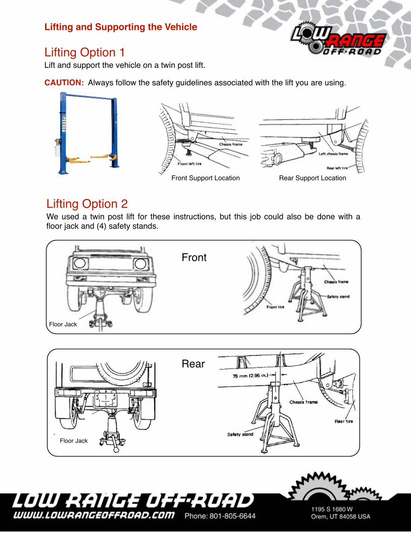
Lifting and Supporting the Vehicle
Lifting Option 2We used a twin post lift for these instructions, but this job could also be done with a floor jack and (4) safety stands.
Front
Rear
Floor Jack
Floor Jack
Lifting Option 1Lift and support the vehicle on a twin post lift.
CAUTION: Always follow the safety guidelines associated with the lift you are using.
Front Support Location Rear Support Location

�
�
Clutch PedalCable AdjusterNut
Cable Pivot
Cable Washer #2
Cable Spring
Cable Washer #1
Cable Restraint
CableGrommet Bolts (2)
Clutch Cable
CableClevis
Pedal Lever
Lever Pinch Bolt
CableBracket
Cable Mounting Nuts (2)
Clevis Pin
Clutch Cable Parts Identification
CableGrommet
Figure A
Clutch Pedal Shaft

�
�
Step 2 While holding the clutch cable secure with a 10mm open end wrench, loosen the clutch cable adjustment nut using a 14mm ratcheting box end wrench.
Step 4 Remove the clutch cable pivot.
Step 1 So that the new cable can be installed with approximately the same adjustment as the old one, count the number of threads the clutch cable extends past the adjustment nut.
Count the number of threads showing.
Removing the Old Clutch Cable
Step 3 Remove the cable adjustment nut.

�
�
Step 5 Remove the clutch cable from the clutch lever and remove the spring and both washers.
Tech Tip 5AWhile you are working in this area, inspect the clutch release arm. (See Figure B) The arm should be secure on the clutch release shaft. Also, check to see that the arm is aligned with the shaft properly. (See Figure C). If the punch marks are NOT aligned properly, you will need to remove the arm from the shaft and reinstall it with the marks aligned. (See tech Tip 5B)
Clutch Release Arm
Clutch Release Shaft
Figure B
Figure C

�
�
Step 7 Remove the clutch cable from he bracket.
Step 6 Loosen the clutch cable mounting nuts using two 17mm open end wrenches.
Note: This bracket is below the starter on the passenger side of the engine.
Tech Tip 5BThis shows the punch marks on the release shaft and the release arm.
Punch Marks
�
�
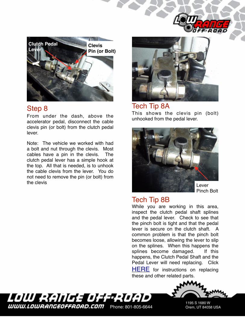
Step 8 From under the dash, above the accelerator pedal, disconnect the cable clevis pin (or bolt) from the clutch pedal lever.
Note: The vehicle we worked with had a bolt and nut through the clevis. Most cables have a pin in the clevis. The clutch pedal lever has a simple hook at the top. All that is needed, is to unhook the cable clevis from the lever. You do not need to remove the pin (or bolt) from the clevis
Clutch Pedal Lever
ClevisPin (or Bolt)
Tech Tip 8BWhile you are working in this area, inspect the clutch pedal shaft splines and the pedal lever. Check to see that the pinch bolt is tight and that the pedal lever is secure on the clutch shaft. A common problem is that the pinch bolt becomes loose, allowing the lever to slip on the splines. When this happens the splines become damaged. If this happens, the Clutch Pedal Shaft and the Pedal Lever will need replacing. Click HERE for instructions on replacing these and other related parts.
Lever Pinch Bolt
Tech Tip 8AThis shows the clevis pin (bolt) unhooked from the pedal lever.

�
�
Step 9 Remove the clutch cable grommet bolts using a 10mm socket.
Step 11 Bend open the cable restraint that is connected to the driver side radiator bracket.
Step 10 Pull the clutch cable through the bulkhead.
Step 12 Remove the clutch cable.
Note: Closely observe the routing of the old clutch cable so you can route the new cable in the same path.
�
�
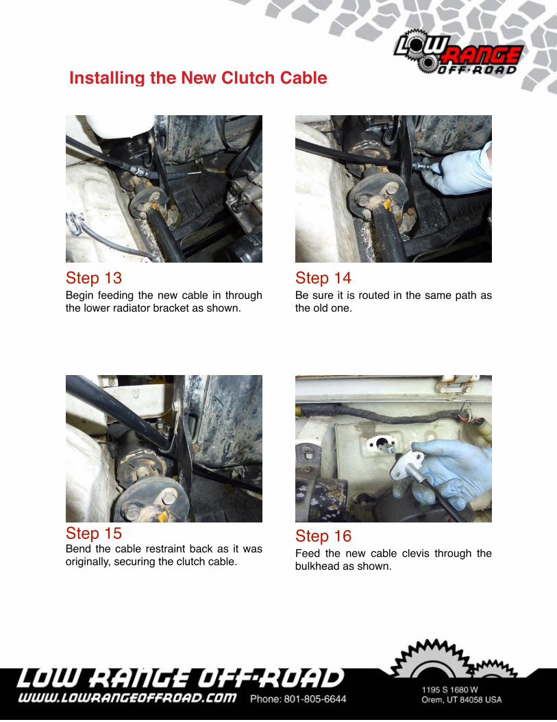
Step 13 Begin feeding the new cable in through the lower radiator bracket as shown.
Step 15 Bend the cable restraint back as it was originally, securing the clutch cable.
Step 14 Be sure it is routed in the same path as the old one.
Step 16 Feed the new cable clevis through the bulkhead as shown.
Installing the New Clutch Cable

�
�
Step 17 Hook the clevis pin over the clutch pedal lever.
Step 19 Install the (2) washers and spring on the clutch cable with the washers on opposite ends of the spring.
Step 18 Align the holes and install the grommet bolts.
Step 20 Insert the cable through the clutch release arm.

�
�
Step 21 Install the clutch pivot.
Step 23 T h r e a d t h e a d j u s t m e n t n u t t o approximately the same number of turns as it was originally in Step 1.
Note: This will be a starting point for the final clutch adjustment to be done later.
Step 22 Install the clutch adjustment nut.
Step 24 Place the cable in the cable bracket and tighten the nuts using two 14mm open end wrenches.

�
�
Step 26 Clutch Pedal Height is adjusted by loosening the lock nut and turning the adjustment bolt up or down until the clutch pedal is level with the brake pedal. Be sure to tighten the lock nut after adjustment.
Step 25 Check the clutch pedal position in relation to the brake pedal. The clutch pedal should be level with the brake pedal. If it is NOT level, advance to Step 26. If it IS level skip to Step 27.
Adjusting the New Clutch Cable
Tech Tip 26AThis shows the pedal height lock nut and adjust bolt.
Adjust Bolt Lock Nut
Tech Tip 26BIf the pedal will not adjust to the specified height, it will be necessary to removing the pedal lever from the pedal shaft and replace it in a different position on the splines.
Pedal Lever Pedal Shaft

�
�
Step 27 The clutch safety switch check is done by placing the shifter in the neutral, setting the park brake, turning the key to the start position, and slowly depressing the clutch pedal until the engine cranks. The pedal position at which the engine cranks is called the “Pedal Crank Point”. The engine should crank when the clutch pedal reaches 2 to 3 inches from the floor. If the engine cranks when the pedal is not within the specified range, loosen the lock nut using a 14mm open end wrench and rotate the clutch safety switch. To raise the “Pedal Crank Point”, turn the switch clockwise. To lower the “Pedal Crank Point”, turn the switch counterclockwise. After adjustment, tighten the lock nut. Check the “Pedal Crank Point” again. If it is within specifications you are done. If not, keep adjusting the switch until the specified Crank Point is achieved.
Clutch Safety Switch Check & Adjustment
Important Note: Clutch Pedal Free Play is very important. If clutch pedal free play is too great, you could experience a grinding or hard shifting when changing gears. If free play is too little, premature throwout bearing failure could result and in extreme cases the clutch will slip causing the clutch disc to wear out extremely fast.
Step 28 Depress the clutch pedal with your hand and stop when resistance is felt. Measure the distance the pedal traveled. This measurement is called “pedal free play”. The pedal free play should be within .8 to 1.1 inches (or 20 to 30 mm). If pedal free play is NOT within specification the clutch will require adjustment.
Clutch Pedal Free-Play Adjustment
Clutch Safety Switch
Lock Nut

�
�
Step 28 ContinuedThe clutch adjustment is performed at the clutch adjustment nut. (See Photograph below) To increase clutch pedal free play, t u r n t h e c l u t c h a d j u s t m e n t n u t COUNTERCLOCKWISE. To decrease clutch pedal free play, turn the clutch adjustment nut CLOCKWISE.
Note: After adjusting pedal free play, there should be AT LEAST .2” (or 5 mm) of cable end extending past the nut. If there is, you are done. If there is less than .2” extending past the cable joint nut, proceed to the next step.
Photograph of Clutch Cable adjustment Nut
Step 29 If there is less than .2” (5mm) of the threaded clutch cable extending past the nut you will need to adjust the cable in the cable bracket. (See figure above) Loosen the rear nut (turning the wrench upward) and tighten the front nut (turning the wrench upward) until it is tight. Then check and adjust the clutch pedal free play again as explained in Step 28. If there is still not enough (.2” minimum) clutch cable end extending out of the cable adjustment nut, repeat Step 28 until there is.
Photograph of Clutch Cable Bracket.
Front
Clutch Cable Bracket
Front NutRear Nut
1. Clutch Cable Adjustment Nut
Front

�
�
Congratulations:You have successfully installed a clutch cable. We hope these instructions have been helpful. If you have suggestions for improvement please [email protected] with your comments.

�
�
As always, If you experience any difficulty during the installation of this product please contact Low Range Off-Road Technical Support at 801-805-6644 M-F during regular store hours. Thank you for purchasing from Low Range Off-Road.
These instructions are designed as a general installation guide. Installation of many Low Range Off-Road products require specialized skills such as metal fabrication, welding and mechanical trouble shooting. If you have any questions or are unsure about how to proceed, please contact our shop at 801-805-6644 or seek help from a competent fabricator. Using fabrication tools such as welders, torches and grinders can cause serious bodily harm and death. Please operate equipment carefully and observe proper safety procedures.
Rock crawling and off-road driving are inherently dangerous activities. Some modifications will adversely affect the on-road handling characteristics of your vehicle. All products sold by Low Range Off-Road are sold for off road use only. Any other use or application is the responsibility of the purchaser and/or user. Some modifications and installation of certain aftermarket parts may under certain circumstances void your original dealer warranty. Modification of your vehicle may create dangerous conditions, which could cause roll-overs resulting in serious bodily injury or death. Buyers and users of these products hereby expressly assume all risks associated with any such modifications and use.
Revised 11/17/15© Copyright 2015 Low Range Off-Road, LC All Rights Reserved