Embed Size (px)
Citation preview

Source characterization and modeling development for monoenergetic-proton radiography experiments on OMEGAM. J.-E. Manuel, A. B. Zylstra, H. G. Rinderknecht, D. T. Casey, M. J. Rosenberg et al. Citation: Rev. Sci. Instrum. 83, 063506 (2012); doi: 10.1063/1.4730336 View online: http://dx.doi.org/10.1063/1.4730336 View Table of Contents: http://rsi.aip.org/resource/1/RSINAK/v83/i6 Published by the American Institute of Physics. Related ArticlesSpatiotemporal correlation between microdischarges in concentric ring pattern in dielectric barrier discharge atatmospheric pressure Phys. Plasmas 19, 062308 (2012) Lasing of extreme ultraviolet light with nitrogen plasma in a recombining phase—Roles of doubly excited states Phys. Plasmas 19, 063302 (2012) Parallel transport of long mean-free-path plasma along open magnetic field lines: Parallel heat flux Phys. Plasmas 19, 062501 (2012) Plasma ion source for in situ ion bombardment in a soft x-ray magnetic scattering diffractometer Rev. Sci. Instrum. 83, 053303 (2012) Generation of tunable, 100–800 MeV quasi-monoenergetic electron beams from a laser-wakefield accelerator inthe blowout regime Phys. Plasmas 19, 056703 (2012) Additional information on Rev. Sci. Instrum.Journal Homepage: http://rsi.aip.org Journal Information: http://rsi.aip.org/about/about_the_journal Top downloads: http://rsi.aip.org/features/most_downloaded Information for Authors: http://rsi.aip.org/authors

REVIEW OF SCIENTIFIC INSTRUMENTS 83, 063506 (2012)
Source characterization and modeling development formonoenergetic-proton radiography experiments on OMEGA
M. J.-E. Manuel, A. B. Zylstra, H. G. Rinderknecht, D. T. Casey, M. J. Rosenberg,N. Sinenian, C. K. Li, J. A. Frenje, F. H. Séguin, and R. D. PetrassoPlasma Science and Fusion Center, Massachusetts Institute of Technology, 77 Massachusetts Avenue,Cambridge, Massachusetts 02139, USA
(Received 23 April 2012; accepted 4 June 2012; published online 22 June 2012)
A monoenergetic proton source has been characterized and a modeling tool developed for proton ra-diography experiments at the OMEGA [T. R. Boehly et al., Opt. Comm. 133, 495 (1997)] laser facil-ity. Multiple diagnostics were fielded to measure global isotropy levels in proton fluence and imagesof the proton source itself provided information on local uniformity relevant to proton radiographyexperiments. Global fluence uniformity was assessed by multiple yield diagnostics and deviationswere calculated to be ∼16% and ∼26% of the mean for DD and D3He fusion protons, respectively.From individual fluence images, it was found that the angular frequencies of �50 rad−1 contributedless than a few percent to local nonuniformity levels. A model was constructed using the Geant4[S. Agostinelli et al., Nuc. Inst. Meth. A 506, 250 (2003)] framework to simulate proton radiographyexperiments. The simulation implements realistic source parameters and various target geometries.The model was benchmarked with the radiographs of cold-matter targets to within experimental ac-curacy. To validate the use of this code, the cold-matter approximation for the scattering of fusionprotons in plasma is discussed using a typical laser-foil experiment as an example case. It is shownthat an analytic cold-matter approximation is accurate to within �10% of the analytic plasma modelin the example scenario. © 2012 American Institute of Physics. [http://dx.doi.org/10.1063/1.4730336]
I. INTRODUCTION
Monoenergetic proton radiography has been used to inferpath-integrated electric and magnetic field strengths in manyhigh energy density physics experiments.1–5 This unique diag-nostic technique provides a method to experimentally probeplasmas for electric and magnetic fields in regimes whereother traditional methods (Langmuir probes, B-dot probes,Faraday rotation, etc.) do not work or are impractical. Imagingprotons are deflected by electromagnetic fields in the plasmathrough the Lorentz force, but do not otherwise perturb theoverall plasma evolution. In this way, path-integrated fieldstrength information becomes encoded within modulationsobserved in proton fluence images. Therefore, it is importantto understand the local fluence uniformity characteristics ofthe backlighter source to be able to accurately deduce quanti-tative information about the plasma subject.
Fusion protons are generated through irradiation ofan “exploding-pusher” shock-driven capsule. This uniquebacklighting source emits monoenergetic protons quasi-isotropically, providing the ability to perform multiple exper-iments on a single shot. Capsules are filled with D3He gas toproduce the following fusion reactions:
D + 3He ⇒ α(3.6 MeV) + p(14.7 MeV), (1)
D + D ⇒ T(1.01 MeV) + p(3.02 MeV). (2)
Furthermore, because the backlighter source is monoenergetic(�E/E∼3%) in nature, there is a one-to-one mapping of de-flection angle to path-integrated field strength. Radiographsare recorded on CR-39 nuclear track detectors6–9 where
absolute location and track characteristics are stored for in-cident charged particles. Typically, two pieces of CR-39 arefielded, each one filtered to register either DD or D3He pro-tons whereby individual images of absolute proton fluence areeasily generated for each species.
This technique is in strong contrast to a complemen-tary method of generating ∼MeV protons for radiography us-ing a short-pulse, high-intensity laser, and the Target NormalSheath Acceleration (TNSA) mechanism.10–12 Both methodsprovide high energy protons useful for probing high energydensity plasmas. The TNSA method provides higher spa-tial and temporal resolution than the exploding-pusher cap-sule. Images are typically recorded on a filtered stack ofradiochromic film, where each film has a dominant proton en-ergy window to which it is sensitive.12 However, there can bea degeneracy in energy between the source continuum andenergy loss in dense plasmas, depending on the configurationand field structure under observation, due to the exponentialproton distribution.13 Contrarily, the exploding-pusher back-lighter generates an isotropic monoenergetic proton source.In conjunction with a filter-matched detector array that countsindividual proton tracks, the complete diagnostic system pro-vides a unique approach to accurately measuring electric andmagnetic fields that were otherwise unmeasurable.
While protons are sensitive to field structures in theplasma, they also interact with ions and electrons throughCoulomb collisions. Energy loss and scattering due toCoulomb interactions are inherently statistical processes andmay be accounted for using a Monte Carlo14 approach. Asimulation has been constructed using the Geant4 (Refs. 15and 16) framework to accurately model these effects on the
0034-6748/2012/83(6)/063506/9/$30.00 © 2012 American Institute of Physics83, 063506-1

063506-2 Manuel et al. Rev. Sci. Instrum. 83, 063506 (2012)
spatial and spectral resolution of proton radiographs. Be-cause Geant4 is open-source code, proton trajectories maybe tracked through arbitrarily defined three-dimensional elec-tromagnetic field geometries and mass distributions. Togetherwith a thorough understanding of the backlighter source, thismodeling tool provides the capabilities to simulate many pro-ton radiography experiments and generate synthetic radio-graphs for direct comparison with experimental data.
This paper is organized as follows. Section II providesan overview of the OMEGA laser system and its capabilities.The experimental methodology used to determine backlighterisotropy is discussed in Sec. III along with a brief overviewof experiments performed to benchmark proton radiographysimulations. Section IV describes the monoenergetic protonsource and its characteristics with a detailed discussion onproton fluence isotropy. Modeling of the proton radiographicsystem using the Geant4 toolkit is presented in Sec. V alongwith a validation of the cold matter approximation and bench-mark experiments. This paper concludes with a summary ofthe results from this work in Sec. VI.
II. OMEGA LASER SYSTEM
The OMEGA laser17 system provides a unique abilityto study fusion with fusion. It is composed of 60 individualbeams that are frequency tripled upon entrance to the vacuumchamber to a wavelength of λ∼0.351 μm. Each laser beamhas a nominal maximum energy of 500 J (for a total of 30 kJin all beams), which can be pointed to any location within1 cm of target chamber center. Beams enter the spherical tar-get chamber in a truncated icosahedron (“soccer ball”) patternand may be split into three different “legs” of 20 beams each.Two separate drivers can be used to allow two different pulseshapes with independent timings to drive individual targets.An Aitoff projection of the target chamber layout is shown inFigure 1 for the orientation of beam legs and diagnostic ports.A typical beam configuration is illustrated where Legs 1 and3 may be used to drive a target using different types of pulseshapes at various intensities and Leg 2 is used to drive the
fusion-proton backlighter. Independent laser drives and therange of pointing capabilities on OMEGA provide the uniqueability to create a plasma with one set of beams and drive amonoenergetic proton backlighter to radiograph the plasmawith another.
III. EXPERIMENTAL METHODS
Experiments were performed to examine proton back-lighter isotropy by fielding multiple proton yield diagnos-tics. The OMEGA port map shown in Figure 1 indicatesbacklighter isotropy diagnostics (green). Four diagnosticsmeasured D3He-proton yield and three measured DD-protonyield, providing data on the global isotropy of both protonspecies. Diagnostic ports TIM2 and TIM3 were configured toradiograph the backlighter source itself to study local unifor-mity on a scale specifically relevant to proton radiography.
Validation experiments were also performed to bench-mark Geant4 simulations of scattering in cold matter. In theseexperiments, non-irradiated subjects were radiographed sothat the mass distributions were well known. The first bench-mark discussed in Sec. V B is a CH capsule where protonssampled various areal densities throughout the shell. Both DDand D3He proton radiographs were taken and fluence imageswere compared to synthetic data. The second benchmark wasconcerned with scattering at various frequencies in differentthicknesses of CH. In these experiments, D3He proton fluenceradiographs were analyzed using a Fourier analysis techniqueto compare synthetic and experimental data.
In all diagnostics, backlighter protons were incidenton 1.5-mm thick sheets of CR-39, a plastic nuclear trackdetector.6 After proton exposure, pieces were etched in a6 N NaOH solution for 1−6 h, depending on fluence level,to reveal tracks created by charged particles. Etched CR-39 samples were scanned using an automated optical mi-croscope system whereby track locations, diameters, eccen-tricities, and contrast levels (relative to the background)are recorded and stored for later analysis. Using detailedtrack information, proton fluence images were generated, and
TIM6
TIM1 TIM4 CPS1
NTD TPS2
XPHC
XPHC XPHC
XPHC
BL Beams (Leg 2)
nTOF
TIM3
TIM5
CPS2
TIM2
Isotropy Diagnostics Target Beams (Legs 1 & 3)
KO1
FIG. 1. An Aitoff projection of the OMEGA target chamber. The 60 beams are split into three legs. In typical experiments, Legs 1 and 3 (blue) are used to drivea target and Leg 2 (red) drives the proton backlighter source. Ports used to field proton fluence diagnostics are also shown (green) and labeled. Other diagnosticports not used are labeled for reference.

063506-3 Manuel et al. Rev. Sci. Instrum. 83, 063506 (2012)
0
0.2
0.4
0.6
0.0 0.5 1.0
Las
er P
ower
[ar
b]
Pro
ton
Em
issi
on [
arb]
Time [ns]
Laser Power
Proton Emission
(b)
0.0
0.2
0.4
0.6
0.8
0 5 10 15 20
Yie
ld/M
eV [
*109 ]
Energy [MeV]
D3He
DD
(a)
FIG. 2. (a) Sample fusion proton spectra from an exploding pusher back-lighter capsule taken from OMEGA shot 51237. DD protons were measuredat 3.6 MeV with FWHM of 320 keV and D3He protons were measured at15.3 MeV with FWHM of 670 keV. (b) Sample emission profile for D3Heprotons over laid on the 1 ns square pulse used to drive the capsule onOMEGA shot 51237. Bang time was measured at 420 ps after laser onsetwith FWHM of 140 ps.
because of the known relationship between particle energyand track diameter,7, 8 an image of relative proton energy mayalso be produced.
IV. CHARACTERIZATION OF AMONOENERGETIC-PROTON SOURCE
A. Fusion-proton production
Exploding-pushers have been used to generate fusion-protons for backlighting in many experiments1, 3–5 at theOMEGA laser facility. Capsules are nominally 420 μm in di-ameter with a 2.0 μm-thick glass shell and filled with equimo-lar D3He gas (6 atm D2, 12 atm 3He) to produce fusion pro-tons. Characteristic spectra of DD and D3He protons emittedfrom backlighter capsules are shown in Figure 2(a). In typi-cal configurations, backlighter capsules are irradiated with 20OMEGA beams18 without smoothing by spectral dispersionor distributed phase plates for a total of ∼9 kJ on target ina 1 ns square pulse as shown in Figure 2(b). Fusion protonspectra are broadened (∼9% and ∼4% FWHM for DD andD3He, respectively) by thermal effects and by time-varyingE fields around the implosion capsule when nuclear produc-tion occurs during the laser pulse.6, 19 The E fields are causedby a net positive charge on the capsule during laser irradi-ation and this charging effect produces an energy upshift of∼300−600 keV in fusion protons. In exploding pushers of thespecified dimensions, nuclear production always takes placeduring the 1 ns drive.
The proton temporal diagnostic (PTD)20 was used tomeasure peak fusion production (bang time) for D3He pro-tons. Previous experiments using 17, 20, or 30 beams on thebacklighter, but still filled with 18 atm of D3He, were exam-ined. It was found that measured bang times fit a normal dis-tribution well with a mean of 486 ± 5 ps after laser onset anda standard deviation of 35 ± 4 ps. When the on-target en-ergy was increased by a factor of ∼2, no systematic change inbang time was observed. This result indicates that increasingon-target energy above ∼7700 J does not appreciably increasethe shock transit time in these exploding pusher capsules.
Timing of the proton source with respect to other laserbeams is essential for radiography experiments. Without ded-icating extra experiments to tuning timing fiducials, PTD has
an absolute uncertainty of ±50 ps, dominating the timing er-ror. However, based on many experiments, 95% of protonbacklighters will have a bang time of 486 ± 70 ps; though itshould still be measured by PTD for each shot when possible.Also, the typical burn duration for these types of capsules wasfound to have a FWHM of ∼150 ps, which sets the temporalresolution of the radiography system. The fusion burn regionhas an approximately Gaussian radial profile with a FWHM of∼45 μm (Ref. 1) that emits protons in a quasi-isotropic fash-ion. DD and D3He proton data have been obtained to quantifythe isotropy of this backlighting technique.
B. Proton emission isotropy
Multiple diagnostics were fielded as indicated in Figure 1to measure large and small scale proton fluence uniformity.The charged-particle spectrometer (CPS2) (Ref. 21 and 22)momentum analyzed charged particles passing through anaperture and energy spectra were recorded on CR-39 detec-tors. A filtered stack of 10 cm × 10 cm sheets of CR-39 wasfielded in TIM2 to image the backlighter’s DD and D3He pro-tons. TIM3 held a single 7 cm round sheet of CR-39 thatwas filtered for DD protons only. To measure proton bangtime and D3He yield, PTD was fielded in TIM5. Lastly, analuminum wedge range filter (WRF) (Ref. 6) in KO1 mea-sured the time-integrated D3He-proton energy spectrum. Ra-diographs of the backlighter in TIM2 (squares) and TIM3 (cir-cles) provided short scale-length information on single sheetsof CR-39, whereas long scale-length fluctuations were mea-sured using the port-to-port variation in the inferred yield.
These diagnostics provided four measurements of D3Heprotons and three measurements of DD protons at differentport locations. The results of multiple experiments to in-vestigate backlighter isotropy are shown in Figure 3. Mea-surements of DD and D3He yields into 4π are shown formultiple angles in Figures 3(a) and 3(b). Each yield measure-ment is represented by a different symbol and the statisticalmean is denoted by (×). Error bars in these plots are calcu-lated as the standard deviation (variance) of the yield mea-surements and are plotted against the average DD and D3Heyields in Figures 3(c) and 3(d). A slight increase in globalvariance with average yield may be inferred from these data,but this is inconclusive within the scatter. The global vari-ance for DD and D3He protons can be accurately character-ized by a simple mean and deviation as �DD ≈ 16 ± 7% and�D3He ≈ 26 ± 10%, respectively. The measured global vari-ance for D3He protons in these 20 beam exploding-pushercapsules is slightly higher than those quoted by Séguin et al.23
for 60 beam implosions of 20 μm thick CH shells. However,capsules in those experiments were thicker and larger than theexploding-pushers such that peak fusion production occurred> 500 ps after the laser pulse.
Local variation in proton fluence was assessed through“blank” radiographs, shown in Figures 3(g) and 3(h). CR-39sheets were fielded in TIM2 and TIM3 to image the back-lighter without a subject in the field of view. These imagesprovided proton fluence distributions over different solid an-gles. The 10 cm square CR-39 fielded in TIM2 was placed

063506-4 Manuel et al. Rev. Sci. Instrum. 83, 063506 (2012)
FIG. 3. Summary of backlighter proton emission isotropy data. (a) and (b) DD and D3He-proton yield measurements from different ports; error bars arecalculated standard deviations. (c) and (d) Global (long-scale) variance of yield measurements as a function of mean yield. Average variance � is shown bythe solid line and the dashed lines are ± one standard deviation. (e) and (f) Local proton variance σ measured from radiographs in TIM2 (10 cm squares) andTIM3 (7 cm circles) as a function of mean proton fluence �. (g) and (h) Average power density spectrum plotted as a function of angular frequency for twopoints in each of (e) and (f) (outlined in black) with corresponding radiographs where darker pixels indicate higher fluence. Frequencies �50 rad−1 are shownto have amplitudes of ≤3% relative to the mean proton fluence level (normalized to 1). These data indicate that most of the local variance stems from long-scaleperturbations.
27.18 cm from the backlighter covering ∼0.13 sr and 7 cmround CR-39 fielded in TIM3 were 21.88 cm away covering∼0.08 sr. Because detectors are fielded at different distances,and fluence fluctuations due to the backlighter itself are ofparticular interest, numerical statistics are removed from lo-cal fluence variation σ by:
σ =√
σ 2�−meas − σ 2
�−stat
〈�meas〉 , (3)
where σ� − meas is the measured statistical deviation of pro-tons per steradian, 〈�meas〉 is the statistical mean proton flu-ence used to normalize the variation across different exper-iments, and σ� − stat is the numeric statistical variation persteradian ∼√〈�meas〉. Figures 3(e) and 3(f) show the results ofstatistically corrected local variance measurements as a func-tion of mean fluence over multiple experiments. The variancein DD-proton fluence was observed to increase slightly withthe mean as shown in Figure 3(e) despite the two outliers.However, no trend is observed within the scatter of a sin-gle detector (in TIM2 or TIM3), this trend is only significantwhen combining the results from TIM2 and TIM3. This couldbe simply explained by a higher local variance in the TIM3direction than in the TIM2 direction; no trend is observedin D3He measurements from TIM2 within the scatter. As inthe case for global variance, the local variance of D3He pro-tons (σD3He) is measured to be slightly higher than that of theDD protons (σDD). The absolute magnitude of the standarddeviations for D3He proton fluence are smaller than thoseof DD protons, but due to lower average fluences, the rela-tive percent-variations for D3He protons are measured higher.Proton fluence fluctuations in “blank” radiographs were char-acterized using a discrete Fourier transform (DFT) technique.
Sample proton radiographs and corresponding averagemode spectra are shown in Figures 3(g) and 3(h). Lineoutsof proton fluence were taken at multiple angles and processedusing a one dimensional DFT technique with a Hann win-dowing function to reduce power leakage.24 The absolute si-nusoidal amplitude αabs corresponding to a power densityPf at a given nonzero frequency is αabs ∝ √
2Pf , where theproportionality constant is dependent on the normalizationof the power spectra. However, the important metric here isthe perturbation amplitude relative to the average (zero fre-quency) fluence α0 ∝ √
P0. The normalized amplitude is de-fined as α = √
2Pf /P0. Furthermore, because α is the am-plitude of a sinusoid, the normalized RMS amplitude at agiven nonzero frequency is simply αRMS = √
Pf /P0. Be-cause spherical symmetry is assumed, DFTs over all anglesare averaged to obtain an overall sense of mode structure inproton fluence.
Spatial frequencies in the detector plane were convertedto angular frequencies (fθ = 1/θ ) for the comparison of modestructure measurements at different distances from the back-lighter; results are shown in Figures 3(g) and 3(h). Theseamplitude spectra are not corrected for statistics, and it isclear that more proton fluence reduces the relative amplitudeof high mode perturbations, as expected. The sample spec-tra shown clearly indicate that low mode perturbations domi-nate the local variance observed in Figures 3(e) and 3(f). RMSamplitudes calculated for angular frequencies �50 rad−1 areless than a few percent relative to the average proton flu-ence. These data indicate that when taking lineouts throughproton fluence radiographs, local nonuniformities due to thebacklighter are quite small for angles less than ∼0.02 ra-dians (∼1.1◦). Local and global variance of fusion protonsdiscussed here is larger than other similar measurements,23

063506-5 Manuel et al. Rev. Sci. Instrum. 83, 063506 (2012)
but much of this variation may be attributed to lower illumi-nation uniformity and bang time occurring during the laserpulse. Long scale-length variation �50% across a singleCR-39 sample may be expected and must be considered whenquantitatively analyzing proton fluence over large solid anglesand when comparing to synthetic data.
V. MODELING USING GEANT4
To model proton radiography experiments, a Monte Carlocode was written using the Geant4 toolkit.15, 16 The geometryand tracking code is an open source library of functions writ-ten in C++. The experimental system was constructed withinthe Geant4 framework (version 4.9.4.p01) through proper ge-ometry, material, and physics package25 implementation. Tothis end, a simulation has been developed employing a spa-tially finite Gaussian proton source for DD and D3He protonsof finite spectral width to create synthetic proton radiographsof various subject types.
Accurate modeling is necessary for quantitative interpre-tation of proton fluence modulations in some radiography ex-periments. Tracking of protons through electromagnetic fieldsis performed in Geant4 using a Cash-Karp algorithm (stepsize set to ≤1 nm). Because Geant4 is open source, the usermay define an electromagnetic field of arbitrary complexityand choose from a number of different solvers for the equa-tions of motion. Currently, the simulation implements simplefields due to spherical shells of charge, cylindrical shells ofcharge or current, or sinusoidal E or B fields of varying spa-tial dimension. Modeling of the Lorentz force is relativelystraight forward; its effect does not change whether parti-cles are traversing a plasma of spatially varying parameters,or standard cold matter. However, the interaction of protonswith matter is a collisional process and dependent on the lo-cal properties of the material at any given point.
A. The cold matter approximation
Coulomb collision physics models currently imple-mented in Geant4 do not account for plasma environments,and assume “cold matter” (CM) conditions in solids or gases.The user may define a material of arbitrary atomic compo-sition and density, but separate ion and electron distributionsmay not be defined. Nonetheless, Coulomb collisions involv-ing high energy ions (�MeV) are standard binary Rutherfordinteractions26 between two charged particles and the caveatsof the state of matter may be addressed after a basic review ofthe two body problem.
In the center-of-mass (CoM) reference frame, the angulardifferential cross section for this Rutherford scattering pro-cess is given by26
dσ
d= b2
90
4
1
sin4(θ/2), (4)
where θ is the exit angle of the particles after the collision inthe CoM. The so-called 90◦ impact parameter27 b90 is depen-
TABLE I. Integration limits for the mean square scattering angle 〈θ2〉 cal-culation under cold-matter and plasma conditions.
θmin θmax
Cold matter max (Zt Zf e2
02πε0mμv2
rela, ¯
mμvrel a) ¯
mμvrelR
Plasma max (Zt Zf e2
02πε0mμv2
relλD
, ¯mμvrelλD
) ¯mμvrelR
dent upon the interacting particle properties by
b90 = Z1Z2e20
4πε0
1
mμv2rel
, (5)
where Z1 and Z2 are the charges of the interacting particles,mμ is the reduced mass of the system, and vrel is the relativespeed between the particles. Coulomb collisions are clearlydominated by small angle scattering due to the ∼1/θ4 propor-tionality in Eq. (4) and diverges as θ → 0. To contend withthis singularity, physical limits are put on the exit angle (θmin
to θmax) when integrating, such that the total cross section isexpressed as σC ≈ πb2
90/θ2min. The upper bound θmax has been
neglected here because the cross section is proportional to∼1/θ2. The expression for θmin represents the largest impactparameter (smallest deflection angle) relevant to the situationand is set as the maximum of the classical or quantum limitsas described by Jackson26 (see Table I).
In the case where a test particle is incident onto manyfield particles, as in proton radiography, many successivesmall angle collisions will occur. Scattering of test protons iscaused by momentum exchange with the field particles, there-fore similar mass particles (field ions not electrons) will dom-inate this process. The test proton travels a distance L throughthe field particles and the probability distribution of exit an-gles approximates a Gaussian with a mean square scatteringangle of26
〈θ2〉 � 2πb290nL ln �, (6)
where � ≡ θmax/θmin is the argument of the Coulomb loga-rithm. The result in Eq. (6) was formulated for two interactingcharged particles irrespective of the material. However, a sim-ple change of the integration limits is sufficient to estimate thevariation of mean scattering angle between plasma and CM.28
Table I provides θ integration limits for both CM andplasma conditions. The maximum scattering angle θmax is setby the quantum limit for the smallest impact parameter R,the nuclear radius, and is approximated26 as R ≈ 1.4A
1/3f fm,
where Af is the mass number of the field particle. The max-imum scattering angle limit does not change when lookingat interactions in a plasma. However, the minimum scatteringangle limit θmin represents the maximum impact parameter inthe classical or quantum limit and the shielding scale lengthwill change from CM to a plasma. In CM, this shielding dis-tance is set to the atomic radius a and can be approximated26
as a ≈ 1.4a0Z−1/3f , where a0 is the classical Bohr radius. In a
plasma, electric shielding is set by the local Debye length
λD =√
ε0kBTe
e20ne
, (7)

063506-6 Manuel et al. Rev. Sci. Instrum. 83, 063506 (2012)
1.E-04
1.E-02
1.E+00
1.E+02
1.E+04
0 50 100 150 Distance [µm]
[g/cm3]
T [keV]
(b)
ne [1020 cm-3]
Typical Laser-plasma Parameters
Proton Trajectory
< Z >
104
102
100
10-2
10-4 1.E-02
1.E-01
1.E+00
1.E+01
1.E-03 1.E-02 1.E-01 1.E+00 1.E+01
T [
keV
]
[g/cc]
(c)
1.3
1.2
1.1
1.0
< 2>plasma/ < 2>CM
101
100
10-1
101 100 10-1 10-2 10-3 10-2 1.E-02
1.E-01
1.E+00
1.E+01
1.E-03 1.E-02 1.E-01 1.E+00 1.E+01
T [
keV
]
[g/cc]
(dE/dx)plasma/(dE/dx)CM
(d)
1.0
1.2
1.4
0.8
1.6
101
100
10-1
101 100 10-1 10-2 10-3 10-2
DD
(a)
CH Foil
Laser Drive
D3He
FIG. 4. (a) Schematic of sample laser interaction with a CH foil of initial density 1.04 g/cc. (b) Plasma parameters predicted by DRACO for the sampleinteraction in (a). The solid (green) line in each plot represents a path through this sample plasma. Contour plots of quantities relevant to Coulomb collisionsfor 3 MeV (dotted) and 15 MeV (dashed) protons in the temperature-density parameter space of a CH (1:1.38) plasma. (d) The ratio of mean square scatteringangle
√〈θ2〉 in a plasma to that in cold matter. The difference between 3 and 15 MeV protons is negligible, because the ratio is dependent only on ln �. (d) The
ratio of stopping power dEdx
in a plasma to that in cold matter.
where kB is Boltzmann’s constant, Te is the local electron tem-perature, and ne the local electron number density. When cal-culating the ratio of plasma scattering to CM scattering fora specified plasma, the only remaining term is the Coulomblogarithm.
A trajectory through a sample laser-foil interaction isshown in Figures 4(a) and 4(b). As a test case, theseplasma conditions are used to contrast the CM approximationfor stopping power and scattering. The plasma parameterswere calculated using the DRACO radiation-hydrodynamiccode29, 30 to simulate a 0.351 μm laser of intensity∼4 × 10¹⁴ W/cm2 incident onto a 21 μm CH foil. It is impor-tant to note that most energy loss and scattering takes placein the high-density, low-temperature domain when lookingalong this path due to the much higher mean free path in thisregime.
Contours of the plasma-to-CM scattering ratio are shownin Figure 4(c) for 3 and 15 MeV protons in T-ρ space. It isshown that at low temperatures and high densities, there islittle difference between scattering in plasma and scattering inCM. To estimate the accuracy of the CM approximation, thesample trajectory shown in Figure 4(c) was path-integratedfor both plasma and CM scattering cases through T-ρ space,
θ ≈√∫
d〈θ2〉 . (8)
This calculation indicated that the effective CM scatteringwould be ∼5% lower than that of plasma for both 3 and15 MeV protons along this trajectory. Because the ratio ofscattering angles results in a ratio of Coulomb logarithms, thedifference between 3 and 15 MeV protons is negligible as il-lustrated by the overlaid dotted and dashed curves, but this isnot the case when looking at stopping power.
The amount of energy-loss caused by Coulomb collisionscan depend on the state of the material. The standard modelfor energy loss of ions traversing cold matter is the Bethe-Bloch formulation31–33 where the dominant loss mechanismis due to collisions with electrons in the material. For pro-tons with �MeV energies, Geant4 uses a Bethe-Bloch model.However, ions traversing a plasma may also lose energy tothe excitation of plasma waves, and at high enough temper-atures and densities stopping by plasma ions (not electrons)
may dominate.34 This contribution has been analytically for-mulated by Li and Petrasso34 for plasmas with a Coulomblogarithm ln � � 2. The Bethe-Bloch model for ions in CMwas compared with the Li-Petrasso stopping power inplasmas.
Contours of the plasma-to-CM stopping power ratio areshown in Figure 4(d) for 3 and 15 MeV protons in T-ρ space.At low temperature and low density, plasma stopping powerstrongly deviates from the CM value for these high energyprotons. As temperature increases for a constant density, atemperature threshold is reached when the electron speed inthe plasma is approximately the test proton speed, and theplasma stopping becomes weaker than that in cold matter ofthe same density. This threshold is clearly reached at a lowertemperature for 3 MeV protons than 15 MeV protons, as ex-pected. Plasma stopping is also weaker than CM at low tem-peratures and high densities because ln � decreases with in-creasing density. Again, to estimate the accuracy of the CMapproximation, the sample trajectory is path-integrated on thesurface in T-ρ space,
�E ≈∫ (
dE
dx
)dx. (9)
It was found that 15 MeV protons would have ∼9% higherstopping power in the plasma, whereas 3 MeV protons wouldhave a lower stopping power by ∼8%. In these calculations,the absolute energy loss was assumed negligible and is suffi-cient for estimation purposes here.
The cold matter approximation has been shown to be ac-curate to �5% for proton scattering and to �10% for energyloss in the typical proton radiography experiments of laser-foil interactions. However, every experiment is different, andin some cases the CM approximation is insufficient and amore complicated plasma model will need to be used. Further-more, the plasma stopping power model implemented here as-sumes a fully ionized plasma and represents an upper boundon the error of the CM approximation. Nevertheless, for ex-periments discussed here and in many laser-foil experiments,the CM approximation is adequate and within the uncertaintyof the presented analytical models. For these reasons the col-lision, physics currently implemented in Geant4 can be usedto model trajectories in proton radiography experiments.
063506-7 Manuel et al. Rev. Sci. Instrum. 83, 063506 (2012)
0.0
0.2
0.4
0.6
200 400 600 800
Pro
ton
Flu
ence
[
#/µm
2 ]
Sim
Data
Fluence
(b)
0.0
0.1
0.2
0.3
200 400 600 800
Pro
ton
Flu
ence
[
#/µm
2 ]
Radius [µm]
Sim
Data
Fluence
(c)
DD and D3He Protons CR-39 (a) CH
Capsule
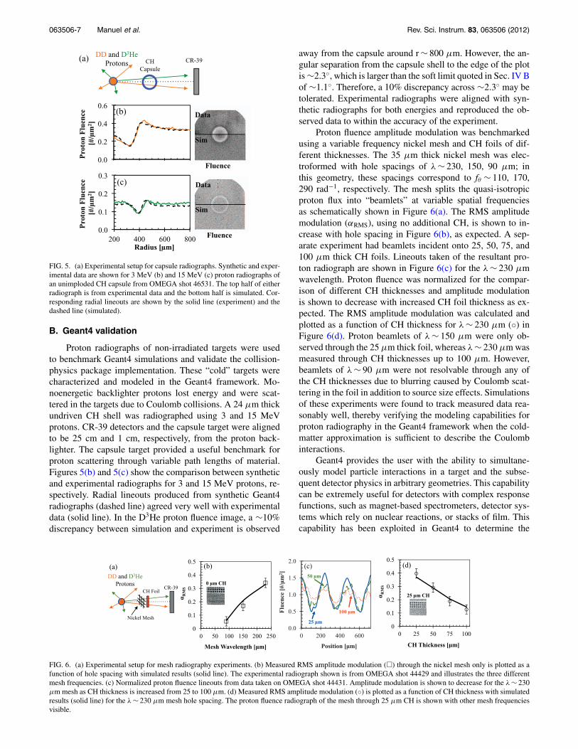
FIG. 5. (a) Experimental setup for capsule radiographs. Synthetic and exper-imental data are shown for 3 MeV (b) and 15 MeV (c) proton radiographs ofan unimploded CH capsule from OMEGA shot 46531. The top half of eitherradiograph is from experimental data and the bottom half is simulated. Cor-responding radial lineouts are shown by the solid line (experiment) and thedashed line (simulated).
B. Geant4 validation
Proton radiographs of non-irradiated targets were usedto benchmark Geant4 simulations and validate the collision-physics package implementation. These “cold” targets werecharacterized and modeled in the Geant4 framework. Mo-noenergetic backlighter protons lost energy and were scat-tered in the targets due to Coulomb collisions. A 24 μm thickundriven CH shell was radiographed using 3 and 15 MeVprotons. CR-39 detectors and the capsule target were alignedto be 25 cm and 1 cm, respectively, from the proton back-lighter. The capsule target provided a useful benchmark forproton scattering through variable path lengths of material.Figures 5(b) and 5(c) show the comparison between syntheticand experimental radiographs for 3 and 15 MeV protons, re-spectively. Radial lineouts produced from synthetic Geant4radiographs (dashed line) agreed very well with experimentaldata (solid line). In the D3He proton fluence image, a ∼10%discrepancy between simulation and experiment is observed
away from the capsule around r ∼ 800 μm. However, the an-gular separation from the capsule shell to the edge of the plotis ∼2.3◦, which is larger than the soft limit quoted in Sec. IV Bof ∼1.1◦. Therefore, a 10% discrepancy across ∼2.3◦ may betolerated. Experimental radiographs were aligned with syn-thetic radiographs for both energies and reproduced the ob-served data to within the accuracy of the experiment.
Proton fluence amplitude modulation was benchmarkedusing a variable frequency nickel mesh and CH foils of dif-ferent thicknesses. The 35 μm thick nickel mesh was elec-troformed with hole spacings of λ ∼ 230, 150, 90 μm; inthis geometry, these spacings correspond to fθ ∼ 110, 170,290 rad−1, respectively. The mesh splits the quasi-isotropicproton flux into “beamlets” at variable spatial frequenciesas schematically shown in Figure 6(a). The RMS amplitudemodulation (αRMS), using no additional CH, is shown to in-crease with hole spacing in Figure 6(b), as expected. A sep-arate experiment had beamlets incident onto 25, 50, 75, and100 μm thick CH foils. Lineouts taken of the resultant pro-ton radiograph are shown in Figure 6(c) for the λ ∼ 230 μmwavelength. Proton fluence was normalized for the compar-ison of different CH thicknesses and amplitude modulationis shown to decrease with increased CH foil thickness as ex-pected. The RMS amplitude modulation was calculated andplotted as a function of CH thickness for λ ∼ 230 μm (◦) inFigure 6(d). Proton beamlets of λ ∼ 150 μm were only ob-served through the 25 μm thick foil, whereas λ ∼ 230 μm wasmeasured through CH thicknesses up to 100 μm. However,beamlets of λ ∼ 90 μm were not resolvable through any ofthe CH thicknesses due to blurring caused by Coulomb scat-tering in the foil in addition to source size effects. Simulationsof these experiments were found to track measured data rea-sonably well, thereby verifying the modeling capabilities forproton radiography in the Geant4 framework when the cold-matter approximation is sufficient to describe the Coulombinteractions.
Geant4 provides the user with the ability to simultane-ously model particle interactions in a target and the subse-quent detector physics in arbitrary geometries. This capabilitycan be extremely useful for detectors with complex responsefunctions, such as magnet-based spectrometers, detector sys-tems which rely on nuclear reactions, or stacks of film. Thiscapability has been exploited in Geant4 to determine the
FIG. 6. (a) Experimental setup for mesh radiography experiments. (b) Measured RMS amplitude modulation (�) through the nickel mesh only is plotted as afunction of hole spacing with simulated results (solid line). The experimental radiograph shown is from OMEGA shot 44429 and illustrates the three differentmesh frequencies. (c) Normalized proton fluence lineouts from data taken on OMEGA shot 44431. Amplitude modulation is shown to decrease for the λ ∼ 230μm mesh as CH thickness is increased from 25 to 100 μm. (d) Measured RMS amplitude modulation (◦) is plotted as a function of CH thickness with simulatedresults (solid line) for the λ ∼ 230 μm mesh hole spacing. The proton fluence radiograph of the mesh through 25 μm CH is shown with other mesh frequenciesvisible.

063506-8 Manuel et al. Rev. Sci. Instrum. 83, 063506 (2012)
TABLE II. Comparison of proton source parameters for exploding-pusher-and TNSA- generated MeV protons. Quantities given for the TNSA protonsource are nominal and in many cases, as in pulse duration, peak energy, andsource size, the values are dependent on the laser and target parameters. Ad-ditionally, CR-39 could be used as a detecting medium for TNSA-generatedprotons, though due to high fluences, saturation can be a problem.
Exploding-pusher TNSA
Source size [μm] ∼45 ∼10Duration (FWHM) [ps] ∼150 ∼1−10Peak energy [MeV] ∼15 ∼60Energy spectrum Monoenergetic ExponentialDrive requirements Multi-beam High-intensity
(implosion) (�1019 W/cm2)Detecting medium CR-39 RC FilmDetection process proton counting dosimetric
(track detection) (optical depth)
response function35 for magnet-based diagnostics, specifi-cally the magnetic-recoil-spectrometer.36, 37 Furthermore, thecomplex detector response of an exponential proton spectrumincident onto a filtered stack of radiochromic film, as in short-pulse proton radiography, may be self-consistently modeledin the Geant4 framework to deduce quantitative informationfrom the images. In the work described here, monoenergetic3 and 15 MeV protons were modeled through a target andthen the detector stack for a comprehensive simulation of theexperiment, from source to detector.
VI. SUMMARY
Monoenergetic proton radiography has been used inmany experiments to measure path-integrated electromag-netic fields in high energy density plasmas where other meth-ods prove ineffective. Proton emittance isotropy of theseexploding-pusher backlighter capsules has been character-ized on a global and local scale. Multiple yield diagnosticswere fielded to quantify the global deviation of both pro-ton species and were measured to be �DD ≈ 16 ± 7% and�D3He ≈ 26 ± 10%. Local variation was measured on singlesheets of CR-39 using “blank” radiographs of the backlightersource. It was shown that local fluence variation was domi-nated by low angular frequency modes fθ � 50 rad−1 and thatvariations of a few percent should be expected on smaller spa-tial scales.
The exploding-pusher proton source discussed here hasbeen recently used in many experiments and is in strong con-trast to the TNSA-generated proton source used previously.A summary of characteristics for the two proton sources isgiven in Table II using typical parameters from OMEGA-EP (Ref. 38), though other facilities will have slightly dif-ferent source characteristics. TNSA-generated protons typi-cally have a smaller source size, shorter pulse duration, andhigher peak energy than the exploding-pusher-generated pro-tons. However, TNSA protons are produced in an exponentialspectrum, where energy-loss in the target can create a degen-eracy not present when using the monoenergetic source. Theexploding-pusher source generates protons isotropically andcan be utilized in multiple experiments in a single shot. Con-trarily, the TNSA source protons are forwardly directed, but
can provide radiographs of the target at multiple times in asingle shot due to the difference in proton time-of-flight.
Typical media for detecting protons also differ betweenthe exploding-pusher and TNSA proton sources. The abilityto count individual tracks and directly measure relative pro-ton fluence using CR-39 removes the necessary deconvolutionwhen using RC film. Using a mesh in an experiment, may re-move the necessity of knowing the relative fluence to make aquantitative measurement at a cost of further energy degener-acy (in the case of TNSA) and at a cost to spatial resolution.These two complimentary diagnostic tools differ substan-tially in source characteristics and both come with a uniqueset of challenges. However, regardless of the proton source,Coulomb collisions in the target will cause energy-loss andscattering and these effects have been modeled and bench-marked for the monoenergetic, exploding-pusher source.
A new simulation tool has been developed to model mo-noenergetic proton radiography experiments using the Geant4open-source framework. Realistic spectral source profiles, ex-act detector geometries, arbitrary electromagnetic field maps,and generic target mass distributions have been implemented.The physics packages currently used address Coulomb inter-actions in the cold-matter approximation and do not accountfor plasma effects. Due to the minimal amount of energy-loss and scattering experienced by MeV protons under plasmaconditions discussed herein, the cold-matter approximationwas shown to accurately approximate the collisional behaviorto �10%, which is within the uncertainty of the analytic for-mulations used. Geant4 modeling was benchmarked againstmultiple experimental radiographs of non-irradiated targets.This simulation tool is used to generate synthetic radiographsfor quantitative comparisons with experimental data as wellas to aid in experimental design.
ACKNOWLEDGMENTS
The authors express their gratitude to the engineeringstaff at LLE for their support. The work described herewas done as part of the first author’s Ph.D. dissertationand supported in part by NLUF (DE-NA0000877), FSC/UR(415023-G), DoE (DE-FG52-09NA29553), LLE (414090-G),and LLNL (B580243).
1C. K. Li, F. H. Séguin, J. A. Frenje, J. R. Rygg, R. D. Petrasso, R. P. J.Town, P. A. Amendt, S. P. Hatchett, O. L. Landen, A. J. Mackinnon, P. K.Patel, V. A. Smalyuk, T. C. Sangster, and J. P. Knauer, Phys. Rev. Lett.97(13), 135003 (2006).
2C. K. Li, F. H. Seguin, J. A. Frenje, J. R. Rygg, R. D. Petrasso, R. P. J.Town, P. A. Amendt, S. P. Hatchett, O. L. Landen, A. J. Mackinnon, P. K.Patel, V. A. Smalyuk, J. P. Knauer, T. C. Sangster, and C. Stoeckl, Rev. Sci.Instrum. 77, 10E725 (2006).
3J. R. Rygg, F. H. Séguin, C. K. Li, J. A. Frenje, M. J.-E. Manuel, R. D.Petrasso, R. Betti, J. A. Delettrez, O. V. Gotchev, J. P. Knauer, D. D.Meyerhofer, F. J. Marshall, C. Stoeckl, and W. Theobald, Science319(5867), 1223–1225 (2008).
4C. K. Li, F. H. Séguin, J. A. Frenje, M. Rosenberg, R. D. Petrasso, P. A.Amendt, J. A. Koch, O. L. Landen, H. S. Park, H. F. Robey, R. P. J. Town,A. Casner, F. Philippe, R. Betti, J. P. Knauer, D. D. Meyerhofer, C. A. Back,J. D. Kilkenny, and A. Nikroo, Science 327(5970), 1231–1235 (2010).
5F. H. Séguin, C. K. Li, M. J.-E. Manuel, H. G. Rinderknecht, N.Sinenian, J. A. Frenje, J. R. Rygg, D. G. Hicks, R. D. Petrasso, J.Delettrez, R. Betti, F. J. Marshall, and V. A. Smalyuk, Phys. Plasmas 19,012701 (2012).

063506-9 Manuel et al. Rev. Sci. Instrum. 83, 063506 (2012)
6F. H. Séguin, J. A. Frenje, C. K. Li, D. G. Hicks, S. Kurebayashi, J. R. Rygg,B. E. Schwartz, R. D. Petrasso, S. Roberts, J. M. Soures, D. D. Meyerhofer,T. C. Sangster, J. P. Knauer, C. Sorce, V. Yu Glebov, C. Stoeckl, T. W.Phillips, R. J. Leeper, K. Fletcher, and S. Padalino, Rev. Sci. Instrum. 74(2),975–995 (2003).
7M. J. E. Manuel, M. J. Rosenberg, N. Sinenian, H. Rinderknecht, A. B.Zylstra, F. H. Seguin, J. Frenje, C. K. Li, and R. D. Petrasso, Rev. Sci.Instrum. 82(9), 095110–095110–8 (2011).
8N. Sinenian, M. Rosenberg, M. J. E. Manuel, S. C. McDuffee, F. H. Séguin,J. A. Frenje, C. K. Li, and R. D. Petrasso, Rev. Sci. Instrum. 82(10), 7(2011).
9A. B. Zylstra, H. G. Rinderknecht, N. Sinenian, M. J. Rosenberg, M.Manuel, F. H. Seguin, D. T. Casey, J. A. Frenje, C. K. Li, and R. D.Petrasso, Rev. Sci. Instrum. 82(8), 083301–7 (2011).
10S. P. Hatchett, C. G. Brown, T. E. Cowan, E. A. Henry, J. S. Johnson,M. H. Key, J. A. Koch, A. B. Langdon, B. F. Lasinski, R. W. Lee, A. J.Mackinnon, D. M. Pennington, M. D. Perry, T. W. Phillips, M. Roth, T. C.Sangster, M. S. Singh, R. A. Snavely, M. A. Stoyer, S. C. Wilks, and K.Yasuike, Phys. Plasmas 7(5), 2076–2082 (2000).
11A. J. Mackinnon, P. K. Patel, R. P. Town, M. J. Edwards, T. Phillips,S. C. Lerner, D. W. Price, D. Hicks, M. H. Key, S. Hatchett, S. C. Wilks,M. Borghesi, L. Romagnani, S. Kar, T. Toncian, G. Pretzler, O. Willi, M.Koenig, E. Martinolli, S. Lepape, A. Benuzzi-Mounaix, P. Audebert, J. C.Gauthier, J. King, R. Snavely, R. R. Freeman, and T. Boehlly, Rev. Sci.Instrum. 75(10), 3531–3536 (2004).
12A. B. Zylstra, C. K. Li, H. G. Rinderknecht, F. H. Séguin, R. D. Petrasso,C. Stoeckl, D. D. Meyerhofer, P. Nilson, T. C. Sangster, and S. Le Pape,Rev. Sci. Instrum. 83(1), 013511–013511–9 (2012).
13R. A. Snavely, M. H. Key, S. P. Hatchett, T. E. Cowan, M. Roth, T. W.Phillips, M. A. Stoyer, E. A. Henry, T. C. Sangster, and M. S. Singh, Phys.Rev. Lett. 85(14), 2945–2948 (2000).
14Nicholas Metropolis and S. Ulam, J. Am. Stat. Assoc. 44(247), 335–341(1949) (http://www.jstor.org/stable/2280232).
15S. Agostinelli, J. Allison, K. Amako, J. Apostolakis, H. Araujo, P. Arce,M. Asai, D. Axen, S. Banerjee, G. Barrand, F. Behner, L. Bellagamba, J.Boudreau, L. Broglia, A. Brunengo, H. Burkhardt, S. Chauvie, J. Chuma,R. Chytracek, G. Cooperman, G. Cosmo, P. Degtyarenko, A. Dell’Acqua,G. Depaola, D. Dietrich, R. Enami, A. Feliciello, C. Ferguson, H. Fe-sefeldt, G. Folger, F. Foppiano, A. Forti, S. Garelli, S. Giani, R. Gian-nitrapani, D. Gibin, J. J. Gómez Cadenas, I. González, G. Gracia Abril,G. Greeniaus, W. Greiner, V. Grichine, A. Grossheim, S. Guatelli, P.Gumplinger, R. Hamatsu, K. Hashimoto, H. Hasui, A. Heikkinen, A.Howard, V. Ivanchenko, A. Johnson, F. W. Jones, J. Kallenbach, N. Kanaya,M. Kawabata, Y. Kawabata, M. Kawaguti, S. Kelner, P. Kent, A. Kimura, T.Kodama, R. Kokoulin, M. Kossov, H. Kurashige, E. Lamanna, T. Lampén,V. Lara, V. Lefebure, F. Lei, M. Liendl, W. Lockman, F. Longo, S. Magni,M. Maire, E. Medernach, K. Minamimoto, P. Mora de Freitas, Y. Morita,K. Murakami, M. Nagamatu, R. Nartallo, P. Nieminen, T. Nishimura, K.Ohtsubo, M. Okamura, S. O’Neale, Y. Oohata, K. Paech, J. Perl, A. Pfeif-fer, M. G. Pia, F. Ranjard, A. Rybin, S. Sadilov, E. Di Salvo, G. Santin, T.Sasaki, N. Savvas, Y. Sawada et al., Nucl. Instrum. Methods: Phys. Res. A506(3), 250–303 (2003).
16J. Allison, K. Amako, J. Apostolakis, H. Araujo, P. Arce Dubois, M. Asai,G. Barrand, R. Capra, S. Chauvie, R. Chytracek, G. A. P. Cirrone, G.Cooperman, G. Cosmo, G. Cuttone, G. G. Daquino, M. Donszelmann, M.Dressel, G. Folger, F. Foppiano, J. Generowicz, V. Grichine, S. Guatelli,P. Gumplinger, A. Heikkinen, I. Hrivnacova, A. Howard, S. Incerti, V.Ivanchenko, T. Johnson, F. Jones, T. Koi, R. Kokoulin, M. Kossov, H.Kurashige, V. Lara, S. Larsson, F. Lei, O. Link, F. Longo, M. Maire, A.Mantero, B. Mascialino, I. Mclaren, P. Mendez Lorenzo, K. Minamimoto,K. Murakami, P. Nieminen, L. Pandola, S. Parlati, L. Peralta, J. Perl, A.Pfeiffer, M. G. Pia, A. Ribon, P. Rodrigues, G. Russo, S. Sadilov, G. Santin,T. Sasaki, D. Smith, N. Starkov, S. Tanaka, E. Tcherniaev, B. Tom, A.Trindade, P. Truscott, L. Urban, M. Verderi, A. Walkden, J. P. Wellisch,D. C. Williams, D. Wright, and H. Yoshida, IEEE Trans. Nucl. Sci. 53(1),270–278 (2006).
17T. R. Boehly, D. L. Brown, R. S. Craxton, R. L. Keck, J. P. Knauer,J. H. Kelly, T. J. Kessler, S. A. Kumpan, S. J. Loucks, S. A. Letzring, F. J.Marshall, R. L. McCrory, S. F. B. Morse, W. Seka, J. M. Soures, and C. P.Verdon, Opt. Commun. 133(1−6), 495–506 (1997).
18Depending on the particular experimental configuration, more beams maybe used to provide more laser energy on target.
19D. G. Hicks, C. K. Li, F. H. Séguin, J. D. Schnittman, A. K. Ram, J. A.Frenje, R. D. Petrasso, J. M. Soures, D. D. Meyerhofer, S. Roberts, C.Sorce, C. Stockl, T. C. Sangster, and T. W. Phillips, Phys. Plasmas 8(2),606–610 (2001).
20J. A. Frenje, C. K. Li, F. H. Séguin, J. Deciantis, S. Kurebayashi, J. R.Rygg, R. D. Petrasso, J. Delettrez, V. Yu Glebov, C. Stoeckl, F. J. Marshall,D. D. Meyerhofer, T. C. Sangster, V. A. Smalyuk, and J. M. Soures, Phys.Plasmas 11, 2798–2805 (2004).
21D. G. Hicks, C. K. Li, R. D. Petrasso, F. H. Séguin, B. E. Burke, J. P.Knauer, S. Cremer, R. L. Kremens, M. D. Cable, and T. W. Phillips, Rev.Sci. Instrum. 68, 589–592 (1997).
22D. G. Hicks, “Charged-Particle Spectroscopy: A New Window on InertialConfinement Fusion,” Ph.D. dissertation (Massachusetts Institute of Tech-nology, 1999).
23F. H. Séguin, C. K. Li, J. A. Frenje, S. Kurebayashi, R. D. Petrasso, F. J.Marshall, D. D. Meyerhofer, J. M. Soures, T. C. Sangster, C. Stoeckl, J. A.Delettrez, P. B. Radha, V. A. Smalyuk, and S. Roberts, Phys. Plasmas 9(8),3558–3566 (2002).
24William H. Press, Saul A. Teukolsky, William T. Vetterling, and Brian P.Flannery, Numerical Recipes in C++: The Art of Scientific Computing Sec-ond Edition, 2nd ed. (Cambridge University Press, 2002).
25The QGSP BERT physics package was used.26John David Jackson, Classical Electrodynamics, 3rd ed. (Wiley, New York,
1999).27Jeffrey Freidberg, Plasma Physics and Fusion Engineering (Cambridge
University Press, Cambridge, United Kingdom, 2007).28J. L. DeCiantis, F. H. Séguin, J. A. Frenje, V. Berube, M. J. Canavan, C. D.
Chen, S. Kurebayashi, C. K. Li, J. R. Rygg, B. E. Schwartz, R. D. Petrasso,J. A. Delettrez, S. P. Regan, V. A. Smalyuk, J. P. Knauer, F. J. Marshall, D.D. Meyerhofer, S. Roberts, T. C. Sangster, C. Stoeckl, K. Mikaelian, H. S.Park, and H. F. Robey, Rev. Sci. Instrum. 77(4), 043503–9 (2006).
29D. Keller, T. J. B. Collins, J. A. Delettrez, P. W. McKenty, P. B. Radha,R. P. J. Town, B. Whitney, and G. A. Moses, “DRACO—A new multidi-mensional hydrocode,” November 15–19, 1999.
30P. B. Radha, V. N. Goncharov, T. J. B. Collins, J. A. Delettrez, Y. Elbaz,V. Yu Glebov, R. L. Keck, D. E. Keller, J. P. Knauer, J. A. Marozas, F. J.Marshall, P. W. McKenty, D. D. Meyerhofer, S. P. Regan, T. C. Sangster,D. Shvarts, S. Skupsky, Y. Srebro, R. P. J. Town, and C. Stoeckl, Phys.Plasmas 12(3), 032702–18 (2005).
31H. Bethe, Ann. Phys. 397(3), 325–400 (1930).32F. Bloch, Ann. Phys. 408(3), 285–320 (1933).33W. R. Leo, Techniques for Nuclear and Particle Physics Experiments: A
How-to Approach (Springer, 1994).34Chi-Kang Li and Richard D. Petrasso, Phys. Rev. Lett. 70(20), 3059
(1993).35D. T. Casey, “Diagnosing inertial confinement fusion implosions at
OMEGA and the NIF using novel neutron spectrometry,” Ph.D. disserta-tion (Massachusetts Institute of Technology, 2011).
36J. A. Frenje, D. T. Casey, C. K. Li, J. R. Rygg, F. H. Séguin, R. D. Petrasso,V. Yu Glebov, D. D. Meyerhofer, T. C. Sangster, S. Hatchett, S. Haan, C.Cerjan, O. Landen, M. Moran, P. Song, D. C. Wilson, and R. J. Leeper,Rev. Sci. Instrum. 79(10), 10E502–6 (2008).
37D. T. Casey, J. A. Frenje, M. Gatu Johnson, M. J. E. Manuel, H. G.Rinderknecht, N. Sinenian, F. H. Séguin, C. K. Li, R. D. Petrasso, P. B.Radha, J. A. Delettrez, V. Yu Glebov, D. D. Meyerhofer, T. C. Sangster, D.P. McNabb, P. A. Amendt, R. N. Boyd, J. R. Rygg, H. W. Herrmann, Y. H.Kim, and A. D. Bacher, Phys. Rev. Lett. 108(7), 075002 (2012).
38L. J. Waxer, D. N. Maywar, J. H. Kelly, T. J. Kessler, B. E. Kruschwitz, S.J. Loucks, R. L. McCrory, D. D. Meyerhofer, S. F. B. Morse, C. Stoeckl,and J. D. Zuegel, Opt. Photonics News 16(7), 30–36 (2005).