Embed Size (px)
Citation preview

Technical Assessment of Advanced Transit Bus Propulsion Systems
for
Dallas Area Rapid Transit (DART) 4209 Main Street
Dallas, Texas 75226
August 2002
505 King Avenue
Columbus, OH 43201-2693

i
Table of Contents Executive Summary .................................................................................................................................... iii 1.0 Introduction .............................................................................................................................................1 2.0 Zero Emission Program (ZEP) ................................................................................................................3 3.0 Market Forces..........................................................................................................................................4
3.1 Emissions.............................................................................................................................................5 3.2 Regulations and Incentives ..................................................................................................................6
4.0 Advanced Propulsion Systems ................................................................................................................8 4.1 Clean Diesel Technologies ................................................................................................................10
4.1.1 Exhaust Gas Recirculation (EGR).........................................................................................11 4.1.2 Diesel Oxidation Catalysts (DOC) ........................................................................................11 4.1.3 Catalyzed Passive Regenerative Diesel Particulate Filters (DPF).........................................12 4.1.4 NOx Adsorber Catalyst .........................................................................................................15 4.1.5 Selective Catalytic Reduction (SCR).....................................................................................16 4.1.6 Summary of Performance Issues ...........................................................................................17
4.2 Natural Gas Engine Propulsion .........................................................................................................18 4.3 Hydrogen Engine Propulsion.............................................................................................................20 4.4 Electric Propulsion.............................................................................................................................20 4.5 Hybrid Electric Propulsion ................................................................................................................21
4.5.1 Diesel Power Plant ................................................................................................................23 4.5.2 Natural Gas Power Plant........................................................................................................26 4.5.3 Turbine Power Plant ..............................................................................................................27
4.6 Fuel Cell Power Plant ........................................................................................................................29 5.0 Assessment of Advanced Propulsion Systems for Transit Buses..........................................................31
5.1 Technology Assessment Ranking......................................................................................................34 5.2 Summary of Recommendations For ZEP Phase II ............................................................................35
6.0 Acronyms ..............................................................................................................................................36 7.0 References .............................................................................................................................................37
Table of Tables Table 1. DART Bus Fleet Planned by the End of 2002 ................................................................................3 Table 2. Federal Exhaust Emission Standards for Diesel Bus Engines (g/bhp-hr) .......................................5 Table 3. Diesel Aftertreatment Technologies and Reduction Potential ......................................................17 Table 4. Emissions Certification Levels for Model Year 2002 Transit Bus Engines* (Results shown in
units of g/bhp-hr)............................................................................................................................19 Table 5. Representative Emissions and Emissions Reductions of Hybrid Buses (g/mile, CBD cycle) ......25 Table 6. Manufacturers and Suppliers of Electric Drive Propulsion and Components...............................26 Table 7. Emissions of Capstone Turbine on Diesel, LPG, and CNG..........................................................28 Table 8. Summary Assessment of Advanced Propulsion Technologies for DART....................................33
Table of Figures Figure 1. DART Model Year 1998 Diesel Bus .............................................................................................1 Figure 2. Basic DART 40-Foot Bus Specifications ......................................................................................2 Figure 3. Dallas/Fort Worth Metropolitan Area............................................................................................7 Figure 4. Ralphs Grocery Truck with DPF Installed (Left) and Johnson Matthey CRT (Right) ................13 Figure 5. DART LNG Transit Bus..............................................................................................................18 Figure 6. Electric Shuttle Bus in Chattanooga ............................................................................................21 Figure 7. NYCT Orion VI Diesel Hybrid Electric Bus ...............................................................................24

ii
Figure 8. Denver Natural Gas Hybrid Mall Bus..........................................................................................27 Figure 9. AVS LNG Turbine Hybrid Electric Bus in Tempe, Arizona.......................................................28 Figure 10. Xcellsis/Ballard Fuel Cell Bus at SunLine ................................................................................30 Figure 11. Georgetown Fuel Cell Bus.........................................................................................................30
iii
Executive Summary
This report provides the results of a technology assessment developed as part of Phase I of the Dallas Area Rapid Transit (DART) Zero Emission Program (ZEP). The scope of this report explores the advanced propulsion technologies feasible for bus ordering by DART in 2007 (replacing the model year 1998 and prior standard bus fleet) and capable of adequate performance for DART service, while meeting the emissions standards. Propulsion systems for transit buses are expected to change significantly by 2010 because of the emissions regulations to be phased in from 2007 – 2010 by the U.S. Environmental Protection Agency (EPA). These technology changes and additions are expected for the standard diesel transit bus as well as natural gas and electric propulsion system transit buses. The assessment in this report focuses on indications of performance ability (especially any gaps), maturity or timing of the technology to be fully commercialized, and providing a ranking of technologies that should be considered by DART for the next phase (demonstration of up to 15 buses) of the ZEP. The advanced technology propulsion systems considered in this report are for standard 40-foot transit buses and include the following:
• NOx Adsorber – includes ultra-low sulfur diesel (ULSD) fuel for a diesel engine using at least a NOx adsorber and a diesel particulate filter (DPF), this category may also include EGR.
• SCR – includes ULSD fuel for a diesel engine using at least a SCR system and a DPF, this category may also include EGR.
• Natural Gas – is intended to be a standard natural gas propulsion system with an emissions control to allow NOx to be below 0.5 g/bhp-hr capability; this will most likely include after-treatment technology.
• Hydrogen – includes both hydrogen internal combustion and a mixture of natural gas and hydrogen.
• All Electric – includes an electric propulsion system with some energy storage onboard. • Diesel Hybrid – includes a complete diesel hybrid electric bus system. • Natural Gas Hybrid – includes a complete natural gas hybrid electric bus system. • Turbine Hybrid – includes one 60kW Capstone turbine or 2-30kW Capstone turbines in a
hybrid electric bus and breaks out diesel or natural gas as the fuel for the demonstration phase. • Fuel Cell – includes a bus with a fuel cell stack for the power plant in an electric or hybrid
electric configuration. Categories were chosen to measure the various advanced propulsion systems based on DART’s objectives for the ZEP program. The questions presented and answered for each technology boiled down to two issues – (1) Will the chosen technology be available at DART in 2007 - 2010 in large enough numbers to replace the entire standard bus fleet?; and, (2) Is this technology going to be available in a time frame that will allow testing in the next 4 years? Based on the answers and scoring used in the assessment presented in this report, the technologies are ranked with the total score (out of 25 total) as follows:
• Diesel Hybrid – 24 • NOx Adsorber – 23 • SCR – 22 • Turbine Hybrid, Diesel – 21 • Turbine Hybrid, Natural Gas – 20 • Natural Gas – 19

iv
• Natural Gas Hybrid – 19 • Fuel Cell – 18 • Hydrogen – 12 • All Electric – 6
Based on the scoring and ranking of these propulsion technologies, the suggested top technologies for demonstration and evaluation in the ZEP Phase II are:
1. Diesel Hybrid – diesel hybrid had the top rank because of the maturity of the technology development (compared to the others on the list) and ease of integration into the DART operation.
2. NOx adsorber or SCR (not both) – NOx adsorbers or SCR is the next technology; however, it
is unknown which technology to choose when it comes to NOx adsorbers or SCR. We would suggest that DART allow the engine manufacturer to choose the technology that they would be most interested in demonstrating.
3. Turbine Hybrid (Diesel or natural gas, not both) – turbine hybrid electric, either diesel or
natural gas, but not both was selected next. In general, demonstrating the microturbine technology should suffice for what DART needs to know; however, in order to meet the 2007 emissions standards, natural gas may be required for this propulsion technology.
4. Natural Gas Propulsion - The fourth highest rank system was a tie between natural gas
propulsion (NOx emissions below 0.5 g/bhp-hr) and natural gas hybrid. Testing experience with the natural gas hybrid technology experience can be completed as part of the diesel hybrid testing, which was ranked highest here. The natural gas propulsion (NOx emissions below 0.5 g/bhp-hr) is proposed as the fourth selection for ZEP Phase II.
5. Fuel Cell – fuel cell technology is the fifth selection. Choosing fuel cells for demonstration and
evaluation is not an easy one. DART will need to expend a significant amount of capital and effort to accommodate the fuel cell buses and infrastructure for hydrogen.
Only as an alternate to fuel cell propulsion, DART may want to consider demonstrating and evaluating a hydrogen and natural gas mixture engine propulsion bus instead of the fuel cell because of cost and availability. The testing of the hydrogen and natural gas mixture engine propulsion bus would allow DART the opportunity to learn about hydrogen infrastructure even if the fuel cell propulsion were not available at a reasonable cost. We do not suggest that DART consider the all-electric propulsion system. This propulsion system does not appear to be a realistic option for 2010 delivery of large numbers of new 40-foot transit buses with 350-400 miles of range.
1
1.0 Introduction
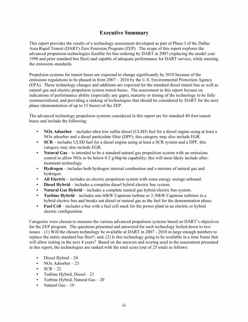
This report provides the results of a technology assessment developed as part of Phase I of the Dallas Area Rapid Transit (DART) Zero Emission Program (ZEP). This report explores the advanced propulsion technologies feasible for bus ordering by DART in 2007 for replacement of the model year 1998 standard bus fleet, one of the diesel buses is shown in Figure 1. The ultimate goal of the ZEP program is to determine the appropriate advanced propulsion systems to be ordered in 2007 for delivery starting in 2010 and provide adequate performance for DART service. The standard DART bus performance specification is the same as the American Public Transportation Association (APTA) Standard Bus Procurement Guidelines from March 25, 1999 with additions specific to the DART operation such as range (380 miles for LNG and 400 miles for diesel) and air conditioning system performance requirements. The DART performance specification is shown in Figure 2.
Figure 1. DART Model Year 1998 Diesel Bus The technology assessment provided in this report is intended to facilitate informed decisions by DART in selecting advanced propulsion system technologies for transit buses for further testing and evaluation in the next phase of the ZEP. This technology assessment investigates available and potentially available heavy-duty, standard 40-foot transit buses for testing in the 2002-2005 time frame. The focus of the assessment is on indications of performance ability (especially any gaps), and the maturity or timing of the technology to be fully commercialized. The ultimate outcome of this assessment is to provide a ranking of technologies that should be considered by DART for the next phase (demonstration of up to 15 buses) of the ZEP. This report is divided into seven sections as described below:
• Introduction – provides a description of this report. • Zero Emission Program (ZEP) – provides a description of the DART ZEP program phases,
planned activities, and approach. • Market Forces – explores the reasons that many transit fleets are investigating and deploying
advanced vehicle propulsion systems even though these technologies are more expensive to

2
Operation temperature ranges: -10° to 115°F; relative humidity between 5 and 100%; altitude
up to 1000 ft above sea level Service Life: At least 12 years or 500,000 miles Overall width: Not to exceed 102 inches maximum Total height: Shall be a maximum of 136 inches (including roof-top systems) as measured from
the ground. Curb Weight: Shall not exceed 29,500 lbs (diesel) or 32,000 lbs (LNG) Axle Weight: Shall not exceed 25,000 lbs Capacity: No less than 39 passengers Engine: Must be ULEV certified or certified to the EPA Emission Standards for MY 2004 and
Later HD Diesel Engines, minimum of 275 hp (Diesel); Optional ULEV LNG Range: Minimum 400 mile operating range (diesel); 380 (LNG), CBD cycle. Battery: 12/24 volt system Usable seated passenger capacity: Shall be maximized to forward facing seats, for 39
passengers. Road Calls: Mean-mileage-between-road calls goal shall be 20,000 miles. Fuel fill rate: Fuel fill rate to be minimum forty (40) liquid gallons per minute, or equivalent of,
the product being stored. Grade: Up to 7% Gradeability: Requirement of 40 mph on a 2.5% grade and 7 mph on a 16% grade. Vehicle Performance (under full accessory load at SLW):
65 mph on a straight and level surface, under SLW and all accessories operating.
400 mile for diesel and 380 mile for LNG or greater range (with AC operating) Average acceleration rate: from idle on level surface at GVWR 10 mph in 5.0 seconds
20 mph in 10.8 seconds 30 mph in 20.0 seconds 40 mph in 31.0 seconds
Figure 2. Basic DART 40-Foot Bus Specifications

3
purchase and operate than the current technology, and in particular, why these new technologies are of interest to DART and their operation.
• Advanced Propulsion Systems – provides descriptions of the major advanced propulsion technologies most likely available to the transit market for testing in the next few years.
• Summary Comparison of Potential Advanced Propulsion Systems – provides a summary of the general rank of options from which DART can choose for demonstration and evaluation in the next phase of ZEP.
• Acronyms – provides definitions of acronyms that are used in this report for quick reference. • References – provides the resources and references used to assemble this report.
2.0 Zero Emission Program (ZEP)
The Dallas Area Rapid Transit (DART) established their Zero Emissions Program (ZEP) to determine the zero-emission or near zero emission bus technology to be ordered in the 2007 time frame for delivery starting as early as the 2010 time frame. Table 1 shows the baseline DART bus fleet as planned for the end of calendar year 2002. The ZEP program is focused on the replacement of the buses on the first three rows of this table, which includes 667 existing buses starting in 2010 with deliveries running through 2016.
Table 1. DART Bus Fleet Planned by the End of 2002
Bus Type Fuel NumberStandard 40-Foot Bus Diesel 438Standard 40-Foot Bus Diesel, EGR 45Standard 40-Foot Bus LNG 184Suburban Coach Diesel 10830-Foot Bus Diesel 91Trolley Replica Diesel 20Total DART Buses 886
DART embarked on the ZEP to assess the impact of advanced engine and propulsion technologies in DART’s operations and introduce low emission vehicles that meet or exceed environmental improvement goals of the Dallas, Texas community. Clean emission vehicles (specifically buses) operating within DART’s service area can help maintain clean, healthy air for residents. This program will assist DART with integrating clean emission vehicles into DART’s fleet. The ZEP is currently in the first of three phases as described below:
• Phase I (10 months) Technical Review – Includes an effort to characterize the DART bus operation, assess potential advanced propulsion systems for demonstration and evaluation in Phase II, and develop a plan for the demonstration and evaluation of a few advanced propulsion systems in Phase II.
• Phase II (2002-2005) Demonstration Vehicle Operational Assessment – As the demonstration
vehicles with advanced propulsion systems are received at DART, the intent is to operate those vehicles and monitor their ability to meet DART performance specifications. Up to 15 test buses are planned and may include transit bus propulsion systems in a hybrid electric, turbine hybrid electric, fuel cell, and other appropriate technology configurations.

4
• Phase III (2005-2007) Implementation Plan – As a result of Phases I and II, one or more of the advanced propulsion systems will be selected for DART to order by 2007 to replace their entire standard bus fleet. The buses are to be delivered to DART starting in 2010.
The ZEP is in Phase I, and more detail on the scope for this phase includes providing a characterization of the requirements for transit buses operating on the 135 DART routes. These operating requirements include top speed, time required at top speed, gradeability, acceleration, range, and fuel consumption at low vehicle speed or idle as well as other measures. This operational assessment is being completed to determine the actual service requirements in the DART bus system. Specifically, some of these new advanced propulsion systems may require compromises in performance that must be fully understood in order to assess the impact on DART service. Regardless of the bus propulsion system chosen for 2010 delivery, all bus propulsion systems being considered (including standard diesel) are expected to be more sophisticated and complicated and, perhaps, less reliable than current models. The results from the operational assessment part of Phase I will be documented separate from this report. The Phase I scope also includes performing a technology assessment of available advanced technology for full-size, heavy-duty transit buses. These technologies include fuel cells, hybrid electric, turbine hybrid electric, and advanced diesel engine controls with after-treatment (including selective catalytic reduction and exhaust gas recirculation). The assessment also includes impacts these technologies may have on facility modifications and additions as well as training needs after adding advanced technology vehicles to the DART fleet. The final task of Phase I includes a data collection and evaluation plan for DART to evaluate demonstration fleets of advanced technology transit buses in Phase II.
3.0 Market Forces
Many metropolitan areas around the country are faced with meeting increasingly stringent air quality standards. To meet those standards, many metro areas are searching for ways of reducing stationary and mobile emission sources. Public transportation is often a primary target in reducing pollution because most buses operate exclusively in the central business district and are supported with public funds. Buses using cleaner emissions technology are often of great interest to transit planners. National and local public policy has promoted cleaner emission and advanced propulsion system vehicles through stricter emissions regulations and incentives to purchase these new vehicles and the supporting infrastructure. Over the past 15 years, there has been a major push to support alternative fuels and specifically natural gas powered vehicles. Natural gas vehicles are the alternative fuel technology of choice in the transit bus market. However, the higher fuel costs of natural gas vehicles and large investments in fueling and facility infrastructure to support natural gas vehicles has made many fleets resistant to incorporating natural gas vehicles into their operation. Also, the latest emissions certification levels for the 2007 - 2010 model years are expected to be so low for oxides of nitrogen (NOx) that even natural gas vehicles will need more development work to meet the regulations. Engine and vehicle manufacturers have become interested in advanced technology vehicles such as hybrids and diesel engine after-treatment, in order to continue using diesel fuel and the existing fuel infrastructure. Federal exhaust emission standards are becoming increasingly stringent and manufacturers must produce vehicles that are cleaner. For heavy-duty vehicles to meet 2007 through 2010 emissions standards, significant modifications to the standard diesel engine are required and advanced technology vehicles such as hybrids and fuel cells are being researched and demonstrated to facilitate the development of a cleaner heavy-duty propulsion system and vehicle. The sulfur content of diesel fuel is

5
also required to become much lower in 2006 to support cleaner diesel emissions technology – ultra-low sulfur diesel (ULSD) at less than 15 parts per million (ppm) sulfur content. Advanced technology vehicles will continue to get attention in the years to come. Both industry and the government continue to research and demonstrate advanced vehicle technology and diesel engine exhaust after-treatment technologies. The key to vehicle development will be fuel cells and hybrid electric vehicle technologies for both light and heavy-duty vehicles. Exhaust after-treatment technologies such as EGR, diesel particulate filters, and diesel oxidation catalysts are used in heavy-duty vehicles but will continue to be researched to improve the technologies. To meet 2004 standards, EGR combined with engine modifications will most likely be used. To meet 2007 standards, vehicle exhaust after-treatment technologies such as selective catalytic reduction (SCR) and NOx adsorbers will be researched and developed. However, NOx adsorber and SCR may need to be combined with other after-treatment technologies such as diesel particulate filters and diesel oxidation catalysts to meet these standards. All of these technologies are discussed later in this report. 3.1 Emissions Heavy-duty engine emissions are regulated by the U.S. Environmental Protection Agency (EPA). Heavy-duty exhaust emissions are engine certified and are measured in grams per brake horsepower hour (g/bhp-hr). This differs from chassis certified exhaust emissions (such as those used for light-duty vehicles), which are measured in grams per mile (g/mi). Table 2 shows the current as well as future heavy-duty bus exhaust emission standards.
Table 2. Federal Exhaust Emission Standards for Diesel Bus Engines (g/bhp-hr)
Years HC (NMHC) CO NOx NOx + NMHC PM Current-2003 1.3 (1.2*) 15.5 4.0 N/A 0.05 2004-2006 (0.5) 15.5 [2.0] 2.4 [2.5] 0.05 2007-2010 (0.14) 15.5 0.20 N/A 0.01 ( ) Non-methane hydrocarbon emission standard; [ ] Optional requirements; NOx standard was obtained by subtracting maximum NMHC emissions allowed from the composite NOx + NMHC emissions standard. * Only for heavy-duty engines using natural gas.
As shown in Table 2, tougher exhaust emission standards will go into effect in 2004 and 2007. For 2004, emission standards, particulate matter (PM) and carbon monoxide (CO) emissions will stay the same. Instead of having separate oxides of nitrogen (NOx) and total hydrocarbon (HC) standards (like those currently in effect), there will be a composite NOx plus non-methane hydrocarbon (NMHC) standard. Two options will be available. The first option is to certify the engine to a composite NOx plus NMHC standard of 2.4 g/bhp-hr. The second is to certify the engine to a composite NOx plus NMHC standard of 2.5 g/bhp-hr with the constraint that NMHC emissions may not exceed 0.5 g/bhp-hr. That corresponds to a NOx standard of 2.0 g/bhp-hr, resulting in a 50% reduction compared to current NOx emission standards. In order to use more active catalysts and more sophisticated after-treatment devices, the EPA has required the reduction of sulfur content of diesel fuel in the U.S. The production and use of ultra-low sulfur diesel (ULSD) fuel will be required by mid-2006 for the country. ULSD is diesel fuel with the sulfur content lowered to below 15 parts per million (ppm). Many parts of the country already have ULSD available commercially, especially in the larger metropolitan areas that are not in compliance with air quality standards, such as in the Los Angeles, California and the Northeast area of the country. ULSD is being

6
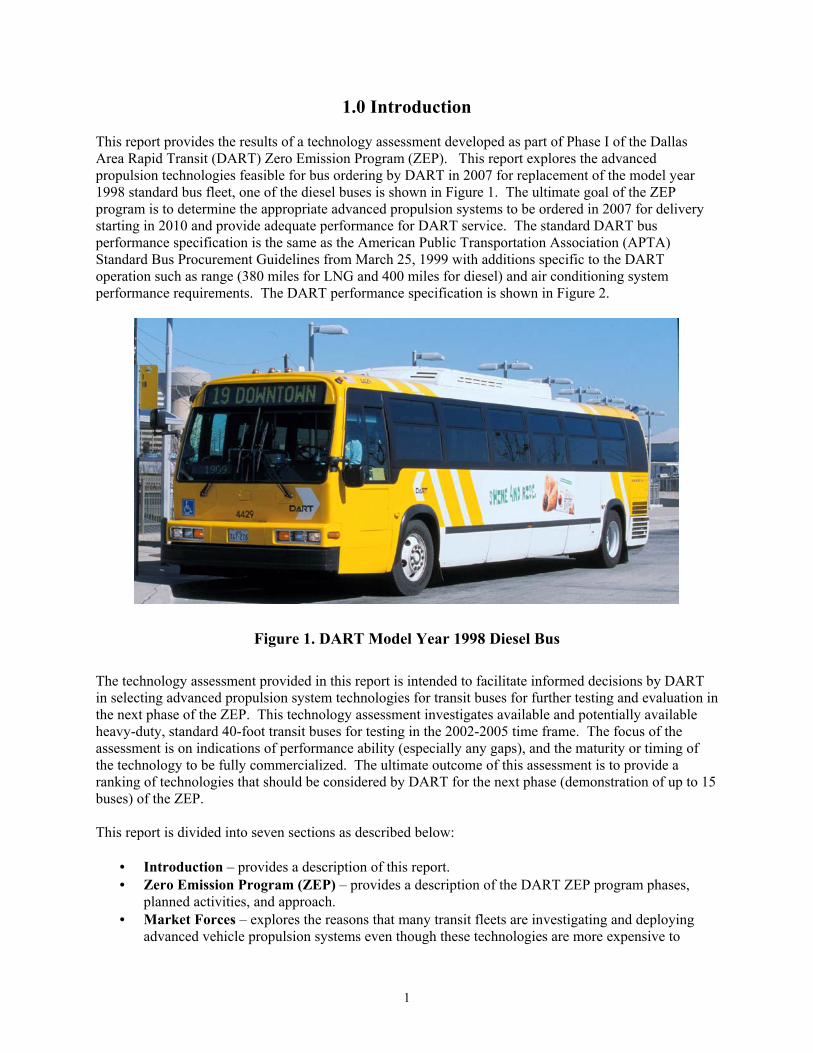
made widely available in time for the 2007 emissions certification levels to start to be phased-in through 2010. For 2007 emission standards, CO emissions are unchanged from current and 2004 standards. There no longer will be a NOx plus NMHC standard. However, both PM and NMHC emissions are reduced compared to 2004 emission standards. The PM and NMHC emission standards are 0.01 and 0.14 g/bhp-hr respectively. This represents a reduction of 80% for PM emissions and 70% for NMHC compared to 2004 emission standards. The most difficult standard for 2007 is the extremely low NOx level at 0.2 g/bhp-hr, which has not yet been demonstrated in a diesel engine even with after-treatment technologies. One more major issue should be discussed at this point. Several of the heavy-duty engine manufacturers who supply to the U.S. market were taken to court by the U.S. Environmental Protection Agency (EPA) and have agreed to a consent decree that among other things requires them to provide engine products for model year 2003 that achieve the 2004 regulated emissions levels. The issue about which the EPA took the engine manufacturers to court consisted of the electronic control of the diesel engine. The control allowed the engine to operate in one fashion for the emissions certification testing and in another mode for road operation. Both of the major engine manufacturers for transit buses were a part of this consent decree – Detroit Diesel Corporation and Cummins Engine Company. Many of the engine emission control technologies that have been considered for the 2004 regulations are now required to be available by the end of 2002 for model year 2003 equipment. 3.2 Regulations and Incentives The main source of funding for the purchase of transit buses and supporting infrastructure in the U.S. is from the Federal Transit Administration (FTA) formula grants and specific initiative programs such as the Alternative Fuel Initiative from 1990. In conjunction with FTA funded programs, the transit agency can apply to receive Congestion Mitigation and Air Quality (CMAQ) funds first developed under the Intermodal Surface Transportation Efficiency Act of 1991 (ISTEA) and reauthorized in the Transportation Equity Act for the 21st Century of 1998 (TEA-21). These funds along with funding from the U.S. Department of Energy through the state energy offices may be used to develop larger bus and infrastructure purchases for clean fuel and propulsion system vehicles. All federal programs usually include local and state matching and a requirement that local and state governments pay a portion of the proposed project. In general, all of these program funds are coordinated with the council of governments local to the proposed project. In Dallas, the coordinating local agency is the North Central Texas Council of Governments (NCTCOG). The state agency coordinating funding for DART and the entire state of Texas is the Texas Natural Resource Conservation Commission (TNRCC). The FTA also has a regional office that coordinates funding and activities for each area of the country, Texas is in FTA Region VI. The major interest in cleaner fuels and vehicles at DART, in this case transit buses, stems from the fact that the Dallas/Fort Worth (DFW) consolidated metropolitan statistical area (CMSA) is a nonattainment area for ground-level ozone. The DFW CMSA consists of 12 counties in Texas including Denton, Collin, Dallas, Tarrant, Johnson, Ellis, Kaufman, Parker, Rockwall, Hunt, Hood, and Henderson. Four of the counties are in serious nonattainment status: Denton, Collin, Dallas, and Tarrant. The remaining counties are near nonattainment for ground-level ozone. The DFW metro area is shown in Figure 3.
7
Figure 3. Dallas/Fort Worth Metropolitan Area
The federal Clean Air Act Amendments of 1990 (CAAA) required significant reductions in emissions and new reporting of emissions inventories in the U.S. As part of this federal legislation, each state is required to provide a plan to reduce emissions to maintain and/or achieve compliance with federal emissions maximum levels. This plan is called a state implementation plan (SIP). The Texas agency responsible for the Texas SIP and coordinating with metropolitan areas in the state is the TNRCC. The responsible agency in the Dallas/Fort Worth CMSA for the SIP is the NCTCOG. The TNRCC is the state air pollution agency and is the principal authority in the state on matters relating to the quality of air resources and for setting standards, criteria levels, and emission limits. The Texas Clean Air Act gives the TNRCC legal authority to: (1) adopt emission standards and limitations; (2) enforce applicable laws, regulations, and standards, and - seek injunctive relief; (3) obtain information necessary to determine compliance; (4) require record keeping and inspections and conduct tests; (5) require owners or operators of stationary sources to install, maintain, and use emissions monitoring devices, and to make periodic reports to the state; and (6) make emissions data available to the public. The Texas state senate recently created significant incentive funding for emissions reduction in Senate Bill 5 in April 2001 named the Texas Emissions Reduction Plan (TERP). The statewide incentive program was created for the purchase or lease of heavy-duty, on-road vehicles and for grants for heavy-duty, on-road and non-road vehicles and equipment in the state’s nonattainment areas and other affected counties of the state. The activities eligible for funding under TERP include the following:
• Lease or purchase of non-road equipment (at least 50 horsepower) • Emissions-reducing activities involving the repower or retrofit of engines, or the add-on of
devices, for non-road diesel powered equipment (at least 50 horsepower) and for on-road heavy-duty (10,000 pounds or more gross vehicle weight rating – GVWR) diesel-powered vehicles
• Infrastructure activities including on-site refueling infrastructure, on-site infrastructure for dispensing electricity, and on-vehicle infrastructure for dispensing/accepting electricity
• Use of qualifying fuel • Demonstration of new technology

8
The TERP funding provided for incremental costs up to a cost-effectiveness of $13,000 per ton of oxides of nitrogen (NOx) reduction from the proposed project.
4.0 Advanced Propulsion Systems
Nearly all purchases of standard transit buses in the U.S. are either diesel- or natural gas-powered. The upcoming national emissions regulations and state and local programs are exerting pressure on transit companies and many other vehicle fleets to have extremely clean emissions from vehicles. The engine and bus manufacturers are working to make sure that diesel and natural gas transit buses continue to be options to be purchased; however, this is taking significant effort and will most likely result in cost increases. At the same time, many transportation researchers and planners believe that the development and use of electric propulsion is inevitable. Electric propulsion technology development enables many things including the use of regenerative braking for fuel economy increases and the use of fuel cell power plants. There is tremendous pressure in the marketplace for the development of heavy-duty vehicles using fuel cells as the power plant. However, the integration and optimization of hybrid electric propulsion systems still needs significant work before full commercialization of hybrids and, ultimately, fuel cells can move forward. Many advanced propulsion systems are based on electric motors driving the wheels. The use of electric power allows several cleaner emissions advances and also allows the use of regenerative braking as already mentioned. By far, the new propulsion technology getting the most attention from the research perspective is fuel cell power. A fuel cell powered transit bus is basically a version of an electric or hybrid electric bus design with the fuel cell being the power plant instead of an internal combustion engine or a turbine. The effort to design, integrate, and optimize hybrid transit buses will be part of the electric drive system that supports the fuel cell bus of the future. As an enabling technology for fuel cells, hybrid electric propulsion technologies and components need to be fully researched and developed before fuel cell-powered heavy-duty vehicles can make major advancements to full commercialization, assuming that fuel cell stacks can provide the power, reliability, and efficiency required. There are three major barriers to the introduction of these hybrid electric propulsion technologies – (1) complexity of the systems integration, (2) cost of the investment for optimization, and (3) purchase cost of the vehicles. In the transit industry, there is a further complication from a lack of market size, which can significantly delay the investments required to move the technology development and commercialization. All of these issues make any predictions of technology advancements more difficult and imprecise than might be expected. However, the intent of this technology assessment exercise is to narrow down the options for consideration in the next phase of the DART ZEP, not choose the most feasible option for 2010. The next phase of the ZEP targets demonstrating and evaluating a few vehicles of 3 to 4 different propulsion technologies. With fuel cell propulsion being the driving force for nearly all advanced vehicle propulsion research at this time, there is critical work to be completed developing hydrogen infrastructure. Fuel cell designs being developed for transit need hydrogen and air to operate. How to store hydrogen on a vehicle for use in a fuel cell is a major hurdle for the introduction of fuel cell buses. The other major hurdle is how to produce and store hydrogen for vehicle use at a reasonable cost. In several cases, the storage method for hydrogen is in liquid form for bulk storage and in high-pressure gas for on-board the fuel cell vehicle. From a research perspective, natural gas vehicle infrastructure for storage, facility safety features, and on-board high-pressure gas cylinder designs are the first steps in how to manage hydrogen storage for fueling

9
and for storage on-board the vehicles. Thus, nearly all of these advanced propulsion systems are connected from the research point of view. With these research perspectives in mind, this section is focused on the advanced propulsion systems that should potentially be considered in this technology assessment for demonstration and evaluation in Phase II of the ZEP. This assessment is focused on full-size (40-foot), standard transit bus propulsion systems. The systems considered here include the following:
• Clean diesel technologies – diesel fuel formulations, exhaust gas recirculation, catalysts and diesel particulate filters, NOx adsorbers, and selective catalytic reduction
• Natural gas engine propulsion – compressed and liquefied natural gas fueled engines for transit bus applications
• Hydrogen engine propulsion – hydrogen and mixtures of hydrogen with natural gas used in internal combustion engines for transit bus applications
• Electric propulsion – direct energy storage device-driven electric propulsion systems • Hybrid electric propulsion – an electric propulsion system with the addition of a power plant as
the main drive system including diesel, gasoline, propane, or natural gas engines or a microturbine fueled with diesel, propane, or natural gas
• Fuel cell propulsion – uses an electric propulsion system and may be a variation of the hybrid electric propulsion system with the fuel cell stack used as the power plant; the system uses some form of hydrogen most likely derived from a hydrocarbon source
The following discussions include each of the propulsion systems listed above and focuses on the capabilities of each and the likelihood that they will be commercialized in time for transit bus deliveries in 2010 and beyond. As mentioned earlier, propulsion systems for transit buses are expected to change significantly by 2010 because of the emissions regulations to be phased in from 2007 - 2010. These technology changes and additions are expected even for the standard diesel transit bus as well as natural gas and electric propulsion systems. For each propulsion system technology discussed, there are four categories of assessment provided. These categories are used to separate the information needed to determine the applicability and availability of these propulsion technologies for DART purchase and testing.
1. Infrastructure, support, and training – explores the implications of the infrastructure, support, and training required for each advanced propulsion system presented here. The infrastructure includes any fueling or special equipment needed and training challenges such as what needs to be focused on and special issues.
2. Availability for a 2010 transit bus delivery – an estimate of whether or not a given advanced propulsion system will be ready for transit bus delivery in large numbers in 2010.
3. Performance and reliability issues – provides descriptions of any performance or reliability issues specific to the propulsion technology that may impact the purchase decision.
4. Technology development status – provides a final technology development status scoring as described next.
Any technology development for vehicle propulsion systems (and most vehicle systems) progress through a set of steps and are described here:
1. Concept development – the idea of this new technology is born and the concept is assembled.

10
2. Technology research and development – the concept appears to be a real possibility; research and development are required to take the idea to the next step of discovering if the concept actually works as expected or well enough for refinement.
3. Vehicle development, design, and integration – the idea has progressed far enough to be plausible in accomplishing the original goals set and work is now starting in how to integrate this technology into the vehicle and how it will work with other systems in the vehicle.
4. Manufacturing and assembly integration – at this point, the idea is ready to be built into an actual working vehicle, this step requires working through how the vehicle will be manufactured and assembled for at least a prototype.
5. Vehicle demonstration, testing evaluation, and production – the technology is now ready for limited field testing and evaluation in a small number of vehicles.
6. Deployment, marketing, and support – the technology is now ready for pre-production or limited production, and is field tested in larger numbers of vehicles.
7. Full product offering – the technology has moved to production and support in large numbers; this would be considered fully commercialized; there will continue to be incremental improvements made.
This list of steps to commercialization is used to generally score the technologies explored and discussed in this section. The higher the number, the closer to commercialization the product is assessed to be. These assessments will be used in the next section to assess each propulsion system candidate for Phase II and rank order the possibilities. 4.1 Clean Diesel Technologies In this report, the definition of clean diesel technologies includes diesel fuel formulations and other technologies that may enable diesel engines to achieve the phase-in of the emissions certification levels from 2007 - 2010. Diesel fuel formulations are the first design issue for clean diesel technologies. The most significant fuel formulation for diesel fuel is the lowering of sulfur content to below 15 ppm (from 300 to 500 ppm on average) by mid-2006 – ultra-low sulfur diesel (ULSD). This lower sulfur content enables the use of more active catalysts and technologies to reduce diesel emissions. Other diesel fuel formulations that are being considered include gas-to-liquids (GTL) such as synthetic diesel fuel produced through the Fischer-Tropsch process (derived primarily from natural gas), biodiesel as an additive for lubricity and some minor emissions reductions, and emulsified diesel, which includes ethanol and water as an additive. The only fuel formulation considered here is ULSD. The other diesel fuel formulations may or may not be used in the future; however, only ULSD is a requirement for the diesel technologies presented here. This subsection is focused on the technologies to make the diesel engine emissions clean enough for the 2007 standard. At this point, none of these technologies by themselves can achieve all of the emissions reductions required in 2007. It is expected that a combination of 2 or 3 of these technologies may be required for heavy-duty diesel engines, accompanied by the use of ULSD fuel. In general, the lower sulfur diesel fuel is significant and sufficient for the operation of the technologies discussed in this section:
• Exhaust gas recirculation (EGR) • Diesel oxidation catalysts (DOC) • Catalyzed passive regenerative diesel particulate filters (DPF) • NOx adsorber catalysts • Selective Catalytic Reduction (SCR)

11
4.1.1 Exhaust Gas Recirculation (EGR) To meet the EPA’s 2002/2004 and 2007 exhaust emission standards, it is likely that exhaust gas recirculation (EGR) will be used. EGR is used primarily to control NOx emissions. It is a control method where part of the engine’s exhaust gas is recirculated (via an EGR valve) back into the engine’s intake system. There are two ways in which EGR reduces NOx. In the first method, oxygen concentrations during combustion are reduced by diluting the intake air with inert gases (from the exhaust). With the second method, the peak combustion temperature is reduced via heat absorption by the EGR stream. Cooled EGR is a control method where the EGR stream is cooled before entering the engine intake. The cooled stream has greater heat absorption potential thus reducing the peak combustion temperature further than would be accomplished by standard EGR. A disadvantage to using EGR is the increase in particulate matter (PM) emissions. EGR may also increase the wear on the engine and ultimately decrease the engine’s durability. EGR alone may reduce NOx emissions by 30-40%1. To meet 2004 standards, it is likely that EGR along with engine modifications (adjustments to engine design, turbocharging, fuel injection, and/or electronic control systems) will be all that is required to comply with the standards. However, for 2007 emission standards, EGR and engine modifications do not appear to be enough. Some type of diesel emissions after-treatment device or technology is needed to comply with the 2007 standard. Infrastructure, Support, and Training Required – There do not appear to be any additional infrastructure or support needed for the use of EGR beyond current diesel infrastructure. There will need to be some training for mechanics from the engine manufacturers on the use, operation, and troubleshooting of an engine operating with EGR. Availability for a 2010 Transit Bus Delivery – EGR is already being used by Detroit Diesel and Cummins in response to the 2004 standard being met in 2002. Both major transit manufacturers offer EGR as a standard option. In fact, DART has already started taking delivery of diesel buses with the DDC Series 50 using EGR. Performance and Reliability Issues – The performance impacts are potentially with fuel economy and visible smoke. There is a possibility of a small decrease of fuel economy; however, the engine manufacturers appear to be able to add other efficiency gains to offset any penalty. Visible smoke (increased particulate) can be an issue, even though the PM emissions are within the regulations. Reliability may be impacted slightly, but EGR technology is fairly mature. Technology Development Status –full product offering (Step 7); however, EGR has not been packaged with some of the other technologies discussed here as a full product offering; if used with other technologies like those described here; there will need to be some integration work and testing done. 4.1.2 Diesel Oxidation Catalysts (DOC) To meet the EPA’s 2002/2004 and 2007 exhaust emission standards, the use of diesel oxidation catalysts (DOC) may be necessary. A DOC operates with exhaust from the engine flowing across the catalyst. DOCs can reduce hydrocarbons (HC), carbon monoxide (CO), and particulate matter (PM) by reducing the solid organic fraction of diesel particulates (SOF). Other non-regulated emissions as well as odor may also be decreased. The DOC consists of a catalyst that is coated on the surface of a carrier. The catalyst is
1 Lyons, James M., Sierra Research, 1999, Effect of Diesel Fuel Properties on Emissions from Current and Future-Technology Engines, 1999 Diesel Issues Forum, April 14-15, 1999.

12
able to adsorb oxygen, which reacts with CO and HC. The result is the production of carbon dioxide (CO2) and water vapor, which desorb from the catalytic material and are released into the exhaust. DOCs alone can achieve emissions reductions of up to 30% for PM emissions2. This should be enough to meet 2004 PM standards but not 2007 PM standards. To meet 2007 PM standards, DOCs will need to be combined with EGR and/or some other aftertreatment technology. The U.S. Department of Energy (DOE) Diesel Emissions Control – Sulfur Effects Project (DECSE) results also show that the DOC alone will not meet 2007 emissions standards. The DECSE project is a joint program with the U.S. DOE, the National Renewable Energy Laboratory (NREL), Engine Manufacturers Association (EMA), and the Manufacturers of Emission Controls Association (MECA). Results show that the DOC may be useful in an emission control system to reduce HC emissions during rich regeneration. The DOC may also be effective when used in combination with selective catalytic reduction (SCR), either as a pre- or post-catalyst3. Infrastructure, Support, and Training – No infrastructure, support, or extra training is expected to be required. The only issue with a DOC is knowing when the catalyst has been compromised and is not working properly. Availability for a 2010 Transit Bus Delivery – DOCs are currently available as options from both DDC and Cummins. Performance and Reliability Issues – There are no performance or reliability issues with the DOC. The only comment has to do with ensuring that the DOC is operating properly, there are no easy ways to confirm that the DOC is working properly without monitoring the emission stream from the bus. Technology Development Status – Full product offering (Step 7); however, DOCs have not been packaged with some of the other technologies discussed here as a full product offering. If used with other technologies like those described here; there will need to be some integration work and testing done. 4.1.3 Catalyzed Passive Regenerative Diesel Particulate Filters (DPF) Generally, a catalyzed passive regenerative diesel particulate filter (DPF) is comprised of a ceramic/glass porous filter that is catalyzed either on the filter or as a two-part catalyst and filter configuration. The key to proper operation of the DPF is to have exhaust temperatures from the engine through the filter that are sufficiently high for enough time during the vehicle operation to properly catalyze the trapped solids in the filter substrate, otherwise the filter will plug up. The filter requires removal and cleaning on occasion – timing depends on the vehicle duty cycle, due to inorganic particulate that builds up, usually ash from the engine oil. To meet the EPA’s 2007 exhaust emission standards, the use of DPFs will probably be necessary to control PM emissions. DPFs physically capture particular matter (PM) and have efficiencies in the 90% range4. However, the DPF alone has no major effect on NOx emissions and will not be sufficient for the 2007 NOx emission standard.
2 Kubsh, Joe, Engelhard Corporation, 1999, Emission Control Technologies for Diesel Engine Applications, DOE Workshop on Emissions Control Strategies for Internal Combustion Engines, January 21, 1999. 3 DOE/NREL, 2002, Summary of Reports, Diesel Emissions Control – Sulfur Effects Project (DECSE), NREL/TP-540-31600, www.ott.doe.gov/decse. 4 DieselNet, 2002, Diesel Particulate Traps, www.dieselnet.com/tech/dpf_top.html.
13
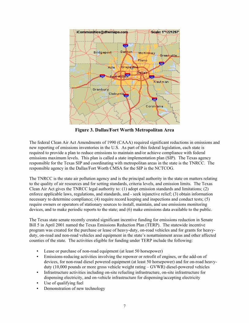
From the DOE/NREL DECSE project, using a DPF with ultra-low sulfur diesel (ULSD) fuel (<15 ppm sulfur content), this technology is capable of meeting future (2007) PM standards. More work is planned by the industry for using a DPF in combination with SCR or a NOx adsorber. The DECSE project has also suggested that more work is required for measurements of PM mass, size, and composition, as well as for air toxics. In California, BP/ARCO completed a program to test the use of ULSD and DPFs in real truck, transit bus, and school bus operation, called the EC-Diesel Technology Validation Program. In this project, the test vehicles were operated on BP/ARCO’s ECD fuel with less than 15 ppm sulfur content and some of the vehicles were equipped with either the Engelhard DPX DPF or the Johnson Matthey CRT DPF. Detailed emissions tests were performed on all of the test vehicles over the year-long study. Figure 4 shows one of the trucks with the DPF installed and a graphic of the operation of the Johnson Matthey CRT DPF. Some of the final results were as follows5:
• Test vehicles retrofitted with DPFs and fueled with ULSD had over 90% reductions in PM compared to vehicles without aftertreatment
• Based on statistical analysis, there is greater than 95% certainty that CO, HC, and PM emissions were significantly reduced when using ULSD
• There appeared to be some slight NOx reduction; however the statistical analysis was inconclusive for NOx reductions
• On average, the DPX and CRT filters were equally effective in reducing HC and PM emitted • The ULSD and DPF combination did not show any statistically significant change in fuel
economy
Figure 4. Ralphs Grocery Truck with DPF Installed (Left) and Johnson Matthey CRT (Right)
5 LeTavec, Chuck, et. al., 2002, Year-Long Evaluation of Trucks and Buses Equipped with Passive Diesel Particulate Filters, SAE International, 2002-01-0433.

14
Another study of DPF use was in New York with the New York State Department of Environmental Conservation and New York City Transit. The conclusions from this study are summarized below6:
• Greater than 90% reductions in PM, CO, and HC are possible by retrofitting existing diesel powered buses with ULSD and using DPFs
• NYCT operated 25 buses for 8 months without a failure or any significant increase in fuel consumption
• Stable backpressure and high exhaust temperature on the buses indicated successful regeneration Infrastructure, Support, and Training – DPF technology works best with ULSD. The easiest way to convert to DPF technology would be to convert the entire diesel fuel supply over to ULSD. If there is a transition to ULSD, there will be fueling infrastructure required to keep the standard diesel and ULSD separate, and procedures and controls in place to make sure that the DPF-equipped vehicles are only fueled with the ULSD. The good news is that short duration exposure of high-sulfur diesel fuel does not have a reliability effect on the DPF; however, the emissions reduction capability will be diminished until the ULSD fuel use has resumed. DPFs are required to be cleaned on approximately a yearly basis, maybe sooner. Currently, cleaning procedures are not completely developed. There needs to be a method for removing the particulate from the filter in a manner that collects the particulate without releasing it into the atmosphere. Currently, the cleaner must wear a mask and blow the filter substrate out with compressed air and then sweep up the particulate. The DPF is flipped over and reinstalled onto the exhaust stack. For widespread use of DPFs, either on-site equipment for cleaning will need to be purchased, or the site will need to purchase cleaning services from a local company or the engine distributor. Off-site cleaning will require extra filters to be purchased so that they can be removed and then cleaned. DPF equipment should be purchased as a package that includes a backpressure sensor and a light on the dashboard or in the engine compartment so that the user will know when the filter needs to be serviced. This installation may also require an addition to the engine computer that shuts down the engine based on the backpressure sensor to protect the engine. Excessive backpressure on the engine will eventually cause problems with the engine operation, significantly reduce fuel economy, and reduce the filter’s ability to limit emissions. The package should also include the brackets and a thermal blanket for the exhaust pipe (if required), all designed for the engine exhaust layout in the specific vehicle. Training for the mechanics will be required to explain the operation of the DPF equipment and how to service the DPF. The support staff will need to be trained in using the cleaning equipment or how to send the filters out for cleaning. Procedures will need to be in place for control of fueling if the entire fuel supply is not switched to ULSD. Availability for a 2010 Transit Bus Delivery – Several DPF models are available from several manufacturers.
• Engelhard • Johnson Matthey • NETT Technologies, Inc. • CleanAir Systems, Inc. • Ceryx, Inc.
6 Lanni, Thomas, et. al., 2001, Performance and Durability Evaluation of Continuously Regenerating Particulate Filters on Diesel Powered Urban Buses at NY City Transit, SAE International, 2001-01-0511.

15
Currently, Engelhard and Johnson Matthey are the leaders in the U.S. in this technology introduction based on sales and planned sales. Both Cummins and Detroit Diesel have worked with each of these two leading suppliers to make sure that they can integrate these DPFs with their products. It is highly likely that a DPF of some sort will be used on diesel transit buses being delivered in 2010. Performance and Reliability Issues – Reliability of the DPFs appears to be extremely good. However, the fleet must closely watch the need to service the DPF or the engine operation may not be optimal and fuel economy may decrease. Brackets and thermal blankets used for the exhaust need to be monitored to ensure that the DPF system works properly. The fleet needs to assure that their operation will allow the exhaust temperature to be higher than the minimum required for the DPF regeneration during a significant portion of the vehicle operation. Otherwise, the system will frequently need to be cleaned because of excessive backpressure on the engine. The fleet must work closely with the manufacturers to understand required operating temperatures and ensure that the operation will provide those temperatures. Engine oil consumption should be monitored closely, because high oil consumption may plug the filter faster than expected. Also, a turbocharger failure that allows engine oil into the exhaust may require that the filter be serviced in order to avoid plugging. Technology Development Status – Full product offering (Step 7); however, DPFs have not been packaged with some of the other technologies discussed here as a full product offering. If used with other technologies like those described here, there will need to be some integration work and testing done. 4.1.4 NOx Adsorber Catalyst The general operation of a NOx adsorber consists of converting nitric oxide (NO) emissions from the engine flowing across the adsorber catalyst into nitric dioxide (NO2). Before the adsorbent becomes saturated, diesel fuel input and engine operation are adjusted to produce a fuel-rich exhaust for a brief interval. These fuel-rich pulses create conditions that release the NOx from the adsorbent and reduce it to harmless nitrogen gas over a three-way catalyst. The major issue with NOx adsorbers is that they need very low levels of sulfur in the diesel fuel or the exhaust stream will produce sulfur dioxide that blocks the reduction of NOx in the adsorbent. The DOE/NREL DECSE project plans more study to investigate the frequency of desulfurization needed and to more accurately characterize thermal degradation associated with the high-temperature desulfurization cycle. More detailed studies are also needed to address the long-term operation of the NOx adsorber catalyst, including the durability of the engine and catalyst, and other exhaust constituents – such as smoke levels during regeneration – and on which trade-offs are required to reduce or keep them low7. Work is also ongoing in developing feedback sensors for controlling the fuel-rich exhaust interval. Infrastructure, Support, and Training – Proper operation of the NOx adsorber catalyst requires ULSD fuel or lower sulfur content. No other infrastructure is needed. Training will be required for the mechanics on the operation of the NOx adsorber catalyst and repair and troubleshooting procedures. Availability for a 2010 Transit Bus Delivery – NOx adsorbers look extremely promising for the reduction of NOx emissions; however, the sensitivity to sulfur in the fuel and the higher temperature operation have caused concerns with reliability of operation. Indications are that the research will continue to make progress. NOx adsorbers and SCR, coupled with a DPF, appear to be equivalent solutions for 2007 emissions levels. However, EPA has been working mostly with NOx adsorbers, and this might indicate a preference. 7 DOE/NREL, 2002, Summary of Reports, Diesel Emissions Control – Sulfur Effects Project (DECSE), NREL/TP-540-31600, www.ott.doe.gov/decse.

16
Performance and Reliability Issues – This technology does show some significant increases in fuel consumption, on the order of 4% as reported in the DECSE project7. Reliability of the NOx adsorber catalyst and associated equipment is of concern at this time- and research continues. Technology Development Status – Vehicle development, design, and integration (Step 3). 4.1.5 Selective Catalytic Reduction (SCR) To meet the EPA’s 2007 exhaust emission standards, selective catalytic reduction (SCR) may be used. SCR is a method used primarily to control NOx emissions. In this method, ammonia is injected into the exhaust stream before a catalyst. The ammonia reduces the NOx to nitrogen (N2). Because there are toxicity and handling issues with ammonia, the use of urea is planned instead of ammonia in mobile applications. Urea breaks down into ammonia chemically in the exhaust stream. Urea is non-toxic, readily available, inexpensive, and does not have the handling issues that ammonia has. The form of urea being most aggressively pursued is in aqueous form. Like ammonia, urea is injected into the exhaust stream. At temperatures above 160°C (320°F), urea starts to decompose and hydrolyze. It should be noted that if urea is injected at too low a temperature, fouling of the catalyst may occur. Therefore, temperature plays an important role in SCR systems. Several other reactions may occur that can adversely affect the SCR system. For instance, oxygen in the exhaust (particularly for diesel engine applications) can react with ammonia to produce secondary emissions or consume ammonia. Ammonia and oxygen may react to produce nitrous oxide (N2O) and nitric oxide (NO) respectively. Ammonia and oxygen may react to form nitrogen and water, therefore wasting ammonia. Other adverse reactions that may occur in the SCR system concern sulfur. The amount of sulfur in the exhaust may cause fouling of the catalyst. There are three main catalysts used in SCR systems. They include platinum (Pt), vanadium (V2O5), and zeolite. Platinum is used in low temperature applications (175 – 250°C [347 – 482°F]) and does not effectively reduce NOx at high temperatures. Because creation of ammonium nitrate is to be avoided, the actual temperature window of a platinum-based catalyst is narrower than the 175 – 250°C temperature window, since it must be kept greater than approximately 200°C (392°F). Due to the narrower range, this type of catalyst is not commonly used. Vanadium, which is typically used in conjunction with a TiO2 carrier (which is not affected by sulfur in the exhaust gas), is used for higher temperatures (300 – 450°C [572 – 842°F]). It is currently the preferred catalyst for mobile applications. Zeolite is used for the highest temperatures (350 – 600°C [662 – 1112°F]). There are multiple issues that need to be addressed before SCR systems can be implemented. First, unlike industrial applications, mobile engines operate in transient conditions and therefore have a great range in operating variables. A catalyst must operate under a wider window in mobile applications. Due to the current lack of NOx and ammonia sensors, control systems (which are typically closed-loop for stationary applications using feedback from exhaust downstream of SCR reactor) must be open-loop for mobile applications. There is also a need for onboard urea storage. This will add size and weight to the system. Finally, regulating the use of urea will need to be addressed by the appropriate agencies. If a vehicle runs out of urea, it can still operate. In addition, when a vehicle’s urea supply runs out, there needs to be an infrastructure in place so the vehicle user can replenish a vehicle’s the supply. Urea can also freeze during winter temperatures. This could be a problem for users in a cold climate. Thus, due to

17
the size and complexity of the system and other issues, SCR still needs further development before a practical system will be available8. SCR systems can greatly reduce NOx, reductions of greater than 90% are possible. SCR will probably be combined with other after-treatment technologies such as EGR, diesel oxidation catalysts, and diesel particulate filters to meet 2007 standards. Infrastructure, Support, and Training – SCR requires a fueling infrastructure suitable to accommodate either ammonia or urea. As mentioned above, urea is the more likely candidate for the SCR process because it is easier to handle than ammonia from a hazardous material standpoint. Several ideas for the fueling of urea/ammonia have been investigated including a combined fueling nozzle with the diesel fuel and canisters that only need to be changed out at oil change intervals. Training for the mechanics will be required for the operation, troubleshooting, and repair of the SCR systems. Availability for a 2010 Transit Bus Delivery – SCR technology appears extremely promising in reducing NOx emissions. Some significant work has been done in Europe. As with NOx adsorbers, it is difficult to know which regime will be used to meet 2007 emissions levels. SCR will need to be used with a DPF or DOC to reduce other emissions, specifically PM in order to meet all 2007 emissions levels. Performance and Reliability Issues – As with NOx adsorbers, the fuel consumption of an engine using SCR may go up significantly, maybe up to a 4% increase. These systems are significantly more complex than today’s diesel engine exhaust system. Also, the use of urea or ammonia will create more costs to operate based on the need to purchase and store this chemical. Technology Development Status – Vehicle development, design, and integration (Step 3). 4.1.6 Summary of Performance Issues In general, the 2007 emission levels will be achieved for diesel engines using ULSD, EGR, and SCR or NOx adsorbers for NOx controls. For both SCR and NOx adsorbers, there is a need to use a DPF or DOC to reduce emissions of HC and PM. These exhaust after-treatment technologies add complexity, cost, and potential reductions in reliability especially in the short term as the engine manufacturers continue to study and optimize these systems for their particular engine technology. One of the most important issues is that it appears that any and all of these technologies may increase fuel consumption, some significantly. However, the engine manufacturers are working diligently to find other engine efficiencies to offset any real fuel efficiency penalties. Ultimately, the end user is inflexible when it comes to fuel efficiency and reliability reductions. EGR, SCR, diesel oxidation catalysts, and diesel particulate filters offer reductions in NOx and/or PM emission. Meeting NOx and PM emissions standards will be the greatest challenge facing engine manufacturers in the future. Listed in Table 3 below are typical reductions possible for each technology. All of these performance issues for clean diesel vehicle operations need to be kept in mind when considering more advanced propulsion systems such as diesel hybrids. The note here is that the baseline standard diesel engine and vehicle definition used for comparisons to advanced propulsion systems is a moving target that is somewhat undefined at this moment.
8 DieselNet, 2002, Various descriptions of SCR technology and theory of operation, www.dieselnet.com.

18
Table 3. Diesel Aftertreatment Technologies and Reduction Potential
Technology PM NOx EGR N/A 30 – 40 % Diesel Oxidation Catalysts 30% N/A Diesel Particulate Filters 90% N/A NOx Adsorber >30% >90% SCR >30% >90%
Sources: Presentations from Cunningham; Kubsh; Lyons; and McKinnon at DOE Workshop on Emissions Control Strategies for Internal Combustion Engines, January 21, 1999.
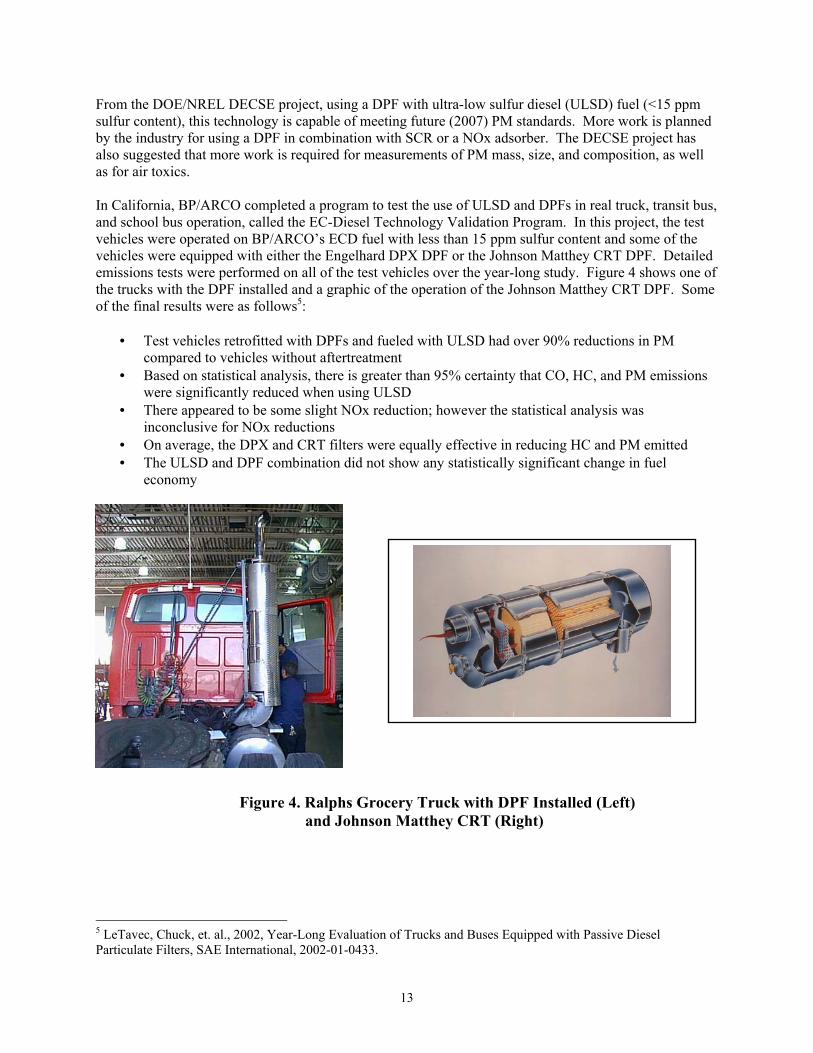
4.2 Natural Gas Engine Propulsion DART currently has 139 LNG standard transit buses in service (one LNG bus shown in Figure 5) with 45 more LNG buses coming in 2002. The principal issues with natural gas engine propulsion are cost to purchase vehicles, infrastructure requirements and cost, fuel economy, range, fuel system complexity and reliability, engine system reliability, and parts costs. Two of the five DART operating facilities are compatible with natural gas vehicle systems and have LNG fueling on site.
Figure 5. DART LNG Transit Bus
As mentioned earlier, natural gas and diesel engines need more work to meet the 2007 emissions levels. The natural gas engine manufacturers are also working on engine developments that will allow natural gas engines to meet that standard without any fuel efficiency penalties from current levels. Table 4 shows the current emissions certification levels for 2002 model year transit bus engines. In general, the natural gas engine certification levels are significantly lower than the diesel counterpart. For the natural gas engines, the PM levels are near the 2007 emissions certification level. NOx + NMHC is below the required level for 2004 certification; however, the NOx levels are significantly higher than the 0.2 g/bhp-hr certification level for 2007. There appears to be some work still needed in controlling NMHC from the natural gas engines for 2004 (0.5 g/bhp-hr) as well as 2007 (0.14 g/bhp-hr) certification levels.

19
Table 4. Emissions Certification Levels for Model Year 2002 Transit Bus Engines* (Results shown in units of g/bhp-hr)
Manufacturer Engine Model Fuel PM NOx HC NMHC NOx + NMHC CO
Cummins ISC 280 Diesel 0.05 3.9 0.1 0.5 Cummins C+8.3-280G Natural Gas 0.01 1.5 0.2 1.7 1.3 DDC Series 50 BUS Diesel 0.05 3.4 0.2 1.0 DDC Series 50G Natural Gas 0.01 1.5 0.8 2.2 DDC Series 50G ULEV Natural Gas 0.01 2.1 0.0 DDC Series 60 BUS Diesel 0.03 3.8 0.2 1.0 DDC Series 60G Natural Gas 0.02 2.0 0.7 1.9
* The engine certification levels for model year 2003 are significantly lower, and will be met by the diesel engines, which will make their emissions levels more similar to the low levels achieved by natural gas engines. Blank entries are not zero, results/levels are unreported.
The two major transit bus engine manufacturers continue to work on natural gas engine development for 2004 and 2007. The next major goal for the emissions from these natural gas engines is to meet a NOx level of 0.5 g/bhp-hr and a PM level of 0.01 g/bhp-hr, with no fuel economy penalty compared to the current natural gas product. This is to be accomplished in the laboratory in calendar year 2002. The U.S. Department of Energy (DOE) through the National Renewable Energy Laboratory (NREL) has established the Next Generation Natural Gas Vehicle (NGNGV) program to support the development of cleaner natural gas engines and better integrated natural gas vehicles for medium- and heavy-duty. The South Coast Air Quality Management District (AQMD) and the California Energy Commission (CEC) are funding and design partners in this program. Work has already been funded for the engine emissions reductions needed for the future, starting with working to a 0.5 g/bhp-hr NOx certification level for heavy natural gas engines with future plans to certify down to the 0.2 g/bhp-hr NOx level9. Infrastructure, Support, and Training – In order to convert the entire DART standard bus fleet, 3 more operating facilities would need to be converted and fueling added. The entire workforce will need to be trained or retrained on the use of natural gas fuels. Significant experience exists at DART to accomplish these tasks. A recent survey of natural gas vehicle use in transit had results consistent with DART’s experience with natural gas vehicles10:
• Do your homework • Assemble a team • Be committed at all levels of the organization • Understand the possible costs involved • Plan a comprehensive training program • Install adequate fueling infrastructure • Promote the program to the public
9 DOE/NREL, 2002, Next Generation Natural Gas Vehicle Program, NREL/FS-540-32133, www.ctts.nrel.gov/ngngv. 10 Eudy, Leslie, NREL, 2002, Natural Gas in Transit Fleets: A Review of the Transit Experience, NREL/TP-540-31479.

20
Availability for a 2010 Transit Bus Delivery – All indications are that natural gas engines and buses will be available for delivery in 2010 from most of the major transit bus manufacturers. Current natural gas engine and vehicle supplier lists are available at www.afdc.doe.gov and www.ngvc.org11. Performance and Reliability Issues – The performance levels are expected to stay the same or get a little bit better than current natural gas technology. The current reliability and parts cost issues will most likely continue. Technology Development Status – Full product offering (Step 7). 4.3 Hydrogen Engine Propulsion There has been some interest in moving to hydrogen internal combustion engines either as an interim step to fuel cell use or as a separate path. However, there have not been many vehicles produced at this point. In the light-duty market, BMW and Ford have each announced some development work on hydrogen engine vehicles. SunLine Transit Agency in Thousand Palms, California, has been testing 2 Hythane fueled natural gas buses. The Hythane fuel consists of approximately 80% natural gas and 20% hydrogen. SunLine reports that significant emissions savings can be achieved with Hythane compared to natural gas12. The Hythane engines were retrofited by Hydrogen Components, Inc. SunLine hopes to convert up to 30 of their existing CNG fleet over to Hythane for full transit service. A few other projects in California have been announced recently with plans to use a mixture of hydrogen and natural gas in transit buses. Infrastructure, Support, and Training – Hydrogen and Hythane infrastructure for supporting internal combustion engines are essentially the same as hydrogen supplied fuel cells for vehicles. This topic is covered in more detail in the fuel cell subsection. Availability for a 2010 Transit Bus Delivery – There do not appear to be any new full-size transit buses available with a hydrogen internal combustion engine, certainly not in the numbers of vehicles that DART would be interested in by 2010. There are only 2 Hythane powered buses in the country with a few other buses planned. Access to a large number of Hythane powered buses is uncertain at this time. Currently, only retrofit of existing natural gas engines is available in small numbers. Performance and Reliability Issues – There is very little experience available for these types of engines and heavy-duty vehicles. Technology Development Status – Vehicle development, design, and integration (Step 3). 4.4 Electric Propulsion An electric propulsion bus has electric motors driven by batteries or some other energy storage device. In general, there are no standard transit buses with 380 to 400 mile range on one charge of energy. The obstacle is in the energy storage devices used. Typically, batteries are used, but do not allow enough energy storage density (energy per weight) that would allow a full complement of passengers and sufficient range at the same time.
11 NREL, 2001, Heavy Vehicle and Engine Resource Guide, NREL/TP-540-31274; NGVC/RP Publishing, 2002 Natural Gas Vehicle Purchasing Guide, www.ngvc.org. 12 SunLine Transit Agency, www.sunline.org/clean_fuels/cf_hythane_middle.html.

21
Electric propulsion buses have been demonstrated and placed into service for smaller than standard transit buses such as shuttle buses shown in Figure 6. In some cases, the buses have the battery packs removed and replaced during the day so that the bus can stay in service. Infrastructure, Support, and Training – Infrastructure required for electric propulsion buses (if they were available) would consist of storage space for extra energy device packs and electric charging equipment. As with all electric propulsion vehicles, support and training in understanding high voltage vehicle systems safety is required. Mechanic training in how to service and troubleshoot electric propulsion components is required. Availability for a 2010 Transit Bus Delivery – This type of propulsion system is not available and is not likely to be available in 2010 for the DART service requirements. Performance and Reliability Issues – Range is not acceptable for DART minimum service requirements. Technology Development Status – Technology research and development (Step 2) for full-size transit bus.
Figure 6. Electric Shuttle Bus in Chattanooga
4.5 Hybrid Electric Propulsion In general, a hybrid electric vehicle (HEV) combines an electric propulsion system (electric motor or motors driving the wheels) with another power plant such as a conventional internal combustion engine (diesel, gasoline, propane, or natural gas), turbine, or fuel cell stack in order to take advantage of each13. This subsection includes a discussion of the diesel and natural gas internal combustion engines and
13 Most of this general description of the HEV has been excerpted from Battelle, 2002, Hybrid-Electric Transit Buses, NYCT’s Diesel Hybrid-Electric Buses, Final Data Report, NREL, www.afdc.doe.gov.

22
turbines used as the power plant. Demonstration hybrid buses have included power plants using propane and gasoline as well. Fuel cells used as the power plant are discussed in the next subsection. HEVs come in two general types – series and parallel. The series HEV has its wheels driven only by electric motor(s) with a power plant that provides electric power to the electric motor(s) as needed. The parallel HEV is designed to allow the wheels to be driven by either the electric motor(s) or the power plant mechanically. The power sources that drive the wheels in a parallel HEV can be combined or separate. Generally, electric propulsion vehicles are valued because they reduce mobile vehicle emissions and petroleum fuel consumption. However, all-electric vehicles are limited by range and onboard energy storage. The use of a power plant in the HEV allows an extended range compared with all-electric vehicles. In a transit bus, the HEV power plant is an internal combustion engine that is smaller than a standard transit diesel engine. The power plant is operated in a fashion that is cleaner for emissions than the standard transit diesel engine. Another advantage with HEV transit buses is the ability to use regenerative (or dynamic) braking. Regenerative braking allows the propulsion system to apply a load on the drive axle (like a retarder) during braking and convert kinetic (moving) energy into electrical energy. The vehicle stores that energy onboard, to be used to drive the wheels at another time. This regenerative braking can save brake wear and increase the overall fuel economy of the vehicle by recycling energy that is normally lost as heat during braking. In an all-electric vehicle, the electric propulsion system has electricity provided by batteries or another energy storage device, and that energy is used to drive the electric motors until the batteries (or energy storage devices) are depleted. The all-electric vehicle will then need to have the batteries or energy storage device recharged by an external source of electricity. In an HEV, the design of the propulsion system can be charge-depleting or charge-sustaining. A charge-depleting design would be similar to the all-electric vehicle. The vehicle would need to have the batteries (or energy storage device) recharged on a regular basis; however, the range of the charge-depleting HEV would be longer than an equivalent all-electric vehicle. A charge-sustaining HEV would not need to have the batteries or energy storage device recharged from an external source (occasional recharging or conditioning may be required). The batteries or energy storage device would be recharged with an onboard charger using the onboard power plant and the electrical energy from regenerative braking. Currently, there are some disadvantages to using HEVs. The prevalent energy storage device for electric and hybrid-electric vehicles today is a lead-acid battery. These energy storage devices add significant weight to the bus. Current battery technology does not have the energy storage capacity per unit weight (or density) that would optimize the use of HEV technology for the range and load capacity of the bus. The ease and speed at which energy can be removed and added back to the energy storage device is key for efficient operation of the HEV and regenerative braking. Energy storage device research continues in the areas of other battery types and devices:
• Nickel metal hydride, nickel cadmium, lithium polymer, and other batteries • Ultra (or super) capacitors • Flywheels
The biggest obstacles for new energy storage devices are cost, availability, and reliability. Another significant issue with HEVs is the relatively complicated control process needed to operate all of the electrical systems and optimize the use of the energy storage device and power plant. HEV design and integration are still in an early developmental stage. Significant work has gone into optimizing the power flow and control of the electric components as well as determining the best equipment for the

23
hybrid electric environment. This integration process can be costly and can only be finalized with demonstration/prototype vehicles in the field for actual service experience. The current emissions certification process is an issue for HEVs as well. The emissions certification process requires the engine to be tested and certified on its own. One of the key advantages of the HEV is the combined vehicle using a smaller than usual engine as the power plant and controlled operating range. Current emissions certification does not take this into account. As the emissions regulations require lower emissions, the power plant will be able to meet those emissions on its own, and the overall vehicle/bus emissions will be significantly lower. The key is that the fleet be able to get credit for that lower emission level in order to help offset the extra cost for the vehicle. Both EPA and the California Air Resources Board (CARB) are working on collecting emissions data to determine the best way to give heavy-duty hybrid vehicles the appropriate credit for lower emissions for this size vehicle. The Northeast Advanced Vehicle Consortium (NAVC) formed the Hybrid Transit Bus Certification Workgroup in 2000 to study and debate possible solutions to this problem. This group has offered an alternate emissions certification cycle to be more representative of a series hybrid operation – the Euro III, thirteen-mode test. Work also continues with this workgroup to assemble and finalize a new Society of Automotive Engineers (SAE) recommended practice for chassis dynamometer testing of heavy-duty vehicles, J2711. Many of the manufacturers of heavy-duty hybrid transit buses are low volume, specialty bus manufacturers. This is going to be an issue for DART or any transit agency wishing to order a large number of buses. DART may want to order up to 800 standard hybrid buses over a 7-year period. Only the large bus manufacturers can handle this size order and perform the quality and configuration control required for established commercial products. The specialty bus manufacturers will need to license their technology approach or cooperate with a larger bus manufacturer. Otherwise, the risk will be extremely large for a small company both in cash flow and liability. From a financial standpoint, the last thing the transit agency wants is for the bus manufacturer to go out of business and not be able to support their products. 4.5.1 Diesel Power Plant The HEV using a diesel engine as the power plant has been in demand because of the knowledge base in diesel engines and because the hybrid system and electric propulsion are very difficult to integrate. Using a well-known power plant reduces the unknown variables in the design. One of the first issues with using a medium-duty diesel engine was the realization that the engines are not as clean for emissions as the heavy-duty diesel engines. There has not been as much work done on the emissions of the medium-duty diesel engines until recently. Several diesel engines have been tried in HEVs. The prevalent engine is the Cummins ISB diesel engine. This is the same diesel engine platform used in some larger pick-up trucks. There has been some research done looking at using even smaller engines for this size hybrid. There is some minor concern over the Cummins ISB being available (beyond calendar year 2002) because Cummins is concerned about taking responsibility for the DPF to be used in the hybrid. Although the engine will be emissions certified, Cummins wants the DPF manufacturer to take more responsibility for the warranty exposure in a hybrid configuration. This issue remains unresolved. Emissions of all hybrids depend on the type of power plant and fuel used. For diesel hybrid electric buses, the emissions will generally be lower than comparable diesel buses. Table 5 summarizes chassis dynamometer emission data for NYCT diesel and diesel hybrid buses. The hybrid bus is an Orion VII

24
diesel hybrid bus with the BAE SYSTEMS HybriDriveTM propulsion system. These hybrid buses are equipped with the Cummins ISB diesel engine and an Engelhard DPX DPF. The diesel buses are 1999 Orion V standard buses with a DDC Series 50 diesel engine without a DPF for the baseline and then equipped with a Johnson Matthey CRT DPX for testing. The emissions tests were performed at Environment Canada using ultra low sulfur diesel (ULSD) fuel on a chassis dynamometer testing on the CBD test cycle. One of the NYCT Orion VI diesel hybrid buses is shown in Figure 7. The hybrid bus configuration compared to the baseline showed higher THC, but both sets of numbers were low for diesel engines. The PM was 93% lower, NOx was 49% lower, and CO was 94% lower for the hybrid bus. The fuel economy was 54% higher for the hybrid compared to the baseline diesel bus. The hybrid bus configuration compared to the same baseline diesel bus with a DPF installed again had higher THC, but the numbers were still low. The PM was 60% lower, NOx was 49% lower, and CO was 38% lower for the hybrid bus. The fuel economy was 59% higher for the hybrid bus compared to the baseline diesel bus with a DPF installed.
Figure 7. NYCT Orion VI Diesel Hybrid Electric Bus Infrastructure, Support, and Training – The advantage of diesel hybrid electric buses is that they require minimal facility modifications necessary to accommodate them. Since most transit facilities use diesel fuel to power their buses, facility modifications derive from the electrical system with no modifications necessary for diesel fuel. The main modification needed is the addition of charging equipment for conditioning the battery packs or on-grid charging, if desired. There may also be a need for an overhead crane for any roof top units, such as battery packs. Training will also be required to accommodate the hybrid vehicles. It should be noted that training is required regardless of what fuel is used. All hybrids have advanced systems that are much more complex than their diesel counterparts. In addition, hybrids have higher voltage systems (500 to 700 V DC), which most mechanics are not accustomed to. Therefore, it will be essential that the proper personnel get training on the hybrid systems, at a minimum for safety.

25
Table 5. Representative Emissions and Emissions Reductions of Hybrid Buses (g/mile, CBD cycle)
ULSD Diesel and Diesel-Electric
Hybrid Bus Emission Results THC PM NOx CO MPG Orion V w/Series 50 (Baseline)1 0.05 0.17 25.4 1.4 3.5 Orion V w/Series 50, w/DPF 0.02 0.03 25.1 0.13 3.4 Compared to baseline -60% -82% -1% -91% -3% Orion VII Hybrid2 0.11 0.012 12.9 0.08 5.4 Compared to baseline 120% -93% -49% -94% 54% Compared to Diesel w/DPF 450% -60% -49% -38% 59%
Percent Reduction from baseline = 100 * (Compared emission - baseline emission)/baseline emission Emissions data for each bus type was obtained by taking averages of various vehicles if emissions data was available for multiple buses. 1. Results for Orion V diesel buses from SAE paper 2001-01-0511, Performance and Durability Evaluation of
Continuously Regenerating Particulate Filters on Diesel Powered Urban Buses at NYCity Transit. 2. Results for the Orion VII hybrid are from report #01-12, Environment Canada, Emissions Evaluation of Orion VII
Hybrid Bus with BAE SYSTEMS Controls HybriDriveTM Propulsion System. Availability for a 2010 Transit Bus Delivery – There are a few full-size (40 foot) diesel hybrid bus configurations available.
• Advanced Vehicle Systems Inc., www.avsbus.com • ISE Research, www.iseresearch.com • New Flyer of America, www.newflyer.com, Allison EP 50 SystemTM Bus,
www.allisontransmission.com (other bus manufacturers are planned to offer this product in the future)
• Orion Bus Industries, Orion VII, BAE SYSTEMS HybriDriveTM, www.hybridrive.com • Other suppliers may be available for a small number of vehicles
The Allison EP 50 system for buses is now in the testing stage. Allison has been collecting orders for vehicles to be delivered this year and next for testing of this pre-commercial technology. However, Allison is still planning to have a commercial product under manufacture in October 2003. Several manufacturers and fleets are testing prototype hybrid buses and trucks. NREL keeps an updated list on their website at www.ott.doe.gov/otu/field_ops/prog_info2.html. There are several manufacturers involved in electric propulsion for vehicles including complete propulsion systems, electric propulsion components, and integrator companies. Table 6 shows several manufacturers and the products that they supply to this market. Performance and Reliability Issues – As mentioned earlier, there are significant issues with hybrid transit buses in propulsion system integration, operation, and maintenance. Only one product is near full commercial service – BAE SYSTEMS HybriDriveTM propulsion system in the Orion VII bus for New York City Transit. All other hybrid bus configurations are in small numbers of test fleets. Performance and reliability in NYCT operation appears to be making significant progress to full service. Performance of the hybrid bus systems has been as good or better than the diesel buses14. New Flyer has delivered one
14 Battelle, 2002, Hybrid-Electric Transit Buses, NYCT Diesel Hybrid-Electric Buses, Final Data Report, NREL, www.afdc.nrel.gov.

26
bus to Tri-Met in Portland, Oregon with Allison electric hybrid systems (April 2002). This is a series hybrid that is to be retrofitted with the parallel hybrid system in the near future. Technology Development Status – Diesel hybrid electric transit buses are in the vehicle demonstration, testing, and production phase (Step 5) up to deployment, marketing, and support (Step 6); these are nearing full commercial products. 4.5.2 Natural Gas Power Plant In general, the diesel hybrid electric bus and the natural gas hybrid electric bus are essentially the same, except that their engines use a different fuel. Using the natural gas power plant will require on-board natural gas fuel storage in compressed or liquefied form. This fuel storage for the natural gas powered hybrid will weigh more compared to the diesel-powered hybrid for the same vehicle range. This has become an important issue due to the weight penalty of using lead-acid batteries in hybrids. Weight was already an issue with a diesel hybrid bus, and adding weight for natural gas fuel storage adds a few more challenges. Another issue is that the engine response and torque curves are slightly different for a spark-ignited natural gas engines compared to a compression ignition diesel engine. In other words, the controls portion of the hybrid may have some significant modifications required to accommodate this different type of engine. However, there is no technical reason why this cannot be done.
Table 6. Manufacturers and Suppliers of Electric Drive Propulsion and Components
Company Equipment Website BAE SYSTEMS HybriDriveTM propulsion system www.hybridrive.com Allison Transmission EP System for hybrid propulsion www.allisontransmission.com PEI Electronics Electric drive systems, controllers www.pei-idt.com UQM Traction drive system, electric motors, torque
motors, controllers www.uqm.com
Solectria Motor controllers, DC-DC converters, traction motors
www.solectria.com
ISE Research ThunderVoltTM drive system; Integrator of systems for hybrid and fuel cell propulsion systems
www.isecorp.com
Ballard (including Ecostar and Xcellsis)
Fuel cell power plants, electric drive systems and components
www.ballard.com www.ecostardrives.com www.xcellsis.com
Saminco Electric drive systems and controllers www.samincoinc.com Capstone Turbine MicroTurbines for vehicles www.capstoneturbine.com UTC Fuel Cells Fuel cell power plants www.ifc.com Hawker Batteries www.hepi.com Saft Batteries www.saftsales.com Avestor Batteries www.avestor.com Texaco Ovonic Batteries www.ovonic.com Maxwell Technologies Ultracapacitors www.maxwell.com Infrastructure, Support, and Training – the natural gas fuel storage and dispensing will require the appropriate infrastructure to support fueling and maintaining the vehicles. This will be essentially the same as for other natural gas buses. The natural gas hybrid bus will require the same high-voltage training and safety precautions as the diesel hybrid bus. Availability for a 2010 Transit Bus Delivery – There are no natural gas hybrid standard transit buses being demonstrated. Because of the weight and complexity issues, it may be difficult to get the bus

27
manufacturers to commit the appropriate resources to develop this technology for a large quantity bus purchase. However, there is interest in natural gas hybrid buses in transit including the mall buses in Denver (shown in Figure 8) and buses for rapid transit in Los Angeles.
Figure 8. Denver Natural Gas Hybrid Mall Bus
Performance and Reliability Issues –the issues in this category include both the natural gas engine and hybrid development as discussed previously. Technology Development Status – vehicle development, design, and integration (Step 3). 4.5.3 Turbine Power Plant A turbine hybrid electric vehicle operates in a similar manner to the diesel hybrid electric vehicle. However, the turbine hybrid electric vehicle is easiest to configure as a series hybrid. A typical 40-foot turbine hybrid electric bus will need to have 60 kW of power from one 60kW turbine or two 30kW turbines. Currently, the only supplier for turbines of this size for vehicle applications is Capstone Turbine. The 30kW microturbine is available using LPG, natural gas, and diesel fuels. The 60kW microturbine is now advertised as available for vehicle applications. One of the 30kW equipped turbine hybrid electric buses from Tempe, Arizona is shown in Figure 9.

28
Figure 9. AVS LNG Turbine Hybrid Electric Bus in Tempe, Arizona
Emissions data for the 60 kW Capstone microturbine are limited. However, there are some preliminary lab results reported by AVS as shown in Table 7 along with emissions from the 30 kW microturbine on the three available fuels. From the table, it is clear that the 60 kW engine should meet 2004 and 2007 NOx and HC/NMHC emission standards using CNG as the fuel (based on the preliminary lab results). It is also clear that the 30 kW turbines meet all 2004 emissions standards for all three fuels (diesel, CNG, and LPG). However, only PM and CO emissions meet 2007 standards (for the three fuels) while both NOx and HC/NMHC 2007 standards are not met (for all three fuels). It should be noted that these are emissions without the use of aftertreatment devices. If aftertreatment devices are used, 2007 emissions may possibly be met. Infrastructure, Support, and Training – these vehicles may have need of support and infrastructure for LPG or natural gas. These issues and needs as well as training are fairly well known. As for each of these hybrid types, high voltage vehicle maintenance and safety are issues. Access to charging of the batteries or other energy storage device may be required for maximizing energy storage or conditioning the batteries for longer life. Some infrastructure may be required for this charging or conditioning.
Table 7. Emissions of Capstone Turbine on Diesel, LPG, and CNG
CAPSTONE TURBINE EMISSIONS, g/bhp-hr Fuel and Size NOx HC CO PM Diesel 30 kW1 0.75 0.30 0.40 0.01 LPG 30 kW2 0.53 0.42 0.18 0.004 CNG 30 kW2 0.26 0.42 0.41 0.004 CNG 60 kW3 0.12 0.0 Pending Pending
1 AVS test results 2 Results per CARB certification 3 AVS preliminary lab results Source: AVS 2002
Availability for a 2010 Transit Bus Delivery – AVS and ISE Research currently advertise that they each have a 40-foot turbine hybrid electric transit bus available. This product has not yet been proven or tested in a 40-foot configuration, nor has the 60kW Capstone microturbine been field-tested at this point.
29
Performance and Reliability Issues – As already mentioned, there is limited data on the performance of this product or similar products. The diesel microturbine does not appear to be able to meet the emissions levels required by 2007 without significant work on the emissions including potentially adding after-treatment. Technology Development Status – manufacturing and assembly integration (Step 4) for the 40-foot transit bus. 4.6 Fuel Cell Power Plant The major suppliers of fuel cells and fuel cell engines are Ballard, Xcellsis (part of Ballard), and UTC (formerly International Fuel Cells). Suppliers of other subsystem components were discussed in the hybrid subsection above. Manufacturers/ integrators of fuel cell buses currently include ISE Research and Xcellsis/Ballard. Fuel cell vehicles include an electric drive system powered by a fuel cell power plant. This configuration may or may not include energy storage such as batteries or super/ultra capacitors. With energy storage, this would be a hybrid electric vehicle; without energy storage, this would be an all-electric vehicle. In a fuel cell, the reaction is one of combining hydrogen and oxygen to provide electricity and water, the opposite of electrolysis (using electricity to separate hydrogen and oxygen in water). This use of hydrogen and oxygen to release electricity is accomplished in a few types of fuel cell configurations including:
• Alkaline fuel cell (AFC) • Proton exchange membrane (PEM) • Phosphoric acid fuel cell (PAFC) • Molten carbonate fuel cell (MCFC) • Solid oxide fuel cell (SOFC)
Each of these fuel cell types operates at different temperatures and has different power densities. The two main fuel cell manufacturers for heavy-duty vehicles (Ballard and UTC) are using PEM fuel cells; however, at least one light-duty manufacturer is developing a SOFC application (Delphi). For each of the fuel cell designs, the main ingredient of concern is hydrogen. Oxygen from air is usually the other main ingredient, and easy to capture and use. Hydrogen production is achieved through other chemical processes such as electrolysis. The hydrogen can be captured as a gas under high pressure up to 5,000 to 10,000 psi or as a cryogenic liquid (–423°F or –217°C), like liquefied natural gas. Current hydrogen infrastructure for vehicles is in liquefied bulk storage for dispensing a high-pressure gas for the vehicle up to 5,000 psi. The high-pressure hydrogen is stored on-board the vehicle in high-pressure gas cylinders of a similar design as compressed natural gas (CNG) storage cylinders, but at a higher pressure. Hydrogen can also be generated by a reformer, which can convert a chemical such as natural gas, methanol, or gasoline/diesel into hydrogen and other by-products. Reformers are generally planned for use as part of the hydrogen infrastructure, but have also been researched to be small and on-board the vehicle. Fuel cell vehicles have zero emissions or some emissions if fuel reformers are used. Most buses in demonstrations and those currently available use compressed hydrogen. In this case, there are no exhaust emissions. In one demonstration (Georgetown), a methanol reformer was used. In reforming methanol, there will be some emissions. However, no data is currently available on reformer emissions.

30
There are not many 40-foot fuel cell buses available or in demonstrations. There were two fuel cell demonstrations (three buses each) in Vancouver, Canada and at the Chicago Transit Authority (CTA) [Chicago, IL]. There were also demonstrations at SunLine (Thousand Palms, CA) and Georgetown. Figure 10 shows the Xcellsis bus at SunLine and Figure 11 shows one of the Georgetown fuel cell buses. Only two manufacturers currently integrate fuel cells into 40-foot buses, ISE Research and XCELLSIS/Ballard.
Figure 10. Xcellsis/Ballard Fuel Cell Bus at SunLine
Figure 11. Georgetown Fuel Cell Bus
Infrastructure, Support, and Training – Infrastructure, support, and training requirements will depend on what type of fuel is used for the fuel cells. Hydrogen may be obtained directly (compressed or liquefied hydrogen) or can be reformed (methanol or other hydrocarbon fuel). Most demonstrations and available buses use pure hydrogen. The fuel cell powered, electric drive vehicle is very different from the standard diesel bus. Infrastructure will be required for the hydrogen fuel either in bulk storage or for the reformer. Maintenance of the fueling infrastructure will need to be considered as well. As with natural gas fuel systems, the maintenance and vehicle storage buildings will need to be reviewed for mitigation of hydrogen leaks inside buildings. This will mean, at a minimum, proper air ventilation and leak detectors that control emergency equipment inside the buildings. Hydrogen has some safety issues beyond natural gas including the potential ability to detonate, rather than just combust.

31
There are many hazards associated with the use of hydrogen. Hazards such as asphyxiation, leaks, fires, high pressure (compressed hydrogen), and cryogenic exposure (liquid hydrogen) are possible. Asphyxiation is possible if hydrogen gas is allowed to concentrate in enclosed areas with poor ventilation or areas where hydrogen gas can accumulate due to partial confinement. Asphyxiation may be avoided by preventing the air from being less than 19.5% oxygen by volume in air (OSHA requirement). Hydrogen combusts within a wide flammability range of 4 to 75 percent by volume in air. Fires may result if leaking hydrogen gas mixes with air and is both within the flammability range and is exposed to an ignition source. If the hydrogen gas is in an enclosed area, an explosion may result. Unlike natural gas, hydrogen can detonate in an open area. The detonablility limits of hydrogen are 18.3 to 59 percent by volume in air. Flames resulting from hydrogen ignition burn in a nearly invisible flame. It is extremely important to keep ignition sources away from hydrogen leaks. Compressed hydrogen (and to a lesser degree liquid hydrogen) also presents high-pressure hazards. Opening fittings or working on the fuel system may cause a sudden release of gas (or debris) that may injure the skin or eyes. Also, compressed hydrogen fuel tanks and fuel system components many fail if misused or abused. Failure of the tank or fuel system components may release high-pressure gas and/or material that may harm nearby people or equipment. Other chemicals such as methanol used to reform into hydrogen have their own safety/hazard issues. Because hydrogen has different properties than diesel or even gasoline, many modifications will need to be made to the infrastructure and employees will need to be trained to handle this fuel. Employees must know the general properties of the fuel, the hazards, how to handle the fuel (fueling, maintenance, emergencies, etc.), and any personal protective equipment needed. Among the infrastructure modifications that may be needed are alarms, detectors, ventilation system, wiring, and signage. Availability for a 2010 Transit Bus Delivery – As already mentioned, the only two fuel cell power plants for heavy vehicles are from Ballard and UTC. Also, at this point, only the UTC fuel cell is available for installation into a transit bus and integrated by ISE Research. Ballard is currently concentrating on the European market, but has assured potential partners that they will have products available for the North American market after meeting their European commitments. Ballard appears to have committed to one project in the U.S., and includes 3 Gillig buses in San Jose, CA (VTA). The bigger issue here is will the technology be proven by 2010 for a large bus order – probably not. Large advances in the technology are expected; however, hydrogen infrastructure research and development have a long way to go. Performance and Reliability Issues – It is early in the development process for heavy-duty fuel cell buses to determine the reliability. The performance characteristics of demonstration buses have been impressive and positive. Technology Development Status – Vehicle development, design, and integration (Step 3) for the 40-foot transit bus.
5.0 Assessment of Advanced Propulsion Systems for Transit Buses
This section summarizes the technology assessment for each of the transit bus propulsion systems discussed in the previous section. A summary of the scoring is shown in Table 8. The following discussion includes the categories used, the scoring scale, the ranking of the technologies, and the recommendations for the technologies that should be demonstrated and studied in Phase II.

32
The advanced technology propulsion systems considered in this summary are for standard 40-foot transit buses and are listed below:
• NOx Adsorber – includes ULSD fuel for a diesel engine using at least a NOx adsorber and a diesel particulate filter (DPF), this category may also include EGR.
• SCR – includes ULSD fuel for a diesel engine using at least a SCR system and a DPF, this category may also include EGR.
• Natural Gas – is intended to be a standard natural gas propulsion system with an emissions control to allow NOx to be below 0.5 g/bhp-hr capability; this will most likely include after-treatment technology.
• Hydrogen – includes both hydrogen internal combustion and a mixture of natural gas and hydrogen.
• All Electric – includes an electric propulsion system with some energy storage onboard. • Diesel Hybrid – includes a complete diesel hybrid electric bus system. • Natural Gas Hybrid – includes a complete natural gas hybrid electric bus system. • Turbine Hybrid – includes one 60kW Capstone turbine or 2-30kW Capstone turbines in a
hybrid electric bus and breaks out diesel or natural gas as the fuel for the demonstration phase. • Fuel Cell – includes a bus with a fuel cell stack for the power plant in an electric or hybrid
electric configuration. Categories were chosen to measure the various advanced propulsion systems based on DART’s objectives for the ZEP program. The questions presented here concern two issues – (1) Will this technology be available for DART in 2007 - 2010 in large enough numbers to replace the entire fleet?, and (2) Is this technology going to be available in a time frame that will allow testing during the next 4 years? The categories used are as follows:
• Technology available for test – it is important that DART purchase a demonstration bus in time for delivery and evaluation during the Phase II demonstration (2002-2005).
• Expected ability to perform at DART – this is a question of the expectation of the advanced propulsion technology to be capable of meeting DART performance requirements based on current information.
• Whole fleet conversion simplicity – each of the advanced propulsion technologies are being considered as a replacement for the entire standard bus fleet at DART; this category looks at the estimated effort and cost required to meet the needs of replacing the entire fleet with this technology.
• Infrastructure investment for test – this category is different from the previous category by focusing on what is needed for the demonstration (Phase II) implementation and evaluation.
• Available in 2010 – there is no reason to consider an advanced propulsion technology that may not be available in 2010 in sufficient numbers to be considered for replacing the standard bus fleet at DART.
• Total Score – this column shows a simple addition of the scores in each of the other categories out of a possible top score of 25.
The scoring scale is based on a 5-point system. The top score is 5 and indicates a more positive impression of the technology being able to meet the category objective. The lowest score is a 1 and indicates a negative impression for meeting the expectations for the category.

33
Table 8. Summary Assessment of Advanced Propulsion Technologies for DART
Technology Technology Available for Test
Expected Ability to Perform at
DART
Whole Fleet Conversion Simplicity
Infrastructure Investment for
Test
Available in 2010
Total Score
NOx Adsorber 4 5 5 4 5 23 SCR 4 5 5 3 5 22 Natural Gas 3 4 3 4 5 19 Hydrogen 3 3 1 3 2 12 All Electric 1 1 1 2 1 6 Diesel Hybrid 5 5 5 4 5 24 Natural Gas Hybrid 3 4 3 4 5 19
Turbine Hybrid – Diesel 4 5 4 4 4 21
Turbine Hybrid – Natural Gas 4 5 3 4 4 20
Fuel Cell 4 5 3 3 3 18 NOx Adsorber – The technology being available for the test at DART was rated high at 4. This was not a 5 because it is yet unknown if either engine manufacturer (Cummins or DDC) would participate in a demonstration of this technology. The NOx adsorber is not expected to have a major impact on performance of the vehicle and was rated 5 for this category. The whole fleet at DART could be easily converted over to NOx adsorbers if the technology were available, so this was rated high at 5. Infrastructure investment for the DART ZEP Phase II test was rated at 4, because there is some significant investment required for the ultra-low sulfur diesel (ULSD) fuel. This technology is expected to be available for a vehicle purchase in 2007 and delivery in 2010, so the score was a 5. This gave an overall score of 23. Selective Catalytic Reduction – The scoring for SCR was exactly the same as for NOx adsorber technology for the same reasons except for the infrastructure investment for the test, which received a 3 instead of a 4. This score was lower because of the need of the urea or ammonia storage and dispensing capability. The total score is 22. Natural Gas Engine Propulsion (NOx emissions less than 0.5 g/bhp-hr) – There is some question as to the availability of the natural gas engines with a reduction of NOx emissions down to 0.5 g/bhp-hr in time for DART’s testing schedule for Phase II, therefore, the score was a 3. There is no expectation that performance of the natural gas engine technology performance will change much from DART’s current LNG buses, so the score for expected ability to perform at DART was a 4, a little lower than the diesel options. DART’s entire bus fleet could be converted to natural gas propulsion, except for the suburban coaches; however, there would be significant cost for the vehicles and for the infrastructure to support that effort, the score was a 3. The infrastructure investment would be significant, but two of the operations facilities are already open for natural gas bus operations, a score of 4 was given. It is believed that natural gas engine propulsion will be available for purchase by transit agencies for the 2007 to 2010 time frame and the score was a 5. The total score is 19. Hydrogen Engine Propulsion – A few buses equipped with an engine using hydrogen or hydrogen and natural gas mixed could be available for the DART test, but may require the conversion of an LNG bus, the score was a 3. The ability of this technology to perform in DART service is unknown, but probably acceptable and not much different than the LNG buses; however, the score given was a 3 based on issues with lack of range. The expectation that this technology would be available for converting the entire

34
DART fleet was low, the score given was a 1. The infrastructure investment for hydrogen use is expected to be high, the score was a 3. This technology is not expected to be available in large numbers in 2010, the score was a 2. The total score is 12. All Electric Propulsion – As mentioned earlier, an all electric propulsion 40-foot transit bus is not expected to be available any time soon, the score given was 1. The reason that this technology will not be available is that it cannot provide a range acceptable for typical transit service, the score given was a 1. With the first two categories in mind, the whole fleet at DART cannot be converted to this technology, the score given was a 1. The infrastructure investment for batteries is high, but not impossible, the score given was a 2. This technology is not expected to be available in 2010 in a 40-foot transit bus, the score given was a 1. The total score is 6. Diesel Hybrid Propulsion – The diesel hybrid propulsion system is available for the DART test, the score was 5. Results from testing of diesel hybrid propulsion systems supports that this technology would be acceptable for DART operating expectations, the score was a 5. The entire fleet at DART can be converted to diesel hybrid buses, the score is a 5. The infrastructure investment for the Phase II test is not much, but it is significant for charging equipment, the score was a 4. This technology is already available and expected to be available in 2010, the score was a 5. The total score is 24. Natural Gas Hybrid Propulsion – The scores for the natural gas hybrid propulsion are exactly the same as natural gas engine propulsion, since the hybrid systems are already available. The total score is 19. Turbine Hybrid Propulsion – Diesel – This technology is currently available for buses less than 40 foot long, and work continues towards the availability of a 40 foot bus, the score was a 4. This technology is expected to meet DART performance expectations, the score was a 5. Because of a potential lack of availability, the score for the simplicity of converting the entire fleet was a 4. Infrastructure investments for the test would include charging equipment, the score was a 4. This technology could be available in 2010, the score was a 4. The total score is 21. Turbine Hybrid Propulsion – Natural Gas – The scores for this technology using natural gas is the same as for using diesel except for the whole fleet conversion. As with the natural gas engine propulsion technology, there are some significant infrastructure investments for natural gas at three of the operating divisions at DART. The total score is 20. Fuel Cell Propulsion – Fuel cell transit bus availability for the test at DART is only limited by the number of companies willing to make the investment in the integration required for the bus and propulsion system, the score was a 4. The fuel cell bus is expected to meet DART performance expectations, the score was a 5. The cost of converting the entire bus fleet to fuel cells would be very expensive for the buses and the infrastructure, the score was a 3. The infrastructure investment for a test fleet is extensive, the score was a 3. Fuel cell bus availability in 2010 looks positive, but the score was a 3. The total score is 18. 5.1 Technology Assessment Ranking Based on the scoring in the table, the technologies are ranked as follows:
• Diesel Hybrid – 24 • NOx Adsorber – 23 • SCR – 22 • Turbine Hybrid, Diesel – 21

35
• Turbine Hybrid, Natural Gas – 20 • Natural Gas – 19 • Natural Gas Hybrid – 19 • Fuel Cell – 18 • Hydrogen – 12 • All Electric – 6
5.2 Summary of Recommendations For ZEP Phase II For the DART ZEP Phase II, the intent is to determine the rank of appropriate advanced propulsion technologies to be demonstrated and evaluated. Based on this exercise of scoring and ranking these propulsion technologies, the suggested top technologies in order are as follows:
1. Diesel Hybrid 2. NOx adsorber or SCR (not both) 3. Turbine Hybrid (Diesel or natural gas, not both) 4. Natural Gas 5. Fuel Cell
1. Diesel hybrid had the top rank because of the maturity of the technology development (compared to the others on the list) and ease of integration into the DART operation. There is also a gasoline hybrid bus integrated by ISE Research that would be equivalent for testing in this category because of the maturity of the engine technology. 2. NOx adsorbers or SCR is the next technology; however, it is unknown which technology to choose when it comes to NOx adsorbers or SCR. We would suggest that DART allow the engine manufacturer to choose the technology that they would be most interested in demonstrating. 3. Turbine hybrid electric, either diesel or natural gas, but not both was selected next. In general, demonstrating the microturbine technology should suffice for what DART needs to know; however, in order to meet the 2007 emissions standards, natural gas may be required for this technology. 4. The fourth level in the ranking was a tie between natural gas propulsion (NOx emissions below 0.5 g/bhp-hr) and natural gas hybrid. Testing experience with the natural gas hybrid technology experience can be completed as part of the diesel hybrid testing. The natural gas propulsion (NOx emissions below 0.5 g/bhp-hr) has been chosen as the fourth selection. 5. Fuel cell technology has been chosen for the fifth selection. Choosing fuel cells for demonstration and evaluation is not an easy one. DART will need to expend a significant amount of capital and effort to accommodate the fuel cell buses and infrastructure for hydrogen. Only as an alternate to fuel cell propulsion, DART may want to consider demonstrating and evaluating a hydrogen and natural gas mixture engine propulsion bus instead of the fuel cell because of cost and availability. The testing of the hydrogen and natural gas mixture engine propulsion bus would allow DART the opportunity to learn about hydrogen infrastructure even if the fuel cell propulsion were not available at a reasonable cost. We do not suggest that DART consider the all-electric propulsion system. This propulsion system does not appear to be a realistic option for 2010 delivery of large numbers of new 40-foot transit buses with 350-400 miles of range.

36
6.0 Acronyms
The following acronym definitions are provided here for quick reference in the use of this report. AFC – alkaline fuel cell AFDC – Alternative Fuels Data Center AQMD – South Coast Air Quality Management District CAAA – Clean Air Act Amendments of 1990 CARB – California Air Resources Board CBD – central business district operating cycle CEC – California Energy Commission CMAQ – Congestion Mitigation and Air Quality CMSA – consolidated metropolitan statistical area CNG – compressed natural gas CO – carbon monoxide CO2 – carbon dioxide CTA – Chicago Transit Authority DART – Dallas Area Rapid Transit DECSE – Diesel Emissions Control – Sulfur Effects Project DFW – Dallas/Fort Worth DOC – diesel oxidation catalyst DOE – U.S. Department of Energy DPF – diesel particulate filter EGR – exhaust gas recirculation EMA – Engine Manufacturers Association EPA – U.S. Environmental Protection Agency FTA – Federal Transit Administration GVWR – gross vehicle weight rating HC – hydrocarbons HEV – hybrid electric vehicle kW – kilowatts LEV – low emission vehicle LNG – liquefied natural gas MCFC – molten carbonate fuel cell MECA – Manufacturers of Emission Controls Association NAVC – Northeast Advanced Vehicle Consortium NCTCOG – North Central Texas Council of Governments NGNGV – Next Generation Natural Gas Vehicle program NGVC – Natural Gas Vehicle Coalition NMHC – non-methane hydrocarbons NOx – oxides of nitrogen NREL – National Renewable Energy Laboratory NYCT – New York City Transit PAFC – phosphoric acid fuel cell PEM – proton exchange membrane PM – particulate matter ppm – parts per million SAE – Society of Automotive Engineers SCR – selective catalytic reduction

37
SIP – state implementation plan SLW – seated load weight SOF – solid organic fraction SOFC – solid oxide fuel cell THC – total hydrocarbons TNRCC – Texas Natural Resource Conservation Commission ULEV – Ultra-low emission vehicle ULSD – Ultra-low sulfur diesel ZEP – Zero Emissions Program at DART
7.0 References
General TNRCC, 2001, Texas Emissions Reduction Plan (TERP): Guidelines for the Incentive Program to Purchase or Lease New Heavy Duty Motor Vehicle, RG-390 APTA, 2001, 2001 APTA Access Vehicle Database DOE/OTT, 2001, Heavy Vehicle and Engine Resource Guide, www.afdc.doe.gov/pdfs/hvrg.pdf NREL, 2001, Spreadsheet of Advanced Vehicle Demonstrations, www.ott.doe.gov/otu/field_ops/prog_info2.html Eudy, Leslie, 2001, Field Operations Program – Overview of Advanced Technology Transportation, Update for CY 2001, MP-540-30187 Battelle, 2001, Vehicle Technology Assessment for MPG Impact and Forecast, Federal Highway Administration, Washington, DC DART, 2001, Technical Services Division, Zero Emission Program, Business Plan 2001-2007 APTA, 1999, Standard Bus Procurement Guidelines, Technical Specifications Advanced Diesel Technologies DOE/NREL, 2002, Summary of Reports, Diesel Emissions Control – Sulfur Effects Project (DECSE), NREL/TP-540-31600, www.ott.doe.gov/decse LeTavec, Chuck, et.al., 2002, Year-Long Evaluation of Trucks and Buses Equipped with Passive Diesel Particulate Filters, SAE International, 2002-01-0433 DieselNet, 2002, Diesel Particulate Traps, www.dieselnet.com/tech/dpf_top.html DieselNet, 2002, Diesel Oxidation Catalyst, www.dieselnet.com/tech/cat_doc.html DieselNet, 2002, Selective Catalytic Reduction, www.dieselnet.com/tech/cat_scr.html

38
Lanni, Thomas; Chatterjee, Sougato; Conway, Ray; Windawi, Hassan; Rosenblatt, Deborah; Bush, Christopher; Lowell, Dana; Evans, James; McLean, Robert, 2001, Performance and Durability Evaluation of Continuously Regenerating Particulate Filters on Diesel Powered Urban Buses at NY City Transit, SAE paper 2001-01-0511 Battelle, 2001, Ralphs ECD Truck Fleet, Final Data Report, Battelle, Columbus, OH Battelle, 2001, Ralphs ECD Truck Fleet, Start-Up Experience, National Renewable Energy Laboratory, Golden, CO, NREL/BR-540-29485
Vertin, K., Chandler, K., LeTavec, C., Goguen, S., Keski-Hynnila, D., Chatterjee, S., Smith, G., Hallstrom, K., 2001, Class 8 Trucks Operating on Ultra-Low Sulfur Diesel with Particulate Filter Systems: A Fleet Start-Up Experience, SAE International, Warrendale, PA, 2001-01-2821 Kubsh, Joe, 1999, “Emission Control Technologies for Diesel Engine Applications,” DOE Workshop on Emissions Control Strategies for Internal Combustion Engines, 21 January 1999. Cunningham, Larry, 1999, “The Future of Diesel,” DOE Workshop on Emissions Control Strategies for Internal Combustion Engines, 21 January 1999. Lyons, James M., 1999, “Effect of Diesel Fuel Properties on Emissions from Current and Future-Technology Engines,” 1999 Diesel Issues Forum, 14-15 April 1999. McKinnon, Dale L., 1999, “Advanced Emissions Control Technologies for Very Low Emissions HDDEs” 1999 Diesel Issues Forum, 14-15 April 1999. Natural Gas Propulsion Chandler, K., Gifford, M., Carpenter, B., 2002, Resource Guide for Heavy-Duty LNG Vehicles, Infrastructure, and Support Operations, Gas Technology Institute and Brookhaven National Laboratory, GRI-02/0105 Kubesh, J., Southwest Research Institute, 2002, Development of a Throttleless Natural Gas Engine, Final Report, NREL/SR-540-31141
DOE/NREL, 2002, Next Generation Natural Gas Vehicle Program, NREL/FS-540-32133 Eudy, Leslie, NREL, 2002, Natural Gas in Transit Fleets: A Review of the Transit Experience, NREL/TP-540-31479 NGVC/RP Publishing, 2002, 2002 Natural Gas Vehicle Purchasing Guide, www.ngvc.org Watt, G., Gas Technology Services, Australia, 2001, Natural Gas Vehicle Transit Bus Fleets: The Current International Experience, IANGV Walkowicz, K., et. al., 2001, The DOE/NREL Next Generation Natural Gas Vehicle Program – An Overview, SAE International, 2001-01-2069 Chandler, K., Norton, P., Clark, N., 2000, DART’s LNG Bus Fleet, Final Results, National Renewable Energy Laboratory, Golden, CO, NREL/BR-540-28739

39
Battelle, 2000, DART’s LNG Bus Fleet, Final Data Report, Battelle, Columbus, OH Battelle, 2000, DART’s LNG Bus Fleet, Start-Up Experience, National Renewable Energy Laboratory, Golden, CO, NREL/BR-540-28124 Hydrogen Propulsion SunLine Transit Agency, www.sunline.org/clean_fuels/cf_hythane_middle.html ENN, 2001, Ford Develops Hydrogen-Powered Engine, www.enn.com/news/wire-stories/2001/08/08232001/upi_ford_44730.asp Cattelan, A., Wallace, J, 1995, Exhaust Emission and Energy Consumption Effects from Hydrogen Supplementation of National Gas, SAE International, 952497 All-Electric Propulsion Electric Vehicle Association of the Americas (EVAA), 2002, Listing of available electric and hybrid electric buses, www.evaa.org/evaa/pages/bus_manufacturers.htm Hybrid Electric Propulsion Kitowski, J., California Air Resources Board, 2002, California Response to Hybrid-Electric Vehicles, presentation in Memphis, TN, April 2, 2002 Buckner, K., AVS, 2002, AVS Series-Hybrid Programs Using the Capstone MicroTurbine, presentation in Memphis, TN, April 3, 2002 Battelle, 2002, Hybrid-Electric Transit Buses, NYCT Diesel Hybrid-Electric Buses, Final Data Report, NREL Battelle, 2002, Hybrid-Electric Transit Buses, NYCT Diesel Hybrid-Electric Buses, Program Status Update, NREL-BR/540-31668, www.ott.doe.gov/otu/field_ops/nyc.html NREL, 2002, Advanced Technology Vehicles in Service, LNG Turbine Hybrid Electric Buses, NREL/FS-540-31594, www.ott.doe.gov/otu/field_ops AVS, 2002, 40 Foot Turbine Hybrid Specifications, www.avsbus.com/forty.html ISE Research, 2002, 40 Foot Hybrid Bus Specifications, www.isecorp.com/content.htm New Flyer of America, 2002, DE40LF Parallel Hybrid, www.newflyer.com/alfu/alfudeh.htm NREL, 2001, Advanced Technology Vehicles in Service, Diesel Hybrid Electric Buses, NREL/FS-540-30736, www.ott.doe.gov/otu/field_ops/nyc_bus.pdf

40
Rosenblatt, Deborah, 2001, Emissions Evaluation of Orion VII Hybrid Bus with BAE Systems Controls HybriDrive Propulsion System, Environment Canada, EMRD Report #01-12 NAVC, 2000, Hybrid Transit Bus Certification Workgroup, Engine Certification Recommendations Report, Northeast Advanced Vehicle Consortium (NAVC), September 15, 2000 NAVC, 2000, Hybrid-Electric Drive Heavy-Duty Vehicle Testing Project – Final Emissions Report, NAVC, February 15, 2000 NAVC/M.J. Bradley & Associates, 2000, TCRP Report 59, Hybrid-Electric Transit Buses: Status, Issues, and Benefits Rideout, Greg, 1997, Evaluation of Engine RPM on the Emissions from the Low Floor Diesel-Electric Hybrid Bus, Environment Canada, EMRD Report #97-26771-3 Fuel Cell Propulsion Ballard Power Systems, 2002, Buses – Introduction, www.ballard.com/bus_intro.asp California Fuel Cell Partnership, 2002, Meet the Partners, www.fuelcellpartnership.org/partners.html ISE Research, 2002, 40 Foot Fuel Cell Bus Specifications, www.isecorp.com/content.htm NovaBus, 2002, Fuel Cells for the Future of Transit, www.novabus.com/aerg/FUELCELL.HTM Larminie, J., Dicks, A., 2000, Fuel Cell Systems Explained, John Wiley & Sons, LTD Stobart, R. editor, 2000, Fuel Cell Technology for Vehicles, SAE International, PT-84 Thomas, C., et. al., 1998, Societal Impacts of Fuel Options for Fuel Cell Vehicles, SAE International, 982496 Ogden, J., et. al., 1998, Fuels for Fuel Cell Vehicles: Vehicle Design and Infrastructure Issues, SAE International, 982500