Embed Size (px)
Citation preview
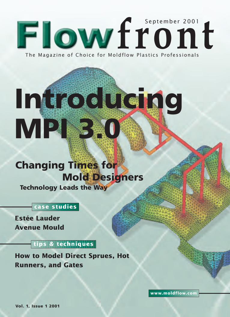
front
Vol. 1, Issue 1 2001
IntroducingMPI 3.0
Estée LauderAvenue Mould
case studies
tips & techniques
How to Model Direct Sprues, HotRunners, and Gates
www.moldflow.com
Changing Times forMold Designers
Technology Leads the Way
September 2001
The Magazine of Choice for Moldf low P last ics Profess ionals

Flow front
contentsfocus onMoldflow Manufacturing Solutions for the Automation, Control
and Monitoring of the Injection Molding Process
cover storyIntroducing MPI 3.0 - Moldflow Plastics Insight and C-MOLD
2000 Work in Synergy
cover story 15
IntroducingMPI 3.0!
For more information, contact us at:Tel: 508-358-5848Fax: 508-358-5868Web: www.moldflow.comEmail: [email protected]: 430 Boston Post Road
Wayland, MA 01778Editor: Laura CarrabineCopy Editor: Marcia SwanDesigner: Joanna King
How to Advertise
Contact Marcia Swan at 607-257-4280, ext. 467for rates and availability, or go to our Web site atwww.moldflow.com and click on the FLOWfronticon, then click for advertisers. Here you candownload a PDF file that describes our insertionorder and rates.
focus on 5
ManufacturingSolutions forInjection Molding
from the editor
tips and techniques
the executive view
the analyst says
professional developmentEnhancing Customer Education
real world successAvenue Moulds Wins Top
Honors as Toolmaker of the
Year
the polymer pagesMoldflow Plastics Insight 3.0
Thermoplastic Materials
Properties Database
learning curvesPlastics Engineering Education
at the University of
Massachusetts Lowell
what’s newExploring Moldflow Plastics
Insight 3.0 Finite-Element
Meshing Capabilities
design & moldingChanging Times for Mold
Designers - Technology Leads
the Way
user reviewEstée Lauder Uses Moldflow Part
Adviser to Design Sleek Shapes
for Cosmetic Lines
FEATURES5
15
11
12
22
23
26
28
30
4
9
19
33
COLUMNS
DEPARTMENTS
©2001 Moldflow Corporation. All rights reserved. Flowfront is a bi-yearly publication of Moldflow Corporation

Harry “Hercules” Adams: Ski equipmentBob “The Conqueror” Carson: Assembly machinery Steve “Invincible” Thomas: Medical instruments
New SolidWorks Office.More than a great value, it gives you
quite a powerful feeling.You can do it all. Now everything you need to beef-up your productivity and add more
muscle to your presentations is in your hands. You are the product designer with all the tools: � SolidWorks® 3D CAD software � PhotoWorks™ � SolidWorks Animator � 3D Instant Website
� SolidWorks Toolbox � FeatureWorks® � SolidWorks Utilities. You have all the power in one very affordable package. SolidWorks Office, the complete 3D CAD solution. Find out more, big guy.
Log on to: www.solidworks.com/flowpower or call 1-800-693-9000 ext. 3556.
©2001 SolidWorks Corporation. SolidWorks and the SolidWorks logo are registered trademarks and PhotoWorks is a trademark of SolidWorks Corporation. FeatureWorks is a registered trademark of Geometric Software Solutions Co. Limited. All other company and product names are trademarks of their respective owners.
4Flow front Vol . 1 I ssue 1 www.moldflow.com
from the editor
Dear Readers,
Welcome to the first edition of the new format of Flowfront. Flowfront begins its life cycle as a semi-annualpublication with an issue targeted for spring and fall of each year. Each issue contains a myriad of compellingarticles that are focused on technology, academic and R&D breakthroughs, and industry trends and issues. Thisnew magazine format allows us to get more in depth on each topic we cover.
Flowfront, unlike other publications that briefly touch on issues important to injection molding professionals, will explore these topicsmore deeply and help our readers find solutions to the problems they face every day. For this to happen, we need contributions from ourreaders. We are always on the lookout for interesting application stories, topics of industry interest, and articles discussing technology andautomation. If you feel that you have a topic or story to contribute, we encourage you to contact us.
Moldflow product line manager Dean Piepiora explains Moldflow's exciting new Synergy technology inside Moldflow Plastics Insight3.0. Synergy is a powerful new pre- and post-processor for model preparation and cleanup, as well as for viewing and manipulatinganalysis results. The technological breakthrough integrates the best features of Moldflow Plastics Insight (MPI) and C-MOLD 2000 (CM2K) products into a single, merged product family. Also in this issue, product line manager Peter Rucinski offersinsight to Moldflow's Manufacturing Solutions for automating, controlling, and monitoring injection-molding processes. He gives full,updated descriptions of Moldflow Plastics Xpert, Moldflow Shotscope, and Moldflow EZ Track manufacturing software solutions.
Each edition of Flowfront will feature innovative commentary authored by Moldflow customers and partners, as well as Moldflowresources. In fact, each month guest author and Gartner Group research director Marc Halpern, Ph.D., will offer his overviews ofCAD/CAM/CAE, plastics engineering, e-commerce, and the supply chain. In this issue, he addresses the need for manufacturers andsuppliers to develop collaborative product commerce (CPC) networks.
As you will see in this issue, Moldflow customers Avenue Mould (Sligo, Ireland) and Estée Lauder (New York, NY) offer insights as tohow these world class manufacturers are using Moldflow products to reduce product development lead times, enhance product quality,and win industry awards! Each Flowfront edition will contain exclusive customer success stories from applications around the world. Ifyou would like your application featured in an upcoming issue of Flowfront, please contact me at [email protected].
Also in this issue, Barr Klaus, vice-president of technology at Milacron, Inc., comments about how Milacron is responding to the globalenergy crisis in the Executive Spotlight. This column is a forum for senior management to discuss industry trends, solutions to problems,and what's on the horizon in terms of new technology. In his commentary, Mr. Klaus explains how all-electric injection molding machinescan help save manufacturers millions of dollars in terms of conserving energy and why the benefits of converting to all-electric faroutweigh the costs of retaining inefficient equipment.
Professor Robert Malloy of the Plastics Engineering Program at the University of Massachusetts Lowell provides an interesting historicaloverview of the Plastics Engineering Program at the school. From its humble beginnings in 1895, the program today is rich in technologyand resources. Support and endowments from outside sources such as Moldflow and Milacron are testament to the program's success.
This issue of Flowfront also provides tips and techniques for using Moldflow Plastics Advisers (MPA) 5.0 design-for-manufacture analysissoftware from product line manager Murali Anna-Reddy. Using MPA tools, designers can test every part and mold concept formanufacturing feasibility before the tool is cut, when the cost of change is minimal.
ProMold's sales and engineering manager, Scott Peters, tells us how the role of mold designer has changed over the course of his career. Fromoverpaid draftspeople to valued team members, Scott says that technically savvy mold designers today are key to a manufacturer's success.
Soon, Moldflow will open its Center for Professional Development. Stephen Thompson, Moldflow's global training manager, explainswhy the facility came to be and how it will be used. The Center is a corporate university that is being developed for Moldflow customersto help empower their Moldflow users.
Enjoy this first issue. We are excited to bring you the latest news and technology via this format. We welcome reader input and encourageyou to submit article ideas, suggestions, and comments about what you like and don't like about the publication. If you have softwaretips and/or techniques that you would like to share, please do. Send your feedback to [email protected].
Laura CarrabineEditor
Welcome
5Flow front Vol . 1 I ssue 1 www.moldflow.com
Focuson
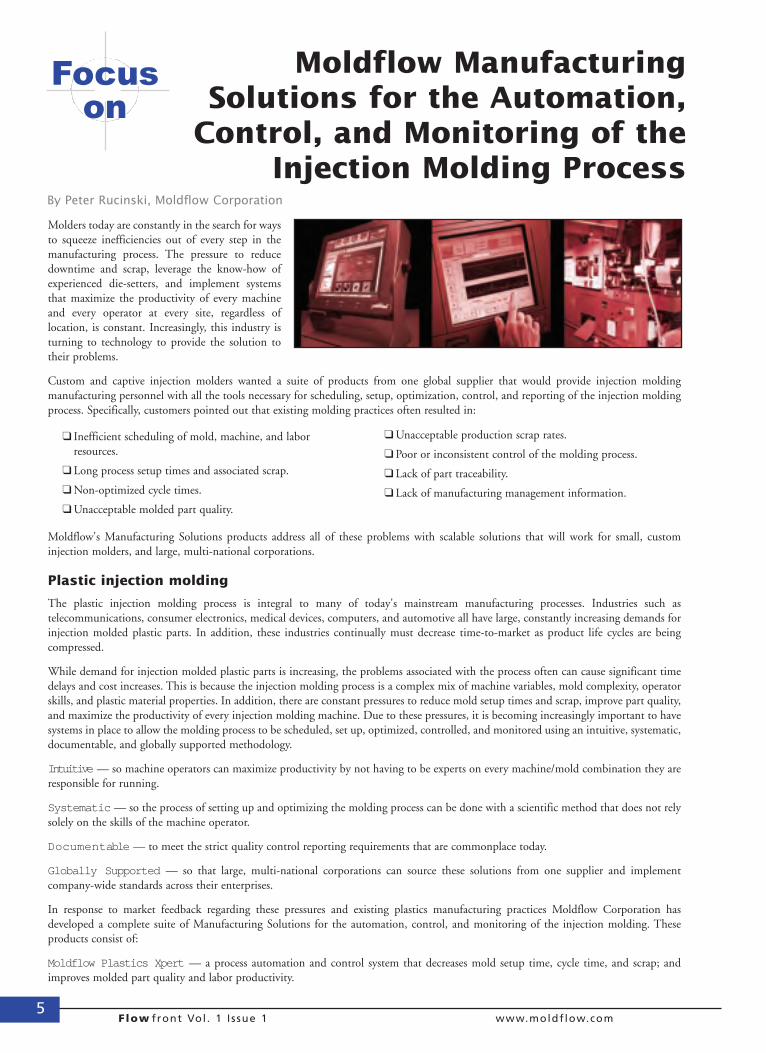
Moldflow ManufacturingSolutions for the Automation,
Control, and Monitoring of theInjection Molding Process
Molders today are constantly in the search for waysto squeeze inefficiencies out of every step in themanufacturing process. The pressure to reducedowntime and scrap, leverage the know-how ofexperienced die-setters, and implement systemsthat maximize the productivity of every machineand every operator at every site, regardless oflocation, is constant. Increasingly, this industry isturning to technology to provide the solution totheir problems.
Custom and captive injection molders wanted a suite of products from one global supplier that would provide injection moldingmanufacturing personnel with all the tools necessary for scheduling, setup, optimization, control, and reporting of the injection moldingprocess. Specifically, customers pointed out that existing molding practices often resulted in:
Moldflow's Manufacturing Solutions products address all of these problems with scalable solutions that will work for small, custominjection molders, and large, multi-national corporations.
Plastic injection molding
The plastic injection molding process is integral to many of today's mainstream manufacturing processes. Industries such astelecommunications, consumer electronics, medical devices, computers, and automotive all have large, constantly increasing demands forinjection molded plastic parts. In addition, these industries continually must decrease time-to-market as product life cycles are beingcompressed.
While demand for injection molded plastic parts is increasing, the problems associated with the process often can cause significant timedelays and cost increases. This is because the injection molding process is a complex mix of machine variables, mold complexity, operatorskills, and plastic material properties. In addition, there are constant pressures to reduce mold setup times and scrap, improve part quality,and maximize the productivity of every injection molding machine. Due to these pressures, it is becoming increasingly important to havesystems in place to allow the molding process to be scheduled, set up, optimized, controlled, and monitored using an intuitive, systematic,documentable, and globally supported methodology.
Intuitive — so machine operators can maximize productivity by not having to be experts on every machine/mold combination they areresponsible for running.
Systematic — so the process of setting up and optimizing the molding process can be done with a scientific method that does not relysolely on the skills of the machine operator.
Documentable — to meet the strict quality control reporting requirements that are commonplace today.
Globally Supported — so that large, multi-national corporations can source these solutions from one supplier and implementcompany-wide standards across their enterprises.
In response to market feedback regarding these pressures and existing plastics manufacturing practices Moldflow Corporation hasdeveloped a complete suite of Manufacturing Solutions for the automation, control, and monitoring of the injection molding. Theseproducts consist of:
Moldflow Plastics Xpert — a process automation and control system that decreases mold setup time, cycle time, and scrap; andimproves molded part quality and labor productivity.
❑ Inefficient scheduling of mold, machine, and labor resources.
❑ Long process setup times and associated scrap.
❑ Non-optimized cycle times.
❑ Unacceptable molded part quality.
❑ Unacceptable production scrap rates.
❑ Poor or inconsistent control of the molding process.
❑ Lack of part traceability.
❑ Lack of manufacturing management information.
By Peter Rucinski, Moldflow Corporation
6Flow front Vol . 1 I ssue 1 www.moldflow.com
Shotscope — a process monitoring andanalysis system that collects critical data inreal time from the injection moldingmachine and then records, analyzes, andreports on that data.
EZ-Track — a real time productionmonitoring and reporting system that canbe attached to virtually any cyclicmanufacturing equipment.
Moldflow Plastics Xpert
Throughout the injection moldingindustry today, the number of molds thatmust be set up and optimized for high-volume part production is far outpacingthe number of process engineers ortrained technicians qualified to do so. It isnot uncommon for a molding operationto have a small number of individuals whohave the education or experience to set upthe injection molding process. And, eventhose who can set up the process often donot have time to optimize it due toproduction pressures. This scenario resultsin problems such as long process setuptimes and associated scrap, non-optimizedcycle times, unacceptable molded partquality, unacceptable production scraprates, and poor or inconsistent control ofthe molding process.
Moldflow Plastics Xpert (MPX) processautomation and control technologyprovides machine operators with an easy-to-learn and easy-to-use tool for the setup,optimization, and control of the injectionmolding process. MPX allows a less-experienced operator to set up molds,optimize the process, and controlproduction.
MPX functionality isarranged into threemodules
I: The Setup Xpert module allows users toperform a variety of injection-velocity andpressure-phase-related setup routines tofix certain defects, such as short shots,flash, burn marks, sink marks, etc.Setup Xpert helps users achieve one good
molded part with no defects. A user moldsa part, then provides feedback to the MPXsystem regarding molded part quality.MPX processes this feedback along withdata being collected from the machineand (if necessary) determines a processchange that will improve the result.
After completing Setup Xpert anddetermining a combination of processingparameters that results in a single,satisfactorily molded part, the user stilldoes not know if these parameters arewithin a robust processing window. Forexample, any process parameter drift orvariation could easily result in parts ofunacceptable quality. In the injectionmolding process, variation is inherent.Whether the material, machine, process,operator, or environment causes it, therewill always be some variation. Thisvariation may or may not result in theproduction of bad parts. The variation isnormal, so the processing window mustbe robust enough to compensate for itwithout producing bad parts.
Design of experiments (DOE) is a usefultool in determining a robust processingwindow. The process window is defined asthe maximum amount of allowable processvariation — allowable, because it will notresult in the production of bad parts.
However, the historical perception of DOEis that it can be complicated, resulting inextensive training requirements and costsfor those responsible for running it. DOEis also time consuming, thus increasing thetime required to put a given mold intoproduction.
II: Optimize Xpert is an automated design
o fexperiments(DOE) thatcan be runquickly andeasily. Thesoftware does not requireany special training in statistical processcontrol. The goal of using Optimize Xpertis to obtain a robust processing windowthat will compensate for normal processvariation and ensure that acceptablequality parts are produced consistently.
While the Optimize Xpert DOE isautomated, easy to use, and relatively fastto complete, it is far from simple. Thereare five process parameters that can beused as DOE factors: packing pressure,mean (or average) injection velocity,velocity stroke, packing time, and coolingtime. In addition, there are a number ofmolding defects that can be used tomeasure part quality criteria, includingshort shots, flash, sink marks, burn marks,poor weld line appearance, weight,dimension, and warpage problems.
Assuming a robust processing window isdetermined using the Optimize Xpert,control mechanisms are still required tomake sure that the process stays within itsspecified limits.
III: Production Xpert is a comprehensiveprocess control system that maintains theoptimized processing conditionsdetermined with Optimize Xpert.Production Xpert allows the user tomaintain the production processconsistently, resulting in reduced rejectrates, higher part quality, and moreefficient use of machine time. If desired,Production Xpert will correct the processautomatically should it drift or go out ofcontrol.
There are still many functions required ina manufacturing operation, includingproduction scheduling, processmonitoring, statistical process control(SPC), statistical quality control (SQC),scrap tracking, production monitoringand reporting, preventive maintenancescheduling, and more.
Moldflow Shotscope
The Moldflow Shotscope processmonitoring and analysis system is acomprehensive product suite that collectscritical data in real time from moldingmachines on the factory floor. Thesoftware then records, analyzes, reports,and allows access to the information for
While demand for injection molded plasticparts is increasing, the problems associatedwith the process can often cause significanttime delays and cost increases.
Focuson
7Flow front Vol . 1 I ssue 1 www.moldflow.com
use in criticaldecision making.Addit ional ly,the product canbe used forboth plastic
injection molding and metaldie casting operations.
Shotscope allows molders to maximize theirproductivity by providing necessary tools toschedule mold and machine resourcesefficiently. The software also monitors thestatus and efficiency of any mold/machinecombination. By monitoring the efficiencyof a given mold/machine combination,molders can schedule jobs based on anumber of criteria, including minimumcycle times, highest production yields, andso on. Users also can define periodicmaintenance schedules for molds andmachines, and, after a pre-determined
number of cycles or operating hours,Shotscope will signal that preventativemaintenance is required.
Shotscope also maintains and displaysstatistical process control (SPC) data in avariety of formats, including trend charts,X-bar and R charts, histograms, andscatter diagrams. This informationprovides molders with the knowledge thattheir processes are in control, and, shouldthey go out of control, Shotscope can alertto an out-of-control condition and divertsuspect-quality parts. Furthermore,because the Shotscope system can measureand archive up to 50 process parameters(such as pressures, temperatures, times,etc.) for every shot monitored, theprocessing "fingerprint" for any part canbe stored and retrieved at any time in thefuture. This functionality is extremelyimportant to any manufacturersconcerned with the potential failure of amolded part in its end-use application (forexample, a medical device).
Shotscope maintains a reporting
mechanism that communicates all thedata collected and entered into the systemacross a manufacturing enterprise. As aresult, informed decisions can be made.Users can generate production, scrap,downtime, efficiency, and job summaryreports, any of which also can be used asdocumentation that accompanies partshipments.
Moldflow EZ-Track
Moldflow EZ-Track is software for real-time, plant-wide production monitoringand reporting. The EZ-Track system canbe attached to virtually any cyclicmanufacturing equipment and machinery,such as ultrasonic welders, assemblymachines, packaging equipment, etc., inaddition to injection molding machines.The EZ-Track system provides a scalablesolution for production monitoring,which can be used by small, custommolders with fewer than 10 machines orby large, multi-national corporations withdistributed injection molding andmanufacturing operations around theworld. There are extensive setupcapabilities that allow complete definitionof resources and flexible customization ofmost displays and reports.
The EZ-Track system collects data oncycle times, cycle/part counts, and numberof rejects, and it uses this data as thefoundation to perform powerfulscheduling tasks. The EZ-Track schedulercan check for mold conflicts and machinefeasibility and highlight any problems.The product continuously updatesestimates of job completion times basedon actual cycle time, downtime, rejects,and cavitation. In addition, the schedulersupports family molds.
EZ-Track monitors machine status,downtime, scrap, raw material usage, andlabor activity. The product can also beused to track machine efficiencies andcompute yield efficiencies. Labor, time,and attendance can be tracked byemployee and associated with machines,jobs, and activities. In this way,manufacturing managers can determinewhat jobs, machines, or activities requiremore labor resources than others require.This capability can allow managers toinvestigate areas where more efficiency,possibly in the form of processautomation, could be introduced intotheir manufacturing operations.
EZ-Track can be used to count good parts,diverted parts, packed cases, and othervariables. Downtime is measured
automatically and can be classified into anunlimited number of causes. Onceproduction data is collected, there is anextensive set of Web-based reports that canincorporate trend charts, tabular reports,pie charts, and Pareto charts. It is possibleto interface the EZ-Track system toERP/MRP systems via an advanced SQLdatabase that is open, fully documented,and ODBC-compliant.
There are many companies today across abroad range of industries for which plasticinjection molding and related upstreamand downstream manufacturing processesare on the critical path to achievingsuccessful and profitable productlaunches. These companies face a varietyof issues that make it difficult to remaincompetitive:
❑ Product life cycles are decreasing while short-term volume requirements are increasing exponentially.
❑ Customers continue to demand increased quality at lower costs.
❑ There is a shortage of skilled labor to run ever-more-sophisticated injection molding equipment.
❑ Inefficiencies in the scheduling, monitoring, and reporting of production do not allow for efficientmanufacturing management.
❑ Molded part process documentationand traceability increasingly are becoming a standard requirement.
Competitive companies require tools thatare intuitive, systematic, documentable,and globally supported, such as theMoldflow Manufacturing Solutionsproducts, to remain globally successful.
For the latest information on MoldflowManufacturing Solutions products, visitwww.moldflow.com.
Focuson

FREE ReportReveals the Best Kept Secrets
of In-Plant TrainingIf you’re considering the implementation of an in-
plant training program, one thing matters. Will itimprove your bottom line by giving you a competitiveadvantage now as well as in the future?
Recent breakthroughs in training technology aremaking this possible like never before. This newtechnology, developed by A. Routsis Associates, takesfull advantage of multimedia while using the latest inlearning technology. Utilizing this powerfulcombination results in shorter training times and higheremployee retention rates.
Over 100 Interactive Training titles, including moldmaking and mold design, injection molding technology& plastic part design.
For a FREE copy of The Best Kept Secrets of In-House Training and the latest issue of Plastics TrainingReview contact:
A. Routsis Associates, Inc.275 Donohue Rd, Suite 14 � Dracut, MA 01826
Tel:(978) 957-0700 � Fax:(978) 957-1860www.traininteractive.com
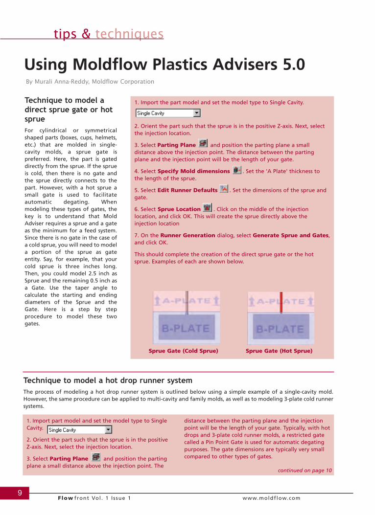
Technique to model adirect sprue gate or hotsprueFor cylindrical or symmetricalshaped parts (boxes, cups, helmets,etc.) that are molded in single-cavity molds, a sprue gate ispreferred. Here, the part is gateddirectly from the sprue. If the sprueis cold, then there is no gate andthe sprue directly connects to thepart. However, with a hot sprue asmall gate is used to facilitateautomatic degating. Whenmodeling these types of gates, thekey is to understand that MoldAdviser requires a sprue and a gateas the minimum for a feed system.Since there is no gate in the case ofa cold sprue, you will need to modela portion of the sprue as gateentity. Say, for example, that yourcold sprue is three inches long.Then, you could model 2.5 inch asSprue and the remaining 0.5 inch asa Gate. Use the taper angle tocalculate the starting and endingdiameters of the Sprue and theGate. Here is a step by stepprocedure to model these twogates.
9Flow front Vol . 1 I ssue 1 www.moldflow.com
tips & techniques
Using Moldflow Plastics Advisers 5.0By Murali Anna-Reddy, Moldflow Corporation
1. Import the part model and set the model type to Single Cavity.
2. Orient the part such that the sprue is in the positive Z-axis. Next, selectthe injection location.
3. Select Parting Plane and position the parting plane a smalldistance above the injection point. The distance between the partingplane and the injection point will be the length of your gate.
4. Select Specify Mold dimensions . Set the 'A Plate' thickness tothe length of the sprue.
5. Select Edit Runner Defaults . Set the dimensions of the sprue andgate.
6. Select Sprue Location . Click on the middle of the injectionlocation, and click OK. This will create the sprue directly above theinjection location
7. On the Runner Generation dialog, select Generate Sprue and Gates,and click OK.
This should complete the creation of the direct sprue gate or the hotsprue. Examples of each are shown below.
Sprue Gate (Cold Sprue) Sprue Gate (Hot Sprue)
Technique to model a hot drop runner systemThe process of modeling a hot drop runner system is outlined below using a simple example of a single-cavity mold.However, the same procedure can be applied to multi-cavity and family molds, as well as to modeling 3-plate cold runnersystems.
1. Import part model and set the model type to SingleCavity.
2. Orient the part such that the sprue is in the positive Z-axis. Next, select the injection location.
3. Select Parting Plane and position the partingplane a small distance above the injection point. The
distance between the parting plane and the injectionpoint will be the length of your gate. Typically, with hotdrops and 3-plate cold runner molds, a restricted gatecalled a Pin Point Gate is used for automatic degatingpurposes. The gate dimensions are typically very smallcompared to other types of gates.
continued on page 10
10Flow front Vol . 1 I ssue 1 www.moldflow.com
tips & techniques
4. Select Specify Mold dimensions . Set the APlate thickness to the length of the sprue. Turn on theFloating Plate, and set its thickness to the length of thehot drop.
5. Select Edit Runner Defaults . Set thedimensions of the sprue, runner and gate.
6. Select Sprue Location . Click on the middle ofthe injection location, and click OK. This will create thesprue directly above the injection location.
7. On the Runner Generation dialog, select GenerateSprue, and click OK.
8. Select Design Runners . This will allow you tocreate runners and gates manually. Click the bottom ofthe sprue. The Runner Creation dialog pops up. SelectCreate Drop and the hot drop will be createdautomatically using the dimensions specified earlier.
9. Only the gate is left to be created. Select DisplayBeam Elements to display the runner as a beamelement. This is quite useful, especially if the runner islarge and obstructs the view. Similarly, select DisplayCavities to turn off the display of the cavities. Thistoo can be helpful during the modeling of gates.
10. Now select Design Runners again and click onthe end of the hot drop and then on the injection cone.The gate will be created automatically between the hotrunner and the injection point.
This will complete the creation of a single-cavity moldwith a hot runner system. An example of such a modelis shown below. As mentioned earlier, the sameprocedure could be applied for creating hot runners formulti-cavity and family molds as well as 3-plate coldrunner systems. Examples of such molds are shownbelow.
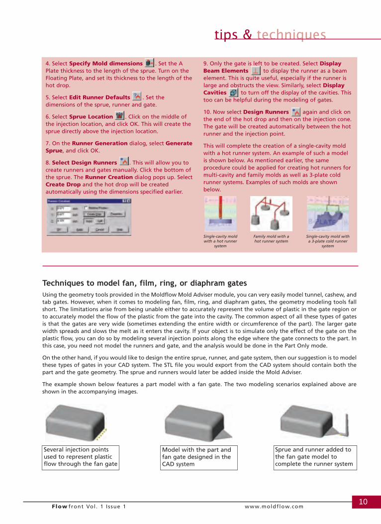
Techniques to model fan, film, ring, or diaphram gatesUsing the geometry tools provided in the Moldflow Mold Adviser module, you can very easily model tunnel, cashew, andtab gates. However, when it comes to modeling fan, film, ring, and diaphram gates, the geometry modeling tools fallshort. The limitations arise from being unable either to accurately represent the volume of plastic in the gate region orto accurately model the flow of the plastic from the gate into the cavity. The common aspect of all these types of gatesis that the gates are very wide (sometimes extending the entire width or circumference of the part). The larger gatewidth spreads and slows the melt as it enters the cavity. If your object is to simulate only the effect of the gate on theplastic flow, you can do so by modeling several injection points along the edge where the gate connects to the part. Inthis case, you need not model the runners and gate, and the analysis would be done in the Part Only mode.
On the other hand, if you would like to design the entire sprue, runner, and gate system, then our suggestion is to modelthese types of gates in your CAD system. The STL file you would export from the CAD system should contain both thepart and the gate geometry. The sprue and runners would later be added inside the Mold Adviser.
The example shown below features a part model with a fan gate. The two modeling scenarios explained above areshown in the accompanying images.
Model with the part andfan gate designed in theCAD system
Several injection pointsused to represent plasticflow through the fan gate
Sprue and runner added tothe fan gate model tocomplete the runner system
Single-cavity moldwith a hot runner
system
Family mold with ahot runner system
Single-cavity mold witha 3-plate cold runner
system
11Flow front Vol . 1 I ssue 1 www.moldflow.com
professional development
Savvy software providers offer flexible, innovative trainingprograms that help customers learn to quickly and efficientlybecome proficient using their software products. The initialchallenge for organizations such as Moldflow is to developeffective methods of empowering customers with the skills, tools,and information to harness knowledge and maximize businessperformance.
The next challenge is to align these outcomes with businessprocesses to deliver measurableresults. Moldflow customers needto implement software and trainusers while adhering to existingtime-to-market requirements andproduction deadlines. Sendingengineers and designers off-sitefor week-long training sessionsand on-the-job learning curvescan negatively affect new productdevelopment cycles.
Knowing these challenges and aspart of our commitment to helpour customers achieve maximumbusiness and productivity valuesas quickly as possible, Moldflow islaunching the Moldflow Centerfor Professional Development(MCPD). The MCPD is acorporate university that is beingdeveloped specifically for our customers to empower MPI users.
The MCPD comprises a worldwide team of professionals whospecialize in assessing, designing, developing, delivering,administering, and evaluating learning solutions to improvecustomer performance. These learning solutions will provide ablended mix of instructor-led classes; live, online collaborativelearning experiences; and Web-based, self-study resources.
New course structure
We are developing an enhanced Moldflow curriculum that willinclude a five-day Simulation Fundamentals class designed todeliver instruction for our MPI/Flow module while introducingstudents to the basics of the Cool and Warp modules. The primarypurpose is to "jump start" students so they are functional withbasic performance requirements once back at work. As follow-upfor students who wish to complete their Moldflow education, werecommend advanced training, which includes two-day classesfocusing on the Flow and Cool modules, as well as a one-day Warpclass.
With the release of MPI 3.0, a new, one-day update training classis being created for both MPI and former C-MOLD users. Thisclass will be given for the first time at the International MoldflowUser Group Conference in September and then offered regionally.
Our Web-based training initiative will allow students to haveround-the-clock access to Web-based, self-study resources createdby Moldflow. Web-based courses are planned to cover MPI 3.0modules for gas-assisted flow, injection compression, co-injection,stress, and thermoset molding analyses, and these will augment thecore MPI/Flow, Cool, and Warp classes. These Web-based coursesare expected to be available in stages beginning in January 2002.
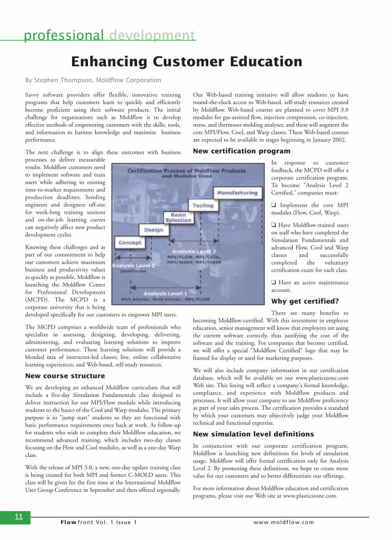
New certification program
In response to customerfeedback, the MCPD will offer acorporate certification program.To become "Analysis Level 2Certified," companies must:
❑ Implement the core MPImodules (Flow, Cool, Warp).
❑ Have Moldflow-trained userson staff who have completed theSimulation Fundamentals andadvanced Flow, Cool and Warpclasses and successfullycompleted the voluntarycertification exam for each class.
❑ Have an active maintenanceaccount.
Why get certified?
There are many benefits tobecoming Moldflow-certified. With this investment in employeeeducation, senior management will know that employees are usingthe current software correctly, thus justifying the cost of thesoftware and the training. For companies that become certified,we will offer a special "Moldflow Certified" logo that may beframed for display or used for marketing purposes.
We will also include company information in our certificationdatabase, which will be available on our www.plasticszone.comWeb site. This listing will reflect a company's formal knowledge,compliance, and experience with Moldflow products andprocesses. It will allow your company to use Moldflow proficiencyas part of your sales process. The certification provides a standardby which your customers may objectively judge your Moldflowtechnical and functional expertise.
New simulation level definitions
In conjunction with our corporate certification program,Moldflow is launching new definitions for levels of simulationusage. Moldflow will offer formal certification only for AnalysisLevel 2. By promoting these definitions, we hope to create morevalue for our customers and to better differentiate our offerings.
For more information about Moldflow education and certificationprograms, please visit our Web site at www.plasticszone.com.
Enhancing Customer EducationBy Stephen Thompson, Moldflow Corporation
12Flow front Vol . 1 I ssue 1 www.moldflow.com
real world success
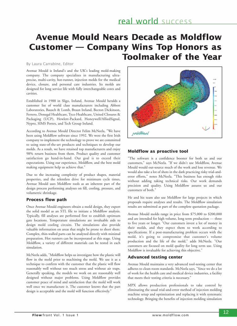
Avenue Mould is Ireland's and the UK's leading mold-makingcompany. The company specializes in manufacturing ultra-precise, multi-cavity, hot-runner, injection molds for the medicaldevice, closure, and personal care industries. Its molds aredesigned for long service life with fully interchangeable cores andcavities.
Established in 1988 in Sligo, Ireland, Avenue Mould heralds acustomer list of world class manufacturers including AbbottLaboratories, Bausch & Lomb, Braun Ireland, Becton Dickinson,Ferrero, Donegal Healthcare, Tyco Healthcare, United Closures &Packaging (UCP), Hewlett-Packard, Honeywell/AlliedSignal,Nypro, SIMS Portex, and Tech Group Ireland.
According to Avenue Mould Director Felim McNeela, "We havebeen using Moldflow software since 1992. We were the first Irishcompany to implement the technology to prove we are committedto using state-of-the-art products and techniques to develop ourmolds. As a result, we have retained top manufacturers and enjoy98% return business from them. Product quality and customersatisfaction go hand-in-hand. Our goal is to exceed theirexpectations. Using our experience, Moldflow, and the best moldmaking equipment help us achieve that."
Due to the increasing complexity of product shapes, materialproperties, and the relentless drive for minimum cycle times,Avenue Mould uses Moldflow tools as an inherent part of thedesign process performing analyses on fill, cooling, pressure, andvolumetric shrinkage.
Process flow path
Once Avenue Mould engineers obtain a mold design, they exportthe solid model as an STL file to initiate a Moldflow analysis.Typically, fill analyses are performed first to establish optimumgate locations. Temperature simulations are invaluable aids todesign mold cooling circuits. The simulations also providevaluable information on areas that might be prone to short shots.Complex, thin-walled parts can be analyzed directly with minimalpreparation. Hot runners can be incorporated at this stage. UsingMoldflow, a variety of different materials can be tested in eachsimulation.
McNeela adds, "Moldflow helps us investigate how the plastic willflow in the mold prior to machining the mold. We use it as atechnique to confirm with the customer that the plastic will flowreasonably well without too much stress and without air traps.Generally speaking, the models we work on are reasonably welldesigned without major problems. Using Moldflow providescustomer peace of mind and satisfaction that the mold will workwell once we manufacture it. The customer knows that the partdesign is acceptable and the mold will function effectively."
Moldflow as proactive tool
"The software is a confidence booster for both us and ourcustomers," says McNeela. "If we didn't use Moldflow, AvenueMould would out-source much of the work and lose revenue. Wewould also take a lot of shots in the dark practicing risky trial-and-error efforts," notes McNeela. "This business has enough riskswithout adding taking technical risks. Our work demandsprecision and quality. Using Moldflow assures us and ourcustomers of both."
He and his team also use Moldflow for large projects in whichproposals require analyses and results. The Moldflow simulationresults are submitted as part of the complete quotation package.
Avenue Mould molds range in price from $75,000 to $200,000and are intended for high volume, long term production — threeto five years or longer. "Our customers invest a lot of money intheir molds, and they expect them to work according tospecifications. If a post-manufacturing problem occurs with themold, it's going to compromise that customer's volumeproduction and the life of the mold," adds McNeela. "Ourcustomers are focused on mold quality for long term use. UsingMoldflow is invaluable for achieving this objective."
Advanced testing center
Avenue Mould maintains a very advanced tool-testing center thatadheres to clean-room standards. McNeela says, "Since we do a lotof work for the health care and medical device industries, a facilitythat meets their testing criteria is necessary."
MPX allows production professionals to take control byeliminating the usual trial-and-error method of injection moldingmachine setup and optimization and replacing it with systematictechnology. Bringing the benefits of injection molding simulation
Avenue Mould Nears Decade as MoldflowCustomer — Company Wins Top Honors as
Toolmaker of the YearBy Laura Carrabine, Editor
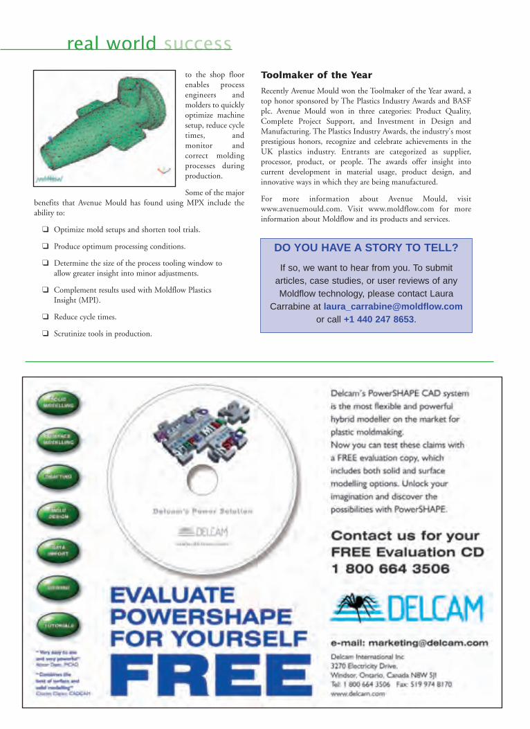
real world successto the shop floorenables processengineers andmolders to quicklyoptimize machinesetup, reduce cycletimes, andmonitor andcorrect moldingprocesses duringproduction.
Some of the majorbenefits that Avenue Mould has found using MPX include theability to:
❑ Optimize mold setups and shorten tool trials.
❑ Produce optimum processing conditions.
❑ Determine the size of the process tooling window to allow greater insight into minor adjustments.
❑ Complement results used with Moldflow Plastics Insight (MPI).
❑ Reduce cycle times.
❑ Scrutinize tools in production.
Toolmaker of the Year
Recently Avenue Mould won the Toolmaker of the Year award, atop honor sponsored by The Plastics Industry Awards and BASFplc. Avenue Mould won in three categories: Product Quality,Complete Project Support, and Investment in Design andManufacturing. The Plastics Industry Awards, the industry's mostprestigious honors, recognize and celebrate achievements in theUK plastics industry. Entrants are categorized as supplier,processor, product, or people. The awards offer insight intocurrent development in material usage, product design, andinnovative ways in which they are being manufactured.
For more information about Avenue Mould, visitwww.avenuemould.com. Visit www.moldflow.com for moreinformation about Moldflow and its products and services.
DO YOU HAVE A STORY TO TELL? If so, we want to hear from you. To submit
articles, case studies, or user reviews of anyMoldflow technology, please contact Laura
Carrabine at [email protected] call +1 440 247 8653.
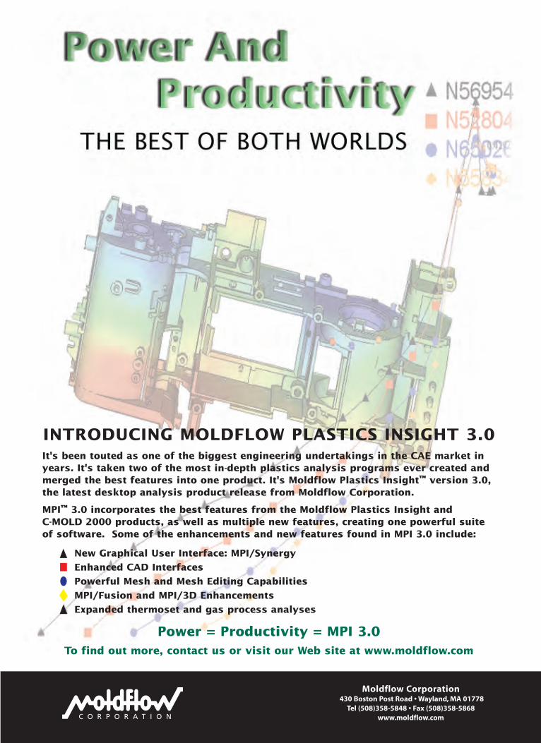
INTRODUCING MOLDFLOW PLASTICS INSIGHT 3.0It's been touted as one of the biggest engineering undertakings in the CAE market inyears. It's taken two of the most in-depth plastics analysis programs ever created andmerged the best features into one product. It's Moldflow Plastics Insight™ version 3.0,the latest desktop analysis product release from Moldflow Corporation.
MPI™ 3.0 incorporates the best features from the Moldflow Plastics Insight and C-MOLD 2000 products, as well as multiple new features, creating one powerful suiteof software. Some of the enhancements and new features found in MPI 3.0 include:
New Graphical User Interface: MPI/Synergy
Enhanced CAD Interfaces
Powerful Mesh and Mesh Editing Capabilities
MPI/Fusion and MPI/3D Enhancements
Expanded thermoset and gas process analyses
Power = Productivity = MPI 3.0 To find out more, contact us or visit our Web site at www.moldflow.com
C O R P O R A T I O N
Moldflow Corporation430 Boston Post Road • Wayland, MA 01778
Tel (508)358-5848 • Fax (508)358-5868www.moldflow.com
15Flow front Vol . 1 I ssue 1 www.moldflow.com
cover story
It's been touted as one of the biggestengineering undertakings in the CAEmarket in years. It's taken two of the mostin-depth plastics analysis programs evercreated and merged the best features intoone product. It's Moldflow PlasticsInsight™ version 3.0, the latest desktopanalysis product release from MoldflowCorporation.
The Moldflow Plastics Insight (MPI™)and C-MOLD® 2000 suites of softwareare advanced injection molding softwaretools for predicting and eliminatingpotential manufacturing problems beforethey occur. When Moldflow Corporationand C-MOLD became one company inearly 2000, one of the first goals set amongthe management and developers was tointegrate the two existing advancedanalysis products into one superset. Sincethat time, under the code name "Synergy,"Moldflow development has moved aheadfull force to create this integrated,advanced analysis product, which is beingreleased as MPI version 3.0.
This product development effort has beenaccomplished on both technology anduser-interface levels. In addition, manynew features have been added to leveragethe combined technical expertise of theMoldflow and C-MOLD productengineering teams. The result is a productmuch more powerful than the sum of thetwo — the definition of Synergy!
Many release goals and user enhancementrequests drove the development of MPI3.0. One major enhancement request wasto improve the integration to leading
CAD packages to make it easier to get 3Dsolid CAD models into the Moldflowenvironment. Users also needed meshingand mesh editing tools to create a finite-element model that would be completelyready for analysis. To accomplish this,Moldflow developers created a new userinterface to perform all pre- and post-processing functionality and eliminate theneed for users to switch among multipleprograms to complete their tasks. Userrequests also made it very important for usto put enhancements for MPI/Fusion and3D analyses on the critical path. Thiscombined development work also fosteredimprovements to the materials database
and resulted in additional benefits to otheranalysis modules. A description of some ofthe major features and functionalityenhancements follows.
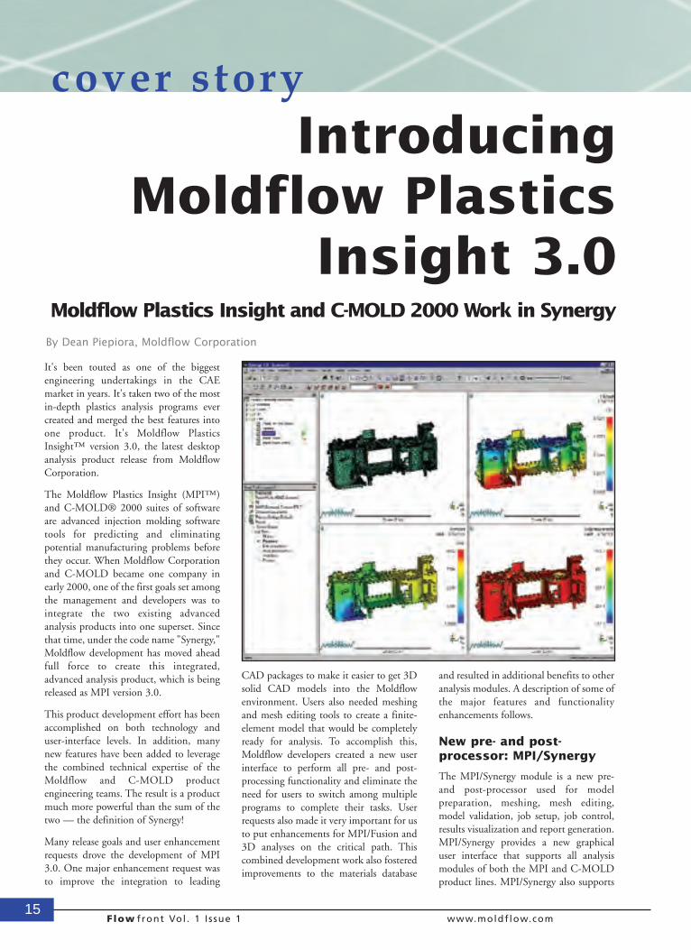
New pre- and post-processor: MPI/Synergy
The MPI/Synergy module is a new pre-and post-processor used for modelpreparation, meshing, mesh editing,model validation, job setup, job control,results visualization and report generation.MPI/Synergy provides a new graphicaluser interface that supports all analysismodules of both the MPI and C-MOLDproduct lines. MPI/Synergy also supports
IntroducingMoldflow Plastics
Insight 3.0 Moldflow Plastics Insight and C-MOLD 2000 Work in Synergy
By Dean Piepiora, Moldflow Corporation
16Flow front Vol . 1 I ssue 1 www.moldflow.com
m i d p l a n e ,MPI/Fusion and 3DTET mesh models in asingle multi-window, multi-document, Windows-basedenvironment.
The MPI/Synergy user interface hasbeen streamlined to provide a cleaner,more intuitive working environment.The previous six-tabbed projectmanager has been replaced with twodockable work panes. The top pane,Project View, provides a quick visualreview of the different studies and analysesperformed and is used for organizingprojects. The lower pane provides theStudy Tasks, which are designed to guideusers through the necessary tasks toimport their CAD model, then set up andrun an analysis.
MPI/Synergy takes advantage of many ofthe popular Windows-based, ease-of-usefunctions, including drag-and-drop,double clicking, and right-mouse-buttonaccess for performing the most commontasks, and also includes many commandshortcuts (control keys) that advancedusers prefer to use.
Enhanced CAD Interfacesand GeometryRepresentation
The Moldflow Design Link (MDL) iscompletely integrated with MPI/Synergy.MDL provides data integration to leadingCAD systems through standard interfacessuch as IGES, STEP, and ParaSolid. Newin MPI 3.0 is an option to directly importPro/ENGINEER® part files. This workswithout the need to have a separatePro/ENGINEER license.
In addition, imported geometry is nowrepresented in MPI/Synergy as trimmedNURBS surfaces. These surfaces can beindependently viewed, grouped, ormeshed. NURBS surfaces are supportedby the IGES, STEP, ParaSolid andPro/ENGINEER file formats.
Meshing and Mesh Editing
MPI/Synergy provides a complete set oftools to create, edit and validate meshesfor midplane, MPI/Fusion and full 3Danalyses. Moldflow is the only CAE
softwareavailable today thatsupports simulation of theplastic injection molding processwith all three of these mesh types.
New in MPI 3.0 is a fully automatic 3Dtetrahedral mesh generator. Unique to thisfeature is the ability to control the numberof elements through the thickness of apart. This complements other automaticmeshing capabilities already in theproduct for creating midplane andMPI/Fusion meshes.
Also new in MPI 3.0 is a large set ofmeshing editing and validation tools. Thenew Mesh Diagnostics provide the abilityto easily visualize the quality of the meshin areas such as aspect ratio, overlappingelements, connectivity, thickness, freeedges, and occurrence number. Severalnew mesh editing tools are provided toclean up and refine the mesh. Also, newselection methods are available to allowusers to quickly and easily focus onspecific problem areas.
In addition, MPI 3.0 also includesmodeling wizards to automate thecreation of multiple cavities, runnersystems, cooling systems, and moldinserts. To learn more about mesh typesand modeling tools, see "ExploringMoldflow Plastics Insight 3.0 Finite-Element Meshing Capabilities" on page26.
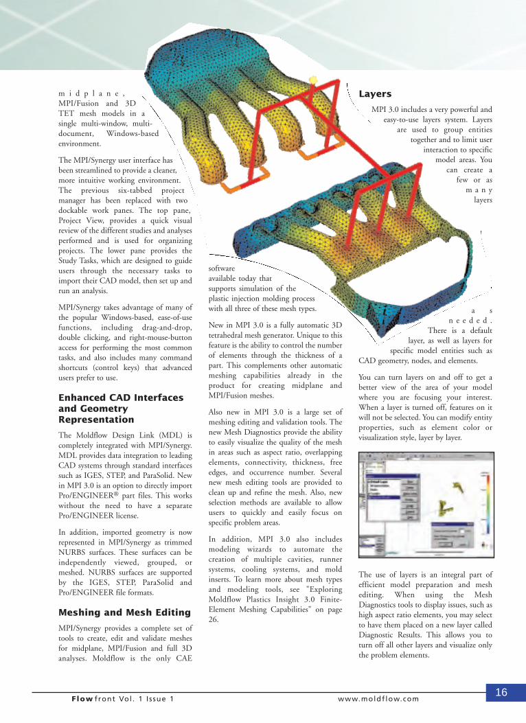
Layers
MPI 3.0 includes a very powerful andeasy-to-use layers system. Layers
are used to group entitiestogether and to limit user
interaction to specificmodel areas. You
can create afew or as
m a n ylayers
a sn e e d e d .
There is a defaultlayer, as well as layers for
specific model entities such asCAD geometry, nodes, and elements.
You can turn layers on and off to get abetter view of the area of your modelwhere you are focusing your interest.When a layer is turned off, features on itwill not be selected. You can modify entityproperties, such as element color orvisualization style, layer by layer.
The use of layers is an integral part ofefficient model preparation and meshediting. When using the MeshDiagnostics tools to display issues, such ashigh aspect ratio elements, you may selectto have them placed on a new layer calledDiagnostic Results. This allows you toturn off all other layers and visualize onlythe problem elements.
17Flow front Vol . 1 I ssue 1 www.moldflow.com
The new Expand Layer tool allows you toexpand an area you have selected toinclude the next layer of connectedelements, by one or more levels ofconnection. This allows you to editproblem elements easily, since you canvisualize the connecting elements.
Results synchronizationand window locking
MPI/Synergy includes a new ResultsSynchronization capability for comparingresults. Typically, you would run ananalysis, review the results, make somechanges, and re-run the analysis. It is nowpossible to open the results from the newanalysis and display them using the samescale as the results of the first analysis. Thisgreatly helps in interpreting results andidentifying the analysis that provides thebetter results.
Complementing Results Synchronizationis a new Window Locking feature thatallows any graphical windows to be lockedtogether. Locking links view manipulationoperations (pan, rotate, zoom, etc.) suchthat all window view changes are donesimultaneously. This feature is usefulduring both the pre- and post-processingstages. During pre-processing, you candisplay your mesh in one window and themesh Diagnostic Results in another tosimplify mesh editing tasks. During post-processing, you can modify the view ofdifferent result quantities displayed inmultiple windows at the same time tofacilitate interpreting the results.
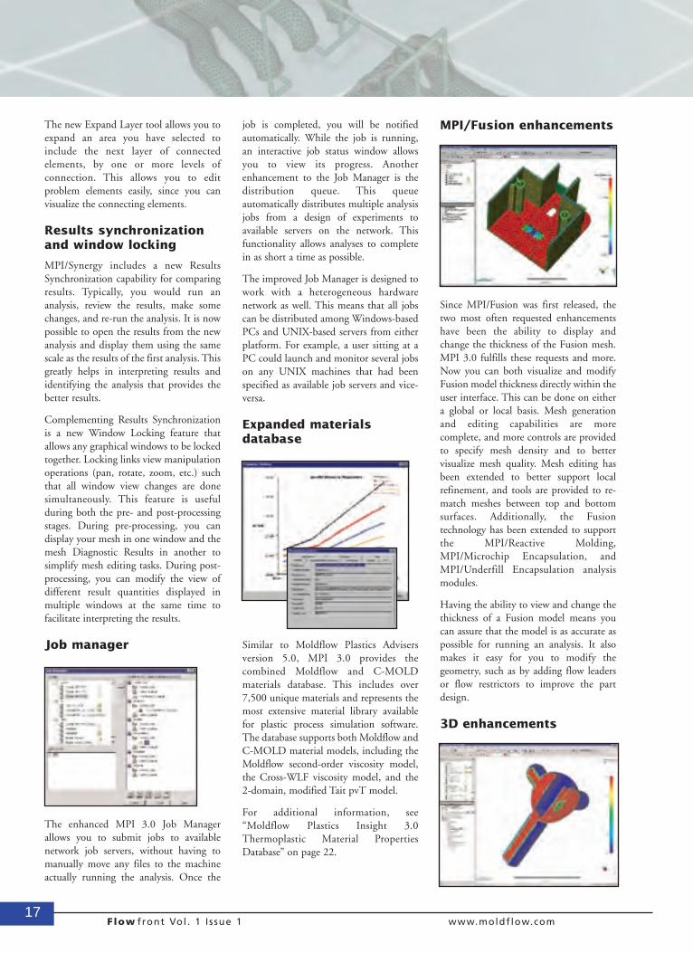
Job manager
The enhanced MPI 3.0 Job Managerallows you to submit jobs to availablenetwork job servers, without having tomanually move any files to the machineactually running the analysis. Once the
job is completed, you will be notifiedautomatically. While the job is running,an interactive job status window allowsyou to view its progress. Anotherenhancement to the Job Manager is thedistribution queue. This queueautomatically distributes multiple analysisjobs from a design of experiments toavailable servers on the network. Thisfunctionality allows analyses to completein as short a time as possible.
The improved Job Manager is designed towork with a heterogeneous hardwarenetwork as well. This means that all jobscan be distributed among Windows-basedPCs and UNIX-based servers from eitherplatform. For example, a user sitting at aPC could launch and monitor several jobson any UNIX machines that had beenspecified as available job servers and vice-versa.
Expanded materialsdatabase
Similar to Moldflow Plastics Advisersversion 5.0, MPI 3.0 provides thecombined Moldflow and C-MOLDmaterials database. This includes over7,500 unique materials and represents themost extensive material library availablefor plastic process simulation software.The database supports both Moldflow andC-MOLD material models, including theMoldflow second-order viscosity model,the Cross-WLF viscosity model, and the2-domain, modified Tait pvT model.
For additional information, see“Moldflow Plastics Insight 3.0Thermoplastic Material PropertiesDatabase” on page 22.
MPI/Fusion enhancements
Since MPI/Fusion was first released, thetwo most often requested enhancementshave been the ability to display andchange the thickness of the Fusion mesh.MPI 3.0 fulfills these requests and more.Now you can both visualize and modifyFusion model thickness directly within theuser interface. This can be done on eithera global or local basis. Mesh generationand editing capabilities are morecomplete, and more controls are providedto specify mesh density and to bettervisualize mesh quality. Mesh editing hasbeen extended to better support localrefinement, and tools are provided to re-match meshes between top and bottomsurfaces. Additionally, the Fusiontechnology has been extended to supportthe MPI/Reactive Molding,MPI/Microchip Encapsulation, andMPI/Underfill Encapsulation analysismodules.
Having the ability to view and change thethickness of a Fusion model means youcan assure that the model is as accurate aspossible for running an analysis. It alsomakes it easy for you to modify thegeometry, such as by adding flow leadersor flow restrictors to improve the partdesign.
3D enhancements
18Flow front Vol . 1 I ssue 1 www.moldflow.com
MPI/Flow3D now works with theMPI/Reactive Molding module tosimulate thermoset injection molding,rubber injection molding, and thermosettransfer molding processes in full 3D. Inaddition, MPI/Flow3D has beenenhanced to support compressible flowduring the filling stage of the injectionmolding process, and now producesresults for clamp force and shear-ratecalculations for beams.
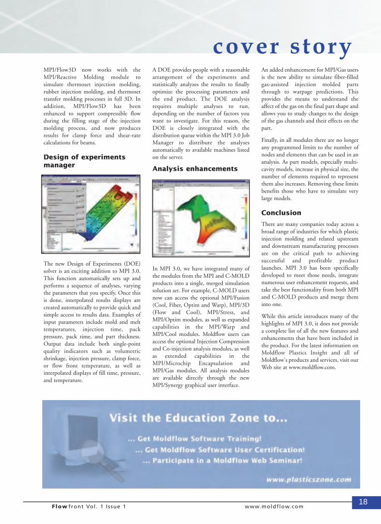
Design of experimentsmanager
The new Design of Experiments (DOE)solver is an exciting addition to MPI 3.0.This function automatically sets up andperforms a sequence of analyses, varyingthe parameters that you specify. Once thisis done, interpolated results displays arecreated automatically to provide quick andsimple access to results data. Examples ofinput parameters include mold and melttemperatures, injection time, packpressure, pack time, and part thickness.Output data include both single-pointquality indicators such as volumetricshrinkage, injection pressure, clamp force,or flow front temperature, as well asinterpolated displays of fill time, pressure,and temperature.
A DOE provides people with a reasonablearrangement of the experiments andstatistically analyzes the results to finallyoptimize the processing parameters andthe end product. The DOE analysisrequires multiple analyses to run,depending on the number of factors youwant to investigate. For this reason, theDOE is closely integrated with thedistribution queue within the MPI 3.0 JobManager to distribute the analysesautomatically to available machines listedon the server.
Analysis enhancements
In MPI 3.0, we have integrated many ofthe modules from the MPI and C-MOLDproducts into a single, merged simulationsolution set. For example, C-MOLD usersnow can access the optional MPI/Fusion(Cool, Fiber, Optim and Warp), MPI/3D(Flow and Cool), MPI/Stress, andMPI/Optim modules, as well as expandedcapabilities in the MPI/Warp andMPI/Cool modules. Moldflow users canaccess the optional Injection Compressionand Co-injection analysis modules, as wellas extended capabilities in theMPI/Microchip Encapsulation andMPI/Gas modules. All analysis modulesare available directly through the newMPI/Synergy graphical user interface.
An added enhancement for MPI/Gas usersis the new ability to simulate fiber-filledgas-assisted injection molded partsthrough to warpage predictions. Thisprovides the means to understand theaffect of the gas on the final part shape andallows you to study changes to the designof the gas channels and their effects on thepart.
Finally, in all modules there are no longerany programmed limits to the number ofnodes and elements that can be used in ananalysis. As part models, especially multi-cavity models, increase in physical size, thenumber of elements required to representthem also increases. Removing these limitsbenefits those who have to simulate verylarge models.
Conclusion
There are many companies today across abroad range of industries for which plasticinjection molding and related upstreamand downstream manufacturing processesare on the critical path to achievingsuccessful and profitable productlaunches. MPI 3.0 has been specificallydeveloped to meet those needs, integratenumerous user enhancement requests, andtake the best functionality from both MPIand C-MOLD products and merge theminto one.
While this article introduces many of thehighlights of MPI 3.0, it does not providea complete list of all the new features andenhancements that have been included inthe product. For the latest information onMoldflow Plastics Insight and all ofMoldflow's products and services, visit ourWeb site at www.moldflow.com.
cover story
19Flow front Vol . 1 I ssue 1 www.moldflow.com
the executive view
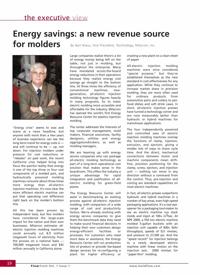
"Energy crisis" seems to wax andwane as a news headline, butanyone with more than a few yearsof business experience can see thelong-term trend for energy costs is —and will continue to be — up, notdown. For injection molders underpressure for cost reductions or"rebates" on past work, the recentCalifornia crisis helped bring intofocus the painful reality that energyis one of the top three or four costcomponents of a molded part, andhydraulically powered moldingmachines consume about three timesmore energy than all-electricinjection machines. It's now clear themore efficient electric machine canput that operating cost differenceright back on the molder's bottomline.
All this has been proven byindependent tests, but few moldershave considered the large-scaleimpact for the nation and their ownbusinesses. Milacron estimates all-electric injection molding machinescould annually cut 8.9 millionmegawatt hours of electricity fromthe process on a national basis —700,000 megawatt hours and $42million annually in California alone.
Large companies realize there's a lotof energy money being left on thetable, not just in molding, butthroughout the enterprise. Manyhave mandated across-the-boardenergy reductions in their operationsbecause they realize energy costsavings go straight to the bottomline. At three times the efficiency ofconventional machines, new-generation, all-electric injectionmolding technology figures heavilyin many programs. So to makeelectric molding more accessible andaffordable for the industry, Milacronhas opened the world's first EnergyResource Center for plastics injectionmolding.
The center addresses the interests oftop corporate management, moldmakers, financial executives, facilitydesigners, utilities and energyaggregators/brokers, as well asmolding managers.
We are teaming up with energyservice companies who can packageall-electric molding technology aspart of a long-term operational costsolution that makes sense in theboardroom. This offers the industry aunique advantage for rapidintegration and justification of all-electric molding for green-fieldplants.
The Energy Resource Center willassist in benchmarking an existingprocess against all-electric injectionmolding, with comparison of a widerange of cost and productivityfactors. We're already working withenergy service companies to givethem the benchmark data they needto make sound financial decisions inhelping their own customers designenergy-efficient facilities orprocesses. For customers who needmore data or assistance, the EnergyResource Center will run productionlots of product or provide fee-baseddesign services for re-configuring aplant for higher efficiency or
creating a new plant on a clean sheetof paper.
All-electric injection moldingmachines were once considered"special purpose," but they'veestablished themselves as the newstandard in cost-effectiveness for anyapplication. While they continue toincrease market share in precisionmolding, they are more often usedfor ordinary products fromautomotive parts and cutlery to pet-food dishes and soft drink cases. Inshort, all-electric injection presseshave turned a technology corner andare now measurably better thanhydraulic or hybrid machines formainstream applications.
The four independently poweredand controlled axes of electricinjection molding machines overlapthe functions of clamp, injection,extrusion, and ejection, giving amolder lots of ways to shave cycletime. And the direct, mechanicalconnections between motor andmachine components mean drift-free, precision positioning for theclamp, screw, ejectors, and injectionunit — nothing can move in anydirection without a command fromthe control. Thus, pre-injection andcoining are standard capabilities onmost electric machines.
In fact, all-electric presses outperformhydraulic and hybrid machines in anumber of key areas, even high-speedpackaging applications. It's a real eye-opener for a packaging tool-maker tosee an electric machine run stackmolds and inject at 100+ in3/sec. AtNPE 2000, a 550 ton electric machinemolded 5-gallon buckets with aninjection unit capable of 600+ lb/hrthroughput, speeds of 521 mm/sec,and pressure to 27,500 psi. And the"speed record" for injection belongsto a newly developed electricmachine with linear motors on theinjection axis: 2000 mm/sec for"paper-thin" molding.
Energy savings: a new revenue sourcefor molders By Barr Klaus, Vice President, Technology, Milacron, Inc.
20Flow front Vol . 1 I ssue 1 www.moldflow.com
the executive view
This new breed of electric machine is no longer a limiting factor on cycletime. It's not uncommon for an all-electric machine to “outrun” a moldthat was already taxing the limits of a high-performance, accumulator-boosted hydraulic machine, which shifts the focus of the process designquite a bit.
Mold design can be simpler and less expensive for an all-electric machineas well, because independent operation of clamp and injection allowsparting-line venting during tonnage build. This reduces cost and time forexcessive or difficult mold vents. Venting during pre-injection meansthere's less resistance in the mold; fill times are shorter. Hot gas that canoverheat the mold or melt is relieved. And mold maintenance is reducedbecause plasticizer does not build up so quickly in the vents.
Precise control of mold position also reduces wear, especially for stackmolds, allowing more design freedom and lower cost. Higher cavitation orlarger parts can often be accommodated in the same clamp area, too,because the precision shot control on an electric machine typically reducesclamp force requirements.
Electric injection molding machines continue steady market penetration inthe USA (30+%) and Japan (70+%) as energy costs rise and cost gapsbetween electrics and hydraulics decline. The only disadvantage of electrictechnology is that, ton for ton, ounce for ounce, the equipment has ahigher initial cost. Despite an initial cost premium, electric injectionmolding machines cost so much less to operate that real savings accruefrom the very first part molded on the machine, rapidly offsetting thedifference.
Can the "more expensive" machine actually cost less to own long term?The market has already decided that it does.
1. There's no warm-up, no delay inwaiting to find out what quality ofpart will be produced on the machinethat day. Output is usually stable andpredictable after the first 3-4 parts, aswell as after 4-5 years.
2. Material use can be lowered, close tothe threshold of a short shot, withoutexceeding that threshold.
3. There's no expense for cleaning,storage, disposal, or maintenance ofhydraulic fluid.
4. Air conditioning load on the plant isgreatly reduced.
5. Low noise levels (<68 dBA) allowmore flexibility in plant layout, sitingother functions or facilities nearmolding machines.
6. For new construction, electricalservice to the plant can be reducedabout two-thirds, tower waterrequirements reduced, and plumbingreduced.
7. Faster cycles are achieved due to theinherent ability to overlap functions.
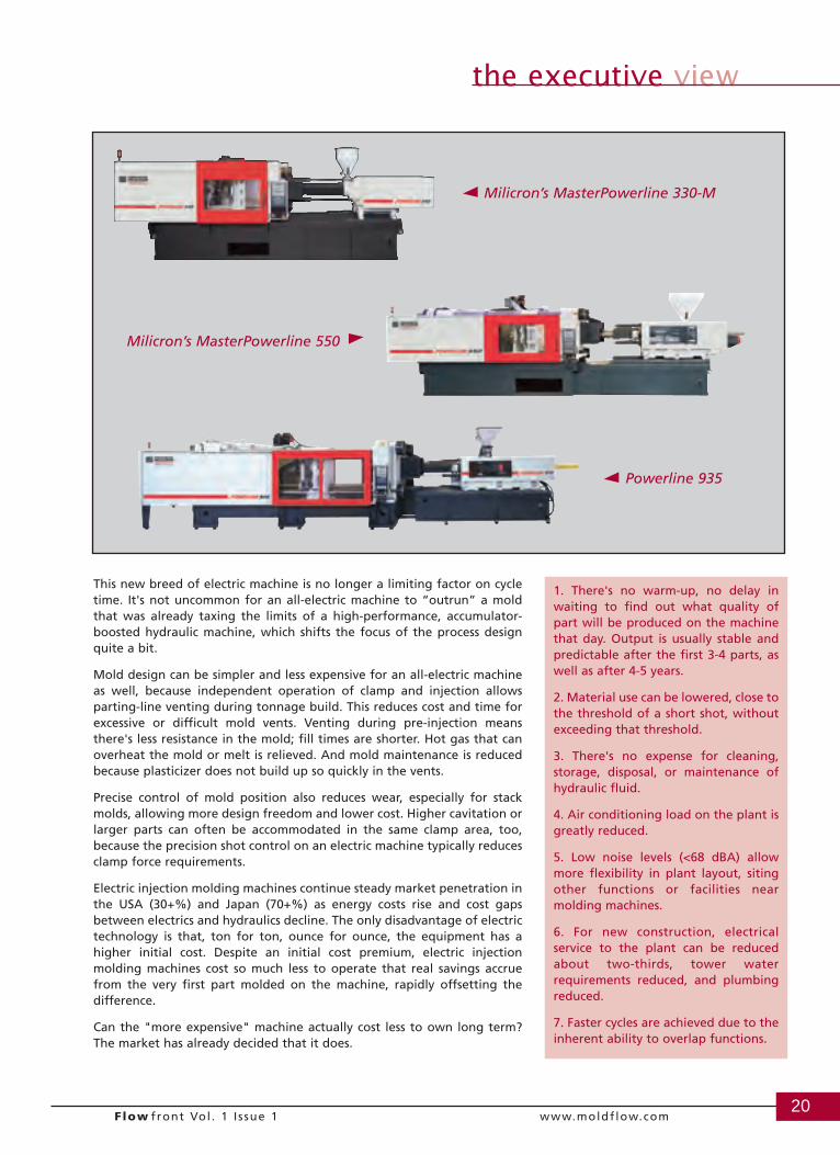
Milicron’s MasterPowerline 330-M
Powerline 935
Milicron’s MasterPowerline 550

Go to the source...Moldflow Plastics Labs constantly strive to provide the highest quality material data that yields themost accurate simulation results. Our commitment to continuous improvement has lead to numerousinnovations in material testing and behavior modeling as simulation technology has evolved.
Standard testing packages include a rigorous array of molding trials and data verification inMoldflow software. Each material tested and modeled for shrinkage predictions undergoes moldingtrials at over two dozen process settings. You can be sure that material properties data fromMoldflow Plastics Labs represents the best data for Moldflow simulations.
Moldflow Plastics Labs. The right source... and we prove it.
How can you be sure your material propertiesdata is right for Moldflow solutions?
C O R P O R A T I O N
Moldflow Corporation430 Boston Post Road • Wayland, MA 01778
Tel (508)358-5848 • Fax (508)358-5868www.moldflow.com
Moldflow Plastics Labs — USA31 Dutch Mill Road • Ithaca, NY 14850
Tel +1 607 257-4280 • Fax +1 607 [email protected]
Moldflow Plastics Labs — Australia259-261 Colchester Road • Kilsyth, Victoria 3137 Tel +1 61 3 9720 2088 • Fax +1 61 3 9729 0433
22Flow front Vol . 1 I ssue 1 www.moldflow.com
the polymer pages
Introduction
Moldflow Corporation's predictive analysis products, MoldflowPlastics Insight (MPI) and Moldflow Plastics Advisers (MPA), areused to simulate the complex behavior of injection-moldedpolymer melts. As Moldflow is constantly striving to assure thatour analysis results are as accurate as possible, one of our highestpriorities is to provide analysis solver algorithms and material datato achieve that goal. Regarding material data, Moldflow hasdeveloped some of the world's most innovative testing methods toassure that the material characteristics used for analysis representthose of injection-molded polymer melts. For example, Moldflowuses instrumented injection molding machines to determinerheological data, which is basic to all flow analyses.
This article covers the thermoplastic material properties requiredfor Moldflow analysis, the test methods used to derive the data,and some of the unique features which contribute to making theMoldflow Material Database the most comprehensive of its kindin the world. We follow internationally recognized standard testmethods as well as fully documented, internal standard methods,which have allowed us to achieve significant simulationimprovements. We provide a large database on as wide a range ofpolymer materials as possible, including data obtained from resinmanufacturers and third-party sources. Also introduced are thekey features and enhancements of the Moldflow Plastics Insight3.0 (MPI 3.0) Material Database.
Viscosity test methods
Moldflow's injection molding simulation software is used topredict the flow of polymer melts through mold sprues, runners,gates, and part cavities. As such, the most accurate analyses thatcan be performed start with the most accurate material rheologicaldata. Moldflow studies have clearly shown that rheologicalcharacteristics measured on instrumented injection moldingmachines can yield better simulation results for both filled andunfilled materials. Therefore, Moldflow's standard andrecommended test method employs instrumented injectionmolding machine rheometers.
However, standard capillary rheology data is widely available andit may be the only data available to many of our users. Othertesting techniques are also applied at times due to unique materialbehavior or limited access to preferred techniques. Moldflow willcontinue to provide such data upon request, and will offer suchdata within our standard databases.
A major drawback of having such a variety of testing techniques isthat Moldflow users were previously unaware of which testingtechnique was used for each data set. Therefore, a new feature ofthe MPI 3.0 Material Database is that each data set within a given
material grade now includes test method information, includingthe source, date of testing, and test method used, if theinformation is available.
Viscosity data models
In order to provide a more consistent database, the Cross/WLFmodel has been applied as the default model to the materials inMoldflow's database. The Moldflow second-order model is stillavailable and will be provided for many materials.
Viscosity indexes
Users have expressed a desire to have a simple, single-pointcomparison of viscosity for different grades. While such values donot show the relevant effects of shear and temperature uponviscosity, they often can be useful for comparing very similarmaterials. Melt Flow Rate (MFR) values are listed in the MoldflowMaterial Database when available. To avoid any confusion incomparisons, only complete MFR data sets, with appropriate testtemperature and plunger mass details, are listed.
However, it is important to note that there are some limitations toMFR data: it is not available for all materials, and it is ameasurement performed at fairly low shear rates relative to thosethat occur during injection molding. To address these issues, theMoldflow Material Database lists a Moldflow Viscosity Indexvalue. This single-point viscosity value is generated from amaterial’s actual viscosity model at a typical melt processingtemperature and a shear rate of 1000 1/sec. To further aid in theease of comparing materials of the same generic type, theMoldflow Material Database now has Moldflow Viscosity Indexvalues generated at the same temperature. This makes it very easyto search the database to identify materials of the same generictype with similar Moldflow Viscosity Index values.
Transition temperature data
A single-point transition temperature is used to define thematerial's state transition from melt to solid. This data iscommonly measured by a differential scanning calorimeter in acooling mode. However, various methods may be used bydifferent data sources. The MPI 3.0 Material Database nowprovides the method used to measure or estimate the transitiontemperature, if the information is available.
Thermal conductivity and specific heat data
The thermal properties of polymers change with temperature. Inorder to improve the accuracy of simulation, the ability to storeand use temperature-dependent thermal data is required. A new
Moldflow Plastics Insight 3.0Thermoplastic Material Properties
DatabaseBy Robert Newman, Moldflow Corporation
23Flow front Vol . 1 I ssue 1 www.moldflow.com
the polymer pages
feature of MPI 3.0 is that tabulated thermal conductivity andspecific heat data as a function of temperature can be used forsimulations. Such data is available for over 2,000 grades. Becausethermal properties data may be generated by a variety of testmethods, the MPI 3.0 Material Database now provides the testmethod used, if the information is available.
Pressure-volume-temperature data
The effect of temperature and pressure on material density is animportant property for simulations. Data can be gathered byeither indirect or direct dilatometry techniques.
pvT data model
The two-domain, modified Tait model currently is used for alldata in MPI 3.0. In order to assure consistency within a data set,all single-point density values are derived from the pvT model inuse. The MPI 3.0 Material Database now provides the source ofpvT data, date of testing, and test method used, if theinformation is available.
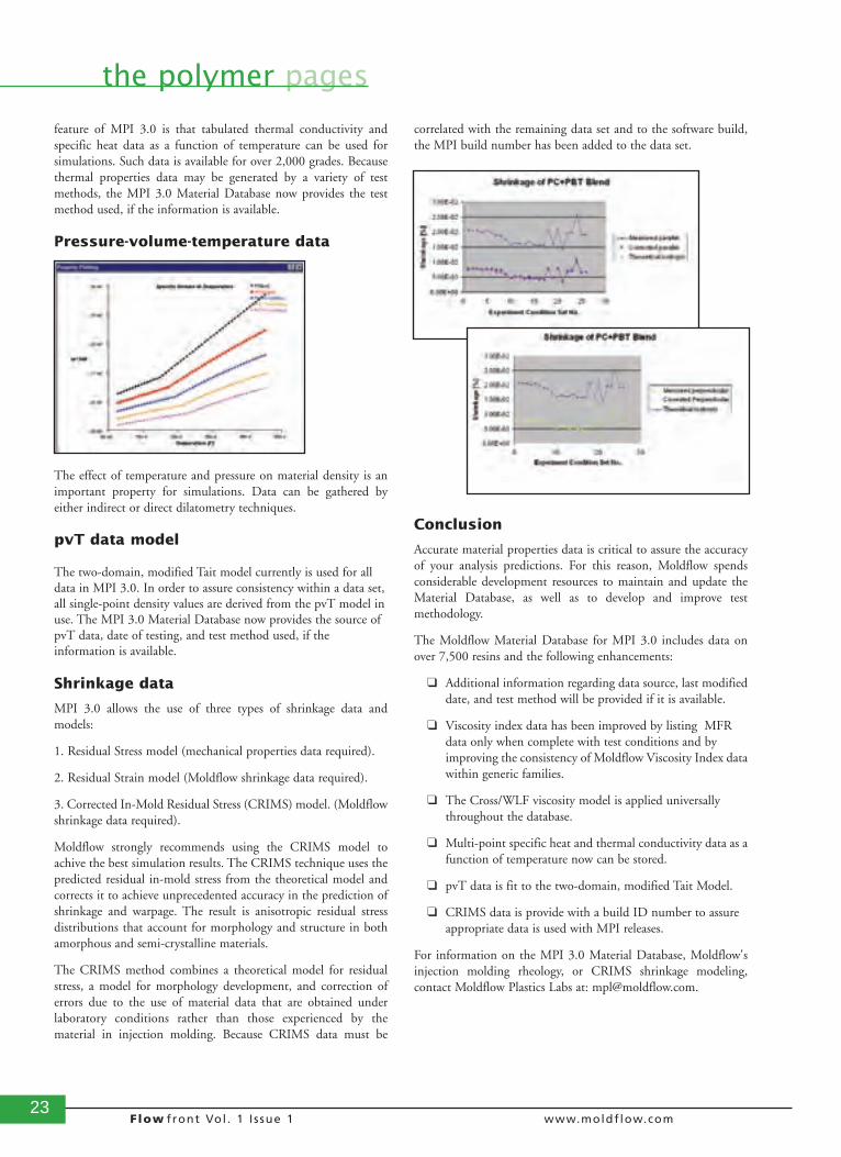
Shrinkage data
MPI 3.0 allows the use of three types of shrinkage data andmodels:
1. Residual Stress model (mechanical properties data required).
2. Residual Strain model (Moldflow shrinkage data required).
3. Corrected In-Mold Residual Stress (CRIMS) model. (Moldflowshrinkage data required).
Moldflow strongly recommends using the CRIMS model toachive the best simulation results. The CRIMS technique uses thepredicted residual in-mold stress from the theoretical model andcorrects it to achieve unprecedented accuracy in the prediction ofshrinkage and warpage. The result is anisotropic residual stressdistributions that account for morphology and structure in bothamorphous and semi-crystalline materials.
The CRIMS method combines a theoretical model for residualstress, a model for morphology development, and correction oferrors due to the use of material data that are obtained underlaboratory conditions rather than those experienced by thematerial in injection molding. Because CRIMS data must be
correlated with the remaining data set and to the software build,the MPI build number has been added to the data set.
Conclusion
Accurate material properties data is critical to assure the accuracyof your analysis predictions. For this reason, Moldflow spendsconsiderable development resources to maintain and update theMaterial Database, as well as to develop and improve testmethodology.
The Moldflow Material Database for MPI 3.0 includes data onover 7,500 resins and the following enhancements:
❑ Additional information regarding data source, last modifieddate, and test method will be provided if it is available.
❑ Viscosity index data has been improved by listing MFR data only when complete with test conditions and by improving the consistency of Moldflow Viscosity Index datawithin generic families.
❑ The Cross/WLF viscosity model is applied universally throughout the database.
❑ Multi-point specific heat and thermal conductivity data as afunction of temperature now can be stored.
❑ pvT data is fit to the two-domain, modified Tait Model.
❑ CRIMS data is provide with a build ID number to assure appropriate data is used with MPI releases.
For information on the MPI 3.0 Material Database, Moldflow'sinjection molding rheology, or CRIMS shrinkage modeling,contact Moldflow Plastics Labs at: [email protected].
24Flow front Vol . 1 I ssue 1 www.moldflow.com
learning curves
The past
The Plastics Engineering Program at the University ofMassachusetts Lowell has a very strong history as a leader in thefield of plastics education. The school, first known as the LowellTextile School, was founded in 1895 to serve the needs of the localtextile companies. Over time, the textile industry gradually startedmoving away from the Lowell area to the southern states, and thefocus of the school shifted to other newly emerging technicalareas. In 1954, the name of the school was changed to LowellTechnological Institute to reflect this broader educational mission,the very same year that the plastics program was founded. Therewere only eight students in the 1958 first graduating class whoreceived Bachelor of Science degrees in Plastics Technology. Astime went on, student interest in this novel plastics program grewrapidly, due in large part to the great demand and good jobopportunities for well-trained plastics technologists. The wordspread quickly, and subsequent classes included as many as 100graduates.
In these early years, three dedicated faculty members molded theprogram's curriculum and laboratory facilities. There is noquestion that Lowell's plastics program would not be where it istoday without the efforts of these three professors, especially thelate Russell W. Ehlers. Russ was responsible for bringing thestrong, hands-on processing focus to the plastics department,which still exists today. Russ also served as department chair formany years. The late Raymond Normandin was responsible fordeveloping the chemistry and materials aspects of the program.His influence can be still be felt today as approximately 25% ofthe current curriculum credits are chemistry and plastics materialscourses. The third founder, the late Henry Thomas, wasresponsible for bringing the solid engineering and design focus tothe department. Once again, this remains as an integral part of theprogram.
In fact, this balanced curriculum is what continues to make thenow Accrediting Board for Engineering and Technology (ABET)Plastics Engineering program at the University of MassachusettsLowell so unique. Students enrolled in the Plastics Engineeringprogram receive an education that is a well-rounded balance ofengineering and design fundamentals, hands-on processing andtesting experience, and a strong plastics materials background. TheB.S. program has always been the backbone of the PlasticsEngineering Department, and the department has maintained itsABET Plastics Engineering accreditation since 1977. In morerecent years, the department also developed a strong set ofgraduate programs and a research focus. The department hasoffered an M.S. degree in Plastics Engineering since 1968, a jointPolymer Science/Plastics Engineering Ph.D. degree since 1981,and a Doctor of Engineering degree since 1986.
The present
The Plastics Engineering Department at UMass Lowell has grownto the point where it now has sixteen full-time faculty and 30,000square feet of laboratory space. The Plastics Engineering facultystrive to maintain a balance of the theoretical and hands-onaspects of plastics engineering education that was set forth by thedepartment founders. As of this year, more than 3,000 studentshave received undergraduate or graduate degrees in plastics. Thedepartment attracts both men and women, and this year's juniorclass has an equal number of male and female students.
There have been some major changes and improvements to theprogram over the years. The theoretical aspects of engineeringeducation, such as the laws of thermodynamics or condensationpolymerization reaction kinetics, are the same today as they were47 years ago when the program started. However, the technologiesused to design, manufacture, and test plastic products have
Plastics Engineering Education at theUniversity of Massachusetts Lowell: the
Past, the Present, and the FutureBy Robert Malloy, Professor of Plastics Engineering, UMass Lowell
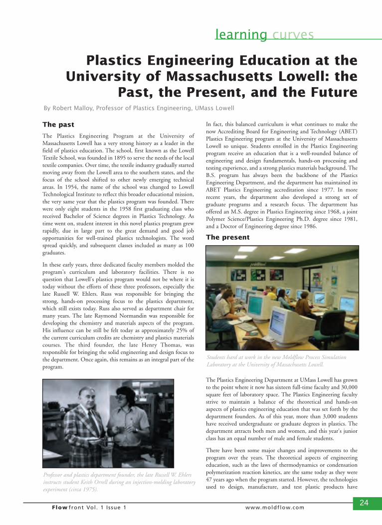
Professor and plastics department founder, the late Russell W. Ehlersinstructs student Keith Orrell during an injection-molding laboratoryexperiment (circa 1975).
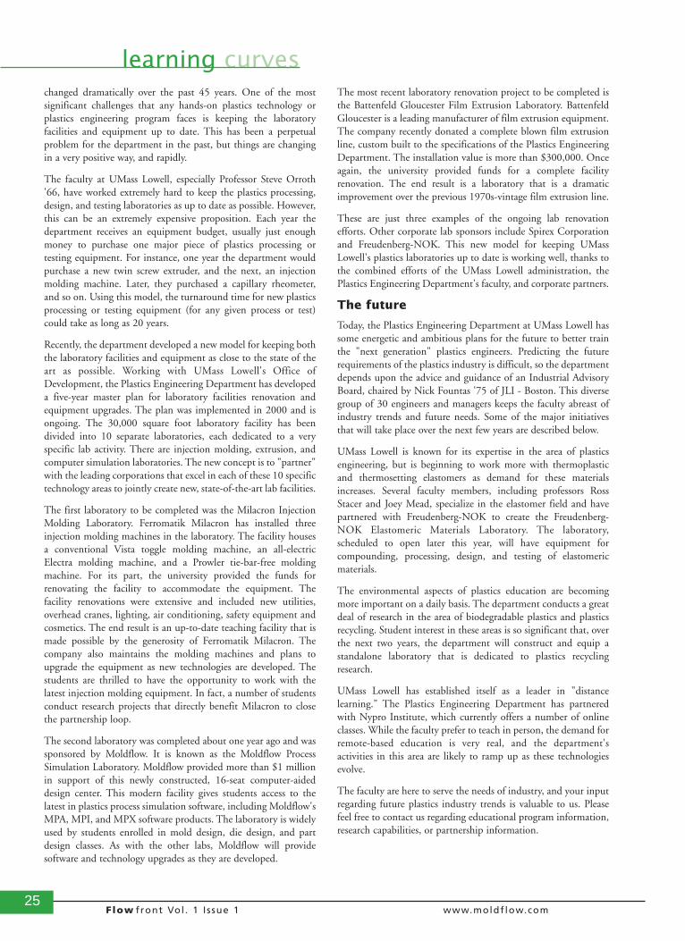
Students hard at work in the new Moldflow Process SimulationLaboratory at the University of Massachusetts Lowell.
25Flow front Vol . 1 I ssue 1 www.moldflow.com
learning curveschanged dramatically over the past 45 years. One of the mostsignificant challenges that any hands-on plastics technology orplastics engineering program faces is keeping the laboratoryfacilities and equipment up to date. This has been a perpetualproblem for the department in the past, but things are changingin a very positive way, and rapidly.
The faculty at UMass Lowell, especially Professor Steve Orroth'66, have worked extremely hard to keep the plastics processing,design, and testing laboratories as up to date as possible. However,this can be an extremely expensive proposition. Each year thedepartment receives an equipment budget, usually just enoughmoney to purchase one major piece of plastics processing ortesting equipment. For instance, one year the department wouldpurchase a new twin screw extruder, and the next, an injectionmolding machine. Later, they purchased a capillary rheometer,and so on. Using this model, the turnaround time for new plasticsprocessing or testing equipment (for any given process or test)could take as long as 20 years.
Recently, the department developed a new model for keeping boththe laboratory facilities and equipment as close to the state of theart as possible. Working with UMass Lowell's Office ofDevelopment, the Plastics Engineering Department has developeda five-year master plan for laboratory facilities renovation andequipment upgrades. The plan was implemented in 2000 and isongoing. The 30,000 square foot laboratory facility has beendivided into 10 separate laboratories, each dedicated to a veryspecific lab activity. There are injection molding, extrusion, andcomputer simulation laboratories. The new concept is to "partner"with the leading corporations that excel in each of these 10 specifictechnology areas to jointly create new, state-of-the-art lab facilities.
The first laboratory to be completed was the Milacron InjectionMolding Laboratory. Ferromatik Milacron has installed threeinjection molding machines in the laboratory. The facility housesa conventional Vista toggle molding machine, an all-electricElectra molding machine, and a Prowler tie-bar-free moldingmachine. For its part, the university provided the funds forrenovating the facility to accommodate the equipment. Thefacility renovations were extensive and included new utilities,overhead cranes, lighting, air conditioning, safety equipment andcosmetics. The end result is an up-to-date teaching facility that ismade possible by the generosity of Ferromatik Milacron. Thecompany also maintains the molding machines and plans toupgrade the equipment as new technologies are developed. Thestudents are thrilled to have the opportunity to work with thelatest injection molding equipment. In fact, a number of studentsconduct research projects that directly benefit Milacron to closethe partnership loop.
The second laboratory was completed about one year ago and wassponsored by Moldflow. It is known as the Moldflow ProcessSimulation Laboratory. Moldflow provided more than $1 millionin support of this newly constructed, 16-seat computer-aideddesign center. This modern facility gives students access to thelatest in plastics process simulation software, including Moldflow'sMPA, MPI, and MPX software products. The laboratory is widelyused by students enrolled in mold design, die design, and partdesign classes. As with the other labs, Moldflow will providesoftware and technology upgrades as they are developed.
The most recent laboratory renovation project to be completed isthe Battenfeld Gloucester Film Extrusion Laboratory. BattenfeldGloucester is a leading manufacturer of film extrusion equipment.The company recently donated a complete blown film extrusionline, custom built to the specifications of the Plastics EngineeringDepartment. The installation value is more than $300,000. Onceagain, the university provided funds for a complete facilityrenovation. The end result is a laboratory that is a dramaticimprovement over the previous 1970s-vintage film extrusion line.
These are just three examples of the ongoing lab renovationefforts. Other corporate lab sponsors include Spirex Corporationand Freudenberg-NOK. This new model for keeping UMassLowell's plastics laboratories up to date is working well, thanks tothe combined efforts of the UMass Lowell administration, thePlastics Engineering Department's faculty, and corporate partners.
The future
Today, the Plastics Engineering Department at UMass Lowell hassome energetic and ambitious plans for the future to better trainthe "next generation" plastics engineers. Predicting the futurerequirements of the plastics industry is difficult, so the departmentdepends upon the advice and guidance of an Industrial AdvisoryBoard, chaired by Nick Fountas '75 of JLI - Boston. This diversegroup of 30 engineers and managers keeps the faculty abreast ofindustry trends and future needs. Some of the major initiativesthat will take place over the next few years are described below.
UMass Lowell is known for its expertise in the area of plasticsengineering, but is beginning to work more with thermoplasticand thermosetting elastomers as demand for these materialsincreases. Several faculty members, including professors RossStacer and Joey Mead, specialize in the elastomer field and havepartnered with Freudenberg-NOK to create the Freudenberg-NOK Elastomeric Materials Laboratory. The laboratory,scheduled to open later this year, will have equipment forcompounding, processing, design, and testing of elastomericmaterials.
The environmental aspects of plastics education are becomingmore important on a daily basis. The department conducts a greatdeal of research in the area of biodegradable plastics and plasticsrecycling. Student interest in these areas is so significant that, overthe next two years, the department will construct and equip astandalone laboratory that is dedicated to plastics recyclingresearch.
UMass Lowell has established itself as a leader in "distancelearning." The Plastics Engineering Department has partneredwith Nypro Institute, which currently offers a number of onlineclasses. While the faculty prefer to teach in person, the demand forremote-based education is very real, and the department'sactivities in this area are likely to ramp up as these technologiesevolve.
The faculty are here to serve the needs of industry, and your inputregarding future plastics industry trends is valuable to us. Pleasefeel free to contact us regarding educational program information,research capabilities, or partnership information.
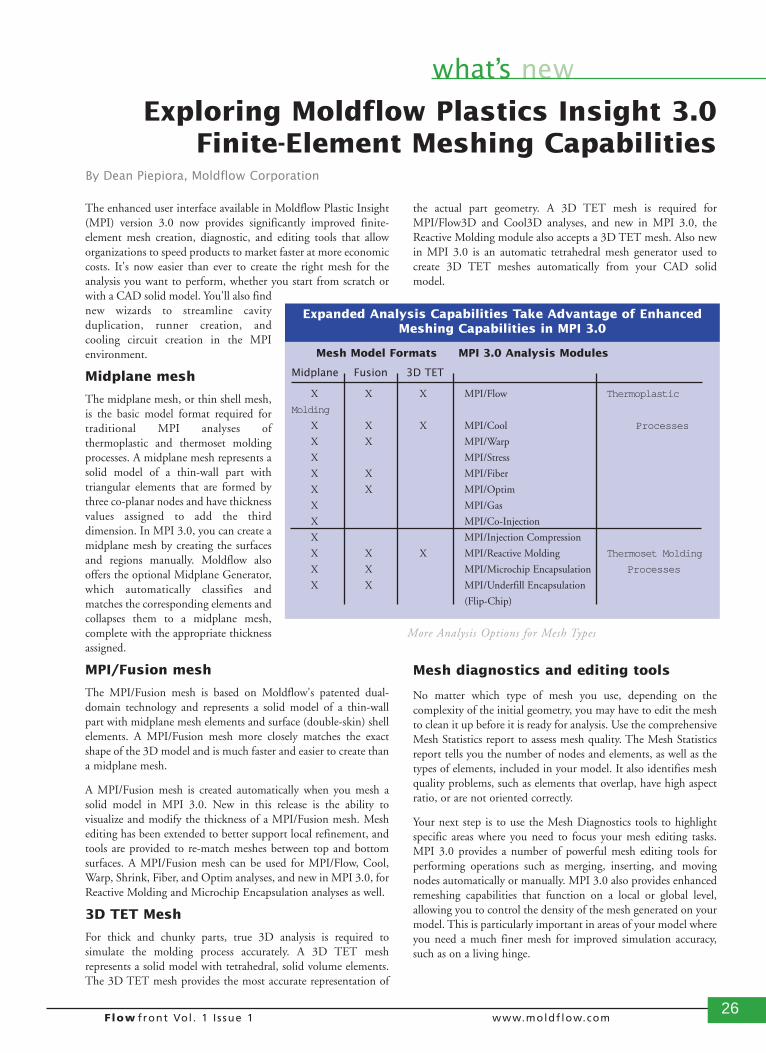
26Flow front Vol . 1 I ssue 1 www.moldflow.com
what’s new
The enhanced user interface available in Moldflow Plastic Insight(MPI) version 3.0 now provides significantly improved finite-element mesh creation, diagnostic, and editing tools that alloworganizations to speed products to market faster at more economiccosts. It's now easier than ever to create the right mesh for theanalysis you want to perform, whether you start from scratch orwith a CAD solid model. You'll also findnew wizards to streamline cavityduplication, runner creation, andcooling circuit creation in the MPIenvironment.
Midplane mesh
The midplane mesh, or thin shell mesh,is the basic model format required fortraditional MPI analyses ofthermoplastic and thermoset moldingprocesses. A midplane mesh represents asolid model of a thin-wall part withtriangular elements that are formed bythree co-planar nodes and have thicknessvalues assigned to add the thirddimension. In MPI 3.0, you can create amidplane mesh by creating the surfacesand regions manually. Moldflow alsooffers the optional Midplane Generator,which automatically classifies andmatches the corresponding elements andcollapses them to a midplane mesh,complete with the appropriate thicknessassigned.
MPI/Fusion mesh
The MPI/Fusion mesh is based on Moldflow's patented dual-domain technology and represents a solid model of a thin-wallpart with midplane mesh elements and surface (double-skin) shellelements. A MPI/Fusion mesh more closely matches the exactshape of the 3D model and is much faster and easier to create thana midplane mesh.
A MPI/Fusion mesh is created automatically when you mesh asolid model in MPI 3.0. New in this release is the ability tovisualize and modify the thickness of a MPI/Fusion mesh. Meshediting has been extended to better support local refinement, andtools are provided to re-match meshes between top and bottomsurfaces. A MPI/Fusion mesh can be used for MPI/Flow, Cool,Warp, Shrink, Fiber, and Optim analyses, and new in MPI 3.0, forReactive Molding and Microchip Encapsulation analyses as well.
3D TET Mesh
For thick and chunky parts, true 3D analysis is required tosimulate the molding process accurately. A 3D TET meshrepresents a solid model with tetrahedral, solid volume elements.The 3D TET mesh provides the most accurate representation of
the actual part geometry. A 3D TET mesh is required forMPI/Flow3D and Cool3D analyses, and new in MPI 3.0, theReactive Molding module also accepts a 3D TET mesh. Also newin MPI 3.0 is an automatic tetrahedral mesh generator used tocreate 3D TET meshes automatically from your CAD solidmodel.
Mesh diagnostics and editing tools
No matter which type of mesh you use, depending on thecomplexity of the initial geometry, you may have to edit the meshto clean it up before it is ready for analysis. Use the comprehensiveMesh Statistics report to assess mesh quality. The Mesh Statisticsreport tells you the number of nodes and elements, as well as thetypes of elements, included in your model. It also identifies meshquality problems, such as elements that overlap, have high aspectratio, or are not oriented correctly.
Your next step is to use the Mesh Diagnostics tools to highlightspecific areas where you need to focus your mesh editing tasks.MPI 3.0 provides a number of powerful mesh editing tools forperforming operations such as merging, inserting, and movingnodes automatically or manually. MPI 3.0 also provides enhancedremeshing capabilities that function on a local or global level,allowing you to control the density of the mesh generated on yourmodel. This is particularly important in areas of your model whereyou need a much finer mesh for improved simulation accuracy,such as on a living hinge.
Exploring Moldflow Plastics Insight 3.0Finite-Element Meshing Capabilities
By Dean Piepiora, Moldflow Corporation
Mesh Model Formats MPI 3.0 Analysis Modules
Midplane Fusion 3D TET
X X X MPI/Flow Thermoplastic
Molding
X X X MPI/Cool Processes
X X MPI/Warp
X MPI/Stress
X X MPI/Fiber
X X MPI/Optim
X MPI/Gas
X MPI/Co-Injection
X MPI/Injection Compression
X X X MPI/Reactive Molding Thermoset Molding
X X MPI/Microchip Encapsulation Processes
X X MPI/Underfill Encapsulation
(Flip-Chip)
Expanded Analysis Capabilities Take Advantage of EnhancedMeshing Capabilities in MPI 3.0
More Analysis Options for Mesh Types
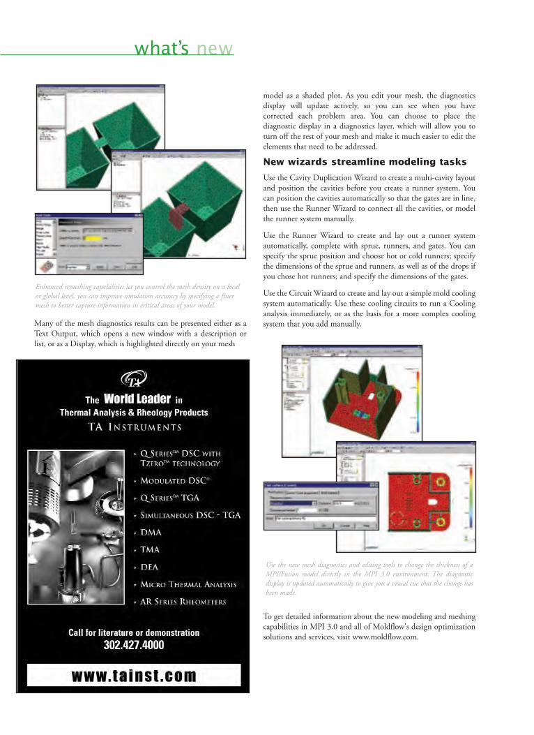
what’s new
Many of the mesh diagnostics results can be presented either as aText Output, which opens a new window with a description orlist, or as a Display, which is highlighted directly on your mesh
model as a shaded plot. As you edit your mesh, the diagnosticsdisplay will update actively, so you can see when you havecorrected each problem area. You can choose to place thediagnostic display in a diagnostics layer, which will allow you toturn off the rest of your mesh and make it much easier to edit theelements that need to be addressed.
New wizards streamline modeling tasks
Use the Cavity Duplication Wizard to create a multi-cavity layoutand position the cavities before you create a runner system. Youcan position the cavities automatically so that the gates are in line,then use the Runner Wizard to connect all the cavities, or modelthe runner system manually.
Use the Runner Wizard to create and lay out a runner systemautomatically, complete with sprue, runners, and gates. You canspecify the sprue position and choose hot or cold runners; specifythe dimensions of the sprue and runners, as well as of the drops ifyou chose hot runners; and specify the dimensions of the gates.
Use the Circuit Wizard to create and lay out a simple mold coolingsystem automatically. Use these cooling circuits to run a Coolinganalysis immediately, or as the basis for a more complex coolingsystem that you add manually.
To get detailed information about the new modeling and meshingcapabilities in MPI 3.0 and all of Moldflow's design optimizationsolutions and services, visit www.moldflow.com.
Enhanced remeshing capabilities let you control the mesh density on a localor global level, you can improve simulation accuracy by specifying a finermesh to better capture information in critical areas of your model.
Use the new mesh diagnostics and editing tools to change the thickness of aMPI/Fusion model directly in the MPI 3.0 environment. The diagnosticdisplay is updated automatically to give you a visual cue that the change hasbeen made.
28Flow front Vol . 1 I ssue 1 www.moldflow.com
design & molding
I am uniquely positioned inour industry to comment onthe ever-changing culture ofthe mold making industry. Ibegan my career in thisbusiness as an apprentice moldmaker/designer, and later as amanufacturing engineer.Today, I am a sales/engineeringmanager and have beenfortunate to see first-hand the
kinds of changes we are experiencing today.
For years, in some companies, mold designers were consideredoverpaid draftspeople. Many toolmakers and product engineersenvisioned these individuals as a means to obtaining a functionalinjection mold. However, these overpaid draftspeople were onlyneeded when it came time to determine parting lines and generalmold construction methods. The actual completed design was leftto the artisan toolmaker. The toolmaker alone understood themold as no one else could, due to his/her experience and expertise.The toolmaker determined actions, fit, and function. The designerdetermined that there was adequate steel and specific, accurategate locations, based primarily on trial and error, past experiences,and a product engineer's guidance.
Today, however, mold designers are valuable participants in thedesign-to-manufacture process of bringing new products tomarket. They are relied upon for a greater amount of engineeringinformation. Now, mold designers must be familiar with an everwidening variety of plastic resins, be more creative in determiningmoving actions within a mold, and have a working understandingof new and exotic mold materials.
Newer resins demand more engineering
In addition, mold designers need a working knowledge of, or anexcellent resource base for, items such as shear characteristics,shrinkage rates (both in and across flow), chemical reactions withmold materials, and venting requirements. Just as important,mold designers need to understand processing parameters as wellas other key issues, such as being familiar with higher operatingtemperatures associated with exotic molding resins. For example,some of the toughest new thermoplastic resins mimic thermosetsin terms of dimensional stability at elevated temperatures.
These resins are injected at temperatures often double that ofcommodity-grade materials. The molds are usually cooled withhot water, live steam, or hot oil. In these cases, the designer notonly has to account for thermal expansion of the mold itself butalso provide adequate insulation to isolate the mold from thepress. If too much heat is lost from the mold to the platen, theprocess can be hindered, and the product will be rejected.
Newer resins allow greater complexityin design
Along with the elevated temperatures, product engineers arediscovering new ways to add complexity to the end product.Where it was once unusual for a product to require unscrewingactions or side cores, it is today becoming the norm. It is alsobecoming almost common for a product to require at least oneaction in a direction out of die draw. Today's designer mustrecognize these requirements and find a proper cost-effectivesolution. In addition, depending on the actual molder, toolbuilder, and the required action, a designer may need to proposeseveral options during the preliminary design phase. Thoseoptions may range from a simple mechanical slide to a complexreciprocation unscrewing action. Whichever the case, it is thedesigner who must find a cost-competitive, durable answer to theactions required.
As a result of all these new requirements, many componentmanufacturers have begun standardizing items for use in amodular approach to mold building. In this case, the designer notonly has the responsibility of designing the mold but also utilizingstandardized parts. In Europe, for example, a designer maycommit career suicide if asked to detail a part for manufacture thatcould be purchased commercially. In an industry where lead timesare becoming shorter and shorter, the designer has a greater role inmeeting the delivery schedule.
The electronic and print engineering libraries are becoming morevaluable every day. During slack times, a wise designer spends timebecoming familiar with the various manufacturers andcomponents. Thanks to the Internet, information is available24/7, and geographical and time zone barriers no longer exist.With the use of e-mail and catalog data, purchase orders andrequests for quotation can be solicited anytime, in any time zone,and a confirmation will be waiting in the morning. This evolutionhas helped make the task of securing and reviewing cataloginformation all the more important.
In some instances, the designer must play the role of salespersonto introduce a new approach to building a mold or using a newstandardized component in meeting the product design challenge.Whatever the task, a good designer derives a feeling of successwhen the mold is finally finished and parts are shot, especiallywhen new technology has been introduced and implemented.
New mold materials require greaterchemical awareness
With one eye on cycle reduction and the other on durability,today's designer practically needs a minor in chemicalengineering. For example, designers need to understand therelationship of phosphates in a nickel bath to sulfurs in a rubbercompound. In addition, they should understand the potential forgalvanic corrosion between copper-based alloys and tool steels.What's more, in many cases, designers are expected to determine
Changing Times for Mold Designers:Technology Leads the Way By Scott Peters, Sales/Engineering
Manager, ProMold, Inc.
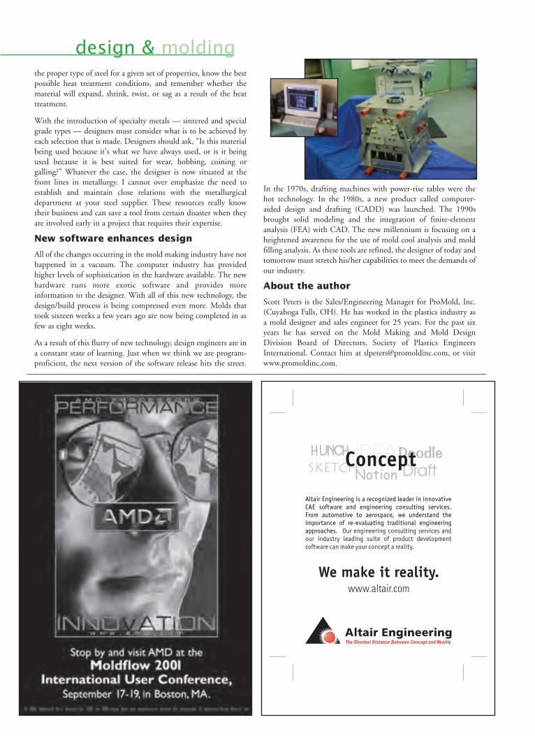
the proper type of steel for a given set of properties, know the bestpossible heat treatment conditions, and remember whether thematerial will expand, shrink, twist, or sag as a result of the heattreatment.
With the introduction of specialty metals — sintered and specialgrade types — designers must consider what is to be achieved byeach selection that is made. Designers should ask, "Is this materialbeing used because it's what we have always used, or is it beingused because it is best suited for wear, hobbing, coining orgalling?" Whatever the case, the designer is now situated at thefront lines in metallurgy. I cannot over emphasize the need toestablish and maintain close relations with the metallurgicaldepartment at your steel supplier. These resources really knowtheir business and can save a tool from certain disaster when theyare involved early in a project that requires their expertise.
New software enhances design
All of the changes occurring in the mold making industry have nothappened in a vacuum. The computer industry has providedhigher levels of sophistication in the hardware available. The newhardware runs more exotic software and provides moreinformation to the designer. With all of this new technology, thedesign/build process is being compressed even more. Molds thattook sixteen weeks a few years ago are now being completed in asfew as eight weeks.
As a result of this flurry of new technology, design engineers are ina constant state of learning. Just when we think we are program-proficient, the next version of the software release hits the street.
In the 1970s, drafting machines with power-rise tables were thehot technology. In the 1980s, a new product called computer-aided design and drafting (CADD) was launched. The 1990sbrought solid modeling and the integration of finite-elementanalysis (FEA) with CAD. The new millennium is focusing on aheightened awareness for the use of mold cool analysis and moldfilling analysis. As these tools are refined, the designer of today andtomorrow must stretch his/her capabilities to meet the demands ofour industry.
About the author
Scott Peters is the Sales/Engineering Manager for ProMold, Inc.(Cuyahoga Falls, OH). He has worked in the plastics industry asa mold designer and sales engineer for 25 years. For the past sixyears he has served on the Mold Making and Mold DesignDivision Board of Directors, Society of Plastics EngineersInternational. Contact him at [email protected], or visitwww.promoldinc.com.
design & molding
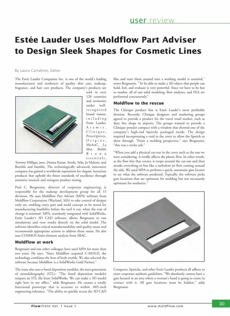
Flow front Vol . 1 I ssue 1 www.moldflow.com 30
user review
The Estée Lauder Companies Inc. is one of the world's leadingmanufacturers and marketers of quality skin care, makeup,fragrance, and hair care products. The company's products are
sold in over120 countriesand territoriesunder well-r e c o g n i z e dbrand names,i n c l u d i n gEstée Lauder,A r a m i s ,C l i n i q u e ,Prescriptives,O r i g i n s ,MoAoC, LaMer, BobbiB r o w ne s s e n t i a l s ,
Tommy Hilfiger, jane, Donna Karan, Aveda, Stila, Jo Malone, andBumble and bumble. The technologically advanced, innovativecompany has gained a worldwide reputation for elegant, luxuriousproducts that uphold the finest standards of excellence throughextensive research and stringent product testing.
Paul C. Bergmann, director of corporate engineering, isresponsible for the makeup development group for all 15divisions. He uses Moldflow Part Adviser (MPA) software fromMoldflow Corporation (Wayland, MA) to take control of designsearly on, enabling every part and mold concept to be tested formanufacturing feasibility before the tool is cut, when the cost ofchange is minimal. MPA, seamlessly integrated with SolidWorks,Estée Lauder's 3D CAD software, allows Bergmann to runsimulations and view results directly on the solid model. Thesoftware identifies critical manufacturability and quality issues andrecommends appropriate actions to address those issues. He alsouses COSMOS finite-element analysis from SRAC.
Moldflow at work
Bergmann and one other colleague have used MPA for more thantwo years. He says, "Since Moldflow acquired C-MOLD, thetechnology combines the best of both worlds. We also selected thesoftware because Moldflow is a SolidWorks Gold Partner."
The team also uses a fused deposition modeler, the next generationof stereolithography (STL). "The fused deposition modeleroutputs an STL file from SolidWorks. We can make a 3D modelright here in my office," adds Bergmann. He creates a totallyfunctional prototype that is accurate to within .005-inchengineering tolerance. "The ability to quickly access the 3D CAD
files and turn them around into a working model is essential,"notes Bergmann. "To be able to make a 3D object that people canhold, feel, and evaluate is very powerful. Since we have to be fastto market, all of our solid modeling, flow analyses, and FEA areperformed concurrently."
Moldflow to the rescue
The Clinique product line is Estée Lauder's most profitabledivision. Recently, Clinique designers and marketing groupsagreed to provide a product for the travel retail market, such asduty free shops in airports. The groups wanted to provide aClinique powder compact with a window that showed one of thecompany's high-end lipsticks packaged inside. The designrequired incorporating a void in the cover to allow the lipstick toshow through. "From a molding perspective," says Bergmann,"this was a tricky job."
"When you add a physical cut-out in the cover such as the one wewere considering, it totally affects the plastic flow. In other words,as the flow hits that corner, it wraps around the cut-out and thenstreaks everything in line like a turbulent jet flow coming aroundthe side. We used MPA to perform a quick, automatic gate locatorto see what the software predicted. Typically, the software picksgate locations that are optimum for molding but not necessarilyoptimum for aesthetics."
Compacts, lipsticks, and other Estée Lauder products all adhere tostrict corporate aesthetic guidelines. "We absolutely cannot have agate located in an area where a woman's hand is going to come incontact with it. All gate locations must be hidden," addsBergmann.
Estée Lauder Uses Moldflow Part Adviserto Design Sleek Shapes for Cosmetic Lines
By Laura Carrabine, Editor
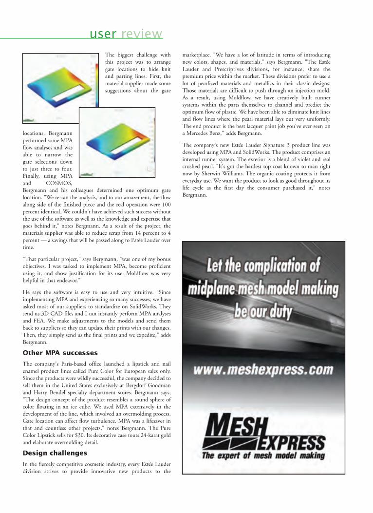
user reviewThe biggest challenge withthis project was to arrangegate locations to hide knitand parting lines. First, thematerial supplier made somesuggestions about the gate
locations. Bergmannperformed some MPAflow analyses and wasable to narrow thegate selections downto just three to four.Finally, using MPAand COSMOS,Bergmann and his colleagues determined one optimum gatelocation. "We re-ran the analysis, and to our amazement, the flowalong side of the finished piece and the real operation were 100percent identical. We couldn't have achieved such success withoutthe use of the software as well as the knowledge and expertise thatgoes behind it," notes Bergmann. As a result of the project, thematerials supplier was able to reduce scrap from 14 percent to 4percent — a savings that will be passed along to Estée Lauder overtime.
"That particular project," says Bergmann, "was one of my bonusobjectives. I was tasked to implement MPA, become proficientusing it, and show justification for its use. Moldflow was veryhelpful in that endeavor."
He says the software is easy to use and very intuitive. "Sinceimplementing MPA and experiencing so many successes, we haveasked most of our suppliers to standardize on SolidWorks. Theysend us 3D CAD files and I can instantly perform MPA analysesand FEA. We make adjustments to the models and send themback to suppliers so they can update their prints with our changes.Then, they simply send us the final prints and we expedite," addsBergmann.
Other MPA successes
The company's Paris-based office launched a lipstick and nailenamel product lines called Pure Color for European sales only.Since the products were wildly successful, the company decided tosell them in the United States exclusively at Bergdorf Goodmanand Harry Bendel specialty department stores. Bergmann says,"The design concept of the product resembles a round sphere ofcolor floating in an ice cube. We used MPA extensively in thedevelopment of the line, which involved an overmolding process.Gate location can affect flow turbulence. MPA was a lifesaver inthat and countless other projects," notes Bergmann. The PureColor Lipstick sells for $30. Its decorative case touts 24-karat goldand elaborate overmolding detail.
Design challenges
In the fiercely competitive cosmetic industry, every Estée Lauderdivision strives to provide innovative new products to the
marketplace. "We have a lot of latitude in terms of introducingnew colors, shapes, and materials," says Bergmann. "The EstéeLauder and Prescriptives divisions, for instance, share thepremium price within the market. These divisions prefer to use alot of pearlized materials and metallics in their classic designs.Those materials are difficult to push through an injection mold.As a result, using Moldflow, we have creatively built runnersystems within the parts themselves to channel and predict theoptimum flow of plastic. We have been able to eliminate knit linesand flow lines where the pearl material lays out very uniformly.The end product is the best lacquer paint job you've ever seen ona Mercedes Benz," adds Bergmann.
The company's new Estée Lauder Signature 3 product line wasdeveloped using MPA and SolidWorks. The product comprises aninternal runner system. The exterior is a blend of violet and realcrushed pearl. "It's got the hardest top coat known to man rightnow by Sherwin Williams. The organic coating protects it fromeveryday use. We want the product to look as good throughout itslife cycle as the first day the consumer purchased it," notesBergmann.
Do you know what job your machine is currently running? Is it running that job at its peak efficiency?What are the optimal settings on this machine for this specific job? This is information you need to knowwhen producing your parts, but you don’t have to carry that burden on your back!
Moldflow Manufacturing Solutions products can answer all of these questions for you. Whether you are a small,custom injection molder or a large multi-national corporation, our products will enable you to:
�� Collect critical data in real time from the injection molding machines on the factory floor�� Analyze process and production data and access real time reports�� Improve molded part quality and labor productivity�� Access plant-wide production information from anywhere in the world �� Automate the process of scientific molding to decrease mold set up time, cycle time and scrap
Let Moldflow Manufacturing Solutions take the weight off you. To find out more, contact us or go to our web site atwww.moldflow.com to download our new Manufacturing Solutions white paper.
Moldflow Corporation430 Boston Post Road • Wayland, MA 01778
Tel (508)358-5848 • Fax (508)358-5868www.moldflow.com
tthheerree aarree bbeetttteerr wwaayyss ttoo ccoolllleecctt ddaattaa ffrroomm yyoouurr iinnjjeeccttiioonn mmoollddiinngg mmaacchhiinnee!!
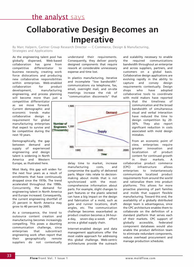
33Flow front Vol . 1 I ssue 1 www.moldflow.com
the analyst says
As the engineering talent pool hasglobally dispersed, Web-basedcollaboration has gone fromcompetitive differentiator tobusiness necessity, creating workforce dislocations and producingnew collaborative responsibilitieswithin enterprises. Web-enabledcollaboration for productdevelopment, manufacturingengineering, and process planningwill become more than just acompetitive differentiatoras we move forward.Current demographic andeconomic trends makecollaborative design arequirement for globalmanufacturing enterprisesthat expect to survive andbe competitive during thenext 10 years.
Demographically, the gapbetween demand andsupply of experiencedengineering and designtalent is widening in NorthAmerica and WesternEurope, as illustrated here.
Most likely, this gap will widen forthe next four years as a result ofenrollments that have continuouslydropped since the 1970s. The trendaccelerated throughout the 1990s.Concurrently, the demand forengineering talent in North Americaand Europe increased. Consequently,the current engineering shortfall of25 percent in North America maygrow to 40 percent by 2005.
As a consequence, the trend tooutsource content creation andmanufacturing becomes increasinglycompelling. This poses a dauntingcommunication challenge, sinceenterprises that subcontractengineering work often report thattheir geographically remotesuppliers do not contextually
understand their requirements.Consequently, they deliver poorlydesigned components that requirerework at considerable unnecessaryexpense and time lost.
In plastics manufacturing, iterativeand incomplete "low bandwidth"communications via telephone, fax,email, overnight mail, and on-sitemeetings increase the risk of"communication disconnects" that
delay time to market, increasemanufacturing costs, andcompromise the quality of deliveredparts. Major risks relate to decision-making about molds that is notsynchronized with the most-comprehensive information aboutparts. For example, slight changes topart features or the plastic selectedcan have a big impact on the designand fabrication of a mold, such asgate and runner locations, draftangles, etc. The communicationchallenge becomes exacerbated asproduct creation becomes a 24-hour-a-day, seven-day-a-week effortacross a global supply chain.
Internet-enabled design and datamanagement applications offer themost viable approach for addressingthis global challenge. Web-centricarchitectures provide the outreach
and scalability necessary to enablethe required communicationsbandwidth throughout an enterpriseand across suppliers, partners, andcustomers on a global basis.Collaborative design applications areevolving rapidly in the ability tocapture and convey designrequirements contextually. Designshops who have adoptedcollaborative tools to coordinatewith mold makers have reported
that the timeliness ofcommunication and the broadbandwidth of simultaneousvisual and verbal interactionhave reduced the time todesign competition by 20-30%. They also reportsignificant reduction in costsassociated with mold designmistakes.
From an economic point ofview, enterprises requiregreater innovation andlocalization of productcontent for continued growthin their markets. A
collaborative product commerce(CPC) infrastructure allowsenterprises to instantaneouslycommunicate localized productrequirements from around the worldand rationalize them into productplatforms. This allows for moreproactive planning of part familiesand molds that support flexiblemanufacturing. Toward this end, theavailability of a globally distributeddesign team is advantageous, sincethe CPC architecture enables them tocollaborate on the definition of astandard platform that serves eachof their markets. CPC support ofglobally accessible, federatedcomponent databases would alsoenable the product definition teamto eliminate redundant components,reduce overhead procurement andmanage production schedules.
Collaborative Design Becomes anImperative
By Marc Halpern, Gartner Group Research Director — C-Commerce, Design & Manufacturing, Strategies and Applications

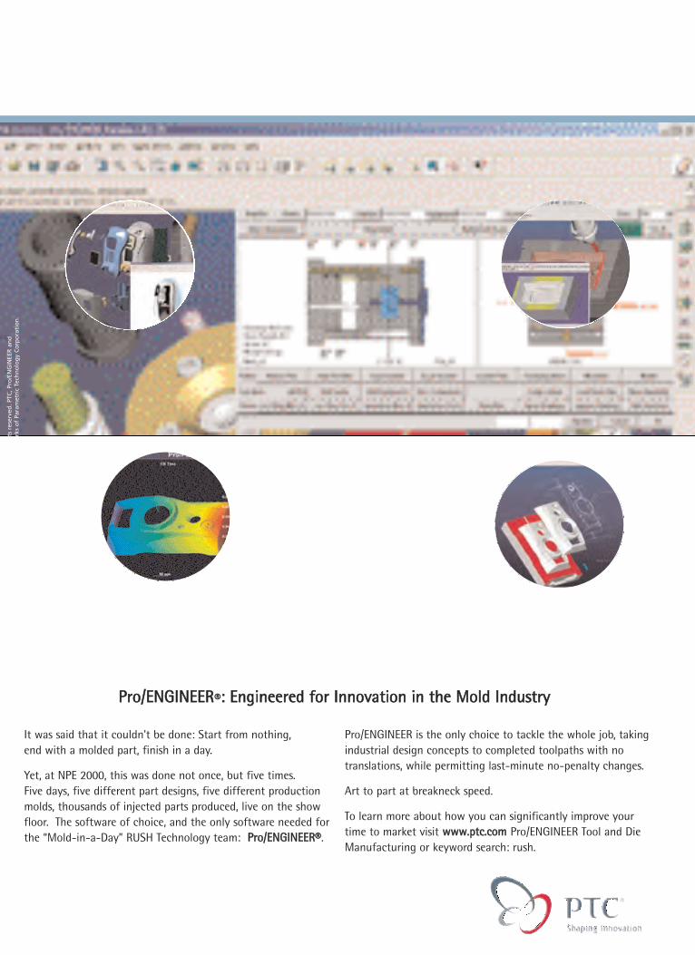
It was said that it couldn't be done: Start from nothing, end with a molded part, finish in a day.
Yet, at NPE 2000, this was done not once, but five times. Five days, five different part designs, five different productionmolds, thousands of injected parts produced, live on the showfloor. The software of choice, and the only software needed forthe “Mold-in-a-Day” RUSH Technology team: PPrroo//EENNGGIINNEEEERR®®.
Pro/ENGINEER is the only choice to tackle the whole job, takingindustrial design concepts to completed toolpaths with notranslations, while permitting last-minute no-penalty changes.
Art to part at breakneck speed.
To learn more about how you can significantly improve yourtime to market visit wwwwww..ppttcc..ccoomm Pro/ENGINEER Tool and DieManufacturing or keyword search: rush.
© 2
001
Para
met
ric
Tech
no
log
y C
orp
ora
tio
n. A
ll ri
gh
ts r
eser
ved
. PTC
, Pro
/EN
GIN
EER
an
dth
e PT
C lo
go
are
tra
dem
arks
or
reg
iste
red
tra
dem
arks
of
Para
met
ric
Tech
no
log
y C
orp
ora
tio
n.
PPrroo//EENNGGIINNEEEERR®®:: EEnnggiinneeeerreedd ffoorr IInnnnoovvaattiioonn iinn tthhee MMoolldd IInndduussttrryy
AArrtt ttoo PPaarrtt aatt BBrreeaakknneecckk SSppeeeedd