Embed Size (px)
Citation preview
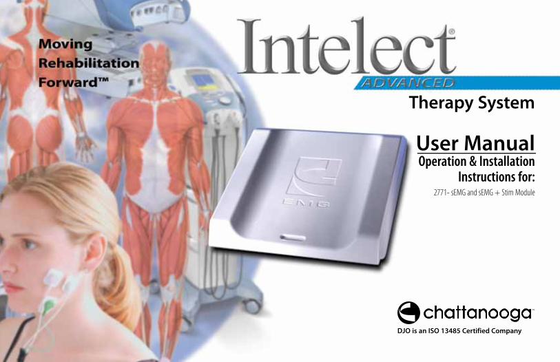
User ManualOperation & Installation
Instructions for:2771- sEMG and sEMG + Stim Module
Therapy System
DJO is an ISO 13485 Certified Company
Intelect® Advanced sEMG and sEMG + Stim Module
i
FOREWORD . . . . . . . . . . . . . . . . . . . . . . . . . . . . . . . . . . . . . . . . . . . . . . . . . . . . . . . . . . . . . . . . . 1 PRODUCT DESCRIPTION . . . . . . . . . . . . . . . . . . . . . . . . . . . . . . . . . . . . . . . . . . . . . . . .1SAFETY PRECAUTIONS . . . . . . . . . . . . . . . . . . . . . . . . . . . . . . . . . . . . . . . . . . . . . . . . . . . . 2-7 PRECAUTIONARY DEFINITIONS . . . . . . . . . . . . . . . . . . . . . . . . . . . . . . . . . . . . . . . . . .2 CAUTIONS . . . . . . . . . . . . . . . . . . . . . . . . . . . . . . . . . . . . . . . . . . . . . . . . . . . . . . . . . . . . . .3 WARNINGS . . . . . . . . . . . . . . . . . . . . . . . . . . . . . . . . . . . . . . . . . . . . . . . . . . . . . . . . . . . . .4 DANGERS. . . . . . . . . . . . . . . . . . . . . . . . . . . . . . . . . . . . . . . . . . . . . . . . . . . . . . . . . . . . . . .5 SEMG INDICATIONS . . . . . . . . . . . . . . . . . . . . . . . . . . . . . . . . . . . . . . . . . . . . . . . . . . . . .6 sEMG + STIM INDICATIONS, CONTRAINDICATIONS AND ADVERSE EFFECTS . . . . . . . . . . . . . . . . . . . . . . . . . . . . . . . . . . . . . . . . . . . . . . . . .7 Indications- sEMG + Stim using VMS™, Symmetrical Biphasic (TENS), . . . . Asymmetrical Biphasic (TENS) or Russian waveforms . . . . . . . . . . . . . . . . . . . . 7 Contraindications . . . . . . . . . . . . . . . . . . . . . . . . . . . . . . . . . . . . . . . . . . . . . . . . . . . . . . . . . 7 Additional Precautions. . . . . . . . . . . . . . . . . . . . . . . . . . . . . . . . . . . . . . . . . . . . . . . . . . . . 7 Adverse Eff ects . . . . . . . . . . . . . . . . . . . . . . . . . . . . . . . . . . . . . . . . . . . . . . . . . . . . . . . . . . . . 7NOMENCLATURE. . . . . . . . . . . . . . . . . . . . . . . . . . . . . . . . . . . . . . . . . . . . . . . . . . . . . . . . . 8-10 sEMG and sEMG + STIM STANDARD ACCESSORIES . . . . . . . . . . . . . . . . . . . . . . . . . 8 SYMBOL DEFINITIONS. . . . . . . . . . . . . . . . . . . . . . . . . . . . . . . . . . . . . . . . . . . . . . . . . . .9 System Hardware Symbols. . . . . . . . . . . . . . . . . . . . . . . . . . . . . . . . . . . . . . . . . . . . . . . . 9 SystemSoftware Symbols . . . . . . . . . . . . . . . . . . . . . . . . . . . . . . . . . . . . . . . . . . . . . . . . . 9 Operator Remote . . . . . . . . . . . . . . . . . . . . . . . . . . . . . . . . . . . . . . . . . . . . . . . . . . . . . . . . . 9 Battery Module. . . . . . . . . . . . . . . . . . . . . . . . . . . . . . . . . . . . . . . . . . . . . . . . . . . . . . . . . . . . 9 Channel 3/4ElectrothrapyModule . . . . . . . . . . . . . . . . . . . . . . . . . . . . . . . . . . . . . . . . 9 TERMINOLOGY DEFINITIONS . . . . . . . . . . . . . . . . . . . . . . . . . . . . . . . . . . . . . . . . . . 10SPECIFICATIONS . . . . . . . . . . . . . . . . . . . . . . . . . . . . . . . . . . . . . . . . . . . . . . . . . . . . . . . .11-13
SEMG AND sEMG + STIM MODULE SPECIFICATIONS . . . . . . . . . . . . . . . . . . . . 11 WAVEFORM SPECIFICATIONS . . . . . . . . . . . . . . . . . . . . . . . . . . . . . . . . . . . . . . . . . . 12 TENS- Asymmetrical Biphasic . . . . . . . . . . . . . . . . . . . . . . . . . . . . . . . . . . . . . . . . . . . . 12 TENS- Symmetrical Biphasic . . . . . . . . . . . . . . . . . . . . . . . . . . . . . . . . . . . . . . . . . . . . . 12 VMSTM . . . . . . . . . . . . . . . . . . . . . . . . . . . . . . . . . . . . . . . . . . . . . . . . . . . . . . . . . . . . . . . . . . . . 13 High Voltage Pulsed Current (HVPC). . . . . . . . . . . . . . . . . . . . . . . . . . . . . . . . . . . . . 13INSTALLATION & REMOVAL. . . . . . . . . . . . . . . . . . . . . . . . . . . . . . . . . . . . . . . . . . . . . .14-19 GENERAL INFORMATION . . . . . . . . . . . . . . . . . . . . . . . . . . . . . . . . . . . . . . . . . . . . . . 14 sEMG Module . . . . . . . . . . . . . . . . . . . . . . . . . . . . . . . . . . . . . . . . . . . . . . . . . . . . . . . . . . . . 14 Therapy System . . . . . . . . . . . . . . . . . . . . . . . . . . . . . . . . . . . . . . . . . . . . . . . . . . . . . . . . . . 14
THERAPY SYSTEM PREPARATION . . . . . . . . . . . . . . . . . . . . . . . . . . . . . . . . . . . . . . 15 Disconnect System Mains . . . . . . . . . . . . . . . . . . . . . . . . . . . . . . . . . . . . . . . . . . . . . . . . 15 Disconnect Leads and Accessories. . . . . . . . . . . . . . . . . . . . . . . . . . . . . . . . . . . . . . . 15 Remove Therapy System from Cart . . . . . . . . . . . . . . . . . . . . . . . . . . . . . . . . . . . . . 15 Remove Module. . . . . . . . . . . . . . . . . . . . . . . . . . . . . . . . . . . . . . . . . . . . . . . . . . . . . . . . . . 15 Remove Breakout Tabs . . . . . . . . . . . . . . . . . . . . . . . . . . . . . . . . . . . . . . . . . . . . . . . . . . . 16 INSTALLING SEMG MODULE . . . . . . . . . . . . . . . . . . . . . . . . . . . . . . . . . . . . . . . . . . . 17 Position sEMG Module . . . . . . . . . . . . . . . . . . . . . . . . . . . . . . . . . . . . . . . . . . . . . . . . . . . 17 Secure sEMG Module . . . . . . . . . . . . . . . . . . . . . . . . . . . . . . . . . . . . . . . . . . . . . . . . . . . . 17 Install and Reinstall Additional Module . . . . . . . . . . . . . . . . . . . . . . . . . . . . . . . . . 17 Install Rear Access Panel . . . . . . . . . . . . . . . . . . . . . . . . . . . . . . . . . . . . . . . . . . . . . . . . . 17 Install Cables and Accessories . . . . . . . . . . . . . . . . . . . . . . . . . . . . . . . . . . . . . . . . . . . 18 Apply Mains Power. . . . . . . . . . . . . . . . . . . . . . . . . . . . . . . . . . . . . . . . . . . . . . . . . . . . . . . 18 REMOVING SEMG MODULE . . . . . . . . . . . . . . . . . . . . . . . . . . . . . . . . . . . . . . . . . . . . 19 Prepare System. . . . . . . . . . . . . . . . . . . . . . . . . . . . . . . . . . . . . . . . . . . . . . . . . . . . . . . . . . . 19 Remove sEMG Module . . . . . . . . . . . . . . . . . . . . . . . . . . . . . . . . . . . . . . . . . . . . . . . . . . . 19 sEMG Plug Kit . . . . . . . . . . . . . . . . . . . . . . . . . . . . . . . . . . . . . . . . . . . . . . . . . . . . . . . . . . . . 19PATIENT PREPARATION . . . . . . . . . . . . . . . . . . . . . . . . . . . . . . . . . . . . . . . . . . . . . . . . . .20-24 SEMG AND SEMG+STIM PATIENT PREPARATION. . . . . . . . . . . . . . . . . . . . . . . . . 20 Electrode Placement . . . . . . . . . . . . . . . . . . . . . . . . . . . . . . . . . . . . . . . . . . . . . . . . . . . . . 20 Dura-Stick™ II Electrodes . . . . . . . . . . . . . . . . . . . . . . . . . . . . . . . . . . . . . . . . . . . . . . . . . 20 Install sEMG Lead Wires to System . . . . . . . . . . . . . . . . . . . . . . . . . . . . . . . . . . . . . . . 21 Install Dura-Stick™ II Electrodes. . . . . . . . . . . . . . . . . . . . . . . . . . . . . . . . . . . . . . . . . . 21 Select Modality. . . . . . . . . . . . . . . . . . . . . . . . . . . . . . . . . . . . . . . . . . . . . . . . . . . . . . . . . . . 21 Select Body Area . . . . . . . . . . . . . . . . . . . . . . . . . . . . . . . . . . . . . . . . . . . . . . . . . . . . . . . . . 22 View Electrode Placement Graphic . . . . . . . . . . . . . . . . . . . . . . . . . . . . . . . . . . . . . . 22 View Electrode Placement Text . . . . . . . . . . . . . . . . . . . . . . . . . . . . . . . . . . . . . . . . . . 23 Prepare Treatment Area. . . . . . . . . . . . . . . . . . . . . . . . . . . . . . . . . . . . . . . . . . . . . . . . . . 23 Electrode Placement . . . . . . . . . . . . . . . . . . . . . . . . . . . . . . . . . . . . . . . . . . . . . . . . . . . . . 24 Intra-Vaginal Probe . . . . . . . . . . . . . . . . . . . . . . . . . . . . . . . . . . . . . . . . . . . . . . . . . . . . . . 24OPERATION . . . . . . . . . . . . . . . . . . . . . . . . . . . . . . . . . . . . . . . . . . . . . . . . . . . . . . . . . . . . .25-43 SEMG THERAPY SET UP . . . . . . . . . . . . . . . . . . . . . . . . . . . . . . . . . . . . . . . . . . . . . . . . 25 General Information . . . . . . . . . . . . . . . . . . . . . . . . . . . . . . . . . . . . . . . . . . . . . . . . . . . . . 25 Optional Patient Data Management System (PDMS) . . . . . . . . . . . . . . . . . . . . 25 sEMG Screen . . . . . . . . . . . . . . . . . . . . . . . . . . . . . . . . . . . . . . . . . . . . . . . . . . . . . . . . . . . . . 26
TABLE OF CONTENTS
Intelect® Advanced sEMG and sEMG + Stim Module
ii
Prepare System and Patient. . . . . . . . . . . . . . . . . . . . . . . . . . . . . . . . . . . . . . . . . . . . . . 27 Select sEMG Modality . . . . . . . . . . . . . . . . . . . . . . . . . . . . . . . . . . . . . . . . . . . . . . . . . . . . 27 View sEMG Description Text . . . . . . . . . . . . . . . . . . . . . . . . . . . . . . . . . . . . . . . . . . . . . 27 Select Edit . . . . . . . . . . . . . . . . . . . . . . . . . . . . . . . . . . . . . . . . . . . . . . . . . . . . . . . . . . . . . . . . 28 Select Channel . . . . . . . . . . . . . . . . . . . . . . . . . . . . . . . . . . . . . . . . . . . . . . . . . . . . . . . . . . . 28 Set Alarm . . . . . . . . . . . . . . . . . . . . . . . . . . . . . . . . . . . . . . . . . . . . . . . . . . . . . . . . . . . . . . . . . 28 Set Audio Type . . . . . . . . . . . . . . . . . . . . . . . . . . . . . . . . . . . . . . . . . . . . . . . . . . . . . . . . . . . 29 Select Target Option . . . . . . . . . . . . . . . . . . . . . . . . . . . . . . . . . . . . . . . . . . . . . . . . . . . . . 29 Setting Max Target . . . . . . . . . . . . . . . . . . . . . . . . . . . . . . . . . . . . . . . . . . . . . . . . . . . . . . . 29 Setting Avg Target . . . . . . . . . . . . . . . . . . . . . . . . . . . . . . . . . . . . . . . . . . . . . . . . . . . . . . . 30 Setting Manual Target . . . . . . . . . . . . . . . . . . . . . . . . . . . . . . . . . . . . . . . . . . . . . . . . . . . 31 Set Volume . . . . . . . . . . . . . . . . . . . . . . . . . . . . . . . . . . . . . . . . . . . . . . . . . . . . . . . . . . . . . . . 31 Start sEMG Therapy Session . . . . . . . . . . . . . . . . . . . . . . . . . . . . . . . . . . . . . . . . . . . . . 32 Stopping sEMG Therapy Session. . . . . . . . . . . . . . . . . . . . . . . . . . . . . . . . . . . . . . . . . 32 SEMG+STIM THERAPY SET UP. . . . . . . . . . . . . . . . . . . . . . . . . . . . . . . . . . . . . . . . . . 33 General Information . . . . . . . . . . . . . . . . . . . . . . . . . . . . . . . . . . . . . . . . . . . . . . . . . . . . . 33 Prepare System and Patient. . . . . . . . . . . . . . . . . . . . . . . . . . . . . . . . . . . . . . . . . . . . . . 34 Select sEMG + Stim Modality . . . . . . . . . . . . . . . . . . . . . . . . . . . . . . . . . . . . . . . . . . . . 34 Select Edit . . . . . . . . . . . . . . . . . . . . . . . . . . . . . . . . . . . . . . . . . . . . . . . . . . . . . . . . . . . . . . . . 34 Select Channel . . . . . . . . . . . . . . . . . . . . . . . . . . . . . . . . . . . . . . . . . . . . . . . . . . . . . . . . . . . 34 Set Alarm . . . . . . . . . . . . . . . . . . . . . . . . . . . . . . . . . . . . . . . . . . . . . . . . . . . . . . . . . . . . . . . . . 35 Set Audio Type . . . . . . . . . . . . . . . . . . . . . . . . . . . . . . . . . . . . . . . . . . . . . . . . . . . . . . . . . . . 35 Select Stim Waveform . . . . . . . . . . . . . . . . . . . . . . . . . . . . . . . . . . . . . . . . . . . . . . . . . . . . 35 Edit Stim. . . . . . . . . . . . . . . . . . . . . . . . . . . . . . . . . . . . . . . . . . . . . . . . . . . . . . . . . . . . . . . . . . 36 Select Target Option . . . . . . . . . . . . . . . . . . . . . . . . . . . . . . . . . . . . . . . . . . . . . . . . . . . . . 36 Setting Max Target . . . . . . . . . . . . . . . . . . . . . . . . . . . . . . . . . . . . . . . . . . . . . . . . . . . . . . . 36 Setting Avg Target . . . . . . . . . . . . . . . . . . . . . . . . . . . . . . . . . . . . . . . . . . . . . . . . . . . . . . . 37 Setting Manual Target . . . . . . . . . . . . . . . . . . . . . . . . . . . . . . . . . . . . . . . . . . . . . . . . . . . 38 Set Volume . . . . . . . . . . . . . . . . . . . . . . . . . . . . . . . . . . . . . . . . . . . . . . . . . . . . . . . . . . . . . . . 38 Set Auto Feature . . . . . . . . . . . . . . . . . . . . . . . . . . . . . . . . . . . . . . . . . . . . . . . . . . . . . . . . . 39 Start sEMG Therapy Session . . . . . . . . . . . . . . . . . . . . . . . . . . . . . . . . . . . . . . . . . . . . . 39 Stopping Stim . . . . . . . . . . . . . . . . . . . . . . . . . . . . . . . . . . . . . . . . . . . . . . . . . . . . . . . . . . . . 40 Stopping Therapy Session . . . . . . . . . . . . . . . . . . . . . . . . . . . . . . . . . . . . . . . . . . . . . . . 40
SET UP OF NEW SEMG DATA CARD. . . . . . . . . . . . . . . . . . . . . . . . . . . . . . . . . . . . . 41 General Information . . . . . . . . . . . . . . . . . . . . . . . . . . . . . . . . . . . . . . . . . . . . . . . . . . . . . 41
Insert New sEMG Data Card . . . . . . . . . . . . . . . . . . . . . . . . . . . . . . . . . . . . . . . . . . . . . . 42 Prepare System and Patient. . . . . . . . . . . . . . . . . . . . . . . . . . . . . . . . . . . . . . . . . . . . . . 42 Set Up sEMG Therapy Session . . . . . . . . . . . . . . . . . . . . . . . . . . . . . . . . . . . . . . . . . . . 42 Enter Patient ID . . . . . . . . . . . . . . . . . . . . . . . . . . . . . . . . . . . . . . . . . . . . . . . . . . . . . . . . . . 42 Begin Save . . . . . . . . . . . . . . . . . . . . . . . . . . . . . . . . . . . . . . . . . . . . . . . . . . . . . . . . . . . . . . . 43 End Save. . . . . . . . . . . . . . . . . . . . . . . . . . . . . . . . . . . . . . . . . . . . . . . . . . . . . . . . . . . . . . . . . . 43TROUBLESHOOTING . . . . . . . . . . . . . . . . . . . . . . . . . . . . . . . . . . . . . . . . . . . . . . . . . . . .44-49 ERROR CODES . . . . . . . . . . . . . . . . . . . . . . . . . . . . . . . . . . . . . . . . . . . . . . . . . . . . . 44-49 General Information . . . . . . . . . . . . . . . . . . . . . . . . . . . . . . . . . . . . . . . . . . . . . . . . . . . . . 44REPLACEMENT ACCESSORIES . . . . . . . . . . . . . . . . . . . . . . . . . . . . . . . . . . . . . . . . . . . . . . 50 General Information . . . . . . . . . . . . . . . . . . . . . . . . . . . . . . . . . . . . . . . . . . . . . . . . . . . . . 50 Color Series Standard Features . . . . . . . . . . . . . . . . . . . . . . . . . . . . . . . . . . . . . . . . . . 50 Color Series Optional Accessories . . . . . . . . . . . . . . . . . . . . . . . . . . . . . . . . . . . . . . . 50 Mains Power Cords . . . . . . . . . . . . . . . . . . . . . . . . . . . . . . . . . . . . . . . . . . . . . . . . . . . . . . . 50MAINTENANCE . . . . . . . . . . . . . . . . . . . . . . . . . . . . . . . . . . . . . . . . . . . . . . . . . . . . . . . . . . . . 51 CARING FOR THE THERAPY SYSTEM. . . . . . . . . . . . . . . . . . . . . . . . . . . . . . . . . . . . 51 Cleaning the Therapy System . . . . . . . . . . . . . . . . . . . . . . . . . . . . . . . . . . . . . . . . . . . . 51 Cleaning the Lens . . . . . . . . . . . . . . . . . . . . . . . . . . . . . . . . . . . . . . . . . . . . . . . . . . . . . . . . 51 FACTORY SERVICE. . . . . . . . . . . . . . . . . . . . . . . . . . . . . . . . . . . . . . . . . . . . . . . . . . . . . 51WARRANTY . . . . . . . . . . . . . . . . . . . . . . . . . . . . . . . . . . . . . . . . . . . . . . . . . . . . . . . . . . . . . . . . 52
TABLE OF CONTENTS
Intelect® Advanced sEMG and sEMG + Stim Module
1
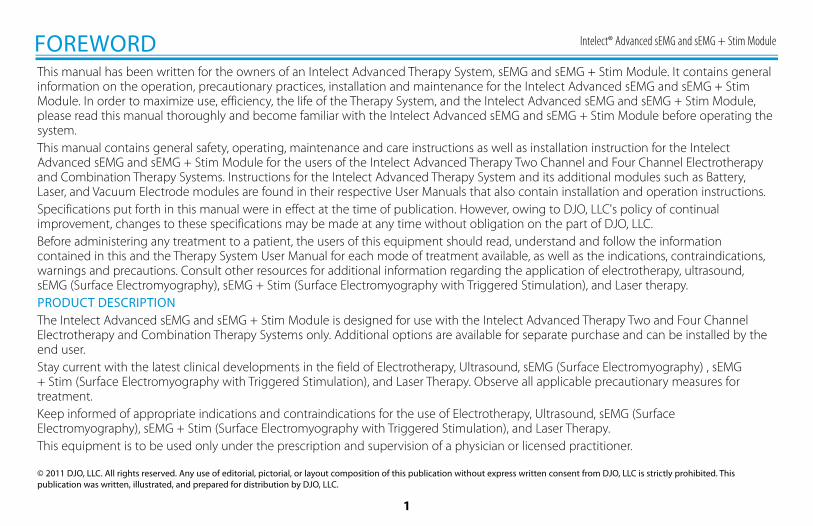
This manual has been written for the owners of an Intelect Advanced Therapy System, sEMG and sEMG + Stim Module. It contains general information on the operation, precautionary practices, installation and maintenance for the Intelect Advanced sEMG and sEMG + Stim Module. In order to maximize use, efficiency, the life of the Therapy System, and the Intelect Advanced sEMG and sEMG + Stim Module, please read this manual thoroughly and become familiar with the Intelect Advanced sEMG and sEMG + Stim Module before operating the system.This manual contains general safety, operating, maintenance and care instructions as well as installation instruction for the Intelect Advanced sEMG and sEMG + Stim Module for the users of the Intelect Advanced Therapy Two Channel and Four Channel Electrotherapy and Combination Therapy Systems. Instructions for the Intelect Advanced Therapy System and its additional modules such as Battery, Laser, and Vacuum Electrode modules are found in their respective User Manuals that also contain installation and operation instructions.Specifications put forth in this manual were in effect at the time of publication. However, owing to DJO, LLC's policy of continual improvement, changes to these specifications may be made at any time without obligation on the part of DJO, LLC.Before administering any treatment to a patient, the users of this equipment should read, understand and follow the information contained in this and the Therapy System User Manual for each mode of treatment available, as well as the indications, contraindications, warnings and precautions. Consult other resources for additional information regarding the application of electrotherapy, ultrasound, sEMG (Surface Electromyography), sEMG + Stim (Surface Electromyography with Triggered Stimulation), and Laser therapy.PRODUCT DESCRIPTIONThe Intelect Advanced sEMG and sEMG + Stim Module is designed for use with the Intelect Advanced Therapy Two and Four Channel Electrotherapy and Combination Therapy Systems only. Additional options are available for separate purchase and can be installed by the end user.Stay current with the latest clinical developments in the field of Electrotherapy, Ultrasound, sEMG (Surface Electromyography) , sEMG + Stim (Surface Electromyography with Triggered Stimulation), and Laser Therapy. Observe all applicable precautionary measures for treatment.Keep informed of appropriate indications and contraindications for the use of Electrotherapy, Ultrasound, sEMG (Surface Electromyography), sEMG + Stim (Surface Electromyography with Triggered Stimulation), and Laser Therapy.This equipment is to be used only under the prescription and supervision of a physician or licensed practitioner.
© 2011 DJO, LLC. All rights reserved. Any use of editorial, pictorial, or layout composition of this publication without express written consent from DJO, LLC is strictly prohibited. This publication was written, illustrated, and prepared for distribution by DJO, LLC.
FOREWORD
Intelect® Advanced sEMG and sEMG + Stim Module
2
SAFETY PRECAUTIONS
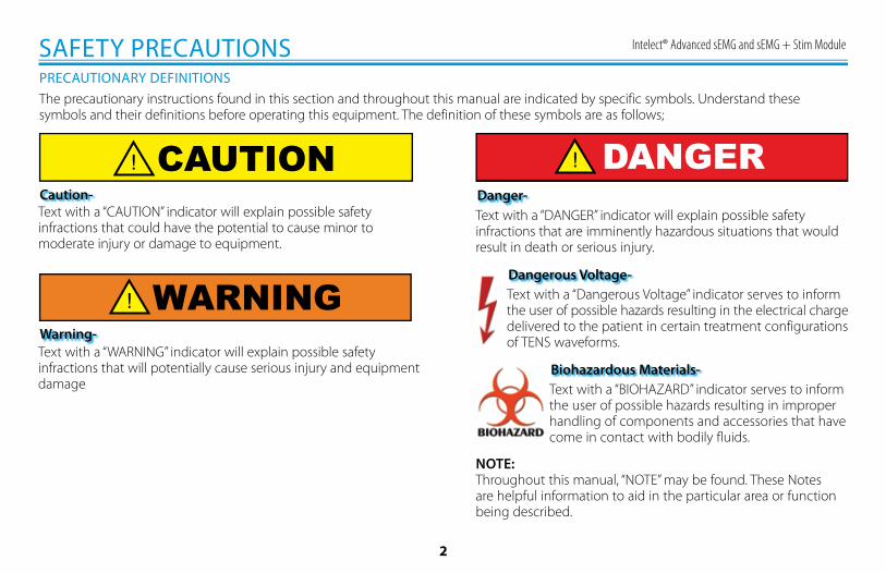
The precautionary instructions found in this section and throughout this manual are indicated by specific symbols. Understand these symbols and their definitions before operating this equipment. The definition of these symbols are as follows;
Text with a “CAUTION” indicator will explain possible safety infractions that could have the potential to cause minor to moderate injury or damage to equipment.
Text with a “WARNING” indicator will explain possible safety infractions that will potentially cause serious injury and equipment damage
Text with a “Dangerous Voltage” indicator serves to inform the user of possible hazards resulting in the electrical charge delivered to the patient in certain treatment configurations of TENS waveforms.
NOTE:Throughout this manual, “NOTE” may be found. These Notes are helpful information to aid in the particular area or function being described.
PRECAUTIONARY DEFINITIONS
Caution-
Warning-
Dangerous Voltage-
Text with a “DANGER” indicator will explain possible safety infractions that are imminently hazardous situations that would result in death or serious injury.
Danger-
Text with a “BIOHAZARD” indicator serves to inform the user of possible hazards resulting in improper handling of components and accessories that have come in contact with bodily fluids.
Biohazardous Materials-
DANGER
WARNING
CAUTION
Intelect® Advanced sEMG and sEMG + Stim Module
3
CAUTIONCAUTIONRead, understand and practice the precautionary and operating instructions. Know the limitations and hazards associated with using any electrical stimulation. Observe the precautionary and operational decals placed on the unit.• DO NOT operate the Intelect Advanced Therapy System sEMG
Module when connected to any unit other than Chattanooga devices.
• DO NOT operate this unit in an environment where other devices are being used that intentionally radiate electromagnetic energy in an unshielded manner.
• DO NOT use sharp objects such as a pencil point or ballpoint pen to operate the buttons on the control panel as damage may result.
• This unit should be operated, transported and stored in temperatures between 15° C and 40° C (59° F and 104° F), with Relative Humidity ranging from 30%-60%.
• Inspect Lead wires and associated connectors for signs of damage before each use. Replace damaged lead wires immediately with new before any treatment is applied.
• The Intelect Advanced Therapy System is not designed to prevent the ingress of water or liquids. Ingress of water or liquids could cause malfunction of internal components of the system and therefore create a risk of injury to the patient.
• This equipment generates, uses and can radiate radio frequency energy and, if not installed and used in accordance with the instructions, may cause harmful interference to other devices in the vicinity. However, there is no guarantee that interference will not occur in a particular installation. Harmful interference to other devices can be determined by turning this equipment on and off. Try to correct the interference using one or more of the following: Reorient or relocate the receiving device, increase the separation between the equipment, connect the equipment to an outlet on a different circuit from that to which the other device(s) are connected and/or consult the factory field service technician for help.
• The Nylatex® Wraps shipped with this unit contain dry natural rubber and may cause allergic reactions in patients with allergies to latex.
CAUTIONS
SAFETY PRECAUTIONS
Intelect® Advanced sEMG and sEMG + Stim Module
4
WARNINGWARNINGThese devices are restricted to sale by, or on the order of, a physician or licensed practitioner. This device should be used only under the continued supervision of a physician or licensed practitioner.• Care must be taken when operating this equipment around other
equipment. Potential electromagnetic or other interference could occur to this or to the other equipment. Try to minimize this interference by not using other equipment in conjunction with it.
• Before administering any treatment to a patient you should become acquainted with the operating procedures for each mode of treatment available, as well as the indications, contraindications, warnings and precautions. Consult other resources for additional information regarding the application of sEMG + Electrical Stimulation.
• To prevent electrical shock, disconnect the unit from the power source before attempting any maintenance procedures.
• Keep stim electrodes separated during treatment. Electrodes in contact with each other could result in improper stimulation or skin burns.
• Long term effects of chronic electrical stimulation are unknown.• Stimulation should not be applied over the anterior neck or mouth.
Severe spasm of the laryngeal and pharyngeal muscles may occur and the contractions may be strong enough to close the airway or cause difficulty in breathing.
WARNINGS
• Stimulation should not be applied transthoracically in that the introduction of electrical current into the heart may cause cardiac arrhythmia.
• Stimulation should not be applied over swollen, infected, inflamed areas or skin eruptions, e.g., phlebitis, thrombophlebitis, varicose veins, etc.
• Stimulation should not be applied over, or in proximity to, cancerous lesions.
• The safety of TENS devices for use during pregnancy or birth has not been established.
• TENS is not effective for pain of central origin. (This includes headache.)
• TENS devices should be used only under the continued supervision of a physician or licensed practitioner.
• TENS devices have no curative value.• TENS is a symptomatic treatment and as such suppresses the
sensation of pain which would otherwise serve as a protective mechanism.
• The user must keep the device out of the reach of children.• Electronic monitoring equipment (such as ECG monitors and ECG
alarms) may not operate properly when TENS stimulation is in use.• Before each therapy session begins, make certain the patient has
the appropriate patient switch for the channels being used.
SAFETY PRECAUTIONS
Intelect® Advanced sEMG and sEMG + Stim Module
5
• Stimulus delivered by the TENS waveforms of this device, in certain configurations, will deliver a charge of 25 microcoulombs (µC) or greater per pulse and may be sufficient to cause electrocution. Electrical current of this magnitude must not flow through the thorax because it may cause a cardiac arrhythmia.
• Patients with an implanted neurostimulation device must not be treated with or be in close proximity to any shortwave diathermy, microwave diathermy, therapeutic ultrasound diathermy or laser diathermy anywhere on their body. Energy from diathermy (shortwave, microwave, ultrasound and laser) can be transferred through the implanted neurostimulation system, can cause tissue damage and can result in severe injury or death. Injury, damage or death can occur during diathermy therapy even if the implanted neurostimulation system is turned “off.”
• Handle, clean, and dispose of components and accessories that have come in contact with bodily fluids according to National, Local and Facility rules, regulations and procedures.
DANGERS
SAFETY PRECAUTIONS
DANGER
Intelect® Advanced sEMG and sEMG + Stim Module
6
SEMG INDICATIONS
To determine the activation timing of muscles for:• Retraining of muscle activation• Coordination of muscle activation• An indication of the force produced by muscle for control and
maintenance of muscle contractions.• Relaxation muscle training• Muscle re-education
SAFETY PRECAUTIONS
Indications- Surface EMG
Intelect® Advanced sEMG and sEMG + Stim Module
7
sEMG + STIM INDICATIONS, CONTRAINDICATIONS AND ADVERSE EFFECTS
SAFETY PRECAUTIONS
• Stroke rehab by muscle re-education• Relaxation of muscle spasms• Prevention or retardation of disuse atrophy• Increase local blood circulation• Muscle re-education• Maintaining or increasing range of motion
• Caution should be used for patients with suspected or diagnosed heart problems.
• Caution should be used for patients with suspected or diagnosed epilepsy.• Caution should be used in the presence of the following:
• When there is a tendency to hemorrhage following acute trauma or fracture.
• Following recent surgical procedures when muscle contraction may disrupt the healing process.
• Over a menstruating or pregnant uterus; over areas of the skin which lack normal sensation.
• Some patients may experience skin irritation or hypersensitivity due to the electrical stimulation or electrical conductive medium. The irritation can usually be reduced by using an alternative conductive medium or an alternative electrode placement.
• Electrode placement and stimulation settings should be based on the guidance of the prescribing practitioner.
• Powered muscle stimulators should be used only with the lead wires and electrodes recommended for use by the manufacturer.
• With TENS waveforms, isolated cases of skin irritation may occur at the site of electrode placement following long term application.
• The effectiveness of TENS waveforms is highly dependent upon patient selection by a person qualified in the management of pain patients.
Indications- sEMG + Stim using VMS™, Symmetrical Biphasic (TENS), Asymmetrical Biphasic (TENS) or Russian waveforms
Contraindications• This device should not be used for symptomatic local pain relief unless
etiology is established or unless a pain syndrome has been diagnosed.• This device should not be used when cancerous lesions are present in the
treatment area.• Stimulation should not be applied over swollen, infected, inflamed areas,
or skin erruptions, e.g. phlebitis, thrombophlebitis, varicose veins, etc.• Other contraindications are patients suspected of carrying serious
infectious disease and or disease where it is advisable, for general medical purposes, to suppress heat or fevers.
• Electrode placements must be avoided that apply current to the carotid sinus region (anterior neck) or transcereberally (through the head).
• Safety has not been established for the use of therapeutic electrical stimulation during pregnancy.
• Powered muscle stimulators should not be used on patients with cardiac demand pacemakers.
• There should not be any use of TENS waveforms on patients with cardiac demand pacemakers.
Additional Precautions
• Skin irritation and burns beneath the electrodes have been reported with the use of powered muscle stimulators.
• Potential adverse effects with TENS are skin irritation and electrode burns.
Adverse Effects
Intelect® Advanced sEMG and sEMG + Stim Module
8
DANGER
sEMG & sEMG + STIM STANDARD ACCESSORIES
NOMENCLATURE
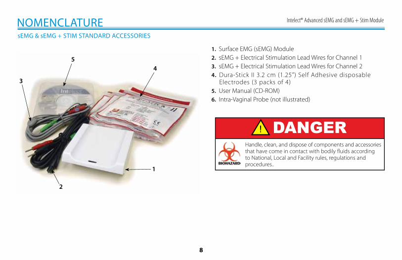
1. Surface EMG (sEMG) Module2. sEMG + Electrical Stimulation Lead Wires for Channel 13. sEMG + Electrical Stimulation Lead Wires for Channel 24. Dura-Stick II 3.2 cm (1.25”) Self Adhesive disposable
Electrodes (3 packs of 4)5. User Manual (CD-ROM)6. Intra-Vaginal Probe (not illustrated)
1
2
3
45
Handle, clean, and dispose of components and accessories that have come in contact with bodily fluids according to National, Local and Facility rules, regulations and procedures..
Intelect® Advanced sEMG and sEMG + Stim Module
9
SYMBOL DEFINITIONS
ON/OFFSWITCH
DATAPORT
MULTI-MEDIA AND
PATIENT CARD
STOPTREATMENT
PAUSETREATMENT
STARTTREATMENT
THERAPYINTENSITYCONTROL
CHANNEL 1/2OPERATOR REMOTECONTROL(OPTIONAL)
PATIENTINTERRUPTSWITCH
CHANNEL 1LEAD WIRES
CHANNEL 2LEAD WIRES
MICROCURRENTPROBE
ULTRASOUNDAPPLICATOR
HOME
CLINICALRESOURCESLIBRARY
BACK
MOVE UP
MOVE DOWN
MOVE RIGHT
MOVE LEFT
ACCEPT ANDRETURN
DO NOT ACCEPTAND RETURN
M
INCREASEINTENSITY
DECREASEINTENSITY
PAUSETREATMENT
MANUALSTIMULATION
CHANNEL 3LEAD WIRES
CHANNEL 4LEAD WIRES
MICROCURRENTPROBE
CHARGE LEVEL
BATTERYCHARGING
CHANNEL 3/4OPERATOR REMOTECONTROL(OPTIONAL)
PATIENTINTERRUPTSWITCH
CONTRAST CONTROL(NOT FUNCTIONAL ON COLOR SYSTEMS)
NOMENCLATURE
System Hardware Symbols SystemSoftware Symbols
Optional Module and Accessory Symbols
Operator Remote
Battery Module
Channel 3/4Electrothrapy
Module
PAD CONTACT QUALITY(SINGLE CHANNEL GRAPH)
PAD CONTACT QUALITY(DUAL CHANNEL GRAPH)
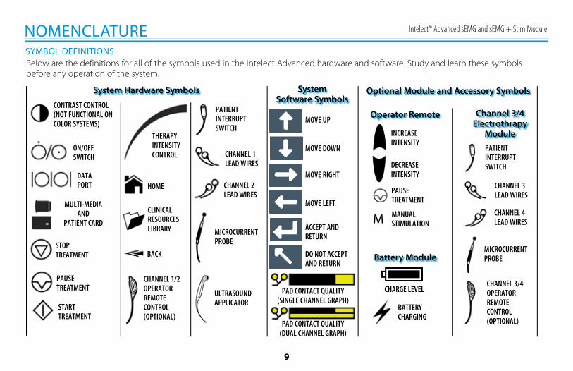
Below are the definitions for all of the symbols used in the Intelect Advanced hardware and software. Study and learn these symbols before any operation of the system.
Intelect® Advanced sEMG and sEMG + Stim Module
10
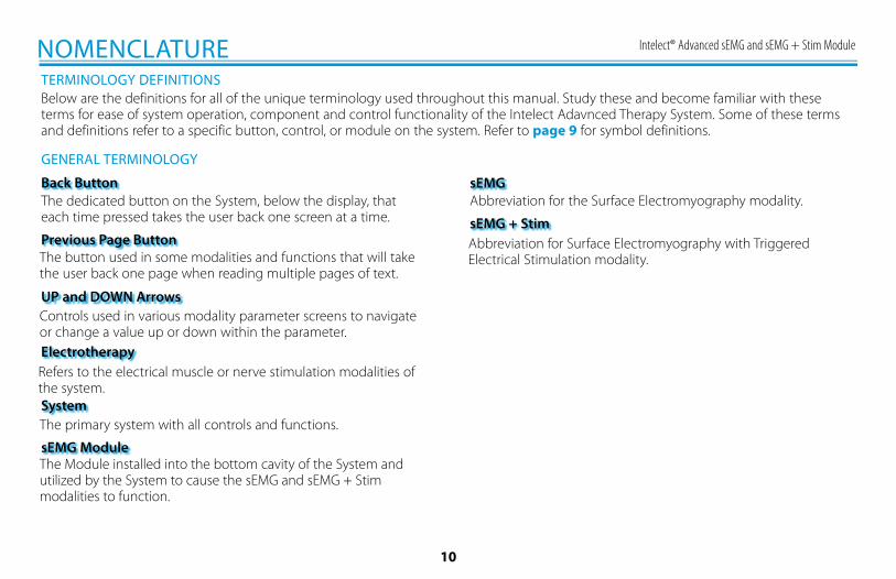
TERMINOLOGY DEFINITIONSBelow are the definitions for all of the unique terminology used throughout this manual. Study these and become familiar with these terms for ease of system operation, component and control functionality of the Intelect Adavnced Therapy System. Some of these terms and definitions refer to a specific button, control, or module on the system. Refer to page 9 for symbol definitions.
The dedicated button on the System, below the display, that each time pressed takes the user back one screen at a time.
GENERAL TERMINOLOGY
NOMENCLATURE
Back Button
Previous Page Button
UP and DOWN Arrows
Electrotherapy
System
sEMG Module
Abbreviation for the Surface Electromyography modality.sEMG
sEMG + Stim
The button used in some modalities and functions that will take the user back one page when reading multiple pages of text.
Controls used in various modality parameter screens to navigate or change a value up or down within the parameter.
Refers to the electrical muscle or nerve stimulation modalities of the system.
The primary system with all controls and functions.
The Module installed into the bottom cavity of the System and utilized by the System to cause the sEMG and sEMG + Stim modalities to function.
Abbreviation for Surface Electromyography with Triggered Electrical Stimulation modality.
Intelect® Advanced sEMG and sEMG + Stim Module
11
sEMG AND sEMG + STIM MODULE SPECIFICATIONS
HEIGHT
SPECIFICATIONS
WIDTH
DEPTH
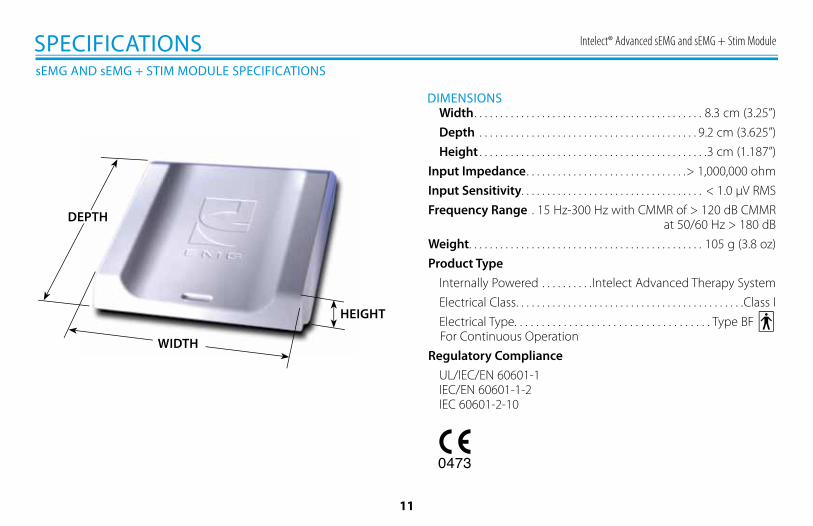
DIMENSIONS Width . . . . . . . . . . . . . . . . . . . . . . . . . . . . . . . . . . . . . . . . . . . . 8.3 cm (3.25”) Depth . . . . . . . . . . . . . . . . . . . . . . . . . . . . . . . . . . . . . . . . . . 9.2 cm (3.625”) Height . . . . . . . . . . . . . . . . . . . . . . . . . . . . . . . . . . . . . . . . . . . .3 cm (1.187”)Input Impedance . . . . . . . . . . . . . . . . . . . . . . . . . . . . . . .> 1,000,000 ohmInput Sensitivity. . . . . . . . . . . . . . . . . . . . . . . . . . . . . . . . . . . < 1.0 µV RMSFrequency Range . 15 Hz-300 Hz with CMMR of > 120 dB CMMR
at 50/60 Hz > 180 dBWeight . . . . . . . . . . . . . . . . . . . . . . . . . . . . . . . . . . . . . . . . . . . . . 105 g (3.8 oz)Product Type Internally Powered . . . . . . . . . .Intelect Advanced Therapy System Electrical Class . . . . . . . . . . . . . . . . . . . . . . . . . . . . . . . . . . . . . . . . . . . .Class I Electrical Type. . . . . . . . . . . . . . . . . . . . . . . . . . . . . . . . . . . . Type BF For Continuous OperationRegulatory Compliance UL/IEC/EN 60601-1 IEC/EN 60601-1-2 IEC 60601-2-10
Intelect® Advanced sEMG and sEMG + Stim Module
12
WAVEFORM SPECIFICATIONS
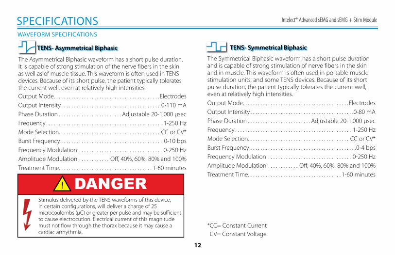
The Asymmetrical Biphasic waveform has a short pulse duration. It is capable of strong stimulation of the nerve fibers in the skin as well as of muscle tissue. This waveform is often used in TENS devices. Because of its short pulse, the patient typically tolerates the current well, even at relatively high intensities.Output Mode . . . . . . . . . . . . . . . . . . . . . . . . . . . . . . . . . . . . . . . . . .ElectrodesOutput Intensity . . . . . . . . . . . . . . . . . . . . . . . . . . . . . . . . . . . . . . . 0-110 mAPhase Duration . . . . . . . . . . . . . . . . . . . . . . . . . Adjustable 20-1,000 µsecFrequency . . . . . . . . . . . . . . . . . . . . . . . . . . . . . . . . . . . . . . . . . . . . . . 1-250 HzMode Selection . . . . . . . . . . . . . . . . . . . . . . . . . . . . . . . . . . . . . . . . CC or CV*Burst Frequency . . . . . . . . . . . . . . . . . . . . . . . . . . . . . . . . . . . . . . . . 0-10 bpsFrequency Modulation . . . . . . . . . . . . . . . . . . . . . . . . . . . . . . . . . 0-250 HzAmplitude Modulation . . . . . . . . . . . . Off, 40%, 60%, 80% and 100%Treatment Time . . . . . . . . . . . . . . . . . . . . . . . . . . . . . . . . . . . . . 1-60 minutes
*CC= Constant Current CV= Constant Voltage
SPECIFICATIONS
TENS- Asymmetrical Biphasic
The Symmetrical Biphasic waveform has a short pulse duration and is capable of strong stimulation of nerve fibers in the skin and in muscle. This waveform is often used in portable muscle stimulation units, and some TENS devices. Because of its short pulse duration, the patient typically tolerates the current well, even at relatively high intensities.Output Mode . . . . . . . . . . . . . . . . . . . . . . . . . . . . . . . . . . . . . . . . . .ElectrodesOutput Intensity . . . . . . . . . . . . . . . . . . . . . . . . . . . . . . . . . . . . . . . . .0-80 mAPhase Duration . . . . . . . . . . . . . . . . . . . . . . . . . Adjustable 20-1,000 µsecFrequency . . . . . . . . . . . . . . . . . . . . . . . . . . . . . . . . . . . . . . . . . . . . . . 1-250 HzMode Selection . . . . . . . . . . . . . . . . . . . . . . . . . . . . . . . . . . . . . . . . CC or CV*Burst Frequency . . . . . . . . . . . . . . . . . . . . . . . . . . . . . . . . . . . . . . . . . .0-4 bpsFrequency Modulation . . . . . . . . . . . . . . . . . . . . . . . . . . . . . . . . . 0-250 HzAmplitude Modulation . . . . . . . . . . . . Off, 40%, 60%, 80% and 100%Treatment Time . . . . . . . . . . . . . . . . . . . . . . . . . . . . . . . . . . . . . 1-60 minutes
TENS- Symmetrical Biphasic
DANGERStimulus delivered by the TENS waveforms of this device, in certain configurations, will deliver a charge of 25 microcoulombs (µC) or greater per pulse and may be sufficient to cause electrocution. Electrical current of this magnitude must not flow through the thorax because it may cause a cardiac arrhythmia.
Intelect® Advanced sEMG and sEMG + Stim Module
13
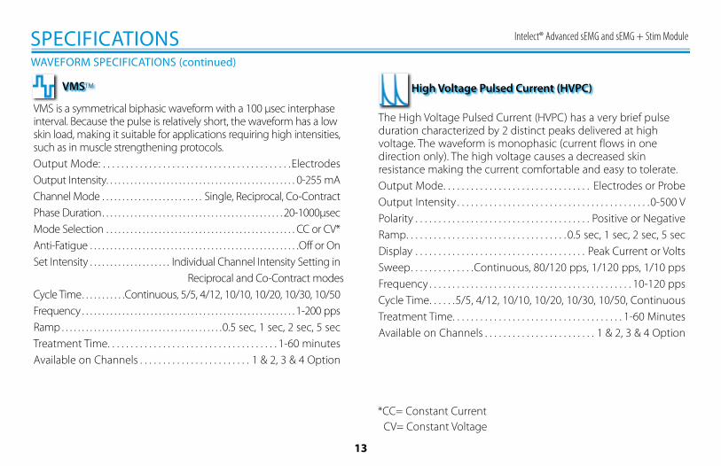
The High Voltage Pulsed Current (HVPC) has a very brief pulse duration characterized by 2 distinct peaks delivered at high voltage. The waveform is monophasic (current flows in one direction only). The high voltage causes a decreased skin resistance making the current comfortable and easy to tolerate.Output Mode . . . . . . . . . . . . . . . . . . . . . . . . . . . . . . . . Electrodes or ProbeOutput Intensity . . . . . . . . . . . . . . . . . . . . . . . . . . . . . . . . . . . . . . . . . .0-500 VPolarity . . . . . . . . . . . . . . . . . . . . . . . . . . . . . . . . . . . . . . Positive or NegativeRamp . . . . . . . . . . . . . . . . . . . . . . . . . . . . . . . . . . . 0.5 sec, 1 sec, 2 sec, 5 secDisplay . . . . . . . . . . . . . . . . . . . . . . . . . . . . . . . . . . . . . Peak Current or VoltsSweep . . . . . . . . . . . . . .Continuous, 80/120 pps, 1/120 pps, 1/10 ppsFrequency . . . . . . . . . . . . . . . . . . . . . . . . . . . . . . . . . . . . . . . . . . . . 10-120 ppsCycle Time . . . . . .5/5, 4/12, 10/10, 10/20, 10/30, 10/50, ContinuousTreatment Time . . . . . . . . . . . . . . . . . . . . . . . . . . . . . . . . . . . . . 1-60 MinutesAvailable on Channels . . . . . . . . . . . . . . . . . . . . . . . . 1 & 2, 3 & 4 Option
*CC= Constant Current CV= Constant Voltage
WAVEFORM SPECIFICATIONS (continued)
SPECIFICATIONS
High Voltage Pulsed Current (HVPC)
VMS is a symmetrical biphasic waveform with a 100 µsec interphase interval. Because the pulse is relatively short, the waveform has a low skin load, making it suitable for applications requiring high intensities, such as in muscle strengthening protocols.Output Mode: . . . . . . . . . . . . . . . . . . . . . . . . . . . . . . . . . . . . . . . . .ElectrodesOutput Intensity . . . . . . . . . . . . . . . . . . . . . . . . . . . . . . . . . . . . . . . . . . . . . . . 0-255 mAChannel Mode . . . . . . . . . . . . . . . . . . . . . . . . . Single, Reciprocal, Co-ContractPhase Duration . . . . . . . . . . . . . . . . . . . . . . . . . . . . . . . . . . . . . . . . . . . . . 20-1000µsecMode Selection . . . . . . . . . . . . . . . . . . . . . . . . . . . . . . . . . . . . . . . . . . . . . . . CC or CV*Anti-Fatigue . . . . . . . . . . . . . . . . . . . . . . . . . . . . . . . . . . . . . . . . . . . . . . . . . . . .Off or OnSet Intensity . . . . . . . . . . . . . . . . . . . . Individual Channel Intensity Setting in
Reciprocal and Co-Contract modesCycle Time . . . . . . . . . . .Continuous, 5/5, 4/12, 10/10, 10/20, 10/30, 10/50Frequency . . . . . . . . . . . . . . . . . . . . . . . . . . . . . . . . . . . . . . . . . . . . . . . . . . . . . 1-200 ppsRamp . . . . . . . . . . . . . . . . . . . . . . . . . . . . . . . . . . . . . . . .0.5 sec, 1 sec, 2 sec, 5 secTreatment Time . . . . . . . . . . . . . . . . . . . . . . . . . . . . . . . . . . . . . 1-60 minutesAvailable on Channels . . . . . . . . . . . . . . . . . . . . . . . . 1 & 2, 3 & 4 Option
VMSTM
Intelect® Advanced sEMG and sEMG + Stim Module
14
GENERAL INFORMATION
INSTALLATION & REMOVAL
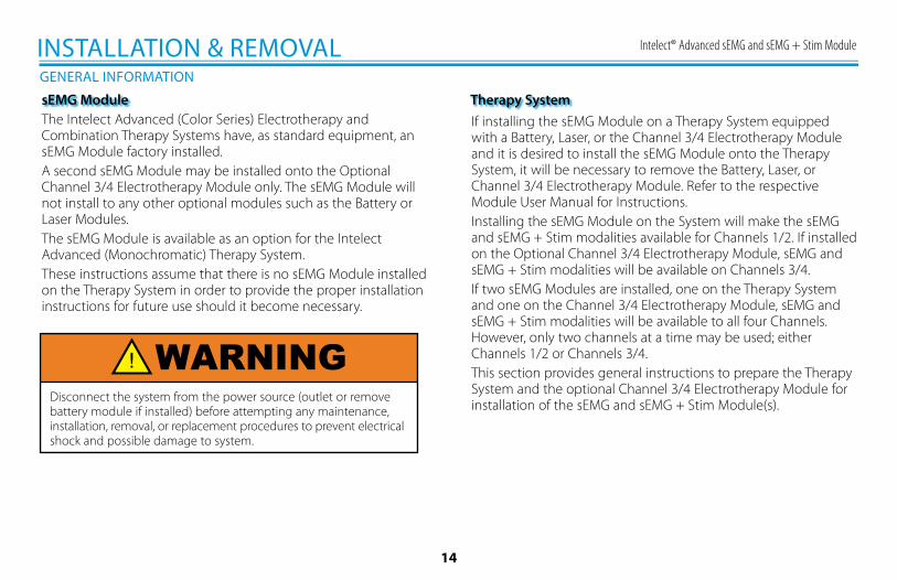
The Intelect Advanced (Color Series) Electrotherapy and Combination Therapy Systems have, as standard equipment, an sEMG Module factory installed.A second sEMG Module may be installed onto the Optional Channel 3/4 Electrotherapy Module only. The sEMG Module will not install to any other optional modules such as the Battery or Laser Modules.The sEMG Module is available as an option for the Intelect Advanced (Monochromatic) Therapy System.These instructions assume that there is no sEMG Module installed on the Therapy System in order to provide the proper installation instructions for future use should it become necessary.
sEMG ModuleIf installing the sEMG Module on a Therapy System equipped with a Battery, Laser, or the Channel 3/4 Electrotherapy Module and it is desired to install the sEMG Module onto the Therapy System, it will be necessary to remove the Battery, Laser, or Channel 3/4 Electrotherapy Module. Refer to the respective Module User Manual for Instructions.Installing the sEMG Module on the System will make the sEMG and sEMG + Stim modalities available for Channels 1/2. If installed on the Optional Channel 3/4 Electrotherapy Module, sEMG and sEMG + Stim modalities will be available on Channels 3/4.If two sEMG Modules are installed, one on the Therapy System and one on the Channel 3/4 Electrotherapy Module, sEMG and sEMG + Stim modalities will be available to all four Channels. However, only two channels at a time may be used; either Channels 1/2 or Channels 3/4.This section provides general instructions to prepare the Therapy System and the optional Channel 3/4 Electrotherapy Module for installation of the sEMG and sEMG + Stim Module(s).
Therapy System
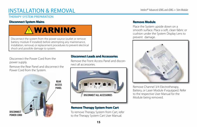
WARNINGDisconnect the system from the power source (outlet or remove battery module if installed) before attempting any maintenance, installation, removal, or replacement procedures to prevent electrical shock and possible damage to system.
Intelect® Advanced sEMG and sEMG + Stim Module
15
THERAPY SYSTEM PREPARATION
INSTALLATION & REMOVAL
Disconnect System Mains
Disconnect the Power Cord from the power supply.Remove the Rear Panel and disconnect the Power Cord from the System.
Remove the Front Access Panel and discon-nect all accessories.
REAR ACCESSPANEL
DISCONNECTPOWER CORD
Disconnect Leads and Accessories
To remove Therapy System from Cart, refer to the Therapy System Cart User Manual.
DISCONNECT ALL ACCESSORIES
Remove Therapy System from Cart
Place the System upside down on a smooth surface. Place a soft, clean fabric or cushion under the System Display Lens to prevent damage.
Remove Module
Remove Channel 3/4 Electrotherapy, Battery, or Laser Module if equipped. Refer to the respective User Manual for the Module being removed.
WARNINGDisconnect the system from the power source (outlet or remove battery module if installed) before attempting any maintenance, installation, removal, or replacement procedures to prevent electrical shock and possible damage to system.
Intelect® Advanced sEMG and sEMG + Stim Module
16
THERAPY SYSTEM PREPARATION (continued)
INSTALLATION & REMOVAL
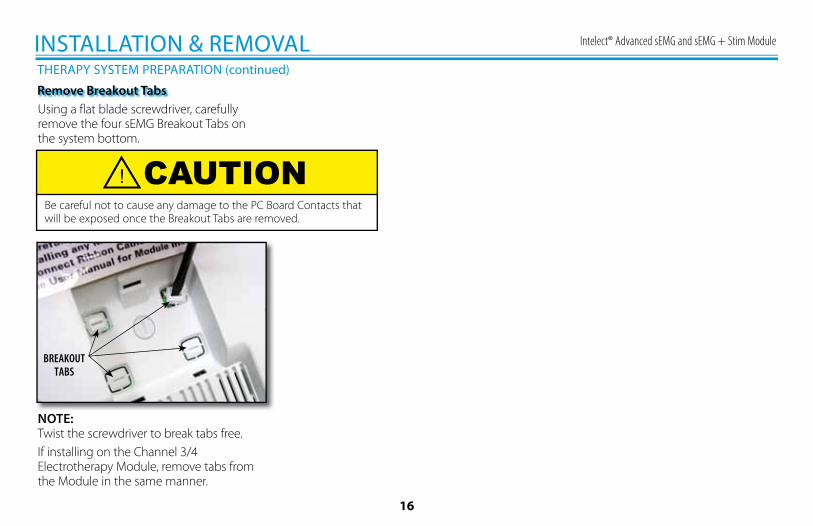
Remove Breakout TabsUsing a flat blade screwdriver, carefully remove the four sEMG Breakout Tabs on the system bottom.
NOTE:Twist the screwdriver to break tabs free. If installing on the Channel 3/4 Electrotherapy Module, remove tabs from the Module in the same manner.
BREAKOUTTABS
CAUTIONBe careful not to cause any damage to the PC Board Contacts that will be exposed once the Breakout Tabs are removed.
Intelect® Advanced sEMG and sEMG + Stim Module
17
INSTALLING SEMG MODULE
INSTALLATION & REMOVAL
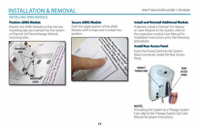
Position the sEMG Module so that the two mounting tabs are inserted into the System or Channel 3/4 Electrotherapy Module mounting slots.
Position sEMG Module
MOUNTING SLOTS
MOUNTING TABS
Secure sEMG ModulePush the upper portion of the sEMG Module until it snaps and is locked into position.
NOTE:If installing the System to a Therapy System Cart, refer to the Therapy System Cart User Manual for proper instructions.
If desired, install a Channel 3/4, Battery or Laser Module to the System, refer to the respective module User Manual for installation instructions prior the following procedures.
Install and Reinstall Additional Module
Install Rear Access Panel
Insert the Power Cord into the System Mains connector. Install the Rear Access Panel.
REAR ACCESSPANEL
CONNECTPOWER CORD
Intelect® Advanced sEMG and sEMG + Stim Module
18
INSTALLING SEMG MODULE (continued)
INSTALLATION & REMOVAL
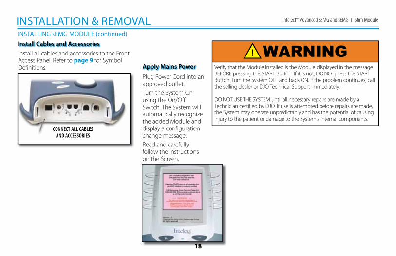
Install Cables and AccessoriesInstall all cables and accessories to the Front Access Panel. Refer to page 9 for Symbol Definitions.
Plug Power Cord into an approved outlet.Turn the System On using the On/Off Switch. The System will automatically recognize the added Module and display a configuration change message.Read and carefully follow the instructions on the Screen.
CONNECT ALL CABLESAND ACCESSORIES
Apply Mains Power Verify that the Module installed is the Module displayed in the message BEFORE pressing the START Button. If it is not, DO NOT press the START Button. Turn the System OFF and back ON. If the problem continues, call the selling dealer or DJO Technical Support immediately.
DO NOT USE THE SYSTEM until all necessary repairs are made by a Technician certified by DJO. If use is attempted before repairs are made, the System may operate unpredictably and has the potential of causing injury to the patient or damage to the System's internal components.
18
WARNING
Intelect® Advanced sEMG and sEMG + Stim Module
19
REMOVING SEMG MODULE
INSTALLATION & REMOVAL
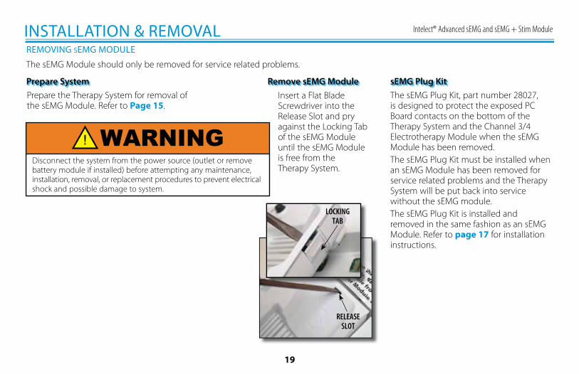
Prepare SystemPrepare the Therapy System for removal of the sEMG Module. Refer to Page 15.
Remove sEMG ModuleInsert a Flat Blade Screwdriver into the Release Slot and pry against the Locking Tab of the sEMG Module until the sEMG Module is free from the Therapy System.
LOCKING TAB
RELEASE SLOT
The sEMG Plug Kit, part number 28027, is designed to protect the exposed PC Board contacts on the bottom of the Therapy System and the Channel 3/4 Electrotherapy Module when the sEMG Module has been removed.The sEMG Plug Kit must be installed when an sEMG Module has been removed for service related problems and the Therapy System will be put back into service without the sEMG module.The sEMG Plug Kit is installed and removed in the same fashion as an sEMG Module. Refer to page 17 for installation instructions.
sEMG Plug Kit
The sEMG Module should only be removed for service related problems.
WARNINGDisconnect the system from the power source (outlet or remove battery module if installed) before attempting any maintenance, installation, removal, or replacement procedures to prevent electrical shock and possible damage to system.
Intelect® Advanced sEMG and sEMG + Stim Module
20
• Examine the skin for any wounds and clean the skin.• Apply the electrodes on the treatment area.• Ensure the electrodes are applied securely to the skin.• Ensure good contact between each electrode and the skin.• Check the electrode contact regularly during the treatment.• Examine the skin again after the treatment.• Choose electrodes that fit the anatomy.• View the Electrode Placement recommendations in the
Treatment Review screen for the particular modality being used for treatment as a reference point only prior to administering treatment.
• Follow electrode manufacturer instructions.
SEMG AND SEMG+STIM PATIENT PREPARATION
PATIENT PREPARATION
Electrode Placement
• Keep electrodes separated during treatment. Electrodes in contact with each other could result in improper stimulation or skin burns.
• Output current density is related to electrode size. Improper application may result in patient injury. If any question arises as to the proper electrode size, consult a licensed practitioner prior to therapy session.
• Powered muscle stimulators should be used only with the leads and electrodes recommended for use by the manufacturer.
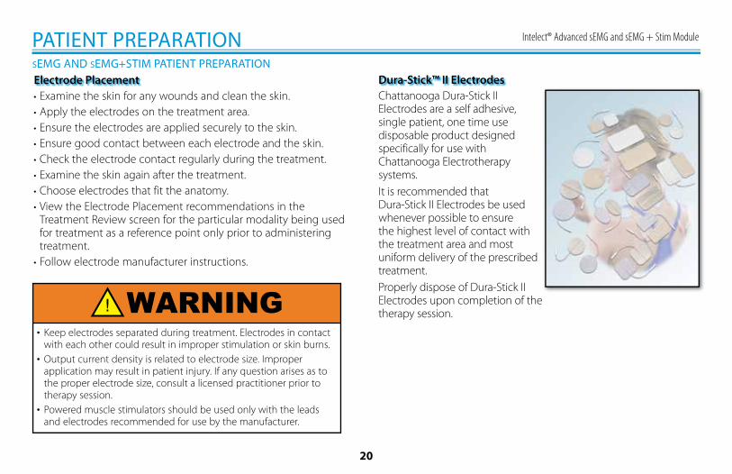
Dura-Stick™ II ElectrodesChattanooga Dura-Stick II Electrodes are a self adhesive, single patient, one time use disposable product designed specifically for use with Chattanooga Electrotherapy systems.It is recommended thatDura-Stick II Electrodes be used whenever possible to ensure the highest level of contact with the treatment area and most uniform delivery of the prescribed treatment.Properly dispose of Dura-Stick II Electrodes upon completion of the therapy session.WARNING
Intelect® Advanced sEMG and sEMG + Stim Module
21
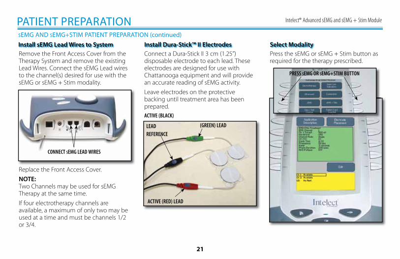
Install sEMG Lead Wires to SystemConnect a Dura-Stick II 3 cm (1.25”) disposable electrode to each lead. These electrodes are designed for use with Chattanooga equipment and will provide an accurate reading of sEMG activity.Leave electrodes on the protective backing until treatment area has been prepared.ACTIVE (BLACK)
PATIENT PREPARATIONSEMG AND SEMG+STIM PATIENT PREPARATION (continued)
Remove the Front Access Cover from the Therapy System and remove the existing Lead Wires. Connect the sEMG Lead wires to the channel(s) desired for use with the sEMG or sEMG + Stim modality.
CONNECT SEMG LEAD WIRES
Replace the Front Access Cover.NOTE:Two Channels may be used for sEMG Therapy at the same time.If four electrotherapy channels are available, a maximum of only two may be used at a time and must be channels 1/2 or 3/4.
Install Dura-Stick™ II Electrodes Select ModalityPress the sEMG or sEMG + Stim button as required for the therapy prescribed.
PRESS SEMG OR SEMG+STIM BUTTON
(GREEN) LEAD
ACTIVE (RED) LEAD
LEADREFERENCE
Intelect® Advanced sEMG and sEMG + Stim Module
22
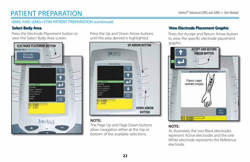
PATIENT PREPARATIONSEMG AND SEMG+STIM PATIENT PREPARATION (continued)Select Body AreaPress the Electrode Placement button to view the Select Body Area screen.
ELECTRODE PLACEMENT BUTTON
Press the Up and Down Arrow buttons until the area desired is highlighted.
UP ARROW BUTTON
DOWN ARROWBUTTON
NOTE:The Page Up and Page Down buttons allow navigation either at the top or bottom of the available selections.
Press the Accept and Return Arrow button to view the specific electrode placement graphic.
ACCEPT AND RETURNARROW BUTTON
NOTE:As illustrated, the two Black electrodes represent Active electrodes and the one White electrode represents the Reference electrode.
View Electrode Placement Graphic
Intelect® Advanced sEMG and sEMG + Stim Module
23
PATIENT PREPARATIONSEMG AND SEMG+STIM PATIENT PREPARATION (continued)
BACKBUTTON
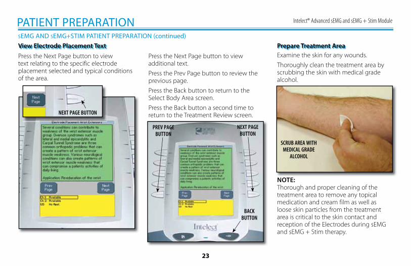
View Electrode Placement TextPress the Next Page button to view text relating to the specific electrode placement selected and typical conditions of the area.
NEXT PAGE BUTTON
Press the Next Page button to view additional text.Press the Prev Page button to review the previous page.Press the Back button to return to the Select Body Area screen.Press the Back button a second time to return to the Treatment Review screen.
NEXT PAGEBUTTON
PREV PAGEBUTTON
Prepare Treatment AreaExamine the skin for any wounds.Thoroughly clean the treatment area by scrubbing the skin with medical grade alcohol.
NOTE:Thorough and proper cleaning of the treatment area to remove any topical medication and cream film as well as loose skin particles from the treatment area is critical to the skin contact and reception of the Electrodes during sEMG and sEMG + Stim therapy.
SCRUB AREA WITH MEDICAL GRADE
ALCOHOL
Intelect® Advanced sEMG and sEMG + Stim Module
24
Electrode Placement
PATIENT PREPARATIONSEMG AND SEMG+STIM PATIENT PREPARATION (continued)
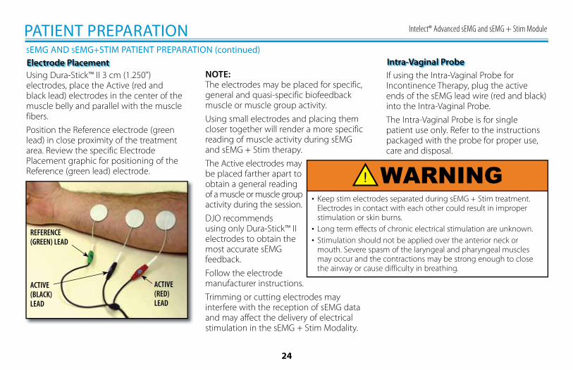
Using Dura-Stick™ II 3 cm (1.250") electrodes, place the Active (red and black lead) electrodes in the center of the muscle belly and parallel with the muscle fibers.Position the Reference electrode (green lead) in close proximity of the treatment area. Review the specific Electrode Placement graphic for positioning of the Reference (green lead) electrode.
NOTE:The electrodes may be placed for specific, general and quasi-specific biofeedback muscle or muscle group activity.Using small electrodes and placing them closer together will render a more specific reading of muscle activity during sEMG and sEMG + Stim therapy.The Active electrodes may be placed farther apart to obtain a general reading of a muscle or muscle group activity during the session.DJO recommends using only Dura-Stick™ II electrodes to obtain the most accurate sEMG feedback.Follow the electrode manufacturer instructions.Trimming or cutting electrodes may interfere with the reception of sEMG data and may affect the delivery of electrical stimulation in the sEMG + Stim Modality.
• Keep stim electrodes separated during sEMG + Stim treatment. Electrodes in contact with each other could result in improper stimulation or skin burns.
• Long term effects of chronic electrical stimulation are unknown.• Stimulation should not be applied over the anterior neck or
mouth. Severe spasm of the laryngeal and pharyngeal muscles may occur and the contractions may be strong enough to close the airway or cause difficulty in breathing.
If using the Intra-Vaginal Probe for Incontinence Therapy, plug the active ends of the sEMG lead wire (red and black) into the Intra-Vaginal Probe.The Intra-Vaginal Probe is for single patient use only. Refer to the instructions packaged with the probe for proper use, care and disposal.
Intra-Vaginal Probe
REFERENCE (GREEN) LEAD
ACTIVE (RED)LEAD
ACTIVE (BLACK) LEAD
WARNING
Intelect® Advanced sEMG and sEMG + Stim Module
25
SEMG THERAPY SET UP
OPERATION
The Intelect Advanced sEMG modality reads and records the sEMG biofeedback activity of a muscle or muscle group by sensing the electrical impulses generated during a voluntary muscle contraction and relax cycle. These signals are accurately relayed to the Intelect Advanced Therapy System through 3 cm (1.250") Dura-Stick™ II Disposable Electrodes.sEMG can be beneficial in the area of muscle retraining therapy by setting target values and charting the patient progress in reaching those goals in a specific muscle or muscle group. Within this section, general setup procedures of the various parameters of sEMG are explained. Also, setup and use of the optional sEMG Data Card for recording sEMG Data is demonstrated.
General Information
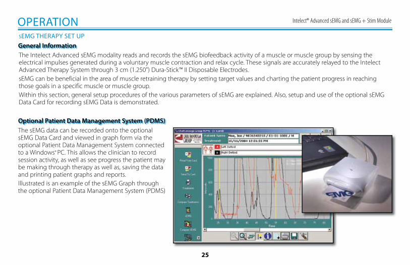
The sEMG data can be recorded onto the optional sEMG Data Card and viewed in graph form via the optional Patient Data Management System connected to a Windows ® PC. This allows the clinician to record session activity, as well as see progress the patient may be making through therapy as well as, saving the data and printing patient graphs and reports.Illustrated is an example of the sEMG Graph through the optional Patient Data Management System (PDMS)
Optional Patient Data Management System (PDMS)
Intelect® Advanced sEMG and sEMG + Stim Module
26
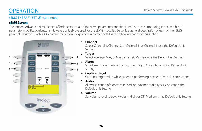
1. ChannelSelect Channel 1, Channel 2, or Channel 1+2. Channel 1+2 is the Default Unit Setting.
2. TargetSelect Average, Max, or Manual Target. Max Target is the Default Unit Setting.
3. AlarmSet Alarm to sound Above, Below, or at Target. Above Target is the Default Unit Setting.
4. Capture TargetCaptures target value while patient is performing a series of muscle contractions.
5. AudioAllows selection of Constant, Pulsed, or Dynamic audio types. Constant is the Default Unit Setting.
6. VolumeSet volume level to Low, Medium, High, or Off. Medium is the Default Unit Setting.
1
3
5
2
4
6
OPERATION
The Intelect Advanced sEMG screen affords access to all of the sEMG parameters and functions. The area surrounding the screen has 10 parameter modification buttons. However, only six are used for the sEMG modality. Below is a general description of each of the sEMG parameter buttons. Each sEMG parameter button is explained in greater detail in the following pages of this section.
SEMG THERAPY SET UP (continued)sEMG Screen
Intelect® Advanced sEMG and sEMG + Stim Module
27
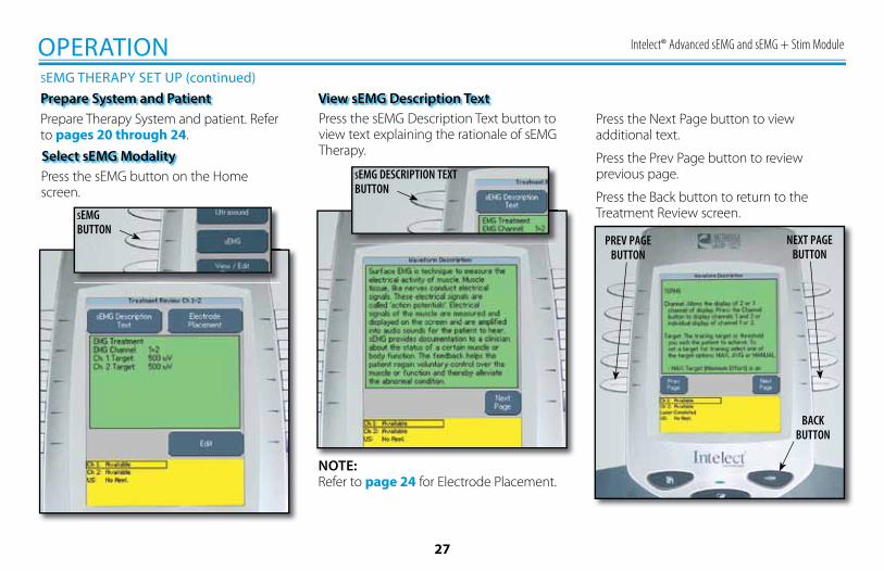
OPERATIONSEMG THERAPY SET UP (continued)Prepare System and PatientPrepare Therapy System and patient. Refer to pages 20 through 24.
Press the sEMG button on the Home screen.
Select sEMG Modality
SEMGBUTTON
Press the sEMG Description Text button to view text explaining the rationale of sEMG Therapy.
View sEMG Description Text
SEMG DESCRIPTION TEXTBUTTON
Press the Next Page button to view additional text.
Press the Prev Page button to review previous page.
Press the Back button to return to the Treatment Review screen.
BACKBUTTON
NEXT PAGEBUTTON
PREV PAGEBUTTON
NOTE:Refer to page 24 for Electrode Placement.
Intelect® Advanced sEMG and sEMG + Stim Module
28
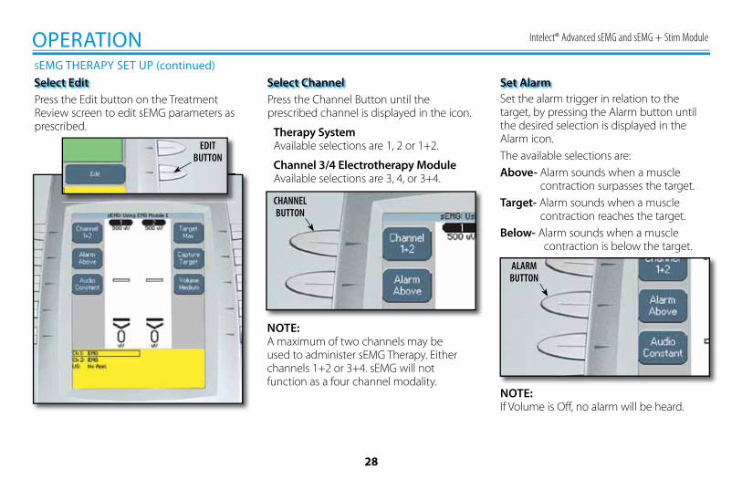
OPERATIONSEMG THERAPY SET UP (continued)Select EditPress the Edit button on the Treatment Review screen to edit sEMG parameters as prescribed.
EDITBUTTON
Select ChannelPress the Channel Button until the prescribed channel is displayed in the icon.
Therapy System Available selections are 1, 2 or 1+2.
Channel 3/4 Electrotherapy Module Available selections are 3, 4, or 3+4.
CHANNELBUTTON
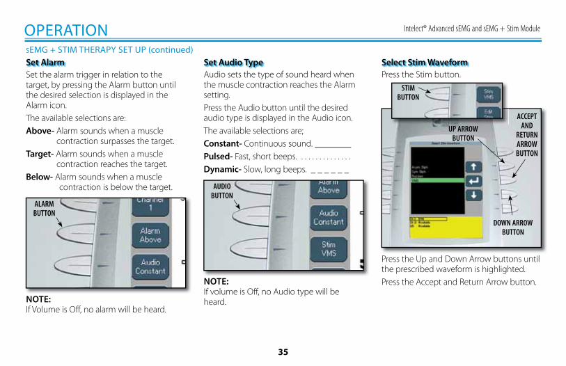
Set AlarmSet the alarm trigger in relation to the target, by pressing the Alarm button until the desired selection is displayed in the Alarm icon.The available selections are:Above- Alarm sounds when a muscle contraction surpasses the target.Target- Alarm sounds when a muscle contraction reaches the target.Below- Alarm sounds when a muscle contraction is below the target.
NOTE:A maximum of two channels may be used to administer sEMG Therapy. Either channels 1+2 or 3+4. sEMG will not function as a four channel modality.
ALARMBUTTON
NOTE:If Volume is Off, no alarm will be heard.
Intelect® Advanced sEMG and sEMG + Stim Module
29
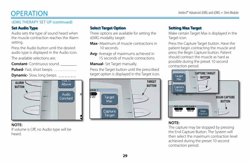
OPERATIONSEMG THERAPY SET UP (continued)Set Audio TypeAudio sets the type of sound heard when the muscle contraction reaches the Alarm setting.Press the Audio button until the desired audio type is displayed in the Audio icon.The available selections are; Constant- Continuous sound. ________Pulsed- Fast, short beeps. . . . . . . . . . . . . . .Dynamic- Slow, long beeps. _ _ _ _ _ _
ALARMBUTTON
NOTE:If volume is Off, no Audio type will be heard.
Three options are available for setting the sEMG modality target:Max- Maximum of muscle contractions in 10 seconds.Avg- Average of maximums achieved in 15 seconds of muscle contractions.Manual- Set Target manually.Press the Target button until the prescribed target option is displayed in the Target icon.
Select Target Option
TARGETBUTTON
Setting Max TargetMake certain Target Max is displayed in the Target icon.Press the Capture Target button. Have the patient begin contracting the muscle and press the Begin Capture button. Patient should contract the muscle as hard as possible during the preset 10 second contraction period.
CAPTURE TARGETBUTTON
BEGIN CAPTUREBUTTON
NOTE:The capture may be stopped by pressing the End Capture Button. The System will then select the maximum contraction level achieved during the preset 10 second contraction period.
Intelect® Advanced sEMG and sEMG + Stim Module
30
OPERATIONSEMG THERAPY SET UP (continued)
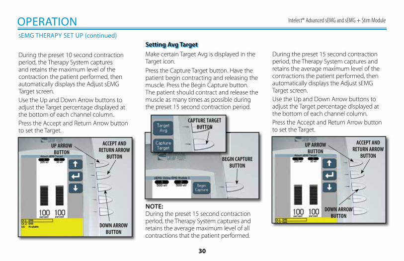
During the preset 10 second contraction period, the Therapy System captures and retains the maximum level of the contraction the patient performed, then automatically displays the Adjust sEMG Target screen.Use the Up and Down Arrow buttons to adjust the Target percentage displayed at the bottom of each channel column.Press the Accept and Return Arrow button to set the Target.
UP ARROWBUTTON
ACCEPT ANDRETURN ARROW
BUTTON
DOWN ARROWBUTTON
Setting Avg TargetMake certain Target Avg is displayed in the Target icon.Press the Capture Target button. Have the patient begin contracting and releasing the muscle. Press the Begin Capture button. The patient should contract and release the muscle as many times as possible during the preset 15 second contraction period.
NOTE:During the preset 15 second contraction period, the Therapy System captures and retains the average maximum level of all contractions that the patient performed.
CAPTURE TARGETBUTTON
BEGIN CAPTUREBUTTON
During the preset 15 second contraction period, the Therapy System captures and retains the average maximum level of the contractions the patient performed, then automatically displays the Adjust sEMG Target screen.Use the Up and Down Arrow buttons to adjust the Target percentage displayed at the bottom of each channel column.Press the Accept and Return Arrow button to set the Target.
UP ARROWBUTTON
ACCEPT ANDRETURN ARROW
BUTTON
DOWN ARROWBUTTON
Intelect® Advanced sEMG and sEMG + Stim Module
31
OPERATIONSEMG THERAPY SET UP (continued)
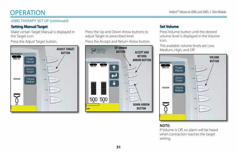
Press the Up and Down Arrow buttons to adjust Target to prescribed level.Press the Accept and Return Arrow button.
DOWN ARROWBUTTON
ACCEPT AND RETURN
ARROW BUTTON
UP ARROWBUTTON
Set VolumePress Volume button until the desired volume level is displayed in the Volume icon. The available volume levels are Low, Medium, High, and Off.
VOLUMEBUTTON
NOTE:If Volume is Off, no alarm will be heard when contraction reaches the target setting.
Make certain Target Manual is displayed in the Target icon.Press the Adjust Target button.
Setting Manual Target
ADJUST TARGETBUTTON
Intelect® Advanced sEMG and sEMG + Stim Module
32
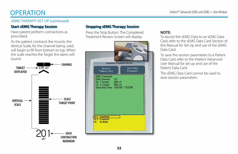
NOTE:To record the sEMG Data to an sEMG Data Card, refer to the sEMG Data Card Section of this Manual for Set Up and use of the sEMG Data Card.To save the session parameters to a Patient Data Card, refer to the Intelect Advanced User Manual for set up and use of the Patient Data Card.The sEMG Data Card cannot be used to save session parameters.
Press the Stop Button. The Completed Treatment Review Screen will display.
Stopping sEMG Therapy Session
OPERATIONSEMG THERAPY SET UP (continued)Start sEMG Therapy SessionHave patient perform contractions as prescribed.As the patient contracts the muscle, the Vertical Scale, for the channel being used, will begin to fill from bottom to top. When the scale reaches the Target the alarm will sound.
CHANNELTARGET
DISPLAYED
SCALETARGET POINT
EACHCONTRACTION
MAXIMUM
VERTICALSCALE
Intelect® Advanced sEMG and sEMG + Stim Module
33
OPERATIONSEMG+STIM THERAPY SET UPGeneral InformationThe Intelect Advanced sEMG + Stim modality utilizes sEMG biofeedback activity coupled with triggered electrical muscle stimulation using selected electrotherapy waveforms for the maximum benefit in muscle retraining. The sEMG + Stim will not function as a multi-channel modality. It is designed for single channel use only. However, it is available to all electrotherapy channels.The Electrical Muscle Stimulation is triggered when the muscle contraction (sEMG portion of the therapy) reaches the target. sEMG stops and the muscle is then electrically stimulated for a period. After stimulation, the patient is given a short rest period and then repeats the muscle contraction, attempting to reach the target to again trigger the electrical stimulation. This is repeated throughout the therapy session.Session parameters can be stored on a Patient Data Card. The Patient Data Card can be used with the optional Patient Data Management System for adding session notes and printing reports. Several sessions can be stored on a Patient Data Card. Any of the sessions stored on the Patient Data Card can be recalled in the Therapy System for future use.It is recommended that each patient be assigned a Patient Data Card. Refer to the Intelect Advanced User Manual for Patient Data Card setup and use instructions.The sEMG portion of sEMG + Stim modality is used to force the patient to contract the muscle to a prescribed target. The data cannot be recorded or stored on the Patient Data Card or the sEMG Data Card.
Intelect® Advanced sEMG and sEMG + Stim Module
34
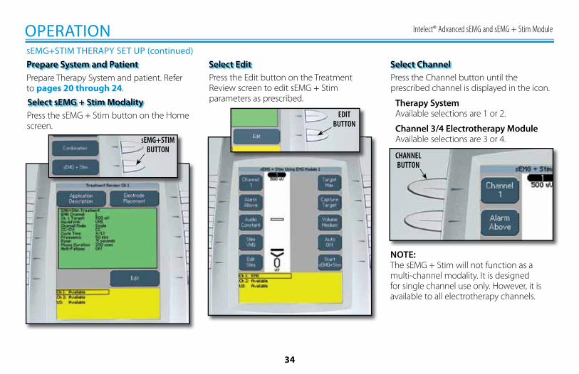
Prepare System and PatientPrepare Therapy System and patient. Refer to pages 20 through 24.
Press the sEMG + Stim button on the Home screen.
Select sEMG + Stim Modality
SEMG+STIMBUTTON
OPERATIONSEMG+STIM THERAPY SET UP (continued)
Select EditPress the Edit button on the Treatment Review screen to edit sEMG + Stim parameters as prescribed.
EDITBUTTON
Select ChannelPress the Channel button until the prescribed channel is displayed in the icon.
Therapy System Available selections are 1 or 2.
Channel 3/4 Electrotherapy Module Available selections are 3 or 4.
CHANNELBUTTON
NOTE:The sEMG + Stim will not function as a multi-channel modality. It is designed for single channel use only. However, it is available to all electrotherapy channels.
Intelect® Advanced sEMG and sEMG + Stim Module
35
ALARMBUTTON
OPERATIONSEMG + STIM THERAPY SET UP (continued)
AUDIOBUTTON
Select Stim WaveformPress the Stim button.
STIMBUTTON
UP ARROWBUTTON
DOWN ARROWBUTTON
ACCEPT AND
RETURN ARROWBUTTON
Press the Up and Down Arrow buttons until the prescribed waveform is highlighted.Press the Accept and Return Arrow button.
Set AlarmSet the alarm trigger in relation to the target, by pressing the Alarm button until the desired selection is displayed in the Alarm icon.The available selections are:Above- Alarm sounds when a muscle contraction surpasses the target.Target- Alarm sounds when a muscle contraction reaches the target.Below- Alarm sounds when a muscle contraction is below the target.
NOTE:If Volume is Off, no alarm will be heard.
Set Audio TypeAudio sets the type of sound heard when the muscle contraction reaches the Alarm setting.Press the Audio button until the desired audio type is displayed in the Audio icon.The available selections are; Constant- Continuous sound. ________Pulsed- Fast, short beeps. . . . . . . . . . . . . . .Dynamic- Slow, long beeps. _ _ _ _ _ _
NOTE:If volume is Off, no Audio type will be heard.
Intelect® Advanced sEMG and sEMG + Stim Module
36
OPERATIONSEMG + STIM THERAPY SET UP (continued)
TARGETBUTTON
CAPTURE TARGETBUTTON
BEGIN CAPTUREBUTTON
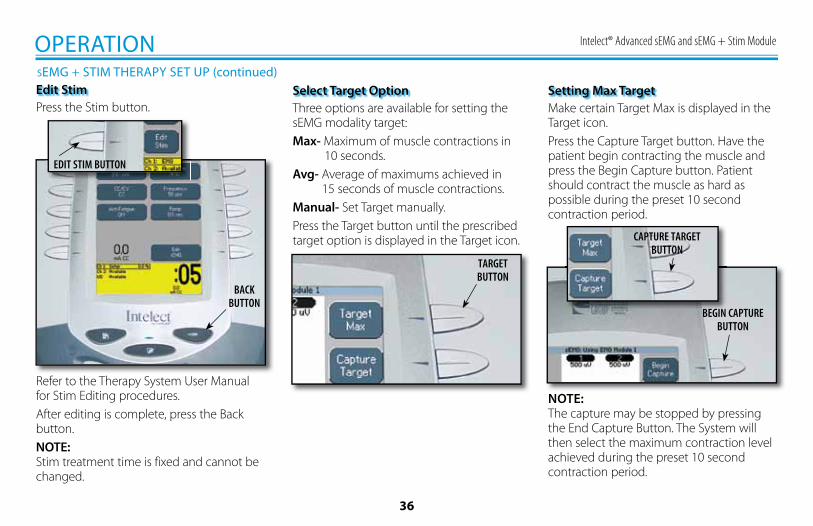
Edit StimPress the Stim button.
EDIT STIM BUTTON
BACKBUTTON
Refer to the Therapy System User Manual for Stim Editing procedures.After editing is complete, press the Back button.NOTE:Stim treatment time is fixed and cannot be changed.
Three options are available for setting the sEMG modality target:Max- Maximum of muscle contractions in 10 seconds.Avg- Average of maximums achieved in 15 seconds of muscle contractions.Manual- Set Target manually.Press the Target button until the prescribed target option is displayed in the Target icon.
Select Target Option Setting Max TargetMake certain Target Max is displayed in the Target icon.Press the Capture Target button. Have the patient begin contracting the muscle and press the Begin Capture button. Patient should contract the muscle as hard as possible during the preset 10 second contraction period.
NOTE:The capture may be stopped by pressing the End Capture Button. The System will then select the maximum contraction level achieved during the preset 10 second contraction period.
Intelect® Advanced sEMG and sEMG + Stim Module
37
OPERATIONSEMG + STIM THERAPY SET UP (continued)
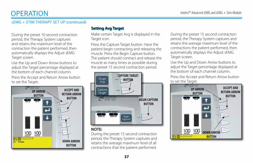
During the preset 10 second contraction period, the Therapy System captures and retains the maximum level of the contraction the patient performed, then automatically displays the Adjust sEMG Target screen.Use the Up and Down Arrow buttons to adjust the Target percentage displayed at the bottom of each channel column.Press the Accept and Return Arrow button to set the Target.
UP ARROWBUTTON
ACCEPT ANDRETURN ARROW
BUTTON
DOWN ARROWBUTTON
Setting Avg TargetMake certain Target Avg is displayed in the Target icon.Press the Capture Target button. Have the patient begin contracting and releasing the muscle. Press the Begin Capture button. The patient should contract and release the muscle as many times as possible during the preset 15 second contraction period.
NOTE:During the preset 15 second contraction period, the Therapy System captures and retains the average maximum level of all contractions that the patient performed.
CAPTURE TARGETBUTTON
BEGIN CAPTUREBUTTON
During the preset 15 second contraction period, the Therapy System captures and retains the average maximum level of the contractions the patient performed, then automatically displays the Adjust sEMG Target screen.Use the Up and Down Arrow buttons to adjust the Target percentage displayed at the bottom of each channel column.Press the Accept and Return Arrow button to set the Target.to set the Target.
UP ARROWBUTTON
ACCEPT ANDRETURN ARROW
BUTTON
DOWN ARROWBUTTON
Intelect® Advanced sEMG and sEMG + Stim Module
38
OPERATIONSEMG + STIM THERAPY SET UP (continued)
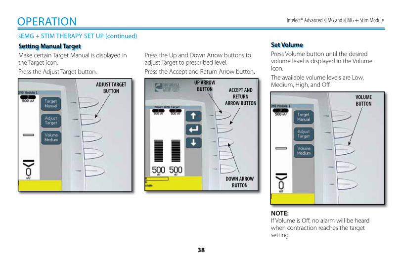
Press the Up and Down Arrow buttons to adjust Target to prescribed level.Press the Accept and Return Arrow button.
DOWN ARROWBUTTON
ACCEPT AND RETURN
ARROW BUTTON
UP ARROWBUTTON
Make certain Target Manual is displayed in the Target icon.Press the Adjust Target button.
Setting Manual Target
ADJUST TARGETBUTTON
Set VolumePress Volume button until the desired volume level is displayed in the Volume icon. The available volume levels are Low, Medium, High, and Off.
VOLUMEBUTTON
NOTE:If Volume is Off, no alarm will be heard when contraction reaches the target setting.
Intelect® Advanced sEMG and sEMG + Stim Module
39
OPERATIONSEMG + STIM THERAPY SET UP (continued)
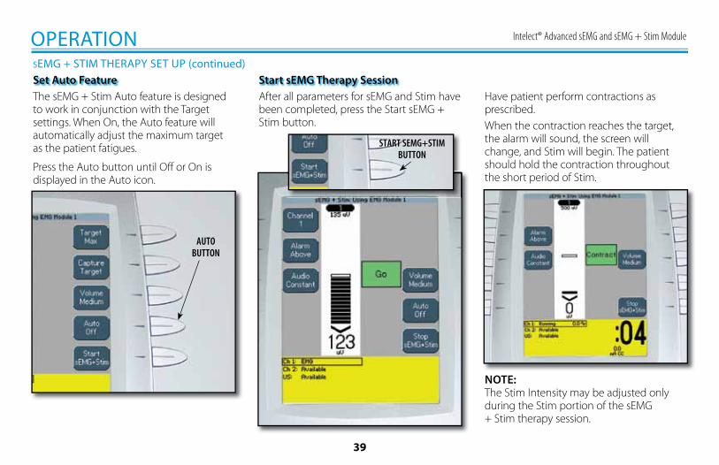
Start sEMG Therapy SessionHave patient perform contractions as prescribed.When the contraction reaches the target, the alarm will sound, the screen will change, and Stim will begin. The patient should hold the contraction throughout the short period of Stim.
After all parameters for sEMG and Stim have been completed, press the Start sEMG + Stim button.
START SEMG+STIMBUTTON
NOTE:The Stim Intensity may be adjusted only during the Stim portion of the sEMG + Stim therapy session.
Set Auto FeatureThe sEMG + Stim Auto feature is designed to work in conjunction with the Target settings. When On, the Auto feature will automatically adjust the maximum target as the patient fatigues.
Press the Auto button until Off or On is displayed in the Auto icon.
AUTOBUTTON
Intelect® Advanced sEMG and sEMG + Stim Module
40
OPERATIONSEMG + STIM THERAPY SET UP (continued)
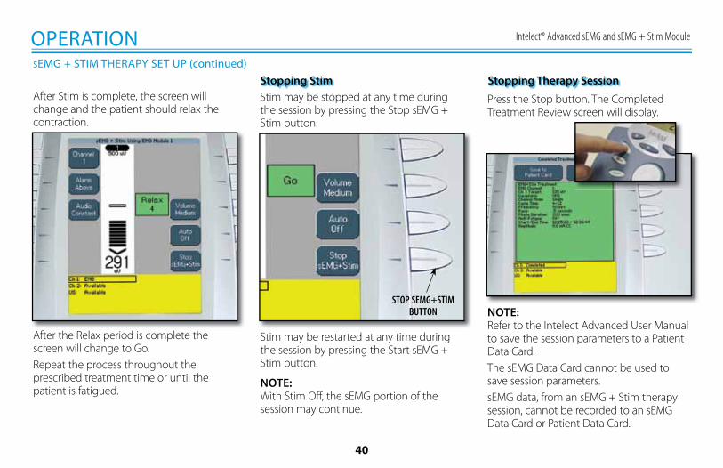
Stopping StimStim may be stopped at any time during the session by pressing the Stop sEMG + Stim button.
STOP SEMG+STIMBUTTON NOTE:
Refer to the Intelect Advanced User Manual to save the session parameters to a Patient Data Card.The sEMG Data Card cannot be used to save session parameters.sEMG data, from an sEMG + Stim therapy session, cannot be recorded to an sEMG Data Card or Patient Data Card.
Press the Stop button. The Completed Treatment Review screen will display.
Stopping Therapy Session
Stim may be restarted at any time during the session by pressing the Start sEMG + Stim button.
NOTE:With Stim Off, the sEMG portion of the session may continue.
After Stim is complete, the screen will change and the patient should relax the contraction.
After the Relax period is complete the screen will change to Go.Repeat the process throughout the prescribed treatment time or until the patient is fatigued.
Intelect® Advanced sEMG and sEMG + Stim Module
41
OPERATIONSET UP OF NEW sEMG DATA CARD
The Intelect Advanced Therapy System incorporates an sEMG Data Card recording device that allows the recording of sEMG data from sEMG therapy sessions. After recording the sEMG data, it can be imported, saved to, and viewed through a Windows® PC equipped with the optional Patient Data Management System. The Patient Data Management System software and Card Reader are designed to allow importing and easy access to the sEMG data, printing of reports, adding session notes, and adding other sEMG specific information to the sEMG data through a Windows® PC.The Therapy System recording device allows recording only of the sEMG Data. No sEMG Data may be recorded from the PC and saved to the sEMG Data Card for use in the Therapy System. However, the sEMG session parameters may be saved to a Patient Data Card (refer to the Therapy System User Manual) and recalled in the Therapy System.Each time an existing sEMG Data Card is used for another sEMG therapy session, the existing sEMG data is overwritten with the new session data.It is recommended that each patient be assigned an sEMG Data Card. sEMG Data cannot be saved or recorded to the Patient Data Card.
General Information
Intelect® Advanced sEMG and sEMG + Stim Module
42
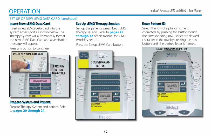
OPERATIONSET UP OF NEW sEMG DATA CARD (continued)Insert New sEMG Data CardInsert a new sEMG Data Card into the system access port as shown below. The Therapy System will automatically format the new sEMG Data Card and a verification message will appear.Press any button to continue.
PRESS ANY BUTTON
TO CONTINUE
INSERT NEW SEMG DATA CARD
Set up the patient's prescribed sEMG therapy session. Refer to pages 25 through 32 of this manual for sEMG modality set up.Press the Setup sEMG Card button.
Set Up sEMG Therapy Session
Prepare System and PatientPrepare Therapy System and patient. Refer to pages 20 through 24.
SETUP SEMG CARD BUTTON
Select the row of alpha or numeric characters by pushing the button beside the corresponding row. Select the desired character in the row by pressing the row button until the desired letter is framed.
Enter Patient ID
SELECT ROW AND CHARACTERS
Intelect® Advanced sEMG and sEMG + Stim Module
43
OPERATIONSET UP OF NEW sEMG DATA CARD (continued)
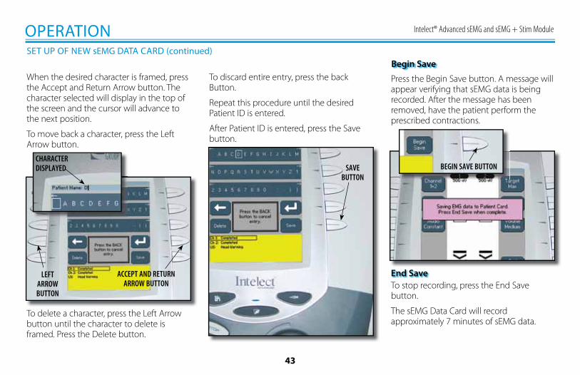
Press the Begin Save button. A message will appear verifying that sEMG data is being recorded. After the message has been removed, have the patient perform the prescribed contractions.
Begin Save
BEGIN SAVE BUTTON
When the desired character is framed, press the Accept and Return Arrow button. The character selected will display in the top of the screen and the cursor will advance to the next position.
To move back a character, press the Left Arrow button.
To discard entire entry, press the back Button.
Repeat this procedure until the desired Patient ID is entered.
After Patient ID is entered, press the Save button.
CHARACTERDISPLAYED
ACCEPT AND RETURNARROW BUTTON
LEFTARROWBUTTON
To delete a character, press the Left Arrow button until the character to delete is framed. Press the Delete button.
SAVE BUTTON
To stop recording, press the End Save button.
The sEMG Data Card will record approximately 7 minutes of sEMG data.
End Save
Intelect® Advanced sEMG and sEMG + Stim Module
44
TROUBLESHOOTINGERROR CODES
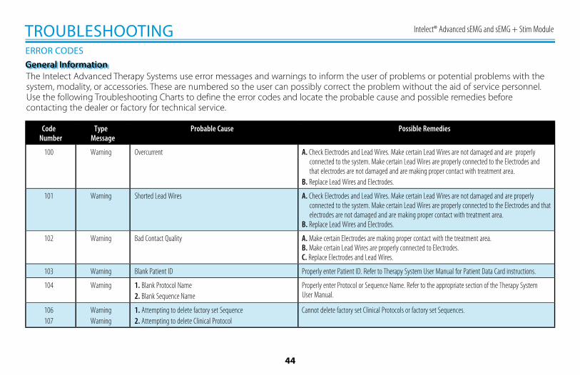
The Intelect Advanced Therapy Systems use error messages and warnings to inform the user of problems or potential problems with the system, modality, or accessories. These are numbered so the user can possibly correct the problem without the aid of service personnel. Use the following Troubleshooting Charts to define the error codes and locate the probable cause and possible remedies before contacting the dealer or factory for technical service.
General Information
Code Number
Type Message
Probable Cause Possible Remedies
100 Warning Overcurrent A. Check Electrodes and Lead Wires. Make certain Lead Wires are not damaged and are properly connected to the system. Make certain Lead Wires are properly connected to the Electrodes and that electrodes are not damaged and are making proper contact with treatment area.
B. Replace Lead Wires and Electrodes.
101 Warning Shorted Lead Wires A. Check Electrodes and Lead Wires. Make certain Lead Wires are not damaged and are properly connected to the system. Make certain Lead Wires are properly connected to the Electrodes and that electrodes are not damaged and are making proper contact with treatment area.
B. Replace Lead Wires and Electrodes.
102 Warning Bad Contact Quality A. Make certain Electrodes are making proper contact with the treatment area.B. Make certain Lead Wires are properly connected to Electrodes.C. Replace Electrodes and Lead Wires.
103 Warning Blank Patient ID Properly enter Patient ID. Refer to Therapy System User Manual for Patient Data Card instructions.
104 Warning 1. Blank Protocol Name2. Blank Sequence Name
Properly enter Protocol or Sequence Name. Refer to the appropriate section of the Therapy SystemUser Manual.
106107
WarningWarning
1. Attempting to delete factory set Sequence2. Attempting to delete Clinical Protocol
Cannot delete factory set Clinical Protocols or factory set Sequences.
Intelect® Advanced sEMG and sEMG + Stim Module
45
TROUBLESHOOTINGERROR CODES (continued)
Code Number
Type Message Probable Cause Possible Remedies
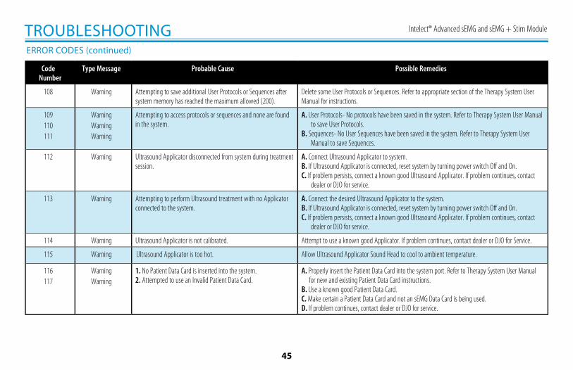
108 Warning Attempting to save additional User Protocols or Sequences after system memory has reached the maximum allowed (200).
Delete some User Protocols or Sequences. Refer to appropriate section of the Therapy System User Manual for instructions.
109110111
WarningWarningWarning
Attempting to access protocols or sequences and none are found in the system.
A. User Protocols- No protocols have been saved in the system. Refer to Therapy System User Manual to save User Protocols.
B. Sequences- No User Sequences have been saved in the system. Refer to Therapy System User Manual to save Sequences.
112 Warning Ultrasound Applicator disconnected from system during treatment session.
A. Connect Ultrasound Applicator to system.B. If Ultrasound Applicator is connected, reset system by turning power switch Off and On.C. If problem persists, connect a known good Ultrasound Applicator. If problem continues, contact
dealer or DJO for service.
113 Warning Attempting to perform Ultrasound treatment with no Applicator connected to the system.
A. Connect the desired Ultrasound Applicator to the system.B. If Ultrasound Applicator is connected, reset system by turning power switch Off and On.C. If problem persists, connect a known good Ultrasound Applicator. If problem continues, contact
dealer or DJO for service.
114 Warning Ultrasound Applicator is not calibrated. Attempt to use a known good Applicator. If problem continues, contact dealer or DJO for Service.
115 Warning Ultrasound Applicator is too hot. Allow Ultrasound Applicator Sound Head to cool to ambient temperature.
116117
WarningWarning
1. No Patient Data Card is inserted into the system.2. Attempted to use an Invalid Patient Data Card.
A. Properly insert the Patient Data Card into the system port. Refer to Therapy System User Manual for new and existing Patient Data Card instructions.
B. Use a known good Patient Data Card.C. Make certain a Patient Data Card and not an sEMG Data Card is being used.D. If problem continues, contact dealer or DJO for service.
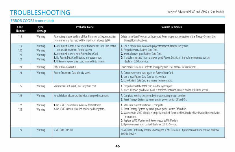
Intelect® Advanced sEMG and sEMG + Stim Module
46
TROUBLESHOOTINGERROR CODES (continued)
Code Number
Type Message
Probable Cause Possible Remedies
118 Warning Attempting to save additional User Protocols or Sequences after system memory has reached the maximum allowed (200).
Delete some User Protocols or Sequences. Refer to appropriate section of the Therapy System User Manual for instructions.
119120121122
WarningWarningWarningWarning
1. Attempted to read a treatment from Patient Data Card that is not a valid treatment for the system
2. Attempted to use a Non-Patient Data Card.3. No Patient Data Card inserted into system port.4. Unknown type of smart card inserted into system.
A. Use a Patient Data Card with proper treatment data for the system.B. Properly insert a Patient Data Card.C. Insert a known good Patient Data Card.D. If problem persists, insert a known good Patient Data Card. If problem continues, contact
dealer or DJO for service.
123 Warning Patient Data Card is full. Erase Patient Data Card. Refer to Therapy System User Manual for instructions.
124 Warning Patient Treatment Data already saved. A. Cannot save same data again on Patient Data Card.B. Use a new Patient Data Card to resave data.C. Erase Patient Data Card and resave treatment data.
125 Warning Multimedia Card (MMC) not in system port. A. Properly insert the MMC card into the system port.B. Insert a known good MMC Card. If problem continues, contact dealer or DJO for service.
126 Warning No valid channels are available for attempted treatment. A. Complete existing treatment before attempting to start another.B. Reset Therapy System by turning main power switch Off and On.
127128
WarningWarning
1. No sEMG Channels are available for treatment.2. No sEMG Module installed or detected by system.
A. Wait until current treatment is complete.B. Reset Therapy System by turning main power switch Off and On.C. Make certain sEMG Module is properly installed. Refer to sEMG Module User Manual for installation
instructions.D. Replace sEMG Module with known good sEMG Module.E. If problem continues, contact dealer or DJO for Service.
129 Warning sEMG Data Card full. sEMG Data Card faulty. Insert a known good sEMG Data Card. If problem continues, contact dealer or DJO for Service.
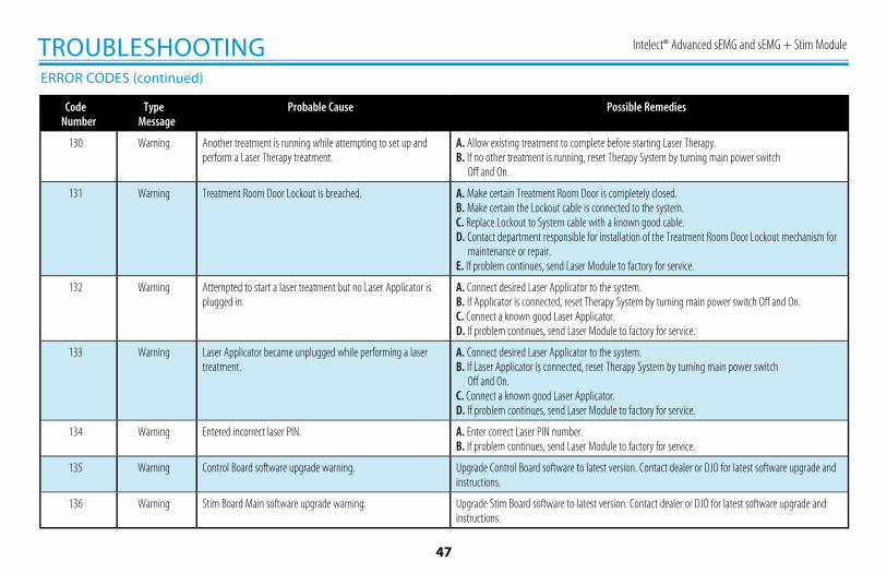
Intelect® Advanced sEMG and sEMG + Stim Module
47
TROUBLESHOOTINGERROR CODES (continued)
Code Number
Type Message
Probable Cause Possible Remedies
130 Warning Another treatment is running while attempting to set up and perform a Laser Therapy treatment.
A. Allow existing treatment to complete before starting Laser Therapy.B. If no other treatment is running, reset Therapy System by turning main power switch
Off and On.
131 Warning Treatment Room Door Lockout is breached. A. Make certain Treatment Room Door is completely closed.B. Make certain the Lockout cable is connected to the system.C. Replace Lockout to System cable with a known good cable.D. Contact department responsible for installation of the Treatment Room Door Lockout mechanism for
maintenance or repair.E. If problem continues, send Laser Module to factory for service.
132 Warning Attempted to start a laser treatment but no Laser Applicator is plugged in.
A. Connect desired Laser Applicator to the system.B. If Applicator is connected, reset Therapy System by turning main power switch Off and On.C. Connect a known good Laser Applicator.D. If problem continues, send Laser Module to factory for service.
133 Warning Laser Applicator became unplugged while performing a laser treatment.
A. Connect desired Laser Applicator to the system.B. If Laser Applicator is connected, reset Therapy System by turning main power switch
Off and On.C. Connect a known good Laser Applicator.D. If problem continues, send Laser Module to factory for service.
134 Warning Entered incorrect laser PIN. A. Enter correct Laser PIN number.B. If problem continues, send Laser Module to factory for service.
135 Warning Control Board software upgrade warning. Upgrade Control Board software to latest version. Contact dealer or DJO for latest software upgrade and instructions.
136 Warning Stim Board Main software upgrade warning. Upgrade Stim Board software to latest version. Contact dealer or DJO for latest software upgrade and instructions.
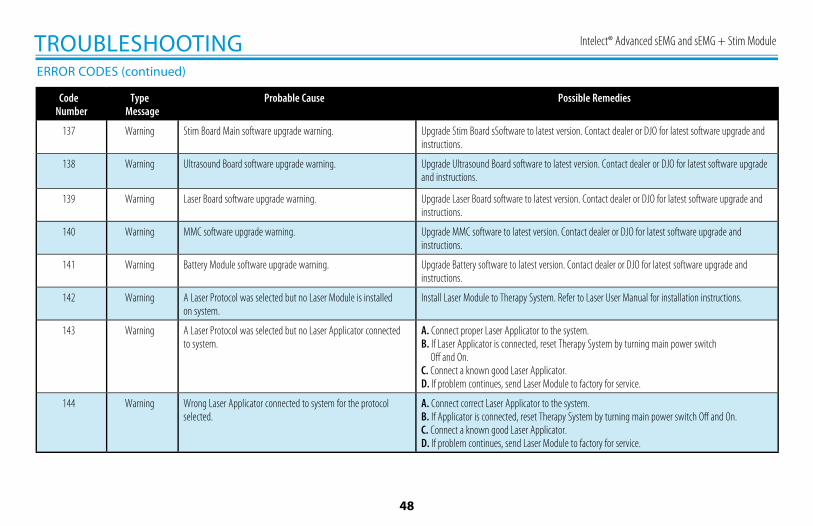
Intelect® Advanced sEMG and sEMG + Stim Module
48
TROUBLESHOOTINGERROR CODES (continued)
Code Number
Type Message
Probable Cause Possible Remedies
137 Warning Stim Board Main software upgrade warning. Upgrade Stim Board sSoftware to latest version. Contact dealer or DJO for latest software upgrade and instructions.
138 Warning Ultrasound Board software upgrade warning. Upgrade Ultrasound Board software to latest version. Contact dealer or DJO for latest software upgrade and instructions.
139 Warning Laser Board software upgrade warning. Upgrade Laser Board software to latest version. Contact dealer or DJO for latest software upgrade and instructions.
140 Warning MMC software upgrade warning. Upgrade MMC software to latest version. Contact dealer or DJO for latest software upgrade and instructions.
141 Warning Battery Module software upgrade warning. Upgrade Battery software to latest version. Contact dealer or DJO for latest software upgrade and instructions.
142 Warning A Laser Protocol was selected but no Laser Module is installed on system.
Install Laser Module to Therapy System. Refer to Laser User Manual for installation instructions.
143 Warning A Laser Protocol was selected but no Laser Applicator connected to system.
A. Connect proper Laser Applicator to the system.B. If Laser Applicator is connected, reset Therapy System by turning main power switch
Off and On.C. Connect a known good Laser Applicator.D. If problem continues, send Laser Module to factory for service.
144 Warning Wrong Laser Applicator connected to system for the protocol selected.
A. Connect correct Laser Applicator to the system.B. If Applicator is connected, reset Therapy System by turning main power switch Off and On.C. Connect a known good Laser Applicator.D. If problem continues, send Laser Module to factory for service.
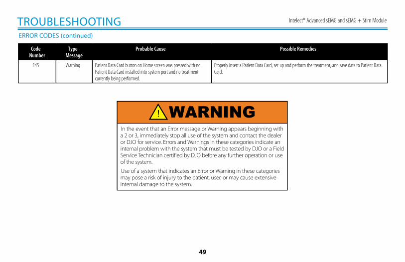
Intelect® Advanced sEMG and sEMG + Stim Module
49
TROUBLESHOOTINGERROR CODES (continued)
Code Number
Type Message
Probable Cause Possible Remedies
145 Warning Patient Data Card button on Home screen was pressed with no Patient Data Card installed into system port and no treatment currently being performed.
Properly insert a Patient Data Card, set up and perform the treatment, and save data to Patient Data Card.
In the event that an Error message or Warning appears beginning with a 2 or 3, immediately stop all use of the system and contact the dealer or DJO for service. Errors and Warnings in these categories indicate an internal problem with the system that must be tested by DJO or a Field Service Technician certified by DJO before any further operation or use of the system.
Use of a system that indicates an Error or Warning in these categories may pose a risk of injury to the patient, user, or may cause extensive internal damage to the system.
WARNING
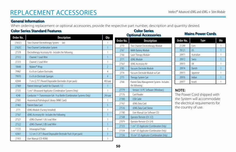
Intelect® Advanced sEMG and sEMG + Stim Module
50
REPLACEMENT ACCESSORIES
When ordering replacement or optional accessories, provide the respective part number, description and quantity desired.General Information
NOTE:The Power Cord shipped with the System will accommodate the electrical requirements for the country of use.
Color Series Standard Features
Order No. Description Qty
2765CS Two Channel Electrotherapy System (or) 1
2762CC Two Channel Combination System 1
27378 Electrotherapy Accessory Kit- Includes the following: 1
27312 Channel 1 Lead Wire 1
27313 Channel 2 Lead Wire 1
10648 Nylatex® Wrap 2
79967 6 x 8 cm Carbon Electrodes 4
79970 6 x 8 cm Electrode Sponges 4
42044 7 cm (2.75") Round Disposable Electrodes (4 per pack) 40/case
27469 Patient Interrupt Switch for Channels 1/2 1
27335 5 cm2 Ultrasound Applicator (Combination Systems Only) 1
4248 Conductor TM Transmission Gel- 9 oz Bottle (Combination Systems Only) 24/case
27085 Anatomical/Pathological Library (MMC Card) 1
27465 Patient Data Card 5
2771 sEMG Module (Factory Installed) 1
27567 sEMG Accessory Kit- Includes the Following 1
27321 sEMG Channel 1 (A) Lead Wire 1
27322 sEMG Channel 2 (B) Lead Wire 1
77725 Intravaginal Probe 1
42061 3.2 cm (1.25") Round Disposable Electrode Pack (4 per pack) 3
27455 User Manual (CD-ROM) 1
Color Series Optional Accessories
Order No. Description
2770 Two Channel Electrotherapy Module
2767 NiMH Battery Module
2766 Laser Therapy Module
2771 sEMG Module
27567 sEMG Accessory Kit
2785 Vacuum Electrode Module
2774 Vacuum Electrode Module w/Cart
2775 Therapy System Cart
2768 Patient Data Management System- Includes the following:
27779 Version 1.0 PC Software (Windows)
27176 Card Reader
27300 USB Cable
27167 sEMG Data Card
27516 sEMG Data Card Sleeve
27780 User Manual (on Software CD)
27508 Operator Remote (Ch 1/2)
27079 Operator Remote (Ch 3/4)
27333 1 cm2 US Applicator (Combination Only)
27334 2 cm2 US Applicator (Combination Only)
27336 10 cm2 US Applicator (Combination Only)
Mains Power Cords
Order No. Type Qty
21284 Euro 1
78121 US 1
20971 Australian 1
20972 Swiss 1
20973 UK 1
20974 Danish 1
20975 Japanese 1
20976 Indian 1
20977 Israeli 1
Intelect® Advanced sEMG and sEMG + Stim Module
51
MAINTENANCE
With the system disconnected from the power source, clean the system with a clean, lint free cloth moistened with water and mild antibacterial soap. If a more sterile cleaning is needed, use a cloth moistened with an antimicrobial cleaner.
Do not submerse the system or modules in liquids. Should the unit accidentally become submersed, contact the dealer or DJO Service Department immediately. Do not attempt to use a system that has been wet inside until inspected and tested by a Service Technician Certified by DJO
Do not allow liquids to enter the ventilation holes in the optional modules. This could permanently damage the modules.
CARING FOR THE THERAPY SYSTEM SERVICEShould the unit require service, warranty, or repair, please contact the selling dealer or your local DJO customer service. Ultrasound Applicators require annual calibration, from the date placed in service, by the Factory or a Service Technician certified by DJO.
Cleaning the Therapy System
Clean the Therapy System Screen Lens using NOVUS® Polish System.Contact Novus at: www.novuspolish.com
Cleaning the Lens
NOVUS is the Registered Trademark of NOVUS Inc.
Intelect® Advanced sEMG and sEMG + Stim Module
52
DJO, LLC ("Company") warrants that the Intelect Advanced Electrotherapy System sEMG and sEMG + Stim Module ("Product") is free of defects in material and workman-ship. This warranty shall remain in effect for two years (24 months) from the date of original consumer purchase. If this Product fails to function during the two year warranty period due to a defect in material or workmanship, Company or the selling dealer will repair or replace this Product without charge within a period of thirty (30) days from the date on which the Product is returned to the Company or the dealer.
All repairs to the Product must be performed by a service center authorized by the Company. Any modifications or repairs performed by unauthorized centers or groups will void this warranty.The warranty period for accessories is 180 days. Accessories consist of sEMG Lead Wires, Electrodes and Nylatex®.This warranty does not cover:
• Replacement parts or labor furnished by anyone other than the Company, the selling dealer or a certified Company service technician.• Defects or damage caused by labor furnished by someone other than Company, the selling dealer or a certified Company service technician.• Any malfunction or failure in the Product caused by product misuse, including, but not limited to, the failure to provide reasonable and required maintenance or any use that is inconsistent with the Product User's Manual.• DJO, LLC is not responsible for injury or damage resulting from modifications or service performed by non-authorized DJO, LLC service personnel.
COMPANY SHALL NOT BE LIABLE IN ANY EVENT FOR INCIDENTAL OR CONSEQUENTIAL DAMAGES.Some locations do not allow the exclusion or limitation of incidental or consequential damages, so the above limitation or exclusion may not apply to you.
To Obtain Service From Company or the selling dealer under this warranty:
1. A written claim must be made within the warranty period to the Company or the selling dealer.
2. The Product must be returned to the Company or the selling dealer by the owner.
This warranty gives you specific legal rights and you may also have other rights which vary from location to location.
The Company does not authorize any person or representative to create for it any other obligation or liability in connection with the sale of the Product.Any representative or agreement not contained in the warranty shall be void and of no effect.
THE FOREGOING WARRANTY IS IN LIEU OF ALL OTHER WARRANTIES, EXPRESSED OR IMPLIED, INCLUDING ANY WARRANTY OR MERCHANTABILITY OR FITNESS FOR A PARTICULAR PURPOSE.
WARRANTY

27455_H SEMG (English)
DJO is an ISO 13485 Certified Company
DJO France SASCentre Europeen de Fret3 rue de Bethar64990 Mouguerre, FranceT: + 33 (0) 5 59 52 86 90F: + 33 (0) 5 59 52 86 91djoglobal.eu/fr_FR
© 2011 DJO, LLC. All rights reserved.