Embed Size (px)
Citation preview
Description of Functions 03/2004 Edition
motion controlinformation system
SINUMERIK 840D/840Di/810DRemote DiagnosisRCS Host / RCS Viewer

Valid for
Control Software VersionSINUMERIK 840D 6SINUMERIK 840DE (export version) 6SINUMERIK 840D powerline 6SINUMERIK 840DE powerline 6SINUMERIK 840Di 2SINUMERIK 840DiE (export version) 2SINUMERIK 810D 3SINUMERIK 810DE (export version) 3SINUMERIK 810D powerline 6SINUMERIK 810DE powerline 6
03.04 Edition
SINUMERIK 840D/840Di/810DMotion Control InformationSystem
Remote DiagnosisRCS Host / RCS Viewer
Description of Functions
Remote Diagnosis FE1
Interrupt-Controlled EmailMessaging: @Event FE2
RCS Host / RCS Viewer FE3
References A
Index
SINUMERIK Documentation
Printing history
Brief details of this edition and previous editions are listed below.
The status of each edition is shown by the code in the “Remarks” column.
Status code in the “Remarks” column:
A New documentation.. . . . . B Unrevised reprint with new order no.. . . . . C Revised edition with new status. . . . . .
If factual changes have been made on the page in relation to the same softwareversion, this is indicated by a new edition coding in the header on that page.
Edition Order No. Remarks02.01 6FC5 297-0AF00-0BP0 A11.01 6FC5 297-0AF00-0BP1 C04.03 6FC5 297-0AF00-0BP2 C03.04 6FC5 297-0AF00-0BP3 C
This book is part of the documentation on CD-ROM (DOCONCD)Edition Order No. Remarks03.04 6FC5 298-7CA00-0BG0 C
TrademarksSIMATIC�, SIMATIC HMI�, SIMATIC NET�, SIROTEC�, SINUMERIK� and SIMODRIVE� are trademarks ofSiemens. Other product names used in this documentation may be trademarks which, if used by third par-ties, could infringe the rights of their owners.
Further information is available on the Internet under:http://www.siemens.com/motioncontrol
This publication was produced with Interleaf V7.
The reproduction, transmission or use of this document or itscontents is not permitted without express written authority. Offenderswill be liable for damages. All rights, including those created by patentgrant or registration of a utility model or design, are reserved.
Siemens AG, 2001–2004. All rights reserved
Other functions not described in this documentation might beexecutable in the control. However, no claim can be made regardingthe availability of these functions when the equipment is first suppliedor for service cases.
We have checked that the contents of this document correspond tothe hardware and software described. Nonetheless, differences mightexist and therefore we cannot guarantee that they are completelyidentical. The information contained in this document is, however,reviewed regularly and any necessary changes will be included in thenext edition. We welcome suggestions for improvement.
Subject to changes without prior notice
Siemens AktiengesellschaftOrder No. 6FC5 297-0AF00-0BP3Printed in Germany
3ls
03.04
v Siemens AG, 2004. All rights reservedSINUMERIK 840D/840Di/810D Description of Functions Remote Diagnosis (FBFE) – 03.04 Edition
Preface
The SINUMERIK documentation is organized on three levels:
� General documentation
� User documentation
� Manufacturer/service documentation.
This document is designed for machine tool manufacturers. The brochure con-tains a detailed description of the scope of functions offered by SINUMERIK840D/810D controllers.
The function descriptions are only valid for the specific software version or up tothe software version specified. You should request valid function descriptionsfor new software versions. Old function descriptions are only partly applicablefor new software versions.
More detailed information about other SINUMERIK 840D/840Di/810D brochuresand brochures for all SINUMERIK controllers (e.g. universal interface, measur-ing cycles, etc.) can be obtained from your local Siemens representative.
Note
It may be possible to run functions that are not described in this document in your controller.This does not, however, represent an obligation to supply such functions with a new controlor when servicing.
If you have queries regarding the control system, please contact the followinghotline:
A&D Technical Support Phone: ++49-(0)180-5050-222Fax: ++49-(0)180-5050-223Email: [email protected]
If you have queries regarding documentation (suggestions, corrections), pleasesend a fax to the following fax address:
Fax: ++49-(0)9131-98-2176Email: [email protected]
Fax form: See the feedback page at the end of the document
http://www.siemens.com/motioncontrol
Notes for theReader
Hotline
Internet addressfor SINUMERIK
03.04
vi Siemens AG, 2004. All rights reserved
SINUMERIK 840D/840Di/810D Description of Functions Remote Diagnosis (FBFE) – 03.04 Edition
Improved-performance variants
� SINUMERIK 840D powerline and
� SINUMERIK 840DE powerline
will be available from 09.2001 onwards. For a list of available powerlinemodules, please refer to Section 1.1 of the Hardware Description /PHD/.
Improved-performance variants
� SINUMERIK 810D powerline and
� SINUMERIK 810DE powerline
will be available from 12.2001 onwards. For a list of available powerlinemodules, please refer to Section 1.1 of the Hardware Description /PHC/.
The function descriptions provide the information required for configuration andinstallation.
The information contained in the function descriptions is designed for:
� Design engineers
� Start-up engineers once the system has been configured and set up
� Maintenance personnel inspecting and interpreting status signals andalarms
!Important
This documentation is valid for the following controls:� control SINUMERIK 840D,
software version 6� control SINUMERIK 810D,
software version 6� control SINUMERIK 840Di
software version 2
SINUMERIK 840Dpowerline
SINUMERIK 810Dpowerline
Objective
Target groups
03.04
vii Siemens AG, 2004. All rights reservedSINUMERIK 840D/840Di/810D Description of Functions Remote Diagnosis (FBFE) – 03.04 Edition
The software versions indicated in the documentation relate to the SINUMERIK840D controller. The software version valid in parallel for the SINUMERIK 810Dcontroller (if the function has been enabled, see /OI/, Catalog NC 60) is not indi-cated specifically. The following applies:
Table 1-1 Equivalent software version
SINUMERIK 840D softwareversion
SINUMERIK 810D softwareversion
6.3 (09.01) Corresponds to 6.1 (12.01)
4.3 (12.97) Corresponds to 2.3 (12.97)
3.7 (03.97) Corresponds to 1.7 (03.97)
!Danger
Indicates an imminently hazardous situation which, if not avoided, will result indeath or serious injury or in substantial property damage.
!Warning
Indicates a potentially hazardous situation which, if not avoided, could result indeath or serious injury or in substantial property damage.
!Caution
Used with the safety alert symbol indicates a potentially hazardous situationwhich, if not avoided, may result in minor or moderate injury or in property dam-age.
Caution
Used without safety alert symbol indicates a potentially hazardous situationwhich, if not avoided, may result in property damage.
Notice
Used without the safety alert symbol indicates a potential situation which, if notavoided, may result in an undesirable result or state.
Software version
Symbols
10.00
03.04
viii Siemens AG, 2004. All rights reserved
SINUMERIK 840D/840Di/810D Description of Functions Remote Diagnosis (FBFE) – 03.04 Edition
!Important
Important indicates an important or especially relevant item of information.
Note
This note contains additional important information.
FE1/i Siemens AG, 2004. All rights reservedSINUMERIK 840D/840Di/810D Description of Functions Remote Diagnosis (FBFE) – 03.04 Edition
SINUMERIK 840D/810D Description of Functions Remote Diagnosis(FBFE)
Remote Diagnosis up to HMI SW 6.2(FE1)
Contents
1 Brief Description FE1/1-3. . . . . . . . . . . . . . . . . . . . . . . . . . . . . . . . . . . . . . . . . . . . . . .
1.1 Remote diagnosis for PCU 50/70 with HMI Advanced FE1/1-3. . . . . . . .
1.2 Remote diagnosis for PCU 20 with HMI Embedded FE1/1-6. . . . . . . . . .
1.3 Remote diagnosis for HT 6 FE1/1-8. . . . . . . . . . . . . . . . . . . . . . . . . . . . . . .
2 Hardware Configuration FE1/2-11. . . . . . . . . . . . . . . . . . . . . . . . . . . . . . . . . . . . . . . . .
2.1 General FE1/2-11. . . . . . . . . . . . . . . . . . . . . . . . . . . . . . . . . . . . . . . . . . . . . . . 2.1.1 PCU 50/70 with HMI Advanced FE1/2-11. . . . . . . . . . . . . . . . . . . . . . . . . . . 2.1.2 PCU 20 with HMI Embedded and HT6 FE1/2-12. . . . . . . . . . . . . . . . . . . . .
2.2 Booting the PCU 50/70 with HMI Advanced in service mode FE1/2-13. .
2.3 Analog modem or ISDN FE1/2-15. . . . . . . . . . . . . . . . . . . . . . . . . . . . . . . . . 2.3.1 Installing/configuring an analog modem FE1/2-16. . . . . . . . . . . . . . . . . . . . 2.3.2 Installing and configuring the ISDN terminal adapter FE1/2-20. . . . . . . . . 2.3.3 Installing and configuring the ISDN Fritz!Card FE1/2-23. . . . . . . . . . . . . .
2.4 Network (PCU 50/70 only) FE1/2-24. . . . . . . . . . . . . . . . . . . . . . . . . . . . . . .
2.5 Internet FE1/2-26. . . . . . . . . . . . . . . . . . . . . . . . . . . . . . . . . . . . . . . . . . . . . . . . 2.5.1 Configuring the Internet for PCU 50 FE1/2-26. . . . . . . . . . . . . . . . . . . . . . .
2.6 Windows with gateway (PCU 50/70 with HMI Advanced only) FE1/2-37.
3 Software Installation and Start-Up on the PCU 50/70 FE1/3-39. . . . . . . . . . . . . .
3.1 Installation from the CD-ROM drive on the PC/PGacross the network FE1/3-40. . . . . . . . . . . . . . . . . . . . . . . . . . . . . . . . . . . . . .
3.2 Installing remote diagnosis from the PC/PG floppy drivevia RS-232-C FE1/3-41. . . . . . . . . . . . . . . . . . . . . . . . . . . . . . . . . . . . . . . . . .
3.3 Installation for Win32 via floppy disk drive on PCU 50 FE1/3-42. . . . . . . .
3.4 Installing the host on the PCU 50/70 FE1/3-50. . . . . . . . . . . . . . . . . . . . . . .
3.5 Deinstalling the remote diagnosis software on the PCU 50 FE1/3-51. . .
4 Software Installation and Start-up on the PCU 20 and HT 6 FE1/4-53. . . . . . . .
4.1 Installing and configuring the software on the PCU 20 FE1/4-53. . . . . . .
03.04
FE1/ii Siemens AG, 2004. All rights reserved
SINUMERIK 840D/840Di/810D Description of Functions Remote Diagnosis (FBFE) – 03.04 Edition
4.1.1 Modem link FE1/4-53. . . . . . . . . . . . . . . . . . . . . . . . . . . . . . . . . . . . . . . . . . . .
4.2 Installing and configuring the software on the HT 6 FE1/4-60. . . . . . . . . .
4.3 Activating remote diagnosis subsequently FE1/4-66. . . . . . . . . . . . . . . . . .
4.4 Quitting remote diagnosis FE1/4-66. . . . . . . . . . . . . . . . . . . . . . . . . . . . . . . .
5 Installing the Remote Diagnosis Software on the PC (Viewer) FE1/5-67. . . . . .
5.1 Viewer for Windows 95/98/2000/NT FE1/5-67. . . . . . . . . . . . . . . . . . . . . . .
5.2 Viewer for MS-DOS (necessary for PCU 20/HT 6 as the host) FE1/5-68
6 Connecting FE1/6-71. . . . . . . . . . . . . . . . . . . . . . . . . . . . . . . . . . . . . . . . . . . . . . . . . . . .
6.1 General information on connecting with viewer forWin32 (Win95/98/2000/NT) FE1/6-71. . . . . . . . . . . . . . . . . . . . . . . . . . . . . .
6.2 Connecting to the viewer for Win95/98/2000/NT(with HMI Advanced) FE1/6-71. . . . . . . . . . . . . . . . . . . . . . . . . . . . . . . . . . . .
6.3 Cascaded connection with Viewer/Host under WindowsNT(PCU 50) FE1/6-75. . . . . . . . . . . . . . . . . . . . . . . . . . . . . . . . . . . . . . . . . . . . . .
6.4 Connecting to the viewer under MS-DOS (for PCU 20/HT 6) FE1/6-77. .
7 Functions of the Viewer PC, Version Win32 FE1/7-79. . . . . . . . . . . . . . . . . . . . . . .
7.1 Remote control FE1/7-80. . . . . . . . . . . . . . . . . . . . . . . . . . . . . . . . . . . . . . . . .
7.2 File transfer FE1/7-80. . . . . . . . . . . . . . . . . . . . . . . . . . . . . . . . . . . . . . . . . . . .
7.3 Chat for PCU 50/70 with HMI Advanced(communication via text input window) FE1/7-81. . . . . . . . . . . . . . . . . . . . .
7.4 Terminal emulation FE1/7-82. . . . . . . . . . . . . . . . . . . . . . . . . . . . . . . . . . . . . .
7.5 Exit FE1/7-82. . . . . . . . . . . . . . . . . . . . . . . . . . . . . . . . . . . . . . . . . . . . . . . . . . .
7.6 Help FE1/7-82. . . . . . . . . . . . . . . . . . . . . . . . . . . . . . . . . . . . . . . . . . . . . . . . . .
8 Function of the Viewer PC (PCU 20/HT 6) FE1/8-83. . . . . . . . . . . . . . . . . . . . . . . . .
8.1 Remote control FE1/8-83. . . . . . . . . . . . . . . . . . . . . . . . . . . . . . . . . . . . . . . . .
8.2 File transfer FE1/8-83. . . . . . . . . . . . . . . . . . . . . . . . . . . . . . . . . . . . . . . . . . . .
8.3 Chat FE1/8-84. . . . . . . . . . . . . . . . . . . . . . . . . . . . . . . . . . . . . . . . . . . . . . . . . .
9 Tips and Tricks FE1/9-85. . . . . . . . . . . . . . . . . . . . . . . . . . . . . . . . . . . . . . . . . . . . . . . . .
9.1 Cascading of Win-Viewer to the DOS-HOST via “Gateway” FE1/9-85. . .
9.2 Automated installation of remote diagnosis FE1/9-86. . . . . . . . . . . . . . . . .
9.3 Adapting the Remote Diagnosis window FE1/9-94. . . . . . . . . . . . . . . . . . .
9.4 Repeated restart request FE1/9-95. . . . . . . . . . . . . . . . . . . . . . . . . . . . . . . .
9.5 Troubleshooting tips for modem connections FE1/9-95. . . . . . . . . . . . . . .
10 Alarms FE1/10-97. . . . . . . . . . . . . . . . . . . . . . . . . . . . . . . . . . . . . . . . . . . . . . . . . . . . . . . . .
10.1 Alarms FE1/10-97. . . . . . . . . . . . . . . . . . . . . . . . . . . . . . . . . . . . . . . . . . . . . . . .
FE1/1-3 Siemens AG, 2004. All rights reservedSINUMERIK 840D/840Di/810D Description of Functions Remote Diagnosis (FBFE) – 03.04 Edition
Brief Description
1.1 Remote diagnosis for PCU 50/70 with HMI Advanced
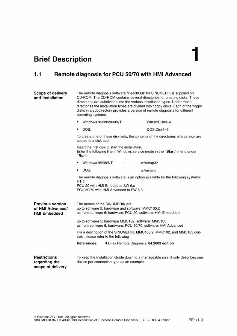
The remote diagnosis software “ReachOut” for SINUMERIK is supplied onCD-ROM. The CD-ROM contains several directories for creating disks. Thesedirectories are subdivided into the various installation types. Under thesedirectories the installation types are divided into floppy disks. Each of the floppydisks in a subdirectory provides a version of remote diagnosis for differentoperating systems.
� Windows 95/98/2000/NT Win32\Disk0–4
� DOS: DOS\Disk1–3
To create one of these disk sets, the contents of the directories of a version arecopied to a disk each.
Insert the first disk to start the installation. Enter the following line in Windows service mode in the “Start” menu under“Run”:
� Windows 95/98/NT : a:\setup32
� DOS: : a:\installd
The remote diagnosis software is an option available for the following systems:HT 6PCU 20 with HMI Embedded SW 6.xPCU 50/70 with HMI Advanced to SW 6.3
The names of the SINUMERIK are:up to software 5: hardware and software: MMC100.2 as from software 6: hardware: PCU 20, software: HMI Embedded
up to software 5: hardware MMC102, software: MMC103as from software 6: hardware: PCU 50/70, software: HMI Advanced
For a description of the SINUMERIK, MMC100.2, MMC102, and MMC103 con-trols, please refer to the following
References: /FBFE/ Remote Diagnosis, 04.2003 edition
To keep the Installation Guide down to a manageable size, it only describes onedevice per connection type as an example.
Scope of deliveryand installation
Previous versionof HMI Advanced/HMI Embedded
Restrictionsregarding thescope of delivery
1
03.041.1 Remote diagnosis for PCU 50/70 with HMI Advanced
FE1/1-4 Siemens AG, 2004. All rights reserved
SINUMERIK 840D/840Di/810D Description of Functions Remote Diagnosis (FBFE) – 03.04 Edition
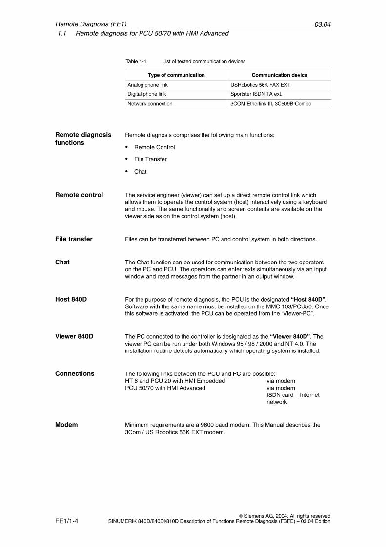
Table 1-1 List of tested communication devices
Type of communication Communication device
Analog phone link USRobotics 56K FAX EXT
Digital phone link Sportster ISDN TA ext.
Network connection 3COM Etherlink III, 3C509B-Combo
Remote diagnosis comprises the following main functions:
� Remote Control
� File Transfer
� Chat
The service engineer (viewer) can set up a direct remote control link whichallows them to operate the control system (host) interactively using a keyboardand mouse. The same functionality and screen contents are available on theviewer side as on the control system (host).
r Files can be transferred between PC and control system in both directions.
The Chat function can be used for communication between the two operatorson the PC and PCU. The operators can enter texts simultaneously via an inputwindow and read messages from the partner in an output window.
For the purpose of remote diagnosis, the PCU is the designated “Host 840D”.Software with the same name must be installed on the MMC 103/PCU50. Oncethis software is activated, the PCU can be operated from the “Viewer-PC”.
The PC connected to the controller is designated as the “Viewer 840D”. Theviewer PC can be run under both Windows 95 / 98 / 2000 and NT 4.0. Theinstallation routine detects automatically which operating system is installed.
The following links between the PCU and PC are possible:HT 6 and PCU 20 with HMI Embedded via modemPCU 50/70 with HMI Advanced via modem
ISDN card – Internetnetwork
Minimum requirements are a 9600 baud modem. This Manual describes the3Com / US Robotics 56K EXT modem.
Remote diagnosisfunctions
Remote control
File transfer
Chat
Host 840D
Viewer 840D
Connections
Modem
Remote Diagnosis (FE1)
03.041.1 Remote diagnosis for PCU 50/70 with HMI Advanced
FE1/1-5 Siemens AG, 2004. All rights reservedSINUMERIK 840D/840Di/810D Description of Functions Remote Diagnosis (FBFE) – 03.04 Edition
We recommend the external ISDN terminal adapter 3Com/US RoboticsSportster. It is treated in the same way as a modem.For the ISDN card, the ISA card AVM Fritz!Card Classic is recommended. TheISDN card can be used with the new remote diagnosis version V6.0 or higheron the PCU 50/70.
The remote diagnosis can also be used on the PCU 50/70 with HMI Advancedvia an Ethernet network using the TCP/IP (Windows sockets) protocol. For thenetwork card, Siemens recommends the 3COM Etherlink III Network Card(3C509B-Combo or 3C905B-TX). A PCI/ISA adapter is also required on thePCU.On the PCU 20 and HT 6, no network link is possible.
The remote diagnosis can also be used on the PCU 50/70 with HMI Advancedvia the Internet. This requires an Internet provider (e.g., T-Online, AOL)providing a PPP dial-in node (analog or ISDN). In addition, either a modem, anISDN terminal adapter or an ISDN card is required for the connection from thePCU 50/70 or PC to the dialin node. At the Viewer’s end, Windows 95/98/2000 or NT must be installed.
The remote diagnosis can also be operated over a Windows NT 4.0 gateway.This gateway acts as the link between the service PC and the PCUs connectedto the customer Ethernet network. The service PC and the gateway areinterconnected via modem or ISDN. The PCUs are connected to the gatewayvia Ethernet (TCP/IP). Here there are generally two possibilities:
1. From PC viewer –> gateway host and further fromgateway viewer –> PCU host
2. With the gateway as RAS directly from the PC viewer –> PCU host
For more user-friendly operation of the remote diagnosis on the control, connecta keyboard and a mouse if required. These items of equipment facilitate textinputs in the chat window. A keyboard and possibly a mouse are needed in allcases for installation and configuration. The operation of the remote diagnosis ispossible on control systems with OP3X or OP01x also without a keyboard.
ISDN
Network
Internet
Gateway
Keyboard, mouse
Remote Diagnosis (FE1)
03.041.2 Remote diagnosis for PCU 20 with HMI Embedded
FE1/1-6 Siemens AG, 2004. All rights reserved
SINUMERIK 840D/840Di/810D Description of Functions Remote Diagnosis (FBFE) – 03.04 Edition
1.2 Remote diagnosis for PCU 20 with HMI Embedded
The “remote diagnosis for PCU 20 with HMI Embedded” option differs in someregards from the remote diagnosis of the PCU 50/70 with HMI Advanced. Thedifferences are explained in this section. The information given on remote diag-nosis generally applies to both PCU 50/70 with HMI Advanced and PCU 20 withHMI Embedded. The differences are each described separately.
Unlike the PCU 50/70, the PCU 20 has no free hard disk capacity and is basedon the DOS operating system. For this reason, the remote diagnosis softwarefor the PCU 20 is supplied on a PC Card. This contains the complete softwarefor using the remote diagnosis functions and is plugged into the PCMIC memorycard interface of the PCU 20. The functional scope of the software for the PCU 20 is limited compared withthe PCU 50/70. The same software is used on the viewer (PC) as on the PCU 50 (seeSection 1.1 Scope of delivery and installation).
Note
If you are using a Windows operating system on the Viewer PC for remotediagnosis on the PCU 20, the DOS software must be installed and operated inthe Windows DOS box. The Windows versions of the remote diagnosis cannot be used here.
Remote diagnosis on PCU 20 with HMI Embedded provides the followingfunctions:
� Remote control (cf. PCU 50/70 with HMI Advanced)
� File transfer (cf. PCU 50/70 with HMI Advanced)
� Chat, Dialog; in limited form only via parts program
The service engineer (viewer) can set up a direct remote control link whichallows him/her to operate the PCU 20 control system (host) interactively using akeyboard. The same functionality and screen contents are available on theviewer side as on the PCU 20 (host).
Files can be transferred between the PC and PCU 20 via the modem link. Thefiles can only be stored on the PCU 20 on RAM disk “E:” All other drives areread-only.
Scope of deliveryand installation
Functions
Remote control
File transfer
Remote Diagnosis (FE1)
03.041.2 Remote diagnosis for PCU 20 with HMI Embedded
FE1/1-7 Siemens AG, 2004. All rights reservedSINUMERIK 840D/840Di/810D Description of Functions Remote Diagnosis (FBFE) – 03.04 Edition
The Chat function is not implemented in the PCU 20. The users of the viewerand host can communicate only indirectly by means of a parts program.
For the purpose of remote diagnosis, the PCU 20 is the designated “Host840D/810D”. Software with the same name must be installed on the PCU 20.Once this software has been activated, the PCU 20 can be operated from thePC (viewer).
The PC connected to the controller is designated as the “Viewer 840D/810D”.The viewer PC can be run under both Windows 95/98/2000 and NT. The DOSvariant of the remote diagnosis must be installed.
Basic prerequisite for communication is a modem with at least 9600 baud,connected to the serial port on the PC and PCU.
Chat
Host 840D/810D
Viewer 840D/810D
Modem
Remote Diagnosis (FE1)
03.041.3 Remote diagnosis for HT 6
FE1/1-8 Siemens AG, 2004. All rights reserved
SINUMERIK 840D/840Di/810D Description of Functions Remote Diagnosis (FBFE) – 03.04 Edition
1.3 Remote diagnosis for HT 6
The “remote diagnosis for HT6” option differs in some regards from the remotediagnosis of the PCU 50/70. The differences are explained in this section. Thedescription and instructions for remote diagnosis above generally apply to bothPCU 50/70 and HT 6. The differences are each described separately.
Unlike the PCU 50/70, the HT 6 has no free hard disk capacity and is based onthe DOS operating system. The remote diagnosis software for the HT 6 isalready stored on the EPROM. The scope of functions of the software for theHT 6 is limited, compared with the PCU 50/70.
Note
If you are using a Windows operating system on the viewer PC for remotediagnosis on the HT 6, the DOS software must be installed and operated in theWindows DOS box. The Windows versions of the remote diagnosis cannot be used here.
The connection of the HT 6 (host) to the PC (Viewer) is only possible with amodem. A connection via Internet, network, or gateway is not possible.
Remote diagnosis for HT 6 provides the following functions:
� Remote control (cf. PCU 50/70 with HMI Advanced)
� File transfer (cf. PCU 50/70 with HMI Advanced)
� Chat, Dialog; in limited form only via parts program.
The service engineer (viewer) can set up a direct remote control link whichallows him/her to operate the HT 6 control system (host) interactively using akeyboard. The same functionality and screen contents are available on theviewer side as on the HT 6 (host).
Files can be transferred between the PC and HT 6 via the modem link. The filescan only be stored on the HT 6 on RAM disk “E:” All other drives are read-only.
The Chat function is not implemented in the HT 6. The users of the viewer andhost can communicate only indirectly by means of a parts program.
For the purpose of remote diagnosis, the PCU 6 is the designated “Host840D/810D”. Software with the same name must be activated on the HT 6.Once this software has been activated, the HT 6 can be operated from the PC(viewer).
Scope of deliveryand installation
Functions
Remote control
File transfer
Chat
Host 840D/810D
Remote Diagnosis (FE1)
03.041.3 Remote diagnosis for HT 6
FE1/1-9 Siemens AG, 2004. All rights reservedSINUMERIK 840D/840Di/810D Description of Functions Remote Diagnosis (FBFE) – 03.04 Edition
The PC connected to the controller is designated as the “Viewer 840D/810D”.The viewer PC can be run under both Windows 95/98/2000 and NT. The DOSvariant of the remote diagnosis must be installed.
Basic prerequisite for communication is a modem with at least 9600 baud, Thismodem is connected to a COM port on the HT 6.
�
Viewer 840D/810D
Modem
Remote Diagnosis (FE1)
03.041.3 Remote diagnosis for HT 6
FE1/1-10 Siemens AG, 2004. All rights reserved
SINUMERIK 840D/840Di/810D Description of Functions Remote Diagnosis (FBFE) – 03.04 Edition
Remote Diagnosis (FE1)
Notes
FE1/2-11 Siemens AG, 2004. All rights reservedSINUMERIK 840D/840Di/810D Description of Functions Remote Diagnosis (FBFE) – 03.04 Edition
Hardware Configuration
2.1 General
2.1.1 PCU 50/70 with HMI Advanced
The supplied software can be used to install the remote diagnosis on aSINUMERIK 840D control system and to integrate it into the area switchover.The software is supplied on a CD-ROM that contains a set of diskettes forinstalling the remote diagnosis.
The supplied CD-ROM contains the Remote Diagnosis Documentation in pdfformat (Adobe Acrobat) in the SIEMENS directory. The CD-ROM can be readand printed using Adobe Acrobat Reader (recommended: V4.0).
A comprehensive help system such as is familiar from Windows supportsoperation of the remote diagnosis software on the PCU 50/70 with HMIAdvanced (host) and on the PC (viewer). The CD-ROM also contains furtherhelp files, such as readme.wri, support.wri, siemens_d.wri and siemens_e.wri,tipps_d.wri, tipps_e.wri, faq_d.wri.
The remote diagnosis function can be operated on the viewer PC by means of amouse and a keyboard.On the PCU 50/70, the software is installed using the integrated mouse andmembrane keyboard, provided lower case letters are not required. Remote diagnosis should therefore already be configured on start-up. In aservice case, nothing has to be changed in the remote diagnosis configuration.Remote diagnosis can be activated without a keyboard and mouse.
A so-called chat window is available to allow the operator at the machine andthe service personnel at the viewer PC to communicate. Communication cantake place only in the form of text inputs. Here we recommend you use akeyboard.
Software
Documentation
Help function
Keyboard, mouse
CommunicationViewer <=> Host
2
03.042.1 General
FE1/2-12 Siemens AG, 2004. All rights reserved
SINUMERIK 840D/840Di/810D Description of Functions Remote Diagnosis (FBFE) – 03.04 Edition
For larger service activities, a voice connection via a second telephone isrecommended.
All operating actions (softkeys) can be carried out in the same way as theoperating actions on the control system (PCU 50/70). The MCP cannot beoperated.
!Caution
To activate the machine control panel function, the viewer must request theoperator at the control to perform the necessary actions via CHAT or a secondphone link.The operator at the control is responsible for ensuring that the actions can beexecuted without any danger to man or machine. If it is not possible to perform a particular operation safely the operator on thecontroller must refuse it. The viewer cannot see the state of the machine or itssafety equipment.
2.1.2 PCU 20 with HMI Embedded and HT6
The supplied software must only be installed on the PC. On all Windowsoperating systems, installation of the DOS version must be called via“installd. exe”. The DOS version installed can be run either in the DOS box ofthe Windows operating systems or in the DOS mode of Win95/98/2000/NT.The software of the SINUMERIK 810/840D control can be accessed via the PCcard that is slotted into the PCU 20.The HT6 is supplied with the software already installed.It merely has to be configured to suit the individual system.
Use the Help in the software supplied on the viewer PC. The Help on the PCU(host) and HT6 is a DOS help because of the operating system used. You canaccess the Help by pressing function key “F1” or select it in the “Help”.
The remote diagnosis viewer software can be operated using a keyboard and amouse. Only one keyboard can be used on the PCU 20. The HOST software isoperated via the HT 6 membrane keys or with the external keyboard.
Second phone link
Actions on the ext.PC (viewer)
Software
Help function
Keyboard, mouse
Remote Diagnosis (FE1)
03.042.2 Booting the PCU 50/70 with HMI Advanced in service mode
FE1/2-13 Siemens AG, 2004. All rights reservedSINUMERIK 840D/840Di/810D Description of Functions Remote Diagnosis (FBFE) – 03.04 Edition
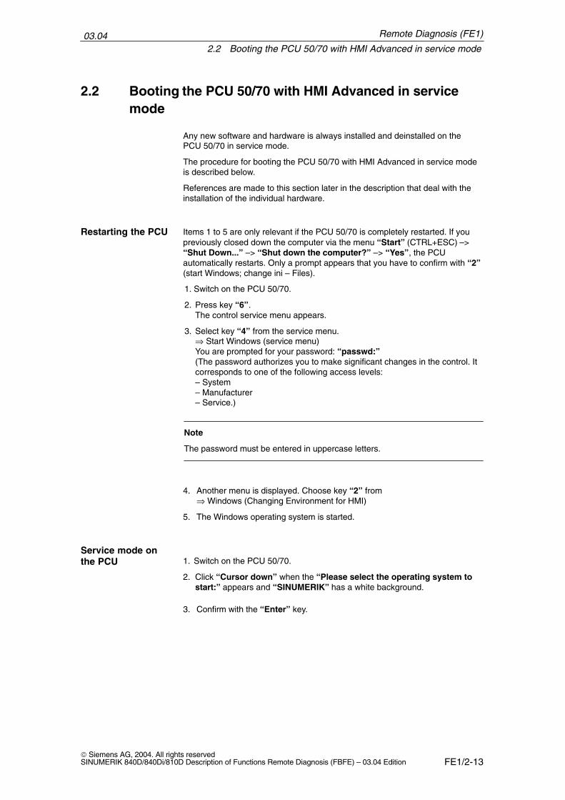
2.2 Booting the PCU 50/70 with HMI Advanced in servicemode
Any new software and hardware is always installed and deinstalled on thePCU 50/70 in service mode.
The procedure for booting the PCU 50/70 with HMI Advanced in service modeis described below.
References are made to this section later in the description that deal with theinstallation of the individual hardware.
Items 1 to 5 are only relevant if the PCU 50/70 is completely restarted. If youpreviously closed down the computer via the menu “Start” (CTRL+ESC) –>“Shut Down...” –> “Shut down the computer?” –> “Yes”, the PCUautomatically restarts. Only a prompt appears that you have to confirm with “2”(start Windows; change ini – Files).
1. Switch on the PCU 50/70.
2. Press key “6”.The control service menu appears.
3. Select key “4” from the service menu.⇒ Start Windows (service menu)You are prompted for your password: “passwd:”(The password authorizes you to make significant changes in the control. Itcorresponds to one of the following access levels:– System– Manufacturer– Service.)
Note
The password must be entered in uppercase letters.
4. Another menu is displayed. Choose key “2” from⇒ Windows (Changing Environment for HMI)
5. The Windows operating system is started.
1. Switch on the PCU 50/70.
2. Click “Cursor down” when the “Please select the operating system tostart:” appears and “SINUMERIK” has a white background.
3. Confirm with the “Enter” key.
Restarting the PCU
Service mode onthe PCU
Remote Diagnosis (FE1)
03.042.2 Booting the PCU 50/70 with HMI Advanced in service mode
FE1/2-14 Siemens AG, 2004. All rights reserved
SINUMERIK 840D/840Di/810D Description of Functions Remote Diagnosis (FBFE) – 03.04 Edition
4 Select key “4” from the service menu.⇒ Start Windows (service menu)You are prompted for your password: “passwd:”(The password authorizes you to make significant changes in the control. It corresponds to one of the following access levels:– System– Manufacturer– Service)
Note
The password must be entered in uppercase letters.
5. Another menu is displayed. Choose key “1” from⇒ Windows (Changing Environment for HMI)
6. The PCU is rebooted. Do not make any entries during rebooting even if aprompt appears!Wait until WinNT has started.
As soon as the operator panel has booted in service mode you can start instal-lation or configuration of new software or hardware.
Refer to the current description in the followingReferences: /IAM/IM4 HMI Advanced Installation/Start-Up Guide
Remote Diagnosis (FE1)
03.042.3 Analog modem or ISDN
FE1/2-15 Siemens AG, 2004. All rights reservedSINUMERIK 840D/840Di/810D Description of Functions Remote Diagnosis (FBFE) – 03.04 Edition
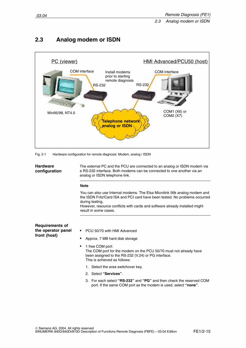
2.3 Analog modem or ISDN
HMI Advanced/PCU50 (host)PC (viewer)
RS-232 RS-232
Install modemsprior to startingremote diagnosis
Telephone networkanalog or ISDN
COM1 (X6) orCOM2 (X7)
Win95/98, NT4.0
COM interface COM interface
Fig. 2-1 Hardware configuration for remote diagnosis: Modem, analog / ISDN
The external PC and the PCU are connected to an analog or ISDN modem viaa RS-232 interface. Both modems can be connected to one another via ananalog or ISDN telephone link.
Note
You can also use Internal modems. The Elsa Microlink 56k analog modem andthe ISDN Fritz!Card ISA and PCI card have been tested. No problems occurredduring testing.However, resource conflicts with cards and software already installed mightresult in some cases.
� PCU 50/70 with HMI Advanced
� Approx. 7 MB hard disk storage
� 1 free COM port:The COM port for the modem on the PCU 50/70 must not already havebeen assigned to the RS-232 (V.24) or PG interface.This is achieved as follows:
1. Select the area switchover key.
2. Select “Services”.
3. For each select “RS-232” and “PG” and then check the reserved COMport. If the same COM port as the modem is used, select “none”.
Hardwareconfiguration
Requirements ofthe operator panelfront (host)
Remote Diagnosis (FE1)
03.042.3 Analog modem or ISDN
FE1/2-16 Siemens AG, 2004. All rights reserved
SINUMERIK 840D/840Di/810D Description of Functions Remote Diagnosis (FBFE) – 03.04 Edition
� IBM AT or 100% compatible PC, Intel 486 or higher
� Windows 95/98/2000 or Windows NT/XP operating system
� RAM according to operating system requirements
� Approx. 7 MB hard disk storage
� VGA or SVGA screen.
A modem with 14,400 baud or higher and the correspondingly specific drivermust be installed and configured before installing the remote diagnosis tool. Werecommend using brand name modems such as 3COM/US-Robotics SportsterFlash or Voice 33.6 PnP External for an analog connection and the3COM/US-Robotics Sportster ISDN terminal adapter for ISDN connections.
2.3.1 Installing/configuring an analog modem
PCU 50/70 (host) specific steps:
Start the PCU in Windows service mode as described in Section 2.2 andcontinue with item 2 (below).
General steps (viewer/host):
1. Starting the installation program:
Start the installation program with “Start” –> “Settings” –> “ControlPanel” by double clicking on the symbol “Modems”.
2. Select type of modem (only Win98):From the “Install New Modem” dialog box, choose the “Add” option. Click“Next” to continue installation.
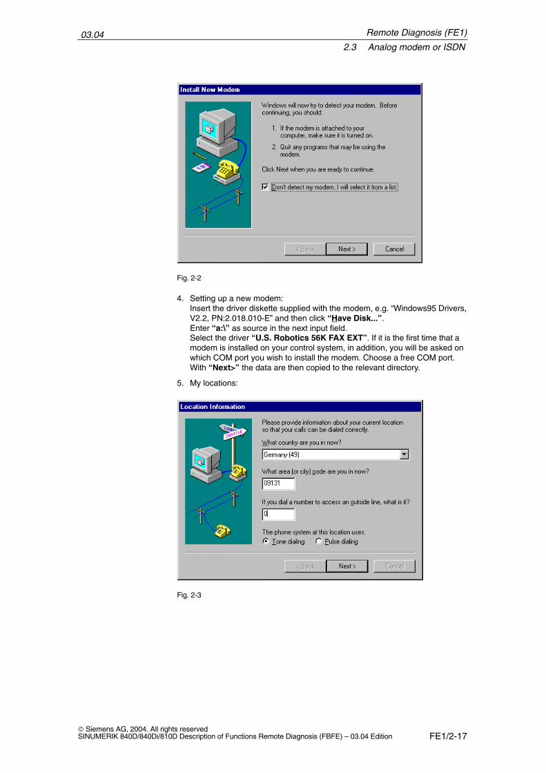
3. Modem detection:Select “Don’t detect my modem; I will select it from a list.” to save time(to select without a mouse use the tab key and then the spacebar).
Requirements ofPC (VIEWER)
Modemrequirements
Installation themodem on PCU
Installing themodem underWin95/98/2000/NT
Remote Diagnosis (FE1)
03.042.3 Analog modem or ISDN
FE1/2-17 Siemens AG, 2004. All rights reservedSINUMERIK 840D/840Di/810D Description of Functions Remote Diagnosis (FBFE) – 03.04 Edition
Fig. 2-2
4. Setting up a new modem:Insert the driver diskette supplied with the modem, e.g. “Windows95 Drivers,V2.2, PN:2.018.010-E” and then click “Have Disk...”.Enter “a:\” as source in the next input field. Select the driver “U.S. Robotics 56K FAX EXT”. If it is the first time that amodem is installed on your control system, in addition, you will be asked onwhich COM port you wish to install the modem. Choose a free COM port. With “Next>” the data are then copied to the relevant directory.
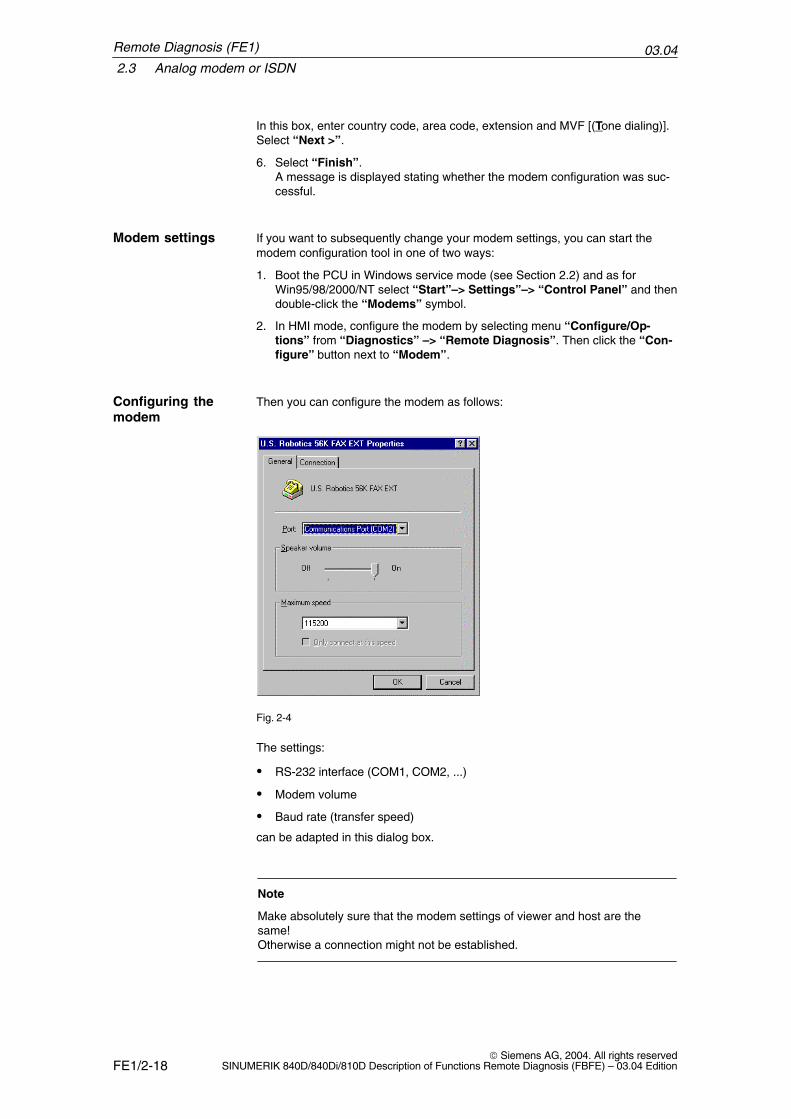
5. My locations:
Fig. 2-3
Remote Diagnosis (FE1)
03.042.3 Analog modem or ISDN
FE1/2-18 Siemens AG, 2004. All rights reserved
SINUMERIK 840D/840Di/810D Description of Functions Remote Diagnosis (FBFE) – 03.04 Edition
In this box, enter country code, area code, extension and MVF [(Tone dialing)].Select “Next >”.
6. Select “Finish”.A message is displayed stating whether the modem configuration was suc-cessful.
Modem settings If you want to subsequently change your modem settings, you can start themodem configuration tool in one of two ways:
1. Boot the PCU in Windows service mode (see Section 2.2) and as forWin95/98/2000/NT select “Start”–> Settings”–> “Control Panel” and thendouble-click the “Modems” symbol.
2. In HMI mode, configure the modem by selecting menu “Configure/Op-tions” from “Diagnostics” –> “Remote Diagnosis”. Then click the “Con-figure” button next to “Modem”.
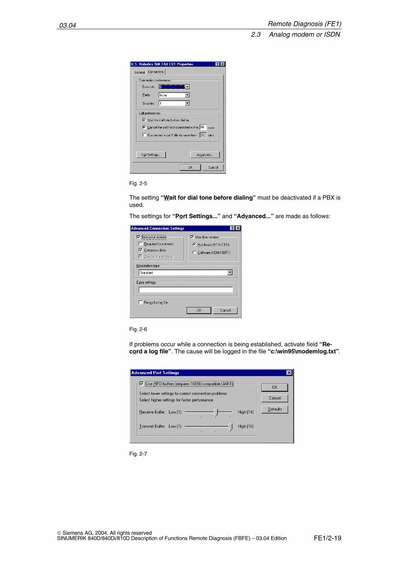
Then you can configure the modem as follows:
Fig. 2-4
The settings:
� RS-232 interface (COM1, COM2, ...)
� Modem volume
� Baud rate (transfer speed)
can be adapted in this dialog box.
Note
Make absolutely sure that the modem settings of viewer and host are thesame!Otherwise a connection might not be established.
Configuring themodem
Remote Diagnosis (FE1)
03.042.3 Analog modem or ISDN
FE1/2-19 Siemens AG, 2004. All rights reservedSINUMERIK 840D/840Di/810D Description of Functions Remote Diagnosis (FBFE) – 03.04 Edition
Fig. 2-5
The setting “Wait for dial tone before dialing” must be deactivated if a PBX isused.
The settings for “Port Settings...” and “Advanced...” are made as follows:
Fig. 2-6
If problems occur while a connection is being established, activate field “Re-cord a log file”. The cause will be logged in the file “c:\win95\modemlog.txt”.
Fig. 2-7
Remote Diagnosis (FE1)
03.042.3 Analog modem or ISDN
FE1/2-20 Siemens AG, 2004. All rights reserved
SINUMERIK 840D/840Di/810D Description of Functions Remote Diagnosis (FBFE) – 03.04 Edition
2.3.2 Installing and configuring the ISDN terminal adapter
The following description only applies to the 3COM/US-Robotics Sportster TAterminal adapter.
PCU (host) specific steps
1. Start the PCU in Windows service mode (see Section 2.1) and continue withitem 2 (below).
General steps (viewer/host):
2. Starting the installation program:Start the installation program with “Start”–> “Settings”–> “Control Panel”by double-clicking the “Modems” symbol.
3. Select type of modem (only Win98):From the “Install New Modem” dialog box, choose the “Add” option. Click“Next” to continue the installation.
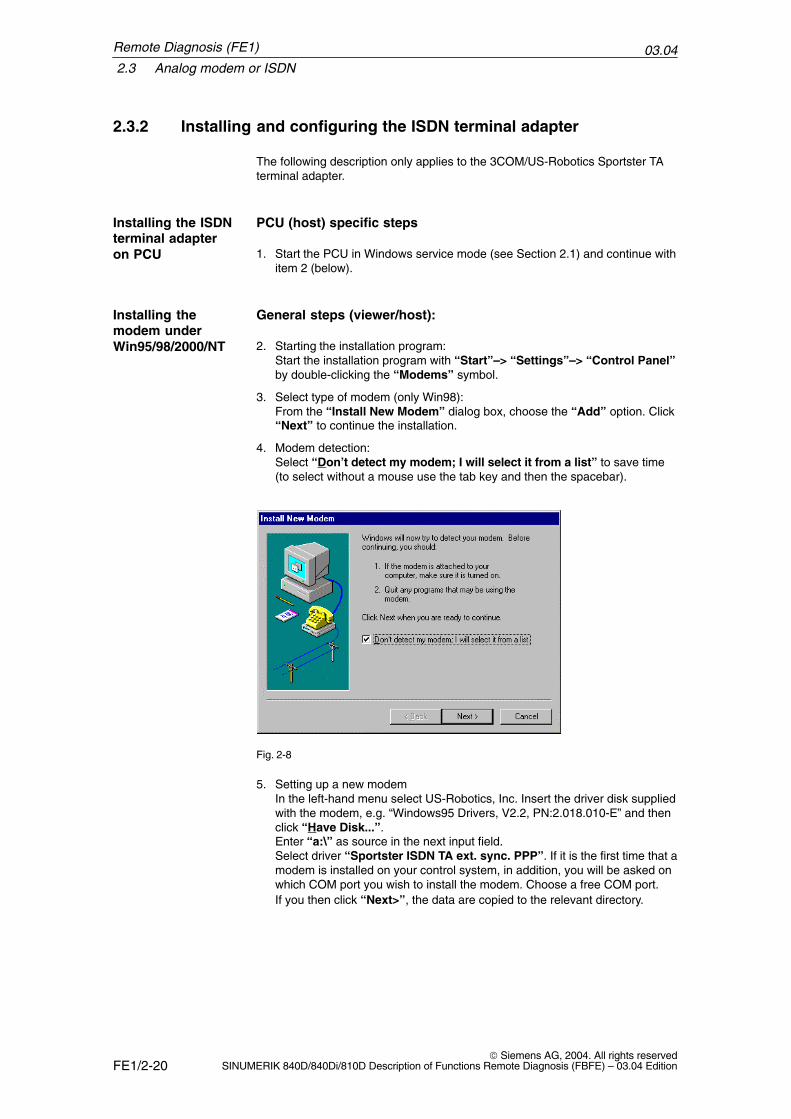
4. Modem detection:Select “Don’t detect my modem; I will select it from a list” to save time(to select without a mouse use the tab key and then the spacebar).
Fig. 2-8
5. Setting up a new modemIn the left-hand menu select US-Robotics, Inc. Insert the driver disk suppliedwith the modem, e.g. “Windows95 Drivers, V2.2, PN:2.018.010-E” and thenclick “Have Disk...”.Enter “a:\” as source in the next input field. Select driver “Sportster ISDN TA ext. sync. PPP”. If it is the first time that amodem is installed on your control system, in addition, you will be asked onwhich COM port you wish to install the modem. Choose a free COM port. If you then click “Next>”, the data are copied to the relevant directory.
Installing the ISDNterminal adapteron PCU
Installing themodem underWin95/98/2000/NT
Remote Diagnosis (FE1)
03.042.3 Analog modem or ISDN
FE1/2-21 Siemens AG, 2004. All rights reservedSINUMERIK 840D/840Di/810D Description of Functions Remote Diagnosis (FBFE) – 03.04 Edition
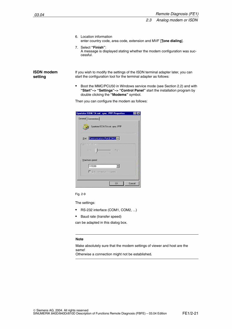
6. Location informationenter country code, area code, extension and MVF [Tone dialing].
7. Select “Finish”:A message is displayed stating whether the modem configuration was suc-cessful.
If you wish to modify the settings of the ISDN terminal adapter later, you canstart the configuration tool for the terminal adapter as follows:
� Boot the MMC/PCU50 in Windows service mode (see Section 2.2) and with“Start”–> “Settings”–> “Control Panel” start the installation program bydouble clicking the “Modems” symbol.
Then you can configure the modem as follows:
Fig. 2-9
The settings:
� RS-232 interface (COM1, COM2, ...)
� Baud rate (transfer speed)
can be adapted in this dialog box.
Note
Make absolutely sure that the modem settings of viewer and host are thesame!Otherwise a connection might not be established.
ISDN modemsetting
Remote Diagnosis (FE1)
03.042.3 Analog modem or ISDN
FE1/2-22 Siemens AG, 2004. All rights reserved
SINUMERIK 840D/840Di/810D Description of Functions Remote Diagnosis (FBFE) – 03.04 Edition
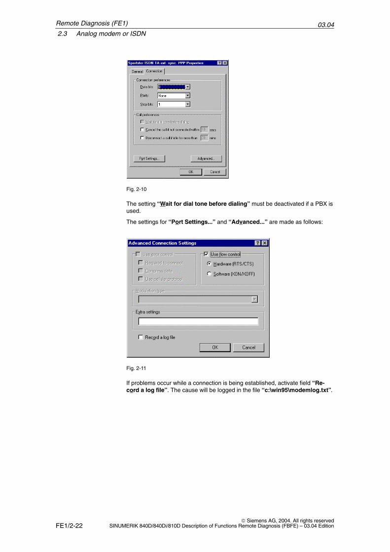
Fig. 2-10
The setting “Wait for dial tone before dialing” must be deactivated if a PBX isused.
The settings for “Port Settings...” and “Advanced...” are made as follows:
Fig. 2-11
If problems occur while a connection is being established, activate field “Re-cord a log file”. The cause will be logged in the file “c:\win95\modemlog.txt”.
Remote Diagnosis (FE1)
03.042.3 Analog modem or ISDN
FE1/2-23 Siemens AG, 2004. All rights reservedSINUMERIK 840D/840Di/810D Description of Functions Remote Diagnosis (FBFE) – 03.04 Edition
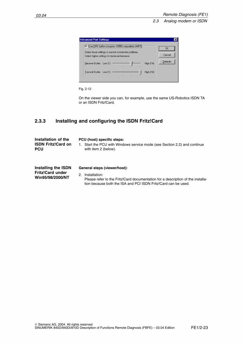
Fig. 2-12
On the viewer side you can, for example, use the same US-Robotics ISDN TAor an ISDN Fritz!Card.
2.3.3 Installing and configuring the ISDN Fritz!Card
PCU (host) specific steps:1. Start the PCU with Windows service mode (see Section 2.2) and continue
with item 2 (below).
General steps (viewer/host):
2. Installation:Please refer to the Fritz!Card documentation for a description of the installa-tion because both the ISA and PCI ISDN Fritz!Card can be used.
Installation of theISDN Fritz!Card onPCU
Installing the ISDNFritz!Card underWin95/98/2000/NT
Remote Diagnosis (FE1)
03.042.4 Network (PCU 50/70 only)
FE1/2-24 Siemens AG, 2004. All rights reserved
SINUMERIK 840D/840Di/810D Description of Functions Remote Diagnosis (FBFE) – 03.04 Edition
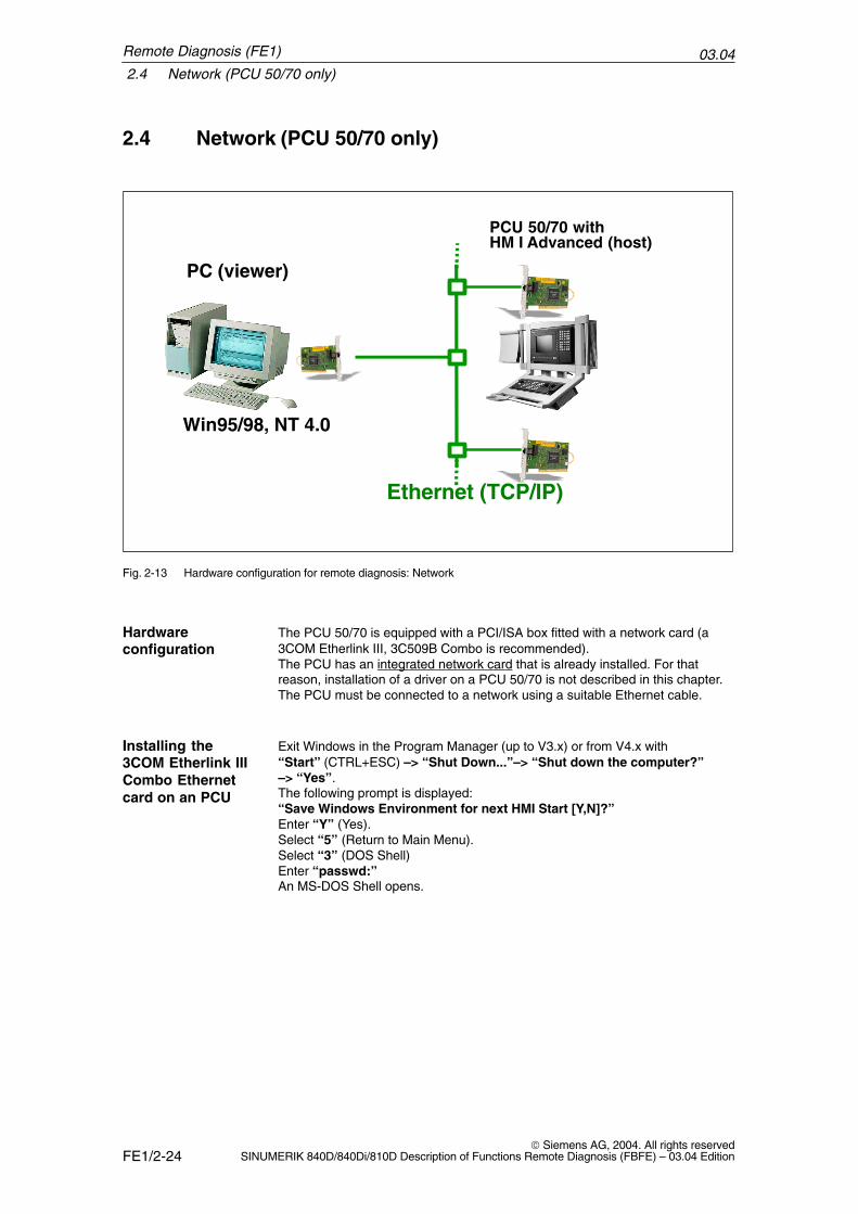
2.4 Network (PCU 50/70 only)
ISA Box +
Ethernet (TCP/IP)
PC (viewer)
Win95/98, NT 4.0
PCU 50/70 withHM I Advanced (host)
Fig. 2-13 Hardware configuration for remote diagnosis: Network
The PCU 50/70 is equipped with a PCI/ISA box fitted with a network card (a3COM Etherlink III, 3C509B Combo is recommended).The PCU has an integrated network card that is already installed. For thatreason, installation of a driver on a PCU 50/70 is not described in this chapter.The PCU must be connected to a network using a suitable Ethernet cable.
I Exit Windows in the Program Manager (up to V3.x) or from V4.x with “Start” (CTRL+ESC) –> “Shut Down...”–> “Shut down the computer?”–> “Yes”.The following prompt is displayed:“Save Windows Environment for next HMI Start [Y,N]?”Enter “Y” (Yes).Select “5” (Return to Main Menu).Select “3” (DOS Shell)Enter “passwd:” An MS-DOS Shell opens.
Hardwareconfiguration
Installing the3COM Etherlink IIICombo Ethernetcard on an PCU
Remote Diagnosis (FE1)
03.042.4 Network (PCU 50/70 only)
FE1/2-25 Siemens AG, 2004. All rights reservedSINUMERIK 840D/840Di/810D Description of Functions Remote Diagnosis (FBFE) – 03.04 Edition
Installing the TCP/IP protocol
For installation, the MS TCP/IP 32 stack is required. For further informationplease refer to the appropriate contact person.
1. Select “Start” –> “Settings” –> “Control Panel” –> “Network”.
2. Select “Add...” and in the dialog box that appears select “Protocol”.
3. In the second dialog box, select “Microsoft” in the left selection field and“TCP/IP” in the right one.
4. Confirm your settings with “OK” to add the new network protocol.
5. Restart the PCU with “Start” –> “Shut Down...” –> “Shut downComputer” to apply the changes.
6. Select “Start” –> “Settings” –> “Control Panel” –> “Network”.
7. In the display window select “Network” –> “TCP/IP” and click“Properties” to view or change the IP address. This IP address is requiredby the viewer for connection setup.
8. Save all current settings, or else they will be lost at restart. Shut down thecomputer with “Start” (CTRL+ESC)–> “Shut Down...” –> “Shut downComputer” –> “Yes”.
9. The following prompt is displayed: “Save Windows Environment for nextHMI start [Y, N]?”. Confirm with “Y” (Yes).
10. The following prompt is displayed: “Do you want to backup your oldEnvironment [Y, N]?”. Confirm with “Y” (Yes).
!Warning
Confirm both queries with “Y”.
Another query might be displayed:
“...overwrite them with the current one ?”
Respond with “1” (Overwrite...).
You can start Windows again or boot the control in HMI mode.
To be on the safe side, press “2” (Start Windows). Shut down the computer again with “Start” und “Shut Down...” –> “Shutdown Computer” –> “Yes”. Respond to both queries as described above.The backup is saved a second time and the configurations are also savedshould an error occur.
Setting up aTCP/IP protocol onPCU 50/70
Remote Diagnosis (FE1)
03.042.5 Internet
FE1/2-26 Siemens AG, 2004. All rights reserved
SINUMERIK 840D/840Di/810D Description of Functions Remote Diagnosis (FBFE) – 03.04 Edition
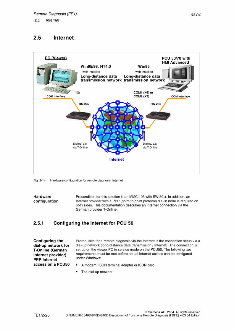
2.5 Internet
PC (Viewer)
COM interface
RS-232
COM1 (X6) orCOM2 (X7)
PCU 50/70 withHMI Advanced
COM interface
Internet
Dialing, e.g.via T-Online
Dialing, e.g.
Win95/98, NT4.0with installed
Long-distance data
Win95with installed
via T-Online
transmission networkLong-distance data transmission network
RS-232
Fig. 2-14 Hardware configuration for remote diagnosis: Internet
Precondition for this solution is an MMC 103 with SW 50.x. In addition, anInternet provider with a PPP (point-to-point protocol) dial-in node is required onboth sides. This documentation describes an Internet connection via theGerman provider T-Online.
2.5.1 Configuring the Internet for PCU 50
Prerequisite for a remote diagnosis via the Internet is the connection setup via adial-up network (long-distance data transmission / Internet). The connection isset up on the viewer PC in service mode on the PCU50. The following tworequirements must be met before actual Internet access can be configuredunder Windows:
� A modem, ISDN terminal adapter or ISDN card
� The dial-up network
Hardwareconfiguration
Configuring thedial-up network forT-Online (GermanInternet provider)PPP Internetaccess on a PCU50
Remote Diagnosis (FE1)
03.042.5 Internet
FE1/2-27 Siemens AG, 2004. All rights reservedSINUMERIK 840D/840Di/810D Description of Functions Remote Diagnosis (FBFE) – 03.04 Edition
The dial-up network is used to set up a new connection as the final step ofinstallation.For the installation instructions of the modem, please refer to the suppliedmanual or follow the steps stated in Subsection 2.3.1.
An analog modem is superfluous if an ISDN telephone link and an ISDN cardare already available.
The company AVM supplies a driver that works with many ISDN cards. ThisCAPIPORT driver is available for AVM’s Fritz!Card. It can also be used withTELES 16.0 and TELES 16.3 PnP. The German Telekom’s Teledat 150, whichis also from AVM, operates with the AVM CAPIPORT driver.
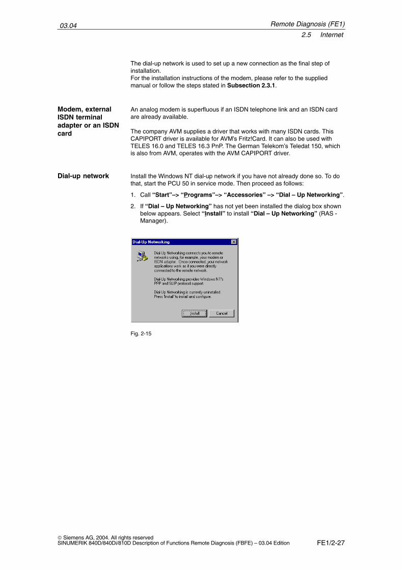
Install the Windows NT dial-up network if you have not already done so. To dothat, start the PCU 50 in service mode. Then proceed as follows:
1. Call “Start”–> “Programs”–> “Accessories” –> “Dial – Up Networking”.
2. If “Dial – Up Networking” has not yet been installed the dialog box shownbelow appears. Select “Install” to install “Dial – Up Networking” (RAS -Manager).
Fig. 2-15
Modem, externalISDN terminaladapter or an ISDNcard
Dial-up network
Remote Diagnosis (FE1)
03.042.5 Internet
FE1/2-28 Siemens AG, 2004. All rights reserved
SINUMERIK 840D/840Di/810D Description of Functions Remote Diagnosis (FBFE) – 03.04 Edition
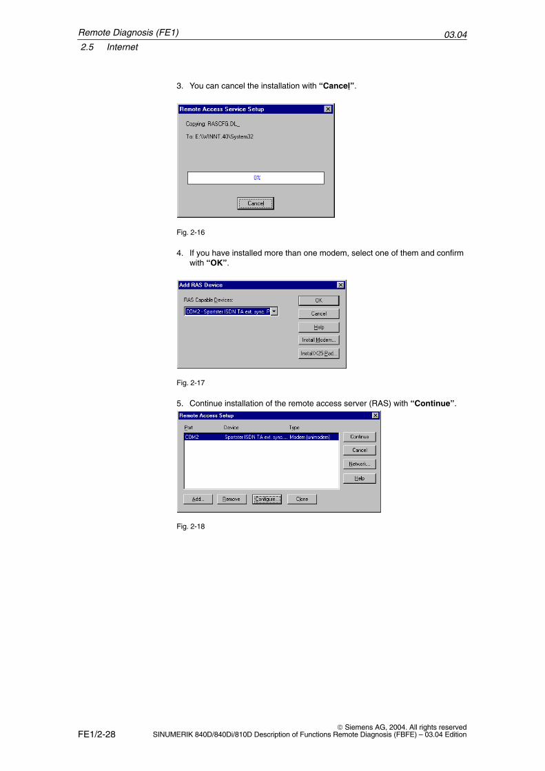
3. You can cancel the installation with “Cancel”.
Fig. 2-16
4. If you have installed more than one modem, select one of them and confirmwith “OK”.
Fig. 2-17
5. Continue installation of the remote access server (RAS) with “Continue”.
Fig. 2-18
Remote Diagnosis (FE1)
03.042.5 Internet
FE1/2-29 Siemens AG, 2004. All rights reservedSINUMERIK 840D/840Di/810D Description of Functions Remote Diagnosis (FBFE) – 03.04 Edition
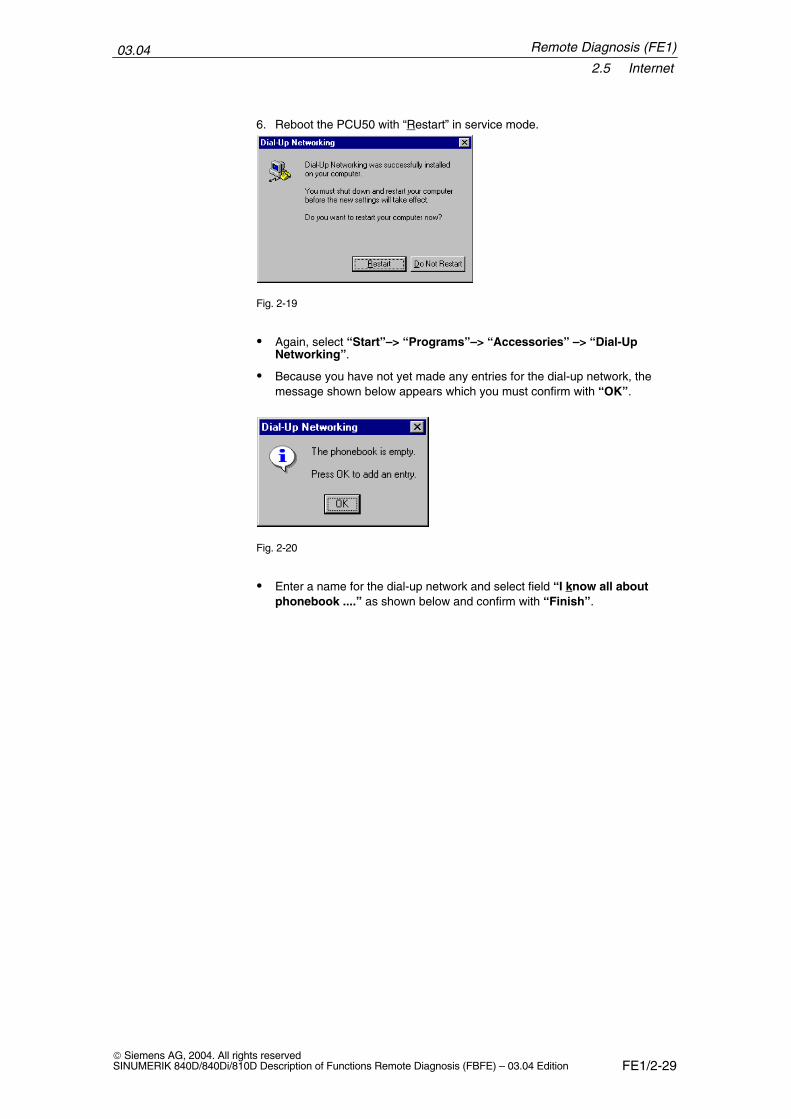
6. Reboot the PCU50 with “Restart” in service mode.
Fig. 2-19
� Again, select “Start”–> “Programs”–> “Accessories” –> “Dial-UpNetworking”.
� Because you have not yet made any entries for the dial-up network, themessage shown below appears which you must confirm with “OK”.
Fig. 2-20
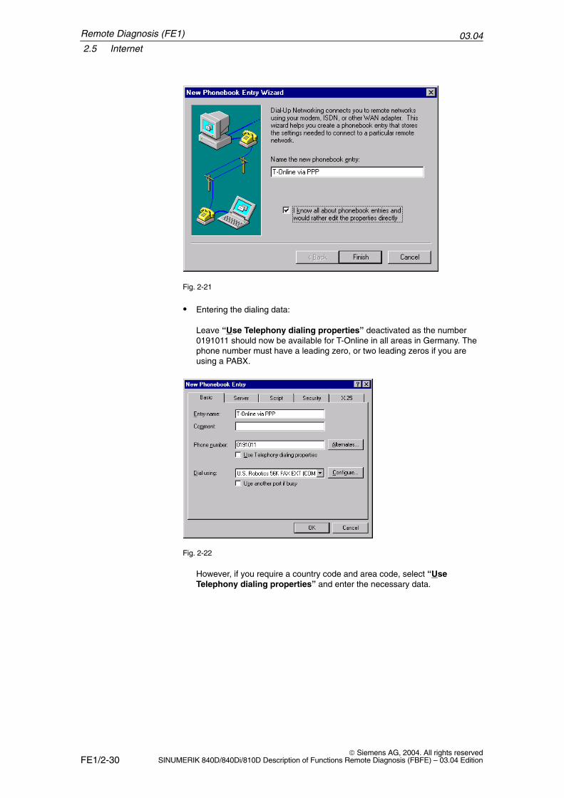
� Enter a name for the dial-up network and select field “I know all aboutphonebook ....” as shown below and confirm with “Finish”.
Remote Diagnosis (FE1)
03.042.5 Internet
FE1/2-30 Siemens AG, 2004. All rights reserved
SINUMERIK 840D/840Di/810D Description of Functions Remote Diagnosis (FBFE) – 03.04 Edition
Fig. 2-21
� Entering the dialing data:
Leave “Use Telephony dialing properties” deactivated as the number0191011 should now be available for T-Online in all areas in Germany. Thephone number must have a leading zero, or two leading zeros if you areusing a PABX.
Fig. 2-22
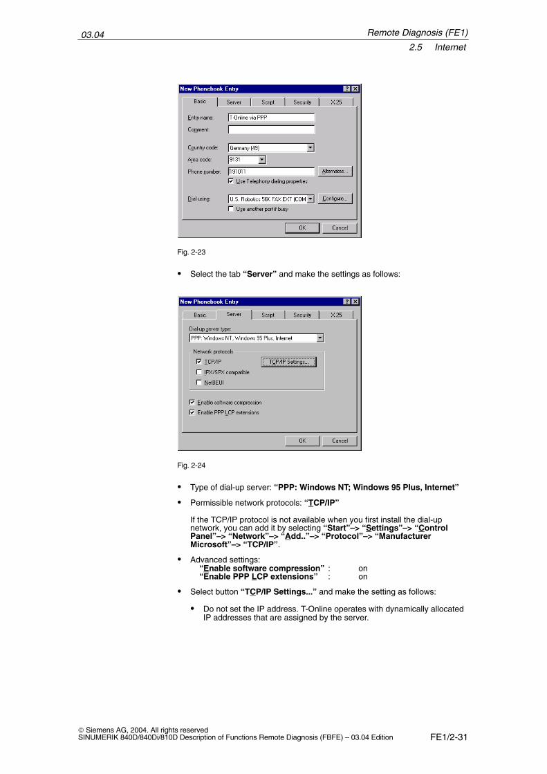
However, if you require a country code and area code, select “UseTelephony dialing properties” and enter the necessary data.
Remote Diagnosis (FE1)
03.042.5 Internet
FE1/2-31 Siemens AG, 2004. All rights reservedSINUMERIK 840D/840Di/810D Description of Functions Remote Diagnosis (FBFE) – 03.04 Edition
Fig. 2-23
� Select the tab “Server” and make the settings as follows:
Fig. 2-24
� Type of dial-up server: “PPP: Windows NT; Windows 95 Plus, Internet”
� Permissible network protocols: “TCP/IP”
If the TCP/IP protocol is not available when you first install the dial-upnetwork, you can add it by selecting “Start”–> “Settings”–> “ControlPanel”–> “Network”–> “Add..”–> “Protocol”–> “ManufacturerMicrosoft”–> “TCP/IP”.
� Advanced settings:“Enable software compression” : on“Enable PPP LCP extensions” : on
� Select button “TCP/IP Settings...” and make the setting as follows:
� Do not set the IP address. T-Online operates with dynamically allocatedIP addresses that are assigned by the server.
Remote Diagnosis (FE1)
03.042.5 Internet
FE1/2-32 Siemens AG, 2004. All rights reserved
SINUMERIK 840D/840Di/810D Description of Functions Remote Diagnosis (FBFE) – 03.04 Edition
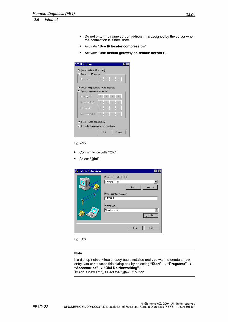
� Do not enter the name server address. It is assigned by the server whenthe connection is established.
� Activate “Use IP header compression”
� Activate “Use default gateway on remote network”.
Fig. 2-25
� Confirm twice with “OK”.
� Select “Dial”.
Fig. 2-26
Note
If a dial-up network has already been installed and you want to create a newentry, you can access this dialog box by selecting “Start” –> “Programs” –>“Accessories” –> “Dial-Up Networking”. To add a new entry, select the “New...” button.
Remote Diagnosis (FE1)
03.042.5 Internet
FE1/2-33 Siemens AG, 2004. All rights reservedSINUMERIK 840D/840Di/810D Description of Functions Remote Diagnosis (FBFE) – 03.04 Edition
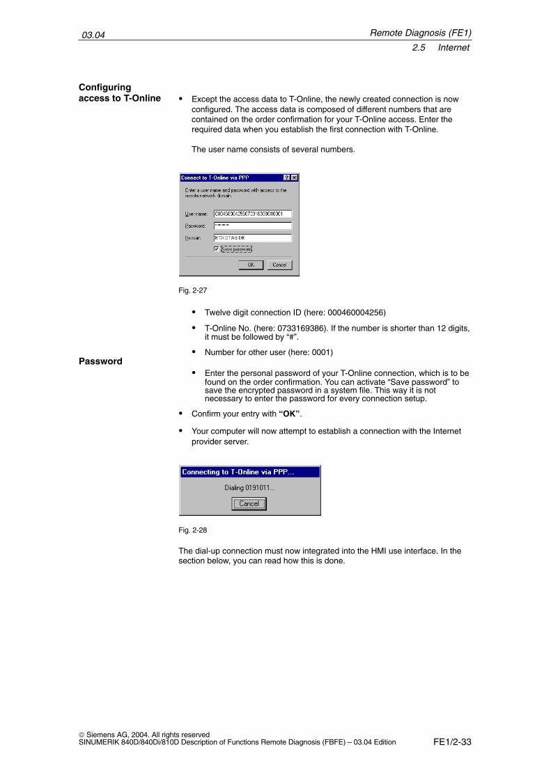
� Except the access data to T-Online, the newly created connection is nowconfigured. The access data is composed of different numbers that arecontained on the order confirmation for your T-Online access. Enter therequired data when you establish the first connection with T-Online.
The user name consists of several numbers.
Fig. 2-27
� Twelve digit connection ID (here: 000460004256)
� T-Online No. (here: 0733169386). If the number is shorter than 12 digits,it must be followed by “#”.
� Number for other user (here: 0001)
� Enter the personal password of your T-Online connection, which is to befound on the order confirmation. You can activate “Save password” tosave the encrypted password in a system file. This way it is notnecessary to enter the password for every connection setup.
� Confirm your entry with “OK”.
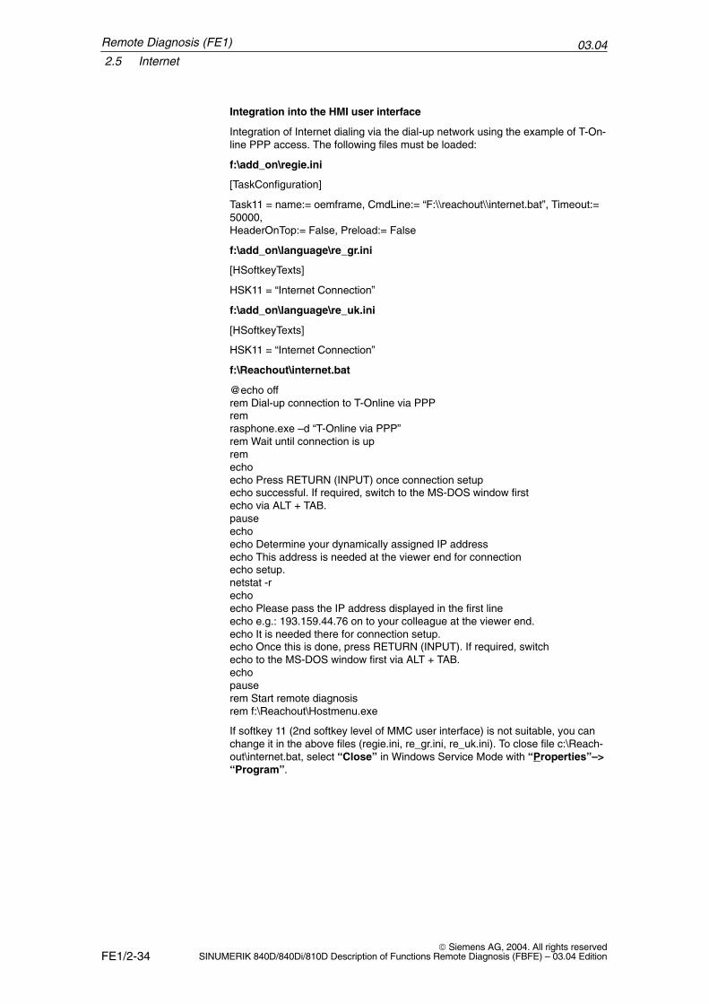
� Your computer will now attempt to establish a connection with the Internetprovider server.
Fig. 2-28
The dial-up connection must now integrated into the HMI use interface. In thesection below, you can read how this is done.
Configuringaccess to T-Online
Password
Remote Diagnosis (FE1)
03.042.5 Internet
FE1/2-34 Siemens AG, 2004. All rights reserved
SINUMERIK 840D/840Di/810D Description of Functions Remote Diagnosis (FBFE) – 03.04 Edition
Integration into the HMI user interface
Integration of Internet dialing via the dial-up network using the example of T-On-line PPP access. The following files must be loaded:
f:\add_on\regie.ini
[TaskConfiguration]
Task11 = name:= oemframe, CmdLine:= “F:\\reachout\\internet.bat”, Timeout:=50000,HeaderOnTop:= False, Preload:= False
f:\add_on\language\re_gr.ini
[HSoftkeyTexts]
HSK11 = “Internet Connection”
f:\add_on\language\re_uk.ini
[HSoftkeyTexts]
HSK11 = “Internet Connection”
f:\Reachout\internet.bat
@echo offrem Dial-up connection to T-Online via PPPremrasphone.exe –d “T-Online via PPP”rem Wait until connection is upremechoecho Press RETURN (INPUT) once connection setupecho successful. If required, switch to the MS-DOS window firstecho via ALT + TAB.pauseechoecho Determine your dynamically assigned IP addressecho This address is needed at the viewer end for connectionecho setup.netstat -rechoecho Please pass the IP address displayed in the first lineecho e.g.: 193.159.44.76 on to your colleague at the viewer end.echo It is needed there for connection setup.echo Once this is done, press RETURN (INPUT). If required, switchecho to the MS-DOS window first via ALT + TAB.echopauserem Start remote diagnosisrem f:\Reachout\Hostmenu.exe
If softkey 11 (2nd softkey level of MMC user interface) is not suitable, you canchange it in the above files (regie.ini, re_gr.ini, re_uk.ini). To close file c:\Reach-out\internet.bat, select “Close” in Windows Service Mode with “Properties”–>“Program”.
Remote Diagnosis (FE1)
03.042.5 Internet
FE1/2-35 Siemens AG, 2004. All rights reservedSINUMERIK 840D/840Di/810D Description of Functions Remote Diagnosis (FBFE) – 03.04 Edition
Configuring the hostIn file internet.bat you might have to adapt the entry “rundll rnaui.dll,RnaDialT-Online per PPP” for the HMI or the entry “rasphone.exe -d” –> “T-Onlinevia PPP” for the PPC50 to the name of the configured dial-up connections.
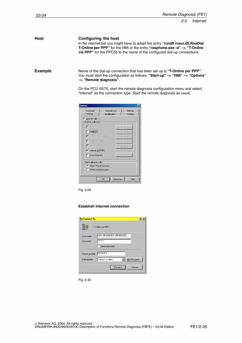
Name of the dial-up connection that has been set up is “T-Online per PPP”.You must start the configuration as follows: “Start-up” –> “HMI” –> “Options”–> “Remote diagnosis”.
On the PCU 50/70, start the remote diagnosis configuration menu and select“Internet” as the connection type. Start the remote diagnosis as usual.
Fig. 2-29
Establish Internet connection
Fig. 2-30
Host
Example
Remote Diagnosis (FE1)
03.042.5 Internet
FE1/2-36 Siemens AG, 2004. All rights reserved
SINUMERIK 840D/840Di/810D Description of Functions Remote Diagnosis (FBFE) – 03.04 Edition
Establish the Internet connection with softkey 11 “Internet connection” andstart remote diagnosis with “Diagnosis” –> “Remote diagnosis”. Select“Connect to” to set up the modem/ISDN connection to the Internet PPP dial-upnode. The following window is displayed:
Fig. 2-31
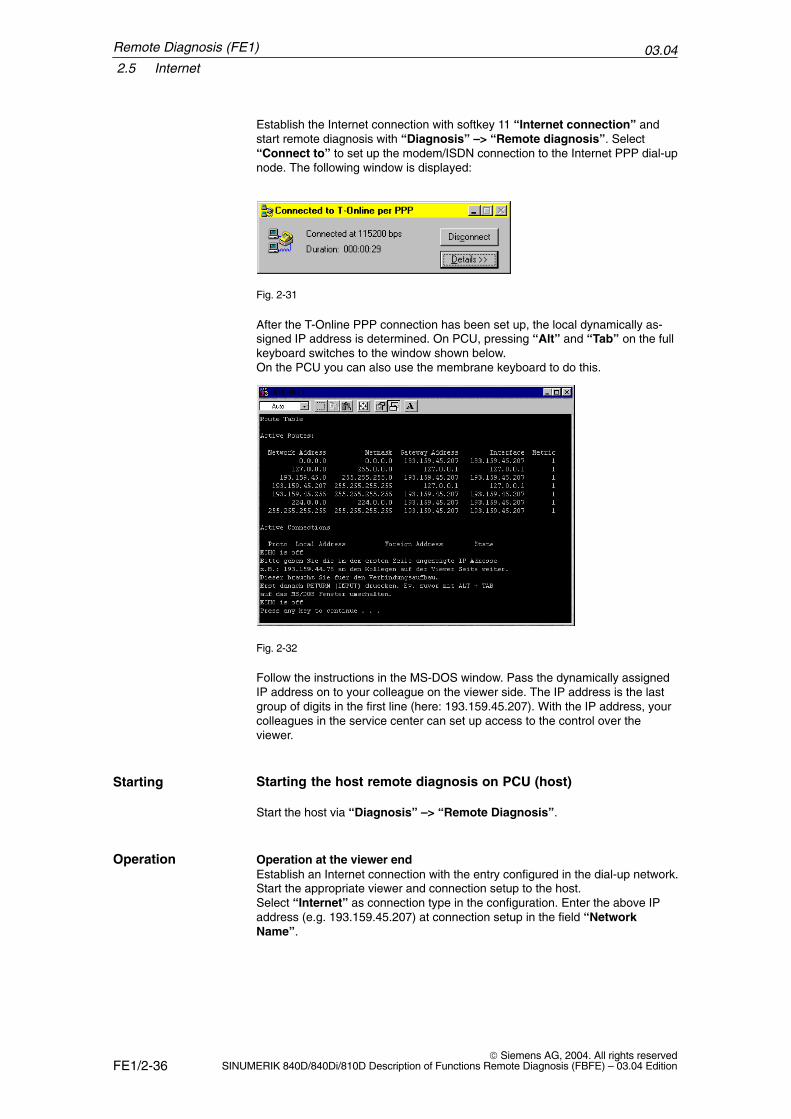
After the T-Online PPP connection has been set up, the local dynamically as-signed IP address is determined. On PCU, pressing “Alt” and “Tab” on the fullkeyboard switches to the window shown below.On the PCU you can also use the membrane keyboard to do this.
Fig. 2-32
Follow the instructions in the MS-DOS window. Pass the dynamically assignedIP address on to your colleague on the viewer side. The IP address is the lastgroup of digits in the first line (here: 193.159.45.207). With the IP address, yourcolleagues in the service center can set up access to the control over theviewer.
Starting the host remote diagnosis on PCU (host)
Start the host via “Diagnosis” –> “Remote Diagnosis”.
Operation at the viewer endEstablish an Internet connection with the entry configured in the dial-up network.Start the appropriate viewer and connection setup to the host. Select “Internet” as connection type in the configuration. Enter the above IPaddress (e.g. 193.159.45.207) at connection setup in the field “NetworkName”.
Starting
Operation
Remote Diagnosis (FE1)
03.042.6 Windows with gateway (PCU 50/70 with HMI Advanced only)
FE1/2-37 Siemens AG, 2004. All rights reservedSINUMERIK 840D/840Di/810D Description of Functions Remote Diagnosis (FBFE) – 03.04 Edition
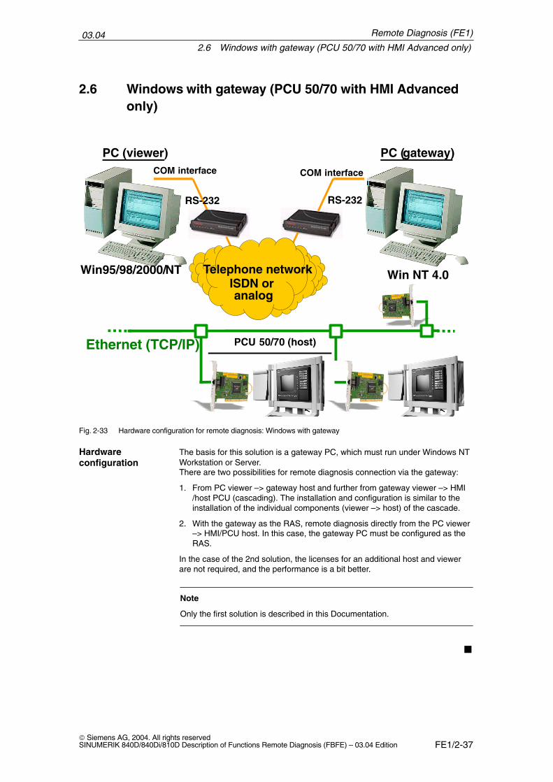
2.6 Windows with gateway (PCU 50/70 with HMI Advancedonly)
PC (viewer)
RS-232
COM interfaceCOM interface
RS-232
Telephone networkISDN oranalog
PC (gateway)
Win NT 4.0
Ethernet (TCP/IP) PCU 50/70 (host)
Win95/98/2000/NT
Fig. 2-33 Hardware configuration for remote diagnosis: Windows with gateway
The basis for this solution is a gateway PC, which must run under Windows NTWorkstation or Server.There are two possibilities for remote diagnosis connection via the gateway:
1. From PC viewer –> gateway host and further from gateway viewer –> HMI/host PCU (cascading). The installation and configuration is similar to theinstallation of the individual components (viewer –> host) of the cascade.
2. With the gateway as the RAS, remote diagnosis directly from the PC viewer–> HMI/PCU host. In this case, the gateway PC must be configured as theRAS.
In the case of the 2nd solution, the licenses for an additional host and viewerare not required, and the performance is a bit better.
Note
Only the first solution is described in this Documentation.
�
Hardwareconfiguration
Remote Diagnosis (FE1)

03.042.6 Windows with gateway (PCU 50/70 with HMI Advanced only)
FE1/2-38 Siemens AG, 2004. All rights reserved
SINUMERIK 840D/840Di/810D Description of Functions Remote Diagnosis (FBFE) – 03.04 Edition
Remote Diagnosis (FE1)
Notes
FE1/3-39 Siemens AG, 2004. All rights reservedSINUMERIK 840D/840Di/810D Description of Functions Remote Diagnosis (FBFE) – 03.04 Edition
Software Installation and Start-Up on thePCU 50/70
The remote diagnosis software “ReachOut” must be installed both on a PC(viewer) and on the control system (host). Before the remote diagnosis isinstalled, the communication devices (such as modem, network card...) shouldbe installed (see Chapter 2).
For the option “Remote Diagnosis”, the software package “Host 840D RemoteDiagnosis” is offered. The companion installation program is used to install theremote diagnosis software on the controller (MM103). During the installation, itis imperative to configure an initial user with administrator rights and anappropriate password. If password protection was enabled on the host, a loginshould be set up on the host for the user on the viewer side, since this isrequired for establishing the connection on the viewer PC during the remotediagnosis session.
Note
To start up the remote diagnosis, an MFII keyboard must be connected to thePCU 50.
The remote diagnosis software is supplied on CD-ROM. The CD-ROM containsone folder each with installation disks for the operating systems DOS, Win95/98/2000/NT.
Table 3-1 List of CD-ROM folders for the individual operating systems
Folder Operating system
’DOS’ DOS
’Win32’ Win95/98/2000/XP/NT
The disks 0 to 4 in the folder ’Win32’ contain the host for the control system andWin32 Viewer. If the controller has no CD-ROM drive, but, instead of that, afloppy disk drive, the individual directories ’Disk 0, 1, 2, 3, 4’ must be copied to3.5 floppy disks prior to the installation from the CD-ROM. If the control systemalso has no floppy disk drive, the installation can also be carried out via Interlinkor via a network.
Note
The CD contains the host for the PCU 50 and the host/viewer for Win95/98/2000/NT (see also brief description).
Installing remotediagnosis onPCU 50
Supply format
3
03.043.1 Installation from the CD-ROM drive on the PC/PG across the network
FE1/3-40 Siemens AG, 2004. All rights reserved
SINUMERIK 840D/840Di/810D Description of Functions Remote Diagnosis (FBFE) – 03.04 Edition
3.1 Installation from the CD-ROM drive on the PC/PG acrossthe network
If the PCU 50 with HMI Advanced is already connected to a network, the instal-lation is also possible from the CD-ROM drive of a PC or PG (programming de-vice) of the same network. To do so, the corresponding drive of the PC/PG mustbe enabled in Windows Service Mode and mapped via the control system’sExplorer.
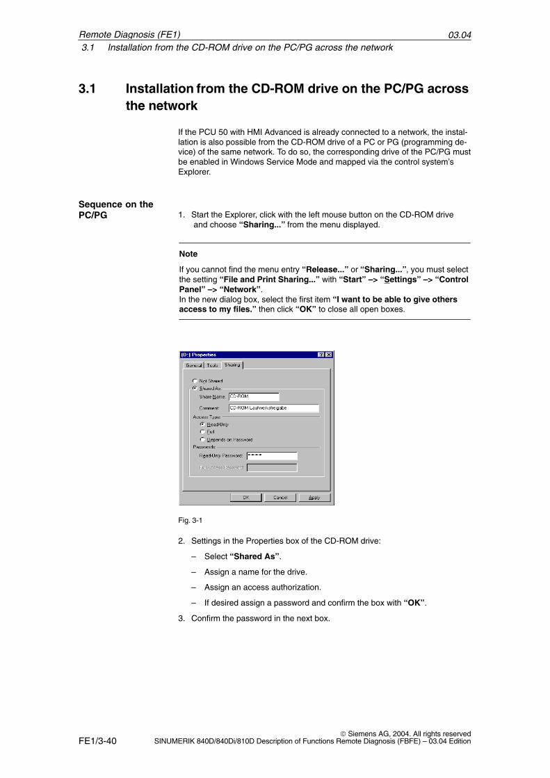
1. Start the Explorer, click with the left mouse button on the CD-ROM drive and choose “Sharing...” from the menu displayed.
Note
If you cannot find the menu entry “Release...” or “Sharing...”, you must selectthe setting “File and Print Sharing...” with “Start” –> “Settings” –> “ControlPanel” –> “Network”.In the new dialog box, select the first item “I want to be able to give othersaccess to my files.” then click “OK” to close all open boxes.
Fig. 3-1
2. Settings in the Properties box of the CD-ROM drive:
– Select “Shared As”.
– Assign a name for the drive.
– Assign an access authorization.
– If desired assign a password and confirm the box with “OK”.
3. Confirm the password in the next box.
Sequence on thePC/PG
Remote Diagnosis (FE1)
03.043.2 Installing remote diagnosis from the PC/PG floppy drive via RS-232-C
FE1/3-41 Siemens AG, 2004. All rights reservedSINUMERIK 840D/840Di/810D Description of Functions Remote Diagnosis (FBFE) – 03.04 Edition
1. Starting up the controller in Windows service mode (see Section 2.2).
2. Start the Explorer and select the computer with the CD-ROM drive in thenetwork environment.
3. With the left mouse button click the drive called “CD - ROM” and from menu“Connect network drive...” select (“Map Networkdrive...”).
4. Click “OK” to confirm the new dialog box.
Note
Make sure that the setting “Reconnect at logon” is not active. Otherwise, thedrive will try to connect every time you try to log on.
The remote diagnosis software can now be installed using the newly createddrive as described in Section 3.3.
3.2 Installing remote diagnosis from the PC/PG floppy drivevia RS-232-C
Connect a notebook or PG to the X6 interface (COM1) via a null modem cable.Boot the notebook in DOS mode and start the InterServer program(Intersvr.exe). Switch on the control. The floppy disk drive on the Notebook is recognized by the controller as a driveand can be addressed by the controller, for example, as “e:\”. To complete theinstallation, proceed as with installation via a separate drive (see Section 3.3).
Sequence for PCU
Remote Diagnosis (FE1)
03.043.3 Installation for Win32 via floppy disk drive on PCU 50
FE1/3-42 Siemens AG, 2004. All rights reserved
SINUMERIK 840D/840Di/810D Description of Functions Remote Diagnosis (FBFE) – 03.04 Edition
3.3 Installation for Win32 via floppy disk drive on PCU 50
Connect MFII keyboard!
1. Start the PCU 50 in Windows service mode (see Section 2.2) and continuewith item 2 (below).
2. The Windows operating system is started.Insert the first diskette (remote diagnosis for WIN32 Disk0) into the floppydisk drive.Call up program menu “Start” with “Ctrl” and “Esc” and select “Run” withthe cursor keys. Enter “a:\setup32” in the prompt if your floppy disk drive is drive “a”.Otherwise type the appropriate letter for the drive. (“z” with Interlink). Press“Return” to continue.
Note
If you are installing remote diagnosis from a CD-ROM select the drive letter ofthe mapped CD-ROM drive instead of drive letter “a:”.
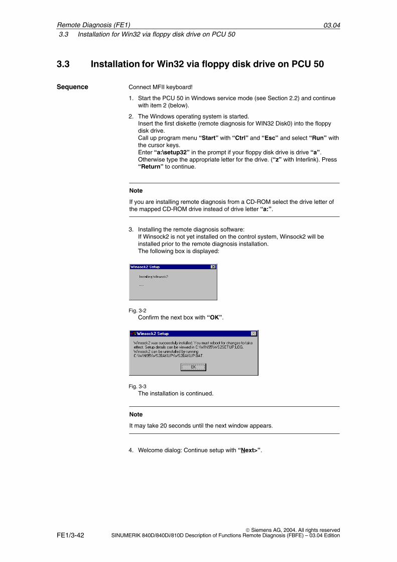
3. Installing the remote diagnosis software: If Winsock2 is not yet installed on the control system, Winsock2 will beinstalled prior to the remote diagnosis installation.The following box is displayed:
Fig. 3-2Confirm the next box with “OK”.
Fig. 3-3The installation is continued.
Note
It may take 20 seconds until the next window appears.
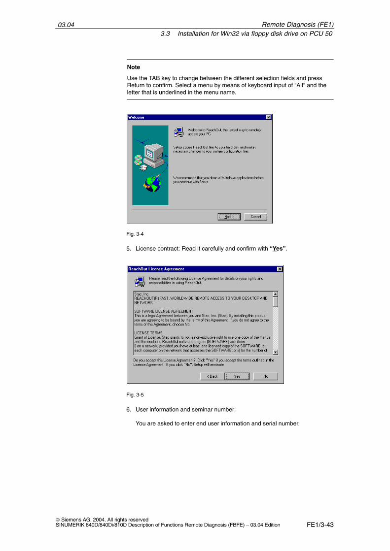
4. Welcome dialog: Continue setup with “Next>”.
Sequence
Remote Diagnosis (FE1)
03.043.3 Installation for Win32 via floppy disk drive on PCU 50
FE1/3-43 Siemens AG, 2004. All rights reservedSINUMERIK 840D/840Di/810D Description of Functions Remote Diagnosis (FBFE) – 03.04 Edition
Note
Use the TAB key to change between the different selection fields and pressReturn to confirm. Select a menu by means of keyboard input of “Alt” and theletter that is underlined in the menu name.
Fig. 3-4
5. License contract: Read it carefully and confirm with “Yes”.
Fig. 3-5
6. User information and seminar number:
You are asked to enter end user information and serial number.
Remote Diagnosis (FE1)
03.043.3 Installation for Win32 via floppy disk drive on PCU 50
FE1/3-44 Siemens AG, 2004. All rights reserved
SINUMERIK 840D/840Di/810D Description of Functions Remote Diagnosis (FBFE) – 03.04 Edition
Fig. 3-6
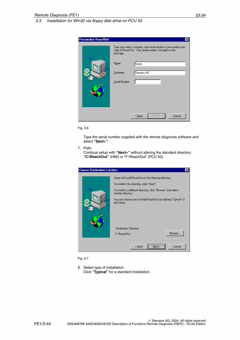
Type the serial number supplied with the remote diagnosis software andselect “Next>”.
7. Path:Continue setup with “Next>” without altering the standard directory“C:\ReachOut” (HMI) or “F:\ReachOut” (PCU 50).
Fig. 3-7
8. Select type of installation:Click “Typical” for a standard installation.
Remote Diagnosis (FE1)
03.043.3 Installation for Win32 via floppy disk drive on PCU 50
FE1/3-45 Siemens AG, 2004. All rights reservedSINUMERIK 840D/840Di/810D Description of Functions Remote Diagnosis (FBFE) – 03.04 Edition
Fig. 3-8
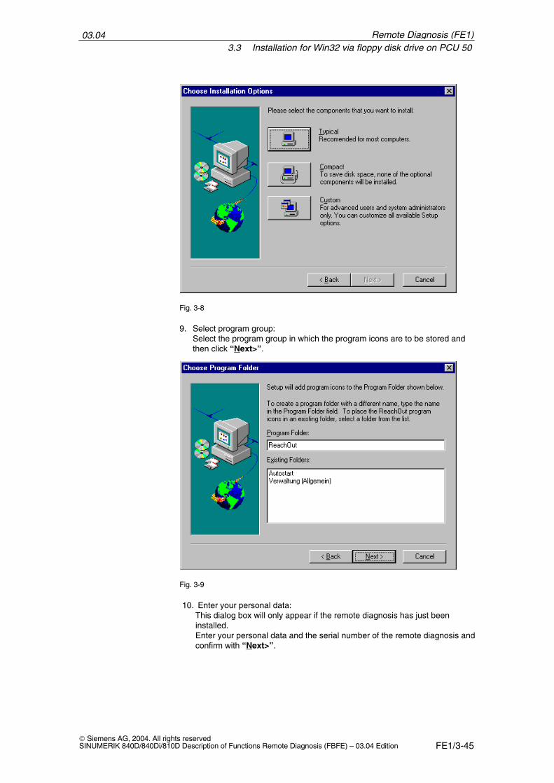
9. Select program group:Select the program group in which the program icons are to be stored andthen click “Next>”.
Fig. 3-9
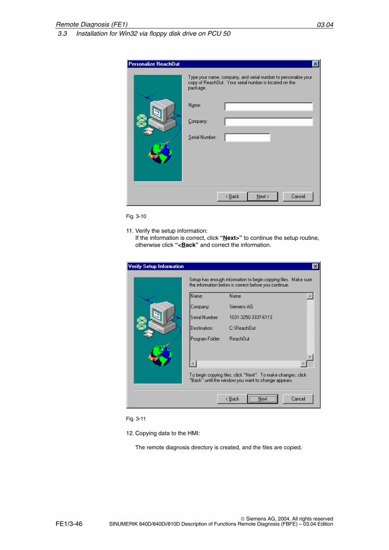
10. Enter your personal data:This dialog box will only appear if the remote diagnosis has just beeninstalled.Enter your personal data and the serial number of the remote diagnosis andconfirm with “Next>”.
Remote Diagnosis (FE1)
03.043.3 Installation for Win32 via floppy disk drive on PCU 50
FE1/3-46 Siemens AG, 2004. All rights reserved
SINUMERIK 840D/840Di/810D Description of Functions Remote Diagnosis (FBFE) – 03.04 Edition
Fig. 3-10
11. Verify the setup information:If the information is correct, click “Next>” to continue the setup routine,otherwise click “<Back” and correct the information.
Fig. 3-11
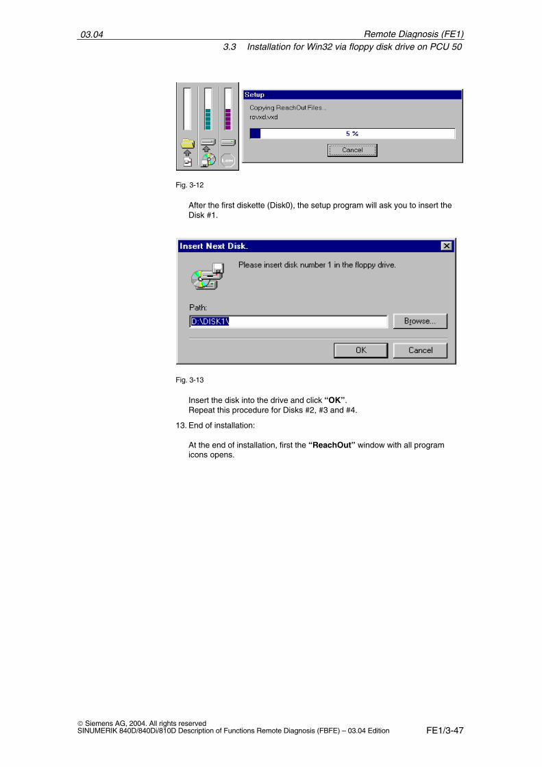
12. Copying data to the HMI:
The remote diagnosis directory is created, and the files are copied.
Remote Diagnosis (FE1)
03.043.3 Installation for Win32 via floppy disk drive on PCU 50
FE1/3-47 Siemens AG, 2004. All rights reservedSINUMERIK 840D/840Di/810D Description of Functions Remote Diagnosis (FBFE) – 03.04 Edition
Fig. 3-12
After the first diskette (Disk0), the setup program will ask you to insert theDisk #1.
Fig. 3-13
Insert the disk into the drive and click “OK”.Repeat this procedure for Disks #2, #3 and #4.
13. End of installation:
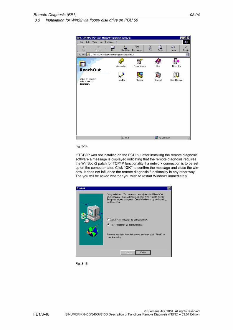
At the end of installation, first the “ReachOut” window with all programicons opens.
Remote Diagnosis (FE1)
03.043.3 Installation for Win32 via floppy disk drive on PCU 50
FE1/3-48 Siemens AG, 2004. All rights reserved
SINUMERIK 840D/840Di/810D Description of Functions Remote Diagnosis (FBFE) – 03.04 Edition
Fig. 3-14
If TCP/IP was not installed on the PCU 50, after installing the remote diagnosissoftware a message is displayed indicating that the remote diagnosis requiresthe WinSock2 patch for TCP/IP functionality if a network connection is to be setup on the computer later. Click “OK” to confirm the message and close the win-dow. It does not influence the remote diagnosis functionality in any other way.The you will be asked whether you wish to restart Windows immediately.
Fig. 3-15
Remote Diagnosis (FE1)
03.043.3 Installation for Win32 via floppy disk drive on PCU 50
FE1/3-49 Siemens AG, 2004. All rights reservedSINUMERIK 840D/840Di/810D Description of Functions Remote Diagnosis (FBFE) – 03.04 Edition
Note
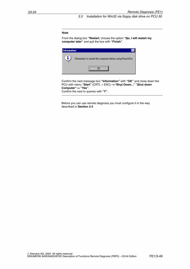
From the dialog box “Restart, choose the option “No, I will restart mycomputer later” and quit the box with “Finish”.
Confirm the next message box “Information” with “OK” and close down thePCU with menu “Start” (CRTL + ESC) –>“Shut Down...” “Shut downComputer”–> “Yes”.Confirm the next to queries with “Y”.
Before you can use remote diagnosis you must configure it in the waydescribed in Section 3.4.
Remote Diagnosis (FE1)
03.043.4 Installing the host on the PCU 50/70
FE1/3-50 Siemens AG, 2004. All rights reserved
SINUMERIK 840D/840Di/810D Description of Functions Remote Diagnosis (FBFE) – 03.04 Edition
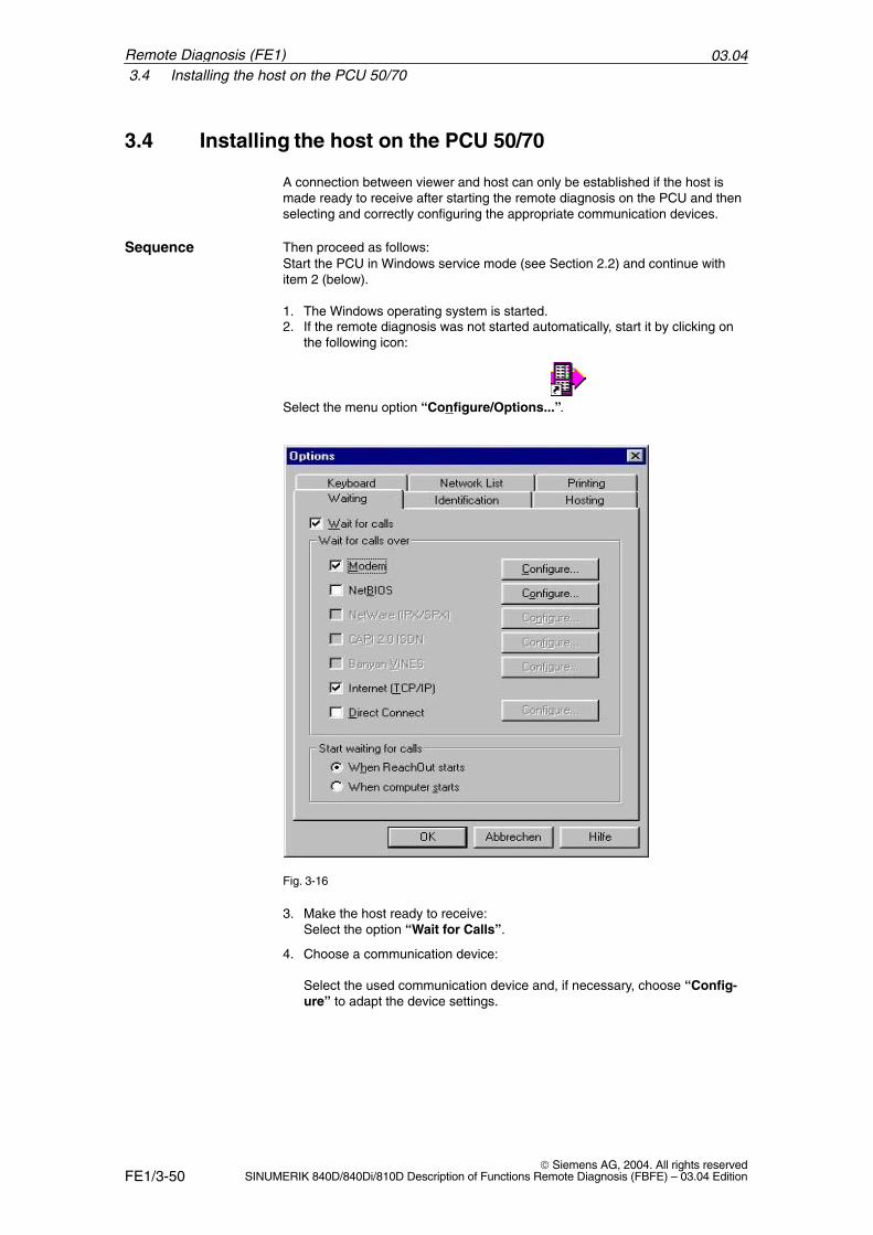
3.4 Installing the host on the PCU 50/70
A connection between viewer and host can only be established if the host ismade ready to receive after starting the remote diagnosis on the PCU and thenselecting and correctly configuring the appropriate communication devices.
Then proceed as follows:Start the PCU in Windows service mode (see Section 2.2) and continue withitem 2 (below).
1. The Windows operating system is started.2. If the remote diagnosis was not started automatically, start it by clicking on
the following icon:
Select the menu option “Configure/Options...”.
Fig. 3-16
3. Make the host ready to receive:Select the option “Wait for Calls”.
4. Choose a communication device:
Select the used communication device and, if necessary, choose “Config-ure” to adapt the device settings.
Sequence
Remote Diagnosis (FE1)
03.043.5 Deinstalling the remote diagnosis software on the PCU 50
FE1/3-51 Siemens AG, 2004. All rights reservedSINUMERIK 840D/840Di/810D Description of Functions Remote Diagnosis (FBFE) – 03.04 Edition
Note
In the “Options” dialog box, only devices can be selected, which have alreadybeen installed on the PCU. For this reason, first install and configure thecommunication devices to be used (see Chapter 2) and the install andconfigure the remote diagnosis.
5. Time when the host is ready to receive:
For “Start waiting for calls” select option “When ReachOut starts” sothat is not ready to receive until remote diagnosis has been started.
3.5 Deinstalling the remote diagnosis software on thePCU 50
1. Start the PCU 50 in Windows service mode (see Section 2.2) and continuewith item 2 (below).
2. Start the uninstall procedure with “Start” (Ctrl + Esc) –>“Programs”–>“ReachOut”–> “Uninstall”–> “Yes”. The question “... Delete all re-maining files ...” may be displayed. Respond with “Yes”.
3. Close Windows service mode with “Start” (Ctrl + Esc)–> “Shut Down...”–>“Shut down the Computer?”–> “Yes”.
4. Up to and including V4.x: Save the environment again with:“Save Windows Environment for ...”–> “Yes”–> “1.”–>“2” Windows (changing...) Save the environment again with:“Start” (Ctrl + Esc)–> “Shut Down...”–> “Shut down the computer?”–>“Yes”–> “Save Windows Environment for ...”–> “Yes”–> “1”–>“2” Windows (changing...)
All remote diagnosis files and all entries in the SYSTEM.INI file are removed.
�
Remote Diagnosis (FE1)
03.043.5 Deinstalling the remote diagnosis software on the PCU 50
FE1/3-52 Siemens AG, 2004. All rights reserved
SINUMERIK 840D/840Di/810D Description of Functions Remote Diagnosis (FBFE) – 03.04 Edition
Remote Diagnosis (FE1)
Notes
FE1/4-53 Siemens AG, 2004. All rights reservedSINUMERIK 840D/840Di/810D Description of Functions Remote Diagnosis (FBFE) – 03.04 Edition
Software Installation and Start-up on thePCU 20 and HT 6
The remote diagnosis software must be installed both on the PC (viewer) andon the SINUMERIK 840D / 810D PCU 20 (host).
The PCU 20 has no free memory medium on which the software could beinstalled. For this reason, the remote diagnosis software “ReachOut” is sup-plied pre-installed on a PC card. This card need only be plugged into thePCU 20 and configured. The HT 6 is supplied with the software already installed. The installation routineincludes setting the modem and configuring the user with the relevant pass-word.
Note
When installing the remote diagnosis software, an MFII keyboard can beconnected to the PCU 20. This facilitates data entry.
4.1 Installing and configuring the software on the PCU 20
The software required to operate the remote diagnosis is completely installedon the PC card. It need only be configured to match the user’s system beforethe software is used for the first time.
4.1.1 Modem link
The PC card is installed in the PCU 20 and the modem connected. Please pro-ceed as follows to configure the card:
1. Switch the control system on.
2. Press key “6” as soon as the copyright line containing the serial numberappears on the screen. The configuration menu appears.
This menu offers you a selection of different actions. you can select thefunction of your choice with the keys “1” to “5”.
Installing softwareon PCU 20/HT 6
Call configurationmode
4
03.044.1 Installing and configuring the software on the PCU 20
FE1/4-54 Siemens AG, 2004. All rights reserved
SINUMERIK 840D/840Di/810D Description of Functions Remote Diagnosis (FBFE) – 03.04 Edition
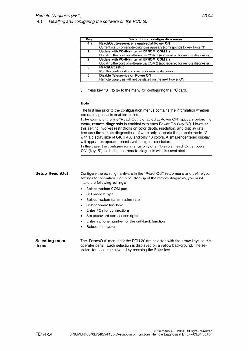
Key Description of configuration menu(4:) ReachOut teleservice is enabled at Power ON
Current status of remote diagnosis appears (corresponds to key Taste “4”)1: Update with PC–IN (internal EPROM, COM 1:)
Updating the control software via COM 1 (not required for remote diagnosis)2: Update with PC–IN (internal EPROM, COM 2:)
Updating the control software via COM 2 (not required for remote diagnosis)3: ReachOut setup
Run the configuration software for remote diagnosis5: Disable Teleservice on Power ON
Remote diagnosis will not be stated on the next Power ON
3. Press key “3”. to go to the menu for configuring the PC card.
Note
The first line prior to the configuration menus contains the information whetherremote diagnosis is enabled or not. If, for example, the line “ReachOut is enabled at Power ON” appears before themenu, remote diagnosis is enabled with each Power ON (key “4”). However,this setting involves restrictions on color depth, resolution, and display ratebecause the remote diagnostics software only supports the graphic mode 12with a display size of 640 x 480 and only 16 colors. A smaller centered displaywill appear on operator panels with a higher resolution.In this case, the configuration menus only offer “Disable ReachOut at powerON” (key “5”) to disable the remote diagnosis with the next start.
Configure the existing hardware in the “ReachOut” setup menu and define yoursettings for operation. For initial start-up of the remote diagnosis, you mustmake the following settings:
• Select modem COM port• Set modem type
• Select modem transmission rate• Select phone line type• Enter PCs for connections• Set password and access rights• Enter a phone number for the call-back function• Reboot the system
The “ReachOut” menus for the PCU 20 are selected with the arrow keys on theoperator panel. Each selection is displayed on a yellow background. The se-lected item can be activated by pressing the Enter key.
Setup ReachOut
Selecting menuitems
Remote Diagnosis (FE1)
03.044.1 Installing and configuring the software on the PCU 20
FE1/4-55 Siemens AG, 2004. All rights reservedSINUMERIK 840D/840Di/810D Description of Functions Remote Diagnosis (FBFE) – 03.04 Edition
Note
If you have not connected an MFII keyboard to the PCU 20, you can close themenus with the keys “X” (Exit), or “Cancel”. The “Esc” key is the “Cancel”key on the front of the operator panel. The function keys “F1” to “F8” areactivated with the horizontal softkeys.
The main “Help” menu contains a brief description of each menu. You can alsodisplay direct help for any subject by pressing function key “F1”. Use the arrowkeys to page through the help topics.
The PCU 20 has two COM ports. Check first which of the two ports the modemis connected to. You can set the appropriate COM port in the menu “CommPort”.
1. Select “Preferences” –> “Communication Settings” in the “ReachOut”menu bar. A new form with a new menu opens in which you can enter the“Communication Settings”.
2. In this new window, select “Comm Settings” –> “Comm Port” to display aselection list.
3. Select either serial interface COM 1 or COM 2 depending on the modemconnection.
4. Confirm your selection with the Enter key. The menu is closed.
Note
Both the configuration for modem type, data transfer rate, and connectiontype and for Comm Port is carried out in the screen form “CommunicationSettings”.
ReachOut offers a selection list of typical modems to choose from in the screenform for the Communication Settings in the menu “Modem Select”.
1. Select “Comm Settings” –> “Modem Select” in the “CommunicationSettings” screenform. A selection list of modems is displayed.
2. Select the connected modem and appropriate baud rate in the “ModemTable”.
Note
If the modem you are using is not contained in the selection list, select “AHayes Compatible” modem with the data transfer rate of the modem you areusing. If you have selected the modem type, the software expects that amodem is installed and turned on.
3. Confirm your selection with the Enter key. The menu is closed.
Help
Select the COMport
Modem type
Remote Diagnosis (FE1)
03.044.1 Installing and configuring the software on the PCU 20
FE1/4-56 Siemens AG, 2004. All rights reserved
SINUMERIK 840D/840Di/810D Description of Functions Remote Diagnosis (FBFE) – 03.04 Edition
“ReachOut” automatically sets the highest possible transfer rate for the selectedmodem. You can change the current transfer rate in the “Data Speed” menu inthe “Communications Settings” form.
1. Select “Comm Settings” –> “Data Speed”. A selection list of transfer ratesis displayed.
2. Use the arrow keys to select a transfer rate.
3. Confirm your selection by pressing the Enter key. The menu is closed.
Note
When modems from different manufacturers are used, the same data transferrate must be set for both viewer and host; otherwise, possibly no connectioncan be established.
Set the modem to tone or pulse dialing in the “Dialing Prefix” menu in theCommunication Settings screenform.
1. Select menu items “Comm Settings” –> “Dialing Prefix” to access the“Enter Phone Dialog Prefix” menu.
2. Enter the prefix for the desired dialing signal type in the text line.ATDT: Tone dialingATDP: Pulse dialing
Note
If you use the Call Back option on private branch exchanges, the string for tonedialing must be ATX3DT, with pulse dialing ATX3DP to ensure that the dialingtone is ignored. For more detailed information on the prefix ATXn, please referto your Modem Manual.
You can enter additional parameters for PBX systems. Descriptions of thesecan be found directly in the “Enter Phone Dialog Prefix” menu.
3. Confirm your selection with the Enter key. The menu is closed.
4. Press the “Cancel” or “Esc” key to exit the Communication Settingsscreenform. The “Save Current Settings” option window appears.
5. Press key “Y” to save your settings and return to the main screen form of“ReachOut”.
In the menu “Phone Book”, select the PCs with which you want to establishconnections.
1. Select “Preferences” –> “Edit Phone book” in the “ReachOut” menu bar.The “Call-Out Phone book” screen form opens.
2. Press key “A” (Add New Entry) to enter a new phone connection.
Data transfer rate
Phone line type
Making aconnection to a PC
Remote Diagnosis (FE1)
03.044.1 Installing and configuring the software on the PCU 20
FE1/4-57 Siemens AG, 2004. All rights reservedSINUMERIK 840D/840Di/810D Description of Functions Remote Diagnosis (FBFE) – 03.04 Edition
3. Enter a “Description” and “Phone Number”. You can also fill in the “UserName” and “Password” fields if you wish.
4. Confirm you inputs by pressing the Enter key.
5. Repeat the operation if you wish to enter further phone connections.
6. Press key “X” (Exit) to close the menu.
Note
Use the “E” key (Edit Entry) to modify existing entries. Use the “D” key (DeleteEntry) to delete existing entries.
Use the “Edit Passwords” menu to define which access rights the user of theviewer PC will have when contacting the host. Each user can also be assignedhis/her own password. Only users entered in the list can activate the remotediagnosis function.
1. Select “Security” –> “Edit Passwords” in the “ReachOut” menu bar. Thescreen headed “Password List for this computer when it is a host” isthen opened.
2. Press key “A” (Add Password) to record a new user with password. The“Add New Password” screen opens.
3. Enter the name and password in text lines “User Name” and “Password”.
Select menu item “File Access” to display a selection list in which you canassign varying levels of access rights to the user.
4. If you wish to grant full access rights to the user, select “Full Access” in thelist. Select the appropriate entry for restricted rights.
For Call Back mode, you can enter the phone numbers of the viewer PC. If thehost dialed from the viewer PC, no direct connection is established with activeCall Back. The host will call back the logged-on viewer PC only with the storedphone number. The remote diagnosis system is not activated until a connectionhas been successfully set up with Call Back.
Call Back ensures that computers without access authorization cannot performremote diagnosis. Only viewer PCs and users entered in the host with theirphone numbers will be accepted after successful Call Back.
5. Type the phone number of the viewer PC when working with Call Back.
6. Confirm your entries by pressing the “Enter” key and return to the mainscreen form of “ReachOut”.
Password and CallBack
Call Back
Remote Diagnosis (FE1)
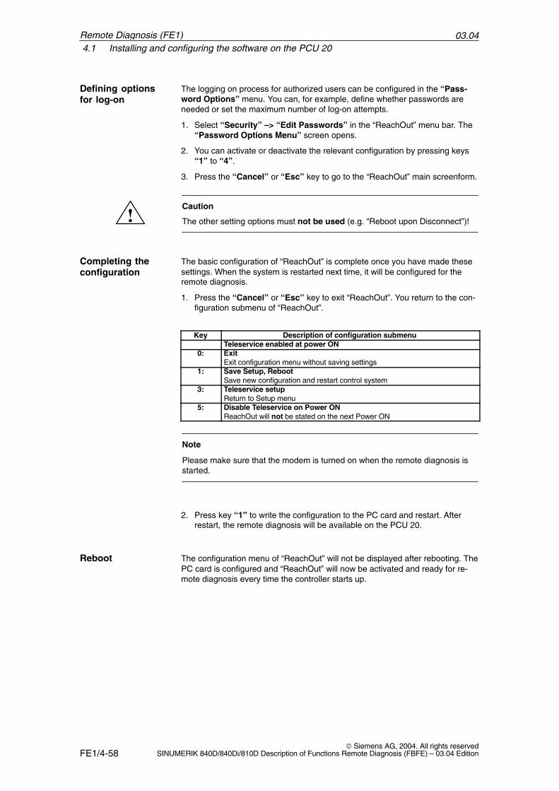
03.044.1 Installing and configuring the software on the PCU 20
FE1/4-58 Siemens AG, 2004. All rights reserved
SINUMERIK 840D/840Di/810D Description of Functions Remote Diagnosis (FBFE) – 03.04 Edition
The logging on process for authorized users can be configured in the “Pass-word Options” menu. You can, for example, define whether passwords areneeded or set the maximum number of log-on attempts.
1. Select “Security” –> “Edit Passwords” in the “ReachOut” menu bar. The“Password Options Menu” screen opens.
2. You can activate or deactivate the relevant configuration by pressing keys“1” to “4”.
3. Press the “Cancel” or “Esc” key to go to the “ReachOut” main screenform.
!Caution
The other setting options must not be used (e.g. “Reboot upon Disconnect”)!
The basic configuration of “ReachOut” is complete once you have made thesesettings. When the system is restarted next time, it will be configured for theremote diagnosis.
1. Press the “Cancel” or “Esc” key to exit “ReachOut”. You return to the con-figuration submenu of “ReachOut”.
Key Description of configuration submenuTeleservice enabled at power ON
0: ExitExit configuration menu without saving settings
1: Save Setup, Reboot Save new configuration and restart control system
3: Teleservice setupReturn to Setup menu
5: Disable Teleservice on Power ONReachOut will not be stated on the next Power ON
Note
Please make sure that the modem is turned on when the remote diagnosis isstarted.
2. Press key “1” to write the configuration to the PC card and restart. Afterrestart, the remote diagnosis will be available on the PCU 20.
The configuration menu of “ReachOut” will not be displayed after rebooting. ThePC card is configured and “ReachOut” will now be activated and ready for re-mote diagnosis every time the controller starts up.
Defining optionsfor log-on
Completing theconfiguration
Reboot
Remote Diagnosis (FE1)
03.044.1 Installing and configuring the software on the PCU 20
FE1/4-59 Siemens AG, 2004. All rights reservedSINUMERIK 840D/840Di/810D Description of Functions Remote Diagnosis (FBFE) – 03.04 Edition
Note
Whenever you update the control software you must call up the “ReachOut”software again with “3”. Close the configuration software without making anychanges. As soon as the configuration menu appears, press key “0” and closethe configuration menu again. A new menu is displayed which you can close bypressing key “1” (Save Setup, Reboot).Updating the control software might have altered the settings in autoexec.batand config.sys. Calling the configuration submenu of “ReachOut” again willupdate the settings on the PC card.
Remote Diagnosis (FE1)
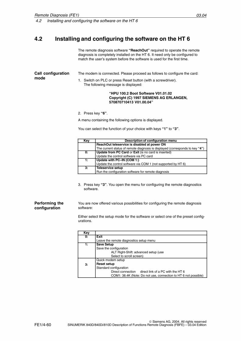
03.044.2 Installing and configuring the software on the HT 6
FE1/4-60 Siemens AG, 2004. All rights reserved
SINUMERIK 840D/840Di/810D Description of Functions Remote Diagnosis (FBFE) – 03.04 Edition
4.2 Installing and configuring the software on the HT 6
The remote diagnosis software “ReachOut” required to operate the remotediagnosis is completely installed on the HT 6. It need only be configured tomatch the user’s system before the software is used for the first time.
The modem is connected. Please proceed as follows to configure the card:
1. Switch on PLC or press Reset button (with a screwdriver). The following message is displayed:
“HPU 100.2 Boot Software V01.01.02Copyright (C) 1997 SIEMENS AG ERLANGEN,570870710413 V01.00.04”
2. Press key “6”.
A menu containing the following options is displayed.
You can select the function of your choice with keys “1” to “3”.
Key Description of configuration menuReachOut teleservice is disabled at power ONThe current status of remote diagnosis is displayed (corresponds to key “4”)
0: Update from PC Card or Exit (is no card is inserted)Update the control software via PC card
1: Update with PC–IN (COM 1:)Update the control software via COM 1 (not supported by HT 6)
3: Teleservice setupRun the configuration software for remote diagnosis
3. Press key “3”. You open the menu for configuring the remote diagnosticssoftware.
You are now offered various possibilities for configuring the remote diagnosissoftware:
Either select the setup mode for the software or select one of the preset config-urations.
Key0: Exit
Leave the remote diagnostics setup menu1: Save Setup
Save the configurationALT Right-Shift: advanced setup (useSelect to scroll screen)
3:Quick modem setup Reset setupStandard configuration
Direct connection direct link of a PC with the HT 6COM1: 38.4K (Note: Do not use, connection to HT 6 not possible)
Call configurationmode
Performing theconfiguration
Remote Diagnosis (FE1)
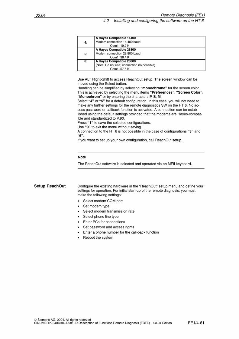
03.044.2 Installing and configuring the software on the HT 6
FE1/4-61 Siemens AG, 2004. All rights reservedSINUMERIK 840D/840Di/810D Description of Functions Remote Diagnosis (FBFE) – 03.04 Edition
4:A Hayes Compatible 14400 Modem connection 14,400 baud
Com1: 19.2 K
5:A Hayes Compatible 28800 Modem connection 28,800 baud
Com1: 38.4 K6: A Hayes Compatible 28800
(Note: Do not use; connection no possible)Com1: 57.6 K
Use ALT Right-Shift to access ReachOut setup. The screen window can bemoved using the Select button.Handling can be simplified by selecting “monochrome” for the screen color.This is achieved by selecting the menu items “Preferences”, “Screen Color”,“Monochrom” or by entering the characters P, S, M.Select “4” or “5” for a default configuration. In this case, you will not need tomake any further settings for the remote diagnostics SW on the HT 6. No ac-cess password or callback function is activated. A connection can be estab-lished using the default settings provided that the modems are Hayes-compat-ible and standardized to V.90.Press “1” to save the selected configurations.Use “0” to exit the menu without saving.A connection to the HT 6 is not possible in the case of configurations “3” and“6”.If you want to set up your own configuration, call ReachOut setup.
Note
The ReachOut software is selected and operated via an MFII keyboard.
Configure the existing hardware in the “ReachOut” setup menu and define yoursettings for operation. For initial start-up of the remote diagnosis, you mustmake the following settings:
• Select modem COM port• Set modem type• Select modem transmission rate• Select phone line type
• Enter PCs for connections• Set password and access rights• Enter a phone number for the call-back function• Reboot the system
Setup ReachOut
Remote Diagnosis (FE1)
03.044.2 Installing and configuring the software on the HT 6
FE1/4-62 Siemens AG, 2004. All rights reserved
SINUMERIK 840D/840Di/810D Description of Functions Remote Diagnosis (FBFE) – 03.04 Edition
The “ReachOut” menus for the HT 6 are selected with the arrow keys on theoperator panel. The selected item can be activated by pressing the Enter key.
The main “Help” menu contains a brief description of each menu. You can alsodisplay direct help for any subject by pressing function key “F1”. Use the arrowkeys to page through the help topics.
The HT 6 has one COM port: Com 1. You can set the appropriate COM port inthe menu “Comm Port”.
1. Select “Preferences” –> “Communication Settings” in the “ReachOut”menu bar. A new form with a new menu opens in which you can enter the“Communication Settings”.
2. In this new window, select “Comm Settings” –> “Comm Port” to display aselection list.
3. Select serial interface COM 1.
4. Confirm your selection with the Enter key. The menu is closed.
Note
Both the configuration for modem type, data transfer rate and connection typeand for Comm Port is carried out in the screen form “CommunicationSettings”.
“ReachOut” offers a selection list of typical modems to choose from in thescreen form for the Communication Settings in the menu “Modem Select”.
1. Select “Comm Settings” –> “Modem Select” in the “CommunicationSettings” screenform. A selection list of modems is displayed.
2. Select the connected modem and appropriate baud rate in the “ModemTable”.
Note
If the modem you are using is not contained in the selection list, select “AHayes Compatible” modem with the data transfer rate of the modem you areusing. If you have selected the modem type, the software expects that amodem is installed and turned on.
3. Confirm your selection with the Enter key. The menu is closed.
“ReachOut” automatically sets the highest possible transfer rate for the selectedmodem. You can change the current transfer rate in the “Data Speed” menu inthe “Communications Settings” form.
1. Select “Comm Settings” –> “Data Speed”. A selection list of transfer ratesis displayed.
2. Use the arrow keys to select a transfer rate.
Selecting menuitems
Help
Select the COMport
Modem type
Data transfer rate
Remote Diagnosis (FE1)
03.044.2 Installing and configuring the software on the HT 6
FE1/4-63 Siemens AG, 2004. All rights reservedSINUMERIK 840D/840Di/810D Description of Functions Remote Diagnosis (FBFE) – 03.04 Edition
3. Confirm your selection by pressing the Enter key. The menu is closed.
Note
When modems from different manufacturers are used, the same data transferrate must be set for both viewer and host; otherwise, possibly no connectioncan be established.
Set the modem to tone or pulse dialing in the “Dialing Prefix” menu in theCommunication Settings screenform.
1. Select menu items “Comm Settings” –> “Dialing Prefix” to access the“Enter Phone Dialog Prefix” menu.
2. Enter the prefix for the desired dialing signal type in the text line.ATDT: Tone dialingATDP: Pulse dialing
Note
If you use the Call Back option on private branch exchanges, the string for tonedialing must be ATX3DT, with pulse dialing ATX3DP to ensure that the dialingtone is ignored. For more detailed information on the prefix ATXn, please referto your Modem Manual.
You can enter additional parameters for PBX systems. Descriptions of thesecan be found directly in the “Enter Phone Dialog Prefix” menu.
3. Confirm your selection with the Enter key. The menu is closed.
4. Press the “Cancel” or “Esc” key to exit the Communication Settingsscreenform. The “Save Current Settings” option window appears.
5. Press key “Y” to save your settings and return to the main screen form of“ReachOut”.
In the menu “Phone Book”, select the PCs with which you want to establishconnections.
1. Select “Preferences” –> “Edit Phone book” in the “ReachOut” menu bar.The “Call-Out Phone book” screen form opens.
2. Press key “A” (Add New Entry) to enter a new phone connection.
3. Enter a “Description” and “Phone Number”. You can also fill in the “UserName” and “Password” fields if you wish.
4. Confirm you inputs by pressing the Enter key.
5. Repeat the operation if you wish to enter further phone connections.
6. Press key “X” (Exit) to close the menu.
Phone line type
Making aconnection to a PC
Remote Diagnosis (FE1)
03.044.2 Installing and configuring the software on the HT 6
FE1/4-64 Siemens AG, 2004. All rights reserved
SINUMERIK 840D/840Di/810D Description of Functions Remote Diagnosis (FBFE) – 03.04 Edition
Note
Use the “E” key (Edit Entry) to modify existing entries. Use the “D” key (DeleteEntry) to delete existing entries.
Use the “Edit Passwords” menu to define which access rights the user of theviewer PC will have when contacting the host. Each user can also be assignedhis/her own password. Only users entered in the list can activate the remotediagnosis function.
1. Select “Security” –> “Edit Passwords” in the “ReachOut” menu bar. Thescreen headed “Password List for this computer when it is a host” isthen opened.
2. Press key “A” (Add Password) to record a new user with password. The“Add New Password” screen opens.
3. Enter the name and password in text lines “User Name” and “Password”.
Select menu item “File Access” to display a selection list in which you canassign varying levels of access rights to the user.
4. If you wish to grant full access rights to the user, select “Full Access” in thelist. Select the appropriate entry for restricted rights.
For Call Back mode, you can enter the phone numbers of the viewer PC. If thehost dialed from the viewer PC, no direct connection is established with activeCall Back. The host will call back the logged-on viewer PC only with the storedphone number. The remote diagnosis system is not activated until a connectionhas been successfully set up with Call Back.
Call Back ensures that computers without access authorization cannot performremote diagnosis. Only viewer PCs and users entered in the host with theirphone numbers will be accepted after successful Call Back.
1. Type the phone number of the viewer PC when working with Call Back.
2. Confirm your entries by pressing the “Enter” key and return to the mainscreen form of “ReachOut”.
The logging on process for authorized users can be configured in the “Pass-word Options” menu. You can, for example, define whether passwords areneeded and/or how many logon attempts a user has.
1. Select “Security” –> “Edit Passwords” in the “ReachOut” menu bar. The“Password Options Menu” screen form is opened.
2. You can activate or deactivate the relevant configuration by pressing keys“1” to “4”.
3. Press the “Cancel” or “Esc” key to go to the “ReachOut” main screenform.
!Caution
The other setting options must not be used (e.g. “Reboot upon Disconnect”)!
Password and CallBack
Call Back
Defining optionsfor log-on
Remote Diagnosis (FE1)
03.044.2 Installing and configuring the software on the HT 6
FE1/4-65 Siemens AG, 2004. All rights reservedSINUMERIK 840D/840Di/810D Description of Functions Remote Diagnosis (FBFE) – 03.04 Edition
The basic configuration of “ReachOut” is complete once you have made thesesettings. When the system is restarted next time, it will be configured for theremote diagnosis.
1. Press the “Cancel” or “Esc” key to exit “ReachOut”. You return to the con-figuration submenu of “ReachOut”.
Key Description of configuration submenu0: Exit
Exit configuration menu without saving settings1: Save Modem Setup
Save the configurationALT Right-Shift: advanced setup (useSelect to scroll screen)
3:Quick modem setupReset setupStandard configuration
Direct connection direct link of a PC with the HT 6COM1: 38.4K
4:A Hayes Compatible 14400 Modem connection 14,400 baud
Com1: 19.2K
5:A Hayes Compatible 28800 Modem connection 28,800 baud
Com1: 38.4K6: A Hayes Compatible 28800
(Note: Do not use; connection no possible)Com1: 57.6K
Note
Please make sure that the modem is turned on when the remote diagnosis isstarted.
2. Press key “1” to write the configuration to the PC card and restart. Afterrestart, the remote diagnosis will be available on the HT 6.
The configuration menu of “ReachOut” will not be displayed after rebooting.“ReachOut” is now ready for remote diagnosis. You can activate the remotediagnosis software with the “Remote diagnosis” softkey in the “Diagnosis”area.
Note
The remote diagnostics software configuration remains unchanged even whenthe HT 6 system software is updated.
Completing theconfiguration
Reboot
Remote Diagnosis (FE1)
03.044.4 Quitting remote diagnosis
FE1/4-66 Siemens AG, 2004. All rights reserved
SINUMERIK 840D/840Di/810D Description of Functions Remote Diagnosis (FBFE) – 03.04 Edition
4.3 Activating remote diagnosis subsequently
The remote diagnostics software must be activated when the PCU 20/HT 6 hasbooted. You can call up the function as a softkey on the PCU 20/HT 6.
1. Press the “Diagnosis” softkey.
2. Press the “Remote diagnosis” softkey. The message “Starting remotediagnosis, restarting control unit; continue with OK” appears.
3. Confirm restart of the control unit by selecting “OK”. “ReachOut” is activatedand the control unit restarted. The NCK is not affected by this process and isnot restarted.
4.4 Quitting remote diagnosis
Depending on the configuration you have set, you can exit the function in thefollowing way:Mode “Disable ReachOut at Power ON” is active:
� Hardware reset of the PCU 20/HT 6
Mode “Enable ReachOut at Power ON” is active:
� Turn off the control system (with power ON, remote diagnosis is immediatelyactive in this mode).
�
Remote Diagnosis (FE1)
FE1/5-67 Siemens AG, 2004. All rights reservedSINUMERIK 840D/840Di/810D Description of Functions Remote Diagnosis (FBFE) – 03.04 Edition
Installing the Remote Diagnosis Softwareon the PC (Viewer)
Before you install the remote diagnosis software on your PC, observe thefollowing:
• Determine which viewer version is required. When an PCU 20/HT 6 is actingas the host, the DOS version of the viewer must be installed.
• Erase every other remote control software from the PC.• If you are using a modem, make sure that it is configured correctly and
connected to the telephone system.• Make a note of the modem type, model number and transmission rate.• Locate the RS-232 interface (e.g. COM1 or COM2) to which the modem is
connected.• Determine under which operating system your viewer is operated.
5.1 Viewer for Windows 95/98/2000/NT
The software package for the remote diagnosis on the PC is called “RemoteDiagnosis Viewer 840D”. The supplied installation batch file of“SetupW32.bat” can be used to set up the tool on your PC under Windows asfollows:
1. Insert the CD into the CD-ROM drive.
2. Select “Run” in the “File” menu in the Program Manager.
3. Type the command line “E:\SetupW32.bat” (“E” is the drive letter for theCD-ROM which can vary).
4. Confirm with “OK”.
5. Follow the further instructions to complete the installation. The steps are thesame as required for installation on the controller (see Section 3.3).
Click the Help symbol if you need assistance during installation. The help func-tion is available at all times.
Note
To install the remote diagnosis under Windows NT4.0, administrator rights arerequired.
Preparation
Installation
5
03.045.2 Viewer for MS-DOS (necessary for PCU 20/HT 6 as the host)
FE1/5-68 Siemens AG, 2004. All rights reserved
SINUMERIK 840D/840Di/810D Description of Functions Remote Diagnosis (FBFE) – 03.04 Edition
5.2 Viewer for MS-DOS (necessary for PCU 20/HT 6 as thehost)
1. Use the installation program installd.exe to install the DOS version on theviewer PC:
2. Insert the CD into the CD-ROM drive.
3. Under Windows 95, 98, 2000, NT, change to the MS-DOS prompt to open aDOS window.
4. Change to directory “Dos/Disk1” on the CD-ROM and enter “installd.exe”.The installation program for the remote diagnosis for DOS is started.
Note
None of the Windows versions 95, 98, 2000, NT can be used for remotediagnosis between a viewer PC and the PCU 20/HT 6. Only the DOS variantmay be installed. In the Windows versions mentioned above, it can be startedin a DOS box. Background: PCU 20/HT 6 uses the DOS operating system.
You are guided through the installation routine by a menu-driven menu. Pleaseproceed as follows for a standard installation:
1. Enter your name, company name and serial number in the first screen formof “ReachOut Dos Install”. Confirm your inputs by pressing function key“F10”. Another prompt concerning the correctness of entries is displayed.
2. Confirm you inputs again with “F10” if they are all correct. The new window“Select the correct Path Names below” will appear.
By default, the remote diagnosis software is installed on C:\reachout. ReachOutstores all data in this path during operation.
3. Confirm the standard path name by pressing function key “F10”. Screenform “Full (complete) or Custom Installation?” is displayed.
4. Press key “C” to customize the installation. Screen “Install forHost/Viewer?” then appears.
5. Press key “3” to install the software for the viewer. Screen “Install forwhich environment?” appears.
6. Press key “2” to install only the DOS version of ReachOut. Screen “SelectCommunications” appears.
7. Press key “3” to install communication via modem. The screen form closesand all necessary files are copied onto your computer by the installationroutine.
8. During the installation, you will be asked to insert disk 2 (disk 2). Insert disk2 (disk 13) in drive A: and confirm by pressing the “Enter” key. Do the samewith disk 3 (disk 3).
Installation
Installationprocedure
Remote Diagnosis (FE1)
03.045.2 Viewer for MS-DOS (necessary for PCU 20/HT 6 as the host)
FE1/5-69 Siemens AG, 2004. All rights reservedSINUMERIK 840D/840Di/810D Description of Functions Remote Diagnosis (FBFE) – 03.04 Edition
Note
If you install the program from the CD-ROM, specify the new directory on theCD-ROM as the source when changing the disk, e.g. with disk 2, type“d:\disk2”. Drive letter “d:” stands for the CD-ROM drive (may vary).
After all files have been copied onto the hard disk, all you need to do is config-ure the connection. The screen headed “Type of Modem Support” appears.
9. Press key “1” to configure a connection with an analog modem. Screen“Enter Computer Name” appears.
10. Enter the name of the viewer PC and confirm with “Enter”. This name willbe used thereafter for remote diagnosis with ReachOut. Screen“Communication Settings” appears.
11. Configure the modem you have installed in the “Comm Settings” menu.
Note
You will find a description of the main configuration steps under configuration ofthe modem for the host in Section 2.1 under items “Select COM port”,“Modem type, “Transmission rate” and “Transmission type”.
12. Select “File” –> “Save Configuration” when you have finished configuringthe modem and connection.
13. Press the “Esc” key to close the “Communication Settings” menu.Message box “ReachOut Installation Complete” appears.
14. The installation of the remote diagnosis for the viewer is completed.
�
Remote Diagnosis (FE1)
03.045.2 Viewer for MS-DOS (necessary for PCU 20/HT 6 as the host)
FE1/5-70 Siemens AG, 2004. All rights reserved
SINUMERIK 840D/840Di/810D Description of Functions Remote Diagnosis (FBFE) – 03.04 Edition
Remote Diagnosis (FE1)
Notes
FE1/6-71 Siemens AG, 2004. All rights reservedSINUMERIK 840D/840Di/810D Description of Functions Remote Diagnosis (FBFE) – 03.04 Edition
Connecting
6.1 General information on connecting with viewer forWin32 (Win95/98/2000/NT)
The Windows 32 variant supports connecting with several computers to or froma single PC.
• A single viewer PC can be connected to several waiting computers. It ispossible to use Chat, the Explorer or “RemoteControl” simultaneously orseparately.
• A single computer (viewer) can set up connections under Windows95/98/2000/NT and wait for connections.
Note
If the controller has no mouse and no “ALT” key, the host on the controller canonly be quitted via the viewer.
6.2 Connecting to the viewer for Win95/98/2000/NT(with HMI Advanced)
Start “ReachOut” under Windows 95/98/2000/NT. The following window isoverlaid:
Connecting withmultipleconnections
Connecting to theviewer and modem
6
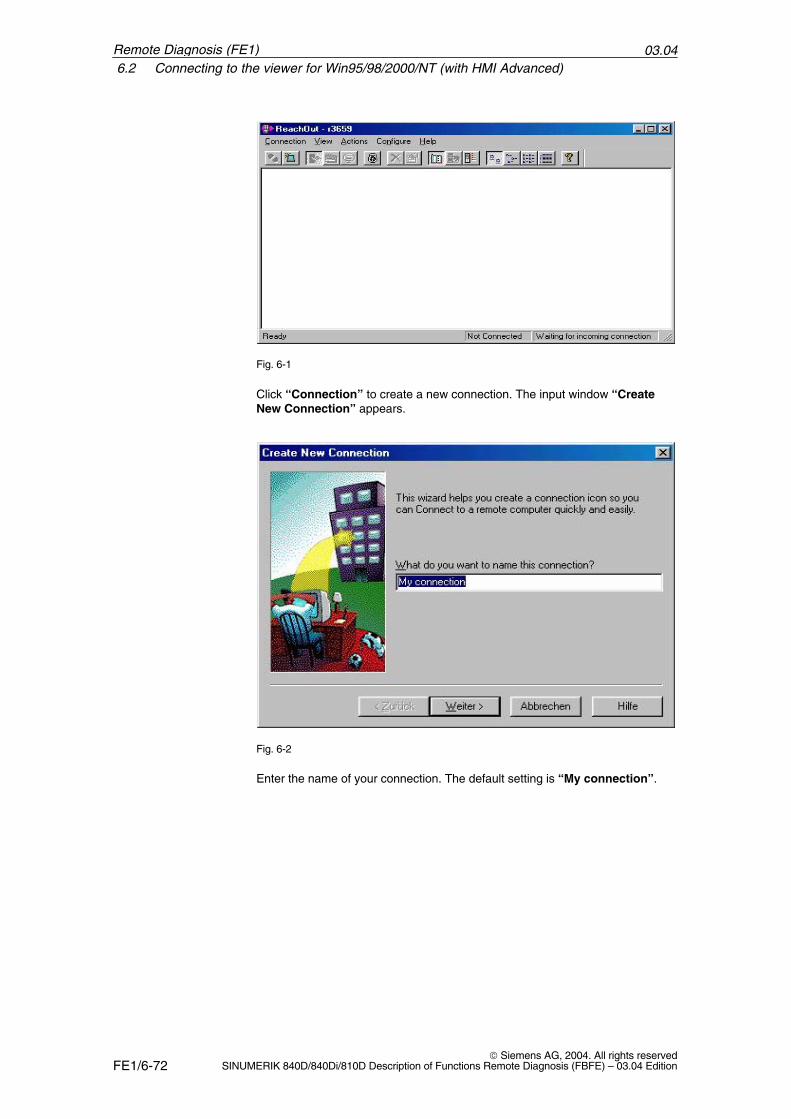
03.046.2 Connecting to the viewer for Win95/98/2000/NT (with HMI Advanced)
FE1/6-72 Siemens AG, 2004. All rights reserved
SINUMERIK 840D/840Di/810D Description of Functions Remote Diagnosis (FBFE) – 03.04 Edition
Fig. 6-1
Click “Connection” to create a new connection. The input window “CreateNew Connection” appears.
Fig. 6-2
Enter the name of your connection. The default setting is “My connection”.
Remote Diagnosis (FE1)
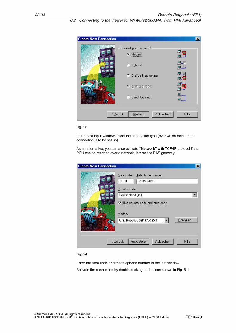
03.046.2 Connecting to the viewer for Win95/98/2000/NT (with HMI Advanced)
FE1/6-73 Siemens AG, 2004. All rights reservedSINUMERIK 840D/840Di/810D Description of Functions Remote Diagnosis (FBFE) – 03.04 Edition
Fig. 6-3
In the next input window select the connection type (over which medium theconnection is to be set up).
As an alternative, you can also activate “Network” with TCP/IP protocol if thePCU can be reached over a network, Internet or RAS gateway.
Fig. 6-4
Enter the area code and the telephone number in the last window.
Activate the connection by double-clicking on the icon shown in Fig. 6-1.
Remote Diagnosis (FE1)
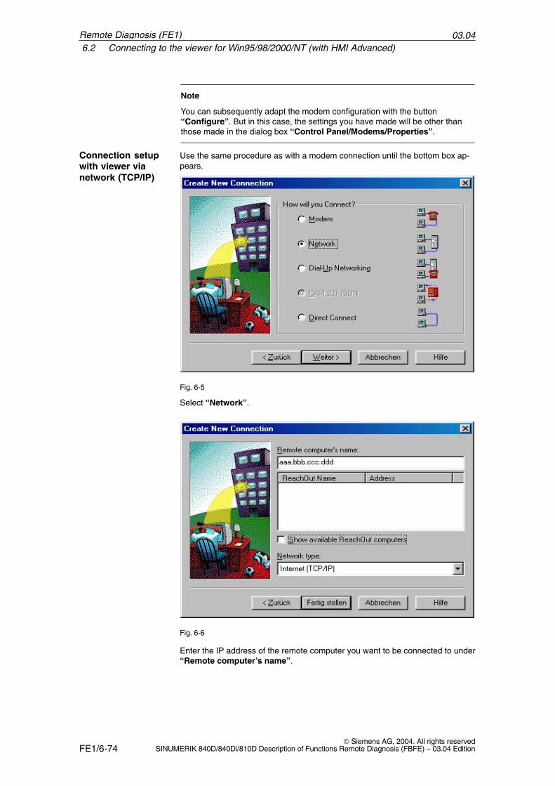
03.046.2 Connecting to the viewer for Win95/98/2000/NT (with HMI Advanced)
FE1/6-74 Siemens AG, 2004. All rights reserved
SINUMERIK 840D/840Di/810D Description of Functions Remote Diagnosis (FBFE) – 03.04 Edition
Note
You can subsequently adapt the modem configuration with the button“Configure”. But in this case, the settings you have made will be other thanthose made in the dialog box “Control Panel/Modems/Properties”.
Use the same procedure as with a modem connection until the bottom box ap-pears.
Fig. 6-5
Select “Network”.
Fig. 6-6
Enter the IP address of the remote computer you want to be connected to under“Remote computer’s name”.
Connection setupwith viewer vianetwork (TCP/IP)
Remote Diagnosis (FE1)
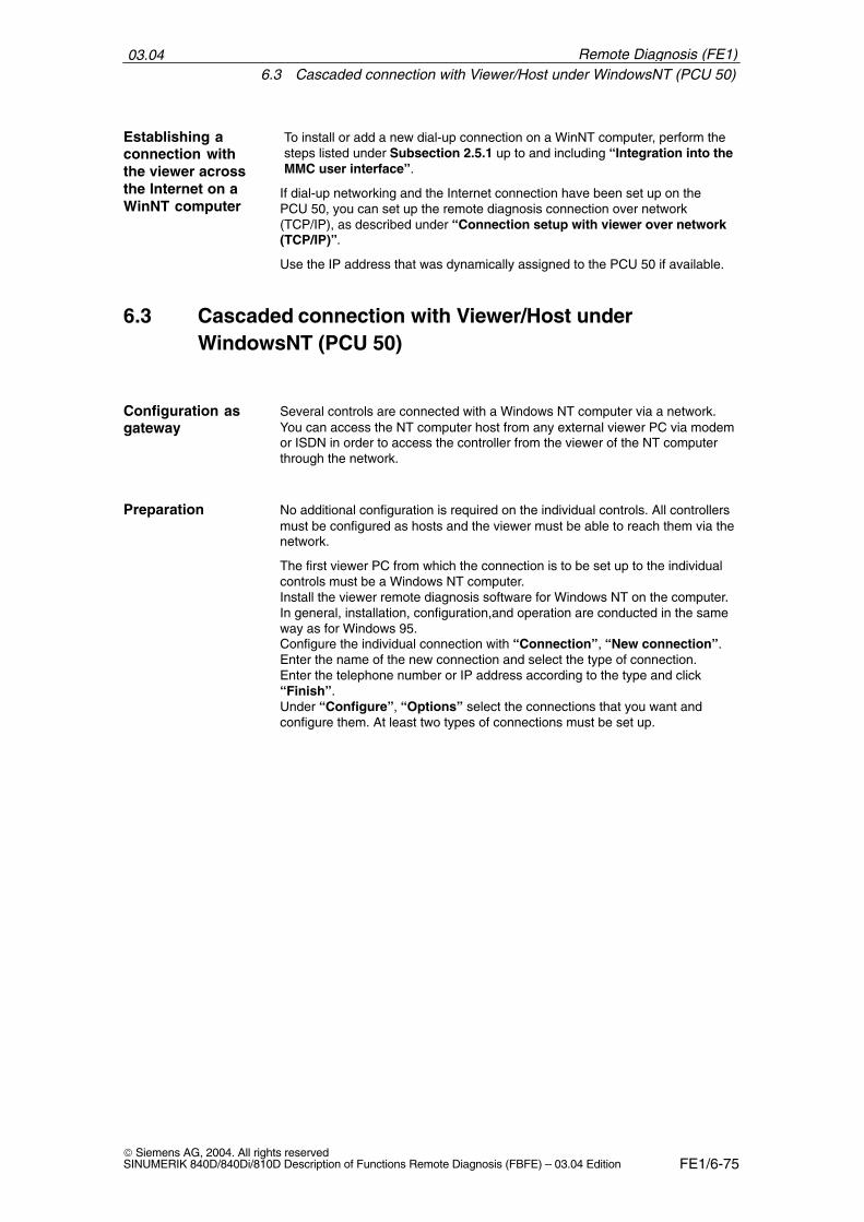
03.046.3 Cascaded connection with Viewer/Host under WindowsNT (PCU 50)
FE1/6-75 Siemens AG, 2004. All rights reservedSINUMERIK 840D/840Di/810D Description of Functions Remote Diagnosis (FBFE) – 03.04 Edition
To install or add a new dial-up connection on a WinNT computer, perform thesteps listed under Subsection 2.5.1 up to and including “Integration into theMMC user interface”.
If dial-up networking and the Internet connection have been set up on thePCU 50, you can set up the remote diagnosis connection over network(TCP/IP), as described under “Connection setup with viewer over network(TCP/IP)”.
Use the IP address that was dynamically assigned to the PCU 50 if available.
6.3 Cascaded connection with Viewer/Host underWindowsNT (PCU 50)
Several controls are connected with a Windows NT computer via a network.You can access the NT computer host from any external viewer PC via modemor ISDN in order to access the controller from the viewer of the NT computerthrough the network.
No additional configuration is required on the individual controls. All controllersmust be configured as hosts and the viewer must be able to reach them via thenetwork.
The first viewer PC from which the connection is to be set up to the individualcontrols must be a Windows NT computer.Install the viewer remote diagnosis software for Windows NT on the computer.In general, installation, configuration,and operation are conducted in the sameway as for Windows 95.Configure the individual connection with “Connection”, “New connection”. Enter the name of the new connection and select the type of connection. Enter the telephone number or IP address according to the type and click“Finish”. Under “Configure”, “Options” select the connections that you want andconfigure them. At least two types of connections must be set up.
Establishing aconnection withthe viewer acrossthe Internet on aWinNT computer
Configuration asgateway
Preparation
Remote Diagnosis (FE1)
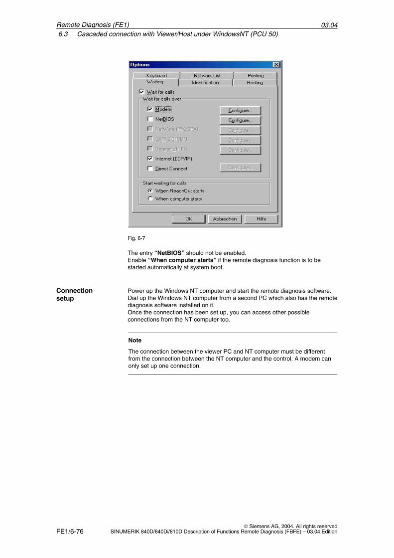
03.046.3 Cascaded connection with Viewer/Host under WindowsNT (PCU 50)
FE1/6-76 Siemens AG, 2004. All rights reserved
SINUMERIK 840D/840Di/810D Description of Functions Remote Diagnosis (FBFE) – 03.04 Edition
Fig. 6-7
The entry “NetBIOS” should not be enabled.Enable “When computer starts” if the remote diagnosis function is to bestarted automatically at system boot.
Power up the Windows NT computer and start the remote diagnosis software.Dial up the Windows NT computer from a second PC which also has the remotediagnosis software installed on it.Once the connection has been set up, you can access other possibleconnections from the NT computer too.
Note
The connection between the viewer PC and NT computer must be differentfrom the connection between the NT computer and the control. A modem canonly set up one connection.
Connectionsetup
Remote Diagnosis (FE1)
03.046.4 Connecting to the viewer under MS-DOS (for PCU 20/HT 6)
FE1/6-77 Siemens AG, 2004. All rights reservedSINUMERIK 840D/840Di/810D Description of Functions Remote Diagnosis (FBFE) – 03.04 Edition
6.4 Connecting to the viewer under MS-DOS(for PCU 20/HT 6)
The PCU 20/HT 6 is based on the MS-DOS operating system. The “ReachOut”software for the viewer is also available as an MS-DOS program. If you use aWindows operating system on the viewer PC, you must use the DOS version ofthe remote diagnosis.
To set up the connection between the viewer and host via a modem, pleaseproceed as follows:
1. Start “ReachOut” under MS-DOS or from the DOS prompt of Windows bycalling the file gvm.bat from the “ReachOut” directory. “ReachOut” for theviewer is loaded.
2. Select “Link”–>“Connect using Phone book”. Every entered host is dis-played with name and telephone number.
3. Select the host of your choice from the list using the cursor keys and confirmby pressing the “Enter” key. The host is selected.
Or:
1. Select “Link”–> “Contact to Host PC”. Screen “Enter Phone Number forHost PC” appears.
2. Enter the telephone number of the desired host and confirm by pressing the“Enter” key. The host is selected.
The Windows 32 variant supports connecting with several computers to or froma single PC.
• A single viewer PC can be connected to several waiting computers. It ispossible to use Chat, the Explorer or “RemoteControl” simultaneously orseparately.
• A single computer (viewer) can set up connections under Windows95/98/2000/NT or XP and wait for connections.
Note
If the controller has no mouse and no “ALT” key, the host on the controller canonly be quitted via the viewer.
�
Connection setupin MS-DOS
Connecting withmultipleconnections
Remote Diagnosis (FE1)
03.046.4 Connecting to the viewer under MS-DOS (for PCU 20/HT 6)
FE1/6-78 Siemens AG, 2004. All rights reserved
SINUMERIK 840D/840Di/810D Description of Functions Remote Diagnosis (FBFE) – 03.04 Edition
Remote Diagnosis (FE1)
Notes
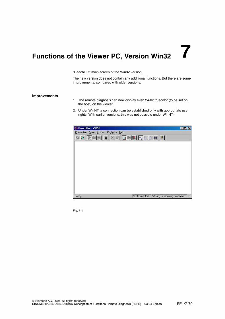
FE1/7-79 Siemens AG, 2004. All rights reservedSINUMERIK 840D/840Di/810D Description of Functions Remote Diagnosis (FBFE) – 03.04 Edition
Functions of the Viewer PC, Version Win32
“ReachOut” main screen of the Win32 version:
The new version does not contain any additional functions. But there are someimprovements, compared with older versions.
1. The remote diagnosis can now display even 24-bit truecolor (to be set onthe host) on the viewer.
2. Under WinNT, a connection can be established only with appropriate userrights. With earlier versions, this was not possible under WinNT.
Fig. 7-1
Improvements
7
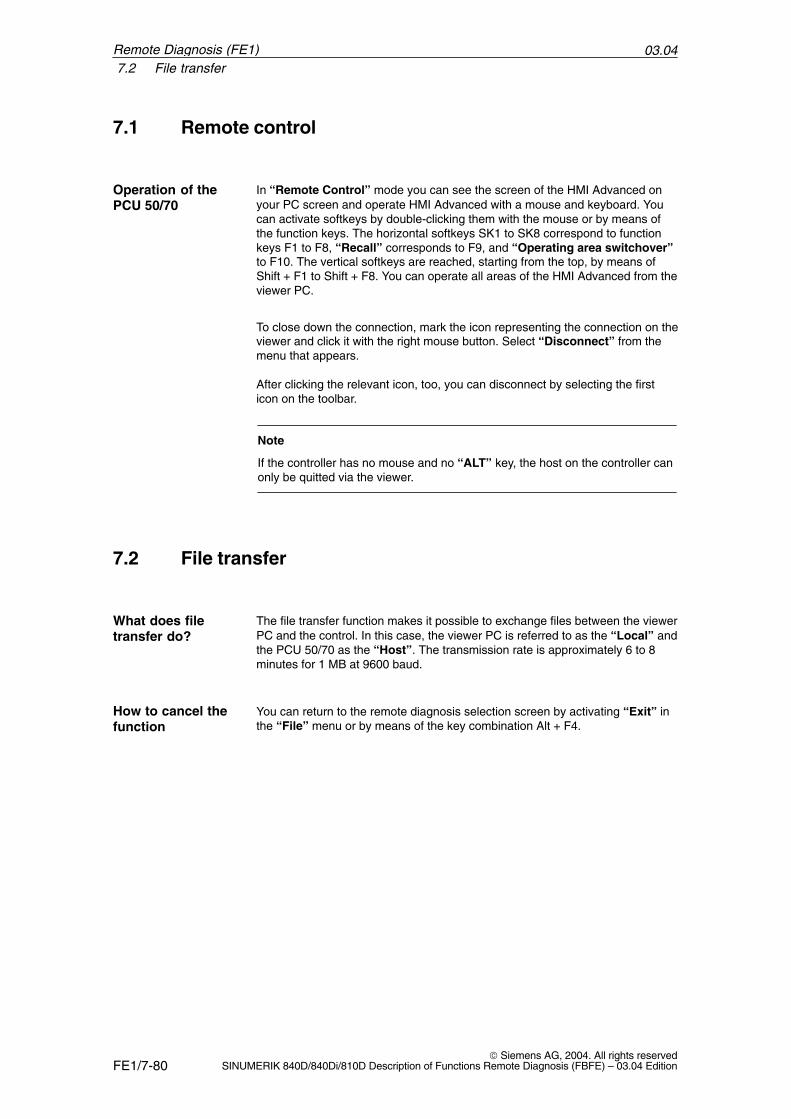
03.047.2 File transfer
FE1/7-80 Siemens AG, 2004. All rights reserved
SINUMERIK 840D/840Di/810D Description of Functions Remote Diagnosis (FBFE) – 03.04 Edition
7.1 Remote control
In “Remote Control” mode you can see the screen of the HMI Advanced onyour PC screen and operate HMI Advanced with a mouse and keyboard. Youcan activate softkeys by double-clicking them with the mouse or by means ofthe function keys. The horizontal softkeys SK1 to SK8 correspond to functionkeys F1 to F8, “Recall” corresponds to F9, and “Operating area switchover”to F10. The vertical softkeys are reached, starting from the top, by means ofShift + F1 to Shift + F8. You can operate all areas of the HMI Advanced from theviewer PC.
To close down the connection, mark the icon representing the connection on theviewer and click it with the right mouse button. Select “Disconnect” from themenu that appears.
After clicking the relevant icon, too, you can disconnect by selecting the firsticon on the toolbar.
Note
If the controller has no mouse and no “ALT” key, the host on the controller canonly be quitted via the viewer.
7.2 File transfer
The file transfer function makes it possible to exchange files between the viewerPC and the control. In this case, the viewer PC is referred to as the “Local” andthe PCU 50/70 as the “Host”. The transmission rate is approximately 6 to 8minutes for 1 MB at 9600 baud.
You can return to the remote diagnosis selection screen by activating “Exit” inthe “File” menu or by means of the key combination Alt + F4.
Operation of thePCU 50/70
What does filetransfer do?
How to cancel thefunction
Remote Diagnosis (FE1)
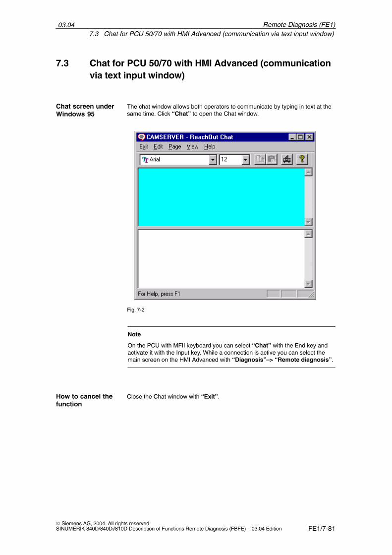
03.047.3 Chat for PCU 50/70 with HMI Advanced (communication via text input window)
FE1/7-81 Siemens AG, 2004. All rights reservedSINUMERIK 840D/840Di/810D Description of Functions Remote Diagnosis (FBFE) – 03.04 Edition
7.3 Chat for PCU 50/70 with HMI Advanced (communicationvia text input window)
The chat window allows both operators to communicate by typing in text at thesame time. Click “Chat” to open the Chat window.
Fig. 7-2
Note
On the PCU with MFII keyboard you can select “Chat” with the End key andactivate it with the Input key. While a connection is active you can select themain screen on the HMI Advanced with “Diagnosis”–> “Remote diagnosis”.
Close the Chat window with “Exit”.
Chat screen underWindows 95
How to cancel thefunction
Remote Diagnosis (FE1)
03.047.6 Help
FE1/7-82 Siemens AG, 2004. All rights reserved
SINUMERIK 840D/840Di/810D Description of Functions Remote Diagnosis (FBFE) – 03.04 Edition
Note
This is not possible on the PCU 50/70 without the MFII keyboard. In that case,the viewer must close the chat window on the viewer side. The window on thePCU 50/70 is then automatically closed.
7.4 Terminal emulation
This function is not required for remote diagnosis.
7.5 Exit
You can leave the menu by activating “Exit”. If the connection is still up a warn-ing appears telling the operator that the viewer is still connected and that theconnection will be broken when remote diagnosis closes. Confirming this warn-ing with “OK” closes the program and breaks the connection.
7.6 Help
A comprehensive help menu is available to assist at every important stage ofoperation.
�
Remote Diagnosis (FE1)
FE1/8-83 Siemens AG, 2004. All rights reservedSINUMERIK 840D/840Di/810D Description of Functions Remote Diagnosis (FBFE) – 03.04 Edition
Function of the Viewer PC (PCU 20/HT 6)
Remote diagnosis on the PCU 20 or HT 6 provides the same functions as thatfor the PCU 50/70. However, the Chat function is restricted in the PCU 20 or HT 6 version. Commu-nication is only indirectly possible via a parts program.
8.1 Remote control
In “Remote Control mode the screen contents of the PCU 20 or HT 6 (host)are displayed on your screen. You can control the host functions via the viewerPC keyboard. In this instance, softkeys are activated via function keys. Horizon-tal softkeys SK1 to SK8 are operated via function keys F1 to F8. The verticalsoftkeys are operated, starting from the top, using Shift + F1 to Shift + F8. “Re-call” corresponds to function key F9 and “operating area switchover” F10. Inother words, you have control over all host functions from the viewer PC.
If you wish to clear the connection between the viewer and host, you must pressthe left-hand and right-hand shift keys together. The window is closed and youreturn to the “ReachOut” interface.
In ReachOut, change to the menu “Link”–> “Disconnect from Host-PC”. Theconnection to the PCU 20/HT 6 is ended.
Note
On older MMC versions (< SW 5) the function “Hardware rely” might have tobe activated in the viewer under “Preferences –> Keyboard Handling”.
8.2 File transfer
File transfer allows you to transfer data from the viewer to the host and from thehost to the viewer. The transferred data for the PCU 20/ HT 6 are placed in theclipboard on drive “e”: of the host. The “transfer” directory is provided for thispurpose on drive “e:”.
Operation of thePCU 20/HT 6
Disconnecting
Meaning
8
03.048.3 Chat
FE1/8-84 Siemens AG, 2004. All rights reserved
SINUMERIK 840D/840Di/810D Description of Functions Remote Diagnosis (FBFE) – 03.04 Edition
To transfer data you must open the File Manager:
1. Select “File” –> “Invoke File Manager” on the “ReachOut” interface. AnExplorer with two windows is opened.
The directory of the viewer PC is displayed in the left-hand window of the Ex-plorer. The host directory is displayed in the right-hand window. Files can becopied and moved between the host and viewer or deleted. Files can only bewritten to drive “e:” on the host. All other drives have read status only.
2. Close the File Manager by selecting “Exit” –> “Yes”. You then return to the“ReachOut” interface.
The transfer of data between the viewer and host is organized via a transferdirectory. Data from the viewer or host are stored initially in this directory. Totransfer parts programs, for example, the data are copied into the transfer direc-tory from the viewer PC where they can then be processed from the host.
To access data stored in the transfer directory from the host, proceed as follows:
1. Select the “Services” softkey on the host. A new screen form appears.
2. Select the “Clipboard” softkey.
3. Select the “Transfer-Directory” softkey. The transfer directory is opened.
The functions “Copy and paste”, “Create archive”, “Delete” and “Refresh-Dir” are available on the vertical softkeys.
8.3 Chat
Direct CHAT is not supported.The Chat function is available on the PCU 20/ HT 6 only in a limited form, i.e.where a parts program, e.g. CHAT1.MPF, is edited in a remote diagnosis ses-sion. This parts program should be deleted at the end of the session.
!Caution
Do not start the CHAT function from the remote diagnosis menu!
�
Transfer of data
Transfer directory
Meaning
Remote Diagnosis (FE1)
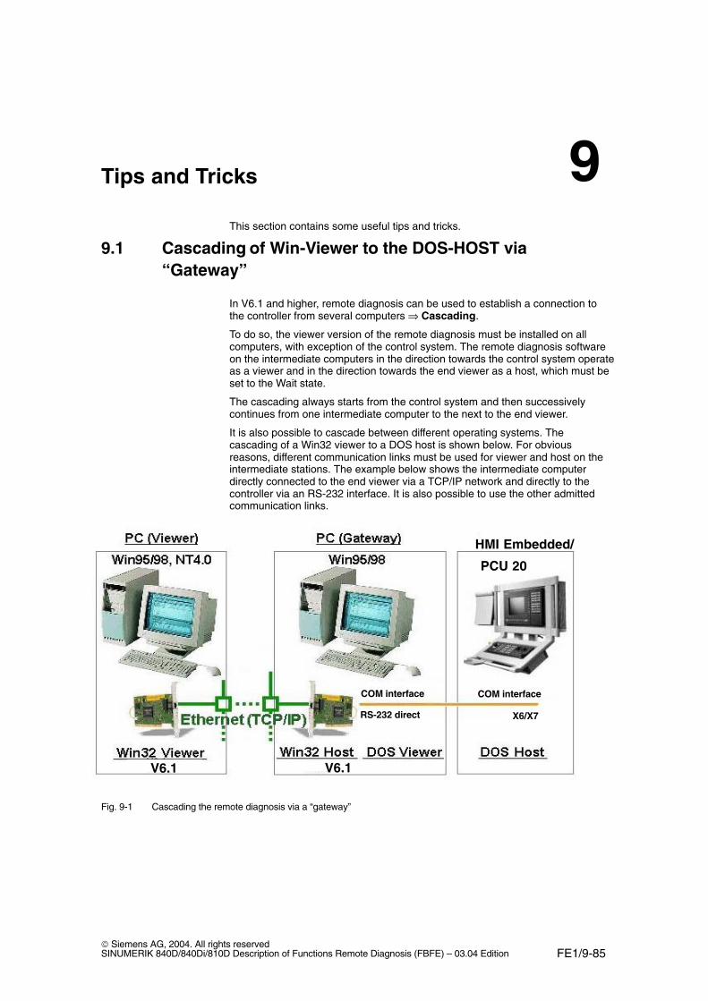
FE1/9-85 Siemens AG, 2004. All rights reservedSINUMERIK 840D/840Di/810D Description of Functions Remote Diagnosis (FBFE) – 03.04 Edition
Tips and Tricks
This section contains some useful tips and tricks.
9.1 Cascading of Win-Viewer to the DOS-HOST via“Gateway”
In V6.1 and higher, remote diagnosis can be used to establish a connection tothe controller from several computers ⇒ Cascading.
To do so, the viewer version of the remote diagnosis must be installed on allcomputers, with exception of the control system. The remote diagnosis softwareon the intermediate computers in the direction towards the control system operateas a viewer and in the direction towards the end viewer as a host, which must beset to the Wait state.
The cascading always starts from the control system and then successivelycontinues from one intermediate computer to the next to the end viewer.
It is also possible to cascade between different operating systems. Thecascading of a Win32 viewer to a DOS host is shown below. For obviousreasons, different communication links must be used for viewer and host on theintermediate stations. The example below shows the intermediate computerdirectly connected to the end viewer via a TCP/IP network and directly to thecontroller via an RS-232 interface. It is also possible to use the other admittedcommunication links.
V6.1 V6.1V6.1
HMI Embedded/
PCU 20
COM interface
RS-232 direct
COM interface
X6/X7
Fig. 9-1 Cascading the remote diagnosis via a “gateway”
9
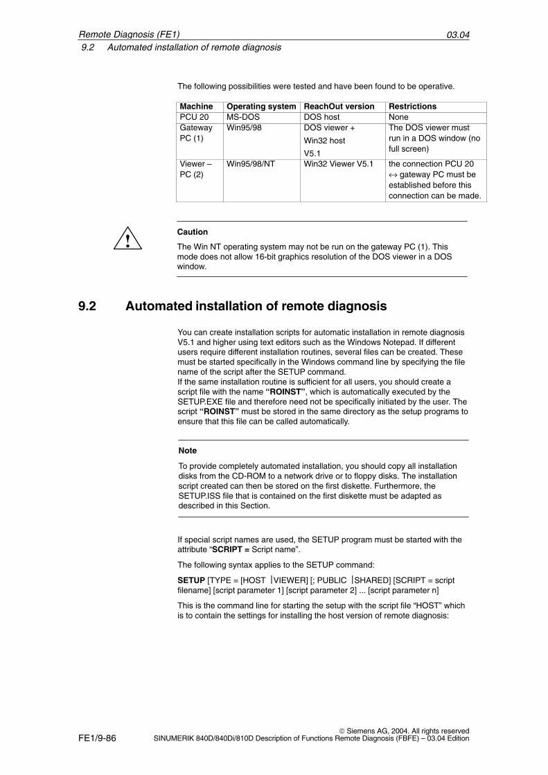
03.049.2 Automated installation of remote diagnosis
FE1/9-86 Siemens AG, 2004. All rights reserved
SINUMERIK 840D/840Di/810D Description of Functions Remote Diagnosis (FBFE) – 03.04 Edition
The following possibilities were tested and have been found to be operative.
Machine Operating system ReachOut version RestrictionsPCU 20 MS-DOS DOS host NoneGatewayPC (1)
Win95/98 DOS viewer +
Win32 host
V5.1
The DOS viewer mustrun in a DOS window (nofull screen)
Viewer –PC (2)
Win95/98/NT Win32 Viewer V5.1 the connection PCU 20↔ gateway PC must beestablished before thisconnection can be made.
!Caution
The Win NT operating system may not be run on the gateway PC (1). Thismode does not allow 16-bit graphics resolution of the DOS viewer in a DOSwindow.
9.2 Automated installation of remote diagnosis
You can create installation scripts for automatic installation in remote diagnosisV5.1 and higher using text editors such as the Windows Notepad. If differentusers require different installation routines, several files can be created. Thesemust be started specifically in the Windows command line by specifying the filename of the script after the SETUP command.If the same installation routine is sufficient for all users, you should create ascript file with the name “ROINST”, which is automatically executed by theSETUP.EXE file and therefore need not be specifically initiated by the user. Thescript “ROINST” must be stored in the same directory as the setup programs toensure that this file can be called automatically.
Note
To provide completely automated installation, you should copy all installationdisks from the CD-ROM to a network drive or to floppy disks. The installationscript created can then be stored on the first diskette. Furthermore, theSETUP.ISS file that is contained on the first diskette must be adapted asdescribed in this Section.
If special script names are used, the SETUP program must be started with theattribute “SCRIPT = Script name”.
The following syntax applies to the SETUP command:
SETUP [TYPE = [HOST VIEWER] [; PUBLIC SHARED] [SCRIPT = scriptfilename] [script parameter 1] [script parameter 2] ... [script parameter n]
This is the command line for starting the setup with the script file “HOST” whichis to contain the settings for installing the host version of remote diagnosis:
Remote Diagnosis (FE1)
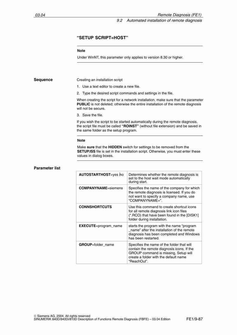
03.049.2 Automated installation of remote diagnosis
FE1/9-87 Siemens AG, 2004. All rights reservedSINUMERIK 840D/840Di/810D Description of Functions Remote Diagnosis (FBFE) – 03.04 Edition
“SETUP SCRIPT=HOST”
Note
Under WinNT, this parameter only applies to version 8.30 or higher.
Creating an installation script
1. Use a text editor to create a new file.
2. Type the desired script commands and settings in the file.
When creating the script for a network installation, make sure that the parameterPUBLIC is not deleted; otherwise the entire installation of the remote diagnosiswill not be secure.
3. Save the file.
If you wish the script to be started automatically during the remote diagnosis,the script file must be called “ROINST” (without file extension) and be saved inthe same folder as the setup program.
Note
Make sure that the HIDDEN switch for settings to be removed from theSETUP.ISS file is set in the installation script. Otherwise, you must enter thesevalues in dialog boxes.
AUTOSTARTHOST=yesno Determines whether the remote diagnosis isset to the host wait mode automaticallyduring start.
COMPANYNAME=siemens Specifies the name of the company for whichthe remote diagnosis is licensed. If you donot want to specify a company name, use“COMPANYNAME=”.
CONNSHORTCUTS Use this command to create shortcut iconsfor all remote diagnosis link icon files(*.RCO) that have been found in the [DISK1]folder during installation.
EXECUTE=program_name starts the program with the name “program_name” after the installation of the remotediagnosis has been completed and Windowshas been restarted.
GROUP=folder_name Specifies the name of the folder that willcontain the remote diagnosis icons. If theGROUP command is missing, Setup willcreate a folder with the default name“ReachOut”.
Sequence
Parameter list
Remote Diagnosis (FE1)
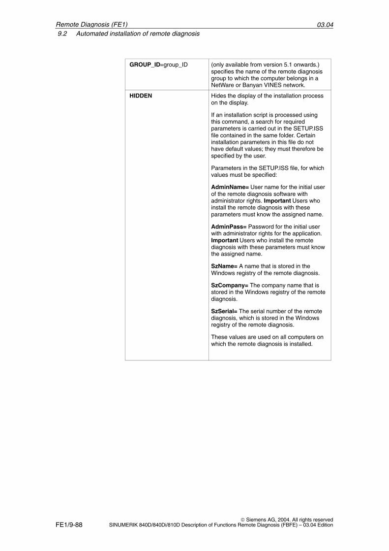
03.049.2 Automated installation of remote diagnosis
FE1/9-88 Siemens AG, 2004. All rights reserved
SINUMERIK 840D/840Di/810D Description of Functions Remote Diagnosis (FBFE) – 03.04 Edition
GROUP_ID=group_ID (only available from version 5.1 onwards.)specifies the name of the remote diagnosisgroup to which the computer belongs in aNetWare or Banyan VINES network.
HIDDEN Hides the display of the installation processon the display.
If an installation script is processed usingthis command, a search for requiredparameters is carried out in the SETUP.ISSfile contained in the same folder. Certaininstallation parameters in this file do nothave default values; they must therefore bespecified by the user.
Parameters in the SETUP.ISS file, for whichvalues must be specified:
AdminName= User name for the initial userof the remote diagnosis software withadministrator rights. Important Users whoinstall the remote diagnosis with theseparameters must know the assigned name.
AdminPass= Password for the initial userwith administrator rights for the application.Important Users who install the remotediagnosis with these parameters must knowthe assigned name.
SzName= A name that is stored in theWindows registry of the remote diagnosis.
SzCompany= The company name that isstored in the Windows registry of the remotediagnosis.
SzSerial= The serial number of the remotediagnosis, which is stored in the Windowsregistry of the remote diagnosis.
These values are used on all computers onwhich the remote diagnosis is installed.
Remote Diagnosis (FE1)
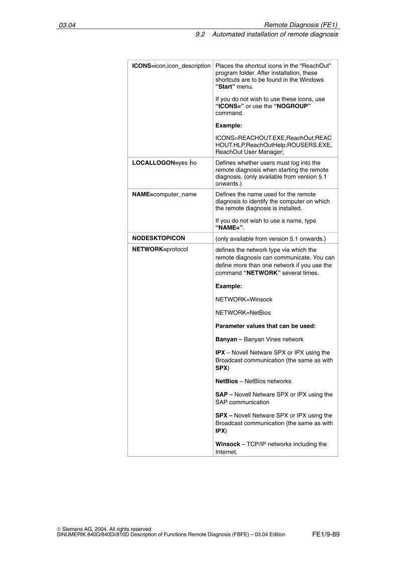
03.049.2 Automated installation of remote diagnosis
FE1/9-89 Siemens AG, 2004. All rights reservedSINUMERIK 840D/840Di/810D Description of Functions Remote Diagnosis (FBFE) – 03.04 Edition
ICONS=icon,icon_description Places the shortcut icons in the “ReachOut”program folder. After installation, theseshortcuts are to be found in the Windows“Start” menu.
If you do not wish to use these icons, use“ICONS=” or use the “NOGROUP”command.
Example:
ICONS=REACHOUT.EXE,ReachOut;REACHOUT.HLP,ReachOutHelp;ROUSERS.EXE,ReachOut User Manager;
LOCALLOGON=yesno Defines whether users must log into theremote diagnosis when starting the remotediagnosis. (only available from version 5.1onwards.)
NAME=computer_name Defines the name used for the remotediagnosis to identify the computer on whichthe remote diagnosis is installed.
If you do not wish to use a name, type“NAME=”.
NODESKTOPICON (only available from version 5.1 onwards.)
NETWORK=protocol defines the network type via which theremote diagnosis can communicate. You candefine more than one network if you use thecommand “NETWORK” several times.
Example:
NETWORK=Winsock
NETWORK=NetBios
Parameter values that can be used:
Banyan – Banyan Vines network
IPX – Novell Netware SPX or IPX using theBroadcast communication (the same as withSPX)
NetBios – NetBios networks
SAP – Novell Netware SPX or IPX using theSAP communication
SPX – Novell Netware SPX or IPX using theBroadcast communication (the same as withIPX)
Winsock – TCP/IP networks including theInternet.
Remote Diagnosis (FE1)
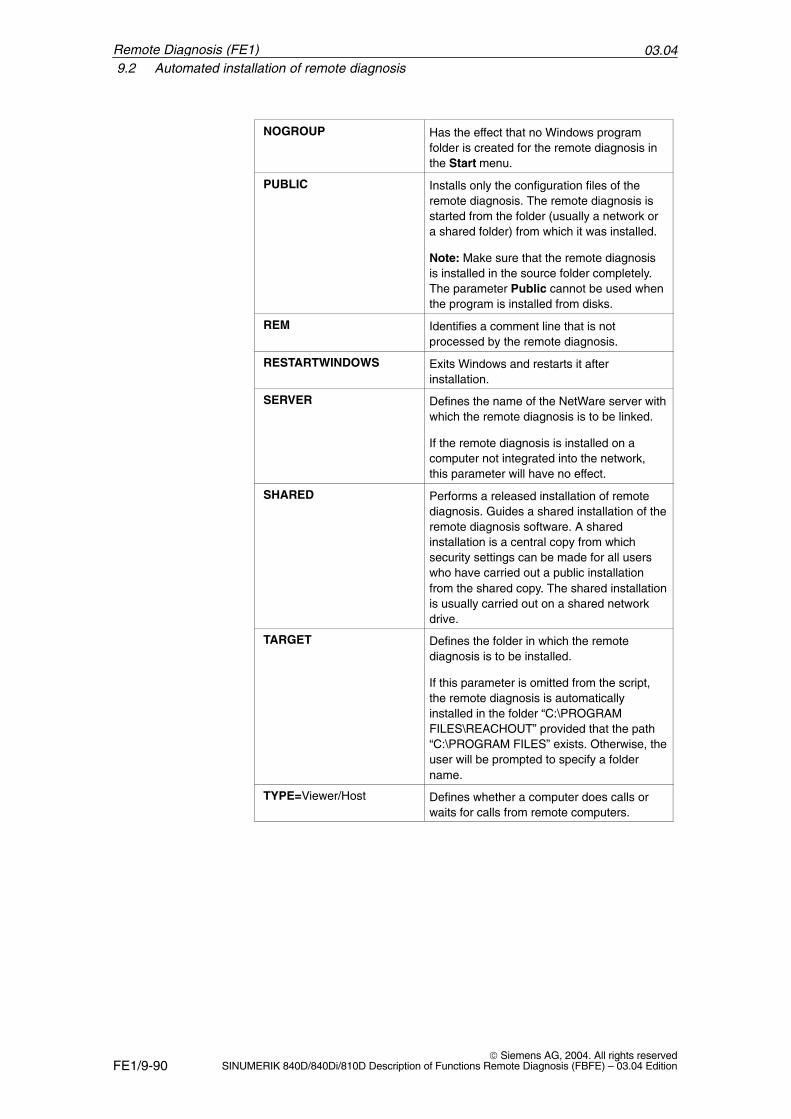
03.049.2 Automated installation of remote diagnosis
FE1/9-90 Siemens AG, 2004. All rights reserved
SINUMERIK 840D/840Di/810D Description of Functions Remote Diagnosis (FBFE) – 03.04 Edition
NOGROUP Has the effect that no Windows programfolder is created for the remote diagnosis inthe Start menu.
PUBLIC Installs only the configuration files of theremote diagnosis. The remote diagnosis isstarted from the folder (usually a network ora shared folder) from which it was installed.
Note: Make sure that the remote diagnosisis installed in the source folder completely.The parameter Public cannot be used whenthe program is installed from disks.
REM Identifies a comment line that is notprocessed by the remote diagnosis.
RESTARTWINDOWS Exits Windows and restarts it afterinstallation.
SERVER Defines the name of the NetWare server withwhich the remote diagnosis is to be linked.
If the remote diagnosis is installed on acomputer not integrated into the network,this parameter will have no effect.
SHARED Performs a released installation of remotediagnosis. Guides a shared installation of theremote diagnosis software. A sharedinstallation is a central copy from whichsecurity settings can be made for all userswho have carried out a public installationfrom the shared copy. The shared installationis usually carried out on a shared networkdrive.
TARGET Defines the folder in which the remotediagnosis is to be installed.
If this parameter is omitted from the script,the remote diagnosis is automaticallyinstalled in the folder “C:\PROGRAMFILES\REACHOUT” provided that the path“C:\PROGRAM FILES” exists. Otherwise, theuser will be prompted to specify a foldername.
TYPE=Viewer/Host Defines whether a computer does calls orwaits for calls from remote computers.
Remote Diagnosis (FE1)
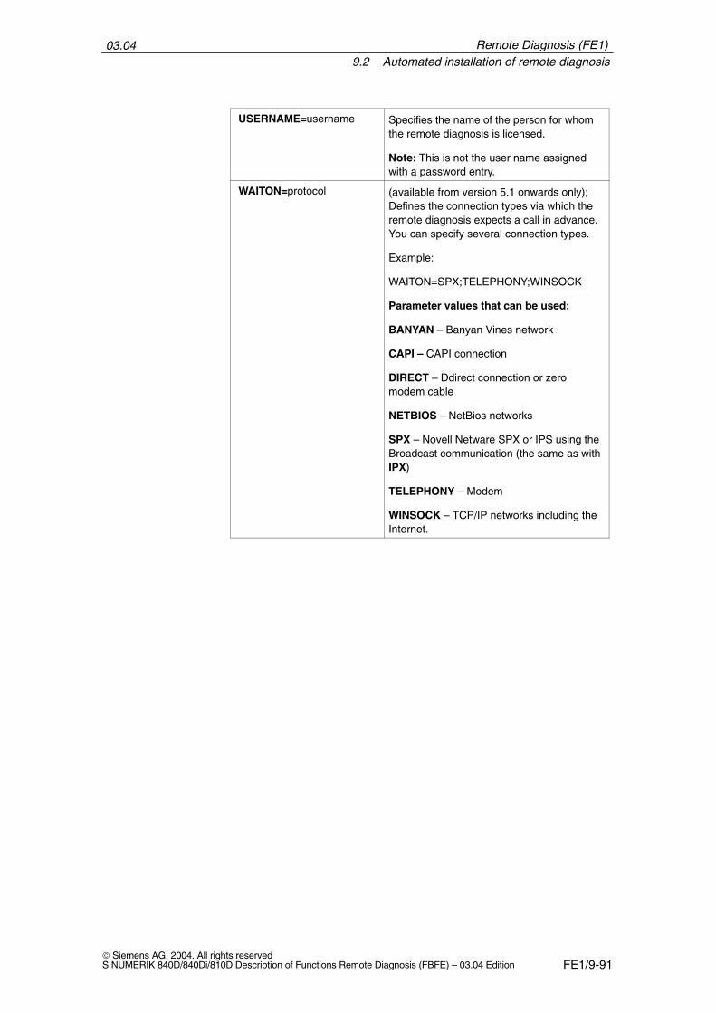
03.049.2 Automated installation of remote diagnosis
FE1/9-91 Siemens AG, 2004. All rights reservedSINUMERIK 840D/840Di/810D Description of Functions Remote Diagnosis (FBFE) – 03.04 Edition
USERNAME=username Specifies the name of the person for whomthe remote diagnosis is licensed.
Note: This is not the user name assignedwith a password entry.
WAITON=protocol (available from version 5.1 onwards only);Defines the connection types via which theremote diagnosis expects a call in advance.You can specify several connection types.
Example:
WAITON=SPX;TELEPHONY;WINSOCK
Parameter values that can be used:
BANYAN – Banyan Vines network
CAPI – CAPI connection
DIRECT – Ddirect connection or zeromodem cable
NETBIOS – NetBios networks
SPX – Novell Netware SPX or IPS using theBroadcast communication (the same as withIPX)
TELEPHONY – Modem
WINSOCK – TCP/IP networks including theInternet.
Remote Diagnosis (FE1)
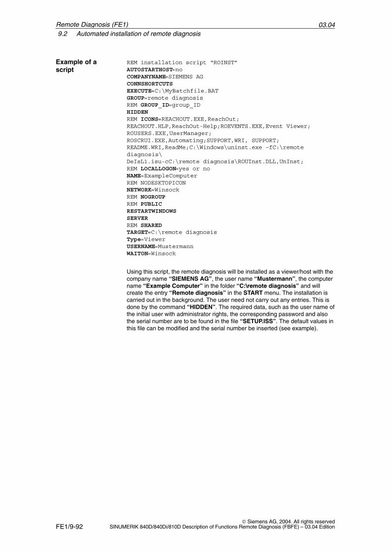
03.049.2 Automated installation of remote diagnosis
FE1/9-92 Siemens AG, 2004. All rights reserved
SINUMERIK 840D/840Di/810D Description of Functions Remote Diagnosis (FBFE) – 03.04 Edition
REM installation script “ROINST”AUTOSTARTHOST=noCOMPANYNAME=SIEMENS AGCONNSHORTCUTSEXECUTE=C:\MyBatchfile.BATGROUP=remote diagnosisREM GROUP_ID=group_IDHIDDENREM ICONS=REACHOUT.EXE,ReachOut;REACHOUT.HLP,ReachOut-Help;ROEVENTS.EXE,Event Viewer;ROUSERS.EXE,UserManager;ROSCRUI.EXE,Automating;SUPPORT,WRI, SUPPORT;README.WRI,ReadMe;C:\Windows\uninst.exe –fC:\remotediagnosis\DeIsL1.isu-cC:\remote diagnosis\ROUInst.DLL,UnInst;REM LOCALLOGON=yes or noNAME=ExampleComputerREM NODESKTOPICONNETWORK=WinsockREM NOGROUPREM PUBLICRESTARTWINDOWSSERVERREM SHAREDTARGET=C:\remote diagnosisType=ViewerUSERNAME=MustermannWAITON=Winsock
Using this script, the remote diagnosis will be installed as a viewer/host with thecompany name “SIEMENS AG”, the user name “Mustermann”, the computername “Example Computer” in the folder “C:\remote diagnosis” and willcreate the entry “Remote diagnosis” in the START menu. The installation iscarried out in the background. The user need not carry out any entries. This isdone by the command “HIDDEN”. The required data, such as the user name ofthe initial user with administrator rights, the corresponding password and alsothe serial number are to be found in the file “SETUP.ISS”. The default values inthis file can be modified and the serial number be inserted (see example).
Example of ascript
Remote Diagnosis (FE1)
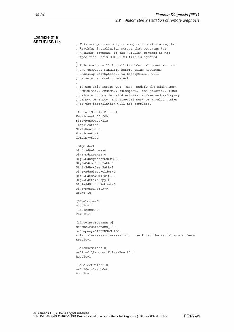
03.049.2 Automated installation of remote diagnosis
FE1/9-93 Siemens AG, 2004. All rights reservedSINUMERIK 840D/840Di/810D Description of Functions Remote Diagnosis (FBFE) – 03.04 Edition
; This script runs only in conjunction with a regular ; ReachOut installation script that contains the
; “HIDDEN” command. If the “HIDDEN” command is not
; specified, this SETUP.ISS file is ignored.
;
; This script will install ReachOut. You must restart
; the computer manually before using ReachOut.
; Changing BootOption=0 to BootOption=3 will
; cause an automatic restart.
;
; To use this script you _must_ modify the AdminName=,
; AdminPass=, szName=, szCompany=, and szSerial= lines
; below and provide valid entries. szName and szCompany
; cannot be empty, and szSerial must be a valid number
; or the installation will not complete.
[InstallShield Silent]
Version=v3.00.000
File=ResponseFile
[Application]
Name=ReachOut
Version=8.43
Company=Stac
[DlgOrder]
Dlg0=SdWelcome-0
Dlg1=SdLicense-0
Dlg2=SdRegisterUserEx-0
Dlg3=SdAskDestPath-0
Dlg4=SdAskDestPath-1
Dlg5=SdSelectFolder-0
Dlg6=SdShowDlgEdit3-0
Dlg7=SdStartCopy-0
Dlg8=SdFinishReboot-0
Dlg9=MessageBox-0
Count=10
[SdWelcome-0]
Result=1
[SdLicense-0]
Result=1
[SdRegisterUserEx-0]
szName=Mustermann_ISS
szCompany=SIEMENSAG_ISS
szSerial=xxxx–xxxx–xxxx–xxxx ← Enter the serial number here!
Result=1
[SdAskDestPath-0]
szDir=C:\Program Files\ReachOut
Result=1
[SdSelectFolder-0]
szFolder=ReachOut
Result=1
Example of aSETUP.ISS file
Remote Diagnosis (FE1)
03.049.3 Adapting the Remote Diagnosis window
FE1/9-94 Siemens AG, 2004. All rights reserved
SINUMERIK 840D/840Di/810D Description of Functions Remote Diagnosis (FBFE) – 03.04 Edition
[SdShowDlgEdit3-0]
AdminName=ADMINISTRATOR ← User name with administrator rights!
AdminPass=PASSWORD ← Password for administrator rights!
Confirm=PASSWORD ← Confirm password for administrator rights!
Result=1
[SdStartCopy-0]
Result=1
[SdFinishReboot-0]
Result=1
BootOption=0
[MessageBox-0]
Result=1
After installation, the computer is rebooted, and the batch file “MyBatch-file.BAT” (it could also be an EXE file) is executed. Since the command“ICONS” is provided with comments, all icons of the remote diagnosis will becreated. If certain icons are not created, remove the comment mark “REM”before the “ICONS” and the appropriate entries for the icons.
Note
If the icon “Uninst” is created using the “ICONS” command in script“ROINST”, the inverted commas must be removed from the string of the shortcut for the icon in the Properties, otherwise it will not find “UNINSTALL.EXE”.
The host is configured such that it is not automatically set to the Wait statusafter starting the remote diagnosis. It must be started manually with “Winsock” (TCP/IP, incl. Internet) set as the default setting.
9.3 Adapting the Remote Diagnosis window
In most cases the remote dagnosis window is hidden by the header. To adaptthe window, it is possible to specify the size and position of the window in theregistry.
1. Boot the PCU in Windows Service Mode.
2. In Notepad, type the following text:
3. Save this as a file with the extension “.reg”.
4. Now open the Explorer and start the file you have created by double-clickingon it.
Sequence
Remote Diagnosis (FE1)
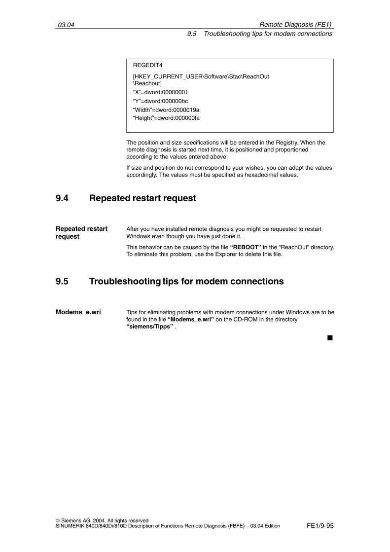
03.049.5 Troubleshooting tips for modem connections
FE1/9-95 Siemens AG, 2004. All rights reservedSINUMERIK 840D/840Di/810D Description of Functions Remote Diagnosis (FBFE) – 03.04 Edition
REGEDIT4
[HKEY_CURRENT_USER\Software\Stac\ReachOut\Reachout]
“X”=dword:00000001
“Y”=dword:000000bc
“Width”=dword:0000019a“Height”=dword:000000fa
The position and size specifications will be entered in the Registry. When theremote diagnosis is started next time, it is positioned and proportionedaccording to the values entered above.
If size and position do not correspond to your wishes, you can adapt the valuesaccordingly. The values must be specified as hexadecimal values.
9.4 Repeated restart request
After you have installed remote diagnosis you might be requested to restartWindows even though you have just done it.
This behavior can be caused by the file “REBOOT” in the “ReachOut” directory.To eliminate this problem, use the Explorer to delete this file.
9.5 Troubleshooting tips for modem connections
Tips for eliminating problems with modem connections under Windows are to befound in the file “Modems_e.wri” on the CD-ROM in the directory“siemens/Tipps” .
�
Repeated restartrequest
Modems_e.wri
Remote Diagnosis (FE1)
03.049.5 Troubleshooting tips for modem connections
FE1/9-96 Siemens AG, 2004. All rights reserved
SINUMERIK 840D/840Di/810D Description of Functions Remote Diagnosis (FBFE) – 03.04 Edition
Remote Diagnosis (FE1)
Notes
FE1/10-97 Siemens AG, 2004. All rights reservedSINUMERIK 840D/840Di/810D Description of Functions Remote Diagnosis (FBFE) – 03.04 Edition
Alarms
No signals or machine data are required for this function.
10.1 Alarms
Detailed explanations of the alarms which may occur are given in
References: /DA/, Diagnostics Guide
For systems with HMI Advanced you can refer to the online help.
�
10

03.0410.1 Alarms
FE1/10-98 Siemens AG, 2004. All rights reserved
SINUMERIK 840D/840Di/810D Description of Functions Remote Diagnosis (FBFE) – 03.04 Edition
Remote Diagnosis (FE1)
Notes
FE2/i Siemens AG, 2004. All rights reservedSINUMERIK 840D/840Di/810D Description of Functions Remote Diagnosis (FBFE) – 03.04 Edition
SINUMERIK 840D/840Di/810D Description ofFunctions Remote Diagnosis (FBFE)
Interrupt-Controlled EmailMessaging: @Event (FE2)
The @Event product description can be found in the following document:
/HBA/ SINUMERIK 840D/840Di/810D @Event manual 03.02 Edition
The previous document @Event (FE2) in this manual has been replaced by theabove document.
�

03.04
FE2/ii Siemens AG, 2004. All rights reserved
SINUMERIK 840D/840Di/810D Description of Functions Remote Diagnosis (FBFE) – 03.04 Edition
Interrupt-Controlled Email Messaging: @Event (FE2)
Notes
FE3/iii Siemens AG, 2004. All rights reservedSINUMERIK 840D/840Di/810D Description of Functions Remote Diagnosis (FBFE) – 03.04 Edition
SINUMERIK 840D/810D Description of Functions Remote Diagnosis(FBFE)
Remote Diagnosis from HMI SW 6.3and higher (FE3)
Contents
1 Brief Description FE3/1-3. . . . . . . . . . . . . . . . . . . . . . . . . . . . . . . . . . . . . . . . . . . . . . .
2 Hardware Configuration FE3/2-7. . . . . . . . . . . . . . . . . . . . . . . . . . . . . . . . . . . . . . . . .
2.1 Component overview FE3/2-7. . . . . . . . . . . . . . . . . . . . . . . . . . . . . . . . . . . .
2.2 Internet connection via modem FE3/2-10. . . . . . . . . . . . . . . . . . . . . . . . . . . 2.2.1 Internet under Windows 9x, 2000, ME, NT FE3/2-12. . . . . . . . . . . . . . . . . 2.2.2 Internet under WinXP FE3/2-18. . . . . . . . . . . . . . . . . . . . . . . . . . . . . . . . . . .
2.3 Direct connection FE3/2-26. . . . . . . . . . . . . . . . . . . . . . . . . . . . . . . . . . . . . . .
2.4 Ethernet connection (TCP/IP) FE3/2-27. . . . . . . . . . . . . . . . . . . . . . . . . . . .
2.5 Remote diagnosis via a gateway PC FE3/2-28. . . . . . . . . . . . . . . . . . . . . .
3 Software Installation/Deinstallation FE3/3-29. . . . . . . . . . . . . . . . . . . . . . . . . . . . . .
3.1 Booting the PCU 50/70 in service mode FE3/3-30. . . . . . . . . . . . . . . . . . . .
3.2 PCU 50/70 (host) FE3/3-31. . . . . . . . . . . . . . . . . . . . . . . . . . . . . . . . . . . . . . . 3.2.1 Starting installation/deinstallation FE3/3-31. . . . . . . . . . . . . . . . . . . . . . . . . .
3.3 PC (viewer) FE3/3-32. . . . . . . . . . . . . . . . . . . . . . . . . . . . . . . . . . . . . . . . . . . . 3.3.1 Starting installation/deinstallation FE3/3-33. . . . . . . . . . . . . . . . . . . . . . . . . .
4 Start-Up and Operation FE3/4-35. . . . . . . . . . . . . . . . . . . . . . . . . . . . . . . . . . . . . . . . .
4.1 PCU 50/70 (host) FE3/4-35. . . . . . . . . . . . . . . . . . . . . . . . . . . . . . . . . . . . . . . 4.1.1 Creating a new host connection object FE3/4-38. . . . . . . . . . . . . . . . . . . . . 4.1.2 Changing/renaming/deleting a connection object FE3/4-40. . . . . . . . . . . . 4.1.3 Starting up a connection object FE3/4-40. . . . . . . . . . . . . . . . . . . . . . . . . . .
4.2 Higher-level settings FE3/4-41. . . . . . . . . . . . . . . . . . . . . . . . . . . . . . . . . . . . 4.2.1 Support request settings FE3/4-42. . . . . . . . . . . . . . . . . . . . . . . . . . . . . . . . . 4.2.2 Adjusting the PLC trigger bit settings FE3/4-44. . . . . . . . . . . . . . . . . . . . . . 4.2.3 Activate a video recording FE3/4-45. . . . . . . . . . . . . . . . . . . . . . . . . . . . . . . . 4.2.4 Processing the status display FE3/4-46. . . . . . . . . . . . . . . . . . . . . . . . . . . . .
4.3 Establishing a connection to an Internet provider automatically FE3/4-47
03.04
FE3/iv Siemens AG, 2004. All rights reserved
SINUMERIK 840D/840Di/810D Description of Functions Remote Diagnosis (FBFE) – 03.04 Edition
4.4 Chat FE3/4-47. . . . . . . . . . . . . . . . . . . . . . . . . . . . . . . . . . . . . . . . . . . . . . . . . .
4.5 Exiting a remote diagnosis session FE3/4-48. . . . . . . . . . . . . . . . . . . . . . . .
4.6 PC (viewer) FE3/4-48. . . . . . . . . . . . . . . . . . . . . . . . . . . . . . . . . . . . . . . . . . . .
4.7 General functions FE3/4-50. . . . . . . . . . . . . . . . . . . . . . . . . . . . . . . . . . . . . . . 4.7.1 File transfer FE3/4-50. . . . . . . . . . . . . . . . . . . . . . . . . . . . . . . . . . . . . . . . . . . .
4.8 Help FE3/4-51. . . . . . . . . . . . . . . . . . . . . . . . . . . . . . . . . . . . . . . . . . . . . . . . . .
5 Alarms FE3/5-53. . . . . . . . . . . . . . . . . . . . . . . . . . . . . . . . . . . . . . . . . . . . . . . . . . . . . . . . .
5.1 Alarms FE3/5-53. . . . . . . . . . . . . . . . . . . . . . . . . . . . . . . . . . . . . . . . . . . . . . . .
FE3/1-3 Siemens AG, 2004. All rights reservedSINUMERIK 840D/840Di/810D Description of Functions Remote Diagnosis (FBFE) – 03.04 Edition
Brief Description
Remote diagnosis software permits:
� A member of service staff (viewer) to control and influence the operation of acontroller from his/her PC/PG via the PCU of the controller.
� A machine operator to request service support at the controller (host).
Using the remote diagnosis software, a connection can be established from theviewer to one or more computers.
As a viewer, you can display the computer screen of another user and carry outyour work as though you were sitting directly in front of the other computer orSinumerik control.To establish a connection, the remote diagnosis technology must be installed onall computers (PC or PG/PCU). Before a connection is established with other computers and files and programsare transferred, the information required to establish a connection and to startand end a remote diagnosis session must be entered. This information is savedin the connection objects and is displayed as symbols.The PCU 50/70 must be configured as a host and the PC/PG as a remote(viewer).
Remote diagnosis “MCIS RCS Host / MCIS RCS Viewer” comprises the follow-ing main functions:
� Remote Control (remote control of the PCU)
� File transfer (PCU–>PC, PC–>PCU data transfer, always controlled by theviewer with PC/PG)
� Chat (dialog box)
Use
Remote diagnosisfunctions
1
03.04
FE3/1-4 Siemens AG, 2004. All rights reserved
SINUMERIK 840D/840Di/810D Description of Functions Remote Diagnosis (FBFE) – 03.04 Edition
Compared with remote diagnosis up to HMI software 6.2 (“ReachOut”), remotediagnosis “MCIS RCS Host / MCIS RCS Viewer” Version1.x also offers the fol-lowing additional functions:
� Establish an automatic connection to the Internet Provider
� Request the remote diagnosis service via e-mail(install the @Event software)
� Status display on the PCU and the PC via a symbol display
� Start and stop a connection via a PLC bit
� Record a remote diagnosis session (session recording)
� Set a PLC bit at the start of a remote session
� Automatic start of a selected host object on starting remote diagnosis asfrom software “MCIS RCS Host” Version 1.1
Remote diagnosis is installed and configured on the PCU 50/70, underWindowsNT or WindowsXP. As all remote diagnosis functions can be accessedvia softkeys, neither a mouse nor a keyboard are required. On the PC/PG, remote diagnosis can be installed under Windows 9x/Millennium Edition (Me)/2000/NT/XP.
The PCU 50/70 (with HMI Advanced SW 6.3 or higher) is supplied with the re-mote diagnosis software installed under the name “MCIS RCS Host” VersionV1.x. The Certificate of License must be purchased separately. For the PC, the remote diagnosis is supplied under the name “MCIS RCSViewer” Version 1.x on CD-ROM.
For the purpose of remote diagnosis, the PCU is the designated “Host”.Software with the same name must be installed on the MMC 103/PCU50. Oncethis software has been activated, the PCU can be operated from the PC(viewer). When configuring a host computer, you may define who is permitted toestablish a connection to the PCU and the access rights required by the PCuser.
The PC connected to the PCU is designated as the “Viewer”. The PC userestablishes a connection to a PCU (host) and defines the actions to beperformed. All processes to be carried out on a PCU can be seen on the screenof the PC.
Operation of the host computer (PCU) from the viewer (PC) is termed “RemoteControl” or “remote diagnosis session”.
r The viewer can initiate the transfer of files in both directions between the PCand the PCU.
New functions
Systemrequirements
Scope of delivery
Host
Viewer
Remote control
File transfer
Remote Diagnosis (FE3)
03.04
FE3/1-5 Siemens AG, 2004. All rights reservedSINUMERIK 840D/840Di/810D Description of Functions Remote Diagnosis (FBFE) – 03.04 Edition
The Chat function can be used for communication between the two operatorson the PC and PCU. The operators can enter texts simultaneously via an inputwindow and read messages from the partner in an output window. Directswapping is also possible.
The remote diagnosis “MCIS RCS Host / MCIS RCS Viewer” is based on theremote control of “Symantec pcAnywhere V10.5”. The following documentation(pdf format) is available under this name:
� pca_whatsnew.pdf: Introduction to Symantec pcAnywhere 10.x
� pcauser.pdf: Symantec pcAnywhere User’s Guide
� pcaadmin.pdf: Symantec pcAnywhere Administrator’s Guide
� pcaole.pdf
�
Chat
Documentation inpdf format
Remote Diagnosis (FE3)
03.04
FE3/1-6 Siemens AG, 2004. All rights reserved
SINUMERIK 840D/840Di/810D Description of Functions Remote Diagnosis (FBFE) – 03.04 Edition
Remote Diagnosis (FE3)
Notes
FE3/2-7 Siemens AG, 2004. All rights reservedSINUMERIK 840D/840Di/810D Description of Functions Remote Diagnosis (FBFE) – 03.04 Edition
Hardware Configuration
2.1 Component overview
There are various options for setting up a connection from the PCU (host) to thePC (viewer).
The remote diagnosis software supports the following types of connection:
� Internet connection via ISDN modem or analog modem
� Modem connection via ISDN modem or analog modem
� Direct connection via cable(s)
� Network connection via Ethernet cable(s)
� Connection via a gateway PC
The connection method depends on the PC and PCU environment. In order tocontrol data exchange, the connection device acts as the interface between thePC and the PCU, e.g. cable, analog modem, ISDN modem, DSL modem.
A modem with 19200 baud or higher and the corresponding specific driver mustbe installed and configured before installing the remote diagnosis tool.
Information about the latest tested connection devices can be found on the In-ternet at: http://www.ad.siemens.de/csinfo. Select the following paths: Product Support–> Automation Systems –> SINUMERIK CNC Automation Systems –> HMISoftware for CNC Controls –> enter the term, e.g. “ISDN Modem” in the“Search” input field.
The following system requirements must be met by the computers in order forthe program to be executed correctly:
� Control PCU 50/70 HMI Advanced, SW 6.3 or higherWindowsNT or WindowsXP– one free COM port, if work is to be performed via modem or direct connection
– one free slot, if work is to be performed via an internal modem.
Connectiondevices
Modemrequirements
Tested connectiondevices
PC/PCU 50/70
2
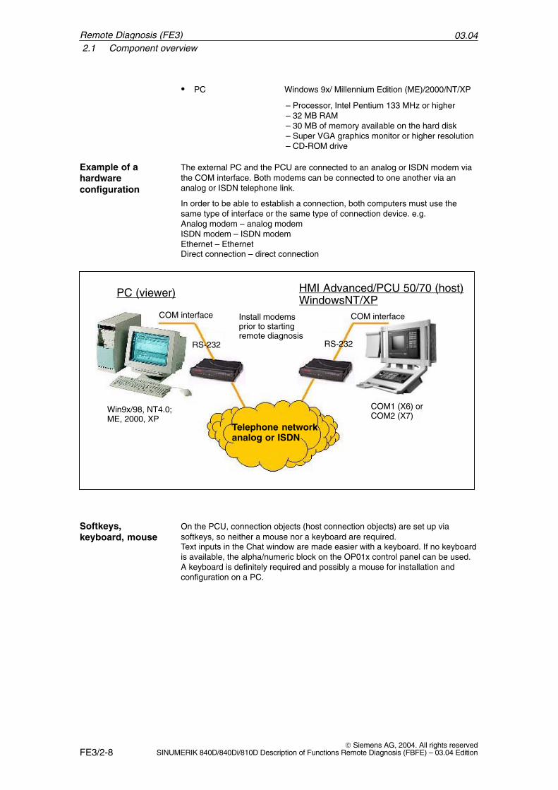
03.042.1 Component overview
FE3/2-8 Siemens AG, 2004. All rights reserved
SINUMERIK 840D/840Di/810D Description of Functions Remote Diagnosis (FBFE) – 03.04 Edition
� PC Windows 9x/ Millennium Edition (ME)/2000/NT/XP
– Processor, Intel Pentium 133 MHz or higher– 32 MB RAM– 30 MB of memory available on the hard disk– Super VGA graphics monitor or higher resolution– CD-ROM drive
The external PC and the PCU are connected to an analog or ISDN modem viathe COM interface. Both modems can be connected to one another via ananalog or ISDN telephone link.
In order to be able to establish a connection, both computers must use thesame type of interface or the same type of connection device. e.g. Analog modem – analog modemISDN modem – ISDN modemEthernet – EthernetDirect connection – direct connection
HMI Advanced/PCU 50/70 (host)WindowsNT/XP
PC (viewer)
RS-232 RS-232
Install modemsprior to startingremote diagnosis
Telephone networkanalog or ISDN
COM1 (X6) orCOM2 (X7)
Win9x/98, NT4.0;ME, 2000, XP
COM interface COM interface
On the PCU, connection objects (host connection objects) are set up viasoftkeys, so neither a mouse nor a keyboard are required.Text inputs in the Chat window are made easier with a keyboard. If no keyboardis available, the alpha/numeric block on the OP01x control panel can be used. A keyboard is definitely required and possibly a mouse for installation andconfiguration on a PC.
Example of ahardwareconfiguration
Softkeys,keyboard, mouse
Remote Diagnosis (FE3)
03.042.1 Component overview
FE3/2-9 Siemens AG, 2004. All rights reservedSINUMERIK 840D/840Di/810D Description of Functions Remote Diagnosis (FBFE) – 03.04 Edition
Remote diagnosis can also run via the Internet. This requires an Internetprovider (e.g., T-Online, AOL) providing a PPP dial-in node (analog or ISDN). Inaddition, either an analog modem, an ISDN modem or a DSL modem isrequired as the dial-in node for the connection between PCU and PC/PG.
Use cable(s) and connectors suitable for the operating system used. A freeCOM connection is required for the service PC/PG and the PCU.
Remote diagnosis can also run on a TCP/IP Ethernet network.
Remote diagnosis can also run via a gateway PC. This gateway is the linkbetween the service PC and the PCU connected to the customer Ethernetnetwork. The service PC and the gateway PC are connected via modem orISDN. The PCUs are connected to the gateway PC via Ethernet (TCP/IP). Herethere are generally two possibilities:
1. From PC viewer –> gateway host and further fromgateway viewer –> PCU host
2. With the gateway as RAS directly from the PC viewer –> PCU host
If the @Event software is used, information can be sent out fully automaticallyby e-mail provided @Event is configured accordingly.
The remote diagnosis documentation can be found on the “MCIS RCS Viewer”Version 1.x installation CD as a pdf (Adobe Acrobat) file called “SymantecpcAnywhere V10.5”.
Internetconnection
Direct connection
Networkconnection
Gateway PC
Additionalfunctions
Documentation
Remote Diagnosis (FE3)
03.042.2 Internet connection via modem
FE3/2-10 Siemens AG, 2004. All rights reserved
SINUMERIK 840D/840Di/810D Description of Functions Remote Diagnosis (FBFE) – 03.04 Edition
2.2 Internet connection via modem
The following two requirements must be met before actual Internet access canbe configured under Windows:
� An analog modem, an ISDN modem or a DSL modem
� Connection to the dial-up network (long-distance data transmission /Internet), i.e. there must be at least one dial-up connection object.The connection with the dial-up network is defined in a dial-up connectionobject. This object is created on the PCU in service mode and configured sothat connecting is performed automatically.
Assumption: Modem to COM port: The COM port for the modem on the PCUmust not have already been assigned to the RS-232-C or PG interface. Perform the following operation:
1. Select the area switchover key.
2. Select “Services”.
3. For each select “RS-232” and “PG” and then check the reserved COMport. If the same COM port as the modem is used, select “none”.
The installation description can be found in the documentation for the relevantconnection devices (analog and ISDN modem, ISDN Fritz!Card, ...).
Precondition
Requirements forthe host PCU
Installation ofmodem or card
Remote Diagnosis (FE3)
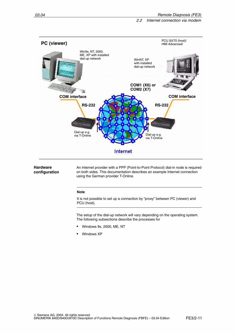
03.042.2 Internet connection via modem
FE3/2-11 Siemens AG, 2004. All rights reservedSINUMERIK 840D/840Di/810D Description of Functions Remote Diagnosis (FBFE) – 03.04 Edition
PC (viewer)
Win9x, NT, 2000,ME, XP with installed dial-up network WinNT, XP
with installed dial-up network
PCU 50/70 (host)/HMI Advanced/
Dial-up e.g. via T-Online Dial-up e.g.
via T-Online
COM interface COM interface
RS-232 RS-232
COM1 (X6) orCOM2 (X7)
An Internet provider with a PPP (Point-to-Point Protocol) dial-in node is requiredon both sides. This documentation describes an example Internet connectionusing the German provider T-Online.
Note
It is not possible to set up a connection by “proxy” between PC (viewer) andPCU (host).
The setup of the dial-up network will vary depending on the operating system.The following subsections describe the processes for
� Windows 9x, 2000, ME, NT
� Windows XP
Hardwareconfiguration
Remote Diagnosis (FE3)
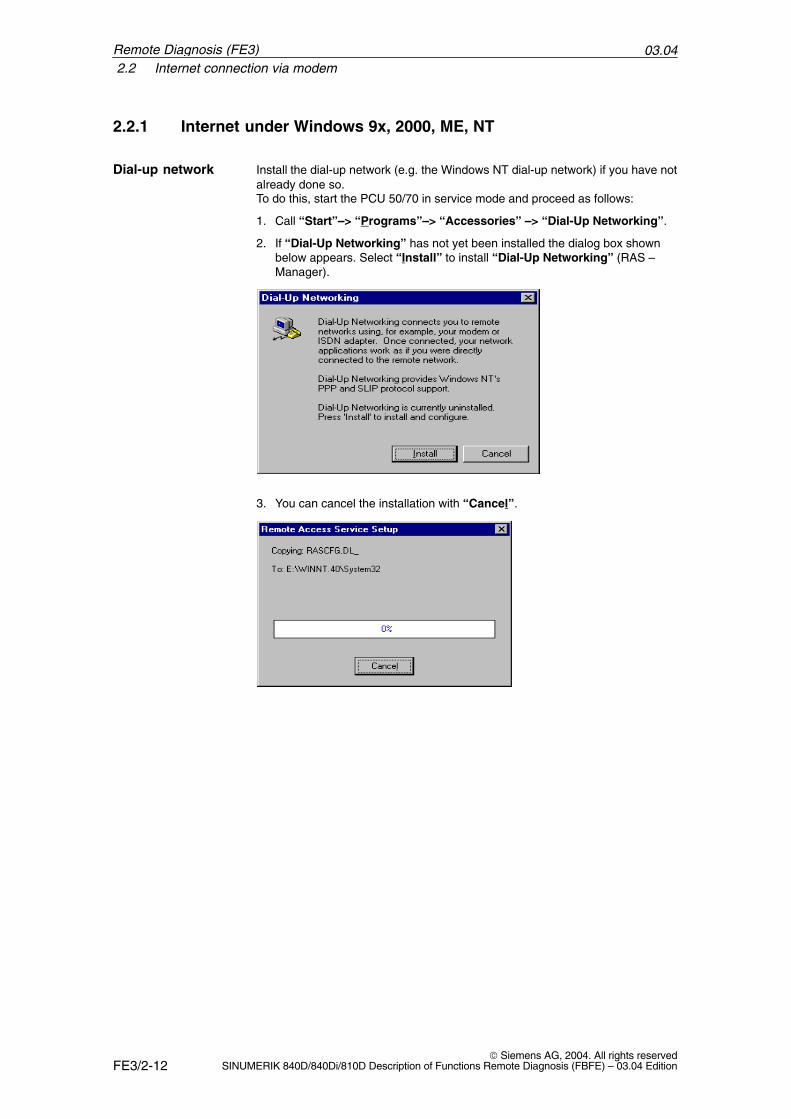
03.042.2 Internet connection via modem
FE3/2-12 Siemens AG, 2004. All rights reserved
SINUMERIK 840D/840Di/810D Description of Functions Remote Diagnosis (FBFE) – 03.04 Edition
2.2.1 Internet under Windows 9x, 2000, ME, NT
Install the dial-up network (e.g. the Windows NT dial-up network) if you have notalready done so. To do this, start the PCU 50/70 in service mode and proceed as follows:
1. Call “Start”–> “Programs”–> “Accessories” –> “Dial-Up Networking”.
2. If “Dial-Up Networking” has not yet been installed the dialog box shownbelow appears. Select “Install” to install “Dial-Up Networking” (RAS –Manager).
3. You can cancel the installation with “Cancel”.
Dial-up network
Remote Diagnosis (FE3)
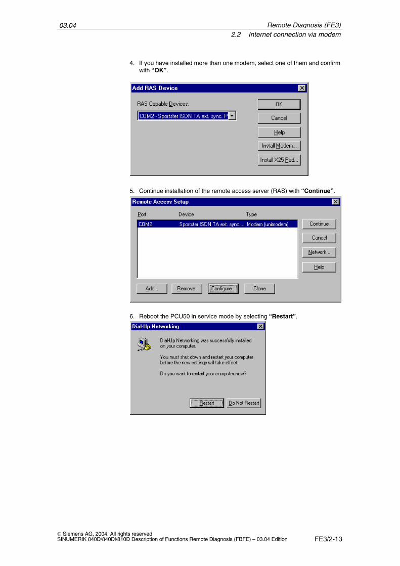
03.042.2 Internet connection via modem
FE3/2-13 Siemens AG, 2004. All rights reservedSINUMERIK 840D/840Di/810D Description of Functions Remote Diagnosis (FBFE) – 03.04 Edition
4. If you have installed more than one modem, select one of them and confirmwith “OK”.
5. Continue installation of the remote access server (RAS) with “Continue”.
6. Reboot the PCU50 in service mode by selecting “Restart”.
Remote Diagnosis (FE3)
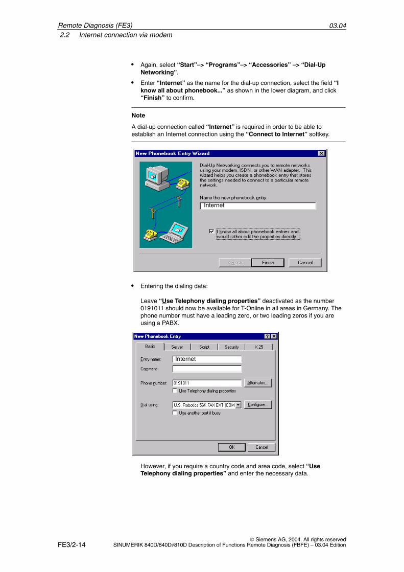
03.042.2 Internet connection via modem
FE3/2-14 Siemens AG, 2004. All rights reserved
SINUMERIK 840D/840Di/810D Description of Functions Remote Diagnosis (FBFE) – 03.04 Edition
� Again, select “Start”–> “Programs”–> “Accessories” –> “Dial-UpNetworking”.
� Enter “Internet” as the name for the dial-up connection, select the field “Iknow all about phonebook...” as shown in the lower diagram, and click“Finish” to confirm.
Note
A dial-up connection called “Internet” is required in order to be able toestablish an Internet connection using the “Connect to Internet” softkey.
Internet
� Entering the dialing data:
Leave “Use Telephony dialing properties” deactivated as the number0191011 should now be available for T-Online in all areas in Germany. Thephone number must have a leading zero, or two leading zeros if you areusing a PABX.
Internet
However, if you require a country code and area code, select “UseTelephony dialing properties” and enter the necessary data.
Remote Diagnosis (FE3)
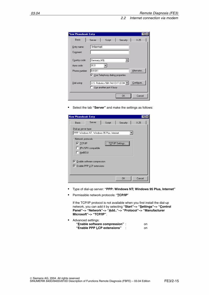
03.042.2 Internet connection via modem
FE3/2-15 Siemens AG, 2004. All rights reservedSINUMERIK 840D/840Di/810D Description of Functions Remote Diagnosis (FBFE) – 03.04 Edition
Internet
� Select the tab “Server” and make the settings as follows:
� Type of dial-up server: “PPP: Windows NT; Windows 95 Plus, Internet”
� Permissible network protocols: “TCP/IP”
If the TCP/IP protocol is not available when you first install the dial-upnetwork, you can add it by selecting “Start”–> “Settings”–> “ControlPanel”–> “Network”–> “Add..”–> “Protocol”–> “ManufacturerMicrosoft”–> “TCP/IP”.
� Advanced settings:“Enable software compression” : on“Enable PPP LCP extensions” : on
Remote Diagnosis (FE3)
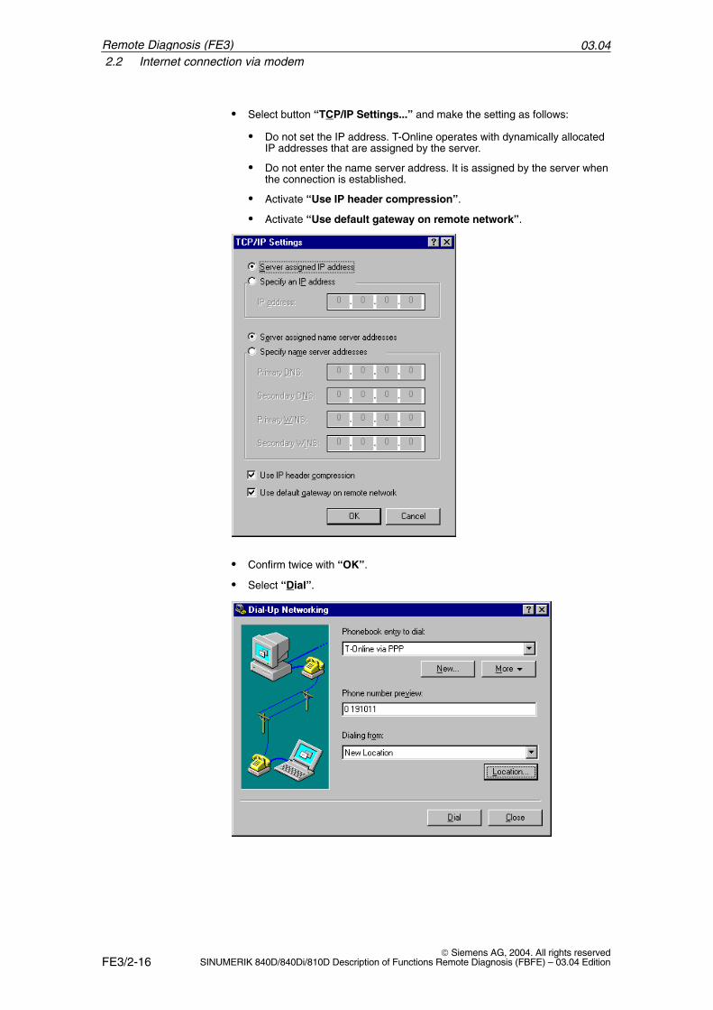
03.042.2 Internet connection via modem
FE3/2-16 Siemens AG, 2004. All rights reserved
SINUMERIK 840D/840Di/810D Description of Functions Remote Diagnosis (FBFE) – 03.04 Edition
� Select button “TCP/IP Settings...” and make the setting as follows:
� Do not set the IP address. T-Online operates with dynamically allocatedIP addresses that are assigned by the server.
� Do not enter the name server address. It is assigned by the server whenthe connection is established.
� Activate “Use IP header compression”.
� Activate “Use default gateway on remote network”.
� Confirm twice with “OK”.
� Select “Dial”.
Remote Diagnosis (FE3)
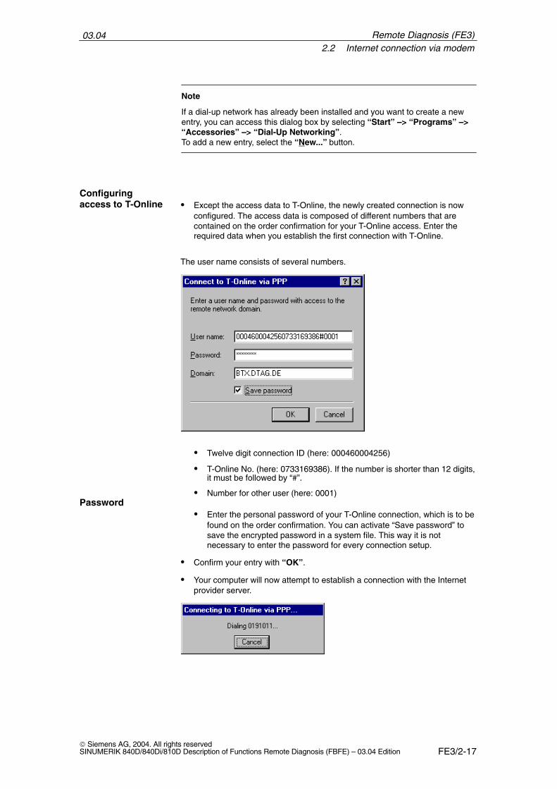
03.042.2 Internet connection via modem
FE3/2-17 Siemens AG, 2004. All rights reservedSINUMERIK 840D/840Di/810D Description of Functions Remote Diagnosis (FBFE) – 03.04 Edition
Note
If a dial-up network has already been installed and you want to create a newentry, you can access this dialog box by selecting “Start” –> “Programs” –>“Accessories” –> “Dial-Up Networking”. To add a new entry, select the “New...” button.
� Except the access data to T-Online, the newly created connection is nowconfigured. The access data is composed of different numbers that arecontained on the order confirmation for your T-Online access. Enter therequired data when you establish the first connection with T-Online.
The user name consists of several numbers.
� Twelve digit connection ID (here: 000460004256)
� T-Online No. (here: 0733169386). If the number is shorter than 12 digits,it must be followed by “#”.
� Number for other user (here: 0001)
� Enter the personal password of your T-Online connection, which is to befound on the order confirmation. You can activate “Save password” tosave the encrypted password in a system file. This way it is notnecessary to enter the password for every connection setup.
� Confirm your entry with “OK”.
� Your computer will now attempt to establish a connection with the Internetprovider server.
Configuringaccess to T-Online
Password
Remote Diagnosis (FE3)
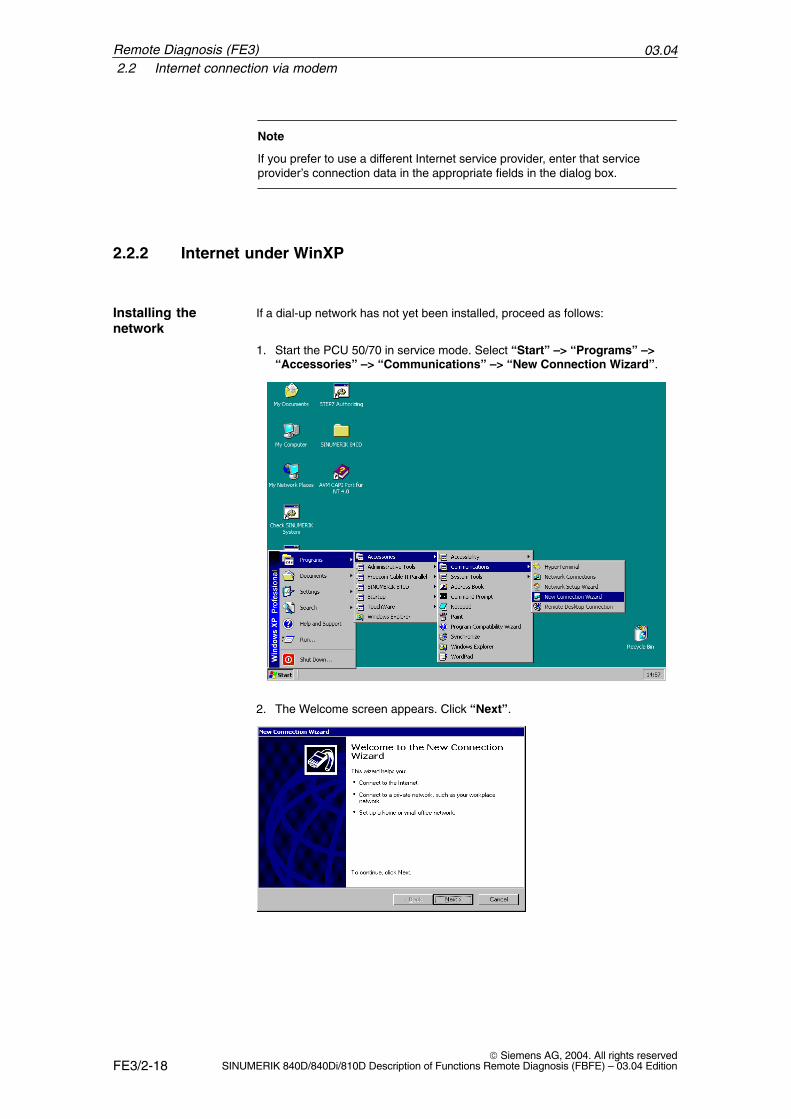
03.042.2 Internet connection via modem
FE3/2-18 Siemens AG, 2004. All rights reserved
SINUMERIK 840D/840Di/810D Description of Functions Remote Diagnosis (FBFE) – 03.04 Edition
Note
If you prefer to use a different Internet service provider, enter that serviceprovider’s connection data in the appropriate fields in the dialog box.
2.2.2 Internet under WinXP
If a dial-up network has not yet been installed, proceed as follows:
1. Start the PCU 50/70 in service mode. Select “Start” –> “Programs” –>“Accessories” –> “Communications” –> “New Connection Wizard”.
2. The Welcome screen appears. Click “Next”.
Installing thenetwork
Remote Diagnosis (FE3)
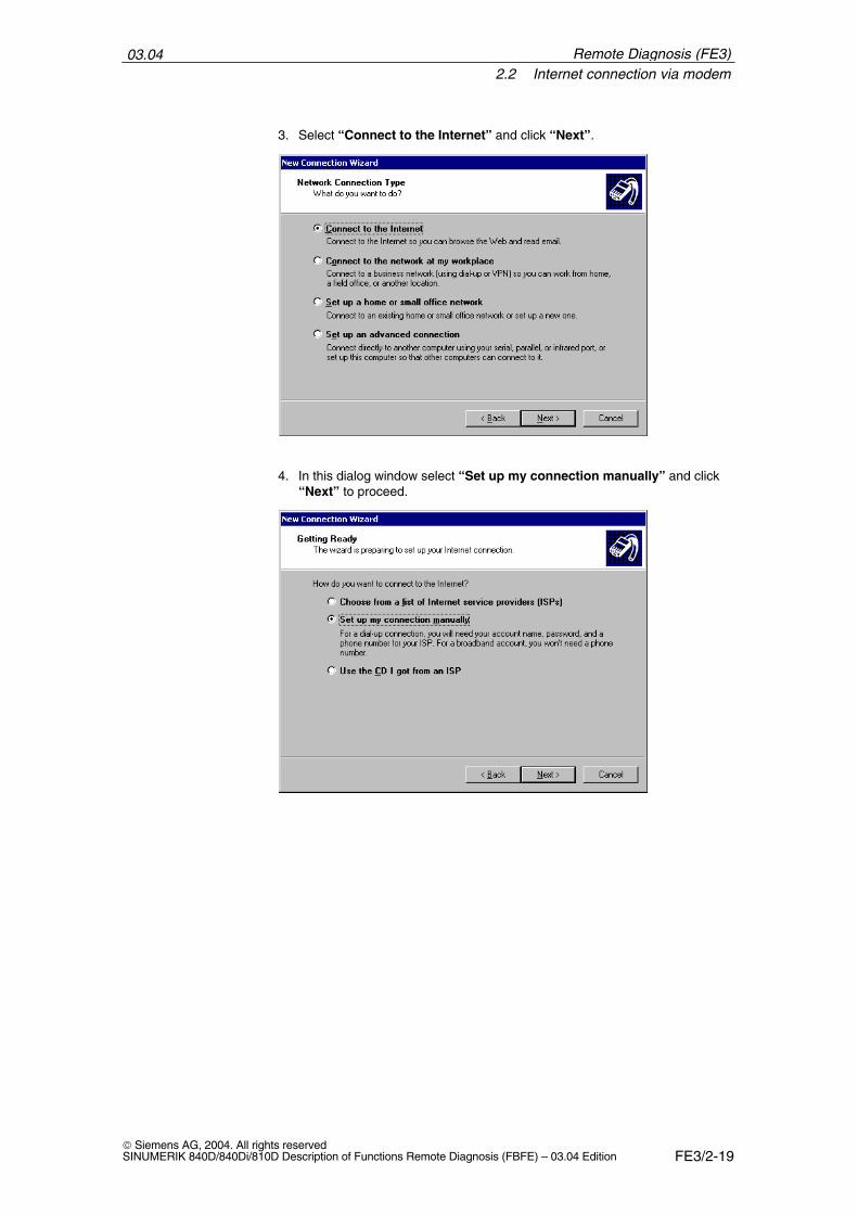
03.042.2 Internet connection via modem
FE3/2-19 Siemens AG, 2004. All rights reservedSINUMERIK 840D/840Di/810D Description of Functions Remote Diagnosis (FBFE) – 03.04 Edition
3. Select “Connect to the Internet” and click “Next”.
4. In this dialog window select “Set up my connection manually” and click“Next” to proceed.
Remote Diagnosis (FE3)
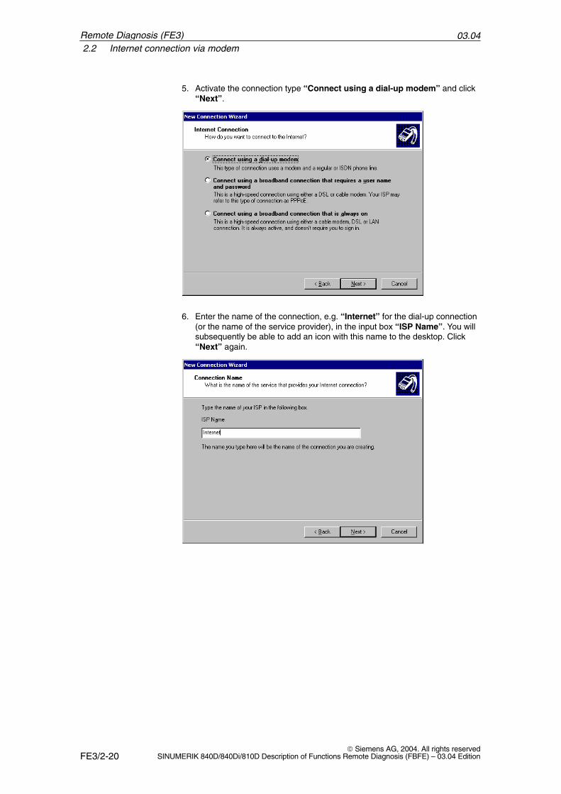
03.042.2 Internet connection via modem
FE3/2-20 Siemens AG, 2004. All rights reserved
SINUMERIK 840D/840Di/810D Description of Functions Remote Diagnosis (FBFE) – 03.04 Edition
5. Activate the connection type “Connect using a dial-up modem” and click“Next”.
6. Enter the name of the connection, e.g. “Internet” for the dial-up connection(or the name of the service provider), in the input box “ISP Name”. You willsubsequently be able to add an icon with this name to the desktop. Click“Next” again.
Remote Diagnosis (FE3)
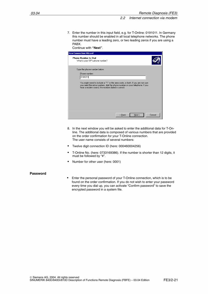
03.042.2 Internet connection via modem
FE3/2-21 Siemens AG, 2004. All rights reservedSINUMERIK 840D/840Di/810D Description of Functions Remote Diagnosis (FBFE) – 03.04 Edition
7. Enter the number in this input field, e.g. for T-Online: 0191011. In Germanythis number should be enabled in all local telephone networks. The phonenumber must have a leading zero, or two leading zeros if you are using aPABX. Continue with “Next”.
8. In the next window you will be asked to enter the additional data for T-On-line. The additional data is composed of various numbers that are providedon the order confirmation for your T-Online connection. The user name consists of several numbers:
� Twelve digit connection ID (here: 000460004256)
� T-Online No. (here: 0733169386). If the number is shorter than 12 digits, itmust be followed by “#”.
� Number for other user (here: 0001)
� Enter the personal password of your T-Online connection, which is to befound on the order confirmation. If you do not wish to enter your passwordevery time you dial up, you can activate “Confirm password” to save theencrypted password in a system file.
Password
Remote Diagnosis (FE3)
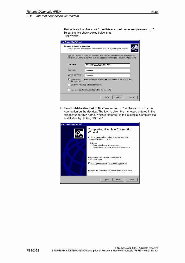
03.042.2 Internet connection via modem
FE3/2-22 Siemens AG, 2004. All rights reserved
SINUMERIK 840D/840Di/810D Description of Functions Remote Diagnosis (FBFE) – 03.04 Edition
Also activate the check box “Use this account name and password....”.Select the two check boxes below that.Click “Next”.
9. Select “Add a shortcut to this connection ....” to place an icon for thisconnection on the desktop. The icon is given the name you entered in thewindow under ISP Name, which is “Internet” in this example. Complete theinstallation by clicking “Finish”.
Remote Diagnosis (FE3)
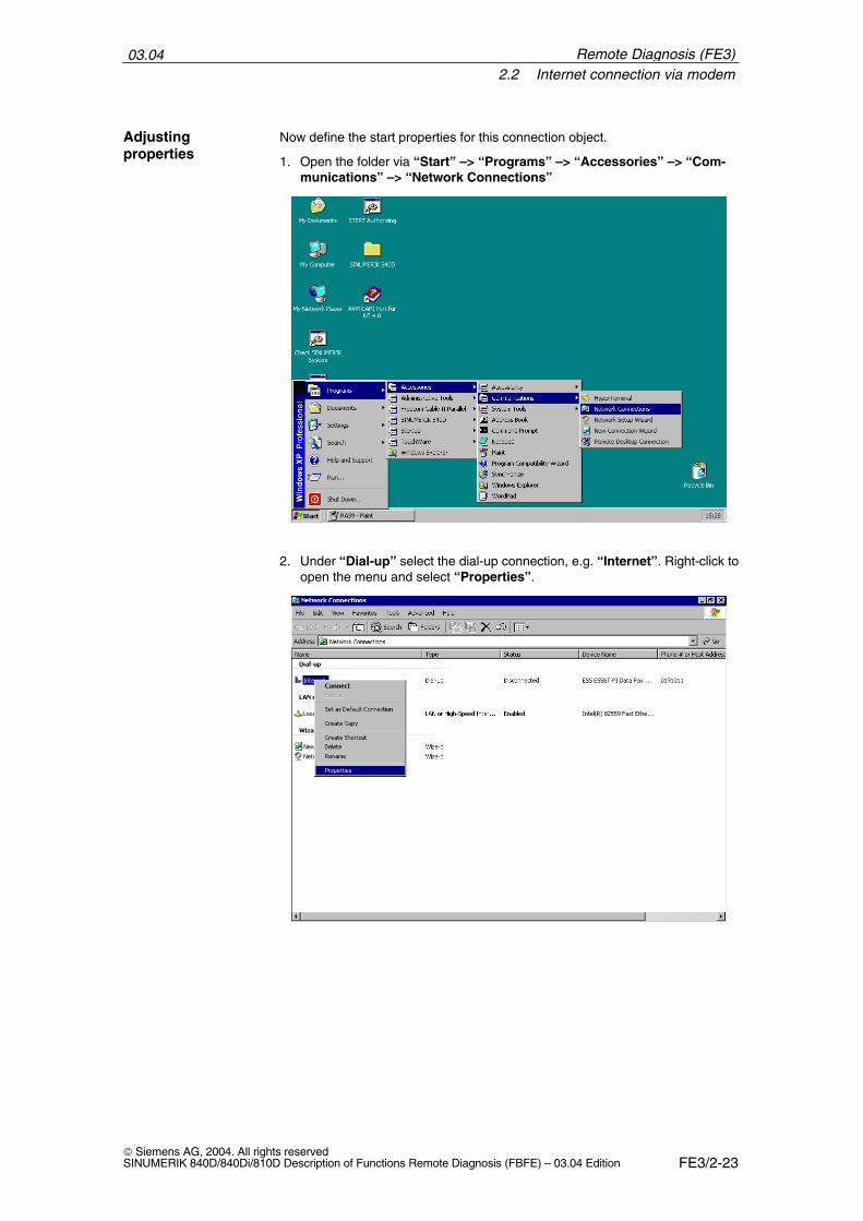
03.042.2 Internet connection via modem
FE3/2-23 Siemens AG, 2004. All rights reservedSINUMERIK 840D/840Di/810D Description of Functions Remote Diagnosis (FBFE) – 03.04 Edition
Now define the start properties for this connection object.
1. Open the folder via “Start” –> “Programs” –> “Accessories” –> “Com-munications” –> “Network Connections”
2. Under “Dial-up” select the dial-up connection, e.g. “Internet”. Right-click toopen the menu and select “Properties”.
Adjustingproperties
Remote Diagnosis (FE3)
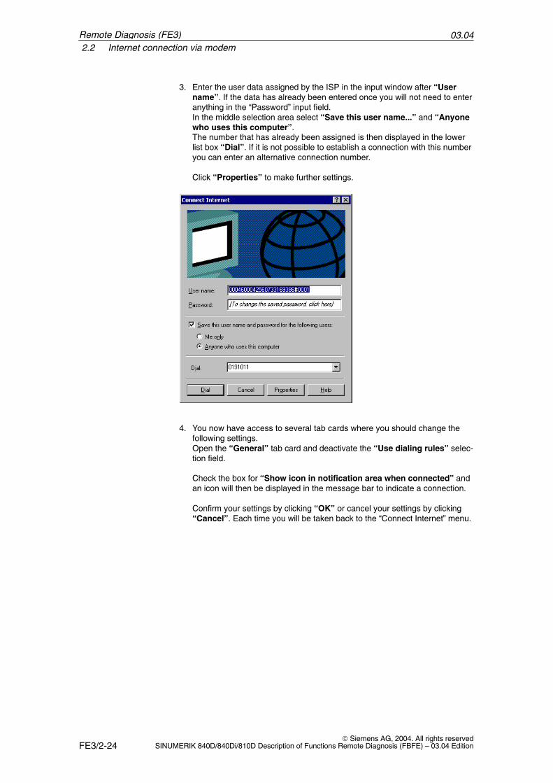
03.042.2 Internet connection via modem
FE3/2-24 Siemens AG, 2004. All rights reserved
SINUMERIK 840D/840Di/810D Description of Functions Remote Diagnosis (FBFE) – 03.04 Edition
3. Enter the user data assigned by the ISP in the input window after “Username”. If the data has already been entered once you will not need to enteranything in the “Password” input field. In the middle selection area select “Save this user name...” and “Anyonewho uses this computer”.The number that has already been assigned is then displayed in the lowerlist box “Dial”. If it is not possible to establish a connection with this numberyou can enter an alternative connection number.
Click “Properties” to make further settings.
4. You now have access to several tab cards where you should change thefollowing settings.Open the “General” tab card and deactivate the “Use dialing rules” selec-tion field.
Check the box for “Show icon in notification area when connected” andan icon will then be displayed in the message bar to indicate a connection.
Confirm your settings by clicking “OK” or cancel your settings by clicking“Cancel”. Each time you will be taken back to the “Connect Internet” menu.
Remote Diagnosis (FE3)
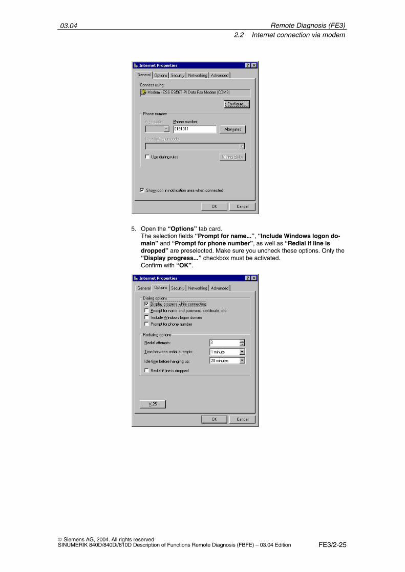
03.042.2 Internet connection via modem
FE3/2-25 Siemens AG, 2004. All rights reservedSINUMERIK 840D/840Di/810D Description of Functions Remote Diagnosis (FBFE) – 03.04 Edition
5. Open the “Options” tab card. The selection fields “Prompt for name...”, “Include Windows logon do-main” and “Prompt for phone number”, as well as “Redial if line isdropped” are preselected. Make sure you uncheck these options. Only the“Display progress...” checkbox must be activated.Confirm with “OK”.
Remote Diagnosis (FE3)
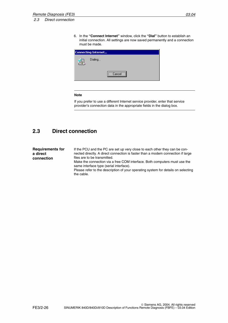
03.042.3 Direct connection
FE3/2-26 Siemens AG, 2004. All rights reserved
SINUMERIK 840D/840Di/810D Description of Functions Remote Diagnosis (FBFE) – 03.04 Edition
6. In the “Connect Internet” window, click the “Dial” button to establish aninitial connection. All settings are now saved permanently and a connectionmust be made.
Note
If you prefer to use a different Internet service provider, enter that serviceprovider’s connection data in the appropriate fields in the dialog box.
2.3 Direct connection
If the PCU and the PC are set up very close to each other they can be con-nected directly. A direct connection is faster than a modem connection if largefiles are to be transmitted. Make the connection via a free COM interface. Both computers must use thesame interface type (serial interface). Please refer to the description of your operating system for details on selectingthe cable.
Requirements fora directconnection
Remote Diagnosis (FE3)
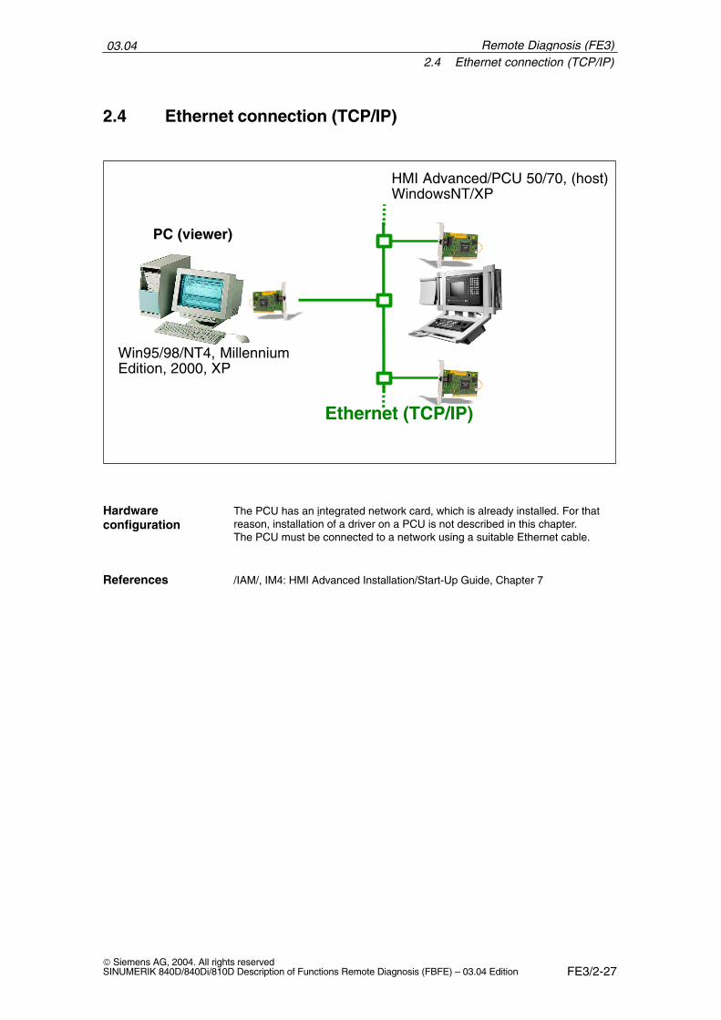
03.042.4 Ethernet connection (TCP/IP)
FE3/2-27 Siemens AG, 2004. All rights reservedSINUMERIK 840D/840Di/810D Description of Functions Remote Diagnosis (FBFE) – 03.04 Edition
2.4 Ethernet connection (TCP/IP)
ISA Box +
Ethernet (TCP/IP)
Win95/98/NT4, MillenniumEdition, 2000, XP
HMI Advanced/PCU 50/70, (host)WindowsNT/XP
PC (viewer)
The PCU has an integrated network card, which is already installed. For thatreason, installation of a driver on a PCU is not described in this chapter.The PCU must be connected to a network using a suitable Ethernet cable.
/IAM/, IM4: HMI Advanced Installation/Start-Up Guide, Chapter 7
Hardwareconfiguration
References
Remote Diagnosis (FE3)
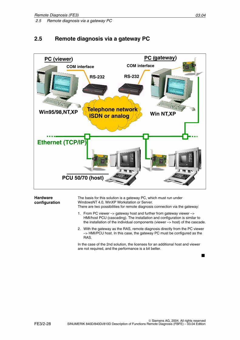
03.042.5 Remote diagnosis via a gateway PC
FE3/2-28 Siemens AG, 2004. All rights reserved
SINUMERIK 840D/840Di/810D Description of Functions Remote Diagnosis (FBFE) – 03.04 Edition
2.5 Remote diagnosis via a gateway PC
PC (viewer)
Win95/98,NT,XP
RS-232
COM interfaceCOM interface
RS-232
Telephone networkISDN or analog
PC (gateway)
Win NT,XP
Ethernet (TCP/IP)
PCU 50/70 (host)
The basis for this solution is a gateway PC, which must run underWindowsNT 4.0, WinXP Workstation or Server.There are two possibilities for remote diagnosis connection via the gateway:
1. From PC viewer –> gateway host and further from gateway viewer –>HMI/host PCU (cascading). The installation and configuration is similar tothe installation of the individual components (viewer –> host) of the cascade.
2. With the gateway as the RAS, remote diagnosis directly from the PC viewer–> HMI/PCU host. In this case, the gateway PC must be configured as theRAS.
In the case of the 2nd solution, the licenses for an additional host and viewerare not required, and the performance is a bit better.
�
Hardwareconfiguration
Remote Diagnosis (FE3)
FE3/3-29 Siemens AG, 2004. All rights reservedSINUMERIK 840D/840Di/810D Description of Functions Remote Diagnosis (FBFE) – 03.04 Edition
Software Installation/Deinstallation
Remote diagnosis must be installed both on a PC (viewer) and on the PCU(host). Before the remote diagnosis is installed, the communication devices(such as modem, network card...) should be installed (see Chapter 2).
The companion installation program is used to install the remote diagnosissoftware on the PCU in service mode.
The PCU is supplied with the remote diagnosis software as “MCIS RCS Host”Version 1.x” and must be installed.
For installation on the PC you will receive the program on a CD called “MCISRCS Viewer” Version 1.x”.
With the purchase of this software you also receive a “Certificate of License”containing the license number. You will need this number for initial installation.
The following versions of the remote diagnosis software must be installed.
Remote diagnosis on the PCU 50/70 with HMI Advanced, SW 6.3 or higher
Remote diagnosis on the PC/PG (viewer)
MCIS RCS Host Version1.x MCIS RCS Viewer Version1.x
Remote diagnosisinstallation
Supply format
Name and SWversion
3
03.043.1 Booting the PCU 50/70 in service mode
FE3/3-30 Siemens AG, 2004. All rights reserved
SINUMERIK 840D/840Di/810D Description of Functions Remote Diagnosis (FBFE) – 03.04 Edition
3.1 Booting the PCU 50/70 in service mode
New software is always installed or deinstalled on the PCU in service mode.
1. Switch on the PCU.
2. The following prompt will appear:“Please select the operating system to start:”The “SINUMERIK” text field will appear highlighted in white. Use the direc-tion key to move this field downwards and press ENTER to confirm thechange. Service mode appears.
3. From the menu select “4”.–> Start Windows (service mode)
4. Another menu is displayed. Select “1”. –> Standard Windows (without starting SINUMERIK HMI)The system will then reboot automatically.
5. The prompt described in point 2. will appear again. You do not need to doanything. After a short time the “SINUMERIK 840D powerline” welcomescreen will appear.
6. The following screen will then appear: You want to enter the SINUMERIK Desktop Please enter the password Password: ........ SINUMERIK Desktop (SINUMERIK HMI) Shutdown Please enter the Password, select “SINUMERIK Desktop”, and press theReturn key.
Note
The password must be entered in uppercase letters.
(The password authorizes you to make significant changes in the control. Itcorresponds to one of the following access levels:– System– Manufacturer– Service.)
The message “Application is already running” indicates the start-up status.Instead of the HMI system software, the SINUMERIK desktop for the servicemode is now displayed.
Service mode onthe PCU
Remote Diagnosis (FE3)
03.043.2 PCU 50/70 (host)
FE3/3-31 Siemens AG, 2004. All rights reservedSINUMERIK 840D/840Di/810D Description of Functions Remote Diagnosis (FBFE) – 03.04 Edition
3.2 PCU 50/70 (host)
Once you have started up the PCU in service mode, you will need to install the“MCIS RCS Host” Version 1.x software.
The “host” option is installed on the PCU, i.e. the network and modem connec-tions are supported, but no remote diagnosis or file transfer functionality. Thismeans that the controller can be monitored via the PCU by a service PC/PG,but it cannot monitor other PCs or other controllers itself.
1. When you purchase the software you are given a printed “Certificate of Li-cense” showing the license number. The license number always begins with“T-...”.
2. The PCU (as from HMI Software 6.3) must be equipped with the Win-dowsNT/XP operating system.
3. Earlier versions of the remote diagnosis software should be deinstalled.
4. All other applications must be shut down.
Installation/configuration and operation can be performed using softkeys.
3.2.1 Starting installation/deinstallation
Select the following path in the Windows Start menu: “Start” –> “Programs” –> “SINUMERIK 840D” –> “Tools” –> “Install-Deinstall MCIS RCS Host”
After start-up you will be asked whether you want to install: “Do you want toinstall MCIS RCS Host?”
If you click “Yes”, you will be asked to read the licensing agreement. Use thehorizontal softkeys to choose from five languages. Click the “Accept” button to accept the terms of the licensing agreement. Enterthe license number when asked to do so. You can find this number in your “Cer-tificate of License”. Confirm your entries with “OK”. Follow the remaining instructions. Installation runs automatically.
If the message “Setup finished with errors” appears you will need to restartthe installation process or contact the hotline.
If the installation was successful then the message “Setup is finished suc-cessfully”. The system will then restart automatically.
If after the first prompt you do not wish to proceed, click “No” to abort the pro-cess.
Installation option
Installationrequirements
Operating options
Start theinstallationprocess
Remote Diagnosis (FE3)
03.043.3 PC (viewer)
FE3/3-32 Siemens AG, 2004. All rights reserved
SINUMERIK 840D/840Di/810D Description of Functions Remote Diagnosis (FBFE) – 03.04 Edition
Select the following path in the Windows Start menu:“Start” –> “Programs” –> “SINUMERIK 840D” –> “Tools” and click –> “Install-Deinstall MCIS RCS Host”. You will be asked whether you want to deinstall: “Do you want to deinstallMCIS RCS Host?”
Click “No” to abort the process. If you click “Yes”, the software will be deinstalled and the system will restartautomatically.
3.3 PC (viewer)
Before you install the remote diagnosis software on your PC, observe thefollowing:
• Determine which viewer version is required. The software version mustmatch the software version of the remote diagnosis software installed on thePCU.
• You should remove any other remote diagnosis software from the PC.
• If you are using a modem, make sure that it is configured correctly andconnected to the telephone system.
• Make a note of the modem type, model number and transmission rate.
• Locate the RS-232 interface (e.g. COM1 or COM2) to which the modem isconnected.
• Determine under which operating system your PC is operating.
Installation is performed via CD-ROM. Before installing “MCIS RCS Viewer”, you should deinstall previous remotediagnostic software (e.g. ReachOut).However, if you want to keep previous remote diagnosis software, make sureyou never use both programs simultaneously!
The complete functionality covering host, remote, and file transmission opera-tions is installed on the PC.
Performingdeinstallation
Preparation
Installation on thePC
Installation optionon the PC
Remote Diagnosis (FE3)
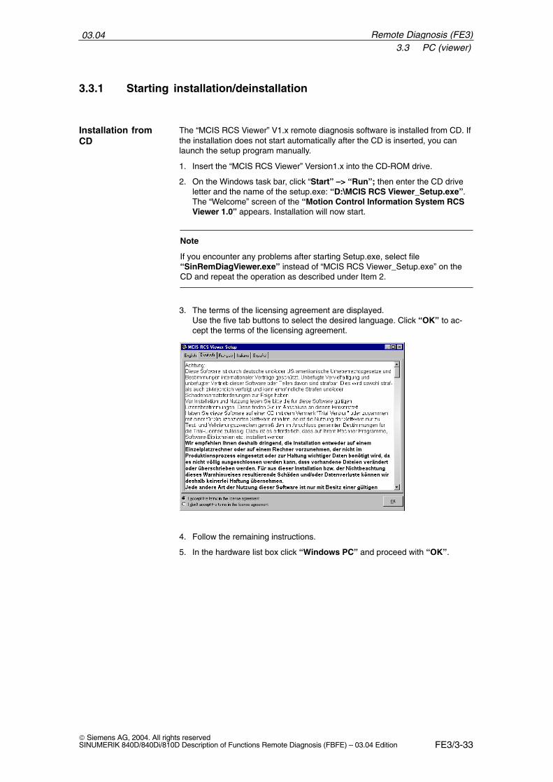
03.043.3 PC (viewer)
FE3/3-33 Siemens AG, 2004. All rights reservedSINUMERIK 840D/840Di/810D Description of Functions Remote Diagnosis (FBFE) – 03.04 Edition
3.3.1 Starting installation/deinstallation
The “MCIS RCS Viewer” V1.x remote diagnosis software is installed from CD. Ifthe installation does not start automatically after the CD is inserted, you canlaunch the setup program manually.
1. Insert the “MCIS RCS Viewer” Version1.x into the CD-ROM drive.
2. On the Windows task bar, click “Start” –> “Run”; then enter the CD driveletter and the name of the setup.exe: “D:\MCIS RCS Viewer_Setup.exe”. The “Welcome” screen of the “Motion Control Information System RCSViewer 1.0” appears. Installation will now start.
Note
If you encounter any problems after starting Setup.exe, select file“SinRemDiagViewer.exe” instead of “MCIS RCS Viewer_Setup.exe” on theCD and repeat the operation as described under Item 2.
3. The terms of the licensing agreement are displayed. Use the five tab buttons to select the desired language. Click “OK” to ac-cept the terms of the licensing agreement.
4. Follow the remaining instructions.
5. In the hardware list box click “Windows PC” and proceed with “OK”.
Installation fromCD
Remote Diagnosis (FE3)
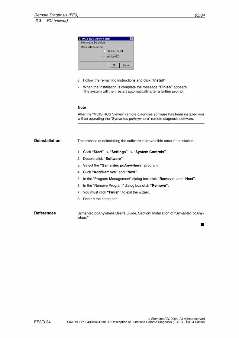
03.043.3 PC (viewer)
FE3/3-34 Siemens AG, 2004. All rights reserved
SINUMERIK 840D/840Di/810D Description of Functions Remote Diagnosis (FBFE) – 03.04 Edition
6. Follow the remaining instructions and click “Install”.
7. When the installation is complete the message “Finish” appears. The system will then restart automatically after a further prompt.
Note
After the “MCIS RCS Viewer” remote diagnosis software has been installed youwill be operating the “Symantec pcAnywhere” remote diagnosis software.
The process of deinstalling the software is irreversible once it has started.
1. Click “Start” –> “Settings” –> “System Controls”.
2. Double-click “Software”.
3. Select the “Symantec pcAnywhere” program.
4. Click “Add/Remove” and “Next”.
5. In the “Program Management” dialog box click “Remove” and “Next”.
6. In the “Remove Program” dialog box click “Remove”.
7. You must click “Finish” to exit the wizard.
8. Restart the computer.
Symantec pcAnywhere User’s Guide, Section: Installation of “Symantec pcAny-where”
�
Deinstallation
References
Remote Diagnosis (FE3)
FE3/4-35 Siemens AG, 2004. All rights reservedSINUMERIK 840D/840Di/810D Description of Functions Remote Diagnosis (FBFE) – 03.04 Edition
Start-Up and Operation
4.1 PCU 50/70 (host)
Various connection objects need to be set up before a session can take place.
Connection objects are stored data relating to connections. They are displayedwith a labeled icon in the working window. Host connection objects saved onthe PCU (host) are also known simply as “host”, particularly for the softkey la-bels (e.g. “Start Host”).
First launch the software.You may activate the “MCIS RCS Host V1.x” remote diagnosis software in
� Service mode or in
� HMI mode
on the PCU 50/70.
Activate service mode on the PCU refer to Section 3.1
Start up the remote diagnosis software via “Start” –> “Programs” –> “SINUMERIK 840D” –> “Tools” –> “Start MCISRCS Host”,
Or
Start up the remote diagnosis software via softkeys after HMI Advanced hasbooted.
1. Press the “Diagnosis” softkey.
Note
The Diagnosis operating area does not have a “Remote diagnosis” softkey,then their is no communication between the PCU and NC/PLC. In that case,you must enter at least one manufacturer password after PCU start-up.See Section: Booting the PCU in service mode.
2. Press the “Remote diagnosis” softkey. The “MCIS RCS Host V1.x” remotediagnosis starts up and the following window appears.
Activation inservice mode
Activation in HMImode
4
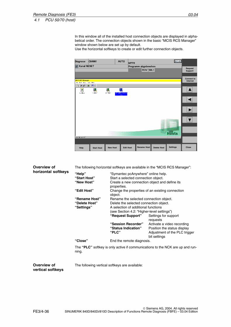
03.044.1 PCU 50/70 (host)
FE3/4-36 Siemens AG, 2004. All rights reserved
SINUMERIK 840D/840Di/810D Description of Functions Remote Diagnosis (FBFE) – 03.04 Edition
In this window all of the installed host connection objects are displayed in alpha-betical order. The connection objects shown in the basic “MCIS RCS Manager”window shown below are set up by default. Use the horizontal softkeys to create or edit further connection objects.
Start Host New HostHelp Edit Host Rename Host Delete Host Settings Close
Connect toInternet
Request Support
The following horizontal softkeys are available in the “MCIS RCS Manager”:
“Help” “Symantec pcAnywhere” online help.“Start Host” Start a selected connection object.“New Host” Create a new connection object and define its
properties.“Edit Host” Change the properties of an existing connection
object.“Rename Host” Rename the selected connection object.“Delete Host” Delete the selected connection object.“Settings” A selection of additional functions
(see Section 4.2: “Higher-level settings”)“Request Support” Settings for support
requests“Session Recorder” Activate a video recording“Status Indication” Position the status display“PLC” Adjustment of the PLC trigger
bit settings“Close” End the remote diagnosis.
The “PLC” softkey is only active if communications to the NCK are up and run-ning.
The following vertical softkeys are available:
Overview ofhorizontal softkeys
Overview ofvertical softkeys
Remote Diagnosis (FE3)
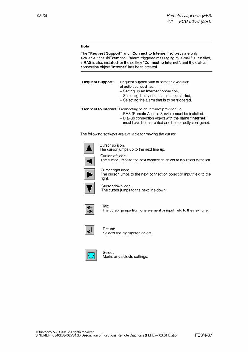
03.044.1 PCU 50/70 (host)
FE3/4-37 Siemens AG, 2004. All rights reservedSINUMERIK 840D/840Di/810D Description of Functions Remote Diagnosis (FBFE) – 03.04 Edition
Note
The “Request Support” and “Connect to Internet” softkeys are onlyavailable if the @Event tool: “Alarm-triggered messaging by e-mail” is installed,if RAS is also installed for the softkey “Connect to Internet”, and the dial-upconnection object “Internet” has been created.
“Request Support” Request support with automatic execution of activities, such as:
– Setting up an Internet connection,– Selecting the symbol that is to be started,– Selecting the alarm that is to be triggered.
“Connect to Internet” Connecting to an Internet provider, i.e.– RAS (Remote Access Service) must be installed.– Dial-up connection object with the name “Internet” must have been created and be correctly configured.
The following softkeys are available for moving the cursor:
Cursor up icon: The cursor jumps up to the next line up.
Cursor left icon: The cursor jumps to the next connection object or input field to the left.
Cursor right icon:The cursor jumps to the next connection object or input field to theright.
Cursor down icon:The cursor jumps to the next line down.
Tab:The cursor jumps from one element or input field to the next one.
Return:Selects the highlighted object.
Select:Marks and selects settings.
Remote Diagnosis (FE3)
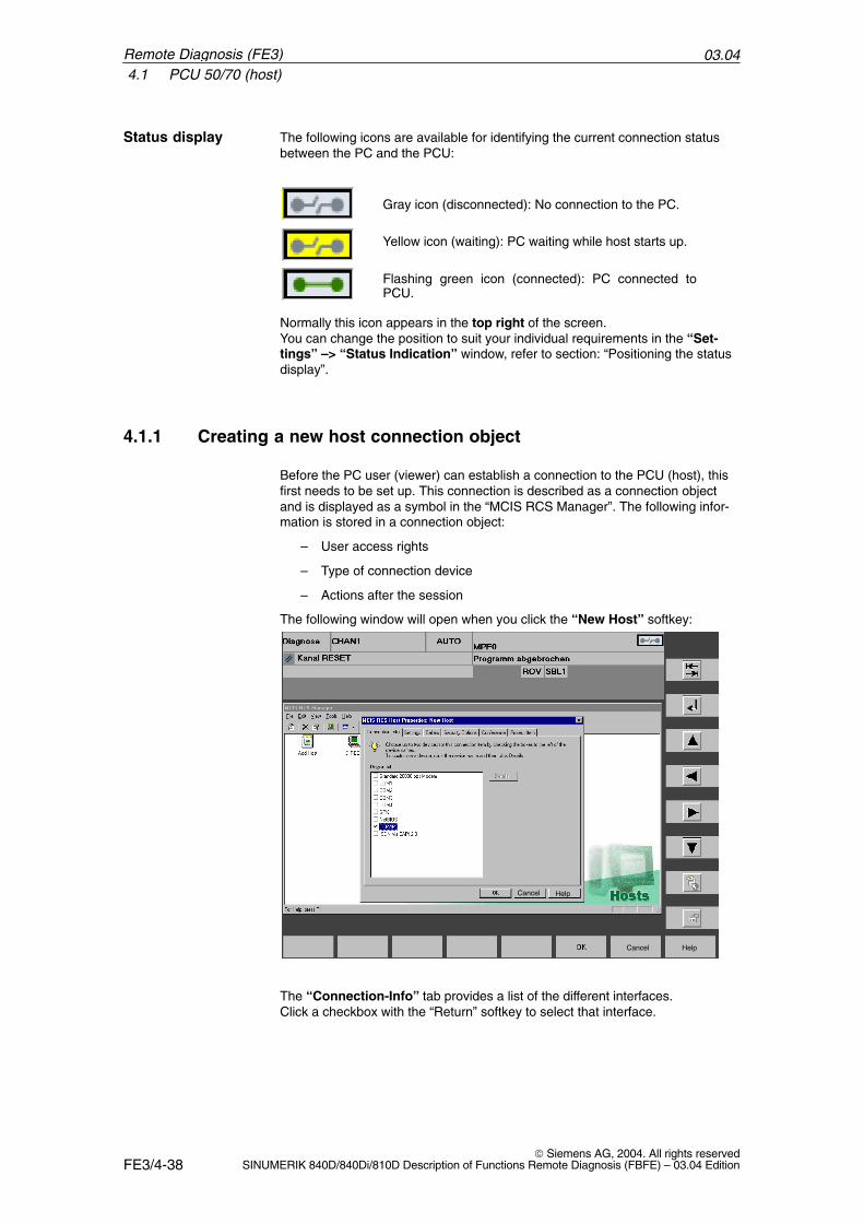
03.044.1 PCU 50/70 (host)
FE3/4-38 Siemens AG, 2004. All rights reserved
SINUMERIK 840D/840Di/810D Description of Functions Remote Diagnosis (FBFE) – 03.04 Edition
The following icons are available for identifying the current connection statusbetween the PC and the PCU:
Gray icon (disconnected): No connection to the PC.
Yellow icon (waiting): PC waiting while host starts up.
Flashing green icon (connected): PC connected toPCU.
Normally this icon appears in the top right of the screen. You can change the position to suit your individual requirements in the “Set-tings” –> “Status Indication” window, refer to section: “Positioning the statusdisplay”.
4.1.1 Creating a new host connection object
Before the PC user (viewer) can establish a connection to the PCU (host), thisfirst needs to be set up. This connection is described as a connection objectand is displayed as a symbol in the “MCIS RCS Manager”. The following infor-mation is stored in a connection object:
– User access rights
– Type of connection device
– Actions after the session
The following window will open when you click the “New Host” softkey:
Cancel Help
Cancel Help
The “Connection-Info” tab provides a list of the different interfaces. Click a checkbox with the “Return” softkey to select that interface.
Status display
Remote Diagnosis (FE3)
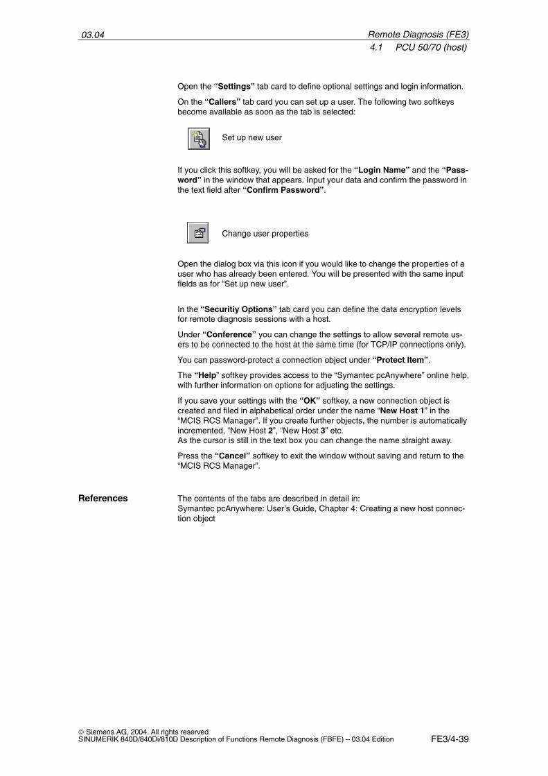
03.044.1 PCU 50/70 (host)
FE3/4-39 Siemens AG, 2004. All rights reservedSINUMERIK 840D/840Di/810D Description of Functions Remote Diagnosis (FBFE) – 03.04 Edition
Open the “Settings” tab card to define optional settings and login information.
On the “Callers” tab card you can set up a user. The following two softkeysbecome available as soon as the tab is selected:
Set up new user
If you click this softkey, you will be asked for the “Login Name” and the “Pass-word” in the window that appears. Input your data and confirm the password inthe text field after “Confirm Password”.
Change user properties
Open the dialog box via this icon if you would like to change the properties of auser who has already been entered. You will be presented with the same inputfields as for “Set up new user”.
In the “Securitiy Options” tab card you can define the data encryption levelsfor remote diagnosis sessions with a host.
Under “Conference” you can change the settings to allow several remote us-ers to be connected to the host at the same time (for TCP/IP connections only).
You can password-protect a connection object under “Protect Item”.
The “Help” softkey provides access to the “Symantec pcAnywhere” online help,with further information on options for adjusting the settings.
If you save your settings with the “OK” softkey, a new connection object iscreated and filed in alphabetical order under the name “New Host 1” in the“MCIS RCS Manager”. If you create further objects, the number is automaticallyincremented, “New Host 2”, “New Host 3” etc. As the cursor is still in the text box you can change the name straight away.
Press the “Cancel” softkey to exit the window without saving and return to the“MCIS RCS Manager”.
The contents of the tabs are described in detail in:Symantec pcAnywhere: User’s Guide, Chapter 4: Creating a new host connec-tion object
References
Remote Diagnosis (FE3)
03.044.1 PCU 50/70 (host)
FE3/4-40 Siemens AG, 2004. All rights reserved
SINUMERIK 840D/840Di/810D Description of Functions Remote Diagnosis (FBFE) – 03.04 Edition
4.1.2 Changing/renaming/deleting a connection object
After selecting an object, press the “Edit Host” softkey if you want to view orchange the properties of a connection object. The same dialog boxes will beavailable as for “New Host”.
A detailed description of all settings and entries can be found in the followingpublication:Symantec pcAnywhere: User’s Guide, Chapter 4: Editing a host connectionobject
In the MCIS RCS Manager select a connection object and press the “RenameHost” softkey. The cursor will jump straight to the name field under the connec-tion object. Enter the new name and press the Return softkey to save the entry.The revised object symbol is filed in alphabetical order in the overview windowof the “MCIS RCS Manager”.
Select a connection object and press the “Delete Host” softkey.The followingsafety prompt will appear: “Delete the selected item?”. Click “Yes” to deletethe connection object, click “No” to return to the “MCIS RCS Manager”.
4.1.3 Starting up a connection object
On the MCIS RCS Manager select a connection object and press the “StartHost” softkey. While the PCU is waiting for a connection from an authorizedremote user, the softkey changes to “Close Host”. You can use the “Close Host” softkey to cancel or abort the function.
Editing the host
References
Renaming a host
Deleting a host
Starting up a host
Remote Diagnosis (FE3)
03.044.2 Higher-level settings
FE3/4-41 Siemens AG, 2004. All rights reservedSINUMERIK 840D/840Di/810D Description of Functions Remote Diagnosis (FBFE) – 03.04 Edition
4.2 Higher-level settings
Press the “Settings” softkey to access the following additional functions:
– “Request Support” Settings for support requests:– Select the operating mode,– Establish an Internet connection,– Select the symbol to be started,– Select the alarm to be triggered.
– “Session Recorder” – Activate/deactivate a video recording, – Define the storage path of the video file.
– “Status Indication” – Position the status display icon on the screen.– Define the statuses to be indicated.
– “PLC” – Define the PLC bit that automatically activates remote diagnosis.– Set the status bits for displaying a current connection.
The @Event: “Alarm-triggered messaging by e-mail” tool must be installed inorder to activate the “Request Support” and “Connect to Internet” softkeys.
The “PLC” softkey is only active if there is a connection from the PCU to theNCK.
“Settings” softkey
Precondition
Remote Diagnosis (FE3)
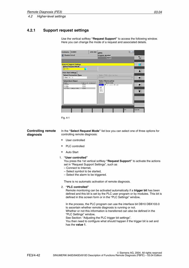
03.044.2 Higher-level settings
FE3/4-42 Siemens AG, 2004. All rights reserved
SINUMERIK 840D/840Di/810D Description of Functions Remote Diagnosis (FBFE) – 03.04 Edition
4.2.1 Support request settings
Use the vertical softkey “Request Support” to access the following window.Here you can change the mode of a request and associated details.
Fig. 4-1
In the “Select Request Mode” list box you can select one of three options forcontrolling remote diagnosis:
� User controlled
� PLC controlled
� Auto Start
1. “User controlled”You press the 1st vertical softkey “Request Support” to activate the actionsset in “Request Support Settings”, such as– Connect to Internet,– Select symbol to be started,– Select the alarm to be triggered.
There is no automatic activation of remote diagnosis.
2. “PLC controlled”Remote monitoring can be activated automatically if a trigger bit has beendefined and this bit is set by the PLC user program or by modules. This bit isdefined in this screen form or in the “PLC Settings” window.
In the process, the PLC program can use the interface bit DB10 DBX103.0to ascertain whether remote diagnosis is running or not. Whether or not this information is transferred can also be defined in the“PLC Settings” window.See Section: “Adjusting the PLC trigger bit settings”. You then need to configure what should happen if the trigger bit is set andhas the value 1.
Controlling remotediagnosis
Remote Diagnosis (FE3)
03.044.2 Higher-level settings
FE3/4-43 Siemens AG, 2004. All rights reservedSINUMERIK 840D/840Di/810D Description of Functions Remote Diagnosis (FBFE) – 03.04 Edition
Select the “Request Bit On” tab card and enter:– The connection type under “Select Connection Type”; if “With Internet” is
selected then you must also select “Dial-up Network”– The host connection object under “Select Host Object” (selection),– An alarm to be triggered under “Select Alarm Number” (selection).
If the trigger bit has the value 0, you will also need to make the correspond-ing entries in the “Request Bit Off” tab card.
3. “Auto Start” (as from RCS Host Version 1.1)
� In Service Mode, without the HMI running, you can operate the “MCIS RCSManager” and still make change to the objects.
� On the PCU on the HMI, you can start a host object immediately in the“Diagnosis” operating area by selecting the “Remote diagnosis” soft-ware. You must have selected it in the “Request Support” display first.
– Once a connection is up, “MCIS RCS Host” is minimized, becoming asmall icon on the task bar.
– If the previously defined host object cannot be started, an error messageis displayed and “MCIS RCS Host” is ended.
– If a host object has already been started or a connection is already upwhen the “Remote diagnosis” softkey is selected, the host object isended and “MCIS RCS Host” is closed.
Under “Select Host Object” select the host connection object you want tostart.
If you would like this connection to be established via the Internet, go to “SelectConnection Type” and select “With Internet”. The “Select RAS Connection” selection box next to it becomes active and youcan use the small arrow switch to the right to select a dial-up connection. Choose “Without Internet” if the selected connection type is for example adirect, modem to modem or Ethernet connection.
Under “Alarms” select an alarm number for the connection object. All alarmscan be parameterized in the @Event tool and sent by e-mail to the respectiveaddresses. These addresses are displayed in the right-hand window under“Failure Case”.
When you do not want an alarm number to appear when you start a host object,set “None” (as from RCS Host Version 1.1).
Click “OK” to save the settings.
Press “Cancel” to exit the window without saving and return to the MCIS RCSManager overview window.
Selecting a hostobject
Connection type
Sending an alarmmessage
Remote Diagnosis (FE3)
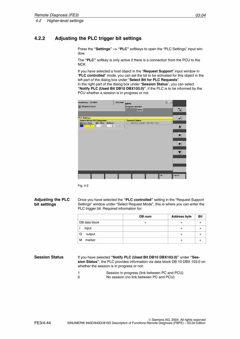
03.044.2 Higher-level settings
FE3/4-44 Siemens AG, 2004. All rights reserved
SINUMERIK 840D/840Di/810D Description of Functions Remote Diagnosis (FBFE) – 03.04 Edition
4.2.2 Adjusting the PLC trigger bit settings
Press the “Settings” –> “PLC” softkeys to open the “PLC Settings” input win-dow.
The “PLC” softkey is only active if there is a connection from the PCU to theNCK.
If you have selected a host object in the “Request Support” input window in“PLC controlled” mode, you can set the bit to be activated for this object in theleft part of the dialog box under “Select Bit for PLC Requests”. In the right part of the dialog box under “Session Status”, you can select“Notify PLC (Used Bit DB10 DBX103.0)”, if the PLC is to be informed by thePCU whether a session is in progress or not.
Fig. 4-2
Once you have selected the “PLC controlled” setting in the “Request SupportSettings” window under “Select Request Mode”, this is where you can enter thePLC trigger bit. Required information for:
DB num Address byte Bit
DB data block + + +
I input + +
Q output + +
M marker + +
If you have selected “Notify PLC (Used Bit DB10 DBX103.0)” under “Ses-sion Status”, the PLC provides information via data block DB 10 DBX 103.0 onwhether the session is in progress or not:
1 Session in progress (link between PC and PCU)0 No session (no link between PC and PCU)
Adjusting the PLCbit settings
Session Status
Remote Diagnosis (FE3)
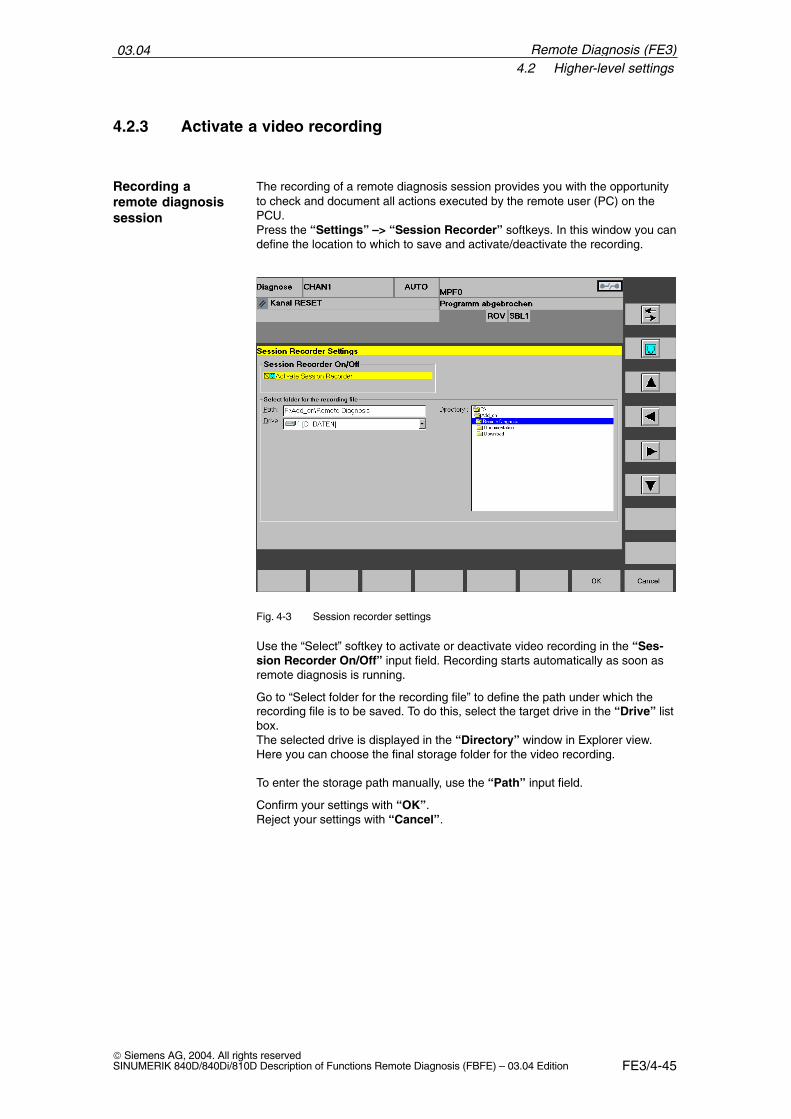
03.044.2 Higher-level settings
FE3/4-45 Siemens AG, 2004. All rights reservedSINUMERIK 840D/840Di/810D Description of Functions Remote Diagnosis (FBFE) – 03.04 Edition
4.2.3 Activate a video recording
The recording of a remote diagnosis session provides you with the opportunityto check and document all actions executed by the remote user (PC) on thePCU. Press the “Settings” –> “Session Recorder” softkeys. In this window you candefine the location to which to save and activate/deactivate the recording.
Fig. 4-3 Session recorder settings
Use the “Select” softkey to activate or deactivate video recording in the “Ses-sion Recorder On/Off” input field. Recording starts automatically as soon asremote diagnosis is running.
Go to “Select folder for the recording file” to define the path under which therecording file is to be saved. To do this, select the target drive in the “Drive” listbox. The selected drive is displayed in the “Directory” window in Explorer view.Here you can choose the final storage folder for the video recording.
To enter the storage path manually, use the “Path” input field.
Confirm your settings with “OK”.Reject your settings with “Cancel”.
Recording aremote diagnosissession
Remote Diagnosis (FE3)
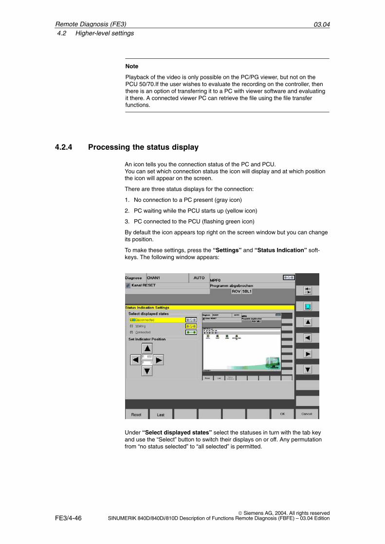
03.044.2 Higher-level settings
FE3/4-46 Siemens AG, 2004. All rights reserved
SINUMERIK 840D/840Di/810D Description of Functions Remote Diagnosis (FBFE) – 03.04 Edition
Note
Playback of the video is only possible on the PC/PG viewer, but not on thePCU 50/70.If the user wishes to evaluate the recording on the controller, thenthere is an option of transferring it to a PC with viewer software and evaluatingit there. A connected viewer PC can retrieve the file using the file transferfunctions.
4.2.4 Processing the status display
An icon tells you the connection status of the PC and PCU. You can set which connection status the icon will display and at which positionthe icon will appear on the screen.
There are three status displays for the connection:
1. No connection to a PC present (gray icon)
2. PC waiting while the PCU starts up (yellow icon)
3. PC connected to the PCU (flashing green icon)
By default the icon appears top right on the screen window but you can changeits position.
To make these settings, press the “Settings” and “Status Indication” soft-keys. The following window appears:
Under “Select displayed states” select the statuses in turn with the tab keyand use the “Select” button to switch their displays on or off. Any permutationfrom “no status selected” to “all selected” is permitted.
Remote Diagnosis (FE3)
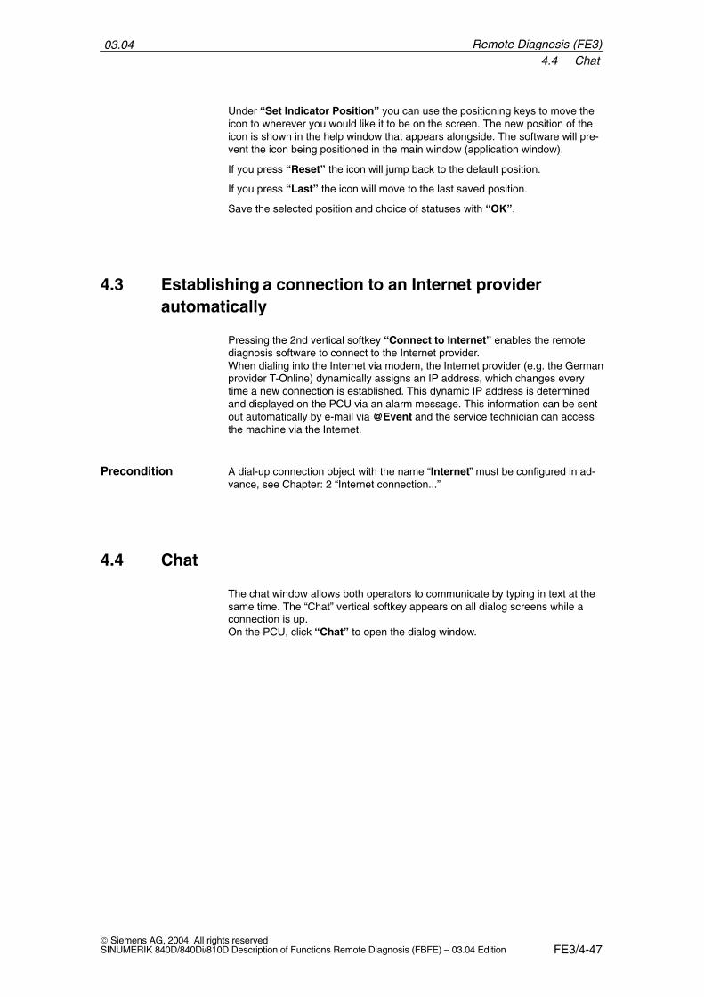
03.044.4 Chat
FE3/4-47 Siemens AG, 2004. All rights reservedSINUMERIK 840D/840Di/810D Description of Functions Remote Diagnosis (FBFE) – 03.04 Edition
Under “Set Indicator Position” you can use the positioning keys to move theicon to wherever you would like it to be on the screen. The new position of theicon is shown in the help window that appears alongside. The software will pre-vent the icon being positioned in the main window (application window).
If you press “Reset” the icon will jump back to the default position.
If you press “Last” the icon will move to the last saved position.
Save the selected position and choice of statuses with “OK”.
4.3 Establishing a connection to an Internet providerautomatically
Pressing the 2nd vertical softkey “Connect to Internet” enables the remotediagnosis software to connect to the Internet provider.When dialing into the Internet via modem, the Internet provider (e.g. the Germanprovider T-Online) dynamically assigns an IP address, which changes everytime a new connection is established. This dynamic IP address is determinedand displayed on the PCU via an alarm message. This information can be sentout automatically by e-mail via @Event and the service technician can accessthe machine via the Internet.
A dial-up connection object with the name “Internet” must be configured in ad-vance, see Chapter: 2 “Internet connection...”
4.4 Chat
The chat window allows both operators to communicate by typing in text at thesame time. The “Chat” vertical softkey appears on all dialog screens while aconnection is up.On the PCU, click “Chat” to open the dialog window.
Precondition
Remote Diagnosis (FE3)
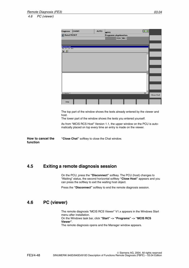
03.044.6 PC (viewer)
FE3/4-48 Siemens AG, 2004. All rights reserved
SINUMERIK 840D/840Di/810D Description of Functions Remote Diagnosis (FBFE) – 03.04 Edition
The top part of the window shows the texts already entered by the viewer andhost.The lower part of the window shows the texts you entered yourself.
As from “MCIS RCS Host” Version 1.1, the upper window on the PCU is auto-matically placed on top every time an entry is made on the viewer.
“Close Chat” softkey to close the Chat window.
4.5 Exiting a remote diagnosis session
On the PCU, press the “Disconnect” softkey. The PCU (host) changes to“Waiting” status, the second horizontal softkey “Close Host” appears and youcan press the softkey to exit the waiting host object.
Press the “Disconnect” softkey to end the remote diagnosis session.
4.6 PC (viewer)
The remote diagnosis “MCIS RCS Viewer” V1.x appears in the Windows Startmenu after installation.On the Windows task bar, click “Start” –> “Programs” –> “MCIS RCSViewer”.The remote diagnosis opens and the Manager window appears.
How to cancel thefunction
Remote Diagnosis (FE3)
03.044.6 PC (viewer)
FE3/4-49 Siemens AG, 2004. All rights reservedSINUMERIK 840D/840Di/810D Description of Functions Remote Diagnosis (FBFE) – 03.04 Edition
Requirements:– Modem connection between PC/PG and PCU– A telephone must be connected to each modem– Only the viewer can use the telephone and continue monitorinvia the same
connection
Before the remote diagnosis session starts it is possible to conduct a telephoneconversation with the PCU user (host). After the end of the conversation theconnection remains intact and immediately switches to data transfer mode. ThePC user (viewer) starts the remote diagnosis session.
All operations can be carried out in the same way as operations on thecontroller. The MCP cannot be operated.
For details of the operation of the remote diagnosis software please refer to thedescription “Symantec pcAnywhere, User’s Guide”.
!Caution
To activate the machine control panel function, the viewer must request theoperator at the control to perform the necessary actions via Chat or a phonelink.The operator at the control is responsible for ensuring that the actions can beexecuted without any danger to man or machine. If it is not possible to perform a particular operation safely the operator on thecontroller must refuse it. The viewer cannot see the state of the machine or itssafety equipment.
In “Remote Control” mode you can see the PCU screen on your PC screenand operate HMI Advanced using your mouse and keyboard. You can activatesoftkeys by double-clicking them with the mouse or by means of the functionkeys. The horizontal softkeys SK1 to SK8 correspond to function keys F1 to F8,“Recall” corresponds to F9 and “Operating area switchover” to F10. Thevertical softkeys are reached, starting from the top, by means of Shift + F1 toShift + F8. You can operate all areas of the HMI and the PCU from the viewerPC.
Voice connections
Actions on the PC(viewer)
References
Operation of thePCU
Remote Diagnosis (FE3)
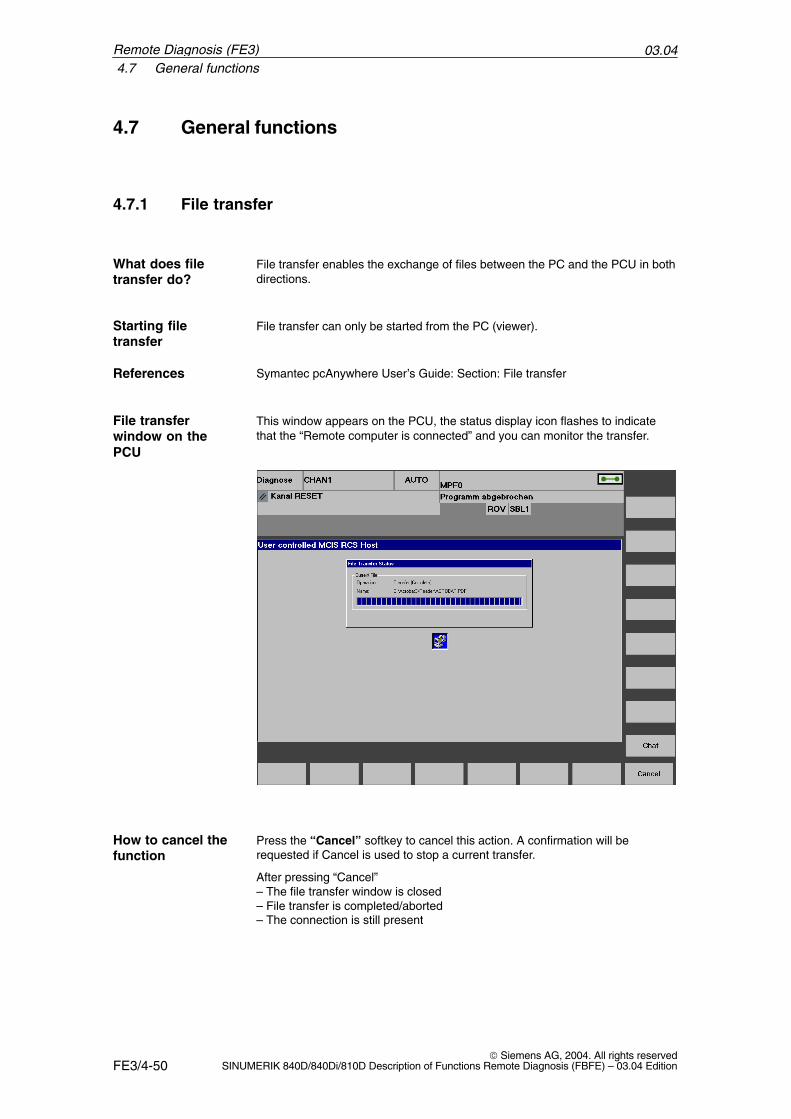
03.044.7 General functions
FE3/4-50 Siemens AG, 2004. All rights reserved
SINUMERIK 840D/840Di/810D Description of Functions Remote Diagnosis (FBFE) – 03.04 Edition
4.7 General functions
4.7.1 File transfer
File transfer enables the exchange of files between the PC and the PCU in bothdirections.
File transfer can only be started from the PC (viewer).
Symantec pcAnywhere User’s Guide: Section: File transfer
This window appears on the PCU, the status display icon flashes to indicatethat the “Remote computer is connected” and you can monitor the transfer.
Press the “Cancel” softkey to cancel this action. A confirmation will berequested if Cancel is used to stop a current transfer.
After pressing “Cancel”– The file transfer window is closed– File transfer is completed/aborted– The connection is still present
What does filetransfer do?
Starting filetransfer
References
File transferwindow on thePCU
How to cancel thefunction
Remote Diagnosis (FE3)
03.044.8 Help
FE3/4-51 Siemens AG, 2004. All rights reservedSINUMERIK 840D/840Di/810D Description of Functions Remote Diagnosis (FBFE) – 03.04 Edition
4.8 Help
The “Symantec pcAnywhere” online help can be accessed at any time duringoperation.
The following documents covering installation and operation of the remote diag-nosis software are available in pdf format:– Symantec pcAnywhere, User’s Guide– Symantec pcAnywhere, Administrator’s Guide – Short Guide: “What’s New”
You can also contact the hotline.
Up-to-date information can be found on the Intranet under http://www.ad.siemens.de/csinfo.
�
Remote Diagnosis (FE3)

03.044.8 Help
FE3/4-52 Siemens AG, 2004. All rights reserved
SINUMERIK 840D/840Di/810D Description of Functions Remote Diagnosis (FBFE) – 03.04 Edition
Remote Diagnosis (FE3)
Notes
FE3/5-53 Siemens AG, 2004. All rights reservedSINUMERIK 840D/840Di/810D Description of Functions Remote Diagnosis (FBFE) – 03.04 Edition
Alarms
No signals or machine data are required for this function.
5.1 Alarms
The @Event tool must be installed and active.
The following internal alarms are available and can be implemented via the set-tings in the “Request Support“ dialog window:
User controlled: 142000 to 142004: The operator on the machine is waiting for assistance viaremote control.
PLC controlled: 142005 to 142009: The machine is ready for remote diagnosis.
If a host object is started manually.142010: The operator on the machine is waiting for assistance via remote diag-nosis.
Press the following softkeys: “Diagnosis” –> “Alarms” –> “Confirm MMCAlarms” to delete the alarm message.
�
Precondition
Cancel an alarm
5

03.045.1 Alarms
FE3/5-54 Siemens AG, 2004. All rights reserved
SINUMERIK 840D/840Di/810D Description of Functions Remote Diagnosis (FBFE) – 03.04 Edition
Remote Diagnosis (FE3)
Notes
A-55 Siemens AG, 2004. All rights reservedSINUMERIK 840D/840Di/810D Description of Functions Remote Diagnosis (FBFE) – 03.04 Edition
References
General Documentation
SINUMERIK & SIMODRIVE, Automation Systems for Machine ToolsCatalog NC 60Order number: E86060-K4460-A101-A9-7600
Industrial Communication and Field DevicesCatalog IK PI Order number: E86060-K6710-A101-B2-7600
SIMATICProducts for Totally Integrated Automation and Micro AutomationCatalog ST 70Order number: E86060-K4670-A111-A8-7600
MOTION-CONNECTConnections & System Components for SIMATIC, SINUMERIK, MASTERDRIVES, and SIMOTIONCatalog NC ZOrder number: E86060-K4490-A001-B1-7600
Safety Integrated Application ManualThe safety program for the industries of the worldOrder number: 6ZB5000-0AA02-0BA0
Electronic Documentation
The SINUMERIK System (03.04 Edition)DOC ON CD(includes all SINUMERIK 840D/840Di/810D/802 and SIMODRIVE publications)Order number: 6FC5298-7CA00-0BG0
/BU/
/IKPI/
/ST7/
/Z/
/CD1/
A
03.04
A-56 Siemens AG, 2004. All rights reserved
SINUMERIK 840D/840Di/810D Description of Functions Remote Diagnosis (FBFE) – 03.04 Edition
User Documentation
SINUMERIK 840D/810D (09.99 Edition)AutoTurn Short Operating Guide Order number: 6FC5298-4AA30-0BP2
SINUMERIK 840D/810D (02.02 Edition)AutoTurn Graphic Programming SystemProgramming/SetupOrder number: 6FC5298-4AA40-0BP3
SINUMERIK 840D/810D (10.00 Edition)MMC Operator’s Guide Order number: 6FC5298-6AA00-0BP0
SINUMERIK 840D/840Di/810D (03.04 Edition)Operator’s Guide HMI AdvancedOrder number: 6FC5298-6AF00-0BP3
SINUMERIK 840D/840Di/810D (03.04 Edition)Operator’s Guide HT 6 Order number: 6FC5298-0AD60-0BP3
SINUMERIK 840D/840Di/810D (02.01 Edition)Short Operating Guide Order number: 6FC5298-6AA10-0BP0
SINUMERIK 810D/840D (08.02 Edition)ManualTurn Operator’s GuideOrder number: 6FC5298-6AD00-0BP0
SINUMERIK 840D/840Di/810D (11.03 Edition)Operator’s Guide ShopMillOrder number: 6FC5298-6AD10-0BP2
SINUMERIK 840D/810D (06.03 Edition)Operator’s Guide ShopTurnOrder number: 6FC5298-6AD50-0BP2
SINUMERIK 840D/810D (03.04 Edition)Operator’s Guide HMI EmbeddedOrder number: 6FC5298-6AC00-0BP3
SINUMERIK 840D840Di/810D (03.04 Edition)Operator’s Guide Measuring Cycles Order number: 6FC5298-6AA70-0BP3
SINUMERIK 840D/840Di/810D (04.03 Edition)Motion Control Information System (MCIS)User’s Guide Tool Data Information Order number: 6FC5297-6AE01-0BP0
/AUK/
/AUP/
/BA/
/BAD/
/BAH/
/BAK/
/BAM/
/BAS/
/BAT/
/BEM/
/BNM/
/BTDI/
03.04
03.04
A-57 Siemens AG, 2004. All rights reservedSINUMERIK 840D/840Di/810D Description of Functions Remote Diagnosis (FBFE) – 03.04 Edition
SINUMERIK 840D/840Di/810D (03.02 Edition)Operator’s Guide CAD ReaderOrder number: (part of the online help)
SINUMERIK 840D/840Di/810D (03.04 Edition)Diagnostics GuideOrder number: 6FC5298-7AA20-0BP0
SINUMERIK 840D/810D (04.01 Edition)Short Guide ManualTurn Order number: 6FC5298-5AD40-0BP0
SINUMERIK 840D/810D (04.01 Edition)Short Guide ShopMill Order number: 6FC5298-5AD30-0BP0
SINUMERIK 840D/810D (07.01 Edition)Short Guide ShopTurn Order number: 6FC5298-6AF20-0BP0
SINUMERIK 840D/840Di/810D (03.04 Edition)Programming Guide Fundamentals Order number: 6FC5298-7AB00-0BP0
SINUMERIK 840D/840Di/810D (03.04 Edition)Programming Guide Advanced Order number: 6FC5298-7AB10-0BP0
SINUMERIK 840D/840Di/810D (03.04 Edition)Lists Manual System Variables Order number: 6FC5298-7AE10-0BP0
SINUMERIK 840D/840Di/810D (03.04 Edition)Short Guide ProgrammingOrder number: 6FC5298-7AB30-0BP0
SINUMERIK 840D/840Di/810D (11.02 Edition)Programming Guide ISO MillingOrder number: 6FC5298-6AC20-0BP2
SINUMERIK 840D/840Di/810D (11.02 Edition) Programming Guide ISO TurningOrder number: 6FC5298-6AC10-0BP2
SINUMERIK 840D840Di//810D (03.04 Edition)Programming Guide Cycles Order number: 6FC5298-7AB40-0BP0
/CAD/
/DA/
/KAM/
/KAS/
/KAT/
/PG/
/PGA/
/PGA1/
/PGK/
/PGM/
/PGT/
/PGZ/
03.04
03.04
A-58 Siemens AG, 2004. All rights reserved
SINUMERIK 840D/840Di/810D Description of Functions Remote Diagnosis (FBFE) – 03.04 Edition
PCIN 4.4Software for Data Transfer to/from MMC ModulesOrder number: 6FX2060-4AA00-4XB0 (English, German, French)Order from: WK Fürth
SINUMERIK 840Di (02.01 Edition)System OverviewOrder number: 6FC5298-6AE40-0BP0
Manufacturer/Service Documentation
SINUMERIK 840D/840Di/810D (03.04 Edition)SIMODRIVE 611DListsOrder number: 6FC5297-7AB70-0BP0
SIMODRIVE (10.03 Edition)Planning Guide General Part for Asynchronous MotorsOrder number: 6SN1197-0AC62-0BP0
SIMODRIVE (10.03 Edition)Planning Guide Asynchronous Motors 1PH2Order number: 6SN1197-0AC63-0BP0
SIMODRIVE (10.03 Edition)Planning Guide Asynchronous Motors 1PH4Order number: 6SN1197-0AC64-0BP0
MASTERDRIVES VC/MC (04.04 edition)Planning Guide Asynchronous Motors 1PH7Order number: 6SN1197-0AC66-0BP0
SIMODRIVE (01.04 edition)Planning Guide Asynchronous Motors 1PH7Order number: 6SN1197-0AC65-0BP0
MASTERDRIVES VC/MC (01.04 Edition)Planning Guide Asynchronous Motors 1PL6Order number: 6SN1197-0AC67-0BP0
SINUMERIK 840D/840Di/810D (11.03 Edition)Operator Components ManualOrder number: 6FC5297-6AA50-0BP3
/PI/
/SYI/
a) Lists
/LIS/
b) Hardware
/ASAL/
/APH2/
/APH4/
/APH7M/
/APH7S/
/APL6/
/BH/
03.04
A-59 Siemens AG, 2004. All rights reservedSINUMERIK 840D/840Di/810D Description of Functions Remote Diagnosis (FBFE) – 03.04 Edition
SIMODRIVE Sensor (03.03 Edition)Absolute Encoder with Profibus DP User’s Guide (HW)Order number: 6SN1197-0AB10-0YP2
SINUMERIK, SIROTEC, SIMODRIVE (06.99 Edition)Planning Guide EMC Installation GuideOrder number: 6FC5297-0AD30-0BP1
The up-to-date declaration of conformity can be viewed on the Internet athttp://www4.ad.siemens.dePlease enter the ID No.: 15257461 in the “Find”/“Search” field (upper right) andclick “go”.
SINUMERIK/SIMOTION (02.03 Edition)ADI4 – Analog Drive Interface for 4 AxesManualOrder number: 6FC5297-0BA01-0BP1
SIMODRIVE 611, SIMOVERT MASTERDRIVES MC (05.03 Edition)Planning Guide Synchronous Servo Motors 1FK6Order number: 6SN1197-0AD05-0BP0
SIMODRIVE 611, SIMOVERT MASTERDRIVES MC (01.03 Edition)Planning Guide Synchronous Servo Motors 1FK7Order number: 6SN1197-0AD06-0BP0
SIMODRIVE 611, SIMOVERT MASTERDRIVES MC (04.04 Edition)Planning Guide Synchronous Servo Motors 1FS6Order number: 6SN1197-0AD08-0BP1
SIMODRIVE (05.03 Edition)Planning Guide Synchronous Servo Motors 1FT5Order number: 6SN1197-0AD01-0BP0
SIMODRIVE 611, SIMOVERT MASTERDRIVES MC (01.04 Edition)Planning Guide Synchronous Servo Motors 1FT6Order number: 6SN1197-0AD02-0BP0
SINAMICS, SIMOVERT MASTERDRIVES (09.03 Edition) MICROMASTERSIEMOSYN Motors 1FU8Order number: 6SN1197-0AC80-0BP0
SINUMERIK 810D (11.02 Edition)Configuring Manual (HW)Order number: 6FC5297-6AD10-0BP1
SINUMERIK 840D (11.03 Edition)Configuring Manual (HW)Order number: 6FC5297-6AC10-0BP3
/BHA/
/EMV/
/GHA/
/PFK6/
/PFK7/
/PFS6/
/PFT5/
/PFT6/
/PFU/
/PHC/
/PHD/
03.04
A-60 Siemens AG, 2004. All rights reserved
SINUMERIK 840D/840Di/810D Description of Functions Remote Diagnosis (FBFE) – 03.04 Edition
SIMODRIVE 611, SIMOVERT MASTERDRIVES MC (01.04 Edition)Planning Guide Synchronous Servo MotorsGeneral Part for 1FT/1FK MotorsOrder number: 6SN1197-0AD07-0BP0
SIMODRIVE, MASTERDRIVES (06.04 Edition)Planning Guide for Asynchronous MotorsContent: General Part, 1PH2, 1PH4, 1PH7, 1PL6Order number: 6SN1197-0AC61-0BP0
SIMODRIVE (03.04 Edition)Planning Guide Built-In Synchronous Motors 1FE1 Three-Phase AC Motors for Main Spindle DrivesOrder number: 6SN1197-0AC00-0BP4
SIMODRIVE (12.02 Edition)Installation Guide Built-In Synchronous Motors 1FE1 051.-1FE1 147.Three-Phase AC Motors for Main Spindle DrivesOrder number: 610.43000.02
SIMODRIVE (06.02 Edition)Planning Guide Linear Motors 1FN1, 1FN3ALL General Information on the Linear Motor1FN1 Three-Phase AC Linear Motor 1FN11FN3 Three-Phase AC Linear Motor 1FN3CON ConnectionsOrder number: 6SN1197-0AB70-0BP3
SIMODRIVE 611, SIMOVERT MASTERDRIVES (11.00 Edition)Planning Guide Servo Motors Three-Phase Motors for Feed and Main Spindle DrivesOrder number: 6SN1197-0AC20-0BP4
SIMODRIVE, MASTERDRIVES MC (06.04 Edition)Planning Guide for Synchronous Servo MotorsContent: General Part, 1FT5, 1FT6, 1FK6, 1FK7, 1FS6Order number: 6SN1197-0AA20-0BP0
SIMODRIVE (05.03 Edition)Planning Guide Built-In Torque Motors 1FW6Order number: 6SN1197-0AD00-0BP1
SIMODRIVE 611 (02.03 Edition)Planning Guide ConvertersOrder number: 6SN1197-0AA00-0BP6
SIMODRIVE, SIMOVERT MASTERDRIVES (03.04 Edition)Planning Guide Complete Torque Motors 1FW3Order number: 6SN1197-0AC70-0BP0
/PJAL/
/PJAS/
/PJFE/
/PJF1/
/PJLM/
/PJM/
/PJM2/
/PJTM/
/PJU/
/PKTM/
03.04
A-61 Siemens AG, 2004. All rights reservedSINUMERIK 840D/840Di/810D Description of Functions Remote Diagnosis (FBFE) – 03.04 Edition
SIMODRIVE Sensor (07.02 Edition)Planning/Installation Guide Hollow-Shaft Measuring System SIMAG HOrder number: 6SN1197-0AB30-0BP1
SIMODRIVE Sensor (03.04 edition)Planning/Installation Guide Hollow-Shaft Measuring System SIMAG H2Order number: 6SN1197-0AB31-0BP1
/PMHS/ SIMODRIVE (03.04 Edition)Installation Guide Measuring System for Main Spindle DrivesGear Wheel Encoder SIZAG2Order number: 6SN1197-0AB00-0YP3
SIMODRIVE (03.04 Edition)Planning Guide ECO Motor Spindle for Main Spindle DrivesOrder number: 6SN1197-0AD04-0BP1
SIMODRIVE (12.01 Edition)Planning Guide 1PH2 / 1PH4 / 1PH7 MotorsThree-Phase Asynchronous Motors for Main Spindle DrivesOrder number: 6SN1197-0AC60-0BP0
SIMODRIVE (11.01 Edition)Planning Guide Hollow-Shaft Motors for Main Spindle Drives 1PM4 and 1PM6Order number: 6SN1197-0AD03-0BP0
SINUMERIK 840D/840Di/810D/FM-NC (03.04 Edition)Description of Functions Basic Machine (Part 1)(the various manuals are listed below)Order number: 6FC5297-7AC20-0BP0A2 Various Interface SignalsA3 Axis Monitoring, Protection ZonesB1 Continuous Path Mode, Exact Stop and Look AheadB2 AccelerationD1 Diagnostic ToolsD2 Interactive ProgrammingF1 Travel to Fixed StopG2 Velocites, Setpoint/Actual Value Systems, Closed-Loop ControlH2 Output of Auxiliary Functions to PLCK1 Mode Group, Channels, Program Operation ModeK2 Axis Types, Coordinate Systems, Frames,
Actual-Value System for Workpiece, External Zero OffsetK4 CommunicationN2 EMERGENCY STOPP1 Traverse AxesP3 Basic PLC ProgramR1 Reference Point ApproachS1 SpindlesV1 FeedsW1 Tool Compensation
/PMH/
/PMH2/
/PMS/
/PPH/
/PPM/
c) Software
/FB1/
03.04
A-62 Siemens AG, 2004. All rights reserved
SINUMERIK 840D/840Di/810D Description of Functions Remote Diagnosis (FBFE) – 03.04 Edition
SINUMERIK 840D/840Di/810D (03.04 Edition)Description of Functions Extended Functions (Part 2) including FM-NC: turning, stepper motor(contents listed below)Order no.: 6FC5297-7AC30-0BP0A4 Digital and Analog NCK I/OsB3 Several Operator Panels and NCUsB4 Operation via PG/PCF3 Remote DiagnosisH1 Jog with/without HandwheelK3 CompensationsK5 Mode Groups, Channels, Axis ReplacementL1 FM-NC Local BusM1 Kinematic TransformationM5 MeasurementsN3 Software Cams, Position Switching SignalsN4 Punching and NibblingP2 Positioning AxesP5 OscillationR2 Rotary AxesS3 Synchronous SpindlesS5 Synchronized Actions (SW 3 and lower, higher /FBSY/)S6 Stepper Motor ControlS7 Memory ConfigurationT1 Indexing AxesW3 Tool ChangeW4 Grinding
SINUMERIK 840D/840Di/810D (03.04 Edition)Description of Functions Special Functions (Part 3)(the various manuals are listed below)Order number: 6FC5297-7AC80-0BP0F2 3-Axis to 5-Axis TransformationG1 Gantry AxesG3 Cycle TimesK6 Contour Tunnel MonitoringM3 Coupled Axes and ESRS8 Constant Workpiece Speed for Centerless GrindingS9 Setpoint Switching (S9)T3 Tangential ControlTE0 Installation and Activation of Compile CyclesTE1 Clearance ControlTE2 Analog AxisTE3 Speed/Torque Coupling Master-Slave TE4 Transformation Package HandlingTE5 Setpoint ExchangeTE6 MCS CouplingTE7 Retrace SupportTE8 Unclocked Path-Synchronous Switching Signal OutputV2 Preprocessing W5 3D Tool Radius Compensation
/FB2/
/FB3/
03.04
A-63 Siemens AG, 2004. All rights reservedSINUMERIK 840D/840Di/810D Description of Functions Remote Diagnosis (FBFE) – 03.04 Edition
SIMODRIVE 611D/SINUMERIK 840D/810D (03.04 Edition)Description of Functions Drive Functions(the various manuals are listed below)Order number: 6SN1197-0AA80-1BP1DB1 Operational Messages/Alarm ReactionsDD1 Diagnostic FunctionsDD2 Speed Control LoopDE1 Extended Drive FunctionsDF1 Enable CommandsDG1 Encoder ParameterizationDL1 Linear Motor MDDM1 Calculation of Motor/Power Section Parameters and Controller DataDS1 Current Control LoopDÜ1 Monitors/Limitations
SINUMERIK 840D/SIMODRIVE 611 DIGITAL (02.00 Edition)Description of Functions ANA MODULEOrder number: 6SN1197-0AB80-0BP0
SINUMERIK 840D (07.99 Edition)Description of Functions DigitizingOrder number: 6FC5297-4AC50-0BP0DI1 Start-UpDI2 Scanning with Tactile Sensors (scancad scan)DI3 Scanning with Lasers (scancad laser)DI4 Milling Program Generation (scancad mill)
SINUMERIK 840D/840Di/810D (09.03 Edition)Description of Functions NC Program ManagementDNC MachinesOrder number: 6FC5297-1AE81-0BP0
SINUMERIK 840D/840Di/810D (03.03 Edition)Motion Control Information System (MCIS)Description of Functions NC Program Management DNC Order number: 6FC5297-1AE80-0BP0DN1 DNC Plant / DNC CellDN2 DNC IFC SINUMERIK, NC Data Transfer via Network
SINUMERIK 840D/840Di/810D (11.02 Edition)Description of Functions ISO Dialects for SINUMERIKOrder number: 6FC5297-6AE10-0BP3
SINUMERIK 840D/810D (03.04 Edition)Motion Control Information System (MCIS)Description of Functions Remote Diagnosis Order number: 6FC5297-0AF00-0BP3FE1 Remote Diagnosis (ReachOut)FE3 RCS Host / RCS Viewer (pcAnywhere)
/FBA/
/FBAN/
/FBD/
/FBDM/
/FBDN/
/FBFA/
/FBFE/
03.04
03.04
A-64 Siemens AG, 2004. All rights reserved
SINUMERIK 840D/840Di/810D Description of Functions Remote Diagnosis (FBFE) – 03.04 Edition
SINUMERIK 840D/840Di/810D HMI Programming Package (11.02 Edition)Order number: (included with the software)
Part 1 Operator’s GuidePart 2 Description of Functions
SINUMERIK 840D/840Di/810DHMI Programming Package (03.03 Edition)ProTool/Pro Option SINUMERIKOrder number: (included with the software)
SINUMERIK 840D/SIMODRIVE 611 digital (10.03 Edition)Description of Functions HLA ModuleOrder number: 6SN1197-0AB60-0BP3
SINUMERIK 840D/840Di/810D (06.03 Edition)Motion Control Information System (MCIS)Description of Functions TDI Ident ConnectionOrder number: 6FC5297-1AE60-0BP0
SINUMERIK 840D/810D (08.02 Edition)Description of Functions ManualTurn Order number: 6FC5297-6AD50-0BP0
SINUMERIK 840D/810D (09.01 Edition)Description of Functions Configuring of OP 030 Operator Interface(the various sections are listed below)Order number: 6FC5297-6AC40-0BP0BA Operator’s GuideEU Development Environment (Configuring Package)PSE Introduction to Configuring of Operator Interface(IK Screen Kit: Software Update and Configuration)
SINUMERIK 840D (03.96 Edition)Description of Functions C-PLC ProgrammingOrder number: 6FC5297-3AB60-0BP0
SINUMERIK 840D/840Di/810D (09.03 Edition)Description of Functions Computer Link (SinCOM)Order number: 6FC5297-6AD60-0BP0NFL Interface to Central Production ComputerNPL Interface to PLC/NCK
SINUMERIK 840D/SIMODRIVE (11.03 Edition)Description of Functions SINUMERIK Safety Integrated Order number: 6FC5297-6AB80-0BP2
SINUMERIK 840D/840Di/810D (11.03 Edition)Description of Functions ShopMill Order number: 6FC5297-6AD80-0BP2
/FBH/
/FBH1/
/FBHL/
/FBIC/
/FBMA/
/FBO/
/FBP/
/FBR/
/FBSI/
/FBSP/
03.04
03.04
A-65 Siemens AG, 2004. All rights reservedSINUMERIK 840D/840Di/810D Description of Functions Remote Diagnosis (FBFE) – 03.04 Edition
SIMATIC (01.01 Edition)Description of Functions FM STEPDRIVE/SIMOSTEPOrder number: 6SN1197-0AA70-0YP4
SINUMERIK 840D/810D (03.04 Edition)Description of Functions Synchronized Actions Order number: 6FC5297-7AD40-0BP2
SINUMERIK 840D/810D (03.04 Edition)Description of Functions ShopTurnOrder number: 6FC5297-6AD70-0BP
SINUMERIK 840D/810D (01.02 Edition)IT SolutionsDescription of Functions Tool Data Communication SinTDCOrder number: 6FC5297-5AF30-0BP0
SINUMERIK 840D/810D (02.01 Edition)IT SolutionsDescription of Functions Tool Information Systems (SinTDC) with Online Help Order number: 6FC5297-6AE00-0BP0
SINUMERIK 840D/840Di/810D (01.03 Edition)Motion Control Information System (MCIS)Description of Functions Preventive Maintenance TPMOrder number: Document is included with the software
SIMODRIVE 611 universal/universal E (07.03 Edition)Description of Functions Closed-Loop Control Component for Speed Control and PositioningOrder number: 6SN1197-0AB20-0BP8
SIMODRIVE 611 universal (04.02 Edition)Installation Guide (included with every SIMODRIVE 611 universal)
SINUMERIK 840D/810D (11.02 Edition)Description of Functions Tool ManagementOrder number: 6FC5297-6AC60-0BP1
SINUMERIK 840D/840Di/810D (03.02 Edition)Manual @EventOrder number: 6AU1900-0CL20-0BA0
SINUMERIK 840Di (09.03 Edition)Manual SINUMERIK 840DiOrder number: 6FC5297-6AE60-0BP2
SINUMERIK 840D840Di//810D (06.03 Edition)System Overview Commissioning Tool SINUMERIK SinuCOM NCOrder number: (part of the Online Help for the Startup Tool)
/FBST/
/FBSY/
/FBT/
/FBTC/
/FBTD/
/FBTP/
/FBU/
/FBU2/
/FBW/
/HBA/
/HBI/
/INC/
03.04
03.04
A-66 Siemens AG, 2004. All rights reserved
SINUMERIK 840D/840Di/810D Description of Functions Remote Diagnosis (FBFE) – 03.04 Edition
SINUMERIK 840D/810D (08.01 Edition)Description of Functions HMI Embedded Configuring PackageSoftware Update, Configuration, InstallationOrder number: 6FC5297-6EA10-0BP0
/PS/ SINUMERIK 840D/810D (09.03 Edition)Planning Guide Configuring SyntaxThis publication is included with the software and available as a pdf file.
SIMODRIVE POSMO A (08.03 Edition)User Guide Decentralized Positioning Motor on PROFIBUS DPOrder number: 6SN2197-0AA00-0BP6
SIMODRIVE POSMO A (05.03 Edition)Installation Guide (included with every POSMO A)
SIMODRIVE POSMO SI/CD/CA (07.03 Edition)User Guide Distributed Servo Drive SystemsOrder number: 6SN2197-0AA20-0BP5
SIMODRIVE POSMO SI (04.02 Edition)Installation Guide (included with every POSMO SI)
SIMODRIVE POSMO CD/CA (04.02 Edition)Installation Guide (included with every POSMO CD/CA)
SIMATIC S7-300 (2002 Edition)Installation Manual Technological FunctionsOrder number: 6ES7398-8AA03-8BA0– Reference Manual: CPU data (Hardware Reference Manual)– Reference Manual: Module Data
SIMATIC S7-300 (03.97 Edition)Manual STEP 7, Fundamentals, V. 3.1Order number: 6ES7810-4CA02-8BA0
SIMATIC S7-300 (03.97 Edition)Manual STEP 7, Reference Manuals, V. 3.1Order number: 6ES7810-4CA02-8BR0
SIMATIC S7-300 (04.02 Edition)FM 353 for Stepper Drive Positioning ModuleOrder together with configuring package
SIMATIC S7-300 (04.02 Edition)FM 354 for Servo Drive Positioning ModuleOrder together with configuring package
/PJE/
/POS1/
/POS2/
/POS3/
/POS4/
/POS5/
/S7H/
/S7HT/
/S7HR/
/S7S/
/S7L/
03.04
03.04
A-67 Siemens AG, 2004. All rights reservedSINUMERIK 840D/840Di/810D Description of Functions Remote Diagnosis (FBFE) – 03.04 Edition
SIMATIC S7-300 (01.03 Edition)FM 357.2 Multimodule for Servo and Stepper DrivesOrder together with configuring package
SIMODRIVE 611-A/611-DSimoPro 3.1Program for Configuring Machine-Tool DrivesOrder number: 6SC6111-6PC00-0BA�,Order from: WK Fürth
SIMODRIVE 611 analog (10.00 Edition)Description Start-Up Software for Main Spindle and Asynchronous Motor Modules Version 3.20Order number: 6SN1197-0AA30-0BP1
SIMODRIVE 611A (10.00 Edition)Installation and Start-Up Guide Order number: 6SN1197-0AA60-0BP6
SINUMERIK 810D (11.02 Edition)Installation and Start-Up Guide (including description of SIMODRIVE 611D start-up software)Order number: 6FC5297-6AD20-0BP1
SINUMERIK 840D/SIMODRIVE 611D (03.04 Edition)Installation and Start-Up Guide (including description of SIMODRIVE 611D start-up software)Order number: 6FC5297-7AB10-0BP0
SINUMERIK 840D/840Di/810D (03.04 Edition)Installation and Start-Up Guide HMIOrder number: 6FC5297-6AE20-0BP3AE1 Updates/OptionsBE1 Expanding the Operator InterfaceHE1 Online HelpIM2 Start-Up HMI EmbeddedIM4 Start-Up HMI Advanced TX1 Setting Foreign Language Texts
/S7M/
/SP/
d) Start-up
/BS/
/IAA/
/IAC/
/IAD/
/IAM/

03.04
A-68 Siemens AG, 2004. All rights reserved
SINUMERIK 840D/840Di/810D Description of Functions Remote Diagnosis (FBFE) – 03.04 Edition
Notes
Index-69 Siemens AG, 2004. All rights reservedSINUMERIK 840D/840Di/810D Description of Functions Remote Diagnosis (FBFE) – 03.04 Edition
Index
AActivate a video recording, FE3/4-45Activating subsequently remote diagnosis
“ReachOut” for PCU 20/HT 6, FE1/4-66Adapting the Remote Diagnosis window, tips and
tricks, FE1/9-94Alarm message, sending by e-mail, FE3/4-43,
FE3/4-47Alarms, FE1/10-97, FE3/5-53Auto Start, FE3/4-43Automated installation of remote diagnosis, tips
and tricks, FE1/9-86
BBooting the PCU 50/70 in service mode,
FE3/3-30Brief description MCIS RCS Host, RCS Viewer,
FE3/1-3
CCascading of Win-Viewer to the DOS-HOST via
“Gateway”, tips and tricks, FE1/9-85Chat
Function of the viewer PC, PCU 20/HT 6,FE1/8-84
Function Viewer PC, Win32, FE1/7-81Communication via text input window, chat,
Win32, FE1/7-81Configuring access to T-Online, RCS, FE3/2-17Configuring the Internet for PCU 50, Internet,
FE1/2-26Configuring the software for HT 6, installation on
PCU 20/HT 6, FE1/4-60Configuring the software for PCU 20, installation
on PCU 20/HT 6, FE1/4-53Connecting
Cascaded configuration under WindowsNT,FE1/6-75
For Win32, FE1/6-71Under MS-DOS for PCU 20/HT 6, FE1/6-77With HMI Advanced under
Windows 95/98/2000/NT, FE1/6-71Connecting, automatic, FE3/4-43Connection devices for RCS, FE3/2-7Connection object
Create, FE3/4-38Deleting, FE3/4-40Program, FE3/4-40Renaming, FE3/4-40Starting, FE3/4-40
DDeinstalling remote diagnosis “ReachOut” on the
PCU 50, FE1/3-51Dial-up connection “Internet”, FE3/2-14Dial-up network under Win9x/2000/ME/NT,
FE3/2-12Direct connection, RCS, FE3/2-26Documentation for MCIS RCS, Symantec pcAny-
where, FE3/1-5
EEstablish Internet connection, FE1/2-35Ethernet connection (TCP/IP), RCS, FE3/2-27
FFile transfer, FE3/4-50
Function of the viewer PC, PCU 20/HT 6,FE1/8-83
Function Viewer PC, Win32, FE1/7-80Files, transferring, FE3/4-50Function keys, FE3/4-49Function of the viewer PC, MS-DOS, PCU 20/
HT 6, FE1/8-83Function viewer PC, MS-DOS, Win32, FE1/7-79
GGateway PC, RCS, FE3/2-28
HHardware configuration, Windows with gateway,
FE1/2-37Hardware configuration PCU 50/70
Internet, FE1/2-26Network, FE1/2-24
Hardware configuration RCSAnalog modem, FE3/2-10ISDN Fritz!Card, FE3/2-10ISDN modem, FE3/2-10
Hardware configuration for remote diagnosis“ReachOut”, FE1/2-11, FE1/2-13
Hardware configuration MCIS RCS, FE3/2-7Hardware configuration remote diagnosis
“ReachOut”ISDN, FE1/2-15Modem, FE1/2-15
Help, FE3/4-51
03.04
Index-70 Siemens AG, 2004. All rights reserved
SINUMERIK 840D/840Di/810D Description of Functions Remote Diagnosis (FBFE) – 03.04 Edition
Help in the Editor, FE3/4-51HMI user interface, integration of Internet dialing,
FE1/2-34Host connection object, FE3/4-35Host RCS, FE3/1-4
IInstallation
Starting installation of RCS Host onPCU 50/70, FE3/3-31
Of RCS Host on the PCU 50/70, FE3/3-31Of RCS Viewer on PC, FE3/3-32
Installation remote diagnosis “ReachOut”, forWin32 via floppy disk drive on PCU 50,FE1/3-42
Installing and configuring the ISDN Fritz!Card,Analog modem or ISDN, FE1/2-23
Installing and configuring the ISDN terminaladapter, analog modem or ISDN, FE1/2-20
Installation and start-up on the PCU 20 and HT 6,FE1/4-53
Installation remote diagnosis “ReachOut”, fromthe CD-ROM drive on the PC/PG via the net-work, FE1/3-40
Installation remote diagnosis “ReachOut”, fromthe PC/PG floppy drive via RS-232-C,FE1/3-41
Installing the host on the PCU 50/70, FE1/3-50Installing remote diagnosis “ReachOut” on the PC
(viewer), FE1/5-67Installing the TCP/IP protocol, FE3/2-15Installing/configuring an analog modem, FE1/2-16Integration into the HMI user interface, FE1/2-34Internet
Configure under WinXP, FE3/2-23Connecting automatically, FE3/4-47Installation under WinXP, FE3/2-18
Internet, installation under Win9x, 2000, ME, NT,FE3/2-12
Internet connection via modem, FE3/2-10
MModem for RCS, Scope, FE3/2-7
PPCU 20 and HT6 hardware configuration,
FE1/2-12Processing the icon, FE3/4-46
QQuitting remote diagnosis “ReachOut”, FE1/4-66
RRCS
Software installation, FE3/3-29Startup, FE3/3-29
RCS HostDeinstallation on the PCU 50/70, FE3/3-31Installation on the PCU 50/70, FE3/3-31
RCS Viewer, installation on the PC, FE3/3-32RCS via a gateway PC, FE3/2-28ReachOut, brief description, FE1/1-3Remote control, FE3/4-49
Function of the viewer PC, PCU 20/HT 6,FE1/8-83
Function Viewer PC, Win32, FE1/7-80Remote diagnosis “ReachOut”
Communication, FE1/2-12Connecting to the Internet, FE1/2-35Exit, Win32, FE1/7-82Help, Win32, FE1/7-82Installing the TCP/IP protocol, FE1/2-25Keyboard, FE1/2-11Software installation, FE1/3-39Startup, FE1/3-39
Remote diagnosis RCSExit, FE3/4-48Help, FE3/4-51Starting from the PCU, FE3/4-35Starting in HMI mode, FE3/4-35
Remote diagnosis RCS Viewer, Starting from PC,FE3/4-48
Remote diagnosis “ReachOut”For HT 6, brief description, FE1/1-8For PCU 20 with HMI Embedded, brief de-
scription, FE1/1-6For PCU 50/70 (SW 6.2 and lower), brief de-
scription, FE1/1-3Remote diagnosis RCS-controlled
Automatic, FE3/4-42By user, FE3/4-42
Repeated restart request, tips and tricks,FE1/9-95
Request Support, FE3/4-42Reserving a COM port, RCS, FE3/2-10
Remote Diagnosis 04.03
Index
03.04
Index-71 Siemens AG, 2004. All rights reservedSINUMERIK 840D/840Di/810D Description of Functions Remote Diagnosis (FBFE) – 03.04 Edition
SSetting up connection objects, PCU 50/70,
FE3/4-35Softkey Short Description, FE3/4-36Status display, FE3/4-38
Processing, FE3/4-46Symantec pcAnywhere, documentation, FE3/1-5
TTCP/IP protocol installation on PCU 50/70,
FE1/2-25Terminal emulation, Function Viewer PC Win32,
FE1/7-82Tips and tricks, FE1/9-85Troubleshooting tips for modem connections, Tips
and tricks, FE1/9-95
UUninstalling, Of RCS Host on PCU 50/70,
FE3/3-31User
Changing, FE3/4-39Setting up, FE3/4-39
VViewer for MS-DOS, Remote diagnosis
“ReachOut”, FE1/5-68Viewer for Windows 95/98/2000/NT,
Remote diagnosis ”ReachOut”, FE1/5-67Viewer RCS, FE3/1-4
Remote Diagnosis04.03
Index

From
Name
Company/Dept.
Address
Phone: /
Suggestions
CorrectionsFor Publication/Manual:
Manufacturer/Service Documentation
Description of Functions
Order No.: 6FC5 297-0AF00-0BP3Edition: 03.04
Should you come across any printing errors whenreading this publication, please notify us on thissheet.Suggestions for improvement are also welcome.
To SIEMENS AGA&D MC BMSP.O. Box 3180
D-91050 Erlangen, Germany(Phone: ++49 (180) 5050-222 [Hotline]Fax: ++49 (9131) 98-2176 [Documentation]Email: [email protected])
Fax: /
SINUMERIK 840D/840Di/810DRemote DiagnosisRCS Host / RCS Viewer
Suggestions and/or corrections

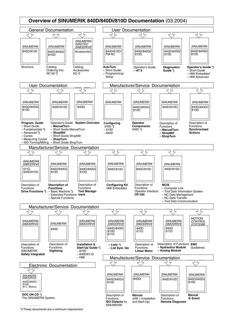
User Documentation
SINUMERIK
840D/810D
SINUMERIK
Overview of SINUMERIK 840D/840Di/810D Documentation (03.2004)
Brochure Catalog Ordering Info.NC 60 *)
Description of Functions Drive Functions *)
Description of Functions– Basic Machine *) – Extended Functions– Special Functions
611D840D/810D
SINUMERIK
840D/840Di/810D
Accessories
CatalogAccessoriesNC-Z
SINUMERIKSIROTECSIMODRIVE
840D/840Di810D
– Lists *)– List Syst. Var.
Installation &Start-Up Guide *)– 810D– 840D/611D– HMI
SINUMERIK
840D
Description of FunctionsDigitizing
611D
SINUMERIK
SINUMERIK
840D/810D
Configuring Kit HMI Embedded
SINUMERIK
840D/840Di/810D
SINUMERIK
840D/840Di/810D
Description of FunctionsSINUMERIKSafety Integrated
SINUMERIKSIMODRIVE
SINUMERIK
840D/840Di/810D611, Motors
SIMODRIVE
DOC ON CD *)The SINUMERIK System
General Documentation
Electronic Documentation
Manufacturer/Service Documentation
Manufacturer/Service Documentation
SINUMERIK
840D/810D/FM-NC
SINUMERIK
840D/840Di/810D
User Documentation
DiagnosticsGuide *)
Operator’s Guide – HT 6
AutoTurn– Short Guide– Programming/ Setup
SINUMERIK
840D/840Di/810D
Program. Guide– Short Guide– Fundamentals *)– Advanced *)– Cycles– Measuring Cycles– ISO Turning/Milling
Operator Components(HW) *)
Description ofFunctionsSynchronized Actions
840D/810D
SINUMERIK
Operator’s Guide– ManualTurn– Short Guide ManualTurn– ShopMill– Short Guide ShopMill– ShopTurn– Short Guide ShopTurn
840D/810D
Manufacturer/Service Documentation
*) These documents are a minimum requirement
Operator’s Guide *)– Short Guide– HMI Embedded– HMI Advanced
SINUMERIK
840D/840Di/810D
Configuring (HW) *)– 810D– 840D
SINUMERIK
SINUMERIK
840D/840Di/810D
SINUMERIK
840D/810D
Description of FunctionsOperator InterfaceOP 030
Description ofFunctionsTool Manage-ment
SINUMERIKSIMODRIVE
SINUMERIKSIMODRIVE
SINUMERIKSIMODRIVE
SINUMERIKSIMODRIVE
SINUMERIKSIMODRIVE
840D611D
840D611D
Description ofFunctionsLinear Motor
Description of Functions– Hydraulics Module– Analog Module
MOTIONCONTROLSYSTEMS
EMCGuidelines
Manufacturer/Service Documentation
SINUMERIK
Description of FunctionsISO Dialects for SINUMERIK
840D/840Di/810D
SINUMERIK
Manual(HW + Installationand Start-Up)
840Di
SINUMERIK
System Overview
840Di
840D/840Di/810D/
SINUMERIK
Description of FunctionsRemote Diagnosis
840D/810D
SINUMERIK
840D/810D
MCIS– Computer Link– Tool Data Information System– NC Data Management– NC Data Transfer– Tool Data Communication
SINUMERIK
Description ofFunctions– ManualTurn– ShopMill– ShopTurn
840D/840Di/810D
SINUMERIK
840D/840Di/810D
Manual@ Event

© Siemens AG, 2004Subject to change without prior notice
Order No.: 6FC5297-0AF00-0BP3
Printed in Germany
Siemens AGAutomation and DrivesMotion Control SystemsP.O. Box 3180, D-91050 ErlangenGermany
www.siemens.com/motioncontrol