Embed Size (px)
Citation preview
Vol-3 Issue-2 2017 IJARIIE-ISSN(O)-2395-4396
4235 www.ijariie.com 1492
.
DESIGN AND FABRICATION OF VEHICLE
IGNITION CONTROL BY HELMET
Mrs. Sushma Bawane1, Prashik Ganvir
2, Blesson Saji
3, Lankesh Yadav
4, Shubham Joshi
5, Suhas
Nimje6, Amol Bhute
7
( 1 Guide,Mechanical Engineeringt, KDKCE , Maharashtra, India
2 Student, Mechanical Engineeringt, KDKCE , Maharashtra, India
3 Student, Mechanical Engineeringt, KDKCE , Maharashtra, India
4 Student, Mechanical Engineeringt, KDKCE , Maharashtra, India
5 Student, Mechanical Engineeringt, KDKCE , Maharashtra, India
6 Student, Mechanical Engineeringt, KDKCE , Maharashtra, India
7 Student, Mechanical Engineeringt, KDKCE , Maharashtra, India
ABSTRACT
The proposed system is a simple telemetry system, which is activated by means of a pressure that is applied to the
helmet’s interior when the rider wears it. The technology used is wireless frequency and is absolutely same for long
term usage. Once activated the transmitter sends a control signal to the receiver circuit and activates the motor and
the gear box attached to the chassis move forward direction. Here we are not showing the vehicles gear applying
system we showing that how the signal can be bypass and the gear box by using the low rpm and high torque hoe
easily the mechanism can be driven. There is some time lag in wearing the helmet and switching on of the circuit
(average experimental time= 1.57 seconds)
Keyword : - Transmitter , Receiver , helmet and motor
1. INTRODUCTION
ROAD traffic crashes take the lives of nearly 1.3 million every year and injure 20-50 million more in the world.
Refusal to use proper motorcycle helmets is among the main factor contributing to deaths from road crashes – WHO
said this in its report on 'Decade of Action for Road Safety 2011-2010’. More disturbingly, a large number of deaths
from road accidents are borne by "vulnerable road users" such as pedestrians, cyclists and motorcyclists. Around
13% of the victims from road-related deaths are pedestrians in India as compared to 15% of accidents from
passenger cars and taxis and 27% from riders of motorized two-or-three wheelers. So if it can be made mandatory to
make the people wear the helmet when they ride the bike then the rates of these accidents can be expected to fall.
Vol-3 Issue-2 2017 IJARIIE-ISSN(O)-2395-4396
4235 www.ijariie.com 1493
Worldwide most governments have already made stringent laws regarding wearing the helmet .But despite the laws
such cases are still on a rise because of The lack of proper implementation. Most helmet innovations today focuses
on only one thing, i.e, fancy features like adding a MP3 player or wireless phone or even a flash light on top of it.
But none of these features give a guarantee that they are meant to be used for bike rider’s safety.
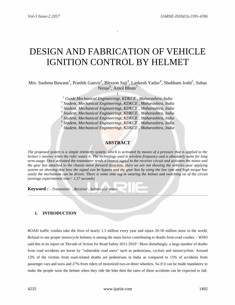
2. WORKING OF BLOCK DIAGRAM
The pressure
based
mechanical
switch will be
attached on the helmet of the driver. When the helmet is weared by the driver the switch will be pressed
and the transmitter circuit will generate a command and the data will be sent to the receiver module
attached with the receiver circuit.
The motor will work as engine.
The data will be sent through the frequency and the frequency will define that is individual and will not
match to any other vehicle Helmet. Engine will be on and off as per the helmet wearing status.
3.DESCRIPTION OF EACH COMPONENTS
Vol-3 Issue-2 2017 IJARIIE-ISSN(O)-2395-4396
4235 www.ijariie.com 1494
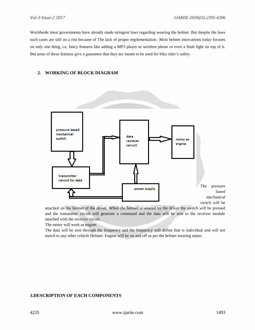
3.1Transmitter circuit
Fig. 2(b):- transmitter circuit
Parts list
Transmitter
Resistor
R1 -1mohm (1/4watt)
Semiconductors
D1 -1n4148
U1-ht12e
Sc1-18pin ic socket
Accessories
Snp1-9volt battery snapper
Sw1-sw4 4 pins connection to the voice recognition module
Dip sw1-8 way dip switch
From A0 to A7 the dip switch that the address setting switch between the transmitter and receiver will be connected.
From pin no.13 to pin no.10 the connection will be connected to voice recognition module. This four connection will
Vol-3 Issue-2 2017 IJARIIE-ISSN(O)-2395-4396
4235 www.ijariie.com 1495
give commands for forward, reverse, left; right.the d1 is the zener diode that will drop the voltage that will be
supplied to the tx module. The input voltage will be 9 volt dc.that will supply from the battery.
Transmitter circuit is mounted on the helmet. The function of this circuit is to transmit the control signal of
particular frequency to the receiver circuit. The working of this circuit is explained below one by one.
BATTERY : 9 V ( 200 mA.) this is non-rechargable battery. This battery supply power to each components
mounted on the transmitter circuit.
CONNECTORS: this is used to simply connect the circuit to the battery.
Encoder IC: it decode the signal from pressure switch i.e, either it is ON command or OFF command.
And depending upon this it will transmit signal to transmitter module.
TRANSMITTER MODULE(433 MHz): it receives control signal from encoder IC and convert it into wireless
signal and then this signal is transmitted to the receiver module through antenna
PAIRING SWITCHES : this switch is provided with 1 to 8 digit numbers which can be set by user and the serial
number on this switch should match with the serial no. provided on the same switch on the receiver circuit.
ZENER DIODE: It lowers the voltage from 9V to 5V which is required by the all components on transmitter
circuit.
RESISTOR : to protect ic from heating and provide favorable voltage level.
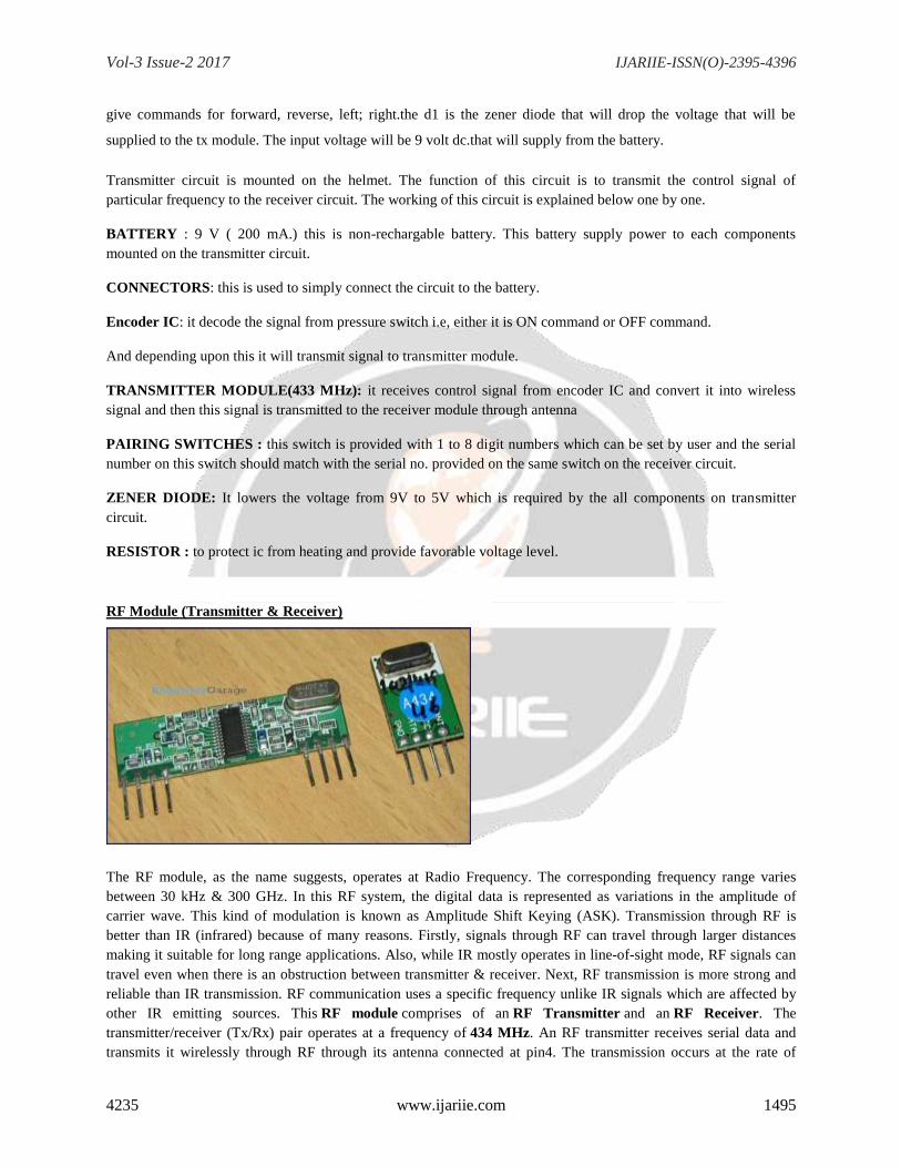
RF Module (Transmitter & Receiver)
The RF module, as the name suggests, operates at Radio Frequency. The corresponding frequency range varies
between 30 kHz & 300 GHz. In this RF system, the digital data is represented as variations in the amplitude of
carrier wave. This kind of modulation is known as Amplitude Shift Keying (ASK). Transmission through RF is
better than IR (infrared) because of many reasons. Firstly, signals through RF can travel through larger distances
making it suitable for long range applications. Also, while IR mostly operates in line-of-sight mode, RF signals can
travel even when there is an obstruction between transmitter & receiver. Next, RF transmission is more strong and
reliable than IR transmission. RF communication uses a specific frequency unlike IR signals which are affected by
other IR emitting sources. This RF module comprises of an RF Transmitter and an RF Receiver. The
transmitter/receiver (Tx/Rx) pair operates at a frequency of 434 MHz. An RF transmitter receives serial data and
transmits it wirelessly through RF through its antenna connected at pin4. The transmission occurs at the rate of
Vol-3 Issue-2 2017 IJARIIE-ISSN(O)-2395-4396
4235 www.ijariie.com 1496
1Kbps - 10Kbps.The transmitted data is received by an RF receiver operating at the same frequency as that of the
transmitter. The RF module is often used alongwith a pair of encoder/decoder. The encoder is used for encoding
parallel data for transmission feed while reception is decoded by a decoder. HT12E-HT12D, HT640-HT648, etc. are
some commonly used encoder/decoder pair ICs.
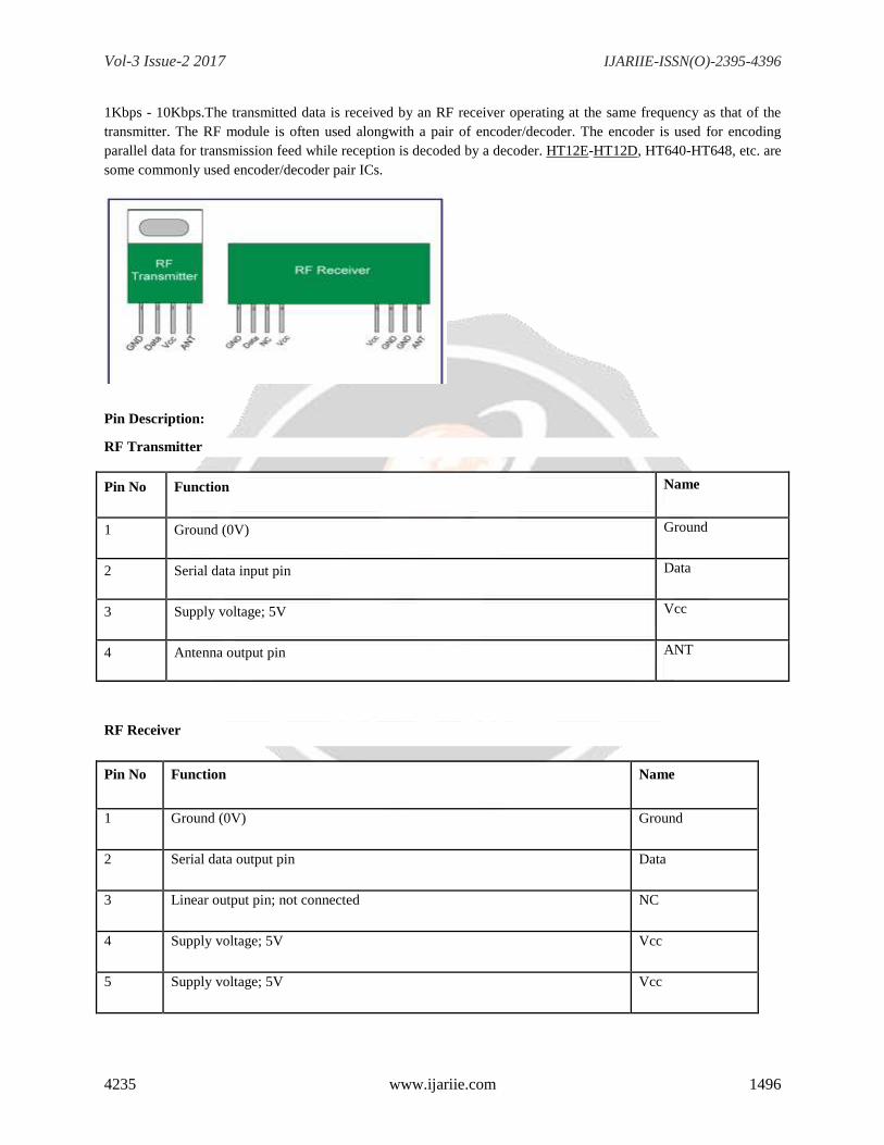
Pin Description:
RF Transmitter
Pin No Function Name
1 Ground (0V) Ground
2 Serial data input pin Data
3 Supply voltage; 5V Vcc
4 Antenna output pin ANT
RF Receiver
Pin No Function Name
1 Ground (0V) Ground
2 Serial data output pin Data
3 Linear output pin; not connected NC
4 Supply voltage; 5V Vcc
5 Supply voltage; 5V Vcc
Vol-3 Issue-2 2017 IJARIIE-ISSN(O)-2395-4396
4235 www.ijariie.com 1497
6 Ground (0V) Ground
7 Ground (0V) Ground
8 Antenna input pin ANT
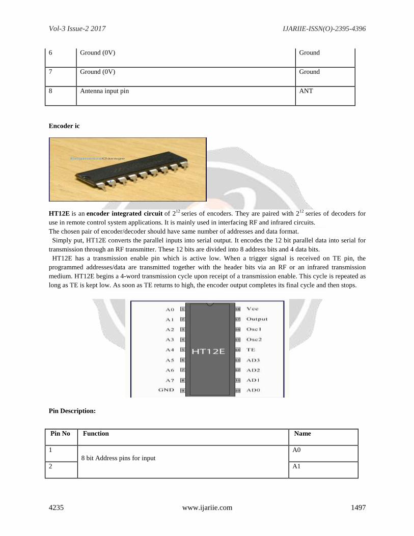
Encoder ic
HT12E is an encoder integrated circuit of 212
series of encoders. They are paired with 212
series of decoders for
use in remote control system applications. It is mainly used in interfacing RF and infrared circuits.
The chosen pair of encoder/decoder should have same number of addresses and data format.
Simply put, HT12E converts the parallel inputs into serial output. It encodes the 12 bit parallel data into serial for
transmission through an RF transmitter. These 12 bits are divided into 8 address bits and 4 data bits.
HT12E has a transmission enable pin which is active low. When a trigger signal is received on TE pin, the
programmed addresses/data are transmitted together with the header bits via an RF or an infrared transmission
medium. HT12E begins a 4-word transmission cycle upon receipt of a transmission enable. This cycle is repeated as
long as TE is kept low. As soon as TE returns to high, the encoder output completes its final cycle and then stops.
Pin Description:
Pin No Function Name
1
8 bit Address pins for input
A0
2 A1
Vol-3 Issue-2 2017 IJARIIE-ISSN(O)-2395-4396
4235 www.ijariie.com 1498
3 A2
4 A3
5 A4
6 A5
7 A6
8 A7
9 Ground (0V) Ground
10
4 bit Data/Address pins for input
AD0
11 AD1
12 AD2
13 AD3
14 Transmission enable; active low TE
15 Oscillator input Osc2
16 Oscillator output Osc1
17 Serial data output Output
18 Supply voltage; 5V (2.4V-12V) Vcc
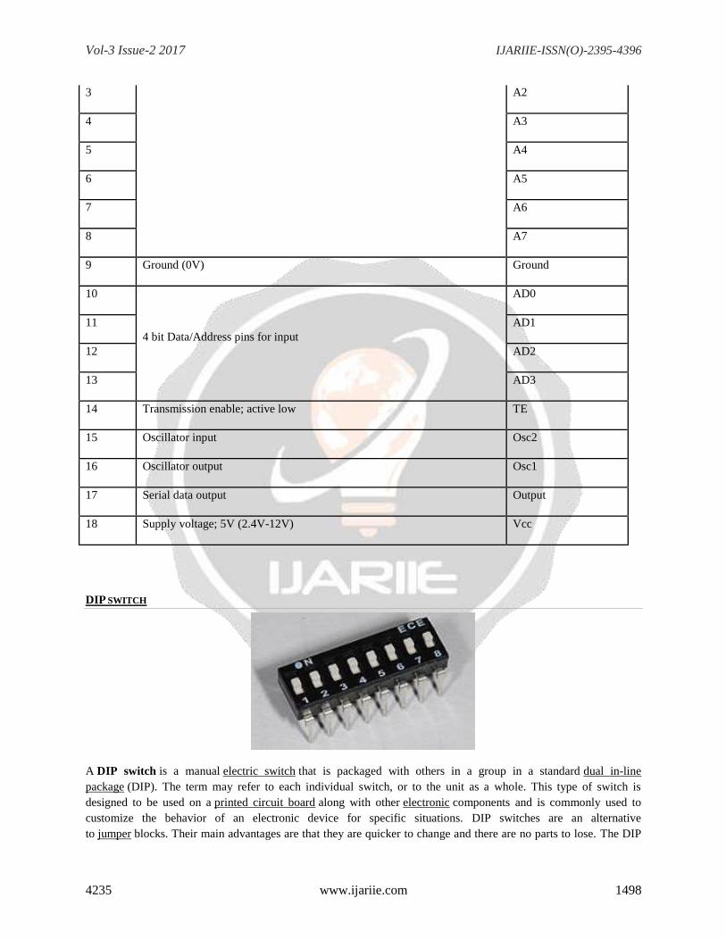
DIP SWITCH
A DIP switch is a manual electric switch that is packaged with others in a group in a standard dual in-line
package (DIP). The term may refer to each individual switch, or to the unit as a whole. This type of switch is
designed to be used on a printed circuit board along with other electronic components and is commonly used to
customize the behavior of an electronic device for specific situations. DIP switches are an alternative
to jumper blocks. Their main advantages are that they are quicker to change and there are no parts to lose. The DIP
Vol-3 Issue-2 2017 IJARIIE-ISSN(O)-2395-4396
4235 www.ijariie.com 1499
switch with sliding levers was granted US Patent 4012608 in 1976. It was applied for 1974 and was used in 1977 in
an ATARI Flipper game.
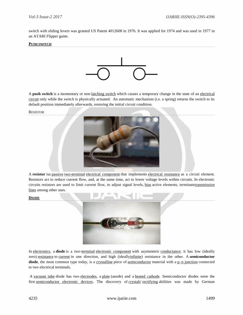
PUSH SWITCH
A push switch is a momentary or non-latching switch which causes a temporary change in the state of an electrical
circuit only while the switch is physically actuated. An automatic mechanism (i.e. a spring) returns the switch to its
default position immediately afterwards, restoring the initial circuit condition.
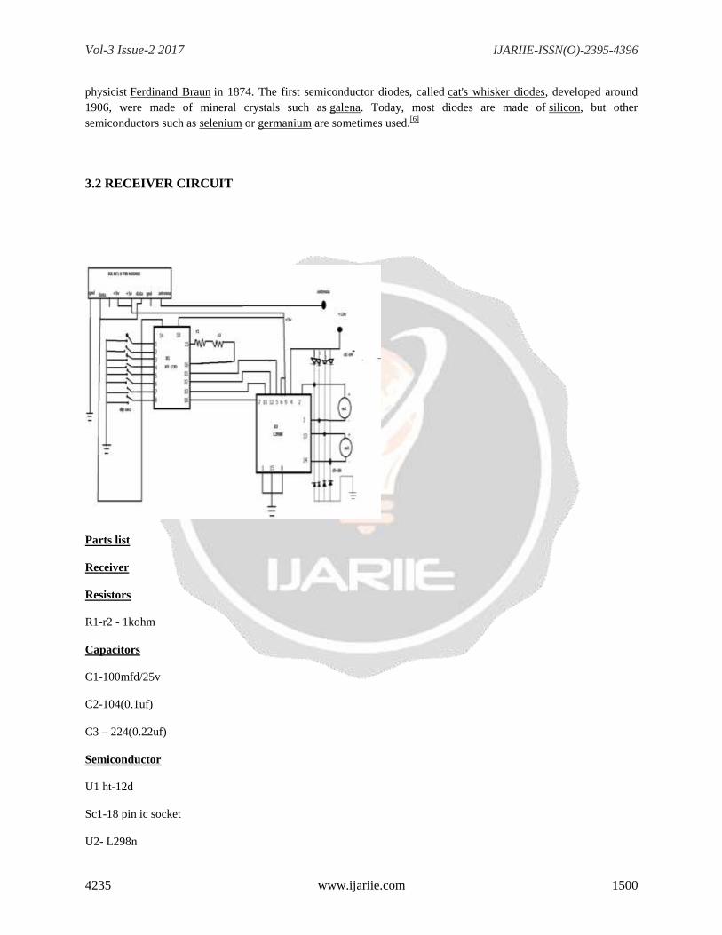
RESISTOR
A resistor isa passive two-terminal electrical component that implements electrical resistance as a circuit element.
Resistors act to reduce current flow, and, at the same time, act to lower voltage levels within circuits. In electronic
circuits resistors are used to limit current flow, to adjust signal levels, bias active elements, terminatetransmission
lines among other uses.
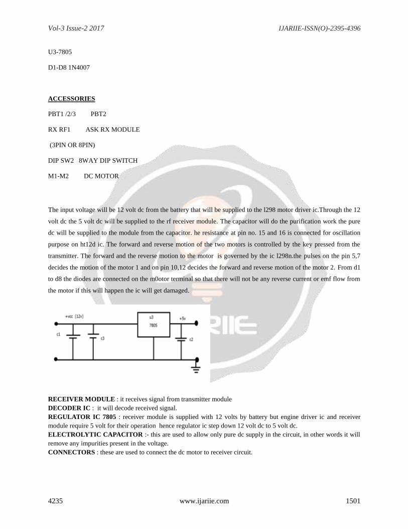
DIODE
In electronics, a diode is a two-terminal electronic component with asymmetric conductance; it has low (ideally
zero) resistance to current in one direction, and high (ideallyinfinite) resistance in the other. A semiconductor
diode, the most common type today, is a crystalline piece of semiconductor material with a p–n junction connected
to two electrical terminals.
A vacuum tube diode has two electrodes, a plate (anode) and a heated cathode. Semiconductor diodes were the
first semiconductor electronic devices. The discovery of crystals' rectifying abilities was made by German
Vol-3 Issue-2 2017 IJARIIE-ISSN(O)-2395-4396
4235 www.ijariie.com 1500
physicist Ferdinand Braun in 1874. The first semiconductor diodes, called cat's whisker diodes, developed around
1906, were made of mineral crystals such as galena. Today, most diodes are made of silicon, but other
semiconductors such as selenium or germanium are sometimes used.[6]
3.2 RECEIVER CIRCUIT
Parts list
Receiver
Resistors
R1-r2 - 1kohm
Capacitors
C1-100mfd/25v
C2-104(0.1uf)
C3 – 224(0.22uf)
Semiconductor
U1 ht-12d
Sc1-18 pin ic socket
U2- L298n
Vol-3 Issue-2 2017 IJARIIE-ISSN(O)-2395-4396
4235 www.ijariie.com 1501
U3-7805
D1-D8 1N4007
ACCESSORIES
PBT1 /2/3 PBT2
RX RF1 ASK RX MODULE
(3PIN OR 8PIN)
DIP SW2 8WAY DIP SWITCH
M1-M2 DC MOTOR
The input voltage will be 12 volt dc from the battery that will be supplied to the l298 motor driver ic.Through the 12
volt dc the 5 volt dc will be supplied to the rf receiver module. The capacitor will do the purification work the pure
dc will be supplied to the module from the capacitor. he resistance at pin no. 15 and 16 is connected for oscillation
purpose on ht12d ic. The forward and reverse motion of the two motors is controlled by the key pressed from the
transmitter. The forward and the reverse motion to the motor is governed by the ic l298n.the pulses on the pin 5,7
decides the motion of the motor 1 and on pin 10,12 decides the forward and reverse motion of the motor 2. From d1
to d8 the diodes are connected on the m0otor terminal so that there will not be any reverse current or emf flow from
the motor if this will happen the ic will get damaged.
RECEIVER MODULE : it receives signal from transmitter module
DECODER IC : it will decode received signal.
REGULATOR IC 7805 : receiver module is supplied with 12 volts by battery but engine driver ic and receiver
module require 5 volt for their operation hence regulator ic step down 12 volt dc to 5 volt dc.
ELECTROLYTIC CAPACITOR :- this are used to allow only pure dc supply in the circuit, in other words it will
remove any impurities present in the voltage.
CONNECTORS : these are used to connect the dc motor to receiver circuit.
Vol-3 Issue-2 2017 IJARIIE-ISSN(O)-2395-4396
4235 www.ijariie.com 1502
PAIRING SWITCHES : just as in transmitter circuit, this switch is provided with 1 to 8 digit numbers which can
be set by user and the serial number on this switch should match with the serial no. provided on the same switch on
the transmitter circuit.
CERAMIC CAPACITOR : these are fixed value capacitors consisting no ON/OFF terminals in which the ceramic
material act as dielectric.
RESISTORS : to protect decoder ic from heating and provide favorable voltage level.
ENGINE DRIVER IC : it will carry signal from decoder ic and supply to the motor and gear system to drive it. due
to this the temperature of engine driver ic will start increasing hence the aluminum fins is provided known as heat
sink.
8 DIODES : sometimes the magnetic flux produced in the motor are reversed and this will flow towards engine
driver ic resulting in the damage to the engine driver ic to stop it diodes will block this reversed flux to protect ic
from damaging.
CONNECTORS : these are used to connect the dc motor to Engine driver circuit.
ENGINE DRIVER IC : it will carry signal from decoder ic and supply to the motor and gear system to drive it. due
to this the temperature of engine driver ic will start increasing hence the aluminum fins is provided known as heat
sink.8 DIODES : sometimes the magnetic flux produced in the motor are reversed and this will flow towards engine
driver ic resulting in the damage to the engine driver ic to stop it diodes will block this reversed flux to protect ic
from damaging.
CONNECTORS : these are used to connect the dc motor to Engine driver circuit.
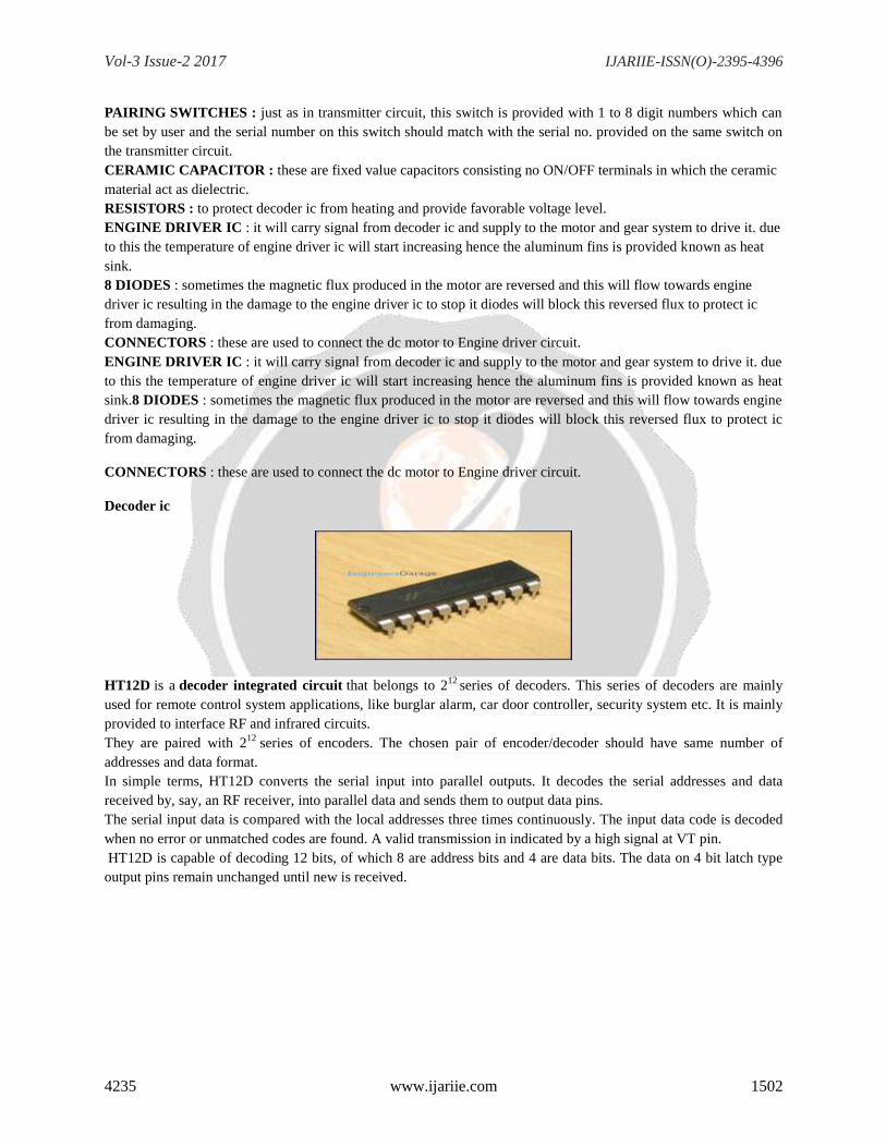
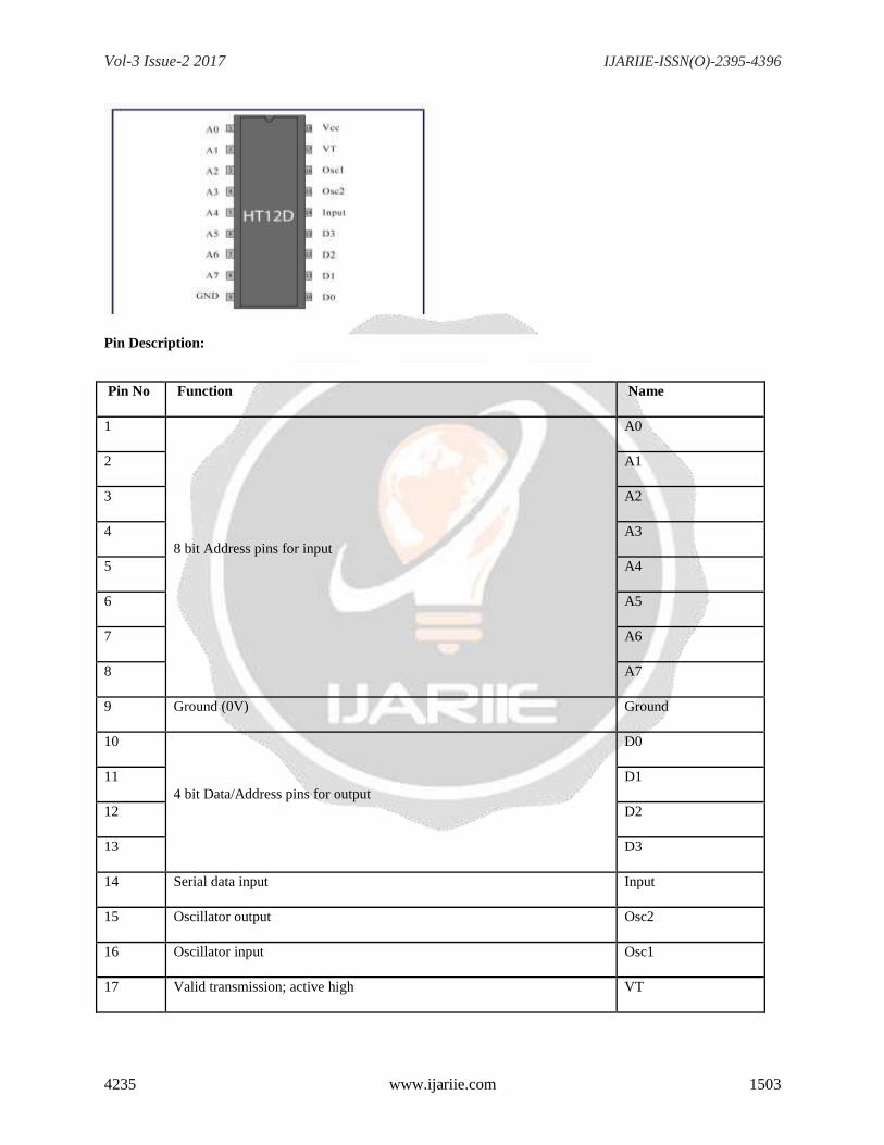
Decoder ic
HT12D is a decoder integrated circuit that belongs to 212
series of decoders. This series of decoders are mainly
used for remote control system applications, like burglar alarm, car door controller, security system etc. It is mainly
provided to interface RF and infrared circuits.
They are paired with 212
series of encoders. The chosen pair of encoder/decoder should have same number of
addresses and data format.
In simple terms, HT12D converts the serial input into parallel outputs. It decodes the serial addresses and data
received by, say, an RF receiver, into parallel data and sends them to output data pins.
The serial input data is compared with the local addresses three times continuously. The input data code is decoded
when no error or unmatched codes are found. A valid transmission in indicated by a high signal at VT pin.
HT12D is capable of decoding 12 bits, of which 8 are address bits and 4 are data bits. The data on 4 bit latch type
output pins remain unchanged until new is received.
Vol-3 Issue-2 2017 IJARIIE-ISSN(O)-2395-4396
4235 www.ijariie.com 1503
Pin Description:
Pin No Function Name
1
8 bit Address pins for input
A0
2 A1
3 A2
4 A3
5 A4
6 A5
7 A6
8 A7
9 Ground (0V) Ground
10
4 bit Data/Address pins for output
D0
11 D1
12 D2
13 D3
14 Serial data input Input
15 Oscillator output Osc2
16 Oscillator input Osc1
17 Valid transmission; active high VT
Vol-3 Issue-2 2017 IJARIIE-ISSN(O)-2395-4396
4235 www.ijariie.com 1504
18 Supply voltage; 5V (2.4V-12V) Vcc
RF Modules are used wireless transfer data and low cost application. This makes them suitable for remote control
applications, as in where you need to control some machines or robots without getting in touch with them (may be
due to various reasons like safety, etc).
Now depending upon the type of application, the RF module is chosen. For short range wireless control applications,
an RF Transmitter-Receiver Module of frequency 315 MHz is the most suitable type. This RF modules are works
with PT2262(encoder) and PT2272(decoder) as remote control.
Specification:
Frequency: 315Mhz
Modulation: ASK
Transmitter input voltage: 3-12V
Transmitter(RF-TX-315) and Receiver(RF-RX-315)
Range in open space(Standard Conditions) : 100 Meters
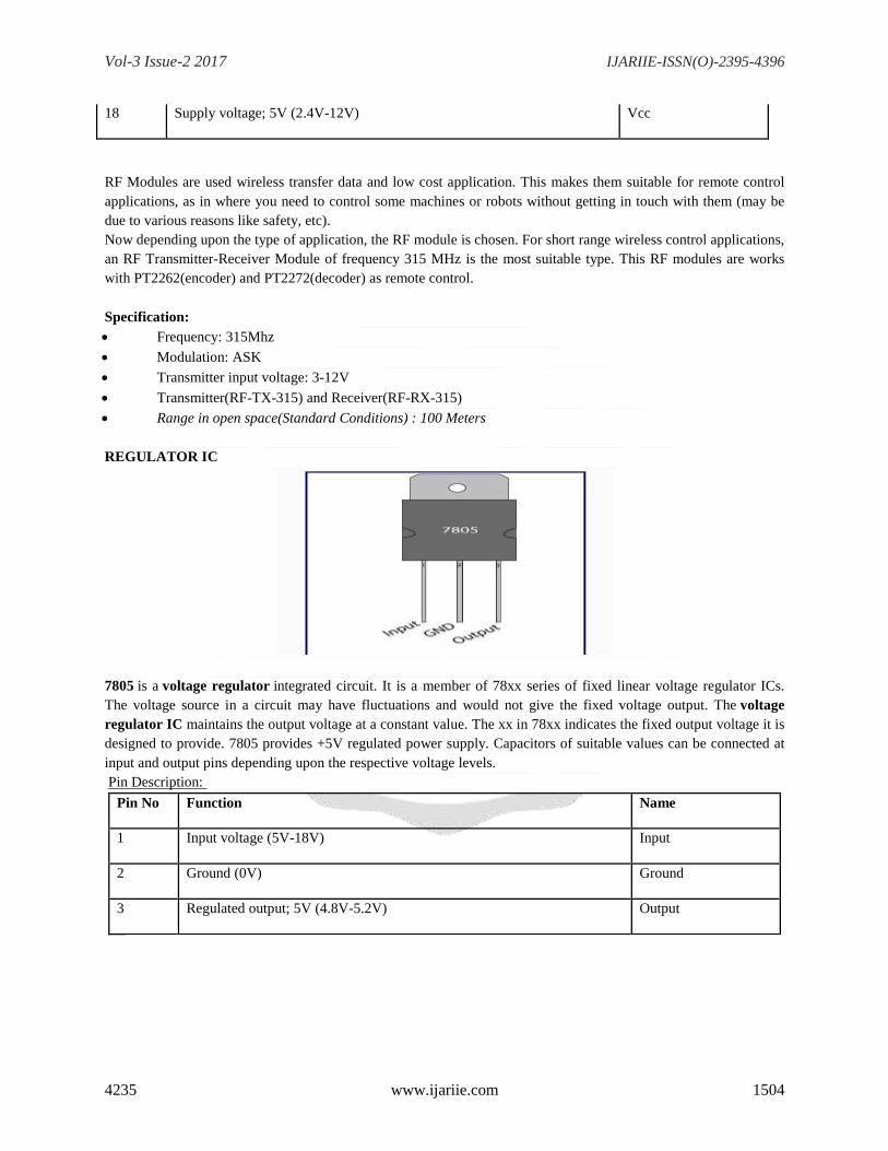
REGULATOR IC
7805 is a voltage regulator integrated circuit. It is a member of 78xx series of fixed linear voltage regulator ICs.
The voltage source in a circuit may have fluctuations and would not give the fixed voltage output. The voltage
regulator IC maintains the output voltage at a constant value. The xx in 78xx indicates the fixed output voltage it is
designed to provide. 7805 provides +5V regulated power supply. Capacitors of suitable values can be connected at
input and output pins depending upon the respective voltage levels.
Pin Description:
Pin No Function Name
1 Input voltage (5V-18V) Input
2 Ground (0V) Ground
3 Regulated output; 5V (4.8V-5.2V) Output
Vol-3 Issue-2 2017 IJARIIE-ISSN(O)-2395-4396
4235 www.ijariie.com 1505
ELECTROLYTIC CAPACITOR
An electrolytic capacitor ("electrolytic") is a capacitor in which one electrode is made of a metal on which a thin
oxide layer forms. This layer acts as the capacitor's dielectric. An electrolyte covers the surface of the oxide layer
and also serves as the second electrode.Electrolytics have a capacitance to volume ratio much higher than to ceramic
capacitors and film capacitors, but smaller than supercapacitors. They find extensive use in electronic devices. Their
large capacitance makes electrolytics particularly suitable for passing or bypassing low-frequency signals and
storing large amounts of energy. They may serve as filter and reservoir elements in power supplies, to couple
signals between amplifier stages, or to store energy as in a flashlamp. Electrolytics can be made
with aluminum, tantalum or niobium as the metal electrode and use various liquid (water based or solvent based) or
solid electrolytes. Electrolytics store electric energy in an electric field in the dielectric oxide layer between the two
electrodes. The cathode and the storage principle distinguish them from electrochemical supercapacitors, in which
the electrolyte is the conductive connection between two electrodes and storage occurs via double-layer
capacitance and pseudocapacitance. Electrolytics are polarized and operate with DC voltage. Reverse polarity, or
excess ripple current can destroy the dielectric and thus the device. The destruction of electrolytics can produce an
explosion and/or fire. Bipolar electrolytic capacitors, which may be operated with AC voltage, use two anodes c
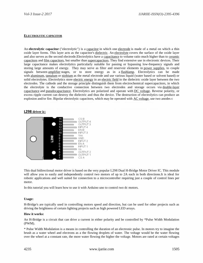
L298 driver ic:
This dual bidirectional motor driver is based on the very popular L298 Dual H-Bridge Motor Driver IC. This module
will allow you to easily and independently control two motors of up to 2A each in both directions.It is ideal for
robotic applications and well suited for connection to a microcontroller requiring just a couple of control lines per
motor.
In this tutorial you will learn how to use it with Arduino uno to control two dc motors.
Usage:
H-Bridge's are typically used in controlling motors speed and direction, but can be used for other projects such as
driving the brightness of certain lighting projects such as high powered LED arrays.
How it works:
An H-Bridge is a circuit that can drive a current in either polarity and be controlled by *Pulse Width Modulation
(PWM).
* Pulse Width Modulation is a means in controlling the duration of an electronic pulse. In motors try to imagine the
brush as a water wheel and electrons as a the flowing droplets of water. The voltage would be the water flowing
over the wheel at a constant rate, the more water flowing the higher the voltage. Motors are rated at certain voltages
Vol-3 Issue-2 2017 IJARIIE-ISSN(O)-2395-4396
4235 www.ijariie.com 1506
and can be damaged if the voltage is applied to heavily or if it is dropped quickly to slow the motor down. Thus
PWM. Take the water wheel analogy and think of the water hitting it in pulses but at a constant flow. The longer the
pulses the faster the wheel will turn, the shorter the pulses, the slower the water wheel will turn. Motors will last
much longer and be more reliable if controlled through PWM.
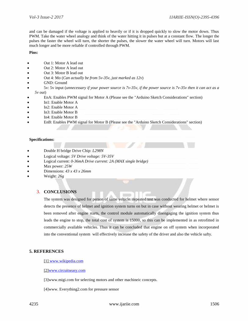
Pins:
Out 1: Motor A lead out
Out 2: Motor A lead out
Out 3: Motor B lead out
Out 4: Mo (Can actually be from 5v-35v, just marked as 12v)
GND: Ground
5v: 5v input (unnecessary if your power source is 7v-35v, if the power source is 7v-35v then it can act as a
5v out)
EnA: Enables PWM signal for Motor A (Please see the "Arduino Sketch Considerations" section)
In1: Enable Motor A
In2: Enable Motor A
In3: Enable Motor B
In4: Enable Motor B
EnB: Enables PWM signal for Motor B (Please see the "Arduino Sketch Considerations" section)
Specifications:
Double H bridge Drive Chip: L298N
Logical voltage: 5V Drive voltage: 5V-35V
Logical current: 0-36mA Drive current: 2A (MAX single bridge)
Max power: 25W
Dimensions: 43 x 43 x 26mm
Weight: 26g
3. CONCLUSIONS
The system was designed for person of same vehicle. repeated test was conducted for helmet where sensor
detects the presence of helmet and ignition system turns on but in case without wearing helmet or helmet is
been removed after engine starts, the control module automatically disengaging the ignition system thus
leads the engine to stop, the total cost of system is 15000, so this can be implemented in as retrofitted in
commercially available vehicles. Thus it can be concluded that engine on off system when incorporated
into the conventional system will effectively increase the safety of the driver and also the vehicle safty.
5. REFERENCES
[1] www.wikipedia.com
[2]www.circuitseasy.com
[3]www.migi.com for selecting motors and other machineic concepts.
[4]www. Everything2.com for pressure sensor

Vol-3 Issue-2 2017 IJARIIE-ISSN(O)-2395-4396
4235 www.ijariie.com 1507
[5]Wireless Communications by Andreas F. Molisch