Embed Size (px)
Citation preview
ARLINGTON COUNTY COURTHOUSE Arlington, Virginia Chiller Plan Replacement Specifications – FOR BID November 27th, 2017 B2E Project # 17605 Prepared By:

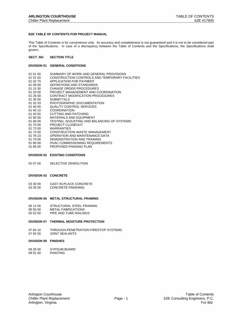
ARLINGTON COURTHOUSE TABLE OF CONTENTS Chiller Plant Replacement b2E #17605
Arlington Courthouse Table of Contents Chiller Plant Replacement Page - 1 b2E Consulting Engineers, P.C. Arlington, Virginia For Bid
B2E TABLE OF CONTENTS FOR PROJECT MANUAL
This Table of Contents is for convenience only. Its accuracy and completeness is not guaranteed and it is not to be considered part of the Specifications. In case of a discrepancy between the Table of Contents and the Specifications, the Specifications shall govern. SECT. NO. SECTION TITLE
DIVISION 01 GENERAL CONDITIONS
01 01 00 SUMMARY OF WORK AND GENERAL PROVISIONS 01 01 50 CONSTRUCTION CONTROLS AND TEMPORARY FACILITIES 01 02 70 APPLICATION FOR PAYMENT 01 09 00 DEFINITIONS AND STANDARDS 01 15 30 CHANGE ORDER PROCEDURES 01 20 00 PROJECT MANAGEMENT AND COORDINATION 01 26 00 CONTRACT MODIFICATION PROCEDURES 01 30 00 SUBMITTALS 01 32 33 PHOTOGRAPHIC DOCUMENTATION 01 40 00 QUALITY CONTROL SERVICES 01 40 10 COORDINATION 01 40 50 CUTTING AND PATCHING 01 60 00 MATERIALS AND EQUIPMENT 01 66 00 TESTING, ADJUSTING AND BALANCING OF SYSTEMS 01 70 00 PROJECT CLOSEOUT 01 73 00 WARRANTIES 01 74 00 CONSTRUCTION WASTE MANAGEMENT 01 78 23 OPERATION AND MAINTENANCE DATA 01 79 00 DEMONSTRATION AND TRAINING 01 80 00 HVAC COMMISSIONING REQUIREMENTS 01 85 00 PROPOSED PHASING PLAN
DIVISION 02 EXISTING CONDITIONS
02 07 00 SELECTIVE DEMOLITION
DIVISION 03 CONCRETE
03 30 00 CAST-IN-PLACE CONCRETE 03 35 00 CONCRETE FINISHING DIVISION 05 METAL STRUCTURAL FRAMING 05 12 00 STRUCTURAL STEEL FRAMING 05 50 00 METAL FABRICATIONS 05 52 00 PIPE AND TUBE RAILINGS
DIVISION 07 THERMAL MOISTURE PROTECTION
07 84 10 THROUGH-PENETRATION FIRESTOP SYSTEMS 07 92 00 JOINT SEALANTS DIVISION 09 FINISHES
09 25 00 GYPSUM BOARD 09 91 00 PAINTING
ARLINGTON COURTHOUSE TABLE OF CONTENTS Chiller Plant Replacement b2E #17605
Arlington Courthouse Table of Contents Chiller Plant Replacement Page - 2 b2E Consulting Engineers, P.C. Arlington, Virginia For Bid
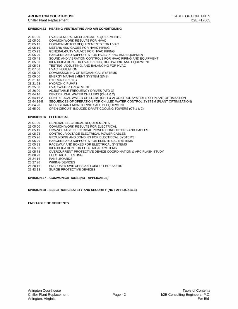
DIVISION 23 HEATING VENTILATING AND AIR CONDITIONING
23 01 00 HVAC GENERAL MECHANICAL REQUIREMENTS 23 05 00 COMMON WORK RESULTS FOR HVAC 23 05 13 COMMON MOTOR REQUIREMENTS FOR HVAC 23 05 19 METERS AND GAGES FOR HVAC PIPING 23 05 23 GENERAL-DUTY VALVES FOR HVAC PIPING 23 05 29 HANGERS AND SUPPORTS FOR HVAC PIPING AND EQUIPMENT 23 05 48 SOUND AND VIBRATION CONTROLS FOR HVAC PIPING AND EQUIPMENT 23 05 53 IDENTIFICATION FOR HVAC PIPING, DUCTWORK AND EQUIPMENT 23 05 93 TESTING, ADJUSTING, AND BALANCING FOR HVAC 23 07 00 HVAC INSULATION 23 08 00 COMMISSIONING OF MECHANICAL SYSTEMS 23 09 00 ENERGY MANAGEMENT SYSTEM (EMS) 23 21 13 HYDRONIC PIPING 23 21 23 HYDRONIC PUMPS 23 25 00 HVAC WATER TREATMENT 23 26 90 ADJUSTABLE FREQUENCY DRIVES (AFD-X) 23 64 16 CENTRIFUGAL WATER CHILLERS (CH-1 & 2) 23 64 16-A CENTRIFUGAL WATER CHILLERS (CH-1 & 2) CONTROL SYSTEM (FOR PLANT OPTIMZATION 23 64 16-B SEQUENCES OF OPERATION FOR CHILLED WATER CONTROL SYSTEM (PLANT OPTIMIZATION) 23 64 20 REFRIGERANT MONITORING SAFETY EQUIPMENT 23 65 00 OPEN-CIRCUIT, INDUCED DRAFT COOLING TOWERS (CT-1 & 2)
DIVISION 26 ELECTRICAL
26 01 00 GENERAL ELECTRICAL REQUIREMENTS 26 05 00 COMMON WORK RESULTS FOR ELECTRICAL 26 05 19 LOW-VOLTAGE ELECTRICAL POWER CONDUCTORS AND CABLES 26 05 23 CONTROL-VOLTAGE ELECTRICAL POWER CABLES 26 05 26 GROUNDING AND BONDING FOR ELECTRICAL SYSTEMS 26 05 29 HANGERS AND SUPPORTS FOR ELECTRICAL SYSTEMS 26 05 33 RACEWAY AND BOXES FOR ELECTRICAL SYSTEMS 26 05 53 IDENTIFICATION FOR ELECTRICAL SYSTEMS 26 05 73 OVERCURRENT PROTECTIVE DEVICE COORDINATION & ARC FLASH STUDY 26 08 23 ELECTRICAL TESTING 26 24 16 PANELBOARDS 26 27 26 WIRING DEVICES 26 28 16 ENCLOSED SWITCHES AND CIRCUIT BREAKERS 26 43 13 SURGE PROTECTIVE DEVICES
DIVISION 27 – COMMUNICATIONS (NOT APPLICABLE)
DIVISION 28 – ELECTRONIC SAFETY AND SECURITY (NOT APPLICABLE)
END TABLE OF CONTENTS

Arlington Courthouse Summary of Work and General Provisions Chiller Plant Replacement 01 01 00-1 b2E Consulting Engineers, P.C. Arlington, Virginia For Bid
SECTION 01 01 00
SUMMARY OF WORK AND GENERAL PROVISIONS
PART 1 – GENERAL
1.1 RELATED DOCUMENTS:
A. Drawings and General Provisions of Contract, including General and Supplementary Conditions, Division 1 Specification sections, and all other sections of the specifications shall also apply to the extent required for proper performance of the Work of the section.
1.2 WORK COVERED BY CONTRACT DOCUMENTS A. The Project consists of a phased occupied Chiller Plant Replacement, Arlington County, VA.
1. Project Location: Arlington County Courthouse, 1425 N. Courthouse Road, Arlington, VA
22201. 2. Owner: Arlington County, Board of Supervisors, 2100 Clarendon Boulevard, Arlington,
VA 22201. B. Contract Documents, dated November 27th, 2017 were prepared for the Project by:
B2E Consulting Engineers, P.C. 116-N Edwards Ferry Road, N.E. Leesburg, Virginia 20176
C. The Work consists of:
1. MECHANICAL The mechanical work required for the HVAC system upgrade generally consists of the following:
1. Refer to the Proposed Phasing Plan in Section 01 85 00 for detailed information. 2. Remove existing cooling towers and provide new cooling towers and associated
piping hydronic specialties and controls. 3. Remove existing condenser water pumps and provide new condenser water
pumps and associated piping, hydronic specialties and controls. 4. Install plant isolation valves and taps for connections needed to relocate the
chilled water piping. 5. Isolate chiller #2 and remove existing chiller and inertia pad. Extend existing
housekeeping pad to accept new larger chiller. Chiller #1 shall continue to serve the building with chilled water.
6. Provide new chiller #2 and set on extended housekeeping pad on spring isolators. 7. Install chilled water pumps on inertia pads and provide new chilled water piping,
hydronic specialties and controls. Connect new CHW piping to taps in existing piping.
Arlington Courthouse Summary of Work and General Provisions Chiller Plant Replacement 01 01 00-2 b2E Consulting Engineers, P.C. Arlington, Virginia For Bid
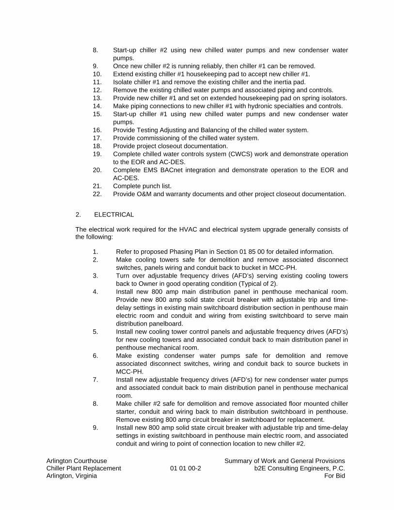
8. Start-up chiller #2 using new chilled water pumps and new condenser water pumps.
9. Once new chiller #2 is running reliably, then chiller #1 can be removed. 10. Extend existing chiller #1 housekeeping pad to accept new chiller #1. 11. Isolate chiller #1 and remove the existing chiller and the inertia pad. 12. Remove the existing chilled water pumps and associated piping and controls. 13. Provide new chiller #1 and set on extended housekeeping pad on spring isolators. 14. Make piping connections to new chiller #1 with hydronic specialties and controls. 15. Start-up chiller #1 using new chilled water pumps and new condenser water
pumps. 16. Provide Testing Adjusting and Balancing of the chilled water system. 17. Provide commissioning of the chilled water system. 18. Provide project closeout documentation. 19. Complete chilled water controls system (CWCS) work and demonstrate operation
to the EOR and AC-DES. 20. Complete EMS BACnet integration and demonstrate operation to the EOR and
AC-DES. 21. Complete punch list. 22. Provide O&M and warranty documents and other project closeout documentation.
2. ELECTRICAL The electrical work required for the HVAC and electrical system upgrade generally consists of the following:
1. Refer to proposed Phasing Plan in Section 01 85 00 for detailed information. 2. Make cooling towers safe for demolition and remove associated disconnect
switches, panels wiring and conduit back to bucket in MCC-PH. 3. Turn over adjustable frequency drives (AFD’s) serving existing cooling towers
back to Owner in good operating condition (Typical of 2). 4. Install new 800 amp main distribution panel in penthouse mechanical room.
Provide new 800 amp solid state circuit breaker with adjustable trip and time-delay settings in existing main switchboard distribution section in penthouse main electric room and conduit and wiring from existing switchboard to serve main distribution panelboard.
5. Install new cooling tower control panels and adjustable frequency drives (AFD’s) for new cooling towers and associated conduit back to main distribution panel in penthouse mechanical room.
6. Make existing condenser water pumps safe for demolition and remove associated disconnect switches, wiring and conduit back to source buckets in MCC-PH.
7. Install new adjustable frequency drives (AFD’s) for new condenser water pumps and associated conduit back to main distribution panel in penthouse mechanical room.
8. Make chiller #2 safe for demolition and remove associated floor mounted chiller starter, conduit and wiring back to main distribution switchboard in penthouse. Remove existing 800 amp circuit breaker in switchboard for replacement.
9. Install new 800 amp solid state circuit breaker with adjustable trip and time-delay settings in existing switchboard in penthouse main electric room, and associated conduit and wiring to point of connection location to new chiller #2.
Arlington Courthouse Summary of Work and General Provisions Chiller Plant Replacement 01 01 00-3 b2E Consulting Engineers, P.C. Arlington, Virginia For Bid
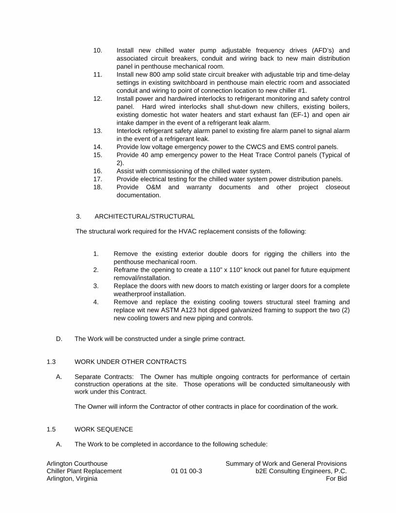
10. Install new chilled water pump adjustable frequency drives (AFD’s) and associated circuit breakers, conduit and wiring back to new main distribution panel in penthouse mechanical room.
11. Install new 800 amp solid state circuit breaker with adjustable trip and time-delay settings in existing switchboard in penthouse main electric room and associated conduit and wiring to point of connection location to new chiller #1.
12. Install power and hardwired interlocks to refrigerant monitoring and safety control panel. Hard wired interlocks shall shut-down new chillers, existing boilers, existing domestic hot water heaters and start exhaust fan (EF-1) and open air intake damper in the event of a refrigerant leak alarm.
13. Interlock refrigerant safety alarm panel to existing fire alarm panel to signal alarm in the event of a refrigerant leak.
14. Provide low voltage emergency power to the CWCS and EMS control panels. 15. Provide 40 amp emergency power to the Heat Trace Control panels (Typical of
2). 16. Assist with commissioning of the chilled water system. 17. Provide electrical testing for the chilled water system power distribution panels. 18. Provide O&M and warranty documents and other project closeout
documentation.
3. ARCHITECTURAL/STRUCTURAL The structural work required for the HVAC replacement consists of the following:
1. Remove the existing exterior double doors for rigging the chillers into the penthouse mechanical room.
2. Reframe the opening to create a 110” x 110” knock out panel for future equipment removal/installation.
3. Replace the doors with new doors to match existing or larger doors for a complete weatherproof installation.
4. Remove and replace the existing cooling towers structural steel framing and replace wit new ASTM A123 hot dipped galvanized framing to support the two (2) new cooling towers and new piping and controls.
D. The Work will be constructed under a single prime contract.
1.3 WORK UNDER OTHER CONTRACTS A. Separate Contracts: The Owner has multiple ongoing contracts for performance of certain
construction operations at the site. Those operations will be conducted simultaneously with work under this Contract.
The Owner will inform the Contractor of other contracts in place for coordination of the work.
1.5 WORK SEQUENCE A. The Work to be completed in accordance to the following schedule:
Arlington Courthouse Summary of Work and General Provisions Chiller Plant Replacement 01 01 00-4 b2E Consulting Engineers, P.C. Arlington, Virginia For Bid
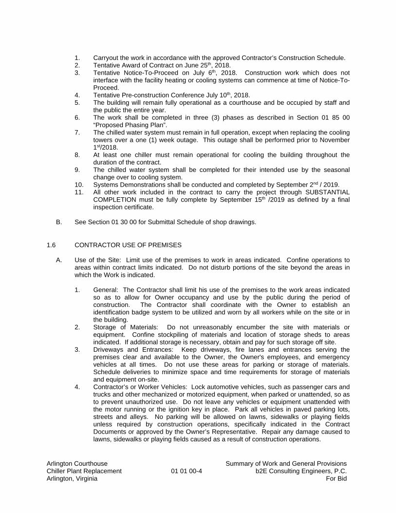
1. Carryout the work in accordance with the approved Contractor’s Construction Schedule. 2. Tentative Award of Contract on June 25th, 2018. 3. Tentative Notice-To-Proceed on July 6th, 2018. Construction work which does not
interface with the facility heating or cooling systems can commence at time of Notice-To-Proceed.
4. Tentative Pre-construction Conference July 10th, 2018. 5. The building will remain fully operational as a courthouse and be occupied by staff and
the public the entire year. 6. The work shall be completed in three (3) phases as described in Section 01 85 00
“Proposed Phasing Plan”. 7. The chilled water system must remain in full operation, except when replacing the cooling
towers over a one (1) week outage. This outage shall be performed prior to November 1st/2018.
8. At least one chiller must remain operational for cooling the building throughout the duration of the contract.
9. The chilled water system shall be completed for their intended use by the seasonal change over to cooling system.
10. Systems Demonstrations shall be conducted and completed by September 2nd / 2019. 11. All other work included in the contract to carry the project through SUBSTANTIAL
COMPLETION must be fully complete by September 15th /2019 as defined by a final inspection certificate.
B. See Section 01 30 00 for Submittal Schedule of shop drawings.
1.6 CONTRACTOR USE OF PREMISES A. Use of the Site: Limit use of the premises to work in areas indicated. Confine operations to
areas within contract limits indicated. Do not disturb portions of the site beyond the areas in which the Work is indicated.
1. General: The Contractor shall limit his use of the premises to the work areas indicated
so as to allow for Owner occupancy and use by the public during the period of construction. The Contractor shall coordinate with the Owner to establish an identification badge system to be utilized and worn by all workers while on the site or in the building.
2. Storage of Materials: Do not unreasonably encumber the site with materials or equipment. Confine stockpiling of materials and location of storage sheds to areas indicated. If additional storage is necessary, obtain and pay for such storage off site.
3. Driveways and Entrances: Keep driveways, fire lanes and entrances serving the premises clear and available to the Owner, the Owner's employees, and emergency vehicles at all times. Do not use these areas for parking or storage of materials. Schedule deliveries to minimize space and time requirements for storage of materials and equipment on-site.
4. Contractor’s or Worker Vehicles: Lock automotive vehicles, such as passenger cars and trucks and other mechanized or motorized equipment, when parked or unattended, so as to prevent unauthorized use. Do not leave any vehicles or equipment unattended with the motor running or the ignition key in place. Park all vehicles in paved parking lots, streets and alleys. No parking will be allowed on lawns, sidewalks or playing fields unless required by construction operations, specifically indicated in the Contract Documents or approved by the Owner’s Representative. Repair any damage caused to lawns, sidewalks or playing fields caused as a result of construction operations.
Arlington Courthouse Summary of Work and General Provisions Chiller Plant Replacement 01 01 00-5 b2E Consulting Engineers, P.C. Arlington, Virginia For Bid
B. Use of the Existing Building: Maintain the existing building in a weather tight condition throughout the construction period. Repair damage caused by construction operations. Take all precautions necessary to protect the building and its occupants during the construction period. Repair any damage caused by construction operations to match existing conditions and finishes. Take all precautions necessary to protect the building and its occupants during the construction period. 1. Keep public areas such as hallways, stairs, elevator lobbies and toilet rooms free from
accumulation of waste material, rubbish or construction debris. 2. Smoking or open fires will not be permitted within the building enclosure or on the
premises at any time. 3. Contractor shall provide their own toilet facilities. Arlington County will not provide toilet
facilities for this project. 4. The Owner will designate a staging and storage area for the Contractor’s use on site.
The Contractor shall assume full responsibility for protection of products, equipment and materials stored on site, in vehicles or in trailers.
5. There will be no on-site parking spaces allowed for vehicles belonging to the Contractor and their sub-Contractors. Paid parking spaces are available at parking garages and lots near the project site. The Contractor is responsible for the payment of any parking charges or fines resulting from illegal parking.
1.7 OCCUPANCY REQUIREMENTS A. Owner Occupancy: The Owner reserves the right to occupy the building in accordance with the
work sequence outlined previously and to place and install equipment in completed areas of the building prior to Substantial Completion, provided such occupancy does not interfere with completion of the Work. Such placing of equipment and partial occupancy shall not constitute acceptance of the total Work. During the summer vacation period, school staff will continue to occupy the building and site. Contractor is responsible for final construction cleaning as part of substantial completion.
1.8 CONTRACTOR’S MANPOWER TO CONDUCT THE WORK
A. Commencement of each phase of work in existing classrooms shall not occur until sufficient materials and equipment are available for the particular phase and sufficient numbers of workmen are available to execute the work in the time period indicated.
B. Multiple Work Shifts: In order to ensure completion of work phases during the time periods
indicated, the contractor may operate two (2) separate, full time, eight hour shifts per day, six days per week, employing trades, skills, and specialties including, but not limited to, the following:
1. General Labor 2. Cleaning Staff 3. Special Systems Technicians 4. Electrical 5. Plumbing 6. HVAC 7 The Contractor may modify this list to include other trade, skill and specialties required to
comply with the phasing requirements. 8. Qualified supervision for all trades for all work shifts.
Arlington Courthouse Summary of Work and General Provisions Chiller Plant Replacement 01 01 00-6 b2E Consulting Engineers, P.C. Arlington, Virginia For Bid
1.9 OWNER’S REPRESENTATIVE The Owner’s representative during the course of this work will be:
Mr. Alberto Abosaid, PE Arlington County Department of Environmental Services 1400 N. Uhle Street, Suite 601 Arlington, VA 22201 Tel. 702 | 228 | 7516
1.10 HAZARDOUS MATERIALS
The Owner’s representative will notify the Contractor of any asbestos or other hazardous materials that may be encountered in this building during the course of the contract, in compliance with AHERA regulations and the Virginia Occupational Safety and Health Program Hazard Communication standard. Copies of the Arlington County Hazard Communication Program and Material Safety Data Sheets for each facility are available on site and from the Owner’s Representative. Copies of the AHERA Asbestos Management Plan for each facility are available on site and from the Owner’s Representative.
1.11 BUILDING PERMITS The Owner has made application for the Arlington County Building Permit. The Contractor shall obtain and pay, prior to beginning work, all building permits, including trade permits, necessary for the completion of this contract. Permits shall be clearly displayed at the project site and a copy delivered to the Owner’s Representative prior to commencing work. All inspections required by the Arlington County Code Enforcement Office shall be completed and certificates delivered to the Owner’s Representative prior to Request for Final Payment.
1.12 HEALTH AND SAFETY PROGRAM Contractor shall comply with and meet all OSHA standards and the AC DES Safety manual
during construction. Contractor shall provide Owner with a copy of a company wide Safety Program relating to this construction project. Periodic safety meetings will be held and all safety reports maintained at the construction site. Contractor shall provide Owner with a copy of HAZMAT Communications Program which includes labeling, MSDS, employee training and other right-to-know materials.
1.13 ELECTRONIC TRANSFER OF DOCUMENTS
All documents, submittals, request for information (RFIs), meeting minutes, proposed change orders (PCOs), change orders (COs), applications for payment, etc. shall be submitted electronically. The contractor shall provide document management software with a license for the owner and the engineer for managing the submitting, posting, and recovery of all code procedure. Software can be ProCore, or similar. The owner must have easy access and training to use the management software provided by the contractor for the project.
1.14 WORK HOURS:
Arlington Courthouse Summary of Work and General Provisions Chiller Plant Replacement 01 01 00-7 b2E Consulting Engineers, P.C. Arlington, Virginia For Bid
The facility is open and available 24 hours a day. Normal working hours are between 7:00am and 5:00pm on weekdays. These work hours also applies to Contractor performing work the construction staging areas.
1.15 ACCESS:
Access to this secure building is limited and requires any applicants to attend a Security Orientation Class prior to any on site activities. The Contractor shall coordinate all construction activities with the County Project Manager, Police Department and the Sheriff's Department as part of the initial project scheduling and weekly work program.
END OF SECTION 01 01 00
Arlington Courthouse Construction Controls and Temporary Facilities Chiller Plant Replacement 01 01 50-1 b2E Consulting Engineers, P.C. Arlington, Virginia For Bid
SECTION 01 01 50
CONSTRUCTION CONTROLS AND TEMPORARY FACILITIES
PART 1 – GENERAL 1.1 RELATED DOCUMENTS:
A. Drawings and General Provisions of Contract, including General and Supplementary Conditions, Division 1 Specification sections, and all other sections of the specifications shall also apply to the extent required for proper performance of the Work of the section.
1.2 SUMMARY A. This Section includes requirements for construction facilities and temporary controls, including
temporary utilities, support facilities, and security and protection. B. Temporary utilities include, but are not limited to, the following: potable water and electrical
power. C. Support facilities include, but are not limited to, the following:
1. Field offices and storage sheds. 2. Temporary enclosures. 3. Temporary project identification signs and bulletin boards. 4. Waste disposal services. 5. Restrooms.
D. Security and protection facilities include, but are not limited to, the following:
1. Temporary fire protection. 2. Barricades, warning signs, and lights. 3. Environmental protection.
1.3 QUALITY ASSURANCE A. Regulations: Comply with industry standards and applicable laws and regulations of authorities
having jurisdiction including, but not limited to, the following: 1. Building code requirements. 2. Health and safety regulations. 3. Utility company regulations. 4. Police, fire department, and rescue squad rules. 5. Environmental protection regulations.
B. Standards: Comply with NFPA 241 "Standard for Safeguarding Construction, Alterations, and
Demolition Operations," ANSI A10 Series standards for "Safety Requirements for Construction and Demolition," and NECA Electrical Design Library "Temporary Electrical Facilities."
Arlington Courthouse Construction Controls and Temporary Facilities Chiller Plant Replacement 01 01 50-2 b2E Consulting Engineers, P.C. Arlington, Virginia For Bid
C. Inspections: Arrange for authorities having jurisdiction to inspect and test each temporary facility, if required, before use. Obtain required certifications and permits.
1.4 PROJECT CONDITIONS A. Temporary Utilities: The Owner will furnish reasonable quantities of potable water and electric
power for the project at no cost to the Contractor. B. Conditions of Use: Keep temporary services and facilities clean and neat in appearance.
Operate in a safe and efficient manner. Relocate temporary services and facilities as the Work progresses. Do not overload facilities or permit them to interfere with progress. Take necessary fire-prevention measures. Do not allow hazardous, dangerous, or unsanitary conditions, or public nuisances to develop or persist on-site.
PART 2 - PRODUCTS
2.1 MATERIALS A. General: Provide new materials. If acceptable to the County and Engineer, the Contractor may
use undamaged, previously used materials in serviceable condition. Provide materials suitable for use intended.
2.2 EQUIPMENT
A. Fire Extinguishers: Hand carried, portable, UL rated. Provide class and extinguishing agent as indicated or a combination of extinguishers of NFPA-recommended classes for exposures.
1. Comply with NFPA 10 and NFPA 241 for classification, extinguishing agent, and size required by location and class of fire exposure.
B. Self-Contained Toilet Units: Single-occupant units of chemical, aerated recirculation or combustion type; vented; fully enclosed with a glass-fiber-reinforced polyester shell or similar nonabsorbent material.
C. General: Provide new equipment. If acceptable to the Engineer, the Contractor may use undamaged, previously used equipment in serviceable condition. Provide equipment suitable for use intended.
PART 3 - EXECUTION
3.1 INSTALLATION A. Use qualified personnel for installation of temporary facilities. Locate facilities where they will
serve the Project adequately and result in minimum interference with performance of the Work. Relocate and modify facilities as required.
Arlington Courthouse Construction Controls and Temporary Facilities Chiller Plant Replacement 01 01 50-3 b2E Consulting Engineers, P.C. Arlington, Virginia For Bid
B. Provide each facility ready for use when needed to avoid delay. Maintain and modify as required. Do not remove until facilities are no longer needed or are replaced by authorized use of completed permanent facilities.
3.2 SUPPORT FACILITIES INSTALLATION A. Locate field offices, storage sheds, and other temporary construction and support facilities for
easy access in area approved by Owner. B. Provide incombustible construction for offices, shops, and sheds located within the construction
area or within 30 feet (9 m) of building lines. Comply with requirements of NFPA 241. C. Temporary Enclosures: Provide temporary enclosures for protection of construction, in
progress and completed, from exposure, foul weather, other construction operations, and similar activities. 1. Close openings through floor or roof decks and horizontal surfaces with load-bearing,
wood-framed construction.
D. Temporary Lifts and Hoists: Provide facilities for hoisting materials and employees. Truck cranes and similar devices for hoisting materials are considered "tools and equipment" and not temporary facilities.
E. Collection and Disposal of Waste: Collect waste from construction areas and elsewhere daily.
Comply with requirements of NFPA 241 for removal of combustible waste material and debris. Enforce requirements strictly. Do not hold materials more than 7 days during normal weather or 3 days when the temperature is expected to rise above 80 deg F. Handle hazardous, dangerous, or unsanitary waste materials separately from other waste by containerizing properly. Dispose of material lawfully. Use of Owners dumpsters and waste disposal facilities is NOT permitted.
F. Restrooms: The Contractor is not allowed to use the restrooms in the buildings. The Contractor
shall provide their own portable restrooms. The Contractor shall be responsible and provide daily cleaning and maintenance of the portable restrooms.
3.3 SECURITY AND PROTECTION FACILITIES INSTALLATION A. The building will remain occupied during construction. Provide barriers as required to prevent
entry into isolated construction areas and to protect adjacent rooms or spaces from damage during construction operations.
B. Barricades, Warning Signs, and Lights: Comply with standards and code requirements for
erection of structurally adequate barricades. Paint with appropriate colors, graphics, and warning signs to inform personnel and the public of the hazard being protected against. On exterior of building, where appropriate and needed, provide lighting, including flashing red or amber lights, is required.
C. Environmental Protection: Provide protection, operate temporary facilities, and conduct
construction in ways and by methods that comply with environmental regulations, and minimize the possibility that air, waterways, and subsoil might be contaminated or polluted or that other undesirable effects might result. Avoid use of tools and equipment that produce harmful noise.
Arlington Courthouse Construction Controls and Temporary Facilities Chiller Plant Replacement 01 01 50-4 b2E Consulting Engineers, P.C. Arlington, Virginia For Bid
Restrict use of noise-making tools and equipment to hours that will minimize complaints from persons or firms near the site.
3.4 OPERATION, TERMINATION, AND REMOVAL
A. Supervision: Enforce strict discipline in use of temporary facilities. Limit availability of temporary facilities to essential and intended uses to minimize waste and abuse.
B. Maintenance: Maintain facilities in good operating condition until removal. Protect from
damage by freezing temperatures and similar elements. C. Termination and Removal: Unless the Engineer requests that it be maintained longer, remove
each temporary facility when the need has ended, when replaced by authorized use of a permanent facility, or no later than Substantial Completion. Complete or, if necessary, restore permanent construction that may have been delayed because of interference with the temporary facility. Repair damaged Work, clean exposed surfaces, and replace construction that cannot be satisfactorily repaired.
END OF SECTION 01 50 00
Arlington Courthouse Applications for Payment Chiller Plant Replacement 01 02 70-1 b2E Consulting Engineers, P.C. Arlington, Virginia For Bid
SECTION 01 02 70
APPLICATIONS FOR PAYMENT
PART 1 - GENERAL 1.1 RELATED DOCUMENTS
A. Drawings and General Provisions of Contract, including General and Supplementary Conditions, Division 1 Specification sections, and all other sections of the specifications shall also apply to the extent required for proper performance of the Work of the section.
1.2 SUMMARY
A. This Section specifies administrative and procedural requirements governing the Contractor's Applications for Payment.
B. This Section specifies administrative and procedural requirements governing Contractor’s
Applications for Payment.
1. Coordinate the Schedule of Values and Applications for Payment with the Contractor's Construction Schedule, List of Subcontracts, and Submittal Schedule.
C. The Contractor's Construction Schedule and Submittal Schedule are included in Section
"Submittals". 1.3 SCHEDULE OF VALUES
A. Coordinate preparation of the Schedule of Values with preparation of the Contractor's Construction Schedule. 1. Provide individual line items for Unit Quantity Work Items as described in Section
010100 and the Bid Form.
B. Each prime Contractor shall coordinate preparation of its Schedule of Values for its part of the Work with preparation of the Contractors' Construction Schedule.
1. Correlate line items in the Schedule of Values with other required administrative
schedules and forms, including:
a. Contractor's construction schedule. b. Application of Payment form. c. List of subcontractors. d. List of principal’s suppliers and fabricators. e. Schedule of submittals. f. List of products g. List of principal’s suppliers and fabricators. h. Schedule of submittals.
Arlington Courthouse Applications for Payment Chiller Plant Replacement 01 02 70-2 b2E Consulting Engineers, P.C. Arlington, Virginia For Bid
2. Submit the Schedule of Values to the Engineer at the earliest feasible date, but in no case later than 7 days before the date scheduled for submittal of the initial Application for Payment.
C. Format and Content: Use the Project Manual Table of Contents as a guide to establish the
format for the Schedule of Values.
1. Identification: Include the following Project identification on the Schedule of Values:
a. Project name and location. b. Name of the Engineer. c. Project number. d. Contractor's name and address. e. Date of submittal.
2. Arrange the Schedule of Values in a tabular form with separate columns to indicate
the following for each item listed; provide a line item for each specification section and a schedule value of each specification section.
a. Generic name. b. Related Specification Section. c. Name of subcontractor. d. Name of manufacturer or fabricator. e. Name of supplier. f. Change Orders (numbers) that have affected value. g. Dollar value. h. Percentage of Contract Sum to the nearest one-hundredth percent, adjusted
to total 100 percent.
3. Provide a breakdown of the Contract Sum in sufficient detail to facilitate continued evaluation of Applications for Payment and progress reports. Break principal subcontract amounts down into several line items.
4. Each line item in the Schedule of Values shall be broken down into the following
categories. a. Labor cost b. Material cost c. Equipment cost 5. Round amounts off to the nearest whole dollar; the total shall equal the Contract
sum. 6. For each part of the Work where an Application for Payment may include materials
or equipment, purchased or fabricated and stored, but not yet installed, provide separate line items on the Schedule of Values for initial cost of the materials, for each subsequent stage of completion, and for total installed value of that part of the Work.

Arlington Courthouse Applications for Payment Chiller Plant Replacement 01 02 70-3 b2E Consulting Engineers, P.C. Arlington, Virginia For Bid
7. Margins of Cost: Show line items for indirect costs, and margins on actual costs, only to the extent that such items will be listed individually in Applications for Payment. Each item in the Schedule of Values and Applications for Payment shall be complete including its total cost and proportionate share of general overhead and profit margin. a. At the Contractor's option, temporary facilities and other major cost items
that are not direct cost of actual work-in-place may be shown as separate line items in the Schedule of Values or distributed as general overhead expense.
8. Schedule Updating: Update and resubmit the Schedule of Values when Change
Orders or Construction Change Directives result in a change in the Contract Sum. 1.4 APPLICATIONS FOR PAYMENT:
A. Each Application for Payment shall be consistent with previous applications and payments as certified by the Engineer and paid for by the Owner.
1. The initial Application for Payment, the Application for Payment at time of Substantial
Completion, and the final Application for Payment involve additional requirements.
B. Payment Application Times: Each progress payment date is as indicated in the Agreement. The period of construction Work covered by each Application or Payment is the period indicated in the Agreement.
C. Payment Application Forms: Use AIA G-702 and AIA G-703 - Latest Edition.
D. Application Preparation: Complete every entry on the form, including notarization and
execution by person authorized to sign legal documents on behalf of the Owner.
1. Entries shall match data on the Schedule of Values and Contractor's Construction Schedule. Use updated schedules if revisions have been made.
2. Include amounts of Change Orders and Construction Change Directives issued prior
to the last day of the construction period covered by the application.
E. Transmittal: All documents shall be submitted electronically. Please submit five (5) original notarized completed copies of the AIA G-702 and AIA G-703, in addition to the electronic version. Also provide Schedule of Values and Certificate of Payment.
These forms may be xeroxed but the signatures of the Contractor's representative must be
original. Page 2 of the Schedule of Values should be complete and, if applicable, the original
signatures of the engineer should be obtained before the schedule is submitted to the Owner.
F. Initial Application for Payment: Administrative actions and submittals that must precede or coincide with submittal of the first Application for Payment (within 30 days of Notice to Proceed) include the following:
Arlington Courthouse Applications for Payment Chiller Plant Replacement 01 02 70-4 b2E Consulting Engineers, P.C. Arlington, Virginia For Bid
1. List of subcontractors. 2. List of principal suppliers and fabricators. 3. Schedule of Values. 4. Contractor's Construction Schedule (90-day) detailed-Schematic of Balance. 5. Schedule of principal products. 6. Schedule of unit prices. 7. Submittal Schedule. (Preliminary, if not final). 8. List of Contractor's staff assignments and their resumes. 9. List of Contractor’s principal consultants. 10. Copies of building permits. 11. Copies of authorizations and licenses from governing authorities for performance of
the Work. 12. Initial progress report. 13. Report of pre-construction meeting. 14. Certificates of insurance and insurance policies. 15. Performance and payment bonds. 16. Data needed to acquire Owner's insurance. 17. Initial settlement survey and damage report.
H. Second Application for Payment: Administrative actions and submittals that must precede or
coincide with submittal of the second Application for Payment (within 45 to 60 days of Notice to Proceed).
1. Detailed Construction Project Management (CPM) Schedule for entire project.
I. Application for Payment at Substantial Completion: Following issuance of the Certificate of
Substantial Completion, submit an Application for Payment; this application shall reflect any Certificates of Partial Substantial Completion issued previously for Owner occupancy of designated portion of the Work.
J. Administrative actions and submittals that shall proceed or coincide with this application
include:
1. Occupancy permits and similar approvals. 2. Warranties, guarantees, and maintenance agreements. 3. Test/adjust/balance records. 4. Maintenance instructions. 5. Meter readings. 6. Start-up performance reports. 7. Change-over information related to Owner's occupancy, use, operation and
maintenance. 8. Final Cleaning. 9. Application for reduction of retainage, and consent of surety. 10. Advice on shifting insurance coverages. 11. Final progress photographs. 12. List of incomplete Work, recognized as exceptions to Engineer's Certificate of
Substantial Completion. K. Final Payment Application: Administrative actions and submittals which must precede or
coincide with submittal of the final payment Application for Payment include the following:
1. Completion of Project closeout requirements.
Arlington Courthouse Applications for Payment Chiller Plant Replacement 01 02 70-5 b2E Consulting Engineers, P.C. Arlington, Virginia For Bid
2. Completion of items specified for completion after Substantial Completion. 3. Assurance that unsettled claims will be settled. 4. Assurance that Work not complete and accepted will be completed without undue
delay. 5. Transmittal of required Project construction records to Owner. 6. Certified property survey. 7. Proof that taxes, fees and similar obligations have been paid. 8. Removal of temporary facilities and services. 9. Removal of surplus materials, rubbish and similar elements. 10. Change of door locks to Owner’s access.
PART 2 - PRODUCTS (Not Applicable) PART 3 - EXECUTION (Not Applicable) END OF SECTION 01 02 70
Arlington Courthouse Definitions and Standards Chiller Plant Replacement 01 09 00-1 b2E Consulting Engineers, P.C. Arlington, Virginia ForBid
SECTION 01 09 00
DEFINITIONS AND STANDARDS
PART 1 - GENERAL
1.1 RELATED DOCUMENTS:
A. Drawings and General Provisions of Contract, including General and Supplementary Conditions, Division 1 Specification sections, and all other sections of the specifications shall also apply to the extent required for proper performance of the Work of the section.
1.2 DEFINITIONS:
A. Engineer: Where the term Engineer is used it shall mean the Owner’s Prime Consultant for this contract which is the “Engineer of Record”.
B. General: Basic Contract definitions are included in the General Conditions. C. Indicated: Refers to graphic representations, notes or schedules on the Drawings, or other
paragraphs or schedules in Specifications, and similar requirements in Contract Documents. Where terms such as "shown", "noted", "scheduled", and "specified" are used, it is to help locate the reference; no limitation on location is intended, except as specifically noted.
D. Directed: Terms such as "directed", "requested", "authorized", "selected", "approved", "required",
and "permitted" mean "directed by the Architect", "requested by the Architect", and similar phrases. However, no implied meaning shall be interpreted to extend the Architect's responsibility into the Contractor's area of construction supervision.
E. Approve: The term "approved", where used in conjunction with the Architect's action on the
Contractor's submittals, applications, and requests, is limited to the duties and responsibilities of the Architect as stated in General and Supplementary Conditions. Such approval shall not release the Contractor from responsibility to fulfill Contract requirements unless otherwise provided in the Contract Documents.
F. Regulation: The term "Regulations" includes laws, ordinances, statutes, and lawful orders issued
by authorities having jurisdiction, as well as rules, conventions, and agreements within the construction industry that control performance of The Work, whether lawfully imposed by authorities having jurisdiction or not.
G. Furnish: The term "furnish" is generally used to mean "supply and deliver to the project site,
ready for unloading, unpacking, assembly, installation, and similar operations". The Contractor shall install unless specific exclusions have been provided elsewhere in the Contract Documents.
H. Install: The term "install" is used to describe operations at project site including the actual
"unloading, unpacking, assembly, erection, placing, anchoring, applying, working to dimension, finishing, curing, protecting, cleaning, and similar operations".
I. Provide: The term "provide" means "to furnish and install, complete and ready for the intended
use".
Arlington Courthouse Definitions and Standards Chiller Plant Replacement 01 09 00-2 b2E Consulting Engineers, P.C. Arlington, Virginia ForBid
J. Installer: An "Installer" is the Contractor, or an entity engaged by the Contractor, either as an employee, subcontractor, or sub-subcontractor, for performance of a particular construction activity, including installation, erection, application, and similar operations. Installers are required to be experienced in the operations they are engaged to perform. The term "experienced", when used with the term "Installer" means having a minimum of three (3) previous Projects, similar in size and scope to this Project, being familiar with the precautions required, and having complied with requirements of the authority having jurisdiction.
K. Proposed Phasing Plan: Overview provided to help the contractor develop the “Contractor’s Phasing Plan”.
L. Contractor’s Phasing Plan: A detailed scope of work that clearly describes the sequence of the work fully coordinated to the contractor’s schedule. The plan shall clearly identify the project phases, long lead equipment delivery, crane lifts, outages; equipment start-up, controls completion, commissioning, substantial completion and project close out. This phasing plan shall be updated by the Contractor prior to each progress meeting.
M. Project Site is the space available to the Contractor for performance of construction activities,
either exclusively or in conjunction with others performing other construction activities as part of the Project. The extent of the Project Site is shown on the Drawings and may or may not be identical with the description of the land upon which the Project is to be built.
N. Testing Laboratories: A "testing laboratory" is an independent entity engaged to perform specific
inspections or tests, either at the Project Site or elsewhere, and to report on, and, if required, to interpret results of those inspections or tests.
1.3 DRAWING SYMBOLS
A. Graphic symbols: Where not otherwise noted, symbols are defined by "Architectural Graphic Standards", published by John Wiley & Sons, Inc., eighth edition.
B. Mechanical/ Electrical Drawings: Graphic symbols used on mechanical and electrical Drawings
are generally aligned with symbols recommended by ASHRAE. Where appropriate, they are supplemented by more specific symbols recommended by technical associations, including ASME, ASPE, IEEE, and similar organizations. Refer instances of uncertainty to the Architect for clarification before proceeding.
1.4 INDUSTRY STANDARDS
A. Applicability of Standards: Except where the Contract Documents include more stringent requirements, applicable construction industry standards have the same force and effect as if bound or copied directly into the Contract Documents. Such standards are made a part of the Contract Documents by reference. Individual sections indicate which codes and standards the Contractor must keep available at the Project Site for reference.
B. Publication Dates: Where the date of issue of a referenced standard in not specified, comply with
the standard in effect as of date of Contract Documents.
C. Updated Standards: At the request of the Architect, Contractor, or authority having jurisdiction, submit a Proposal Request where an applicable code or standard has been revised and reissued after the date of the Contract Documents and before performance of Work affected. The Architect will decide whether to issue a Change Order to proceed with the updated standard.
Arlington Courthouse Definitions and Standards Chiller Plant Replacement 01 09 00-3 b2E Consulting Engineers, P.C. Arlington, Virginia ForBid
D. Conflicting Requirements: Where compliance with two or more standards is specified, and they establish different or conflicting requirements for minimum quantities or quality levels, the most stringent requirement will be enforced, unless the Contract Documents indicate otherwise. Refer requirements that are different, but apparently equal, and uncertainties as to which quality level is more stringent to the Architect for a decision before proceeding.
E. Minimum Quantity or Quality Levels: In every instance the quantity or quality level shown or
specified shall be the minimum to be provided or performed. The actual installation may comply exactly, within specified tolerances, with the minimum quantity or quality specified, or it may exceed that minimum within reasonable limits. In complying with these requirements, indicated numeric values are minimum or maximum values, as noted, or appropriate for the context of the requirements. Refer instances of uncertainty to the Architect for a decision before proceeding.
F. Copies of Standards: Each entity engaged in construction on the Project is required to be familiar
with industry standards applicable to that entity's construction activity. Copies of applicable standards are not bound with the Contract Documents. Where copies of standards are needed for performance of a required construction activity, the Contractor shall obtain copies directly from the publication source. Although copies of standards needed for enforcement of requirements also may be included as part of required submittals, the Architect reserves the right to require the Contractor to submit additional copies as necessary for enforcement of requirements.
G. Abbreviations and Names: Trade association names and titles of general standards are frequently
abbreviated. Where such acronyms or abbreviations are used in the Specifications or other Contract Documents, they mean the recognized name of the trade association, standards generating organization, authority having jurisdiction, or other entity applicable to the context of the text provision. Refer to the "Encyclopedia of Associations", published by Gale Research Co., available in most libraries.
1.5 SUBMITTALS
A. Permits, Licenses, and Certificates: For the Owner's records, submit copies of permits, licenses, certifications, inspection reports, releases, jurisdictional settlements, notices, receipts for fee payments, judgments, and similar documents, correspondence, and records established in conjunction with compliance with standards and regulations bearing upon performance of The Work.
PART 2 - PRODUCTS (Not Applicable) PART 3 - EXECUTION (Not Applicable) END OF SECTION 01 09 00
Arlington Courthouse Change Order Procedures Chiller Plant Replacement 01 15 30-1 b2E Consulting Engineers, P.C. Arlington, Virginia For Bid
SECTION 01 15 30
CHANGE ORDER PROCEDURES
PART 1 - GENERAL 1.1 RELATED DOCUMENTS:
A. Drawings and General Provisions of Contract, including General and Supplementary Conditions, Division 1 Specification sections, and all other sections of the specifications shall also apply to the extent required for proper performance of the Work of the section.
1.2 SUMMARY:
A. Make such changes in The Work, in the Contract Sum, in the Contract Time of Completion, or any combination thereof, as are described in written change orders signed by the Owner and the Engineer and issued after execution of the Contract, in accordance with the provisions of this section.
B. Changes in The Work are described further in Article 7 of the General Conditions.
C. Engineer's Supplemental Instructions (ESIs):
1. During progress of The Work, the Engineer may issue an "Engineer's Supplemental
Instruction" which interprets the Contract Documents or orders minor changes in The Work without change in contract sum or contract time.
2. Should the Contractor consider the instruction inappropriate and that a change in Contract
sum or Contract time is required, he shall notify the Engineer immediately and submit an itemized proposal to the Engineer for review before proceeding with The Work. The Engineer will then assign a Request for Proposal and, if the Engineer and Owner determine the proposal is satisfactory and the work is additional to the Contract, a Change Order will be processed.
D. Request for Proposals (RFPs):
1. During progress of The Work, the Engineer may issue a "Request for Proposal" to the
Contractor for an itemized quotation for possible changes in The Work as provided in the Contract Documents.
2. This will not be a Change Order, and will not be a direction to proceed with the changes
described therein.
3. The Contractor shall respond promptly so that, in the event that the Proposal is accepted and a Change Order issued, the Project will not be unduly delayed.
E. Construction Change Directives (CCDs):
1. During progress of The Work, the Engineer may issue a "Construction Change Directive" to
the Contractor directing changes in The Work as provided in the Contract Documents.
2. This will not be a formal Change Order but shall be considered direction to the Contractor to proceed with the changes described therein to avoid possible project delays, while costs can be determined in a manner agreeable by all parties.
Arlington Courthouse Change Order Procedures Chiller Plant Replacement 01 15 30-2 b2E Consulting Engineers, P.C. Arlington, Virginia For Bid
3. A "Construction Change Directive" that will affect contract cost and/or time will also be
assigned a corresponding "Request for Proposal" number.
4. The Contractor shall respond promptly so that a formal Change Order can be issued. 1.3 SUBMITTALS:
A. Make Proposal Requests directly to the Engineer. 1.4 QUALITY ASSURANCE:
A. The Contractor shall take such measures as are needed to assure familiarity of the Contractor's staff and employees (to include subcontractors and material suppliers) with these procedures for processing Change Orders.
1.5 PRODUCT HANDLING:
A. Maintain a Register of Request for Proposals, Architect’s Supplemental Instructions, Construction Change Directives, and Change Orders at the job site, accurately reflecting current status of all pertinent data. This will be reviewed by the Engineer and Owner at each construction progress meeting.
1.6 PROCESSING CHANGES INITIATED BY THE OWNER:
A. Should the Owner contemplate or make a change in The Work or a change in the Contract time of completion, the Engineer will issue a "Proposal Request" to the Contractor.
B. The Contractor shall promptly advise the Engineer as to credit or cost proposed for the described
change, the Contractor shall:
1. Analyze the described change and its impact on costs and time;
2. Secure the required information and forward it to the Engineer for review;
3. Meet with the Engineer and Owner, as required to explain costs and, when appropriate, determine other acceptable ways to achieve the desired objective;
4. Alert pertinent personnel and subcontractors as to the possible impending change and, to the
maximum extent possible, avoid such work as would increase the Owner's cost for making the change, advising the Engineer in writing when such avoidance no longer is practicable.
1.7 PROCESSING CHANGES INITIATED BY THE CONTRACTOR:
A. Should the Contractor discover a discrepancy among the Contract Documents, a concealed condition as described in Division 01 General conditions, or other cause for suggesting a change in The Work, a change in the Contract sum, or a change in the Contract time of Completion, he shall notify the Engineer by Proposal Request in accordance to the requirements of this section and other provisions of the Contract Documents.
B. Request for extension of completion time due to strikes, lack of materials or any condition over
which the Contractor has no control, will be reviewed by the Owner after written application is made for a time extension to the Engineer. Any request for an extension of time is to be made immediately upon occurrence of conditions which, in the opinion of the Contractor, warrant such an extension with reasons clearly stated and detailed proof given for all delays beyond the Contractor's control. Time extensions will not be allowed except by formal approval of the Owner by a Change Order. Requests for extensions of time due to weather conditions will not be considered unless accompanied by Weather Bureau documentary evidence showing by
Arlington Courthouse Change Order Procedures Chiller Plant Replacement 01 15 30-3 b2E Consulting Engineers, P.C. Arlington, Virginia For Bid
comparison the weather occurrence for which the claim is based against any weather within a time period thirty (30) days preceding through thirty (30) days after the weather occurrence period for which the claim is based that such weather is abnormal to any weather within the stipulated comparison period to any of the previous five (5) years.
Approved time extensions will apply to and extend the Contract's final Substantial Completion date only. Specified early occupancy or early substantial completion dates and incentive dates (if any) will not be extended, unless in the Owner's sole opinion conditions warrant, the Owner's decision shall be final. Contractor claims for an increase in the Contract amount as a result of delays relating to time extension requests will not be considered or allowed.
1.8 PROCESSING REQUEST FOR PROPOSALS:
A. The Contractor shall make written reply to the Engineer in response to each RFP initiated by the Engineer, the Owner or the Contractor. Proposals shall be dated and numbered in sequence. Proposal numbers shall be assigned by the Owner, beginning with number 001.
1. State proposed change in the Contract Time of completion, if any.
a. If additional time is requested by the Contractor, the proposal shall include the time requested and a complete justification. General statements reserving the right to request additional time at a later date shall be considered invalid and shall not be allowed. If proposal does not include a request for additional time, it will be assumed additional time will not be required. Extensions of time will not be considered or granted to the Contractor for changes in The Work that do not significantly impede the entire Project's construction progress.
2. Clearly describe other changes in The Work, if any, required by the proposed change or
which may be desirable therewith. 3. Include full backup data, such as subcontractor's letter of proposal. Include material
quantities, unit prices, all labor costs, bond cost adjustments, or similar information. General statements reserving the right to request additional costs at a later date shall be considered invalid and shall not be allowed.
4. Submit this response in single copy to the Engineer with a photo copy simultaneously
submitted to the Owner.
B. Where changes involve both increases and decreases in amount of Work, the actual amounts of labor and material involved in each case will be shown. On proposals involving both increases and decreases in the amount of the Contract, the overhead and profit will be allowed on the net increase only.
C. Where changes involve a decrease in a stipulated allowance amount, Contractor claims for
overhead and profit on the unused or remaining allowance balance will not be allowed. D. When cost or credit and time for the change have been agreed upon by the Engineer, the Owner
and the Contractor, the Engineer will issue a Change Order to the Contractor. Unless authorized by a Construction Change Directive, the work associated with a Change Order shall not commence until processing of the Change Order is completed and signed by the Owner.
E. Without the written consent of the Owner, all costs for any work which the Contractor considers
additional to the Contract and performed by the Contractor without a properly executed Construction Change Directive or Change Order shall not be additional to the Contract.
1.9 PROCESSING CHANGE ORDERS:
Arlington Courthouse Change Order Procedures Chiller Plant Replacement 01 15 30-4 b2E Consulting Engineers, P.C. Arlington, Virginia For Bid
A. Change Orders will be dated and will be numbered in sequence. B. The Change Order will describe the change or changes, will refer to the Request for Proposal(s)
involved and will be signed by the Engineer (first), the Contractor (second), and the Owner (last). C. The Engineer will issue four (4) copies of each Change Order, signed by the Engineer, to the
Contractor.
1. The Contractor promptly shall sign all four (4) copies and forward them to the Owner. 2. The Owner will sign and retain two (2) fully executed copies in his file, will forward one fully
executed copy to the Engineer, and will forward one fully executed copy to the Contractor.
D. Should the Contractor disagree with the stipulated change in Contract Sum or change in Contract Time of completion, or both:
1. The Contractor, promptly, shall return three (3) copies of the Change Order, unsigned by him,
to the Engineer with a letter signed by the Contractor and stating the reason or reasons for the Contractor's disagreement.
2. The Contractor's disagreement with the Change Order shall not in any way relieve the Contractor of his responsibility to proceed with the change if ordered to proceed in writing by the Owner and to seek settlement of the dispute under pertinent provisions of the Contract Documents.
END OF SECTION 01 15 30
Arlington Courthouse Project Management and Coordination Chiller Plant Replacement 01 20 00-1 b2E Consulting Engineers, P.C. Arlington, Virginia For Bid
SECTION 01 20 00
PROJECT MANAGEMENT AND COORDINATION
PART 1 - GENERAL
1.1 RELATED DOCUMENTS
A. Drawings and General Provisions of Contract, including General and Supplementary Conditions, Division 1 Specification sections, and all other sections of the specifications shall also apply to the extent required for proper performance of the Work of the section.
1.2 SUMMARY
A. Section includes administrative provisions for coordinating construction operations on Project including, but not limited to, the following:
1. General coordination procedures. 2. Coordination drawings. 3. RFIs. 4. Digital project management procedures. 5. Project meetings.
B. Each contractor shall participate in coordination requirements. Certain areas of responsibility are assigned to a specific contractor.
1.3 DEFINITIONS
A. BIM: Building Information Modeling.
B. RFI: Request for Information. Request from Contractor seeking information required by or clarifications of the Contract Documents.
1.4 INFORMATIONAL SUBMITTALS
A. Subcontract List: Prepare a written summary identifying individuals or firms proposed for each portion of the Work, including those who are to furnish products or equipment fabricated to a special design. Include the following information in tabular form:
1. Name, address, telephone number, and email address of entity performing subcontract or supplying products.
2. Number and title of related Specification Section(s) covered by subcontract. 3. Drawing number and detail references, as appropriate, covered by subcontract.
B. Key Personnel Names: Within 15 days of starting construction operations, submit a list of key personnel assignments, including superintendent and other personnel in attendance at Project site. Identify individuals and their duties and responsibilities; list addresses and cellular
Arlington Courthouse Project Management and Coordination Chiller Plant Replacement 01 20 00-2 b2E Consulting Engineers, P.C. Arlington, Virginia For Bid
telephone numbers and e-mail addresses. Provide names, addresses, and telephone numbers of individuals assigned as alternates in the absence of individuals assigned to Project.
1. Post copies of list in project meeting room, in temporary field office, in web-based Project software directory, and in prominent location in the facility. Keep list current at all times.
1.5 GENERAL COORDINATION PROCEDURES
A. Coordination: Coordinate construction operations included in different Sections of the Specifications to ensure efficient and orderly installation of each part of the Work. Coordinate construction operations included in different Sections that depend on each other for proper installation, connection, and operation.
1. Schedule construction operations in sequence required to obtain the best results where installation of one part of the Work depends on installation of other components, before or after its own installation.
2. Coordinate installation of different components to ensure maximum performance and accessibility for required maintenance, service, and repair.
3. Make adequate provisions to accommodate items scheduled for later installation.
B. Coordination: The contractor shall cooperate with Owner’s Project Manager who shall coordinate its activities in the building with the Contractor’s superintendent. The superintendant shall coordinate construction operations with those of other contractors and entities to ensure efficient and orderly installation of each part of the Work. Each contractor shall coordinate its own operations with operations included in different Sections that depend on each other for proper installation, connection, and operation.
1. Schedule construction operations in sequence required to obtain the best results where installation of one part of the Work depends on installation of other components, before or after its own installation.
2. Coordinate installation of different components with other contractors to ensure maximum performance and accessibility for required maintenance, service, and repair.
3. Make adequate provisions to accommodate items scheduled for later installation.
C. Prepare memoranda for distribution to each party involved, outlining special procedures required for coordination. Include such items as required notices, reports, and list of attendees at meetings.
1. Prepare similar memoranda for Owner and separate contractors if coordination of their Work is required.
D. Administrative Procedures: Coordinate scheduling and timing of required administrative procedures with other construction activities to avoid conflicts and to ensure orderly progress of the Work. Such administrative activities include, but are not limited to, the following:
1. Preparation of Contractor's construction schedule. 2. Preparation of the schedule of values. 3. Installation and removal of temporary facilities and controls. 4. Delivery and processing of submittals. 5. Progress meetings. 6. Preinstallation conferences. 7. Project closeout activities. 8. Startup and adjustment of systems.
Arlington Courthouse Project Management and Coordination Chiller Plant Replacement 01 20 00-3 b2E Consulting Engineers, P.C. Arlington, Virginia For Bid
1.6 COORDINATION DRAWINGS
A. Coordination Drawings, General: Prepare coordination drawings according to requirements in individual Sections, and additionally where installation is not completely indicated on Shop Drawings, where limited space availability necessitates coordination, or if coordination is required to facilitate integration of products and materials fabricated or installed by more than one entity.
1. Content: Project-specific information, drawn accurately to a scale large enough to indicate and resolve conflicts. Do not base coordination drawings on standard printed data. Include the following information, as applicable:
a. Use applicable Drawings as a basis for preparation of coordination drawings. Prepare sections, elevations, and details as needed to describe relationship of various systems and components.
b. Coordinate the addition of trade-specific information to coordination drawings in a sequence that best provides for coordination of the information and resolution of conflicts between installed components before submitting for review.
c. Indicate functional and spatial relationships of components of architectural, structural, civil, mechanical, and electrical systems.
d. Indicate space requirements for routine maintenance and for anticipated replacement of components during the life of the installation.
e. Show location and size of access doors required for access to concealed dampers, valves, and other controls.
f. Indicate required installation sequences. g. Indicate dimensions shown on Drawings. Specifically note dimensions that appear
to be in conflict with submitted equipment and minimum clearance requirements. Provide alternative sketches to Architect indicating proposed resolution of such conflicts. Minor dimension changes and difficult installations will not be considered changes to the Contract.
B. Coordination Drawing Organization: Organize coordination drawings as follows:
1. Floor Plans: Show architectural and structural elements, and mechanical, plumbing, fire-protection, fire-alarm, and electrical Work. Supplement plan drawings with section drawings where required to adequately represent the Work.
2. Mechanical Rooms: Provide coordination drawings for mechanical rooms showing plans and elevations of mechanical, plumbing, fire-protection, fire-alarm, and electrical equipment.
3. Indicate locations and sizes of metal fabrications, sleeves, anchor bolts, bearing plates, angles, door openings, louvers, curbs and housekeeping pads, and similar items.
4. Mechanical and Plumbing Work: Show the following:
a. Sizes and bottom elevations of ductwork, piping, and conduit runs, including insulation, bracing, flanges, and support systems.
b. Dimensions of major components, such as dampers, valves, diffusers, access doors, cleanouts and electrical distribution equipment.
5. Electrical Work: Show the following:
a. Runs of vertical and horizontal conduit 1-1/4 inches (32 mm) in diameter and larger.
b. Panel board, switch board, transformer, and motor-control center locations. c. Location of pull boxes and junction boxes dimensioned from column center lines.
Arlington Courthouse Project Management and Coordination Chiller Plant Replacement 01 20 00-4 b2E Consulting Engineers, P.C. Arlington, Virginia For Bid
6. Review: Engineer will review coordination drawings to confirm that in general the Work is being coordinated, but not for the details of the coordination, which are Contractor's responsibility. If Engineer determines that coordination drawings are not being prepared in sufficient scope or detail, or are otherwise deficient, Engineer will so inform Contractor, who shall make suitable modifications and resubmit.
7. Coordination Drawing Prints: Prepare coordination drawing prints according to requirements in Section 013000 "Submittals."
C. Coordination Digital Data Files: Prepare coordination digital data files according to the following requirements:
1. File Preparation Format: Same digital data software program, version, and operating system as original Drawings.
2. File Preparation Format: AutoCAD or Revit 2017, Version for Windows OS 10, 3. File Submittal Format: Submit or post coordination drawing files using ACAD files or Revit
files and PDF. 4. Engineer will furnish Contractor one set of Revit or ACAD digital data files of Drawings for
use in preparing coordination digital data files.
a. Architect makes no representations as to the accuracy or completeness of digital data files as they relate to Drawings.
b. Digital Data Software Program: Drawings are available in ACAD or Revit 2017. c. Contractor shall execute a data licensing agreement in the form of
AIA Document C106 Agreement form acceptable to Owner and Engineer.
1.7 REQUEST FOR INFORMATION (RFI)
A. General: Immediately on discovery of the need for additional information, clarification, or interpretation of the Contract Documents, Contractor shall prepare and submit an RFI in the form specified.
1. Engineer will return without response those RFIs submitted to Engineer by other entities controlled by Contractor.
2. Coordinate and submit RFIs in a prompt manner so as to avoid delays in Contractor's work or work of subcontractors.
B. Content of the RFI: Include a detailed, legible description of item needing information or interpretation and the following:
1. Project name. 2. Project number. 3. Date. 4. Name of Contractor. 5. Name of Engineer. 6. RFI number, numbered sequentially. 7. RFI subject. 8. Specification Section number and title and related paragraphs, as appropriate. 9. Drawing number and detail references, as appropriate. 10. Field dimensions and conditions, as appropriate. 11. Contractor's suggested resolution. If Contractor's suggested resolution impacts the
Contract Time or the Contract Sum, Contractor shall state impact in the RFI. 12. Contractor's signature.
Arlington Courthouse Project Management and Coordination Chiller Plant Replacement 01 20 00-5 b2E Consulting Engineers, P.C. Arlington, Virginia For Bid
13. Attachments: Include sketches, descriptions, measurements, photos, Product Data, Shop Drawings, coordination drawings, and other information necessary to fully describe items needing interpretation.
a. Include dimensions, thicknesses, structural grid references, and details of affected materials, assemblies, and attachments on attached sketches.
C. RFI Forms: AIA Document G716.
1. Attachments shall be electronic files in PDF format.
D. Engineer’s Action: Engineer will review each RFI, determine action required, and respond. Allow seven working days for Engineer’s response for each RFI. RFIs received by Engineer after 1:00 p.m. will be considered as received the following working day.
1. The following Contractor-generated RFIs will be returned without action:
a. Requests for approval of submittals. b. Requests for approval of substitutions. c. Requests for approval of Contractor's means and methods. d. Requests for coordination information already indicated in the Contract
Documents. e. Requests for adjustments in the Contract Time or the Contract Sum. f. Requests for interpretation of Engineer’s actions on submittals. g. Incomplete RFIs or inaccurately prepared RFIs.
2. Engineer’s action may include a request for additional information, in which case Engineer’s time for response will date from time of receipt by Engineer of additional information.
3. Engineer’s action on RFIs that may result in a change to the Contract Time or the Contract Sum may be eligible for Contractor to submit Change Proposal according to Section 011530 "Change Order Procedure."
a. If Contractor believes the RFI response warrants change in the Contract Time or the Contract Sum, notify Engineer in writing within 10 days of receipt of the RFI response.
E. RFI Log: Prepare, maintain, and submit a tabular log of RFIs organized by the RFI number. Submit log weekly. Use software log that is part of web-based Project software. Include the following:
1. Project name. 2. Name and address of Contractor. 3. Name and address of Engineer. 4. RFI number including RFIs that were returned without action or withdrawn. 5. RFI description. 6. Date the RFI was submitted. 7. Date Engineer’s response was received. 8. Identification of related Minor Change in the Work, Construction Change Directive, and
Proposal Request, as appropriate. 9. Identification of related Field Order, Work Change Directive, and Proposal Request, as
appropriate.
Arlington Courthouse Project Management and Coordination Chiller Plant Replacement 01 20 00-6 b2E Consulting Engineers, P.C. Arlington, Virginia For Bid
F. On receipt of Engineer’s action, update the RFI log and immediately distribute the RFI response to affected parties. Review response and notify Engineer within 7 days if Contractor disagrees with response.
1.8 DIGITAL PROJECT MANAGEMENT PROCEDURES
A. Use of Engineer’s Digital Data Files: Digital data files of Architect/Engineer’s Revit or ACAD drawings will be provided by Engineer for Contractor's use during construction. The Contractor must sign a liability waiver provided by the Architect/Engineer prior to receiving the electronic files.
1. Digital data files may be used by Contractor in preparing coordination drawings, Shop Drawings, and Project record Drawings.
2. Engineer makes no representations as to the accuracy or completeness of digital data files as they relate to Contract Drawings.
3. Digital Drawing Software Program: Contract Drawings are available in Revit or ACAD 2017.
4. Contractor shall execute a data licensing agreement in the form of AIA Document C106 Digital Data Licensing Agreement.
a. Subcontractors, and other parties granted access by Contractor to Engineer’s digital data files shall execute a data licensing agreement in the form of AIA Document C106.
5. The Engineer will require the Contractor to sign a waiver of responsibility to use the Engineer’s files.
6. The following digital data files will be furnished for each appropriate discipline:
a. Floor plans.
B. Web-Based Project Software: Provide, administer, and use web-based Project software site for purposes of hosting and managing Project communication and documentation until Final Completion.
1. Web-based Project software site includes, at a minimum, the following features:
a. Compilation of Project data, including Contractor, subcontractors, Engineer, Engineer’s consultants, Owner, and other entities involved in Project. Include names of individuals and contact information.
b. Access control for each entity for each workflow process, to determine entity's digital rights to create, modify, view, and print documents.
c. Document workflow planning, allowing customization of workflow between project entities.
d. Creation, logging, tracking, and notification for Project communications required in other Specification Sections, including, but not limited to, RFIs, submittals, Minor Changes in the Work, Construction Change Directives, and Change Orders.
e. Track status of each Project communication in real time, and log time and date when responses are provided.
f. Procedures for handling PDFs or similar file formats, allowing markups by each entity. Provide security features to lock markups against changes once submitted.
g. Processing and tracking of payment applications. h. Processing and tracking of contract modifications. i. Creating and distributing meeting minutes.
Arlington Courthouse Project Management and Coordination Chiller Plant Replacement 01 20 00-7 b2E Consulting Engineers, P.C. Arlington, Virginia For Bid
j. Document management for Drawings, Specifications, and coordination drawings, including revision control.
k. Management of construction progress photographs. l. Mobile device compatibility, including smartphones and tablets.
2. Provide up to seven web-based Project software user licenses for use of Owner, Engineer, and Engineer’s consultants. Provide eight hours of software training at Engineer’s office for web-based Project software users.
3. At completion of Project, provide digital archive in format that is readable by common desktop software applications in format acceptable to Architect. Provide data in locked format to prevent further changes.
4. Provide one of the following web-based Project software packages under their current published licensing agreements:
a. Procore Technologies, Inc.
C. PDF Document Preparation: Where PDFs are required to be submitted to Architect, prepare as follows:
1. Assemble complete submittal package into a single indexed file incorporating submittal requirements of a single Specification Section and transmittal form with links enabling navigation to each item.
2. Name file with submittal number or other unique identifier, including revision identifier. 3. Certifications: Where digitally submitted certificates and certifications are required,
provide a digital signature with digital certificate on where indicated.
1.9 PROJECT MEETINGS
A. General: Schedule and conduct meetings and conferences at Project site unless otherwise indicated.
1. Attendees: Inform participants and others involved, and individuals whose presence is required, of date and time of each meeting. Notify Owner and Engineer of scheduled meeting dates and times a minimum of 10 working days prior to meeting.
2. Agenda: Prepare the meeting agenda. Distribute the agenda to all invited attendees. 3. Minutes: Entity responsible for conducting meeting will record significant discussions and
agreements achieved. Distribute the meeting minutes to everyone concerned, including Owner and Engineer, within three days of the meeting.
B. Preconstruction Conference: Owner will schedule and conduct a preconstruction conference before starting construction, but no later than 15 days after execution of the Agreement.
1. Attendees: Authorized representatives of Owner Engineer, and their consultants; Contractor and its superintendent; major subcontractors; suppliers; and other concerned parties shall attend the conference. Participants at the conference shall be familiar with Project and authorized to conclude matters relating to the Work.
2. Agenda: Discuss items of significance that could affect progress, including the following:
a. Responsibilities and personnel assignments. b. Tentative construction schedule. c. Phasing. d. Critical work sequencing and long lead items. e. Designation of key personnel and their duties. f. Lines of communications.
Arlington Courthouse Project Management and Coordination Chiller Plant Replacement 01 20 00-8 b2E Consulting Engineers, P.C. Arlington, Virginia For Bid
g. Use of web-based Project software. h. Procedures for processing field decisions and Change Orders. i. Procedures for RFIs. j. Procedures for testing and inspecting. k. Procedures for processing Applications for Payment. l. Distribution of the Contract Documents. m. Submittal procedures. n. Sustainable design requirements. o. Preparation of Record Documents. p. Use of the existing building. q. Work restrictions. r. Working hours. s. Owner's occupancy requirements. t. Responsibility for temporary facilities and controls. u. Procedures for moisture and mold control. v. Procedures for disruptions and shutdowns. w. Construction waste management and recycling. x. Parking availability. y. Office, work, and storage areas. z. Equipment deliveries and priorities. aa. First aid. bb. Security. cc. Progress cleaning.
3. Minutes: Entity responsible for conducting meeting will record and distribute meeting minutes.
C. Preinstallation Conferences: Conduct a preinstallation conference at Project site before each construction activity when required by other sections and when required for coordination with other construction.
1. Attendees: Installer and representatives of manufacturers and fabricators involved in or affected by the installation and its coordination or integration with other materials and installations that have preceded or will follow, shall attend the meeting. Advise Engineer of scheduled meeting dates.
2. Agenda: Review progress of other construction activities and preparations for the particular activity under consideration, including requirements for the following:
a. Contract Documents. b. Options. c. Related RFIs. d. Related Change Orders. e. Purchases. f. Deliveries. g. Submittals. h. Sustainable design requirements. i. Review of mockups. j. Possible conflicts. k. Compatibility requirements. l. Time schedules. m. Weather limitations. n. Manufacturer's written instructions. o. Warranty requirements. p. Compatibility of materials. q. Acceptability of substrates.
Arlington Courthouse Project Management and Coordination Chiller Plant Replacement 01 20 00-9 b2E Consulting Engineers, P.C. Arlington, Virginia For Bid
r. Temporary facilities and controls. s. Space and access limitations. t. Regulations of authorities having jurisdiction. u. Testing and inspecting requirements. v. Installation procedures. w. Coordination with other work. x. Required performance results. y. Protection of adjacent work. z. Protection of construction and personnel.
3. Record significant conference discussions, agreements, and disagreements, including required corrective measures and actions.
4. Reporting: Distribute minutes of the meeting to each party present and to other parties requiring information.
5. Do not proceed with installation if the conference cannot be successfully concluded. Initiate whatever actions are necessary to resolve impediments to performance of the Work and reconvene the conference at earliest feasible date.
D. Project Closeout Conference: A project closeout conference, at a time convenient to Owner and Engineer, but no later than 90 days prior to the scheduled date of Substantial Completion.
1. Conduct the conference to review requirements and responsibilities related to Project closeout.
2. Attendees: Authorized representatives of Owner, Engineer, and their consultants; Contractor and its superintendent; major subcontractors; suppliers; and other concerned parties shall attend the meeting. Participants at the meeting shall be familiar with Project and authorized to conclude matters relating to the Work.
3. Agenda: Discuss items of significance that could affect or delay Project closeout, including the following:
a. Preparation of Record Documents. b. Procedures required prior to inspection for Substantial Completion and for final
inspection for acceptance. c. Procedures for completing and archiving web-based Project software site data
files. d. Submittal of written warranties. e. Requirements for completing sustainable design documentation. f. Requirements for preparing operations and maintenance data. g. Requirements for delivery of material samples, attic stock, and spare parts. h. Requirements for demonstration and training. i. Preparation of Contractor's punch list. j. Procedures for processing Applications for Payment at Substantial Completion and
for final payment. k. Submittal procedures. l. Coordination of separate contracts. m. Owner's partial occupancy requirements. n. Installation of Owner's furniture, fixtures, and equipment. o. Responsibility for removing temporary facilities and controls.
4. Minutes: Entity conducting meeting will record and distribute meeting minutes.
E. Progress Meetings: Conduct progress meetings at weekly intervals.
1. Coordinate dates of meetings with preparation of payment requests.
Arlington Courthouse Project Management and Coordination Chiller Plant Replacement 01 20 00-10 b2E Consulting Engineers, P.C. Arlington, Virginia For Bid
2. Attendees: In addition to representatives of Owner and Engineer, each contractor, subcontractor, supplier, and other entity concerned with current progress or involved in planning, coordination, or performance of future activities shall be represented at these meetings. All participants at the meeting shall be familiar with Project and authorized to conclude matters relating to the Work.
3. Agenda: Review and correct or approve minutes of previous progress meeting. Review other items of significance that could affect progress. Include topics for discussion as appropriate to status of Project.
a. Contractor's Construction Schedule: Review progress since the last meeting. Determine whether each activity is on time, ahead of schedule, or behind schedule, in relation to Contractor's construction schedule. Determine how construction behind schedule will be expedited; secure commitments from parties involved to do so. Discuss whether schedule revisions are required to ensure that current and subsequent activities will be completed within the Contract Time.
1) Review schedule for next period. 2) Review Contractor’s phasing plan.
b. Review present and future needs of each entity present, including the following:
1) Interface requirements. 2) Sequence of operations. 3) Resolution of BIM component conflicts. 4) Status of submittals. 5) Status of sustainable design documentation. 6) Deliveries. 7) Off-site fabrication. 8) Access. 9) Site use. 10) Temporary facilities and controls. 11) Progress cleaning. 12) Quality and work standards. 13) Status of correction of deficient items. 14) Field observations. 15) Status of RFIs. 16) Status of Proposal Requests. 17) Pending changes. 18) Status of Change Orders. 19) Pending claims and disputes. 20) Documentation of information for payment requests.
4. Minutes: Contractor is responsible for recording and distributing the meeting minutes to each party present and to parties requiring information.
a. Schedule Updating: Revise Contractor's construction schedule after each progress meeting where revisions to the schedule have been made or recognized. Issue revised schedule concurrently with the report of each meeting.
F. Coordination Meetings: Conduct project coordination meetings at regular intervals. Project coordination meetings are in addition to specific meetings held for other purposes, such as progress meetings and preinstallation conferences.
1. Attendees: In addition to representatives of Owner and Engineer, each contractor, subcontractor, supplier, and other entity concerned with current progress or involved in
Arlington Courthouse Project Management and Coordination Chiller Plant Replacement 01 20 00-11 b2E Consulting Engineers, P.C. Arlington, Virginia For Bid
planning, coordination, or performance of future activities shall be represented at these meetings. All participants at the meetings shall be familiar with Project and authorized to conclude matters relating to the Work.
2. Agenda: Review and correct or approve minutes of the previous coordination meeting. Review other items of significance that could affect progress. Include topics for discussion as appropriate to status of Project.
a. Combined Contractor's Construction Schedule: Review progress since the last coordination meeting. Determine whether each contract is on time, ahead of schedule, or behind schedule, in relation to combined Contractor's construction schedule. Determine how construction behind schedule will be expedited; secure commitments from parties involved to do so. Discuss whether schedule revisions are required to ensure that current and subsequent activities will be completed within the Contract Time.
b. Schedule Updating: Revise combined Contractor's construction schedule after each coordination meeting where revisions to the schedule have been made or recognized. Issue revised schedule concurrently with report of each meeting.
c. Review present and future needs of each contractor present, including the following:
1) Interface requirements. 2) Sequence of operations. 3) Resolution of coordinate drawing conflicts. 4) Status of submittals. 5) Deliveries. 6) Off-site fabrication. 7) Access. 8) Site use. 9) Temporary facilities and controls. 10) Work hours. 11) Hazards and risks. 12) Progress cleaning. 13) Quality and work standards. 14) Status of RFIs. 15) Proposal Requests. 16) Change Orders. 17) Pending changes.
3. Reporting: Record meeting results and distribute copies to everyone in attendance and to others affected by decisions or actions resulting from each meeting.
PART 2 - PRODUCTS (Not Used)
PART 3 - EXECUTION (Not Used)
END OF SECTION 01 20 00
Arlington County Courthouse Contract Modification Procedures Chilled Water System Upgrade 01 26 00 - 1 b2E Consulting Engineers, P.C.
For Bid
SECTION 01 26 00
CONTRACT MODIFICATION PROCEDURES
PART 1 - GENERAL
1.1 SUMMARY
A. Section includes administrative and procedural requirements for handling and processing Contract modifications.
1.2 MINOR CHANGES IN THE WORK
A. Architect will issue through the Owner supplemental instructions authorizing minor changes in the Work, not involving adjustment to the Contract Sum or the Contract Time, on AIA Document G710, "Architect's Supplemental Instructions."
1.3 PROPOSAL REQUESTS
A. Owner-Initiated Proposal Requests: The Owner will issue a detailed description of proposed changes in the Work that may require adjustment to the Contract Sum or the Contract Time. If necessary, the description will include supplemental or revised Drawings and Specifications. 1. Work Change Proposal Requests issued by the Owner are not instructions either
to stop work in progress or to execute the proposed change. 2. Within time specified in Proposal Request or fourteen (14) days, when not
otherwise specified, after receipt of Proposal Request, submit a quotation estimating cost adjustments to the Contract Sum and the Contract Time necessary to execute the change. a. Include a list of quantities of products required or eliminated and unit
costs, with total amount of purchases and credits to be made. If requested, furnish survey data to substantiate quantities.
b. Indicate applicable taxes, delivery charges, equipment rental, and amounts of trade discounts.
c. Include costs of labor and supervision directly attributable to the change.
d. Include an updated Contractor's construction schedule that indicates the effect of the change, including, but not limited to, changes in activity duration, start and finish times, and activity relationship. Use available total float before requesting an extension of the Contract Time.
e. Quotation Form: Use forms acceptable to Owner.
B. Contractor-Initiated Work Change Proposals: Contractor may initiate a claim by submitting a request for a change to the Owner in accordance with the contract document.. 1. Include a statement outlining reasons for the change and the effect of the change
on the Work. Provide a complete description of the proposed change. Indicate the effect of the proposed change on the Contract Sum and the Contract Time.
2. Include a list of quantities of products required or eliminated and unit costs, with total amount of purchases and credits to be made. If requested, furnish survey data to substantiate quantities.
Arlington County Courthouse Contract Modification Procedures Chilled Water System Upgrade 01 26 00 - 2 b2E Consulting Engineers, P.C.
For Bid
3. Indicate applicable taxes, delivery charges, equipment rental, and amounts of trade discounts.
4. Include costs of labor and supervision directly attributable to the change. 5. Include an updated Contractor's construction schedule that indicates the effect of
the change, including, but not limited to, changes in activity duration, start and finish times, and activity relationship. Use available total float before requesting an extension of the Contract Time.
6. Comply with requirements in Section 016000 “Materials and Equipment”, section 1.4 if the proposed change requires substitution of one product or system for product or system specified.
7. Work Change Proposal Request Form: Use form acceptable to Engineer.
1.4 CHANGE ORDER PROCEDURES
A. On approval of a Work Changes Proposal Request, the Contractor will issue a Change Order for signatures by Owner and Contractor on AIA Document G701.
1.5 CONSTRUCTION CHANGE DIRECTIVE
A. Construction Change Directive: Engineer may issue a Construction Change Directive on AIA Document G714. Construction Change Directive instructs Contractor to proceed with a change in the Work, for subsequent inclusion in a Change Order. 1. Construction Work Change Directive contains a complete description of change
in the Work. It also designates method to be followed to determine change in the Contract Sum or the Contract Time.
B. Documentation: Maintain detailed records on a time and material basis of work required by the Construction Change Directive. 1. After completion of change, submit an itemized account and supporting data
necessary to substantiate cost and time adjustments to the Contract.
PART 2 - PRODUCTS (Not Used)
PART 3 - EXECUTION (Not Used)
END OF SECTION 01 26 00
Arlington Courthouse Submittals Chiller Plant Replacement 01 30 00-1 b2E Consulting Engineers, P.C. Arlington, Virginia For Bid
SECTION 01 30 00
SUBMITTALS
PART 1 – GENERAL
1.1 RELATED DOCUMENTS:
A. Drawings and General Provisions of Contract, including General and Supplementary Conditions, Division 1 Specification sections, and all other sections of the specifications shall also apply to the extent required for proper performance of the Work of the section.
1.2 SUMMARY A. This Section includes administrative and procedural requirements for submittals required for
performance of the Work, including the following: 1. Contractor's construction schedule. 2. Submittal schedule. 3. Daily construction reports. 4. Shop Drawings. 5. Product Data. 6. Samples. 7. Quality assurance submittals.
B. Administrative Submittals: Refer to other Division 1 Sections and other Contract Documents for
requirements for administrative submittals. Such submittals include, but are not limited to, the following: 1. Permits. 2. Applications for Payment. 3. Performance and payment bonds. 4. Insurance certificates. 5. List of subcontractors.
1.3 DEFINITIONS
A. Coordination Drawings show the relationship and integration of different construction elements
that require careful coordination during fabrication or installation to fit in the space provided or to function as intended. 1. Preparation of Coordination Drawings is specified in Division 1 Section 014010
"Coordination" and may include components previously shown in detail on Shop Drawings or Product Data.
1.4 SUBMITTAL SCHEDULE
A. Submittals of shop drawings and product data for all equipment, materials and operations shall be submitted to the engineer for review within 45 days of notice of award.
Arlington Courthouse Submittals Chiller Plant Replacement 01 30 00-2 b2E Consulting Engineers, P.C. Arlington, Virginia For Bid
1. Any long lead items requiring an expedited review (to be delivered to the engineer) as early as the pre-construction conference or within 15 days of notice of award.
1.5 SUBMITTAL PROCEDURES A. Coordination: Coordinate preparation and processing of submittals with performance of
construction activities. Transmit each submittal sufficiently in advance of performance of related construction activities to avoid delay. 1. Coordinate each submittal with fabrication, purchasing, testing, delivery, other submittals,
and related activities that require sequential activity. 2. Coordinate transmittal of different types of submittals for related elements of the Work so
processing will not be delayed by the need to review submittals concurrently for coordination. a. The Engineer reserves the right to withhold action on a submittal requiring
coordination with other submittals until all related submittals are received. 3. Processing: To avoid the need to delay installation as a result of the time required to
process submittals, allow sufficient time for submittal review, including time for re-submittals. a. Allow 2 weeks for initial review. Allow additional time if the Engineer must delay
processing to permit coordination with subsequent submittals. b. If an intermediate submittal is necessary, process the same as the initial submittal. c. Allow 2 weeks for reprocessing each submittal. d. No extension of Contract Time will be authorized because of failure to transmit
submittals to the Engineer sufficiently in advance of the Work to permit processing. B. Submittal Preparation: Place a permanent label or title block on each submittal for
identification. Indicate the name of the entity that prepared each submittal on the label or title block. 1. Provide a space approximately 4 by 5 inches (100 by 125 mm) on the label or beside the
title block on Shop Drawings to record the Contractor's review and approval markings and the action taken.
2. Include the following information on the label for processing and recording action taken. a. Project name. b. Date. c. Name and address of the Engineer. d. Name and address of the Contractor. e. Name and address of the Subcontractor. f. Name and address of the Supplier. g. Name of the Manufacturer. h. Number and title of appropriate Specification Section. i. Drawing number and detail references, as appropriate.
C. Submittal Transmittal: Package each submittal appropriately for transmittal and handling.
Transmit each submittal from the Contractor to the Engineer using a transmittal form. The Engineer will not accept submittals received from sources other than the Contractor. 1. On the transmittal, record relevant information and requests for data. On the form, or
separate sheet, record deviations from Contract Document requirements, including
Arlington Courthouse Submittals Chiller Plant Replacement 01 30 00-3 b2E Consulting Engineers, P.C. Arlington, Virginia For Bid
variations and limitations. Include Contractor's certification that information complies with Contract Document requirements.
2. Electronic Submittals: Identify and incorporate information in each electronic submittal file as follows: i. Assemble complete submittal package into a single indexed file incorporating
submittal requirements of a single Specification Section and transmittal form with links enabling navigation to each item.
ii. Name file with submittal number or other unique identifier, including revision identifier.
3. File name shall use project identifier and Specification Section number followed by a decimal point and then a sequential number (e.g., NHS-061000.01). Resubmittals shall include an alphabetic suffix after another decimal point (e.g., LNHS-061000.01.A). i. Provide means for insertion to permanently record Contractor’s review and
approval markings and action taken by Architect.
1.6 CONTRACTOR'S CONSTRUCTION SCHEDULE AND PHASING PLAN A. Bar-Chart Schedule: Prepare a fully developed, horizontal bar-chart-type, contractor's
construction schedule. 1. Provide a separate time bar for each significant construction activity. Provide a
continuous vertical line to identify the first working day of each week. Use the same breakdown of units of the Work as indicated in the "Schedule of Values."
2. Within each time bar, indicate estimated completion percentage in 10 percent increments. As Work progresses, place a contrasting mark in each bar to indicate Actual Completion.
3. Prepare the schedule on a sheet, or series of sheets, of stable transparency, or other reproducible media, of sufficient width to show data for the entire construction period.
4. Secure time commitments for performing critical elements of the Work from parties involved. Coordinate each element on the schedule with other construction activities; include minor elements involved in the sequence of the Work. Show each activity in proper sequence. Indicate graphically the sequences necessary for completion of related portions of the Work.
5. Coordinate the Contractor's Construction Schedule with the Schedule of Values, list of subcontracts, Submittal Schedule, progress reports, payment requests, and other schedules.
6. Indicate completion in advance of the date established for Substantial Completion. Indicate Substantial Completion on the schedule to allow time for the Engineer's procedures necessary for certification of Substantial Completion.
7. Contractor’s Phasing Plan: Identify the project phases, long lead equipment delivery, crane lifts, outages, equipment start-up, controls completion, commissioning, substantial completion and project close-out.
i. The Contractor’s phasing schedule shall be updated prior to each progress meeting. C. Work Stages: Indicate important stages of construction for each major portion of the Work,
including submittal review, testing, and installation. D. Area Separations: Provide a separate time bar to identify each major construction area for
each major portion of the Work. Indicate where each element in an area must be sequenced or integrated with other activities.
E. Cost Correlation: At the head of the schedule, provide a cost correlation line, indicating
planned and actual costs. On the line, show dollar volume of Work performed as of the dates used for preparation of payment requests.
Arlington Courthouse Submittals Chiller Plant Replacement 01 30 00-4 b2E Consulting Engineers, P.C. Arlington, Virginia For Bid
F. Distribution: Following response to the initial submittal, print and distribute copies to the Engineer, Owner, subcontractors, and other parties required to comply with scheduled dates. Post copies in the Project meeting room and temporary field office. 1. When revisions are made, distribute to the same parties and post in the same locations.
Delete parties from distribution when they have completed their assigned portion of the Work and are no longer involved in construction activities.
G. Schedule Updating: Revise the schedule and the phasing plan after each meeting, event, or
activity where revisions have been recognized or made. Issue the updated schedule concurrently with the report of each meeting.
1.7 SHOP DRAWINGS A. Submit newly prepared information drawn accurately to scale. Highlight, encircle, or otherwise
indicate deviations from the Contract Documents. Do not reproduce Contract Documents or copy standard information as the basis of Shop Drawings. Standard information prepared without specific reference to the Project is not a Shop Drawing.
B. Shop Drawings include fabrication and installation Drawings, setting diagrams, schedules,
patterns, templates and similar Drawings. Include the following information: 1. Dimensions. 2. Identification of products and materials included by sheet and detail number. 3. Compliance with specified standards. 4. Notation of coordination requirements. 5. Notation of dimensions established by field measurement. 6. Sheet Size: Except for templates, patterns and similar full-size Drawings, submit Shop
Drawings on sheets at least 8-1/2 by 11 inches (215 by 280 mm) but no larger than 36 by 48 inches (890 by 1220 mm).
9. Final Submittal: Submit submittals in electronic format; submit 5 prints where required for maintenance manuals. The Engineer will retain 2 prints and return the remainder.
10. Final Submittal: Submit submittal in electronic format and 2 additional prints where required for maintenance manuals, plus the number of prints needed by the Engineer for distribution. The Engineer will retain 2 prints and return the remainder. a. One of the prints returned shall be marked up and maintained as a "Record
Document." 11. Do not use Shop Drawings without an appropriate final stamp indicating action taken.
1.8 PRODUCT DATA A. Collect Product Data into a single submittal for each element of construction or system.
Product Data includes printed information, such as manufacturer's installation instructions, catalog cuts, standard color charts, roughing-in diagrams and templates, standard wiring diagrams, and performance curves. 1. Mark each copy to show applicable choices and options. Where printed Product Data
includes information on several products that are not required, mark copies to indicate the applicable information. Include the following information: a. Manufacturer's printed recommendations. b. Compliance with trade association standards.
Arlington Courthouse Submittals Chiller Plant Replacement 01 30 00-5 b2E Consulting Engineers, P.C. Arlington, Virginia For Bid
c. Compliance with recognized testing agency standards. d. Application of testing agency labels and seals. e. Notation of dimensions verified by field measurement. f. Notation of coordination requirements.
2. Do not submit Product Data until compliance with requirements of the Contract
Documents has been confirmed. 3. Preliminary Submittal: Submit a preliminary single copy of Product Data where selection
of options is required. 4. Submittals: Submit 2 copies of each required submittal; submit 4 copies where required
for maintenance manuals. The Engineer will retain one and will return the other marked with action taken and corrections or modifications required. a. Unless noncompliance with Contract Document provisions is observed, the
submittal may serve as the final submittal. 5. Distribution: Furnish copies of final submittal to installers, subcontractors, suppliers,
manufacturers, fabricators, and others required for performance of construction activities. Show distribution on transmittal forms. a. Do not proceed with installation until a copy of Product Data is in the Installer's
possession. b. Do not permit use of unmarked copies of Product Data in connection with
construction.
1.9 SAMPLES A. Submit full-size, fully fabricated Samples cured and finished as specified and physically
identical with the material or product proposed. Samples include partial sections of manufactured or fabricated components, cuts or containers of materials, color range sets, and swatches showing color, texture, and pattern. 1. Mount or display Samples in the manner to facilitate review of qualities indicated.
Prepare Samples to match the Engineer's sample. Include the following: a. Specification Section number and reference. b. Generic description of the Sample. c. Sample source. d. Product name or name of the manufacturer. e. Compliance with recognized standards. f. Availability and delivery time.
2. Submit Samples for review of size, kind, color, pattern, and texture. Submit Samples for
a final check of these characteristics with other elements and a comparison of these characteristics between the final submittal and the actual component as delivered and installed. a. Where variation in color, pattern, texture, or other characteristic is inherent in the
material or product represented, submit at least 3 multiple units that show approximate limits of the variations.
b. Refer to other Specification Sections for requirements for Samples that illustrate workmanship, fabrication techniques, and details of assembly, connections, operation, and similar construction characteristics.
c. Refer to other Sections for Samples to be returned to the Contractor for incorporation in the Work. Such Samples must be undamaged at time of use. On
Arlington Courthouse Submittals Chiller Plant Replacement 01 30 00-6 b2E Consulting Engineers, P.C. Arlington, Virginia For Bid
the transmittal, indicate special requests regarding disposition of Sample submittals.
d. Samples not incorporated into the Work, or otherwise designated as the Owner's property, are the property of the Contractor and shall be removed from the site prior to Substantial Completion.
3. Preliminary Submittals: Submit a full set of choices where Samples are submitted for
selection of color, pattern, texture, or similar characteristics from a range of standard choices. a. The Engineer will review and return preliminary submittals with the Engineer's
notation, indicating selection and other action. 4. Submittals: Except for Samples illustrating assembly details, workmanship, fabrication
techniques, connections, operation, and similar characteristics, submit 3 sets. The Engineer will return one set marked with the action taken.
5. Maintain sets of Samples, as returned, at the Project Site, for quality comparisons throughout the course of construction. a. Unless noncompliance with Contract Document provisions is observed, the
submittal may serve as the final submittal. b. Sample sets may be used to obtain final acceptance of the construction associated
with each set. B. Distribution of Samples: Prepare and distribute additional sets to subcontractors,
manufacturers, fabricators, suppliers, installers, and others as required for performance of the Work. Show distribution on transmittal forms. 1. Field samples are full-size examples erected on-site to illustrate finishes, coatings, or
finish materials and to establish the Project standard. a. Comply with submittal requirements to the fullest extent possible. Process
transmittal forms to provide a record of activity.
1.10 QUALITY ASSURANCE SUBMITTALS A. Submit quality-control submittals, including design data, certifications, manufacturer's
instructions, manufacturer's field reports, and other quality-control submittals as required under other Sections of the Specifications.
B. Certifications: Where other Sections of the Specifications require certification that a product,
material, or installation complies with specified requirements, submit a notarized certification from the manufacturer certifying compliance with specified requirements. 1. Signature: Certification shall be signed by an officer of the manufacturer or other
individual authorized to sign documents on behalf of the company. C. Inspection and Test Reports: Requirements for submittal of inspection and test reports from
independent testing agencies are specified in Division 1 Section "Quality Control Services."
1.11 ENGINEER'S ACTION A. Except for submittals for the record or information, where action and return is required, the
Engineer will review each submittal, mark to indicate action taken, and return promptly.
Arlington Courthouse Submittals Chiller Plant Replacement 01 30 00-7 b2E Consulting Engineers, P.C. Arlington, Virginia For Bid
1. Compliance with the characteristics specified in the Contract Documents is the Contractor's responsibility.
B. Action Stamp: The Engineer will stamp each submittal with a uniform, action stamp. The
Engineer will mark the stamp appropriately to indicate the action taken, as follows: 1. Final Unrestricted Release: When the Engineer marks a submittal "No Exception
Taken," the Work covered by the submittal may proceed provided it complies with requirements of the Contract Documents. Final payment depends on that compliance.
2. Final-But-Restricted Release: When the Engineer marks a submittal "Make Corrections Noted," the Work covered by the submittal may proceed provided it complies with notations or corrections on the submittal and requirements of the Contract Documents. Final payment depends on that compliance.
3. Returned for Resubmittal: When the Engineer marks a submittal "Revise and Resubmit or Rejected," do not proceed with Work covered by the submittal, including purchasing, fabrication, delivery, or other activity. Revise or prepare a new submittal according to the notations; resubmit without delay. Repeat if necessary to obtain different action mark. “Rejected “does not meet the requirements of the Contract Documents. Resubmit another product or material that is in compliance with the Contract Documents. a. Do not use, or allow others to use, submittals marked "Revise and Resubmit or
Rejected" at the Project Site or elsewhere where Work is in progress. 4. Other Action: Where a submittal is for information or record purposes or special
processing or other activity, the Engineer will return the submittal marked "Action Not Required."
C. Unsolicited Submittals: The Engineer will return unsolicited submittals to the sender without
action.
PART 2 - PRODUCTS (Not Applicable)
PART 3 - EXECUTION (Not Applicable)
END OF SECTION 01 30 00
Arlington County Courthouse Photographic DocumentationChilled Water System Upgrade 01 32 33-1 b2E Consulting Engineers, P.C.
For Bid
SECTION 01 32 33
PHOTOGRAPHIC DOCUMENTATION
PART 1 - GENERAL
1.01 SUMMARY
A. Section includes administrative and procedural requirements for the following:
1. Preconstruction photographs. 2. Periodic construction photographs.
B. Related Requirements:
1. Section 017000 “Project Closeout" for submitting photographic documentation as Project Record Documents at Project closeout.
1.02 INFORMATIONAL SUBMITTALS
A. Key Plan: Submit key plan of Project site and building with notation of vantage points marked for location and direction of each photograph. Indicate elevation or story of construction. Include same information as corresponding photographic documentation.
B. Digital Photographs: Submit unaltered, original, full-size image files within three days of taking photographs.
1. Digital Camera: Minimum sensor resolution of 15 megapixels. 2. Identification: Provide the following information with each image description in file
metadata tag:
a. Name of Project. b. Name and contact information for photographer. c. Date photograph was taken. d. Description of vantage point, indicating location, direction (by compass point), and
elevation or story of construction.
C. Construction Photographs: Submit digital copies of each photographic view to the Owner and Architect within three days of taking photographs. 1. Identification: Provide a cover/index page with the following information:
a. Name of Project. b. Name and contact information for photographer. c. Name of Owner d. Name of Architect e. Name of Contractor. f. Date photograph was taken if not date stamped by camera. g. Description of vantage point, indicating location, direction (by compass point), and
elevation or story of construction. h. Unique sequential identifier keyed to accompanying key plan.
Arlington County Courthouse Photographic DocumentationChilled Water System Upgrade 01 32 33-2 b2E Consulting Engineers, P.C.
For Bid
1.03 USAGE RIGHTS
A. Obtain and transfer copyright usage rights from photographer to Owner for unlimited reproduction of photographic documentation.
PART 2 - PRODUCTS
2.01 PHOTOGRAPHIC MEDIA
A. Digital Images: Provide images in JPG or other format mutually agreed with the Owner.
PART 3 - EXECUTION
3.01 CONSTRUCTION PHOTOGRAPHS
A. Photographer: Engage a qualified photographer to take construction photographs.
B. General: Take photographs using the maximum range of depth of field, and that are in focus, to clearly show the Work. Photographs with blurry or out-of-focus areas will not be accepted.
1. Maintain key plan with each set of construction photographs that identifies each photographic location.
C. Digital Images: Submit digital images exactly as originally recorded in the digital camera, without alteration, manipulation, editing, or modifications using image-editing software.
1. Date and Time: Include date and time in file name for each image. 2. Field Office Images: Maintain one set of images accessible in the field office at Project
site, available at all times for reference. Identify images in the same manner as those submitted to the Owner and the Architect.
D. Preconstruction Photographs: Before starting construction, take photographs of Project site and surrounding properties, including existing items to remain during construction, from different vantage points, as directed by the Owner.
1. Flag construction limits before taking construction photographs. 2. Take a minimum of 20 photographs to show existing conditions adjacent to property
before starting the Work. 3. Take a minimum of 20 photographs of existing buildings either on or adjoining property to
accurately record physical conditions at start of construction.
E. Periodic Construction Photographs: Take a minimum of 10 color photographs monthly, coinciding with the cutoff date associated with each Application for Payment. Select vantage points to show status of construction and progress since last photographs were taken.
F. Final Completion Construction Photographs: Take a minimum of 20 color photographs after date of Substantial Completion for submission as Project Record Documents. Owner will inform photographer of desired vantage points.
Arlington County Courthouse Photographic DocumentationChilled Water System Upgrade 01 32 33-3 b2E Consulting Engineers, P.C.
For Bid
G. Additional Photographs: Owner may request photographs in addition to periodic photographs specified. Additional photographs will be paid for by Change Order and are not included in the Contract Sum.
1. Three days' notice will be given, where feasible. 2. In emergency situations, take additional photographs within 24 hours of request. 3. Circumstances that could require additional photographs include, but are not limited to,
the following:
a. Special events planned at Project site. b. Immediate follow-up when on-site events result in construction damage or losses. c. Photographs to be taken at fabrication locations away from Project site. These
photographs are not subject to unit prices or unit-cost allowances. d. Substantial Completion of a major phase or component of the Work. e. Extra record photographs at time of final acceptance. f. Owner's request for special publicity photographs.
END OF SECTION 01 32 33
Arlington County Courthouse Quality Control Services Chilled Water System Upgrade 01 40 00-1 b2E Consulting Engineers, P.C. For Bid
SECTION 01 40 00
QUALITY CONTROL SERVICES
PART 1 - GENERAL
1.1 RELATED DOCUMENTS
A. Drawings and general provisions of Contract, including General and Supplementary
Conditions and other Division-1 Specification Sections, apply to this Section.
1.2 SUMMARY
A. This Section specifies administrative and procedural requirements for quality control services.
B. Quality control services include inspections and tests and related actions including reports,
performed by independent agencies, governing authorities, and the Contractor. They do not
include Contract enforcement activities performed by the Engineer.
C. Inspection and testing services are required to verify compliance with requirements specified
or indicated. These services do not relieve the Contractor of responsibility for compliance
with Contract Document requirements.
1. Specific quality control requirements for individual construction activities are
specified in the Sections that specify those activities. Those requirements, including
inspections and tests, cover production of standard products as well as customized
fabrication and installation procedures.
2. Inspections, test and related actions specified are not intended to limit the
Contractor's quality control procedures that facilitate compliance with Contract
Document requirements.
3. Requirements for the Contractor to provide quality control services required by the
Engineer, Owner, or authorities having jurisdiction are not limited by provisions of
this Section.
1.3 DEFINITIONS
A. Commissioning Process: The commissioning process is a quality process which is intended to monitor the construction process, including but not limited to, submittal conformance with the contract documents, construction installation and associated testing and system startup, prove-out and seasonal performance monitoring.
B. Quality-Assurance Services: Activities, actions, and procedures performed before and during execution of the Work to guard against defects and deficiencies and substantiate that proposed construction will comply with requirements.
C. Quality-Control Services: Tests, inspections, procedures, and related actions during and after execution of the Work to evaluate that actual products incorporated into the Work and completed construction comply with requirements. Services do not include contract enforcement activities performed by Engineer.
Arlington County Courthouse Quality Control Services Chilled Water System Upgrade 01 40 00-2 b2E Consulting Engineers, P.C. For Bid
D. Field Quality-Control Testing: Tests and inspections that are performed on-site for installation of the Work and for completed Work.
E. Testing Agency: An entity engaged to perform specific tests, inspections, or both. Testing laboratory shall mean the same as testing agency.
F. Installer/Applicator/Erector: Contractor or another entity engaged by Contractor as an employee, Subcontractor, or Sub-subcontractor, to perform a particular construction operation, including installation, erection, application, and similar operations.
1.4 CONFLICTING REQUIREMENTS
A. General: If compliance with two or more standards is specified and the standards establish
different or conflicting requirements for minimum quantities or quality levels, comply with the
most stringent requirement. Refer uncertainties and requirements that are different, but
apparently equal, to Engineer for a decision before proceeding.
B. Minimum Quantity or Quality Levels: The quantity or quality level shown or specified shall be
the minimum provided or performed. The actual installation may comply exactly with the
minimum quantity or quality specified, or it may exceed the minimum within reasonable limits.
To comply with these requirements, indicated numeric values are minimum or maximum, as
appropriate, for the context of requirements. Refer uncertainties to Engineer for a decision
before proceeding.
1.5 RESPONSIBILITIES
A. Associated Services: The Contractor shall cooperate with agencies performing required
inspections, tests and similar services and provide reasonable auxiliary services as
requested. Notify the agency sufficiently in advance of operations to permit assignment of
personnel. Auxiliary services required include but are not limited to:
1. Providing access to the Work and furnishing incidental labor and facilities necessary
to facilitate inspections and tests.
2. Taking adequate quantities of representative samples of materials that require
testing or assisting the agency in taking samples.
3. Providing facilities for storage and curing of test samples, and delivery of samples to
testing laboratories (example, concrete).
4. Providing the agency with a preliminary design mix proposed for use for materials
mixes that require control by the testing agency.
5. Security and protection of samples and test equipment at the Project site.
B. Owner Responsibilities: The Owner will provide inspections, tests and similar quality control
services specified to be performed by independent agencies and not by the Contractor,
except where they are specifically indicated as the Contractor's responsibility or are provided
by another identified entity. Costs for these services are not included in the Contract Sum.
1. The Owner will employ and pay for the services of an independent agency, testing
laboratory or other qualified firm to perform services which are the Owner's
Arlington County Courthouse Quality Control Services Chilled Water System Upgrade 01 40 00-3 b2E Consulting Engineers, P.C. For Bid
responsibility.
C. Duties of the Testing Agency: The independent testing agency engaged to perform
inspections, sampling and testing of materials and construction specified in individual
Specification Sections shall cooperate with the Engineer and Contractor in performance of its
duties, and shall provide qualified personnel to perform required inspections and tests.
1. The agency shall notify the Engineer and Contractor promptly of irregularities or
deficiencies observed in the Work during performance of its services.
2. The agency is not authorized to release, revoke, alter or enlarge requirements of the
Contract Documents, or approve or accept any portion of the Work.
3. The agency shall not perform any duties of the Contractor.
D. Coordination: The Contractor and each agency engaged to perform inspections, tests and
similar services shall coordinate the sequence of activities to accommodate required services
with a minimum of delay. In addition the Contractor and each agency shall coordinate
activities to avoid the necessity of removing and replacing construction to accommodate
inspections and tests.
1. The Contractor is responsible for scheduling times for inspections, tests, taking
samples and similar activities.
2. Any deviation from the design intent that result additional time or cost for testing and
inspections will be borne by the contractor.
3. Failure to coordinate the work in an efficient manner that result in undue testing and
inspections (cost) may result in the Owner seeking reimbursement for additional
testing and inspections.
1.6 SUBMITTALS
A. The Contractor's testing agency shall submit a certified written report of each inspection, test
or similar service, to the Engineer, in duplicate.
B. Qualification Data: For testing agencies demonstrate their capabilities and experience. Include proof of qualifications in the form of a recent report on the inspection of the testing agency by a recognized authority.
C. Delegated-Design Submittal: In addition to Shop Drawings, Product Data, and other required submittals, submit a statement, signed and sealed by the responsible design professional, for each product and system specifically assigned to Contractor to be designed or certified by a design professional, indicating that the products and systems are in compliance with performance and design criteria indicated. Include list of codes, loads, and other factors used in performing these services.
D. Schedule of Tests and Inspections: Prepare in tabular form and include the following within 30 calendar days after the Notice to Proceed. Failure of contractor to submit this information may result in Arlington County withholding the monthly progress payment(s):
1. Specification Section number and title. 2. Description of test and inspection. 3. Identification of applicable standards. 4. Identification of test and inspection methods.
Arlington County Courthouse Quality Control Services Chilled Water System Upgrade 01 40 00-4 b2E Consulting Engineers, P.C. For Bid
5. Number of tests and inspections required. 6. Time schedule or time span for tests and inspections. 7. Entity responsible for performing tests and inspections. 8. Requirements for obtaining samples. 9. Unique characteristics of each quality-control service.
E. Project Quality Control/Quality Assurance Plan: Prepare a written and/or graphical plan that includes the following within 30 calendar days after the Notice to Proceed. Failure for contractor to submit this information may result in Arlington County withholding the monthly progress payment(s) :
1. Project organization 2. Work approach for providing the required quality control/quality assurance.
F. Test Reports: Prepare and submit certified written reports that include the following:
1. Date of issue. 2. Project title and number. 3. Name, address, and telephone number of testing agency. 4. Dates and locations of samples and tests or inspections. 5. Names of individuals making tests and inspections. 6. Description of the Work and test and inspection method. 7. Identification of product and Specification Section. 8. Complete test or inspection data. 9. Test and inspection results and an interpretation of test results. 10. Record of temperature and weather conditions at time of sample taking and testing
and inspecting. 11. Comments or professional opinion on whether tested or inspected Work complies
with the Contract Document requirements. 12. Name and signature of laboratory inspector. 13. Recommendations on retesting and reinspecting.
G. Permits, Licenses, and Certificates: For county records, submit copies of permits, licenses, certifications, inspection reports, releases, jurisdictional settlements, notices, receipts for fee payments, judgments, correspondence, records, and similar documents, established for compliance with standards and regulations bearing on performance of the Work.
1.7 QUALITY ASSURANCE
B. Fabricator Qualifications: A firm experienced in producing products similar to those
indicated for this Project and with a record of successful in-service performance, as well as sufficient production capacity to produce required units.
C. Factory-Authorized Service Representative Qualifications: An authorized representative of manufacturer who is trained and approved by manufacturer to inspect installation of manufacturer’s products that are similar in material, design, and extent to those indicated for this Project.
D. Installer Qualifications: A firm or individual experienced in installing, erecting, or
assembling work similar in material, design, and extent to that indicated for this Project, whose work has resulted in construction with a record of successful in-service performance. Most specifically, this firm must have experience installing Variable Refrigerant Volume equipment as specified in Section 15730 “VRV and Split-System Heat
Arlington County Courthouse Quality Control Services Chilled Water System Upgrade 01 40 00-5 b2E Consulting Engineers, P.C. For Bid
Pump/Air-Conditioning Units” with at least three systems installed within the last 3 years with least two systems of 20 tons or greater. Training certification proof must be submitted with bidding documents.
E. Manufacturer Qualifications: A firm experienced in manufacturing products or systems
similar to those indicated for this Project and with a record of successful in-service performance.
F. Specialists: Certain sections of the Specifications require that specific construction activities shall be performed by entities who are recognized experts in those operations. Specialists shall satisfy qualification requirements indicated and shall be engaged for the activities indicated.
1. Requirement for specialists shall not supersede building codes and regulations governing the Work, nor interfere with local trade-union jurisdictional settlements and similar conventions.
G. Testing Agency Qualifications: An independent agency with the experience and capability to conduct testing and inspecting indicated, as documented according to ASTM E 548; and with additional qualifications specified in individual Sections; and where required by authorities having jurisdiction, that is acceptable to authorities.
1. When testing is complete, remove test specimens, assemblies, mockups, and laboratory mockups; do not reuse products on Project.
2. Testing Agency Responsibilities: Submit a certified written report of each test, inspection, and similar quality-assurance service to Engineer, with copy to Contractor. Interpret tests and inspections and state in each report whether tested and inspected work complies with or deviates from the Contract Documents.
1.8 QUALITY CONTROL
A. Contractor Responsibilities: Unless otherwise indicated, provide quality-control services, specified and required by authorities having jurisdiction.
1. Engage a qualified testing agency to perform quality-control services, excluding concrete and soil compacting testing.
2. Notify testing agencies and Arlington County at least 72 hours in advance of time when Work that requires testing or inspecting will be performed.
3. Submit a certified written report, in duplicate, of each quality-control service. 4. Testing and inspecting requested by Contractor and not required by the Contract
Documents are Contractor's responsibility. 5. Submit additional copies of each written report directly to authorities having
jurisdiction, when they so direct.
B. Manufacturer's Field Services: Where indicated, engage a factory-authorized service representative to inspect field-assembled components and equipment installation, including service connections. Report results in writing as specified in Division 1 Section "Submittal Procedures.”
C. Tests and Inspections: Contractor shall engage a testing agency to conduct special tests and inspections as required by the Engineer, Commissioning Authority or authorities having jurisdiction as the responsibility of Contractor.
Arlington County Courthouse Quality Control Services Chilled Water System Upgrade 01 40 00-6 b2E Consulting Engineers, P.C. For Bid
1. Testing agency will notify the county, Engineer, Commissioning Authority and Contractor promptly of irregularities and deficiencies observed in the Work during performance of its services.
2. Testing agency will submit a certified written report of each test, inspection, and similar quality-control service to Engineer with copy to Contractor and to authorities having jurisdiction.
3. Testing agency will submit a final report of special tests and inspections at Substantial Completion, which includes a list of unresolved deficiencies.
4. Testing agency will interpret tests and inspections and state in each report whether tested and inspected work complies with or deviates from the Contract Documents.
5. Testing agency will retest and re-inspect corrected work.
D. Retesting/Reinspecting: Regardless of whether original tests or inspections were Contractor's responsibility, provide quality-control services, including retesting and reinspecting, for construction that replaced Work that failed to comply with the Contract Documents.
1. Retesting/Reinspection as a result of the contractor may result in the Owner seeking reimbursement at the contractor’s expense.
E. Testing Agency Responsibilities: Cooperate with Engineer and Commissioning Authority in performance of duties. Provide qualified personnel to perform required tests and inspections.
1. Testing agency shall notify the Commissioning Authority and Contractor promptly of irregularities or deficiencies observed in the Work during performance of its services.
2. Determine the location from which test samples will be taken and in which in-situ tests are conducted.
3. Conduct and interpret tests and inspections and state in each report whether tested and inspected work complies with or deviates from requirements.
4. Submit a certified written report, in duplicate, of each test, inspection, and similar quality-control service through Contractor.
5. Do not release, revoke, alter, or increase the Contract Document requirements or approve or accept any portion of the Work.
F. Coordination: Coordinate sequence of activities to accommodate required quality-assurance and -control services with a minimum of delay and to avoid necessity of removing and replacing construction to accommodate testing and inspecting.
G. Schedule of Tests and Inspections: Prepare a schedule of tests, inspections, and similar quality-control services required by the Contract Documents. Submit schedule within 30 days of date established for the Notice to Proceed.
1. Distribution: Distribute schedule to Arlington County CM, Commissioning Authority, testing agencies, and each party involved in performance of portions of the Work where tests and inspections are required.
Arlington County Courthouse Quality Control Services Chilled Water System Upgrade 01 40 00-7 b2E Consulting Engineers, P.C. For Bid
PART 2 - PRODUCTS (Not Applicable).
PART 3 - EXECUTION
3.1 REPAIR AND PROTECTION
A. General: Upon completion of inspection, testing, sample-taking and similar services, repair
damaged construction and restore substrates and finishes to eliminate deficiencies, including
deficiencies in visual qualities of exposed finishes. Comply with Contract Document
requirements for "Cutting and Patching."
B. Protect construction exposed by or for quality control service activities, and protect repaired
construction.
C. Repair and protection is the Contractor's responsibility, regardless of the assignment of
responsibility for inspection, testing or similar services.
3.2 TEST AND INSPECTION LOG
A. Prepare a record of tests and inspections. Include the following:
1. Date test or inspection was conducted. 2. Description of the Work tested or inspected. 3. Date test or inspection results were transmitted to Engineer. 4. Identification of testing agency or special inspector conducting test or inspection.
B. Maintain log at Project site. Post changes and modifications as they occur. Provide access to test and inspection log for Engineer's reference during normal working hours.
END OF SECTION 01 40 00
Arlington Courthouse Coordination Chiller Plant Replacement 01 40 10-1 b2E Consulting Engineers, P.C. Arlington, Virginia For Bid
SECTION 01 40 10
COORDINATION
PART 1 – GENERAL
1.1 RELATED DOCUMENTS:
A. Drawings and General Provisions of Contract, including General and Supplementary Conditions, Division 1 Specification sections, and all other sections of the specifications shall also apply to the extent required for proper performance of the Work of the section.
1.2 SUMMARY A. This Section includes administrative and supervisory requirements necessary for coordinating
construction operations including, but not necessarily limited to, the following: 1. General project coordination procedures, especially as relating to the continued
occupancy of the facility during part of the contract time. 2. Conservation. 3. Coordination Drawings. 4. Administrative and supervisory personnel. 5. Cleaning and protection.
1.3 COORDINATION A. Coordinate construction operations included in various Sections of these Specifications to
assure efficient and orderly installation of each part of the Work. Coordinate construction operations included under different Sections that depend on each other for proper installation, connection, and operation. 1. SEE SECTION 01 01 00, SUMMARY OF WORK for project WORK SEQUENCE
requirements. The building will remain in operation as a courthouse facility during part of the contract time. The Contractor will schedule his work so as to not interfere with the operations of the building. Schedule construction operations in the sequence required to obtain the best results where installation of one part of the Work depends on installation of other components, before or after its own installation.
2. Coordinate installation of different components to assure maximum accessibility for required maintenance, service, and repair.
3. Make provisions to accommodate items scheduled for later installation. B. Where necessary, prepare memoranda for distribution to each party involved, outlining special
procedures required for coordination. Include such items as required notices, reports, and attendance at meetings. 1. Prepare similar memoranda for the Owner and separate contractors where coordination
of their work is required.
Arlington Courthouse Coordination Chiller Plant Replacement 01 40 10-2 b2E Consulting Engineers, P.C. Arlington, Virginia For Bid
C. Administrative Procedures: Coordinate scheduling and timing of required administrative procedures with other construction activities to avoid conflicts and assure orderly progress of the Work. Such administrative activities include, but are not limited to, the following: 1. Preparation of schedules. 2. Installation and removal of temporary facilities. 3. Delivery and processing of submittals. 4. Progress meetings. 5. Project closeout activities. 6. Identification badges for al works on site; coordinate procedure with Owner.
D. Conservation: Coordinate construction operations to assure that operations are carried out with
consideration given to conservation of energy, water, and materials.
1.4 SUBMITTALS A. Coordination Drawings: Prepare coordination drawings where careful coordination is needed
for installation of products and materials and to coordinate with the Owner the scheduling of the execution of the work within the existing occupied building.
B. Staff Names: Within 15 days of commencement of construction operations, submit a list of the
Contractor's principal staff assignments, including the superintendent and other personnel in attendance at the Project Site. Identify individuals and their duties and responsibilities. List their addresses, telephone numbers, including pagers and 24 hour emergency telephone numbers. 1. Post copies of the list in the Project meeting room, the temporary field office, and each
temporary telephone.
PART 2 - PRODUCTS (Not Applicable)
PART 3 - EXECUTION
3.1 GENERAL COORDINATION PROVISIONS A. Inspection of Conditions: Require the Installer of each major component to inspect both the
substrate and conditions under which Work is to be performed. Do not proceed until unsatisfactory conditions have been corrected in an acceptable manner.
B. Coordinate temporary enclosures with required inspections and tests to minimize the necessity
of uncovering completed construction for that purpose.
3.2 CLEANING AND PROTECTION A. Clean the work area the end of each work day. Protect construction in progress and adjoining
materials in place, during handling and installation. Apply protective covering to walls, floors, ceilings, furnishings and equipment to remain in place where required to assure protection from damage or deterioration at throughout the construction period until substantial completion.
Arlington Courthouse Coordination Chiller Plant Replacement 01 40 10-3 b2E Consulting Engineers, P.C. Arlington, Virginia For Bid
B. Clean and provide maintenance on completed construction as frequently as necessary through the remainder of the construction period. Adjust and lubricate operable components to assure operability without damaging effects.
C. Limiting Exposures: Supervise construction operations to assure that no part of the
construction, completed or in progress, is subject to harmful, dangerous, damaging, or otherwise deleterious exposure during the construction period. Where applicable, such exposures include, but are not limited to, the following: 1. Dangerous exposure to building occupants. 2. Excessively high or low humidity. 3. Air contamination or pollution. 4. Water or ice. 5. Solvents. 6. Chemicals. 7. Soiling, staining, and corrosion. 8. Bacteria. 9. Rodent and insect infestation. 10. Combustion. 11. Electrical current. 12. Contact between incompatible materials. 13. Misalignment. 14. Excessive weathering. 15. Unprotected storage. 16. Improper shipping or handling. 17. Theft. 18. Vandalism.
D. Scheduled Outages:
1. Outages for any existing system operation shall be identified on the Contractor’s phasing plan and shall be shown on the detailed projected schedule. The project, schedule shall be generated by the contractor and shall be updated before each progress meeting.
2. Coordinate all mechanical and electrical work to minimize chilled after and power outages. Notify owner 14 days in advance for any outages. Outages shall occur after normal business hours or over the weekend as determined by the Owner.
3. The contractor shall be responsible for all coordinate with the Owner’s Representative for the electrical power distribution circuit breaker installation.
END OF SECTION 01 04 10
Arlington Courthouse Cutting and Patching Chiller Plant Replacement 01 40 50-1 b2E Consulting Engineers, P.C. Arlington, Virginia For Bid
SECTION 01 40 50
CUTTING AND PATCHING
PART 1 – GENERAL
1.1 RELATED DOCUMENTS:
A. Drawings and General Provisions of Contract, including General and Supplementary Conditions, Division 1 Specification sections, and all other sections of the specifications shall also apply to the extent required for proper performance of the Work of the section.
1.2 SUMMARY A. This Section includes administrative and procedural requirements for cutting and patching.
1.3 SUBMITTALS A. Cutting and Patching Proposal: Submit a proposal describing procedures well in advance of
the time cutting and patching will be performed. Include product data for patching materials. Request approval to proceed.
1.4 QUALITY ASSURANCE A. Requirements for Structural Work: Do not cut and patch structural elements in a manner that
would change their load-carrying capacity or load-deflection ratio. 1. Obtain approval of the cutting and patching proposal before cutting and patching the
following structural elements: a. Foundation and pier construction. b. Load bearing and basement walls. c. Structural concrete. a. Structural steel b. Lintels and lintel bearing. c. Bar joists d. Roof deck
B. Visual Requirements: Do not cut and patch construction exposed on the exterior or in occupied
spaces in a manner that would, in the Owner's opinion, reduce the building's aesthetic qualities. Do not cut and patch construction in a manner that would result in visual evidence of cutting and patching. Remove and replace construction cut and patched in a visually unsatisfactory manner, at no additional cost to the Owner.
1.5 WARRANTY
Arlington Courthouse Cutting and Patching Chiller Plant Replacement 01 40 50-2 b2E Consulting Engineers, P.C. Arlington, Virginia For Bid
A. Existing Warranties: Replace, patch, and repair material and surfaces cut or damaged by methods and with materials in such a manner as not to void any warranties required or existing.
PART 2 - PRODUCTS
2.1 MATERIALS, GENERAL A. Use materials identical to existing materials. For exposed surfaces, use materials that visually
match existing adjacent surfaces to the fullest extent possible if identical materials are unavailable or cannot be used. Use materials whose installed performance will equal or surpass that of existing materials.
PART 3 - EXECUTION
3.1 INSPECTION A. Examine surfaces to be cut and patched and conditions under which cutting and patching is to
be performed before cutting. If unsafe or unsatisfactory conditions are encountered, take corrective action before proceeding. 1. Before proceeding, meet at the Project Site with parties involved in cutting and patching,
including mechanical and electrical trades. Review areas of potential interference and conflict with structural elements and utilities. Coordinate procedures and resolve potential conflicts before proceeding. Locate under-slab or in-slab utilities prior to proceeding with cutting and demolition of concrete slab areas or concrete equipment pads.
3.2 PREPARATION A. Temporary Support: Provide temporary support of work to be cut. B. Protection: Protect existing construction during cutting and patching to prevent damage.
Provide protection from adverse weather conditions for portions of the Project that might be exposed during cutting and patching operations.
C. Avoid interference with use of adjoining areas or interruption of free passage to adjoining areas. D. Avoid cutting existing pipe, conduit, or ductwork serving the building but scheduled to be
removed or relocated until provisions have been made to bypass them.
3.3 PERFORMANCE A. General: Employ skilled workmen to perform cutting and patching. Proceed with cutting and
patching at the earliest feasible time and complete without delay. 1. Cut existing construction to provide for installation of other components or performance
of other construction activities and the subsequent fitting and patching required to restore surfaces to their original condition.
Arlington Courthouse Cutting and Patching Chiller Plant Replacement 01 40 50-3 b2E Consulting Engineers, P.C. Arlington, Virginia For Bid
B. Cutting: Cut existing construction using methods least likely to damage elements retained or
adjoining construction. Where possible, review proposed procedures with the original Installer; comply with the original Installer's recommendations. 1. In general, where cutting, use hand or small power tools designed for sawing or grinding,
not hammering and chopping. Cut holes and slots as small as possible, neatly to size required, and with minimum disturbance of adjacent surfaces. Temporarily cover openings when not in use.
2. To avoid marring existing finished surfaces cut or drill from the exposed or finished side into concealed surfaces.
3. Cut through concrete and masonry using a cutting machine, such as a Carborundum saw or a diamond-core drill.
4. Where services are required to be removed, relocated, or abandoned, by-pass utility services, such as pipe or conduit, before cutting. Cut-off pipe or conduit in walls or partitions to be removed. Cap, valve, or plug and seal the remaining portion of pipe or conduit to prevent entrance of moisture or other foreign matter after by-passing and cutting.
C. Patching: Patch with durable seams that are as invisible as possible. Comply with specified
tolerances. 1. Inspect and test patched areas to demonstrate integrity of the installation. 2. Restore exposed-to-view finishes of patched areas and extend finish restoration into
retained adjoining construction in a manner that will eliminate evidence of patching and refinishing.
3. Patch and repair floor surfaces to provide an even surface; provide troweled finish to match existing adjacent concrete.
4. Patch, repair, or rehang existing ceilings as necessary to provide an even-plane surface of uniform appearance.
3.4 CLEANING A. Clean areas and spaces where cutting and patching are performed. Completely remove paint,
mortar, oils, putty, and similar items. Thoroughly clean piping, conduit, and similar features before applying paint or other finishing materials. Restore damaged pipe covering to its original condition.
END OF SECTION 01 04 50
Arlington Courthouse Materials and Equipment Chiller Plant Replacement 01 60 00-1 b2E Consulting Engineers, P.C. Arlington, Virginia For Bid
SECTION 01 60 00
MATERIALS AND EQUIPMENT
PART 1 - GENERAL 1.1 RELATED DOCUMENTS
A. Drawings and General Provisions of Contract, including General and Supplementary Conditions, Division 1 Specification sections, and all other sections of the specifications shall also apply to the extent required for proper performance of the Work of the section.
1.2 SUMMARY
A. This section specifies administrative and procedural requirements governing the Contractor's selection of products for use in the project and administrative procedures for handling requests for substitutions made after award of the Contract.
1.3 DEFINITIONS
A. "Products" are new items purchased for incorporation in The Work, whether purchased for the project or taken from previously purchased stock. The term "product" includes the terms "material", "equipment", "system", and terms of similar intent.
B. "Named Products" are items identified by manufacturer's product name, including make or model designation indicated in the manufacturer's published product literature that is current as of the date of the Contract Documents.
C. "Materials" are products that are substantially shaped, cut, worked, mixed, finished, refined or otherwise fabricated, processed, or installed to form a part of The Work.
D. "Equipment" is a product with operational parts, whether motorized or manually operated, that may require service connections such as wiring or piping.
E. Substitutions: Requests for changes in products, materials, equipment, and methods of construction required by Contract Documents proposed by the Contractor after award of the Contract are considered requests for "substitutions". The following are not considered substitutions:
1. Substitutions requested by Bidders during the bidding period and/or voluntary alternates
presented by the Bidders in accordance with the Substitution Procedures and accepted ten (10) days prior to bid opening, are considered as included in the Contract Documents and are not subject to requirements specified in this section for substitutions.
2. Revisions to Contract Documents requested by the Owner.
3. Specified options of products and construction methods included in Contract Documents.
4. The Contractor's determination of, and compliance with governing regulations and orders issued by governing authorities.
1.4 SUBSTITUTION REQUEST SUBMITTAL
A. Requests for substitution will be considered if received 10 days prior to bid accordance with the Invitation to bid schedule. Requests may be considered or rejected without justification to the Contractor by the Owner. The Owner's decision shall be final.
Arlington Courthouse Materials and Equipment Chiller Plant Replacement 01 60 00-2 b2E Consulting Engineers, P.C. Arlington, Virginia For Bid
B. Submit three (3) copies of each request for substitution for consideration.
C. Identify the product, or the fabrication or installation method to be replaced in each request.
Include related Specification section and Drawing numbers. Provide completed documentation showing compliance with the requirements for substitutions, and the following information, as appropriate:
1. Product Data, including Drawings and descriptions of products, fabrication and installation
procedures.
2. Samples, where applicable or requested.
3. A detailed comparison of significant qualities of the proposed substitution with those of The Work specified. Significant qualities may include efficiency, size, weight, clearances, durability, performance, sound, vibration and visual effect.
4. Coordination information, including a list of changes or modifications needed to other parts of The Work, and to other construction performed by the Owner, and separate Contractors, that will become necessary to accommodate the proposed substitution. The Contractor shall assume responsibility for coordination of the substitution into The Work and any revisions or modifications required to accommodate the substitution will be at the sole expense of the Contractor.
5. A statement indicating the substitution's effect on the Contractor's construction schedule compared to the schedule without approval of the substitution. Indicate the effect of the proposed substitution on overall Contract time.
6. Cost information, including a proposal of the net change, if any, in the Contract sum and/or time.
7. Certification by the Contractor that the substitution proposed is equal-to or better in every significant respect to that required by the Contract Documents, and that it will perform adequately in the application indicated. Include the Contractor's waiver of rights to additional payment or time that may subsequently become necessary because of the failure of the substitution to perform adequately. a. Submitting a letter stating the product substitution complies with requirements will not
be considered sufficient information and will be rejected unless accompanied with other required or requested documentation.
D. Following receipt of the request for substitution, the Engineer may request additional information
or documentation necessary for evaluation of the request. Following receipt of the request, or receipt of the additional information or documentation, the Engineer will notify the Contractor of acceptance or rejection of the proposed substitution. Acceptance will be in the form of a Change Order or as a formal Architect's Supplemental Instruction.
1.5 QUALITY ASSURANCE
A. Source Limitations: To the fullest extent possible, provide products of the same kind, from a single source.
B. Compatibility of Options: When the Contractor is given the option of selecting between two or more products for use on the project, the product selected shall be compatible with products previously selected, even if previously selected products were also options.
C. Nameplates: Except for required labels and operating data, do not attach or imprint manufacturers or producer's nameplates or trademarks on exposed surfaces of products which will be exposed to view in occupied spaces or on the exterior. Locate required product labels and
Arlington Courthouse Materials and Equipment Chiller Plant Replacement 01 60 00-3 b2E Consulting Engineers, P.C. Arlington, Virginia For Bid
stamps on a concealed surface or, where required for observation after installation, on an accessible surface that is not conspicuous.
D. The General Contractor shall submit a notarized statement to the Owner through the Engineer that all materials used in this entire project are certified asbestos free.
1.6 PRODUCT DELIVERY, STORAGE, AND HANDLING
A. Deliver, store and handle products in accordance with the manufacturer's recommendations, using means and methods that will prevent damage, deterioration and loss, including theft.
1. Schedule delivery and installation times. (The Owner will not receive or handle any of the
Contractor's products that are to be incorporated into The Work.)
2. Deliver products to the site in the manufacturer's original sealed container or other packaging system, complete with labels and instructions for handling, storing, unpacking, protecting and installing.
3. Provide cranes, hoists, towers, or other lifting devices necessary for the proper and efficient
movement of products. Provide qualified operating personnel for equipment as required. Provide equipment with proper guys, bracing and other safety devices as required by Federal, local or State codes. Remove towers and hoisting equipment when they are no longer needed, and as required by the local authorities having jurisdiction. a. Use of cranes or other lifting devices shall occur after normal business hours and on
the weekend.
4. Inspect products upon delivery to ensure compliance with the Contract Documents, and to ensure that products are undamaged and properly protected.
5. Store products at the site in a manner that will facilitate inspection and measurement of quantity or counting of units.
6. Store heavy materials away from the project structure in a manner that will not endanger the supporting construction.
7. Store products subject to damage by the elements, above ground, under cover, in a weather-tight enclosure (including masonry products), with ventilation adequate to prevent condensation. Maintain temperature and humidity within range required by manufacturer's instructions.
B. Rigging shall be the contractor’s responsibility:
1. Remove and replace sections of doors and walls to make access for rigging in equipment.
2. Protect existing roof, floors, pavers and waterproofing from damage while rigging heavy equipment.
3. Maintain the building construction weatherproof throughout the duration of this contract. 4. Obtain crane permits from the local authorities having jurisdiction.
PART 2 - PRODUCTS 2.1 PRODUCT SELECTION
A. Provide products that comply with the Contract Documents, that are undamaged and unless otherwise indicated, new and unused at the time of installation. Provide products complete with
Arlington Courthouse Materials and Equipment Chiller Plant Replacement 01 60 00-4 b2E Consulting Engineers, P.C. Arlington, Virginia For Bid
all accessories, trim, and other features needed for a complete installation and for the intended use.
B. Product selection is governed by the Contract Documents and governing regulations, not by
previous Project experience. Procedures governing product selection include the following:
1. Proprietary Specification Requirements: Where only a single product or manufacturer is named, (Siemens Integration, for example) provide the product indicated. No substitutions will be permitted.
2. Semi-proprietary Specification Requirements: Where two or more products or manufacturers equipment are named, (chillers, for example) provide one of the products indicated. No substitutions will be permitted.
3. "Or Equal" or "or approved Equal": Where products or manufacturers are specified by name, accompanied by the term "or equal", or "or approved equal", comply with provisions concerning "substitutions" to obtain approval for use of an unnamed product. The Engineer and Owner will determine what is considered "equal". Their decision shall be final.
4. Non-Proprietary Specifications: When the Specifications list products or manufacturers that are available and may be incorporated in The Work, but do not restrict the Contractor to use of these products only (i.e. "but not limited to the following"), the Contractor may propose any available product that complies with Contract requirements. Comply with specified provisions concerning "substitutions" to obtain approval for use of an unnamed product.
5. Performance Specification Requirements: Where Specifications require compliance with performance requirements, provide products that comply with these requirements, and are recommended by the manufacturer for the application indicated. General overall performance of a product is implied where the product is specified for a specific application. The manufacturer's recommendations may be contained in published product literature, or by the manufacturer's certification of performance.
6. Compliance with Standards, Codes and Regulations: Where the Specifications only require compliance with an imposed code, standard or regulations, select a product that complies with the standards, codes or regulations specified.
7. Visual Matching: Where Specifications require matching an established sample, the Engineer's decision will be final on whether a proposed product matches satisfactorily.
8. Visual Selection: Where specified product requirements include the phrase ". . . as selected from manufacturer's standard colors, patterns, textures. . ." or a similar phrase, select a product and manufacturer that complies with other specified requirements. The Engineer will select the color pattern and texture from the product line selected.
9. Where the specified product is no longer available, provide a product of the same manufacturer with the latest Model number meeting or exceeding the intent of the specified product at no additional cost. In the event the manufacturer of the specified product does not manufacture a compatible replacement, than an alternate manufacturer's product shall be submitted for review. The submitted product shall meet or exceed the requirements of the specified product at no additional cost.
2.2 SUBSTITUTIONS
A. The Contractor's substitution request will be received and considered by the Owner and Engineer when the following conditions are satisfied, as determined by the Owner and Engineer; otherwise, requests will be returned without action except to record noncompliance with these requirements.
Arlington Courthouse Materials and Equipment Chiller Plant Replacement 01 60 00-5 b2E Consulting Engineers, P.C. Arlington, Virginia For Bid
1. Proposed changes for Semi-proprietary products or equipment are submitted and approved not less than ten (10) days prior to bid.
2. Proposed changes are acceptable to the Owner. 3. Extensive revisions to Contract Documents are not required. 4. Proposed changes are in keeping with the general intent of Contract Documents. 5. The request is timely, fully documented and properly submitted. 6. The request is directly related to an "or equal" clause, or similar language, in the Contract
Documents. 7. The specified product, or method of construction, cannot be provided within the Contract
time or is no longer available. The request will not be considered if the product or method cannot be provided as a result of failure to pursue The Work promptly or coordinate activities properly.
8. The specified product, or method of construction cannot receive necessary approval by a
governing authority, and the requested substitution can be approved. 9. The specified product or method of construction cannot be provided in a manner that is
compatible with other materials, and where the Contractor certifies that the substitution will overcome the incompatibility.
10. The specified product or method of construction cannot be coordinated with other materials,
and where the Contractor certifies that the proposed substitution can be coordinated. 11. The specified product or method of construction cannot provide the warranty required by the
Contract Documents and where the Contractor certifies that the proposed substitution will provide the required warranty.
B. The Contractor's submittal and Engineer's acceptance of Shop Drawings, Product Data or
Samples that relate to construction activities not complying with the Contract Documents does not constitute an acceptable or valid request for substitution, nor does it constitute approval.
PART 3 - EXECUTION 3.1 INSTALLATION OF PRODUCTS
A. Comply with manufacturer's instructions and recommendations for installation of products in the applications indicated. Anchor each product securely in place, accurately located and aligned with other work.
B. Clean exposed surfaces and protect as necessary to ensure freedom from damage and
deterioration at time of Substantial Completion. Contractor shall bear all costs incurred to re-establish all damaged products to a new condition and to the Owner's satisfaction.
END OF SECTION 01 60 00
Arlington Courthouse Testing, Adjusting and Balancing of Systems Chiller Plant Replacement 01 66 00-1 b2E Consulting Engineers, P.C. Arlington, Virginia For Bid
SECTION 01 66 00
TESTING, ADJUSTING AND BALANCING OF SYSTEMS
PART 1 - GENERAL
1.1 RELATED DOCUMENTS:
A. Drawings and General Provisions of Contract, including General and Supplementary Conditions, Division 1 Specification sections, and all other sections of the specifications shall also apply to the extent required for proper performance of the Work of the section.
1.2 SUMMARY:
A. Division 23 Specifications: Section 23 05 93, Testing Adjusting and Balancing for HVAC, for the detailed requirements and procedure.
1.3 WORK DESCRIPTION:
A. This Section covers the general requirements for testing, adjusting and balancing of environmental systems including but not limited to: air distribution systems, chiller water cooling systems, and the equipment and apparatus connected thereto.
B. The Contractor shall provide all labor, materials, equipment and service and shall perform all
operations required for testing, adjusting, and balancing of systems and related work to obtain the performance of the systems as shown on the Drawings and in the Specifications.
C. The balancing agency shall submit for review to the Engineer. An acceptable procedure for
performing this work. This procedure shall be submitted within sixty (60) days after the agreement between the Owner and Contractor has been signed.
D. The Contractor shall contract the Balancing Agency directly. The Contractor shall provide one
of the TAB Agencies listed in Section 23 05 93 to perform the TAB scope of work. E. After the work of testing, adjusting and balancing the systems has been completed, the
balancing agency shall submit final reports to the Engineer for review. The final reports shall be submitted within thirty (30) days after substantial completion of the environmental systems.
1.4 QUALITY ASSURANCE:
A. The testing, adjusting and balancing of systems shall be performed by an independent balancing agency whose supervisor is certified by the National Environmental Balancing Bureau (NEBB), the Associated Air Balance Council (AABC), or an independent balancing agency operating full time in this specialty, and whose supervisor is a registered professional engineer in the Commonwealth of Virginia. The balancing agency shall not be affiliated in any way with the Division 23 contractor, equipment suppliers, or installers.
B. The environmental systems, including all equipment, apparatus and distribution systems, shall
be tested, adjusted and balanced in accordance with the latest edition of the NEBB "Procedural Standards for Testing, Adjusting and Balancing of Environmental Systems" or "The AABC National Standard for Total System Balancing."
Arlington Courthouse Testing, Adjusting and Balancing of Systems Chiller Plant Replacement 01 66 00-2 b2E Consulting Engineers, P.C. Arlington, Virginia For Bid
PART 2 - PRODUCTS 2.1 INSTRUMENTS:
A. The balancing agency shall supply all the instruments and other material required to perform the work.
B. All instruments used for measurements shall be accurate, and calibration histories for each
instrument shall be available for examination. Calibration and maintenance of all instruments shall be in accordance with the requirements of NEBB.
C. Accuracy of measurements shall be in accordance with NEBB standards.
2.2 ADDITIONAL MATERIALS:
A. The balancing agency shall be responsible for all items or materials necessary for connection of its instrumentation onto the ductwork, piping or equipment regardless of whether or not they are specifically mentioned in the specifications or on the drawings.
B. Balancing specialties such as small parts of balancing equipment shall be the responsibility of
the balancing agency. C. Each item or material shall be furnished to the appropriate workman with instructions for its
installation in time to be incorporated into its respective system.
D. Major permanently installed measuring or balancing devices not shown or specified but found necessary as the work progresses shall be identified, justified in a report and shall be provided under separate documentation.
PART 3 - EXECUTION
3.1 PROCEDURES:
A. A procedure shall be prepared for testing, adjusting and balancing the systems in accordance with the latest edition of the NEBB "Procedural Standards for Testing, Adjusting and Balancing of Environmental Systems." The procedures shall be reviewed by the Engineer before any field work is started.
3.2 FIELD WORK:
A. It shall be the responsibility of the balancing agency to notify the Engineer and the Owner in writing of any deficiencies that are found such as, but not limited to, inadequate starters or motor horsepower, improper sheave and belt sizes, missing, improperly installed, or malfunctioning volume control dampers, air extractors, air terminals, air monitors, variable or constant volume boxes, power wiring, controls and any and all other items that prevent the Contractor from completing his work. The notification may be for single or multiple deficiencies. The work necessary to correct items on the listing shall be done and verified by the affected trade before the balancing agency returns to work in the reported area. In the event a discrepancy is found to remain after the repair is reported as corrected, the balancing agency may submit an itemized request for its lost time involved in re-documenting the problem.
Arlington Courthouse Testing, Adjusting and Balancing of Systems Chiller Plant Replacement 01 66 00-3 b2E Consulting Engineers, P.C. Arlington, Virginia For Bid
B. The balancing agency shall be responsible for adjusting sheaves to achieve required air quantities. If the sheaves require replacement, the sheaves and belts will be replaced under Division 23.
C. The balancing agency shall set all outside air dampers to the final minimum position during
the testing, adjusting and balancing period.
3.3 REPORTS:
A. Three (3) certified hard bound copies of the final report shall be submitted on applicable NEBB reporting forms for review within thirty days after substantial completion. If either the heating or cooling cycle test cannot be made because of the time of the year, the final report shall be filed without this test. A supplement to the final report shall be made when the test is completed.
B. Each individual final reporting form submitted shall bear the name of the person who recorded
the data.
C. Identification of all types of instruments used and their last dates of calibration shall be submitted with the final report.
D. Each hard bound copy of the final report shall be signed by the supervisor in charge of testing,
adjusting and balancing this project to certify that the environmental systems are operating as designed.
END OF SECTION 01 66 00
Arlington Courthouse Project Closeout Chiller Plant Replacement 01 70 00-1 b2E Consulting Engineers, P.C. Arlington, Virginia For Bid
SECTION 01 70 00
PROJECT CLOSEOUT
PART 1 – GENERAL
1.1 RELATED DOCUMENTS:
A. Drawings and General Provisions of Contract, including General and Supplementary Conditions, Division 1 Specification sections, and all other sections of the specifications shall also apply to the extent required for proper performance of the Work of the section.
1.2 SUMMARY A. This Section includes administrative and procedural requirements for contract closeout
including, but not limited to, the following: 1. Inspection procedures. 2. Project record document submittal. 3. Operation and maintenance manual submittal. 4. Submittal of warranties. 5. Final cleaning. 6. Demonstration and Training.
B. Closeout requirements for specific construction activities are included in the appropriate
Sections in Divisions 2 through 26.
1.3 SUBSTANTIAL COMPLETION A. Preliminary Procedures: Before requesting inspection for certification of Substantial Completion,
complete the following. List exceptions in the request. 1. In the Application for Payment that coincides with, or first follows, the date of request for
inspection to certify substantial completion, show 100 percent completion for the portion of The Work claimed as substantially complete.
2. If 100 percent completion cannot be shown, include a list of incomplete items, the value of incomplete construction, and reasons The Work is not complete.
3. Advise Owner of pending insurance change-over requirements. 4. Submit specific warranties in accordance with Section 017300. 5. Obtain and submit releases enabling the Owner unrestricted use of The Work and access
to services and utilities; include Certificates of Final inspections, occupancy permits, operating certificates and similar releases.
6. Submit operating and maintenance manuals, and similar final record information. 7. Deliver tools, spare parts, and similar items. 8. Deliver to the Owner extra stock of materials as specified. The Contractor shall submit a
composite list, in log format, of all extra stock required, to the Architect for approval. The log shall identify the Specification Section, minimum quantities required, quantities actually provided, and the date of transmittal. Provide space for signature of Owner’s representative that will acknowledge receipt.
Arlington Courthouse Project Closeout Chiller Plant Replacement 01 70 00-2 b2E Consulting Engineers, P.C. Arlington, Virginia For Bid
9. Make final change-over of permanent locks and transmit keys to the Owner. Advise the Owner’s personnel of change-over in security provisions.
10. Complete start up and testing of systems. 11. Commission the Mechanical Systems with the EOR. 12. Demonstrate equipment and systems to Owner’s personnel. 13. Provide 40 hours of on-site and classroom training for the Owner’s Maintenance staff.
The training hours shall be scheduled as determined by the Owner. 14. Review operating and maintenance manuals with Owner’s personnel. 15. Remove temporary facilities from the site, along with construction tools, mock-ups, and
similar elements. 16. Complete final clean up requirements. 17. Submit final meter readings for utilities, a measured record of stored fuel, and similar data
as of the date of Substantial Completion, or when the Owner took possession of and responsibility for, corresponding elements of The Work.
B. On receipt of a request for inspection, the Architect will either proceed with inspection or advise
the Contractor of unfulfilled requirements. The Engineer will prepare the Certificate of Substantial Completion following inspection, or advise the Contractor of construction that must be completed or corrected before the certificate will be issued. 1. The Architect and Owner will provide a second inspection when requested and assured
that The Work has been substantially completed. In the event The Work is not substantially completed, then all costs relative to any additional inspection by the Engineer and Owner shall be incurred by the Contractor.
2. Results of the completed inspection will form the basis of requirements for final acceptance.
1.4 FINAL ACCEPTANCE A. Procedures: Before requesting final inspection for certification of final acceptance and final
payment, complete the following. List exceptions in the request.
1. Submit the Application for Final Payment with releases. Include certificates of insurance for products and completed operations where required.
2. Submit a certification that all items of the Engineer’s final inspection list have been completed or otherwise resolved for acceptance.
3. Submit Record Drawings. 4. Submit consent of surety to final payment on AIA Form G707. 5. Submit affidavit form included in Supplementary Conditions (9.10.2.1). 6. Submit evidence of continuing bonding and insurance requirements.
B. The Engineer and Owner will re-inspect The Work upon receipt of notice that The Work
including inspection list items from earlier inspections, has been completed.
1. Upon completion of reinspection, the Engineer will prepare a certificate of final acceptance or advise the Contractor of Work that is incomplete or of obligations that have not been fulfilled but are required for final acceptance. All costs relative to any additional inspections by the Engineer and Owner shall be borne by the Contractor.
1.5 RECORD DOCUMENT SUBMITTALS
Arlington Courthouse Project Closeout Chiller Plant Replacement 01 70 00-3 b2E Consulting Engineers, P.C. Arlington, Virginia For Bid
A. General: Do not use record documents for construction purposes. Protect record documents from deterioration and loss in a secure, fire-resistant location. Provide access to record documents for the Engineer's reference during normal working hours.
B. Record Drawings: Maintain a clean, undamaged set of blue or black line white-prints of Contract
Drawings and Shop Drawings. Mark the set to show the actual installation where the installation varies substantially from the Work as originally shown. Mark which drawing is most capable of showing conditions fully and accurately. Where Shop Drawings are used, record a cross-reference at the corresponding location on the Contract Drawings. Give particular attention to concealed elements that would be difficult to measure and record at a later date. 1. Mark record sets with red erasable pencil. Use other colors to distinguish between
variations in separate categories of the Work. 2. Mark new information that is important to the Owner but was not shown on Contract
Drawings or Shop Drawings. 3. Note related change-order numbers where applicable. 4. Organize record drawing sheets into manageable sets. Bind sets with durable-paper
cover sheets; print suitable titles, dates, and other identification on the cover of each set. 5. Record Documents must be complete, accurate, and legible with regard to concealed
pipe, drains, mains, conduit (underground, under floor, and overhead), raceways, ducts, temperature control piping or wiring, and all like equipment or devices. Unless Record Documents are sufficiently accurate to permit immediate location and identification of concealed work, with a minimum tolerance, Record Documents will be considered inadequate and the Work deemed incomplete.
6. Upon completion of mark-up, submit the complete set of blue or black line Record Documents along with a scanned copy of the mark-up Record Documents scanned at 300 dpi and saved as an Adobe Acrobat PDF (latest version). Each sheet should be an individual file, named after the corresponding sheet.
C. Record Specifications: Maintain one complete copy of the Project Manual, including addenda.
Include with the Project Manual one copy of other written construction documents, such as Change Orders and modifications issued in printed form during construction. 1. Mark these documents to show substantial variations in actual Work performed in
comparison with the text of the Specifications and modifications. 2. Give particular attention to substitutions and selection of options and information on
concealed construction that cannot otherwise be readily discerned later by direct observation.
3. Note related record drawing information and Product Data. 4. Upon completion of the Work, submit record Specifications to the Engineer for the
Owner's records. D. Record Product Data: Maintain one copy of each Product Data submittal. Note related Change
Orders and markup of record drawings and Specifications. 1. Mark these documents to show significant variations in actual Work performed in
comparison with information submitted. Include variations in products delivered to the site and from the manufacturer's installation instructions and recommendations.
2. Give particular attention to concealed products and portions of the Work that cannot otherwise be readily discerned later by direct observation.
3. Upon completion of markup, submit complete set of record Product Data to the Engineer for the Owner's records.
E. Record Sample Submitted: Immediately prior to Substantial Completion, the Contractor shall
meet with the Engineer and the Owner's personnel at the Project Site to determine which
Arlington Courthouse Project Closeout Chiller Plant Replacement 01 70 00-4 b2E Consulting Engineers, P.C. Arlington, Virginia For Bid
Samples are to be transmitted to the Owner for record purposes. Comply with the Owner's instructions regarding delivery to the Owner's Sample storage area.
F. Miscellaneous Record Submittals: Refer to other Specification Sections for requirements of
miscellaneous record keeping and submittals in connection with actual performance of the Work. Immediately prior to the date or dates of Substantial Completion, complete miscellaneous records and place in good order. Identify miscellaneous records properly and bind or file, ready for continued use and reference. Submit to the Engineer for the Owner's records.
G. Operating and Maintenance Manuals: Provide five (5) CD’s or USB Drives containing all the
documents listed below. Also provide two (2) hard copies of the operation and maintenance manuals. Organize electronic and hard copy operation and maintenance data into suitable sets of manageable size for use and printing from electronic media. Bind properly indexed data in individual, heavy-duty, 2-inch (51-mm), 3-ring, vinyl-covered binders, with pocket folders for folded sheet information. Mark appropriate identification on front and spine of each binder. Include the following types of information: 1. Emergency operations procedures and instructions. 2. Spare parts list with manufacturer and/or distributor’s telephone numbers. 3. Copies of 5-year warranties, including separate long term warranties for chillers and
cooling towers. 4. Wiring diagrams. 5. Recommended "turn-around" cycles. 6. Inspection procedures. 7. Shop Drawings and Product Data. 8. Fixture lamping schedule. 9. Start-up forms (completed) and operations procedures. 10. Detailed sequence of operation for all automatic equipment. 11. All submittals for the project, including Engineers comments and technical data. 12. CWCS submittals (approved). 13. EMS submittals (approved). 14. Laminated P&ID diagrams (mounted in glass format). 15. Complete parts lists with installation and maintenance manuals for each piece of
equipment.
H. Owner Training: Provide 40 hours of site and classroom training for the Owner’s Facility Maintenance Staff.
PART 2 - PRODUCTS (Not Applicable)
PART 3 - EXECUTION
3.1 CLOSEOUT PROCEDURES A. Operation and Maintenance Instructions: Arrange for each Installer of equipment that requires
regular maintenance to meet with the Owner's personnel to provide instruction in proper operation and maintenance. Provide instruction by manufacturer's representatives if installers are not experienced in operation and maintenance procedures. Include a detailed review of the following items: 1. Maintenance manuals.
Arlington Courthouse Project Closeout Chiller Plant Replacement 01 70 00-5 b2E Consulting Engineers, P.C. Arlington, Virginia For Bid
2. Record documents. 3. Spare parts and materials. 4. Tools. 5. Lubricants. 6. Fuels. 7. Identification systems. 8. Control sequences. 9. Hazards. 10. Cleaning. 11. Warranties and bonds. 12. Maintenance agreements and similar continuing commitments.
B. As part of instruction for operating equipment, demonstrate the following procedures:
1. Startup. 2. Shutdown. 3. Emergency operations. 4. Noise and vibration adjustments. 5. Safety procedures. 6. Economy and efficiency adjustments. 7. Effective energy utilization. 8. Plant optimization for maximum energy efficiency.
3.2 OWNER TRAINING
A. General: The contractor shall organize owner training with the Owner’s facility managers and staff.
1. Refer to Section 01 79 00 for additional requirements for Owner training on the new chilled water system and associated controls.
B. Provide all training materials to each of the Owner’s personnel who attend the training, but not fewer than 6 persons.
C. Provide a training video to AC DES Facilities Management Division documenting the detailed training course. The training video shall be delivered on MP4 or equal (easy to access) on a CD or a USB thumb drive (8 copies).
D. The training video shall be comprised of the Manufacturer’s preventative and operations and maintenance recommendations and shall have detailed explanations of exactly how to control the chilled water system for optimal energy efficiency.
E. Describe and set up the chiller plant optimization software for this chilled water system mapping the efficiencies for the equipment actually installed.
F. Present the algorithms embedded in the software that clearly demonstrates the operational system used in this facility.
G. Include demonstration of the operation to each pad interface for scheduling, setpoint, and other optimization strategies.
Arlington Courthouse Project Closeout Chiller Plant Replacement 01 70 00-6 b2E Consulting Engineers, P.C. Arlington, Virginia For Bid
3.3 FINAL CLEANING A. General: The General Conditions require general cleaning during construction. Regular site
cleaning shall be performed in accordance with 23 01 00.3.6 and other sections where indicated. B. Cleaning: Employ experienced workers or professional cleaners for final cleaning. Clean each
surface or unit to the condition expected in a normal, commercial building cleaning and maintenance program. Comply with manufacturer's instructions. 1. Complete the following cleaning operations before requesting inspection for certification
of Substantial Completion. a. Remove labels that are not permanent labels. b. Replace chipped or broken glass and other damaged transparent materials. c. Leave tile and concrete floors broom clean. Vacuum carpeted surfaces. d. Wipe surfaces of mechanical and electrical equipment. Remove excess lubrication
and other substances. Clean light fixtures and lamps. e. Clean the site, including landscape development areas, of rubbish, litter, and other
foreign substances. Sweep paved areas broom clean; remove stains, spills, and other foreign deposits. Rake grounds that are neither paved nor planted to a smooth, even-textured surface. Remove mud and dirt from pavement.
C. Removal of Protection: Remove temporary protection and facilities installed for protection of the
Work during construction. D. Compliance: Comply with regulations of authorities having jurisdiction and safety standards for
cleaning. Do not burn waste materials. Do not bury debris or excess materials on the Owner's property. Do not discharge volatile, harmful, or dangerous materials into drainage systems. Remove waste materials from the site and dispose of lawfully.
END OF SECTION 01 70 00
Arlington Courthouse Warranties Chiller Plant Replacement 01 73 00-1 b2E Consulting Engineers, P.C. Arlington, Virginia For Bid
SECTION 01 73 00
WARRANTIES
PART 1 - GENERAL 1.1 RELATED DOCUMENTS:
A. Drawings and General Provisions of Contract, including General and Supplementary Conditions, Division 1 Specification sections, and all other sections of the specifications shall also apply to the extent required for proper performance of the Work of the section.
1.2 SUMMARY:
A. This section specifies general administrative and procedural requirements for warranties and guarantees required by the Contract Documents, including manufacturers standard warranties on products and special warranties.
B. Refer to the General Conditions for terms of the Contractor's special warranty of workmanship and materials.
C. General closeout requirements are included in Section 01 70 00, Project Closeout.
D. Specific requirements for warranties for the Work and products and installation that are specified to be warranted, are specified elsewhere in the Contract Documents.
E. Certifications and other commitments and agreements for continuing services to Owner are specified elsewhere in the Contract Documents.
1.3 DISCLAIMERS AND LIMITATIONS:
A. Manufacturer's disclaimers and limitations on product warranties do not relieve the Contractor of the warranty on the Work that incorporates the products, nor does it relieve suppliers, manufacturers, and subcontractors required to countersign special warranties with the Contractor.
1.4 DEFINITIONS:
A. Standard Product Warranties are preprinted written warranties published by individual manufacturers for particular products and are specifically endorsed by the manufacturer to the Owner.
B. Special Warranties are written warranties required by or incorporated in the Contract Documents, either to extend time limits provided by standard warranties or to provide greater rights for the Owner
C. Warranty/Guarantee are terms that, where used, shall be considered interchangeable within the Contract Documents.
1.5 WARRANTY REQUIREMENTS:
A. Every system and associated piece of equipment shall be warranted for a minimum of five (5) years for all labor and material for any problems in craftsmanship or defects in materials or equipment that can affect system operation.
B. Related Damages and Losses: When correcting warranted Work that has failed, remove and/or
Arlington Courthouse Warranties Chiller Plant Replacement 01 73 00-2 b2E Consulting Engineers, P.C. Arlington, Virginia For Bid
replace other Work and any furnishings that have been damaged as a result of such failure or that must be removed and replaced to provide access for correction of warranted Work.
C. Reinstatement of Warranty: When Work covered by a warranty has failed and been corrected by replacement or rebuilding, the warranty shall be reinstated. The reinstated warranty shall be equal to the original warranty.
D. Replacement Cost: Upon determination that Work covered by a warranty has failed, replace or rebuild the Work to an acceptable condition complying with requirements of Contract Documents. The Contractor is responsible for the cost of replacing or rebuilding defective Work and furnishings regardless of whether the Owner has benefited from use of the Work through a portion of its anticipated useful service life.
E. Owner's Recourse: Written warranties made to the Owner are in addition to implied warranties, and shall not limit the duties, obligations, right and remedies otherwise available under the law, nor shall warranty periods be interpreted as limitations on time in which the Owner can enforce such other duties, obligations, rights, or remedies.
F. Rejection of Warranties: The Owner reserves the right to reject warranties and to limit selections to products with warranties not in conflict with requirements of the Contract Documents.
G. The Owner reserves the right to refuse to accept Work for the Project where a special warranty, certifications, or similar commitment is required on such Work or part of the Work, until evidence is presented that entities required to countersign such commitments are willing to do so.
1.6 SUBMITTALS:
A. Submit written warranties to the Engineer prior to the date certified for Substantial Completion. If the Architect's Certificate of Substantial Completion designates a commencement date for warranties other than the date of Substantial Completion for the Work submit written warranties upon Owner's acceptance of that portion of the Work.
B. When a special warranty is required to be executed by the Contractor, or the Contractor and a
subcontractor, supplier or manufacturer, prepare a written document that contains appropriate terms and identification, ready for execution by the required parties. Submit a draft to the Owner through the Architect for approval prior to final execution. Refer to individual sections of Divisions-2 through - 26 for specific content requirements, and particular requirements for submittal of special warranties.
C. Form of Submittal: At Final Completion compile three (3) copies of each required 5 year warranty
properly executed by the Contractor, or by the Contractor, subcontractor, supplier, or manufacturer. Organize the warranty documents into an orderly sequence based on the table of contents of the Project Manual. Provide separate warranty information for chillers and cooling towers which shall have full 10 years parts and labor warranties.
1. Bind warranties and bonds in heavy-duty, commercial quality, durable three (3) ring vinyl
covered loose-leaf binders, thickness as necessary to accommodate contents, and sized to receive 8-1/2" x 11" paper.
2. Provide heavy paper dividers with plastic covered tabs for each separate warranty. Mark the
tab to identify the product or installation. Provide a typed description of the product or installation, including the name of the product, and the name, address and telephone number of the installer.
3. Identify each binder on the front and the spine with the typed or printed title "WARRANTIES",
the project title or name, and the name of the Contractor.
D. In addition to warranties included in bound Warranty Manuals, provide additional copies in appropriate sections of each Operation and Maintenance Manual.
Arlington Courthouse Warranties Chiller Plant Replacement 01 73 00-3 b2E Consulting Engineers, P.C. Arlington, Virginia For Bid
PART 2 - PRODUCTS (Not applicable.) PART 3 - EXECUTION 3.1 WARRANTY PROCEDURE:
A. The following procedure will be followed for specified warranties for five (5) years duration. Extended ten (10) year manufacturer warranties for the chillers and cooling towers will generally be coordinated directly with the manufacturer, although exceptions may occur.
1. When a deficiency or malfunction of the work is discovered, the Arlington County designee,
Facilities Management Division employee, or Facilities Services Construction Division employee shall contact the Arlington County Facilities Management Division.
2. Based upon a description of the suspected problem, the Arlington County Facilities
Management Division will deploy appropriate personnel to evaluate problem conditions. 3. Problem conditions determined as defective and covered by the project warranty(ies) will be
submitted by Arlington County Facilities Management Division to the ARLINGTON COUNTY Facilities Services Construction Division on an Internal Work Order System.
4. The Arlington County Facilities Services Construction Division will review the request and
upon determination that the request is appropriate will then issue a "WARRANTY REPAIR REQUEST" and will assign a warranty work order number.
5. The Contractor will be notified of the "Warranty Repair Request" by FAX or E-MAIL. 6. The Contractor shall promptly respond to the "Warranty Repair Request" within a time
limitation commensurate with the implication of the services required. 7. Immediately upon entering the Owner's premises, the Contractor shall report to the building
maintenance office to sign in and request access to areas requiring warranty repairs. The Contractor shall cooperate as necessary with the facility and coordinate repair activities so as to minimize disruption of normal county activities. The Contractor shall report to the building maintenance office and sign out at the conclusion of each day's activities.
8. Upon completion of the warranty repairs, the Contractor shall fully complete the
"Contractor/Subcontractor" section of the "Warranty Repair Request" form. 9. The Contractor shall obtain written acknowledgment of the completed repairs by the building
principal as designated on the "Warranty Repair Request" form. 10. The Contractor shall then FORWARD, FAX or E-MAIL a copy of the completed "Warranty
Repair Request" form to: Arlington County 1400 N. Uhle Street, Suite 601 Arlington, VA 22201 11. The Arlington County Facilities Services Construction Division and/or Facilities Management
Division will verify completeness of warranty repairs.
END OF SECTION 01 73 00

Arlington Courthouse Construction Waste Management Chiller Plant Replacement 01 74 00-1 b2E Consulting Engineers, P.C. Arlington, Virginia For Bid
SECTION 01 74 00
CONSTRUCTION WASTE MANAGEMENT
PART 1 - GENERAL
1.01 RELATED DOCUMENTS
A. Drawings and general provisions of the Contract, including General and Supplementary Conditions and Division 1 Specification Sections, apply to this Section.
1.02 SUMMARY
A. This Section includes administrative and procedural requirements for the following:
1. Salvaging nonhazardous demolition and construction waste. 2. Recycling nonhazardous demolition and construction waste. 3. Disposing of nonhazardous demolition and construction waste.
1.03 DEFINITIONS
A. Construction Waste: Building and site improvement materials and other solid waste resulting from construction, remodeling, renovation, or repair operations. Construction waste includes packaging.
B. Demolition Waste: Building and site improvement materials resulting from demolition or selective demolition operations.
C. Disposal: Removal off-site of demolition and construction waste and subsequent sale, recycling, reuse, or deposit in landfill or incinerator acceptable to authorities having jurisdiction.
D. Recycle: Recovery of demolition or construction waste for subsequent processing in preparation for reuse.
E. Salvage: Recovery of demolition or construction waste and subsequent sale or reuse in another facility.
F. Salvage and Reuse: Recovery of demolition or construction waste and subsequent incorporation into the Work.
1.04 PERFORMANCE REQUIREMENTS
A. General: Develop waste management plan that results in end-of-Project rates for salvage/recycling of 50 percent by weight of total waste generated by the Work.
B. Salvage/Recycle Requirements: Owner's goal is to salvage and recycle as much nonhazardous demolition and construction waste as possible.
1. Demolition Waste:
a. Concrete.
Arlington Courthouse Construction Waste Management Chiller Plant Replacement 01 74 00-2 b2E Consulting Engineers, P.C. Arlington, Virginia For Bid
b. Concrete reinforcing steel. c. Concrete masonry units. d. Structural and miscellaneous steel. e. Rough hardware. f. Equipment. g. Piping. h. Supports and hangers. i. Valves. j. Mechanical equipment. k. Refrigerants. l. Electrical conduit. m. Copper wiring. n. Electrical devices. o. Panelboards.
2. Construction Waste:
a. Masonry and CMU. b. Metals. c. Piping. d. Electrical conduit. e. Packaging: Regardless of salvage/recycle goal indicated above, salvage or
recycle 100 percent of the following uncontaminated packaging materials:
1) Paper. 2) Cardboard. 3) Boxes. 4) Plastic sheet and film. 5) Polystyrene packaging. 6) Wood crates. 7) Plastic pails.
1.05 SUBMITTALS
A. Waste Management Plan: Submit plan within 30 days of Notice to Proceed.
B. Waste Reduction Progress Reports: Concurrent with each Application for Payment, submit three copies of report. Include separate reports for demolition and construction waste. Include the following information:
1. Material category. 2. Total quantity of waste in tons. 3. Total quantity of waste recovered (salvaged plus recycled) in tons.
C. Waste Reduction Calculations: Before request for Substantial Completion, submit three copies of calculated end-of-Project rates for salvage, recycling, and disposal as a percentage of total waste generated by the Work.
D. Records of Donations: Indicate receipt and acceptance of salvageable waste donated to individuals and organizations. Indicate whether organization is tax exempt.
Arlington Courthouse Construction Waste Management Chiller Plant Replacement 01 74 00-3 b2E Consulting Engineers, P.C. Arlington, Virginia For Bid
E. Records of Sales: Indicate receipt and acceptance of salvageable waste sold to individuals and organizations. Indicate whether organization is tax exempt.
F. Recycling and Processing Facility Records: Indicate receipt and acceptance of recyclable waste by recycling and processing facilities licensed to accept them. Include manifests, weight tickets, receipts, and invoices.
G. Landfill and Incinerator Disposal Records: Indicate receipt and acceptance of waste by landfills and incinerator facilities licensed to accept them. Include manifests, weight tickets, receipts, and invoices.
H. Qualification Data: For Waste Management Coordinator and refrigerant recovery technician.
I. Statement of Refrigerant Recovery: Signed by refrigerant recovery technician responsible for recovering refrigerant, stating that all refrigerant that was present was recovered and that recovery was performed according to EPA regulations. Include name and address of technician and date refrigerant was recovered.
1.06 QUALITY ASSURANCE
A. Regulatory Requirements: Comply with hauling and disposal regulations of authorities having jurisdiction.
B. Waste Management Conference: Conduct conference at Project site to comply with requirements in Division 1 Section "Project Management and Coordination." Review methods and procedures related to waste management including, but not limited to, the following:
1. Review and discuss waste management plan including responsibilities of Waste Management Coordinator.
2. Review requirements for documenting quantities of each type of waste and its disposition. 3. Review and finalize procedures for materials separation and verify availability of containers
and bins needed to avoid delays. 4. Review procedures for periodic waste collection and transportation to recycling and
disposal facilities. 5. Review waste management requirements for each trade.
1.07 WASTE MANAGEMENT PLAN
A. General: Develop plan consisting of waste identification, waste reduction work plan, and cost/revenue analysis. Include separate sections in plan for demolition and construction waste. Indicate quantities by weight or volume, but use same units of measure throughout waste management plan.
B. Waste Identification: Indicate anticipated types and quantities of demolition and construction waste generated by the Work. Include estimated quantities and assumptions for estimates.
C. Waste Reduction Work Plan: List each type of waste and whether it will be salvaged, recycled, or disposed of in landfill or incinerator. Include points of waste generation, total quantity of each type of waste, quantity for each means of recovery, and handling and transportation procedures.
Arlington Courthouse Construction Waste Management Chiller Plant Replacement 01 74 00-4 b2E Consulting Engineers, P.C. Arlington, Virginia For Bid
1. Salvaged Materials for Reuse: For materials that will be salvaged and reused in this Project, describe methods for preparing salvaged materials before incorporation into the Work.
2. Salvaged Materials for Sale: For materials that will be sold to individuals and organizations, include list of their names, addresses, and telephone numbers.
3. Salvaged Materials for Donation: For materials that will be donated to individuals and organizations, include list of their names, addresses, and telephone numbers.
4. Recycled Materials: Include list of local receivers and processors and type of recycled materials each will accept. Include names, addresses, and telephone numbers.
5. Disposed Materials: Indicate how and where materials will be disposed of. Include name, address, and telephone number of each landfill and incinerator facility.
6. Handling and Transportation Procedures: Include method that will be used for separating recyclable waste including sizes of containers, container labeling, and designated location on Project site where materials separation will be located.
D. Cost/Revenue Analysis: Indicate total cost of waste disposal as if there was no waste management plan and net additional cost or net savings resulting from implementing waste management plan. Include the following:
1. Total quantity of waste. 2. Estimated cost of disposal (cost per unit). Include hauling and tipping fees and cost of
collection containers for each type of waste. 3. Total cost of disposal (with no waste management). 4. Revenue from salvaged materials. 5. Revenue from recycled materials. 6. Savings in hauling and tipping fees by donating materials. 7. Savings in hauling and tipping fees that are avoided. 8. Handling and transportation costs. Include cost of collection containers for each type of
waste. 9. Net additional cost or net savings from waste management plan.
E. Forms: Prepare waste management plan on forms included at end of Part 3.
PART 2 - PRODUCTS (Not Used)
PART 3 - EXECUTION
3.01 PLAN IMPLEMENTATION
A. General: Implement waste management plan as approved by Owner. Provide handling, containers, storage, signage, transportation, and other items as required to implement waste management plan during the entire duration of the Contract.
B. Waste Management Coordinator: Engage a waste management coordinator to be responsible for implementing, monitoring, and reporting status of waste management work plan. Coordinator shall be present at Project site full time for duration of Project.
C. Training: Train workers, subcontractors, and suppliers on proper waste management procedures, as appropriate for the Work occurring at Project site.
Arlington Courthouse Construction Waste Management Chiller Plant Replacement 01 74 00-5 b2E Consulting Engineers, P.C. Arlington, Virginia For Bid
1. Distribute waste management plan to everyone concerned within seven days of submittal return.
2. Distribute waste management plan to entities when they first begin work on-site. Review plan procedures and locations established for salvage, recycling, and disposal.
D. Site Access and Temporary Controls: Conduct waste management operations to ensure minimum interference with roads, streets, walks, walkways, and other adjacent occupied and used facilities.
1. Designate and label specific areas on Project site necessary for separating materials that are to be salvaged, recycled, reused, donated, and sold.
3.02 SALVAGING DEMOLITION WASTE
A. Salvaged Items for Reuse in the Work:
1. Clean salvaged items. 2. Pack or crate items after cleaning. Identify contents of containers. 3. Store items in a secure area until installation. 4. Protect items from damage during transport and storage. 5. Install salvaged items to comply with installation requirements for new materials and
equipment. Provide connections, supports, and miscellaneous materials necessary to make items functional for use indicated.
B. Salvaged Items for Sale and Donation: Not permitted on Project site.
C. Doors and Hardware: Brace open end of door frames. Except for removing door closers, leave door hardware attached to doors.
3.03 RECYCLING DEMOLITION AND CONSTRUCTION WASTE, GENERAL
A. General: Recycle paper and beverage containers used by on-site workers.
B. Recycling Incentives: Revenues, savings, rebates, tax credits, and other incentives received for recycling waste materials shall accrue to Contractor.
C. Procedures: Separate recyclable waste from other waste materials, trash, and debris. Separate recyclable waste by type at Project site to the maximum extent practical.
1. Provide appropriately marked containers or bins for controlling recyclable waste until they are removed from Project site. Include list of acceptable and unacceptable materials at each container and bin.
a. Inspect containers and bins for contamination and remove contaminated materials if found.
2. Stockpile processed materials on-site without intermixing with other materials. Place, grade, and shape stockpiles to drain surface water. Cover to prevent windblown dust.
3. Stockpile materials away from construction area. Do not store within drip line of remaining trees.
4. Store components off the ground and protect from the weather. 5. Remove recyclable waste off Owner's property and transport to recycling receiver or
processor.
Arlington Courthouse Construction Waste Management Chiller Plant Replacement 01 74 00-6 b2E Consulting Engineers, P.C. Arlington, Virginia For Bid
3.04 RECYCLING CONSTRUCTION WASTE
A. Packaging:
1. Cardboard and Boxes: Break down packaging into flat sheets. Bundle and store in a dry location.
2. Polystyrene Packaging: Separate and bag materials. 3. Pallets: As much as possible, require deliveries using pallets to remove pallets from
Project site. For pallets that remain on-site, break down pallets into component wood pieces and comply with requirements for recycling wood.
4. Crates: Break down crates into component wood pieces and comply with requirements for recycling wood.
B. Wood Materials:
1. Clean Cut-Offs of Lumber: Grind or chip into small pieces. 2. Clean Sawdust: Bag sawdust that does not contain painted or treated wood.
C. Gypsum Board: Stack large clean pieces on wood pallets and store in a dry location.
1. Clean Gypsum Board: Grind scraps of clean gypsum board using small mobile chipper or hammer mill. Screen out paper after grinding.
3.05 DISPOSAL OF WASTE
A. General: Except for items or materials to be salvaged, recycled, or otherwise reused, remove waste materials from Project site and legally dispose of them in a landfill or incinerator acceptable to authorities having jurisdiction.
1. Except as otherwise specified, do not allow waste materials that are to be disposed of accumulate on-site.
2. Remove and transport debris in a manner that will prevent spillage on adjacent surfaces and areas.
B. Burning: Do not burn waste materials.
C. Burning: Burning of waste materials is permitted only at designated areas on Owner's property, provided required permits are obtained. Provide full-time monitoring for burning materials until fires are extinguished.
D. Disposal: Transport waste materials and dispose of at designated spoil areas on Owner's property.
E. Disposal: Transport waste materials off Owner's property and legally dispose of them.
END OF SECTION 01 74 00
Arlington County Courthouse Operation and Maintenance Data Chilled Water System Upgrade 01 78 23 - 1 b2E Consulting Engineers, P.C.
For Bid For Bid
SECTION 01 78 23
OPERATION AND MAINTENANCE DATA
PART 1 - GENERAL
1.1 SUMMARY
A. Section includes administrative and procedural requirements for preparing operation and maintenance manuals, including the following:
1. Operation and maintenance documentation directory. 2. Emergency manuals. 3. Operation manuals for systems, subsystems, and equipment. 4. Product maintenance manuals. 5. Systems and equipment maintenance manuals. 6. Lockout Tagout Procedures.
1.2 CLOSEOUT SUBMITTALS
A. Manual Content: Operations and maintenance manual content is specified in individual Specification Sections to be reviewed at the time of Section submittals. Submit reviewed manual content formatted and organized as required by this Section.
1. Engineer will comment on whether content of operations and maintenance submittals are acceptable.
2. Where applicable, clarify and update reviewed manual content to correspond to revisions and field conditions.
B. Format: Submit operations and maintenance manuals in the following format:
1. Digital electronic file. Assemble each manual into a composite electronically indexed file. Submit on digital media acceptable to Owner.
a. Name each indexed document file in composite electronic index with applicable item name. Include a complete electronically linked operation and maintenance directory.
b. Enable inserted reviewer comments on draft submittals.
2. Three paper copies. Include a complete operation and maintenance directory. Enclose title pages and directories in clear plastic sleeves. Architect will return two copies.
C. Manual Submittal: Submit each manual in final form prior to requesting inspection for Substantial Completion and at least 15 working days before commencing demonstration and training. Architect and Commissioning Authority will return copy with comments.
1. Correct or revise each manual to comply with Architect's and Commissioning Authority's comments. Submit copies of each corrected manual within 15 days of receipt of Architect's and Commissioning Authority's comments and prior to commencing demonstration and training.
Arlington County Courthouse Operation and Maintenance Data Chilled Water System Upgrade 01 78 23 - 2 b2E Consulting Engineers, P.C.
For Bid For Bid
PART 2 - PRODUCTS
2.1 REQUIREMENTS FOR EMERGENCY, OPERATION, AND MAINTENANCE MANUALS
A. Directory: Prepare a single, comprehensive directory of emergency, operation, and maintenance data and materials, listing items and their location to facilitate ready access to desired information.
B. Organization: Unless otherwise indicated, organize each manual into a separate section for each system and subsystem, and a separate section for each piece of equipment not part of a system. Each manual shall contain the following materials, in the order listed:
1. Title page. 2. Table of contents. 3. Manual contents.
C. Title Page: Include the following information:
1. Subject matter included in manual. 2. Name and address of Project. 3. Name and address of Owner. 4. Date of submittal. 5. Name and contact information for Contractor. 6. Name and contact information for Construction Manager. 7. Name and contact information for Architect. 8. Name and contact information for Commissioning Authority. 9. Names and contact information for major consultants to the Architect that designed the
systems contained in the manuals. 10. Cross-reference to related systems in other operation and maintenance manuals.
D. Table of Contents: List each product included in manual, identified by product name, indexed to the content of the volume, and cross-referenced to Specification Section number in Project Manual.
E. Manual Contents: Organize into sets of manageable size. Arrange contents alphabetically by system, subsystem, and equipment. If possible, assemble instructions for subsystems, equipment, and components of one system into a single binder.
F. Manuals, Electronic Files: Submit manuals in the form of a multiple file composite electronic PDF file for each manual type required.
1. Electronic Files: Use electronic files prepared by manufacturer where available. Where scanning of paper documents is required, configure scanned file for minimum readable file size.
2. File Names and Bookmarks: Enable bookmarking of individual documents based on file names. Name document files to correspond to system, subsystem, and equipment names used in manual directory and table of contents. Group documents for each system and subsystem into individual composite bookmarked files, then create composite manual, so that resulting bookmarks reflect the system, subsystem, and equipment names in a readily navigated file tree. Configure electronic manual to display bookmark panel on opening file.
Arlington County Courthouse Operation and Maintenance Data Chilled Water System Upgrade 01 78 23 - 3 b2E Consulting Engineers, P.C.
For Bid For Bid
G. Manuals, Paper Copy: Submit manuals in the form of hard copy, bound and labeled volumes in addition to a Digital Copy with bookmarks.
1. Binders: Heavy-duty, three-ring, vinyl-covered, loose-leaf binders, in thickness necessary to accommodate contents, sized to hold 8-1/2-by-11-inch paper; with clear plastic sleeve on spine to hold label describing contents and with pockets inside covers to hold folded oversize sheets.
a. Identify each binder on front and spine, with printed title "OPERATION AND MAINTENANCE MANUAL," Project title or name, subject matter of contents, and indicate Specification Section number on bottom of spine. Indicate volume number for multiple-volume sets.
2. Dividers: Heavy-paper dividers with plastic-covered tabs for each section of the manual. Mark each tab to indicate contents. Include typed list of products and major components of equipment included in the section on each divider, cross-referenced to Specification Section number and title of Project Manual.
3. Protective Plastic Sleeves: Transparent plastic sleeves designed to enclose diagnostic software storage media for computerized electronic equipment.
4. Drawings: Attach reinforced, punched binder tabs on drawings and bind with text.
a. If oversize drawings are necessary, fold drawings to same size as text pages and use as foldouts.
b. If drawings are too large to be used as foldouts, fold and place drawings in labeled envelopes and bind envelopes in rear of manual. At appropriate locations in manual, insert typewritten pages indicating drawing titles, descriptions of contents, and drawing locations.
2.2 EMERGENCY MANUALS
A. Content: Organize manual into a separate section for each of the following:
1. Type of emergency. 2. Emergency instructions. 3. Emergency procedures.
B. Type of Emergency: Where applicable for each type of emergency indicated below, include instructions and procedures for each system, subsystem, piece of equipment, and component:
1. Fire. 2. Flood. 3. Gas leak. 4. Water leak. 5. Power failure. 6. Water outage. 7. System, subsystem, or equipment failure. 8. Chemical release or spill.
C. Emergency Instructions: Describe and explain warnings, trouble indications, error messages, and similar codes and signals. Include responsibilities of Owner's operating personnel for notification of Installer, supplier, and manufacturer to maintain warranties.
D. Emergency Procedures: Include the following, as applicable:
Arlington County Courthouse Operation and Maintenance Data Chilled Water System Upgrade 01 78 23 - 4 b2E Consulting Engineers, P.C.
For Bid For Bid
1. Instructions on stopping. 2. Shutdown instructions for each type of emergency. 3. Operating instructions for conditions outside normal operating limits. 4. Required sequences for electric or electronic systems. 5. Special operating instructions and procedures.
2.3 OPERATION MANUALS
A. Content: In addition to requirements in this Section, include operation data required in individual Specification Sections and the following information:
1. System, subsystem, and equipment descriptions. Use designations for systems and equipment indicated on Contract Documents.
2. Performance and design criteria if Contractor is delegated design responsibility. 3. Operating standards. 4. Operating procedures. 5. Operating logs. 6. Wiring diagrams. 7. Control diagrams. 8. Piped system diagrams. 9. Precautions against improper use. 10. License requirements including inspection and renewal dates.
B. Descriptions: Include the following:
1. Product name and model number. Use designations for products indicated on Contract Documents.
2. Manufacturer's name. 3. Equipment identification with serial number of each component. 4. Equipment function. 5. Operating characteristics. 6. Limiting conditions. 7. Performance curves. 8. Engineering data and tests. 9. Complete nomenclature and number of replacement parts.
C. Operating Procedures: Include the following, as applicable:
1. Startup procedures. 2. Equipment or system break-in procedures. 3. Routine and normal operating instructions. 4. Regulation and control procedures. 5. Instructions on stopping. 6. Normal shutdown instructions. 7. Seasonal and weekend operating instructions. 8. Required sequences for electric or electronic systems. 9. Special operating instructions and procedures.
D. Systems and Equipment Controls: Describe the sequence of operation, and diagram controls as installed.
E. Piped Systems: Diagram piping as installed, and identify color-coding where required for identification.
Arlington County Courthouse Operation and Maintenance Data Chilled Water System Upgrade 01 78 23 - 5 b2E Consulting Engineers, P.C.
For Bid For Bid
2.4 PRODUCT MAINTENANCE MANUALS
A. Content: Organize manual into a separate section for each product, material, and finish. Include source information, product information, maintenance procedures, repair materials and sources, and warranties and bonds, as described below.
B. Source Information: List each product included in manual, identified by product name and arranged to match manual's table of contents. For each product, list name, address, and telephone number of Installer or supplier and maintenance service agent, and cross-reference Specification Section number and title in Project Manual.
C. Product Information: Include the following, as applicable:
1. Product name and model number. 2. Manufacturer's name. 3. Color, pattern, and texture. 4. Material and chemical composition. 5. Reordering information for specially manufactured products.
D. Maintenance Procedures: Include manufacturer's written recommendations and the following:
1. Inspection procedures. 2. Types of cleaning agents to be used and methods of cleaning. 3. List of cleaning agents and methods of cleaning detrimental to product. 4. Schedule for routine cleaning and maintenance. 5. Repair instructions.
E. Repair Materials and Sources: Include lists of materials and local sources of materials and related services.
F. Warranties and Bonds: Include copies of warranties and bonds and lists of circumstances and conditions that would affect validity of warranties or bonds.
2.5 SYSTEMS AND EQUIPMENT MAINTENANCE MANUALS
A. Content: For each system, subsystem, and piece of equipment not part of a system, include source information, manufacturers' maintenance documentation, maintenance procedures, maintenance and service schedules, spare parts list and source information, maintenance service contracts, and warranty and bond information, as described below.
B. Source Information: List each system, subsystem, and piece of equipment included in manual, identified by product name and arranged to match manual's table of contents. For each product, list name, address, and telephone number of Installer or supplier and maintenance service agent, and cross-reference Specification Section number and title in Project Manual.
C. Manufacturers' Maintenance Documentation: Manufacturers' maintenance documentation including the following information for each component part or piece of equipment:
1. Standard maintenance instructions and bulletins. 2. Drawings, diagrams, and instructions required for maintenance, including disassembly
and component removal, replacement, and assembly. 3. Identification and nomenclature of parts and components. 4. List of items recommended to be stocked as spare parts.
Arlington County Courthouse Operation and Maintenance Data Chilled Water System Upgrade 01 78 23 - 6 b2E Consulting Engineers, P.C.
For Bid For Bid
D. Maintenance Procedures: Include the following information and items that detail essential maintenance procedures:
1. Test and inspection instructions. 2. Troubleshooting guide. 3. Precautions against improper maintenance. 4. Disassembly; component removal, repair, and replacement; and reassembly instructions. 5. Aligning, adjusting, and checking instructions. 6. Demonstration and training video recording, if available.
E. Maintenance and Service Schedules: Include service and lubrication requirements, list of required lubricants for equipment, and separate schedules for preventive and routine maintenance and service with standard time allotment.
F. Spare Parts List and Source Information: Include lists of replacement and repair parts, with parts identified and cross-referenced to manufacturers' maintenance documentation and local sources of maintenance materials and related services.
G. Maintenance Service Contracts: Include copies of maintenance agreements with name and telephone number of service agent.
H. Warranties and Bonds: Include copies of warranties and bonds and lists of circumstances and conditions that would affect validity of warranties or bonds.
2.6 LOCKOUT TAGOUT PROCEDURES.
A. Contractor shall generate Logout Tagout Procedures to comply with the following:
1. Procedures shall be custom created with all the essential elements for OSHA compliance. These procedures shall be developed to establish the minimum requirements for the lockout of energy isolating devices whenever maintenance or servicing is done on machines or equipment. It shall include the process to ensure that the machine or equipment is stopped, isolated from all potentially hazardous energy sources and locked out before employees perform any servicing or maintenance where the unexpected energization or start-up of the machine or equipment or release of stored energy could cause injury.
2. Procedures shall be graphical indicating isolation Point Tags and installed at point-of-use.
3. Provide a reference binder with all the procedures.
4. Digital copies of the files shall be provided to be compatible Link 360 (created by Brady Inc.).
5. Certifications: Engineers shall be certified to develop procedures that ensures quality and safety. Engineers shall be certified to train new personnel.
6. Comply with the most up to date Federal Regulation 1910.147
Arlington County Courthouse Operation and Maintenance Data Chilled Water System Upgrade 01 78 23 - 7 b2E Consulting Engineers, P.C.
For Bid For Bid
PART 3 - EXECUTION
3.1 MANUAL PREPARATION
A. Emergency Manual: Assemble a complete set of emergency information indicating procedures for use by emergency personnel and by Owner's operating personnel for types of emergencies indicated.
B. Product Maintenance Manual: Assemble a complete set of maintenance data indicating care and maintenance of each product, material, and finish incorporated into the Work.
C. Operation and Maintenance Manuals: Assemble a complete set of operation and maintenance data indicating operation and maintenance of each system, subsystem, and piece of equipment not part of a system.
D. Manufacturers' Data: Where manuals contain manufacturers' standard printed data, include only sheets pertinent to product or component installed. Mark each sheet to identify each product or component incorporated into the Work. If data include more than one item in a tabular format, identify each item using appropriate references from the Contract Documents. Identify data applicable to the Work and delete references to information not applicable.
E. Drawings: Prepare drawings supplementing manufacturers' printed data to illustrate the relationship of component parts of equipment and systems and to illustrate control sequence and flow diagrams. Coordinate these drawings with information contained in record Drawings to ensure correct illustration of completed installation.
1. Do not use original project record documents as part of operation and maintenance manuals.
F. Comply with Section 017000 "Project Closeout" for schedule for submitting operation and maintenance documentation.
END OF SECTION 01 78 23
Arlington County Courthouse Demonstration and Training Chilled Water System Upgrade 01 79 00-1 b2E Consulting Engineers, P.C.
For Bid
SECTION 01 79 00
DEMONSTRATION AND TRAINING
PART 1 - GENERAL
1.01 RELATED DOCUMENTS
A. Drawings and general provisions of the Contract, including General and Supplementary Conditions and other Division 1 Specification Sections, apply to this Section.
1.02 SUMMARY
A. The training requirements of this section are critical to the overall long-term success of the installed mechanical and electrical systems and is intended to educate the client operations and maintenance personnel in the following:
1. Basic operations of the system 2. Troubleshooting problems which are typical of the installed systems 3. Basic maintenance requirements which are critical to operations 4. Basic repair approach 5. Complex maintenance requirements which may require specialists 6. Emergency operations
B. This Section includes administrative and procedural requirements for instructing Owner's
personnel, including the following:
1. Demonstration of operation of systems, subsystems, and equipment. 2. Training in operation and maintenance of systems, subsystems, and equipment.
1.03 SUBMITTALS
A. Instruction Program: Submit outline of instructional program for demonstration and training, including a schedule of proposed dates, times, length of instruction time, and instructors' names for each training module. Include learning objective and outline for each training module.
1. At completion of training, submit three complete training manuals for Owner's use.
B. Qualification Data: For firms and persons specified in "Quality Assurance" Article to
demonstrate their capabilities and experience. Include lists of completed projects with project names and addresses, names and addresses of architects and owners, and other information specified.
C. Attendance Record: For each training module, submit list of participants and length of
instruction time.
D. Evaluations: For each participant and for each training module, submit results and documentation of performance-based test.
Arlington County Courthouse Demonstration and Training Chilled Water System Upgrade 01 79 00-2 b2E Consulting Engineers, P.C.
For Bid
E. Demonstration and Training Recording: Submit a Digital copy and two DVD’s at end of each training module.
1.04 QUALITY ASSURANCE
A. Facilitator Qualifications: A firm or individual experienced in training or educating maintenance personnel in a training program similar in content and extent to that indicated for this Project, and whose work has resulted in training or education with a record of successful learning performance.
B. Instructor Qualifications: A factory-authorized service representative, complying with
requirements in Division 1 Section 014000 "Quality Control Services," experienced in operation and maintenance procedures and training.
C. Pre-instruction Conference: Conduct conference at Project site to comply with requirements in
Division 1 Section 012000 "Project Management and Coordination." Review methods and procedures related to demonstration and training including, but not limited to, the following:
1. Inspect and discuss locations and other facilities required for instruction. 2. Review and finalize instruction schedule and verify availability of educational materials,
instructors' personnel, audiovisual equipment, and facilities needed to avoid delays. 3. Review required content of instruction. 4. For instruction that must occur outside, review weather and forecasted weather
conditions and procedures to follow if conditions are unfavorable.
1.05 COORDINATION
A. The contractor and training facilitator shall attend a coordination meeting with the owner, the CxA Arlington County Construction Manager to review the training objectives and initiate training schedules.
B. Coordinate instruction schedule with Owner's operations. Adjust schedule as required to
minimize disrupting Owner's operations.
C. Coordinate instructors, including providing notification of dates, times, length of instruction time, and course content.
D. Coordinate content of training modules with content of approved emergency, operation, and
maintenance manuals. Do not submit instruction program until operation and maintenance data has been reviewed and approved by Engineer.
E. O&M Manuals shall be approved as Final prior to Demonstration and Training.
PART 2 - PRODUCTS
2.01 INSTRUCTION PROGRAM
A. General: The training shall be sufficiently comprehensive so that employees responsible for
building operations will fully understand all building systems. This includes emergency operations in case of fire, spills, leaks etc. The training shall include “hands on” exercises which are deemed appropriate by the owner. They should also understand how to inspect
Arlington County Courthouse Demonstration and Training Chilled Water System Upgrade 01 79 00-3 b2E Consulting Engineers, P.C.
For Bid
the building for proper functioning and operation, as well as of safety system function and operation.
B. Program Structure: Develop an instruction program that includes individual training modules
for each system and equipment not part of a system, as required by individual specification sections, and as follows:
1. Chillers. 2. Cooling Tower. 3. Pumps. 4. Building Automation Controls
C. Training Modules: Develop a learning objective and teaching outline for each module.
Include a description of specific skills and knowledge that participant is expected to master. For each module, include instruction for the following:
1. Basis of System Design, Operational Requirements, and Criteria: Include
the following:
a. System, subsystem, and equipment descriptions. b. Performance and design criteria if the Contractor is delegated design re-
sponsibility. c. Operating standards. d. Regulatory requirements. e. Equipment function. f. Operating characteristics. g. Limiting conditions.
2. Documentation: Review the following items in detail:
a. Emergency manuals. b. Operations manuals. c. Maintenance manuals. d. Project Record Documents. e. Identification systems. f. Warranties and bonds. g. Maintenance service agreements and similar continuing commitments.
3. Emergencies: Include the following, as applicable:
a. Instructions on meaning of warnings, trouble indications, and error messag- es. b. Shutdown instructions for each type of emergency. c. Operating instructions for conditions outside of normal operating limits. d. Sequences for electric or electronic systems. e. Special operating instructions and procedures.
4. Operations: Include the following, as applicable:
a. Startup procedures. b. Routine and normal operating instructions. c. Regulation and control procedures. d. Control sequences. e. Safety procedures. f. Normal shutdown instructions. g. Operating procedures for emergencies. h. Operating procedures for system, subsystem, or equipment failure.
Arlington County Courthouse Demonstration and Training Chilled Water System Upgrade 01 79 00-4 b2E Consulting Engineers, P.C.
For Bid
i. Required sequences for electric or electronic systems. j. Special operating instructions and procedures.
5. Adjustments: Include the following:
a. Checking adjustments. b. Noise and vibration adjustments. c. Economy and efficiency adjustments.
6. Troubleshooting: Include the following:
a. Diagnostic instructions. b. Test and inspection procedures.
7. Maintenance: Include the following: a. Inspection procedures. b. Types of cleaning agents to be used and methods of cleaning. c. List of cleaning agents and methods of cleaning detrimental to product. d. Procedures for routine cleaning e. Procedures for preventive maintenance. f. Procedures for routine maintenance. g. Instruction on use of special tools.
8. Repairs: Include the following:
a. Diagnosis instructions. b. Repair instructions. c. Disassembly; component removal, repair, and replacement; and reassembly
instructions. d. Instructions for identifying parts and components.
9. Review of spare parts needed for operation and maintenance.
D. Chilled Water System equipment for demonstration and training: Provide training for the following equipment individually and as a complete operating system: 1. Chillers: CHW-1 & 2. 2. Chilled Water Pumps: CHWP-1 & CHWP-2. 3. Cooling Towers: CT-1 & CT-2. 4. Condenser Water Pumps: CWP-1 & CWP-2. 5. Side Stream Solid Separator: SSP01. 6. Chiller Control Panels: CCP. 7. Chilled Water Control System: CWCS. 8. Energy Management System: EMS. 9. HVAC Water Treatment Systems. 10. Adjustable Frequency Drives: AFD-X.
PART 3 - EXECUTION
3.01 PREPARATION
A. Assemble educational materials necessary for instruction, including documentation and
training module. Assemble training modules into a combined training manual.
B. Set up video recording equipment as well as instructional equipment at instruction location. 3.02 INSTRUCTION
Arlington County Courthouse Demonstration and Training Chilled Water System Upgrade 01 79 00-5 b2E Consulting Engineers, P.C.
For Bid
A. Facilitator: Engage a qualified facilitator to prepare instruction program and training
modules, to coordinate instructors, and to coordinate between Contractor and Owner for number of participants, instruction times, and location.
B. Engage qualified instructors to instruct Owner's personnel to adjust, operate, and maintain
systems, subsystems, and equipment not part of a system.
1. Owner will furnish Contractor with names and positions of participants.
C. Scheduling: Provide instruction at mutually agreed on times. For equipment that requires seasonal operation, provide similar instruction at start of each season.
1. Schedule training with the Owner with at least seven days' advance notice or as
required by individual specification sections.
D. Video Recording: Provide high definition recording all training sessions with clear voice quality. Recording equipment shall be operated by a qualified videographer.
E. Cleanup: Collect used and leftover educational materials and remove from Project site. Remove instructional equipment. Restore systems and equipment to condition existing before initial training use.
END OF SECTION 01 79 00
Arlington County Courthouse HVAC Commissioning Requirements Chilled Water System Upgrade 01 80 00-1 b2E Consulting Engineers, P.C. For Bid
SECTION 01 80 00
HVAC COMMISSIONING REQUIREMENTS
PART 1 - GENERAL
1.1 RELATED DOCUMENTS:
A. Drawings and General Provisions of Contract, including General and Supplementary Conditions,
Division I Specification sections, and all other sections of the specifications shall also apply to the extent required for proper performance of the Work of the section.
1.2 DESCRIPTION
A. Commissioning is a quality-oriented process for achieving, verifying, and documenting that the performance of facilities, systems, and assemblies meet defined objectives and criteria. The commissioning process includes specific tasks to be conducted during construction to verify that construction is performed in accordance with contract requirements, equipment installations provide adequate service access, systems perform in accordance with design intent, and training meets the owner's requirements.
B. The commissioning process does not take away from or reduce the responsibility of the system designers or installing contractors to provide a finished and fully functioning product.
1.3 COMMISSIONING TEAM
A. Commissioning Team: The members of the commissioning team consist of:
1. The owner’s representative (OR) 2. The commissioning authority (CA) – Third party or the Engineer of Record. 3. The architect and design engineers (AE) 4. The general contractor (GC) 5. The mechanical contractor (MC) 6. The electrical contractor (EC) 7. The testing and balancing contractor (TAB) 8. The controls contractor (CC) 9. The facility operating and maintenance staff
10. Other installing subcontractors 11. Equipment suppliers and manufacturers representatives
B. The CA directs and coordinates the project commissioning activities and reports to the owner. All team members work together to fulfill their contracted responsibilities and meet the objectives of the contract documents.
1.4 SCOPE
A. This section provides the general requirements that apply to the implementation of the commissioning process. Specific components, assemblies, and systems commissioning requirements are per Division 23.
Arlington County Courthouse HVAC Commissioning Requirements Chilled Water System Upgrade 01 80 00-2 b2E Consulting Engineers, P.C. For Bid
B. In general, the following components, assemblies, and systems will be commissioned:
1. Chilled Water Control System (CWCS)
2. Energy Management System (EMS) BACnet Integration
1.5 COORDINATION
A. Project Commissioning Team: The members of the project commissioning team will consist of the commissioning authority and any support personnel, the construction manager, the owner’s facility staff or designee, the general contractor, subcontractors and/or vendors as required, and the architect/ engineer.
B. Management: The CA coordinates the commissioning activities through the construction manager. All members shall work together to fulfill their contracted responsibilities and meet the objectives of the contract documents.
C. Scheduling: The CA will provide sufficient information to the contractor for required commissioning activities. The contractor will integrate all commissioning activities into the overall project schedule. All parties will address scheduling problems and make necessary notifications in a timely manner in order to expedite the commissioning process.
1.6 PROCESS
A. The following is a brief overview of the typical commissioning tasks during and after construction and the general order in which they occur.
1. Commissioning during construction begins with an initial commissioning meeting conducted by the CA where the commissioning process is reviewed with the project commissioning team members.
2. Additional meetings will be required throughout construction, scheduled by the CA, through the owner or CM, with necessary parties attending to plan, scope, coordinate, schedule future activities and resolve problems.
3. Equipment documentation is submitted to the CA, through the owner or CM, during normal submittals, including detailed startup procedures.
4. The pre-functional checklists are to be completed by the contractors throughout the construction installation and during the startup process.
5. Pre-functional checklists and equipment startup must be completed before systems performance verification. Additionally, testing and balancing and automation system trending must be completed before HVAC systems performance verification can occur.
6. The contractor ensures that the subcontractors’ construction checklists are executed and documented and that startup and initial checkout are performed. The CA verifies that the TAB, construction checklists and startup were completed according to contract requirements.
7. The CA develops and implements equipment and system performance verification procedures. The performance verification tests are executed by the contractor under the direction of the CA with participation of the facility staff.
8. Deficiencies discerned during construction, start-up, or performance verification will be documented by the CA. Rectification of deficiencies resides with the contractor or AE.
9. The CA reviews the O&M documentation for completeness and pertinence; and participates in contractor’s instructions and training of Owner’s operating and maintenance personnel.
B. All equipment/systems:
1. This includes functional checklists completion, trends analysis and seasonal performance verification testing.
Arlington County Courthouse HVAC Commissioning Requirements Chilled Water System Upgrade 01 80 00-3 b2E Consulting Engineers, P.C. For Bid
1.7 RESPONSIBILITIES
A. The general responsibilities of various parties in the commissioning process are provided herein; amplification of specific responsibilities are in Division 23.
B. All Parties
1. Follow the commissioning plan. 2. Attend initial commissioning meeting and additional meetings as necessary.
C. Owner’s Representative (OR)
1. Facilitate the coordination of the commissioning work by the CA, and, with the GC and CA, insure that commissioning activities are being scheduled into the master schedule.
2. Review and approve the final Commissioning Plan. 3. Attend a commissioning scoping meeting and other commissioning team meetings. 4. Furnish a copy of all construction documents, addenda, change orders and approved
submittals and shop drawings related to commissioned equipment to the CA, OR may delegate this duty to the AE.
5. Review and approve the performance test procedures submitted by the CA. 6. Observe and witness startup and performance testing of selected equipment. 7. Review commissioning progress and deficiency reports. Coordinate and enforce the
resolution of cited non-compliance issues and deficiencies. 8. Sign-off (final approval) on individual commissioning tests as completed and passing. 9. Assign operation and maintenance personnel and schedule them to participate in
commissioning team activities and contractor’s instructions and training. 10. Assist the CA as necessary in the seasonal or deferred performance verification and
deficiency corrections required by the specifications. 11. Acknowledge completion of commissioning process and accept substantial completion.
D. Architect/Engineer (AE)
1. Architect: In addition to performing the normal construction contract administration functions, architect shall:
a. Attend initial commissioning meeting and selected commissioning team meetings. b. Provide any design narrative documentation requested by the CA. c. Coordinate with OR to assure that the CA is:
1) Provided copies of approved shop drawings as they are returned to the Contractor 2) Notified of time, date, and place of all regularly scheduled progress meetings, and of
any special meetings that may be called regarding commissioned systems. 3) Copied on all correspondence pertinent to the commissioned systems including but
not limited to minutes of progress meetings, responses to contractor requests for information, change order documentation.
d. Coordinate resolution of cited deficiencies.
2. Engineers: In addition to performing the normal construction contract administration functions of submittals review, site visits, O&M manuals and As-Built documents review, engineers shall:
a. Attend initial commissioning meeting and other selected commissioning team meetings. b. Provide any design narrative and sequences documentation requested by the CA. Assist
in clarifying the operation and control of commissioned equipment in areas where the specifications, control drawings, or equipment documentation is not sufficient for writing performance verification procedures.
Arlington County Courthouse HVAC Commissioning Requirements Chilled Water System Upgrade 01 80 00-4 b2E Consulting Engineers, P.C. For Bid
c. Participate in the resolution of cited deficiencies. d. Participate in training of owner’s operating and maintenance personnel, including
providing systems design intent. e. Witness performance verification of selected equipment and systems
E. Contractors: General contractor, subcontractors, and vendors shall assign representatives with expertise and authority to act on their behalf and schedule them to participate in and perform commissioning activities including, but not limited to, the following:
1. Facilitate the coordination of commissioning and incorporate commissioning activities into the project schedule.
2. Provide detailed startup procedures for all commissioned equipment/systems. 3. Include the cost of commissioning in the total contract price. 4. Attend initial commissioning meeting and other selected commissioning team meetings. 5. GC shall execute the commissioning responsibilities according to the contract documents and
ensure that all subcontractors and vendors do likewise. Among the requirements:
a. The CA is to be notified to witness construction milestones. b. Pre-functional checklists are completed by contractors as work progresses. c. Written responses are to be provided to deficiencies/issues resolution logs issued by the
CA; responses are to be returned to the CA within 2-weeks of date of issue. d. O&M manuals are to be submitted for review no later than 60 days after the last shop
drawing/submittal has been approved.
6. Provide the training of owner personnel. Training plan shall be submitted for approval at least four weeks prior to first training session. Approved O&M manuals shall be employed in training.
7. Provide equipment/systems performance verification under CA direction, including for seasonal or deferred verification. The contractors shall provide all tools or the use of tools to start, check-out and test equipment and systems. Evaluate performance deficiencies and, in collaboration with entity responsible for system and equipment installation, recommend corrective action.
F. Commissioning Authority (CA)
1. Coordinates and directs the commissioning activities in a logical, sequential and efficient manner using consistent protocols and forms, centralized documentation, clear and regular communications and consultations with all necessary parties, frequently updated timelines and schedules and technical expertise.
2. Coordinate the commissioning work and, with the GC and owner/CM, help integrate commissioning activities into the master schedule.
3. Revise the Construction Phase Commissioning Plan as necessary. 4. Plan and conduct an initial commissioning meeting and other commissioning meetings as
required. 5. Request and review additional information required to perform commissioning tasks, including
O&M materials, contractor startup and checkout procedures. 6. Review AE approved contractor submittals applicable to systems being commissioned for
compliance with commissioning needs. 7. Write and distribute construction pre-functional checklists. Monitor execution of checklists
during construction and provide approval when warranted. 8. Perform site visits, as necessary, to observe component and system installations. Attend
selected planning and job-site meetings to obtain information on construction progress. Review construction meeting minutes for revisions/substitutions relating to the commissioning process. Assist in resolving discrepancies.
9. Witness and document milestone events as identified in Division 23. 10. Recommend approval of systems startup by reviewing startup reports and by selected site
Arlington County Courthouse HVAC Commissioning Requirements Chilled Water System Upgrade 01 80 00-5 b2E Consulting Engineers, P.C. For Bid
observation. 11. With necessary assistance and review from A/E, installing contractors, and vendors; write the
performance verification procedures for equipment and systems. Analyze any performance trend logs and monitoring data to verify performance. Direct, coordinate, and/or witness equipment/systems performance verification and recommend approval. Coordinate retesting as necessary until satisfactory performance is achieved
12. Maintain a master Issues Log. Provide the owner with written progress reports and test results with recommended actions.
13. Witness performance testing of select systems over which the CA may not have direct control such as refrigerant safety monitoring systems tested by Fire Marshall, tests by manufacturer’s personnel, and other owner contracted tests. Assure that tests documentation is in O&M manuals.
14. Review equipment warranties to ensure that the owner’s responsibilities are clearly defined. 15. Witness and participate in the contractor’s training of the owner’s operating personnel. 16. Review the O&M manuals. 17. Provide a final commissioning report (as described in this section).
PART 2 – PRODUCTS (Not Used)
PART 3 - EXECUTION
3.1 SEQUENCING AND SCHEDULING: Systems commissioning may be construed to be in three parts: installation verification, training and demonstrations, and performance verification.
A. Installation verification utilizes Pre-Functional Check Lists, documenting that equipment/systems are installed with contract documents, are serviceable, and started in accordance contract requirements and/or manufacturers’ recommendations.
B. Contractor’s training of and demonstrations for Owner’s operating and maintenance personnel occurs after Pre-Functional Checks are complete and all test and inspection reports and operation and maintenance manuals have been submitted and approved. Training and demonstrations usually precede Performance Verification; some training, such as use and operations of the automation system, occurs during and after performance verifications.
C. Performance verification employs Functional Performance Verification forms and occurs only after all work required in related Sections has been successfully completed. HVAC systems require functional performance verification in distinct heating and cooling seasons; i.e. a minimum of two sessions of performance verification.
3.2 MEETINGS:
A. Initial Meeting. Within 60 days of the Notice to Proceed, CA shall schedule an initial commissioning meeting. All commissioning parties are required to attend. CA will issue an agenda and chair the meeting. General content of the meeting will be for the CA to provide an overview of the commissioning process for the project, to establish lines of communications.
B. Post-Submittal Meeting: Within 30 days of the final submittal approval by trade (mechanical, electrical, security, etc.), the CA will schedule a coordination meeting for the concerned parties. CA will issue an agenda and chair the meeting. General content of the meeting will be for the CA
Arlington County Courthouse HVAC Commissioning Requirements Chilled Water System Upgrade 01 80 00-6 b2E Consulting Engineers, P.C. For Bid
to provide and discuss pre-functional checklists and performance verification forms.
C. Miscellaneous Meetings. Other meetings may be planned and conducted by the CA as construction progresses to address coordination, deficiency resolution, and planning issues.
3.3 SUBMITTALS
A. The CA will review the approved submittals related to the commissioned equipment for conformance to the contract documents as it relates to the commissioning process, to the performance of the equipment and adequacy for developing test procedures. This review is intended primarily to aid in the development of performance verification procedures and only secondarily to verify compliance with equipment specifications. The CA will notify the owner, PM and/or A/E as requested, of items missing or areas that are not in conformance with contract documents.
B. The CA may request additional submittal documentation to facilitate the commissioning work. These requests may entail manufacturer’s printed installation and detailed startup procedures, full sequences of operation, O&M data, performance test procedures, control drawings and details of owner contracted tests. All documentation requested by the CA shall be included by the subcontractors in the O&M manuals.
3.4 CONSTRUCTION CHECKLISTS AND START-UP
A. Pre-Functional checklists are employed to verify that the equipment and systems are fully connected and operational. Installation elements of the checklists for a given system must be successfully completed and approved prior to startup. Contractors assert completion of installations, CA verifies contractors’ assertions.
B. Equipment startups are performed by responsible contractors and/or factory authorized technicians as required by pertinent specification sections. The primary role of the CA in the start-up process is to ensure that there is written documentation that each of the specified start-up requirements or the manufacturer-recommended procedures has been completed. Successful start-ups shall be documented on the Pre-Functional Checklists.
C. Execution of Pre-Functional Checklists and Startup
1. The pre-functional checklists will be provided by the CA at the Post Submittal Commissioning Meeting. Sample checklists are provided by the EMS/ATC Contractor and shall be indicative of required procedures to be executed as part of startup and initial checkout of the systems and the parties responsible for their execution. The sample pre-functional checklists will be honed responsive to approved submittals.
2. The execution and approval of the pre-functional checklist and startup shall be directed and performed by the contractor, subcontractor or vendor. Signatures are required of the applicable subcontractors for verification of completion of their work.
3. The contractor/subcontractor responsible for the purchase of the equipment shall develop the full startup plan by combining the manufacturer’s detailed startup and checkout procedures and the construction checklists and document the successful start-up. CA shall witness startups and verify successful startup documentation.
4. The contractor shall coordinate startup and checkout with the owner, A/E, and CA. Startups requiring witnessing by the CA and the ERU system, and the hot water boilers. In general, startup of all major pieces of equipment shall be witnessed; a sampling strategy will be used for witnessing startup of multiple similar pieces of equipment.
Arlington County Courthouse HVAC Commissioning Requirements Chilled Water System Upgrade 01 80 00-7 b2E Consulting Engineers, P.C. For Bid
D. Deficiencies, Non-Conformance, and Approval in Checklists and Startup (Issues Log).
1. During the commissioning process, the Commissioning Agent may identify issues that require corrective action. The Commissioning Agent has no authority to dictate ways and means of issues resolution other than enforcing the dictates of Contract Drawings and Specifications. Resolution of issues that require interpretations or modifications to the contract documents shall be the responsibility of the Architect and Engineers. Project completion date shall not be delayed due to lack of timely issues resolution unless authorized contract extensions have been executed.
2. Written responses shall be made to issues reported by the Commissioning Agent. The Commissioning Agent shall provide status reports and issues logs as deemed appropriate during the commissioning process with original provided to Owner and copies to the General Contractor, and Architect. The General Contractor and/or Architect shall provide the Owner with a written response to each issue cited by the Commissioning Agent as to corrective actions implemented. The written response shall be provided to the Owner within two (2) weeks of the date of the Commissioning Agent's issues citing correspondence; copies shall be provided to the Commissioning Agent, General Contractor, and Architect. Issues that have not been fully resolved within the two week period shall be noted as such with explanation of intended resolution; and subsequent status reports of the continued issue resolution shall be made in writing at two week intervals until such time as the issue has been fully rectified. The Owner reserves the right to withhold partial payment for construction contract or professional services until satisfactory resolution of mechanical issues have been documented and verified.
3.5 OPERATIONS AND MAINTENANCE MANUALS
A. The commissioning process requires detailed O&M documentation as identified in this section, Division 1, and technical specifications.
B. Operating and Maintenance Manuals shall be provided to the Architect/Engineer for review no later than sixty (60) days after the last submittal/shop drawing has been approved. A/E shall provide the Operating and Maintenance Manuals to the Commissioning Agent after the A/E’s review. The Manuals with A/E and Commissioning Agent’s review comments will be returned to the Contractor for preparation for use in training of Owner’s operating and maintenance personnel. Return of the reviewed Manuals shall be approximately six weeks after Contractor submission.
C. Manuals format and content shall be as specified in Division 1.
3.6 DEMONSTRATIONS AND TRAINING
A. The contractor shall provide demonstrations and training in accordance with Division 1, technical specification sections.
B. Demonstration and training plan shall be submitted to the Commissioning Agent at the time of submission of the Operation and Maintenance Manuals. Plan shall fully detail all demonstrations and training that are to be provided by the Contractor to the Owner’s operating and maintenance personnel and include a time allocation schedule. Actual dates and times, if used, shall be understood as tentative and subject to change based upon actual construction progress. However, at a minimum, the Demonstration and Training schedule shall include time allocations (i.e. hours) for each piece of equipment or system for which demonstration and training are specified. Commissioning agent review comments will be provided to when Operating and Maintenance Manuals are returned to the Contractor. The plan shall cover the following elements:
1. Equipment/system 2. Intended audience
Arlington County Courthouse HVAC Commissioning Requirements Chilled Water System Upgrade 01 80 00-8 b2E Consulting Engineers, P.C. For Bid
3. Location of training 4. Subjects covered (description, duration of discussion, special methods, etc.) 5. Methods (classroom lecture, manufacturer’s quality video, site walk-through, actual operational
demonstrations, written handouts, etc.).
C. The O&M manuals shall be incorporated into all training sessions.
1. Use the printed installation, operation and maintenance instruction material included in the O&M manuals.
2. Review the written O&M instructions emphasizing safe and proper operating requirements,
preventative maintenance, special tools needed and spare parts inventory suggestions. The training shall include startup, operation in all modes possible, shutdown, seasonal changeover and any emergency procedures.
3. Discussion of relevant health and safety issues and concerns. 4. Discussion of warranties and guarantees. 5. Common troubleshooting problems and solutions. 6. Discussion of any peculiarities of equipment installation or operation.
D. The majority of training and demonstrations shall precede Performance Verification; some training, such as use and operations of the automation system, occurs during and after performance verifications.
E. The CA participation in demonstration and training is largely observation, verifying that training has given to the satisfaction of Owner’s operating and maintenance personnel. The CA may amplify the training sessions by explaining design concepts and systems interactions.
3.7 PERFORMANCE VERIFICATION
A. Requirements: Performance verification shall demonstrate that each system is operating according to the design intent and contract documents. Performance verification facilitates bringing the systems from a state of individual substantial completion to full dynamic operation. All major systems, such as large air handling units, shall have performances verified by the CA. Systems involving multiple, repeated equipment, such as VAV terminals, shall be verified by sampling.
B. Coordination and Scheduling: The contractor shall provide sufficient notice, regarding their completion schedule for the pre-functional checklists and startup of all equipment and systems to allow the performance verification to be scheduled. The commissioning team shall oversee, witness, and document the performance all equipment and systems. The CA in association with the contractor/subcontractors and facility staff shall execute the verifications.
1. Performance verification shall be conducted after the pre-functional checklists and startup has been satisfactorily completed.
2. For HVAC systems, air balancing and water balancing shall be completed and all systems shall be operating under automation system control programming (automatic control) prior to performance verification.
3. Performance verification proceeds from components to sub-systems to systems. When the proper performance of all interacting individual systems has been achieved, the interface or coordinated responses between systems shall be verified.
C. Procedures. CA will provide detailed performance verification procedures and forms after all submittals, including controls, have been approved. Equipment performance shall be tested or verified per the parameters and requirements of the pertinent technical specifications and/or
Arlington County Courthouse HVAC Commissioning Requirements Chilled Water System Upgrade 01 80 00-9 b2E Consulting Engineers, P.C. For Bid
manufacturers’ recommendations. Systems performances shall be verified per procedures of pertinent technical specifications, including Testing and Balancing of Division 23, and as further amplified by the CA.
1. Performance testing and verification may be achieved by manual testing or by monitoring the performance and analyzing the results using the control system’s trend log capabilities or by stand-alone data loggers. The CA may substitute specified methods or require an additional method to be executed other than what was specified, with the approval of the A/E and owner. The CA will determine which method is most appropriate for tests that do not have a specified method.
2. Performance verification and testing shall be performed under design conditions as closely as is practically possible. Simulation of design conditions may be employed to verify performance. When simulation is used, the actual results may also require re-verification under design load conditions.
3. The Installing Contractor shall operate all equipment and systems in support of the commissioning work effort and shall provide all labor, equipment, and materials necessary to allow operational and performance verification of all commissioned equipment and systems.
D. Non-Conformance.
1. Corrections of minor deficiencies identified may be made during performance verification at the discretion of the CA. In such cases the deficiency and resolution will be documented on the procedure form or on an attached sheet.
2. As tests progress and a deficiency is identified that cannot be immediately rectified, the CA shall discuss the issue with the commissioning team:
a. When there is no dispute on the deficiency and the contractor accepts responsibility to correct it, the CA will document the deficiency in the Issues Log. After the contractor acknowledges correction of the deficiency in writing in the Issues Log, the contractor shall reschedule the test; and the test shall be repeated.
b. If there is a dispute about a deficiency, regarding whether it is a contractor issue or a design issue:
1) The apparent deficiency shall be documented in the Issues Log. 2) The deciding responsible party shall indicate the resolution on the Issues Log and the
performance verification shall be repeated responsive to the resolution.
3. The contractor shall acknowledge in writing the status of each outstanding discrepancy identified in the Issues Log. A two week time interval shall be allowed between the date of issuance of the Issues Log and the contractor’s response. Where deficiencies have not been rectified within the allotted two weeks, contractor’s response shall provide explanations.
4. Failure Due to Manufacturer Defect: If 10% (or three, whichever is greater) of identical pieces of equipment fail to perform to the contract documents (mechanically or substantively) due to a manufacturing defect, not allowing it to meet its submitted performance specification, all identical units may be considered unacceptable by the A/E or CA. In such case, the contractor shall provide the owner with the following:
a. The contractor or manufacturer’s representative shall examine all other identical units making a record of the findings. The findings shall signed and dated, written explanation of the problem, cause of failures, etc., and all proposed solutions.
b. The A/E will determine whether a replacement of all identical units or a repair is acceptable.
c. Performance verification shall be repeated after all repairs/replacements have been completed.
Arlington County Courthouse HVAC Commissioning Requirements Chilled Water System Upgrade 01 80 00-10 b2E Consulting Engineers, P.C. For Bid
E. Deferred Performance Verification
1. Unforeseen Deferred Tests. If any check or test cannot be completed due to the project completion level or required occupancy condition, execution of checklists and performance verification may be delayed upon approval of the CA and Owner. These tests will be conducted in the same manner as originally required as soon as possible.
2. Seasonal Testing: During the warranty period, seasonal testing (tests delayed until weather conditions are closer to the system’s design) shall be completed as part of this contract. The CA shall coordinate this activity through the owner. Tests will be executed, documented by the CA and deficiencies should be corrected by the appropriate contractor/ subcontractors with the CA witnessing. Any final adjustments to the O&M manuals and as-builts due to the testing shall be made by the contractor.
F. Costs for Re-Testing: Contractor is responsible for costs of performance verification. The cost of the work of the CA is covered by the Owner. However, where re-testing of a system is required due to a deficiency having been cited and the re-test again fails due to un-rectified deficiencies, the costs of the CA associated with all subsequent re-testing may be withheld from Owner’s payment to the contractor. Retesting shall not be considered a justified reason for a claim of delay or for a time extension by the contractor.
3.8 RECOMMENDED ACCEPTANCE: The CA notes each satisfactorily demonstrated function on the performance verification forms. CA provides all forms in he final commissioning manual delivered to the Owner with an executive summary recommending acceptance of the installation as complete and operating in accordance with contract requirements. Recommendation of acceptance may be conditional where:
A. The vast majority of the work was found to be installed and operating per contract requirements, but some minor deficiencies remain. Final acceptance would be predicated upon the condition that all know deficiencies have been corrected and accepted by the Owner.
B. The HVAC system may be conditionally accepted in the initial season of operation, with the condition that the operations in the opposite season must meet performance verification. Final acceptance of the HVAC system requires two season (i.e. heating season and cooling season) performance verification.
Arlington County Courthouse HVAC Commissioning Requirements Chilled Water System Upgrade 01 80 00-11 b2E Consulting Engineers, P.C. For Bid
HVAC PRE-FUNCTIONAL CHECKLISTS
SPEC. SECTION
SYSTEM DESCRIPTION
230513 Common Motor Requirements for HVAC
230519 Meters and Gages for HVAC Piping
230523 General Duty Valves for HVAC Piping
230529 Hangers and Supports
230548 Mechanical Sound and Vibration Controls
230553 Mechanical Identification
230593 Testing, Adjusting and Balancing
230700 HVAC Insulation
232113 Hydronic Piping
232123 Hydronic Pumps
236416 Centrifugal Water Chiller (CH-X)
236420 Refrigerant Monitoring and Safety Equipment
232690 Adjustable Frequency Drives (AFD-X)
236500 Open-Circuit Induced Draft Cooling Tower (CT-X)
HVAC FUNCTIONAL PERFORMANCE VERIFICATION
SPEC. SECTION
SYSTEM DESCRIPTION
236416 A, B & C Chilled Water System Controls
Arlington County Courthouse HVAC Commissioning Requirements Chilled Water System Upgrade 01 80 00-12 b2E Consulting Engineers, P.C. For Bid
Functional Checklist – Section 23 05 13 Common Motor Requirements for HVAC
CHECKLIST ITEM
PASS
FAIL
A/E
MC
CAX
GENERAL
Verify motor submittals meet Construction Document requirements.
Verify motor phase and frequency.
Verify all extra materials are provided to the Owner.
Verify motor efficiency.
Verify that products are provided by one of the acceptable manufacturers listed in the Construction Documents.
Verify cleaning has been completed.
Verify factory-authorized service representative has performed demonstrations and training.
Verify that Motor Overload Table is completed including all motors.
INSTALLATION
Motor assembly is anchored to base, adjustable rails, or other support according to manufacturer’s written instructions.
Verify motor is mounted and anchored as required by “Mechanical Sound & Vibration Controls” division.
Motors, bases, shafts pulleys and belts are aligned.
Belt drives are tensioned to manufacturers written instructions.
Bearings are lubricated.
Demonstrate correct motor rotation.
Verify motor alignment.
Motor sheaves are sized to meet design flow rate requirements.
Verify motor belt tension is in accordance with manufacturer written instructions.
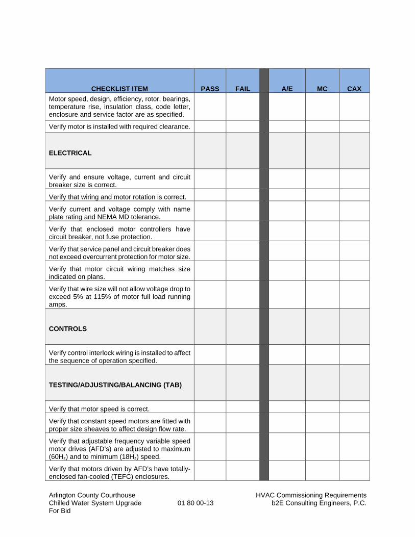
Arlington County Courthouse HVAC Commissioning Requirements Chilled Water System Upgrade 01 80 00-13 b2E Consulting Engineers, P.C. For Bid
CHECKLIST ITEM
PASS
FAIL
A/E
MC
CAX
Motor speed, design, efficiency, rotor, bearings, temperature rise, insulation class, code letter, enclosure and service factor are as specified.
Verify motor is installed with required clearance.
ELECTRICAL
Verify and ensure voltage, current and circuit breaker size is correct.
Verify that wiring and motor rotation is correct.
Verify current and voltage comply with name plate rating and NEMA MD tolerance.
Verify that enclosed motor controllers have circuit breaker, not fuse protection.
Verify that service panel and circuit breaker does not exceed overcurrent protection for motor size.
Verify that motor circuit wiring matches size indicated on plans.
Verify that wire size will not allow voltage drop to exceed 5% at 115% of motor full load running amps.
CONTROLS
Verify control interlock wiring is installed to affect the sequence of operation specified.
TESTING/ADJUSTING/BALANCING (TAB)
Verify that motor speed is correct.
Verify that constant speed motors are fitted with proper size sheaves to affect design flow rate.
Verify that adjustable frequency variable speed motor drives (AFD’s) are adjusted to maximum (60Hz) and to minimum (18Hz) speed.
Verify that motors driven by AFD’s have totally-enclosed fan-cooled (TEFC) enclosures.
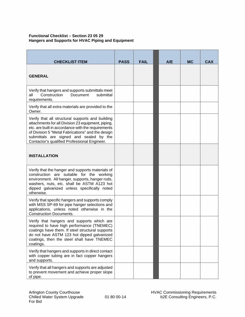
Arlington County Courthouse HVAC Commissioning Requirements Chilled Water System Upgrade 01 80 00-14 b2E Consulting Engineers, P.C. For Bid
Functional Checklist – Section 23 05 29 Hangers and Supports for HVAC Piping and Equipment
CHECKLIST ITEM
PASS
FAIL
A/E
MC
CAX
GENERAL
Verify that hangers and supports submittals meet all Construction Document submittal requirements.
Verify that all extra materials are provided to the Owner.
Verify that all structural supports and building attachments for all Division 23 equipment, piping, etc. are built in accordance with the requirements of Division 5 “Metal Fabrications” and the design submittals are signed and sealed by the Contactor’s qualified Professional Engineer.
INSTALLATION
Verify that the hanger and supports materials of construction are suitable for the working environment. All hanger, supports, hanger rods, washers, nuts, etc. shall be ASTM A123 hot dipped galvanized unless specifically noted otherwise.
Verify that specific hangers and supports comply with MSS SP-69 for pipe hanger selections and applications, unless noted otherwise in the Construction Documents.
Verify that hangers and supports which are required to have high performance (TNEMEC) coatings have them. If steel structural supports do not have ASTM 123 hot dipped galvanized coatings, then the steel shall have TNEMEC coatings.
Verify that hangers and supports in direct contact with copper tubing are in fact copper hangers and supports.
Verify that all hangers and supports are adjusted to prevent movement and achieve proper slope of pipe.
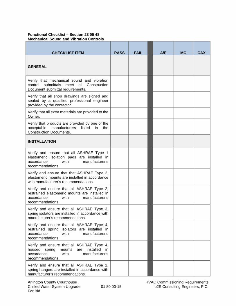
Arlington County Courthouse HVAC Commissioning Requirements Chilled Water System Upgrade 01 80 00-15 b2E Consulting Engineers, P.C. For Bid
Functional Checklist – Section 23 05 48 Mechanical Sound and Vibration Controls
CHECKLIST ITEM
PASS
FAIL
A/E
MC
CAX
GENERAL
Verify that mechanical sound and vibration control submittals meet all Construction Document submittal requirements.
Verify that all shop drawings are signed and sealed by a qualified professional engineer provided by the contactor.
Verify that all extra materials are provided to the Owner.
Verify that products are provided by one of the acceptable manufacturers listed in the Construction Documents.
INSTALLATION
Verify and ensure that all ASHRAE Type 1 elastomeric isolation pads are installed in accordance with manufacturer’s recommendations.
Verify and ensure that that ASHRAE Type 2, elastomeric mounts are installed in accordance with manufacturer’s recommendations.
Verify and ensure that all ASHRAE Type 2, restrained elastomeric mounts are installed in accordance with manufacturer’s recommendations.
Verify and ensure that all ASHRAE Type 3, spring isolators are installed in accordance with manufacturer’s recommendations.
Verify and ensure that all ASHRAE Type 4, restrained spring isolators are installed in accordance with manufacturer’s recommendations.
Verify and ensure that all ASHRAE Type 4, housed spring mounts are installed in accordance with manufacturer’s recommendations.
Verify and ensure that all ASHRAE Type 2, spring hangers are installed in accordance with manufacturer’s recommendations.
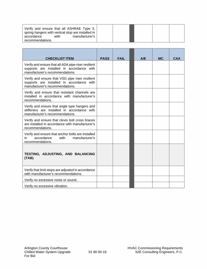
Arlington County Courthouse HVAC Commissioning Requirements Chilled Water System Upgrade 01 80 00-16 b2E Consulting Engineers, P.C. For Bid
Verify and ensure that all ASHRAE Type 3, spring hangers with vertical stop are installed in accordance with manufacturer’s recommendations.
CHECKLIST ITEM
PASS
FAIL
A/E
MC
CAX
Verify and ensure that all ADA pipe riser resilient supports are installed in accordance with manufacturer’s recommendations.
Verify and ensure that VSG pipe riser resilient supports are installed in accordance with manufacturer’s recommendations.
Verify and ensure that resistant channels are installed in accordance with manufacturer’s recommendations.
Verify and ensure that angle type hangers and stiffeners are installed in accordance with manufacturer’s recommendations.
Verify and ensure that clevis bolt cross braces are installed in accordance with manufacturer’s recommendations.
Verify and ensure that anchor bolts are installed in accordance with manufacturer’s recommendations.
TESTING, ADJUSTING, AND BALANCING (TAB)
Verify that limit stops are adjusted in accordance with manufacturer’s recommendations.
Verify no excessive noise or sound.
Verify no excessive vibration.
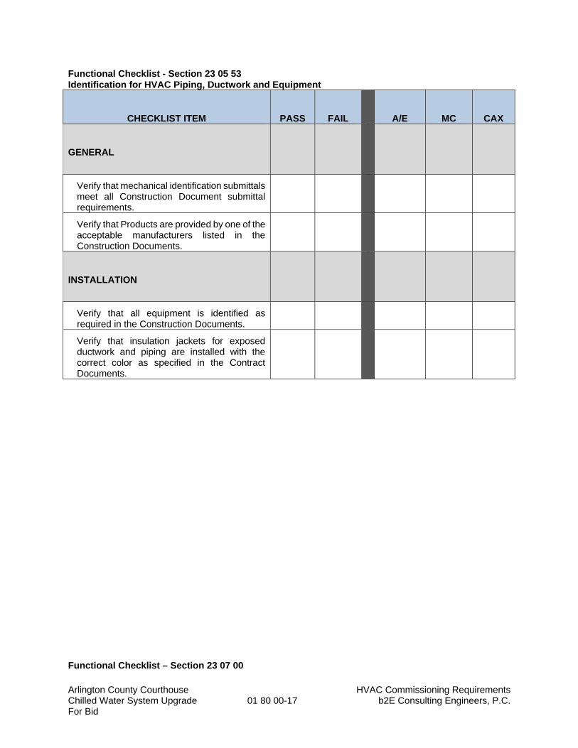
Arlington County Courthouse HVAC Commissioning Requirements Chilled Water System Upgrade 01 80 00-17 b2E Consulting Engineers, P.C. For Bid
Functional Checklist - Section 23 05 53 Identification for HVAC Piping, Ductwork and Equipment
CHECKLIST ITEM
PASS
FAIL
A/E
MC
CAX
GENERAL
Verify that mechanical identification submittals meet all Construction Document submittal requirements.
Verify that Products are provided by one of the acceptable manufacturers listed in the Construction Documents.
INSTALLATION
Verify that all equipment is identified as required in the Construction Documents.
Verify that insulation jackets for exposed ductwork and piping are installed with the correct color as specified in the Contract Documents.
Functional Checklist – Section 23 07 00
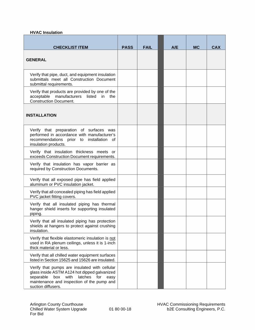
Arlington County Courthouse HVAC Commissioning Requirements Chilled Water System Upgrade 01 80 00-18 b2E Consulting Engineers, P.C. For Bid
HVAC Insulation
CHECKLIST ITEM
PASS
FAIL
A/E
MC
CAX
GENERAL
Verify that pipe, duct, and equipment insulation submittals meet all Construction Document submittal requirements.
Verify that products are provided by one of the acceptable manufacturers listed in the Construction Document.
INSTALLATION
Verify that preparation of surfaces was performed in accordance with manufacturer’s recommendations prior to installation of insulation products.
Verify that insulation thickness meets or exceeds Construction Document requirements.
Verify that insulation has vapor barrier as required by Construction Documents.
Verify that all exposed pipe has field applied aluminum or PVC insulation jacket.
Verify that all concealed piping has field applied PVC jacket fitting covers.
Verify that all insulated piping has thermal hanger shield inserts for supporting insulated piping.
Verify that all insulated piping has protection shields at hangers to protect against crushing insulation.
Verify that flexible elastomeric insulation is not used in RA plenum ceilings, unless it is 1-inch thick material or less.
Verify that all chilled water equipment surfaces listed in Section 15625 and 15626 are insulated.
Verify that pumps are insulated with cellular glass inside ASTM A124 hot dipped galvanized separable box with latches for easy maintenance and inspection of the pump and suction diffusers.
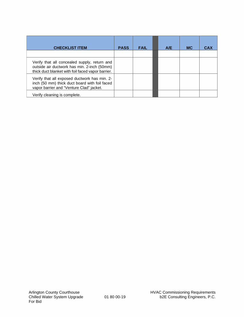
Arlington County Courthouse HVAC Commissioning Requirements Chilled Water System Upgrade 01 80 00-19 b2E Consulting Engineers, P.C. For Bid
CHECKLIST ITEM
PASS
FAIL
A/E
MC
CAX
Verify that all concealed supply, return and outside air ductwork has min. 2-inch (50mm) thick duct blanket with foil faced vapor barrier.
Verify that all exposed ductwork has min. 2-inch (50 mm) thick duct board with foil faced vapor barrier and “Venture Clad” jacket.
Verify cleaning is complete.
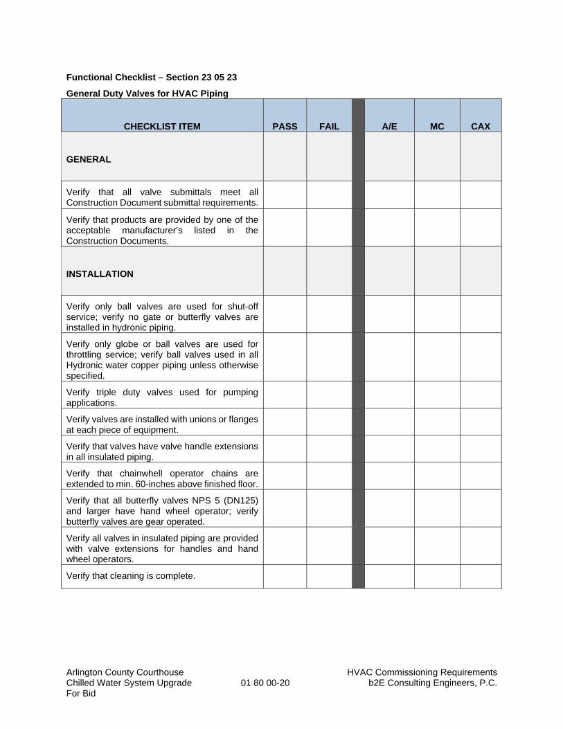
Arlington County Courthouse HVAC Commissioning Requirements Chilled Water System Upgrade 01 80 00-20 b2E Consulting Engineers, P.C. For Bid
Functional Checklist – Section 23 05 23
General Duty Valves for HVAC Piping
CHECKLIST ITEM
PASS
FAIL
A/E
MC
CAX
GENERAL
Verify that all valve submittals meet all Construction Document submittal requirements.
Verify that products are provided by one of the acceptable manufacturer’s listed in the Construction Documents.
INSTALLATION
Verify only ball valves are used for shut-off service; verify no gate or butterfly valves are installed in hydronic piping.
Verify only globe or ball valves are used for throttling service; verify ball valves used in all Hydronic water copper piping unless otherwise specified.
Verify triple duty valves used for pumping applications.
Verify valves are installed with unions or flanges at each piece of equipment.
Verify that valves have valve handle extensions in all insulated piping.
Verify that chainwhell operator chains are extended to min. 60-inches above finished floor.
Verify that all butterfly valves NPS 5 (DN125) and larger have hand wheel operator; verify butterfly valves are gear operated.
Verify all valves in insulated piping are provided with valve extensions for handles and hand wheel operators.
Verify that cleaning is complete.
Arlington County Courthouse HVAC Commissioning Requirements Chilled Water System Upgrade 01 80 00-21 b2E Consulting Engineers, P.C. For Bid
Functional Checklist – Section 23 05 19
Meters and Gages for HVAC Piping
CHECKLIST ITEM
PASS
FAIL
A/E
MC
CAX
GENERAL
Verify that all meters and gages submittals meet all Construction Document submittal requirements.
Verify that products are provided by one of the acceptable manufacturer’s listed in the Construction Documents.
Verify that all extra materials are provided to the Owner.
INSTALLATION
Verify that digital, UV powered thermometers are installed in locations required by the contract documents.
Verify that dry-case type pressure gauges are installed for discharge of each pressure reducing valve.
Verify that liquid-filled case type pressure gauges are installed at chilled water inlets and outlets of chillers.
Verify that liquid-filled case type pressure gauges are installed at the suction and discharge of each pump.
Verify that liquid-filled case type pressure gauges are installed at outlets of boilers.
Verify that UV digital thermometers are adjusted to be easily read, and are located such that they are in a lighted area.
Verify that thermowells are installed with sockets extending to the center of the piping for 3-inch (DN75) and larger piping.
Verify that thermowells are installed in Tees or Ells with sockets extending min 2-inches (50mm) into piping system.
Verify that socket extensions are used for insulated piping for flush thermometer installation.
Arlington County Courthouse HVAC Commissioning Requirements Chilled Water System Upgrade 01 80 00-22 b2E Consulting Engineers, P.C. For Bid
Verify that pressure gauges are installed with needle valves and snubber fittings.
CHECKLIST ITEM
PASS
FAIL
A/E
MC
CAX
Verify that test plugs are installed at Tees or weld-o-lets and are either brass or stainless steel.
Verify all gauges are installed to be easily read.
Verify thermometers are installed at the inlet and outlet of each hydronic boiler.
Verify thermometers are installed at the two (2) inlets and two (2) outlets of each chiller.
Verify all meters have been calibrated according to MFGR instructions.
Verify cleaning is complete.
Arlington County Courthouse HVAC Commissioning Requirements Chilled Water System Upgrade 01 80 00-23 b2E Consulting Engineers, P.C. For Bid
Functional Checklist – Section 23 21 13 Hydronic Piping
CHECKLIST ITEM
PASS
FAIL
A/E
MC
CAX
GENERAL
Verify that hydronic Piping submittals meet all Construction Document submittal requirements.
Verify that products are provided by one of the acceptable manufacturer’s listed in the Construction Documents.
Verify that all extra materials are provided to the Owner.
INSTALLATION
Verify that all hot and chilled hydronic piping 2-inch (DN50) and smaller is Type L drawn-temper copper tubing with soldered joints or Schedule 40 steel pipe with threaded joints.
Verify that hot and chilled hydronic piping 2 ½ -inch (DN65) and larger is Scheduled 40 welded steel pipe with welded and flanged joints.
Verify that all condenser hydronic piping 2 ½ -inch (DN65) and larger is Schedule 40 welded pipe with welded and flanged joints.
Verify that condensate drain lines are Type L drawn-temper copper tubing with soldered joints.
Verify that grooved couplings are only used at connections to equipment for ease of removal for that piece of equipment such as chillers.
Verify that all ball and butterfly valves are used for shut-off duty. Gate and butterfly valves are not allowed.
Verify that globe, ball and butterfly valves are used for throttling duty. Gate and butterfly valves are not allowed.
Verify that shut-off duty valves are installed at the entrance/exit to the main chiller room to allow system drain down without draining entire piping system.
Verify calibrated balancing valves are installed in the return water line for each chiller and additionally as indicated on drawings.

Arlington County Courthouse HVAC Commissioning Requirements Chilled Water System Upgrade 01 80 00-24 b2E Consulting Engineers, P.C. For Bid
CHECKLIST ITEM
PASS
FAIL
A/E
MC
CAX
Verify that safety valves are installed as required by the ASME Boiler and Pressure Vessel Code.
1) Set heating side safety valves to 100 psig.
2) Set cooling side safety valves to 100 psig.
Verify that pressure reducing station make-up-water assembly is set to 20 psig.
Verify that triple duty check valves are installed on each pump discharge. Rotate to ensure that stem does not drip on pump shaft.
Verify that drain valves are installed at low points in mains, risers, branch lines and elsewhere to facilitate total and partial system draining as desired.
Verify that air vents are installed where indicated on plans with drain at 3’-6” above finished floor.
1) Drain valves shall be hose drain type with brass cap and chain.
Verify piping installed in groups parallel to each other, spaced to permit applying insulation and servicing of valves.
Verify that all drain valves have Tee fitting, 3/4 –inch (DN20) ball valve, and short ¾-inch (DN20) threaded nipple (hose connections) with brass cap and chain.
Verify that piping installed at a uniform grade of 0.2 percent upward in direction of flow.
Verify that pipe sizes are reduced using appropriate type of fitting.
1) Vertical Piping: Concentric reducer.
2) Horizontal Water Piping: Eccentric reducer with level side up.
Verify that strainer installed on the inlet to the make-up-water assembly before the pressure reducing valve.
Verify that strainers are installed for ease of maintenance (screen removal) and provided with blow-down valves.
1) Blow-down (drain) valve shall be hose drain type with brass cap and chain.
Verify that all piping and fittings of dissimilar metals are protected using dialectic unions, couplings, etc.
Arlington County Courthouse HVAC Commissioning Requirements Chilled Water System Upgrade 01 80 00-25 b2E Consulting Engineers, P.C. For Bid
CHECKLIST ITEM
PASS
FAIL
A/E
MC
CAX
Verify that piping hangers and supports are corrosion resistant using either ASTM A123 hot dipped galvanized, or high performance coated (TNEMEC).
Verify that piping support spacing does not exceed the distances indicated in Section 23 21 13.
Verify that manual air vents are installed at all high points in piping.
Verify that automatic air vents are installed in all mechanical rooms at high points of system piping.
Verify tangential air separators are installed in pump suction line, clearances are maintained and blow down valve is installed.
1) Route blow-down piping to nearest floor drain.
Verify expansion tanks are “full acceptance” diagram type and are charged to 25 psig prior to filling hydronic system with water.
Verify that bypass chemical feeders are installed for each closed-loop hydronic system.
Verify that hydronic systems are filled and initial chemical treatment is performed.
Verify that field quality control is performed in accordance with Section 23 21 13.
Verify that adjustments are made in accordance with Section 23 21 13.
Verify that hydronic system is thoroughly cleaned (flushed-out) using startup strainers, and systems are cleaned in accordance with Section 23 21 13.
Verify that isolation valves are installed on the interior side of each mechanical equipment room for all CW and CHW piping; verify a ¾ - inch drain valve with ¾ - inch hose connection (including brass cap and chain) are provided before and after (both sides) of isolation valves; verify that mechanical equipment room piping can be drained for service while the remainder of the building hydronic systems remain fully operational.
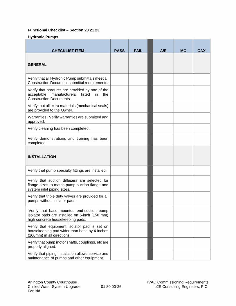
Arlington County Courthouse HVAC Commissioning Requirements Chilled Water System Upgrade 01 80 00-26 b2E Consulting Engineers, P.C. For Bid
Functional Checklist – Section 23 21 23
Hydronic Pumps
CHECKLIST ITEM
PASS
FAIL
A/E
MC
CAX
GENERAL
Verify that all Hydronic Pump submittals meet all Construction Document submittal requirements.
Verify that products are provided by one of the acceptable manufacturers listed in the Construction Documents.
Verify that all extra materials (mechanical seals) are provided to the Owner.
Warranties: Verify warranties are submitted and approved.
Verify cleaning has been completed.
Verify demonstrations and training has been completed.
INSTALLATION
Verify that pump specialty fittings are installed.
Verify that suction diffusers are selected for flange sizes to match pump suction flange and system inlet piping sizes.
Verify that triple duty valves are provided for all pumps without isolator pads.
Verify that base mounted end-suction pump isolator pads are installed on 6-inch (150 mm) high concrete housekeeping pads.
Verify that equipment isolator pad is set on housekeeping pad wider than base by 4-inches (100mm) in all directions.
Verify that pump motor shafts, couplings, etc are properly aligned.
Verify that piping installation allows service and maintenance of pumps and other equipment.
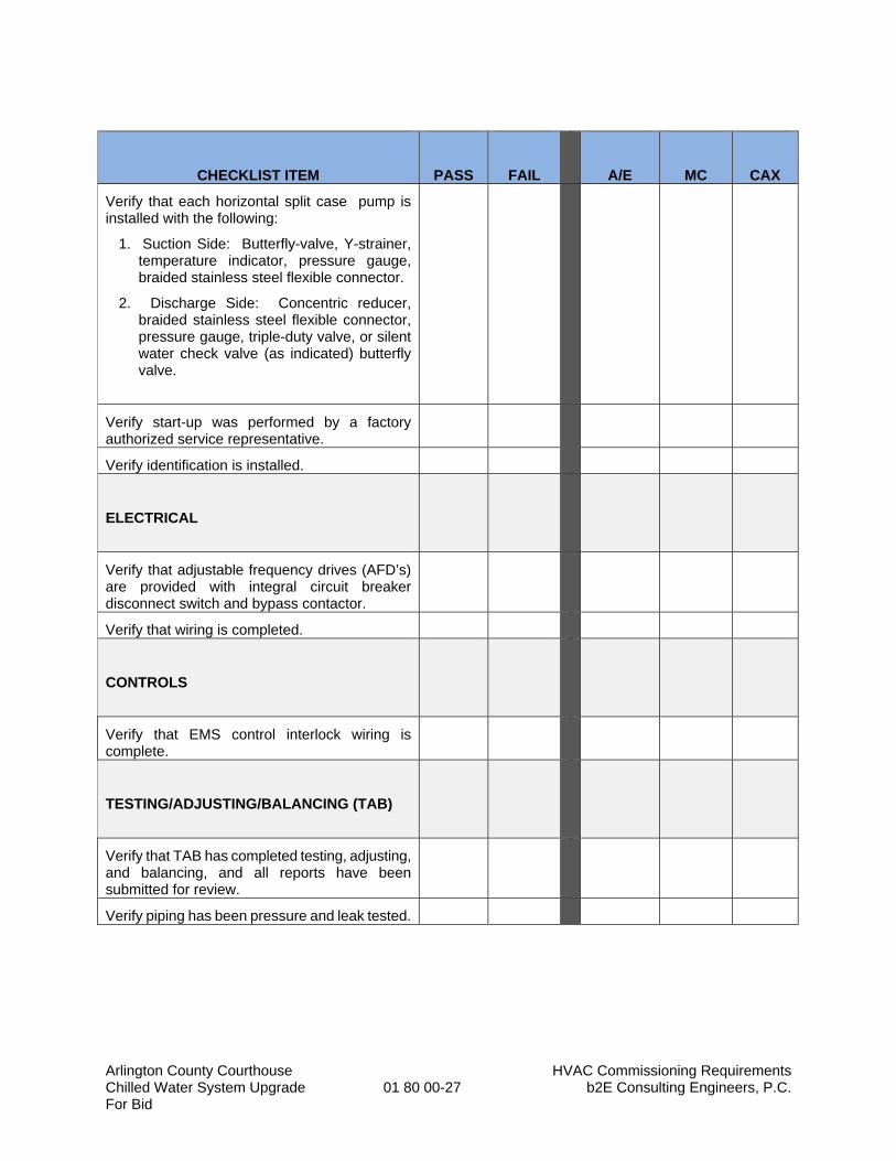
Arlington County Courthouse HVAC Commissioning Requirements Chilled Water System Upgrade 01 80 00-27 b2E Consulting Engineers, P.C. For Bid
CHECKLIST ITEM
PASS
FAIL
A/E
MC
CAX
Verify that each horizontal split case pump is installed with the following:
1. Suction Side: Butterfly-valve, Y-strainer, temperature indicator, pressure gauge, braided stainless steel flexible connector.
2. Discharge Side: Concentric reducer, braided stainless steel flexible connector, pressure gauge, triple-duty valve, or silent water check valve (as indicated) butterfly valve.
Verify start-up was performed by a factory authorized service representative.
Verify identification is installed.
ELECTRICAL
Verify that adjustable frequency drives (AFD’s) are provided with integral circuit breaker disconnect switch and bypass contactor.
Verify that wiring is completed.
CONTROLS
Verify that EMS control interlock wiring is complete.
TESTING/ADJUSTING/BALANCING (TAB)
Verify that TAB has completed testing, adjusting, and balancing, and all reports have been submitted for review.
Verify piping has been pressure and leak tested.
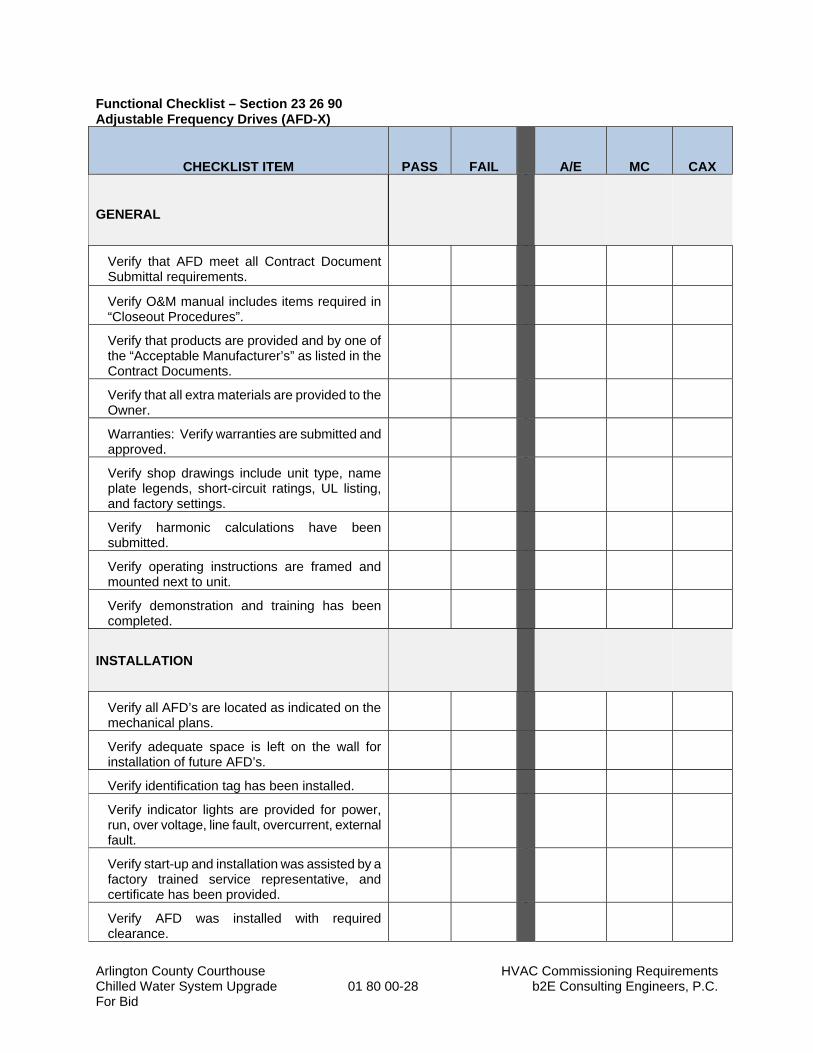
Arlington County Courthouse HVAC Commissioning Requirements Chilled Water System Upgrade 01 80 00-28 b2E Consulting Engineers, P.C. For Bid
Functional Checklist – Section 23 26 90 Adjustable Frequency Drives (AFD-X)
CHECKLIST ITEM
PASS
FAIL
A/E
MC
CAX
GENERAL
Verify that AFD meet all Contract Document Submittal requirements.
Verify O&M manual includes items required in “Closeout Procedures”.
Verify that products are provided and by one of the “Acceptable Manufacturer’s” as listed in the Contract Documents.
Verify that all extra materials are provided to the Owner.
Warranties: Verify warranties are submitted and approved.
Verify shop drawings include unit type, name plate legends, short-circuit ratings, UL listing, and factory settings.
Verify harmonic calculations have been submitted.
Verify operating instructions are framed and mounted next to unit.
Verify demonstration and training has been completed.
INSTALLATION
Verify all AFD’s are located as indicated on the mechanical plans.
Verify adequate space is left on the wall for installation of future AFD’s.
Verify identification tag has been installed.
Verify indicator lights are provided for power, run, over voltage, line fault, overcurrent, external fault.
Verify start-up and installation was assisted by a factory trained service representative, and certificate has been provided.
Verify AFD was installed with required clearance.
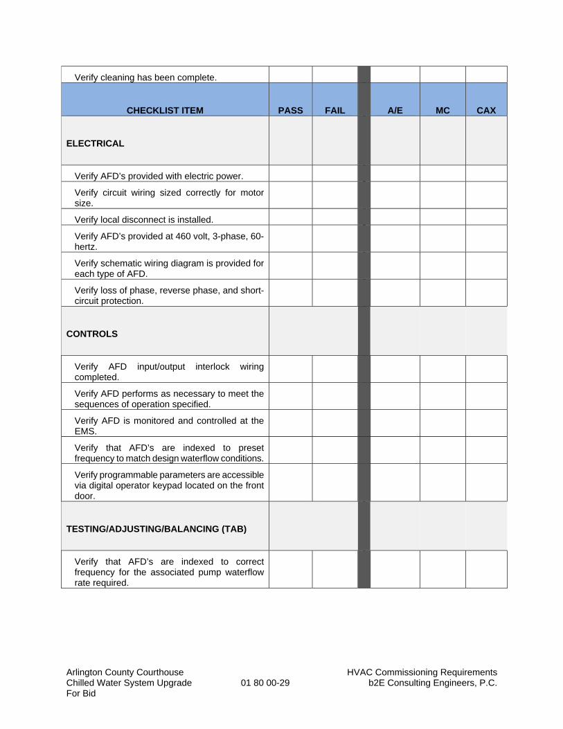
Arlington County Courthouse HVAC Commissioning Requirements Chilled Water System Upgrade 01 80 00-29 b2E Consulting Engineers, P.C. For Bid
Verify cleaning has been complete.
CHECKLIST ITEM
PASS
FAIL
A/E
MC
CAX
ELECTRICAL
Verify AFD’s provided with electric power.
Verify circuit wiring sized correctly for motor size.
Verify local disconnect is installed.
Verify AFD’s provided at 460 volt, 3-phase, 60-hertz.
Verify schematic wiring diagram is provided for each type of AFD.
Verify loss of phase, reverse phase, and short-circuit protection.
CONTROLS
Verify AFD input/output interlock wiring completed.
Verify AFD performs as necessary to meet the sequences of operation specified.
Verify AFD is monitored and controlled at the EMS.
Verify that AFD’s are indexed to preset frequency to match design waterflow conditions.
Verify programmable parameters are accessible via digital operator keypad located on the front door.
TESTING/ADJUSTING/BALANCING (TAB)
Verify that AFD’s are indexed to correct frequency for the associated pump waterflow rate required.
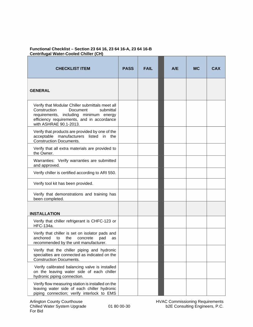
Arlington County Courthouse HVAC Commissioning Requirements Chilled Water System Upgrade 01 80 00-30 b2E Consulting Engineers, P.C. For Bid
Functional Checklist – Section 23 64 16, 23 64 16-A, 23 64 16-B Centrifugal Water-Cooled Chiller (CH)
CHECKLIST ITEM
PASS
FAIL
A/E
MC
CAX
GENERAL
Verify that Modular Chiller submittals meet all Construction Document submittal requirements, including minimum energy efficiency requirements, and in accordance with ASHRAE 90.1-2013.
Verify that products are provided by one of the acceptable manufacturers listed in the Construction Documents.
Verify that all extra materials are provided to the Owner.
Warranties: Verify warranties are submitted and approved.
Verify chiller is certified according to ARI 550.
Verify tool kit has been provided.
Verify that demonstrations and training has been completed.
INSTALLATION
Verify that chiller refrigerant is CHFC-123 or HFC-134a.
Verify that chiller is set on isolator pads and anchored to the concrete pad as recommended by the unit manufacturer.
Verify that the chiller piping and hydronic specialties are connected as indicated on the Construction Documents.
Verify calibrated balancing valve is installed on the leaving water side of each chiller hydronic piping connection.
Verify flow measuring station is installed on the leaving water side of each chiller hydronic piping connection; verify interlock to EMS
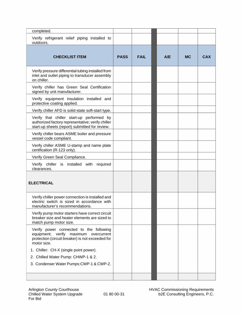
Arlington County Courthouse HVAC Commissioning Requirements Chilled Water System Upgrade 01 80 00-31 b2E Consulting Engineers, P.C. For Bid
completed.
Verify refrigerant relief piping installed to outdoors.
CHECKLIST ITEM
PASS
FAIL
A/E
MC
CAX
Verify pressure differential tubing installed from inlet and outlet piping to transducer assembly on chiller.
Verify chiller has Green Seal Certification signed by unit manufacturer.
Verify equipment insulation installed and protective coating applied.
Verify chiller AFD is solid-state soft-start type.
Verify that chiller start-up performed by authorized factory representative; verify chiller start-up sheets (report) submitted for review.
Verify chiller bears ASME boiler and pressure vessel code compliant.
Verify chiller ASME U-stamp and name plate certification (R-123 only).
Verify Green Seal Compliance.
Verify chiller is installed with required clearances.
ELECTRICAL
Verify chiller power connection is installed and electric switch is sized in accordance with manufacturer’s recommendations.
Verify pump motor starters have correct circuit breaker size and heater elements are sized to match pump motor size.
Verify power connected to the following equipment; verify maximum overcurrent protection (circuit breaker) is not exceeded for motor size.
1. Chiller: CH-X (single point power).
2. Chilled Water Pump: CHWP-1 & 2.
3. Condenser Water Pumps:CWP-1 & CWP-2.
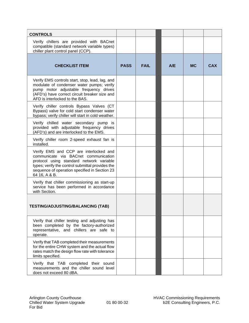
Arlington County Courthouse HVAC Commissioning Requirements Chilled Water System Upgrade 01 80 00-32 b2E Consulting Engineers, P.C. For Bid
CONTROLS
Verify chillers are provided with BACnet compatible (standard network variable types) chiller plant control panel (CCP).
CHECKLIST ITEM
PASS
FAIL
A/E
MC
CAX
Verify EMS controls start, stop, lead, lag, and modulate of condenser water pumps; verify pump motor adjustable frequency drives (AFD’s) have correct circuit breaker size and AFD is interlocked to the BAS.
Verify chiller controls Bypass Valves (CT Bypass) valve for cold start condenser water bypass; verify chiller will start in cold weather.
Verify chilled water secondary pump is provided with adjustable frequency drives (AFD’s) and are interlocked to the EMS.
Verify chiller room 2-speed exhaust fan is installed.
Verify EMS and CCP are interlocked and communicate via BACnet communication protocol using standard network variable types; verify the control submittal provides the sequence of operation specified in Section 23 64 16, A & B.
Verify that chiller commissioning as start-up service has been performed in accordance with Section.
TESTING/ADJUSTING/BALANCING (TAB)
Verify that chiller testing and adjusting has been completed by the factory-authorized representative, and chillers are safe to operate.
Verify that TAB completed their measurements for the entire CHW system and the actual flow rates match the design flow rate with tolerance limits specified.
Verify that TAB completed their sound measurements and the chiller sound level does not exceed 80 dBA.

Arlington County Courthouse HVAC Commissioning Requirements Chilled Water System Upgrade 01 80 00-33 b2E Consulting Engineers, P.C. For Bid
Functional Checklist – Section 23 64 20
Refrigerant Monitoring and Safety Equipment
CHECKLIST ITEM
PASS
FAIL
A/E
MC
CAX
GENERAL
Verify that Refrigerant Monitoring and Safety Equipment submittals meet all Contract Document submittal requirements.
Verify that products are provided by one of the acceptable manufacturers listed in the Contract Documents.
Verify that all extra materials are provided to the Owner.
Warranties: Verify warranties are submitted and approved.
INSTALLATION
Verify control panel wired to sensors and provided with 120V single phase electric power.
Verify minimum three (3) sensors provided around the chillers; verify sensors calibrated at 10ppm for correct refrigerant with + 1 ppm accuracy.
Verify control panel auxiliary relay hard wired to chiller shunt-trip circuit breaker.
ELECTRICAL
Verify refrigerant monitoring initiates the following:
1) Initiate chiller shut-down sequence.
2) Start EF-26 on high speed; if running index to high speed.
3) Open gravity ventilator damper to 100%.
4) All gas-fired equipment is shutdown.
5) Local alarm annunciates and flashes blue light.
6) Controller initiates trouble signal and fire alarm control panel.
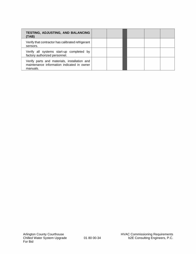
Arlington County Courthouse HVAC Commissioning Requirements Chilled Water System Upgrade 01 80 00-34 b2E Consulting Engineers, P.C. For Bid
TESTING, ADJUSTING, AND BALANCING (TAB)
Verify that contractor has calibrated refrigerant sensors.
Verify all systems start-up completed by factory authorized personnel.
Verify parts and materials, installation and maintenance information indicated in owner manuals.

Arlington County Courthouse HVAC Commissioning Requirements Chilled Water System Upgrade 01 80 00-35 b2E Consulting Engineers, P.C. For Bid
Functional Checklist – Section 23 65 00
Open-Circuit, Induced-Draft Cooling Towers (CT-X)
CHECKLIST ITEM
PASS
FAIL
A/E
MC
CAX
GENERAL
Verify that Open-Circuit, Mechanical Draft Cooling Tower submittals meet all Construction Document submittal requirements.
Verify that products are provided by one of the acceptable manufacturers listed in the Construction Documents.
Verify that all extra materials are provided to the Owner.
Warranties: Verify warranties are submitted and approved.
Verify certification of towers thermal performance according to CTI 201.
Verify demonstrations and training is complete.
INSTALLATION
Verify that structural steel support system designed by contractor was designed by a licensed professional engineer registered in the Commonwealth of Virginia and that sealed and signed fabrication drawings have been submitted; verify ladder is extended to roof level; verify side access platforms are provided with ladders.
Verify that registered spring vibration isolators are selected properly and spring colors match submittals; verify min. 1-inch deflection at operating weight.
Verify that cooling tower inlet and outlet piping connections are flexible type.
Verify that cooling tower outlet piping (inside basin) is protected with stainless steel strainer assembly.
Verify CT-CWS outlet is 10” connection size and CT CWR inlet is 8” connection size.
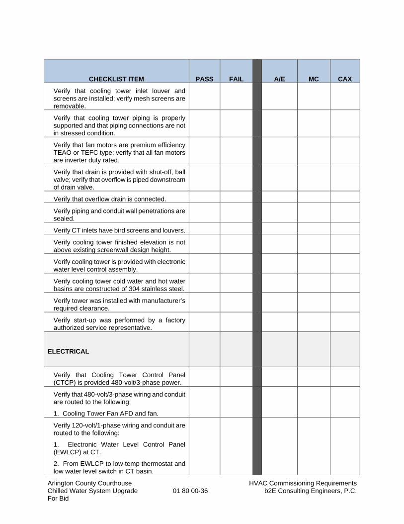
Arlington County Courthouse HVAC Commissioning Requirements Chilled Water System Upgrade 01 80 00-36 b2E Consulting Engineers, P.C. For Bid
CHECKLIST ITEM
PASS
FAIL
A/E
MC
CAX
Verify that cooling tower inlet louver and screens are installed; verify mesh screens are removable.
Verify that cooling tower piping is properly supported and that piping connections are not in stressed condition.
Verify that fan motors are premium efficiency TEAO or TEFC type; verify that all fan motors are inverter duty rated.
Verify that drain is provided with shut-off, ball valve; verify that overflow is piped downstream of drain valve.
Verify that overflow drain is connected.
Verify piping and conduit wall penetrations are sealed.
Verify CT inlets have bird screens and louvers.
Verify cooling tower finished elevation is not above existing screenwall design height.
Verify cooling tower is provided with electronic water level control assembly.
Verify cooling tower cold water and hot water basins are constructed of 304 stainless steel.
Verify tower was installed with manufacturer’s required clearance.
Verify start-up was performed by a factory authorized service representative.
ELECTRICAL
Verify that Cooling Tower Control Panel (CTCP) is provided 480-volt/3-phase power.
Verify that 480-volt/3-phase wiring and conduit are routed to the following:
1. Cooling Tower Fan AFD and fan.
Verify 120-volt/1-phase wiring and conduit are routed to the following:
1. Electronic Water Level Control Panel (EWLCP) at CT.
2. From EWLCP to low temp thermostat and low water level switch in CT basin.
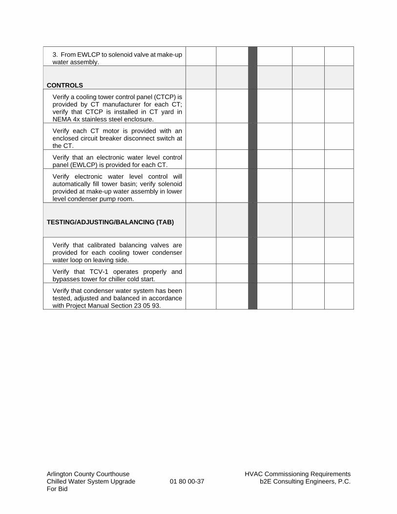
Arlington County Courthouse HVAC Commissioning Requirements Chilled Water System Upgrade 01 80 00-37 b2E Consulting Engineers, P.C. For Bid
3. From EWLCP to solenoid valve at make-up water assembly.
CONTROLS
Verify a cooling tower control panel (CTCP) is provided by CT manufacturer for each CT; verify that CTCP is installed in CT yard in NEMA 4x stainless steel enclosure.
Verify each CT motor is provided with an enclosed circuit breaker disconnect switch at the CT.
Verify that an electronic water level control panel (EWLCP) is provided for each CT.
Verify electronic water level control will automatically fill tower basin; verify solenoid provided at make-up water assembly in lower level condenser pump room.
TESTING/ADJUSTING/BALANCING (TAB)
Verify that calibrated balancing valves are provided for each cooling tower condenser water loop on leaving side.
Verify that TCV-1 operates properly and bypasses tower for chiller cold start.
Verify that condenser water system has been tested, adjusted and balanced in accordance with Project Manual Section 23 05 93.

Arlington County Courthouse HVAC Commissioning Requirements Chilled Water System Upgrade 01 80 00-38 b2E Consulting Engineers, P.C. For Bid
Functional Checklist – Section 23 05 93
Testing, Adjusting, and Balancing
CHECKLIST ITEM
PASS
FAIL
A/E
MC
CAX
GENERAL
Verify that Testing, Adjusting and Balancing submittals meet all Construction Document submittal requirements.
Verify that products are provided by one of the acceptable manufacturers listed in the Construction Documents.
Verify that all extra materials are provided to the Owner.
Warranties: Verify warranties are submitted and approved.
INSTALLATION
Verify all balancing dampers indicated on the mechanical plans and other dampers necessary to properly balance the air distribution systems have been installed.
Verify all balancing valves indicated on the mechanical plans and other valves necessary to properly balance the hydronic systems have been installed.
CONTROLS
Verify the EMS software has been completed to affect the sequence of operation specified.
TESTING, ADJUSTING, AND BALANCING (TAB)
Verify and ensure the TAB has submitted and met all quality assurance qualifications.
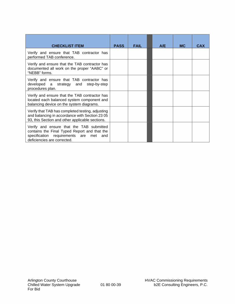
Arlington County Courthouse HVAC Commissioning Requirements Chilled Water System Upgrade 01 80 00-39 b2E Consulting Engineers, P.C. For Bid
CHECKLIST ITEM
PASS
FAIL
A/E
MC
CAX
Verify and ensure that TAB contractor has performed TAB conference.
Verify and ensure that the TAB contractor has documented all work on the proper “AABC” or “NEBB” forms.
Verify and ensure that TAB contractor has developed a strategy and step-by-step procedures plan.
Verify and ensure that the TAB contractor has located each balanced system component and balancing device on the system diagrams.
Verify that TAB has completed testing, adjusting and balancing in accordance with Section 23 05 93, this Section and other applicable sections.
Verify and ensure that the TAB submitted contains the Final Typed Report and that the specification requirements are met and deficiencies are corrected.
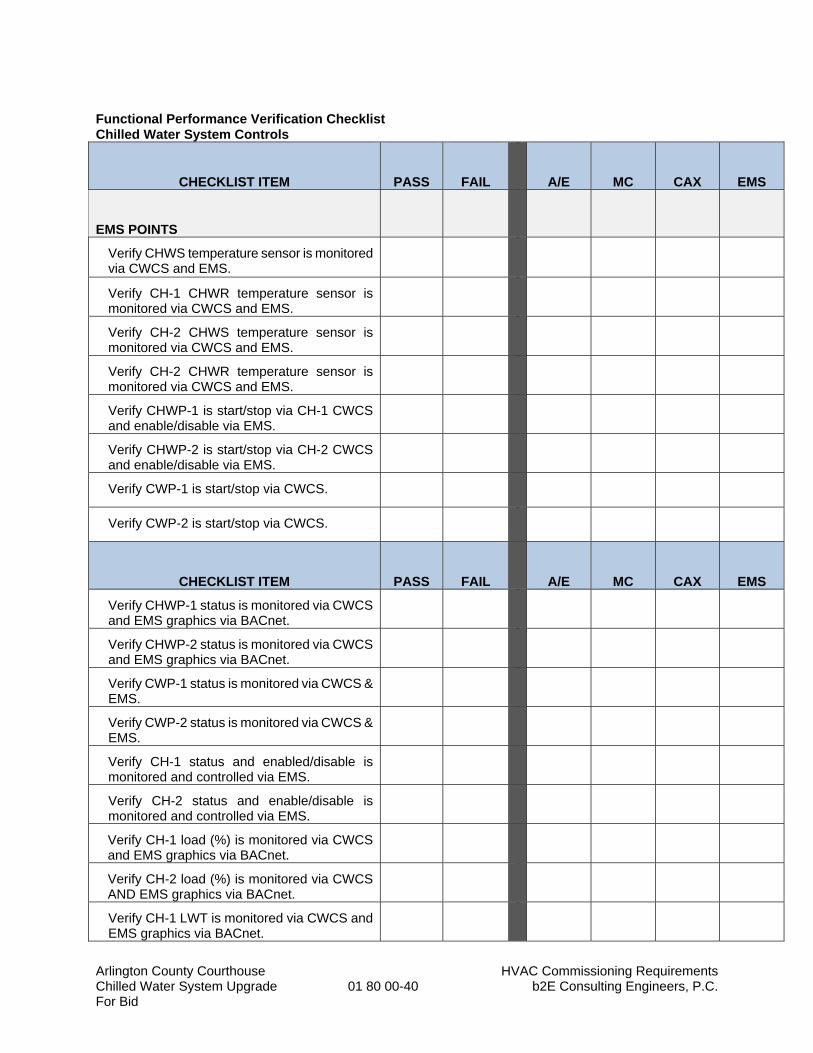
Arlington County Courthouse HVAC Commissioning Requirements Chilled Water System Upgrade 01 80 00-40 b2E Consulting Engineers, P.C. For Bid
Functional Performance Verification Checklist Chilled Water System Controls
CHECKLIST ITEM
PASS
FAIL
A/E
MC
CAX
EMS
EMS POINTS
Verify CHWS temperature sensor is monitored via CWCS and EMS.
Verify CH-1 CHWR temperature sensor is monitored via CWCS and EMS.
Verify CH-2 CHWS temperature sensor is monitored via CWCS and EMS.
Verify CH-2 CHWR temperature sensor is monitored via CWCS and EMS.
Verify CHWP-1 is start/stop via CH-1 CWCS and enable/disable via EMS.
Verify CHWP-2 is start/stop via CH-2 CWCS and enable/disable via EMS.
Verify CWP-1 is start/stop via CWCS.
Verify CWP-2 is start/stop via CWCS.
CHECKLIST ITEM
PASS
FAIL
A/E
MC
CAX
EMS
Verify CHWP-1 status is monitored via CWCS and EMS graphics via BACnet.
Verify CHWP-2 status is monitored via CWCS and EMS graphics via BACnet.
Verify CWP-1 status is monitored via CWCS & EMS.
Verify CWP-2 status is monitored via CWCS & EMS.
Verify CH-1 status and enabled/disable is monitored and controlled via EMS.
Verify CH-2 status and enable/disable is monitored and controlled via EMS.
Verify CH-1 load (%) is monitored via CWCS and EMS graphics via BACnet.
Verify CH-2 load (%) is monitored via CWCS AND EMS graphics via BACnet.
Verify CH-1 LWT is monitored via CWCS and EMS graphics via BACnet.
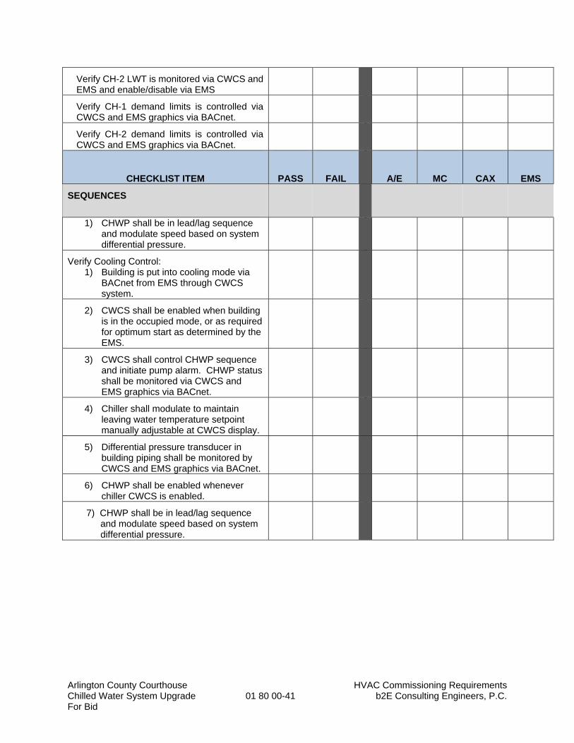
Arlington County Courthouse HVAC Commissioning Requirements Chilled Water System Upgrade 01 80 00-41 b2E Consulting Engineers, P.C. For Bid
Verify CH-2 LWT is monitored via CWCS and EMS and enable/disable via EMS
Verify CH-1 demand limits is controlled via CWCS and EMS graphics via BACnet.
Verify CH-2 demand limits is controlled via CWCS and EMS graphics via BACnet.
CHECKLIST ITEM
PASS
FAIL
A/E
MC
CAX
EMS
SEQUENCES
1) CHWP shall be in lead/lag sequence and modulate speed based on system differential pressure.
Verify Cooling Control: 1) Building is put into cooling mode via
BACnet from EMS through CWCS system.
2) CWCS shall be enabled when building is in the occupied mode, or as required for optimum start as determined by the EMS.
3) CWCS shall control CHWP sequence and initiate pump alarm. CHWP status shall be monitored via CWCS and EMS graphics via BACnet.
4) Chiller shall modulate to maintain leaving water temperature setpoint manually adjustable at CWCS display.
5) Differential pressure transducer in building piping shall be monitored by CWCS and EMS graphics via BACnet.
6) CHWP shall be enabled whenever chiller CWCS is enabled.
7) CHWP shall be in lead/lag sequence and modulate speed based on system differential pressure.
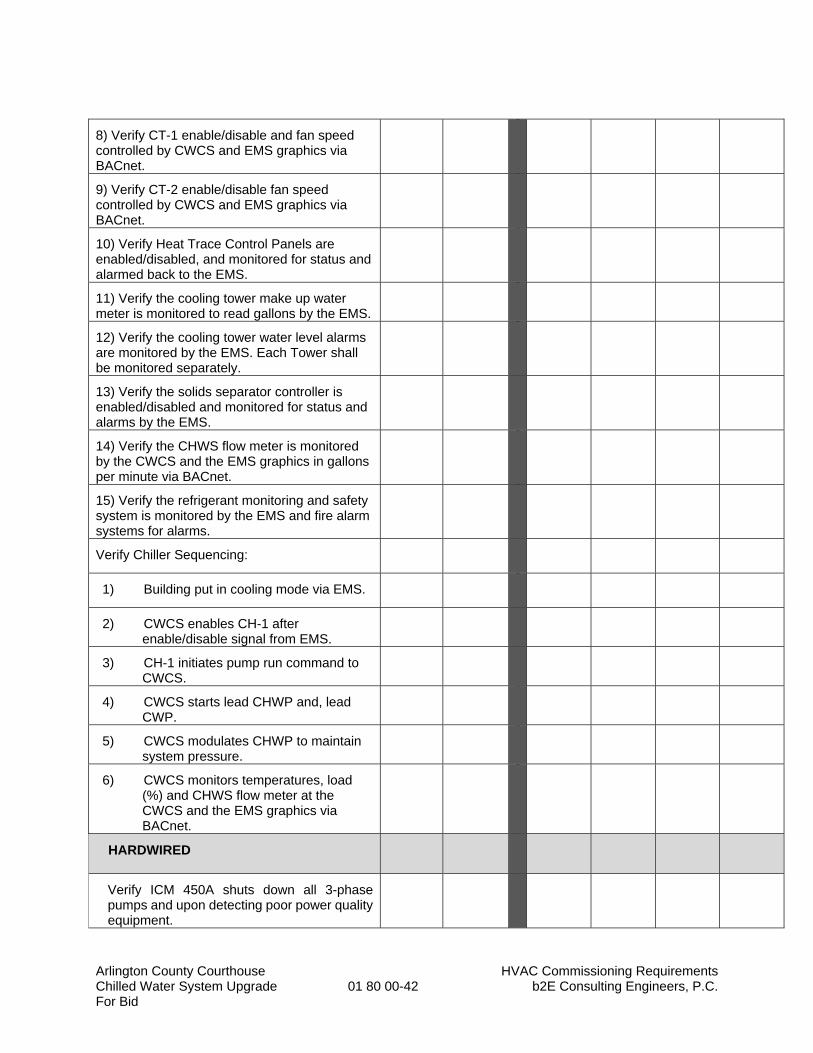
Arlington County Courthouse HVAC Commissioning Requirements Chilled Water System Upgrade 01 80 00-42 b2E Consulting Engineers, P.C. For Bid
8) Verify CT-1 enable/disable and fan speed controlled by CWCS and EMS graphics via BACnet.
9) Verify CT-2 enable/disable fan speed controlled by CWCS and EMS graphics via BACnet.
10) Verify Heat Trace Control Panels are enabled/disabled, and monitored for status and alarmed back to the EMS.
11) Verify the cooling tower make up water meter is monitored to read gallons by the EMS.
12) Verify the cooling tower water level alarms are monitored by the EMS. Each Tower shall be monitored separately.
13) Verify the solids separator controller is enabled/disabled and monitored for status and alarms by the EMS.
14) Verify the CHWS flow meter is monitored by the CWCS and the EMS graphics in gallons per minute via BACnet.
15) Verify the refrigerant monitoring and safety system is monitored by the EMS and fire alarm systems for alarms.
Verify Chiller Sequencing:
1) Building put in cooling mode via EMS.
2) CWCS enables CH-1 after enable/disable signal from EMS.
3) CH-1 initiates pump run command to CWCS.
4) CWCS starts lead CHWP and, lead CWP.
5) CWCS modulates CHWP to maintain system pressure.
6) CWCS monitors temperatures, load (%) and CHWS flow meter at the CWCS and the EMS graphics via BACnet.
HARDWIRED
Verify ICM 450A shuts down all 3-phase pumps and upon detecting poor power quality equipment.
Arlington County Courthouse HVAC Commissioning Requirements Chilled Water System Upgrade 01 80 00-43 b2E Consulting Engineers, P.C. For Bid
END OF SECTION 01 80 00
Arlington Courthouse Proposed Phasing Plan Chiller Plant Replacement 01 85 00-1 b2E Consulting Engineers, P.C. Arlington, Virginia For Bid
SECTION 01 85 00
PROPOSED PHASING PLAN
PART 1 – GENERAL
1.1 RELATED DOCUMENTS:
A. Drawings and General Provisions of Contract, including General and Supplementary Conditions, Division 1 Specification sections, and all other sections of the specifications shall also apply to the extent required for proper performance of the Work of the section.
1.2 SUMMARY
A. This proposed phasing plan is provided as an overview of the scope of work to maintain the
existing chilled water system operational throughout the duration of construction. It shall not be
considered the approved contractor phasing plan, which is the responsibility of the Contractor.
B. Provide a schedule which identifies the project phases, long lead equipment delivery, crane lifts,
outages, equipment start-up, controls completion, commissioning, substantial completion and
project close out.
C. This plan allows the existing cooling towers to be taken out of service for up to one week. The
existing condenser water system serves the existing computer room air conditioning units in the
building. The Owner will provide spot cooling for the computer rooms during this time.
D. Plan the work accordingly to replace the cooling towers and condenser water pumps and cooling
tower start-up before TBD. Plan and schedule all work activities to meet the milestone dates
required to complete the work in phases and substantial completion deadlines.
E. Submit Contractors Phasing Plan for review and approval by the Owner/Engineer. Refer to
Section 01 30 00, “Submittals”.
1.3 PHASE 1A DEMOLITION, SHEET M401 & E101: REMOVE EXISTING COOLING TOWER AND
STRUCTURAL STEEL SUPPORT SYSTEM
A. MECHANICAL
1. Perform initial tab to determine existing CW and CHW flows and pressures.
Submit to the Engineer for review prior to submitting pump submittals.
2. Disconnect existing cooling tower connections and remove existing piping back
to exterior wall.
3. Remove existing power connections back to cooling tower control panels and
remove existing AFD’s and turn over to owner in good operational condition.
4. Remove existing cooling tower.
Arlington Courthouse Proposed Phasing Plan Chiller Plant Replacement 01 85 00-2 b2E Consulting Engineers, P.C. Arlington, Virginia For Bid
5. Remove existing structural steel support system unbolt existing structure from
existing concrete pile caps. Do not damage the existing structure as it will be
reused for the new galvanized steel support system.
6. Remove one of the existing CW pumps and remove the existing inertia block.
Extend existing housekeeping pad as needed to support the new CW pump.
7. When first pump is completed and operational the second pump and inertia
block can be removed.
8. Remove the existing disconnect switches serving CWP-1 and CWP-2.
9. Cut-in the plant isolation valves into the existing CHW piping with taps for the
CHW piping connections required in phase 2. Provide blind flanges to prevent
leaks.
10. Raise the existing fuel oil piping from 105” to 118” above finished slab, and
relocate piping through the wall in the way where door opening is cut (in Phase
1).
B. ELECTRICAL
1. Shut power off to existing cooling towers, existing CW pumps, disconnect wiring,
and make safe for demolition.
2. Remove existing power connections back to cooling tower control panels and
remove existing AFD’s and turn over to owner in good operational condition.
3. Remove existing cooling tower, remove existing circuit from MCC-PH, and
associated conduit serving the existing cooling tower control panels.
4. Remove one of the existing CW pumps and its corresponding disconnect switch
(CWP-1). Remove existing circuit from MCC-PH and associated conduit serving
existing P-3
5. When first pump is completed and operational the second existing CW pump
and disconnect switch (CWP-2) can be removed. Remove existing circuit from
MCC-PH and associated conduit serving existing P-4.
1.4 PHASE 1B NEW WORK, SHEET M402 & E102: INSTALL COOLING TOWER STRUCTURAL
STEEL SUPPORT SYSTEM AND COOLING TOWERS.
A. MECHANICAL
1. Install the new galvanized structural steel support system. Bolt columns to the
existing concrete pile caps. Also install the spring vibration isolators and the top
support steel.
2. Modify the existing ladder to the roof to stop at the new cooling tower platform
level. Refer to architectural for other applicable requirements.
3. Install the cooling towers on the steel structure. Install the factory fabricated
structural platforms, ladders and safety cages.
Arlington Courthouse Proposed Phasing Plan Chiller Plant Replacement 01 85 00-3 b2E Consulting Engineers, P.C. Arlington, Virginia For Bid
4. Install the cooling tower platform in front of the cooling towers with OSHA rails
and guards as well as the ladder and safety cages.
5. Relocate the power disconnect switch for existing pump p-8 which serves the
computer room. This will make addition space to allow installation of the cooling
tower control panels inside.
6. Install the make-up water assembly with backflow preventer, water meter and
solenoid fill valves. Connect to water piping to the cooling tower for mechanical
filling of the cooling towers (Typical of 2). Heat trace the piping and insulate with
3-inch thick insulation with aluminum jacket.
7. Install new solids separator pipe connections with butterfly valves and blind
flanges for future (Phase III) installation of the solids separator.
8. Install new piping from point of connection to cooling tower connections with all
manual valves, hydronic specialties and motor operated isolation valves. Heat
trace the piping and insulate with 3-inch thick insulation with aluminum jacket.
9. Install cooling tower control panels. Install all power connections to cooling tower
fan motors, heaters, electronic water level controls, heat trace cables and other
connections as indicated on the detail sheet.
10. Install new 800 amp circuit breaker in the existing switchgear and run conduit
and wiring to the new power distribution panel in the chiller plant. This panel will
serve power for the cooling tower control panel, the CW pumps and the chilled
water pumps. It will also have spare capacity for future.
11. Fill system with water using the make-up water system connected to mechanical
float valve that comes with the cooling tower.
12. Connect the cooling tower control panels power and control connections.
Provide power to AFD to power fans and set fan speed manually if controls are
not ready at this time.
13. Install plant isolation valves and taps for connection to new CHW piping in phase
2. Insulate valves with 2-inch thick insulation. Freeze piping to allow installation
of valves without draining system CHW piping.
14. Fill piping systems with water and flush piping. Run condenser water pumps thru
existing chiller #1 and throttle to maintain proper flow for the existing chiller #1.
15. Once the new cooling tower system is operational start the existing computer
room pumping system. Ensure the system is operating correctly so the client can
remove the temporary spot coolers serving the computer room (data center)
while the cooling towers were being replaced.
16. Run existing chiller #1 using new cooling towers and CW pumps. Run existing
CHW pumps to serve the building.
B. ELECTRICAL
1. Relocate the power disconnect switch for existing pump P-8 which serves the
computer room. This will create additional space to allow installation of the
cooling tower control panels inside.
Arlington Courthouse Proposed Phasing Plan Chiller Plant Replacement 01 85 00-4 b2E Consulting Engineers, P.C. Arlington, Virginia For Bid
2. Install new 800 amp circuit breaker in the existing switchgear and run conduit
and wiring to the new power distribution panel CHP in the chiller plant. This
panel will serve power for the cooling tower control panels, the new CW pumps
and the new CHW pumps. It will also have spare capacity for future.
3. Install cooling tower control panels. Install all power connections to cooling tower
fan motors, heaters, electronic water level controls, heat trace cables and other
connections as indicated on the detail sheet, E-504.
4. Connect the cooling tower control panels power and control connections.
Provide power to AFD to power fans and set fan speed manually if controls are
not ready at this time.
1.5 PHASE 2A DEMOLITION, SHEET M403 & E103: DISCONNECT POWER AND REMOVE
CHILLER #2.
A. MECHANICAL
1. Remove double doors and portion of outside wall to allow chillers to be removed and
installed. Refer to architectural plans and specifications for other applicable requirements.
2. Shut power off to chiller #2, disconnect wiring and make safe for demolition.
3. Remove the chiller #2 starter and associated housekeeping pad. Pad shall be leveled
with existing floor and painted to match the existing floor.
4. Remove existing 800 amp circuit breaker from the switchboard and associated conduit
and wiring serving chiller #2.
5. Remove chiller #2 and, the concrete inertia pad, and the floor mounted starter and starter
housekeeping pad.
6. Modify and extend and finish existing housekeeping pad to accept the new chiller #2.
B. ELECTRICAL
1. Shut power off to chiller #2, disconnect wiring and make safe for demolition.
2. Remove the chiller #2 starter and associated housekeeping pad. Pad shall be leveled
with existing floor and finished and painted to match the existing floor.
3. Remove existing 800 amp circuit breaker from the switchboard and associated conduit
and wiring serving existing chiller #2.
1.6 PHASE 2B NEW WORK, SHEET M404 & E104: INSTALL CHILLER #2 AND ASSOCIATED
CHW PUMPS, PIPING AND POWER CONNECTIONS
A. MECHANICAL
Arlington Courthouse Proposed Phasing Plan Chiller Plant Replacement 01 85 00-5 b2E Consulting Engineers, P.C. Arlington, Virginia For Bid
1. Install new 800 amp circuit breaker in the switchboard and install new conduit and wiring
to serve new chiller #2.
2. Set chiller #2 in place on the housekeeping pad on spring vibration isolators.
3. Install 4-inch refrigerant relief vent and run in same location as existing thru the concrete
roof deck. Penetration shall be increased in size to allow the larger pipe penetration.
4. Build 4-inch housekeeping pad and ASHRAE Type C inertia base for new chilled water
pump #1 (CHWP-1) and pump #2 (CHWP-2).
5. Install new closed water make up water assembly with backflow preventer to fill CHW
piping system and new expansion tank. Adjust pressures for automatic fill of the CHW
piping system.
6. Install CHWP-1 and CHWP-2 on inertia bases and run CHWs and CHWR piping from the
pumps to chiller #2. Install piping rough-in valves and blind flanges capped-off at pipe
drop to chiller #1 (new location).
7. Install adjustable frequency drives and power circuits from new chiller plant distribution
panel to CHW pumps.
8. Install CHWs and CHWR piping up to tie-in point for connection to the 8" CHW mains
serving the building. Keep piping out of way for rigging in chiller #1.
9. Install CWS and CWR piping up to tie-in point for connection to the 10" CW piping mains
to the cooling towers.
10. Once the CHW and CW piping is completed for chiller #2 and the chiller and the primary
pumps are ready to start, then plan an outage over the weekend to tie-in chiller #2 to the
existing operational CHW and CW piping.
11. This tie-in shall be done using valves to allow either the existing chilled water pumps and
chiller #1 operate or the new chilled water pumps and chiller #2 operate.
12. The new piping shall be filled with water and the new pumps and chiller #2 shall be
started up. The new condenser water pumps will need to run to serve the new chiller.
13. If there is a problem with start-up then the existing system can be used until the problem
is resolved.
14. Once the new chiller is started up and operational, run it for a week prior to removing
chiller #1
B. ELECTRICAL
1. Install new 800 amp circuit breaker in the switchboard and install new conduit and wiring
to serve new chiller #2.
2. Install adjustable frequency drives and power circuits from new chiller plant distribution
panel CHP to CHW pumps (CHWP-1 & CHWP-2).
3. Once the CHW and CW piping is completed for chiller #2 and the chiller and the new
chilled water pumps are ready to start, then plan an outage over the weekend to tie-in
chiller #2 to the existing switchboard.
Arlington Courthouse Proposed Phasing Plan Chiller Plant Replacement 01 85 00-6 b2E Consulting Engineers, P.C. Arlington, Virginia For Bid
4. The new pumps and chiller #2 wiring shall be inspected by the start-up technician and the
equipment shall be started up. The new condenser water pumps will need to run to serve
the new chiller.
5. If there is a problem with start-up of chiller #2, then the existing chilled water pumps and
chiller #1 be used until the problem is resolved.
6. Once the new chiller is started up and operational, run it for a week prior to initiating the
demolition for chiller #1
1.7 PHASE 3A DEMOLITION, SHEET M405 & E105: REMOVE EXISTING CHILLER #1 AND
REPLACE WITH NEW CHILLER #1
A. MECHANICAL
1. Shut power off to chiller #1, disconnect wiring and make safe for demolition.
2. Remove the chiller #2 starter and associated housekeeping pad. Pad shall be leveled
with existing floor and painted to match the existing floor.
3. Remove existing 800 amp circuit breaker from the switchboard and associated conduit
and wiring serving chiller #2.
4. Remove chiller #1, and the concrete inertia pad, and the floor mounted starter and starter
house keeping pad.
5. Modify and extend and finish the existing housekeeping pad to accept the new chiller #1.
6. Remove the existing chilled water pumps and associated piping back to the new chiller
tie-in point.
7. Remove the existing pump inertia pads and housekeeping pad to create space to install
the new chiller #1. Pads shall be leveled with existing floor and painted to match the
existing floor.
B. ELECTRICAL
1. Shut power off to chiller #1, disconnect wiring and make safe for demolition.
2. Remove the chiller #1 starter and associated housekeeping pad. Pad shall be leveled
with existing floor and finished and painted to match the existing floor.
3. Remove existing 800 amp circuit breaker from the switchboard and associated conduit
and wiring serving chiller #1.
4. Remove the existing chilled water circuits from MCC-PH and associated conduit serving
the existing chilled water pumps (P-1 & P-2).
1.8 PHASE 3B NEW WORK, SHEET M406 & E106: INSTALL CHILLER #1 AND ASSOCIATED
PIPING AND POWER CONNECTIONS
A. MECHANICAL
Arlington Courthouse Proposed Phasing Plan Chiller Plant Replacement 01 85 00-7 b2E Consulting Engineers, P.C. Arlington, Virginia For Bid
1. Install new 800 amp circuit breaker in the switchboard and install new conduit and wiring
to serve new chiller #1.
2. Set chiller #1 in place on the housekeeping pad on spring vibration isolators.
3. Install 4-inch refrigerant relief vent and run in same location as existing thru the concrete
roof deck. Penetration shall be increased in size to allow the larger pipe penetration.
4. Install solids separator skid with solids separator, pump and blow down valve. Install
piping to valve connections on CW piping. Run solids separator drain to existing floor
drain. Do not create trip hazard.
5. Install remaining CHW piping from rough-in blind flange to the chiller #1.
6. Install remaining CW piping from rough-in blind flange to the chiller #1.
7. Fill piping with water and perform start up on the chiller #1.
8. Perform final tab and issue report. Correct any deficiencies found during the tab work.
9. Complete automatic controls installation of chilled water plant control system.
10. Perform commissioning of the chilled water system, including seasonal performance
testing. Set up and adjust the chilled water plant control system to optimize energy
efficiency.
B. ELECTRICAL
1. Install new 800 amp circuit breaker in the switchboard and install new conduit and wiring
to serve new chiller #1.
2. The new chiller #1 shall be inspected by the start-up technician and the equipment shall
be started up.
3. If there is a problem with the start-up of chiller #1, then the new chiller #2 shall be used
until the problem is resolved.
4. Once the new chiller #1 is running for a week, initiate commissioning performance
verification testing of the chiller plant.
5. Perform chilled water system optimization during the commissioning process, document
trends and issue a report to confirm operation of chiller conforms with the design.
PART 2 - PRODUCTS
2.1 SUMMARY
A. Provide all labor and materials as necessary to plan the phasing activities, prepare a detailed phasing schedule to keep the chilled water system operational and manage and complete the work in accordance with the contract requirements.
Arlington Courthouse Proposed Phasing Plan Chiller Plant Replacement 01 85 00-8 b2E Consulting Engineers, P.C. Arlington, Virginia For Bid
PART 3 - EXECUTION
3.1 SUMMARY
A. Coordinate and provide all activities to perform the work as required to keep the chilled water system operational throughout the duration of this contract. Perform the work in accordance with the Contractors Phasing Plan and other construction document requirements.
END OF SECTION 01 85 00
Arlington Courthouse Selective Demolition Chiller Plant Replacement 02 07 00-1 b2E Consulting Engineers, P.C. Arlington, Virginia For Bid
SECTION 02 07 00
SELECTIVE DEMOLITION
PART 1 - GENERAL
1.1 RELATED DOCUMENTS
A. Drawings and General Provisions of Contract, including General and Supplementary Conditions, Division 1 Specification sections, and all other sections of the specifications below shall also apply to the extent required for proper performance of the Work of the section.
1.2 SUMMARY
A. This Section includes the following:
1. Demolition and removal of chilled water systems and equipment. 2. Demolition and removal of selected condenser water systems and equipment. 3. Cutting and Patching. 4. Remove and replace existing ladder to the roof (in cooling tower enclosure).
1.3 DEFINITIONS
A. Phasing Plan: Develop a detailed phasing plan to replace and upgrade the existing chilled water and condenser water systems while keeping the existing chilled water system operational.
1. Refer to Section 01 85 00 for other applicable requirements.
B. Remove: Detach items from existing construction and legally dispose of them off-site unless indicated to be removed and salvaged or recycle.
C. Remove and Salvage: Items indicated to be removed and salvaged remain the Owner's property. Remove, clean, and pack or crate items to protect against damage. Identify contents of containers and deliver to Owner's designated storage area.
D. Remove and Reinstall: Remove items indicated; clean, service, and otherwise prepare them for reuse; store and protect against damage. Reinstall items in the same locations or in locations indicated.
E. Existing to Remain: Protect construction indicated to remain against damage and soiling during selective demolition. When permitted by the Engineer, items may be removed to a suitable, protected storage location during selective demolition and then cleaned and reinstalled in their original locations.
1.4 MATERIALS OWNERSHIP
Arlington Courthouse Selective Demolition Chiller Plant Replacement 02 07 00-2 b2E Consulting Engineers, P.C. Arlington, Virginia For Bid
A. Except for items or materials indicated to be reused, salvaged, reinstalled, or otherwise indicated to remain the Owner's property, demolished materials shall become the Contractor's property and shall be removed from the site with further disposition at the Contractor's option.
1.5 SUBMITTALS
A. General: Submit each item in this Article according to the Conditions of the Contract and Division 1 Specification Sections, for information only, unless otherwise indicated.
B. Detailed Phasing Plan: Narrative and accompanying schedule shall include but not be limited to, the project phases, long lead equipment delivery, crane lifts, outages, equipment startup, controls completion, commissioning, substantial completion and project close-out.
C. Proposed dust-control measures.
D. Proposed noise-control measures.
E. Schedule of selective demolition activities indicating the following:
1. Detailed sequence of selective demolition and removal work, with starting and ending dates for each activity.
2. Interruption of utility services. 3. Coordination for shutoff, capping, and continuation of existing systems and utility
services. 4. Detailed sequence of selective demolition and removal work to ensure uninterrupted
progress of Owner's on-site operations. 5. Coordination for the Owner's continuing full occupancy of the existing building for its
intended use. 6. Locations of temporary partitions and means of egress. 7. Coordination for dates, times and duration where cranes or other lifting devices will be
used to remove equipment from the building.
F. Inventory: After each phase of building demolition is complete, submit a list of items that have been removed and salvaged.
G. Photographs or videotape, sufficiently detailed, of existing conditions of the existing building construction and / or site improvements that might be misconstrued as damage caused by selective demolition operations.
H. Record drawings at Project closeout according to Division 01 70 00.
1.6 QUALITY ASSURANCE
A. Demolition Firm Qualifications: Engage an experienced firm that has successfully completed selective demolition Work similar to that indicated for this Project.
B. Regulatory Requirements: Comply with governing EPA notification regulations before starting selective demolition. Comply with hauling and disposal regulations of authorities having jurisdiction.
Arlington Courthouse Selective Demolition Chiller Plant Replacement 02 07 00-3 b2E Consulting Engineers, P.C. Arlington, Virginia For Bid
C. Predemolition Phasing Plan Conference: Conduct conference at Project site to comply with preinstallation conference requirements of Division 1 Section 012000 “ Project Management and Coordination.”
1.7 PROJECT CONDITIONS
A. Owner will occupy portions of the building immediately adjacent to selective demolition area. Conduct selective demolition so that Owner's operations will not be affected by dust, noise or vibration or otherwise not be disrupted. Provide not less than 72 hours' notice to Owner of activities that will affect Owner's operations. 1. Conditions existing at time of inspection for bidding purposes will be maintained by
Owner as far as practical. 2. Asbestos: Asbestos should not be present. Hazardous material documentation may be
obtained from the Owner’s Hazardous Materials Management Manual available from the AC Project Manager, if requested.
B. Storage or sale of removed items or materials on-site will not be permitted.
1.8 SCHEDULING
A. Arrange selective demolition phasing plan schedule so as not to interfere with Owner's on-site operations.
1.9 WARRANTY
A. Existing Special Warranty: Remove, replace, patch, and repair materials and surfaces cut or damaged during selective demolition, by methods and with materials so as not to void existing warranties.
PART 2 - PRODUCTS
2.1 REPAIR MATERIALS
A. Use repair materials identical to existing materials.
1. Where identical materials are unavailable or cannot be used for exposed surfaces, use materials that visually match existing adjacent surfaces to the fullest extent possible.
2. Use materials whose installed performance equals or surpasses and exceeds that of existing materials.
PART 3 - EXECUTION
3.1 EXAMINATION
A. Verify that utilities have been disconnected and capped.
B. Survey existing conditions and correlate with requirements indicated to determine ex-tent of selective demolition required.
Arlington Courthouse Selective Demolition Chiller Plant Replacement 02 07 00-4 b2E Consulting Engineers, P.C. Arlington, Virginia For Bid
C. Inventory and record the condition of items to be removed and reinstalled and items to be removed and salvaged.
D. When unanticipated mechanical, electrical, or structural elements that conflict with the intended function or design are encountered, investigate and measure the nature and extent of the conflict. Promptly submit a written report to the Engineer.
E. Survey the condition of the building to determine whether removing any element might result in structural deficiency or unplanned collapse of any portion of the structure or adjacent structures during selective demolition.
F. Perform surveys as the Work progresses to detect hazards resulting from selective demolition activities.
G. Cooling Tower Enclosure (on roof): Survey existing conditions for removal of existing cooling towers, existing cooling tower support steel, existing aluminum ladder to roof and other associated systems and equipment.
H. Generator Enclosure (on roof): Survey existing conditions for removal of existing double doors and section of wall, and diesel fuel oil piping systems including wall mounted power.
3.2 UTILITY SERVICES
A. Maintain existing utilities indicated to remain in service and protect them against damage during selective demolition operations.
1. Do not interrupt existing utilities serving occupied or operating facilities, except when authorized in writing by Owner and authorities having jurisdiction. Provide temporary services during interruptions to existing utilities, as acceptable to Owner and to governing authorities. a. Provide not less than 72 hours' notice to Owner if shutdown of service is required
during changeover.
3.3 PREPARATION
A. Refrigerant: Remove and store refrigerant according to 40 CFR 82 and regulations of authorities having jurisdiction.
B. Existing Utilities: Locate, identify, disconnect, and seal or cap off indicated utilities serving buildings systems and structures to be demolished.
1. Owner will arrange to shut off indicated utilities when requested by Contractor. 2. Arrange to shut off indicated utilities with utility companies.
C. Conduct lifting and demolition operations remove debris to ensure minimum interference with roads, streets, walks, garages and other adjacent occupied businesses and facilities.
1. Do not close or obstruct streets, walks, or other adjacent occupied businesses, garages and facilities without permission from Owner and authorities having jurisdiction. Provide alternate routes around closed or obstructed traffic ways if required by governing regulations.
Arlington Courthouse Selective Demolition Chiller Plant Replacement 02 07 00-5 b2E Consulting Engineers, P.C. Arlington, Virginia For Bid
D. Conduct demolition operations to prevent injury to people and damage to adjacent buildings businesses and facilities to remain. Ensure safe passage of people around lifting and selective demolition areas.
1. Erect temporary protection, such as walks, fences, railings, canopies, and covered passageways, where required by authorities having jurisdiction.
2. Protect existing site improvements, appurtenances, and landscaping to remain. 3. Erect a plainly visible fence around drip line of individual trees or around perimeter drip
line of groups of trees to remain. 4. Provide temporary weather protection, during interval between demolition and removal of
existing construction, on exterior surfaces and new construction to ensure that no water leakage or damage occurs to structure or interior areas.
5. Protect walls, ceilings, floors, roofs and waterproofing systems and, and other existing finish work that are to remain and are exposed during selective demolition operations.
6. Cover and protect floors, furnishings, and equipment that have not been removed. 7. Lay down min. ½” thick steel plates on top of 100 psi/sf protection board on top of pavers
to prevent damage prior to lifting off or in the heavy chilled water system equipment.
E. Erect and maintain dustproof partitions and temporary enclosures to limit dust and dirt migration and to separate areas from fumes and noise.
1. Construct dustproof partitions of not less than nominal 4-inch studs, 5/8-inch gypsum wallboard with joints taped on occupied side, and 1/2-inch fire-retardant plywood on the demolition side.
2. Seal joints and perimeter. Equip partitions with dustproof doors and security locks. 3. Protect other equipment on the building which may be affected by the phased demolition
activities.
3.4 SELECTIVE DEMOLITION
A. Demolish and remove existing phased construction only to the extent required by new construction and as indicated. Use methods required to complete Work within limitations of governing regulations and as follows:
1. Neatly cut openings and holes plumb, square, and true to dimensions required. Use cutting methods least likely to damage construction to remain or adjoining construction. To minimize disturbance of adjacent surfaces, use hand or small power tools designed for sawing or grinding, not hammering and chopping. Temporarily cover openings to remain.
2. Cut or drill from the exposed or finished side into concealed surfaces to avoid marring existing finished surfaces.
3. Do not use cutting torches until burn permit is obtained and work area is cleared of flammable materials. At concealed spaces, such as duct and pipe interiors, verify condition and contents of hidden space before starting flame-cutting operations.
4. Maintain portable fire-suppression devices during flame-cutting operations. 5. Maintain adequate ventilation when using cutting torches. 6. Return elements of construction and surfaces to remain to condition existing be-fore start
of selective demolition operations. 7. Use burn blankets to protect existing equipment to remain. 8. Clean area of work each day. If Owner requires cleaners to maintain existing plant in
good clean operational condition, the cost shall be charged to the contractor.
Arlington Courthouse Selective Demolition Chiller Plant Replacement 02 07 00-6 b2E Consulting Engineers, P.C. Arlington, Virginia For Bid
B. Demolish concrete pads and inertia blocks in small sections. Cut concrete pads and inertia blocks at junctures with construction to remain, using power-driven masonry saw or hand tools; do not use power-driven impact tools.
C. Remove air-conditioning equipment without releasing refrigerants.
3.5 PATCHING AND REPAIRS
A. Promptly patch and repair holes and damaged surfaces caused to adjacent construction by selective demolition operations.
B. Where repairs to existing surfaces are required, patch to produce surfaces suitable for new materials. 1. Completely fill holes and depressions in existing exterior and interior walls to remain with
an approved masonry patching material, applied according to manufacturer's printed recommendations.
C. Restore exposed finishes of patched areas and extend finish restoration into adjoining construction to remain in a manner that eliminates evidence of patching and refinishing.
D. Patch and repair any floor and wall surfaces damaged by construction activities. Where housekeeping pads are removed provide a flush and even surface of uniform color and appearance to match existing.
1. Closely match texture and finish of existing adjacent surface. 2. Where patching smooth painted surfaces, extend final paint coat over entire un-broken
surface containing the patch after the surface has received primer and second coat. 3. Remove existing floor and wall coverings and replace with new materials, if necessary, to
achieve uniform color and appearance. 4. Inspect and test patched areas to demonstrate integrity of the installation, where feasible.
E. Patch, repair, or respray existing spray-on fireproofing as necessary to maintain existing fire rating of roof structure in penthouse if building attachments are connected to the existing roof structure.
F. Roof Pavers: Replace any roof pavers that may be damaged by the construction activities. Pavers shall match existing.
G. Roof Waterproofing: Patch, repair or replace the roof waterproofing system if damaged by construction activities. Any roofing work should be performed by a roofing contractor that is certified by the roofing manufacturer to maintain the existing roof warranty.
3.6 DISPOSAL OF DEMOLISHED MATERIALS
A. General: Promptly dispose of demolished materials. Do not allow demolished materials to accumulate on-site.
B. Disposal: Transport demolished materials off Owner's property and legally dispose of them.
3.7 CLEANING
Arlington Courthouse Selective Demolition Chiller Plant Replacement 02 07 00-7 b2E Consulting Engineers, P.C. Arlington, Virginia For Bid
A. Sweep the building broom clean on completion of selective demolition operation.
B. Change filters on air-handling equipment on completion of selective demolition operations.
C. Heavy equipment such as chillers and cooling towers shall be removed before the replacement for the equipment can be set on the building structure.
END OF SECTION 02 07 00
Arlington Courthouse Cast-in-Place Concrete Chiller Plant Replacement 03 30 00-1 b2E Consulting Engineers, P.C. Arlington, Virginia For Bid
SECTION 03 30 00
CAST-IN-PLACE CONCRETE
PART 1 - GENERAL
1.1 RELATED DOCUMENTS
A. Drawings and General Provisions of Contract, including General and Supplementary Conditions, Division 1 Specification sections, and all other sections of the specifications below shall also apply to the extent required for proper performance of the Work of the section.
1.2 SUMMARY
A. Section includes cast-in-place concrete and control, expansion and contraction joint devices associated with concrete work.
1.3 REFERENCES
A. American Concrete Institute (ACI):
1. ACI 301 - Standard Specification for Structural Concrete. 2. ACI 302.1 - Guide for Concrete Floor and Slab Construction. 3. ACI 305R - Hot Weather Concreting. 4. ACI 306.1 - Standard Specification for Cold Weather Concreting. 5. ACI 318 - Building Code Requirements for Structural Concrete.
B. ASTM International:
1. ASTM C31 - Making and Curing Concrete Test Specimens in the Field. 2. ASTM C33 - Concrete Aggregates. 3. ASTM C94 - Ready-Mixed Concrete. 4. ASTM C150 - Portland Cement. 5. ASTM C260 - Air Entraining Admixtures for Concrete. 6. ASTM C494 - Chemicals Admixtures for Concrete. 7. ASTM C881 - Epoxy-Resin-Base Bonding Systems for Concrete. 8. ASTM C1017 - Chemical Admixtures for Use in Producing Flowing Concrete. 9. ASTM C1059 - Latex Agents for Bonding Fresh to Hardened Concrete. 10. ASTM D994 - Preformed Expansion Joint Filler for Concrete (Bituminous Type). 11. ASTM C1116 – Fiber Reinforced Concrete and Shotcrete.
1.4 SUBMITTALS
A. Section 01 30 00 - Submittals: Submittal Procedures.
B. Product Data: Submit data on manufactured accessories and admixtures.
C. Shop Drawings:
Arlington Courthouse Cast-in-Place Concrete Chiller Plant Replacement 03 30 00-2 b2E Consulting Engineers, P.C. Arlington, Virginia For Bid
1. Shop drawings are interpretations of and are supplemental to the Drawings and Project Manual.
2. Their intent is to demonstrate to the Engineer that this Contractor has understood the design concept, and to provide the detailed information necessary for the fabrication, assembly and installation of the products or materials specified.
3. Neither the shop drawings nor comments placed on them by the Engineer shall be construed as being change orders.
4. If any deviations, discrepancies or conflicts between the Contract Documents and shop drawings are discovered, either prior to or after the shop drawings have been reviewed, the Drawings and Project Manual shall control and shall be executed.
D. Provide the following in accordance with ACI 301:
1. Mill tests for cement. 2. Admixture certification. Chloride ion content must be included. 3. Aggregate certification. 4. Concrete mix designs and certification that mix design complies with ASTM C94 and ACI
318; provide three (3) copies of Certification of Conformance with ACI 318, Paragraph 5.3. 5. Construction and control joints not shown on Drawings. 6. Method of developing bond at joints. 7. Method of adding admixtures. 8. Materials and methods for curing. 9. Testing agency to perform services required in ACI 301, Section 16.7. 10. Laboratory tests on concrete.
E. Quality Assurance Submittals:
1. Field service reports by representative of superplasticizer manufacturer. 2. Delivery tickets. 3. Testing laboratory reports. 4. Certification of chloride ion content in admixtures.
F. Closeout Submittals:
1. Project Record Documents: Accurately record actual locations of embedded utilities and components concealed from view in finished construction.
1.5 QUALITY ASSURANCE
A. Perform Work in accordance with ACI 301.
B. Acquire cement and aggregate from one source for Work.
C. Conform to ACI 305R when concreting during hot weather.
D. Conform to ACI 306.1 when concreting during cold weather.
E. Field Service for Superplasticizer:
1. A technically qualified representative of the admixture manufacturer must be present during mixing and the initial stages of the concrete placement employing high-range water-reducing admixture (superplasticizer) to assist the Contractor and ready-mix producer to achieve the optimum benefits of this concrete under the prevailing job site conditions.
2. The superplasticizer manufacturer’s representative shall issue a report on company letterhead stationary documenting:
Arlington Courthouse Cast-in-Place Concrete Chiller Plant Replacement 03 30 00-3 b2E Consulting Engineers, P.C. Arlington, Virginia For Bid
a. Amount of admixture in each ready-mix truck. b. Amount of water in each ready-mix truck. c. Deviations from the mix design.
3. The report shall be submitted with the delivery ticket.
F. Testing:
1. The testing laboratory representative shall be present during the placement of concrete unless this requirement is waived by the Engineer.
2. The testing laboratory shall conduct the tests specified in ASTM C31, and in addition, shall inspect the reinforcing steel placement (including grade of steel) prior to the beginning of placement.
3. The testing laboratory shall notify the Engineer of any non-complying items immediately by telephone and follow up in writing.
4. The Contractor shall provide ample notice to the testing laboratory and shall make available to the testing laboratory, shop drawings of the reinforcing steel placement bearing the review stamp of the Engineer and applicable portions of the Contract Documents (such as specifications, structural drawings, and reviewed submittals).
1.6 PROJECT CONDITIONS
A. Coordinate placement of joint devices with erection of concrete formwork and placement of form accessories.
B. Provisions for Embeds: Locate embeds at exact dimensions required by shop drawings.
C. Provisions for Pipes and Conduits:
1. The Contractor is responsible for the coordination of the placement of all items in a concrete pour.
2. Make provisions for the installation of sleeves, pipes, joint devices, conduits, boxes, inserts, hangers, form accessories and Work of other trades, which shall be placed so that concrete construction will not be weakened.
3. The pour must have the required minimum concrete coverage around reinforcing. 4. Each trade shall place any and all of the above inserts, but this concrete installer shall be
responsible to see that these procedures are followed and the position maintained for all inserts until the concrete is placed and cured.
5. When conduits or pipes embedded in slabs are of larger outside diameter than 1-1/2 inches or when they come closer than 1 inch from either upper or lower surface of the slab, 14 gage expanded metal or wire mesh must be laid and extended beyond such conduit or piping at least 8 inches on all sides.
6. Conduits or pipes must be spaced not closer to each other than three diameters on centers, and they must be placed prior to rebar to avoid changing the location of any reinforcement.
7. Conduits and pipes cannot be tied parallel or close to rebars; maintain 2 inches of minimum coverage around each rebar.
PART 2 - PRODUCTS
2.1 CONCRETE MATERIALS
A. Portland Cement: ASTM C150 Type I, IA or II.
Arlington Courthouse Cast-in-Place Concrete Chiller Plant Replacement 03 30 00-4 b2E Consulting Engineers, P.C. Arlington, Virginia For Bid
B. Aggregate: ASTM C33.
1. Coarse Aggregate: Clean, hard, fine grained, sound crushed rock or washed gravel, or a combination of both, containing not more than 5 percent by weight of flat, chip-like, thin, elongated, friable, or laminated pieces, nor more than 2 percent by weight of shale or cherty material.
a. Pieces having a length in excess of five times the average thickness shall be
considered flat or elongated. b. Aggregate for footings and foundations shall be 1 inch to 1-1/2 inch size; slabs shall be
3/4 inch to 1 inch size; other Work shall be1 inch to 1-1/2 inch size.
2. Fine Aggregate: Provide washed natural sand having strong, hard, durable particles, and containing not more than 2 percent by weight of deleterious matter such as clay lumps, mica, shale, or schist.
C. Water: Clean and not detrimental to concrete.
D. Concrete Micro Synthetic Reinforcing Fibers:
1. 100 percent virgin polypropylene fibrillated fibers specifically manufactured for use as concrete reinforcement, containing no reprocessed olefin materials.
2. Fibrous concrete reinforcement shall conform to ASTM C1116 Type 3. 3. Physical Characteristics:
a. Specific Gravity: 0.91. b. Tensile Strength: 70 to 100 ksi. c. Fiber lengths 1/2 inch or 3/4 inch.
4. Manufacturers:
a. Fibermesh Company. b. Evalid Chemical Fiber. c. Grace Concrete Products. d. Sika Corporation, Inc.
5. Location:
a. Concrete Reinforcing Fibers can be provided as a Contractor Option to welded wire
fabric. b. Use to be limited to house keeping pad and slab-on-deck applications with subsequent
finish materials.
2.2 ADMIXTURES
A. Air Entrainment: Comply with ASTM C260.
B. Water Reducing Admixture:
1. ASTM C494, Type A and not contain more chloride ions than are present in municipal drinking water.
2. Product Selection:
a. Eucon WR-75 by Euclid Chemical Company. b. Pozzolith 200N by Master Builders.
Arlington Courthouse Cast-in-Place Concrete Chiller Plant Replacement 03 30 00-5 b2E Consulting Engineers, P.C. Arlington, Virginia For Bid
c. Plastocrete 160 by Sika Chemical Corporation.
C. Water Reducing, Retarding Admixture:
1. ASTM C494, Type D and not contain more chloride ions than are present in municipal drinking water.
2. Product Selection:
a. Eucon Retarder-75 by Euclid Chemical Company. b. Pozzolith 100XR by Master Builders. c. Plastiment by Sika Chemical Corporation.
D. High Range Water Reducing Admixture:
1. ASTM C1017, Type I or II, and not contain more chloride ions than are present in municipal drinking water.
2. Product Selection:
a. Eucon 37 by Euclid Chemical Company. b. Sikament by Sika Chemical Corporation.
E. Non-Corrosive, Non-Chloride Accelerator Admixture:
1. ASTM C494, Type C or E, and not contain more chloride ions than are present in municipal drinking water.
2. The admixture manufacturer must have long-term non-corrosive test data from an independent testing laboratory (of at least one year's duration) using an acceptable accelerated corrosion test method such as that using electrical potential measures.
3. Product Selection:
a. Accelguard 80 by Euclid Chemical Company.
F. Prohibited Admixtures:
1. Calcium chloride, thiocyanates or admixtures containing more than 0.05 percent chloride ions are not permitted.
2. Certification: Written conformance to the above mentioned requirements and the chloride ion content of the admixture will be required from the admixture manufacturer prior to mix design review by the Engineer.
2.3 GROUT AND BONDING MATERIALS
A. Grout for Threaded Anchors and Reinforcing Bars into Concrete: ASTM C881, Types I, II and III, Grade 2, Class B.
1. Sand may be added up to 22 percent of the mixture total. 2. Fill annular area solid with grout and apply sealant wash, sealing anchored item water tight to
concrete. 3. Product Selection:
a. 452 Epoxy System adhesive used as grout by Euclid Chemical Company. b. 32 Hi-mod by Sika Chemical Corporation. c. Resiweld 1000 by W. R. Meadows.
Arlington Courthouse Cast-in-Place Concrete Chiller Plant Replacement 03 30 00-6 b2E Consulting Engineers, P.C. Arlington, Virginia For Bid
B. Grout for Column Plates: Non-shrink, non-metallic grout.
1. Grout area shall be dammed and grout poured solid under all base plates. 2. Product Selection: 3. NS Grout by Euclid Chemical Company.
a. Masterflow 713 by Master Builders. b. CG-86 by W. R. Meadows. c. Sonogrout by Sonneborn ChemRex, Inc.
C. Bonding Materials:
1. Areas Not Subject to Moisture:
a. The compound shall be polyvinyl acetate, rewettable type. b. Product Selection:
1) Euco Weld by Euclid Chemical Company.
2. Epoxy Adhesive:
a. The compound shall be two (2) component, 100 percent solids, 100 percent reactive
compound suitable for use on dry or damp surfaces. b. Product Selection:
1) Euco Epoxy No. 452MV or No. 620 by the Euclid Chemical Company. 2) Sikadur Hi-Mod by the Sika Chemical Corporation.
3. Bonding Admixture:
a. The compound shall be latex, non-rewettable type. b. Product Selection: As directed by manufacturer.
1) SBR Latex or Flex-con by Euclid Chemical Company.
D. Concrete Repair Materials:
1. Vertical and Overhead Repairs: Polymer modified cementitious mortar; ASTM C1059, Type II.
a. Euco Verticoat by Euclid Chemical Company. b. Durapatch VOH by L&M Construction Chemicals, Inc. c. Sonopatch 200 by Sonneborn/ChemRex, Inc.
2. Exposed Localized Slab Repairs - Less than 1/2 inch thickness: Polymer modified patch;
minimum 6,800 psi compressive strength.
a. Euco Thin Coat by Euclid Chemical Company. b. Durathin by L&M Construction Chemicals, Inc.
3. Exposed Localized Slab Repairs - 1/2 inch to 2 inch thickness: Polymer modified patch;
minimum 6,000 psi compressive strength.
a. Euco Concrete Coat by Euclid Chemical Company. b. Duratop by L&M Construction Chemicals, Inc.
4. Self-Leveling Resurfacer - Exposed Final Surface: Minimum 6,100 psi compressive
strength.
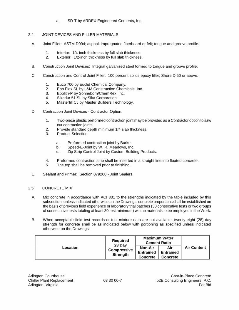
Arlington Courthouse Cast-in-Place Concrete Chiller Plant Replacement 03 30 00-7 b2E Consulting Engineers, P.C. Arlington, Virginia For Bid
a. SD-T by ARDEX Engineered Cements, Inc.
2.4 JOINT DEVICES AND FILLER MATERIALS
A. Joint Filler: ASTM D994; asphalt impregnated fiberboard or felt; tongue and groove profile.
1. Interior: 1/4-inch thickness by full slab thickness. 2. Exterior: 1/2-inch thickness by full slab thickness.
B. Construction Joint Devices: Integral galvanized steel formed to tongue and groove profile.
C. Construction and Control Joint Filler: 100 percent solids epoxy filler; Shore D 50 or above.
1. Euco 700 by Euclid Chemical Company. 2. Epo Flex SL by L&M Construction Chemicals, Inc. 3. Epolith-P by Sonneborn/ChemRex, Inc. 4. Sikadur 51 SL by Sika Corporation. 5. Masterfill CJ by Master Builders Technology.
D. Contraction Joint Devices - Contractor Option:
1. Two-piece plastic preformed contraction joint may be provided as a Contractor option to saw cut contraction joints.
2. Provide standard depth minimum 1/4 slab thickness. 3. Product Selection:
a. Preformed contraction joint by Burke. b. Speed-E-Joint by W. R. Meadows, Inc. c. Zip Strip Control Joint by Custom Building Products.
4. Preformed contraction strip shall be inserted in a straight line into floated concrete. 5. The top shall be removed prior to finishing.
E. Sealant and Primer: Section 079200 - Joint Sealers.
2.5 CONCRETE MIX
A. Mix concrete in accordance with ACI 301 to the strengths indicated by the table included by this subsection, unless indicated otherwise on the Drawings; concrete proportions shall be established on the basis of previous field experience or laboratory trial batches (30 consecutive tests or two groups of consecutive tests totaling at least 30 test minimum) wit the materials to be employed in the Work.
B. When acceptable field test records or trial mixture data are not available, twenty-eight (28) day strength for concrete shall be as indicated below with portioning as specified unless indicated otherwise on the Drawings:
Location
Required
28 Day
Compressive
Strength
Maximum Water
Cement Ratio
Air Content Non-Air
Entrained
Concrete
Air
Entrained
Concrete
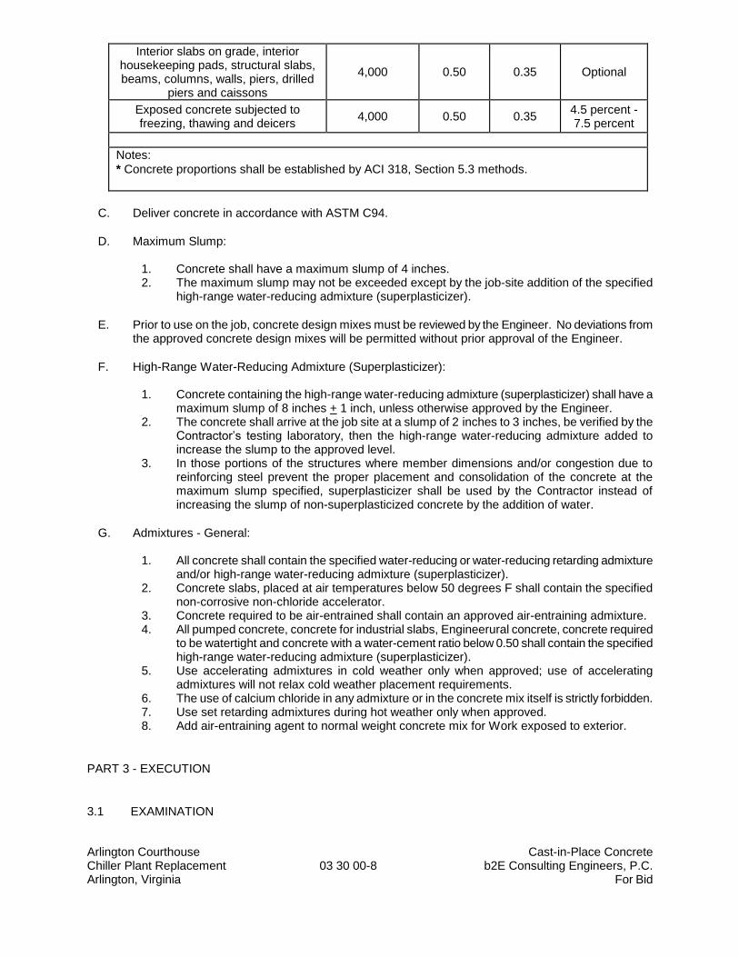
Arlington Courthouse Cast-in-Place Concrete Chiller Plant Replacement 03 30 00-8 b2E Consulting Engineers, P.C. Arlington, Virginia For Bid
Interior slabs on grade, interior housekeeping pads, structural slabs, beams, columns, walls, piers, drilled
piers and caissons
4,000 0.50 0.35 Optional
Exposed concrete subjected to freezing, thawing and deicers
4,000 0.50 0.35 4.5 percent - 7.5 percent
Notes:
* Concrete proportions shall be established by ACI 318, Section 5.3 methods.
C. Deliver concrete in accordance with ASTM C94.
D. Maximum Slump:
1. Concrete shall have a maximum slump of 4 inches. 2. The maximum slump may not be exceeded except by the job-site addition of the specified
high-range water-reducing admixture (superplasticizer).
E. Prior to use on the job, concrete design mixes must be reviewed by the Engineer. No deviations from the approved concrete design mixes will be permitted without prior approval of the Engineer.
F. High-Range Water-Reducing Admixture (Superplasticizer):
1. Concrete containing the high-range water-reducing admixture (superplasticizer) shall have a maximum slump of 8 inches + 1 inch, unless otherwise approved by the Engineer.
2. The concrete shall arrive at the job site at a slump of 2 inches to 3 inches, be verified by the Contractor’s testing laboratory, then the high-range water-reducing admixture added to increase the slump to the approved level.
3. In those portions of the structures where member dimensions and/or congestion due to reinforcing steel prevent the proper placement and consolidation of the concrete at the maximum slump specified, superplasticizer shall be used by the Contractor instead of increasing the slump of non-superplasticized concrete by the addition of water.
G. Admixtures - General:
1. All concrete shall contain the specified water-reducing or water-reducing retarding admixture and/or high-range water-reducing admixture (superplasticizer).
2. Concrete slabs, placed at air temperatures below 50 degrees F shall contain the specified non-corrosive non-chloride accelerator.
3. Concrete required to be air-entrained shall contain an approved air-entraining admixture. 4. All pumped concrete, concrete for industrial slabs, Engineerural concrete, concrete required
to be watertight and concrete with a water-cement ratio below 0.50 shall contain the specified high-range water-reducing admixture (superplasticizer).
5. Use accelerating admixtures in cold weather only when approved; use of accelerating admixtures will not relax cold weather placement requirements.
6. The use of calcium chloride in any admixture or in the concrete mix itself is strictly forbidden. 7. Use set retarding admixtures during hot weather only when approved. 8. Add air-entraining agent to normal weight concrete mix for Work exposed to exterior.
PART 3 - EXECUTION
3.1 EXAMINATION
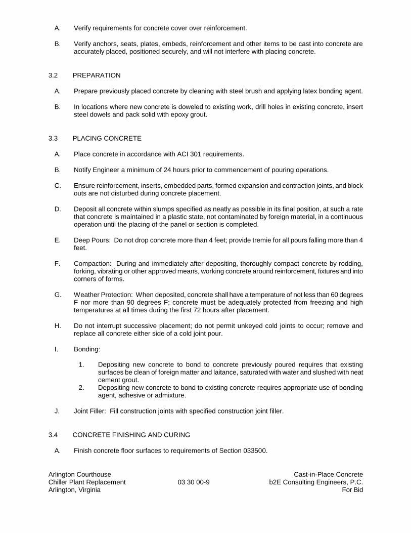
Arlington Courthouse Cast-in-Place Concrete Chiller Plant Replacement 03 30 00-9 b2E Consulting Engineers, P.C. Arlington, Virginia For Bid
A. Verify requirements for concrete cover over reinforcement.
B. Verify anchors, seats, plates, embeds, reinforcement and other items to be cast into concrete are accurately placed, positioned securely, and will not interfere with placing concrete.
3.2 PREPARATION
A. Prepare previously placed concrete by cleaning with steel brush and applying latex bonding agent.
B. In locations where new concrete is doweled to existing work, drill holes in existing concrete, insert steel dowels and pack solid with epoxy grout.
3.3 PLACING CONCRETE
A. Place concrete in accordance with ACI 301 requirements.
B. Notify Engineer a minimum of 24 hours prior to commencement of pouring operations.
C. Ensure reinforcement, inserts, embedded parts, formed expansion and contraction joints, and block outs are not disturbed during concrete placement.
D. Deposit all concrete within slumps specified as neatly as possible in its final position, at such a rate that concrete is maintained in a plastic state, not contaminated by foreign material, in a continuous operation until the placing of the panel or section is completed.
E. Deep Pours: Do not drop concrete more than 4 feet; provide tremie for all pours falling more than 4 feet.
F. Compaction: During and immediately after depositing, thoroughly compact concrete by rodding, forking, vibrating or other approved means, working concrete around reinforcement, fixtures and into corners of forms.
G. Weather Protection: When deposited, concrete shall have a temperature of not less than 60 degrees F nor more than 90 degrees F; concrete must be adequately protected from freezing and high temperatures at all times during the first 72 hours after placement.
H. Do not interrupt successive placement; do not permit unkeyed cold joints to occur; remove and replace all concrete either side of a cold joint pour.
I. Bonding:
1. Depositing new concrete to bond to concrete previously poured requires that existing surfaces be clean of foreign matter and laitance, saturated with water and slushed with neat cement grout.
2. Depositing new concrete to bond to existing concrete requires appropriate use of bonding agent, adhesive or admixture.
J. Joint Filler: Fill construction joints with specified construction joint filler.
3.4 CONCRETE FINISHING AND CURING
A. Finish concrete floor surfaces to requirements of Section 033500.
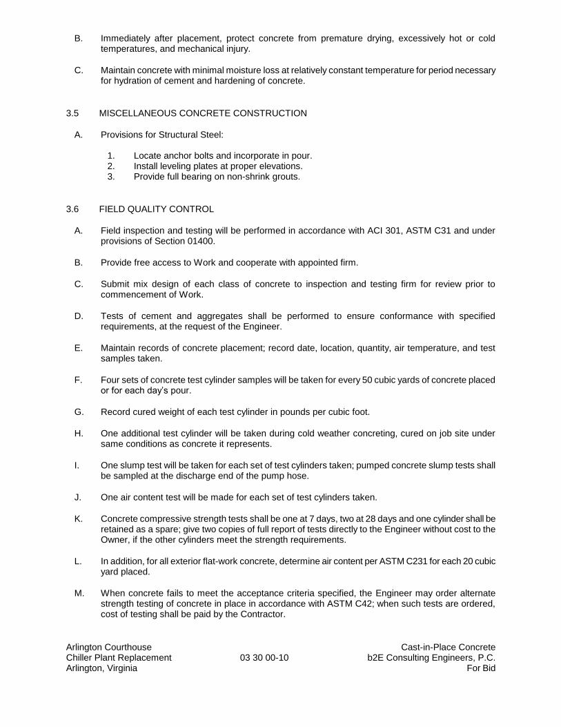
Arlington Courthouse Cast-in-Place Concrete Chiller Plant Replacement 03 30 00-10 b2E Consulting Engineers, P.C. Arlington, Virginia For Bid
B. Immediately after placement, protect concrete from premature drying, excessively hot or cold temperatures, and mechanical injury.
C. Maintain concrete with minimal moisture loss at relatively constant temperature for period necessary for hydration of cement and hardening of concrete.
3.5 MISCELLANEOUS CONCRETE CONSTRUCTION
A. Provisions for Structural Steel:
1. Locate anchor bolts and incorporate in pour. 2. Install leveling plates at proper elevations. 3. Provide full bearing on non-shrink grouts.
3.6 FIELD QUALITY CONTROL
A. Field inspection and testing will be performed in accordance with ACI 301, ASTM C31 and under provisions of Section 01400.
B. Provide free access to Work and cooperate with appointed firm.
C. Submit mix design of each class of concrete to inspection and testing firm for review prior to commencement of Work.
D. Tests of cement and aggregates shall be performed to ensure conformance with specified requirements, at the request of the Engineer.
E. Maintain records of concrete placement; record date, location, quantity, air temperature, and test samples taken.
F. Four sets of concrete test cylinder samples will be taken for every 50 cubic yards of concrete placed or for each day’s pour.
G. Record cured weight of each test cylinder in pounds per cubic foot.
H. One additional test cylinder will be taken during cold weather concreting, cured on job site under same conditions as concrete it represents.
I. One slump test will be taken for each set of test cylinders taken; pumped concrete slump tests shall be sampled at the discharge end of the pump hose.
J. One air content test will be made for each set of test cylinders taken.
K. Concrete compressive strength tests shall be one at 7 days, two at 28 days and one cylinder shall be retained as a spare; give two copies of full report of tests directly to the Engineer without cost to the Owner, if the other cylinders meet the strength requirements.
L. In addition, for all exterior flat-work concrete, determine air content per ASTM C231 for each 20 cubic yard placed.
M. When concrete fails to meet the acceptance criteria specified, the Engineer may order alternate strength testing of concrete in place in accordance with ASTM C42; when such tests are ordered, cost of testing shall be paid by the Contractor.
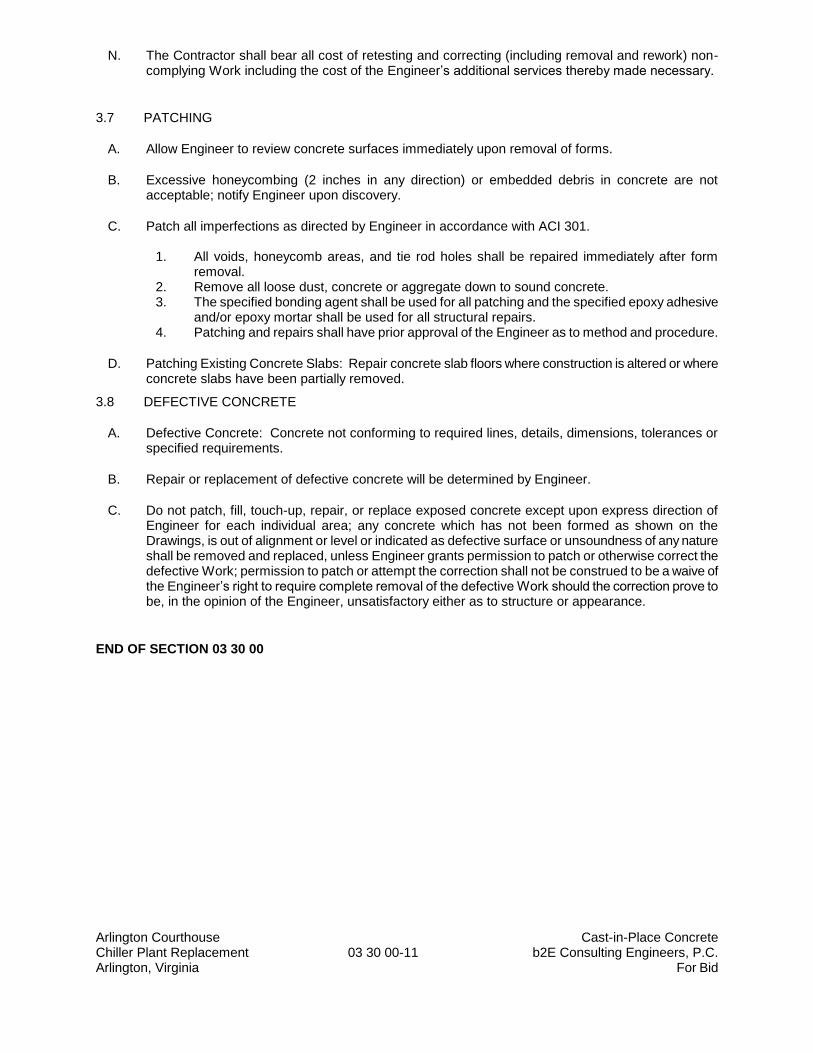
Arlington Courthouse Cast-in-Place Concrete Chiller Plant Replacement 03 30 00-11 b2E Consulting Engineers, P.C. Arlington, Virginia For Bid
N. The Contractor shall bear all cost of retesting and correcting (including removal and rework) non-complying Work including the cost of the Engineer’s additional services thereby made necessary.
3.7 PATCHING
A. Allow Engineer to review concrete surfaces immediately upon removal of forms.
B. Excessive honeycombing (2 inches in any direction) or embedded debris in concrete are not acceptable; notify Engineer upon discovery.
C. Patch all imperfections as directed by Engineer in accordance with ACI 301.
1. All voids, honeycomb areas, and tie rod holes shall be repaired immediately after form removal.
2. Remove all loose dust, concrete or aggregate down to sound concrete. 3. The specified bonding agent shall be used for all patching and the specified epoxy adhesive
and/or epoxy mortar shall be used for all structural repairs. 4. Patching and repairs shall have prior approval of the Engineer as to method and procedure.
D. Patching Existing Concrete Slabs: Repair concrete slab floors where construction is altered or where concrete slabs have been partially removed.
3.8 DEFECTIVE CONCRETE
A. Defective Concrete: Concrete not conforming to required lines, details, dimensions, tolerances or specified requirements.
B. Repair or replacement of defective concrete will be determined by Engineer.
C. Do not patch, fill, touch-up, repair, or replace exposed concrete except upon express direction of Engineer for each individual area; any concrete which has not been formed as shown on the Drawings, is out of alignment or level or indicated as defective surface or unsoundness of any nature shall be removed and replaced, unless Engineer grants permission to patch or otherwise correct the defective Work; permission to patch or attempt the correction shall not be construed to be a waive of the Engineer’s right to require complete removal of the defective Work should the correction prove to be, in the opinion of the Engineer, unsatisfactory either as to structure or appearance.
END OF SECTION 03 30 00
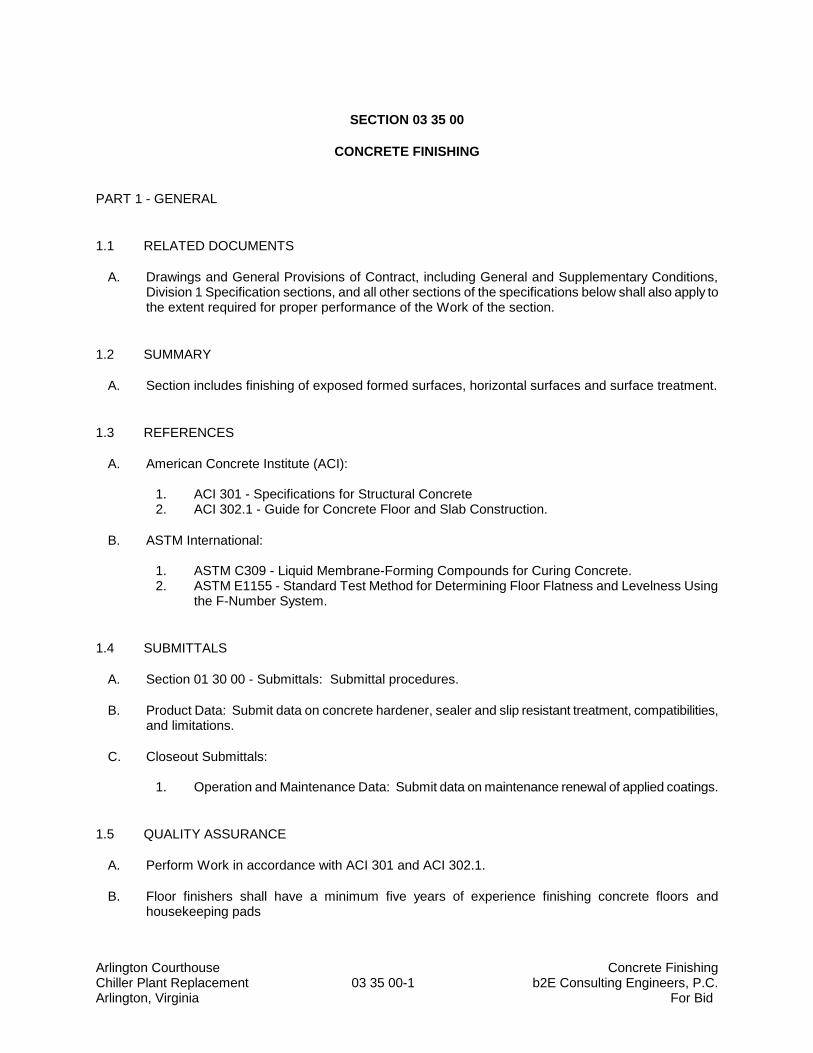
Arlington Courthouse Concrete Finishing Chiller Plant Replacement 03 35 00-1 b2E Consulting Engineers, P.C. Arlington, Virginia For Bid
SECTION 03 35 00
CONCRETE FINISHING
PART 1 - GENERAL
1.1 RELATED DOCUMENTS
A. Drawings and General Provisions of Contract, including General and Supplementary Conditions, Division 1 Specification sections, and all other sections of the specifications below shall also apply to the extent required for proper performance of the Work of the section.
1.2 SUMMARY
A. Section includes finishing of exposed formed surfaces, horizontal surfaces and surface treatment.
1.3 REFERENCES
A. American Concrete Institute (ACI):
1. ACI 301 - Specifications for Structural Concrete 2. ACI 302.1 - Guide for Concrete Floor and Slab Construction.
B. ASTM International:
1. ASTM C309 - Liquid Membrane-Forming Compounds for Curing Concrete. 2. ASTM E1155 - Standard Test Method for Determining Floor Flatness and Levelness Using
the F-Number System.
1.4 SUBMITTALS
A. Section 01 30 00 - Submittals: Submittal procedures.
B. Product Data: Submit data on concrete hardener, sealer and slip resistant treatment, compatibilities, and limitations.
C. Closeout Submittals:
1. Operation and Maintenance Data: Submit data on maintenance renewal of applied coatings.
1.5 QUALITY ASSURANCE
A. Perform Work in accordance with ACI 301 and ACI 302.1.
B. Floor finishers shall have a minimum five years of experience finishing concrete floors and housekeeping pads
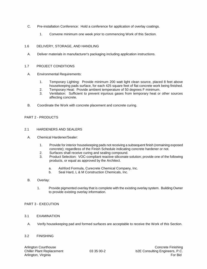
Arlington Courthouse Concrete Finishing Chiller Plant Replacement 03 35 00-2 b2E Consulting Engineers, P.C. Arlington, Virginia For Bid
C. Pre-installation Conference: Hold a conference for application of overlay coatings.
1. Convene minimum one week prior to commencing Work of this Section.
1.6 DELIVERY, STORAGE, AND HANDLING
A. Deliver materials in manufacturer's packaging including application instructions.
1.7 PROJECT CONDITIONS
A. Environmental Requirements:
1. Temporary Lighting: Provide minimum 200 watt light clean source, placed 8 feet above housekeeping pads surface, for each 425 square feet of flat concrete work being finished.
2. Temporary Heat: Provide ambient temperature of 50 degrees F minimum. 3. Ventilation: Sufficient to prevent injurious gases from temporary heat or other sources
affecting concrete.
B. Coordinate the Work with concrete placement and concrete curing.
PART 2 - PRODUCTS
2.1 HARDENERS AND SEALERS
A. Chemical Hardener/Sealer:
1. Provide for interior housekeeping pads not receiving a subsequent finish (remaining exposed concrete); regardless of the Finish Schedule indicating concrete hardener or not.
2. Surfaces shall receive curing and sealing compound. 3. Product Selection: VOC-compliant reactive siliconate solution; provide one of the following
products, or equal as approved by the Architect.
a. Ashford Formula, Curecrete Chemical Company, Inc. b. Seal Hard, L & M Construction Chemicals, Inc.
B. Overlay:
1. Provide pigmented overlay that is complete with the existing overlay system. Building Owner to provide existing overlay information.
PART 3 - EXECUTION
3.1 EXAMINATION
A. Verify housekeeping pad and formed surfaces are acceptable to receive the Work of this Section.
3.2 FINISHING
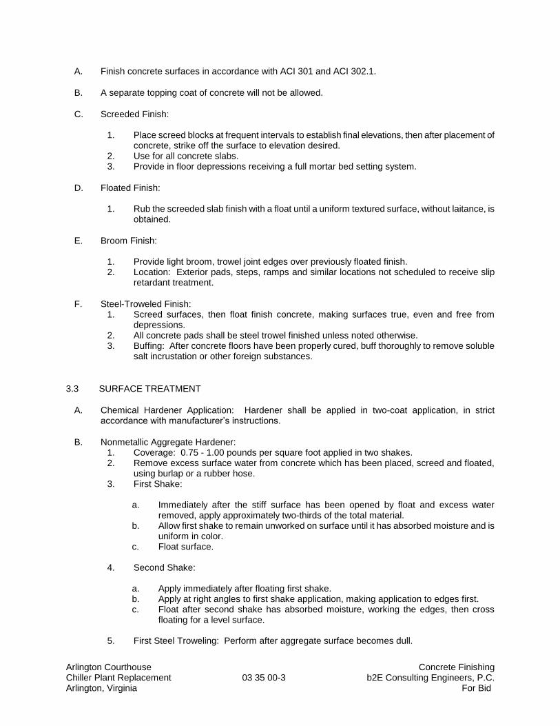
Arlington Courthouse Concrete Finishing Chiller Plant Replacement 03 35 00-3 b2E Consulting Engineers, P.C. Arlington, Virginia For Bid
A. Finish concrete surfaces in accordance with ACI 301 and ACI 302.1.
B. A separate topping coat of concrete will not be allowed.
C. Screeded Finish:
1. Place screed blocks at frequent intervals to establish final elevations, then after placement of concrete, strike off the surface to elevation desired.
2. Use for all concrete slabs. 3. Provide in floor depressions receiving a full mortar bed setting system.
D. Floated Finish:
1. Rub the screeded slab finish with a float until a uniform textured surface, without laitance, is obtained.
E. Broom Finish:
1. Provide light broom, trowel joint edges over previously floated finish. 2. Location: Exterior pads, steps, ramps and similar locations not scheduled to receive slip
retardant treatment.
F. Steel-Troweled Finish: 1. Screed surfaces, then float finish concrete, making surfaces true, even and free from
depressions. 2. All concrete pads shall be steel trowel finished unless noted otherwise. 3. Buffing: After concrete floors have been properly cured, buff thoroughly to remove soluble
salt incrustation or other foreign substances.
3.3 SURFACE TREATMENT
A. Chemical Hardener Application: Hardener shall be applied in two-coat application, in strict accordance with manufacturer’s instructions.
B. Nonmetallic Aggregate Hardener: 1. Coverage: 0.75 - 1.00 pounds per square foot applied in two shakes. 2. Remove excess surface water from concrete which has been placed, screed and floated,
using burlap or a rubber hose. 3. First Shake:
a. Immediately after the stiff surface has been opened by float and excess water
removed, apply approximately two-thirds of the total material. b. Allow first shake to remain unworked on surface until it has absorbed moisture and is
uniform in color. c. Float surface.
4. Second Shake:
a. Apply immediately after floating first shake. b. Apply at right angles to first shake application, making application to edges first. c. Float after second shake has absorbed moisture, working the edges, then cross
floating for a level surface.
5. First Steel Troweling: Perform after aggregate surface becomes dull.
Arlington Courthouse Concrete Finishing Chiller Plant Replacement 03 35 00-4 b2E Consulting Engineers, P.C. Arlington, Virginia For Bid
6. Final Steel Troweling: When no additional water or fines are brought to the surface, commence troweling by slightly raising the trowel to give a hard and smooth finish.
3.4 TOLERANCES
A. Finish and measure surface so gap at any point between concrete surface and an unleveled freestanding 10-foot long straightedge, resting on two high spots and placed anywhere on the surface, does not exceed these specified tolerances.
B. Maximum Variation of Surface Flatness for Exposed Concrete Housekeeping Pads: 1/4 inch in 10 feet.
3.5 GRINDING
A. Correct unsuitable rough finish, surfaces not flat or level, or to provide acceptable surface conditions for finish flooring after the concrete slabs have been cured.
B. Grind concrete with a multiple stone carborundum motor-driven rotary type grinder to remove any roughness, unevenness, soluble salt incrustation or other substance.
C. Remove dust and residue using a commercial type vacuum cleaner.
END OF SECTION 03 35 00
Arlington Courthouse Structural Steel Framing Chiller Plant Replacement 05 12 00-1 b2E Consulting Engineers, P.C.
Arlington, Virginia For Bid
SECTION 05 12 00
STRUCTURAL STEEL FRAMING
PART 1 - GENERAL
1.1 RELATED DOCUMENTS
A. Drawings and General Provisions of Contract, including General and Supplementary Conditions, Division 1 Specification sections, and all other sections of the specifications below shall also apply to the extent required for proper performance of the Work of the section.
1.2 SUMMARY
A. Section Includes:
1. Cooling Tower Dunnage Galvanized Steel Framing.
B. Phasing Plan: The Contractor’s phasing plan shall include the replacement of the existing cooling towers and the existing structural support steel system.
1. The cooling tower galvanized steel support structure shall be pre-fabricated to exact dimensions for fast assembly on the roof of the building as required minimize any condenser water outage in the building.
2. The existing structural steel support system shall be unbolted from the existing roof piers and removed.
3. The new galvanized structural steel support system shall be installed to fit in the exact same location to match the bolt hole locations on the existing roof piers and bolted in place.
4. The new structure shall be fabricated to fit the approved cooling towers at a height to ensure the top of the cooling tower is at the same elevation as the height of the existing roof (approximately 29’ – 6”). The exact dimensions shall be determined by the contractor for submission and approval by the Engineer.
5. Contractor’s Phasing Plan: The Contractor’s phasing plan shall require that the cooling towers be set on the structural steel framing system efficiently to minimize the condenser water system outage. Coordinate the location of structural members with the Division 23 contractor to ensure the steel pipe and tube railings do not impede the mechanical piping and electrical conduit routing and/or connections.
1.3 DEFINITIONS
A. Structural Steel: Elements of the structural frame indicated on Drawings and as described in AISC 303, "Code of Standard Practice for Steel Buildings and Bridges."
Arlington Courthouse Structural Steel Framing Chiller Plant Replacement 05 12 00-2 b2E Consulting Engineers, P.C.
Arlington, Virginia For Bid
1.4 PREINSTALLATION MEETINGS
A. Pre-installation Conference: Conduct conference at Arlington County Courthouse Site.
1.5 ACTION SUBMITTALS
A. Product Data: For each type of product.
B. Shop Drawings: Show fabrication of structural-steel components.
C. Field verification of dimensions and locations of structural steel connections to the existing building prior to shop drawing submittal.
D. Burn Permit: Obtain a burn permit from the local authorities having jurisdiction prior to performing the work.
1.6 INFORMATIONAL SUBMITTALS
A. Qualification Data: For Installer, fabricator and testing agency.
B. Welding certificates.
C. Mill test reports for structural steel, including chemical and physical properties.
D. Source quality-control reports.
E. Field quality-control and special inspection reports.
1.7 PERFORMANCE REQUIREMENTS
A. Delegated Design: The Contractor shall engage a qualified professional engineer, to design structural steel support systems, platforms and ladders.
1. Outdoor metals shall have ASTM A123 hot-dipped galvanized coating.
B. Thermal Movements: Allow for thermal movements from ambient and surface temperature changes acting on exterior metal fabrications by preventing buckling, opening of joints, overstressing of components, failure of connections, and other detrimental effects.
1. Temperature Change: 120 deg F (67 deg C), ambient; 180 deg F (100 deg C), material surfaces.
1.8 QUALITY ASSURANCE
A. Welding Qualifications: Qualify procedures and personnel according to AWS D1.1/D1.1M, "Structural Welding Code - Steel."
B. Comply with applicable provisions of the following specifications and documents:
Arlington Courthouse Structural Steel Framing Chiller Plant Replacement 05 12 00-3 b2E Consulting Engineers, P.C.
Arlington, Virginia For Bid
1. AISC 360. 2. RCSC's "Specification for Structural Joints Using ASTM A 325 or A 490 Bolts."
PART 2 - PRODUCTS
2.1 PERFORMANCE REQUIREMENTS
A. Connections: Provide details of simple shear connections required by the Contract Documents to be selected or completed by structural-steel fabricator to withstand loads indicated and comply with other information and restrictions indicated.
1. Select and complete connections using AISC 360. 2. Use Allowable Stress Design; data are given at service-load level. 3. Entire cooling tower structural steel support system shall be ASTM A123 hot-dipped
galvanized.
2.2 STRUCTURAL-STEEL MATERIALS (INDOOR)
A. W-Shapes: ASTM A 572/A 572M, Grade 50 (345).
B. Channels and Angles-Shapes: ASTM A 36/A 36M.
C. Plate and Bar: ASTM A 36/A 36M.
D. Cold-Formed Hollow Structural Sections: ASTM A 500/A 500M, Grade B, structural tubing.
E. Steel Pipe: ASTM A 53/A 53M, Type E or Type S, Grade B.
F. Welding Electrodes: Comply with AWS requirements.
2.3 STRUCTURAL STEEL MATERIALS (OUTDOOR)
A. W-Shapes: ASTM A 572/A 572M, Grade 50 (345), with ASTM A123 hot dipped galvanized coating.
B. Channels and Angles-Shapes: ASTM A 36/A 36M, with ASTM A123 hot dipped galvanized coating.
C. Plate and Bar: ASTM A 36/A 36M, with ASTM A123 hot dipped galvanized coating.
D. Cold-Formed Hollow Structural Sections: ASTM A 500/A 500M, Grade B, structural tubing, with ASTM A123 hot dipped galvanized coating.
E. Steel Pipe: ASTM A 53/A 53M, Type E or Type S, Grade B, with ASTM A123 hot dipped galvanized coating.
F. Welding Electrodes: Comply with AWS requirements, with ASTM A123 hot dipped galvanized coating.
Arlington Courthouse Structural Steel Framing Chiller Plant Replacement 05 12 00-4 b2E Consulting Engineers, P.C.
Arlington, Virginia For Bid
2.4 BOLTS, CONNECTORS, AND ANCHORS
A. Zinc-Coated High-Strength Bolts, Nuts, and Washers: ASTM A 325 (ASTM A 325M), Type 1, heavy-hex steel structural bolts; ASTM A 563, Grade DH (ASTM A 563M, Class 10S) heavy-hex carbon-steel nuts; and ASTM F 436 (ASTM F 436M), Type 1, hardened carbon-steel washers.
1. Finish (Indoor): Mechanically deposited zinc coating.
2. Finish (Outdoor): ASTM A123 hot dipped galvanized coating.
B. Tension-Control, High-Strength Bolt-Nut-Washer Assemblies: ASTM F 1852, Type 1, round head assemblies consisting of steel structural bolts with splined ends, heavy-hex carbon-steel nuts, and hardened carbon-steel washers.
1. Finish (Indoor): Mechanically deposited zinc coating.
2. Finish (Outdoor): ASTM A123 hot dipped galvanized coating.
C. Threaded Rods: ASTM A 36/A 36M.
1. Finish (Indoor): Mechanically deposited zinc coating, ASTM B 695, Class 50.
2. Finish (Outdoor): ASTM A123 hot-dipped galvanized coating.
2.5 PRIMER
A. Primer: Fabricator's standard lead- and chromate-free, nonasphaltic, rust-inhibiting primer complying with MPI#79 and compatible with topcoat.
2.6 FABRICATION
A. Structural Steel: Fabricate and assemble in shop to greatest extent possible. Fabricate according to AISC 303, "Code of Standard Practice for Steel Buildings and Bridges," and to AISC 360.
2.7 SHOP CONNECTIONS
A. High-Strength Bolts: Shop install high-strength bolts according to RCSC's "Specification for Structural Joints Using ASTM A 325 or A 490 Bolts" for type of bolt and type of joint specified.
1. Joint Type: Pretensioned with tension controlled twist-off assembly.
B. Weld Connections: Comply with AWS D1.1/D1.1M for tolerances, appearances, welding procedure specifications, weld quality, and methods used in correcting welding work.
2.8 SHOP PRIMING
A. Shop prime steel surfaces except the following:
Arlington Courthouse Structural Steel Framing Chiller Plant Replacement 05 12 00-5 b2E Consulting Engineers, P.C.
Arlington, Virginia For Bid
1. Surfaces embedded in concrete or mortar. Extend priming of partially embedded members to a depth of 2 inches (50 mm).
2. Surfaces to be field welded. 3. Surfaces of high-strength bolted, slip-critical connections. 4. Galvanized surfaces.
B. Surface Preparation: Clean surfaces to be painted. Remove loose rust and mill scale and spatter, slag, or flux deposits. Prepare surfaces according to the following specifications and standards:
1. SSPC-SP 2, "Hand Tool Cleaning." 2. SSPC-SP 3, "Power Tool Cleaning."
C. Priming: Immediately after surface preparation, apply primer according to manufacturer's written instructions and at rate recommended by SSPC to provide a minimum dry film thickness of 1.5 mils (0.038 mm). Use priming methods that result in full coverage of joints, corners, edges, and exposed surfaces.
2.9 SOURCE QUALITY CONTROL
A. Testing Agency: Owner will engage a qualified testing agency to perform shop tests and inspections.
1. Provide testing agency with access to places where structural-steel work is being fabricated or produced to perform tests and inspections.
B. Bolted Connections: Inspect shop-bolted connections according to RCSC's "Specification for Structural Joints Using ASTM A 325 or A 490 Bolts."
C. Welded Connections: Visually inspect shop-welded connections according to AWS D1.1/D1.1M and the following inspection procedures, at testing agency's option:
1. Liquid Penetrant Inspection: ASTM E 165.
D. Prepare test and inspection reports.
PART 3 - EXECUTION
3.1 EXAMINATION
A. Verify, with certified steel erector present, elevations of existing concrete pier bearing surfaces and locations of existing anchor bolts, bearing plates, and other embedments for compliance with requirements.
B. Proceed with installation only after unsatisfactory conditions have been corrected.
C. Burn Permit: Obtain a burn permit from the local authorities having jurisdiction prior to performing the work.
Arlington Courthouse Structural Steel Framing Chiller Plant Replacement 05 12 00-6 b2E Consulting Engineers, P.C.
Arlington, Virginia For Bid
3.2 ERECTION
A. Set structural steel accurately in locations and to elevations indicated and according to AISC 303 and AISC 360.
B. Base Plates: Clean bearing surfaces of deleterious materials and check for loose concrete piers. Re-set loose concrete and steel plates. Strengthen existing base with as indicated in the drawings prior to setting base plates. Anchor base plates to strengthened bearing conditions.
C. Bearing Plates and Leveling Plates: Clean bearing surfaces of deleterious materials for bearing load transfer. Clean bottom surface of plates.
D. Maintain erection tolerances of structural steel within AISC 303, "Code of Standard Practice for Steel Buildings and Bridges."
E. Contractor’s Phasing Plan: The Contractor’s phasing plan shall require that the cooling towers be set on the structural steel framing system efficiently to minimize the condenser water system outage. Coordinate the location of structural members with the Division 23 contractor to ensure the steel pipe and tube railings do not impede the mechanical piping and electrical conduit routing and/or connections.
3.3 FIELD CONNECTIONS
A. High-Strength Bolts: Install high-strength bolts according to RCSC's "Specification for Structural Joints Using ASTM A 325 or A 490 Bolts" for type of bolt and type of joint specified.
1. Joint Type: Pretensioned with tension controlled twist-off assembly.
B. Weld Connections: Comply with AWS D1.1/D1.1M for tolerances, appearances, welding procedure specifications, weld quality, and methods used in correcting welding work.
1. Comply with AISC 303 and AISC 360 for bearing, alignment, adequacy of temporary connections, and removal of paint on surfaces adjacent to field welds.
2. Remove backing bars or runoff tabs, back gouge, and grind steel smooth. 3. Assemble and weld built-up sections by methods that maintain true alignment of axes
without exceeding tolerances in AISC 303, "Code of Standard Practice for Steel Buildings and Bridges," for mill material.
3.4 PAINT
A. Light Industrial Coating of Exterior water based Semi-Gloss compatible to primed surfaces that are not indicated to be galvanized.
3.5 FELD QUALITY CONTROL
A. Special Inspections: Owner will engage a qualified special inspector to perform the following special inspections: 1. Verify structural-steel materials and inspect steel frame joint details. 2. Verify weld materials and inspect welds. 3. Verify connection materials and inspect high-strength bolted connections.
B. Testing Agency: Owner will engage a qualified testing agency to perform tests and inspections.
Arlington Courthouse Structural Steel Framing Chiller Plant Replacement 05 12 00-7 b2E Consulting Engineers, P.C.
Arlington, Virginia For Bid
C. Bolted Connections: Inspect bolted connections according to RCSC's "Specification for Structural Joints Using ASTM A 325 or A 490 Bolts."
D. Welded Connections: Visually inspect field welds according to AWS D1.1/D1.1M.
1. In addition to visual inspection, test and inspect field welds according to AWS D1.1/D1.1M and the following inspection procedures, at testing agency's option: a. Liquid Penetrant Inspection: ASTM E 165.
END OF SECTION 05 12 00
Arlington Courthouse Metal Fabrications Chiller Plant Replacement 05 50 00-1 b2E Consulting Engineers, P.C.
Arlington, Virginia For Bid
SECTION 05 50 00
METAL FABRICATIONS
PART 1 - GENERAL
1.1 RELATED DOCUMENTS
A. Drawings and General Provisions of Contract, including General and Supplementary Conditions, Division 1 Specification sections, and all other sections of the specifications below shall also apply to the extent required for proper performance of the Work of the section.
1.2 SUMMARY
A. Section Includes:
1. Miscellaneous steel framing and supports. 2. Metal ladders. 3. Ladder safety cages.
B. Products furnished, but not installed, under this Section include the following:
1. Loose steel lintels. 2. Post installed anchors in masonry.
C. Contractor’s Phasing Plan: The Contractor’s phasing plan shall require that the cooling towers be set on the structural steel framing system efficiently to minimize the condenser water system outage. Coordinate the location of structural members with the Division 23 contractor to ensure the steel pipe and tube railings do not impede the mechanical piping and electrical conduit routing and/or connections.
1.3 ACTION SUBMITTALS
A. Product Data: For the following: 1. Paint products. 2. Grout.
B. Shop Drawings: Show fabrication and installation details. Include plans, elevations, sections, and details of metal fabrications and their connections. Show anchorage and accessory items.
C. Delegated-Design Submittal: For ladders, including analysis data signed and sealed by the qualified professional engineer responsible for their preparation.
Arlington Courthouse Metal Fabrications Chiller Plant Replacement 05 50 00-2 b2E Consulting Engineers, P.C.
Arlington, Virginia For Bid
PART 2 - PRODUCTS
2.1 PERFORMANCE REQUIREMENTS
A. Delegated Design: The Contractor shall engage a qualified professional engineer, to design structural steel support systems, platforms and ladders.
1. Outdoor metals shall have ASTM A123 hot-dipped galvanized coating.
B. Thermal Movements: Allow for thermal movements from ambient and surface temperature changes acting on exterior metal fabrications by preventing buckling, opening of joints, overstressing of components, failure of connections, and other detrimental effects.
1. Temperature Change: 120 deg F (67 deg C), ambient; 180 deg F (100 deg C), material surfaces.
2.2 METALS
A. Metal Surfaces, General: Provide materials with smooth, flat surfaces unless otherwise indicated. For metal fabrications exposed to view in the completed Work, provide materials without seam marks, roller marks, rolled trade names, or blemishes.
1. Outdoor metals shall have ASTM A123 hot dipped galvanized coating.
B. Steel Plates, Shapes, and Bars: ASTM A 36/A 36M.
C. Steel Tubing: ASTM A 500/A 500M, cold-formed steel tubing.
D. Steel Pipe: ASTM A 53/A 53M, Standard Weight (Schedule 40) unless otherwise indicated.
2.3 FASTENERS
A. General: Unless otherwise indicated, provide Type 316 stainless-steel fasteners for exterior use and zinc-plated fasteners with coating complying with ASTM B 633 or ASTM F 1941 (ASTM F 1941M), Class Fe/Zn 5, at exterior walls. Select fasteners for type, grade, and class required.
B. Post-Installed Anchors: Chemical anchors. 1. Material: Alloy Group 2 (A4) stainless-steel bolts, ASTM F 593 (ASTM F 738M), and
nuts, ASTM F 594 (ASTM F 836M).
2.4 MISCELLANEOUS MATERIALS
A. Water-Based Primer: Emulsion type, anticorrosive primer for mildly corrosive environments that is resistant to flash rusting when applied to cleaned steel, complying with MPI#107 and compatible with topcoat.
B. Galvanizing Repair Paint: High-zinc-dust-content paint complying with SSPC-Paint 20 and compatible with paints specified to be used over it.
Arlington Courthouse Metal Fabrications Chiller Plant Replacement 05 50 00-3 b2E Consulting Engineers, P.C.
Arlington, Virginia For Bid
C. Nonshrink, Nonmetallic Grout: Factory-packaged, nonstaining, noncorrosive, nongaseous grout complying with ASTM C 1107/C 1107M. Provide grout specifically recommended by manufacturer for interior and exterior applications.
2.5 FABRICATION, GENERAL
A. Shop Assembly: Preassemble items in the shop to greatest extent possible. Use connections that maintain structural value of joined pieces.
B. Cut, drill, and punch metals cleanly and accurately. Remove burrs and ease edges. Remove sharp or rough areas on exposed surfaces.
C. Weld corners and seams continuously to comply with the following:
1. Use materials and methods that minimize distortion and develop strength and corrosion resistance of base metals.
2. Obtain fusion without undercut or overlap. 3. Remove welding flux immediately. 4. At exposed connections, finish exposed welds and surfaces smooth and blended.
D. Form exposed connections with hairline joints, flush and smooth, using concealed fasteners or welds where possible. Locate joints where least conspicuous.
E. Fabricate seams and other connections that are exposed to weather in a manner to exclude water. Provide weep holes where water may accumulate.
F. Where units are indicated to be cast into concrete or built into masonry, equip with integrally welded steel strap anchors not less than 8 inches (200 mm) from ends and corners of units and 24 inches (600 mm) o.c.
2.6 MISCELLANEOUS FRAMING AND SUPPORTS
A. General: Provide steel framing and supports not specified in other Sections as needed to complete the Work.
B. Fabricate units from steel shapes, plates, and bars of welded construction unless otherwise indicated. Fabricate to sizes, shapes, and profiles indicated and as necessary to receive adjacent construction.
2.7 METAL LADDERS
A. General:
1. Comply with ANSI A14.3
B. Steel Ladders:
1. Space siderails 18 inches (457 mm) apart unless otherwise indicated. 2. Siderails: Continuous, 1/2-by-2-1/2-inch (12.7-by-64-mm) steel flat bars, with eased
edges. 3. Rungs: 1-inch- (25-mm-) diameter steel bars.
Arlington Courthouse Metal Fabrications Chiller Plant Replacement 05 50 00-4 b2E Consulting Engineers, P.C.
Arlington, Virginia For Bid
4. Fit rungs in centerline of siderails; plug-weld and grind smooth on outer rail faces. 5. Provide nonslip surfaces on top of each rung. 6. Galvanize exterior ladders, including brackets.
2.8 LADDER SAFETY CAGES
A. Fabricate ladder safety cages to comply with ANSI A14.3. Assemble by welding or with stainless-steel fasteners.
B. Provide primary hoops at tops and bottoms of cages and spaced not more than 20 feet (6 m) o.c. Provide secondary intermediate hoops spaced not more than 48 inches (1200 mm) o.c. between primary hoops.
C. Galvanize steel ladder safety cages, including brackets and fasteners.
2.9 LOOSE STEEL LINTELS
A. Fabricate loose steel lintels from steel angles and shapes of size indicated for openings and recesses in masonry walls and partitions at locations indicated.
B. Galvanize loose steel lintels located in exterior walls.
2.10 FINISHES, GENERAL
A. Finish metal fabrications after assembly.
2.11 STEEL AND IRON FINISHES
A. Galvanizing: Hot-dip galvanize items as indicated to comply with ASTM A 153/A 153M for steel and iron hardware and with ASTM A 123/A 123M for other steel and iron products.
B. Shop prime iron and steel items not indicated to be galvanized unless they are to be embedded in concrete, sprayed-on fireproofing, or masonry, or unless otherwise indicated.
C. Preparation for Shop Priming: Prepare surfaces to comply with SSPC-SP 6/NACE No. 3, "Commercial Blast Cleaning."
D. Shop Priming: Apply shop primer to comply with SSPC-PA 1, "Paint Application Specification No. 1: Shop, Field, and Maintenance Painting of Steel," for shop painting.
PART 3 - EXECUTION
3.1 INSTALLATION, GENERAL
A. Cutting, Fitting, and Placement: Perform cutting, drilling, and fitting required for installing metal fabrications. Set metal fabrications accurately in location, alignment, and elevation; with edges and surfaces level, plumb, true, and free of rack; and measured from established lines and levels.
Arlington Courthouse Metal Fabrications Chiller Plant Replacement 05 50 00-5 b2E Consulting Engineers, P.C.
Arlington, Virginia For Bid
B. Fit exposed connections accurately together to form hairline joints. Weld connections that are not to be left as exposed joints but cannot be shop welded because of shipping size limitations. Do not weld, cut, or abrade surfaces of exterior units that have been hot-dip galvanized after fabrication and are for bolted or screwed field connections.
C. Field Welding: Comply with the following requirements:
1. Use materials and methods that minimize distortion and develop strength and corrosion resistance of base metals.
2. Obtain fusion without undercut or overlap. 3. Remove welding flux immediately. 4. At exposed connections, finish exposed welds and surfaces smooth and blended so no
roughness shows after finishing and contour of welded surface matches that of adjacent surface.
D. Fastening to In-Place Construction: Provide anchorage devices and fasteners where metal fabrications are required to be fastened to in-place construction.
E. Provide temporary bracing or anchors for items that are to be built into concrete, masonry, or similar construction.
F. Contractor’s Phasing Plan: The Contractor’s phasing plan shall require that the cooling towers be set on the structural steel framing system efficiently to minimize the condenser water system outage. Coordinate the location of structural members with the Division 23 contractor to ensure the steel pipe and tube railings do not impede the mechanical piping and electrical conduit routing and/or connections.
3.2 ADJUSTING AND CLEANING
A. Touchup Painting: Immediately after erection, clean field welds, bolted connections, and abraded areas. Paint uncoated and abraded areas with the same material as used for shop painting to comply with SSPC-PA 1 for touching up shop-painted surfaces.
B. Galvanized Surfaces: Clean field welds, bolted connections, and abraded areas and repair galvanizing to comply with ASTM A 780/A 780M.
END OF SECTION 05 50 00
Arlington Courthouse Pipe and Tube Railings Chiller Plant Replacement 05 52 00-1 b2E Consulting Engineers, P.C. Arlington, Virginia For Bid
SECTION 05 52 00
PIPE AND TUBE RAILINGS
PART 1 - GENERAL
1.1 RELATED DOCUMENTS
A. Drawings and General Provisions of Contract, including General and Supplementary Conditions, Division 1 Specification sections, and all other sections of the specifications below shall also apply to the extent required for proper performance of the Work of the section.
1.2 SUMMARY
A. This Section includes the following:
1. Steel pipe and tube railings.
B. See Division 05 Section "Structural Steel Framing" for steel tube railings associated with cooling tower support steel.
C. Contractor’s Phasing Plan: The Contractor’s phasing plan shall require that the cooling towers be set on the structural steel framing system efficiently to minimize the condenser water system outage. Coordinate the location of structural members with the Division 23 contractor to ensure the steel pipe and tube railings do not impede the mechanical piping and electrical conduit routing and/or connections.
1.3 PERFORMANCE REQUIREMENTS
A. Structural Performance: Provide railings and guards capable of withstanding the effects of gravity loads and the following loads and stresses within limits and under conditions indicated:
1. Top Rails of Guards:
a. Uniform load of 50 lbf/ ft. (0.73 kN/m) applied in any direction. b. Concentrated load of 200 lbf (0.89 kN) applied in any direction. c. Uniform and concentrated loads need not be assumed to act concurrently.
2. Infill of Guards:
a. Concentrated load of 50 lbf (0.22 kN) applied horizontally on an area of 1 sq. ft. (0.093 sq. m).
b. Uniform load of 25 lbf/sq. ft. (1.2 kN/sq. m) applied horizontally. c. Infill load and other loads need not be assumed to act concurrently.
B. Control of Corrosion: Prevent galvanic action and other forms of corrosion by insulating metals and other materials from direct contact with incompatible materials.
Arlington Courthouse Pipe and Tube Railings Chiller Plant Replacement 05 52 00-2 b2E Consulting Engineers, P.C. Arlington, Virginia For Bid
1.4 SUBMITTALS
A. Product Data: For mechanically connected railings and anchoring cement products.
B. Shop Drawings: Include plans, elevations, sections, details, and attachments to other work.
1. For installed products indicated to comply with design loads, include structural analysis data signed and sealed by the qualified professional engineer responsible for their preparation.
C. Product Test Reports: Based on evaluation of comprehensive tests performed by a qualified testing agency, according to ASTM E 894 and ASTM E 935.
PART 2 - PRODUCTS
2.1 METALS
A. Brackets, Flanges, and Anchors: Cast or formed metal of same type of material and finish as supported rails, unless otherwise indicated.
1. Where steel materials are located outdoors provide ASTM A123 hot-dipped galvanized coating.
B. Steel and Iron:
1. Tubing: ASTM A 500 (cold formed). 2. Pipe: ASTM A 53/A 53M, Type F or Type S, Grade A, Standard Weight (Schedule 40),
unless another grade and weight are required by structural loads. 3. Plates, Shapes, and Bars: ASTM A 36/A 36M. 4. Castings: Either gray or malleable iron, unless otherwise indicated.
a. Gray Iron: ASTM A 48/A 48M, Class 30, unless another class is indicated or required by structural loads.
b. Malleable Iron: ASTM A 47/A 47M. 5. Where steel materials are located outdoors provide ASTM A123 hot-dipped galvanized
coating.
2.2 MISCELLANEOUS MATERIALS
A. Fasteners: Provide concealed fasteners, unless unavoidable or standard for railings indicated.
1. Steel Railings: Plated steel fasteners complying with ASTM B 633, Class Fe/Zn 25 for electrodeposited zinc coating.
B. Anchors: Provide chemical anchors, fabricated from corrosion-resistant materials with capability to sustain, without failure, a load equal to six times the load imposed when installed in unit masonry and equal to four times the load imposed when installed in concrete, as determined by testing per ASTM E 488.
C. Welding Rods and Bare Electrodes: Select according to AWS specifications for metal alloy welded.
Arlington Courthouse Pipe and Tube Railings Chiller Plant Replacement 05 52 00-3 b2E Consulting Engineers, P.C. Arlington, Virginia For Bid
D. Shop Primer for Galvanized Steel: Zinc-dust, zinc-oxide primer compatible with finish paint systems indicated, and complying with SSPC-Paint 5.
E. Anchoring Cement: Factory-packaged, nonshrink, nonmetallic grout complying with ASTM C 1107; or water-resistant, nonshrink anchoring cement; recommended by manufacturer for exterior use.
F. Where steel materials are located outdoors provide ASTM A123 hot-dipped galvanized coating.
2.3 FABRICATION
A. General: Fabricate railings and guards to comply with design, dimensions, and details indicated, but not less than that required to support structural loads.
B. Welded Connections: Cope components at connections to provide close fit, or use fittings designed for this purpose. Weld all around at connections, including at fittings.
C. Nonwelded Connections: Connect members with concealed mechanical fasteners and fittings.
D. Form curves by bending in jigs to produce uniform curvature; maintain cross section of member throughout bend without cracking or otherwise deforming exposed surfaces.
E. Close exposed ends of all railing and guard members.
F. Brackets, Flanges, Fittings, and Anchors: Provide wall brackets, flanges, miscellaneous fittings, and anchors to interconnect railing members to other work, unless otherwise indicated.
2.4 FINISHES
A. Steel and Iron:
1. Galvanized Railings: Hot-dip galvanize exterior railings and guards, after fabrication, to comply with ASTM A 123/A 123M. Provide hot-dip galvanized fittings, brackets, fasteners, sleeves, and other ferrous components.
2. Shop-Primed Galvanized Railings: After galvanizing, clean railings, treat with metallic-phosphate process, and apply primer to comply with SSPC-PA 1.
PART 3 - EXECUTION
3.1 INSTALLATION
A. General: Perform cutting, drilling, and fitting required for installing railings and guards. Set railings accurately in location, alignment, and elevation.
1. Set posts plumb within a tolerance of 1/16 inch in 3 feet (2 mm in 1 m).
B. Contractor’s Phasing Plan: Contractor’s phasing plan shall require that the cooling towers be set on the structural steel framing system efficiently to minimize the condenser water system outage. Coordinate the location of structural members with the Division 23 contractor to ensure
Arlington Courthouse Pipe and Tube Railings Chiller Plant Replacement 05 52 00-4 b2E Consulting Engineers, P.C. Arlington, Virginia For Bid
the steel pipe and tube railings do not impede the mechanical piping and electrical conduit routing and/or connections.
C. Adjusting and Cleaning:
1. Immediately after erection, clean field welds, bolted connections, and abraded areas of shop paint, and paint exposed areas with the same material as used for shop painting.
2. Galvanized Surfaces: Clean field welds, bolted connections, and abraded areas and repair galvanizing to comply with ASTM A 780.
END OF SECTION 05 22 00
Arlington Courthouse Through-Penetration Firestop Systems Chiller Plant Replacement 07 84 10-1 b2E Consulting Engineers, P.C. Arlington, Virginia For Bid
SECTION 07 84 10
THROUGH-PENETRATION FIRESTOP SYSTEMS
PART 1 - GENERAL
1.1 RELATED DOCUMENTS
A. Drawings and General Provisions of Contract, including General and Supplementary Conditions, Division 1 Specification sections, and all other sections of the specifications below shall also apply to the extent required for proper performance of the Work of the section.
1.2 SUMMARY
A. Section Includes penetrations vertical and horizontal assemblies and smoke barriers.
B. See Mechanical drawings for additional details and requirements.
1.3 SUBMITTALS
A. Product Data: For each type of product indicated.
PART 2 - PRODUCTS
2.1 MANUFACTURERS
A. Manufacturers: Subject to compliance with requirements, available manufacturers offering products that may be incorporated into the Work include, but are not limited to, the following:
1. Hilti, Inc.
2. Nelson Firestop Products.
3. 3M Fire Protection Products.
2.2 PENETRATION FIRESTOPPING
A. Provide penetration firestopping that is produced and installed to resist spread of fire according to requirements indicated, resist passage of smoke and other gases, and maintain original fire-resistance rating of construction penetrated. Penetration firestopping systems shall be compatible with one another, with the substrates forming openings, and with penetrating items if any.
B. Accessories: Provide components for each penetration firestopping system that are needed to install fill materials and to maintain ratings required. Use only those components specified by penetration firestopping manufacturer and approved by qualified testing and inspecting agency for firestopping indicated.
PART 3 - EXECUTION
3.1 INSTALLATION
A. Examine substrates and conditions, with Installer present, for compliance with requirements for opening configurations, penetrating items, substrates, and other conditions affecting performance of the Work.
B. Install penetration firestopping to comply with manufacturer's written installation instructions and published drawings for products and applications indicated.
Arlington Courthouse Through-Penetration Firestop Systems Chiller Plant Replacement 07 84 10-2 b2E Consulting Engineers, P.C. Arlington, Virginia For Bid
C. Install forming materials and other accessories of types required to support fill materials during their application and in the position needed to produce cross-sectional shapes and depths required to achieve fire ratings indicated.
3.2 IDENTIFICATION
A. Identify penetration firestopping with preprinted metal or plastic labels.
END OF SECTION 07 84 10
Arlington Courthouse Joint Sealants
Chiller Plant Replacement 07 92 00-1 b2E Consulting Engineers, P.C. Arlington, Virginia For Bid
SECTION 07 92 00
JOINT SEALANTS
PART 1 - GENERAL
1.1 RELATED DOCUMENTS
A. Drawings and General Provisions of Contract, including General and Supplementary Conditions, Division 1 Specification sections, and all other sections of the specifications below shall also apply to the extent required for proper performance of the Work of the section.
1.2 SUMMARY
A. Section includes for exterior and interior building applications.
1.3 SUBMITTALS
A. Product Data: For each joint-sealant product indicated.
PART 2 - PRODUCTS
2.1 MATERIALS, GENERAL
A. VOC Content of Interior Sealants: Provide sealants and sealant primers for use inside the weatherproofing system.
B. Liquid-Applied Joint Sealants: Comply with ASTM C 920 and other requirements indicated for each liquid-applied joint sealant specified, including those referencing ASTM C 920 classifications for type, grade, class, and uses related to exposure and joint substrates.
2.2 SEALANT TYPES
A. Sealants for Exterior applications: One part non-sag, polyurethane.
B. Sealants for Interior applications: One part, non-sag, silicone acrylic latex, paintable.
C. Sealants for toilet rooms and similar areas: one part silicone sanitary sealant, moisture and mildew resistant.
2.3 JOINT SEALANT BACKING
A. Cylindrical Sealant Backings: ASTM C 1330 and of size and density to control sealant depth and otherwise contribute to producing optimum sealant performance.
B. Bond-Breaker Tape: Polyethylene tape or other plastic tape recommended by sealant manufacturer.
PART 3 - EXECUTION
3.1 INSTALLATION
A. Install sealant backings of kind indicated to support sealants during application and at position required to produce cross-sectional shapes and depths of installed sealants relative to joint widths that allow optimum sealant movement capability.
Arlington Courthouse Joint Sealants
Chiller Plant Replacement 07 92 00-2 b2E Consulting Engineers, P.C. Arlington, Virginia For Bid
B. Install bond-breaker tape behind sealants where sealant backings are not used between sealants and backs of joints.
C. Tooling of Sealants: Immediately after sealant application and before skinning or curing begins, tool sealants to form smooth, uniform beads; to eliminate air pockets; and to ensure contact and adhesion of sealant with sides of joint.
D. Clean off excess sealant or sealant smears adjacent to joints as the Work progresses by methods and with cleaning materials approved in writing by manufacturers of joint sealants and of products in which joints occur.
END OF SECTION 07 92 00
Arlington Courthouse Gypsum Board Chiller Plant Replacement 09 25 00-1 b2E Consulting Engineers, P.C. Arlington, Virginia For Bid
SECTION 09 25 00
GYPSUM BOARD
PART 1 - GENERAL
1.1 RELATED DOCUMENTS
A. Drawings and General Provisions of Contract, including General and Supplementary Conditions, Division 1 Specification sections, and all other sections of the specifications below shall also apply to the extent required for proper performance of the Work of the section.
1.2 SUMMARY
A. This Section includes the following:
1. Interior gypsum board.
1.3 SUBMITTALS
A. Product Data: For each type of product indicated.
PART 2 - PRODUCTS
2.1 INTERIOR GYPSUM BOARD
A. General: Complying with ASTM C 36/C 36M or ASTM C 1396/C 1396M, as applicable to type of gypsum board indicated and whichever is more stringent.
B. Regular Type:
1. Thickness: 1/2 inch. 2. Long Edges: Tapered.
C. Moisture- and Mold-Resistant Type: With moisture- and mold-resistant core and surfaces.
1. Core: 5/8 inch, Type X. 2. Long Edges: Tapered.
2.2 TRIM ACCESSORIES
A. Interior Trim: ASTM C 1047.
1. Material: Galvanized or aluminum-coated steel sheet, rolled zinc, plastic, or paper-faced galvanized steel sheet.
2. Shapes:
a. Cornerbead. b. Bullnose bead. c. LC-Bead: J-shaped; exposed long flange receives joint compound. d. L-Bead: L-shaped; exposed long flange receives joint compound. e. U-Bead: J-shaped; exposed short flange does not receive joint compound. f. Expansion (control) joint.
Arlington Courthouse Gypsum Board Chiller Plant Replacement 09 25 00-2 b2E Consulting Engineers, P.C. Arlington, Virginia For Bid
2.3 JOINT TREATMENT MATERIALS
A. General: Comply with ASTM C 475/C 475M.
B. Joint Tape:
1. Interior Gypsum Wallboard: Paper.
2. Tile Backing Panels: As recommended by panel manufacturer.
C. Joint Compound for Interior Gypsum Wallboard: For each coat use formulation that is compatible with other compounds applied on previous or for successive coats.
1. Prefilling: At open joints and damaged surface areas, use setting-type taping compound.
2. Embedding and First Coat: For embedding tape and first coat on joints, fasteners, and trim flanges, use setting-type taping compound.
3. Fill Coat: For second coat, use setting-type, sandable topping compound.
4. Finish Coat: For third coat, use setting-type, sandable topping compound.
2.4 AUXILIARY MATERIALS
A. General: Provide auxiliary materials that comply with referenced installation standards and manufacturer's written recommendations.
PART 3 - EXECUTION
3.1 APPLYING AND FINISHING PANELS, GENERAL
A. Comply with ASTM C 840.
B. Examine panels before installation. Reject panels that are wet, moisture damaged, and mold damaged.
3.2 INSTALLING TRIM ACCESSORIES
A. General: For trim with back flanges intended for fasteners, attach to framing with same fasteners used for panels. Otherwise, attach trim according to manufacturer's written instructions.
3.3 FINISHING GYPSUM BOARD
A. General: Treat gypsum board joints, interior angles, edge trim, control joints, penetrations, fastener heads, surface defects, and elsewhere as required to prepare gypsum board surfaces for decoration. Promptly remove residual joint compound from adjacent surfaces.
B. Prefill open joints and damaged surface areas.
C. Apply joint tape over gypsum board joints, except those with trim having flanges not intended for tape.
D. Gypsum Board Finish Levels: Finish panels to levels indicated below:
1. Level 4: At panel surfaces that will be exposed to view, unless otherwise indicated.
2. Not exposed to view, tape and spackle joints.
3.4 PROTECTION
A. Protect installed products from damage from weather, condensation, direct sunlight, construction, and other causes during remainder of the construction period.
END OF SECTION 09 25 00
Arlington Courthouse Painting Chiller Plant Replacement 09 91 00-1 b2E Consulting Engineers, P.C. Arlington, Virginia For Bid
SECTION 09 91 00
PAINTING
PART 1 - GENERAL
1.1 RELATED DOCUMENTS
A. Drawings and General Provisions of Contract, including General and Supplementary Conditions, Division 1 Specification sections, and all other sections of the specifications below shall also apply to the extent required for proper performance of the Work of the section.
1.2 SUMMARY
A. This Section includes surface preparation and the application of paint systems on the following interior and exterior substrates:
1. Concrete. 2. Steel. 3. Gypsum board.
B. Painting under this project is generally to be limited to patched walls areas where the wall has been removed to install HVAC equipment exterior doors and other areas where pipe and conduit penetrations occur. The un-insulated steel HVAC piping shall also be painted.
1.3 SUBMITTALS
A. Product Data: For each type of product indicated.
B. Samples: For each finish and for each color and texture required.
1.4 EXTRA MATERIALS
A. Furnish extra materials described below that are from same production run (batch mix) as materials applied and that are packaged for storage and identified with labels describing contents.
1. Quantity: Furnish an additional 5 percent, but not less than 1 gal. of each material and color applied.
PART 2 - PRODUCTS
2.1 PAINT, GENERAL
A. Material Compatibility:
1. Provide materials for use within each paint system that are compatible with one another and substrates indicated, under conditions of service and application as demonstrated by manufacturer, based on testing and field experience.
2. For each coat in a paint system, provide products recommended in writing by manufacturers of topcoat for use in paint system and on substrate indicated.
B. Colors: To match existing adjacent painted finishes to remain.
Arlington Courthouse Painting Chiller Plant Replacement 09 91 00-2 b2E Consulting Engineers, P.C. Arlington, Virginia For Bid
PART 3 - EXECUTION
3.1 EXAMINATION
A. Examine substrates and conditions, with Applicator present, for compliance with requirements for maximum moisture content and other conditions affecting performance of work.
B. Maximum Moisture Content of Substrates: When measured with an electronic moisture meter as follows:
1. Concrete: 12 percent. 2. Masonry (Clay and CMU): 12 percent. 3. Gypsum Board: 12 percent.
C. Verify suitability of substrates, including surface conditions and compatibility with existing finishes and primers.
D. Begin coating application only after unsatisfactory conditions have been corrected and surfaces are dry.
3.2 PREPARATION AND APPLICATION
A. Comply with manufacturer's written instructions applicable to substrates indicated.
B. Clean substrates of substances that could impair bond of paints, including dirt, oil, grease, and incompatible paints and encapsulants.
C. Apply paints to produce surface films without cloudiness, spotting, holidays, laps, brush marks, roller tracking, runs, sags, ropiness, or other surface imperfections. Cut in sharp lines and color breaks.
D. Painting Mechanical and Electrical Work: Paint items exposed in equipment rooms and occupied spaces. Do NOT paint equipment nameplates or specification tags.
E. Protect work of other trades against damage from paint application. Correct damage to work of other trades by cleaning, repairing, replacing, and refinishing, and leave in an undamaged condition.
F. At completion of construction activities, touch up and restore damaged or defaced painted surfaces.
3.3 INTERIOR PAINTING SCHEDULE
A. Concrete Substrates, Nontraffic Surfaces:
1. Latex System: a. Prime Coat: Interior latex matching topcoat. b. Intermediate Coat: Interior latex matching topcoat. c. Topcoat: Interior latex satin.
B. Steel Substrates:
1. Quick-Drying Enamel System: a. Prime Coat: Quick-drying alkyd metal primer. b. Intermediate Coat: Quick-drying enamel matching topcoat. c. Topcoat: Quick-drying enamel, semigloss.
C. Gypsum Board Substrates:
1. Latex System: a. Prime Coat: Interior latex primer/sealer. b. Intermediate Coat: Interior latex matching topcoat. c. Topcoat: Interior latex satin.
Arlington Courthouse Painting Chiller Plant Replacement 09 91 00-3 b2E Consulting Engineers, P.C. Arlington, Virginia For Bid
3.4 Exterior Painting Schedule
A. Steel Substrates:
1. Water-Based Light Industrial Coating System: a. Prime Coat: Primer, alkyd, anti-corrosive for metal. b. Intermediate Coat: Light industrial coating, exterior, water based, matching
topcoat. c. Topcoat: Light industrial coating, exterior, water based, semi-gloss.
END OF SECTION 09 91 00
Arlington Courthouse HVAC General Mechanical Requirements Chiller Plant Replacement 23 01 00-1 b2E Consulting Engineers, P.C. Arlington, Virginia For Bid
SECTION 23 01 00
HVAC GENERAL MECHANICAL REQUIREMENTS
PART 1 - GENERAL
1.1 SUMMARY
A. Drawings and general provisions of the Contract, including General and Supplementary Conditions and Division 1 Specification Sections, apply to this Section.
1. This Section compliments and applies to all other Division 23 Sections. 2. Refer to other applicable Sections in this Division, and other Divisions and drawings as
necessary for additional requirements, especially where “See Structural” and “See Architectural” is indicated on the mechanical drawings and specifications.
3. Wherever conflict exists for materials and/or labor between specification sections the more stringent, more expensive requirement shall be provided in the bid price.
1.2 SPECIAL MECHANICAL REQUIREMENTS
A. Drawing use and interpretation:
1. Drawings are diagrammatic and indicate general arrangement of systems and equipment, except when specifically dimensioned or detailed.
2. For locations of building elements, refer to architectural, structural, mechanical, plumbing, fire protection, and electrical drawings.
3. Field measurements take precedence over drawings. 4. Mechanical plans are intended to indicate size, capacity, approximate location, direction
and general relationship of the work, but not exact detail or arrangement. 5. Field verify locations and arrangement of actual structures, systems and equipment. 6. All systems and equipment shall be installed in accordance with the manufacturer’s
written recommendations and/or written instruction manuals. 7. Pipe Hanger System: Piping under high roof areas shall be on pipe stands.
a. Refer to details on structural.
B. Installation of systems and equipment:
1. Installation is subject to clarification as indicated in reviewed and approved Shop and Field Coordination Drawings.
a. Generally, lay out piping requiring gravity drainage first; then lay out large pipe mains, ductwork and electrical conduit.
b. This procedure is intended to promote orderly installation, but not to establish trade precedence.
c. Dimensions indicated are limiting dimensions. d. Do not use equipment that does not meet the manufacturers’ and applicable code
requirements for clear service access. The contractor shall remove and replace any equipment which does not meet the manufacturer’s and code required
Arlington Courthouse HVAC General Mechanical Requirements Chiller Plant Replacement 23 01 00-2 b2E Consulting Engineers, P.C. Arlington, Virginia For Bid
clearances as determined by the Engineer and/or the local authorities having jurisdiction.
e. Coordinate ductwork and piping penetrations through walls, floors and roof with actual field conditions and dimensions. Contractors shall thoroughly familiarize themselves with the project requirements and the construction documents prior to submitting bid price, and shall have measured and coordinated the installations between trades using manufacturer’s actual equipment dimension drawings prior to submitting coordinated shop drawings.
f. Under no circumstances shall any mechanical equipment be hung, supported or suspended from the building ceilings. Ductwork, piping, etc. shall only be hung or supported directly from the building structure (i.e. steel beam, or concrete floor system). Refer to structural requirements for building attachments.
C. Utility coordination with the Owner: There shall be no unauthorized utility interruptions
throughout the duration of the project.
1. The Contractor shall notify Engineer/Owner and obtain approval for any utility interruptions at least seventy two (72) hours in advance of such interruption and obtain approval from the Owner before proceeding.
2. Identify extent and duration of utility interruptions. 3. Any damage to the Owner materials and equipment due to the Contractor’s work or utility
interruptions shall be entirely the Contractor’s responsibility. D. Description of systems: Furnish and install materials resulting, upon completion, in functioning
systems in compliance with performance requirements specified, and including all modifications resulting from reviewed and approved Shop and Field Coordination Drawings.
1. Provide materials and equipment as indicated on the construction documents. Where items installed are determined by the Owner and the Engineer not in general conformance with the intent of the construction documents replace materials and equipment at no additional cost to the Owner.
E. Start-up and Commissioning the HVAC System:
1. The contractor is responsible to provide pre-functional testing, equipment start up, system demonstrations and detailed documentation for each of these items.
2. Refer to the Commissioning Plan in Section 23 08 00.
F. Energy Management System Coordination and Related Work: This project includes installation of a Web based electronic control system to monitor and control equipment provided under this contract.
1. The chiller plant shall be controlled by the chiller manufacturer control system for plant optimization. Refer to Section 236416 for applicable requirements, including the sequence of operation.
2. The building Energy Management System (EMS) vendor for the Owner is Siemens Infrastructure & Cities. Siemens shall provide BACnet integraton for monitoring and setpoint adjustment via graphical interface.
3. All equipment provided under this contract for mechanical systems shall be integrated
via BACnet to the Energy Management System (EMS).
Arlington Courthouse HVAC General Mechanical Requirements Chiller Plant Replacement 23 01 00-3 b2E Consulting Engineers, P.C. Arlington, Virginia For Bid
G. Existing Computer Room: The existing condenser water system serves the chillers and the existing computer rooms on the lower floors. The existing computer room is a water cooled system that cannot have a utility condenser water outage longer than one week (168 hours) hours.
H. Crane: Provide as many crane lifts as necessary to plan the equipment replacement in phase to keep the chiller plant operational at all times.
1. The Owner will provide temporary spot coolers for a one (1) week duration for the computer rooms. If the condenser water outage lasts longer than one week (168 hours), then the additional cost shall be paid by the contractor.
2. The contractor shall be responsible to plan and determine the quantity and schedule of crane lifts and schedule required to replace the existing chilled water system with new equipment provided under this contract.
I. Phasing: The existing cooling tower shall be replaced with two separate cooling towers. The new cooling towers and condenser water pumps shall be fully operational to serve the existing chiller and the first new chiller. The first chiller shall be served CHW by new chilled water pumps provided under this contract. One chiller can be removed while the remaining chiller remains operational. It shall be the contractor’s responsibility to maintain the existing (remaining) chiller in operation the entire time the first chiller is replaced. Once the first chiller is fully operational the second chiller shall be replaced.
1. Refer to Section 01 85 00 “Proposed Phasing Plan” for other applicable requirements.
J. Architectural Doors: This project requires removal of 6’-0” wide x 7’-0 high double exterior doors which shall be replaced with 8’ – 0” wide x 8’ – 0” high double exterior doors to match existing construction. This work shall be completed to allow access into the penthouse for rigging in the chillers and removing the old chillers. The final construction shall leave a 110” x 110” knock out panel for future equipment removal.
K. HVAC Pipe Flushing: Provide plant isolation values with a bypass for flushing the plant piping. These valves shall allow flushing debris out of the piping system prior to running water through the building.
1. Contractor shall be responsible for the initial flushing of the plant piping system and supply all cleaning chemicals. The Owner’s mechanical inspector shall verify that this has been done. The contractor shall obtain written approval from the Owner that the flushing and cleaning of the plant piping system is complete prior to system startup of the system by the Contractor.
L. Warranty: Provide a full five (5) year warranty on all HVAC labor and materials with guaranteed 24 hr. service.
1. Extended Warranty: Provide a manufacturer’s ten (10) year labor and materials warranty for the chillers and cooling towers as indicated in Section 23 64 16 and 23 65 00.
M. Miscellaneous Emergency Electric Power: Provide six (6) 120 volt, 20 amp emergency power circuits for the mechanical room and the cooling tower enclosure.
1. EMS: Provide emergency power to all chiller control and EMS panels serving equipment in the penthouse mechanical room to maintain communication from remote site.
Arlington Courthouse HVAC General Mechanical Requirements Chiller Plant Replacement 23 01 00-4 b2E Consulting Engineers, P.C. Arlington, Virginia For Bid
2. Heat Trace: Provide emergency power for heat trace to freeze protect CT-1 and CT-2 outdoor piping.
O. Post Tension Penthouse Floor: The existing penthouse structural slab is post tension construction and shall not be penetrated or damaged. Any damage to the existing floor system shall be the responsibility of the contractor and shall be fixed by the contractor immediately. The post tensing structural floor has a concrete pour on top of it which is suitable for adding housekeeping pads for the chillers and pumps.
1. Do not drill into or penetrate the exiting post tension slab.
P. Rigging: Remove demolished heavy inertia pads and equipment before setting new heavy equipment on roof or in penthouse.
1. Contractor shall provide 2-inch thick 100 psi protection board and ½-inch thick steel plates over generator enclosure pavers to protect pavers from being damaged by construction operations during the rigging process.
2. Do not set heavy equipment on the roof pavers.
1.3 DEFINITIONS
A. Finished Spaces: Spaces other than mechanical and electrical equipment rooms, concealed furred spaces, pipe and duct shafts, unheated spaces immediately below roof, spaces above ceilings, unexcavated spaces, crawlspaces, and tunnels.
B. Exposed, Interior Installations: Exposed to view indoors. Examples include finished occupied spaces and mechanical equipment rooms.
C. Exposed, Exterior Installations: Exposed to view outdoors or on grade subject to outdoor ambient temperatures and weather conditions. Examples include rooftop locations.
D. Concealed, Interior Installations: Concealed from view and protected from physical contact by building occupants. Examples include above ceilings and in duct shafts.
E. Concealed, Exterior Installations: Concealed from view and protected from weather conditions and physical contact by building occupants but subject to outdoor ambient temperatures. Examples include installations within unheated shelters.
F. Basis of Design: Equipment specifically designated with the term “Basis of Design” as indicated in the specifications or as scheduled on drawings.
1. The Contractor shall provide the “Basis of Design” or one of the “Acceptable Manufacturers” listed in the specification. Where “Acceptable Manufacturer’s” equipment other than the “Basis of Design” is provided, the contractor is responsible to fully coordinate and provide design changes to structural steel, electrical power to match nameplate data, controls, ductwork connections, piping connections, unit efficiency, compatibility with controls, for a complete operating system in accordance with the plans and specifications.
G. Substantial Completion: Refer to the Supplemental Conditions and Division 1 and Section 017700 “Closeout Procedures” sections of the specifications for the Substantial Completion requirements.
Arlington Courthouse HVAC General Mechanical Requirements Chiller Plant Replacement 23 01 00-5 b2E Consulting Engineers, P.C. Arlington, Virginia For Bid
H. Acceptance: Shall occur after Substantial Completion and at which time all contract requirements and Quality Control for the HVAC system (including equipment start-up, pre-functional checklists, and functional performance testing) have been completed and all Cx Issues Log items have been resolved by the Contractor to the satisfaction of the Owner and the Engineer.
1. With respect to initiation of warranty, the date when the Engineer signs the certificate for Substantial Completion for the work.
2. With respect to payment of retainage, the date when the Engineer accepts the Commissioning of the HVAC System (including systems demonstrations in summer (>90°F)) for the entire building, Functional checklists are complete, start-up commissioning is complete, and performance verification and issues logs are completed with the systems fully operational in accordance with the Contract Documents.
I. The Owner:
J. TAB: Testing, Adjusting and Balancing. Refer to Section 23 05 93 for specific requirements.
K. EMS: Energy Management System (Division 23).
L. Acceptable Manufacturer: Equipment that meets the criteria specified and which is fabricated and assembled by one of the manufacturers listed in the “manufacturer’s” paragraph of the Specification Section.
M. After-hours: Unoccupied hours of operation for the facility as determined by the Owner.
N. Occupied Area: Any area on the property during occupied hours as determined by the Owner.
O. Scheduled: As scheduled on drawing equipment schedules or as called-out by manufacturer/model number/designation in the specification.
P. Cutting: Removal of existing construction necessary to permit installation or performance of other Work.
Q. Patching: Fitting and repair work required to restore surfaces to specified “new” or better conditions after installation or removal of other Work.
S. CT-X: Cooling Tower; X = numbering sequence. See schedules on plans.
T. CH-X: Water Cooled Chiller; X = numbering sequence. See schedules on plans.
U. CWP-X: Condenser Water Pump: Custom Pool Energy Recovery Units; X = numbering sequence. See schedules on plans.
V. CHP-X: Chilled water pumps: X = numbering sequence. See schedules on plans.
W. (E): Existing to remain (in the current phase of work).
X. (R): Existing to be removed (in the current phase of work).
Y. (RL): Existing to be relocated (in the current phase of work).
Arlington Courthouse HVAC General Mechanical Requirements Chiller Plant Replacement 23 01 00-6 b2E Consulting Engineers, P.C. Arlington, Virginia For Bid
2.14 SUBMITTALS
A. Product Data: For the following:
1. Shop Drawings. 2. Coordination Drawings. 3. Penetration and Building Attachment Coordination Plans. 4. Auto CAD 2017 (MEP 3-D) or Revit 2017 Generated Coordination and Installation
Drawings (1/4 scale). 5. Identifying Devices and Labels. 6. Housekeeping Pads. 7. Rated Penetrations. 8. Structural Steel for Supports. 9. Heat Tracing Cable. 10. Motor Protectors. 11. Commercial Power Relay. 12. List of Mock-Ups.
B. Shop Drawings: Detail fabrication and installation for structural steel strengthening, metal supports and anchorage for mechanical materials and equipment. Provide structural and mechanical submittals at same time to allow engineering review of complete proposed systems located on the roof, or inside the building.
C. Contractor’s Phasing Plan: Provide a detailed phasing plan clearly identifying each phase of construction. The phasing plan shall have a narrative explaining the selective demolition, the sequences of the work, the submittal schedule, the equipment lead times, the quantity and duration of any outages, the number of crane lifts and the equipment removed from and rigged on to the building with each lift, and other pertinent information which affects the schedule.
1. Rigging: Remove demolished heavy equipment before setting new heavy equipment in penthouse. Do not set heavy equipment on the roof pavers.
2. Refer to Section 01 85 00 “Proposed Phasing Plan”.
D. Project Schedule: Provide a detailed project schedule using MS Project which is coordinated with the contractor’s phasing plan.
E. Coordination Drawings: Detail major elements, components, and systems of mechanical equipment and materials in relationship with other systems, installations, and building components. Show space requirements for installation and access. Indicate if sequence and coordination of installations are important to efficient flow of the Work. Include the following:
1. Clearances for servicing and maintaining equipment, accessories, and specialties, including space for disassembly required for periodic maintenance, minimum or greater code required clearance to electric panels, fan and shaft pull and compressor and motor service access shall be indicated.
2. Equipment and accessory service connections and support details. 3. Wall penetrations. 4. Fire-rated wall penetrations. 5. Scheduling, sequencing, movement, and positioning of large equipment into/onto building
during construction.
Arlington Courthouse HVAC General Mechanical Requirements Chiller Plant Replacement 23 01 00-7 b2E Consulting Engineers, P.C. Arlington, Virginia For Bid
a. The roof structure may not support concentrated loads. Do not set heavy tools or equipment on the roof. Obtain permission from the Engineer prior setting any equipment on the roof.
6. Floor plans, elevations, and details to indicate penetrations in walls and roofs and their relationship to other penetrations and installations.
7. Floor plans (including penthouse mechanical, cooling tower yard, electric room and elevator lobby) to coordinate and integrate installation of all building attachments for ductwork, piping equipment, light fixtures, sprinkler, structural steel framing, pipe hangers/supports, electric equipment, conduit, etc.
8. Access panel and door locations. 9. Plans, elevations, and details to indicate penetrations in walls and roofs for piping and
conduit, locations of roof mounted equipment, structural steel, walk-ways, equipment service access, fuel piping, piping hangers and supports, etc.
10. Operation and Maintenance Data: In accordance with Division 1 and provide multiple review submissions to modify or reorganize format and content as requested by the Engineer at no additional cost to the Owner.
a. Submit O&M manuals for initial review and comment no later than 90 days after
equipment submittals have been completed.
F. Building Attachment Coordination Plans: Submit scaled coordination plans indicating all attachments, sleeves, etc. Plan shall be min. ¼” scale and shall indicate penetrations required for all trades work, including mechanical, and, electrical. Include the following information:
1. Extent: Indicate all building attachments. 2. Products: List products to be used and firms or entities that will perform the Work. 3. Structural Elements: Where building attachments involve adding reinforcement to
structural elements, submit details and engineering calculations showing integration of reinforcement with structure for review and approval by the Engineer.
4. Powder-Driven Fasteners Prohibited: Do not use powder driven fasteners in concrete construction in this building without prior written approval from the Structural Engineer. Building damage due to the Contractor’s use of powder-driven fasteners in the building shall be entirely the responsibility of the Contractor.
5. Steel Stanchions and Channels: The Contractor shall provide steel stanchions and channels to support from the floor all multiple mechanical, piping and, electrical conduit and for equipment. The steel stanchions and channels position (spacing interval) and quantities and lengths shall be coordinated and provided by the Contractor for the actual quantity and weight of pipes. Individual pipes which are not hung from the concrete roof area shall be supported using floor stanchions. Refer to structural for other applicable requirements.
G. CAD Generated 3-D Coordination and Installation Drawings (1/4 scale): Provide for the following systems; including the entire condenser and chilled water distribution systems. The drawings shall show the building structure and other trades work (including but not limited to, electrical, lighting, mechanical) and shall indicate all chillers, cooling towers, pumps, air separators, expansion tanks, etc. a. Water-Cooled Chilled Water System: Chillers, CHW piping, CHW pumps, adjustable
frequency drives, (AFD’s), make-up water assembly (closed), air separator, expansion tank, bypass feeder, hydronic specialties, etc.
b. Condenser Water System: Cooling towers, condenser water piping, CW pumps, control valves, diverting bypass valve, make-up water assembly (open), skid mounted centrifugal solids separator, etc.
c. Cabinet Unit Heater (CUH-X): All piping and ductwork, including service access clearances.
Arlington Courthouse HVAC General Mechanical Requirements Chiller Plant Replacement 23 01 00-8 b2E Consulting Engineers, P.C. Arlington, Virginia For Bid
d. Exhaust Fan (EF-X): All associated, air inlets, ductwork, curbs, etc. e. Refrigeration Monitor and Safety Exhaust System: Refrigerant monitor and sensors,
louvers, exhaust fans and associated ductwork.
H. Samples: Of color, lettering style, and other graphic representation required for each identification material and device.
1.5 QUALITY ASSURANCE
A. Comply with ASME A13.1 for lettering size, length of color field, colors, and viewing angles of identification devices.
B. Equipment Selection: Provide “Basis of Design” where listed in the drawings and specifications. “Acceptable Manufacturers” equipment of higher electrical characteristics, physical dimensions, weight, capacities, and ratings other than indicated as “Basis of Design”, may be furnished if connecting mechanical and electrical services, circuit breakers, conduit, motors, bases, structural steel, hangers and supports, and equipment spaces are increased. Additional costs to the Owner shall not be considered for such modifications, and shall remain the responsibility of the contractor. Equipment must meet design capacities, minimum energy ratings or efficiencies, not to exceed physical dimensions, controls and all commissioning requirements.
C. Investigation: Coordinate and provide thorough investigation of concrete slabs and CMU walls which have penetrations drilled or cut into the slab or wall before proceeding with such work. Immediately repair and or replace conduit, piping or structural members in or under the concrete slabs or walls which are damaged during the course of the work at no additional cost to the Owner.
a. Investigate structures and locate any cables, electric conduit, piping, etc. prior to cutting or drilling.
D. Structural Elements: Do not cut and patch structural elements in a manner that could change their load-carrying capacity or load-deflection ratio.
a. Repair or replace the damaged structure immediately as determined by the Architect.
E. Operational Elements: Do not cut and patch the following operating elements and related components in a manner that results in reducing their capacity to perform as intended or that results in increased maintenance or decreased operational life or safety.
2. Primary operational systems and equipment. 3. Fire-protection systems. 4. Control systems. 5. Communication systems. 6. Conveying systems. 7. Electrical wiring systems. 8. Building structure.
F. Miscellaneous Elements: Do not cut and patch the following elements or related components in a manner that could change their load-carrying capacity that results in reducing their capacity to perform as intended or that results in increased maintenance or decreased operational life or safety.
1. Water, moisture, or vapor barriers. 2. Membranes and flashings.
Arlington Courthouse HVAC General Mechanical Requirements Chiller Plant Replacement 23 01 00-9 b2E Consulting Engineers, P.C. Arlington, Virginia For Bid
3. Exterior curtain-wall construction. 4. Equipment supports. 5. Piping, ductwork, vessels, and equipment. 6. Noise- and vibration-control elements and systems. 7. Building structure.
G. Visual Requirements: Do not cut and patch construction in a manner that results in visual evidence of cutting and patching. Do not cut and patch construction exposed on the exterior or in occupied spaces in a manner that would, in Engineer’s opinion, reduce the building's aesthetic qualities. Remove and replace construction that has been cut and patched in a visually unsatisfactory manner.
H. Perform work in accordance with following codes:
1. International Building Code (IBC 2015). 2. International Mechanical Code (IMC 2015). 3. International Plumbing Code (IPC 2015). 4. International Fuel Gas Code (IFGC 2015). 5. International Fire Protection Code (IFPC 2015). 6. International Energy Efficiency Code (IEEC 2015) 7. National Fire Protection Association Applicable Codes listed below others applicable
latest editions unless otherwise specified.
a. National Sprinkler Code (NFPA 13). b. Standpipes (NFPA 14). c. Fire pumps (NFPA 20). d. National Electric Code (NFPA 70). e. Air Distribution (NFPA 90 A).
8. ASHRAE, Standard 15, 2016 - Mechanical Refrigeration Safety Code, (Latest Edition). 9. ASHRAE/IES 90.1, 2010 - Energy Code for Commercial and High-Rise Residential
Buildings. 10. SMACNA Fire and Smoke Damper Installation. 11. Underwriters Laboratories (UL) Firestopping Systems Guide. (Latest Edition). 12. ASHRAE Guideline 1-2010: The HVAC Commissioning Process. 13. Virginia Uniform Statewide Building Code (latest amendments). 14. In accordance with local codes, ordinances, amendments, etc. and as required by the
authorities having jurisdiction.
1.6 DELIVERY, STORAGE, AND HANDLING
A. Deliver pipes and tubes with factory-applied end caps. Maintain end caps through shipping, storage, and handling to prevent pipe end damage and prevent entrance of dirt, debris, and moisture.
B. Protect stored pipes and tubes from moisture and dirt. Elevate above grade. Do not exceed structural capacity of floor or roof, when rigging materials or equipment.
1. Do not store heavy equipment or materials inside or on the roof, unless approved by the structural Engineering in writing.
C. Protect flanges, fittings, and piping specialties from moisture and dirt.
D. Provide covering and shielding for equipment to protect from damage.
Arlington Courthouse HVAC General Mechanical Requirements Chiller Plant Replacement 23 01 00-10 b2E Consulting Engineers, P.C. Arlington, Virginia For Bid
E. Protect existing building and building components.
F. Repair, restore, and replace damaged building components and equipment.
G. Protect nameplates on motors, pumps and other equipment.
1.7 COORDINATION, SEQUENCING AND SCHEDULING
A. Coordinate mechanical equipment installation with other building components.
B. The walls may require electric conduit and piping walls to rough-in equipment. Coordinate and provide electric conduit and piping as necessary to maintain weatherproof integrity of exterior walls to rough-in for actual equipment connections.
1. Immediately repair any equipment damaged due to cutting the exterior or interior walls.
C. Arrange for pipe penetrations in building walls during progress of construction to allow for mechanical installations.
1. Set sleeves in wall penetrations as they are constructed.
D. Coordinate installation of required supporting devices with actual field conditions to ensure that maximum support intervals do not exceed code requirements.
E. Sequence, coordinate, and integrate installations of mechanical materials and equipment for efficient flow of the Work.
F. Coordinate lifting and rigging, and connection of mechanical systems with exterior underground and overhead utilities and services. Comply with requirements of governing regulations, franchised service companies, and controlling agencies for setting or moving large equipment. Perform work in accordance with all applicable codes and local authorities having jurisdiction and obtain and pay for all permits and other costs.
1. Do not lift or crane any equipment above occupied areas of the site or the building.
G. Coordinate requirements for access panels and doors if mechanical items requiring access are concealed behind finished surfaces.
H. Coordinate installation of identifying devices after completing covering and painting, if devices are applied to surfaces. Install identifying devices before installing acoustical ceilings and similar concealment.
I. Coordinate lifting and rigging and connection of mechanical systems with interior space limitations and finishes. Remove and replace as necessary existing architectural, mechanical, electrical, plumbing, etc., building components as required to install large and/or heavy equipment.
J. Coordinate and provide installation of all work to meet the contract milestone deadlines, substantial completion, and construction completion dates. Refer to the “Contract Requirements” and Division 1 and Section 01 77 00 “Closeout Procedures” sections of the specifications for other applicable requirements.
Arlington Courthouse HVAC General Mechanical Requirements Chiller Plant Replacement 23 01 00-11 b2E Consulting Engineers, P.C. Arlington, Virginia For Bid
1.8 JOB CONDITIONS
A. Once utilities and services are functional cause as little interference or interruption of utilities and services as possible.
1. The Contractor shall notify Owner/Engineer and obtain approval for any utility interruptions at least seventy two (72) hours in advance of such interruption and obtain approval from Engineer before proceeding.
B. Keep roads and parking areas clear of materials and debris.
C. Examine Contract Documents to determine how other work will affect execution of mechanical work.
D. Examine site and become familiar with actual conditions affecting work.
E. Make arrangements and pay for necessary permits, licenses, and inspections as required in the Supplemental Conditions and Division 1 sections of the specifications.
F. Record drawings: Shall be provided as required in the supplemental Conditions and Division 1 sections of the specifications.
1. Keep a complete set of mechanical drawings in job site office for indicating actual installation of mechanical systems and equipment.
2. Use this set of drawings for no other purpose. 3. Where material, equipment, or systems components are installed differently from that
indicated, show such differences clearly and neatly. 4. At project completion, submit record set of as-built drawings in accordance with Division
1.
1.9 SUBSTANTIAL COMPLETION AND ACCEPTANCE
A. The Contractor shall refer to Division 1, and other applicable Project Manual Sections for Substantial Completion requirements prior to submitting bid price.
B. Acceptance: The mechanical and plumbing systems shall not be accepted by the Engineer until all systems are installed, fully operational, all commissioning of HVAC systems (including all functional performance testing and resolution of all Cx Issue Log items), and documentation are completed to the satisfaction of the Owner and the Engineer.
1. The Engineer will not Accept and will not release payment for retainage until all Contract
Requirements, including Division 23 contract requirements are completed, and the systems are Accepted by the Owner and Engineer.
2. Refer to paragraph 3.7 of this Section for other applicable requirements.
PART 2 - PRODUCTS
2.1 MANUFACTURERS
Arlington Courthouse HVAC General Mechanical Requirements Chiller Plant Replacement 23 01 00-12 b2E Consulting Engineers, P.C. Arlington, Virginia For Bid
A. Acceptable Manufacturers: Subject to compliance with requirements, provide products by one of the manufacturers specified.
1. Refer to Section 01 60 00 “Product Requirements” for other applicable requirements.
2.2 IDENTIFYING DEVICES AND LABELS
A. General: Manufacturer's standard products of categories and types required for each application as referenced in Division 23 Section 23 05 53 “Identification for HVAC Piping and Equipment.” If more than one type is specified for application, selection is Installer's option, but provides one selection for each product category.
2.3 ROOF MOUNTED PIPE AND CONDUIT SUPPORTS
A. Roof Mounted: Provide shop fabricated piping supports. Provide re-cycled rubber material base. Do not cut roofing to install supports.
2.4 RATED PENETRATIONS
A. The contractor is responsible for reviewing the full set of drawings prior to submitting their bid price. The contractor shall include in their bid price all required UL listed firestopping penetration system whether or not indicated on the mechanical drawings.
2.5 STRUCTURAL STEEL FOR SUPPORTS
A. Mechanical Equipment: Maximum allowable operating weights are identified on the mechanical equipment schedules. The contractor shall ensure that the operating weight of the actual equipment installed does not exceed the scheduled value.
B. Refer to Structural for other applicable requirements.
2.6 HEAT TRACING CABLE
A. The Contractor shall provide heat trace cable for all piping serving CT-1 and CT-2 exposed to outdoor temperatures. Heat trace shall be provided whether or not heat transfer fluid is water or glycol solution. The heat trace shall be controlled using a heat trace control panel with Ethernet/BACnet interface to the EMS.
1. Acceptable Manufacturers: Subject to compliance with requirements, provide products by one of the manufacturer’s specified.
a. Basis of Design: Chromalox, IntelliTrace 1TC2. b. Raychem. c. Markel.
B. Heat Trace Control Panel (Typ. of 2): Provide NEMA 4x enclosure with temperature, GFEP, current monitoring, and communicating via BACnet.
1. Provide 40 amps per circuit capacity (2 circuits per cooling tower).
C. Heat tracing cable shall consist of flat, flexible, low heat density strip of parallel circuit construction.
Arlington Courthouse HVAC General Mechanical Requirements Chiller Plant Replacement 23 01 00-13 b2E Consulting Engineers, P.C. Arlington, Virginia For Bid
1. 16 AWG bus bars and a continuous inner core of self-regulating conductive material. 2. Insulate core with a radiation cross-linked polyolefin jacket.
D. Design system with integral thermostat to automatically maintain minimum water temperature of 40 deg. F to an ambient of 0 deg. F.
1. Interlock electrical power to operate whenever circuit breaker is energized and tempera-ture is below 40 deg. F.
E. Cable shall be self-regulating and thermostatically controlled by a 2 circuit control panel. Pro-vide one control panel per cooling tower.
1. Cable shall respond to varying localized temperature conditions along the pipe by self-regulating its heat output at each point along its length.
F. Provide control panel in NEMA 4 X enclosure, power connection kit, splices, end seal kits, glass cloth adhesive tape, and other components required for a complete installation.
G. Provide adjustable high limit thermostat for outdoor mounting to prevent pipe temperature from exceeding 50 deg. F.
H. Power: Coordinate with electrical and provide heat trace for available voltage.
I. Systems Protected: The following piping systems shall be protected. The contractor is respon-sible to provide calculations indicating the length of cable and quantity of power circuits needed for each system based on the actual piping length, diameter, insulation thickness, etc. The con-tractor is responsible to coordinate the quantity and location of power circuits with Division 26 and provide weatherproof power circuits as necessary to affect a complete operating system.
1. Condenser water supply and return piping exposed to outdoors serving CT-1 and CT-2.
2. Domestic water supply and return piping exposed to outdoors serving CT-1 and CT-2.
2.7 THREE-PHASE MOTOR PROTECTORS
A. Provide all labor and materials for provision, installation, setup and testing motor protectors which will shut-down and protect all three-phase motors (1 HP and greater) upon detecting overvoltage, under-voltage, loss of phase, phase reversal, phase imbalance, etc.
B. Provide motor protectors for each 3-phase motor whether provided as a factory mounted or field installed motor. Provide for built-up and for factory fabricated equipment. Provide whether or not equipment is provided with internal motor protection (i.e. AFD) or not. Provide all motor protectors with auto reset.
C. Basis of Design: ICM 450 or approved equal.
2.8 COMMERCIAL POWER RELAY
A. Provide commercial power relay. Provide interlock to EMS.
B. Basis of Design: Motor Saver – MS 250A.
Arlington Courthouse HVAC General Mechanical Requirements Chiller Plant Replacement 23 01 00-14 b2E Consulting Engineers, P.C. Arlington, Virginia For Bid
2.9 MOCK-UPS
A. Mock-up: Provide a mock-up using the actual equipment to be installed for the following systems. The mock-up shall be reviewed by the Owner/Engineer. The Engineer will give direction to the contractor for any modifications. The mock-up shall be approved in writing by the Engineers prior to the contractor proceeding with the work. a. CHW pumps (CHWP-X). b. CHW pump insulation box at impeller. c. CHW pipe insulation. d. CW pumps (CWP-X). e. CW pipe insulation (exterior). f. In-line wall mounted pump assemblies. g. System identification (pumps, piping, equipment, etc.).
PART 3 - EXECUTION
3.1 GENERAL
A. When changes in location of work are required, for coordination with the building structural or between trades work, obtain approval of Engineer before making change.
1. Make changes at no additional cost to the Owner.
B. Provide all necessary offsets and crossovers in piping and ductwork, whether indicated or not, as required to allow code required maintenance (service) access.
C. Do not change indicated piping sizes without approval of Engineer.
D. Electrical equipment:
1. Install no piping in or above electrical equipment rooms and closets, unless above and protected by a rated ceiling
2. Install no piping above panelboards, switchboards, motor control centers, or motor control panels, unless above and protected by a rated ceiling.
3. Adjustable Frequency Drives (AFD’s) shall be installed indoors as close as possible to the motor served. The AFD’s shall be remote mounted in the mechanical rooms where the drive is located.
a. All AFD’s shall be by the same manufacturer. b. AFD’s serving equipment outdoors shall be factory installed in the equipment
housings by the manufacturer. c. AFD’s serving the pump motors shall be located wall mounted in the main
equipment room.
4. Motor Controllers: All disconnect/starters shall be provided with panel mounted hand-off-auto (H.O.A.) switches. The H.O.A. switches shall be provided with indicator lights, and control power transformers.
5. Motor Protectors: Provide motor protectors for all three-phase motors.
a. Provide ICM-450 motor protectors.
Arlington Courthouse HVAC General Mechanical Requirements Chiller Plant Replacement 23 01 00-15 b2E Consulting Engineers, P.C. Arlington, Virginia For Bid
b. Mount in NEMA 1 enclosure adjacent motor controller, or inside control panel of equipment served.
6. Commercial Power Relay: Provide a commercial power relay in main mechanical room.
a. Connect to 20 amp, three-phase breaker space at 480 V, three-phase. b. Interlock relay to EMS to signal loss of power c. Locate relay in NEMA 1 enclosure.
E. Floor and Roof penetrations:
1. See Structural and Architectural.
3.2 LOCATING SERVICEABLE DEVICES
A. Install devices that may require adjustment, service, or maintenance in normally accessible locations, or provide flush-mounted access doors.
1. Such devices include but are not limited to equipment, valves, motors, drives, compressors, unions, traps, strainers, thermometers, gauges, meters, switches, measurement devices, tubes, detectors, dampers, sensors, monitors, backflow prevention devices, test stations, signal devices, air vents, expansion joints, system drains, fire dampers, manual balancing dampers, etc.
2. Arrange piping and conduit, and related work to facilitate maintenance. 3. Relocate items, which interfere with access, to satisfaction of Engineer. 4. All equipment in mechanical spaces requiring adjustment, service or maintenance shall
be installed no higher than 8’-0” above finished floor or roof level. Where indicated on drawings, locate at elevation no higher than scaled in sections, elevations or as noted.
5. Final location of equipment requiring adjustment, service or maintenance shall be identified on the coordination drawings. The Owner and the Engineer will make the final determination whether equipment is accessible. The contractor shall relocate at their own expense any equipment, which is determined inaccessible due to apparent lack of coordination.
6. Provide adequate means for maintenance and inspection and removal of equipment for repairs, such as compressor motors, cooling tower motors and pump motors. This includes, but is not limited to, removable railings, removable structural, supports, etc. Demonstrate the method for maintenance and inspection and removal of the equipment with one (1) person to the Owner/Engineer. If the Engineer determines that the equipment is not serviceable by one (1) person the Contractor shall revise the installations until the installation is serviceable as determined by the Engineer.
3.3 CUTTING AND PATCHING
A. General: Employ skilled workers to perform cutting and patching.
1. Do not cut construction without prior written approval from the Structural Engineer and the Contractor.
2. Do not damage the building finishes or structural systems. The contractor shall fix any building damage immediately.
3.4 EQUIPMENT INSTALLATION - COMMON REQUIREMENTS
Arlington Courthouse HVAC General Mechanical Requirements Chiller Plant Replacement 23 01 00-16 b2E Consulting Engineers, P.C. Arlington, Virginia For Bid
A. Install equipment in accordance with manufacturer’s recommendations, and as specified.
B. Install equipment to provide maximum possible headroom if mounting heights are not indicated.
C. Install equipment according to approved submittal data. Portions of the Work are shown only in diagrammatic form. Refer conflicts to Engineer.
D. Install equipment level and plumb, parallel and perpendicular to other building systems and components in exposed interior spaces, unless otherwise indicated.
E. Install mechanical equipment to facilitate service, maintenance, and repair or replacement of components. Connect equipment for ease of disconnecting, with minimum interference to other installations. Extend grease fittings to accessible locations.
F. Provide necessary anchoring devices and supports.
1. Use structural supports suitable for equipment (See Structural). 2. Check loadings and dimensions of equipment with shop drawings. 3. Do not cut or weld to building structural members. 4. Provide equipment supports, for all equipment whether or not, indicated or detailed on
construction documents. 5. Where installed equipment exceeds the maximum weight indicated by the “Basis of
Design” manufacturer, it shall be the contractor’s responsibility to design, provide and install additional structural work required to support the acceptable manufacturer’s equipment at no additional cost to the Owner.
G. Verify that equipment will fit exactly in the support layouts indicated.
1. Where substitute equipment is used, revise supports to fit. 2. See Structural.
H. Arrange for necessary openings in building or clear passage thru building corridors and to allow entry of equipment.
I. Install rain hoods and metal counter flashings and make penetrations of mechanical piping ductwork, conduit, and other work through walls both water and weathertight.
J. Install equipment to allow right of way for piping installed at required slope.
3.5 FIELD QUALITY CONTROL
A. Perform indicated tests to demonstrate workmanship, operation, and performance.
1. Conduct tests in presence of Engineer and the Owner and, if required, inspectors of agencies having jurisdiction.
2. Arrange date of tests in advance with Engineer and the Owner, manufacturer and installer.
3. Give inspectors minimum of 24 hours notice, or as required by local inspection department.
4. Furnish or arrange for use of electrical energy, water or gas required for tests. 5. Furnish materials required for test.
Arlington Courthouse HVAC General Mechanical Requirements Chiller Plant Replacement 23 01 00-17 b2E Consulting Engineers, P.C. Arlington, Virginia For Bid
B. Repair or replace equipment and systems found inoperative or defective and retest.
1. If equipment or system fails retest, replace it with products conforming to Contract Document.
2. Continue remedial measures and retest until satisfactory results are obtained. 3. Provide demonstrations of system functionality and assist in system testing as required
by the Owner’s Commissioning Agent (CxA). The pre-functional checklists, point to point verification forms, and start-up forms shall be developed by the contractor and reviewed by the Owner’s CxA as outlined in the Cx Plan. The start-ups and pre-functional testing shall be performed by the contractor. Refer to the Cx Plan for required attendees for these demonstrations and testing.
4. Commissioning shall be executed in accordance with the Cx Plan. The commissioning shall be performed by the Contractor necessary for a complete operating system. The Contractor shall execute the commissioning plan until a result satisfactory to the Owner is achieved.
C. Test all equipment and systems.
1. Tests specified in Section 23 05 93, “Testing, Adjusting, and Balancing” need not be duplicated under other sections.
2. Assist in system testing as required by the Owner’s Commissioning Agent (CxA). The functional performance test (FPT) procedures shall be developed by the Owner’s Commissioning Agent (CxA) for each commissioned system as outlined in the Cx Plan. The FPTs shall be performed by the contractor in the presence of the CxA, A/E, and the Owner. Testing shall be repeated by the Contractor(s) until all systems are accepted to the Satisfaction of the Engineer.
3. The Commissioning requirements shall be planned by the CxA. The Contractor is required to assist the Owner’s CxA as necessary to ensure that the owner is delivered a complete operating system in accordance with applicable Contract Documents. Contractor shall execute Cx testing in accordance with the Cx Plan until results satisfactory to the Owner are achieved. Costs incurred due to faulty equipment and/or contractor errors shall be the responsibility of the Contractor.
3.6 ADJUST AND CLEAN
A. Inspect equipment and put in satisfactory working order. Refer to Section 23 21 13 for other applicable requirements.
1. Flush plant piping system prior to system start-up and/or balancing.
B. Clean exposed and concealed items:
1. Clean all surfaces of chillers, pumps, cooling towers and piping. 2. Clean existing floor drains, cleanouts.
a. Rod-out all existing plumbing drains and test to ensure all floor drains are clear and draining prior to performing any work.
b. Existing floor drains shall be clear and draining prior to turning building over to the Owner.
3. Clean piping of tags, debris and other construction materials before insulating or painting.
4. Clean dust and debris out of existing ductwork and exhaust fans.
Arlington Courthouse HVAC General Mechanical Requirements Chiller Plant Replacement 23 01 00-18 b2E Consulting Engineers, P.C. Arlington, Virginia For Bid
5. Clean debris out of piping, flush clean using flushing valves before opening valves to equipment coils. a. Provide detergent cleaning agent and cleaning pump connected to hose
connections in piping system. b. Refer to Section 23 25 00 for other applicable requirements.
C. Clean the flow of the penthouse and other areas of work.
1. Clean off the top of all equipment. 2. Wipe down the entire piping system and equipment all around to remove dust and
debris. 3. Clean the building floors as necessary after the equipment is wiped off and cleaned.
D. Clean the central plant equipment:
1. Clean off and wipe down all pump, pump motors, pump bases, and housekeeping pads. 2. Clean off and wipe down the chiller, chiller components, and housekeeping pads. 3. Clean off and wipe down all existing boilers, boiler components, and housekeeping pads. 4. Clean off and wipe down all piping and hydronic specificities. 5. Clean the mechanical room floors.
3.7 PUTTING SYSTEMS IN OPERATION-START-UP
A. Prior to substantial completion, at time agreed to by Engineer, put systems into satisfactory operation.
1. At first cooling season following Substantial Completion, put systems not yet operated under their seasonal loads into satisfactory operation.
2. Back-check systems until all commissioning issues log and punch list items are completed to the satisfaction of the Owner and the Engineer.
B. Perform initial equipment start-ups and functional performance testing in accordance with Contract Documents including the Cx Plan. The Contractor is responsible for all adjustments required to provide a functioning system in accordance with contract documents. The first Systems Demonstration shall be completed by the Contractor and results approved by the Owner/Engineer prior to the Engineer accepting the work.
1. Start-ups shall be completed by the contractor and results approved by the A/E prior to the Engineer accepting the work.
2. Equipment start-ups and TAB must be completed and documentation submitted and approved prior to Substantial Completion.
END OF SECTION 23 01 00
Arlington Courthouse Common work results for HVAC Chiller Plant Replacement 23 05 00-1 b2E Consulting Engineers, P.C. Arlington, Virginia For Bid
SECTION 23 05 00
COMMON WORK RESULTS FOR HVAC
PART 1 - GENERAL
1.1 SUMMARY
A. This Section includes the following:
1. Piping materials and installation instructions common to most piping systems. 2. Transition fittings. 3. Dielectric fittings. 4. Mechanical sleeve seals for above ground pipe and conduit penetrations. 5. Exterior wall weatherproof pipe and conduit penetrations. 6. Sleeves. 7. Escutcheons. 8. Grout. 9. Adjust and clean. 10. Painting and finishing. 11. Concrete bases.
1.2 SUBMITTALS
A. Product Data: For the following:
1. Transition fittings. 2. Dielectric fittings. 3. Mechanical sleeve seals. 4. Escutcheons. 5. Flexible connections.
B. Welding certificates.
1.3 QUALITY ASSURANCE
A. Steel Support Welding: Qualify processes and operators according to AWS D1.1, "Structural Welding Code--Steel."
B. Steel Pipe Welding: Qualify processes and operators according to ASME Boiler and Pressure Vessel Code: Section IX, "Welding and Brazing Qualifications."
1. Comply with provisions in ASME B31 Series, "Code for Pressure Piping." 2. Certify that each welder has passed AWS qualification tests for welding processes
involved and that certification is current.
Arlington Courthouse Common work results for HVAC Chiller Plant Replacement 23 05 00-2 b2E Consulting Engineers, P.C. Arlington, Virginia For Bid
1.4 DELIVERY, STORAGE, AND HANDLING
A. Deliver pipes and tubes with factory-applied end caps. Maintain end caps through shipping, storage, and handling to prevent pipe end damage and to prevent entrance of dirt, debris, and moisture.
1.5 COORDINATION
A. Arrange for pipe spaces, chases, slots, and openings in building walls during progress of construction, to allow for pipe and conduit installations.
B. Coordinate installation of required supporting devices and fasten to existing concrete and other structural components as they are constructed.
1. Coordinate with structural engineer and obtain permission in writing for all penetrations and anchors in floors.
1.6 GRAPHICS DATABASE
A. This project’s Computer Aided Design & Drafting (CADD) drawing files may be purchased directly from the Engineer for $200 for use in preparing computer graphics specific to this project. These drawings are not allowed to be transferred electronically over the internet per Arlington County Security Standards.
PART 2 - PRODUCTS
2.1 MANUFACTURERS
A. Acceptable Manufacturers: Subject to compliance with requirements, provide products by the manufacturers specified. 1. Refer to Section 01 60 00 “Project Requirements” for other applicable requirements.
B. FLEXIBLE CONNECTORS
C. General: Fabricated from materials suitable for system fluid and that will provide flexible pipe connections. Include 125-psig minimum working-pressure rating, unless higher working pressure is indicated, and ends according to the following:
1. 2-Inch NPS and Smaller: Threaded. 2. 2-1/2-Inch NPS and Larger: Flanged.
D. Stainless-Steel-Hose/Steel Pipe, Flexible Connectors: Corrugated, stainless-steel, inner tubing covered with stainless-steel wire braid. Include steel nipples or flanges, welded to hose.
1. Provide stainless steel hose type connectors for boiler connections.
2. Refer to Hydronic Piping (Section 23 21 13) for spherical rubber flexible connectors. Provide spherical rubber flexible for all centrifugal base-mounted pumps.
Arlington Courthouse Common work results for HVAC Chiller Plant Replacement 23 05 00-3 b2E Consulting Engineers, P.C. Arlington, Virginia For Bid
2.2 PIPE, TUBE, AND FITTINGS
A. Refer to individual Division 23 piping Sections for pipe, tube, and fitting materials and joining methods.
B. Pipe Threads: ASME B1.20.1 for factory-threaded pipe and pipe fittings.
2.3 JOINING MATERIALS
A. Refer to individual Division 23 piping Sections for special joining materials not listed below.
B. Pipe-Flange Gasket Materials: Suitable for chemical and thermal conditions of piping system contents.
1. ASME B16.21, nonmetallic, flat, asbestos-free, 1/8-inch maximum thickness unless thickness or specific material is indicated.
a. Full-Face Type: For flat-face, Class 125, cast-iron and cast-bronze flanges. b. Narrow-Face Type: For raised-face, Class 250, cast-iron and steel flanges.
2. AWWA C110, rubber, flat face, 1/8 inch thick, unless otherwise indicated; and full-face or ring type, unless otherwise indicated.
C. Flange Bolts and Nuts: ASME B18.2.1, carbon steel, unless otherwise indicated.
D. Solder Filler Metals: ASTM B 32, lead-free alloys. Include water-flushable flux according to ASTM B 813.
E. Brazing Filler Metals: AWS A5.8, BCuP Series, copper-phosphorus alloys for general-duty brazing, unless otherwise indicated; and AWS A5.8, BAg1, silver alloy for refrigerant piping, unless otherwise indicated.
F. Welding Filler Metals: Comply with AWS D10.12 for welding materials appropriate for wall thickness and chemical analysis of steel pipe being welded.
2.4 DIELECTRIC FITTINGS
A. Description: Combination fitting of copper alloy and ferrous materials with threaded, solder-joint, plain, or weld-neck end connections that match piping system materials.
B. Insulating Material: Suitable for system fluid, pressure, and temperature.
C. Dielectric Unions: Not allowed.
D. Dielectric Flanges: Factory-fabricated, companion-flange assembly, for 150- or 300-psig minimum working pressure as required to suit system pressures.
1. Acceptable Manufacturers:
a. Capitol Manufacturing Co. b. Central Plastics Company. c. Epco Sales, Inc.
Arlington Courthouse Common work results for HVAC Chiller Plant Replacement 23 05 00-4 b2E Consulting Engineers, P.C. Arlington, Virginia For Bid
d. Watts Industries, Inc.; Water Products Div.
E. Dielectric-Flange Kits: Companion-flange assembly for field assembly. Include flanges, full-face- or ring-type neoprene or phenolic gasket, phenolic or polyethylene bolt sleeves, phenolic washers, and steel backing washers.
1. Acceptable Manufacturers:
a. Advance Products & Systems, Inc. b. Calpico, Inc. c. Central Plastics Company. d. Pipeline Seal and Insulator, Inc.
2. Separate companion flanges and steel bolts and nuts shall have 150- or 300-psig minimum working pressure where required to suit system pressures.
F. Dielectric Couplings: Galvanized-steel coupling with inert and noncorrosive, thermoplastic lining; threaded ends; and 300-psig minimum working pressure at 225 deg F.
1. Acceptable Manufacturers:
a. Calpico, Inc. b. Lochinvar Corp.
G. Dielectric Nipples: Electroplated steel nipple with inert and noncorrosive, thermoplastic lining; plain, threaded, or grooved ends; and 300-psig minimum working pressure at 225 deg F.
1. Acceptable Manufacturers:
a. Perfection Corp. b. Precision Plumbing Products, Inc. c. Sioux Chief Manufacturing Co., Inc. d. Victaulic Co. of America.
2.5 MECHANICAL SLEEVE SEALS (for above ground pipe and conduit penetrations)
A. Description: Modular sealing element unit, designed for field assembly, to fill annular space between pipe and sleeve.
1. Acceptable Manufacturers:
a. Advance Products & Systems, Inc. b. Calpico, Inc. c. Metraflex Co. d. Pipeline Seal and Insulator, Inc.
2. Sealing Elements: EPDM or NBR interlocking links shaped to fit surface of pipe. Include type and number required for pipe material and size of pipe.
3. Pressure Plates: Carbon steel or Stainless steel. Include two for each sealing element. 4. Connecting Bolts and Nuts: Carbon steel with corrosion-resistant coating or Stainless
steel of length required to secure pressure plates to sealing elements. Include one for each sealing element.
Arlington Courthouse Common work results for HVAC Chiller Plant Replacement 23 05 00-5 b2E Consulting Engineers, P.C. Arlington, Virginia For Bid
2.6 SLEEVES
A. Galvanized-Steel Sheet: 0.0239-inch minimum thickness; round tube closed with welded longitudinal joint.
B. Steel Pipe: ASTM A 53, Type E, Grade B, Schedule 40, galvanized, plain ends.
C. Cast Iron: Cast or fabricated "wall pipe" equivalent to ductile-iron pressure pipe, with plain ends and integral waterstop, unless otherwise indicated.
D. Stack Sleeve Fittings: Manufactured, cast-iron sleeve with integral clamping flange. Include clamping ring and bolts and nuts for membrane flashing.
1. Underdeck Clamp: Clamping ring with set screws.
2.7 ESCUTCHEONS
A. Description: Manufactured wall and ceiling escutcheons and floor plates, with an ID to closely fit around pipe, tube, and insulation of insulated piping and an OD that completely covers opening.
B. One-Piece, Deep-Pattern Type: Deep-drawn, box-shaped brass with polished chrome-plated finish.
C. One-Piece, Cast-Brass Type: With set screw.
1. Finish: Polished chrome-plated or Polished chrome-plated and rough brass to match adjacent construction.
2.8 GROUT
A. Description: ASTM C 1107, Grade B, non-shrink and nonmetallic, dry hydraulic-cement grout.
1. Characteristics: Post-hardening, volume-adjusting, non-staining, noncorrosive, nongaseous, and recommended for interior and exterior applications.
2. Design Mix: 5000-psi, 28-day compressive strength. 3. Packaging: Premixed and factory packaged.
2.9 PAINTING AND FINISHING
A. Ferrous Metal: Provide the following finish systems over ferrous metal.
1. Semigloss, Alkyd-Enamel Finish. One finish coat over an enamel undercoater and a primer.
a. Primer: Quick-drying, rust inhibitive, alkyd-based or epoxy-metal primer, as recommended by the manufacturer for this substrate, applied at spreading rate recommended by the manufacturer to achieve a total dry film thickness of not less than 1.5 mils.
Arlington Courthouse Common work results for HVAC Chiller Plant Replacement 23 05 00-6 b2E Consulting Engineers, P.C. Arlington, Virginia For Bid
1. Devoe 13101 Mirrolac Rust Penetrating Metal Primer. 2. Fuller: 621-04 Blox-Rust Alkyd Metal Primer. 3. Glidden: 520 Ghd-Guard Tank & Structural Primer, White. 4. Moore: IronClad Retardo Rust-Inhibitive Pain #163. 5. PPG: 6-208 Speedhide Interior/Exterior Rust Inhibitive Steel Primer. 6. S-W: Kem Kromik Metal Primer B50N2/B50WI.
b. Undercoat Alkyd, interior enamel undercoat or semigloss, interior, alkyd-enamel finish coat, as recommended by the manufacturer for this substrate, applied at spreading rate recommended by the manufacturer to achieve a total dry film thickness of not less than 1.2 mils.
1. Devoe 26XX Velour Interior Alkyd Semi-Gloss Enamel. 2. Fuller: 222-07 Interior Alkyd Enamel Undercoat. 3. Glidden: UH 8400 Ultra Traditional Alkyd Semi-Gloss Enamel. 4. Moore: Moore’s Alkyd Enamel Underbody #217. 5. PPG: 6-6 Speedhide Interior Quick-Drying Enamel Undercoat. 6. P & L: S/D 1011 Suprime “11” Interior Alkyd Wood Primer. 7. S-W: ProMar 200 Interior Alkyd Semi-Glass Enamel B34W200.
c. Finish Coat: Odorless, semigloss, alkyd, interior enamel applied at spreading rate recommended by the manufacturer to achieve a total dry film thickness of not less than 1.4 mils.
1. Devoe 26XX Velour Interior Alkyd Semi-Gloss Enamel. 2. Fuller: 110-XX Fullerglo Alkyd Semi-Gloss Enamel. 3. Glidden: UH 8400 Ultra Traditional Alkyd Semi-Gloss Enamel. 4. Moore: Satin Impervo #235. 5. PPG: 27 Line Wallhide Low Odor Interior Enamel Wall and Trim Semi-Gloss Oil. 6. P & L: S/D 5700 Cellu-Tone Alkyd Satin Enamel. 7. S-W: Classic 99 Interior/Exterior Semi-Gloss Alkyd Enamel A-40 Series.
B. Ferrous Metal above the Roof (outdoors): Metal surfaces shall be protected from corrosion by one of the following:
a. ASTM A 123 Hot dipped galvanized finish.
PART 3 - EXECUTION
3.1 PIPING SYSTEMS - COMMON REQUIREMENTS
A. Install piping according to the following requirements and Division 23 Sections specifying piping systems.
B. Drawing plans, schematics, and diagrams indicate general location and arrangement of piping systems. Indicated locations and arrangements were used to size pipe and calculate friction loss, expansion, pump sizing, and other design considerations. Install piping as indicated unless deviations to layout are approved on Coordination Drawings.
C. Install piping in concealed locations, unless otherwise indicated and except in equipment rooms and service areas.
Arlington Courthouse Common work results for HVAC Chiller Plant Replacement 23 05 00-7 b2E Consulting Engineers, P.C. Arlington, Virginia For Bid
D. Install piping indicated to be exposed and piping in equipment rooms and service areas at right angles or parallel to building walls. Diagonal runs are prohibited unless specifically indicated otherwise.
E. Install piping above accessible ceilings to allow sufficient space for ceiling panel removal.
F. Install piping to permit valve servicing.
G. Install piping at required slopes for a complete operating system.
H. Install piping free of sags and bends.
I. Install fittings for changes in direction and branch connections.
J. Install piping to allow application of insulation.
K. Select system components with pressure rating equal to or greater than system operating pressure.
L. Install escutcheons for penetrations of walls, ceilings, and floors according to the following:
1. New Piping:
a. Piping with Fitting or Sleeve Protruding from Wall: One-piece, deep-pattern type. b. Chrome-Plated Piping: One-piece, cast-brass type with polished chrome-plated
finish. c. Insulated Piping: One-piece, stamped-steel type with spring clips. d. Bare Piping at Wall and Floor Penetrations in Finished Spaces: One-piece, cast-
brass type with polished chrome-plated finish. e. Bare Piping in Unfinished Service Spaces: One-piece, cast-brass type with rough-
brass finish. f. Bare Piping at Floor Penetrations in Equipment Rooms: One-piece, floor-plate
type.
M. Install sleeves for pipes passing through concrete and masonry walls, gypsum-board partitions, and concrete floor and roof slabs.
1. Cut sleeves to length for mounting flush with both surfaces.
a. Exception: Extend sleeves installed in floors of mechanical equipment areas or other wet areas 2 inches above finished floor level. Extend cast-iron sleeve fittings below floor slab as required to secure clamping ring if ring is specified.
2. Install sleeves in existing walls and slabs as new walls and slabs are constructed. 3. Install sleeves that are large enough to provide 1-inch annular clear space between
sleeve and pipe or pipe insulation. Use the following sleeve materials:
a. Steel Pipe Sleeves: For pipes smaller than NPS 6. b. Steel Sheet Sleeves: For pipes NPS 6 and larger, penetrating gypsum-board
partitions. c. Stack Sleeve Fittings: For pipes penetrating floors with membrane waterproofing.
Secure flashing between clamping flanges. Install section of cast-iron soil pipe to extend sleeve to 2 inches above finished floor level. Refer to Division 07 Section 07 62 00 "Sheet Metal Flashing and Trim" for flashing.
Arlington Courthouse Common work results for HVAC Chiller Plant Replacement 23 05 00-8 b2E Consulting Engineers, P.C. Arlington, Virginia For Bid
1) Seal space outside of sleeve fittings with grout.
4. Except for underground wall penetrations, seal annular space between sleeve and pipe or pipe insulation, using joint sealants appropriate for size, depth, and location of joint. Refer to Division 07 Section 07 92 00 "Joint Sealants" for materials and installation.
N. Aboveground, Exterior-Wall Pipe Penetrations: Seal penetrations using sleeves and mechanical sleeve seals. Select sleeve size to allow for 1-inch annular clear space between pipe and sleeve for installing mechanical sleeve seals.
1. Install steel pipe for sleeves smaller than 6 inches in diameter. 2. Install cast-iron "wall pipes" for sleeves 6 inches and larger in diameter. 3. Mechanical Sleeve Seal Installation: Select type and number of sealing elements
required for pipe material and size. Position pipe in center of sleeve. Assemble mechanical sleeve seals and install in annular space between pipe and sleeve. Tighten bolts against pressure plates that cause sealing elements to expand and make watertight seal.
O. Fire-Barrier Penetrations: Maintain indicated fire rating of walls, partitions, ceilings, and floors at pipe penetrations. Seal pipe penetrations with firestop materials. Refer to Division 07 Section "Penetration Firestopping" for materials.
P. Verify final equipment locations for roughing-in.
Q. Refer to equipment specifications in other Sections of these Specifications for roughing-in requirements.
3.2 PIPING JOINT CONSTRUCTION
A. Join pipe and fittings according to the following requirements and Division 23 Sections specifying piping systems.
B. Ream ends of pipes and tubes and remove burrs. Bevel plain ends of steel pipe.
C. Remove scale, slag, dirt, and debris from inside and outside of pipe and fittings before assembly.
D. Soldered Joints: Apply ASTM B 813, water-flushable flux, unless otherwise indicated, to tube end. Construct joints according to ASTM B 828 or CDA's "Copper Tube Handbook," using lead-free solder alloy complying with ASTM B 32.
E. Brazed Joints: Construct joints according to AWS's "Brazing Handbook," "Pipe and Tube" Chapter, using copper-phosphorus brazing filler metal complying with AWS A5.8.
F. Threaded Joints: Thread pipe with tapered pipe threads according to ASME B1.20.1. Cut threads full and clean using sharp dies. Ream threaded pipe ends to remove burrs and restore full ID. Join pipe fittings and valves as follows:
1. Apply appropriate tape or thread compound to external pipe threads unless dry seal threading is specified.
2. Damaged Threads: Do not use pipe or pipe fittings with threads that are corroded or damaged. Do not use pipe sections that have cracked or open welds.
Arlington Courthouse Common work results for HVAC Chiller Plant Replacement 23 05 00-9 b2E Consulting Engineers, P.C. Arlington, Virginia For Bid
G. Welded Joints: Construct joints according to AWS D10.12, using qualified processes and welding operators according to Part 1 "Quality Assurance" Article.
H. Flanged Joints: Select appropriate gasket material, size, type, and thickness for service application. Install gasket concentrically positioned. Use suitable lubricants on bolt threads.
3.3 PIPING CONNECTIONS
A. Make connections according to the following, unless otherwise indicated:
1. Install unions, in piping NPS 2 and smaller, adjacent to each valve and at final connection to each piece of equipment.
2. Install flanges, in piping NPS 2-1/2 and larger, adjacent to flanged valves and at final connection to each piece of equipment.
3. Dry Piping Systems: Install dielectric flanges to connect piping materials of dissimilar metals.
4. Wet Piping Systems: Install dielectric coupling and nipple fittings to connect piping materials of dissimilar metals.
3.4 EQUIPMENT INSTALLATION - COMMON REQUIREMENTS
A. Install equipment to allow maximum possible headroom unless specific mounting heights are not indicated.
B. Install equipment level and plumb, parallel and perpendicular to other building systems and components in exposed interior spaces, unless otherwise indicated.
C. Install HVAC equipment to facilitate service, maintenance, and repair or replacement of components. Connect equipment for ease of disconnecting, with minimum interference to other installations. Extend grease fittings to accessible locations.
D. Install equipment to allow right of way for piping installed at required slope.
E. Install piping on floor mounted pipe supports. Refer to schedule for other applicable requirements.
F. Pipe penetrations shall be provided with sleeves, sleeve seals and rubber boot for waterproofing.
3.5 PAINTING AND FINISHING
A. Apply paint to exposed piping according to the following, unless otherwise indicated:
1. Interior, Ferrous Condenser Water Piping: Use semigloss, acrylic-enamel finish. Include finish coat over enamel undercoat and primer.
2. Interior, Ferrous Supports (misc.): Use semigloss, acrylic-enamel finish. Include finish coat over enamel undercoat and primer.
3. Exterior, Ferrous Drain and Overflow Piping: Use semigloss, acrylic-enamel finish. Include two finish coats over rust-inhibitive metal primer. a. Exterior condenser water and domestic cold water piping shall be insulated and
protected with aluminum jacket.
Arlington Courthouse Common work results for HVAC Chiller Plant Replacement 23 05 00-10 b2E Consulting Engineers, P.C. Arlington, Virginia For Bid
4. Exterior, Ferrous Supports (misc.): Use semigloss, acrylic-enamel finish. Include two finish coats over rust-inhibitive metal primer.
B. Do not paint piping specialties with factory-applied finish.
C. Damage and Touchup: Repair marred and damaged factory-painted finishes with materials and procedures to match original factory finish.
1. Touchup of welded galvanized metal with zinc-rich coating and other high performance coatings.
3.6 CONCRETE BASES
A. Concrete Bases: Anchor equipment to concrete base according to equipment manufacturer's written instructions and according to seismic codes at Project.
1. Construct concrete bases of dimensions indicated, but not less than 4 inches larger in both directions than supported unit.
2. Install dowel rods to connect concrete base to concrete floor. Unless otherwise indicated, install dowel rods on 18-inch centers around the full perimeter of the base.
3. Install epoxy-coated anchor bolts for supported equipment that extend through concrete base, and anchor into structural concrete floor.
4. Place and secure anchorage devices. Use supported equipment manufacturer's setting drawings, templates, diagrams, instructions, and directions furnished with items to be embedded.
5. Install anchor bolts to elevations required for proper attachment to supported equipment. 6. Install anchor bolts according to anchor-bolt manufacturer's written instructions. 7. Use 3500-psi, 28-day compressive-strength concrete and reinforcement as specified in
Division 03 Section 03 30 00 "Cast-in-Place Concrete."
3.7 ERECTION OF METAL SUPPORTS AND ANCHORAGES
A. Refer to Division 05 Section "Metal Fabrications" for structural steel.
B. Cut, fit, and place miscellaneous metal supports accurately in location, alignment, and elevation to support and anchor HVAC materials and equipment.
C. Field Welding: Comply with AWS D1.1.
3.8 GROUTING
A. Mix and install grout for HVAC equipment base bearing surfaces, pump and other equipment base plates, and anchors.
B. Clean surfaces that will come into contact with grout.
C. Provide forms as required for placement of grout.
D. Avoid air entrapment during placement of grout.
E. Place grout, completely filling equipment bases.
F. Place grout on concrete bases and provide smooth bearing surface for equipment.
Arlington Courthouse Common work results for HVAC Chiller Plant Replacement 23 05 00-11 b2E Consulting Engineers, P.C. Arlington, Virginia For Bid
G. Place grout around anchors.
H. Cure placed grout.
3.9 ADJUST AND CLEAN
A. Inspect equipment and put in satisfactory working order. Refer to Section 23 21 13 for other applicable requirements.
1. Flush plant piping system prior to system start-up and/or balancing.
B. Clean exposed and concealed items:
1. Clean all surfaces of chillers, pumps, cooling towers and piping. 2. Clean existing floor drains, cleanouts.
a. Rod-out all existing plumbing drains and test to ensure all floor drains are clear and draining prior to performing any work.
b. Existing floor drains shall be clear and draining prior to turning building over to the Owner.
3. Clean piping of tags, debris and other construction materials before insulating or painting.
4. Clean dust and debris out of existing ductwork and exhaust fans. 5. Clean debris out of piping, flush clean using flushing valves before opening valves to
equipment coils. a. Provide detergent cleaning agent and cleaning pump connected to hose
connections in piping system. b. Refer to Section 23 25 00 for other applicable requirements.
C. Clean the flow of the penthouse and other areas of work.
1. Clean off the top of all equipment. 2. Wipe down the entire piping system and equipment all around to remove dust and
debris. 3. Clean the building floors as necessary after the equipment is wiped off and cleaned.
D. Clean the central plant equipment:
1. Clean off and wipe down all pump, pump motors, pump bases, and housekeeping pads. 2. Clean off and wipe down the chiller, chiller components, and housekeeping pads. 3. Clean off and wipe down all existing boilers, boiler components, and housekeeping pads. 4. Clean off and wipe down all piping and hydronic specificities. 5. Clean the mechanical room floors.
END OF SECTION 23 05 00
Arlington Courthouse Common Motor Requirements for HVAC Chiller Plant Replacement 23 05 13-1 b2E Consulting Engineers, P.C. Arlington, Virginia For Bid
SECTION 23 05 13
COMMON MOTOR REQUIREMENTS FOR HVAC
PART 1 - GENERAL
1.1 SUMMARY
A. Section includes general requirements for single-phase and polyphase, general-purpose, horizontal, small and medium, squirrel-cage induction motors for use on ac power systems up to 600 V and installed at equipment manufacturer's factory or shipped separately by equipment manufacturer for field installation.
1.2 COORDINATION
A. Coordinate features of motors, installed units, and accessory devices to be compatible with the following:
1. Motor controllers. 2. Torque, speed, and horsepower requirements of the load. 3. Ratings and characteristics of supply circuit and required control sequence. 4. Ambient and environmental conditions of installation location.
PART 2 - PRODUCTS
2.1 GENERAL MOTOR REQUIREMENTS
A. Comply with requirements in this Section except when stricter requirements are specified in HVAC equipment schedules or Sections.
B. Comply with NEMA MG 1 unless otherwise indicated.
C. Comply with IEEE 841 for severe-duty motors.
2.2 MOTOR CHARACTERISTICS
A. Motors ¾ HP and Larger: Three phase.
B. Motors Smaller Than ¾ HP: Single phase.
C. Frequency Rating: 60 Hz.
D. Voltage Rating: NEMA standard voltage selected to operate on nominal circuit voltage to which motor is connected.
E. Duty: Continuous duty at ambient temperature of 40 deg C and at altitude of 3300 feet above sea level.
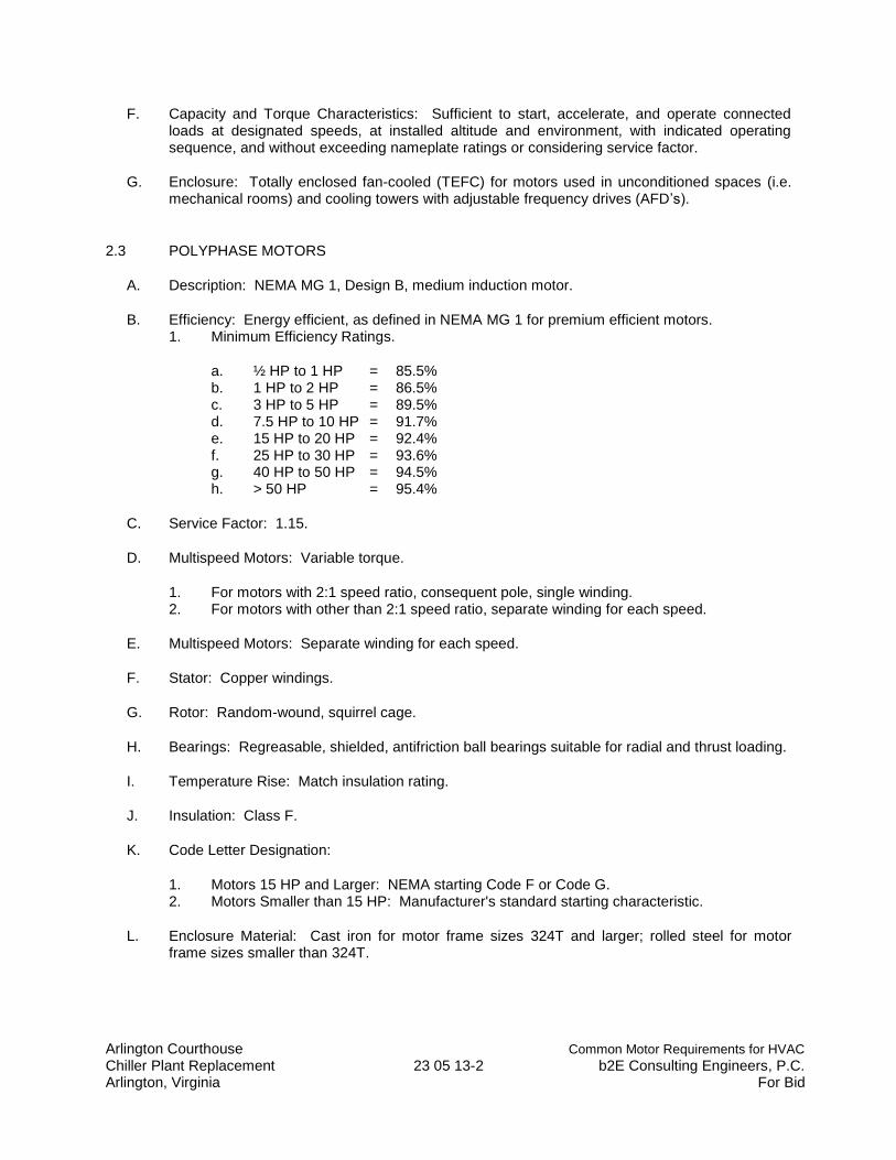
Arlington Courthouse Common Motor Requirements for HVAC Chiller Plant Replacement 23 05 13-2 b2E Consulting Engineers, P.C. Arlington, Virginia For Bid
F. Capacity and Torque Characteristics: Sufficient to start, accelerate, and operate connected loads at designated speeds, at installed altitude and environment, with indicated operating sequence, and without exceeding nameplate ratings or considering service factor.
G. Enclosure: Totally enclosed fan-cooled (TEFC) for motors used in unconditioned spaces (i.e. mechanical rooms) and cooling towers with adjustable frequency drives (AFD’s).
2.3 POLYPHASE MOTORS
A. Description: NEMA MG 1, Design B, medium induction motor.
B. Efficiency: Energy efficient, as defined in NEMA MG 1 for premium efficient motors. 1. Minimum Efficiency Ratings.
a. ½ HP to 1 HP = 85.5% b. 1 HP to 2 HP = 86.5% c. 3 HP to 5 HP = 89.5% d. 7.5 HP to 10 HP = 91.7% e. 15 HP to 20 HP = 92.4% f. 25 HP to 30 HP = 93.6% g. 40 HP to 50 HP = 94.5% h. > 50 HP = 95.4%
C. Service Factor: 1.15.
D. Multispeed Motors: Variable torque.
1. For motors with 2:1 speed ratio, consequent pole, single winding. 2. For motors with other than 2:1 speed ratio, separate winding for each speed.
E. Multispeed Motors: Separate winding for each speed.
F. Stator: Copper windings.
G. Rotor: Random-wound, squirrel cage.
H. Bearings: Regreasable, shielded, antifriction ball bearings suitable for radial and thrust loading.
I. Temperature Rise: Match insulation rating.
J. Insulation: Class F.
K. Code Letter Designation:
1. Motors 15 HP and Larger: NEMA starting Code F or Code G. 2. Motors Smaller than 15 HP: Manufacturer's standard starting characteristic.
L. Enclosure Material: Cast iron for motor frame sizes 324T and larger; rolled steel for motor frame sizes smaller than 324T.
Arlington Courthouse Common Motor Requirements for HVAC Chiller Plant Replacement 23 05 13-3 b2E Consulting Engineers, P.C. Arlington, Virginia For Bid
2.4 POLYPHASE MOTORS WITH ADDITIONAL REQUIREMENTS
A. Motors Used with Reduced-Voltage and Multispeed Controllers: Match wiring connection requirements for controller with required motor leads. Provide terminals in motor terminal box, suited to control method.
B. Motors Used with Variable Frequency Controllers: Provide totally enclosed fan-cooled (TEFC) premium efficient inverter duty motors with flexible variable speed duty drive couplings. Ratings, characteristics, and features coordinated with and approved by controller manufacturer.
1. Windings: Copper magnet wire with moisture-resistant insulation varnish, designed and tested to resist transient spikes, high frequencies, and short time rise pulses produced by pulse-width modulated inverters.
2. Energy- and Premium-Efficient Motors: Class B temperature rise; Class F insulation. 3. Premium – Efficient Inverter-Duty Motors: Class F temperature rise; Class H insulation. 4. Thermal Protection: Comply with NEMA MG 1 requirements for thermally protected
motors.
2.5 SINGLE-PHASE MOTORS
A. Motors larger than 1/20 hp shall be one of the following, to suit starting torque and requirements of specific motor application:
1. Permanent-split capacitor. 2. Split phase. 3. Capacitor start, inductor run. 4. Capacitor start, capacitor run.
B. Multispeed Motors: Variable-torque, permanent-split-capacitor type.
C. Bearings: Prelubricated, antifriction ball bearings or sleeve bearings suitable for radial and thrust loading.
D. Motors 1/20 HP and Smaller: Shaded-pole type.
E. Thermal Protection: Internal protection to automatically open power supply circuit to motor when winding temperature exceeds a safe value calibrated to temperature rating of motor insulation. Thermal-protection device shall automatically reset when motor temperature returns to normal range.
2.6 EXAMINATION
A. Examine areas to receive field-installed motors for compliance with requirements, installation tolerances, and other conditions affecting performance.
B. Examine roughing-in of conduit systems to verify actual locations of conduit connections before motor installation.
C. Proceed with installation only after unsatisfactory conditions have been corrected.
2.7 MOTOR INSTALLATION
Arlington Courthouse Common Motor Requirements for HVAC Chiller Plant Replacement 23 05 13-4 b2E Consulting Engineers, P.C. Arlington, Virginia For Bid
A. Anchor each motor assembly to base, adjustable rails, or other support, arranged and sized according to manufacturer's written instructions. Attach by bolting. Level and align with load transfer link.
B. Install motors on equipment bases for pumps and inside cooling towers and on other equipment in accordance with manufacturer’s written instructions.
C. Comply with mounting and anchoring requirements specified in Division 23 Section "Mechanical Sound and Vibration Controls."
2.8 FIELD QUALITY CONTROL
A. Prepare for acceptance tests as follows:
1. Align motors, bases, shafts, pulleys, and belts. Tension belts according to manufacture’s written instructions.
2. Verify bearing lubrication. 3. Run each motor with its controller. Demonstrate correct rotation, alignment, and speed at
motor design load. 4. Test interlocks and control and safety features for proper operation. 5. Verify that current and voltage for each phase comply with nameplate rating and NEMA
MG 1 tolerances.
B. Testing: Engage a qualified testing agency to perform the following field quality-control testing:
1. Perform each electrical test and visual and mechanical inspection stated in NETA ATS, Section 7.15.1.
2. Certify compliance with test parameters. 3. Correct malfunctioning units on-site, where possible, and retest to demonstrate
compliance; otherwise, replace with new units and retest.
C. Manufacturer's Field Service: Engage a factory-authorized service representative to perform the following:
1. Inspect components, equipment installation, and piping and electrical connections for compliance with requirements.
2. Test and adjust controls and safeties. Replace damaged and malfunctioning controls and equipment.
3. Verify bearing lubrication. 4. Verify proper motor rotation. 5. Test Reports: Prepare a written report to record the following:
a. Test procedures used. b. Test results that comply with requirements. c. Test results that do not comply with requirements and corrective action taken to
achieve compliance.
2.9 ADJUSTING
A. Align motors, bases, shafts, pulleys and belts. Tension belts according to manufacturer's written instructions.
Arlington Courthouse Common Motor Requirements for HVAC Chiller Plant Replacement 23 05 13-5 b2E Consulting Engineers, P.C. Arlington, Virginia For Bid
2.10 CLEANING
A. After completing equipment installation, inspect unit components. Remove paint splatters and other spots, dirt, and debris. Repair damaged finish to match original finish.
B. Clean motors, on completion of installation, according to manufacturer's written instructions.
2.11 MOTOR REPLACEMENT
A. Cooling Tower: Each cooling tower shall be provided with a davit type lifting device that allows the motor to be lifted from the cooling tower and swung-out and lowered to the penthouse roof by one technician. Refer to structural for details.
B. Pumps: Each pump shall be installed to allow the use of a portable lift to pick up the motor and move it (roll) out of the chiller plant.
C. Compressor Motors: Each chiller compressor shall be installed to allow the use of a portable lift to pick up the motor lower it and move it (roll) out of the chiller plant.
2.12 FIELD-INTALLED MOTOR DEMONSTATION
A. Engage a factory-authorized service representative to train Owner’s maintenance personnel to adjust, operate, and maintain field-installed motors. Refer to Division 1 Section “Closeout Procedures” and for other applicable requirements.
END OF SECTION 23 05 13
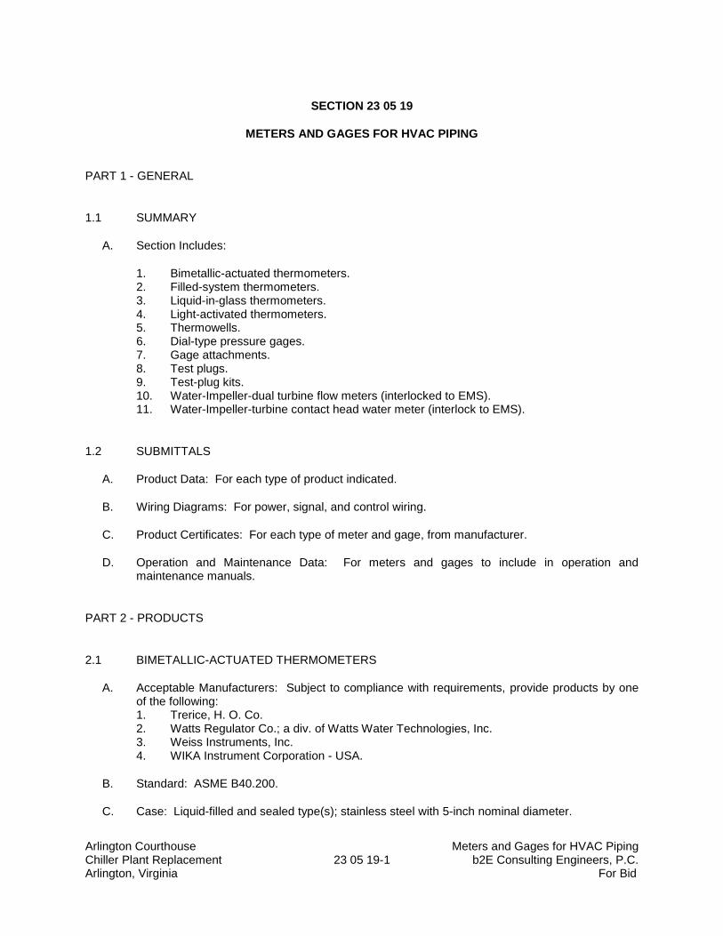
Arlington Courthouse Meters and Gages for HVAC Piping Chiller Plant Replacement 23 05 19-1 b2E Consulting Engineers, P.C. Arlington, Virginia For Bid
SECTION 23 05 19
METERS AND GAGES FOR HVAC PIPING
PART 1 - GENERAL
1.1 SUMMARY
A. Section Includes:
1. Bimetallic-actuated thermometers. 2. Filled-system thermometers. 3. Liquid-in-glass thermometers. 4. Light-activated thermometers. 5. Thermowells. 6. Dial-type pressure gages. 7. Gage attachments. 8. Test plugs. 9. Test-plug kits. 10. Water-Impeller-dual turbine flow meters (interlocked to EMS). 11. Water-Impeller-turbine contact head water meter (interlock to EMS).
1.2 SUBMITTALS
A. Product Data: For each type of product indicated.
B. Wiring Diagrams: For power, signal, and control wiring.
C. Product Certificates: For each type of meter and gage, from manufacturer.
D. Operation and Maintenance Data: For meters and gages to include in operation and maintenance manuals.
PART 2 - PRODUCTS
2.1 BIMETALLIC-ACTUATED THERMOMETERS
A. Acceptable Manufacturers: Subject to compliance with requirements, provide products by one of the following: 1. Trerice, H. O. Co. 2. Watts Regulator Co.; a div. of Watts Water Technologies, Inc. 3. Weiss Instruments, Inc. 4. WIKA Instrument Corporation - USA.
B. Standard: ASME B40.200.
C. Case: Liquid-filled and sealed type(s); stainless steel with 5-inch nominal diameter.
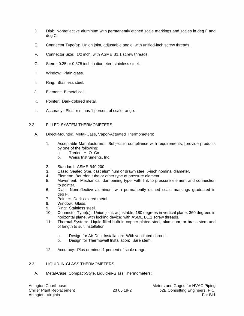
Arlington Courthouse Meters and Gages for HVAC Piping Chiller Plant Replacement 23 05 19-2 b2E Consulting Engineers, P.C. Arlington, Virginia For Bid
D. Dial: Nonreflective aluminum with permanently etched scale markings and scales in deg F and deg C.
E. Connector Type(s): Union joint, adjustable angle, with unified-inch screw threads.
F. Connector Size: 1/2 inch, with ASME B1.1 screw threads.
G. Stem: 0.25 or 0.375 inch in diameter; stainless steel.
H. Window: Plain glass.
I. Ring: Stainless steel.
J. Element: Bimetal coil.
K. Pointer: Dark-colored metal.
L. Accuracy: Plus or minus 1 percent of scale range.
2.2 FILLED-SYSTEM THERMOMETERS
A. Direct-Mounted, Metal-Case, Vapor-Actuated Thermometers:
1. Acceptable Manufacturers: Subject to compliance with requirements, [provide products by one of the following: a. Trerice, H. O. Co. b. Weiss Instruments, Inc.
2. Standard: ASME B40.200. 3. Case: Sealed type, cast aluminum or drawn steel 5-inch nominal diameter. 4. Element: Bourdon tube or other type of pressure element. 5. Movement: Mechanical, dampening type, with link to pressure element and connection
to pointer. 6. Dial: Nonreflective aluminum with permanently etched scale markings graduated in
deg F. 7. Pointer: Dark-colored metal. 8. Window: Glass. 9. Ring: Stainless steel. 10. Connector Type(s): Union joint, adjustable, 180 degrees in vertical plane, 360 degrees in
horizontal plane, with locking device; with ASME B1.1 screw threads. 11. Thermal System: Liquid-filled bulb in copper-plated steel, aluminum, or brass stem and
of length to suit installation.
a. Design for Air-Duct Installation: With ventilated shroud. b. Design for Thermowell Installation: Bare stem.
12. Accuracy: Plus or minus 1 percent of scale range.
2.3 LIQUID-IN-GLASS THERMOMETERS
A. Metal-Case, Compact-Style, Liquid-in-Glass Thermometers:
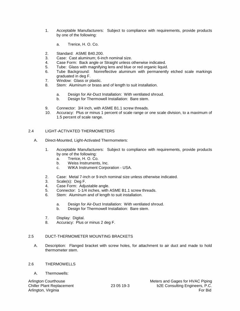
Arlington Courthouse Meters and Gages for HVAC Piping Chiller Plant Replacement 23 05 19-3 b2E Consulting Engineers, P.C. Arlington, Virginia For Bid
1. Acceptable Manufacturers: Subject to compliance with requirements, provide products by one of the following:
a. Trerice, H. O. Co.
2. Standard: ASME B40.200. 3. Case: Cast aluminum; 6-inch nominal size. 4. Case Form: Back angle or Straight unless otherwise indicated. 5. Tube: Glass with magnifying lens and blue or red organic liquid. 6. Tube Background: Nonreflective aluminum with permanently etched scale markings
graduated in deg F. 7. Window: Glass or plastic. 8. Stem: Aluminum or brass and of length to suit installation.
a. Design for Air-Duct Installation: With ventilated shroud. b. Design for Thermowell Installation: Bare stem.
9. Connector: 3/4 inch, with ASME B1.1 screw threads. 10. Accuracy: Plus or minus 1 percent of scale range or one scale division, to a maximum of
1.5 percent of scale range.
2.4 LIGHT-ACTIVATED THERMOMETERS
A. Direct-Mounted, Light-Activated Thermometers:
1. Acceptable Manufacturers: Subject to compliance with requirements, provide products by one of the following: a. Trerice, H. O. Co. b. Weiss Instruments, Inc. c. WIKA Instrument Corporation - USA.
2. Case: Metal 7-inch or 9-inch nominal size unless otherwise indicated. 3. Scale(s): Deg F. 4. Case Form: Adjustable angle. 5. Connector: 1-1/4 inches, with ASME B1.1 screw threads. 6. Stem: Aluminum and of length to suit installation.
a. Design for Air-Duct Installation: With ventilated shroud. b. Design for Thermowell Installation: Bare stem.
7. Display: Digital. 8. Accuracy: Plus or minus 2 deg F.
2.5 DUCT-THERMOMETER MOUNTING BRACKETS
A. Description: Flanged bracket with screw holes, for attachment to air duct and made to hold thermometer stem.
2.6 THERMOWELLS
A. Thermowells:
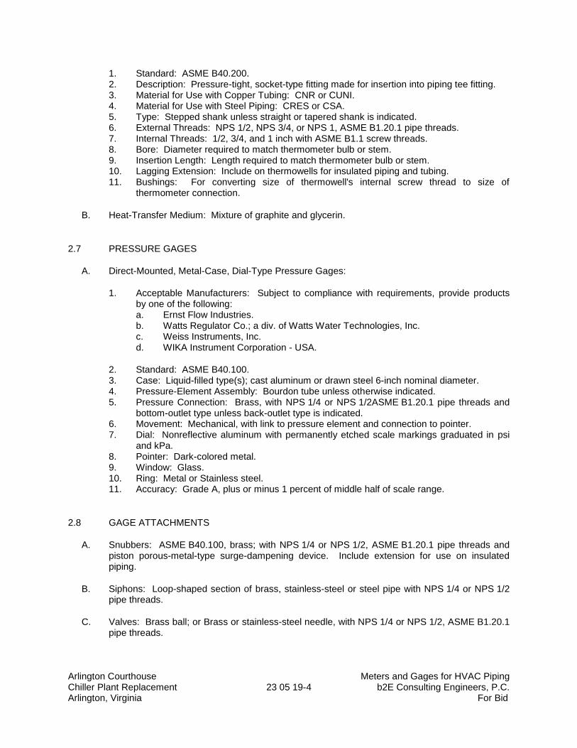
Arlington Courthouse Meters and Gages for HVAC Piping Chiller Plant Replacement 23 05 19-4 b2E Consulting Engineers, P.C. Arlington, Virginia For Bid
1. Standard: ASME B40.200. 2. Description: Pressure-tight, socket-type fitting made for insertion into piping tee fitting. 3. Material for Use with Copper Tubing: CNR or CUNI. 4. Material for Use with Steel Piping: CRES or CSA. 5. Type: Stepped shank unless straight or tapered shank is indicated. 6. External Threads: NPS 1/2, NPS 3/4, or NPS 1, ASME B1.20.1 pipe threads. 7. Internal Threads: 1/2, 3/4, and 1 inch with ASME B1.1 screw threads. 8. Bore: Diameter required to match thermometer bulb or stem. 9. Insertion Length: Length required to match thermometer bulb or stem. 10. Lagging Extension: Include on thermowells for insulated piping and tubing. 11. Bushings: For converting size of thermowell's internal screw thread to size of
thermometer connection.
B. Heat-Transfer Medium: Mixture of graphite and glycerin.
2.7 PRESSURE GAGES
A. Direct-Mounted, Metal-Case, Dial-Type Pressure Gages:
1. Acceptable Manufacturers: Subject to compliance with requirements, provide products by one of the following: a. Ernst Flow Industries. b. Watts Regulator Co.; a div. of Watts Water Technologies, Inc. c. Weiss Instruments, Inc. d. WIKA Instrument Corporation - USA.
2. Standard: ASME B40.100. 3. Case: Liquid-filled type(s); cast aluminum or drawn steel 6-inch nominal diameter. 4. Pressure-Element Assembly: Bourdon tube unless otherwise indicated. 5. Pressure Connection: Brass, with NPS 1/4 or NPS 1/2ASME B1.20.1 pipe threads and
bottom-outlet type unless back-outlet type is indicated. 6. Movement: Mechanical, with link to pressure element and connection to pointer. 7. Dial: Nonreflective aluminum with permanently etched scale markings graduated in psi
and kPa. 8. Pointer: Dark-colored metal. 9. Window: Glass. 10. Ring: Metal or Stainless steel. 11. Accuracy: Grade A, plus or minus 1 percent of middle half of scale range.
2.8 GAGE ATTACHMENTS
A. Snubbers: ASME B40.100, brass; with NPS 1/4 or NPS 1/2, ASME B1.20.1 pipe threads and piston porous-metal-type surge-dampening device. Include extension for use on insulated piping.
B. Siphons: Loop-shaped section of brass, stainless-steel or steel pipe with NPS 1/4 or NPS 1/2 pipe threads.
C. Valves: Brass ball; or Brass or stainless-steel needle, with NPS 1/4 or NPS 1/2, ASME B1.20.1 pipe threads.
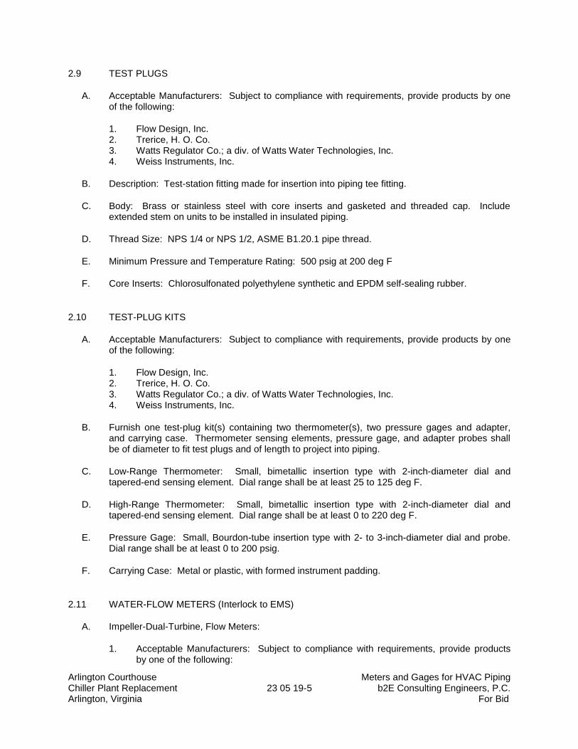
Arlington Courthouse Meters and Gages for HVAC Piping Chiller Plant Replacement 23 05 19-5 b2E Consulting Engineers, P.C. Arlington, Virginia For Bid
2.9 TEST PLUGS
A. Acceptable Manufacturers: Subject to compliance with requirements, provide products by one of the following:
1. Flow Design, Inc. 2. Trerice, H. O. Co. 3. Watts Regulator Co.; a div. of Watts Water Technologies, Inc. 4. Weiss Instruments, Inc.
B. Description: Test-station fitting made for insertion into piping tee fitting.
C. Body: Brass or stainless steel with core inserts and gasketed and threaded cap. Include extended stem on units to be installed in insulated piping.
D. Thread Size: NPS 1/4 or NPS 1/2, ASME B1.20.1 pipe thread.
E. Minimum Pressure and Temperature Rating: 500 psig at 200 deg F
F. Core Inserts: Chlorosulfonated polyethylene synthetic and EPDM self-sealing rubber.
2.10 TEST-PLUG KITS
A. Acceptable Manufacturers: Subject to compliance with requirements, provide products by one of the following:
1. Flow Design, Inc. 2. Trerice, H. O. Co. 3. Watts Regulator Co.; a div. of Watts Water Technologies, Inc. 4. Weiss Instruments, Inc.
B. Furnish one test-plug kit(s) containing two thermometer(s), two pressure gages and adapter, and carrying case. Thermometer sensing elements, pressure gage, and adapter probes shall be of diameter to fit test plugs and of length to project into piping.
C. Low-Range Thermometer: Small, bimetallic insertion type with 2-inch-diameter dial and tapered-end sensing element. Dial range shall be at least 25 to 125 deg F.
D. High-Range Thermometer: Small, bimetallic insertion type with 2-inch-diameter dial and tapered-end sensing element. Dial range shall be at least 0 to 220 deg F.
E. Pressure Gage: Small, Bourdon-tube insertion type with 2- to 3-inch-diameter dial and probe. Dial range shall be at least 0 to 200 psig.
F. Carrying Case: Metal or plastic, with formed instrument padding.
2.11 WATER-FLOW METERS (Interlock to EMS)
A. Impeller-Dual-Turbine, Flow Meters:
1. Acceptable Manufacturers: Subject to compliance with requirements, provide products by one of the following:
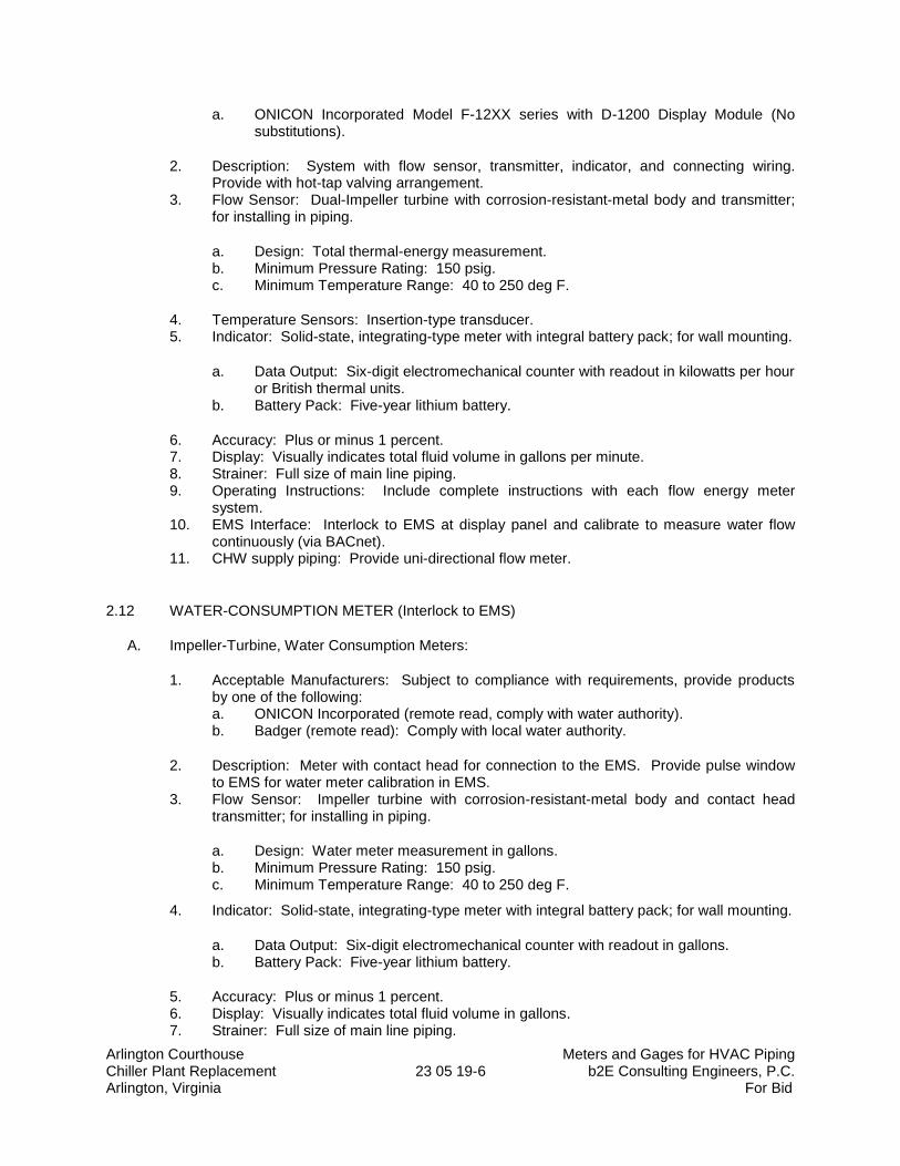
Arlington Courthouse Meters and Gages for HVAC Piping Chiller Plant Replacement 23 05 19-6 b2E Consulting Engineers, P.C. Arlington, Virginia For Bid
a. ONICON Incorporated Model F-12XX series with D-1200 Display Module (No substitutions).
2. Description: System with flow sensor, transmitter, indicator, and connecting wiring. Provide with hot-tap valving arrangement.
3. Flow Sensor: Dual-Impeller turbine with corrosion-resistant-metal body and transmitter; for installing in piping.
a. Design: Total thermal-energy measurement. b. Minimum Pressure Rating: 150 psig. c. Minimum Temperature Range: 40 to 250 deg F.
4. Temperature Sensors: Insertion-type transducer. 5. Indicator: Solid-state, integrating-type meter with integral battery pack; for wall mounting.
a. Data Output: Six-digit electromechanical counter with readout in kilowatts per hour or British thermal units.
b. Battery Pack: Five-year lithium battery.
6. Accuracy: Plus or minus 1 percent. 7. Display: Visually indicates total fluid volume in gallons per minute. 8. Strainer: Full size of main line piping. 9. Operating Instructions: Include complete instructions with each flow energy meter
system. 10. EMS Interface: Interlock to EMS at display panel and calibrate to measure water flow
continuously (via BACnet). 11. CHW supply piping: Provide uni-directional flow meter.
2.12 WATER-CONSUMPTION METER (Interlock to EMS)
A. Impeller-Turbine, Water Consumption Meters:
1. Acceptable Manufacturers: Subject to compliance with requirements, provide products by one of the following: a. ONICON Incorporated (remote read, comply with water authority). b. Badger (remote read): Comply with local water authority.
2. Description: Meter with contact head for connection to the EMS. Provide pulse window to EMS for water meter calibration in EMS.
3. Flow Sensor: Impeller turbine with corrosion-resistant-metal body and contact head transmitter; for installing in piping.
a. Design: Water meter measurement in gallons. b. Minimum Pressure Rating: 150 psig. c. Minimum Temperature Range: 40 to 250 deg F.
4. Indicator: Solid-state, integrating-type meter with integral battery pack; for wall mounting.
a. Data Output: Six-digit electromechanical counter with readout in gallons. b. Battery Pack: Five-year lithium battery.
5. Accuracy: Plus or minus 1 percent. 6. Display: Visually indicates total fluid volume in gallons. 7. Strainer: Full size of main line piping.
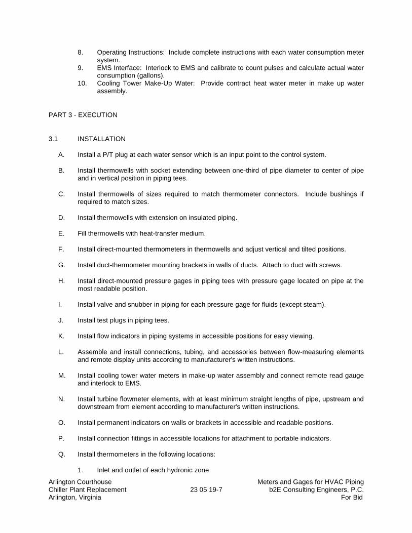
Arlington Courthouse Meters and Gages for HVAC Piping Chiller Plant Replacement 23 05 19-7 b2E Consulting Engineers, P.C. Arlington, Virginia For Bid
8. Operating Instructions: Include complete instructions with each water consumption meter system.
9. EMS Interface: Interlock to EMS and calibrate to count pulses and calculate actual water consumption (gallons).
10. Cooling Tower Make-Up Water: Provide contract heat water meter in make up water assembly.
PART 3 - EXECUTION
3.1 INSTALLATION
A. Install a P/T plug at each water sensor which is an input point to the control system.
B. Install thermowells with socket extending between one-third of pipe diameter to center of pipe and in vertical position in piping tees.
C. Install thermowells of sizes required to match thermometer connectors. Include bushings if required to match sizes.
D. Install thermowells with extension on insulated piping.
E. Fill thermowells with heat-transfer medium.
F. Install direct-mounted thermometers in thermowells and adjust vertical and tilted positions.
G. Install duct-thermometer mounting brackets in walls of ducts. Attach to duct with screws.
H. Install direct-mounted pressure gages in piping tees with pressure gage located on pipe at the most readable position.
I. Install valve and snubber in piping for each pressure gage for fluids (except steam).
J. Install test plugs in piping tees.
K. Install flow indicators in piping systems in accessible positions for easy viewing.
L. Assemble and install connections, tubing, and accessories between flow-measuring elements and remote display units according to manufacturer's written instructions.
M. Install cooling tower water meters in make-up water assembly and connect remote read gauge and interlock to EMS.
N. Install turbine flowmeter elements, with at least minimum straight lengths of pipe, upstream and downstream from element according to manufacturer's written instructions.
O. Install permanent indicators on walls or brackets in accessible and readable positions.
P. Install connection fittings in accessible locations for attachment to portable indicators.
Q. Install thermometers in the following locations:
1. Inlet and outlet of each hydronic zone.
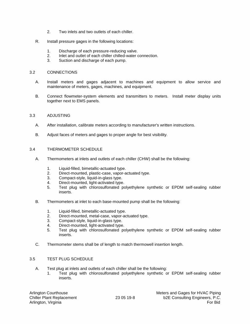
Arlington Courthouse Meters and Gages for HVAC Piping Chiller Plant Replacement 23 05 19-8 b2E Consulting Engineers, P.C. Arlington, Virginia For Bid
2. Two inlets and two outlets of each chiller.
R. Install pressure gages in the following locations:
1. Discharge of each pressure-reducing valve. 2. Inlet and outlet of each chiller chilled-water connection. 3. Suction and discharge of each pump.
3.2 CONNECTIONS
A. Install meters and gages adjacent to machines and equipment to allow service and maintenance of meters, gages, machines, and equipment.
B. Connect flowmeter-system elements and transmitters to meters. Install meter display units together next to EMS panels.
3.3 ADJUSTING
A. After installation, calibrate meters according to manufacturer's written instructions.
B. Adjust faces of meters and gages to proper angle for best visibility.
3.4 THERMOMETER SCHEDULE
A. Thermometers at inlets and outlets of each chiller (CHW) shall be the following:
1. Liquid-filled, bimetallic-actuated type. 2. Direct-mounted, plastic-case, vapor-actuated type. 3. Compact-style, liquid-in-glass type. 4. Direct-mounted, light-activated type. 5. Test plug with chlorosulfonated polyethylene synthetic or EPDM self-sealing rubber
inserts.
B. Thermometers at inlet to each base-mounted pump shall be the following:
1. Liquid-filled, bimetallic-actuated type. 2. Direct-mounted, metal-case, vapor-actuated type. 3. Compact-style, liquid-in-glass type. 4. Direct-mounted, light-activated type. 5. Test plug with chlorosulfonated polyethylene synthetic or EPDM self-sealing rubber
inserts.
C. Thermometer stems shall be of length to match thermowell insertion length.
3.5 TEST PLUG SCHEDULE
A. Test plug at inlets and outlets of each chiller shall be the following: 1. Test plug with chlorosulfonated polyethylene synthetic or EPDM self-sealing rubber
inserts.
Arlington Courthouse Meters and Gages for HVAC Piping Chiller Plant Replacement 23 05 19-9 b2E Consulting Engineers, P.C. Arlington, Virginia For Bid
3.6 THERMOMETER SCALE-RANGE SCHEDULE
A. Scale Range for Chilled-Water Piping: 0 to 100 deg F.
3.7 PRESSURE-GAGE SCHEDULE
A. Pressure gages at discharge of each pressure-reducing valve shall be the following:
1. Liquid-filled, direct-mounted, metal case. 2. Test plug with chlorosulfonated polyethylene synthetic or EPDM self-sealing rubber
inserts.
B. Pressure gages at inlet and outlet of each chiller chilled-water and water connection shall be the following:
1. Liquid-filled, remote-mounted, metal case. 2. Test plug with chlorosulfonated polyethylene synthetic or EPDM self-sealing rubber
inserts.
C. Pressure gages at suction and discharge of each pump shall be the following:
1. Liquid-filled, direct-mounted, metal case. 2. Test plug with chlorosulfonated polyethylene synthetic or EPDM self-sealing rubber
inserts.
3.8 PRESSURE-GAGE SCALE-RANGE SCHEDULE
A. Scale Range for Chilled-Water Piping: 0 to 100 psi.
3.9 WATER IMPELLER-DUAL TURBINE METER SCHEDULE
A. Chilled Water: Provide flow meter with remote display is CHW supply piping with remote display. Interlock remote display to EMS to read flow rate (gpm) at the EMS.
3.10 WATER IMPELLER-TURBINE METER SCHEDULE
A. Water Meters for Cooling tower make-up Water Service: Impeller-turbine type with remote read on wall and contact head with pulse window connected to EMS.
END OF SECTION 23 05 19
Arlington Courthouse General-Duty Valves for HVAC Piping Chiller Plant Replacement 23 05 23-1 b2E Consulting Engineers, P.C. Arlington, Virginia For Bid
SECTION 23 05 23
GENERAL-DUTY VALVES FOR HVAC PIPING
PART 1 - GENERAL
1.1 SUMMARY
A. Section Includes: 1. Bronze ball valves. 2. Iron ball valves. 3. Bronze swing check valves. 4. Iron swing check valves with closure control. 5. Iron, center-guided check valves. 6. Chainwheels.
1.2 DEFINITIONS
A. CWP: Cold working pressure.
B. EPDM: Ethylene propylene copolymer rubber.
C. NBR: Acrylonitrile-butadiene, Buna-N, or nitrile rubber.
D. NRS: Nonrising stem.
E. OS&Y: Outside screw and yoke.
F. RS: Rising stem.
1.3 SUBMITTALS
A. Product Data: For each type of valve indicated.
1.4 QUALITY ASSURANCE
A. Source Limitations for Valves: Obtain each type of valve from single source from single manufacturer.
B. ASME Compliance:
1. ASME B16.10 and ASME B16.34 for ferrous valve dimensions and design criteria. 2. ASME B31.1 for power piping valves. 3. ASME B31.9 for building services piping valves.
Arlington Courthouse General-Duty Valves for HVAC Piping Chiller Plant Replacement 23 05 23-2 b2E Consulting Engineers, P.C. Arlington, Virginia For Bid
1.5 DELIVERY, STORAGE, AND HANDLING
A. Prepare valves for shipping as follows:
1. Protect internal parts against rust and corrosion. 2. Protect threads, flange faces, grooves, and weld ends. 3. Set ball valves open to minimize exposure of functional surfaces. 4. Block check valves in either closed or open position.
B. Use the following precautions during storage:
1. Maintain valve end protection. 2. Store valves indoors and maintain at higher than ambient dew point temperature. If
outdoor storage is necessary, store valves off the ground in watertight enclosures.
C. Use sling to handle large valves; rig sling to avoid damage to exposed parts. Do not use handwheels or stems as lifting or rigging points.
PART 2 - PRODUCTS
2.1 GENERAL REQUIREMENTS FOR VALVES
A. Refer to HVAC valve schedule articles for applications of valves.
B. Valve Pressure and Temperature Ratings: Not less than indicated and as required for system pressures and temperatures.
C. Valve Sizes: Same as upstream piping unless otherwise indicated.
D. Valve Actuator Types:
1. Gear Actuator: For quarter-turn valves NPS 8 and larger. 2. Handwheel: For valves other than quarter-turn types. 3. Handlever: For quarter-turn valves NPS 6 and smaller. 4. Chainwheel: Device for attachment to valve handwheel, stem, or other actuator; of size
and with chain for mounting height, as indicated in the "Valve Installation" Article.
E. Valves in Insulated Piping: With 2-inch stem extensions and the following features: 1. Ball Valves: With extended operating handle of non-thermal-conductive material, and
protective sleeve that allows operation of valve without breaking the vapor seal or disturbing insulation.
2. Butterfly Valves: Not allowed.
F. Valve-End Connections:
1. Flanged: With flanges according to ASME B16.1 for iron valves. 2. Solder Joint: With sockets according to ASME B16.18. 3. Threaded: With threads according to ASME B1.20.1.
G. Valve Bypass and Drain Connections: MSS SP-45.

Arlington Courthouse General-Duty Valves for HVAC Piping Chiller Plant Replacement 23 05 23-3 b2E Consulting Engineers, P.C. Arlington, Virginia For Bid
2.2 BRONZE BALL VALVES
A. Two-Piece, Full-Port, Bronze Ball Valves with Bronze Trim:
1. Acceptable Manufacturers: Subject to compliance with requirements, provide products by one of the following:
a. American Valve, Inc. b. Conbraco Industries, Inc.; Apollo Valves. c. Crane Co.; Crane Valve Group; Crane Valves. d. Milwaukee Valve Company. e. NIBCO INC. f. Watts Regulator Co.; a division of Watts Water Technologies, Inc.
2. Description:
a. Standard: MSS SP-110. b. SWP Rating: 150 psig. c. CWP Rating: 600 psig. d. Body Design: Two piece. e. Body Material: Bronze. f. Ends: Threaded. g. Seats: PTFE or TFE. h. Stem: Bronze. i. Ball: Chrome-plated brass. j. Port: Full.
B. Two-Piece, Full-Port, Bronze Ball Valves with Stainless-Steel Trim:
1. Acceptable Manufacturers: Subject to compliance with requirements, provide products by one of the following:
a. Conbraco Industries, Inc.; Apollo Valves. b. Crane Co.; Crane Valve Group; Crane Valves. c. Milwaukee Valve Company. d. NIBCO INC. e. Watts Regulator Co.; a division of Watts Water Technologies, Inc.
2. Description:
a. Standard: MSS SP-110. b. SWP Rating: 150 psig. c. CWP Rating: 600 psig. d. Body Design: Two piece. e. Body Material: Bronze. f. Ends: Threaded. g. Seats: PTFE or TFE. h. Stem: Stainless steel. i. Ball: Stainless steel, vented. j. Port: Full.
C. Three-Piece, Full-Port, Bronze Ball Valves with Bronze Trim:
Arlington Courthouse General-Duty Valves for HVAC Piping Chiller Plant Replacement 23 05 23-4 b2E Consulting Engineers, P.C. Arlington, Virginia For Bid
1. Acceptable Manufacturers: Subject to compliance with requirements, provide products by one of the following:
a. Conbraco Industries, Inc.; Apollo Valves. b. Milwaukee Valve Company. c. NIBCO INC.
2. Description:
a. Standard: MSS SP-110. b. SWP Rating: 150 psig. c. CWP Rating: 600 psig. d. Body Design: Three piece. e. Body Material: Bronze. f. Ends: Threaded. g. Seats: PTFE or TFE. h. Stem: Bronze. i. Ball: Chrome-plated brass. j. Port: Full.
D. Three-Piece, Full-Port, Bronze Ball Valves with Stainless-Steel Trim:
1. Acceptable Manufacturers: Subject to compliance with requirements, provide products by one of the following:
a. Conbraco Industries, Inc.; Apollo Valves. b. Milwaukee Valve Company. c. NIBCO INC.
2. Description:
a. Standard: MSS SP-110. b. SWP Rating: 150 psig. c. CWP Rating: 600 psig. d. Body Design: Three piece. e. Body Material: Bronze. f. Ends: Threaded. g. Seats: PTFE or TFE. h. Stem: Stainless steel. i. Ball: Stainless steel, vented. j. Port: Full.
2.3 IRON BALL VALVES
A. Class 125, Iron Ball Valves:
1. Acceptable Manufacturers: Subject to compliance with requirements, provide products by one of the following:
a. American Valve, Inc. b. Conbraco Industries, Inc.; Apollo Valves. c. Watts Regulator Co.; a division of Watts Water Technologies, Inc.
Arlington Courthouse General-Duty Valves for HVAC Piping Chiller Plant Replacement 23 05 23-5 b2E Consulting Engineers, P.C. Arlington, Virginia For Bid
2. Description:
a. Standard: MSS SP-72. b. CWP Rating: 200 psig. c. Body Design: Split body. d. Body Material: ASTM A 126, gray iron. e. Ends: Flanged. f. Seats: PTFE or TFE. g. Stem: Stainless steel. h. Ball: Stainless steel. i. Port: Full.
2.4 BRONZE SWING CHECK VALVES
A. Class 125, Bronze Swing Check Valves with Bronze Disc:
1. Acceptable Manufacturers: Subject to compliance with requirements, provide products by one of the following:
a. American Valve, Inc. b. Crane Co.; Crane Valve Group; Crane Valves. c. Milwaukee Valve Company. d. NIBCO INC. e. Watts Regulator Co.; a division of Watts Water Technologies, Inc.
2. Description:
a. Standard: MSS SP-80, Type 3. b. CWP Rating: 200 psig. c. Body Design: Horizontal flow. d. Body Material: ASTM B 62, bronze. e. Ends: Threaded. f. Disc: Bronze.
B. Class 150, Bronze Swing Check Valves with Bronze Disc:
1. Acceptable Manufacturers: Subject to compliance with requirements, provide products by one of the following:
a. American Valve, Inc. b. Crane Co.; Crane Valve Group; Crane Valves. c. Kitz Corporation. d. Milwaukee Valve Company. e. NIBCO INC.
2. Description:
a. Standard: MSS SP-80, Type 3. b. CWP Rating: 300 psig. c. Body Design: Horizontal flow. d. Body Material: ASTM B 62, bronze. e. Ends: Threaded. f. Disc: Bronze.
Arlington Courthouse General-Duty Valves for HVAC Piping Chiller Plant Replacement 23 05 23-6 b2E Consulting Engineers, P.C. Arlington, Virginia For Bid
2.5 IRON SWING CHECK VALVES WITH CLOSURE CONTROL
A. Class 125, Iron Swing Check Valves with Lever- and Spring-Closure Control:
1. Acceptable Manufacturers: Subject to compliance with requirements, provide products by one of the following:
a. NIBCO INC.
2. Description:
a. Standard: MSS SP-71, Type I. b. NPS 2-1/2 to NPS 12, CWP Rating: 200 psig. c. NPS 14 to NPS 24, CWP Rating: 150 psig. d. Body Design: Clear or full waterway. e. Body Material: ASTM A 126, gray iron with bolted bonnet. f. Ends: Flanged. g. Trim: Bronze. h. Gasket: Asbestos free. i. Closure Control: Factory-installed, exterior lever and spring.
B. Class 125, Iron Swing Check Valves with Lever and Weight-Closure Control:
1. Acceptable Manufacturers: Subject to compliance with requirements, provide products by one of the following:
a. Crane Co.; Crane Valve Group; Crane Valves. b. Milwaukee Valve Company. c. NIBCO INC. d. Watts Regulator Co.; a division of Watts Water Technologies, Inc.
2. Description:
a. Standard: MSS SP-71, Type I. b. NPS 2-1/2 to NPS 12, CWP Rating: 200 psig. c. NPS 14 to NPS 24, CWP Rating: 150 psig. d. Body Design: Clear or full waterway. e. Body Material: ASTM A 126, gray iron with bolted bonnet. f. Ends: Flanged. g. Trim: Bronze. h. Gasket: Asbestos free. i. Closure Control: Factory-installed, exterior lever and weight.
2.6 IRON, CENTER-GUIDED CHECK VALVES
A. Class 125, Iron, Compact-Wafer, Center-Guided Check Valves with Resilient Seat:
1. Acceptable Manufacturers: Subject to compliance with requirements, provide products by one of the following: a. Flo Fab Inc. b. Milwaukee Valve Company. c. NIBCO INC.
Arlington Courthouse General-Duty Valves for HVAC Piping Chiller Plant Replacement 23 05 23-7 b2E Consulting Engineers, P.C. Arlington, Virginia For Bid
2. Description:
a. Standard: MSS SP-125. b. NPS 2-1/2 to NPS 12, CWP Rating: 200 psig. c. NPS 14 to NPS 24, CWP Rating: 150 psig. d. Body Material: ASTM A 126, gray iron. e. Style: Compact wafer. f. Seat: EPDM or NBR.
2.7 CHAINWHEELS
A. Acceptable Manufacturers: Subject to compliance with requirements, provide products by one of the following:
1. Babbitt Steam Specialty Co. 2. Roto Hammer Industries. 3. Trumbull Industries.
B. Description: Valve actuation assembly with sprocket rim, brackets, and chain.
1. Brackets: Type, number, size, and fasteners required to mount actuator on valve. 2. Attachment: For connection to ball valve stems. 3. Sprocket Rim with Chain Guides: Ductile or cast iron, of type and size required for valve. 4. Chain: Hot-dip, galvanized steel, of size required to fit sprocket rim.
PART 3 - EXECUTION
3.1 EXAMINATION
A. Examine valve interior for cleanliness, freedom from foreign matter, and corrosion. Remove special packing materials, such as blocks, used to prevent disc movement during shipping and handling.
B. Operate valves in positions from fully open to fully closed. Examine guides and seats made accessible by such operations.
C. Examine threads on valve and mating pipe for form and cleanliness.
D. Examine mating flange faces for conditions that might cause leakage. Check bolting for proper size, length, and material. Verify that gasket is of proper size, that its material composition is suitable for service, and that it is free from defects and damage.
E. Do not attempt to repair defective valves; replace with new valves.
3.2 VALVE INSTALLATION
A. Install valves with unions or flanges at each piece of equipment arranged to allow service, maintenance, and equipment removal without system shutdown.
B. Locate valves for easy access and provide separate support where necessary.
Arlington Courthouse General-Duty Valves for HVAC Piping Chiller Plant Replacement 23 05 23-8 b2E Consulting Engineers, P.C. Arlington, Virginia For Bid
C. Install valves in horizontal piping with stem at or above center of pipe.
D. Install valves in position to allow full stem movement.
E. Install chainwheels on operators for ball valves NPS 4 and larger and more than 96 inches above floor. Extend chains to 60 inches above finished floor.
F. Install check valves for proper direction of flow and as follows:
1. Swing Check Valves: In horizontal position with hinge pin level. 2. Center-Guided Check Valves: In horizontal or vertical position, between flanges. 3. Lift Check Valves: With stem upright and plumb.
3.3 ADJUSTING
A. Adjust or replace valve packing after piping systems have been tested and put into service but before final adjusting and balancing. Replace valves if persistent leaking occurs.
3.4 GENERAL REQUIREMENTS FOR VALVE APPLICATIONS
A. If valve applications are not indicated, use the following:
1. Shutoff Service: Ball or butterfly valves. 2. Throttling Service: Ball valves. 3. Pump-Discharge Check Valves:
a. NPS 2 and Smaller: Bronze swing check valves with bronze disc. b. NPS 2-1/2 and Larger: Iron swing check valves with lever and weight or with
spring or iron, center-guided, resilient-seat check valves.
B. If valves with specified SWP classes or CWP ratings are not available, the same types of valves with higher SWP classes or CWP ratings may be substituted.
C. Select valves, except wafer types, with the following end connections:
1. For Copper Tubing, NPS 2 and Smaller: Threaded ends except where solder-joint valve-end option is indicated in valve schedules below.
2. For Steel Piping, NPS 2 and Smaller: Threaded ends. 3. For Steel Piping, NPS 2-1/2 to NPS 4: Flanged ends except where threaded valve-end
option is indicated in valve schedules below. 4. For Steel Piping, NPS 5 and Larger: Flanged ends.
3.5 CHILLED-WATER VALVE SCHEDULE
A. Pipe NPS 2 and Smaller:
1. Bronze Valves: May be provided with solder-joint ends instead of threaded ends. 2. Ball Valves: Two or Three piece, full port, bronze with bronze trim. 3. Bronze Swing Check Valves: Class 125 or Class 150, bronze disc.
B. Pipe NPS 2-1/2 and Larger:
Arlington Courthouse General-Duty Valves for HVAC Piping Chiller Plant Replacement 23 05 23-9 b2E Consulting Engineers, P.C. Arlington, Virginia For Bid
1. Iron Valves, NPS 2-1/2 to NPS 4: Shall be provided with flanged ends. 2. Iron Ball Valves, NPS 2-1/2 to NPS 10: Class 150. 3. Iron Swing Check Valves with Closure Control, NPS 2-1/2 to NPS 12: Class 125, lever
and spring or weight. 4. Iron, Center-Guided Check Valves: Class 125, resilient seat.
END OF SECTION 23 05 23
Arlington Courthouse Hangers and Supports for HVAC Piping & Equipment Chiller Plant Replacement 23 05 29-1 b2e Consulting Engineers, P.C. Arlington, Virginia For Bid
SECTION 23 05 29
HANGERS AND SUPPORTS FOR HVAC PIPING AND EQUIPMENT
PART 1 - GENERAL
1.1 SUMMARY
A. This Section includes the following hangers and supports for HVAC system piping and equipment:
1. Steel pipe hangers and supports. 2. Trapeze pipe hangers. 3. Metal framing systems. 4. Thermal-saddles and blocking inserts. 5. Fastener systems. 6. Pipe stands. 7. Equipment supports. 8. Burn Permit.
B. The piping shall be supported using a galvanized steel floor mounted pipe support system.
1. Do not hang piping from high roof structure.
1.2 DEFINITIONS
A. MSS: Manufacturers Standardization Society for The Valve and Fittings Industry Inc.
B. Terminology: As defined in MSS SP-90, "Guidelines on Terminology for Pipe Hangers and Supports."
1.3 PERFORMANCE REQUIREMENTS
A. Design supports for multiple pipes, including pipe stands, capable of supporting combined weight of supported systems, system contents, and test water.
B. Design equipment supports capable of supporting combined operating weight of supported equipment and connected systems and components.
1.4 SUBMITTALS
A. Product Data: For the following:
1. Steel pipe hangers and supports. 2. Thermal-hanger shield inserts. 3. Powder-actuated fastener systems.
Arlington Courthouse Hangers and Supports for HVAC Piping & Equipment Chiller Plant Replacement 23 05 29-2 b2e Consulting Engineers, P.C. Arlington, Virginia For Bid
a. Do not install powder-actuated fasteners without written approval from the Structural Engineer for type, size, length, material and acceptable locations.
4. Mechanical-expansion anchor systems.
a. Do not install mechanical-expansion anchors without written approval from the Structural Engineer for type, size, length, material and acceptable locations.
B. Shop Drawings: Show fabrication and installation details and include calculations for the following:
1. Trapeze pipe hangers. Include Product Data for components. 2. Metal framing systems. Include Product Data for components. 3. Pipe stands. Include Product Data for components. 4. Equipment supports. 5. Design Calculations (Delegated Design): Signed and sealed by a qualified professional
engineer for designing the underslab pipe hanger system to support the operating weight of the piping system.
C. Welding certificates.
1.5 QUALITY ASSURANCE
A. Welding: Qualify procedures and personnel according to AWS D1.1, "Structural Welding Code-Steel”. AWS D1.3, "Structural Welding Code--Sheet Steel."; AWS D1.4, "Structural Welding Code--Reinforcing Steel."; ASME Boiler and Pressure Vessel Code: Section IX.
B. Welding: Qualify procedures and personnel according to the following:
1. AWS D1.1, "Structural Welding Code-Steel." 2. AWS D1.2, "Structural Welding Code-Aluminum." 3. AWS D1.3, "Structural Welding Code-Sheet Steel." 4. AWS D1.4, "Structural Welding Code-Reinforcing Steel." 5. ASME Boiler and Pressure Vessel Code: Section IX.
C. PVC piping is not allowed.
PART 2 - PRODUCTS
2.1 MANUFACTURERS
A. Acceptable Manufacturers: Subject to compliance with requirements, provide products by one of the manufacturers specified.
2.2 STEEL PIPE HANGERS AND SUPPORTS
A. Description: MSS SP-58, Types 1 through 58, factory-fabricated components. Refer to Part 3 "Hanger and Support Applications" Article for where to use specific hanger and support types.
B. Acceptable Manufacturers:
Arlington Courthouse Hangers and Supports for HVAC Piping & Equipment Chiller Plant Replacement 23 05 29-3 b2e Consulting Engineers, P.C. Arlington, Virginia For Bid
1. B-Line Systems, Inc.; a division of Cooper Industries. 2. ERICO/Michigan Hanger Co. 3. Grinnell Corp. 4. GS Metals Corp. 5. National Pipe Hanger Corporation.
C. Galvanized, Metallic Coatings: Pregalvanized or hot dipped.
D. Nonmetallic Coatings: Plastic coating, jacket, or liner.
E. Uninsulated Copper Piping: Provide similar copper metal hangers where copper piping is in direct contact with hangers.
2.3 TRAPEZE PIPE HANGERS
A. Description: MSS SP-69, Type 59, shop- or field-fabricated pipe-support assembly made from structural-steel shapes with MSS SP-58 hanger rods, nuts, saddles, and U-bolts.
2.4 METAL FRAMING SYSTEMS
A. MFMA Manufacturer Metal Framing Systems: For concrete roof areas only.
1. Manufacturers: Subject to compliance with requirements, provide products by one of the following:
a. Allied Tube & Conduit. b. Cooper B-Line, Inc. c. Flex-Strut Inc. d. GS Metals Corp. e. Thomas & Betts Corporation. f. Unistrut Corporation; Tyco International, Ltd. g. Wesanco, Inc.
2. Description: Shop- or field-fabricated pipe-support assembly for supporting multiple parallel pipes.
3. Standard: MFMA-4. 4. Channels: Continuous slotted steel channel with inturned lips. 5. Channel Nuts: Formed or stamped steel nuts or other devices designed to fit into
channel slot and, when tightened, prevent slipping along channel. 6. Hanger Rods: Continuous-thread rod, nuts, and washer made of ASTM A123 hot dipped
galvanized carbon steel. 7. Metallic Coating: Hot-dipped galvanized or High Performance Paint.
a. Basis of Design: Galvanized or TNEMEC.
B. Non-MFMA Manufacturer Metal Framing Systems: For concrete roof areas only.
1. Manufacturers: Subject to compliance with requirements, provide products by one of the following:
a. Anvil International; a subsidiary of Mueller Water Products Inc. b. Empire Industries, Inc.
Arlington Courthouse Hangers and Supports for HVAC Piping & Equipment Chiller Plant Replacement 23 05 29-4 b2e Consulting Engineers, P.C. Arlington, Virginia For Bid
c. ERICO International Corporation. d. Haydon Corporation; H-Strut Division. e. NIBCO INC. f. PHD Manufacturing, Inc. g. PHS Industries, Inc.
2. Description: Shop- or field-fabricated pipe-support assembly made of steel channels, accessories, fittings, and other components for supporting multiple parallel pipes.
3. Standard: Comply with MFMA-4. 4. Channels: Continuous slotted steel channel with inturned lips. 5. Channel Nuts: Formed or stamped steel nuts or other devices designed to fit into
channel slot and, when tightened, prevent slipping along channel. 6. Hanger Rods: Continuous-thread rod, nuts, and washer made of ASTM A123 hot dipped
galvanized carbon steel. 7. Coating: Hot dipped galvanized or High Performance Paint.
a. Basis of Design: Galvanized or TNEMEC.
2.5 THERMAL-SADDLES AND BLOCKING INSERTS
A. Manufacturers: Subject to compliance with requirements, provide products by one of the following:
1. Buckaroos (no substitution). 2. Material for Cold Piping: Fiberglass blocking which meets ASTM E-84 for 25 flame
spread index and 50 smoke development index. 3. Material for Hot Piping: Wood blocking which meets ASTM E-84 for 25 flame spread
index and 50 smoke development index. 4. UL listed for use in return air ceiling plenums. 5. For Trapeze or Clamped System: Insert and shield cover entire circumference of pipe in
accordance with manufacturer’s recommendations. 6. For Clevis, Band or Roller Hanger: Insert and shield cover lower 180 degrees of pipe. 7. Insert length shall be in accordance with manufacturer’s recommendations for each pipe
diameter size. 8. Saddle length and sheet steel gauge thickness shall be in accordance with the
manufacturer’s recommendations.
a. Provide flared and rounded saddle with hanger ridges. 9. For 8-inch and 10-inch pipe size (only) roller hangers may be replaced with sliding
saddled system using dual upper/lower saddles with Teflon (PTFE) inner layer. The sliding saddle system can be used with clevis hangers (instead of pipe rollers).
10. Basis of Design: Buckaroos, Inc. or approved equal.
a. Single Pipe Saddle with Fiberglass Inserts: Model Flared Roundup Saddles. b. Sliding Saddle System with Fiberglass Inserts: Model Tru-Balance 2550FS. c. Contact: Buckaroos.com
B. For Trapeze or Clamped Systems: Insert and shield shall cover entire circumference of pipe.
C. For Clevis or Band Hangers: Insert and shield shall cover lower 180 degrees of pipe.
D. Insert Length: Extend 2 inches (50 mm) beyond sheet metal shield for piping operating below ambient air temperature.
Arlington Courthouse Hangers and Supports for HVAC Piping & Equipment Chiller Plant Replacement 23 05 29-5 b2e Consulting Engineers, P.C. Arlington, Virginia For Bid
2.6 FASTENER SYSTEMS
A. Powder-Actuated Fasteners: Threaded-steel stud, for use in hardened portland cement concrete with pull-out, tension, and shear capacities appropriate for supported loads and building materials where used.
1. Acceptable Manufacturers:
a. Hilti, Inc. b. ITW Ramset/Red Head. c. Masterset Fastening Systems, Inc. d. MKT Fastening, LLC. e. Powers Fasteners.
2. Building Attachments: Do not install powder-actuated fasteners without written approval from the Structural Engineer for type, size, length, material and acceptable locations.
B. Mechanical-Expansion Anchors: Insert-wedge-type stainless steel, for use in hardened portland cement concrete with pull-out, tension, and shear capacities appropriate for supported loads and building materials where used.
1. Acceptable Manufacturers:
a. B-Line Systems, Inc.; a division of Cooper Industries. b. Hilti, Inc. c. ITW Ramset/Red Head. d. MKT Fastening, LLC. e. Powers Fasteners.
2. Building Attachments: Do not install mechanical-expansion anchors without written approval from the Structural Engineer for type, size, length, material and acceptable locations.
2.7 PIPE STAND FABRICATION
A. Pipe Stands, General: Shop or field-fabricated assemblies made of manufactured corrosion-resistant components to support roof-mounted piping.
B. Compact Pipe Stand: One-piece plastic unit with integral-rod-roller, pipe clamps, or V-shaped cradle to support pipe, for roof installation without membrane penetration.
1. Acceptable Manufacturers:
a. ERICO/Michigan Hanger Co. b. MIRO Industries.
C. Low-Type, Single-Pipe Stand: One-piece stainless-steel base unit with plastic roller, for roof installation without membrane penetration.
1. Acceptable Manufacturers:
a. MIRO Industries.
Arlington Courthouse Hangers and Supports for HVAC Piping & Equipment Chiller Plant Replacement 23 05 29-6 b2e Consulting Engineers, P.C. Arlington, Virginia For Bid
D. High-Type, Single-Pipe Stand: Assembly of base, vertical and horizontal members, and pipe support, for roof installation without membrane penetration.
1. Acceptable Manufacturers:
a. ERICO/Michigan Hanger Co. b. MIRO Industries. c. Portable Pipe Hangers.
2. Base: Stainless steel. 3. Vertical Members: Two or more cadmium-plated-steel or stainless-steel, continuous-
thread rods. 4. Horizontal Member: Cadmium-plated-steel or stainless-steel rod with plastic or stainless-
steel, roller-type pipe support.
E. High-Type, Multiple-Pipe Stand: Assembly of bases, vertical and horizontal members, and pipe supports, for roof installation without membrane penetration.
1. Acceptable Manufacturers:
a. Portable Pipe Hangers.
2. Bases: One or more plastic. 3. Vertical Members: Two or more protective-coated-steel channels. 4. Horizontal Member: Protective-coated-steel channel. 5. Pipe Supports: Galvanized-steel, clevis-type pipe hangers.
F. Curb-Mounting-Type Pipe Stands: Shop- or field-fabricated pipe support made from structural-carbon steel shape, continuous-thread rods, and rollers for mounting on permanent stationary roof curb.
2.8 EQUIPMENT SUPPORTS
A. Description: Welded, shop- or field-fabricated equipment support made from structural-carbon steel shapes.
B. Burn Permit: Obtain a Burn Permit form the local authorities having jurisdiction prior to performing work.
2.9 MISCELLANEOUS MATERIALS
A. Powder-Actuated Drive-Pin Fasteners: Powder-actuated-type, drive-pin attachments with pull-out and shear capacities appropriate for supported loads and building materials where used.
1. Do not use powder-activated drive pipe fasteners without prior written approval by Structural Engineer. Any building damage due to the use of powder-activated drive pin fasteners shall be entirely the responsibility of the contractor.
B. Mechanical-Anchor Fasteners: Insert-type attachments with pull-out and shear capacities appropriate for supported loads and building materials where used.
Arlington Courthouse Hangers and Supports for HVAC Piping & Equipment Chiller Plant Replacement 23 05 29-7 b2e Consulting Engineers, P.C. Arlington, Virginia For Bid
1. Do not use mechanical-anchor fasteners without prior written approval by Structural Engineer. Any building damage due to the use of powder-activated drive pin fasteners shall be entirely the responsibility of the contractor.
C. Structural Steel: ASTM A36/A 36M, steel plates, shapes, and bars; black and galvanized.
D. Grout: ASTM C 1107, factory-mixed and packaged, dry, hydraulic-cement, nonshrink and nonmetallic grout; suitable for interior and exterior applications.
1. Properties: Nonstaining, noncorrosive, and nongaseous.
PART 3 - EXECUTION
3.1 HANGER AND SUPPORT APPLICATIONS
A. Specific hanger and support requirements are specified in Sections specifying piping systems and equipment.
B. Comply with MSS SP-69 for pipe hanger selections and applications that are not specified in piping system Sections.
C. Use nonmetallic coatings on attachments for electrolytic protection where attachments are in direct contact with copper tubing.
D. Horizontal-Piping Hangers and Supports: Unless otherwise indicated and except as specified in piping system Sections, install the following types:
1. Adjustable, Steel Clevis Hangers (MSS Type 1): For suspension of noninsulated or insulated stationary pipes, NPS 1/2 to NPS 30.
2. U-Bolts (MSS Type 24): For support of heavy pipes, NPS 1/2 to NPS 30. 3. Pipe Saddle Supports (MSS Type 36): For support of pipes, NPS 4 to NPS 36, with steel
pipe base stanchion support and cast-iron floor flange. 4. Pipe Stanchion Saddles (MSS Type 37): For support of pipes, NPS 4 to NPS 36, with
steel pipe base stanchion support and cast-iron floor flange and with U-bolt to retain pipe. 5. Adjustable, Pipe Saddle Supports (MSS Type 38): For stanchion-type support for pipes,
NPS 2-1/2 to NPS 36, if vertical adjustment is required, with steel pipe base stanchion support and cast-iron floor flange.
6. Single Pipe Rolls (MSS Type 41): For suspension of pipes, NPS 1 to NPS 30, from 2 rods if longitudinal movement caused by expansion and contraction might occur.
7. Adjustable Roller Hangers (MSS Type 43): For suspension of pipes, NPS 2-1/2 to NPS 20, from single rod if horizontal movement caused by expansion and contraction might occur.
8. Complete Pipe Rolls (MSS Type 44): For support of pipes, NPS 2 to NPS 42, if longitudinal movement caused by expansion and contraction might occur but vertical adjustment is not necessary.
9. Pipe Roll and Plate Units (MSS Type 45): For support of pipes, NPS 2 to NPS 24, if small horizontal movement caused by expansion and contraction might occur and vertical adjustment is not necessary.
10. Adjustable Pipe Roll and Base Units (MSS Type 46): For support of pipes, NPS 2 to NPS 30, if vertical and lateral adjustment during installation might be required in addition to expansion and contraction.
Arlington Courthouse Hangers and Supports for HVAC Piping & Equipment Chiller Plant Replacement 23 05 29-8 b2e Consulting Engineers, P.C. Arlington, Virginia For Bid
E. Vertical-Piping Clamps: Unless otherwise indicated and except as specified in piping system Sections, install the following types:
1. Extension Pipe or Riser Clamps (MSS Type 8): For support of pipe risers, NPS 3/4 to NPS 20.
2. Carbon- or Alloy-Steel Riser Clamps (MSS Type 42): For support of pipe risers, NPS 3/4 to NPS 20, if longer ends are required for riser clamps.
F. Hanger-Rod Attachments: Unless otherwise indicated and except as specified in piping system Sections, install the following types:
1. Steel Turnbuckles (MSS Type 13): For adjustment up to 6 inches for heavy loads. 2. Steel Clevises (MSS Type 14): For 120 to 450 deg F piping installations. 3. Swivel Turnbuckles (MSS Type 15): For use with MSS Type 11, split pipe rings. 4. Malleable-Iron Sockets (MSS Type 16): For attaching hanger rods to various types of
building attachments. 5. Steel Weldless Eye Nuts (MSS Type 17): For 120 to 450 deg F piping installations.
G. Building Attachments: Unless otherwise indicated and except as specified in piping system Sections, install the following type as approved by the project structural engineer:
1. Steel or Malleable Concrete Inserts (MSS Type 18): For upper attachment to suspend pipe hangers from concrete ceiling.
2. Top-Beam C-Clamps (MSS Type 19): For use under roof installations with bar-joist construction to attach to top flange of structural shape.
3. Side-Beam or Channel Clamps (MSS Type 20): For attaching to bottom flange of beams, channels, or angles.
4. Center-Beam Clamps (MSS Type 21): For attaching to center of bottom flange of beams. 5. Welded Beam Attachments (MSS Type 22): For attaching to bottom of beams if loads
are considerable and rod sizes are large. 6. C-Clamps (MSS Type 23): For structural shapes. 7. Top-Beam Clamps (MSS Type 25): For top of beams if hanger rod is required tangent to
flange edge. 8. Side-Beam Clamps (MSS Type 27): For bottom of steel I-beams. 9. Steel-Beam Clamps with Eye Nuts (MSS Type 28): For attaching to bottom of steel I-
beams for heavy loads. 10. Linked-Steel Clamps with Eye Nuts (MSS Type 29): For attaching to bottom of steel I-
beams for heavy loads, with link extensions. 11. Malleable Beam Clamps with Extension Pieces (MSS Type 30): For attaching to
structural steel. 12. Welded-Steel Brackets: For support of pipes from below, or for suspending from above
by using clip and rod. Use one of the following for indicated loads:
a. Light (MSS Type 31): 750 lb. b. Medium (MSS Type 32): 1500 lb. c. Heavy (MSS Type 33): 3000 lb.
13. Side-Beam Brackets (MSS Type 34): For sides of steel beams. 14. Plate Lugs (MSS Type 57): For attaching to steel beams if flexibility at beam is required. 15. Horizontal Travelers (MSS Type 58): For supporting piping systems subject to linear
horizontal movement where headroom is limited.
H. Thermal Insulation Support System (Saddles and Inserts): Fiberglass insert (blocking) for CHW piping and wood insert (blocking) for HW and SHW piping sized to match insulation thickness. Insert quantity shall be based on pipe size as indicated in the manufacturer’s literature.
Arlington Courthouse Hangers and Supports for HVAC Piping & Equipment Chiller Plant Replacement 23 05 29-9 b2e Consulting Engineers, P.C. Arlington, Virginia For Bid
1. Material for Cold Piping: Fiberglass blocking which meets ASTM E-84 for 25 flame spread index and 50 smoke development index.
2. Material for Hot Piping: Pressure treated fire retardant wood blocking which meets ASTM E84 for 25 flame spread index and 50 smoke development index.
3. UL listed for use in return air ceiling plenums. 4. For Trapeze or Clamped System: Insert and shield cover entire circumference of pipe in
accordance with manufacturer’s recommendations. 5. For Clevis, Band or Roller Hanger: Insert and shield cover lower 180 degrees of pipe. 6. Insert length shall be in accordance with manufacturer’s recommendations for each pipe
diameter size. 7. Saddle length and sheet steel gauge thickness shall be in accordance with the
manufacturer’s recommendations. a. Provide flared and rounded saddle with hanger ridges.
8. For 8-inch and 10-inch pipe size (only) roller hangers may be replaced with sliding saddled system using dual upper/lower saddles with Teflon (PTFE) inner layer. The sliding saddle system can be used with clevis hangers (instead of pipe rollers).
9. Basis of Design: Buckaroos, Inc. or approved equal. a. Single Pipe Saddle with Fiberglass Inserts: Model Flared Roundup Saddles. b. Sliding Saddle System with Fiberglass Inserts: Model Tru-Balance 2550FS. c. Contact: Buckaroos.com
I. Spring Hangers and Supports: Unless otherwise indicated and except as specified in piping system Sections, install the following types:
1. Restraint-Control Devices (MSS Type 47): Where indicated to control piping movement. 2. Spring Cushions (MSS Type 48): For light loads if vertical movement does not exceed 1-
1/4 inches. 3. Spring-Cushion Roll Hangers (MSS Type 49): For equipping Type 41 roll hanger with
springs.
J. Comply with MSS SP-69 for trapeze pipe hanger selections and applications that are not specified in piping system Sections.
K. Comply with MFMA-102 for metal framing system selections and applications that are not specified in piping system Sections.
L. Where approved in writing by the project Structural Engineer, use powder-actuated fasteners or mechanical-expansion anchors for building attachments where allowed in concrete construction, if approved in writing by the Structural Engineer.
M. Provide hanger rod spacing in accordance with Section 23 21 13. 1. Where approved in writing by the project Structural Engineer as allowed provide hanger
rods of different hanger spacing than indicated in Section 23 21 13. 2. All point loads shall be calculated, checked and verified not to exceed design limits by the
project Structural Engineer as approved by the Contractor.
3.2 HANGER AND SUPPORT INSTALLATION
A. Steel Pipe Hanger Installation: Comply with MSS SP-69 and MSS SP-89. Install hangers, supports, clamps, and attachments as required to properly support piping from building structure.
B. Channel Support System Installation: Arrange for grouping of parallel runs of piping and support together on field-assembled channel systems.
Arlington Courthouse Hangers and Supports for HVAC Piping & Equipment Chiller Plant Replacement 23 05 29-10 b2e Consulting Engineers, P.C. Arlington, Virginia For Bid
1. Field assemble and install according to manufacturer’s written instructions.
C. Heavy-Duty Trapeze Pipe Hanger Installation: Comply with MSS SP-69 and MSS SP-89. Arrange for grouping of parallel runs of horizontal piping and support together on field-fabricated trapeze pipe hangers.
1. Pipes of Various Sizes: Support together and space trapezes for smallest pipe size or install intermediate supports for smaller diameter pipes as specified above for individual pipe hangers.
2. Field fabricate from ASTM A 36/A 36M, steel shapes selected for loads being supported. Weld steel according to AWS D1.1.
D. Install building attachments within concrete slabs or attach to structural steel. Space attachments within maximum piping span length indicated in MSS SP-69. Install additional attachments at concentrated loads, including valves, flanges, guides, strainers, and expansion joints, and at changes in direction of piping.
1. The contractor is responsible to provide complete coordinate shop drawings indicating each building attachment location, type, load, etc. The contractor’s structural engineer shall submit sealed shop drawings and calculations for each pipe support, duct support, duct support, conduit support, HVAC unit support, etc.
2. Building damage due to the contractor’s work shall be entirely the responsibility of the contractor.
E. Install powder-actuated drive-pin fasteners in concrete after concrete is placed and completely cured. Use operators that are licensed by powder-actuated tool manufacturer. Install fasteners according to powder-actuated tool manufacturer's operating manual. 1. Do not use powder-activated drive pipe fasteners without prior written approval by
Structural Engineer. Any building damage due to the use of powder-activated drive pin fasteners shall be entirely the responsibility of the contractor.
F. Install mechanical-anchor fasteners in concrete after concrete is placed and completely cured. Install fasteners according to manufacturer’s written instructions. 1. Do not use mechanical-anchor fasteners without prior written approval by Structural
Engineer. Any building damage due to the use of powder-activated drive pin fasteners shall be entirely the responsibility of the Contractor.
G. Metal Framing System Installation: Arrange for grouping of parallel runs of piping and support together on field-assembled metal framing systems.
H. Thermal-Saddles and Blocking Insert Installation: Install in pipe hanger with saddle and inserts for insulated piping.
1. Hot water piping shall be supported at each hanger or support using fire retardant wood inserts for blocking.
2. Chilled water piping shall be supported at each hanger or support using fire retardant fiberglass insert for blocking.
3. Insert shield length and gauge and number of inserts as in accordance with manufacturer’s recommendations for each pipe size.
I. Pipe Stand Installation:
1. Pipe Stand Types except Curb-Mounting Type: Assemble components and mount on smooth roof surface. Do not penetrate roof membrane.
Arlington Courthouse Hangers and Supports for HVAC Piping & Equipment Chiller Plant Replacement 23 05 29-11 b2e Consulting Engineers, P.C. Arlington, Virginia For Bid
2. Curb-Mounting-Type Pipe Stands: Assemble components or fabricate pipe stand and mount on permanent, stationary roof curb. Refer to Division 07 Section "Roof Accessories" for curbs.
J. Install hangers and supports complete with necessary inserts, bolts, rods, nuts, washers, and other accessories.
K. Equipment Support Installation: Fabricate from welded-structural-steel shapes.
L. Install hangers and supports to allow controlled thermal movement of piping systems, to permit freedom of movement between pipe anchors, and to facilitate action of expansion joints, expansion loops, expansion bends, and similar units.
M. Load Distribution: Install hangers and supports so piping live and dead loads and stresses from movement will not be transmitted to connected equipment.
N. Pipe Slopes: Install hangers and supports to provide indicated pipe slopes and so maximum pipe deflections allowed by ASME B31.1 (for power piping) and ASME B31.9 (for building services piping) are not exceeded.
O. Insulated Piping: Comply with the following:
1. Attach clamps and spacers to piping.
a. Piping Operating above Ambient Air Temperature: Use thermal-hanger shield insert with clamp sized to match OD of insert.
b. Piping Operating below Ambient Air Temperature: Use fiberglass insert for blocking to prevent insulation from sweating.
c. Do not exceed pipe stress limits according to ASME B31.1 for power piping and ASME B31.9 for building services piping.
2. Install MSS SP-58, Type 39 protection saddles.
a. Basis of Design: Buckaroos, Inc. or approved equal. Refer to Paragraph 2.7. and 3.1.H this section.
3. Install MSS SP-58, Type 40 protective shields on cold piping with vapor barrier.
a. Basis of Design: Buckaroos, Inc. or approved equal. Refer to Paragraph 2.7 and 3.1.H this section.
4. Saddle Dimensions for Insulated Pipe (outside diameter of insulation): Not less than the following:
a. NPS 2 to NPS 5 ½ (O.D.): 12 inches (305 mm) long and 22-gauge galvanized steel thick.
b. NPS 6 to NPS 11 (O.D.): 12 inches (305 mm) long and 20-gauge galvanized steel thick.
c. NPS 11 ½ and NPS 14 (O.D.): 15 inches (381 mm) long and 20-gauge galvanized steel thick.
d. NPS 15 and NPS 16 (O.D): 18-inches (457 mm) long and 18-gauge galvanized steel thick.
Arlington Courthouse Hangers and Supports for HVAC Piping & Equipment Chiller Plant Replacement 23 05 29-12 b2e Consulting Engineers, P.C. Arlington, Virginia For Bid
5. Pipes NPS 2 (DN50) and Larger: Include fiberglass inserts for CHW piping and wood inserts for HW and SHW piping. Quantity shall be determined by pipe diameter based on manufacturer’s recommendations.
6. Insert Material: Length of insert shall be determined by pipe diameter based on manufacturer’s recommendations.
7. Thermal-Hanger and Support Saddles and Blocking Inserts: Metal Thermal Hanger Shields not allowed.
3.3 EQUIPMENT SUPPORTS
A. Fabricate structural-steel stands to suspend equipment from structure overhead or to support equipment above floor.
B. Grouting: Place grout under supports for equipment and make smooth bearing surface.
3.4 METAL FABRICATIONS
A. Cut, drill, and fit miscellaneous metal fabrications for trapeze pipe hangers and equipment supports.
B. Fit exposed connections together to form hairline joints. Field weld connections that cannot be shop welded because of shipping size limitations.
C. Field Welding: Comply with AWS D1.1 procedures for shielded metal arc welding, appearance and quality of welds, and methods used in correcting welding work, and with the following: 1. Burn Permit: Obtain Burn Permit from the local authorities having jurisdiction prior to
performing work. 2. Use materials and methods that minimize distortion and develop strength and corrosion
resistance of base metals. 3. Obtain fusion without undercut or overlap. 4. Remove welding flux immediately. 5. Finish welds at exposed connections so no roughness shows after finishing and contours
of welded surfaces match adjacent contours.
3.5 ADJUSTING
A. Hanger Adjustments: Adjust hangers to distribute loads equally on attachments and to achieve indicated slope of pipe.
B. Trim excess length of continuous-thread hanger and support rods to 1-1/2 inches.
3.6 PAINTING
A. Touch Up: Clean field welds and abraded areas of shop paint. Paint exposed areas immediately after erecting hangers and supports. Use same materials as used for shop painting. Comply with SSPC-PA 1 requirements for touching up field-painted surfaces.
1. Apply paint by brush or spray to provide minimum dry film thickness of 2.0 mils.
Arlington Courthouse Hangers and Supports for HVAC Piping & Equipment Chiller Plant Replacement 23 05 29-13 b2e Consulting Engineers, P.C. Arlington, Virginia For Bid
B. Galvanized Surfaces: Clean welds, bolted connections, and abraded areas and apply galvanizing-repair paint to comply with ASTM A 780.
END OF SECTION 23 05 29
Arlington Courthouse Sound and Vibration Controls for HVAC Piping and Equipment Chiller Plant Replacement 23 05 48-1 b2E Consulting Engineers, P.C. Arlington, Virginia For Bid
SECTION 23 05 48
SOUND AND VIBRATION CONTROLS FOR HVAC PIPING AND EQUIPMENT
PART 1 - GENERAL
1.1 SUMMARY
A. This Section includes the following:
1. Isolation pads. 2. Isolation mounts. 3. Restrained elastomeric isolation mounts. 4. Freestanding and restrained spring isolators. 5. Housed spring mounts. 6. Elastomeric hangers. 7. Spring hangers. 8. Spring hangers with vertical-limit stops. 9. Concrete Inertia Pads.
1.2 DEFINITIONS
A. IBC: International Building Code.
B. ICC-ES: ICC-Evaluation Service.
1.3 SUBMITTALS
A. Product Data: For the following:
1. Include rated load, rated deflection, and overload capacity for each vibration isolation device.
B. Submittal: For vibration isolation and restraint details indicated to comply with performance requirements and design criteria, including analysis data.
1. Riser Supports: Include riser diagrams and calculations showing anticipated expansion and contraction at each support point, initial and final loads on building structure and spring deflection changes. Include certification that riser system has been examined for excessive stress and that none will exist.
2. Vibration Isolation Base Details: Detail overall dimensions, including anchorages and attachments to structure and to supported equipment. Include auxiliary motor slides and rails, base weights, equipment static loads, power transmission, component misalignment, and cantilever loads.
C. Coordination Drawings: Show coordination of seismic bracing for HVAC piping and equipment with other systems and equipment in the vicinity, including other supports.
Arlington Courthouse Sound and Vibration Controls for HVAC Piping and Equipment Chiller Plant Replacement 23 05 48-2 b2E Consulting Engineers, P.C. Arlington, Virginia For Bid
D. Welding certificates.
E. Qualification Data: For testing agency.
F. Field quality-control test reports.
G. Operation and Maintenance Data: For air-mounting systems to include in operation and maintenance manuals.
1.4 QUALITY ASSURANCE
A. Testing Agency Qualifications: An independent agency, with the experience and capability to conduct the testing indicated, that is a nationally recognized testing laboratory (NRTL) as defined by OSHA in 29 CFR 1910.7, and that is acceptable to authorities having jurisdiction.
B. Comply with seismic-restraint requirements in the IBC unless requirements in this Section are more stringent.
C. Welding: Qualify procedures and personnel according to AWS D1.1/D1.1M, "Structural Welding Code - Steel."
PART 2 - PRODUCTS
2.1 VIBRATION ISOLATORS
A. Acceptable Manufacturers: Subject to compliance with requirements, provide products by one of the following: 1. Amber/Booth Company, Inc. 2. Kinetics Noise Control. 3. Mason Industries. 4. Vibration Eliminator Co., Inc. 5. Vibration Mountings & Controls, Inc.
B. Elastometric Isolator Pads (ASHRAE Type 1): Arranged in single or multiple layers of sufficient stiffness for uniform loading over pad area, molded with a nonslip pattern and galvanized-steel baseplates, and factory cut to sizes that match requirements of supported equipment.
1. Resilient Material: Oil- and water-resistant neoprene or rubber.
C. Elastometric Isolator Mounts (ASHRAE Type 2): Double-deflection type, with molded, oil-resistant rubber, hermetically sealed compressed fiberglass, or neoprene isolator elements with factory-drilled, encapsulated top plate for bolting to equipment and with baseplate for bolting to structure. Color-code or otherwise identify to indicate capacity range.
1. Materials: Cast-ductile-iron or welded steel housing containing two separate and opposing, oil-resistant rubber or neoprene elements that prevent central threaded element and attachment hardware from contacting the housing during normal operation.
2. Neoprene: Shock-absorbing materials compounded according to the standard for bridge-bearing neoprene as defined by AASHTO.
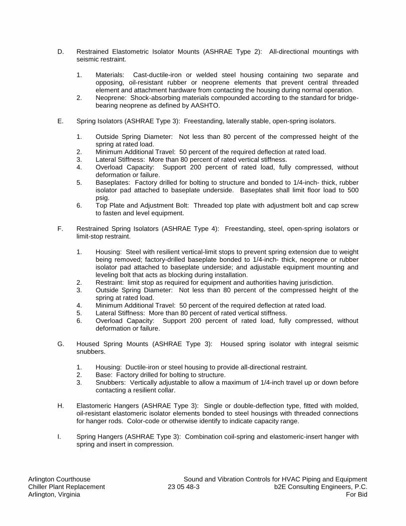
Arlington Courthouse Sound and Vibration Controls for HVAC Piping and Equipment Chiller Plant Replacement 23 05 48-3 b2E Consulting Engineers, P.C. Arlington, Virginia For Bid
D. Restrained Elastometric Isolator Mounts (ASHRAE Type 2): All-directional mountings with seismic restraint.
1. Materials: Cast-ductile-iron or welded steel housing containing two separate and opposing, oil-resistant rubber or neoprene elements that prevent central threaded element and attachment hardware from contacting the housing during normal operation.
2. Neoprene: Shock-absorbing materials compounded according to the standard for bridge-bearing neoprene as defined by AASHTO.
E. Spring Isolators (ASHRAE Type 3): Freestanding, laterally stable, open-spring isolators.
1. Outside Spring Diameter: Not less than 80 percent of the compressed height of the spring at rated load.
2. Minimum Additional Travel: 50 percent of the required deflection at rated load. 3. Lateral Stiffness: More than 80 percent of rated vertical stiffness. 4. Overload Capacity: Support 200 percent of rated load, fully compressed, without
deformation or failure. 5. Baseplates: Factory drilled for bolting to structure and bonded to 1/4-inch- thick, rubber
isolator pad attached to baseplate underside. Baseplates shall limit floor load to 500 psig.
6. Top Plate and Adjustment Bolt: Threaded top plate with adjustment bolt and cap screw to fasten and level equipment.
F. Restrained Spring Isolators (ASHRAE Type 4): Freestanding, steel, open-spring isolators or limit-stop restraint.
1. Housing: Steel with resilient vertical-limit stops to prevent spring extension due to weight being removed; factory-drilled baseplate bonded to 1/4-inch- thick, neoprene or rubber isolator pad attached to baseplate underside; and adjustable equipment mounting and leveling bolt that acts as blocking during installation.
2. Restraint: limit stop as required for equipment and authorities having jurisdiction. 3. Outside Spring Diameter: Not less than 80 percent of the compressed height of the
spring at rated load. 4. Minimum Additional Travel: 50 percent of the required deflection at rated load. 5. Lateral Stiffness: More than 80 percent of rated vertical stiffness. 6. Overload Capacity: Support 200 percent of rated load, fully compressed, without
deformation or failure.
G. Housed Spring Mounts (ASHRAE Type 3): Housed spring isolator with integral seismic snubbers.
1. Housing: Ductile-iron or steel housing to provide all-directional restraint. 2. Base: Factory drilled for bolting to structure. 3. Snubbers: Vertically adjustable to allow a maximum of 1/4-inch travel up or down before
contacting a resilient collar.
H. Elastomeric Hangers (ASHRAE Type 3): Single or double-deflection type, fitted with molded, oil-resistant elastomeric isolator elements bonded to steel housings with threaded connections for hanger rods. Color-code or otherwise identify to indicate capacity range.
I. Spring Hangers (ASHRAE Type 3): Combination coil-spring and elastomeric-insert hanger with spring and insert in compression.
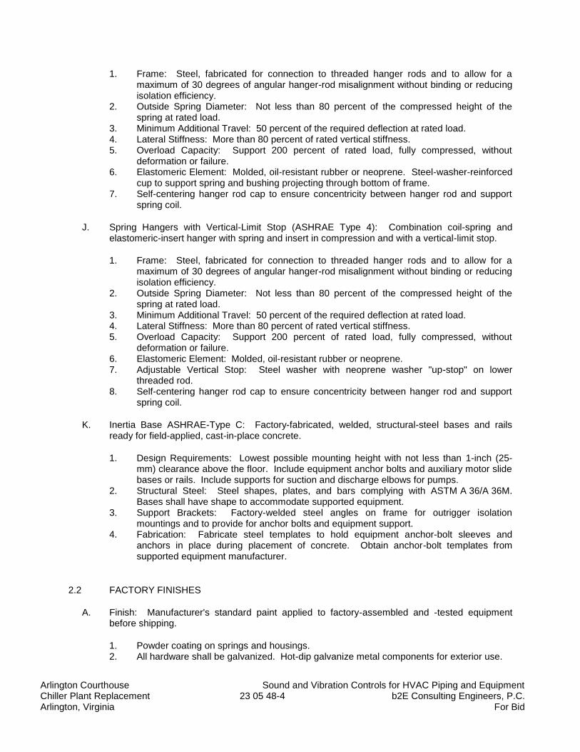
Arlington Courthouse Sound and Vibration Controls for HVAC Piping and Equipment Chiller Plant Replacement 23 05 48-4 b2E Consulting Engineers, P.C. Arlington, Virginia For Bid
1. Frame: Steel, fabricated for connection to threaded hanger rods and to allow for a maximum of 30 degrees of angular hanger-rod misalignment without binding or reducing isolation efficiency.
2. Outside Spring Diameter: Not less than 80 percent of the compressed height of the spring at rated load.
3. Minimum Additional Travel: 50 percent of the required deflection at rated load. 4. Lateral Stiffness: More than 80 percent of rated vertical stiffness. 5. Overload Capacity: Support 200 percent of rated load, fully compressed, without
deformation or failure. 6. Elastomeric Element: Molded, oil-resistant rubber or neoprene. Steel-washer-reinforced
cup to support spring and bushing projecting through bottom of frame. 7. Self-centering hanger rod cap to ensure concentricity between hanger rod and support
spring coil.
J. Spring Hangers with Vertical-Limit Stop (ASHRAE Type 4): Combination coil-spring and elastomeric-insert hanger with spring and insert in compression and with a vertical-limit stop.
1. Frame: Steel, fabricated for connection to threaded hanger rods and to allow for a maximum of 30 degrees of angular hanger-rod misalignment without binding or reducing isolation efficiency.
2. Outside Spring Diameter: Not less than 80 percent of the compressed height of the spring at rated load.
3. Minimum Additional Travel: 50 percent of the required deflection at rated load. 4. Lateral Stiffness: More than 80 percent of rated vertical stiffness. 5. Overload Capacity: Support 200 percent of rated load, fully compressed, without
deformation or failure. 6. Elastomeric Element: Molded, oil-resistant rubber or neoprene. 7. Adjustable Vertical Stop: Steel washer with neoprene washer "up-stop" on lower
threaded rod. 8. Self-centering hanger rod cap to ensure concentricity between hanger rod and support
spring coil.
K. Inertia Base ASHRAE-Type C: Factory-fabricated, welded, structural-steel bases and rails ready for field-applied, cast-in-place concrete.
1. Design Requirements: Lowest possible mounting height with not less than 1-inch (25-mm) clearance above the floor. Include equipment anchor bolts and auxiliary motor slide bases or rails. Include supports for suction and discharge elbows for pumps.
2. Structural Steel: Steel shapes, plates, and bars complying with ASTM A 36/A 36M. Bases shall have shape to accommodate supported equipment.
3. Support Brackets: Factory-welded steel angles on frame for outrigger isolation mountings and to provide for anchor bolts and equipment support.
4. Fabrication: Fabricate steel templates to hold equipment anchor-bolt sleeves and anchors in place during placement of concrete. Obtain anchor-bolt templates from supported equipment manufacturer.
2.2 FACTORY FINISHES
A. Finish: Manufacturer's standard paint applied to factory-assembled and -tested equipment before shipping.
1. Powder coating on springs and housings. 2. All hardware shall be galvanized. Hot-dip galvanize metal components for exterior use.
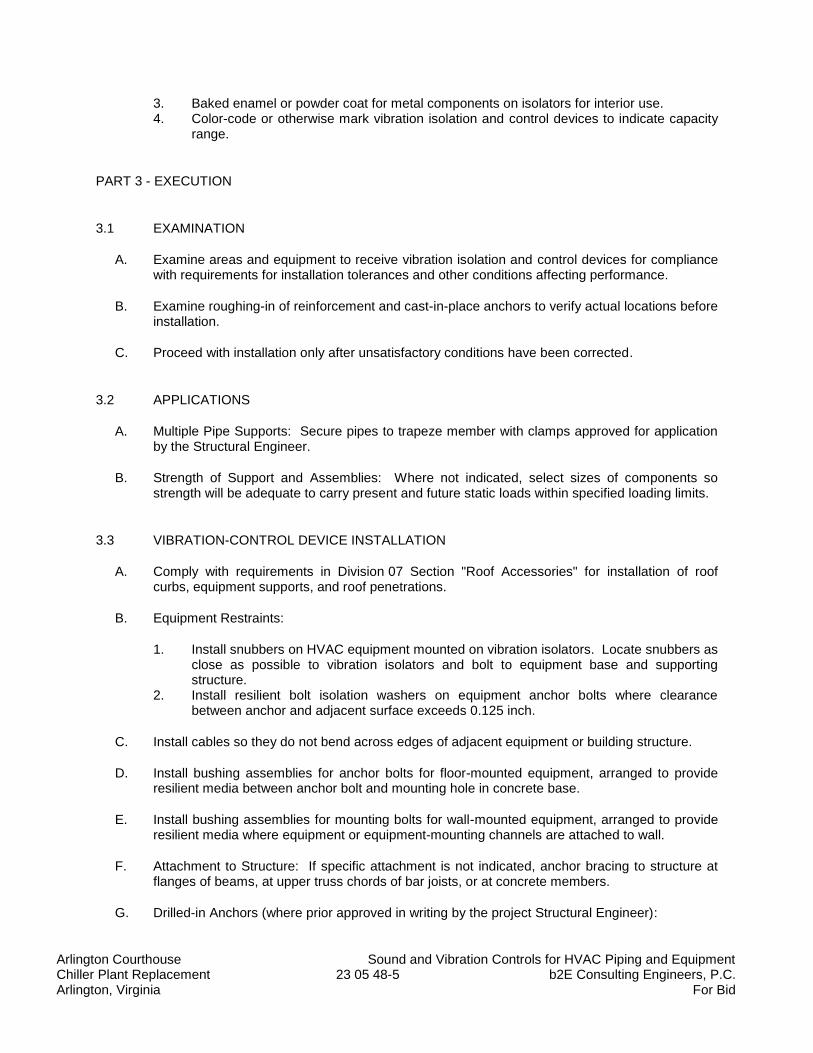
Arlington Courthouse Sound and Vibration Controls for HVAC Piping and Equipment Chiller Plant Replacement 23 05 48-5 b2E Consulting Engineers, P.C. Arlington, Virginia For Bid
3. Baked enamel or powder coat for metal components on isolators for interior use. 4. Color-code or otherwise mark vibration isolation and control devices to indicate capacity
range.
PART 3 - EXECUTION
3.1 EXAMINATION
A. Examine areas and equipment to receive vibration isolation and control devices for compliance with requirements for installation tolerances and other conditions affecting performance.
B. Examine roughing-in of reinforcement and cast-in-place anchors to verify actual locations before installation.
C. Proceed with installation only after unsatisfactory conditions have been corrected.
3.2 APPLICATIONS
A. Multiple Pipe Supports: Secure pipes to trapeze member with clamps approved for application by the Structural Engineer.
B. Strength of Support and Assemblies: Where not indicated, select sizes of components so strength will be adequate to carry present and future static loads within specified loading limits.
3.3 VIBRATION-CONTROL DEVICE INSTALLATION
A. Comply with requirements in Division 07 Section "Roof Accessories" for installation of roof curbs, equipment supports, and roof penetrations.
B. Equipment Restraints:
1. Install snubbers on HVAC equipment mounted on vibration isolators. Locate snubbers as close as possible to vibration isolators and bolt to equipment base and supporting structure.
2. Install resilient bolt isolation washers on equipment anchor bolts where clearance between anchor and adjacent surface exceeds 0.125 inch.
C. Install cables so they do not bend across edges of adjacent equipment or building structure.
D. Install bushing assemblies for anchor bolts for floor-mounted equipment, arranged to provide resilient media between anchor bolt and mounting hole in concrete base.
E. Install bushing assemblies for mounting bolts for wall-mounted equipment, arranged to provide resilient media where equipment or equipment-mounting channels are attached to wall.
F. Attachment to Structure: If specific attachment is not indicated, anchor bracing to structure at flanges of beams, at upper truss chords of bar joists, or at concrete members.
G. Drilled-in Anchors (where prior approved in writing by the project Structural Engineer):
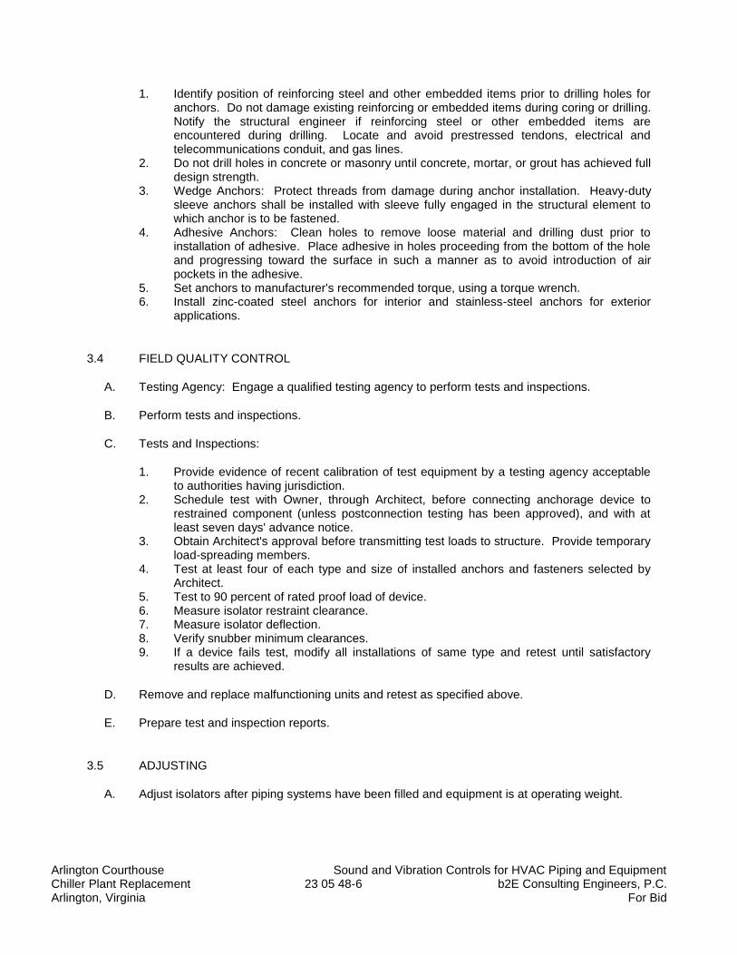
Arlington Courthouse Sound and Vibration Controls for HVAC Piping and Equipment Chiller Plant Replacement 23 05 48-6 b2E Consulting Engineers, P.C. Arlington, Virginia For Bid
1. Identify position of reinforcing steel and other embedded items prior to drilling holes for anchors. Do not damage existing reinforcing or embedded items during coring or drilling. Notify the structural engineer if reinforcing steel or other embedded items are encountered during drilling. Locate and avoid prestressed tendons, electrical and telecommunications conduit, and gas lines.
2. Do not drill holes in concrete or masonry until concrete, mortar, or grout has achieved full design strength.
3. Wedge Anchors: Protect threads from damage during anchor installation. Heavy-duty sleeve anchors shall be installed with sleeve fully engaged in the structural element to which anchor is to be fastened.
4. Adhesive Anchors: Clean holes to remove loose material and drilling dust prior to installation of adhesive. Place adhesive in holes proceeding from the bottom of the hole and progressing toward the surface in such a manner as to avoid introduction of air pockets in the adhesive.
5. Set anchors to manufacturer's recommended torque, using a torque wrench. 6. Install zinc-coated steel anchors for interior and stainless-steel anchors for exterior
applications.
3.4 FIELD QUALITY CONTROL
A. Testing Agency: Engage a qualified testing agency to perform tests and inspections.
B. Perform tests and inspections.
C. Tests and Inspections:
1. Provide evidence of recent calibration of test equipment by a testing agency acceptable to authorities having jurisdiction.
2. Schedule test with Owner, through Architect, before connecting anchorage device to restrained component (unless postconnection testing has been approved), and with at least seven days' advance notice.
3. Obtain Architect's approval before transmitting test loads to structure. Provide temporary load-spreading members.
4. Test at least four of each type and size of installed anchors and fasteners selected by Architect.
5. Test to 90 percent of rated proof load of device. 6. Measure isolator restraint clearance. 7. Measure isolator deflection. 8. Verify snubber minimum clearances. 9. If a device fails test, modify all installations of same type and retest until satisfactory
results are achieved.
D. Remove and replace malfunctioning units and retest as specified above.
E. Prepare test and inspection reports.
3.5 ADJUSTING
A. Adjust isolators after piping systems have been filled and equipment is at operating weight.
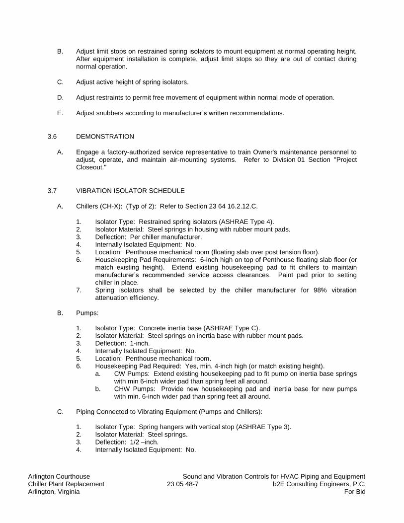
Arlington Courthouse Sound and Vibration Controls for HVAC Piping and Equipment Chiller Plant Replacement 23 05 48-7 b2E Consulting Engineers, P.C. Arlington, Virginia For Bid
B. Adjust limit stops on restrained spring isolators to mount equipment at normal operating height. After equipment installation is complete, adjust limit stops so they are out of contact during normal operation.
C. Adjust active height of spring isolators.
D. Adjust restraints to permit free movement of equipment within normal mode of operation.
E. Adjust snubbers according to manufacturer’s written recommendations.
3.6 DEMONSTRATION
A. Engage a factory-authorized service representative to train Owner's maintenance personnel to adjust, operate, and maintain air-mounting systems. Refer to Division 01 Section "Project Closeout."
3.7 VIBRATION ISOLATOR SCHEDULE
A. Chillers (CH-X): (Typ of 2): Refer to Section 23 64 16.2.12.C.
1. Isolator Type: Restrained spring isolators (ASHRAE Type 4). 2. Isolator Material: Steel springs in housing with rubber mount pads. 3. Deflection: Per chiller manufacturer. 4. Internally Isolated Equipment: No. 5. Location: Penthouse mechanical room (floating slab over post tension floor). 6. Housekeeping Pad Requirements: 6-inch high on top of Penthouse floating slab floor (or
match existing height). Extend existing housekeeping pad to fit chillers to maintain manufacturer’s recommended service access clearances. Paint pad prior to setting chiller in place.
7. Spring isolators shall be selected by the chiller manufacturer for 98% vibration attenuation efficiency.
B. Pumps:
1. Isolator Type: Concrete inertia base (ASHRAE Type C). 2. Isolator Material: Steel springs on inertia base with rubber mount pads. 3. Deflection: 1-inch. 4. Internally Isolated Equipment: No. 5. Location: Penthouse mechanical room. 6. Housekeeping Pad Required: Yes, min. 4-inch high (or match existing height).
a. CW Pumps: Extend existing housekeeping pad to fit pump on inertia base springs with min 6-inch wider pad than spring feet all around.
b. CHW Pumps: Provide new housekeeping pad and inertia base for new pumps with min. 6-inch wider pad than spring feet all around.
C. Piping Connected to Vibrating Equipment (Pumps and Chillers):
1. Isolator Type: Spring hangers with vertical stop (ASHRAE Type 3). 2. Isolator Material: Steel springs. 3. Deflection: 1/2 –inch. 4. Internally Isolated Equipment: No.
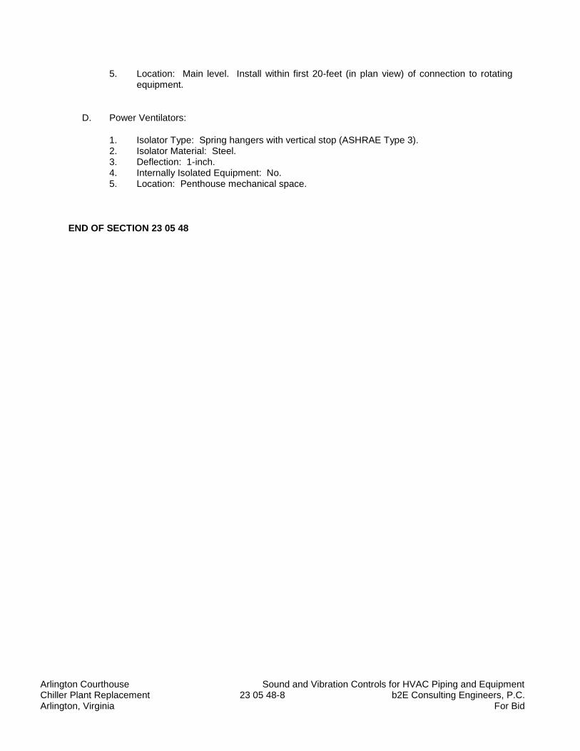
Arlington Courthouse Sound and Vibration Controls for HVAC Piping and Equipment Chiller Plant Replacement 23 05 48-8 b2E Consulting Engineers, P.C. Arlington, Virginia For Bid
5. Location: Main level. Install within first 20-feet (in plan view) of connection to rotating equipment.
D. Power Ventilators:
1. Isolator Type: Spring hangers with vertical stop (ASHRAE Type 3). 2. Isolator Material: Steel. 3. Deflection: 1-inch. 4. Internally Isolated Equipment: No. 5. Location: Penthouse mechanical space.
END OF SECTION 23 05 48
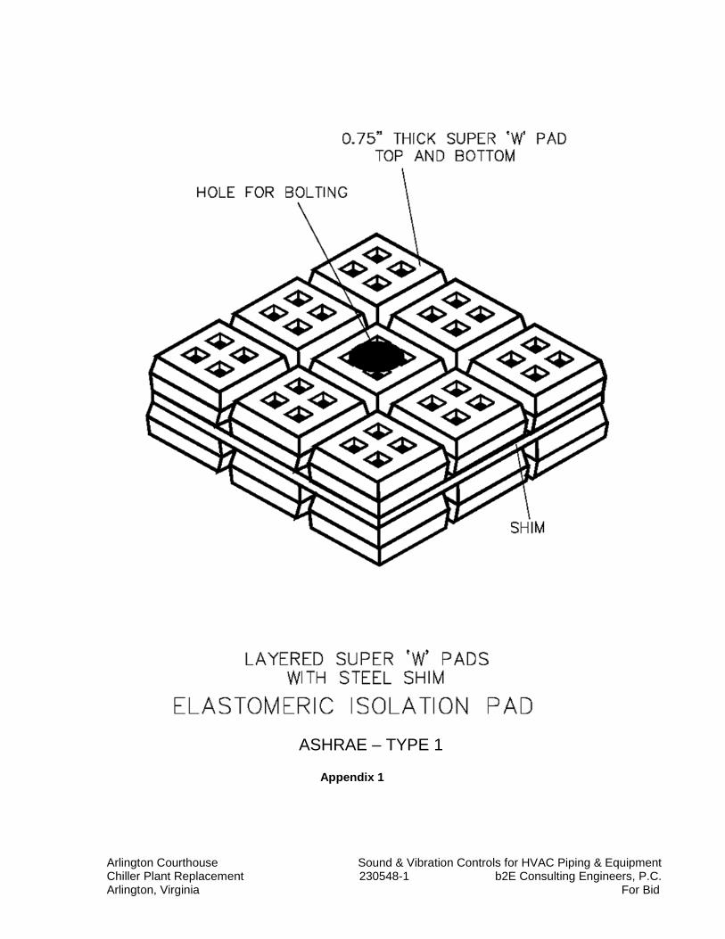
Arlington Courthouse Sound & Vibration Controls for HVAC Piping & Equipment Chiller Plant Replacement 230548-1 b2E Consulting Engineers, P.C. Arlington, Virginia For Bid
ASHRAE – TYPE 1
Appendix 1
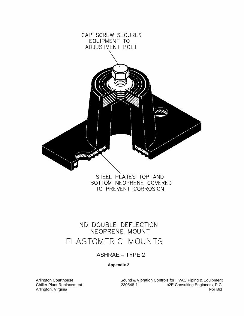
Arlington Courthouse Sound & Vibration Controls for HVAC Piping & Equipment Chiller Plant Replacement 230548-1 b2E Consulting Engineers, P.C. Arlington, Virginia For Bid
ASHRAE – TYPE 2 Appendix 2
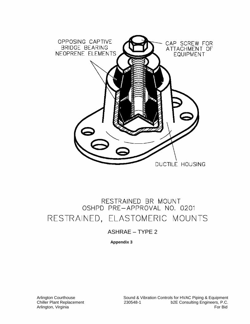
Arlington Courthouse Sound & Vibration Controls for HVAC Piping & Equipment Chiller Plant Replacement 230548-1 b2E Consulting Engineers, P.C. Arlington, Virginia For Bid
ASHRAE – TYPE 2
Appendix 3
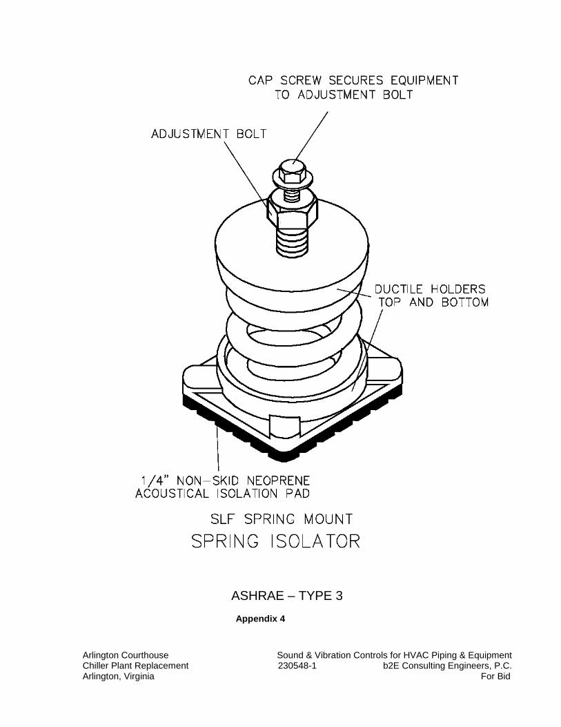
Arlington Courthouse Sound & Vibration Controls for HVAC Piping & Equipment Chiller Plant Replacement 230548-1 b2E Consulting Engineers, P.C. Arlington, Virginia For Bid
ASHRAE – TYPE 3
Appendix 4
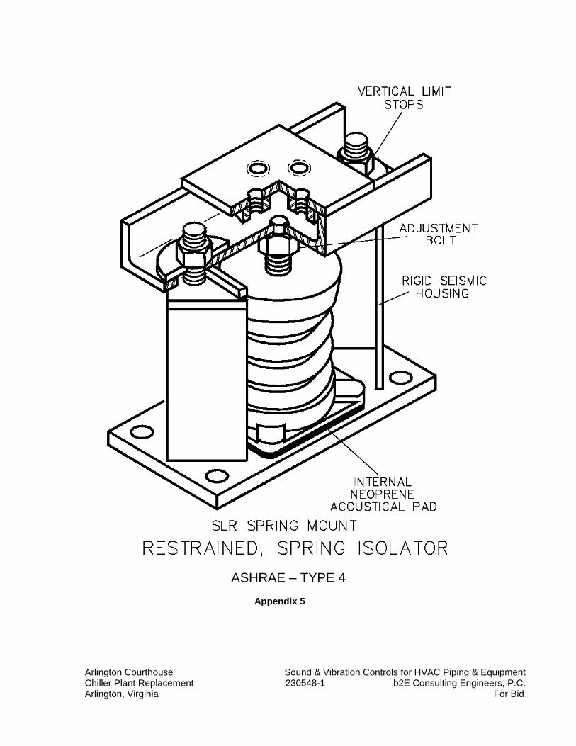
Arlington Courthouse Sound & Vibration Controls for HVAC Piping & Equipment Chiller Plant Replacement 230548-1 b2E Consulting Engineers, P.C. Arlington, Virginia For Bid
ASHRAE – TYPE 4
Appendix 5
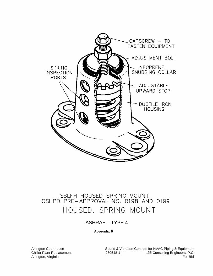
Arlington Courthouse Sound & Vibration Controls for HVAC Piping & Equipment Chiller Plant Replacement 230548-1 b2E Consulting Engineers, P.C. Arlington, Virginia For Bid
ASHRAE – TYPE 4
Appendix 6
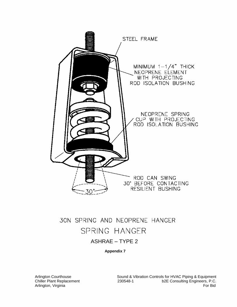
Arlington Courthouse Sound & Vibration Controls for HVAC Piping & Equipment Chiller Plant Replacement 230548-1 b2E Consulting Engineers, P.C. Arlington, Virginia For Bid
ASHRAE – TYPE 2
Appendix 7
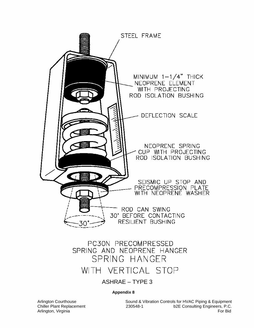
Arlington Courthouse Sound & Vibration Controls for HVAC Piping & Equipment Chiller Plant Replacement 230548-1 b2E Consulting Engineers, P.C. Arlington, Virginia For Bid
ASHRAE – TYPE 3
Appendix 8
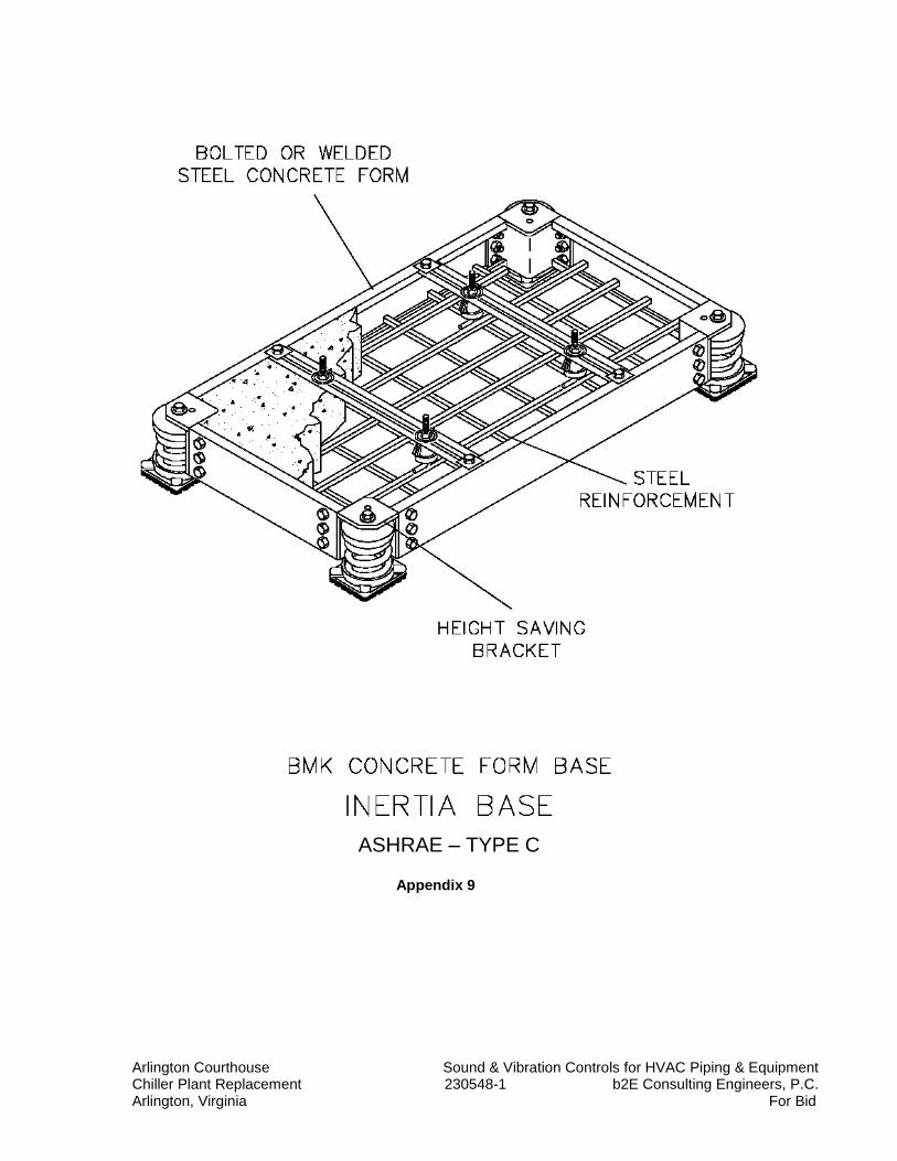
Arlington Courthouse Sound & Vibration Controls for HVAC Piping & Equipment Chiller Plant Replacement 230548-1 b2E Consulting Engineers, P.C. Arlington, Virginia For Bid
ASHRAE – TYPE C
Appendix 9
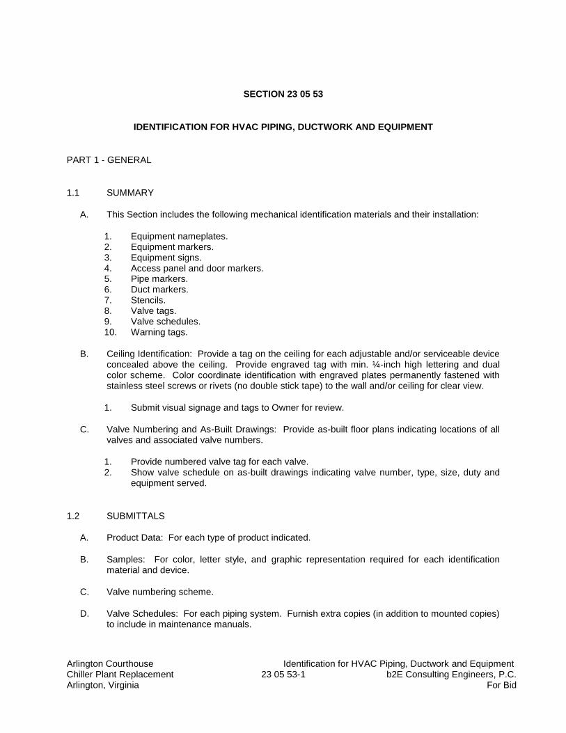
Arlington Courthouse Identification for HVAC Piping, Ductwork and Equipment Chiller Plant Replacement 23 05 53-1 b2E Consulting Engineers, P.C. Arlington, Virginia For Bid
SECTION 23 05 53
IDENTIFICATION FOR HVAC PIPING, DUCTWORK AND EQUIPMENT
PART 1 - GENERAL
1.1 SUMMARY
A. This Section includes the following mechanical identification materials and their installation:
1. Equipment nameplates. 2. Equipment markers. 3. Equipment signs. 4. Access panel and door markers. 5. Pipe markers. 6. Duct markers. 7. Stencils. 8. Valve tags. 9. Valve schedules. 10. Warning tags.
B. Ceiling Identification: Provide a tag on the ceiling for each adjustable and/or serviceable device concealed above the ceiling. Provide engraved tag with min. ¼-inch high lettering and dual color scheme. Color coordinate identification with engraved plates permanently fastened with stainless steel screws or rivets (no double stick tape) to the wall and/or ceiling for clear view.
1. Submit visual signage and tags to Owner for review.
C. Valve Numbering and As-Built Drawings: Provide as-built floor plans indicating locations of all valves and associated valve numbers.
1. Provide numbered valve tag for each valve. 2. Show valve schedule on as-built drawings indicating valve number, type, size, duty and
equipment served.
1.2 SUBMITTALS
A. Product Data: For each type of product indicated.
B. Samples: For color, letter style, and graphic representation required for each identification material and device.
C. Valve numbering scheme.
D. Valve Schedules: For each piping system. Furnish extra copies (in addition to mounted copies) to include in maintenance manuals.
Arlington Courthouse Identification for HVAC Piping, Ductwork and Equipment Chiller Plant Replacement 23 05 53-2 b2E Consulting Engineers, P.C. Arlington, Virginia For Bid
1.3 QUALITY ASSURANCE
A. ASME Compliance: Comply with ASME A13.1, "Scheme for the Identification of Piping Systems," for letter size, length of color field, colors, and viewing angles of identification devices for piping.
1.4 COORDINATION
A. Coordinate installation of identifying devices with completion of covering and painting of surfaces where devices are to be applied.
B. Coordinate installation of identifying devices with location of access panels and doors.
C. Install identifying devices before installing acoustical ceilings and similar concealment.
PART 2 - PRODUCTS
2.1 EQUIPMENT IDENTIFICATION DEVICES
A. Equipment Nameplates: Metal, with data engraved or stamped, for permanent attachment on equipment.
1. Data:
a. Manufacturer, product name, model number, and serial number. b. Capacity, operating and power characteristics, and essential data. c. Labels of tested compliances.
2. Location: Accessible and visible. 3. Fasteners: As required to mount on equipment.
B. Equipment Markers: Engraved, color-coded laminated plastic. Include contact-type, permanent adhesive.
1. Terminology: Match schedules as closely as possible. 2. Data:
a. Name and plan number. b. Equipment service. c. Design capacity. d. Other design parameters such as pressure drop, entering and leaving conditions,
and speed.
3. Size: 2-1/2 by 4 inches for control devices, dampers, and valves; 4-1/2 by 6 inches for equipment.
4. Color Coding: Refer to paragraph 3.2.D.
C. Equipment Signs: ASTM D 709, Type I, cellulose, paper-base, phenolic-resin-laminate engraving stock; Grade ES-2, black surface, black phenolic core, with white melamine subcore,
Arlington Courthouse Identification for HVAC Piping, Ductwork and Equipment Chiller Plant Replacement 23 05 53-3 b2E Consulting Engineers, P.C. Arlington, Virginia For Bid
unless otherwise indicated. Fabricate in sizes required for message. Provide holes for mechanical fastening.
1. Data: Instructions for operation of equipment and for safety procedures. 2. Engraving: Manufacturer's standard letter style, of sizes and with terms to match
equipment identification. 3. Thickness: 1/16 inch for units up to 20 sq. in. or 8 inches in length, and 1/8 inch for larger
units. 4. Fasteners: Self-tapping, stainless-steel screws or contact-type, permanent adhesive.
D. Access Panel and Door Markers: 1/16-inch- thick, engraved laminated plastic, with abbreviated terms and numbers corresponding to identification. Provide 1/8-inch center hole for attachment.
1. Fasteners: Self-tapping, stainless-steel screws or contact-type, permanent adhesive.
2.2 PIPING IDENTIFICATION DEVICES
A. Manufactured Pipe Markers, General: Preprinted, color-coded, with lettering indicating service, and showing direction of flow.
1. Colors: Comply with ASME A13.1, unless otherwise indicated. 2. Lettering: Use piping system terms indicated and abbreviate only as necessary for each
application length. 3. Pipes with OD, Including Insulation, Less Than 6 Inches: Full-band pipe markers
extending 360 degrees around pipe at each location. 4. Pipes with OD, Including Insulation, 6 Inches and Larger: Either full-band or strip-type
pipe markers at least three times letter height and of length required for label. 5. Arrows: Integral with piping system service lettering to accommodate both directions; or
as separate unit on each pipe marker to indicate direction of flow.
B. Plastic Tape: Continuously printed, vinyl tape at least 3 mils thick with pressure-sensitive, permanent-type, self-adhesive back.
1. Width for Markers on Pipes with OD, Including Insulation, Less Than 6 Inches: 3/4 inch minimum.
2. Width for Markers on Pipes with OD, Including Insulation, 6 Inches or Larger: 1-1/2 inches minimum.
C. Pipe Painting for Pipe with Board Insulation and Glass Cloth Jacket: Prepare surface for painting and paint entire surface of glass cloth jacket pipework (all sides) with color indicated in paragraph 3.3.B. Provide stencil marking after painting to indicate pipe type, pressure, and water-flow direction.
D. “Venture Clad” Jacket Color for Exposed Insulated Pipework: Provide the colors indicated in paragraph 3.3.B. Provide stencil marking to indicate pipe type and air-flow direction.
E. Pipe Painting for Uninsulated Pipe: Prepare surface for painting and paint entire surface of pipe (all sides) with color indicated in paragraph 3.3.B. Provide stencil marking after painting to indicate pipe type, pressure, and water-flow direction.
Arlington Courthouse Identification for HVAC Piping, Ductwork and Equipment Chiller Plant Replacement 23 05 53-4 b2E Consulting Engineers, P.C. Arlington, Virginia For Bid
2.4 STENCILS
A. Stencils: Prepared with letter sizes according to ASME A13.1 for piping; minimum letter height of 1-1/4 inches for ducts; and minimum letter height of 3/4 inch for access panel and door markers, equipment markers, equipment signs, and similar operational instructions.
1. Stencil Material: Galvanized. 2. Stencil Paint: Exterior, gloss, alkyd enamel or acrylic enamel black, unless otherwise
indicated. Paint may be in pressurized spray-can form. 3. Identification Paint: Exterior, alkyd enamel or acrylic enamel in colors according to
ASME A13.1, unless otherwise indicated.
2.5 VALVE TAGS
A. Valve Tags: Stamped or engraved with 1/4-inch letters for piping system abbreviation and 1/2-inch numbers, with numbering scheme approved by Architect/Engineer. Provide 5/32-inch hole for fastener.
1. Material: 0.032-inch thick brass in equipment areas. 2. Valve-Tag Fasteners: Brass wire-link; or S-hook.
2.6 VALVE SCHEDULES
A. Valve Schedules: For each piping system, on standard-size bond paper. Tabulate valve number, piping system, system abbreviation (as shown on valve tag), location of valve (room or space), normal-operating position (open, closed, or modulating), and variations for identification. Mark valves for emergency shutoff and similar special uses.
1. Valve-Schedule Frames: Glazed display frame for removable mounting on masonry walls for each page of valve schedule. Include mounting screws.
2. Frame: Extruded Galvanized. 3. Glazing: ASTM C 1036, Type I, Class 1, Glazing Quality B, 2.5-mm, single-thickness
glass.
2.7 WARNING TAGS
A. Warning Tags: Preprinted or partially preprinted, accident-prevention tags; of plasticized card stock with matte finish suitable for writing.
1. Size: Approximately 4 by 7 inches 2. Fasteners: Brass grommet and wire. 3. Nomenclature: Large-size primary caption such as DANGER, CAUTION, or DO NOT
OPERATE. 4. Color: Yellow background with black lettering.
PART 3 - EXECUTION
3.1 APPLICATIONS, GENERAL
Arlington Courthouse Identification for HVAC Piping, Ductwork and Equipment Chiller Plant Replacement 23 05 53-5 b2E Consulting Engineers, P.C. Arlington, Virginia For Bid
A. Products specified are for applications referenced in other Division 23 Sections. If more than single-type material, device, or label is specified for listed applications, selection is Installer's option.
3.2 EQUIPMENT IDENTIFICATION
A. Install color coded “Venture Clad” jackets or painted glass cloth jackets for all equipment and permanently fasten equipment nameplates on each major item of mechanical equipment. Locate nameplates where accessible and visible. Include nameplates for the following general categories of equipment: 1. Pumps, chillers, cooling towers and similar motor-driven units. 2. Adjustable frequency drives and motor controllers. 3. Flow meter and water meters. 4. Tanks and pressure vessels, including air separator, expansion tank and bypass feeder. 5. Strainers, filters, water-treatment systems, and similar equipment. 6. EMS Control Panels, actuators, operators, valves, dampers, switches, temperature
sensors, etc. 7. Any electrical breakers, disconnects, AFD’s, etc. serving mechanical equipment.
B. Install equipment markers on ceiling grid and walls to identify the location of concealed equipment with minimum two (2) permanent self-tapping screws on or near each major item of mechanical equipment.
1. Letter Size: Minimum 1/4 inch for name of units if viewing distance is less than 24 inches, 1/2 inch for viewing distances up to 72 inches, and proportionately larger lettering for greater viewing distances. Include secondary lettering two-thirds to three-fourths the size of principal lettering.
2. Data: Identify equipment tag with marker. 3. Locate markers where accessible and visible. Include markers for the following general
categories of equipment:
a. Main control and operating valves, including safety devices and hazardous units such as gas outlets.
b. Meters, gages, thermometers, and similar units. c. Fans, and other similar motor-driven units. d. EMS Control Panels, actuators, operators, valves, dampers, switches, etc. e. Any electrical disconnects, motor controllers, etc. serving mechanical equipment.
C. Stenciled Equipment Marker: Stenciled markers shall be provided instead of laminated-plastic equipment markers, if lettering larger than 1 inch high is needed for proper identification because of distance from normal location of required identification.
D. Install equipment signs with minimum two (2) self-tapping screws on or near each major item of mechanical equipment. Locate signs where accessible and visible.
1. Identify mechanical equipment with color coded PVC jackets or painted glass cloth jackets with equipment markers in the following color codes:
a. Blue: For cooling equipment and components. b. Red: For heating equipment and components. c. Red/Blue: For combination cooling and heating equipment and components. d. Green: For energy-reclamation equipment and components.
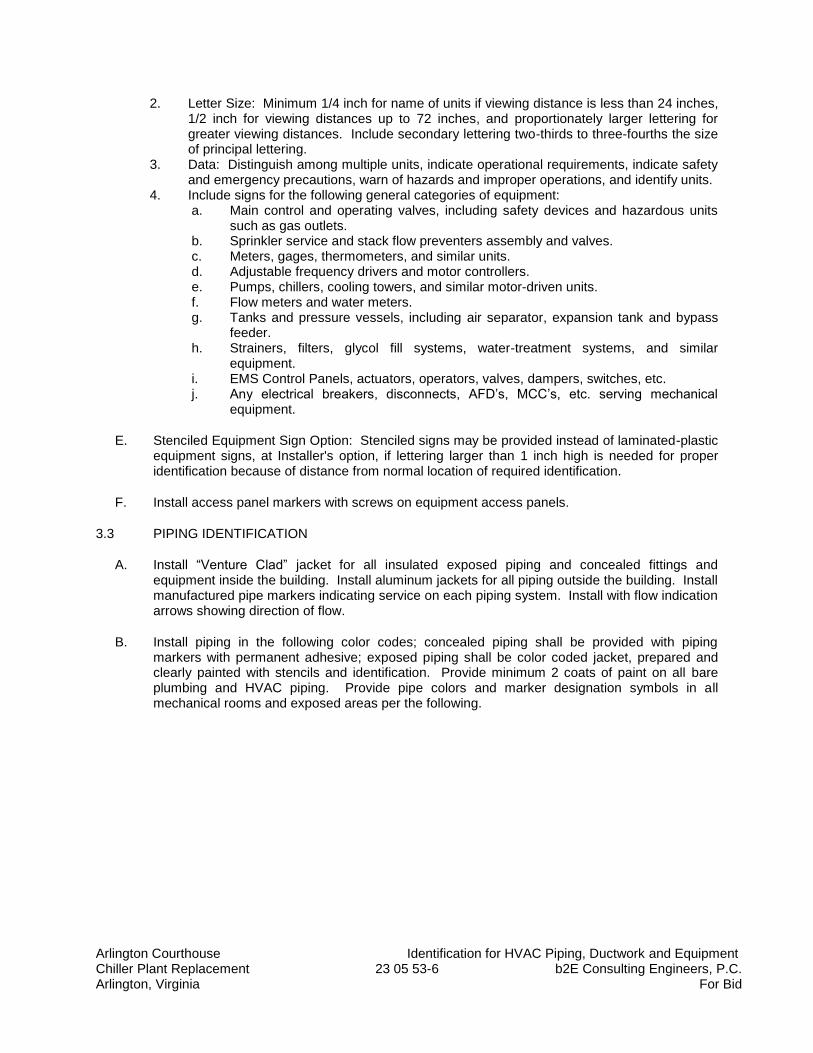
Arlington Courthouse Identification for HVAC Piping, Ductwork and Equipment Chiller Plant Replacement 23 05 53-6 b2E Consulting Engineers, P.C. Arlington, Virginia For Bid
2. Letter Size: Minimum 1/4 inch for name of units if viewing distance is less than 24 inches, 1/2 inch for viewing distances up to 72 inches, and proportionately larger lettering for greater viewing distances. Include secondary lettering two-thirds to three-fourths the size of principal lettering.
3. Data: Distinguish among multiple units, indicate operational requirements, indicate safety and emergency precautions, warn of hazards and improper operations, and identify units.
4. Include signs for the following general categories of equipment: a. Main control and operating valves, including safety devices and hazardous units
such as gas outlets. b. Sprinkler service and stack flow preventers assembly and valves. c. Meters, gages, thermometers, and similar units. d. Adjustable frequency drivers and motor controllers. e. Pumps, chillers, cooling towers, and similar motor-driven units. f. Flow meters and water meters. g. Tanks and pressure vessels, including air separator, expansion tank and bypass
feeder. h. Strainers, filters, glycol fill systems, water-treatment systems, and similar
equipment. i. EMS Control Panels, actuators, operators, valves, dampers, switches, etc. j. Any electrical breakers, disconnects, AFD’s, MCC’s, etc. serving mechanical
equipment.
E. Stenciled Equipment Sign Option: Stenciled signs may be provided instead of laminated-plastic equipment signs, at Installer's option, if lettering larger than 1 inch high is needed for proper identification because of distance from normal location of required identification.
F. Install access panel markers with screws on equipment access panels.
3.3 PIPING IDENTIFICATION
A. Install “Venture Clad” jacket for all insulated exposed piping and concealed fittings and equipment inside the building. Install aluminum jackets for all piping outside the building. Install manufactured pipe markers indicating service on each piping system. Install with flow indication arrows showing direction of flow.
B. Install piping in the following color codes; concealed piping shall be provided with piping markers with permanent adhesive; exposed piping shall be color coded jacket, prepared and clearly painted with stencils and identification. Provide minimum 2 coats of paint on all bare plumbing and HVAC piping. Provide pipe colors and marker designation symbols in all mechanical rooms and exposed areas per the following.
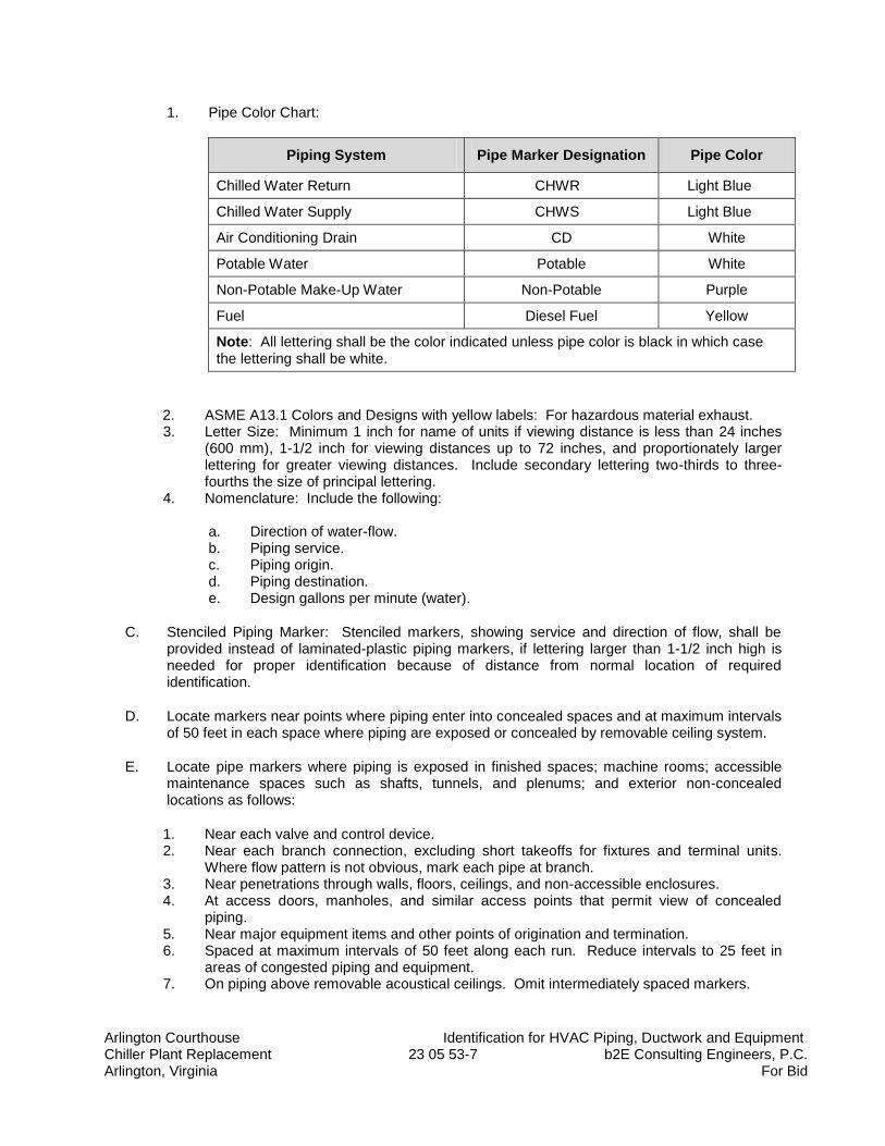
Arlington Courthouse Identification for HVAC Piping, Ductwork and Equipment Chiller Plant Replacement 23 05 53-7 b2E Consulting Engineers, P.C. Arlington, Virginia For Bid
1. Pipe Color Chart:
Piping System Pipe Marker Designation Pipe Color
Chilled Water Return CHWR Light Blue
Chilled Water Supply CHWS Light Blue
Air Conditioning Drain CD White
Potable Water Potable White
Non-Potable Make-Up Water Non-Potable Purple
Fuel Diesel Fuel Yellow
Note: All lettering shall be the color indicated unless pipe color is black in which case the lettering shall be white.
2. ASME A13.1 Colors and Designs with yellow labels: For hazardous material exhaust. 3. Letter Size: Minimum 1 inch for name of units if viewing distance is less than 24 inches
(600 mm), 1-1/2 inch for viewing distances up to 72 inches, and proportionately larger lettering for greater viewing distances. Include secondary lettering two-thirds to three-fourths the size of principal lettering.
4. Nomenclature: Include the following:
a. Direction of water-flow. b. Piping service. c. Piping origin. d. Piping destination. e. Design gallons per minute (water).
C. Stenciled Piping Marker: Stenciled markers, showing service and direction of flow, shall be provided instead of laminated-plastic piping markers, if lettering larger than 1-1/2 inch high is needed for proper identification because of distance from normal location of required identification.
D. Locate markers near points where piping enter into concealed spaces and at maximum intervals of 50 feet in each space where piping are exposed or concealed by removable ceiling system.
E. Locate pipe markers where piping is exposed in finished spaces; machine rooms; accessible maintenance spaces such as shafts, tunnels, and plenums; and exterior non-concealed locations as follows:
1. Near each valve and control device. 2. Near each branch connection, excluding short takeoffs for fixtures and terminal units.
Where flow pattern is not obvious, mark each pipe at branch. 3. Near penetrations through walls, floors, ceilings, and non-accessible enclosures. 4. At access doors, manholes, and similar access points that permit view of concealed
piping. 5. Near major equipment items and other points of origination and termination. 6. Spaced at maximum intervals of 50 feet along each run. Reduce intervals to 25 feet in
areas of congested piping and equipment. 7. On piping above removable acoustical ceilings. Omit intermediately spaced markers.
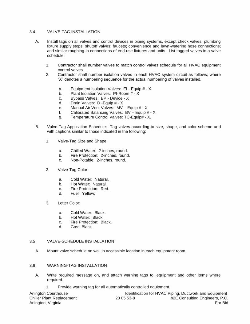
Arlington Courthouse Identification for HVAC Piping, Ductwork and Equipment Chiller Plant Replacement 23 05 53-8 b2E Consulting Engineers, P.C. Arlington, Virginia For Bid
3.4 VALVE-TAG INSTALLATION
A. Install tags on all valves and control devices in piping systems, except check valves; plumbing fixture supply stops; shutoff valves; faucets; convenience and lawn-watering hose connections; and similar roughing-in connections of end-use fixtures and units. List tagged valves in a valve schedule.
1. Contractor shall number valves to match control valves schedule for all HVAC equipment control valves.
2. Contractor shall number isolation valves in each HVAC system circuit as follows; where “X” denotes a numbering sequence for the actual numbering of valves installed.
a. Equipment Isolation Valves: EI - Equip # - X b. Plant Isolation Valves: PI-Room # - X c. Bypass Valves: BP - Device - X d. Drain Valves: D -Equip # - X e. Manual Air Vent Valves: MV – Equip # - X f. Calibrated Balancing Valves: BV – Equip # - X g. Temperature Control Valves: TC-Equip# - X.
B. Valve-Tag Application Schedule: Tag valves according to size, shape, and color scheme and with captions similar to those indicated in the following:
1. Valve-Tag Size and Shape:
a. Chilled Water: 2-inches, round. b. Fire Protection: 2-inches, round. c. Non-Potable: 2-inches, round.
2. Valve-Tag Color:
a. Cold Water: Natural. b. Hot Water: Natural. c. Fire Protection: Red. d. Fuel: Yellow.
3. Letter Color:
a. Cold Water: Black. b. Hot Water: Black. c. Fire Protection: Black. d. Gas: Black.
3.5 VALVE-SCHEDULE INSTALLATION
A. Mount valve schedule on wall in accessible location in each equipment room.
3.6 WARNING-TAG INSTALLATION
A. Write required message on, and attach warning tags to, equipment and other items where required.
1. Provide warning tag for all automatically controlled equipment.
Arlington Courthouse Identification for HVAC Piping, Ductwork and Equipment Chiller Plant Replacement 23 05 53-9 b2E Consulting Engineers, P.C. Arlington, Virginia For Bid
2. Provide warning tags wherever required in other sections.
3.7 ADJUSTING
A. Relocate mechanical identification materials and devices that have become visually blocked by other work.
3.8 CLEANING
A. Clean faces of mechanical identification devices and glass frames of valve schedules.
END OF SECTION 23 05 53
Arlington Courthouse Testing, Adjusting, and Balancing for HVAC Chiller Plant Replacement 23 05 93-1 b2E Consulting Engineers, P.C. Arlington, Virginia For Bid
SECTION 23 05 93
TESTING, ADJUSTING, AND BALANCING FOR HVAC
PART 1 - GENERAL
1.1 SUMMARY
A. Section Includes:
1. Balancing Hydronic Piping Systems:
a. Constant-flow hydronic systems. b. Variable-flow hydronic systems.
2. Equipment quantitative-performance settings. 3. Vibration measuring. 4. Sound level measuring. 5. Verifying that automatic control devices are functioning 6. Reporting results of activities and procedures specified in this Section.
B. Pre-Tab Documentation: The TAB contractor shall measure the flow in all existing chilled water and condenser water pumps and record the waterflow rate and head pressure.
1. Provide this information to the design engineer of record prior to ordering pumps and other equipment.
1.2 DEFINITIONS
A. AABC: Associated Air Balance Council.
B. NEBB: National Environmental Balancing Bureau.
C. TAB: Testing, adjusting, and balancing.
D. TABB: Testing, Adjusting, and Balancing Bureau.
E. TAB Specialist: An entity engaged to perform TAB Work.
1.3 SUBMITTALS
A. Qualification Data: Within 45 days of Contractor's Notice to Proceed, submit documentation that the TAB contractor and this Project's TAB team members meet the qualifications specified in "Quality Assurance" Article.
B. Contract Documents Examination Report: Within 90 days of Contractor's Notice to Proceed, submit the Contract Documents review report as specified in Part 3.
Arlington Courthouse Testing, Adjusting, and Balancing for HVAC Chiller Plant Replacement 23 05 93-2 b2E Consulting Engineers, P.C. Arlington, Virginia For Bid
C. Strategies and Procedures Plan: Within 90 days of Contractor's Notice to Proceed, submit TAB strategies and step-by-step procedures as specified in "Preparation" Article.
D. Certified TAB reports.
E. Sample report forms.
F. Instrument calibration reports, to include the following:
1. Instrument type and make. 2. Serial number. 3. Application. 4. Dates of use. 5. Dates of calibration.
G. Sustainable Design Submittal:
1. Air-Balance Report for Prerequisite EQ 1: Documentation of work performed for ASHRAE 62.1-2004, Section 7.2.2, “Air Balancing.”
1.4 QUALITY ASSURANCE
A. TAB Contractor Qualifications: Engage a TAB entity certified by AABC, NEBB or TABB.
1. TAB Field Supervisor: Employee of the TAB contractor and certified by AABC, NEBB, or TABB.
2. TAB Technician: Employee of the TAB contractor and who is certified by AABC, NEBB, or TABB as a TAB technician.
B. TAB Conference: Meet with Architect, Owner, and Commissioning Agent on approval of the TAB strategies and procedures plan to develop a mutual understanding of the details. Require the participation of the TAB field supervisor and technicians. Provide 14 days' advance notice of scheduled meeting time and location.
1. Agenda Items:
a. The Contract Documents examination report. b. The TAB plan. c. Coordination and cooperation of trades and subcontractors. d. Coordination of documentation and communication flow.
C. Certify TAB field data reports and perform the following:
1. Review field data reports to validate accuracy of data and to prepare certified TAB reports.
2. Certify that the TAB team complied with the approved TAB plan and the procedures specified and referenced in this Specification.
D. TAB Report Forms: Use standard TAB contractor's forms reviewed by Commissioning Agent.
E. Instrumentation Type, Quantity, Accuracy, and Calibration: As described in ASHRAE 111, Section 5, "Instrumentation."
Arlington Courthouse Testing, Adjusting, and Balancing for HVAC Chiller Plant Replacement 23 05 93-3 b2E Consulting Engineers, P.C. Arlington, Virginia For Bid
1.5 PROJECT CONDITIONS
A. Partial Owner Occupancy: Owner may occupy completed areas of building before Substantial Completion. Cooperate with Owner during TAB operations to minimize conflicts with Owner's operations.
1.6 COORDINATION
A. Notice: Provide seven (7) days' advance notice for each test. Include scheduled test dates and times.
B. Perform TAB after leakage and pressure tests on air and water distribution systems have been satisfactorily completed.
PART 2 - PRODUCTS (Not Applicable)
PART 3 - EXECUTION
3.1 TAB SPECIALISTS
A. Subject to compliance with requirements, engage one of the following:
1. Annandale Air Balancing Co. 2. Other qualified TAB contractor with large chiller plant experience.
a. TAB contractor shall have made TAB pressure measurements for chilled water control systems for at least five (5) facilities of similar size and scope within the past five (5) years.
3.2 EXAMINATION
A. Examine the Contract Documents to become familiar with Project requirements and to discover conditions in systems' designs that may preclude proper TAB of systems and equipment.
B. Examine systems for installed balancing devices, such as test ports, gage cocks, thermometer wells, flow-control devices, balancing valves and fittings, and manual volume dampers. Verify that locations of these balancing devices are accessible.
C. Examine the approved submittals for HVAC systems and equipment.
D. Examine design data including chilled water system descriptions, statements of design assumptions for environmental conditions and systems' output, and statements of philosophies and assumptions about chilled water system and equipment controls.
E. Examine ceiling plenums and under-floor air plenums used for supply, return, or relief air to verify that they meet the leakage class of connected ducts as specified in Division 23 Section "Metal Ducts" and are properly separated from adjacent areas. Verify that penetrations in plenum walls are sealed and fire-stopped if required.
Arlington Courthouse Testing, Adjusting, and Balancing for HVAC Chiller Plant Replacement 23 05 93-4 b2E Consulting Engineers, P.C. Arlington, Virginia For Bid
F. Examine equipment performance data including pump curves.
1. Relate performance data to Project conditions and requirements, including system effects that can create undesired or unpredicted conditions that cause reduced capacities in all or part of a system.
G. Examine system and equipment installations and verify that field quality-control testing,
cleaning, and adjusting specified in individual Sections have been performed.
H. Examine test reports specified in individual system and equipment Sections.
I. Examine HVAC equipment and filters and verify that bearings are greased, belts are aligned and tight, and equipment with functioning controls is ready for operation.
J. Examine strainers. Verify that startup screens are replaced by permanent screens with indicated perforations.
K. Examine three-way valves for proper installation for their intended function of diverting or mixing fluid flows.
L. Examine system pumps to ensure absence of entrained air in the suction piping.
M. Examine operating safety interlocks and controls on HVAC equipment.
N. Report deficiencies discovered before and during performance of TAB procedures. Observe and record system reactions to changes in conditions. Record default set points if different from indicated values.
3.3 PREPARATION
A. Prepare a TAB plan that includes strategies and step-by-step procedures.
B. Complete system-readiness checks and prepare reports. Verify the following:
1. Permanent electrical-power wiring is complete. 2. Hydronic systems are filled, clean, and free of air. 3. Automatic temperature-control systems are operational. 4. Equipment and duct access doors are securely closed. 5. Balance, smoke, and fire dampers are open. 6. Isolating and balancing valves are open and control valves are operational. 7. Ceilings are installed in critical areas where air-pattern adjustments are required and
access to balancing devices is provided. 8. Windows and doors can be closed so indicated conditions for system operations can be
met.
C. Provide Pre-Balance for existing condenser water and chilled water pumps to determine the existing system flow rate, pressure loss and bhp consumption. Provide this report prior to submitting for the CW and CHW pumps on this project.
Arlington Courthouse Testing, Adjusting, and Balancing for HVAC Chiller Plant Replacement 23 05 93-5 b2E Consulting Engineers, P.C. Arlington, Virginia For Bid
3.4 GENERAL PROCEDURES FOR TESTING AND BALANCING
A. Perform testing and balancing procedures on each system according to the procedures contained in AABC's "National Standards for Total System Balance;" ASHRAE 111; NEBB's "Procedural Standards for Testing, Adjusting, and Balancing of Environmental Systems;" or SMACNA's "HVAC Systems - Testing, Adjusting, and Balancing" and in this Section.
1. Comply with requirements in ASHRAE 62.1-2013, Section 7.2.2, "Air Balancing." 2. Install and join new insulation that matches removed materials. Restore insulation,
coverings, vapor barrier, and finish according to Division 23 Section "HVAC Insulation."
3.5 GENERAL PROCEDURES FOR HYDRONIC SYSTEMS
A. Prepare test reports with pertinent design data, and number in sequence starting at pump to end of system. Check the sum of branch-circuit flows against the approved pump flow rate. Correct variations that exceed plus or minus 5 percent.
B. Prepare schematic diagrams of systems' "as-built" piping layouts.
C. Prepare hydronic systems for testing and balancing according to the following, in addition to the general preparation procedures specified above:
1. Open all manual valves for maximum flow. 2. Check liquid level in expansion tank. 3. Check makeup water-station pressure gage for adequate pressure for highest vent. 4. Check flow-control valves for specified sequence of operation, and set at indicated flow. 5. Set differential-pressure control valves at the specified differential pressure. Do not set at
fully closed position when pump is positive-displacement type unless several terminal valves are kept open.
6. Set system controls so automatic valves are wide open to heat exchangers. 7. Check pump-motor load. If motor is overloaded, throttle main flow-balancing device so
motor nameplate rating is not exceeded. 8. Check air vents for a forceful liquid flow exiting from vents when manually operated.
3.6 PROCEDURES FOR CONSTANT-FLOW HYDRONIC SYSTEMS
A. Measure water flow at pumps. Use the following procedures except for positive-displacement pumps:
1. Verify impeller size by operating the pump with the discharge valve closed. Read pressure differential across the pump. Convert pressure to head and correct for differences in gage heights. Note the point on manufacturer's pump curve at zero flow and verify that the pump has the intended impeller size.
a. If impeller sizes must be adjusted to achieve pump performance, obtain approval from Architect and comply with requirements in Division 23 Section "Hydronic Pumps."
2. Check system resistance. With all valves open, read pressure differential across the pump and mark pump manufacturer's head-capacity curve. Adjust pump discharge valve until indicated water flow is achieved.
Arlington Courthouse Testing, Adjusting, and Balancing for HVAC Chiller Plant Replacement 23 05 93-6 b2E Consulting Engineers, P.C. Arlington, Virginia For Bid
a. Monitor motor performance during procedures and do not operate motors in overload conditions.
3. Verify pump-motor brake horsepower. Calculate the intended brake horsepower for the system based on pump manufacturer's performance data. Compare calculated brake horsepower with nameplate data on the pump motor. Report conditions where actual amperage exceeds motor nameplate amperage.
4. Report flow rates that are not within plus or minus 10 percent of design.
B. Measure flow at all stations and adjust, where necessary, to obtain first balance.
1. System components that have Cv rating or an accurately cataloged flow-pressure-drop relationship may be used as a flow-indicating device.
C. Measure flow at main balancing station and set main balancing device to achieve flow that is 5 percent greater than indicated flow.
D. Adjust balancing stations to within specified tolerances of indicated flow rate as follows:
1. Determine the balancing station with the highest percentage over indicated flow. 2. Adjust each station in turn, beginning with the station with the highest percentage over
indicated flow and proceeding to the station with the lowest percentage over indicated flow.
3. Record settings.
E. Open all automatic modulating flow control valves to 100% open position. Measure flow at all calibrated balancing valves from longest run back towards pumps to verify that valves are set to design flow rates. 1. Isolate areas of the building with similar dynamic head loss and balance to design water
flow rates. 2. Open all areas of building for water flow through piping systems. 3. Re-measure water flow through calibrated balancing valves with automatic control valves
in full open position. 4. All flows should read as a percentage of block load (design) max. flow over the
connected load. All valves shall read as a percentage within 5% plus or minus of the calculated design percentage.
5. Record settings and mark balancing devices.
F. Measure pump flow rate and make final measurements of pump amperage, voltage, rpm, pump heads, and systems' pressures and temperatures including outdoor-air temperature.
G. Measure the differential-pressure-control-valve settings existing at the conclusion of balancing. 1. Calculate to differential pressure setpoint at EMS to provide adequate flow to longest
runs in system.
H. Release the automatic modulating flow control valves to automatic. 1. Adjust EMS pressure differential setpoints and verify adequate flow at farthest run in
system.
I. Check settings and operation of each safety valve. Record settings.
Arlington Courthouse Testing, Adjusting, and Balancing for HVAC Chiller Plant Replacement 23 05 93-7 b2E Consulting Engineers, P.C. Arlington, Virginia For Bid
3.7 PROCEDURES FOR VARIABLE-FLOW HYDRONIC SYSTEMS
A. Balance systems with automatic two- and three-way control valves by setting systems at maximum flow through heat-exchange terminals and proceed as specified above for hydronic systems.
B. Variable Primary Chilled Water System: Balance system for max. flow for block load with pony chiller off. Once system is adjusted for large chiller turn small chiller pump on. Reread the water balance valves with max flow thru both chillers. Once system flows are adjusted to design with both chillers running, check for min. flow in main system required to keep small chiller on-line. Reduce flow in main slowly to 40% of design flow in main chiller. 1. Run Chiller System: Ensure the flow rate is constant thru the pony (smaller) chiller as the
main flow is reduced. Ensure there are no swings in temperature or water flow to the pony chiller. Adjust the rate of AFD speed to ensure the system remains stable and under control when the main chiller flow modulated from 40% to 100% and back again while both chillers are running and loaded.
3.8 PROCEDURES FOR MOTORS
A. Motors, 1/2 HP and Larger: Test at final balanced conditions and record the following data:
1. Manufacturer's name, model number, and serial number. 2. Motor horsepower rating. 3. Motor rpm. 4. Efficiency rating. 5. Nameplate and measured voltage, each phase. 6. Nameplate and measured amperage, each phase. 7. Starter thermal-protection-element rating.
B. Motors Driven by Variable-Frequency Controllers: Test for proper operation at speeds varying from minimum to maximum. Test the manual bypass of the controller to prove proper operation. Record observations including name of controller manufacturer, model number, serial number, and nameplate data.
3.9 PROCEDURES FOR CHILLERS
A. Balance water flow through each evaporator and condenser to within specified tolerances of indicated flow with all pumps operating. With only one chiller operating in a multiple chiller installation, do not exceed the flow for the maximum tube velocity recommended by the chiller manufacturer. Measure and record the following data with each chiller operating at design conditions:
1. Evaporator-water entering and leaving temperatures, pressure drop, and water flow. 2. For water-cooled chillers, condenser-water entering and leaving temperatures, pressure
drop, and water flow. 3. Evaporator and condenser refrigerant temperatures and pressures, using instruments
furnished by chiller manufacturer. 4. Power factor if factory-installed instrumentation is furnished for measuring kilowatts. 5. Kilowatt input if factory-installed instrumentation is furnished for measuring kilowatts. 6. Capacity: Calculate in tons of cooling.
Arlington Courthouse Testing, Adjusting, and Balancing for HVAC Chiller Plant Replacement 23 05 93-8 b2E Consulting Engineers, P.C. Arlington, Virginia For Bid
3.10 PROCEDURES FOR COOLING TOWERS
A. Verify proper rotation of fans.
B. Measure entering- and leaving-air temperatures.
C. Record compressor data.
D. Adjust balancing values to each cooling tower to design flow rate.
E. Verify fully welted fill at desgn water and air flow conditions.
3.11 TOLERANCES
A. Set HVAC system's air flow rates and water flow rates within the following tolerances: 1. Condenser-Water Flow Rate: Plus or minus 5 percent. 2. Chilled Water Flow Rate: Plus or minus 5 percent.
3.12 REPORTING
A. Initial Construction-Phase Report: Based on examination of the Contract Documents as specified in "Examination" Article, prepare a report on the adequacy of design for systems' balancing devices. Recommend changes and additions to systems' balancing devices to facilitate proper performance measuring and balancing. Recommend changes and additions to HVAC systems and general construction to allow access for performance measuring and balancing devices.
B. Status Reports: Prepare biweekly progress reports to describe completed procedures, procedures in progress, and scheduled procedures. Include a list of deficiencies and problems found in systems being tested and balanced. Prepare a separate report for each system and each building floor for systems serving multiple floors.
3.13 FINAL REPORT
A. General: Prepare a certified written report; tabulate and divide the report into separate sections for tested systems and balanced systems.
1. Include a certification sheet at the front of the report's binder, signed and sealed by the certified testing and balancing engineer.
2. Include a list of instruments used for procedures, along with proof of calibration.
B. Final Report Contents: In addition to certified field-report data, include the following:
1. Pump curves. 2. Manufacturers' test data. 3. Field test reports prepared by system and equipment installers. 4. Other information relative to equipment performance; do not include Shop Drawings and
product data.
C. General Report Data: In addition to form titles and entries, include the following data:
Arlington Courthouse Testing, Adjusting, and Balancing for HVAC Chiller Plant Replacement 23 05 93-9 b2E Consulting Engineers, P.C. Arlington, Virginia For Bid
1. Title page. 2. Name and address of the TAB contractor. 3. Project name. 4. Project location. 5. Owner’s name and address. 6. Engineer's name and address. 7. Contractor's name and address. 8. Report date. 9. Signature of TAB supervisor who certifies the report. 10. Table of Contents with the total number of pages defined for each section of the report.
Number each page in the report. 11. Summary of contents including the following:
a. Indicated versus final performance. b. Notable characteristics of systems. c. Description of system operation sequence if it varies from the Contract
Documents.
12. Nomenclature sheets for each item of equipment. 13. Data for terminal units, including manufacturer's name, type, size, and fittings. 14. Notes to explain why certain final data in the body of reports vary from indicated values. 15. Test conditions for pump performance forms including the following:
a. Pump impeller size and pump curve. b. Motor load in amps. c. Water flow rate at deign conditions. d. Pump max head pressure at no flow conditions. e. AFD speed (Hz) for secondary pumps and motor load (amps). f. Other system operating conditions that affect performance.
D. System Diagrams: Include schematic layouts of hydronic distribution systems. Present each system with single-line diagram and include the following: 1. Water flow rates. 2. Pipe and valve sizes and locations. 3. Balancing stations. 4. Position of balancing devices.
E. Pump Test Reports: Calculate impeller size by plotting the shutoff head on pump curves and include the following:
1. Unit Data:
a. Unit identification. b. Location. c. Service. d. Make and size. e. Model number and serial number. f. Water flow rate in gpm. g. Water pressure differential in feet of head or psig. h. Required net positive suction head in feet of head or psig. i. Pump rpm. j. Impeller diameter in inches. k. Motor make and frame size. l. Motor horsepower and rpm. m. Voltage at each connection.
Arlington Courthouse Testing, Adjusting, and Balancing for HVAC Chiller Plant Replacement 23 05 93-10 b2E Consulting Engineers, P.C. Arlington, Virginia For Bid
n. Amperage for each phase. o. Full-load amperage and service factor. p. Seal type.
2. Test Data (Indicated and Actual Values):
a. Static head in feet of head or psig. b. Pump shutoff pressure in feet of head or psig. c. Actual impeller size in inches. d. Full-open flow rate in gpm. e. Full-open pressure in feet of head or psig. f. Final discharge pressure in feet of head or psig. g. Final suction pressure in feet of head or psig. h. Final total pressure in feet of head or psig. i. Final water flow rate in gpm. j. Voltage at each connection. k. Amperage for each phase.
F. Packaged Chiller Reports:
1. Unit Data:
a. Unit identification. b. Make and model number. c. Manufacturer's serial number. d. Refrigerant type and capacity in gal.. e. Starter type and size. f. Starter thermal protection size. g. Compressor make and model number. h. Compressor manufacturer's serial number.
2. Water-Cooled Condenser Test Data (Indicated and Actual Values):
a. Refrigerant pressure in psig. b. Refrigerant temperature in deg F. c. Entering-water temperature in deg F. d. Leaving-water temperature in deg F. e. Entering-water pressure in feet of head or psig. f. Water pressure differential in feet of head or psig.
3. Evaporator Test Reports (Indicated and Actual Values):
a. Refrigerant pressure in psig. b. Refrigerant temperature in deg F. c. Entering-water temperature in deg F. d. Leaving-water temperature in deg F. e. Entering-water pressure in feet of head or psig. f. Water pressure differential in feet of head or psig.
4. Compressor Test Data (Indicated and Actual Values):
a. Suction pressure in psig.
Arlington Courthouse Testing, Adjusting, and Balancing for HVAC Chiller Plant Replacement 23 05 93-11 b2E Consulting Engineers, P.C. Arlington, Virginia For Bid
b. Suction temperature in deg F. c. Discharge pressure in psig. d. Discharge temperature in deg F. e. Oil pressure in psig. f. Oil temperature in deg F. g. Voltage at each connection. h. Amperage for each phase. i. Kilowatt input. j. Crankcase heater kilowatt. k. Chilled-water control set point in deg F. l. Condenser-water control set point in deg F. m. Refrigerant low-pressure-cutoff set point in psig. n. Refrigerant high-pressure-cutoff set point in psig.
5. Refrigerant Test Data (Indicated and Actual Values):
a. Oil level. b. Refrigerant level. c. Relief valve setting in psig. d. Unloader set points in psig. e. Percentage of cylinders unloaded. f. Bearing temperatures in deg F. g. Vane position. h. Low-temperature-cutoff set point in deg F.
G. Vibration Measurement Reports:
1. Date and time of test. 2. Vibration meter manufacturer, model number, and serial number. 3. Equipment designation, location, equipment, speed, motor speed, and motor
horsepower. 4. Diagram of equipment showing the vibration measurement locations. 5. Measurement readings for each measurement location. 6. Calculate isolator efficiency using measurements taken. 7. Description of predominant vibration source.
H. Sound Measurement Reports: Record sound measurements on octave band and dBA test forms and on an NC or RC chart indicating the decibel level measured in each frequency band for both "background" and "HVAC system operating" readings. Record each tested location on a separate NC or RC chart. Record the following on the forms:
1. Date and time of test. Record each tested location on its own NC curve. 2. Sound meter manufacturer, model number, and serial number. 3. Space location within the building including floor level and room number. 4. Diagram or color photograph of the space showing the measurement location. 5. Time weighting of measurements, either fast or slow. 6. Description of the measured sound: steady, transient, or tonal. 7. Description of predominant sound source.
I. Instrument Calibration Reports:
1. Report Data:
Arlington Courthouse Testing, Adjusting, and Balancing for HVAC Chiller Plant Replacement 23 05 93-12 b2E Consulting Engineers, P.C. Arlington, Virginia For Bid
a. Instrument type and make. b. Serial number. c. Application. d. Dates of use. e. Dates of calibration.
3.14 INSPECTIONS
A. Initial Inspection:
1. After testing and balancing are complete, operate each system and randomly check measurements to verify that the system is operating according to the final test and balance readings documented in the final report.
2. Check the following for each system: a. Measure water temperature at each temperature sensor. Compare the reading to
the set point. b. Verify that balancing devices are marked with final balance position. c. Note deviations from the Contract Documents in the final report.
B. Final Inspection:
1. After initial inspection is complete and documentation by random checks verifies that testing and balancing are complete and accurately documented in the final report, request that a final inspection be made by Commissioning Agent.
2. The TAB contractor's test and balance engineer shall conduct the inspection in the presence of Commissioning Agent.
3. Commissioning Agent shall randomly select measurements, documented in the final report, to be rechecked. Rechecking shall be 100 percent of the total measurements recorded.
4. If rechecks yield measurements that differ from the measurements documented in the final report by more than the tolerances allowed, the measurements shall be noted as "FAILED."
5. If the number of "FAILED" measurements is greater than 20 percent of the total measurements checked during the final inspection, the testing and balancing shall be considered incomplete and shall be rejected.
C. TAB Work will be considered defective if it does not pass final inspections. If TAB Work fails, proceed as follows:
1. Recheck all measurements and make adjustments. Revise the final report and balancing device settings to include all changes; resubmit the final report and request a second final inspection.
2. If the second final inspection also fails, Owner may contract the services of another TAB contractor to complete TAB Work according to the Contract Documents and deduct the cost of the services from the original TAB contractor's final payment.
D. Prepare test and inspection reports.
Arlington Courthouse Testing, Adjusting, and Balancing for HVAC Chiller Plant Replacement 23 05 93-13 b2E Consulting Engineers, P.C. Arlington, Virginia For Bid
3.15 ADDITIONAL TESTS
A. Within 90 days of completing TAB, perform additional TAB to verify that balanced conditions are being maintained throughout and to correct unusual conditions.
B. Seasonal Periods: If initial TAB procedures were not performed during near-peak summer and winter conditions, perform additional TAB during near-peak summer and winter conditions.
3.16 COMMISSIONING
A. Provide documentation support for commissioning activities, and support for functional performance testing as outlined in specification section 23 08 00 “Commissioning Plan”.
END OF SECTION 23 05 93
Arlington Courthouse HVAC Insulation Chiller Plant Replacement 23 07 00-1 b2E Consulting Engineers, P.C. Arlington, Virginia For Bid
SECTION 23 07 00
HVAC INSULATION
PART 1 - GENERAL
1.1 SUMMARY
A. Section Includes:
1. Insulation Materials:
a. Cellular glass. b. Flexible elastomeric. c. Mineral fiber.
2. Fire-rated insulation systems. 3. Insulating cements. 4. Adhesives. 5. Mastics. 6. Lagging adhesives. 7. Sealants. 8. Factory-applied jackets. 9. Field-applied fabric-reinforcing mesh. 10. Field-applied cloths. 11. Field-applied jackets. 12. Tapes. 13. Securements. 14. Corner angles. 15. Thermal shield inserts and fire retardant blocking.
1.2 SUBMITTALS
A. Product Data: For each type of product indicated. Include thermal conductivity, thickness, and jackets (both factory and field applied, if any).
B. Shop Drawings:
1. Detail application of protective shields, saddles, and inserts at hangers for each type of insulation and hanger.
2. Detail attachment and covering of heat tracing inside insulation. 3. Detail insulation application at pipe expansion joints for each type of insulation. 4. Detail insulation application at elbows, fittings, flanges, valves, and specialties for each
type of insulation. 5. Detail removable insulation at piping specialties, equipment connections, and access
panels. 6. Detail application of field-applied jackets. 7. Detail application at linkages of control devices. 8. Detail field application for each equipment type.
Arlington Courthouse HVAC Insulation Chiller Plant Replacement 23 07 00-2 b2E Consulting Engineers, P.C. Arlington, Virginia For Bid
C. Samples: For each type of insulation and jacket indicated. Identify each Sample, describing product and intended use.
1. Sample Sizes:
a. Preformed Pipe Insulation Materials: 12 inches long by NPS 2 (DN 50). b. Sheet Form Insulation Materials: 12 inches square. c. Jacket Materials for Pipe: 12 inches long by NPS 2 (DN 50). d. Sheet Jacket Materials: 12 inches square. e. Manufacturer's Color Charts: For products where color is specified, show the full
range of colors available for each type of finish material.
D. Qualification Data: For qualified Installer.
E. Material Test Reports: From a qualified testing agency acceptable to authorities having jurisdiction indicating, interpreting, and certifying test results for compliance of insulation materials, sealers, attachments, cements, and jackets, with requirements indicated. Include dates of tests and test methods employed.
F. Field quality-control reports.
1.3 QUALITY ASSURANCE
A. Installer Qualifications: Skilled mechanics who have successfully completed an apprenticeship program or another craft training program certified by the Department of Labor, Bureau of Apprenticeship and Training.
B. Fire-Test-Response Characteristics: Insulation and related materials shall have fire-test-response characteristics indicated, as determined by testing identical products per ASTM E 84, by a testing and inspecting agency acceptable to authorities having jurisdiction. Factory label insulation and jacket materials and adhesive, mastic, tapes, and cement material containers, with appropriate markings of applicable testing and inspecting agency.
1. Insulation Installed Indoors: Flame-spread index of 25 or less, and smoke-developed index of 50 or less.
2. Insulation Installed Outdoors: Flame-spread index of 75 or less, and smoke-developed index of 150 or less.
C. Mockups: Before installing insulation, build mockups for each type of insulation and finish listed below to demonstrate quality of insulation application and finishes. Build mockups in the location indicated or, if not indicated, as directed by Engineer. Use materials indicated for the completed Work.
1. Piping Mockups:
a. One 10-foot section of NPS 2 straight pipe. b. One each of a 90-degree threaded, welded, and flanged elbow. c. One each of a threaded, welded, and flanged tee fitting. d. One NPS 2 or smaller valve, and one NPS 2-1/2 or larger valve. e. Four support hangers including hanger shield and insert. f. One threaded strainer and one flanged strainer with removable portion of
insulation.
Arlington Courthouse HVAC Insulation Chiller Plant Replacement 23 07 00-3 b2E Consulting Engineers, P.C. Arlington, Virginia For Bid
g. One threaded reducer and one welded reducer. h. One pressure temperature tap. i. One mechanical coupling.
2. Equipment Mockups:
a. One chilled-water pump. b. One tank or vessel.
3. For each mockup, fabricate cutaway sections to allow observation of application details for insulation materials, adhesives, mastics, attachments, and jackets.
4. Notify Engineer seven days in advance of dates and times when mockups will be constructed.
5. Obtain Engineer's approval of mockups before starting insulation application. 6. Approval of mockups does not constitute approval of deviations from the Contract
Documents contained in mockups unless Engineer specifically approves such deviations in writing.
7. Maintain mockups during construction in an undisturbed condition as a standard for judging the completed Work.
8. Demolish and remove mockups when directed.
1.4 DELIVERY, STORAGE, AND HANDLING
A. Packaging: Insulation material containers shall be marked by manufacturer with appropriate ASTM standard designation, type and grade, and maximum use temperature.
1.5 COORDINATION
A. Coordinate size and location of supports, hangers, and insulation shields specified in Division 23 Section "Hangers and Supports for HVAC Piping and Equipment."
B. Coordinate clearance requirements with piping Installer for piping insulation application, duct Installer for duct insulation application, and equipment Installer for equipment insulation application. Before preparing piping and ductwork Shop Drawings, establish and maintain clearance requirements for installation of insulation and field-applied jackets and finishes and for space required for maintenance.
C. Coordinate installation and testing of heat tracing.
1.6 SCHEDULING
A. Schedule insulation application after pressure testing systems and, where required, after installing and testing heat tracing. Insulation application may begin on segments that have satisfactory test results.
B. Complete installation and concealment of plastic materials as rapidly as possible in each area of construction.
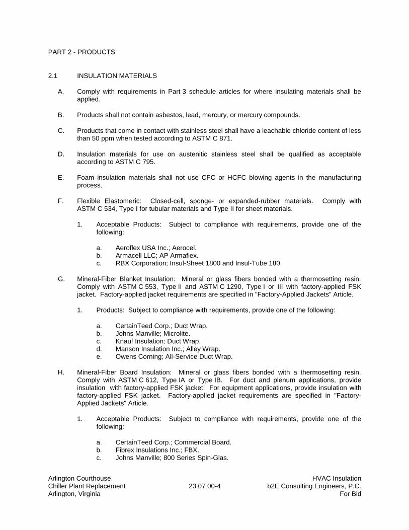
Arlington Courthouse HVAC Insulation Chiller Plant Replacement 23 07 00-4 b2E Consulting Engineers, P.C. Arlington, Virginia For Bid
PART 2 - PRODUCTS
2.1 INSULATION MATERIALS
A. Comply with requirements in Part 3 schedule articles for where insulating materials shall be applied.
B. Products shall not contain asbestos, lead, mercury, or mercury compounds.
C. Products that come in contact with stainless steel shall have a leachable chloride content of less than 50 ppm when tested according to ASTM C 871.
D. Insulation materials for use on austenitic stainless steel shall be qualified as acceptable according to ASTM C 795.
E. Foam insulation materials shall not use CFC or HCFC blowing agents in the manufacturing process.
F. Flexible Elastomeric: Closed-cell, sponge- or expanded-rubber materials. Comply with ASTM C 534, Type I for tubular materials and Type II for sheet materials.
1. Acceptable Products: Subject to compliance with requirements, provide one of the following:
a. Aeroflex USA Inc.; Aerocel. b. Armacell LLC; AP Armaflex. c. RBX Corporation; Insul-Sheet 1800 and Insul-Tube 180.
G. Mineral-Fiber Blanket Insulation: Mineral or glass fibers bonded with a thermosetting resin. Comply with ASTM C 553, Type II and ASTM C 1290, Type I or III with factory-applied FSK jacket. Factory-applied jacket requirements are specified in "Factory-Applied Jackets" Article.
1. Products: Subject to compliance with requirements, provide one of the following:
a. CertainTeed Corp.; Duct Wrap. b. Johns Manville; Microlite. c. Knauf Insulation; Duct Wrap. d. Manson Insulation Inc.; Alley Wrap. e. Owens Corning; All-Service Duct Wrap.
H. Mineral-Fiber Board Insulation: Mineral or glass fibers bonded with a thermosetting resin. Comply with ASTM C 612, Type IA or Type IB. For duct and plenum applications, provide insulation with factory-applied FSK jacket. For equipment applications, provide insulation with factory-applied FSK jacket. Factory-applied jacket requirements are specified in "Factory-Applied Jackets" Article.
1. Acceptable Products: Subject to compliance with requirements, provide one of the following:
a. CertainTeed Corp.; Commercial Board. b. Fibrex Insulations Inc.; FBX. c. Johns Manville; 800 Series Spin-Glas.
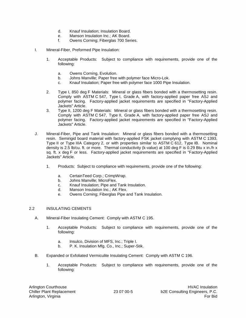
Arlington Courthouse HVAC Insulation Chiller Plant Replacement 23 07 00-5 b2E Consulting Engineers, P.C. Arlington, Virginia For Bid
d. Knauf Insulation; Insulation Board. e. Manson Insulation Inc.; AK Board. f. Owens Corning; Fiberglas 700 Series.
I. Mineral-Fiber, Preformed Pipe Insulation:
1. Acceptable Products: Subject to compliance with requirements, provide one of the following:
a. Owens Corning, Evolution. b. Johns Manville; Paper free with polymer face Micro-Lok. c. Knauf Insulation; Paper free with polymer face 1000 Pipe Insulation.
2. Type I, 850 deg F Materials: Mineral or glass fibers bonded with a thermosetting resin. Comply with ASTM C 547, Type I, Grade A, with factory-applied paper free ASJ and polymer facing. Factory-applied jacket requirements are specified in "Factory-Applied Jackets" Article.
3. Type II, 1200 deg F Materials: Mineral or glass fibers bonded with a thermosetting resin. Comply with ASTM C 547, Type II, Grade A, with factory-applied paper free ASJ and polymer facing. Factory-applied jacket requirements are specified in "Factory-Applied Jackets" Article.
J. Mineral-Fiber, Pipe and Tank Insulation: Mineral or glass fibers bonded with a thermosetting resin. Semirigid board material with factory-applied FSK jacket complying with ASTM C 1393, Type II or Type IIIA Category 2, or with properties similar to ASTM C 612, Type IB. Nominal density is 2.5 lb/cu. ft. or more. Thermal conductivity (k-value) at 100 deg F is 0.29 Btu x in./h x sq. ft. x deg F or less. Factory-applied jacket requirements are specified in "Factory-Applied Jackets" Article.
1. Products: Subject to compliance with requirements, provide one of the following:
a. CertainTeed Corp.; CrimpWrap. b. Johns Manville; MicroFlex. c. Knauf Insulation; Pipe and Tank Insulation. d. Manson Insulation Inc.; AK Flex. e. Owens Corning; Fiberglas Pipe and Tank Insulation.
2.2 INSULATING CEMENTS
A. Mineral-Fiber Insulating Cement: Comply with ASTM C 195.
1. Acceptable Products: Subject to compliance with requirements, provide one of the following:
a. Insulco, Division of MFS, Inc.; Triple I. b. P. K. Insulation Mfg. Co., Inc.; Super-Stik.
B. Expanded or Exfoliated Vermiculite Insulating Cement: Comply with ASTM C 196.
1. Acceptable Products: Subject to compliance with requirements, provide one of the following:
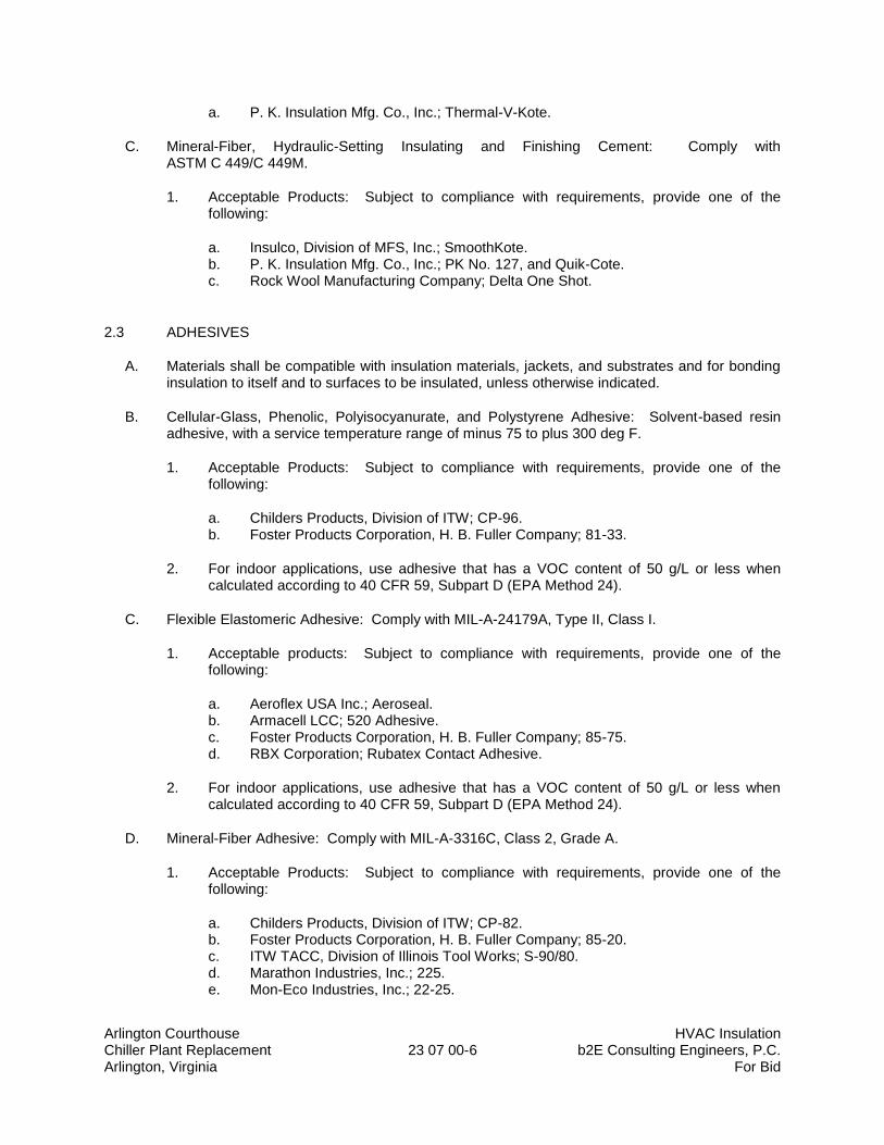
Arlington Courthouse HVAC Insulation Chiller Plant Replacement 23 07 00-6 b2E Consulting Engineers, P.C. Arlington, Virginia For Bid
a. P. K. Insulation Mfg. Co., Inc.; Thermal-V-Kote.
C. Mineral-Fiber, Hydraulic-Setting Insulating and Finishing Cement: Comply with ASTM C 449/C 449M.
1. Acceptable Products: Subject to compliance with requirements, provide one of the following:
a. Insulco, Division of MFS, Inc.; SmoothKote. b. P. K. Insulation Mfg. Co., Inc.; PK No. 127, and Quik-Cote. c. Rock Wool Manufacturing Company; Delta One Shot.
2.3 ADHESIVES
A. Materials shall be compatible with insulation materials, jackets, and substrates and for bonding insulation to itself and to surfaces to be insulated, unless otherwise indicated.
B. Cellular-Glass, Phenolic, Polyisocyanurate, and Polystyrene Adhesive: Solvent-based resin adhesive, with a service temperature range of minus 75 to plus 300 deg F.
1. Acceptable Products: Subject to compliance with requirements, provide one of the following:
a. Childers Products, Division of ITW; CP-96. b. Foster Products Corporation, H. B. Fuller Company; 81-33.
2. For indoor applications, use adhesive that has a VOC content of 50 g/L or less when calculated according to 40 CFR 59, Subpart D (EPA Method 24).
C. Flexible Elastomeric Adhesive: Comply with MIL-A-24179A, Type II, Class I.
1. Acceptable products: Subject to compliance with requirements, provide one of the following:
a. Aeroflex USA Inc.; Aeroseal. b. Armacell LCC; 520 Adhesive. c. Foster Products Corporation, H. B. Fuller Company; 85-75. d. RBX Corporation; Rubatex Contact Adhesive.
2. For indoor applications, use adhesive that has a VOC content of 50 g/L or less when calculated according to 40 CFR 59, Subpart D (EPA Method 24).
D. Mineral-Fiber Adhesive: Comply with MIL-A-3316C, Class 2, Grade A.
1. Acceptable Products: Subject to compliance with requirements, provide one of the following:
a. Childers Products, Division of ITW; CP-82. b. Foster Products Corporation, H. B. Fuller Company; 85-20. c. ITW TACC, Division of Illinois Tool Works; S-90/80. d. Marathon Industries, Inc.; 225. e. Mon-Eco Industries, Inc.; 22-25.

Arlington Courthouse HVAC Insulation Chiller Plant Replacement 23 07 00-7 b2E Consulting Engineers, P.C. Arlington, Virginia For Bid
2. For indoor applications, use adhesive that has a VOC content of 80 g/L or less when calculated according to 40 CFR 59, Subpart D (EPA Method 24).
E. ASJ Adhesive, and FSK Jacket Adhesive: Comply with MIL-A-3316C, Class 2, Grade A for bonding insulation jacket lap seams and joints.
1. Acceptable Products: Subject to compliance with requirements, provide one of the following:
a. Childers Products, Division of ITW; CP-82. b. Foster Products Corporation, H. B. Fuller Company; 85-20. c. ITW TACC, Division of Illinois Tool Works; S-90/80. d. Marathon Industries, Inc.; 225. e. Mon-Eco Industries, Inc.; 22-25.
2. For indoor applications, use adhesive that has a VOC content of 50 g/L or less when calculated according to 40 CFR 59, Subpart D (EPA Method 24).
F. “Venture Clad” Jacket Adhesive: Compatible with “Venture Clad” jacket.
1. Acceptable Products: Subject to compliance with requirements, provide one of the following:
a. Dow Chemical Company (The); 739, Dow Silicone. b. Johns-Manville; Zeston Perma-Weld, CEEL-TITE Solvent Welding Adhesive. c. P.I.C. Plastics, Inc.; Welding Adhesive. d. Speedline Corporation; Speedline Vinyl Adhesive. e. “Venture Clad” recommended adhesive.
2. For indoor applications, use adhesive that has a VOC content of 50 g/L or less when calculated according to 40 CFR 59, Subpart D (EPA Method 24).
2.4 MASTICS
A. Materials shall be compatible with insulation materials, jackets, and substrates; comply with MIL-C-19565C, Type II.
1. For indoor applications, use mastics that have a VOC content of 80 g/L or less when calculated according to 40 CFR 59, Subpart D (EPA Method 24).
B. Vapor-Barrier Mastic: Water based; suitable for indoor and outdoor use on below ambient services.
1. Acceptable Products: Subject to compliance with requirements, provide one of the following:
a. Childers Products, Division of ITW; CP-35. b. Foster Products Corporation, H. B. Fuller Company; 30-90. c. ITW TACC, Division of Illinois Tool Works; CB-50. d. Marathon Industries, Inc.; 590. e. Mon-Eco Industries, Inc.; 55-40. f. Vimasco Corporation; 749.
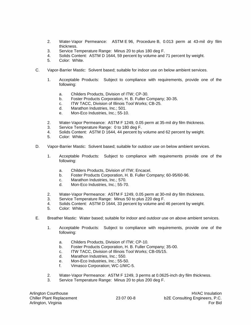
Arlington Courthouse HVAC Insulation Chiller Plant Replacement 23 07 00-8 b2E Consulting Engineers, P.C. Arlington, Virginia For Bid
2. Water-Vapor Permeance: ASTM E 96, Procedure B, 0.013 perm at 43-mil dry film thickness.
3. Service Temperature Range: Minus 20 to plus 180 deg F. 4. Solids Content: ASTM D 1644, 59 percent by volume and 71 percent by weight. 5. Color: White.
C. Vapor-Barrier Mastic: Solvent based; suitable for indoor use on below ambient services.
1. Acceptable Products: Subject to compliance with requirements, provide one of the following:
a. Childers Products, Division of ITW; CP-30. b. Foster Products Corporation, H. B. Fuller Company; 30-35. c. ITW TACC, Division of Illinois Tool Works; CB-25. d. Marathon Industries, Inc.; 501. e. Mon-Eco Industries, Inc.; 55-10.
2. Water-Vapor Permeance: ASTM F 1249, 0.05 perm at 35-mil dry film thickness. 3. Service Temperature Range: 0 to 180 deg F. 4. Solids Content: ASTM D 1644, 44 percent by volume and 62 percent by weight. 5. Color: White.
D. Vapor-Barrier Mastic: Solvent based; suitable for outdoor use on below ambient services.
1. Acceptable Products: Subject to compliance with requirements provide one of the following:
a. Childers Products, Division of ITW; Encacel. b. Foster Products Corporation, H. B. Fuller Company; 60-95/60-96. c. Marathon Industries, Inc.; 570. d. Mon-Eco Industries, Inc.; 55-70.
2. Water-Vapor Permeance: ASTM F 1249, 0.05 perm at 30-mil dry film thickness. 3. Service Temperature Range: Minus 50 to plus 220 deg F. 4. Solids Content: ASTM D 1644, 33 percent by volume and 46 percent by weight. 5. Color: White.
E. Breather Mastic: Water based; suitable for indoor and outdoor use on above ambient services.
1. Acceptable Products: Subject to compliance with requirements, provide one of the following:
a. Childers Products, Division of ITW; CP-10. b. Foster Products Corporation, H. B. Fuller Company; 35-00. c. ITW TACC, Division of Illinois Tool Works; CB-05/15. d. Marathon Industries, Inc.; 550. e. Mon-Eco Industries, Inc.; 55-50. f. Vimasco Corporation; WC-1/WC-5.
2. Water-Vapor Permeance: ASTM F 1249, 3 perms at 0.0625-inch dry film thickness. 3. Service Temperature Range: Minus 20 to plus 200 deg F.
Arlington Courthouse HVAC Insulation Chiller Plant Replacement 23 07 00-9 b2E Consulting Engineers, P.C. Arlington, Virginia For Bid
4. Solids Content: 63 percent by volume and 73 percent by weight. 5. Color: White.
2.5 LAGGING ADHESIVES
A. Description: Comply with MIL-A-3316C Class I, Grade A and shall be compatible with insulation materials, jackets, and substrates.
1. For indoor applications, use lagging adhesives that have a VOC content of 80 g/L or less when calculated according to 40 CFR 59, Subpart D (EPA Method 24).
2. Acceptable Products: Subject to compliance with requirements, provide one of the following:
a. Childers Products, Division of ITW; CP-52. b. Foster Products Corporation, H. B. Fuller Company; 81-42. c. Marathon Industries, Inc.; 130. d. Mon-Eco Industries, Inc.; 11-30. e. Vimasco Corporation; 136.
3. Fire-resistant, water-based lagging adhesive and coating for use indoors to adhere fire-resistant lagging cloths over duct, equipment, and pipe insulation.
4. Service Temperature Range: Minus 50 to plus 180 deg F. 5. Color: White.
2.6 SEALANTS
A. Joint Sealants:
1. Joint Sealants for Cellular-Glass, Phenolic, and Polyisocyanurate Products: Subject to compliance with requirements, provide one of the following:
a. Childers Products, Division of ITW; CP-76. b. Foster Products Corporation, H. B. Fuller Company; 30-45. c. Marathon Industries, Inc.; 405. d. Mon-Eco Industries, Inc.; 44-05. e. Pittsburgh Corning Corporation; Pittseal 444. f. Vimasco Corporation; 750.
B. FSK and Metal Jacket Flashing Sealants:
1. Products: Subject to compliance with requirements, provide one of the following:
a. Childers Products, Division of ITW; CP-76-8. b. Foster Products Corporation, H. B. Fuller Company; 95-44. c. Marathon Industries, Inc.; 405. d. Mon-Eco Industries, Inc.; 44-05. e. Vimasco Corporation; 750.
2. Materials shall be compatible with insulation materials, jackets, and substrates. 3. Fire- and water-resistant, flexible, elastomeric sealant. 4. Service Temperature Range: Minus 40 to plus 250 deg F.
Arlington Courthouse HVAC Insulation Chiller Plant Replacement 23 07 00-10 b2E Consulting Engineers, P.C. Arlington, Virginia For Bid
5. Color: Aluminum. 6. For indoor applications, use sealants that have a VOC content of 250 g/L or less when
calculated according to 40 CFR 59, Subpart D (EPA Method 24).
C. ASJ Flashing Sealants, and ”Venture Clad” Jacket Flashing Sealants:
1. Products: Subject to compliance with requirements, provide one of the following:
a. Childers Products, Division of ITW; CP-76. b. “Venture Clad” recommended sealants.
2. Materials shall be compatible with insulation materials, jackets, and substrates. 3. Fire- and water-resistant, flexible, elastomeric sealant. 4. Service Temperature Range: Minus 40 to plus 250 deg F. 5. Color: White. 6. For indoor applications, use sealants that have a VOC content of 250 g/L or less when
calculated according to 40 CFR 59, Subpart D (EPA Method 24).
2.7 FACTORY-APPLIED JACKETS
A. Insulation system schedules indicate factory-applied jackets on various applications. When factory-applied jackets are indicated, comply with the following: 1. ASJ-paper free polymer facing: ASJ with self-sealing, pressure-sensitive, acrylic-based
adhesive covered by a removable protective strip; complying with ASTM C 1136, Type I and ASTM C 1338 to prevent mold growth, and microbial resistant when treated by the “Greenguard Environmental Institute”.
2. FSK Jacket: Aluminum-foil, fiberglass-reinforced scrim with kraft-paper backing; complying with ASTM C 1136, Type II.
2.8 FIELD-APPLIED FABRIC-REINFORCING MESH
A. Woven Glass-Fiber Fabric for Pipe Insulation: Approximately 2 oz./sq. yd. with a thread count of 10 strands by 10 strands/sq. inch for covering pipe and pipe fittings.
1. Acceptable Products: Subject to compliance with requirements, provide one of the following:
a. Vimasco Corporation; Elastafab 894.
B. Woven Glass-Fiber Fabric for Duct and Equipment Insulation: Approximately 6 oz./sq. yd. with a thread count of 5 strands by 5 strands/sq. inch for covering equipment.
1. Acceptable Products: Subject to compliance with requirements, provide one of the following:
a. Childers Products, Division of ITW; Chil-Glas No. 5.
C. Woven Polyester Fabric: Approximately 1 oz./sq. yd. with a thread count of 10 strands by 10 strands/sq. inch, in a Leno weave, for duct, equipment, and pipe.
Arlington Courthouse HVAC Insulation Chiller Plant Replacement 23 07 00-11 b2E Consulting Engineers, P.C. Arlington, Virginia For Bid
1. Acceptable Products: Subject to compliance with requirements, provide one of the following:
a. Foster Products Corporation, H. B. Fuller Company; Mast-A-Fab. b. Vimasco Corporation; Elastafab 894.
2.9 FIELD-APPLIED CLOTHS
A. Woven Glass-Fiber Fabric: Comply with MIL-C-20079H, Type I, plain weave, and presized a minimum of 8 oz./sq. yd.
1. Acceptable Products: Subject to compliance with requirements, provide one of the following:
a. Alpha Associates, Inc.; Alpha-Maritex 84215 and 84217/9485RW, Luben 59.
2.10 FIELD-APPLIED JACKETS
A. Field-applied jackets shall comply with ASTM C 921, Type I, unless otherwise indicated.
B. Metal Jacket:
1. Products: Subject to compliance with requirements, provide one of the following:
a. Childers Products, Division of ITW; Metal Jacketing Systems. b. PABCO Metals Corporation; Surefit. c. RPR Products, Inc.; Insul-Mate.
2. Aluminum Jacket: Comply with ASTM B 209, Alloy 3003, 3005, 3105 or 5005, Temper H-14.
a. Sheet and roll stock ready for shop or field sizing; or Factory cut and rolled to size. b. Finish and thickness are indicated in field-applied jacket schedules. c. Moisture Barrier for Indoor Applications: 1-mil thick, heat-bonded polyethylene and
kraft paper; 3-mil thick, heat-bonded polyethylene and kraft paper; or 2.5-mil- thick Polysurlyn.
d. Moisture Barrier for Outdoor Applications: 3-mil thick, heat-bonded polyethylene and kraft paper; or 2.5-mil thick Polysurlyn.
e. Factory-Fabricated Fitting Covers:
1) Same material, finish, and thickness as jacket. 2) Preformed 2-piece or gore, 45- and 90-degree, short- and long-radius
elbows. 3) Tee covers. 4) Flange and union covers. 5) End caps. 6) Beveled collars. 7) Valve covers. 8) Field fabricate fitting covers only if factory-fabricated fitting covers are not
available.
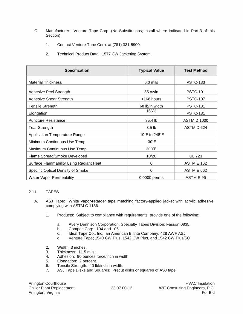
Arlington Courthouse HVAC Insulation Chiller Plant Replacement 23 07 00-12 b2E Consulting Engineers, P.C. Arlington, Virginia For Bid
C. Manufacturer: Venture Tape Corp. (No Substitutions; install where indicated in Part-3 of this Section).
1. Contact Venture Tape Corp. at (781) 331-5900.
2. Technical Product Data: 1577 CW Jacketing System.
Specification Typical Value Test Method
Material Thickness 6.0 mils PSTC-133
Adhesive Peel Strength 55 oz/in PSTC-101
Adhesive Shear Strength >168 hours PSTC-107
Tensile Strength 68 lb/in width PSTC-131
Elongation 166%
PSTC-131
Puncture Resistance 35.4 lb ASTM D 1000
Tear Strength 8.5 lb ASTM D 624
Application Temperature Range -10˚F to 248˚F
Minimum Continuous Use Temp. -30˚F
Maximum Continuous Use Temp. 300˚F
Flame Spread/Smoke Developed 10/20 UL 723
Surface Flammability Using Radiant Heat 0 ASTM E 162
Specific Optical Density of Smoke 0 ASTM E 662
Water Vapor Permeability 0.0000 perms ASTM E 96
2.11 TAPES
A. ASJ Tape: White vapor-retarder tape matching factory-applied jacket with acrylic adhesive, complying with ASTM C 1136.
1. Products: Subject to compliance with requirements, provide one of the following:
a. Avery Dennison Corporation, Specialty Tapes Division; Fasson 0835. b. Compac Corp.; 104 and 105. c. Ideal Tape Co., Inc., an American Biltrite Company; 428 AWF ASJ. d. Venture Tape; 1540 CW Plus, 1542 CW Plus, and 1542 CW Plus/SQ.
2. Width: 3 inches. 3. Thickness: 11.5 mils. 4. Adhesion: 90 ounces force/inch in width. 5. Elongation: 2 percent. 6. Tensile Strength: 40 lbf/inch in width. 7. ASJ Tape Disks and Squares: Precut disks or squares of ASJ tape.
Arlington Courthouse HVAC Insulation Chiller Plant Replacement 23 07 00-13 b2E Consulting Engineers, P.C. Arlington, Virginia For Bid
B. FSK Tape: Foil-face, vapor-retarder tape matching factory-applied jacket with acrylic adhesive; complying with ASTM C 1136.
1. Products: Subject to compliance with requirements, provide one of the following:
a. Avery Dennison Corporation, Specialty Tapes Division; Fasson 0827. b. Compac Corp.; 110 and 111. c. Ideal Tape Co., Inc., an American Biltrite Company; 491 AWF FSK. d. Venture Tape; 1525 CW, 1528 CW, and 1528 CW/SQ.
2. Width: 3 inches. 3. Thickness: 6.5 mils. 4. Adhesion: 90 ounces force/inch in width. 5. Elongation: 2 percent. 6. Tensile Strength: 40 lbf/inch in width. 7. FSK Tape Disks and Squares: Precut disks or squares of FSK tape.
C. Aluminum-Foil Tape: Vapor-retarder tape with acrylic adhesive.
1. Products: Subject to compliance with requirements, provide one of the following:
a. Avery Dennison Corporation, Specialty Tapes Division; Fasson 0800. b. Compac Corp.; 120. c. Ideal Tape Co., Inc., an American Biltrite Company; 488 AWF. d. Venture Tape; 3520 CW.
2. Width: 2 inches. 3. Thickness: 3.7 mils. 4. Adhesion: 100 ounces force/inch in width. 5. Elongation: 5 percent. 6. Tensile Strength: 34 lbf/inch in width.
2.12 SECUREMENTS
A. Bands:
1. Products: Subject to compliance with requirements, provide one of the following:
a. Childers Products; Bands. b. PABCO Metals Corporation; Bands. c. RPR Products, Inc.; Bands.
2. Stainless Steel: ASTM A 167 or ASTM A 240/A 240M, Type 304 or Type 316; 0.015 inch thick, 1/2 inch or 3/4 inch wide with wing or closed seal.
3. Aluminum: ASTM B 209 (ASTM B 209M), Alloy 3003, 3005, 3105, or 5005; Temper H-14, 0.020 inch thick, 1/2 inch or 3/4 inch wide with wing or closed seal.
4. Springs: Twin spring set constructed of stainless steel with ends flat and slotted to accept metal bands. Spring size determined by manufacturer for application.
Arlington Courthouse HVAC Insulation Chiller Plant Replacement 23 07 00-14 b2E Consulting Engineers, P.C. Arlington, Virginia For Bid
2.13 THERMAL SADDLES AND FIRE RETARDANT FIBERGLASS BLOCKING FOR PIPING
A. Chilled Water (Condensing): Provide insulation protection saddles and fiberglass inserts matching insulation thickness at each hanger location.
B. Fire-Rated Fiberglass Blocking: Provide strips of under pipe matching length of saddle (or min. 12 inches long). Insulation must be cut exactly to match dimension of blocking. Blocking shall be factory fabricated to exact thickness of insulation and installed in preformed pipe insulation. Provide quantity of blocks at each hanger or support location in accordance with the factory manufacturer’s recommendations for each pipe size.
C. Refer to Section 23 05 29 for “Hangers and Supports” where saddles and inserts are specified.
PART 3 - EXECUTION
3.1 EXAMINATION
A. Examine substrates and conditions for compliance with requirements for installation and other conditions affecting performance of insulation application.
1. Verify that systems and equipment to be insulated have been tested and are free of defects.
2. Verify that surfaces to be insulated are clean and dry. 3. Proceed with installation only after unsatisfactory conditions have been corrected.
3.2 PREPARATION
A. Surface Preparation: Clean and dry surfaces to receive insulation. Remove materials that will adversely affect insulation application.
B. Surface Preparation: Clean and prepare surfaces to be insulated. Before insulating, apply a corrosion coating to insulated surfaces as follows:
1. Stainless Steel: Coat 300 series stainless steel with an epoxy primer 5 mils thick and an epoxy finish 5 mils thick if operating in a temperature range between 140 and 300 deg F. Consult coating manufacturer for appropriate coating materials and application methods for operating temperature range.
2. Carbon Steel: Coat carbon steel operating at a service temperature between 32 and 300 deg Fwith an epoxy coating. Consult coating manufacturer for appropriate coating materials and application methods for operating temperature range.
C. Coordinate insulation installation with the trade installing heat tracing. Comply with requirements for heat tracing that apply to insulation.
D. Mix insulating cements with clean potable water; if insulating cements are to be in contact with stainless-steel surfaces, use de-mineralized water.
Arlington Courthouse HVAC Insulation Chiller Plant Replacement 23 07 00-15 b2E Consulting Engineers, P.C. Arlington, Virginia For Bid
3.3 GENERAL INSTALLATION REQUIREMENTS
A. Install insulation materials, accessories, and finishes with smooth, straight, and even surfaces; free of voids throughout the length of equipment, and piping including fittings, valves, and specialties.
B. Install insulation materials, forms, vapor barriers or retarders, jackets, and thicknesses required for each item of equipment, and pipe system as specified in insulation system schedules.
C. Install accessories compatible with insulation materials and suitable for the service. Install accessories that do not corrode, soften, or otherwise attack insulation or jacket in either wet or dry state.
D. Install insulation with longitudinal seams at top and bottom of horizontal runs.
E. Install multiple layers of insulation with longitudinal and end seams staggered.
F. Do not weld brackets, clips, or other attachment devices to piping, fittings, and specialties.
G. Keep insulation materials dry during application and finishing.
H. Install insulation with tight longitudinal seams and end joints. Bond seams and joints with adhesive recommended by insulation material manufacturer.
I. Install insulation with least number of joints practical.
J. Where vapor barrier is indicated, seal joints, seams, and penetrations in insulation at hangers, supports, anchors, and other projections with vapor-barrier mastic.
1. Install insulation continuously through hangers and around anchor attachments. 2. For insulation application where vapor barriers are indicated, extend insulation on anchor
legs from point of attachment to supported item to point of attachment to structure. Taper and seal ends at attachment to structure with vapor-barrier mastic.
3. Install insert materials and install insulation to tightly join the insert. Seal insulation to insulation inserts with adhesive or sealing compound recommended by insulation material manufacturer.
4. Cover inserts with jacket material matching adjacent pipe insulation. Install shields over jacket, arranged to protect jacket from tear or puncture by hanger, support, and shield.
K. Apply adhesives, mastics, and sealants at manufacturer's recommended coverage rate and wet and dry film thicknesses.
L. Install insulation with factory-applied jackets as follows:
1. Draw jacket tight and smooth. 2. Cover circumferential joints with 3-inch- wide strips, of same material as insulation jacket.
Secure strips with adhesive and outward clinching staples along both edges of strip, spaced 4 inches o.c.
3. Overlap jacket longitudinal seams at least 1-1/2 inches. Install insulation with longitudinal seams at bottom of pipe. Clean and dry surface to receive self-sealing lap. Staple laps with outward clinching staples along edge at 2 inches or 4 inches o.c.
a. For below ambient services, apply vapor-barrier mastic over staples.
Arlington Courthouse HVAC Insulation Chiller Plant Replacement 23 07 00-16 b2E Consulting Engineers, P.C. Arlington, Virginia For Bid
4. Cover joints and seams with tape as recommended by insulation material manufacturer to maintain vapor seal.
5. Where vapor barriers are indicated, apply vapor-barrier mastic on seams and joints and at ends adjacent to duct and pipe flanges and fittings.
M. Cut insulation in a manner to avoid compressing insulation more than 75 percent of its nominal thickness.
N. Finish installation with systems at operating conditions. Repair joint separations and cracking due to thermal movement.
O. Repair damaged insulation facings by applying same facing material over damaged areas. Extend patches at least 4 inches beyond damaged areas. Adhere, staple, and seal patches similar to butt joints.
P. For above ambient services, do not install insulation to the following:
1. Vibration-control devices. 2. Testing agency labels and stamps. 3. Nameplates and data plates. 4. Manholes. 5. Handholes. 6. Cleanouts.
3.4 PENETRATIONS
A. Insulation Installation at Roof Penetrations: Install insulation continuously through roof penetrations.
1. Seal penetrations with flashing sealant. 2. For applications requiring only indoor insulation, terminate insulation above roof surface
and seal with joint sealant. For applications requiring indoor and outdoor insulation, install insulation for outdoor applications tightly joined to indoor insulation ends. Seal joint with joint sealant.
3. Extend jacket of outdoor insulation outside roof flashing at least 2 inches below top of roof flashing.
4. Seal jacket to roof flashing with flashing sealant.
B. Insulation Installation at Aboveground Exterior Wall Penetrations: Install insulation continuously through wall penetrations.
1. Seal penetrations with flashing sealant. 2. For applications requiring only indoor insulation, terminate insulation inside wall surface
and seal with joint sealant. For applications requiring indoor and outdoor insulation, install insulation for outdoor applications tightly joined to indoor insulation ends. Seal joint with joint sealant.
3. Extend jacket of outdoor insulation outside wall flashing and overlap wall flashing at least 2 inches.
4. Seal jacket to wall flashing with flashing sealant.
C. Insulation Installation at Interior Wall and Partition Penetrations (That Are Not Fire Rated): Install insulation continuously through walls and partitions.
Arlington Courthouse HVAC Insulation Chiller Plant Replacement 23 07 00-17 b2E Consulting Engineers, P.C. Arlington, Virginia For Bid
D. Insulation Installation at Fire-Rated Wall and Partition Penetrations: Install insulation continuously up to penetrations of fire-rated walls and partitions. Terminate insulation at fire damper sleeves for fire-rated wall and partition penetrations. Externally insulate damper sleeves to match adjacent insulation and overlap duct insulation at least 2 inches.
1. Comply with requirements in Division 07 Section "Penetration Firestopping" and fire-resistive joint sealers.
E. Insulation Installation at Floor Penetrations:
1. Duct: Install insulation continuously through floor penetrations that are not fire rated. For penetrations through fire-rated assemblies, terminate insulation at fire damper sleeves and externally insulate damper sleeve beyond floor to match adjacent duct insulation. Overlap damper sleeve and duct insulation at least 2 inches.
2. Pipe: Install insulation continuously through floor penetrations. 3. Seal penetrations through fire-rated assemblies. Comply with requirements in
Division 07 Section "Penetration Firestopping."
F. Insulation Installation at Floor Penetrations:
1. Pipe: Install insulation continuously through floor penetrations. 2. Seal penetrations through fire-rated assemblies. Comply with requirements in
Division 07 Section "Penetration Firestopping."
3.5 EQUIPMENT, TANK, AND VESSEL INSULATION INSTALLATION
A. Mineral Fiber, Pipe and Tank Insulation Installation for Tanks and Vessels: Secure insulation with adhesive and anchor pins and speed washers.
1. Apply adhesives according to manufacturer's recommended coverage rates per unit area, for 100 percent coverage of tank and vessel surfaces.
2. Groove and score insulation materials to fit as closely as possible to equipment, including contours. Bevel insulation edges for cylindrical surfaces for tight joints. Stagger end joints.
3. Protect exposed corners with secured corner angles. 4. Install adhesively attached or self-sticking insulation hangers and speed washers on
sides of tanks and vessels as follows:
a. Do not weld anchor pins to ASME-labeled pressure vessels. b. Select insulation hangers and adhesive that are compatible with service
temperature and with substrate. c. On tanks and vessels, maximum anchor-pin spacing is 3 inches from insulation
end joints, and 16 inches o.c. in both directions. d. Do not overcompress insulation during installation. e. Cut and miter insulation segments to fit curved sides and domed heads of tanks
and vessels. f. Impale insulation over anchor pins and attach speed washers. g. Cut excess portion of pins extending beyond speed washers or bend parallel with
insulation surface. Cover exposed pins and washers with tape matching insulation facing.
Arlington Courthouse HVAC Insulation Chiller Plant Replacement 23 07 00-18 b2E Consulting Engineers, P.C. Arlington, Virginia For Bid
5. Secure each layer of insulation with stainless-steel or aluminum bands. Select band material compatible with insulation materials.
6. Where insulation hangers on equipment and vessels are not permitted or practical and where insulation support rings are not provided, install a girdle network for securing insulation. Stretch prestressed aircraft cable around the diameter of vessel and make taut with clamps, turnbuckles, or breather springs. Place one circumferential girdle around equipment approximately 6 inches from each end. Install wire or cable between two circumferential girdles 12 inches o.c. Install a wire ring around each end and around outer periphery of center openings, and stretch prestressed aircraft cable radially from the wire ring to nearest circumferential girdle. Install additional circumferential girdles along the body of equipment or tank at a minimum spacing of 48 inches o.c. Use this network for securing insulation with tie wire or bands.
7. Stagger joints between insulation layers at least 3 inches. 8. Install insulation in removable segments on equipment access doors, manholes,
handholes, and other elements that require frequent removal for service and inspection. 9. Bevel and seal insulation ends around manholes, handholes, ASME stamps, and
nameplates. 10. For equipment with surface temperatures below ambient, apply mastic to open ends,
joints, seams, breaks, and punctures in insulation.
B. Flexible Elastomeric Thermal Insulation Installation for Tanks and Vessels: Install insulation over entire surface of tanks and vessels.
1. Apply 100 percent coverage of adhesive to surface with manufacturer's recommended adhesive.
2. Seal longitudinal seams and end joints.
C. Insulation Installation on Pumps:
1. Fabricate metal boxes lined with insulation. Fit boxes around pumps and coincide box joints with splits in pump casings. Fabricate joints with outward bolted flanges. Bolt flanges on 6-inch centers, starting at corners. Install 3/8-inch- diameter fasteners with wing nuts. Alternatively, secure the box sections together using a latching mechanism.
2. Fabricate boxes from galvanized steel, at least 0.060 inch thick. 3. For below ambient services, install a vapor barrier at seams, joints, and penetrations.
Seal between flanges with replaceable gasket material to form a vapor barrier.
3.6 GENERAL PIPE INSULATION INSTALLATION
A. Requirements in this article generally apply to all insulation materials except where more specific requirements are specified in various pipe insulation material installation articles.
B. Insulation Installation on Fittings, Valves, Strainers, Flanges, and Unions:
1. Install insulation over fittings, valves, strainers, flanges, unions, and other specialties with continuous thermal and vapor-retarder integrity, unless otherwise indicated.
2. Insulate pipe elbows using preformed fitting insulation or mitered fittings made from same material and density as adjacent pipe insulation. Each piece shall be butted tightly against adjoining piece and bonded with adhesive. Fill joints, seams, voids, and irregular surfaces with insulating cement finished to a smooth, hard, and uniform contour that is uniform with adjoining pipe insulation.
Arlington Courthouse HVAC Insulation Chiller Plant Replacement 23 07 00-19 b2E Consulting Engineers, P.C. Arlington, Virginia For Bid
3. Insulate tee fittings with preformed fitting insulation or sectional pipe insulation of same material and thickness as used for adjacent pipe. Cut sectional pipe insulation to fit. Butt each section closely to the next and hold in place with tie wire. Bond pieces with adhesive.
4. Insulate valves using preformed fitting insulation or sectional pipe insulation of same material, density, and thickness as used for adjacent pipe. Overlap adjoining pipe insulation by not less than two times the thickness of pipe insulation, or one pipe diameter, whichever is thicker. For valves, insulate up to and including the bonnets, valve stuffing-box studs, bolts, and nuts. Fill joints, seams, and irregular surfaces with insulating cement.
5. Insulate strainers using preformed fitting insulation or sectional pipe insulation of same material, density, and thickness as used for adjacent pipe. Overlap adjoining pipe insulation by not less than two times the thickness of pipe insulation, or one pipe diameter, whichever is thicker. Fill joints, seams, and irregular surfaces with insulating cement. Insulate strainers so strainer basket flange or plug can be easily removed and replaced without damaging the insulation and jacket. Provide a removable reusable insulation cover. For below ambient services, provide a design that maintains vapor barrier.
6. Insulate flanges and unions using a section of oversized preformed pipe insulation. Overlap adjoining pipe insulation by not less than two times the thickness of pipe insulation, or one pipe diameter, whichever is thicker.
7. Cover segmented insulated surfaces with a layer of finishing cement and coat with a mastic. Install vapor-barrier mastic for below ambient services and a breather mastic for above ambient services. Reinforce the mastic with fabric-reinforcing mesh. Trowel the mastic to a smooth and well-shaped contour.
8. For services not specified to receive a field-applied jacket except for flexible elastomeric and polyolefin, install fitted PVC cover over elbows, tees, strainers, valves, flanges, and unions. Terminate ends with PVC end caps. Tape PVC covers to adjoining insulation facing using PVC tape.
9. Stencil or label the outside insulation jacket of each union with the word "UNION." Match size and color of pipe labels.
C. Insulate instrument connections for thermometers, pressure gages, pressure temperature taps, test connections, flow meters, sensors, switches, and transmitters on insulated pipes, vessels, and equipment. Shape insulation at these connections by tapering it to and around the connection with insulating cement and finish with finishing cement, mastic, and flashing sealant.
D. Install removable insulation covers at locations indicated. Installation shall conform to the following:
1. Make removable flange and union insulation from sectional pipe insulation of same thickness as that on adjoining pipe. Install same insulation jacket as adjoining pipe insulation.
2. When flange and union covers are made from sectional pipe insulation, extend insulation from flanges or union long at least two times the insulation thickness over adjacent pipe insulation on each side of flange or union. Secure flange cover in place with stainless-steel or aluminum bands. Select band material compatible with insulation and jacket.
3. Construct removable valve insulation covers in same manner as for flanges except divide the two-part section on the vertical center line of valve body.
4. When covers are made from block insulation, make two halves, each consisting of mitered blocks wired to stainless-steel fabric. Secure this wire frame, with its attached insulation, to flanges with tie wire. Extend insulation at least 2 inches over adjacent pipe insulation on each side of valve. Fill space between flange or union cover and pipe
Arlington Courthouse HVAC Insulation Chiller Plant Replacement 23 07 00-20 b2E Consulting Engineers, P.C. Arlington, Virginia For Bid
insulation with insulating cement. Finish cover assembly with insulating cement applied in two coats. After first coat is dry, apply and trowel second coat to a smooth finish.
5. Unless a PVC jacket is indicated in field-applied jacket schedules, finish exposed surfaces with a metal jacket.
3.7 FLEXIBLE ELASTOMERIC INSULATION INSTALLATION
A. Seal longitudinal seams and end joints with manufacturer's recommended adhesive to eliminate openings in insulation that allow passage of air to surface being insulated.
B. Insulation Installation on Pipe Flanges:
1. Install pipe insulation to outer diameter of pipe flange. 2. Make width of insulation section same as overall width of flange and bolts, plus twice the
thickness of pipe insulation. 3. Fill voids between inner circumference of flange insulation and outer circumference of
adjacent straight pipe segments with cut sections of sheet insulation of same thickness as pipe insulation.
4. Secure insulation to flanges and seal seams with manufacturer's recommended adhesive to eliminate openings in insulation that allow passage of air to surface being insulated.
C. Insulation Installation on Pipe Fittings and Elbows:
1. Install mitered sections of pipe insulation. 2. Secure insulation materials and seal seams with manufacturer's recommended adhesive
to eliminate openings in insulation that allow passage of air to surface being insulated.
D. Insulation Installation on Valves and Pipe Specialties:
1. Install preformed valve covers manufactured of same material as pipe insulation when available.
2. When preformed valve covers are not available, install cut sections of pipe and sheet insulation to valve body. Arrange insulation to permit access to packing and to allow valve operation without disturbing insulation.
3. Install insulation to flanges as specified for flange insulation application. 4. Secure insulation to valves and specialties and seal seams with manufacturer's
recommended adhesive to eliminate openings in insulation that allow passage of air to surface being insulated.
3.8 MINERAL-FIBER INSULATION INSTALLATION
A. Insulation Installation on Straight Pipes and Tubes:
1. Secure each layer of preformed pipe insulation to pipe with wire or bands and tighten bands without deforming insulation materials.
2. Where vapor barriers are indicated, seal longitudinal seams, end joints, and protrusions with vapor-barrier mastic and joint sealant.
3. For insulation with factory-applied jackets on above ambient surfaces, secure laps with outward clinched staples at 6 inches o.c.
Arlington Courthouse HVAC Insulation Chiller Plant Replacement 23 07 00-21 b2E Consulting Engineers, P.C. Arlington, Virginia For Bid
4. For insulation with factory-applied jackets on below ambient surfaces, do not staple longitudinal tabs but secure tabs with additional adhesive as recommended by insulation material manufacturer and seal with vapor-barrier mastic and flashing sealant.
5. Provide insulation shields to prevent insulation from crushing at hanger locations.
a. Piping (non-condensing): Install thermal insulation shield inserts at each hanger location. Weld steel inserts to bottom of steel pipe.
b. Piping (condensing): Install thermal insulation with fire retardant treated wood block strips at each hanger location. Carefully cut away the insulation at support point over entire length of saddle (or min. 12 inches long).
B. Insulation Installation on Pipe Flanges:
1. Install preformed pipe insulation to outer diameter of pipe flange. 2. Make width of insulation section same as overall width of flange and bolts, plus twice the
thickness of pipe insulation. 3. Fill voids between inner circumference of flange insulation and outer circumference of
adjacent straight pipe segments with mineral-fiber blanket insulation. 4. Install jacket material with manufacturer's recommended adhesive, overlap seams at
least 1 inch, and seal joints with flashing sealant.
C. Insulation Installation on Pipe Fittings and Elbows:
1. Install preformed sections of same material as straight segments of pipe insulation when available.
2. When preformed insulation elbows and fittings are not available, install mitered sections of pipe insulation, to a thickness equal to adjoining pipe insulation. Secure insulation materials with wire or bands.
D. Insulation Installation on Valves and Pipe Specialties:
1. Install preformed sections of same material as straight segments of pipe insulation when available.
2. When preformed sections are not available, install mitered sections of pipe insulation to valve body.
3. Arrange insulation to permit access to packing and to allow valve operation without disturbing insulation.
4. Install insulation to flanges as specified for flange insulation application.
3.9 FIELD-APPLIED JACKET INSTALLATION
A. Where glass-cloth jackets are indicated, install directly over bare insulation or insulation with factory-applied jackets.
1. Draw jacket smooth and tight to surface with 2-inch overlap at seams and joints. 2. Embed glass cloth between two 0.062-inch- thick coats of lagging adhesive. 3. Completely encapsulate insulation with coating, leaving no exposed insulation.
B. Where FSK jackets are indicated, install as follows:
1. Draw jacket material smooth and tight. 2. Install lap or joint strips with same material as jacket.
Arlington Courthouse HVAC Insulation Chiller Plant Replacement 23 07 00-22 b2E Consulting Engineers, P.C. Arlington, Virginia For Bid
3. Secure jacket to insulation with manufacturer's recommended adhesive. 4. Install jacket with 1-1/2-inch laps at longitudinal seams and 3-inch- wide joint strips at end
joints. 5. Seal openings, punctures, and breaks in vapor-retarder jackets and exposed insulation
with vapor-barrier mastic.
C. Where metal jackets are indicated, install with 2-inch overlap at longitudinal seams and end joints. Overlap longitudinal seams arranged to shed water. Seal end joints with weatherproof sealant recommended by insulation manufacturer. Secure jacket with stainless-steel bands 12 inches o.c. and at end joints.
D. Where Venture Tape jacket is indicated, install as follows:
1. Install in accordance with strict adherence to manufacturer’s instructions.
3.10 FIRE-RATED INSULATION SYSTEM INSTALLATION
A. Where fire-rated insulation system is indicated, secure system to ducts and duct hangers and supports to maintain a continuous fire rating.
B. Insulate duct access panels and doors to achieve same fire rating as duct.
C. Install firestopping at penetrations through fire-rated assemblies. Fire-stop systems are specified in Division 07 Section "Penetration Firestopping."
3.11 FINISHES
A. Duct, Equipment, and Pipe Insulation with ASJ, Glass-Cloth, or Other Paintable Jacket Material: Paint jacket with paint system identified below and as specified in Division 09 painting Sections.
1. Flat Acrylic Finish: Two finish coats over a primer that is compatible with jacket material and finish coat paint. Add fungicidal agent to render fabric mildew proof.
a. Finish Coat Material: Interior, flat, latex-emulsion size.
B. Flexible Elastomeric Thermal Insulation: After adhesive has fully cured, apply two coats of insulation manufacturer's recommended protective coating.
C. Color: Final color as selected by Engineer. Vary first and second coats to allow visual inspection of the completed Work.
D. Do not field paint aluminum or stainless-steel jackets.
3.12 FIELD QUALITY CONTROL
A. Testing Agency: Engage a qualified testing agency to perform tests and inspections.
B. Perform tests and inspections.
C. Tests and Inspections:
Arlington Courthouse HVAC Insulation Chiller Plant Replacement 23 07 00-23 b2E Consulting Engineers, P.C. Arlington, Virginia For Bid
1. Inspect ductwork, randomly selected by Engineer, by removing field-applied jacket and insulation in layers in reverse order of their installation. Extent of inspection shall be limited to one location(s) for each duct system defined in the "Duct Insulation Schedule, General" Article.
2. Inspect field-insulated equipment, randomly selected by Engineer, by removing field-applied jacket and insulation in layers in reverse order of their installation. Extent of inspection shall be limited to one location(s) for each type of equipment defined in the "Equipment Insulation Schedule" Article. For large equipment, remove only a portion adequate to determine compliance.
3. Inspect pipe, fittings, strainers, and valves, randomly selected by Engineer, by removing field-applied jacket and insulation in layers in reverse order of their installation. Extent of inspection shall be limited to three locations of straight pipe, three locations of threaded fittings, three locations of welded fittings, two locations of threaded strainers, two locations of welded strainers, three locations of threaded valves, and three locations of flanged valves for each pipe service defined in the "Piping Insulation Schedule, General" Article.
D. All insulation applications will be considered defective Work if sample inspection reveals noncompliance with requirements.
3.13 EQUIPMENT INSULATION SCHEDULE
A. Insulation materials and thicknesses are identified below. If more than one material is listed for a type of equipment, selection from materials listed is Contractor's option.
B. Insulate indoor and outdoor equipment in paragraphs below that is not factory insulated.
C. Chillers: Insulate cold surfaces on chillers, including, but not limited to, evaporator bundles, condenser bundles, suction piping, compressor inlets, tube sheets, water boxes, and nozzles with the following: 1. Flexible Elastomeric: 1 inch thick.
D. Chilled-water pump insulation shall be installed in a removable pump box cover with access panels, hinges and latches made from 18-gauge galvanized steel painted. Box shall be formed with edge returns so insulation is not exposed. Provide access without the use of tools. The exterior surface of the box shall not sweat in an unconditioned mechanical space. Paint color shall match Section 23 05 53. 1. Mineral-Fiber Board or Flexible Elastomeric: 2 inches thick and 2-lb/cu. ft. nominal
density.
E. Chilled-water expansion tank insulation shall be the following: 1. Flexible Elastomeric: 1 inch thick.
F. Chilled-water air-separator insulation shall be one of the following: 1. Mineral-Fiber Pipe and Tank: 2 inch thick.
G. Cooling Tower Condenser-water (outdoor) insulation shall be one of the following: 1. Mineral-Fiber Pipe and Tank: 2 inches thick with heat trace and aluminum jacket.
Arlington Courthouse HVAC Insulation Chiller Plant Replacement 23 07 00-24 b2E Consulting Engineers, P.C. Arlington, Virginia For Bid
3.14 PIPING INSULATION SCHEDULE, GENERAL
A. Acceptable preformed pipe and tubular insulation materials and thicknesses are identified for each piping system and pipe size range. If more than one material is listed for a piping system, selection from materials listed is Contractor's option.
B. Items Not Insulated: Unless otherwise indicated, do not install insulation on the following:
1. Indoor condenser water piping.
3.15 INDOOR PIPING INSULATION SCHEDULE
A. Condensate and Equipment Drain Water below 60 Deg F:
1. All Pipe Sizes: Insulation shall be one of the following: a. Flexible Elastomeric: 3/4 inch thick. b. Mineral-Fiber, Preformed Pipe Insulation, Type I: 1 inch thick.
B. Chilled Water and Brine, 60 Deg F and below (inside building):
1. NPS 1 ½ (DN 40) and Smaller: Insulation shall be one of the following:
a. Mineral Fiber, Preformed Pipe, Type I: 1 ½ inch thick.
2. NPS 2 to NPS 12: Insulation shall be one of the following:
a. Mineral Fiber, Preformed Pipe, Type I: 2 inches thick.
C. Refrigerant Suction and Hot-Gas Piping (on Chillers):
1. All Pipe Sizes: Insulation shall be the following:
a. Flexible Elastomeric: 1 ½ inch thick.
3.16 OUTDOOR, ABOVEGROUND PIPING INSULATION SCHEDULE
A. Condenser-Water Supply and Return, 60°F and below (outside building):
1. All Pipe Sizes: Insulation shall be one of the following:
a. Mineral-Fiber, Preformed Pipe Insulation, Type I: 2 inches thick with heat trace.
3.17 INDOOR, FIELD-APPLIED JACKET SCHEDULE
A. Install jacket over insulation material. For insulation with factory-applied jacket, install the field-applied jacket over the factory-applied jacket.
B. If more than one material is listed, selection from materials listed is Contractor's option.
C. Equipment, Concealed:
Arlington Courthouse HVAC Insulation Chiller Plant Replacement 23 07 00-25 b2E Consulting Engineers, P.C. Arlington, Virginia For Bid
1. “Venture Clad”, Color-Coded by System: 20 mils thick.
D. Equipment, Exposed, up to 48 Inches in Diameter or with Flat Surfaces up to 72 Inches:
1. “Venture Clad”, Color-Coded by System: 20 mils thick. 2. Aluminum: Smooth, 0.040 inch thick.
E. Piping, Exposed: 1. “Venture Clad”, Color-Coded by System: 20 mils thick. 2. Aluminum Jackets: 0.04” thick. 3. PVC Jacket: Color coded.
3.18 OUTDOOR, FIELD-APPLIED JACKET SCHEDULE
A. Install jacket over insulation material. For insulation with factory-applied jacket, install the field-applied jacket over the factory-applied jacket.
B. Piping, Exposed:
1. Aluminum, Smooth with Z-Shaped Locking Seam: 0.040 inch thick.
END OF SECTION 23 07 00
Arlington Courthouse HVAC Commissioning Requirements Chiller Plant Replacement 23 08 00-1 b2E Consulting Engineers, P.C. Arlington, Virginia For Bid
SECTION 23 08 00
HVAC COMMISSIONING REQUIREMENTS
PART 1 - GENERAL
1.1 DESCRIPTION
A. Commissioning is a quality-oriented process for achieving, verifying, and documenting that the performance of facilities, systems, and assemblies meet defined objectives and criteria. The commissioning process includes specific tasks to be conducted during construction to verify that construction is performed in accordance with contract requirements, equipment installations provide adequate service access, systems perform in accordance with design intent, and training meets the owner's requirements.
B. The commissioning process does not take away from or reduce the responsibility of the system designers or installing contractors to provide a finished and fully functioning product.
1.3 COMMISSIONING TEAM
A. Commissioning Team: The members of the commissioning team consist of:
1. The owner’s representative (OR) 2. The commissioning authority (CA) – Third party or the Engineer of Record. 3. The architect and design engineers (AE) 4. The general contractor (GC) 5. The mechanical contractor (MC) 6. The electrical contractor (EC) 7. The testing and balancing contractor (TAB) 8. The controls contractor (CC) 9. The facility operating and maintenance staff
10. Other installing subcontractors 11. Equipment suppliers and manufacturers representatives
B. The CA directs and coordinates the project commissioning activities and reports to the owner. All team members work together to fulfill their contracted responsibilities and meet the objectives of the contract documents.
1.4 SCOPE
A. This section provides the general requirements that apply to the implementation of the commissioning process. Specific components, assemblies, and systems commissioning requirements are per Division 23.
B. In general, the following components, assemblies, and systems will be commissioned:
1. Chilled Water Control System (CWCS)
2. Energy Management System (EMS) BACnet Integration
1.5 COORDINATION
Arlington Courthouse HVAC Commissioning Requirements Chiller Plant Replacement 23 08 00-2 b2E Consulting Engineers, P.C. Arlington, Virginia For Bid
A. Project Commissioning Team: The members of the project commissioning team will consist of the commissioning authority and any support personnel, the construction manager, the owner’s facility staff or designee, the general contractor, subcontractors and/or vendors as required, and the architect/ engineer.
B. Management: The CA coordinates the commissioning activities through the construction manager. All members shall work together to fulfill their contracted responsibilities and meet the objectives of the contract documents.
C. Scheduling: The CA will provide sufficient information to the contractor for required commissioning activities. The contractor will integrate all commissioning activities into the overall project schedule. All parties will address scheduling problems and make necessary notifications in a timely manner in order to expedite the commissioning process.
1.6 PROCESS
A. The following is a brief overview of the typical commissioning tasks during and after construction and the general order in which they occur.
1. Commissioning during construction begins with an initial commissioning meeting conducted by the CA where the commissioning process is reviewed with the project commissioning team members.
2. Additional meetings will be required throughout construction, scheduled by the CA, through the owner or CM, with necessary parties attending to plan, scope, coordinate, schedule future activities and resolve problems.
3. Equipment documentation is submitted to the CA, through the owner or CM, during normal submittals, including detailed startup procedures.
4. The pre-functional checklists are to be completed by the contractors throughout the construction installation and during the startup process.
5. Pre-functional checklists and equipment startup must be completed before systems performance verification. Additionally, testing and balancing and automation system trending must be completed before HVAC systems performance verification can occur.
6. The contractor ensures that the subcontractors’ construction checklists are executed and documented and that startup and initial checkout are performed. The CA verifies that the TAB, construction checklists and startup were completed according to contract requirements.
7. The CA develops and implements equipment and system performance verification procedures. The performance verification tests are executed by the contractor under the direction of the CA with participation of the facility staff.
8. Deficiencies discerned during construction, start-up, or performance verification will be documented by the CA. Rectification of deficiencies resides with the contractor or AE.
9. The CA reviews the O&M documentation for completeness and pertinence; and participates in contractor’s instructions and training of Owner’s operating and maintenance personnel.
B. All equipment/systems:
1. This includes functional checklists completion, trends analysis and seasonal performance verification testing.
1.7 RESPONSIBILITIES
A. The general responsibilities of various parties in the commissioning process are provided herein; amplification of specific responsibilities are in Division 23.
B. All Parties
Arlington Courthouse HVAC Commissioning Requirements Chiller Plant Replacement 23 08 00-3 b2E Consulting Engineers, P.C. Arlington, Virginia For Bid
1. Follow the commissioning plan. 2. Attend initial commissioning meeting and additional meetings as necessary.
C. Owner’s Representative (OR)
1. Facilitate the coordination of the commissioning work by the CA, and, with the GC and CA, insure that commissioning activities are being scheduled into the master schedule.
2. Review and approve the final Commissioning Plan. 3. Attend a commissioning scoping meeting and other commissioning team meetings. 4. Furnish a copy of all construction documents, addenda, change orders and approved
submittals and shop drawings related to commissioned equipment to the CA, OR may delegate this duty to the AE.
5. Review and approve the performance test procedures submitted by the CA. 6. Observe and witness startup and performance testing of selected equipment. 7. Review commissioning progress and deficiency reports. Coordinate and enforce the
resolution of cited non-compliance issues and deficiencies. 8. Sign-off (final approval) on individual commissioning tests as completed and passing. 9. Assign operation and maintenance personnel and schedule them to participate in
commissioning team activities and contractor’s instructions and training. 10. Assist the CA as necessary in the seasonal or deferred performance verification and
deficiency corrections required by the specifications. 11. Acknowledge completion of commissioning process and accept substantial completion.
D. Architect/Engineer (AE)
1. Architect: In addition to performing the normal construction contract administration functions, architect shall:
a. Attend initial commissioning meeting and selected commissioning team meetings. b. Provide any design narrative documentation requested by the CA. c. Coordinate with OR to assure that the CA is:
1) Provided copies of approved shop drawings as they are returned to the Contractor 2) Notified of time, date, and place of all regularly scheduled progress meetings, and of
any special meetings that may be called regarding commissioned systems. 3) Copied on all correspondence pertinent to the commissioned systems including but
not limited to minutes of progress meetings, responses to contractor requests for information, change order documentation.
d. Coordinate resolution of cited deficiencies.
2. Engineers: In addition to performing the normal construction contract administration functions of submittals review, site visits, O&M manuals and As-Built documents review, engineers shall:
a. Attend initial commissioning meeting and other selected commissioning team meetings. b. Provide any design narrative and sequences documentation requested by the CA. Assist
in clarifying the operation and control of commissioned equipment in areas where the specifications, control drawings, or equipment documentation is not sufficient for writing performance verification procedures.
c. Participate in the resolution of cited deficiencies. d. Participate in training of owner’s operating and maintenance personnel, including
providing systems design intent. e. Witness performance verification of selected equipment and systems
E. Contractors: General contractor, subcontractors, and vendors shall assign representatives with
Arlington Courthouse HVAC Commissioning Requirements Chiller Plant Replacement 23 08 00-4 b2E Consulting Engineers, P.C. Arlington, Virginia For Bid
expertise and authority to act on their behalf and schedule them to participate in and perform commissioning activities including, but not limited to, the following:
1. Facilitate the coordination of commissioning and incorporate commissioning activities into the project schedule.
2. Provide detailed startup procedures for all commissioned equipment/systems. 3. Include the cost of commissioning in the total contract price. 4. Attend initial commissioning meeting and other selected commissioning team meetings. 5. GC shall execute the commissioning responsibilities according to the contract documents and
ensure that all subcontractors and vendors do likewise. Among the requirements:
a. The CA is to be notified to witness construction milestones. b. Pre-functional checklists are completed by contractors as work progresses. c. Written responses are to be provided to deficiencies/issues resolution logs issued by the
CA; responses are to be returned to the CA within 2-weeks of date of issue. d. O&M manuals are to be submitted for review no later than 60 days after the last shop
drawing/submittal has been approved.
6. Provide the training of owner personnel. Training plan shall be submitted for approval at least four weeks prior to first training session. Approved O&M manuals shall be employed in training.
7. Provide equipment/systems performance verification under CA direction, including for seasonal or deferred verification. The contractors shall provide all tools or the use of tools to start, check-out and test equipment and systems. Evaluate performance deficiencies and, in collaboration with entity responsible for system and equipment installation, recommend corrective action.
F. Commissioning Authority (CA)
1. Coordinates and directs the commissioning activities in a logical, sequential and efficient manner using consistent protocols and forms, centralized documentation, clear and regular communications and consultations with all necessary parties, frequently updated timelines and schedules and technical expertise.
2. Coordinate the commissioning work and, with the GC and owner/CM, help integrate commissioning activities into the master schedule.
3. Revise the Construction Phase Commissioning Plan as necessary. 4. Plan and conduct an initial commissioning meeting and other commissioning meetings as
required. 5. Request and review additional information required to perform commissioning tasks, including
O&M materials, contractor startup and checkout procedures. 6. Review AE approved contractor submittals applicable to systems being commissioned for
compliance with commissioning needs. 7. Write and distribute construction pre-functional checklists. Monitor execution of checklists
during construction and provide approval when warranted. 8. Perform site visits, as necessary, to observe component and system installations. Attend
selected planning and job-site meetings to obtain information on construction progress. Review construction meeting minutes for revisions/substitutions relating to the commissioning process. Assist in resolving discrepancies.
9. Witness and document milestone events as identified in Division 23. 10. Recommend approval of systems startup by reviewing startup reports and by selected site
observation. 11. With necessary assistance and review from A/E, installing contractors, and vendors; write the
performance verification procedures for equipment and systems. Analyze any performance trend logs and monitoring data to verify performance. Direct, coordinate, and/or witness
Arlington Courthouse HVAC Commissioning Requirements Chiller Plant Replacement 23 08 00-5 b2E Consulting Engineers, P.C. Arlington, Virginia For Bid
equipment/systems performance verification and recommend approval. Coordinate retesting as necessary until satisfactory performance is achieved
12. Maintain a master Issues Log. Provide the owner with written progress reports and test results with recommended actions.
13. Witness performance testing of select systems over which the CA may not have direct control such as refrigerant safety monitoring systems tested by Fire Marshall, tests by manufacturer’s personnel, and other owner contracted tests. Assure that tests documentation is in O&M manuals.
14. Review equipment warranties to ensure that the owner’s responsibilities are clearly defined. 15. Witness and participate in the contractor’s training of the owner’s operating personnel. 16. Review the O&M manuals. 17. Provide a final commissioning report (as described in this section).
PART 2 – PRODUCTS (Not Used)
PART 3 - EXECUTION
3.1 SEQUENCING AND SCHEDULING: Systems commissioning may be construed to be in three parts: installation verification, training and demonstrations, and performance verification.
A. Installation verification utilizes Pre-Functional Check Lists, documenting that equipment/systems are installed with contract documents, are serviceable, and started in accordance contract requirements and/or manufacturers’ recommendations.
B. Contractor’s training of and demonstrations for Owner’s operating and maintenance personnel occurs after Pre-Functional Checks are complete and all test and inspection reports and operation and maintenance manuals have been submitted and approved. Training and demonstrations usually precede Performance Verification; some training, such as use and operations of the automation system, occurs during and after performance verifications.
C. Performance verification employs Functional Performance Verification forms and occurs only after all work required in related Sections has been successfully completed. HVAC systems require functional performance verification in distinct heating and cooling seasons; i.e. a minimum of two sessions of performance verification.
3.2 MEETINGS:
A. Initial Meeting. Within 60 days of the Notice to Proceed, CA shall schedule an initial commissioning meeting. All commissioning parties are required to attend. CA will issue an agenda and chair the meeting. General content of the meeting will be for the CA to provide an overview of the commissioning process for the project, to establish lines of communications.
B. Post-Submittal Meeting: Within 30 days of the final submittal approval by trade (mechanical, electrical, security, etc.), the CA will schedule a coordination meeting for the concerned parties. CA will issue an agenda and chair the meeting. General content of the meeting will be for the CA to provide and discuss pre-functional checklists and performance verification forms.
C. Miscellaneous Meetings. Other meetings may be planned and conducted by the CA as construction progresses to address coordination, deficiency resolution, and planning issues.
Arlington Courthouse HVAC Commissioning Requirements Chiller Plant Replacement 23 08 00-6 b2E Consulting Engineers, P.C. Arlington, Virginia For Bid
3.3 SUBMITTALS
A. The CA will review the approved submittals related to the commissioned equipment for conformance to the contract documents as it relates to the commissioning process, to the performance of the equipment and adequacy for developing test procedures. This review is intended primarily to aid in the development of performance verification procedures and only secondarily to verify compliance with equipment specifications. The CA will notify the owner, PM and/or A/E as requested, of items missing or areas that are not in conformance with contract documents.
B. The CA may request additional submittal documentation to facilitate the commissioning work. These requests may entail manufacturer’s printed installation and detailed startup procedures, full sequences of operation, O&M data, performance test procedures, control drawings and details of owner contracted tests. All documentation requested by the CA shall be included by the subcontractors in the O&M manuals.
3.4 CONSTRUCTION CHECKLISTS AND START-UP
A. Pre-Functional checklists are employed to verify that the equipment and systems are fully connected and operational. Installation elements of the checklists for a given system must be successfully completed and approved prior to startup. Contractors assert completion of installations, CA verifies contractors’ assertions.
B. Equipment startups are performed by responsible contractors and/or factory authorized technicians as required by pertinent specification sections. The primary role of the CA in the start-up process is to ensure that there is written documentation that each of the specified start-up requirements or the manufacturer-recommended procedures has been completed. Successful start-ups shall be documented on the Pre-Functional Checklists.
C. Execution of Pre-Functional Checklists and Startup
1. The pre-functional checklists will be provided by the CA at the Post Submittal Commissioning Meeting. Sample checklists are provided by the EMS/ATC Contractor and shall be indicative of required procedures to be executed as part of startup and initial checkout of the systems and the parties responsible for their execution. The sample pre-functional checklists will be honed responsive to approved submittals.
2. The execution and approval of the pre-functional checklist and startup shall be directed and performed by the contractor, subcontractor or vendor. Signatures are required of the applicable subcontractors for verification of completion of their work.
3. The contractor/subcontractor responsible for the purchase of the equipment shall develop the full startup plan by combining the manufacturer’s detailed startup and checkout procedures and the construction checklists and document the successful start-up. CA shall witness startups and verify successful startup documentation.
4. The contractor shall coordinate startup and checkout with the owner, A/E, and CA. Startups requiring witnessing by the CA and the ERU system, and the hot water boilers. In general, startup of all major pieces of equipment shall be witnessed; a sampling strategy will be used for witnessing startup of multiple similar pieces of equipment.
D. Deficiencies, Non-Conformance, and Approval in Checklists and Startup (Issues Log).
1. During the commissioning process, the Commissioning Agent may identify issues that require corrective action. The Commissioning Agent has no authority to dictate ways and means of issues resolution other than enforcing the dictates of Contract Drawings and Specifications. Resolution of issues that require interpretations or modifications to the contract documents shall be the responsibility of the Architect and Engineers. Project completion date shall not be
Arlington Courthouse HVAC Commissioning Requirements Chiller Plant Replacement 23 08 00-7 b2E Consulting Engineers, P.C. Arlington, Virginia For Bid
delayed due to lack of timely issues resolution unless authorized contract extensions have been executed.
2. Written responses shall be made to issues reported by the Commissioning Agent. The Commissioning Agent shall provide status reports and issues logs as deemed appropriate during the commissioning process with original provided to Owner and copies to the General Contractor, and Architect. The General Contractor and/or Architect shall provide the Owner with a written response to each issue cited by the Commissioning Agent as to corrective actions implemented. The written response shall be provided to the Owner within two (2) weeks of the date of the Commissioning Agent's issues citing correspondence; copies shall be provided to the Commissioning Agent, General Contractor, and Architect. Issues that have not been fully resolved within the two week period shall be noted as such with explanation of intended resolution; and subsequent status reports of the continued issue resolution shall be made in writing at two week intervals until such time as the issue has been fully rectified. The Owner reserves the right to withhold partial payment for construction contract or professional services until satisfactory resolution of mechanical issues have been documented and verified.
3.5 OPERATIONS AND MAINTENANCE MANUALS
A. The commissioning process requires detailed O&M documentation as identified in this section, Division 1, and technical specifications.
B. Operating and Maintenance Manuals shall be provided to the Architect/Engineer for review no later than sixty (60) days after the last submittal/shop drawing has been approved. A/E shall provide the Operating and Maintenance Manuals to the Commissioning Agent after the A/E’s review. The Manuals with A/E and Commissioning Agent’s review comments will be returned to the Contractor for preparation for use in training of Owner’s operating and maintenance personnel. Return of the reviewed Manuals shall be approximately six weeks after Contractor submission.
C. Manuals format and content shall be as specified in Division 1.
3.6 DEMONSTRATIONS AND TRAINING
A. The contractor shall provide demonstrations and training in accordance with Division 1, technical specification sections.
B. Demonstration and training plan shall be submitted to the Commissioning Agent at the time of submission of the Operation and Maintenance Manuals. Plan shall fully detail all demonstrations and training that are to be provided by the Contractor to the Owner’s operating and maintenance personnel and include a time allocation schedule. Actual dates and times, if used, shall be understood as tentative and subject to change based upon actual construction progress. However, at a minimum, the Demonstration and Training schedule shall include time allocations (i.e. hours) for each piece of equipment or system for which demonstration and training are specified. Commissioning agent review comments will be provided to when Operating and Maintenance Manuals are returned to the Contractor. The plan shall cover the following elements:
1. Equipment/system 2. Intended audience 3. Location of training 4. Subjects covered (description, duration of discussion, special methods, etc.) 5. Methods (classroom lecture, manufacturer’s quality video, site walk-through, actual
operational demonstrations, written handouts, etc.).
C. The O&M manuals shall be incorporated into all training sessions.
Arlington Courthouse HVAC Commissioning Requirements Chiller Plant Replacement 23 08 00-8 b2E Consulting Engineers, P.C. Arlington, Virginia For Bid
1. Use the printed installation, operation and maintenance instruction material included in the O&M manuals.
2. Review the written O&M instructions emphasizing safe and proper operating requirements,
preventative maintenance, special tools needed and spare parts inventory suggestions. The training shall include startup, operation in all modes possible, shutdown, seasonal changeover and any emergency procedures.
3. Discussion of relevant health and safety issues and concerns. 4. Discussion of warranties and guarantees. 5. Common troubleshooting problems and solutions. 6. Discussion of any peculiarities of equipment installation or operation.
D. The majority of training and demonstrations shall precede Performance Verification; some training, such as use and operations of the automation system, occurs during and after performance verifications.
E. The CA participation in demonstration and training is largely observation, verifying that training has given to the satisfaction of Owner’s operating and maintenance personnel. The CA may amplify the training sessions by explaining design concepts and systems interactions.
3.7 PERFORMANCE VERIFICATION
A. Requirements: Performance verification shall demonstrate that each system is operating according to the design intent and contract documents. Performance verification facilitates bringing the systems from a state of individual substantial completion to full dynamic operation. All major systems, such as large air handling units, shall have performances verified by the CA. Systems involving multiple, repeated equipment, such as VAV terminals, shall be verified by sampling.
B. Coordination and Scheduling: The contractor shall provide sufficient notice, regarding their completion schedule for the pre-functional checklists and startup of all equipment and systems to allow the performance verification to be scheduled. The commissioning team shall oversee, witness, and document the performance all equipment and systems. The CA in association with the contractor/subcontractors and facility staff shall execute the verifications.
1. Performance verification shall be conducted after the pre-functional checklists and startup has been satisfactorily completed.
2. For HVAC systems, air balancing and water balancing shall be completed and all systems shall be operating under automation system control programming (automatic control) prior to performance verification.
3. Performance verification proceeds from components to sub-systems to systems. When the proper performance of all interacting individual systems has been achieved, the interface or coordinated responses between systems shall be verified.
C. Procedures. CA will provide detailed performance verification procedures and forms after all submittals, including controls, have been approved. Equipment performance shall be tested or verified per the parameters and requirements of the pertinent technical specifications and/or manufacturers’ recommendations. Systems performances shall be verified per procedures of pertinent technical specifications, including Testing and Balancing of Division 23, and as further amplified by the CA.
1. Performance testing and verification may be achieved by manual testing or by monitoring the performance and analyzing the results using the control system’s trend log capabilities or by stand-alone data loggers. The CA may substitute specified methods or require an additional
Arlington Courthouse HVAC Commissioning Requirements Chiller Plant Replacement 23 08 00-9 b2E Consulting Engineers, P.C. Arlington, Virginia For Bid
method to be executed other than what was specified, with the approval of the A/E and owner. The CA will determine which method is most appropriate for tests that do not have a specified method.
2. Performance verification and testing shall be performed under design conditions as closely as is practically possible. Simulation of design conditions may be employed to verify performance. When simulation is used, the actual results may also require re-verification under design load conditions.
3. The Installing Contractor shall operate all equipment and systems in support of the commissioning work effort and shall provide all labor, equipment, and materials necessary to allow operational and performance verification of all commissioned equipment and systems.
D. Non-Conformance.
1. Corrections of minor deficiencies identified may be made during performance verification at the discretion of the CA. In such cases the deficiency and resolution will be documented on the procedure form or on an attached sheet.
2. As tests progress and a deficiency is identified that cannot be immediately rectified, the CA shall discuss the issue with the commissioning team:
a. When there is no dispute on the deficiency and the contractor accepts responsibility to correct it, the CA will document the deficiency in the Issues Log. After the contractor acknowledges correction of the deficiency in writing in the Issues Log, the contractor shall reschedule the test; and the test shall be repeated.
b. If there is a dispute about a deficiency, regarding whether it is a contractor issue or a design issue:
1) The apparent deficiency shall be documented in the Issues Log. 2) The deciding responsible party shall indicate the resolution on the Issues Log and the
performance verification shall be repeated responsive to the resolution.
3. The contractor shall acknowledge in writing the status of each outstanding discrepancy identified in the Issues Log. A two week time interval shall be allowed between the date of issuance of the Issues Log and the contractor’s response. Where deficiencies have not been rectified within the allotted two weeks, contractor’s response shall provide explanations.
4. Failure Due to Manufacturer Defect: If 10% (or three, whichever is greater) of identical pieces of equipment fail to perform to the contract documents (mechanically or substantively) due to a manufacturing defect, not allowing it to meet its submitted performance specification, all identical units may be considered unacceptable by the A/E or CA. In such case, the contractor shall provide the owner with the following:
a. The contractor or manufacturer’s representative shall examine all other identical units making a record of the findings. The findings shall signed and dated, written explanation of the problem, cause of failures, etc., and all proposed solutions.
b. The A/E will determine whether a replacement of all identical units or a repair is acceptable.
c. Performance verification shall be repeated after all repairs/replacements have been completed.
E. Deferred Performance Verification
1. Unforeseen Deferred Tests. If any check or test cannot be completed due to the project completion level or required occupancy condition, execution of checklists and performance verification may be delayed upon approval of the CA and Owner. These tests will be conducted in the same manner as originally required as soon as possible.
2. Seasonal Testing: During the warranty period, seasonal testing (tests delayed until weather
Arlington Courthouse HVAC Commissioning Requirements Chiller Plant Replacement 23 08 00-10 b2E Consulting Engineers, P.C. Arlington, Virginia For Bid
conditions are closer to the system’s design) shall be completed as part of this contract. The CA shall coordinate this activity through the owner. Tests will be executed, documented by the CA and deficiencies should be corrected by the appropriate contractor/ subcontractors with the CA witnessing. Any final adjustments to the O&M manuals and as-builts due to the testing shall be made by the contractor.
F. Costs for Re-Testing: Contractor is responsible for costs of performance verification. The cost of the work of the CA is covered by the Owner. However, where re-testing of a system is required due to a deficiency having been cited and the re-test again fails due to un-rectified deficiencies, the costs of the CA associated with all subsequent re-testing may be withheld from Owner’s payment to the contractor. Retesting shall not be considered a justified reason for a claim of delay or for a time extension by the contractor.
3.8 RECOMMENDED ACCEPTANCE: The CA notes each satisfactorily demonstrated function on the performance verification forms. CA provides all forms in he final commissioning manual delivered to the Owner with an executive summary recommending acceptance of the installation as complete and operating in accordance with contract requirements. Recommendation of acceptance may be conditional where:
A. The vast majority of the work was found to be installed and operating per contract requirements, but some minor deficiencies remain. Final acceptance would be predicated upon the condition that all know deficiencies have been corrected and accepted by the Owner.
B. The HVAC system may be conditionally accepted in the initial season of operation, with the condition that the operations in the opposite season must meet performance verification. Final acceptance of the HVAC system requires two season (i.e. heating season and cooling season) performance verification.
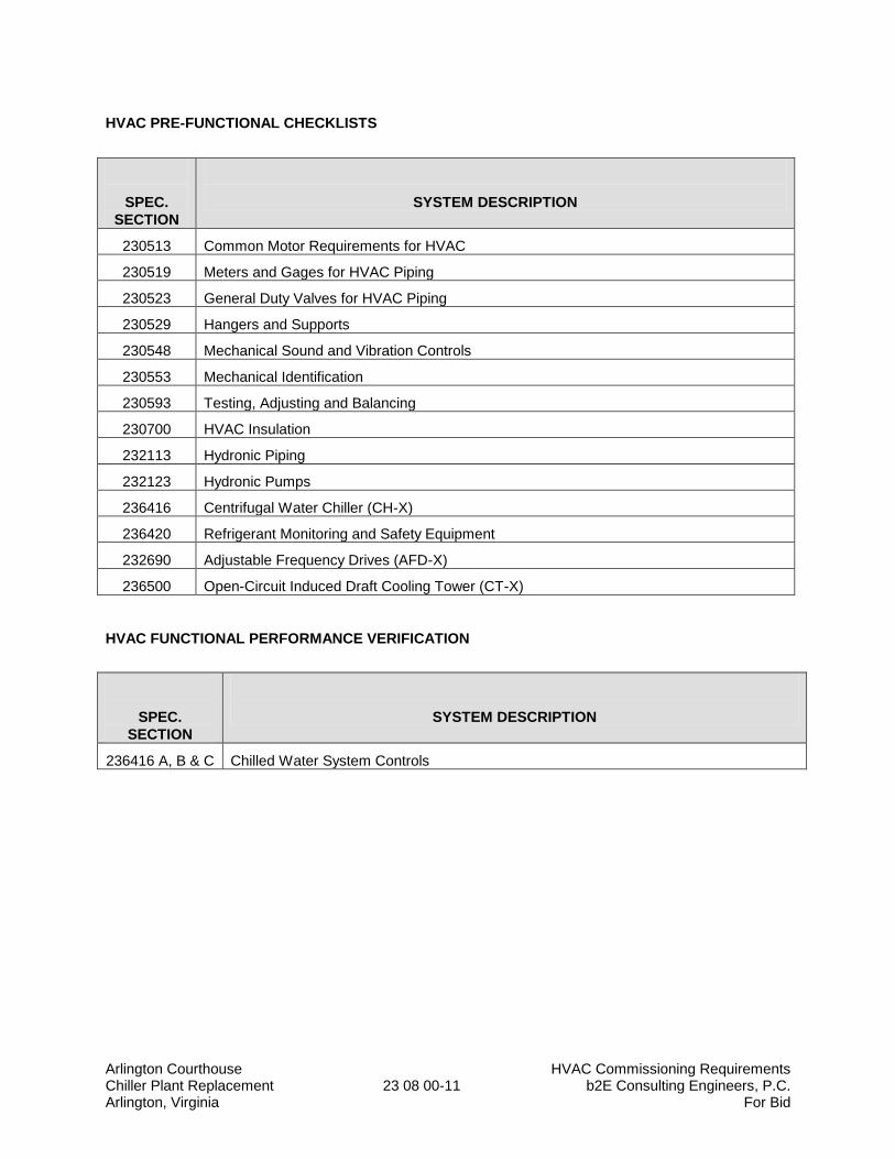
Arlington Courthouse HVAC Commissioning Requirements Chiller Plant Replacement 23 08 00-11 b2E Consulting Engineers, P.C. Arlington, Virginia For Bid
HVAC PRE-FUNCTIONAL CHECKLISTS
SPEC.
SECTION
SYSTEM DESCRIPTION
230513 Common Motor Requirements for HVAC
230519 Meters and Gages for HVAC Piping
230523 General Duty Valves for HVAC Piping
230529 Hangers and Supports
230548 Mechanical Sound and Vibration Controls
230553 Mechanical Identification
230593 Testing, Adjusting and Balancing
230700 HVAC Insulation
232113 Hydronic Piping
232123 Hydronic Pumps
236416 Centrifugal Water Chiller (CH-X)
236420 Refrigerant Monitoring and Safety Equipment
232690 Adjustable Frequency Drives (AFD-X)
236500 Open-Circuit Induced Draft Cooling Tower (CT-X)
HVAC FUNCTIONAL PERFORMANCE VERIFICATION
SPEC.
SECTION
SYSTEM DESCRIPTION
236416 A, B & C Chilled Water System Controls
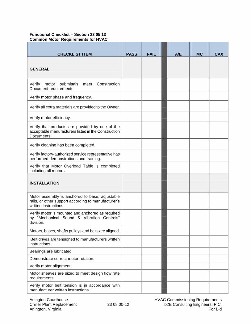
Arlington Courthouse HVAC Commissioning Requirements Chiller Plant Replacement 23 08 00-12 b2E Consulting Engineers, P.C. Arlington, Virginia For Bid
Functional Checklist – Section 23 05 13
Common Motor Requirements for HVAC
CHECKLIST ITEM
PASS
FAIL
A/E
MC
CAX
GENERAL
Verify motor submittals meet Construction Document requirements.
Verify motor phase and frequency.
Verify all extra materials are provided to the Owner.
Verify motor efficiency.
Verify that products are provided by one of the acceptable manufacturers listed in the Construction Documents.
Verify cleaning has been completed.
Verify factory-authorized service representative has performed demonstrations and training.
Verify that Motor Overload Table is completed including all motors.
INSTALLATION
Motor assembly is anchored to base, adjustable rails, or other support according to manufacturer’s written instructions.
Verify motor is mounted and anchored as required by “Mechanical Sound & Vibration Controls” division.
Motors, bases, shafts pulleys and belts are aligned.
Belt drives are tensioned to manufacturers written instructions.
Bearings are lubricated.
Demonstrate correct motor rotation.
Verify motor alignment.
Motor sheaves are sized to meet design flow rate requirements.
Verify motor belt tension is in accordance with manufacturer written instructions.
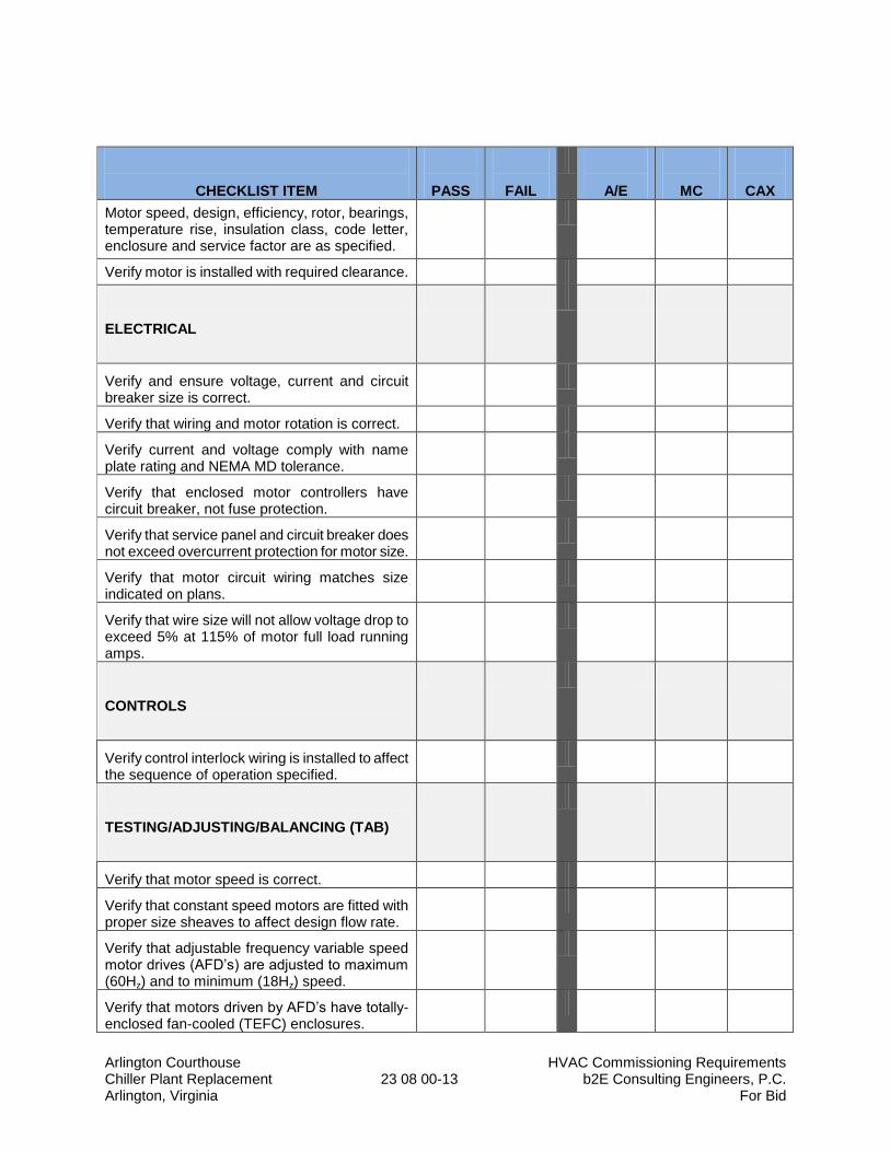
Arlington Courthouse HVAC Commissioning Requirements Chiller Plant Replacement 23 08 00-13 b2E Consulting Engineers, P.C. Arlington, Virginia For Bid
CHECKLIST ITEM
PASS
FAIL
A/E
MC
CAX
Motor speed, design, efficiency, rotor, bearings, temperature rise, insulation class, code letter, enclosure and service factor are as specified.
Verify motor is installed with required clearance.
ELECTRICAL
Verify and ensure voltage, current and circuit breaker size is correct.
Verify that wiring and motor rotation is correct.
Verify current and voltage comply with name plate rating and NEMA MD tolerance.
Verify that enclosed motor controllers have circuit breaker, not fuse protection.
Verify that service panel and circuit breaker does not exceed overcurrent protection for motor size.
Verify that motor circuit wiring matches size indicated on plans.
Verify that wire size will not allow voltage drop to exceed 5% at 115% of motor full load running amps.
CONTROLS
Verify control interlock wiring is installed to affect the sequence of operation specified.
TESTING/ADJUSTING/BALANCING (TAB)
Verify that motor speed is correct.
Verify that constant speed motors are fitted with proper size sheaves to affect design flow rate.
Verify that adjustable frequency variable speed motor drives (AFD’s) are adjusted to maximum (60Hz) and to minimum (18Hz) speed.
Verify that motors driven by AFD’s have totally-enclosed fan-cooled (TEFC) enclosures.
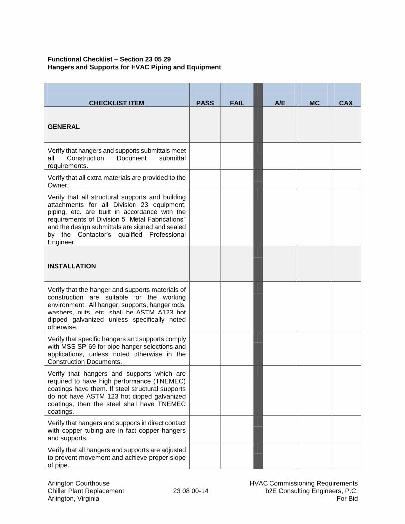
Arlington Courthouse HVAC Commissioning Requirements Chiller Plant Replacement 23 08 00-14 b2E Consulting Engineers, P.C. Arlington, Virginia For Bid
Functional Checklist – Section 23 05 29
Hangers and Supports for HVAC Piping and Equipment
CHECKLIST ITEM
PASS
FAIL
A/E
MC
CAX
GENERAL
Verify that hangers and supports submittals meet all Construction Document submittal requirements.
Verify that all extra materials are provided to the Owner.
Verify that all structural supports and building attachments for all Division 23 equipment, piping, etc. are built in accordance with the requirements of Division 5 “Metal Fabrications” and the design submittals are signed and sealed by the Contactor’s qualified Professional Engineer.
INSTALLATION
Verify that the hanger and supports materials of construction are suitable for the working environment. All hanger, supports, hanger rods, washers, nuts, etc. shall be ASTM A123 hot dipped galvanized unless specifically noted otherwise.
Verify that specific hangers and supports comply with MSS SP-69 for pipe hanger selections and applications, unless noted otherwise in the Construction Documents.
Verify that hangers and supports which are required to have high performance (TNEMEC) coatings have them. If steel structural supports do not have ASTM 123 hot dipped galvanized coatings, then the steel shall have TNEMEC coatings.
Verify that hangers and supports in direct contact with copper tubing are in fact copper hangers and supports.
Verify that all hangers and supports are adjusted to prevent movement and achieve proper slope of pipe.
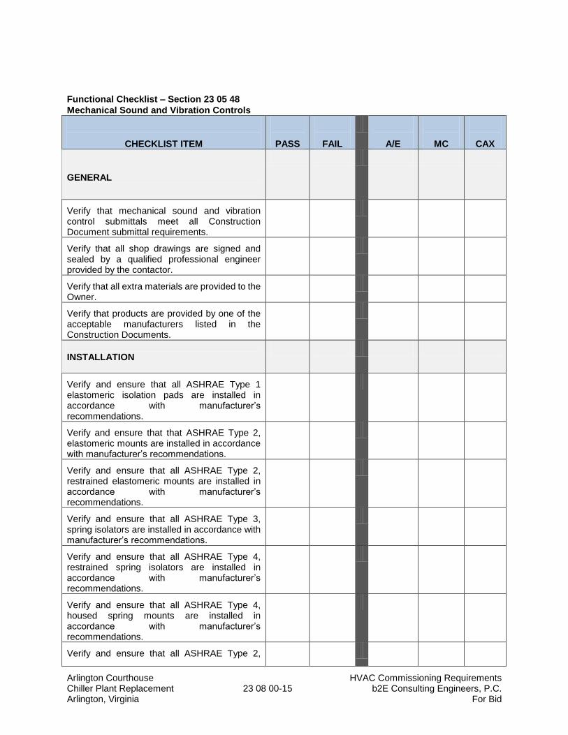
Arlington Courthouse HVAC Commissioning Requirements Chiller Plant Replacement 23 08 00-15 b2E Consulting Engineers, P.C. Arlington, Virginia For Bid
Functional Checklist – Section 23 05 48
Mechanical Sound and Vibration Controls
CHECKLIST ITEM
PASS
FAIL
A/E
MC
CAX
GENERAL
Verify that mechanical sound and vibration control submittals meet all Construction Document submittal requirements.
Verify that all shop drawings are signed and sealed by a qualified professional engineer provided by the contactor.
Verify that all extra materials are provided to the Owner.
Verify that products are provided by one of the acceptable manufacturers listed in the Construction Documents.
INSTALLATION
Verify and ensure that all ASHRAE Type 1 elastomeric isolation pads are installed in accordance with manufacturer’s recommendations.
Verify and ensure that that ASHRAE Type 2, elastomeric mounts are installed in accordance with manufacturer’s recommendations.
Verify and ensure that all ASHRAE Type 2, restrained elastomeric mounts are installed in accordance with manufacturer’s recommendations.
Verify and ensure that all ASHRAE Type 3, spring isolators are installed in accordance with manufacturer’s recommendations.
Verify and ensure that all ASHRAE Type 4, restrained spring isolators are installed in accordance with manufacturer’s recommendations.
Verify and ensure that all ASHRAE Type 4, housed spring mounts are installed in accordance with manufacturer’s recommendations.
Verify and ensure that all ASHRAE Type 2,
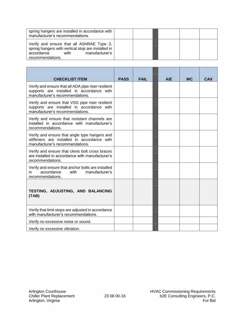
Arlington Courthouse HVAC Commissioning Requirements Chiller Plant Replacement 23 08 00-16 b2E Consulting Engineers, P.C. Arlington, Virginia For Bid
spring hangers are installed in accordance with manufacturer’s recommendations.
Verify and ensure that all ASHRAE Type 3, spring hangers with vertical stop are installed in accordance with manufacturer’s recommendations.
CHECKLIST ITEM
PASS
FAIL
A/E
MC
CAX
Verify and ensure that all ADA pipe riser resilient supports are installed in accordance with manufacturer’s recommendations.
Verify and ensure that VSG pipe riser resilient supports are installed in accordance with manufacturer’s recommendations.
Verify and ensure that resistant channels are installed in accordance with manufacturer’s recommendations.
Verify and ensure that angle type hangers and stiffeners are installed in accordance with manufacturer’s recommendations.
Verify and ensure that clevis bolt cross braces are installed in accordance with manufacturer’s recommendations.
Verify and ensure that anchor bolts are installed in accordance with manufacturer’s recommendations.
TESTING, ADJUSTING, AND BALANCING
(TAB)
Verify that limit stops are adjusted in accordance with manufacturer’s recommendations.
Verify no excessive noise or sound.
Verify no excessive vibration.
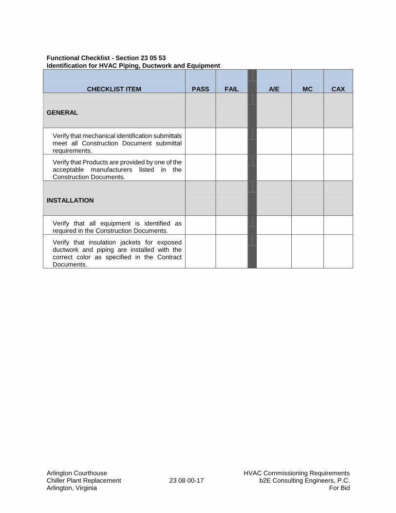
Arlington Courthouse HVAC Commissioning Requirements Chiller Plant Replacement 23 08 00-17 b2E Consulting Engineers, P.C. Arlington, Virginia For Bid
Functional Checklist - Section 23 05 53
Identification for HVAC Piping, Ductwork and Equipment
CHECKLIST ITEM
PASS
FAIL
A/E
MC
CAX
GENERAL
Verify that mechanical identification submittals meet all Construction Document submittal requirements.
Verify that Products are provided by one of the acceptable manufacturers listed in the Construction Documents.
INSTALLATION
Verify that all equipment is identified as required in the Construction Documents.
Verify that insulation jackets for exposed ductwork and piping are installed with the correct color as specified in the Contract Documents.
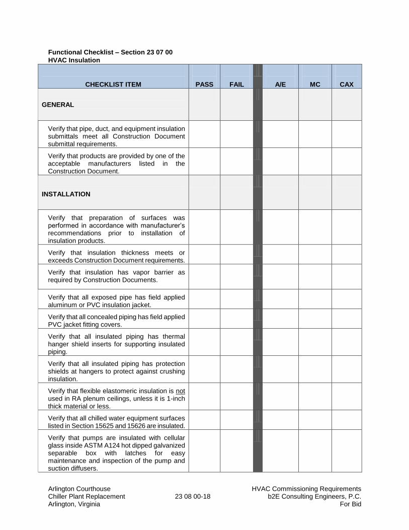
Arlington Courthouse HVAC Commissioning Requirements Chiller Plant Replacement 23 08 00-18 b2E Consulting Engineers, P.C. Arlington, Virginia For Bid
Functional Checklist – Section 23 07 00
HVAC Insulation
CHECKLIST ITEM
PASS
FAIL
A/E
MC
CAX
GENERAL
Verify that pipe, duct, and equipment insulation submittals meet all Construction Document submittal requirements.
Verify that products are provided by one of the acceptable manufacturers listed in the Construction Document.
INSTALLATION
Verify that preparation of surfaces was performed in accordance with manufacturer’s recommendations prior to installation of insulation products.
Verify that insulation thickness meets or exceeds Construction Document requirements.
Verify that insulation has vapor barrier as required by Construction Documents.
Verify that all exposed pipe has field applied aluminum or PVC insulation jacket.
Verify that all concealed piping has field applied PVC jacket fitting covers.
Verify that all insulated piping has thermal hanger shield inserts for supporting insulated piping.
Verify that all insulated piping has protection shields at hangers to protect against crushing insulation.
Verify that flexible elastomeric insulation is not used in RA plenum ceilings, unless it is 1-inch thick material or less.
Verify that all chilled water equipment surfaces listed in Section 15625 and 15626 are insulated.
Verify that pumps are insulated with cellular glass inside ASTM A124 hot dipped galvanized separable box with latches for easy maintenance and inspection of the pump and suction diffusers.
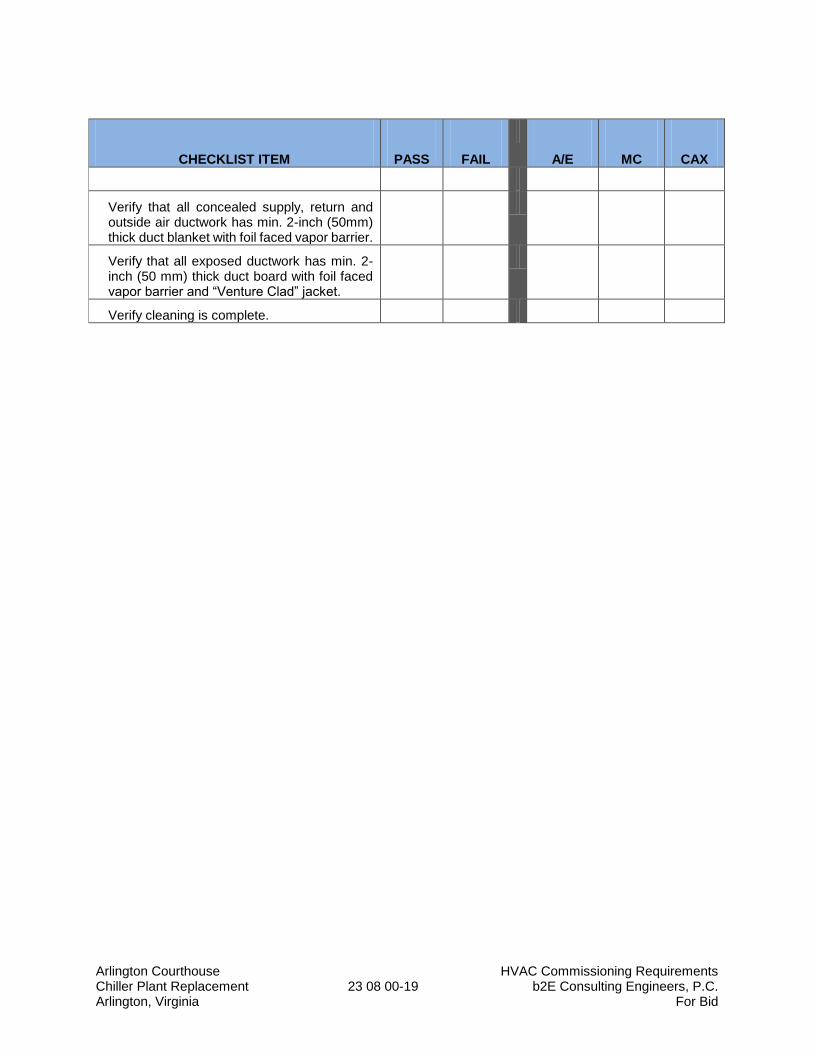
Arlington Courthouse HVAC Commissioning Requirements Chiller Plant Replacement 23 08 00-19 b2E Consulting Engineers, P.C. Arlington, Virginia For Bid
CHECKLIST ITEM
PASS
FAIL
A/E
MC
CAX
Verify that all concealed supply, return and outside air ductwork has min. 2-inch (50mm) thick duct blanket with foil faced vapor barrier.
Verify that all exposed ductwork has min. 2-inch (50 mm) thick duct board with foil faced vapor barrier and “Venture Clad” jacket.
Verify cleaning is complete.
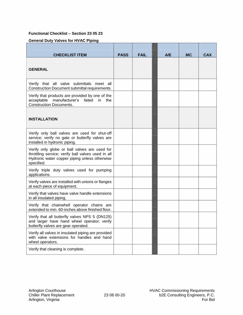
Arlington Courthouse HVAC Commissioning Requirements Chiller Plant Replacement 23 08 00-20 b2E Consulting Engineers, P.C. Arlington, Virginia For Bid
Functional Checklist – Section 23 05 23
General Duty Valves for HVAC Piping
CHECKLIST ITEM
PASS
FAIL
A/E
MC
CAX
GENERAL
Verify that all valve submittals meet all Construction Document submittal requirements.
Verify that products are provided by one of the acceptable manufacturer’s listed in the Construction Documents.
INSTALLATION
Verify only ball valves are used for shut-off service; verify no gate or butterfly valves are installed in hydronic piping.
Verify only globe or ball valves are used for throttling service; verify ball valves used in all Hydronic water copper piping unless otherwise specified.
Verify triple duty valves used for pumping applications.
Verify valves are installed with unions or flanges at each piece of equipment.
Verify that valves have valve handle extensions in all insulated piping.
Verify that chainwhell operator chains are extended to min. 60-inches above finished floor.
Verify that all butterfly valves NPS 5 (DN125) and larger have hand wheel operator; verify butterfly valves are gear operated.
Verify all valves in insulated piping are provided with valve extensions for handles and hand wheel operators.
Verify that cleaning is complete.

Arlington Courthouse HVAC Commissioning Requirements Chiller Plant Replacement 23 08 00-21 b2E Consulting Engineers, P.C. Arlington, Virginia For Bid
Functional Checklist – Section 23 05 19
Meters and Gages for HVAC Piping
CHECKLIST ITEM
PASS
FAIL
A/E
MC
CAX
GENERAL
Verify that all meters and gages submittals meet all Construction Document submittal requirements.
Verify that products are provided by one of the acceptable manufacturer’s listed in the Construction Documents.
Verify that all extra materials are provided to the Owner.
INSTALLATION
Verify that digital, UV powered thermometers are installed in locations required by the contract documents.
Verify that dry-case type pressure gauges are installed for discharge of each pressure reducing valve.
Verify that liquid-filled case type pressure gauges are installed at chilled water inlets and outlets of chillers.
Verify that liquid-filled case type pressure gauges are installed at the suction and discharge of each pump.
Verify that liquid-filled case type pressure gauges are installed at outlets of boilers.
Verify that UV digital thermometers are adjusted to be easily read, and are located such that they are in a lighted area.
Verify that thermowells are installed with sockets extending to the center of the piping for 3-inch (DN75) and larger piping.
Verify that thermowells are installed in Tees or Ells with sockets extending min 2-inches (50mm) into piping system.
Verify that socket extensions are used for insulated piping for flush thermometer installation.
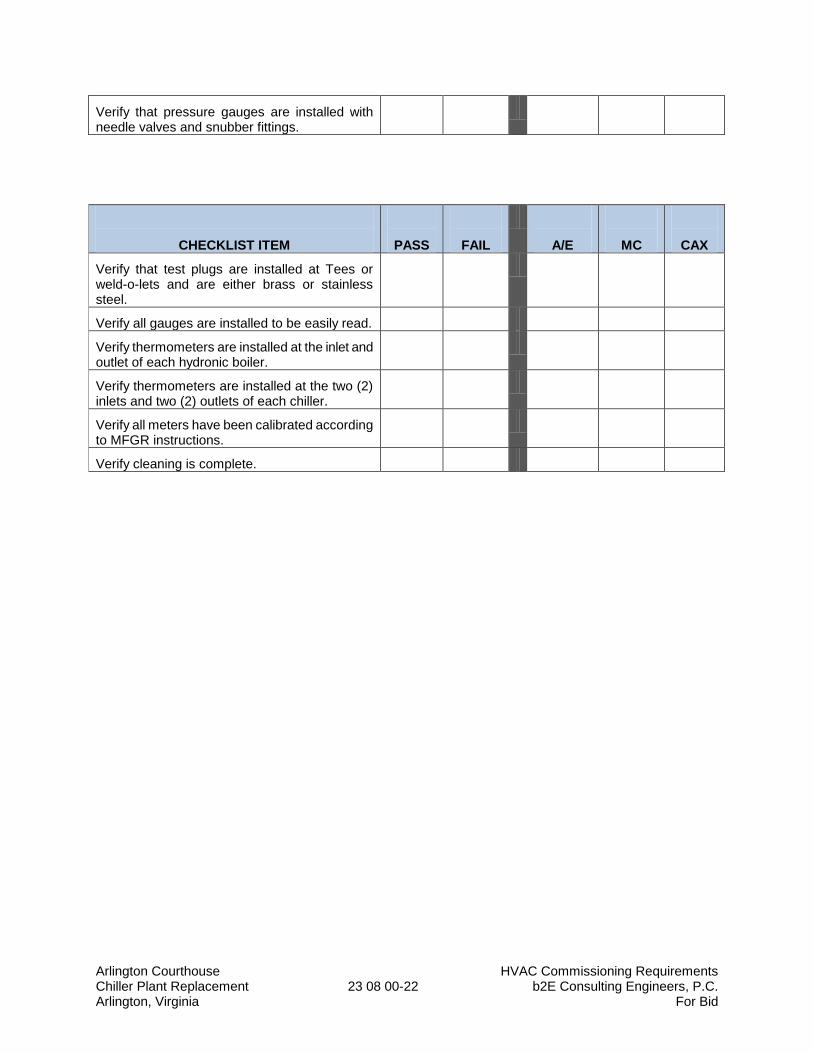
Arlington Courthouse HVAC Commissioning Requirements Chiller Plant Replacement 23 08 00-22 b2E Consulting Engineers, P.C. Arlington, Virginia For Bid
Verify that pressure gauges are installed with needle valves and snubber fittings.
CHECKLIST ITEM
PASS
FAIL
A/E
MC
CAX
Verify that test plugs are installed at Tees or weld-o-lets and are either brass or stainless steel.
Verify all gauges are installed to be easily read.
Verify thermometers are installed at the inlet and outlet of each hydronic boiler.
Verify thermometers are installed at the two (2) inlets and two (2) outlets of each chiller.
Verify all meters have been calibrated according to MFGR instructions.
Verify cleaning is complete.
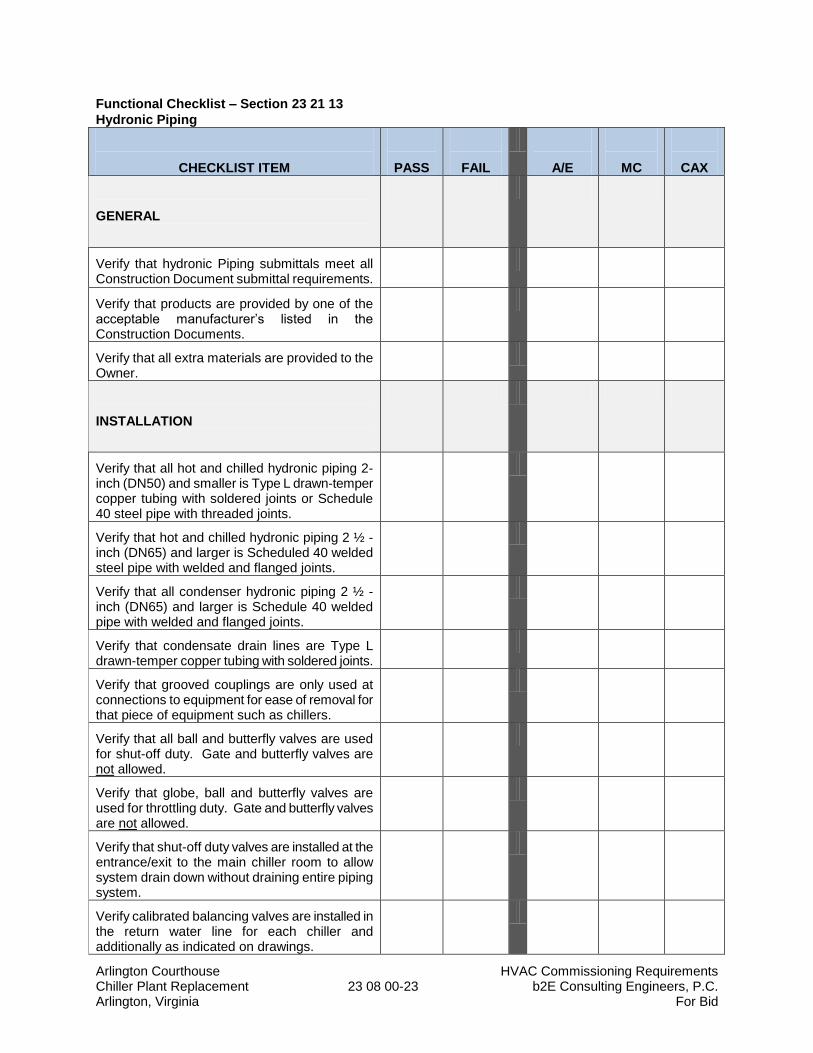
Arlington Courthouse HVAC Commissioning Requirements Chiller Plant Replacement 23 08 00-23 b2E Consulting Engineers, P.C. Arlington, Virginia For Bid
Functional Checklist – Section 23 21 13
Hydronic Piping
CHECKLIST ITEM
PASS
FAIL
A/E
MC
CAX
GENERAL
Verify that hydronic Piping submittals meet all Construction Document submittal requirements.
Verify that products are provided by one of the acceptable manufacturer’s listed in the Construction Documents.
Verify that all extra materials are provided to the Owner.
INSTALLATION
Verify that all hot and chilled hydronic piping 2-inch (DN50) and smaller is Type L drawn-temper copper tubing with soldered joints or Schedule 40 steel pipe with threaded joints.
Verify that hot and chilled hydronic piping 2 ½ -inch (DN65) and larger is Scheduled 40 welded steel pipe with welded and flanged joints.
Verify that all condenser hydronic piping 2 ½ -inch (DN65) and larger is Schedule 40 welded pipe with welded and flanged joints.
Verify that condensate drain lines are Type L drawn-temper copper tubing with soldered joints.
Verify that grooved couplings are only used at connections to equipment for ease of removal for that piece of equipment such as chillers.
Verify that all ball and butterfly valves are used for shut-off duty. Gate and butterfly valves are not allowed.
Verify that globe, ball and butterfly valves are used for throttling duty. Gate and butterfly valves are not allowed.
Verify that shut-off duty valves are installed at the entrance/exit to the main chiller room to allow system drain down without draining entire piping system.
Verify calibrated balancing valves are installed in the return water line for each chiller and additionally as indicated on drawings.
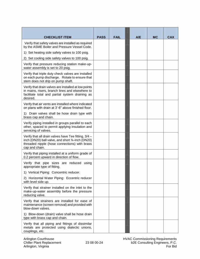
Arlington Courthouse HVAC Commissioning Requirements Chiller Plant Replacement 23 08 00-24 b2E Consulting Engineers, P.C. Arlington, Virginia For Bid
CHECKLIST ITEM
PASS
FAIL
A/E
MC
CAX
Verify that safety valves are installed as required by the ASME Boiler and Pressure Vessel Code.
1) Set heating side safety valves to 100 psig.
2) Set cooling side safety valves to 100 psig.
Verify that pressure reducing station make-up-water assembly is set to 20 psig.
Verify that triple duty check valves are installed on each pump discharge. Rotate to ensure that stem does not drip on pump shaft.
Verify that drain valves are installed at low points in mains, risers, branch lines and elsewhere to facilitate total and partial system draining as desired.
Verify that air vents are installed where indicated on plans with drain at 3’-6” above finished floor.
1) Drain valves shall be hose drain type with brass cap and chain.
Verify piping installed in groups parallel to each other, spaced to permit applying insulation and servicing of valves.
Verify that all drain valves have Tee fitting, 3/4 –inch (DN20) ball valve, and short ¾-inch (DN20) threaded nipple (hose connections) with brass cap and chain.
Verify that piping installed at a uniform grade of 0.2 percent upward in direction of flow.
Verify that pipe sizes are reduced using appropriate type of fitting.
1) Vertical Piping: Concentric reducer.
2) Horizontal Water Piping: Eccentric reducer with level side up.
Verify that strainer installed on the inlet to the make-up-water assembly before the pressure reducing valve.
Verify that strainers are installed for ease of maintenance (screen removal) and provided with blow-down valves.
1) Blow-down (drain) valve shall be hose drain type with brass cap and chain.
Verify that all piping and fittings of dissimilar metals are protected using dialectic unions, couplings, etc.

Arlington Courthouse HVAC Commissioning Requirements Chiller Plant Replacement 23 08 00-25 b2E Consulting Engineers, P.C. Arlington, Virginia For Bid
CHECKLIST ITEM
PASS
FAIL
A/E
MC
CAX
Verify that piping hangers and supports are corrosion resistant using either ASTM A123 hot dipped galvanized, or high performance coated (TNEMEC).
Verify that piping support spacing does not exceed the distances indicated in Section 23 21 13.
Verify that manual air vents are installed at all high points in piping.
Verify that automatic air vents are installed in all mechanical rooms at high points of system piping.
Verify tangential air separators are installed in pump suction line, clearances are maintained and blow down valve is installed.
1) Route blow-down piping to nearest floor drain.
Verify expansion tanks are “full acceptance” diagram type and are charged to 25 psig prior to filling hydronic system with water.
Verify that bypass chemical feeders are installed for each closed-loop hydronic system.
Verify that hydronic systems are filled and initial chemical treatment is performed.
Verify that field quality control is performed in accordance with Section 23 21 13.
Verify that adjustments are made in accordance with Section 23 21 13.
Verify that hydronic system is thoroughly cleaned (flushed-out) using startup strainers, and systems are cleaned in accordance with Section 23 21 13.
Verify that isolation valves are installed on the interior side of each mechanical equipment room for all CW and CHW piping; verify a ¾ - inch drain valve with ¾ - inch hose connection (including brass cap and chain) are provided before and after (both sides) of isolation valves; verify that mechanical equipment room piping can be drained for service while the remainder of the building hydronic systems remain fully operational.
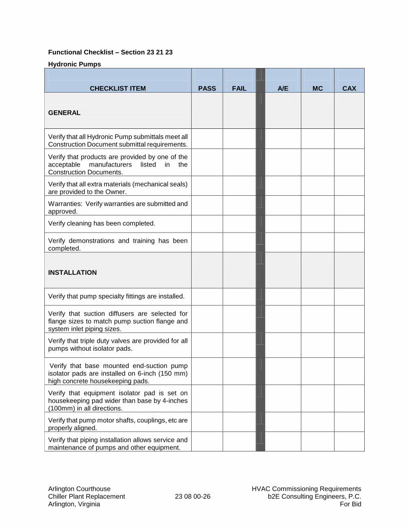
Arlington Courthouse HVAC Commissioning Requirements Chiller Plant Replacement 23 08 00-26 b2E Consulting Engineers, P.C. Arlington, Virginia For Bid
Functional Checklist – Section 23 21 23
Hydronic Pumps
CHECKLIST ITEM
PASS
FAIL
A/E
MC
CAX
GENERAL
Verify that all Hydronic Pump submittals meet all Construction Document submittal requirements.
Verify that products are provided by one of the acceptable manufacturers listed in the Construction Documents.
Verify that all extra materials (mechanical seals) are provided to the Owner.
Warranties: Verify warranties are submitted and approved.
Verify cleaning has been completed.
Verify demonstrations and training has been completed.
INSTALLATION
Verify that pump specialty fittings are installed.
Verify that suction diffusers are selected for flange sizes to match pump suction flange and system inlet piping sizes.
Verify that triple duty valves are provided for all pumps without isolator pads.
Verify that base mounted end-suction pump isolator pads are installed on 6-inch (150 mm) high concrete housekeeping pads.
Verify that equipment isolator pad is set on housekeeping pad wider than base by 4-inches (100mm) in all directions.
Verify that pump motor shafts, couplings, etc are properly aligned.
Verify that piping installation allows service and maintenance of pumps and other equipment.

Arlington Courthouse HVAC Commissioning Requirements Chiller Plant Replacement 23 08 00-27 b2E Consulting Engineers, P.C. Arlington, Virginia For Bid
CHECKLIST ITEM
PASS
FAIL
A/E
MC
CAX
Verify that each horizontal split case pump is installed with the following:
1. Suction Side: Butterfly-valve, Y-strainer, temperature indicator, pressure gauge, braided stainless steel flexible connector.
2. Discharge Side: Concentric reducer, braided stainless steel flexible connector, pressure gauge, triple-duty valve, or silent water check valve (as indicated) butterfly valve.
Verify start-up was performed by a factory authorized service representative.
Verify identification is installed.
ELECTRICAL
Verify that adjustable frequency drives (AFD’s) are provided with integral circuit breaker disconnect switch and bypass contactor.
Verify that wiring is completed.
CONTROLS
Verify that EMS control interlock wiring is complete.
TESTING/ADJUSTING/BALANCING (TAB)
Verify that TAB has completed testing, adjusting, and balancing, and all reports have been submitted for review.
Verify piping has been pressure and leak tested.
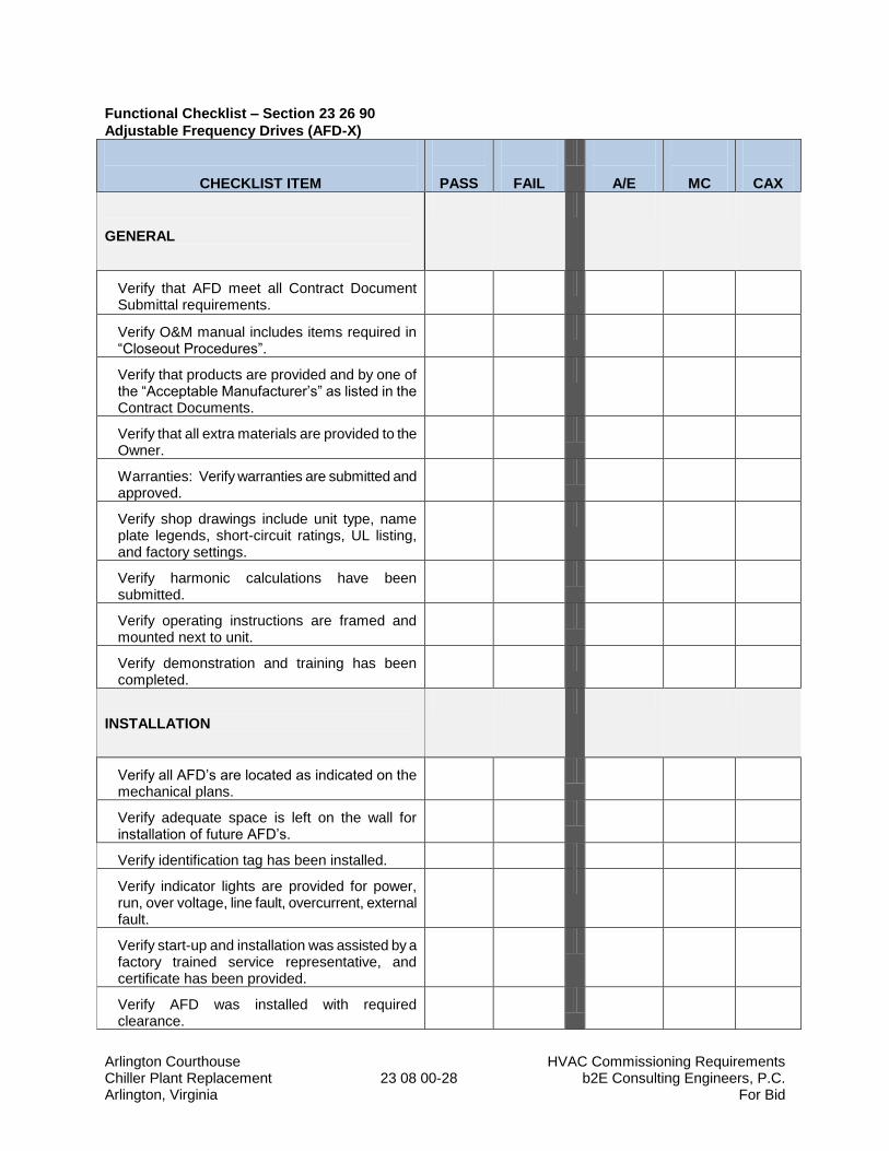
Arlington Courthouse HVAC Commissioning Requirements Chiller Plant Replacement 23 08 00-28 b2E Consulting Engineers, P.C. Arlington, Virginia For Bid
Functional Checklist – Section 23 26 90
Adjustable Frequency Drives (AFD-X)
CHECKLIST ITEM
PASS
FAIL
A/E
MC
CAX
GENERAL
Verify that AFD meet all Contract Document Submittal requirements.
Verify O&M manual includes items required in “Closeout Procedures”.
Verify that products are provided and by one of the “Acceptable Manufacturer’s” as listed in the Contract Documents.
Verify that all extra materials are provided to the Owner.
Warranties: Verify warranties are submitted and approved.
Verify shop drawings include unit type, name plate legends, short-circuit ratings, UL listing, and factory settings.
Verify harmonic calculations have been submitted.
Verify operating instructions are framed and mounted next to unit.
Verify demonstration and training has been completed.
INSTALLATION
Verify all AFD’s are located as indicated on the mechanical plans.
Verify adequate space is left on the wall for installation of future AFD’s.
Verify identification tag has been installed.
Verify indicator lights are provided for power, run, over voltage, line fault, overcurrent, external fault.
Verify start-up and installation was assisted by a factory trained service representative, and certificate has been provided.
Verify AFD was installed with required clearance.
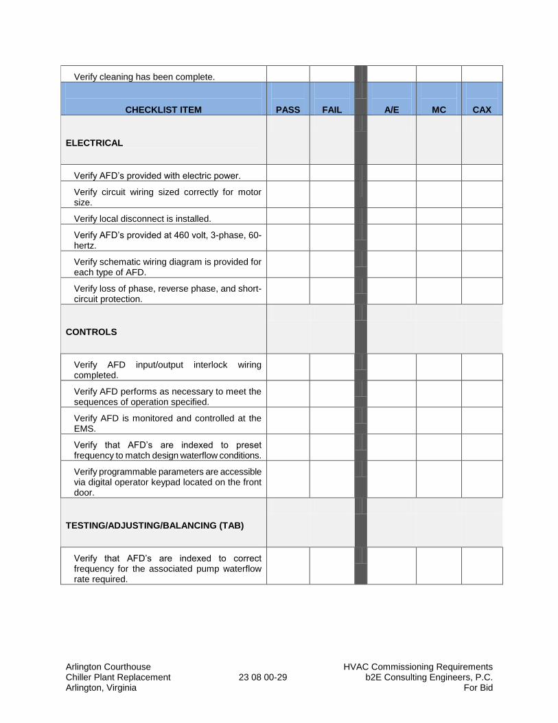
Arlington Courthouse HVAC Commissioning Requirements Chiller Plant Replacement 23 08 00-29 b2E Consulting Engineers, P.C. Arlington, Virginia For Bid
Verify cleaning has been complete.
CHECKLIST ITEM
PASS
FAIL
A/E
MC
CAX
ELECTRICAL
Verify AFD’s provided with electric power.
Verify circuit wiring sized correctly for motor size.
Verify local disconnect is installed.
Verify AFD’s provided at 460 volt, 3-phase, 60-hertz.
Verify schematic wiring diagram is provided for each type of AFD.
Verify loss of phase, reverse phase, and short-circuit protection.
CONTROLS
Verify AFD input/output interlock wiring completed.
Verify AFD performs as necessary to meet the sequences of operation specified.
Verify AFD is monitored and controlled at the EMS.
Verify that AFD’s are indexed to preset frequency to match design waterflow conditions.
Verify programmable parameters are accessible via digital operator keypad located on the front door.
TESTING/ADJUSTING/BALANCING (TAB)
Verify that AFD’s are indexed to correct frequency for the associated pump waterflow rate required.
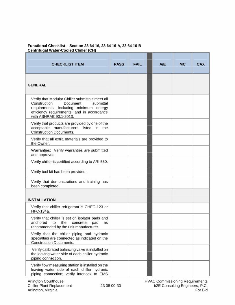
Arlington Courthouse HVAC Commissioning Requirements Chiller Plant Replacement 23 08 00-30 b2E Consulting Engineers, P.C. Arlington, Virginia For Bid
Functional Checklist – Section 23 64 16, 23 64 16-A, 23 64 16-B
Centrifugal Water-Cooled Chiller (CH)
CHECKLIST ITEM
PASS
FAIL
A/E
MC
CAX
GENERAL
Verify that Modular Chiller submittals meet all Construction Document submittal requirements, including minimum energy efficiency requirements, and in accordance with ASHRAE 90.1-2013.
Verify that products are provided by one of the acceptable manufacturers listed in the Construction Documents.
Verify that all extra materials are provided to the Owner.
Warranties: Verify warranties are submitted and approved.
Verify chiller is certified according to ARI 550.
Verify tool kit has been provided.
Verify that demonstrations and training has been completed.
INSTALLATION
Verify that chiller refrigerant is CHFC-123 or HFC-134a.
Verify that chiller is set on isolator pads and anchored to the concrete pad as recommended by the unit manufacturer.
Verify that the chiller piping and hydronic specialties are connected as indicated on the Construction Documents.
Verify calibrated balancing valve is installed on the leaving water side of each chiller hydronic piping connection.
Verify flow measuring station is installed on the leaving water side of each chiller hydronic piping connection; verify interlock to EMS

Arlington Courthouse HVAC Commissioning Requirements Chiller Plant Replacement 23 08 00-31 b2E Consulting Engineers, P.C. Arlington, Virginia For Bid
completed.
Verify refrigerant relief piping installed to outdoors.
CHECKLIST ITEM
PASS
FAIL
A/E
MC
CAX
Verify pressure differential tubing installed from inlet and outlet piping to transducer assembly on chiller.
Verify chiller has Green Seal Certification signed by unit manufacturer.
Verify equipment insulation installed and protective coating applied.
Verify chiller AFD is solid-state soft-start type.
Verify that chiller start-up performed by authorized factory representative; verify chiller start-up sheets (report) submitted for review.
Verify chiller bears ASME boiler and pressure vessel code compliant.
Verify chiller ASME U-stamp and name plate certification (R-123 only).
Verify Green Seal Compliance.
Verify chiller is installed with required clearances.
ELECTRICAL
Verify chiller power connection is installed and electric switch is sized in accordance with manufacturer’s recommendations.
Verify pump motor starters have correct circuit breaker size and heater elements are sized to match pump motor size.
Verify power connected to the following equipment; verify maximum overcurrent protection (circuit breaker) is not exceeded for motor size.
1. Chiller: CH-X (single point power).
2. Chilled Water Pump: CHWP-1 & 2.
3. Condenser Water Pumps:CWP-1 & CWP-2.
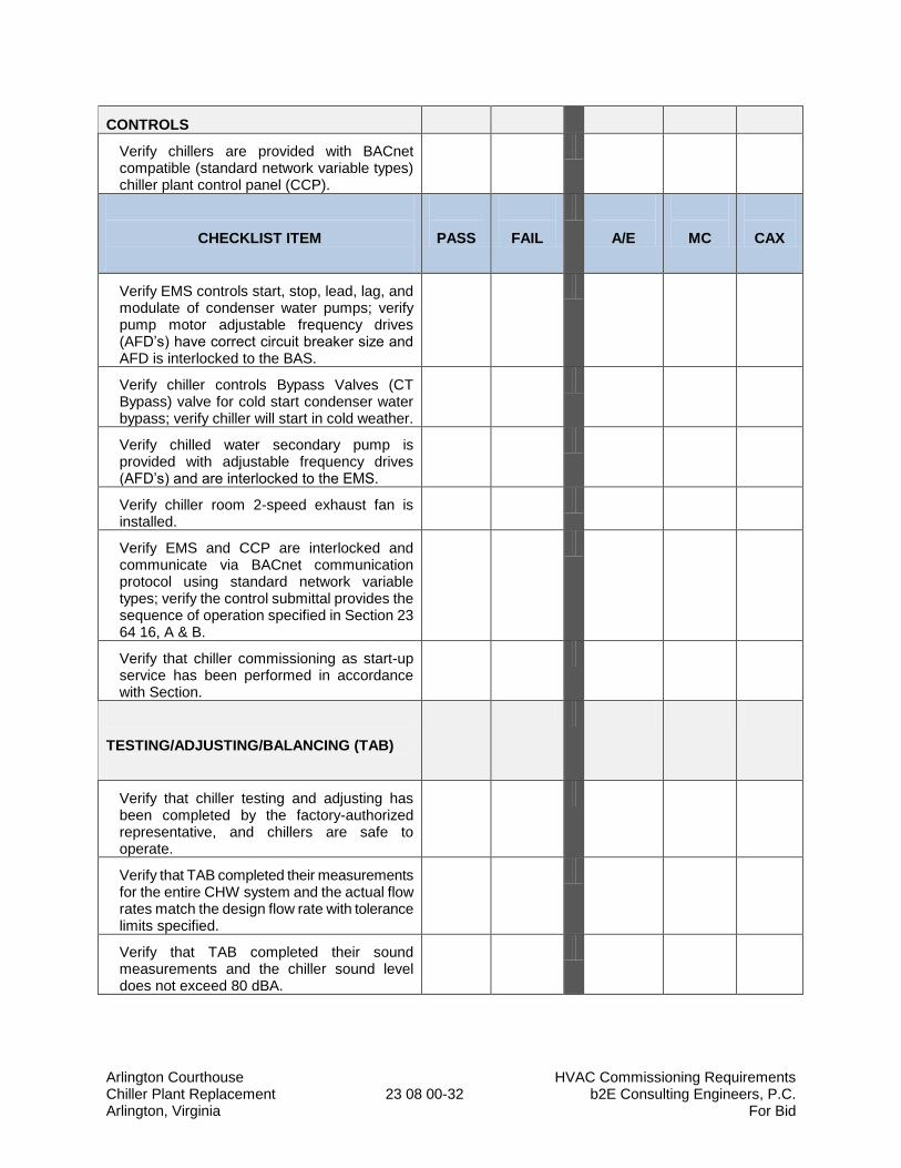
Arlington Courthouse HVAC Commissioning Requirements Chiller Plant Replacement 23 08 00-32 b2E Consulting Engineers, P.C. Arlington, Virginia For Bid
CONTROLS
Verify chillers are provided with BACnet compatible (standard network variable types) chiller plant control panel (CCP).
CHECKLIST ITEM
PASS
FAIL
A/E
MC
CAX
Verify EMS controls start, stop, lead, lag, and modulate of condenser water pumps; verify pump motor adjustable frequency drives (AFD’s) have correct circuit breaker size and AFD is interlocked to the BAS.
Verify chiller controls Bypass Valves (CT Bypass) valve for cold start condenser water bypass; verify chiller will start in cold weather.
Verify chilled water secondary pump is provided with adjustable frequency drives (AFD’s) and are interlocked to the EMS.
Verify chiller room 2-speed exhaust fan is installed.
Verify EMS and CCP are interlocked and communicate via BACnet communication protocol using standard network variable types; verify the control submittal provides the sequence of operation specified in Section 23 64 16, A & B.
Verify that chiller commissioning as start-up service has been performed in accordance with Section.
TESTING/ADJUSTING/BALANCING (TAB)
Verify that chiller testing and adjusting has been completed by the factory-authorized representative, and chillers are safe to operate.
Verify that TAB completed their measurements for the entire CHW system and the actual flow rates match the design flow rate with tolerance limits specified.
Verify that TAB completed their sound measurements and the chiller sound level does not exceed 80 dBA.
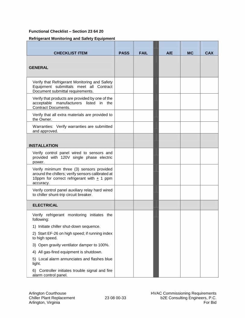
Arlington Courthouse HVAC Commissioning Requirements Chiller Plant Replacement 23 08 00-33 b2E Consulting Engineers, P.C. Arlington, Virginia For Bid
Functional Checklist – Section 23 64 20
Refrigerant Monitoring and Safety Equipment
CHECKLIST ITEM
PASS
FAIL
A/E
MC
CAX
GENERAL
Verify that Refrigerant Monitoring and Safety Equipment submittals meet all Contract Document submittal requirements.
Verify that products are provided by one of the acceptable manufacturers listed in the Contract Documents.
Verify that all extra materials are provided to the Owner.
Warranties: Verify warranties are submitted and approved.
INSTALLATION
Verify control panel wired to sensors and provided with 120V single phase electric power.
Verify minimum three (3) sensors provided around the chillers; verify sensors calibrated at 10ppm for correct refrigerant with + 1 ppm accuracy.
Verify control panel auxiliary relay hard wired to chiller shunt-trip circuit breaker.
ELECTRICAL
Verify refrigerant monitoring initiates the following:
1) Initiate chiller shut-down sequence.
2) Start EF-26 on high speed; if running index to high speed.
3) Open gravity ventilator damper to 100%.
4) All gas-fired equipment is shutdown.
5) Local alarm annunciates and flashes blue light.
6) Controller initiates trouble signal and fire alarm control panel.
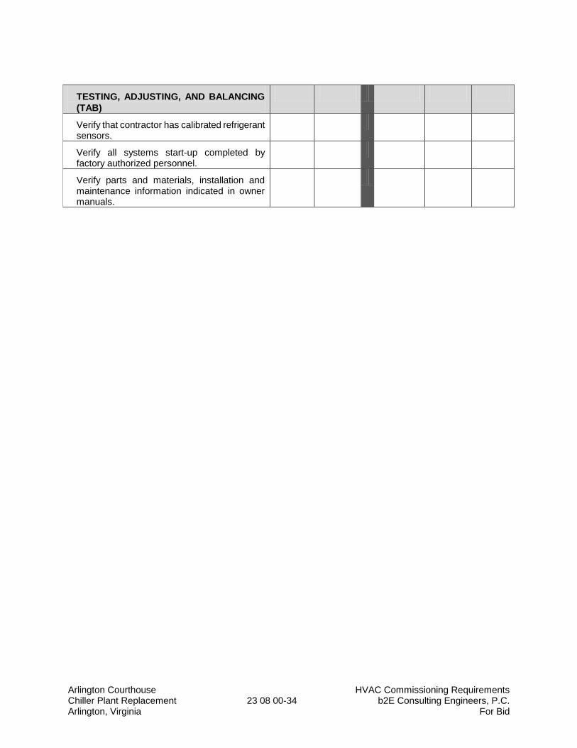
Arlington Courthouse HVAC Commissioning Requirements Chiller Plant Replacement 23 08 00-34 b2E Consulting Engineers, P.C. Arlington, Virginia For Bid
TESTING, ADJUSTING, AND BALANCING
(TAB)
Verify that contractor has calibrated refrigerant sensors.
Verify all systems start-up completed by factory authorized personnel.
Verify parts and materials, installation and maintenance information indicated in owner manuals.
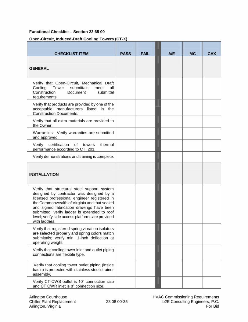
Arlington Courthouse HVAC Commissioning Requirements Chiller Plant Replacement 23 08 00-35 b2E Consulting Engineers, P.C. Arlington, Virginia For Bid
Functional Checklist – Section 23 65 00
Open-Circuit, Induced-Draft Cooling Towers (CT-X)
CHECKLIST ITEM
PASS
FAIL
A/E
MC
CAX
GENERAL
Verify that Open-Circuit, Mechanical Draft Cooling Tower submittals meet all Construction Document submittal requirements.
Verify that products are provided by one of the acceptable manufacturers listed in the Construction Documents.
Verify that all extra materials are provided to the Owner.
Warranties: Verify warranties are submitted and approved.
Verify certification of towers thermal performance according to CTI 201.
Verify demonstrations and training is complete.
INSTALLATION
Verify that structural steel support system designed by contractor was designed by a licensed professional engineer registered in the Commonwealth of Virginia and that sealed and signed fabrication drawings have been submitted; verify ladder is extended to roof level; verify side access platforms are provided with ladders.
Verify that registered spring vibration isolators are selected properly and spring colors match submittals; verify min. 1-inch deflection at operating weight.
Verify that cooling tower inlet and outlet piping connections are flexible type.
Verify that cooling tower outlet piping (inside basin) is protected with stainless steel strainer assembly.
Verify CT-CWS outlet is 10” connection size and CT CWR inlet is 8” connection size.
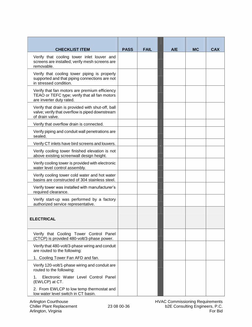
Arlington Courthouse HVAC Commissioning Requirements Chiller Plant Replacement 23 08 00-36 b2E Consulting Engineers, P.C. Arlington, Virginia For Bid
CHECKLIST ITEM
PASS
FAIL
A/E
MC
CAX
Verify that cooling tower inlet louver and screens are installed; verify mesh screens are removable.
Verify that cooling tower piping is properly supported and that piping connections are not in stressed condition.
Verify that fan motors are premium efficiency TEAO or TEFC type; verify that all fan motors are inverter duty rated.
Verify that drain is provided with shut-off, ball valve; verify that overflow is piped downstream of drain valve.
Verify that overflow drain is connected.
Verify piping and conduit wall penetrations are sealed.
Verify CT inlets have bird screens and louvers.
Verify cooling tower finished elevation is not above existing screenwall design height.
Verify cooling tower is provided with electronic water level control assembly.
Verify cooling tower cold water and hot water basins are constructed of 304 stainless steel.
Verify tower was installed with manufacturer’s required clearance.
Verify start-up was performed by a factory authorized service representative.
ELECTRICAL
Verify that Cooling Tower Control Panel (CTCP) is provided 480-volt/3-phase power.
Verify that 480-volt/3-phase wiring and conduit are routed to the following:
1. Cooling Tower Fan AFD and fan.
Verify 120-volt/1-phase wiring and conduit are routed to the following:
1. Electronic Water Level Control Panel (EWLCP) at CT.
2. From EWLCP to low temp thermostat and low water level switch in CT basin.
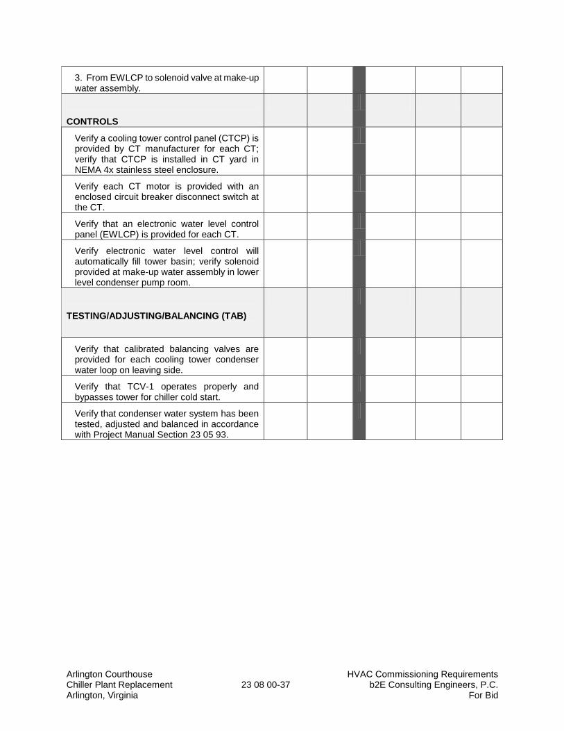
Arlington Courthouse HVAC Commissioning Requirements Chiller Plant Replacement 23 08 00-37 b2E Consulting Engineers, P.C. Arlington, Virginia For Bid
3. From EWLCP to solenoid valve at make-up water assembly.
CONTROLS
Verify a cooling tower control panel (CTCP) is provided by CT manufacturer for each CT; verify that CTCP is installed in CT yard in NEMA 4x stainless steel enclosure.
Verify each CT motor is provided with an enclosed circuit breaker disconnect switch at the CT.
Verify that an electronic water level control panel (EWLCP) is provided for each CT.
Verify electronic water level control will automatically fill tower basin; verify solenoid provided at make-up water assembly in lower level condenser pump room.
TESTING/ADJUSTING/BALANCING (TAB)
Verify that calibrated balancing valves are provided for each cooling tower condenser water loop on leaving side.
Verify that TCV-1 operates properly and bypasses tower for chiller cold start.
Verify that condenser water system has been tested, adjusted and balanced in accordance with Project Manual Section 23 05 93.
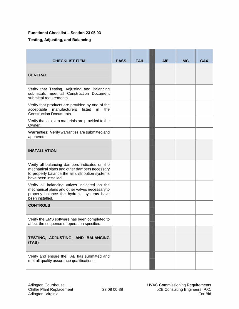
Arlington Courthouse HVAC Commissioning Requirements Chiller Plant Replacement 23 08 00-38 b2E Consulting Engineers, P.C. Arlington, Virginia For Bid
Functional Checklist – Section 23 05 93
Testing, Adjusting, and Balancing
CHECKLIST ITEM
PASS
FAIL
A/E
MC
CAX
GENERAL
Verify that Testing, Adjusting and Balancing submittals meet all Construction Document submittal requirements.
Verify that products are provided by one of the acceptable manufacturers listed in the Construction Documents.
Verify that all extra materials are provided to the Owner.
Warranties: Verify warranties are submitted and approved.
INSTALLATION
Verify all balancing dampers indicated on the mechanical plans and other dampers necessary to properly balance the air distribution systems have been installed.
Verify all balancing valves indicated on the mechanical plans and other valves necessary to properly balance the hydronic systems have been installed.
CONTROLS
Verify the EMS software has been completed to affect the sequence of operation specified.
TESTING, ADJUSTING, AND BALANCING
(TAB)
Verify and ensure the TAB has submitted and met all quality assurance qualifications.
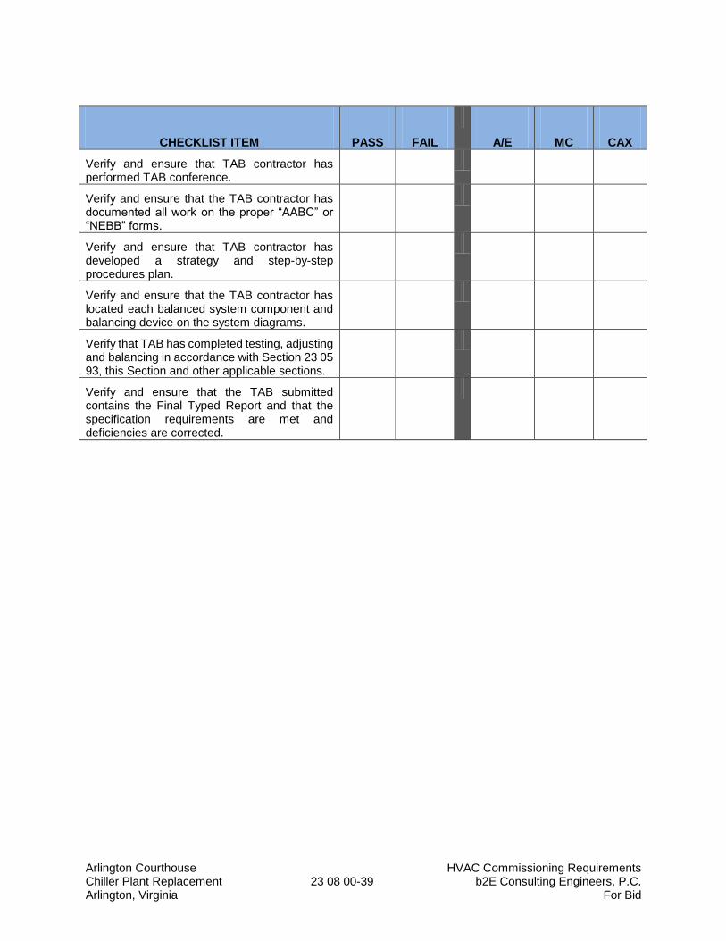
Arlington Courthouse HVAC Commissioning Requirements Chiller Plant Replacement 23 08 00-39 b2E Consulting Engineers, P.C. Arlington, Virginia For Bid
CHECKLIST ITEM
PASS
FAIL
A/E
MC
CAX
Verify and ensure that TAB contractor has performed TAB conference.
Verify and ensure that the TAB contractor has documented all work on the proper “AABC” or “NEBB” forms.
Verify and ensure that TAB contractor has developed a strategy and step-by-step procedures plan.
Verify and ensure that the TAB contractor has located each balanced system component and balancing device on the system diagrams.
Verify that TAB has completed testing, adjusting and balancing in accordance with Section 23 05 93, this Section and other applicable sections.
Verify and ensure that the TAB submitted contains the Final Typed Report and that the specification requirements are met and deficiencies are corrected.
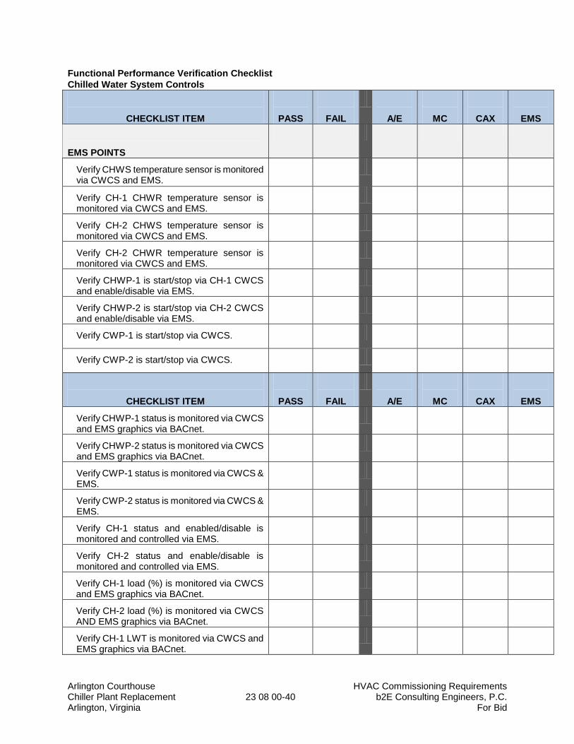
Arlington Courthouse HVAC Commissioning Requirements Chiller Plant Replacement 23 08 00-40 b2E Consulting Engineers, P.C. Arlington, Virginia For Bid
Functional Performance Verification Checklist
Chilled Water System Controls
CHECKLIST ITEM
PASS
FAIL
A/E
MC
CAX
EMS
EMS POINTS
Verify CHWS temperature sensor is monitored via CWCS and EMS.
Verify CH-1 CHWR temperature sensor is monitored via CWCS and EMS.
Verify CH-2 CHWS temperature sensor is monitored via CWCS and EMS.
Verify CH-2 CHWR temperature sensor is monitored via CWCS and EMS.
Verify CHWP-1 is start/stop via CH-1 CWCS and enable/disable via EMS.
Verify CHWP-2 is start/stop via CH-2 CWCS and enable/disable via EMS.
Verify CWP-1 is start/stop via CWCS.
Verify CWP-2 is start/stop via CWCS.
CHECKLIST ITEM
PASS
FAIL
A/E
MC
CAX
EMS
Verify CHWP-1 status is monitored via CWCS and EMS graphics via BACnet.
Verify CHWP-2 status is monitored via CWCS and EMS graphics via BACnet.
Verify CWP-1 status is monitored via CWCS & EMS.
Verify CWP-2 status is monitored via CWCS & EMS.
Verify CH-1 status and enabled/disable is monitored and controlled via EMS.
Verify CH-2 status and enable/disable is monitored and controlled via EMS.
Verify CH-1 load (%) is monitored via CWCS and EMS graphics via BACnet.
Verify CH-2 load (%) is monitored via CWCS AND EMS graphics via BACnet.
Verify CH-1 LWT is monitored via CWCS and EMS graphics via BACnet.
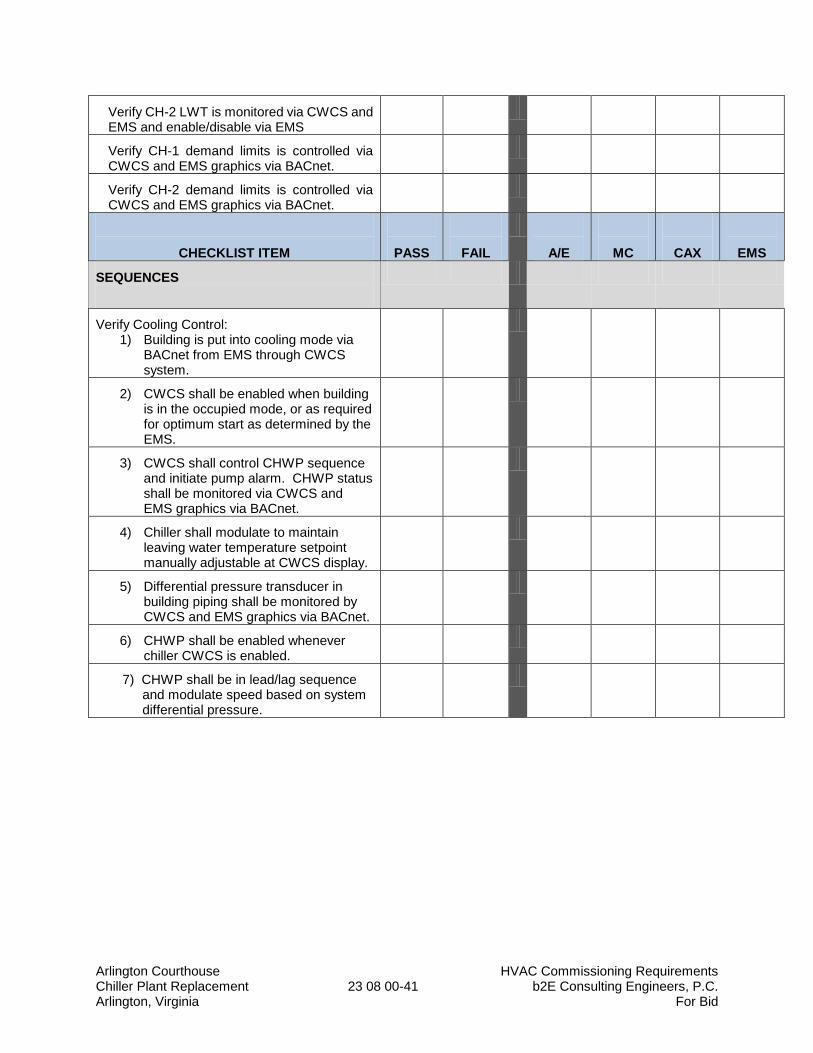
Arlington Courthouse HVAC Commissioning Requirements Chiller Plant Replacement 23 08 00-41 b2E Consulting Engineers, P.C. Arlington, Virginia For Bid
Verify CH-2 LWT is monitored via CWCS and EMS and enable/disable via EMS
Verify CH-1 demand limits is controlled via CWCS and EMS graphics via BACnet.
Verify CH-2 demand limits is controlled via CWCS and EMS graphics via BACnet.
CHECKLIST ITEM
PASS
FAIL
A/E
MC
CAX
EMS
SEQUENCES
Verify Cooling Control: 1) Building is put into cooling mode via
BACnet from EMS through CWCS system.
2) CWCS shall be enabled when building is in the occupied mode, or as required for optimum start as determined by the EMS.
3) CWCS shall control CHWP sequence and initiate pump alarm. CHWP status shall be monitored via CWCS and EMS graphics via BACnet.
4) Chiller shall modulate to maintain leaving water temperature setpoint manually adjustable at CWCS display.
5) Differential pressure transducer in building piping shall be monitored by CWCS and EMS graphics via BACnet.
6) CHWP shall be enabled whenever chiller CWCS is enabled.
7) CHWP shall be in lead/lag sequence and modulate speed based on system differential pressure.
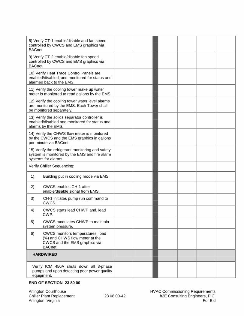
Arlington Courthouse HVAC Commissioning Requirements Chiller Plant Replacement 23 08 00-42 b2E Consulting Engineers, P.C. Arlington, Virginia For Bid
8) Verify CT-1 enable/disable and fan speed controlled by CWCS and EMS graphics via BACnet.
9) Verify CT-2 enable/disable fan speed controlled by CWCS and EMS graphics via BACnet.
10) Verify Heat Trace Control Panels are enabled/disabled, and monitored for status and alarmed back to the EMS.
11) Verify the cooling tower make up water meter is monitored to read gallons by the EMS.
12) Verify the cooling tower water level alarms are monitored by the EMS. Each Tower shall be monitored separately.
13) Verify the solids separator controller is enabled/disabled and monitored for status and alarms by the EMS.
14) Verify the CHWS flow meter is monitored by the CWCS and the EMS graphics in gallons per minute via BACnet.
15) Verify the refrigerant monitoring and safety system is monitored by the EMS and fire alarm systems for alarms.
Verify Chiller Sequencing:
1) Building put in cooling mode via EMS.
2) CWCS enables CH-1 after enable/disable signal from EMS.
3) CH-1 initiates pump run command to CWCS.
4) CWCS starts lead CHWP and, lead CWP.
5) CWCS modulates CHWP to maintain system pressure.
6) CWCS monitors temperatures, load (%) and CHWS flow meter at the CWCS and the EMS graphics via BACnet.
HARDWIRED
Verify ICM 450A shuts down all 3-phase pumps and upon detecting poor power quality equipment.
END OF SECTION 23 80 00
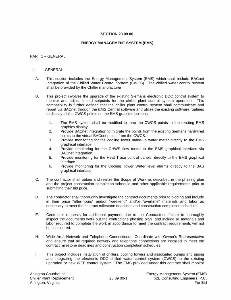
Arlington Courthouse Energy Management System (EMS) Chiller Plant Replacement 23 09 00-1 b2E Consulting Engineers, P.C. Arlington, Virginia For Bid
SECTION 23 09 00
ENERGY MANAGEMENT SYSTEM (EMS)
PART 1 – GENERAL
1.1. GENERAL
A. This section includes the Energy Management System (EMS) which shall include BACnet Integration of the Chilled Water Control System (CWCS). The chilled water control system shall be provided by the Chiller manufacturer.
B. This project involves the upgrade of the existing Siemans electronic DDC control system to monitor and adjust limited setpoints for the chiller plant control system operation. This compatibility is further defined that the chiller plant control system shall communicate and report via BACnet through the EMS Central software and utilize the existing software routines to display all the CWCS points on the EMS graphics screens.
1. The EMS system shall be modified to map the CWCS points to the existing EMS graphics display.
2. Provide BACnet integration to migrate the points from the existing Siemans hardwired points to the virtual BACnet points from the CWCS.
3. Provide monitoring for the cooling tower make-up water meter directly to the EMS graphical interface.
4. Provide monitoring for the CHWS flow meter to the EMS graphical interface via BACnet integration.
5. Provide monitoring for the Heat Trace control panels, directly to the EMS graphical interface.
6. Provide monitoring for the Cooling Tower Water level alarms directly to the BAS graphical interface.
C. The contractor shall obtain and realize the Scope of Work as described in the phasing plan and the project construction completion schedule and other applicable requirements prior to submitting their bid price.
D. The contractor shall thoroughly investigate the contract documents prior to bidding and include in their price “after-hours” and/or “weekend” and/or “overtime” materials and labor as necessary to meet the contract milestone deadlines and construction completion schedule.
E. Contractor requests for additional payment due to the Contractor’s failure to thoroughly inspect the documents work out the contractor’s phasing plan and include all materials and labor required to complete the work in accordance to meet the contract requirements will not be considered.
H. Wide Area Network and Telephone Connections: Coordinate with Owner’s Representative and ensure that all required network and telephone connections are installed to meet the contract milestone deadlines and construction completion schedules.
I. This project includes installation of chillers, cooling towers and associated pumps and piping and integrating the electronic DDC chilled water control system (CWCS) to the existing upgraded or new WEB control system. The EMS provided under this contract shall monitor
Arlington Courthouse Energy Management System (EMS) Chiller Plant Replacement 23 09 00-2 b2E Consulting Engineers, P.C. Arlington, Virginia For Bid
the chilled water control system (CWCS). The EMS shall graphically illustrate the chiller plant at the operator workstation and via a WEB control system.
J. Water-cooled chillers (CH-1 and 2): The EMS contractor shall integrate via BACnet the schematic flow control diagrams to monitor the sequences of operation as indicated in Section 23 64 16 of the construction documents. a. The EMS BACnet Integration contractor shall provide a network connection at the
controller to allow the EMS Technicians suitable access to connect lap-top computers within the chiller plant.
b. The chilled water system control manufacturer (same as chillers) shall provide a network connection at the chilled water control system (CWCS) to allow the technicians suitable access to connect lap-top computers within the chiller plant via the Arlington County WAN.
K. Thermometer wells and pressure sensors shall be provided and roughed-in by Div. 23. The appropriate contractor shall coordinate with other trades to ensure the rough-in is installed correctly for ease of maintenance and functional accuracy.
L. Emergency Power Circuits for remote monitoring: Provide the 120-volt branch circuits from the designated emergency panel to each DDC EMS control panel. Coordinate with Div-26 to obtain the exact location of each panel and associated component.
M. Equipment Emergency Power Circuits for Freeze Protection Systems: Coordinate with Div-26 to ensure they have all locations and emergency power connection requirements for freeze protection equipment including but not limited to the following: a. Heat Trace Control Panels for Cooling Tower Heat Trace Cables (CT-X) shall be
enabled/disabled, monitored for status and alarms by the EMS.
N. The cooling tower make up water meter shall be monitored by the EMS to read gallons used by the EMS graphics.
O. The cooling tower water level alarms shall be monitored by the EMS. Each cooling tower shall be monitored separately.
P. The solids separate controller shall be enabled/disabled and monitored for static and alarms by the EMS.
Q. The chilled water supply flow shall be monitored by the flow meter at the remote display unit on the EMS graphics via BACnet from the CWCS.
1.2 SUMMARY
A. This section includes control equipment for BACnet integration to HVAC Systems and components including, but not limited to, Water Cooled Chillers, Cooling Towers, Pumping Systems, temperature monitoring, pressure monitoring, equipment starters, etc.
1. The chillers shall be provided with factory installed and tested controls. The control sequence shall be uploaded by the manufacturer’s representative to optimize control for the chillers, cooling towers and pumps. Refer to Section 23 64 16, 2364 16-A & 23 64 16-B.
2. The system integration shall communicate with the chiller control panels via BACnet to monitor and control setpoints, schedules, and alarms from the Arlington County
Arlington Courthouse Energy Management System (EMS) Chiller Plant Replacement 23 09 00-3 b2E Consulting Engineers, P.C. Arlington, Virginia For Bid
Facilities Office via the Arlington County Wide Area Network (WAN) ethernet connection to the central EMS server which runs the graphics software.
B. At a minimum, the new control system shall integrate control of all points described in the sequence of operation, and control diagrams, plus those additional points necessary to satisfy the commissioning requirements indicated in Section 23 08 00.
C. The EMS system shall be engineered and equipment selected by the manufacturer as required to meet the performance specified herein. The location and quantity of EMS DDC panels shall be as determined by the EMS system manufacturer (Siemans). The EMS system component capacity shall be designed with 20% spare capacity in each controller to provide flexibility to add controls and sensors (i.e. digital inputs, digital outputs, analog inputs, analog outputs) as necessary during the systems demonstrations and commissioning phase of the project. All system Network Control Panels, including the data transmission system shall provide for the future addition of at least 20% of the number of input/output points designed for the system.
1.3 DEFINITIONS
AC (DES): Arlington County (Department of Environmental Services)
AFD: Adjustable Frequency Drive
AFD-X: Adjustable Frequency Drive Tag
AI: Analog Input to the EMS
AO: Analog Output from the EMS
ASC: Application Specific Controllers
ATC: Automatic Temperature Controls
BI: Digital or Binary Input to the EMS
BO: Digital or Binary Output from the EMS
CWCS: Chilled Water Control System (CWCS) – Stand-Alone DDC system by Chiller Manufacturer
CF: Cubic Feet
CH: Chiller
CH-X: Chiller Tag
CHWP: Chilled Water Pump
CT: Cooling Tower
CT-X: Cooling Tower Tag
CV: Constant Volume
Arlington Courthouse Energy Management System (EMS) Chiller Plant Replacement 23 09 00-4 b2E Consulting Engineers, P.C. Arlington, Virginia For Bid
DDC: Direct-digital Controls
DCW: Domestic Cold Water
E/D: Enable/Disable
EMS: Energy Management System (BACnet Integration and Controls)
EPO: Emergency Power-Off Switch
EWT: Entering Water Temperature
FT-X: Flow Transmitter Tag
HOA: Hand-Off-Auto Switch
HT-X: Heat Trace Controller Tag (Freeze Protection)
HVAC: Heating, Ventilation, and Air-Conditioning
HZ: Frequency
I/O: Input/output
LAN: Local Area Network
LWT: Leaving Water Temperature
MS/TP: Master-slave/token-passing
OAH: Outside Air Humidity
OAT: Outside Air Temperature
PB: Pushbutton Override
CHWP-X: Chilled Water Pump Tag
PI: Proportional Integral
PICS: Protocol Implementation Conformance Statement
PID: Proportional Integral Derivative
PT: Pressure Transducer
SNVT: Standard Network Variable Types
S/S: Start/Stop
T: Temperature Sensor
TCV: Temperature Control Valve
Arlington Courthouse Energy Management System (EMS) Chiller Plant Replacement 23 09 00-5 b2E Consulting Engineers, P.C. Arlington, Virginia For Bid
TOD: Time of day
TT-X: Temperature Transmitter (Tag)
V: Valve
V-X: Valve Tag
WAN: Wide Area Network
1.4 SYSTEM DESCRIPTION
A. General: The control system shall be as indicated on the drawings and described in the specifications.
B. Direct Digital Control (DDC) technology shall be used to provide the functions necessary for
control of mechanical systems on this project. C. The control system shall accommodate simultaneous multiple user operation. Access to the
control system data should be limited only by operator password. Multiple users shall have access to all valid system data. An authorized operator shall be able to log onto any workstation on the WAN, open the control system and have access to all appropriate data.
D. The control system shall be designed such that each mechanical system will be able to
operate under stand-alone control. As such, in the event of a network communication failure, or the loss of any other controller, the control system shall continue to independently operate under control.
E. Communication between the control panels and all workstations shall be over a high-speed
network. All nodes on this network shall be peers. The operator shall not have to know the panel identifier or location to view or control an object. Application Specific Controllers shall be constantly scanned by the network controllers to update point information and alarm information.
F. The documentation is schematic in nature. The Contractor shall provide hardware and
software necessary to implement the functions and sequences indicated.
G. Chilled Water System: Provide all hardware and software necessary to support a direct data communication between the EMS and the DDC chilled water system control (CWSC). The EMS system shall incorporate a BACnet protocol interface fully coordinated to communicate with a BACnet control panel by the chiller manufacturer which allows a bi-directional flow of monitoring and control point communication point between the CWSC and the EMS. 1. Provide all monitoring and control points indicated on the Schematic Flow Control
Diagrams (Drawings), in Section 23 09 93 “Sequence of Operation” and as required by Section 23 08 00 “Quality Control for the HVAC System” shall be provided for each chiller.
2. The EMS contractor shall coordinate and provide all points as necessary to accommodate the Chilled Water Control System and integration monitoring and control points via BACnet to the CWCS. Installation, start-up, programming, calibration, demonstration, pre-commissioning, and commissioning shall be provided by the EMS Contractor with help from the mechanical contractor, and chiller manufacturer’s factory authorized representative and other specialty contractors to affect a complete operational system.
Arlington Courthouse Energy Management System (EMS) Chiller Plant Replacement 23 09 00-6 b2E Consulting Engineers, P.C. Arlington, Virginia For Bid
H. The EMS contractor shall provide low voltage (less than 120 volt) power wiring and conduit required for the EMS. The EMS contractor is responsible to coordinate all line voltage (120 volt) EMS power requirements with the electrical contractor prior to submitting their bid price and ensure that electric panelboards are provided with an adequate quantity of additional circuit breakers. 1. All EMS control panels shall be powered from an emergency power panel.
I. The EMS contractor shall provide all the initial programming and any revisions to the software to integrate the sequence of operating for the chiller plant and accomplish the desired EMS sequence of operation, as required, or requested by the Engineer. This shall include any software revisions during any of the demonstration, pre-commissioning, commissioning, and the warranty periods that may be required by the Engineer.
J. Provide all modifications and updates to the Arlington County Facilities Office WAN server and operator workstations necessary to provide the operator interface desired by Arlington County.
K. Install, electrically wire, calibrate and check-out all controls associated with the installation of the EMS as required by the component manufacturer and as indicated in the Specifications.
1.5 RELATED WORK BY OTHER TRADES
A. The Division 26 Electrical Contractor shall provide the following information, coordination, and installation to accommodate the EMS system.
1. The Contractor shall ensure that the mechanical contractor, the EMS Contractor, and the electrical Contractor coordinate between trades and provide all power required to affect a complete operating system in accordance with all requirements in the construction documents.
2. Provide all required 120v AC power sources for EMS equipment in the building. This includes, but is not limited to equipment mounted in the thirteenth-floor physical chiller plant and in the cooling for enclosure on the roof. The power required is at least four (4) 20 amp, 120 v circuits in the physical plant, and four (4) 20 amp, 120v circuits in outdoor cooling tower enclosure. The electrical contractor shall coordinate with the EMS contractor to determine circuit distribution and location. a. Each heat trace circuit shall be monitored by the EMS via BACnet integration
from the Heat Trace Control Panel. The EMS shall monitor outdoor temperature, heat trace status, heat trace setpoint, actual piping temperature and failure alarm
3. All required 120v AC power sources for EMS equipment for monitoring and setpoint control of the chillers, cooling towers and pumps. Some EMS equipment may need to be mounted outdoors in a weatherproof enclosure as determined by the EMS Contractor. The electrical contractor is to coordinate with the EMS contractor to determine circuit distribution and location.
a. Power for the EMS controls may be provided using a control power transformer. The EMS contractor is responsible to ensure that each control transformer is sized to handle the VA load and each transformer is protected by line side fuses.
4. Control Power Transformer: Coordinate the locations of circuits enclosures, and
junctions’ boxes as required by the EMS contractor. Provide quantity and locations as required by the EMS.
Arlington Courthouse Energy Management System (EMS) Chiller Plant Replacement 23 09 00-7 b2E Consulting Engineers, P.C. Arlington, Virginia For Bid
1.6 OTHER WORK
A. Operators for all valves and dampers shall be electric type unless otherwise noted.
B. The work included under this Division shall include all drawings, submittals, equipment, labor, materials, technical supervision, transportation, training services, documentation, warranty, and other appurtenant work as required to furnish and install a fully operational system to monitor and control the facility set forth, in strict accordance with these specifications and subject to the terms and conditions of the Contract. Any apparatus, appliance, material or work not shown on the drawings but mentioned in specifications, or vice or versa, or any incidental accessories necessary to make the work complete in all respects and ready for operation, even if not particularly specified, shall be furnished, delivered, and installed by the EMS contractor without additional expense to the Owner.
1.7 GENERAL PRODUCT DESCRIPTION
A. The Energy Management System (EMS) shall integrate multiple building functions including equipment supervision, control, alarm management, energy management and historical data collection.
B. The EMS shall consist of the following:
1. Network manager and data management controller, integrated with building I/O controllers.
2. Stand-alone DDC Controllers. 3. Stand-alone Application Specific Controllers (ASC’s).
C. The system shall be modular in nature and shall permit expansion of both capacity and functionality through the addition of sensors, actuators, Programmable DDC Controllers, Application Specific Controllers, and operator devices.
D. System architectural design shall eliminate dependence upon any single device for alarm reporting and control execution. Each DDC and ASC Controller shall operate independently by performing its own specified control, alarm management, operator I/O and data collection. The failure of any single component or network connection shall not interrupt the execution of control strategies at other operational devices.
E. All EMS Controllers shall be able to access any data from, or send control commands and alarm reports directly to, any other EMS Controller or combination of controllers on the EMS network and through the ARLINGTON COUNTY WAN interface. EMS Controllers shall also be able to send alarm reports to multiple operator workstations without dependence upon a central processing device.
1.8 QUALITY ASSURANCE
A. System Installer Qualifications: An experienced installer who is an authorized representative and certified installer of the automatic control system manufacturer for both installation and maintenance of units required for this Project.
1. The Installer shall have an established working relationship with the EMS Control
System Manufacturer of not less than five (5) years.
Arlington Courthouse Energy Management System (EMS) Chiller Plant Replacement 23 09 00-8 b2E Consulting Engineers, P.C. Arlington, Virginia For Bid
B. The Installer shall have successfully completed Control System Manufacturer's classes on the control system. The Installer shall present for review the certification of completed training, including the hours of instruction and course outlines upon request.
C. The installer shall have an office within 100 miles of the project site and provide 24-hour response in the event of a customer call.
D. Single Source Responsibility: The EMS control system shall be completely installed and placed in operating condition by a firm specializing in this type of work. The firm shall provide a single source responsibility for all system components, engineering services, maintenance, and warranty. Qualifying conditions are more fully described in a separate paragraph.
1. The EMS contractor shall be qualified and thoroughly experienced in providing single sources responsibility for the Automatic Temperature Control System.
2. The EMS contractor shall be fully responsible for the complete design, installation, and proper operation of the system, including but not limited to: Data and control signal transmission systems, Energy Management System (EMS) control panels and interfacing of all system equipment, sensors and controls, memory units and peripheral devices.
3. After the installation, the EMS Contractor shall be responsible for the debugging and calibration of the system, including all software, and maintenance of the system functions in accordance with these specifications and successfully completes the final Operational Acceptance Test as witnessed by the Engineer. The EMS Contractor’s responsibilities shall also include all software and software maintenance during the warranty periods.
E. Manufacturer Qualifications: A firm experienced in manufacturing automatic temperature-control systems similar to those indicated for this Project and with a record of successful in-service performance.
F. Approved Controls Integration Manufacturers (No equals or substitutions):
1. Basis of Design: Siemens; Contact: Brian Nolan (301) 837-2600; ext. 2605. 2. Trane.
G. Approved Controls Integration Contractors (No equals or substitutions):
1. Basis of Design: Siemens: Infrastructure and Cities. 2. Trane.
H. Codes and Standards: Meet requirements of all applicable standards and codes, except when more detailed or stringent requirements are indicated by the Contract Documents, including requirements of this Section
1. Underwriters Laboratories: Products shall be UL-916-PAZX listed. 2. National Electrical Code – NFPA 90A. 3. Federal Communications Commission -- Part J. 4. ASHRAE/ANSI 135-2000 (BACnet). 5. EIA 901.2 Lonmark.
I. All products used in this installation shall be new, currently under manufacture, and shall be applied in similar installations for a minimum of 2 years.
Arlington Courthouse Energy Management System (EMS) Chiller Plant Replacement 23 09 00-9 b2E Consulting Engineers, P.C. Arlington, Virginia For Bid
J. Spare parts shall be available for at least 7 years after completion of this contract.
K. Electrical Components, Devices, and Accessories: Listed and labeled as defined in NFPA 70, Article 100, by a testing agency acceptable to authorities having jurisdiction, and marked for intended use.
L. Comply with NFPA 90A, "Installation of Air Conditioning and Ventilation Systems."
M. The Temperature Control System shall be designed by competent engineers, mechanics and technicians regularly employed by a specialty firm that is in the full-time business of designing and installing Energy Management System. This firm is to be an authorized representative of one of the approved control equipment manufacturers listed in the products section of this specification. Manufacturer’s documentation of the authorized is required.
N. A supervised installation of component installation and wire pulling is not acceptable. A supervised installation is defined as one at which the control elements, components, wiring and items of a similar nature are installed, under the direction of one authorized specialty firms, by a firm whose major activity is not the engineering and documentation of environmental controls. A firm whose primary activity is the installation of major mechanical equipment, ductwork or piping is not a specialty firm under the intent of this section of the specifications.
O. The EMS Contractor shall have a local office within a 100-mile radius of the job site. This office shall be staffed with factory trained engineers fully capable of readily training and instructing the Owner in the use of the installed system. This office shall maintain a spare parts inventory and all necessary test and diagnostic equipment for routine maintenance service on all systems components.
P. The EMS Contractor shall be prepared to respond with qualified service personnel at the project within twenty-four (24) hours from time of notification of any corrective action that may be required.
Q. Materials and equipment shall be the catalogued products of manufacturers regularly engaged in production and installation of automatic temperature control systems and shall be the manufacturer’s latest standard design that complies with the specification requirements.
R. All electronic equipment shall conform to the requirements of FCC Regulation, Part 15, Section 15, Governing Radio Frequency Electromagnetic Interference and be so labeled.
S. Design and build all system components to be fault-tolerant.
1. Satisfactory operation without damage at 110% and 85% of rated voltage and at ± 3 Hertz variation in line frequency.
2. Static, transient and line voltage short-circuit protection on all inputs and outputs. 3. Protect communication lines against incorrect wiring, static transient and induced
magnetic interference. 4. Network-connected devices to be A.C. coupled or equivalent so that any single device
failure will not disrupt or halt network communication. 5. All real-time clocks and data file RAM to be battery-backed for a minimum of 72-hours
and include local and system low battery indication. 6. It must be possible to receive and print out alarms at a central location even when the
workstation at that location in non-operational or taken out service for periodic maintenance.
Arlington Courthouse Energy Management System (EMS) Chiller Plant Replacement 23 09 00-10 b2E Consulting Engineers, P.C. Arlington, Virginia For Bid
1.9 TRENDING AND COMMISSIONING
A. Prior to the commissioning agent participating in on-site demonstrations of HVAC systems operations, the automation/temperature (EMS) contractor shall submit operating trends to the commissioning agent for review.
B. The Contractor shall have their software completely loaded and functional on site and remotely. Prior to submitting trends, the Contractor shall perform a self review to identify and correct problems. Trend submittals indicating that the contractor has not performed their own reviews will be rejected and returned to the contractor. Trends shall be presented at hourly intervals for a minimum 24-hour period, unless directed otherwise (24 samples per point at 60-minute intervals). Systems being monitored shall be operated with an occupancy schedule; i.e. indications that a system was scheduled off for the 24 hours of the trend and remained off are of no value.
C. All system schedules and setpoints (both calculated and manual inputs) shall be provided with the trends.
D. One Summer seasonal submission of trends shall be presented: One submission during the cooling season. Cooling season trends shall be submitted for a day where outdoor air temperatures have exceeded 90 deg. F for at least one hour of the trended period
E. Trends shall be organized such that all points pertinent to a particular system are shown on one or two trend pages; i.e. points for a chiller unit should be on one or sequential pages, not spread throughout the trend package.
F. The initial review of submitted trends by the commissioning agent normally results in requiring corrections to be performed by the contractor. The commissioning agent will provide written review comments, and the contractor shall respond to all deficiencies noted and re-submit new trends to demonstrate proper operations. Deficiencies may require corrective action of any trade and may not be solely the responsibility of the controls contractor. Predicated upon the extent of deficiencies, either complete building trends or system specific trends may be required for re-submittal. Contractor shall allocate for two (2) complete sets of trends for each season of operation. Should trends not demonstrate acceptable systems operation after two attempts, the Owner/Engineer may back-charge the contractor for the cost of the time expended by the commissioning agent to review additional trends.
G. Once suitable operations are demonstrated via automation system trends, the commissioning agent will schedule on-site demonstrations.
1.10 SUBMITTALS
A. Product Data: Include manufacturer's technical literature for each control device. Indicate dimensions, capacities, performance characteristics, electrical characteristics, finishes for materials, and installation and startup instructions for each type of product indicated.
1. Operator Work Station and Servers. 2. Network Manager. 3. All Input/output modules. 4. All communication/interconnecting cables for use between controllers. 5. Local programming, monitoring, and printing capabilities.
Arlington Courthouse Energy Management System (EMS) Chiller Plant Replacement 23 09 00-11 b2E Consulting Engineers, P.C. Arlington, Virginia For Bid
6. All miscellaneous Sensors (Water meters, flow, etc.). 7. Labels – Provide sample of each type. 8. Warning Labels (Caution Equipment is EMS controlled…..). 9. All other required equipment and accessories.
B. Shop Drawings: Detail equipment assemblies and indicate dimensions, weights, loads, required clearances, method of field assembly, components, and location and size of each field connection. 1. All data communication wiring, data ports and modem/telephone locations are to be
identified on the floor plan drawings. The location of the local workstation shall be identified.
2. All EMS contractor built enclosures shall be documented with an approximate scale component layout drawing showing internal component relative locations and labeling. Once reviewed by the Engineer these enclosures are to be built to conform to the submitted drawings.
3. Provide shop drawings, in a point-to-point format, for all wiring terminating on a EMS controller. All wiring within EMS contractor built enclosures shall be depicted as ladder type.
4. Provide complete manufacturers schematic wiring diagrams of all pieces of mechanical equipment being interfaced to the EMS system. These drawings are to be modified to show all field terminations and interfaces. Clearly delineate between factory wiring and field wiring.
5. Provide layout diagrams of mechanical equipment showing where EMS interface wiring is to be landed. Show OEM internal component layout and terminal strip locations for all mechanical equipment.
6. EMS contractor shall indicate all wire sizes on all the shop drawings. All wiring shall be sized per NEC requirements or per minimum wire sizes noted in this specification. Wire size calculations shall be submitted upon request.
7. The EMS contractor shall indicate on the shop drawings, all identifiable codes of all relays along with the point they control. Identification of points controlled shall utilize the present nomenclature used by the Engineer and be approved by the Engineer.
8. All wiring diagrams shall indicate all wire and terminal numbers/letters as will be used during the installation. If none presently exist, EMS Contractor shall develop and install terminal numbers/letters and wiring numbers/letters. All relays, switches, disconnect switches, etc., shall be identified on the drawings with a nomenclature approved by the Engineer.
9. For all mechanical equipment including motor starters indicate all required electrical wiring. Clearly differentiate between portions of wiring that are factory-installed and/or existing and portions to be field-installed.
10. Provide details of faces of control enclosures where switches or displays are to be installed, including controls, instruments, and labeling.
11. Inside each remote EMS enclosure, the EMS Contractor shall provide laminated control diagrams of each piece of equipment controlled from the EMS controller. All of these laminated drawings shall be “Half Sized” of the EMS Contractors submitted drawings or a minimum of 11”x17” whichever is larger.
12. Wiring Diagrams: Power, signal, and control wiring. Differentiate between manufacturer-installed and field-installed wiring.
13. Details of control panel faces, including controls, instruments, and labeling. 15. Listing of connected data points, including connected control unit and input device. 16. Existing system graphics to be modified indicating monitored systems, data (connected
and calculated) point addresses, and operator notations. 17. System configuration showing peripheral devices, batteries, power supplies, diagrams,
modems, and interconnections.
C. Programming
Arlington Courthouse Energy Management System (EMS) Chiller Plant Replacement 23 09 00-12 b2E Consulting Engineers, P.C. Arlington, Virginia For Bid
1. Existing Software Documentation: Shall mean that all programs shall be easily referenced from flow diagrams and English text summary sheets that compare control programs with pertinent information about hardware and wiring information in the field. Documentation required shall include:
a. Complete point identification, including terminal number, symbol, engineering units and control program reference number and nomenclature.
b. Field information including location, device, device type and function, electrical parameters, and installation drawing number.
c. Location identification of EMS control hardware. d. Complete and finalized logical flow diagram of each system program which shall
be complete in details to enable tracing all stages and sequence of controls.
2. Existing Software Storage: Upon successful completion of the operational acceptance test, the EMS Contractor shall provide a medium, and hardware for bulk storage of the accepted versions of the software. In addition, the EMS Contractor shall supply the programs, summary sheets, and flow diagrams of the systems as accepted indicating all changes and modifications to the programs as required to obtain the finalized accepted control sequences and operation.
a. This shall not relieve the EMS Contractor from providing software changes throughout the installation years and warranty periods as required by the Engineer and subsequently supplying the specified revised backup to the Owner.
3. Modification of Existing As-Built Drawings
a. Final acceptance shall be contingent of Engineer’s receipt and acceptance of six (6) complete sets of prints of final approved record drawings “As-Built”. The quality of the drawings shall be acceptable to the Engineer.
b. Complete AutoCAD “As-Built” drawings of the system including a complete listing of all components and parts utilize including manufacturer, model number and distributor are to be turned over to the Engineer on diskette.
4. Any system revision and/or additions provided for or required under this contract shall be included in this documentation in the form of updated documents.
5. The requirements for tools shall also apply to all keys for all locks utilized on the project. 6. Should the Engineer or Architect request sets of keys to the EMS, the contractor shall
furnish all required sets of keys to the Engineer. The EMS Contractor shall keep written receipts for these keys and shall include the receipts at such a time as the remaining sets of keys are turned over to the Engineer.
7. All keys turned over to Engineer shall be stamped with a four-digit alphanumeric code to indicate the purpose of the key. Codes shall be submitted and approved by the Engineer prior to stamping keys. These codes shall be included as part of the Operations & Maintenance Manuals.
D. ASHRAE BACnet Statement: PIC statements shall be provided for each DDC system component (panel zone controller, field devices and operator workstation, etc.) proposed.
E. Field Test Reports: Indicate and interpret test results for compliance with performance requirements.
1.11 DELIVERY, STORAGE, AND HANDLING
Arlington Courthouse Energy Management System (EMS) Chiller Plant Replacement 23 09 00-13 b2E Consulting Engineers, P.C. Arlington, Virginia For Bid
A. Factory-Mounted Components: Where control devices specified in this Section are indicated to be factory mounted on equipment, arrange for shipping of control devices to unit manufacturer.
1.12 COORDINATION
A. Coordinate communication requirements of this EMS contractor with that of the chilled water system control (CWCS) equipment specified with open standard protocols.
1.13 ACCEPTANCE AND GUARANTEE
A. The system herein specified shall be free from defects in workmanship and material under normal use and service, including all materials and labor. If within 24 months (2 years) from the date of Substantial Completion issued by the Engineer, any of the equipment or software herein described is found defective or not in conformance with these specifications or any item is determined to have been damaged due to the work in this contract the problem(s) shall be repaired and/or replaced by EMS Contractor at no cost to the Owner. As long as the EMS Contractor has been notified of a problem(s) during the guarantee period, the EMS Contractor is responsible to correct the problem(s) to the satisfaction of the Owner/Engineer even after the guarantee period ends all at no additional cost to the Owner.
B. When interfacing with controls and equipment or products supplied by others, the EMS Contractor shall document any deficiencies found in this equipment that would compromise the intended operation of this system.
C. EMS Contractor shall submit a quotation to repair or replace the documented deficiencies.
D. After the Engineer agrees all requirements of these specifications and contract documents are complete, the EMS Contractor shall request, in writing, a final inspection of the system by the Engineer through the Contractor via certified mail.
E. The EMS Contractor shall provide knowledgeable and qualified personnel to assist the Engineer during the inspection for a time period as solely determined by the Engineer. All deficiencies or omissions found shall be repaired or replaced by the EMS Contractor including any damage caused by the EMS Contractor or his employees directly attributable to the installation of the scope of work. After all deficiencies are repaired, reprogrammed, and/or replaced, the EMS Contractor shall request in writing a second inspection via certified mail to the Construction Manager. The EMS Contractor shall again provide qualified and knowledgeable personnel to assist in the second inspection.
F. In the event the EMS Contractor has not corrected all of the deficiencies noted from the first (or previous) inspection(s) and check out(s), the EMS Contractor shall reimburse the Architect by means of reduction of the contract amount owed the EMS Contractor by the Owner for all costs related to the Engineer and/or his authorized representatives making the inspections which have been requested by the Engineer.
G. Just prior to the end of the guarantee period, the EMS Contractor shall provide qualified and knowledgeable personnel to work with the Engineer to re-inspect the system and programs for conformance to all the contract documents.
1.14 ENGINEERS RIGHTS RESERVED
Arlington Courthouse Energy Management System (EMS) Chiller Plant Replacement 23 09 00-14 b2E Consulting Engineers, P.C. Arlington, Virginia For Bid
A. The EMS Contractor shall not utilize the name of the project, Engineer, or any Principal or employee of the above reference, in any promotional materials or for any purpose other than the completion of work under this contract without the prior written consent of an authorized representative. Subcontractors and material suppliers shall also be prohibited from the use of said names.
PART 2 – PRODUCTS
2.1. ACCEPTABLE MANUFACTURERS
A. The Contractor shall only use the approved EMS controls manufacturer and approved controls EMS BACnet Integration contractor listed as shown in Part 1.8 F and 1.8 G of this Section.
2.2 EXISTING OPERATOR INTERFACE
A. Existing Operator Interface. The Siemans EMS is existing to remain with the existing graphics for the chilled water system to be updated using BACnet software points provided by the CWCS manufacturers.
B. Existing Scheduling
1. The existing EMS scheduling functions shall remain.
2.3 DDC CONTROL CABINETS
A. A control enclosure shall be Hoffman two-door wall or floor-mount, piano hinged, UL listed, lockable and keyed alike. Enclosure classification for interior panels shall be NEMA-1 or 12, 508 Type 1/12, unless otherwise required by Code or other authorities. Enclosure mounted outside of the building or in a location where weather may be a factor shall a NEMA-4X, UL 508 Type 4X, classification with cover mounted captive, plated steel screws and an integral hasp/staple or padlocking unless noted otherwise.
B. The control cabinets shall be UL #E 130598, or approved equal. Cabinets shall have the following features:
1. Removable door. 2. Furnished with a key lock. 3. 20x4 character LCD display and keypad 4. NEMA 1 (indoor) or NEMA 4 X (outdoor) rating as required for installation.
2.4 CONTROL TRANSFORMERS
A. Provide Transformers: UL listed commercial machine tool heavy-duty type by HEVI-Duty Electric or approved equal.
1. Multi-tap primary connections for 120VAC, 208VAC, 240VAC, and 480VAC. 2. 24VAC secondary voltage output. 3. 100VA rating for DDC controller power 4. 40VA rating for field device power 5. Manual, resettable, current-limiting secondary circuit breaker.
Arlington Courthouse Energy Management System (EMS) Chiller Plant Replacement 23 09 00-15 b2E Consulting Engineers, P.C. Arlington, Virginia For Bid
6. Foot mount provisions. 7. UL # E3210 8. Insulation class– 356 degrees F. 9. Temperature rise– 144 degrees F.
2.5 FUSED DISCONNECTS
A. All power sources entering an interface enclosure or feeding each EMS controller shall be fused. Fuses shall be installed in a housing allowing a safe and easy method to disconnect the power source from each controller or group of output control points. Fuse amp ratings shall be selected to protect the EMS components, fuse size shall fit the specified fuse holder. Fuse holders are to provide a safe “finger pull” means of circuit disconnect. All fuse holders shall be Gould-Shawmut USCC or USM ULTRASAFE™ modular units with the integral fuse indicator status light. Fuse holders shall be single or multiple pole as needed to accommodate the application.
2.6 MISCELLANEOUS COMPONENTS
A. All miscellaneous electrical components (switches, transformers, fuses, fuse blocks, pilot lights and sockets, etc.), shall be of a quality commercial grade and shall be manufactured by Honeywell, Cutler Hammer, Square “D”, Potter-Brumfield, All Bradley or other approved equal.
2.7 DIRECT EMS CONTROLS
A. The following equipment shall be monitored and controlled directly by the EMS.
1. Existing building systems shall remain. 2. CWCS enable/disable and monitoring at the EMS graphics via BACnet. 3. Heat Trace Control Panels enable/disable and monitoring status and alarms (Typ. of
2). 4. Cooling Tower make up water meter consumption in gallons of the EMS graphics 5. Cooling Tower Water Level Alarms (Typ. of 2). 6. Solids Separator enable/disable and monitoring status and alarms (Typ. of 2). 7. Chilled water supply flow meter monitoring in gallons per minute on the EMS
graphics.
PART 3 - EXECUTION
3.1 GENERAL
A. Where control devices are installed on insulated piping or ductwork, provide standoff brackets or thermowells sized to clear insulation thickness. Provide extended sensing elements, actuator linkages, and other accessories as required.
B. Caution: This facility has very high spaces. Running conduit concealed thru these spaces can exceed the typical length for network communication cable. Routing conduit underground is possible using UL wet-listed cables if carefully coordinated with underground structure and equipment or thru technical spaces when carefully coordinated with other trades work.
Arlington Courthouse Energy Management System (EMS) Chiller Plant Replacement 23 09 00-16 b2E Consulting Engineers, P.C. Arlington, Virginia For Bid
3.2 PANELS
A. Wiring connecting to apparatus on the front panel shall be concealed behind the front panel.
1. Wire electric switches and controls in the control panel to a terminal block. Line voltage and low voltage shall be separated on different terminal blocks with labels indicating voltage. Each electrical device shall be wired back to the terminal block in the control panel. Devices in series shall be individually terminated at the terminal block, such that each side of each device is available at the control panel for troubleshooting. In addition to the number markings on each wire, wire color shall be the same throughout each wire run. Wiring shall be neatly tied and routed in the control panel. Shielded wiring shall be terminated neatly, with heat shrink tubing placed over the bare end of the shield. Ground conductors over 4" long shall be insulated with tubing.
3.3 WIRING
A. Low voltage EMS control wiring only (24VAC or below):
B. Provide metal raceway for the following application:
1. Unfinished exposed spaces: EMT. 2. Concealed inaccessible space: EMT in walls, EMT above ceilings. 3. Finished Space: Concealed in wall construction flush mounted, EMT with outlet box
aligned with light switches.
C. Line voltage wiring shall be not less than #12 AWG, 600V insulation. The EMS contractor is responsible to power all control equipment provided by Section 23 09 00.
D. Materials and installation of wiring and electrical devices shall be in accordance with NFPA 70-1996, and Division 26.
E. Control and sensor wiring shall be installed in conduits separate from power wiring.
F. Low voltage control and sensor wiring shall be continuous without splicing.
G. Provide all low voltage to control voltage tap connectors with fusing or circuit breakers on primary and secondary line side of control power transformer (CPT). Integral circuit breakers on load side are acceptable. EMS contractor is responsible to size all CPT for the actual VA loads required.
3.10 EXAMINATION
A. Pneumatic controls for the new chilled water system shall be upgraded to electronic motor operated danger actuators and value operations.
B. If accidently or intentionally disconnected verify that existing wiring and pneumatic piping for existing control devices to remain are re-connected before proceeding with installation.
3.11 INSTALLATION
A. Install equipment level and plumb.
B. Connect and configure equipment and software to achieve BACnet Integration as specified.
Arlington Courthouse Energy Management System (EMS) Chiller Plant Replacement 23 09 00-17 b2E Consulting Engineers, P.C. Arlington, Virginia For Bid
C. Install labels and nameplates to identify control components according to Division 23 Section "Basic Mechanical Materials and Methods."
3.12 ELECTRICAL WIRING AND CONNECTION INSTALLATION
A. Install raceways, boxes, and cabinets according to Division 26 Section "Raceways and Boxes."
B. Install building wire and cable according to Division 26 Section "Conductors and Cables."
C. Install signal and communication cable according to Division 26 Sections.
3.13 CONNECTIONS
A. Ground equipment.
1. Tighten electrical connectors and terminals according to manufacturer's published torque-tightening values. If manufacturer's torque values are not indicated, use those specified in UL 486A and UL 486B.
3.14 FIELD QUALITY CONTROL
A. Manufacturer's Field Service: Engage a factory-authorized service representative to inspect BACnet Integration to ensure hardware and software points have been programmed to show up on graphical interface in easy to use format.
B. Replace damaged or malfunctioning controls and equipment.
C. Verify DDC as follows:
1. Verify software including BACnet Integration is complete.
3.15 DEMONSTRATION
A. Engage a factory-authorized service representative to train Owner’s maintenance personnel to renew chiller plant graphics.
1. Demonstrate to Owner that BACnet software points have been properly integrated to show-up properly on the existing graphical interface.
2. Modify graphics as needed to include points that were added by the CWCS Contractor.
3.16 ON-SITE ASSISTANCE
A. Occupancy Adjustments: Within one year of date of Substantial Completion, provide site visits, when requested by Engineer, to adjust graphical interface to suit the users needs.
END OF SECTION 23 09 00
Arlington Courthouse Hydronic Piping Chiller Plant Replacement 23 21 13-1 b2E Consulting Engineers, P.C. Arlington, Virginia For Bid
SECTION 23 21 13
HYDRONIC PIPING
PART 1 - GENERAL
1.1 SUMMARY
A. This Section includes pipe and fitting materials, joining methods, special-duty valves, and specialties for the following: 1. Chilled and Condenser-water piping. 2. Domestic and Non-Potable Makeup-water piping. 3. Blowdown-drain piping. 4. Air-vent piping. 5. Safety-valve-inlet and -outlet piping.
B. Plastic Piping (not allowed), except temporary piping may be Schedule 80 PVC as required by the Phasing Plan to make temporary piping connections. 1. No plastic piping shall remain after substantial completion of this contract.
C. Some of the existing chiller plant has high bay ceilings with spray on fireproofing. Do not damage existing fireproofing. Refer to structural for locations of floor mounted pipe supports in the area.
1.2 SYSTEM DEMONSTRATION
A. The project includes, but is not limited to, installation of condenser water and chilled water cooling systems. The chilled water system shall have a variable primary pumping arrangement.
B. Make-up Water Assembly: The domestic water backflow preventers for the service make-up water piping assembly protects the potable water supply. The make-up water assemblies supplies water to the chilled water closed loop and open condenser water loop. 1. A make-up water piping assembly shall be provided for the closed-loop chilled water
system. 2. An electronic water level controller and a make-up water assembly shall be provided for
the cooling towers. The open loop condenser water make-up assembly shall have electric solenoid valves for each cooling tower for auto fill and a meter for water savings.
a. The cooling towers shall also have mechanical float type piping connection at the cooling tower float value for back up fill in case the electronic system fails.
C. Chilled Water Pumps. The primary pump arrangement shall use two pumps, CHWP-1 and CHWP-2. The pumps are manifolded together and flow shall be controlled to each chiller using 2-way, 2-position automated motor operated isolation valves. Variable speed chilled water pumps shall be provided with adjustable frequency drives and shall be arranged as lead/lag. The chilled water system controls shall alternate the lead and lag pumps to maintain equal run times. The pump AFD shall automatically modulate to maintain chilled water system piping differential pressure setpoint on the lowest level of the building and not drop below the minimum chiller waterflow rate (40% of design value).
Arlington Courthouse Hydronic Piping Chiller Plant Replacement 23 21 13-2 b2E Consulting Engineers, P.C. Arlington, Virginia For Bid
D. Each chiller and cooling tower circuit shall be provided with unit isolation valves at all CW and CHW piping connections. The valves shall be provided with min. 1/2-inch manual vent (on top) drain ball valves (on bottom) with hose connection cap and chain on both sides of the isolation valves. Each mechanical unit shall be able to completely drain for service while keeping the remaining mechanical units fully operational.
E. The main mechanical room shall be provided with manual plant isolation valves. Provide valves for the following systems:
1. Chilled water supply and return isolation valves (Typ. of 4).
F. The mechanical equipment shall be provided with automatic isolation valves.
1. Chilled water supply and return at each chiller(Typ. of 4). 2. Condenser water supply, return and equalizer at each cooling tower(Typ. of 5). 3. Condenser water supply and return at each chiller (typ. of 4). 4. Condenser water 3-way bypass valve in CW return piping (typ. of 1).
1.3 PERFORMANCE REQUIREMENTS
A. Hydronic piping components and installation shall be capable of withstanding the following minimum working pressure and temperature: 1. Chilled-Water Piping: 125 psig at 200 deg F. 2. Makeup-Water Piping: 80 psig at 150 deg F. 3. Cooling Tower Blowdown-Drain Piping: 125 psi at 100 deg F. 4. Air-Vent Piping: 125 psi at 100 deg F. 5. Safety-Valve-Inlet and Outlet Piping: Equal to the pressure of the piping system to which
it is attached, but not less than 125 psi at 100 deg F.
1.4 SUBMITTALS
A. Product Data: For each type of the following:
1. Pressure-seal fittings. 2. Valves. Include flow and pressure drop curves based on manufacturer's testing for
calibrated-orifice balancing valves and automatic flow-control valves. 3. Air control devices. 4. Chemical treatment. 5. Hydronic specialties.
C. Shop Drawings: Detail, at 1/4 (1:50) scale, the piping layout, fabrication of pipe anchors, hangers, supports for multiple pipes, alignment guides, expansion joints and loops, and attachments of the same to the building structure. Detail location of anchors, alignment guides, and expansion joints and loops.
D. Welding certificates.
E. Qualification Data: For Installer.
F. Field quality-control test reports.
Arlington Courthouse Hydronic Piping Chiller Plant Replacement 23 21 13-3 b2E Consulting Engineers, P.C. Arlington, Virginia For Bid
G. Operation and Maintenance Data: For air control devices, hydronic specialties, and special-duty valves to include in emergency, operation, and maintenance manuals.
H. Water Analysis: Submit a copy of the water analysis to illustrate water quality available at Project site.
1.5 QUALITY ASSURANCE
A. Steel Support Welding: Qualify processes and operators according to AWS D1.1/D1.1M, "Structural Welding Code - Steel."
B. Welding: Qualify processes and operators according to ASME Boiler and Pressure Vessel Code: Section IX.
1. Comply with provisions in ASME B31 Series, "Code for Pressure Piping." 2. Certify that each welder has passed AWS qualification tests for welding processes
involved and that certification is current.
C. ASME Compliance: Comply with ASME B31.9, "Building Services Piping," for materials, products, and installation. Safety valves and pressure vessels shall bear the appropriate ASME label. Fabricate and stamp air separators and expansion tanks to comply with ASME Boiler and Pressure Vessel Code: Section VIII, Division 01.
1.6 EXTRA MATERIALS
A. Water-Treatment Chemicals: Furnish enough chemicals for initial system startup and for preventive maintenance for one year from date of Substantial Completion.
B. Differential Pressure Meter: For each type of balancing valve and automatic flow control valve, include flowmeter, probes, hoses, flow charts, and carrying case.
C. Manual Air Vents: Provide 10 extra.
D. Automatic Air Vents: Provide 10 extra.
E. Strainer Screens, Stainless Steel: Provide one (1) extra for each strainer.
F. Pressure Relief Valves: Provide two (2) extra (100psi).
G. 1-Inch Brass Plugs: Provide twenty (20) extra.
PART 2 - PRODUCTS
2.1 MANUFACTURERS
A. Acceptable Manufacturers: Subject to compliance with requirements, provide products by one of the following:
1. Calibrated Balancing Valves:
Arlington Courthouse Hydronic Piping Chiller Plant Replacement 23 21 13-4 b2E Consulting Engineers, P.C. Arlington, Virginia For Bid
a. Armstrong Pumps, Inc. b. Flow Design, Inc. c. Gerand Engineering Company. d. Griswold Controls. e. ITT Bell & Gossett; ITT Fluid Technology Corp. f. Taco, Inc. g. Vitaulic.
2. Pressure-Reducing Valves:
a. Amtrol, Inc. b. Armstrong Pumps, Inc. c. Conbraco Industries, Inc. d. ITT Bell & Gossett; ITT Fluid Technology Corp. e. Spence Engineering Company, Inc. f. Watts Industries, Inc.; Watts Regulators.
3. Safety Valves:
a. Amtrol, Inc. b. Armstrong Pumps, Inc. c. Conbraco Industries, Inc. d. ITT McDonnell & Miller Div.; ITT Fluid Technology Corp. e. Kunkle Valve Division. f. Spence Engineering Company, Inc.
4. Expansion Tanks:
a. Amtrol, Inc. b. Armstrong Pumps, Inc. c. ITT Bell & Gossett; ITT Fluid Technology Corp. d. Taco, Inc.
5. Air Separators and Air Purgers:
a. Amtrol, Inc. b. Armstrong Pumps, Inc. c. ITT Bell & Gossett; ITT Fluid Technology Corp. d. Taco, Inc.
2.2 COPPER TUBE AND FITTINGS
A. Drawn-Temper Copper Tubing: ASTM B 88, Type L (ASTM B 88M, Type B); or ASTM B 88, Type M (ASTM B 88M, Type C).
B. Annealed-Temper Copper Tubing: ASTM B 88, Type K (ASTM B 88M, Type A).
C. DWV Copper Tubing: ASTM B 306, Type DWV.
D. Wrought-Copper Fittings: ASME B16.22.
E. Wrought-Copper Unions: ASME B16.22.
Arlington Courthouse Hydronic Piping Chiller Plant Replacement 23 21 13-5 b2E Consulting Engineers, P.C. Arlington, Virginia For Bid
2.3 STEEL PIPE AND FITTINGS
A. Steel Pipe: ASTM A 53/A 53M, black steel with plain ends; type, grade, and wall thickness as indicated in Part 3 "Piping Applications" Article.
B. Malleable-Iron Threaded Fittings: ASME B16.3, Classes 150 and 300 as indicated in Part 3 "Piping Applications" Article.
C. Malleable-Iron Unions: ASME B16.39; Classes 150, 250, and 300 as indicated in Part 3 "Piping Applications" Article.
D. Cast-Iron Pipe Flanges and Flanged Fittings: ASME B16.1, Classes 25, 125, and 250; raised ground face, and bolt holes spot faced as indicated in Part 3 "Piping Applications" Article.
E. Wrought-Steel Fittings: ASTM A 234/A 234M, wall thickness to match adjoining pipe.
F. Wrought Cast- and Forged-Steel Flanges and Flanged Fittings: ASME B16.5, including bolts, nuts, and gaskets of the following material group, end connections, and facings:
1. Material Group: 1.1. 2. End Connections: Butt welding. 3. Facings: Raised face.
G. Steel Pipe Nipples: ASTM A 733, made of same materials and wall thicknesses as pipe in which they are installed.
2.4 JOINING MATERIALS
A. Pipe-Flange Gasket Materials: Suitable for chemical and thermal conditions of piping system contents.
1. ASME B16.21, nonmetallic, flat, asbestos free, 1/8-inch maximum thickness unless thickness or specific material is indicated.
a. Full-Face Type: For flat-face, Class 125, cast-iron and cast-bronze flanges. b. Narrow-Face Type: For raised-face, Class 250, cast-iron and steel flanges.
B. Flange Bolts and Nuts: ASME B18.2.1, carbon steel, unless otherwise indicated.
C. Plastic, Pipe-Flange Gasket, Bolts, and Nuts: Type and material recommended by piping system manufacturer, unless otherwise indicated.
D. Solder Filler Metals: ASTM B 32, lead-free alloys. Include water-flushable flux according to ASTM B 813.
E. Brazing Filler Metals: AWS A5.8, BCuP Series, copper-phosphorus alloys for joining copper with copper; or BAg-1, silver alloy for joining copper with bronze or steel.
F. Welding Filler Metals: Comply with AWS D10.12/D10.12M for welding materials appropriate for wall thickness and chemical analysis of steel pipe being welded.
G. Gasket Materials Thickness, material, and type suitable for fluid to be handled and working temperatures and pressures.
Arlington Courthouse Hydronic Piping Chiller Plant Replacement 23 21 13-6 b2E Consulting Engineers, P.C. Arlington, Virginia For Bid
2.5 DIELECTRIC FITTINGS
A. Description: Combination fitting of copper-alloy and ferrous materials with threaded, solder-joint, plain, or weld-neck end connections that match piping system materials.
B. Insulating Material: Suitable for system fluid, pressure, and temperature.
C. Dielectric Unions: 1. Acceptable Manufacturers: Subject to compliance with requirements, provide products
by one of the following:
a. Capitol Manufacturing Company. b. Central Plastics Company. c. Hart Industries International, Inc. d. Watts Regulator Co.; a division of Watts Water Technologies, Inc. e. Zurn Plumbing Products Group; AquaSpec Commercial Products Division.
2. Factory-fabricated union assembly, for 250-psig minimum working pressure at 180 deg F.
D. Dielectric Flanges: 1. Manufacturers: Subject to compliance with requirements, provide products by one of the
following:
a. Capitol Manufacturing Company. b. Central Plastics Company. c. Watts Regulator Co.; a division of Watts Water Technologies, Inc.
2. Factory-fabricated companion-flange assembly, for 150- or 300-psig minimum working pressure as required to suit system pressures.
E. Dielectric-Flange Kits: 1. Acceptable Manufacturers: Subject to compliance with requirements, provide products
by one of the following:
a. Advance Products & Systems, Inc. b. Calpico, Inc. c. Central Plastics Company. d. Pipeline Seal and Insulator, Inc.
2. Companion-flange assembly for field assembly. Include flanges, full-face- or ring-type neoprene or phenolic gasket, phenolic or polyethylene bolt sleeves, phenolic washers, and steel backing washers.
3. Separate companion flanges and steel bolts and nuts shall have 150- or 300-psig minimum working pressure where required to suit system pressures.
F. Dielectric Couplings: 1. Acceptable Manufacturers: Subject to compliance with requirements, provide products
by one of the following:
a. Calpico, Inc. b. Lochinvar Corporation.
2. Galvanized-steel coupling with inert and noncorrosive thermoplastic lining; threaded ends; and 300-psig minimum working pressure at 225 deg F.
Arlington Courthouse Hydronic Piping Chiller Plant Replacement 23 21 13-7 b2E Consulting Engineers, P.C. Arlington, Virginia For Bid
G. Dielectric Nipples: 1. Acceptable Manufacturers: Subject to compliance with requirements, provide products
by one of the following:
a. Perfection Corporation; a subsidiary of American Meter Company. b. Precision Plumbing Products, Inc. c. Sioux Chief Manufacturing Company, Inc. d. Victaulic Company of America.
2. Electroplated steel nipple with inert and noncorrosive, thermoplastic lining; plain, threaded, or grooved ends; and 300-psig minimum working pressure at 225 deg F.
2.6 VALVES
A. Gate, Globe, Check, and Ball: Comply with requirements specified in Division 23 Section "General-Duty Valves for HVAC Piping."
B. Automatic Temperature-Control Valves, Actuators, and Sensors: Comply with requirements specified in Division 23 Section "Energy Management Systems (EMS)”.
C. Bronze, Calibrated-Orifice, Balancing Valves: 1. Acceptable Manufacturers: Subject to compliance with requirements, provide products
by one of the following:
a. Armstrong Pumps, Inc. b. Bell & Gossett Domestic Pump; a division of ITT Industries. c. Flow Design Inc. d. Gerand Engineering Co. e. Griswold Controls. f. Taco.
2. Body: Bronze, ball or plug type with calibrated orifice or venturi. 3. Ball: Brass or stainless steel. 4. Plug: Resin. 5. Seat: PTFE. 6. End Connections: Threaded or socket. 7. Pressure Gage Connections: Integral seals for portable differential pressure meter. 8. Handle Style: Lever, with memory stop to retain set position. 9. CWP Rating: Minimum 125 psig. 10. Maximum Operating Temperature: 250 deg F.
D. Cast-Iron or Steel, Calibrated-Orifice, Balancing Valves: 1. Acceptable Manufacturers: Subject to compliance with requirements, provide products
by one of the following:
a. Armstrong Pumps, Inc. b. Bell & Gossett Domestic Pump; a division of ITT Industries. c. Flow Design Inc. d. Gerand Engineering Co. e. Griswold Controls. f. Taco. g. Tour & Anderson; available through Victaulic Company of America.
2. Body: Cast-iron or steel body, ball, plug, or globe pattern with calibrated orifice or venturi.
Arlington Courthouse Hydronic Piping Chiller Plant Replacement 23 21 13-8 b2E Consulting Engineers, P.C. Arlington, Virginia For Bid
3. Ball: Brass or stainless steel. 4. Stem Seals: EPDM O-rings. 5. Disc: Glass and carbon-filled PTFE. 6. Seat: PTFE. 7. End Connections: Flanged or grooved. 8. Pressure Gage Connections: Integral seals for portable differential pressure meter. 9. Handle Style: Lever, with memory stop to retain set position. 10. CWP Rating: Minimum 125 psig. 11. Maximum Operating Temperature: 250 deg F.
E. Diaphragm-Operated, Pressure-Reducing Valves: 1. Acceptable Manufacturers: Subject to compliance with requirements, provide products
by one of the following:
a. Amtrol, Inc. b. Armstrong Pumps, Inc. c. Bell & Gossett Domestic Pump; a division of ITT Industries. d. Conbraco Industries, Inc. e. Spence Engineering Company, Inc. f. Watts Regulator Co.; a division of Watts Water Technologies, Inc.
2. Body: Bronze or brass. 3. Disc: Glass and carbon-filled PTFE. 4. Seat: Brass. 5. Stem Seals: EPDM O-rings. 6. Diaphragm: EPT. 7. Low inlet-pressure check valve. 8. Inlet Strainer: 316 Stainless Steel, removable without system shutdown. 9. Valve Seat and Stem: Noncorrosive. 10. Valve Size, Capacity, and Operating Pressure: Selected to suit system in which installed,
with operating pressure and capacity factory set and field adjustable.
F. Diaphragm-Operated Safety Valves: 1. Acceptable Manufacturers: Subject to compliance with requirements, provide products
by one of the following:
a. Amtrol, Inc. b. Armstrong Pumps, Inc. c. Bell & Gossett Domestic Pump; a division of ITT Industries. d. Conbraco Industries, Inc. e. Spence Engineering Company, Inc. f. Watts Regulator Co.; a division of Watts Water Technologies, Inc.
2. Body: Bronze or brass. 3. Disc: Glass and carbon-filled PTFE. 4. Seat: Brass. 5. Stem Seals: EPDM O-rings. 6. Diaphragm: EPT. 7. Wetted, Internal Work Parts: Brass and rubber. 8. Inlet Strainer: 316 Stainless Steel, removable without system shutdown. 9. Valve Seat and Stem: Noncorrosive. 10. Valve Size, Capacity, and Operating Pressure: Comply with ASME Boiler and Pressure
Vessel Code: Section IV, and selected to suit system in which installed, with operating pressure and capacity factory set and field adjustable.
Arlington Courthouse Hydronic Piping Chiller Plant Replacement 23 21 13-9 b2E Consulting Engineers, P.C. Arlington, Virginia For Bid
G. Automatic Flow-Control Valves: 1. Acceptable Manufacturers: Subject to compliance with requirements, provide products
by one of the following:
a. Flow Design Inc. b. Griswold Controls.
2. Body: Brass or ferrous metal. 3. Piston and Spring Assembly: Stainless steel, tamper proof, self cleaning, and removable. 4. Combination Assemblies: Include bonze or brass-alloy ball valve. 5. Identification Tag: Marked with zone identification, valve number, and flow rate. 6. Size: Same as pipe in which installed. 7. Performance: Maintain constant flow, plus or minus 5 percent over system pressure
fluctuations. 8. Minimum CWP Rating: 300 psig. 9. Maximum Operating Temperature: 250 deg F.
2.7 AIR CONTROL DEVICES
A. Acceptable Manufacturers: Subject to compliance with requirements, provide products by one of the following:
1. Amtrol, Inc. 2. Armstrong Pumps, Inc. 3. Bell & Gossett Domestic Pump; a division of ITT Industries. 4. Taco.
B. Manual Air Vents:
1. Body: Bronze. 2. Internal Parts: Nonferrous. 3. Operator: Screwdriver or thumbscrew. 4. Inlet Connection: NPS 1/2. 5. Discharge Connection: NPS 1/8. 6. CWP Rating: 150 psig. 7. Maximum Operating Temperature: 225 deg F.
C. Automatic Air Vents:
1. Body: Bronze or cast iron. 2. Internal Parts: Nonferrous. 3. Operator: Noncorrosive metal float. 4. Inlet Connection: NPS 1/2. 5. Discharge Connection: NPS 1/4. 6. CWP Rating: 150 psig. 7. Maximum Operating Temperature: 240 deg F.
D. Diaphragm-Type Expansion Tanks:
1. Tank: Welded steel, rated for 125-psig working pressure and 375 deg F maximum operating temperature. Factory test with taps fabricated and supports installed and labeled according to ASME Boiler and Pressure Vessel Code: Section VIII, Division 1.
Arlington Courthouse Hydronic Piping Chiller Plant Replacement 23 21 13-10 b2E Consulting Engineers, P.C. Arlington, Virginia For Bid
2. Diaphragm: Securely sealed into tank to separate air charge from system water to maintain required expansion capacity. Provide full acceptance type.
3. Air-Charge Fittings: Schrader valve, stainless steel with EPDM seats.
E. Tangential-Type Air Separators:
1. Tank: Welded steel; ASME constructed and labeled for 125-psig minimum working pressure and 375 deg F maximum operating temperature.
2. Air Collector Tube: Perforated stainless steel, constructed to direct released air into expansion tank.
3. Tangential Inlet and Outlet Connections: Threaded for NPS 2 and smaller; flanged connections for NPS 2-1/2 and larger.
4. Blowdown Connection: Threaded. 5. Size: Match system flow capacity.
F. In-Line Air Separators:
1. Tank: One-piece cast iron with an integral weir constructed to decelerate system flow to maximize air separation.
2. Maximum Working Pressure: Up to 175 psig. 3. Maximum Operating Temperature: Up to 300 deg F.
G. Air Purgers:
1. Body: Cast iron with internal baffles that slow the water velocity to separate the air from solution and divert it to the vent for quick removal.
2. Maximum Working Pressure: 150 psig. 3. Maximum Operating Temperature: 250 deg F.
2.8 CHEMICAL TREATMENT
A. Bypass Chemical Feeder (Closed Loop CHW): Welded steel construction; 125-psig working pressure; 5-gal., capacity; with fill funnel and inlet, outlet, and drain valves.
1. Chemicals: Specially formulated, based on analysis of makeup water, to prevent accumulation of scale and corrosion in piping and connected equipment.
B. Chemical Treatment for the HVAC System (Open Loop CW): Existing Dolphin 3000 chemical treatment shall remain. The existing chemical water treatment contractor shall monitor the existing system and adjust for larger cooling towers and flow rates.
1. Flow rate increasing from 1050 gpm to 1650 gpm. 2. If the Dolphin 3000 system cannot handle 1650 gpm it shall be replace with a new unit by
the same water treatment company.
2.9 HYDRONIC PIPING SPECIALTIES
A. Y-Pattern Strainers:
1. Body: ASTM A 126, Class B, cast iron with bolted cover and bottom drain connection. 2. End Connections: Threaded ends for NPS 2 and smaller; flanged ends for NPS 2-1/2
and larger.
Arlington Courthouse Hydronic Piping Chiller Plant Replacement 23 21 13-11 b2E Consulting Engineers, P.C. Arlington, Virginia For Bid
3. Strainer Screen: 60-mesh startup strainer, and perforated stainless-steel basket with 50 percent free area.
4. CWP Rating: 125 psig.
B. Basket Strainers:
1. Body: ASTM A 126, Class B, high-tensile cast iron with bolted cover and bottom drain connection.
2. End Connections: Threaded ends for NPS 2 and smaller; flanged ends for NPS 2-1/2 and larger.
3. Strainer Screen: 60-mesh startup strainer, and perforated stainless-steel basket with 50 percent free area.
4. CWP Rating: 125 psig.
C. T-Pattern Strainers:
1. Body: Ductile or malleable iron with removable access coupling and end cap for strainer maintenance.
2. End Connections: Grooved ends. 3. Strainer Screen: 60-mesh startup strainer, and perforated stainless-steel basket with 57
percent free area. 4. CWP Rating: 750 psig.
D. Stainless-Steel Bellow, Flexible Connectors:
1. Body: Stainless-steel bellows with woven, flexible, bronze, wire-reinforcing protective jacket.
2. End Connections: Threaded or flanged to match equipment connected. 3. Performance: Capable of 3/4-inch misalignment. 4. CWP Rating: 150 psig. 5. Maximum Operating Temperature: 250 deg F.
E. Spherical, Rubber, Flexible Connectors:
1. Body: Fiber-reinforced rubber body. 2. End Connections: Steel flanges drilled to align with Classes 150 and 300 steel flanges. 3. Performance: Capable of misalignment. 4. CWP Rating: 150 psig. 5. Maximum Operating Temperature: 250 deg F.
F. Expansion fittings are specified in Division 23 Section "Expansion Fittings and Loops for HVAC Piping."
PART 3 - EXECUTION
3.1 PIPING APPLICATIONS
A. Chilled-water piping, aboveground, NPS 2 and smaller, shall be the following:
1. Type L (B), drawn-temper copper tubing, wrought-copper fittings, and soldered or brazed joints.
Arlington Courthouse Hydronic Piping Chiller Plant Replacement 23 21 13-12 b2E Consulting Engineers, P.C. Arlington, Virginia For Bid
B. Chilled-water piping, aboveground, NPS 2-1/2 and larger, shall be the following: 1. Schedule 40 steel pipe, wrought-steel fittings and wrought-cast or forged-steel flanges
and flange fittings, and welded and flanged joints.
C. Makeup-water piping installed aboveground shall be the following:
1. Type L (B), drawn-temper copper tubing, wrought-copper fittings, and soldered or brazed joints.
D. Blowdown-Drain Piping: Same materials and joining methods as for piping specified for the service in which blowdown drain is installed.
E. Air-Vent Piping:
1. Inlet: Same materials and joining methods as service piping materials where installed. 2. Outlet: Type K (A), annealed-temper copper tubing with soldered or flared joints.
F. Safety-Valve-Inlet and -Outlet Piping for Closed-Loop Piping (CHW): Same materials and joining methods as for piping specified for the service in which safety valve is installed.
3.2 VALVE APPLICATIONS
A. General-Duty Valve Applications: Use the following valve types:
1. Shutoff Duty: Ball valves. 2. Throttling Duty: Globe, ball valves.
B. Install shutoff duty valves at each branch connection to supply mains, at supply connection to each piece of equipment, unless only one piece of equipment is connected in the branch line. Install throttling duty valves at each branch connection to return mains, at return connections to each piece of equipment, and elsewhere as indicated.
C. Install calibrated balancing valves in the return water line of each chiller, cooling tower and elsewhere as required to facilitate system balancing.
D. Install safety valves as required by the ASME Boiler and Pressure Vessel Code. Install safety-valve discharge piping, with union at valve connection and without valves, to floor. Comply with the ASME Boiler and Pressure Vessel Code, Section VIII, Division 1, for installation requirements.
1. All safety valves shall be provided with piped drain to closest floor drain. Provide union adjacent safety valve to allow easy removal of drain piping.
E. Install pressure-reducing valves as required to regulate system pressure.
F. Install triple duty check valves on each pump discharge.
1. Rotate the valves so that the adjustment stem is not directly above the pump motor/shaft
(~45).
G. Install drain valves at low points in mains, risers, branch lines, and elsewhere as required for system drainage.
Arlington Courthouse Hydronic Piping Chiller Plant Replacement 23 21 13-13 b2E Consulting Engineers, P.C. Arlington, Virginia For Bid
H. Install air vents where indicated on piping plans.
1. Install ½” weld-0-let with steel nipple to dielectric union to ½” copper drain line with ½” ball valve with ¾” hose thread and brass cap on chain.
2. Install ½-inch ball valve with hose connection. Valve shall be installed at 3’-6” above finished floor.
I. Install plant isolation/shut-off valves at piping leaving plant (mechanical rooms) with drain valves
on system and plant side to facilitate plant or system drain down without draining entire systems.
J. Install differential pressure relief valve in chiller room between pump suction and discharge to bypass water if using all 2-way system valves. Size piping per manufacturer’s recommendations.
K. Install manual operated and motorized Belimo or Siemans isolation control valves on both sides of each chiller and cooling tower.
L. Install the cooling tower bypass valve with a new electronic Belimo or Siemans valve.
3.3 PIPING INSTALLATIONS
A. Drawing plans, schematics, and diagrams indicate general location and arrangement of piping systems. Indicate piping locations and arrangements if such were used to size pipe and calculate friction loss, expansion, pump sizing, and other design considerations. Install piping as indicated unless deviations to layout are approved on Coordination Drawings.
B. Install piping in concealed locations, unless otherwise indicated and except in equipment rooms and service areas.
C. Install piping indicated to be exposed and piping in equipment rooms and service areas at right angles or parallel to building walls. Diagonal runs are prohibited unless specifically indicated otherwise.
D. Install piping above accessible ceilings to allow sufficient space for ceiling panel removal.
E. Install piping to permit valve servicing.
F. Install piping at indicated slopes.
G. Install piping free of sags and bends.
H. Install fittings for changes in direction and branch connections.
I. Install piping to allow application of insulation.
J. Select system components with pressure rating equal to or greater than system operating pressure.
K. Install groups of pipes parallel to each other, spaced to permit applying insulation and servicing of valves.
Arlington Courthouse Hydronic Piping Chiller Plant Replacement 23 21 13-14 b2E Consulting Engineers, P.C. Arlington, Virginia For Bid
L. Install drains, consisting of a tee fitting, NPS 3/4 ball valve, and short NPS 3/4 threaded nipple with cap, at low points in piping system mains and elsewhere as required for system drainage.
M. Install piping at a uniform grade of 0.2 percent upward in direction of flow.
N. Reduce pipe sizes using eccentric reducer fitting installed with level side up.
O. Install branch connections to mains using tee fittings in main pipe, with the branch connected to the bottom of the main pipe. For up-feed risers, connect the branch to the top of the main pipe.
P. Install valves according to Division 23 Section "General-Duty Valves for HVAC Piping."
Q. Install unions in piping, NPS 2 and smaller, adjacent to valves, at final connections of equipment, and elsewhere as indicated.
R. Install flanges in piping, NPS 2-1/2 and larger, at final connections of equipment and elsewhere as indicated.
S. Install strainers on inlet side of each control valve, pressure-reducing valve, solenoid valve, in-line pump, and elsewhere as indicated. Install NPS 3/4 nipple and ball valve in blowdown connection of strainers NPS 2 and larger. Match size of strainer blowoff connection for strainers smaller than NPS 2.
T. Identify piping as specified in Division 23 Section "Identification for HVAC Piping and Equipment."
U. Refer to Division 23 Section "Basic Mechanical Materials and Methods" for basic piping installation requirements.
V. Install groups of pipes parallel to each other, spaced to permit applying insulation and servicing of valves.
W. Install drains, consisting of a tee fitting, NPS 3/4 ball valve, and short NPS 3/4 threaded nipple with cap, at low points in piping system mains and elsewhere as required for system drainage.
X. Install piping at a uniform grade of 0.2 percent upward in direction of flow.
Y. Reduce pipe sizes using correct reducer fitting installed with level side up.
1. Vertical Piping: Concentric reducer. 2. Horizontal Water Piping: Eccentric reducer with level side up.
Z. Unless otherwise indicated, install branch connections to mains using tee fittings in main pipe, with the takeoff coming out the bottom of the main pipe. For up-feed risers, install the takeoff coming out the side of the main pipe.
AA. Install strainers on supply side of each, chiller or other element with a control valve. In addition, install strainers on the inlet side of each pump, pressure-reducing valve, solenoid valve, in-line pump, and elsewhere as indicated. Install NPS 3/4 nipple and ball valve in blowdown connection of strainers NPS 2 and larger. Match size of strainer blowoff connection for strainers smaller than NPS 2.
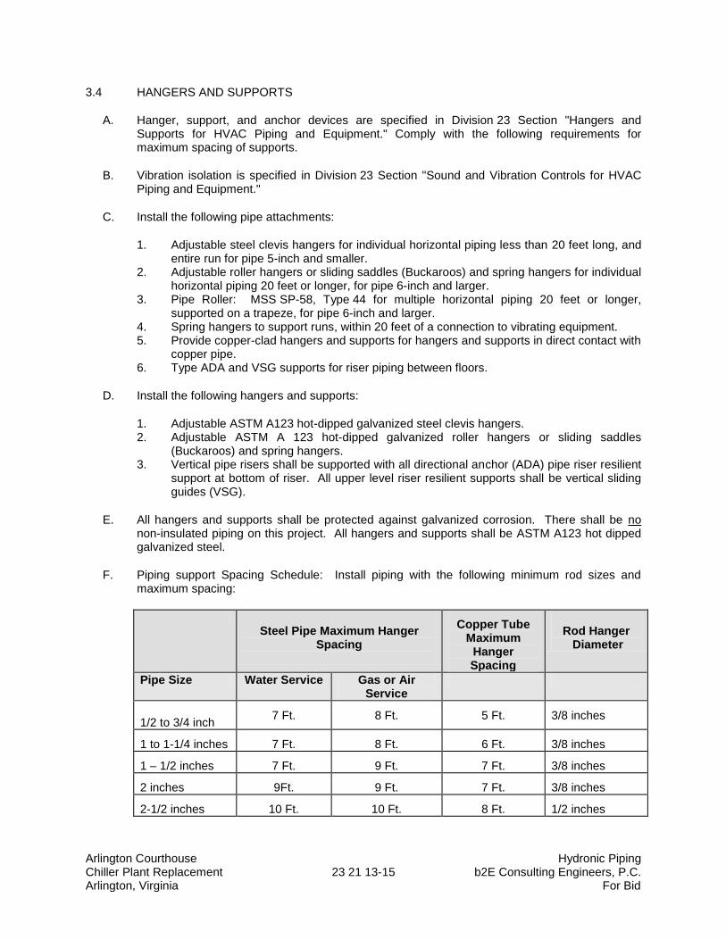
Arlington Courthouse Hydronic Piping Chiller Plant Replacement 23 21 13-15 b2E Consulting Engineers, P.C. Arlington, Virginia For Bid
3.4 HANGERS AND SUPPORTS
A. Hanger, support, and anchor devices are specified in Division 23 Section "Hangers and Supports for HVAC Piping and Equipment." Comply with the following requirements for maximum spacing of supports.
B. Vibration isolation is specified in Division 23 Section "Sound and Vibration Controls for HVAC Piping and Equipment."
C. Install the following pipe attachments:
1. Adjustable steel clevis hangers for individual horizontal piping less than 20 feet long, and entire run for pipe 5-inch and smaller.
2. Adjustable roller hangers or sliding saddles (Buckaroos) and spring hangers for individual horizontal piping 20 feet or longer, for pipe 6-inch and larger.
3. Pipe Roller: MSS SP-58, Type 44 for multiple horizontal piping 20 feet or longer, supported on a trapeze, for pipe 6-inch and larger.
4. Spring hangers to support runs, within 20 feet of a connection to vibrating equipment. 5. Provide copper-clad hangers and supports for hangers and supports in direct contact with
copper pipe. 6. Type ADA and VSG supports for riser piping between floors.
D. Install the following hangers and supports:
1. Adjustable ASTM A123 hot-dipped galvanized steel clevis hangers. 2. Adjustable ASTM A 123 hot-dipped galvanized roller hangers or sliding saddles
(Buckaroos) and spring hangers. 3. Vertical pipe risers shall be supported with all directional anchor (ADA) pipe riser resilient
support at bottom of riser. All upper level riser resilient supports shall be vertical sliding guides (VSG).
E. All hangers and supports shall be protected against galvanized corrosion. There shall be no non-insulated piping on this project. All hangers and supports shall be ASTM A123 hot dipped galvanized steel.
F. Piping support Spacing Schedule: Install piping with the following minimum rod sizes and maximum spacing:
Steel Pipe Maximum Hanger
Spacing
Copper Tube Maximum
Hanger Spacing
Rod Hanger Diameter
Pipe Size Water Service Gas or Air Service
1/2 to 3/4 inch 7 Ft. 8 Ft. 5 Ft. 3/8 inches
1 to 1-1/4 inches 7 Ft. 8 Ft. 6 Ft. 3/8 inches
1 – 1/2 inches 7 Ft. 9 Ft. 7 Ft. 3/8 inches
2 inches 9Ft. 9 Ft. 7 Ft. 3/8 inches
2-1/2 inches 10 Ft. 10 Ft. 8 Ft. 1/2 inches
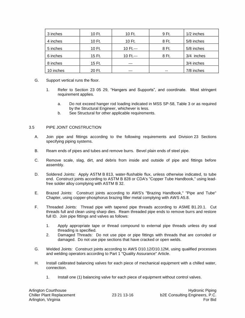
Arlington Courthouse Hydronic Piping Chiller Plant Replacement 23 21 13-16 b2E Consulting Engineers, P.C. Arlington, Virginia For Bid
3 inches 10 Ft. 10 Ft. 9 Ft. 1/2 inches
4 inches 10 Ft. 10 Ft. 8 Ft. 5/8 inches
5 inches 10 Ft. 10 Ft.--- 8 Ft. 5/8 inches
6 inches 15 Ft. 10 Ft.--- 8 Ft. 3/4 inches
8 inches 15 Ft. --- 3/4 inches
10 inches 20 Ft. --- -- 7/8 inches
G. Support vertical runs the floor.
1. Refer to Section 23 05 29, “Hangers and Supports”, and coordinate. Most stringent requirement applies.
a. Do not exceed hanger rod loading indicated in MSS SP-58, Table 3 or as required by the Structural Engineer, whichever is less.
b. See Structural for other applicable requirements.
3.5 PIPE JOINT CONSTRUCTION
A. Join pipe and fittings according to the following requirements and Division 23 Sections specifying piping systems.
B. Ream ends of pipes and tubes and remove burrs. Bevel plain ends of steel pipe.
C. Remove scale, slag, dirt, and debris from inside and outside of pipe and fittings before assembly.
D. Soldered Joints: Apply ASTM B 813, water-flushable flux, unless otherwise indicated, to tube end. Construct joints according to ASTM B 828 or CDA's "Copper Tube Handbook," using lead-free solder alloy complying with ASTM B 32.
E. Brazed Joints: Construct joints according to AWS's "Brazing Handbook," "Pipe and Tube" Chapter, using copper-phosphorus brazing filler metal complying with AWS A5.8.
F. Threaded Joints: Thread pipe with tapered pipe threads according to ASME B1.20.1. Cut threads full and clean using sharp dies. Ream threaded pipe ends to remove burrs and restore full ID. Join pipe fittings and valves as follows:
1. Apply appropriate tape or thread compound to external pipe threads unless dry seal threading is specified.
2. Damaged Threads: Do not use pipe or pipe fittings with threads that are corroded or damaged. Do not use pipe sections that have cracked or open welds.
G. Welded Joints: Construct joints according to AWS D10.12/D10.12M, using qualified processes and welding operators according to Part 1 "Quality Assurance" Article.
H. Install calibrated balancing valves for each piece of mechanical equipment with a chilled water, connection.
1. Install one (1) balancing valve for each piece of equipment without control valves.
Arlington Courthouse Hydronic Piping Chiller Plant Replacement 23 21 13-17 b2E Consulting Engineers, P.C. Arlington, Virginia For Bid
2. Provide one (1) balancing valve for equipment with two-way control valves.
I. Flanged Joints: Select appropriate gasket material, size, type, and thickness for service application. Install gasket concentrically positioned. Use suitable lubricants on bolt threads.
3.6 HYDRONIC SPECIALTIES INSTALLATION
A. Install manual air vents at high points in piping, at heat-transfer coils, and elsewhere as required for system air venting.
B. Install automatic air vents at high points of system piping in mechanical equipment rooms only. Manual vents at heat-transfer coils and elsewhere as required for air venting.
C. Install piping from boiler air outlet, air separator, or air purger to expansion tank with a 2 percent upward slope toward tank.
D. Install in-line air separators in pump suction. Install drain valve on air separators NPS 2 and larger.
E. Install tangential air separator in pump suction. Install blowdown piping with gate or full-port ball valve; extend full size to nearest floor drain.
F. Install bypass chemical feeders in each hydronic system where indicated, in upright position with top of funnel not more than 48 inches above the floor. Install feeder in minimum NPS 3/4 bypass line, from main with full-size, full-port, ball valve in the main between bypass connections. Install NPS 3/4 pipe from chemical feeder drain, to nearest equipment drain and include a full-size, full-port, ball valve.
G. Install expansion tanks on the floor. Vent and purge air from hydronic system, and ensure tank is properly charged with air to suit system Project requirements.
3.7 TERMINAL EQUIPMENT CONNECTIONS
A. Sizes for supply and return piping connections shall be the same as or larger than equipment connections.
B. Install control valves in accessible locations close to connected equipment.
C. Install bypass piping with globe valve around control valve. If parallel control valves are installed, only one bypass is required.
D. Install ports for pressure gages and thermometers at coil inlet and outlet connections according to Division 23 Section "Meters and Gages for HVAC Piping."
3.8 CHEMICAL TREATMENT
A. Perform an analysis of makeup water to determine type and quantities of chemical treatment needed to keep system free of scale, corrosion, and fouling, and to sustain the following water characteristics:
1. pH: 9.0 to 10.5.
Arlington Courthouse Hydronic Piping Chiller Plant Replacement 23 21 13-18 b2E Consulting Engineers, P.C. Arlington, Virginia For Bid
2. "P" Alkalinity: 100 to 500 ppm. 3. Boron: 100 to 200 ppm. 4. Chemical Oxygen Demand: Maximum 100 ppm. Modify this value if closed system
contains glycol. 5. Corrosion Inhibitor:
a. Sodium Nitrate: 1000 to 1500 ppm. b. Molybdate: 200 to 300 ppm. c. Chromate: 200 to 300 ppm. d. Sodium Nitrate Plus Molybdate: 100 to 200 ppm each. e. Chromate Plus Molybdate: 50 to 100 ppm each.
6. Soluble Copper: Maximum 0.20 ppm. 7. Tolyiriazole Copper and Yellow Metal Corrosion Inhibitor: Minimum 10 ppm. 8. Total Suspended Solids: Maximum 10 ppm. 9. Ammonia: Maximum 20 ppm. 10. Free Caustic Alkalinity: Maximum 20 ppm. 11. Microbiological Limits:
a. Total Aerobic Plate Count: Maximum 1000 organisms/ml. b. Total Anaerobic Plate Count: Maximum 100 organisms/ml. c. Nitrate Reducers: 100 organisms/ml. d. Sulfate Reducers: Maximum 0 organisms/ml. e. Iron Bacteria: Maximum 0 organisms/ml.
B. Fill system with fresh water and add liquid alkaline compound with emulsifying agents and detergents to remove grease and petroleum products from piping. Circulate solution for a minimum of 24 hours, drain, clean strainer screens, and refill with fresh water.
1. Repeat at least three (3) times to ensure entire piping system is clean prior to start-up of pumps.
C. Add initial chemical treatment and maintain water quality in ranges noted above for the first two (2) years of operation.
3.9 FIELD QUALITY CONTROL
A. Prepare hydronic piping according to ASME B31.9 and as follows:
1. Leave joints, including welds, uninsulated and exposed for examination during test. 2. Provide temporary restraints for expansion joints that cannot sustain reactions due to test
pressure. If temporary restraints are impractical, isolate expansion joints from testing. 3. Flush hydronic piping systems with clean water; then remove and clean or replace
strainer screens. 4. Isolate equipment from piping. If a valve is used to isolate equipment, its closure shall be
capable of sealing against test pressure without damage to valve. Install blinds in flanged joints to isolate equipment.
5. Install safety valve, set at a pressure no more than one-third higher than test pressure, to protect against damage by expanding liquid or other source of overpressure during test.
B. Perform the following tests on hydronic piping:
Arlington Courthouse Hydronic Piping Chiller Plant Replacement 23 21 13-19 b2E Consulting Engineers, P.C. Arlington, Virginia For Bid
1. Use ambient temperature water as a testing medium unless there is risk of damage due to freezing. Another liquid that is safe for workers and compatible with piping may be used.
2. While filling system, use vents installed at high points of system to release air. Use drains installed at low points for complete draining of test liquid.
3. Isolate expansion tanks and determine that hydronic system is full of water. 4. Subject piping system to hydrostatic test pressure that is not less than 1.5 times the
system's working pressure (200 psig). Test pressure shall not exceed maximum pressure for any vessel, pump, valve, or other component in system under test. Verify that stress due to pressure at bottom of vertical runs does not exceed 90 percent of specified minimum yield strength or 1.7 times "SE" value in Appendix A in ASME B31.9, "Building Services Piping."
5. After hydrostatic test pressure has been applied for at least 10 minutes, examine piping, joints, and connections for leakage. Eliminate leaks by tightening, repairing, or replacing components, and repeat hydrostatic test until there are no leaks. Leave under pressure for 24 hours and check to ensure no leaks have occurred.
6. Prepare written report of testing.
C. Perform the following before operating the system:
1. Open manual valves fully. 2. Inspect pumps for proper rotation. 3. Set makeup pressure-reducing valves for required system pressure. 4. Inspect air vents at high points of system and determine if all are installed and operating
freely (automatic type), or bleed air completely (manual type). 5. Set temperature controls so all coils are calling for full flow. 6. Inspect and set operating temperatures of hydronic equipment, such as boilers, chillers,
cooling towers, to specified values. 7. Verify lubrication of motors and bearings.
3.10 ADJUSTING
A. Mark calibrated nameplates of pump discharge valves after hydronic system balancing has been completed, to permanently indicate final balanced position.
B. Perform these adjustments before operating the system:
1. Open valves to fully open position. Close coil bypass valves. 2. Check pump for proper direction of rotation. 3. Set automatic fill valves for required system pressure. 4. Check air vents at high points of system and determine if all are installed and operating
freely (automatic type), or bleed air completely (manual type). 5. Set temperature controls so all coils are calling for full flow. 6. Check operation of automatic bypass valves. 7. Check and set operating temperatures of chillers to design requirements. 8. Lubricate motors and bearings.
3.11 CLEANING
A. Flush hydronic piping systems with clean water. Remove and clean or replace strainer screens. After cleaning and flushing hydronic piping systems, but before balancing, remove disposable fine-mesh strainers in pump suction diffusers.
Arlington Courthouse Hydronic Piping Chiller Plant Replacement 23 21 13-20 b2E Consulting Engineers, P.C. Arlington, Virginia For Bid
1. Piping systems shall be flushed continuously twice per week until project acceptable weld slag, dirt, rust, etc. is removed and the water is clearance. The contractor is responsible for any and all damage to the equipment. The contractor shall thoroughly chemically clean all heat-transfer coils and surface prior to project substantial completion.
2. Contractor shall supply all HVAC water treatment chemicals, and shall measure, test and adjust the chemical water treatment to protect all piping systems in accordance with Section 23 25 00.
END OF SECTION 23 21 13
Arlington Courthouse Hydronic Pumps Chiller Plant Replacement 23 21 23-1 b2E Consulting Engineers, P.C. Arlington, Virginia For Bid
SECTION 23 21 23
HYDRONIC PUMPS
PART 1 - GENERAL
1.1 SUMMARY
A. This Section includes the following: 1. Separately coupled, base-mounted, horizontal split-case centrifugal pumps.
1.2 DEFINITIONS
A. Buna-N: Nitrile rubber.
B. EPT: Ethylene propylene terpolymer.
1.3 SUBMITTALS
A. Product Data: Include certified performance curves and rated capacities, operating characteristics, furnished specialties, final impeller dimensions, and accessories for each type of product indicated. Indicate pump's operating point on curves.
B. Shop Drawings: Show pump layout and connections. Include setting drawings with templates for installing foundation and anchor bolts and other anchorages.
1. Wiring Diagrams: Power, signal, and control wiring.
C. Operation and Maintenance Data: For pumps to include in emergency, operation, and maintenance manuals.
1.4 QUALITY ASSURANCE
A. Source Limitations: Obtain hydronic pumps through one source from a single manufacturer.
B. Product Options: Drawings indicate size, profiles, and dimensional requirements of hydronic pumps and are based on the specific system indicated.
C. Electrical Components, Devices, and Accessories: Listed and labeled as defined in NFPA 70, Article 100, by a testing agency acceptable to authorities having jurisdiction, and marked for intended use.
D. UL Compliance: Comply with UL 778 for motor-operated water pumps.
Arlington Courthouse Hydronic Pumps Chiller Plant Replacement 23 21 23-2 b2E Consulting Engineers, P.C. Arlington, Virginia For Bid
1.5 DELIVERY, STORAGE, AND HANDLING
A. Manufacturer's Preparation for Shipping: Clean flanges and exposed machined metal surfaces and treat with anticorrosion compound after assembly and testing. Protect flanges, pipe openings, and nozzles with wooden flange covers or with screwed-in plugs.
B. Store pumps in dry location.
C. Retain protective covers for flanges and protective coatings during storage.
D. Protect bearings and couplings against damage from sand, grit, and other foreign matter.
E. Comply with pump manufacturer's written rigging instructions.
1.6 COORDINATION
A. Coordinate size and location of concrete bases. Cast anchor-bolt inserts into bases. Concrete, reinforcement, and formwork requirements are specified in Division 03.
1.7 EXTRA MATERIALS
A. Furnish extra materials described below that match products installed and that are packaged with protective covering for storage and identified with labels describing contents.
1. Mechanical Seals: One mechanical seal(s) for each pump.
PART 2 - PRODUCTS
2.1 MANUFACTURERS
A. Acceptable Manufacturers: Subject to compliance with requirements, provide products by one of the manufacturers specified.
2.2 SEPARATELY COUPLED, BASE-MOUNTED, HORIZONTAL SPLIT-CASE CENTRIFUGAL PUMPS
A. Acceptable Manufacturers:
1. Basis of Design: Bell & Gossett; Div. of ITT Industries. 2. Armstrong Pumps Inc. 3. Taco, Inc. 4. Wilo.
B. Description: Factory-assembled and -tested, centrifugal, overhung-impeller, separately coupled, horizontal split-case pump as defined in HI 1.1-1.2 and HI 1.3; designed for base mounting, with pump and motor shafts horizontal. Rate pump for 125-psig (860-kPa) minimum working pressure and a continuous water temperature of 250 deg F.
Arlington Courthouse Hydronic Pumps Chiller Plant Replacement 23 21 23-3 b2E Consulting Engineers, P.C. Arlington, Virginia For Bid
C. Pump Construction:
1. Casing: Horizontal-case split, cast iron, with replaceable bronze wear rings, threaded gage tappings at inlet and outlet, drain plug at bottom and air vent at top of volute, and flanged connections. Provide integral mount on volute to support the casing, and attached piping to allow removal and replacement of impeller without disconnecting piping or requiring the realignment of pump and motor shaft.
2. Impeller: ASTM B 584, cast bronze; statically and dynamically balanced, keyed to shaft, and secured with a locking cap screw. Trim impeller to match specified performance.
3. Pump Shaft: Stainless steel. 4. Mechanical Seal: Carbon rotating ring against a ceramic seat held by a stainless-steel
spring, and Buna-N or EPT bellows and gasket. 5. Packing Seal: Stuffing box, with a minimum of four rings of graphite-impregnated braided
yarn with bronze lantern ring between center two graphite rings, and bronze packing gland.
6. Pump Bearings: Grease-lubricated ball bearings contained in cast-iron housing with grease fittings.
D. Shaft Coupling: Molded rubber insert and interlocking spider capable of absorbing vibration. Couplings shall be drop-out type to allow disassembly and removal without removing pump shaft or motor; and EPDM coupling sleeve for variable-speed applications.
1. Couplings for adjustable frequency drive (AFD) pumps shall be designed for variable speed duty.
2. Basis of Design: Dodge or equal.
E. Coupling Guard: Dual rated; ANSI B15.1, Section 8; OSHA 1910.219 approved; steel; removable; attached to mounting frame.
F. Mounting Frame: Welded-steel frame and cross members, factory fabricated from ASTM A 36/A 36M channels and angles. Fabricate to mount pump casing, coupling guard, and motor.
G. Motor: Variable speed, with grease-lubricated ball bearings, unless otherwise indicated; secured to mounting frame, with adjustable alignment. Comply with requirements in Division 23 Section "Common Motor Requirements for HVAC Equipment."
H. Capacities and Characteristics: Refer to pump schedule on drawings.
I. Two (2) years of date of substantial completion for defects in material and workmanship. 1. Shafts, seals, couplings, motors: Two (2) years.
J. Coordination: Coordinate with suction diffuser supplier to match the flange sizes for diffuser inlet and pump suction.
2.3 PUMP SPECIALTY FITTINGS
A. Triple-Duty Valve: Angle or straight pattern, 175-psig pressure rating, cast or ductile-iron body, pump-discharge fitting; with drain plug and bronze-fitted shutoff, balancing, and check valve features. Brass gage ports with integral check valve, and orifice for flow measurement.
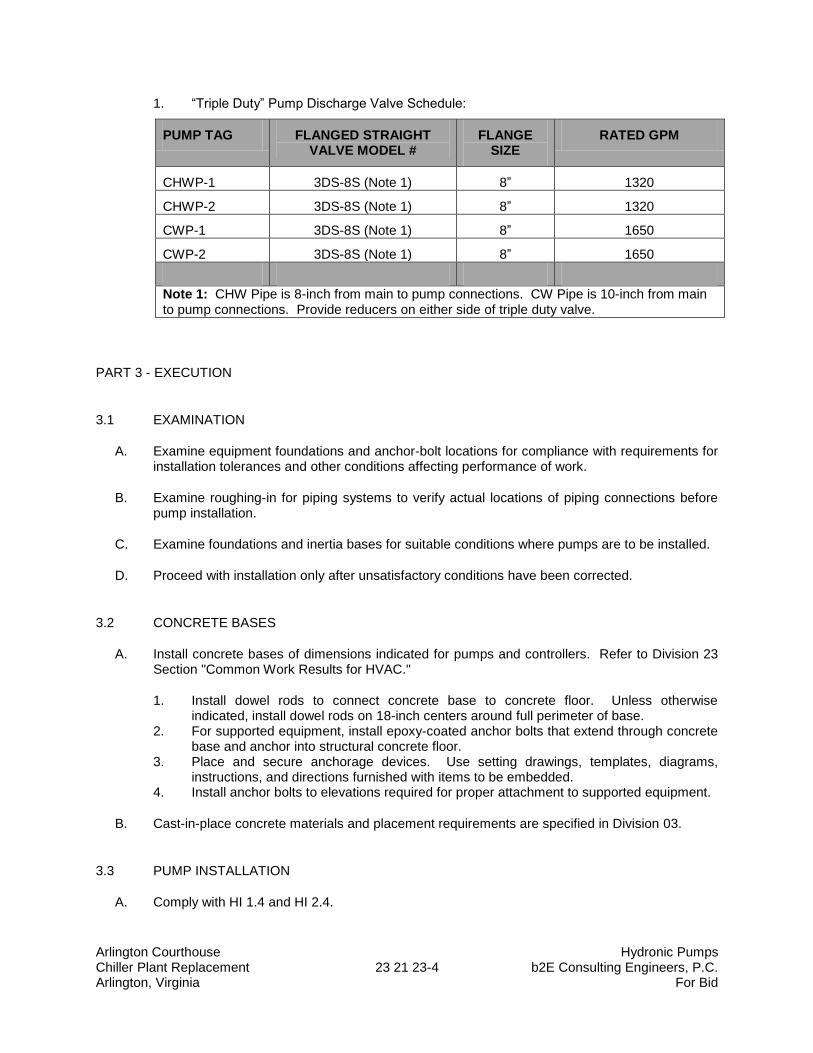
Arlington Courthouse Hydronic Pumps Chiller Plant Replacement 23 21 23-4 b2E Consulting Engineers, P.C. Arlington, Virginia For Bid
1. “Triple Duty” Pump Discharge Valve Schedule:
PUMP TAG FLANGED STRAIGHT VALVE MODEL #
FLANGE SIZE
RATED GPM
CHWP-1 3DS-8S (Note 1) 8” 1320
CHWP-2 3DS-8S (Note 1) 8” 1320
CWP-1 3DS-8S (Note 1) 8” 1650
CWP-2 3DS-8S (Note 1) 8” 1650
Note 1: CHW Pipe is 8-inch from main to pump connections. CW Pipe is 10-inch from main to pump connections. Provide reducers on either side of triple duty valve.
PART 3 - EXECUTION
3.1 EXAMINATION
A. Examine equipment foundations and anchor-bolt locations for compliance with requirements for installation tolerances and other conditions affecting performance of work.
B. Examine roughing-in for piping systems to verify actual locations of piping connections before pump installation.
C. Examine foundations and inertia bases for suitable conditions where pumps are to be installed.
D. Proceed with installation only after unsatisfactory conditions have been corrected.
3.2 CONCRETE BASES
A. Install concrete bases of dimensions indicated for pumps and controllers. Refer to Division 23 Section "Common Work Results for HVAC."
1. Install dowel rods to connect concrete base to concrete floor. Unless otherwise indicated, install dowel rods on 18-inch centers around full perimeter of base.
2. For supported equipment, install epoxy-coated anchor bolts that extend through concrete base and anchor into structural concrete floor.
3. Place and secure anchorage devices. Use setting drawings, templates, diagrams, instructions, and directions furnished with items to be embedded.
4. Install anchor bolts to elevations required for proper attachment to supported equipment.
B. Cast-in-place concrete materials and placement requirements are specified in Division 03.
3.3 PUMP INSTALLATION
A. Comply with HI 1.4 and HI 2.4.
Arlington Courthouse Hydronic Pumps Chiller Plant Replacement 23 21 23-5 b2E Consulting Engineers, P.C. Arlington, Virginia For Bid
B. Install pumps with access for periodic maintenance including removal of motors, impellers, couplings, and accessories.
C. Independently support pumps and piping so weight of piping is not supported by pumps and weight of pumps is not supported by piping.
D. Install continuous-thread hanger rods and spring hangers with vertical-limit stop of sufficient size to support pump weight. Vibration isolation devices are specified in Division 23 Section "Vibration and Seismic Controls for HVAC Piping and Equipment." Fabricate brackets or supports as required. Hanger and support materials are specified in Division 23 Section "Hangers and Supports for HVAC Piping and Equipment."
E. Suspend vertically mounted, in-line centrifugal pumps independent of piping. Install pumps with motor and pump shafts vertical. Use continuous-thread hanger rods and spring hangers with vertical-limit stop of sufficient size to support pump weight. Vibration isolation devices are specified in Division 21 Section "Sound and Vibration Controls for Fire-Suppression Piping and Equipment." Hanger and support materials are specified in Division 22 Section "Hangers and Supports for Plumbing Piping and Equipment/Hangers and Supports for HVAC Piping and Equipment."
F. Set base-mounted pumps on ASHRAE TYPE-C concrete inertion block foundation. Disconnect coupling before setting. Do not reconnect couplings until alignment procedure is complete.
1. Support pump baseplate on rectangular metal blocks and shims, or on metal wedges with small taper, at points near foundation bolts to provide a gap of 3/4 to 1-1/2 inches between pump base and foundation for grouting.
2. Adjust metal supports or wedges until pump and driver shafts are level. Check coupling faces and suction and discharge flanges of pump to verify that they are level and plumb.
3.4 ALIGNMENT
A. Align pump and motor shafts and piping connections after setting on foundation, grout has been set and foundation bolts have been tightened, and piping connections have been made.
B. Comply with pump and coupling manufacturers' written instructions.
C. Adjust pump and motor shafts for angular and offset alignment by methods specified in HI 1.1-1.5, "Centrifugal Pumps for Nomenclature, Definitions, Application and Operation; and HI 2.1-2.5, " Vertical Pumps for Nomenclature, Definitions, Application and Operation," As applicable.
D. After alignment is correct, tighten foundation bolts evenly but not too firmly. Completely fill baseplate with nonshrink, nonmetallic grout while metal blocks and shims or wedges are in place. After grout has cured, fully tighten foundation bolts.
3.5 CONNECTIONS
A. Piping installation requirements are specified in other Division 23 Sections. Drawings indicate general arrangement of piping, fittings, and specialties.
B. Install piping adjacent to machine to allow service and maintenance.
Arlington Courthouse Hydronic Pumps Chiller Plant Replacement 23 21 23-6 b2E Consulting Engineers, P.C. Arlington, Virginia For Bid
C. Connect piping to pumps. Install butterfly valves that are the same size as piping connected to pumps.
D. Install concentric reducer at pump discharge nozzles.
E. Install suction pipe sizes to suction diffuser inlet as indicated. Suction diffuser inlet shall match inlet pipe size indicated on schedule.
F. Install isolation (throttling) valve on discharge side of in-line circulators, and install, y-strainer and isolation valve on suction side. Install pressure indicator(s) across pump discharge and suction piping.
G. Install concentric reducer (to increase pipe size), flexible connector, triple duty valve for constant or variable speed pumps and butterfly valve with hand wheel operators on discharge side of horizontal split-case pumps, and install suction diffuser, flexible connector, y-strainer and butterfly valve with hand wheel operators on suction side.
H. Install suction diffuser on suction side of base mounted pumps.
I. Install pressure gages on pump suction and discharge, chiller entering and leaving water piping, and boiler leaving water piping in field fabricated spool piece in flanged piping.
J. Install temperature wells and digital thermometers in pump suction piping, chiller entering and leaving water piping, heat exchanger entering and leaving water piping, tube bundle entering and leaving, boiler entering and leaving water temperature.
1. Install ½-inch ball valves for gauges.
K. Install two (2) 1-inch brass test plug connections on entering and leaving side of each chiller piping connection for chemical cleaning.
L. Extend 3/8-inch brass tubing to chiller pressure transducers with ball valve per manufacturers’ recommendations.
M. Install water flow stations with eight (8) pipe diameters unobstructed straight pipe on inlet side and eight (8) pipe diameters on outlet side. If the energy flow measuring stations do not indicate properly due to improper placement in the piping system, the contractor shall re-work the piping system at their own cost until functioning properly as determined by the Engineer.
N. Install calibrated balancing valves at the outlet side of each chiller.
O. Install temperature, pressure transducer, and flow measuring station wells for EMS as required by the EMS contractor.
P. Install differential pressure transducers in building chilled water system piping (approx. ¾ way down stream in building lower floor levels) as required by the EMS contractor for adjustable frequency drive (AFD) pumping control.
1. Provide one (1) differential pressure systems for the chilled water piping loop on the first floor.
2. CWCS contractor shall determine location to install DP element and transducer in piping system.
Arlington Courthouse Hydronic Pumps Chiller Plant Replacement 23 21 23-7 b2E Consulting Engineers, P.C. Arlington, Virginia For Bid
Q. Install butterfly valve, Y-strainer, double spherical rubber flexible connectors and reducer on inlet and reducer double spherical rubber flexile connector, triple duty valve and butterfly valve on pump outlets.
R. Install stainless steel braided flexible connector and butterfly valve on chiller inlet piping and stainless steel braided flexible connector, calibrated balancing valve and butterfly valve on outlet piping.
S. Install electrical connections for power, controls, and devices.
T. Electrical power and control wiring and connections are specified in Division 26 Sections.
U. Ground equipment.
1. Tighten electrical connectors and terminals according to manufacturer's published torque-tightening values. If manufacturer's torque values are not indicated, use those specified in UL 486A and UL 486B.
3.6 STARTUP SERVICE
A. Engage a factory-authorized service representative to perform startup service.
1. Complete installation and startup checks according to manufacturer's written instructions. 2. Check piping connections for tightness. 3. Clean strainers on suction piping. 4. Perform the following startup checks for each pump before starting:
a. Verify bearing lubrication. b. Verify that pump is free to rotate by hand and that pump for handling hot liquid is
free to rotate with pump hot and cold. If pump is bound or drags, do not operate until cause of trouble is determined and corrected.
c. Verify that pump is rotating in the correct direction.
5. Prime pump by opening suction valves and closing drains, and prepare pump for operation.
6. Start motor. 7. Open discharge valve slowly.
3.7 PRE-FUNCTIONING TESTING AND START-UPS
A. Verify that pumps are installed and connected according to the Contract Documents.
B. Verify that electrical wiring installation complies with manufacturer's written instructions and the Contract Documents.
C. Verify that EMS control wiring installation is complete and affects a complete operating system in accordance with the sequence of operation specified.
D. Perform the following preventive maintenance operations and checks before starting:
1. Lubricate bearings.
Arlington Courthouse Hydronic Pumps Chiller Plant Replacement 23 21 23-8 b2E Consulting Engineers, P.C. Arlington, Virginia For Bid
2. Remove grease-lubricated bearing covers, flush bearings with kerosene, and clean thoroughly. Fill with new lubricant according to manufacturer's written instructions.
3. Disconnect coupling and check motor for proper rotation that matches direction marked on pump casing. Verify that variable speed pump couplings are designed for variable speed variable torque applications up to maximum operating RPM of pump motor.
4. Verify that pumps are free to rotate by hand and that pumps for handling hot liquids are free to rotate with pumps hot and cold. Do not operate pumps if they are bound or drag, until cause of trouble is determined and corrected.
5. Check suction piping connections for tightness to avoid drawing air into pumps. 6. Clean strainers. 7. Verify that pump controls are correct for required application.
E. Starting procedure for pumps with shutoff power not exceeding safe motor power is as follows:
1. Prime pumps by opening suction valves and closing drains, and prepare pumps for operation.
2. Open cooling water-supply valves in CHW to equipment. 3. Open sealing liquid-supply valves if pumps are so fitted. 4. Open warm-up valves of pumps handling hot liquids if pumps are not normally kept at
operating temperature. 5. Open circulating line valves if pumps should not be operated against dead shutoff. 6. Start motors. 7. Open discharge valves slowly. 8. Observe leakage from stuffing boxes and adjust sealing liquid valve for proper flow to
ensure lubrication of packing. Let packing "run in" before reducing leakage through stuffing boxes; then tighten glands.
9. Check general mechanical operation of pumps and motors. 10. Close circulating line valves once there is sufficient flow through pumps to prevent
overheating.
F. When pumps are to be started against closed check valves with discharge shutoff valves open, steps are the same, except open discharge valves before starting motors.
G. Refer to Division 23 Section "Testing, Adjusting, and Balancing" for detailed requirements for testing, adjusting, and balancing hydronic systems.
3.8 DEMONSTRATION
A. Engage a factory-authorized service representative to train Owner’s maintenance personnel to adjust, operate, and maintain hydronic pumps as specified below:
1. Train Owner’s maintenance personnel on procedures and schedules for starting and stopping, troubleshooting, servicing, and maintaining pumps.
2. Review data in maintenance manuals. Refer to Division 1 Section 01 70 00 "Project Closeout."
3. Review data in maintenance manuals. Refer to Division 1 Section "Operation and Maintenance Data."
4. Schedule training with Owner, through Engineer, with at least seven days' advance notice.
5. Contractor shall provide all materials and labor necessary to demonstrate system operation to Owner/Engineer as required by Section 23 08 00 “Commissioning of the HVAC System.” The contractor shall repeatedly make site visits, demonstrate and make
Arlington Courthouse Hydronic Pumps Chiller Plant Replacement 23 21 23-9 b2E Consulting Engineers, P.C. Arlington, Virginia For Bid
revisions to system at their own expense until all systems are accepted by the Architect and Engineer.
6. Refer to Drawing 01 Section “Project Closeout”.
3.9 COMMISSIONING
A. Provide documentation, support for commissioning activities, and support for functional performance testing as outlined in specification section 23 08 00 “Commissioning Plan.”
END OF SECTION 23 21 23
Arlington Courthouse HVAC Water Treatment Chiller Plant Replacement 23 25 00-1 b2E Consulting Engineers, P.C. Arlington, Virginia For Bid
SECTION 23 25 00
HVAC WATER TREATMENT
PART 1 - GENERAL
1.1 SUMMARY
A. This Section includes the following HVAC water-treatment systems:
1. Bypass chemical-feed equipment and controls. 2. Chemical treatment test equipment. 3. HVAC water-treatment chemicals. 4. Water filtration units.
1.2 DEFINITIONS
A. EEPROM: Electrically erasable, programmable read-only memory.
B. Low Voltage: As defined in NFPA 70 for circuits and equipment operating at less than 50 V or for remote-control, signaling power-limited circuits.
C. RO: Reverse osmosis.
D. TDS: Total dissolved solids.
1.3 PERFORMANCE REQUIREMENTS
A. Water quality for HVAC systems shall minimize corrosion, scale buildup, and biological growth for optimum efficiency of HVAC equipment without creating a hazard to operating personnel or the environment.
B. Base HVAC water treatment on quality of water available at Project site, HVAC system equipment material characteristics and functional performance characteristics, operating personnel capabilities, and requirements and guidelines of authorities having jurisdiction.
C. Closed hydronic systems, including hot-water heating and chilled water, shall have the following water qualities:
1. pH: Maintain a value within 9.0 to 10.5. 2. "P" Alkalinity: Maintain a value within 100 to 500 ppm. 3. Boron: Maintain a value within 100 to 200 ppm. 4. Chemical Oxygen Demand: Maintain a maximum value of 100 ppm. 5. Soluble Copper: Maintain a maximum value of 0.20 ppm. 6. TDS: Maintain a maximum value of 10 ppm. 7. Ammonia: Maintain a maximum value of 20 ppm. 8. Microbiological Limits:
a. Total Aerobic Plate Count: Maintain a maximum value of 1000 organisms/ml. b. Nitrate Reducers: Maintain a maximum value of 100 organisms/ml.
Arlington Courthouse HVAC Water Treatment Chiller Plant Replacement 23 25 00-2 b2E Consulting Engineers, P.C. Arlington, Virginia For Bid
c. Sulfate Reducers: Maintain a maximum value of 0 organisms/ml. d. Iron Bacteria: Maintain a maximum value of 0 organisms/ml.
D. Passivation for Galvanized Steel: For the first 60 days of operation.
1. pH: Maintain a value within 7 to 8. 2. Calcium Carbonate Hardness: Maintain a value within 100 to 300 ppm. 3. Calcium Carbonate Alkalinity: Maintain a value within 100 to 300 ppm.
1.4 SUBMITTALS
A. Product Data: Include rated capacities, operating characteristics, furnished specialties, and accessories for the following products:
1. Bypass feeders. 2. Water meters. 3. Chemical test equipment. 4. Chemical material safety data sheets. 5. Multimedia filters. 6. Self-cleaning strainers. 7. Bag- or cartridge-type filters. 8. Centrifugal separators. 9. Closed system cleaning list.
B. Shop Drawings: Pretreatment and chemical, equipment showing tanks, maintenance space required, and piping connections to HVAC systems. Include plans, elevations, sections, details, and attachments to other work.
1. Wiring Diagrams: Power and control wiring.
C. Field quality-control test reports.
D. Operation and Maintenance Data: For sensors, injection pumps, water softeners, RO equipment, water filtration units, and controllers to include in emergency, operation, and maintenance manuals.
1.5 QUALITY ASSURANCE
A. HVAC Water-Treatment Service Provider Qualifications: An experienced HVAC water-treatment service provider capable of analyzing water qualities, installing water-treatment equipment, and applying water treatment as specified in this Section.
B. Electrical Components, Devices, and Accessories: Listed and labeled as defined in NFPA 70, Article 100, by a testing agency acceptable to authorities having jurisdiction, and marked for intended use.
1.6 MAINTENANCE SERVICE
A. Scope of Maintenance Service: Provide chemicals and service program to maintain water conditions required above to inhibit corrosion, scale formation, and biological growth for cooling, chilled-water piping; heating, hot-water piping; and solar-water piping and equipment. Services
Arlington Courthouse HVAC Water Treatment Chiller Plant Replacement 23 25 00-3 b2E Consulting Engineers, P.C. Arlington, Virginia For Bid
and chemicals shall be provided for a period of two (2) years from date of Substantial Completion, and shall include the following:
1. Initial water analysis and HVAC water-treatment recommendations. 2. Startup assistance for Contractor to flush the systems, clean with detergents, and initially
fill systems with required chemical treatment prior to operation. 3. Periodic field service and consultation. 4. Customer report charts and log sheets. 5. Laboratory technical analysis. 6. Analyses and reports of all chemical items concerning safety and compliance with
government regulations.
1.7 EXTRA MATERIALS
A. Closed Loop: Chemicals as needed for two (2) years warranty period.
PART 2 - PRODUCTS
2.1 MANUFACTURERS
A. Acceptable Manufacturers: Subject to compliance with requirements, provide products by one of the following:
1. Walchem. 2. Zentox. 3. Harmsco. 4. Air-Sep. 5. PSA. 6. Omega Engineering. 7. Harrington. 8. Other approved manufacturers.
2.2 MANUAL CHEMICAL-FEED EQUIPMENT
A. Bypass Feeders: Steel, with corrosion-resistant exterior coating, minimum 3-1/2-inch fill opening in the top, and NPS 3/4 bottom inlet and top side outlet. Quarter turn or threaded fill cap with gasket seal and diaphragm to lock the top on the feeder when exposed to system pressure in the vessel.
1. Capacity: 5 gal. 2. Minimum Working Pressure: 125 psig.
B. Injection Assembly:
1. Quill: Minimum NPS 1/2 with insertion length sufficient to discharge into at least 25 percent of pipe diameter.
2. Ball Valve: Three-piece, stainless steel as described in "Stainless-Steel Pipes and Fittings" Article below; and selected to fit quill.
3. Packing Gland: Mechanical seal on quill of sufficient length to allow quill removal during system operation.
4. Assembly Pressure/Temperature Rating: Minimum 600 psig at 200 deg F.
Arlington Courthouse HVAC Water Treatment Chiller Plant Replacement 23 25 00-4 b2E Consulting Engineers, P.C. Arlington, Virginia For Bid
2.3 CHEMICAL TREATMENT TEST EQUIPMENT
A. Test Kit: Manufacturer-recommended equipment and chemicals in a wall-mounting cabinet for testing pH, TDS, inhibitor, chloride, alkalinity, and hardness; sulfite and testable polymer tests for high-pressure boilers and hand held refractometer for glycol solution testing.
B. Sample Coupons:
1. Tube: Sample.
a. Size: NPS 1/4 tubing. b. Material: ASTM A 666, Type 316 stainless steel. c. Pressure Rating: Minimum 2000 psig. d. Temperature Rating: Minimum 850 deg F.
2. Shell: Cooling water.
a. Material: ASTM A 666, Type 304 stainless steel. b. Pressure Rating: Minimum 250 psig. c. Temperature Rating: Minimum 450 deg F.
3. Capacities and Characteristics:
a. Tube: Sample.
1) Flow Rate: 0.25 gpm. 2) Entering Temperature: 400 deg F. 3) Leaving Temperature: 88 deg F. 4) Pressure Loss: 6.5 psig.
b. Shell: Cooling water.
1) Flow Rate: 3 gpm. 2) Entering Temperature: 70 deg F. 3) Pressure Loss: 1.0 psig.
C. Corrosion Test-Coupon Assembly: Constructed of corrosive-resistant material, complete with piping, valves, and mild steel and copper coupons. Locate copper coupon downstream from mild steel coupon in the test-coupon assembly.
1. Two-station rack for each closed-loop system.
2.4 CHEMICALS
A. Chemicals shall be as recommended by water-treatment system manufacturer that are compatible with piping system components and connected equipment, and that can attain water quality specified in Part 1 "Performance Requirements" Article.
2.5 FILTRATION EQUIPMENT
A. Cartridge-Type Filters:
1. Acceptable Manufacturers: Subject to compliance with requirements, provide products by one of the following:
Arlington Courthouse HVAC Water Treatment Chiller Plant Replacement 23 25 00-5 b2E Consulting Engineers, P.C. Arlington, Virginia For Bid
a. Basis of Design: Harmsco, Model HIF-7-SS. b. Filter Specialists, Inc. c. Hayward Industrial Products, Inc. d. PEP Filters, Inc. e. USFilter.
2. Description: Floor-mounting housing with filter cartridges for removing particles from water.
a. Housing: Corrosion resistant; designed to separate inlet from outlet and to direct inlet through cartridge-type water filter; with base, feet, or skirt.
1) Pipe Connections NPS 2 and Smaller: Threaded according to ASME B1.20.1.
2) Steel Housing Pipe Connections NPS 2-1/2 and Larger: Steel, Class 150 flanges according to ASME B16.5 or grooved according to AWWA C606.
b. Filter Cartridge: Replaceable; of shape to fit housing. 1) PSA Oxygen Generator: Free standing PSA oxygen generator located
within reach of power cord provided and oxygen piping. Connection shall be made to the bottom of the control panel and ozone generator.
2.6 CLOSED SYSTEM CLEANER: Multi Purpose Alkaline Cleaner (Bond 8050)
A. Contractor shall provide as needed.
1. Suppliers: a. Aquatomic. b. Bondwater. c. ARC Water Treatment. d. Tricon.
2.7 SOLIDS SEPERATOR
A. Centrifugal Solids Separator: Complete assembled and factory tested unit. 1. Packaged Solids Separator and Pumps: a. Basis of Design: Tower Flow Model TFSR-0350 centrifugal separator system. B. Skid Mounted with a 10 HP pump to filter 350 gpm condenser water system shall include
separator, pump, motor, motor controls, and continuous zero discharge purge to a recovery bag filter.
C. Connections: 6-inch flanged inlet and 4-inch flanged outlet with 1-inch fpt purge connection. D. Provide the following: 1. 4” x 6” and 6” x 8” Clean Out Ports. 2. Inlet and Outlet pressure gauges. 3. Steel Base with baked enamel finish. 4. Pump suction strainer. 5. TEFC premium efficiency motor 460 V, 3 phase. 6. Control panel, NEMA 4X with single point power connection. 7. Unit mounted disconnect switch. 8. IEC motor starter with overload protection. 9. Purge valve power supplied from control panel. 10. Isolation valve on pump discharge.
Arlington Courthouse HVAC Water Treatment Chiller Plant Replacement 23 25 00-6 b2E Consulting Engineers, P.C. Arlington, Virginia For Bid
11. UL listed system. 12. Factory tested and assembled. 13. Max operating pressure: 150 psi. 14. Max operating temperature: 125 deg. F. 15. 2-inch drip pan of structural steel channel. 16. Pump HOA switch with contacts for remote pump on/off from building EMS. 17. Purge duration and frequency control timer. 18. Manual purge push button.
19. 2-way brass purge valve with 24 VAC with fail-safe actuator that closes in the event of power failure.
20. 2-way manual brass ball valve for isolation. 21. Sch 40 steel construction. 22. 120 deg. F max. Operating temperature. 23. 150 psi max. operating pressure.
PART 3 - EXECUTION
3.1 WATER ANALYSIS
A. Perform an analysis of supply water to determine quality of water available at Project site.
3.2 INSTALLATION
A. Install chemical application equipment on concrete bases, level and plumb. Maintain manufacturer's recommended clearances. Arrange units so controls and devices that require servicing are accessible. Anchor chemical tanks and floor-mounting accessories to substrate.
B. Install water testing equipment on wall near water chemical application equipment.
C. Install interconnecting control wiring for chemical treatment controls and sensors.
D. Bypass Feeders: Install in closed hydronic systems, including chilled water, and equipped with the following: 1. Install bypass feeder in a bypass circuit around circulating pumps, unless otherwise
indicated on Drawings. 2. Install water meter in makeup water supply. 3. Install test-coupon assembly in bypass circuit around circulating pumps, unless otherwise
indicated on Drawings. 4. Install a gate or full-port ball isolation valves on inlet, outlet, and drain below feeder inlet. 5. Install a swing check on inlet after the isolation valve.
E. Install centrifugal solids separator and connect piping from inlet and outlet connects to CW piping. 1. Connect blow down drain and run to nearest floor drain. 2. Adjust purge valve duration and frequency at the unit controller. 3. Interlock the control panel to the EMS for remote control in HOA “Auto” mode.
Arlington Courthouse HVAC Water Treatment Chiller Plant Replacement 23 25 00-7 b2E Consulting Engineers, P.C. Arlington, Virginia For Bid
3.3 CONNECTIONS
A. Piping installation requirements are specified in other Division 23 Sections. Drawings indicate general arrangement of piping, fittings, and specialties.
B. Install piping adjacent to equipment to allow service and maintenance.
C. Make piping connections between HVAC water-treatment equipment and dissimilar-metal piping with dielectric fittings. Dielectric fittings are specified in Division 23 Section "Common Work Results for HVAC."
D. Install shutoff valves on HVAC water-treatment equipment inlet and outlet. Metal general-duty valves are specified in Division 23 Section "General-Duty Valves for HVAC Piping."
E. Refer to Division 23 Section "Hydronic Piping" for backflow preventers required in makeup water connections to potable-water systems.
F. Confirm applicable electrical requirements in Division 26 Sections for connecting electrical equipment.
G. Ground equipment according to Division 26 Section "Grounding and Bonding for Electrical Systems."
H. Connect wiring according to Division 26 Section "Low-Voltage Electrical Power Conductors and Cables."
3.4 FIELD QUALITY CONTROL
A. Manufacturer’s Field Service: Engage a factory-authorized service representative to inspect, test, and adjust components, assemblies, and equipment installations, including connections. Report results in writing.
B. Perform tests and inspections and prepare test reports.
1. Manufacturer's Field Service: Engage a factory-authorized service representative to inspect components, assemblies, and equipment installations, including connections, and to assist in testing.
C. Tests and Inspections:
1. Inspect field-assembled components and equipment installation, including piping and electrical connections.
2. Inspect piping and equipment to determine that systems and equipment have been cleaned, flushed, and filled with water, and are fully operational before introducing chemicals for water-treatment system.
3. Place HVAC water-treatment system into operation and calibrate controls during the preliminary phase of HVAC systems' startup procedures.
4. Do not enclose, cover, or put piping into operation until it is tested and satisfactory test results are achieved.
5. Test for leaks and defects. If testing is performed in segments, submit separate report for each test, complete with diagram of portion of piping tested.
6. Leave uncovered and unconcealed new, altered, extended, and replaced water piping until it has been tested and approved. Expose work that has been covered or concealed before it has been tested and approved.
Arlington Courthouse HVAC Water Treatment Chiller Plant Replacement 23 25 00-8 b2E Consulting Engineers, P.C. Arlington, Virginia For Bid
7. Cap and subject piping to static water pressure of 50 psig above operating pressure, without exceeding pressure rating of piping system materials. Isolate test source and allow test pressure to stand for four hours. Leaks and loss in test pressure constitute defects.
8. Repair leaks and defects with new materials and retest piping until no leaks exist.
D. Remove and replace malfunctioning units and retest as specified above.
E. At four-week intervals following Substantial Completion, perform separate water analyses on hydronic systems to show that systems are maintaining water quality within performance requirements specified in this Section. Submit written reports of water analysis advising Owner of changes necessary to adhere to Part 1 "Performance Requirements" Article.
F. Comply with ASTM D 3370 and with the following standards:
1. Silica: ASTM D 859. 2. Steam System: ASTM D 1066. 3. Acidity and Alkalinity: ASTM D 1067. 4. Iron: ASTM D 1068. 5. Water Hardness: ASTM D 1126.
3.5 CLEANING PIPING AND EQUIPMENT:
A. Closed loop systems shall be cleaned as follows:
1. Use a chemical clean out or closed loop cleaner as directed by the manufacturer. (Recommended product: Bond 8050).
2. Allow cleaning solution to circulate through the system for 24-72 hours, during which time the system shall reach operating temperature.
3. The system shall then be flushed with fresh water and refilled with fresh water and purged of air.
4. Arlington County (AC) mechanical construction specialist shall inspect the system. 5. Sodium nitrate shall be added to 800 ppm. 6. Contractor shall provide and install new water housing filters in housing and run system
pumps for 72 hours to clean system and install new filters after 72 hours and show filters to AC mechanical construction specialist.
B. Contractor shall coordinate with AC mechanical inspector to verify that the cleaning and flushing has been done. The Contractor must have AC approval of the cleaning and flushing in writing.
3.6 CLEANING AND STERILIZATION FOR POTABLE WATER:
A. After final testing for leaks, all potable water lines shall be thoroughly flushed, by the Plumbing Contractor, to remove foreign material. All lines shall be sterilized in accordance with Montgomery County requirements. Before placing the systems in service, sterilize the new water lines in accordance with the following procedure:
1. Through a ¾” hose connection in each branch main prior to connecting to existing piping, pump in sufficient sodium hypochlorite to produce a free available chlorine residual of not less than 200 ppm.
2. Proceed upstream from the point of chlorine application opening all faucets and taps until chlorine is detected. Close faucets and taps when chlorine is evident.
Arlington Courthouse HVAC Water Treatment Chiller Plant Replacement 23 25 00-9 b2E Consulting Engineers, P.C. Arlington, Virginia For Bid
3. When chlorinated water has been brought to every faucet and tap with a minimum concentration of 200 ppm chlorine, retain this water in the system for three (3) hours. Caution: Over-concentration of chlorine and more than three (3) hours of retention may result in damage to the piping system.
4. At the end of the retention period, no less than 100 ppm of chlorine shall be present at the extreme end of the system.
5. Proceed to open all faucets and taps and thoroughly flush all new lines until the chlorine residual in the water is less than 1.0 ppm.
6. Obtain representative water sample from the system for analysis by an independent and recognized bacteriological laboratory.
7. If the sample tested for coliform organisms is negative, a letter and laboratory report shall be submitted by the service organization to the Contractor, certifying successful completion of the sterilization. Additionally, this report shall be forwarded to the AC mechanical construction specialist as well as be included in the O&M Manual.
8. If any samples tested indicate the presence of coliform organisms, the entire sterilization procedure shall be repeated.
3.7 WATER TREATMENT SERVICES:
A. Systems to be protected shall include closed-loop condenser water systems, and open-loop cooling tower water systems. Services shall include flushing and cleaning of piping systems specified under “Pipe, Valves and Fittings” section, furnishing and installing all chemical treatment equipment and accessories to perform the water treatment specified below.

Arlington Courthouse HVAC Water Treatment Chiller Plant Replacement 23 25 00-10 b2E Consulting Engineers, P.C. Arlington, Virginia For Bid
B. Contractor shall add chemicals to maintain the following conditions in each system.
Condition Hot Water
(closed loop) Chilled Water (closed loop)
pH 9-10.5 9-10.5
Inhibitor Copper 0.2 ppm Copper 0.2 ppm
‘P” Alkalinity 100-500 ppm 100-500 ppm
Boron 100-200 ppm 100-200 ppm
Oxygen 100 ppm (max) 100 ppm (max)
TDS 10 ppm (max) 10 ppm (max)
Ammonia 20 ppm (max) 20 ppm (max)
Aerobic Plate Count Max. 1000 organism per ml Max. 100 organism per ml
Nitrate Reducers Max. 100 organisms per ml Max. 100 organism per ml
Sulfate Reducers Max. 0 organism per ml Max. 0 organism per ml
Iron Bacteria Max. 0 organism per ml Max. 0 organism per ml
C. Contractor will install the first set of filters in the close loop system.
3.8 DEMONSTRATION
A. Engage a factory-authorized service representative to train Owner's maintenance personnel to adjust, operate, and maintain HVAC water-treatment systems and equipment. Refer to Division 01 Section "Project Closeout."
B. Training: Provide a "how-to-use" self-contained breathing apparatus video that details exact operating procedures of equipment.
END OF SECTION 23 25 00
Arlington Courthouse Adjustable Frequency Drives (AFD-X) Chiller Plant Replacement 23 26 90-1 b2E Consulting Engineers, P.C. Arlington, Virginia For Bid
SECTION 23 26 90
ADJUSTABLE FREQUENCY DRIVES (AFD’s)
PART 1 - GENERAL
1.1 SUMMARY
A. This Section includes solid-state, PWM, AFD’s for speed control of three-phase, squirrel-cage induction motors, for HVAC components indicated on the plans to be AFD protected.
B. The contractor shall provide full coordination between the AFD manufacturer and the chiller plant control system contractor, and shall coordinate, furnish and adjust all contactors, controllers, auxiliary contacts, digital and analog inputs and outputs, and devices required to provide the sequence of operation specified under Section 23 09 93.
C. The contractor shall provide full coordination between the equipment manufacturers to ensure that the AFD is fully compatible with the pump/motor, and fan/motor drives. The contractor shall provide start-up, testing, adjusting and systems demonstration in accordance with this Section and Related Sections.
D. HVAC Pumps (CHWP-X and CWP-X): Pumps shall be interlocked to the chiller plant control system and shall be controlled in accordance with the sequence of operation specified. Refer to Section 23 09 93 and 23 64 16 for other applicable requirements.
1.2 DEFINITIONS
A. AFD: Adjustable Frequency Drive.
B. CCP: Chiller Control Panel (Stand-Alone DDC system by the chiller manufacturer)
C. EMS: Energy Management System. (EMS BACnet Integration and Controls by Siemens).
D. IGBT: Integrated gate bipolar transistor.
E. LAN: Local area network.
F. PID: Control action, proportional plus integral plus derivative.
G. PWM: Pulse-width modulated.
1.3 SUBMITTALS
A. Product Data: For each AFD, provide dimensions; mounting arrangements; location for conduit entries; shipping and operating weights; and manufacturer's technical data on features, performance, electrical ratings, characteristics, and finishes.
1. All AFD’s in this building shall be the same manufacturer and provided by the same local manufacturer’s representative.
Arlington Courthouse Adjustable Frequency Drives (AFD-X) Chiller Plant Replacement 23 26 90-2 b2E Consulting Engineers, P.C. Arlington, Virginia For Bid
B. Shop Drawings: For each AFD.
1. Include dimensioned plans, elevations, sections, and details, including required clearances and service space around equipment. Show tabulations of installed devices, equipment features, and ratings. Include the following:
a. Each installed unit's type and details. b. Nameplate legends. c. Short-circuit current ratings of integrated unit. d. UL listing for series rating of overcurrent protective devices in combination
controllers. e. Features, characteristics, ratings, and factory settings of each motor-control center
unit.
2. Wiring Diagrams: Power, signal, and control wiring for AFD. Provide schematic wiring diagram for each type of AFD.
C. Coordination Drawings: Floor plans showing dimensioned layout, required working clearances, and required area above and around AFD’s where pipe and ducts are prohibited. Show AFD layout and relationships between electrical components and adjacent structural and mechanical elements. Show support locations, type of support, and weight on each support. Indicate field measurements.
D. Qualification Data: For testing agency and manufacturer.
E. Field Test Reports: Written reports specified in Part 3.
F. Manufacturer's field service report.
G. Operation and Maintenance Data: For AFD’s, all installed devices, and components to include in emergency, operation, and maintenance manuals. In addition to items specified in Division 1 Section "Closeout Procedures," include the following:
1. Routine maintenance requirements for AFD’s and all installed components. 2. Manufacturer's written instructions for testing and adjusting overcurrent protective
devices. 3. Final as-built drawings and information for items provided. 4. Wiring diagrams. 5. Certified production test reports. 6. Installation information.
H. Load-Current and Overload-Relay Heater List: Compile after motors have been installed and arrange to demonstrate that selection of heaters suits actual motor nameplate full-load currents.
I. Load-Current and List of Settings of Adjustable Overload Relays: Compile after motors have been installed and arrange to demonstrate that dip switch settings for motor running overload protection suit actual motor to be protected.
J. Harmonic Calculations: Contractor shall provide calculations performed by the equipment manufacturer. The calculations shall indicate harmonic distortion reflected on to the installed power distribution system. The calculations shall reference voltage and distortion levels as defined by IEEE 519 for general system applications. The calculations shall indicate reduction in harmonic distortion using the drive-line reactance or multi-counter phase shifting arrangement actually provided for each AFD. The manufacturer shall perform calculations and submit same attached to equipment shop drawing submittals.
Arlington Courthouse Adjustable Frequency Drives (AFD-X) Chiller Plant Replacement 23 26 90-3 b2E Consulting Engineers, P.C. Arlington, Virginia For Bid
1.4 QUALITY ASSURANCE
A. Manufacturer Qualifications: Maintain, within 100 miles of Project site, a service center capable of providing training, parts, and emergency maintenance and repairs.
B. Testing Agency Qualifications: An independent testing agency, acceptable to authorities having jurisdiction, with the experience and capability to conduct the testing indicated, as documented according to ASTM E 548.
C. Source Limitations: Obtain AFD’s of a single type through one source from a single manufacturer.
D. Electrical Components, Devices, and Accessories: Listed and labeled as defined in NFPA 70, Article 100, by a testing agency acceptable to authorities having jurisdiction, and marked for intended use.
E. Product Selection for Restricted Space: Drawings indicate maximum dimensions for AFD’s, minimum clearances between AFD’s, and adjacent surfaces and other items. Comply with indicated dimensions and clearances.
F. Comply with NFPA 70.
G. The manufacturer of the assembly shall be the manufacturer of the major components within the assembly.
H. For the equipment specified herein, the manufacturer shall be ISO 9000, 9001 or 9002 certified.
I. The manufacturer of this equipment shall have produced similar electrical equipment for a minimum period of five (5) years in manufacture and operation of pulse width modulated drive(s) in sizes indicated for this project. When requested by the Engineer, an acceptable list of installations with similar equipment shall be provided demonstrating compliance with this requirement.
J. UL listed and labeled, Canadian Standards Association listed and labeled, and/or Electrical Testing Laboratories listed and labeled.
K. Tested to ANSI/UL-508.
L. Meet requirements of IEEE Standard 519, latest edition, “Guide for Harmonic Control and Reactive Compensation of Static Power Converters”.
M. Local service representative’s qualifications:
1. Provide and maintain field service personnel authorized and factory trained to perform service both in and out of warranty.
2. Maintain full stock of service parts for all units furnished. 3. Provide in-depth training in operation of all units.
1.5 DELIVERY, STORAGE, AND HANDLING
A. Deliver AFD’s in shipping splits of lengths that can be moved past obstructions in delivery path as indicated.
Arlington Courthouse Adjustable Frequency Drives (AFD-X) Chiller Plant Replacement 23 26 90-4 b2E Consulting Engineers, P.C. Arlington, Virginia For Bid
B. Store AFD’s indoors in clean, dry space with uniform temperature to prevent condensation. Protect AFD’s from exposure to dirt, fumes, water, corrosive substances, and physical damage.
C. If stored in areas subject to weather, cover AFD’s to protect them from weather, dirt, dust, corrosive substances, and physical damage. Remove loose packing and flammable materials from inside controllers; install electric heating of sufficient wattage to prevent condensation.
1.6 COORDINATION
A. Coordinate layout and installation of AFD’s with other construction including conduit, piping, equipment, and adjacent surfaces. Maintain required workspace clearances and required clearances for equipment access doors and panels.
B. Coordinate size and location of concrete bases. Cast anchor-bolt inserts into bases. Concrete, reinforcement, and formwork requirements are specified in Division 3.
C. Coordinate features of AFD’s, installed units, and accessory devices with pilot devices and control circuits to which they connect.
D. Coordinate features, accessories, and functions of each AFD and each installed unit with ratings and characteristics of supply circuit, motor, required control sequence, and duty cycle of motor and load.
1.8 REGULATORY REQUIREMENTS
A. The entire AFD system shall be factory assembled and system tested by the AFD manufacturer to assure a properly coordinated system.
B. Codes: Provide equipment in full accordance with the latest applicable rules, regulations, and
standards of: 1. National Electric Code (NEC). 2. Underwriters Laboratories (UL). 3. American National Standards Institute (ANSI). 4. National Electrical Manufacturers Association (NEMA). 5. Institute of Electrical and Electronics Engineers (IEEE).
C. The complete drive system shall be UL listed.
Arlington Courthouse Adjustable Frequency Drives (AFD-X) Chiller Plant Replacement 23 26 90-5 b2E Consulting Engineers, P.C. Arlington, Virginia For Bid
1.9 WARRANTY
A. All equipment furnished under this section shall be warranted for parts and labor by the contractor and the equipment manufacturers for a period of two (2) years after Substantial Completion. As part of this warranty, the manufacturer shall be engaged to provide all start up and commissioning for frequency drive equipment. The contractors bid includes all start up procedures recommended by the manufacturer.
B. The vendor shall respond on site within 24 hours for any service call during the warranty period.
PART 2 - PRODUCTS
2.1 MANUFACTURERS
A. Acceptable Manufacturers: Subject to compliance with requirements, provide products by one of the following:
1. Basis of Design: Trane. 2. ABB Power Distribution, Inc.; ABB Control, Inc. Subsidiary. 3. Toshiba. 4. Reliance Electric. 5. Yaskawa/Magnatek.
2.2 ADJUSTABLE FREQUENCY DRIVES (AFD’S)
A. Description: NEMA ICS 2, IGBT, PWM, AFD; listed and labeled as a complete unit and arranged to provide variable speed of a NEMA MG 1, Design B, 3-phase, premium-efficiency induction motor by adjusting output voltage and frequency.
B. Design and Rating: Match load type such as fans, blowers, and pumps; and type of connection used between motor and load such as direct or through a power-transmission connection.
1. The AFD shall be rated for continuous duty at 460V. The AFD shall provide a microprocessor-based adjustment of three-phase motors. The variable frequency and voltage output shall provide constant volts per hertz excitation for the motor up to 60 hertz. The controllers shall be rated as shown in the drawings. As a minimum the full load output current of the drive shall be equal to the equivalent motor horsepower as listed by National Electric Code Table 430-150.
2. The AFDs shall be of the Pulse Width Modulated (PWM) design converting the utility input voltage and frequency to a variable voltage and frequency output via a two-step operation. Variable Current Source AFD’s are not acceptable. Insulated Gate Bipolar Transistor shall be used in the inverter section. Bipolar Transistor, GTOs and SCRs are not acceptable.
3. The AFD’s shall have an efficiency that exceeds 96% at 100% speed and load. The efficiency shall exceed 80% at 50% speed and load.
4. The AFD’s shall maintain the line side displacement power factor no less than 0.95 regardless of speed and load.
5. The AFD’s shall have a one (1) minute overload current rating of 110% for variable torque loads and 150% for constant torque loads.
Arlington Courthouse Adjustable Frequency Drives (AFD-X) Chiller Plant Replacement 23 26 90-6 b2E Consulting Engineers, P.C. Arlington, Virginia For Bid
6. The AFD’s shall be capable of operating any NEMA B squirrel cage induction motor, regardless of manufacturer, with a load rating within the capacity of the AFD’s.
7. The AFD’s shall limit harmonic distortion reflected onto the installed distribution system to a voltage and current distortion level as defined by IEEE 519 for general system applications. Harmonic attenuation shall be provided by the addition of drive line reactance or multi-converter phase shifting arrangement. Tuned harmonic filters are not acceptable.
8. The AFD’s shall be able to start into a spinning motor. The AFD’s shall be able to determine the motor speed in any direction and resume operation without tripping. If the motor is spinning in the reverse direction, the AFD’s shall start into the motor in the reverse direction, bring the motor to a controlled stop, and then accelerate the motor in the preset method of starting.
9. Standard operating conditions shall be:
a. Incoming Power: Three -phase, 460V/60 hertz (+/-2 hertz) power to a fixed potential DC bus level.
b. Frequency stability of +/- 0.5% for 24 hours with voltage regulation of +/- 2% of maximum rated output voltage.
c. Motor slip dependent speed regulation of 3%. d. Five cycle carry-over during utility loss. e. Insensitive to input line rotation. f. Humidity: 0 to 95% (noncondensing and noncorrosive). g. Altitude: 0 to 3,300 feet above sea level. h. Ambient Temperature: 0 to 40 degrees C.
10. THD (Total Harmonic Distortion) at the AFD supply bus shall not exceed 10% (current measure) or 5% (voltage measure). THD performance shall be consistent from half-load through full load of equipment.
C. Output Rating: 3-phase; 6 to 60 Hz, with voltage proportional to frequency throughout voltage range.
D. Unit Operating Requirements:
1. Input ac voltage tolerance of 380 to 500 V, plus or minus 10 percent. 2. Input frequency tolerance of 50/60 Hz, plus or minus 6 percent. 3. Capable of driving full load, under the following conditions, without derating:
a. Ambient Temperature: 32 to 104 deg C. b. Humidity: Up to 90 percent (non-condensing). c. Altitude: 0 feet (0 m).
4. Minimum Efficiency: 96 percent at 60 Hz, full load. 5. Minimum Displacement Primary-Side Power Factor: 96 percent. 6. Overload Capability: 1.1 times the base load current for 60 seconds; 2.0 times the base
load current for 3 seconds. 7. Starting Torque: 100 percent of rated torque or as indicated. 8. Speed Regulation: Plus or minus 1 percent. 9. Isolated control interface to allow controller to follow control signal over an 11:1 speed
range. 10. Unit shall not cause > 5 dba noise increase (5 feet from motor) throughout complete
frequency operating range. 11. Pool Filter Pumps: AFDs shall have capability of 30 seconds ramp up to full speed from
zero, and 5 second ramp down from full speed to zero.
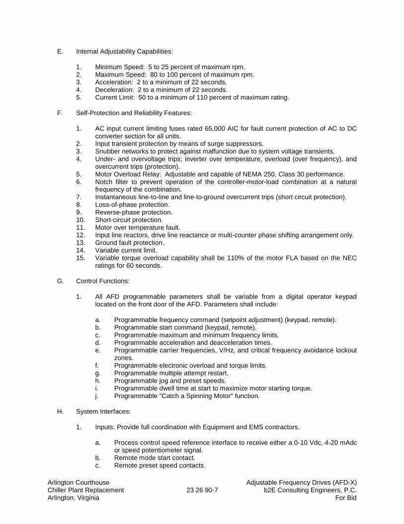
Arlington Courthouse Adjustable Frequency Drives (AFD-X) Chiller Plant Replacement 23 26 90-7 b2E Consulting Engineers, P.C. Arlington, Virginia For Bid
E. Internal Adjustability Capabilities:
1. Minimum Speed: 5 to 25 percent of maximum rpm. 2. Maximum Speed: 80 to 100 percent of maximum rpm. 3. Acceleration: 2 to a minimum of 22 seconds. 4. Deceleration: 2 to a minimum of 22 seconds. 5. Current Limit: 50 to a minimum of 110 percent of maximum rating.
F. Self-Protection and Reliability Features:
1. AC input current limiting fuses rated 65,000 AIC for fault current protection of AC to DC converter section for all units.
2. Input transient protection by means of surge suppressors. 3. Snubber networks to protect against malfunction due to system voltage transients. 4. Under- and overvoltage trips; inverter over temperature, overload (over frequency), and
overcurrent trips (protection). 5. Motor Overload Relay: Adjustable and capable of NEMA 250, Class 30 performance. 6. Notch filter to prevent operation of the controller-motor-load combination at a natural
frequency of the combination. 7. Instantaneous line-to-line and line-to-ground overcurrent trips (short circuit protection). 8. Loss-of-phase protection. 9. Reverse-phase protection. 10. Short-circuit protection. 11. Motor over temperature fault. 12. Input line reactors, drive line reactance or multi-counter phase shifting arrangement only. 13. Ground fault protection. 14. Variable current limit. 15. Variable torque overload capability shall be 110% of the motor FLA based on the NEC
ratings for 60 seconds.
G. Control Functions:
1. All AFD programmable parameters shall be variable from a digital operator keypad located on the front door of the AFD. Parameters shall include:
a. Programmable frequency command (setpoint adjustment) (keypad, remote). b. Programmable start command (keypad, remote). c. Programmable maximum and minimum frequency limits. d. Programmable acceleration and deacceleration times. e. Programmable carrier frequencies, V/Hz, and critical frequency avoidance lockout
zones. f. Programmable electronic overload and torque limits. g. Programmable multiple attempt restart. h. Programmable jog and preset speeds. i. Programmable dwell time at start to maximize motor starting torque. j. Programmable "Catch a Spinning Motor" function.
H. System Interfaces:
1. Inputs: Provide full coordination with Equipment and EMS contractors.
a. Process control speed reference interface to receive either a 0-10 Vdc, 4-20 mAdc or speed potentiometer signal.
b. Remote mode start contact. c. Remote preset speed contacts.
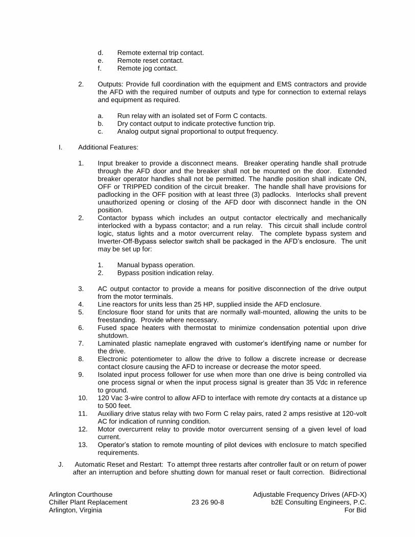
Arlington Courthouse Adjustable Frequency Drives (AFD-X) Chiller Plant Replacement 23 26 90-8 b2E Consulting Engineers, P.C. Arlington, Virginia For Bid
d. Remote external trip contact. e. Remote reset contact. f. Remote jog contact.
2. Outputs: Provide full coordination with the equipment and EMS contractors and provide the AFD with the required number of outputs and type for connection to external relays and equipment as required.
a. Run relay with an isolated set of Form C contacts. b. Dry contact output to indicate protective function trip. c. Analog output signal proportional to output frequency.
I. Additional Features:
1. Input breaker to provide a disconnect means. Breaker operating handle shall protrude through the AFD door and the breaker shall not be mounted on the door. Extended breaker operator handles shall not be permitted. The handle position shall indicate ON, OFF or TRIPPED condition of the circuit breaker. The handle shall have provisions for padlocking in the OFF position with at least three (3) padlocks. Interlocks shall prevent unauthorized opening or closing of the AFD door with disconnect handle in the ON position.
2. Contactor bypass which includes an output contactor electrically and mechanically interlocked with a bypass contactor; and a run relay. This circuit shall include control logic, status lights and a motor overcurrent relay. The complete bypass system and Inverter-Off-Bypass selector switch shall be packaged in the AFD’s enclosure. The unit may be set up for:
1. Manual bypass operation. 2. Bypass position indication relay.
3. AC output contactor to provide a means for positive disconnection of the drive output from the motor terminals.
4. Line reactors for units less than 25 HP, supplied inside the AFD enclosure. 5. Enclosure floor stand for units that are normally wall-mounted, allowing the units to be
freestanding. Provide where necessary. 6. Fused space heaters with thermostat to minimize condensation potential upon drive
shutdown. 7. Laminated plastic nameplate engraved with customer’s identifying name or number for
the drive. 8. Electronic potentiometer to allow the drive to follow a discrete increase or decrease
contact closure causing the AFD to increase or decrease the motor speed. 9. Isolated input process follower for use when more than one drive is being controlled via
one process signal or when the input process signal is greater than 35 Vdc in reference to ground.
10. 120 Vac 3-wire control to allow AFD to interface with remote dry contacts at a distance up to 500 feet.
11. Auxiliary drive status relay with two Form C relay pairs, rated 2 amps resistive at 120-volt AC for indication of running condition.
12. Motor overcurrent relay to provide motor overcurrent sensing of a given level of load current.
13. Operator’s station to remote mounting of pilot devices with enclosure to match specified requirements.
J. Automatic Reset and Restart: To attempt three restarts after controller fault or on return of power after an interruption and before shutting down for manual reset or fault correction. Bidirectional
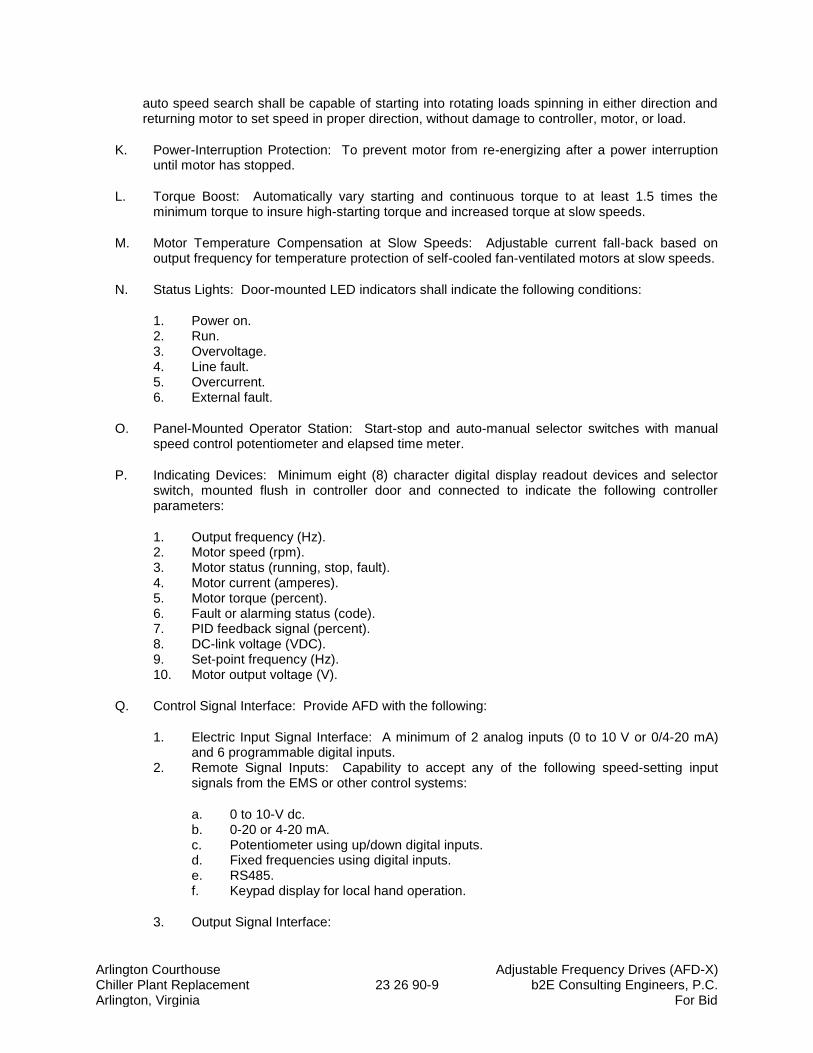
Arlington Courthouse Adjustable Frequency Drives (AFD-X) Chiller Plant Replacement 23 26 90-9 b2E Consulting Engineers, P.C. Arlington, Virginia For Bid
auto speed search shall be capable of starting into rotating loads spinning in either direction and returning motor to set speed in proper direction, without damage to controller, motor, or load.
K. Power-Interruption Protection: To prevent motor from re-energizing after a power interruption until motor has stopped.
L. Torque Boost: Automatically vary starting and continuous torque to at least 1.5 times the minimum torque to insure high-starting torque and increased torque at slow speeds.
M. Motor Temperature Compensation at Slow Speeds: Adjustable current fall-back based on output frequency for temperature protection of self-cooled fan-ventilated motors at slow speeds.
N. Status Lights: Door-mounted LED indicators shall indicate the following conditions:
1. Power on. 2. Run. 3. Overvoltage. 4. Line fault. 5. Overcurrent. 6. External fault.
O. Panel-Mounted Operator Station: Start-stop and auto-manual selector switches with manual speed control potentiometer and elapsed time meter.
P. Indicating Devices: Minimum eight (8) character digital display readout devices and selector switch, mounted flush in controller door and connected to indicate the following controller parameters:
1. Output frequency (Hz). 2. Motor speed (rpm). 3. Motor status (running, stop, fault). 4. Motor current (amperes). 5. Motor torque (percent). 6. Fault or alarming status (code). 7. PID feedback signal (percent). 8. DC-link voltage (VDC). 9. Set-point frequency (Hz). 10. Motor output voltage (V).
Q. Control Signal Interface: Provide AFD with the following:
1. Electric Input Signal Interface: A minimum of 2 analog inputs (0 to 10 V or 0/4-20 mA) and 6 programmable digital inputs.
2. Remote Signal Inputs: Capability to accept any of the following speed-setting input signals from the EMS or other control systems:
a. 0 to 10-V dc. b. 0-20 or 4-20 mA. c. Potentiometer using up/down digital inputs. d. Fixed frequencies using digital inputs. e. RS485. f. Keypad display for local hand operation.
3. Output Signal Interface:
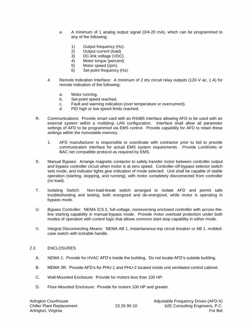
Arlington Courthouse Adjustable Frequency Drives (AFD-X) Chiller Plant Replacement 23 26 90-10 b2E Consulting Engineers, P.C. Arlington, Virginia For Bid
a. A minimum of 1 analog output signal (0/4-20 mA), which can be programmed to any of the following:
1) Output frequency (Hz). 2) Output current (load). 3) DC-link voltage (VDC). 4) Motor torque (percent). 5) Motor speed (rpm). 6) Set-point frequency (Hz).
4. Remote Indication Interface: A minimum of 2 dry circuit relay outputs (120-V ac, 1 A) for remote indication of the following:
a. Motor running. b. Set-point speed reached. c. Fault and warning indication (over temperature or overcurrent). d. PID high or low speed limits reached.
R. Communications: Provide smart card with an RS485 interface allowing AFD to be used with an external system within a multidrop LAN configuration. Interface shall allow all parameter settings of AFD to be programmed via EMS control. Provide capability for AFD to retain these settings within the nonvolatile memory.
1. AFD manufacturer is responsible to coordinate with contractor prior to bid to provide communication interface for actual EMS system requirements. Provide LonWorks or BAC net compatible protocol as required by EMS.
S. Manual Bypass: Arrange magnetic contactor to safely transfer motor between controller output and bypass controller circuit when motor is at zero speed. Controller-off-bypass selector switch sets mode, and indicator lights give indication of mode selected. Unit shall be capable of stable operation (starting, stopping, and running), with motor completely disconnected from controller (no load).
T. Isolating Switch: Non-load-break switch arranged to isolate AFD and permit safe troubleshooting and testing, both energized and de-energized, while motor is operating in bypass mode.
U. Bypass Controller: NEMA ICS 2, full-voltage, nonreversing enclosed controller with across-the-line starting capability in manual-bypass mode. Provide motor overload protection under both modes of operation with control logic that allows common start-stop capability in either mode.
V. Integral Disconnecting Means: NEMA AB 1, instantaneous-trip circuit breaker or AB 1, molded-case switch with lockable handle.
2.3 ENCLOSURES
A. NEMA 1: Provide for HVAC AFD’s inside the building. Do not locate AFD’s outside building.
B. NEMA 3R: Provide AFD’s for PHU-1 and PHU-2 located inside unit ventilated control cabinet.
C. Wall-Mounted Enclosure: Provide for motors less than 100 HP.
D. Floor-Mounted Enclosure: Provide for motors 100 HP and greater.
Arlington Courthouse Adjustable Frequency Drives (AFD-X) Chiller Plant Replacement 23 26 90-11 b2E Consulting Engineers, P.C. Arlington, Virginia For Bid
E. NEMA 12 Enclosure: Provide for all pool pumps.
2.4 ACCESSORIES
A. Devices shall be factory installed in controller enclosure, unless otherwise indicated.
B. Push-Button Stations, Pilot Lights, and Selector Switches: NEMA ICS 2, heavy-duty type.
C. Stop and Lockout Push-Button Station: Momentary-break, push-button station with a factory-applied hasp arranged so padlock can be used to lock push button in depressed position with control circuit open.
D. Control Relays: Auxiliary and adjustable time-delay relays.
E. Standard Displays:
1. Output frequency (Hz). 2. Set-point frequency (Hz). 3. Motor current (amperes). 4. DC-link voltage (VDC). 5. Motor torque (percent). 6. Motor speed (rpm). 7. Motor output voltage (V).
F. Historical Logging Information and Displays:
1. Real-time clock with current time and date. 2. Running log of total power versus time. 3. Total run time. 4. Fault log, maintaining last four faults with time and date stamp for each.
G. Current-Sensing, Phase-Failure Relays for Bypass Controller: Solid-state sensing circuit with isolated output contacts for hard-wired connection; arranged to operate on phase failure, phase reversal, current unbalance of from 30 to 40 percent, or loss of supply voltage; with adjustable response delay.
2.5 FACTORY FINISHES
A. Manufacturer's standard finish for NEMA 1 and NEMA 3R enclosures.
B. Finish: NEMA 12 enclosures in the pool filter room shall be aluminum.
PART 3 - EXECUTION
3.1 EXAMINATION
A. Examine areas, surfaces, and substrates to receive AFD’s for compliance with requirements, installation tolerances, and other conditions affecting performance.
Arlington Courthouse Adjustable Frequency Drives (AFD-X) Chiller Plant Replacement 23 26 90-12 b2E Consulting Engineers, P.C. Arlington, Virginia For Bid
B. Examine roughing-in for conduit systems to verify actual locations of conduit connections before AFD installation.
C. Proceed with installation only after unsatisfactory conditions have been corrected.
3.2 APPLICATIONS
A. Select features of each AFD to coordinate with ratings and characteristics of supply circuit and motor; required control sequence; and duty cycle of motor, drive, and load.
B. Select rating of controllers to suit motor controlled.
3.3 INSTALLATION
A. Anchor each AFD assembly to steel-channel sills arranged and sized according to manufacturer's written instructions. Attach by bolting. Level and grout sills flush with VFC mounting surface.
B. Install AFD’s on concrete bases complying with Division 3 Section "Cast-in-Place Concrete."
C. Comply with mounting and anchoring requirements specified in Division 26 Section "Seismic Controls for Electrical Work."
D. Controller Fuses: Install fuses in each fusible switch. Comply with requirements in Division 26 Section "Fuses.”
E. Install in accordance with the manufacturer’s installation instructions and as specified.
F. Install free standing units on 6 inch house keeping pads.
G. Install wall mounted units to room walls, or on free standing pedestals.
H. Cover and protect units from installation dust and contamination until environment is cleaned and ready for operation.
3.4 IDENTIFICATION
A. Identify AFD’s, components, and control wiring according to Division 26 Section “Electrical Identification."
B. Operating Instructions: Frame printed operating instructions for AFD’s, including control sequences and emergency procedures. Fabricate frame of finished metal, and cover instructions with clear acrylic plastic. Mount on front of AFD units.
3.5 CONTROL WIRING INSTALLATION
A. Install wiring between AFD’s and remote devices according to Division 26 Section "Conductors and Cables."
B. Bundle, train, and support wiring in enclosures.
Arlington Courthouse Adjustable Frequency Drives (AFD-X) Chiller Plant Replacement 23 26 90-13 b2E Consulting Engineers, P.C. Arlington, Virginia For Bid
C. Connect hand-off-automatic switch and other automatic-control devices where available.
1. Connect selector switches to bypass only manual- and automatic-control devices that have no safety functions when switch is in hand position.
3.6 CONNECTIONS
A. Conduit installation requirements are specified in other Division 26 Sections. Drawings indicate general arrangement of conduit, fittings, and specialties.
B. Ground equipment.
C. Tighten electrical connectors and terminals according to manufacturer's published torque-tightening values. If manufacturer's torque values are not indicated, use those specified in UL 486A and UL 486B.
D. The following standard factory tests shall be performed on the equipment provided under this section. All tests shall be in accordance with the latest version of UL, ANSI and NEMA standards.
1. All printed circuit boards shall be tested under a temperature cycling load test and then functionally tested via fault finder bench equipment prior to unit installation.
2. All final assemblies shall be tested at full load with application of line-to-line and line-to-ground bolted faults. The Adjustable Frequency Drive shall trip electronically without device failure.
3. After all tests have been performed; each AFD shall undergo a 12-hour burn-in test. The drive shall be burned in at 100% inductive or motor load for 12 hours without an unscheduled shutdown.
4. After the burn-in cycle is complete, each AFD shall be put through a 30-minute cycling motor load test before inspection and shipping.
E. The manufacturer shall provide certified copies of factory test reports, to confirm that AFD has been tested as specified.
1. Tests shall verify not only performance of unit and integrated assembly, but also suitability of enclosure venting and rigging.
2. In addition, unit shall be tested in accordance with ANSI Standards.
3.7 FIELD QUALITY CONTROL
A. Provide the services of a qualified, factory-trained manufacturer's representative to assist the Contractor in installation and start-up of the equipment specified under this section. The manufacturer's representative shall provide technical direction and assistance to the Contractor in general assembly of the equipment, connections and adjustments, and testing of the assembly and components contained herein. The contractor shall include any and all applicable commissioning procedures recommended by the manufacturer for the specific unit.
B. The following minimum work shall be performed by the Contractor under the technical direction of the manufacturer's service representative.
1. Inspection and final adjustment. 2. Operational and function checks of AFD’s and spare parts.
Arlington Courthouse Adjustable Frequency Drives (AFD-X) Chiller Plant Replacement 23 26 90-14 b2E Consulting Engineers, P.C. Arlington, Virginia For Bid
3. Coordination and field service as required or requested by the HVAC Balancing contractor.
4. Coordination and field service as required or requested by the EMS contractor.
C. The Contractor shall provide Submittals of the manufacturer's field start-up report before final payment is made.
D. Prepare for acceptance tests as follows:
1. Test insulation resistance for each AFD element, bus, component, connecting supply, feeder, and control circuit.
2. Test continuity of each circuit.
E. Testing: Engage a qualified testing agency to perform the following field quality-control testing:
1. Perform each electrical test and visual and mechanical inspection stated in NETA ATS, Sections 7.5, 7.6, and 7.16. Certify compliance with test parameters.
2. Correct malfunctioning units on-site, where possible, and retest to demonstrate compliance; otherwise, replace with new units and retest.
F. Manufacturer's Field Service: Engage a factory-authorized service representative to inspect field-assembled components and equipment installation, including pretesting and adjusting AFD’s.
G. Test Reports: Prepare a written report to record the following:
1. Test procedures used. 2. Test results that comply with requirements. 3. Test results that do not comply with requirements and corrective action taken to achieve
compliance with requirements.
3.8 MANUFACTURER'S CERTIFICATION
A. A qualified factory-trained manufacturer's representative shall certify in writing that the equipment has been installed, adjusted, and tested in accordance with the manufacturer's recommendations.
B. The Contractor shall provide three (3) copies of the manufacturer's representative's certification before final payment is made.
3.9 TRAINING
A. The Contractor shall provide a factory training session for up to 4 owner’s representative for 2 normal workdays at a jobsite location. In addition, one day of factory training shall be provided at the vendors training center.
B. The training session shall be conducted by a manufacturer’s qualified representative.
C. The training program for the Owner’s maintenance staff shall consist of the following:
1. Instructions on the proper maintenance and operation of the equipment. 2. Instructional hours shall be in addition to testing and start-up hours.
Arlington Courthouse Adjustable Frequency Drives (AFD-X) Chiller Plant Replacement 23 26 90-15 b2E Consulting Engineers, P.C. Arlington, Virginia For Bid
3. Schedule training after equipment and associated systems are completely installed and tested and can operate under normal loads.
4. Provide instruction on each type of system.
D. The training program for the EMS contractor shall consist of the following:
1. Train the EMS contractor to use the AFD and provide wiring diagrams, and direction specific to this project to ensure that the EMS contractor is able to operate the AFD’s, and that all input and output interlocks are fully coordinated with the EMS.
2. Provide additional training for EMS contractor field technicians until all monitoring and control points are operating as specified under Section 23 09 93, and as required by the Arlington County Commissioning Agent.
3. Provide the EMS contractor with a complete set of installation and start-up, and operating manuals. These documents shall be in addition to those provided to the owner. Provide the EMS contractor documents no later than 60 days prior to the contract completion date.
3.10 STARTUP SERVICE
A. Engage a factory-authorized service representative to perform startup service.
B. Verify that electrical wiring installation complies with manufacturer's submittal and installation requirements in Division 26 Sections.
C. Complete installation and startup checks according to manufacturer's written instructions.
3.11 ADJUSTING
A. Set field-adjustable switches and circuit-breaker trip ranges.
3.12 CLEANING
A. Clean AFD’s internally, on completion of installation, according to manufacturer's written instructions. Vacuum dirt and debris; do not use compressed air to assist in cleaning.
3.13 DEMONSTRATION
A. Engage a factory-authorized service representative to train Owner's maintenance personnel to adjust, operate, and maintain AFD’s. Refer to Division 1 Section 01 70 00 "Closeout Procedures."
3.14 COMMISSIONING
A. The Adjustable Frequency Drives (AFDs) shall be commissioned in accordance with the Commissioning (Cx) Plan.
B. The mechanical, controls, and start-up contractors are responsible for supporting all Cx activities and testing as outlined in the Cx Plan. These activities include but are not limited to the following:
Arlington Courthouse Adjustable Frequency Drives (AFD-X) Chiller Plant Replacement 23 26 90-16 b2E Consulting Engineers, P.C. Arlington, Virginia For Bid
1. Respond to all comments provided on the AFD submittals by the Commissioning Agent (CxA).
2. Attend Cx related meetings as outlined in the Cx Plan.
3. Ensure all VFDs are operational in accordance with the contract drawings prior to the start of functional performance testing (FPT).
4. Provide copies of the completed start-up reports and pre-functional checklists to the CxA prior to the start of FPT.
5. Technicians from the start-up, controls, and mechanical contractors are required during all AFD FPT. The start-up technician shall be familiar with the operation of the units and be capable of demonstrating and troubleshooting all required functions.
6. Promptly rectify all AFD related issues that are recorded in the Cx Issues Log. Submit written notification to the Owner, CxA, and Engineer that this has been done. (Note: The CxA does not provide any directives so any deviation from the original scope must be approved be approved by the Owner or Engineer prior to performing work).
3.15 SCHEDULE OF AFD’S
A. Total of 6 AFD’s: Coordinate and provide with capacity to match final approved equipment motor horsepower.
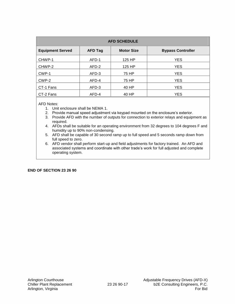
Arlington Courthouse Adjustable Frequency Drives (AFD-X) Chiller Plant Replacement 23 26 90-17 b2E Consulting Engineers, P.C. Arlington, Virginia For Bid
AFD SCHEDULE
Equipment Served AFD Tag Motor Size Bypass Controller
CHWP-1 AFD-1 125 HP YES
CHWP-2 AFD-2 125 HP YES
CWP-1 AFD-3 75 HP YES
CWP-2 AFD-4 75 HP YES
CT-1 Fans AFD-3 40 HP YES
CT-2 Fans AFD-4 40 HP YES AFD Notes:
1. Unit enclosure shall be NEMA 1. 2. Provide manual speed adjustment via keypad mounted on the enclosure’s exterior. 3. Provide AFD with the number of outputs for connection to exterior relays and equipment as
required. 4. AFDs shall be suitable for an operating environment from 32 degrees to 104 degrees F and
humidity up to 90% non-condensing. 5. AFD shall be capable of 30 second ramp up to full speed and 5 seconds ramp down from
full speed to zero. 6. AFD vendor shall perform start-up and field adjustments for factory trained. An AFD and
associated systems and coordinate with other trade’s work for full adjusted and complete operating system.
END OF SECTION 23 26 90
Arlington Courthouse Centrifugal Water Chillers (CH-1 & 2) Chiller Plant Replacement 23 64 16-1 b2E Consulting Engineers, P.C. Arlington, Virginia For Bid
SECTION 23 64 16
CENTRIFUGAL WATER CHILLERS (CH-1 & 2)
PART 1 - GENERAL
1.1 SUMMARY
A. Section Includes:
1. Packaged, water-cooled, electric-motor-driven centrifugal chillers. 2. Packaged, portable refrigerant recovery units. 3. Chilled water plant control system (See Section 23 64 16-A and 23 64 16-B).
B. Chiller Rigging: The chillers shall be factory assembled and witness tested and shall be installed as tested without disassembly.
1.2 DEFINITIONS
A. CWSC: (Chiller Manufacturers Plant Optimization Controls).
B. EMS: Energy Management System, (Siemans BACnet Integration).
C. COP: Coefficient of performance. The ratio of the rate of heat removal to the rate of energy input using consistent units for any given set of rating conditions.
D. EER: Energy-efficiency ratio. The ratio of the cooling capacity given in terms of Btu/h to the total power input given in terms of watts at any given set of rating conditions.
E. IPLV: Integrated part-load value. A single-number part-load efficiency figure of merit calculated per the method defined by ARI 550/590 and referenced to ARI standard rating conditions.
F. kW/Ton (kW/kW): The ratio of total power input of the chiller in kilowatts to the net refrigerating capacity in tons (kW) at any given set of rating conditions.
F. NPLV: Nonstandard part-load value. A single-number part-load efficiency figure of merit calculated per the method defined by ARI 550/590 and intended for operating conditions other than the ARI standard rating conditions.
1.3 PERFORMANCE REQUIREMENTS
A. Condenser-Fluid Temperature Performance: 1. Startup Condenser-Fluid Temperature: Chiller shall be capable of starting with an entering
condenser-fluid temperature of 40 deg F (4 deg C) and providing stable operation until the system temperature is elevated to the minimum operating entering condenser-fluid temperature.
Arlington Courthouse Centrifugal Water Chillers (CH-1 & 2) Chiller Plant Replacement 23 64 16-2 b2E Consulting Engineers, P.C. Arlington, Virginia For Bid
2. Minimum Operating Condenser-Fluid Temperature: Chiller shall be capable of continuous operation over the entire capacity range indicated with an entering condenser-fluid temperature of 60 deg F (16 deg C).
3. Make factory modifications to standard chiller design if necessary to comply with performance indicated.
B. Site Altitude: Chiller shall be suitable for altitude at which installed without affecting performance indicated. Make adjustments to affected chiller components to account for site altitude.
C. Performance Tolerance: Comply with ARI 550/590:
1. Allowable Capacity Tolerance: ARI 550/590. 2. Allowable IPLV/NPLV Performance Tolerance: ARI 550/590.
1.4 SUBMITTALS
A. Product Data: For each type of product indicated. Include refrigerant, rated capacities, operating characteristics, furnished specialties, and accessories.
1. Performance at ARI standard conditions and at conditions indicated. 2. Performance at ARI standard unloading conditions. 3. Minimum evaporator flow rate. 4. Refrigerant capacity of chiller. 5. Oil capacity of chiller. 6. Fluid capacity of evaporator, condenser. 7. Characteristics of safety relief valves. 8. Minimum entering condenser-fluid temperature. 9. Performance at varying capacities with constant design condenser-fluid temperature.
Repeat performance at varying capacities for different condenser-fluid temperatures from design to minimum in 5 deg F (3 deg C) increments.
B. Shop Drawings: Include plans, elevations, sections, details, and attachments to other work.
1. Detail equipment assemblies and indicate dimensions, weights, load distribution, required clearances, method of field assembly, components, and location and size of each field connection.
2. Wiring Diagrams: For power, signal, and control wiring.
C. Coordination Drawings: Floor plans, drawn to scale, on which the following items are shown and coordinated with each other, using input from installers of the items involved:
1. Structural supports. 2. Piping roughing-in requirements. 3. Wiring roughing-in requirements, including spaces reserved for electrical equipment. 4. Access requirements, including working clearances for mechanical controls and electrical
equipment, and tube pull and service clearances.
D. Certificates: For certification required in "Quality Assurance" Article.
E. Source quality-control reports.
Arlington Courthouse Centrifugal Water Chillers (CH-1 & 2) Chiller Plant Replacement 23 64 16-3 b2E Consulting Engineers, P.C. Arlington, Virginia For Bid
F. Startup service reports.
G. Operation and Maintenance Data: For each chiller to include in emergency, operation, and maintenance manuals.
H. Warranty: Sample of special warranty.
1.5 QUALITY ASSURANCE
A. ARI Certification: Certify chiller according to ARI 550 certification program.
B. ARI Rating: Rate chiller performance according to requirements in ARI 550/590.
C. ASHRAE Compliance:
1. ASHRAE 15 for safety code for mechanical refrigeration. 2. ASHRAE 147 for refrigerant leaks, recovery, and handling and storage requirements.
D. ASHRAE/IESNA Compliance: Applicable requirements in ASHRAE/IESNA 90.1-2004.
E. ASME Compliance: Fabricate and label chillers to comply with ASME Boiler and Pressure Vessel Code: Section VIII, Division 1, as applicable to chiller design. For chillers charged with R-134a refrigerant, include an ASME U-stamp and nameplate certifying compliance.
F. Comply with NFPA 70.
G. Comply with requirements of UL and UL Canada, and include label by a qualified testing agency showing compliance.
H. Green Seal Compliance: Signed by manufacturer certifying compliance with GS-31.
1.6 DELIVERY, STORAGE, AND HANDLING
A. Ship chillers from the factory fully charged with refrigerant or field charged by factory service technician.
B. Ship each chiller with a full charge of refrigerant. Charge each chiller with nitrogen if refrigerant is shipped in containers separate from chiller.
C. Ship each oil-lubricated chiller with a full charge of oil.
1. Ship oil factory installed in chiller.
D. Package chiller for export shipping in totally enclosed crate with bagging.
1.7 COORDINATION
A. Coordinate sizes and locations of concrete bases with actual equipment provided. Cast anchor-bolt inserts into bases.
Arlington Courthouse Centrifugal Water Chillers (CH-1 & 2) Chiller Plant Replacement 23 64 16-4 b2E Consulting Engineers, P.C. Arlington, Virginia For Bid
B. Coordinate sizes, locations, and anchoring attachments of structural-steel support structures.
1.8 WARRANTY – TEN YEARS, PARTS, LABOR AND REFRIGERANT
A. Special Warranty: Manufacturer's standard form in which manufacturer agrees to repair or replace components of chillers that fail in materials or workmanship within specified warranty period.
1. Extended warranties include, but are not limited to, the following:
a. Complete chiller including refrigerant and oil charge. b. Complete compressor and drive assembly including refrigerant and oil charge. c. Refrigerant and oil charge. d. Parts and labor. e. Loss of refrigerant charge for any reason.
2. Warranty Period: Ten years from date of Substantial Completion.
1.9 QUARTERLY INSPECTIONS – TWO YEARS
A. Provide quarterly inspections for two years starting from substantial completion.
PART 2 - PRODUCTS
2.1 MANUFACTURERS
A. Acceptable Manufacturers: Subject to compliance with requirements, provide products by one of the following:
1. Basis of Design: Trane; a division of Ingersoll Rand.
2. Or Approved Equal: In Accordance with substitution procedures in section 016000 Paragraph 2.2.
2.2 MANUFACTURED UNIT
A. Description: Factory-assembled and tested chiller complete with compressor, compressor motor, compressor motor controller, lubrication system evaporator, condenser, heat-reclaim condenser as indicated, controls, interconnecting unit piping and wiring, and indicated accessories.
1. Disassemble chiller into major assemblies as required by the installation after factory testing and before packaging for shipment.
2. For chillers with dual compressors, provide each compressor with a dedicated motor and motor controller, and provide for continued operation when either compressor-drive assembly fails or is being serviced.
Arlington Courthouse Centrifugal Water Chillers (CH-1 & 2) Chiller Plant Replacement 23 64 16-5 b2E Consulting Engineers, P.C. Arlington, Virginia For Bid
B. Fabricate chiller mounting base with reinforcement strong enough to resist chiller movement during a seismic event when chiller is anchored to field support structure.
2.3 COMPRESSOR AND MOTOR
A. The compressor shall be centrifugal with single or multiple stages.
B. Low or medium pressure refrigerant machines shall be done by manufacturer’s commercial warranty agent.
C. Service: Easily accessible for inspection and service.
1. Compressor's internal components shall be accessible without having to remove compressor-drive assembly from chiller.
2. Provide lifting lugs or eyebolts attached to casing.
D. Economizer: A flash economizer with no moving parts provides power saving capability.
E. Capacity Control: Modulating, variable-inlet, guide-vane assembly combined with hot-gas bypass, if necessary, to achieve performance indicated.
1. Maintain stable operation that is free of surge, cavitation, and vibration throughout range of operation. Configure to achieve most energy-efficient operation possible.
2. Operating Range: From 100 to 8 percent of design capacity. 3. Condenser-Fluid Unloading Requirements over Operating Range: Constant-design
entering condenser-fluid temperature. 4. Chillers with variable frequency controllers shall modulate compressor speed with variable-
inlet, guide-vane control to achieve optimum energy efficiency.
F. Oil Lubrication System: Consisting of pump, filtration, heater, cooler, factory-wired power connection, and controls.
1. Provide lubrication to bearings, gears, and other rotating surfaces at all operating, startup, coast down, and standby conditions including power failure.
2. Thermostatically controlled oil heater properly sized to remove refrigerant from oil. 3. Dual oil filters, one redundant, shall be the easily replaceable cartridge type, minimum 0.5-
micron efficiency, with means of positive isolation while servicing. 4. Refrigerant- or water-cooled oil cooler. 5. Factory-installed and pressure-tested piping with isolation valves and accessories. 6. Oil compatible with refrigerant and chiller components. 7. Positive visual indication of oil level.
2.4 REFRIGERATION
A. Refrigerant:
1. Type: R-123 (or R-134a if substituted is approved); ASHRAE 34, Class A1 or Class B1. 2. Compatibility: Chiller parts exposed to refrigerants shall be fully compatible with
refrigerants, and pressure components shall be rated for refrigerant pressures.
Arlington Courthouse Centrifugal Water Chillers (CH-1 & 2) Chiller Plant Replacement 23 64 16-6 b2E Consulting Engineers, P.C. Arlington, Virginia For Bid
B. Refrigerant Flow Control: Manufacturer's standard refrigerant flow-control device satisfying performance requirements indicated.
C. Pressure Relief Device:
1. Comply with requirements in ASHRAE 15 and in applicable portions of ASME Boiler and Pressure Vessel Code: Section VIII, Division 1.
2. For Chillers Using R-123 Spring-loaded, pressure relief valve; single- or multiple-reseating type (Field installed).
3. For Chillers Using R-134a: ASME-rated, spring-loaded, pressure relief valve; single- or multiple-reseating type. Pressure relief valve(s) shall be provided for each heat exchanger. Condenser shall have dual valves with one being redundant and configured to allow either valve to be replaced without loss of refrigerant.
D. Refrigeration Transfer: Provide service valves and other factory-installed accessories required to facilitate transfer of refrigerant from chiller to a remote refrigerant storage and recycling system. Comply with requirements in ASHRAE 15 and ASHRAE 147.
E. Refrigerant Isolation for Chillers Using R-134a: Factory install positive shutoff, manual isolation valves in the compressor discharge line to the condenser and the refrigerant liquid line leaving the condenser to allow for isolation and storage of full refrigerant charge in the chiller condenser shell. In addition, provide isolation valve on suction side of compressor from evaporator to allow for isolation and storage of full refrigerant charge in the chiller evaporator shell.
F. Purge System:
1. For chillers operating at subatmospheric pressures (using R-123 refrigerant), factory install an automatic purge system for collection and return of refrigerant and lubricating oil and for removal of noncondensables including, but not limited to, water, water vapor, and noncondensable gases.
2. System shall be a thermal purge design, refrigerant or air cooled, equipped with a carbon filter that includes an automatic regeneration cycle.
3. Factory wire to chiller's main power supply and system complete with controls, piping, and refrigerant valves to isolate the purge system from the chiller.
4. Construct components of noncorrodible materials. 5. Controls shall interface with chiller control panel to indicate modes of operation, set points,
data reports, diagnostics, and alarms. 6. Efficiency of not more than 0.02 lb of refrigerant per pound of air (9 g of refrigerant per
gram of air) when rated according to ARI 580. 7. Operation independent of chiller per ASHRAE 147.
2.5 EVAPORATOR
A. Description: Shell-and-tube design with water in tubes and refrigerant surrounding tubes within shell. Shell is separate from condenser.
B. Shell Material: Carbon-steel rolled plates with continuously welded seams or seamless pipe.
C. Designed to prevent liquid refrigerant carryover from entering compressor.
D. Provide evaporator with sight glass or other form of positive visual verification of liquid-refrigerant level.
Arlington Courthouse Centrifugal Water Chillers (CH-1 & 2) Chiller Plant Replacement 23 64 16-7 b2E Consulting Engineers, P.C. Arlington, Virginia For Bid
E. Tubes:
1. Individually replaceable from either end and without damage to tube sheets and other tubes.
2. Mechanically expanded into end sheets and physically attached to intermediate tube sheets.
3. Material: Copper or Copper-nickel alloy. 4. Nominal OD: 3/4 or 1 inch (19 or 25 mm). 5. Minimum Wall Thickness: 0.035 inch (0.025 mm). 6. External Finish: Manufacturer's standard. 7. Internal Finish: Enhanced or smooth.
F. End Tube Sheets: Continuously welded to each end of shell; drilled and reamed to accommodate tubes with positive seal between fluid in tubes and refrigerant in shell.
G. Intermediate Tube Sheets: Installed in shell and spaced along length of tube at intervals required to eliminate vibration and to avoid contact of tubes resulting in abrasion and wear.
H. Marine Water Boxes: Grooved connections with 2 vents and 2 drains.
I. Hinged access, both ends of the evaporator.
2.6 CONDENSER
A. Description: Shell-and-tube design with water in tubes and refrigerant surrounding tubes within shell. Shell is separate from evaporator.
B. Shell Material: Carbon-steel rolled plates with continuously welded seams or seamless pipe.
C. Designed to prevent direct impingement of high-velocity hot gas from compressor discharge on tubes.
D. Provide condenser with sight glass or other form of positive visual verification of refrigerant charge and condition.
E. Tubes:
1. Individually replaceable from either end and without damage to tube sheets and other tubes.
2. Mechanically expanded into end sheets and physically attached to intermediate tube sheets.
3. Material: Copper or Copper-nickel alloy. 4. Nominal OD: 3/4 or 1 inch (19 or 25 mm). 5. Minimum Wall Thickness: 0.028 inches. 6. External Finish: Manufacturer's standard. 7. Internal Finish: Enhanced or smooth.
F. End Tube Sheets: Continuously welded to each end of shell; drilled and reamed to accommodate tubes with positive seal between fluid in tubes and refrigerant in shell.
G. Intermediate Tube Sheets: Installed in shell and spaced along length of tube at intervals required to eliminate vibration and to avoid contact of tubes resulting in abrasion and wear.
Arlington Courthouse Centrifugal Water Chillers (CH-1 & 2) Chiller Plant Replacement 23 64 16-8 b2E Consulting Engineers, P.C. Arlington, Virginia For Bid
H. Marine Water Boxes: Grooved connections with 1 vent and 1 drain.
I. Hinged access, both ends of the condenser.
2.7 INSULATION
A. Closed-cell, flexible elastomeric thermal insulation complying with ASTM C 534, Type I for tubular materials and Type II for sheet materials.
1. Thickness: 3/4 inch (19 mm) or 1-1/2 inches (38 mm) as necessary to prevent sweating.
B. Adhesive: As recommended by insulation manufacturer.
C. Factory-applied insulation over all cold surfaces of chiller capable of forming condensation. Components shall include, but not be limited to, evaporator shell and end tube sheets, evaporator water boxes including nozzles, refrigerant suction pipe from evaporator to compressor, cold surfaces of compressor, refrigerant-cooled motor, and auxiliary piping.
1. Apply adhesive to 100 percent of insulation contact surface. 2. Before insulating steel surfaces, prepare surfaces for paint, and prime and paint as
indicated for other painted components. Do not insulate unpainted steel surfaces. 3. Seal seams and joints to provide a vapor barrier. 4. After adhesive has fully cured, paint exposed surfaces of insulation to match other painted
parts.
2.8 ELECTRICAL
A. Factory installed and wired, and functionally tested at factory before shipment.
B. Single-point, field-power connection to circuit breaker. Minimum withstand rating shall be as required by electrical power distribution system, but not less than 100,000 AIC.
1. Branch power circuit to each motor, electric heater, dedicated electrical load, and controls.
a. NEMA KS 1, heavy-duty, fusible switch with rejection-type fuse clips rated for fuses. Select and size fuses to provide Type 2 protection according to IEC 60947-4-1.
b. NEMA AB 1, motor-circuit protector (circuit breaker) with field-adjustable, short-circuit-trip set point.
2. NEMA ICS 2-rated motor controller for auxiliary motors, hand-off-auto switch, and overcurrent protection for each motor. Provide variable frequency controller for each variable-speed motor furnished.
3. Control-circuit transformer with primary and secondary side fuses.
C. Terminal blocks with numbered and color-coded wiring to match wiring diagram. Spare wiring terminal block for connection to external controls or equipment.
D. Factory-installed wiring outside of enclosures shall be in metal raceway except make terminal connections with not more than a 24-inch (610-mm) length of liquidtight or flexible metallic conduit.
Arlington Courthouse Centrifugal Water Chillers (CH-1 & 2) Chiller Plant Replacement 23 64 16-9 b2E Consulting Engineers, P.C. Arlington, Virginia For Bid
E. Factory install and wire capacitor bank for the purpose of power factor correction to 0.95 at all operating conditions.
1. If capacitors are mounted in a dedicated enclosure, use same NEMA enclosure type as motor controller. Provide enclosure with service entrance knockouts and bushings for conduit.
2. Capacitors shall be non-PCB dielectric fluid, metallized electrode design, low loss with low-temperature rise. The kVAr ratings shall be indicated and shall not exceed the maximum limitations set by NFPA 70. Provide individual cells as required.
3. Provide each cell with current-limiting replaceable fuses and carbon-film discharge resistors to reduce residual voltage to less than 50 V within one minute after de-energizing.
4. Provide a ground terminal and a terminal block or individual connectors for phase connection.
2.9 LOW VOLTAGE VARIABLE SPEED DRIVE (VSD), UNIT MOUNTED
1. The centrifugal water chiller shall be furnished with a liquid cooled variable speed drive (VSD) as shown on the drawings. The VSD shall be factory mounted on the chiller and shipped completely factory assembled, wired and tested.
2. The VSD will be specifically designed to interface with the centrifugal water chiller con-trols and allow for the operating ranges and specific characteristics of the chiller. The VSD control logic shall optimize chiller efficiency by coordinating compressor motor speed and compressor inlet guide vane position to maintain the chilled water setpoint while avoiding surge. If a surge is detected, VSD surge avoidance logic will make ad-justments to move away from and avoid surge at similar conditions in the future.
3. The VSD efficiency shall be 97% or better at full speed and full load. Fundamental dis-placement power factor shall be a minimum of 0.96 at all loads.
4. The VSD shall be solid state, microprocessor based pulse-width modulated (PWM) de-sign. The VSD shall be voltage and current regulated. Output power devices shall be IGBT transistors.
5. Power semi-conductor and capacitor cooling shall be from a liquid cooled heatsink.
6. The VSD shall be refrigerant cooled to minimize maintenance and maximize cooling effi-ciency. If a water cooling design is used, especially an open loop condenser water de-sign, a cleanable shell and tube heat exchanger must be supplied. Plate and frame heat exchangers are not allowed.
7. The VSDs shall each be furnished in a NEMA 1 metal enclosure having as minimum a short circuit current rating (SCCR) of 65,000 amps per UL 508. It will include three phase input lugs plus a grounding lug for electrical connections, output motor connection via fac-tory installed bus bars and all components properly segregated and completely enclosed in a single metal enclosure.
a. Enclosure shall include a padlockable, door-mounted circuit breaker with shunt trip and AIC rating of 65,000 amps.
b. The entire chiller package shall be UL/CUL listed.
Arlington Courthouse Centrifugal Water Chillers (CH-1 & 2) Chiller Plant Replacement 23 64 16-10 b2E Consulting Engineers, P.C. Arlington, Virginia For Bid
8. The VSD shall be tested to ANSI/UL Standard 508 and shall be listed by a Nationally Recognized Testing Laboratory (NRTL) as designated by OSHA.
9. The VSD design shall include a standard integrated active rectification control system to limit total demand distortion (TDD) in current at the VSD to less than or equal to 5% as measured at the VSD input, in compliance to recommendations stated in IEEE 519-1992.
a. If optional active or passive filters are used to meet the less than or equal to 5% TDD, then the losses associated with the filter shall be included in the chiller per-formance on the selection (adjust penalties accordingly).
b. If a remote mounted filter is used to meet the less than or equal to 5% TDD, then the losses associated with the filter shall be included in the chiller performance on the selection (adjust penalties accordingly). Additionally, the remote filter must be brought in and tested along with the chiller for all applicable tests.
c. If a remote mounted filter is used and is required to be tested, the contractor is re-sponsible for all associated installation costs of the remote filter for testing.
10. Input shall be nominal 460 - 480V, 60Hz, three phase AC power, ± 10 percent of nominal voltage.
11. Frequency range 38-60 hertz.
12. The VSD shall include the following features:
a. All control circuit voltages are physically and electrically isolated from power circuit voltage.
b. 150% instantaneous torque available for improved surge control. c. Soft start, adjustable linear acceleration, coast-to-stop. d. Insensitivity to incoming power phase sequence. e. Adjustable current limiting and U.L. approved electronic motor overload protection. f. Output line-to-line short circuit protection. g. Line-to-ground short circuit protection. h. Protection from phase loss at AFD input. i. Protection from phase reversal/imbalance. j. Protection from over/under-voltage. k. Protection from over-temperature.
13. The following VSD status indicators shall be available to facilitate startup and mainte-nance:
a. Output speed in hertz and rpm. b. Input line voltage. c. Input line kW. d. Output/load amps. e. Average current in percent RLA. f. Load power factor. g. Fault. h. VSD transistor temperature.
Arlington Courthouse Centrifugal Water Chillers (CH-1 & 2) Chiller Plant Replacement 23 64 16-11 b2E Consulting Engineers, P.C. Arlington, Virginia For Bid
14. Service Conditions - at full output power:
a. No external venting or heat exchangers shall be required. b. Operating ambient temperature of 32°F - 104°F (0°C - 40°C). c. Room ambient up to 95% relative humidity.
F. Elevation up to 3300 feet (1000 meters). For every 300 feet (90 meters) above 3300 feet, the rated output current shall be decreased by 1%.
2.10 CHILLER CONTROLS
A. Control: Standalone and microprocessor based, with all memory stored in nonvolatile memory so that reprogramming is not required on loss of electrical power.
B. Enclosure: Unit mounted, NEMA 250, Type 4, hinged or lockable; factory wired with a single-point, field-power connection, and a separate control circuit.
C. Operator Interface: Touch screen, 12-inch graphic display with dynamic update of information and with keypad or touch-sensitive display located on front of control enclosure. In either imperial or metric units selectable through the interface, display the following information:
1. Date and time. 2. Operating or alarm status. 3. Fault history with not less than last 10 faults displayed. 4. Set points of controllable parameters. 5. Trend data. 6. Operating hours. 7. Number of chiller starts. 8. Outdoor-air temperature or space temperature if required for chilled-water reset. 9. Entering- and leaving-fluid temperatures of evaporator and condenser. 10. Difference in fluid temperatures of evaporator and condenser. 11. Fluid flow of evaporator and condenser. 12. Fluid pressure drop of evaporator and condenser. 13. Refrigerant pressures in evaporator and condenser. 14. Refrigerant saturation temperature in evaporator and condenser shell. 15. Compressor refrigerant suction and discharge temperature. 16. Compressor bearing temperature. 17. Motor bearing temperature. 18. Motor winding temperature. 19. Oil temperature. 20. Oil discharge pressure. 21. Phase current. 22. Percent of motor rated load amperage. 23. Phase voltage. 24. Demand power (kilowatts). 25. Energy use (kilowatt-hours). 26. Power factor. 27. For chillers equipped with variable frequency controllers and harmonic filters, include the
following:
a. Output voltage and frequency. b. Voltage total harmonic distortion for each phase.
Arlington Courthouse Centrifugal Water Chillers (CH-1 & 2) Chiller Plant Replacement 23 64 16-12 b2E Consulting Engineers, P.C. Arlington, Virginia For Bid
c. Supply current total demand distortion for each phase. d. Inlet vane position. e. Controller internal ambient temperature. f. Heatsink temperature.
28. Purge suction temperature if purge system is provided. 29. Purge elapsed time if purge system is provided.
D. Control Functions:
1. Manual or automatic startup and shutdown time schedule. 2. Entering and leaving chilled-water temperatures, control set points, and motor load limits.
Evaporator fluid temperature shall be reset based on return-water and/or outdoor-air temperature.
3. Current limit and demand limit. 4. Condenser-fluid temperature. 5. External chiller emergency stop.
E. Manually Reset Safety Controls: The following conditions shall shut down chiller and require manual reset:
1. Low evaporator pressure or temperature; high condenser pressure. 2. Low evaporator fluid temperature. 3. Low oil differential pressure. 4. High or low oil pressure. 5. High oil temperature. 6. High compressor-discharge temperature. 7. Loss of condenser-fluid flow. 8. Loss of evaporator fluid flow. 9. Motor overcurrent. 10. Motor overvoltage. 11. Motor undervoltage. 12. Motor phase reversal. 13. Motor phase failure. 14. Sensor- or detection-circuit fault. 15. Processor communication loss. 16. Motor controller fault. 17. Extended compressor surge. 18. Excessive air-leakage detection for chillers using R-123 refrigerant.
F. Trending: Capability to trend analog data of up to five parameters simultaneously over an adjustable period and frequency of polling.
G. Security Access: Provide electronic security access to controls through identification and password with at least three levels of access: view only; view and operate; and view, operate, and service.
H. Control Authority: At least four conditions: Off, local manual control at chiller, local automatic control at chiller, and automatic control through a remote source.
I. Communication Port: RS-232 port, USB 2.0 port, or equivalent connection capable of connecting a printer and a notebook computer.
Arlington Courthouse Centrifugal Water Chillers (CH-1 & 2) Chiller Plant Replacement 23 64 16-13 b2E Consulting Engineers, P.C. Arlington, Virginia For Bid
2.11 CHILLED WATER SYSTEM CONTROLS
A. The chiller manufacturer shall provide a stand-alone direct digital control system to operate the chilled water system. Refer to P & ID diagrams, Points lists and Sequencing of Operation for other applicable requirements.
B. This control system shall control operation of the following equipment: 1. Chiller #1 (CH-1) and associated automatic 2-position isolation valves. 2. Chiller #2 (CH-2) and associated automatic 2-position isolation valves. 3. Cooling Tower #1 (CT-1) and associated automatic 2-position isolation valves, AFD drivers. 4. Cooling Tower #2 (CT-2) and associated automatic 2-position isolation valves, AFD drivers. 5. Condenser Water pump #1 (CWP-1); AFD driven with differential pressure stats. 6. Condenser Water Pump #2 (CWP-2); AFD driven with differential pressure stats. 7. Chilled Water Pump #1 (CHWP-1); AFD drivers with pressure transducers for pump speed
control, and differential pressure status. 8. Chilled Water Pump #2 (CHWP-2); AFD drivers with pressure transducers for pump speed
control, and differential pressure status. 9. Solids separator (blow down for cooling tower). 10. CHW supply flow meter. 11. CW supply temperature. 12. CW return temperature. 13. CHW supply temperature for each chiller. 14. CHW return temperature for each chiller. 15. Chiller #1 differential pressure. 16. Chiller #2 differential pressure. 17. Other points as listed on the points list.
C. The chiller plant control system is specified in Section 23 64 16-A and 23 64 16-B and shall be provided by the Chiller Manufacturer.
2.12 FINISH
A. Paint chiller, using manufacturer's standard procedures, except comply with the following minimum requirements:
1. Provide at least one coat of primer with a total dry film thickness of at least 2 mils (0.05 mm).
2. Provide at least two coats of alkyd-modified, vinyl enamel; epoxy; or polyurethane finish with a total dry film thickness of at least 4 mils (0.10 mm).
3. Paint surfaces that are to be insulated before applying the insulation. 4. Paint installed insulation to match adjacent uninsulated surfaces. 5. Color of finish coat to be manufacturer's standard.
B. Provide Owner with quart container of paint used in application of topcoat to use in touchup applications after Project Closeout.
2.12 ACCESSORIES
A. Flow Switches:
Arlington Courthouse Centrifugal Water Chillers (CH-1 & 2) Chiller Plant Replacement 23 64 16-14 b2E Consulting Engineers, P.C. Arlington, Virginia For Bid
1. Chiller manufacturer shall furnish a switch for each evaporator and condenser and verify field-mounting location before installation.
2. Pressure Differential Switches:
a. Construction: Wetted parts of body and trim constructed of Type 316 stainless steel. b. Performance: Switch shall withstand, without damage, the full-pressure rating of the
heat exchanger applied to either port and exhibit zero set-point shift due to variation in working pressure.
c. Set Point: Screw type, field adjustable. d. Electrical Connections: Internally mounted screw-type terminal blocks. e. Switch Enclosure: NEMA 250, Type 4. f. Switch Action: Double-pole, double-throw switch with one pole field wired to the
chiller control panel and the other pole field wired to the EMS. g. Switches shall be selected to operate at the minimum operating design flow.
B. Vibration Isolation:
1. Chiller manufacturer shall furnish vibration isolation for each chiller.
C. Restrained Spring Isolators (ASHRAE Type 4): Freestanding, steel, open-spring isolators or limit-stop restraint. 1. Housing: Steel with resilient vertical-limit stops to prevent spring extension due to weight
being removed; factory-drilled baseplate bonded to 1/4-inch- thick, neoprene or rubber isolator pad attached to baseplate underside; and adjustable equipment mounting and leveling bolt that acts as blocking during installation.
2. Restraint: limit stop as required for equipment and authorities having jurisdiction. 3. Outside Spring Diameter: Not less than 80 percent of the compressed height of the spring
at rated load. 4. Minimum Additional Travel: 50 percent of the required deflection at rated load. 5. Lateral Stiffness: More than 80 percent of rated vertical stiffness. 6. Overload Capacity: Support 200 percent of rated load, fully compressed, without
deformation or failure. 7. Springs shall be selected by the chiller manufacturer for 95% vibration insulation efficiency.
2.13 TESTING
A. GENERAL
1. Performance witness tests, the owner or his representative and the design engineer shall be notified 14 days in advance to witness the factory performance test. The manufacturer representative shall assume all expenses incurred by the owner or his representative to witness the test.
2. Both chillers shall be factory performance tested with the proposed refrigerant under full-load and part load conditions in an AHRI certified test facility. The manufacturer shall supply a certified test report to confirm performance as specified. Proper AHRI certification documents for the manufacturer's test loop shall be made available for inspection upon request.
3. The factory test instrumentation shall be per AHRI Standard 550/590, and the calibration of all instrumentation shall be traceable to the National Institute of Standards
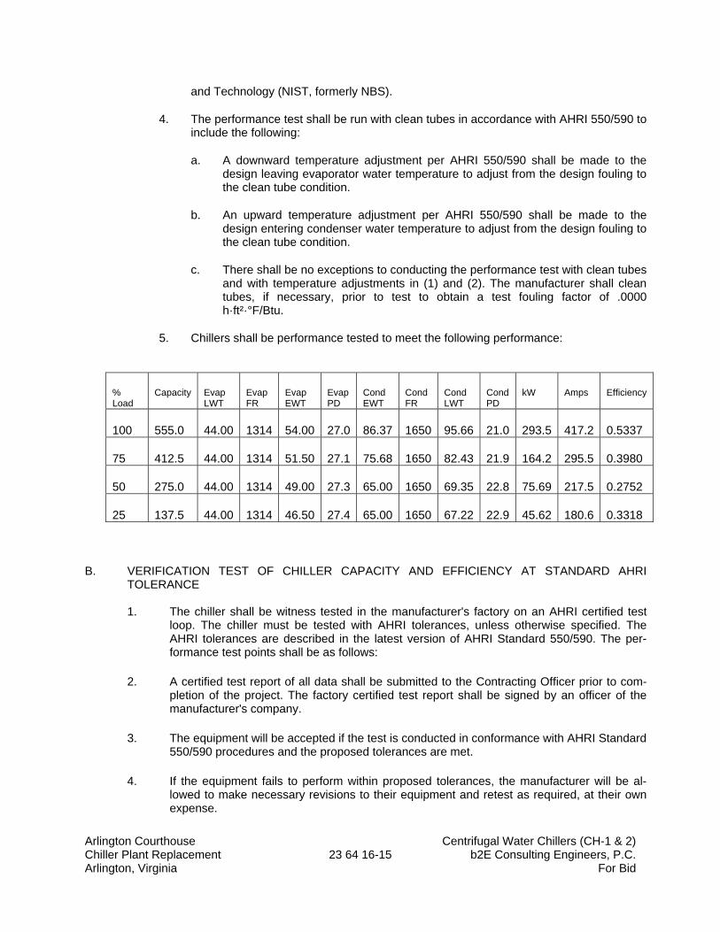
Arlington Courthouse Centrifugal Water Chillers (CH-1 & 2) Chiller Plant Replacement 23 64 16-15 b2E Consulting Engineers, P.C. Arlington, Virginia For Bid
and Technology (NIST, formerly NBS).
4. The performance test shall be run with clean tubes in accordance with AHRI 550/590 to include the following:
a. A downward temperature adjustment per AHRI 550/590 shall be made to the design leaving evaporator water temperature to adjust from the design fouling to the clean tube condition.
b. An upward temperature adjustment per AHRI 550/590 shall be made to the design entering condenser water temperature to adjust from the design fouling to the clean tube condition.
c. There shall be no exceptions to conducting the performance test with clean tubes and with temperature adjustments in (1) and (2). The manufacturer shall clean tubes, if necessary, prior to test to obtain a test fouling factor of .0000 h·ft²·°F/Btu.
5. Chillers shall be performance tested to meet the following performance:
% Load
Capacity Evap LWT
Evap FR
Evap EWT
Evap PD
Cond EWT
Cond FR
Cond LWT
Cond PD
kW Amps Efficiency
100 555.0 44.00 1314 54.00 27.0 86.37 1650 95.66 21.0 293.5 417.2 0.5337
75 412.5 44.00 1314 51.50 27.1 75.68 1650 82.43 21.9 164.2 295.5 0.3980
50 275.0 44.00 1314 49.00 27.3 65.00 1650 69.35 22.8 75.69 217.5 0.2752
25 137.5 44.00 1314 46.50 27.4 65.00 1650 67.22 22.9 45.62 180.6 0.3318
B. VERIFICATION TEST OF CHILLER CAPACITY AND EFFICIENCY AT STANDARD AHRI TOLERANCE
1. The chiller shall be witness tested in the manufacturer's factory on an AHRI certified test
loop. The chiller must be tested with AHRI tolerances, unless otherwise specified. The AHRI tolerances are described in the latest version of AHRI Standard 550/590. The per-formance test points shall be as follows:
2. A certified test report of all data shall be submitted to the Contracting Officer prior to com-pletion of the project. The factory certified test report shall be signed by an officer of the manufacturer's company.
3. The equipment will be accepted if the test is conducted in conformance with AHRI Standard 550/590 procedures and the proposed tolerances are met.
4. If the equipment fails to perform within proposed tolerances, the manufacturer will be al-lowed to make necessary revisions to their equipment and retest as required, at their own expense.
Arlington Courthouse Centrifugal Water Chillers (CH-1 & 2) Chiller Plant Replacement 23 64 16-16 b2E Consulting Engineers, P.C. Arlington, Virginia For Bid
5. In the event that these revisions do not achieve submitted performance, the following pen-alties will be imposed:
a. CAPACITY PENALTY: For each ton below the allowable capacity, $1000 per ton will be deducted from the contract price.* Allowable capacity = [(1 - tolerance) x design capacity].
b. POWER CONSUMPTION PENALTY: All load points and the Power Consumption Penalty (P.C.P.) shall be based upon the tolerances specified above. The P.C.P. shall be calculated based upon the following formula: P.C.P. = [Measured kW - (Measured tons x ALLOWABLE kW/ton*)] x $2000/kW.*Allowable kW/ton = [(1 + tolerance) x design kW/ton].
c. TOTAL PERFORMANCE PENALTY: The total performance penalty will be the sum of the CAPACITY PENALTY AND THE POWER CONSUMPTION PENALTY times the number of typical chillers, regardless if tested.
d. Equipment manufacturer shall not invoice for the chillers(s) until successful completion of the performance test or acceptance of penalty deduction from the contract.
2.14 MOTOR PROTECTORS
A. The EMS contractor shall provide and install ICM-450 motor protectors for each 3-phase Pump Motor and Fan Motor with or without an AFD and for each piece of 3-phase HVAC equipment. Contact Mr. Jim Fusco, Tel: (301) 455-7769.
PART 3 - EXECUTION
3.1 EXAMINATION
A. Examine chillers before installation. Reject chillers that are damaged.
B. Examine roughing-in for equipment support, anchor-bolt sizes and locations, piping, and electrical connections to verify actual locations, sizes, and other conditions affecting chiller performance, maintenance, and operations before equipment installation.
1. Final chiller locations indicated on Drawings are approximate. Determine exact locations before roughing-in for piping and electrical connections.
C. Proceed with installation only after unsatisfactory conditions have been corrected.
3.2 CHILLER INSTALLATION
A. Install chillers on support structure indicated.
B. Equipment Mounting: Install chiller on concrete bases using ASHRAE Type 4 restrained spring isolators. Comply with requirements for concrete bases specified in Division 03 Section "Cast-in-Place Concrete." Comply with requirements for vibration isolation devices specified in Division 23 Section "Sound and Vibration Controls for HVAC Piping and Equipment."
Arlington Courthouse Centrifugal Water Chillers (CH-1 & 2) Chiller Plant Replacement 23 64 16-17 b2E Consulting Engineers, P.C. Arlington, Virginia For Bid
1. Minimum Deflection: Determined by the chiller manufacturer for 98% vibration isolation efficiency.
2. Install dowel rods to connect concrete base to concrete floor. Unless otherwise indicated, install dowel rods on 18-inch (450-mm) centers around the full perimeter of concrete base.
3. For supported equipment, install epoxy-coated anchor bolts that extend through concrete base and anchor into floating concrete floor. Do not penetrate the post tension structural slab.
4. Place and secure anchorage devices. Use setting drawings, templates, diagrams, instructions, and directions furnished with items to be embedded.
5. Install anchor bolts to elevations required for proper attachment to supported equipment.
C. Maintain manufacturer's recommended clearances for service and maintenance.
D. Charge chiller with refrigerant and fill with oil if not factory installed.
E. Install separate devices furnished by manufacturer and not factory installed.
F. Interconnect brush-cleaning system controls with chiller controls. Coordinate requirements to ensure safe, trouble-free operation.
G. Functionally test the entire brush-cleaning system, including the valve, actuator, position indicator, and control panel, with chiller in operation.
3.3 CONNECTIONS
A. Comply with requirements for piping specified in Division 23 Section "Hydronic Piping" and Division 23 Section "Refrigerant Piping." Drawings indicate general arrangement of piping, fittings, and specialties.
B. Install piping adjacent to chiller to allow service and maintenance.
C. Evaporator Fluid Connections: Connect to evaporator inlet with shutoff valve, strainer, flexible connector, thermometer, and plugged tee with pressure gage. Connect to evaporator outlet with shutoff valve, balancing valve, flexible connector, flow switch, thermometer, plugged tee with shutoff valve and pressure gage, flow meter, and drain connection with valve. Make connections to chiller with a flange or mechanical coupling.
D. Condenser-Fluid Connections: Connect to condenser inlet with shutoff valve, strainer, flexible connector, thermometer, and plugged tee with pressure gage. Connect to condenser outlet with shutoff valve, balancing valve, flexible connector, flow switch, thermometer, plugged tee with shutoff valve and pressure gage, flow meter, and drain connection with valve. Make connections to chiller with a flange or mechanical coupling.
E. Refrigerant Pressure Relief Device Connections: Extend separate 4-inch vent piping for each chiller to the outdoors without valves or restrictions. Comply with ASHRAE 15. Connect to chiller pressure relief device with flexible connector and dirt leg with drain valve.
F. For chillers equipped with a purge system, extend separate purge vent piping for each chiller to the outdoors. Comply with ASHRAE 15 and ASHRAE 147.
G. Connect each chiller drain connection with a union and drain pipe, and extend pipe, full size of connection, to floor drain. Provide a shutoff valve at each connection.
Arlington Courthouse Centrifugal Water Chillers (CH-1 & 2) Chiller Plant Replacement 23 64 16-18 b2E Consulting Engineers, P.C. Arlington, Virginia For Bid
3.4 STARTUP SERVICE
A. Engage a factory-authorized service representative to perform startup service.
1. Complete installation and startup checks according to manufacturer's written instructions. 2. Verify that refrigerant charge is sufficient and chiller has been leak tested. 3. Verify that pumps are installed and functional. 4. Verify that thermometers and gages are installed. 5. Operate chiller for run-in period. 6. Check bearing lubrication and oil levels. 7. Verify that refrigerant pressure relief device is vented outside. 8. Verify proper motor rotation. 9. Verify static deflection of vibration isolators, including deflection during chiller startup and
shutdown. 10. Verify and record performance of fluid flow and low-temperature interlocks for evaporator
and condenser. 11. Verify and record performance of chiller protection devices. 12. Test and adjust controls and safeties. Replace damaged or malfunctioning controls and
equipment. 13. Verify that communications is established with EMS to CWCS.
B. Inspect field-assembled components, equipment installation, and piping and electrical connections for proper assembly, installation, and connection.
C. Prepare test and inspection startup reports.
3.5 DEMONSTRATION
A. Engage a factory-authorized service representative to train Owner's maintenance personnel to adjust, operate, and maintain centrifugal chiller as specified below.
1. Train Owner’s maintenance personnel on procedures and schedules for starting and stopping, troubleshooting, servicing, and maintaining the chiller.
2. Review data in maintenance manuals. Refer to Division 1 Section "Project Closeout." 3. Review data in maintenance manuals. Refer to Division 1 Section "Project Closeout”. 4. Schedule training with Owner, through Engineer, with at least seven days' advance notice. 5. Refer to Division 01 Section "Project Closeout."
END OF SECTION 23 64 16
Arlington Courthouse Centrifugal Water Chillers (CH-1 & 2) Chiller Plant Replacement Control system (for plant optimization) Arlington, Virginia 23 64 16 - A - 1 b2E Consulting Engineers, P.C. For Bid
SECTION 23 64 16 – A
CENTRIFUGAL WATER CHILLERS (CH-1 & 2) CONTROL SYSTEM (FOR PLANT OPTIMIZATION)
PART 1 - GENERAL 1.1 SUMMARY 1.2 DEFINITIONS
A. CWSC: Chilled Water Control System (Chiller Manufacturers Plant Optimization Controls)
1.3 QUALITY ASSURANCE
A. CWCS Manufacturer Qualifications
1. The CWCS manufacturer shall have an established business office within 50.00 miles of the project site and must provide 24 hours/day, 7 days/week response in the event of a customer warranty or service call.
2. The CWCS Manufacturer shall have factory trained and certified personnel providing all engineering, service, startup, and commissioning field labor for the project from their local office location. CWCS manufacturer shall be able to provide training certifications for all local office personnel upon request.
3. The CWCS shall be provided by a single manufacturer and this manufacturer’s equipment must consist of operator workstation software, Web-Based hardware/software, Open Standard Protocol hardware/software, Custom application Programming Language, Graphical Programming Language, Building Controllers, Custom Application Controllers, and Application Specific Controllers. All other products specified herein (i.e., sensors, valves, dampers, actuators, etc.) need not be manufactured by the CWCS manufacturer listed in this specification.
4. Independent representatives of CWCS manufacturers are not acceptable. CWCS vendor must be corporate owned entity of CWCS manufacturer.
1.4 CODES AND STANDARDS
A. Codes and Standards: Meet requirements of all applicable standards and codes, except when
more detailed or stringent requirements are indicated by the Contract Documents, including requirements of this Section.
1. Underwriters Laboratories: Products shall be UL-916-PAZX listed. 2. National Electrical Code – NFPA 70. 3. Federal Communications Commission – Part J. 4. ASHRAE/ANSI 135-2012 (BACnet) - (System Level Devices) - Building Controllers shall
conform to the listed version of the BACnet specification in order to improve interoperability with various building system manufacturers’ control systems and devices.
Arlington Courthouse Centrifugal Water Chillers (CH-1 & 2) Chiller Plant Replacement Control system (for plant optimization) Arlington, Virginia 23 64 16 - A - 2 b2E Consulting Engineers, P.C. For Bid
5. ASHRAE/ANSI 135-2012 (BACnet) - (Unit Level Devices) - Unit Controllers shall conform to the listed version of the BACnet specification in order to improve interoperability with various building system manufacturers’ control systems and devices.
6. EIA-709.1 LonTalk Standard and EIA 901.2 (LonMark Certification) - (Unit Level Devices) - Custom Application Controllers and Application Specific Controllers shall use FTT-10A transceivers and support the LonTalk communication protocol utilizing Standard Network Variable Types (SNVT) as defined by Echelon Corporation. This standard communication protocol provides interoperability with hundreds of other various building system manufacturers’ control systems and devices.
1.5 SYSTEM PERFORMANCE
A. Performance Standards. The CWCS system shall conform to the following:
5. Graphic Display. The system shall display a graphic with a minimum of 20 dynamic points. All current data shall be displayed within 10 seconds of the operator’s request.
6. Graphic Refresh. The system shall update all dynamic points with current data within 10 seconds.
7. Object Command. The maximum time between the command of a binary object by the operator and the reaction by the device shall be 5 seconds. Analog objects shall start to adjust within 5 seconds.
8. Object Scan. All changes of state and change of analog values shall be transmitted over the high-speed network such that any data used or displayed at a controller or workstation will be current within the prior 10 seconds.
9. Alarm Response Time. The maximum time from when an object goes into alarm to when it is annunciated at the workstation shall not exceed 10 seconds.
10. Program Execution Frequency. Custom and standard applications shall be capable of running as often as once every 5 seconds. The Contractor shall be responsible for selecting execution times consistent with the mechanical process under control.
11. Programmable Controllers shall be able to execute DDC PID control loops at a selectable frequency from at least once every 5 seconds. The controller shall scan and update the process value and output generated by this calculation at this same frequency.
12. Multiple Alarm Annunciations. All workstations on the network shall receive alarms within 5 seconds of each other.
13. Reporting Accuracy. Table 1 lists minimum acceptable reporting accuracies for all values reported by the specified system. a. Table 1: Reporting Accuracy
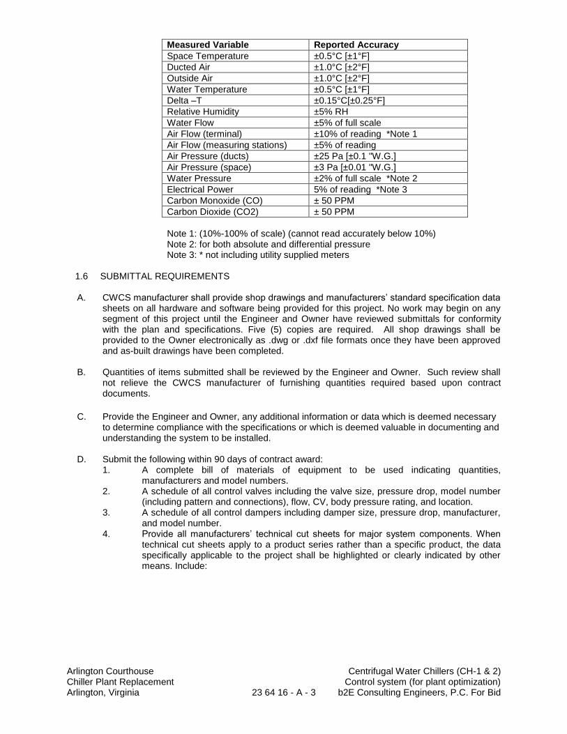
Arlington Courthouse Centrifugal Water Chillers (CH-1 & 2) Chiller Plant Replacement Control system (for plant optimization) Arlington, Virginia 23 64 16 - A - 3 b2E Consulting Engineers, P.C. For Bid
Measured Variable Reported Accuracy
Space Temperature ±0.5°C [±1°F]
Ducted Air ±1.0°C [±2°F]
Outside Air ±1.0°C [±2°F]
Water Temperature ±0.5°C [±1°F]
Delta –T ±0.15°C[±0.25°F]
Relative Humidity ±5% RH
Water Flow ±5% of full scale
Air Flow (terminal) ±10% of reading *Note 1
Air Flow (measuring stations) ±5% of reading
Air Pressure (ducts) ±25 Pa [±0.1 "W.G.]
Air Pressure (space) ±3 Pa [±0.01 "W.G.]
Water Pressure ±2% of full scale *Note 2
Electrical Power 5% of reading *Note 3
Carbon Monoxide (CO) ± 50 PPM
Carbon Dioxide (CO2) ± 50 PPM
Note 1: (10%-100% of scale) (cannot read accurately below 10%) Note 2: for both absolute and differential pressure Note 3: * not including utility supplied meters
1.6 SUBMITTAL REQUIREMENTS
A. CWCS manufacturer shall provide shop drawings and manufacturers’ standard specification data
sheets on all hardware and software being provided for this project. No work may begin on any segment of this project until the Engineer and Owner have reviewed submittals for conformity with the plan and specifications. Five (5) copies are required. All shop drawings shall be provided to the Owner electronically as .dwg or .dxf file formats once they have been approved and as-built drawings have been completed.
B. Quantities of items submitted shall be reviewed by the Engineer and Owner. Such review shall
not relieve the CWCS manufacturer of furnishing quantities required based upon contract documents.
C. Provide the Engineer and Owner, any additional information or data which is deemed necessary
to determine compliance with the specifications or which is deemed valuable in documenting and understanding the system to be installed.
D. Submit the following within 90 days of contract award:
1. A complete bill of materials of equipment to be used indicating quantities, manufacturers and model numbers.
2. A schedule of all control valves including the valve size, pressure drop, model number (including pattern and connections), flow, CV, body pressure rating, and location.
3. A schedule of all control dampers including damper size, pressure drop, manufacturer, and model number.
4. Provide all manufacturers’ technical cut sheets for major system components. When technical cut sheets apply to a product series rather than a specific product, the data specifically applicable to the project shall be highlighted or clearly indicated by other means. Include:
Arlington Courthouse Centrifugal Water Chillers (CH-1 & 2) Chiller Plant Replacement Control system (for plant optimization) Arlington, Virginia 23 64 16 - A - 4 b2E Consulting Engineers, P.C. For Bid
a. Building Controllers b. Custom Application Controllers c. Application Specific Controllers d. Operator Workstations e. Portable Operator Terminals f. Auxiliary Control Devices
5. Provide proposed Building Automation System architectural diagram depicting various controller types, workstations, device locations, addresses, and communication cable requirements
6. Provide detailed termination drawings showing all required field and factory terminations, as well as terminal tie-ins to DDC controls provided by mechanical equipment manufacturers. Terminal numbers shall be clearly labeled.
7. Provide points list showing all system objects and the proposed English language object names.
8. Provide a sequence of operation for each controlled mechanical system and terminal end devices.
9. Provide a BACnet Protocol Implementation Conformance Statement (PICS) for each BACnet system level device (i.e. Building Controller & Operator Workstations) type. This defines the points list for proper coordination of interoperability with other building systems if applicable for this project.
10. Provide LonMark Certification and functional profile SNVT’s for unitary-level controllers (i.e. chillers, RTU’s, AHU’s, Terminal VAV boxes, FCU’s, UV’s, etc.) for interoperability with other building systems if applicable for this project.
E. Project Record Documents: Upon completion of installation, submit three (3) copies of record
(as-built) documents. The documents shall be submitted for approval prior to final completion and include: 1. Project Record Drawings - These shall be as-built versions of the submittal shop
drawings. One set of electronic media including CAD .dwg and .pdf drawing files shall be provided.
2. Testing and Commissioning Reports and Checklists signed off by trained factory (equipment manufacturers) and field (CWCS) commissioning personnel.
3. Operating and Maintenance (O & M) Manuals - These shall be as-built versions of the submittal product data. In addition to the information required for the submittals, Operating & Maintenance manual shall include: a. Name, addresses and 24-hour / 7-day per week telephone numbers of
Contractor personnel managing and installing equipment, along with service personnel responsible for supporting the ongoing warranty and services of the control system.
b. Procedures for operating the CWCS including logging on/off, alarm management, generation of reports, trends, overrides of computer control, modification of setpoints, and other interactive system requirements.
c. Description of the programming language including syntax, statement descriptions, algorithms, calculations, point dataCWCSe creation and modification, program creation and modification, and operator use of the editor.
d. Explanation of how to design and install new points, new DDC controllers, and other CWCS hardware.
Arlington Courthouse Centrifugal Water Chillers (CH-1 & 2) Chiller Plant Replacement Control system (for plant optimization) Arlington, Virginia 23 64 16 - A - 5 b2E Consulting Engineers, P.C. For Bid
d. Preventative Maintenance and calibration procedures; hardware troubleshooting; and hardware repair and/or replacement procedures.
e. Documentation of all software program logic created for Custom Programmable Controllers including the overall point dataCWCSe. Provide one set of magnetic media containing files of the software and point dataCWCSe.
f. One set of electronic media containing files of all operator color graphic screens for the project.
g. A list of recommended spare parts including pricing, manufacturer, supplier, and part numbers.
h. Documentation, installation, and maintenance information for all third party hardware/software products provided including personal computers, printers, hubs, sensors, valves, etc.
i. Original issue media for all software provided, including operating systems, programming language, operator workstation software, and graphics software.
j. Licenses, Guarantee, and Warranty documents for all equipment and systems.
k. Recommended preventive maintenance procedures for all system components including a schedule of tasks (inspection, cleaning, calibration, etc.) and task descriptions.
F. Training Manuals: The CWCS manufacturer shall provide a course outline and copies of training
manuals at least two weeks prior to the start of any corporate training class to be attended by the Owner.
1.5 RELATED WORK BY OTHER TRADES
A. The Division 23 Mechanical Contractor shall provide the following information, coordination and installation to accommodate the CWCS system.
1. The Chiller Control Panel (CCP) shall be provided with all necessary interface hardware and programming required to support direct data communication, point mapping, between the CWCS system and the Chiller Control Panels. Items included in this category are:
a. Direct Data Interface boards and termination points to allow the CWCS contractor to connect a data bus cable.
b. Programming and protocols of the mechanical equipment by the equipment manufacturer to support the specified EMS interface.
c. Start-up coordination with CWCS contractor to verify everything is working correctly.
d. Clearly defined termination points in the OEM control panel to allow CWCS interface as specified.
2. The CWCS contractor shall furnish various sensors to be installed in CHW hydronic piping. These sensors require holes in the piping and welded threadolets. The mechanical contractor shall provide all labor and equipment necessary to install the threadolets to support the installation of these sensors. The CWCS contractor is to coordinate with the mechanical contractor for the location of these sensors. a. Uni-directional Flow Measuring Stations: 6 Pipe diameters clear straight pipe in
both directions and 36-inches to remove element from hot tap. b. Temperature Sensor: 4 Pipe diameters clear straight pipe in both directions, or 36-
inches either side whichever is greater.
3. The CWCS contractor shall furnish all automated control valves. These valves shall be turned over to the mechanical contractor for installation in the CHW hydronic piping
Arlington Courthouse Centrifugal Water Chillers (CH-1 & 2) Chiller Plant Replacement Control system (for plant optimization) Arlington, Virginia 23 64 16 - A - 6 b2E Consulting Engineers, P.C. For Bid
system on all equipment as necessary to comply with these specifications. The CWCS contractor will document how and where the valves shall be installed and the mechanical contractor will provide all labor and equipment necessary for the actual installation of the valves.
4. The CWCS contractor is required to provide complete wiring diagrams for each piece of mechanical equipment. These wiring diagrams shall show all OEM wiring and all field wiring. The CWCS interfaces shall be clearly defined and documented. The mechanical contractor is required to provide complete wiring schematics for every piece of mechanical equipment as part of the equipment submittals. These wiring diagrams shall be provided in AutoCAD or another dxf compatible electronic format to the CWCS contractor.
5. The CWCS contractor is required to provide floor plan drawings of the building to document the location of all wire routings and equipment locations. As-built floor plan backgrounds with mechanical equipment, sheet metal and piping shown shall be turned over to the CWCS contractor on an AutoCAD disk.
1.6 WARRANTY REQUIREMENTS
A. Warrant all work as follows: 1. CWCS system labor and materials shall be warranted free from defects for a period of
twenty four (24) months after final completion acceptance by the Owner. CWCS failures during the warranty period shall be adjusted, repaired, or replaced at no charge to the Owner. The CWCS manufacturer shall respond to the Owner's request for warranty service within 24 hours of the initiated call and will occur during normal business hours (8AM-5PM).
2. At the end of the final start-up/testing, if equipment and systems are operating satisfactorily to the Owner and Engineer, the Owner shall sign certificates certifying that the CWCS is operational, and has been tested and accepted in accordance with the terms of this specification. The date of Owner's acceptance shall be the start of the warranty period.
3. Operator workstation software, project specific software, graphics, database, and firmware updates shall be provided to the Owner at no charge during the warranty period. Written authorization by the Owner must be granted prior to the installation of these updates.
4. The CWCS manufacturer shall provide a web-accessible Users Network for the proposed System and give the Owner free access to question/answer forum, user tips, upgrades, and training schedules for a one year period of time correlating with the warranty period.
1.7 SYSTEM MAINTENANCE
A. Perform Chilled Water Control System (CWCS) System preventative maintenance and support
for a period of 2 years (beginning the date of substantial completion). 1. Make a minimum of 2 complete Chilled Water Control System inspections, in addition to
normal warranty requirements. Inspections to include:
Arlington Courthouse Centrifugal Water Chillers (CH-1 & 2) Chiller Plant Replacement Control system (for plant optimization) Arlington, Virginia 23 64 16 - A - 7 b2E Consulting Engineers, P.C. For Bid
a. System Review – Review the CWCS to correct programming errors, failed
points, points in alarm, and points that have been overridden manually. b. Seasonal Control Loop Tuning – Control loops are reviewed to reflect
changing seasonal conditions and / or facility heating and cooling loads. c. Sequence of operation verification – Systems all verified to be operating as
designed and in automatic operation. Scheduling and setpoints are reviewed and modified.
d. Database back-up e. Operator coaching
A. Perform Chilled Water Control System (CWCS) System preventative maintenance and
support for a period of 2 years (beginning the date of substantial completion). 2. Make a minimum of 2 complete Chilled Water Control System inspections, in addition
to normal warranty requirements. Inspections to include: a. System Review – Review the CWCS to correct programming errors, failed
points, points in alarm, and points that have been overridden manually. b. Seasonal Control Loop Tuning – Control loops are reviewed to reflect
changing seasonal conditions and / or facility heating and cooling loads. c. Sequence of operation verification – Systems all verified to be operating as
designed and in automatic operation. Scheduling and setpoints are reviewed and modified.
d. Database back-up. e. Operator coaching.
3. Technician shall review critical alarm log and advise owner of additional services that
may be required. 4. Technician shall provide a written report to owner after each inspection.
B. Do not assign or transfer maintenance service to agent or subcontractor without prior written
consent of owner.
1.8 OWNERSHIP OF PROPRIETARY MATERIAL
A. Project specific software and documantation shall become the owner’s property upon project
completion. This includes the following: 1. Operator Graphic files. 2. As built hardware design drawings. 3. Operating & Maintenance Manuals. 4. CWCS System software database. 5. Controller application programming databases. 6. Application Specific Controller configuration files. 7. Required Licensed software.
B. The Division 26 Electrical Contractor shall provide the following information, coordination, and installation to accommodate the EMS system.
1. The Contractor shall ensure that the mechanical contractor, the EMS Contractor, and the electrical Contractor coordinate between trades and provide all power required to affect a complete operating system in accordance with all requirements in the construction documents.
2. Provide all required 120v AC power sources for EMS equipment in the building. This includes, but is not limited to equipment mounted in the thirteenth-floor physical chiller plant and in the cooling for enclosure on the roof. The power required is at least four (4) 20 amp, 120 v circuits in the physical plant, and four (4) 20 amp, 120v circuits in outdoor cooling tower enclosure. The electrical contractor shall coordinate with the EMS contractor to determine circuit distribution and location.
Arlington Courthouse Centrifugal Water Chillers (CH-1 & 2) Chiller Plant Replacement Control system (for plant optimization) Arlington, Virginia 23 64 16 - A - 8 b2E Consulting Engineers, P.C. For Bid
a. Each heat trace circuit shall be monitored by the EMS via BACnet integration from the Heat Trace Control Panel. The EMS shall monitor outdoor temperature, heat trace status, heat trace setpoint, actual piping temperature and failure alarm
3. All required 120v AC power sources for EMS equipment for monitoring and setpoint control of the chillers, cooling towers and pumps. Some EMS equipment may need to be mounted outdoors in a weatherproof enclosure as determined by the EMS Contractor. The electrical contractor is to coordinate with the EMS contractor to determine circuit distribution and location.
a. Power for the EMS controls may be provided using a control power transformer. The EMS contractor is responsible to ensure that each control transformer is sized to handle the VA load and each transformer is protected by line side fuses.
4. Control Power Transformer: Coordinate the locations of circuits enclosures, and
junctions’ boxes as required by the EMS contractor. Provide quantity and locations as required by the EMS.
PART 2 – PRODUCTS
2.1 MANUFACTURERS
A. Acceptable Manufacturers: Subject to compliance with requirements, provide products by one of the following:
1. Basis of Design: Trane; a division of Ingersoll Rand.
2. Or Approved Equal: In Accordance with substitution procedures in section 016000 Paragraph 2.2.
2.2 MATERIALS
A. Use new products that the manufacturer is currently manufacturing and that have been installed in a minimum of 25 installations. Do not use this installation as a product test site unless explicitly approved in writing by the owner or the owner’s representative. Spare parts shall be available for at least five years after completion of this contract.
2.3 COMMUNICATION
A. This project shall be comprised of a high speed Ethernet network utilizing BACnet/IP communications between System Controllers and Workstations. Each System Controller shall function as a BACnet Router to each unit controller providing a unique BACnet Device ID for all controllers within the system. Communications between System Controllers and sub-networks of Custom Application Controllers and/or Application Specific Controllers shall be as defined below.
2.4 OPERATOR INTERFACE
A. A dedicated PC shall not be required to access the Enterprise or Building operator web interfaces.
2.5 CONTROLLER SOFTWARE 2.6 ADVANCED APPLICATION CONTROLLERS
Arlington Courthouse Centrifugal Water Chillers (CH-1 & 2) Chiller Plant Replacement Control system (for plant optimization) Arlington, Virginia 23 64 16 - A - 9 b2E Consulting Engineers, P.C. For Bid
A. Advance Application Controllers shall be used to control all equipment or applications of medium and high complexity, including but not limited to Air Handlers, Boiler Plants and Chiller Plants.
B. For Stand-Alone Operation of Advanced Application Controllers:
1. Shall operate a schedule in a standalone application using a Real Time Clock with a 7 day power backup. a. The Controller shall have a built in schedule (assessable with or without a
display) b. Support will be for at least 3 schedules with up to 10 events for each day of
the week. c. Each of the 3 schedules can be Analog, Binary or Multi-State d. The controller shall support a minimum of 25 exceptions each with up to 10
events.
C. For ease of troubleshooting, the Controller shall support data trend logging. 1. 25,000 samples minimum. 2. Trends shall be capable of being collected at a minimum sample rate of once every
second. 3. Trends shall be capable of being scheduled or triggered.
D. To meet the sequence of operation for each application, the Controller shall use library
programs provided by the controller manufacturer that are either factory loaded or downloaded with service tool to the Controller.
E. Environment - Controller hardware shall be suitable for the anticipated ambient conditions.
1. Storage conditions: a. Temperature: -67°F to 203°F (-55°C to 95°C) b. Humidity: Between 5% to 100% RH (non-condensing)
2. Operating conditions: a. Temperature: -40°F to 158°F (-40°C to 70°C) b. Humidity: Between 5% to 100% RH (non-condensing)
3. Controllers used indoors shall be mounted in a NEMA 1 enclosure at a minimum. 4. Controllers used outdoors and/or in wet ambient shall be mounted within NEMA 4 type
waterproof enclosures, and shall be rated for operation at -40° F to 158° F [-40° C to 70° C].
F. Input/Output: The Controller shall have on board or through expansion module all I/O capable of performing all functionality needed for the application. Controls provided by the equipment manufacture must supply the required I/O for the equipment. In addition other controls must meet the following requirements: 1. Shall support flexibility in valve type, the controllers shall be capable of supporting the
following valve control types: 0-10VDC, 0-5VDC, 4-20mA, 24VAC - 2 position. 2. Shall support flexibility in sensor type, the Controller shall be capable of reading sensor
input ranges of 0 to10V, 0 to 20mA, 50ms or longer pulses, 200 to 20Kohm and RTD input.
Arlington Courthouse Centrifugal Water Chillers (CH-1 & 2) Chiller Plant Replacement Control system (for plant optimization) Arlington, Virginia 23 64 16 - A - 10 b2E Consulting Engineers, P.C. For Bid
3. Shall support flexibility in sensor type, all Analog Outputs shall have the additional capability of being programmed to operate as Universal Inputs or Pulse Width Modulation Outputs.
4. Shall support flexibility in sensor type, the Controller and/or expansion modules shall support dry and wetted (24VAC) binary inputs.
5. The controller shall support pulse accumulator for connecting devices like energy meters.
6. In order to support a wide range of devices, the Controller’s binary output shall be able to drive at least 10VA each.
7. Any unused I/O that is not needed for the functionality of the equipment shall be available to be used by custom programs on the Controller and by any other controller on the network.
8. The Controller shall provide 24VAC and 24VDC power terminals sensors and other devices required.
9. The Controller shall provide a dedicated static pressure input.
G. Input/Output Expandability – The Controller shall provide the following functionality in order to meet current and future application needs: 1. For the application flexibility, the Controller shall be capable of expanding to a total of
at least 100 hardware I/O terminations. 2. Expansion I/O can be mounted up to 650 ft. (200m) from control. 3. Expansion I/O can be added in as small as 4 point increments. 4. To keep BACnet MS/TP network traffic to a minimum, expansion I/O must
communicate via an internal controller communication bus (point expansion via the BACnet MS/TP network is not allowed).
H. Serviceability– The Controller shall provide the following in order to improve serviceability of
the Controller. 1. Diagnostic LEDs for power/normal operation/status, BACnet communications, sensor
bus communications, and binary outputs. All wiring connections shall be clearly labeled and made to be field removable.
2. Binary and analog inputs and outputs shall use removable connectors or be connected to terminal strip external to the control box.
3. Software service tool connection through all of the following methods: direct cable connection to the Controller, connection through another controller on BACnet link and through the Controller’s zone sensor.
4. For safety purposes, the controller shall be capable of being powered by a portable computer's USB port for the purposes of configuration, programming and testing programs so that this work can be accomplished with the power off to the associated equipment.
5. The Controller software tool service port shall utilize standard off-the-shelf USB printer cable.
6. Capabilities to temporarily override the BACnet point values with built-in time expiration in the Controller.
7. To aid in service replacement, the Controller shall easily attached to standard DIN rail mounting.
Arlington Courthouse Centrifugal Water Chillers (CH-1 & 2) Chiller Plant Replacement Control system (for plant optimization) Arlington, Virginia 23 64 16 - A - 11 b2E Consulting Engineers, P.C. For Bid
8. For future expansion, the Controller shall be capable of adding sequence of operation programming utilizing service tools software with a graphical programming interface (editing or programming in line code is not permissible).
9. To aid in service replacement, the Controller shall allow for setting its BACnet address via controller mounted rotary switches that correspond to the numerical value of the address. (DIP switch methodologies are not allowed). Setting of the address shall be accomplished without the need of a service tool or power applied to the controller.
10. Controller data shall be maintained through a power failure.
I. Software Retention: All Controller operating parameters, setpoints, BIOS, and sequence of operation code must be stored in non-volatile memory in order to maintain such information for months without power.
J. Transformer for the Controller must be rated at minimum of 115% of ASC power consumption,
and shall be fused or current limiting type. 24 VAC, +/- 15% nominal, 50-60 Hz, 24 VA plus binary output loads for a maximum of 12 VA for each binary output.
K. Controller must meet the following Agency Compliance:
1. UL916 PAZX, Open Energy Management Equipment 2. UL94-5V, Flammability 3. FCC Part 15, Subpart B, Class B Limit 4. BACnet Testing Laboratory (BTL) Listed
2.6 APPLICATION-SPECIFIC CONTROLLERS
A. Application Specific Controllers (ASC) shall be microprocessor-Based DDC controllers which, through hardware or firmware design, control specified equipment. They are not user programmable, but are customized for operation within the confines of the equipment they are designed to serve. 1. Application Specific Controller are only allowed when both the following are met
a. The equipment is compressor based or boiler based. b. The controller is provided by the equipment manufacturer and warrantied as part
of the equipment.
B. Zone Controllers are controllers that operate equipment that control the space temperature of single zone. Examples are controllers for VAV, Fan coil, Blower Coils, Unit Ventilators, Heat Pumps, and Water Source Heat Pumps. 1. Software
a. To meet the sequence of operation for each zone control, the controller shall use programs developed and tested by the controller manufacturer that are either factory loaded or downloaded with service tool to the controller.
b. Stand-Alone Operation: Each piece of equipment specified in section “A” shall be controlled by a single controller and provide stand-alone control in the event of communication failure. In case of communications failure stand-alone operation shall use default values or last values for remote sensors read over the network such as outdoor air temperature.
c. For controlling ancillary devices and for flexibility to change the sequence of operation in the future, the controller shall be capable running custom programs written in a graphical programming language.
2. Environment: Controller hardware shall be suitable for the anticipated ambient
conditions. a. Storage: -55° to 203° F (-48° to 95° C) and 5 to 95% Rh, non-condensing. b. Operating: -40° to 158° F (-40 to 70° C) and 5 to 95% Rh, non-condensing. c. Controllers used indoors shall be mounted in a NEMA 1 enclosure at a
minimum.
Arlington Courthouse Centrifugal Water Chillers (CH-1 & 2) Chiller Plant Replacement Control system (for plant optimization) Arlington, Virginia 23 64 16 - A - 12 b2E Consulting Engineers, P.C. For Bid
d. Controllers used outdoors and/or in wet ambient shall be mounted within NEMA 4 type waterproof enclosures, and shall be rated for operation at -40° to 158° F [-40° to 70° C].
3. Input/Output:
a. For flexibility in selection and replacement of valves, the controllers shall be capable of supporting all of the following valve control types 0-10VDC, 0-5VDC, 4-20mA, 24VAC floating point, 24VAC - 2 position (Normally Open or Normally Closed).
b. For flexibility in selection and replacement of sensors, the controllers shall be capable of reading sensor input ranges of 0 to10V, 0 to 20mA, pulse counts, and 200 to 20Kohm.
c. For flexibility in selection and replacement of binary devices, the controller shall support dry and wetted (24VAC) binary inputs.
d. For flexibility in selection and replacement devices, the controller’s shall have binary output which are able to drive at least 12VA each.
e. For flexibility in selection and replacement of motors, the controller shall be capable of outputting 24VAC (binary output), DC voltage (0 to 10VDC minimum range) and PWM (in the 80 to 100 Hz range).
f. For future needs, any I/O that is unused by functionality of equipment control shall be available to be used by custom program on the controller and by another controller on the network.
g. For future expansion and flexibility, the controller shall have either on board or through expansion, 20 hardware input/output points. Expansion points must communicate with the controller via an internal communications bus. Expansion points must be capable of being mounted up to 650ft. (200 m) from the controller. Expansion points that require the BACnet network for communication with the controller are not allowed.
4. Serviceability – The controller shall provide the following in order to improve serviceability
of the controller. a. Diagnostic LEDs shall indicate correct operation or failures/faults for all of the
following: power, sensors, BACnet communications, and I/O communications bus.
b. All binary output shall have LED’s indicating the output state. c. All wiring connectors shall removable without the use of a tool. d. Software service tool connection through all of the following methods: direct
cable connection to the controller, connection through another controller on BACnet link and through the controller’s zone sensor.
e. For safety purposes, the controller shall be capable of being powered by a portable computer for the purposes of configuration, programming, and testing programs so that this work can be accomplished with the power off to the equipment.
f. Capabilities to temporarily override of BACnet point values with built-in time expiration in the controller.
g. BACnet MAC Address shall be set using decimal (0-9) Based rotary switches. h. Configuration change shall not be made in a programming environment, but
rather by a configuration page utilizing dropdown list, check boxes, and numeric boxes.
i. BACnet trending objects resident on controller. 1) Minimum of 20,000 trending points total on controller 2) Shall be capable of trending all BACnet points used by controller 3) Shall be capable of 1 second sample rates on all points
5. Software Retention: All Zone Controller operating parameters, setpoints, BIOS, and
sequence of operation code must be stored in non-volatile memory in order to maintain such information for months without power.
Arlington Courthouse Centrifugal Water Chillers (CH-1 & 2) Chiller Plant Replacement Control system (for plant optimization) Arlington, Virginia 23 64 16 - A - 13 b2E Consulting Engineers, P.C. For Bid
6. Transformer for the controller must be rated at minimum of 115% of ASC power
consumption, and shall be fused or current limiting type. 24 VAC, +/- 15% nominal, 50-60 Hz, 24 VA plus binary output loads, for a maximum of 12 VA for each binary output.
7. Agency Approval: The controller shall have meet the Agency Compliance:
a. UL916 PAZX, Open Energy Management Equipment b. UL94-5V, Flammability c. FCC Part 15, Subpart B, Class B Limit
2.7 INPUT / OUTPUT INTERFACE A. Hardwired inputs and outputs may tie into the system through building, custom application, or
ASCs. B. All input points and output points shall be protected such that shorting of the point to itself, to
another point, or to ground will cause no damage to the controller. All input and output points shall be protected from voltage up to 24V of any duration, such that contact with this voltage will cause no damage to the controller.
C. Binary inputs shall allow the monitoring of on/off signals from remote devices. The binary inputs
shall provide a wetting current of at least 12 mA to be compatible with commonly available control devices and shall be protected against the effects of contact bounce and noise. Binary inputs shall sense “dry contact” closure without external power (other than that provided by the controller) being applied.
D. Pulse accumulation input objects. This type of object shall conform to all the requirements of
binary input objects and also accept up to 10 pulses per second for pulse accumulation. E. Analog inputs shall allow the monitoring of low voltage (0 to 10 VDC), current (4 to 20 mA), or
resistance signals (thermistor, RTD). Analog inputs shall be compatible with and field configurable to commonly available sensing devices.
F. Binary outputs shall provide for on/off operation or a pulsed low-voltage signal for pulse width
modulation control. Binary outputs on building and custom application controllers shall have status lights. Outputs shall be selectable for either normally open or normally closed operation.
G. Analog outputs shall provide a modulating signal for the control of end devices. Outputs shall
provide either a 0 to 10VDC or a 4 to 20 mA signal as required to provide proper control of the output device. Analog outputs shall not exhibit a drift of greater than 0.4% of range per year.
H. Tri-State Outputs. Provide tri-state outputs (two coordinated binary outputs) for control of three-
point floating type electronic actuators without feedback. Use of three-point floating devices shall be limited to zone control and terminal unit control applications (VAV terminal units, duct-mounted heating coils, zone dampers, radiation, etc.). Control algorithms shall run the zone actuator to one end of its stroke once every 24 hours for verification of operator tracking.
I. System Object Capacity. The system size shall be expandable to at least twice the number of
input/ output objects required for this project. Additional controllers (along with associated devices and wiring) shall be all that is necessary to achieve this capacity requirement. The operator interfaces installed for this project shall not require any hardware additions or software revisions in order to expand the system.
2.8 AUXILLARY CONTROL DEVICES
Arlington Courthouse Centrifugal Water Chillers (CH-1 & 2) Chiller Plant Replacement Control system (for plant optimization) Arlington, Virginia 23 64 16 - A - 14 b2E Consulting Engineers, P.C. For Bid
A. Control Valves 1. Control valves shall be two-way or three-way type for two-position or modulating service as
scheduled or shown. 2. Close-off (differential) Pressure Rating: Valve actuator and trim shall be furnished to
provide the following minimum close-off pressure ratings: a. Water Valves:
1) Two-way: 150% of total system (pump) head, but not less than 150 psi. 2) Three-way: 300% of pressure differential between ports A and B at design
flow or 100% of total system (pump) head, but not less than 150 psi. 3) Basis of Design: Belimo Models as indicated below:
1. 8” 2-Way Line Size Isolation Valves: Model F6200-150 SHP+SY3-24 w/285 psi close-off pressure end switch and hand wheel override.
2. 10” 2-Way Line Size Isolation Valves: Model F6250-150 SHP+SY4-24 with 185 psi close-off pressure, end switch and hand wheel override.
3. 3” 2-Way Control Valve: Model F7150-SHP+SY4-24 with 185 psi close-off pressure and hand wheel override (fail open).
B. Water Valves
1. Body and trim style and materials shall be in accordance with manufacturer’s recommendations for design conditions and service shown, with equal percentage ports for modulating service.
2. Sizing Criteria: a. Two-position service: Line size. b. Two-way modulating service: Pressure drop shall be equal to twice the pressure
drop through heat exchanger (load), 50% of the pressure difference between supply and return mains, or 5 psi, whichever is greater.
c. Three-way modulating service: Pressure drop equal to twice the pressure drop through the coil exchanger (load), 5 psi maximum.
d. Valves DN 15 (½ in.) through DN 50 (2 in.) shall be bronze body or cast brass ANSI Class 250, spring-loaded, PTFE packing, quick opening for two-position service. Two-way valves to have replaceable composition disc or stainless steel ball.
e. Valves DN 65 (2½ in.) and larger shall be cast iron ANSI Class 125 with guided plug and PTFE packing.
3. Water valves shall fail normally open or closed, as scheduled on plans, or as follows: a. Cooling Tower Equalizer Valve - normally closed with manual override. b. Water zone valves - normally open preferred. c. Cooling tower isolation valves normally closed with manual override. d. Chiller isolation valves - normally closed with manual override. e. Other applications - as scheduled or as required by sequences of operation.
4. Zone valves shall be sized to meet the control application and they shall maintain their last position in the event of a power failure.
5. Basis of Design: Belimo Models as indicated below: 1. 8” 2-Way Isolation Valves: Model F6200-150 SHP+SY3-24 w/285 psi close-off
pressure end switch and hand wheel override. 2. 10” 2-Way Isolation Valves: Model F6250-150 SHP+SY4-24 with 185 psi close-
off pressure, end switch and hand wheel override. 3. 3” 2-Way Control Valve: Model F7150-SHP+SY4-24 with 185 psi close-off
pressure and hand wheel override (fail open).
Arlington Courthouse Centrifugal Water Chillers (CH-1 & 2) Chiller Plant Replacement Control system (for plant optimization) Arlington, Virginia 23 64 16 - A - 15 b2E Consulting Engineers, P.C. For Bid
C. Flow Switches 1. Flow-proving switches shall be either paddle or differential pressure type, as shown. 2. Paddle type switches (water service only) shall be UL listed, SPDT snap-acting with pilot
duty rating (125VA minimum) and shall have adjustable sensitivity with NEMA 1 enclosure unless otherwise specified.
3. Differential pressure type switches (air or water service) shall be UL listed, SPDT snap-acting, pilot duty rated (125 VA minimum), NEMA 1 enclosure, with scale range and differential suitable for intended application or as specified.
D. Relays
1. Control relays shall be UL listed plug-in type with dust cover and LED “energized” indicator. Contact rating, configuration, and coil voltage shall be suitable for application.
2. Time delay relays shall be UL listed solidstate plug-in type with adjustable time delay. Delay shall be adjustable ± 200% (minimum) from setpoint shown on plans. Contact rating, configuration, and coil voltage shall be suitable for application. Provide NEMA 1 enclosure when not installed in local control panel.
E. Current Switches
1. Current-operated switches shall be self-powered, solid state with adjustable trip current. The switches shall be selected to match the current of the application and output requirements of the DDC system.
2.9 WIRING AND RACEWAYS
A. General: Provide copper wiring, plenum cable, and raceways as specified in the applicable sections of this specification.
B. All insulated wire to be copper conductors, UL labeled for 90°C (194°F) minimum service.
PART 3 - EXECUTION
3.1 EXAMINATION
A. The Contract Documents shall be thoroughly examined for coordination of control devices, their installation, wiring, and commissioning. Coordinate and review mechanical equipment specifications, locations, and identify any discrepancies, conflicts, or omissions that shall be reported to the Architect/Engineer for resolution before rough-in work is started.
B. The CWCS manufacturer shall inspect the jobsite in order to verify that control equipment can be
installed as required, and any discrepancies, conflicts, or omissions shall be reported to the Architect/Engineer for resolution before rough-in work is started.
3.2 PROTECTION
A. The CWCS installation contractor shall protect all work and material from damage by their work or personnel, and shall be liable for all damage thus caused.
B. The CWCS manufacturer shall be responsible for their work and equipment until final inspection,
testing, and acceptance. The CWCS installing contractor shall protect their work against theft or damage, and shall carefully store material and equipment received on site that is not immediately installed. The Contractor shall close all open ends of work with temporary covers or plugs during storage and construction to prevent entry of foreign objects.
3.3 COORDINATION
Arlington Courthouse Centrifugal Water Chillers (CH-1 & 2) Chiller Plant Replacement Control system (for plant optimization) Arlington, Virginia 23 64 16 - A - 16 b2E Consulting Engineers, P.C. For Bid
A. Site 1. Where the mechanical work will be installed in close proximity to, or will interfere with, work
of other trades, the contractor shall assist in working out space conditions to make a satisfactory adjustment. If the contractor installs his/her work before coordinating with other trades, so as to cause any interference with work of other trades, the contractor shall make the necessary changes in his/her work to correct the condition without extra charge.
2. Coordinate and schedule work with all other work in the same area, or with work that is dependent upon other work, to facilitate mutual progress.
B. Submittals. Refer to the “Submittals,” section of this specification for requirements.
C. Test and Balance: Refer to Section 23 05 93
1. Furnish a single set of all tools necessary to interface to the control system for test and balance purposes.
2. Provide training in the use of these tools. This training will be planned for a duration of 4 hours.
3. Provide a qualified technician to assist in the test and balance process, until the first 20 terminal units are balanced.
4. The tools used during the test and balance process shall be returned to the TAB contractor at the completion of the testing and balancing.
D. Life Safety
1. Refrigerant Monitoring Safety Equipment shall be supplied under section 23 64 20 of this specification. Interlock the refrigerant sensors to the refrigerant monitoring panel and provide interlocks to shut-down the chillers and the existing boilers in the evet of a refrigerant leak.
E. Coordination with Controls Specified in Other Sections or Divisions. Other sections and/or
divisions of this specification include controls and control devices that are to be part of or interfaced to the control system specified in this section. These controls shall be integrated into the system and coordinated by the contractor as follows: 1. All communication media and equipment shall be provided as specified in the
“Communication” section of this specification. 2. Each supplier of a controls product is responsible for the configuration, programming, start-
up, and testing of that product to meet the sequences of operation described in this section.
3. Coordinate and resolve any incompatibility issues that arise between the control products provided under this section and those provided under other sections or divisions of this specification.
3.4 GENERAL WORKMANSHIP
A. Install equipment, piping, wiring/conduit, parallel to building lines (i.e. horizontal, vertical, and parallel to walls) wherever possible.
B. Provide sufficient slack and flexible connections to allow for vibration of piping and
equipment. C. Install all equipment in readily accessible locations as defined by National Electric Code
(NEC). Control panels shall be attached to structural walls or properly supported in a free-standing configuration, unless mounted in equipment enclosure specifically designed for that purpose. Panels shall be mounted to allow for unobstructed access for service.
Arlington Courthouse Centrifugal Water Chillers (CH-1 & 2) Chiller Plant Replacement Control system (for plant optimization) Arlington, Virginia 23 64 16 - A - 17 b2E Consulting Engineers, P.C. For Bid
D. Verify integrity of all control wiring to ensure continuity and freedom from shorts and grounds prior to commencing the startup and commissioning procedures.
E. All control device installation and wiring shall comply with Contract Documents,
acceptable industry specifications, and industry standards for performance, reliability, and compatibility. Installation and wiring shall be executed in strict adherence to local codes and standard practices referenced in Contract Documents.
3.5 FIELD QUALITY CONTROL
A. All work, materials, and equipment shall comply with the rules and regulations of applicable local, state, and federal codes and ordinances as identified in Contract Documents.
B. CWCS manufacturer shall continually monitor the field installation for building code
compliance and quality of workmanship. All visible piping and or wiring runs shall be installed parallel to building lines and properly supported.
C. CWCS installing Contractor(s) shall arrange for field inspections by local and/or state
authorities having jurisdiction over the work.
3.6 WIRING A. All control and interlock wiring shall comply with the National, Local Electrical Codes, and
Section 26 05 19 and 26 05 23 of these Contract Document specifications. Where the requirements of this section differ with those in Section 26 05 23, the requirements of this section shall take precedence.
B. All NEC Class 1 (line voltage) wiring shall be installed in UL Listed approved metal
raceway according to NEC requirements. C. All Class 2 wires shall be installed in UL listed approved metal raceway according to
NEC requriements. 1. Circuits meet NEC Class 2 (current-limited) requirements. (Low-voltage power
circuits shall be sub-fused when required to meet Class 2 current-limit.) 2. All cables shall be UL listed for application.
D. Do not install Class 2 (control voltage) wiring in conduits containing Class 1 wiring.
Boxes and panels containing high voltage may not be used for low voltage wiring except for the purpose of interfacing the two via control relays and transformers.
E. Where Class 2 wiring is run exposed the wiring shall be run in metal raceway up to the
point of connection at a junction box. Provide liquid tight flexible metallic conduit from the junction box to the point of connecton to the control device.
F. All wire-to-device connections shall be made at a terminal blocks or terminal strip. All
wire-to wire connections shall be at a terminal block, or with a crimped connector. All wiring within enclosures shall be neatly bundled and anchored to permit access and prevent restriction to devices and terminals.
G. Maximum allowable voltage for control wiring shall be 120Vac. If only higher voltages are
available for use, the CWCS manufacturer shall provide step-down transformers to achieve the desired control voltages.
Arlington Courthouse Centrifugal Water Chillers (CH-1 & 2) Chiller Plant Replacement Control system (for plant optimization) Arlington, Virginia 23 64 16 - A - 18 b2E Consulting Engineers, P.C. For Bid
H. All control wiring shall be installed as continuous lengths, where possible. Any required splices shall be made only within an approved junction box or other approved protective device.
I. Maintain fire rating at all penetrations in accordance with Contract Documents and
National and/or Local Codes. J. Conduit and wire sizing shall be determined by the CWCS manufacturer in order to
maintain manufacturer’s recommendation and meet National and Local Codes. K. Control and status relays are to be located in pre-fabricated enclosures that meet the
application. These relays may also be located within packaged equipment control panel enclosures as coordinated. These relays shall not be located within Class 1 starter enclosures.
L. Follow manufacturer's installation recommendations for all communication and network
bus cabling. Network or communication cabling shall be run separately from all control power wiring.
M. Adhere to Section 26 05 33 requirements for installation of electrical raceways. N. CWCS manufacturer shall terminate all control and/or interlock wiring and shall maintain
updated (as-built) wiring diagrams with terminations identified at the job site. O. Flexible metal conduits and liquid-tight flexible metal conduits shall not exceed 3' in
length and shall be supported at each end. Flexible metal conduit less than 3/4" electrical trade size shall not be used. In areas exposed to moisture, including chiller and boiler rooms, liquid-tight, flexible metal conduits shall be used.
3.7 COMMUNICATION WIRING
A. All cabling shall be installed in a neat and workmanlike manner. Follow manufacturer’s installation recommendations for all communication cabling.
B. Do not install communication wiring in raceway and enclosures containing Class 1 or
other Class 2 wiring. C. Maximum pulling, tension, and bend radius for cable installation, as specified by the cable
manufacturer shall not be exceeded during installation. D. Contractor shall verify the integrity of the entire network following cable installation. Use
appropriate test measures for each particular cable. E. When a cable enters or exits a building, a lighting arrestor must be installed between the
line and ground. F. All runs of communication wiring shall be unspliced length when the length is
commercially available. G. All communication wiring shall be labeled to indicate origin and destination.
3.8 INSTALLATION OF SENSORS
Arlington Courthouse Centrifugal Water Chillers (CH-1 & 2) Chiller Plant Replacement Control system (for plant optimization) Arlington, Virginia 23 64 16 - A - 19 b2E Consulting Engineers, P.C. For Bid
A. Sensors required for mechanical equipment operation shall be factory installed and wired as specified in mechanical equipment specifications. CWCS manufacturer shall be responsible for coordinating these control devices and ensuring the sequence of operations will be met. Installation and wiring shall be in accordance with the CWCS manufacturer's recommendations.
B. Sensors that require field mounting shall meet the CWCS manufacturer’s
recommendations and be coordinated with the mechanical equipment they will be associated.
C. Mount sensors rigidly and adequately for the environment the sensor will operate. D. Install pipe differential pressure sensors with transducers connected to pipe with thread-
o-let and connection to copper tubing rated for operating pressure and set for different pressure setpoint.
E. All pipe mounted temperature sensors shall be installed in matched thermowells. Install
all liquid temperature sensors with heat conducting fluid in thermal wells for adequate thermal conductance.
F. Install outdoor air temperature sensors on north wall complete with sun shield at
manufacturer’s recommended location and coordinated with Engineer.
3.9 FLOW SWITCH INSTALLATION
A. Coordinate installation of flow switch with Mechanical Contractor who will be responsible for installing a thread-o-let in steel piping applications. Copper pipe applications will require the use CxCxF Tee, and no pipe extensions or substitutions will be allowed.
B. Mount a minimum of 5 pipe diameters upstream and 5 pipe diameters downstream, or
two feet, whichever is greater, from pipe fittings and other inline potential obstructions. C. Install in accordance with manufacturers' instructions, which will require proper flow
direction, horizontal alignment with flow switch mounting on the top of pipe.
3.10 3-WAY COOLING TOWER BYPASS VALVE INSTALLATION
A. Remove existing pneumatic 3-way valves in condenser water return piping during Phase 1A Demolition and replace during Phase 1B New Work.
B. Interlock the valve operator to the CWCS.
3.11 2 –WAY, 2-POSITION AUTOMATIC ISOLATION VALVE INSTALLATION
A. Install cooling tower isolation valves during Phase 1B – New Work. B. Remove existing pneumatic 2-way valves for chiller #2 during Phase 1A – Demolition and
cut new valves into existing piping during phase 1B – New Work. C. Remove existing pneumatic 2-way valves for chiller #1 during Phase 1A – Demolition and
cut new valves into existing piping during phase 1B – New Work. D. Interlock valve operators and end switches to the CWCS. E. Isolation Valve Basis of Design: Belimo Models as follows:
Arlington Courthouse Centrifugal Water Chillers (CH-1 & 2) Chiller Plant Replacement Control system (for plant optimization) Arlington, Virginia 23 64 16 - A - 20 b2E Consulting Engineers, P.C. For Bid
1. 8” 2-Way, line size Isolation Valves: Belimo Model F6200-150 SHP+SY3-24 w/285 psi close-off pressure end switch and hand wheel override.
2. 10” 2-Way, line size Isolation Valves: Belimo Model F6250-150 SHP+SY4-24 with 185 psi close-off pressure, end switch and hand wheel override.
3. 6” 3-Way Control Valve: Belimo Model F7150-SHP+SY4-24 with 185 psi close-off pressure and hand wheel override (fail open).
3.12 DUAL TURBINE WATER METER INSTALLATION
A. Install chilled water supply flow meter in CWS piping during Phase 2B – New Work. B. Install meter with hot tap in accordance with manufacturer’s recommendations with
adequate removal access. C. Interlock meter to the display unit and interlock the display unit to the CWCS.
3.10 WARNING LABELS A. Permanent warning labels shall be affixed to all equipment that can be automatically
started by the CWCS system. B. Permanent warning labels shall be affixed to all motor starters and all control panels that
are connected to multiple power sources utilizing separate disconnects.
3.11 IDENTIFICATION OF HARDWARE AND WIRING A. All field wiring and cabling, including that within factory mounted, and wired control panels
and devices for mechanical equipment, shall be labeled at each end within 2" of termination with a cable identifier and other descriptive information for troubleshooting, maintenance, and service purposes. CWCS manufacturer to coordinate this labeling requirement with mechanical equipment manufacturer as it relates to controls.
B. Permanently label or code each point of field terminal strips to show the instrument or
item served and correlate them to the CWCS design drawings. C. Identify control panels with minimum 1-cm letters on laminated plastic nameplates. D. Identifiers shall match record documents. All plug-in components shall be labeled such
that removal of the component does not remove the label.
3.12 CONTROLLERS
A. Provide a separate DDC Controller for individual HVAC mechanical equipment. DDC
Controllers shall be factory mounted, installed, and wired by mechanical equipment manufacturer as specified. CWCS manufacturer shall furnish and coordinate DDC controllers and control devices and ensure that installation and wiring adhere to CWCS manufacturer’s design recommendations. For those mechanical equipment units that do not have factory installed controls specified, the CWCS manufacturer shall field mount controls and coordinate all installation and termination information to ensure the specified sequence of operations are met.
Arlington Courthouse Centrifugal Water Chillers (CH-1 & 2) Chiller Plant Replacement Control system (for plant optimization) Arlington, Virginia 23 64 16 - A - 21 b2E Consulting Engineers, P.C. For Bid
B. Building Controllers and Custom Application Controllers shall be selected to provide a minimum of 15% spare I/O point capacity for each point type (analog or digital) found at each location. If input points are not universal, 15% of each type is required. If outputs are not universal, 15% of each type is required. A minimum of one spare is required for each type of point used in each controller. 1. Future use of spare I/O point capacity shall require providing the field instrument
and control device, field wiring, engineering, programming, and commissioning. No additional Controller boards or point modules shall be required to implement use of these spare points.
3.13 PROGRAMMING
A. Provide sufficient internal memory for all controllers to ensure specified sequence of operations, alarming, trending, and reporting requirements are achieved. CWCS manufacturer shall provide a minimum of 25% spare memory capacity for future use.
B. Point Naming: System point names shall be modular in design, allowing easy operator
interface without the use of a written point index. C. Software Programming
1. Provide programming for individual mechanical systems to achieve all aspects of the sequence of operation specified. It is the CWCS manufacturer’s responsibility to ensure all mechanical equipment functions and operates as specified in sequence of operations. Provide sufficient programming comments in controller application software to clearly describe each section of the program. The comment statements shall reflect the language used in the sequence of operations.
D. CWCS Operator’s Interface
1. When Operator Workstation is specified, provide color graphics for each piece of mechanical equipment depicting sufficient I/O to monitor and troubleshoot operation. Additionally, provide individual floor plans of the building allowing an operator to quickly view the overall floor plan area for any out of tolerance conditions that may need addressing. Operator color graphics shall include Chiller Plant, Cooling Tower System, pumps, solids separtor, refrigerant monitoring system, louver dampers and exhaust fans. These standard graphics shall depict all points dynamically as specified in the points list and/or indicated in sequence of operation.
2. The CWCS manufacturer shall provide all the labor necessary to install, initialize, start-up, and trouble-shoot all operator interface software and their functions as described in this section. This includes any operating system software, the operator interface database, and any third party software installation and integration required for successful operation of the operator interface.
3. As part of this execution phase, the CWCS manufacturer shall perform a complete test of the operator interface. Test duration shall be a minimum of (8) hours on-site. Tests shall be made in the presence of the Owner and/or Engineer.
3.14 CONTROL SYSTEM CHECKOUT AND TESTING
A. Start-up testing. All testing in this section shall be performed by the contractor and shall make up part of the necessary verification of an operating control system. This testing shall be completed before the owner’s representative is notified of the system demonstration. 1. The contractor shall furnish all labor and test apparatus required to calibrate and
prepare for service all of the instruments, controls and accessory equipment furnished under this specification.
Arlington Courthouse Centrifugal Water Chillers (CH-1 & 2) Chiller Plant Replacement Control system (for plant optimization) Arlington, Virginia 23 64 16 - A - 22 b2E Consulting Engineers, P.C. For Bid
2. Verify that all control wiring is properly connected and free of all shorts and ground faults. Verify that terminations are tight.
3. Enable the control systems and verify calibration of all input devices individually. Perform calibration procedures according to manufacturers’ recommendations.
4. Verify all binary output devices (relays, solenoid valves, two-position actuators and control valves, magnetic starter, etc.) operate properly and normal positions are correct.
5. Verify all analog output devices (I/Ps, actuators, etc) are functional, that start and span are correct, and that direction and normal positions are correct. The contractor shall check all control valves and automatic dampers to ensure proper action and closure. The contractor shall make any necessary adjustments to valve stem and damper blade travel.
6. Verify the system operation adheres to the sequences of operation. Simulate and observe all modes of operation by overriding and varying inputs and schedules. Tune all DDC loops and optimal start/stop routimes.
7. Alarms and Interlocks a. Check each alarm separately by including an appropriate signal at a
value that will trip the alarm. b. Interlocks shall be tripped using field contacts to check the logic, as well
as to ensure that the fail-safe condition for all actuators is in the proper direction,
c. Interlock actions shall be tested by simulating alarm conditions to check the initiating value of the variable and interlock action.
3.15 CLEANING
A. The CWCS manufacturer’s installing contractor(s) shall clean up all debris resulting from their installation activities on a daily basis. The installation contractors shall remove all cartons, containers, crates, etc. under his control as soon as their contents have been removed. Waste shall be collected and placed in a location designated by the Owner, Construction Manager, General Contractor, and/or Mechanical Contractor.
B. At the completion of work in any area, the installation contractor shall clean all of their
work, equipment, etc., making it free from dust, dirt and debris. C. At the completion of work, all equipment furnished under this Section shall be checked for
paint damage. Any factory finished paint that has been damaged shall be repaired to match the adjacent areas. Any metal cabinet or enclosure that has been deformed shall be replaced with new material and repainted to match the adjacent areas.
3.16 TRAINING
A. Provide minimum of (4) classroom training sessions, and (4) hours for each session, throughout the contract period. The training will be provided for personnel designated by the Owner.
B. These objectives will be divided into logical groupings; participants may attend one or
more of these, depending on level of knowledge required: 1. Day-to-day CWCS Operators 2. CWCS Troubleshooting & Maintenance
C. Provide course outline and materials prior to schedule training session. The instructor(s)
shall provide one copy of training material per student. D. The instructor(s) shall be factory-trained and experienced in teaching this technical
material.
END OF SECTION 23 64 16 – A
Arlington Courthouse Sequences of Operation for Chilled Water Chiller Plant Replacement Control System (Plant Optimization) Arlington, Virginia 23 64 16 - B - 1 b2E Consulting Engineers, P.C. For Bid
SECTION 23 64 16 – B
SEQUENCES OF OPERATION FOR CHILLED WATER CONTROL SYSTEM
(PLANT OPTIMIZATION)
PART 1 – GENERAL
1.1 SUMMARY
A. Sequence of Operation for the Chilled Water System
1.2 SYSTEM GENERAL DESCRIPTION
A. The chilled water / condenser water system consists of the following:
1. Two (2) chillers, configured as: one (1) lead and one (1) lag
2. Two (2) manifolded, variable-speed condenser water pumps: one (1) lead, one (1) lag
3. Two (2) condenser water isolation valves per chiller
4. Two (2) cooling towers
5. Common Cooling tower bypass valve
6. Two (2) manifolded, variable-speed chilled water pumps: one (1) lead, one (1) lag
7. Two (2) chilled water isolation valves per chiller
8. Chilled water bypass valve - Chilled Water Control System (CWCS) controller provides stand-alone control of the chilled and condenser water systems. Control from a higher level CWCS of the chilled water system shall be accomplished via BACnet IP communication.
1.3 CHILLED WATER SIDE
A. Chilled Water System Enable/Disable:
1. The chilled water system shall be enabled by a communicated binary input from the higher level CWCS. When enabled, the CWCS controller shall open the isolation valve and start the lead chilled water pump. As additional chillers make chilled water requests, the next pump in the sequence shall be enabled and chiller isolation valves opened.
2. When the chilled water system is disabled, the chilled water pumps shall be off and the isolation valves shall be closed unless requested by one of the chillers. The isolation valve for the first chiller in the sequence shall be an exception to this. If the plant is disabled, the isolation valve for that chiller shall be opened so that the pump can start immediately when the plant is enabled.
B. Chilled Water Pump Start/Stop:
1. The CWCS controller shall start a chilled water pump through a contact closure of the pumps Variable Frequency Drive (VFD) drive run-enable contacts.
C. Chilled Water Pump Status:
1. The CWCS controller shall detect chilled water pump run status by a VFD current switch.
Arlington Courthouse Sequences of Operation for Chilled Water Chiller Plant Replacement Control System (Plant Optimization) Arlington, Virginia 23 64 16 - B - 2 b2E Consulting Engineers, P.C. For Bid
D. Chilled Water Pump Lead/Lag:
1. The chilled water pump lead/standby sequence shall be rotated on a weekly schedule. The sequence shall be based on calculated run time with the pump having the least run time as lead, the pump with the highest run time shall be the standby pump. From the CWCS or with Tracer TU an operator shall be able to manually change the lead/standby sequence.
E. Chilled Water Pump Failure:
1. If the lead start/stop relay is enabled and the current switch status is off for more than 30 seconds (adj.), the CWCS controller shall annunciate a chilled water pump failure alarm to the CWCS and start the next pump in the sequence.
Once the problem has been corrected, the operator shall be able to clear the alarm failure from the CWCS controller using Tracer TU, from a CWCS or by manually overriding the pump on momentarily.
This shall re-enable the lead/lag/standby sequence.
F. Chilled Water Pump Speed:
1. The CWCS controller shall monitor the chilled water system differential pressure sensor. When the pump VFD is enabled, the CWCS controller shall control the analog speed signal that is sent to the pump VFD to maintain the chilled water differential pressure setpoint of 15 psig (adj.).
G. Chiller Isolation Valves (Chilled Water Side):
1. Chiller isolation valves shall prevent the flow of water through non-operating chillers. Chiller chilled water pump operation will be coordinated with the isolation valve operation.
H. Chilled Water Bypass Valve Control:
1. The CWCS controller shall monitor the evaporator differential pressure of the chiller. When the pressure of the operating chiller indicates a low pressure (flow), the CWCS controller shall control the analog signal that is sent to the chilled water bypass valve to maintain the minimum pressure (flow) setpoint (adj.) of the chillers.
1.4 CONDENSER WATER SIDE
A. Condenser Water System Enable/Disable:
1. The condenser water system shall be enabled whenever the chilled water system is enabled. When enabled, the CWCS controller shall start the lead condenser water pump and control the cooling tower fans and tower bypass valve to maintain the condenser water setpoint (adj.). As additional chillers make condenser water requests, the lag pump(s) will be enabled.
When the condenser water system is disabled, the condenser water pump and cooling tower fan shall be off.
B. Condenser Pump Start/Stop:
1. The CWCS controller shall start a condenser water pump through a contact closure of the pumps VFD run-enable contacts.
C. Condenser Pump Status:
1. The CWCS controller shall detect condenser water pump run status by a VFD current switch.
D. Condenser Pump Lead/Standby:
1. The condenser pump lead/lag sequence shall be rotated on a weekly schedule. The sequence shall be Based on calculated run time with the pump having the least run
Arlington Courthouse Sequences of Operation for Chilled Water Chiller Plant Replacement Control System (Plant Optimization) Arlington, Virginia 23 64 16 - B - 3 b2E Consulting Engineers, P.C. For Bid
time as lead, the pump with the next lowest run time will be the second in the sequence and so on. From the CWCS or with Tracer TU an operator shall be able to manually change the lead/lag sequence.
E. Condenser Pump Failure:
1. If the lead start/stop relay is enabled and the current switch status is off for more than 30 seconds (adj.), the CWCS controller shall annunciate a condenser water pump failure alarm to the CWCS and shall start the next pump in the sequence. Once the problem has been corrected, the operator shall be able to clear the alarm failure from the CWCS controller using Tracer TU, from a CWCS or by manually overriding the pump on momentarily.
This shall re-enable the lead/lag/standby sequence.
F. Condenser Pump Speed:
1. The CWCS controller shall monitor the chillers condenser differential pressure sensor. When the pump VFD(s) are enabled, the CWCS controller shall control the analog speed signal that is sent to the pump VFD(s) to maintain the chiller condenser water differential pressure setpoint (adj.).
G. Chiller Isolation Valves (Condenser Water Side):
1. Chiller isolation valves shall prevent the flow of condenser water through non-operating chillers. Chiller condenser water pump operation shall be coordinated with the isolation valve operation.
1.5 COOLING TOWERS
A. Tower Isolation Valves:
1. Cooling towers shall operate with condenser water pumps. Tower isolation valves shall control in conjunction with the condenser water system and allow tower temperature control to function.
B. Tower Bypass Valve Control:
1. When the condenser water system is enabled, the cooling tower shall maintain the entering condenser water temperature by first modulating the normally open bypass valve. When the valve is in full tower bypass and the entering condenser water temperature is greater than the entering condenser water temperature setpoint minus 2.0 deg. F (adj.), the bypass valve shall begin to close sending water to the cooling tower. The bypass valve shall continue to modulate closed to maintain the entering condenser water temperature setpoint without the tower fans.
When the bypass valve is fully closed and the entering condenser water temperature reaches condenser water temperature setpoint plus 2.0 deg. F (adj.) the condenser water temperature shall be maintained by operating the cooling tower fans to maintain the entering condenser water temperature setpoint.
C. Tower Fan Control:
1. Cooling tower sequence shall be rotated on a weekly schedule. From the CWCS or the service tool an operator shall be able to manually change the staging sequence. When a chiller is operating and the cooling tower CWCS in temperature rises to 2.0 deg. F (adj.) above the current tower leaving water setpoint the lead cooling tower fan shall be turned on at minimum speed and the DDC control loop enabled. The system shall then delay adding additional towers for 3 minutes (adj.). When the operating fans are operating at 50 percent speed (adj.), an additional tower shall be enabled and controlled at the same speed as the operating fans until all active cooling towers are enabled. When operating fans are running at minimum speed and the tower supply water temperature is 5.0 deg. F (adj.) below the current tower leaving water setpoint
Arlington Courthouse Sequences of Operation for Chilled Water Chiller Plant Replacement Control System (Plant Optimization) Arlington, Virginia 23 64 16 - B - 4 b2E Consulting Engineers, P.C. For Bid
the most lag tower fan shall be turned off. The system shall then delay subtracting additional fans for 3 minutes (adj.). Cooling tower fans shall have 5 minute (adj.) minimum on and off delays.
D. Tower Fan Start/Stop:
1. The CWCS controller shall start a tower fan through a contact closure of the fan VFD run-enable contacts.
E. Tower Fan Status:
1. The CWCS controller shall detect tower fan status by a VFD current switch.
F. Tower Fan Failure: 1. If the lead tower fan start/stop relay is enabled and the current switch status is off for
more than 15 seconds (adj.), the CWCS controller shall annunciate a tower fan failure alarm to the CWCS and start the next tower cell in the sequence. When a tower fan failure exists, lead/lag automation shall be disabled and the currently running tower cell becomes lead cell. Once the problem has been corrected, the operator shall be able to clear the alarm failure from the CWCS controller using Tracer TU, from a CWCS, or by momentarily overriding the fan on. This action shall re-enable the lead/lag sequence.
G. Cooling Tower Sump Control:
1. The sump heat shall only be enabled when the outdoor temperature is below 38.0 deg. F (adj.) and the system is disabled.
1. Level Alarms:
A multiple position cooling tower sump level sensor shall provide the following information to the CWCS.
a. High water alarm
b. Low water alarm
2. Sump Heater:
a. All cooling towers shall have a sump temperature sensor and sump heater. Cooling tower sump heaters shall be controlled to maintain a sump temperature of 45.0 deg. F(adj.) with the following schedule.
Outside Air Temperature Controlled
45.0 deg. F (adj.) ON
48.0 deg. F (adj.) OFF
1.6 ADDITIONAL POINTS OF CONTROL
A. Miscellaneous plant equipment controls shall be provided by the CWCS manufacturer as follows:
1. Chilled Water Supply Flow Meter and Remote display panel. Interlock to display module to monitor the CHWS flow rate in gallons per minute (gpm).
a. Provide flow meter in accordance with Section “Meters and Gages for HVAC piping.
2. Chilled Water and Condenser Water equipment isolation valves with end switches shall indicate valve status.
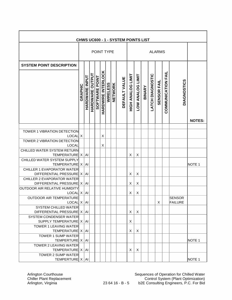
Arlington Courthouse Sequences of Operation for Chilled Water Chiller Plant Replacement Control System (Plant Optimization) Arlington, Virginia 23 64 16 - B - 5 b2E Consulting Engineers, P.C. For Bid
CHWS UC600 - 1 - SYSTEM POINTS LIST
POINT TYPE ALARMS
SYSTEM POINT DESCRIPTION
GR
AP
HIC
HA
RD
WA
RE
IN
PU
T
HA
RD
WA
RE
OU
TP
UT
SO
FT
WA
RE
PO
INT
HA
RD
WIR
E I
NT
ER
LO
CK
WIR
EL
ES
S
NE
TW
OR
K
DE
FA
UL
T V
AL
UE
HIG
H A
NA
LO
G L
IMIT
LO
W A
NA
LO
G L
IMIT
BIN
AR
Y
LA
TC
H D
IAG
NO
ST
IC
SE
NS
OR
FA
IL
CO
MM
UN
ICA
TIO
N F
AIL
DIA
GN
OS
TIC
S
NOTES:
TOWER 1 VIBRATION DETECTION
LOCAL X X
TOWER 2 VIBRATION DETECTION
LOCAL X
CHILLED WATER SYSTEM RETURN
TEMPERATURE X AI X X
CHILLED WATER SYSTEM SUPPLY
TEMPERATURE X AI NOTE 1
CHILLER 1 EVAPORATOR WATER
DIFFERENTIAL PRESSURE X AI X X
CHILLER 2 EVAPORATOR WATER
DIFFERENTIAL PRESSURE X AI X X
OUTDOOR AIR RELATIVE HUMIDITY
LOCAL X AI X X
OUTDOOR AIR TEMPERATURE
LOCAL X AI X
SENSOR
FAILURE
SYSTEM CHILLED WATER
DIFFERENTIAL PRESSURE X AI X X
SYSTEM CONDENSER WATER
SUPPLY TEMPERATURE X AI X
TOWER 1 LEAVING WATER
TEMPERATURE X AI X X
TOWER 1 SUMP WATER
TEMPERTURE X AI NOTE 1
TOWER 2 LEAVING WATER
TEMPERATURE X AI X X
TOWER 2 SUMP WATER
TEMPERTURE X AI NOTE 1
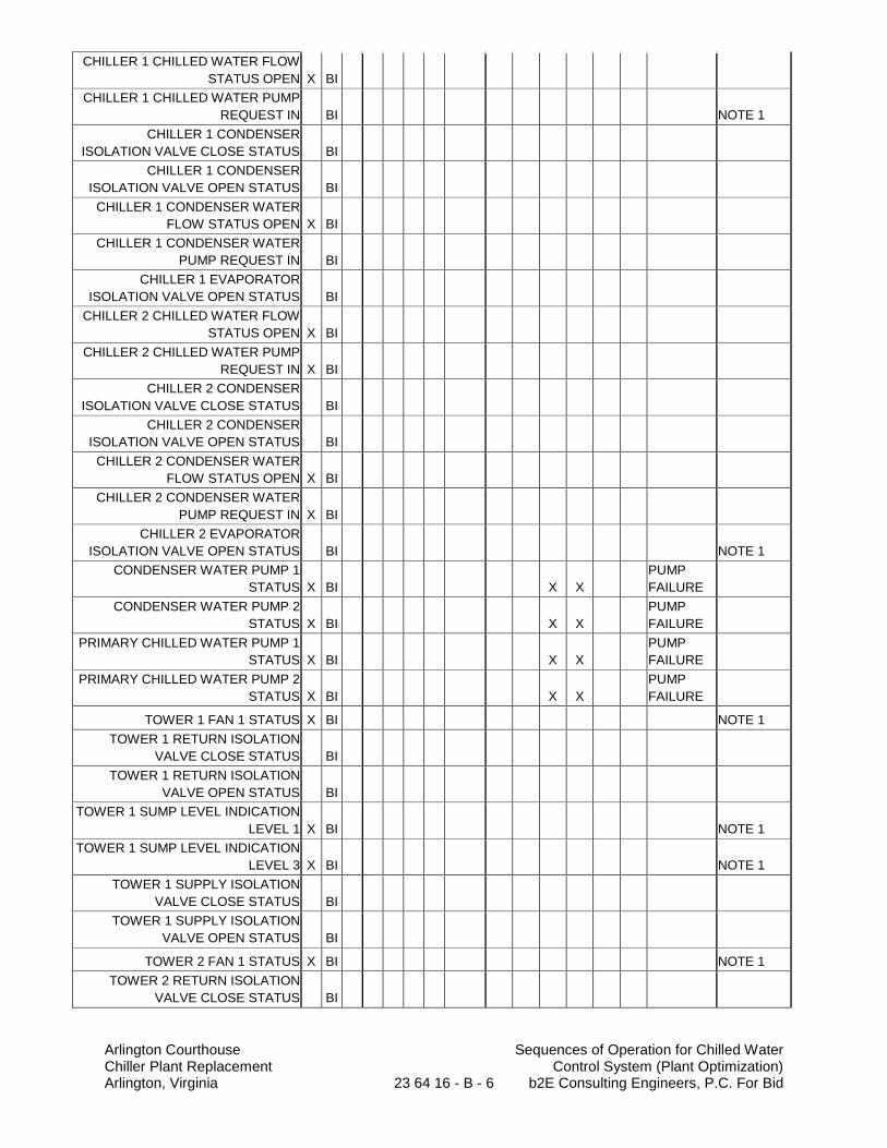
Arlington Courthouse Sequences of Operation for Chilled Water Chiller Plant Replacement Control System (Plant Optimization) Arlington, Virginia 23 64 16 - B - 6 b2E Consulting Engineers, P.C. For Bid
CHILLER 1 CHILLED WATER FLOW
STATUS OPEN X BI
CHILLER 1 CHILLED WATER PUMP
REQUEST IN BI NOTE 1
CHILLER 1 CONDENSER
ISOLATION VALVE CLOSE STATUS BI
CHILLER 1 CONDENSER
ISOLATION VALVE OPEN STATUS BI
CHILLER 1 CONDENSER WATER
FLOW STATUS OPEN X BI
CHILLER 1 CONDENSER WATER
PUMP REQUEST IN BI
CHILLER 1 EVAPORATOR
ISOLATION VALVE OPEN STATUS BI
CHILLER 2 CHILLED WATER FLOW
STATUS OPEN X BI
CHILLER 2 CHILLED WATER PUMP
REQUEST IN X BI
CHILLER 2 CONDENSER
ISOLATION VALVE CLOSE STATUS BI
CHILLER 2 CONDENSER
ISOLATION VALVE OPEN STATUS BI
CHILLER 2 CONDENSER WATER
FLOW STATUS OPEN X BI
CHILLER 2 CONDENSER WATER
PUMP REQUEST IN X BI
CHILLER 2 EVAPORATOR
ISOLATION VALVE OPEN STATUS BI NOTE 1
CONDENSER WATER PUMP 1
STATUS X BI X X
PUMP
FAILURE
CONDENSER WATER PUMP 2
STATUS X BI X X
PUMP
FAILURE
PRIMARY CHILLED WATER PUMP 1
STATUS X BI X X
PUMP
FAILURE
PRIMARY CHILLED WATER PUMP 2
STATUS X BI X X
PUMP
FAILURE
TOWER 1 FAN 1 STATUS X BI NOTE 1
TOWER 1 RETURN ISOLATION
VALVE CLOSE STATUS BI
TOWER 1 RETURN ISOLATION
VALVE OPEN STATUS BI
TOWER 1 SUMP LEVEL INDICATION
LEVEL 1 X BI NOTE 1
TOWER 1 SUMP LEVEL INDICATION
LEVEL 3 X BI NOTE 1
TOWER 1 SUPPLY ISOLATION
VALVE CLOSE STATUS BI
TOWER 1 SUPPLY ISOLATION
VALVE OPEN STATUS BI
TOWER 2 FAN 1 STATUS X BI NOTE 1
TOWER 2 RETURN ISOLATION
VALVE CLOSE STATUS BI
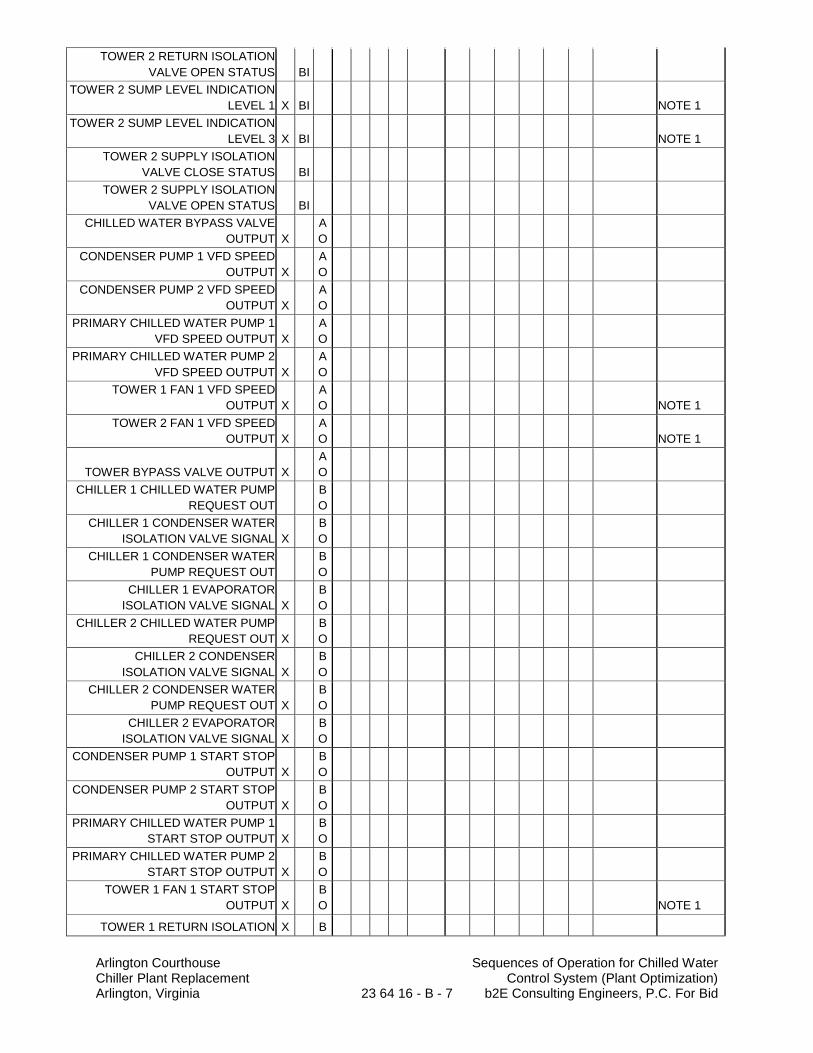
Arlington Courthouse Sequences of Operation for Chilled Water Chiller Plant Replacement Control System (Plant Optimization) Arlington, Virginia 23 64 16 - B - 7 b2E Consulting Engineers, P.C. For Bid
TOWER 2 RETURN ISOLATION
VALVE OPEN STATUS BI
TOWER 2 SUMP LEVEL INDICATION
LEVEL 1 X BI NOTE 1
TOWER 2 SUMP LEVEL INDICATION
LEVEL 3 X BI NOTE 1
TOWER 2 SUPPLY ISOLATION
VALVE CLOSE STATUS BI
TOWER 2 SUPPLY ISOLATION
VALVE OPEN STATUS BI
CHILLED WATER BYPASS VALVE
OUTPUT X
A
O
CONDENSER PUMP 1 VFD SPEED
OUTPUT X
A
O
CONDENSER PUMP 2 VFD SPEED
OUTPUT X
A
O
PRIMARY CHILLED WATER PUMP 1
VFD SPEED OUTPUT X
A
O
PRIMARY CHILLED WATER PUMP 2
VFD SPEED OUTPUT X
A
O
TOWER 1 FAN 1 VFD SPEED
OUTPUT X
A
O NOTE 1
TOWER 2 FAN 1 VFD SPEED
OUTPUT X
A
O NOTE 1
TOWER BYPASS VALVE OUTPUT X
A
O
CHILLER 1 CHILLED WATER PUMP
REQUEST OUT
B
O
CHILLER 1 CONDENSER WATER
ISOLATION VALVE SIGNAL X
B
O
CHILLER 1 CONDENSER WATER
PUMP REQUEST OUT
B
O
CHILLER 1 EVAPORATOR
ISOLATION VALVE SIGNAL X
B
O
CHILLER 2 CHILLED WATER PUMP
REQUEST OUT X
B
O
CHILLER 2 CONDENSER
ISOLATION VALVE SIGNAL X
B
O
CHILLER 2 CONDENSER WATER
PUMP REQUEST OUT X
B
O
CHILLER 2 EVAPORATOR
ISOLATION VALVE SIGNAL X
B
O
CONDENSER PUMP 1 START STOP
OUTPUT X
B
O
CONDENSER PUMP 2 START STOP
OUTPUT X
B
O
PRIMARY CHILLED WATER PUMP 1
START STOP OUTPUT X
B
O
PRIMARY CHILLED WATER PUMP 2
START STOP OUTPUT X
B
O
TOWER 1 FAN 1 START STOP
OUTPUT X
B
O NOTE 1
TOWER 1 RETURN ISOLATION X B
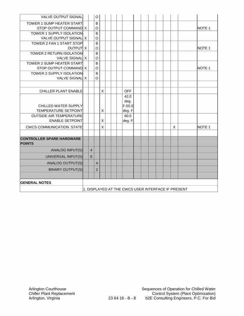
Arlington Courthouse Sequences of Operation for Chilled Water Chiller Plant Replacement Control System (Plant Optimization) Arlington, Virginia 23 64 16 - B - 8 b2E Consulting Engineers, P.C. For Bid
VALVE OUTPUT SIGNAL O
TOWER 1 SUMP HEATER START
STOP OUTPUT COMMAND X
B
O NOTE 1
TOWER 1 SUPPLY ISOLATION
VALVE OUTPUT SIGNAL X
B
O
TOWER 2 FAN 1 START STOP
OUTPUT X
B
O NOTE 1
TOWER 2 RETURN ISOLATION
VALVE SIGNAL X
B
O
TOWER 2 SUMP HEATER START
STOP OUTPUT COMMAND X
B
O NOTE 1
TOWER 2 SUPPLY ISOLATION
VALVE SIGNAL X
B
O
CHILLER PLANT ENABLE X OFF
CHILLED WATER SUPPLY
TEMPERATURE SETPOINT X
42.0
deg.
F-55.0
deg. F
OUTSIDE AIR TEMPERATURE
ENABLE SETPOINT X
60.0
deg. F
CWCS COMMUNICATION STATE X X NOTE 1
CONTROLLER SPARE HARDWARE
POINTS
ANALOG INPUT(S) 4
UNIVERSAL INPUT(S) 8
ANALOG OUTPUT(S) 4
BINARY OUTPUT(S) 2
GENERAL NOTES
1. DISPLAYED AT THE CWCS USER INTERFACE IF PRESENT
Arlington Courthouse Refrigerant Monitoring Safety Equipment Chiller Plant Replacement 23 64 20-1 b2E Consulting Engineers, P.C. Arlington, Virginia For Bid
SECTION 23 64 20
REFRIGERANT MONITORING SAFETY EQUIPMENT
PART 1 - GENERAL
1.1 SUMMARY
A. This Section includes refrigerant monitors and alarms.
B. Refrigerant: The refrigerant detection equipment shall be designed specifically to refrigerant matching the actual chillers provided.
C. The existing exhaust fan EF-26 shall be replaced with a new ducted in-line, two-speed exhaust fan with motor operated damper and a ducted exhaust system as required by ASHRAE Standard 15-2013.
a. A new outside air intake louver shall be installed below the existing louver with a motor operated damper.
D. Provide 4-inch refrigerant relief vents through the low roof to outside. Increase the existing openings for the larger piping.
a. Refer to Architectural for roofing and waterproofing.
1.2 DEFINITIONS
A. CMOS: Ceramic metal-oxide semiconductor.
B. HFC: Hydrofluorocarbon.
C. IR: Infrared.
D. LED: Light-emitting diode.
E. ppm: Parts per million.
1.3 SUBMITTALS
A. Shop Drawings: For each type of refrigerant monitor; include refrigerant ppm range, temperature range, alarm outputs, readout range, furnished specialties, installation requirements, and power consumption.
1. Wiring Diagrams: Power, signal, and control wiring.
B. Coordination Drawings: Include machinery room layout showing location of monitoring devices in relation to refrigerant equipment.
C. Product Certificates: For monitoring devices signed by product manufacturer.
D. Operation and Maintenance Data: For refrigerant monitoring equipment to include in emergency, operation, and maintenance manuals.
Arlington Courthouse Refrigerant Monitoring Safety Equipment Chiller Plant Replacement 23 64 20-2 b2E Consulting Engineers, P.C. Arlington, Virginia For Bid
1.4 QUALITY ASSURANCE
A. ASHRAE: Monitoring system shall comply with ASHRAE 15.
PART 2 - PRODUCTS
2.1 MANUFACTURERS
A. Acceptable Manufacturers: Subject to compliance with requirements, provide products by one of the following:
1. Refrigerant Monitoring Equipment:
a. Basis of Design: Trane Co. (The). b. Davis Instruments Manufacturing Co., Inc. c. General Analysis Corp. d. Thermal Gas Systems, Inc.; Haloguard Monitors.
2.2 FUNCTIONAL DESCRIPTION OF REFRIGERANT MONITORING SYSTEM
A. On leak detection by refrigerant sensor(s), the hardwire control system shall perform the following:
1. Activate machinery room ventilation, index exhaust fan EF-26 in high speed to alarm mode start.
2. Activate audio and visual alarm inside and outside machinery room. 3. Shut down refrigeration machines, heating hot water boilers and domestic hot water
boilers. 4. Notify Energy Management System to initiate alarm signal of the EMS. 5. Interlock to the fire alarm system to initiate an alarm upon release and detection of
refrigerant leak.
2.3 REFRIGERANT MONITOR
A. Description: CMOS or IR sensor shall continuously measure and display the specific gas concentration and shall be capable of indicating, alarming, and shutting down equipment, and automatically activating ventilation system.
B. Performance Requirements:
1. Refrigerant to Be Monitored: R-123 or R-134a. Coordinate with actual chillers provided. 2. Refrigerant Concentration: 0 to 1000 ppm. 3. Accuracy: 0 to 100 ppm; 1 ppm. 4. Linearity: 0 to 100 ppm; linear. 5. Sensitivity: 1 ppm. 6. Resolution: 1 ppm. 7. Operating Temperature: 41 to 104 deg F. 8. Response Time: 90 percent of a step change in 4 minutes. 9. Relatively Humidity: 20 to 95 percent, noncondensing over the operating temperature
range.
Arlington Courthouse Refrigerant Monitoring Safety Equipment Chiller Plant Replacement 23 64 20-3 b2E Consulting Engineers, P.C. Arlington, Virginia For Bid
C. Operating Requirements:
1. Maximum Power Input: 120-V ac; 60 Hz, 30 W. 2. Alarm Relays: 3 relays at 5- to 8-A resistive load. 3. Alarm Set Points: Displayed on front of meter. 4. Audible Output: Sonic alert at 75 to 80 dB at 60 inches. 5. Analog Output: 0- to 10-V dc or 4- to 20-mA current sourcing. 6. Serial Output Type: RS 232.
D. Sensor Configuration: CMOS or Photoabsorptive IR or Photoacoustic IR sensor.
1. Three (3)-sensing channels. 2. Expandable to four channels.
E. Display: 10-character, alphanumeric, vacuum-fluorescent indicating lights for each alarm set point; standard alarm; acknowledge switch and test switch mounted on front panel; and alarm status LEDs and service fault LEDs.
1. Enclosure: NEMA 250, type as required for ambient condition.
F. Alarm Output: Indicating light flashes and horn sounds.
1. Unit-mounting device with single-light beacon. 2. Remote unit for mounting outside machinery room and having light beacon with double
lights. 3. Field-adjustable alarm set points.
G. Calibration: Factory calibrated.
H. Electrical: Connect 120 volt circuit to emergency power to ensure complete safety shut-down in the event of a commercial power outage.
2.4 CONTROL CABLE
A. Electronic and fiber-optic cable for control wiring shall be as specified in Division 26 Section “Control/Signal Transmission Media.”
2.5 SOURCE QUALITY CONTROL
A. Refrigerant Monitor: Factory tested and certified.
PART 3 - EXECUTION
3.1 EXAMINATION
A. Examine chiller layout for proper location of monitoring device.
B. Verify refrigerant contained in chiller(s) to ensure compatibility of refrigerant monitor.
C. Examine machinery room ventilation system to verify its operation with refrigerant monitor(s).
Arlington Courthouse Refrigerant Monitoring Safety Equipment Chiller Plant Replacement 23 64 20-4 b2E Consulting Engineers, P.C. Arlington, Virginia For Bid
3.2 INSTALLATION
A. Install refrigerant monitoring equipment level and plumb.
B. Install labels and nameplates to identify monitoring devices components according to Division 23 Section “Mechanical Identification.”
C. Install building wire and cable according to Division 26 “Conductors and Cables.”
D. Install signal and communication cable according to Division 26 Section “Control/Signal Transmission Media.”
3.3 FIELD QUALITY CONTROL
A. Manufacturer’s Field Service: Engage a factory-authorized service representative to perform the following:
1. Inspect field-assembled components, equipment installation, and electrical connections for compliance with requirements.
2. Test and adjust controls and safeties. 3. Test Reports: Prepare a written report to record the following:
a. Test procedures used. b. Test results that comply with requirements. c. Test results that do not comply with requirements and corrective action taken to
achieve compliance with requirements.
B. Repair or replace malfunctioning units. Retest as specified above after repairs or replacements are made.
3.4 ADJUSTING
A. Adjust alarm set points.
B. Set field-adjustable switches and circuit-breaker trip ranges as indicated.
3.5 DEMONSTRATION
A. Engage a factory-authorized service representative to train Owner’s maintenance personnel to adjust, operate, and maintain refrigerant monitoring devices. Refer to Division 1 Section “Closeout Procedures.”
END OF SECTION 23 64 20
Arlington Courthouse Open-Circuit, Induced Draft Chiller Plant Replacement 23 65 00-1 Cooling Towers (CT-1) Arlington, Virginia b2E Consulting Engineers, P.C. For Bid
SECTION 23 65 00
PART 1 - GENERAL
OPEN-CIRCUIT, INDUCED-DRAFT COOLING TOWERS
1.1 SUMMARY
A. This Section includes factory-assembled and -tested, open-circuit, induced-draft cooling towers.
B. There is limited space in the existing cooling tower enclosure. The contractor and the cooling tower manufacturer’s representative shall coordinate the locations for each platform, including clearance, and ladder and relay design to engineer the final access system is in accordance with all local codes, ordinances, and Federal OSHA requirements.
1.2 SUBMITTALS
A. Product Data: Include rated capacities, pressure drop, fan performance data, rating curves with selected points indicated, furnished specialties, and accessories.
B. Shop Drawings:
1. Design Calculations: Calculate requirements for selecting vibration isolators and seismic restraints and for designing vibration isolation bases.
2. Vibration Isolation Base Details: Detail fabrication including anchorages and attachments to structure and to supported equipment. Include handrails, ladders, and equipment mounting frame.
3. Detail equipment assemblies and indicate dimensions, required clearances, method of field assembly, components, and location and size of each field piping and wiring connection.
4. Wiring Diagrams: Power, signal, and control wiring. 5. Refer to Division 5 for structural steel support design and applicable requirements.
C. Coordination Drawings: Plans, elevations, and other details, drawn to scale, on which the following CWCS are shown and coordinated with each other, based on input from installers of the CWCS involved:
1. Structural supports. 2. Piping and wiring roughing-in requirements (determine spaces reserved for electrical
equipment). 3. Access requirements for service and maintenance.
D. Field quality-control test reports.
E. Product Certificates: Signed by manufacturers of cooling towers to include certified performance curves plotting leaving-water temperature against wet-bulb temperature.
1. Performance curves or actual performance test results on tower of same design criteria. 2. Sound performance data: Manufacturer’s sound power levels by frequency (63 to 8000
Hz) on every side and top; and overall dBA rating. 3. Vibration tests certified by manufacturer.
Arlington Courthouse Open-Circuit, Induced Draft Chiller Plant Replacement 23 65 00-2 Cooling Towers (CT-1) Arlington, Virginia b2E Consulting Engineers, P.C. For Bid
F. Operation and Maintenance Data: For cooling towers to include in emergency, operation, and maintenance manuals. Include part lists for tower fill, water distribution system, fans, bearings, fan drives, vibration isolators, controls, basin heaters, and accessories.
1. Operating and maintenance data. 2. Owner instruction report. 3. Guarantee. 4. Manufacturer’s recommended spare parts list.
G. Warranties: Special warranties specified in this Section.
1.3 QUALITY ASSURANCE
A. Manufacturer's Certification: Certify cooling tower's thermal performance according to CTI 201.
1. Thermal performance standard: Cooling Tower performance shall be certified by the Cooling Tower Institute in accordance with CTI Certification Standard STD-201 or, lacking such certification, a field performance test shall be conducted by the Cooling Tower Institute within the warranty period and in accordance with CTI Acceptance code ATC-105. The Contractor shall include in bid price all costs for the instrumentation as well as preparation and conducting the Cooling Tower Institute filed performance test. Should the field performance test prove the cooling tower performance deficient, the tower shall be replaced by CTI certified tower.
B. Testing Agency Qualifications: An independent agency, with the experience and capability to conduct the testing indicated, that is certified by CTI, and that is acceptable to authorities having jurisdiction.
C. Do not exceed maximum allowable height of tower scheduled. Contractor shall adjust height of architectural cooling tower screen and structural steel if tower exceeds height of screen designed at no additional cost to owner.
D. Electrical Components, Devices, and Accessories: Listed and labeled as defined in NFPA 70, Article 100, by a testing agency acceptable to authorities having jurisdiction, and marked for intended use.
1.4 COORDINATION
A. Coordinate installation of structural steel (dunnage), equipment supports, and roof penetrations. These CWCS are specified in Division 5 Section “Metal Fabrications” and Division 7 Section "Roof Accessories."
B. Coordinate size and location of structural steel rails. Location of vibration isolation bases. Fastening of bases to rails by bolting (not welding). Location of additional steel for support to piping below tower from steel dunnage.
C. Coordinate installation of piping below tower with unit connection locations and roof penetration locations.
D. Coordinate method for lifting tower onto steel dunnage. Do not lift over occupied site or building. Coordinate scheduling with AC Facilities and Department of Environmental Services.
1.5 DELIVERY, STORAGE, AND HANDLING
A. Deliver cooling tower as a factory-assembled unit with protective crating and covering.
Arlington Courthouse Open-Circuit, Induced Draft Chiller Plant Replacement 23 65 00-3 Cooling Towers (CT-1) Arlington, Virginia b2E Consulting Engineers, P.C. For Bid
1.6 WARRANTY
A. Special Warranty: Manufacturer's standard form in which manufacturer agrees to repair or replace the following components of mechanical-draft cooling towers that fail in materials or workmanship within specified warranty period:
1. Fan, motor, drive shaft, bearings, and motor supports. 2. Cooling tower controls, panels and integral controls. 3. Adjustable Frequency Drive (AFD). 4. Drift eliminators, fill and supports. 5. Warranty Period: Five (5) years parts and labor from date of substantial completion plus
extended corrosion protection replacement warranty for ten (10) years.
PART 2 - PRODUCTS
2.1 MANUFACTURERS
A. Acceptable Manufacturers : Subject to compliance with requirements, provide products by one of the following; “No Substitutions Allowed.” 1. Basis of Design: Baltimore Aircoil Company, Series 1500, Model S15E-1212-12NM
(Typ of 2). 2. Marley Cooling Tower, AV Series, Model AV6817TAN (Typ of 2).
2.2 MANUFACTURED UNITS
A. Description: Factory-assembled and -tested, open-circuit, induced-draft cooling tower.
B. Fabricate cooling tower mounting frame and attachments with reinforcement strong enough to resist cooling tower movement during a seismic event when cooling tower mounting frame is attached to the building structure.
C. Cooling Tower Characteristics and Capacities (Each):
1. Condenser-Water Flow: 1,650 gpm. 2. Pump Head: 7.81 psig. 3. Entering Condenser-Water Temperature: 96.37 deg F. 4. Leaving Condenser-Water Temperature: 86.37 deg F. 5. Entering-Air Wet-Bulb Temperature: 78 deg F. 6. Maximum Drift Loss: <0.5% of external-circuit flow. 7. Number of Fans: Two (2) 20 hp fans per cell. 8. Fan Motor Electrical Characteristics: 480-V ac, 3 phase, 60 Hz, premium efficiency,
inverter duty, rugged-duty, totally enclosed, fan-cooled. 9. Basin Heater: 16 kW to maintain 40 deg F condenser-water temperature at -20 deg F
10. Maximum Operating Weight: 19,120 lbs per cell.
outside-air temperature.
11. Condenser Water: Make-up and blow down connections in mechanical room.
2.3 MATERIALS
A. Casing Material: Galvanized sheet steel complying with ASTM A 653/A 653M, G235 (Z700)
B. Collection Basin Material: Welded 304 stainless steel cold water basin. Basin shall carry a 5-year leak-proof warranty.
coating designation.
Arlington Courthouse Open-Circuit, Induced Draft Chiller Plant Replacement 23 65 00-4 Cooling Towers (CT-1) Arlington, Virginia b2E Consulting Engineers, P.C. For Bid
1. Removable strainer with openings smaller than nozzle orifices. 2. Overflow connection. 3. Makeup water connection. 4. Drain connection. 5. Equalizer connection in end.
C. Hot-Water Distribution System: Evenly distributes water over fill material (at 50% to 100% design flow rate).
1. Hot water distribution basins shall be the open gravity type. Basin weirs and plastic metering orifices shall be provided to assure even distribution of water over the wet deck surfaces.
2. G235 galvanized hot water basin covers shall be furnished to prevent the accumulation of debris in the hot water distribution basins. The fan deck and hot water basin covers shall be designed for 50-psf live load or a 200-pound concentrated load.
D. Tower Balancing Valves: Contractor shall provide calibrated balancing valve for balancing each cooling tower. Locate on return-water piping side.
E. Construction: Structural components and steel parts of tower fabricated of heavy gauge, G235 hot dipped galvanized steel with all edges coated.
1. Provide access door on both end walls. 2. Bolts, nuts and washers: Galvanized steel. 3. Hot dip galvanizes components subjected to factory welding after welding is performed. 4. Heavy gauge hot dipped galvanized wire fan guard shall be provided on each fan
cylinder. 5. Provide air inlet screens.
F. Fill Material: Resistant to rot, decay, and biological attack; with maximum flame-spread rating of five according to ASTM E 84; and fabricated, formed, and installed by manufacturer to ensure that water breaks up into droplets.
1. Each section to include wave-formed, PVC wet deck surface below a spray-type water distribution system, encased by hot-dip galvanized steel panels with removable sectional eliminators at top.
2. Surface manufactured and performance tested by cooling tower manufacturer.
G. Drift-Eliminator Material: Resistant to rot, decay, and biological attack; with maximum flame-spread rating of five according to ASTM E 84.
1. PVC construction arranged to ensure constant thermal performance. Eliminators shall have a minimum of three changes in air direction with a hooked leaving edge and be removable in easily handled sections. They shall direct discharge air away from the fans and limit drift loss of less than 0.002% of the total water circulated.
H. Air Inlet Louvers: Inlet louvers wave formed, FRP spaced to minimize air resistance, eliminate water splash-out, and prevent scale formation on the face of the wet deck.
1. Provide hot dipped galvanized-steel mesh air inlet screens with polymer coating, mounted in removable frames.
I. Air Inlet Screen Material: Galvanized-steel mesh mounted in removable frames.
Arlington Courthouse Open-Circuit, Induced Draft Chiller Plant Replacement 23 65 00-5 Cooling Towers (CT-1) Arlington, Virginia b2E Consulting Engineers, P.C. For Bid
2.4 COMPONENTS
A. Water makeup assembly:
1. Each cooling tower shall be provided with electric water level control assembly consisting of electric probes mounted in a stilling chamber external of the tower, solid state control relay in a weather proof enclosure, and a remotely located slow acting solenoid valve in the Penthouse chiller room.
a. Stilling chamber heat trace and insulation by Division 23 Solenoid valve conduit and wiring by Division 26.
b. 120-volt power to electronic water level controller by Division 26. c. Solenoid installation in make-up water assembly by Division 26. Typical one (1)
solenoid valve per cooling tower. d. Refer to construction documents cooling tower control diagrams for wiring
arrangements.
B. Fan: Aluminum alloy, propeller.
1. Drive: Belt; fan and motor sheaves: Aluminum. 2. Bearings: Self-aligning ball bearings or bronze sleeve bearings. 3. Vibration Cutout Switch: De-energize fan motors if excessive vibration occurs. 4. Statically and dynamically balanced. 5. Fan housings with curved inlet rings for efficient air entry. Rectangular discharge cowls
to extend into pan to increase fan efficiency and prevent water from entering fans. 6. Fans mounted on a steel fan shaft supported by heavy-duty, self-aligning, pillow block
housed bearings. The fan shaft shall be protected with a two-part epoxy coating for corrosion protection.
a. Provide extended lube lines.
7. Provide one (1) adjustable frequency drives (AFD) for each cooling tower.
C. Capacity-Control Fan Modulation: Provide adjustable frequency drive (AFD) for one (1) fan motor.
1. Modulate fan speed to control leaving condenser water temperature.
a. Monitoring and control shall be interlocked to building CWCS to affect Sequence of Operation specified in Section 23 09 93 and 23 64 16-B.
D. Basin Heater: Electric-resistance coil.
1. Basin-Heater Capacity: 16 kW to maintain basin water temperature at 40 deg F when ambient temperature is -20 deg F and wind velocity is 10 mph (16 km/h)
2. Heater Type: Electric immersion heaters with thermostat and low-water cutout switch enclosed in weatherproof housing suitable for field wiring.
.
3. Fan Interlock: Lock-out heater from energizing whenever supply fan(s) are running.
2.5 CONTROLS
A. Basin Heaters:
Arlington Courthouse Open-Circuit, Induced Draft Chiller Plant Replacement 23 65 00-6 Cooling Towers (CT-1) Arlington, Virginia b2E Consulting Engineers, P.C. For Bid
1. Provide one (1) 16 kW electric heater(s) in each cooling tower basin and ready for field wiring.
2. Provide thermostat control with sensing bulb located in water basin. 3. Provide low water cutoff control to prevent heater operation unless element is fully
submerged. 4. Provide 460-volt electrical connection to cooling tower control panel by Division 26. 5. Heater shall maintain tower sump water temperature above freezing with outside air
temperature of -20 deg. F. 6. Provide current sensing relay in each equipment circuit to allow status monitoring by
Chilled Water Control System (CWCS). Coordinate with CWCS contractor, and provide interface devices to communicate with the CWCS.
7. Interlock sump heater with tower fan to prevent its operation when fan is running. Coordinate with CWCS contractor.
B. Cooling Tower Control Panel: 1. The cooling tower manufacturer is responsible for providing control components for the
cooling tower control panel (one (1) CTCP per tower) and the following:
a. Install CWCS provided controllers (relays) in CTCP (Refer to CTCP ladder control diagram, Sheet M-803.
b. Electronic water level probe and controller: Provide weatherproof enclosure install outside at cooling tower.
c. Water make-up solenoid: Install on make-up water assembly located in Penthouse chiller room (Refer to make-up water assembly detail).
d. Electric immersion heaters: Provide and install one (1) per cooling tower. e. Basin water temperature transmitter, and low water cut-off for basin heater. f. Heater lock-out when fan operational. g. Install two (2) CWCS provided current sensing relays for one (1) fan motor and
one (1) electric immersion heater. h. Basin heater contactors one (1) per tower. i. Adjustable Frequency Drives (AFD) one (1) per fan or cell (per manufacturer). j. Indicator lights.
2. The cooling tower control panel (CTCP) control wiring shall be modified to allow CWS temperature control by the CWCS. The cooling tower panel manufacturer shall coordinate with the CWCS Contractor and install CWCS provided controllers, auxiliary relays, and all devices necessary to provide the sequence of operation specified at no additional cost to the owner. The CTCP manufacturer shall provide all engineering, labor and materials for a complete operational system.
a. Panel enable/disable by the CWCS. b. Fan No. 1: A.F.D. enable/disable, output frequency, input frequency feedback,
input alarm signal. c. Heater No. 1: “On/Off” with current sensing relay. d. Water level:
i. Tower low (solenoid “open”). ii. Tower full (solenoid “closed”). iii. Low water level (lock-out heater, alarm). iv. High water level (alarm).
e. Leaving Water Temperature (Read by CWCS, display at Operator Workstation).
Arlington Courthouse Open-Circuit, Induced Draft Chiller Plant Replacement 23 65 00-7 Cooling Towers (CT-1) Arlington, Virginia b2E Consulting Engineers, P.C. For Bid
f. CWCS Controller/Relay enable/disable fans in sequence to maintain setpoint temperature.
g. All data shall be shared via a network connection interface. Provide full coordination with CWCS contractor.
3. The cooling tower control panel (CTCP) shall have the following indicators:
a. Fan No. 1: “On” Red light; “Off” Green light. b. Heater No. 1 “On” Red light; “Off” Green light. c. Panel Energized: Red light.
4. The cooling tower control panel (CTCP) shall have a single point electrical connection. Provide factory wired-installed main disconnect circuit breaker, auxiliary load circuit breakers, and control power transformer (CPT) sized to accommodate all VA loads required. The CPT shall have fuse protection. Terminal blocks shall be organized and labeled inside the panel for all control devices.
a. The AFD shall be remote mounted next to the CTCP at provided power from the CTCP.
b. Refer to mechanical drawings for schematic control diagrams.
C. CWCS Controls:
1. The CWCS shall have the following controls:
a. CWS immersion temperature transmitter (TT-X) in CT leaving water piping (inside building).
b. CWCS Controller/relay.
i. Fan No. 1 & 2: AFD enable/disable.
c. Current sensing relays for each contractor and motor starter. d. Digital input and output and analog input and output for each AFD.
i. DI= Enable/disable. ii. DO= Alarm. iii. AI= Frequency (Speed). iv. AO= Modulation.
e. CWS immersion temperature sensor (transmitter) for automatic temperature
control.
i. CWCS contractor shall write algorithm to minimize energy consumption of chiller plant considering chiller efficiency and fan motor energy consumption (i.e. Energy demand (kW)) by varying speed of AFD to maintain optimal CWS temperature at actual part load of chiller and actual ambient outdoor wet bulb temperature.
2.6 MOTORS
A. Comply with requirements in Division 23 Section "Motors."
B. Motor Efficiency: Premium, refer to Section 23 05 13.
Arlington Courthouse Open-Circuit, Induced Draft Chiller Plant Replacement 23 65 00-8 Cooling Towers (CT-1) Arlington, Virginia b2E Consulting Engineers, P.C. For Bid
C. Enclosure Type Premium Efficiency: Rugged-duty, totally enclosed, fan-cooled (TEFC).
D. Motor Speed: Premium efficiency, inverter duty type for variable-speed controller.
E. Motor Drives: V-belt drives designed for 150 percent of motor nameplate power rating.
2.7 VIBRATION CONTROL
A. Direct isolation with I-beam on top of restrained-spring isolators supporting both cooling towers.
1. Coordinate with Section 23 05 48.
2. Spring isolators shall be bolted to steel support (dunnage), not welded.
2.8 HANDRAILS, LADDERS, AND PLATFORMS
A. Ladders and Safety Cages: Galvanized steel or aluminum complying with 29 CFR 1910.27.
B. Service Platforms: OSHA Compliant, galvanized steel with a bar grating floor. 1. Internal service platforms and associated access doors required inside towers, to allow
maintenance access from side or through towers (from one to the other).
a. Manufacturer shall coordinate all access requirements and provide ease of maintenance in each tower.
b. Work around existing duct outlets and with limiting field dimensions in existing cooling tower enclosure.
2. Full width external service platforms, across top of tower to allow inspection of hot water basin.
a. Ladder shall not extend higher than top of tower. b. Ladder shall be extended to level of roof after tower set in place.
PART 3 - EXECUTION
3.1 EXAMINATION
A. Examine roughing-in for concrete bases, anchor-bolt sizes and locations, piping, and electrical to verify actual locations and sizes before cooling tower installation and other conditions affecting cooling tower performance, maintenance, and operation.
B. Examine proposed route of moving cooling towers into place and verify that it is free of interferences.
C. Proceed with installation only after unsatisfactory conditions have been corrected.
3.2 INSTALLATION
A. Install cooling towers on concrete bases. Concrete base is specified in Division 23 Section "Basic Mechanical Materials and Methods," and concrete materials and installation requirements are specified in Division 3.
Arlington Courthouse Open-Circuit, Induced Draft Chiller Plant Replacement 23 65 00-9 Cooling Towers (CT-1) Arlington, Virginia b2E Consulting Engineers, P.C. For Bid
B. Vibration Isolation: Restrained spring isolators with a minimum deflection of 1-inch (25mm). Vibration isolation devices and installation requirements are specified in Division 23 Section "Mechanical Sound and Vibration Controls."
C. Maintain manufacturer's recommended clearances for service and maintenance.
D. Loose Equipment: Install electrical components, devices, and accessories that are not factory mounted.
E. Electrical Wiring: Install electrical devices furnished by cooling tower manufacturer that are not factory mounted. Power wiring and conduit by Division 26. Control wiring and conduit by the CWCS contractor.
3.3 CONNECTIONS
A. Piping installation requirements are specified in other Division 23 Sections. Drawings indicate general arrangement of piping, fittings, and specialties.
B. Install piping adjacent to cooling towers to allow service and maintenance.
C. Install flexible pipe connectors at final connections of towers mounted on vibration isolators.
D. Connect overflow drain to roof drain and blow down to sanitary floor drain.
E. Domestic Water Piping: Comply with applicable requirements in Division 23 Section "Domestic Water Piping." Provide make-up water assembly as indicated on the contract documents.
F. Condenser-Water Piping: Comply with applicable requirements in Division 23 Section "Hydronic Piping." Connect to supply and return cooling-tower connections with shutoff valve, flow-control valve, and union or flange on supply connection to the cooling tower and shutoff valve and union or flange to return connection from the cooling tower to the chiller.
G. Ground cooling towers according to Division 26 Section "Grounding and Bonding."
H. Connect wiring according to Division 26 Section "Conductors and Cables."
I. Tighten electrical connectors and terminals according to manufacturer's published torque-tightening values. If manufacturer's torque values are not indicated, use those specified in UL 486A and UL 486B.
3.4 FIELD QUALITY CONTROL
A. Testing Agency: If the cooling tower is not certified by the Cooling Technology Institute, the contractor will engage a qualified testing and inspecting agency to perform field tests and inspections according to CTI's Supplement to ATC 105, "Acceptance Test Code for Cooling Towers," and prepare test reports.
3.5 STARTUP SERVICE
A. Engage a factory-authorized service representative to perform startup service.
B. Inspect field-assembled components, equipment installation, and piping and electrical connections for proper assemblies, installations, and connections.
C. Obtain performance tables from manufacturer.
Arlington Courthouse Open-Circuit, Induced Draft Chiller Plant Replacement 23 65 00-10 Cooling Towers (CT-1) Arlington, Virginia b2E Consulting Engineers, P.C. For Bid
D. Complete installation and startup checks according to manufacturer's written instructions and perform the following:
1. Clean entire unit including basins. 2. Verify that accessories are properly installed. 3. Check makeup water assembly and control. 4. Verify clearances for airflow and for cooling tower servicing. 5. Check for vibration isolation and structural support. 6. Lubricate bearings on fans and shafts. 7. Verify fan wheel rotation for correct direction and for vibration or binding. Correct
vibration and binding problems. 8. Adjust belts to proper alignment and tension. 9. Verify water level in tower basin. Fill to proper startup level. 10. Start external-circuit circulating and condenser-water pumps. 11. Verify operation of tower basin, makeup line, automatic freeze protect dump, and
controlling device. Replace defective and malfunctioning units. 12. Verify operation of basin heater and control thermostat. Replace defective and
malfunctioning units. 13. Verify that tower discharge is not recirculating into air intakes. Recommend corrective
action. 14. Ensure that heat trace cable is installed with thermostatic control and working properly on
all piping installed above the roof. 15. Perform operation tests to determine performance.
a. Test in conjunction with chillers and pump tests.
E. Check HVAC water treatment system for proper operation, and measure chemical treatment levels. Verify operation of tower basin automatic blowdown, and controlling device.
F. Start cooling tower and condenser-water pumps. Follow manufacturer's written starting procedures.
G. Prepare a written startup report that records the results of tests and inspections.
3.6 ADJUSTING
A. Set and balance condenser-water flow to each cooling tower inlet.
B. Adjust water-level control for proper operating level.
C. Occupancy Adjustments: When requested within 24 months of date of Substantial Completion, provide on-site in assistance in adjusting system to suit actual occupied conditions. Provide up to six (6) visits to site outside normal occupancy hours for this purpose.
3.7 DEMONSTRATION
A. Engage a factory-authorized service representative to train Owner's maintenance personnel to adjust, operate, and maintain cooling towers as specified below. 1. Train Owner's maintenance personnel on procedures and schedules for starting up and
shutting down, troubleshooting, servicing, and maintaining cooling towers. 2. Review data in maintenance manuals. Refer to Division 1 Section "Project Closeout." 3. Review data in maintenance manuals. Refer to Division 1 Section "Operation and
Maintenance Data." 4. Schedule training with Owner, through Architect, with at least seven days' advance
notice. 5. Refer to Division 01 Section "Project Closeout."
Arlington Courthouse Open-Circuit, Induced Draft Chiller Plant Replacement 23 65 00-11 Cooling Towers (CT-1) Arlington, Virginia b2E Consulting Engineers, P.C. For Bid
END OF SECTION 23 65 00
Arlington Courthouse General Electrical Requirements Chiller Plant Replacement 26 01 00-1 b2E Consulting Engineers, P.C. Arlington, Virginia For Bid
SECTION 26 01 00
GENERAL ELECTRICAL REQUIREMENTS
PART 1 - GENERAL
1.1 SPECIAL ELECTRICAL REQUIREMENTS
A. Drawing use and interpretation:
1. Design drawings are diagrammatic and do not show all offsets, bends, elbows, or other specific elements that may be required for proper installation of the work. Such work shall be verified at the site. Additional bends and offsets, and conduit as required by vertical and horizontal equipment locations or other job conditions, shall be provided to complete the work at no additional cost to the Owner.
2. For locations of building elements, refer to architectural, structural, mechanical and electrical drawings. Except where shown in dimensional detail, the locations of switches, receptacles, lights, motors, outlets, and other equipment shown on plans are approximate. Such items shall be placed to eliminate interference with ducts, piping and equipment. Outlets shall not be installed behind ducts, grilles, built-in casework, or in other inaccessible places. Exact locations shall be determined in the field. Door swings shall be verified to ensure that light switches are properly located.
3. Field measurements take precedence over drawings. 4. Electrical plans are intended to indicate size, capacity, approximate location, direction
and general relationship of the work, but not exact detail or arrangement. The contractor is responsible for indicating detailed arrangements for procured equipment and layouts on all shop drawings required in all specification sections. Equipment sizes indicated are minimum. Before installing any wire or conduit, the Contractor shall obtain the exact equipment requirements and shall install wire, conduit, disconnect switches, motor starters, heaters, circuit breakers, and other items for the correct size for the equipment actually installed. Wire and conduit sizes shown on the drawings shall be taken as a minimum and shall not be reduced without written approval.
5. Where job conditions require reasonable deviation from contract documents, make such deviations without additional cost to Owner after obtaining approval of the Engineer.
B. Installation of systems and equipment:
1. Installation is subject to clarification as indicated in reviewed Shop and Field Coordination Drawings.
a. Generally, lay out piping requiring gravity drainage first; then lay out large pipe mains, ductwork and electrical conduit.
b. This procedure is intended to promote orderly installation, but not to establish trade precedence.
c. Dimensions indicated are limiting dimensions. d. Do not use equipment exceeding dimensions required by manufacturer for service
access, and applicable codes reduce required clearances. e. In electrical equipment room corridors and aisle ways, maintain clear head room
between floor and underside of conduit, switches, controllers, panelboards, transformers and equipment to allow for future replacing of equipment and major components.
Arlington Courthouse General Electrical Requirements Chiller Plant Replacement 26 01 00-2 b2E Consulting Engineers, P.C. Arlington, Virginia For Bid
f. Coordinate connections to all equipment, and penetrations of conduit through floors, walls and roof with actual field conditions and dimensions. Contractors shall thoroughly familiarize themselves with the project requirements prior to submitting bid price.
g. Measure and coordinate the connections and the installations between trades prior to submitting shop drawings.
h. Under no circumstances shall any electrical equipment be hung, supported or suspended from the building suspended ceilings.
C. Utility coordination with Owner
1. Notify Owner’s representative of any utility interruptions at least seventy two (72) hours in advance and obtain approval from property manager before proceeding.
2. Identify extent and duration of utility interruptions.
D. Installation of chilled water system equipment and distribution equipment.
1. Installation requirements are subject to vary with each manufacturer’s equipment. The contractor is responsible for reviewing the manufacturer’s shop and installation drawings.
a. The contractor shall install the electrical distribution equipment per manufacturer’s installation drawings.
b. Prior to the preparation of submittals, the contractor shall contact the manufacturer and coordinate the exact locations, sizes, weights, connections, and assembly requirements for each piece of equipment.
c. The contractor is responsible for installation of a complete operating system in accordance with the manufacturer installation drawings and in accordance with the specification requirements.
2. As part of the submittal process, the contractor shall provide a detailed installation drawing for all electrical distribution equipment specifically for the chilled water system to fit within the allocated space. Distribution equipment submittals which are presented without complete room layout drawings will not be considered or reviewed. The manufacturer and contractor shall coordinate with actual field conditions and perform surveys as necessary to develop a complete equipment installation drawing which meets all applicable codes, code amendments, Arlington County Standards, ordinances, laws, etc., including but not limited to:
a. Manufacturer service access clearances; top, front, back and sides. b. National Electric Code (NEC) service access clearances; top, front, back and
sides. c. Any other requirements of the local authorities having jurisdiction. d. All conduit routings and terminations. e. Full field erection drawing with detail on distribution wireway. f. Detail of conduit penetrations through exterior walls far waterproof installation. h. Drawings for pull box. These drawings shall be submitted coincident with
distribution gear shop drawings.
3. The contractor and manufacturer shall fully coordinate the complete installation of all materials and labor described in the following sections. a. Section 26 24 16 – Panelboards. b. Section 26 28 16 – Enclosed Switches and Circuit Breakers.
E. Electrical coordination study:
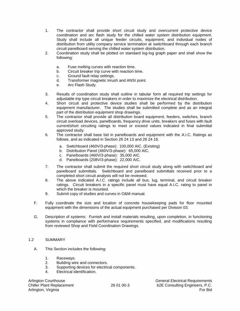
Arlington Courthouse General Electrical Requirements Chiller Plant Replacement 26 01 00-3 b2E Consulting Engineers, P.C. Arlington, Virginia For Bid
1. The contractor shall provide short circuit study and overcurrent protective device coordination and arc flash study for the chilled water system distribution equipment. Study shall include all unique feeder circuits, equipment, and individual nodes of distribution from utility company service termination at switchboard through each branch circuit panelboard serving the chilled water system distribution.
2. Coordination study shall be plotted on standard log-log graph paper and shall show the following:
a. Fuse melting curves with reaction time. b. Circuit breaker trip curve with reaction time. c. Ground fault relay settings. d. Transformer magnetic inrush and ANSI point. e. Arc Flash Study.
3. Results of coordination study shall outline in tabular form all required trip settings for adjustable trip type circuit breakers in order to maximize the electrical distribution.
4. Short circuit and protective device studies shall be performed by the distribution equipment manufacturer. The studies shall be submitted complete and as an integral part of the distribution equipment shop drawings.
5. The contractor shall provide all distribution board equipment, feeders, switches, branch circuit overload devices, panelboards, frequency drive units, breakers and fuses with fault current/short circuiting ratings to meet or exceed values indicated in final submittal approved study.
6. The contractor shall base bid in panelboards and equipment with the A.I.C. Ratings as follows, and as indicated in Section 26 24 13 and 26 24 16.
a. Switchboard (460V/3-phase): 100,000 AIC. (Existing) b. Distribution Panel (460V/3-phase): 65,000 AIC. c. Panelboards (460V/3-phase): 35,000 AIC. d. Panelboards (208V/3-phase): 22,000 AIC.
7. The contractor shall submit the required short circuit study along with switchboard and panelboard submittals. Switchboard and panelboard submittals received prior to a completed short circuit analysis will not be reviewed.
8. The above indicated A.I.C. ratings include all bus, lug, terminal, and circuit breaker ratings. Circuit breakers in a specific panel must have equal A.I.C. rating to panel in which the breaker is mounted.
9. Submit copy of studies and curves in O&M manual.
F. Fully coordinate the size and location of concrete housekeeping pads for floor mounted equipment with the dimensions of the actual equipment purchased per Division 03.
G. Description of systems: Furnish and install materials resulting, upon completion, in functioning systems in compliance with performance requirements specified, and modifications resulting from reviewed Shop and Field Coordination Drawings.
1.2 SUMMARY
A. This Section includes the following:
1. Raceways. 2. Building wire and connectors. 3. Supporting devices for electrical components. 4. Electrical identification.
Arlington Courthouse General Electrical Requirements Chiller Plant Replacement 26 01 00-4 b2E Consulting Engineers, P.C. Arlington, Virginia For Bid
5. Concrete equipment bases. 6. Electrical equipment coordination and installation. 7. Cutting and patching for electrical construction. 8. Touchup painting.
1.3 DEFINITIONS
A. RMC: Rigid metal conduit.
B. EMT: Electrical metallic tubing.
C. FMC: Flexible metal conduit.
D. IMC: Intermediate metal conduit.
E. LFMC: Liquid tight flexible metal conduit.
F. Scheduled: As scheduled on drawing equipment schedules or as called out by model number/designation in the specification.
G. Acceptance: With respect to initiation of warranty, the date when the Engineer signs the Contractor’s Application for Final Payment for release of retainage.
H. EMS: Energy Management System.
J. Notice-to-Proceed: The date, which the building owner or authorized agent authorizes Notice–to-Proceed by Letter.
K. Scheduled: As scheduled on drawing equipment schedules or as called-out by manufacturer/model number/designation in the specification.
1.4 SUBMITTALS
A. Shop Drawings: Dimensioned plans and sections or elevation layouts of electricity-metering equipment.
B. Field Test Reports: Indicate and interpret test results for compliance with performance requirements.
1.5 QUALITY ASSURANCE
A. Electrical Components, Devices, and Accessories: Listed and labeled as defined in NFPA 70, Article 100, by a testing agency acceptable to authorities having jurisdiction, and marked for intended use.
B. Equipment Selection: Mechanical equipment by “Acceptable Manufacturer” of higher electrical characteristics other than as indicated as “Basis of Design” on drawings may be furnished provided electrical services, circuit breakers, conduit, starters, adjustable frequency drives, panelboards, motor control cabinets are increased. The contractor is responsible to coordinate between trades prior to submitting bid price. Additional costs to the Owner shall not be considered for such modifications, and shall remain the responsibility of the contractor.
Arlington Courthouse General Electrical Requirements Chiller Plant Replacement 26 01 00-5 b2E Consulting Engineers, P.C. Arlington, Virginia For Bid
C. Perform work in accordance with the following codes:
1. State and local building electrical and fire alarm codes. 2. National Electric Code (NFPA 70). 3. National Fire Alarm Code (NFAP 72). 4. National Fire Protection Association (Applicable Codes). 5. Underwriter Laboratories (Comply with or exceed all provisions of specific equipment
listings or classifications). 6. National Electrical Manufacturers Association (NEMA). 7. Virginia Uniform Statewide Building Code (latest amendments). 8. Fire alarm testing criteria as may published by the Chief Fire Code Inspector for Arlington
County, Virginia. 9. ASHRAE Energy Code – 90.1 - 2010.
D. Conductors: All wire, bus, lugs terminations, connectors, etc. shall be copper. Use of any aluminum in the conductor path is not allowed. This includes but is not limited to all panels, disconnects, enclosed breakers, lugs, splices, terminals, etc.
1.6 DELIVERY, STORAGE AND HANDLING
A. Deliver conduit with factory-applied end caps. Maintain end caps through shipping, storage, and handling to prevent conduit end damage and prevent entrance of dirt, debris, and moisture.
B. Protect stored conduit from moisture and dirt. Elevate above grade. Do not exceed structural capacity of floor or roof, if stored inside or on the roof.
1. Do not store heavy equipment or materials inside or on the roof.
C. Protect couplings, fittings and specialties from moisture and dirt.
D. Provide covering and shielding for equipment to protect from damage.
E. Protect existing building and building components.
F. Repair, restore, and replace damaged existing and new building components and equipment.
G. Protect nameplates on electrical panelboards, motor controllers, control centers, transformers, circuit breakers and other equipment.
1.7 SEQUENCING AND SCHEDULING
A. Coordinate electrical equipment installation with other building components. B. Arrange for conduit spaces, chases, slots, and openings in existing building structure and shaft
during progress of construction to allow for electrical installations.
C. Coordinate installation of required supporting devices and set sleeves in poured-in-place concrete and other structural components, as they are constructed.
Arlington Courthouse General Electrical Requirements Chiller Plant Replacement 26 01 00-6 b2E Consulting Engineers, P.C. Arlington, Virginia For Bid
D. Sequence, coordinate, and integrate installations of electrical materials and equipment for efficient flow of the Work. Coordinate installation of large equipment requiring positioning, re-assembly before closing in chiller room, electric room, shaft, etc.
E. Coordinate lifting and rigging and connection of electrical systems with exterior underground and overhead utilities and services. Comply with requirements of governing regulations, franchised service companies, and controlling agencies for setting or moving large equipment. Perform work in accordance with all applicable codes and local authorities having jurisdiction and obtain and pay for all permits and other costs.
F. Coordinate requirements for access panels and doors if electrical items requiring access are concealed behind finished surfaces.
G. Coordinate installation of identifying devices and panel schedules after completing covering and painting, if devices are applied to surfaces. Install identifying devices before installing acoustical ceilings and similar concealment.
H. Coordinate lifting and rigging and connection of electrical systems with interior space limitations and finishes. Remove and replace as necessary existing architectural, mechanical, electrical, plumbing, etc., building components as required to install large and/or heavy equipment.
1.8 JOB CONDITIONS
A. Cause as little interference or interruption of existing utilities and services as possible.
1. Schedule work which will cause interference or interruption in advance with Owner Authorities having jurisdiction, and affected contractors.
B. Keep roads clear of materials and debris.
C. Examine Contract Documents to determine how other work will affect execution of electrical work.
D. Examine site and become familiar with existing local conditions affecting work.
E. Determine and verify locations of conduit and equipment in building where work is being performed.
F. Make arrangements and pay for necessary permits, licenses, and inspections.
G. Record drawings:
1. Keep one (1) complete set of electrical drawings in job site office for indicating actual installation of electrical systems and equipment.
2. Use this set of drawings for no other purpose. 3. Where material, equipment, or systems components are installed differently from that
indicated, show such differences clearly and neatly. 4. At project completion, provide record set of drawings in accordance with Division 1.
Record drawing shall show all important information which is changed from contract drawings. Dimensionally locate all underground or in-slab conduit on record drawings.
1.9 HAZARDOUS MATERIALS
Arlington Courthouse General Electrical Requirements Chiller Plant Replacement 26 01 00-7 b2E Consulting Engineers, P.C. Arlington, Virginia For Bid
A. The Contractor shall refer to the “Contract Requirements” Sections, Division 1 and other applicable Divisions and Sections for hazardous materials abatement coordination and other requirements prior to submitting bid price.
1.10 SUBSTANTIAL COMPLETION AND ACCEPTANCE
A. The Contractor shall refer to Section 017700, “Closeout Procedures”, Division 1, and other applicable Project Manual Sections for Substantial Completion requirements prior to submitting bid price.
B. Acceptance: The electrical and fire alarm systems shall not be accepted by the Owner and Engineer until all systems are installed, fully operational, and commissioning for HVAC systems and low voltage electrical systems are completed, pre-commissioning is completed, and commissioning is completed to the satisfaction of the Owner.
1. The Owner will not accept and will not release payment for retainage identified in the
paragraph below until all Division 26, 27 and 28 contract requirements are completed and the systems are accepted by the Owner and Architect.
PART 2 - PRODUCTS
2.1 SUPPORTING DEVICES
A. Material: Cold-formed steel, with corrosion-resistant coating acceptable to authorities having jurisdiction.
B. Metal Items for Use Outdoors or in Damp Locations: Hot-dip galvanized steel.
C. Slotted-Steel Channel Supports: Flange edges turned toward web, and 9/16-inch- diameter slotted holes at a maximum of 2 inches o.c., in webs.
D. Slotted-Steel Channel Supports: Comply with Division 5 Section "Metal Fabrications" for slotted channel framing.
1. Channel Thickness: Selected to suit structural loading. 2. Fittings and Accessories: Products of the same manufacturer as channel supports.
E. Raceway and Cable Supports: Manufactured clevis hangers, “J” hooks, riser clamps, straps, threaded C-clamps with retainers, ceiling trapeze hangers, wall brackets, and spring-steel clamps or click-type hangers.
F. Pipe Sleeves: ASTM A 53, Type E, Grade A, Schedule 40, galvanized steel, plain ends.
G. Cable Supports for Vertical Conduit: Factory-fabricated assembly consisting of threaded body and insulating wedging plug for non-armored electrical cables in riser conduits. Plugs have number and size of conductor gripping holes as required to suit individual risers. Body constructed of malleable-iron casting with hot-dip galvanized finish.
H. Expansion Anchors: Carbon-steel wedge or sleeve type.
I. Toggle Bolts: All-steel springhead type.
Arlington Courthouse General Electrical Requirements Chiller Plant Replacement 26 01 00-8 b2E Consulting Engineers, P.C. Arlington, Virginia For Bid
J. Powder-Driven Threaded Studs: Heat-treated steel (obtain approval from Structural Engineer).
2.2 WARRANTIES
A. The Contractor shall warrant for period of two (2) years all work provided under the contract to include, but not necessarily limited to, all systems, equipment, materials, and workmanship. This shall not be construed to limit any extended warranty periods of longer than one year for specific items or systems specified elsewhere in the Contract Documents.
B. The warranty period shall commence on the date of acceptance by the Owner and shall cover all parts and labor as required to fulfill the warranty at no cost to the Owner. Refer to Division 1 for additional warranty requirements.
C. Information on all warranties shall be included in the O&M Manuals specified herein to be provided by the Owner.
D. Provide a separate warranty binder for all warranties that are included in the O&M manuals.
2.5 ASBESTOS
A. Asbestos Free Materials: The intention of these drawings and specifications is that there be no asbestos containing materials installed on this project. The best of Architect’s and Engineer’s knowledge, none of the material or equipment specified herein or shown on the drawings contains asbestos. The Contractor shall make every effort to prevent any asbestos materials from being installed in or used on construction of the project. At the completion of the project, the Contractor shall certify by letter that to the best of his knowledge, no asbestos containing materials were used for or in the construction of this project.
2.6 TOUCHUP PAINT
A. For Equipment: Equipment manufacturer's paint selected to match installed equipment finish.
B. Galvanized Surfaces: Zinc-rich paint recommended by item manufacturer.
2.7 PENETRATIONS
A. Maintain fire ratings and provide U.L. Listed firestopping system where electrical items penetrate fire rated building elements (See Architectural). Include in written warranty of work, a guarantee of the weatherproof integrity of penetrations where such penetrations occur at exterior envelope.
B. See Roof Curbs, Division 23, Section “HVAC General Mechanical Requirements” for piping penetrations through special roof curbs. Do not penetrate roof with wiring, conduit, etc, unless through a roof curb.
PART 3 - EXECUTION
Arlington Courthouse General Electrical Requirements Chiller Plant Replacement 26 01 00-9 b2E Consulting Engineers, P.C. Arlington, Virginia For Bid
3.1 ELECTRICAL EQUIPMENT INSTALLATION
A. Headroom Maintenance: If mounting heights or other location criteria are not indicated, arrange and install components and equipment to provide the maximum possible headroom.
B. Materials and Components: Install level, plumb, and parallel and perpendicular to other building systems and components, unless otherwise indicated. Where headroom or space conditions appear inadequate, contractor shall notify Architect before proceeding.
C. Equipment: Install to facilitate service, maintenance, and repair or replacement of components. Connect for ease of disconnecting, with minimum interference with other installations.
D. Conduit Raceway Right of Way: Give to raceways and piping systems installed at a required slope.
E. The contractor shall not install any raceway in a manner that creates moisture traps.
3.2 RACEWAY APPLICATION
A. Use the following raceways for outdoor installations:
1. Exposed: RMC (galvanized) or IMC. 2. Concealed: Aboveground RMC (galvanized) or IMC. 3. Underground: RNC, Type EPC-40-PVC, direct buried or concrete encased. 4. Connection to Vibrating Equipment: LFMC. 5. Boxes and Enclosures: NEMA 250, Type 3R or Type 4.
B. Use the following raceways for indoor installations:
1. Exposed: Not subject to damage; EMT, Subject to damage; RMC (galvanized) or IMC. 2. Concealed: EMT. 3. Connection to Vibrating Equipment: FMC; except in wet or damp locations, use LFMC. 4. Damp or Wet Locations: RMC (galvanized). 5. Natatorium: Aluminum Type 4 in Natatorium areas. 6. Boxes and Enclosures: NEMA 250, Type 1, unless otherwise indicated.
3.3 RACEWAY AND CABLE INSTALLATION
A. Conceal raceways and cables, unless otherwise indicated, within finished walls, ceilings, and floors.
B. Install raceways and cables at least 6 inches away from parallel runs of flues and steam or hot-water pipes. Locate horizontal raceway runs above water and steam piping.
C. Use temporary raceway caps to prevent foreign matter from entering.
D. Make conduit bends and offsets so ID is not reduced. Keep legs of bends in the same plane and straight legs of offsets parallel, unless otherwise indicated.
E. Use raceway and cable fittings compatible with raceways and cables and suitable for use and location.
Arlington Courthouse General Electrical Requirements Chiller Plant Replacement 26 01 00-10 b2E Consulting Engineers, P.C. Arlington, Virginia For Bid
F. Install raceways embedded in slabs in middle third of slab thickness where practical, and leave at least 1-inch concrete cover. 1. Secure raceways to reinforcing rods to prevent sagging or shifting during concrete
placement. 2. Space raceways laterally to prevent voids in concrete. 3. Install conduit larger than 1-inch trade size parallel to or at right angles to main
reinforcement. Where conduit is at right angles to reinforcement, place conduit close to slab support.
4. Transition from nonmetallic tubing to Schedule 80 nonmetallic conduit, rigid steel conduit (RMC), or IMC before rising above floor.
5. Make bends in exposed parallel or banked runs from same centerline to make bends parallel. Use factory elbows only where elbows can be installed parallel; otherwise, provide field bends for exposed parallel raceways.
G. Without exception, install pull wires in empty raceways. Use No. 14 AWG zinc-coated steel or monofilament plastic line with not less than 200-lb tensile strength. Leave at least 12 inches of slack at each end of the pull wire.
H. Install telephone and signal system raceways, 2-inch trade size and smaller, in maximum lengths of 150 feet and with a maximum of two 90-degree bends or equivalent. Separate lengths with pull or junction boxes where necessary to comply with these requirements, in addition to requirements above.
I. Connect motors and equipment subject to vibration, noise transmission, or movement with a maximum of 72-inch flexible conduit. Install LFMC in wet or damp locations. Install separate ground conductor across flexible connections.
3.4 WIRING METHODS FOR POWER, LIGHTING, AND CONTROL CIRCUITS
A. Feeders: Type THHN/THWN insulated conductors in raceway.
B. Branch Circuits: Type THHN/THWN insulated conductors in raceway, #12 AWG and larger. MC-flexible raceway not allowed.
1. Do not use less than ¾-inch diameter conduit for any branch circuit. 2. Do not install more than three (3) current carrying conductors in any conduit. 3. Do not install smaller than #12 awg. wire size for any power distribution circuits.
C. Remote-Control Signaling and Power-Limited Circuits: Type THHN/THWN insulated conductors in raceway for Classes 1, 2, and 3, unless otherwise indicated.
3.5 WIRING INSTALLATION
A. Install splices and taps that are compatible with conductor material and that possess equivalent or better mechanical strength and insulation ratings than un-spliced conductors.
B. Install wiring at outlets with at least 6 inches of slack conductor at each outlet.
C. Connect outlet and component connections to wiring systems and to ground. Tighten electrical connectors and terminals, according to manufacturer's published torque-tightening values. If manufacturer's torque values are not indicated, use those specified in UL 486A.
Arlington Courthouse General Electrical Requirements Chiller Plant Replacement 26 01 00-11 b2E Consulting Engineers, P.C. Arlington, Virginia For Bid
3.6 ELECTRICAL SUPPORTING DEVICE APPLICATION
A. Damp Locations and Outdoors: Hot-dip galvanized materials or nonmetallic, U-channel system components.
B. Natatorium: Aluminum, powder coated.
C. Dry Locations: Steel materials.
D. Selection of Supports: Comply with manufacturer's written instructions, (See Structural).
E. Strength of Supports: Adequate to carry present and future loads, times a safety factor of at least four; minimum of 200-lb design load.
3.7 SUPPORT INSTALLATION
A. Install support devices to securely and permanently fasten and support electrical components.
B. Install individual and multiple raceway hangers and riser clamps to support raceways. Provide U-bolts, clamps, attachments, and other hardware necessary for hanger assemblies and for securing hanger rods and conduits.
C. Support parallel runs of horizontal raceways together on trapeze- or bracket-type hangers.
D. Size supports for multiple raceway installations so capacity can be increased by a 25 percent minimum in the future.
E. Support individual horizontal raceways with separate, malleable-iron pipe hangers or clamps.
F. Install 1/4-inch- diameter or larger threaded steel hanger rods, unless otherwise indicated.
G. Spring-steel fasteners specifically designed for supporting single conduits or tubing may be used instead of malleable-iron hangers for 1-1/2-inch and smaller raceways serving lighting and receptacle branch circuits above suspended ceilings and for fastening raceways to slotted channel and angle supports.
H. Arrange supports in vertical runs so the weight of raceways and enclosed conductors is carried entirely by raceway supports, with no weight load on raceway terminals.
I. Simultaneously install vertical conductor supports with conductors.
J. Install metal channel racks for mounting cabinets, panelboards, disconnect switches, control enclosures, pull and junction boxes, transformers, and other devices unless components are mounted directly to structural elements of adequate strength.
K. Install sleeves for cable and raceway penetrations of concrete slabs and walls unless core-drilled holes are used. Install sleeves for cable and raceway penetrations of masonry and fire-rated gypsum walls and of all other fire-rated floor and wall assemblies. Install sleeves during erection of concrete and masonry walls.
L. Securely fasten electrical items and their supports to the building structure, unless otherwise indicated. Perform fastening according to the following unless other fastening methods are indicated:
Arlington Courthouse General Electrical Requirements Chiller Plant Replacement 26 01 00-12 b2E Consulting Engineers, P.C. Arlington, Virginia For Bid
1. Wood: Fasten with wood screws or screw-type nails. 2. Masonry: Toggle bolts on hollow masonry units and expansion bolts on solid masonry
units. 3. New Concrete: Concrete inserts with machine screws and bolts. 3. Existing Concrete: Expansion bolts.
a. Instead of expansion bolts, threaded studs driven by a powder charge and provided with lock washers may be used in existing concrete.
4. Steel: Welded threaded studs or spring-tension clamps on steel.
a. Field Welding: Comply with AWS D1.1.
5. Welding to steel structure may be used only for threaded studs, not for conduits, pipe straps, or other items.
6. Light Steel: Sheet-metal screws. 7. Fasteners: Select so the load applied to each fastener does not exceed 25 percent of its
proof-test load.
3.8 FIRESTOPPING
A. Apply firestopping to cable and raceway penetrations of fire-rated floor and wall assemblies to achieve fire-resistance rating of the assembly. Firestopping materials and installation requirements are specified in Division 7 Section "Firestopping."
3.9 CONCRETE BASES AND CONSTRUCTION
A. Construct concrete bases of dimensions required by all floor mounted electrical equipment including transformers, switchboards, motor control centers, distribution panels, generators, etc., but not less than 6-inches larger, in both directions, than supported unit. Follow supported equipment manufacturer's anchorage recommendations and setting templates for anchor-bolt and tie locations, unless otherwise indicated. Use compressive-strength concrete and reinforcement as specified in Division 3 Section "Cast-in-Place Concrete", 3500-psi, 28-day compressive-strength concrete. Provide test samples.
3.10 CUTTING AND PATCHING
A. The installed floors, walls and roofs contain electric conduit and piping either under or in the floor/roof and walls. The contractor is responsible for locating previously installed equipment under or in the floor/roof or walls. The contractor is responsible for repairing previously installed equipment damaged due to cutting the floors, walls and roof.
B. Perform or pay for cutting, fitting, repairing, patching and finishing of work of other sections where it is necessary to disturb such work to permit installation of mechanical work.
C. Avoid cutting, where possible, by setting sleeves or frames, and by requesting openings in advance. Coordinate locations with work of other sections.
D. Before cutting of structural elements, obtain written approval of Structural Engineer. Use only approved methods. Neatly cut holes as small as possible to admit work. Do not weaken walls or floors; locate holes in concrete to miss structural.
Arlington Courthouse General Electrical Requirements Chiller Plant Replacement 26 01 00-13 b2E Consulting Engineers, P.C. Arlington, Virginia For Bid
E. Locate openings and sleeves to permit neat installation of piping, ductwork and equipment.
F. Do not remove or damage fireproofing materials. Install hangers, inserts, supports, and anchors prior to installation of fireproofing. Repair or replace fireproofing removed or damaged, at no extra cost.
G. Cut channel, chase and drill floors, walls, partitions, ceilings and other surfaces necessary for mechanical installations. Perform cutting by skilled mechanics of trades involved.
H. Repair cut surfaces to match adjacent surfaces.
I. Cut, channel, chase, and drill floors, walls, partitions, ceilings, and other surfaces required to permit electrical installations. Perform cutting by skilled mechanics of trades involved.
J. Repair and refinish disturbed finish materials and other surfaces to match adjacent undisturbed surfaces. Install new fireproofing where existing firestopping has been disturbed. Repair and refinish materials and other surfaces by skilled mechanics of trades involved.
3.11 FIELD QUALITY CONTROL
A. Inspect installed components for damage and faulty work, including the following:
1. Raceways. 2. Building wire and connectors. 3. Supporting devices for electrical components. 4. Electrical identification. 5. Concrete bases. 6. Electrical demolition. 7. Cutting and patching for electrical construction. 8. Touchup painting.
3.12 REFINISHING AND TOUCHUP PAINTING
A. Refinish and touch up paint. Paint materials and application requirements are specified in Division 9 Section "Painting."
1. Clean damaged and disturbed areas and apply primer, intermediate, and finish coats to suit the degree of damage at each location.
2. Follow paint manufacturer's written instructions for surface preparation and for timing and application of successive coats.
3. Repair damage to galvanized finishes with zinc-rich paint recommended by manufacturer.
4. Repair damage to PVC or paint finishes with matching touchup coating recommended by manufacturer.
3.13 CLEANING AND PROTECTION
A. Protect work area against damage for all causes. Provide and maintain protective coverings to exclude dirt, dust, water, paint, etc. from equipment. Close all ducts, conduits, box and equipment openings to prevent entrance of dirt or construction material.
Arlington Courthouse General Electrical Requirements Chiller Plant Replacement 26 01 00-14 b2E Consulting Engineers, P.C. Arlington, Virginia For Bid
B. On completion of installation, including outlets, fittings, and devices, inspect exposed finish. Remove burrs, dirt, paint spots, and construction debris.
C. Protect equipment and installations and maintain conditions to ensure that coatings, finishes, and cabinets are without damage or deterioration during construction and restore finishes to original condition at time of Substantial Completion.
1. Thoroughly clean work area no less than weekly.
3.14 DIV. 26 CONTRACTOR SUPPORT FOR SYSTEMS IN OPERATION-START-UP
The Div. 26 contractor shall provide all labor and materials to fully support Div. 23 HVAC systems start up field quality control, pre-commissioning and commissioning. The Div. 26 contractor shall perform all required electrical portions of the Div. 23 commissioning. As part of this requirement, indicate by signature when check list items are complete where so indicated in the Div. 23 checklists. Assist in performing the following:
A. Prior to substantial completion, at time agreed to by Owner, put systems into satisfactory operation.
1. At first cooling or heating season following Substantial Completion, put systems not yet operated under their seasonal loads into satisfactory operation.
2. At second cooling or heating season following Substantial Completion put systems not yet operated under their first seasonal loads into satisfactory operation.
B. Perform first quality control for the HVAC system (i.e. Systems Demonstration) specified in Commissioning Section and make all adjustments required. The first Systems Demonstration shall be completed by the Contractor and results approved by the Owner and Engineer prior to the Owner accepting the work.
1. Perform first Systems Demonstration in accordance with Commissioning Sections for all of the work prior to Substantial Completion and after the Contractor has obtained a certificate of occupancy, and the TAB balancing report is submitted and approved.
C. Provide a second Systems Demonstration, not sooner than twelve (12) months after substantial completion and make all adjustments/corrections required by the Owner and Engineer prior to expiration of three (3) year EMS warranty period.
1. Retainage will be withheld from the payment to the Contractor until all the Systems Demonstrations, Precommissioning Checklists and contract requirements in the contract documents are completed by the contractor to the satisfaction of the Owner and Engineer, and the Commissioning is completed to the satisfaction of the Owner and the Owner’s Commissioning Agent. The contractor can apply for payment of this amount after all systems are Commissioned and Accepted by the Owner and Engineer.
D. Coordinate all provisions and installations of Div. 26 and 28 with the hardware schedule indicated on the Architectural drawings.
END OF SECTION 26 01 00
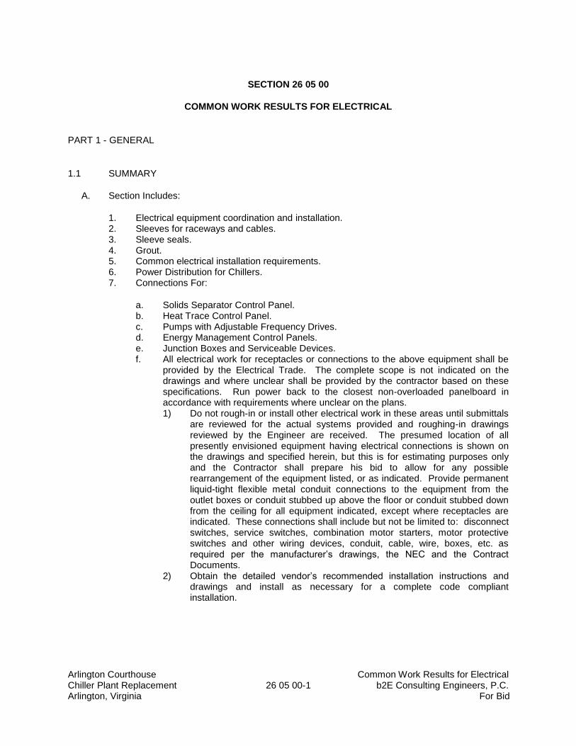
Arlington Courthouse Common Work Results for Electrical Chiller Plant Replacement 26 05 00-1 b2E Consulting Engineers, P.C. Arlington, Virginia For Bid
SECTION 26 05 00
COMMON WORK RESULTS FOR ELECTRICAL
PART 1 - GENERAL
1.1 SUMMARY
A. Section Includes:
1. Electrical equipment coordination and installation. 2. Sleeves for raceways and cables. 3. Sleeve seals. 4. Grout. 5. Common electrical installation requirements. 6. Power Distribution for Chillers. 7. Connections For:
a. Solids Separator Control Panel. b. Heat Trace Control Panel. c. Pumps with Adjustable Frequency Drives. d. Energy Management Control Panels. e. Junction Boxes and Serviceable Devices. f. All electrical work for receptacles or connections to the above equipment shall be
provided by the Electrical Trade. The complete scope is not indicated on the drawings and where unclear shall be provided by the contractor based on these specifications. Run power back to the closest non-overloaded panelboard in accordance with requirements where unclear on the plans. 1) Do not rough-in or install other electrical work in these areas until submittals
are reviewed for the actual systems provided and roughing-in drawings reviewed by the Engineer are received. The presumed location of all presently envisioned equipment having electrical connections is shown on the drawings and specified herein, but this is for estimating purposes only and the Contractor shall prepare his bid to allow for any possible rearrangement of the equipment listed, or as indicated. Provide permanent liquid-tight flexible metal conduit connections to the equipment from the outlet boxes or conduit stubbed up above the floor or conduit stubbed down from the ceiling for all equipment indicated, except where receptacles are indicated. These connections shall include but not be limited to: disconnect switches, service switches, combination motor starters, motor protective switches and other wiring devices, conduit, cable, wire, boxes, etc. as required per the manufacturer’s drawings, the NEC and the Contract Documents.
2) Obtain the detailed vendor’s recommended installation instructions and drawings and install as necessary for a complete code compliant installation.
Arlington Courthouse Common Work Results for Electrical Chiller Plant Replacement 26 05 00-2 b2E Consulting Engineers, P.C. Arlington, Virginia For Bid
1.2 DEFINITIONS
A. EPDM: Ethylene-propylene-diene terpolymer rubber.
B. NBR: Acrylonitrile-butadiene rubber.
1.3 ELECTRICAL SUBMITTALS
A. Refer to the Conditions of the Contract (General and Supplementary) and Division 1 for submittal definitions, requirements and procedures. Examples for samples, provision of submittals by the Contractor in electronic format is required unless otherwise authorized by the Architect.
B. Submittal of shop drawings, product data and samples will be accepted only when submitted by the General Contractor. Data submitted from subcontractors and material suppliers directly to the Architect will not be processed.
C. Submittals that are not acceptable in their entirety must be resubmitted until returned as approved by the engineer. If the third submittal is not approved, the contractor will be responsible for paying additional fees for subsequent reviews of submittals at a rate of $150 per hour. Submittals will not be returned until payment is received.
D. Shop drawings, samples, diagrams, catalog data and such other data necessary to fully describe and substantiate compliance with these contract documents shall be submitted as follows:
1. All the equipment and materials where submissions are specifically required by other Divisions of the Contract Documents.
2. All the equipment and materials that are acceptable equal substitution. 3. Samples, in good working order, shall be submitted in accordance with Division 1,
complete with all installation and service drawings and instructions. All samples will be returned at the submitter’s expense unless otherwise indicated. Samples may be subject to destructive testing by Engineer.
E. OPERATING AND MAINTENANCE DATA
1. Refer to sections of Division 1 for procedures and requirements for preparation and submittal of maintenance manuals.
2. In addition to the information required by Division 1 for Maintenance Data, include the following information: a. Description of function, normal operating characteristics and limitations,
performance curves, engineering data and tests, and complete nomenclature and commercial numbers of all replaceable parts.
b. Manufacturer’s printed operating procedures to include start-up, break-in, routine and normal operating instructions; regulation, control, stopping, shut-down, and emergency instructions; and summer and winter operating instructions.
c. Maintenance procedures for routine preventative maintenance and troubleshooting; disassembly, repair and reassembly, aligning and adjusting instructions.
d. Servicing instructions and lubrication charts and schedules. Provide two (2) copies to Owner and one (1) copy electronic media (CD).
Arlington Courthouse Low-Voltage Electrical Power Chiller Plant Replacement Conductors and Cables Arlington, Virginia 26 05 19-1 b2E Consulting Engineers, P.C
For Bid
SECTION 26 05 19
LOW-VOLTAGE ELECTRICAL POWER CONDUCTORS AND CABLES
PART 1 - GENERAL
1.1 SUMMARY
A. Section Includes:
1. Building wires and cables rated 600 V and less. 2. Connectors, splices, and terminations rated 600 V and less. 3. Sleeves and sleeve seals for cables.
1.2 DEFINITIONS
A. VFC: Variable frequency controller.
B. EPDM: Ethylene-propylene-diene terpolymer rubber.
C. NBR: Acrylonitrile-butadiene rubber.
D. RACEWAY: An enclosed channel of metal or nonmetallic materials designed expressly for holding wires or cables. Raceways include, but are not limited to, rigid metal conduit, intermediate metal conduit, liquidtight flexible conduit, and electrical metallic conduit.
1.3 SUBMITTALS
A. Product data: For each type of product indicated.
B. Qualification Data: For testing agency.
C. Field quality-control reports: From Contractor.
1.4 QUALITY ASSURANCE
A. Testing Agency Qualifications: An independent agency, with the experience and capability to conduct the testing indicated, that is a member company of the International Electrical Testing Association or is a nationally recognized testing laboratory (NRTL) as defined by OSHA in 29 CFR 1910.7, and that is acceptable to authorities having jurisdiction.
1. Testing Agency's Field Supervisor: Person currently certified by the International Electrical Testing Association or the National Institute for Certification in Engineering Technologies to supervise on-site testing specified in Part 3.
Arlington Courthouse Low-Voltage Electrical Power Chiller Plant Replacement Conductors and Cables Arlington, Virginia 26 05 19-2 b2E Consulting Engineers, P.C
For Bid
B. Electrical Components, Devices, and Accessories: Listed and labeled as defined in NFPA 70, Article 100, by a testing agency acceptable to authorities having jurisdiction, and marked for intended use.
C. Comply with NFPA 70.
1.5 COORDINATION
A. Set sleeves in cast-in-place concrete, masonry walls, and other structural components as they are constructed.
B. Do not install more than three (3) current carrying conductors in any conduit.
C. Label each branch circuit conduit with panel board and circuit breaker number.
PART 2 - Comply with NFPA 70 PRODUCTS
2.1 CONDUCTORS AND CABLES
A. Acceptable Manufacturers: Subject to compliance with requirements, manufacturers offering products that may be incorporated into the Work include, but are not limited to the comparable product by one of the following:
1. Alcan Products Corporation; Alcan Cable Division. 2. Alpha Wire. 3. Belden Inc. 4. General Cable Technologies Corporation. 5. Senator Wire & Cable Company 6. Southwire Incorporated.
B. Copper Conductors: Comply with NEMA WC 70
C. Conductor Insulation: Comply with NEMA WC 70 for Type THHN, Type THWN, Type XHHW & Type SO. Insulation shall be color-coded entire length of conductor as indicated in section 26 05 53 “Identification for Electrical Systems.”
2.2 CONNECTORS AND SPLICES
A. Acceptable Manufacturers: Subject to compliance with requirements, manufacturers offering products that may be incorporated into the Work include, but are not limited, to the following: 1. AFC Cable Systems, Inc. 2. Hubbell Power Systems, Inc. 3. Ideal Industries, Inc. 4. O-Z/Gedney; a brand of the EGS Electrical Group. 5. 3-M; Electrical Markets Division. 6. Tyco Electronics.
B. Description: Factory-fabricated connectors and splices of size, capacity rating, material, type, and class for application and service indicated.
Arlington Courthouse Low-Voltage Electrical Power Chiller Plant Replacement Conductors and Cables Arlington, Virginia 26 05 19-3 b2E Consulting Engineers, P.C
For Bid
2.3 SLEEVES FOR CABLES
A. Description: Modular sealing device, designed for field assembly, to fill annular space between sleeve and raceway or cable.
B. Acceptable Manufacturers: Subject to compliance with requirements, manufacturers offering products that may be incorporated into the Work include, but are not limited, to the following: 1. O-Z, Gedney: a brand of the EGS Electrical Group. 2. Spring City Electrical.
C. Steel Pipe Sleeves: ASTM A 53/A 53M, Type E, Grade B Schedule 40, galvanized steel, plain ends.
D. Sleeves for Rectangular Openings: Galvanized sheet metal with minimum 0.052- or 0.138-inch thickness as indicated and of length to suit application.
1. Sealing Elements: EPDM interlocking links shaped to fit surface of cable or conduit. Include type and number required for material and size of raceway or cable.
2. Pressure Plates: Stainless steel. Include two (2) for each sealing element. 3. Connecting Bolts and Nuts: Stainless steel of length required to secure pressure plates to
sealing elements. Include one for each sealing element.
E. Coordinated sleeve selection and application with selection and application of fire stopping specified
2.4 RATED WALL SEALS
A. Acceptable Manufacturers: Subject to compliance with requirements, manufacturers offering products that may be incorporated into the Work include, but are not limited, to the following:
1. Thomas & Betts “Flame Safe” Fire Stop System. 2. 3M Brand Fire Barrier Penetration Sealing System #7904. 3. 3M Brand Fire Barrier Caulk CP-25 and Putty-303.
2.5 SLEEVE SEALS
A. Acceptable Manufacturers: Subject to compliance with requirements, manufacturers offering products that may be incorporated into the Work include, but are not limited to, the following: 1. Advance Products & Systems, Inc. 2. Calpico, Inc. 3. Metraflex Co. 4. Pipeline Seal and Insulator, Inc.
B. Description: Modular sealing device, designed for field assembly, to fill annular space between sleeve and cable. 1. Sealing Elements: EPDM interlocking links shaped to fit surface of cable or conduit. Include
type and number required for material and size of raceway or cable. 2. Pressure Plates: Stainless steel. Include two (2) for each sealing element. 3. Connecting Bolts and Nuts: Stainless steel of length required to secure pressure plates to
sealing elements. Include one (1) for each sealing element.
Arlington Courthouse Low-Voltage Electrical Power Chiller Plant Replacement Conductors and Cables Arlington, Virginia 26 05 19-4 b2E Consulting Engineers, P.C
For Bid
PART 3 - EXECUTION
3.1 CONDUCTOR MATERIAL APPLICATIONS
A. Feeders: All wire sizes indicated on the drawings are based upon the use of copper conductors rated at 75 degree C rated insulation. Terminals for all equipment shall be listed and labeled either 60/75C or 75C. Feeder schedule on drawings is based on copper conductors. Solid for No. 10 AWG and smaller; stranded for No. 8 AWG and larger.
B. Branch Circuits: Copper. Solid for No. 10 AWG and smaller; stranded for No. 8 AWG and larger.
C. Minimum size of Branch Circuit Wire shall be No. 12 AWG.
D. Maximum length for 12 AWG copper conductors for the following voltage.
1. 120V/1-phase: 50-feet, use 10 AWG for 51 to 75 feet. Use larger wire as required beyond 75-feet.
2. 208V, 3-phase, 3-wire: 110-feet maximum, use 10 AWG from 111-feet to 175 feet. Use larger wire size as required beyond 175-feet.
3. 120/208V, 3-phase, 4-wire: 110-feet maximum, use 10 AWG from 111 to 175 feet. Use larger wire size, as required beyond 175 feet.
4. 277V/1-phase: 125-feet, use to 10 AWG from 126 to 200 feet. Use larger wire size, as required beyond 200-feet.
5. 460V/3-phase, 3-wire 250-feet, use 10 AWG for 251 to 400 feet. Use larger wire size, as required beyond 400-feet.
6. 277V/460-volt, 3-phase, 4-wire: 250 feet, use 10 AWG for 251 to 400 feet. Use larger wire size, as required beyond 400-feet.
3.2 CONDUCTOR INSULATION APPLICATIONS AND WIRING METHODS
A. Exposed Feeders: Type THHN-THWN, single conductors in raceway.
B. Exposed Branch Circuits: Type THHN-THWN, single conductors in raceway.
C. Branch Circuits Concealed in Walls, and Partitions: Type THHN-THWN, single conductors in raceway.
D. Class 1 Control Circuits: Type THHN-THWN, in raceway.
E. Class 2 Control Circuits: Type THHN-THWN, in raceway; Power-limited tray cable in J-hook systems.
F. Multi-Conductor Cable: Not allowed.
3.3 INSTALLATION OF CONDUCTORS AND CABLES
A. Conceal cables in finished walls, unless otherwise indicated.
B. Complete raceway installation between conductor and cable termination points according to Section 26 05 33 “’Raceways and Boxes for Electrical Systems” prior to pulling conductors and cables.
Arlington Courthouse Low-Voltage Electrical Power Chiller Plant Replacement Conductors and Cables Arlington, Virginia 26 05 19-5 b2E Consulting Engineers, P.C
For Bid
C. Use manufacturer-approved pulling compound or lubricant where necessary; compound used must not deteriorate conductor or insulation. Do not exceed manufacturer's recommended maximum pulling tensions and sidewall pressure values.
D. Use pulling means, including fish tape, cable, rope, and basket-weave wire/cable grips, that will not damage cables or raceway.
E. Install exposed cables parallel and perpendicular to surfaces of exposed structural members, and follow surface contours where possible.
F. Support cables according to Section 26 05 29 "Hangers and Supports for Electrical Systems."
G. Identify and color-code conductors and cables according to Division 26 Section 26 05 53 "Identification for Electrical Systems."
H. Do not install more than three (3) current carrying conductors in any one conduit.
I. Seal around cables penetrating fire-rated elements according to Division 7 Section “Firestopping”.
J. Identify and color-code conductors and cables according to Division 26 Section “Identification for Electrical Systems”.
K. All line to neutral branch circuits shall include a grounding conductor and a dedicated neutral.
L. Unless otherwise indicated, minimum conductor size shall be 12 AWG.
3.4 CONNECTIONS
A. Tighten electrical connectors and terminals according to manufacturer's published torque-tightening values. If manufacturer's torque values are not indicated, use those specified in UL 486A and UL 486B.
B. Make splices and taps that are compatible with conductor material and that possess equivalent or better mechanical strength and insulation ratings than un-spliced conductors.
C. Wiring at Outlets: Install conductor at each outlet, with at least 6-inches of slack.
3.5 SLEEVE INSTALLATION FOR ELECTRICAL PENETRATIONS
A. Coordinate sleeve selection and application with selection and application of firestopping specified in Division 07 Section "Penetration Firestopping."
B. Use pipe sleeves unless penetration arrangement requires rectangular sleeved opening.
C. Rectangular Sleeve Minimum Metal Thickness:
1. For sleeve rectangle perimeter less than 50 inches and no side greater than 16 inches, thickness shall be 0.052 inch.
2. For sleeve rectangle perimeter equal to, or greater than, 50 inches and 1 or more sides equal to, or greater than, 16 inches, thickness shall be 0.138 inch.
Arlington Courthouse Low-Voltage Electrical Power Chiller Plant Replacement Conductors and Cables Arlington, Virginia 26 05 19-6 b2E Consulting Engineers, P.C
For Bid
D. Fire-Rated Assemblies: Install sleeves for penetrations of fire-rated floor and wall assemblies unless openings compatible with firestop system used are fabricated during construction of floor or wall.
E. Cut sleeves to length for mounting flush with both wall surfaces.
F. Size pipe sleeves to provide 1/4-inch annular clear space between sleeve and cable unless sleeve seal is to be installed.
G. Seal space outside of sleeves with grout for penetrations of concrete and masonry and with approved joint compound for gypsum board assemblies.
H. Interior Penetrations of Non-Fire-Rated Walls and Floors: Seal annular space between sleeve and cable, using joint sealant appropriate for size, depth, and location of joint according to Division 07 Section "Joint Sealants."
I. Fire-Rated-Assembly Penetrations: Maintain indicated fire rating of walls, partitions, ceilings, and floors at cable penetrations. Install sleeves and seal with firestop materials according to Division 07 Section "Penetration Firestopping."
J. Aboveground Exterior-Wall Penetrations: Seal penetrations using sleeves and mechanical sleeve seals. Size sleeves to allow for 1-inch annular clear space between pipe and sleeve for installing mechanical sleeve seals.
3.6 SLEEVE-SEAL INSTALLATION
A. Use type and number of sealing elements recommended by manufacturer for cable material and size. Position cable in center of sleeve. Assemble mechanical sleeve seals and install in annular space between cable and sleeve. Tighten bolts against pressure plates that cause sealing elements to expand and make watertight seal.
3.7 FIRESTOPPING
A. Apply firestopping to electrical penetrations of fire-rated floor and wall assemblies to restore original fire-resistance rating of assembly according to Division 07 Section "Penetration Firestopping."
3.8 FIELD QUALITY CONTROL
A. Testing Agency: Engage a qualified testing agency to perform tests and inspections and prepare test reports.
B. Perform tests and inspections and prepare test reports. Provide written test results to Engineer within 30-days of test completion.
C. Tests and Inspections:
1. After installing conductors and cables and before electrical circuitry has been energized, test service entrance and feeder conductors for compliance with requirements.
2. Perform each visual and mechanical inspection and electrical test stated in NETA Acceptance Testing Specification. Certify compliance with test parameters.
Arlington Courthouse Low-Voltage Electrical Power Chiller Plant Replacement Conductors and Cables Arlington, Virginia 26 05 19-7 b2E Consulting Engineers, P.C
For Bid
3. Infrared Scanning: After Substantial Completion, but not more than 60 days after Final Acceptance, perform an infrared scan of each splice in cables and conductors No. 3 AWG and larger. Remove box and equipment covers so splices are accessible to portable scanner. Provide written test results to Engineer within 30-days of test completion.
a. Follow-up Infrared Scanning: Perform an additional follow-up infrared scan of each splice 11 months after date of Substantial Completion.
b. Instrument: Use an infrared scanning device designed to measure temperature or to detect significant deviations from normal values. Provide calibration record for device.
c. Record of Infrared Scanning: Prepare a certified report that identifies splices checked and that describes scanning results. Include notation of deficiencies detected, remedial action taken and observations after remedial action.
D. Test Reports: Prepare a written report to the Engineer to record the following:
1. Test procedures used. 2. Test results that comply with requirements. 3. Test results that do not comply with requirements and corrective action taken to achieve
compliance with requirements.
E. Cables will be considered defective if they do not pass tests and inspections.
F. Remove and replace malfunctioning units and retest as specified above.
END OF SECTION 26 05 19
Arlington Courthouse Control-Voltage Electrical Power Cables Chiller Plant Replacement 26 05 23-1 b2E Consulting Engineers, P.C. Arlington, Virginia For Bid
SECTION 26 05 23
CONTROL-VOLTAGE ELECTRICAL POWER CABLES
PART 1 - GENERAL
1.1 SUMMARY
A. Section Includes: 1. Low-voltage control cabling. 2. Control-circuit conductors. 3. Identification products.
B. Fire Alarm Wiring: Provide all fire alarm wiring in continuous EMT raceway system. 1. Partial conduit fire alarm systems not allowed.
1.2 DEFINITIONS
A. EMI: Electromagnetic interference.
B. IDC: Insulation displacement connector.
C. Low Voltage: As defined in NFPA 70 for circuits and equipment operating at less than 50 V or for remote-control and signaling power-limited circuits.
D. RCDD: Registered Communications Distribution Designer.
E. Raceway: An enclosed channel of metal or non-metallic materials designed expressly for holding wires or cables. Raceways include, but are not limited to, rigid metal conduit, rigid non-metallic conduit, intermediate metal conduit, liquid tight flexible conduit, electrical metallic conduit. 1. Cables such as MC, AC, or Greenfield are not raceways.
F. UTP: Unshielded Twisted Pair.
1.3 SUBMITTALS
A. Product Data: For each type of product indicated.
B. Shop Drawings: For cable tray layout, showing cable tray route to scale, with relationship between the tray and adjacent structural, electrical, and mechanical elements. Include the following:
1. Vertical and horizontal offsets and transitions. 2. Clearances for access above and to side of cable trays. 3. Vertical elevation of cable trays above the floor or bottom of ceiling structure. 4. Load calculations to show dead and live loads as not exceeding manufacturer's rating for
tray and its support elements.
C. Qualification Data: For qualified layout technician, installation supervisor, and field inspector.
Arlington Courthouse Control-Voltage Electrical Power Cables Chiller Plant Replacement 26 05 23-2 b2E Consulting Engineers, P.C. Arlington, Virginia For Bid
D. Source quality-control reports.
E. Field quality-control reports by contractor.
F. Maintenance Data: For wire and cable to include in maintenance manuals.
1.4 QUALITY ASSURANCE
A. Testing Agency Qualifications: Member company of an NRTL.
1. Testing Agency's Field Supervisor: Currently certified by BICSI as an RCDD to supervise on-site testing. Provide copy of certification with submittals.
B. Surface-Burning Characteristics: As determined by testing identical products according to ASTM E 84 by a qualified testing agency. Identify products with appropriate markings of applicable testing agency.
1. Flame-Spread Index: 25 or less. 2. Smoke-Developed Index: 50 or less.
C. Electrical Components, Devices, and Accessories: Listed and labeled as defined in NFPA 70, by a qualified testing agency, and marked for intended location and application.
1.5 DELIVERY, STORAGE, AND HANDLING
A. Test cables upon receipt at Project site.
1.6 PROJECT CONDITIONS
A. Environmental Limitations: Do not deliver or install low voltage control cables and connecting materials until wet work in spaces is complete and dry, and temporary HVAC system is operating and maintaining ambient temperature and humidity conditions at occupancy levels during the remainder of the construction period.
1.7 EXTRA MATERIALS
A. Furnish extra materials that match products installed that are packaged with protection covering for storage and identified with labels describing contents. 1. Connecting Blocks: Equal to 25% installed, but not fewer than five (5).
PART 2 - PRODUCTS
2.1 PATHWAYS
A. Conduit and Boxes: Comply with requirements in Division 26 Section "Raceway and Boxes for Electrical Systems."
1. Outlet boxes shall be no smaller than 2 inches wide, 3 inches high and 2-1/2 inches deep.
Arlington Courthouse Control-Voltage Electrical Power Cables Chiller Plant Replacement 26 05 23-3 b2E Consulting Engineers, P.C. Arlington, Virginia For Bid
2.2 LOW-VOLTAGE CONTROL CABLE
A. Plenum-Rated, Paired Cable: NFPA 70, Type CMP.
1. Two pair, twisted, No. 16 AWG, stranded (19x29) tinned-copper conductors. 2. PVC insulation. 3. Unshielded. 4. PVC jacket. 5. Flame Resistance: Comply with NFPA 262.
B. Plenum-Rated, Paired Cable: NFPA 70, Type CMP.
1. Two pair, twisted, No. 18 AWG, stranded (19x30) tinned-copper conductors. 2. Fluorinated ethylene propylene insulation. 3. Unshielded. 4. Plastic jacket. 5. Flame Resistance: NFPA 262, Flame Test.
2.3 CONTROL-CIRCUIT CONDUCTORS
A. Acceptable Manufacturers: Subject to compliance with requirements, manufacturers offering products that may be incorporated into the work include one of the following: 1. Encore Wire Corporation. 2. General Cable Technologies Corporation. 3. Southwire Company.
B. Class 2 Control Circuits: Stranded copper, Type THHN-THWN, in raceway, complying with UL 83.
C. Class 3 Remote-Control and Signal Circuits: Stranded copper, Type TW or Type TF, complying with UL 83.
2.4 IDENTIFICATION PRODUCTS
A. Manufacturers: Subject to compliance with requirements. Provide products by one of the following:
1. Brady Corporation. 2. HellermannTyton. 3. Kroy LLC. 4. Panduit Corp.
B. Comply with UL 969 for a system of labeling materials, including label stocks, laminating adhesives, and inks used by label printers.
C. Comply with requirements in Division 26 Section "Identification for Electrical Systems."
2.5 SOURCE QUALITY CONTROL
A. Testing Agency: Engage a qualified testing agency to evaluate cables.
B. Cable will be considered defective if it does not pass tests and inspections.
Arlington Courthouse Control-Voltage Electrical Power Cables Chiller Plant Replacement 26 05 23-4 b2E Consulting Engineers, P.C. Arlington, Virginia For Bid
C. Prepare test and inspection reports. Provide to engineer for review.
PART 3 - EXECUTION
3.1 INSTALLATION OF PATHWAYS
A. Comply with requirements in Division 26 Section 26 05 33 “Raceways and Boxes for Electrical Systems” for raceway selection and installation requirements for boxes, conduits, and wireways as supplemented or modified in this section.
1. Flexible metal conduit shall not be used.
B. Comply with requirements in Division 26 Section 26 05 33 "Raceway and Boxes for Electrical Systems" for installation of conduits and wireways.
3.2 INSTALLATION OF CONDUCTORS AND CABLES
A. Comply with NECA 1 and NFPA 70.
B. General Requirements for Cabling: 1. Terminate all conductors; no cable shall contain un-terminated elements. Make
terminations only at indicated outlets, terminals, and cross-connect and patch panels. 2. Cables may not be spliced. 3. Secure and support cables at intervals not exceeding 30 inches and not more than 6
inches from cabinets, boxes, fittings, outlets, racks, frames, and terminals. 4. Do not install bruised, kinked, scored, deformed, or abraded cable. Do not splice cable
between termination, tap, or junction points. Remove and discard cable if damaged during installation and replace it with new cable.
5. Cold-Weather Installation: Bring cable to room temperature before de-reeling. Do not use heat lamps for heating.
C. Installation of Control-Circuit Conductors:
1. Install wiring in raceways. Comply with requirements specified in Division 26 Section 26 05 33, "Raceway and Boxes for Electrical Systems."
D. Separation from EMI Sources:
1. Comply with BICSI TDMM and TIA/EIA-569-A recommendations for separating unshielded copper voice and data communication cable from potential EMI sources, including electrical power lines and equipment.
2. Separation between open communications cables or cables in nonmetallic raceways and unshielded power conductors and electrical equipment shall be as follows: a. Electrical Equipment Rating Less Than 2 kVA: A minimum of 5 inches. b. Electrical Equipment Rating between 2 and 5 kVA: A minimum of 12 inches. c. Electrical Equipment Rating More Than 5 kVA: A minimum of 24 inches.
3. Separation between communications cables in grounded metallic raceways and unshielded power lines or electrical equipment shall be as follows: a. Electrical Equipment Rating Less Than 2 kVA: A minimum of 2-1/2 inches. b. Electrical Equipment Rating between 2 and 5 kVA: A minimum of 6 inches. c. Electrical Equipment Rating More Than 5 kVA: A minimum of 12 inches.
Arlington Courthouse Control-Voltage Electrical Power Cables Chiller Plant Replacement 26 05 23-5 b2E Consulting Engineers, P.C. Arlington, Virginia For Bid
4. Separation between communications cables in grounded metallic raceways and power lines and electrical equipment located in grounded metallic conduits or enclosures shall be as follows: a. Electrical Equipment Rating Less Than 2 kVA: No requirement. b. Electrical Equipment Rating between 2 and 5 kVA: A minimum of 3 inches. c. Electrical Equipment Rating More Than 5 kVA: A minimum of 6 inches.
5. Separation between Cables and Electrical Motors and Transformers, 5 kVA or HP and Larger: A minimum of 48 inches.
6. Separation between Cables and Fluorescent Fixtures: A minimum of 5 inches.
E. Fire Alarm Wiring: Provide all fire alarm wiring in red EMT raceway for concealed and exposed conduit.
3.3 CONTROL-CIRCUIT CONDUCTORS
A. Minimum Conductor Sizes: 1. Class 1 remote-control and signal circuits, No. 14 AWG. 2. Class 2 low-energy, remote-control, and signal circuits, No. 16 AWG. 3. Class 3 low-energy, remote-control, alarm, and signal circuits, No. 12 AWG.
3.4 FIRESTOPPING
A. Apply firestopping to electrical penetrations of fire-rated floor and wall assemblies to restore original fire-resistance rating of assembly. Comply with requirements in Division 07 Section "Penetration Firestopping."
3.5 GROUNDING
A. For low-voltage wiring and cabling, comply with requirements in Division 26 Section 26 05 26, "Grounding and Bonding for Electrical Systems."
3.6 IDENTIFICATION
A. Comply with requirements for identification specified in Division 26 Section 26 05 53, "Identification for Electrical Systems."
3.7 FIELD QUALITY CONTROL
A. Testing Agency: Engage a qualified testing agency to perform tests and inspections.
B. End-to-end cabling will be considered defective if it does not pass tests and inspections.
C. Remove and replace malfunctioning units and retest if it does not pass tests and inspections.
D. Prepare test and inspection reports for review by the Engineer.
END OF SECTION 26 05 23
Arlington Courthouse Grounding and Bonding for Electrical Systems Chiller Plant Replacement 26 05 26-1 b2E Consulting Engineers, P.C. Arlington, Virginia For Bid
SECTION 26 05 26
GROUNDING AND BONDING FOR ELECTRICAL SYSTEMS
PART 1 - GENERAL
1.1 SUMMARY
A. This Section includes methods and materials for grounding systems and equipment, plus the following special application:
1.2 SUBMITTALS
A. Product Data: For each type of product indicated.
B. Other Informational Submittals: Plans showing dimensioned as-built locations of grounding features specified in Part 3 "Field Quality Control" Article, including the following: 1. Grounding arrangements and connections for separately derived systems. 2. Grounding for sensitive electronic equipment.
C. Qualification Data: For testing agency and testing agencies field supervisor.
D. Field quality-control test reports. Submit written test reports for review by the Engineer. 1. Test procedures used. 2. Test results that comply with requirements. 3. Results of failed tests and corrective action taken to achieve test results that comply with
requirements.
E. Operation and Maintenance Data: For grounding to include the following in emergency, operation, and maintenance manuals:
1. In addition to items specified in Section 01 70 00, “Project Closeout”.
2. Instructions for periodic testing and inspection of grounding features at test wells, ground rings, grounding connections for separately derived systems based on NFPA 70B.
a. Tests shall be to determine if ground resistance or impedance values remain within specified maximums, and instructions shall recommend corrective action if they do not.
b. Include recommended testing intervals.
1.3 QUALITY ASSURANCE
A. Testing Agency Qualifications: An independent agency, with the experience and capability to conduct the testing indicated, that is a member company of the International Electrical Testing Association or is a nationally recognized testing laboratory (NRTL) as defined by OSHA in 29 CFR 1910.7, and that is acceptable to authorities having jurisdiction.
1. Testing Agency's Field Supervisor: Person currently certified by the InterNational Electrical Testing Association to supervise on-site testing specified in Part 3.
Arlington Courthouse Grounding and Bonding for Electrical Systems Chiller Plant Replacement 26 05 26-2 b2E Consulting Engineers, P.C. Arlington, Virginia For Bid
B. Electrical Components, Devices, and Accessories: Listed and labeled as defined in NFPA 70, Article 100, by a testing agency acceptable to authorities having jurisdiction, and marked for intended use.
C. Comply with UL 467 for grounding and bonding materials and equipment.
PART 2 - PRODUCTS
2.1 Manufacturers: Subject to compliance with requirements, manufacturers offering products that may be incorporated into the Work include:
A. Burndy; Part of Hubbell Electrical Systems.
B. ERICO International Corporation.
C. O-Z/Gedney, A brand of the EGS Electrical Group.
2.2 SYSTEM DESCRIPTION
A. Electrical Components, Devices, and Accessories: Listed and labeled as defined in NFPA 70, by a qualified testing agency, and marked for intended location and application.
B. Comply with UL 467 for grounding and bonding materials and equipment.
2.3 CONDUCTORS
A. For Insulated Conductors: Copper wire or cable insulated for 600 V unless otherwise required by applicable Code or authorities having jurisdiction.
B. Bare Copper Conductors:
1. Solid Conductors: ASTM B 3. 2. Stranded Conductors: ASTM B 8. 3. Bonding Cable: 28 kcmil, 14 strands of No. 17 AWG conductor, 1/4 inch in diameter. 4. Bonding Conductor: No. 4 or No. 6 AWG, stranded conductor. 5. Bonding Jumper: Copper tape, braided conductors, terminated with copper ferrules; 1-
5/8 inches wide and 1/16 inch thick.
C. Grounding Bus: Predrilled Rectangular bars of annealed copper, 1/4 by 4 inches in cross section, with 9/32-inch holes spaced 1 1/8-inches apart. Stand-off isolators for mounting shall comply with UL 891 for use in switchboards, 600 V. Lexan or PVC, impulse tested at 5000 V.
D. Equipment Grounding Conductors: Insulated with green-colored insulation sized in accordance with 2014 NEC Table 250.122.
E. Isolated Ground Conductors: Insulated with green-colored insulation with yellow stripe. On feeders with isolated ground, use colored tape, alternating bands of green and yellow tape. Provide a minimum of three (3) bands of green and two (2) bands of yellow.
Arlington Courthouse Grounding and Bonding for Electrical Systems Chiller Plant Replacement 26 05 26-3 b2E Consulting Engineers, P.C. Arlington, Virginia For Bid
2.4 CONNECTORS
A. Listed and labeled by a nationally recognized testing laboratory (NRTL) acceptable to authorities having jurisdiction for applications in which used, and for specific types, sizes, and combinations of conductors and other items connected.
B. Bolted Connectors for Conductors and Pipes: Copper or copper alloy, bolted pressure-type, with at least two bolts.
1. Pipe Connectors: Clamp type, sized for pipe.
C. Welded Connectors: Exothermic-welding kits of types recommended by kit manufacturer for materials being joined and installation conditions.
D. Bus-bar Connectors: Mechanical type, cast silicone bronze, solderless compression type wire terminals, and long-barrel, two-bolt connection to ground bus.
PART 3 - EXECUTION
3.1 APPLICATIONS
A. Conductors: Install solid conductor for No. 8 AWG and smaller, and stranded conductors for No. 6 AWG and larger, unless otherwise indicated.
B. Conductor Terminations and Connections:
1. Pipe and Equipment Grounding Conductor Terminations: Bolted connectors. 2. Underground Connections: Welded connectors, except at test wells and as otherwise
indicated. 3. Connections to Structural Steel: Welded connectors.
3.2 EQUIPMENT GROUNDING
A. Install insulated equipment grounding conductors with all feeders and branch circuits.
B. Install insulated equipment grounding conductors with the following items, in addition to those required by NFPA 70:
1. Feeders and branch circuits. 2. Receptacle circuits. 3. Three-phase motor and appliance branch circuits. 4. Computer Electronic Equipment Circuits: Install insulated equipment grounding
conductor in branch-circuit runs from equipment-area power panels and power-distribution units.
5. Transformer primary and secondary feeders.
C. Heat-Tracing: Install a separate insulated equipment grounding conductor to each heat-tracing cable from the Heat Trace control panel. Bond conductor to heat trace panels, piping, connected equipment, and components.
Arlington Courthouse Grounding and Bonding for Electrical Systems Chiller Plant Replacement 26 05 26-4 b2E Consulting Engineers, P.C. Arlington, Virginia For Bid
D. Solids Separator: Install a separate insulated equipment ground conductor to the solid separator from the solids separator control panel. Bond conductor to the control panel, piping, connected equipment and components.
E. Signal and Communication Equipment: In addition to grounding and bonding required by NFPA 70, provide a separate grounding system complying with requirements in TIA/ATIS, J-STD-670-A.
1. For control data network, and other communication equipment, provide No. 2 AWG minimum insulated grounding conductor in raceway from grounding electrode system to each service location, terminal cabinet, wiring closet, and central equipment location.
2. ¼Terminal Cabinets: Terminate grounding conductor on cabinet grounding terminal.
F. Isolated Grounding Receptacle: Install an insulated equipment grounding connected to the receptacle grounding terminal. Isolate conductor from raceway and from panelboard grounding terminals. Terminate at equipment grounding terminal of the applicable derived system or service, unless otherwise indicated.
G. Power Transformers: Provide system ground to building steel and bonding conductor to nearest water line serving the area per NEC, or as scheduled, whichever is the larger conductor.
3.3 INSTALLATION
A. Grounding Conductors: Route along shortest and straightest paths possible, unless otherwise indicated or required by Code. Avoid obstructing access or placing conductors where they may be subjected to strain, impact, or damage.
B. Bonding Straps and Jumpers: Install in locations accessible for inspection and maintenance, except where routed through short lengths of conduit.
1. Bonding to Structure: Bond straps directly to basic structure, taking care not to penetrate any adjacent parts.
2. Bonding to Equipment Mounted on Vibration Isolation Hangers and Supports: Install so vibration is not transmitted to rigidly mounted equipment.
3. Use exothermic-welded connectors for outdoor locations, but if a disconnect-type connection is required, use a bolted clamp.
C. Grounding and Bonding for Piping:
1. Metal Water Service Pipe: Install insulated copper grounding conductors, in conduit, from building’s main service equipment, or grounding bus, to main metal water service entrances to building. Connect grounding conductors to main metal water service pipes, using a bolted clamp connector or by bolting a lug-type connector to a pipe flange, using one of the lug bolts of the flange. Where a dielectric main water fitting is installed, connect grounding conductor on street side of fitting. Bond metal grounding conductor conduit or sleeve to conductor at each end.
2. Water Meter Piping: Use braided-type bonding jumpers to electrically bypass water meters. Connect to pipe with a bolted connector.
D. Grounding for Steel Building Structure: Install a driven ground rod at base of each corner column and at intermediate exterior columns at distances not more than 60 feet apart.
E. Moisture Protection: If insulated conductors are connected to ground rods or grounding buses, insulate entire area of connection and seal against moisture penetration of insulation and cable.
Arlington Courthouse Grounding and Bonding for Electrical Systems Chiller Plant Replacement 26 05 26-5 b2E Consulting Engineers, P.C. Arlington, Virginia For Bid
3.4 CONNECTIONS
A. General: Make connections so galvanic action or electrolysis possibility is minimized. Select connectors, connection hardware, conductors, and connection methods so metals in direct contact will be galvanically compatible. 1. Use electroplated or hot-tin coated materials to ensure high conductivity and to make
contact points closer to order of galvanic series. 2. Make connections with clean, bare metal at points of contact. 3. Make aluminum-to-steel connections with stainless-steel separators and mechanical
clamps. 4. Make aluminum-to-galvanized steel connections with tin-plated copper jumpers and
mechanical clamps. 5. Coat and seal connections having dissimilar metals with inert material to prevent future
penetration of moisture to contact surfaces.
B. Exothermic-Welded Connections: Comply with manufacturer’s written instructions. Welds that are puffed up or that show convex surfaces indicating improper cleaning are not acceptable.
C. Equipment Grounding Conductor Terminations: For No. 8 AWG and larger, use pressure-type grounding lugs. No. 10 AWG and smaller grounding conductors may be terminated with winged pressure-type connectors.
D. Noncontact Metal Raceway Terminations: Ensure continuity of metallic raceway systems, boxes, and equipment. 1. Circuits Greater than 250V to Ground: If metallic raceways terminate at metal housings
without mechanical and electrical connection to housing, or where raceways connect to equipment or boxes with eccentric or concentric knockouts, terminate each conduit with a grounding bushing. Connect grounding bushings with a bare grounding conductor to grounding bus or terminal in housing. Bond electrically non-continuous conduits at entrances and exits with grounding bushings and bare grounding conductors, unless otherwise indicated.
E. Tighten screws and bolts for grounding and bonding connectors and terminals according to manufacturer’s published torque-tightening values. If manufacturer’s torque values are not indicated, use those specified in UL 486A.
F. Compression-Type Connections: Use hydraulic compression tools to provide correct circumferential pressure for compression connectors. Use tools and dies recommended by a connector manufacturer. Provide embossing die code or other standard method to make a visible indication that a connector has been adequately compressed on grounding conductor.
3.5 LABELING
A. Comply with requirements in Division 26, Section 26 05 53 “Identification for Electrical Systems” for instructional signs.
B. Install labels at telecommunications bonding conductor and grounding equalizer. 1. Label Text: “If this connector or cable is loose or must be removed for any reason, notify
the facility manager”.
Arlington Courthouse Grounding and Bonding for Electrical Systems Chiller Plant Replacement 26 05 26-6 b2E Consulting Engineers, P.C. Arlington, Virginia For Bid
3.6 FIELD QUALITY CONTROL
A. Testing Agency: Engage a qualified testing and inspecting agency to perform the following field tests and inspections and prepare test reports:
B. Manufacturers Field Services: Engage a factory-authorized service representative to inspect, test and adjust components, assemblies, and equipment installations, including connections.
C. Perform the following tests and inspections and prepare test reports:
1. After installing grounding system but before permanent electrical circuits have been energized, test for compliance with requirements.
2. Inspect and physical and mechanical conditions. Verify tightness of accessible, bolted, electrical connections with a calibrated torque wrench according to manufacturers written instructions.
3. Test completed grounding system at each location where a maximum ground-resistance level is specified, at service disconnect enclosure grounding terminal.
a. Measure ground resistance not less than two full days after last trace of precipitation and without soil being moistened by any means other than natural drainage or seepage and without chemical treatment or other artificial means of reducing natural ground resistance.
b. Perform tests by fall-of-potential method according to IEEE 81.
D. Grounding system shall be considered defective if it does not pass tests and inspections.
E. Report measured ground resistances that exceed the following values:
1. Power Equipment or System with Capacity 500 kVA and Less: 10 ohms. 2. Power Equipment or System with Capacity 500 to 1000 kVA: 5 ohms. 3. Power Equipment or System with Capacity More Than 1000 kVA: 3 ohms. 4. Power Distribution Units or Panelboards Serving Electronic Equipment: 1 ohm(s).
F. Excessive Ground Resistance: If resistance to ground exceeds specified values, notify Engineer promptly and include recommendations to reduce ground resistance.
END OF SECTION 26 05 26
Arlington Courthouse Hangers and Supports for Electrical Systems Chiller Plant Replacement 26 05 29-1 b2E Consulting Engineers, P.C. Arlington, Virginia For Bid
SECTION 26 05 29
HANGERS AND SUPPORTS FOR ELECTRICAL SYSTEMS
PART 1 - GENERAL
1.1 SUMMARY
A. This Section includes the following:
1. Hangers and supports for electrical equipment and systems. 2. Construction requirements for concrete bases.
1.2 DEFINITIONS
A. EMT: Electrical metallic tubing.
B. IMC: Intermediate metal conduit.
C. RMC: Rigid metal conduit.
1.3 PERFORMANCE REQUIREMENTS
A. Delegated Design: Design supports for multiple raceways, including comprehensive engineering analysis by a qualified professional engineer, using performance requirements and design criteria indicated.
B. Design supports for multiple raceways capable of supporting combined weight of supported systems and its contents.
C. Design equipment supports capable of supporting combined operating weight of supported equipment and connected systems and components.
D. Rated Strength: Adequate in tension, shear, and pullout force to resist maximum loads calculated or imposed for this Project, with a minimum structural safety factor of five times the applied force.
1.4 SUBMITTALS
A. Product Data: For the following:
1. Steel slotted support systems. 2. Nonmetallic slotted support systems.
B. Shop Drawings: Signed and sealed by a qualified professional engineer. Show fabrication and installation details and include calculations for the following:
1. Trapeze hangers. Include Product Data for components.
Arlington Courthouse Hangers and Supports for Electrical Systems Chiller Plant Replacement 26 05 29-2 b2E Consulting Engineers, P.C. Arlington, Virginia For Bid
2. Steel slotted channel systems. Include Product Data for components. 3. Nonmetallic slotted channel systems. Include Product Data for components. 4. Equipment supports.
C. Welding certificates.
1.5 QUALITY ASSURANCE
A. Welding: Qualify procedures and personnel according to AWS D1.1/D1.1M, "Structural Welding Code - Steel."
B. Comply with NFPA 70.
1.6 COORDINATION
A. Coordinate size and location of concrete bases. Cast anchor-bolt inserts into bases. Concrete, reinforcement, and formwork requirements are specified in Division 03.
B. Coordinate installation of roof curbs, equipment supports, and roof penetrations. These items are specified in Division 07 Section "Roof Accessories."
PART 2 - PRODUCTS
2.1 SUPPORT, ANCHORAGE, AND ATTACHMENT COMPONENTS
A. Steel Slotted Support Systems: Comply with MFMA-4, factory-fabricated components for field assembly.
1. Acceptable Manufacturers: Subject to compliance with requirements, manufacturers offering products that may be incorporated into the Work include, but are not limited to, the following:
a. Allied Tube & Conduit. b. Cooper B-Line, Inc.; a division of Cooper Industries. c. ERICO International Corporation. d. GS Metals Corp. e. Thomas & Betts Corporation. f. Unistrut; Tyco International, Ltd. g. Wesanco, Inc.
2. Metallic Coatings: Hot-dip galvanized after fabrication and applied according to MFMA-4. 3. Nonmetallic Coatings: Manufacturer's standard PVC, polyurethane, or polyester coating
applied according to MFMA-4. 4. Painted Coatings: Manufacturer's standard painted coating applied according to MFMA-
4. 5. Channel Dimensions: Selected for applicable load criteria.
B. Raceway Supports: As described in NECA 1 and NECA 101.
Arlington Courthouse Hangers and Supports for Electrical Systems Chiller Plant Replacement 26 05 29-3 b2E Consulting Engineers, P.C. Arlington, Virginia For Bid
C. Conduit Support Devices: Steel hangers, clamps, and associated fittings, designed for types and sizes of raceway or cable to be supported.
D. Support for Conductors in Vertical Conduit: Factory-fabricated assembly consisting of threaded body and insulating wedging plug or plugs for non-armored electrical conductors or cables in riser conduits. Plugs shall have number, size, and shape of conductor gripping pieces as required to suit individual conductors or cables supported. Body shall be malleable iron.
E. Structural Steel for Fabricated Supports and Restraints: ASTM A 36/A 36M, steel plates, shapes, and bars; black and galvanized.
F. Mounting, Anchoring, and Attachment Components: Items for fastening electrical items or their supports to building surfaces include the following:
1. Powder-Actuated Fasteners: Threaded-steel stud, for use in hardened portland cement concrete, steel, or wood, with tension, shear, and pullout capacities appropriate for supported loads and building materials where used. a. Acceptable Manufacturers: Subject to compliance with requirements, provide
products by one of the following:
1) Hilti Inc. 2) ITW Ramset/Red Head; a division of Illinois Tool Works, Inc. 3) MKT Fastening, LLC. 4) Simpson Strong-Tie Co., Inc.; Masterset Fastening Systems Unit.
2. Mechanical-Expansion Anchors: Insert-wedge-type, stainless steel, for use in hardened portland cement concrete with tension, shear, and pullout capacities appropriate for supported loads and building materials in which used.
a. Acceptable Manufacturers: Subject to compliance with requirements, provide products by one of the following:
1) Cooper B-Line, Inc.; a division of Cooper Industries. 2) Empire Tool and Manufacturing Co., Inc. 3) Hilti Inc. 4) ITW Ramset/Red Head; a division of Illinois Tool Works, Inc. 5) MKT Fastening, LLC.
3. Concrete Inserts: Steel or malleable-iron, slotted support system units similar to MSS Type 18; complying with MFMA-4 or MSS SP-58.
4. Clamps for Attachment to Steel Structural Elements: MSS SP-58, type suitable for attached structural element.
5. Through Bolts: Structural type, hex head, and high strength. Comply with ASTM A 325. 6. Toggle Bolts: All-steel springhead type. 7. Hanger Rods: Threaded steel.
2.2 FABRICATED METAL EQUIPMENT SUPPORT ASSEMBLIES
A. Description: Welded or bolted, structural-steel shapes, shop or field fabricated to fit dimensions of supported equipment.
B. Materials: Comply with requirements in Division 05 Section "Metal Fabrications" for steel shapes and plates.
Arlington Courthouse Hangers and Supports for Electrical Systems Chiller Plant Replacement 26 05 29-4 b2E Consulting Engineers, P.C. Arlington, Virginia For Bid
PART 3 - EXECUTION
3.1 APPLICATION
A. Comply with NECA 1 and NECA 101 for application of hangers and supports for electrical equipment and systems except if requirements in this Section are stricter.
B. Maximum Support Spacing and Minimum Hanger Rod Size for Raceway: Space supports for EMT, IMC, and RMC as required by NFPA 70. Minimum rod size shall be 1/4 inch in diameter.
C. Multiple Raceways or Cables: Install trapeze-type supports fabricated with steel slotted support system, sized so capacity can be increased by at least 25 percent in future without exceeding specified design load limits.
1. Secure raceways and cables to these supports with two-bolt conduit clamps.
D. Spring-steel clamps designed for supporting single conduits without bolts may be used for 1-1/2-inch and smaller raceways serving branch circuits and communication systems above suspended ceilings and for fastening raceways to trapeze supports.
3.2 SUPPORT INSTALLATION
A. Comply with NECA 1 and NECA 101 for installation requirements except as specified in this Article.
B. Raceway Support Methods: In addition to methods described in NECA 1, EMT, IMC, and RMC may be supported by openings through structure members, as permitted in NFPA 70.
C. Strength of Support Assemblies: Where not indicated, select sizes of components so strength will be adequate to carry present and future static loads within specified loading limits. Minimum static design load used for strength determination shall be weight of supported components plus 200 lb.
D. Mounting and Anchorage of Surface-Mounted Equipment and Components: Anchor and fasten electrical items and their supports to building structural elements by the following methods unless otherwise indicated by code: 1. To Masonry: Approved toggle-type bolts on hollow masonry units and expansion anchor
fasteners on solid masonry units. 2. To Concrete: Expansion anchor fasteners. 3. Instead of expansion anchors, powder-actuated driven threaded studs provided with lock
washers and nuts may be used in existing standard-weight concrete 4 inches thick or greater. Do not use for anchorage to lightweight-aggregate concrete or for slabs less than 4 inches thick.
4. To Steel: Beam clamps (MSS Type 19, 21, 23, 25, or 27) complying with MSS SP-69. 5. To Light Steel: Sheet metal screws. 6. Items Mounted on Hollow Walls and Nonstructural Building Surfaces: Mount cabinets,
panelboards, disconnect switches, control enclosures, pull and junction boxes, transformers, and other devices on slotted-channel racks attached to substrate by means that meet seismic-restraint strength and anchorage requirements.
E. Drill holes for expansion anchors in concrete at locations and to depths that avoid reinforcing bars.
Arlington Courthouse Hangers and Supports for Electrical Systems Chiller Plant Replacement 26 05 29-5 b2E Consulting Engineers, P.C. Arlington, Virginia For Bid
3.3 INSTALLATION OF FABRICATED METAL SUPPORTS
A. Comply with installation requirements in Division 05 Section "Metal Fabrications" for site-fabricated metal supports.
B. Cut, fit, and place miscellaneous metal supports accurately in location, alignment, and elevation to support and anchor electrical materials and equipment.
C. Field Welding: Comply with AWS D1.1/D1.1M.
3.4 CONCRETE BASES
A. Construct concrete bases of dimensions indicated but not less than 4 inches larger in both directions than supported unit, and so anchors will be a minimum of 10 bolt diameters from edge of the base.
B. Use 3500-psi, 28-day compressive-strength concrete. Provide samples for testing. Concrete materials, reinforcement, and placement requirements are specified in Division 03 Section "Cast-in-Place Concrete.”
C. Anchor equipment to concrete base.
1. Place and secure anchorage devices. Use supported equipment manufacturer's setting drawings, templates, diagrams, instructions, and directions furnished with items to be embedded.
2. Install anchor bolts to elevations required for proper attachment to supported equipment. 3. Install anchor bolts according to anchor-bolt manufacturer's written instructions.
3.5 PAINTING
A. Touchup: Clean field welds and abraded areas of shop paint. Paint exposed areas immediately after erecting hangers and supports. Use same materials as used for shop painting. Comply with SSPC-PA 1 requirements for touching up field-painted surfaces.
1. Apply paint by brush or spray to provide minimum dry film thickness of 2.0 mils.
B. Touchup: Comply with requirements in Division 09 painting Sections for cleaning and touchup painting of field welds, bolted connections, and abraded areas of shop paint on miscellaneous metal.
C. Galvanized Surfaces: Clean welds, bolted connections, and abraded areas and apply galvanizing-repair paint to comply with ASTM A 780.
END OF SECTION 26 05 29
Arlington Courthouse Raceway and Boxes for Electrical Systems Chiller Plant Replacement 26 05 33-1 b2E Consulting Engineers, P.C. Arlington, Virginia For Bid
SECTION 26 05 33
RACEWAY AND BOXES FOR ELECTRICAL SYSTEMS
PART 1 - GENERAL
1.1 SUMMARY
A. Section Includes: 1. Metal conduits, tubing and fittings. 2. Metal wireways and auxiliary gutters. 3. Boxes, enclosures, and cabinets.
1.2 DEFINITIONS
A. EMT: Electrical metallic tubing.
B. IMC: Intermediate metal conduit.
C. LFMC: Liquidtight flexible metal conduit.
D. RACEWAY: An enclosed channel of metal or non-metallic materials designed expressly for holding wires or cables. Raceways include, but are not limited to, rigid metal conduit, rigid non-metallic conduit, intermediate metal conduit, liquid tight flexible conduit and electrical metallic tubing. 1. Cables such as AC or Greenfield are not raceways.
E. RMC: Rigid metal conduit (Galvanized).
1.3 SUBMITTALS
A. Product Data: For surface raceways, wireways and fittings, floor boxes, hinged-cover enclosures, and cabinets.
B. Shop Drawings: For the following raceway components. Include plans, elevations, sections, details, and attachments to other work.
1. Custom enclosures and cabinets. 2. For handholes and boxes for underground wiring, including the following:
a. Frame and cover design. b. Grounding details. c. Joint details.
C. Coordination Drawings: Conduit routing plans, drawn to scale, on which the following items are shown and coordinated with each other, based on input from installers of the items involved:
1. Structural members in the paths of conduit groups with common supports. 2. HVAC and plumbing items and architectural features in the paths of conduit groups with
common supports.
Arlington Courthouse Raceway and Boxes for Electrical Systems Chiller Plant Replacement 26 05 33-2 b2E Consulting Engineers, P.C. Arlington, Virginia For Bid
D. Qualification Data: For professional engineer and testing agency.
E. Source quality-control test reports.
F. Samples for Initial Selection: For wireways and surface raceways with factory-applied textures and color finishes. Size 9-inches length of each material proposed.
1.4 QUALITY ASSURANCE
A. Electrical Components, Devices, and Accessories: Listed and labeled as defined in NFPA 70, Article 100, by a testing agency acceptable to authorities having jurisdiction, and marked for intended use.
B. Comply with NFPA 70.
PART 2 - PRODUCTS
2.1 METAL CONDUIT AND TUBING
A. Acceptable Manufacturers: Subject to compliance with requirements, provide products by one of the following:
1. AFC Cable Systems, Inc. 2. Allied Tube & Conduit; a Tyco International Ltd. Co. 3. O-Z Gedney; a unit of General Signal. 4. Wheatland Tube Company.
B. RMC Galvanized (Rigid Metal Conduit): ANSI C80.1.
C. IMC: ANSI C80.6.
D. EMT: ANSI C80.3.
E. LFMC: Flexible steel conduit with PVC jacket and complying with UL 360.
F. Fittings for Conduit (Including all Types and Flexible and Liquidtight), EMT: NEMA FB 1; listed for type and size raceway with which used, and for application and environment in which installed.
1. Fittings for EMT: Steel compression type. 2. Expansion Fittings: Steel to match conduit type complying with UL 651, rated for
environmental conditions where conduit installed and including flexible external bonding jumper.
G. Joint Compound for Rigid Metal Conduit or IMC: Listed, approved as defined in NFPA 70, by authorities having jurisdiction, for use in conduit assemblies and compounded for use to lubricate and protect threaded raceway joints from corrosion and enhance their conductivity.
Arlington Courthouse Raceway and Boxes for Electrical Systems Chiller Plant Replacement 26 05 33-3 b2E Consulting Engineers, P.C. Arlington, Virginia For Bid
2.2 METAL WIREWAYS
A. Acceptable Manufacturers: Subject to compliance with requirements, manufacturers offering products that may be incorporated into the Work include, but are not limited to, the following:
1. Cooper B-Line, Inc. 2. Hoffman. 3. Square D; Schneider Electric.
B. Description: Sheet metal sized and shaped as indicated, NEMA 250, Type 1R unless otherwise indicated.
1. Metal wireways installed outdoors shall be listed and labeled as defined in NFPA 70 by a qualified testing agency and marked for intended location and application.
C. Fittings and Accessories: Include couplings, offsets, elbows, expansion joints, adapters, hold-down straps, end caps, and other fittings to match and mate with wireways as required for complete system.
D. Wireway Covers: Hinged type unless otherwise indicated.
E. Finish: Manufacturer's standard enamel finish.
2.3 BOXES, ENCLOSURES, AND CABINETS
A. Acceptable Manufacturers: Subject to compliance with requirements, provide products by one of the following:
1. Cooper Crouse-Hinds; Div. of Cooper Industries, Inc. 2. Hoffman. 3. Killark Electric Manufacturing Co. Division. 4. RACO, Hubbell Inc. 5. Thomas & Betts Corporation. 6. Walker Systems, Inc.; Wiremold Company (The). 7. Woodhead, Daniel Company; Woodhead Industries, Inc. Subsidiary. 8. Wiremold©/Legrand
B. Sheet Metal Outlet and Device Boxes: Comply with NEMA OS 1 and UL 514A.
C. Cast-Metal Outlet and Device Boxes: Comply with NEMA FB 1, ferrous alloy, Type FD, with gasketed cover.
D. Small Sheet Metal Pull and Junction Boxes: NEMA OS 1.
E. Cast-Metal Access, Pull, and Junction Boxes: NEMA FB 1, galvanized, cast iron with gasketed cover.
F. Hinged-Cover Enclosures: NEMA 250, Type 1, with continuous-hinge cover with flush latch, unless otherwise indicated.
1. Metal Enclosures: Steel, finished inside and out with manufacturer's standard enamel.
G. Cabinets:
Arlington Courthouse Raceway and Boxes for Electrical Systems Chiller Plant Replacement 26 05 33-4 b2E Consulting Engineers, P.C. Arlington, Virginia For Bid
1. NEMA 250, Type 1, galvanized-steel box with removable interior panel and removable front, finished inside and out with manufacturer's standard enamel.
2. Hinged door in front cover with flush latch and concealed hinge. 3. Key latch to match panelboards. Provide twelve (12) sets of keys to Owner. 4. Metal barriers to separate wiring of different systems and voltage. 5. Accessory feet where required for freestanding equipment.
H. Small Sheet Metal Pull and Junction Boxes: NEMA OS 1.
2.4 SLEEVES FOR RACEWAYS
A. Steel Pipe Sleeves: ASTM A 53/A 53M, Type E, Grade B, Schedule 40, galvanized steel, plain ends.
B. Cast-Iron Pipe Sleeves: Cast or fabricated "wall pipe," equivalent to ductile-iron pressure pipe, with plain ends and integral waterstop, unless otherwise indicated.
C. Sleeves for Rectangular Openings: Galvanized sheet steel with minimum 0.052- or 0.138-inch thickness as indicated and of length to suit application.
D. Coordinate sleeve selection and application with selection and application of firestopping specified in Division 07 Section "Penetration Firestopping."
2.5 SLEEVE SEALS
A. Acceptable Manufacturers: Subject to compliance with requirements, provide products by one of the following:
1. Advance Products & Systems, Inc. 2. Calpico, Inc. 3. Metraflex Co. 4. Pipeline Seal and Insulator, Inc.
B. Description: Modular sealing device, designed for field assembly, to fill annular space between sleeve and cable.
1. Sealing Elements: EPDM interlocking links shaped to fit surface of cable or conduit. Include type and number required for material and size of raceway or cable.
2. Pressure Plates: Stainless steel. Include two for each sealing element. 3. Connecting Bolts and Nuts: Stainless steel of length required to secure pressure plates
to sealing elements. Include one for each sealing element.
PART 3 - EXECUTION
3.1 RACEWAY APPLICATION
A. Outdoors: Apply raceway products as specified below, unless otherwise indicated:
1. Exposed Conduit: Rigid Metal Conduit (RMC) or IMC. Provide galvanized conduit in outdoor or wet locations.
2. Concealed Conduit, Aboveground: RMC (Rigid Metal Conduit) or IMC.
Arlington Courthouse Raceway and Boxes for Electrical Systems Chiller Plant Replacement 26 05 33-5 b2E Consulting Engineers, P.C. Arlington, Virginia For Bid
3. Connection to Vibrating Equipment (Including Transformers and Hydraulic, Pneumatic, Electric Solenoid, or Motor-Driven Equipment): LFMC.
4. Boxes and Enclosures, Aboveground: NEMA 250, Type 3R.
B. Comply with the following indoor applications, unless otherwise indicated:
1. Exposed, Not Subject to Physical Damage: EMT. 2. Exposed, Not Subject to Severe Physical Damage: EMT. 3. Exposed and Subject to Severe Physical Damage: Rigid steel conduit (RMC) and IMC.
Includes raceways in the following locations: a. Penthouse Mechanical rooms. b. Corridors used for traffic of equipment. c. Outdoor Cooling Tower Enclosure. d. 90 degree elbows and vertical risers.
4. Concealed in Interior Walls and Partitions: EMT. 5. Connection to Vibrating Equipment (Including Transformers and Hydraulic, Pneumatic,
Electric Solenoid, or Motor-Driven Equipment): FMC, except use LFMC in damp or wet locations.
6. Damp or Wet Locations: IMC. 7. Boxes and Enclosures: NEMA 250, Type 1, except use NEMA 250, Type 4, stainless
steel , where UL listed for slab-on-grade use in damp or wet locations.
C. Minimum Raceway Size: 3/4-inch trade size.
D. Raceway Fittings: Compatible with raceways and suitable for use and location.
1. Rigid Metal Conduit (RMC) and Intermediate Metal Conduit (IMC): Use threaded rigid steel conduit fittings, unless otherwise indicated. Comply with NEMA FB 2.10.
2. Electrical Metallic Conduit (EMT): Compression type fittings with insulated throats.
Comply with NEMA FB 2.10.
3. Flexible Conduit: Use only fittings listed for use with flexible conduit. Comply with NEMA FB 2.10.
3.2 INSTALLATION
A. Comply with NECA 1 and NECA 101 for installation requirements applicable to products specified in Part 2 except where requirements on Drawings or in this Article are stricter. Comply with NFPA 70 limitations for types of raceways allowed in specific occupancies and number of floors.
B. Keep raceways at least 6 inches away from parallel runs of flues and steam or hot-water pipes. Install horizontal raceway runs above water and steam piping.
C. Complete raceway installation before starting conductor installation.
D. Support raceways as specified in Division 26 Section 26 05 29, “Hangers and Supports for Electrical Systems.”
E. Install no more than the equivalent of three 90-degree bends in any conduit run except for communications conduits, for which fewer bends are allowed. Provide pull or junction boxes where more than three (3) bends are needed.
Arlington Courthouse Raceway and Boxes for Electrical Systems Chiller Plant Replacement 26 05 33-6 b2E Consulting Engineers, P.C. Arlington, Virginia For Bid
F. Support conduit within 12-inches of enclosures to which attached.
G. Conceal conduit and EMT within finished walls.
H. Raceways Below Floor Slabs: 1. Arrange raceways to cross building expansion joints at right angles with expansion
fittings.
I. Threaded Conduit Joints, Exposed to Wet, Damp, Corrosive, or Outdoor Conditions: Apply listed compound to threads of raceway and fittings before making up joints. Follow compound manufacturer’s written instructions.
J. Raceway Terminations at Locations Subject to Moisture or Vibration: Use insulating bushings to protect conductors, including conductors smaller than No. 4 AWG.
K. Install pull wires in empty raceways. Use polypropylene or monofilament plastic line with not less than 200-lb tensile strength. Leave at least 12 inches of slack at each end of pull wire.
L. Install raceway sealing fittings at suitable, approved, and accessible locations and fill them with listed sealing compound. For concealed raceways, install each fitting in a flush steel box with a blank cover plate having a finish similar to that of adjacent plates or surfaces. Install raceway sealing fittings at the following points:
1. Where conduits pass from warm to cold locations, such as boundaries of refrigerated spaces.
2. Where otherwise required by NFPA 70.
M. Flexible Conduit Connections: Use maximum of 72 inches of flexible conduit for recessed and semi recessed lighting fixtures, equipment subject to vibration, noise transmission, or movement; and for transformers and motors.
1. Use LFMC in damp or wet locations.
N. Outlet Boxes for devices shown on drawings to be installed on opposite sides of same wall shall be separated horizontally by not less than 6-inches and if connected with each other, the ends of the raceway shall be filled with sound insulating material after wiring has been installed to fill the voids around the wire. For fire-rated walls, provide a minimum of 24-inches separation or use fire-rated assembly.
3.3 “”“”“”“”’SLEEVE INSTALLATION FOR ELECTRICAL PENETRATIONS
A. Coordinate sleeve selection and application with selection and application of firestopping specified in Division 07 Section “Penetration Firestopping.”
B. Use pipe sleeves unless penetration arrangement requires rectangular sleeved opening.
C. Fire-Rated Assemblies: Install sleeves for penetrations of fire-rated floor and wall assemblies unless openings compatible with firestop system used are fabricated during construction of floor or wall.
D. Cut sleeves to length for mounting flush with both surfaces of walls.
E. Size pipe sleeves to provide 1/4-inch annular clear space between sleeve and raceway unless sleeve seal is to be installed or unless seismic criteria require different clearance.
Arlington Courthouse Raceway and Boxes for Electrical Systems Chiller Plant Replacement 26 05 33-7 b2E Consulting Engineers, P.C. Arlington, Virginia For Bid
F. Seal space outside of sleeves with grout for penetrations of concrete and masonry and with approved joint compound for gypsum board assemblies.
G. Interior Penetrations of Non-Fire-Rated Walls and Floors: Seal annular space between sleeve and raceway, using joint sealant appropriate for size, depth, and location of joint. Refer to Division 07 Section “Joint Sealants” for materials and installation.
H. Fire-Rated-Assembly Penetrations: Maintain indicated fire rating of walls, partitions, ceilings, and floors at raceway penetrations. Install sleeves and seal with firestop materials. Comply with Division 07 Section “Penetration Firestopping.”
I. Aboveground, Exterior-Wall Penetrations: Seal penetrations using sleeves and mechanical sleeve seals. Select sleeve size to allow for 1-inch annular clear space between pipe and sleeve for installing mechanical sleeve seals.
3.4 “”SLEEVE-SEAL INSTALLATION
A. Use type and number of sealing elements recommended by manufacturer for raceway material and size. Position raceway in center of sleeve. Assemble mechanical sleeve seals and install in annular space between raceway and sleeve. Tighten bolts against pressure plates that cause sealing elements to expand and make watertight seal.
3.5 FIRESTOPPING
A. Apply firestopping to electrical penetrations of fire-rated floor and wall assemblies to restore original fire-resistance rating of assembly. Firestopping materials and installation requirements are specified in Division 07 Section “Penetration Firestopping.”
3.6 PROTECTION
A. Provide final protection and maintain conditions that ensure coatings, finishes, and cabinets are without damage or deterioration at time of Substantial Completion.
1. Repair damage to galvanized finishes with zinc-rich paint recommended by manufacturer.
2. Repair damage to PVC or paint finishes with matching touchup coating recommended by manufacturer.
END OF SECTION 26 05 33
Arlington Courthouse Identification for Electrical Systems Chiller Plant Replacement 26 05 53-1 b2E Consulting Engineers, P.C. Arlington, Virginia For Bid
SECTION 26 05 53
IDENTIFICATION FOR ELECTRICAL SYSTEMS
PART 1 - GENERAL
1.1 SUMMARY
A. Section Includes:
1. Identification for raceways. 2. Identification of power and control cables. 3. Identification for conductors. 4. Warning labels and signs. 5. Instruction signs. 6. Equipment identification labels. 7. Miscellaneous identification products.
1.2 SUBMITTALS
A. Product Data: For each electrical identification product indicated.
B. Samples: For each type of label and sign to illustrate size, colors, lettering style, mounting provisions, and graphic features of identification products.
C. Identification Schedule: An index of nomenclature of electrical equipment and system components used in identification signs and labels.
1.3 QUALITY ASSURANCE
A. Comply with ANSI A13.1 and IEEE C2.
B. Comply with NFPA 70.
C. Comply with 29 CFR 1910.144 and 29 CFR 1910.145.
D. Comply with ANSI Z535.4 for safety signs and labels.
E. Adhesive-attached labeling materials, including label stocks, laminating adhesives, and inks used by label printers, shall comply with UL 969.
1.4 COORDINATION
A. Coordinate identification names, abbreviations, colors, and other features with requirements in other Sections requiring identification applications, Drawings, Shop Drawings, manufacturer's wiring diagrams, and the Operation and Maintenance Manual; and with those required by codes, standards, and 29 CFR 1910.145. Use consistent designations throughout Project.
Arlington Courthouse Identification for Electrical Systems Chiller Plant Replacement 26 05 53-2 b2E Consulting Engineers, P.C. Arlington, Virginia For Bid
B. Coordinate installation of identifying devices with completion of covering and painting of surfaces where devices are to be applied.
C. Coordinate installation of identifying devices with location of access panels and doors.
D. Install identifying devices before installing acoustical ceilings and similar concealment.
PART 2 - PRODUCTS
2.1 POWER RACEWAY IDENTIFICATION MATERIALS
A. Comply with ANSI A13.1 for minimum size of letters for legend and for minimum length of color field for each raceway size.
B. Colors for Raceways Carrying Circuits at 600 V or Less:
1. Black letters on an orange field. 2. Legend: Indicate voltage and system or service type.
C. Self-Adhesive Vinyl Labels for Raceways Carrying Circuits at 600 V or Less: Preprinted, flexible label laminated with a clear, weather- and chemical-resistant coating and matching wraparound adhesive tape for securing ends of legend label.
D. Snap-Around Labels for Raceways Carrying Circuits at 600 V or Less: Slit, pretensioned, flexible, preprinted, color-coded acrylic sleeve, with diameter sized to suit diameter of raceway or cable it identifies and to stay in place by gripping action.
E. Snap-Around, Color-Coding Bands for Raceways Carrying Circuits at 600 V or Less: Slit, pretensioned, flexible, solid-colored acrylic sleeve, 2 inches long, with diameter sized to suit diameter of raceway or cable it identifies and to stay in place by gripping action.
F. Metal Tags: Brass or aluminum, 2 by 2 by 0.05 inch, with stamped legend, punched for use with self-locking cable tie fastener.
G. Write-On Tags: Polyester tag, 0.015 inch thick, with corrosion-resistant grommet and cable tie for attachment to conductor or cable.
1. Marker for Tags: Machine-printed, permanent, waterproof, black ink marker recommended by printer manufacturer.
2.2 POWER AND CONTROL CABLE IDENTIFICATION MATERIALS
A. Comply with ANSI A13.1 for minimum size of letters for legend and for minimum length of color field for each raceway and cable size.
B. Self-Adhesive Vinyl Labels: Preprinted, flexible label laminated with a clear, weather- and chemical-resistant coating and matching wraparound adhesive tape for securing ends of legend label.
C. Metal Tags: Brass or aluminum, 2 by 2 by 0.05 inch, with stamped legend, punched for use with self-locking cable tie fastener.
Arlington Courthouse Identification for Electrical Systems Chiller Plant Replacement 26 05 53-3 b2E Consulting Engineers, P.C. Arlington, Virginia For Bid
D. Write-On Tags: Polyester tag, 0.010 inch or 0.015 inch thick, with corrosion-resistant grommet and cable tie for attachment to conductor or cable.
1. Marker for Tags: Machine-printed, permanent, waterproof, black ink marker
recommended by printer manufacturer.
E. Snap-Around Labels: Slit, pretensioned, flexible, preprinted, color-coded acrylic sleeve, with diameter sized to suit diameter of raceway or cable it identifies and to stay in place by gripping action.
F. Snap-Around, Color-Coding Bands: Slit, pretensioned, flexible, solid-colored acrylic sleeve, 2 inches long, with diameter sized to suit diameter of raceway or cable it identifies and to stay in place by gripping action.
2.3 CONDUCTOR IDENTIFICATION MATERIALS
A. Color-Coding Conductor Tape: Colored, self-adhesive vinyl tape not less than 3 mils thick by 1 to 2 inches wide.
B. Self-Adhesive Vinyl Labels: Preprinted, flexible label laminated with a clear, weather- and chemical-resistant coating and matching wraparound adhesive tape for securing ends of legend label.
C. Snap-Around Labels: Slit, pretensioned, flexible, preprinted, color-coded acrylic sleeve, with diameter sized to suit diameter of raceway or cable it identifies and to stay in place by gripping action.
D. Snap-Around, Color-Coding Bands: Slit, pretensioned, flexible, solid-colored acrylic sleeve, 2 inches long, with diameter sized to suit diameter of raceway or cable it identifies and to stay in place by gripping action.
E. Marker Tapes: Vinyl or vinyl-cloth, self-adhesive wraparound type, with circuit identification legend machine printed by thermal transfer or equivalent process.
F. Write-On Tags: Polyester tag, 0.010 inch or 0.015 inch thick, with corrosion-resistant grommet and cable tie for attachment to conductor or cable. 1. Marker for Tags: Machine-printed, permanent, waterproof, black ink marker
recommended by printer manufacturer.
2.4 FLOOR MARKING TAPE
A. 2-inch- wide, 5-mil pressure-sensitive vinyl tape, with black and white stripes and clear vinyl overlay.
2.5 WARNING LABELS AND SIGNS
A. Comply with NFPA 70 and 29 CFR 1910.145.
B. Baked-Enamel Warning Signs:
Arlington Courthouse Identification for Electrical Systems Chiller Plant Replacement 26 05 53-4 b2E Consulting Engineers, P.C. Arlington, Virginia For Bid
1. Preprinted aluminum signs, punched or drilled for fasteners, with colors, legend, and size required for application.
2. 1/4-inch grommets in corners for mounting. 3. Nominal size, 7 by 10 inches.
C. Warning label and sign shall include, but are not limited to, the following legends:
1. Multiple Power Source Warning: "DANGER - ELECTRICAL SHOCK HAZARD - EQUIPMENT HAS MULTIPLE POWER SOURCES."
2. Workspace Clearance Warning: "WARNING - OSHA REGULATION - AREA IN FRONT OF ELECTRICAL EQUIPMENT MUST BE KEPT CLEAR FOR 36 INCHES."
3. High Voltage Warning: “WARNING-HIGH VOLTAGE – 208 V”. 4. High Voltage Warning: “WARNING-HIGH VOLTAGE – 480 V”.
2.6 INSTRUCTION SIGNS
A. Engraved, laminated acrylic or melamine plastic, minimum 1/16 inch thick for signs up to 20 sq. inches and 1/8 inch thick for larger sizes.
1. Engraved legend with black letters on white face. 2. Punched or drilled for mechanical fasteners. 3. Framed with mitered acrylic molding and arranged for attachment at applicable
equipment.
2.7 EQUIPMENT IDENTIFICATION LABELS
A. Self-Adhesive, Engraved, Laminated Acrylic or Melamine Label: Adhesive backed, with white letters on a dark-gray background. Minimum letter height shall be 3/8 inch.
B. Engraved, Laminated Acrylic or Melamine Label: Punched or drilled for screw mounting. White letters on a dark-gray background. Minimum letter height shall be 3/8 inch.
C. Stenciled Legend: In nonfading, waterproof, black ink or paint. Minimum letter height shall be 1 inch.
2.8 CABLE TIES
A. General-Purpose Cable Ties: Fungus inert, self extinguishing, one piece, self locking, Type 6/6 nylon.
1. Minimum Width: 3/16 inch. 2. Tensile Strength at 73 deg F, According to ASTM D 638: 12,000 psi. 3. Temperature Range: Minus 40 to plus 185 deg F. 4. Color: Black except where used for color-coding.
B. UV-Stabilized Cable Ties: Fungus inert, designed for continuous exposure to exterior sunlight, self extinguishing, one piece, self locking, Type 6/6 nylon.
1. Minimum Width: 3/16 inch. 2. Tensile Strength at 73 deg F, According to ASTM D 638: 12,000 psi. 3. Temperature Range: Minus 40 to plus 185 deg F. 4. Color: Black.
Arlington Courthouse Identification for Electrical Systems Chiller Plant Replacement 26 05 53-5 b2E Consulting Engineers, P.C. Arlington, Virginia For Bid
C. Plenum-Rated Cable Ties: Self extinguishing, UV stabilized, one piece, self locking.
1. Minimum Width: 3/16 inch. 2. Tensile Strength at 73 deg F, According to ASTM D 638: 7000 psi. 3. UL 94 Flame Rating: 94V-0. 4. Temperature Range: Minus 50 to plus 284 deg F. 5. Color: Black.
2.9 MISCELLANEOUS IDENTIFICATION PRODUCTS
A. Paint: Comply with requirements in Division 09 painting Sections for paint materials and application requirements. Select paint system applicable for surface material and location (exterior or interior).
B. Fasteners for Labels and Signs: Self-tapping, stainless-steel screws or stainless-steel machine screws with nuts and flat and lock washers.
PART 3 - EXECUTION
3.1 INSTALLATION
A. Verify identity of each item before installing identification products.
B. Location: Install identification materials and devices at locations for most convenient viewing without interference with operation and maintenance of equipment.
C. Apply identification devices to surfaces that require finish after completing finish work.
D. Self-Adhesive Identification Products: Clean surfaces before application, using materials and methods recommended by manufacturer of identification device.
E. Attach signs and plastic labels that are not self-adhesive type with mechanical fasteners appropriate to the location and substrate.
F. System Identification Color-Coding Bands for Raceways and Cables: Each color-coding band shall completely encircle cable or conduit. Place adjacent bands of two-color markings in contact, side by side. Locate bands at changes in direction, at penetrations of walls and floors, at 50-foot maximum intervals in straight runs, and at 25-foot maximum intervals in congested areas.
G. Aluminum Wraparound Marker Labels and Metal Tags: Secure tight to surface of conductor or cable at a location with high visibility and accessibility.
H. Cable Ties: For attaching tags. Use general-purpose type, except as listed below:
1. Outdoors: UV-stabilized nylon. 2. In Spaces Handling Environmental Air: Plenum rated.
I. Painted Identification: Comply with requirements in Division 09 painting Sections for surface preparation and paint application.
Arlington Courthouse Identification for Electrical Systems Chiller Plant Replacement 26 05 53-6 b2E Consulting Engineers, P.C. Arlington, Virginia For Bid
3.2 IDENTIFICATION SCHEDULE
A. Accessible Raceways within Buildings: Identify the covers of each junction and pull box of the following systems with self-adhesive vinyl labels with the wiring system legend and system voltage. System legends shall be as follows:
1. Emergency Power. 2. Power. 3. UPS.
B. Power-Circuit Conductor Identification, 600 V or Less: For conductors in vaults, pull and junction boxes, manholes, and handholes, use color-coding conductor tape to identify the phase.
1. Color-Coding for Phase and Voltage Level Identification, 600 V or Less: Use colors listed below for ungrounded service, feeder, and branch-circuit conductors. a. Color shall be factory applied or field applied for sizes larger than No. 8 AWG, if
authorities having jurisdiction permit. b. Colors for 208/120-V Circuits:
1) Phase A: Black. 2) Phase B: Red. 3) Phase C: Blue.
c. Colors for 480/277-V Circuits: 1) Phase A: Brown. 2) Phase B: Orange. 3) Phase C: Yellow.
d. Field-Applied, Color-Coding Conductor Tape: Apply in half-lapped turns for a minimum distance of 6 inches from terminal points and in boxes where splices or taps are made. Apply last two turns of tape with no tension to prevent possible unwinding. Locate bands to avoid obscuring factory cable markings.
C. Install instructional sign including the color-code for grounded and ungrounded conductors using adhesive-film-type labels.
D. Auxiliary Electrical Systems Conductor Identification: Identify field-installed alarm, control, and signal connections.
1. Identify conductors, cables, and terminals in enclosures and at junctions, terminals, and pull points. Identify by system and circuit designation.
2. Use system of marker tape designations that is uniform and consistent with system used by manufacturer for factory-installed connections.
3. Coordinate identification with Project Drawings, manufacturer's wiring diagrams, and the Operation and Maintenance Manual.
E. Workspace Indication: Install floor marking tape to show working clearances in the direction of access to live parts. Workspace shall be as required by NFPA 70 and 29 CFR 1926.403 unless otherwise indicated. Do not install at flush-mounted panelboards and similar equipment in finished spaces.
F. Warning Labels for Indoor Cabinets, Boxes, and Enclosures for Power and Lighting: Metal-backed, butyrate warning signs. 1. Comply with 29 CFR 1910.145. 2. Identify system voltage with black letters on an orange background. 3. Apply to exterior of door, cover, or other access.
Arlington Courthouse Identification for Electrical Systems Chiller Plant Replacement 26 05 53-7 b2E Consulting Engineers, P.C. Arlington, Virginia For Bid
4. For equipment with multiple power or control sources, apply to door or cover of equipment including, but not limited to, the following: a. Power transfer switches. b. Controls with external control power connections.
G. Operating Instruction Signs: Install instruction signs to facilitate proper operation and maintenance of electrical systems and items to which they connect. Install instruction signs with approved legend where instructions are needed for system or equipment operation.
H. Emergency Operating Instruction Signs: Install instruction signs with white legend on a red background with minimum 3/8-inch- high letters for emergency instructions at equipment used for power transfer, load shedding.
I. Equipment Identification Labels: On each unit of equipment, install unique designation label that is consistent with wiring diagrams, schedules, and the Operation and Maintenance Manual. Apply labels to disconnect switches and protection equipment, central or master units, control panels, control stations, terminal cabinets, and racks of each system. Systems include power, lighting, control, communication, signal, monitoring, and alarm systems unless equipment is provided with its own identification.
1. Labeling Instructions: a. Indoor Equipment: Engraved, laminated acrylic or melamine label. Unless
otherwise indicated, provide a single line of text with 1/2-inch- high letters on 1-1/2-inch- high label; where two lines of text are required, use labels 2 inches high.
b. Outdoor Equipment: Engraved, laminated acrylic or melamine label. c. Elevated Components: Increase sizes of labels and letters to those appropriate for
viewing from the floor. d. Unless provided with self-adhesive means of attachment, fasten labels with
appropriate mechanical fasteners that do not change the NEMA or NRTL rating of the enclosure.
2. Equipment to Be Labeled: a. Panelboards: Typewritten directory of circuits in the location provided by
panelboard manufacturer. Panelboard identification shall be engraved, laminated acrylic or melamine label.
b. Enclosures and electrical cabinets. c. Access doors and panels for concealed electrical items. d. New circuit breakers in existing gear. e. Transformers: Label that includes tag designation shown on Drawings for the
transformer, feeder, and panelboards or equipment supplied by the secondary. f. Emergency system boxes and enclosures. g. Enclosed switches. h. Enclosed circuit breakers. i. Enclosed controllers. j. Variable-speed controllers. k. Push-button stations. l. Contactors. m. Remote-controlled switches, dimmer modules, and control devices. n. Monitoring and control equipment. o. UPS equipment.
END OF SECTION 26 05 53
Arlington Courthouse Overcurrent Protective Device Coordination & Arc Flash Study Chiller Plant Replacement 26 05 73-1 b2E Consulting Engineers, P.C. Arlington, Virginia For Bid
SECTION 26 05 73
OVERCURRENT PROTECTIVE DEVICE COORDINATION & ARC FLASH STUDY
PART 1 - GENERAL
1.1 SUMMARY
A. This Section includes computer-based, fault-current and overcurrent protective device coordination studies and an Arc Flash Study. Protective devices shall be set based on results of the protective device coordination study.
B. Series-rated devices are not permitted.
C. The Coordination and Arc Flash studies shall be submitted not less than two times for review by the Engineer.
1. Submission One: Submit with gear submittal including all actual feeder material, sizes and lengths to be provided on the project.
2. Submission Two: Submit final report upon working all corrections for breaker types and other sizing and configuration requirements.
1.2 DEFINITIONS
A. Existing to Remain: Existing items of construction that are not to be removed and that are not otherwise indicated to be removed, removed and salvaged, or removed and reinstalled.
B. One-Line Diagram: A diagram which shows, by means of single lines and graphic symbols, the course of an electric circuit or system of circuits and the component devices or parts used therein.
C. Protective Device: A device that senses when an abnormal current flow exists and then removes the affected portion from the system.
D. SCCR: Short-circuit current rating.
E. Service: The conductors and equipment for delivering electric energy from the serving utility to the wiring system of the premises served.
1.3 SUBMITTALS
A. Product Data: For computer software program to be used for studies.
B. Product Certificates: For coordination-study and fault-current-study computer software programs, certifying compliance with IEEE 399. Studies performed by the electrical equipment manufacturer are not required to submit product certificates.
C. Qualification Data: For coordination-study specialist. Studies performed by the electrical equipment manufacturer are not required to submit qualification data.
Arlington Courthouse Overcurrent Protective Device Coordination & Arc Flash Study Chiller Plant Replacement 26 05 73-2 b2E Consulting Engineers, P.C. Arlington, Virginia For Bid
D. Other Action Submittals: The following submittals shall be made after the approval process for system protective devices has been completed. Submittals shall be in digital form.
1. Printed correspondence from the Electric Utility Company, indicating the fault-current available at the secondary lugs of the utility transformer(s) to be provided for the facility.
2. Coordination-study input data, including completed computer program input data sheets. 3. Study and Equipment Evaluation Reports. 4. Coordination-Study Report. 5. Arc-Flash Analysis Report. 6. Arc-flash study input data, including completed computer program input data sheets. 7. Arc-flash study report; signed, dated, and sealed by a qualified professional engineer.
a. Submit study report for action prior to receiving final approval of the distribution equipment submittals. If formal completion of studies will cause delay in equipment manufacturing, obtain approval from Architect for preliminary submittal of sufficient study data to ensure that the selection of devices and associated characteristics is satisfactory.
8. SKM data disk for Engineer to archive on their SKM software for the project. 9. Final Coordination & Arc Flash Study Report incorporating all of the Engineers comments
and the final approved submittals and feeder sizes and lengths into the study.
1.4 Coordination with Equipment Submittals: The findings of the Coordination Study Report (CSR) may affect the fault-current withstand requirements for switchboards, panelboards, and transfer switches. Also, the preparation of the CSR is dependent on the manufacturer’s data for this equipment. Therefore until Submittal final Approval is granted for the CSR, these materials shall be considered at best “Approved, pending Approval of the CSR” and not released for order.
1.5 INFORMATIONAL SUBMITTALS
A. Product Certificates: For arc-flash hazard analysis software, certifying compliance with IEEE 1584 and NFPA 70E.
1.6 CLOSEOUT SUBMITTALS
A. Maintenance procedures according to requirements in NFPA 70E shall be provided in the equipment manuals.
B. Operation and Maintenance Procedures: In addition to items specified in Section 017823 "Operation and Maintenance Data," provide maintenance procedures for use by Owner's personnel that comply with requirements in NFPA 70E.
1.7 QUALITY ASSURANCE
A. Studies shall use computer programs that are distributed nationally and are in wide use. Software algorithms shall comply with requirements of standards and guides specified in this Section. Manual calculations are not acceptable.
B. Arc-Flash Study Software Developer Qualifications: An entity that owns and markets computer software used for studies, having performed successful studies of similar magnitude on electrical distribution systems using similar devices.
Arlington Courthouse Overcurrent Protective Device Coordination & Arc Flash Study Chiller Plant Replacement 26 05 73-3 b2E Consulting Engineers, P.C. Arlington, Virginia For Bid
1. The computer program shall be developed under the charge of a licensed professional engineer who holds IEEE Computer Society's Certified Software Development Professional certification.
C. Arc-Flash Study Specialist Qualifications: Professional engineer in charge of performing the study, analyzing the arc flash, and documenting recommendations, licensed in the state where Project is located. All elements of the study shall be performed under the direct supervision and control of this professional engineer.
D. Field Adjusting Agency Qualifications: An independent agency, with the experience and capability to adjust overcurrent devices and to conduct the testing indicated, that is a member company of the International Electrical Testing Association or is a nationally recognized testing laboratory (NRTL) as defined by OSHA in 29 CFR 1910.7, and that is acceptable to authorities having jurisdiction
E. Coordination-Study Specialist Qualifications: An entity experienced in the application of computer software used for studies, having performed successful studies of similar magnitude on electrical distribution systems using similar devices.
F. Comply with IEEE 242 for short-circuit currents and coordination time intervals.
G. Comply with IEEE 399 for general study procedures.
PART 2 - PRODUCTS
2.1 COMPUTER SOFTWARE DEVELOPERS
A. Acceptable Computer Software Developers: Subject to compliance with requirements, companies offering computer software programs that may be used in the Work include, but are not limited to the following:
1. ESA, Inc. 2. CGI CYME. 3. EDSA Micro Corporation. 4. ESA Inc. 5. Operation Technology, Inc. 6. Power Analytics Corporation. 7. SKM Systems Analysis, Inc.
2.2 COMPUTER SOFTWARE PROGRAM REQUIREMENTS
A. Comply with IEEE 1584 and NFPA 70E.
B. Analytical features of fault-current-study computer software program shall include "mandatory," "very desirable," and "desirable" features as listed in IEEE 399.
C. Computer software program shall be capable of plotting and diagramming time-current-characteristic curves as part of its output. Computer software program shall report device settings and ratings of all overcurrent protective devices and shall demonstrate selective coordination by computer-generated, time-current coordination plots.
1. Optional Features:
Arlington Courthouse Overcurrent Protective Device Coordination & Arc Flash Study Chiller Plant Replacement 26 05 73-4 b2E Consulting Engineers, P.C. Arlington, Virginia For Bid
a. Arcing faults. b. Simultaneous faults. c. Explicit negative sequence. d. Mutual coupling in zero sequence
2.3 SHORT-CIRCUIT STUDY REPORT CONTENT
A. Executive summary.
B. Study descriptions, purpose, basis and scope.
C. One-line diagram, showing the following: 1. Protective device designations and ampere ratings. 2. Cable size and lengths. 3. Transformer kilovolt ampere (kVA) and voltage ratings. 4. Motor and generator designations and kVA ratings. 5. Switchgear, switchboard, motor-control center and panelboard designations.
D. Study Input Data: As described in "Power System Data" Article.
E. Short-Circuit Study Output: 1. Interrupting Duty Report: Three-phase and unbalanced fault calculations, showing the
following for each overcurrent device location: 2. Voltage. 3. Calculated symmetrical fault-current magnitude and angle. 4. Fault-point X/R ratio. 5. No AC Decrement (NACD) ratio. 6. Equivalent impedance. 7. Multiplying factors for 2-, 3-, 5-, and 8-cycle circuit breakers rated on a symmetrical basis. 8. Multiplying factors for 2-, 3-, 5-, and 8-cycle circuit breakers rated on a total basis.
F. Incident Energy and Flash Protection Boundary Calculations: 1. Arcing fault magnitude. 2. Protective device clearing time. 3. Duration of arc. 4. Arc-flash boundary. 5. Working distance. 6. Incident energy. 7. Hazard risk category. 8. Recommendations for arc-flash energy reduction.
2.4 Fault study input data, case descriptions, and fault-current calculations including a definition of terms and guide for interpretation of the computer printout
2.5 ARC-FLASH WARNING LABELS
A. Comply with requirements in Section 260553 "Identification for Electrical Systems." Produce a 3.5-by-5-inch thermal transfer label of high-adhesion polyester for each work location included in the analysis.
B. Provide Arc Flash hazard warning labels for all electrical equipment identified on the One Line Diagram with the specific equipment ID
Arlington Courthouse Overcurrent Protective Device Coordination & Arc Flash Study Chiller Plant Replacement 26 05 73-5 b2E Consulting Engineers, P.C. Arlington, Virginia For Bid
C. The label shall have an orange header with the wording, "WARNING, ARC-FLASH HAZARD," and shall include the following information taken directly from the arc-flash hazard analysis:
1. Location designation. 2. Nominal voltage. 3. Flash protection boundary. 4. Hazard risk category. 5. Incident energy. 6. Working distance. 7. Engineering report number, revision number, and issue date.
D. Labels shall be machine printed, with no field-applied markings.
PART 3 - EXECUTION
3.1 EXAMINATION
A. Examine Project overcurrent protective device submittals for compliance with electrical distribution system coordination requirements and other conditions affecting performance. Devices to be coordinated are indicated on Drawings.
1. Proceed with coordination study only after relevant equipment submittals have been assembled. Overcurrent protective devices that have not been submitted and approved prior to coordination study may not be used in study.
3.2 SHORT-CIRCUIT STUDY
A. Perform study following the general study procedures contained in IEEE 399.
B. Calculate short-circuit currents according to IEEE 551.
C. Base study on the device characteristics supplied by device manufacturer.
D. The extent of the electrical power system to be studied is indicated on Drawings.
E. Begin analysis at the service, extending down to the system overcurrent protective devices as follows:
1. To normal system low-voltage load buses where fault current is 10 kA or less. 2. Exclude equipment rated 240-V ac or less when supplied by a single transformer rated
less than 125 kVA.
F. Study electrical distribution system from normal and alternate power sources throughout electrical distribution system for Project. Include studies of system-switching configurations and alternate operations that could result in maximum fault conditions.
G. The calculations shall include the ac fault-current decay from induction motors, synchronous motors, and asynchronous generators and shall apply to low- and medium-voltage, three-phase ac systems.
Arlington Courthouse Overcurrent Protective Device Coordination & Arc Flash Study Chiller Plant Replacement 26 05 73-6 b2E Consulting Engineers, P.C. Arlington, Virginia For Bid
H. Calculate short-circuit momentary and interrupting duties for a three-phase bolted fault and single line-to-ground fault at each of the following:
1. Electric utility's supply termination point. 2. Switchgear. 3. Unit substation primary and secondary terminals. 4. Low-voltage switchgear. 5. Motor-control centers. 6. Standby generators and automatic transfer switches. 7. Branch circuit panelboards.
3.3 ARC-FLASH HAZARD ANALYSIS
A. Comply with NFPA 70E and its Annex D for hazard analysis study.
B. Use the short-circuit study output and the field-verified settings of the overcurrent devices.
C. Calculate maximum and minimum contributions of fault-current size.
1. The minimum calculation shall assume that the utility contribution is at a minimum and shall assume no motor load.
2. The maximum calculation shall assume a maximum contribution from the utility and shall assume motors to be operating under full-load conditions.
D. Calculate the arc-flash protection boundary and incident energy at locations in the electrical distribution system where personnel could perform work on energized parts.
E. Include medium- and low-voltage equipment locations, except 240-V ac and 208-V ac systems fed from transformers less than 125 kVA.
F. Safe working distances shall be specified for calculated fault locations based on the calculated arc-flash boundary, considering incident energy of 1.2 cal/sq.cm.
G. Incident energy calculations shall consider the accumulation of energy over time when performing arc-flash calculations on buses with multiple sources. Iterative calculations shall take into account the changing current contributions, as the sources are interrupted or decremented with time. Fault contribution from motors and generators shall be decremented as follows:
1. Fault contribution from induction motors should not be considered beyond three to five cycles.
2. Fault contribution from synchronous motors and generators should be decayed to match the actual decrement of each as closely as possible (e.g., contributions from permanent magnet generators will typically decay from 10 per unit to three per unit after 10 cycles).
H. Arc-flash computation shall include both line and load side of a circuit breaker as follows:
1. When the circuit breaker is in a separate enclosure. 2. When the line terminals of the circuit breaker are separate from the work location.
I. Base arc-flash calculations on actual overcurrent protective device clearing time. Cap maximum clearing time at two seconds based on IEEE 1584, Section B.1.2.
Arlington Courthouse Overcurrent Protective Device Coordination & Arc Flash Study Chiller Plant Replacement 26 05 73-7 b2E Consulting Engineers, P.C. Arlington, Virginia For Bid
3.4 POWER SYSTEM DATA
A. Obtain all data necessary for the conduct of the arc-flash hazard analysis.
1. Verify completeness of data supplied on the one-line diagram on Drawings. Call discrepancies to the attention of Architect.
2. For new equipment, use characteristics submitted under the provisions of action submittals and information submittals for this Project.
3. For existing equipment, whether or not relocated, obtain required electrical distribution system data by field investigation and surveys, conducted by qualified technicians and engineers. The qualifications of technicians and engineers shall be qualified as defined by NFPA 70.
B. Gather and tabulate the following input data to support coordination study. Comply with recommendations in IEEE 1584 and NFPA 70E as to the amount of detail that is required to be acquired in the field. Field data gathering shall be under the direct supervision and control of the engineer in charge of performing the study, and shall be by the engineer or its representative who holds NETA ETT Level III certification or NICET Electrical Power Testing Level III certification.
1. Product Data for overcurrent protective devices specified in other Division 26 Sections and involved in overcurrent protective device coordination studies. Use equipment designation tags that are consistent with electrical distribution system diagrams, overcurrent protective device submittals, input and output data, and recommended device settings.
2. Obtain electrical power utility impedance at the service entrance. 3. Power sources and ties. 4. Electrical Distribution System Diagram: In hard-copy and electronic-copy formats,
showing the following:
a. For circuit-breaker and fuse: provide manufacturing and model designation. List type of breaker, type of trip and available range of settings, SCCR, current rating, and breaker settings.
b. For relays, provide manufacturer and model designation, current transformer ratios, potential transformer ratios, and relay settings.
c. For transformers, include kilovolt amperes (kVA), primary and secondary voltages, connection type, impedance, X/R ratio, taps measured in per cent, and phase shift.
d. Generator short-circuit current combination data, including short–circuit transformer rations, potential transformer ratios, kilovolt amperes, size, voltage, and source impedance.
e. Cables: Indicate conduit material, sizes of conductors, conductor material (magnetic or nonmagnetic), insulation, and length.
f. Busway manufacturer and model designation, current ratting, impedance, lengths, conductor material and ampacity.
g. Motor horsepower and NEMA MG 1.code letter designation. h. Full-load current of all loads.
5. Data sheets to supplement electrical distribution system diagram, cross-referenced with tag numbers on diagram, showing the following:
a. Special load considerations, including starting inrush currents and frequent starting and stopping.
b. Transformer characteristics, including primary protective device, magnetic inrush current, and overload capability.
Arlington Courthouse Overcurrent Protective Device Coordination & Arc Flash Study Chiller Plant Replacement 26 05 73-8 b2E Consulting Engineers, P.C. Arlington, Virginia For Bid
c. Motor full-load current, locked rotor current, service factor, starting time, type of start, and thermal-damage curve.
d. Generator thermal-damage curve. e. Ratings, types, and settings of utility company's overcurrent protective devices. f. Special overcurrent protective device settings or types stipulated by utility
company. g. Time-current-characteristic curves of devices indicated to be coordinated. h. Manufacturer, frame size, interrupting rating in amperes rms symmetrical, ampere
or current sensor rating, long-time adjustment range, short-time adjustment range, and instantaneous adjustment range for circuit breakers.
i. Manufacturer and type, ampere-tap adjustment range, time-delay adjustment range, instantaneous attachment adjustment range, and current transformer ratio for overcurrent relays.
j. Panelboards, switchboards, motor-control center ampacity, and interrupting rating in amperes rms symmetrical.
k. Identify series-rated interrupting devices for a condition where the available fault current is greater than the interrupting rating of the downstream equipment. Obtain device data details to allow verification that series application of these devices complies with NFPA 70 and UL 489 requirements.
3.5 FAULT-CURRENT STUDY
A. Calculate the maximum available short-circuit current in amperes rms symmetrical at circuit-breaker positions of the electrical power distribution system. The calculation shall be for a current immediately after initiation and for a three-phase bolted short circuit at each of the following:
1. Switchgear and switchboard bus. 2. Distribution panelboard. 3. Branch circuit panelboard.
B. Study electrical distribution system from normal and alternate power sources throughout electrical distribution system for Project. Include studies of system-switching configurations and alternate operations that could result in maximum fault conditions.
C. Calculate momentary and interrupting duties on the basis of maximum available fault current.
D. Calculations to verify interrupting ratings of overcurrent protective devices shall comply with IEEE 141 and IEEE 242.
E. Study Report:
1. Show calculated X/R ratios and equipment interrupting rating (1/2-cycle) fault currents on electrical distribution system diagram.
F. Equipment Evaluation Report:
1. For 600-V overcurrent protective devices, ensure that interrupting ratings are equal to or higher than calculated 1/2-cycle symmetrical fault current.
2. For devices and equipment rated for asymmetrical fault current, apply multiplication factors listed in the standards to 1/2-cycle symmetrical fault current.
3. Verify adequacy of phase conductors at maximum three-phase bolted fault currents; verify adequacy of equipment grounding conductors and grounding electrode conductors
Arlington Courthouse Overcurrent Protective Device Coordination & Arc Flash Study Chiller Plant Replacement 26 05 73-9 b2E Consulting Engineers, P.C. Arlington, Virginia For Bid
at maximum ground-fault currents. Ensure that short-circuit withstand ratings are equal to or higher than calculated 1/2-cycle symmetrical fault current.
3.6 COORDINATION STUDY
A. Perform coordination study using approved computer software program. Prepare a written report using results of fault-current study. Comply with IEEE 399.
1. Calculate the maximum and minimum 1/2-cycle short-circuit currents. 2. Calculate the maximum and minimum ground-fault currents.
B. Comply with IEEE 141 and IEEE 241 recommendations for fault currents and time intervals.
C. Transformer Primary Overcurrent Protective Devices:
1. Device shall not operate in response to the following:
a. Inrush current when first energized. b. Self-cooled, full-load current or forced-air-cooled, full-load current, whichever is
specified for that transformer. c. Permissible transformer overloads according to IEEE C57.96 if required by
unusual loading or emergency conditions.
2. Device settings shall protect transformers according to IEEE C57.12.00, for fault currents.
D. Conductor Protection: Protect cables against damage from fault currents according to ICEA P-32-382, ICEA P-45-482, and conductor melting curves in IEEE 242. Demonstrate that equipment withstands the maximum short-circuit current for a time equivalent to the tripping time of the primary relay protection or total clearing time of the fuse. To determine temperatures that damage insulation, use curves from cable manufacturers or from listed standards indicating conductor size and short-circuit current.
E. Coordination-Study Report: Prepare a written report indicating the following results of coordination study:
1. Tabular Format of Settings Selected for Overcurrent Protective Devices:
a. Device tag. b. Relay-current transformer ratios; and tap, time-dial, and instantaneous-pickup
values. c. Circuit-breaker sensor rating; and long-time, short-time, and instantaneous
settings. d. Fuse-current rating and type. e. Ground-fault relay-pickup and time-delay settings.
2. Coordination Curves: Prepared to determine settings of overcurrent protective devices to achieve selective coordination. Graphically illustrate that adequate time separation exists between devices installed in series, including power utility company's upstream devices. Prepare separate sets of curves for the switching schemes and for emergency periods where the power source is local generation. Show the following information:
a. Device tag. b. Voltage and current ratio for curves.
Arlington Courthouse Overcurrent Protective Device Coordination & Arc Flash Study Chiller Plant Replacement 26 05 73-10 b2E Consulting Engineers, P.C. Arlington, Virginia For Bid
c. Three-phase and single-phase damage points for each transformer. d. No damage, melting, and clearing curves for fuses. e. Cable damage curves. f. Transformer inrush points. g. Maximum fault-current cutoff point.
F. Completed data sheets for setting of overcurrent protective devices.
3.7 ARC FLASH STUDY
A. Perform an Arc Flash analysis study in conjunction with the previous specified short circuit and protective device coordination study. This Arc Flash analysis study shall be performed in accordance with IEEE Standard 1584a.
B. The study shall be calculated by means of a digital computer, with the latest version of Approved Software. Pertinent data and the rationale employed n developing the calculations shall be incorporated in the introductory remarks of the study.
C. Determine the following for each bus analyzed:
1. Flash Hazard Protection Boundary. 2. Incident Energy Level. 3. Required Personal Protective Equipment Category. 4. Type of Fire Rated Clothing. 5. Limited Approach Boundary. 6. Restricted Approach Boundary. 7. Prohibited Approach Boundary.
D. Present the data determined by the Arc Flash Analysis Study in a tabular format summary sheet. Include the following for each bus analyzed:
1. Flash Bus Name. 2. Protective Device Name. 3. Bus Operating Voltage. 4. Bus Bolted Fault Current. 5. Protective Device Bolted Fault Current. 6. Protective Device Arcing Fault Current. 7. Trip/Delay Time (Sec). 8. Breaker Opening Time (Sec). 9. Ground. 10. Equipment Type. 11. Gap (mm). 12. Arc Flash Boundary (in). 13. Working Distance (in). 14. Incident Energy (cal/cm
2).
15. Required Protective FR Clothing Category.
E. Provide an Arc Flash Warning label for each piece of electrical equipment with a specific equipment ID and the previous items D1-15 listed. Also include the system operating voltage and date of issue. Labels shall be printed in color on adhesive backed nylon labels. Provide engineer and owner with a report listing this information.
Arlington Courthouse Overcurrent Protective Device Coordination & Arc Flash Study Chiller Plant Replacement 26 05 73-11 b2E Consulting Engineers, P.C. Arlington, Virginia For Bid
3.8 OVERCURRENT PROTECTIVE DEVICE SETTING
A. Manufacturer’s Field Service: Engage a factory-authorized service representative, of electrical distribution equipment being set and adjusted, to assist in setting of overcurrent protective devices within equipment.
B. Testing: Perform the following device setting and prepare reports:
1. After installing overcurrent protective devices and during energizing process of electrical distribution system, perform the following:
a. Verify that overcurrent protective devices meet parameters used in studies. b. Adjust devices to values listed in study results.
2. Adjust devices according to recommendations in Chapter 7, “Inspection and Test Procedures,” and Tables 10.7 and 10.8 in NETA ATS.
3.9 LABELING
A. Apply one arc-flash label for 600-V ac, 480-V ac, and applicable 208-V ac panelboards and disconnects and for each of the following locations:
1. Motor-control center. 2. Low-voltage switchboard. 3. Switchgear. 4. Medium-voltage switch. 5. Control panel.
3.10 APPLICATION OF WARNING LABELS
A. Install the arc-fault warning labels under the direct supervision and control of the Arc-Flash Study Specialist.
3.11 FIELD ADJUSTING
A. Adjust relay and protective device settings according to the recommended settings provided by the coordination study. Field adjustments shall be completed by the engineering service division of the equipment manufacturer under the Startup and Acceptance Testing contract portion.
B. Make minor modifications to equipment as required to accomplish compliance with [short-circuit and protective device coordination studies.
C. Testing and adjusting shall be by a full-time employee of the Field Adjusting Agency, who holds NETA ETT Level III certification or NICET Electrical Power Testing Level III certification.
1. Perform each visual and mechanical inspection and electrical test stated in NETA Acceptance Testing Specification. Certify compliance with test parameters. Perform NETA tests and inspections for all adjustable overcurrent protective devices.
Arlington Courthouse Overcurrent Protective Device Coordination & Arc Flash Study Chiller Plant Replacement 26 05 73-12 b2E Consulting Engineers, P.C. Arlington, Virginia For Bid
3.12 DEMONSTRATION
A. Engage the Arc-Flash Study Specialist to train Owner's maintenance personnel in the potential arc-flash hazards associated with working on energized equipment and the significance of the arc-flash warning labels
B. Engage the Coordination Study Specialist to train Owner's maintenance personnel in the following:
1. Acquaint personnel in the fundamentals of operating the power system in normal and emergency modes.
2. Hand-out and explain the objectives of the coordination study, study descriptions, purpose, basis, and scope. Include case descriptions, definition of terms, and guide for interpreting the time-current coordination curves.
3. Adjust, operate, and maintain overcurrent protective device settings.
END OF SECTION 26 05 73
Arlington Courthouse Electrical Testing Chiller Plant Replacement 26 08 23-1 b2E Consulting Engineers, P.C. Arlington, Virginia For Bid
SECTION 26 08 23
ELECTRICAL TESTING
PART 1 - GENERAL
1.1 SUMMARY
A. This Section shall be applied in addition to all other checklists, testing, and commissioning requirements. This section shall not exempt contractual requirements to perform other tests, etc. throughout each and every Division 26 Specification section.
B. This Section includes general requirements for electrical field testing and inspecting. Without exception, the Contractor is responsible and bid price includes all testing referenced within this section and all other Div. 26 sections. General requirements include the following:
1. Qualifications of testing agencies and their personnel. 2. Suitability of test equipment. 3. Calibration of test instruments. 4. Coordination requirements for testing and inspecting. 5. Reporting requirements for testing and inspecting.
C. Related Sections include the following:
1. All Div. 26 Sections.
D. Feeders:
1. Include in testing, ground, resistance, conducting, and torque testing on all newly installed feeders. This applies to all feeders to panelboards and individual pieces of HVAC equipment.
2. Test shall be from and including lugs of originating source to terminal lugs @ equipment listed above.
a. Test ground continuity throughout circuit per NETA Standards. b. Test resistivity of insulation for each feeder conductor per tables and text in NETA
Standards. c. Test and verify conductance per NETA Standards, wire manufacturers
recommendations, and applicable U.L. Standards. Check torque at all lugs. Retorque where appropriate ft. pound valve at termination does not meet cable manufacturer specifications, U.L. standards for tested cable, and NETA Test Standards.
e. Contractor shall also adhere to my requirements of the Arlington County Building Officials with respect to feeder requirements.
4. The Contractor shall record in writing the results for each test parameter at each feeder
and submit to both The Owner and the Engineer prior to beginning any work in subject panelboard.
5. The Contractor includes in bid price, the full services of a certified, independent electrical testing organization approved by The Owner. The independent testing organization must be certified and have ten (10) or more years in demonstrated experience in testing and analyzing conditions and performance of existing aluminum cables.
Arlington Courthouse Electrical Testing Chiller Plant Replacement 26 08 23-2 b2E Consulting Engineers, P.C. Arlington, Virginia For Bid
6. Voltage Drop: Calculate, then measure the voltage drop at all feeders from the switchboard through the system to each panelboard.
a. Where large equipment is connected, measure the voltage drop to the equipment at full load.
1.2 QUALITY ASSURANCE
A. Testing Agency Qualifications: As specified in each Section containing electrical testing requirements and in subparagraph and associated subparagraph below.
1. Independent Testing Agencies: Independent of manufacturers, suppliers, and installers of components to be tested or inspected.
a. Testing Agency's Field Supervisor for Power Component Testing: Person currently certified by the InterNational Electrical Testing Association or the National Institute for Certification in Engineering Technologies to supervise on-site testing specified in Division 26 power component Sections.
B. Test Equipment Suitability: Comply with NETA ATS, Section 5.2.
C. Test Equipment Calibration: Comply with NETA ATS, Section 5.3.
PART 2 - NOT USED
PART 3 - EXECUTION
3.1 GENERAL TESTS AND INSPECTIONS
A. If a group of tests are specified to be performed by an independent testing agency, prepare systems, equipment, and components for tests and inspections, and perform preliminary tests to ensure that systems, equipment, and components are ready for independent agency testing. Include the following minimum preparations as appropriate:
1. Perform insulation-resistance tests. 2. Perform continuity tests. 3. Perform rotation test (for motors to be tested). 4. Provide a stable source of single-phase, 208/120-V electrical power for test
instrumentation at each test location.
B. Test and Inspection Reports: In addition to requirements specified elsewhere, report the following:
1. Manufacturer's written testing and inspecting instructions. 2. Calibration and adjustment settings of adjustable and interchangeable devices involved in
tests. 3. Tabulation of expected measurement results made before measurements. 4. Tabulation of "as-found" and "as-left" measurement and observation results. 5. Tabulate the calculated and measured voltage drop to each panelboard and large
equipment.
END OF SECTION 26 08 23
Arlington Courthouse Panelboards Chiller Plant Replacemet 26 24 16-1 b2E Consulting Engineers, P.C. Arlington, Virginia For Bid
SECTION 26 24 16
PANELBOARDS
PART 1 - GENERAL
1.1 SUMMARY
A. Section Includes:
1. Distribution panelboards.
1.2 DEFINITIONS
A. SVR: Suppressed voltage rating.
1.3 SUBMITTALS
A. Product Data: For each type of panelboard, switching and overcurrent protective device, transient voltage suppression device, accessory, and component indicated. Include dimensions and manufacturers' technical data on features, performance, electrical characteristics, ratings, and finishes.
B. Shop Drawings: For each panelboard and related equipment.
1. Include dimensioned plans, elevations, sections, and details. Show tabulations of installed devices, equipment features, and ratings.
2. Detail enclosure types and details for types other than NEMA 250, Type 1. 3. Detail bus configuration, current, and voltage ratings. 4. Short-circuit current rating of panelboards and overcurrent protective devices. 5. Include evidence of NRTL listing for series rating of installed devices. 6. Detail features, characteristics, ratings, and factory settings of individual overcurrent
protective devices and auxiliary components. 7. Include wiring diagrams for power, signal, and control wiring.
C. Qualification Data: For qualified testing agency.
D. Field Quality-Control Reports:
1. Test procedures used. 2. Test results that comply with requirements. 3. Results of failed tests and corrective action taken to achieve test results that comply with
requirements.
E. Panelboard Schedules: For installation in panelboards. Submit final versions after load balancing.
Arlington Courthouse Panelboards Chiller Plant Replacemet 26 24 16-2 b2E Consulting Engineers, P.C. Arlington, Virginia For Bid
F. Operation and Maintenance Data: For panelboards and components to include in emergency, operation, and maintenance manuals. In addition to items specified in Division 01 Section "Operation and Maintenance Data," include the following:
1. Manufacturer's written instructions for testing and adjusting overcurrent protective devices.
2. Time-current curves, including selectable ranges for each type of overcurrent protective device that allows adjustments.
1.4 QUALITY ASSURANCE
A. Testing Agency Qualifications: Member Company of NETA or an NRTL.
1. Testing Agency's Field Supervisor: Currently certified by NETA to supervise on-site testing.
B. Source Limitations: Obtain panelboards, overcurrent protective devices, components, and accessories from single source from single manufacturer.
C. Product Selection for Restricted Space: Drawings indicate maximum dimensions for panelboards including clearances between panelboards and adjacent surfaces and other items. Comply with indicated maximum dimensions.
D. Electrical Components, Devices, and Accessories: Listed and labeled as defined in NFPA 70, by a qualified testing agency, and marked for intended location and application.
E. Comply with NEMA PB 1.
F. Comply with NFPA 70.
1.5 DELIVERY, STORAGE, AND HANDLING
A. Remove loose packing and flammable materials from inside panelboards; install temporary electric heating (250 W per panelboard) to prevent condensation.
B. Handle and prepare panelboards for installation according to NECA 407.
1.6 PROJECT CONDITIONS
A. Environmental Limitations:
1. Do not deliver or install panelboards until spaces are enclosed and weathertight, wet work in spaces is complete and dry, work above panelboards is complete, and temporary HVAC system is operating and maintaining ambient temperature and humidity conditions at occupancy levels during the remainder of the construction period.
2. Rate equipment for continuous operation under the following conditions unless otherwise indicated:
a. Ambient Temperature: Not exceeding minus 22 deg F to plus 104 deg F. b. Altitude: Not exceeding 6600 feet.
Arlington Courthouse Panelboards Chiller Plant Replacemet 26 24 16-3 b2E Consulting Engineers, P.C. Arlington, Virginia For Bid
1.7 COORDINATION
A. Coordinate layout and installation of panelboards and components with other construction that penetrates walls or is supported by them, including electrical and other types of equipment, raceways, piping, encumbrances to workspace clearance requirements, and adjacent surfaces. Maintain required workspace clearances and required clearances for equipment access doors and panels.
B. Coordinate sizes and locations of concrete bases with actual equipment provided. Cast anchor-bolt inserts into bases. Concrete, reinforcement, and formwork requirements are specified in Division 03.
1.8 WARRANTY
A. Special Warranty: Manufacturer's standard form in which manufacturer agrees to repair or replace transient voltage suppression devices that fail in materials or workmanship within specified warranty period.
1. Warranty Period: Five years from date of Substantial Completion.
1.9 EXTRA MATERIALS
A. Furnish extra materials that match products installed and that are packaged with protective covering for storage and identified with labels describing contents.
1. Keys: Two spares for each type of panelboard cabinet lock. 2. Circuit Breakers Including GFCI and Ground Fault Equipment Protection (GFEP) Types:
Two spares for each panelboard.
PART 2 - PRODUCTS
2.1 GENERAL REQUIREMENTS FOR PANELBOARDS
A. Enclosures: Flush- and surface-mounted cabinets.
1. Rated for environmental conditions at installed location.
a. Indoor Dry and Clean Locations: NEMA 250, Type 1. b. Other Wet or Damp Indoor Locations: NEMA 250, Type 4.
2. Hinged Front Cover: Entire front trim hinged to box and with standard door within hinged trim cover.
3. Finishes:
a. Panels and Trim: Steel, factory finished immediately after cleaning and pretreating with manufacturer's standard two-coat, baked-on finish consisting of prime coat and thermosetting topcoat.
b. Back Boxes: Galvanized steel.
4. Directory Card: Inside panelboard door, mounted in transparent card holder.
Arlington Courthouse Panelboards Chiller Plant Replacemet 26 24 16-4 b2E Consulting Engineers, P.C. Arlington, Virginia For Bid
B. Incoming Mains Location: Top and bottom.
C. Phase, Neutral, and Ground Buses:
1. Material: Hard-drawn copper, 98 percent conductivity. 2. Equipment Ground Bus: Adequate for feeder and branch-circuit equipment grounding
conductors; bonded to box.
D. Conductor Connectors: Suitable for use with conductor material and sizes.
1. Material: Hard-drawn copper, 98 percent conductivity. 2. Main and Neutral Lugs: Mechanical type. 3. Ground Lugs and Bus-Configured Terminators: Mechanical type. 4. Feed-Through Lugs: Compression type, suitable for use with conductor material. Locate
at opposite end of bus from incoming lugs or main device. 5. Subfeed (Double) Lugs: Mechanical type suitable for use with conductor material. Locate
at same end of bus as incoming lugs or main device.
E. Future Devices: Mounting brackets, bus connections, filler plates, and necessary appurtenances required for future installation of devices.
F. Panelboard Short Circuit Current Rating: Fully rated to 65,000 AIC interrupt symmetrical short-
circuit current as indicated below or greater as is available at terminals.
1. Full-rated for connected system with integral or remote upstream overcurrent protective devices and labeled by an NRTL. Include size and type of allowable upstream and branch devices, listed and labeled for series-connected short-circuit rating by an NRTL. a. Provide minimum KAIC fault current interrupt based on the study for all panels,
panelboards and other applicable gear provided for this project. b. Bidding: The Contractor shall bid the following: KAIC fault current interrupt
ratings. Provide credit to Owner where rating is reduced. 1) Switchboard: 100,000 KAIC (Existing). 2) 480/277V Distribution Boards: 65,000 KAIC. 3) 480/277V Panelboards: 35,000 KAIC. 4) 208/120V Panelboards: 22,000 KAIC.
2.2 DISTRIBUTION PANELBOARDS
A. Acceptable Manufacturers: Subject to compliance with requirements, provide products by one of the following:
1. Basis of Design: Siemens Energy & Automation, Inc. 2. General Electric Company; GE Consumer & Industrial - Electrical Distribution. 3. Eaton Electrical Inc., Cutler Hammer Business Unit.
B. Panelboards: NEMA PB 1, power and feeder distribution type.
C. Doors: Secured with vault-type latch with tumbler lock; keyed alike.
1. For doors more than 36 inches high, provide two latches, keyed alike.
D. Mains: Circuit breaker or Lugs as indicated on the drawings.
Arlington Courthouse Panelboards Chiller Plant Replacemet 26 24 16-5 b2E Consulting Engineers, P.C. Arlington, Virginia For Bid
E. Branch Overcurrent Protective Devices for Circuit-Breaker Frame Sizes 125 A and Smaller: Bolt-on circuit breakers.
F. Branch Overcurrent Protective Devices for Circuit-Breaker Frame Sizes Larger than 125 A: Bolt-on circuit breakers; plug-in circuit breakers where individual positive locking device requires mechanical release for removal.
2.3 APPLIANCE BRANCH-CIRCUIT PANELBOARDS
A. Acceptable Manufacturers: Subject to compliance with requirements, provide products by one of the following:
1. General Electric Company; GE Consumer & Industrial - Electrical Distribution. 2. Siemens Energy & Automation, Inc. 3. Eaton Electrical Inc., Cutler Hammer Business Unit.
B. Panelboards: NEMA PB 1, lighting and appliance branch-circuit type.
C. Mains: Circuit breaker or lugs only.
D. Branch Overcurrent Protective Devices: Bolt-on circuit breakers, replaceable without disturbing adjacent units.
E. Doors: Concealed hinges; secured with flush latch with tumbler lock; keyed alike.
2.4 DISCONNECTING AND OVERCURRENT PROTECTIVE DEVICES
A. Acceptable Manufacturers: Subject to compliance with requirements, provide products by one of the following:
1. General Electric Company; GE Consumer & Industrial - Electrical Distribution. 2. Siemens Energy & Automation, Inc. 3. Eaton Electric Inc., Cutler Hammer Business Unit.
B. Molded-Case Circuit Breaker (MCCB): Comply with UL 489, with interrupting capacity to meet available fault currents.
1. Thermal-Magnetic Circuit Breakers: Inverse time-current element for low-level overloads, and instantaneous magnetic trip element for short circuits. Adjustable magnetic trip setting for circuit-breaker frame sizes 250 A and larger.
2. Adjustable Instantaneous-Trip Circuit Breakers: Magnetic trip element with front-mounted, field-adjustable trip setting.
3. Electronic trip circuit breakers with rms sensing; field-replaceable rating plug or field-replicable electronic trip; and the following field-adjustable settings:
a. Instantaneous trip. b. Long- and short-time pickup levels. c. Long- and short-time time adjustments. d. Ground-fault pickup level, time delay, and I
2t response.
4. Current-Limiting Circuit Breakers: Frame sizes 400 A and smaller; let-through ratings less than NEMA FU 1, RK-5.
Arlington Courthouse Panelboards Chiller Plant Replacemet 26 24 16-6 b2E Consulting Engineers, P.C. Arlington, Virginia For Bid
5. GFCI Circuit Breakers: Single- and two-pole configurations with Class A ground-fault protection (6-mA trip).
6. Ground-Fault Equipment Protection (GFEP) Circuit Breakers: Class B ground-fault protection (30-mA trip).
7. Molded-Case Circuit-Breaker (MCCB) Features and Accessories:
a. Standard frame sizes, trip ratings, and number of poles. b. Lugs: Mechanical style, suitable for number, size, trip ratings, and conductor
materials. c. Application Listing: Appropriate for application; Type SWD for switching
fluorescent lighting loads; Type HID for feeding fluorescent and high-intensity discharge (HID) lighting circuits.
d. Ground-Fault Protection: Integrally mounted relay and trip unit with adjustable pickup and time-delay settings, push-to-test feature, and ground-fault indicator.
e. Shunt Trip: 120-V trip coil energized from separate circuit, set to trip at 55 percent of rated voltage.
f. Handle Padlocking Device: Fixed attachment, for locking circuit-breaker handle in on or off position.
g. Handle Clamp: Loose attachment, for holding circuit-breaker handle in on position.
2.5 ACCESSORY COMPONENTS AND FEATURES
A. Accessory Set: Include tools and miscellaneous items required for overcurrent protective device test, inspection, maintenance, and operation.
B. Portable Test Set: For testing functions of solid-state trip devices without removing from panelboard. Include relay and meter test plugs suitable for testing panelboard meters and switchboard class relays.
PART 3 - EXECUTION
3.1 EXAMINATION
A. Receive, inspect, handle, and store panelboards according to NECA 407.
B. Examine panelboards before installation. Reject panelboards that are damaged or rusted or have been subjected to water saturation.
C. Examine elements and surfaces to receive panelboards for compliance with installation tolerances and other conditions affecting performance of the Work.
D. Proceed with installation only after unsatisfactory conditions have been corrected.
3.2 INSTALLATION
A. Install panelboards and accessories according to NECA 407.
B. Equipment Mounting: Install panelboards on concrete bases, 4-inch nominal thickness. Comply with requirements for concrete base specified in Division 03 Section "Cast-in-Place Concrete."
Arlington Courthouse Panelboards Chiller Plant Replacemet 26 24 16-7 b2E Consulting Engineers, P.C. Arlington, Virginia For Bid
1. Install dowel rods to connect concrete base to concrete floor. Unless otherwise indicated, install dowel rods on 18-inch centers around full perimeter of base.
2. For panelboards, install epoxy-coated anchor bolts that extend through concrete base and anchor into structural concrete floor.
3. Place and secure anchorage devices. Use setting drawings, templates, diagrams, instructions, and directions furnished with items to be embedded.
4. Install anchor bolts to elevations required for proper attachment to panelboards. 5. Attach panelboard to the vertical finished or structural surface behind the panelboard.
C. Temporary Lifting Provisions: Remove temporary lifting eyes, channels, and brackets and temporary blocking of moving parts from panelboards.
D. Mount top of trim 90 inches above finished floor unless otherwise indicated.
E. Mount panelboard cabinet plumb and rigid without distortion of box. Mount recessed panelboards with fronts uniformly flush with wall finish and mating with back box.
F. Install overcurrent protective devices and controllers not already factory installed.
1. Set field-adjustable, circuit-breaker trip ranges.
G. Install filler plates in unused spaces.
H. Stub four 1-inch empty conduits from panelboard into accessible ceiling space or space designated to be ceiling space in the future. Stub four 1-inch empty conduits into raised floor space or below slab not on grade.
I. Arrange conductors in gutters into groups and bundle and wrap with wire ties after completing load balancing.
J. Comply with NECA 1.
3.3 IDENTIFICATION
A. Identify field-installed conductors, interconnecting wiring, and components; provide warning signs complying with Division 26 Section "Identification for Electrical Systems."
B. Create a directory to indicate installed circuit loads after balancing panelboard loads; incorporate Owner's final room designations. Obtain approval before installing. Use a computer or typewriter to create directory; handwritten directories are not acceptable.
C. Panelboard Nameplates: Label each panelboard with a nameplate complying with requirements for identification specified in Division 26 Section "Identification for Electrical Systems."
D. Device Nameplates: Label each branch circuit device in distribution panelboards with a nameplate complying with requirements for identification specified in Division 26 Section "Identification for Electrical Systems."
3.4 FIELD QUALITY CONTROL
A. Testing Agency: Engage a qualified testing agency to perform tests and inspections.
Arlington Courthouse Panelboards Chiller Plant Replacemet 26 24 16-8 b2E Consulting Engineers, P.C. Arlington, Virginia For Bid
B. Manufacturer's Field Service: Engage a factory-authorized service representative to inspect, test, and adjust components, assemblies, and equipment installations, including connections.
C. Perform tests and inspections.
1. Manufacturer's Field Service: Engage a factory-authorized service representative to inspect components, assemblies, and equipment installations, including connections, and to assist in testing.
D. Acceptance Testing Preparation:
1. Test insulation resistance for each panelboard bus, component, connecting supply, feeder, and control circuit.
2. Test continuity of each circuit.
E. Tests and Inspections:
1. Perform each visual and mechanical inspection and electrical test stated in NETA Acceptance Testing Specification. Certify compliance with test parameters.
2. Correct malfunctioning units on-site, where possible, and retest to demonstrate compliance; otherwise, replace with new units and retest.
3. Perform the following infrared scan tests and inspections and prepare reports:
a. Initial Infrared Scanning: After Substantial Completion, but not more than 60 days after Final Acceptance, perform an infrared scan of each panelboard. Remove front panels so joints and connections are accessible to portable scanner.
b. Follow-up Infrared Scanning: Perform an additional follow-up infrared scan of each panelboard 11 months after date of Substantial Completion.
c. Instruments and Equipment:
1) Use an infrared scanning device designed to measure temperature or to detect significant deviations from normal values. Provide calibration record for device.
F. Panelboards will be considered defective if they do not pass tests and inspections.
G. Prepare test and inspection reports, including a certified report that identifies panelboards included and that describes scanning results. Include notation of deficiencies detected, remedial action taken, and observations after remedial action.
3.5 ADJUSTING
A. Adjust moving parts and operable component to function smoothly, and lubricate as recommended by manufacturer.
B. Set field-adjustable circuit-breaker trip ranges as specified in Division 26 Section "Overcurrent Protective Device Coordination Study."
C. Load Balancing: After Substantial Completion, but not more than 60 days after Final Acceptance, measure load balancing and make circuit changes.
1. Measure as directed during period of normal system loading.
Arlington Courthouse Panelboards Chiller Plant Replacemet 26 24 16-9 b2E Consulting Engineers, P.C. Arlington, Virginia For Bid
2. Perform load-balancing circuit changes outside normal occupancy/working schedule of the facility and at time directed. Avoid disrupting critical 24-hour services such as fax machines and on-line data processing, computing, transmitting, and receiving equipment.
3. After circuit changes, recheck loads during normal load period. Record all load readings before and after changes and submit test records.
4. Tolerance: Difference exceeding 20 percent between phase loads, within a panelboard, is not acceptable. Rebalance and recheck as necessary to meet this minimum requirement.
3.6 PROTECTION
A. Temporary Heating: Apply temporary heat to maintain temperature according to manufacturer's written instructions.
END OF SECTION 26 24 16
Arlington Courthouse Wiring Devices Chiller Plant Replacement 26 27 26-1 b2E Consulting Engineers, P.C. Arlington, Virginia For Bid
SECTION 26 27 26
WIRING DEVICES
PART 1 - GENERAL
1.1 SUMMARY
A. This Section includes the following:
1. Receptacles, receptacles with integral GFCI, and associated device plates. 2. Wall-switch and exterior occupancy sensors. 3. Communications outlets. 4. Cord and plug sets.
1.2 SUBMITTALS
A. Product Data: For each type of product indicated.
B. Shop Drawings: List of legends and description of materials and process used for premarking wall plates.
C. Samples: One for each type of device and wall plate specified, in each color specified.
D. Field quality-control test reports.
E. Operation and Maintenance Data: For wiring devices to include in all manufacturers' packing label warnings and instruction manuals that include labeling conditions.
1.3 QUALITY ASSURANCE
A. Source Limitations: Obtain each type of wiring device and associated wall plate through one source from a single manufacturer. Insofar as they are available, obtain all wiring devices and associated wall plates from a single manufacturer and one source.
B. Electrical Components, Devices, and Accessories: Listed and labeled as defined in NFPA 70, Article 100, by a testing agency acceptable to authorities having jurisdiction, and marked for intended use.
C. Comply with NFPA 70.
1.4 COORDINATION
A. Receptacles for Owner-Furnished Equipment: Match plug configurations.
1. Cord and Plug Sets: Match equipment requirements.
Arlington Courthouse Wiring Devices Chiller Plant Replacement 26 27 26-2 b2E Consulting Engineers, P.C. Arlington, Virginia For Bid
PART 2 - PRODUCTS
2.1 MANUFACTURERS
A. Acceptable Manufacturers' Names: Shortened versions (shown in parentheses) of the following manufacturers' names are used in other Part 2 articles:
1. Cooper Wiring Devices; a division of Cooper Industries, Inc. (Cooper). 2. Hubbell Incorporated; Wiring Device-Kellems (Hubbell). 3. Leviton Mfg. Company Inc. (Leviton). 4. Pass & Seymour/Legrand; Wiring Devices & Accessories (Pass & Seymour).
2.2 STRAIGHT BLADE RECEPTACLES
A. Convenience Receptacles, 125 V, 20 A: Comply with NEMA WD 1, NEMA WD 6 configuration 5-20R, and UL 498.
1. Acceptable Products: Subject to compliance with requirements, provide one of the following:
a. Cooper; 5351 (single), 5352 (duplex). b. Hubbell; HBL5351 (single), CR5352 (duplex). c. Leviton; 5891 (single), 5352 (duplex). d. Pass & Seymour; 5381 (single), 5352 (duplex).
2.3 GFCI RECEPTACLES
A. General Description: Straight blade, non-feed-through type. Comply with NEMA WD 1, NEMA WD 6, UL 498, and UL 943, Class A, and include indicator light that is lighted when device is tripped.
B. Duplex GFCI Convenience Receptacles, 125 V, 20 A:
1. Acceptable Products: Subject to compliance with requirements, provide products by one of the manufacturers listed:
a. Cooper; GF20. b. Pass & Seymour; 2084.
2.4 CORD AND PLUG SETS
A. Description: Match voltage and current ratings and number of conductors to requirements of equipment being connected.
1. Cord: Rubber-insulated, stranded-copper conductors, with Type SOW-A jacket; with green-insulated grounding conductor and equipment-rating ampacity plus a minimum of 30 percent.
2. Plug: Nylon body and integral cable-clamping jaws. Match cord and receptacle type for connection.
Arlington Courthouse Wiring Devices Chiller Plant Replacement 26 27 26-3 b2E Consulting Engineers, P.C. Arlington, Virginia For Bid
2.5 COMMUNICATIONS OUTLETS
A. Communications Outlets:
1. Outlets to be specified on other divisions of this specification. Refer to Division 27 for requirements and descriptions of data telephone, intercom, CATV, and other communication type outlets.
2.6 WALL PLATES
A. Single and combination types to match corresponding wiring devices.
1. Plate-Securing Screws: Metal with head color to match plate finish. 2. Material for Finished Spaces: 0.04-inch- thick steel with chrome-plated finish. 3. Material for Unfinished Spaces: Galvanized steel. 4. Material for Damp Locations: Cast aluminum with spring-loaded lift cover, and listed and
labeled for use in "wet locations."
B. Wet-Location, Weatherproof Cover Plates: NEMA 250, complying with type 3R weather-resistant, die-cast aluminum with lockable cover.
2.7 MULTIOUTLET ASSEMBLIES
A. Acceptable Manufacturers: Subject to compliance with requirements, manufacturers offering products that may be incorporated into the Work include, but are not limited to, the following:
1. Hubbell Incorporated; Wiring Device-Kellems. 2. Wiremold Company (The).
B. Components of Assemblies: Products from a single manufacturer designed for use as a complete, matching assembly of raceways and receptacles.
C. Raceway Material: Metal, with manufacturer's standard finish.
D. Wire: No. 12 AWG.
2.8 FINISHES
A. Color: Wiring device catalog numbers in Section Text do not designate device color.
1. Wiring Devices Connected to Normal Power System: As selected by Architect, unless otherwise indicated or required by NFPA 70 or device listing.
2. Wiring Devices Connected to Emergency Power System: Red. 3. TVSS Devices: Blue.
Arlington Courthouse Wiring Devices Chiller Plant Replacement 26 27 26-4 b2E Consulting Engineers, P.C. Arlington, Virginia For Bid
PART 3 - EXECUTION
3.1 INSTALLATION
A. Comply with NECA 1, including the mounting heights listed in that standard, unless otherwise noted.
B. Coordination with Other Trades:
1. Take steps to insure that devices and their boxes are protected. Do not place wall finish materials over device boxes and do not cut holes for boxes with routers that are guided by riding against outside of the boxes.
2. Keep outlet boxes free of plaster, drywall joint compound, mortar, cement, concrete, dust, paint, and other material that may contaminate the raceway system, conductors, and cables.
3. Install device boxes in brick or block walls so that the cover plate does not cross a joint unless the joint is troweled flush with the face of the wall.
4. Install wiring devices after all wall preparation, including painting, is complete.
C. Conductors:
1. Do not strip insulation from conductors until just before they are spliced or terminated on devices.
2. Strip insulation evenly around the conductor using tools designed for the purpose. Avoid scoring or nicking of solid wire or cutting strands from stranded wire.
3. The length of free conductors at outlets for devices shall meet provisions of NFPA 70, Article 300, without pigtails.
D. Device Installation:
1. Replace all devices that have been in temporary use during construction or that show signs that they were installed before building finishing operations were complete.
2. Keep each wiring device in its package or otherwise protected until it is time to connect conductors.
3. Do not remove surface protection, such as plastic film and smudge covers, until the last possible moment.
4. Connect devices to branch circuits using pigtails that are not less than 6 inches in length. 5. When there is a choice, use side wiring with binding-head screw terminals. Wrap solid
conductor tightly clockwise, 2/3 to 3/4 of the way around terminal screw. 6. Use a torque screwdriver when a torque is recommended or required by the
manufacturer. 7. When conductors larger than No. 12 AWG are installed on 15- or 20-A circuits, splice
No. 12 AWG pigtails for device connections. 8. Tighten unused terminal screws on the device. 9. When mounting into metal boxes, remove the fiber or plastic washers used to hold device
mounting screws in yokes, allowing metal-to-metal contact.
E. Receptacle Orientation:
1. Install ground pin of vertically mounted receptacles up, and on horizontally mounted receptacles to the right.
F. Device Plates: Do not use oversized or extra-deep plates. Repair wall finishes and remount outlet boxes when standard device plates do not fit flush or do not cover rough wall opening.
Arlington Courthouse Wiring Devices Chiller Plant Replacement 26 27 26-5 b2E Consulting Engineers, P.C. Arlington, Virginia For Bid
G. Arrangement of Devices: Unless otherwise indicated, mount flush, with long dimension vertical and with grounding terminal of receptacles on top. Group adjacent switches under single, multigang wall plates. All outlets shall align horizontally and vertically and be installed parallel to other building structure elements.
3.2 IDENTIFICATION
A. Comply with Division 26 Section "Identification for Electrical Systems."
1. Receptacles: Identify panelboard and circuit number from which served. Use hot, stamped or engraved machine printing with black-filled lettering on face of plate, and durable wire markers or tags inside outlet boxes.
3.3 FIELD QUALITY CONTROL
A. Perform tests and inspections and prepare test reports.
1. Test Instruments: Use instruments that comply with UL 1436. 2. Test Instrument for Convenience Receptacles: Digital wiring analyzer with digital readout
or illuminated LED indicators of measurement.
B. Tests for Convenience Receptacles:
1. Line Voltage: Acceptable range is 105 to 132 V. 2. Percent Voltage Drop under 15-A Load: A value of 6 percent or higher is not acceptable. 3. Ground Impedance: Values of up to 2 ohms are acceptable. 4. GFCI Trip: Test for tripping values specified in UL 1436 and UL 943. 5. Using the test plug, verify that the device and its outlet box are securely mounted. 6. The tests shall be diagnostic, indicating damaged conductors, high resistance at the
circuit breaker, poor connections, inadequate fault current path, defective devices, or similar problems. Correct circuit conditions, remove malfunctioning units and replace with new ones, and retest as specified above.
END OF SECTION 26 27 26
Arlington Courthouse Enclosed Switches and Circuit Breakers Chiller Plant Replacement 26 28 16-1 b2E Consulting Engineers, P.C. Arlington, Virginia For Bid
SECTION 26 28 16
ENCLOSED SWITCHES AND CIRCUIT BREAKERS
PART 1 - GENERAL
1.1 SUMMARY
A. Section Includes:
1. Fusible switches. 2. Nonfusible switches. 3. Molded-case circuit breakers (MCCBs). 4. Enclosures.
1.2 DEFINITIONS
A. NC: Normally closed.
B. NO: Normally open.
C. SPDT: Single pole, double throw.
1.3 SUBMITTALS
A. Product Data: For each type of enclosed switch, circuit breaker, accessory, and component indicated. Include dimensioned elevations, sections, weights, and manufacturers' technical data on features, performance, electrical characteristics, ratings, accessories, and finishes.
1. Enclosure types and details for types other than NEMA 250, Type 1. 2. Current and voltage ratings. 3. Short-circuit current ratings (interrupting and withstand, as appropriate). 4. Include evidence of NRTL listing for series rating of installed devices. 5. Detail features, characteristics, ratings, and factory settings of individual overcurrent
protective devices, accessories, and auxiliary components. 6. Include time-current coordination curves (average melt) for each type and rating of
overcurrent protective device; include selectable ranges for each type of overcurrent protective device.
B. Shop Drawings: For enclosed switches and circuit breakers. Include plans, elevations, sections, details, and attachments to other work.
1. Wiring Diagrams: For power, signal, and control wiring.
C. Qualification Data: For qualified testing agency.
D. Field quality-control reports.
Arlington Courthouse Enclosed Switches and Circuit Breakers Chiller Plant Replacement 26 28 16-2 b2E Consulting Engineers, P.C. Arlington, Virginia For Bid
1. Test procedures used. 2. Test results that comply with requirements. 3. Results of failed tests and corrective action taken to achieve test results that comply with
requirements.
E. Manufacturer's field service report.
F. Operation and Maintenance Data: For enclosed switches and circuit breakers to include in emergency, operation, and maintenance manuals. In addition to items specified in Division 01 Section "Operation and Maintenance Data," include the following:
1. Manufacturer's written instructions for testing and adjusting enclosed switches and circuit breakers.
2. Time-current coordination curves (average melt) for each type and rating of overcurrent protective device; include selectable ranges for each type of overcurrent protective device.
1.4 QUALITY ASSURANCE
A. Testing Agency Qualifications: Member company of NETA or an NRTL.
1. Testing Agency's Field Supervisor: Currently certified by NETA to supervise on-site testing.
B. Source Limitations: Obtain enclosed switches and circuit breakers, overcurrent protective devices, components, and accessories, within same product category, from single source from single manufacturer.
C. Product Selection for Restricted Space: Drawings indicate maximum dimensions for enclosed switches and circuit breakers, including clearances between enclosures, and adjacent surfaces and other items. Comply with indicated maximum dimensions.
D. Electrical Components, Devices, and Accessories: Listed and labeled as defined in NFPA 70, by a qualified testing agency, and marked for intended location and application.
E. Comply with NFPA 70.
1.5 PROJECT CONDITIONS
A. Environmental Limitations: Rate equipment for continuous operation under the following conditions unless otherwise indicated:
1. Ambient Temperature: Not less than minus 22 deg F and not exceeding 104 deg F. 2. Altitude: Not exceeding 6600 feet.
1.6 COORDINATION
A. Coordinate layout and installation of switches, circuit breakers, and components with equipment served and adjacent surfaces. Maintain required workspace clearances and required clearances for equipment access doors and panels.
Arlington Courthouse Enclosed Switches and Circuit Breakers Chiller Plant Replacement 26 28 16-3 b2E Consulting Engineers, P.C. Arlington, Virginia For Bid
1.7 EXTRA MATERIALS
A. Furnish extra materials that match products installed and that are packaged with protective covering for storage and identified with labels describing contents.
1. Fuses: Equal to 10 percent of quantity installed for each size and type, but no fewer than three of each size and type.
2. Fuse Pullers: Two for each size and type.
PART 2 - PRODUCTS
2.1 FUSIBLE SWITCHES
A. Manufacturers: Subject to compliance with requirements, provide products by one of the following:
1. Eaton Electric Inc., Cutler-Hammer Business Unit. 2. General Electric Company; GE Consumer & Industrial – Electrical Distribution. 3. Siemens Energy & Automation, Inc. 4. Square D; a brand of Schneider Electric.
B. Type HD, Heavy Duty, Single Throw, 600-V ac, 1200 A and Smaller: UL 98 and NEMA KS 1, horsepower rated, with clips or bolt pads to accommodate specified fuses, lockable handle with capability to accept three padlocks, and interlocked with cover in closed position.
C. Accessories (provide for all):
1. Equipment Ground Kit: Internally mounted and labeled for copper and aluminum ground conductors.
2. Neutral Kit: Internally mounted; insulated, capable of being grounded and bonded; labeled for copper and aluminum neutral conductors.
3. Isolated Ground Kit: Internally mounted; insulated, capable of being grounded and bonded, labeled for copper and aluminum neutral conductors.
4. Class R Fuse Kit: Provides rejection of other fuse types when Class R fuses are specified.
5. Auxiliary Contact Kit: Two NO/NC (Form "C") auxiliary contact(s), arranged to activate before switch blades open.
6. Hookstick Handle: Allows use of a hookstick to operate the handle. 7. Lugs: Mechanical type, suitable for number, size, and conductor material. 8. Service-Rated Switches: Labeled for use as service equipment. 9. Accessory Control Power Voltage: Remote mounted and powered; 120-V ac.
2.2 NONFUSIBLE SWITCHES
A. Manufacturers: Subject to compliance with requirements, provide products by one of the following:
1. Eaton Electric Inc., Cutler-Hammer Business Unit. 2. General Electric Company; GE Consumer & Industrial - Electrical Distribution. 3. Siemens Energy & Automation, Inc.
Arlington Courthouse Enclosed Switches and Circuit Breakers Chiller Plant Replacement 26 28 16-4 b2E Consulting Engineers, P.C. Arlington, Virginia For Bid
4. Square D; a brand of Schneider Electric.
B. Type HD, Heavy Duty, Single Throw, 600-V ac, 1200 A and Smaller: UL 98 and NEMA KS 1, horsepower rated, lockable handle with capability to accept three padlocks, and interlocked with cover in closed position.
C. Accessories (provide for all):
1. Equipment Ground Kit: Internally mounted and labeled for copper and aluminum ground conductors.
2. Neutral Kit: Internally mounted; insulated, capable of being grounded and bonded; labeled for copper and aluminum neutral conductors.
3. Isolated Ground Kit: Internally mounted; insulated, capable of being grounded and bonded; labeled for copper and aluminum neutral conductors.
4. Auxiliary Contact Kit: Two NO/NC (Form "C") auxiliary contact(s), arranged to activate before switch blades open.
5. Hookstick Handle: Allows use of a hookstick to operate the handle. 6. Lugs: Mechanical type, suitable for number, size, and conductor material. 7. Accessory Control Power Voltage: Remote mounted and powered; 120-V ac.
2.3 MOLDED-CASE CIRCUIT BREAKERS
A. Acceptable Manufacturers: Subject to compliance with requirements, provide products by one of the following:
1. Eaton Electric, Inc.; Cutler-Hammer Business Unit. 2. General Electric Company; GE Consumer & Industrial – Electrical Distribution. 3. Siemens Energy & Automation, Inc. 4. Square D; a brand of Schneider Electric
B. General Requirements: Comply with UL 489, NEMA AB 1, and NEMA AB 3, with interrupting capacity to comply with available fault currents.
C. Thermal-Magnetic Circuit Breakers: Inverse time-current element for low-level overloads and instantaneous magnetic trip element for short circuits. Adjustable magnetic trip setting for circuit-breaker frame sizes 250 A and larger.
D. Adjustable, Instantaneous-Trip Circuit Breakers: Magnetic trip element with front-mounted, field-adjustable trip setting.
E. Electronic Trip Circuit Breakers: Field-replaceable rating plug, RMS sensing, with the following field-adjustable settings:
1. Instantaneous trip. 2. Long- and short-time pickup levels. 3. Long- and short-time time adjustments. 4. Ground-fault pickup level, time delay, and I2t response.
F. Ground-Fault, Circuit-Interrupter (GFCI) Circuit Breakers: Single- and two-pole configurations with Class A ground-fault protection (6-mA trip).
Arlington Courthouse Enclosed Switches and Circuit Breakers Chiller Plant Replacement 26 28 16-5 b2E Consulting Engineers, P.C. Arlington, Virginia For Bid
G. Ground-Fault, Equipment-Protection (GFEP) Circuit Breakers: With Class B ground-fault protection (30-mA trip).
H. Features and Accessories:
1. Standard frame sizes, trip ratings, and number of poles. 2. Lugs: Mechanical type, suitable for number, size, trip ratings, and conductor material. 3. Ground-Fault Protection: Comply with UL 1053; integrally mounted, self-powered type
with mechanical ground-fault indicator; relay with adjustable pickup and time-delay settings, push-to-test feature, internal memory, and shunt trip unit; and three-phase, zero-sequence current transformer/sensor.
4. Communication Capability: Integral communication module with functions and features compatible with power monitoring and control system, specified in Section 260913 "Electrical Power Monitoring."
5. Shunt Trip: Trip coil energized from separate circuit, with coil-clearing contact. 6. Undervoltage Trip: Set to operate at 35 to 75 percent of rated voltage without intentional
time delay. 7. Auxiliary Contacts: Two SPDT switches with "a" and "b" contacts; "a" contacts mimic
circuit-breaker contacts, "b" contacts operate in reverse of circuit-breaker contacts. 8. Alarm Switch: One NO contact that operates only when circuit breaker has tripped.
2.4 ENCLOSURES
A. Enclosed Switches and Circuit Breakers: NEMA AB 1, NEMA KS 1, NEMA 250, and UL 50, to comply with environmental conditions at installed location.
1. Indoor, Dry and Clean Locations: NEMA 250, Type 1. 2. Outdoor Locations: NEMA 250, Type 3R. 3. Other Wet or Damp, Indoor Locations: NEMA 250, Type 4.
PART 3 - EXECUTION
3.1 EXAMINATION
A. Examine elements and surfaces to receive enclosed switches and circuit breakers for compliance with installation tolerances and other conditions affecting performance of the Work.
B. Proceed with installation only after unsatisfactory conditions have been corrected.
3.2 INSTALLATION
A. Install individual wall-mounted switches and circuit breakers with tops at uniform height unless otherwise indicated.
B. Temporary Lifting Provisions: Remove temporary lifting eyes, channels, and brackets and temporary blocking of moving parts from enclosures and components.
C. Install fuses in fusible devices.
Arlington Courthouse Enclosed Switches and Circuit Breakers Chiller Plant Replacement 26 28 16-6 b2E Consulting Engineers, P.C. Arlington, Virginia For Bid
D. Comply with NECA 1.
3.3 IDENTIFICATION
A. Comply with requirements in Section 260553 "Identification for Electrical Systems."
1. Identify field-installed conductors, interconnecting wiring, and components; provide warning signs.
2. Label each enclosure with engraved metal or laminated-plastic nameplate.
3.4 FIELD QUALITY CONTROL
A. Testing Agency: Engage a qualified testing agency to perform tests and inspections.
B. Manufacturer's Field Service: Engage a factory-authorized service representative to inspect, test, and adjust components, assemblies, and equipment installations, including connections.
C. Perform tests and inspections.
1. Manufacturer's Field Service: Engage a factory-authorized service representative to inspect components, assemblies, and equipment installations, including connections, and to assist in testing.
D. Acceptance Testing Preparation:
1. Test insulation resistance for each enclosed switch and circuit breaker, component, connecting supply, feeder, and control circuit.
2. Test continuity of each circuit.
E. Tests and Inspections:
1. Perform each visual and mechanical inspection and electrical test stated in NETA Acceptance Testing Specification. Certify compliance with test parameters.
2. Correct malfunctioning units on-site, where possible, and retest to demonstrate compliance; otherwise, replace with new units and retest.
3. Perform the following infrared scan tests and inspections and prepare reports:
a. Initial Infrared Scanning: After Substantial Completion, but not more than 60 days after Final Acceptance, perform an infrared scan of each enclosed switch and circuit breaker. Remove front panels so joints and connections are accessible to portable scanner.
b. Follow-up Infrared Scanning: Perform an additional follow-up infrared scan of each enclosed switch and circuit breaker four months and 11 months after date of Substantial Completion.
c. Instruments and Equipment: Use an infrared scanning device designed to measure temperature or to detect significant deviations from normal values. Provide calibration record for device.
4. Test and adjust controls, remote monitoring, and safeties. Replace damaged and malfunctioning controls and equipment.
Arlington Courthouse Enclosed Switches and Circuit Breakers Chiller Plant Replacement 26 28 16-7 b2E Consulting Engineers, P.C. Arlington, Virginia For Bid
F. Enclosed switches and circuit breakers will be considered defective if they do not pass tests and inspections.
G. Prepare test and inspection reports, including a certified report that identifies enclosed switches and circuit breakers and that describes scanning results. Include notation of deficiencies detected, remedial action taken, and observations after remedial action.
3.5 ADJUSTING
A. Adjust moving parts and operable components to function smoothly, and lubricate as recommended by manufacturer.
B. Set field-adjustable circuit-breaker trip ranges as specified in Division 26 Section "Overcurrent Protective Device Coordination Study", 26 05 73.
END OF SECTION 26 28 16
Arlington Courthouse Surge Protection Devices Chiller Plant Replacement 26 43 13-1 b2E Consulting Engineers, P.C. Arlington, Virginia For Bid
SECTION 26 43 13
SURGE PROTECTIVE DEVICES
PART 1 - GENERAL
1.1 SUMMARY
A. Section includes field-mounted SPD for low-voltage (120 to 600 V) power distribution and control equipment.
1.2 REFERENCES
A. Underwriters Laboratories; UL 1449 Third Edition (2006), Revisions (June 1, 2009).
B. Underwriters Laboratories; UL 1283 (complementary listing for Type 2 locations).
C. American National Standards Institute and Institute of Electrical and Electronic Engineers (ANSI/IEEE C62.34, C62.41, C62.45).
D. Institute of Electrical and Electronic Engineers 1100 Emerald Book.
E. Federal Information Processing Standards Publication 94 (FIPS PUB 94).
F. National Fire Protection Association (NFPA 20, 70, 75 and 780).
G. International Electro-technical Commission (IEC 801).
H. International Standards Organization (ISO) Company certified ISO 9001:2000 for manufacturing, design and service.
I. Federal Communications Commission (FCC).
1.3 DEFINITIONS
A. ATS: Acceptance Testing Specifications.
B. SPD: SPD Surge Protective Device(s).
C. SVR: Suppressed voltage rating.
D. TVSS: Transient voltage surge suppressor(s), both singular and plural; also, transient voltage surge suppression. This is an obsolete term. Where TVSS is used in the Contract Documents, it shall be construed to mean SPD Surge Protective Device(s).
Arlington Courthouse Surge Protection Devices Chiller Plant Replacement 26 43 13-2 b2E Consulting Engineers, P.C. Arlington, Virginia For Bid
1.4 SUBMITTALS
A. Product Data: For each type of product indicated. Include rated capacities, operating weights, electrical characteristics, furnished specialties, and accessories.
B. Qualification Data: For qualified testing agency.
C. Product Certificates: For SPD’s, from manufacturer.
D. Field quality control reports.
E. Operation and Maintenance Data: For SPD’s to include in emergency, operation and maintenance manuals.
F. Warranties: Sample of special warranties.
G. Shop Drawings: Provide Shop Drawings, installation information with wiring diagrams, testing and maintenance procedures, and operational information for the SPD. Shop drawings shall be submitted to Engineer for approval before starting actual fabrication.
H. Submittals for Approval: Provide the following product data submittals:
1. Manufacturer shall provide ANSI/UL 1449 Third Edition (2006). Revisions (June 1, 2009) data card indicating the Voltage Protection Rating (VPR) and “Engineering Considerations” for the specific catalog number submitted. UL 1449, Second Edition data is not acceptable. Units manufactured prior to September 29, 2009 are not acceptable.
2. In accordance with the requirements of NEC Article 285.6, SPD’s shall be marked with the short circuit current rating. This rating shall meet or exceed the available fault current of the equipment served. Test data shall be provided to demonstrate the short circuit current rating has been tested on a complete device.
3. Submit test report data clearly demonstrating the maximum surge current rating has been tested on a COMPLETE device including all necessary fusing/overcurrent protection, thermal disconnects, integral disconnects and monitoring systems. Manufacturers who cannot provide this data will not be approved.
4. Submit data demonstrating that the SPD is capable of surviving the specified minimum repetitive surge current rating. The rating is based on surviving a specified number of ANSI/IEEE C62.41, Category C3 (10kA) impulses without failure or degradation in performance characteristics of more than 10%.
5. Written detailed response to each paragraph of the specification indicating that the proposed product meets or exceeds this specification. If specific paragraphs are not met, provide written explanation as to why not.
1.5 QUALITY ASSURANCE
A. Testing Agency Qualifications: Member company of NETA or an NRTL. 1. Testing Agency’s Field Supervisor: Currently certified by NETA to supervise on-site
testing.
Arlington Courthouse Surge Protection Devices Chiller Plant Replacement 26 43 13-3 b2E Consulting Engineers, P.C. Arlington, Virginia For Bid
B. Electrical Components, Devices, and Accessories: Listed and labeled as defined in NFPA 70, by a testing agency, and marked for intended location and application.
C. Comply with IEEE C62.41, IEEE C62.41.2 and test devices according to IEEE C62.45.
D. Comply with NEMA LS 1.
E. Comply with UL 1283 and UL 1449, latest adopted editions including UL addenda/revisions.
F. Comply with NFPA 70.
1.6 PROJECT CONDITIONS
A. Service Conditions: Rate SPD’s for continuous operation under the following conditions unless otherwise indicated: 1. Maximum Continuous Operating Voltage: Not less than 115 percent of nominal system
operating voltage. 2. Operating Temperature: 30 to 120 deg F. 3. Humidity: 0 to 85 percent, noncondensing. 4. Altitude: Less than 20,000 feet above sea level.
1.7 COORDINATION
A. Coordinate location of field-mounted SPD’s to allow adequate clearances for maintenance.
1.8 WARRANTY
A. Special Warranty: Manufacturer’s standard form in which manufacturer agrees to repair or replace components of surge suppressors that fail in materials or workmanship within specified warranty period. 1. Warranty Period: Five years from date of Substantial Completion.
B. Special Warranty for Cord-Connected, Plug-in Surge Suppressors: Manufacturer’s standard form in which manufacturer agrees to repair or replace electronic equipment connected to circuits protected by surge suppressors.
C. If this Section warranty presents any real or perceived conflict with another warranty, provide the greater amount of work and materials (no warranty shall reduce the Owner’s protection under another warranty).
PART 2 - PRODUCTS
2.1 PANELBOARD SUPPRESSORS
A. Manufacturers: Subject to compliance with requirements, available manufacturers offering products that may be incorporated into the Work include, but are not limited to, the following: 1. Current Technology Inc. 2. Eaton Electrical Inc.; Cutler-Hammer Business Unit. 3. General Electric Company; GE Consumer & Industrial – Electrical Distribution.
Arlington Courthouse Surge Protection Devices Chiller Plant Replacement 26 43 13-4 b2E Consulting Engineers, P.C. Arlington, Virginia For Bid
4. Liebert Cororation; a division of Emerson Network Power. 5. Siemens Energy & Automation, Inc.
B. Environmental 1. No audible noise shall be generated during normal operation. 2. No appreciable magnetic fields shall be generated. System shall be capable of use
directly in computer rooms in any location without danger to disc units, disk packs, or tapes.
3. Operating Conditions: a. Operating Temperature: -40 to 60°C (-40 to +140°F) b. Relative Humidity: 0% to 95% (non-condensing) c. Audible Noise: less than 45dB at 5 feet (1.5m) d. Operating Altitude: 0 to 18,000 feet above sea level
C. General Requirements: 1. Branch Panel Equipment: Rated for 480Y/277 volt, 60 Hertz, 3-phase, 4-wire
panelboard. 2. Protective Rating: Unit shall have a minimum surge current rating of 125,000 amperes L-
N, 125,000 amperes L-G, and 125,000 amperes N-G, based on ANSI/IEEE C62.41 standard 8 by 20 microsecond current waveform. 160kA per mode, 320kA per phase.
3. Quality: The manufacturer shall be ISO 9001: 2000 certified, demonstrating world-class quality systems for the design and manufacturer of the surge protective devices.
4. The unit shall be tested and certified by Underwriters Laboratories to the ANSI/UL 1449 Third Edition Standard for Surge Protective Devices and the resulting voltage protection ratings (VPRs) shall be permanently affixed to the SPD.
5. The system shall be constructed using multiple surge current diversion arrays utilizing metal oxide varistors (MOV) computer matched to a variance of + volt and tested for manufacturing defects. The arrays shall be designed and constructed in a manner that ensures surge current sharing. Use of gas tubes, silicon avalanche diodes or selenium cells are unacceptable unless documentation from a nationally recognized laboratory demonstrates current sharing of all dissimilar components at all surge current levels.
6. Each surge suppression element (MOV) shall be individually fused so that a failure of one element and/or fuse shall not affect other surge suppression elements. SPD shall have a short-circuit rating of 200kAIC.
7. Unit shall include solid-state, long-life externally mounted LED visual status indicators that indicate the on-line status and operational integrity of the unit.
8. Unit shall have a Form C summary alarm output contact rated for at least 1 amp at 120VAC for remote annunciation of SPD status.
9. Unit shall have an audible alarm with an alarm enable/disable feature to silence the alarm.
10. Unit shall be ANSI/UL 1449 Third Edition, Type 1 listed with a nominal discharge current rating of 20kA.
11. Select for 208 volt unit shall provide maximum ANSI/UL 1449 Third Edition, VPRs for 208Y/120V systems as follows: a. L-N = 1000V b. L-G = 1200V c. N-G = 1000V d. L-L = 1800V
12. The branch panel SPD will be capable of surviving 15,000 ANSI/IEEE, Category C3 (10kA) impulses per mode (30,000 per phase) without failure or degradation of original performance characteristics of more than 10%.
13. Unit may be UL 1283 listed at Type 2 locations as an electromagnetic interference filter and provide 50 Ohm noise attenuation of at least 63dB.
14. Form C summary alarm output contact rated for at least 1 amp at 120VAC for remote annunciation of SPD status.
Arlington Courthouse Surge Protection Devices Chiller Plant Replacement 26 43 13-5 b2E Consulting Engineers, P.C. Arlington, Virginia For Bid
15. The SPD will be connected to the panelboard bus bar through a dedicated 30 breaker provided by the equipment manufacturer.
16. SPD unit shall be: a. SPD enclosure shall be NEMA 250, with type matching the enclosure of panel
being protected. The enclosure shall be suitable for the location in which it is installed, indoors or outdoors. Install the SPD unit with no more than 48” conductor length to SPD disconnecting means circuit breaker of the equipment served. If this is not practical, provide panel-integrated SPD.
PART 3 - EXECUTION
3.1 INSTALLATION
A. Install SPD’s at service entrance on load side, with ground lead bonded to service entrance ground.
B. Conductors between suppressor and point of attachment to equipment shall be sized in accordance with manufacturer’s Shop Drawings and conductor lengths shall be as short as possible, preferably not exceeding 24”.
C. Grounding: Suppressor ground shall be bonded to the equipment grounding conductor and service entrance ground. Do not bond neutral and ground.
3.2 FIELD QUALITY CONTROL
A. Testing Agency: Engage a qualified testing agency to perform tests and inspections.
B. Manufacturer’s Field Service: Engage a factory-authorized service representative to inspect, test, and adjust components, assemblies, and equipment installations, including connections. 1. Verify that electrical wiring installation complies with manufacturer’s written installation
requirements.
C. Perform tests and inspections 1. Manufacturer’s Field Service: Engage a factory-authorized service representative to
inspect components, assemblies, and equipment installations, including connections, and to assist in testing.
D. Tests and Inspections: 1. Perform each visual and mechanical inspection and electrical test stated in NETA ATS
“Surge Arresters, Low-Voltage Surge Protection Devices” Section. Certify compliance with test parameters.
2. After installing SPD devices but before electrical circuitry has been energized, test for compliance with requirements.
3. Complete start-up checks according to manufacturer’s written instructions.
E. SPD devices will be considered defective if it does not pass tests and inspections.
F. Prepare test and inspection reports.
Arlington Courthouse Surge Protection Devices Chiller Plant Replacement 26 43 13-6 b2E Consulting Engineers, P.C. Arlington, Virginia For Bid
3.3 START-UP SERVICE
A. Do not energize or connect service entrance equipment and panelboards to their sources until SPD devices are installed and connected.
B. Do not perform insulation resistance tests of the distribution wiring equipment with the SPD installed. Disconnect before conducting insulation resistance tests, and reconnect immediately after the testing is over.
3.4 DEMONSTRATION
A. Train Owner’s maintenance personnel to maintain SPD devices.
END OF SECTION 26 43 13