Embed Size (px)
Citation preview
Technical Specifications
for
Power Transformers
Lower Colorado River AuthoritySubstation Engineering
Austin, Texas 78744
February 2018
^W^"^',3AI ROBERT J.VANTOL
.̂/
\^1. 111753 .:.^V?%<ACENS@^•>^ii?-'
Version #: 2
2
Revision Control
Version Number Date Description Revision Author1 04/20/2017 Original Sub. Eng/O&M Eng2 02/28/2018 Added: 6.02.03, 6.06.02(3), 7.01.10
Revised: 7.01.07, 7.07.09(4), 7.13.10,7.15.10, 7.15.12, 7.19.03, 8.03, 9.01.01.
9.01.01(x), 9.01.02, 11.01.05
Sub. Eng/O&M Eng
3
TABLE OF CONTENTS
1.00 ITEMS................................................................................................................................................... 4
2.00 SCOPE................................................................................................................................................. 4
3.00 USE ...................................................................................................................................................... 4
4.00 APPLICABLE STANDARDS ................................................................................................................ 4
5.00 GENERAL ............................................................................................................................................ 5
6.00 RATINGS.............................................................................................................................................. 6
7.00 CONSTRUCTION .............................................................................................................................. 10
8.00 DESIGN REVIEW S, DRAW INGS AND INSTRUCTION MANUALS ................................................. 34
9.00 INSPECTIONS-TESTS ...................................................................................................................... 38
10.00 SHIPPING .......................................................................................................................................... 43
11.00 SERVICING AND ASSEMBLY .......................................................................................................... 44
12.00 APPENDIX ......................................................................................................................................... 45
4
LOW ER COLORADO RIVER AUTHORITYLONG TERM AGREEMENT
TECHNICAL SPECIFICATION FORPOW ER TRANSFORMERS
1.0 ITEMS Nine (9) total transformer configurations consisting of the following:Five (5)basic configurations of Power Transformers with “LTC”(Load Tap Changer), and four (4)basicconfigurations of Dual Voltage Power Transformers with “LTC”(Load Tap Changer),.
2.00 SCOPEThis specification covers the design, construction, testing, inspection, shipping, and performance of PowerTransformers, Autotransformer and their accessories.
3.00 USE:These transformers will be ordered on an “as needed”basis in quantities and configurations needed by theLCRA TSC for use for three phase, 60 hertzvoltage conversion in outdoor transmission and distributionsubstations in the Central Texas area.
4.00 APPLICABLE STANDARDS
4.01 Industry StandardsLatest versions of each of the following specific standards shall become a part of this specification. W henrequirements in these specifications are more stringent than those given in the standards, thesespecifications shall apply.
4.01.01ANSI V-1 Compressed Gas Cylinder-Valve Outlet and Inlet Connections
4.01.02 IEEE C57.12.00_2015 - General Requirements for Distribution, Power, and RegulatingTransformers
4.01.03 IEEE C57.12.10_2010 -Requirements for Transformers 230,000 Volts and below, 833/958through 8333/10,417kVA, Single Phase, and 759/862through 60,000/80,000/100,000kVA, Three Phase
4.01.04 IEEE C57.12.70_2011 - Terminal Markings and Connections for Distribution and PowerTransformers
4.01.05IEEE C57.12.90_2015-Test Code for Distribution, Power, and Regulating Transformers
4.01.06IEEE C57.13_2008-Requirements for Instrument Transformers
4.01.07 IEEE C57.19.00_2004-General Requirements and Test Procedure for Outdoor Power ApparatusBushings
4.01.08 IEEE C57.19.01_2000 - Standard Performance Characteristics and Dimensions for OutdoorApparatus Bushings
4.01.09IEEE C57.19.100_2012-IEEE Guide for Application of Power Apparatus Bushings
4.01.10IEEE C57.92_1981-Guide for Loading Oil Immersed Distribution and Power Transformers
4.01.11IEEE C57.98_2011-IEEE Guide for Transformer Impulse Test
4.01.12IEEE C57.106_2006-Guide for Acceptance and Maintenance of Insulating Oil in Equipment
4.01.13 IEEE C62.11_2012 -Standard for Metal-Oxide Surge Arresters for Alternating Current PowerCircuits
4.01.14 IEEE C62.22_2009 - Standard Guide for the application of Metal-Oxide Surge Arresters forAlternating-Current Systems
4.01.15IEEE STD 4_2013-Standard Techniques for High Voltage Testing
4.01.16IEEE 80-Guide for Safety in Substation Grounding
5
4.01.17 IEEE C57.93_2007 - Guide for Installation and Maintenance of Liquid-Immersed PowerTransformers
4.01.18IEEE C57.131_2012–Standard Requirements for Tap Changers
5.00 GENERAL
5.01 Design
5.01.01 All transformers, of the same design and rating, furnished on a given order shall havemechanically and electrically interchangeable parts.
5.01.02 The requirements specifically stated herein shall govern should there be any conflict with theabove standards or the references therein.
5.01.03 W inding materials shall be copper with an appropriate insulation over the full length of the coils.This includes leads and other windings such as series and preventive autos associated with the applicationof an LTC.
5.02 Service Conditions
The transformers shall be suitable for operation at the rated kVA for the usual temperature and altitude serviceconditions as defined in IEEE C57.12.00_2015.
5.03 Losses
5.03.01The design shall be for the most economic loss ratio (conductor loss/core loss).
5.03.02 The guaranteed losses will be used in an economic evaluation of the contractor's proposal.The criteria for evaluation is as follows:
No-Load Losses:$3020/kWLoad Losses:$1225/kWAuxiliary Losses:$810/kW
5.03.03 A transformer which, after factory testing, has losses exceeding the guaranteed losses asstated in the bid shall have its selling price reduced. The amount of reduction will be calculated by the kWgreater than the guaranteed kW losses multiplied by the evaluated cost per kW . The price reduction shallbe the difference between the calculated cost for losses used for bid evaluation and the cost of actuallosses as determined by the test.
5.04Rating
Specific ratings will be found in Section 6.00of this specification. The following general conditions apply.
5.04.01 The transformers shall be rated at 65 degrees Centigrade temperature rise and insulated withmaterials which are capable of operating at a 65degrees Centigrade temperature rise. The transformers’nameplate shall indicate the capacity ratings.
5.05Loading
Transformers shall be capable of emergency overload conditions per IEEE C57.92_1981. Theappurtenances such as bushings, bushing leads, and load tap changer shall not limit this overloadcapacity. It is understood that there will be some loss of life associated with this overload condition. Thatloss of life should be approximated using IEEE C57.92_1981.
5.06 Short Circuit Strength
5.06.01 The transformers shall meet or exceed the requirements of IEEE C57.12.00_2015, Section 7,Short-Circuit Characteristics, limited to two seconds.
6
5.06.02 The contractor shall also show evidence that his design will meet or exceed the requirementsstated in 5.06.01by either:
(1) submitting certified test reports covering two fully offset shorts per phase at ratedvoltage with the short circuit current limited only by the Transformers impedance on aprototype unit, or
(2) submitting data and drawings showing that the successful short circuit strength designhas been accomplished.
The transformers shall be self-protecting without the aid of external impedance from a through fault standpoint.This design criterion shall apply to all transformer windings. Impedance ranges for the transformers are listedin Table 5.1.
TABLE 5.1IMPEDANCE RANGES
Power Transformers 22.4MVA 8% to 11.5% @ 13.4MVA BasePower Transformers 33.6MVA 9% to 11.5% @ 20.2MVA BasePower Transformer 46.7MVA 10.5% to 12.5% @ 28.0MVA Base
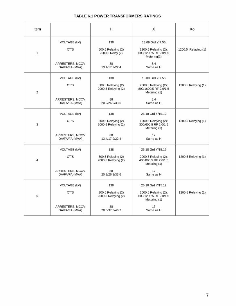
6.00 RATINGS SEE TABLE 6.1AND TABLE 6.2FOR INFORMATION
6.01 Voltage Rating
The specific voltage ratings for transformers covered by this specification are to be provided according toTable 6.1and Table 6.2.
6.02 Capacity Rating
6.02.01 The 65 degrees Centigrade temperature rise capacity ratings for transformers included in thisspecification are to be provided according to Table 6.1and Table 6.2.
6.02.02 The following types of cooling for transformers are allowed (Self-cooled/Forced Air-cooled FirstStage/Forced Air-cooled Second Stage):
(1) ONAN/ONAF(2) ONAN/ONAF/ONAF
6.02.03The transformer design shall be analyzed to determine any limitations on operating the transformerin the step-up direction. This analysis shall include the transformer active part, on-load & off-load tapchangers, control devices, and any other subcomponent that would have an effect on the transformer’sstep-up capability. If the transformer ratings are different in step-up operation than the step-down ratings,the step-up ratings will be listed separately on the transformer nameplate. If the transformer step-upratings are found to be equivalent to the step-down ratings, a statement shall be added to the nameplateindicating that the listed ratings apply to both step-up and step-down operation.
6.03 Bushing Current Transformers Ratio
6.03.01 All current transformers shall be multi-ratio (five tap), except for metering CT’s, which are dual ratiounless otherwise specified in Table 6.1or Table 6.2.
6.03.02 The bushing current transformers required shall be internal to the tank and shall meet therequirements of Section 7.14of this specification.
6.04 Basic Impulse Level (BIL)Rating
6.04.01 The BIL corresponding to each voltage rating included in this specification shall be as specified inTable 6.3.
7
TABLE 6.1POW ER TRANSFORMERS RATINGS
Item H X Xo
1
VOLTAGE (kV)
CT’S
ARRESTERS, MCOVOA/FA/FA (MVA)
138
600:5Relaying (2)2000:5Relay (2)
8813.4/17.9/22.4
13.09Grd Y/7.56
1200:5Relaying (2);600/1200:5RF 2.0/1.5
Metering(1)
8.4Same as H
1200:5 Relaying (1)
2
VOLTAGE (kV)
CT’S
ARRESTERS, MCOVOA/FA/FA (MVA)
138
600:5Relaying (2)2000:5Relaying (2)
8820.2/26.9/33.6
13.09Grd Y/7.56
2000:5Relaying (2);800/1600:5RF 2.0/1.5
Metering (1)
8.4Same as H
1200:5Relaying (1)
3
VOLTAGE (kV)
CT’S
ARRESTERS, MCOVOA/FA/FA (MVA)
138
600:5Relaying (2)2000:5Relaying (2)
8813.4/17.9/22.4
26.18Grd Y/15.12
1200:5Relaying (2);300/600:5RF 2.0/1.5
Metering (1)
17Same as H
1200:5Relaying (1)
4
VOLTAGE (kV)
CT’S
ARRESTERS, MCOVOA/FA/FA (MVA)
138
600:5Relaying (2)2000:5Relaying (2)
8820.2/26.9/33.6
26.18Grd Y/15.12
2000:5Relaying (2);400/800:5RF 2.0/1.5
Metering (1)
17Same as H
1200:5Relaying (1)
5
VOLTAGE (kV)
CT’S
ARRESTERS, MCOVOA/FA/FA (MVA)
138
800:5Relaying (2)2000:5Relaying (2)
8828.0/37.3/46.7
26.18Grd Y/15.12
2000:5Relaying (2);600/1200:5RF 2.0/1.5
Metering (1)
17Same as H
1200:5Relaying (1)
8
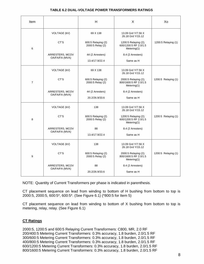
TABLE 6.2DUAL-VOLTAGE POW ER TRANSFORMERS RATINGS
Item H X Xo
6
VOLTAGE (kV)
CT’S
ARRESTERS, MCOVOA/FA/FA (MVA)
69X 138
600:5Relaying (2)2000:5Relay (2)
44(2Arresters)
13.4/17.9/22.4
13.09Grd Y/7.56X26.18Grd Y/15.12
1200:5Relaying (2);600/1200:5RF 2.0/1.5
Metering(1)
8.4(2Arresters)
Same as H
1200:5Relaying (1)
7
VOLTAGE (kV)
CT’S
ARRESTERS, MCOVOA/FA/FA (MVA)
69X 138
600:5Relaying (2)2000:5Relay (2)
44(2Arresters)
20.2/26.9/33.6
13.09Grd Y/7.56X26.18Grd Y/15.12
2000:5Relaying (2);800/1600:5RF 2.0/1.5
Metering(1)
8.4(2Arresters)
Same as H
1200:5 Relaying (1)
8
VOLTAGE (kV)
CT’S
ARRESTERS, MCOVOA/FA/FA (MVA)
138
600:5Relaying (2)2000:5Relay (2)
88
13.4/17.9/22.4
13.09Grd Y/7.56X26.18Grd Y/15.12
1200:5Relaying (2);600/1200:5RF 2.0/1.5
Metering(1)
8.4(2Arresters)
Same as H
1200:5 Relaying (1)
9
VOLTAGE (kV)
CT’S
ARRESTERS, MCOVOA/FA/FA (MVA)
138
600:5Relaying (2)2000:5Relay (2)
88
20.2/26.9/33.6
13.09Grd Y/7.56X26.18Grd Y/15.12
2000:5Relaying (2);800/1600:5RF 2.0/1.5
Metering(1)
8.4(2Arresters)
Same as H
1200:5 Relaying (1)
NOTE:Quantity of Current Transformers per phase is indicated in parenthesis.
CT placement sequence on lead from winding to bottom of H bushing from bottom to top is2000:5, 2000:5, 600:5*, 600:5*. (See Figure 6.1)(*800:5for Item 5)
CT placement sequence on lead from winding to bottom of X bushing from bottom to top ismetering, relay, relay. (See Figure 6.1)
CTRatings
2000:5, 1200:5and 600:5Relaying Current Transformers:C800, MR, 2.0RF200/400:5Metering Current Transformers:0.3% accuracy, 1.8burden, 2.0/1.5RF300/600:5Metering Current Transformers:0.3% accuracy, 1.8burden, 2.0/1.5RF400/800:5Metering Current Transformers:0.3% accuracy, 1.8burden, 2.0/1.5RF600/1200:5Metering Current Transformers:0.3% accuracy, 1.8burden, 2.0/1.5RF800/1600:5Metering Current Transformers:0.3% accuracy, 1.8burden, 2.0/1.5RF
9
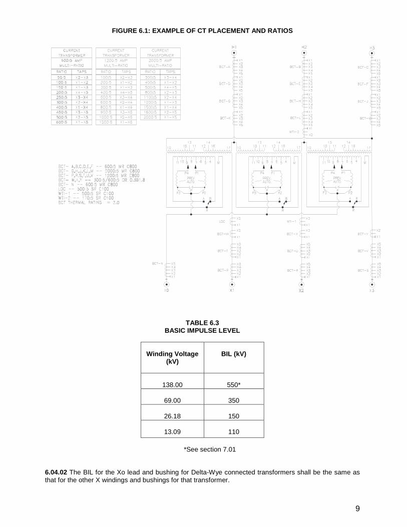
FIGURE 6.1:EXAMPLE OF CT PLACEMENT AND RATIOS
TABLE 6.3BASIC IMPULSE LEVEL
W inding Voltage(kV)
BIL (kV)
138.00 550*
69.00 350
26.18 150
13.09 110
*See section 7.01
6.04.02 The BIL for the Xo lead and bushing for Delta-W ye connected transformers shall be the same asthat for the other X windings and bushings for that transformer.
10
6.05Surge Arrester Ratings
6.05.01Surge arresters shall be station class and provided according to the details of section 7.15.
6.05.02The rating of the surge arrester corresponding to each voltage rating included in this specificationshall be as specified in Table 6.1and Table 6.2.
6.06Additional Tap Voltages
6.06.01De-energized Tap Changer
(1) The H winding of all transformers shall have a full capacity De-energized TapChanger unless otherwise specified.
(2) The tap changer shall have two (2)21/2% steps above and two (2)21/2% stepsbelow nominal rated voltage.
6.06.02 Load Tap Changer (LTC)
(1)The X winding of all transformers shall have a full capacity Load Tap Changer unlessotherwise specified. This shall be provided according to Section 7.13of this specification.
(2) The LTC shall have sixteen (16)5/8% taps above, and sixteen (16)5/8% taps belownominal rated voltage for each voltage setting.
(3) In certain cases, the LTC’s of dual-LV transformers may be permitted to havesixteen(16)5/16% taps above, and sixteen(16)5/16% taps below nominal rated voltage inthe 26.18Grd Y/15.12kV setting only. W hen in the 13.09Grd Y/7.56kV setting the LTC ofdual-LV transformers shall have sixteen (16)5/8% taps above, and sixteen (16)5/8% tapsbelow nominal rated voltage. This alternate requirement will be stated on LCRA TSC’squotation request, and subsequent purchase order.
7.00 CONSTRUCTION:
The transformers shall be constructed with the following features:
7.01 BushingsThe insulation class of the bushings required shall be as specified in Section 6.04except 138kV bushingsshall have a BIL rating of 650kV.
7.01.01The electrical and dimensional characteristics of apparatus bushings shall be as specified for theappropriate insulation class in IEEE C57.19.00_2004and C57.19.01_2000.
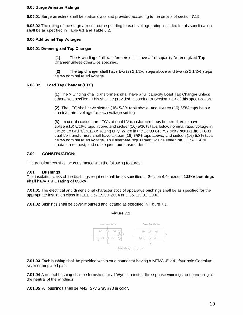
7.01.02Bushings shall be cover mounted and located as specified in Figure 7.1.
Figure 7.1
7.01.03Each bushing shall be provided with a stud connector having a NEMA 4" x4", four-hole Cadmium,silver or tin plated pad.
7.01.04A neutral bushing shall be furnished for all W ye connected three-phase windings for connecting tothe neutral of the windings.
7.01.05 All bushings shall be ANSI Sky Gray #70in color.
11
7.01.06 All bushings of the same voltage class, provided on the same order, shall be electrically andmechanically identical.
7.01.07 All bushings shall be manufactured by ABB or Pcore and have C1 and C2 test taps. C1 powerfactor shall not exceed 0.5% . C2 power factor shall not exceed 1% . Test results shall be recorded asreferenced in specification. Power factor shall be stamped on the nameplate. Table 7.1below listspreferred bushings for the transformer application.
TABLE 7.1
Transformers W inding Voltage kV BIL(kV) Manuf./Catalog #
138kV 138 650ABB #138Z0800AA or LCRA TSC approved
Pcore equivalent
25kV and 15kV 25 150ABB #025W 2000BE or 025W 0412AT orLCRA TSC approved Pcore equivalent
Neutral:Xo 25 150ABB #025W 0412AT or LCRA TSC
approved Pcore equivalent
7.01.08 If the successful offeror is not able to furnish the proposed bushings as indicated on the BidProposal, and an identical spare unit was not proposed to be furnished as excepted in 7.01.07above, thenthe contractor shall furnish a spare bushing with no change in bid price or change in delivery date.
7.01.09 The minimum phase to phase spacing of any two bushings shall not be less than thedimensions listed in the Table 7.2below, unless approved by LCRA TSC.
TABLE 7.2
MINIMUM BUSHING SPACINGNominal Operating Voltage
138kV 26.18kV 13.09 kV
Minimum live-to-live dimension 63” 24” 24”
7.01.10 One PCORE test terminal for field dielectric tests shall be provided on all transformer HV andLV bushings. The PCORE test terminals shall be rated for the continuous current rating of the bushing it isinstalled on, or higher. All PCORE test terminals shall use a NEMA 4hole terminal pad with 1.75”holespacing. The PCORE test terminal main components shall be made of aluminum or tin-plated copper.Silver-plated copper components are not acceptable. All minimum phase to phase and phase to groundclearances shall be maintained with the test terminals installed.
7.02 Liquid-Level Indicator
A magnetic liquid-level indicator shall be readable while standing at the base level. The liquid-levelindicator shall be a Messko MTO series indicator or LCRA TSC approved equivalent, with a minimum oftwo sets of normally-open contacts.
7.02.01 The indicator shall have a darkface dial with light colored markings and a light coloredindicating hand.
7.02.02 The diameter of the dial (inside bezel)shall not be less than:
(1) 31/4", when the center of the indicator dial is 96" or less above the base.
(2) 51/2", when the center of the indicator dial is more than 96" above the bottom of the base.
7.02.03 Dial markings shall show the 25degrees Centigrade. level and the "Hi-Lo" levels.
7.02.04 The words "liquid level at 25°C" shall be on the dial or on a suitable nameplate adjacent to it.
12
7.02.05 The 25degrees Centigrade liquid level shall be indicated by suitable permanent markings onthe tankor by indicating the distance from the liquid level to the highest point of the hand-hole or manholeflange surfaces on the nameplate.
7.02.06 The change in liquid level per 10degrees Centigrade change in temperature shall be indicatedon the transformer nameplate.
7.02.07 Low liquid level alarm contacts and critical low liquid level trip contacts shall be provided. Thelow liquid level alarm contacts shall be set by the contractor to alarm when the oil level drops below normaloperating level. The critical low liquid level trip contacts shall be set by the contractor to trip when the oillevel drops to the minimum safe operating level. The critical low liquid level trip contacts shall be wired toterminal blocks for connection by LCRA TSC.
7.03Alarm Contacts
(1) Non-grounded minimum-level alarm contacts shall be provided, suitable forinterrupting, at 250Vdc, a maximum of:
(a) 0.02amperes direct-current inductive load(b) 0.20amperes direct-current non-inductive load
(2) These alarm contacts and any additional or spare contacts shall be brought out asindividual alarms and terminated in the control cabinet on a properly labeled (descriptionand whether Normally Open NO, or Normally Closed NC)terminal blockfor alarms. SeeSection 7.07.09.
(3) The terminal blocks shall meet the requirements of Section 7.07.12herein.
(4) The wiring for the alarm contacts shall meet the requirements of Section 7.18,Auxiliary W iring, herein.
7.04 Thermometer (Top-Oil)
7.04.01 The top oil temperature, winding temperature(s), and LTC temperature functions shall becombined into a single intelligent temperature monitor (ITM).The monitor shall be a QualitrolSeries 509-100/200ITM for Oil Filled Transformers, and mounted in a NEMA 3R Enclosure with aclear viewing window.
(a) The ITM shall be configured to monitor the high-voltage winding hot spot temperature,low-voltage winding hot spot temperature, main tanktop oil temperature, and LTC oiltemperature.
(b)The ITM shall be configured to calculate the temperature difference between the maintankand LTC. See section 7.04.01(c)for acceptable temperature probe types andmounting locations.
(c) The main tankand LTC temperature probes shall be well-mounted resistivetemperature device probes (RTDs)mounted in the main tankand LTC on the sameside of the transformer the same distance above ground level. Magnetically-mountedRTDs are not acceptable.
(d)An ambient temperature probe shall be provided and an input to the ITM shall beconfigured to monitor the ambient temperature.
(e) The ITM shall be responsive to winding temperature of the transformer and responsiveto the current derived in phase
(f) The ITM shall have programmable relays configured to alarm for high oil temperature,high winding temperature, and high LTC/main tankdifferential temperature.
13
(g)The Contractor shall provide the transformer ITM completely configured with thecorrect parameters as required by the ITM manufacturer. The contractor will provideLCRA TSC with a copy of the ITM input parameters.
(h)The current transformers to furnish this current are to be in addition to the currenttransformers required in Table 6.1or Table 6.2herein and shall be shown along withits ratio on the main transformer nameplate.
(i) There shall be an ammeter test jackwith a switch blade in the secondary circuit ofthese current transformers designed to accommodate a Superior test plug, Cat. No.3614. This test jackshall be located in the main control cabinet for calibration andtesting.
(j) The calibration resistor shall be located adjacent to the test jackand properly labeled.
(k) The instruction books shall define a procedure for field calibration of the RTD’s givingtest curves on points.
(l) The ITM shall be configured to monitor the current of the Stage 1and Stage 2coolingfans.
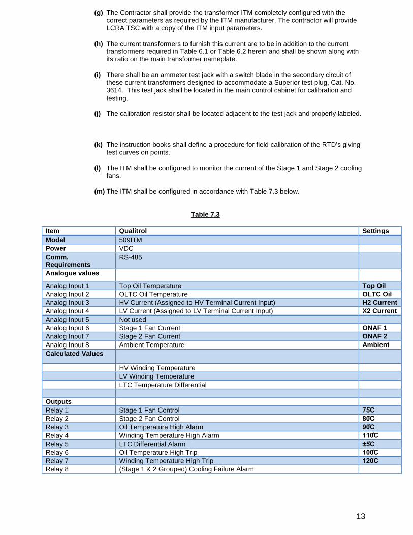
(m)The ITM shall be configured in accordance with Table 7.3below.
Table 7.3
Item Qualitrol Settings
Model 509ITM
Power VDCComm.Requirements
RS-485
Analogue values
Analog Input 1 Top Oil Temperature Top Oil
Analog Input 2 OLTC Oil Temperature OLTC Oil
Analog Input 3 HV Current (Assigned to HV Terminal Current Input) H2Current
Analog Input 4 LV Current (Assigned to LV Terminal Current Input) X2Current
Analog Input 5 Not used
Analog Input 6 Stage 1Fan Current ONAF 1
Analog Input 7 Stage 2Fan Current ONAF 2
Analog Input 8 Ambient Temperature Ambient
Calculated Values
HV W inding Temperature
LV W inding Temperature
LTC Temperature Differential
Outputs
Relay 1 Stage 1Fan Control 75̊C
Relay 2 Stage 2Fan Control 80̊C
Relay 3 Oil Temperature High Alarm 90̊C
Relay 4 W inding Temperature High Alarm 110̊C
Relay 5 LTC Differential Alarm ±5̊C
Relay 6 Oil Temperature High Trip 100̊C
Relay 7 W inding Temperature High Trip 120̊C
Relay 8 (Stage 1& 2Grouped)Cooling Failure Alarm
14
7.05 Sudden Pressure Relay (see 7.13.25for LTC SPR requirements)
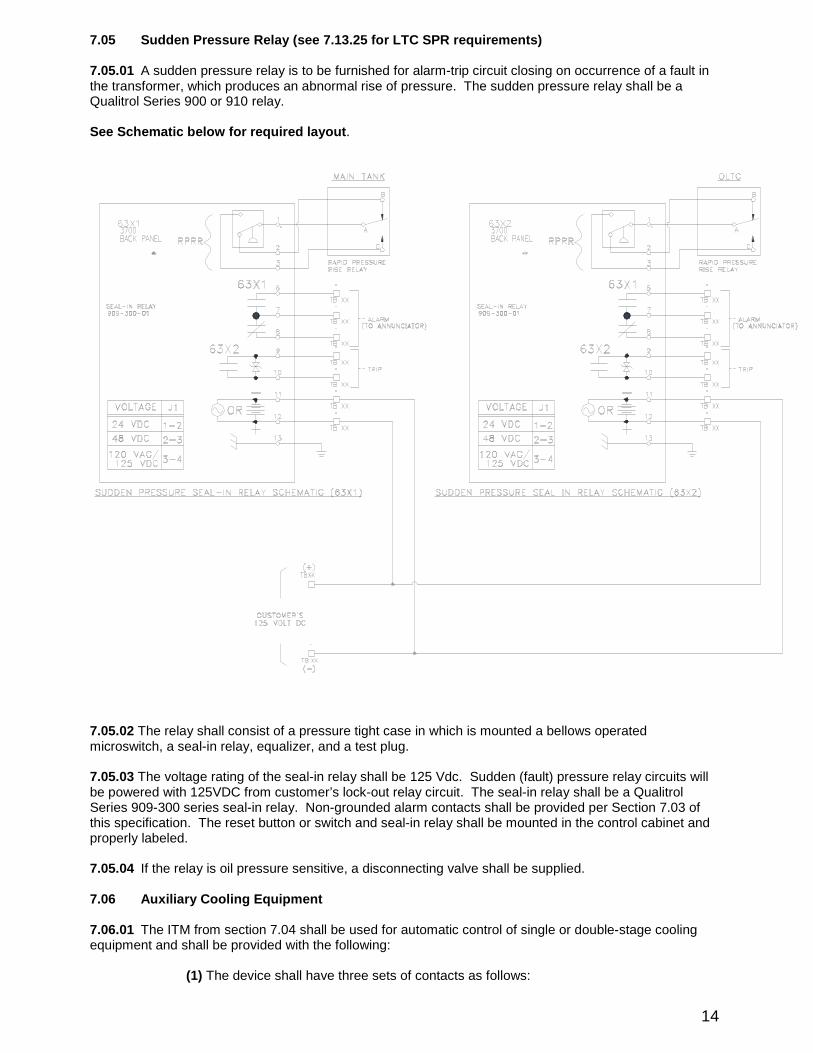
7.05.01 A sudden pressure relay is to be furnished for alarm-trip circuit closing on occurrence of a fault inthe transformer, which produces an abnormal rise of pressure. The sudden pressure relay shall be aQualitrol Series 900or 910relay.
See Schematic below for required layout.
7.05.02The relay shall consist of a pressure tight case in which is mounted a bellows operatedmicroswitch, a seal-in relay, equalizer, and a test plug.
7.05.03The voltage rating of the seal-in relay shall be 125Vdc. Sudden (fault)pressure relay circuits willbe powered with 125VDC from customer’s lock-out relay circuit. The seal-in relay shall be a QualitrolSeries 909-300series seal-in relay. Non-grounded alarm contacts shall be provided per Section 7.03ofthis specification. The reset button or switch and seal-in relay shall be mounted in the control cabinet andproperly labeled.
7.05.04 If the relay is oil pressure sensitive, a disconnecting valve shall be supplied.
7.06 Auxiliary Cooling Equipment
7.06.01 The ITM from section 7.04shall be used for automatic control of single or double-stage coolingequipment and shall be provided with the following:
(1)The device shall have three sets of contacts as follows:
15
Contact Function
(a) Supply power to first bankof cooling either directly or by control of an auxiliaryrelay
(b) Supply power to second bankof cooling either directly or by control of anauxiliary relay
(c) Initiate alarm or actuate a relay with non-grounded contacts provided perSection 7.03of this specification.
(2) A switch for automatic and manual control of each bankof cooling equipment is to belocated in the control cabinet. Controls to also provide selection of which bankwill leadthe other with increasing temperature shall be provided on ONAN/ONAF/ONAF ratedtransformers.
(3) An electronic loss of voltage relay (or relays)shall be incorporated in the wiring andshall be connected ahead of the switch in Section 7.06.01(2)above and have a settabletime delay up to five minutes before contact closure to eliminate false indication and shallhave non-grounded alarm contacts per Section 7.03herein.
(4) An over current protective device with manual reset for each bankof coolingequipment in the control cabinet.
(5)An automatic over current protective device on each individual fan motor.
7.06.02 The following shall apply to cooling fans and fan motors:
(1) All fan blades shall have OSHA type side and rear guards enclosing them for personalsafety. The fans shall also have front guards to prevent birds and other animals fromentering the fan housing. Fans shall be by Krenzor LCRA TSC approved equal.
(2) All fan motors shall be single phase and have sealed-permanently lubricated ballbearings.
(3) No fans shall be mounted on the bottom side of radiators on any designs.
7.07Control Cabinet
The control cabinet shall be furnished as follows:
7.07.01 There shall be only one control cabinet to which LCRA TSC's wiring is to be connected.
7.07.02 The cabinet shall be weatherproof. Vents with replaceable filters shall be provided.
7.07.03 The door of the cabinet shall swing in the horizontal plane.
7.07.04 The door shall have a device for keeping it open during operation at the cabinet.
7.07.05 The door shall have a hinged panel on the inner side that can be lowered to a horizontal positionto hold a voltmeter or multimeter while making tests in the cabinet.
7.07.06 The door shall have a compartment for holding the Instruction Manual and one set of drawings.
7.07.07 The cabinet shall be at a convenient working height from the base of the transformers.
7.07.08 The cabinet shall contain the following:
(1) Terminals for all LCRA TSC provided sources such as ac and dc power and LTCsensing voltage.
(2) Short circuiting terminal blocks for all current transformer leads.
16
(3) All alarm terminals brought to terminal blocks.
(4) Sudden-pressure relay reset switch.
(5) Cooling equipment switching devices.
(6) Automatic-tap-changer control equipment which shall be panel mounted andcapable of being removed without disturbing the current shorting switch for thecompensator circuit.
(7) A 130V, 100W incandescent light with a switch, and a 120V duplexoutlet,both protected by a 20A ground fault interrupting current breaker.
(8) Thermostatically controlled heater for control of humidity. The thermostat shallbe set to cut-off when temperature rises above 90degrees Fahrenheit.
(9) All other accessories named in this specification which are to be located in thecontrol cabinet.
(10) Neutral and ground conductors in control cabinet shall be separated.
7.07.09 Annunciators
(1) The Contractor shall provide one or more Puleo Type PE103-48-2Bannunciator(s)or LCRA TSC approved equivalent to handle all annunciator pointsspecified.
(2) W iring shall be provided between the alarm contact terminal blocks and theannunciator point module terminals.
(3) The terminals of the annunciators point modules shall be properly andpermanently labeled to indicate the alarm function.
(4) The contractor shall provide as many annunciators as is necessary to makeavailable to the LCRA TSC all required alarm points. The following minimum alarm pointsshall be provided:
a) Sudden pressure relay operation -Main Tankb) Sudden pressure relay operation -OLTCc) H2winding temperatured) Gas accumulation relay operation (if oil preservation system is
conservator-type)e) Pressure relief device operation -Main Tankf) Pressure relief device operation -OLTCg) High liquid temperature –Main Tankh) Low oil level -Main tanki) Low oil level -OLTCj) AC failure alarm -120/240VACk) X2winding temperaturel) Gas in Oilm) High liquid temperature -OLTCn) Tap Change Incompleteo) Air Cell Failure (if oil preservation system is conservator-type)p) OLTC control relay failure alarmq) OLTC Backup Relay Operationr) OLTC/Main tanktemperature differential alarms) OLTC upper/lower limit overtravelt) Nitrogen system high pressure (Main Tank)u) Nitrogen system vacuum (Main Tank)v) Nitrogen cylinder empty
17
(5) Each of the annunciator power supply circuits shall be connected to a 125Vdc powersupply terminal block. The annunciator power supply(s)will be supplied by a separatecustomer connection from the other 125Vdc devices on the Transformers.
(6) A 125VDC failure alarm shall be provided, with NO/NC contacts wired directly toterminal blocks.
(7) Each of the annunciator's relay module contact terminals shall be terminated onterminal blocks for LCRA TSC's connections as described in Sections 7.07.11, 7.07.12,7.07.14, and 7.07.16herein.
(8) All wiring specified shall be in accordance with Section 7.18herein.
7.07.10The bottom of the cabinet shall consist of a bolt-in removable steel plate a minimum of 270squareinches in area and of a gauge similar to that of the main cabinet material. The plate shall be of suchdimension that the LCRA TSC can remove and cut sufficient number and size of conduit holes for theconnection of LCRA TSC's wiring.
7.07.11All terminals and equipment shall be legibly and indelibly identified.
7.07.12All connecting terminal blocks shall be General Electric type EB-25or LCRA TSC approvedequivalent.
7.07.13All current transformer leads shall be individually terminated onto a short-circuiting terminal block.These terminal blocks shall be General Electric type EB-27or LCRA TSC approved equivalent. See7.07.08(2).
7.07.14There shall be no contractor connection on the side of the terminal blocks allocated for LCRATSC’s connections. All LCRA TSC connections shall be labeled by contractor with the correct devicelabel.
7.07.15The cabinet shall have a grounding connector for safety grounding.
7.07.16All terminal blocks for the LCRA TSC's connections shall be accessible to LCRA TSC's controlcable entering the bottom of the cabinet without overlapping other control components in the cabinet.
7.07.17 All wiring shall be bundled or contained and shall meet the requirements of Section 7.18of thisspecification.
7.08 Oil
All Transformers shall be shipped to Purchaser’s final destination filled with oil.
The contractor shall provide oil for insulating and cooling of all transformers according to the following.This includes any “topping off”oil required after final installation of the transformer at the Purchaser’ssubstation.
LCRA TSC must approve the results of the certified oil test analysis twice before the unit isdelivered.1. Before the contractor fills the transformer for testing.2. Before final delivery.
THE OFFERER SHALL PROVIDE A NARRATIVE DESCRIPTION ON HOW THEYPROPOSE TO ACCOMPLISH THIS W ITH THEIR PROPOSAL.
Any additional quantities of oil needed after testing,shipping or assembly need to be approved by
LCRA TSC.
GENERAL
The oil furnished under this specification shall be Type IIMineral Oil as described in ASTM D3487.
The oil furnished under this specification shall meet the characteristics stated in the aforementionedindustry standards or the references therein.
18
The requirements, specifically stated within this specification, shall govern should there be any conflictswith the above standards or the references therein.
The required oil characteristics are summarized in AppendixA.
OIL TEST ANALYSIS
The contractor shall perform a chemical analysis and submit a certified chemist's report to LCRA TSC onthe contents of the oil prior to filling the Transformer tankto show that the requirements of thecharacteristic chart above have been met or exceeded.
If oil properties do not meet or exceed the requirements in the Table listed above, corrective action will betaken at the expense of the contractor to bring the properties of the oil to the correct specification beforefilling the transformer with oil for testing and final delivery. Oil that has been treated with passivatorto address the presence of Corrosive Sulfur will not be accepted.
7.09 Oil Preservation Systems
7.09.01The contractor shall provide an oil preservation composed of either an inert gas pressure system(nitrogen blanket), or a conservator expansion tanksystem incorporating an impermeable barrier betweenthe transformer oil and ambient air, accordance with IEEE C57.12.10_2010and C57.12.80_2010. Freebreathing or other type designs allowing direct contact between the transformer oil and ambient air are notacceptable.
7.09.02The inert gas pressure system is one in which the interior of the transformers (by means of apositive pressure of inert gas maintained from a separate inert gas source and reducing valve system)issealed from the atmosphere throughout a top-oil temperature range of 100degrees Centigrade., and theinternal pressure does not exceed 8psi gauge.
(1)The inert gas shall be dry nitrogen with less than 0.5percent by volume of impuritiesand less than 0.03percent by weight of moisture.
(2)The nitrogen shall be supplied in 200cubic foot cylinders equipped with connection No.580of ANSI B57.1.
(3)The nitrogen bottle shall be in a weatherproof cabinet at base level.
(4)The gauges shall monitor and regulate the gas pressure of the transformers tankandmonitor the gas pressure of the nitrogen bottle.
(5)All transformers shall have a provision for sampling tankgas. This provision shallconsist of a valve and fitting designed to accommodate one-quarter inch I.D. "Tygon"-typetubing. This shall be located inside the nitrogen bottle cabinet. The gas sample locationon the transformers tankshall be valved and located at an opposite end of the tankfromthe gas filling location.
(6)A non-grounded alarm contact shall be provided per Section 7.03herein for detectionof low gas pressure.
7.09.03 The conservator expansion tankoil preservation shall utilize a rubber bladder bag to exclude aircontact with the oil. Bladder shall have proven 20year plus life expectancy. If the conservator expansiontanksystem is used, an air cell failure relay shall be installed on the top of the conservator tankto detectloss of pressure in the bladder bag. This relay shall be an EMB air cell failure protection relay or LCRATSC approved equivalent.
The bottom of the expansion tankmust be at least 4”above the top of the Transformers cover and abovethe highest oil to air gasketed joint. The tankshall be constructed so that the bag will not blockthe pipe tothe Transformers at low oil levels. Isolation valves shall be provided between the conservator tankand themain tank. Appropriate bleed valves shall be located on the main tankand conservator for filling theTransformers. Dessicant containers shall be located at ground level. A Buchholz-style gas accumulationrelay shall be located in the piping between the conservator tankand main tank. The gas accumulationrelay shall be wired to a separate seal-In relay inside the control cabinet. The gas accumulation relay shall
19
be a Messko MSafe Series Relay, or LCRA TSC approved equivalent. Non-grounded alarm contacts shallbe provided in accordance with Section 7.03of this specification.
7.10 Pressure Relief Valve
A pressure relief device shall be located on the cover within 12inches of the side of the tank. Electricalarm contacts and mechanical target operation of the device are both required. The pressure relief deviceshall be a Messko MPREC LMPRD with the “oil directed”feature equipped. The termination of thedischarge pipe shall be no more than 3feet above grade level.
7.10.01 The non-grounded electrical alarm contacts shall be provided according to Section 7.03of thisspecification. The contact leads shall be terminated in the control cabinet.
7.10.02 The mechanical target shall be capable of being viewed from ground level.
7.10.03 The target shall also be capable of being reset by a hot stickwhile the transformer is energized.
7.11 Tanks
7.11.01 Design
(1)The main Transformers tankand any attached compartment that is subjected tooperating pressures shall be designed to withstand, without permanent deformation,pressure 25percent greater than the maximum operating pressures resulting from thesystem of oil preservation used.
(2)The maximum operating pressures (above and below standard atmospheric pressure)which the Transformers tankis designed to withstand shall be indicated on the nameplate.
(3)Tanks shall be designed for vacuum filling (essentially full vacuum)in the field.Auxiliary compartments, when not designed for vacuum filling, shall be so designated andvalves shall be provided to isolate them from the main tank. Specific instructionsconcerning vacuum procedures shall be defined in the instruction manual.
(4) Main cover shall be welded construction. Baseplates to facilitate installation of fallprotection equipment shall be welded in the two locations of the main cover. Fallprotection equipment will be supplied by LCRA TSC and consist of a detachable tie offpole, manufactured by Uni-Hoist, LLC of Clanton, Ala., mounted to the tankcoverbaseplate. The tether pole is a Uni-Hoist Style #NUL4000-P1A. The base plate is a Uni-Hoist Style #NUH4000-2. The pole will induce certain shear and bending moment forcesto the tankcover. Design criteria to accommodate these loads shall be designed into thetankby the contractor. See the AppendixB for reference drawing related to baseplatedesign.
Note: All plugs in this specification shall have external square heads. No Allen headfittings are allowed. Also cast type plugs are not acceptable.
(4) One or more manholes shall be provided in the cover to provide access to all bushingsaccording to the following requirements:
(a) Removable bolted covers shall be provided.
(b) The manhole covers should be flat with a minimum diameter of 18inches.
(c) Covers weighing more than 45pounds shall be hinged and removable.
(d) All covers shall have handles.
(6)All joints for tankand manhole covers, bushings, and other bolted covers shall havegaskets. These joints shall be designed so gaskets will not be exposed to the weather,and shall be provided with mechanical stops to prevent crushing. One set of sparegaskets shall be provided with each unit. All gaskets shall be in recessed, machinedgrooves. All gasket surfaces shall be made up by flanges. All gaskets shall be made ofhigh temperature viton. Gaskets shall be O-ring or flat type only.
20
7.11.02 Grounding
(1) TankGround Pads
Grounding pads shall be provided per IEEE C57.12.10_2010Section 5.5. A totalof four NEMA 4-hole, or 6-hole steel-based copper-faced pads shall be welded tothe tankin each of the following locations:
(a) Sixinches up from the bottom on left and right corners when facing lowvoltage side.
(b)Sixinches up from tankbottom on left and right corners when facing highvoltage side.
Thread protection for these ground pads during shipment shall consist of a flangedcup of a non-corrosive material suitable for press fitting into threaded openings.
(2)Neutral Bushing Grounding
(a) The Xo bushing shall have a stud to NEMA 4-hole pad tin or silver-platedcopper connector.
(b) A ground strap shall be furnished from the Xo terminal to the adjacenttankground pad.
(c) A suitably sized copper neutral bus bar shall be furnished and attached tothe side of the transformer at a location as close to the neutral (Xo)bushing aspossible. The bus bar shall be made of suitable copper bar and shall beconnected directly to a four hole pad stud connector on the neutral bushing. Thebus bar must be supported approximately every three feet with suitable insulatedsupports and the bottom of the bus bar shall have a NEMA four hole drilling at 6inches above the base of the transformer. The neutral bus bar shall be painted thesame color as the tank.
(3) Surge Arrester Grounding
The surge arresters furnished on the transformers shall be grounded to all fourtankground pads listed in 7.11.02(1)(a)or (b)above. These grounds shall becopper bars with suitable supports on tankfor all bars. This is a total of four (4)vertically positioned copper bars, one on each corner, running from top to bottomof the transformers tankplus horizontal bar runs at the top of the tankas requiredto connect the four vertical bars. If tanks are not shipped with bars installed, adetail assembly drawing, on the outline drawing, showing piece marks for all barsshall be provided and bars shall be marked with these piece numbers. No coppercable shall be used in this system design.
(4) Core Ground
(a) The location of core ground(s)shall be indicated on the outline drawing.
(b) Transformers shall have the core ground(s)terminate through the tankwall by means of a suitably rated bushing for proper core insulation. Each coreshall have a separate ground and bushing (main, series, preventative auto, etc.).
(c) The bushing(s)shall be housed in a weather resistant protective metalhousing.
(d)The ground bushing terminal(s)shall be connected by cable or strap to anadjacent ground pad welded to the Transformers tankwall. The cable or strapshall be easily removable for core ground resistance testing.
(5) LCRA TSC shall connect tankground pads to substation ground grid tocomplete adequate Transformers grounding protection. Two holes shall bemaintained on the tankground pads of 7.11.02(1)(a)and (b)for LCRA TSC's use.
21
7.11.03Drain and Filter Valves
(1) A combination drain and lower filter valve of the globe type shall be provided.
(2) This valve shall provide for complete drainage of the liquid and for outlet to oilfiltering means.
(3) The size of the drain valve should be 2-inches and it should have 2-inch NPTthreads with a pipe plug in the open end.
(4) The drain valve shall have a built-in 3/8-inch sampling device, which shall belocated in the side of the valve between the main valve seat and the pipe plug.
(5) The sampling device shall be supplied with a 5/16-inch, 32threads per inch,male connector equipped with a cap.
(6) An upper filter valve of the globe type, located in the same segment of thedrain valve, should be located below the 25degrees Centigrade liquid level, suitable forthe return of filtered oil.
(7) The size of the upper filter valve shall be 2-inch and shall have 2-inch NPTthreads with a pipe plug in the open end.
7.11.04 Lifting Facilities
(1) Means for lifting the complete transformers by overhead crane shall beprovided. No other structural or mechanical items shall be installed next to the lifting lugsthat will interfere with sling attachments to the lifting lugs.
(2) The bearing surfaces of the lifting means shall be free from sharp edges.Facilities for guying the Transformers during transport shall be provided.
(3) Lifting means shall be provided for removing the lid and untanking thetransformers.
7.11.05 Moving Facilities
(1) The base shall permit rolling or sliding in the directions of both center-lines ofthe transformers and attachment holes in base structure shall be provided for pulling thetransformers in these directions.
The base shall be so designed that the center of gravity of the transformers, asnormally prepared for shipment, shall not fall outside the base support members for a tilt ofbase of 15degrees from the horizontal, with or without oil in the transformers.
(2) The transformers center of gravity for shipment and for fully assembledtransformers (including oil)shall be permanently marked and labeled on all four tankwalls,and on the transformers outline drawing. The transformer’s centerline shall bepermanently marked and labeled on all four tankwalls within 6inches of the base.
7.11.06 Jacking Facilities
(1) Jacking facilities shall be located near the corners of the base.
(2) The jackports or lugs shall be so designed that the jackcan be inserted.
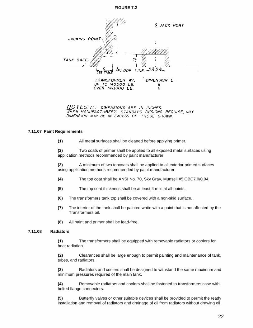
(3) Dimensions and clearances for jacking provisions shall be as shown in Figure 7.2.
22
FIGURE 7.2
7.11.07 Paint Requirements
(1) All metal surfaces shall be cleaned before applying primer.
(2) Two coats of primer shall be applied to all exposed metal surfaces usingapplication methods recommended by paint manufacturer.
(3) A minimum of two topcoats shall be applied to all exterior primed surfacesusing application methods recommended by paint manufacturer.
(4) The top coat shall be ANSI No. 70, Sky Gray, Munsell #5.OBC7.0/0.04.
(5) The top coat thickness shall be at least 4mils at all points.
(6) The transformers tanktop shall be covered with a non-skid surface. .
(7) The interior of the tankshall be painted white with a paint that is not affected by theTransformers oil.
(8) All paint and primer shall be lead-free.
7.11.08 Radiators
(1) The transformers shall be equipped with removable radiators or coolers forheat radiation.
(2) Clearances shall be large enough to permit painting and maintenance of tank,tubes, and radiators.
(3) Radiators and coolers shall be designed to withstand the same maximum andminimum pressures required of the main tank.
(4) Removable radiators and coolers shall be fastened to transformers case withbolted flange connectors.
(5) Butterfly valves or other suitable devices shall be provided to permit the readyinstallation and removal of radiators and drainage of oil from radiators without drawing oil
23
from Transformers tank. Verification of valve shutoff capability shall be documented to theLCRA TSC in final test reports that are submitted.
(6) There shall be no external valve levers or stops constructed of plastic oraluminum material.
(7) Radiators and coolers shall be equipped with lifting eyes, and so designed thatthey may be handled without the addition of special bracing.
(8) The top and bottom of each radiator assembly shall have a vent and draincoupling and plug. The coupling is to be American Pipe Standard with 3/4inch taperedplug.
(9) Radiators may have a galvanized finish in lieu of the paint requirements of7.11.07.
7.12 De-energized Tap Changer and Series –Parallel Switches
7.12.01 Each tapped winding shall have a tap changer for de-energized operation (see 6.06.01)with anoperating handle located on the side of the tankat a height convenient for operation from the base level. Ifmultiple high side voltage ratings are specified, a single handle shall operate all de-energized tapchangers.
7.12.02 Ratings for the de-energized tap changer shall meet the requirements of Section 6.06.01ofthis specification. If multiple high/low side voltage ratings are specified, an externally mounted operatinghandle located on the side of the tankat a height convenient for operation from the base level shall besupplied to operate the required internal series-parallel switch(s). The position of the switch handle(s)shall identify the voltage chosen:i.e., 138000, 69000, 26180, or 13090.
7.12.03 The De-energized tap changer handle and Series-Parallel handles shall have provisions forpadlocking, consisting of a 3/8-inch minimum diameter hole, and shall provide visible indication of the tapposition without unlocking. For a given winding, the number 1or the letter A shall be assigned to taphaving the greatest number of effective turns.
7.12.04 If more than one de-energized mechanism is required, such as a series-multiple, the handle shallbe gang operated.
7.12.05 The contractor shall provide their usage history for the specific model of de-energized tapchanger proposed. LCRA TSC reserves the right to approve the type of de-energized tap changersupplied.
7.13 Load-Tap Changing Equipment (LTC)
7.13.01 Design
The load-tap changing equipment shall consist of reactance bridging in a vacuum interrupter;a motor-drivemechanism;and control devices. Reactive or resistive bridging tap changers with contacts in oil are notacceptable. The LTC shall regulate the secondary (low voltage)side of the transformer unless otherwisespecified in Table 6.1or Table 6.2. The offeror shall state in his proposal the manufacturer and type of LTCto be supplied. The following type of LTC is approved by LCRA TS C:Reinhausen Type RMV, or LCRATSC approved equivalent.
7.13.02 Rating
LTC ratings are per Section 6.00of this specification.
7.13.03 Vacuum Interrupter
If a vacuum interrupter-type LTC is used, it shall consist of the following:
(1) The vacuum interrupter shall consist of a stationary and moving contact enclosed in avacuum tight bottle.
24
(2) An extension of the operating rod shall serve as an external wear indicator for theelectrical contacts.
(3) The vacuum interrupter contact life shall be the same as the service life of theTransformers.
7.13.04 The LTC shall be provided in accordance with IEEE Std. C57.131_2012.
7.13.05 The LTC shall include a protective circuit that senses vacuum bottle failure.
7.13.06 The LTC motor drive shall be a Reinhausen TAPMOTION MD-III or LCRA TSC approvedequivalent. The motor shall be 120V or 240V single phase AC.
7.13.07 Removable bolted covers shall be provided for access to the load tap changing compartmentwithout opening the main tankor lowering the liquid in the main tank. Covers weighing more than 45pounds shall be hinged and removable. Covers weighing 45pounds or less shall have handles.
7.13.08 Door swings of any doors on the LTC compartments, including doors to be opened on sidemounted LTCs, shall be noted on the outline drawing.
7.13.09 LTC shall not be mounted on the tankwall, cover, or other location subject to deflection due tovacuum evacuation of the tank, or mechanical forces encountered in transport or service.
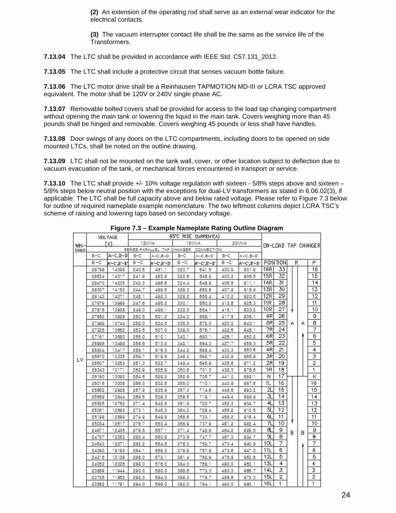
7.13.10 The LTC shall provide +/-10% voltage regulation with sixteen -5/8% steps above and sixteen –5/8% steps below neutral position with the exceptions for dual-LV transformers as stated in 6.06.02(3), ifapplicable. The LTC shall be full capacity above and below rated voltage. Please refer to Figure 7.3belowfor outline of required nameplate example nomenclature. The two leftmost columns depict LCRA TSC’sscheme of raising and lowering taps based on secondary voltage.
Figure 7.3–Example Nameplate Rating Outline Diagram
25
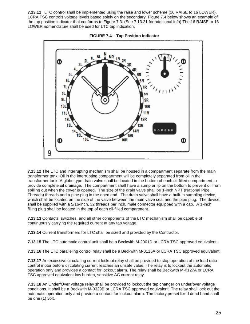
7.13.11 LTC control shall be implemented using the raise and lower scheme (16RAISE to 16LOW ER).LCRA TSC controls voltage levels based solely on the secondary. Figure 7.4below shows an example ofthe tap position indicator that conforms to Figure 7.3. (See 7.13.21for additional info)The 16RAISE to 16LOW ER nomenclature shall be used for LTC tap indication.
FIGURE 7.4–Tap Position Indicator
7.13.12The LTC and interrupting mechanism shall be housed in a compartment separate from the maintransformer tank. Oil in the interrupting compartment will be completely separated from oil in thetransformer tank. A globe type drain valve shall be located in the bottom of each oil-filled compartment toprovide complete oil drainage. The compartment shall have a sump or lip on the bottom to prevent oil fromspilling out when the cover is opened. The size of the drain valve shall be 1-inch NPT (National PipeThreads)threads and a pipe plug in the open end. The drain valve shall have a built-in sampling device,which shall be located on the side of the valve between the main valve seal and the pipe plug. The deviceshall be supplied with a 5/16-inch, 32threads per inch, male connector equipped with a cap. A 1-inchfilling plug shall be located in the top of each oil-filled compartment.
7.13.13Contacts, switches, and all other components of the LTC mechanism shall be capable ofcontinuously carrying the required current at any tap voltage.
7.13.14Current transformers for LTC shall be sized and provided by the Contractor.
7.13.15The LTC automatic control unit shall be a Beckwith M-2001D or LCRA TSC approved equivalent.
7.13.16The LTC paralleling control relay shall be a Beckwith M-0115A or LCRA TSC approved equivalent.
7.13.17An excessive circulating current lockout relay shall be provided to stop operation of the load ratiocontrol motor before circulating current reaches an unsafe value. The relay is to lockout the automaticoperation only and provides a contact for lockout alarm. The relay shall be Beckwith M-0127A or LCRATSC approved equivalent low burden, sensitive AC current relay.
7.13.18An Under/Over voltage relay shall be provided to lockout the tap changer on under/over voltageconditions. It shall be a Beckwith M-0329B or LCRA TSC approved equivalent. The relay shall lockout theautomatic operation only and provide a contact for lockout alarm. The factory preset fixed dead band shallbe one (1)volt.
26
7.13.19The LTC shall have manual, automatic, and remote control capability via LCRA TSC supervisoryequipment. The Contractor shall provide one manual, “Raise-Off-Lower”selector switch for local operationof the LTC. The Contractor shall also provide one manual “Remote-Local”selector switch to selectbetween local or supervisory control of the LTC. In the “Remote”position, LCRA TSC will provide drycontact inputs from supervisory interface panels to raise or lower the LTC tap position. In the “Local”mode,the LTC tap position will be controlled from the LTC automatic control unit. A ‘raise’command shall causethe secondary voltage to increase and cause the tap indication to move towards 16RAISE. A ‘lower’command shall cause the secondary voltage to decrease and cause the tap indication to move towards 16LOW ER.
7.13.20The Contractor shall provide a ventilated weatherproof cabinet with hinged doors. The doors shallprovide access to the control devices and have provisions for padlocking. All cabinet and door hardwareshall be non-rust stainless steel. The LTC manual controls shall be located on the same side of thetransformer as the tap position indicator. A hand crankor hand wheel for manual operation of the drivingmechanism shall be provided. If a hand crankor spoke type of hand wheel is provided, it shall beelectrically interlocked to prevent operation by the motor when the crankor spoke type hand wheel isremoved from its storage position. If the hand crankor hand wheel is detachable, a storage place shall beprovided.
7.13.21The LTC shall have a tap position indicator with maximum/minimum drag hands, resettable fromground level. The tap position indicator will be labeled from ’16LOW ER’to ’16RAISE’with tap position ‘N’denotative of the neutral position. A ‘raise’command will result in the tap indication moving in the RAISEdirection.
7.13.22The LTC shall provide tap position indication to both the main LTC controller and LCRA TSCsupervisory. A Beckwith M-2025or LCRA TSC approved equivalent shall be provided for tap positionindication into the M-2001D main LTC controller and LCRA TSC supervisory. Three separate signals, a 0-1mA signal, a 4-20mA signal, and a resistive network, shall be provided and wired to Contractor terminalblocks for LCRA TSC supervisory indication.
7.13.23A mechanical operations counter shall be provided and shall be accessible from ground level.
7.13.24A separate nameplate shall be provided for and mounted on the LTC mechanism.
The nameplate shall include the following minimum data in addition to the IEEE C57.131_2012specifieditems:
Model number of mechanismType of drive mechanismRatio of any series autotransformerLTC manufacturer nameModel number of MechanismYear of ManufactureMaximum rated through current of mechanismBIL RatingOil Volume in mechanism compartmentType of transition impedance (resistor)Method of Arc interruptionType of drive mechanism
7.13.25The Contractor shall provide one (1)sudden pressure sensing unit mounted on the LTCcompartment. The unit shall be equipped with test plugs to simulate a sudden pressure rise, so that theunit can be tested periodically. Circuitry from this device shall be provided to a seal-in relay. This seal-inrelay, reset button, indicating light, and 63X trip and alarm contacts shall be mounted in the main controlcabinet. Indicating light shall indicate SPR -LTC (Sudden Pressure Relay -LTC)trip and shall remain lituntil the sudden pressure relay has been manually reset. All circuitry and relays associated with thesudden pressure relay scheme for the LTC shall be independent from the sudden pressure relay schemefor the main tank. The sudden pressure sensing unit shall be a Qualitrol Series 910or LCRA TSCapproved equivalent Rapid Pressure Rise Relay. The seal-in relay shall be a Qualitrol 909-300series orLCRA TSC approved equivalent Seal-In Relay. Trip contacts shall be identified on the drawings and wiredout to terminal blocks for LCRA TSC use. Alarm contacts shall be provided in accordance with Section7.03, with one set wired to a terminal blockfor LCRA TSC use and another set wired to the annunciator.Terminal blockpoints shall be provided for LCRA TSC to supply 125volts DC exclusively to the LTC SPRseal-in relay.
27
7.13.26 The use of internal varistors is discouraged, but they may be used to provide added voltageprotection during transient conditions. Contractor shall provide a justification for varistor use during thedesign review.
7.13.27A separate annunciator alarm shall be provided to indicate when the temperature of the oil in theLTC compartment is 5degrees Celsius or greater than the oil temperature in the main tankat thecorresponding level. Temperature differential shall be monitored by the ITM. If an RTD type sensor is usedfor detecting the main tanktemperature, it shall be provided with a weather cover to prevent solar gainfrom affecting the temperature reading. RTD sensors should be located on the same side at the sameheight..7.13.28The LTC Motor shall be 240volt, single phase, 60Hz. It shall be accessible and replaceable fromthe hand hole in the cover (bolt-on, external LTC tanks). The motor shall be equipped with over currentprotection of 10amps with a manual reset. No autotransformer shall be required between the motor and itspower source.
7.13.29Mechanically operated electric limit switches and mechanical stops shall be provided on the drivemechanism to prevent over travel beyond the maximum raise and lower positions.
7.13.30An over current automatic-trip air circuit breaker with manual reset for control of the power circuitat the motor drive shall be provided.
7.13.31An over current automatic-trip air circuit breaker with manual reset for control of the potential circuitto the automatic control devices shall be provided.
7.13.32The Contractor shall provide one (1)automatic pressure relief device for the LTC compartmentthat resets automatically. The automatic pressure relief device shall provide a visual indication of operationwhich is reset manually. Circuitry from this device shall be routed to the main control cabinet where alarmcontacts shall be provided and connected to the annunciator. Alarm contacts shall be provided inaccordance with Section 7.03. The automatic pressure relief device shall be a Reinhausen MesskoLMPRD with the “oil directed”feature equipped. The termination of the discharge pipe shall be no morethan 3feet above grade level.
7.13.33The Contractor shall provide one (1)magnetic liquid level gauge with low liquid level alarmcontacts and critical low liquid level trip contacts for the LTC. The low liquid level alarm contacts shall beset by the contractor to alarm when the oil level drops below normal operating level. The critical low liquidlevel trip contacts shall be set by the contractor to trip when the oil level drops to the minimum safeoperating level. The critical low liquid level trip contacts shall be wired to terminal blocks for connection byLCRA TSC. The liquid level gauge shall have a six(6)inch dial. The magnetic liquid level gauge shall be aMessko MTO or LCRA TSC approved equivalent.
7.13.34The Contractor shall supply trip contacts for LCRA TSC’s use per LTC manufacturer’srecommendations, and shall clearly label their purpose.
7.13.35A Reinhausen MTraB or LCRA TSC approved equivalent maintenance free breather shall beinstalled for the LTC oil containment system. The breather shall be accessible at grade level.
7.13.36 Current and Potential Sources
The current and potential source for the automatic control shall be as follows:
(1) The user shall furnish a source of potential for the voltage regulating relay. It shallbe in phase with the line to neutral voltage (X1-X0)of the terminals to be regulated.This requires that the LDC CT be on the X1bushing.
(2) The contractor shall furnish a current transformer for supply of the line dropcompensator and for paralleling equipment in addition to those required in Table 6.1and Table 6.2herein. (See #1above.)
(3) The LDC current Transformers shall deliver a current to the line-drop compensator,which is in phase with the line-drop compensator potential supply at unity powerfactor. (See #1above.)
28
(4) The current Transformers or Transformers shall deliver not less than 0.15and notmore than 0.20amps secondary from 5amps primary to the circuits of theparalleling equipment when the power Transformers is operating at the maximumcontinuous rating for which it is designed, including increases which can be obtainedby normal cooling modifications. See Beckwith type M-0329B-C1.
(5) The current Transformer along with its ratio shall be shown on the mainTransformer’s nameplate.
(6) There shall be an ammeter test jackwith a switch blade in the secondary circuit ofthis current Transformers designed to accommodate a Superior test plug Cat. No.3614. This test jackshall be located in the main control cabinet for calibration andtesting.
(7) The current Transformers leads shall have a shorting switch in the control cabinet.There shall also be means of disconnecting leads between shorting switch andcontrol device for removal of control device.
(8) The LDC CT shall be mounted on the X1bushing. The CT for paralleling is selfcontained and is mounted inside the LTC cabinet.
7.13.37 Operating Characteristics
The transformers and load-tap-changing equipment shall be designed to permit full-rated operation withtap-changing equipment temporarily stalled in any intermediate position. Transformers shall be designedto have minimum impedance variation and uniform voltage change across the tap changer range. If aseries transformer or preventive autotransformer is used for the load tap changer, the windings shall be thesame type (Type II)as the main windings. The contractor shall use the same winding construction on allwindings, including the series transformers or preventive autotransformer.
7.14 Current Transformers (CT’s)
7.14.01 Multi-ratio bushing current transformers shall be provided with the ratio and quantity as specifiedin Table 6.1and Table 6.2of this specification. See Figure 6.1for example of CT ratings and placement.
7.14.02 Multi-ratio current transformers shall conform to IEEE C57.13_2008. Metering bushing CTaccuracy classification shall be 0.3% acc at 1.8burden with a rating factor of 2.0/1.5.
7.14.03 Relay accuracy classification of bushing CT’s shall be C800with a rating factor of 2.0.
7.14.04 All secondary leads of current Transformers shall be brought to a common outlet boxnear thecover and then to the weatherproof control cabinet where each lead shall be terminated on a short-circuiting type terminal blockper Section 7.07.13of this specification. There shall be one terminal blockforeach multi-ratio current Transformer.
7.15 Surge Arresters
7.15.01 Surge arresters shall be provided with the rating as specified in Section 6.05of this specification.
7.15.02 The mounting of the arresters shall be adjacent and convenient to the bushing to which itconnects. Arresters on the low voltage side of the transformers shall not be less than 36" spacing oncenters.
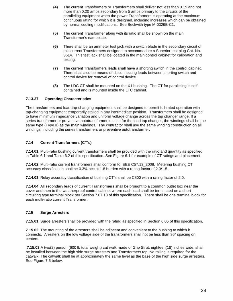
7.15.03A two(2)person (600lb total weight)cat walkmade of Grip Strut, eighteen(18)inches wide, shallbe installed between the high side surge arresters and Transformers top. No railing is required for thecatwalk. The catwalkshall be at approximately the same level as the base of the high side surge arresters.See Figure 7.5below.
29
FIGURE 7.5
7.15.04 The top terminal, of the surge arrester, shall be on same level as the top terminal of its partneredbushing.
7.15.05 The surge arresters shall be grounded per Section 7.11.02of this specification.
7.15.06 The grounding of surge arresters shall follow the methods recommended in IEEE Standard No. 80except as stated herein.
7.15.07 All surge arresters shall be provided with a NEMA 4" x4", four-hole pad:aluminum or cadmium,silver or tin plated on top for LCRA TSC to connect to.
7.15.08 The arresters protecting the XV bushings shall have a strike distance not less than 7inches.
7.15.09 APPLICABLE STANDARDS
Industry Standards
IEEE C62.11_2012-Standard for Metal-Oxide Surge Arresters for Alternating-Current Power Circuits.
GENERAL
Arresters provided shall in all respects meet the dimensional and performance requirements hereinafterstated and as stated in the above standards or the references therein. The requirements specifically statedherein shall govern should there be any conflict with the above standards or references therein. Items shallbe manufactured in a good workmanlike manner using quality material free from any defects.
7.15.10CLASSIFICATION OR RATING
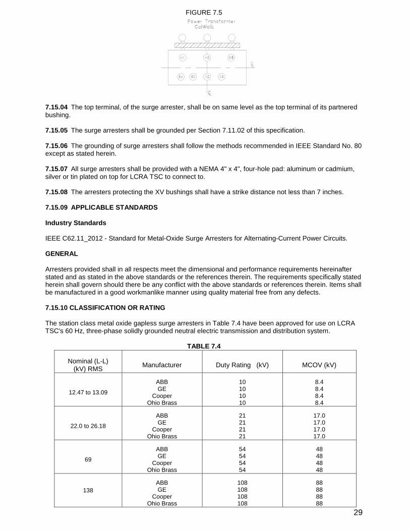
The station class metal oxide gapless surge arresters in Table 7.4have been approved for use on LCRATSC's 60Hz, three-phase solidly grounded neutral electric transmission and distribution system.
TABLE 7.4
Nominal (L-L)(kV)RMS
Manufacturer Duty Rating (kV) MCOV (kV)
12.47to 13.09
ABBGE
CooperOhio Brass
10101010
8.48.48.48.4
22.0to 26.18
ABBGE
CooperOhio Brass
21212121
17.017.017.017.0
69
ABBGE
CooperOhio Brass
54545454
48484848
138
ABBGE
CooperOhio Brass
108108108108
88888888
30
7.15.11 Pressure relief capability
The station class arrester pressure relief capability shall be 65kA RMS (symm), min.
7.15.12CONSTRUCTION
Arrester shall be metal oxide type.
Insulator to be ANSI #70(Light Gray)color.
Terminals
(1)The top terminal shall have a four-hole NEMA pad.
(2)The bottom terminal shall have an "L" bracket for attaching an Anderson Electric TLS-42type bronze eyebolt connector furnished by LCRA TSC for grounding.
(3)No connectors shall be furnished by contractor.
7.15.13INSPECTIONS-TESTS
Contractor
Contractor shall perform production and final inspections to assure that the items have beenmanufactured in accordance with the requirements specified herein.
Design tests shall be made on arrester units as described in IEEE C62.11_2012.
Routine production tests shall include the following:
(a) Radio influence voltage(b) Grading current(c) Seal integrity
7.16 Station Service
7.16.01LCRA TSC shall provide the necessary station service power for operating the load tap changerand auxiliary cooling equipment.
7.16.02The voltage available is 240/120V, single-phase, 4-wire.
7.16.03The contractor shall state single-phase kVA requirements in the Bid Proposal form.
7.16.04 The AC neutral shall be electrically isolated from the equipment ground.
7.16.05 Incoming AC terminals shall be large enough to accommodate up to and including 2/0AW Gcopper conductors.
7.16.06 Incoming terminals shall be provided for single phase, 240VAC with separate neutral and groundconductor.
7.17 Nameplate
The transformers nameplate shall be designed per IEEE C57.12.00_2015, except as stated herein.
7.18 Auxiliary W iring
7.18.01 All wiring shall by 600volt, flame resistant, moisture resistant, heat resistant, oil resistant, 90degrees Centigrade rated insulation over copper conductors.
7.18.02Each stranded conductor shall have compression type terminals. Solid conductors shall have cupwashers for screw post connections.
31
7.18.03All conductor terminations shall be designed to fit on General Electric type EB terminal blocks.
7.18.04Each end of a conductor shall be permanently tagged and identified.
7.18.05All wiring shall be bundled or contained.
7.18.06All auxiliary wiring external to the transformers shall be in rigid metallic conduit or armor flex(noPVC or plastic)with weatherproof fittings and shall not be installed across the cover.
7.19 Transformer W indings and Core
(1) All transformers windings and leads shall be copper or silver-bearing copper for allMVA ratings of transformers listed herein. No aluminum windings are allowed on anytransformers covered by this specification.
(2) The insulation of all windings shall be capable of withstanding the dielectric testscorresponding to the basic insulation level of each winding, as specified in the IEEEstandards. The voltage distribution shall be substantially uniform throughout the windings.The conductors and insulation shall be designed so the formation of partial discharge willbe minimized at the operating voltages specified herein.
(3) The conductors shall be designed so the eddy current losses are minimized and therequired mechanical strength is assured. All joints in winding conductors shall be brazed.All conductors shall be carefully smoothed to remove any burrs and slivers before theinsulation is applied. Coil winding insulation shall be high density, thermally upgraded,Dennison kraft paper for the entire length and thickness of all windings. Leads shall beinsulated with high density, thermally upgraded, creped kraft paper.
(4) All coils shall have each turn supported at frequent intervals by insulating spacers,which shall be locked or clamped in place and so arranged as to ensure positive andeffective oil circulation. All such insulating spacers shall be compressed at high pressurebefore assembling in the coil stacks in order that the coil stacks shall remain permanentlytight.
(5) Leads and lead supports shall be designed for all dielectric, mechanical, and thermaleffects that could be encountered. The design shall not permit temporary or permanentdeflection of supports and leads due to forces acting on the lead during transport orservice. Note that lead and lead support information is required in the design review perthe Design Review Requirements.
Tap leads and series or parallel crossover leads and supports shall be designed to providesignificant safety margins above the worst case dielectric stresses that would occur duringspecified lightning and switching surge and power frequency voltages, as though thesevoltages were applied at each tap position. Similarly, line leads shall be designed toprovide reasonable safety margins during these conditions.
7.19.01 Material
(1) All material used or proposed for use in the Transformers shall be tested and shallhave passed the Transformers oil compatibility test using the method outlined in ASTMD3455.
(2) All material used in the Transformers shall be subjected to rigid quality assurance andcontrol standards. The contractor shall have complete tractability on material.
7.19.02Core
(1) Each lamination or sheet of core steel shall be free from burrs, sharp projections, rust,scales, or other conditions that may impair the operation or life of the core. Eachlamination or sheet of core steel shall be sufficiently coated with a durable, oil-proof, heat-resistant insulating coating. The maximum allowable burrs on the slit or cut edge of theelectrical steel used in the core shall not exceed 0.7mils. Excessive edge or surfacedamage during manufacture may result in rejection of the core.
32
(2) Cooling surfaces and oil ducts shall be arranged so the temperature of all parts of thecore will be substantially uniform and no spot in the core will exceed an absolutetemperature at nominal operating voltage of 125degrees C, at 40degrees C ambient.
(3) The materials and methods of construction used shall be such that the core structurewill be strong, rigid, and durable and will have permanently low losses. The magneticcircuit shall be constructed of the highest-quality, non-aging grain-oriented sheet steelhaving high permeability and low losses.
(4) In core configurations other than step lap, the core gaps shall not be greater than1/16”. Gaps greater than 1/16”must be justified during the design review.
(5) The core and end frames shall be securely clamped and bolted to prevent vibrationduring operation and the core assembly shall withstand, without change of shape orposition, all stresses due to shipping, handling, and short circuits. End frames, coreclamping structures, and tie rods shall be constructed of steel. Core clamping structuresshall be insulated from the core with a high strength insulating material such as Nomex.
(6) The core induction must meet the ANSI/IEEE requirements for continuous operation at110% voltage no load, and with 105% voltage on the loaded winding at full load. Themaximum induction in the core at either of these conditions shall not exceed 1.93Tesla.
7.19.03Sound Level
The sound level on any unit shall not exceed 64dB average sound level at the ONAN rating and 67dBaverage sound level at the maximum forced cooled rating as measured by the procedures outlined in IEEEC57.12.90_2015. Sound level shall be measured on a tap setting that includes the preventive auto (ifinstalled).
7.20 Accessories and General Requirements
(1) All nuts, bolts, and washers used on the Transformers shall be non-rust stainless steelor approved equivalent. Split or star lockwashers shall not be furnished as locking orclamping devices inside the tank. Double nutting, or other methods approved by LCRATSC, shall be used for locking or clamping on the lead support framework.
(2) The contractor shall provide the following components for optional purchase by LCRATSC:
One (1)HV bushingOne (1)LV bushingOne (1)Complete itemized set of gasketsOne (1)Fan and motor assembly
(3)The contractor shall state the special tools that are required for the installation andmaintenance of the Transformers in the bid. In addition, the contractor shall provide anyspecial tools required for the installation and maintenance of the unit without additionalcost.
7.21 Gas Monitor
(1) One Calisto 2transformer gas analyzer or LCRA TSC approved equivalent shall beprovided with enclosure cabinet and alarms. All cabling between sensors and alarmcabinet shall be provided. Alarm contacts shall be provided in accordance with section7.03with one set wired to a terminal blockfor LCRA TSC use and another set wired tothe annunciator. Power supply requirements for this device shall be 1.5times themonitor manufacturer’s recommendation. The Calisto 2shall be powered by VDC fromthe control cabinet. (Internally supplied primary and customer provided backup optionsshall be available).
33
(2) The transformer tankshall be furnished with two valves to accommodate the Calisto 2,both full-opening ball type valves with a 2”NPT female end. These valves shall belocated on the same side of the transformer where the Calisto 2is to be installed. Onevalve shall be 6feet above grade level and the other at the bottom of the transformertank, both mounted to project horizontally from the tankwall. Both valves shall have a2”NPT pipe plug (male)in the open end. Both valves shall be dedicated for theCalisto 2and shall be in addition to any other valves specified herein.
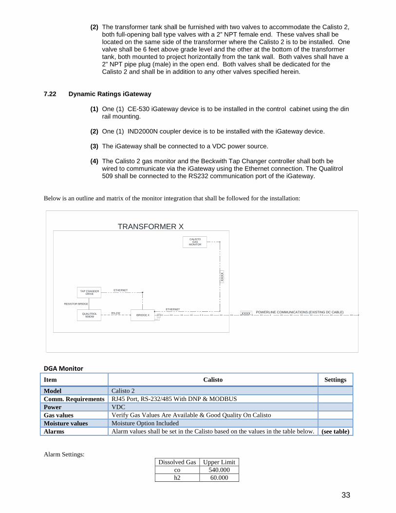
7.22 Dynamic Ratings iGateway
(1) One (1) CE-530iGateway device is to be installed in the control cabinet using the dinrail mounting.
(2) One (1) IND2000N coupler device is to be installed with the iGateway device.
(3) The iGateway shall be connected to a VDC power source.
(4) The Calisto 2gas monitor and the Beckwith Tap Changer controller shall both bewired to communicate via the iGateway using the Ethernet connection. The Qualitrol509shall be connected to the RS232communication port of the iGateway.
Below is an outline and matrix of the monitor integration that shall be followed for the installation:
XXXX POW ERLINE COMMUNICATIONS (EXISTING DC CABLE)
CALISTOGAS
MONITOR
TRANSFORMER X
QUALITROL509DW
TAP CHANGERDRIVE
ETHERNET
XX
XX
IBRIDGE X
RESISTOR BRIDGE
RS-232
ETHERNET
DG A M onitor
Item Calisto Settings
Model Calisto 2
Comm. Requirements RJ45 Port, RS-232/485 W ithDNP & MODBUS
Power VDC
Gas values Verify Gas Values Are Available & Good Quality On Calisto
Moisture values Moisture Option Included
Alarms Alarm values shall be set in the Calisto based on the values in the table below. (see table)
Alarm Settings:Dissolved Gas Upper Limit
co 540.000h2 60.000
34
8.00 DESIGN REVIEW ,DRAW INGS AND INSTRUCTION MANUALS
DESIGN REVIEW AND APPROVAL
8.01 After the contractor completes his design, LCRA TSC may, at its discretion, conduct a designreview with the contractor to review all drawings and procedures before the contractor starts construction.The design review meeting (to be held at LCRA TSC’s facilities in Austin, Texas)may be required as partof the approval drawing process. W ritten notice of the meeting shall be supplied to LCRA TSC threeweeks in advance of meeting date. The details and format of the design review shall be mutually agreedupon by LCRA TSC and the apparent successful offeror prior to placing the purchase order.
The design review will include, but is not limited to, the following topics:(1) Contractor analytical tools:
(a) Transient voltage distribution and calculation methods(b) Thermal analysis calculation methods(c) Short circuit stress calculation methods(d) Leakage magnetic field calculation methods
(2) Magnetic circuit:(a) Material(b) Core geometry and fluxdensity(c) Lamination cutting parameters(d) No load loss and excitation parameters(e) Core temperatures rise and flux density distribution in limb/yoke for nominal and
maximum excitation(f) Measures used to minimize circulating currents and stray losses in the inactive part(g) Fluxshielding locations, design and construction(h) Total core weight
(3)W inding design:(a) W inding arrangement(b) Coil design and winding material including coil types for each winding (disk, layer,
helical, pancake, etc.)(c) Type of voltage regulation and regulating winding design(d) Coil insulation(e) Voltage distribution in windings;turn-to-turn, disk-to-disk.(f) Number of turns in each disc, layer, or pancake; General description of where
winding conductor joints are permitted and quality control procedures employed toensure their integrity
(g) Clamping structure description, including materials used for phase blocking, endrings, pressure plates and special components or systems used.
(h) Number and size of axial and radial spacers used in circular windings. Number ofinsulating barriers between windings and the thickness of each barrier and oil gap
(i)Electrical and physical details of connections between adjacent windings, includingconnections between windings, crossover leads and connection to bushings
(j) Variable resistors or semiconductor elements used to protect the windings(4) Insulation, Lead, & Supporting Structure design:
(a) Major insulation clearances and their locations(b) Insulation configuration and materials(c) Voltage distribution and electrical stresses in major insulation(d) Dielectric stresses in the highly stresses regions of oil, including leads, and bottom
region of HV bushings(e) Drawings showing design, routing, and support of all leads and supporting
equipment/structure(f) Description of lead construction, including insulation used to insulate leads(g) Description of support structure for leads(h) Quality control measures taken to insure that leads have correct insulation and
proper spacing to ground, other leads or windings(i) Critical dielectric stresses between leads and other items, along with associated
margins factors(j) Description of how design limits were developed and applied
(5) Load loss and impedances(6) Thermal design:
35
(a) Cooling design(b) Heat transfer equipment(c) Average temperature and hot spot temperature calculations(d) Locations of hottest spot temperature within each winding(e) Location and magnitude of hottest oil temperature within each winding(f) Loss calculations for the core, windings and structural members(g) Hydraulic design and directional controls for the oil flow , and calculated velocities
and the heat transfer rates of the oil flow(h) Calculated top, average and bottom oil temperature rises.
(7) Leakage magnetic field analysis:(a) Control of leakage fields(b) Localized temperature calculation due to leakage fields
(8) Short circuit analysis:(c) Types of through faults considered(d) Calculation of coil stresses(e) Calculation of mechanical structure stresses
(8) Tap changer equipment:(9) Accessories:
(a) Bushings(b) Gauges(c) Controls, wiring, conduit, etc.
(10)Testing and test plan:(a) Required tests(b) Acceptance criteria(c) Applicable test standards
(11)Through-Fault Design(a) General forces –details(b) Failure Mode Analysis(c) Structural Support – description of axial and radial loading of the windings and
support(d) W inding Preparation – description of pressures, temperatures and drying process,
time, dimensional tolerances allowed, and the purpose for each step in the windingpreparation
(e) Leads and supports – description of the worst case forces acting on all leads andcrossovers. The ability of these leads and their supporting structures to withstandthese shall be described.
(f) Supportive Evidence – A certificate of successful short-circuit test experience withthis design Transformers shall be reviewed in detail as it relates to the designpractices applied to this design. Strengths of materials used, design margins andother details shall be presented.
(12) Detailed Test Plan(a) Tests and checks during the manufacturing(b) Tests for acceptance testing (per the requirements of 9.0 Testing of this technical
specifications)
8.02 Core and Coils Pre-Tanking Inspection
Three weeks prior to tanking of the wound core and coils, the contractor shall notify the LCRA TSC so itsrepresentative may be present to inspect the unit before tanking.
8.03 Testing Inspection
The contractor shall notify the LCRA TSC at least three weeks prior to factory acceptance testing of the unit,so the LCRA TSC, or it’s representative(s), may be present to witness the testing. A schedule of tests shall beincluded in this notification. The contractor shall bear the additional travel costs incurred by LCRA TSCresulting from any changes to the scheduled test dates that occur within this three weekperiod. In the event ofa test failure that requires corrective action to the transformer and re-testing at a later date, the Contractor shallbear the travel and lodging expenses of LCRA TSC’s representative(s)to attend and witness re-testing ifdesired by LCRA TSC.
8.04 Schedule
The contractor shall furnish the LCRA TSC a schedule showing his estimated design, manufacturing andtesting timetable indicating all key project approval and inspection dates. The contractor shall
36
designate/identify a focal point of contact for all communications with the LCRA TSC. The contractor shallprovide a Monthly Progress Report to the LCRA TSC. Any change in the schedule shall be coordinatedwith LCRA TSC.
GENERAL
8.05 The drawings and instruction manuals shall be furnished as specified herein.
8.06 The list of drawings and instruction manuals shall be as specified below.
8.07 The drawings and instruction manuals collectively shall contain sufficient information to enableLCRA TSC to adequately receive, assemble, install, operate, overhaul and order renewal parts for allequipment ordered.
8.08 W hen the drawings and instruction manuals for a particular order covers a range of similarequipment, the information applicable to that order must be specified.
8.09 The following information must be provided on every drawing or drawing transmittal andinstruction book:
(1) LCRA TSC's purchase order number and item number.(2) Contractor's name and order number if applicable.(3) Contractor's shop order number and/or sales order number.(4) Contractor's drawing number and title including revision number.(5) Identification as an approval or final (certified)drawing.(6) Date of transmittal.(7) Date deadline of receipt of "Approved as Noted" drawings by contractor
from LCRA TSC to maintain construction schedule.
APPROVAL DRAW INGS
8.10 The drawings listed below shall be submitted folded and collated in sets for approval.Drawings, which are not approved and/or request a revision by LCRA TSC, shall be re-submitted to LCRATSC for final approval. All drawings in the five categories listed below must be submitted on onetransmittal. LCRA TSC will not accept partial submittals at different dates.
(1) Outline -showing location of all external parts and accessories(2) Nameplate(3) W iring diagrams and schematics (including those for the LTC)(4) Control panel layout(5) Bushing and arrester outline drawings(6) Ground bar detail drawing per section 7.11.02
8.11 The contractor shall furnish six(6)sets of prints of all drawings applicable to an order for approvalby LCRA TSC unless LCRA TSC waives drawing approval in writing. W hen drawing approval is waived,certified drawings shall be substituted.
8.12 LCRA TSC will return one set of drawings marked "APPROVED EXCEPT AS NOTED" by mailor E-Mail.
Note:LCRA TSC may return a letter, fax, or E-Mail indicating no changes or comments in lieu of returningdrawings if there are no comments.
This action by LCRA TSC does not relieve contractor of responsibility of (1)strict adherence to thespecifications except where deviation is fully described in writing by LCRA TSC and (2)for corrections ofengineering, draftsmanship, design, workmanship, materials, and all other matters and liabilitieshereunder, such as product liability and delivery schedule.
8.13 Approval drawings shall also be supplied in AutoCAD 2012or DXF format for an IBM-compatiblePC. All drawing files shall be submitted on a CD-ROM magnetic media labeled with all transmittalinformation. Computer disks shall be shipped in a protective-shipping container. The disks shall be clearlylabeled with the purchase order number and item number. In lieu of a CD-ROM, drawings may be E-Mailed to LCRA TSC if desired.
37
CERTIFIED FOR CONSTRUCTION DRAW INGS
After contractor receives approval drawings from LCRA TSC, any Changes shall be made per LCRA TSC’srequest along with any other changes the contractor’s changes at that time shall be incorporated into thedrawings. These revised drawings shall be sent to LCRA TSC as noted above (sixsets of printed drawings,AutoCAD data disks). These drawings shall be sent as immediate as practicable (ASAP)to LCRA TSC. Thisis to allow LCRA TSC to proceed with design. These drawings shall be noted as “Certified for Construction.”
FINAL AS-BUILT DRAW INGS
The following drawings, if applicable, shall be issued to LCRA TSC as final drawings. Also, one set ofdrawings shall be located in the control cabinet.
(1) Outline(2) Nameplate(3) W iring diagrams(4) Shipping outlines(5) Bushings(6) Arresters(7) Inert-gas system cabinet(8) Fan Mounting(9) Current Transformers excitation curves(10) Ground bar detail drawing
After equipment is completely built per LCRA TSC’s and manufacture’s specifications, Final As-Builtdrawings shall be produced and supplied to LCRA TSC as described in section 8.14.
8.14 Contractor shall furnish;
Six(6)sets of good quality drawing prints for each item listed on LCRA TSC's purchase order.
One (1) set of drawing prints packaged in a weatherproof container and sent with each and everyequipment unit ordered.
One (1)set of drawings in AutoCAD 2012 or DXF format on CD-ROM properly labeled with all transmittalinformation. Drawings may be E-mailed to the LCRA TSC if desired.
8.15 All final as-built drawings must be submitted rolled (not folded)in a regular mailing tube, except for8-1/2x11" drawings capable of being placed in an envelope with a cardboard backing.
8.16 The final as-built drawings shall be forwarded in the most expeditious manner. Final drawings areto be received prior to receipt and payment for the order.
INSTRUCTION MANUALS
8.17 The instruction manual shall contain the LCRA TSC's name, purchase order number andcontractor's sales order number and/or shop order number.
8.18 The instruction manual shall have an index giving the name and identification number of theinformation bulletins (I.B.'s)contained therein.
8.19 The I.B.'s shall have complete information on shipping, receiving, installation, operation andmaintenance instructions as well as renewal parts lists for all parts. Specifically and in addition to therequirements herein, the I.B.'s will include the following:
(1) Good schematics for trouble shooting electronic modules, showing howeach module is incorporated into the control schematic of the equipment.
(2) Sufficient information for obtaining electronic parts from local sources.Include cross-reference to Motorola, Texas Instruments and the like.
38
(3) Any "O" ring and gasket information such as material, size, lubrication oradhesive data.
8.20 Six(6)sets of instruction manuals for each item of the purchase order shall be received by LCRATSC prior to receipt of order.
8.21 One (1)set of instruction manuals shall be in a weatherproof container and placed in a holdingdevice within the control cabinet of each and every unit listed on the purchase order or subsequent changeorders thereto.
8.22 If instruction manuals are available on word processing format, these shall be so supplied on CDROM in MS W ord or PDF format. The electronic version of the manual shall have each file or folder clearlylabeled with it’s contents.
8.23 Supplemental Drawings
The contractor shall supply one set of drawings and color photographs showing the physical assembly ofthe Transformer’s internal components to assist in troubleshooting and/or partial overhaul of the unit.
9.00 INSPECTIONS-TESTS
9.01 Contractor
9.01.01 Factory Tests
The contractor shall test all items manufactured under these specifications. Any items, which do not meetall of the requirements of this specification, shall not be shipped to LCRA TSC. Such tests shall includethe following tests, which shall be performed on the full transformers with all of its appurtenances andaccessories (such as bushings, radiators and fans)attached as specified in IEEE C57.12.00_2015and inaccordance with applicable sections of IEEE Standard C57.12.90_2015. Only bushings that are to besupplied and shipped with the transformers shall be used during all tests. All test results shall be recordedand made available to LCRA TSC. Should a dielectric test failure occur that requires entry into thetransformer tankto correct, all dielectric tests shall be re-performed.
The following test sequence shall be used:
1)Routine Tests2)Load Loss Measurements3)No Load Loss and Excitation Current Measurements4)110% Excitation Test5)Temperature Rise Tests6)Impulse Test7)Applied Test8)Induced Test with PD Measurement9) No Load Loss and Excitation Current Measurements10) Sound Test11) Sweep Frequency Response Analysis (SFRA)Measurements/Traces.
Required tests shall include the following.
(a) Resistance measurements on the rated voltage connection and at all tap extremes.All resistance values shall be converted to 20deg. C temperature.
(b) Contact resistance measurements of each contact of the LTC.
(c) Hi-potential test of vacuum bottles in the LTC.
(d) Ratio and regulation tests.
(e) Polarity and phase relation tests on all windings and BCTs.
39
(f) No load loss at rated voltage and at 110% rated voltage before and after impulsetests. Tests shall be performed at LTC positions 16L, Neutral, 1R, and 16R.
(g)Exciting current at rated voltage and at 110% rated voltage. The contractor shallperform a 24-hour excitation test at 110% voltage. Oil samples shall be taken for gas in oilanalysis immediately before and after the excitation test. The measured gas levels shall becorrected to an equivalent 10,000gallon oil level before comparison. The maximumincreases in the gas levels based on the 10,000gallon level are as shown:
Ethylene 1ppmMethane 2ppmEthane 2ppmAcetylene Non detectable
(h)Measured impedance, both positive and zero sequence.
(i) Load loss and auxiliary loss at base 65oC rise over ambient rating, and at maximum
65oC rating.
(j) IEEE temperature test shall be made on all units. If LCRA TSC elects to not have atemperature test on an established unit, the offeror will subtract the ”Temperature TestCredit”from the Lump Sum Firm Price. The “Bid Proposal”will have a line item for the“Temperature Test Credit”.
Temperature rise tests at self-cooled and maximum forced cooled ratings. . Oil samplesshall be taken for gas in oil analysis both before and after temperature rise testing. Testresults and the contractor’s analysis shall be submitted to LCRA TSC prior to acceptancefor shipment. Any increased level of combustible gases between the “before”and “after”tests shall be addressed by the contractor and presented to LCRA TSC for approval. Themeasured gas levels shall be corrected to an equivalent 10,000gallon oil level beforecomparison. The maximum increases in the gas levels based on the 10,000gallon levelare as shown:
Hydrogen 20ppmEthylene 3ppmMethane 5ppmEthane 5ppmAcetylene Non detectableCarbon Monoxide 75ppmCarbon Dioxide 250ppm
(k)Applied potential tests. The applied voltage test shall be made in accordance with theappropriate IEEE standards.
(l)Induced potential tests as specified in IEEE C57.12.90_2015. Also, partial dischargetesting and measurements must be taken during the test, including the one hour durationtest. Partial discharge measurements shall be taken on all HV and LV terminals and meetthe requirements below. Failure will be as specified in IEEE C57.12.90_2015, section10.8.5. Oil samples shall be taken before and again eight (8)hours after induced tests,same as 9.01.01(j)above.
1)The partial discharge shall be measured and recorded at the 150% level as thevoltage is being increased to the enhancement level of 173% .2)The partial discharge shall be measured and recorded on the HV terminals atthe enhancement level.3)The first reading at 150% following the enhancement shall be taken five (5)minutes after the voltage reaches the 150% level and every five (5)minutesthereafter for one (1)hour.4)The partial discharge level shall not exceed 300picocoulombs during the hour.The partial discharge level shall not increase more than 100picocoulombs duringthe hour using the value at 150% prior to the enhancement as the base reading.There shall be no continuous increase during the hour or during the last 20minutes of the hour.
40
5)In the event that the 300picocoulomb limit, the 100picocoulomb increase, orthe continuous increase requirement is exceeded, the cause shall be determinedand corrected.
(m)Insulation power factor test by IEEE C57.12.90_2015, Method II, (not to exceed
0.5% corrected to 20oC). Insulation power factor tests shall be performed with either“Doble”M2HD or the M4000test systems. Reports shall be delivered in both the “DobleTest Assistant”version 3.06(or later)and on printed test reports included with the certifiedtest results. The required test and the methods to be followed are stated in IEEE Std.C57.12.90_2015section 10.10. In Table 4Method II is the required technique.
(n)Insulation resistance test. Each winding to ground and to other windings and core toground shall be tested. (Core to ground test shall be made just prior to shipment.)Insulation resistance measurements shall be performed when the unit under test is atambient temperature. The insulation resistance tests shall include the HV to LV andground, HV to ground, HV to LV, LV to HV and ground, LV to ground, and LV to HV.These tests shall be performed with instrumentation that includes a guard circuit. Printedtest results will be included with certified test results. Test voltage and time duration ofeach test shall be included in the documentation
(o)Leaktest on tanks, coolers, and piping. Test shall be conducted using the followingprocedure:
Pull a vacuum of 1TorrClose valve connecting the Transformers to the vacuum pumpBegin monitoring the pressureMaximum permissible Torr rise after 15minutes is 0.20Torr.
(p)Dew point test:Test shall be made of the sealing gas prior to shipping. However, thecontractor must wait a minimum of 48hours after installing the gas before taking the dewpoint test. Contractor shall include tankpressure and winding temperature at time of test.Acceptable dew point shall indicate the moisture content in the insulating paper is lessthan 0.5% and shall be less than the allowable maximum dew point as calculated in theformula:
Max. dew point in °C <[0.75x(W inding temp in °C –80)]
(q)Insulating oil test. Contractor shall supply LCRA TSC specifications on which oil wasordered and from which refiner and oil test data performed by the refiner shall be provided.Oil must be certified non-PCB.
(r)The contractor shall perform the Lightning Impulse Tests per IEEE C57.12.90_2015section 10.3and C57.98_2011except that tolerance on crest voltage magnitude forimpulse tests shall be minus 0.5% . The impulse circuit and measuring connections shallremain unchanged during calibration and full wave tests. All windings and neutrals shallbe tested for the BIL specified. H1, H2, H3, X1, X2, and X3winding tests shall consist of:
One (1)Reduced Full W aveOne (1)Full W aveTwo (2)Chopped W avesTwo (2)Full W avesOne (1)Reduced Full W ave
Neutral tests shall consist of:
One (1)Reduced Full W aveThree (3)Full W avesOne (1)Reduced Full W ave
Oil samples shall be taken before and after impulse tests, same as above.
The required crest voltage for the LI tests shall be increased if the actual front timeexceeds 2.0µs or the actual tail time (time to 50% crest value)is less than 40µs. If the
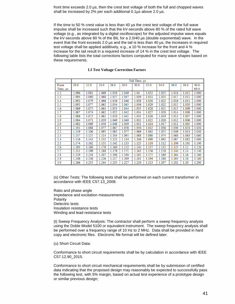
41
front time exceeds 2.0µs, then the crest test voltage of both the full and chopped wavesshall be increased by 2% per each additional 0.1µs above 2.0µs.
If the time to 50% crest value is less than 40µs the crest test voltage of the full waveimpulse shall be increased such that the kV-seconds above 80% of the rated full wavevoltage (e.g., as integrated by a digital oscilloscope)for the adjusted impulse wave equalsthe kV-seconds above 80% of the BIL for a 2.0/40µs (double exponential)wave. In theevent that the front exceeds 2.0µs and the tail is less than 40µs, the increases in requiredtest voltage shall be applied additively, e.g., a 10% increase for the front and 4%increase for the tail result in a required increase of 14% in the crest test voltage. Thefollowing table lists the total corrections factors computed for many wave shapes based onthese requirements.
LITest Voltage Correction Factors
(s)Other Tests:The following tests shall be performed on each current transformer inaccordance with IEEE C57.13_2008:
Ratio and phase angleImpedance and excitation measurementsPolarityDielectric testsInsulation resistance testsW inding and lead resistance tests
(t)Sweep Frequency Analysis:The contractor shall perform a sweep frequency analysisusing the Doble Model 5100or equivalent instrument. The sweep frequency analysis shallbe performed over a frequency range of 10Hzto 2MHz. Data shall be provided in hardcopy and electronic files. Electronic file format will be defined later.
(u)Short Circuit Data:
Conformance to short circuit requirements shall be by calculation in accordance with IEEEC57.12.90_2015.
Conformance to short circuit mechanical requirements shall be by submission of certifieddata indicating that the proposed design may reasonably be expected to successfully passthe following test, with 5% margin, based on actual test experience of a prototype designor similar previous design;
42
The transformer must successfully withstand five short circuits, including at least one fullyoffset (asymmetrical)fault per phase. Each short circuit test shall be at least 60cycles induration with the primary voltage maintained within a range of 95% to 105% of rated tapvoltage during the course of the test.
(v)Control and Power W iring:
Low frequency withstand voltage tests shall be performed on all control and secondarywiring. All low voltage wiring including control and indication wiring shall be given acontinuity check. All control circuits shall be functionally tested by simulating internal andexternal control functions. All Current Transformers Ratio and Polarity Tests are to beverified. A written checklist, dated and signed by the technician(s)performing the tests,shall be provided with each transformer to show compliance with this requirement andincluded with test report documentation.
(w) Test data shall be submitted to the LCRA TSC prior to notification for shipment. Sixsets of certified test data shall be furnished to the LCRA TSC for each unit.
(x) In addition to routine and other tests that are part of the Customer witness testing, itis also required that all transformer monitoring and detection systems be powered on andfunctioning at the time of witness testing with the exception of the gas monitoring system.Monitoring and detection systems that require additional field labor to wire up and makeoperational due to incomplete factory installation will be billed to the Contractor at LCRATSC’s prevailing labor and equipment rates and will require Contractor personnel to bepresent at time of monitor commissioning.
9.01.02Field Tests and Final Field Acceptance
Any inspection, special testing and correction of the transformers which is necessary due to damage,abnormal impact recorder readings, no positive gas pressure, abnormal core to ground insulation resistance,or PCB contamination will be at the expense of the contractor.
LCRA TSC will complete the tests listed below. The final acceptance of the transformers will be based onthe results of these tests. If these tests limits are not achieved, the contractor shall find and correct theproblem prior to processing of the contractors invoice for the unit.
If the Contractor is performing these tests as part of a turn-key installation, the Contractor shall provide adetailed report of the results of each of the tests included in this section.
1)Take a DC core ground resistance measurement. This measurement shall be withinthe limits specified by the contractor in its Instruction and Maintenance Manual.2)Make insulation power factor measurements of the transformers. The power factorshall be less than 0.5% uncorrected.3)Take C1and C2power factor measurements and capacitance measurements of allcapacitance graded bushings. These values shall not deviate by more than 10% from thevalues stamped on the nameplate.4)Make single phase excitation tests. The patterns generated by these tests shall matchthose that were made by the contractor at the factory. The current generated by thesetests shall match the currents measured by the contractor in the factory.5)Make turns ratio measurements from 16R to 16L on each phase. All ratios shall bewithin 0.5% of the nameplate values.6)Make DC winding resistance measurements on each phase from 1R to 16L at themaximum DETC position. Readings on each phase shall be within +1% of the adjacentphases.7)Make single phase and three phase leakage reactance tests at the neutral tappositions. Measurement shall be within +5% of the nameplate value.8)Make the oil tests to verify the physical, electrical and chemical properties defined inAppendixA.9)CT ratio and polarity (Ratio CTs with current and voltage to cabinet terminal blocks)10)Functional checkall control and alarm points.11)Functional checkof all protective devices.12)A Sweep Frequency Analysis will be performed on the unit and the results will becompared with analysis performed at the factory. The contractor shall find and correct anyproblems that are found from the results of the analysis.
43
9.02 Contractor
The contractor shall assure that all items, which have been in the contractors’possession and scope of supply,have been inspected and are in compliance with this specification.
9.03 LCRA TSC
9.03.0l LCRA TSC reserves the right to be present to observe any tests or inspections performed on theitems. In the event of test failures that require corrective action to the transformer and re-testing at a laterdate, the contractor shall bear the travel and lodging expenses of LCRA TSC to attend and witness re-tests if the witnessing of the re-tests is desired by LCRA TSC.
9.03.02 LCRA TSC may test or cause to be tested any item furnished under this specification.
9.03.03 LCRA TSC will check the entire unit including the gas pressure and any impact recorder(s)forvisual evidence of shipping damage within 72 hours after arrival. Otherwise a representative of thecontractor will make this inspection. In either case the contractor shall notify the carrier of possibleconcealed damage. A copy of this notice shall be sent to LCRA TSC.
9.04 Notification for Coordination
9.04.01 All correspondence pertaining to this order concerning engineering and testing shall beaddressed to:
LOW ER COLORADO RIVER AUTHORITYRobert vanTol3505Montopolis Blvd.Austin, Texas 78744Area Code 800-776-5272;X4498
9.04.02 All correspondence shall include the LCRA TSC's purchase order number and a description of thepertinent items.
10.00 Shipping
10.01 The contractor shall notify LCRA TSC of:
(1) The date unit is to be shipped.
(2) The date and expected arrival time, carrier, and freight bill number when applicable.
(3) Notification 96hours prior to arrival.
10.02 If units are shipped from outside the United States and are subject to Customs Inspection,LCRA TSC shall be notified if the units are to be held for inspection. If the units are to be opened forinspection, LCRA TSC shall be notified and the opening shall be delayed until LCRA TSC is able to sendtheir representative to witness the opening. If the unit is drained of oil or physically entered for inspection,the unit shall be returned to the manufacturing facility of origin for vapor-phase processing, inspection forinternal cleanliness and correct phase to ground clearances, and re-performance of applied voltage tests.
10.03 Impact Recorder
Each vehicle carrying the transformer or transformer parts shall have a digital impact recorder, owned by thecontractor, attached to the transformer. The recorder shall be in good working order and capable of recordingduring the complete shipment period. The recorder shall be capable of recording impact in a three-axiscoordinate system and shall have GPS and communications capabilities to allow LCRA TSC to login andcheck the location and impact data during shipment. The recorder shall be the strip chart inertia type only.LCRA TSC will deem malfunctioning or missing recorder as if the recorder is showing high impact reading.Impact acceptance criteria shall not exceed the recommended limits defined in Article 4.3.1 of IEEEC57.93_2007.
44
11.0 SERVICING AND ASSEMBLY
11.01 Service Personnel
11.01.01 The services of an authorized service representative to inspect the unit and to assist theLCRA TSC's personnel in preparing the transformers for service shall be furnished by the contractor.
11.01.02 LCRA TSC shall notify the contractor at least two weeks prior to the scheduled time for theinstallation and inspection of the transformers.
11.01.03 The number of days of service time will vary with the complexity of the individualtransformers but in no case shall the time be less than two (2)days. Two days of service rep time shall beincluded in the price of each transformer unit ordered.
11.01.04 This time shall include the core and coil inspection, bushing and radiator installation, vacuumoil-filling and testing as required from the condition of the transformers after arrival.
11.01.05 As an option, LCRA TSC may request the contractor provide turn-key installation of thetransformers as a replacement for the requirements of 11.01.01, 11.01.02, 11.01.03, and 11.01.04above.The Contractor shall provide pricing for turn-key installation as requested by LCRA-TSC. If turn-keyinstallation is requested by LCRA TSC, the field tests listed in 9.01.02 shall be performed by theContractor.
11.02 Contractor's Requirements
Any contractor's requirements regarding servicing and assembly shall be stated in the Instruction Manualper Section 8.19of this specification.
11.03 LCRA TSC Requirements
The LCRA TSC will be responsible for normal servicing of the transformers. Normal service to atransformers shall be:
(1) Installation of bushings and surge arresters(2) Installation of radiators and fans(3) Adjusting oil level
All additional assembly shall be done at the contractor's expense.
12.0 APPENDIXAppendixA -OIL SPECIFICATIONAppendixB -SAFETY HOIST REFERENCE DRAW INGS

45
APPENDIX A
46Rev: March2017, Page 1 Doble Engineering Company, 85 W alnut Street, W atertown, MA 02472 USA
TRANSFORMER OIL PURCHASE SPECIFICATIONS(Developed Under the Auspices of the Doble Oil Committee)
March, 2017
COMPOSITION
This specifications covers new insulating oil for general applications for liquid-filled electrical equipment,which are manufactured from mineral crude, which may be either naphthenic, which has a very lownaturally occurring n-paraffin (wax)content, or paraffinic, which contain substantial n-paraffins. Distillatesmay be refined using a number of processes, such as hydro-refining, solvent extraction, distillation, orother suitable means to yield acceptable mineral insulating oils at the point of delivery.
ADDITIVES
All additives must be specifically identified or at a minimum identified by class of compounds if the specificinformation is proprietary. An additive is defined as a suitable chemical substance, which is deliberatelyadded to a mineral insulating oil to improve certain characteristics. Some common examples would bepour point depressants, gassing tendency improvers, metal passivators to help mitigate corrosive sulfur,static electrification or improve oxidation stability, and antifoaming agents..
OXIDATION STABILITY
Uninhibited oils must be free of additives that are used to improve oxidation stability. This includes butare not limited to 2,6 ditetiary-butyl phenol, 2,6 dietertiary-butyl cresol, or metal deactivators such asbenzotriazole and its derivatives.
Inhibited oils are insulating oils, which have been supplemented with either 2,6 ditetiary-butyl phenol or2,6dietertiary-butyl-p-cresol or any other specified and acceptable oxidation inhibitor. If an additive otherthan 2,6 ditetiary-butyl phenol or 2,6 dietertiary-butyl-p-cresol is used, appropriate limit values foroxidation stability tests (those for Type I or Type II oils)should be agreed to by the purchaser and seller.
Oils with any detectable amounts of passivator will be assessed using the oxidation stability limits forType II oils.
PRODUCTION AND SHIPPING
Shipping containers should be dedicated to new transformer oils. It is recommended that if these cannotbe provided, the purchaser should approve the cleaning process and documentation related to it prior touse. Recommended cleaning process is steam cleaning followed by hot air drying without the use of adetergent.
The shipping method and containers once agreed upon by purchaser and seller shall not be changedwithout prior approval of the purchaser.
For some applications, purchasers may use the oil without first degassing. In such cases it is of benefitto test the oil for dissolved gas analysis to obtain baseline data and to avoid introduction of highcombustible gases into equipment.
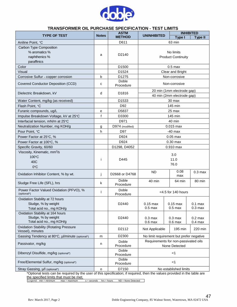
47Rev: March2017, Page 2 Doble Engineering Company, 85 W alnut Street, W atertown, MA 02472 USA
TRANSFORMER OIL PURCHASE SPECIFICATION -TESTLIMITS
TYPE OF TEST NotesASTM
METHOD UNINHIBITEDINHIBITED
Type I Type II
Aniline Point, °C D611 63min
Carbon Type Composition
% aromatics %
naphthenics %
paraffinics
a D2140No limits
Product Continuity
Color D1500 0.5max
Visual D1524 Clear and Bright
Corrosive Sulfur –copper corrosion b D1275 Non-corrosive
Covered Conductor Deposition (CCD) cDoble
Procedure Non-corrosive
Dielectric Breakdown, kV d D181620min (1mm electrode gap)
40min (2mm electrode gap)
W ater Content, mg/kg (as received) D1533 30max
Flash Point, °C D92 145min
Furanic compounds, ug/L e D5837 25max
Impulse Breakdown Voltage, kV at 25°C f D3300 145min
Interfacial tension, mN/m at 25°C D971 40min
Neutralization Number, mg KOH/g g D974(modified) 0.015max
Pour Point, °C h D97 -40max
Power Factor at 25°C, % D924 0.05max
Power Factor at 100°C, % D924 0.30max
Specific Gravity, 60/60 D1298, D4052 0.910max
Viscosity, Kinematic, mm2/s
100°C
40C
0°C
i D445
3.0
11.0
76.0
Oxidation Inhibitor Content, % by wt. j D2668or D4768ND 0.08
max0.3max
Sludge Free Life (SFL), hrs kDoble
Procedure40min 64min 80min
Power Factor Valued Oxidation (PFVO), %(optional*) l
DobleProcedure
<4.5for 140hours
Oxidation Stability at 72hours
Sludge, % by weight
Total acid no., mg KOH/g
D2440 0.15max0.5max
0.15max0.5max
0.1max0.3max
Oxidation Stability at 164hoursSludge, % by weightTotal acid no., mg KOH/g
D2440 0.3max0.6max
0.3max0.6max
0.2max0.4max
Oxidation Stability (Rotating PressureVessel), minutes
D2112 Not Applicable 195min 220min
Gassing Tendency at 80°C, µl/minute (optional*) m D2300 No limit requirement but prefer negative
Passivator, mg/kg nDoble
Procedure
Requirements for non-passivated oils
None Detected
Dibenzyl Disulfide, mg/kg (optional*)Doble
Procedure <1
Free/Elemental Sulfur, mg/kg (optional*)Doble
Procedure <1
Stray Gassing, µ/l (optional*) o D7150 No established limits*Optional tests can be required by the user of this specification;if required, then the values provided in the table arethe specified limits that must be met.Legend: min =minimum max=maximum s =seconds hrs =hours ND =None Detected
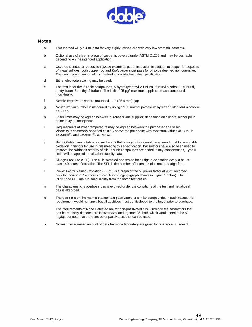
48Rev: March2017, Page 3 Doble Engineering Company, 85 W alnut Street, W atertown, MA 02472 USA
Notes
a This method will yield no data for very highly refined oils with very low aromatic contents.
b Optional use of silver in place of copper is covered under ASTM D1275and may be desirabledepending on the intended application.
c Covered Conductor Deposition (CCD)examines paper insulation in addition to copper for depositsof metal sulfides;both copper rod and Kraft paper must pass for oil to be deemed non-corrosive.The most recent version of this method is provided with this specification.
d Either electrode spacing may be used.
e The test is for five furanic compounds, 5-hydroxymethyl-2-furfural, furfuryl alcohol, 2-furfural,acetyl furan, 5-methyl-2-furfural. The limit of 25µg/l maximum applies to each compoundindividually.
f Needle negative to sphere grounded, 1-in (25.4-mm)gap
g Neutralization number is measured by using 1/100normal potassium hydroxide standard alcoholicsolution.
h Other limits may be agreed between purchaser and supplier;depending on climate, higher pourpoints may be acceptable.
i Requirements at lower temperature may be agreed between the purchaser and seller.Viscosity is commonly specified at 10°C above the pour point with maximum values at -30°C is1800mm2/s and 2500mm2/s at -40°C.
j Both 2,6-ditertiary butyl-para cresol and 2,6-ditertiary butyl-phenol have been found to be suitableoxidation inhibitors for use in oils meeting this specification. Passivators have also been used toimprove the oxidation stability of oils. If such compounds are added in any concentration, Type IIlimits will be applied to oxidation stability data.
k Sludge-Free Life (SFL):The oil is sampled and tested for sludge precipitation every 8hoursover 140hours of oxidation. The SFL is the number of hours the oil remains sludge-free.
l Power Factor Valued Oxidation (PFVO)is a graph of the oil power factor at 95°C recordedover the course of 140hours of accelerated aging (graph shown in Figure 1below). ThePFVO and SFL are run concurrently from the same test set-up
m The characteristic is positive if gas is evolved under the conditions of the test and negative ifgas is absorbed.
n There are oils on the market that contain passivators or similar compounds. In such cases, thisrequirement would not apply but all additives must be disclosed to the buyer prior to purchase.
The requirements of None Detected are for non-passivated oils. Currently the passivators thatcan be routinely detected are Benzotriazol and Irgamet 36, both which would need to be <1mg/kg, but note that there are other passivators that can be used.
o Norms from a limited amount of data from one laboratory are given for reference in Table 1.
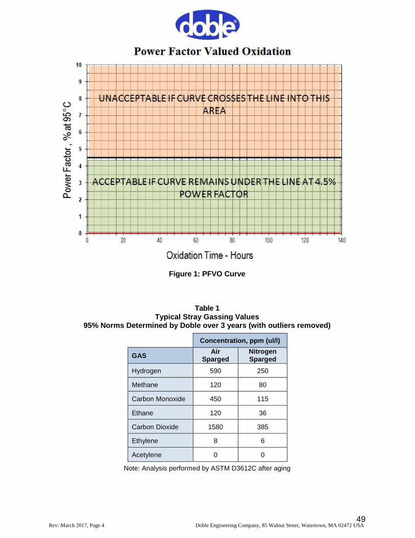
49Rev: March2017, Page 4 Doble Engineering Company, 85 W alnut Street, W atertown, MA 02472 USA
Figure 1:PFVO Curve
Table 1Typical Stray Gassing Values
95% Norms Determined by Doble over 3years (with outliers removed)
Concentration,ppm (ul/l)
GASAir
SpargedNitrogenSparged
Hydrogen 590 250
Methane 120 80
Carbon Monoxide 450 115
Ethane 120 36
Carbon Dioxide 1580 385
Ethylene 8 6
Acetylene 0 0
Note:Analysis performed by ASTM D3612C after aging
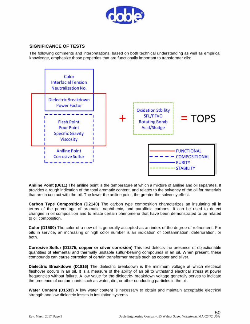
50Rev: March2017, Page 5 Doble Engineering Company, 85 W alnut Street, W atertown, MA 02472 USA
SIGNIFICANCE OF TESTS
The following comments and interpretations, based on both technical understanding as well as empiricalknowledge, emphasize those properties that are functionally important to transformer oils:
Aniline Point (D611)The aniline point is the temperature at which a mixture of aniline and oil separates. Itprovides a rough indication of the total aromatic content, and relates to the solvency of the oil for materialsthat are in contact with the oil. The lower the aniline point, the greater the solvency effect.
Carbon Type Composition (D2140)The carbon type composition characterizes an insulating oil interms of the percentage of aromatic, naphthenic, and paraffinic carbons. It can be used to detectchanges in oil composition and to relate certain phenomena that have been demonstrated to be relatedto oil composition.
Color (D1500)The color of a new oil is generally accepted as an indexof the degree of refinement. Foroils in service, an increasing or high color number is an indication of contamination, deterioration, orboth.
Corrosive Sulfur (D1275,copper or silver corrosion)This test detects the presence of objectionablequantities of elemental and thermally unstable sulfur-bearing compounds in an oil. W hen present, thesecompounds can cause corrosion of certain transformer metals such as copper and silver.
Dielectric Breakdown (D1816)The dielectric breakdown is the minimum voltage at which electricalflashover occurs in an oil. It is a measure of the ability of an oil to withstand electrical stress at powerfrequencies without failure. A low value for the dielectric-breakdown voltage generally serves to indicatethe presence of contaminants such as water, dirt, or other conducting particles in the oil.
W ater Content (D1533)A low water content is necessary to obtain and maintain acceptable electricalstrength and low dielectric losses in insulation systems.
51Rev: March2017, Page 6 Doble Engineering Company, 85 W alnut Street, W atertown, MA 02472 USA
Flash Point (D92)The flash point is the minimum temperature at which heated oil gives off sufficientvapor to form a flammable mixture with air. It is an indicator of the volatility of the oil.
Furanic Compounds (D5837) Furanic compounds are byproducts of the degradation of cellulosicmaterials such as insulating paper, pressboard, and wood and serve as indicators of insulationdegradations in service. Use of 2-furfural as an extraction solvent can be an unintended source of furans ifnot properly removed as part of the refining process. To ensure a low baseline, no significant furaniccompounds should be present in new oil.
Impulse Breakdown Voltage (D3300)The impulse breakdown voltage is the voltage at which electricalflashover occurs in an oil under impulse conditions. It indicates the ability of an oil to resist transientvoltage stresses such as those caused by nearby lightning strokes and high-voltage switching surges. Theresults are dependent on electrode geometry, spacing, and polarity.
Interfacial Tension (D971)The interfacial tension of an oil is the force in mN/m required to rupture theoil film existing at an oil-water interface. W hen certain contaminants such as soaps, paints, varnishes,and oxidation products are present in the oil, the film strength of the oil is weakened, thus requiringless force to rupture. For oils in service, a decreasing value indicates the accumulation ofcontaminants, oxidation products, or both.
Neutralization Number (D974)The neutralization number of an oil is a measure of the amount of acidicor alkaline materials present. As oils age in service, the acidity and therefore the neutralization numberincreases. A used oil having a high neutralization number indicates that the oil is either oxidized orcontaminated with materials such as varnish, paint, or other foreign matter. (A basic neutralization numberresults from an alkaline contaminant in the oil.)
Pour Point (D97)The pour point is the lowest temperature at which oil will just flow. A low pour point isimportant, particularly in cold climates, to ensure that the oil will circulate and serve its purpose as aninsulating and cooling medium.
Power Factor (D 924)The power factor of an insulating oil is the cosine of the phase angle between asinusoidal potential applied to the oil and the resulting current. Power factor indicates the dielectric loss ofan oil;thus the dielectric heating. A high power factor is an indication of the presence of contamination ordeterioration products such as moisture, carbon or other conducting matter, metal soaps and products ofoxidation.
Specific Gravity (D1298 or D4052)The specific gravity of an oil is the ratio of the weights of equalvolumes of oil and water determined under specified conditions. In extremely cold climates, specific gravityhas been used to determine whether ice, resulting from the freezing of water in oil-filled apparatus, willfloat on the oil and possibly result in flashover of conductors extending above the oil level. The specificgravity of mineral oil influences the heat transfer rates. Oils of different specific gravity may not readily mixwhen added to each other and precautions should be taken to ensure mixing.
Oxidation Inhibitor Content (D2668, D4760) These tests provide a method for the quantitativedetermination of the amount of oxidation inhibitor (2,6-ditertiary butyl-paracresol or 2,6 ditertiary phenol)present in an inhibited oil. Control of the inhibitor content is an important factor in maintaining long servicelife of inhibited insulating oils.
Power Factor Valued Oxidation (PFVO)This test, developed by the Doble Engineering Company,periodically measures the power factor of an oil while over a 140 hour period it is being aged at 95°C inthe presence of copper and air. The resulting graph of power factor versus time is characteristic of an oiland is a continuity test, as well as a measure of oil quality. The test is run concurrently with the DobleSludge-Free Life test that measures the time until the oil forms sludge.
Oxidation Stability (acid/sludge)(D2440)This is a method of assessing the oxidation resistance of anoil by determining the amount of acid and sludge products formed under laboratory accelerated agingconditions. Oils which satisfy the requirements tend to preserve insulation system life and ensure
52Rev: March2017, Page 7 Doble Engineering Company, 85 W alnut Street, W atertown, MA 02472 USA
acceptable heat transfer. The test may also be used to checkthe performance consistency of this characteristic ofproduction oils.
Oxidation Stability (D2112)This test is used as a control test for evaluating the response characteristics of newoils to oxidation inhibitors. It may also be used to checkthe performance consistency of production oils.
Gassing Under Electrical Stress (D2300)The gassing tendency is defined as the rate of gas evolved or absorbedby an insulating oil when subjected to electrical stress of sufficient intensity to cause ionization. The value is positiveif gas is evolved and negative if gas is absorbed. Direct correlation of results with equipment performance is limitedat present.
Polychlorinated Biphenyls (D4059) Regulations prohibiting the commercial distribution of polychlorinatedbiphenyls (PCBs)mandate that insulating oils be examined for PCB contamination levels to assure that newproducts do not contain detectable amounts.
Viscosity (D445)Viscosity is the resistance of oil to flow under specified conditions and is an important factor inassessing ability to act as an effective coolant as it influences heat transfer rates and consequently the temperaturerise of an apparatus. The viscosity of an oil also influences the speed of moving parts in tap changers and circuitbreakers. High viscosity oils are less desirable, especially in cold climates. Standard viscosity curves can begenerated using Method D341.
Passivators (Doble Procedure)Passivators, also known as metal deactivators, are sometimes added to an oil toimprove oxidation stability and also to reduce the rate of metal sulfide reactions.
Dibenzyl Disulfide Detection (DBDS)(Doble Procedure)DBDS is a corrosive sulfur compound that has been foundin a number of oils known to be involved in metal sulfide deposits inside transformers in service.
Free/Elemental Sulfur (Doble Procedure)This is a very reactive form of sulfur that has been associated withtransformers experiencing corrosive sulfur problems.
Stray Gassing (ASTM D7150)This test is used to evaluate the amount of combustible gases generated by an oilafter seven days at 120°C. The oil is prepared by sparging one set of samples with oxygen and another set withnitrogen. This is used to simulate the preservation system in use and can influence the type and amount of gasesgenerated in service. An understanding of the tendency of an oil to generate gases at moderate temperatures isbeneficial when interpreting DGA data of the transformer in service.

53
APPENDIX B
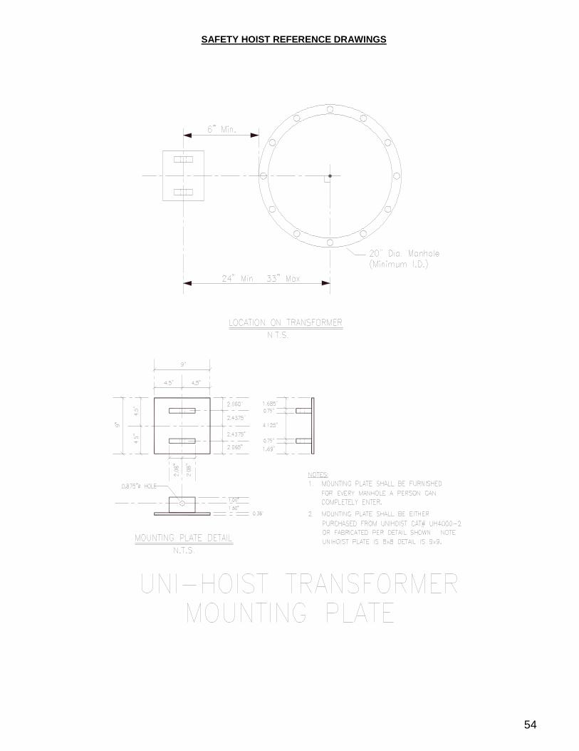
54
SAFETY HOIST REFERENCE DRAW INGS