Embed Size (px)
Citation preview
TABLE OF CONTENTS
TABLE OF CONTENTS OF SPECIAL PROVISIONS
Note: This Table of Contents has been prepared for the convenience of those using this
contract with the sole express purpose of locating quickly the information contained
herein; and no claims shall arise due to omissions, additions, deletions, etc., as this Table
of Contents shall not be considered part of the contract.
0042-0304 1
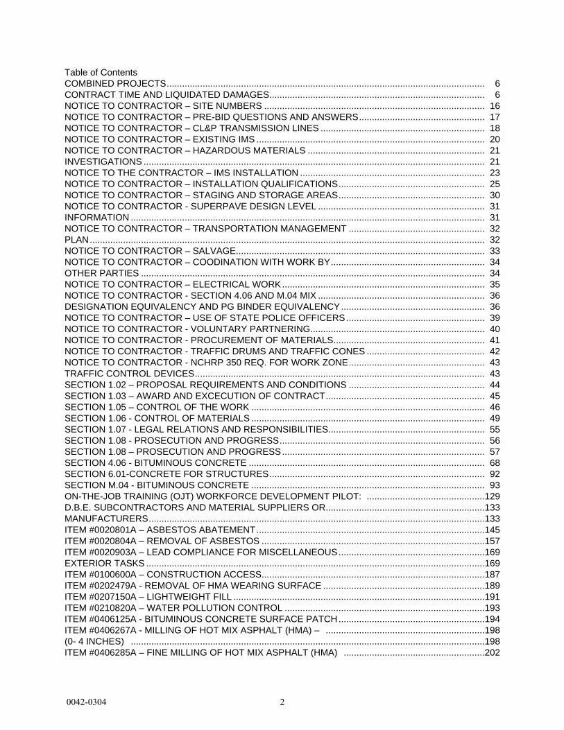
Table of ContentsCOMBINED PROJECTS............................................................................................................................CONTRACT TIME AND LIQUIDATED DAMAGES....................................................................................NOTICE TO CONTRACTOR – SITE NUMBERS ......................................................................................NOTICE TO CONTRACTOR – PRE-BID QUESTIONS AND ANSWERS.................................................NOTICE TO CONTRACTOR – CL&P TRANSMISSION LINES ................................................................NOTICE TO CONTRACTOR – EXISTING IMS .........................................................................................NOTICE TO CONTRACTOR – HAZARDOUS MATERIALS .....................................................................INVESTIGATIONS .....................................................................................................................................NOTICE TO THE CONTRACTOR – IMS INSTALLATION ........................................................................NOTICE TO CONTRACTOR – INSTALLATION QUALIFICATIONS.........................................................NOTICE TO CONTRACTOR – STAGING AND STORAGE AREAS.........................................................NOTICE TO CONTRACTOR - SUPERPAVE DESIGN LEVEL .................................................................INFORMATION ..........................................................................................................................................NOTICE TO CONTRACTOR – TRANSPORTATION MANAGEMENT .....................................................PLAN..........................................................................................................................................................NOTICE TO CONTRACTOR – SALVAGE.................................................................................................NOTICE TO CONTRACTOR – COODINATION WITH WORK BY............................................................OTHER PARTIES ......................................................................................................................................NOTICE TO CONTRACTOR – ELECTRICAL WORK...............................................................................NOTICE TO CONTRACTOR - SECTION 4.06 AND M.04 MIX .................................................................DESIGNATION EQUIVALENCY AND PG BINDER EQUIVALENCY........................................................NOTICE TO CONTRACTOR – USE OF STATE POLICE OFFICERS......................................................NOTICE TO CONTRACTOR - VOLUNTARY PARTNERING....................................................................NOTICE TO CONTRACTOR - PROCUREMENT OF MATERIALS...........................................................NOTICE TO CONTRACTOR - TRAFFIC DRUMS AND TRAFFIC CONES ..............................................NOTICE TO CONTRACTOR - NCHRP 350 REQ. FOR WORK ZONE.....................................................TRAFFIC CONTROL DEVICES.................................................................................................................SECTION 1.02 – PROPOSAL REQUIREMENTS AND CONDITIONS .....................................................SECTION 1.03 – AWARD AND EXCECUTION OF CONTRACT..............................................................SECTION 1.05 – CONTROL OF THE WORK ...........................................................................................SECTION 1.06 - CONTROL OF MATERIALS ...........................................................................................SECTION 1.07 - LEGAL RELATIONS AND RESPONSIBILITIES.............................................................SECTION 1.08 - PROSECUTION AND PROGRESS................................................................................SECTION 1.08 – PROSECUTION AND PROGRESS...............................................................................SECTION 4.06 - BITUMINOUS CONCRETE ............................................................................................SECTION 6.01-CONCRETE FOR STRUCTURES....................................................................................SECTION M.04 - BITUMINOUS CONCRETE ...........................................................................................ON-THE-JOB TRAINING (OJT) WORKFORCE DEVELOPMENT PILOT: ..............................................D.B.E. SUBCONTRACTORS AND MATERIAL SUPPLIERS OR..............................................................MANUFACTURERS...................................................................................................................................ITEM #0020801A – ASBESTOS ABATEMENT.........................................................................................ITEM #0020804A – REMOVAL OF ASBESTOS .......................................................................................ITEM #0020903A – LEAD COMPLIANCE FOR MISCELLANEOUS.........................................................EXTERIOR TASKS ....................................................................................................................................ITEM #0100600A – CONSTRUCTION ACCESS.......................................................................................ITEM #0202479A - REMOVAL OF HMA WEARING SURFACE ...............................................................ITEM #0207150A – LIGHTWEIGHT FILL ..................................................................................................ITEM #0210820A – WATER POLLUTION CONTROL ..............................................................................ITEM #0406125A - BITUMINOUS CONCRETE SURFACE PATCH.........................................................ITEM #0406267A - MILLING OF HOT MIX ASPHALT (HMA) – ..............................................................(0- 4 INCHES) ..........................................................................................................................................ITEM #0406285A – FINE MILLING OF HOT MIX ASPHALT (HMA) .......................................................
66
1617182021212325303131323233343435363639404142434344454649555657689293
129133133145157169169187189191193194198198202
0042-0304 2
\(0 TO 4 INCHES\) .................................................................................................................................ITEM #0406287A RUMBLE STRIPS - AUTOMATED................................................................................ITEM #0406289A - REMOVAL OF RUMBLE STRIPS...............................................................................ITEM #0406999A - ASPHALT ADJUSTMENT COST................................................................................ITEM #0503151A - REMOVAL OF SUPERSTRUCTURE (SITE NO. 1) .................................................ITEM #0503153A - REMOVAL OF SUPERSTRUCTURE (SITE NO. 3) .................................................ITEM #0503154A - REMOVAL OF SUPERSTRUCTURE (SITE NO. 4) .................................................ITEM #0506550A – DOWNSPOUT SPLASH PAD....................................................................................ITEM #0513003A – 1½" POLYVINYL CHLORIDE PLASTIC PIPE ...........................................................ITEM #0520032A - ELASTOMERIC CONCRETE HEADERS...................................................................ITEM #0520035A – SILICONE EXPANSION JOINT SYSTEM .................................................................ITEM #0520036A - ASPHALTIC PLUG EXPANSION JOINT SYSTEM ....................................................ITEM #0520038A – PREFORMED SILICONE JOINT SEALING SYSTEM...............................................ITEM #0521003A – BEARING REPLACEMENT WITH ELASTOMERIC ..................................................BEARING PADS ........................................................................................................................................ITEM #0521014A – STEEL-LAMINATED ELASTOMERIC BEARINGS....................................................ITEM #0522178A – CONSTRUCT CONCRETE KEEPER BLOCKS ........................................................ITEM #0601045A – RECONSTRUCT BRIDGE ENDBLOCK ....................................................................ITEM #0601073A – CLASS “S” CONCRETE.............................................................................................ITEM #0601118A –BRIDGE DECK CONCRETE ......................................................................................ITEM #0601247A - PRECAST CONCRETE PIER CAP ............................................................................ITEM #0601318A - PARTIAL DEPTH PATCH...........................................................................................ITEM #0601548A – CONCRETE ...............................................................................................................ITEM #0601788A – STAIN PROTECTION (SITE NO. 4) ........................................................................ITEM #0601923A – SAWCUTTING CONCRETE......................................................................................ITEM #0602865A - # 5 MECHANICAL COUPLERS..................................................................................ITEM #0602867A - #6 MECHANICAL COUPLERS...................................................................................ITEM #0602871A - #10 MECHANICAL COUPLERS.................................................................................ITEM #0602910A - DRILLING HOLES AND GROUTING DOWELS.........................................................ITEM #0602971A – DEBRIS SHIELD........................................................................................................ITEM #0603064A – STRUCTURAL STEEL (SITE NO. 4) .......................................................................ITEM #0603468A – TEMPORARY SLAB SUPPORT (SITE NO. 2) ........................................................ITEM #0603729A - LOCALIZED PAINT REMOVAL AND FIELD ..............................................................PAINTING OF EXISTING STEEL ..............................................................................................................ITEM #0702081A– BITUMINOUS COATING FOR STEEL PILES ............................................................ITEM #0702109A – PRE-AUGERING OF PILES ......................................................................................ITEM #0702111A – DRIVING STEEL PILES.............................................................................................ITEM #0707009A – MEMBRANE WATERPROOFING (COLD LIQUID ...................................................ELASTOMERIC) .......................................................................................................................................ITEM #0707200A – GEOGRID ..................................................................................................................ITEM #0712010A - REINFORCED SOIL SLOPE ......................................................................................ITEM #0714050A – TEMPORARY EARTH RETAINING SYSTEM...........................................................ITEM #0715050A - EARTH RETAINING SYSTEM LEFT IN PLACE ........................................................ITEM #0821189A – CONCRETE BARRIER TRANSITION SECTION ......................................................ITEM #0821995A – PRECAST CONCRETE END–BLOCK ......................................................................ITEM #0822005A – TEMPORARY PRECAST CONCRETE BARRIER ....................................................CURB (STRUCTURE) ..............................................................................................................................ITEM #0822006A – RELOCATED TEMPORARY PRECAST CONCRETE ..............................................BARRIER CURB (STRUCTURE) .............................................................................................................ITEM #0822014A – RELOCATE STATE-OWNED TEMPORARY.............................................................PRECAST CONCRETE BARRIER CURB PC/MI ......................................................................................ITEM #0952001A – SELECTIVE CLEARING AND THINNING .................................................................ITEM #0969000A - PROJECT COORDINATOR .......................................................................................
202206210214217217217219220221225228235237237239243247249253257270280284286287287287288290291298300300306307307308308316318324327328328329329329329333333334335
0042-0304 3
ITEM #0969066A - CONSTRUCTION FIELD OFFICE, EXTRA-LARGE ..................................................ITEM #0970006A - TRAFFICPERSON (MUNICIPAL POLICE OFFICER) ..............................................ITEM #0970007A - TRAFFICPERSON (UNIFORMED FLAGGER) ........................................................ITEM #0971001A – MAINTENANCE AND PROTECTION OF TRAFFIC..................................................ITEM #0974001A - REMOVAL OF EXISTING MASONRY........................................................................ITEM #0974099A - REMOVAL OF DETERIORATED CONCRETE ..........................................................ITEM #0974105A – CONCRETE HAUNCH REMOVAL ............................................................................ITEM #0975004A - MOBILIZATION AND PROJECT CLOSEOUT............................................................ITEM #0979003A - CONSTRUCTION BARRICADE TYPE III...................................................................ITEM #0980001A – CONSTRUCTION STAKING......................................................................................ITEM #1001001A – TRENCHING AND BACKFILLING.............................................................................ITEM #1008901A – REMOVE CONDUIT ..................................................................................................ITEM #1008907A - CLEANING EXISTING CONDUIT...............................................................................ITEM #1010051A - GALVANIZED STEEL HANDHOLE COVER ..............................................................ITEM #1010905A – RESET CONCRETE HANDHOLE .............................................................................ITEM #1014901A - REMOVE CABLE........................................................................................................ITEM #1020030A - TEMPORARY ILLUMINATION UNIT..........................................................................ITEM #1113601A - OPTICAL FIBER CABLE – SINGLE MODE, LOOSE.................................................BUFFER TUBE CABLE, 2FIBER...............................................................................................................ITEM #1131002A - REMOTE CONTROLLED CHANGEABLE MESSAGE...............................................SIGN ..........................................................................................................................................................ITEM #1201804A – 4 CHORD TRUSS CANTILEVER SIGN STRUCTURE .............................................ITEM #1202999A – DRILLED SHAFT TRAFFIC STRUCTURE................................................................FOUNDATION............................................................................................................................................ITEM #1206023A - REMOVAL AND RELOCATION OF EXISTING SIGNS..............................................ITEM #1207034A – SIGN FACE - EXTRUDED ALUMINUM (TYPE IV ....................................................RETROREFLECTIVE SHEETING) ...........................................................................................................ITEM #1210101A – 4” (100 mm) WHITE EPOXY RESIN PAVEMENT ...................................................MARKINGS ................................................................................................................................................ITEM # 1210102A – 4” (100 mm) YELLOW EPOXY RESIN PAVEMENT ...............................................MARKINGS ................................................................................................................................................ITEM #1210103A – 6” (150 mm) WHITE EPOXY RESIN PAVEMENT ...................................................MARKINGS ................................................................................................................................................ITEM #1210104A – 8” (200 mm) WHITE EPOXY RESIN PAVEMENT ...................................................MARKINGS ................................................................................................................................................ITEM #1210105A – EPOXY RESIN PAVEMENT MARKINGS, SYMBOLS...............................................AND LEGENDS..........................................................................................................................................ITEM #1216020A - 6” BLACK AGGREGATE COVER-UP RESIN ............................................................PAVEMENT MARKINGS ...........................................................................................................................ITEM #1216021A - 8” BLACK AGGREGATE COVER-UP RESIN ............................................................PAVEMENT MARKINGS ...........................................................................................................................ITEM #1220013A – CONSTRUCTION SIGNS - BRIGHT FLUORESCENT..............................................SHEETING.................................................................................................................................................ITEM #1803066A - TYPE B IMPACT ATTENUATION SYSTEM (HIGH- .................................................INCIDENT) NON-GATING ........................................................................................................................PERMITS AND/OR SUPPLEMENTAL TO FORM 816 AND REQUIRED PROVISIONS: .........................
347355355358389390393396398399402405406407408409410413413430430434452452466467467469469469469469469469469469469472472472472476476480480482
0042-0304 4
Rev. Date 5-02-11
GENERAL
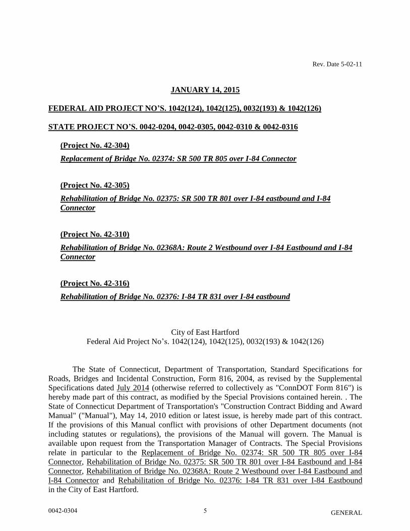
JANUARY 14, 2015
FEDERAL AID PROJECT NO’S. 1042(124), 1042(125), 0032(193) & 1042(126)
STATE PROJECT NO’S. 0042-0204, 0042-0305, 0042-0310 & 0042-0316
(Project No. 42-304)
Replacement of Bridge No. 02374: SR 500 TR 805 over I-84 Connector
(Project No. 42-305)
Rehabilitation of Bridge No. 02375: SR 500 TR 801 over I-84 eastbound and I-84
Connector
(Project No. 42-310)
Rehabilitation of Bridge No. 02368A: Route 2 Westbound over I-84 Eastbound and I-84
Connector
(Project No. 42-316)
Rehabilitation of Bridge No. 02376: I-84 TR 831 over I-84 eastbound
City of East Hartford
Federal Aid Project No’s. 1042(124), 1042(125), 0032(193) & 1042(126)
The State of Connecticut, Department of Transportation, Standard Specifications for
Roads, Bridges and Incidental Construction, Form 816, 2004, as revised by the Supplemental
Specifications dated July 2014 (otherwise referred to collectively as "ConnDOT Form 816") is
hereby made part of this contract, as modified by the Special Provisions contained herein. . The
State of Connecticut Department of Transportation's "Construction Contract Bidding and Award
Manual" ("Manual"), May 14, 2010 edition or latest issue, is hereby made part of this contract.
If the provisions of this Manual conflict with provisions of other Department documents (not
including statutes or regulations), the provisions of the Manual will govern. The Manual is
available upon request from the Transportation Manager of Contracts. The Special Provisions
relate in particular to the Replacement of Bridge No. 02374: SR 500 TR 805 over I-84
Connector, Rehabilitation of Bridge No. 02375: SR 500 TR 801 over I-84 Eastbound and I-84
Connector, Rehabilitation of Bridge No. 02368A: Route 2 Westbound over I-84 Eastbound and
I-84 Connector and Rehabilitation of Bridge No. 02376: I-84 TR 831 over I-84 Eastbound
in the City of East Hartford.
0042-0304 5
Rev. Date 5-02-11
GENERAL
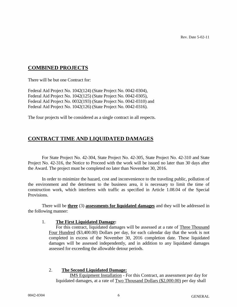
COMBINED PROJECTS
There will be but one Contract for:
Federal Aid Project No. 1042(124) (State Project No. 0042-0304),
Federal Aid Project No. 1042(125) (State Project No. 0042-0305),
Federal Aid Project No. 0032(193) (State Project No. 0042-0310) and
Federal Aid Project No. 1042(126) (State Project No. 0042-0316).
The four projects will be considered as a single contract in all respects.
CONTRACT TIME AND LIQUIDATED DAMAGES
For State Project No. 42-304, State Project No. 42-305, State Project No. 42-310 and State
Project No. 42-316, the Notice to Proceed with the work will be issued no later than 30 days after
the Award. The project must be completed no later than November 30, 2016.
In order to minimize the hazard, cost and inconvenience to the traveling public, pollution of
the environment and the detriment to the business area, it is necessary to limit the time of
construction work, which interferes with traffic as specified in Article 1.08.04 of the Special
Provisions.
There will be three (3) assessments for liquidated damages and they will be addressed in
the following manner:
1. The First Liquidated Damage: For this contract, liquidated damages will be assessed at a rate of Three Thousand
Four Hundred ($3,400.00) Dollars per day, for each calendar day that the work is not
completed in excess of the November 30, 2016 completion date. These liquidated
damages will be assessed independently, and in addition to any liquidated damages
assessed for exceeding the allowable detour periods.
2. The Second Liquidated Damage: IMS Equipment Installation - For this Contract, an assessment per day for
liquidated damages, at a rate of Two Thousand Dollars ($2,000.00) per day shall
0042-0304 6
Rev. Date 5-02-11
GENERAL
be applied to each calendar day that the CCTV Cameras are not operational. The
CCTV Camera Sites included in this Contract are the following:
(Existing) CCTV Camera Site No. 21 (I-84 EB at Bridge No. 02375)
The contractor shall refer to the “Notice to Contractor – IMS Installation Qualifications”,
“Notice to Contractor – IMS Installation” and “Item No. 11122250A - Equipment Operations”
special provisions for terms and conditions.
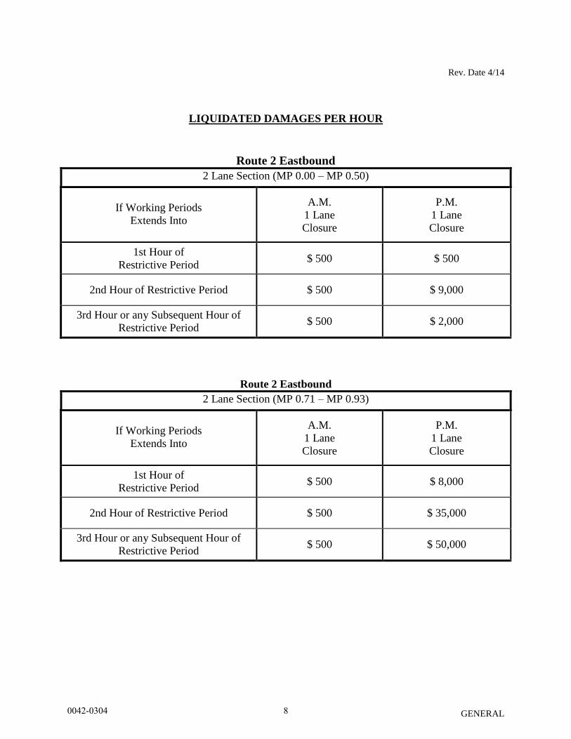
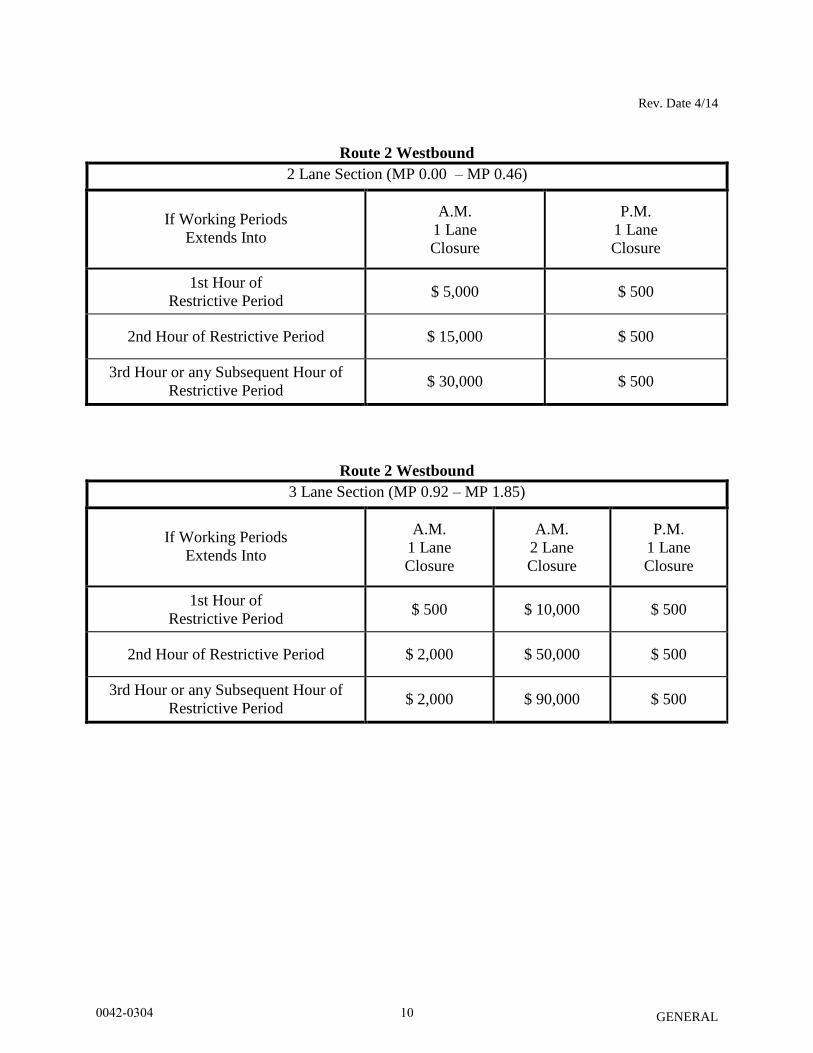
3. The Third Liquidated Damage: For this contract, an assessment per hour for liquidated damages shall be applied
to each hour, or any portion thereof, in which the Contractor interferes with normal
traffic operations during the restricted hours given in Article 1.08.04 of the Special
Provisions. The liquidated damages shall be as shown in the following tables entitled
“Liquidated Damages Per Hour” for each hour, or any portion thereof, in which the
Contractor interferes with normal traffic operations during the restricted hours.
For the purpose of administering this contract, normal traffic operations are considered
interfered with when:
1. Any portion of the travel lanes or shoulders is occupied by any personnel,
equipment, materials, or supplies including signs.
2. The transition between the planes of pavement surfaces is at a rate of one inch in less
than fifteen feet longitudinally.
0042-0304 7
Rev. Date 4/14
GENERAL
LIQUIDATED DAMAGES PER HOUR
Route 2 Eastbound
2 Lane Section (MP 0.00 – MP 0.50)
If Working Periods
Extends Into
A.M.
1 Lane
Closure
P.M.
1 Lane
Closure
1st Hour of
Restrictive Period $ 500 $ 500
2nd Hour of Restrictive Period $ 500 $ 9,000
3rd Hour or any Subsequent Hour of
Restrictive Period $ 500 $ 2,000
Route 2 Eastbound
2 Lane Section (MP 0.71 – MP 0.93)
If Working Periods
Extends Into
A.M.
1 Lane
Closure
P.M.
1 Lane
Closure
1st Hour of
Restrictive Period $ 500 $ 8,000
2nd Hour of Restrictive Period $ 500 $ 35,000
3rd Hour or any Subsequent Hour of
Restrictive Period $ 500 $ 50,000
0042-0304 8
Rev. Date 4/14
GENERAL
Route 2 Eastbound
3 Lane Section (MP 0.93 – MP 1.49)
If Working Periods
Extends Into
A.M.
1 Lane
Closure
A.M.
2 Lane
Closure
P.M.
1 Lane
Closure
1st Hour of
Restrictive Period $ 500 $ 500 $ 500
2nd Hour of Restrictive Period $ 500 $ 2,000 $ 9,000
3rd Hour or any Subsequent Hour of
Restrictive Period $ 500 $ 7,000 $ 15,000
Route 2 Eastbound
2 Lane Section (MP 1.49 – MP 5.31)
If Working Periods Extends Into
A.M.
1 Lane
Closure
1st Hour of Restrictive Period $ 500
2nd Hour of Restrictive Period $ 3,000
3rd Hour or any Subsequent Hour of
Restrictive Period $ 9,000
0042-0304 9
Rev. Date 4/14
GENERAL
Route 2 Westbound
2 Lane Section (MP 0.00 – MP 0.46)
If Working Periods
Extends Into
A.M.
1 Lane
Closure
P.M.
1 Lane
Closure
1st Hour of
Restrictive Period $ 5,000 $ 500
2nd Hour of Restrictive Period $ 15,000 $ 500
3rd Hour or any Subsequent Hour of
Restrictive Period $ 30,000 $ 500
Route 2 Westbound
3 Lane Section (MP 0.92 – MP 1.85)
If Working Periods
Extends Into
A.M.
1 Lane
Closure
A.M.
2 Lane
Closure
P.M.
1 Lane
Closure
1st Hour of
Restrictive Period $ 500 $ 10,000 $ 500
2nd Hour of Restrictive Period $ 2,000 $ 50,000 $ 500
3rd Hour or any Subsequent Hour of
Restrictive Period $ 2,000 $ 90,000 $ 500
0042-0304 10
Rev. Date 4/14
GENERAL
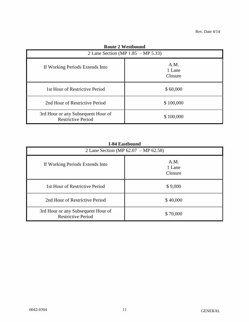
Route 2 Westbound
2 Lane Section (MP 1.85 – MP 5.33)
If Working Periods Extends Into
A.M.
1 Lane
Closure
1st Hour of Restrictive Period $ 60,000
2nd Hour of Restrictive Period $ 100,000
3rd Hour or any Subsequent Hour of
Restrictive Period $ 100,000
I-84 Eastbound
2 Lane Section (MP 62.07 – MP 62.58)
If Working Periods Extends Into
A.M.
1 Lane
Closure
1st Hour of Restrictive Period $ 9,000
2nd Hour of Restrictive Period $ 40,000
3rd Hour or any Subsequent Hour of
Restrictive Period $ 70,000
0042-0304 11
Rev. Date 4/14
GENERAL
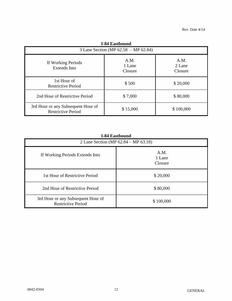
I-84 Eastbound
3 Lane Section (MP 62.58 – MP 62.84)
If Working Periods
Extends Into
A.M.
1 Lane
Closure
A.M.
2 Lane
Closure
1st Hour of
Restrictive Period $ 500 $ 20,000
2nd Hour of Restrictive Period $ 7,000 $ 80,000
3rd Hour or any Subsequent Hour of
Restrictive Period $ 15,000 $ 100,000
I-84 Eastbound
2 Lane Section (MP 62.84 – MP 63.18)
If Working Periods Extends Into
A.M.
1 Lane
Closure
1st Hour of Restrictive Period $ 20,000
2nd Hour of Restrictive Period $ 80,000
3rd Hour or any Subsequent Hour of
Restrictive Period $ 100,000
0042-0304 12
Rev. Date 4/14
GENERAL
I-84 Eastbound
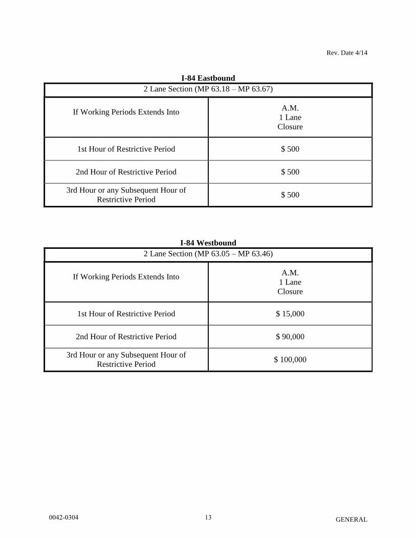
2 Lane Section (MP 63.18 – MP 63.67)
If Working Periods Extends Into
A.M.
1 Lane
Closure
1st Hour of Restrictive Period $ 500
2nd Hour of Restrictive Period $ 500
3rd Hour or any Subsequent Hour of
Restrictive Period $ 500
I-84 Westbound
2 Lane Section (MP 63.05 – MP 63.46)
If Working Periods Extends Into
A.M.
1 Lane
Closure
1st Hour of Restrictive Period $ 15,000
2nd Hour of Restrictive Period $ 90,000
3rd Hour or any Subsequent Hour of
Restrictive Period $ 100,000
0042-0304 13
Rev. Date 4/14
GENERAL
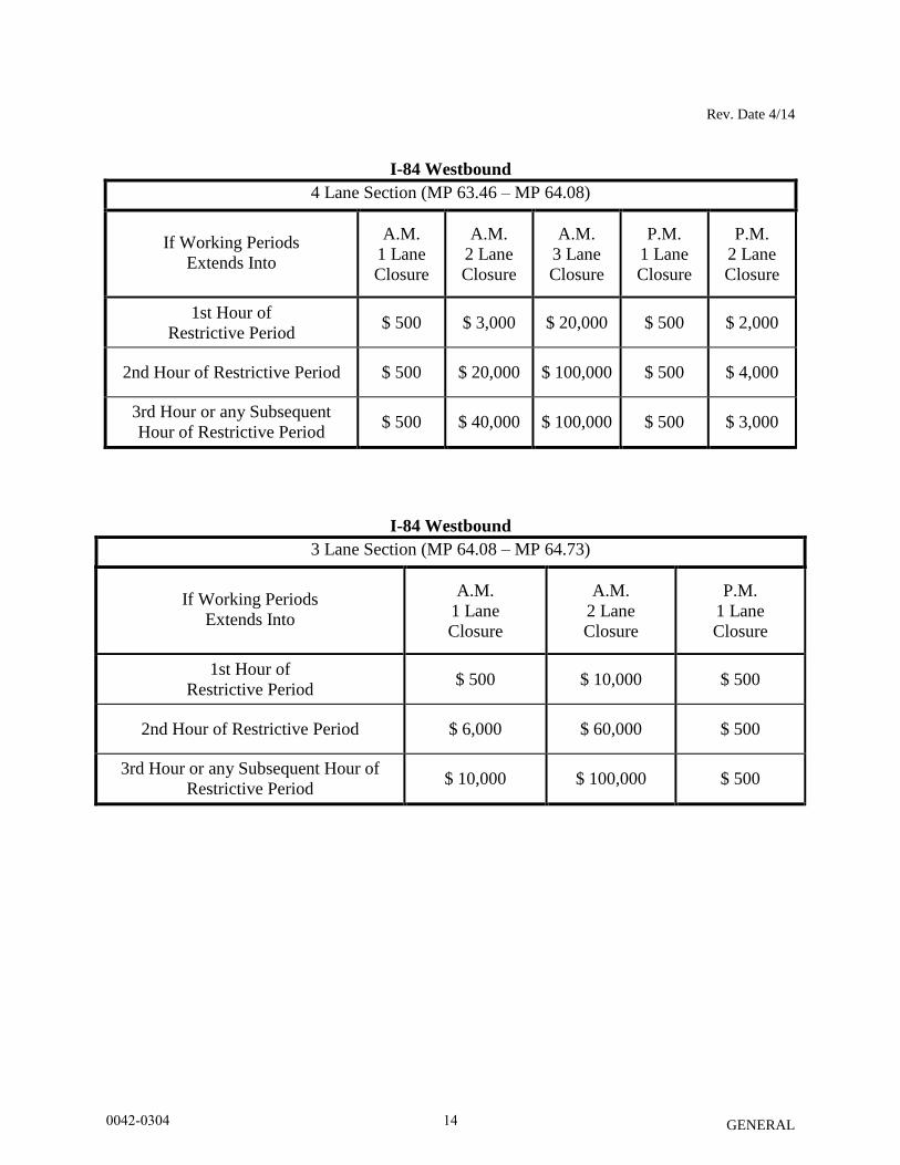
I-84 Westbound
4 Lane Section (MP 63.46 – MP 64.08)
If Working Periods
Extends Into
A.M.
1 Lane
Closure
A.M.
2 Lane
Closure
A.M.
3 Lane
Closure
P.M.
1 Lane
Closure
P.M.
2 Lane
Closure
1st Hour of
Restrictive Period $ 500 $ 3,000 $ 20,000 $ 500 $ 2,000
2nd Hour of Restrictive Period $ 500 $ 20,000 $ 100,000 $ 500 $ 4,000
3rd Hour or any Subsequent
Hour of Restrictive Period $ 500 $ 40,000 $ 100,000 $ 500 $ 3,000
I-84 Westbound
3 Lane Section (MP 64.08 – MP 64.73)
If Working Periods
Extends Into
A.M.
1 Lane
Closure
A.M.
2 Lane
Closure
P.M.
1 Lane
Closure
1st Hour of
Restrictive Period $ 500 $ 10,000 $ 500
2nd Hour of Restrictive Period $ 6,000 $ 60,000 $ 500
3rd Hour or any Subsequent Hour of
Restrictive Period $ 10,000 $ 100,000 $ 500
0042-0304 14
Rev. Date 4/14
GENERAL
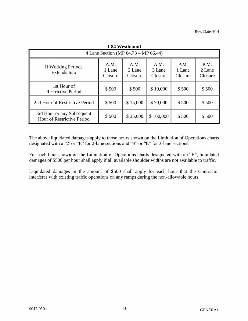
I-84 Westbound
4 Lane Section (MP 64.73 – MP 66.44)
If Working Periods
Extends Into
A.M.
1 Lane
Closure
A.M.
2 Lane
Closure
A.M.
3 Lane
Closure
P.M.
1 Lane
Closure
P.M.
2 Lane
Closure
1st Hour of
Restrictive Period $ 500 $ 500 $ 10,000 $ 500 $ 500
2nd Hour of Restrictive Period $ 500 $ 15,000 $ 70,000 $ 500 $ 500
3rd Hour or any Subsequent
Hour of Restrictive Period $ 500 $ 35,000 $ 100,000 $ 500 $ 500
The above liquidated damages apply to those hours shown on the Limitation of Operations charts
designated with a “2”or “E” for 2-lane sections and “3” or “E” for 3-lane sections.
For each hour shown on the Limitation of Operations charts designated with an “E”, liquidated
damages of $500 per hour shall apply if all available shoulder widths are not available to traffic.
Liquidated damages in the amount of $500 shall apply for each hour that the Contractor
interferes with existing traffic operations on any ramps during the non-allowable hours.
0042-0304 15
Rev. Date 11/17/14
GENERAL
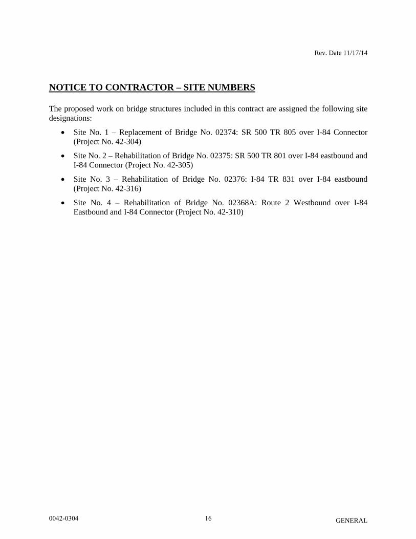
NOTICE TO CONTRACTOR – SITE NUMBERS
The proposed work on bridge structures included in this contract are assigned the following site
designations:
Site No. 1 – Replacement of Bridge No. 02374: SR 500 TR 805 over I-84 Connector
(Project No. 42-304)
Site No. 2 – Rehabilitation of Bridge No. 02375: SR 500 TR 801 over I-84 eastbound and
I-84 Connector (Project No. 42-305)
Site No. 3 – Rehabilitation of Bridge No. 02376: I-84 TR 831 over I-84 eastbound
(Project No. 42-316)
Site No. 4 – Rehabilitation of Bridge No. 02368A: Route 2 Westbound over I-84
Eastbound and I-84 Connector (Project No. 42-310)
0042-0304 16

12-12-13
GENERAL
NOTICE TO CONTRACTOR – PRE-BID QUESTIONS AND ANSWERS
Questions pertaining to DOT advertised construction projects must be presented through the
CTDOT Pre-Bid Q and A Website. The Department cannot guarantee that all questions will be
answered prior to the bid date. PLEASE NOTE - at 12:01 am, the day before the bid, the
subject project(s) being bid will be removed from the Q and A Website, Projects
Advertised Section, at which time questions can no longer be submitted through the Q and
A Website. At this time, the Q and A for those projects will be considered final, unless
otherwise stated and/or the bid is postponed to a future date and time to allow for further
questions and answers to be posted.
If a question needs to be asked the day before the bid date, please contact the Contracts Unit staff
and email your question to [email protected] immediately.
Contractors must identify their company name, contact person, contact email address and phone
number when asking a question. The email address and phone number will not be made public.
The questions and answers (if any) located on the Q and A Website are hereby made part of the
bid/contract solicitation documents (located on the State Contracting Portal), and resulting
contract for the subject project(s). It is the bidder’s responsibility to monitor, review, and become
familiar with the questions and answers, as with all bid requirements and contract documents,
prior to bidding. By signing the bid proposal and resulting contract, the bidder acknowledges
receipt of, and agrees to the incorporation of the final list of Q and A, into the contract document.
Contractors will not be permitted to file a future claim based on lack of receipt, or knowledge of
the questions and answers associated with a project. All bidding requirements and project
information, including but not limited to contract plans, specifications, addenda, Q and A, Notice
to Contractors, etc., are made public on the State Contracting Portal and/or the CTDOT website.
0042-0304 17
GENERAL
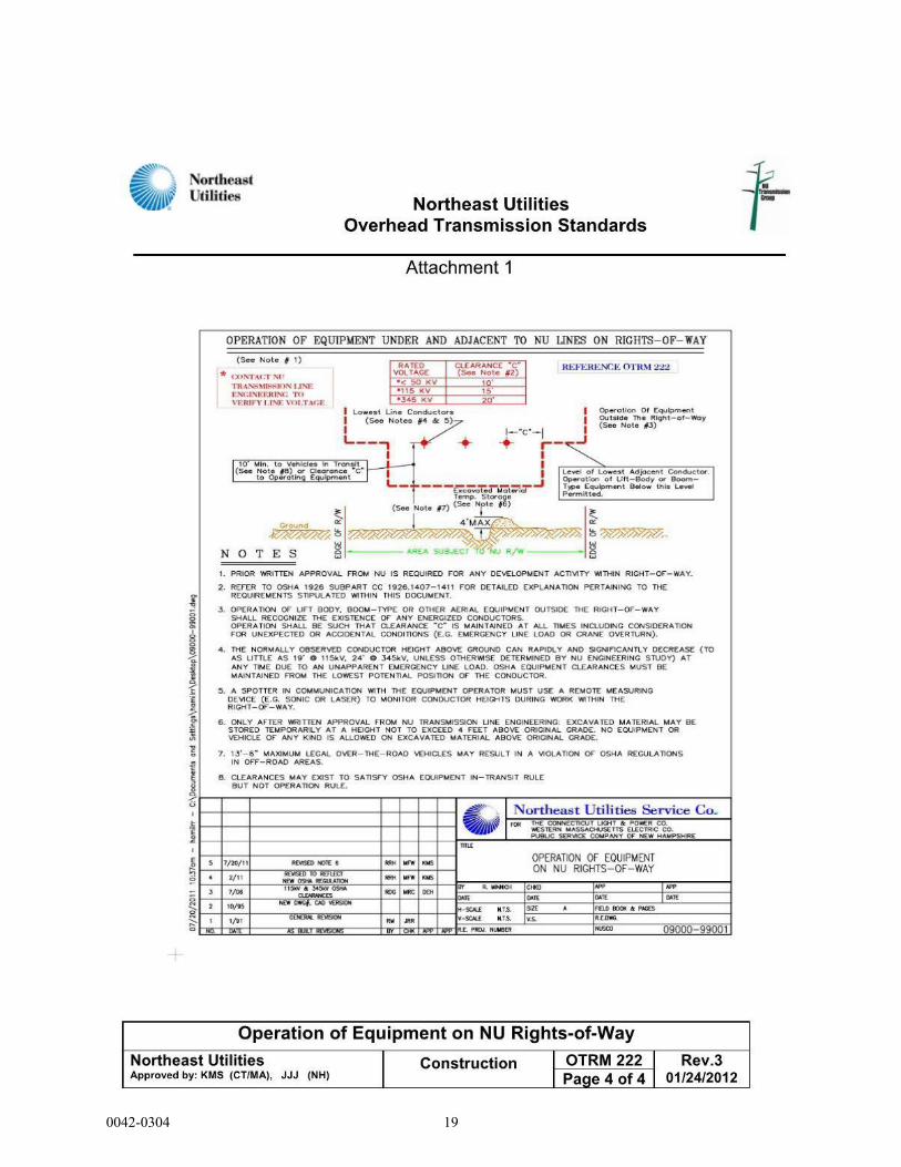
NOTICE TO CONTRACTOR – CL&P TRANSMISSION LINES
The Contractor is hereby notified that CL&P Transmission lines are in the vicinity of
Bridge No. 02376 and should be aware of their location during all crane operations within the
area. OSHA requires a minimum 15-foot clearance envelope for the 115kV lines. The following
shall be observed during all construction activities:
Assembly and disassembly of the crane is prohibited below energized transmission lines
or within the 15 feet clearance distance.
If the 15 feet clearance will be encroached on for any reason during construction, please
contact John Landry at (860) 665-5425 to arrange for a CL&P construction representative
to be present on site during construction. All workers at the site during these construction
activities, including the crane operator and spotter, need to be qualified and trained in
power line safety per OSHA Regulation 1926.1408 (g).
The position of the crane with respect to the transmission lines must be observed at all
times so that the minimum safe clearance is maintained in accordance with the
“Northeast Utilities Overhead Transmission Standards” on the next page.
0042-0304 18
GENERAL
0042-0304 19
Rev. Date 08/14
GENERAL
NOTICE TO CONTRACTOR – EXISTING IMS
The Contractor is herein made aware of existing Incident Management System (IMS) conduit
and appurtenances located on I-95 NB in the vicinity of the project area.
The Contractor will be responsible for locating, verifying the location of and protecting all IMS
below and above the ground. Prior to the start of construction, the Contractor shall contact “Call
Before You Dig” and all utility within the towns along the project corridor. The Contractor shall
also contact Robert Kennedy (860-594-3458) or James Gannon (203-673-7373) of ConnDOT
Highway Operations at to mark out IMS conduit and appurtenances.
In areas adjacent to existing incident management system equipment, the Contractor is required
to hand excavate. Any damage caused to the IMS conduit/equipment will be the responsibility of
the Contractor, and will be replaced by the Contractor at the Contractor’s expense, as directed by
the Engineer. Mark out of the IMS will not relieve the Contractor of responsibility for repair of
damage caused by the Contractor or the Contractor’s sub-contractors.
0042-0304 20
Rev. Date 10/10/14
GENERAL
NOTICE TO CONTRACTOR – HAZARDOUS MATERIALS
INVESTIGATIONS
Limited hazardous materials site investigations have been conducted at Site No 1 (Bridge No.
02374), Site No. 2 (Bridge No. 02375), Site No. 3 (Bridge No. 02376), Site No. 4 (Bridge No.
02368A) and Sign Support No. 21607 (near Site No 4) in East Hartford, Connecticut. The scope
of inspection was limited to the representative components projected for impact.
The results of the investigation indicated detectable amounts of lead in the painted surfaces of
the steel/metal bridge components scheduled for impact at all four (4) Sites as well as Sign
Support No. 21607.
A small amount of lead paint is also presumed on the painted asphalt shoulder divider lines
scheduled for impact at Site No. 3.
TCLP waste stream sampling/analysis of the paint for leachable lead characterized the paint
waste from the steel as RCRA hazardous waste and the paint waste (>5.0 mg/l) at all 4 Sites.
No TCLP sample for lead was warranted on the white painted shoulder lines of the asphalt at
Site No. 3 as the XRF readings were below 1.0 mg/cm2 and therefore the painted asphalt waste
stream is presumed as Non-hazardous per CTDEEP/USEPA clarification memo of January 26,
2004.
TCLP waste stream sampling/analysis of the paint for leachable lead characterized the paint
waste from the metal sign support components as non-hazardous C&D bulky waste (<5.0 mg/l)
Any steel and metal generated from the work tasks (painted or not) shall be segregated and
recycled as scrap metal at a scrap metal recycling facility. The recycling of scrap metal
(regardless of lead paint concentration) is exempt from USEPA RCRA and CTDEEP Hazardous
Waste Regulation.
A dark grey caulking on the bridge guard rail brackets and parapet walls at Site No. 3, a black
flashing tar at the metal bearings/concrete abutment pads at Site No. 4 and black flashing tar
waterproofing on the base plates of Sign Support 21607 were all determined to contain asbestos.
Asbestos containing damp-proofing is also presently presumed to be present on the back side of
abutments and retaining walls at each bridge site.
The Contractor is hereby notified that these hazardous materials requiring special management or
disposal procedures will be encountered during various construction activities conducted within
the project limits. The Contractor will be required to implement appropriate health and safety
measures for all construction activities impacting these materials. These measures shall include,
but are not limited to, air monitoring, engineering controls, personal protective equipment and
decontamination, equipment decontamination and personnel training. WORKER HEALTH
AND SAFETY PROTOCOLS WHICH ADDRESS POTENTIAL AND/OR ACTUAL RISK OF
0042-0304 21
Rev. Date 10/10/14
GENERAL
EXPOSURE TO SITE SPECIFIC HAZARDS ARE SOLELY THE RESPONSIBILITY OF
THE CONTRACTOR.
The Department, as Generator, will provide an authorized representative to sign all manifests and
waste profile documentation required by disposal facilities for disposal of hazardous materials.
The Sections which shall be reviewed by the Contractor include, but are not limited to, the
following:
Item No. 0020903A – Lead Compliance for Miscellaneous Exterior Tasks
Item No. 0020801A – Asbestos Abatement
Item No. 0020804A – Removal of Asbestos
The Contractor is alerted to the fact that a Department environmental consultant may be on site
for abatement and related activities, to collect environmental samples (if necessary), and to
observe site conditions for the State.
Information pertaining to the results of the limited hazardous materials investigation discussed
can be found in the document listed below. This document shall be available for review at the
Office of Contracts, 2800 Berlin Turnpike, Newington, Connecticut.
HazMat Inspection Letter, Replacement of Bridge No. 02368A, East Hartford, CT, TRC
Environmental Corporation, October 11, 2013.
HazMat Inspection Letter, Bridge No. 02376, East Hartford, CT, TRC Environmental Corporation, April 7, 2014.
HazMat Inspection Letter, Bridge Nos. 02374 & 02375, East Hartford, CT, TRC Environmental Corporation, September 18, 2014.
HazMat Inspection Letter, Sign Support No. 21607 near Bridge No. 02368A, East Hartford, CT, TRC Environmental Corporation, October 10, 2014.
0042-0304 22
Rev. Date 8/14
GENERAL
NOTICE TO THE CONTRACTOR – IMS INSTALLATION
The Contractor is alerted that no service interruption of the Incident Management System (IMS),
resulting from the Contractors operations will be allowed. The existing IMS conduit system
(junction boxes, conduit and fiber optic cable) are located behind the permanent concrete barrier
on Route 2 ramp to Governor St.
In order to maintain an uninterrupted service of the existing IMS infrastructure, the Contractor
will re-route the existing IMS conduit, electric service conduit, fiber optic cable and electric
service cable from bridge mounted to trench and under I-84 EB avoiding the future
reconstruction Bridge 02375.
New IMS Installation:
The Contractor shall install as much of the new IMS conduit and service conduit as practical to
minimize the downtime of the existing Incident Management System (Camera 21). The work
associated with the new IMS conduit, electric service conduit, fiber optic cable, and electric
service cable shall conform to the requirements of Notice to Contractor – Installation
Qualifications and Section 1.08.04 Prosecution and Progress, Limitations of Operations -
Incident Management System. The Contractor shall not begin the splicing operation of the fiber
optic cable until the new IMS conduit, service conduit, fiber optic cable, and service cable is
installed.
The work associated with the installation of the IMS conduit, electric service conduit, fiber optic
cable and electric service cable includes the following:
Conduit and Fiber Cable Installation:
Install four (4)- Type II Handholes (two on the North side of 84EB and two on the South
side of 84EB). See Drawing No. IMS-002.
Install the two (2)- 2” RMC in trench from the North handholes to the Junction Boxes on
Route 2 ramp to Governor St. See Drawing No. IMS-002.
Install two (2)- 2” RMC under roadway from the North handholes to the South
handholes. See Drawing No. IMS-002.
Install the two (2)- 2” RMC in trench from the South handholes to the Existing CCTV
Control Cabinet for Camera 21. See Drawing No. IMS-003.
Install electric service cable from Camera 20 cabinet to Existing CCTV Control Cabinet
for Camera 21.
Final Conduit, Fiber Cable and Splicing Operation:
After the work described in “Conduit and Fiber Cable Installation” is complete, the
Contractor shall notify the Department that they would like to schedule the “downtime” of
the IMS fiber cable as described in the special provision “Notice to Contractor – Installation
Qualifications”. The contractor shall be permitted to remove the electrical service and fiber
0042-0304 23
Rev. Date 8/14
GENERAL
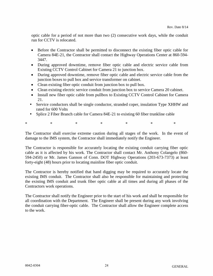
optic cable for a period of not more than two (2) consecutive work days, while the conduit
run for CCTV is relocated.
Before the Contractor shall be permitted to disconnect the existing fiber optic cable for
Camera 84E-21, the Contractor shall contact the Highway Operations Center at 860-594-
3447.
During approved downtime, remove fiber optic cable and electric service cable from
Existing CCTV Control Cabinet for Camera 21 to junction box.
During approved downtime, remove fiber optic cable and electric service cable from the
junction boxes to pull box and service transformer on cabinet.
Clean existing fiber optic conduit from junction box to pull box.
Clean existing electric service conduit from junction box to service Camera 20 cabinet.
Install new fiber optic cable from pullbox to Existing CCTV Control Cabinet for Camera
21.
Service conductors shall be single conductor, stranded coper, insulation Type XHHW and
rated for 600 Volts
Splice 2 Fiber Branch cable for Camera 84E-21 to existing 60 fiber trunkline cable
* * * * * * *
The Contractor shall exercise extreme caution during all stages of the work. In the event of
damage to the IMS system, the Contractor shall immediately notify the Engineer.
The Contractor is responsible for accurately locating the existing conduit carrying fiber optic
cable as it is affected by his work. The Contractor shall contact Mr. Anthony Colangelo (860-
594-2450) or Mr. James Gannon of Conn. DOT Highway Operations (203-673-7373) at least
forty-eight (48) hours prior to locating mainline fiber optic conduit.
The Contractor is hereby notified that hand digging may be required to accurately locate the
existing IMS conduit. The Contractor shall also be responsible for maintaining and protecting
the existing IMS conduit and trunk fiber optic cable at all times and during all phases of the
Contractors work operations.
The Contractor shall notify the Engineer prior to the start of his work and shall be responsible for
all coordination with the Department. The Engineer shall be present during any work involving
the conduit carrying fiber-optic cable. The Contractor shall allow the Engineer complete access
to the work.
0042-0304 24

Rev Date 12/09
GENERAL
NOTICE TO CONTRACTOR – INSTALLATION QUALIFICATIONS
All management, construction, installation, and inspection services shall be performed by
individuals who have performed the same job function on at least two previously
completed construction and installation communication projects of comparable size and
complexity.
Approval of ITS Equipment Installer:
Each Contractor or Subcontractor performing the work involved with the installation of
Intelligent Transportation System (ITS) equipment related to the Incident Management
System shall provide references and resumes of staff that shall meet the following
requirements:
Satisfactory completion of at least three (3) projects in the last three (3) years that
includes the installation of each of the ITS equipment identified below.
100 mm Multiduct Conduit
Pullboxes
Camera Lowering Devices
Camera Assemblies
Traffic Management System Cabinets (TMSC)
Traffic Flow Monitors (TFM) and TFM Poles
Variable Message Signs (VMS) and VMS Controller Cabinets
The Contractor shall provide a list of each ITS project which the Contractor has
performed, including a description of each project, the location of each project, inclusive
dates of when the work was performed on each project, and a contact reference for each
project listed.
This document shall be submitted to ConnDOT for review and approval before any
Incident Management System project work may proceed.
Approval of Fiber-Optic Cable Installation, Splicing and Testing:
Each Contractor or Subcontractor performing the work involved with installing, splicing
and testing of cable and electronic communication systems and installing detection and
video systems, shall provide references and resumes of staff that shall meet the following
requirements:
Satisfactory completion of at least three (3) fiber-optic based communication projects in
the last three years. Experience shall be in related fiber optic systems for installers
involving single-mode cables in excess of 10 kilometers.
0042-0304 25
Rev Date 12/09
GENERAL
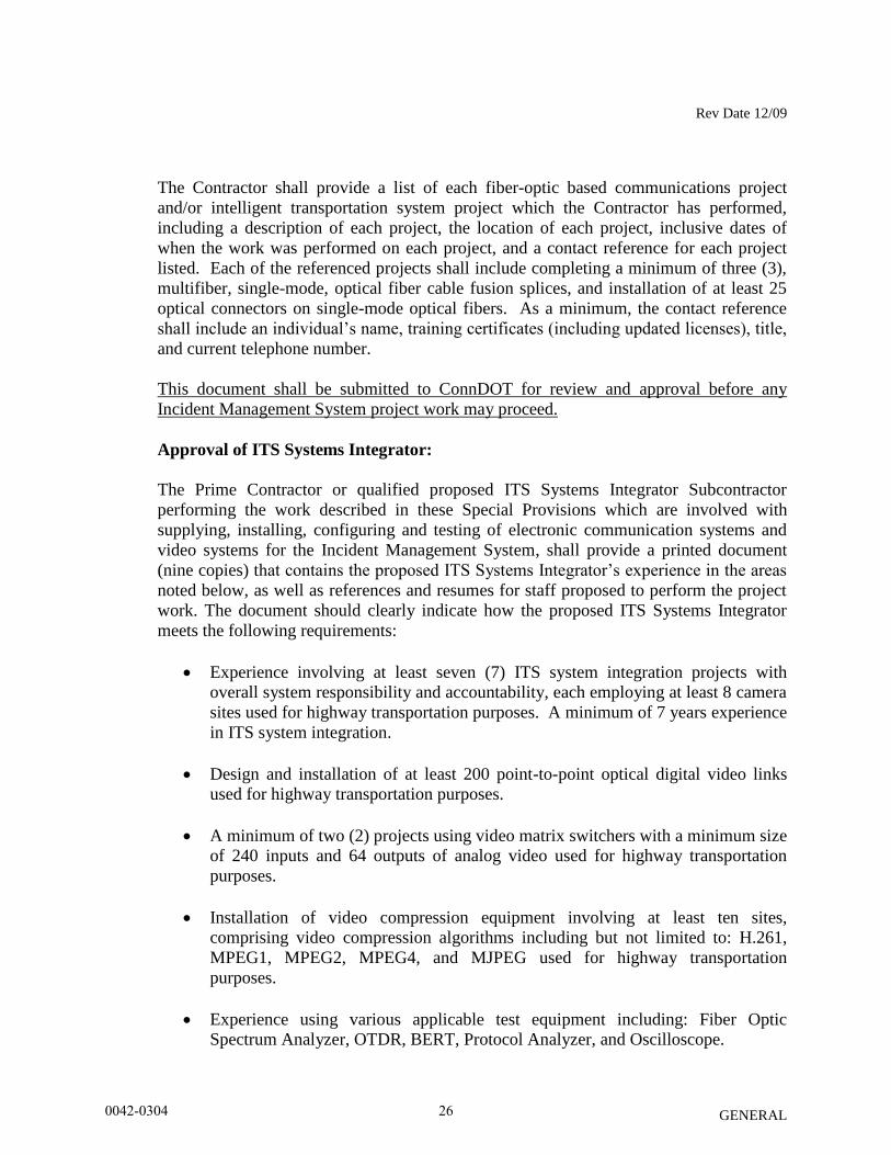
The Contractor shall provide a list of each fiber-optic based communications project
and/or intelligent transportation system project which the Contractor has performed,
including a description of each project, the location of each project, inclusive dates of
when the work was performed on each project, and a contact reference for each project
listed. Each of the referenced projects shall include completing a minimum of three (3),
multifiber, single-mode, optical fiber cable fusion splices, and installation of at least 25
optical connectors on single-mode optical fibers. As a minimum, the contact reference
shall include an individual’s name, training certificates (including updated licenses), title,
and current telephone number.
This document shall be submitted to ConnDOT for review and approval before any
Incident Management System project work may proceed.
Approval of ITS Systems Integrator:
The Prime Contractor or qualified proposed ITS Systems Integrator Subcontractor
performing the work described in these Special Provisions which are involved with
supplying, installing, configuring and testing of electronic communication systems and
video systems for the Incident Management System, shall provide a printed document
(nine copies) that contains the proposed ITS Systems Integrator’s experience in the areas
noted below, as well as references and resumes for staff proposed to perform the project
work. The document should clearly indicate how the proposed ITS Systems Integrator
meets the following requirements:
Experience involving at least seven (7) ITS system integration projects with
overall system responsibility and accountability, each employing at least 8 camera
sites used for highway transportation purposes. A minimum of 7 years experience
in ITS system integration.
Design and installation of at least 200 point-to-point optical digital video links
used for highway transportation purposes.
A minimum of two (2) projects using video matrix switchers with a minimum size
of 240 inputs and 64 outputs of analog video used for highway transportation
purposes.
Installation of video compression equipment involving at least ten sites,
comprising video compression algorithms including but not limited to: H.261,
MPEG1, MPEG2, MPEG4, and MJPEG used for highway transportation
purposes.
Experience using various applicable test equipment including: Fiber Optic
Spectrum Analyzer, OTDR, BERT, Protocol Analyzer, and Oscilloscope.
0042-0304 26
Rev Date 12/09
GENERAL
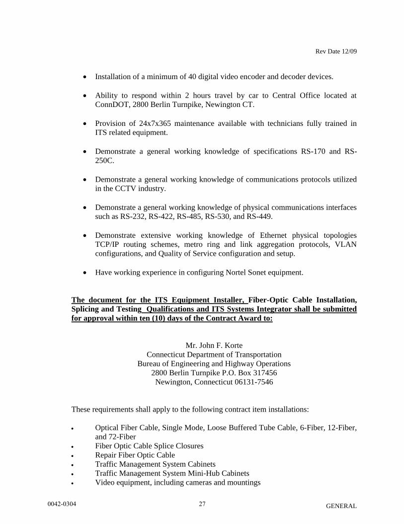
Installation of a minimum of 40 digital video encoder and decoder devices.
Ability to respond within 2 hours travel by car to Central Office located at
ConnDOT, 2800 Berlin Turnpike, Newington CT.
Provision of 24x7x365 maintenance available with technicians fully trained in
ITS related equipment.
Demonstrate a general working knowledge of specifications RS-170 and RS-
250C.
Demonstrate a general working knowledge of communications protocols utilized
in the CCTV industry.
Demonstrate a general working knowledge of physical communications interfaces
such as RS-232, RS-422, RS-485, RS-530, and RS-449.
Demonstrate extensive working knowledge of Ethernet physical topologies
TCP/IP routing schemes, metro ring and link aggregation protocols, VLAN
configurations, and Quality of Service configuration and setup.
Have working experience in configuring Nortel Sonet equipment.
The document for the ITS Equipment Installer, Fiber-Optic Cable Installation,
Splicing and Testing Qualifications and ITS Systems Integrator shall be submitted
for approval within ten (10) days of the Contract Award to:
Mr. John F. Korte
Connecticut Department of Transportation
Bureau of Engineering and Highway Operations
2800 Berlin Turnpike P.O. Box 317456
Newington, Connecticut 06131-7546
These requirements shall apply to the following contract item installations:
Optical Fiber Cable, Single Mode, Loose Buffered Tube Cable, 6-Fiber, 12-Fiber,
and 72-Fiber
Fiber Optic Cable Splice Closures
Repair Fiber Optic Cable
Traffic Management System Cabinets
Traffic Management System Mini-Hub Cabinets
Video equipment, including cameras and mountings
0042-0304 27

Rev Date 12/09
GENERAL
Modify Existing Operations Center Control System
Modify Existing Mini-hub Cabinet
Optical Video/Data Transmitter and Receiver
10/100 Ethernet Switch
Terminal Server
Port Sharing Device
Ethernet Media Converter
Video and Graphics Wall Equipment
Multi-Channel Fiber Optic Video Multiplexer/Demultiplexer
Modify Existing Main Fiber Hub
Single Mode Fiber Optic Directional Coupler
Traffic Flow Monitor
10/100 Ethernet Router
The Contractor shall not start work on the Incident Management System until the
Contractor receives approval from the Office of Highway Operations.
The Incident Management System shall be maintained in normal working operation at all
times.
In the event that the Contractor needs to remove an Incident Management System device
from service, the Contractor shall notify Mr. Robert Kennedy at the Newington
Operations Center (860) 594-3458 at least ten (10) working days prior to any scheduled
work operation. An Incident Management System device shall consist of CCTV cameras,
camera cabinets, mini-hub cabinets, Traffic Flow Monitors, Variable Message Signs,
Highway Advisory Radio site equipment and fiber optic cable including any associated
fiber optic communications plant equipment.
All Project related scheduled work that will require the downtime of the Incident
Management System, such as the splicing of the fiber optic trunkline cable, shall be
performed on a non-holiday weekend as specified in Section 1.08 Prosecution and
Progress - Incident Management System and as approved by Mr. Robert Kennedy,
Newington Operations Center. The scheduled work performed on the approved non-
holiday weekend shall be completed in a fifteen (15) hour work window. The Contractor
shall identify the work that will be performed during this work window as well as a list of
the approved staff to be performing work on the Incident Management System. Any
deviation in the fifteen (15) hour work window must be approved by the Newington
Operations Center staff.
Prior to the scheduled start of work on the Incident Management System, the Contractor
shall contact the Bridgeport Operations Center to determine if there are any on-going
incidents on the highway system. The Incident Management System will not be removed
from service until any on-going incidents on the highway system are cleared and
approval is granted by the Newington Operations Center staff.
0042-0304 28

Rev Date 12/09
GENERAL
All Contractor personnel involved in the placing, splice preparation and splicing of fiber
optic cable shall meet or exceed the above referenced installation qualifications and shall
be approved by the Office of Highway Operations. Under no circumstance will
unqualified, unapproved Contractor personnel be allowed to work on the Incident
Management System.
0042-0304 29

GENERAL
NOTICE TO CONTRACTOR – STAGING AND STORAGE AREAS
The Contractor is hereby notified that there is to be no staging and/or storing of material and/or
equipment within the 100-year floodplain, floodway, gore areas, Department property or areas
with a natural resource impact without review and written approval by the Office of
Environmental Planning (OEP) or by the District Environmental Coordinator (DEC). If staging
and/or storing of material and/or equipment is allowed within these regulated areas, the
Contractor must provide a flood contingency plan or an Erosion and Sedimentation Control Plan
to the OEP or the DEC for review and approval.
The Contractor is also hereby notified that any staging and/or storing of material and/or
equipment throughout the project is only permitted on existing pavement surfaces without review
and written approval by the Office of Environmental Planning (OEP) or by the District
Environmental Coordinator (DEC).
All staging and/or storage areas will be reviewed and approved by the Engineer.
No surplus material due to construction activities is to be disposed of on Department property in
accordance with Section 1.17.18-Use of State Property.
The Contractor’s attention is directed to the fact that only limited stockpiling and storage within
the project are available for use. It may be required that the Contractor, according to his means
and methods, make arrangements to have available for his use sufficient storage and staging
areas outside of the limits of the project.
In all cases, the Contractor shall adhere to and comply with Section 1.10 - Environmental
Compliance, of the Standard Specifications for Roads, Bridges and Incidental Construction Form
816 and any Supplements thereto.
0042-0304 30
Rev. Date 04/23/13
GENERAL
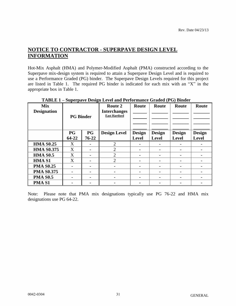
NOTICE TO CONTRACTOR - SUPERPAVE DESIGN LEVEL
INFORMATION
Hot-Mix Asphalt (HMA) and Polymer-Modified Asphalt (PMA) constructed according to the
Superpave mix-design system is required to attain a Superpave Design Level and is required to
use a Performance Graded (PG) binder. The Superpave Design Levels required for this project
are listed in Table 1. The required PG binder is indicated for each mix with an “X” in the
appropriate box in Table 1.
TABLE 1 – Superpave Design Level and Performance Graded (PG) Binder
Mix
Designation
PG Binder
Route 2
Interchanges East Hartford
Route
______
______
______
______
Route
_______
_______
_______
_______
Route
_______
_______
_______
_______
Route
_______
_______
_______
_______
PG
64-22
PG
76-22
Design Level Design
Level
Design
Level
Design
Level
Design
Level
HMA S0.25 X - 2 - - - -
HMA S0.375 X - 2 - - - -
HMA S0.5 X - 2 - - - -
HMA S1 X - 2 - - - -
PMA S0.25 - - - - - - -
PMA S0.375 - - - - - - -
PMA S0.5 - - - - - - -
PMA S1 - - - - - - -
Note: Please note that PMA mix designations typically use PG 76-22 and HMA mix
designations use PG 64-22.
0042-0304 31

Rev. Date 100714
GENERAL
NOTICE TO CONTRACTOR – TRANSPORTATION MANAGEMENT
PLAN
Included in the Contract provisions is the Department’s Transportation Management Plan (TMP)
for this Project. The TMP was developed in conformance with Federal regulations and consists
of strategies to manage the work zone impacts of this Project. Its scope, content, and degree of
detail are based upon the State's work zone policies and regulations along with the State's
understanding of the expected work zone impacts of the Project.
The TMP consists of a Temporary Traffic Control (TTC) plan and addresses both Transportation
Operations (TO) and Public Information (PI) components.
The TMP is a living document that is to be updated and/or revised to manage the work zone
impacts as the Project progresses.
This document is being provided for informational purposes.
Any costs associated with the TMP shall be included under the cost of Item No. 0971001A –
Maintenance and Protection of Traffic.
For information on the regulations related to the TMP please go to:
http://cfr.regstoday.com/23cfr630.aspx#23_CFR_630p1012
0042-0304 32
GENERAL
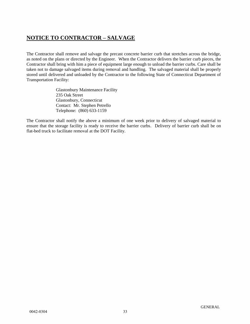
NOTICE TO CONTRACTOR – SALVAGE
The Contractor shall remove and salvage the precast concrete barrier curb that stretches across the bridge,
as noted on the plans or directed by the Engineer. When the Contractor delivers the barrier curb pieces, the
Contractor shall bring with him a piece of equipment large enough to unload the barrier curbs. Care shall be
taken not to damage salvaged items during removal and handling. The salvaged material shall be properly
stored until delivered and unloaded by the Contractor to the following State of Connecticut Department of
Transportation Facility:
Glastonbury Maintenance Facility
235 Oak Street
Glastonbury, Connecticut
Contact: Mr. Stephen Petrello
Telephone: (860) 633-1159
The Contractor shall notify the above a minimum of one week prior to delivery of salvaged material to
ensure that the storage facility is ready to receive the barrier curbs. Delivery of barrier curb shall be on
flat-bed truck to facilitate removal at the DOT Facility.
0042-0304 33
Rev. Date 11/17/14
GENERAL
NOTICE TO CONTRACTOR – COODINATION WITH WORK BY
OTHER PARTIES
The Contractor shall be aware that other Contractors will be adjacent to and within the project
limits before, during and after construction. The following State Project is, or may be, under
construction concurrently with this project:
State Project No. 42-300/301
East Hartford Multi-use Trail
The Contractor will be required to attend coordination meetings for and with the adjacent
projects (as required) and will be required to fully coordinate operations, including traffic control
signing patterns for temporary lane and/or shoulder closures, temporary traffic shifts and
temporary detours on any roadway on the project with the adjacent projects.
The Contractor is responsible for coordination of all overlapping activities between these
projects to ensure continuous sequence of construction activities such that the project is not
delayed.
0042-0304 34
Rev. Date 7/27/14
GENERAL
NOTICE TO CONTRACTOR – ELECTRICAL WORK
The Contractor is hereby advised that the Department has identified the need to install the
permanent highway lighting system circuit bypass prior to commencing the bridge rehabilitation
work. The Contractor shall install the circuit bypass as indicated on the illumination plan and
details and as directed by the Engineer. The Contractor shall carry out the electrical work in such
a manner that there is no disruption of the proper nighttime operation of the highway lighting
system. Prior to disconnection of the existing lighting circuit, the Contractor shall install the new
RMC and circuit conductors. The Contractor shall only disconnect the existing conductors when
the new conductors have been installed and are ready for final connection. All circuit
connections shall be carried out during daylight hours.
Additionally, the Department has identified the need to order certain electrical materials and
equipment, and thereby submit certain submittals for approval early in the construction process
to ensure proper nighttime highway illumination and project coordination are maintained.
Submittals shall be in accordance with Form 816 Article 1.20 – 1.05.02. The following items
have been identified as possibly requiring early ordering thereby requiring early submission of
shop drawings and product data:
Rigid Metal Conduit
No. 2 Single Conductor
No. 8 Bare Copper Grounding Conductor
Splices
The list above is not intended to be all-inclusive and does not relieve the Contractor from
coordinating the activities of its subcontractors and suppliers. The Contractor will not be
permitted to remove any existing highway lighting facilities without approval of the required
submittals. Failure to properly plan for long lead items within the contract schedule will not be
justification for additional construction time.
It is recommended that the Contractor identify early in the construction sequencing process the
subcontractors and suppliers associated with long lead time items and submit the appropriate
shop drawings and supporting data for review upon Notice to Proceed.
0042-0304 35
Rev. Date 11/03/14
English
GENERAL
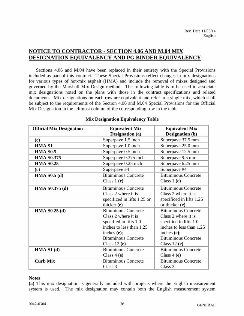
NOTICE TO CONTRACTOR - SECTION 4.06 AND M.04 MIX
DESIGNATION EQUIVALENCY AND PG BINDER EQUIVALENCY
Sections 4.06 and M.04 have been replaced in their entirety with the Special Provisions
included as part of this contract. These Special Provisions reflect changes in mix designations
for various types of hot-mix asphalt (HMA) and include the removal of mixes designed and
governed by the Marshall Mix Design method. The following table is to be used to associate
mix designations noted on the plans with those in the contract specifications and related
documents. Mix designations on each row are equivalent and refer to a single mix, which shall
be subject to the requirements of the Section 4.06 and M.04 Special Provisions for the Official
Mix Designation in the leftmost column of the corresponding row in the table.
Mix Designation Equivalency Table
Official Mix Designation Equivalent Mix
Designation (a)
Equivalent Mix
Designation (b)
(c) Superpave 1.5 inch Superpave 37.5 mm
HMA S1 Superpave 1.0 inch Superpave 25.0 mm
HMA S0.5 Superpave 0.5 inch Superpave 12.5 mm
HMA S0.375 Superpave 0.375 inch Superpave 9.5 mm
HMA S0.25 Superpave 0.25 inch Superpave 6.25 mm
(c) Superpave #4 Superpave #4
HMA S0.5 (d) Bituminous Concrete
Class 1 (e)
Bituminous Concrete
Class 1 (e)
HMA S0.375 (d) Bituminous Concrete
Class 2 where it is
specificed in lifts 1.25 or
thicker (e)
Bituminous Concrete
Class 2 where it is
specificed in lifts 1.25
or thicker (e)
HMA S0.25 (d) Bituminous Concrete
Class 2 where it is
specified in lifts 1.0
inches to less than 1.25
inches (e);
Bituminous Concrete
Class 12 (e)
Bituminous Concrete
Class 2 where it is
specified in lifts 1.0
inches to less than 1.25
inches (e);
Bituminous Concrete
Class 12 (e)
HMA S1 (d) Bituminous Concrete
Class 4 (e)
Bituminous Concrete
Class 4 (e)
Curb Mix Bituminous Concrete
Class 3
Bituminous Concrete
Class 3
Notes
(a) This mix designation is generally included with projects where the English measurement
system is used. The mix designation may contain both the English measurement system
0042-0304 36
Rev. Date 11/03/14
English
GENERAL
designation and the SI (metric) measurement system designation, one of which would be in
parenthesis.
(b) This mix designation is generally included with projects where the SI (metric) measurement
system is used. The mix designation may contain both the English measurement system
designation and the SI measurement system designation, one of which would be in parenthesis.
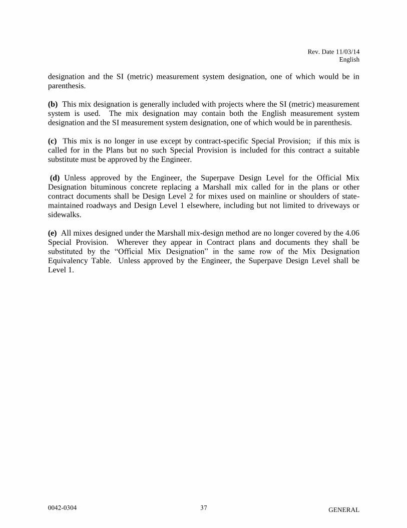
(c) This mix is no longer in use except by contract-specific Special Provision; if this mix is
called for in the Plans but no such Special Provision is included for this contract a suitable
substitute must be approved by the Engineer.
(d) Unless approved by the Engineer, the Superpave Design Level for the Official Mix
Designation bituminous concrete replacing a Marshall mix called for in the plans or other
contract documents shall be Design Level 2 for mixes used on mainline or shoulders of state-
maintained roadways and Design Level 1 elsewhere, including but not limited to driveways or
sidewalks.
(e) All mixes designed under the Marshall mix-design method are no longer covered by the 4.06
Special Provision. Wherever they appear in Contract plans and documents they shall be
substituted by the “Official Mix Designation” in the same row of the Mix Designation
Equivalency Table. Unless approved by the Engineer, the Superpave Design Level shall be
Level 1.
0042-0304 37
Rev. Date 11/03/14
English
GENERAL
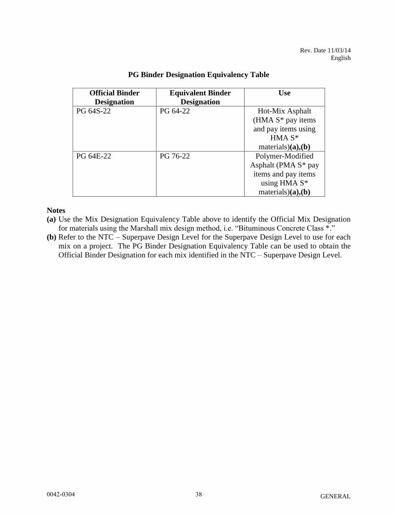
PG Binder Designation Equivalency Table
Official Binder
Designation
Equivalent Binder
Designation
Use
PG 64S-22 PG 64-22 Hot-Mix Asphalt
(HMA S* pay items
and pay items using
HMA S*
materials)(a),(b)
PG 64E-22 PG 76-22 Polymer-Modified
Asphalt (PMA S* pay
items and pay items
using HMA S*
materials)(a),(b)
Notes
(a) Use the Mix Designation Equivalency Table above to identify the Official Mix Designation
for materials using the Marshall mix design method, i.e. “Bituminous Concrete Class *.”
(b) Refer to the NTC – Superpave Design Level for the Superpave Design Level to use for each
mix on a project. The PG Binder Designation Equivalency Table can be used to obtain the
Official Binder Designation for each mix identified in the NTC – Superpave Design Level.
0042-0304 38
Rev. Date 062912
GENERAL
NOTICE TO CONTRACTOR – USE OF STATE POLICE OFFICERS
The Department will reimburse services of State Police Officers as a direct payment to the
Department of Emergency Services and Public Protection. Payment for State Police Officers
utilized by the Contractor for its convenience, not approved by the Engineer, is the responsibility
of the Contractor. No separate payment item for State Police Officers is included in this
contract.
Any costs associated with coordination and scheduling of State Police Officers will be included
under the cost of Item No. 0971001A – Maintenance and Protection of Traffic.
0042-0304 39
Rev. Date 06/16/00
GENERAL
NOTICE TO CONTRACTOR - VOLUNTARY PARTNERING
The Connecticut Department of Transportation (ConnDOT) intends to encourage the
foundation of a cohesive partnership with the Contractor and its principal subcontractors on this
project. This partnership will be structured to draw on the strengths of each organization to identify
and achieve reciprocal goals. The objectives are effective and efficient contract performance and
completion within budget, on schedule, and in accordance with plans and specifications.
This partnership will be bilateral in makeup, and participation will be totally voluntary. Any
cost associated with effectuating this partnering will be agreed to by both parties and will be shared
equally.
To implement this partner initiative, the Contractor and ConnDOT will meet and plan a
partnering development seminar/team building workshop. At this planning session arrangements
will be made to determine attendees at the workshop, agenda of the workshop, duration and
location. Persons required to be in attendance will be the ConnDOT District Engineer and key
project personnel, the Contractor's on-site project manager and key supervision personnel of both
the prime and principal subcontractors. The project design engineers and key local government
personnel will also be required to have Regional/District and Corporate/State level managers on the
project team.
Follow-up workshops will be held periodically throughout the duration of the Contract as
agreed by the Contractor and ConnDOT.
The establishment of a partnership charter on a project will not change the legal relationship
of the parties to the Contract nor relieve either party from any of the terms of the Contract.
ConnDOT and the Contractor will jointly select a facilitator to conduct the partnering
workshops. The Contractor will obtain the services of the chosen facilitator and ConnDOT will
reimburse the Contractor for fifty percent (50%) of the costs agreed to between ConnDOT and the
Contractor.
0042-0304 40
Rev. Date 07/05/00
GENERAL
NOTICE TO CONTRACTOR - PROCUREMENT OF MATERIALS
Upon award, the Contractor shall proceed with shop drawings, working drawings,
procurement of materials, and all other submittals required to complete the work in accordance with
the contract documents.
0042-0304 41
Rev. Date 04/19/05
GENERAL
NOTICE TO CONTRACTOR - TRAFFIC DRUMS AND TRAFFIC CONES
Traffic Drums and 42-inch (1 m) Traffic Cones shall have four six-inch (150 mm) wide stripes
(two - white and two - orange) of flexible bright fluorescent sheeting.
The material for the stripes shall be one of the following, or approved equal:
• 3M Scotchlite Diamond Grade Flexible Work Zone Sheeting, Model 3910 for the white
stripes and Model 3914 for the orange stripes,
• Avery Dennison WR-7100 Series Reboundable Prismatic Sheeting, Model WR-7100 for
the white stripes and Model WR-7114 for the orange stripes.
0042-0304 42
Rev. Date 05/05/14
GENERAL
NOTICE TO CONTRACTOR - NCHRP 350 REQ. FOR WORK ZONE
TRAFFIC CONTROL DEVICES
CATEGORY 1 DEVICES (traffic cones, traffic drums, tubular markers, flexible delineator posts)
Prior to using the Category 1 Devices on the project, the Contractor shall submit to the Engineer
a copy of the manufacturer’s self-certification that the devices conform to the requirements in
National Cooperative Highway Research Program (NCHRP) Report 350 or the AASHTO
Manual for Assessing Safety Hardware (MASH), as appropriate.
CATEGORY 2 DEVICES (construction barricades, construction signs and portable sign
supports)
Prior to using Category 2 Devices on the project, the Contractor shall submit to the Engineer a
copy of the Letter of Acceptance issued by the FHWA to the manufacturer documenting that the
devices (both sign and portable support tested together) have been crash tested and have approval
in writing from FHWA conforming to the requirements in National Cooperative Highway
Research Program (NCHRP) Report 350 or the AASHTO Manual for Assessing Safety
Hardware (MASH), as appropriate.
Specific requirements for these devices are included in the Special Provisions.
Information regarding NCHRP Report 350 and AASHTO Manual for Assessing Safety Hardware
(MASH) may be found at the following web sites:
FHWA: http://safety.fhwa.dot.gov/roadway_dept/Policy_guide/road_hardware/
ATSSA: http://www.atssa.com/resources.aspx
NOTE: The portable wooden sign supports that have been traditionally used by most contractors
in the State of Connecticut do NOT meet NCHRP Report 350 criteria and shall not be utilized on
any project advertised after October 01, 2000.
CATEGORY 3 DEVICES (Truck-Mounted Attenuators & Work Zone Crash Cushions)
Prior to using Category 3 Devices on the project, the Contractor shall submit to the Engineer a
copy of the Letter of Acceptance issued by the FHWA to the manufacturer documenting that the
devices have been crash tested and have approval in writing from FHWA conforming to the
requirements in National Cooperative Highway Research Program (NCHRP) Report 350 or the
AASHTO Manual for Assessing Safety Hardware (MASH), as appropriate.
0042-0304 43
Rev. Date 03/25/08
GENERAL
SECTION 1.02 – PROPOSAL REQUIREMENTS AND CONDITIONS
Article 1.02.04 – Examination of Plans, Specifications, Special Provisions and Site of Work:
Replace the third sentence of the last paragraph with:
The Department cannot ensure a response to inquiries received later than ten (10) days
prior to the original scheduled opening of the related bid.
0042-0304 44
Rev. 12/02/14
GENERAL
SECTION 1.03 – AWARD AND EXCECUTION OF CONTRACT
Article 1.03.02 – Award and Execution of Contract:
Change the second sentence to read as follows:
The award, if made, will be made within 45 days after the opening of the proposals.
Article 1.03.03 – Return of Proposal Guaranty:
Change the third sentence to read as follows:
Should no award be made within 45 calendar days after the opening of proposals, the
Commissioner may reject all proposals and return the proposal guaranties, except that with the
approval of the lowest bidder and its surety, the Commissioner may extend the time for the
award and may retain the proposal and proposal guaranty of the lowest bidder for said extended
time, or for any other period of time agreed upon by the Commissioner, bidder and surety.
Article 1.03.08 – Notice to Proceed and Commencement of Work:
Change the first and second paragraphs to read as follows:
The Contractor will commence and proceed with the Contract work on the date specified in a
written notice to proceed issued by the Engineer to the Contractor. The date specified will be no
later than 30 days after the execution of the Contract by the Department.
0042-0304 45
GENERAL
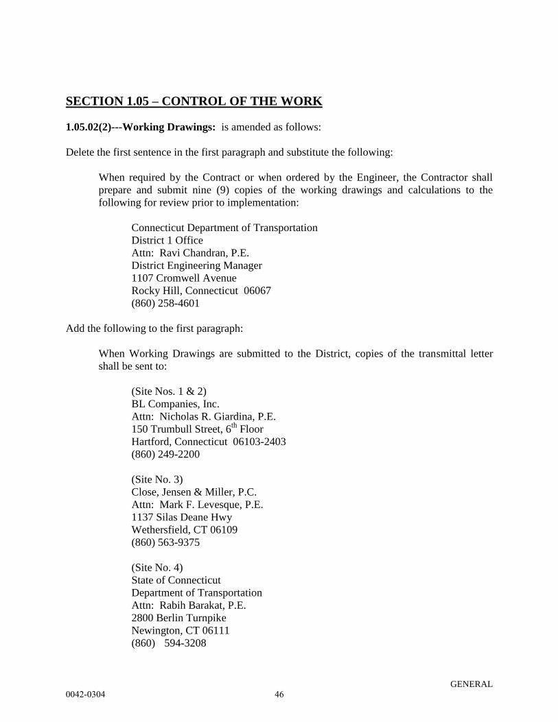
SECTION 1.05 – CONTROL OF THE WORK
1.05.02(2)---Working Drawings: is amended as follows:
Delete the first sentence in the first paragraph and substitute the following:
When required by the Contract or when ordered by the Engineer, the Contractor shall
prepare and submit nine (9) copies of the working drawings and calculations to the
following for review prior to implementation:
Connecticut Department of Transportation
District 1 Office
Attn: Ravi Chandran, P.E.
District Engineering Manager
1107 Cromwell Avenue
Rocky Hill, Connecticut 06067
(860) 258-4601
Add the following to the first paragraph:
When Working Drawings are submitted to the District, copies of the transmittal letter
shall be sent to:
(Site Nos. 1 & 2)
BL Companies, Inc.
Attn: Nicholas R. Giardina, P.E.
150 Trumbull Street, 6th
Floor
Hartford, Connecticut 06103-2403
(860) 249-2200
(Site No. 3)
Close, Jensen & Miller, P.C.
Attn: Mark F. Levesque, P.E.
1137 Silas Deane Hwy
Wethersfield, CT 06109
(860) 563-9375
(Site No. 4)
State of Connecticut
Department of Transportation
Attn: Rabih Barakat, P.E.
2800 Berlin Turnpike
Newington, CT 06111
(860) 594-3208
0042-0304 46
Rev. Date mm/dd/yy
GENERAL
When required by the contract documents or when ordered by the Engineer, the Contractor shall
prepare and submit catalog cuts, working drawings and/or shop drawings for all Incident
Management System (IMS) related items to the Bureau of Highway Operations for approval
before fabrication. IMS related items include multiduct conduit, pullboxes, fiber optic and
communications cables, cabinets, cameras, camera lowering devices, variable message signs
(VMS), traffic flow monitors (TFM) and telecommunications related equipment.
The packaged set of catalog cuts, working drawings and/or shop drawings shall be submitted
either in paper (hard copy) form or in an electronic portable document format (.pdf). The
package submitted in paper form shall include one (1) set. Catalog cuts shall be printed on ANSI
A (8 ½” x 11”; 216 mm x 279mm; letter) sheets. Working drawings and shop drawings shall be
printed on ANSI B (11” x 17”; 279 mm x 432 mm; ledger/tabloid) sheets.
Please forward to:
Mr. John F. Korte
Connecticut Department of Transportation
Bureau of Highway Operations
2800 Berlin Turnpike
P.O. Box 317546
Newington, Connecticut 06131-7546
1.05.02(3)---Shop Drawings: is amended as follows:
Delete the first sentence in the first paragraph and substitute the following:
When required by the Contract or when ordered by the Engineer, the Contractor shall
prepare and submit nine (9) copies of the shop drawings to the following Contracting
Engineers for review and approval before fabrication:
(Site No. 3)
Stantec Consulting Services, Inc.
Attn: Andrew Lessard, P.E.
2321 Whitney Avenue
Hamden, Connecticut 06518
(203) 281-1350
(Site Nos. 1 & 2)
McFarland Johnson, Inc.
Attn: Gene McCarthy, P.E.
53 Regional Drive
Concord, NH 03301
(603) 225-2978
0042-0304 47
Rev. Date mm/dd/yy
GENERAL
(Site No. 4)
State of Connecticut
Department of Transportation
Attn: Rabih Barakat, P.E.
2800 Berlin Turnpike
Newington, CT 06111
(860) 594-3208
Add the following to the first paragraph:
When Shop Drawings are submitted to the Contracting Engineer, copies of the transmittal
letter shall be sent to:
(Site Nos. 1 & 2)
BL Companies, Inc.
Attn: Nicholas R. Giardina, P.E.
150 Trumbull Street, 6th
Floor
Hartford, Connecticut 06103-2403
(860) 249-2200
(Site No. 3)
Close, Jensen & Miller, P.C.
Attn: Mark F. Levesque, P.E.
1137 Silas Deane Hwy
Wethersfield, CT 06109
(860) 563-9375
(Site No. 4)
State of Connecticut
Department of Transportation
Attn: Rabih Barakat, P.E.
2800 Berlin Turnpike
Newington, CT 06111
(860) 594-3208
and to the District:
Connecticut Department of Transportation
District 1 Office
Attn: Ravi Chandran, P.E.
District Engineering Manager
1107 Cromwell Avenue
Rocky Hill, Connecticut 06067
(860) 258-4601
0042-0304 48
Rev. Date 07/14/14
GENERAL
SECTION 1.06 - CONTROL OF MATERIALS
General:
The Special Provisions contain the description of various items which must be submitted to the
Engineer by the Contractor for review and approval. These items are in addition to other
requirements described in the Specifications. Where conflicts exist, these Special Provisions
shall govern. Unless otherwise noted, the Contractor shall provide nine (9) complete copies of
all required submissions.
The State will complete its review of the material within thirty (30) days from the date of receipt
of the submission. The State shall advise the Contractor, in writing, as to the acceptability of the
material submitted. The State reserves the right to return the Contractor’s submission without
review comments or submittal determination for approval or rejection where the submittal does
not provide sufficient information for determination. The State may determine that the item is
approved in which case no further submittal is required by the Contractor, approved – resubmit
for record where the contract shall supply any outstanding information to make the material
approved, or the item may be partially or totally rejected in which case the Contractor shall be
required to modify or clarify the submittal as required by the State and resubmit the item within
fifteen (15) days. At this time, the review and approval cycle described above shall begin again.
Approval by the Engineer of equipment and materials lists, catalog cuts, and/or shop drawings
shall not relieve the Contractor of any responsibility under the Contract for the successful
completion of the work in conformity with the requirements of the Special Provisions.
Article 1.06.01 - Source of Supply and Quality:
Add the following:
For the following items the Contractor shall submit a complete description of the item, together
with eight (8) copies of shop drawings, cuts and other descriptive literature which completely
illustrates such items presented for formal approval. Such approval shall not change the
requirements for a certified test report and materials certificate as may be called for.
Conductors
Conduit
Handhole Cover
Required catalog cuts for all items listed above shall be submitted in one package at the same
time. All approvals or disapprovals and comments will be returned in one package.
0042-0304 49

Rev. Date 07/14/14
GENERAL
When required by the contract documents or when ordered by the Engineer, the Contractor shall
prepare and submit (8) sets of catalog cuts and/or shop drawings for all illumination items in one
package at the same time to the following for approval prior to ordering or fabrication.
Mr. Theodore H. Nezames
Principal Engineer – Facilities Design
Bureau of Engineering and Highway Operations
Connecticut Department of Transportation
P.O. Box 317546
Newington, Connecticut 06131-7546
Delete the last paragraph and replace with the following:
Incident Management System (IMS) Items:
For the following items required for the Incident Management System, the Contractor shall
submit a complete description of the item, together with either in paper (hard copy) form or in an
electronic portable document format (.pdf) one (1) copy of shop drawings, cuts, data sheets and
other descriptive literature which completely illustrates such items presented for formal approval.
Such approval shall not change the requirements for a certified test report, and materials
certificate as may be called for.
Approval of the Shop Drawings and catalog cuts shall not change the requirements for a certified
test report, materials certificate and certificate of compliance as may be called for.
Shop drawings shall be submitted on 8-1/2 inch by 11 inch sheets, 11 inch by 17 inch sheets or
on 24 inch by 36 inch standard plan sheets. Shop drawings and data sheets shall be required for,
but not limited to the following
Structural supports
Surface Mounted Conduit and Appurtenances
Conduit, pulling tape, supports, brackets, hangers, clamps and any hardware involved
with the supports and including complete fabrication details.
Field fastener details including chemical and mechanical anchors
Hand holes and covers
Pullboxes and pullbox covers
Fiber Optic Modems
Camera Assembly. Schematics of the wiring between the camera and the equipment
cabinet shall also be provided.
Camera power supply
Camera Video Cables, Data Cables, Power Cables and Connectors
0042-0304 50

Rev. Date 07/14/14
GENERAL
Traffic Flow Monitors
Cast Iron Handhole Cover
Cast Iron Junction Box
Fiberglass Junction Box
Traffic Management System Cabinets
Traffic Management System Mini-hub Cabinets
Auxiliary Termination Cabinets
Transformers
Steel CCTV Poles
Camera Lowering Device Assembly
Remote Control Flashing Lights
Service Cabinets
Meter Sockets
Conductors
Fiber Optic Cable
Fiber Patch Cords
Fiber Optic Connectors
Fiber Optic Splice Enclosures
Optical Fiber Termination Patch Panels
Optical Video/Data Transmitter
Optical Video/Data Receiver
Network Customer Service Unit
Video encoders and de-coders
Surge Panels
Ethernet switch
Ethernet Port Sharing Device
Cat 6 Cable
CCTV Coax Cable
Coax Cable Connectors
CCTV Twisted Pair cable
CCTV Twisted pair connectors
RJ 45 and RJ 48 Connectors
Modify Existing Operations Center Control System including all materials, schematics,
diagrams and drawings.
Motorists Aid Variable Message Signs, cabinets, cables, diagrams, schematics etc.
Required catalog cuts for all items listed above shall be submitted in one package at the same
time. All approvals or disapprovals and comments will be returned in one package.
Please forward to:
Mr. John F. Korte
Connecticut Department of Transportation
0042-0304 51
Rev. Date 07/14/14
GENERAL
Highway Operations Section
2800 Berlin Turnpike
P.O. Box 317546
Newington, Connecticut 06131-7546
Article 1.06.05 - Shipping Materials: Add the following:
All vehicles transporting materials on highways and bridges in the State shall comply
with all the vehicle regulations of the Connecticut General Statutes and regulations of
Connecticut State Agencies as they apply to vehicle length, width, height and weight.
Any vehicle, either loaded or unloaded, will not be allowed to travel across any bridge or
on any highway when such vehicle exceeds the legal limits or posted limits of such bridge or
highway without a permit. The owner of the vehicle must apply to the Department for a permit
for such travel, as provided in the statutes.
The General Statutes include the following limitations:
Vehicle Width (Section 14-262(a)(1)) - The width of a vehicle and
combination vehicle and trailer, including its load, is limited to
2590 mm, without a permit.
Vehicle Length (Section 14-262(c)) - The length of the semitrailer
portion of a tractor-trailer unit, including its load, is limited to 14
630 mm, without a permit.
Vehicle Height (Section 14-264) - The height of a vehicle, with its
load, is limited to 4110 mm, without a permit.
Vehicle Weight (Section 14-267a(b)(7)) - The gross vehicle weight
(weight of vehicle including its load) is limited to 36 280 kg on 5
axles for vehicles with a 15 540 mm wheelbase, without a permit.
Axle Weights of Vehicles (Section 14-267a) – For the above five
axle vehicle, weight on a single axle may not exceed 10 160 kg or
in the case of axles spaced less than 1828 mm apart, 8160 kg.
On Department projects, in accordance with the Commissioner’s policy, any member or
component, either temporary or permanent, that measures 36 570 mm or less and weighs no
greater than 54 430 kg, is transportable via an authorized permit route established by the
Department provided the individual axle weights on the vehicle and trailer transporting the
member or component do not exceed 9070 kg.
0042-0304 52
Rev. Date 07/14/14
GENERAL
Members and components, shown in the contract documents, that exceed the above
length and weight limits have been reviewed by the Department’s Oversize and Overweight
Permits Section and are transportable via an authorized permit route established by the
Department provided the individual axle weights on the vehicle and trailer transporting the
member or component do not exceed 20,000 lb.
All permits to transport materials are subject to shipping times established by the
Department’s Oversize and Overweight Permits Section.
Applications for permits, required to transport materials, shall be submitted a minimum
of two weeks prior to their required use, to the Department's Oversize and Overweight Permits
Sections.
Article 1.06.07 Certified Test Reports and Materials Certificate.
1) For the materials in the following items, a Certified Test Report will be required confirming
their conformance to the requirements set forth in these plans or specifications or both. Should
the consignee noted on a Certified Test Report be other than the Prime Contractor, then Materials
Certificates shall be required to identify the shipment.
Conductors
2) For materials in the following items, a Materials Certificate will be required confirming their
conformance to the requirements set forth in these plans or specifications or both.
Conductors
Conduit
Add the following:
Incident Management System (IMS) Items:
1) For the materials in the following Incident Management System items, a Materials Certificate
will be required confirming their conformance to the requirements set forth in these plans or
specifications or both.
0042-0304 53
Rev. Date 07/14/14
GENERAL
Structural Steel (Poles and Sign Supports)
_ Structural Tubing
_ Galvanizing (certifying compliance with ASTM)
_ Zinc Rich Primer
_ Neoprene Gasket
_ Polyurethane Sealant
Grounding Rods
Copper Wire
Rigid Metal Conduit
Anchor Bolts
Conduit hangers, supports, clamps
Handholes
Cast Iron Junction Box
Pull Box
Pull Box Cover
Lowering Device Assembly
Fiber Optic Cable
Fiber Optic Cable Connectors
2) For the materials in the following Incident Management System items, a Certified Test
Report will be required confirming their conformance to the requirements set forth in these plans
or specifications or both.
Anchor Bolt and Hardware
Structural Steel (Poles and Sign Supports)
_ Structural Tubing
Welds
Conduit
Service Cabinet
Transformer
Camera Cables
Structural Steel (Poles)
Fiber Optic Cable
Fiber Optic Cable Connectors
0042-0304 54
Rev. Date 10-16-13
GENERAL
SECTION 1.07 - LEGAL RELATIONS AND RESPONSIBILITIES
Article 1.07.10 - Contractor’s Duty to Indemnify the State against Claims for Injury or
Damage:
Add the following after the only paragraph:
“It is further understood and agreed by the parties hereto, that the Contractor shall not use
the defense of Sovereign Immunity in the adjustment of claims or in the defense of any suit,
including any suit between the State and the Contractor, unless requested to do so by the State.”
1.07.11 – Opening of Section of project to Traffic or Occupancy:
Add the following sentence to the last paragraph;
“In cases in which guiderail is damaged by the traveling public, repair or replacement
will be reimbursable as contained elsewhere herein.”
0042-0304 55
04/26/14
GENERAL
SECTION 1.08 - PROSECUTION AND PROGRESS
1.08.01—Transfer of Work or Contract:
The first sentence of the first paragraph is hereby changed to read as follows:
The Contractor shall perform with its own organization Contract work with a value under the
Contract of at least __% of the original total Contract value.
0042-0304 56

Rev. Date 11/17/14
GENERAL
SECTION 1.08 – PROSECUTION AND PROGRESS
Article 1.08.04 - Limitation of Operations - Add the following:
In order to provide for traffic operations as outlined in the Special Provision "Maintenance and
Protection of Traffic," the Contractor will not be permitted to perform any work which will interfere
with the described traffic operations on all project roadways as follows:
ROUTE I-84/ROUTE 2
On the following State observed Legal Holidays:
New Year's Day
Good Friday, Easter*
Memorial Day
Independence Day
Labor Day
Columbus Day
Thanksgiving Day**
Christmas Day
The following restrictions also apply to the above Legal Holidays:
On the day before and the day after any of the above Legal Holidays.
On the Friday, Saturday, and Sunday immediately preceding any of the above Holidays celebrated
on a Monday.
On the Saturday, Sunday, and Monday immediately following any of the above Holidays celebrated
on a Friday.
* From 6:00 a.m. the Thursday before the Holiday to 8:00 p.m. the Monday after the Holiday.
** From 6:00 a.m. the Wednesday before the Holiday to 8:00 p.m. the Monday after the Holiday.
During All Other Times
The Contractor will be allowed to halt Route I-84 traffic for a period not to exceed 10 minutes to
perform necessary work for the erection and setting of structural steel, for removal of existing
bridge superstructures, for the installation and removal of overhead sign supports as approved by the
Engineer, from 12:01 a.m. to 5:00 a.m. on all non-Holiday days.
The Contractor shall maintain and protect traffic as shown on the accompanying “Limitation of
Operations” chart, which dictates the minimum number of lanes that must remain open for each
day of the week.
0042-0304 57

Rev. Date 11/17/14
GENERAL
Special Events
The Contractor will not be allowed to perform any work that will interfere with the existing traffic
operations during the time period from four hours prior to and four hours following any event
scheduled at the XL Center, Xfinity Theater, Convention Center, Expo Center, Rentschler Field,
Downtown Hartford, and Downtown East Hartford.
This restriction is in addition to the restrictions noted above for Route 2 and I-84 and the associated
ramps and exit only lanes. A schedule of special events at these facilities shall be requested through
the East Hartford and Hartford Police Departments and shall be the responsibility of the Contractor.
Route 44
Monday through Friday between 6:00 a.m. & 9:00 a.m. and between 3:00 p.m. & 6:00 p.m.
Ramps and Turning Roadways
The Contractor shall not be permitted to perform any work that will interfere with existing traffic
operations on any ramps and turning roadways within the project limits on:
Monday through Friday between 6:00 a.m. & 9:00 a.m. and between 3:00 p.m. & 7:00 p.m.
Saturday and Sunday between 10:00 a.m. and 6:00 p.m.
During stage construction, the existing traffic operations is considered the number of lanes
shown on the Maintenance and Protection of Traffic Plans contained in the Contract Plans.
The Contractor will be allowed to halt ramp traffic for a period not to exceed 10 minutes to perform
necessary work for the erection and setting of structural steel, for removal of existing bridge
superstructures, for the installation and removal of overhead sign supports as approved by the
Engineer, from 12:01 a.m. to 5:00 a.m. on all non-Holiday or non-Special Event days.
All Other Roadways
Monday through Friday between 6 a.m. and 9 a.m. and between 3 p.m. and 6 p.m.
Additional Lane Closure Restrictions
It is anticipated that work on adjacent projects will be ongoing simultaneously with this project.
The Contractor shall be aware of those projects and anticipate that coordination will be required to
maintain proper traffic flow at all times on all project roadways, in a manner consistent with these
specifications and acceptable to the Engineer.
The Contractor will not be allowed to perform any work that will interfere with traffic operations on
a roadway when traffic operations are being restricted on that same roadway, unless there is at least
a one mile clear area length where the entire roadway is open to traffic or the closures have been
0042-0304 58
Rev. Date 11/17/14
GENERAL
coordinated and are acceptable to the Engineer. The one mile clear area length shall be measured
from the end of the first work area to the beginning of the signing pattern for the next work area.
SEQUENCE OF OPERATIONS
Information on the anticipated traffic positions and construction activities of adjacent contracts
are supplied for the Contractor’s information. The Contractor shall conform to the sequence of
operation as follows:
Season One
Site No. 1
Implement detour for SR 500 TR 805 from Governor Street to Route 2 Eastbound
Shift traffic to the western side of Bridge No. 02374 per Stage 1 Construction Plans and the
Maintenance and Protection of Traffic special provision.
Construct eastern portion of Bridge No. 02374.
Shift traffic to the eastern side of Bridge No. 02374 per Stage 2 Construction Plans and the
Maintenance and Protection of Traffic special provision.
Site No. 3
Implement detour for Site No. 3.
Construct Bridge No. 02376 while traffic is detoured
Allow use of closed ramp for construction access and activities associated with Site No. 4
Complete Construction
Site No. 4
Construct access areas for Site No. 4.
Perform initial earthwork
Install Temporary Earth Retaining Systems
Remove and install Sign Support
Season Two
Site No. 1
Continue use of detour for SR 500 TR 805 from Governor Street to Route 2 Eastbound
Construct western portion of Bridge No. 02374.
Complete Construction
Site No. 4
Implement detour for Site No. 4
Construct Bridge No. 02368A while traffic is detoured
Weekend closures of TR 831 from I-84 Connector to Governor Street, TR 833 (I-84
Connector), SR 500 TR 805 from Governor Street to Route 2 eastbound and TR 830 from I-
0042-0304 59
Rev. Date 11/17/14
GENERAL
84 westbound to Route 2 eastbound during removal and installation of bridge superstructure
elements.
Complete Construction
Site No. 2
Shift traffic to the western side of Bridge No. 02375 per Stage 1 Construction Plans and the
Maintenance and Protection of Traffic special provision.
Construct eastern portion of Bridge No. 02375.
Shift traffic to the eastern side of Bridge No. 02375 per Stage 2 Construction Plans and the
Maintenance and Protection of Traffic special provision.
Construct western portion of Bridge No. 02375.
Complete Construction
0042-0304 60
Rev. Date 11/17/14
GENERAL
Route: 2 Eastbound
Location: MP 0.00 – 0.93 & 1.49-5.31
Number of Through Lanes: 2
Hour
Beginn-
ing Mon Tue Wed Thu Fri Sat Sun
Mid 1 1 1 1 1 1 1
1 AM 1 1 1 1 1 1 1
2 AM 1 1 1 1 1 1 1
3 AM 1 1 1 1 1 1 1
4 AM 1 1 1 1 1 1 1
5 AM 1 1 1 1 1 1 1
6 AM E E E E E E E
7 AM E E E E E E E
8 AM E E E E E E E
9 AM E E E E E E E
10 AM E E E E E E E
11 AM E E E E E E E
Noon E E E E E E E
1 PM E E E E E E E
2 PM E E E E E E E
3 PM E E E E E E E
4 PM E E E E E E E
5 PM E E E E E E E
6 PM E E E E E E E
7 PM E E E E E 2 E
8 PM 2 2 2 E E 2 E
9 PM 2 2 2 2 2 2 2
10 PM 2 2 2 2 2 2 2
11 PM 1 1 1 1 1 1 1
Route: 2 Eastbound
Location: MP 0.93-1.49
Number of Through Lanes: 3
Hour
Beginn-
ing Mon Tue Wed Thu Fri Sat Sun
Mid 1 1 1 1 1 1 1
1 AM 1 1 1 1 1 1 1
2 AM 1 1 1 1 1 1 1
3 AM 1 1 1 1 1 1 1
4 AM 1 1 1 1 1 1 1
5 AM 1 1 1 1 1 1 1
6 AM 2 2 2 2 2 2 2
7 AM 3 3 3 3 E 2 2
8 AM 3 3 3 3 E 2 2
9 AM 3 3 3 3 3 3 2
10 AM 3 3 3 3 3 3 3
11 AM 3 3 3 3 3 3 3
Noon 3 3 3 3 3 E 3
1 PM 3 3 3 3 3 E 3
2 PM 3 3 3 3 E E 3
3 PM E E E E E 3 E
4 PM E E E E E 3 E
5 PM E E E E E 3 3
6 PM 3 3 3 3 E 2 3
7 PM 2 2 2 2 3 2 3
8 PM 2 2 2 2 2 2 2
9 PM 2 2 2 2 2 2 2
10 PM 1 1 1 1 1 2 2
11 PM 1 1 1 1 1 1 1
On Holidays and within Holiday Periods, all Hours shall be ‘E.’
‘E’ = maintain existing traffic operations = all available travel lanes, including exit only
lanes, climbing lanes and all available shoulder widths shall be open to traffic during this
period.
0042-0304 61
Rev. Date 11/17/14
GENERAL
Route: 2 Westbound
Location: MP 0.00-0.46 & 1.85-5.33
Number of Through Lanes: 2
Hour
Beginn-
ing Mon Tue Wed Thu Fri Sat Sun
Mid 1 1 1 1 1 1 1
1 AM 1 1 1 1 1 1 1
2 AM 1 1 1 1 1 1 1
3 AM 1 1 1 1 1 1 1
4 AM 1 1 1 1 1 1 1
5 AM 2 2 2 2 2 1 1
6 AM E E E E E E E
7 AM E E E E E E E
8 AM E E E E E E E
9 AM E E E E E E E
10 AM E E E E E E E
11 AM E E E E E E E
Noon E E E E E E E
1 PM E E E E E E E
2 PM E E E E E E E
3 PM E E E E E E E
4 PM E E E E E E E
5 PM E E E E E E E
6 PM E E E E E E E
7 PM 2 2 2 2 2 2 E
8 PM 2 2 2 E E 2 2
9 PM 1 1 1 1 2 2 2
10 PM 1 1 1 1 1 2 2
11 PM 1 1 1 1 1 1 1
Route: 2 Westbound
Location: MP 0.92-1.85
Number of Through Lanes: 3
Hour
Beginn-
ing Mon Tue Wed Thu Fri Sat Sun
Mid 1 1 1 1 1 1 1
1 AM 1 1 1 1 1 1 1
2 AM 1 1 1 1 1 1 1
3 AM 1 1 1 1 1 1 1
4 AM 1 1 1 1 1 1 1
5 AM 1 1 1 1 1 1 1
6 AM 2 2 2 2 2 2 2
7 AM 2 2 2 2 2 2 2
8 AM 2 2 2 2 2 2 2
9 AM 2 2 2 2 2 2 2
10 AM 2 2 2 2 2 2 2
11 AM 2 2 2 2 2 2 2
Noon 2 2 2 2 2 2 2
1 PM 2 2 2 2 2 2 2
2 PM 2 2 2 2 2 2 2
3 PM 2 2 2 2 2 2 2
4 PM 2 2 2 2 2 2 2
5 PM 2 2 2 2 2 2 2
6 PM 2 2 2 2 2 2 2
7 PM 1 1 1 1 1 1 1
8 PM 1 1 1 1 1 1 1
9 PM 1 1 1 1 1 1 1
10 PM 1 1 1 1 1 1 1
11 PM 1 1 1 1 1 1 1
On Holidays and within Holiday Periods, all Hours shall be ‘E.’
‘E’ = maintain existing traffic operations = all available travel lanes, including exit only
lanes, climbing lanes and all available shoulder widths shall be open to traffic during this
period.
0042-0304 62
Rev. Date 11/17/14
GENERAL
Route: I-84 Eastbound
Location: MP 62.07 - 62.58 & 62.84 - 63.67
Number of Through Lanes: 2
Hour
Beginn-
ing Mon Tue Wed Thu Fri Sat Sun
Mid 1 1 1 1 2 2 1
1 AM 1 1 1 1 1 1 1
2 AM 1 1 1 1 1 1 1
3 AM 1 1 1 1 1 1 1
4 AM 1 1 1 1 1 1 1
5 AM 2 2 2 2 2 1 1
6 AM E E E E E E E
7 AM E E E E E E E
8 AM E E E E E E E
9 AM E E E E E E E
10 AM E E E E E E E
11 AM E E E E E E E
Noon E E E E E E E
1 PM E E E E E E E
2 PM E E E E E E E
3 PM E E E E E E E
4 PM E E E E E E E
5 PM E E E E E E E
6 PM E E E E E E E
7 PM E E E E E E E
8 PM E E E E E E E
9 PM E E E E E E E
10 PM 2 2 2 E E 2 2
11 PM 2 2 2 2 2 2 2
Route: I-84 Eastbound
Location: MP 62.58 - 62.84
Number of Through Lanes: 3
Hour
Beginn-
ing Mon Tue Wed Thu Fri Sat Sun
Mid 1 1 1 2 2 2 2
1 AM 1 1 1 1 1 1 1
2 AM 1 1 1 1 1 1 1
3 AM 1 1 1 1 1 1 1
4 AM 1 1 1 1 1 1 1
5 AM 2 2 2 2 2 1 1
6 AM E E E E E E E
7 AM E E E E E E E
8 AM E E E E E E E
9 AM E E E E E E E
10 AM E E E E E E E
11 AM E E E E E E E
Noon E E E E E E E
1 PM E E E E E E E
2 PM E E E E E E E
3 PM E E E E E E E
4 PM E E E E E E E
5 PM E E E E E E E
6 PM E E E E E E E
7 PM E E E E E E E
8 PM E E E E E 3 E
9 PM 3 3 3 E E 3 E
10 PM 3 3 3 3 3 3 3
11 PM 2 2 2 2 2 2 2
On Holidays and within Holiday Periods, all Hours shall be ‘E.’
‘E’ = maintain existing traffic operations = all available travel lanes, including exit only
lanes, climbing lanes and all available shoulder widths shall be open to traffic during this
period.
0042-0304 63
Rev. Date 11/17/14
GENERAL
Route: I-84 Westbound
Location: MP 63.05 - 63.46
Number of Through Lanes: 2
Hour
Beginn-
ing Mon Tue Wed Thu Fri Sat Sun
Mid 1 1 1 2 2 2 1
1 AM 1 1 1 1 1 1 1
2 AM 1 1 1 1 1 1 1
3 AM 1 1 1 1 1 1 1
4 AM 1 1 1 1 1 1 1
5 AM 2 2 2 2 E 1 1
6 AM E E E E E E E
7 AM E E E E E E E
8 AM E E E E E E E
9 AM E E E E E E E
10 AM E E E E E E E
11 AM E E E E E E E
Noon E E E E E E E
1 PM E E E E E E E
2 PM E E E E E E E
3 PM E E E E E E E
4 PM E E E E E E E
5 PM E E E E E E E
6 PM E E E E E E E
7 PM E E E E E E E
8 PM E E E E E E E
9 PM E E E E E E E
10 PM E E 2 E E 2 2
11 PM 2 2 2 2 2 2 2
Route: I-84 Westbound
Location: MP 63.46 - 64.08
Number of Through Lanes: 4
Hour
Beginn-
ing Mon Tue Wed Thu Fri Sat Sun
Mid 1 1 1 1 1 1 1
1 AM 1 1 1 1 1 1 1
2 AM 1 1 1 1 1 1 1
3 AM 1 1 1 1 1 1 1
4 AM 1 1 1 1 1 1 1
5 AM 2 2 2 2 2 1 1
6 AM 4 4 4 4 E 2 1
7 AM E E E E E 2 1
8 AM E E E E E 3 2
9 AM 4 4 4 4 4 3 3
10 AM 3 3 3 3 4 4 3
11 AM 3 3 3 3 4 4 4
Noon 3 3 3 3 4 4 4
1 PM 3 3 3 4 4 4 4
2 PM 3 3 3 4 4 4 4
3 PM 4 3 3 4 4 4 4
4 PM 3 3 3 4 4 4 4
5 PM 3 3 3 3 4 4 4
6 PM 3 3 3 3 4 4 4
7 PM 2 2 2 3 3 3 3
8 PM 2 2 2 2 2 2 3
9 PM 2 2 2 2 2 2 3
10 PM 2 2 2 2 2 2 2
11 PM 1 1 1 1 2 1 1
On Holidays and within Holiday Periods, all Hours shall be ‘E.’
‘E’ = maintain existing traffic operations = all available travel lanes, including exit only
lanes, climbing lanes and all available shoulder widths shall be open to traffic during this
period.
0042-0304 64
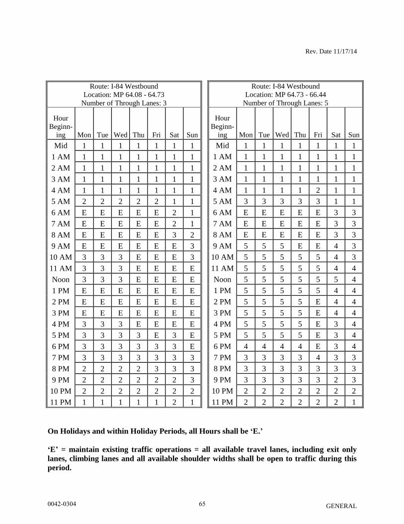
Rev. Date 11/17/14
GENERAL
Route: I-84 Westbound
Location: MP 64.73 - 66.44
Number of Through Lanes: 5
Hour
Beginn-
ing Mon Tue Wed Thu Fri Sat Sun
Mid 1 1 1 1 1 1 1
1 AM 1 1 1 1 1 1 1
2 AM 1 1 1 1 1 1 1
3 AM 1 1 1 1 1 1 1
4 AM 1 1 1 1 2 1 1
5 AM 3 3 3 3 3 1 1
6 AM E E E E E 3 3
7 AM E E E E E 3 3
8 AM E E E E E 3 3
9 AM 5 5 5 E E 4 3
10 AM 5 5 5 5 5 4 3
11 AM 5 5 5 5 5 4 4
Noon 5 5 5 5 5 5 4
1 PM 5 5 5 5 5 4 4
2 PM 5 5 5 5 E 4 4
3 PM 5 5 5 5 E 4 4
4 PM 5 5 5 5 E 3 4
5 PM 5 5 5 5 E 3 4
6 PM 4 4 4 4 E 3 4
7 PM 3 3 3 3 4 3 3
8 PM 3 3 3 3 3 3 3
9 PM 3 3 3 3 3 2 3
10 PM 2 2 2 2 2 2 2
11 PM 2 2 2 2 2 2 1
On Holidays and within Holiday Periods, all Hours shall be ‘E.’
‘E’ = maintain existing traffic operations = all available travel lanes, including exit only
lanes, climbing lanes and all available shoulder widths shall be open to traffic during this
period.
Route: I-84 Westbound
Location: MP 64.08 - 64.73
Number of Through Lanes: 3
Hour
Beginn-
ing Mon Tue Wed Thu Fri Sat Sun
Mid 1 1 1 1 1 1 1
1 AM 1 1 1 1 1 1 1
2 AM 1 1 1 1 1 1 1
3 AM 1 1 1 1 1 1 1
4 AM 1 1 1 1 1 1 1
5 AM 2 2 2 2 2 1 1
6 AM E E E E E 2 1
7 AM E E E E E 2 1
8 AM E E E E E 3 2
9 AM E E E E E E 3
10 AM 3 3 3 E E E 3
11 AM 3 3 3 E E E E
Noon 3 3 3 E E E E
1 PM E E E E E E E
2 PM E E E E E E E
3 PM E E E E E E E
4 PM 3 3 3 E E E E
5 PM 3 3 3 3 E 3 E
6 PM 3 3 3 3 3 3 E
7 PM 3 3 3 3 3 3 3
8 PM 2 2 2 2 3 3 3
9 PM 2 2 2 2 2 2 3
10 PM 2 2 2 2 2 2 2
11 PM 1 1 1 1 1 2 1
0042-0304 65

Rev. Date 11/17/14
GENERAL
INCIDENT MANAGEMENT SYSTEM
The Contractor will not be allowed to perform any work that will disrupt the normal operation of
the Incident Management System (IMS) as follows:
On Monday through Friday from 5:00 a.m. to 9:00 p.m.
On Saturday and Sunday.
On the day before or after any of the Legal Holidays listed below:
New Years Day
Good Friday
Memorial Day
Independence Day
Labor Day
Thanksgiving Day
Christmas Day
On the Saturday, Sunday and Monday following Thanksgiving Day.
On the Friday, Saturday and Sunday immediately preceding any of the above Legal
holidays celebrated on a Monday.
On the Saturday, Sunday and Monday immediately following any of the above Legal
holidays celebrated on a Friday.
In order to maintain continuous operation of the Incident Management System, the Contractor
shall adhere to the requirements in the special provision “Notice to Contractor – Installation
Qualifications” and “Notice to Contractor –Installation of IMS Systems”.
Article 1.08.07 - Determination of Contract Time:
Delete the second, third and fourth paragraphs and replace them with the following:
0042-0304 66
Rev. Date 11/17/14
GENERAL
When the contract time is on a calendar day basis, it shall be the number of consecutive
calendar days stated in the contract, INCLUDING the time period from December 1 through
March 31 of each year. The contract time will begin on the effective date of the Engineer’s
order to commence work, and it will be computed on a consecutive day basis, including all
Saturdays, Sundays, Holidays, and non-work days.
Article 1.08.08 - Extension of Time:
Delete the last paragraph, “If an approved extension of time…. the following April 1”.
Article 1.08.09 - Failure to Complete Work on Time:
Delete the second paragraph, "If the last day...the project is substantially completed" and
replace it with "Liquidated damages as specified in the Contract shall be assessed against the
Contractor per calendar day from that day until the date on which the project is substantially
completed.".
0042-0304 67
Rev. Date 11/03/2014
GENERAL
SECTION 4.06 - BITUMINOUS CONCRETE
Section 4.06 is being deleted in its entirety and replaced with the following:
4.06.01—Description
4.06.02—Materials
4.06.03—Construction Methods
4.06.04—Method of Measurement
4.06.05—Basis of Payment
4.06.01—Description: Work under this section shall include the production, delivery and
placement of a non-segregated, smooth and dense bituminous concrete mixture brought to proper
grade and cross section. This section shall also include the method and construction of
longitudinal joints. The Contractor shall furnish ConnDOT with a Quality Control Plan (QCP)
as described in Article 4.06.03.
The terms listed below as used in this specification are defined as:
Bituminous Concrete: A concrete material that uses a bituminous material (typically asphalt) as
the binding agent and stone and sand as the principal aggregate components. Bituminous
concrete may also contain any of a number of additives engineered to modify specific properties
and/or behavior of the concrete material. For the purposes of this Specification, references to
bituminous concrete apply to all of its sub-categories, for instance those defined on the basis of
production and placement temperatures, such as hot-mix asphalt (HMA) or warm-mix asphalt
(WMA), or those defined on the basis of composition, such as those containing polymer-
modified asphalt (PMA).
Course: A lift or multiple lifts comprised of the same bituminous concrete mixture placed as part
of the pavement structure.
Density Lot: All material placed in a single lift and as defined in Article 4.06.03.
Disintegration: Wearing away or fragmentation of the pavement. Disintegration will be evident
in the following forms: Polishing, weathering-oxidizing, scaling, spalling, raveling, potholes or
loss of material.
Dispute Resolution: A procedure used to resolve conflicts resulting from discrepancies between
the Engineer and the Contractor’s density results that may affect payment.
Hot Mix Asphalt (HMA): A bituminous concrete mixture typically produced at 325°F.
Lift: An application of a bituminous concrete mixture placed and compacted to a specified
thickness in a single paver pass.
0042-0304 68
Rev. Date 11/03/2014
GENERAL
Polymer Modified Asphalt (PMA): A bituminous concrete mixture containing a polymer
modified asphalt binder in accordance with contract specifications. All PMA mixtures shall
incorporate a qualified warm mix technology.
Production Lot: All material placed during a continuous daily paving operation.
Quality Assurance (QA): All those planned and systematic actions necessary to provide
confidence that a product or facility will perform as designed.
Quality Control (QC): The sum total of activities performed by the vendor (Producer,
Manufacturer, and Contractor) to ensure that a product meets contract specification
requirements.
Superpave: A bituminous concrete mix design used in mixtures designated as “S*” Where “S”
indicates Superpave and * indicates the sieve related to the nominal maximum aggregate size of
the mix.
Segregation: A non-uniform distribution of a bituminous concrete mixture in terms of gradation,
temperature, or volumetric properties.
Warm Mix Asphalt (WMA): A bituminous concrete mixture that can be produced and placed at
reduced temperatures than HMA using a qualified additive or technology.
4.06.02—Materials: All materials shall conform to the requirements of Section M.04.
1. Materials Supply: The bituminous concrete mixture must be from one source of supply and
originate from one Plant unless authorized by the Engineer. Bituminous Concrete plant QCP
requirements are defined in Section M.04.
2. Recycled Materials: Reclaimed Asphalt Pavement (RAP), Crushed Recycled Container
Glass (CRCG), Recycled Asphalt Shingles (RAS), or crumb rubber (CR) from recycled tires
may be incorporated in bituminous concrete mixtures in accordance with Section M.04 and
Project Specifications. CRCG and RAS shall not be used in the surface course.
4.06.03—Construction Methods:
1. Material Documentation: All vendors producing bituminous concrete must have their truck-
weighing scales, storage scales, and mixing plant automated to provide a detailed ticket.
Delivery tickets shall include the following information:
a. State of Connecticut printed on ticket.
b. Name of producer, identification of plant, and specific storage bin (silo) if used.
c. Date and time of day.
0042-0304 69
Rev. Date 11/03/2014
GENERAL
d. Mixture Designation; Mix type and level Curb mixtures for machine-placed curbing must
state "curb mix only".
e. If RAP is used, the plant printouts shall include the RAP dry weight, percentage and daily
moisture content.
f. If RAS is used, the plant printouts shall include the RAS dry weight and percentage daily
moisture content.
g. The delivery ticket for all mixes produced with Warm Mix Technology must indicate the
additive name, and the injection rate (water or additive) incorporated at the HMA plant.
The delivery ticket for all mixes produced with pre-blended WMA additive must indicate
the name of the WMA Technology.
h. Net weight of mixture loaded into truck (When RAP and/or RAS is used the moisture
content shall be excluded from mixture net weight).
i. Gross weight (Either equal to the net weight plus the tare weight or the loaded scale
weight).
j. Tare weight of truck – Daily scale weight.
k. Project number, purchase order number, name of Contractor (if Contractor other than
Producer).
l. Truck number for specific identification of truck.
m. Individual aggregate, Recycled Materials, and virgin asphalt high/target/low weights. For
drum plants and silo loadings, the plant printouts shall be produced at 5 minute intervals
maintained by the vendor for a period of three years after the completion of the project.
n. For every mixture designation the running daily total delivered and sequential load
number.
The net weight of mixture loaded into the truck must be equal to the cumulative measured weight
of its components.
The Contractor must notify the Engineer immediately if, during the production day, there is a
malfunction of the weighing or recording system in the automated plant or truck-weighing
scales. Manually written tickets containing all required information will be allowed for one
hour, but for no longer, provided that each load is weighed on State-approved scales. At the
Engineer’s sole discretion, trucks may be approved to leave the plant if a State inspector is
present to monitor weighing. If such a malfunction is not fixed within forty-eight hours, mixture
will not be approved to leave the plant until the system is fixed to the Engineer's satisfaction. No
damages will be considered should the State be unable to provide an inspector at the plant.
The State reserves the right to have an inspector present to monitor batching and /or weighing
operations.
2. Transportation of Mixture: Trucks with loads of bituminous concrete being delivered to
State projects must not exceed the statutory or permitted load limits referred to as gross vehicle
weight (GVW). The Contractor shall furnish a list of all vehicles and allowable weights
transporting mixture.
0042-0304 70
Rev. Date 11/03/2014
GENERAL
The State reserves the right to check the gross and tare weight of any delivery truck. A variation
of 0.4 percent or less in the gross or tare weight shown on the delivery ticket and the certified
scale weight shall be considered evidence that the weight shown on the delivery ticket is correct.
If the gross or tare weight varies from that shown on the delivery ticket by more than 0.4 percent,
the Engineer will recalculate the net weight. The Contractor shall take action to correct
discrepancy to the satisfaction of the Engineer.
If a truck delivers mixture to the project and the ticket indicates that the truck is overweight, the
load will not be rejected but a “Measured Weight Adjustment” will be taken in accordance with
Article 4.06.04.
The mixture shall be transported from the mixing plant in trucks that have previously been
cleaned of all foreign material and that have no gaps through which mixture might inadvertently
escape. The Contractor shall take care in loading trucks uniformly so that segregation is
minimized. Loaded trucks shall be tightly covered with waterproof covers acceptable to the
Engineer. Mesh covers are prohibited. The front and rear of the cover must be fastened to
minimize air infiltration. The Contractor shall assure that all trucks are in conformance with this
specification. Trucks found not to be in conformance shall not be allowed to be loaded until re-
inspected to the satisfaction of the Engineer.
Truck body coating and cleaning agents must not have a deleterious effect on the transported
mixture. The use of solvents or fuel oil, in any concentration, is strictly prohibited for the
coating of the inside of truck bodies. When acceptable coating or agents are applied, truck
bodies shall be raised immediately prior to loading to remove any excess agent in an
environmentally acceptable manner.
3. Paving Equipment: The Contractor shall have the necessary paving and compaction
equipment at the project site to perform the work. All equipment shall be in good working order
and any equipment that is worn, defective or inadequate for performance of the work shall be
repaired or replaced by the Contractor to the satisfaction of the Engineer. During the paving
operation, the use of solvents or fuel oil, in any concentration, is strictly prohibited as a release
agent or cleaner on any paving equipment (i.e., rollers, pavers, transfer devices, etc.).
Refueling of equipment is prohibited in any location on the paving project where fuel might
come in contact with bituminous concrete mixtures already placed or to be placed. Solvents for
use in cleaning mechanical equipment or hand tools shall be stored clear of areas paved or to be
paved. Before any such equipment and tools are cleaned, they shall be moved off the paved or to
be paved area; and they shall not be returned for use until after they have been allowed to dry.
Pavers: Each paver shall have a receiving hopper with sufficient capacity to provide for a
uniform spreading operation and a distribution system that places the mix uniformly, without
segregation. The paver shall be equipped with and use a vibratory screed system with heaters or
burners. The screed system shall be capable of producing a finished surface of the required
evenness and texture without tearing, shoving, or gouging the mixture. Pavers with extendible
0042-0304 71
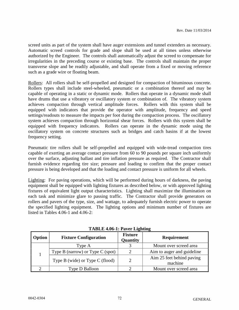
Rev. Date 11/03/2014
GENERAL
screed units as part of the system shall have auger extensions and tunnel extenders as necessary.
Automatic screed controls for grade and slope shall be used at all times unless otherwise
authorized by the Engineer. The controls shall automatically adjust the screed to compensate for
irregularities in the preceding course or existing base. The controls shall maintain the proper
transverse slope and be readily adjustable, and shall operate from a fixed or moving reference
such as a grade wire or floating beam.
Rollers: All rollers shall be self-propelled and designed for compaction of bituminous concrete.
Rollers types shall include steel-wheeled, pneumatic or a combination thereof and may be
capable of operating in a static or dynamic mode. Rollers that operate in a dynamic mode shall
have drums that use a vibratory or oscillatory system or combination of. The vibratory system
achieves compaction through vertical amplitude forces. Rollers with this system shall be
equipped with indicators that provide the operator with amplitude, frequency and speed
settings/readouts to measure the impacts per foot during the compaction process. The oscillatory
system achieves compaction through horizontal shear forces. Rollers with this system shall be
equipped with frequency indicators. Rollers can operate in the dynamic mode using the
oscillatory system on concrete structures such as bridges and catch basins if at the lowest
frequency setting.
Pneumatic tire rollers shall be self-propelled and equipped with wide-tread compaction tires
capable of exerting an average contact pressure from 60 to 90 pounds per square inch uniformly
over the surface, adjusting ballast and tire inflation pressure as required. The Contractor shall
furnish evidence regarding tire size; pressure and loading to confirm that the proper contact
pressure is being developed and that the loading and contact pressure is uniform for all wheels.
Lighting: For paving operations, which will be performed during hours of darkness, the paving
equipment shall be equipped with lighting fixtures as described below, or with approved lighting
fixtures of equivalent light output characteristics. Lighting shall maximize the illumination on
each task and minimize glare to passing traffic. The Contractor shall provide generators on
rollers and pavers of the type, size, and wattage, to adequately furnish electric power to operate
the specified lighting equipment. The lighting options and minimum number of fixtures are
listed in Tables 4.06-1 and 4.06-2:
TABLE 4.06-1: Paver Lighting
Option Fixture Configuration Fixture
Quantity Requirement
1
Type A 3 Mount over screed area
Type B (narrow) or Type C (spot) 2 Aim to auger and guideline
Type B (wide) or Type C (flood) 2 Aim 25 feet behind paving
machine
2 Type D Balloon 2 Mount over screed area
0042-0304 72
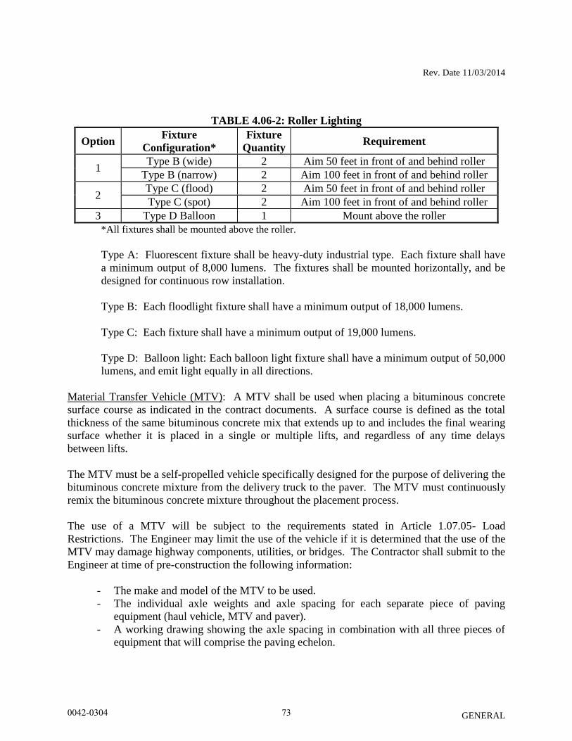
Rev. Date 11/03/2014
GENERAL
TABLE 4.06-2: Roller Lighting
Option Fixture
Configuration*
Fixture
Quantity Requirement
1 Type B (wide) 2 Aim 50 feet in front of and behind roller
Type B (narrow) 2 Aim 100 feet in front of and behind roller
2 Type C (flood) 2 Aim 50 feet in front of and behind roller
Type C (spot) 2 Aim 100 feet in front of and behind roller
3 Type D Balloon 1 Mount above the roller
*All fixtures shall be mounted above the roller.
Type A: Fluorescent fixture shall be heavy-duty industrial type. Each fixture shall have
a minimum output of 8,000 lumens. The fixtures shall be mounted horizontally, and be
designed for continuous row installation.
Type B: Each floodlight fixture shall have a minimum output of 18,000 lumens.
Type C: Each fixture shall have a minimum output of 19,000 lumens.
Type D: Balloon light: Each balloon light fixture shall have a minimum output of 50,000
lumens, and emit light equally in all directions.
Material Transfer Vehicle (MTV): A MTV shall be used when placing a bituminous concrete
surface course as indicated in the contract documents. A surface course is defined as the total
thickness of the same bituminous concrete mix that extends up to and includes the final wearing
surface whether it is placed in a single or multiple lifts, and regardless of any time delays
between lifts.
The MTV must be a self-propelled vehicle specifically designed for the purpose of delivering the
bituminous concrete mixture from the delivery truck to the paver. The MTV must continuously
remix the bituminous concrete mixture throughout the placement process.
The use of a MTV will be subject to the requirements stated in Article 1.07.05- Load
Restrictions. The Engineer may limit the use of the vehicle if it is determined that the use of the
MTV may damage highway components, utilities, or bridges. The Contractor shall submit to the
Engineer at time of pre-construction the following information:
- The make and model of the MTV to be used.
- The individual axle weights and axle spacing for each separate piece of paving
equipment (haul vehicle, MTV and paver).
- A working drawing showing the axle spacing in combination with all three pieces of
equipment that will comprise the paving echelon.
0042-0304 73
Rev. Date 11/03/2014
GENERAL
4. Test Section: The Engineer may require the Contractor to place a test section whenever the
requirements of this specification or Section M.04 are not met.
The Contractor shall submit the quantity of mixture to be placed and the location of the test
section for review and acceptance by the Engineer. The equipment used in the construction of a
passing test section shall be used throughout production.
If a test section fails to meet specifications, the Contractor shall stop production, make necessary
adjustments to the job mix formula, plant operations, or procedures for placement and
compaction. The Contractor shall construct test sections, as allowed by the Engineer, until all
the required specifications are met. All test sections shall also be subject to removal as set forth
in Article 1.06.04.
5. Transitions for Roadway Surface: Transitions shall be formed at any point on the roadway
where the pavement surface deviates, vertically, from the uniform longitudinal profile as
specified on the plans. Whether formed by milling or by bituminous concrete mixture, all
transition lengths shall conform to the criteria below unless otherwise specified.
Permanent Transitions: A permanent transition is defined as any transition that remains as a
permanent part of the work. All permanent transitions, leading and trailing ends shall meet the
following length requirements:
a) Posted speed limit is greater than 35 MPH: 30 feet per inch of vertical change (thickness)
b) Posted speed limit is 35 MPH or less: 15 feet per inch of vertical change (thickness).
c) Bridge Overpass and underpass transition length will be 75 feet either
(1) Before and after the bridge expansion joint, or
(2) Before or after the parapet face of the overpass.
In areas where it is impractical to use the above described permanent transition lengths the use of
a shorter permanent transition length may be permitted when approved by the Engineer.
Temporary Transitions: A temporary transition is defined as a transition that does not remain a
permanent part of the work. All temporary transitions shall meet the following length
requirements:
a) Posted speed limit is greater than 50 MPH
(1) Leading Transitions = 15 feet per inch of vertical change (thickness)
(2) Trailing Transitions = 6 feet per inch of vertical change (thickness)
b) Posted speed limit is 40, 45, or 50 MPH
(1) Leading and Trailing = 4 feet per inch of vertical change (thickness)
c) Posted speed limit is 35 MPH or less
(1) Leading and Trailing = 3 feet per inch of vertical change (thickness)
Note: Any temporary transition to be in-place over the winter shutdown period or during
extended periods of inactivity (more than 14 calendar days) shall conform to the greater than 50
MPH requirements shown above.
0042-0304 74
Rev. Date 11/03/2014
GENERAL
6. Spreading and Finishing of Mixture: Prior to the placement of the bituminous concrete, the
underlying base course shall be brought to the plan grade and cross section within the allowable
tolerance. Immediately before placing the mixture, the area to be surfaced shall be cleaned by
sweeping or by other means acceptable to the Engineer. The bituminous concrete mixture shall
not be placed whenever the surface is wet or frozen. The Engineer will verify the mix
temperature by means of a probe or infrared type of thermometer. A probe type thermometer,
verified by the Department on an annual basis, must be used in order to reject a load of mixture
based on temperatures outside the range stated in the placement QCP.
Placement: The bituminous concrete mixture shall be placed and compacted to provide a
smooth, dense surface with a uniform texture and no segregation at the specified thickness and
dimensions indicated in the plans and specifications.
When unforeseen weather conditions prevent further placement of the mix, the Engineer is not
obligated to accept or place the bituminous concrete mixture that is in transit from the plant.
In advance of paving, traffic control requirements shall be set up daily, maintained throughout
placement, and shall not be removed until all associated work including density testing is
completed.
The Contractor shall inspect the newly placed pavement for defects in the mixture or placement
before rolling is started. Any deviation from standard crown or section shall be immediately
remedied by placing additional mixture or removing surplus mixture. Such defects shall be
corrected to the satisfaction of the Engineer.
Where it is impractical due to physical limitations to operate the paving equipment, the Engineer
may permit the use of other methods or equipment. Where hand spreading is permitted, the
mixture shall be placed by means of suitable shovels and other tools, and in a uniformly loose
layer at a thickness that will result in a completed pavement meeting the designed grade and
elevation.
Placement Tolerances: Each lift of bituminous concrete placed at a uniform specified thickness
shall meet the following requirements for thickness and area. Any pavement exceeding these
limits shall be subject to an adjustment or removal. Lift tolerances will not relieve the
Contractor from meeting the final designed grade. Lifts of specified non-uniform thickness, i.e.
wedge or shim course, shall not be subject to thickness and area adjustments.
a) Thickness- Where the total thickness of the lift of mixture exceeds that shown on the plans
beyond the tolerances shown in Table 4.06-3, the longitudinal limits of such variation
including locations and intervals of the measurements will be documented by the
Engineer for use in calculating an adjustment in accordance with Article 4.06.04.
0042-0304 75
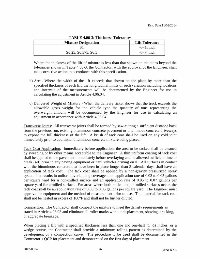
Rev. Date 11/03/2014
GENERAL
TABLE 4.06-3: Thickness Tolerances
Mixture Designation Lift Tolerance
S1 +/- ⅜ inch
S0.25, S0.375, S0.5 +/- ¼ inch
Where the thickness of the lift of mixture is less than that shown on the plans beyond the
tolerances shown in Table 4.06-3, the Contractor, with the approval of the Engineer, shall
take corrective action in accordance with this specification.
b) Area- Where the width of the lift exceeds that shown on the plans by more than the
specified thickness of each lift, the longitudinal limits of such variation including locations
and intervals of the measurements will be documented by the Engineer for use in
calculating the adjustment in Article 4.06.04.
c) Delivered Weight of Mixture - When the delivery ticket shows that the truck exceeds the
allowable gross weight for the vehicle type the quantity of tons representing the
overweight amount will be documented by the Engineer for use in calculating an
adjustment in accordance with Article 4.06.04.
Transverse Joints: All transverse joints shall be formed by saw-cutting a sufficient distance back
from the previous run, existing bituminous concrete pavement or bituminous concrete driveways
to expose the full thickness of the lift. A brush of tack coat shall be used on any cold joint
immediately prior to additional bituminous concrete mixture being placed.
Tack Coat Application: Immediately before application, the area to be tacked shall be cleaned
by sweeping or by other means acceptable to the Engineer. A thin uniform coating of tack coat
shall be applied to the pavement immediately before overlaying and be allowed sufficient time to
break (set) prior to any paving equipment or haul vehicles driving on it. All surfaces in contact
with the bituminous concrete that have been in place longer than 3 calendar days shall have an
application of tack coat. The tack coat shall be applied by a non-gravity pressurized spray
system that results in uniform overlapping coverage at an application rate of 0.03 to 0.05 gallons
per square yard for a non-milled surface and an application rate of 0.05 to 0.07 gallons per
square yard for a milled surface. For areas where both milled and un-milled surfaces occur, the
tack coat shall be an application rate of 0.03 to 0.05 gallons per square yard. The Engineer must
approve the equipment and the method of measurement prior to use. The material for tack coat
shall not be heated in excess of 160°F and shall not be further diluted.
Compaction: The Contractor shall compact the mixture to meet the density requirements as
stated in Article 4.06.03 and eliminate all roller marks without displacement, shoving, cracking,
or aggregate breakage.
When placing a lift with a specified thickness less than one and one-half (1 ½) inches, or a
wedge course, the Contractor shall provide a minimum rolling pattern as determined by the
development of a compaction curve. The procedure to be used shall be documented in the
Contractor’s QCP for placement and demonstrated on the first day of placement.
0042-0304 76
Rev. Date 11/03/2014
GENERAL
The use of the vibratory system on concrete structures is prohibited. When approved by the
Engineer, the Contractor may operate a roller using an oscillatory system at the lowest frequency
setting.
If the Engineer determines that the use of compaction equipment in the dynamic mode may
damage highway components, utilities, or adjacent property, the Contractor shall provide
alternate compaction equipment. The Engineer may allow the Contractor to operate rollers in the
dynamic mode using the oscillatory system at the lowest frequency setting.
Rollers operating in the dynamic mode shall be shut off when changing directions.
These allowances will not relieve the Contractor from meeting pavement compaction
requirements.
Surface Requirements: The pavement surface of any lift shall meet the following requirements
for smoothness and uniformity. Any irregularity of the surface exceeding these requirements
shall be corrected by the Contractor.
a) Smoothness- Each lift of the surface course shall not vary more than ¼ inch from a
Contractor-supplied 10 foot straightedge. For all other lifts of bituminous concrete, the
tolerance shall be ⅜ inch. Such tolerance will apply to all paved areas.
b) Uniformity- The paved surface of the mat and joints shall not exhibit segregation, rutting,
cracking, disintegration, flushing or vary in composition as determined by the Engineer.
7. Longitudinal Joint Construction Methods: The Contractor shall use Method I- Notched
Wedge Joint (see Figure 4.06-1) when constructing longitudinal joints where lift thicknesses are
between 1½ and 3 inches, except for S1mixes. Method II Butt Joint (see Figure 4.06-2) shall be
used for lifts less than 1½ inches or greater than 3 inches, and S1mixes. During placement of
multiple lifts of bituminous concrete, the longitudinal joint shall be constructed in such a manner
that it is located at least 6 inches from the joint in the lift immediately below. The joint in the
final lift shall be at the centerline or at lane lines. Each longitudinal joint shall maintain a
consistent offset from the centerline of the roadway along its entire length. The difference in
elevation between the two faces of any completed longitudinal joint shall not exceed ¼ of an
inch in any location.
0042-0304 77
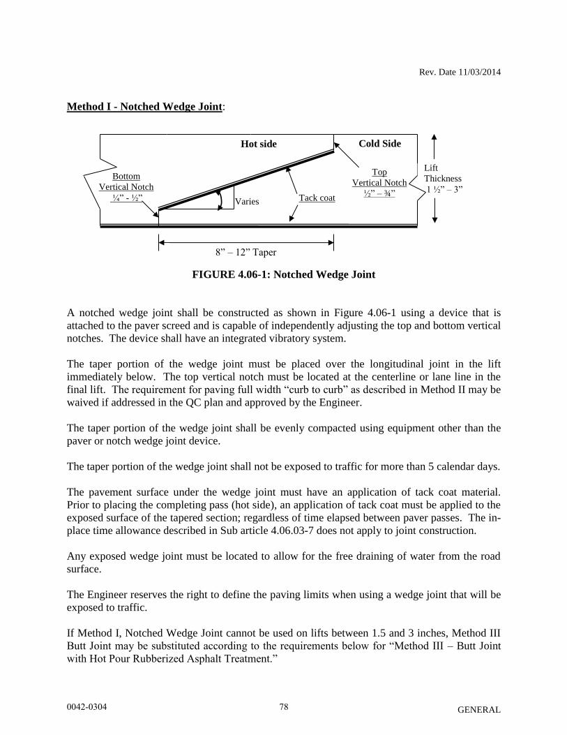
Rev. Date 11/03/2014
GENERAL
Method I - Notched Wedge Joint:
FIGURE 4.06-1: Notched Wedge Joint
A notched wedge joint shall be constructed as shown in Figure 4.06-1 using a device that is
attached to the paver screed and is capable of independently adjusting the top and bottom vertical
notches. The device shall have an integrated vibratory system.
The taper portion of the wedge joint must be placed over the longitudinal joint in the lift
immediately below. The top vertical notch must be located at the centerline or lane line in the
final lift. The requirement for paving full width “curb to curb” as described in Method II may be
waived if addressed in the QC plan and approved by the Engineer.
The taper portion of the wedge joint shall be evenly compacted using equipment other than the
paver or notch wedge joint device.
The taper portion of the wedge joint shall not be exposed to traffic for more than 5 calendar days.
The pavement surface under the wedge joint must have an application of tack coat material.
Prior to placing the completing pass (hot side), an application of tack coat must be applied to the
exposed surface of the tapered section; regardless of time elapsed between paver passes. The in-
place time allowance described in Sub article 4.06.03-7 does not apply to joint construction.
Any exposed wedge joint must be located to allow for the free draining of water from the road
surface.
The Engineer reserves the right to define the paving limits when using a wedge joint that will be
exposed to traffic.
If Method I, Notched Wedge Joint cannot be used on lifts between 1.5 and 3 inches, Method III
Butt Joint may be substituted according to the requirements below for “Method III – Butt Joint
with Hot Pour Rubberized Asphalt Treatment.”
Hot side Cold Side
8” – 12” Taper
Top
Vertical Notch
½” – ¾” Tack coat
Bottom
Vertical Notch
¼” - ½”
Lift
Thickness
1 ½” – 3”
Varies
0042-0304 78
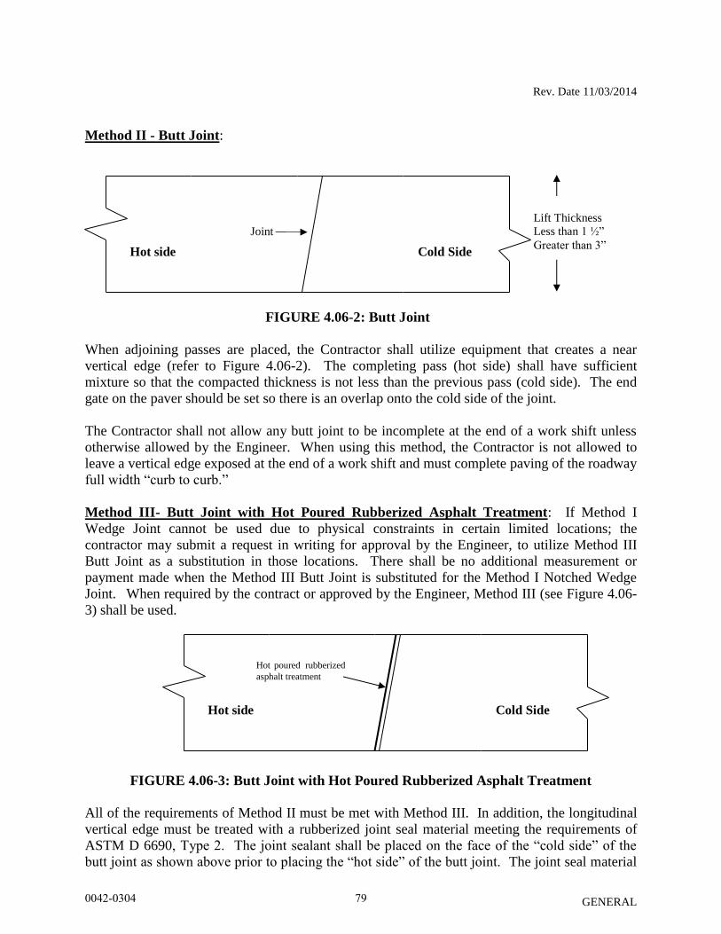
Rev. Date 11/03/2014
GENERAL
Method II - Butt Joint:
FIGURE 4.06-2: Butt Joint
When adjoining passes are placed, the Contractor shall utilize equipment that creates a near
vertical edge (refer to Figure 4.06-2). The completing pass (hot side) shall have sufficient
mixture so that the compacted thickness is not less than the previous pass (cold side). The end
gate on the paver should be set so there is an overlap onto the cold side of the joint.
The Contractor shall not allow any butt joint to be incomplete at the end of a work shift unless
otherwise allowed by the Engineer. When using this method, the Contractor is not allowed to
leave a vertical edge exposed at the end of a work shift and must complete paving of the roadway
full width “curb to curb.”
Method III- Butt Joint with Hot Poured Rubberized Asphalt Treatment: If Method I
Wedge Joint cannot be used due to physical constraints in certain limited locations; the
contractor may submit a request in writing for approval by the Engineer, to utilize Method III
Butt Joint as a substitution in those locations. There shall be no additional measurement or
payment made when the Method III Butt Joint is substituted for the Method I Notched Wedge
Joint. When required by the contract or approved by the Engineer, Method III (see Figure 4.06-
3) shall be used.
FIGURE 4.06-3: Butt Joint with Hot Poured Rubberized Asphalt Treatment
All of the requirements of Method II must be met with Method III. In addition, the longitudinal
vertical edge must be treated with a rubberized joint seal material meeting the requirements of
ASTM D 6690, Type 2. The joint sealant shall be placed on the face of the “cold side” of the
butt joint as shown above prior to placing the “hot side” of the butt joint. The joint seal material
Hot side Cold Side
Joint
Hot side Cold Side
Hot poured rubberized
asphalt treatment
Lift Thickness
Less than 1 ½”
Greater than 3”
0042-0304 79

Rev. Date 11/03/2014
GENERAL
shall be applied in accordance with the manufacturer’s recommendation so as to provide a
uniform coverage and avoid excess bleeding onto the newly placed pavement.
8. Contractor Quality Control (QC) Requirements: The Contractor shall be responsible for maintaining adequate quality control procedures
throughout the production and placement operations. Therefore, the Contractor must ensure that
the materials, mixture and work provided by Subcontractors, Suppliers and Producers also meet
contract specification requirements.
This effort must be documented in Quality Control Plans and address the actions, inspection, or
sampling and testing necessary to keep the production and placement operations in control, to
determine when an operation has gone out of control and to respond to correct the situation in a
timely fashion.
The Standard QCP for production shall consist of the quality control program specific to the
production facility.
There are three components to the QCP for placement: a Standard QCP, a Project Summary
Sheet that details project specific information, and if applicable a separate Extended Season
Paving Plan as required in Section 9 “Temperature and Seasonal Requirements”.
The Standard QCP for both production and placement shall be submitted to the Department for
approval each calendar year and.at a minimum of 30 days prior to production or placement.
Production or placement shall not occur until all QCP components have been approved by the
Engineer.
Each QCP shall include the name and qualifications of a Quality Control Manager (QCM). The
QCM shall be responsible for the administration of the QCP, and any modifications that may
become necessary. The QCM shall have the ability to direct all Contractor personnel on the
project during paving operations. All Contractor sampling, inspection and test reports shall be
reviewed and signed by the QCM prior to submittal to the Engineer. The QCPs shall also
include the name and qualifications of any outside testing laboratory performing any QC
functions on behalf of the Contractor.
Approval of the QCP does not relieve the Contractor of its responsibility to comply with the
project specifications. The Contractor may modify the QCPs as work progresses and must
document the changes in writing prior to resuming operations. These changes include but are not
limited to changes in quality control procedures or personnel. The Department reserves the right
to deny significant changes to the QCPs.
QCP for Production: Refer to Section M.04.03-1.
0042-0304 80
Rev. Date 11/03/2014
GENERAL
QCP for Placement: The Standard QCP, Project Summary Sheet, and Extended Season Paving
Plan shall conform to the format provided by the Engineer. The format is available at http://www.ct.gov/dot/lib/dot/documents/dconstruction/pat/qcp_outline_hma_plac
ement.pdf.
The Contractor shall perform all quality control sampling and testing, provide inspection, and
exercise management control to ensure that bituminous concrete placement conforms to the
requirements as outlined in its QCP during all phases of the work. The Contractor shall
document these activities for each day of placement.
The Contractor shall submit complete field density testing and inspection records to the Engineer
within 48 hours in a manner acceptable to the Engineer.
The Contractor may obtain one (1) mat core and one (1) joint core per day for process control,
provided this process is detailed in the QCP. The results of these process control cores shall not
be used to dispute the Department determinations from the acceptance cores. The Contractor
shall submit the location of each process control core to the Engineer for approval prior to taking
the core. The core holes shall be filled to the same requirements described in Sub article
4.06.03-10.
9. Temperature and Seasonal Requirements: Paving, including placement of temporary
pavements, shall be divided into two seasons, “In-Season” and “Extended-Season”. In-Season
paving occurs from May 1 – October 14, and Extended Season paving occurs from October 15-
April 30. The following requirements shall apply unless otherwise authorized or directed by the
Engineer:
Bituminous concrete mixes shall not be placed when the air or sub base temperature is
below 40°F regardless of the season.
Should paving operations be scheduled during the Extended Season, the Contractor must
submit an Extended Season Paving Plan for the project that addresses minimum delivered
mix temperature considering WMA, PMA or other additives, maximum paver speed,
enhanced rolling patterns and the method to balance mixture delivery and placement
operations. Paving during Extended Season shall not commence until the Engineer has
approved the plan.
10. Density Testing of Bituminous Concrete Utilizing Core Samples: This procedure
describes the frequency and the method the Contractor shall use to obtain pavement cores for
acceptance from the project.
Coring shall be performed on each lift specified to a thickness of one and one-half (1 ½) inches
or more. All material placed in a lift shall be compacted to the degree specified in Tables 4.06-9
and 4.06-10. The density of each core will be determined using the production lot’s average
maximum theoretical specific gravity (Gmm) established during the testing of the parent material
at the plant. When there was no testing of the parent material or any Gmm exceeds the specified
tolerances in the Department’s current QA Program for Materials, the Engineer will determine
0042-0304 81
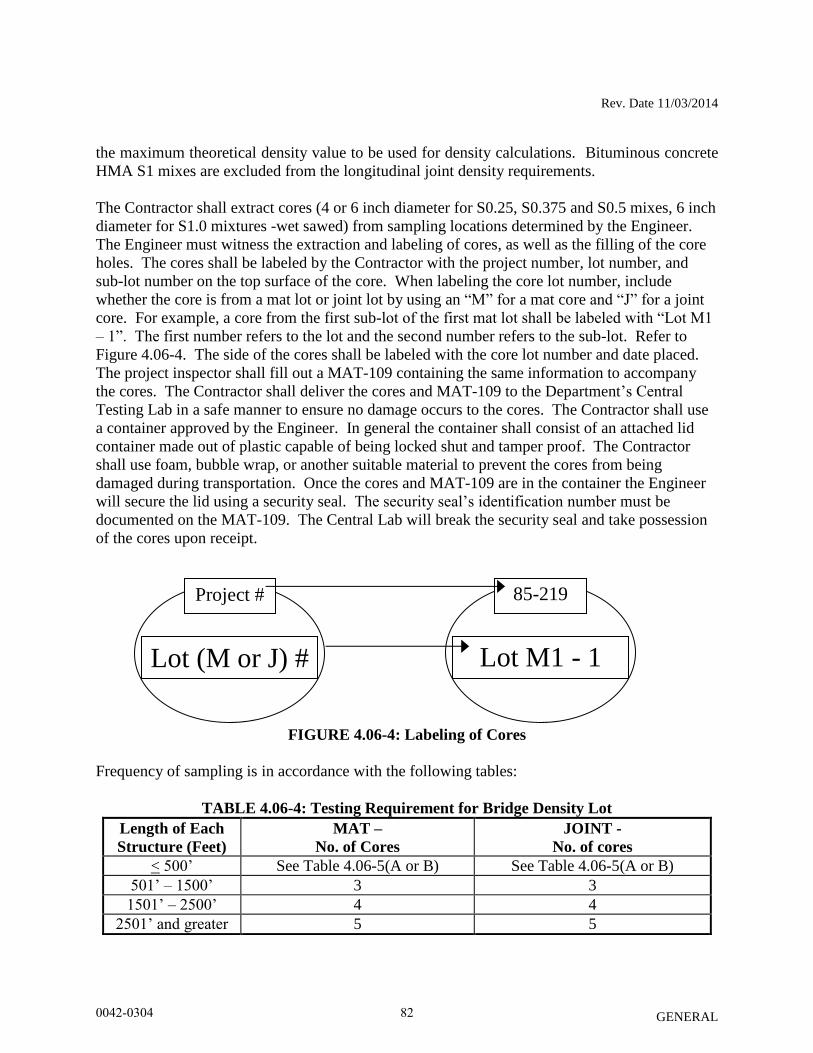
Rev. Date 11/03/2014
GENERAL
the maximum theoretical density value to be used for density calculations. Bituminous concrete
HMA S1 mixes are excluded from the longitudinal joint density requirements.
The Contractor shall extract cores (4 or 6 inch diameter for S0.25, S0.375 and S0.5 mixes, 6 inch
diameter for S1.0 mixtures -wet sawed) from sampling locations determined by the Engineer.
The Engineer must witness the extraction and labeling of cores, as well as the filling of the core
holes. The cores shall be labeled by the Contractor with the project number, lot number, and
sub-lot number on the top surface of the core. When labeling the core lot number, include
whether the core is from a mat lot or joint lot by using an “M” for a mat core and “J” for a joint
core. For example, a core from the first sub-lot of the first mat lot shall be labeled with “Lot M1
– 1”. The first number refers to the lot and the second number refers to the sub-lot. Refer to
Figure 4.06-4. The side of the cores shall be labeled with the core lot number and date placed.
The project inspector shall fill out a MAT-109 containing the same information to accompany
the cores. The Contractor shall deliver the cores and MAT-109 to the Department’s Central
Testing Lab in a safe manner to ensure no damage occurs to the cores. The Contractor shall use
a container approved by the Engineer. In general the container shall consist of an attached lid
container made out of plastic capable of being locked shut and tamper proof. The Contractor
shall use foam, bubble wrap, or another suitable material to prevent the cores from being
damaged during transportation. Once the cores and MAT-109 are in the container the Engineer
will secure the lid using a security seal. The security seal’s identification number must be
documented on the MAT-109. The Central Lab will break the security seal and take possession
of the cores upon receipt.
FIGURE 4.06-4: Labeling of Cores
Frequency of sampling is in accordance with the following tables:
TABLE 4.06-4: Testing Requirement for Bridge Density Lot
Length of Each
Structure (Feet)
MAT –
No. of Cores
JOINT -
No. of cores
< 500’ See Table 4.06-5(A or B) See Table 4.06-5(A or B)
501’ – 1500’ 3 3
1501’ – 2500’ 4 4
2501’ and greater 5 5
Project #
Lot (M or J) #
- #
85-219
Lot M1 - 1
0042-0304 82
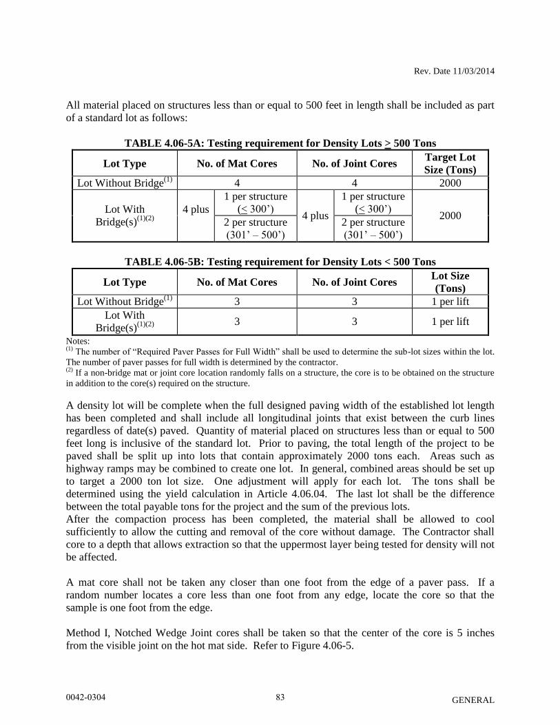
Rev. Date 11/03/2014
GENERAL
All material placed on structures less than or equal to 500 feet in length shall be included as part
of a standard lot as follows:
TABLE 4.06-5A: Testing requirement for Density Lots > 500 Tons
Lot Type No. of Mat Cores No. of Joint Cores Target Lot
Size (Tons)
Lot Without Bridge(1)
4 4 2000
Lot With
Bridge(s)(1)(2)
4 plus
1 per structure
(< 300’) 4 plus
1 per structure
(< 300’) 2000
2 per structure
(301’ – 500’)
2 per structure
(301’ – 500’)
TABLE 4.06-5B: Testing requirement for Density Lots < 500 Tons
Lot Type No. of Mat Cores No. of Joint Cores Lot Size
(Tons)
Lot Without Bridge(1)
3 3 1 per lift
Lot With
Bridge(s)(1)(2)
3 3 1 per lift
Notes: (1)
The number of “Required Paver Passes for Full Width” shall be used to determine the sub-lot sizes within the lot.
The number of paver passes for full width is determined by the contractor. (2)
If a non-bridge mat or joint core location randomly falls on a structure, the core is to be obtained on the structure
in addition to the core(s) required on the structure.
A density lot will be complete when the full designed paving width of the established lot length
has been completed and shall include all longitudinal joints that exist between the curb lines
regardless of date(s) paved. Quantity of material placed on structures less than or equal to 500
feet long is inclusive of the standard lot. Prior to paving, the total length of the project to be
paved shall be split up into lots that contain approximately 2000 tons each. Areas such as
highway ramps may be combined to create one lot. In general, combined areas should be set up
to target a 2000 ton lot size. One adjustment will apply for each lot. The tons shall be
determined using the yield calculation in Article 4.06.04. The last lot shall be the difference
between the total payable tons for the project and the sum of the previous lots.
After the compaction process has been completed, the material shall be allowed to cool
sufficiently to allow the cutting and removal of the core without damage. The Contractor shall
core to a depth that allows extraction so that the uppermost layer being tested for density will not
be affected.
A mat core shall not be taken any closer than one foot from the edge of a paver pass. If a
random number locates a core less than one foot from any edge, locate the core so that the
sample is one foot from the edge.
Method I, Notched Wedge Joint cores shall be taken so that the center of the core is 5 inches
from the visible joint on the hot mat side. Refer to Figure 4.06-5.
0042-0304 83
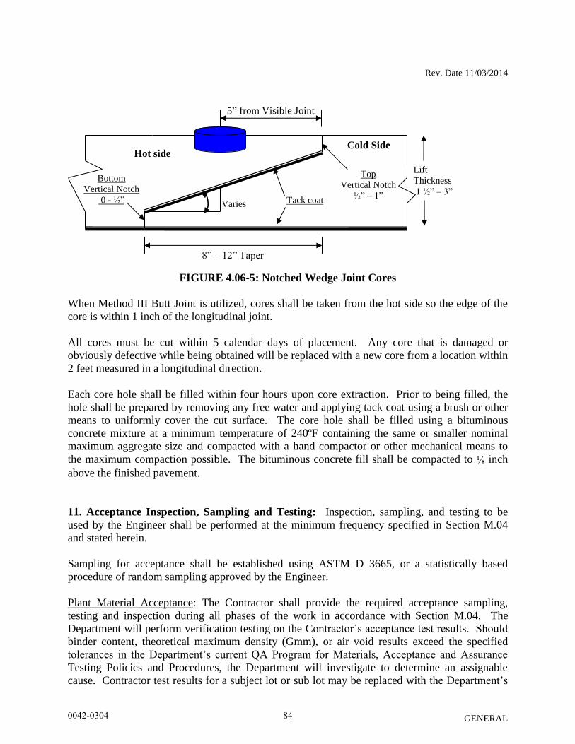
Rev. Date 11/03/2014
GENERAL
FIGURE 4.06-5: Notched Wedge Joint Cores
When Method III Butt Joint is utilized, cores shall be taken from the hot side so the edge of the
core is within 1 inch of the longitudinal joint.
All cores must be cut within 5 calendar days of placement. Any core that is damaged or
obviously defective while being obtained will be replaced with a new core from a location within
2 feet measured in a longitudinal direction.
Each core hole shall be filled within four hours upon core extraction. Prior to being filled, the
hole shall be prepared by removing any free water and applying tack coat using a brush or other
means to uniformly cover the cut surface. The core hole shall be filled using a bituminous
concrete mixture at a minimum temperature of 240ºF containing the same or smaller nominal
maximum aggregate size and compacted with a hand compactor or other mechanical means to
the maximum compaction possible. The bituminous concrete fill shall be compacted to ⅛ inch
above the finished pavement.
11. Acceptance Inspection, Sampling and Testing: Inspection, sampling, and testing to be
used by the Engineer shall be performed at the minimum frequency specified in Section M.04
and stated herein.
Sampling for acceptance shall be established using ASTM D 3665, or a statistically based
procedure of random sampling approved by the Engineer.
Plant Material Acceptance: The Contractor shall provide the required acceptance sampling,
testing and inspection during all phases of the work in accordance with Section M.04. The
Department will perform verification testing on the Contractor’s acceptance test results. Should
binder content, theoretical maximum density (Gmm), or air void results exceed the specified
tolerances in the Department’s current QA Program for Materials, Acceptance and Assurance
Testing Policies and Procedures, the Department will investigate to determine an assignable
cause. Contractor test results for a subject lot or sub lot may be replaced with the Department’s
Hot side Cold Side
8” – 12” Taper
Top
Vertical Notch
½” – 1” Tack coat
Bottom
Vertical Notch
0 - ½”
Lift
Thickness
1 ½” – 3”
Varies
5” from Visible Joint
0042-0304 84
Rev. Date 11/03/2014
GENERAL
results for the purpose of assessing adjustments. The verification procedure is included in the
Department’s current QA Program for Materials.
Density Acceptance: The Engineer will perform all acceptance testing on the cores in
accordance with AASHTO T 331.
12. Density Dispute Resolution Process: The Contractor and Engineer will work in partnership
to avoid potential conflicts and to resolve any differences that may arise during quality control or
acceptance testing for density. Both parties will review their sampling and testing procedures
and results and share their findings. If the Contractor disputes the Engineer’s test results, the
Contractor must submit in writing a request to initiate the Dispute Resolution Process within 7
calendar days of the notification of the test results. No request for dispute resolution will be
allowed unless the Contractor provides quality control results within the timeframe described in
Sub article 4.06.03-9 supporting its position. No request for Dispute Resolution will be allowed
for a Density Lot in which any core was not taken within the required 5 calendar days of
placement. Should the dispute not be resolved through evaluation of existing testing data or
procedures, the Engineer may authorize the Contractor to obtain a new set of core samples per
disputed lot. The core samples must be extracted no later than 14 calendar days from the date of
Engineer’s authorization.
The number and type (mat, joint, or structure) of the cores taken for dispute resolution must
reflect the number and type of the cores taken for acceptance. The location of each core shall be
randomly located within the respective original sub lot. All such core samples shall be extracted
and filled using the procedure outlined in Article 4.06.03. The results from the dispute resolution
cores shall be added to the results from the acceptance cores and averaged for determining the
final in-place density value.
13. Corrective Work Procedures: Any portion of the completed pavement that does not meet
the requirements of the specification shall be corrected at the expense of the Contractor. Any
corrective courses placed as the final wearing surface shall match the specified lift thickness after
compaction.
If pavement placed by the Contractor does not meet the specifications, and the Engineer requires
its replacement or correction, the Contractor shall:
a) Propose a corrective procedure to the Engineer for review and approval prior to any
corrective work commencing. The proposal shall include:
- Limits of pavement to be replaced or corrected, indicating stationing or other
landmarks that are readily distinguishable.
- Proposed work schedule.
- Construction method and sequence of operations.
- Methods of maintenance and protection of traffic.
- Material sources.
- Names and telephone numbers of supervising personnel.
0042-0304 85
Rev. Date 11/03/2014
GENERAL
b) Perform all corrective work in accordance with the Contract and the approved corrective
procedure.
14. Protection of the Work: The Contractor shall protect all sections of the newly finished
pavement from damage that may occur as a result of the Contractor’s operations for the duration
of the Project. Prior to the Engineer’s authorization to open the pavement to traffic, the
Contractor is responsible to protect the pavement from damage.
15. Cut Bituminous Concrete Pavement: Work under this item shall consist of making a
straight-line cut in the bituminous concrete pavement to the lines delineated on the plans or as
directed by the Engineer. The cut shall provide a straight, clean, vertical face with no cracking,
tearing or breakage along the cut edge.
4.06.04—Method of Measurement:
1. HMA S* or PMA S*: The quantity of bituminous concrete measured for payment will be
determined by the documented net weight in tons accepted by the Engineer in accordance with
this specification and Section M.04.
2. Adjustments: Adjustments may be applied to bituminous concrete quantities and will be
measured for payment using the following formulas:
Yield Factor for Adjustment Calculation = 0.0575 Tons/SY/inch
Actual Area = [(Measured Length (ft)) x (Avg. of width measurements (ft))]
Actual Thickness (t) = Total tons delivered / [Actual Area (SY) x 0.0575 Tons/SY/inch]
a) Area: If the average width exceeds the allowable tolerance, an adjustment will be made
using the following formula. The tolerance for width is equal to the specified thickness
(in.) of the lift being placed.
Tons Adjusted for Area (TA) = [(L x Wadj)/9] x (t) x 0.0575 Tons/SY/inch = (-) Tons
Where: L = Length (ft)
(t) = Actual thickness (inches)
Wadj = (Designed width (ft) + tolerance /12) - Measured Width)
b) Thickness: If the actual thickness is less than the allowable tolerance, the Contractor
shall submit a repair procedure to the Engineer for approval. If the actual thickness
exceeds the allowable tolerance, an adjustment will be made using the following formula:
Tons Adjusted for Thickness (TT) = A x tadj x 0.0575 = (-) Tons
0042-0304 86
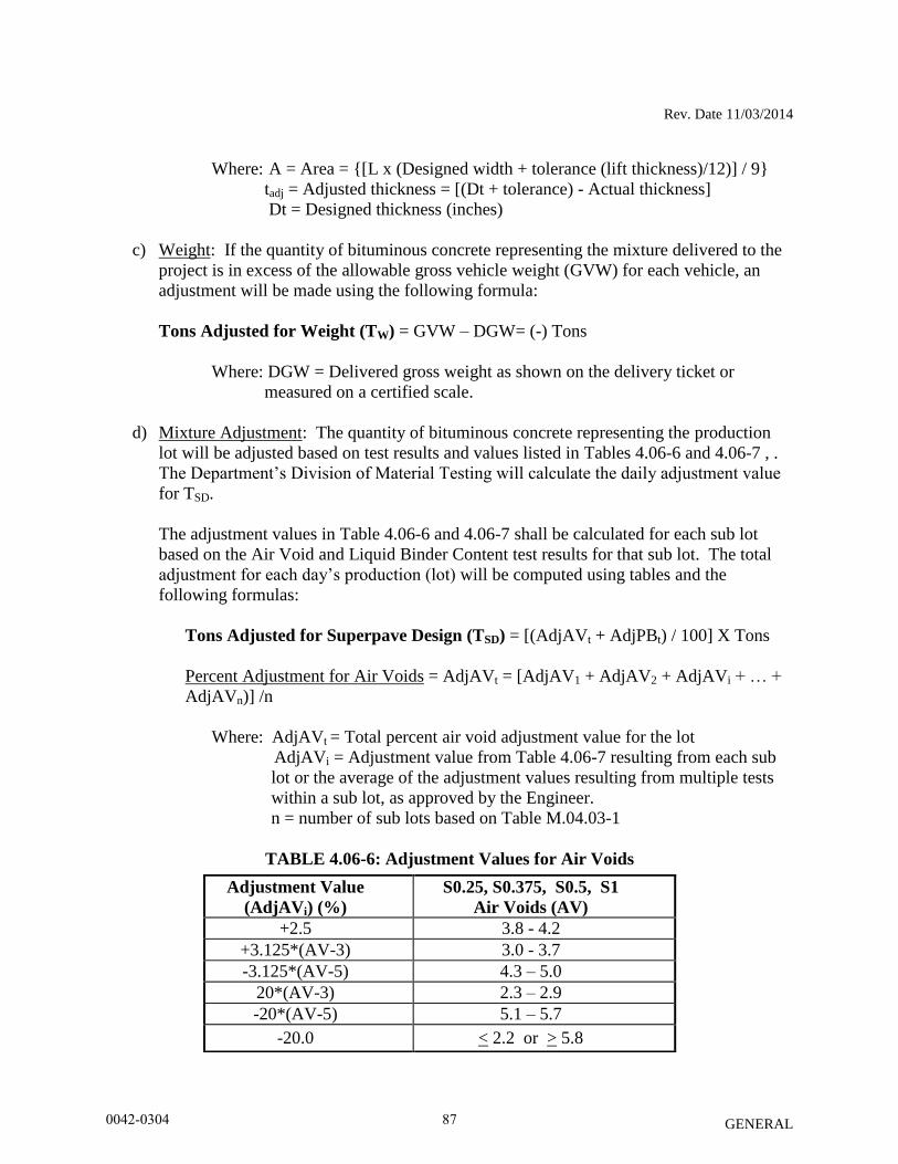
Rev. Date 11/03/2014
GENERAL
Where: A = Area = {[L x (Designed width + tolerance (lift thickness)/12)] / 9}
tadj = Adjusted thickness = [(Dt + tolerance) - Actual thickness]
Dt = Designed thickness (inches)
c) Weight: If the quantity of bituminous concrete representing the mixture delivered to the
project is in excess of the allowable gross vehicle weight (GVW) for each vehicle, an
adjustment will be made using the following formula:
Tons Adjusted for Weight (TW) = GVW – DGW= (-) Tons
Where: DGW = Delivered gross weight as shown on the delivery ticket or
measured on a certified scale.
d) Mixture Adjustment: The quantity of bituminous concrete representing the production
lot will be adjusted based on test results and values listed in Tables 4.06-6 and 4.06-7 , .
The Department’s Division of Material Testing will calculate the daily adjustment value
for TSD.
The adjustment values in Table 4.06-6 and 4.06-7 shall be calculated for each sub lot
based on the Air Void and Liquid Binder Content test results for that sub lot. The total
adjustment for each day’s production (lot) will be computed using tables and the
following formulas:
Tons Adjusted for Superpave Design (TSD) = [(AdjAVt + AdjPBt) / 100] X Tons
Percent Adjustment for Air Voids = AdjAVt = [AdjAV1 + AdjAV2 + AdjAVi + … +
AdjAVn)] /n
Where: AdjAVt = Total percent air void adjustment value for the lot
AdjAVi = Adjustment value from Table 4.06-7 resulting from each sub
lot or the average of the adjustment values resulting from multiple tests
within a sub lot, as approved by the Engineer.
n = number of sub lots based on Table M.04.03-1
TABLE 4.06-6: Adjustment Values for Air Voids
Adjustment Value
(AdjAVi) (%)
S0.25, S0.375, S0.5, S1
Air Voids (AV)
+2.5 3.8 - 4.2
+3.125*(AV-3) 3.0 - 3.7
-3.125*(AV-5) 4.3 – 5.0
20*(AV-3) 2.3 – 2.9
-20*(AV-5) 5.1 – 5.7
-20.0 < 2.2 or > 5.8
0042-0304 87
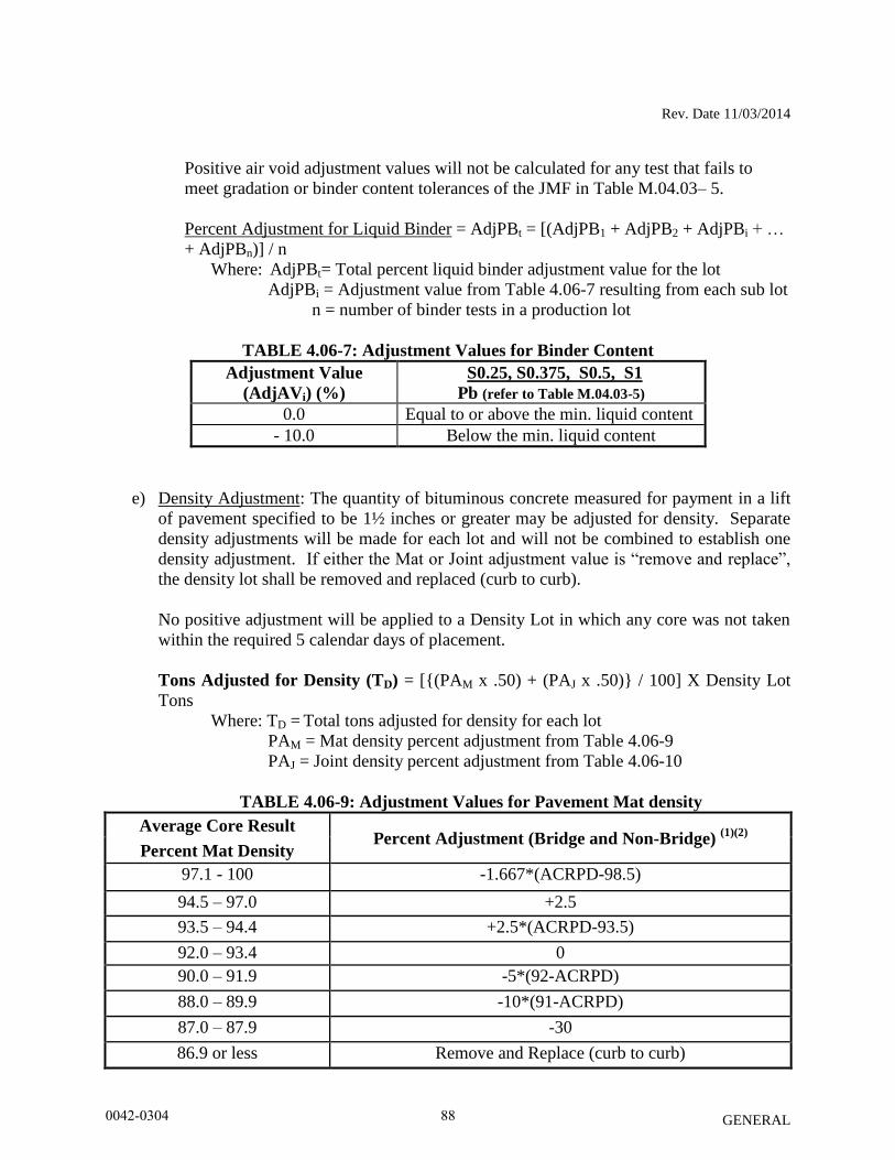
Rev. Date 11/03/2014
GENERAL
Positive air void adjustment values will not be calculated for any test that fails to
meet gradation or binder content tolerances of the JMF in Table M.04.03– 5.
Percent Adjustment for Liquid Binder = AdjPBt = [(AdjPB1 + AdjPB2 + AdjPBi + …
+ AdjPBn)] / n
Where: AdjPBt= Total percent liquid binder adjustment value for the lot
AdjPBi = Adjustment value from Table 4.06-7 resulting from each sub lot
n = number of binder tests in a production lot
TABLE 4.06-7: Adjustment Values for Binder Content
Adjustment Value
(AdjAVi) (%)
S0.25, S0.375, S0.5, S1
Pb (refer to Table M.04.03-5)
0.0 Equal to or above the min. liquid content
- 10.0 Below the min. liquid content
e) Density Adjustment: The quantity of bituminous concrete measured for payment in a lift
of pavement specified to be 1½ inches or greater may be adjusted for density. Separate
density adjustments will be made for each lot and will not be combined to establish one
density adjustment. If either the Mat or Joint adjustment value is “remove and replace”,
the density lot shall be removed and replaced (curb to curb).
No positive adjustment will be applied to a Density Lot in which any core was not taken
within the required 5 calendar days of placement.
Tons Adjusted for Density (TD) = [{(PAM x .50) + (PAJ x .50)} / 100] X Density Lot
Tons
Where: TD = Total tons adjusted for density for each lot
PAM = Mat density percent adjustment from Table 4.06-9
PAJ = Joint density percent adjustment from Table 4.06-10
TABLE 4.06-9: Adjustment Values for Pavement Mat density
Average Core Result Percent Adjustment (Bridge and Non-Bridge)
(1)(2)
Percent Mat Density
97.1 - 100 -1.667*(ACRPD-98.5)
94.5 – 97.0 +2.5
93.5 – 94.4 +2.5*(ACRPD-93.5)
92.0 – 93.4 0
90.0 – 91.9 -5*(92-ACRPD)
88.0 – 89.9 -10*(91-ACRPD)
87.0 – 87.9 -30
86.9 or less Remove and Replace (curb to curb)
0042-0304 88
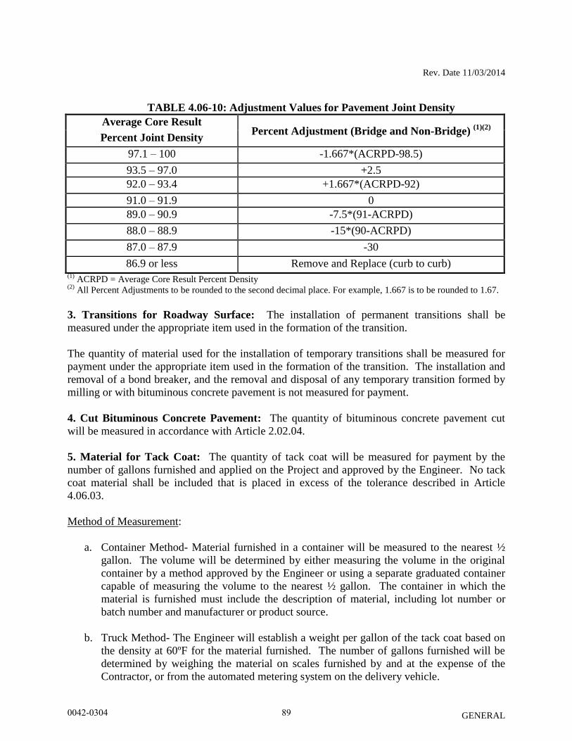
Rev. Date 11/03/2014
GENERAL
TABLE 4.06-10: Adjustment Values for Pavement Joint Density
Average Core Result Percent Adjustment (Bridge and Non-Bridge)
(1)(2)
Percent Joint Density
97.1 – 100 -1.667*(ACRPD-98.5)
93.5 – 97.0 +2.5
92.0 – 93.4 +1.667*(ACRPD-92)
91.0 – 91.9 0
89.0 – 90.9 -7.5*(91-ACRPD)
88.0 – 88.9 -15*(90-ACRPD)
87.0 – 87.9 -30
86.9 or less Remove and Replace (curb to curb) (1)
ACRPD = Average Core Result Percent Density (2)
All Percent Adjustments to be rounded to the second decimal place. For example, 1.667 is to be rounded to 1.67.
3. Transitions for Roadway Surface: The installation of permanent transitions shall be
measured under the appropriate item used in the formation of the transition.
The quantity of material used for the installation of temporary transitions shall be measured for
payment under the appropriate item used in the formation of the transition. The installation and
removal of a bond breaker, and the removal and disposal of any temporary transition formed by
milling or with bituminous concrete pavement is not measured for payment.
4. Cut Bituminous Concrete Pavement: The quantity of bituminous concrete pavement cut
will be measured in accordance with Article 2.02.04.
5. Material for Tack Coat: The quantity of tack coat will be measured for payment by the
number of gallons furnished and applied on the Project and approved by the Engineer. No tack
coat material shall be included that is placed in excess of the tolerance described in Article
4.06.03.
Method of Measurement:
a. Container Method- Material furnished in a container will be measured to the nearest ½
gallon. The volume will be determined by either measuring the volume in the original
container by a method approved by the Engineer or using a separate graduated container
capable of measuring the volume to the nearest ½ gallon. The container in which the
material is furnished must include the description of material, including lot number or
batch number and manufacturer or product source.
b. Truck Method- The Engineer will establish a weight per gallon of the tack coat based on
the density at 60ºF for the material furnished. The number of gallons furnished will be
determined by weighing the material on scales furnished by and at the expense of the
Contractor, or from the automated metering system on the delivery vehicle.
0042-0304 89
Rev. Date 11/03/2014
GENERAL
6. Material Transfer Vehicle (MTV): The furnishing and use of a MTV will be measured
separately for payment based on the actual number of surface course tons delivered to a paver
using the MTV.
4.06.05—Basis of Payment:
1. HMA S* or PMA S*: The furnishing and placing of bituminous concrete will be paid for at
the Contract unit price per ton for “HMA S*” or “PMA S*”.
- All costs associated with providing illumination of the work area are included in the general
cost of the work.
- All costs associated with cleaning the surface to be paved, including mechanical sweeping, are
included in the general cost of the work. All costs associated with constructing longitudinal
joints are included in the general cost of the work.
- All costs associated with obtaining cores for acceptance testing and dispute resolution are
included in the general cost of the work.
2. Bituminous Concrete Adjustment Costs: The adjustment will be calculated using the
formulas shown below if all of the measured adjustments in Article 4.06.04 are not equal to zero.
A positive or negative adjustment will be applied to monies due the Contractor.
Production Lot: [TT + TA + TW + (TMD or TSD)] x Unit Price = Est. (P)
Density Lot: TD X Unit Price = Est. (D)
Where: Unit Price = Contract unit price per ton per type of mixture
T* = Total tons of each adjustment calculated in Article 4.06.04
Est. ( ) = Pay Unit represented in dollars representing incentive or
disincentive.
The Bituminous Concrete Adjustment Cost item if included in the bid proposal or
estimate is not to be altered in any manner by the Contractor. If the Contractor should
alter the amount shown, the altered figure will be disregarded and the original estimated
cost will be used for the Contract.
3. Transitions for Roadway Surface: The installation of permanent transitions shall be paid
under the appropriate item used in the formation of the transition. The quantity of material used
for the installation of temporary transitions shall be paid under the appropriate pay item used in
the formation of the transition. The installation and removal of a bond breaker, and the removal
and disposal of any temporary transition formed by milling or with bituminous concrete
pavement is included in the general cost of the work.
4. The cutting of bituminous concrete pavement will be paid in accordance with Article 2.02.05.
0042-0304 90
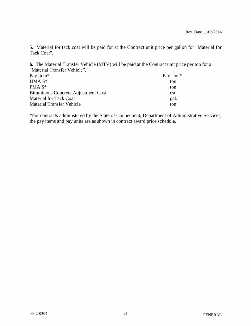
Rev. Date 11/03/2014
GENERAL
5. Material for tack coat will be paid for at the Contract unit price per gallon for "Material for
Tack Coat".
6. The Material Transfer Vehicle (MTV) will be paid at the Contract unit price per ton for a
"Material Transfer Vehicle”.
Pay Item* Pay Unit*
HMA S* ton
PMA S* ton
Bituminous Concrete Adjustment Cost est.
Material for Tack Coat gal.
Material Transfer Vehicle ton
*For contracts administered by the State of Connecticut, Department of Administrative Services,
the pay items and pay units are as shown in contract award price schedule.
0042-0304 91
Rev. Date 11/17/2014
GENERAL
SECTION 6.01-CONCRETE FOR STRUCTURES
6.01.02 - Materials:
Subarticle M.03.01-8(b)-Joint Sealer for Structures: Add the following:
Structure joint sealers shall conform to the following:
Where “Joint Seal” is specified in the plans, it shall conform to the Federal Specifications
SS-S-200-E (Self-leveling type), TT-S-0227E (COM-NBS) Type II-Class A (Non-sag
type), or one component polyurethane-based elastomeric sealants conforming to the Federal
Specification TT-S-00230C Type II-Class A.
A Certified Test Report will be required in accordance with Article 1.06.07, certifying the
conformance of the sealant to the requirements set forth in the Federal Specification. Should the
consignee noted on the Certified Test Report be other than the Prime Contractor, the materials
Certificates shall be required to identify the shipment.
6.01.03-Construction Methods:
Subarticle 6.01.03-24-Joint Seal: Add the following:
Sealant shall be applied as outlined in the manufacturer’s printed instructions.
Primer shall be supplied by the sealant manufacturer and shall be applied on contact surfaces of the
joint in accordance with the requirements of the particular sealant manufacturer.
0042-0304 92
Rev. Date 10/01/12
English
GENERAL
SECTION M.04 - BITUMINOUS CONCRETE
Section M.04 is being deleted in its entirety and replaced with the following:
M.04.01—Bituminous Concrete Materials and Facilities
M.04.02—Mix Design and Job Mix Formula (JMF)
M.04.03—Production Requirements
M.04.01—Bituminous Concrete Materials and Facilities: Each source of material, and
facility or plant used to produce and test bituminous concrete must be qualified on an annual
basis by the Engineer. Test Procedures and Specifications referenced herein are in accordance
with the latest AASHTO and ASTM Standard Test Procedures and Specifications. Such
references when noted with an (M) have been modified by the Engineer and are detailed in Table
M.04.03-6.
The Contractor shall submit to the Engineer all sources of coarse aggregate, fine aggregate,
mineral filler, PG binder, and if applicable any additives such as but not limited to anti-strip,
warm mix, and polymer modifiers. The Contractor shall submit a Material Safety Data Sheet
(MSDS) for each grade of binder, and additive to be used on the Project. The Contractor shall
not change any material sources without prior approval of the Engineer.
An adequate quantity of each size aggregate, mineral filler, bitumen, and additives, shall be
maintained at the bituminous concrete plant site at all times while the plant is in operation to
ensure that the plant can consistently produce bituminous concrete mixtures that meet the job
mix formula (JMF) as specified in Article M.04.02. The quantity of such material shall be
reviewed by the Engineer on an individual plant basis and is dependent upon the plant's daily
production capacity. A total quantity of any material on site that amounts to less than one day’s
production capacity may be cause for the job mix formula to be rejected.
1. Coarse Aggregate:
a. Requirements: The coarse aggregate shall consist of clean, hard, tough, durable
fragments of crushed stone or crushed gravel of uniform quality. Aggregates from
multiple sources of supply must not be mixed or stored in the same stockpile.
b. Basis of Approval: The request for approval of the source of supply shall include a
washed sieve analysis in accordance with AASHTO T 27. The Gsa, Gsb, and Pwa shall
be determined in accordance with AASHTO T 85. The coarse aggregate must not
contain more than 1% crusher dust, sand, soft disintegrated pieces, mud, dirt, organic and
other injurious materials. When tested for abrasion using AASHTO T 96, the aggregate
loss must not exceed 40%. When tested for soundness using AASHTO T 104 with a
magnesium sulfate solution, the coarse aggregate must not have a loss exceeding 10% at
the end of 5 cycles.
For all bituminous mixtures, materials shall also meet the coarse aggregate angularity
criteria as specified in Tables M.04.02-2 thru M.04.02-4 for blended aggregates retained
0042-0304 93
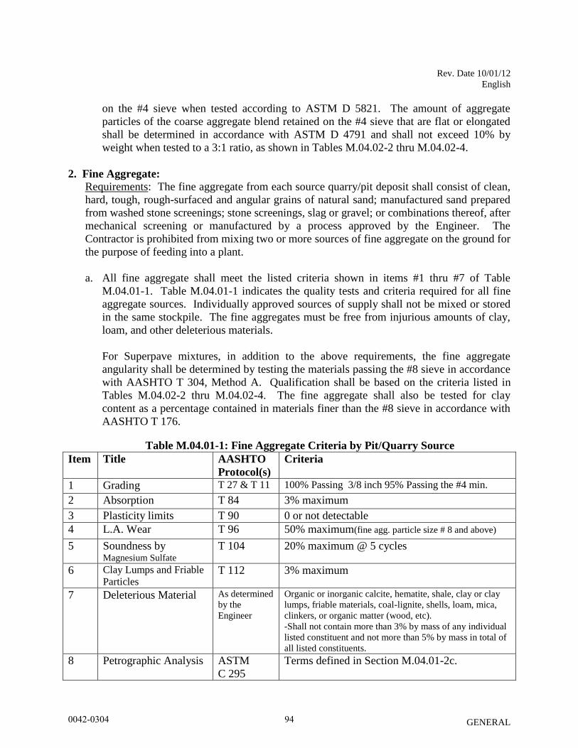
Rev. Date 10/01/12
English
GENERAL
on the #4 sieve when tested according to ASTM D 5821. The amount of aggregate
particles of the coarse aggregate blend retained on the #4 sieve that are flat or elongated
shall be determined in accordance with ASTM D 4791 and shall not exceed 10% by
weight when tested to a 3:1 ratio, as shown in Tables M.04.02-2 thru M.04.02-4.
2. Fine Aggregate:
Requirements: The fine aggregate from each source quarry/pit deposit shall consist of clean,
hard, tough, rough-surfaced and angular grains of natural sand; manufactured sand prepared
from washed stone screenings; stone screenings, slag or gravel; or combinations thereof, after
mechanical screening or manufactured by a process approved by the Engineer. The
Contractor is prohibited from mixing two or more sources of fine aggregate on the ground for
the purpose of feeding into a plant.
a. All fine aggregate shall meet the listed criteria shown in items #1 thru #7 of Table
M.04.01-1. Table M.04.01-1 indicates the quality tests and criteria required for all fine
aggregate sources. Individually approved sources of supply shall not be mixed or stored
in the same stockpile. The fine aggregates must be free from injurious amounts of clay,
loam, and other deleterious materials.
For Superpave mixtures, in addition to the above requirements, the fine aggregate
angularity shall be determined by testing the materials passing the #8 sieve in accordance
with AASHTO T 304, Method A. Qualification shall be based on the criteria listed in
Tables M.04.02-2 thru M.04.02-4. The fine aggregate shall also be tested for clay
content as a percentage contained in materials finer than the #8 sieve in accordance with
AASHTO T 176.
Table M.04.01-1: Fine Aggregate Criteria by Pit/Quarry Source
Item Title AASHTO
Protocol(s)
Criteria
1 Grading T 27 & T 11 100% Passing 3/8 inch 95% Passing the #4 min.
2 Absorption T 84 3% maximum
3 Plasticity limits T 90 0 or not detectable
4 L.A. Wear T 96 50% maximum(fine agg. particle size # 8 and above)
5 Soundness by Magnesium Sulfate
T 104 20% maximum @ 5 cycles
6 Clay Lumps and Friable
Particles T 112 3% maximum
7 Deleterious Material As determined
by the
Engineer
Organic or inorganic calcite, hematite, shale, clay or clay
lumps, friable materials, coal-lignite, shells, loam, mica,
clinkers, or organic matter (wood, etc).
-Shall not contain more than 3% by mass of any individual
listed constituent and not more than 5% by mass in total of
all listed constituents.
8 Petrographic Analysis ASTM
C 295
Terms defined in Section M.04.01-2c.
0042-0304 94
Rev. Date 10/01/12
English
GENERAL
b. Basis of Approval: A Quality Control Plan for Fine Aggregate (QCPFA) provided by the
Contractor shall be submitted for review and approval for each new source documenting
how conformance to Items 1 through 7 as shown in Table M.04.01-1 is monitored. The
QCPFA must be resubmitted any time the process, location or manner of how the fine
aggregate (FA) is manufactured changes, or as requested by the Engineer. The QCPFA
must include the locations and manufacturing processing methods. The QCPFA for any
source may be suspended by the Engineer due to the production of inconsistent mixtures.
The Contractor shall submit all test results to the Engineer for review. The Contractor
shall also include a washed sieve analysis in accordance with AASHTO T 27/T 11. Any
fine aggregate component or final combined product shall have 100% passing the 3/8
inch sieve and a minimum of 95% passing the # 4. The Gsa, Gsb, and Pwa shall be
determined in accordance with AASHTO T 84.
The Contractor will be notified by the Engineer if any qualified source of supply fails any
portion of Table M.04.01-1. One retest will be allowed for the Contractor to make
corrections and/or changes to the process. If, upon retest, the material does not meet the
requirements of items 1-7, additional testing will be required in accordance with item 8.
c. The Contractor may provide a Petrographic analysis of the material performed by a third
party acceptable to the Engineer at its’ own expense. The Contractor shall submit the
results of the analysis with recommended changes to the manufacturing process to the
Engineer. The Contractor shall submit fine aggregate samples for testing by the Engineer
after the recommended changes have been made.
The Contractor may request the use of such fine aggregate on select project(s) for certain
applications of bituminous concrete pavement. Such material will be monitored for a
period no less than 48 months, at no cost to the State. Terms of any evaluation and
suitable application will be determined by the Engineer.
3. Mineral Filler: a. Requirements: Mineral filler shall consist of finely divided mineral matter such as rock
dust, including limestone dust, slag dust, hydrated lime, hydraulic cement, or other
accepted mineral matter. At the time of use it shall be freely flowing and devoid of
agglomerations. Mineral filler shall be introduced and controlled at all times during
production in a manner acceptable to the Engineer.
b. Basis of Approval: The request for approval of the source of supply shall include the
location, manufacturing process, handling and storage methods for the material. Mineral
filler shall conform to the requirements of AASHTO M-17
0042-0304 95
Rev. Date 10/01/12
English
GENERAL
4. Liquid Bituminous Materials:
a. General:
i Liquid PG binders shall be uniformly mixed and blended and be free of contaminants
such as fuel oils and other solvents. Binders shall be properly heated and stored to
prevent damage or separation.
ii. The blending at mixing plants of PG binder from different suppliers is strictly
prohibited. Contractors who blend PG binders will be classified as a supplier and will
be required to certify the binder in accordance with AASHTO R-26(M). The binder
shall meet the requirements of AASHTO M-320(M) and AASHTO R-29(M). The
Contractor shall submit a Certified Test Report and bill of lading representing each
delivery in accordance with AASHTO R-26(M). The Certified Test Report must also
indicate the binder specific gravity at 77ºF; rotational viscosity at 275ºF and 329ºF and
the mixing and compaction viscosity-temperature chart for each shipment.
iii. The Contractor shall submit the name(s) of personnel responsible for receipt,
inspection, and record keeping of PG binder materials. Contractor plant personnel
shall document specific storage tank(s) where binder will be transferred and stored
until used, and provide binder samples to the Engineer upon request. The person(s)
shall assure that each shipment (tanker truck) is accompanied by a statement certifying
that the transport vehicle was inspected before loading and was found acceptable for
the material shipped and that the binder will be free of contamination from any
residual material, along with two (2) copies of the bill of lading.
iv. Basis of Approval: The request for approval of the source of supply shall list the
location where the material will be manufactured, and the handling and storage
methods, along with necessary certification in accordance with AASHTO R-26(M).
Only suppliers/refineries that have an approved “Quality Control Plan for Performance
Graded Binders” formatted in accordance with AASHTO R-26(M) will be allowed to
supply PG binders to Department projects.
b. Neat Performance Grade (PG) Binder:
i. PG binder shall be classified by the supplier as a “Neat” binder for each lot and be so
labeled on each bill of lading. Neat PG binders shall be free from modification with:
fillers, extenders, reinforcing agents, adhesion promoters, thermoplastic polymers,
acid modification and other additives, and shall indicate such information on each bill
of lading and certified test report.
ii. The asphalt binder shall be Performance Grade PG 64-22.
0042-0304 96
Rev. Date 10/01/12
English
GENERAL
c. Modified Performance Grade (PG) Binder
Unless otherwise noted, the asphalt binder shall be Performance Grade PG 76-22 asphalt
modified with a Styrene-Butadiene-Styrene (SBS) polymer. The polymer modifier shall
be added at either the refinery or terminal and delivered to the bituminous concrete
production facility as homogenous blend. The stability of the modified binder shall be
verified in accordance with ASTM D7173 using the Dynamic Shear Rheometer (DSR).
The DSR G*/sin(δ) results from the top and bottom sections of the ASTM D7173 test
shall not differ by more than 10%. The results of ASTM D7173 shall be included on the
Certified Test Report. The binder shall meet the requirements of AASHTO M-320(M)
and AASHTO R-29(M).
d. Warm Mix Additive or Technology:
i. The warm mix additive or technology must be listed on the NEAUPG Qualified
Warm Mix Asphalt (WMA) Technologies List at the time of bid, which may be
accessed online at http://www.neaupg.uconn.edu/wma_info.html.
ii. The warm mix additive shall be blended with the asphalt binder in accordance with
the manufacturer’s recommendations.
iii. The blended binder shall meet the requirements of AASHTO M-320(M) and
AASHTO R-29(M) for the specified binder grade. The Contractor shall submit a
Certified Test Report showing the results of the testing demonstrating the binder
grade. In addition, it must include the grade of the virgin binder, the brand name of
the warm mix additive, the manufacturer’s suggested rate for the WMA additive, the
water injection rate (when applicable) and the WMA Technology manufacturer’s
recommended mixing and compaction temperature ranges.
iv. Cut-backs (medium cure type);
i. Requirements: The liquid petroleum materials shall be produced by fluxing an
asphalt base with appropriate petroleum distillates to produce the grade specified.
ii. Basis of Approval: The request for approval of the source of supply shall be
submitted at least seven days prior to its use listing the location where the materials
will be produced, and manufacturing, processing, handling and storage methods. The
Contractor shall submit a Certified Test Report in accordance with Section 1.06 and a
Material Safety Data Sheet (MSDS) for the grade to be used on the Project. The
liquid asphalt shall be MC-250 conforming to AASHTO M-82.
0042-0304 97
Rev. Date 10/01/12
English
GENERAL
e. Emulsions
i. Requirements: The emulsified asphalt shall be homogeneous and not be used if
exposed to freezing temperatures.
ii. Basis of Approval: The request for approval of the source of supply must include the
location where the materials will be produced, and manufacturing, processing,
handling and storage methods.
1. Emulsified asphalts shall conform to the requirements of AASHTO M-140.
Materials used for tack coat shall not be diluted and meet grade RS-1. When
ambient temperatures are 80˚F and rising, grade SS-1 or SS-lh may be substituted
if accepted by the Engineer. Each shipment shall be accompanied with a Certified
Test Report listing Saybolt viscosity, residue by evaporation, penetration of
residue, and weight per gallon.
2. Cationic emulsified asphalt shall conform to the requirements of AASHTO M-
208(M). Materials used for tack coat shall not be diluted and meet grade CRS-1.
The settlement and demulsibility test will not be performed unless deemed
necessary by the Engineer. When ambient temperatures are 80˚F and rising, grade
CSS-1 or CSS-lh may be substituted if accepted by the Engineer. Each shipment
shall be accompanied with a Certified Test Report listing Saybolt viscosity,
residue by evaporation, penetration of residue, and weight per gallon.
5. Reclaimed Asphalt Pavement (RAP):
a. Requirements: RAP shall consist of asphalt pavement constructed with asphalt and
aggregate reclaimed by cold milling or other removal techniques approved by the
Engineer. For bituminous concrete mixtures containing RAP, the Contractor shall submit
a JMF in accordance with Article M.04.02 to the Engineer for review.
b. Basis of Approval: The RAP material will be accepted on the basis of one of the
following criteria:
i. When the source of all RAP material is from pavements previously constructed on
Department projects, the Contractor shall provide a materials certificate listing the
detailed locations and lengths of those pavements and that the RAP is only from those
locations listed.
ii. When the RAP material source or quality is not known, the Contractor shall test the
material and provide the following information along with a request for approval to
the Engineer at least 30 calendar days prior to the start of the paving operation. The
request shall include a material certificate stating that the RAP consists of aggregates
that meet the specification requirements of sub articles M.04.01-1 through 3 and that
the binder in the RAP is substantially free of solvents, tars and other contaminants.
The Contractor is prohibited from using unapproved material on Department projects
0042-0304 98
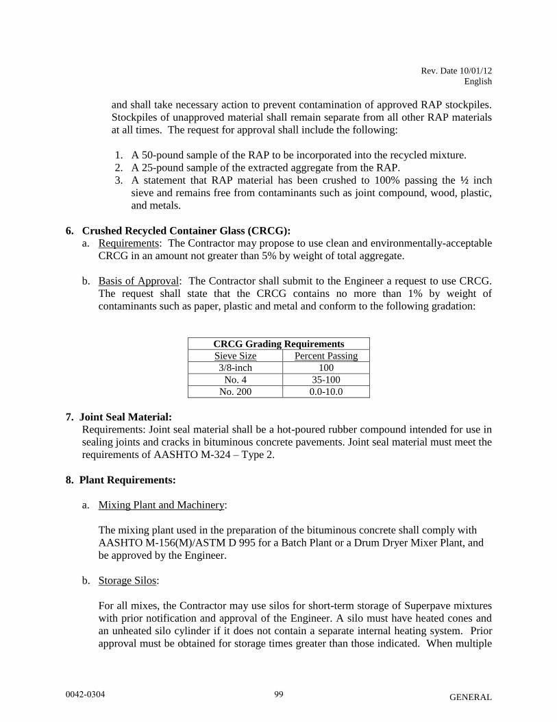
Rev. Date 10/01/12
English
GENERAL
and shall take necessary action to prevent contamination of approved RAP stockpiles.
Stockpiles of unapproved material shall remain separate from all other RAP materials
at all times. The request for approval shall include the following:
1. A 50-pound sample of the RAP to be incorporated into the recycled mixture.
2. A 25-pound sample of the extracted aggregate from the RAP.
3. A statement that RAP material has been crushed to 100% passing the ½ inch
sieve and remains free from contaminants such as joint compound, wood, plastic,
and metals.
6. Crushed Recycled Container Glass (CRCG): a. Requirements: The Contractor may propose to use clean and environmentally-acceptable
CRCG in an amount not greater than 5% by weight of total aggregate.
b. Basis of Approval: The Contractor shall submit to the Engineer a request to use CRCG.
The request shall state that the CRCG contains no more than 1% by weight of
contaminants such as paper, plastic and metal and conform to the following gradation:
CRCG Grading Requirements
Sieve Size Percent Passing
3/8-inch 100
No. 4 35-100
No. 200 0.0-10.0
7. Joint Seal Material:
Requirements: Joint seal material shall be a hot-poured rubber compound intended for use in
sealing joints and cracks in bituminous concrete pavements. Joint seal material must meet the
requirements of AASHTO M-324 – Type 2.
8. Plant Requirements:
a. Mixing Plant and Machinery:
The mixing plant used in the preparation of the bituminous concrete shall comply with
AASHTO M-156(M)/ASTM D 995 for a Batch Plant or a Drum Dryer Mixer Plant, and
be approved by the Engineer.
b. Storage Silos:
For all mixes, the Contractor may use silos for short-term storage of Superpave mixtures
with prior notification and approval of the Engineer. A silo must have heated cones and
an unheated silo cylinder if it does not contain a separate internal heating system. Prior
approval must be obtained for storage times greater than those indicated. When multiple
0042-0304 99
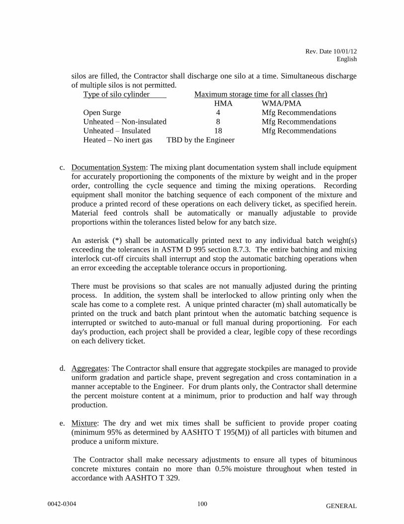
Rev. Date 10/01/12
English
GENERAL
silos are filled, the Contractor shall discharge one silo at a time. Simultaneous discharge
of multiple silos is not permitted.
Type of silo cylinder Maximum storage time for all classes (hr)
HMA WMA/PMA
Open Surge 4 Mfg Recommendations
Unheated – Non-insulated 8 Mfg Recommendations
Unheated – Insulated 18 Mfg Recommendations
Heated – No inert gas TBD by the Engineer
c. Documentation System: The mixing plant documentation system shall include equipment
for accurately proportioning the components of the mixture by weight and in the proper
order, controlling the cycle sequence and timing the mixing operations. Recording
equipment shall monitor the batching sequence of each component of the mixture and
produce a printed record of these operations on each delivery ticket, as specified herein.
Material feed controls shall be automatically or manually adjustable to provide
proportions within the tolerances listed below for any batch size.
An asterisk (*) shall be automatically printed next to any individual batch weight(s)
exceeding the tolerances in ASTM D 995 section 8.7.3. The entire batching and mixing
interlock cut-off circuits shall interrupt and stop the automatic batching operations when
an error exceeding the acceptable tolerance occurs in proportioning.
There must be provisions so that scales are not manually adjusted during the printing
process. In addition, the system shall be interlocked to allow printing only when the
scale has come to a complete rest. A unique printed character (m) shall automatically be
printed on the truck and batch plant printout when the automatic batching sequence is
interrupted or switched to auto-manual or full manual during proportioning. For each
day's production, each project shall be provided a clear, legible copy of these recordings
on each delivery ticket.
d. Aggregates: The Contractor shall ensure that aggregate stockpiles are managed to provide
uniform gradation and particle shape, prevent segregation and cross contamination in a
manner acceptable to the Engineer. For drum plants only, the Contractor shall determine
the percent moisture content at a minimum, prior to production and half way through
production.
e. Mixture: The dry and wet mix times shall be sufficient to provide proper coating
(minimum 95% as determined by AASHTO T 195(M)) of all particles with bitumen and
produce a uniform mixture.
The Contractor shall make necessary adjustments to ensure all types of bituminous
concrete mixtures contain no more than 0.5% moisture throughout when tested in
accordance with AASHTO T 329.
0042-0304 100
Rev. Date 10/01/12
English
GENERAL
f. RAP: The Contractor shall indicate the percent of RAP, the moisture content (as a
minimum determined twice daily – prior to production and halfway through production),
and the net dry weight of RAP added to the mixture on each truck ticket. For each day of
production, the production shall conform to the job mix formula and RAP percentage and
no change shall be made without the prior approval of the Engineer.
g. Asphalt Binder: The last day of every month, a binder log shall be submitted when the
monthly production for the Department exceeds 5000 tons. Blending of PG binders from
different suppliers or grades at the bituminous concrete production facility is strictly
prohibited.
h. Warm mix additive: For mechanically foamed WMA, the maximum water injection rate
shall not exceed 2.0% water by total weight of binder and the water injection rate shall be
constantly monitored during production.
i. Field Laboratory: The Contractor shall furnish the Engineer an acceptable field
laboratory at the production facility to test bituminous concrete mixtures during
production. The field laboratory shall have a minimum of 300 square feet, have a potable
water source and drainage in accordance with the CT Department of Public Health
Drinking Water Division, be equipped with all necessary testing equipment as well as
with a PC, printer, and telephone with a dedicated hard-wired phone line. In addition, the
PC shall have a high speed internet connection with a minimum upstream of 384 Kbps
and a functioning web browser with unrestricted access to https://ctmail.ct.gov. This
equipment shall be maintained in clean and good working order at all times and be made
available for use by the Engineer.
The laboratory shall be equipped with a suitable heating system capable of maintaining a
minimum temperature of 65°F. It shall be clean and free of all materials and equipment
not associated with the laboratory. Windows shall be installed to provide sufficient light
and ventilation. During summer months adequate cooling or ventilation must be
provided so the indoor air temperature shall not exceed the ambient outdoor temperature.
Light fixtures and outlets shall be installed at convenient locations, and a telephone shall
be within audible range of the testing area. The laboratory shall be equipped with an
adequate workbench that has a suitable length, width, and sampling tables, and be
approved by the Engineer.
The field laboratory testing apparatus, supplies, and safety equipment shall be capable of
performing all tests in their entirety that are referenced in AASHTO R 35(M), Standard
Practice for Superpave Volumetric Design for Hot-Mix Asphalt (HMA) and AASHTO M
323, Standard Specification for Superpave Volumetric Mix Design. In addition, the
quantity of all equipment and supplies necessary to perform the tests must be sufficient to
initiate and complete the number of tests identified in Table M.04.03-2 for the quantity of
mixture produced at the facility on a daily basis. The Contractor shall ensure that the
0042-0304 101
Rev. Date 10/01/12
English
GENERAL
Laboratory is adequately supplied at all times during the course of the project with all
necessary testing materials and equipment.
The Contractor shall maintain a list of laboratory equipment used in the acceptance
testing processes including but not limited to, balances, scales, manometer/vacuum
gauge, thermometers, gyratory compactor, clearly showing calibration and/or inspection
dates, in accordance with AASHTO R-18.The Contractor shall notify the Engineer if any
modifications are made to the equipment within the field laboratory. The Contractor
shall take immediate action to replace, repair, and/or recalibrate any piece of equipment
that is out of calibration, malfunctioning, or not in operation.
M.04.02—Mix Design and Job Mix Formula (JMF)
1. Marshall Method - Class 1, 2, 3, 4, 5, 5A, 5B and 12:
a. Requirements: When specified, the Marshall method shall be employed to develop a
bituminous concrete mix design that includes a JMF consisting of target values for
gradation and bitumen content for each class of bituminous concrete designated for the
project in accordance with the latest Asphalt Institute’s MS-2 manual. Each class of
bituminous concrete must meet the requirements as shown in Table M.04.02-1.
b. Basis of Approval: The Contractor shall submit to the Engineer a request for approval of
the JMF annually in accordance with one of the methods described herein. Prior to the
start of any paving operations, the JMF and production percentage of bitumen must be
accepted by the Engineer, and the Contractor must demonstrate the ability to meet the
accepted JMF and production percentage of bitumen for each class of mixture.
Additionally, the fraction of material retained between any two consecutive sieves shall
not be less than 4%.
The Engineer will test each class of mixture for compliance with the submitted JMF and
Table M.04.02-1. The maximum theoretical density (Gmm) will be determined by
AASHTO T 209(M). If the mixture does not meet the requirements, the JMF shall be
adjusted within the ranges shown in Table M.04.02-1 until an acceptable mixture is
produced. All equipment, tests and computations shall conform to the Marshall method
in accordance with AASHTO T 245(M).
An accepted JMF from the previous operating season may be acceptable to the Engineer
provided that there are no changes in the sources of supply for the coarse aggregate, fine
aggregate, recycled material (if applicable) and the plant operation had been consistently
producing acceptable mixture.
The Contractor shall not change sources of supply after a JMF has been accepted. Before
a new source of supply for materials is used, a new JMF shall be submitted to the
Engineer for approval.
0042-0304 102
Rev. Date 10/01/12
English
GENERAL
c. Marshall Mixture (Virgin): For bituminous concrete mixtures that contain no recycled
material, the limits prescribed in Table M.04.02-1 govern. The Contractor shall submit to
the Engineer for approval, a JMF with the individual fractions of the aggregate expressed
as percentages of the total weight of the mix and the source(s) of all materials. The JMF
shall indicate two bitumen contents; the JMF target percentage and a production
percentage (actual amount added to mix) of bitumen for each mix class by total weight.
For surface course Class 1, a 0.45 power gradation chart shall also be submitted on which
is plotted the percentage passing each sieve. The JMF shall also indicate the target
temperature of completed mixture as it is dumped from the mixer and tested in
accordance with Article M.04.03.
d. Marshall Mixtures with RAP: In addition to subarticles M.04.02 – 1a through c, RAP in
bituminous concrete shall comply with requirements stated in Article M.04.01, and as
stated herein. Upon approval of the Engineer, a maximum of 15% RAP may be used
with no binder grade modification. RAP material shall not be used with any other
recycling option.
The Contractor may increase the RAP percentage in 5% increments up to a maximum of
30% provided a new JMF is accepted by the Engineer. The following information shall
be included in the JMF submittal:
- Gradation and asphalt content of the RAP.
- Percentage of RAP to be used.
- Virgin aggregate source(s).
- Total binder content based on total mixture weight.
- Production pull percentage of added virgin binder based on total mixture weight.
- Gradation of combined bituminous concrete mixture (including RAP).
- Grade of virgin added, if greater than 15% of total mix weight.
e. Marshall Mixture with CRCG: In addition to subarticle M.04.02 – 1a through c, for
bituminous concrete that contains CRCG, the Contractor shall submit a materials
certificate to the Engineer stating that the mixture and its components comply with
requirements stated in subarticle M.04.01 - (6). Additionally, 1% hydrated lime, or other
accepted non-stripping agent, shall be added to all mixtures containing CRCG. CRCG
material shall not be used with any other recycling option.
2. Cold Patch Method - Class 5, 5A, 5B:
a. Requirements: This mixture must be capable of being stockpiled and workable at all
times. A non-stripping agent accepted by the Engineer shall be used in accordance with
manufacturer's recommendations. The Contractor shall take necessary steps to ensure
that this mixture uses aggregate containing no more than 1% moisture and is not exposed
to any rain, snow, or standing water for a period of 6 hours after being mixed. This
mixture shall be mixed and stockpiled at the point of production on a paved surface at a
height not greater than 4 feet during the first 48 hours prior to its use.
0042-0304 103
Rev. Date 10/01/12
English
GENERAL
i. Class 5A mixture shall have 3/8 to ½ inch polypropylene fibers that have been
approved by the Engineer added at a rate of 6 pounds per ton of mixture.
ii. Class 5B mixture shall have ¼ inch polyester fibers that have been approved by the
Engineer added at the rate of 2 1/2 pounds per ton of mixture.
iii. Class 5 mixture shall not contain fibers.
b. Basis of Approval: The aggregates, fibers and binder (MC-250) shall meet the
requirements as specified in sub articles M.04.01-1 through 4 and in Table M.04.02-1.
The use of recycled material is not permitted with these classes of bituminous concrete.
Mixtures not conforming to the binder content as shown in Table M.04.02-1 shall be
subject to rejection. There is a two test minimum per day of production. Mixtures not
conforming to the gradation as shown in Table M.04.02-1 shall be subject to payment
adjustment as specified in Section 4.06. .
0042-0304 104
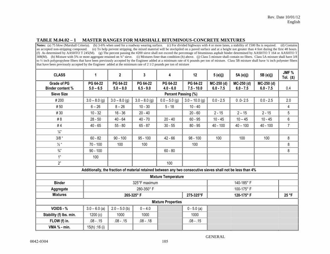
Rev. Date 10/01/12
English
GENERAL
TABLE M.04.02 – 1 MASTER RANGES FOR MARSHALL BITUMINOUS-CONCRETE MIXTURES Notes: (a) 75 blow (Marshall Criteria). (b) 3-6% when used for a roadway wearing surface. (c) For divided highways with 4 or more lanes, a stability of 1500 lbs is required. (d) Contains
an accepted non-stripping compound. (e) To help prevent stripping, the mixed material will be stockpiled on a paved surface and at a height not greater than 4 feet during the first 48 hours. (f) As determined by AASHTO T 245(M). (g) The percent passing the #200 sieve shall not exceed the percentage of bituminous asphalt binder determined by AASHTO T 164 or AASHTO T
308(M). (h) Mixture with 5% or more aggregate retained on ¾" sieve. (i) Mixtures finer than condition (h) above. (j) Class 5 mixture shall contain no fibers. Class 5A mixture shall have 3/8
to ½ inch polypropylene fibers that have been previously accepted by the Engineer added at a minimum rate of 6 pounds per ton of mixture. Class 5B mixture shall have ¼ inch polyester fibers that have been previously accepted by the Engineer added at the minimum rate of 2 1/2 pounds per ton of mixture
CLASS 1 2 3 4 12 5 (e)(j) 5A (e)(j) 5B (e)(j) JMF % Tol. (±)
Grade of PG Binder content %
PG 64-22 5.0 – 6.5
PG 64-22 5.0 – 8.0
PG 64-22 6.5 - 9.0
PG 64-22 4.0 - 6.0
PG 64-22 7.5 - 10.0
MC-250 (d) 6.0 - 7.5
MC-250 (d) 6.0 - 7.5
MC-250 (d) 6.0 - 7.5
0.4
Sieve Size Percent Passing (%)
# 200 3.0 – 8.0 (g) 3.0 – 8.0 (g) 3.0 – 8.0 (g) 0.0 – 5.0 (g) 3.0 – 10.0 (g) 0.0 - 2.5 0 .0- 2.5 0.0 - 2.5 2.0
# 50 6 – 26 8 – 26 10 - 30 5 - 18 10 - 40 4
# 30 10 - 32 16 - 36 20 - 40 20 - 60 2 - 15 2 – 15 2 - 15 5
# 8 28 - 50 40 - 64 40 - 70 20 - 40 60 - 95 10 - 45 10 – 45 10 - 45 6
# 4 40 - 65 55 - 80 65 - 87 30 - 55 80 - 95 40 - 100 40 – 100 40 - 100 7
¼”
3/8 “ 60 - 82 90 - 100 95 - 100 42 - 66 98 - 100 100 100 100 8
½ “ 70 - 100 100 100 100 8
¾” 90 - 100 60 - 80 8
1” 100
2” 100
Additionally, the fraction of material retained between any two consecutive sieves shall not be less than 4%
Mixture Temperature
Binder 325°F maximum 140-185° F
Aggregate 280-350° F 100-175° F
Mixtures 265-325° F 275-325°F 120-175° F 25 °F
Mixture Properties
VOIDS - % 3.0 – 6.0 (a) 2.0 – 5.0 (b) 0 – 4.0 0 - 5.0 (a)
Stability (f) lbs. min. 1200 (c) 1000 1000 1000
FLOW (f) in. .08 - .15 .08 - .15 .08 - .18 .08 - .15
VMA % - min. 15(h) :16 (i)
0042-0304 105
Rev. Date 10/01/12
English
GENERAL
3. Superpave Design Method – S0.25, S0.375, S0.5, and S1
a. Requirements: The Contractor or its representative shall design and submit Superpave
mix designs annually for approval. The design laboratory developing the mixes shall be
approved by the Engineer. The mix design shall be based on the specified Equivalent
Single-Axle Loads (ESAL). Each bituminous concrete mix type must meet the
requirements shown in Tables M.04.02-2 thru Table M.04.02-5 and in accordance with
AASHTO M 323(M) and AASHTO R 35(M). The mix design shall include the nominal
maximum aggregate size and a JMF consisting of target values for gradation and bitumen
content for each bituminous concrete mix type designated for the project.
The contractor shall provide test results with supporting documentation from an
AASHTO Materials Reference Laboratory (AMRL) with the use of NETTCP Certified
Technicians for the following tests;
1. Aggregate consensus properties for each type & level, as specified in Table
M.04.02-3. In addition the Gsa, Gsb, Pwa shall also be provided for each
component aggregate.
2. New mixes shall be tested in accordance with AASHTO T 283(M) Standard
Method of Test for Resistance of Compacted Hot-Mix Asphalt (HMA) to
Moisture-Induced Damage, (TSR). The compacted specimens may be fabricated
at a bituminous concrete facility and then tested at an AMRL accredited facility.
The AASHTO T 283(M) test results, specimens, and corresponding JMF sheet
(Form MAT-429s) shall be submitted by the Contractor for review.
The Contractor shall supply the Engineer with 1 gallon of the specified PG binder and 1
gallon of the same PG binder with the warm mix additive blended into it. The MSDS for
the WMA additive shall be included with every submittal.
In addition, minimum binder content values apply to all types of bituminous concrete
mixtures, as stated in Table M.04.02-5. For mixtures containing RAP, the virgin
production and the anticipated proportion of binder contributed by the RAP cannot be
less than the total permitted binder content value for that type nor the JMF minimum
binder content.
i. Superpave Mixture (virgin): For bituminous concrete mixtures that contain no
recycled material, the limits prescribed in Tables M.04.02-2 thru Table M.04.02-5
apply. The Contractor shall submit a JMF, on a form provided by the Engineer,
with the individual fractions of the aggregate expressed as percentages of the total
weight of the mix and the source(s) of all materials to the Engineer for approval.
The JMF shall indicate the corrected target binder content and applicable binder
correction factor (ignition oven or extractor) for each mix type by total weight of
mix. The mineral filler (dust) shall be defined as that portion of blended mix that
0042-0304 106
Rev. Date 10/01/12
English
GENERAL
passes the #200 sieve by weight when tested in accordance with AASHTO T
30(M). The dust-to-effective asphalt (D/Pbe) ratio shall be between 0.6 and 1.2
by weight. The dry/wet mix times and hot bin proportions (batch plants only) for
each type shall be included in the JMF.
The percentage of aggregate passing each sieve shall be plotted on a 0.45 power
gradation chart and shall be submitted for all bituminous concrete mixtures. This chart
shall delineate the percentage of material passing each test sieve size as defined by the
JMF. The percentage of aggregate passing each standard sieve shall fall within the
specified control points, but outside the restricted zone limits as shown in Tables
M.04.02-2 thru Table M.04.02-5. Mixes with documented performance history which
pass through the restricted zone may be permitted for use as long as all other physical and
volumetric criteria meets specifications as specified in Tables M.04.02-2 thru Table
M.04.02-5 and with prior approval from the Engineer. A change in the JMF requires that
a new chart be submitted.
ii. Superpave Mixtures with RAP: Use of approved RAP may be allowed with the
following conditions:
RAP amounts up to 15% may be used with no binder grade modification.
RAP amounts up to 20% may be used provided a new JMF is approved by the
Engineer. The JMF submittal shall include the grade of virgin binder added and
test results that show the combined binder (recovered binder from the RAP, virgin
binder at the mix design proportions and warm mix asphalt additive if used) meets
the requirements of the specified binder grade.
Unless approved by the Engineer, RAP material shall not be used with any other
recycling option.
b. Basis of Approval: On an annual basis, the Contractor shall submit to the Engineer any
bituminous concrete mix design, and JMF anticipated for use on Department projects.
Prior to the start of any paving operations, the mix design and JMF must be approved by
the Engineer. Bituminous concrete mixture supplied to the project without an approved
mix design and JMF will be rejected. The following information must be included in the
mix design submittal:
a. Gradation, specific gravities and asphalt content of the RAP,
b. Source of RAP and percentage to be used.
c. Warm mix Technology and manufacturer’s recommended additive rate and
tolerances, mixing and compaction temperature ranges for the mix with and without
the warm-mix technology incorporated.
d. Result of TSR testing, and if applicable Anti-strip manufacturer, and dosage rate.
e. Target Temperature at plant discharge.
0042-0304 107
Rev. Date 10/01/12
English
GENERAL
Note – Testing to be performed shall be done in accordance with section M.04.03.
The JMF shall be accepted if the Plant mixture and materials meet all criteria as specified
in Tables M.04.02-2 thru Table M.04.02-5. If the mixture does not meet the
requirements, the contractor shall adjust the JMF within the ranges shown in Tables
M.04.02-2 thru Table M.04.02-5 until an acceptable mixture is produced. All equipment,
tests, and computations shall conform to the latest AASHTO R-35(M) and AASHTO M-
323(M).
Any JMF, once approved, shall only be acceptable for use when it is produced by the
designated plant, it utilizes the same component aggregates and binder source, and it
continues to meet all criteria as specified herein, and component aggregates are
maintained within the tolerances shown in Table M.04.02-2.
The Contractor shall not change any component source of supply including consensus
properties after a JMF has been accepted. Before a new source of materials is used, a
revised JMF shall be submitted to the Engineer for approval. Any approved JMF applies
only to the plant for which it was submitted. Only one mix with one JMF will be
approved for production at any one time. Switching between approved JMF mixes with
different component percentages or sources of supply is prohibited.
Superpave mixture with CRCG: In addition to subarticles M.04.02 – 3 a through c, for
bituminous concrete mixtures that contain CRCG, the Contractor shall submit a materials
certificate to the Engineer stating that the CRCG complies with requirements stated in
Article M.04.01, as applicable. Additionally, 1% hydrated lime, or other accepted non-
stripping agent, shall be added to all mixtures containing CRCG. CRCG material shall
not be used with any other recycling option.
c. Mix Status: Each facility will have each type of bituminous concrete mixture evaluated
based on the previous year of production, for the next construction paving season, as
determined by the Engineer. Based on the rating a type of mixture receives it will
determine whether the mixture can be produced without the completion of a PPT.
Ratings will be provided to each bituminous concrete producer annually prior to the
beginning of the paving season.
The rating criteria are based on compliance with Air Voids and Voids in Mineral
Aggregate (VMA) as indicated in Table M.04.03-3: Superpave Master Range for
Bituminous Concrete Mixture Production, and are as follows:
Criteria A: Based on Air Voids. Percentage of acceptance results with passing air voids.
Criteria B: Based on Air Voids and VMA. The percentage of acceptance results with
passing VMA, and the percentage of acceptance results with passing air voids, will be
averaged.
0042-0304 108
Rev. Date 10/01/12
English
GENERAL
The final rating assigned will be the lower of the rating obtained with Criteria A or
Criteria B.
Ratings are defined as:
“A” – Approved:
A rating of “A” is assigned to each mixture type from a production facility with a
current rating of 70% passing or greater.
“PPT” – Pre-Production Trial:
Rating assigned to each mixture type from a production facility when:
1. there are no passing acceptance production results submitted to the
Department from the previous year;
2. there is a source change in one or more aggregate components from
the JMF on record by more than 10% by weight;
3. there is a change in RAP percentage ,
4. the mixture has a rating of less than 70% from the previous season;
5. a new JMF not previously submitted.
Bituminous concrete mixtures rated with a “PPT” cannot be shipped or used on
Department projects. A passing “PPT” test shall be performed with NETTCP
certified personnel on that type of mixture by the bituminous concrete producer and
meet all specifications (Table M.04.02-2 Table M.04.02-5) before production
shipment may be resumed.
Contractors that have mix types rated a “PPT” may use one of the following methods
to change the rating to an “A.”
Option A: Schedule a day when a Department inspector can be at the facility to
witness a passing “PPT” test or,
Option B: When the Contractor or their representative performs a “PPT” test
without being witnessed by an inspector, the Contractor shall submit the test
results and a split sample including 2 gyratory molds, 5,000 grams of boxed
bituminous concrete for binder and gradation determination, and 5,000 grams of
cooled loose bituminous concrete for Gmm determination for verification testing
and approval. Passing verifications will designate the bituminous concrete type
to be on an “A” status. Failing verifications will require the contractor to submit
additional trials.
Option C: When the Contractor or their representative performs a “PPT” test
without being witnessed by a Department inspector, the Engineer may verify the
mix in the Contractor’s laboratory. Passing verifications will designate the
bituminous concrete type to be an “A” status. Failing verifications will require the
Contractor to submit additional trials.
0042-0304 109
Rev. Date 10/01/12
English
GENERAL
When Option (A) is used and the “PPT” test meets all specifications, the “PPT”
test is considered a passing test and the rating for that mix is changed to “A”.
When the “PPT” test is not witnessed, the “PPT” Option (B) or (C) procedure
must be followed. If the “PPT” Option (B) procedure is followed, the mixtures
along with the test results must be delivered to the Materials Testing Lab. The
test results must meet the “C” tolerances established by the Engineer. The
tolerance Table is included in the Department’s current QA Program for
Materials, Acceptance and Assurance Testing Policies and Procedures.
“U” – No Acceptable Mix Design on File:
Rating assigned to a type of mixture that does not have a JMF submitted, or the JMF
submitted has not been approved, or is incomplete. A mix design or JMF must be
submitted annually seven (7) days prior in order to obtain an “A,” or “PPT” status for
that mix. A “U” will be used only to designate the mix status until the mix design has
been approved, and is accompanied with all supporting data as specified. Bituminous
concrete mixtures rated with a “U” cannot be used on Department projects.
0042-0304 110
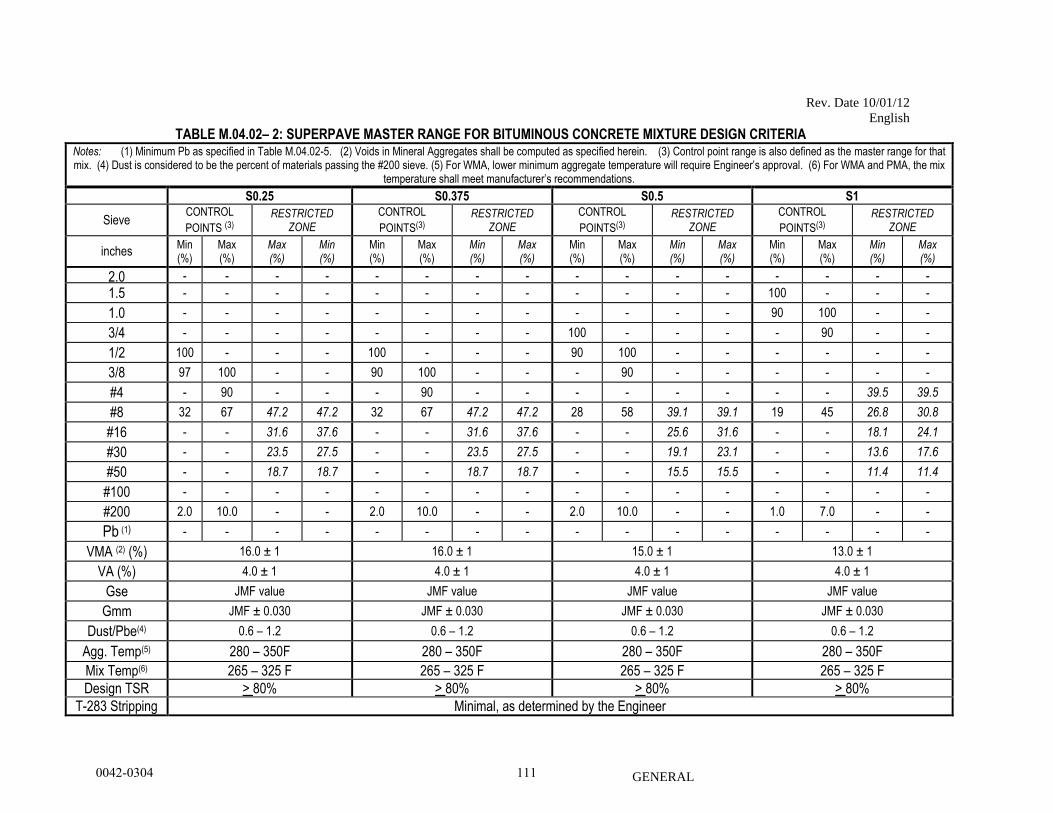
Rev. Date 10/01/12
English
GENERAL
TABLE M.04.02– 2: SUPERPAVE MASTER RANGE FOR BITUMINOUS CONCRETE MIXTURE DESIGN CRITERIA Notes: (1) Minimum Pb as specified in Table M.04.02-5. (2) Voids in Mineral Aggregates shall be computed as specified herein. (3) Control point range is also defined as the master range for that mix. (4) Dust is considered to be the percent of materials passing the #200 sieve. (5) For WMA, lower minimum aggregate temperature will require Engineer’s approval. (6) For WMA and PMA, the mix
temperature shall meet manufacturer’s recommendations.
S0.25 S0.375 S0.5 S1
Sieve CONTROL
POINTS (3)
RESTRICTED ZONE
CONTROL
POINTS(3)
RESTRICTED ZONE
CONTROL
POINTS(3)
RESTRICTED ZONE
CONTROL
POINTS(3)
RESTRICTED ZONE
inches Min (%)
Max (%)
Max (%)
Min (%)
Min (%)
Max (%)
Min (%)
Max (%)
Min (%)
Max (%)
Min (%)
Max (%)
Min (%)
Max (%)
Min (%)
Max (%)
2.0 - - - - - - - - - - - - - - - -
1.5 - - - - - - - - - - - - 100 - - -
1.0 - - - - - - - - - - - - 90 100 - -
3/4 - - - - - - - - 100 - - - - 90 - -
1/2 100 - - - 100 - - - 90 100 - - - - - -
3/8 97 100 - - 90 100 - - - 90 - - - - - -
#4 - 90 - - - 90 - - - - - - - - 39.5 39.5
#8 32 67 47.2 47.2 32 67 47.2 47.2 28 58 39.1 39.1 19 45 26.8 30.8
#16 - - 31.6 37.6 - - 31.6 37.6 - - 25.6 31.6 - - 18.1 24.1
#30 - - 23.5 27.5 - - 23.5 27.5 - - 19.1 23.1 - - 13.6 17.6
#50 - - 18.7 18.7 - - 18.7 18.7 - - 15.5 15.5 - - 11.4 11.4
#100 - - - - - - - - - - - - - - - -
#200 2.0 10.0 - - 2.0 10.0 - - 2.0 10.0 - - 1.0 7.0 - -
Pb (1) - - - - - - - - - - - - - - - -
VMA (2) (%) 16.0 ± 1 16.0 ± 1 15.0 ± 1 13.0 ± 1
VA (%) 4.0 ± 1 4.0 ± 1 4.0 ± 1 4.0 ± 1
Gse JMF value JMF value JMF value JMF value
Gmm JMF ± 0.030 JMF ± 0.030 JMF ± 0.030 JMF ± 0.030
Dust/Pbe(4) 0.6 – 1.2 0.6 – 1.2 0.6 – 1.2 0.6 – 1.2
Agg. Temp(5) 280 – 350F 280 – 350F 280 – 350F 280 – 350F
Mix Temp(6) 265 – 325 F 265 – 325 F 265 – 325 F 265 – 325 F
Design TSR > 80% .
> 80%
> 80%
> 80% T-283 Stripping Minimal, as determined by the Engineer
0042-0304 111
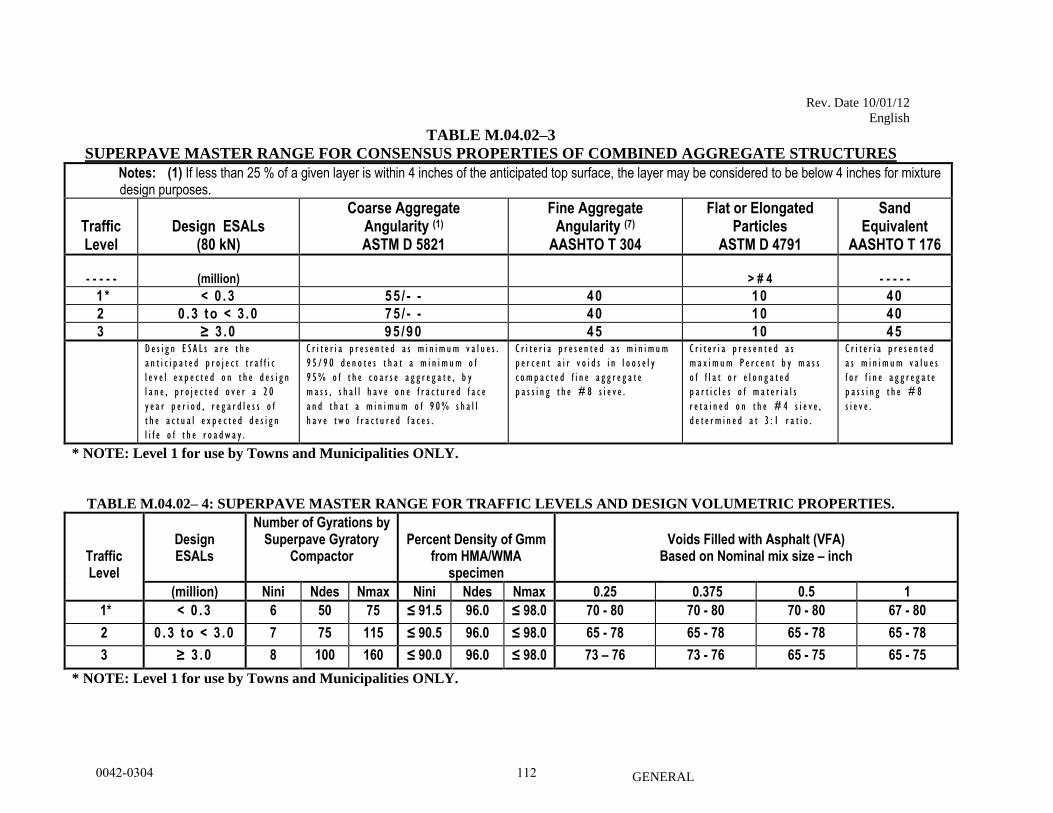
Rev. Date 10/01/12
English
GENERAL
TABLE M.04.02–3
SUPERPAVE MASTER RANGE FOR CONSENSUS PROPERTIES OF COMBINED AGGREGATE STRUCTURES
Notes: (1) If less than 25 % of a given layer is within 4 inches of the anticipated top surface, the layer may be considered to be below 4 inches for mixture design purposes.
Traffic Level
Design ESALs
(80 kN)
Coarse Aggregate Angularity (1) ASTM D 5821
Fine Aggregate Angularity (7)
AASHTO T 304
Flat or Elongated Particles
ASTM D 4791
Sand Equivalent
AASHTO T 176
- - - - -
(million)
> # 4
- - - - -
1 * < 0 .3 55 / - - 40 10 40
2 0 .3 to < 3 .0 75 / - - 40 10 40
3 ≥ 3 .0 95 /90 45 10 45 D e s i g n E S A L s a r e t h e
a n t i c i p a t e d p r o j e c t t r a f f i c
l e v e l e x p e c t e d o n t h e d e s i g n
l a n e , p r o j e c t e d o v e r a 2 0
y e a r p e r i o d , r e g a r d l e s s o f
t h e a c t u a l e x p e c t e d d e s i g n
l i f e o f t h e r o a d w a y .
C r i t e r i a p r e s e n t e d a s m i n i m u m v a l u e s .
9 5 / 9 0 d e n o t e s t h a t a m i n i m u m o f
9 5% o f t h e c o a r s e a g g r e g a t e , b y
m a s s , s h a l l h a v e o n e f r a c t u r e d f a c e
a n d t h a t a m i n i m u m o f 9 0% s h a l l
h a v e t w o f r a c t u r e d f a c e s .
C r i t e r i a p r e s e n t e d a s m i n i m u m
p e r c e n t a i r v o i d s i n l o o s e l y
c o m p a c t e d f i n e a g g r e g a t e
p a s s i n g t h e # 8 s i e v e .
C r i t e r i a p r e s e n t e d a s
m a x i m u m P e r c e n t b y m a s s
o f f l a t o r e l o n g a t e d
p a r t i c l e s o f m a t e r i a l s
r e t a i n e d o n t h e # 4 s i e v e ,
d e t e r m i n e d a t 3 : 1 r a t i o .
C r i t e r i a p r e s e n t e d
a s m i n i m u m v a l u e s
f o r f i n e a g g r e g a t e
p a s s i n g t h e # 8
s i e v e .
* NOTE: Level 1 for use by Towns and Municipalities ONLY.
TABLE M.04.02– 4: SUPERPAVE MASTER RANGE FOR TRAFFIC LEVELS AND DESIGN VOLUMETRIC PROPERTIES.
Traffic Level
Design ESALs
Number of Gyrations by Superpave Gyratory
Compactor
Percent Density of Gmm
from HMA/WMA specimen
Voids Filled with Asphalt (VFA)
Based on Nominal mix size – inch
(million) Nini Ndes Nmax Nini Ndes Nmax 0.25 0.375 0.5 1
1* < 0 .3 6 50 75 ≤ 91.5 96.0 ≤ 98.0 70 - 80 70 - 80 70 - 80 67 - 80
2 0 .3 to < 3 .0 7 75 115 ≤ 90.5 96.0 ≤ 98.0 65 - 78 65 - 78 65 - 78 65 - 78
3 ≥ 3 .0 8 100 160 ≤ 90.0 96.0 ≤ 98.0 73 – 76 73 - 76 65 - 75 65 - 75
* NOTE: Level 1 for use by Towns and Municipalities ONLY.
0042-0304 112
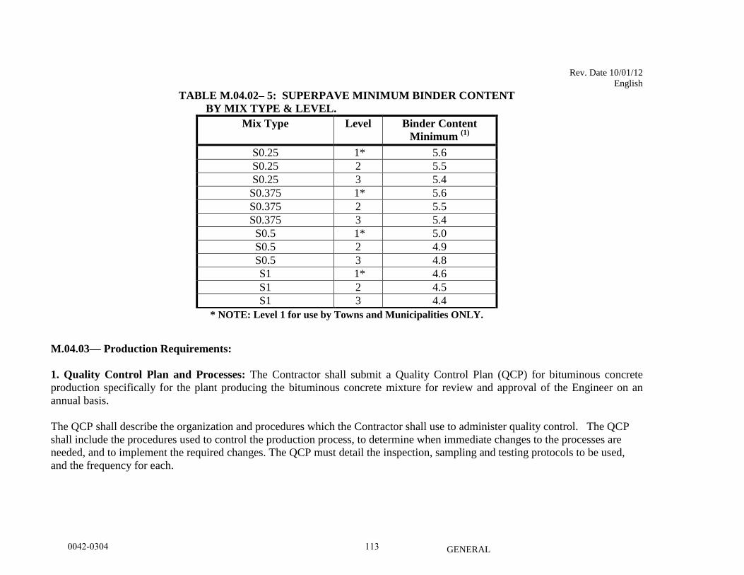
Rev. Date 10/01/12
English
GENERAL
TABLE M.04.02– 5: SUPERPAVE MINIMUM BINDER CONTENT
BY MIX TYPE & LEVEL.
Mix Type Level Binder Content
Minimum (1)
S0.25 1* 5.6
S0.25 2 5.5
S0.25 3 5.4
S0.375 1* 5.6
S0.375 2 5.5
S0.375 3 5.4
S0.5 1* 5.0
S0.5 2 4.9
S0.5 3 4.8
S1 1* 4.6
S1 2 4.5
S1 3 4.4
* NOTE: Level 1 for use by Towns and Municipalities ONLY.
M.04.03— Production Requirements:
1. Quality Control Plan and Processes: The Contractor shall submit a Quality Control Plan (QCP) for bituminous concrete
production specifically for the plant producing the bituminous concrete mixture for review and approval of the Engineer on an
annual basis.
The QCP shall describe the organization and procedures which the Contractor shall use to administer quality control. The QCP
shall include the procedures used to control the production process, to determine when immediate changes to the processes are
needed, and to implement the required changes. The QCP must detail the inspection, sampling and testing protocols to be used,
and the frequency for each.
0042-0304 113
Rev. Date 10/01/12
English
GENERAL
Control Chart(s) shall be developed and maintained for critical aspect(s) of the production process as determined by the
Contractor. The control chart(s) shall identify the material property, applicable upper and lower control limits, and be updated
with current test data. The control chart(s) shall be used as part of the quality control system to document variability of the
bituminous concrete production process. The control chart(s) shall be submitted to the Engineer upon request.
The QCP shall also include the name and qualifications of a Quality Control Manager. The Quality Control Manager shall be
responsible for the administration of the QCP, including compliance with the plan and any plan modifications. All daily QC
sampling, inspection and test reports shall be reviewed by the Quality Control Manager and be submitted to the Engineer upon
request.
The QCP shall also include the name and qualifications of any outside testing laboratory performing any QC functions on behalf
of the Contractor. The QCP must also include a list of sampling & testing methods and frequencies used during production, and
the names of all Quality Control personnel and their duties.
Approval of the QCP does not imply any warranty by the Engineer that adherence to the plan will result in production of
bituminous concrete that complies with these specifications. The Contractor shall submit any changes to the QCP as work
progresses.
2. Acceptance Sampling & Testing Methods: Acceptance samples of mixtures shall be obtained from the hauling vehicles and
tested by the Contractor at the facility during each day's production.
The hauling vehicle from which samples are obtained shall be selected using stratified – random sampling based on the total
estimated tons of production in accordance with ASTM D 3665, except that the first test shall be randomly taken from the first 151
tons or as directed by the Engineer.
The number of sub lots and tests required per sub lot is based on the total estimated tons of production per day as indicated in
Table M.04.03-1. Quantities of the same type/level mix per plant may be combined daily for multiple state projects to determine
the number of sub lots.
The payment adjustment for air voids and liquid binder will be calculated per sub lot as described in Section 4.06.
0042-0304 114
Rev. Date 10/01/12
English
GENERAL
An acceptance test shall not be performed within 150 tons of production from a previous acceptance test unless approved by the
Engineer. Quality Control tests are not subject to this restriction. Unless otherwise tested, a minimum of one (1) acceptance test
shall be performed for every four days of production at a facility for each type/level mix (days of production may or may not be
consecutive days).
The Contractor shall submit all acceptance tests results to the Engineer within 24 hours or prior to the next day’s production. All
acceptance test specimens and supporting documentation must be retained by the Contractor. Verification testing will be
performed by the Engineer on the retained specimens in accordance with the Department’s QA Program for Materials.
Should the Department be unable to verify the Contractor’s acceptance test result(s) due to a failure of the Contractor to retain
acceptance test specimens or supporting documentation, the Contractor shall review its quality control plan, determine the cause of
the nonconformance and respond in writing within 24 hours to the Engineer describing the corrective action taken at the plant. In
addition the Contractor must provide supporting documentation or test results to validate the subject acceptance test result(s). The
Engineer may invalidate any positive adjustments for material corresponding to the acceptance test(s). Failure of the Contractor to
adequately address quality control issues at a facility may result in suspension of production for Department projects at that
facility.
Contractor personnel performing acceptance sampling and testing must be present at the facility prior to, and during production,
and be certified as a NETTCP HMA Plant Technician or Interim HMA Plant Technician and be in good standing. Production of
material for use on State projects must be suspended by the Contractor if such personnel are not present.
Technicians found by the Engineer to be non-compliant with NETTCP or Department policies may be removed by the Engineer
from participating in the acceptance testing process for Department projects until their actions can be reviewed.
Anytime during production that testing equipment becomes inoperable, production can continue for a maximum of 1 hour. The
Contractor shall obtain box sample(s) in accordance with Table M.04.03-1 to satisfy the daily acceptance testing requirement for
the quantity shipped to the project. The box sample(s) shall be tested once the equipment issue has been resolved to the
satisfaction of the Engineer. Production beyond 1 hour may be considered by the Engineer. Production will not be permitted
beyond that day until the subject equipment issue has been resolved.
0042-0304 115
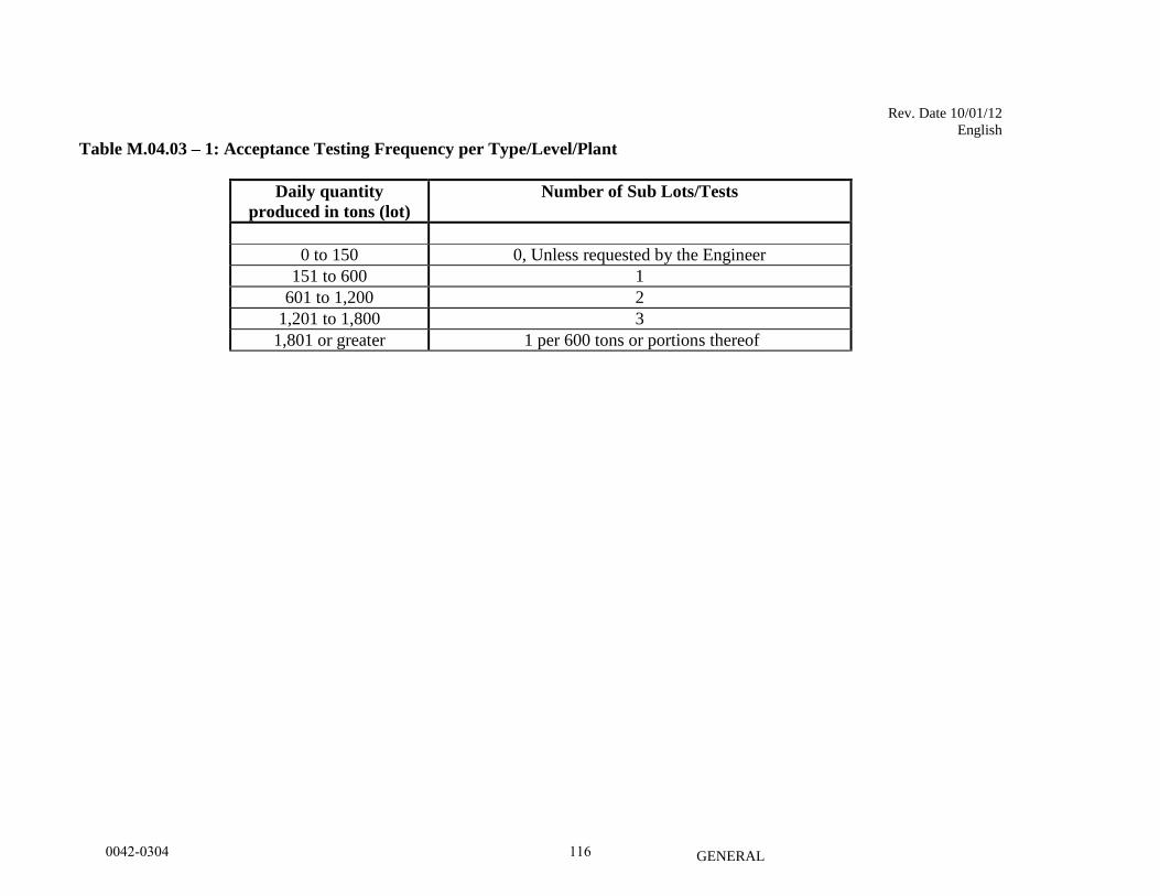
Rev. Date 10/01/12
English
GENERAL
Table M.04.03 – 1: Acceptance Testing Frequency per Type/Level/Plant
Daily quantity
produced in tons (lot)
Number of Sub Lots/Tests
0 to 150 0, Unless requested by the Engineer
151 to 600 1
601 to 1,200 2
1,201 to 1,800 3
1,801 or greater 1 per 600 tons or portions thereof
0042-0304 116
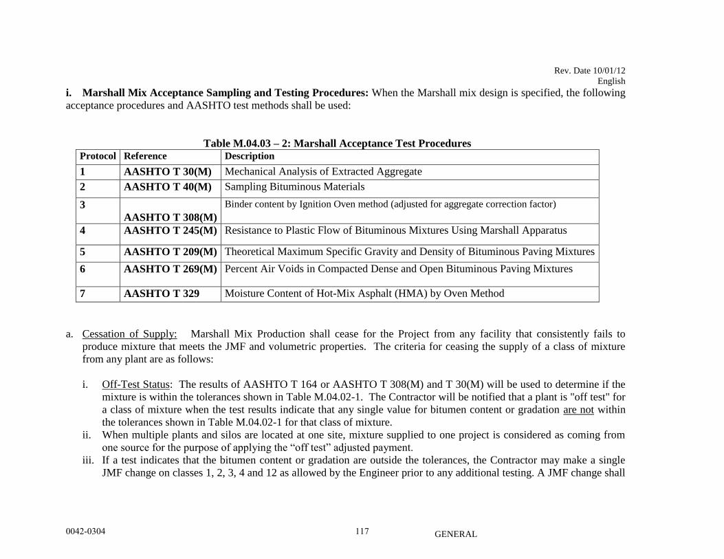
Rev. Date 10/01/12
English
GENERAL
i. Marshall Mix Acceptance Sampling and Testing Procedures: When the Marshall mix design is specified, the following
acceptance procedures and AASHTO test methods shall be used:
Table M.04.03 – 2: Marshall Acceptance Test Procedures
Protocol Reference Description
1 AASHTO T 30(M) Mechanical Analysis of Extracted Aggregate
2 AASHTO T 40(M) Sampling Bituminous Materials
3
AASHTO T 308(M)
Binder content by Ignition Oven method (adjusted for aggregate correction factor)
4 AASHTO T 245(M) Resistance to Plastic Flow of Bituminous Mixtures Using Marshall Apparatus
5 AASHTO T 209(M) Theoretical Maximum Specific Gravity and Density of Bituminous Paving Mixtures
6 AASHTO T 269(M) Percent Air Voids in Compacted Dense and Open Bituminous Paving Mixtures
7 AASHTO T 329 Moisture Content of Hot-Mix Asphalt (HMA) by Oven Method
a. Cessation of Supply: Marshall Mix Production shall cease for the Project from any facility that consistently fails to
produce mixture that meets the JMF and volumetric properties. The criteria for ceasing the supply of a class of mixture
from any plant are as follows:
i. Off-Test Status: The results of AASHTO T 164 or AASHTO T 308(M) and T 30(M) will be used to determine if the
mixture is within the tolerances shown in Table M.04.02-1. The Contractor will be notified that a plant is "off test" for
a class of mixture when the test results indicate that any single value for bitumen content or gradation are not within
the tolerances shown in Table M.04.02-1 for that class of mixture.
ii. When multiple plants and silos are located at one site, mixture supplied to one project is considered as coming from
one source for the purpose of applying the “off test” adjusted payment.
iii. If a test indicates that the bitumen content or gradation are outside the tolerances, the Contractor may make a single
JMF change on classes 1, 2, 3, 4 and 12 as allowed by the Engineer prior to any additional testing. A JMF change shall
0042-0304 117
Rev. Date 10/01/12
English
GENERAL
include the date and name of the Engineer that allowed it. Consecutive test results outside the requirements of Table
M.04.02-1 JMF tolerances may result in rejection of the mixture.
iv. The Engineer may cease supply of mixture from the plant when the test results from three non-consecutive samples of
a class of mixture are not within the JMF tolerances or the test results from two non-consecutive samples not within
the master range indicated in Table M.04.02-1 during any one production period, due to inconsistent production.
v. Any modification to the JMF shall not exceed 50% of the JMF tolerances indicated in Table M.04.02-1 for any given
component of the mixture without approval of the Engineer. When such an adjustment is made to the bitumen, the
corresponding production percentage of bitumen shall be revised accordingly.
b. Adjustments for Off Test Mixture under Cessation of Supply: The bituminous concrete plant shall cease supplying to the
project:
i. When the test results from three consecutive samples are “off test” and not within the JMF tolerances or,
ii. The test results from two consecutive samples are “off test” and not within the ranges indicated in Table M.04.02 – 1
or,
iii. When the percent of material passing the minus #200 sieve material exceeds the percent of extracted bitumen content
for three consecutive samples during any production period of the values stated in Table M.04.02-1:
a. The quantity of mixtures shipped to the project determined to be “off test” and outside the tolerances will be
tabulated by the Engineer and will be adjusted in accordance with Section 4.06.
b. Following cessation, a trial production period will be required at the plant for that class of mixture. Use of that
class of mixture from that plant will be prohibited on the Project until the plant has demonstrated the ability to
consistently produce acceptable mixture.
c. When the Engineer has accepted the mixtures from the trial production period, the use of that mixture on the Project
may resume.
0042-0304 118
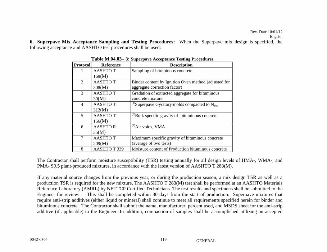
Rev. Date 10/01/12
English
GENERAL
ii. Superpave Mix Acceptance Sampling and Testing Procedures: When the Superpave mix design is specified, the
following acceptance and AASHTO test procedures shall be used:
Table M.04.03– 3: Superpave Acceptance Testing Procedures
Protocol Reference Description
1 AASHTO T
168(M) Sampling of bituminous concrete
2 AASHTO T
308(M) Binder content by Ignition Oven method (adjusted for
aggregate correction factor)
3 AASHTO T
30(M) Gradation of extracted aggregate for bituminous
concrete mixture
4 AASHTO T
312(M)
(1)Superpave Gyratory molds compacted to Ndes
5 AASHTO T
166(M)
(2)Bulk specific gravity of bituminous concrete
6 AASHTO R
35(M)
(2)Air voids, VMA
7 AASHTO T
209(M) Maximum specific gravity of bituminous concrete
(average of two tests)
8 AASHTO T 329 Moisture content of Production bituminous concrete
The Contractor shall perform moisture susceptibility (TSR) testing annually for all design levels of HMA-, WMA-, and
PMA- S0.5 plant-produced mixtures, in accordance with the latest version of AASHTO T 283(M).
If any material source changes from the previous year, or during the production season, a mix design TSR as well as a
production TSR is required for the new mixture. The AASHTO T 283(M) test shall be performed at an AASHTO Materials
Reference Laboratory (AMRL) by NETTCP Certified Technicians. The test results and specimens shall be submitted to the
Engineer for review. This shall be completed within 30 days from the start of production. Superpave mixtures that
require anti-strip additives (either liquid or mineral) shall continue to meet all requirements specified herein for binder and
bituminous concrete. The Contractor shall submit the name, manufacturer, percent used, and MSDS sheet for the anti-strip
additive (if applicable) to the Engineer. In addition, compaction of samples shall be accomplished utilizing an accepted
0042-0304 119
Rev. Date 10/01/12
English
GENERAL
Superpave Gyratory Compactor (SGC), supplied by the Contractor. The SGC shall be located at the facility supplying
mixture to the project.
a. Determination of Off-Test Status:
i. Off Test Status: Superpave mixes shall be considered “off test” when any Control Point Sieve, VA, VMA, and Gmm
values are outside of the limits specified in Table M.04.03-3 and the computed binder content (Pb) established by
AASHTO T308(M) or as documented on the vehicle delivery ticket is below the minimum binder content stated in sub
article M.04.03-5. Note that further testing of samples or portions of samples not initially tested for this purpose cannot
be used to change the status.
ii. Any time the bituminous concrete mixture is considered Off-test:
1. The Contractor shall notify the Engineer (and project staff) when the plant is "off test" for a type of mixture. When
multiple plants and silos are located at one site, mixture supplied to one project is considered as coming from one
source for the purpose of applying the “off test” determination.
2. The Contractor must take immediate actions to correct the deficiency, minimize “off test” production to the project,
and obtain an additional Process Control (PC) test after any corrective action to verify production is in conformance
to the specifications. A PC test will not be used for acceptance and is solely for the use of the Contractor in its
quality control process.
b. Cessation of Supply for Superpave Mixtures with no Payment Adjustment: Production of bituminous concrete shall cease
for the Project from any plant that consistently fails to produce mixture that meets the JMF and volumetric properties. The
quantity of Superpave mixtures shipped to the project that is “off-test” will not be adjusted for deficient mixtures.
A Contractor shall cease to supply mixture from a plant when:
1. Bituminous concrete mixture is “off test” on three (3) consecutive tests for VMA or Gmm, regardless of date of
production due to inconsistency (i.e., small production requires 1 test per day for multiple days).
0042-0304 120
Rev. Date 10/01/12
English
GENERAL
2. Bituminous concrete mixture is “off test” on two (2) consecutive tests for the Control Point sieves in one day’s
production.
Following cessation, the Contractor shall immediately make necessary material or process corrections and run a Pre-
Production Trial (PPT) for that type of mixture. Use of that type of mixture from that plant will be prohibited on the
Project until the Contractor has demonstrated the ability to produce acceptable mixture from that facility. When the
Contractor has a passing test and has received approval from the Engineer, the use of that mixture to the Project may
resume.
c. Cessation of Supply for Superpave Mixtures with Payment Adjustment:
Production of bituminous concrete shall cease for the Project from any plant that consistently fails to produce mixture that
meets the Superpave minimum binder content by mix type and level listed in Table M.04.02-5. The quantity of Superpave
mixtures shipped to the project that is “off-test” will be adjusted for deficient mixtures in accordance with Section 4.06.
A Contractor shall cease to supply mixture from a plant when the binder content (Pb) is below the requirements of Table
M.04.03-5 on the ignition oven test result after two (2) consecutive tests, regardless of the date of production.
Following cessation, the Contractor shall immediately make necessary material or process corrections and run a Pre-
Production Trial (PPT) for that type of mixture. Use of that type of mixture from that plant will be prohibited on the
Project until the Contractor has demonstrated the ability to produce acceptable mixture from that facility. When the
Contractor has a passing test and has received approval from the Engineer, the use of that mixture to the Project may
resume.
d. JMF Changes for Superpave Mixture Production: It is understood that a JMF change is effective from the time it was
submitted forward and is not retroactive to the previous test or tests. JMF changes are permitted to allow for trends in
aggregate and mix properties but every effort shall be employed by the Contractor to minimize this to ensure a uniform and
dense pavement.
JMF changes to the Gmm or mix Absorption Correction Factor (Acf) are only permitted prior to or after a production shift
for all bituminous-concrete types of mixtures and only when they:
0042-0304 121

Rev. Date 10/01/12
English
GENERAL
i. Are requested in writing and pre-approved by the Engineer;
ii. Are based on a minimum of a two test trend;
iii. Are documented with a promptly submitted revised JMF on form provided by the Engineer.
iv. A revised JMF submittal shall include the date and name of the Engineer that allowed it.
0042-0304 122
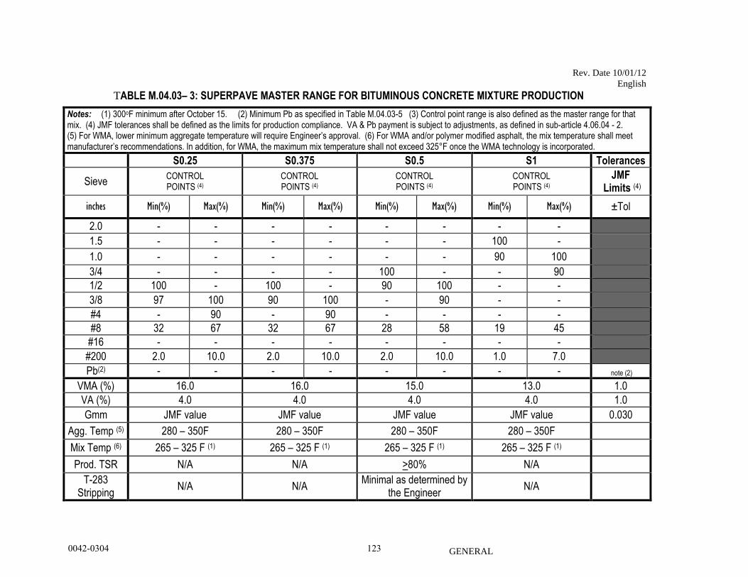
Rev. Date 10/01/12
English
GENERAL
TABLE M.04.03– 3: SUPERPAVE MASTER RANGE FOR BITUMINOUS CONCRETE MIXTURE PRODUCTION
Notes: (1) 300oF minimum after October 15. (2) Minimum Pb as specified in Table M.04.03-5 (3) Control point range is also defined as the master range for that mix. (4) JMF tolerances shall be defined as the limits for production compliance. VA & Pb payment is subject to adjustments, as defined in sub-article 4.06.04 - 2. (5) For WMA, lower minimum aggregate temperature will require Engineer’s approval. (6) For WMA and/or polymer modified asphalt, the mix temperature shall meet manufacturer’s recommendations. In addition, for WMA, the maximum mix temperature shall not exceed 325°F once the WMA technology is incorporated.
S0.25 S0.375 S0.5 S1 Tolerances
Sieve CONTROL POINTS (4)
CONTROL POINTS (4)
CONTROL POINTS (4)
CONTROL POINTS (4)
JMF Limits (4)
inches Min(%) Max(%) Min(%) Max(%) Min(%) Max(%) Min(%) Max(%) ±Tol
2.0 - - - - - - - -
1.5 - - - - - - 100 -
1.0 - - - - - - 90 100
3/4 - - - - 100 - - 90
1/2 100 - 100 - 90 100 - -
3/8 97 100 90 100 - 90 - -
#4 - 90 - 90 - - - -
#8 32 67 32 67 28 58 19 45
#16 - - - - - - - -
#200 2.0 10.0 2.0 10.0 2.0 10.0 1.0 7.0
Pb(2) - - - - - - - - note (2)
VMA (%) 16.0 16.0 15.0 13.0 1.0
VA (%) 4.0 4.0 4.0 4.0 1.0
Gmm JMF value JMF value JMF value JMF value 0.030
Agg. Temp (5) 280 – 350F 280 – 350F 280 – 350F 280 – 350F
Mix Temp (6) 265 – 325 F (1) 265 – 325 F (1) 265 – 325 F (1) 265 – 325 F (1)
Prod. TSR N/A N/A >80% N/A
T-283 Stripping
N/A N/A Minimal as determined by
the Engineer N/A
0042-0304 123
Rev. Date 10/01/12
English
GENERAL
TABLE M.04.03– 4: SUPERPAVE MASTER RANGE FOR TRAFFIC LEVELS AND
DESIGN VOLUMETRIC PROPERTIES.
* NOTE: Level 1 for use by Towns and Municipalities ONLY.
TABLE M.04.03– 5: SUPERPAVE MINIMUM BINDER CONTENT BY MIX TYPE &
LEVEL.
Mix Type Level Binder Content
Minimum (1)
S0.25 1* 5.6
S0.25 2 5.5
S0.25 3 5.4
S0.375 1* 5.6
S0.375 2 5.5
S0.375 3 5.4
S0.5 1* 5.0
S0.5 2 4.9
S0.5 3 4.8
S1 1* 4.6
S1 2 4.5
S1 3 4.4
* NOTE: Level 1 for use by Towns and Municipalities ONLY.
Traffic Level
Design ESALs Number of Gyrations by Superpave Gyratory Compactor
(million) Nini Ndes
1* < 0.3 6 50
2 0.3 to < 3.0 7 75
3 ≥3.0 8 100
0042-0304 124
Rev. Date 10/01/12
English
GENERAL
Table M.04.03-6:
Modifications to Standard AASHTO and ASTM Test Specifications and Procedures.
AASHTO Standard Specification
Reference Modification
M 320 1. Mass change for PG 64-22 shall be a maximum loss of 0.5% when tested in
accordance with AASHTO T 240.
2. The two bottles used for the mass change determination may be re-heated
and used for further testing.
AASHTO Standard Methods of Test
Reference Modification
T 27 Section 7.7 Samples are not washed
T 30 Section 6.2 thru 6.5 Samples are not routinely washed
T 168
Samples are taken at one point in the pile. All types of bituminous concrete except
Class 4 are scooped from the sample container instead of remixing and quartering.
(Method verified by laboratory study).
Samples from a hauling vehicle are taken from only one point instead of three as
specified.
Selection of Samples: Sampling is equally important as the testing, and the sampler
shall use every precaution to obtain samples that are truly representative of the
bituminous mixture.
Box Samples: In order to enhance the rate of processing samples taken in the field
by construction or maintenance personnel the samples will be tested in the order
received and data processed to be determine conformance to material specifications
and to prioritize inspections by laboratory personnel.
T 195 Section 4.3 only one truck load of mixture is sampled. Samples are taken from
opposite sides of the load.
T 209 Article 9.5.1 Bowl is suspended 2 minutes prior to reading rather than 10 minutes.
This makes no significant difference in results.
Section 7.2 The average of two bowls is used proportionally in order to satisfy
minimum mass requirements.
8.3 Omit Pycnometer method.
T 245 Article 3.3.2 A compacting temperature of 140 to 146°C (284 to 295°F) is used
Article 3.5.2 Seventy-five (75) blows per side are used on Classes
1 and 12, per ConnDOT design requirements
Section 3.1 for production testing: one specimen is molded for each extraction test
for production over 275 metric tons/day (300 tons/day). Other mixtures: two
specimens per extraction test.
T 283 When foaming technology is used, the material used for the fabrication of the
specimens shall be cooled to room temperature, and then reheated to the
manufactures recommended compaction temperature prior to fabrication of the
0042-0304 125
Rev. Date 10/01/12
English
GENERAL
specimens.
T 308 In addition to the standard testing procedure, the Department has adopted a
procedure that addresses a correction factor that is calculated using the composite
aggregate percentages (Composite Aggregate Correction Factor Method
(CACF)).
The aggregate is burned in compliance with the standard AASHTO procedure
Method A exclusively. All modifications are listed for this method only.
A2.2 and A2.3 Omit
A2.4 Omit. Replace with: Determine an aggregate gradation for each aggregate
component “blank” in accordance with T30.
A2.5 Omit. Replace with: The individual aggregate samples are to be dried in an
oven at a maximum temperature of 148 ± 5ºC (300 ± 9º F) to a constant weight.
RAP samples are to be oven dried at a maximum temperature of 110 ± 5ºC (230 ±
9º F) to a constant weight. RAP samples will be burned for total binder content
only and not to arrive at a correction factor for a mixture.
A2.6 and A2.7 and A2.8 Omit.
A2.8.1 Omit Note 2
A2.9 Omit. Replace with: Perform a gradation analysis on the residual aggregate
in accordance with T30 and compare it to the gradation performed prior to burning.
A2.9.1 and A2.9.2 Omit
The correction factors for each size aggregate are provided by the Contractor to the
Engineer prior to the Annual Plant Inspection. The Engineer may verify the
correction factors. The Composite Aggregate Correction Factor (CACF) for any
mixture may be calculated by summing the result of the correction factor for each
individual aggregate multiplied by the percentage of that aggregate in the overall
mixture.
(Note: All correction factors must be re-calculated every time the percentage of any
aggregate changes within the mixture.)
If the average corrected Pb content from the ignition oven differs by 0.3% or more
from the average bituminous concrete facility production weigh ticket in five (5)
consecutive tests regardless of the production date (moving average), the
Contractor shall immediately investigate, determine an assignable cause and correct
the issue. When two consecutive moving average differences are 0.3% or more, the
Engineer may require a new correction factor calculation for all the aggregate
components in the mix.
In addition to the standard testing procedure, the Department has adopted a
procedure that addresses the time involved between sampling the hot-mix asphalt
specimen and the beginning of the test.
6.3 Omit. Replace with: The test specimen must be ready to be placed in an
approved ignition furnace for testing within ten minutes of being obtained from the
hauling vehicle and the test shall start immediately after.
0042-0304 126
Rev. Date 10/01/12
English
GENERAL
T 331 6.1 Cores are dried to a constant mass prior to testing using a core-dry machine.
AASHTO Standard Recommended Practices
Reference Modification
R 35 Volumetric Calculations of VMA and Correction Factor
VMAa - Voids in Mineral Aggregate from (Va + Vbe) the mix:
A. VMA calculated from the mix shall be determined in accordance with
Formula 5.16.1A. It can be correlated that the VMA calculated from
AASHTO R-35 is equivalent to VMAa when the Pba x (100-Pbt) / 100 is
known and substituted for Acf, as shown in Formula 5.16.1A (ii). Test results
from VMAa shall therefore be required to meet all contract specifications.
Values of VMAa that are out of specifications during production may be cause
for the contractor to determine assignable reason, take corrective action, and
modify the Job Mix Formula (JMF), as needed. Continued VMAa data that is
out of specifications may be cause for the Engineer to order cessation of
supply.
Formula 5.16.1A. Determining the VMA of bituminous concrete by the mix
or air voids & effective binder method:
b
cftd
aaG
APbGmbVVMA
)((
Where: VMAa = VMA calculated from plant production mix( Va + Vbe)
Gmbd = Bulk specific gravity as determined by AASHTO T
166(M)
Pbt = Total Binder Content (corrected) by AASHTO T 308(M)
Acf = Absorption correction factor provided by Contractor (refer to
B. i and ii)
A. B. Determining the bituminous concrete mix binder correction factor for each
class by use of percent absorption of water by AASHTO T 84/85, AASHTO
M 323 and Df method. This value shall be performed by the Contractor
during the mix design only and submitted as a JMF value. Two methods for
determining the Acf are shown, although method (i) will be the desired method
to be used. Both methods are equivalent when the Gsa, Gsb and Pwa are
recent and valid for the mix.
i. PwaDfAcf x (100 – Pbt) / 100
ii. )( submittalJMFannualfromPbA acf x (100 – Pbt) / 100
Where: Df = as determined by Formula 5.16.1B.
Pwa = as determined by AASHTO T 84/85
Pba = as determined by AASHTO M 323 (from annual JMF submittal)
Df (Density Factor): The Contractor shall calculate the bituminous concrete
0042-0304 127
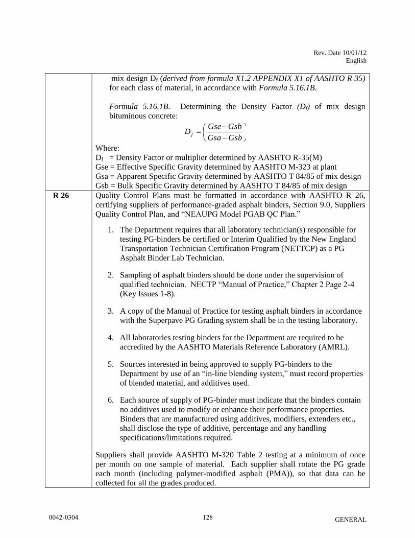
Rev. Date 10/01/12
English
GENERAL
mix design Df (derived from formula X1.2 APPENDIX X1 of AASHTO R 35)
for each class of material, in accordance with Formula 5.16.1B.
Formula 5.16.1B. Determining the Density Factor (Df) of mix design
bituminous concrete:
GsbGsa
GsbGseD f
Where:
Df = Density Factor or multiplier determined by AASHTO R-35(M)
Gse = Effective Specific Gravity determined by AASHTO M-323 at plant
Gsa = Apparent Specific Gravity determined by AASHTO T 84/85 of mix design
Gsb = Bulk Specific Gravity determined by AASHTO T 84/85 of mix design
R 26 Quality Control Plans must be formatted in accordance with AASHTO R 26,
certifying suppliers of performance-graded asphalt binders, Section 9.0, Suppliers
Quality Control Plan, and “NEAUPG Model PGAB QC Plan.”
1. The Department requires that all laboratory technician(s) responsible for
testing PG-binders be certified or Interim Qualified by the New England
Transportation Technician Certification Program (NETTCP) as a PG
Asphalt Binder Lab Technician.
2. Sampling of asphalt binders should be done under the supervision of
qualified technician. NECTP “Manual of Practice,” Chapter 2 Page 2-4
(Key Issues 1-8).
3. A copy of the Manual of Practice for testing asphalt binders in accordance
with the Superpave PG Grading system shall be in the testing laboratory.
4. All laboratories testing binders for the Department are required to be
accredited by the AASHTO Materials Reference Laboratory (AMRL).
5. Sources interested in being approved to supply PG-binders to the
Department by use of an “in-line blending system,” must record properties
of blended material, and additives used.
6. Each source of supply of PG-binder must indicate that the binders contain
no additives used to modify or enhance their performance properties.
Binders that are manufactured using additives, modifiers, extenders etc.,
shall disclose the type of additive, percentage and any handling
specifications/limitations required.
Suppliers shall provide AASHTO M-320 Table 2 testing at a minimum of once
per month on one sample of material. Each supplier shall rotate the PG grade
each month (including polymer-modified asphalt (PMA)), so that data can be
collected for all the grades produced.
0042-0304 128

Rev. Date 08/02/11
GENERAL
ON-THE-JOB TRAINING (OJT) WORKFORCE DEVELOPMENT PILOT:
Description
To provide construction industry related job opportunities to minorities, women and
economically disadvantaged individuals; and to increase the likelihood of a diverse and inclusive
workforce on Connecticut Department of Transportation (ConnDOT) projects.
All contractors (existing and newcomers) will be automatically placed in the Workforce
Development Pilot. Standard OJT requirements typically associated with individual projects will
no longer be applied at the project level for new projects. Instead, these requirements will be
applicable on an annual basis for each contractor performing work on ConnDOT projects.
The OJT Workforce Development Pilot will allow a contractor to train employees on Federal,
State and privately funded projects located in Connecticut. However, contractors should give
priority to training employees on ConnDOT Federal-Aid funded projects.
Funding
The Department will establish an OJT fund annually from which contractors may bill the
Department directly for eligible trainee hours. The funds for payment of trainee hours on
federal-aid projects will be allocated from the ½ of 1% provided for OJT funding, and will be
based on hours trained, not to exceed a maximum of $25,000.00 per year; per contractor.
Minorities and Women
Developing, training and upgrading of minorities, women and economically disadvantaged
individuals toward journeyperson level status is the primary objective of this special training
provision. Accordingly, the Contractor shall make every effort to enroll minority, women and
economically disadvantaged individuals as trainees to the extent that such persons are available
within a reasonable area of recruitment. This training commitment is not intended, and shall not
be used, to discriminate against any applicant for training whether a member of a minority group
or not.
Assigning Training Goals
The Department, through the OJT Program Coordinator, will assign training goals for a calendar
year based on the contractor’s past two year’s activities and the contractor’s anticipated
upcoming year’s activity with the Department. At the beginning of each year, all contractors
eligible will be contacted by the Department to determine the number of trainees that will be
assigned for the upcoming calendar year. At that time, the Contractor shall enter into an
agreement with the Department to provide a self-imposed on-the-job training program for the
calendar year. This agreement will include a specific number of annual training goals agreed to
by both parties. The number of training assignments may range from one (1) to six (6) per
0042-0304 129
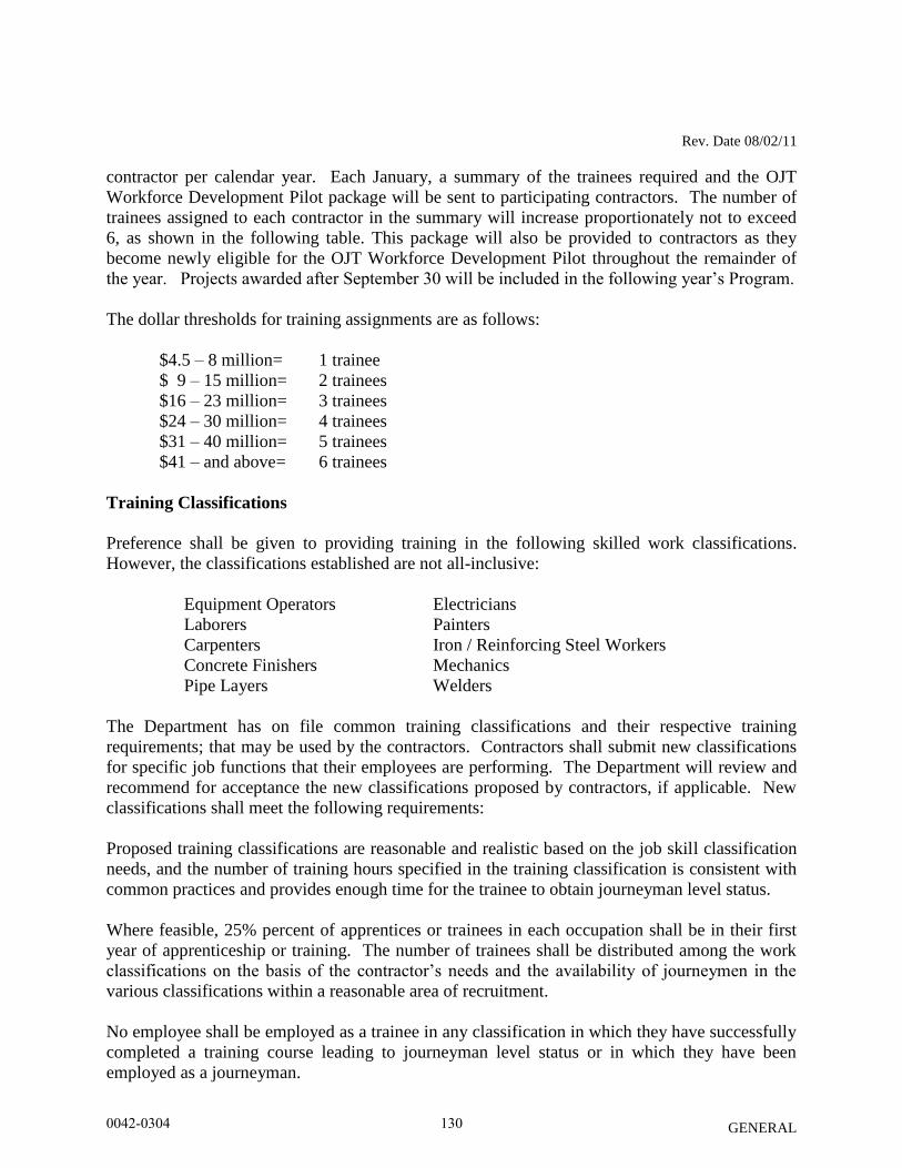
Rev. Date 08/02/11
GENERAL
contractor per calendar year. Each January, a summary of the trainees required and the OJT
Workforce Development Pilot package will be sent to participating contractors. The number of
trainees assigned to each contractor in the summary will increase proportionately not to exceed
6, as shown in the following table. This package will also be provided to contractors as they
become newly eligible for the OJT Workforce Development Pilot throughout the remainder of
the year. Projects awarded after September 30 will be included in the following year’s Program.
The dollar thresholds for training assignments are as follows:
$4.5 – 8 million= 1 trainee
$ 9 – 15 million= 2 trainees
$16 – 23 million= 3 trainees
$24 – 30 million= 4 trainees
$31 – 40 million= 5 trainees
$41 – and above= 6 trainees
Training Classifications
Preference shall be given to providing training in the following skilled work classifications.
However, the classifications established are not all-inclusive:
Equipment Operators Electricians
Laborers Painters
Carpenters Iron / Reinforcing Steel Workers
Concrete Finishers Mechanics
Pipe Layers Welders
The Department has on file common training classifications and their respective training
requirements; that may be used by the contractors. Contractors shall submit new classifications
for specific job functions that their employees are performing. The Department will review and
recommend for acceptance the new classifications proposed by contractors, if applicable. New
classifications shall meet the following requirements:
Proposed training classifications are reasonable and realistic based on the job skill classification
needs, and the number of training hours specified in the training classification is consistent with
common practices and provides enough time for the trainee to obtain journeyman level status.
Where feasible, 25% percent of apprentices or trainees in each occupation shall be in their first
year of apprenticeship or training. The number of trainees shall be distributed among the work
classifications on the basis of the contractor’s needs and the availability of journeymen in the
various classifications within a reasonable area of recruitment.
No employee shall be employed as a trainee in any classification in which they have successfully
completed a training course leading to journeyman level status or in which they have been
employed as a journeyman.
0042-0304 130
Rev. Date 08/02/11
GENERAL
Records and Reports
The Contractor shall maintain enrollment in the program and submit all required reports
documenting company compliance under these contract requirements. These documents and any
other information shall be submitted to the OJT Program Coordinator as requested.
Upon the trainee’s completion and graduation from the program, the Contractor shall provide
each trainee with a certification Certificate showing the type and length of training satisfactorily
completed.
Trainee Interviews
In order to determine the continued effectiveness of the OJT Program in Connecticut, the
department will periodically conduct personal interviews with current trainees and may survey
recent graduates of the program. This enables the OJT Program Coordinator to modify and
improve the program as necessary. Trainee interviews are generally conducted at the job site to
ensure that the trainees’ work and training is consistent with the approved training program.
Trainee Wages
Contractors shall compensate trainees on a graduating pay scale based upon a percentage of the
prevailing minimum journeyman wages (Davis-Bacon Act). Minimum pay shall be as follows:
60 percent of the journeyman wage for the first half of the training period
75 percent of the journeyman wage for the third quarter of the training period
90 percent of the journeyman wage for the last quarter of the training period
In no case, will the trainee be paid less than the prevailing rate for general laborer as shown in
the contract wage decision (must be approved by the Department of Labor).
Achieving or Failing to Meet Training Goals
The Contractor will be credited for each trainee currently enrolled or who becomes enrolled in
the approved training program and providing they receive the required training under the specific
training program. Trainees will be allowed to be transferred between projects if required by the
Contractor’s schedule and workload. The OJT Program Coordinator must be notified of
transfers within five (5) days of the transfer or reassignments by e-mail
Where a contractor does not or cannot achieve its annual training goal with female or minority
trainees, they must produce adequate Good Faith Efforts documentation. Good Faith Efforts are
those designed to achieve equal opportunity through positive, aggressive, and continuous result-
oriented measures. 23 CFR § 230.409(g) (4). Contractors should request minorities and females
from unions when minorities and females are under-represented in the contractor’s workforce.
0042-0304 131
Rev. Date 08/02/11
GENERAL
Whenever a contractor requests ConnDOT approval of someone other than a minority or female,
the contractor must submit documented evidence of its Good Faith Efforts to fill that position
with a minority or female. When a non-minority male is accepted, a contractor must continue to
attempt to meet its remaining annual training goals with females and minorities.
Where a contractor has neither attained its goal nor submitted adequate Good Faith Efforts
documentation, ConnDOT will issue a letter of non-compliance. Within thirty (30) days of
receiving the letter of non-compliance, the contractor must submit a written Corrective Action
Plan (CAP) outlining the steps that it will take to remedy the non-compliance. The CAP must be
approved by ConnDOT. Failure to comply with the CAP may result in your firm being found
non-responsive for future projects.
Measurement and Payment
Optional reimbursement will be made to the contractor for providing the required training under
this special provision on ConnDOT Federal-Aid funded projects only.
Contractor will be reimbursed at $0.80 for each hour of training given to an employee in
accordance with an approved training or apprenticeship program. This reimbursement will be made
even though the Contractor receives additional training program funds from other sources, provided
such other source does not specifically prohibit the contractor from receiving other reimbursement.
Reimbursement for training is made annually or upon the trainees completion and not on a monthly
basis. No payment shall be made to the Contractor if either the failure to provide the required
training, or the failure to hire the trainee as a journeyperson, is caused by the Contractor.
Program reimbursements will be made directly to the prime contractor on an annual basis. To
request reimbursement, prime contractors must complete the Voucher for OJT Workforce
Development Pilot Hourly Reimbursement for each trainee in the OJT Program. This form is
included in the OJT Workforce Development Pilot package and is available on the Department’s
web site at:
www.ct.gov/dot
The completed form must be submitted to the Office of Contract Compliance for approval. The
form is due on the 15th
day of January for each trainee currently enrolled and for hours worked
on ConnDOT Federal-Aid funded projects only.
0042-0304 132
January 2013
GENERAL
D.B.E. SUBCONTRACTORS AND MATERIAL SUPPLIERS OR
MANUFACTURERS
January 2013
I. ABBREVIATIONS AND DEFINITIONS AS USED IN THIS SPECIAL PROVISION
A. CTDOT means the Connecticut Department of Transportation.
B. USDOT means the U.S. Department of Transportation, including the Office of the Secretary, the Federal
Highway Administration (“FHWA”), the Federal Transit Administration (“FTA”), and the Federal Aviation
Administration (“FAA”).
C. Broker means a party acting as an agent for others in negotiating Contracts, Agreements, purchases, sales, etc.,
in return for a fee or commission.
D. Contract, Agreement or Subcontract means a legally binding relationship obligating a seller to furnish supplies
or services (including but not limited to, construction and professional services) and the buyer to pay for them.
For the purposes of this provision, a lease for equipment or products is also considered to be a Contract.
E. Contractor means a consultant, second party or any other entity under Contract to do business with CTDOT or,
as the context may require, with another Contractor.
F. Disadvantaged Business Enterprise (“DBE”) means a for profit small business concern:
1. That is at least 51 percent owned by one or more individuals who are both socially and economically
disadvantaged or, in the case of a corporation, in which 51 percent of the stock is owned by one or more
such individuals; and
2. Whose management and daily business operations are controlled by one or more of the socially and
economically disadvantaged individuals who own it; and
3. Certified by CTDOT under Title 49 of the Code of Federal Regulations, Part 26, (Title 49 CFR Part 23 of
the Code of Federal Regulations for Participation of Disadvantaged Business Enterprise in Airport
Concessions)
G. USDOT-assisted Contract means any Contract between CTDOT and a Contractor (at any tier) funded in whole
or in part with USDOT financial assistance.
H. Good Faith Efforts (“GFE”) means all necessary and reasonable steps to achieve a DBE goal or other
requirement which by their scope, intensity, and appropriateness to the objective, can reasonably be expected to
fulfill the program requirement.
I. Small Business Concern means, with respect to firms seeking to participate as DBEs in USDOT-assisted
Contracts, a small business concern as defined pursuant to Section 3 of the Small Business Act and Small
Business Administration (“SBA”) regulations implementing it (13 CFR Part 121) that also does not exceed the
cap on average annual gross receipts in 49 CFR Part 26, Section 26.65(b).
0042-0304 133
January 2013
GENERAL
J. Socially and Economically Disadvantaged Individual means any individual who is a citizen (or lawfully
admitted permanent resident) of the United States and who is:
1. Any individual who CTDOT finds, on a case-by-case basis, to be a socially and economically
disadvantaged individual.
2. Any individuals in the following groups, members of which are rebuttably presumed to be socially and
economically disadvantaged:
“Black Americans”, which includes persons having origins in any of the Black racial groups of
Africa;
“Hispanic Americans”, which includes persons of Mexican, Puerto Rican, Cuban, Dominican,
Central or South American, or other Spanish or Portuguese culture or origin, regardless of race;
“Native Americans”, which includes persons who are American Indians, Eskimos, Aleuts, or
Native Hawaiians.
“Asian-Pacific Americans”, which includes persons whose origins are from Japan, China,
Taiwan, Korea, Burma (Myanmar), Vietnam, Laos, Cambodia (Kampuchea), Thailand, Malaysia,
Indonesia, the Philippines, Brunei, Samoa, Guam, the U.S. Trust Territories of the Pacific Islands
(Republic of Palau), the Commonwealth of the Northern Marianas Islands, Macao, Fiji, Tonga,
Kiribati, Juvalu, Nauru, or Federated States of Micronesia;
“Subcontinent Asian Americans”, which includes persons whose origins are from India, Pakistan,
Bangladesh, Bhutan, the Maldives Islands, Nepal or Sri Lanka;
Women;
Any additional groups whose members are designated as socially and economically
disadvantaged by the SBA, at such time as the SBA designation becomes effective.
K. Commercially Useful Function (“CUF”) means the DBE is responsible for the execution of the work of the
contract and is carrying out its responsibilities by actually performing, managing, and supervising the work
involved with its own forces and equipment. The DBE must be responsible for procuring, determining quantity,
negotiating price, determining quality and paying for all materials (where applicable) associated with their work.
The DBE must also perform at least 30% of the total cost of its contract with its own workforce.
II. ADMINISTRATIVE REQUIREMENTS
A. General Requirements
A DBE goal percentage equaling Fourteen Percent (14%) of the Contract value has been established for this
Contract. This DBE goal percentage will be applied to the final Contract value to ultimately determine the
required DBE goal. If additional work is required, DBE firms should be provided the appropriate opportunities
to achieve the required DBE goal.
In order to receive credit toward the Contract DBE goal, the firms utilized as DBE subcontractors or suppliers
must be certified as DBEs in the type of work to be counted for credit by CTDOT’s Office of Contract
Compliance prior to the date of the execution of the subcontract. Neither CTDOT nor the State of Connecticut’s
Unified Certification Program (UCP) makes any representation as to any DBE’s technical or financial ability to
perform the work. Prime contractors are solely responsible for performing due diligence in hiring DBE
subcontractors.
All DBEs shall perform a CUF for the work that is assigned to them. The Contractor shall monitor and ensure
that the DBE is in compliance with this requirement. The Connecticut DBE UPC Directory of certified firms can
0042-0304 134
January 2013
GENERAL
be found on the CTDOT website http://www.ct.gov/dot. The directory lists certified DBE firms with a description
of services that they are certified to perform. Only work identified in this listing may be counted towards the
project’s DBE goal. A DBE firm may request to have services added at any time by contacting CTDOT’s Office
of Contract Compliance. No credit shall be counted for any DBE firm found not to be performing a CUF.
Once a Contract is awarded, all DBEs that were listed on the pre-award DBE commitment document must be
utilized. The Contractor is obligated to provide the value and items of the work originally established in the pre-
award documentation to the DBE firms listed in the pre-award documentation. Any modifications to the pre-
award commitment must follow the procedure established in Section II-C.
The Contractor shall designate a liaison officer who will administer the Contractor's DBE program. Upon
execution of this Contract, the name of the liaison officer shall be furnished in writing to CTDOT’s unit
administering the Contract, CTDOT’s Office of Contract Compliance and CTDOT’s Office of Construction
(“OOC”). Contact information for the designated liaison officer shall be furnished no later than the scheduled
date for the pre-construction meeting.
The Contractor shall submit a bi-monthly report to the appropriate CTDOT unit administering the
Contract. This report shall indicate what work has been performed to date, with the dollars paid and
percentage of DBE goal completed.
Verified payments made to DBEs shall be included in this bi-monthly report. A sample form is included on
the CTDOT website.
In addition, the report shall include:
1. A projected time frame of when the remaining work is to be completed for each DBE.
2. A statement by the Contractor either confirming that the approved DBEs are on schedule to meet the
Contract goal, or that the Contractor is actively pursuing a GFE.
3. If retainage is specified in the Contract specifications, then a statement of certification that the subcontractors’
retainage is being released in accordance with 1.08.01 (Revised or supplemented).
Failure by the Contractor to provide the required reports may result in CTDOT withholding an amount equal to one
percent (1%) of the monthly estimate until the required documentation is received.
The Contractor shall receive DBE credit when a DBE, or any combination of DBEs, perform work under the
Contract in accordance with this specification.
Only work actually performed by and/or services provided by DBEs which are certified for such work and/or
services, as verified by CTDOT, can be counted toward the DBE goal. Supplies and equipment a DBE purchases
or leases from the Contractor or its affiliate cannot be counted toward the goal.
Monitoring of the CUF will occur by CTDOT throughout the life of the project. If it is unclear that the DBE is
performing the work specified in its subcontract with the prime Contractor, further review may be required. If it
is determined that the DBE is not performing a CUF, then the work performed by that DBE will not be counted
towards the DBE goal percentage.
0042-0304 135
January 2013
GENERAL
B. Subcontract Requirements
The Contractor shall submit to CTDOT’s OOC all requests for subcontractor approvals on the standard CLA-12
forms provided by CTDOT. The dollar amount and items of work identified on the CLA-12 form must, at
minimum, equal the dollar value submitted in the pre-award commitment. CLA-12 forms can be found at
http://www.ct.gov/dot/construction under the “Subcontractor Approval” section. All DBE subcontractors must be
identified on the CLA-12 form, regardless of whether they are being utilized to meet a Contract goal percentage.
A copy of the legal Contract between the Contractor and the DBE subcontractor/supplier, a copy of the Title VI
Contractor Assurances and a copy of the Required Contract Provision for Federal Aid Construction Contracts
(Form FHWA-1273) (Federal Highway Administration projects only) must be submitted along with a request for
subcontractor approval. These attachments cannot be substituted by reference.
If retainage is specified in the Contract specifications, then the subcontract agreement must contain a prompt
payment mechanism that acts in accordance with Article 1.08.01 (Revised or supplemented).
If the Contract specifications do not contain a retainage clause, the Contractor shall not include a retainage clause
in any subcontract agreement, and in this case, if a Contractor does include a retainage clause, it shall be deemed
unenforceable.
In addition, the following documents are to be included with the CLA-12, if applicable:
An explanation indicating who will purchase material.
A statement explaining any method or arrangement for utilization of the Contractor’s equipment.
The subcontract must show items of work to be performed, unit prices and, if a partial item, the work involved by
all parties. If the subcontract items of work or unit prices are modified, the procedure established in Section II-C
must be followed.
Should a DBE subcontractor further sublet items of work assigned to it, only lower tier subcontractors who are
certified as a DBE firm will be counted toward the DBE goal. If the lower tier subcontractor is a non-DBE firm,
the value of the work performed by that firm will not be counted as credit toward the DBE goal.
The use of joint checks between a DBE firm and the Contractor is acceptable, provided that written approval is
received from the OOC prior to the issuance of any joint check. Should it become necessary to issue a joint check
between the DBE firm and the Contractor to purchase materials, the DBE firm must be responsible for negotiating
the cost, determining the quality and quantity, ordering the material and installing (where applicable), and
administering the payment to the supplier. The Contractor should not make payment directly to suppliers.
Each subcontract the Contractor signs with a subcontractor must contain the following assurance:
“The subcontractor/supplier/manufacturer shall not discriminate on the basis of race, color, national origin, or sex
in the performance of this contract. The contractor shall carry out applicable requirements of 49 CFR Part 26 in
the award and administration of DOT-assisted contracts. Failure by the
contractor/subcontractor/supplier/manufacturer to carry out these requirements is a material breach of this
contract, which may result in the termination of this contract or such other remedy as the recipient deems
appropriate.”
C. Modification to Pre-Award Commitment
Contractors may not terminate for convenience any DBE subcontractor or supplier that was listed on the pre-
award DBE commitment without prior written approval of the OOC. This includes, but is not limited to, instances
0042-0304 136

January 2013
GENERAL
in which a Contractor seeks to perform work originally designated for a DBE subcontractor with its own forces or
those of an affiliate, a non-DBE firm, or with another DBE firm. Prior to approval, the Contractor must
demonstrate to the satisfaction of the OOC, that it has good cause, as found in 49CFR Part 26.53 (f)(3), for
termination of the DBE firm.
Before transmitting its request for approval to terminate pre-award DBE firms to the OOC, the Contractor must
give written notice to the DBE subcontractor and include a copy to the OOC of its notice to terminate and/or
substitute, and the reason for the notice.
The Contractor must provide five (5) days for the affected DBE firm to respond. This affords the DBE firm the
opportunity to advise the OOC and the Contractor of any reasons why it objects to the termination of its
subcontract and why the OOC should not approve the Contractor’s action.
Once the Contract is awarded, should there be any amendments or modifications of the approved pre-award DBE
submission other than termination of a DBE firm, the Contractor shall follow the procedure below that best meets
the criteria associated with the reason for modification:
1. If the change is due to a scope of work revision or non-routine quantity revision by CTDOT, the
Contractor must notify CTDOT’s OOC in writing or via electronic mail that their DBE participation on
the project may be impacted as soon as they are aware of the change. In this case, a release of work from
the DBE firm may not be required; however the Contractor must concurrently notify the DBE firm in
writing, and copy the OOC for inclusion in the project DBE file. This does not relieve the Contractor of
its obligation to meet the Contract specified DBE goal, or of any other responsibility found in this
specification.
2. If the change is due to a factor other than a CTDOT directive, a request for approval in writing or via
electronic mail of the modification from the OOC must be submitted, along with an explanation of the
change(s), prior to the commencement of work. The Contractor must also obtain a letter of release from
the originally named DBE indicating their concurrence with the change, and the reason(s) for their
inability to perform the work. In the event a release cannot be obtained, the Contractor must document all
efforts made to obtain it.
3. In the event a DBE firm that was listed in the pre-award documents is unable or unwilling to perform the
work assigned, the Contractor shall:
Notify the OOC Division Chief immediately and make efforts to obtain a release of work from the
firm.
Submit documentation that will provide a basis for the change to the OOC for review and approval
prior to the implementation of the change.
Use the DBE Directory to identify and contact firms certified to perform the type of work that was
assigned to the unable or unwilling DBE firm. The Contractor should also contact CTDOT’s Office
of Contract Compliance for assistance in locating additional DBE firms to the extent needed to meet
the contract goal.
Should a DBE subcontractor be terminated or fail to complete work on the Contract for any reason, the Contractor
must make a GFE to find another DBE subcontractor to substitute for the original DBE. The DBE replacement
shall be given every opportunity to perform at least the same amount of work under the Contract as the original
DBE subcontractor.
0042-0304 137
January 2013
GENERAL
If the Contractor is unable to find a DBE replacement:
The Contractor should identify other contracting opportunities and solicit DBE firms in an effort to
meet the Contract DBE goal requirement, if necessary, and provide documentation to support a GFE.
(Refer to GFE in Section III.)
The Contractor must demonstrate that the originally named DBE, who is unable or unwilling to
perform the work assigned, is in default of its subcontract, or identify other issues that affected the
DBE firm’s ability to perform the assigned work. The Contractor's ability to negotiate a more
advantageous agreement with another subcontractor is not a valid basis for change.
III. GOOD FAITH EFFORTS
The DBE goal is NOT reduced or waived for projects where the Contractor receives a Pre-Award GFE
determination from the Office of Contract Compliance prior to the award of the Contract. It remains the
responsibility of the Contractor to make a continuing GFE to achieve the specified Contract DBE goal. The
Contractor shall pursue every available opportunity to obtain additional DBE firms and document all efforts made
in such attempts.
At the completion of all Contract work, the Contractor shall submit a final report to CTDOT`s unit administering
the Contract indicating the work done by and the dollars paid to DBEs. Only verified payments made to DBEs
performing a CUF will be counted towards the Contract goal.
Goal attainment is based on the total Contract value, which includes all construction orders created during the
Contract. If the Contractor does not achieve the specified Contract goal for DBE participation or has not provided
the value of work to the DBE firms originally committed to in the pre-award submission, the Contractor shall
submit documentation to CTDOT`s unit administering the Contract detailing the GFE made during the
performance of the Contract to satisfy the goal.
A GFE should consist of the following, where applicable (CTDOT reserves the right to request additional
information):
1. A detailed statement of the efforts made to replace an unable or unwilling DBE firm, and a
description of any additional subcontracting opportunities that were identified and offered to DBE
firms in order to increase the likelihood of achieving the stated goal.
2. A detailed statement, including documentation of the efforts made to contact and solicit bids from
certified DBEs, including the names, addresses, and telephone numbers of each DBE firm contacted;
the date of contact and a description of the information provided to each DBE regarding the scope of
services and anticipated time schedule of work items proposed to be subcontracted and the response
from firms contacted.
3. Provide a detailed explanation for each DBE that submitted a subcontract proposal which the
Contractor considered to be unacceptable stating the reason(s) for this conclusion.
4. Provide documentation, if any, to support contacts made with CTDOT requesting assistance in
satisfying the specified Contract goal.
0042-0304 138
January 2013
GENERAL
5. Provide documentation of all other efforts undertaken by the Contractor to meet the defined goal.
Additional documentation of efforts made to obtain DBE firms may include but will not be limited
to:
Negotiations held in good faith with interested DBE firms, not rejecting them without sound
reasons.
Written notice provided to a reasonable number of specific DBE firms in sufficient time to allow
effective participation.
Those portions of work that could be performed by readily available DBE firms.
In instances where the Contractor can adequately document or substantiate its GFE and compliance with
other DBE Program requirements, the Contractor will have satisfied the DBE requirement and no
administrative remedies will be imposed.
IV. PROJECT COMPLETION
At the completion of all Contract work, the Contractor shall:
1. Submit a final report to CTDOT`s unit administering the Contract indicating the work done by, and the
dollars paid to DBEs.
2. Submit verified payments made to all DBE subcontractors for the work that was completed.
3. Submit documentation detailing any changes to the DBE pre-award subcontractors that have not met the
original DBE pre-award commitment, including copies of the Department’s approvals of those changes.
4. Retain all records for a period of three (3) years following acceptance by CTDOT of the Contract and
those records shall be available at reasonable times and places for inspection by authorized
representatives of CTDOT and Federal agencies. If any litigation, claim, or audit is started before the
expiration of the three (3) year period, the records shall be retained until all litigation, claims, or audit
findings involving the records are resolved.
If the Contractor does not achieve the specified Contract goal for DBE participation in addition to meeting the
dollar value committed to the DBE subcontractors identified in the pre-award commitment, the Contractor shall
submit documentation to CTDOT`s unit administering the Contract detailing the GFE made during the
performance of the Contract to satisfy the goal.
V. SHORTFALLS
A. Failure to meet DBE goals
As specified in (II-A) above, attainment of the Contract DBE goal is based on the final Contract value. The
Contractor is expected to achieve the amount of DBE participation originally committed to at the time of award;
however, additional efforts must be made to provide opportunities to DBE firms in the event a Contract’s original
value is increased during the life of the Contract.
The Contractor is expected to utilize the DBE subcontractors originally committed in the DBE pre-award
documentation for the work and dollar value that was originally assigned.
0042-0304 139
January 2013
GENERAL
If a DBE is terminated or is unable or unwilling to complete its work on a Contract, the Contractor shall make a
GFE to replace that DBE with another certified DBE to meet the Contract goal.
The Contractor shall immediately notify the OOC of the DBE’s inability or unwillingness to perform, and provide
reasonable documentation and make efforts to obtain a release of work from the firm.
If the Contractor is unable to find a DBE replacement, then the Contractor should identify other contracting
opportunities and solicit DBE firms in an effort to meet the Contract DBE goal requirement, if necessary, and
provide documentation to support a GFE.
When a DBE is unable or unwilling to perform, or is terminated for just cause, the Contractor shall make a GFE
to find other DBE opportunities to increase DBE participation to the extent necessary to at least satisfy the
Contract goal.
For any DBE pre-award subcontractor that has been released appropriately from the project, no remedy will be
assessed, provided that the Contractor has met the criteria described in Section
II-C.
B. Administrative Remedies for Non-Compliance:
In cases where the Contractor has failed to meet the Contract specified DBE goal or the DBE pre-award
commitment, and where no GFE has been demonstrated, then one or more of the following administrative
remedies will be applied:
1. A reduction in Contract payments to the Contractor as determined by CTDOT, not to exceed the shortfall
amount of the DBE goal. The maximum shortfall will be calculated by multiplying the Contract DBE
goal (adjusted by any applicable GFE) by the final Contract value, and subtracting any verified final
payments made to DBE firms by the Contractor.
2. A reduction in Contract payments to the Contractor determined by CTDOT, not to exceed the shortfall
amount of the pre-award commitment. The maximum shortfall will be calculated by subtracting any
verified final payments made by the Contractor to each DBE subcontractor from the amount originally
committed to that subcontractor in the pre-award commitment.
3. A reduction in Contract payments to the Contractor determined by CTDOT for any pre-award DBE
subcontractor who has not obtained the dollar value of work identified in the DBE pre-award commitment
and has not followed the requirements of Section II-C or for any DBE firm submitted for DBE credit that
has not performed a CUF.
4. The Contractor being required to submit a written DBE Program Corrective Action Plan to CTDOT for
review and approval, which is aimed at ensuring compliance on future projects.
5. The Contractor being required to attend a Non-Responsibility Meeting on the next contract where it is the
apparent low bidder.
6. The Contractor being suspended from bidding on contracts for a period not to exceed six (6) months.
0042-0304 140
January 2013
GENERAL
VI. CLASSIFICATIONS OTHER THAN SUBCONTRACTORS
A. Material Manufacturers
Credit for DBE manufacturers is 100% of the value of the manufactured product. A manufacturer is a firm that
operates or maintains a factory or establishment that produces on the premises the materials or supplies obtained
by the Contractor.
If the Contractor elects to utilize a DBE manufacturer to satisfy a portion of, or the entire specified DBE goal, the
Contractor must provide the OOC with:
Subcontractor Approval Form (CLA-12) indicating the firm designation,
An executed “Affidavit for the Utilization of Material Suppliers or Manufacturers" (sample attached), and
Substantiation of payments made to the supplier or manufacturer for materials used on the project.
B. Material Suppliers (Dealers)
Credit for DBE dealers/suppliers is limited to 60% of the value of the material to be supplied, provided such
material is obtained from an approved DBE dealer/supplier.
In order for a firm to be considered a regular dealer, the firm must own, operate, or maintain a store, warehouse,
or other establishment in which the materials, supplies, articles or equipment of the general character described by
the specifications and required under the contract are bought, kept in stock, and regularly sold or leased to the
public in the usual course of business. At least one of the following criteria must apply:
To be a regular dealer, the firm must be an established, regular business that engages, as its principal
business and under its own name, in the purchase and sale or lease of the products in question.
A person may be a regular dealer in such bulk items as petroleum products, steel, cement, gravel, stone,
or asphalt without owning, operating or maintaining a place of business if the person both owns and
operates distribution equipment for the products. Any supplementing of the regular dealers’ own
distribution equipment shall be by long term lease agreement, and not on an ad hoc or contract to contract
basis.
Packagers, brokers, manufacturers’ representatives, or other persons who arrange or expedite transactions
are not regular dealers within the meaning of this paragraph.
If the Contractor elects to utilize a DBE supplier to satisfy a portion or the entire specified DBE goal, the
Contractor must provide the OOC with:
Subcontractor Approval Form (CLA-12) indicating the firm designation,
An executed “Affidavit for the Utilization of Material Suppliers or Manufacturers" (sample attached), and
Substantiation of payments made to the supplier or manufacturer for materials used on the project.
C. Brokering
Brokering of work for DBE firms who have been listed by the Department as certified brokers is allowed.
Credit for those firms shall be applied following the procedures in Section VI-D.
Brokering of work by DBEs who have been approved to perform subcontract work with their own
workforce and equipment is not allowed, and is a Contract violation.
0042-0304 141
January 2013
GENERAL
Firms involved in the brokering of work, whether they are DBEs and/or majority firms who engage in
willful falsification, distortion or misrepresentation with respect to any facts related to the project shall be
referred to the U.S. DOT, Office of the Inspector General for prosecution under Title 18, U.S. Code, Part
I, Chapter 47, Section 1020.
D. Non-Manufacturing or Non-Supplier DBE Credit
Contractors may count towards their DBE goals the following expenditures with DBEs that are not manufacturers or
suppliers:
Reasonable fees or commissions charged for providing a bona fide service such as professional, technical,
consultant or managerial services and assistance in the procurement of essential personnel, facilities,
equipment materials or supplies necessary for the performance of the Contract, provided that the fee or
commission is determined by the OOC to be reasonable and consistent with fees customarily allowed for
similar services.
The fees charged only for delivery of materials and supplies required on a job site when the hauler, trucker,
or delivery service is a DBE, and not the manufacturer, or regular dealer of the materials and supplies, and
provided that the fees are determined by the OOC to be reasonable and not excessive as compared with fees
customarily allowed for similar services.
The fees or commissions charged for providing bonds or insurance specifically required for the
performance of the Contract, provided that the fees or commissions are determined by CTDOT to be
reasonable and not excessive as compared with fees customarily allowed for similar services.
E. Trucking
While technically still considered a subcontractor, the rules for counting credit for DBE trucking firms are as
follows:
The DBE must own and operate at least one fully licensed, insured, and operational truck used on the
Contract.
The DBE receives credit for the total value of the transportation services it provides on the Contract using
trucks it owns, insures and operates using drivers it employs.
The DBE may lease trucks from another DBE firm, including an owner-operator who is certified as a
DBE. The DBE who leases trucks from another DBE receives credit for the total value of the
transportation services the lessee DBE provides on the Contract.
The DBE may lease trucks from a non-DBE firm; however the DBE may only receive credit for any fees
or commissions received for arranging transportation services provided by the non-DBE firms.
Additionally, the DBE firm must demonstrate that they are in full control of the trucking operation for
which they are seeking credit.
VII. Suspected DBE Fraud
In appropriate cases, CTDOT will bring to the attention of the USDOT any appearance of false, fraudulent, or
dishonest conduct in connection with the DBE program, so that USDOT can take the steps, e.g. referral to the
0042-0304 142

January 2013
GENERAL
Department of Justice for criminal prosecution, referral to USDOT Inspector General, action under suspension
and debarment or Program Fraud and Civil Penalties rules provided in 49 CFR Part 31.
0042-0304 143
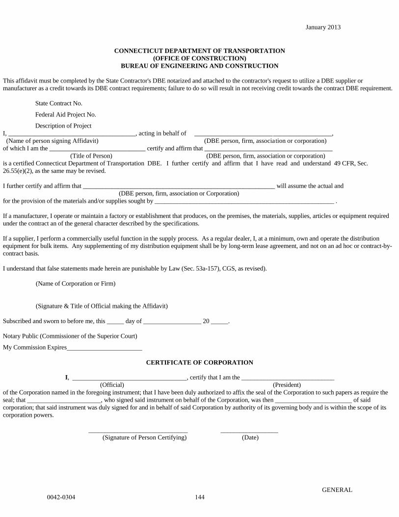
January 2013
GENERAL
CONNECTICUT DEPARTMENT OF TRANSPORTATION
(OFFICE OF CONSTRUCTION)
BUREAU OF ENGINEERING AND CONSTRUCTION
This affidavit must be completed by the State Contractor's DBE notarized and attached to the contractor's request to utilize a DBE supplier or
manufacturer as a credit towards its DBE contract requirements; failure to do so will result in not receiving credit towards the contract DBE requirement.
State Contract No.
Federal Aid Project No.
Description of Project
I, _______________________________________, acting in behalf of __________________________________________,
(Name of person signing Affidavit) (DBE person, firm, association or corporation)
of which I am the ______________________________ certify and affirm that ________________________________________
(Title of Person) (DBE person, firm, association or corporation)
is a certified Connecticut Department of Transportation DBE. I further certify and affirm that I have read and understand 49 CFR, Sec.
26.55(e)(2), as the same may be revised.
I further certify and affirm that ____________________________________________________________ will assume the actual and
(DBE person, firm, association or Corporation)
for the provision of the materials and/or supplies sought by ________________________________________________________ .
If a manufacturer, I operate or maintain a factory or establishment that produces, on the premises, the materials, supplies, articles or equipment required
under the contract an of the general character described by the specifications.
If a supplier, I perform a commercially useful function in the supply process. As a regular dealer, I, at a minimum, own and operate the distribution
equipment for bulk items. Any supplementing of my distribution equipment shall be by long-term lease agreement, and not on an ad hoc or contract-by-
contract basis.
I understand that false statements made herein are punishable by Law (Sec. 53a-157), CGS, as revised).
(Name of Corporation or Firm)
(Signature & Title of Official making the Affidavit)
Subscribed and sworn to before me, this day of 20 .
Notary Public (Commissioner of the Superior Court)
My Commission Expires
CERTIFICATE OF CORPORATION
I, , certify that I am the _____________________________
(Official) (President)
of the Corporation named in the foregoing instrument; that I have been duly authorized to affix the seal of the Corporation to such papers as require the
seal; that , who signed said instrument on behalf of the Corporation, was then of said
corporation; that said instrument was duly signed for and in behalf of said Corporation by authority of its governing body and is within the scope of its
corporation powers.
_______________________________ __________________
(Signature of Person Certifying) (Date)
0042-0304 144
Rev. Date 10/10/14
ITEM #0020801A
ITEM #0020801A – ASBESTOS ABATEMENT
00.20.01 - Description:
Work under this item shall include the abatement of asbestos containing materials (ACM) and
associated work by persons who are knowledgeable, qualified, trained and licensed in the
removal, treatment, handling, and disposal of ACM and the subsequent cleaning of the affected
environment. ACM shall include material composed of any type of asbestos in amounts greater
than one percent (1%) by weight. The Contractor performing this work shall possess a valid
Asbestos Abatement Contractor license issued by the Connecticut Department of Public Health
(CTDPH).
These Specifications govern all work activities that disturb asbestos containing materials. All
activities shall be performed in accordance with, but not limited to, the current revision of the
OSHA General Industry Standard for Asbestos (29 CFR 1926.1001), the OSHA Asbestos in
Construction Regulations (29 CFR 1926.1101), the USEPA Asbestos National Emission
Standards for Hazardous Air Pollutants (NESHAP) Regulations (40 CFR Part 61 Subpart M), the
CTDPH Standards for Asbestos Abatement, Licensure and Training (19a-332a-1 through 16, 20-
440-1 through 9 & 20-441), and the CTDEEP Special Waste Disposal Regulations (22a-209-
8(i)).
The asbestos abatement work shall include the removal and disposal of all ACM as identified on
the Contract Plans and Specifications prior to the planned renovation/demolition project.
Deviations from these Specifications require the written approval of the Engineer.
The Contractor may elect to utilize an Alternative Work Practice (AWP), if approved by the
CTDPH and the Engineer prior to the initiation of the abatement activities. An AWP is a
variance from certain CTDPH asbestos regulatory requirements, which must provide the
equivalent or a greater measure of asbestos emission control than the standard work practices
prescribed by the CTDPH.
00.20.02 - Materials:
All materials shall be delivered to the job site in the original packages, containers, or bundles
bearing the name of the manufacturer, the brand name and product technical description.
No damaged or deteriorating materials shall be used. If material becomes contaminated with
asbestos, the material shall be decontaminated or disposed of as asbestos-containing waste
material. The cost to decontaminate and dispose of this material shall be at the expense of the
Contractor.
Fire retardant polyethylene sheet shall be in roll size to minimize the frequency of joints, with
factory label indicating four (4) or six (6) mil thickness.
0042-0304 145
Rev. Date 10/10/14
ITEM #0020801A
Six (6) mil polyethylene disposable bags shall have pre-printed OSHA/EPA/DOT labels and
shall be transparent.
Tape (or equivalent) capable of sealing joints in adjacent polyethylene sheets and for the
attachment of polyethylene sheets to finished or unfinished surfaces must be capable of adhering
under both dry and wet conditions.
Surfactant is a chemical wetting agent added to water to improve penetration and shall consist of
fifty (50) percent polyoxyethylene ether and fifty (50) percent polyoxyethylene ester, or
equivalent. The surfactant shall be mixed with water to provide a concentration one (1) ounce
surfactant to five (5) gallons of water, or as directed by the manufacturer.
Spray equipment must be capable of mixing necessary chemical agents with water, generating
sufficient pressure and volume; and equipped with adequate hose length to access all necessary
work areas.
Sanders, grinders, wire brushes and needle-gun type removal equipment shall be equipped with a
High Efficiency Particulate Air (HEPA) filtered vacuum dust collection system.
Containers for storage, transportation and disposal of asbestos containing waste material shall be
impermeable and both air and watertight.
Labels and warning signs shall conform to OSHA 29 CFR 1926.1101, USEPA 40 CFR Part
61.152, and USDOT 49 CFR Part 172 as appropriate.
Encapsulant, a material used to chemically entrap asbestos fibers to prevent these fibers from
becoming airborne, shall be of the type which has been approved by the Engineer. Use shall be
in accordance with manufacturer's printed technical data. The encapsulant shall be clear and
must be compatible with new materials being installed, if any.
Glovebag assembly shall be manufactured of six (6) mil transparent polyethylene or PVC with
two (2) inward projecting long sleeve gloves, an internal pouch for tools, and an attached labeled
receptacle for waste.
Mastic removal chemicals shall be low odor and non-citrus based, with a flash point in excess of
140° F.
Any planking, bracing, shoring, barricades and/or temporary sheet piling, necessary to
appropriately perform work activities shall conform to all applicable federal, state and local
regulations.
Air filtration devices and vacuum units shall be equipped with HEPA filters.
0042-0304 146
Rev. Date 10/10/14
ITEM #0020801A
00.20.03 - Construction Methods:
(1) Pre-Abatement Submittals and Notices
(a) The Contractor shall submit, in accordance with CTDPH Standard 19a-332a-3, proper
notification using the prescribed form, to the Commissioner, State of Connecticut,
Department of Public Health not fewer than ten (10) days prior to the commencement of
work as follows:
1. The asbestos to be removed is exterior NESHAP Category I/II Non-Friable
ACM, and it is not expected that the abatement procedures will render the
Category I/II asbestos friable; thereby not categorizing it as NESHAP
Regulated ACM (RACM); therefore not defining the removal as a CTDPH
“abatement”; and as such the CT licensed Asbestos Abatement Contractor
will not be required to file an Asbestos Abatement notification so long as no
more than 10 linear feet (LF)/25 square feet (SF) of ACM is rendered friable.
(b) Fifteen (15) working days prior to the commencement of asbestos abatement work, the
Contractor shall submit to the Engineer for review and acceptance and/or
acknowledgment of the following:
1. Permits and licenses for the removal, transport, and disposal of asbestos-
containing or contaminated materials, including a CTDPH valid asbestos removal
contractor’s license.
2. Documentation dated within the previous twelve (12) months, certifying that all
employees have received USEPA Model Accreditation Plan approved asbestos
worker/supervisor training in the proper handling of materials that contain
asbestos; understand the health implications and risks involved, including the
illnesses possible from exposure to airborne asbestos fibers; understands the use
and limits of respiratory equipment to be used; and understands the results of
monitoring of airborne quantities of asbestos as related to health and respiratory
equipment as indicated in 29 CFR 1926.1101 on an initial and annual basis, and
copies of all employees CTDPH asbestos worker and/or supervisor licenses.
3. Documentation from the Contractor, typed on company letterhead and signed by
the Contractor, certifying that all employees listed therein have received the
following:
a. medical monitoring within the previous twelve (12) months, as
required in 29 CFR 1926.1101;
b. respirator fit testing within the previous twelve (12) months as
detailed in 29 CFR 1910.134 (for all employees who must also don a
tight-fitting face piece respirator).
0042-0304 147
Rev. Date 10/10/14
ITEM #0020801A
4. Copies of the EPA/State-approved certificates for the proposed asbestos landfill.
(c) No abatement shall commence until a copy of all required submittals have been received
and found acceptable to the Engineer. Those employees added to the Contractor's
original list will be allowed to perform work only upon submittal to, and receipt of, all
required paperwork by the Engineer.
(2) Asbestos Abatement Provisions:
(a) General Requirements
The Abatement Contractor/Subcontractor shall possess a valid State of Connecticut Asbestos
Contractor License. Should any portion of the work be subcontracted, the subcontractor must
also possess a valid State of Connecticut Asbestos Contractor License. The Asbestos Abatement
Site Supervisor employed by the Contractor shall be in control on the job site at all times during
asbestos abatement work. All employees of the Contractor who shall perform work (i.e. Asbestos
Abatement Site Supervisor, Asbestos Abatement Worker) shall be properly certified/licensed by
the State of Connecticut to perform such duties.
All labor, materials, tools, equipment, services, testing, insurance (with specific coverage for
work on asbestos), and incidentals which are necessary or required to perform the work in
accordance with applicable governmental regulations, industry standards and codes, and these
Specifications shall be provided by the Contractor. The Contractor shall be prepared to work all
shifts and weekends throughout the course of this project.
Prior to beginning work, the Engineer and Contractor shall perform a visual survey of each work
area and review conditions at the site for safety reasons. In addition, the Contractor shall instruct
all workers in all aspects of personnel protection, work procedures, emergency evacuation
procedures and use of equipment including procedures unique to this project.
The Contractor shall:
Shut down and lock out electrical power, including all receptacles and light fixtures,
when feasible. The use or isolation of electrical power will be coordinated with all other
ongoing uses of electrical power at the site.
When necessary, provide temporary power and adequate lighting and ensure safe
installation of electrical equipment, including ground fault protection and power cables,
in compliance with applicable electrical codes and OSHA requirements. The Contractor
is responsible for proper connection and installation of electrical wiring.
Water service may not be available at the site. Contractor shall supply sufficient water for each
shift to operate the decontamination shower units as well as to maintain the work areas
adequately wet.
0042-0304 148

Rev. Date 10/10/14
ITEM #0020801A
Ladders and/or scaffolds shall be in compliance with OSHA requirements, and of adequate
length, strength and sufficient quantity to support the scope of work. Use of ladders/scaffolds
shall be in conformance with OSHA 29 CFR 1926 Subpart L and X requirements.
Work performed at heights exceeding six feet (6’) shall be performed in accordance with the
OSHA Fall Protection Standard 29 CFR 1926 Subpart M including the use of fall arrest systems
as applicable.
Data provided regarding asbestos sampling conducted throughout the structure(s) is for
informational purposes only. Under no circumstances shall this information be the sole means
used by the Contractor for determining the presence and location of all asbestos containing
materials. The Contractor shall verify all field conditions affecting performance of the work as
described in these Specifications in accordance with OSHA, USEPA, USDOT, DEP standards.
Compliance with the applicable requirements is solely the responsibility of the Contractor.
The Engineer will provide a Project Monitor to oversee the activities of the Contractor. No
asbestos work shall be performed until the Project Monitor is on-site. Pre-abatement, during
abatement and post-abatement air sampling will be conducted as deemed necessary by the
Project Monitor. Waste stream testing will be performed, as necessary, by the Project Monitor
prior to waste disposal.
(b) Set-Up
The Contractor shall establish contiguous to the Regulated Area, a Worker Decontamination
Enclosure System consisting of Equipment Room, Shower Room and Clean Room in series, as
detailed below. Access to the Regulated Area shall only be through this enclosure.
Access between rooms in the Worker Decontamination Enclosure System shall be through
airlocks. Other effective designs are permissible. The Clean Room, Shower Room and
Equipment Room located within the Worker Decontamination Enclosure, shall be contiguously
connected with taped airtight edges, thus ensuring the sole source of airflow originates from
outside the regulated areas, once the negative pressure differential within the Regulated Area is
established.
The Clean Room shall be adequately sized to accommodate workers and shall be equipped with
a suitable number of hooks, lockers, shelves, etc., for workers to store personal articles and
clothing. Changing areas of the Clean Room shall be suitably screened from areas occupied by
the public.
The Shower Room shall be of sufficient capacity to accommodate the number of workers. One
shower stall shall be provided for each eight (8) workers. Showers shall be equipped with hot
and cold or warm running water through the use of electric hot water heaters supplied by the
Contractor. No worker or other person shall leave a Regulated Area without showering. Shower
water shall be collected and filtered using best available technology and dumped down an
0042-0304 149

Rev. Date 10/10/14
ITEM #0020801A
approved sanitary drain. Shower stalls and plumbing shall include sufficient hose length and
drain system or an acceptable alternate.
The Contractor shall ensure that no personnel or equipment be permitted to leave the Regulated
Area until proper decontamination procedures (including HEPA vacuuming, wet wiping and
showering) to remove all asbestos debris have occurred. No asbestos-contaminated materials or
persons shall enter the Clean Room.
Post warning signs meeting the specifications of OSHA 29 CFR 1910.1001 and 29 CFR
1926.1101 at each Regulated Area. In addition, signs shall be posted at all approaches to
Regulated Areas so that an employee or building occupant may read the sign and take the
necessary protective steps before entering the area. Additional signs may require posting
following construction of workplace enclosure barriers.
(c) Alternate set up requirements for exterior non-friable asbestos abatement procedures
In lieu of the establishment of a negative pressure enclosure (NPE) system as described by
CTDPH Sections 19a-332a-5(c), 5(d), 5(e), and 5(h), non-friable ACM will be removed from
exterior work areas within an outdoor Regulated Area(s). The regulated work area will be
established by the use of appropriately labeled barrier tape and postings in compliance with
CTDPH 19a-332a-5(a) as well as OSHA 29 CFR 1926.1101. A remote personnel
decontamination unit as specified in Section 19a-332a-6 will be required. This method shall
only be utilized provided exposure assessment air sampling data collected during the removal of
the exterior non-friable materials indicates that the exposure levels during removal of such
materials do not exceed 0.1 asbestos f/cc. Should exposure assessment air sampling data exceed
this level, and engineering efforts to reduce the airborne fiber levels not be successful in reducing
the levels to less than 0.1 f/cc, removal shall occur within these areas under full containment
conditions.
(d) Personnel Protection
The Contractor shall utilize all appropriate engineering controls and safety and protective
equipment while performing the work in accordance with OSHA, USEPA, USDOT, CTDEEP
and CTDPH regulations.
The Contractor shall provide and require all workers to wear protective clothing in the Regulated
Areas where asbestos fiber concentrations may reasonably be expected to exceed the OSHA
established Permissible Exposure Limits (PEL) or where asbestos contamination exists.
Protective clothing shall include impervious coveralls with elastic wrists and ankles, head
covering, gloves and foot coverings.
Respiratory protection shall be provided and shall meet the requirements of OSHA as required in
29 CFR 1910.134, and 29 CFR 1926.1101 as well as the requirements of the CTDPH
regulations. A formal respiratory protection program must be implemented in accordance with
29 CFR 1926.1101 and 29 CFR 1910.134. The Contractor shall provide respirators from among
0042-0304 150

Rev. Date 10/10/14
ITEM #0020801A
those approved as being acceptable for protection by the National Institute for Occupational
Safety and Health (NIOSH) under the provisions of 30 CFR Part ll.
All other necessary personnel protective equipment (i.e. hardhat, work boots, safety glasses,
hearing protection, etc.) required to perform the asbestos abatement work activities shall conform
to all applicable federal, state and local regulations.
All other qualified and authorized persons entering into a Regulated Area (i.e. Project Monitor,
Regulatory Agency Representative) shall adhere to the requirements of personnel protection as
stated in this section.
(e) Asbestos Abatement Procedures
The Asbestos Abatement Site Supervisor, as the OSHA Competent Person shall be at the site at
all times.
The Contractor shall not begin abatement work until authorized by the Project Monitor,
following a pre-abatement visual inspection.
All workers and authorized persons shall enter and leave the Regulated Area through the Worker
Decontamination Enclosure System, leaving contaminated protective clothing in the Equipment
Room for reuse or disposal of as asbestos contaminated waste. No one shall eat, drink, smoke,
chew gum or tobacco, or apply cosmetics while in a Regulated Area.
The following details the extent of each phase of operation designated for this project. Phase
areas may be combined or divided at the direction of the Engineer. Proceed through the
sequencing of the work phases under the direction of the Engineer.
Site No. 3 - Bridge No. 02376, Turning Point 831 over I-84, East Hartford
Includes the removal of:
Dark grey caulking on the bridge guard rail brackets and parapet wall interface
(both sides of the bridge)
A regulated area(s) shall be established at the perimeter of the work area(s), and access
shall be controlled by the Contractor. A remote personnel decontamination unit shall be
utilized. Removal shall be undertaken in accordance with OSHA Class II and USEPA
Asbestos NESHAP requirements.
Site No. 4 - Exterior Flashing Tar, Bridge No. 02368, East Hartford
Includes the removal of:
Black flashing tar on metal bearings/concrete abutment pads (both abutments)
0042-0304 151
Rev. Date 10/10/14
ITEM #0020801A
A regulated area(s) shall be established at the perimeter of the work area(s), and access
shall be controlled by the Contractor. A remote personnel decontamination unit shall be
utilized. Removal shall be undertaken in accordance with OSHA Class II and USEPA
Asbestos NESHAP requirements.
Sign Support No. 21607 near Bridge No. 02368A, East Hartford
Includes the removal of:
Black flashing tar waterproofing on base plates of metal sign support
A regulated area(s) shall be established at the perimeter of the work area(s), and access
shall be controlled by the Contractor. A remote personnel decontamination unit shall be
utilized. Removal shall be undertaken in accordance with OSHA Class II and USEPA
Asbestos NESHAP requirements.
During removal, the Contractor shall spray asbestos materials with amended water using airless
spray equipment capable of providing a "mist" application to reduce the release of airborne
fibers. Spray equipment shall be capable of mixing wetting agent with water and capable of
generating sufficient pressure and volume. Hose length shall be sufficient to reach all of the
Regulated Area. Do not “flood” the area with hose type water supply equipment with the
potential to create water releases from the regulated area.
The Contractor shall continue to spray the asbestos materials with amended water, as necessary,
throughout removal activities to ensure the asbestos materials remain adequately wet. The
asbestos materials shall not be allowed to dry out.
In order to minimize airborne asbestos concentrations inside the Regulated Area, the Contractor
shall remove the adequately wetted asbestos in manageable sections. In addition, asbestos
materials removed from any elevated level shall be carefully lowered to the floor.
The Contractor shall promptly place the adequately wet asbestos material in disposal containers
(six (6) mil polyethylene bags/fiber drum/poly-lined dumpsters, etc.) as it is removed. Large
components removed intact may be wrapped in two (2) layers of six (6) mil polyethylene
sheeting secured with tape. As the disposal containers are filled, the Contractor shall promptly
seal the containers, apply caution labels and clean the containers before transportation to the
equipment decontamination area. Bags shall be securely sealed to prevent accidental opening
and leakage by taping in gooseneck fashion. Small components and asbestos-containing waste
with sharp-edged components (e.g. nails, screws, metal lath, tin sheeting) which could tear
polyethylene bags and sheeting shall be placed in clean drums and sealed with locking ring tops.
All waste containers shall be leak-tight, (typically consisting of two layers of 6 mil poly (or
bags)), and shall be properly labeled and placarded with OSHA Danger labels, DOT shipping
labels, markings and placards and USEPA NESHAP generators labels. Containers shall be
0042-0304 152
Rev. Date 10/10/14
ITEM #0020801A
decontaminated by wet cleaning and HEPA vacuuming within the equipment decontamination
area prior to exiting the regulated area. Wet clean each container thoroughly before moving to
Holding Area.
If at any time during asbestos removal, the Project Monitor should suspect contamination of
areas outside the Regulated Area, the Contractor shall immediately stop all abatement work and
take steps to decontaminate these areas and eliminate causes of such contamination. Unprotected
individuals shall be prohibited from entering contaminated areas until air sampling and/or visual
inspections determine decontamination.
After completion of abatement work, all surfaces from which asbestos has been removed shall be
wet brushed, using a nylon brush, wet wiped and sponged or cleaned by an equivalent method to
remove all visible material (wire brushes are not permitted). During this work the surfaces being
cleaned shall be kept wet. Cleaning shall also include the use of HEPA filtered vacuum
equipment.
The Contractor shall also remove and containerize all visible accumulations of asbestos-
containing and/or asbestos-contaminated debris which may have splattered or collected on the
polyethylene engineering controls/barriers.
Once the Regulated Area surfaces have dried, the Project Monitor shall perform a thorough post
abatement visual inspection utilizing protocols from the ASTM Standard E1368-90 Standard
Practice for Visual Inspection of Asbestos Abatement Projects. All surfaces within the
Regulated Area, including but not limited to ledges, beams, and hidden locations shall be
inspected for visible residue. Evidence of asbestos contamination identified during this
inspection will necessitate further cleaning as heretofore specified. The area shall be re-cleaned
at the Contractor's expense, until the standard of cleaning is achieved.
Once the area has received a satisfactory post-abatement visual inspection, any equipment, tools
or materials not required for completion of the work, shall be removed by the Contractor from
the Regulated Area.
(f) Air Monitoring Requirements
1. The Contractor shall:
a. Provide air monitoring equipment including sample filter cassettes of the
type and quantity required to properly monitor operations and personnel
exposure surveillance throughout the duration of the project.
b. Conduct personnel exposure assessment air sampling, as necessary, to
assure that workers are using appropriate respiratory protection in
accordance with OSHA Standard 1926.1101. Documentation of air
sampling results must be recorded at the work site within twenty-four (24)
hours and shall be available for review until the job is complete.
0042-0304 153
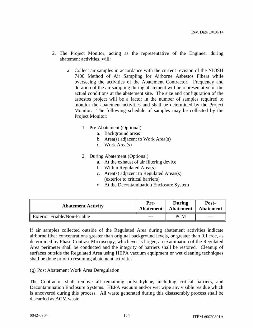
Rev. Date 10/10/14
ITEM #0020801A
2. The Project Monitor, acting as the representative of the Engineer during
abatement activities, will:
a. Collect air samples in accordance with the current revision of the NIOSH
7400 Method of Air Sampling for Airborne Asbestos Fibers while
overseeing the activities of the Abatement Contractor. Frequency and
duration of the air sampling during abatement will be representative of the
actual conditions at the abatement site. The size and configuration of the
asbestos project will be a factor in the number of samples required to
monitor the abatement activities and shall be determined by the Project
Monitor. The following schedule of samples may be collected by the
Project Monitor:
1. Pre-Abatement (Optional)
a. Background areas
b. Area(s) adjacent to Work Area(s)
c. Work Area(s)
2. During Abatement (Optional)
a. At the exhaust of air filtering device
b. Within Regulated Area(s)
c. Area(s) adjacent to Regulated Areas(s)
(exterior to critical barriers)
d. At the Decontamination Enclosure System
Abatement Activity Pre-
Abatement
During
Abatement
Post-
Abatement
Exterior Friable/Non-Friable --- PCM ---
If air samples collected outside of the Regulated Area during abatement activities indicate
airborne fiber concentrations greater than original background levels, or greater than 0.1 f/cc, as
determined by Phase Contrast Microscopy, whichever is larger, an examination of the Regulated
Area perimeter shall be conducted and the integrity of barriers shall be restored. Cleanup of
surfaces outside the Regulated Area using HEPA vacuum equipment or wet cleaning techniques
shall be done prior to resuming abatement activities.
(g) Post Abatement Work Area Deregulation
The Contractor shall remove all remaining polyethylene, including critical barriers, and
Decontamination Enclosure Systems. HEPA vacuum and/or wet wipe any visible residue which
is uncovered during this process. All waste generated during this disassembly process shall be
discarded as ACM waste.
0042-0304 154

Rev. Date 10/10/14
ITEM #0020801A
A final visual inspection of the work area shall be conducted by the Competent Person and the
Project Monitor to ensure that all visible accumulations of suspect materials have been removed
and that no equipment or materials associated with the abatement project remain.
The Contractor shall restore all work areas and auxiliary areas utilized during work to conditions
equal to or better than original. Any damage caused during the performance of the work activity
shall be repaired by the Contractor at no additional expense to the Engineer.
(h) Waste Disposal
Unless otherwise specified, all removed materials and debris resulting from execution of this
project shall become the responsibility of the Contractor and removed from the premises.
Materials not scheduled for reuse shall be removed from the site and disposed of in accordance
with all applicable Federal, State and Local requirements.
Waste removal dumpsters and cargo areas of transport vehicles shall be lined with a layer of six
(6) mil polyethylene sheeting to prevent contamination from leaking or spilled containers. Floor
sheeting shall be installed first, and shall be extended up sidewalls 12-inches. Wall sheeting
shall overlap floor sheeting 24-inches and shall be taped into place.
OSHA “Danger” signs must be attached to vehicles used to transport asbestos-containing waste
prior to loading ACM waste. The signs must be posted so that they are plainly visible.
Waste haulers and disposal facilities utilized shall match those indicated on the submitted
CTDPH notification.
Ensure all waste containers (bags, drums, etc.) are properly packed, sealed and labeled with
USEPA NESHAP generator labels, OSHA danger labels and DOT shipping labels. For each
shipment of ACM waste, the Contractor shall complete an EPA-approved asbestos waste
shipment record.
Authorized representatives signing waste shipment records on behalf of the generator must have
USDOT Shipper Certification training in accordance with HMR 49 CFR Parts 171-180.
Transport vehicles hauling ACM waste shall have appropriate USDOT placards visible on all
four (4) sides of the vehicle.
The Contractor shall dispose of asbestos-containing and/or asbestos contaminated material at an
EPA authorized site and must be in compliance with the requirements of the Special Waste
Provisions of the Office of Solid Waste Management, Department of Environmental Protection,
State of Connecticut, or other designated agency having jurisdiction over solid waste disposal.
Any asbestos-containing and/or asbestos-contaminated waste materials which also contain other
hazardous contaminants shall be disposed of in accordance with the EPA’s Resource
0042-0304 155
Rev. Date 10/10/14
ITEM #0020801A
Conservation and Recovery Act (RCRA), CTDEEP and ConnDOT requirements. Materials may
be required to be stored on-site and tested by the Project Monitor to determine proper waste
disposal requirements.
(i) Project Closeout Data:
1. Provide the Engineer, within 30 days of completion of asbestos abatement, a
compliance package; which shall include, but not be limited to, the following:
a. Asbestos Abatement Site Supervisor job log;
b. OSHA personnel air sampling data;
c. Completed waste shipment records.
The Contractor shall submit the original completed waste shipment records to the Engineer.
00.20.04 - Method of Measurement:
No measurement will be made for the work in this Section. The completed work shall be paid as
a lump sum.
00.20.05 - Basis of Payment:
The lump sum bid price for this item shall include the specialty services of the Asbestos
Removal Contractor including: labor, materials, equipment, insurance, permits, notifications,
submittals, personal air sampling, personal protection equipment, temporary enclosures, utility
costs, incidentals, fees and labor incidental to the removal, transport and disposal of ACM,
including close out documentation.
Final payment for asbestos abatement will not be made until all the project closeout data
submittals have been completed (including waste shipment record(s) signed by an authorized
disposal facility representative) and provided to the Engineer. Once the completed package has
been received in its entirety, the Engineer will make the final payment to the Contractor.
Pay Item Pay Unit
Asbestos Abatement L.S.
0042-0304 156
Rev. Date 10/10/14
ITEM #0020804A
ITEM #0020804A – REMOVAL OF ASBESTOS
00.20.01 - Description:
Work under this item shall include the removal of asbestos containing materials (ACM) and
associated work by persons who are knowledgeable, qualified, trained and licensed in the
removal, treatment, handling, and disposal of ACM and the subsequent cleaning of the affected
environment. ACM shall include material composed of any type of asbestos in amounts greater
than one percent (1%) by weight. The Contractor performing this work shall possess a valid
Asbestos Abatement Contractor license issued by the Connecticut Department of Public Health
(CTDPH).
These Specifications govern all work activities that disturb asbestos containing materials. All
activities shall be performed in accordance with, but not limited to, the current revision of the
OSHA General Industry Standard for Asbestos (29 CFR 1926.1001), the OSHA Asbestos in
Construction Regulations (29 CFR 1926.1101), the USEPA Asbestos National Emission
Standards for Hazardous Air Pollutants (NESHAP) Regulations (40 CFR Part 61 Subpart M), the
CTDPH Standards for Asbestos Abatement, Licensure and Training (19a-332a-1 through 16, 20-
440-1 through 9 & 20-441), and the CTDEEP Special Waste Disposal Regulations (22a-209-
8(i)).
The asbestos abatement work shall include the removal and disposal of all ACM as identified on
the Contract Plans and Specifications prior to the planned renovation/demolition project.
Deviations from these Specifications require the written approval of the Engineer.
The Contractor may elect to utilize an Alternative Work Practice (AWP), if approved by the
CTDPH and the Engineer prior to the initiation of the abatement activities. An AWP is a
variance from certain CTDPH asbestos regulatory requirements, which must provide the
equivalent or a greater measure of asbestos emission control than the standard work practices
prescribed by the CTDPH.
00.20.02 - Materials:
All materials shall be delivered to the job site in the original packages, containers, or bundles
bearing the name of the manufacturer, the brand name and product technical description.
No damaged or deteriorating materials shall be used. If material becomes contaminated with
asbestos, the material shall be decontaminated or disposed of as asbestos-containing waste
material. The cost to decontaminate and dispose of this material shall be at the expense of the
Contractor.
Fire retardant polyethylene sheet shall be in roll size to minimize the frequency of joints, with
factory label indicating four (4) or six (6) mil thickness.
0042-0304 157

Rev. Date 10/10/14
ITEM #0020804A
Six (6) mil polyethylene disposable bags shall have pre-printed OSHA/EPA/DOT labels and
shall be transparent.
Tape (or equivalent) capable of sealing joints in adjacent polyethylene sheets and for the
attachment of polyethylene sheets to finished or unfinished surfaces must be capable of adhering
under both dry and wet conditions.
Surfactant is a chemical wetting agent added to water to improve penetration and shall consist of
fifty (50) percent polyoxyethylene ether and fifty (50) percent polyoxyethylene ester, or
equivalent. The surfactant shall be mixed with water to provide a concentration one (1) ounce
surfactant to five (5) gallons of water, or as directed by the manufacturer.
Spray equipment must be capable of mixing necessary chemical agents with water, generating
sufficient pressure and volume; and equipped with adequate hose length to access all necessary
work areas.
Sanders, grinders, wire brushes and needle-gun type removal equipment shall be equipped with a
High Efficiency Particulate Air (HEPA) filtered vacuum dust collection system.
Containers for storage, transportation and disposal of asbestos containing waste material shall be
impermeable and both air and watertight.
Labels and warning signs shall conform to OSHA 29 CFR 1926.1101, USEPA 40 CFR Part
61.152, and USDOT 49 CFR Part 172 as appropriate.
Encapsulant, a material used to chemically entrap asbestos fibers to prevent these fibers from
becoming airborne, shall be of the type which has been approved by the Engineer. Use shall be
in accordance with manufacturer's printed technical data. The encapsulant shall be clear and
must be compatible with new materials being installed, if any.
Glovebag assembly shall be manufactured of six (6) mil transparent polyethylene or PVC with
two (2) inward projecting long sleeve gloves, an internal pouch for tools, and an attached labeled
receptacle for waste.
Mastic removal chemicals shall be low odor and non-citrus based, with a flash point in excess of
140° F.
Any planking, bracing, shoring, barricades and/or temporary sheet piling, necessary to
appropriately perform work activities shall conform to all applicable federal, state and local
regulations.
Air filtration devices and vacuum units shall be equipped with HEPA filters.
0042-0304 158
Rev. Date 10/10/14
ITEM #0020804A
00.20.03 - Construction Methods:
(1) Pre-Abatement Submittals and Notices
(a) The Contractor shall submit, in accordance with CTDPH Standard 19a-332a-3, proper
notification using the prescribed form, to the Commissioner, State of Connecticut,
Department of Public Health not fewer than ten (10) days prior to the commencement of
work as follows:
1. The asbestos to be removed is exterior NESHAP Category I/II Non-Friable
ACM, and it is not expected that the abatement procedures will render the
Category I/II asbestos friable; thereby not categorizing it as NESHAP
Regulated ACM (RACM); therefore not defining the removal as a CTDPH
“abatement”; and as such the CT licensed Asbestos Abatement Contractor
will not be required to file an Asbestos Abatement notification so long as no
more than 10 linear feet (LF)/25 square feet (SF) of ACM is rendered friable.
(b) Fifteen (15) working days prior to the commencement of asbestos abatement work, the
Contractor shall submit to the Engineer for review and acceptance and/or
acknowledgment of the following:
1. Permits and licenses for the removal, transport, and disposal of asbestos-
containing or contaminated materials, including a CTDPH valid asbestos removal
contractor’s license.
2. Documentation dated within the previous twelve (12) months, certifying that all
employees have received USEPA Model Accreditation Plan approved asbestos
worker/supervisor training in the proper handling of materials that contain
asbestos; understand the health implications and risks involved, including the
illnesses possible from exposure to airborne asbestos fibers; understands the use
and limits of respiratory equipment to be used; and understands the results of
monitoring of airborne quantities of asbestos as related to health and respiratory
equipment as indicated in 29 CFR 1926.1101 on an initial and annual basis, and
copies of all employees CTDPH asbestos worker and/or supervisor licenses.
3. Documentation from the Contractor, typed on company letterhead and signed by
the Contractor, certifying that all employees listed therein have received the
following:
a. medical monitoring within the previous twelve (12) months, as
required in 29 CFR 1926.1101;
b. respirator fit testing within the previous twelve (12) months as
detailed in 29 CFR 1910.134 (for all employees who must also don a
tight-fitting face piece respirator).
0042-0304 159

Rev. Date 10/10/14
ITEM #0020804A
4. Copies of the EPA/State-approved certificates for the proposed asbestos landfill.
(c) No abatement shall commence until a copy of all required submittals have been received
and found acceptable to the Engineer. Those employees added to the Contractor's
original list will be allowed to perform work only upon submittal to, and receipt of, all
required paperwork by the Engineer.
(2) Asbestos Abatement Provisions:
(a) General Requirements
The Abatement Contractor/Subcontractor shall possess a valid State of Connecticut Asbestos
Contractor License. Should any portion of the work be subcontracted, the subcontractor must
also possess a valid State of Connecticut Asbestos Contractor License. The Asbestos Abatement
Site Supervisor employed by the Contractor shall be in control on the job site at all times during
asbestos abatement work. All employees of the Contractor who shall perform work (i.e. Asbestos
Abatement Site Supervisor, Asbestos Abatement Worker) shall be properly certified/licensed by
the State of Connecticut to perform such duties.
All labor, materials, tools, equipment, services, testing, insurance (with specific coverage for
work on asbestos), and incidentals which are necessary or required to perform the work in
accordance with applicable governmental regulations, industry standards and codes, and these
Specifications shall be provided by the Contractor. The Contractor shall be prepared to work all
shifts and weekends throughout the course of this project.
Prior to beginning work, the Engineer and Contractor shall perform a visual survey of each work
area and review conditions at the site for safety reasons. In addition, the Contractor shall instruct
all workers in all aspects of personnel protection, work procedures, emergency evacuation
procedures and use of equipment including procedures unique to this project.
The Contractor shall:
Shut down and lock out electrical power, including all receptacles and light fixtures,
when feasible. The use or isolation of electrical power will be coordinated with all other
ongoing uses of electrical power at the site.
When necessary, provide temporary power and adequate lighting and ensure safe
installation of electrical equipment, including ground fault protection and power cables,
in compliance with applicable electrical codes and OSHA requirements. The Contractor
is responsible for proper connection and installation of electrical wiring.
Water service may not be available at the site. Contractor shall supply sufficient water for each
shift to operate the decontamination shower units as well as to maintain the work areas
adequately wet.
0042-0304 160

Rev. Date 10/10/14
ITEM #0020804A
Ladders and/or scaffolds shall be in compliance with OSHA requirements, and of adequate
length, strength and sufficient quantity to support the scope of work. Use of ladders/scaffolds
shall be in conformance with OSHA 29 CFR 1926 Subpart L and X requirements.
Work performed at heights exceeding six feet (6’) shall be performed in accordance with the
OSHA Fall Protection Standard 29 CFR 1926 Subpart M including the use of fall arrest systems
as applicable.
Data provided regarding asbestos sampling conducted throughout the structure(s) is for
informational purposes only. Under no circumstances shall this information be the sole means
used by the Contractor for determining the presence and location of all asbestos containing
materials. The Contractor shall verify all field conditions affecting performance of the work as
described in these Specifications in accordance with OSHA, USEPA, USDOT, DEP standards.
Compliance with the applicable requirements is solely the responsibility of the Contractor.
The Engineer will provide a Project Monitor to oversee the activities of the Contractor. No
asbestos work shall be performed until the Project Monitor is on-site. Pre-abatement, during
abatement and post-abatement air sampling will be conducted as deemed necessary by the
Project Monitor. Waste stream testing will be performed, as necessary, by the Project Monitor
prior to waste disposal.
(b) Set-Up
The Contractor shall establish contiguous to the Regulated Area, a Worker Decontamination
Enclosure System consisting of Equipment Room, Shower Room and Clean Room in series, as
detailed below. Access to the Regulated Area shall only be through this enclosure.
Access between rooms in the Worker Decontamination Enclosure System shall be through
airlocks. Other effective designs are permissible. The Clean Room, Shower Room and
Equipment Room located within the Worker Decontamination Enclosure, shall be contiguously
connected with taped airtight edges, thus ensuring the sole source of airflow originates from
outside the regulated areas, once the negative pressure differential within the Regulated Area is
established.
The Clean Room shall be adequately sized to accommodate workers and shall be equipped with
a suitable number of hooks, lockers, shelves, etc., for workers to store personal articles and
clothing. Changing areas of the Clean Room shall be suitably screened from areas occupied by
the public.
The Shower Room shall be of sufficient capacity to accommodate the number of workers. One
shower stall shall be provided for each eight (8) workers. Showers shall be equipped with hot
and cold or warm running water through the use of electric hot water heaters supplied by the
Contractor. No worker or other person shall leave a Regulated Area without showering. Shower
water shall be collected and filtered using best available technology and dumped down an
0042-0304 161

Rev. Date 10/10/14
ITEM #0020804A
approved sanitary drain. Shower stalls and plumbing shall include sufficient hose length and
drain system or an acceptable alternate.
The Contractor shall ensure that no personnel or equipment be permitted to leave the Regulated
Area until proper decontamination procedures (including HEPA vacuuming, wet wiping and
showering) to remove all asbestos debris have occurred. No asbestos-contaminated materials or
persons shall enter the Clean Room.
Post warning signs meeting the specifications of OSHA 29 CFR 1910.1001 and 29 CFR
1926.1101 at each Regulated Area. In addition, signs shall be posted at all approaches to
Regulated Areas so that an employee or building occupant may read the sign and take the
necessary protective steps before entering the area. Additional signs may require posting
following construction of workplace enclosure barriers.
(c) Alternate set up requirements for exterior non-friable asbestos abatement procedures
In lieu of the establishment of a negative pressure enclosure (NPE) system as described by
CTDPH Sections 19a-332a-5(c), 5(d), 5(e), and 5(h), non-friable ACM will be removed from
exterior work areas within an outdoor Regulated Area(s). The regulated work area will be
established by the use of appropriately labeled barrier tape and postings in compliance with
CTDPH 19a-332a-5(a) as well as OSHA 29 CFR 1926.1101. A remote personnel
decontamination unit as specified in Section 19a-332a-6 will be required. This method shall
only be utilized provided exposure assessment air sampling data collected during the removal of
the exterior non-friable materials indicates that the exposure levels during removal of such
materials do not exceed 0.1 asbestos f/cc. Should exposure assessment air sampling data exceed
this level, and engineering efforts to reduce the airborne fiber levels not be successful in reducing
the levels to less than 0.1 f/cc, removal shall occur within these areas under full containment
conditions.
(d) Personnel Protection
The Contractor shall utilize all appropriate engineering controls and safety and protective
equipment while performing the work in accordance with OSHA, USEPA, USDOT, CTDEEP
and CTDPH regulations.
The Contractor shall provide and require all workers to wear protective clothing in the Regulated
Areas where asbestos fiber concentrations may reasonably be expected to exceed the OSHA
established Permissible Exposure Limits (PEL) or where asbestos contamination exists.
Protective clothing shall include impervious coveralls with elastic wrists and ankles, head
covering, gloves and foot coverings.
Respiratory protection shall be provided and shall meet the requirements of OSHA as required in
29 CFR 1910.134, and 29 CFR 1926.1101 as well as the requirements of the CTDPH
regulations. A formal respiratory protection program must be implemented in accordance with
29 CFR 1926.1101 and 29 CFR 1910.134. The Contractor shall provide respirators from among
0042-0304 162

Rev. Date 10/10/14
ITEM #0020804A
those approved as being acceptable for protection by the National Institute for Occupational
Safety and Health (NIOSH) under the provisions of 30 CFR Part ll.
All other necessary personnel protective equipment (i.e. hardhat, work boots, safety glasses,
hearing protection, etc.) required to perform the asbestos abatement work activities shall conform
to all applicable federal, state and local regulations.
All other qualified and authorized persons entering into a Regulated Area (i.e. Project Monitor,
Regulatory Agency Representative) shall adhere to the requirements of personnel protection as
stated in this section.
(e) Asbestos Abatement Procedures
The Asbestos Abatement Site Supervisor, as the OSHA Competent Person shall be at the site at
all times.
The Contractor shall not begin abatement work until authorized by the Project Monitor,
following a pre-abatement visual inspection.
All workers and authorized persons shall enter and leave the Regulated Area through the Worker
Decontamination Enclosure System, leaving contaminated protective clothing in the Equipment
Room for reuse or disposal of as asbestos contaminated waste. No one shall eat, drink, smoke,
chew gum or tobacco, or apply cosmetics while in a Regulated Area.
The following details the extent of each phase of operation designated for this project. Phase
areas may be combined or divided at the direction of the Engineer. Proceed through the
sequencing of the work phases under the direction of the Engineer.
All Four Bridge Sites
Includes the removal of:
The presumed presence of asbestos containing damp proofing on the backside of the
abutments and retaining walls
A regulated area(s) shall be established at the perimeter of the work area(s), and access
shall be controlled by the Contractor. A remote personnel decontamination unit shall be
utilized. Removal shall be undertaken in accordance with OSHA Class II and USEPA
Asbestos NESHAP requirements.
The above material is` presently presumed to be present and is presumed to be ACM.
Contractor shall expose the materials as directed under other contract items, at which
time, if present, the Engineer will sample to confirm/refute the presence of ACM. When
accessible, should the materials be confirmed present and be scheduled to be impacted,
0042-0304 163
Rev. Date 10/10/14
ITEM #0020804A
they should be treated as asbestos containing materials unless sampled by the Engineer and
confirmed as non-ACM.
During removal, the Contractor shall spray asbestos materials with amended water using airless
spray equipment capable of providing a "mist" application to reduce the release of airborne
fibers. Spray equipment shall be capable of mixing wetting agent with water and capable of
generating sufficient pressure and volume. Hose length shall be sufficient to reach all of the
Regulated Area. Do not “flood” the area with hose type water supply equipment with the
potential to create water releases from the regulated area.
The Contractor shall continue to spray the asbestos materials with amended water, as necessary,
throughout removal activities to ensure the asbestos materials remain adequately wet. The
asbestos materials shall not be allowed to dry out.
In order to minimize airborne asbestos concentrations inside the Regulated Area, the Contractor
shall remove the adequately wetted asbestos in manageable sections. In addition, asbestos
materials removed from any elevated level shall be carefully lowered to the floor.
The Contractor shall promptly place the adequately wet asbestos material in disposal containers
(six (6) mil polyethylene bags/fiber drum/poly-lined dumpsters, etc.) as it is removed. Large
components removed intact may be wrapped in two (2) layers of six (6) mil polyethylene
sheeting secured with tape. As the disposal containers are filled, the Contractor shall promptly
seal the containers, apply caution labels and clean the containers before transportation to the
equipment decontamination area. Bags shall be securely sealed to prevent accidental opening
and leakage by taping in gooseneck fashion. Small components and asbestos-containing waste
with sharp-edged components (e.g. nails, screws, metal lath, tin sheeting) which could tear
polyethylene bags and sheeting shall be placed in clean drums and sealed with locking ring tops.
All waste containers shall be leak-tight, (typically consisting of two layers of 6 mil poly (or
bags)), and shall be properly labeled and placarded with OSHA Danger labels, DOT shipping
labels, markings and placards and USEPA NESHAP generators labels. Containers shall be
decontaminated by wet cleaning and HEPA vacuuming within the equipment decontamination
area prior to exiting the regulated area. Wet clean each container thoroughly before moving to
Holding Area.
If at any time during asbestos removal, the Project Monitor should suspect contamination of
areas outside the Regulated Area, the Contractor shall immediately stop all abatement work and
take steps to decontaminate these areas and eliminate causes of such contamination. Unprotected
individuals shall be prohibited from entering contaminated areas until air sampling and/or visual
inspections determine decontamination.
After completion of abatement work, all surfaces from which asbestos has been removed shall be
wet brushed, using a nylon brush, wet wiped and sponged or cleaned by an equivalent method to
remove all visible material (wire brushes are not permitted). During this work the surfaces being
cleaned shall be kept wet. Cleaning shall also include the use of HEPA filtered vacuum
equipment.
0042-0304 164
Rev. Date 10/10/14
ITEM #0020804A
The Contractor shall also remove and containerize all visible accumulations of asbestos-
containing and/or asbestos-contaminated debris which may have splattered or collected on the
polyethylene engineering controls/barriers.
Once the Regulated Area surfaces have dried, the Project Monitor shall perform a thorough post
abatement visual inspection utilizing protocols from the ASTM Standard E1368-90 Standard
Practice for Visual Inspection of Asbestos Abatement Projects. All surfaces within the
Regulated Area, including but not limited to ledges, beams, and hidden locations shall be
inspected for visible residue. Evidence of asbestos contamination identified during this
inspection will necessitate further cleaning as heretofore specified. The area shall be re-cleaned
at the Contractor's expense, until the standard of cleaning is achieved.
Once the area has received a satisfactory post-abatement visual inspection, any equipment, tools
or materials not required for completion of the work, shall be removed by the Contractor from
the Regulated Area.
(f) Air Monitoring Requirements
1. The Contractor shall:
a. Provide air monitoring equipment including sample filter cassettes of the
type and quantity required to properly monitor operations and personnel
exposure surveillance throughout the duration of the project.
b. Conduct personnel exposure assessment air sampling, as necessary, to
assure that workers are using appropriate respiratory protection in
accordance with OSHA Standard 1926.1101. Documentation of air
sampling results must be recorded at the work site within twenty-four (24)
hours and shall be available for review until the job is complete.
2. The Project Monitor, acting as the representative of the Engineer during
abatement activities, will:
a. Collect air samples in accordance with the current revision of the NIOSH
7400 Method of Air Sampling for Airborne Asbestos Fibers while
overseeing the activities of the Abatement Contractor. Frequency and
duration of the air sampling during abatement will be representative of the
actual conditions at the abatement site. The size and configuration of the
asbestos project will be a factor in the number of samples required to
monitor the abatement activities and shall be determined by the Project
Monitor. The following schedule of samples may be collected by the
Project Monitor:
1. Pre-Abatement (Optional)
0042-0304 165
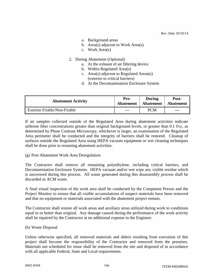
Rev. Date 10/10/14
ITEM #0020804A
a. Background areas
b. Area(s) adjacent to Work Area(s)
c. Work Area(s)
2. During Abatement (Optional)
a. At the exhaust of air filtering device
b. Within Regulated Area(s)
c. Area(s) adjacent to Regulated Areas(s)
(exterior to critical barriers)
d. At the Decontamination Enclosure System
Abatement Activity Pre-
Abatement
During
Abatement
Post-
Abatement
Exterior Friable/Non-Friable --- PCM ---
If air samples collected outside of the Regulated Area during abatement activities indicate
airborne fiber concentrations greater than original background levels, or greater than 0.1 f/cc, as
determined by Phase Contrast Microscopy, whichever is larger, an examination of the Regulated
Area perimeter shall be conducted and the integrity of barriers shall be restored. Cleanup of
surfaces outside the Regulated Area using HEPA vacuum equipment or wet cleaning techniques
shall be done prior to resuming abatement activities.
(g) Post Abatement Work Area Deregulation
The Contractor shall remove all remaining polyethylene, including critical barriers, and
Decontamination Enclosure Systems. HEPA vacuum and/or wet wipe any visible residue which
is uncovered during this process. All waste generated during this disassembly process shall be
discarded as ACM waste.
A final visual inspection of the work area shall be conducted by the Competent Person and the
Project Monitor to ensure that all visible accumulations of suspect materials have been removed
and that no equipment or materials associated with the abatement project remain.
The Contractor shall restore all work areas and auxiliary areas utilized during work to conditions
equal to or better than original. Any damage caused during the performance of the work activity
shall be repaired by the Contractor at no additional expense to the Engineer.
(h) Waste Disposal
Unless otherwise specified, all removed materials and debris resulting from execution of this
project shall become the responsibility of the Contractor and removed from the premises.
Materials not scheduled for reuse shall be removed from the site and disposed of in accordance
with all applicable Federal, State and Local requirements.
0042-0304 166
Rev. Date 10/10/14
ITEM #0020804A
Waste removal dumpsters and cargo areas of transport vehicles shall be lined with a layer of six
(6) mil polyethylene sheeting to prevent contamination from leaking or spilled containers. Floor
sheeting shall be installed first, and shall be extended up sidewalls 12-inches. Wall sheeting
shall overlap floor sheeting 24-inches and shall be taped into place.
OSHA “Danger” signs must be attached to vehicles used to transport asbestos-containing waste
prior to loading ACM waste. The signs must be posted so that they are plainly visible.
Waste haulers and disposal facilities utilized shall match those indicated on the submitted
CTDPH notification.
Ensure all waste containers (bags, drums, etc.) are properly packed, sealed and labeled with
USEPA NESHAP generator labels, OSHA danger labels and DOT shipping labels. For each
shipment of ACM waste, the Contractor shall complete an EPA-approved asbestos waste
shipment record.
Authorized representatives signing waste shipment records on behalf of the generator must have
USDOT Shipper Certification training in accordance with HMR 49 CFR Parts 171-180.
Transport vehicles hauling ACM waste shall have appropriate USDOT placards visible on all
four (4) sides of the vehicle.
The Contractor shall dispose of asbestos-containing and/or asbestos contaminated material at an
EPA authorized site and must be in compliance with the requirements of the Special Waste
Provisions of the Office of Solid Waste Management, Department of Environmental Protection,
State of Connecticut, or other designated agency having jurisdiction over solid waste disposal.
Any asbestos-containing and/or asbestos-contaminated waste materials which also contain other
hazardous contaminants shall be disposed of in accordance with the EPA’s Resource
Conservation and Recovery Act (RCRA), CTDEEP and ConnDOT requirements. Materials may
be required to be stored on-site and tested by the Project Monitor to determine proper waste
disposal requirements.
(i) Project Closeout Data:
1. Provide the Engineer, within 30 days of completion of asbestos abatement, a
compliance package; which shall include, but not be limited to, the following:
a. Asbestos Abatement Site Supervisor job log;
b. OSHA personnel air sampling data;
c. Completed waste shipment records.
The Contractor shall submit the original completed waste shipment records to the Engineer.
0042-0304 167

Rev. Date 10/10/14
ITEM #0020804A
00.20.04 - Method of Measurement:
The work of “REMOVAL OF ASBESTOS” shall be measured for payment as the actual square
footage of ACM removed. Such determinations shall be made by measuring actual material to
be removed at each work site.
00.20.05 - Basis of Payment:
The work shall be paid at the contract unit price per square foot, which shall include the specialty
services of the Asbestos Removal Contractor including: labor, materials, equipment, insurance,
permits, notifications, submittals, personal air sampling, personal protection equipment,
temporary enclosures, utility costs, incidentals, fees and labor incidental to the removal, transport
and disposal of ACM, including close out documentation.
Final payment for “REMOVAL OF ASBESTOS” will not be made until all the project closeout
data submittals have been completed (including waste shipment record(s) signed by an
authorized disposal facility representative) and provided to the Engineer. Once the completed
package has been received in its entirety, the Engineer will make the final payment to the
Contractor.
Pay Item Pay Unit
Removal of Asbestos S.F.
0042-0304 168
Rev. Date 10/10/14
ITEM #0020903A
ITEM #0020903A – LEAD COMPLIANCE FOR MISCELLANEOUS
EXTERIOR TASKS
00.20.01 - Description:
Work under this item shall include the special handling measures and work practices required for
miscellaneous exterior tasks that impact materials containing or covered by lead paint. Lead
paint includes paint found to contain any detectable amount of lead by Atomic Absorption
Spectrophotometry (AAS) or X-Ray Fluorescence (XRF). Examples of typical miscellaneous
exterior tasks includes; work impacting signs, guiderails, minor bridge rehabilitation, catenary
structures, canopy structures, spot/localized paint removal, etc.
All activities shall be performed in accordance with the OSHA Lead in Construction Regulations
(29 CFR 1926.62), the USEPA RCRA Hazardous Waste Regulations (40 CFR Parts 260 through
274), and the CTDEEP Hazardous Waste Regulations (RCSA 22a-209-1 and 22a-449(c)).
All activities shall be performed by individuals with appropriate levels of OSHA lead awareness
and hazard communication training and shall supervised by the Contractors Competent Person
on the job site at all times. The Contractors Competent Person is one who is capable of
identifying existing and predictable hazards in the surroundings or working conditions which are
unsanitary, hazardous or dangerous to employees, and who has authorization to take prompt
corrective measures to eliminate them.
Deviations from these Specifications require the written approval of the Engineer.
00.20.02 - Materials:
All materials shall be delivered to the job site in the original packages, containers, or bundles
bearing the name of the manufacturer, the brand name and product technical description, with
MSDS sheets as applicable.
No damaged or deteriorating materials shall be used. If material becomes contaminated with
lead, the material shall be decontaminated or disposed of as lead-containing waste material. The
cost to decontaminate and dispose of this material shall be at the expense of the Contractor.
The following material requirements are to be met if to be used during the work:
Fire retardant polyethylene sheet shall be in roll size to minimize the frequency of joints, with
factory label indicating minimum six (6) mil thickness.
Polyethylene disposable bags shall be minimum six (6) mils thick.
0042-0304 169
Rev. Date 10/10/14
ITEM #0020903A
Tape (or equivalent) product capable of sealing joints in adjacent polyethylene sheets and for the
attachment of polyethylene sheets to finished or unfinished surfaces must be capable of adhering
under both dry and wet conditions.
Cleaning Agents and detergent shall be lead specific, such as TriSodium Phosphate (TSP).
Chemical strippers and chemical neutralizers shall be compatible with the substrate as well as
with each other. Such chemical stripper shall contain less than 50% Volatile Organic
Compounds (VOCs) by weight in accordance with RCSA 22a-174-40 Table 40-1.
Labels and warning signs shall conform to 29 CFR 1926.62, 40 CFR 260 through 274 and 49
CFR 172 as appropriate.
Air filtration devices and vacuum units shall be equipped with High-Efficiency Particulate Air
(HEPA) filters.
00.20.03 - Construction Methods:
(1) Pre-Abatement Submittals and Notices
A. Prior to the start of any work on a contiguous per site basis that will generate hazardous lead
waste above conditionally exempt small quantities (greater than 100 kg/month or greater than
1000 kg at any time), the Contractor shall obtain from the Engineer on a contiguous per site basis
a temporary EPA Hazardous Waste Generators ID number, unless otherwise directed by the
Engineer.
B. Fifteen (15) working days prior to beginning work that impacts lead paint, the Contractor
shall submit the following to the Engineer:
1. Work plan for work impacting lead paint including engineering controls, methods of
containment of debris and work practices to be employed, as needed, to minimize
employee exposure and prevent the spread of lead contamination outside the
Regulated Area.
2. Copies of all employee certificates, dated within the previous twelve (12) months,
relating to OSHA lead awareness and hazard communication training and training in
the use of lead-safe work practices. SSPC training programs may be accepted as
meeting these requirements if it can be demonstrated that such training addressed all
required topics.
This information shall be updated and resubmitted annually, or as information
changes, for the duration of the activities impacting lead to verify continued
compliance.
0042-0304 170
Rev. Date 10/10/14
ITEM #0020903A
3. Name and qualifications of Contractor’s OSHA Competent Person under 29 CFR
1926.62.
4. Documentation from the Contractor, typed on company letterhead and signed by the
Contractor, certifying that all employees listed therein have received the following:
a. medical monitoring within the previous twelve (12) months, as required in 29
CFR 1926.62;
b. biological monitoring within the previous six (6) months, as required in 29 CFR
1926.62;
c. respirator fit testing within the previous twelve (12) months, as required in 29
CFR 1910.134 (for those who don a tight-fitting face piece respirator)
This information shall be updated and resubmitted annually, or as information
changes, for the duration of the activities impacting lead to verify continued
compliance.
5. Names of the proposed non-hazardous construction and demolition (C&D) lead
debris bulky waste disposal facility (CTDEEP-permitted Solid Waste landfill).
6. Names of the proposed scrap metal recycling facilities. The Contractor shall submit to
the Engineer all documentation necessary to demonstrate the selected facility is able
to accept lead-painted scrap metal.
7. Names of the proposed hazardous waste disposal facility (selected from the
Department approved list provided herein), and copies of each facilities acceptance
criteria and sampling frequency requirements.
8. Copies of the proposed hazardous waste transporters current USDOT Certificate of
Registration for Hazardous Materials Transport, and the proposed transporters current
Hazardous Waste Transporter Permits for the State of Connecticut and the waste
destination State.
9. Negative exposure assessments conducted within the previous 12 months
documenting that employee exposure to lead for each task is below the OSHA Action
Level of 30 μg/m3. If a negative exposure assessment has not been conducted, the
Contractor shall submit its air monitoring program for the work tasks as part of the
Work Plan. Until a negative exposure assessment is developed for each task
impacting lead paint, the Contractor shall ensure that all workers and authorized
persons entering the Regulated Area wear protective clothing and respirators in
accordance with OSHA 29 CFR 1926.62.
No activity shall commence until all required submittals have been received and found
acceptable to the Engineer. Those employees added to the Contractor's original list will be
0042-0304 171
Rev. Date 10/10/14
ITEM #0020903A
allowed to perform work only upon submittal of acceptable documentation to, and review by, the
Engineer.
Contractor shall provide the Engineer with a minimum of 48 hours notice in advance of
scheduling, changing or canceling work activities.
(2) Lead Abatement Provisions
A. General Requirements:
All employees of the Contractor who perform work impacting lead paint shall be properly
trained to perform such duties. In addition, the Contractor shall instruct all workers in all aspects
of personnel protection, work procedures, emergency evacuation procedures and use of
equipment including procedures unique to this project.
Contractor shall provide all labor, materials, tools, equipment, services, testing, and incidentals
which are necessary or required to perform the work in accordance with applicable governmental
regulations, industry standards and codes, and these Specifications.
Prior to beginning work, the Engineer and Contractor shall perform a visual survey of each work
area and review conditions.
As necessary, the Contractor shall:
Shut down and lock out electrical power, including all receptacles and light fixtures,
where feasible. The use or isolation of electrical power will be coordinated with all other
ongoing uses of electrical power at the site.
If adequate electrical supply is not available at the site, the Contractor shall supply temporary
power. Such temporary power shall be sufficient to provide adequate lighting and power the
Contractor’s equipment. The Contractor is responsible for proper connection and installation of
electrical wiring and shall ensure safe installation of electrical equipment in compliance with
applicable electrical codes and OSHA requirements.
If water is not available at the site for the Contractor’s use, the Contractor shall supply sufficient
water for each shift to operate the wash facility/decontamination shower units in addition to the
water needed at the work area.
The Engineer may provide a Project Monitor to monitor compliance of the Contractor and
protect the interests of the Department. In such cases, no activity impacting lead paint shall be
performed until the Project Monitor is on-site. Where no Project Monitor will be provided,
Contractor shall proceed at the direction of the Engineer. Environmental sampling, including
ambient air sampling, TCLP waste stream sampling, and dust wipe sampling, will be conducted
by the State as it deems necessary throughout the project. Air monitoring to comply with the
Contractor’s obligations under OSHA remains solely responsibility of the Contractor.
0042-0304 172
Rev. Date 10/10/14
ITEM #0020903A
If at any time, procedures for engineering, work practice, administrative controls or other topics
are anticipated to deviate from those documented in the submitted and accepted Lead Work Plan,
the Contractor shall submit a modification of its existing plan for review and acceptance by the
Engineer prior to implementing the change.
If air samples collected outside of the Regulated Area during activities impacting lead paint
indicate airborne lead concentrations greater than original background levels or 30 ug/m3,
whichever is larger, or if at any time visible emissions of lead paint extend out from the
Regulated Area, an examination of the Regulated Area shall be conducted and the cause of such
emissions corrected. Cleanup of surfaces outside the Regulated Area using HEPA vacuum
equipment or wet cleaning techniques shall be done prior to resuming work.
Work outside the initial designated area(s) will not be paid for by the Engineer. The Contractor
will be responsible for all costs incurred from these activities including repair of any damage.
B. Regulated Area
The Contractor shall establish a Regulated Area through the use of appropriate barrier tape or
other means to control unauthorized access into the area where activities impacting lead paint are
occurring. Warning signs meeting the requirements of 29 CFR 1926.62 shall be posted at all
approaches to Regulated Areas. These signs shall read:
WARNING
LEAD WORK AREA
POISON
NO SMOKING OR EATING
The Contractor shall implement appropriate engineering controls such as poly drop cloths, local
exhaust ventilation, wet dust suppression methods, etc. as necessary, and as approved by the
Engineer, to prevent the spread of lead contamination beyond the Regulated Area in accordance
with the Contractor’s approved work plan. Should the previously submitted work plan prove to
be insufficient to contain the contamination, the Contractor shall modify its plan and submit it for
review by the Engineer.
C. Wash Facilities:
The Contractor shall provide handwash facilities in compliance with 29 CFR 1926.51(f) and 29
CFR 1926.62 regardless of airborne lead exposure.
If employee exposure to airborne lead exceeds the OSHA Permissible Exposure Limit of 50
micrograms per cubic meter (μg/m3), shower rooms must be provided. The Shower Room shall
be of sufficient capacity to accommodate the number of workers. One shower stall shall be
provided for each eight (8) workers. Showers shall be equipped with hot and cold or warm
0042-0304 173
Rev. Date 10/10/14
ITEM #0020903A
running water. Shower water shall be collected and filtered using best available technology and
disposed of in accordance with all Federal, State and local laws, regulations and ordinances.
D. Personal Protection:
The Contractor shall initially determine if any employee performing construction tasks impacting
lead paint may be exposed to lead at or above the OSHA Action Level of 30 μg/m3.
Assessments shall be based on initial air monitoring results as well as other relevant information.
The Contractor may rely on historical air monitoring data obtained within the past 12 months
under workplace conditions closely resembling the process, type of material, control methods,
work practices and environmental conditions used and prevailing in the Contractors current
operations to satisfy the exposure assessment requirements. Monitoring shall continue as
specified in the OSHA standard until a negative exposure assessment is developed.
Until a negative exposure assessment is developed for each task impacting lead paint, the
Contractor shall ensure that all workers and authorized person entering the Regulated Area wear
protective clothing and respirators in accordance with OSHA 29 CFR 1926.62. Protective
clothing shall include impervious coveralls with elastic wrists and ankles, head covering, gloves
and foot coverings. Sufficient quantities shall be provided to last throughout the duration of the
project.
Protective clothing provided by the Contractor and used during chemical removal operations
shall be impervious to caustic materials. Gloves provided by the Contractor and used during
chemical removal shall be of neoprene composition with glove extenders.
Respiratory protective equipment shall be provided and selection shall conform to 42 CFR Part
84, 29 CFR Part 1910.134, and 29 CFR Part 1926.62. A formal respiratory protection program
must be implemented in accordance with 29 CFR Part 1926.62 and Part 1910.134.
E. Air Monitoring Requirements
The Contractor shall:
1. Provide air monitoring equipment including sample filter cassettes of the type and
quantity required to properly monitor operations and personnel exposure surveillance
throughout the duration of the project.
2. Conduct initial exposure monitoring to determine if any employee performing
construction tasks impacting lead paint may be exposed to lead at or above the OSHA
Action Level of 30 micrograms per cubic meter. Monitoring shall continue as
specified in the OSHA standard until a negative exposure assessment is developed.
3. Conduct personnel exposure assessment air sampling, as necessary, to assure that
workers are using appropriate respiratory protection in accordance with OSHA
Standard 1926.62. Documentation of air sampling results must be recorded at the
0042-0304 174

Rev. Date 10/10/14
ITEM #0020903A
work site within twenty-four (24) hours and shall be available for review until the job
is complete.
F. Lead Abatement Procedures
The Contractor’s Competent Person shall be at the job site at all times during work impacting
lead.
Work impacting lead paint shall not begin until authorized by the Engineer, following a pre-work
visual inspection by the Project Monitor or Engineer to verify existing conditions.
Any activity impacting lead painted surfaces shall be performed in a manner which minimizes
the spread of lead dust contamination and generation of airborne lead.
The Contractor shall conduct exposure assessments for all tasks which impact lead paint in
accordance with 29 CFR 1926.62(d) and shall implement appropriate personal protective
equipment until negative exposure assessments are developed.
All work impacting the materials identified below shall be conducted within an established
Regulated Area with a remote wash facility/decontamination system in accordance with
“C. Wash Facilities” and the OSHA Lead in Construction Standard. In accordance with
29 CFR 1926.62, engineering controls and work practices shall be utilized to prevent the
spread of lead dust and debris beyond the Regulated Area and limit the generation of
airborne lead. All wastes containing lead paint shall be properly contained and secured for
storage, transportation and disposal.
The Contractor shall ensure proper entry and exit procedures for workers and authorized persons
who enter and leave the Regulated Area. All workers and authorized persons shall leave the
Regulated Area and proceed directly to the wash or shower facilities where they will HEPA
vacuum gross debris from work suit, remove and dispose of work suit, wash and dry face and
hands, and vacuum clothes. Lead chips and dust must not be removed by blowing or shaking of
clothing. Wash water shall be collected, filtered, and disposed of in accordance with Federal,
State and local water discharge standards. Any permit required for such discharge shall be the
responsibility of the Contractor.
No one shall eat, drink, smoke, chew gum or tobacco, or apply cosmetics while in the Regulated
Area.
Data from the limited lead testing performed by the Engineer is documented in the reports listed
in the “Notice to Contractor – Hazardous Materials Investigations” or is presented herein. Under
no circumstances shall this information be the sole means used by the Contractor for determining
the extent of lead painted materials. The Contractor shall be responsible for verification of all
field conditions affecting performance of the work as described in these Specifications in
accordance with OSHA, USEPA, USDOT and CTDEEP standards. Compliance with the
applicable requirements is solely the responsibility of the Contractor.
0042-0304 175
Rev. Date 10/10/14
ITEM #0020903A
The following details the extent of each phase of operation designated for this project. Phase
areas may be combined or divided at the direction of the Engineer. Proceed through the
sequencing of the work phases under the direction of the Engineer.
Site No. 1 - Bridge No. 02374, SR 500/TR 805 over I-84, TR 831 & TR 833, East Hartford
Lead paint was identified on the painted metal surfaces of Bridge No. 02374. XRF
readings showed the paint to have detectable amounts of lead.
Girders, Beam
Ends, Rockers,
Cross beams, etc
Metal Grey 0.1-13.9 mg/cm2
Railing Metal Galvanized (no paint) --
TCLP waste stream sampling/analysis of the paint characterized the paint waste as
RCRA/CTDEEP hazardous waste.
Paint debris 140 mg/l
Site No. 2 - Bridge No. 02375, SR 500 & TR 801 over I-84 & I-84 TR 833, East Hartford
Lead paint was identified on the painted metal surfaces of Bridge No. 02375. XRF
readings showed the paint to have detectable amounts of lead.
Girders, Beam
Ends, Rockers,
Cross beams, etc
Metal Grey 0.1-8.5 mg/cm2
Railings Metal Grey 8.8 mg/cm2
TCLP waste stream sampling/analysis of the paint characterized the paint waste as
RCRA/CTDEEP hazardous waste.
Paint debris associated with
structural steel superstructure
58 mg/l
Railings on roadside 140 mg/l
Site No. 3 - Bridge No. 02376, Turning Point 831 over I-84, East Hartford
0042-0304 176
Rev. Date 10/10/14
ITEM #0020903A
Lead paint was identified on the painted metal surfaces of Bridge No. 02376. XRF
readings showed the paint to have detectable amounts of lead.
Painted shoulder line was not safely accessible for paint chip testing and therefore,
small amounts of lead paint is presumed present on the painted surfaces of the
asphalt deck on the bridge.
Girders, Bearings, Cross Beams,
Beam Ends, Guard Rails, etc. Metal Blue/Green 8.0-9.5 mg/cm
2
TCLP waste stream sampling/analysis of the paint located associated with the
steel/metal components and railings characterized the paint waste as RCRA
Hazardous waste.
Paint debris 240 mg/l
No TCLP sample for lead was warranted on the white painted asphalt as the XRF
readings were below 1.0 mg/cm2 and therefore the painted asphalt debris is
presumed as Non-Hazardous per CTDEEP/USEPA clarification memo of January
26, 2004.
Site No. 4 - Bridge No. 02368A, Rte 2 WB over I-84 EB & I-84 Ramps 831 & 833, East
Hartford
Lead paint was identified on the painted metal surfaces of Bridge No. 02368A. XRF
readings showed the paint to have detectable amounts of lead.
Girders, Beam
Ends, Rockers,
Cross beams, etc
Metal Blue Green 3.1-16.9 mg/cm2
TCLP waste stream sampling/analysis of the paint characterized the paint waste as
RCRA/CTDEEP hazardous waste.
Paint debris 250 mg/l
Sign Support No. 21607, Near Bridge No. 02368A, East Hartford
Lead paint was identified on the painted metal surfaces of Sign Support No. 21607.
XRF readings showed the paint to have detectable amounts of lead.
0042-0304 177
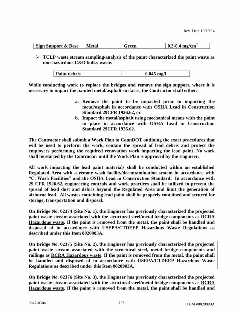
Rev. Date 10/10/14
ITEM #0020903A
Sign Support & Base Metal Green 0.3-0.4 mg/cm2
TCLP waste stream sampling/analysis of the paint characterized the paint waste as
non-hazardous C&D bulky waste.
Paint debris 0.045 mg/l
While conducting work to replace the bridges and remove the sign support, where it is
necessary to impact the painted metal/asphalt surfaces, the Contractor shall either:
a. Remove the paint to be impacted prior to impacting the
metal/asphalt in accordance with OSHA Lead in Construction
Standard 29CFR 1926.62, or
b. Impact the metal/asphalt using mechanical means with the paint
in place in accordance with OSHA Lead in Construction
Standard 29CFR 1926.62.
The Contractor shall submit a Work Plan to ConnDOT outlining the exact procedures that
will be used to perform the work, contain the spread of lead debris and protect the
employees performing the required renovation work impacting the lead paint. No work
shall be started by the Contractor until the Work Plan is approved by the Engineer.
All work impacting the lead paint materials shall be conducted within an established
Regulated Area with a remote wash facility/decontamination system in accordance with
“C. Wash Facilities” and the OSHA Lead in Construction Standard. In accordance with
29 CFR 1926.62, engineering controls and work practices shall be utilized to prevent the
spread of lead dust and debris beyond the Regulated Area and limit the generation of
airborne lead. All wastes containing lead paint shall be properly contained and secured for
storage, transportation and disposal.
On Bridge No. 02374 (Site No. 1), the Engineer has previously characterized the projected
paint waste stream associated with the structural steel/metal bridge components as RCRA
Hazardous waste. If the paint is removed from the metal, the paint shall be handled and
disposed of in accordance with USEPA/CTDEEP Hazardous Waste Regulations as
described under this Item 0020903A.
On Bridge No. 02375 (Site No. 2), the Engineer has previously characterized the projected
paint waste stream associated with the structural steel, metal bridge components and
railings as RCRA Hazardous waste. If the paint is removed from the metal, the paint shall
be handled and disposed of in accordance with USEPA/CTDEEP Hazardous Waste
Regulations as described under this Item 0020903A.
On Bridge No. 02376 (Site No. 3), the Engineer has previously characterized the projected
paint waste stream associated with the structural steel/metal bridge components as RCRA
Hazardous waste. If the paint is removed from the metal, the paint shall be handled and
0042-0304 178
Rev. Date 10/10/14
ITEM #0020903A
disposed of in accordance with USEPA/CTDEEP Hazardous Waste Regulations as
described under this Item 0020903A.
On Bridge No. 02376 (Site No. 3), no TCLP sample for lead was warranted on the white
painted asphalt as the XRF readings were below 1.0 mg/cm2 and therefore the painted
asphalt debris is presumed as Non-Hazardous per CTDEEP/USEPA clarification memo of
January 26, 2004.
On Bridge No. 02368A (Site No. 4), the Engineer has previously characterized the projected
paint waste stream associated with structural steel/metal bridge components as RCRA
Hazardous waste. If the paint is removed from the metal, the paint shall be handled and
disposed of in accordance with USEPA/CTDEEP Hazardous Waste Regulations as
described under this Item 0020903A.
On Sign Support No. 21607 near Bridge No. 02368A (Site No. 4), the Engineer has
previously characterized the projected paint waste stream associated with the metal sign
support components as Non-Hazardous waste. If the paint is removed from the metal, the
paint shall be handled and disposed of at the Contractor’s proposed construction and
demolition (C&D) lead debris bulky waste disposal facility (CTDEEP-permitted Solid
Waste landfill).
All steel and metal components generated from the miscellaneous exterior work tasks
(painted or not) shall be segregated and recycled as scrap metal. The recycling of scrap
metal (regardless of lead paint concentration) is exempt from USEPA RCRA and CTDEEP
Hazardous Waste Regulation.
Should lead contamination be discovered outside of the Regulated Area, the Contractor shall
immediately stop all work in the Regulated Area, eliminate causes of such contamination and
take steps to decontaminate non-work areas.
Special Requirements:
1. Demolition/Renovation:
a. Demolish/renovate in a manner which minimizes the spread of lead contamination
and generation of lead dust.
b. Implement dust suppression controls, such as misters, local exhaust ventilation,
etc. to minimize the generation of airborne lead dust.
c. Segregate work areas from non-work areas through the use or barrier tape, drop
cloths, etc.
d. Clean up immediately after renovation/demolition has been completed
2. Chemical Removal:
a. Apply chemical stripper in quantities and for durations specified by manufacturer.
0042-0304 179
Rev. Date 10/10/14
ITEM #0020903A
b. Where necessary, scrape lead paint from surface down to required level of
removal (i.e. stabilized surface, bare substrate with no trace of residual pigment,
etc.). Use sanding, hand scraping, and dental picks to supplement chemical
methods as necessary.
c. Apply neutralizer compatible with substrate and chemical agent to substrate
following removal in accordance with manufacturer's instructions.
d. Protect adjacent surfaces from damage from chemical removal.
e. Maintain a portable eyewash station in the work area.
f. Wear respirators that will protect workers from chemical vapors.
g. Do not apply caustic agents to aluminum surfaces.
3. Mechanical Paint Removal:
a. Provide sanders, grinders, rotary wire brushes, or needle gun removers equipped
with a HEPA filtered vacuum dust collection system. Cowling on the dust
collection system for orbital-type tools must be capable of maintaining a
continuous tight seal with the surface being abated. Cowling on the dust
collection system for reciprocating-type tools shall promote an effective vacuum
flow of loosened dust and debris. Inflexible cowlings may be used on flat
surfaces only. Flexible contoured cowlings are required for curved or irregular
surfaces.
b. Provide HEPA vacuums that are high performance designed to provide maximum
static lift and maximum vacuum system flow at the actual operating vacuum
condition with the shroud in use. The HEPA vacuum shall be equipped with a
pivoting vacuum head.
c. Remove lead paint from surface down to required level of removal (i.e. stabilized
surface, bare substrate with no trace of residual pigment, etc.). Use chemical
methods, hand scraping, and dental picks to supplement abrasive removal
methods as necessary.
d. Protect adjacent surfaces from damage from abrasive removal techniques.
e. “Sandblasting” type removal techniques shall not be allowed.
4. Component Removal/Replacement:
a. Wet down components which are to be removed to reduce the amount of dust
generated during the removal process.
b. Remove components utilizing hand tools, and follow appropriate safety
procedures during removal. Remove the components by approved methods which
will provide the least disturbance to the substrate material. Do not damage
adjacent surfaces.
c. Clean up immediately after component removals have been completed. Remove
any dust located behind the component removed.
G. Prohibited Removal Methods:
0042-0304 180
Rev. Date 10/10/14
ITEM #0020903A
The use of heat guns in excess of 700 degrees Fahrenheit to remove lead paint is prohibited.
The use of sand, steel grit, air, CO2, baking soda, or any other blasting media to remove lead or
lead paint without the use of a HEPA ventilated contained negative pressure enclosure is
prohibited.
Power/pressure washing shall not be used to remove lead paint.
Compressed air shall not be utilized to remove lead paint.
Chemical strippers containing Methylene Chloride are prohibited. Any chemical stripping may
be prohibited on a project by project basis.
Power tool assisted grinding, sanding, cutting, or wire brushing of lead paint without the use of
cowled HEPA vacuum dust collection systems is prohibited.
Lead paint burning, busting of rivets painted with lead paint, welding of materials painted with
lead paint, and torch cutting of materials painted with lead paint is prohibited. Where cutting,
welding, busting, or torch cutting of materials is required, lead paint in the affected area must be
removed first.
Chemical stripping of coatings from bridge components is generally prohibited unless
specifically allowed on a project by project basis.
H. Clean-up and Visual Inspection:
The Contractor shall remove and containerize all lead waste material and visible accumulations
of debris, paint chips and associated items.
During clean-up the Contractor shall utilize rags and sponges wetted with lead-specific detergent
and water as well as HEPA filtered vacuum equipment.
The Engineer will conduct a visual inspection of the work areas in order to document that all
surfaces have been maintained as free as practicable of accumulations of lead in accordance with
29 CFR 1926.62(h). If visible accumulations of waste, debris, lead paint chips or dust are found
in the work area, the Contractor shall repeat the cleaning, at the Contractor's expense, until the
area is in compliance. The visual inspection will detect incomplete work, damage caused by the
abatement activity, and inadequate clean up of the work site.
I. Post-Work Regulated Area Deregulation:
Following an acceptable visual inspection, any engineering controls implemented may be
removed.
0042-0304 181
Rev. Date 10/10/14
ITEM #0020903A
A final visual inspection of the work area shall be conducted by the Competent Person and the
Project Monitor or Engineer to ensure that all visible accumulations of suspect materials have
been removed and that no equipment or materials associated with the lead paint removal remain.
If this final visual inspection is acceptable, the Contractor will reopen the Regulated Area and
remove all signage.
The Contractor shall restore all work areas and auxiliary areas utilized during work to conditions
equal to or better than original. Any damage caused during the performance of the work activity
shall be repaired by the Contractor at no additional expense to the State.
J. Waste Disposal/Recycling:
Non-metallic building debris waste materials tested and found to be non-hazardous Construction
and Demolition (C&D) bulky waste shall be disposed of properly at a CTDEEP approved Solid
Waste landfill as described under this Item 0020903A.
Metallic debris shall be segregated and recycled as scrap metal at an approved metal recycling
facility.
Concrete, brick, etc. coated with any amount of lead paint cannot be crushed, recycled or buried
on-site to minimize waste disposal unless tested and found to meet the RSR GA/Residential
standards.
Hazardous lead debris shall be disposed of as described under this Item 0020903A.
The Contractor shall comply with the latest requirements of the USEPA RCRA Hazardous
Waste Regulations 40 CFR 260-274 and the DEEP Hazardous/Solid Waste Management
Standards 22a-449(c).
Hazardous lead debris shall be transported from the Project by a licensed hazardous waste
transporter approved by the Department and disposed of at an EPA-permitted and
Department-approved hazardous waste landfill within 90 days from the date of generation.
The Contractor must use one or more of the following Department-approved disposal facilities
for the disposal of hazardous waste:
Clean Earth of North Jersey, Inc., (CENJ)
115 Jacobus Avenue, South Kearny, NJ 07105
Phone: (973) 344-4004; Fax: (973) 344-8652
Clean Harbors Environmental Services, Inc.
2247 South Highway 71, Kimball, NE 69145
Phone: (308) 235-8212; Fax: (308) 235-4307 Clean Harbors of Braintree, Inc.
1 Hill Avenue, Braintree, MA 02184
Phone: (781) 380-7134; Fax: (781) 380-7193
Cycle Chem (General Chemical Corp.)
217 South First Street, Elizabeth, NJ 07206
Phone: (908) 355-5800; Fax (908) 355-0562
0042-0304 182
Rev. Date 10/10/14
ITEM #0020903A
EnviroSafe Corporation Northeast (former
Jones Environmental Services (NE), Inc.)
263 Howard Street, Lowell, MA 01852
Phone: (978) 453-7772; Fax: (978) 453-7775
Environmental Quality Detroit, Inc.
1923 Frederick Street, Detroit, MI 48211
Phone: (800) 495-6059; Fax: (313) 923-3375
Republic Environmental Systems
2869 Sandstone Drive, Hatfield, PA 19440
Phone: (215) 822-8995; Fax: (215) 997-1293
Chemical Waste Management of New York
1550 Balmer Rd., Model City, NY 14107
Phone: (800) 843-3604; Fax: (716) 754-0211
Environmental Quality Company:
Wayne Disposal Facility
49350 North I-94 Service Drive
Belleville, MI 48111
Phone: (800) 592-5489; Fax: (800) 592-5329
Northland Environmental, Inc.
(PSC Environmental Systems)
275 Allens Avenue, Providence, RI 02905
Phone: (401) 781-6340; Fax: (401) 781-9710
The apparent low bidder shall submit in writing, within fourteen days after Bid opening, (1) a
letter listing the names of the hazardous waste disposal facilities (from the above list) that the
bidder, if it is awarded the Contract, will use to receive hazardous material from this Project, and
(2) a copy of each facility’s acceptance criteria and sampling frequency requirements.
Any other Contractor which the Department may subsequently designate as the apparent low
bidder shall make the aforementioned submissions within fourteen (14) days from the date on
which the Department notifies the Contractor that it has become the apparent low bidder. If,
however, the Department deems it is necessary for such a subsequent-designated Contractor to
make said submissions within a shorter period of time, the Contractor shall make those
submissions within the time designated by the Department.
Failure to comply with all of the above requirements may result in the rejection of the bid.
No facility may be substituted for the one(s) designated in the Contractor’s submittal without the
Engineer’s prior approval. If the material cannot be accepted by any of the Contractor’s designated
facilities, the Department will supply the Contractor with the name(s) of other acceptable facilities.
Prior to the generation of any hazardous waste, the Contractor shall notify the Engineer of its
selected hazardous waste transporter and disposal facility. The Contractor must submit to the
Engineer (1) the transporter’s current US DOT Certificate of Registration and (2) the
transporter’s current Hazardous Waste Transporter Permits for the State of Connecticut, the
hazardous waste destination state and any other applicable states. The Engineer will then obtain
on a contiguous per site basis a temporary EPA Generators ID number for the site that he will
forward to the Contractor. Any changes in transporter or facility shall be immediately forwarded
to the Engineer for review.
Handling, storage, transportation and disposal of hazardous waste materials generated as a result
of execution of this project shall comply with all Federal, State and Local regulations including
the USEPA RCRA Hazardous Waste Regulations (40 CFR Parts 260-271), the CTDEEP
0042-0304 183
Rev. Date 10/10/14
ITEM #0020903A
Hazardous Waste Regulations (22a-209 and 22a-449(c)), and the USDOT Hazardous Materials
Regulations (49 CFR Part 171-180).
All debris shall be contained and collected daily or more frequently as directed by the Engineer,
due to debris buildup. Debris shall be removed by HEPA vacuum collection. Such debris and
paint chips shall be stored in leak-proof storage containers in the secured storage site, or as
directed by the Engineer. The storage containers and storage locations shall be reviewed by the
Engineer and shall be located in areas not subject to ponding. Storage containers shall be placed
on pallets and closed and covered with tarps at all times except during placement, sampling and
disposal of the debris.
Hazardous waste materials are to be properly packed and labeled for transport by the Contractor
is accordance with EPA, CTDEEP and USDOT regulations. The disposal of debris
characterized as hazardous waste shall be completed within 90 calendar days of the date on
which it began to be accumulated in the lined containers. Storage of containers shall be in
accordance with current DEEP/EPA procedures.
The Contractor shall label hazardous waste storage containers with a 6-inch square, yellow,
weatherproof, Hazardous Waste sticker in accordance with USDOT regulations.
Materials other than direct paint related debris which are incidental to the paint removal work
activities (tarps, poly, plywood, PPE, gloves, decontamination materials, etc.) which may be
contaminated with lead, shall be stored separately from the direct paint debris, and shall be
sampled by the Engineer for waste disposal characterization testing. Such materials
characterized as hazardous shall be handled/disposed of as described herein, while materials
characterized as non-hazardous shall be disposed of as non-hazardous CTDEEP Solid Waste.
Direct paint related debris materials not previously sampled and characterized for disposal,
which may be originally presumed to be hazardous waste, shall also be stored separately and
sampled by the Engineer for ultimate waste disposal characterization testing and
handled/disposed of based on that testing.
Project construction waste materials unrelated to the paint removal operations shall NOT be
combined/stored with paint debris waste and/or incidental paint removal materials as they are not
lead contaminated and shall NOT be disposed of as hazardous waste. The Engineer’s on-site
Inspectors shall conduct inspections to verify materials remain segregated.
The Contractor shall obtain and complete all paperwork necessary to arrange for material
disposal, including disposal facility waste profile sheets. It is solely the Contractor’s
responsibility to co-ordinate the disposal of hazardous materials with its selected
treatment/recycling/disposal facility(s). Upon receipt of the final approval from the facility, the
Contractor shall arrange for the loading, transport and treatment/recycling/disposal of the
materials in accordance with all Federal and State regulations. No claim will be considered
based on the failure of the Contractor’s disposal facility(s) to meet the Contractor’s
0042-0304 184
Rev. Date 10/10/14
ITEM #0020903A
production rate or for the Contractor’s failure to select sufficient facilities to meet its
production rate.
The Contractor shall process the hazardous waste such that the material conforms with the
requirements of the selected treatment/disposal facility, including but not limited to specified
size and dimension. Refusal on the part of the treatment/disposal facility to accept said material
solely on the basis of non-conformance of the material to the facility’s physical requirements is
the responsibility of the Contractor and no claim for extra work shall be accepted for
reprocessing of said materials to meet these requirements.
All DOT shipping documents, including the Uniform Hazardous Waste Manifests utilized to
accompany the transportation of the hazardous waste material shall be prepared by the
Contractor and reviewed/signed by an authorized agent representing ConnDOT, as Generator,
for each load of hazardous material that is packed to leave the site. The Contractor shall not sign
manifests on behalf of the State as Generator. The Contractor shall forward the appropriate
original copies of all manifests to the Engineer the same day the material leaves the Project site.
Materials not related to lead paint removal and/or characterized as non-hazardous waste shall
NOT be shipped for hazardous waste disposal in accordance with USEPA RCRA hazardous
waste minimization requirements.
A load-specific certificate of disposal, signed by the authorized agent representing the waste
disposal facility, shall be obtained by the Contractor and promptly delivered to the Engineer for
each load.
In addition to all pertinent Federal, State and local laws or regulatory agency polices, the
Contractor shall adhere to the following precautions during the transport of hazardous materials
off-site:
All vehicles departing the site are to be properly logged to show the vehicle
identification, driver’s name, time of departure, destination, and approximate volume,
and contents of materials carried. Vehicles shall display the proper USDOT placards
for the type and quantity of waste;
No materials shall leave the site unless a disposal facility willing to accept all of the
material being transported has agreed to accept the type and quantity of waste;
Documentation must be maintained indicating that all applicable laws have been
satisfied and that the materials have been successfully transported and received at the
disposal facility; and,
The Contractor shall segregate the waste streams (i.e. concrete, wood, etc.) as
directed by the receiving disposal facility.
Any spillage of debris during disposal operations during loading, transport and unloading shall
be cleaned up in accordance with EPA 40 CFR 265 Subparts C & D, at the Contractor’s expense.
0042-0304 185
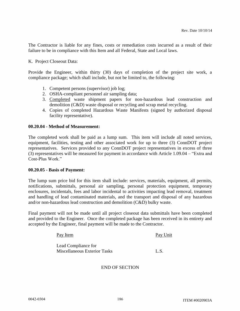
Rev. Date 10/10/14
ITEM #0020903A
The Contractor is liable for any fines, costs or remediation costs incurred as a result of their
failure to be in compliance with this Item and all Federal, State and Local laws.
K. Project Closeout Data:
Provide the Engineer, within thirty (30) days of completion of the project site work, a
compliance package; which shall include, but not be limited to, the following:
1. Competent persons (supervisor) job log;
2. OSHA-compliant personnel air sampling data;
3. Completed waste shipment papers for non-hazardous lead construction and
demolition (C&D) waste disposal or recycling and scrap metal recycling.
4. Copies of completed Hazardous Waste Manifests (signed by authorized disposal
facility representative).
00.20.04 - Method of Measurement:
The completed work shall be paid as a lump sum. This item will include all noted services,
equipment, facilities, testing and other associated work for up to three (3) ConnDOT project
representatives. Services provided to any ConnDOT project representatives in excess of three
(3) representatives will be measured for payment in accordance with Article 1.09.04 – “Extra and
Cost-Plus Work.”
00.20.05 - Basis of Payment:
The lump sum price bid for this item shall include: services, materials, equipment, all permits,
notifications, submittals, personal air sampling, personal protection equipment, temporary
enclosures, incidentals, fees and labor incidental to activities impacting lead removal, treatment
and handling of lead contaminated materials, and the transport and disposal of any hazardous
and/or non-hazardous lead construction and demolition (C&D) bulky waste.
Final payment will not be made until all project closeout data submittals have been completed
and provided to the Engineer. Once the completed package has been received in its entirety and
accepted by the Engineer, final payment will be made to the Contractor.
Pay Item Pay Unit
Lead Compliance for
Miscellaneous Exterior Tasks L.S.
END OF SECTION
0042-0304 186
12/11/14
ITEM #0100600A
ITEM #0100600A – CONSTRUCTION ACCESS
Description: Work under this item shall consist of constructing and restoring access areas required
for the construction of Bridge No. 02374 (Site No. 1) and Bridge No. 02368A (Site No. 4). The
major work activities included under this item are:
-Excavation of existing embankment material.
-Transportation of said embankment material to a storage facility
-Construction of access ways, work areas, and crane platforms
-Reinstallation of the embankment material to its original condition.
-Work under this item shall also consist of the construction of such cofferdams, flow
diversions, barriers, diversion pipes, or other such protective facilities and methods necessary for
the conduction of water beyond the limits of construction; the dewatering of the site on which the
permanent structure is to be constructed; and the removal of all such temporary structures and
facilities upon the completion of the permanent work or as required. The handling of water shall
be in accordance with the requirements of Section 1.10.
For the purposes of this specification, such work shall be understood to mean any temporary type
of protective facility which satisfies the condition that the permanent structures are built in the
dry. The handling of flood flows and the protection of existing structures, and any or all of the
finished construction during high water are included in the scope of work under this item.
Materials: None required under this item
Construction Methods:
Excavation: The Contractor shall excavate material as required to create suitable access areas to
enable the bridge constructions to proceed. The Plans contain suggested locations for temporary
access ways and crane locations; however, it shall be the Contractor’s responsibility to determine
the exact locations and sizes of the access ways and crane locations.
Stockpiling: The excavated material shall be transported to, and stored at, a storage facility that
is not within a regulated area. See the “Notice to Contractor – Staging and Storage Areas” for
additional information.
Replacement of Embankment Material: All of the stockpiled material shall be returned to the
access areas and used for restoration of the embankments. The embankments shall be shaped and
graded to their original condition. This work, including compaction, shall be done in accordance
with Article 2.02.03, subarticles 5 through 7.
0042-0304 187

12/11/14
ITEM #0100600A
Cofferdams and Dewatering: The Contractor shall investigate and verify the existing conditions
and design the necessary protection to conform with the plan. Before commencing construction
the Contractor shall furnish the Engineer with details of the plan and methods he proposes to use
for handling water and accomplishing the work. The furnishing of such plans and methods shall
not relieve the Contractor of any of his responsibility for the safety of the work and for the
successful completion of the project.
The height of any cofferdams, flow diversion, or barriers required to accomplish the work shall
be shown. Any necessary diversion pipes shall be installed in accordance with the contract. All
such temporary structures or facilities shall be safely designed for all applicable loadings,
extended to sufficient depth and be of such dimensions and water-tightness so as to assure
construction of the permanent work in the dry. They shall not interfere with proper performance
of the work. Their locations shall be such as to permit excavation for permanent work to the
limits shown on the plans. Interior dimensions shall give sufficient clearance for construction and
inspection of forms. Movements or failures of the temporary protection facilities, or any portions
thereof, which prevent proper completion of the permanent work shall be corrected at the sole
expense of the Contractor.
Any pumping from within the areas of construction shall be done in such a manner as to prevent
the possibility of movement of water through any fresh concrete. No pumping will be permitted
during placing of concrete or for a period of 24 hours thereafter, unless it is done from a suitable
sump pump properly located and with a capacity to protect against damage from sudden rising of
water. Any pumped water must be discharged in accordance with the requirements of
Section 1.10.
Unless otherwise provided, or directed, all such temporary protective work shall be removed and
disposed of in an approved manner when no longer required.
The Contractor shall be responsible for the scheduling of work under this item so as not to
interfere with any sequence of operations developed for this project. Delays as a result of work
required under this item shall not constitute a claim for an extension of contract time.
Method of Measurement: This work, being paid for on a lump sum basis, will not be measured
for payment.
Basis of Payment: This work will be paid for at the contract lump sum price for "Construction
Access”, which price shall include all equipment, tools, and labor incidental thereto.
0042-0304 188
rev. 121610
ITEM #0202479A
ITEM #0202479A - REMOVAL OF HMA WEARING SURFACE
Description: Work under this item shall consist of the complete removal and disposal of the
existing HMA wearing surface, membrane waterproofing and bond breaker covering the
reinforced concrete bridge deck as shown on the plans, as ordered by the Engineer and in
accordance with these specifications.
Construction Methods: The Contractor shall remove the HMA wearing surface, membrane
waterproofing and bond breaker using means acceptable to the Engineer to completely expose
the underlying concrete deck, without damaging the deck, roadway materials, and structures
which are to remain intact.
Acceptable mechanical method for removal of HMA surface on a structure can be one of the
following:
Micro-milling - Micro-milling equipment shall consist of Cold Plane or Rotomill Grinders using
carbide cutting tools in a rotary drum. The equipment shall provide a tool spacing of not more
than 3/16 inch, capable of leaving a smooth, uniform pattern of striations with a maximum
forward speed of 45 feet/minute.
Fine Milling – Fine milling equipment shall consist of Cold Plane or Rotomill Grinders using
carbide cutting tool in a rotary drum. The equipment shall provide a tool spacing of not more
than 5/16 inch, capable of leaving a smooth, uniform pattern of striations with a maximum forward
speed of 45 feet/minute.
Alternate methods may be submitted to the Engineer for review and acceptance. Demonstration
of the alternate removal method shall be performed prior to consideration.
All particles and aggregate adhering to the exposed concrete that could, in the Engineer's
opinion, cause failure of/or puncture the new membrane shall be removed. The existing HMA
wearing surface, membrane waterproofing, and bond breaker that are removed shall be disposed
of offsite by the Contractor unless otherwise noted in the contract documents or as directed by
the Engineer.
Prior to removal of HMA wearing surface the Contractor shall conduct a survey. A minimum of
four (4) representative depth measurements shall be taken per span for a span up to 100 feet in
length to predetermine the overlay thickness. An additional measurement shall be taken for each
25 feet in span length. If depth of overlay varies across the structure, it shall be clearly marked
to aid in the removal operation. Survey locations shall be filled with bituminous material if
milling operation is not scheduled within five (5) days or at the direction of the Engineer.
The existing HMA wearing surface and membrane waterproofing shall be removed in its entirety
to the limits shown on the plans. The removal operations shall not begin until the Contractor is
prepared to perform the permanent patching and/or repair to the underlying concrete within five
0042-0304 189

rev. 121610
ITEM #0202479A
(5) working days. If this in conflict with "Prosecution and Progress", "Maintenance and
Protection of Traffic", or other contract requirements, the more stringent specification shall
apply.
Protection shall be provided around existing catch basin inlets, bridge scuppers, manholes, utility
valve boxes, median barriers, parapets, and other roadway structures. Any damage to such
structures as a result of removal operations is the Contractor’s responsibility and shall be
repaired at the Contractor’s expense.
A uniform textured riding surface shall be provided and maintained. The surface shall be free
from gouges, longitudinal grooves and ridges, oil film, and other imperfections that are a result
of defective equipment, improper use of equipment, poor workmanship, or inadequate survey.
Any unsatisfactory surfaces caused by the removal operations are the Contractor’s responsibility
and shall be corrected at the Contractor’s expense and to the satisfaction of the Engineer prior to
opening the surface to traffic.
Any raised structures shall be clearly marked by high visibility paint and delineated with traffic
control devices, as directed by the Engineer. Installation of traffic control devices will be
included under the costs for “Maintenance and Protection of Traffic”; payment for the devices
will be under their applicable items.
No vertical faces, transverse or longitudinal, shall be left exposed to traffic. If any vertical face is
formed in an area exposed to traffic a temporary paved transition will be established according to
the requirements shown on the plans. If the milling machine is used to form a temporary
transition, the length of the temporary transition shall conform to, Section 4.06 – Bituminous
Concrete, “Transitions for Roadway Surface”, the requirements shown on the plans, or as
directed by the Engineer. At all permanent limits of removal, a clean vertical face shall be
established prior to paving by saw cutting.
The sweeper shall be equipped with a water tank and be capable of removing the millings and
loose debris from the surface. Other sweeping equipment may be provided in lieu of the sweeper
where acceptable by the Engineer.
Method of Measurement: This work will be measured for payment by the number of square
yards of HMA wearing surface removed to expose the underlying concrete deck. No area
deductions will be made for minor unmilled areas such as scuppers, joints, and any similar
structures.
Basis of Payment: This work will be paid for at the contract unit price per square yard for
"Removal of HMA Wearing Surface", complete and accepted, which price shall include the
removal of membrane waterproofing and bond breaker, saw cutting, and all equipment, tools and
labor.
Pay Item Pay Unit
Removal of HMA Wearing Surface S.Y.
0042-0304 190
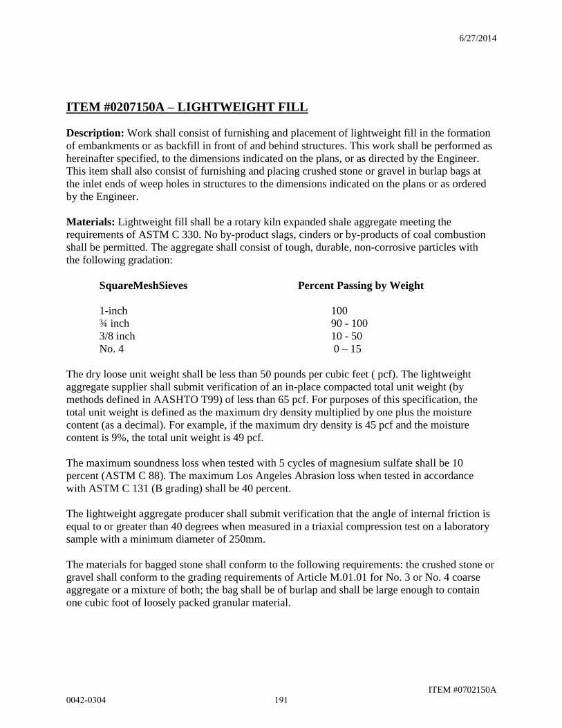
6/27/2014
ITEM #0702150A
ITEM #0207150A – LIGHTWEIGHT FILL
Description: Work shall consist of furnishing and placement of lightweight fill in the formation
of embankments or as backfill in front of and behind structures. This work shall be performed as
hereinafter specified, to the dimensions indicated on the plans, or as directed by the Engineer.
This item shall also consist of furnishing and placing crushed stone or gravel in burlap bags at
the inlet ends of weep holes in structures to the dimensions indicated on the plans or as ordered
by the Engineer.
Materials: Lightweight fill shall be a rotary kiln expanded shale aggregate meeting the
requirements of ASTM C 330. No by-product slags, cinders or by-products of coal combustion
shall be permitted. The aggregate shall consist of tough, durable, non-corrosive particles with
the following gradation:
SquareMeshSieves Percent Passing by Weight
1-inch 100
¾ inch 90 - 100
3/8 inch 10 - 50
No. 4 0 – 15
The dry loose unit weight shall be less than 50 pounds per cubic feet ( pcf). The lightweight
aggregate supplier shall submit verification of an in-place compacted total unit weight (by
methods defined in AASHTO T99) of less than 65 pcf. For purposes of this specification, the
total unit weight is defined as the maximum dry density multiplied by one plus the moisture
content (as a decimal). For example, if the maximum dry density is 45 pcf and the moisture
content is 9%, the total unit weight is 49 pcf.
The maximum soundness loss when tested with 5 cycles of magnesium sulfate shall be 10
percent (ASTM C 88). The maximum Los Angeles Abrasion loss when tested in accordance
with ASTM C 131 (B grading) shall be 40 percent.
The lightweight aggregate producer shall submit verification that the angle of internal friction is
equal to or greater than 40 degrees when measured in a triaxial compression test on a laboratory
sample with a minimum diameter of 250mm.
The materials for bagged stone shall conform to the following requirements: the crushed stone or
gravel shall conform to the grading requirements of Article M.01.01 for No. 3 or No. 4 coarse
aggregate or a mixture of both; the bag shall be of burlap and shall be large enough to contain
one cubic foot of loosely packed granular material.
0042-0304 191
6/27/2014
ITEM #0702150A
Construction Methods: When applicable and except where noted below, lightweight fill
placement shall conform to the requirements of Sections 2.02.03 and 2.16.03 of the Standard
Specifications, Form 816.
The lightweight fill shall be placed in layers of a thickness of 1.5 ft to a maximum of 2.0 ft.
Each layer shall be compacted by the use of self-propelled vibratory compaction equipment
with static mass (weight) less than 6,600 lbs. The minimum number of passes shall be two (2)
and the maximum four (4). The actual lift thickness and exact number of passes shall be
determined by the Engineer depending on the type of compaction equipment. The contractor
shall take all necessary precautions during construction activities in operations on or adjacent
to the lightweight fill to ensure that the material is not over compacted. Construction equipment,
other than for compaction, shall not be operated on the exposed lightweight fill.
Where weep holes are installed within the limits of the lightweight fill, bagged stone shall be
placed around the inlet end of each weep hole, to prevent movement of the lightweight fill
material into the weep hole. Approximately one cubic foot of crushed stone or gravel shall be
enclosed in each of the burlap bags. All bags shall then be securely tied at the neck with cord or
wire so that the enclosed material is contained loosely. The filled bags shall be stacked at the
weep holes to the dimensions shown on the plans or as directed by the Engineer. The bags
shall be unbroken at the time lightweight fill material is placed around them and bags which
are broken or burst prior to or during the placing of the lightweight fill material shall be
replaced at the expense of the contractor.
Method of Measurement: Lightweight fill shall be measured in place after compaction,
including allowances for settlement. There shall be no direct payment for bagged stone, but the
cost thereof shall be considered as included in the cost of the work for “Lightweight Fill”.
Basis of Payment: This work will be paid for at the contract unit price per cubic yard for
“Lightweight Fill”, complete in place, which price shall include all materials, transportation,
tools, equipment and labor incidental thereto.
Pay Item Pay Unit
Lightweight Fill c.y.
0042-0304 192
Rev. Date 11/17/14
ITEM #0210820A
ITEM #0210820A – WATER POLLUTION CONTROL
2.10.01 - Description: Replace with the following:
This work shall consist of measures to control water pollution and soil erosion through the use of
berms, dikes, dams, sediment basins, sediment tanks, erosion control matting, gravel, mulches,
grasses, slope drains, ditches, channels, riprap, grading to control surface runoff and other
erosion control devices or methods chosen by the Contractor or as directed by the Engineer.
If the Contractor proposes changes in construction or his scheduling that would affect the
designed pollution controls, he shall submit plans before starting construction for revised
pollution controls for the approval of the Engineer.
The Contractor shall submit a plan showing erosion and sedimentation controls above and
beyond those called for in the plans and/or specifications, necessitated by the proposed sequence
of operations and/or construction activities. The construction shall not proceed until the erosion
and sedimentation control plans have been approved by the Engineer. The Engineer may order
additional control measures if the measures mentioned above prove insufficient.
0042-0304 193
Rev. Date 10/19/12
ITEM #0406125A
ITEM #0406125A - BITUMINOUS CONCRETE SURFACE PATCH
4.06.01 - Description: This work shall consist of milling and patching an existing deteriorated
bituminous concrete pavement surface. A milling machine shall be used to remove the existing
pavement to a depth of 1.5 to 2.5 inches. The milled surface shall be swept and then be blown
clean with compressed air. Tack coat is to be applied to the milled surface and any vertical or
semi-vertical walls formed by the milling. The milled out area shall then be filled and
compacted with HMA S0.375.
4.06.02 - Materials: Materials for this work shall consist of the following:
Hot-mix Asphalt (specifically HMA S0.375) conforming to the requirements of Sections 4.06
and M.04 of the Standard Specifications. An equivalent PMA may be used conforming to the
requirements of Sections 4.06 and M.04 of the Standard Specifications.
Tack coat conforming to the material requirements for tack coat in Sections 4.06 and M.04 of the
Standard Specifications.
Equipment: Equipment for this work shall include, but is not limited to, the following:
1. Milling machine – A milling machine designed and built for milling flexible
pavements. It shall be self propelled with sufficient power, traction, and stability to
maintain depth and slope and shall be capable of removing the existing HMA
pavement.
The milling machine shall be equipped with a built-in automatic grade averaging
control system that can control the longitudinal profile and the transverse cross-slope
to produce the specified results. The longitudinal controls shall be capable of
operating from any longitudinal grade reference, including string line, contact ski (30
feet minimum), non-contact ski (20 feet minimum), or mobile string line (30 feet
minimum). The transverse controls shall have an automatic system for controlling
cross-slope at a given rate. The Engineer may waive the requirement for automatic
grade or slope controls where the situation warrants such action.
The rotary drum of the machine shall utilize carbide tip tools spaced not more than
5/8 inches apart. The forward speed of the milling machine shall be limited to no
more than 45 feet/minute. The tools on the revolving cutting drum must be
continually maintained and shall be replaced as warranted to provide a uniform
pavement texture.
The Contractor may request to perform a test strip to demonstrate that the same
surface tolerance can be attained at an increased forward speed. The test strip shall be
a maximum length of 500 feet and shall have the same criteria for surface tolerance as
0042-0304 194
Rev. Date 10/19/12
ITEM #0406125A
noted in this specification. The final decision for implementing the increased forward
speed will be at the discretion of the Engineer.
The machine shall be equipped with an integral pickup and conveying device to
immediately remove material being milled from the surface of the roadway and
discharge the millings into a truck, all in one operation. The machine shall also be
equipped with a means of effectively limiting the amount of dust escaping from the
milling and removal operation. When milling smaller areas or areas where it is
impractical to use the above described equipment, the use of a lesser equipped milling
machine may be permitted when approved by the Engineer.
In addition to meeting those requirements, the milling machine shall be capable of
removing the existing pavement to a minimum width of 20 inches in any direction.
This makes the minimum achievable patch size - 20 inches by 20 inches, or 0.30
square yards.
2. Sweeper – The sweeper shall be equipped with a water tank and be capable of
removing the millings and loose debris from the surface. Other sweeping equipment
may be provided in lieu of the sweeper where acceptable by the Engineer.
3. Air compressor – The unit shall consist of an air compressor capable of producing
100 psi, oil free, compressed air for blowing the milled pavement surface clean.
4. Hot air lance – The unit shall be designed for cleaning and drying the pavement
surface. It shall consist of an air compressor capable of delivering 100 psi, oil free
heated air. The compressed air emitted from the tip of the lance shall be flame free
and be capable of achieving a temperature of at least 1500°F.
5. Paving and compaction equipment – All equipment used to place and compact the hot
mix asphalt required for this work shall meet the requirements of Section 4.06 of the
Standard Specifications. Due to the nature of this work, it is expected that much of
the placement of hot mix asphalt will require hand work or a mixture of equipment
and hand work methods and tools to achieve the required results. The same
consideration is to be given to compaction of the hot mix asphalt. Smaller type
compaction equipment, including vibratory plate compactors, shall be allowed to
achieve the required results. At all times the Contractor is required to meet the
density and compaction and all other requirements specified in Sections 4.06 and
M.04 of the Standard Specifications.
4.06.03 - Construction Methods: Demarcation of Areas to be Patched:
Areas to be patched under this item shall consist of pavement surfaces in which the existing
surface lift of pavement is raveling, disintegrating, or delaminated from the lift of pavement
directly beneath it. Under this specification a “lift” of pavement is defined as an individual layer
of bituminous concrete that was placed and compacted previously with one placement pass of a
0042-0304 195
Rev. Date 10/19/12
ITEM #0406125A
paver or other asphalt pavement placement device or method. “Surface lift” is defined as the last
individual layer of bituminous concrete placed and compacted that currently serves as the driving
surface of the roadway. This could include a milled surface. These definitions apply to
previously placed “surface lifts” of pavement that were between 1 inch and 2.5 inches thick.
All areas in which the surface lift of pavement displays raveling, disintegration, or delamination
from the underlying lift of pavement, of such a severity, that it will not likely support traffic
loadings, or remain sound and in-tact, for an additional 2 years, shall be marked out by the
Engineer for removal. The minimum width of any given area shall be 20 inches. All areas to be
patched shall completely encompass the entire raveled, disintegrated, or delaminated area and
extend at least 6 inches beyond into the surrounding pavement.
Patch Preparation and Construction:
Utilizing the specified milling machine, mill the demarcated areas to a depth that completely
removes the surface lift of pavement. The minimum depth shall be 1.5 inches and the maximum
depth shall not exceed 2.5 inches.
As specified in the requirements for milling, the milled surface shall be swept clean (by hand if
necessary.) Once all millings are practicably removed by sweeping, the milled areas shall be
allowed to dry if necessary. Any moisture in or on the milled areas must be allowed to evaporate
or be removed with the assistance of a hot air lance as specified above. Once the milled area is
deemed dry by the Engineer it shall be blown with compressed or hot lance air, as specified
above, so that no debris or dust is present on or within the milled area.
Once deemed clean by the Engineer, the milled area, including the sides/walls of the milled area,
shall receive an application of tack coat as specified above and in Section 4.06 of the Standard
Specifications.
After the tack coat has had sufficient time to cure or break, HMA S0.375 shall be placed and
compacted to the requirements above and in Section 4.06 of the Standard Specification. It shall
be compacted to match the elevation of the surrounding pavement surface.
4.06.04 - Method of Measurement: This work shall be measured by the total area, in square
yards, of “Bituminous Concrete Surface Patch.”
0042-0304 196
Rev. Date 10/19/12
ITEM #0406125A
4.06.05 - Basis of Payment: This work will be paid for at the contract unit price per square yard
of “Bituminous Concrete Surface Patch.” The price shall include milling, pavement excavation
and removal, cleaning of the milled area, tack coat application to the milled surface area, and
placement and compaction of HMA S0.375. All other miscellaneous tools, materials, and
equipment needed to complete the work shall also be included in the cost of the work.
Pay Item Pay Unit
Bituminous Concrete Surface Patch S.Y.
0042-0304 197
Rev. 020212
Item #0406267A
ITEM #0406267A - MILLING OF HOT MIX ASPHALT (HMA) –
(0- 4 INCHES)
Description: This work shall consist of the milling, removal, and disposal of existing
HMA pavement.
Materials: The existing HMA surface shall be disposed of offsite by the Contractor at
an approved disposal facility unless otherwise stated in the contract documents.
Construction Methods: The Contractor shall remove the HMA material using means
acceptable to the Engineer. The pavement surface shall be removed to the line, grade,
and existing or typical cross-section shown on the plans or directed by the Engineer.
The equipment for milling the pavement surface shall be designed and built for milling
flexible pavements. It shall be self propelled with sufficient power, traction, and stability
to maintain depth and slope and shall be capable of removing the existing HMA
pavement.
The milling machine shall be equipped with a built-in automatic grade averaging control
system that can control the longitudinal profile and the transverse cross-slope to produce
the specified results. The longitudinal controls shall be capable of operating from any
longitudinal grade reference, including string line, contact ski (30 feet minimum), non-
contact ski (20 feet minimum), or mobile string line (30 feet minimum). The transverse
controls shall have an automatic system for controlling cross-slope at a given rate. The
Engineer may waive the requirement for automatic grade or slope controls where the
situation warrants such action.
The rotary drum of the machine shall utilize carbide tip tools spaced not more than ⅝
inches apart. The forward speed of the milling machine shall be limited to no more than
45 feet/minute. The tools on the revolving cutting drum must be continually maintained
and shall be replaced as warranted to provide a uniform pavement texture. The
Contractor may request to perform a test strip to demonstrate that the same surface
tolerance can be attained at an increased forward speed. The test strip shall be a
maximum length of 500 feet and shall have the same criteria for surface tolerance as
noted in this specification. The final decision for implementing the increased forward
speed will be at the discretion of the Engineer.
The machine shall be equipped with an integral pickup and conveying device to
immediately remove material being milled from the surface of the roadway and discharge
the millings into a truck, all in one operation. The machine shall also be equipped with a
means of effectively limiting the amount of dust escaping from the milling and removal
operation.
When milling smaller areas or areas where it is impractical to use the above described
equipment, the use of a lesser equipped milling machine may be permitted when
approved by the Engineer.
0042-0304 198
Rev. 020212
Item #0406267A
Protection shall be provided around existing catch basin inlets, manholes, utility valve
boxes, and any similar structures. Any damage to such structures as a result of the
milling operation is the Contractor’s responsibility and shall be repaired at the
Contractor’s expense.
To prevent the infiltration of milled material into the storm drainage system, the
Contractor shall take special care to prevent the milled material from falling into the inlet
openings or inlet grates. Any milled material that has fallen into inlet openings or inlet
grates shall be removed at the Contractor’s expense.
Surface Tolerance: The milled surface shall provide a satisfactory riding surface with a
uniform textured appearance. The milled surface shall be free from gouges, longitudinal
grooves and ridges, oil film, and other imperfections that are a result of defective
equipment, improper use of equipment, or poor workmanship. The Contractor, under the
direction of the inspector, shall perform random spot-checks with a Contractor supplied
ten-foot straightedge to verify surface tolerances at a minimum of five locations per day.
The variation of the top of two ridges from the testing edge of the straightedge, between
any two ridge contact points, shall not exceed ⅜ inch. The variation of the top of any
ridge to the bottom of the groove adjacent to that ridge shall not exceed ⅜ inch. Any
unsatisfactory surfaces produced are the responsibility of the Contractor and shall be
corrected at the Contractor’s expense and to the satisfaction of the Engineer.
The depth of removal will be verified by taking a measurement every 250 feet per each
pass of the milling machine, or as directed by the Engineer. These depth measurements
shall be used to monitor the average depth of removal.
Where a surface delamination between HMA layers or a surface delamination of HMA
on Portland cement concrete causes a non-uniform texture to occur, the depth of milling
shall be adjusted in small increments to a maximum of a +/- ½ inch to eliminate the
condition.
When removing a HMA pavement entirely from an underlying Portland cement concrete
pavement, all of the HMA pavement shall be removed leaving a uniform surface of
Portland cement concrete, unless otherwise directed by the Engineer.
Any unsatisfactory surfaces produced by the milling operation are the Contractor’s
responsibility and shall be corrected at the Contractor’s expense and to the satisfaction of
the Engineer.
No vertical faces, transverse or longitudinal, shall be left exposed to traffic unless it
meets the requirements below. This shall include roadway structures (catch basins,
manholes, utility valve boxes, etc.). If any vertical face is formed in an area exposed to
traffic a temporary paved transition will be established according to the requirements
shown on the plans. If the milling machine is used to form a temporary transition, the
length of the temporary transition shall conform to Special Provision Section 4.06 -
0042-0304 199
Rev. 020212
Item #0406267A
Bituminous Concrete, “Transitions for Roadway Surface”, the requirements shown on the
plans, or as directed by the Engineer. At all permanent limits of removal, a clean vertical
face shall be established by saw cutting prior to paving.
Roadway structures shall not have a vertical face of greater than 1 inch exposed to traffic
as a result of milling. All structures within the roadway that are exposed to traffic and
greater than 1 inch above the milled surface shall receive a transition meeting the
following requirements:
For roadways with a posted speed limit of 35 mph or less*:
1. Round structures with a vertical face of greater than 1 inch to 2.5 inches shall be
transitioned with a hard rubber tapered protection ring of the appropriate inside
diameter designed specifically to protect roadway structures.
2. Round structures with a vertical face greater than 2.5 inches shall receive a
transition of bituminous concrete formed at a minimum 24 to 1 taper.
3. All rectangular structures shall receive a transition of bituminous concrete formed
at a minimum 24 to 1 taper.
*Bituminous concrete tapers at a minimum 24 to 1 taper may be substituted for the
protection rings if approved by the Engineer.
For roadways with a posted speed limit of greater than 35 mph:
1. All structures shall receive a transition of bituminous concrete meeting the
temporary transition requirements in Special Provision Section 4.06- Bituminous
Concrete, “Transitions for Roadway Surface”.
The milling operation shall proceed in accordance with the requirements of the
“Maintenance and Protection of Traffic” and “Prosecution and Progress” specifications,
or other contract requirements. The more stringent specification shall apply.
Prior to opening an area which has been milled to traffic, the pavement shall be
thoroughly swept with a sweeper. The sweeper shall be equipped with a water tank and
be capable of removing the millings and loose debris from the surface. Other sweeping
equipment may be provided in lieu of the sweeper where acceptable by the Engineer.
Any milled area that will not be exposed to live traffic for a minimum of 48 hours prior to
paving shall require a vacuum sweeper truck in addition to, or in lieu of, mechanical
sweeping. The vacuum sweeper truck shall have sufficient power and capacity to
completely remove all millings from the roadway surface including any fine particles
within the texture of the milled surface. Vacuum sweeper truck hose attachments shall be
used to clean around pavement structures or areas that cannot be reached effectively by
the main vacuum. Compressed air may be used in lieu of vacuum attachments if
approved by the Engineer.
Method of Measurement: This work will be measured for payment by the number of
square yards of area from which the milling of asphalt has been completed and the work
0042-0304 200
Rev. 020212
Item #0406267A
accepted. No area deductions will be made for minor unmilled areas such as catch basin
inlets, manholes, utility boxes and any similar structures.
The depth of removal will be calculated by taking a measurement at a minimum every
250 feet per each pass of the milling machine, or as directed by the Engineer. The
average depth of each section will determine which payment item is applicable.
Basis of Payment: This work will be paid for at the contract unit price per square yard
for “Milling of HMA (0 to 4 inches) (greater than 4 to 8 inches) (greater than 8 inches)”.
This price shall include all equipment, tools, labor, and materials incidental thereto.
No additional payments will be made for multiple passes with the milling machine to
remove the bituminous surface.
No separate payments will be made for cleaning the pavement prior to paving; providing
protection and doing handwork removal of bituminous concrete around catch basin inlets,
manholes, utility valve boxes and any similar structures; repairing surface defects as a
result of the Contractors negligence; providing protection to underground utilities from
the vibration of the milling operation; removal of any temporary milled transition;
removal and disposal of millings; furnishing a sweeper and sweeping after milling. The
costs for these items shall be included in the contract unit price.
Pay Item Pay Unit
Milling of Hot Mix Asphalt (HMA) – Sq. Yd
(0- 4 inches)
Milling of Hot Mix Asphalt (HMA) – Sq. Yd
(greater than 4 to 8 inches)
Milling of Hot Mix Asphalt (HMA) – Sq. Yd
(greater than 8 inches)
0042-0304 201
Rev. 020212
ITEM #0406285A
ITEM #0406285A – FINE MILLING OF HOT MIX ASPHALT (HMA)
(0 TO 4 INCHES)
Description: This work shall consist of the milling, removal, and disposal of existing HMA
pavement.
Materials: The existing HMA surface shall be disposed of offsite by the Contractor at an
approved disposal facility unless otherwise stated in the contract documents.
Construction Methods: The Contractor shall remove the HMA material using means acceptable
to the Engineer. The pavement surface shall be removed to the line, grade, and existing or
typical cross-section shown on the plans or directed by the Engineer.
The equipment for milling the pavement surface shall be designed and built for milling flexible
pavements. It shall be self propelled with sufficient power, traction, and stability to maintain
depth and slope and shall be capable of removing the existing HMA pavement.
The milling machine shall be equipped with a built-in automatic grade averaging control system
that can control the longitudinal profile and the transverse cross-slope to produce the specified
results. The longitudinal controls shall be capable of operating from any longitudinal grade
reference, including string line, contact ski (30 feet minimum), non-contact ski (20 feet
minimum), or mobile string line (30 feet minimum). The transverse controls shall have an
automatic system for controlling cross-slope at a given rate. The Engineer may waive the
requirement for automatic grade or slope controls where the situation warrants such action.
The machine shall be able to provide a 0 to 4 inch deep cut in one pass. The rotary drum of the
machine shall utilize carbide tip tools spaced not more than 5/16 inches apart. The forward speed
of the milling machine shall be limited to no more than 45 feet/minute. The tools on the
revolving cutting drum must be continually maintained and shall be replaced as warranted to
provide a uniform pavement texture. The Contractor may request to perform a test strip to
demonstrate that the same surface tolerance can be attained at an increased forward speed. The
test strip shall be a maximum length of 500 feet and shall have the same criteria for surface
tolerance as noted in this specification. The final decision for implementing the increased
forward speed will be at the discretion of the Engineer.
The machine shall be equipped with an integral pickup and conveying device to immediately
remove material being milled from the surface of the roadway and discharge the millings into a
truck, all in one operation. The machine shall also be equipped with a means of effectively
limiting the amount of dust escaping from the milling and removal operation.
When milling smaller areas or areas where it is impractical to use the above described
equipment, the use of a lesser equipped milling machine may be permitted when approved by the
Engineer.
0042-0304 202
Rev. 020212
ITEM #0406285A
Protection shall be provided around existing catch basin inlets, manholes, utility valve boxes, and
any similar structures. Any damage to such structures as a result of the milling operation is the
Contractor’s responsibility and shall be repaired at the Contractor’s expense.
To prevent the infiltration of milled material into the storm drainage system, the Contractor shall
take special care to prevent the milled material from falling into the inlet openings or inlet grates.
Any milled material that has fallen into inlet openings or inlet grates shall be removed at the
Contractor’s expense.
Surface Tolerance: The milled surface shall provide a satisfactory riding surface with a
uniform textured appearance. The milled surface shall be free from gouges, longitudinal grooves
and ridges, oil film, and other imperfections that are a result of defective equipment, improper
use of equipment, or poor workmanship. The Contractor, under the direction of the inspector,
shall perform random spot-checks with a Contractor supplied ten-foot straightedge to verify
surface tolerances at a minimum of five locations per day. The variation of the top of two ridges
from the testing edge of the straightedge, between any two ridge contact points, shall not exceed
¼ inch. The variation of the top of any ridge to the bottom of the groove adjacent to that ridge
shall not exceed ¼ inch. Any unsatisfactory surfaces produced are the responsibility of the
Contractor and shall be corrected at the Contractor’s expense and to the satisfaction of the
Engineer.
The depth of removal will be verified by taking a measurement every 250 feet per each pass of
the milling machine, or as directed by the Engineer. These depth measurements shall be used to
monitor the average depth of removal.
Where a surface delamination between HMA layers or a surface delamination of HMA on
Portland cement concrete causes a non-uniform texture to occur, the depth of milling shall be
adjusted in small increments to a maximum of a +/- ½ inch to eliminate the condition.
When removing a HMA pavement entirely from an underlying Portland cement concrete
pavement, all of the HMA pavement shall be removed leaving a uniform surface of Portland
cement concrete, unless otherwise directed by the Engineer.
Any unsatisfactory surfaces produced by the milling operation are the Contractor’s responsibility
and shall be corrected at the Contractor’s expense and to the satisfaction of the Engineer.
No vertical faces, transverse or longitudinal, shall be left exposed to traffic unless it meets the
requirements below. This shall include roadway structures (catch basins, manholes, utility valve
boxes, etc.). If any vertical face is formed in an area exposed to traffic a temporary paved
transition will be established according to the requirements shown on the plans. If the milling
machine is used to form a temporary transition, the length of the temporary transition shall
conform to Special Provision Section 4.06 –Bituminous Concrete, “Transitions for Roadway
Surface”, the requirements shown on the plans, or as directed by the Engineer. At all permanent
limits of removal, a clean vertical face shall be established by saw cutting prior to paving.
0042-0304 203
Rev. 020212
ITEM #0406285A
Roadway structures shall not have a vertical face of greater than 1 inch exposed to traffic as a
result of milling. All structures within the roadway that are exposed to traffic and greater than 1
inch above the milled surface shall receive a transition meeting the following requirements:
For roadways with a posted speed limit of 35 mph or less*:
1. Round structures with a vertical face of greater than 1 inch to 2.5 inches shall be
transitioned with a hard rubber tapered protection ring of the appropriate inside diameter
designed specifically to protect roadway structures.
2. Round structures with a vertical face greater than 2.5 inches shall receive a transition of
bituminous concrete formed at a minimum 24 to 1 taper.
3. All rectangular structures shall receive a transition of bituminous concrete formed at a
minimum 24 to 1 taper.
*Bituminous concrete tapers at a minimum 24 to 1 taper may be substituted for the protection
rings if approved by the Engineer.
For roadways with a posted speed limit of greater than 35 mph:
1. All structures shall receive a transition of bituminous concrete meeting the temporary
transition requirements in Special Provision Section 4.06- Bituminous Concrete,
“Transitions for Roadway Surface”.
The milling operation shall proceed in accordance with the requirements of the “Maintenance
and Protection of Traffic” and “Prosecution and Progress” specifications, or other contract
requirements. The more stringent specification shall apply.
Prior to opening an area which has been milled to traffic, the pavement shall be thoroughly swept
with a sweeper. The sweeper shall be equipped with a water tank and be capable of removing
the millings and loose debris from the surface. Other sweeping equipment may be provided in
lieu of the sweeper where acceptable by the Engineer.
Any milled area that will not be exposed to live traffic for a minimum of 48 hours prior to paving
shall require a vacuum sweeper truck in addition to, or in lieu of, mechanical sweeping. The
vacuum sweeper truck shall have sufficient power and capacity to completely remove all
millings from the roadway surface including any fine particles within the texture of the milled
surface. Vacuum sweeper truck hose attachments shall be used to clean around pavement
structures or areas that cannot be reached effectively by the main vacuum. Compressed air may
be used in lieu of vacuum attachments if approved by the Engineer.
Method of Measurement: This work will be measured for payment by the number of square
yards of area from which the milling of asphalt has been completed and the work accepted. No
area deductions will be made for minor unmilled areas such as catch basin inlets, manholes,
utility boxes and any similar structures.
0042-0304 204
Rev. 020212
ITEM #0406285A
Basis of Payment: This work will be paid for at the contract unit price per square yard for “Fine
Milling of HMA (0 to 4 inches).” This price shall include all equipment, tools, labor, and
materials incidental thereto.
No additional payments will be made for multiple passes with the milling machine to remove the
bituminous surface.
No separate payments will be made for cleaning the pavement prior to paving; providing
protection and doing handwork removal of bituminous concrete around catch basin inlets,
manholes, utility valve boxes and any similar structures; repairing surface defects as a result of
the Contractors negligence; providing protection to underground utilities from the vibration of
the milling operation; removal of any temporary milled transition; removal and disposal of
millings; furnishing a sweeper and sweeping after milling. The costs for these items shall be
included in the contract unit price.
Pay Item Pay Unit
Fine Milling of Hot Mix Asphalt (HMA) (0 to 4 inches) S.Y.
0042-0304 205
Rev. Date 10/99
ITEM #0406287A
ITEM #0406287A RUMBLE STRIPS - AUTOMATED
Description:
Work under this item shall consist of installing rumble strips on asphalt highway shoulders
where shown on the plans or where directed by the Engineer, and in conformance with these
specifications.
Construction Methods:
The Contractor shall pre-mark the location of the edge of the cut, and the beginning and ending
points of the sections, prior to the installation of the rumble strips. The Engineer shall review
and approve the locations.
The Contractor shall arrange for a technical representative, from the company which produces
the milling machine to be used on the project, who will be required to be on-site from the
beginning of the operation in order to ensure results that meet the requirements of the plans and
specifications until such time the Engineer is satisfied.
Rumble strips should not be installed on bridge decks, in acceleration and deceleration lanes, at
drainage structures, at loop detector sawcut locations, or in other areas identified by the
Engineer.
Automated (Wide Shoulders):
The equipment shall be able to install the rumble strips in sections where the shoulder width
from the edge line to an obstruction is greater than or equal to 4 feet. Where there are no
obstructions, the equipment shall be used in sections where the shoulder width from the edge line
is a minimum of 3 feet. The equipment shall consist of a rotary type cutting head with a
maximum outside diameter of 24” and shall be a minimum of 16” long. The cutting head(s)
shall have the cutting tips arranged in such a pattern as to provide a relatively smooth cut
(approximately 1/16 of an inch between peaks and valleys) in one pass. The cutting head shall
be on its own independent suspension from that of the power unit to allow the tool to self align
with the slope of the shoulder or any irregularities in the shoulder surface. The equipment shall
include suitable provisions for the application of water to prevent dusting. The Contractor shall
use a machine capable of creating the finished pattern at a minimum output of 60 rumble strips
per minute.
Manual (Narrow Shoulders):
The equipment shall be able to install the rumble strips in sections where the shoulder width
from the edge line to an obstruction is between 3 feet and 4 feet. The cutting head(s) shall have
the cutting tips arranged in such a pattern as to provide a relatively smooth cut (approximately
1/16 of an inch between peaks and valleys) in one pass. The equipment shall include suitable
provisions for the application of water to prevent dusting.
0042-0304 206

Rev. Date 10/99
ITEM #0406287A
Finished Cut (Automated or Manual)
The rumble strips shall have finished dimensions of 7” (+/- 1/2”) wide in the direction of travel
and shall be a 16” (+/- 1/2”) long measured perpendicular to the direction of travel. The
depressions shall have a concave circular shape with a minimum 1/2” depth at center (maximum
allowable depth is 5/8” measured to a valley). The rumble strips shall be placed in relation to the
roadway according to the patterns shown in the plans or on the Rumble Strip Details. Alignment
of the edge of the cut shall be checked and verified by the Engineer.
The cutting tool shall be equipped with guides to provide consistent alignment of each cut in
relation to the roadway.
The Contractor shall pick up any waste material resulting from the operation in a manner
acceptable to the Engineer. This waste material shall be disposed of in accordance with
Subarticle 2.02.03-10(a).
The work area shall be returned to a debris-free state prior to re-opening to traffic.
The Contractor shall provide all traffic control according to the Maintenance and Protection of
Traffic Specification included elsewhere in the contract.
Method of Measurement:
This work will be measured for payment by the actual number of feet of shoulder where the
rumble strips are placed and accepted. This distance shall be measured longitudinally along the
edge of pavement with deductions for bridge decks, acceleration and deceleration lanes, drainage
structures, loop detector sawcut locations, and other sections where the rumble strips were not
installed.
Basis of Payment:
This work will be paid for at the Contract unit price per foot for "Rumble Strips - Automated".
The price shall include furnishing all equipment, tools, labor, a technical representative and work
incidental thereto and also disposal of any waste material resulting from the operation. The
Contractor will not be paid under the item "Rumble Strips - Manual" if the field conditions allow
for the use of the "Rumble Strips - Automated" item, even if the manual method was used.
Pay Item Pay Unit
Rumble Strips - Automated l.f.
0042-0304 207
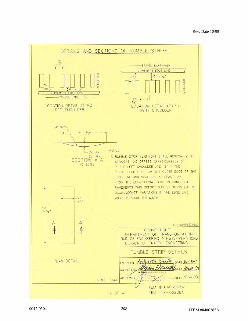
Rev. Date 10/99
ITEM #0406287A
0042-0304 208
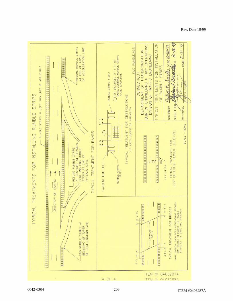
Rev. Date 10/99
ITEM #0406287A
0042-0304 209
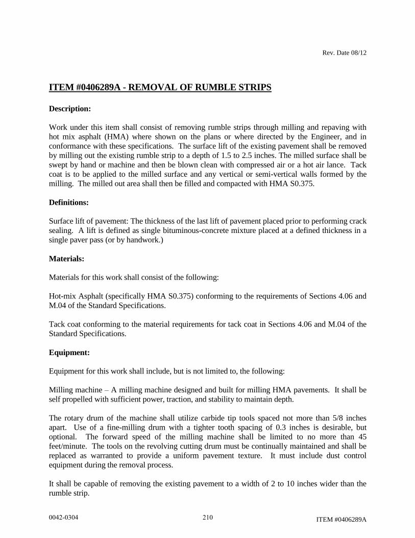
Rev. Date 08/12
ITEM #0406289A
ITEM #0406289A - REMOVAL OF RUMBLE STRIPS
Description:
Work under this item shall consist of removing rumble strips through milling and repaving with
hot mix asphalt (HMA) where shown on the plans or where directed by the Engineer, and in
conformance with these specifications. The surface lift of the existing pavement shall be removed
by milling out the existing rumble strip to a depth of 1.5 to 2.5 inches. The milled surface shall be
swept by hand or machine and then be blown clean with compressed air or a hot air lance. Tack
coat is to be applied to the milled surface and any vertical or semi-vertical walls formed by the
milling. The milled out area shall then be filled and compacted with HMA S0.375.
Definitions:
Surface lift of pavement: The thickness of the last lift of pavement placed prior to performing crack
sealing. A lift is defined as single bituminous-concrete mixture placed at a defined thickness in a
single paver pass (or by handwork.)
Materials:
Materials for this work shall consist of the following:
Hot-mix Asphalt (specifically HMA S0.375) conforming to the requirements of Sections 4.06 and
M.04 of the Standard Specifications.
Tack coat conforming to the material requirements for tack coat in Sections 4.06 and M.04 of the
Standard Specifications.
Equipment:
Equipment for this work shall include, but is not limited to, the following:
Milling machine – A milling machine designed and built for milling HMA pavements. It shall be
self propelled with sufficient power, traction, and stability to maintain depth.
The rotary drum of the machine shall utilize carbide tip tools spaced not more than 5/8 inches
apart. Use of a fine-milling drum with a tighter tooth spacing of 0.3 inches is desirable, but
optional. The forward speed of the milling machine shall be limited to no more than 45
feet/minute. The tools on the revolving cutting drum must be continually maintained and shall be
replaced as warranted to provide a uniform pavement texture. It must include dust control
equipment during the removal process.
It shall be capable of removing the existing pavement to a width of 2 to 10 inches wider than the
rumble strip.
0042-0304 210
Rev. Date 08/12
ITEM #0406289A
A wider milling width may be used in cases where two rumble strips are located near and parallel
to each other, as may occur in a median area; see Construction Methods.
Sweeper – A hand broom is acceptable for smaller areas when approved by the Engineer. If a
mechanized sweeper is used, it shall be equipped with a water tank and be capable of removing the
millings and loose debris from the surface. Other sweeping or vacuum type equipment may be
provided in lieu of the sweeper where acceptable by the Engineer.
Air compressor – The unit shall consist of an air compressor capable of producing 100 psi, oil
free, compressed air for blowing the milled pavement surface clean.
Hot air lance – The unit shall be designed for cleaning and drying the pavement surface. It shall
consist of an air compressor capable of delivering 100 psi, oil free heated air. The compressed air
emitted from the tip of the lance shall be flame free and be capable of achieving a temperature of at
least 1500°F.
Paving and compaction equipment – All equipment used to place and compact the hot mix asphalt
required for this work shall meet the requirements of Section 4.06 of the Standard Specifications,
except no grade and slope control shall be required. Also, due to the nature of this work, it is
expected that much of the placement of hot mix asphalt will require hand work. Either vibratory
plate compactors or rollers may be used for compaction.
Construction Methods:
The Contractor shall pre-mark the location of the beginning and ending points of the sections, prior
to the removal of the rumble strips. The Engineer shall review and approve the limits of removal.
The width of milling shall be as specified on the Plans or other specifications. If no other width
specification exists, the width of milling shall be 2 to 10 inches wider than the existing rumble
strip. Rumble strips are typically about 16 inches wide. If there are two rumble strips located near
and parallel to one another, as may occur in median areas, and if they both can be removed by a
single pass of a wider milling machine without adversely affecting drainage, safety, or quality of
results, then a wider milling machine may be used. In this case the length measured for pay will be
the sum of the lengths of the two individual rumble strips. Milling widths wider than specified
above may be used with the written permission of the Engineer.
The depth of removal shall be as shown on the Plans, or as detailed in specifications, or as directed
by the Engineer, generally from 1.5 to 2.5 inches. The intent is to remove the surface lift. If there
are no Plans or other specifications, mill 1.5 to 2.5 inches as needed to match the thickness of the
surface lift. The Engineer may alter the milling depth based on conditions discovered as work is in
progress. It is expected that the milling depth will not exceed 2.5 inches. If the surface lift is 3
inches thick and it is in good condition, as determined by the Engineer, mill only 1.5 inches deep,
unless directed otherwise by the Plans, project specifications, or Engineer.
0042-0304 211

Rev. Date 08/12
ITEM #0406289A
As specified in the requirements for milling, the milled surface shall be swept clean (by hand if
necessary.) Once all millings are removed by sweeping, the milled areas shall be allowed to dry if
necessary. Any moisture in or on the milled areas must be allowed to evaporate or be removed
with the assistance of a hot air lance as specified above. Once the milled area is deemed dry by the
Engineer it shall be blown with compressed or hot lance air, as specified above, so that no debris or
dust is present on or within the milled area.
Once deemed clean by the Engineer, the milled area, including the sides/walls of the milled area,
shall receive an application of tack coat as specified above and in Section 4.06 of the Standard
Specifications.
After the tack coat has had sufficient time to cure or break, HMA S0.375 (Superpave Level 2) shall
be placed and compacted to the requirements above and in Section 4.06 of the Standard
Specification. It shall be compacted to match the elevation of the surrounding pavement surface.
At all times the Contractor is required to meet the density and compaction and all other
requirements specified in Sections 4.06 and M.04 of the Standard Specifications and any
supplementals that have been issued by the bid date of the project.
The Contractor shall resurface the milled area prior to opening the roadway to traffic. The milled
area shall be swept, cleaned with compressed air, tacked and repaved in the same day.
Precaution should be taken to avoid damage to the existing roadway materials that are to remain in
place. If damage occurs, it must be repaired by the Contractor at no additional cost to the State.
The methods employed in performing the work and all equipment, tools, machinery and plant used
in handling material and executing any part of the work shall be subject to the approval of the
Engineer before the work is started; and whenever found unsatisfactory, it shall be changed and
improved as required by the Engineer.
The Contractor shall pick up any waste material resulting from the operation in a manner
acceptable to the Engineer. This waste material shall be disposed of in accordance with Subarticle
2.02.03-10(a).
Method of Measurement:
This work will be measured for payment by the actual number of linear feet of rumble strips
removed. This distance shall be measured longitudinally along the edge of pavement with
deductions for bridge decks, acceleration and deceleration lanes, drainage structures, loop detector
sawcut locations, and other sections where the rumble strips were not previously installed. If two
rumble strips are near one another and are removed by a single milling machine pass, the length
measured for pay will be the sum of the lengths of the two rumble strips.
0042-0304 212
Rev. Date 08/12
ITEM #0406289A
Basis of Payment:
This work will be paid for at the Contract unit price per linear foot for "Removal of Rumble
Strips." The price shall include the removal of the existing rumble strips, furnishing all materials,
placement, and compaction of the HMA, equipment, tools, labor, and work incidental thereto and
also disposal of any waste material resulting from the operation.
Pay item Pay Unit
Removal of Rumble Strips l.f.
0042-0304 213
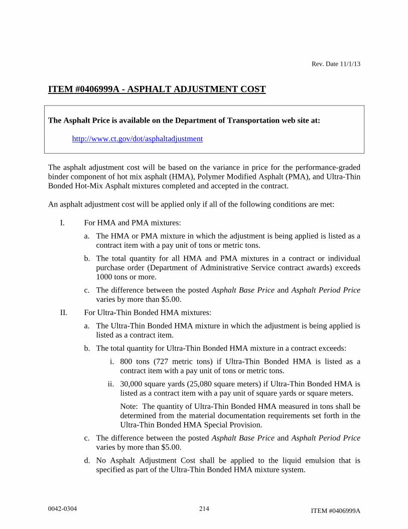
Rev. Date 11/1/13
ITEM #0406999A
ITEM #0406999A - ASPHALT ADJUSTMENT COST
The Asphalt Price is available on the Department of Transportation web site at:
http://www.ct.gov/dot/asphaltadjustment
The asphalt adjustment cost will be based on the variance in price for the performance-graded
binder component of hot mix asphalt (HMA), Polymer Modified Asphalt (PMA), and Ultra-Thin
Bonded Hot-Mix Asphalt mixtures completed and accepted in the contract.
An asphalt adjustment cost will be applied only if all of the following conditions are met:
I. For HMA and PMA mixtures:
a. The HMA or PMA mixture in which the adjustment is being applied is listed as a
contract item with a pay unit of tons or metric tons.
b. The total quantity for all HMA and PMA mixtures in a contract or individual
purchase order (Department of Administrative Service contract awards) exceeds
1000 tons or more.
c. The difference between the posted Asphalt Base Price and Asphalt Period Price
varies by more than $5.00.
II. For Ultra-Thin Bonded HMA mixtures:
a. The Ultra-Thin Bonded HMA mixture in which the adjustment is being applied is
listed as a contract item.
b. The total quantity for Ultra-Thin Bonded HMA mixture in a contract exceeds:
i. 800 tons (727 metric tons) if Ultra-Thin Bonded HMA is listed as a
contract item with a pay unit of tons or metric tons.
ii. 30,000 square yards (25,080 square meters) if Ultra-Thin Bonded HMA is
listed as a contract item with a pay unit of square yards or square meters.
Note: The quantity of Ultra-Thin Bonded HMA measured in tons shall be
determined from the material documentation requirements set forth in the
Ultra-Thin Bonded HMA Special Provision.
c. The difference between the posted Asphalt Base Price and Asphalt Period Price
varies by more than $5.00.
d. No Asphalt Adjustment Cost shall be applied to the liquid emulsion that is
specified as part of the Ultra-Thin Bonded HMA mixture system.
0042-0304 214
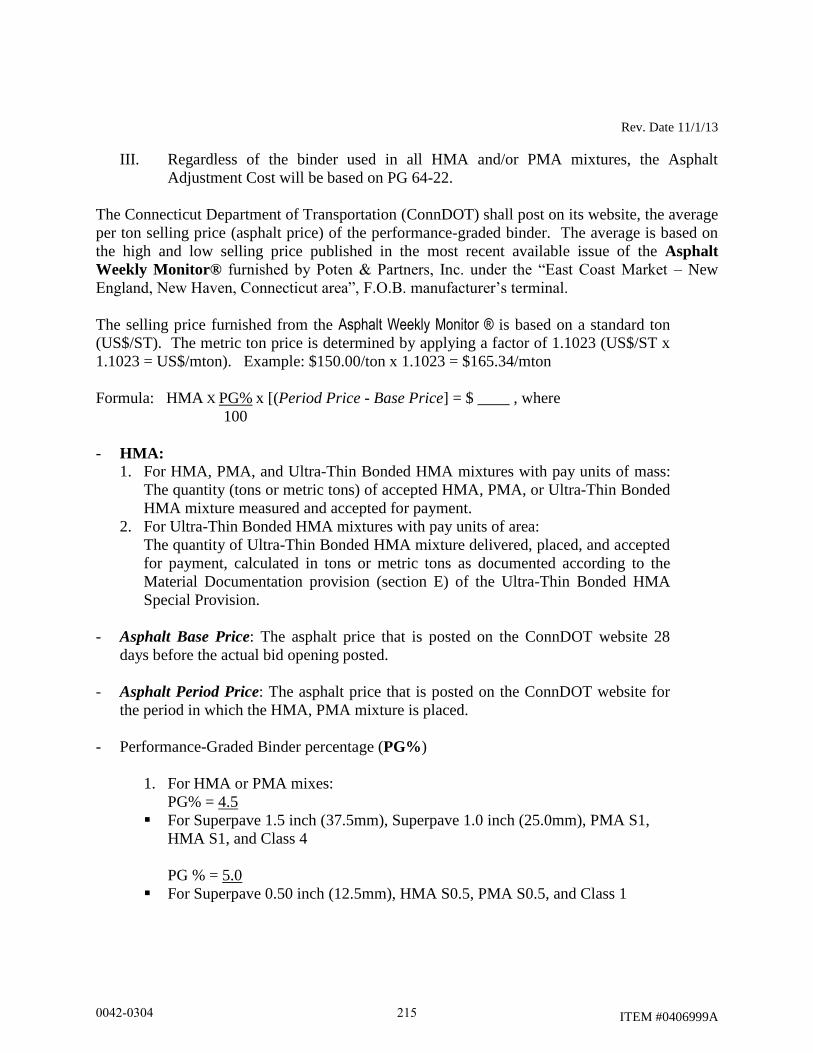
Rev. Date 11/1/13
ITEM #0406999A
III. Regardless of the binder used in all HMA and/or PMA mixtures, the Asphalt
Adjustment Cost will be based on PG 64-22.
The Connecticut Department of Transportation (ConnDOT) shall post on its website, the average
per ton selling price (asphalt price) of the performance-graded binder. The average is based on
the high and low selling price published in the most recent available issue of the Asphalt
Weekly Monitor® furnished by Poten & Partners, Inc. under the “East Coast Market – New
England, New Haven, Connecticut area”, F.O.B. manufacturer’s terminal.
The selling price furnished from the Asphalt Weekly Monitor ® is based on a standard ton
(US$/ST). The metric ton price is determined by applying a factor of 1.1023 (US$/ST x
1.1023 = US$/mton). Example: $150.00/ton x 1.1023 = $165.34/mton
Formula: HMA X PG% x [(Period Price - Base Price] = $ ____ , where
100
- HMA:
1. For HMA, PMA, and Ultra-Thin Bonded HMA mixtures with pay units of mass:
The quantity (tons or metric tons) of accepted HMA, PMA, or Ultra-Thin Bonded
HMA mixture measured and accepted for payment.
2. For Ultra-Thin Bonded HMA mixtures with pay units of area:
The quantity of Ultra-Thin Bonded HMA mixture delivered, placed, and accepted
for payment, calculated in tons or metric tons as documented according to the
Material Documentation provision (section E) of the Ultra-Thin Bonded HMA
Special Provision.
- Asphalt Base Price: The asphalt price that is posted on the ConnDOT website 28
days before the actual bid opening posted.
- Asphalt Period Price: The asphalt price that is posted on the ConnDOT website for
the period in which the HMA, PMA mixture is placed.
- Performance-Graded Binder percentage (PG%)
1. For HMA or PMA mixes:
PG% = 4.5
For Superpave 1.5 inch (37.5mm), Superpave 1.0 inch (25.0mm), PMA S1,
HMA S1, and Class 4
PG % = 5.0
For Superpave 0.50 inch (12.5mm), HMA S0.5, PMA S0.5, and Class 1
0042-0304 215
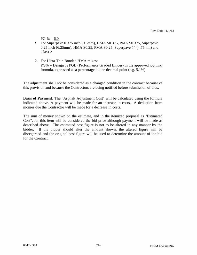
Rev. Date 11/1/13
ITEM #0406999A
PG % = 6.0
For Superpave 0.375 inch (9.5mm), HMA S0.375, PMA S0.375, Superpave
0.25 inch (6.25mm), HMA S0.25, PMA S0.25, Superpave #4 (4.75mm) and
Class 2
2. For Ultra-Thin Bonded HMA mixes:
PG% = Design % PGB (Performance Graded Binder) in the approved job mix
formula, expressed as a percentage to one decimal point (e.g. 5.1%)
The adjustment shall not be considered as a changed condition in the contract because of
this provision and because the Contractors are being notified before submission of bids.
Basis of Payment: The "Asphalt Adjustment Cost" will be calculated using the formula
indicated above. A payment will be made for an increase in costs. A deduction from
monies due the Contractor will be made for a decrease in costs.
The sum of money shown on the estimate, and in the itemized proposal as "Estimated
Cost", for this item will be considered the bid price although payment will be made as
described above. The estimated cost figure is not to be altered in any manner by the
bidder. If the bidder should alter the amount shown, the altered figure will be
disregarded and the original cost figure will be used to determine the amount of the bid
for the Contract.
0042-0304 216

Rev. Date 10/22/14
ITEM #0503151A
ITEM #0503153A
ITEM #0503154A
ITEM #0503151A - REMOVAL OF SUPERSTRUCTURE (SITE NO. 1)
ITEM #0503153A - REMOVAL OF SUPERSTRUCTURE (SITE NO. 3)
ITEM #0503154A - REMOVAL OF SUPERSTRUCTURE (SITE NO. 4)
Work under these items shall conform to the requirements of Section 5.03 of the Standard
Specifications, Form 816, amended as follows:
5.03.01 - Description: Add the following:
This work shall consist of the removal and satisfactory disposal of the existing superstructure at
Site Numbers 1, 3 and 4, as shown on the plans. The existing bridges at Site Numbers 1 and 3
consist of three simply supported steel multi girder spans with reinforced concrete decks. The
existing bridge at Site Number 4 consists of seven curved simply supported steel plate girders
composite with a reinforced concrete deck.
Record plans are available for Site Numbers 1, 3 and 4 from the Connecticut Department of
Transportation Engineering Records building located at 160 Pascone Place, Newington,
Connecticut 06111.
This work shall also include the removal of the two concrete approach slabs at Site No. 4.
5.03.03 - Construction Methods: Add the following:
All work shall proceed as directed by and to the satisfaction of the Engineer and in accordance
with the details shown on the plans, or as approved by the Engineer.
The superstructure at each site shall be dismantled in accordance with the methods proposed by
the Contractor and approved by the Engineer.
The Contractor’s method of demolition shall not result in damage to any adjacent facility or to
adjoining property. If damage does occur, it shall be repaired by the Contractor to the satisfaction
of the Engineer at no additional expense to the State.
Prior to initiating work, the Contractor shall submit for approval, plans and written
documentation describing his falsework, methods of removal and shielding required for the
protection of traffic, utilities and adjoining properties. Approval of the Contractor’s plans shall
not be considered as relieving the Contractor of any of his responsibility. Working drawings and
design computations showing the Contractor’s means and method for temporary shielding shall
be submitted to the Engineer in accordance with Section 1.05.02(2).
0042-0304 217
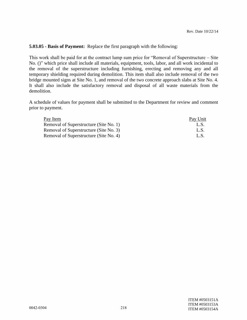
Rev. Date 10/22/14
ITEM #0503151A
ITEM #0503153A
ITEM #0503154A
5.03.05 - Basis of Payment: Replace the first paragraph with the following:
This work shall be paid for at the contract lump sum price for “Removal of Superstructure – Site
No. ()” which price shall include all materials, equipment, tools, labor, and all work incidental to
the removal of the superstructure including furnishing, erecting and removing any and all
temporary shielding required during demolition. This item shall also include removal of the two
bridge mounted signs at Site No. 1, and removal of the two concrete approach slabs at Site No. 4.
It shall also include the satisfactory removal and disposal of all waste materials from the
demolition.
A schedule of values for payment shall be submitted to the Department for review and comment
prior to payment.
Pay Item Pay Unit
Removal of Superstructure (Site No. 1) L.S.
Removal of Superstructure (Site No. 3) L.S.
Removal of Superstructure (Site No. 4) L.S.
0042-0304 218
ITEM #0506550A
ITEM #0506550A – DOWNSPOUT SPLASH PAD
Description: Work under this item shall consist of fabricating, furnishing, transporting and
installing concrete downspout splash pads where shown on the plans and in accordance with
this specification. Downspout splash pads may consist of cast-in-place or precast concrete.
Also included in this item shall be all other necessary materials and equipment required to
complete the work described in this item.
Materials: Materials for splash pads shall conform to the following requirements:
1. Concrete: Concrete shall be Class “A” Concrete conforming to Article M.03.01 of
the Standard Specifications.
2. Welded Wire Fabric: Welded wire fabric shall conform to the requirements of ASTM
A185 and shall conform to Article M.06.01 as applicable.
3. Lifting and Seating Fixtures: The Contractor / Fabricator shall be fully responsible for
the design of lifting devices. All fixtures cast into the concrete for the purpose of
lifting and seating splash pad units shall have a corrosive resistant coating.
4. Corrosive Resistant Coating: Corrosive resistant coating for lifting devices shall either
be epoxy, mechanical or hot-dip galvanizing, or electroplating.
Construction Methods: Downspout splash pads shall be constructed where indicated on the
Contract Plans, to the dimensions, details and requirements shown on the plans, or as ordered
by the Engineer. Splash pads shall be sloped a minimum of 2% or as noted on the plans.
Method of Measurement: This work shall be measured for payment by the number of
downspout splash pads constructed, installed, complete in place and accepted. Welded wire
fabric and lifting inserts will not be measured for payment but shall be included in the cost of
this item.
Basis of Payment: This work shall be paid for at the contract unit price per each for
“Downspout Splash Pad”, complete in place, which price shall include all work associated
with the furnishing, fabrication, construction and installation of downspout splash pads and
all materials, equipment, tools and labor incidental thereto.
Pay Item Pay Unit
Downspout Splash Pad EA
0042-0304 219
ITEM #0513003A
ITEM #0513003A – 1½" POLYVINYL CHLORIDE PLASTIC PIPE
Work under this item shall conform to the requirements of Section 5.13 amended as follows:
Description: Delete and replace with the following:
This item shall consist of furnishing and installing polyvinyl chloride pipe for use as drains
through the backwall at the approach slab seat where shown on the plans or as ordered by the
Engineer.
Construction Methods: Installation of drain pipes shall not result in damage to the backwall
reinforcement. If any damage does occur it shall be repaired by the Contractor to the satisfaction
of the Engineer at no additional expense to the State.
Method of Measurement: This work will be measured for payment by the number of linear feet
of pipe installed in the backwall as indicated on the plans.
Basis of Payment: This work will be paid for at the contract unit price per linear foot for 1½”
Polyvinyl Chloride Plastic Pipe, complete and accepted, which price shall include the installation
of drain pipes, repair of backwall surrounding drain pipes, and all equipment, tools and labor.
Pay Item Pay Unit
1½” Polyvinyl Chloride Plastic Pipe L.F.
0042-0304 220
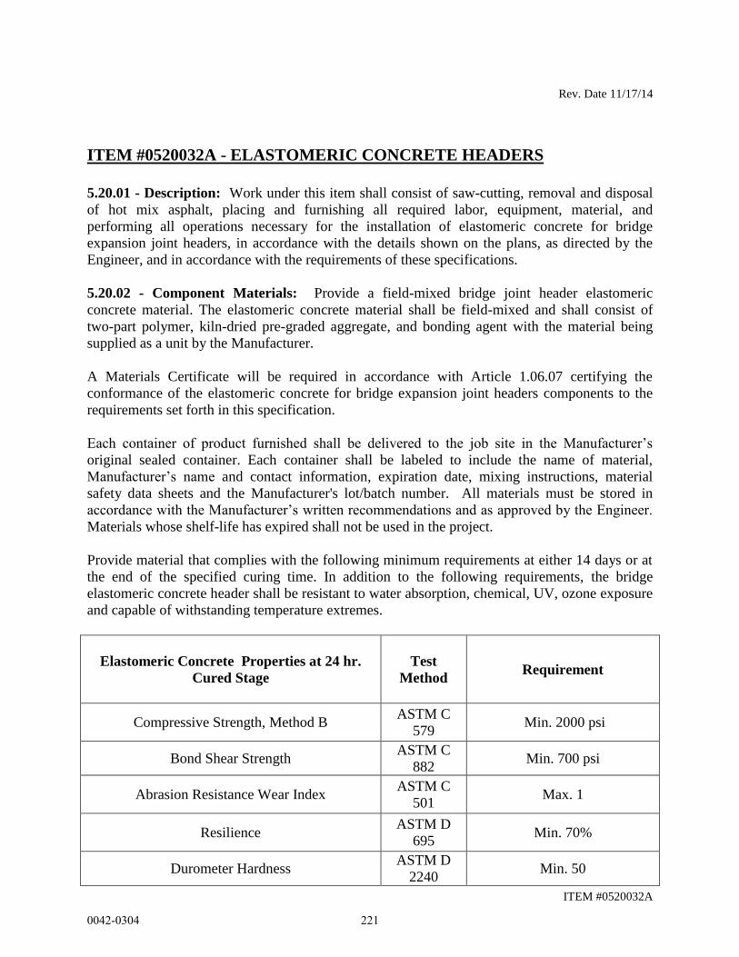
Rev. Date 11/17/14
ITEM #0520032A
ITEM #0520032A - ELASTOMERIC CONCRETE HEADERS
5.20.01 - Description: Work under this item shall consist of saw-cutting, removal and disposal
of hot mix asphalt, placing and furnishing all required labor, equipment, material, and
performing all operations necessary for the installation of elastomeric concrete for bridge
expansion joint headers, in accordance with the details shown on the plans, as directed by the
Engineer, and in accordance with the requirements of these specifications.
5.20.02 - Component Materials: Provide a field-mixed bridge joint header elastomeric
concrete material. The elastomeric concrete material shall be field-mixed and shall consist of
two-part polymer, kiln-dried pre-graded aggregate, and bonding agent with the material being
supplied as a unit by the Manufacturer.
A Materials Certificate will be required in accordance with Article 1.06.07 certifying the
conformance of the elastomeric concrete for bridge expansion joint headers components to the
requirements set forth in this specification.
Each container of product furnished shall be delivered to the job site in the Manufacturer’s
original sealed container. Each container shall be labeled to include the name of material,
Manufacturer’s name and contact information, expiration date, mixing instructions, material
safety data sheets and the Manufacturer's lot/batch number. All materials must be stored in
accordance with the Manufacturer’s written recommendations and as approved by the Engineer.
Materials whose shelf-life has expired shall not be used in the project.
Provide material that complies with the following minimum requirements at either 14 days or at
the end of the specified curing time. In addition to the following requirements, the bridge
elastomeric concrete header shall be resistant to water absorption, chemical, UV, ozone exposure
and capable of withstanding temperature extremes.
Elastomeric Concrete Properties at 24 hr.
Cured Stage
Test
Method Requirement
Compressive Strength, Method B ASTM C
579 Min. 2000 psi
Bond Shear Strength ASTM C
882 Min. 700 psi
Abrasion Resistance Wear Index ASTM C
501 Max. 1
Resilience ASTM D
695 Min. 70%
Durometer Hardness ASTM D
2240 Min. 50
0042-0304 221
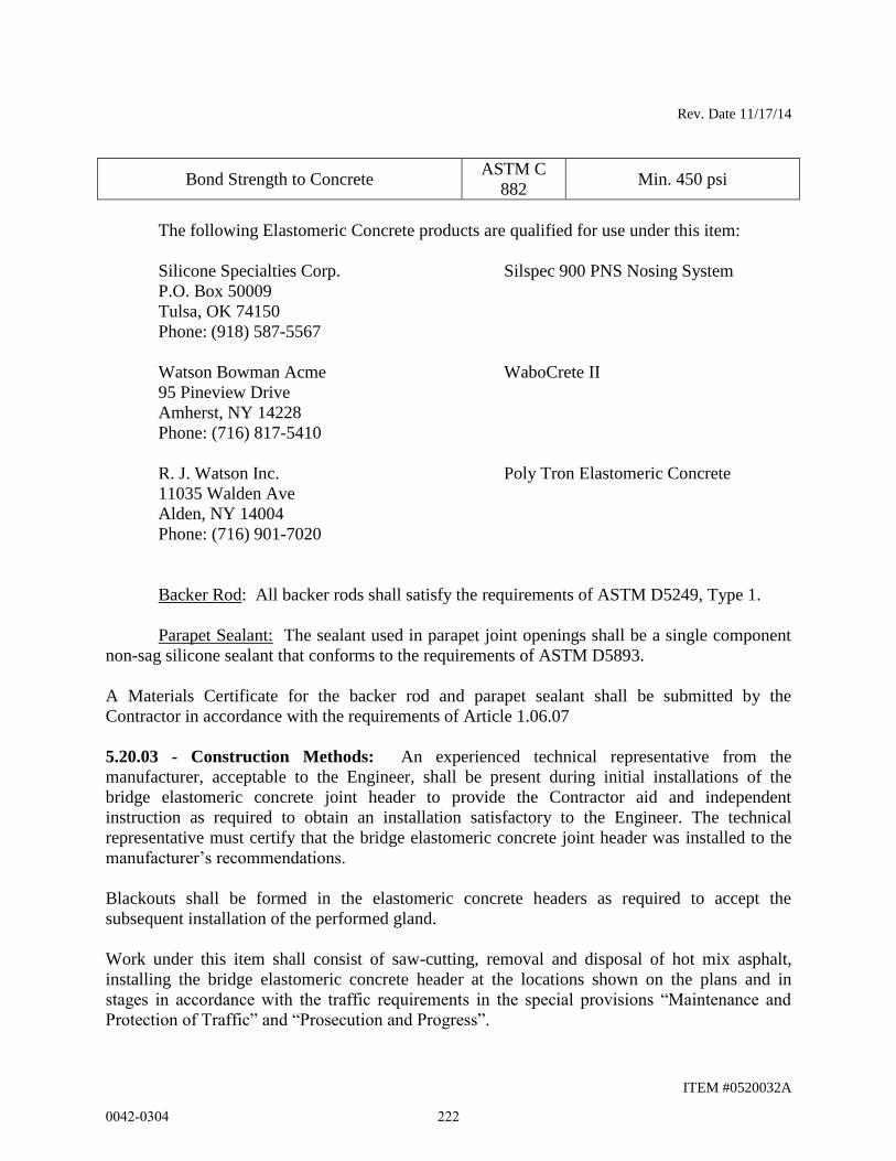
Rev. Date 11/17/14
ITEM #0520032A
Bond Strength to Concrete ASTM C
882 Min. 450 psi
The following Elastomeric Concrete products are qualified for use under this item:
Silicone Specialties Corp.
P.O. Box 50009
Tulsa, OK 74150
Phone: (918) 587-5567
Silspec 900 PNS Nosing System
Watson Bowman Acme
95 Pineview Drive
Amherst, NY 14228
Phone: (716) 817-5410
WaboCrete II
R. J. Watson Inc. Poly Tron Elastomeric Concrete
11035 Walden Ave
Alden, NY 14004
Phone: (716) 901-7020
Backer Rod: All backer rods shall satisfy the requirements of ASTM D5249, Type 1.
Parapet Sealant: The sealant used in parapet joint openings shall be a single component
non-sag silicone sealant that conforms to the requirements of ASTM D5893.
A Materials Certificate for the backer rod and parapet sealant shall be submitted by the
Contractor in accordance with the requirements of Article 1.06.07
5.20.03 - Construction Methods: An experienced technical representative from the
manufacturer, acceptable to the Engineer, shall be present during initial installations of the
bridge elastomeric concrete joint header to provide the Contractor aid and independent
instruction as required to obtain an installation satisfactory to the Engineer. The technical
representative must certify that the bridge elastomeric concrete joint header was installed to the
manufacturer’s recommendations.
Blackouts shall be formed in the elastomeric concrete headers as required to accept the
subsequent installation of the performed gland.
Work under this item shall consist of saw-cutting, removal and disposal of hot mix asphalt,
installing the bridge elastomeric concrete header at the locations shown on the plans and in
stages in accordance with the traffic requirements in the special provisions “Maintenance and
Protection of Traffic” and “Prosecution and Progress”.
0042-0304 222

Rev. Date 11/17/14
ITEM #0520032A
Elastomeric concrete is moisture sensitive. Therefore, new decks and deck ends that have been
reconstructed or patched should be properly cured. The Contractor should follow the
manufacturer’s recommendations for curing and substrate moisture before installation of
elastomeric concrete headers.
Tools, equipment, and techniques used to prepare the bridge elastomeric concrete header shall be
approved by the Engineer and the Manufacturer’s technical representative prior to the start of
construction.
Provide sufficient material in storage at the site prior to beginning construction to complete the
entire bridge elastomeric concrete header as detailed on the plans or as directed by the Engineer.
The Contractor shall saw cut the hot mix asphalt overlay full depth in order to delineate the
location of the elastomeric concrete headers. At the time of installation of the bridge elastomeric
concrete header, all existing material shall be removed from the bridge joint header. All surfaces
in the bridge header shall be cleaned of all dust, dirt, debris, and other loose materials as
recommended by the Manufacturer. The surfaces shall also be frost free. Additionally, all
bonding surfaces shall be abrasive blast cleaned. Following the abrasive blast cleaning
operations all surfaces shall again be wiped clean to remove any remaining dust.
Prepare and apply bonding agent to areas specified by Manufacturer and in accordance with
manufacturer’s instruction. The bonding agent shall be allowed to cure and undisturbed for a
minimum of one hour prior to installation of the bridge elastomeric concrete header or longer if
required by the Manufacturer or the Engineer.
The mixing and installation of the two-part bridge elastomeric concrete header shall be done in
strict conformance with the Manufacturer’s written recommendations including the use of static
mixing devices if so indicated. Traffic must not be allowed on the newly-placed bridge
elastomeric concrete header to let the material cure properly prior to opening the work area to
traffic according to the Manufacturer specification. During curing time the bridge elastomeric
concrete header should be protected from any damages.
Form, place and cast the bridge elastomeric concrete headers to smoothly match the surface of
the finished roadway. Finish the surface to a moderately rough texture such as that produce by a
wood float.
When blast cleaning is performed under this specification the Contractor shall take adequate
measures to ensure that the blast cleaning will not cause damage to adjacent traffic or other
facilities.
The parapet joint sealant shall be prepared and placed in accordance with the manufacturer's
instructions and with the equipment prescribed by the manufacturer. Extreme care shall be taken
to ensure that the sealant is placed in accordance with the manufacturer’s recommended
thickness requirements.
0042-0304 223

Rev. Date 11/17/14
ITEM #0520032A
The joint sealant shall be tooled, if required, in accordance with the manufacturer's instructions.
Primer, if required, shall be supplied by the sealant manufacturer and applied in accordance with
the manufacturer's instructions.
When the sealing operations are completed, the joints shall be effectively sealed against
infiltration of water. Any sealant which does not effectively seal against water shall be removed
and replaced at the Contractor's expense.
5.20.04 - Method of Measurement: This work will be measured for payment by the number of
cubic foot of bridge elastomeric concrete header installed into the final work, measured on the
length-basis for the material required to construct the header from face-of-curb to face-of-curb,
multiplied by the nominal header depth as indicated on the plans or as ordered by the Engineer.
Only a single measurement will be taken along each installed joint, regardless of the number of
recesses, opening or voids filled with the elastomeric concrete header material. Measurement
will be taken along the centerline of the joint, between the outer limits of the installed material.
5.20.05 - Basis of Payment: This work will be paid for at the contract unit price per cubic foot
for “Elastomeric Concrete Headers", complete in place, including the cost of saw-cutting of hot
mix asphalt overlay to delineate the vertical edges of the elastomeric concrete headers; removal
and disposal of hot mix asphalt and abrasive blast cleaning; cleaning of the bonding surfaces;
mixing, constructing and curing the elastomeric concrete headers; and the cost of all services
associated with the technical representative, furnishing all required labor, all other materials,
equipment, tools, and labor incidental thereto and perform all operations necessary for the
installation of elastomeric concrete for bridge expansion joint headers.
The silicone sealant will not be measured for payment but will be included in the contract unit
price.
Providing the Manufacturer’s Representative and the Manufacturer’s warranty will be incidental
to the item “Elastomeric Concrete Headers”.
Pay Item Pay Unit
Elastomeric Concrete Headers C.Y.
0042-0304 224
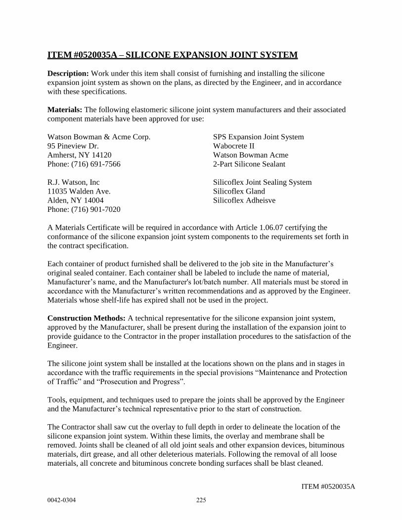
ITEM #0520035A
ITEM #0520035A – SILICONE EXPANSION JOINT SYSTEM
Description: Work under this item shall consist of furnishing and installing the silicone
expansion joint system as shown on the plans, as directed by the Engineer, and in accordance
with these specifications.
Materials: The following elastomeric silicone joint system manufacturers and their associated
component materials have been approved for use:
Watson Bowman & Acme Corp. SPS Expansion Joint System
95 Pineview Dr. Wabocrete II
Amherst, NY 14120 Watson Bowman Acme
Phone: (716) 691-7566 2-Part Silicone Sealant
R.J. Watson, Inc Silicoflex Joint Sealing System
11035 Walden Ave. Silicoflex Gland
Alden, NY 14004 Silicoflex Adheisve
Phone: (716) 901-7020
A Materials Certificate will be required in accordance with Article 1.06.07 certifying the
conformance of the silicone expansion joint system components to the requirements set forth in
the contract specification.
Each container of product furnished shall be delivered to the job site in the Manufacturer’s
original sealed container. Each container shall be labeled to include the name of material,
Manufacturer’s name, and the Manufacturer's lot/batch number. All materials must be stored in
accordance with the Manufacturer’s written recommendations and as approved by the Engineer.
Materials whose shelf-life has expired shall not be used in the project.
Construction Methods: A technical representative for the silicone expansion joint system,
approved by the Manufacturer, shall be present during the installation of the expansion joint to
provide guidance to the Contractor in the proper installation procedures to the satisfaction of the
Engineer.
The silicone joint system shall be installed at the locations shown on the plans and in stages in
accordance with the traffic requirements in the special provisions “Maintenance and Protection
of Traffic” and “Prosecution and Progress”.
Tools, equipment, and techniques used to prepare the joints shall be approved by the Engineer
and the Manufacturer’s technical representative prior to the start of construction.
The Contractor shall saw cut the overlay to full depth in order to delineate the location of the
silicone expansion joint system. Within these limits, the overlay and membrane shall be
removed. Joints shall be cleaned of all old joint seals and other expansion devices, bituminous
materials, dirt grease, and all other deleterious materials. Following the removal of all loose
materials, all concrete and bituminous concrete bonding surfaces shall be blast cleaned.
0042-0304 225

ITEM #0520035A
The bridge joint opening shall be cleaned over the total area of the blockout or openings to
receive the elastomeric concrete. The joint blockout opening, in which elastomeric concrete is to
be installed must be sound, clean, dry and the concrete substrate temperature 45 degrees
Fahrenheit or higher.
Forms shall be used to keep the elastomeric concrete from entering the open joint between the
concrete deck slab and approach slab.
The elastomeric concrete shall be mixed and placed in accordance with the Manufacturer’s
printed instructions and as provided herein. The Contractor shall furnish the Engineer with one
set of the Manufacturer’s instructions not less than one week before the placement is to begin.
The elastomeric concrete shall be installed when the temperature is 45 degrees Fahrenheit and
rising. Cure time of the elastomeric concrete may be accelerated by the use of methods and
techniques as approved by the Manufacturer when deemed necessary by the Contractor and
Engineer.
Prior to placement the elastomeric concrete, the surface of the substrate against which the
elastomeric concrete is to be placed shall be coated with a primer as recommended be the
Manufacturer. The elastomeric concrete shall be installed within 15 minutes of the mixing and
must be thoroughly consolidated and finished within 30 minutes of mixing and before the primer
has set. The elastomeric concrete shall be finished flush with the top of the adjacent roadway
surface and finished to provide a smooth surface free of voids and tears.
The elastomeric concrete may be heat cured with the use of external heat sources, as required by
the Manufacturer. Curing may require that vulcanizing heat be applied for approximately 2 to 3
hours. Traffic shall not be permitted over the joint until proper cooling of the joint has occurred
and the elastomeric concrete has developed adequate strength in accordance with the
Manufacturer’s recommendations.
Before installation of the silicone sealant, the vertical surfaces in the expansion joint opening, to
which the silicone sealant will bond, shall be cleaned of a dust, dirt, debris and other loose
materials as recommended by the Manufacturer. Additionally, the bonding surfaces shall be blast
cleaned if recommended by the Manufacturer.
Primer, if required by the Manufacturer, shall be applied to the vertical surfaces of the
elastomeric concrete on which the silicone sealant will bond. The primer shall be allowed to cure
undisturbed for a minimum of one hour prior to installation of the silicone adhesive, as required
by the Manufacturer and as directed by the Engineer.
The mixing and installation of the two-part silicone sealant should be in strict conformance with
the Manufacturer’s written recommendations. Traffic must not be allowed on the newly sealed
joint for 60 minutes after sealant installation unless otherwise specified by the Manufacturer.
0042-0304 226
ITEM #0520035A
The silicone sealant shall also be installed within the parapet using a backer rod. Following blast
cleaning, a backer rod of a diameter 25% larger than the joint opening shall be installed in the
joint opening. The backer rod shall be comprised of closed cell expanded polyethylene foam,
compatible with cold applied seals unless otherwise approved by the Manufacturer. The backer
rod shall be installed as shown on the plans.
Any portion of the Silicone Expansion Joint System that is punctured, ruptured, debonded,
delaminated, or damaged in any other way shall be removed and replaced by the Contractor at no
additional cost to the State.
All work shall be done in accordance with the special provisions for "Maintenance and
Protection of Traffic" and "Prosecution and Progress" contained elsewhere within.
Method of Measurement: This work will be measured for payment by the number of linear feet
of the Silicone Expansion Joint System, installed and accepted, by the Engineer, measured from
gutterline to gutterline, alone the centerline of the joint. Sealing of curblines shall not be
measured for payment.
Basis of Payment: This work will be paid for at the contract unit price, per linear foot, for
"Silicone Expansion Joint System", complete in place, including all materials, equipment, tools,
and labor incidental thereto.
Pay Item Pay Unit
Silicone Expansion Joint System L.F.
0042-0304 227
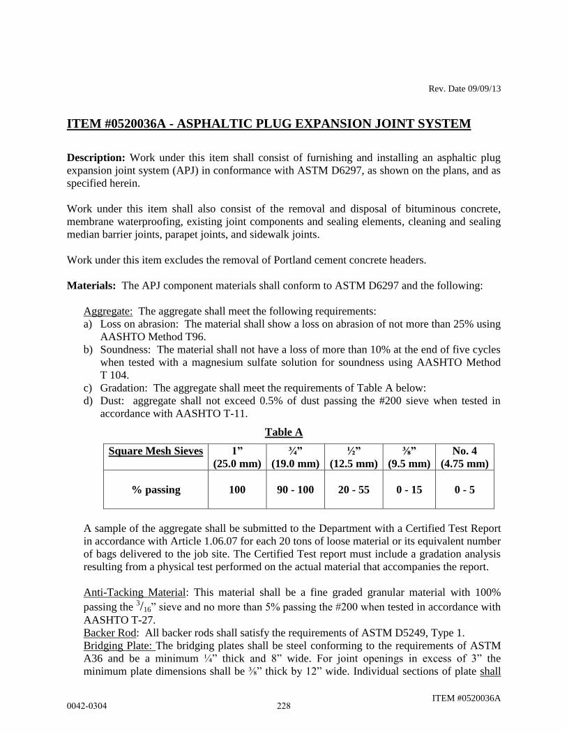
Rev. Date 09/09/13
ITEM #0520036A
ITEM #0520036A - ASPHALTIC PLUG EXPANSION JOINT SYSTEM
Description: Work under this item shall consist of furnishing and installing an asphaltic plug
expansion joint system (APJ) in conformance with ASTM D6297, as shown on the plans, and as
specified herein.
Work under this item shall also consist of the removal and disposal of bituminous concrete,
membrane waterproofing, existing joint components and sealing elements, cleaning and sealing
median barrier joints, parapet joints, and sidewalk joints.
Work under this item excludes the removal of Portland cement concrete headers.
Materials: The APJ component materials shall conform to ASTM D6297 and the following:
Aggregate: The aggregate shall meet the following requirements:
a) Loss on abrasion: The material shall show a loss on abrasion of not more than 25% using
AASHTO Method T96.
b) Soundness: The material shall not have a loss of more than 10% at the end of five cycles
when tested with a magnesium sulfate solution for soundness using AASHTO Method
T 104.
c) Gradation: The aggregate shall meet the requirements of Table A below:
d) Dust: aggregate shall not exceed 0.5% of dust passing the #200 sieve when tested in
accordance with AASHTO T-11.
Table A
Square Mesh Sieves 1”
(25.0 mm)
¾”
(19.0 mm)
½”
(12.5 mm)
⅜”
(9.5 mm)
No. 4
(4.75 mm)
% passing
100 90 - 100 20 - 55 0 - 15 0 - 5
A sample of the aggregate shall be submitted to the Department with a Certified Test Report
in accordance with Article 1.06.07 for each 20 tons of loose material or its equivalent number
of bags delivered to the job site. The Certified Test report must include a gradation analysis
resulting from a physical test performed on the actual material that accompanies the report.
Anti-Tacking Material: This material shall be a fine graded granular material with 100%
passing the 3/16” sieve and no more than 5% passing the #200 when tested in accordance with
AASHTO T-27.
Backer Rod: All backer rods shall satisfy the requirements of ASTM D5249, Type 1.
Bridging Plate: The bridging plates shall be steel conforming to the requirements of ASTM
A36 and be a minimum ¼” thick and 8” wide. For joint openings in excess of 3” the
minimum plate dimensions shall be ⅜” thick by 12” wide. Individual sections of plate shall
0042-0304 228
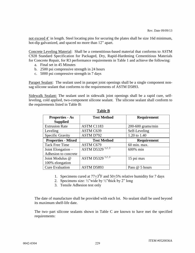
Rev. Date 09/09/13
ITEM #0520036A
not exceed 4’ in length. Steel locating pins for securing the plates shall be size 16d minimum,
hot-dip galvanized, and spaced no more than 12” apart.
Concrete Leveling Material: Shall be a cementitious-based material that conforms to ASTM
C928 Standard Specification for Packaged, Dry, Rapid-Hardening Cementitious Materials
for Concrete Repair, for R3 performance requirements in Table 1 and achieve the following:
a. Final set in 45 Minutes
b. 2500 psi compressive strength in 24 hours
c. 5000 psi compressive strength in 7 days
Parapet Sealant: The sealant used in parapet joint openings shall be a single component non-
sag silicone sealant that conforms to the requirements of ASTM D5893.
Sidewalk Sealant: The sealant used in sidewalk joint openings shall be a rapid cure, self-
leveling, cold applied, two-component silicone sealant. The silicone sealant shall conform to
the requirements listed in Table B:
Table B
Properties - As
Supplied
Test Method Requirement
Extrusion Rate ASTM C1183 200-600 grams/min
Leveling ASTM C639 Self-Leveling
Specific Gravity ASTM D792 1.20 to 1.40
Properties - Mixed Test Method Requirement
Tack Free Time ASTM C679 60 min. max.
Joint Elongation –
Adhesion to concrete
ASTM D5329 1,2 ,3
600% min
Joint Modulus @
100% elongation
ASTM D5329 1,2 ,3
15 psi max
Cure Evaluation ASTM D5893 Pass @ 5 hours
1. Specimens cured at 77+30F and 50+5% relative humidity for 7 days
2. Specimens size: ½”wide by ½”thick by 2” long
3. Tensile Adhesion test only
The date of manufacture shall be provided with each lot. No sealant shall be used beyond
its maximum shelf-life date.
The two–part silicone sealants shown in Table C are known to have met the specified
requirements:
0042-0304 229
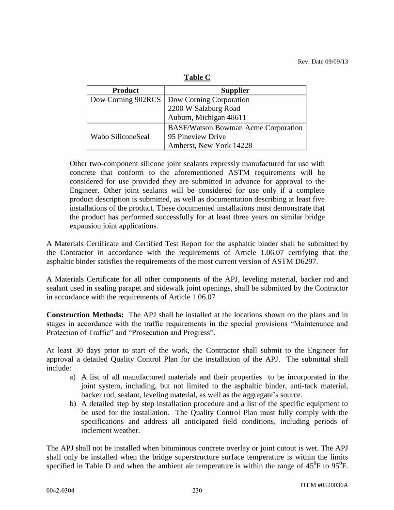
Rev. Date 09/09/13
ITEM #0520036A
Table C
Product Supplier
Dow Corning 902RCS
Dow Corning Corporation
2200 W Salzburg Road
Auburn, Michigan 48611
Wabo SiliconeSeal
BASF/Watson Bowman Acme Corporation
95 Pineview Drive
Amherst, New York 14228
Other two-component silicone joint sealants expressly manufactured for use with
concrete that conform to the aforementioned ASTM requirements will be
considered for use provided they are submitted in advance for approval to the
Engineer. Other joint sealants will be considered for use only if a complete
product description is submitted, as well as documentation describing at least five
installations of the product. These documented installations must demonstrate that
the product has performed successfully for at least three years on similar bridge
expansion joint applications.
A Materials Certificate and Certified Test Report for the asphaltic binder shall be submitted by
the Contractor in accordance with the requirements of Article 1.06.07 certifying that the
asphaltic binder satisfies the requirements of the most current version of ASTM D6297.
A Materials Certificate for all other components of the APJ, leveling material, backer rod and
sealant used in sealing parapet and sidewalk joint openings, shall be submitted by the Contractor
in accordance with the requirements of Article 1.06.07
Construction Methods: The APJ shall be installed at the locations shown on the plans and in
stages in accordance with the traffic requirements in the special provisions “Maintenance and
Protection of Traffic” and “Prosecution and Progress”.
At least 30 days prior to start of the work, the Contractor shall submit to the Engineer for
approval a detailed Quality Control Plan for the installation of the APJ. The submittal shall
include:
a) A list of all manufactured materials and their properties to be incorporated in the
joint system, including, but not limited to the asphaltic binder, anti-tack material,
backer rod, sealant, leveling material, as well as the aggregate’s source.
b) A detailed step by step installation procedure and a list of the specific equipment to
be used for the installation. The Quality Control Plan must fully comply with the
specifications and address all anticipated field conditions, including periods of
inclement weather.
The APJ shall not be installed when bituminous concrete overlay or joint cutout is wet. The APJ
shall only be installed when the bridge superstructure surface temperature is within the limits
specified in Table D and when the ambient air temperature is within the range of 450F to 95
0F.
0042-0304 230
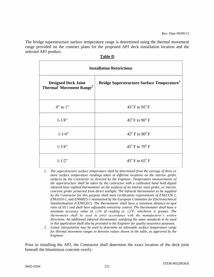
Rev. Date 09/09/13
ITEM #0520036A
The bridge superstructure surface temperature range is determined using the thermal movement
range provided on the contract plans for the proposed APJ deck installation location and the
selected APJ product.
Table D
1. The superstructure surface temperature shall be determined from the average of three or
more surface temperature readings taken at different locations on the interior girder
surfaces by the Contractor as directed by the Engineer. Temperature measurements of
the superstructure shall be taken by the contractor with a calibrated hand held digital
infrared laser-sighted thermometer on the surfaces of an interior steel girder, or interior
concrete girder protected from direct sunlight. The infrared thermometer to be supplied
by the Contractor for this purpose shall meet certification requirements of EN61326-1,
EN61010-1, and EN60825-1 maintained by the European Committee for Electrotechnical
Standardization (CENELEC). The thermometer shall have a minimum distance-to-spot
ratio of 50:1 and shall have adjustable emissivity control. The thermometer shall have a
minimum accuracy value of +1% of reading or +2oF, whichever is greater. The
thermometer shall be used in strict accordance with the manufacturer’s written
directions. An additional infrared thermometer satisfying the same standards to be used
in this application shall also be provided to the Engineer for quality assurance purposes.
2. Linear interpolation may be used to determine an allowable surface temperature range
for thermal movement ranges in between values shown in the table, as approved by the
Engineer.
Prior to installing the APJ, the Contractor shall determine the exact location of the deck joint
beneath the bituminous concrete overly.
Installation Restrictions
Designed Deck Joint
Thermal Movement Range2
Bridge Superstructure Surface Temperature1
0” to 1”
45o F to 95
o F
1-1/8”
45o F to 90
o F
1-1/4”
45o F to 80
o F
1-3/8”
45o F to 70
o F
1-1/2”
45o F to 65
o F
0042-0304 231
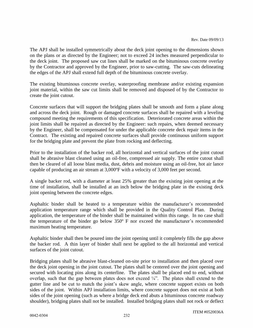
Rev. Date 09/09/13
ITEM #0520036A
The APJ shall be installed symmetrically about the deck joint opening to the dimensions shown
on the plans or as directed by the Engineer; not to exceed 24 inches measured perpendicular to
the deck joint. The proposed saw cut lines shall be marked on the bituminous concrete overlay
by the Contractor and approved by the Engineer, prior to saw-cutting. The saw-cuts delineating
the edges of the APJ shall extend full depth of the bituminous concrete overlay.
The existing bituminous concrete overlay, waterproofing membrane and/or existing expansion
joint material, within the saw cut limits shall be removed and disposed of by the Contractor to
create the joint cutout.
Concrete surfaces that will support the bridging plates shall be smooth and form a plane along
and across the deck joint. Rough or damaged concrete surfaces shall be repaired with a leveling
compound meeting the requirements of this specification. Deteriorated concrete areas within the
joint limits shall be repaired as directed by the Engineer: such repairs, when deemed necessary
by the Engineer, shall be compensated for under the applicable concrete deck repair items in the
Contract. The existing and repaired concrete surfaces shall provide continuous uniform support
for the bridging plate and prevent the plate from rocking and deflecting.
Prior to the installation of the backer rod, all horizontal and vertical surfaces of the joint cutout
shall be abrasive blast cleaned using an oil-free, compressed air supply. The entire cutout shall
then be cleared of all loose blast media, dust, debris and moisture using an oil-free, hot air lance
capable of producing an air stream at 3,000ºF with a velocity of 3,000 feet per second.
A single backer rod, with a diameter at least 25% greater than the existing joint opening at the
time of installation, shall be installed at an inch below the bridging plate in the existing deck
joint opening between the concrete edges.
Asphaltic binder shall be heated to a temperature within the manufacturer’s recommended
application temperature range which shall be provided in the Quality Control Plan. During
application, the temperature of the binder shall be maintained within this range. In no case shall
the temperature of the binder go below 350º F nor exceed the manufacturer’s recommended
maximum heating temperature.
Asphaltic binder shall then be poured into the joint opening until it completely fills the gap above
the backer rod. A thin layer of binder shall next be applied to the all horizontal and vertical
surfaces of the joint cutout.
Bridging plates shall be abrasive blast-cleaned on-site prior to installation and then placed over
the deck joint opening in the joint cutout. The plates shall be centered over the joint opening and
secured with locating pins along its centerline. The plates shall be placed end to end, without
overlap, such that the gap between plates does not exceed ¼”. The plates shall extend to the
gutter line and be cut to match the joint’s skew angle, where concrete support exists on both
sides of the joint. Within APJ installation limits, where concrete support does not exist at both
sides of the joint opening (such as where a bridge deck end abuts a bituminous concrete roadway
shoulder), bridging plates shall not be installed. Installed bridging plates shall not rock or deflect
0042-0304 232
Rev. Date 09/09/13
ITEM #0520036A
in any way. After installation of bridging plates, a thin layer of asphaltic binder shall be applied
to all exposed surfaces of the plates.
The remainder of the joint cutout shall then be filled with a mixture of hot asphaltic binder and
aggregate prepared in accordance with the submitted Quality Control Plan and the following
requirements:
The aggregate shall be heated in a vented, rotating drum mixer by the use of a hot-
compressed air lance to a temperature of between 370° F. to 380° F. This drum mixer
shall be dedicated solely for the heating and, if necessary, supplemental cleaning of the
aggregate. Venting of the gas and loose dust particles shall be accomplished through ¼”
drilled holes spaced no more than 3” on center in any direction along the entire outside
surface of the drum
Once the aggregate has been heated, it shall then be transferred to a secondary drum
mixer where it shall be fully coated with asphaltic binder. A minimum of two gallons
of binder per 100lbs of stone is required.
The temperature of the aggregate and binder shall be monitored by the contractor with a
calibrated digital infrared thermometer.
The coated aggregate shall be loosely placed in the joint cutout in lifts not to exceed 2
inches.
Each lift shall be leveled, compacted and then flooded with hot asphaltic binder to the
level of the aggregate to fill all voids in the coated aggregate layer. The surface of each
lift shall be flooded until only the tips of the aggregate protrude out of the surface.
The final lift shall be placed such that no stones shall project above the level of the
adjacent overlay surface following compaction of the coated aggregate.
Following installation of the final lift, sufficient time and material shall be provided to
allow all voids in the mixture to fill. This step may be repeated as needed.
The joint shall then be top-dressed by heating the entire area with a hot-compressed air
lance and applying binder. The final joint surface must be smooth with no protruding
stones and be absent of voids.
Once top-dressed, the joint shall have an anti-tack material spread evenly over the
entire surface to prevent tracking.
The Contractor shall be responsible for removing all binder material that leaks through the joint
and is deposited on any bridge component, including underside of decks, headers, beams,
diaphragms, bearings, abutments and piers.
Traffic shall not be permitted over the joint until it has cooled to 130º F when measured with a
digital infrared thermometer. Use of water to cool the completed joint is permitted.
Sidewalk, parapet, and/or curb joint openings
Before placement of any sealing materials in parapets, curbs, or sidewalks, the joints shall be
thoroughly cleaned of all scale, loose concrete, dirt, dust, or other foreign matter by abrasive
blast cleaning. Residual dust and moisture shall then be removed by blasting with oil free
0042-0304 233

Rev. Date 09/09/13
ITEM #0520036A
compressed air using a hot air lance. Projections of concrete into the joint space shall also be
removed. The backer rod shall be installed in the joint as shown on the plans. The joint shall be
clean and dry before the joint sealant is applied. Under no circumstances is the binder material
to be used as a substitute for the joint sealant.
Whenever abrasive blast cleaning is performed under this specification, the Contractor shall take
adequate measures to ensure that the abrasive blast cleaning will not cause damage to adjacent
traffic or other facilities.
The joint sealant shall be prepared and placed in accordance with the manufacturer's instructions
and with the equipment prescribed by the manufacturer. Extreme care shall be taken to ensure
that the sealant is placed in accordance with the manufacturer’s recommended thickness
requirements.
The joint sealant shall be tooled, if required, in accordance with the manufacturer's instructions.
Primer, if required, shall be supplied by the sealant manufacturer and applied in accordance with
the manufacturer's instructions.
When the sealing operations are completed, the joints shall be effectively sealed against
infiltration of water. Any sealant which does not effectively seal against water shall be removed
and replaced at the Contractor's expense.
Any installed joint that exhibits evidence of failure, as determined by the Engineer, such as
debonding, cracking, rutting, or shoving of the APJ mixture shall be removed and replaced full-
width and full–depth to a length determined by the Engineer at no additional cost to the State.
Method of Measurement: This work will be measured for payment by the number of cubic feet
of “Asphaltic Plug Expansion Joint System” installed and accepted within approved horizontal
limits. No additional measurement will be made for furnishing and installing backer rod and
joint sealant in the parapets, concrete medians, curbs and/or sidewalks.
Basis of Payment: This work will be paid for at the contract unit price per cubic foot for
"Asphaltic Plug Expansion Joint System," complete in place, which price shall include the saw-
cutting, removal and disposal of bituminous concrete, membrane waterproofing, existing joint
components and sealing elements, the furnishing and placement of the leveling compound,
cleaning of the joint surfaces, furnishing and installing bridging plates, the furnishing and
installing of the asphaltic plug joint mixture, the cost of furnishing and installing joint sealant in
the parapets, concrete medians, curbs and sidewalks, and all other materials, equipment
including, but not limited to, portable lighting, tools, and labor incidental thereto. No additional
payment shall be made for the 12” wide bridging plates that are required for deck joint openings
with widths in excess of 3”.
If directed by the Engineer, additional deck repairs will be addressed and paid for under the
applicable concrete deck repair items in the Contract.
0042-0304 234
Rev. Date 11/17/14
ITEM #0520038A
ITEM #0520038A – PREFORMED SILICONE JOINT SEALING SYSTEM
5.20.01 - Description: Work under this item shall consist of furnishing and installing a
preformed silicone joint sealing system as shown on the Contract Drawings and in conformance
with these specifications or as directed by the Engineer. The preformed silicone joint sealing
system shall seal the deck surface and prevent water from seeping through the joint area.
5.20.02 - Materials:
1 - Acceptable Manufacturer: The Manufacturer supplying the Preformed Silicone Joint
Sealing System shall be:
RJ Watson, Inc
Bridge and Structural Engineered Systems
78 John Glen Drive
Amherst, New York 14228
Tel: (716) 691-3301 Fax: (716) 691-3305
Web site: http://www.rjwatson.com
Models: SF400 (Site No. 3 and Site No. 4)
5.20.03 - Construction Methods:
A technical representative of the Preformed Silicone Joint Sealing System approved by the
Manufacturer shall be notified of the scheduled installation a minimum of 2 weeks in advance
and be present to provide direction and assistance for the first joint installation and succeeding
joint installations until the Contractor becomes proficient in the work and to the satisfaction of
the Engineer. The Preformed Silicone Joint Sealing System shall be completely installed
following the recommended procedures by its Manufacturer.
The Preformed Silicone Joint Sealing System shall be installed at the locations shown on the
plans and in conformance with the traffic staging requirements specified in the special provisions
“Maintenance and Protection of Traffic” and “Prosecution and Progress”.
Tools, equipment, and techniques used to prepare the joints shall be approved by the Engineer
and the Manufacturer's technical representative prior to the start of construction.
The minimum temperature for installing the Preformed Silicone Joint Seal is 40 degrees
Fahrenheit and rising ambient air temperature. The joint surface shall be completely dry before
installing the Preformed Silicone Joint Seal. The Preformed Silicone Joint Seal shall not be
installed immediately after precipitation or if precipitation is forecasted for the day. Joint
preparation and installation of the Preformed Silicone Joint Seal must be done during the same
day. Traffic will not be allowed to pass over the joint after sandblasting has occurred.
0042-0304 235
Rev. Date 11/17/14
ITEM #0520038A
5.20.04 - Method of Measurement: This work will be measured for payment by the number of
linear feet of Preformed Silicone Joint Sealing System installed. The measurement will be made
at the top surface and along the centerline of the joint measured from gutter line to gutter line.
5.20.05 - Basis of Payment: This work will be paid for at the contract unit price per linear foot
for "Preformed Silicone Joint Sealing System", complete in place all materials, equipment, tools,
and labor incidental to both constructions. The price for this work shall also include the cost for
all services associated with the technical representative from the Manufacturer of the Preformed
Silicone Joint Sealing System.
Pay Item Pay Unit
Preformed Silicone Joint Sealing System L.F.
0042-0304 236
ITEM #0521003A
ITEM #0521003A – BEARING REPLACEMENT WITH ELASTOMERIC
BEARING PADS
Description: Work under this item shall consist of removal and disposal of the existing bearings
in accordance with the plans, as directed by the Engineer and these specifications.
Materials: See Item “Steel-Laminated Elastomeric Bearings”.
Construction Methods: Existing bearings assemblies shall be removed in their entirety and
properly disposed of off-site, including the removal of the top of the existing anchor bolts.
Removal of the existing bronze bearing assemblies shall be by methods that do not damage them.
The Engineer shall determine the salvagability of the bearing assemblies and direct the
contractor to salvage or dispose of them accordingly. The salvage or proper disposal of the
bearing assemblies shall be included in the cost of the item. If the Engineer determines that the
bearing assemblies shall be salvaged, they shall be properly stored until they are delivered to the
specified DOT salvage facility. Since lead paste may be present under the existing bearings, the
use of flame cutting equipment to cut the swedge bolts is not allowed. The method of removal
shall be by sawing of the bolts unless another method is approved by the Engineer.
Tarps shall be used by the Contractor to prevent debris from the work operations from falling
onto the ground. This debris shall be disposed of properly under the applicable contract items.
The Contractor shall remove any existing guide angles welded to the bottom flange and dispose
of them accordingly.
The Engineer will inspect the concrete bearing pads before the installation of the
elastomeric bearings. Portions of protruding anchor bolts shall be cut off below the surface of the
concrete and the holes filled in with non-shrink grout. All other cracks, spalls, or deterioration shall
be repaired as determined by the Engineer.
The concrete bearing pads shall have smooth, even, and level surfaces. They shall show no
variation from a true plane greater than 1/16 inches over the entire area upon which the
elastomeric bearings are to rest. The Contractor shall grind the concrete as required to achieve
these requirements.
The Contractor shall provide the Engineer with safe access to the work for inspection purposes.
Method of Measurement: This work shall be measured for payment by the actual number of
bearing locations adequately prepared for the installation of new steel-laminated elastomeric
bearings.
Basis of Payment: This work shall be paid for at the contract unit price each for "Bearing
Replacement with Elastomeric Bearing Pads" complete, in place and accepted, which price shall
include but not limited to disposal or salvage of the existing bearings, and all materials,
equipment, tools and labor incidental thereto, including removal of existing welded guide angles.
0042-0304 237
ITEM #0521003A
Pay Item Pay Unit
Bearing Replacement with Elastomeric Bearing Pads EA
0042-0304 238
Rev. Date 7/17/2014
ITEM #0521014A
ITEM #0521014A – STEEL-LAMINATED ELASTOMERIC BEARINGS
5.21.01 - Description: Work under this item shall consist of furnishing and installing steel-
laminated elastomeric bearings as shown on the plans, as directed by the Engineer and in accor-
dance with these specifications.
5.21.02 - Materials:
1. Elastomer: The elastomer shall be Grade 3 Virgin Neoprene (polychloroprene) with
Shore “A” Durometer hardness as shown on the plans and conforming to the
requirements of the AASHTO Standard Specifications for Highway Bridges, Division II
- Construction. Elastomer shall have shear modulus as indicated on the Contract Plans
when measured using the apparatus and procedure described in Annex A of ASTM
D4014.
2. Steel Laminae: The internal steel laminae shall be mild rolled steel conforming to
ASTM A570, Grade 36 or 40, ASTM A611, Grade C or D, or an approved equal.
Laminae shall be sandblasted and cleaned of all surface coatings, rust and mill scale
before bonding and shall be free of sharp edges and burrs. Steel laminae shall develop
minimum peel strength of 473 lb/ft when tested in accordance with ASTM D429
Method B.
3. External Load Plates (if indicated on the plans): The external load plates shall conform
to AASHTO M270, Grade 50WT2. Bonding surface of the external load plates shall be
abrasive blast cleaned prior to be being hot bonded to the bearing during vulcanization.
Adhesive bonding of the load plate surface to the elastomer is not allowed.
4. Fabrication and Fabrication Tolerances: The fabrication and fabrication tolerances of
elastomeric bearings shall conform to the requirements of the AASHTO LRFD Bridge
Construction Specifications (3rd
Edition) with 2010 and 2011 Interim Revisions.
If guide pins or other devices are used to control the side cover over the steel laminae,
any exposed portions of the steel laminae shall be sealed by vulcanized patching.
5. Testing: The materials for the elastomeric bearing and the finished bearings themselves
shall be subjected to testing. The testing shall conform to the requirements of the
AASHTO LRFD Bridge Construction Specifications (3rd
Edition) with 2010 and 2011
Interim Revisions.
Test bearings, in addition to the bearings shown on the plans, shall be furnished for each
type (size and thickness) of bearing for destructive testing. The test bearings shall be
furnished without external load plates.
0042-0304 239
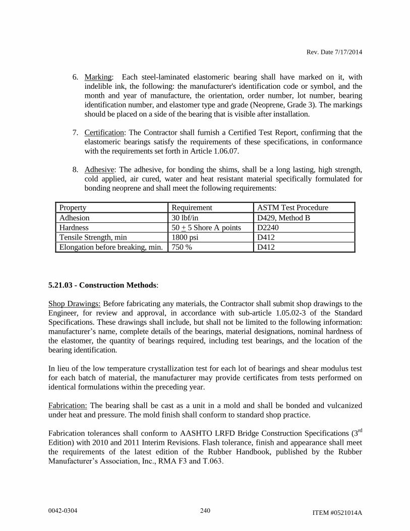
Rev. Date 7/17/2014
ITEM #0521014A
6. Marking: Each steel-laminated elastomeric bearing shall have marked on it, with
indelible ink, the following: the manufacturer's identification code or symbol, and the
month and year of manufacture, the orientation, order number, lot number, bearing
identification number, and elastomer type and grade (Neoprene, Grade 3). The markings
should be placed on a side of the bearing that is visible after installation.
7. Certification: The Contractor shall furnish a Certified Test Report, confirming that the
elastomeric bearings satisfy the requirements of these specifications, in conformance
with the requirements set forth in Article 1.06.07.
8. Adhesive: The adhesive, for bonding the shims, shall be a long lasting, high strength,
cold applied, air cured, water and heat resistant material specifically formulated for
bonding neoprene and shall meet the following requirements:
Property Requirement ASTM Test Procedure
Adhesion 30 lbf/in D429, Method B
Hardness 50 + 5 Shore A points D2240
Tensile Strength, min 1800 psi D412
Elongation before breaking, min. 750 % D412
5.21.03 - Construction Methods:
Shop Drawings: Before fabricating any materials, the Contractor shall submit shop drawings to the
Engineer, for review and approval, in accordance with sub-article 1.05.02-3 of the Standard
Specifications. These drawings shall include, but shall not be limited to the following information:
manufacturer’s name, complete details of the bearings, material designations, nominal hardness of
the elastomer, the quantity of bearings required, including test bearings, and the location of the
bearing identification.
In lieu of the low temperature crystallization test for each lot of bearings and shear modulus test
for each batch of material, the manufacturer may provide certificates from tests performed on
identical formulations within the preceding year.
Fabrication: The bearing shall be cast as a unit in a mold and shall be bonded and vulcanized
under heat and pressure. The mold finish shall conform to standard shop practice.
Fabrication tolerances shall conform to AASHTO LRFD Bridge Construction Specifications (3rd
Edition) with 2010 and 2011 Interim Revisions. Flash tolerance, finish and appearance shall meet
the requirements of the latest edition of the Rubber Handbook, published by the Rubber
Manufacturer’s Association, Inc., RMA F3 and T.063.
0042-0304 240
Rev. Date 7/17/2014
ITEM #0521014A
Every bearing shall be visually inspected for compliance with dimensional tolerance and for
overall quality of manufacture. Buffing, cutting, or other attempt to alter the size of the bearings,
for the purpose of meeting the tolerances stated herein will not be permitted. Adhesive bonding of
the elastomeric bearings to steel and concrete surfaces is not permitted.
Each elastomeric bearing pad shall have embossed on it the following: the word “CONN”,
project number, manufacturer’s identification code or symbol, and the month and year of
manufacture. The bearing shall also have stenciled on it, with indelible ink, the lot number,
bridge number, and the bearing number. The marking shall be placed on a side of the bearing
that is visible after installation.
For structures requiring less than fifty pads, one test pad shall be furnished. For structures
requiring more than fifty pads, one test pad shall be furnished for each additional fifty pads or
part thereof. If there are two or more types of pads in one structure, and only one test pad is
required, the pad will be furnished for the type of which there are the greater numbers. All test
pads shall be furnished without charge.
The same firm shall manufacture all of the elastomeric bearing pads to be installed on this
structure.
The manufacturer shall furnish facilities for the test and inspection for the completed bearing in
its plant or at the independent test facility and the inspectors shall be allowed free access to the
manufacturer’s plant and test facility.
Short-Duration Compression Test: Each bearing shall be tested as follows for a Short-Duration
Compression Test:
1. The Bearing shall be loaded in compression to 1.5 times the design load shown on the
plans. The load shall be held constant for 5 minutes, removed and reapplied for
another 5 minutes.
2. The bearing shall be carefully examined while under the second loading.
3. If the bulging pattern indicates lamina parallelism of layer thickness outside of
specified tolerance, or poor lamina bond, the bearing shall be rejected. If there are
three or more separate surface cracks greater than 1/16” wide and
1/16” deep, the
bearing shall be rejected.
A Certified Test Report in accordance with Section 1.06.07 of the Standard Specifications shall
be required for the specified test on the elastomer and for the specified short duration tests.
Installation: Bearing areas of the masonry upon which the elastomeric bearing pads are to be placed
shall be cleaned of all debris. Bearing areas shall be carefully finished, by grinding if necessary, to a
smooth, even, level surface of the required elevation, and shall show no variations from a true plane
greater than 1/16 inch over the entire area upon which the elastomeric bearing pads are to rest.
0042-0304 241
Rev. Date 7/17/2014
ITEM #0521014A
There shall be full contact and uniform bearing between the elastomeric bearing pad and the
concrete seat after application of full dead load. Also after application of full dead load, there
shall be uniform deflection of the elastomeric bearing pad.
The elastomeric bearings shall be installed as shown on the plans. The elastomeric bearings shall be
installed when the ambient air temperature is between forty (40) and eighty five (85) degrees
Fahrenheit and has been within this range for at least 2 hours.
In no case shall the elastomer or the vulcanized bond be subjected or exposed to temperatures
greater than four hundred (400) degrees Fahrenheit.
Assembly with high strength bolts shall conform to the requirements of Article 6.03.
5.21.04 - Method of Measurement:
This work will be measured by the number of each elastomeric bearing assemblies installed as
shown on the plans, conforming to the details and specifications and as accepted by the Engineer.
No allowance shall be made for test bearings.
5.21.05 -Basis of Payment:
This work will be paid for at the contract unit price for each "Steel-Laminated Elastomeric Bear-
ings", complete in place, which price shall include all vulcanized external load plates, test bearings
and all materials, testing, equipment, tools and labor incidental thereto.
Pay Item Pay Unit
Steel-Laminated Elastomeric Bearings EA
0042-0304 242
ITEM #0522178A
ITEM #0522178A – CONSTRUCT CONCRETE KEEPER BLOCKS
Description: Work under this item shall consist of constructing a concrete keeper block including
roughening of existing concrete, furnishing and placing of reinforcing steel and steel keeper plates
included welded studs, and concrete. Where called for in the plans the Contractor shall also drill
and grout reinforcing steel into the concrete substructure. The Contractor shall perform work as
indicated on the plans, in accordance with this special provision, and as directed by the Engineer.
Materials: The materials shall conform to the following requirements:
1. The steel keeper plates shall conform to ASTM A36. Steel for welded studs shall
conform to the requirements of Subarticle M.06.02-12.
2. Where drilling of holes is called for in the plans, the chemical anchor material shall
be a resin compound specially formulated to anchor steel bars in holes drilled into
concrete for the purpose of resisting tension pull-out. The chemical anchor material
shall conform to Subarticle M.03.01-15 of the Standard Specifications and be
selected from the Department’s Qualified Products List.
3. Concrete shall be a Contractor design mix which achieves a minimum 28 day
strength of 4400 psi.
4. Reinforcement shall conform to ASTM A615, Grade 60 and uncoated.
5. The steel keeper plate assembly including plate and welded studs shall be galvanized
after fabrication in accordance with ASTM A123.
6. Welding details, procedures and testing methods shall conform to the latest
ANSI/AASHTO/AWS D1.5: Bridge Welding Code, unless otherwise notes.
In lieu of a Contractor designed concrete mix, the Contractor may at no additional cost to the State,
submit for approval one of the following bagged repair mortars:
Emaco T415 Rapid Strength Repair Mortar
Manufactured by: BASF Building Systems
889 Valley Park Drive
Shakopee, MN 55379
Emaco T430 Rapid Strength Repair Mortar
Manufactured by: BASF Building Systems
889 Valley Park Drive
Shakopee, MN 55379
0042-0304 243
ITEM #0522178A
Rapid Set DOT Repair Mortar
Manufactured by: CTS Cement Manufacturing Corporation
11065 Knott Avenue, Suite A
Cypress, CA 90630
Five Star Structural Concrete V/O
Manufactured by: Five Star Products Inc.
750 Commerce Drive
Fairfield, CT 06825
The concrete repair mortar shall be extended with aggregate in accordance with and meeting the
requirements of the manufacturer recommendations.
If one of the concrete repair mortars is selected for use, 4” x 8” test cylinders shall be used for
testing in conformance with the Standard Specifications.
A Materials Certificate shall be required for the chemical anchor material, cementitious mortar and
the steel keeper plates in accordance with Article 1.06.07, certifying the conformance of these
materials to the requirements stated herein.
All materials shall be approved by the Engineer before use.
Construction Methods: Before fabricating any materials, the Contractor shall submit shop
drawings to the Engineer for review in accordance with Article 1.05.02.
These drawings shall include but not be limited to the following:
1. Location and sizes of all reinforcing steel including splice lengths, steel plates and studs,
2. Material lists.
3. Material designations.
4. Type of drill.
5. Diameter of bit.
6. Method of cleaning holes.
7. Method of placement of the chemical anchor material.
0042-0304 244
ITEM #0522178A
Specifications and recommendations for the aforementioned may be obtained from the
manufacturer of the chemical anchor material. The weight of the drill shall not exceed 20 pounds.
The anchor bolts shall be able to develop a pull-out resistance of 90 percent of their nominal yield
strength when bonded at the embedment depths provided.
The Contractor shall design, furnish, install and remove temporary demolition shields to prevent
debris from dropping below as directed by the Engineer. The Contractor shall submit working
drawings to the Engineer in accordance with Section 1.05.02. The debris shield shall remain in
place during construction until the Engineer determines it is no longer needed. The Contractor is
responsible for the integrity and maintenance of the shield during their use. Any repairs to the shield
shall be at no cost to the State.
All debris shall be removed from the shields daily and be disposed of, from the site, by the
Contractor.
The Contractor shall install the keeper blocks after the two adjacent elastomeric bearings have been
installed.
The surface on which the concrete keeper is to be poured shall be intentionally roughened to a depth
of ¼ inch and wetted. There shall be no standing water on the surface. Mixing, placing, curing, and
finishing of the concrete shall be in accordance with Article 6.01.03.
Where called for in the plans holes shall be drilled into the concrete at the locations shown on the
plans.
The depth and diameter of each hole shall be as shown on the plans. If the diameter of a hole is not
shown, the diameter of the hole shall conform to the manufacturer's recommendations for the
diameter of the rod or bolt being anchored.
Drilling methods shall not cause spalling, cracking, or other damage to the concrete. Those areas
damaged by the Contractor shall be repaired by him in a manner suitable to the Engineer and at no
expense to the State.
If existing reinforcing bars are encountered during the drilling operation, the hole shall be relocated
to clear the existing reinforcing as directed by the Engineer. Uncompleted holes shall be filled with
the chemical anchor material and finished smooth to the contour of the surrounding concrete
surface. Care shall be taken not to damage exposed reinforcing bars.
The Contractor shall not core holes into the substructure.
Before placing the chemical anchoring material in the holes, the holes shall be cleaned of all dirt,
moisture, concrete dust and other foreign material. The reinforcing steel and chemical anchor
material shall be installed in the holes in accordance with the manufacturer's recommendations.
0042-0304 245

ITEM #0522178A
Fabrication and placement of reinforcing steel shall conform to the requirements of Article 6.02.03.
The installation of welded studs shall be in accordance with the requirements of Article 5.08.03.
Mixing, placing, curing, and finishing of the Contractor designed concrete shall be in accordance
with Article 6.01.03. If a bagged repair mortar is to be used, the concrete surface preparation, mix,
placement and curing shall be done in accordance with the manufacturer’s recommendations and in
accordance with Article 6.01.03.
The Contractor, as directed by the Engineer, shall take adequate precautions to prevent any
materials from dropping to the areas below which may result in damage to any existing
construction, traffic or to adjoining property. Should any damage occur as a result of the
Contractor's operations, the Contractor shall repair and/or replace any such damage to the
satisfaction of the Engineer at no cost to the State.
At no time during the Contractor's work will interruption in traffic carried by the structure be
permitted solely as a result of constructing the keeper block.
Method of Measurement: This work will be measured for payment by the number of concrete
keeper blocks, as described above, completed and accepted by the Engineer.
Basis of Payment: This work will be paid for at the contract unit price each for "Construct
Concrete Keeper Blocks", complete in place, which price shall include drilling and grouting
reinforcing steel, furnishing and placing reinforcing steel, keeper steel plates and welded studs,
concrete or bagged repair mortar, debris shield, access and all materials, equipment, tools and
labor incidental thereto.
0042-0304 246
Rev. Date 12/12/14
ITEM #0601045A
ITEM #0601045A – RECONSTRUCT BRIDGE ENDBLOCK
6.01.01 - Description: Work under this item shall consist of sawcutting, removing portions of
existing concrete and granite curbing, and then reconstructing bridge endblocks, in accordance with
the plans and as directed by the Engineer.
6.01.02 - Materials: Materials for the reconstruction of endblocks shall conform to the following:
1) Concrete: Concrete for constructing endblocks shall be Class “F” Concrete conforming to
Section M.03.01. The minimum compressive strength shall be 4400 psi.
2) Reinforcing Steel: The deformed steel reinforcing bars for this work shall be
uncoated, conforming to ASTM A615, Grade 60 and the requirements of Article
M.06.01.Shop Drawings for the reinforcement need not be submitted.
3) Chemical Anchoring Material: The chemical anchoring material shall conform to
Subarticle M.03.01-15.
6.01.03 - Construction Methods: The Contractor shall remove existing concrete and granite
curbing to the neat lines shown on the plans and as directed by the Engineer. Should the Contractor
damage the existing structure to remain, he shall repair or replace it to the satisfaction of the
Engineer at no additional cost.
The concrete shall be saw cut to delineate the removal limits. A maximum size hammer of 30lb shall
be used as directed by the Engineer. Pneumatic tools shall not be placed in direct contact with the
reinforcing steel. Granite curbing shall be removed to the first mortar joint or as ordered.
The Contractor shall take adequate precautions to prevent any materials from entering on to
adjacent traffic lanes and adjoining property or from falling to the area below the structure.
Hole drilling methods shall not cause spalling, cracking, or other damage to the existing concrete.
The weight of the drill shall not exceed 20lb. The hole diameter for the reinforcement shall be as
recommended by the manufacturer of the chemical anchoring material for its diameter.
Prior to placing the chemical anchoring material in the holes, the holes shall be cleaned of all dirt,
moisture, concrete dust and other foreign materials. Fabrication and placement of reinforcing steel
shall conform to the requirements of Article 6.02.03. The reinforcing steel and the chemical
anchoring material shall be installed in the holes in accordance with the chemical anchoring
material manufacturer's recommendations.
Prior to placing the concrete, the surface on which the concrete will be placed shall be intentionally
roughened to a depth of ½ inch, all loose concrete and dust shall be removed, and the existing
concrete surface shall be saturated immediately prior to placing the new concrete. Mixing, placing,
curing, and finishing of the concrete shall be in accordance with Article 6.01.03.
0042-0304 247
Rev. Date 12/12/14
ITEM #0601045A
Any newly placed concrete having a hollow sound when sounded with a hammer shall be replaced
by the Contractor at his expense by a method acceptable to the Engineer.
The existing vertical faces of parapet shall be protected during the pouring and finishing of the
modified section to prevent concrete staining. Any staining or discoloration of existing concrete
caused by the Contractor shall be cleaned at the Contractor’s expense by a method acceptable to the
Engineer.
6.01.04 - Method of Measurement: This work will be measured for payment by the number of
endblocks that are reconstructed as noted in the plans and as directed by the Engineer.
6.01.05 - Basis of Payment: This work will be paid for at the contract unit price each for
“Reconstruct Bridge Endblock,” which price shall include sawcutting, removal of concrete and
granite curbing, and reconstruction of the endblocks and all other materials, equipment, tools and
labor incidental thereto.
Pay Item Pay Unit
Reconstruct Bridge Endblock EA
0042-0304 248
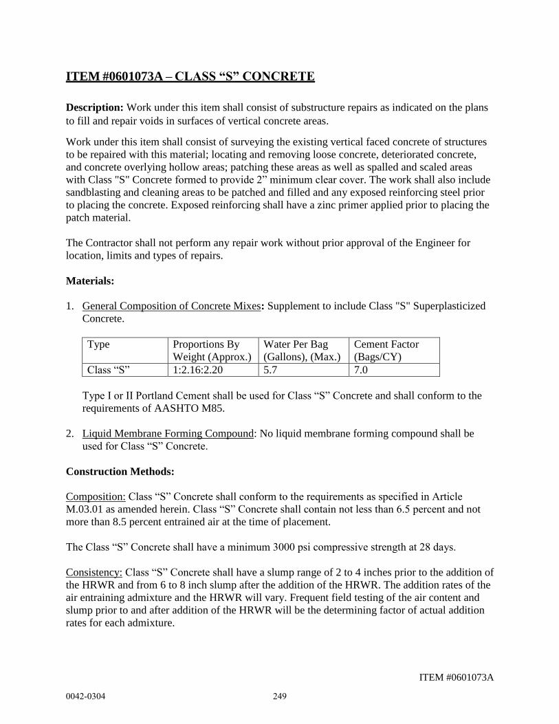
ITEM #0601073A
ITEM #0601073A – CLASS “S” CONCRETE
Description: Work under this item shall consist of substructure repairs as indicated on the plans
to fill and repair voids in surfaces of vertical concrete areas.
Work under this item shall consist of surveying the existing vertical faced concrete of structures
to be repaired with this material; locating and removing loose concrete, deteriorated concrete,
and concrete overlying hollow areas; patching these areas as well as spalled and scaled areas
with Class "S" Concrete formed to provide 2” minimum clear cover. The work shall also include
sandblasting and cleaning areas to be patched and filled and any exposed reinforcing steel prior
to placing the concrete. Exposed reinforcing shall have a zinc primer applied prior to placing the
patch material.
The Contractor shall not perform any repair work without prior approval of the Engineer for
location, limits and types of repairs.
Materials:
1. General Composition of Concrete Mixes: Supplement to include Class "S" Superplasticized
Concrete.
Type Proportions By
Weight (Approx.)
Water Per Bag
(Gallons), (Max.)
Cement Factor
(Bags/CY)
Class “S” 1:2.16:2.20 5.7 7.0
Type I or II Portland Cement shall be used for Class “S” Concrete and shall conform to the
requirements of AASHTO M85.
2. Liquid Membrane Forming Compound: No liquid membrane forming compound shall be
used for Class “S” Concrete.
Construction Methods:
Composition: Class “S” Concrete shall conform to the requirements as specified in Article
M.03.01 as amended herein. Class “S” Concrete shall contain not less than 6.5 percent and not
more than 8.5 percent entrained air at the time of placement.
The Class “S” Concrete shall have a minimum 3000 psi compressive strength at 28 days.
Consistency: Class “S” Concrete shall have a slump range of 2 to 4 inches prior to the addition of
the HRWR and from 6 to 8 inch slump after the addition of the HRWR. The addition rates of the
air entraining admixture and the HRWR will vary. Frequent field testing of the air content and
slump prior to and after addition of the HRWR will be the determining factor of actual addition
rates for each admixture.
0042-0304 249
ITEM #0601073A
Mixing Concrete: For hand mixing of Class “S” Concrete, the Contractor shall provide scale(s)
approved by the Engineer in which cement and aggregate can be accurately weighed for the
required mix proportions.
Note: The Contractor shall also have measuring graduates marked in ounces for the
proportioning of the A.E.A. and the HRWR. Do not mix the A.E.A. and the HRWR
together before adding to the mix; the resultant solution will not work. Do not add the
A.E.A. and the HRWR at the mixer simultaneously, these admixtures must be added
separately in the mixing cycle. All manufactured materials shall be stored, mixed and
used in strict accordance with the written recommendations of the respective
manufacturers.
The single component coating shall be one of the zinc rich primers listed in the latest Product
Reference List noted in Section M.07.02. The color of the coating shall be FS 26270 (Medium
Gray).
Curing Concrete: Concrete shall be cured by leaving forms on for seven (7) days and wetting
them frequently.
Material Storage: The Contractor shall store and maintain the A.E.A. and the HRWR materials in
clean original containers as delivered by the manufacturer.
Repair Procedure: A survey of the existing structure shall be performed by the Contractor, under
the direction and to the satisfaction of the Engineer, to determine the exact limits and locations of
all areas to be repaired under this item. The limits of application shall not exceed the
requirements as specified herein.
The perimeter of each deteriorated area shall be delineated with a ½” deep sawcut. When
sawcutting the concrete, care shall be taken not to cut existing reinforcing.
Loose and deteriorated concrete shall be chipped away back to sound concrete at least 1” below
reinforcing steel. The exposed surfaces shall be thoroughly sandblasted and vacuumed
immediately prior to forming.
Hollow areas in the existing concrete shall be completely exposed by chipping away back to
sound concrete and thoroughly sandblasted and vacuumed immediately prior to forming.
Spalled and scaled areas shall be cleaned of all loose deteriorated concrete. The exposed surfaces
shall be thoroughly sandblasted and vacuumed immediately prior to forming.
Removal of unsound concrete material shall be such as to facilitate uniform placement of fresh
concrete. All upper areas of excavated voids shall slope evenly out to within one inch (1”) of the
face of the concrete to preclude entrapping air and forming hollow spots in the freshly placed
concrete. Within one inch (1”) of the surface, the outline shall be essentially normal
(perpendicular) to the surface.
0042-0304 250
ITEM #0601073A
All surfaces of exposed concrete and reinforcing steel shall be free of oil, solvent, grease, dirt,
dust, bitumen, rust, loose particles and foreign matter. Prior to sandblasting of concrete and steel
surfaces, all petroleum contamination on these surfaces shall be removed by appropriate solvent
or detergent cleaning operations. All compressed air equipment used in cleaning shall have
properly sized and designed oil separators, attached and functional, to assure the delivery of oil
free air to the nozzle.
Extreme care shall be taken where reinforcing steel is uncovered not to damage the steel or its
bond in the surrounding concrete. Pneumatic tools shall not be placed in directed contact with
reinforcing steel. Maximum 15 lb. size hammers shall be used for general chipping and removal.
Exposed reinforcing shall remain in place except where specifically indicated for removal by
direction of the Engineer. Exposed reinforcing steel shall be sandblasted in accordance with
SSPC-SP-6, Commercial Blast Cleaning, to remove all contaminants, rust and rust scale.
In areas where reinforcing steel is found to be surrounded by deteriorated concrete or has at least
one-half of its surface area exposed or has less than 1” cover, the depth of removal shall be such
as to include all deteriorated concrete but not less than 1” below or behind the reinforcing steel.
Where the existing reinforcing steel is severely corroded or damaged, it shall be cut out and
replaced with new reinforcing steel of the same size with a minimum length for lap splices as
required under the tension lap splice requirements set forth under the AASHTO LRFD Bridge
Design Specifications, Customary U.S. Units, 6th Edition, including 2013 Interim Revisions.
When existing steel is determined by the Engineer to have insufficient cover, a bumpout detail
shall be constructed as shown in the plans. Concrete shall be removed to a minimum depth of 1”
behind the existing steel.
When using sandblasting equipment, all work shall be shielded and contained for the protection
of the public and the environment.
The exposed blast cleaned reinforcing steel shall be coated with the single component zinc
primer by brush. All application of the zinc primer shall be in accordance with the
manufacturer’s printed instructions.
All excavated areas on vertical surfaces of concrete members shall be formed using forms coated
with a plastic or similar film to preclude the use of form release agents. Forms and support
systems shall be properly designed in accordance with Subarticle 6.01.03-3. Forms shall be so
designed that placement access shall be allowed at the top of each respective formwork assembly
for contiguous void areas.
Forms and support systems shall be properly designed in accordance with M6.01.03-03.
Forms shall be so designed that placement access shall be allowed at the top of the
formwork assembly.
No bonding materials shall be used before or during the placement of this concrete material.
Concrete surfaces against which this material is to be placed shall be sound, tight, and
0042-0304 251
ITEM #0601073A
thoroughly roughened by the removal and sandblasting procedures specified above. The exposed
concrete surfaces shall be dampened with fresh water immediately prior to placement of the fresh
concrete by “hosing” down the areas behind the forms as thoroughly as possible. Light rust
formations on sandblasted reinforcing steel prior to concrete placement is normal and acceptable.
The minimum ambient and patch area surface temperature shall be 45 degrees Fahrenheit
and rising at the time of concrete installation.
Prior to forming up vertical surfaces, 4 x 4, 6 gauge reinforcing steel wire fabric conforming to
the requirements of M.06.01-3 shall be installed at the proper depth to those areas greater than
six square feet (6 sq. ft.) and three inches (3”) deep or as directed by the Engineer. The fabric
shall be tied to any exposed reinforcing steel or anchored to sound concrete with 1/4” powder
actuated anchors such as Hilti “Gunite Clip”, W-6 Threaded Stud and Eye-Coupling, or
equivalent as approved by the Engineer.
Placement of the fresh concrete shall be in the maximum height lifts possible under the
circumstances and all freshly placed concrete shall be consolidated during placement with
adequately sized and effective vibrators.
Following curing and stripping, the exposed faces of new concrete shall be finished off with the
use of the appropriate tools to blend in the physical appearance to the surrounding areas as much
as possible.
Cured patches shall be sounded by the Engineer to detect the presence of any hollow spots. Such
spots shall be removed and replaced by the Contractor at his cost.
Method of Measurement: Class “S” Concrete shall be measured for payment by the actual
volume in cubic feet of concrete placed and accepted by the Engineer. Wire fabric and
reinforcing steel will not be measured for payment.
Basis of Payment: Class “S” Concrete will be paid for at the contract unit price, per cubic yard,
for “Class “S” Concrete”, complete in place, which price shall include locating and removing
unsound material, sandblasting, cleaning and forming, placing concrete, stripping formwork and
finishing new concrete, and all materials, equipment, tools, labor and clean-up incidental thereto.
Pay Item Pay Unit
Class “S” Concrete C. F.
0042-0304 252
ITEM #0601118A
ITEM #0601118A –BRIDGE DECK CONCRETE
Work under this item shall conform to the pertinent requirements of Section 6.01 supplemented
and amended as follows:
Description: Add the following:
Where indicated in the plans, the Contractor shall furnish and install Bridge Deck Concrete (BDC),
consisting of an Engineered Cementitious Composite (ECC) for use in Link-slabs for newly
constructed bridges, rehabilitated or retrofitted bridges.The concrete shall be composed of Portland
cement (Type 1), fine aggregate, poly-vinyl-alcohol fibers, fly ash (type-F), high range water
reducer, and water. The use of truck mixed or transit mixed concrete is permitted for BDC. The
Contractor shall work closely with the BDC manufacturer or their technical representative to
ensure design criteria are met.
Work under this item also includes furnishing, installing and removing temporary bulkheads to
define the edges of the bridge deck concrete.
Materials: Add the following:
Materials for Bridge Deck Concrete (BDC) shall conform to the requirements of Article M.03.01
amended as follows:
Concrete: The concrete shall consist of a homogeneous mixture of Portland cement (Type 1),
fine aggregate, poly-vinyl-alcohol (PVA) fibers, fly ash (type-F), high range water reducer, and
water. Fine aggregates used for ECC concrete shall be of virgin silica sand consisting of a
gradation curve with 50% particles finer than 0.04 mils and a maximum grain size of 12 mils.
Fiber to be used by ECC concrete shall be manufactured of poly-vinyl-alcohol (PVA) with a
fiber diameter of 1.5 mils and a length between 0.3 inch and 0.5 inch. The surface of the fiber
shall be oiled by the manufacturer with 1.2% (by weight) hydrophobic oiling compound along
the length of the fiber. Fiber strength shall be a minimum of 232 ksi with a tensile elastic
modulus of at least 5,800 ksi.
Water Reducing, High Range Admixture: Water reducing, high range admixture
(superplasticizer) complying with ASTM C 494, Type F or G, ASTM C 1017, Type 1 or 2. In
addition, the selected water reducing-high range admixtures should be comprised of a
polycarboxylate chemical composition.
Retarding admixture shall comply with ASTM C 494, Type D and M.03.01.09
0042-0304 253
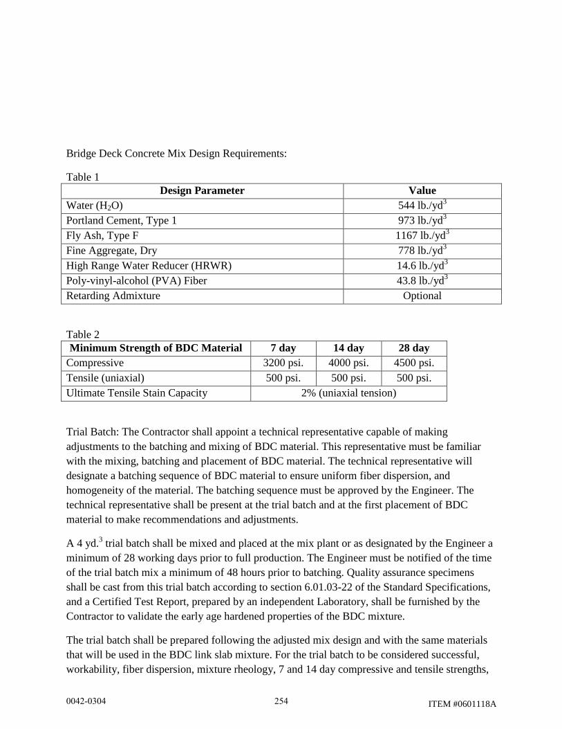
ITEM #0601118A
Bridge Deck Concrete Mix Design Requirements:
Table 1
Design Parameter Value
Water (H2O) 544 lb./yd3
Portland Cement, Type 1 973 lb./yd3
Fly Ash, Type F 1167 lb./yd3
Fine Aggregate, Dry 778 lb./yd3
High Range Water Reducer (HRWR) 14.6 lb./yd3
Poly-vinyl-alcohol (PVA) Fiber 43.8 lb./yd3
Retarding Admixture Optional
Table 2
Minimum Strength of BDC Material 7 day 14 day 28 day
Compressive 3200 psi. 4000 psi. 4500 psi.
Tensile (uniaxial) 500 psi. 500 psi. 500 psi.
Ultimate Tensile Stain Capacity 2% (uniaxial tension)
Trial Batch: The Contractor shall appoint a technical representative capable of making
adjustments to the batching and mixing of BDC material. This representative must be familiar
with the mixing, batching and placement of BDC material. The technical representative will
designate a batching sequence of BDC material to ensure uniform fiber dispersion, and
homogeneity of the material. The batching sequence must be approved by the Engineer. The
technical representative shall be present at the trial batch and at the first placement of BDC
material to make recommendations and adjustments.
A 4 yd.3 trial batch shall be mixed and placed at the mix plant or as designated by the Engineer a
minimum of 28 working days prior to full production. The Engineer must be notified of the time
of the trial batch mix a minimum of 48 hours prior to batching. Quality assurance specimens
shall be cast from this trial batch according to section 6.01.03-22 of the Standard Specifications,
and a Certified Test Report, prepared by an independent Laboratory, shall be furnished by the
Contractor to validate the early age hardened properties of the BDC mixture.
The trial batch shall be prepared following the adjusted mix design and with the same materials
that will be used in the BDC link slab mixture. For the trial batch to be considered successful,
workability, fiber dispersion, mixture rheology, 7 and 14 day compressive and tensile strengths,
0042-0304 254
ITEM #0601118A
and uniaxial tensile stain capacity must meet the requirements of this special provision, as
demonstrated by the Certified Test Report furnished by the Contractor.
Workability is evaluated as outlined in previous section of this provision. Qualitative judgment
must be made by the Engineer as to proper homogeneous fiber dispersion throughout the fresh
material, and acceptable rheology of the mix for the intended application. If the trial batch does
not meet these requirements the trial batch shall be repeated at no additional cost to the
Department.
Neoprene Pads: Shall conform to M.03 of the Standard Specifications, or approved equal.
Construction Methods:
Construction Methods for this work shall conform to the requirements of Section 6.01.03,
amended as follows:
The Contractor shall install temporary bulkheads in the bridge deck slab, where indicated in the
plans, to define the limits of the Bridge Deck Concrete. Reinforcement shall pass through the
temporary bulkheads. The bulkheads shall be removed after curing of the Class “F” Concrete.
Trucks delivering ECC material to the project location must be fully discharged within one hour
of charging at the plant. Prior to placement of the link-slab, all concrete/ECC interfaces shall be
wetted with a uniform spray application of water so that all the surfaces are moist at the time of
placement, with no standing water. Water collecting in depressed areas of the forms shall be
blown out with clean, oil free, compressed air.
The Contractor is advised that due to the high flowability of BDC material it may be difficult to
place the material on sloped bridge decks. The flowability problem may be exacerbated if
vibration is present. Special methods with phased construction may be needed when vibrations
are present during placement of the BDC material.
Sidewalk, curb or barriers shall not be cast on the bridge deck until the link-slab has received a
minimum of two days continuous wet cure cycles. Heavy equipment is not allowed on the link-
slab until the link-slab has reached an age of at least 4 days, and then not until the ECC material
has attained the 28 days strength listed in Table 2. Sidewalks, curbs and parapets within the link-
slab span shall be cast of BDC material.
If the workability limits within this special provision cannot be met, or due to other
circumstances, the Contractor is allowed to use hand held vibration equipment to aid in the
placement and consolidation of the BDC material if approved by the Engineer. Vibration should
be used cautiously to acquire proper consolidation of the BDC material, and only as a final
0042-0304 255
ITEM #0601118A
measure in guaranteeing high quality construction. Precaution must be taken during vibration to
not affect proper dispersion of the fibers within the fresh BDC material.
Neoprene Pads: Shall be placed on top of girder flanges, in accordance with the plans.
Method of Measurement: Add the following:
Bridge Deck Concrete shall be measured for payment by the actual volume in cubic yards of
bridge deck concrete, complete and accepted, within the limits shown on the plans or as ordered
by the Engineer.
Basis of Payment: Add the following:
Bridge Deck Concrete: This material will be paid for at the contract unit price per cubic yard for
BDC, complete in place, which price shall include all materials, equipment, tools, labor and
work incidental thereto, including temporary bulkheads, heating, all costs associated with the
technical representative and all admixtures.
Pay Item Pay Unit
Bridge Deck Concrete c.y.
0042-0304 256
ITEM #0601247A
Revision 7/30/2014
ITEM #0601247A - PRECAST CONCRETE PIER CAP
Description: Work under this item shall consist of furnishing, erecting and installing precast,
post-tensioned pier caps, of the type and size shown on the plans. The use of cast-in-place
concrete will not be considered for substitution.
Materials:
Concrete: Concrete shall conform to Article M.14.01-1. The concrete shall attain a
minimum 28 day compressive strength, f’c, of 5,000 psi.
Reinforcing Steel: All deformed bars shall be uncoated and conform to M.06.01.
All threaded concrete inserts, lifting fixtures and miscellaneous hardware cast into the
pier caps shall be galvanized in accordance with ASTM A153 or ASTM B695, Grade 50, or be
stainless steel.
Steel Shims: Shall conform to ASTM A36 or stronger and shall be hot dip galvanized in
accordance with ASTM A123.
Grouted Splice Couplers: The grouted splice couplers shall meet the minimum
requirements of Article 5.11.5.2.2 - Mechanical Connections, as described in the AASHTO
LRFD Bridge Design Specifications. Grouted splice couplers, including the grout used inside the
couplers, shall be furnished as a system by one of the following three companies:
NMB Splice Sleeve
Splice Sleeve North America, Inc.
38777 West Six Mile Road, Suite 205
Livonia, MI 48152
1-877-880-3230
Dayton Superior Sleeve-Lock Grout Sleeve
Dayton Superior
Corporate Headquarters
1125 Byers Road
Miamisburg, OH 45342
800-745-3700
Erico Lenton Interlok
ERICO United States
34600 Solon Road
Solon, Ohio 44139
1-440-248-0100
0042-0304 257
ITEM #0601247A
Structural grout installed between the columns and the pier caps, whether flowable, or
used as a bedding material, shall be a non-shrinking grout that shall comply with the
requirements of ASTM C 1107. The grout shall be suitable for exterior applications. If the
Contractor proposes a flowable grout, he shall produce documentation from the grout
Manufacturer proving that the grout will be able to flow completely into horizontal gaps between
the columns and the pier cap without creating air voids or honey-combing. Bagged, pre-mixed
formulations of structural grout shall be clearly marked with the manufacturer’s name, date of
production, batch number, and written instructions for proper mixing, placement and curing of
the product.
Post-tensioning materials:
Tendons: Wire strands for all tendons shall conform to the requirements of ASTM A416,
Grade 270.
Anchorage Assemblies: All units comprising an anchorage assembly shall be capable of
developing the ultimate strength of the attached tendon without visible deformation, and shall be
furnished complete with all necessary fittings. All deformed bars, wire, mesh or structural shapes
that are required for distributing the end anchorage loads shall conform to the requirements of
Article M.06.01.
PVC Conduit: Sheathing for the tendons shall be semi-rigid or rigid, interlocked PVC
tubing, of the proper dimensions, especially manufactured for this purpose. The conduit shall be
completely sealed against leakage of mortar into the conduit.
Grout: The Contractor shall submit to the Engineer a proposed grout mix showing the
exact proportions of the materials to be used. The grout shall consist of a mixture of Portland
cement, water and an expansive admixture approved by the Engineer. The grout mix shall
conform to the following requirements:
a. The grout mix shall have an unrestrained volumetric expansion of not less
than 3% nor more than 8%.
b. The grout mix shall have a minimum 28-day compressive strength of 4,650
psi, when tested by methods conforming to the requirements of ASTM C109,
except that the materials and the proportions of the materials shall conform to
the Contractor’s design.
c. The water content of the grout shall be kept as low as possible for proper
grouting. However, it shall not exceed 5 gallons per sack of cement.
The Contractor may substitute a grout mix especially manufactured for grouting tendons,
conforming to the requirements stated herein.
The Contractor shall provide a Certified Test Report that the mix submitted meets the
0042-0304 258
ITEM #0601247A
requirements stated herein, in conformance with the requirements set forth in Article 1.06.07.
Also, the Contractor shall provide, when required by the Engineer, samples of the grout mix for
testing and approval.
Water shall conform to the requirements of Article M.03.01. Chlorides and nitrates shall
not be used. The water shall be potable.
Portland cement shall be Type I or Type II cement conforming to the requirements of
Article M.03.01-3.
Testing of Tendons and Anchorages: All strands to be shipped to the site shall be
assigned a lot number and tagged for identification purposes. Anchorage assemblies to be
shipped shall be likewise identified.
All samples submitted shall be representative of the lot to be furnished. In the case of
strand it shall be taken from the same master roll.
All the materials specified for testing shall be furnished to the Engineer for testing, free
of cost, in ample time for testing and approval. Approval of the material must be obtained before
the material is incorporated in the work.
For seven-wire strand-furnish one strand 7’ long and one typical tendon consisting of
proposed number of strands 7’ long.
The Contractor shall also furnish two anchorage assemblies, complete with distribution
plates of each size or type to be used, if anchorage assemblies are not attached to tendon
samples. Where a common distribution plate is used for anchoring a number of tendons, two
equivalent plates for single tendon shall be furnished.
The anchorage assembly shall be designed so that the maximum bearing stress on
concrete at service load will not exceed the smaller of 17.5 ksi or 0.9 fci.
The anchorage assembly shall hold the prestressing steel at a load producing a stress of
not less than 95 percent of the guaranteed minimum tensile strength of the tendon.
Qualifications of the Precast Concrete Manufacturing Plant: The Contractor will be permitted to
use more than one precast concrete manufacturing plant for this project, however all of the pier
caps must be manufactured by one plant and all of the other components can be manufactured by
one manufacturer. In no case will more than two manufacturing plants be permitted.
The manufacturer shall employ a minimum of one person, regularly present in the plant, who is
certified by PCI for Plant Quality Personnel. Level II.
The precast concrete manufacturing plant(s) shall be certified under the PCI Certified Plant
Program. The manufacturer shall be certified at the time of bidding. Certification shall be in the
following product group(s) and category (ies):
0042-0304 259
ITEM #0601247A
B2 – Prestressed Miscellaneous Bridge Products (Non-Superstructure) Any precast, prestressed elements except for superstructure beams. This includes piling, sheet
piling, retaining-wall elements, stay-in-place bridge deck panels, full-depth deck panels, and all
products covered in B1.
Construction Methods:
1. Shop Drawings: Prior to fabrication, the Contractor shall submit shop drawings to the
Engineer for approval in accordance with Article 1.05.02. These drawings shall include
complete details of the methods, materials and equipment he proposes to use. The shop
drawings shall also include details of the grout installation and curing procedures. The shop
drawings shall also include the following from the grouted sleeve coupler manufacturer:
Documentation stating the minimum compressive strength the grout must attain
so that the resistance of the grout filled sleeve coupler connection is not less than
100% of the yield strength of the connected reinforcement in tension based on
testing.
Documentation stating the minimum compressive strength the grout must attain
so that the resistance of the grout filled sleeve coupler connection is not less than
125% of the yield strength of the connected reinforcement in tension based on
testing.
Shop Drawings for Post Tensioning shall include the following information:
A. Complete details of the methods, materials, and equipment the Contractor
proposes to use the post tensioning operations. Such details shall outline
the method and sequence of stressing, jacking force, strain due to jacking
and effective force for each tendon, and give complete specifications and
details of the tendons and anchorage devices and other data pertaining to
the operations.
B. Complete details of the methods, materials and equipment the Contractor
proposes to use in the grouting operations, including the manner of
mixing, the equipment to be used, step by step procedures to be followed
and the sequence for grouting of the conduits.
C. The size of the anchorage assemblies and pockets shall be detailed
D. The manner of securing the conduit and other components into place,
including the interval of tie-downs.
Four (4) sets of design computations for the proposed method of post tensioning
and sealed by a Professional Engineer licensed in Connecticut shall be submitted
with the shop drawings. The design computations shall include, but not be limited
to the following information:
A. Computed losses for each tendon, such as creep and shrinkage of
concrete, elastic shortening, creep of steel, losses in post-tensioned
0042-0304 260
ITEM #0601247A
steel due to sequence of stressing, friction and anchor set, and all other
losses peculiar to the method or system of prestressing that may take
place or have been provided for.
B. Jacking force for each tendon
C. Effective force for each tendon.
D. Anchorage bearing stress at service load.
E. All other computations required for the system of prestressing being
used.
Approval of shop drawings must be obtained prior to the placing of metal
conduits, tendons, or anchorage assemblies in the forms.
Deviations from prestressing details that have been approved by the Engineer will
not be permitted unless details of such deviations are submitted, in advance of
use, for approval. The approval by the Engineer of any proposed method,
materials or equipment shall not be construed as relieving the Contractor, in any
respect, of full responsibility for successfully completing the prestressing
operations in accordance with the requirements of these special provisions.
2. Fabrication and Manufacture: The fabrication and manufacture of the pier caps shall
conform to the latest edition of the AASHTO LRFD Bridge Design Specifications, including the
latest interim specifications, as supplemented by the following:
2-1. Forms and Forming Material: Forms shall be mortar-tight and sufficiently
strong to prevent misalignment of adjacent precast sections. Forms shall be
constructed to allow their removal without damage to the concrete. A positive
means of supporting reinforcing cages in place during forming shall be required.
The forms shall not be removed until the concrete is sufficiently strong to avoid
possible damage to the concrete. Forms shall not be removed without approval
being granted by the Engineer. Damage to the concrete due to early removal of
the forms shall be cause for rejection.
All forming materials used for casting cylindrical openings for lifting holes or
holes for grouting deformed steel bars shall be removed.
2-2. Concrete Mix: The Contractor shall design and submit to the Engineer for
review a concrete mix that shall attain a minimum 28 day compressive strength,
f’c, of 5,000 psi.
2-3. Reinforcement Steel: Shall be subject to the provisions of Articles 6.02.03-2
through 6.02.03-8. The welding of reinforcement, unless specifically indicated in
the Plans, shall not be permitted.
2-4. Placing Concrete: Concrete shall not be deposited in the forms until the
0042-0304 261
ITEM #0601247A
Engineer has verified the presence and proper location of the reinforcing steel, the
couplers, and other components, and has given his approval thereof.
Concrete shall not be deposited into the forms when the ambient temperature is
below 40 F or above 100 F, unless adequate heating or cooling procedures are
provided and have been previously approved by the Engineer. The concrete
temperature shall be within the range of 60 F to 90 F at the time of placement.
Production during the winter season, from November 15 to March 15 inclusive,
will be permitted only in a completely enclosed structure of suitable size and
dimension that provides a controlled atmosphere for the protection of both the
casting operation and the product.
Outside concreting operations will not be permitted during rainfall unless the
operation is completely under cover.
The concrete shall be vibrated internally, or externally, or both, as ordered by the
Engineer. The vibrating shall be done with care in such a manner as to avoid
displacement of reinforcing steel, forms, or other components. There shall be no
interruption in the pouring of any of the members. Concrete shall be carefully
placed in the forms and sufficiently vibrated to produce a surface that is free from
imperfections such as honeycombing, segregation, cracking, or checking. Any
deficiencies noted in the members may be cause for rejection.
2-5. Test Cylinders:
During the casting of the wall and footing sections, the Contractor shall make test
cylinders under the supervision of a representative of the Department. A
minimum of 4 cylinders shall be taken during each production run or as ordered
by the Engineer. The dimensions and type of cylinder mold shall be as specified
by the Engineer. Cylinders shall be cured under the requirements of ASTM C31
and shall be used to determine the 28 day compressive strength requirements (fc).
The Engineer also reserves the right to request and test core specimens from the
sections to determine their adequacy.
2-6. Finishing: All fins, runs, or mortar shall be removed from the concrete
surfaces which will remain exposed. Form marks on exposed surfaces shall be
smoothed by grinding. All exposed, outside concrete surfaces shall be given a
grout clean-down finish in accordance with Subarticle 6.01.03-21.
2-7. Handling and Storage: Care shall be taken during storage, transporting,
hoisting and handling of all pieces to prevent damage. Sections damaged by
improper storing, transporting or handling shall be repaired or replaced by the
Contractor, as directed by the Engineer and at no cost to the Department. All
storage and handling operations shall be as directed by the Engineer.
0042-0304 262
ITEM #0601247A
The pier caps shall not be shipped to the job site until the 28 day strength (f’c) has
been attained. Prior to shipping, the location of the couplers shall be shall be
carefully measured to insure proper fit up of the pier cap onto the column
reinforcement. Repairs to correct any identified misfits shall be done only after
approval for such repairs is received from the Engineer.
2-8. Repairs: The Engineer shall evaluate the acceptability and the cause of the
defects and the service condition of the pier caps. No repairs shall be done by the
Contractor unless permission has been granted by the Engineer. The Contractor
shall submit to the Engineer, for review, the proposed methods and materials to be
used in the repair operation. All repairs shall be sound and properly finished and
cured before the pier cap is delivered to the job site. The Contractor shall bear the
costs of all repair work.
3. Installation: The installation of the precast concrete pier caps shall conform to the following
requirements:
The installation of the precast concrete pier caps shall proceed as required by the sequence of
construction, and the special provisions entitled "Prosecution and Progress" and "Maintenance
and Protection of Traffic."
The pier caps shall be set to the line and grade indicated on the plans or as directed by the
Engineer. Placement of the pier caps shall not begin until authorized by the Engineer.
4. Grouted splice couplers: Splices made with grouted splice coupler connections shall
be made at the locations shown on the plans. The size of the bars shall be as indicated in
the plans. The length of the reinforcement for the grouted splice coupler connections shall
be as shown on the plans and in accordance with the requirements of the manufacturer of
the coupler. The grouted splice couplers shall be installed in accordance with the
Manufacturer’s recommendations. All tools and equipment required to install and field
inspect the connections shall be provided by the Contractor.
Grout Cubes:
Grout inside couplers: As the Contractor is filling the reinforcement
couplers with the Manufacturer’s recommended grout, the Contractor shall make
cube specimens of the grout in accordance with ASTM C109 except that the grout
cubes shall be cured under ambient conditions (not in a controlled environment
such as a cylinder box). The grout cubes shall be located close to or on the
footings, and protected against dirt, rain, and other contaminants. The dimensions,
type, and number of the grout cubes shall be as specified by the Engineer.
Structural grout (between columns and pier cap): As the Contractor is
filling the gap between the columns and pier cap with structural grout, (whether
0042-0304 263
ITEM #0601247A
the grout is flowed into place or used as bedding material), the Contractor shall
make cube specimens of the grout in accordance with ASTM C109 except that the
grout cubes shall be cured under ambient conditions (not in a controlled
environment such as a cylinder box). The grout cubes shall be located close to or
on the footings, and protected against dirt, rain, and other contaminants. The
dimensions, type, and number of the grout cubes shall be as specified by the
Engineer. If curing compound is recommended for the structural grout it shall also
be applied to the grout cubes.
The grout cubes shall be tested to failure in accordance with ASTM C109 by a
Certified Testing Laboratory approved by the Engineer.
Grout cubes shall also be furnished to the Engineer to allow for additional testing
by the Department’s Material Testing Lab.
Grouted Splice Coupler Connection Operations (2 Installation options)
1. Only personnel who are fully trained in the grout procedures shall be allowed to do the
work.
2. Contractor shall follow the written installation procedures of the coupler manufacturer.
3. It is recommended that the projecting column reinforcement be an extended length.
4. Determine the elevation(s) of the top of column by means of a field survey.
5. Based on the survey results, determine the required reinforcing bar extension lengths and
the required shim heights.
6. Cut the projecting column reinforcement to the required lengths based on the survey and
the coupler manufacturer’s recommendations. Note that the coupler systems can have
very tight allowable tolerances regarding bar lengths within the couplers so extreme care
must be taken with both the survey and the cutting operations.
Installation Option A
7. Erect and brace the pier cap.
8. Fill area under the pier cap with a flowable structural grout (below the lower ports)
9. Install grout in couplers following the manufacturer’s written procedures.
Installation Option B
7. Fill the area to just over the shim packs with a structural grout (bedding material).
8. Erect and brace the pier cap.
9. Install grout in couplers following the manufacturer’s written procedures.
0042-0304 264
ITEM #0601247A
For Installation Options A and B
10. Fill the remainder of the gaps between columns and pier cap with structural grout. Slope
the grout down from the pier cap to prevent water from ponding on the grout. Maintain
the integrity of the structural grout during all subsequent operations. Repair any grout that
becomes displaced or develops cracks.
11. Allow the structural grout to cure and reach minimum compressive strengths as described
on the approved Shop Drawings. The structural grout shall be protected against moisture,
rain, dirt, and other contaminants during the cure time by methods approved in advance
by the Engineer.
12. All grout within the couplers and placed between the pier cap and columns shall cure for
a minimum of 36 hours, unless authorized otherwise by the Engineer.
5. Post Tensioning: Post tensioning shall not begin until the concrete has attained the minimum
compressive strength (fci) shown on the Plans. The compressive strength shall be determined by
testing standard cylinders made and cured identically with the pier cap(s). The stressing of
tendons and grouting of the conduits shall be completed within fourteen (14) calendar days after
the concrete has attained the minimum compressive strength (fci). The tendons shall be tensioned
in such an order that lateral and vertical eccentricity of prestress will be a minimum.
The Contractor shall certify to the Engineer that a technical representative from the prestressing
material supplier will be available to the Contractor to give such aid and instruction in the use of
the prestressing equipment and the installation of materials as is required to obtain satisfactory
results.
The technical representative shall be present during the initial placing of prestressing tendons,
the stressing of the tendons, and the grouting of the conduits. The representative shall remain on
the job until, the opinion of the engineer, each operation is proceeding in an acceptable manner
and the workers are familiar with the work required for each operation. The Contractor shall also
arrange to have the representative present at such other times as the Engineer may request.
No more than one tendon shall be threaded or mechanically locked into an interior end anchor
plate. No factory preassembled tendons will be allowed.
All conduits and other components shall be tied securely into place at intervals shown on the
shop drawings. Concrete shall not be deposited in the forms until the Engineer has inspected and
approved the placement of the conduits, anchorages and distribution reinforcement, and has
marked his approval on each conduit.
All holes, openings and indentations in the conduit shall be repaired prior to placing the concrete.
Holes or openings less than ¼” may be repaired with several wraps of waterproof tape. Holes or
openings larger than ¼” shall be repaired with a split sleeve which shall overlap itself by 3”,
extend at least 3” on either side of the hole, be secured to the conduit and be sealed with
waterproof tape. Indentations which cannot be repaired shall be cut out and repaired as required
above for holes greater than ¼” . All repairs are subject to the approval of the Engineer.
0042-0304 265
ITEM #0601247A
After installation in the forms, the ends of the conduits shall be covered as necessary at all times
to prevent the entry of water or debris.
After each pour of the concrete which comes in contact with the conduit and before the initial set
of the concrete occurs, an elastomeric plug, ¼” smaller in diameter than the inside diameter of
the conduit, shall be passed through each conduit to ensure that there is not a blockage. If a
blockage is indicated, it shall be located and removed.
The tendons shall be stressed in the order indicated on the shop drawings so that lateral and
vertical eccentricity of the prestress will be a minimum.
The Contractor is instructed that special handling is required of all prestressing steel and related
components. Any tendon, or component thereof, that becomes kinked, deformed or otherwise
damaged will be rejected. Tools which would mar or damage the tendons shall not be used. The
prestressing components shall be free from corrosion when installed, and the Contractor shall
take the appropriate measures to prevent corrosion of the tendons after installation. Welding to or
near the prestressing steel is not permitted because of the possibility or arcing. If arcing causes
damage to the prestressing steel the steel shall be rejected. The conduit, tendons, and other
components shall be completely free from oil, grease and other foreign material. Any cleaning
required must be done in a manner approved by the Engineer.
Prestressing shall be done with approved hydraulic jacking equipment. All jacks shall be
equipped with accurate pressure gages. All combinations of jacks and jags shall have been
calibrated by an approved testing agency immediately prior to the start of the prestressing
operations. After being six calendar months on the same project, all combinations of jacks and
gages shall be recalibrated. The Contractor shall furnish the Engineer certified and notarized
calibration charts and tables for each combination of jack and gage.
The prestressing forces shall be measured by calibrated pressure gages. An initial force,
sufficient to remove any slack from the tendon shall be applied. The strain between the initial
force and the total required force will be measured. A record shall be kept of gage pressures and
elongations at all times and shall be submitted to the Engineer. Before beginning of post
tensioning operations the Contractor shall submit his proposed record format to the Engineer for
approval. If the measured strain varies by more than 5% from the calculated strain, the
Contractor shall carefully check his operation to find and correct the source of error before the
operation is allowed to continue.
The protruding ends of tendons shall be cut after prestressing, in a manner prescribed by the
Engineer, or as noted on the plans. A projection of at least 1”, preferably more, beyond the
anchorage wedge or the nut must remain. If the tendons are burned off, the cut must be made as
quickly as possible in order to reduce heat penetration in the tendons.
Drilling of the pier caps or the use of powder actuated tools on the pier caps will not be allowed
after prestressing has begun.
0042-0304 266
ITEM #0601247A
The ends of the grout tubes, vent tubes and drain tubes shall be threaded and the exposed ends
fitted with valves. All grout tubes at the end of conduits shall pass through the anchor plates.
Vent tubes shall be provided at high points of the conduit throughout its length at a maximum
spacing of 26 feet.
Vent tubes and drain tubes which pass through exposed concrete surfaces, shall be fitted with
couplings and threaded extension pipes. The coupling shall be so located that, when removed,
the remaining stub will be recessed at least ½” from the face of the concrete. The grout tubes at
each end of the conduit shall be threaded and shall project at least 4’ above the ends of the
conduit, and shall be fitted with shutoff valves at the tops of the tubes.
All vent or grout tubes at the high points of the conduit shall have a 1” vertical tube attached to
the vent tube with a reducer coupling. The 1” vertical tube shall have a minimum length of 2’
above the exposed concrete surface or a minimum volume of 10% of the grout volume in the
conduit contributing to the waterflow in the grout, whichever is greater. When required by the
volume, the vertical tube diameter may be increased to 1 ½” but the minimum length of the
vertical tube shall remain as described above. The top elevation of all 1” or 1 ½” vertical tubes
for a single conduit shall not vary more than 3” from a common level plane.
The water that may have collected in the conduits shall be blown out with oil-free compressed air
before starting the grouting operations.
The temperature of the pier cap at the time of grouting shall be above 50 degrees F. and shall be
forecasted to remain above 32 degrees F for at least three days after grouting.
The method of grouting shall be such as to ensure the complete filling with grout of the conduit.
No external loads shall be applied to the pier cap before grouting of all tendons has been
completed.
The mixer for the grout shall be a high speed mixer specifically designed for grouting of post
tensioning conduits. The mixer shall be capable of producing grout which is free of lumps and
undispersed cement.
The pump for the grout shall be of the positive displacement type, and shall be able to produce
an outlet gage pressure of at least 150 psi.
The pump shall have seals adequate to prevent the loss of grout and also to prevent the
introduction of oil, air, or other foreign substances into the grout.
The grouting equipment shall utilize gravity feed to the pump inlet.
During the grouting operation, standby water flushing equipment shall be provided. The water
flushing equipment shall be in addition, and separate from the grouting equipment; shall use a
different power source than the grouting equipment; shall have sufficient capacity to flush out
any partially grouted enclosures when blockage or breakdown of the grouting equipment occurs
and shall be capable of developing a gage pressure of at least 250 psi.
0042-0304 267
ITEM #0601247A
The ingredients shall be added to the mixer in the following order: (1) water, (2) cement, (3)
admixture. The ingredients shall be mixed sufficiently to produce a uniform, thoroughly blended
grout with a minim of air entrapped. Excessive temperature rises due to extended mixing shall be
avoided. After mixing, the grout shall be passed through a strainer into pumping equipment
which provides for recirculation. No additional water shall be added to the grout after mixing.
No grout shall be used more than one-half hour after mixing.
The Engineer will perform tests on the grout as specified in the “Recommended Practices for
Grouting” by the Prestressed Concrete Institute. The Engineer will provide equipment and
perform the testing. The Contractor shall operate his equipment and provide sample as required.
Grouting operations shall not start before the post-tensioning operation is complete for the entire
pier cap.
Unless otherwise noted on the plans, the grout shall be injected into the grout tubes from one end
of the pier cap.
The valves on all outlet tubes (drain, vent and grout tubes) shall be closed except for the outlet
tube closest to the grouting end of the conduit, which shall be open. The initial pump gage
pressure shall be less than 40 psi. and shall gradually be increased until a steady stream of grout,
free of air and diluted grout, flows from the outlet tube. The outlet tube shall be closed and
simultaneously, the next outlet tube, in the direction of flow of grout, shall be opened.
This process shall be repeated for each of the outlet tubes until the grout tube at the far end of the
conduit becomes an outlet tube. Pumping shall continue until the flow from the outlet tube
becomes uniform and free from air and diluted grout.
At the completion of the grouting, all valves shall remain closed until the grout has cured, except
that the grout tube at each end of the conduit and at the high points of the conduit, which shall
remain opened during the curing of the grout.
An online device to limit the grout pumping gage pressure shall be set at a maximum of 150 psi.
If the grout reaches the limiting pressure, the grouting operation shall be stopped and the grout
flushed from the entire conduit. The grouting operation shall not resume until the restriction is
located and corrected by the Contractor.
Method of Measurement:
This item will be measured for payment by the number of precast pier caps installed and accepted.
Basis of Payment:
Payment will be full compensation for the manufacturing, furnishing, and placement of each pier
cap, including the post tensioning. All items required to assemble each pier cap into a precast
0042-0304 268

ITEM #0601247A
concrete pier per the plans, including labor, materials and equipment, shall be considered
incidental to this item and will not be paid for separately.
The cost of furnishing and installing the reinforcement that projects up from the pier cap into the
concrete keeper blocks shall be paid for separately under pay item “Construct Concrete Keeper
Blocks”.
0042-0304 269

ITEM #0601318A
ITEM #0601318A - PARTIAL DEPTH PATCH
Description: Work under this item shall consist of the removal of spalled, delaminated or
otherwise deteriorated concrete from existing bridge decks and/or approach slabs by hydro-
demolition methods, and replacement with fast setting patching material as shown on the plans,
as directed by the Engineer, and hereinafter specified.
Where ordered by the Engineer, work under this item shall also include repairing pop-outs on the
underside of the deck caused by the removal of deteriorated concrete.
Work under this item shall also include the furnishing and installation of reinforcing bar wire ties
and vertical supports on inadequately supported and/or vibrating reinforcing steel within deck
patch areas, as ordered by the Engineer.
Materials: The materials shall conform to the following requirements:
1) Patching Material: The patching material shall be a concrete composed of a quick setting
cement, fine aggregate, coarse aggregate and water. This concrete shall harden within 40
minutes, and develop minimum compressive strengths of 1,000 psi within one hour after set and
3,000 psi within three days.
The Contractor shall design and submit a quick setting mix to the engineer for approval. The mix
proportions and method of application shall be in accordance with the manufacturer’s
recommendations. Sources of supply of all the materials shall be clearly indicated.
Fine aggregate shall conform to the requirements of Subarticle M.03.01-2.
The coarse aggregate shall conform to the requirements of Subarticle M.03.01-1. The required
grading shall be obtained by using 100 percent of No. 67 size coarse aggregate. Grading of the
aggregate shall conform to the gradation table of Article M.01.01.
Water shall conform to the requirements of Subarticle M.03.01-4.
Unless otherwise approved by the Engineer, the quick setting cement shall be one of the
following materials:
Cementitous Based Materials:
Emaco T-415 Perma-Patch
Master Builders, Inc. Dayton Superior Corporation
23700 Chagrin Blvd. PO Box 355
Cleveland, OH 44122 Oregon, IL 61061
800-628-7378 800-745-3707
Rapid Set DOT Cement Speed Crete Green Line
0042-0304 270
ITEM #0601318A
CTS Cement Manufacturing Tamms Industries
1023 Dogwood Lane 730 Casey Ave.
West Chester, PA 19382 Wilkes-Barre, PA 18702
215-429-4956 800-218-2667
Fastcrete
Silpro Corporation
2 New England Way
Ayer, MA 01432
508-772-4444
Note: Gypsum based materials will not be allowed.
2) Epoxy Resin: The epoxy resin shall be a two component system. The base polymer shall be a
thermosetting resin of the epoxy type. The epoxy resin shall be composed of 100% reactive
constituents, which are a condensation product of the reaction of epichlorohydrin with bisphenol
ether of bisphenol A, containing no more than trace amounts of hydrolyzable chloride. The
epoxy resin shall have an epoxide equivalent between 465 and 530.
The reacting system shall consist of a blend of condensation polymers of dimerized and
trimerized unsaturated fatty acids and an aliphatic polyamine.
Unless otherwise specified, pigmentation shall be required in the system so that the cured coating
shall conform to the Federal Color Standard 595, No. 16357.
a) Physical Requirements of (Mixed) Epoxy Resin System:
A mixture of both components in the proportions recommended by the manufacturer shall
conform to the following requirements:
Viscosity - 500 to 800 centipoises at 77F
Pot life - 7 hours minimum at 75F
Minimum solids content - 48%
The cured system shall not exhibit amine blushing or sweating.
When testing for abrasion by ASTM Designation D968, the pigmented finish coats shall
require a minimum of 50 liters of sand to abrade a one mil thickness of coating.
A 2 ½ mil dry film thickness of the coating tested according to ASTM Designation D522
shall pass a 1/8 inch diameter mandrel test without splitting the film or causing loss of
bond.
b) Sampling:
0042-0304 271
ITEM #0601318A
A representative sample of each component sufficient for the test specified shall be taken
by a Department representative either from a well-blended bulk lot prior to packaging or
by withdrawing 3 fluid ounce samples from no less than 5 percent by random selection of
the containers comprising the lot or shipment. Unless the samples of the same
component taken from containers show evidence of variability, they may be blended into
a single composite sample to represent that component. The entire lot of both
components may be rejected if samples submitted for test fail to meet any requirements
of this specification.
c) Packaging and Marking:
The two components of the epoxy resin system furnished under these specifications shall
be supplied in separate containers, which are non-reactive with the materials contained
therein. The size of the container shall be such that the recommended proportions of the
final mixture can be obtained by combining one container of one component with one or
more whole containers of the other component.
Containers shall be identified as base polymer and reacting system, and shall show the
mixing directions and usable temperature range as defined by these specifications. Each
container shall be marked with the name of the manufacturer, the lot or batch number, the
date of packaging, pigmentation if any, and the quantity contained therein in pounds and
gallons.
Printed instructions from the manufacturer for mixing and applying the material shall be
included.
Potential hazards shall be so stated on the package in accordance with the Federal
Hazardous Products Labeling Act.
d) Control of Materials:
A Materials Certificate will be required in accordance with Article 1.06.07, certifying the
conformance of the epoxy resin to the requirements set forth in this specification.
Construction Methods:
1) Inspection of the Structural Slab: Before any existing concrete is removed from the structural
slab, the Contractor will provide the Engineer clear access to the bridge deck. During this time,
the Engineer will perform an inspection of the structural slab and designate areas where concrete
removal will be required. Due to the nature of the operations, the inspection can be performed
only after some existing materials, notably overlays and waterproofing systems, have first been
removed from the structural slab. It shall be the responsibility of the Contractor to arrange the
construction schedule so that the required operations may be performed without causing delay to
the work.
0042-0304 272
ITEM #0601318A
No operations will be performed by the Engineer until after the following construction work has
been completed:
a) The existing bituminous overlay or concrete wearing course, if present, has been
removed.
b) The existing waterproofing system, if present, has been removed.
Note: The removal of this material will be paid for under other applicable items.
It shall be the responsibility of the Contractor to inform the Engineer, in writing, of the date that
a structure will be available for inspection operations. Notification shall be given to the Engineer
at least seven (7) days prior to the date that the area in question will be in a condition acceptable
to the Engineer.
The Contractor is hereby informed that the following time period will be necessary to perform
the required inspection operations:
One working day with suitable weather conditions per each six thousand square feet, or
portion thereof, of structural slab area.
The Contractor will not be allowed to do any further work to the structural slab, until all
necessary inspection operations have been performed, unless given permission by the
Engineer.
The Contractor will include any costs related to the allowance for this inspection in the
general cost of the work.
2) Hydro-Demolition Water and Equipment: All hydro-demolition equipment should be capable
of selectively removing spalled, delaminated or otherwise deteriorated concrete and cleaning the
existing reinforcing steel of all rust and corrosion products by use of high-velocity water jets
acting under continuous automatic control.
The hydro-demolition equipment shall consist of filtering and pumping units operating in
conjunction with a remote-controlled robotics device
All hydro-demolition equipment shall be equipped with an angled and rotating water nozzle to
prevent interference of the existing reinforcing steel with the removal of concrete.
The maximum allowable noise level caused by equipment used for the removal of deck concrete
shall not exceed ninety (90) decibels on the “A” weighted scale, as measured at the nearest
residence or occupied building. The Contractor shall demonstrate, to the satisfaction of the
Engineer, that his equipment will meet this requirement before the use of such equipment will be
allowed.
0042-0304 273
ITEM #0601318A
The make and model numbers of hydro-demolition equipment shall be submitted for approval by
the Engineer. No hydro-demolition work shall be initiated until approval by the Engineer is
granted.
The Contractor shall provide structurally adequate shields approved by the Engineer for
protection of adjacent traffic lanes in the vicinity of the removal and cleanup operations.
Water used for the hydro-demolition shall be potable.
The Contractor is advised that the withdrawal of more than 50,000 gallons of water per day from
a single source other than from a municipal water system shall require a diversion permit issued
by the Department of Environmental Protection, Water Resources Unit, in accordance with the
Connecticut Water Diversion Policy Act PA 84-402, CGS Sections 22a-365 through 22a-378.
3) Hammer Demolition and Hydro-Demolition Drainage Runoff Control: At least two weeks
prior to the planned initiation of hydro-demolition operations, the Contractor shall submit to the
Engineer for approval a comprehensive plan for the containment, filtration and disposal of
hydro-demolition runoff water and concrete debris.
The plan shall ensure that all concrete debris and particulant matter will be removed from hydro-
demolition runoff water prior to its release to the environment.
The plan shall include provision for the concurrent vacuuming of all runoff water at the
immediate vicinity of the hydro-demolition operation. Runoff water shall be completely
contained and vacuumed into a suitably sized water tight mobile tank for transport to a disposal
site sedimentation basin approved by the Engineer.
Hydro-demolition operations shall proceed only with the simultaneous operation of a runoff
water vacuum pickup in the immediate area of the hydro-demolition operation. Runoff water
shall not be allowed to flow across adjacent travel lanes, across bridge joints nor through any
existing bridge drainage system.
The size and location of the disposal site sedimentation basin shall be detailed in the
containment, filtration and disposal plan. The sedimentation basin shall be properly sized so that
uncontrolled overflow does not occur. At the conclusion of hydro-demolition operations, the
sedimentation basin and all concrete debris shall be removed and the area restored to its original
condition.
This plan shall include the following:
a. Equipment
b. Containment
c. Filtration for Hydro-demolition runoff
d. Location of Trail Areas
e. Disposal of Hydro-demolition runoff and concrete debris disposal in conformtation with
the following specificaitons:
a. Section 1.10 Environmental Compliance of the Standard Specification.
0042-0304 274
ITEM #0601318A
The approval by the Engineer of the runoff containment, filtration and disposal plan shall in no
way relieve the Contractor of any responsibility for its safe and effective performance.
4) Calibration and Testing of Hydro-Demolition Equipment: A trial area shall be designated by
the Engineer to demonstrate that the equipment, personnel and methods of operation are capable
of producing results satisfactory to the Engineer. The trial area shall consist of two patches, each
of approximately 20 square feet, one area deteriorated and/or defective concrete and one area of
“sound” concrete as determined by the Engineer.
Area of sound concrete is defined as: An area free from chemical defects, delamination, spalling,
cracks, etc.
In the “sound area of concrete”, the equipment shall be programmed to remove concrete to a
depth 1 inch + 1/4 inch below the top reinforcing steel mat.
After completion of the above test area, the equipment shall be located over the deteriorated
and/or defective concrete and using the same parameters for sound concrete removal, remove all
deteriorated and/or defective concrete. If a satisfactory result is obtained, these parameters may
be used as a basis for the production removal.
If, after calibrating the hydro-demolition equipment and beginning removal operations in a
particular zone or area, insufficient removal of concrete is being obtained in the opinion of the
Engineer, the Contractor shall recalibrate the hydro-demolition equipment for that zone or area to
the satisfaction of the Engineer.
5) Removal of Deteriorated Concrete: All deteriorated concrete designated for removal under
this construction item shall be removed within the limits shown on the plans and where ordered
by the Engineer. The lateral limits of each area to be repaired will be delineated by the Engineer
and suitably marked. Where several areas to be repaired are very close together, the Engineer
may combine these individual patches into a large area. The outlines of each such area shall first
be cut to a depth of one-half (1/2) inch with an approved powersaw capable of making straight
cuts. In the event that reinforcing steel is encountered within the upper 1/2 inch depth during
sawing operations, the depth of saw-cut shall immediately be adjusted to a shallower depth so as
not to damage the steel bars. If so directed by the Engineer, saw cutting shall again be carried
down to the 1/2 inch depth at other locations of repair provided reinforcing steel is not again
encountered. Where over-breakage occurs resulting in a featheredge, the featheredge shall be
squared up to a vertical edge in an approved manner. Where sawing is impractical, the area shall
be outlined by chisel or other approved means.
All deteriorated concrete shall be removed by pneumatic hammers or hydro-demolition methods
except under the following circumstances where pneumatic hammers may be used when
approved by the Engineer:
0042-0304 275
ITEM #0601318A
a) The removal of any remaining thin concrete ridges or “shadows” directly beneath
reinforcing bars.
b) When necessary to achieve required clearance around lap splices in the repair of
deteriorated or damaged reinforcing steel.
c) In areas inaccessible to hydro-demolition.
The weight of pneumatic hammers when used shall not exceed 30 pounds for concrete removal
above the top reinforcing steel nor 15 pounds for concrete removal below the top reinforcing
steel.
The depth of hydro-demolition shall be at least 1 inch below the top reinforcing steel mat but
shall be such as to include all spalled, delaminated, or otherwise deteriorated concrete. The
Engineer will be sole determiner of what constitutes deteriorated concrete, using sounding
methods or other evaluation measures at his discretion.
Within one hour following the initiation of a hydro-demolition operation in any patch area, all
loose concrete debris should be removed, followed by water flushing of the existing concrete
bonding surface to completely remove all traces of concrete debris and cement residue so that
rebonding to the surface of the remaining sound concrete will be prevented. If it is not
convenient to clean and flush the patch area within this time framework, all steel reinforcing and
concrete bonding surfaces shall be cleaned subsequently by high pressure water blasting at a
nozzle pressure not less than 3,000 psi with a sufficient volume to completely remove all
rebonded debris and laitance.
Where the existing reinforcing steel is damaged or corroded, it shall be cut out and replaced with
new reinforcing steel of the same size. Any sound reinforcing steel damaged during the concrete
removal operations, shall be repaired or replaced by the Contractor at his expense as directed by
the Engineer. New steel shall be attached beneath or beside existing steel with a minimum splice
length as indicated on the plans, or as directed by the Engineer. The concrete shall be removed
to a minimum depth of 1 inch below the new steel.
6) Surface Preparation: Sound reinforcing steel which is in the proper position in the slab shall be
left in place and cleaned of all concrete, the smaller fragments to be removed with hand tools in
patch areas where pneumatic hammers were used.
Reinforcing bar wire ties and vertical supports shall be installed on inadequately supported
and/or vibrating reinforcing steel, as directed by the Engineer.
The concrete surface and reinforcing steel to receive patching material shall be either sandblasted
or water blasted, followed by air blasting in order to remove all loose particles and dust. All
blasting operations shall be performed using techniques approved by the Engineer, taking care to
protect all pedestrians, traffic, and adjacent property. All compressed air sources shall have
properly sized and designed oil separators, attached and functional, to allow delivered air at the
0042-0304 276
ITEM #0601318A
nozzle to be oil-free. The patch area shall be cleaned of all additional loose or powder-like rust,
oil, solvent, grease, dirt, dust, bitumen, loose particles, and foreign matter just prior to patching.
If the patch area was not cleaned and flushed with clean water immediately following hydro-
demolition, or if run-off from a nearby hydro-demolition operation was allowed to travel through
the previously cleaned and flushed patch surface, all affected concrete and steel reinforcing
bonding surfaces shall be water blast cleaned at a nozzle pressure not less than 3,000 psi as
directed by the Engineer, to assure that all remaining bond inhibiting laitance is completely
removed.
The entire concrete surface to be patched shall be dampened. All free water shall be removed
from the patch area.
7) Mixing, Placing, and Finishing: Mixing and placing concrete should not be done unless the
ambient temperature is above 35F. All mixing shall be accomplished by means of a standard
drum-type portable mixer. A continuous type mobile mixer may be used if permitted by the
Engineer. The Contractor shall calibrate the mobile mixer under supervision of the Engineer.
Calibration shall be in accordance with the applicable sections of ASTM method C685. The
total mix shall be limited to the quantity that can be mixed and placed in 15 minutes. The
concrete mix shall be spread evenly and compacted to a level slightly above the pavement
surface. Vibration, spading or rodding shall be used to thoroughly compact concrete and fill the
entire patch area. Where practical, internal vibration shall be used in cases where concrete has
been removed below the reinforcing steel. Hand tamping shall be used to consolidate concrete in
smaller patches, including popouts.
Vibrating plates or vibrating screeds shall be used on the surface of all patches for strike off and
consolidation. After the concrete has been spread evenly and compacted to a level slightly above
the pavement surface, the vibrating plate or screed shall be drawn over the surface at a uniform
speed without stopping, in order to finish the surface smooth and even with adjacent concrete.
The surface shall be float finished.
Finishing operations shall be completed before initial set takes place.
Cured patches, having a hollow sound when chain dragged or tapped (indicating delamination),
shall be replaced by the Contractor at his expense until a patch acceptable to the Engineer is in
place.
8) Tolerances in Finished Patched Surfaces: The surface profile of the patched area shall not vary
more than one-eighth inch in a distance of 10 feet, when a 10 foot long straightedge is placed on
the surface at any angle relative to the centerline of the bridge. Humps in the patch that exceed
the one-eighth inch tolerance shall be ground down by approved machinery. Sags or depressions
in the surface of the patch area that exceed one-eighth inch tolerance shall be repaired by
removal of the concrete in the depression over an area determined by the Engineer to a depth of
one inch and repaired in the previously described manner.
0042-0304 277

ITEM #0601318A
9) Underside of Bridge Deck Treatment: The Engineer shall examine the underside of the bridge
deck for pop-outs caused by the removal of deteriorated concrete. The surface area of pop-outs
shall be coated with epoxy resin where ordered by the Engineer. The concrete surface and
exposed reinforcing steel, if any, which is to receive the coating material shall be cleaned of all
loose or powder-like rust, oil, dust, dirt, loose particles, and other bond inhibiting matter just
prior to coating.
The epoxy resin shall be mixed in accordance with the manufacturer's instructions. Also in
accordance with the manufacturer’s instructions, two coats of the mixed material shall be applied
in uniform coats of approximately 2 to 3 mil dry film thickness each.
If the pop-outs extend beyond the bottom layer of reinforcing steel, the pop-outs shall be repaired
as ordered by the Engineer.
10) Test Cylinders: The Contractor shall make and perform compressive strength tests on
representative cylinders under the supervision of the Engineer. The dimensions, type of cylinder
mold and number of cylinders shall be specified by the Engineer. Traffic shall not be permitted
on patched surfaces until the patch material attains a strength of 1800 psi, as determined by
breaks of the test cylinders.
A portable compression testing machine shall be provided by the Contractor and available on site
for cylinder testing. All testing and equipment shall conform to ASTM C39.
Note: This compression machine must be calibrated in accordance with the provisions of
Section 5, ASTM C39.
11) Time Schedule: Work under this item begun on any specific bridge during a construction
season shall be completed, at least, to include this item, membrane waterproofing and placing of
first course of wearing surface as soon as possible and specifically before the beginning of the
construction season’s winter shutdown.
All work shall proceed as required by the “Maintenance and Protection of Traffic” and
“Prosecution and Progress” specifications elsewhere within the contract documents. Traffic will
not be allowed on any areas where the Contractor has removed deteriorated concrete until a
minimum of 1.5 hours after the placing and finishing operations on the areas are complete as
required by this specification.
Method of Measurement: This work will be measured for payment by the actual number of
cubic feet of patching material used in acceptable concrete deck patches, except where the
Engineer determines that the Contractor has unnecessarily removed sound concrete. Where
sound concrete has been unnecessarily removed, the replacement concrete will not be measured
for payment.
Basis of Payment: This work will be paid for at the contract unit price per cubic foot of deck
concrete repaired for “Partial Depth Patch”, complete in place and accepted, which price shall
include removal of deteriorated concrete, surface preparation of patch areas, epoxy resin coating
0042-0304 278
ITEM #0601318A
of the underside of deck pop-out surfaces, concrete replacement, the furnishing and installation
of reinforcing bar wire ties and vertical supports for inadequately supported existing reinforcing
steel, all materials, equipment, including the portable compression testing machine required for
the testing of the repair material, tools, labor, inspection access and work incidental thereto.
Pay Item Pay Unit
Partial Depth Patch C.F.
0042-0304 279
ITEM #0601548A
ITEM #0601548A – CONCRETE PEDESTALS
Work under this item shall conform to the pertinent requirements of Section 6.01 supplemented
and amended as follows:
Description: is supplemented by the following:
This item consists of furnishing and placing high performance concrete for the pedestals located
on the piers and abutments of Bridge No. 02368A (Site No. 4), including all necessary materials
and equipment to complete the work, and the design of the concrete mix. Special care as
specified below shall be taken in the finishing of high performance concrete. The inclusion of
microsilica and low water/cement ratio decreases bleeding rates and may cause faster set times.
High performance concrete shall be finished as soon as possible after placement and during
finishing particular measures shall be taken to prevent water loss from the surface of the
concrete. These include: (1) strict adherence to specifications regarding evaporation rates and
cessation of concrete placement if relative humidity is low and temperature and wind speed are
high; (2) expediting finishing of concrete and use of fog sprays during finishing; (3) use of
evaporation retarding agents during and immediately after finishing; and (4) initiation of wet
curing as soon as possible after finishing. The Contractor is encouraged to work closely with the
microsilica manufacturer or their technical representative in developing their finishing
techniques.
Materials:
Materials from this work shall conform to the requirements of Article M.03.01 amended as
follows:
Concrete: The concrete shall consist of a homogeneous mixture of Portland cement, fly ash,
microsilica, fine and coarse aggregate, air entraining agent, admixtures and water. The air-
entraining features shall be obtained by the use of an approved air-entraining admixture.
The consistency shall be determined by the AASHTO Method T119. A uniform consistency
shall be continuously maintained. The slump shall be of 5" to 7". Slumps greater than indicated
may be used only when approved by the Engineer.
The Contractor shall submit a concrete mix design for approval by the Engineer.
The mix design shall generally conform to the following requirements:
28-day Minimum Compressive Strength (5 ksi) (required minimum)
Water/Cementitious Material Ratio 0.40 (maximum)
0042-0304 280
ITEM #0601548A
Fly Ash Used to replace approximately
PPPPPPPPPPPPPPPPPPPPPPPPPPPPPPPPPPPPPPP20% of the cement by weight
Microsilica Used to replace approximately 6%
OOOOOOOOOOOOOOOOOOOOOOOOOOOOO of the cement by weight
Entrained Air Content 5-8% by volume
Coarse Aggregate Utilize a nominal maximum size of
KKKKKKKKKKKKKKKKKKKKKKKKKKKKK No. 6 aggregate
Calcium Chloride Not Permitted
The mix design submitted for Engineer's approval shall contain the following information:
· Compressive Strength
· Amount of Cement (including pozzolan additives)
· Amount of Coarse Aggregate
· Air Content
· Water/Cement Ratio
· Chemical Additives (types, brand name, dosage ranges)
· Laboratory Test Results (Strength, Air Content, W/C ratio, Slump, Coarse Aggregate
Gradation)
Water-Reducing Admixture: The microsilica admixture shall be in accordance with ASTM C
1240 and approved by the Department. Only one brand shall be allowed for any structural
element. The manufacturer shall provide written certification that the supplied material meets
the requirements of the specification.
If the microsilica admixture is supplied in the slurry form, the slurry shall be maintained in
storage above the temperature of 32º F. Slurries exposed to temperatures of 32º F or less shall be
removed and replaced at no cost to the Department. The slurry shall be homogeneous and
agitated as necessary to prevent separation. The slurry shall be added using proportioning
equipment approved by the Engineer.
If the microsilica admixture is supplied in the densified powder form, the mass of the densified
powder shall be measured cumulatively with the cement and fly ash. The densified powder shall
be last in the measuring sequence and the tolerance for each material draw mass shall be based
0042-0304 281
ITEM #0601548A
upon the total mass of cement plus fly ash plus densified powder. The batching tolerance for the
cement plus fly ash plus densified powder shall be ±½% by mass.
Special Mixing Requirements for Densified Microsilica: Densified microsilica requires
enhanced mixing to ensure full dispersion. Mix requirements shall conform to the
recommendations of the microsilica manufacturer.
Construction Methods: is amended and supplemented by the following:
Cylinders for Compressive Strength Testing: The concrete necessary to cast cylinders for
compressive-strength determinations shall be furnished by the Contractor from each pour. The
necessary personnel and forms for casting these specimens will be furnished by the Department
and the number of specimens required will be specified by the Engineer.
The concrete shall be vibrated. Both internal and external vibration shall be used when ordered
by the Engineer. The vibrating shall be performed with care in such a manner as to avoid
displacement of reinforcing steel or other components. Concrete shall be carefully placed in the
forms and vibrated sufficiently to produce a surface free from imperfections such as honeycomb,
segregation, cracking or checking.
Any deficiency such as honeycomb or segregation may be cause for rejection.
The Contractor shall submit procedures to demonstrate compliance with ACI 308 "Standard
Practice for Curing Concrete", ACI 306 "Standard Practice for Cold Weather Concreting", and
ACI 305 "Hot Weather Concreting".
During finishing, the evaporation rate shall not exceed 0.1 lb. per square foot of exposed
concrete per hour. Possible procedures may include cooling ingredients prior to mixing, use of
temporary windbreaks, sun shades, and fog nozzles.
The concrete for each pour sequence shall be kept constantly moist and protected against any
drying action and cured for no less than seven (7) days after the placing of the concrete. Curing
shall be accomplished in the following manner:
Fog Spray:
Curing of the concrete shall begin by the application of a water fog spray immediately after the
initial set. Fog spray shall continue until such time as the moist cotton mats are placed. The
amount of fog spray shall be strictly controlled so that accumulations of standing or flowing
water on the surface of the concrete shall not occur. There shall be a sufficient amount of spray
to keep up with the placing operations.
0042-0304 282
ITEM #0601548A
Should atmospheric conditions render the use of fog spray impractical, the Contractor shall use
plastic covers of suitable thickness and securely fastened down, but not directly in contact with
the concrete. The covers shall be used only until the initial set has taken place, whereupon moist
cotton mats shall be placed immediately thereafter and kept wet for the duration of the curing
period.
On the windward side of the pedestal being cured, the Contractor shall erect barriers of suitable
height, when necessary, to protect the curing concrete from the direct force of the wind.
Moist Curing:
When the concrete has set sufficiently, moist curing shall be substituted for the fog spray.
Cotton mats shall be prewetted and ready to place on the newly finished concrete surface as soon
as placement, consolidation, and finishing of concrete are complete. The time between initial
exposure of the finished concrete to the environment and the application of soaked mats shall not
exceed 10 minutes. The mats shall then be covered with plastic sheeting to prevent evaporation
of the curing water. Additional curing water shall be applied through soaker hoses running under
the protective plastic sheeting so that the mats are kept constantly wet throughout the period of
cure.
Method of Measurement: is supplemented with the following:
This work will be measured for payment by the actual number of concrete pedestals, of high
performance concrete, completed and accepted in place, in accordance with the plans or as
ordered by the Engineer.
Basis of Payment: is supplemented with the following:
Payment for this work will be made at the contract unit price each for "Concrete Pedestals",
complete in place, which price shall include all materials, equipment, tools, labor and work
incidental thereto, including heating and cooling, curing and all admixtures.
0042-0304 283
12/12/14
ITEM #0601788A
ITEM #0601788A – STAIN PROTECTION (SITE NO. 4)
Description: Work under this item shall consist of furnishing and installing catchments as
shown on the plans; furnishing, installing and maintaining temporary coverings required to
protect surface of abutments, piers, and other areas from rust staining, and the removal of rust
stains as directed by the Engineer.
Materials: Fiberglass reinforced plastic shall be used in the manufacture of the catchments. The
resin, monomer, catalyst, filler, pigment and other additives in the resin mix shall produce a general
purpose polyester resin resulting in a product meeting the requirements listed below when
reinforced with fiberglass in a form suitable for the purpose.
The epoxy glaze used with fiberglass catchments shall be manufactured for use with fiberglass and
concrete.
The silicone rubber sealant used with the fiberglass catchments shall be clear and manufactured for
use with fiberglass and concrete.
Temporary covering of reinforced polyethylene film shall be used in areas requiring temporary
protection from staining. The film shall have a minimum thickness of 4 mils. Tie wires and
attachment devices used to hold and fasten the temporary coverings in place shall be manufactured
from non-staining material.
Rust stain remover shall effectively remove rust stains and shall not harm or discolor concrete, steel
or other materials with which it may come in contact.
Construction Methods:
Shop Drawings: before fabricating any materials, the Contractor shall submit shop drawings to
the Engineer for approval in accordance with Article 1.05.02. These drawings shall include but
not be limited to the following information: complete details of the methods and materials to be
used in the manufacture of catchments. Such details shall give complete specification for the
material and procedures to be used in the fabricating operation.
The catchments shall be manufactured by either the hand lay-up or spray-up process. Nominal
thickness shall be three=sixteenths (3/16”). The interior surface shall be gel coated.
Reinforcement content shall be determined by the strength requirements for each unit. Corners
and edges shall be rounded. The color and shade of the catchments shall be compatible with
weathered steel and shall be as approved by the Engineer. The final fabricated unit shall present
a neat appearance.
0042-0304 284
12/12/14
ITEM #0601788A
The manufacturer shall furnish notarized certification that the catchment materials will be
identical to those which have exhibited a useful performance life after installation of at least five
(5) years.
The catchments shall be installed at the time of the structural steel erection and bearing
installation.
Catchments shall be sloped to allow proper drainage. Shim as necessary with neoprene strips.
All materials shall be fabricated and installed in a workmanlike manner. Catchments damaged or
otherwise made inoperative before the structure is completed and accepted shall be replaced, or
repaired at the Contractor’s expense.
Temporary covering shall be installed where shown on the plans or as directed by the Engineer,
and shall be securely fastened into place by tie wires or attachment devices at all times. Damaged
coverings shall be repaired immediately. The installation of the temporary coverings shall be
approved by the engineer prior to erection of any structural steel and shall not be removed until
after all deck joints in the superstructure have been complete or sealed as shown on the plans.
All staining or discoloration shall be removed from the concrete in a workmanlike manner to the
satisfaction of the Engineer.
Method of Measurement: This work, being paid for on a lump sum basis, will not be measured
for payment.
Basis of Payment: This work will be paid for at the contract lump sum price for “Stain
Protection (Site No. 4)”, which price shall include all materials, equipment, tools and labor
incidental thereto.
0042-0304 285
12/12/14
ITEM #0601923A
ITEM #0601923A – SAWCUTTING CONCRETE
Description: This item shall consist of vertically saw cutting the outside surfaces of reinforced
concrete wingwall stems and backwalls where indicated in the Plans and as directed by the
Engineer.
Materials: None required under this item
Construction Methods:
Prior to the saw cutting the Contractor shall mark in the field the exact locations of the saw
cutting. The locations will be reviewed and accepted by the Engineer prior to doing the work.
The saw cutting shall extend through the entire thickness of the wingwall/backwall stem.
All saw cutting shall be as straight as possible with absolutely minimal breakage or damage to
portions of concrete that are to remain. The Contractor may elect to also saw cut the inside
surfaces of wingwall/backwall stems; however, care shall be taken to insure that that the inside
and outside cut lines will be aligned within ¼” of each other.
The footing, and any other portions of the substructure that are to remain, shall not be damaged
by the saw cutting operations. Areas of concrete adjacent to the footing that cannot be removed
by saw cutting shall be removed in a manner acceptable to the Engineer at no extra cost to the
State.
Method of Measurement: This work will be measured for payment by the actual number of
linear feet of outside surfaces of existing wingwall and backwall stems that are saw cut and
accepted. Optional saw cutting of inside surfaces of wingwall/backwall stems will not be measured
for payment.
Basis of Payment: This work will be paid for at the contract unit price for "Sawcutting
Concrete”, which price shall include all equipment, tools and labor incidental thereto.
0042-0304 286
ITEM #0602865A
ITEM #0602867A
ITEM #0602871A
ITEM #0602865A - # 5 MECHANICAL COUPLERS
ITEM #0602867A - #6 MECHANICAL COUPLERS
ITEM #0602871A - #10 MECHANICAL COUPLERS
Work under this item shall comply with Section 6.02 of the Standard Specifications, modified as
follows:
Article 6.02.03 – Construction Methods: Add the following to section 5 – Splicing of Bars:
Reinforcing steel shall be spliced using mechanical couplers where noted on the Contract plans.
Mechanical couplers shall be mechanical butt splice type and shall be installed in accordance
with the manufacturer’s recommendations. The outside diameter of mechanical couplers shall be
limited to 2.5 times the diameter of the largest bar being joined by the coupler. Set screw type
couplers shall be installed with the screws alignment away from the face of concrete in areas
where required concrete cover would otherwise be reduced.
Article 6.02.04 – Method of Measurement: Add the following:
This work will be measured for payment by the number of mechanical couplers, of the type
specified, installed and accepted at the required locations.
Article 6.02.05 - Basis of Payment: Add the following:
Work under this item shall be paid for at the contract unit price each for “#5 Mechanical
Couplers”, “#6 Mechanical Couplers”, or “#10 Mechanical Couplers”, which price shall include
furnishing and installing mechanical couplers and all materials, equipment, tools and labor
incidental thereto. Where the plans identify the need for epoxy coated couplers, such coating
shall also be included.
0042-0304 287
Rev. 11/17/14
ITEM #0602910A
ITEM #0602910A - DRILLING HOLES AND GROUTING DOWELS
06.02.01 - Description: Work under this item shall consist of drilling holes and grouting bars at
the locations shown on the plans, in accordance with the plans, the manufacturer's recommenda-
tions, and as directed by the Engineer.
For the purposes of this specification, a dowel may be a reinforcing bar, anchor bolt or threaded
rod.
06.02.02 - Materials: The chemical anchor material shall be a resin compound specially
formulated to anchor steel bars in holes drilled into concrete for the purpose of resisting tension
pull-out. The chemical anchor material shall conform to Subarticle M.03.01-15 of the Standard
Specifications and be selected from the Department’s Qualified Products List.
06.02.03 - Construction Methods: Before fabricating any materials, the Contractor shall submit
the manufacturer’s specifications and installation for the chemical anchoring material to the
Engineer for review in accordance with Article 1.05.02. This shall include, but not be limited, to
the type of drill, diameter of bit, method of cleaning holes and method of placement of the
chemical anchoring material.
Holes for the dowels shall be located as shown on the plans. The holes shall clear the existing
reinforcement and provide the minimum cover as shown on the plans. A pachometer shall be
used to locate existing reinforcing steel.
If existing reinforcing bars are encountered during the drilling operation, the hole shall be
relocated to clear the existing reinforcing as directed by the Engineer. Uncompleted holes shall
be filled with the chemical anchor material and finished smooth to the contour of the surrounding
concrete surface. Care shall be taken not to damage exposed reinforcing bars.
Each hole shall be drilled. The depth and diameter of each hole shall be as shown on the plans.
If the diameter of a hole is not shown, the diameter of the hole shall conform to the
manufacturer's recommendations for the diameter of the dowel being anchored. If the depth and
diameter of a hole are not shown, the hole shall conform to the manufacturer's recommendations
for the diameter of the dowel being anchored such that the grouted dowels will be able to
develop in tension 100 percent of its specified yield strength.
Due precaution shall be taken to ensure that drilling methods do not cause spalling, cracking, or
other damage to the existing concrete. The weight of the drill shall not exceed 20 pounds unless
otherwise noted in the plans. Those areas damaged by the Contractor shall be repaired by him in
a manner suitable to the Engineer and at no expense to the State.
Prior to placing the chemical anchoring material in the holes, the holes shall be cleaned of all
dirt, moisture, concrete dust and other foreign material. The dowel and the chemical anchoring
0042-0304 288
Rev. 11/17/14
ITEM #0602910A
material shall be installed in the holes in accordance with the chemical anchoring material
manufacturer's recommendations.
The Contractor, as directed by the Engineer, shall take adequate precautions to prevent any
materials from dropping to the area below, which may result in damage to any existing
construction or to traffic. Should any damage occur to the structure as a result of the Contractor's
operations, the Contractor shall make repairs at his own expense. The repair work shall be
approved in advance and shall be of a quality acceptable to the Engineer.
06.02.04 - Method of Measurement: This work will be measured for payment by the actual
number of drilled holes in which dowels are embedded and accepted.
06.02.05 - Basis of Payment: This work will be paid for at the contract unit price each for
"Drilling Holes and Grouting Dowels," which price shall include drilling and preparing holes,
furnishing and installing the chemical anchoring material in the holes and all material,
equipment, tools and labor incidental thereto.
Pay Item Pay Unit
Drilling Holes and Grouting Dowels EA
0042-0304 289

ITEM #0602971A
ITEM #0602971A – DEBRIS SHIELD
Work under this item shall conform to the requirements of Section 9.71 supplemented and
amended as follows:
Article 5.03.01 – Description: Add the following:
Description: Work under this item shall consist of the means and methods for safe removal and
satisfactory disposal of the superstructure components including the deck, parapets, and
haunches. The Contractor shall design, furnish and install protective shielding on the underside
of the bridge to prevent unexpected fall of debris.
Working drawings and design calculations for the temporary shielding shall be submitted in
accordance with the requirements of Article 1.05.02(a). The working drawings and design
calculations shall be prepared, sealed and signed by a Professional Engineer, licensed in the State
of Connecticut. The furnishing of such plans shall not serve to relieve the contractor of any part
of his responsibility for the safety of the work or for the successful completion of the project.
The debris shield shall not be installed at an elevation lower than the posted clearance height of
14’-9”.
Construction Methods: All work shall proceed as directed by and to the satisfaction of the
Engineer in accordance with the details shown on the plans and the requirements of the
"Maintenance and Protection of Traffic" special provision and the "Prosecution and Progress",
contained elsewhere in these Specifications.
The debris shield shall not result in damage to any permanent construction (new or existing) or to
adjoining property. If any damage does occur it shall be repaired by the Contractor to the
satisfaction of the Engineer at no additional expense to the State.
The Contractor shall prepare and submit working drawings, computations, and written
procedures for the debris shield to the Engineer for review. Acceptance of the Contractor's plans
shall not be considered as relieving the Contractor of any responsibility.
Method of Measurement: This work, being paid for on a lump sum basis, will not be measured
for payment.
Basis of Payment: This work will be paid for at the contract lump sum price for "Debris
Shield", which price shall include the safe removal and satisfactory disposal of the superstructure
components, the design, installation and removal of the debris shield, and all equipment, tools
and labor incidental thereto.
Pay Item Pay Unit
Removal of Superstructure L.S.
0042-0304 290
Rev. Date 1/3/2011
ITEM #0603064A
ITEM #0603064A – STRUCTURAL STEEL (SITE NO. 4)
Article 6.03.01 - Description: is supplemented as follows:
This special provision provides additional requirements for the surface preparation, shop
painting, and field touch-up painting of new structural steel.
Work under this item shall conform to the requirement of Section 6.03, supplemented and
amended as follows:
Article 6.03.02 – Materials: Following the second paragraph, add the following:
Painting materials for this work shall conform to the following:
The Contractor shall select a three-coat system from the qualified products Lists A and B
issued by the Northeast Protective Coating Committee (NEPCOAT), except System No.
SSC(03)-02, comprised of Carbozinc 859 organic zinc rich primer, Carboguard 888 epoxy
polyamide, and Carbothatne 133HB aliphatic Polyurethane that shall not be permitted. The
approved NEPCOAT listings may be found at the NEPCOAT website at
http://www.maine.gov/mdot/nepcoat/index. The system chosen shall have a prime coat that
has achieved a Class ‘B’ slip coefficient Top coat paint color shall be as noted on the plans.
Both the shop painted and field touchup applied coating systems shall be of the same three-
coat system. The same coating material manufacturer shall furnish all materials for the
complete coating system. Intermixing of materials within and between coating systems will
not be permitted. Thinning of paint shall conform to the manufacturer’s written instructions.
Article 6.03.03 – Construction Methods: In Subarticle 4 “Field Erection” - part (f) “High
Strength Bolted Connections” , the following revisions are made:
Replace the first sentence of the fourth paragraph “Surface Conditions: At the time
of…other foreign material ” with the following:
At the time of assembly, all connection faying surfaces shall be free of burrs, dirt
or other foreign material. Faying surfaces within portions of structural steel
designated to be uncoated shall be free of scale, except tightly adhered mill scale.
Connection faying surfaces within portions of structural steel designated to be
painted shall receive a single coat of primer in accordance with requirements
stipulated elsewhere in this special provision.
Delete the entire fifth paragraph: “Paint is permitted on…wire brushing is not
permitted.”
0042-0304 291
Rev. Date 1/3/2011
ITEM #0603064A
Following the last paragraph of the article, add the following:
The painting application shall be done in compliance with the following requirements:
Qualification of Shop Painting Firm: All shop painting of structural steel must be performed
by and in an enclosed shop that is certified by the SSPC Painting Contractor Certification
Program QP-3, entitled “Standard Procedure for Evaluating Qualifications of Shop Painting
Contractors” in the enclosed shop category or that holds an AISC Quality Certificate with a
“Sophisticated Paint Endorsement” in the enclosed shop category. They shall be fully certified,
including endorsements, for the duration of the time they are performing the surface preparation
and coating application. A copy of the subject certification shall be provided to the Engineer
prior to commencing any surface preparation or coating application.
The complete coating system shall be applied in an enclosed shop except for field touch-up painting
which shall be applied after all bolts are fully tensioned and deck formwork removed. The enclosed
shop shall be a permanent facility with outside walls to grade and a roof where surface preparation
and coating activities are normally conducted in an environment not subject to outdoor weather
conditions and/or blowing dust.
Quality Control Inspection of Shop Painting: The firm performing shop painting of the
structural steel shall have a written quality control (QC) program. A copy of the QC program and
record keeping procedures shall be provided to the Engineer prior to commencing any surface
preparation or coating application. The program shall contain, but not be limited to, the following:
1. Qualifications of QC staff.
2. Authority of QC staff. QC staff must have the authority to stop non-conforming work.
3. Procedure for QC staff to advise operation supervisor, in writing, of non-conforming
work.
4. Sample copy of QC inspection reports that will document compliance with specification.
5. Procedure for calibrating inspection equipment and recording calibration.
6. Procedure for repairing defective coating applications.
The Contractor or Shop shall provide at least one Quality Control Inspector for the duration of the
shop application to provide Quality Control. The QC Inspector must be a National Association of
Corrosion Engineers (NACE) Coating Inspector Certificated with Peer Review. The QC Inspector
shall verbally inform the Engineer on a daily basis, of the progress and any corrective actions
performed on the coating work. The QC Inspector shall be present during all cleaning and coating
operations.
The Contractor or Shop shall be responsible for purchasing and providing the latest version of the
NACE Coating Inspector Log Book(s) and all necessary inspection tools. The Contractor’s QC
Inspector shall stamp the front page of each inspector's log book used during painting operations.
The stamped book(s) shall indicate the inspector’s NACE certification number, certification
expiration date and shall also be signed. All daily coating activity shall be recorded in the Log
Book. Copies of the log entries shall be provided on a daily basis to the Department’s Quality
0042-0304 292
Rev. Date 1/3/2011
ITEM #0603064A
Assurance (QA) shop representative. Upon completion of the coating, the log book(s) shall then be
furnished to the Department’s QA shop representative.
Technical Advisor: The Contractor or Shop shall obtain the services of a technical advisor who is
employed by the coating manufacturer to assist the Engineer and shop painting firm during this
work. The technical advisor shall be a qualified representative and shall be made available at the
Shop upon request by the QC Inspector or the Engineer.
Surface Preparation: The following shall be performed prior to abrasive blast cleaning of steel
members:
- All corners and edges shall be rounded to a 1/16-inch radius or chamfered to a 1/16-
inch chamfer.
- All fins, slivers and tears shall be removed and ground smooth.
- All rough surfaces shall be ground smooth.
- Flame cut edges shall be ground over their entire surface such that any hardened
surface layer is removed, and subsequent abrasive blast cleaning produces the
specified surface profile depth.
Immediately before abrasive blast cleaning all steel members shall be solvent cleaned in
accordance with SSPC-SP1 - “Solvent Cleaning.”
Abrasive blast cleaning shall be performed in accordance with SSPC-SP 10 - “Near White Blast
Cleaning” using a production line shot and grit blast machine or by air blast. The abrasive working
mix shall be maintained such that the final surface profile is within the range specified elsewhere in
this specification.
The QC Inspector shall test the abrasive for oil, grease or dirt contamination in accordance with the
requirements of ASTM D7393 and document the test results . Contaminated abrasive shall not be
used to blast clean steel surfaces. The blast machine shall be cleared of all contaminated abrasive
and then solvent cleaned thoroughly in accordance with SSPC-SP 1 “Solvent Cleaning”. New
uncontaminated abrasive shall be added. Abrasive shall be tested for contaminants in accordance
with the requirements of ASTM D7393 prior to the start of blast cleaning operations and at least
every four hours during the blast cleaning operations.
All compressed air sources shall have properly sized and designed oil and moisture separators,
attached and functional, to allow air at the nozzle, either for blast cleaning, blow-off, painting or
breathing, to be oil-free, and moisture-free. They shall have sufficient pressure to accomplish the
associated work efficiently and effectively.
The QC Inspector shall perform the blotter test and document the results at the start of each blasting
shift and at least every four hours during the blasting operation to ensure that the compressed air is
free of oil and moisture. The blotter test shall be performed in accordance with the procedure
outlined in ASTM D4285. For contaminated air sources, the oil and moisture separators shall be
drained and the air retested.
0042-0304 293
Rev. Date 1/3/2011
ITEM #0603064A
No surface preparation or coating shall be done when the relative humidity is at or above 80
percent or when the surface temperature of the steel is less than five (5) degrees Fahrenheit
above the dewpoint temperature as determined by a surface thermometer and an electric or sling
psychrometer.
Surface Profile: The steel surface profile shall be 1 to 3 mils. Each girder or beam shall have the
surface profile measured at a minimum of three locations in accordance with the test requirements
of ASTM D4417, Method C. Smaller pieces such as diaphragms shall have the surface profile
measured at a minimum of three locations on one piece at the beginning of abrasive blast operations
and at least every four hours and at the end of abrasive blast cleaning operations. This measurement
shall be performed with both coarse (0.8-2.0 mils) and extra coarse (1.5-4.5 mils) replica tape.
During this measurement, special attention shall be given to areas that may have been shielded from
the blast wheels, such as the corners of stiffeners and connection plates. The impressed tapes shall
be filed in the NACE Coating Inspector’s Log Book. Note: When measuring the profile on the tape,
2 mils shall be subtracted (non-compressible mylar thickness) from the micrometer reading as
indicated on each piece of tape.
A surface profile correction factor shall be measured in accordance with SSPC-PA 2 section 2.2.4
with a “Type 2” magnetic film thickness gage.
Application Methods: The coating system shall be applied by spray equipment of a type and size
capable of applying each coat within the required thickness range. The applicator shall strictly
adhere to the manufacturer’s written recommendations about application methods, cure times,
temperature and humidity restrictions and recoat times for each individual coat of the specified
system. However, in no case shall coatings be applied in ambient conditions that exceed the relative
humidity and dewpoint temperature control limits specified elsewhere within this special provision.
Brushes shall be used in areas where spray application will not achieve acceptable results. Brushing
technique shall be performed in a manner that will provide a uniform, blended finish.
Conventional spray equipment with mechanical agitators shall be used for prime coat application.
All storage, mixing, thinning, application and curing techniques and methods shall be accomplished
in strict accordance with the printed material data sheets and application instructions published by
the respective coating material manufacturer.
Surfaces shall be painted with the specified prime coat material before the end of the same work
shift that they were blast cleaned and before any visible rust back occurs.Applied coatings shall not
have runs, sags, holidays, pinholes or discontinuities.
The dry film thickness shall be within the range specified in the manufacturer’s printed literature for
the specified coating system. Dry film thickness shall be measured in accordance with SSPC-PA 2.
The prime, intermediate and top coats shall be of contrasting colors as determined by the Engineer.
There shall be no color variation in the topcoat as determined by comparison with Federal Standard
595.
0042-0304 294
Rev. Date 1/3/2011
ITEM #0603064A
Areas Requiring Special Treatment: All steel surfaces shall receive the three-coat shop applied
system as specified except the following particular area types which shall be treated as follows:
1) Faying surfaces of connections shall receive only a single application of primer. The
dry film thickness shall be no greater than the thickness tested on the coating
manufacturer's Certified Test Report for slip coefficient.
2) All steel surfaces within four (4) inches of field welds shall receive only a single mist
coating of primer at 0.5 - 1.5 mils dry film thickness.
3) Top surfaces of top flanges that will be in contact with concrete shall receive only a
single mist coating of primer at 0.5 - 1.5 mils dry film thickness.
4) Edges and shop welds shall be locally hand-striped with a brush in the longitudinal
direction with an additional coat of an appropriate zinc-rich primer prior to application
of the full intermediate coat. The application of the striping materials shall be in
accordance with the coatings manufacturer’s written instructions. The striping material
shall be a contrasting color to distinguish it from the primer and intermediate coats.
5) The interior surfaces of box girders, including bracing, shall be prepared in
accordance with these specifications then coated with the first two coats of the three-
coat system. The intermediate coat in these areas shall be white and match Federal
Standard 595 Color Number 27925.
Adhesion: Adhesion strength of the fully coated assemblies shall be the more restrictive of the
manufacturer’s specified adhesion strength or at least 600 psi for systems with organic zinc
primers and at least 250 psi for systems with inorganic zinc rich primers measured as per ASTM
D4541 using apparatus under Annex A4. All adhesion test locations shall be recoated in
accordance with this specification at no additional cost. The QC Inspector shall perform
adhesion strength tests every 500 sq. ft. and document the adhesion strength test results.
If adhesion test results are less than the specified value, but equal to or greater than 80% of the
specified value, four (4) additional adhesion tests shall be taken within the 500 sq. ft. area of the
failed test. If any of the additional adhesion tests are less than the specified value the coating
shall be removed from the entire piece and re-applied at the Contractor’s expense. The entire
coating system shall be removed from a piece if any adhesion tests are less than 80% of the
specified value and re-applied at the Contractor’s expense.
Smaller pieces such as diaphragms shall be analyzed in lots that have an overall coated surface area
of approximately 500 sq. ft.
Protection of Coated Structural Steel: All fully coated and cured assemblies shall be protected
from handling and shipping damage with the prudent use of padded slings, dunnage, separators and
tie downs. Loading procedures and sequences shall be designed to protect all coated surfaces.
0042-0304 295

Rev. Date 1/3/2011
ITEM #0603064A
Erection marks for field identification of members and weight marks shall be affixed in such a
manner as to facilitate removal upon final assembly without damage to the coating system.
Qualification of Field Touchup Painting Contractors: All painting contractors and painting
subcontractors used for all field touchup painting must be certified by the SSPC Painting Contractor
Certification Program (PCCP), QP-1, entitled “Standard Procedure for Evaluating Qualifications of
Painting Contractors: Field Application to Complex Structures” at the time of field touchup coating
application. This certification must be full and not interim. The painting contractors or
subcontractors must remain so certified for the duration of the field coating application. If a
contractor’s or subcontractor’s certification expires, the painting firm will not be allowed to perform
any work until the certification is reissued. Requests for extension of time for any delay to the
completion of the project due to an inactive certification will not be considered and liquidated
damages will apply.
Quality Control Inspection of Field Touchup Painting: The contractor performing field
touchup painting of the structural steel shall have a written quality control (QC) program. A copy of
the QC program and record keeping procedures shall be provided to the Engineer prior to
commencing any surface preparation or coating application. The program shall contain, but not be
limited to, the following:
1. Qualifications of QC staff.
2. Authority of QC staff. QC staff must have the authority to stop non-conforming work.
3. Procedure for QC staff to advise operation supervisor, in writing, of non-conforming
work.
4. Sample copy of QC inspection reports that will document compliance with specification.
5. Procedure for calibrating inspection equipment and recording calibration.
6. Procedure for repairing defective coating applications.
The Contractor shall provide at least one Coating Inspector who is Certificated and peer reviewed
with the National Association of Corrosion Engineers (NACE) for the duration of the field
application to provide Quality Control. The QC Inspector shall verbally inform the Engineer on a
daily basis, of the progress and any corrective actions performed on the coating work. The QC
Inspector shall be present during all cleaning and coating operations.
The Contractor shall be responsible for purchasing and providing the latest version of the NACE
Coating Inspector Log Book(s) and all necessary inspection tools. The Contractor’s QC Inspector
shall stamp the front page of each inspector's log book used during painting operations. The
stamped book(s) shall indicate the inspector’s NACE certification number, certification expiration
date and shall also be signed. All daily coating activity shall be recorded in the Log Book. Copies
of the log entries shall be provided on a daily basis to the Department’s Quality Assurance (QA)
field representative. Upon completion of the coating, the log book(s) shall then be furnished to the
Department’s QA field representative.
Field Touch-Up Painting of Shop applied coating: The field applied coating for touchup
painting shall be the same system used in the shop applied application. Field application of coatings
0042-0304 296
Rev. Date 1/3/2011
ITEM #0603064A
shall be in accordance with the manufacturer’s written application guidelines and these
specifications. All areas cleaned to bare metal must be coated with zinc-rich primer before any
visible rusting occurs. The intermediate and topcoat material for field touch-up painting shall be
from the same lot and batch used in the shop provided its shelf life has not expired. If the shelf life
has expired, the same material of the same color from a different lot and batch shall be used.
After all concrete is placed and the forms are removed, all rust, scale, dirt, grease, concrete splatter
and other foreign material shall be completely removed from all painted surfaces. All surfaces to be
field painted shall also be cleaned by solvent cleaning in accordance with SSPC-SP 1, hand tool
cleaning SSPC-SP 2, and power tool cleaning SSPC-SP 3 and SSPC-SP 11. Areas cleaned to
SSPC-SP 11 must have a 1-3 mil profile and must be primed prior to rusting. All debris generated
from cleaning operations must be contained and properly disposed of by the Contractor.
Bolts, nuts, washers and surrounding areas shall receive brush applications of intermediate and
topcoat after final tensioning. Careful attention shall be given to bolted connections to insure that
all bolts, nuts and washers are fully coated and that no gaps are left unfilled and uncoated.
Field welds and surrounding areas shall be treated in the same manner as shop welded areas,
including special treatment requirements.
Damage to the coating system that extends to the steel surface (such as scratches, gouges or
nicks), shall have the entire three-coat system locally reapplied after power tool cleaning to bare
metal in accordance with SSPC-SP 11. The coating system adjacent to the damage shall be
feathered back to increase the surface area for touch up painting. The area cleaned to SSPC-SP
11 shall be primed with a zinc-rich primer before rusting occurs.
Damage to the coating system that extends back only to the prime or intermediate coat, shall only
have the topcoat applied. Application of the touch-up materials in these damaged areas shall be
performed by brush only.
General: The word “PAINTED”, followed by the month and year the painting of the structure is
completed along with the ConnDOT Project Number and the manufacturer's abbreviations for each
of the three coats, shall be stenciled on the inside of a fascia girder at mid-depth of the girder in
three (3) inch high block letters located near the abutment, so as to be clearly visible from the
ground below. Paint for stenciling information shall be of a contrasting color and be compatible
with the topcoat.
Article 6.03.05 – Basis of Payment: Add the following at the end of the second paragraph:
Payment for either method for structural steel, complete in place, shall also include painting,
equipment, tools and labor incidental thereto.
0042-0304 297
ITEM #0603468A
ITEM #0603468A – TEMPORARY SLAB SUPPORT (SITE NO. 2)
Description: Work under this item shall consist of the design, fabrication, installation, and
removal of temporary slab supports as shown on the plans, as directed by the Engineer, and in
accordance with these specifications.
Materials: Materials for this work shall be of satisfactory quality for the purpose intended and
shall be approved by the Engineer prior to their use. Timber, aluminum, steel or other material
intended for use in the temporary slab supports shall be sound and capable of safely carrying the
specified loads.
Construction Methods: The temporary slab support shall be constructed along the full length of
the deck slab at the link slab. Installation of the temporary slab support shall be complete in place
to the satisfaction of the Engineer prior to sawcutting and removal of concrete deck slab.
The temporary slab support shall be designed in accordance with the applicable provisions of the
AASHTO LRFD Bridge Design Specifications, Customary U.S. Units, 6th Edition, including
2013 Interim Revisions, the requirements shown on the plans, and the following:
Design Live Load: Temporary slab support shall be designed for HL-93 live loading
including a dynamic loading allowance as described in AASHTO Section 3.
Concrete Barrier Loading: Temporary slab support shall be capable of resisting the TL-2
design forces for traffic railings as described in AASHTO Section 13.
Lateral bending of the girder bottom flange to which the temporary slab support is attached shall
also be evaluated and addressed if applicable, dependent on the support geometry and design.
The Contractor shall take all necessary field measurements for proper installation of the
temporary slab support.
The temporary slab support shall not adversely impact the existing or proposed superstructure
such that it can no longer safely carry traffic.
The Contractor shall prepare and submit working drawings and calculations for the Temporary
Slab Support for the review of the Engineer. Drawings and calculations shall address the design
of the temporary slab support, any proposed loadings on and affects resulting to the existing or
proposed bridge structures due to temporary slab support and its design loadings. Working
drawings and calculations shall be prepared by, and signed and sealed by a licensed Professional
Engineer in the State of Connecticut. Preparation and submittal of working drawings shall
conform to the requirements of Section 1.05.02-2. An installation plan shall be submitted
including the design of the temporary slab support system and identification of areas that may
require localized paint removal and touch up painting due to the installation of the temporary
slab support system. Fabrication of the temporary slab support shall not begin until the working
drawings have been reviewed and all comments have been addressed to the satisfaction of the
Engineer.
0042-0304 298
ITEM #0603468A
Any structural steel to be specifically fabricated for the supports shall be fabricated in
accordance with Subarticles 6.03.03-5 and 13. Steel shall be delivered, stored, erected and
assembled in accordance with Subarticles 6.03.03-10, 11, 13 and 17. The field assembly of
bolted connections shall conform to Subarticle 6.03.03-19. The surface preparation and welding
details, procedures, and testing methods shall conform to the ANSI/AASHTO/AWS D1.5-
95 Bridge Welding Code as supplemented by the Connecticut Department of Transportation
Steel Construction Manual and Subarticles 6.03.03-6 and 6.03.03-21. Welding to the tension
flanges shall not be permitted. Welding adjacent to the fillets of the girders shall be avoided.
The Contractor shall maintain the slab supports until their removal. Any materials that have
become worn or damaged shall be repaired or replaced by the Contractor.
The Contractor shall remove and dispose of the temporary supports when they are no
longer required. All material shall remain the property of the Contractor.
As directed by the Engineer, the Contractor shall take adequate precaution to prevent damage
to any portion of the permanent structure or property below. Damages that may occur shall
be repaired as directed by the Engineer. All costs shall be borne by the Contractor.
The Contractor shall completely coordinate his operations, including lane closures on I-84, and
local road lane closures and/or detours, with the Department, the City and all applicable utilities
and agencies.
All work shall be performed in accordance with the special provisions "Maintenance and
Protection of Traffic" and "Prosecution and Progress". The coordination of the work is the
responsibility of the Contractor.
The temporary slab support shall be fully removed once the supporting deck has been removed
and the support is no longer required.
Method of Measurement: This item, being paid for on a lump sum basis will not be measured
for payment.
Basis of Payment: This work will be paid for at the contract lump sum price for “Temporary
Slab Support” complete in place, which price shall include the design, fabrication, installation,
and removal of the temporary slab supports, including all materials, tools, equipment and labor
incidental thereto. A schedule of values for payment shall be submitted to the Department for
review and comment prior to payment.
Pay Item Pay Unit
Temporary Slab Support L.S.
0042-0304 299
ITEM #0603729A
ITEM #0603729A - LOCALIZED PAINT REMOVAL AND FIELD
PAINTING OF EXISTING STEEL
Description: Work under this item shall consist of paint removal and field painting of the
existing steel at designated areas. The work shall include containments, paint removal, collection
of paint and associated debris, surface preparation and field painting. Designated areas include:
areas specifically designated on the plans and those areas where construction activities required the
removal of the existing coatings to accomplish other contract work (i.e., arc gouging, welding, etc.).
The paint removal is required because of the possible presence of hazardous paint (e.g., containing
lead or other hazardous metals). The paint removal is required to comply with OSHA and DEEP
(Department of Energy and Environmental Protection) regulations.
Privately-owned utilities, bridge rails, stay-in-place forms, fences, elastomeric bearing pads and
bronze components shall be protected from damage by surface preparation and painting
operations and are not to be painted.
Contractor - Subcontractor Qualifications: Contractors and subcontractors doing this work are
required to be certified by the SSPC Painting Contractor Certification Program (PCCP) to QP-1
entitled “Standard Procedure for Evaluating Qualifications of Painting Contractors: Field
Application to Complex Structures”. When the work involves the disturbance of lead-containing
paint, the contractor and subcontractor are also required to be certified to SSPC QP-2 “Standard
Procedure for Evaluating the Qualifications of Painting Contractors to Remove Hazardous
Paint”. The certification(s) must be kept current for the duration of the work. If a contractor’s or
subcontractor’s certification expires, the firm will not be allowed to do any work related to this
item until the certification is reissued. Requests for extension of time for delay to the completion
of the project due to an inactive certification will not be considered and liquidated damages will
apply. In addition, if any recoat times are exceeded, the affected areas shall be cleaned to SSPC-
SP 15 and coatings reapplied in accordance with these specifications at no additional cost to the
State.
Submittals: A minimum of 20 calendar days before starting any paint removal, surface
preparation and coating application work, the contractor shall submit the following to the
Engineer for acceptance:
A copy of the firm’s written Quality Control Program used to control the quality of surface
preparation and coating application including ambient conditions, surface cleanliness and
profile, coating mixing, dry film thickness, final film continuity, etc.
A copy of the firm’s written surface preparation and application procedures. This written
program must contain a description of the equipment that will be used for surface
preparation, including the remediation of soluble salts, and for paint mixing and application.
Coating repair procedures shall be included.
A detailed description of the contractor’s enforcement procedures and the authority of
personnel.
Containment plans (paint removal/collection of debris, surface preparation, coating
applications, coating applications with heat, etc.).
If the application of heat is proposed for coating application purposes, provide information
0042-0304 300
ITEM #0603729A
on the heat containment and procedures that will be used, with data sheets for the equipment.
Note: If heat is used for coating operations, the heat and containment must be maintained to
provide the required temperatures for the duration of the cure period.
Proof of SSPC-QP1 qualifications and QP2 qualifications, as applicable.
Proof that the finish coat complies with the color and gloss retention performance criteria of
SSPC Paint 36, Level 3, for accelerated weathering.
Coating product information, including coating manufacturer, product name, application
instructions, technical data, MSDS and color chips.
The Contractor shall not begin paint removal Work until the Engineer has accepted the
submittals. The Contractor shall not construe Engineer acceptance of the submittals to imply
approval of any particular method or sequence for conducting the Work, or for addressing health
and safety concerns. Acceptance of the programs does not relieve the Contractor from the
responsibility to conduct the Work in strict accordance with the requirements of Federal, State,
or local regulations, this specification, or to adequately protect the health and safety of all
workers involved in the project and any members of the public who may be affected by the
project. The Contractor remains solely responsible for the adequacy and completeness of the
programs and work practices, and adherence to them.
Materials: The paint shall be one of the following two coat systems:
Carbomastic 15
Carbothane 134 HS, manufactured by: Carboline
2150 Schuetz Road
St. Louis, MO 63146
(800) 848-4645
Carbomastic 90
Carbothane 134 HS, manufactured by: Carboline
2150 Schuetz Road
St. Louis, MO 63146
(800) 848-4645
Epoxy Mastic Aluminum II
Acrolon 218 HS, manufactured by: Sherwin Williams
425 Benton Street
Stratford, CT 06615
(203) 377-1711
(800) 474-3794
All materials for the complete coating system shall be furnished by the same coating material
manufacturer with no subcontracted manufacturing allowed. Intermixing of materials within and
between coating systems will not be permitted. Thinning of paint shall conform to the
manufacturer’s written recommendations. The coating thickness shall be in accordance with the
Manufacturer’s printed instructions. All components of the coating system and the mixed paint
shall comply with the Emission Standards for Volatile Organic Compounds (VOC) stated in the
0042-0304 301

ITEM #0603729A
Connecticut Department of Energy and Environmental Protection’s Administration Regulation
for the Abatement of Air Pollution, Section 22a-174-20(s).
Control of Materials: A Materials Certificate will be required for the selected paint system in
accordance with Article 1.06.07, confirming the conformance of the paint to the requirements set
forth in these specifications. The coating thickness shall be in accordance with the Manufacturer’s
printed instructions. The selected Topcoat shall conform (as close as possible) in color to the
existing topcoat.
Note: If any of the above and/or following stipulated contract specifications differ from
those of the manufacturer’s recommended procedures or ranges, the more restrictive of the
requirements shall be adhered to unless directed by the Engineer in writing.
Construction Methods: All Contractor activities associated with the work described and specified
herein shall be conducted in accordance with all applicable Federal, State of Connecticut and local
safety regulations and guidelines.
Quality Control Inspections: The Contractor shall perform first line, in process Quality Control
(QC) inspections. The Contractor shall implement a Quality Control Program accepted by the
Engineer, including written daily reports, that ensures that the work accomplished complies with
these specifications. All Quality Control Reports must be reviewed and signed by either a
NACE Coating Inspector Level 2 - Certified (must have completed sessions I, II and III) or
SSPC – BCI Level I Inspector (Minimum qualifications). Copies of these reports shall be
provided daily to the Engineer. Contractor QC inspections shall include, but not be limited to the
following:
Suitability of protective coverings and containments
Ambient conditions
Surface preparation (solvent cleaning or hand/power tool cleaning)
Coating application (mixing, thinning, and wet/dry film thickness)
Recoat times and cleanliness between coats
Coating continuity (freedom from runs, sags, pinholes, shadow-through, skips, misses, etc.)
Final film acceptance
Limits of Paint Removal and Field Painting: Prior to applying the heat of welding equipment to
localized areas of existing steel superstructures, the existing paint shall be removed to a width of 6
inches from wherever the heat will be applied, or as directed by the Engineer. The locations of the
paint removal and field painting shall be reviewed and accepted by the Engineer prior to
commencement of the work. Such acceptance by the Engineer does not relieve the Contractor of
his responsibility for complying with applicable OSHA and DEEP regulations.
Containment for Paint Removal and Collection of Debris: The containment(s) shall be designed and
erected to contain, as well as facilitate the collection of debris from the paint removal operations.
Drawings and details of the containment(s) shall be submitted to the Engineer for review and
comments prior to any paint removal. Review of the containment by the Engineer shall in no way
relieve the Contractor of his responsibility for the containment. The containment shall conform to
the requirements found within the SSPC Guide 6. The class of the containment shall be a minimum
0042-0304 302

ITEM #0603729A
of Class 3P, modified to include paragraphs A through C:
A. The containment materials shall be air and water impenetrable and fire resistant.
B. With the exception of the entryways, all seams in the containment enclosure shall be lapped a
minimum of 24 inches and shall be tied off at intervals not to exceed 18 inches.
C. All attachments to bridge parapets and/or the underside of the bridge deck shall be sealed to
prevent the escape of dust and debris
The above specified containment must be utilized for all paint removal and collection of debris
operations. The containment must remain in place until all associated debris has been collected.
Storage and Disposal of Collected Debris: All of the debris resulting from the paint removal
operations shall be contained and collected. Debris within containment enclosures shall be removed
by HEPA vacuum collection prior to disassembly of the enclosures. All the debris, rust and paint
chips shall be stored in leak proof storage containers at the project site. Debris storage shall be in
accordance with Connecticut Hazardous Waste Management Regulations. The storage containers
and storage locations shall be reviewed by the Engineer and shall be located in areas not subject to
ponding. Storage containers shall be placed on pallets and closed and covered with tarps at all times
except during placement, sampling, and disposal of the debris.
Prior to generation of any hazardous waste, the Contractor shall notify the Engineer of its selected
hazardous waste transporter and disposal facility. The Contractor must submit to the Engineer: (1)
the transporter’s current U.S DOT Certificate of Registration and (2) the transporter’s current
Hazardous Waste Transporter Permits for the State of Connecticut, the hazardous waste destination
state and any other applicable states. The Engineer will then obtain an EPA ID number that will be
forwarded to the contractor. Any changes in transporter or facility shall be immediately forwarded
to the Engineer for review.
The Contractor shall conform to the latest requirements of the Hazardous Waste Management
Regulations prepared by the DEEP’s Hazardous Waste Management Section, subject to regulations
of Section 22a-449(c) of the Connecticut General Statutes.
Disposal of the debris shall be in strict conformance with all Federal E.P.A. and DEEP regulations
for hazardous materials.
All necessary forms, including the “Uniform Hazardous Waste Manifest” obtained from the
Hazardous Waste Management Section of DEEP, must be filled out, approved and signed by the
Department’s Project Engineer (Construction), and appropriate copies returned to the Department’s
Division of Environmental Compliance.
A licensed hazardous waste transporter and a licensed hazardous waste treatment/disposal facility
must be secured from lists available from the DEEP and approved by the Department’s Division of
Environmental Compliance.
The Contractor is liable for any fines, costs, or remediation costs incurred as a result of their failure
to be in compliance with this special provision and all Federal, State and Local laws.
0042-0304 303
ITEM #0603729A
Paint Removal/Surface Preparation: The existing structural steel shall be power tool cleaned
according to SSPC-SP 15 “Commercial Grade Power Tool Cleaning.” The power tools (needle
guns, grinders, etc.) shall be equipped with HEPA vacuum attachments. Before the power tool
cleaning, all dissolvable foreign matter, such as oil, grease, and dust shall be removed by wiping
or scrubbing the surface with rags or brushes wetted with solvent in accordance with the
provisions of SSPC-SP 1 “Solvent Cleaning.” Clean solvent and clean rags or brushes shall be
used for the final wiping. The cleaned surface shall be accepted by the Engineer. If the surface
is determined to meet the requirements of SSPC-SP 15, painting operations can commence.
Note: Chemical stripping will not be permitted. Abrasive blast cleaning is permitted in conjunction
with a negative air containment system.
Existing Steel Surfaces to be Painted: After the designated areas have been inspected and accepted
according to the surface preparation specification, SSPC SP 15, the steel surfaces which are to
receive the field touch up paint shall be cleaned immediately prior to coating operations by wiping
or scrubbing the surface with rags or brushes wetted with solvent. Use clean solvent and clean rags
for the final wiping.
Solvent must be compatible with the specified coatings. Solvent cleaned surfaces shall be
primed before any detrimental recontamination or corrosion occurs. Follow manufacturer’s
safety recommendations when using any solvent.
All foreign materials such as dirt, dust, loose rust scale, sand, bird droppings, and all materials
loosened or deposited on the steel surface by cleaning operations shall also be completely
removed by vacuuming before any painting operations commence.
Failure by the Contractor to properly prepare and clean surfaces to be painted in accordance
with the specifications shall be cause for rejection by the Engineer. All surfaces that are rejected
shall be cleaned and painted to the satisfaction of the Engineer in accordance with the
specifications, at no additional cost to the State.
Application of Field Paint: The method for coating application shall be by brush and roll
equipment. The containment for paint application shall consist of drop cloths and a solid
platform bottom.
Storage, opening, mixing, thinning and application of the paint shall be accomplished in strict
accordance with the specified contract requirements and procedures published by the paint
manufacturer and supplier. The Contractor shall have at the project site, at all times, the current
copies of all technical data, recommendations and procedures published by the paint manufacturer.
All coatings shall be supplied in sealed containers bearing the manufacturer’s name, product
designation, batch number and mixing/thinning instructions. Leaking containers shall not be
used. Paint shall be furnished in the manufacturer’s original sealed and undamaged containers. For
multiple component paints, only complete kits shall be mixed and used. Partial mixing is not
allowed. The paint shall be applied to produce a uniform smooth coat without runs, streaks sags,
wrinkles, or other defects.
0042-0304 304
ITEM #0603729A
The Contractor shall provide a suitable facility for the storage of paint which is in accordance with
the latest Federal and State regulations. This facility must provide protection from the elements and
insure that the paint is not subjected to temperatures outside the manufacturer’s recommended
extremes. Storage for paint must be located in reasonable proximity to the painting locations. The
Engineer shall be provided access to the stored paint at any time, for inspection and to witness
removal of the materials. The Contractor’s facility for the storage of paint is subject to the approval
of the Engineer.
Ambient Conditions: No solvent cleaning just prior to coating application or coating application
work shall be performed when the conditions are as follow:
When the relative humidity is at or above 80 percent or when there is falling rain or dew
present, or anticipated, before a prepared surface can be coated.
When the substrate is damp or covered by frost or ice.
When the surface temperature or air temperature are less than 50 degrees Fahrenheit or
greater than 100 degrees Fahrenheit.
When the surface temperatures of the steel or air are less than five (5) degrees Fahrenheit
above the dew point temperature, as determined by a surface temperature thermometer and
electric or sling psychrometer.
The Contractor is liable for any fines, costs, or remediation costs incurred as a result of his failure to
be in compliance with this special provision and all federal, state, and local laws.
Method of Measurement: This work will be measured by the actual square foot of existing steel
at designated areas where paint was removed, surfaces cleaned, re-painted and accepted. Note: In
some instances when new steel is being added to the designated areas where the paint was removed,
the removal area may not equal the area to be re-painted. Measurement in these cases will be by the
actual square foot of existing steel where the paint was removed and accepted.
Basis of Payment: This work will be paid for at the unit price per square foot for “Localized Paint
Removal and Field Painting of Existing Steel”, complete in place, which price shall include all
materials, containments, collection and disposal of non-hazardous debris, containers, equipment,
tools, labor, heating devices, services of the technical advisor and for any incidental work. No
direct payment will be made for the cost of storage or hauling the paint and other materials,
including paint chips and associated debris, to and/or from the bridge site, but the cost thereof
shall be included in the contract unit price.
Pay Item Pay Unit
Localized Paint Removal and Field Painting of Existing Steel S.F.
0042-0304 305
10/11/2011
ITEM #0702081A
ITEM #0702081A– BITUMINOUS COATING FOR STEEL PILES
Description: Work under this item shall consist of furnishing and applying bituminous coating
to steel piles. This work shall be performed as hereinafter specified, to the dimensions indicated
on the plans, or as directed by the Engineer. This work shall also include field applied touch ups
to coating damaged during shipping and handling.
Materials: Provide bituminous coating for all piles. Bituminous coating shall consist of canal
liner bituminous in accordance with ASTM D 2521. It shall have a softening point of 190°F to
200°F a penetration of 56 to 61 at 77°F and a ductility in excess of 1.38 in. at 77°F. Primer shall
be in accordance with AASHTO M 116.
Construction Methods:
A. All surfaces to be coated with bituminous shall be dry and thoroughly cleaned of
dust and loose materials.
B. Primer or bituminous shall not be applied in wet weather, nor when the ambient
temperature is below 65°F.
C. Application of the prime coat shall be with a brush or other approved means and in
a manner which thoroughly coats the surface of the piling with a continuous film of
primer. The primer shall have set thoroughly before the bituminous coating is
applied. The bituminous shall be heated to 300°F and applied at a temperature
between 200° and 300°F by means of one or more mop coats or other approved
means.
D. The average coating thickness shall be 1/16”.
E. Whitewashing of the coating may be required during hot weather as directed to
prevent running or sagging of the asphalt coating prior to driving of the pile.
F. Bituminous coated piles shall be protected from sunlight or heat immediately after
the coating is applied.
G. The bituminous coating shall not be exposed to damage or contamination during
storage, hauling, or handling. Once the bituminous coating has been applied,
dragging the piles on the ground or the use of cable wraps around the piles during
handling will not be permitted. Pad eyes, or other suitable devices, shall be attached
to the piles to be used for lifting and handling.
H. Where Field splices are required the bituminous coating shall be removed in the
splice area. After completing the field splice, the splice area shall be brush coated or
mop coated with a minimum of one coat of bituminous material as directed.
Method of Measurement: Bituminous coating will be measured per linear foot of pile coated.
Basis of Payment: Payment shall be made at the contract unit price per linear foot of pile
coated. This price shall be full compensation for furnishing all materials, for preparing and
placing these materials, and for all labor, equipment tools, and incidentals necessary to complete
0042-0304 306
ITEM #0702109A ITEM #0702111A
11/4/14
ITEM #0702109A – PRE-AUGERING OF PILES
ITEM #0702111A – DRIVING STEEL PILES
Work under this item shall conform to the requirements of Section 7.02 of Form 816 as replaced
by the special provision for Section 7.02 in this contract, amended as follows:
7.02.01 - Description: Add the following:
Work under this Item includes pre-augering for piles as indicated on the Plans or as ordered by
the Engineer.
7.02.03.2(a) - Construction Methods – Pile Driving Equipment – Hammers: Replace the
second paragraph with the following:
The size of hammer shall be adapted to the type and size of piles and the driving conditions.
Unless otherwise specified, the minimum rated striking energy per blow for hammers used shall
be 26,000-foot pounds (35,000 joules) for driving steel piles. The hammer model used for the
driving of test piles shall be used for the driving of service or production piles, unless a change is
authorized by the Engineer in writing. Hammers delivering an energy which the Engineer
considers detrimental to the piles shall not be used.
7.02.03.2(7) - Construction Methods – Pile Driving Equipment – Pre-Augering: Add the
following:
The following apply when pre-auguring is done for piles with bituminous coating:
The pre-augered hole is to continue to the top of the clay layer or to the depths shown on the
plans or as directed by the Engineer. The pre-augered hole diameter shall be at least the
diagonal dimension of the pile, or as directed by the Engineer. All obstructions which could
interfere with the driving of piles within the depth of pre-augering are to be removed as part of
the pre-auguring work.
The Contractor shall provide temporary casing to maintain the pre-augured dimension of the
hole. Upon completion of pile driving, the annulus between the pile and outer hole diameter shall
be filled with clean sand and any temporary casing will be removed.
7.02.05.11 - Basis of Payment – Pre-Augering of Piles: Add the following:
This work shall also include obstruction removal, casing, and sand backfill
0042-0304 307
Rev. Date 7/17/14
ITEM #0707009A
ITEM #0707009A – MEMBRANE WATERPROOFING (COLD LIQUID
ELASTOMERIC)
7.07.01 - Description: Work under this section includes furnishing and installation of a
seamless elastomeric waterproofing membrane system to the concrete deck as shown on the
plans, in accordance with this specification and as directed by the Engineer.
The completed membrane system shall be comprised of three separate layers at a minimum total
thickness of 0.120 inch resulting from two equal spray applications over a primer.
7.07.02 - Materials:
The membrane waterproofing system shall be one of the following or approved equal:
1. Eliminator
Manufacturer: Stirling Lloyd Products, Inc.
152 Rockwell Road, Building A Newington, CT 06111
Tel: 860-666-5008
2. Bridge Deck Membrane System
Manufacturer: Bridge Preservation, LLC
87 Shawnee Ave.
Kansas City, Kansas 66105
Tel: 913-321-9006
The membrane system shall meet the following requirements set forth in this specification:
1. Primer
The primer shall be a 100% reactive, acrylic based, two component, spray applied
resin capable of full cure in 40 minutes at 200C (680F).
2. Membrane
The membrane shall be 100% solvent free reactive, acrylic based, two component,
spray-applied material.
The membrane shall meet or exceed the following properties as related to laboratory
prepared samples tested at 68 degrees F and 24 hour cure where applicable:
0042-0304 308
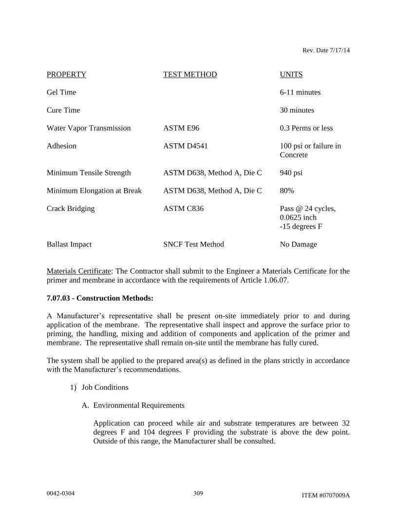
Rev. Date 7/17/14
ITEM #0707009A
PROPERTY TEST METHOD UNITS
Gel Time 6-11 minutes
Cure Time 30 minutes
Water Vapor Transmission ASTM E96 0.3 Perms or less
Adhesion ASTM D4541 100 psi or failure in
Concrete
Minimum Tensile Strength ASTM D638, Method A, Die C 940 psi
Minimum Elongation at Break ASTM D638, Method A, Die C 80%
Crack Bridging ASTM C836 Pass @ 24 cycles,
0.0625 inch
-15 degrees F
Ballast Impact SNCF Test Method No Damage
Materials Certificate: The Contractor shall submit to the Engineer a Materials Certificate for the
primer and membrane in accordance with the requirements of Article 1.06.07.
7.07.03 - Construction Methods:
A Manufacturer’s representative shall be present on-site immediately prior to and during
application of the membrane. The representative shall inspect and approve the surface prior to
priming, the handling, mixing and addition of components and application of the primer and
membrane. The representative shall remain on-site until the membrane has fully cured.
The system shall be applied to the prepared area(s) as defined in the plans strictly in accordance
with the Manufacturer’s recommendations.
1) Job Conditions
A. Environmental Requirements
Application can proceed while air and substrate temperatures are between 32
degrees F and 104 degrees F providing the substrate is above the dew point.
Outside of this range, the Manufacturer shall be consulted.
0042-0304 309
Rev. Date 7/17/14
ITEM #0707009A
The Applicator shall be provided with adequate disposal facilities for non-
hazardous waste generated during installation of the System. The applicator shall
follow safety instructions regarding respirators and safety equipment.
B. Safety Requirements
All open flames and spark producing equipment shall be removed from the work
area prior to commencement of application.
“No Smoking” signs shall be visibly posted at the job site during application of
the membrane waterproofing.
Non-related personnel in the work area shall be kept to a minimum.
2) Delivery, Storage and Handling
A. Packaging and Shipping
All components of the System shall be delivered to the site in the Manufacturer’s
packaging, clearly identified with the products type and batch number.
B. Storage and Protection
The Applicator shall be provided with a storage area for all components. The area
shall be cool, dry and out of direct sunlight and in accordance with the
Manufacturer’s recommendations and relevant health and safety regulations.
Copies of Material Safety Data Sheets (MSDS) for all components shall be kept
on site for review by the Engineer or other personnel.
C. Shelf Life - Membrane Components
Packaging of all membrane components shall include a shelf life date sealed by
the Manufacturer. No membrane components whose shelf life has expired shall be
used.
3) Inspection
Prior to priming of the surface, the Engineer, Applicator and Manufacturer’s
representative shall inspect and approve the prepared substrate.
Random tests for adequate tensile bond strength shall be conducted on the
substrate by the Applicator at the job site using an Elcometer Adhesion Tester in
accordance with the requirements of ASTM D4541. The minimum test frequency
shall be one per 5,000 square feet, but no less than three adhesion tests per bridge.
0042-0304 310
Rev. Date 7/17/14
ITEM #0707009A
Adequate surface preparation will be indicated by tensile bond strengths of primer to
the substrate greater than or equal to 100 psi or failure in the concrete.
If the tensile bond strength is lower than the minimum specified, the Engineer may
request additional substrate preparation. Any primer not adequately applied will be
removed and a new application effected at the Contractor’s expense as directed by
Engineer.
Cracks and joints shall be treated in accordance with the Manufacturer’s
recommendations as approved or directed by the Engineer.
4) Preparation
A. Protection
The Applicator shall be responsible for the protection of equipment and adjacent
areas from over spray or other contamination. Parapets and bridge joints shall be
masked prior to application of the materials.
B. Surface Preparation
The concrete deck shall have cured for a minimum of seven days in accordance
with applicable provisions of Section 6.01.03 of the Standard Specifications.
Surfaces shall be free of oil, grease, curing compounds, loose particles, moss,
algae, growth, laitance, friable matter, dirt, bituminous products, and previous
waterproofing materials. If required, degreasing shall be performed via detergent
washing in accordance with ASTM D4258.
The surface shall be abrasively cleaned in accordance with ASTM D4259 to
provide a sound substrate free from laitance.
The substrate shall be inspected after excavation and all spalls repaired prior to
placement of the prime coat. Spalls shall be repaired with rapid cure concrete
patch materials per the Engineer’s and Manufacturer’s recommendations.
Voids and blow holes on vertical surfaces shall be repaired in the same manner.
The surface profile of prepared substrate is not to exceed 1/4 inch (peak to valley)
and areas of minor surface deterioration of 1/2 inch and greater in depth shall also
be repaired. The extent and location of then surface patches shall require the
approval of the Engineer before the System is applied.
There shall be no visible moisture present on the surface at the time of the
application of the System. Compressed oil-free air and/or a light passing of a
propane torch may be used to dry the substrate.
0042-0304 311
Rev. Date 7/17/14
ITEM #0707009A
All steel components to receive membrane waterproofing shall be blast cleaned in
accordance with SSPC SP6 and coated with the membrane waterproofing system
within the same work shift.
5. Application
A. The Contractor shall retain an Applicator who is fully trained and licensed by the
membrane manufacturer who has successfully completed at least three spray
membrane projects in the past 5 years. The Contractor shall furnish the Engineer
with a list of references including contact persons along with addresses and phone
numbers of persons who supervised these projects. This information shall be
submitted to the Engineer prior to the start of construction. The Engineer shall
have sole authority to determine the adequacy and compliance of the submitted
information. Inadequate proof of ability to perform the work will be grounds to
reject proposed applicators.
B. The System shall be applied in three distinct steps as listed below:
Substrate preparation
Priming
Membrane application
C. Immediately prior to the application of any components of the System, the surface
shall be dry and any remaining dust or loose particles shall be removed using
clean, dry oil free compressed air or industrial vacuum.
D. Where the area to be treated is bound by a vertical surface (e.g. curb or wall), the
System may be continued up the vertical as necessary.
E. The handling, mixing and addition of components shall be performed in a safe
manner to achieve the desired results in accordance with the Manufacturer’s
recommendations or as approved or directed by the Engineer.
F. A neat finish with well-defined boundaries and straight edges shall be provided by
the Applicator.
G. Primer
The primer shall consist of one coat with an overall coverage rate of 125-175
square feet per gallon unless otherwise recommended in the manufacturer’s
written instructions.
All components shall be measured and mixed in accordance with the
Manufacturer’s recommendations.
0042-0304 312
Rev. Date 7/17/14
ITEM #0707009A
The primer shall be spray applied using a single component spray system
approved for use by the Manufacturer. If required by site conditions, brush or
roller application shall be allowed.
The primer shall be allowed to cure tack-free for a minimum of 30 minutes or as
required by the Manufacturer’s instructions, whichever time is greater, prior to
application of the first lift of waterproofing membrane.
Porous concrete (brick) may require a second coat of primer should the first coat
be absorbed.
H. Membrane
The waterproofing membrane shall consist of two coats with a film thickness of
60 mils per coat and a total of 120 mils to achieve an overall coverage rate of 13.0
square feet per gallon. The waterproofing membrane shall consist of two
coats of contrasting colors to aid in quality assurance and inspection.
The membrane shall be comprised of two liquid Components A and B and a
hardener powder which is to be added to Component B in accordance with the
Manufacturer’s recommendations.
The substrate shall be coated in a methodical manner. Checks for wet film
thickness shall be carried out typically once every 100 square feet, where product
gel time allows.
I. Repairs
If an area is left untreated or the membrane becomes damaged, a patch repair shall
be carried out to restore the integrity of the system. The damaged areas shall be
cut back to sound materials and wiped with solvent (e.g. acetone) up to a width of
at least 4 inches on the periphery, removing any contaminants unless otherwise
recommended by the manufacturer. The substrate shall be primed as necessary,
followed by the membrane. A continuous layer shall be obtained over the
substrate with a 4 inches overlap onto existing membrane.
Where the membrane is to be joined to existing cured material, the new
application shall overlap the existing one by at least 4 inches. Cleaning and
surface preparation on areas to be lapped shall be as recommended in the
manufacturer’s written instructions.
J. Application of Tack Coat
0042-0304 313

Rev. Date 7/17/14
ITEM #0707009A
1) A polymer-modified bitumen hot melt adhesive bond tack coat shall be
provided by the waterproof membrane Manufacturer and be fully compatible
with the liquid membrane. The tack coat shall be applied as per the
Manufacturer’s recommendations with all the guidelines regarding surfacing
strictly adhered to.
2) The membrane to be coated shall be clean and free from loose debris,
moisture, or other contaminants. Oil, diesel fuel, or grease shall be removed
with solvent approved by the Manufacturer.
6. Field Quality Control
The following tests shall be conducted by the Applicator or Manufacturer’s
representative and recorded on a form to be submitted to the Engineer. The testing
equipment shall be furnished by the Contractor.
Temperature: Air, substrate temperatures and dew point.
Adhesion Tests: Adhesion tests of the cured membrane to the substrate shall be
checked as per Section 3.
Membrane Thickness: Wet film thickness shall be checked every 100 square feet
using a gauge pin or standard comb type thickness gauge during application where
membrane gel time permits. Ultrasonic testing, calibrated point-penetrating
(destructive) testing, or other methods approved by the Engineer, shall be employed
for determination of dry film thickness in the event that rapid set time of the
membrane does not for allow for the use of wet film thickness testing methods.
Repair of the membrane system following destructive testing shall be in accordance
with the manufacturer’s recommendations.
Coverage Rates: Rates for all layers shall be monitored by checking quantity of
material used against the area covered.
7. Final Review
The Engineer and the Applicator shall jointly review the area(s) over which the
completed System has been installed. Any irregularities or other items that do not
meet the requirements of the Engineer shall be addressed at this time.
7.07.04 - Method of Measurement:
The quantity to be paid for under this item shall be the number of square yards of waterproofed
surface completed and accepted.
0042-0304 314
Rev. Date 7/17/14
ITEM #0707009A
7.07.05 - Basis of Payment:
This item will be paid for at the contract unit price per square yard of “Membrane Waterproofing
(Cold Liquid Elastomeric)”, complete in place, which price shall include all surface preparation,
furnishing and applying the system, quality control tests, and any necessary repairs and
remediation work as well as all materials, equipment, tools, labor incidental to this work.
Pay Item Pay Unit
Membrane Waterproofing S.Y.
(Cold Liquid Elastomeric)
0042-0304 315
04/01/10
ITEM #0707200A
ITEM #0707200A – GEOGRID
Description:
This work shall consist of furnishing, installing, and removing temporary geocell walls at
the locations indicated in the plans. The Plans indicate approximate lengths of the geocell walls.
The height of the walls shall be determined by the Contractor to fit the field conditions and to
improve the size of his working areas. The geocell walls shall be high-density polyethylene,
black, green or tan color, hexagonal or diamond type, perforated three-dimensional geocellular
confinement system, including anchoring systems and in accordance with these specifications, as
shown on the plans or as directed by the Engineer.
Materials:
The geocell product shall be constructed of UV protected high density polyethylene. Its
structure shall be dimensionally stable and able to retain its geometry under manufacture,
transport and installation. The polymer shall meet the requirements of all test methods and
standards per the manufacturer and in conformance of Section 1.06. Materials incidental to and
necessary for the installation of the geocell, such as, but not limited to a tendoning system for
anchoring, rebar anchors, j-bars, clips shall also conform to the requirements of the Manufacturer
of the geocell. The Contractor shall ensure that the geocell is delivered to the site in the
Manufacturer’s original, unopened containers and packaging, with labels clearly identifying
product name and Manufacturer. The geocell shall be stored in accordance with the
Manufacturer’s instructions and out of direct sunlight.
Construction Methods:
The temporary geocell walls shall be installed in accordance with the Manufacturer’s
instructions, and to the lines, grades and dimensions shown on the plans or as directed by the
Engineer.
At the close of construction the geocell walls shall be removed from the site.
Method of Measurement:
This work will be measured for payment by the actual number of square yards of geocell
wall installed as indicated on the plans or authorized by the Engineer.
Basis of Payment:
This work will be paid for at the contract unit price of “GEOGRID”, complete in place,
which price shall include all methods of anchoring the geocell to the ground, including j-hooks,
tendons, rebar, anchor clips, etc. The price for “GEOGRID” will also include all materials,
labor, tools and equipment incidental and necessary for the installation of the “GEOGRID”.
0042-0304 316

04/01/10
ITEM #0707200A
Pay Item Pay Unit
GEOGRID S.Y.
0042-0304 317
Rev. Date 10/17/14
ITEM #0712010A
ITEM #0712010A - REINFORCED SOIL SLOPE
Description: This work shall consist of furnishing material for and constructing a reinforced
soil slope, reinforced with geosynthetic soil reinforcement, in accordance with these
specifications and in reasonable close conformity to the lines, grades, and dimensions shown on
the plans or as directed by the Engineer.
Materials: Materials shall conform to the following requirements
1 - Geosynthetic Reinforcement Material - The geosynthetic reinforcement shall consist
of a geogrid or geotextile that can develop sufficient mechanical interaction with the surrounding
soil or rock. The geosynthetic reinforcement structure shall be dimensionally stable, able to
retain its geometry under construction stresses, and shall have high resistance to damage during
construction, to ultraviolet degradation, and to all forms of chemical and biological degradation
encountered in the soil being reinforced. The permeability of the geosynthetic reinforcement
shall be greater than the permeability of the reinforced fill soil.
Geogrid used as geosynthetic reinforcement shall be a regular network of integrally
connected polymer tensile elements consisting of either polypropylene (PP), polyethylene
(HDPE), or polyester (PET). The geogrid shall have certified properties as shown in Table 1.
Geotextile used as geosynthetic reinforcement may be woven or nonwoven but no “slit-
film” woven fabrics will be permitted. The geotextile shall have certified properties as shown in
Table 2. All property values represent Minimum Average Roll Value (MARV) in the weakest
principal direction and shall meet or exceed the values stated below.
The Contractor shall submit a manufacturer’s certification that the geosynthetic supplied
meets the requirements as shown in the respective table, measured in full accordance with all test
methods and standards specified, as set forth in these specifications, and in conformance with
Article 1.06.07.
The geosynthetic reinforcement shall be manufactured with a high degree of quality
control. The Manufacturer is responsible for establishing and maintaining a quality control (QC)
program to ensure compliance with the requirements of the specification. The purpose of the QC
testing program is to verify that the geosynthetic reinforcement being supplied to the project is
representative of the material used for performance testing and approval by the department.
Conformance testing shall be performed as part of the manufacturing process and may
vary for each type of product. As a minimum, the following index tests shall be considered as
applicable for an acceptable QA/QC program: Wide Width Tensile (ASTM D-4595 for
geotextiles and ASTM D-6637 for geogrids); Specific Gravity (HDPE only, ASTM D-1505);
Melt Flow Index (HDPE and PP only, ASTM D-1238); Intrinsic Viscosity (PET only, ASTM D-
4603); Carboxyl End Group (PET only, ASTM D-2455); and Single Rib Tensile (Geogrid only,
ASTMD-6637). Sampling and conformance testing shall be in accordance with ASTM D-4354.
Conformance testing procedures shall be established as noted in the specification. Geosynthetic
product acceptance shall be based on ASTM D-4759.
The quality control certificate shall include roll number and identification, sampling
procedures, and results of control test (including a description of test methods used).
0042-0304 318
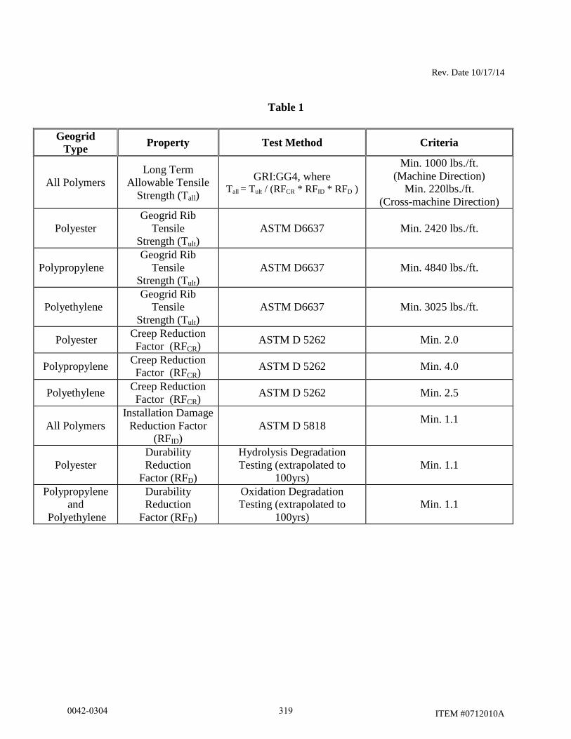
Rev. Date 10/17/14
ITEM #0712010A
Table 1
Geogrid
Type Property Test Method Criteria
All Polymers
Long Term
Allowable Tensile
Strength (Tall)
GRI:GG4, where Tall = Tult / (RFCR * RFID * RFD )
Min. 1000 lbs./ft.
(Machine Direction)
Min. 220lbs./ft.
(Cross-machine Direction)
Polyester
Geogrid Rib
Tensile
Strength (Tult)
ASTM D6637 Min. 2420 lbs./ft.
Polypropylene
Geogrid Rib
Tensile
Strength (Tult)
ASTM D6637 Min. 4840 lbs./ft.
Polyethylene
Geogrid Rib
Tensile
Strength (Tult)
ASTM D6637 Min. 3025 lbs./ft.
Polyester Creep Reduction
Factor (RFCR) ASTM D 5262 Min. 2.0
Polypropylene Creep Reduction
Factor (RFCR) ASTM D 5262 Min. 4.0
Polyethylene Creep Reduction
Factor (RFCR) ASTM D 5262 Min. 2.5
All Polymers
Installation Damage
Reduction Factor
(RFID)
ASTM D 5818 Min. 1.1
Polyester
Durability
Reduction
Factor (RFD)
Hydrolysis Degradation
Testing (extrapolated to
100yrs)
Min. 1.1
Polypropylene
and
Polyethylene
Durability
Reduction
Factor (RFD)
Oxidation Degradation
Testing (extrapolated to
100yrs)
Min. 1.1
0042-0304 319
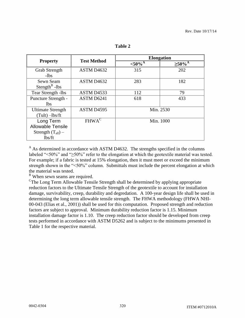
Rev. Date 10/17/14
ITEM #0712010A
Table 2
Property Test Method Elongation
<50%A
≥50%A
Grab Strength
-lbs
ASTM D4632 315 202
Sewn Seam
StengthB -lbs
ASTM D4632 283 182
Tear Strength -lbs ASTM D4533 112 79
Puncture Strength -
lbs
ASTM D6241 618 433
Ultimate Strength
(Tult) –lbs/ft
ASTM D4595 Min. 2530
Long Term Allowable Tensile
Strength (Tall) –
lbs/ft
FHWAC
Min. 1000
A As determined in accordance with ASTM D4632. The strengths specified in the columns
labeled “<50%” and “≥50%” refer to the elongation at which the geotextile material was tested.
For example; if a fabric is tested at 15% elongation, then it must meet or exceed the minimum
strength shown in the “<50%” column. Submittals must include the percent elongation at which
the material was tested. B When sewn seams are required.
CThe Long Term Allowable Tensile Strength shall be determined by applying appropriate
reduction factors to the Ultimate Tensile Strength of the geotextile to account for installation
damage, survivability, creep, durability and degredation. A 100-year design life shall be used in
determining the long term allowable tensile strength. The FHWA methodology (FHWA NHI-
00-043 (Elias et al., 2001)) shall be used for this computation. Proposed strength and reduction
factors are subject to approval. Minimum durability reduction factor is 1.15. Minimum
installation damage factor is 1.10. The creep reduction factor should be developed from creep
tests performed in accordance with ASTM D5262 and is subject to the minimums presented in
Table 1 for the respective material.
0042-0304 320
Rev. Date 10/17/14
ITEM #0712010A
2 - Compacted Granular Fill - Compacted Granular Fill shall conform to the requirements
of Article M.02.01.
3 - Turf Establishment with Erosion Control Matting - The materials for this work shall
conform to the requirements of Article M.13. The Erosion Control Matting shall be Class 1,
Type D. Anchors for the Erosion Control Matting shall be a 9 gage-U Shaped Staple, with a
minimum dimension of 12”x1”x12”.
Construction Methods: The Contractor shall insure that during all periods of shipment and
storage, the geosynthetic material is protected from mud, dirt, all deleterious materials that might
become affixed to it, and temperatures greater than 140oF. Follow manufacturer’s
recommendations with regards to protection from direct sunlight. At the time of installation, the
geosynthetic shall be free of any defects, including, but not limited to tears, punctures, flaws,
deterioration, or any damage due to manufacture, transportation, and storage.
All areas beneath the installation area for the geosynthetic reinforcement shall be
properly prepared as detailed on the plans, specified within this specification, or as directed by
the Engineer. All excavation required for construction of the slope shall conform to Article 2.02.
Subgrade surfaces shall be level. The subgrade surface shall also be free from deleterious
materials, loose soil, topsoil, organic soils, frozen soil, or any other unsuitable material. Prior to
placement of geosynthetic reinforcement, subgrade shall be proof-rolled to provide a uniform
and firm surface. Any soft areas, as determined by the Engineer, shall be excavated and replaced
with suitable compacted soils. The foundation surface shall be inspected and approved by the
Engineer prior to placement of geosynthetic and Compacted Granular Fill. Benching the backcut
into competent soil shall be performed as shown on the plans or as directed by the Engineer and
in conformance with Subarticle 2.02-5, paragraph 3, so as to ensure stability.
The geosynthetic shall be installed in accordance with the plans, specifications, and
manufacturer’s recommendation. The geosynthetic reinforcement shall be placed within the
layers of the Compacted Granular Fill as shown on the plans, or as directed by the Engineer.
The primary geosynthetic reinforcement shall be placed in continuous, longitudinal strips
in the direction of main reinforcement. The secondary geosynthetic reinforcement may be
placed with the cross-machine (weak) direction placed perpendicular to the roadway. If the
Contractor is unable to complete a required length with a single continuous length of geogrid, a
joint may be made with the Engineer’s approval. Only one joint per length of geogrid shall be
allowed. This joint shall be made for the full width of the strip by using a similar material with
similar strength. Joints in geogrid reinforcement shall be pulled and held taut during placement
of Compacted Granular Fill. The minimum length of geogrid placed shall be 6 feet. For primary
geogrids, joints shall not be placed within 6 feet of the slope face. Adjacent, overlying, and
underlying rolls of geogrid shall not have a joint within 6 feet of each other. Joints shall not be
permitted with geotextiles.
Horizontal coverage of less than 100% shall not be allowed. Adjacent strips of
geosynthetic need not be overlapped as long as 100% coverage is maintained.
Place only that amount of geosynthetic reinforcement required for immediately pending
work to prevent undue damage. After a layer of geosynthetic reinforcement has been placed, the
next succeeding layer of soil shall be placed and compacted as appropriate. After the specified
0042-0304 321
Rev. Date 10/17/14
ITEM #0712010A
soil layer has been placed, the next geogrid reinforcing layer shall be installed. The process shall
be repeated for each subsequent layer of geogrid reinforcement and soil.
Geosynthetic reinforcement shall be placed to lay flat and pulled tight prior to backfilling.
After a layer of geosynthetic reinforcement has been placed, suitable means, such as pins or
small piles of soil, shall be used to hold the geosynthetic reinforcement in position until the
subsequent soil layer can be placed.
During construction, the surface of the fill should be kept approximately horizontal.
Geosynthetic reinforcement shall be placed directly on the Compacted Granular Fill surface.
Geosynthetic reinforcements are to be placed within 3 inches of the design elevation view unless
otherwise directed by the Engineer. The Contractor shall verify correct orientation of the
geosyntethic reinforcement.
Compacted Granular Fill shall be placed and compacted as specified in Article 2.14, with
the following amendments. The Contractor shall be allowed a maximum lift of 12 inches. In
addition, the Compacted Granular Fill shall be placed, spread, and compacted in such a manner
to minimize the development of wrinkles and/or displacement of the geosynthetic reinforcement.
The Compacted Granular Fill shall be graded away from the slope crest and rolled at the end of
each work day to prevent ponding of water or erosion on the surface of the reinforced soil mass.
Tracked construction equipment shall not be operated directly upon the geosyntethic
reinforcement. A minimum fill thickness of 6 inches is required prior to operation of tracked
vehicles over the geosynthetic reinforcement. Turning of tracked vehicles should be kept to a
minimum to prevent tracks from displacing the fill and the geosynthetic reinforcement.
The Engineer may allow rubber tired equipment to pass over the geosynthetic
reinforcement at speeds less than 10mph. Sudden braking and sharp turning shall be avoided.
Turf Establishment with Erosion Control Matting shall be placed as specified in Article
9.50. Seeding and/or mulch shall be placed prior to placement of Erosion Control Matting. The
Turf Establishment with Erosion Control Matting shall be performed immediately upon
completion of each 5 foot vertical section of geosynthetic reinforcement and Compacted
Granular Fill. Anchors shall be placed and spaced such that there is 1 anchor per 2 square feet of
matting. The Erosion Control Matting shall be placed horizontal along the face of the slope with
the upper matting overlapping the lower matting by 12”. Anchors shall be placed in the center of
the overlap with 1 foot spacing.
The Contractor shall begin construction of the reinforced soil slope no earlier than March
15th
, and have the reinforced slope constructed, seeded, and Erosion Control Matting installed by
October 15th
of the same calendar year. Out of season seeding will not be permitted.
The Contractor shall construct and maintain the temporary soil berm as shown on the
plans. The temporary soil berm shall be placed immediately upon completion of the placement of
all the geogrid reinforcement and Compacted Granular Fill. It shall remain in place and be
maintained by the Contractor until placement of the pavement and barrier curb on top of the
slope, as shown on the plans, has been completed.
Method of Measurement: This work will be paid for on a lump sum basis and will not be
measured for payment.
0042-0304 322
Rev. Date 10/17/14
ITEM #0712010A
Basis of Payment: This work will be paid for at the contract lump sum price for “Reinforced
Soil Slope”, complete in place, which price shall include all work shown within the pay limits
shown on the contract drawings for the reinforced soil slope including but not limited to the
following: supply and installation of Geosynthetic reinforcement; Compacted Granular Fill;
Slope Underdrain; Outlet for Underdrain; Turf Establishment with Erosion Control Matting;
temporary soil berm and outlet; and earth excavation. The price shall also include all tools,
labor, equipment, and material incidental thereto. If boulders in excess of 1 cubic yard are
encountered in the excavation, the boulder(s) shall be removed and paid for in accordance with
Article 2.02, “Rock Excavation”.
Pay Item Pay Unit
Reinforced Soil Slope L. S.
0042-0304 323
Rev. Date 5/11/12
ITEM #0714050A
ITEM #0714050A – TEMPORARY EARTH RETAINING SYSTEM
7.14.01 - Description: For purposes of this specification, temporary earth retaining system shall
be any type of adequately braced temporary retaining wall such as temporary sheet piling which
the Contractor elects to build to satisfy, and which does satisfy, the condition that existing
facilities be properly retained during excavation or fill for the placement of substructure or other
facilities.
Temporary earth retaining system shall be designed by the Contractor and constructed where
shown on the plans. This system shall be removed upon completion of the permanent work,
except that some sections may be left in place when so ordered by the Engineer.
7.14.02 - Materials: Materials of steel sheet piling shall conform to the requirement of ASTM
A328. Timber sheet piling shall conform to the requirements of Subarticle M.09.01-1. Materials
other than steel or timber, or a combination of these may be used provided they are properly
designed for the purpose intended. Systems utilizing other material(s) shall conform to the
manufacturer’s specifications and project specifications. The parts list shall be furnished for the
proprietary system and the Contractor shall provide the material certificates for the parts.
7.14.03 - Construction Methods: Temporary earth retaining system shall be safely designed and
carried to adequate depths and braced as necessary for proper performance of the work. The
design shall be in accordance with the latest edition of the applicable AASHTO design
specifications. The support system shall provide an approximately plumb face at the plan
location and grades, and shall support all loads imposed by the embankment including
hydrostatic forces as applicable; live load surcharge from vehicular traffic and construction
equipment; and lateral forces from temporary or permanent highway railing systems located on
supported earthen sections. The support system shall be designed and detailed to interface with
substructure units as required to retain the earthen material. The design and details of the
temporary earth retaining system shall be compatible with all construction staging requirements
including highway railing systems, removal of existing retaining walls, and shall be detailed to
not interfere with the staged construction of approach slabs.
Construction of the earth retaining system shall be such as to permit excavation or fill as
required. Interior dimensions shall be such as to give sufficient clearance for the required
construction including the installation of both plumb and battered piles and the placement of
forms. Movement of the system or bracing which prevent the proper completion of the
substructure shall be corrected at the sole expense of the Contractor. No part of the temporary
earth retaining system or bracing shall be allowed to extend into the substructure without written
permission of the Engineer.
Working drawings and design calculations for temporary earth retaining system shall be
submitted in accordance with the requirements of Article 1.05.02(2). The working drawings and
design calculations shall be prepared, sealed, and signed by a Professional Engineer, licensed in
the state of Connecticut. The furnishing of such plans shall not serve to relieve the Contractor of
0042-0304 324
Rev. Date 5/11/12
ITEM #0714050A
any part of his responsibility for the safety of the work or for the successful completion of the
project.
Unless otherwise ordered by the Engineer, all parts of the temporary earth retaining system shall
be removed upon completion of the work for which it was provided. The excavation shall be
backfilled and properly compacted, prior to removal of the system unless otherwise permitted by
the Engineer. Temporary earth retaining system may be left in place at the option of the
Contractor if so permitted by the Engineer, provided that it is cut off at an elevation as directed
by the Engineer and the cutoffs removed from the site.
7.14.04 - Method of Measurement: Temporary earth retaining system will be measured for
payment by the number of square feet of temporary retaining wall completed and accepted, as
computed from the horizontal and vertical payment lines shown on the plans or as ordered by the
Engineer. If no payment limits are shown on the plans, the limits used for payment will be the
actual horizontal limit of temporary earth retaining system installed and accepted, and the
vertical limit as measured from the bottom of the exposed face of the wall system to the top of
the retained earth behind the system. The measurement for temporary earth retaining system
which is used as a common wall for staged construction will be the horizontal payment limit
shown on the plans and the greater vertical dimension of the common wall face.
The Contractor may propose earth retaining system limits beyond the payment limits shown on
the plans, subject to the approval of the Engineer. At locations where such expanded limits are
approved by the Engineer, the payment limit will not be increased beyond the maximum limit
shown on the plans. No additional payment will be made to the Contractor for the area of earth
retaining system beyond the stated payment limits.
No measurement will be made of end extensions or returns necessary for the safety of the
retained facility. Earth retaining system ordered left in place by the Engineer shall be measured
in accordance with the Item “Earth Retaining System Left In Place”. Earth retaining systems left
in place solely at the Contractor’s option, and with the Engineer’s permission, will not have an
additional payment at the contract unit price per square feet for “Earth Retaining System Left in
Place.”
7.14.05 - Basis of Payment: Payment for this work will be made at the contract unit price per
square feet for “Temporary Earth Retaining System,” measured as described above, which price
shall include all design, materials, equipment and labor incidental to the construction and
removal of the temporary earth retaining system required at the locations specified on the plans
including removal of obstructions, repair and correction, adjustments or reconstruction required
by the plans. Any common earth retaining system for staged construction will be measured for
payment only once.
0042-0304 325
Rev. Date 5/11/12
ITEM #0714050A
At locations where the Contractor proposes and is allowed to leave all or parts of the earth
retaining system in place, no additional payment will be made to the Contractor when such
material left in place is encountered in subsequent construction activities including, but not
limited to trench excavation in areas of soil nail walls.
Pay Item Pay Unit
Temporary Earth Retaining System SF
0042-0304 326
ITEM #0715050A
ITEM #0715050A - EARTH RETAINING SYSTEM LEFT IN PLACE
Description:
This specification covers only that portion of the temporary earth retaining system that may be
ordered left in place by the Engineer or designated in the plans to be left in place.
Materials:
Vacant
Construction Methods:
The Contractor shall submit to the Engineer for approval, plans showing the proposed method of
construction prior to the start of such construction.
Method of Measurement:
Earth retaining system material left in place will be measured for payment by the square foot.
This area will be measured or computed from the horizontal and vertical payment limits shown
on the plans or as ordered. If no payment limits are shown on the plans, the limits used for
payment will be the actual horizontal limit of temporary earth retaining system ordered or
designated in the plans to be left in place, and the vertical limit will correspond to the method of
measurement of the temporary earth retaining system.
Temporary earth retaining system left in place solely at the Contractor's option, and with the
Engineer's permission, will not be measured for payment.
Basis of Payment:
Payment for this work will be made as follows:
That portion of the temporary earth retaining system ordered or designated in the plans to be left
in place will be paid for at the contract unit price per square foot for "Earth Retaining System
Left in Place," applying to one or more structures or portions of structures, which price shall
include only the cost of material left in place. All other expenses shall be paid for under the item
for "Temporary Earth Retaining System."
Pay Item Pay Unit
Earth Retaining System Left in Place s.f.
0042-0304 327
ITEM #0821189A
ITEM #0821995A
ITEM #0821189A – CONCRETE BARRIER TRANSITION SECTION
ITEM #0821995A – PRECAST CONCRETE END–BLOCK
Description: Under this item, the Contractor shall furnish and install concrete barrier transition
section and a precast concrete end-block in the locations shown on the plans, or as directed by
the Engineer.
Materials: Materials for the above items shall conform to all the requirements of Section
8.21.02
Construction Methods: The contract items listed above may be precast and follow the methods
of Article 8.21.03 or cast-in-place in accordance with Article 6.01.03. The items shall be coated
with a penetrating sealer protective compound that meets the requirements of Article M.03.09.
Method of Measurement:
1. The Concrete Barrier Transition Section shall be measured for payment along the
centerline of the top of the item being measured and will be the actual number of linear
feet of the item installed and accepted.
2. The Precast Concrete End-Block will be measured for payment by the number of units
installed and accepted.
Basis of Payment:
1. The work for "Concrete Barrier Transition Section," will be paid for at the contract unit
price per linear foot of the size specified, complete in place, which price shall include all
backfill, sand backfill, joint seal, materials, reinforcing steel, dowels, penetrating sealer
protective compound, transportation, equipment, tools and labor incidental thereto.
2. The work for "Precast Concrete End-Block," will be paid for at the contract unit price
each for “Precast Concrete End-Block”, complete in place, which price shall include all
backfill, joint seal, materials, reinforcing steel, dowels, penetrating sealer protective
compound, transportation, equipment, tools and labor incidental thereto.
3. Backfill placed between a double row of concrete barrier curb and/or concrete barrier
transition section shall be paid for under the item "Compacted Granular Fill."
4. The concrete cap shall be paid for under the item "Class 'A' Concrete."
Pay Item Pay Unit
Concrete Barrier Transition Section L.F.
Precast Concrete End–Block EA.
0042-0304 328
Rev. Date 12/18/14
ITEM #0822005A
ITEM #0822006A
ITEM #0822005A – TEMPORARY PRECAST CONCRETE BARRIER
CURB (STRUCTURE)
ITEM #0822006A – RELOCATED TEMPORARY PRECAST CONCRETE
BARRIER CURB (STRUCTURE)
Article 8.22.01 – Description:
Work under this item shall consist of furnishing, installing, relocating and removing
temporary precast concrete barrier curb, suitable for attachment to bridge decks, as shown on the
plans or as directed by the Engineer. This work shall also include the drilling, grouting and later
removal of anchor bolts, and the cleaning and subsequent grouting and sealing of anchor bolt
holes after the barrier is removed.
Article 8.22.02 – Materials:
1. Concrete shall conform to the requirements of Subarticle M.l4.01-l amended as
follows:
a. Concrete shall have a minimum 28 day strength (f’c) of 4000 psi.
b. Coarse Aggregate shall conform to the requirements of Subarticle M.03.01-l and
to the grading requirements of Class "F".
c. Fine Aggregate shall be Light in color and shall conform in color and type to the
samples on file at the Laboratory of the Department of Transportation located in
Rocky Hill, Connecticut.
d. Cement for light concrete shall be Type III or Type IIIA Portland cement or light
colored cement approved by the Engineer.
e. The entrained air content shall not be less than 5% or more than 7%.
f. Manufacturer identification and date of manufacture shall be permanently marked
on the barrier curb in the location shown on the plans.
2. Reinforcing steel shall conform to the requirements of ASTM A615, Grade 60.
3. Lifting hooks, keys, bolts, devices and attachments shall be of the size indicated on the
plans or of a design satisfactory for the purpose intended as approved by the Engineer.
4. Removable anchor bolts shall conform to "KELIBOND/KELIBOND ANCHORS coated
with KELISLIP" as manufactured by Kelken-Gold. Inc., 3220 Bordentown Ave., Parlin,
0042-0304 329
Rev. Date 12/18/14
ITEM #0822005A
ITEM #0822006A
New Jersey 08859, or approved equal. Anchor bolts shall conform to the requirements of
ASTM A325.
5. Galvanizing shall conform to the requirements of ASTM Al23.
6. The grout used in patching the remaining holes in the concrete deck after the removal of
the temporary barrier shall be non-shrink grout conforming to Subarticle M.03.01-12.
7. The pourable sealant used in patching the remaining holes in the overlay after the
removal of the temporary barrier shall be a cold-applied bituminous sealer conforming to
the requirements of Subarticle M.08.01-18.
8. The delineators shall be fabricated of aluminum, steel, plastic or of a material approved
by the Engineer. The reflective sheeting shall be encapsulated lens sheeting conforming
to Article M.18.09.01. Delineator fastening hardware or adhesive shall be suitable for the
purpose intended.
Article 8.22.03 – Construction Methods:
1. Precast Units: Concrete barrier units shall be precast in an approved plant in conformance
with the applicable requirements of Subarticles 5.14.03-4, 6, 7, 8 and 15, supplemented
as follows:
Forms for precast concrete barrier units shall be of substantial construction, so as to
produce a smooth dense surface with a uniform appearance. Form oil shall be a non-
staining type. Pockets for anchor bolts shall be formed as shown on the plans. Air holes
on exposed surfaces shall be filled immediately, after removal of the forms to the
satisfaction of the Engineer.
2. Installation: Temporary precast concrete barrier units shall be placed as shown on the
plans or as directed by the Engineer, on a firm even surface as to produce a smooth
continuous barrier curb.
Anchor bolts shall be installed in properly drilled holes of the size and depth shown on
the plans in strict accordance with the Manufacturer's directions. Care shall be taken not
to drill holes into or through existing structural steel.
The Contractor shall submit the following to the Engineer for approval: type of drill,
diameter of bit, method of cleaning holes, and method of placement of adhesive bonding
material. Specifications and recommendations for the aforementioned may be obtained
from the Manufacturer of the adhesive bonding material. The weight of the drill shall not
exceed 20 pounds.
0042-0304 330
Rev. Date 12/18/14
ITEM #0822005A
ITEM #0822006A
Drilling methods shall not cause spalling, cracking, or other damage to the concrete.
Those areas damaged by the Contractor shall be repaired by him in a manner suitable to
the Engineer and at no expense to the State.
The Contractor shall take necessary precautions to prevent any materials from falling
onto the roadway or into the watercourse below.
For the adhesive bonding material, a Materials Certificate will be required in accordance
with Article 1.06.07, confirming the conformance of the adhesive bonding material to the
requirements set forth in these specifications.
The temporary concrete barrier shall be maintained by the Contractor during all stages of
construction. Any damaged material shall be removed and replaced by the Contractor at
his expense.
When the temporary barrier is no longer required, it shall be removed from the work site
and become the property of the Contractor.
3. Patching Holes: After removal of the concrete barriers, the holes in the new concrete
deck shall be blown clean with an air jet. The grout shall then be mixed and placed as
shown on the plans and in strict accordance with the Manufacturer's direction. Allow
grout to cure for a minimum of 24 hours before placing the pourable sealant in the
remaining hole in the bituminous wearing surface.
4. Delineators: The delineators shall be installed in the center on top of the barrier at the
locations designated on the plans. They may be fastened by hardware or adhesive and
must be maintained in good condition at all times.
DE-7 delineators shall be used when the barriers are on the right side of traffic or
dividing traffic in the same direction. DE-7A delineators shall be used when the barriers
are on the left side of traffic. DE-7B delineators shall be used when the barriers divide
opposing traffic lanes. DE-7C delineators shall be used with the yellow side on the left
side of traffic when traffic is alternated.
Article 8.22.04 – Method of Measurement:
This work will be measured for payment along the centerline of the top of the concrete
barrier and will be the actual number of linear feet of temporary concrete barrier furnished,
installed and accepted.
Relocated temporary concrete barrier will be measured along the centerline of the top of
the concrete barrier each time the barrier has been relocated as directed by the Engineer,
including to and from the storage area. Storage of concrete barrier curb will not be measured for
payment.
0042-0304 331
Rev. Date 12/18/14
ITEM #0822005A
ITEM #0822006A
Delineators will be measured in accordance with Article 12.05.04.
Article 8.22.05 – Basis of Payment:
This work will be paid for at the contract unit price, per linear foot, for "Temporary
Precast Concrete Barrier Curb (Structure)", complete in place, which price shall include all
furnishing, transportation, storage, materials, including concrete, reinforcing steel connecting
rods, removable anchor bolts conforming to the "KELIBOND/KELIBOND ANCHORS coated
with KELISLIP" or approved equal, drilling holes in existing deck, initial installation, removal
and also including hardware and incidental materials, equipment, tools, and labor incidental
thereto. Any temporary barriers that become lost, damaged or defaced shall be replaced by the
Contractor at no cost to the State.
The relocation of the temporary precast concrete barrier curb will be paid for at the
contract unit price, per linear foot, for "Relocated Temporary Precast Concrete Barrier Curb
(Structure)", complete in place, which price shall include all; transportation, materials, drilling
holes in the deck, installation, removal and also including; hardware and incidental materials,
equipment, tools, and labor incidental thereto.
Delineators will be paid for in accordance with Article 12.05.05.
Pay Item Pay Unit
Temporary Precast Concrete Barrier Curb (Structure) L.F.
Relocated Temporary Precast Concrete Barrier Curb (Structure) L.F.
0042-0304 332
Rev. Date 12/16/14
ITEM #0822014A
ITEM #0822014A – RELOCATE STATE-OWNED TEMPORARY
PRECAST CONCRETE BARRIER CURB PC/MI
Work under this item shall conform to the requirements of Section 8.22 of the Standard
specifications Form 816, supplemented and amended as follows:
8.22.01 Description: Work under this item shall consist of relocating existing State owned
precast concrete barrier curb present on the existing bridge to a designated State facility.
8.22.04 Method of Measurement: This work will be measured for payment by the Haul
required to relocate all the existing barrier to the State facility designated in the Notice to
Contractors. Storage of concrete barrier curb will not be measured for Payment.
9.50.05 Basis of Payment: This work will be paid for at the contract unit price for the Haul,
which price shall include removal, transportation, and placement of the barrier curb and all
materials, maintenance, equipment, tools, labor, and work incidental thereto.
Pay Item Pay Unit
Relocate State-Owned Temporary Precast Haul
Concrete Barrier Curb PC/MI
0042-0304 333
Rev. Date 6/15/05
ITEM #0952001A
ITEM #0952001A – SELECTIVE CLEARING AND THINNING
Section 9.52 is amended as follows:
Article 9.52.03 – Construction Methods is supplemented as follows:
Where directed by the Engineer, materials to be cut, trimmed or removed shall be those items
that restrict visibility to an extruded aluminum sign to less than 800 ft (244 m). The entire sign
will be visible for 800 ft (244 m) measured from the center of the left-travel lane approaching the
sign, as viewed from a 3.5 ft (1.1 m) height above the roadway.
All trees scheduled to be removed shall be visibly marked or flagged by the Contractor at least
seven days prior to the cutting of such trees.
The Engineer will inspect the identified trees and verify the limits of clearing and thinning prior
to the Contractor proceeding with his cutting operation.
0042-0304 334

Rev. Date 07/23/12
(Recommended to be included on Projects exceeding $5,000,000
Or Resurfacing or Safety Improvements Projects exceeding $10,000,000) Delete this heading prior to inclusion into the project documents.
ITEM #0969000A
ITEM #0969000A - PROJECT COORDINATOR
Section 1.05.08 of the Standard Specifications is hereby deleted and replaced with the following:
Description: Under this item the Contractor shall furnish the services of an administrative
employee, entitled the Project Coordinator, for this project to coordinate and expedite all phases
of the work required for the project and to ensure that the construction schedule is maintained.
The minimum lump sum bid for this item shall be equal to 0.5% of the Contractor’s total bid.
Failure of the Contractor to bid at least the minimum amount will result in the Department
adjusting the Contractor’s bid to include the minimum bid amount for this item.
The Project Coordinator shall be submitted for approval by name, in writing, with a resume of
his qualifications, within seven (7) calendar days of the award of the Contract, but not later than
the Preconstruction Meeting, and shall not be changed without prior written notice to the
Department.
This resume must demonstrate the Project Coordinator is experienced and versatile in the
preparation, interpretation and modification of Critical Path Method (CPM) construction
schedules. This must include successful completion of at least three (3) construction projects of
similar complexity, where he served in a lead scheduling capacity. If the Contractor does not
have a person in their company that has these skills, then the Contractor shall engage the services
of a Consultant, subject to the approval of the Engineer, for the scheduling work required. If a
Consultant is engaged, they shall be present at the first meeting, along with the Project
Contractor, prepared to discuss, in detail, the methods and techniques he proposes to use.
Thereafter, the Project Coordinator or the Consultant responsible for updating the CPM Schedule
shall attend all meetings between the Contractor, its Subcontractors, and any other meetings,
which will affect the CPM schedule. The Contractor shall prepare CPM Schedules utilizing the
latest version of Primavera Project Planner software as described more fully hereinafter.
If the Contract includes Article 1.20 the following requirement shall also apply:
The Project Coordinator shall have, in addition to the above noted requirements, a minimum of
eight (8) years’ experience related to commercial/industrial building construction as a Project
Coordinator performing duties similar to those required herein.
The Project Coordinator shall have knowledge of all trades involved in the construction,
including civil/site work, environmental work, concrete work, masonry work, steel work, wood
work, electrical work, and mechanical work.
0042-0304 335
Rev. Date 07/23/12
(Recommended to be included on Projects exceeding $5,000,000
Or Resurfacing or Safety Improvements Projects exceeding $10,000,000) Delete this heading prior to inclusion into the project documents.
ITEM #0969000A
Other combinations of experience and education totaling ten (10) years in commercial building
construction will be considered subject to the approval of the Engineer.
Computer Software and Printer: The Contractor shall provide the following equipment with
all the required maintenance and repairs (to include labor and parts) throughout the Contract life.
The Engineer reserves the right to expand or relax the specification to adapt to the software and
hardware limitations and availability.
The Contractor shall provide the Engineer with a licensed copy registered in the Department’s
name of the latest versions of the software listed and maintain customer support services offered
by the software producer for the duration of the project. The Contractor shall deliver to the
Engineer all supporting documentation for the software and hardware including any instructions
or manuals.
A. Software – Minimum Specification: The Contractor shall provide the Engineer with a
licensed copy of the latest version of the Primavera Contractor – Deluxe Version
scheduling software, registered in the Department’s name, and maintain the Primavera
customer support service contract over the duration of the project.
B. HP Officejet Pro K8600 Color Printer – Minimum or equivalent (to be installed as a local
printer on a computer provided under the Construction Field Office specification):
Paper – 11 in x17 in, 8.5 in x 11 in and duplex/double-side print
Resolution – 1200x1200 DPI
Print Drivers – Must support HP PCL6.
RAM – 32 MB RAM
Print speed – 10 ppm – color, 13 ppm - black
Printer cable – 6 ft (1.8 m)
The Contractor is responsible for service and repairs to all computer hardware. All repairs must
be performed within 24 hours. If the repairs require more than a 24 hours then a replacement
must be provided.
Construction Methods: The Project Coordinator shall attend all meetings between the
Contractor and the Department, the Contractor and its Subcontractors, and any other meetings
that affect the progress of the job. The Project Coordinator shall be knowledgeable of the status
of all parts of the work throughout the length of the Contract.
The Contractor shall prepare a CPM Schedule in accordance with the pertinent provisions of
"Section 1.03 - Award and Execution of Contract," "Section 1.05 - Control of the Work," and
"Section 1.08 - Prosecution of Progress" of the Standard Specifications. The schedule shall
incorporate the Sequence of Construction as outlined on the Plans and in the Specifications. All
0042-0304 336

Rev. Date 07/23/12
(Recommended to be included on Projects exceeding $5,000,000
Or Resurfacing or Safety Improvements Projects exceeding $10,000,000) Delete this heading prior to inclusion into the project documents.
ITEM #0969000A
other limiting factors that affect construction shall also be incorporated into the schedule. All
milestones or constrained dates within the schedule shall be clearly indicated.
0042-0304 337
Rev. Date 07/23/12
(Recommended to be included on Projects exceeding $5,000,000
Or Resurfacing or Safety Improvements Projects exceeding $10,000,000) Delete this heading prior to inclusion into the project documents.
ITEM #0969000A
The CPM schedule shall contain a list of activities that represent the major elements of the
project. At a minimum, this list should include a breakdown by individual structure or stage,
including major components of each. The schedule shall contain sufficient detail to describe the
progression of the work in a comprehensive manner. As a guide, 10 to 15 activities should be
provided for each $1 million of contract value.
The following list of items is provided as an example only and is not meant to be all-inclusive
(or all-applicable):
General Items Applicable to all projects
Contractual Constraints including but not limited to
- Winter shutdowns
- Environmental permits/applications time of year restrictions
- Milestones
- Third Party approvals
- Long lead time items (procurement and fabrication of major elements)
- Adjacent Projects or work by others
Award
Notice to Proceed
Signing (Construction, temporary, permanent by location)
Mobilization
Permits as required
Field Office
Utility Relocations
Submittals/shop drawings/working drawings/product data
Construction of Waste Stock pile area
Clearing and Grubbing
Earthwork (Borrow, earth excavation, rock excavation, etc.)
Traffic control items (including illumination and signalization)
Pavement markings
Roadway Construction (Breakdown into components)
Drainage (Breakdown into components)
Culverts
Final Plantings (including turf establishment)
Final Cleanup
The following additional guidelines supplement the general guidelines listed above for the
specific project types indicated:
A. For bridges and other structures, include major components such as: Abutments,
wingwalls, piers, decks and retaining walls; further breakdown by footings, wall sections,
parapets etc.
0042-0304 338
Rev. Date 07/23/12
(Recommended to be included on Projects exceeding $5,000,000
Or Resurfacing or Safety Improvements Projects exceeding $10,000,000) Delete this heading prior to inclusion into the project documents.
ITEM #0969000A
Temporary Earth Retention Systems
Cofferdam and Dewatering
Structure Excavation
Piles/test piles
Temporary Structures
Removal of Superstructure
Bearing Pads
Structural Steel (Breakdown by fabrication, delivery, installation, painting etc.)
Bridge deck
B. Multiple location projects such as traffic signal, incident management, lighting, planting
and guiderail projects will be broken down first by location and then by operation. Other
major activities of these types of projects should include, but are not limited to:
Installation of anchors
Driving posts
Foundations
Trenching and Backfilling
Installation of Span poles/mast arms
Installation of luminaires
Installation of cameras
Installation of VMS
Hanging heads
Sawcut loops
Energizing equipment
C. Facility Projects shall reflect the same breakdown of the project as the schedule of values:
CSI Division 2 – Existing Conditions
CSI Division 3 – Concrete
CSI Division 4 – Masonry
CSI Division 5 – Metals
CSI Division 6 – Wood, Plastic, and Composites
CSI Division 7 – Thermal and Moisture Protection
CSI Division 8 – Openings
CSI Division 9 – Finishes
CSI Division 10 – Specialties
CSI Division 11 – Equipment
CSI Division 12 – Furnishings
CSI Division 13 – Special Construction
CSI Division 14 – Conveying Equipment
0042-0304 339
Rev. Date 07/23/12
(Recommended to be included on Projects exceeding $5,000,000
Or Resurfacing or Safety Improvements Projects exceeding $10,000,000) Delete this heading prior to inclusion into the project documents.
ITEM #0969000A
CSI Division 21 – Fire Suppression
CSI Division 22 – Plumbing
CSI Division 23 – Heating, Ventilating, and Air Conditioning
CSI Division 26 – Electrical
CSI Division 27 – Communications
CSI Division 28 – Electronic Safety and Security
CSI Division 31 – Earthwork
CSI Division 32 – Exterior Improvements
CSI Division 33 – Utilities
The CPM schedule will be compiled using this list of major activities. It will be the
responsibility of the contractor to detail all milestones, environmental permit “window” periods;
winter shutdowns etc. and include them on their schedule under the corresponding dates.
Proper relationship between all major activities shall be indicated. Node numbers shall be
coded such that the major activities shown on the Critical Path Schedule shall be easily
referenced to the Detailed Project Schedule when it is developed. Break down the work covered
under each Special Provision, or Division and Section of Article 1.20 of the Standard
Specifications, into individual activities required and logically group related activities together
within the CPM.
If the Engineer determines that additional detail is necessary, the Contractor shall provide it.
All documents, which require approval by the Department, shall be clearly identified within the
schedule. The Department and any outside agency shall be allocated a minimum number of
calendar days in accordance with Article 1.20-1.05.02. If Article 1.20 does not apply, then the
Department shall be allocated a minimum of thirty (30) calendar days (exclusive of weekends
and holidays) for review and approval of each submittal. Any submittals requiring approval by
an outside Agency (ConnDEEP, Coast Guard, Army Corps of Engineers, etc.) shall be allocated
a minimum of sixty (60) calendar days. The Department shall not be held responsible for any
delay associated with the approval or rejection of any substitution or other revisions proposed by
the Contractor.
The schedule shall indicate the logic of the work for the major elements and components of
work under the Contract, such as the planned mobilization of plant and equipment, sequences of
operations, procurement of materials and equipment, duration of activities, type of relationship,
lag time (if any), and such other information as it is necessary to present a clear statement of the
intended activities.
The Contractor is responsible to inform its subcontractor(s) and supplier(s) of the project
schedule and any relevant updates.
0042-0304 340
Rev. Date 07/23/12
(Recommended to be included on Projects exceeding $5,000,000
Or Resurfacing or Safety Improvements Projects exceeding $10,000,000) Delete this heading prior to inclusion into the project documents.
ITEM #0969000A
The schedules shall consist of a network technique of planning, scheduling and control, shall be
a clear statement of the logical sequence of work to be done, and shall be prepared in such a
manner that the Contractor's work sequence shall be optimized between early start and late start
restraints. The Contractor shall use the same criteria in a consistent manner throughout the term
of the project. If, at any time, the Contractor alters logic, original durations, and descriptions,
adds activities or activity codes or in any way modifies the Baseline Schedule, they must notify
the Engineer of the change, in writing, presenting in detail the reasons for the change. The
Engineer reserves the right to approve or reject any such change.
The critical path of the project must be identified on the CPM schedule. The critical path is the
longest-duration path through the network. The significance of the critical path is that the
activities that lie on it cannot be delayed without delaying the project. Because of its impact on
the entire project, critical path analysis is an important aspect of project planning.
The critical path can be identified by determining the following four parameters for each
activity:
ES - earliest start time: the earliest time at which the activity can start given that its
precedent activities must be completed first.
EF - earliest finish time, equal to the earliest start time for the activity plus the time
required to complete the activity.
LF - latest finish time: the latest time at which the activity can be completed without
delaying the project.
LS - latest start time, equal to the latest finish time minus the time required to complete
the activity.
The float time for an activity is the time between its earliest and latest start time, or between its
earliest and latest finish time. Float is the amount of time that an activity can be delayed past its
earliest start or earliest finish without delaying the project. Delays to activities on the critical
path through the project network in which no float exists, that is, where ES=LS and EF=LF will
delay the project.
Float available in the schedule, at any time shall not be considered for the exclusive use of
either the State or the Contractor. During the course of contract execution, any float generated
due to the efficiencies of either party is not for the sole use of the party generating the float;
rather it is a shared commodity to be reasonably used by either party. Project float will be a
resource available to both the State and the Contractor.
Each CPM Schedule submittal shall be in the form of an activity on node diagram (precedence
diagramming method) and shall include at a minimum; an Early Start computer sort, a Total
Float computer sort, an Activity Number computer sort, a Schedule Diagram in the Time Scaled
0042-0304 341
Rev. Date 07/23/12
(Recommended to be included on Projects exceeding $5,000,000
Or Resurfacing or Safety Improvements Projects exceeding $10,000,000) Delete this heading prior to inclusion into the project documents.
ITEM #0969000A
Logic format and a backup data CD-ROM which includes all Primavera project files. The
diagrams shall be on 2' x 3' sheets. Additional, more detailed diagrams for important aspects or
phases of the work will be required on large or complex projects.
Activity I.D. numbers shall be keyed to the item numbers assigned on the detailed estimate
sheet. The first three digits (four digits for highway illumination, signing, traffic signals and
utility work) of the activity I.D. number shall be identical to the first three digits of the item
number in the contract. The remaining digits may be used to provide unique, orderly and
sequential I.D. numbers for each activity.
Activity codes shall be added to the schedule dictionary at the direction of the Engineer. At a
minimum, activity codes for responsibility (prime, subcontractor by name), location of work
(bridge #, span #, sta. #, site, building, type of work, etc.) and stage or phase number should be
included.
The Project Coordinator shall be required to prepare and submit the following documents:
1. Baseline Submittal Requirements: The Contractor shall be guided by the following
requirements when submitting the CPM Schedules for review and approval.
a. Within ten (10) calendar days after award, the Contractor and their scheduler will attend
a meeting to discuss the submittal requirements. Within twenty (20) calendar days after
contract award, the Contractor shall prepare and submit for review and approval a
detailed CPM Schedule for all work. The review and approval process may take up to
21 calendar days and is more fully described in paragraph (b) of this section.
The work shall be broken out into sufficient detail such that no activity has a duration
greater than twenty (20) days, unless approved by the Engineer. As a guide, 25 to 35
activities should be provided per $1 million of contract work. The Engineer shall be
the sole judge as to whether the schedule is sufficiently detailed.
All work shall be shown in sufficient detail such that the Critical Path may be identified
and the schedule shall incorporate all contract milestones. Upon approval, this
schedule shall be designated the "Baseline".
Failure to submit and gain approval for the "Baseline" may result in the Contractor
being found in violation of Article 1.02.02 of the Standard Specifications. All elapsed
contract time prior to the approval of the “Baseline”, will be considered to be accurately
represented by the actual as-built schedule of that time period. No claims for delays
during that period will be allowed.
0042-0304 342
Rev. Date 07/23/12
(Recommended to be included on Projects exceeding $5,000,000
Or Resurfacing or Safety Improvements Projects exceeding $10,000,000) Delete this heading prior to inclusion into the project documents.
ITEM #0969000A
The approval of a Baseline Schedule shall in no way waive the requirements of the
contract nor shall it excuse the Contractor from any obligations under the contract.
In no instance will the Contractor be permitted to commence work on any significant
portion of the work for which a Baseline Schedule has not been approved without prior
written approval from the Department.
b. The Contractor, represented by the Project Coordinator and/or the Consultant, shall
participate with the Engineer in the review and evaluation of each schedule submitted.
Any and all revisions made necessary as a result of this review shall be made by the
Contractor and a revised schedule submitted within ten (10) calendar days. Any further
revisions required thereafter shall also be submitted for approval within (10) calendar
days.
2. Monthly Updates: Each month, as of a calendar date mutually acceptable to the Contractor
and to the Engineer, the Contractor shall deliver to the Engineer three (3) prints of all
required schedule diagrams and tabulations. In addition, the Contractor shall deliver one
(1) copy of the project backup data CD-ROM(s), which includes all Primavera project files.
The schedule shall be updated to show the work actually accomplished during the
preceding months, the actual time consumed for each activity, and the estimated time
remaining for any activity which as been started but not completed.
The monthly update shall also include revisions to the CPM schedule necessitated by
revisions to the project, which have been directed by the Engineer (including, but not
limited to extra work) during the month preceding the update. Similarly, any changes to
the schedule due to Contractor influences shall also be included within the schedule.
Any changes or revisions made to the approved Baseline shall be identified in narrative
form in a cover letter accompanying the monthly update. The Engineer reserves the right
to approve or reject any such changes. The narrative shall also describe in general terms
the progress of the work since the last schedule update and shall identify any items of
special interest. If the schedule revisions extend the Contract completion date, due to extra
or added work or delays beyond the control of the Contractor, the Contractor must submit a
request in writing for an extension of time in accordance with Article 1.08.08. This request
should be supported by the schedules submitted previously.
The Contractor shall be responsible to develop mitigation measures for all delays,
regardless of responsibility, and to identify all time and cost impacts to the work associated
with those mitigation measures.
Except as otherwise authorized by the Engineer, monthly submissions received after the
due date are considered late.
0042-0304 343
Rev. Date 07/23/12
(Recommended to be included on Projects exceeding $5,000,000
Or Resurfacing or Safety Improvements Projects exceeding $10,000,000) Delete this heading prior to inclusion into the project documents.
ITEM #0969000A
The reports required for each monthly update shall include all reports generated for
approval of the CPM Schedule for that particular portion of the work. On larger or
complex projects, the Engineer may require the schedule data sorted by an activity code to
better reflect the progression of the work. Summary barcharts may also be required.
3. Biweekly Schedules: Each week, the Contractor shall be required to produce and submit to
the Engineer a biweekly schedule showing all activities planned for the following two week
period. This short term schedule may be handwritten; however a two week “look ahead”
filter from the CPM Schedule is preferred. The biweekly schedule shall clearly indicate all
work planned on a crew basis for the two week period.
4. Recovery Schedules: If, in the opinion of the Engineer, the updated schedule indicates that
the Project has fallen behind schedule, or that a revision in sequence of operations may be
necessary for any other reason, absent a justifiable time extension, the Contractor shall
immediately institute all necessary steps to improve the Project’s progress and shall submit
such revised network diagrams, tabulations and operational plans, as may be deemed
necessary by the Engineer, to demonstrate the manner in which an acceptable rate of
progress will be regained.
Should the Contractor not demonstrate an ability to regain an acceptable rate of progress,
the Engineer shall require the schedule to be resource loaded with the next monthly update.
No additional compensation will be allowed for resource loading the schedule.
5. As-Built Schedules: Within thirty (30) days of completion of the project, including all
corrective work, the Contractor shall submit an "As-Built Schedule" showing the actual
progress of work. The Contractor shall submit three prints of this final CPM Schedule and
one project backup data CD-ROM which include all Primavera project files for the
Engineer's exclusive use.
If the contract includes Article 1.20 the following shall also apply:
6. Daily Construction Reports: The Project Coordinator shall assist the Engineer in the
preparation of a daily construction report by ensuring that each of the Contractor’s
employees and subcontractors working on the Project Site on a given day signs the
Engineer’s sign-in sheet for that day; and by keeping and providing to the Engineer its own
daily list of employees and subcontractors who worked on the Project Site on that day.
Method of Measurement: Within ten (10) calendar days of the award of the Contract, the
Contractor shall submit to the Engineer for approval a breakdown of its lump sum bid price for
this item detailing:
0042-0304 344

Rev. Date 07/23/12
(Recommended to be included on Projects exceeding $5,000,000
Or Resurfacing or Safety Improvements Projects exceeding $10,000,000) Delete this heading prior to inclusion into the project documents.
ITEM #0969000A
1. The development cost to prepare the Baseline Schedule in accordance with these
specifications. Development costs shall not exceed 25% of the total cost of the item and
shall include costs to furnish and install all specified hardware.
2. The cost to provide the services of the Project Coordinator, including costs to prepare and
submit the Monthly Updates; furnish and submit any Recovery Schedules; furnish and
submit Two Week Look Ahead Schedules and maintenance of and supplies for the
specified hardware noted above. A per month cost will be derived by taking this cost
divided by the number of Contract months remaining from the date of acceptance of the
Baseline Schedule.
3. The cost of submission and certification of the As-Built Schedule in accordance with these
specifications. The submission and certification costs shall be no less than 2% of the total
cost of the item.
4. Substantiation showing that the costs submitted are reasonable based on the Contractor's
lump sum bid.
Upon approval of the payment schedule by the Engineer, payments for work performed will be
made as follows:
1. Upon approval of the "Baseline" Schedule by the Engineer, the lump sum development
cost will be certified for payment.
2. Upon receipt of each monthly update of the "Baseline" Schedule, the per month cost for the
services of the Project Coordinator will be certified for payment.
3. Upon approval of the As-Built Schedule by the Engineer, the lump sum submission and
certification cost will be certified for payment.
Basis of Payment: This service will be paid for at the contract lump sum price for "Project
Coordinator" complete, which price shall include the preparation and submission of all
schedules, updates, reports and submittals. The lump sum price shall also include the cost of
providing a complete, licensed copy of the Primavera software which will remain the property of
the Engineer, and all materials, equipment, labor and work incidental of this service.
The lump sum price will be certified for payment as described in "Method of Measurement"
subject to the following conditions:
1. Any month where the monthly update of the "Baseline" CPM schedule is submitted late,
without authorization from the Engineer, will result in the following actions:
0042-0304 345
Rev. Date 07/23/12
(Recommended to be included on Projects exceeding $5,000,000
Or Resurfacing or Safety Improvements Projects exceeding $10,000,000) Delete this heading prior to inclusion into the project documents.
ITEM #0969000A
a. The monthly payment for the Project Coordinator item shall be deferred to the next
monthly payment estimate. If any monthly submittal is more than thirty (30) calendar
days late, there will be no monthly payment for the services of the Project Coordinator.
b. The greater of 5% of the monthly payment estimate or $25,000 shall be retained from
the monthly payment estimate until such time as the Contractor submits all required
reports.
c. If in the opinion of the Engineer, the contractor is not in compliance with this
specification, the Engineer may withhold all project payments.
2. In the event the project extends beyond the original completion date by more than thirty
(30) calendar days, and a time extension is granted to the Contractor, the Department may
require additional CPM updates which will be paid at the per month cost for the services of
the Project Coordinator.
3. If, in the opinion of the Engineer, the contractor is not in compliance with this specification
or has failed to submit a "Baseline", monthly update or Recovery Schedule for any portion
of the work in accordance with this specification, it shall result in the withholding of all
contract payments until the schedule is submitted to, and approved by, the Engineer.
Pay Item Pay Unit
Project Coordinator L.S.
0042-0304 346
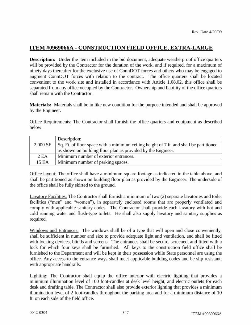
Rev. Date 4/20/09
ITEM #0969066A
ITEM #0969066A - CONSTRUCTION FIELD OFFICE, EXTRA-LARGE
Description: Under the item included in the bid document, adequate weatherproof office quarters
will be provided by the Contractor for the duration of the work, and if required, for a maximum of
ninety days thereafter for the exclusive use of ConnDOT forces and others who may be engaged to
augment ConnDOT forces with relation to the contract. The office quarters shall be located
convenient to the work site and installed in accordance with Article 1.08.02, this office shall be
separated from any office occupied by the Contractor. Ownership and liability of the office quarters
shall remain with the Contractor.
Materials: Materials shall be in like new condition for the purpose intended and shall be approved
by the Engineer.
Office Requirements: The Contractor shall furnish the office quarters and equipment as described
below.
Description:
2,000 SF Sq. Ft. of floor space with a minimum ceiling height of 7 ft. and shall be partitioned
as shown on building floor plan as provided by the Engineer.
2 EA Minimum number of exterior entrances.
15 EA Minimum number of parking spaces.
Office layout: The office shall have a minimum square footage as indicated in the table above, and
shall be partitioned as shown on building floor plan as provided by the Engineer. The underside of
the office shall be fully skirted to the ground.
Lavatory Facilities: The Contractor shall furnish a minimum of two (2) separate lavatories and toilet
facilities (“men” and “women”), in separately enclosed rooms that are properly ventilated and
comply with applicable sanitary codes. The Contractor shall provide each lavatory with hot and
cold running water and flush-type toilets. He shall also supply lavatory and sanitary supplies as
required.
Windows and Entrances: The windows shall be of a type that will open and close conveniently,
shall be sufficient in number and size to provide adequate light and ventilation, and shall be fitted
with locking devices, blinds and screens. The entrances shall be secure, screened, and fitted with a
lock for which four keys shall be furnished. All keys to the construction field office shall be
furnished to the Department and will be kept in their possession while State personnel are using the
office. Any access to the entrance ways shall meet applicable building codes and be slip resistant,
with appropriate handrails.
Lighting: The Contractor shall equip the office interior with electric lighting that provides a
minimum illumination level of 100 foot-candles at desk level height, and electric outlets for each
desk and drafting table. The Contractor shall also provide exterior lighting that provides a minimum
illumination level of 2 foot-candles throughout the parking area and for a minimum distance of 10
ft. on each side of the field office.
0042-0304 347
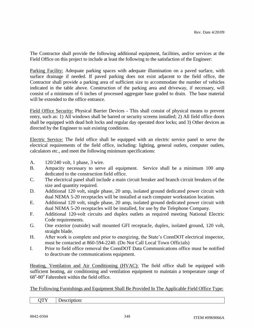
Rev. Date 4/20/09
ITEM #0969066A
The Contractor shall provide the following additional equipment, facilities, and/or services at the
Field Office on this project to include at least the following to the satisfaction of the Engineer:
Parking Facility: Adequate parking spaces with adequate illumination on a paved surface, with
surface drainage if needed. If paved parking does not exist adjacent to the field office, the
Contractor shall provide a parking area of sufficient size to accommodate the number of vehicles
indicated in the table above. Construction of the parking area and driveway, if necessary, will
consist of a minimum of 6 inches of processed aggregate base graded to drain. The base material
will be extended to the office entrance.
Field Office Security: Physical Barrier Devices - This shall consist of physical means to prevent
entry, such as: 1) All windows shall be barred or security screens installed; 2) All field office doors
shall be equipped with dead bolt locks and regular day operated door locks; and 3) Other devices as
directed by the Engineer to suit existing conditions.
Electric Service: The field office shall be equipped with an electric service panel to serve the
electrical requirements of the field office, including: lighting, general outlets, computer outlets,
calculators etc., and meet the following minimum specifications:
A. 120/240 volt, 1 phase, 3 wire.
B. Ampacity necessary to serve all equipment. Service shall be a minimum 100 amp
dedicated to the construction field office.
C. The electrical panel shall include a main circuit breaker and branch circuit breakers of the
size and quantity required.
D. Additional 120 volt, single phase, 20 amp, isolated ground dedicated power circuit with
dual NEMA 5-20 receptacles will be installed at each computer workstation location.
E. Additional 120 volt, single phase, 20 amp, isolated ground dedicated power circuit with
dual NEMA 5-20 receptacles will be installed, for use by the Telephone Company.
F. Additional 120-volt circuits and duplex outlets as required meeting National Electric
Code requirements.
G. One exterior (outside) wall mounted GFI receptacle, duplex, isolated ground, 120 volt,
straight blade.
H. After work is complete and prior to energizing, the State’s ConnDOT electrical inspector,
must be contacted at 860-594-2240. (Do Not Call Local Town Officials)
I. Prior to field office removal the ConnDOT Data Communications office must be notified
to deactivate the communications equipment.
Heating, Ventilation and Air Conditioning (HVAC): The field office shall be equipped with
sufficient heating, air conditioning and ventilation equipment to maintain a temperature range of
68o-80
o Fahrenheit within the field office.
The Following Furnishings and Equipment Shall Be Provided In The Applicable Field Office Type:
QTY Description:
0042-0304 348
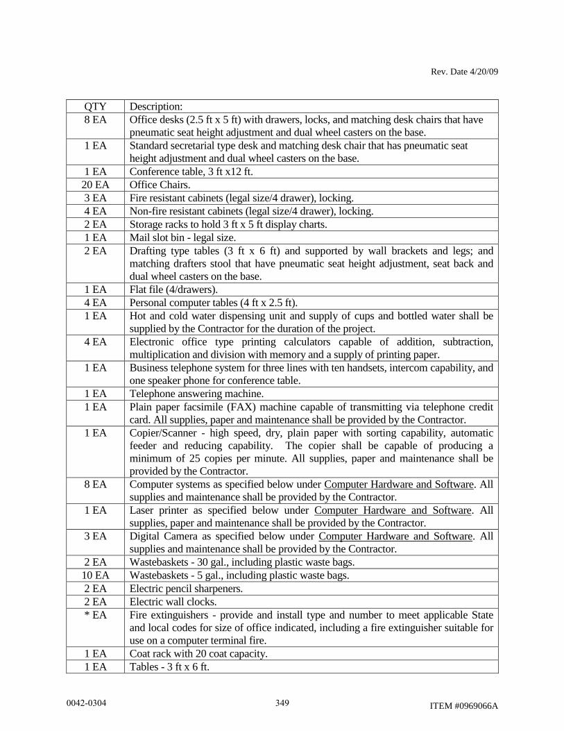
Rev. Date 4/20/09
ITEM #0969066A
QTY Description:
8 EA Office desks (2.5 ft x 5 ft) with drawers, locks, and matching desk chairs that have
pneumatic seat height adjustment and dual wheel casters on the base.
1 EA Standard secretarial type desk and matching desk chair that has pneumatic seat
height adjustment and dual wheel casters on the base.
1 EA Conference table, 3 ft x12 ft.
20 EA Office Chairs.
3 EA Fire resistant cabinets (legal size/4 drawer), locking.
4 EA Non-fire resistant cabinets (legal size/4 drawer), locking.
2 EA Storage racks to hold 3 ft x 5 ft display charts.
1 EA Mail slot bin - legal size.
2 EA Drafting type tables (3 ft x 6 ft) and supported by wall brackets and legs; and
matching drafters stool that have pneumatic seat height adjustment, seat back and
dual wheel casters on the base.
1 EA Flat file (4/drawers).
4 EA Personal computer tables (4 ft x 2.5 ft).
1 EA Hot and cold water dispensing unit and supply of cups and bottled water shall be
supplied by the Contractor for the duration of the project.
4 EA Electronic office type printing calculators capable of addition, subtraction,
multiplication and division with memory and a supply of printing paper.
1 EA Business telephone system for three lines with ten handsets, intercom capability, and
one speaker phone for conference table.
1 EA Telephone answering machine.
1 EA Plain paper facsimile (FAX) machine capable of transmitting via telephone credit
card. All supplies, paper and maintenance shall be provided by the Contractor.
1 EA Copier/Scanner - high speed, dry, plain paper with sorting capability, automatic
feeder and reducing capability. The copier shall be capable of producing a
minimum of 25 copies per minute. All supplies, paper and maintenance shall be
provided by the Contractor.
8 EA Computer systems as specified below under Computer Hardware and Software. All
supplies and maintenance shall be provided by the Contractor.
1 EA Laser printer as specified below under Computer Hardware and Software. All
supplies, paper and maintenance shall be provided by the Contractor.
3 EA Digital Camera as specified below under Computer Hardware and Software. All
supplies and maintenance shall be provided by the Contractor.
2 EA Wastebaskets - 30 gal., including plastic waste bags.
10 EA Wastebaskets - 5 gal., including plastic waste bags.
2 EA Electric pencil sharpeners.
2 EA Electric wall clocks.
* EA Fire extinguishers - provide and install type and number to meet applicable State
and local codes for size of office indicated, including a fire extinguisher suitable for
use on a computer terminal fire.
1 EA Coat rack with 20 coat capacity.
1 EA Tables - 3 ft x 6 ft.
0042-0304 349
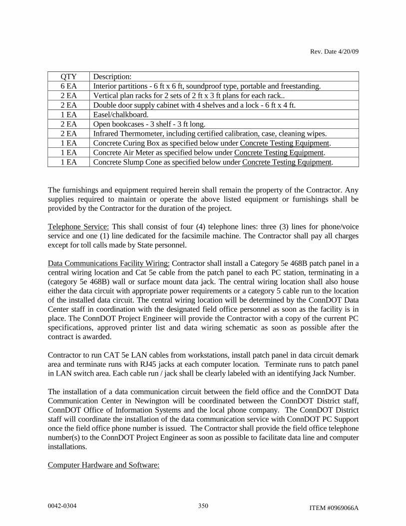
Rev. Date 4/20/09
ITEM #0969066A
QTY Description:
6 EA Interior partitions - 6 ft x 6 ft, soundproof type, portable and freestanding.
2 EA Vertical plan racks for 2 sets of 2 ft x 3 ft plans for each rack..
2 EA Double door supply cabinet with 4 shelves and a lock - 6 ft x 4 ft.
1 EA Easel/chalkboard.
2 EA Open bookcases - 3 shelf - 3 ft long.
2 EA Infrared Thermometer, including certified calibration, case, cleaning wipes.
1 EA Concrete Curing Box as specified below under Concrete Testing Equipment.
1 EA Concrete Air Meter as specified below under Concrete Testing Equipment.
1 EA Concrete Slump Cone as specified below under Concrete Testing Equipment.
The furnishings and equipment required herein shall remain the property of the Contractor. Any
supplies required to maintain or operate the above listed equipment or furnishings shall be
provided by the Contractor for the duration of the project.
Telephone Service: This shall consist of four (4) telephone lines: three (3) lines for phone/voice
service and one (1) line dedicated for the facsimile machine. The Contractor shall pay all charges
except for toll calls made by State personnel.
Data Communications Facility Wiring: Contractor shall install a Category 5e 468B patch panel in a
central wiring location and Cat 5e cable from the patch panel to each PC station, terminating in a
(category 5e 468B) wall or surface mount data jack. The central wiring location shall also house
either the data circuit with appropriate power requirements or a category 5 cable run to the location
of the installed data circuit. The central wiring location will be determined by the ConnDOT Data
Center staff in coordination with the designated field office personnel as soon as the facility is in
place. The ConnDOT Project Engineer will provide the Contractor with a copy of the current PC
specifications, approved printer list and data wiring schematic as soon as possible after the
contract is awarded.
Contractor to run CAT 5e LAN cables from workstations, install patch panel in data circuit demark
area and terminate runs with RJ45 jacks at each computer location. Terminate runs to patch panel
in LAN switch area. Each cable run / jack shall be clearly labeled with an identifying Jack Number.
The installation of a data communication circuit between the field office and the ConnDOT Data
Communication Center in Newington will be coordinated between the ConnDOT District staff,
ConnDOT Office of Information Systems and the local phone company. The ConnDOT District
staff will coordinate the installation of the data communication service with ConnDOT PC Support
once the field office phone number is issued. The Contractor shall provide the field office telephone
number(s) to the ConnDOT Project Engineer as soon as possible to facilitate data line and computer
installations.
Computer Hardware and Software:
0042-0304 350

Rev. Date 4/20/09
ITEM #0969066A
The ConnDOT Project Engineer will provide the Contractor with a copy of the current PC
specifications, approved printer list and data wiring schematic as soon as possible after the
contract is awarded.
Before ordering the computer hardware and software, the Contractor must submit a copy of their
proposed PC specifications and the type of printer to the ConnDOT Project Engineer for review
by the ConnDOT Data Center. If the specification meets or exceeds the minimum specifications
listed below, then the Contractor will be notified that the order may be placed.
Before any equipment is delivered to the Data Center, arrangements must be made a minimum of
24 hours in advance by contacting 860-594-3500. All software, hardware and licenses listed
below shall be clearly labeled, specifying the (1) Project No., (2) Contractor Name, (3) Project
Engineer’s Name and (4) Project Engineer’s Phone No., and shall be delivered to the ConnDOT
Data Center, 2710 Berlin Turnpike, Newington, CT, where it will be configured and prepared for
field installation. Installation will then be coordinated with ConnDOT field personnel and the
computer system specified will be stationed in the Department’s project field office.
The computer system furnished shall have all software and hardware necessary for the complete
installation of the latest versions of the software listed, and therefore supplements the minimum
specifications below. The Engineer reserves the right to expand or relax the specification to
adapt to the software and hardware limitations and availability, the compatibility with current
agency systems, and to provide the Department with a computer system that can handle the
needs of the project. This requirement is to ensure that the rapid changing environment that
computer systems have experienced does not leave the needs of the project orphan to what has
been specified. There will not be any price adjustment due to the change in the minimum system
requirements.
The Contractor shall provide the Engineer with a licensed copy registered in the Department’s
name of the latest versions of the software listed and maintain customer support services offered
by each software producer for the duration of the Contract. The Contractor shall deliver to the
Engineer all supporting documentation for the software and hardware including any instructions
or manuals. The Contractor shall provide original backup media for the software.
The Contractor shall provide the computer system with all required supplies, maintenance and
repairs (including labor and parts) throughout the Contract life.
Once the Contract has been completed, the computer will remain the property of the Contractor.
Prior to the return of any computer(s) to the Contractor, field personnel will coordinate with the
Data Center personnel for the removal of Department owned equipment, software, data, and
associated equipment.
A) Computer – Minimum Specification:
Processor – Intel® Core 2 Duo Processor (2.00 GHz, 800 MHz FSB 2MB L2 Cache)
Memory – 2 GB DIMM DDR2 667MHz.
Monitor – 19.0 inch LCD color monitor.
0042-0304 351
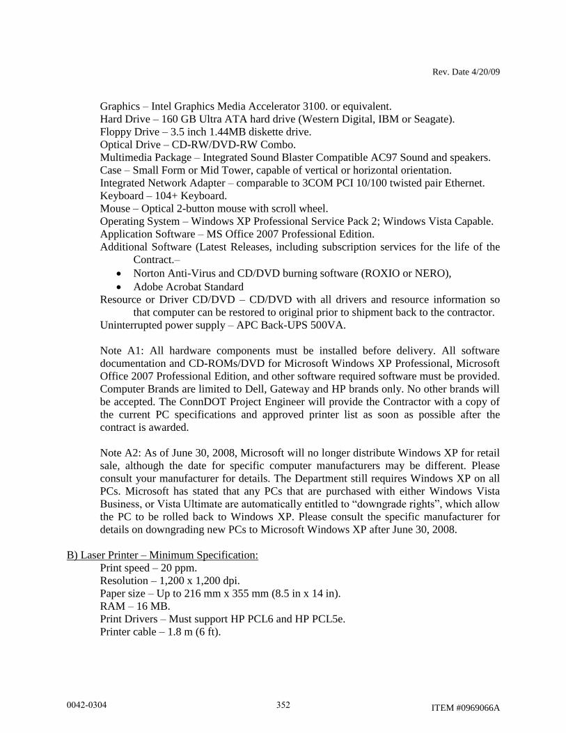
Rev. Date 4/20/09
ITEM #0969066A
Graphics – Intel Graphics Media Accelerator 3100. or equivalent.
Hard Drive – 160 GB Ultra ATA hard drive (Western Digital, IBM or Seagate).
Floppy Drive – 3.5 inch 1.44MB diskette drive.
Optical Drive – CD-RW/DVD-RW Combo.
Multimedia Package – Integrated Sound Blaster Compatible AC97 Sound and speakers.
Case – Small Form or Mid Tower, capable of vertical or horizontal orientation.
Integrated Network Adapter – comparable to 3COM PCI 10/100 twisted pair Ethernet.
Keyboard – 104+ Keyboard.
Mouse – Optical 2-button mouse with scroll wheel.
Operating System – Windows XP Professional Service Pack 2; Windows Vista Capable.
Application Software – MS Office 2007 Professional Edition.
Additional Software (Latest Releases, including subscription services for the life of the
Contract.–
Norton Anti-Virus and CD/DVD burning software (ROXIO or NERO),
Adobe Acrobat Standard
Resource or Driver CD/DVD – CD/DVD with all drivers and resource information so
that computer can be restored to original prior to shipment back to the contractor.
Uninterrupted power supply – APC Back-UPS 500VA.
Note A1: All hardware components must be installed before delivery. All software
documentation and CD-ROMs/DVD for Microsoft Windows XP Professional, Microsoft
Office 2007 Professional Edition, and other software required software must be provided.
Computer Brands are limited to Dell, Gateway and HP brands only. No other brands will
be accepted. The ConnDOT Project Engineer will provide the Contractor with a copy of
the current PC specifications and approved printer list as soon as possible after the
contract is awarded.
Note A2: As of June 30, 2008, Microsoft will no longer distribute Windows XP for retail
sale, although the date for specific computer manufacturers may be different. Please
consult your manufacturer for details. The Department still requires Windows XP on all
PCs. Microsoft has stated that any PCs that are purchased with either Windows Vista
Business, or Vista Ultimate are automatically entitled to “downgrade rights”, which allow
the PC to be rolled back to Windows XP. Please consult the specific manufacturer for
details on downgrading new PCs to Microsoft Windows XP after June 30, 2008.
B) Laser Printer – Minimum Specification:
Print speed – 20 ppm.
Resolution – 1,200 x 1,200 dpi.
Paper size – Up to 216 mm x 355 mm (8.5 in x 14 in).
RAM – 16 MB.
Print Drivers – Must support HP PCL6 and HP PCL5e.
Printer cable – 1.8 m (6 ft).
0042-0304 352
Rev. Date 4/20/09
ITEM #0969066A
Note B1: Laser printer brands are limited to Hewlett-Packard and Savin brands only. The
ConnDOT Project Engineer will provide the Contractor with a copy of the current PC
specifications and approved printer list as soon as possible after the contract is awarded.
Note B2: It is acceptable to substitute (1) a high-speed multi-function all-in-one
printer/copier/scanner/fax machines listed on the approved printer list in place of one
required laser printer and fax machine, and (2) a multi-function all-in-one
printer/copier/scanner/fax machine listed on the approved printer list in place of the second
required laser printer and fax machine. Only one of these devices is required to be set-up to
function as the one required fax machine.
C) Digital Camera – Minimum Specification:
Optical – 5 mega pixel, with 3x optical zoom.
Memory – 2 GB.
Features – Date/time stamp feature.
Connectivity – USB cable or memory card reader.
Software – Must be compatible with Windows XP and Vista.
Power – Rechargeable battery and charger.
The Contractor is responsible for service and repairs to all computer hardware. All repairs must
be performed with-in 48 hours. If the repairs require more than a 48 hours then a replacement
must be provided. All supplies, paper and maintenance for the computers, laptops, printers, copiers,
and fax machines shall be provided by the Contractor.
Concrete Testing Equipment: If the Contract includes items that require compressive strength
cylinders for concrete, in accordance with the Schedule of Minimum Testing Requirements for
Sampling Materials for Test, the Contractor shall provide the following. All testing equipment will
remain the property of the Contractor at the completion of the project.
A) Concrete Cylinder Curing Box – meeting the requirements of Section 6.12 of the Standard
Specifications.
B) Air Meter – The air meter provided shall be in good working order and will meet the
requirements of AASHTO T 152.
C) Slump Cone Mold – Slump cone, base plate, and tamping rod shall be provided in like-new
condition and meet the requirements of AASHTO T119, Standard Test Method for Slump
of Hydraulic-Cement Concrete.
Insurance Policy: The Contractor shall provide a separate insurance policy, with no deductible, in
the minimum amount of forty thousand dollars ($40,000.00) in order to insure all State-owned data
equipment and supplies used in the office against all losses. The Contractor shall be named insured
on that policy, and the Department shall be an additional named insured on the policy. These losses
0042-0304 353
Rev. Date 4/20/09
ITEM #0969066A
shall include, but not be limited to: theft, fire, and physical damage. The Department will be
responsible for all maintenance costs of Department owned computer hardware. In the event of
loss, the Contractor shall provide replacement equipment in accordance with current Department
equipment specifications, within seven days of notice of the loss. If the Contractor is unable to
provide the required replacement equipment within seven days, the Department may provide
replacement equipment and deduct the cost of the equipment from monies due or which may
become due the Contractor under the contract or under any other contract. The Contractor's
financial liability under this paragraph shall be limited to the amount of the insurance coverage
required by this paragraph. If the cost of equipment replacement required by this paragraph should
exceed the required amount of the insurance coverage, the Department will reimburse the
Contractor for replacement costs exceeding the amount of the required coverage.
Maintenance: During the occupancy by the Department, the Contractor shall maintain all
facilities and furnishings provided under the above requirements, and shall maintain and keep the
office quarters clean through the use of weekly professional cleaning to include, but not limited
to, washing & waxing floors, cleaning restrooms, removal of trash, etc. Exterior areas shall be
mowed and clean of debris. A trash receptacle (dumpster) with weekly pickup (trash removal)
shall be provided. Snow removal, sanding and salting of all parking, walkway, and entrance
ways areas shall be accomplished during a storm if on a workday during work hours,
immediately after a storm and prior to the start of a workday. If snow removal, salting and
sanding are not completed by the specified time, the State will provide the service and all costs
incurred will be deducted from the next payment estimate.
Method of Measurement: The furnishing and maintenance of the construction field office will be
measured for payment by the number of calendar months that the office is in place and in operation,
measured to the nearest month.
There will not be any price adjustment due to any change in the minimum computer system
requirements.
Basis of Payment: The furnishing and maintenance of the construction field office will be paid at
the listed unit price per month for the respective item “Construction Field Office, Extra-Large”,
which price shall include all material, equipment, labor, utility services and work incidental thereto.
The cost of providing the parking area, external illumination, trash removal and snow and ice
removal shall be included in the monthly unit price bid for the respective item “Construction Field
Office, Extra-Large”.
The State will be responsible for payment of data communication user fees and for toll calls by State
personnel.
Pay Item Pay Unit
Construction Field Office, Extra-Large Month
0042-0304 354
Rev. Date 1/2008
ITEM #0970006A
ITEM #0970007A
ITEM #0970006A - TRAFFICPERSON (MUNICIPAL POLICE OFFICER)
ITEM #0970007A - TRAFFICPERSON (UNIFORMED FLAGGER)
9.70.01—Description: Under this item the Contractor shall provide the services of
Trafficpersons of the type and number, and for such periods, as the Engineer approves for the
control and direction of vehicular traffic and pedestrians. Traffic persons requested solely for the
contractor’s operational needs will not be approved for payment.
9.70.03—Construction Method: Prior to the start of operations on the project requiring the use of
Trafficpersons, a meeting will be held with the Contractor, Trafficperson agency or firm,
Engineer, and State Police, if applicable, to review the Trafficperson operations, lines of
responsibility, and operating guidelines which will be used on the project. A copy of the
municipality’s billing rates for Municipal Police Officers and vehicles, if applicable, will be
provided to the Engineer prior to start of work.
On a weekly basis, the Contractor shall inform the Engineer of their scheduled operations for the
following week and the number of Trafficpersons requested. The Engineer shall review this
schedule and approve the type and number of Trafficpersons required. In the event of an
unplanned, emergency, or short term operation, the Engineer may approve the temporary use of
properly clothed persons for traffic control until such time as an authorized Trafficperson may be
obtained. In no case shall this temporary use exceed 8 hours for any particular operation.
If the Contractor changes or cancels any scheduled operations without prior notice of same as
required by the agency providing the Trafficpersons, and such that Trafficperson services are no
longer required, the Contractor will be responsible for payment at no cost to the Department of
any show-up cost for any Trafficperson not used because of the change. Exceptions, as approved
by the Engineer, may be granted for adverse weather conditions and unforeseeable causes
beyond the control and without the fault or negligence of the Contractor.
Trafficpersons assigned to a work site are to only take direction from the Engineer.
Trafficpersons shall wear a high visibility safety garment that complies with OSHA, MUTCD,
ASTM Standards and the safety garment shall have the words "Traffic Control" clearly visible
on the front and rear panels (minimum letter size 2 inches (50 millimeters). Worn/faded safety
garments that are no longer highly visible shall not be used. The Engineer shall direct the
replacement of any worn/faded garment at no cost to the State.
A Trafficperson shall assist in implementing the traffic control specified in the Maintenance and
Protection of Traffic contained elsewhere in these specifications or as directed by the Engineer.
Any situation requiring a Trafficperson to operate in a manner contrary to the Maintenance and
Protection of Traffic specification shall be authorized in writing by the Engineer.
Trafficpersons shall consist of the following types:
0042-0304 355
Rev. Date 1/2008
ITEM #0970006A
ITEM #0970007A
1. Uniformed Law Enforcement Personnel: Law enforcement personnel shall wear the high
visibility safety garment provided by their law enforcement agency. If no high visibility safety
garment is provided, the Contractor shall provide the law enforcement personnel with a garment
meeting the requirements stated for the Uniformed Flaggers’ garment.
Law Enforcement Personnel may be also be used to conduct motor vehicle enforcement
operations in and around work areas as directed and approved by the Engineer.
Municipal Police Officers: Uniformed Municipal Police Officers shall be sworn Municipal
Police Officers or Uniformed Constables who perform criminal law enforcement duties from the
Municipality in which the project is located. Their services will also include an official
Municipal Police vehicle when requested by the Engineer. Uniformed Municipal Police Officers
will be used on non-limited access highways. If Uniformed Municipal Police Officers are
unavailable, other Trafficpersons may be used when authorized in writing by the Engineer.
Uniformed Municipal Police Officers and requested Municipal Police vehicles will be used at
such locations and for such periods as the Engineer deems necessary to control traffic operations
and promote increased safety to motorists through the construction sites.
2. Uniformed Flagger: Uniformed Flaggers shall be persons who have successfully completed
flagger training by the American Traffic Safety Services Association (ATSSA), National Safety
Council (NSC) or other programs approved by the Engineer. A copy of the Flagger’s training
certificate shall be provided to the Engineer before the Flagger performs any work on the project.
Uniformed Flaggers shall conform to Chapter 6E, Flagger Control, in the Manual of Uniformed
Traffic Control Devices (MUTCD) and shall wear high-visibility safety apparel, use a
STOP/SLOW paddle that is at least 18 inches (450 millimeters) in width with letters at least 6
inches (150 millimeters) high. The paddle shall be mounted on a pole of sufficient length to be 6
feet (1.8 meters) above the ground as measured from the bottom of the sign.
Uniformed Flaggers will only be used on non-limited access highways to control traffic
operations when authorized in writing by the Engineer.
9.70.04—Method of Measurement: Services of Trafficpersons will be measured for payment
by the actual number of hours for each person rendering services approved by the Engineer.
These services shall include, however, only such trafficpersons as are employed within the limits
of construction, project right of way of the project or along detours authorized by the Engineer to
assist the motoring public through the construction work zone. Services for continued use of a
detour or bypass beyond the limitations approved by the Engineer, for movement of construction
vehicles and equipment, or at locations where traffic is unnecessarily restricted by the
Contractor’s method of operation, will not be measured for payment.
Trafficpersons shall not work more than twelve hours in any one 24 hour period. In case such
services are required for more than twelve hours, additional Trafficpersons shall be furnished and
measured for payment. In cases where the Trafficperson is an employee on the Contractor’s
payroll, payment under the item “Trafficperson (Uniformed Flagger)” will be made only for
those hours when the Contractor’s employee is performing Trafficperson services.
0042-0304 356

Rev. Date 1/2008
ITEM #0970006A
ITEM #0970007A
Travel time will not be measured for payment for services provided by Uniformed Municipal
Police Officers or Uniformed Flaggers.
Mileage fees associated with Trafficperson services will not be measured for payment.
Safety garments and STOP/SLOW paddles will not be measured for payment.
9.70.05—Basis of Payment: Trafficpersons will be paid in accordance with the schedule
described herein.
There will be no direct payment for safety garments or STOP/SLOW paddles. All costs
associated with furnishing safety garments and STOP/SLOW paddles shall be considered
included in the general cost of the item.
1. Uniformed Law Enforcement Personnel: The sum of money shown on the Estimate and in
the itemized proposal as "Estimated Cost" for this work will be considered the bid price even
though payment will be made as described below. The estimated cost figure is not to be altered
in any manner by the bidder. Should the bidder alter the amount shown, the altered figures will
be disregarded and the original price will be used to determine the total amount for the contract.
The Department will pay the Contractor its actual costs for “Trafficperson (Municipal Police
Officer)” plus an additional 5% as reimbursement for the Contractor’s administrative expense in
connection with the services provided.
The invoice must include a breakdown of each officer’s actual hours of work and actual rate
applied. Mileage fees associated with Trafficperson services are not reimbursable expenses and
are not to be included in the billing invoice. The use of a municipal police vehicle authorized by
the Engineer will be paid at the actual rate charged by the municipality. Upon receipt of the
invoice from the municipality, the Contractor shall forward a copy to the Engineer. The invoice
will be reviewed and approved by the Engineer prior to any payments. Eighty (80%) of the
invoice will be paid upon completion of review and approval. The balance (20%) will be paid
upon receipt of cancelled check or receipted invoice, as proof of payment. The rate charged by
the municipality for use of a uniformed municipal police officer and/or a municipal police
vehicle shall not be greater than the rate it normally charges others for similar services.
2. Uniformed Flagger: Uniformed flaggers will be paid for at the contract unit price per hour
for “Trafficperson (Uniformed Flagger)”, which price shall include all compensation, insurance
benefits and any other cost or liability incidental to the furnishing of the trafficpersons ordered.
Pay Item Pay Unit
Trafficperson (Municipal Police Officer) est.
Trafficperson (Uniformed Flagger) Hr.
0042-0304 357
Rev. Date 11/11/14
ITEM #0971001A
ITEM #0971001A – MAINTENANCE AND PROTECTION OF TRAFFIC
9.71.01 – Description: Add the following:
The Contractor shall maintain and protect traffic as described by the following and as limited in the
Special Provision "Prosecution and Progress":
I-84/Route 2
The Contractor shall maintain and protect the minimum number of through lanes and
shoulders as dictated in the Special Provision for Section 1.08 – Prosecution and Progress
“Limitations of Operations – Minimum Number of Lanes to Remain Open” Chart, on a
paved travel path not less than 12-feet in width per lane.
The Contractor shall be allowed to halt traffic on I-84 Eastbound for a period of time not to
exceed 10 minutes, for the purpose of erecting / removing overhead sign supports or
structural steel and girders. If more than one 10-minute period is required, the Contractor
shall allow all stored vehicles to proceed through the work area prior to the next stoppage.
Route 2 Westbound to Founders Bridge
The Contractor shall maintain and protect existing traffic operations.
Expected there from will be these periods, during the allowable periods, when the
Contractor is actively working, at which time the Contractor shall be allowed to maintain
and protected a minimum of one lane of traffic, on a paved travel path not less than 12-feet
in width
The Contractor will be allowed to close the ramp supporting Route 2 Westbound (from
Route 2 Westbound to the Founders Bridge) to through traffic and detour traffic as shown
on the Detour Plan contained in the Contract Plans for Site No. 4.
Route 44
The Contractor shall maintain and protect existing traffic operations.
Excepted therefrom will be those periods, during the allowable periods, when the
Contractor is actively working, at which time the Contractor shall be allowed to maintain
and protect a minimum of one lane of traffic in each direction, on a paved travel path not
less than 12-feet in width.
0042-0304 358
Rev. Date 11/11/14
ITEM #0971001A
Ramps and Turning Roadways
Refer to the Index Plan in Subset 1 of the Contract Plans for the following ramp locations:
I-84 Connector (TR 833 - from Founders Bridge to I-84 Eastbound)
The Contractor shall maintain and protect existing traffic operations.
The Contractor will be allowed to close I-84 Connector (TR 833 - from Founders Bridge to
I-84 Eastbound) to through traffic and detour traffic from 10:00 Friday evening to 5:00
Monday morning as shown on the Detour Plan contained in the Contract Plans for Site Nos.
1 and 4.
The Contractor shall be allowed to halt traffic for a period of time not to exceed 10 minutes,
during the allowable periods, for the purpose of erecting / removing overhead sign supports
or structural steel and girders. If more than one 10-minute period is required, the Contractor
shall allow all stored vehicles to proceed through the work area prior to the next stoppage.
SR 500 TR 805 from Governor Street to Route 2 Eastbound
The Contractor shall maintain and protect existing traffic operations.
The Contractor will be allowed to close SR 500 TR 805 from Governor Street to Route 2
Eastbound to through traffic and detour traffic as shown on the Detour Plan contained in the
Contract Plans for Site Nos. 1 and 4. Closure for Site No. 4 work to only be allowed from
10:00 Friday evening to 5:00 Monday morning.
TR 830 from I-84 Westbound to Route 2 Eastbound
The Contractor shall maintain and protect a paved travel path not less than 12-feet in
width.
The Contractor will be allowed to close the TR 830 from I-84 Westbound to Route 2
Eastbound to through traffic and detour traffic from 10:00 Friday evening to 5:00 Monday
morning as shown on the Detour Plan contained in the Contract Plans for Site No. 4.
TR 831 from I-84 Connector to Governor Street
The Contractor shall maintain and protect a paved travel path not less than 12-feet in width.
The Contractor will be allowed to close the TR 831 from I-84 Connector to Governor Street
to through traffic and detour traffic as shown on the Detour Plan contained in the Contract
Plans for Site Nos. 3 and 4. Closure for Site 4 work to only be allowed from 10:00 Friday
evening to 5:00 Monday morning.
0042-0304 359
Rev. Date 11/11/14
ITEM #0971001A
SR 500 TR 801 from Route 2 Westbound to Governor Street
The Contractor shall maintain and protect a paved travel path not less than 12-feet in
width.
During Stage Construction the Contractor shall maintain and protect one lane of traffic on
a paved travel path not less than 11-feet in width in accordance with the Stage
Construction Plans contained in the Contract Plans for Site No. 2.
TR 827 from Route 2 Westbound to I-84 Westbound
The Contractor shall maintain and protect existing traffic operations.
Excepted therefrom will be those periods, during the allowable periods, when the
Contractor is actively working, at which time the Contractor shall be allowed to maintain
and protect a minimum of one lane of traffic, on a paved travel path not less than 12-feet
in width.
The Contractor shall be allowed to halt traffic for a period of time not to exceed 10 minutes,
during the allowable periods, for the purpose of erecting / removing overhead sign supports
or structural steel and girders. If more than one 10-minute period is required, the Contractor
shall allow all stored vehicles to proceed through the work area prior to the next stoppage.
TR 829 Route 2 Westbound to I-84 Eastbound
The Contractor shall maintain and protect existing traffic operations.
Excepted therefrom will be those periods, during the allowable periods, when the
Contractor is actively working, at which time the Contractor shall be allowed to maintain
and protect a minimum of one lane of traffic, on a paved travel path not less than 12-feet
in width.
TR 212 On-ramp from Pitkin Street to I-84 Connector (TR 833)
The Contractor shall maintain and protect existing traffic operations.
The Contractor will be allowed to close TR 212 On-ramp from Pitkin Street to I-84
Connector (TR 833) to through traffic and detour traffic as shown on the Detour Plan
contained in the Contract Plans for Site Nos. 1 and 4. Closure for Site No. 1 work to only be
allowed from 10:00 Friday evening to 5:00 Monday morning.
0042-0304 360
Rev. Date 11/11/14
ITEM #0971001A
Pitkin Street, East River Drive, Darlin Street, Black Smith Lane, Ash Street and Governor
Street
The Contractor shall maintain and protect existing traffic operations along the detour
routes, as shown on the Detour Plans contained in the Contract Plans.
All Other Roadways
The Contractor shall maintain and protect a minimum of one lane of traffic in each direction,
each lane on a paved travel path not less than 11-feet in width.
Excepted therefrom will be those periods, during the allowable periods, when the Contractor
is actively working, at which time the Contractor shall maintain and protect at least an
alternating one-way traffic operation, on a paved travel path not less than 11-feet in width.
The length of the alternating one-way traffic operation shall not exceed 300 feet and there
shall be no more than one alternating one-way traffic operation within the project limits
without prior approval of the Engineer.
Commercial and Residential Driveways
The Contractor shall maintain access to and egress from all commercial and residential
driveways throughout the project limits. The Contractor will be allowed to close said
driveways to perform the required work during those periods when the businesses are
closed, unless permission is granted from the business owner to close the driveway
during business hours. If a temporary closure of a residential driveway is necessary, the
Contractor shall coordinate with the owner to determine the time period of the closure.
9.71.03 - Construction Method: Add the following:
General
The Contractor is required to delineate any raised structures within the travel lanes, so that the
structures are visible day and night, unless there are specific Contract Plans and provisions to
temporarily lower these structures prior to the completion of work.
The Contractor shall schedule operations so that pavement removal and roadway resurfacing shall
be completed full width across a roadway (bridge) section by the end of a workday (work night), or
as directed by the Engineer.
When the installation of all intermediate courses of bituminous concrete pavement is completed
for the entire roadway, the Contractor shall install the final course of bituminous concrete
pavement.
When the Contractor is excavating adjacent to the roadway, the Contractor shall provide a 3-foot
shoulder between the work area and travel lanes, with traffic drums spaced every 50 feet. At the
0042-0304 361
Rev. Date 11/11/14
ITEM #0971001A
end of the workday, if the vertical drop-off exceeds 3 inches, the Contractor shall provide a
temporary traversable slope of 4:1 or flatter that is acceptable to the Engineer.
The Contractor, during the course of active construction work on overhead signs and structures,
shall close the lanes directly below the work area for the entire length of time overhead work is
being undertaken. At no time shall an overhead sign be left partially removed or installed.
If applicable, when an existing sign is removed, it shall be either relocated or replaced by a new
sign during the same working day.
The Contractor shall not store any material on-site which would present a safety hazard to motorists
or pedestrians (e.g. fixed object or obstruct sight lines).
The field installation of a signing pattern shall constitute interference with existing traffic operations
and shall not be allowed, except during the allowable periods.
Construction vehicles entering travel lanes at speeds less than the posted speed are interfering with
traffic, and shall not be allowed without a lane closure. The lane closure shall be of sufficient length
to allow vehicles to enter or exit the work area at posted speeds, in order to merge with existing
traffic.
Traffic Signals
Loop detectors disturbed by the Contractor’s operations shall be made operational, in accordance
with the special provision for Item No. 1111451A – Loop Detector Saw Cut, or temporary
detection shall be provided within 24 hours of the termination of the existing loop detectors.
Existing Signing
The Contractor shall maintain all existing overhead and side-mounted signs throughout the
project limits during the duration of the project, unless called for removal within the Contract
Plans. The Contractor shall temporarily relocate signs and sign supports as many times as
deemed necessary, and install temporary sign supports if necessary and as directed by the
Engineer.
Requirements for Winter
The Contractor shall schedule a meeting with representatives from the Department including the
offices of Maintenance and Traffic, and the Town/City to determine what interim traffic control
measures the Contractor shall accomplish for the winter to provide safety to the motorists and
permit adequate snow removal procedures. This meeting shall be held prior to October 31 of
each year and will include, but not be limited to, discussion of the status and schedule of the
following items: lane and shoulder widths, pavement restoration, traffic signal work, pavement
markings, and signing.
0042-0304 362
Rev. Date 11/11/14
ITEM #0971001A
Signing Patterns
The Contractor shall erect and maintain all signing patterns in accordance with the traffic control
plans contained herein. Proper distances between advance warning signs and proper taper
lengths are mandatory.
Pavement Markings - Limited Access Highways, Turning Roadways and Ramps
During construction, the Contractor shall maintain all pavement markings throughout the limits
of the project.
Interim Pavement Markings
The Contractor shall install painted pavement markings, which shall include lane lines
(broken lines), shoulder edge lines, stop bars, lane-use arrows and gore markings, on each
intermediate course of bituminous concrete pavement and on any milled surface by the
end of the work day/night. All painted pavement markings will be paid under the
appropriate items.
If the Contractor does not install permanent Epoxy Resin Pavement Markings by the end
of the work day/night on exit ramps where the final course of bituminous concrete
pavement has been installed, the Contractor shall install temporary 12 inch wide white
stop bars. The temporary stop bars shall consist of Temporary Plastic Pavement Marking
Tape and shall be installed by the end of the work day/night. Stop bars may consist of
two 6 inch wide white markings or three 4 inch wide white markings placed side by side.
The Contractor shall remove and dispose of these markings when the permanent Epoxy
Resin Pavement Markings are installed. The cost of furnishing, installing and removing
the Temporary Plastic Pavement Marking Tape shall be at the Contractor’s expense.
If an intermediate course of bituminous concrete pavement will be exposed throughout
the winter, then Epoxy Resin Pavement Markings should be installed unless directed
otherwise by the Engineer.
Final Pavement Markings
The Contractor should install painted pavement markings on the final course of
bituminous concrete pavement by the end of the work day/night. If the painted pavement
markings are not installed by the end of the work day/night, then Temporary Plastic
Pavement Marking Tape shall be installed as described above and the painted pavement
markings shall be installed by the end of the work day/night on Friday of that week.
If Temporary Plastic Pavement Marking Tape is installed, the Contractor shall remove
and dispose of these markings when the painted pavement markings are installed. The
cost of furnishing, installing and removing the Temporary Plastic Pavement Marking
Tape shall be at the Contractor’s expense.
0042-0304 363
Rev. Date 11/11/14
ITEM #0971001A
The Contractor shall install permanent Epoxy Resin Pavement Markings in accordance
with Section 12.10 entitled “Epoxy Resin Pavement Markings, Symbols, and Legends”
after such time as determined by the Engineer.
Pavement Markings -Non-Limited Access Multilane Roadways, Secondary and Local Roadways
During construction, the Contractor shall maintain all pavement markings on paved surfaces on
all roadways throughout the limits of the project.
Pavement Markings on Town Roads While Detours are in Place
The Contractor shall install Temporary Plastic Pavement Marking Tape pavement
markings along the existing pavement along the Detour Routes, as shown in the Plans
and on all Town roads. These temporary pavement markings shall include centerlines,
lane lines (broken lines), lane-use arrows, and stop bars; shoulder edge lines are not
required. These temporary pavement markings shall be removed in a manner that does
not damage the pavement once construction is complete.
Interim Pavement Markings
The Contractor shall install painted pavement markings, which shall include centerlines,
shoulder edge lines, lane lines (broken lines), lane-use arrows, and stop bars, on each
intermediate course of bituminous concrete pavement and on any milled surface by the
end of the work day/night. If the next course of bituminous concrete pavement will be
placed within seven days, shoulder edge lines are not required. The painted pavement
markings will be paid under the appropriate items.
If the Contractor will install another course of bituminous concrete pavement within 24
hours, the Contractor may install Temporary Plastic Pavement Marking Tape in place of
the painted pavement markings by the end of the work day/night. These temporary
pavement markings shall include centerlines, lane lines (broken lines) and stop bars;
shoulder edge lines are not required. Centerlines shall consist of two 4 inch wide yellow
markings, 2 feet in length, side by side, 4 to 6 inches apart, at 40-foot intervals. No
passing zones should be posted with signs in those areas where the final centerlines have
not been established on two-way roadways. Stop bars may consist of two 6 inch wide
white markings or three 4 inch wide white markings placed side by side. The Contractor
shall remove and dispose of the Temporary Plastic Pavement Marking Tape when
another course of bituminous concrete pavement is installed. The cost of furnishing,
installing and removing the Temporary Plastic Pavement Marking Tape shall be at the
Contractor’s expense.
0042-0304 364
Rev. Date 11/11/14
ITEM #0971001A
If an intermediate course of bituminous concrete pavement will be exposed throughout
the winter, then Epoxy Resin Pavement Markings should be installed unless directed
otherwise by the Engineer.
Final Pavement Markings
The Contractor should install painted pavement markings on the final course of
bituminous concrete pavement by the end of the work day/night. If the painted pavement
markings are not installed by the end of the work day/night, then Temporary Plastic
Pavement Marking Tape shall be installed as described above and the painted pavement
markings shall be installed by the end of the work day/night on Friday of that week.
If Temporary Plastic Pavement Marking Tape is installed, the Contractor shall remove
and dispose of these markings when the painted pavement markings are installed. The
cost of furnishing, installing and removing the Temporary Plastic Pavement Marking
Tape shall be at the Contractor’s expense.
The Contractor shall install permanent Epoxy Resin Pavement Markings in accordance
with Section 12.10 entitled “Epoxy Resin Pavement Markings, Symbols, and Legends”
after such time as determined by the Engineer.
TRAFFIC CONTROL DURING CONSTRUCTION OPERATIONS
The following guidelines shall assist field personnel in determining when and what type of traffic
control patterns to use for various situations. These guidelines shall provide for the safe and
efficient movement of traffic through work zones and enhance the safety of work forces in the
work area.
TRAFFIC CONTROL PATTERNS
Traffic control patterns shall be used when a work operation requires that all or part of any
vehicle or work area protrudes onto any part of a travel lane or shoulder. For each situation, the
installation of traffic control devices shall be based on the following:
Speed and volume of traffic
Duration of operation
Exposure to hazards
Traffic control patterns shall be uniform, neat and orderly so as to command respect from the
motorist.
In the case of a horizontal or vertical sight restriction in advance of the work area, the traffic
control pattern shall be extended to provide adequate sight distance for approaching traffic.
0042-0304 365
Rev. Date 11/11/14
ITEM #0971001A
If a lane reduction taper is required to shift traffic, the entire length of the taper should be
installed on a tangent section of roadway so that the entire taper area can be seen by the motorist.
Any existing signs that are in conflict with the traffic control patterns shall be removed, covered,
or turned so that they are not readable by oncoming traffic.
When installing a traffic control pattern, a Buffer Area should be provided and this area shall be
free of equipment, workers, materials and parked vehicles.
Typical traffic control plans 19 through 25 may be used for moving operations such as line
striping, pot hole patching, mowing, or sweeping when it is necessary for equipment to occupy a
travel lane.
Traffic control patterns will not be required when vehicles are on an emergency patrol type
activity or when a short duration stop is made and the equipment can be contained within the
shoulder. Flashing lights and appropriate trafficperson shall be used when required.
Although each situation must be dealt with individually, conformity with the typical traffic
control plans contained herein is required. In a situation not adequately covered by the typical
traffic control plans, the Contractor must contact the Engineer for assistance prior to setting up a
traffic control pattern.
PLACEMENT OF SIGNS
Signs must be placed in such a position to allow motorists the opportunity to reduce their speed
prior to the work area. Signs shall be installed on the same side of the roadway as the work area.
On multi-lane divided highways, advance warning signs shall be installed on both sides of the
highway. On directional roadways (on-ramps, off-ramps, one-way roads), where the sight
distance to signs is restricted, these signs should be installed on both sides of the roadway.
ALLOWABLE ADJUSTMENT OF SIGNS AND DEVICES SHOWN ON THE TRAFFIC
CONTROL PLANS
The traffic control plans contained herein show the location and spacing of signs and devices
under ideal conditions. Signs and devices should be installed as shown on these plans whenever
possible.
The proper application of the traffic control plans and installation of traffic control devices
depends on actual field conditions.
Adjustments to the traffic control plans shall be made only at the direction of the Engineer to
improve the visibility of the signs and devices and to better control traffic operations.
Adjustments to the traffic control plans shall be based on safety of work forces and motorists,
abutting property requirements, driveways, side roads, and the vertical and horizontal curvature
of the roadway.
0042-0304 366
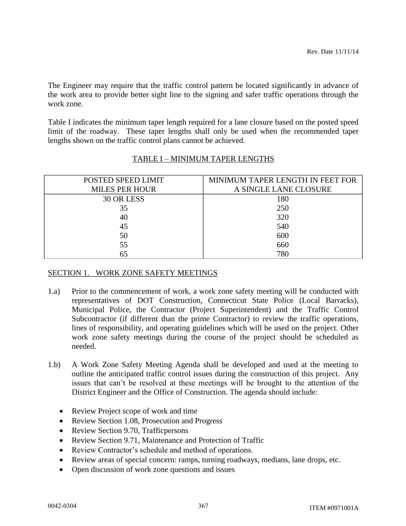
Rev. Date 11/11/14
ITEM #0971001A
The Engineer may require that the traffic control pattern be located significantly in advance of
the work area to provide better sight line to the signing and safer traffic operations through the
work zone.
Table I indicates the minimum taper length required for a lane closure based on the posted speed
limit of the roadway. These taper lengths shall only be used when the recommended taper
lengths shown on the traffic control plans cannot be achieved.
TABLE I – MINIMUM TAPER LENGTHS
SECTION 1. WORK ZONE SAFETY MEETINGS
1.a) Prior to the commencement of work, a work zone safety meeting will be conducted with
representatives of DOT Construction, Connecticut State Police (Local Barracks),
Municipal Police, the Contractor (Project Superintendent) and the Traffic Control
Subcontractor (if different than the prime Contractor) to review the traffic operations,
lines of responsibility, and operating guidelines which will be used on the project. Other
work zone safety meetings during the course of the project should be scheduled as
needed.
1.b) A Work Zone Safety Meeting Agenda shall be developed and used at the meeting to
outline the anticipated traffic control issues during the construction of this project. Any
issues that can’t be resolved at these meetings will be brought to the attention of the
District Engineer and the Office of Construction. The agenda should include:
Review Project scope of work and time
Review Section 1.08, Prosecution and Progress
Review Section 9.70, Trafficpersons
Review Section 9.71, Maintenance and Protection of Traffic
Review Contractor’s schedule and method of operations.
Review areas of special concern: ramps, turning roadways, medians, lane drops, etc.
Open discussion of work zone questions and issues
POSTED SPEED LIMIT
MILES PER HOUR
MINIMUM TAPER LENGTH IN FEET FOR
A SINGLE LANE CLOSURE
30 OR LESS
35
40
45
50
55
65
180
250
320
540
600
660
780
0042-0304 367
Rev. Date 11/11/14
ITEM #0971001A
Discussion of review and approval process for changes in contract requirements as they
relate to work zone areas
SECTION 2. GENERAL
2.a) If the required minimum number of signs and equipment (i.e. one High Mounted
Internally Illuminated Flashing Arrow for each lane closed, two TMAs, Changeable
Message Sign, etc.) are not available; the traffic control pattern shall not be installed.
2.b) The Contractor shall have back-up equipment (TMAs, High Mounted Internally
Illuminated Flashing Arrow, Changeable Message Sign, construction signs, cones/drums,
etc.) available at all times in case of mechanical failures, etc. The only exception to this
is in the case of sudden equipment breakdowns in which the pattern may be installed but
the Contractor must provide replacement equipment within 24 hours.
2.c) Failure of the Contractor to have the required minimum number of signs, personnel and
equipment, which results in the pattern not being installed, shall not be a reason for a time
extension or claim for loss time.
2.d) In cases of legitimate differences of opinion between the Contractor and the Inspection
staff, the Inspection staff shall err on the side of safety. The matter shall be brought to
the District Office for resolution immediately or, in the case of work after regular
business hours, on the next business day.
SECTION 3. INSTALLING AND REMOVING TRAFFIC CONTROL PATTERNS
3.a) Lane Closures shall be installed beginning with the advanced warning signs and
proceeding forward toward the work area.
3.b) Lane Closures shall be removed in the reverse order, beginning at the work area, or end
of the traffic control pattern, and proceeding back toward the advanced warning signs.
3.c) Stopping traffic may be allowed:
As per the contract for such activities as blasting, steel erection, etc.
During paving, milling operations, etc. where, in the middle of the operation, it
is necessary to flip the pattern to complete the operation on the other half of the
roadway and traffic should not travel across the longitudinal joint or difference
in roadway elevation.
To move slow moving equipment across live traffic lanes into the work area.
3.d) Under certain situations when the safety of the traveling public and/or that of the workers
may be compromised due to conditions such as traffic volume, speed, roadside
obstructions, or sight line deficiencies, as determined by the Engineer and/or State Police,
traffic may be briefly impeded while installing and/or removing the advanced warning
0042-0304 368
Rev. Date 11/11/14
ITEM #0971001A
signs and the first ten traffic cones/drums only. Appropriate measures shall be taken to
safely slow traffic. If required, traffic slowing techniques may be used and shall include
the use of Truck Mounted Impact Attenuators (TMAs) as appropriate, for a minimum of
one mile in advance of the pattern starting point. Once the advanced warning signs and
the first ten traffic cones/drums are installed/removed, the TMAs and sign crew shall
continue to install/remove the pattern as described in Section 4c and traffic shall be
allowed to resume their normal travel.
3.e) The Contractor must adhere to using the proper signs, placing the signs correctly, and
ensuring the proper spacing of signs.
3.f) Additional devices are required on entrance ramps, exit ramps, and intersecting roads to
warn and/or move traffic into the proper travelpath prior to merging/exiting with/from the
main line traffic. This shall be completed before installing the mainline pattern past the
ramp or intersecting roadway.
3.g) Prior to installing a pattern, any conflicting existing signs shall be covered with an
opaque material. Once the pattern is removed, the existing signs shall be uncovered.
3.h) On limited access roadways, workers are prohibited from crossing the travel lanes to
install and remove signs or other devices on the opposite side of the roadway. Any signs
or devices on the opposite side of the roadway shall be installed and removed separately.
SECTION 4. USE OF HIGH MOUNTED INTERNALLY ILLUMINATED FLASHING
ARROW
4.a) On limited access roadways, one Flashing Arrow shall be used for each lane that is
closed. The Flashing Arrow shall be installed concurrently with the installation of the
traffic control pattern and its placement shall be as shown on the traffic control plan. For
multiple lane closures, one Flashing Arrow is required for each lane closed. If conditions
warrant, additional Flashing Arrows should be employed (i.e.: curves, major ramps, etc.).
4.b) On non-limited access roadways, the use of a Flashing Arrow for lane closures is
optional. The roadway geometry, sight line distance, and traffic volume should be
considered in the decision to use the Flashing Arrow.
4.c) The Flashing Arrow shall not be used on two lane, two-way roadways for temporary
alternating one-way traffic operations.
4.d) The Flashing Arrow board display shall be in the “arrow” mode for lane closure tapers
and in the “caution” mode (four corners) for shoulder work, blocking the shoulder, or
roadside work near the shoulder. The Flashing Arrow shall be in the “caution” mode
when it is positioned in the closed lane.
0042-0304 369
Rev. Date 11/11/14
ITEM #0971001A
4.e) The Flashing Arrow shall not be used on a multi-lane roadway to laterally shift all lanes
of traffic, because unnecessary lane changing may result.
SECTION 5. USE OF TRUCK MOUNTED IMPACT ATTENUATOR VEHICLES (TMAs)
5.a) For lane closures on limited access roadways, a minimum of two TMAs shall be used to
install and remove traffic control patterns. If two TMAs are not available, the pattern
shall not be installed.
5.b) On non-limited access roadways, the use of TMAs to install and remove patterns closing
a lane(s) is optional. The roadway geometry, sight line distance, and traffic volume
should be considered in the decision to utilize the TMAs.
5.c) Generally, to establish the advance and transition signing, one TMA shall be placed on
the shoulder and the second TMA shall be approximately 1,000 feet ahead blocking the
lane. The flashing arrow board mounted on the TMA should be in the “flashing arrow”
mode when taking the lane. The sign truck and workers should be immediately ahead of
the second TMA. In no case shall the TMA be used as the sign truck or a work truck.
Once the transition is in place, the TMAs shall travel in the closed lane until all
Changeable Message Signs, signs, Flashing Arrows, and cones/drums are installed. The
flashing arrow board mounted on the TMA should be in the “caution” mode when
traveling in the closed lane.
5.d) A TMA shall be placed prior to the first work area in the pattern. If there are multiple
work areas within the same pattern, then additional TMAs shall be positioned at each
additional work area as needed. The flashing arrow board mounted on the TMA should
be in the “caution” mode when in the closed lane.
5.e) TMAs shall be positioned a sufficient distance prior to the workers or equipment being
protected to allow for appropriate vehicle roll-ahead in the event that the TMA is hit, but
not so far that an errant vehicle could travel around the TMA and into the work area. For
additional placement and use details, refer to the specification entitled “Type ‘D’ Portable
Impact Attenuation System”. Some operations, such as paving and concrete repairs, do
not allow for placement of the TMA(s) within the specified distances. In these situations,
the TMA(s) should be placed at the beginning of the work area and shall be advanced as
the paving or concrete operations proceed.
5.f) TMAs should be paid in accordance with how the unit is utilized. When it is used as a
TMA and is in the proper location as specified, and then it should be paid at the specified
hourly rate for “Type ‘D’ Portable Impact Attenuation System”. When the TMA is used
as a Flashing Arrow, it should be paid at the daily rate for “High Mounted Internally
Illuminated Flashing Arrow”. If a TMA is used to install and remove a pattern and then
is used as a Flashing Arrow, the unit should be paid as a “Type ‘D’ Portable Impact
Attenuation System” for the hours used to install and remove the pattern, typically 2
0042-0304 370
Rev. Date 11/11/14
ITEM #0971001A
hours (1 hour to install and 1 hour to remove), and is also paid for the day as a “High
Mounted Internally Illuminated Flashing Arrow”.
SECTION 6. USE OF TRAFFIC DRUMS AND TRAFFIC CONES
6.a) Traffic drums shall be used for taper channelization on limited-access roadways, ramps,
and turning roadways and to delineate raised catch basins and other hazards.
6.b) Traffic drums shall be used in place of traffic cones in traffic control patterns that are in
effect for more than a 36-hour duration.
6.c) Traffic Cones less than 42 inches in height shall not be used on limited-access roadways
or on non-limited access roadways with a posted speed limit of 45 mph and above.
6.d) Typical spacing of traffic drums and/or cones shown on the Traffic Control Plans in the
Contract are maximum spacings and may be reduced to meet actual field conditions as
required.
SECTION 7. USE OF (REMOTE CONTROLLED) CHANGEABLE MESSAGE SIGNS
(CMS)
7.a) For lane closures on limited access roadways and interchange ramps, one CMS shall be
used in advance of the traffic control pattern. Prior to installing the pattern, the CMS
shall be installed and in operation, displaying the appropriate lane closure information
(i.e.: Left Lane Closed - Merge Right). The CMS shall be positioned ½ - 1 mile ahead of
the lane closure taper. If the nearest Exit ramp is greater than the specified ½ - 1 mile
distance, than an additional CMS shall be positioned a sufficient distance ahead of the
Exit ramp to alert motorists to the work and therefore offer them an opportunity to take
the exit.
7.b) CMS should not be installed within 1000 feet of an existing CMS.
7.c) On non-limited access roadways and interchange ramps, the use of CMS for lane closures
is optional. The roadway geometry, sight line distance, and traffic volume should be
considered in the decision to use the CMS.
7.d) The advance CMS is typically placed off the right shoulder, 5 feet from the edge of
pavement. In areas where the CMS cannot be placed beyond the edge of pavement, it
may be placed on the paved shoulder with a minimum of five (5) traffic drums placed in
a taper in front of it to delineate its position. The advance CMS shall be adequately
protected if it is used for a continuous duration of 36 hours or more.
7.e) When the CMS are no longer required, they should be removed from the clear zone and
have the display screen cleared and turned 90 away from the roadway.
0042-0304 371
Rev. Date 11/11/14
ITEM #0971001A
7.f) The CMS generally should not be used for generic messages (ex: Road Work Ahead,
Bump Ahead, Gravel Road, etc.).
7.g) The CMS should be used for specific situations that need to command the motorist’s
attention which cannot be conveyed with standard construction signs (Examples include:
Exit 34 Closed Sat/Sun - Use Exit 35, All Lanes Closed - Use Shoulder, Workers on
Road - Slow Down).
7.h) Messages that need to be displayed for long periods of time, such as during stage
construction, should be displayed with construction signs. For special signs, please
coordinate with the Office of Construction and the Division of Traffic Engineering for
the proper layout/dimensions required.
7.i) The messages that are allowed on the CMS are as follows:
0042-0304 372
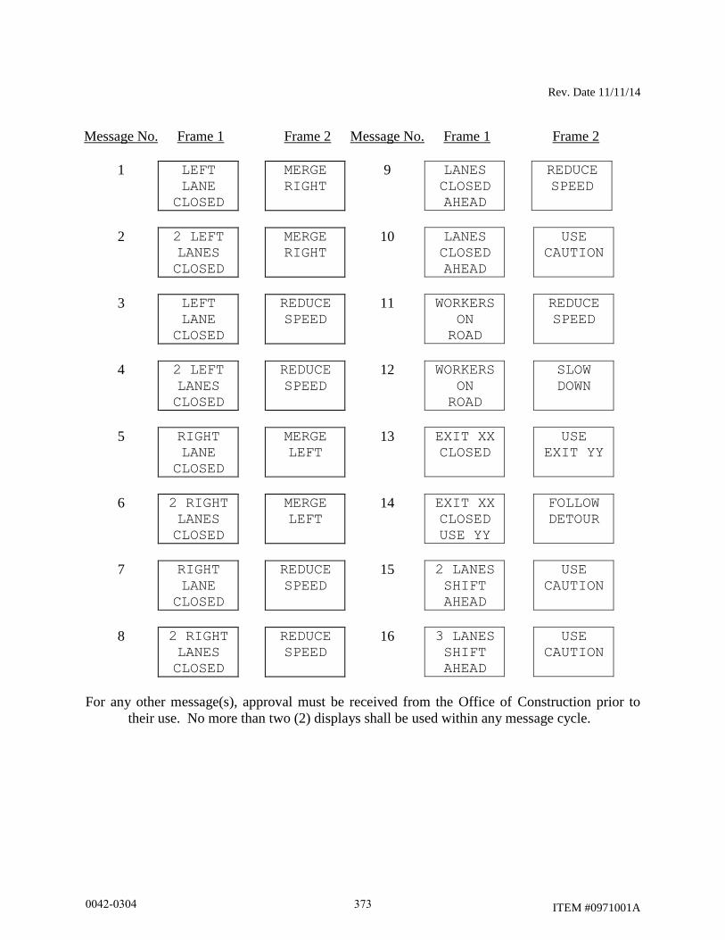
Rev. Date 11/11/14
ITEM #0971001A
Message No. Frame 1 Frame 2 Message No. Frame 1 Frame 2
1 LEFT
LANE
CLOSED
MERGE
RIGHT
9 LANES
CLOSED
AHEAD
REDUCE
SPEED
2 2 LEFT
LANES
CLOSED
MERGE
RIGHT
10 LANES
CLOSED
AHEAD
USE
CAUTION
3 LEFT
LANE
CLOSED
REDUCE
SPEED
11 WORKERS
ON
ROAD
REDUCE
SPEED
4 2 LEFT
LANES
CLOSED
REDUCE
SPEED
12 WORKERS
ON
ROAD
SLOW
DOWN
5 RIGHT
LANE
CLOSED
MERGE
LEFT
13 EXIT XX
CLOSED
USE
EXIT YY
6 2 RIGHT
LANES
CLOSED
MERGE
LEFT
14 EXIT XX
CLOSED
USE YY
FOLLOW
DETOUR
7 RIGHT
LANE
CLOSED
REDUCE
SPEED
15 2 LANES
SHIFT
AHEAD
USE
CAUTION
8 2 RIGHT
LANES
CLOSED
REDUCE
SPEED
16 3 LANES
SHIFT
AHEAD
USE
CAUTION
For any other message(s), approval must be received from the Office of Construction prior to
their use. No more than two (2) displays shall be used within any message cycle.
0042-0304 373
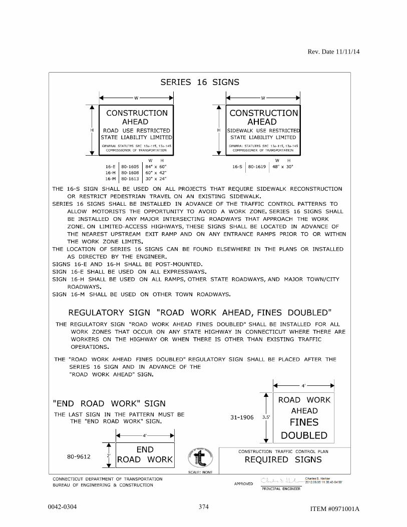
Rev. Date 11/11/14
ITEM #0971001A
0042-0304 374
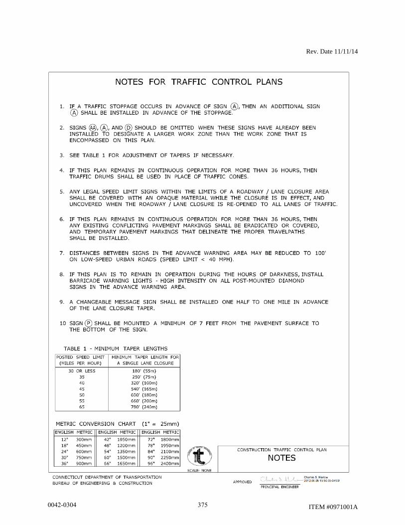
Rev. Date 11/11/14
ITEM #0971001A
0042-0304 375
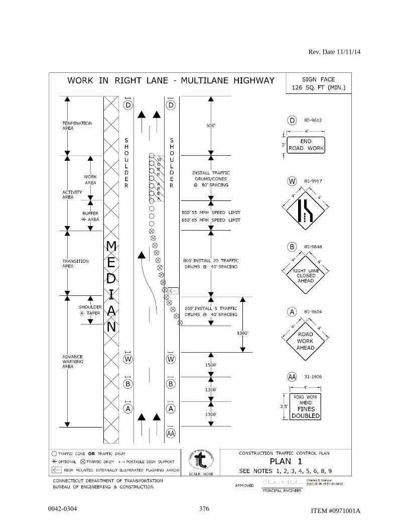
Rev. Date 11/11/14
ITEM #0971001A
0042-0304 376
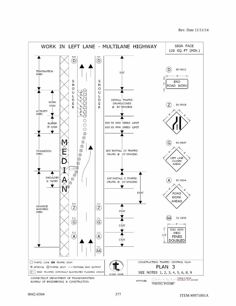
Rev. Date 11/11/14
ITEM #0971001A
0042-0304 377
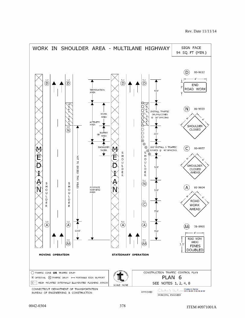
Rev. Date 11/11/14
ITEM #0971001A
0042-0304 378
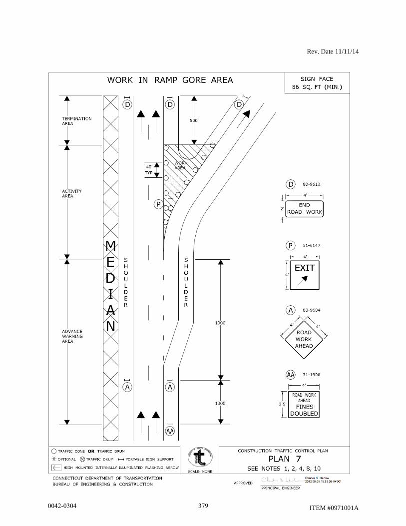
Rev. Date 11/11/14
ITEM #0971001A
0042-0304 379
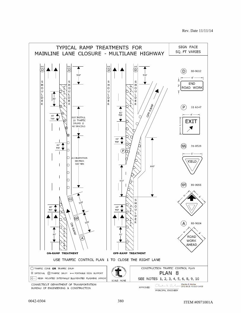
Rev. Date 11/11/14
ITEM #0971001A
0042-0304 380
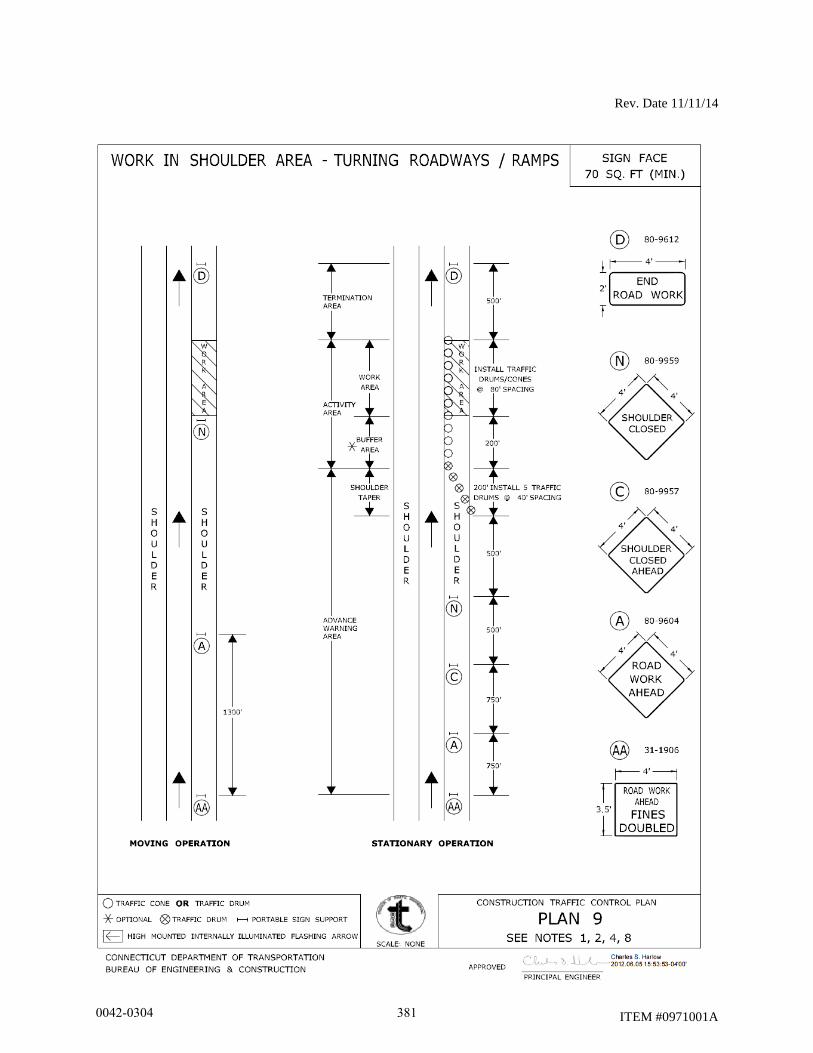
Rev. Date 11/11/14
ITEM #0971001A
0042-0304 381
Rev. Date 11/11/14
ITEM #0971001A
0042-0304 382
Rev. Date 11/11/14
ITEM #0971001A
0042-0304 383
Rev. Date 11/11/14
ITEM #0971001A
0042-0304 384
Rev. Date 11/11/14
ITEM #0971001A
0042-0304 385
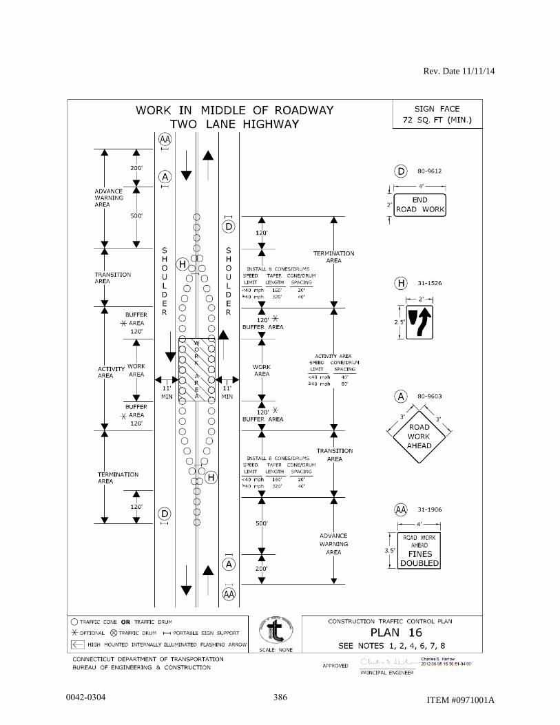
Rev. Date 11/11/14
ITEM #0971001A
0042-0304 386
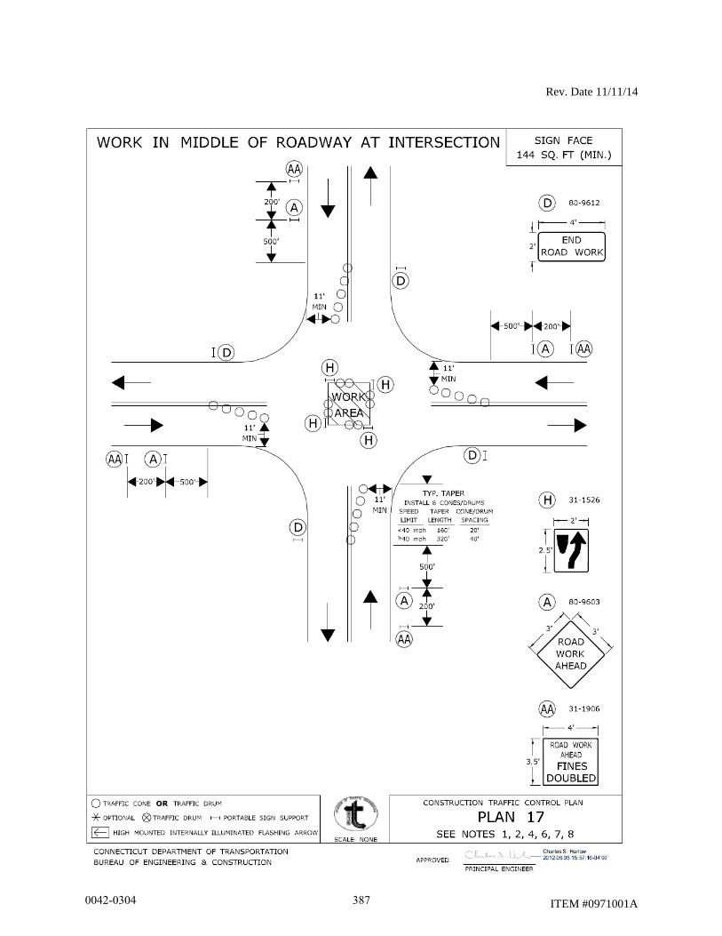
Rev. Date 11/11/14
ITEM #0971001A
0042-0304 387
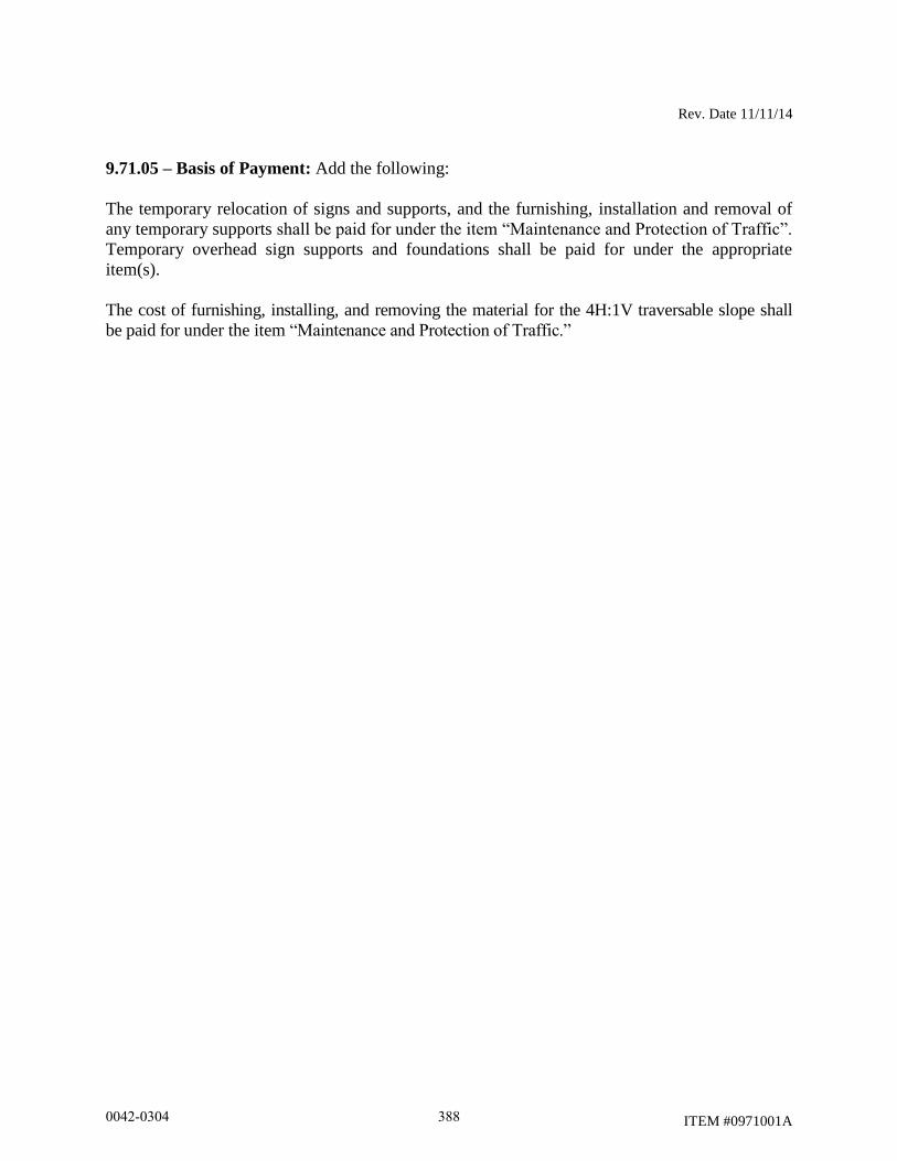
Rev. Date 11/11/14
ITEM #0971001A
9.71.05 – Basis of Payment: Add the following:
The temporary relocation of signs and supports, and the furnishing, installation and removal of
any temporary supports shall be paid for under the item “Maintenance and Protection of Traffic”.
Temporary overhead sign supports and foundations shall be paid for under the appropriate
item(s).
The cost of furnishing, installing, and removing the material for the 4H:1V traversable slope shall
be paid for under the item “Maintenance and Protection of Traffic.”
0042-0304 388
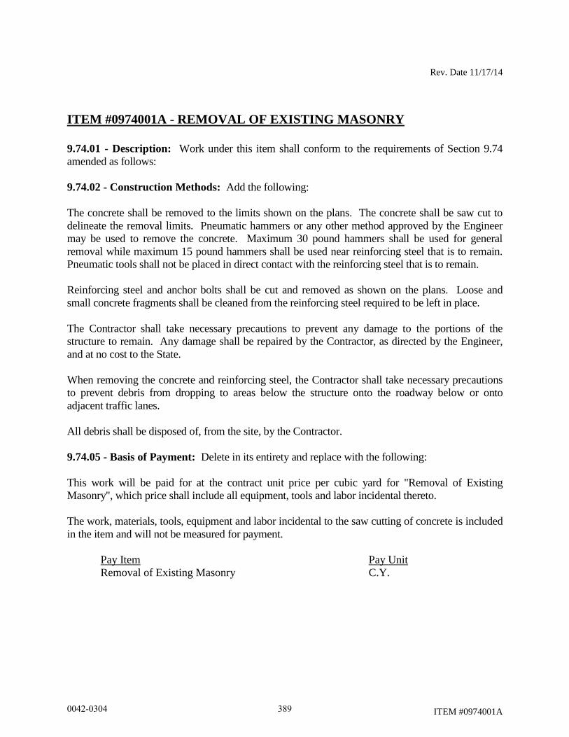
Rev. Date 11/17/14
ITEM #0974001A
ITEM #0974001A - REMOVAL OF EXISTING MASONRY
9.74.01 - Description: Work under this item shall conform to the requirements of Section 9.74
amended as follows:
9.74.02 - Construction Methods: Add the following:
The concrete shall be removed to the limits shown on the plans. The concrete shall be saw cut to
delineate the removal limits. Pneumatic hammers or any other method approved by the Engineer
may be used to remove the concrete. Maximum 30 pound hammers shall be used for general
removal while maximum 15 pound hammers shall be used near reinforcing steel that is to remain.
Pneumatic tools shall not be placed in direct contact with the reinforcing steel that is to remain.
Reinforcing steel and anchor bolts shall be cut and removed as shown on the plans. Loose and
small concrete fragments shall be cleaned from the reinforcing steel required to be left in place.
The Contractor shall take necessary precautions to prevent any damage to the portions of the
structure to remain. Any damage shall be repaired by the Contractor, as directed by the Engineer,
and at no cost to the State.
When removing the concrete and reinforcing steel, the Contractor shall take necessary precautions
to prevent debris from dropping to areas below the structure onto the roadway below or onto
adjacent traffic lanes.
All debris shall be disposed of, from the site, by the Contractor.
9.74.05 - Basis of Payment: Delete in its entirety and replace with the following:
This work will be paid for at the contract unit price per cubic yard for "Removal of Existing
Masonry", which price shall include all equipment, tools and labor incidental thereto.
The work, materials, tools, equipment and labor incidental to the saw cutting of concrete is included
in the item and will not be measured for payment.
Pay Item Pay Unit
Removal of Existing Masonry C.Y.
0042-0304 389
ITEM #0974099A
ITEM #0974099A - REMOVAL OF DETERIORATED CONCRETE
Description:
This item shall consist of surveying the existing reinforced concrete piers as directed by the
Engineer. The Contractor, under the direction of the Engineer, shall locate and remove loose
concrete, deteriorated concrete, spalled and scaled areas and concrete overlaying hollow areas as
well as any other concrete designated for removal under this item in accordance with these
specifications and to the satisfaction of the Engineer.
This work shall also include sandblasting and cleaning these areas and any exposed reinforcing.
Exposed reinforcing shall have a zinc primer applied prior to placing new concrete.
The Contractor shall not perform any repair work without prior approval of the Engineer for
locations, limits and types of repairs.
Materials:
The single component coating shall be one of the zinc rich primers listed in the latest Product
Reference List noted in Section M.07.02. The color of the coating shall be FS 26270 (Medium
Gray).
Construction Methods:
A survey of the existing structure shall be performed by the Contractor, under the direction and to
the satisfaction of the Engineer, to determine the exact limits and locations of all areas to be
removed under this item.
The perimeter of each deteriorated area shall be delineated with a 1/2" deep sawcut. When
sawcutting the concrete, care shall be taken not to cut existing reinforcing.
Loose and deteriorated concrete shall be chipped away back to sound concrete. The exposed
surfaces shall be thoroughly sandblasted and vacuumed immediately prior to forming.
Hollow areas in the existing concrete shall be completely exposed by chipping away back to sound
concrete and thoroughly sandblasted and vacuumed immediately prior to forming.
Spalled and scaled areas shall be cleaned of all loose deteriorated concrete. The exposed surfaces
shall be thoroughly sandblasted and vacuumed immediately prior to forming.
Removal of unsound concrete material shall be such as to facilitate uniform placement of fresh
concrete. All upper areas of excavated voids shall slope evenly out to within one inch (1”) of the
face of the concrete to preclude entrapping air and forming hollow spots in the freshly placed
0042-0304 390

ITEM #0974099A
concrete. Within one inch (1”) of the surface, the outline shall be essentially normal (perpendicular)
to the surface.
All surfaces of exposed concrete and reinforcing steel shall be free of oil, solvent, grease, dirt, dust,
bitumen, rust, loose particles and foreign matter. Prior to sandblasting of concrete and steel surfaces,
all petroleum contamination on these surfaces shall be removed by appropriate solvent or detergent
cleaning operations. All compressed air equipment used in cleaning shall have properly sized and
designed oil separators, attached and functional, to assure the delivery of oil free air to the nozzle.
Extreme care shall be taken where reinforcing steel is uncovered not to damage the steel or its bond
in the surrounding concrete. Pneumatic tools shall not be placed in directed contact with reinforcing
steel. Maximum 15 lb. size hammers shall be used for general chipping and removal. Exposed
reinforcing shall remain in place except where specifically indicated for removal by direction of the
Engineer. Exposed reinforcing steel shall be sandblasted in accordance with SSPC-SP-6,
Commercial Blast Cleaning, to remove all contaminants, rust and rust scale.
In areas where reinforcing steel is found to be surrounded by deteriorated concrete or has at least
one-half of its surface area exposed or has less than 1” cover, the depth of removal shall be such as
to include all deteriorated concrete but not less than 3/4” below or behind the reinforcing steel.
Where the existing reinforcing steel is severely corroded or damaged, it shall be cut out and
replaced with new reinforcing steel of the same size with a minimum length for lap splices as
directed by the Engineer. Concrete shall be removed to a minimum depth of 3/4” behind the new
steel.
When existing steel is determined by the Engineer to have insufficient cover, it shall be either
replaced or adjusted as directed. Concrete shall be removed to a minimum depth of 3/4" behind the
existing steel.
When using sandblasting equipment, all work shall be shielded and contained for the protection of
the public and the environment.
The exposed blast cleaned reinforcing steel shall be coated with the single component zinc primer
by brush. All application of the zinc primer shall be in accordance with the manufacturer's printed
instructions.
Basis of Payment:
This work will be paid for at the contract unit price per cubic foot for "Removal of Deteriorated
Concrete", complete in place. The price shall include locating and removal of deteriorated concrete,
any required sawcutting, sandblasting, cleaning and surface preparation within the removal limits
and zinc primer placed on reinforcing steel. It shall also include all equipment, tools, labor and
incidentals necessary to complete the work and proper disposal of all debris generated during the
removal process.
0042-0304 391
ITEM #0974099A
There will be no direct payment for the cost of furnishing and placing replacement reinforcing steel,
but the cost of this work shall be considered as included in the general cost of the work.
Pay Item Pay Unit
Removal of Deteriorated Concrete c.f.
0042-0304 392
ITEM #0974105A
ITEM #0974105A – CONCRETE HAUNCH REMOVAL
Description: Work under this item shall consist of removing a portion of concrete beam haunch
from the underside of the bridge deck slab along the edge of all beams.
Materials:
Epoxy Resin: The epoxy resin shall be a two component system. The base polymer shall be a
thermosetting resin of the epoxy type. The epoxy resin shall be composed of 100% reactive
constituents, which are a condensation product of the reaction of epichlorohydrin with bisphenol
ether of bisphenol A, containing no more than trace amounts of hydrolyzable chloride. The
epoxy resin shall have an epoxide equivalent between 465 and 530.
The reacting system shall consist of a blend of condensation polymers of dimerized and
trimerized unsaturated fatty acids and an aliphatic polyamine.
Unless otherwise specified, pigmentation shall be required in the system so that the cured coating
shall conform to the Federal Color Standard 595, No. 16357.
a) Physical Requirements of (Mixed) Epoxy Resin System:
A mixture of both components in the proportions recommended by the manufacturer shall
conform to the following requirements:
Viscosity - 500 to 800 centipoises at 77°F
Pot life - 7 hours minimum at 75°F
Minimum solids content - 48%
The cured system shall not exhibit amine blushing or sweating.
When testing for abrasion by ASTM Designation D968, the pigmented finish coats shall
require a minimum of 50 liters of sand to abrade a one mil thickness of coating.
A 2½ mil dry film thickness of the coating tested according to ASTM Designation D522
shall pass a 1/8” diameter mandrel test without splitting the film or causing loss of bond.
b) Sampling:
A representative sample of each component sufficient for the test specified shall be taken
by a Department representative either from a well-blended bulk lot prior to packaging or
by withdrawing 3 fluid ounce samples from no less than 5 percent by random selection of
the containers comprising the lot or shipment. Unless the samples of the same component
taken from containers show evidence of variability, they may be blended into a single
composite sample to represent that component. The entire lot of both components may be
rejected if samples submitted for test fail to meet any requirements of this specification.
0042-0304 393
ITEM #0974105A
c) Packaging and Marking:
The two components of the epoxy resin system furnished under these specifications shall
be supplied in separate containers which are non-reactive with the materials contained
therein. The size of the container shall be such that the recommended proportions of the
final mixture can be obtained by combining one container of one component with one or
more whole containers of the other component.
Containers shall be identified as base polymer and reacting system, and shall show the
mixing directions and usable temperature range as defined by these specifications. Each
container shall be marked with the name of the manufacturer, the lot or batch number, the
date of packaging, pigmentation if any, and the quantity contained therein in pounds and
gallons.
Printed instructions from the manufacturer for mixing and applying the material shall be
included.
Potential hazards shall be so stated on the package in accordance with the Federal
Hazardous Products Labeling Act.
d) Control of Materials:
A Materials Certificate will be required in accordance with Article 1.06.07, certifying the
conformance of the epoxy resin to the requirements set forth in this specification.
Construction Methods: The Contractor shall remove a portion of the concrete beam haunch
located directly over underpass roadways and sidewalks in accordance with details and limits
shown on the plans and as directed by the Engineer.
Concrete shall be removed by saw-cut and pneumatic hammer methods specified herein which
do not damage the sound concrete in the bottom of the bridge deck, the adjacent steel beam, and
portion of the beam haunch to remain.
A three (3) inch deep saw-cut shall be made into the haunch, as shown on the plans, using a
concrete saw guided on a fixed track system for exact control of saw cut alignment and depth of
cut, except at locations above bridge beam diaphragms or other obstructions having insufficient
vertical clearance for saw-cutting equipment. Following the completion of the saw-cut, the
portion of the haunch to be removed shall be broken away by percussive methods.
At haunch removal locations over bridge beam diaphragms or other obstructions having
insufficient clearance for track guided concrete saw equipment, pneumatic hammers may be used
to remove a portion of the beam haunch as shown on the plans. The maximum weight of
pneumatic hammers used in the removal shall be 30 pounds.
The Engineer shall examine the underside of the bridge deck for popouts caused by the removal
of haunches. The surface area of popouts shall be coated with epoxy resin where ordered by the
0042-0304 394

ITEM #0974105A
Engineer. The concrete surface and exposed reinforcing steel, if any, which is to receive the
coating material shall be cleaned of all loose or powder-like rust, oil, dust, dirt, loose particles,
and other bond inhibiting matter just prior to coating.
The epoxy resin shall be mixed in accordance with the manufacturer’s instructions. Also in
accordance with the manufacturer’s instructions, two coats of the mixed material shall be applied
in uniform coats of approximately 2 to 3 mil dry film thickness each.
If the popouts extend beyond the bottom layer of reinforcing steel, the popouts shall be repaired
as directed by the Engineer.
Contractor shall take adequate measures to prevent concrete chips, concrete sawing slurry, tools
and materials from accumulating on the bridge structure and dropping onto the travel lanes
below the structure. All debris shielding will be paid under item 602971A.
All debris shall be promptly swept up, removed, and satisfactorily disposed of by the Contractor
from the site.
Method of Measurement: This work will be measured for payment by the number of linear feet
of concrete beam haunch removed in accordance with the plans and accepted by the Engineer.
Basis of Payment: This work will be paid for at the contract unit price per linear foot for
“Concrete Haunch Removal”, which price shall include the removal of a portion of the concrete
haunch along each edge of a beam, furnishing and application of epoxy resin, disposal of
removed concrete, and all materials, equipment, tools and labor incidental thereto.
Pay Item Pay Unit
Concrete Haunch Removal L.F.
0042-0304 395
Rev. Date 10/25/2013
ITEM #0975004A
ITEM #0975004A - MOBILIZATION AND PROJECT CLOSEOUT
9.75.01 – Description: This item shall consist of all work necessary for the movement of
personnel and furnishing equipment to the project site, and for the establishment of all
Contractors’ field offices, buildings and other facilities necessary to the performance of the
work. In addition, this item shall include the preparation of work plans and submittals necessary
to facilitate the commencement of physical construction. These initial submittals are identified
elsewhere in the contract and may include project schedules, project management plans, safety
plans, quality plans, erosion and sedimentation control plans and similar submittals addressing
the general sequencing and management of the project. This item shall also include
demobilization of plant and equipment, completion of all punchlist work, and administrative
closeout items necessary to satisfy all contract requirements.
This item may not be subcontracted, in whole or part.
9.75.04 – Method of Measurement: This work will be measured for payment in the manner
described hereinafter; however, the determination of the total contract price earned shall not
include the amount of mobilization earned during the period covered by the current monthly
estimate - but shall include amounts previously earned and certified for payment.
1. When the first payment estimate is made, 25 percent of the lump sum bid price for
this item or 2.5 percent of the total original contract price, whichever is less, shall be
certified for payment.
2. When the initial project submittals necessary to begin construction are accepted by
the Engineer, 50 percent of the lump sum bid price for this item or 5.0 percent of the
total original contract price, whichever is less, minus any previous payments, shall be
certified for payment.
3. When the initial project submittals are accepted by the Engineer, and 15 percent of
the total original contract price is earned, 70 percent of the lump sum price of this
item or 7.0 percent of the total original contract price, whichever is less, minus any
previous payments, will be certified for payment.
4. When 30 percent of the total original contract price is earned 85 percent of the lump
sum price of this item or 8.5 percent of the total original contract price, whichever is
less, minus any previous payments, will be certified for payment.
5. When the requirements of Article 1.08.13 have been satisfied 95 percent of the lump
sum price of this item, minus any previous payments, will be certified for payment.
6. When the requirements of Article 1.08.14 have been satisfied 100 percent of the lump
sum price of this item, minus any previous payments, will be certified for payment.
0042-0304 396
Rev. Date 10/25/2013
ITEM #0975004A
Nothing herein shall be construed to limit or preclude partial payments otherwise provided for by
the contract.
9.75.05 – Basis of Payment: This work will be paid for at the contract lump sum price for
“Mobilization and Project Closeout” which price shall include materials, equipment, tools,
transportation, labor and all work incidental thereto.
This item shall not be paid more than one time. If the Contractor is required to mobilize
equipment or facilities more than one time, due to reasons solely the responsibility of the
Department, any additional efforts will be paid as Extra Work under Section 1.04.05.
Pay Item Pay Unit
Mobilization and Project Closeout L.S. (L.S.)
0042-0304 397
Rev. Date 4/22/14
ITEM #0979003A
ITEM #0979003A - CONSTRUCTION BARRICADE TYPE III
Article 9.79.01 – Description: The Contractor shall furnish construction barricades to conform
to the requirements in National Cooperative Highway Research Program (NCHRP) Report 350
or the AASHTO Manual for Assessing Safety Hardware (MASH) and to the requirements stated
in Article 9.71 “Maintenance and Protection of Traffic,” as shown on the plans and/or as directed
by the Engineer.
Article 9.79.02 – Materials: Prior to using the construction barricades, the Contractor shall
submit to the Engineer a copy of the Letter of Acceptance issued by the FHWA to the
manufacturer documenting that the devices have been crash tested and have approval in writing
from FHWA conforming to the requirements in National Cooperative Highway Research
Program (NCHRP) Report 350 or the AASHTO Manual for Assessing Safety Hardware
(MASH), as appropriate.
Alternate stripes of white and orange Type III or Type VI reflective sheeting shall be applied to
the horizontal members as shown on the plans. Application of the reflective sheeting shall
conform to the requirements specified by the reflective sheeting manufacturer. Only one type of
sheeting shall be used on a barricade and all barricades furnished shall have the same type of
reflective sheeting. Reflective sheeting shall conform to the requirements of Article M.18.09.01.
Construction barricades shall be designed and fabricated so as to prevent them from being blown
over or displaced by the wind from passing vehicles. Construction barricades shall be approved
by the Engineer before they are used.
Article 9.79.03 – Construction Methods: Ineffective barricades, as determined by the Engineer
and in accordance with the ATSSA guidelines contained in “Quality Standards for Work Zone
Traffic Control Devices”, shall be replaced by the Contractor at no cost to the State.
Barricades that are no longer required shall be removed from the project and shall remain the
property of the Contractor.
Article 9.79.04 – Method of Measurement: Construction Barricade Type III will be measured
for payment by the number of construction barricades required and used.
Article 9.79.05 – Basis of Payment: “Construction Barricade Type III” required and used will
be paid for at the Contract unit price per each. Each barricade will be paid for once, regardless
of the number of times it is used.
Pay Item Pay Unit
Construction Barricade Type III EA.
0042-0304 398
Rev. Date 03/11
ITEM #0980001A
ITEM #0980001A – CONSTRUCTION STAKING
9.80.01—Description: The work under this item shall consist of construction layout and
reference staking necessary for the proper control and satisfactory completion of all work on the
project, except property lines, highway lines, or non-access lines.
9.80.02—Materials: All stakes used for control staking shall be of the same quality as used by
the Department for this purpose. For slope limits, pavement edges, gutter lines, etc., where so-
called "green" or "working" stakes are commonly used, lesser quality stakes will be acceptable,
provided the stakes are suitable for the intended purpose.
9.80.03—Construction Methods: The Department will furnish the Contractor such control
points, bench marks, and other data as may be necessary for the construction staking and layout
by qualified engineering or surveying personnel as noted elsewhere herein.
The Contractor shall be responsible for the placement and preservation of adequate ties to all
control points, necessary for the accurate re-establishment of all base lines, center lines, and all
critical grades as shown on the plans.
All stakes, references, and batter boards which may be required for construction operations,
signing and traffic control shall be furnished, set and properly referenced by the Contractor. The
Contractor shall be solely and completely responsible for the accuracy of the line and grade of all
features of the work. Any errors or apparent discrepancies found in previous surveys, plans,
specifications or special provisions shall be called to the Engineer's attention immediately for
correction or interpretation prior to proceeding with the work.
During roadway construction (or site work), the Contractor shall provide and maintain for the
periods needed, as determined by the Engineer, reference stakes at 100 foot intervals outside the
slope limits. Further, the Contractor shall provide and maintain reference stakes at 50 foot
intervals immediately prior to and during the formation of subgrade and the construction of all
subsequent pavement layers. These stakes shall be properly marked as to station, offset and shall
be referenced to the proposed grade, even if laser or GPS machine controls are used.
The Contractor shall provide and maintain reference stakes at drainage structures, including
reference stakes for the determination of the structure alignments as may be needed for the
proper construction of the drainage structure. The reference stakes shall be placed immediately
prior to and maintained during the installation of the drainage structure. These stakes shall be
properly marked as to station, offset and shall be referenced to the proposed grade.
The Contractor shall furnish copies of data used in setting and referencing stakes and other
layout markings used by the Contractor after completion of each operation.
The Contractor shall provide safe facilities for convenient access by Department forces to
control points, batter boards, and references.
All staking shall be performed by qualified engineering or surveying personnel who are trained,
experienced and skilled in construction layout and staking of the type required under the
contract. Prior to start of work, the Contractor shall submit for review and comment the
qualifications of personnel responsible for construction staking on the project. On all projects
with an original contract value greater than $25 million and bridge rehabilitation and
reconstruction projects greater than $10 million, surveying shall be performed under the direct
supervision of a Professional Surveyor licensed in the State of Connecticut. The submission shall
0042-0304 399
Rev. Date 03/11
ITEM #0980001A
include a description of the experience and training which the proposed staff possesses and a list
of state projects the personnel have worked on previously. All field layout and staking required
for the project shall be performed under the direct supervision of a person, or persons, of
engineering background experienced in the direction of such work and acceptable to the
Engineer. If the personnel responsible for construction staking change during the course of the
project, then a revised submittal will be required.
The Department may check the control of the work, as established by the Contractor, at any
time as the work progresses. The Contractor will be informed of the results of these checks, but
the Department by so doing in no way relieves the Contractor of responsibility for the accuracy
of the layout work. The Contractor shall correct or replace, at the Contractor’s own expense, any
deficient layout and construction work which may be the result of the inaccuracies in the
Contractor’s staking operations or the failure to report such inaccuracies, or the Contractor’s
failure to report inaccuracies found in work done by the Department or by others. If, as a result
of these inaccuracies, the Department is required to make further studies, redesign, or both, all
expenses incurred by the Department due to such inaccuracies will be deducted from any monies
due the Contractor.
The Contractor shall furnish all necessary personnel, engineering equipment and supplies,
materials, transportation, and work incidental to the accurate and satisfactory completion of this
work.
For roadways where the existing pavement markings need to be reestablished:
Prior to any resurfacing or obliteration of existing pavement markings, the Contractor and a
representative of the Engineer must establish and document pavement marking control points
from the existing markings. These control points shall be used to reestablish the positions of the
lanes, the beginnings and endings of tapers, channelization lines for on and off ramps, lane use
arrows, stop bars, and any lane transitions in the project area. The Contractor shall use these
control points to provide appropriate premarking prior to the installation of the final markings.
The Contractor shall provide and maintain reference stakes and/or markings at 100 foot
intervals immediately off the edge of pavement to be used to reestablish the existing pavement
markings. The Contractor shall also provide and maintain reference stakes and/or markings at
any point where there is a change in pavement markings to reestablish the existing pavement
markings.
For non-limited access roadways
On non-limited access roadways it may be necessary to adjust the final locations of the pavement
markings to accommodate pedestrians and bicyclists where feasible. Prior to any resurfacing or
obliteration of existing pavement markings, the Contractor, a representative of the Engineer, and
a representative of the Division of Traffic Engineering must establish and document pavement
marking control points from the existing markings as described above. The control points at that
time may be adjusted to provide minimum shoulder widths of 4 to 5 feet wherever possible while
maintaining travel lane widths of no less than 11 feet and no more than 12 feet.
9.80.04—Method of Measurement: Construction staking will be at the Contract lump sum for
construction staking.
0042-0304 400
Rev. Date 03/11
ITEM #0980001A
When no price for "Construction Staking" is asked for on the proposal form, the cost of the
work described above shall be included in the general cost of the work and no direct payment for
"Construction Staking" will be made.
9.80.05—Basis of Payment: Construction staking will be paid for at the Contract lump sum
price for "Construction Staking," which price shall include all materials, tools, equipment, labor
and work incidental thereto. A schedule of values for payment shall be submitted to the
Department for review and comment prior to payment.
Pay Item Pay Unit
Construction Staking l.s.
0042-0304 401
Rev. Date 06/10/09
ITEM #1001001A
ITEM #1001001A – TRENCHING AND BACKFILLING
The work under the item Trenching and Backfilling shall conform to Section 10.01 of the
Standard Specifications amended as follows:
Construction Methods: Article 10.01.03 – Construction Methods, add the following:
All cuts in roadways shall be done in a neat and workmanlike manner, so as to cause the least
possible injury to all other improvements. The Contractor should provide protection to all
slopes, roadways, guide rails, drainage structures, illumination conduit and appurtenances,
utilities, etc. as may be necessary or as required by the Engineer. Any property damage caused
by excavation shall be repaired as directed by, and to the satisfaction of, the Engineer at no
additional compensation. Excavating shall not be performed until immediately before
installation of conduit and other appurtenances. The material from the excavation shall be
placed where directed by the Engineer and in a position where the least damage and obstruction
to vehicular traffic and the least interference with the surface drainage will occur.
All excavations shall be closed at the end of each day.
All pavement cutting required for this item, regardless of the type, shall be included as work
under this item.
Where possible, communication conduit and electrical conduit shall be installed in the same
trench and shall be paid for under this item as one. Payment shall not be made for separate
trenching and backfilling where electrical and communication conduit may be installed in the
same trench, but have been installed separately by the Contractor.
When trenching occurs in roadways, neat lines shall be drawn on the surface and the roadway
shall be saw cut and removed to neat lines as indicated on the plans or as directed by the
Engineer. Temporary Pavement Repair
Description:
Temporary pavement repair consists of replacing pavement that has been removed for the
installation of conduits. The Contractor shall repair the pavement immediately upon completion
of the trench backfilling and compaction in accordance with these specifications and to the
dimensions on the contract drawings or as directed by the Engineer.
Materials:
Superpave 12.5 mm and Superpave 9.5 mm shall conform to the requirements of Article M.04 of
the Standard Specifications.
0042-0304 402
Rev. Date 06/10/09
ITEM #1001001A
Construction Methods:
Temporary pavement replacement shall be constructed in accordance with the details shown on
the plans.
Permanent Pavement Repair
Description:
After the temporary pavement has been in place for 30 days and within 3 months of placing the
temporary pavement, the Contractor shall make permanent pavement repairs. Where trenching
occurs across bituminous concrete overlayed concrete pavement, immediate permanent
pavement repairs shall take place. These repairs shall include filling the trench with high-early
concrete fill and upon curing, permanent surface pavement repairs.
Materials:
Concrete fill for restoration of bituminous concrete overlayed concrete pavement shall conform
to the requirements of Article M.03.01 of the Standard Specifications and shall be capable of
achieving 3000 psi within 12 hours. The Contractor shall submit a design mix to the Engineer
for approval.
Processed Aggregate Base shall conform to the requirements of Article M.05.01 of the Standard
Specifications.
Superpave 12.5 mm and Superpave 9.5 mm shall conform to the requirements of Article M.04 of
the Standard Specifications.
Joint Seal shall conform to the requirements of Article M.04.02 of the standard specifications.
Reinforcement shall conform to the requirements of ASTM A615, Grade 60.
Unpaved Areas
Description:
Unpaved areas disturbed during construction shall be restored with a minimum of 50 MM of
topsoil and established turf.
Materials:
Topsoil shall conform to the requirements of Article M.13.01-1 of the standard specifications.
Turf Establishment materials shall conform to Article M.13 of the Standard Specifications.
0042-0304 403
Rev. Date 06/10/09
ITEM #1001001A
Construction Methods:
Topsoil shall be provided in conformance to Section 9.44.03 of the standard specifications. Turf
Establishment shall conform to Section 9.50.03 of the Standard Specifications.
Method of Measurement: Article 10.01.04 – Method of Measurement: Add the following:
There shall be no separate measurement for sawcutting, temporary pavement repair, concrete fill,
joint sealing, permanent pavement repair, sidewalk repair, cutting reinforcement, reinforcement,
topsoil and turf establishment.
Basis of Payment:
Article 10.01.05 -- Basis of Payment: Replace the second paragraph with the following:
It shall also include all sand encasement, backfilling, grading, seeding, fertilizing, mulching,
disposal of surplus material, as well as furnishing and installing concrete fill, topsoil or pavement
as the case may be.
0042-0304 404

ITEM #1008901A
ITEM #1008901A – REMOVE CONDUIT
Description: This item shall consist of removing existing conduit from handholes and in
parapets where indicated on the plans. All removed conduit, conductors and hardware shall
remain the property of the Contractor.
Construction Methods: The Contractor shall remove existing conduit from handholes and
parapets with associated hardware were indicated on the plans. The Contractor shall
disconnect and remove existing conductors along with conduit to be removed. All removed
conduit, conductors and hardware shall be properly disposed of by the Contractor.
Method of Measurement: This work will be measured for payment by the number of linear
feet of conduit removed and disposed of, complete and accepted.
Basis of Payment: This work will be paid for at the contract unit price per linear foot for
"Remove Conduit" complete, which price shall include removal and disposal of conduit,
conductors, fittings, and all associated hardware, and all equipment, materials, tools, labor
and work incidental thereto.
0042-0304 405
Rev. Date 02/00
ITEM #1008907A
ITEM #1008907A - CLEANING EXISTING CONDUIT
Description:
The work under this item shall consist of cleaning existing conduit, as required, as shown on the
plans or as directed by the Engineer to facilitate installation of new cable.
Construction Methods:
The Contractor shall remove all existing cable from conduit that will be reused. The contractor
will be directed the clean the conduit which has obstructions or is found to be impassable. This cleaning
process shall be by one of the following methods:
1) Rodding
2) A high pressure jet spray, or air pressure
3) By pulling a mandral or ball through the conduit.
The Contractor shall submit in writing his anticipated method of cleaning the conduit to the
Engineer for approval prior to cleaning any conduit.
If the conduit is found to be damaged to any extent that the cleaning process will not clear the
obstruction, it will be the judgment of the Engineer whether to replace the entire conduit run or excavate
the damaged section for repair.
Method of Measurement:
This work shall be measured for payment on an hourly basis.
Basis of Payment:
The work under the Item “Cleaning Existing Conduit” shall be paid for at the contract unit price
per hourly basis, which price shall include all cleaning, material, tools, equipment, all labor, and work
incidental thereto.
0042-0304 406
Rev. Date 07/15/14
HANDHOLE COVER ITEM #1010051A
ITEM #1010051A - GALVANIZED STEEL HANDHOLE COVER
DESCRIPTION: This work shall consist of furnishing and installing a new galvanized steel
handhole cover, on an existing concrete handhole, at the location as shown on the plans, and in
accordance with this specification. This item shall also include all work required to locate and
expose the existing handhole
MATERIALS: The steel handhole cover shall be hot-dip galvanized, non skid floor plate steel
which will have a minimum tensile strength of fifty thousand (50,000) lbs. The cover shall be
overlap type with dimensions as indicated in the electrical details.
CONSTRUCTION METHODS: The Contractor shall locate the existing concrete handhole
and excavate all material (dirt, sand, road debris) from the top of the handhole. The Contractor
shall install the galvanized steel handhole cover on the existing concrete handhole at the location
as shown on the plans. The existing recessed type cover shall be disposed of by the Contractor.
The new cover shall be connected to the No. 8 ground wire as indicated on the plans.
The Contractor shall also grade around the existing handhole, so that finished grade is set 1-1/2"
below the top of the handhole.
Prior to ordering, the Contractor shall verify that the cover as dimensioned in the details will fit
on the existing handhole.
METHOD OF MEASUREMENT: This work will be measured for payment by the number of
galvanized steel handhole covers installed, complete and accepted in place.
BASIS OF PAYMENT: This work will be paid for at the contract unit price each for
"Galvanized Steel Handhole Cover" complete and accepted in place, which price shall include
cover, removal and disposal of existing cover, locating, excavation, grounding, grading, seeding,
and all materials, tools, equipment and labor incidental thereto.
0042-0304 407
ITEM #1010905A
ITEM #1010905A – RESET CONCRETE HANDHOLE
Description:
Work under this item shall consist of resetting a concrete handhole at the location shown on the
plans or as directed by the Engineer and in conformity with these specifications.
Materials:
The Contractor shall be responsible for damage to all equipment and materials incurred during
resetting of the concrete handhole. All repairs or replacements due to damage or loss by the
Contractor shall be made at the Contractor's expense.
Construction Methods:
The concrete handhole shall be reset where shown on the plans or directed by the Engineer.
The Contractor shall raise or lower the existing concrete handhole so that the top of the handhole
is 1 1/2" above finished grade. When raising of the handhole is required, the following
exception shall apply: The handhole shall not be raised past the limits of the existing conduit
entering the handhole. The final placement of the handhole shall be such that the conduit ends
are left within the limits of the wiring compartment of the handhole.
No disruption in nighttime illumination will be allowed to carry out this work.
Method of Measurement:
This work will be measured for payment by the number of concrete handholes reset, complete
and accepted.
Basis of Payment:
This work will be paid for at the contract unit price each for "Reset Concrete Handhole" which
price shall include all equipment, labor, delivery and incidentals thereto.
Pay Item Pay Unit
Reset Concrete Handhole ea.
0042-0304 408
ITEM #01014901A
ITEM #1014901A - REMOVE CABLE
Description: This item shall consist of removing conductors and cables from existing
cabinets, conduit and handholes where indicated in the plans or as directed by the
Engineer and in accordance with these specifications. The removed conductors and cables
shall remain the property of the Contractor.
Construction Method: The Contractor shall remove all conductors and cables from
existing cabinets, conduit and handholes at the location where new conductors and cables
are to be installed when alternate circuit provisions are in place. Prior to installing the new
conductors and cables, all existing conductors and cables shall have been removed, neatly
coiled, tied and the conduit reamed cleaned. The removed conductors and cables shall be
disposed of by the Contractor.
Removal of existing cables shall be coordinated with the installation of new or temporary
cables to maintain uninterrupted operation of existing circuits.
Nighttime illumination shall not be interrupted by this work.
Method of Measurement: This work shall be measured for payment by the actual number
of linear feet of conduit from which all conductors are removed, also including the
length of handholes, junction boxes, and cabinets.
Basis o f Payment: This work will be paid for at the contract unit price per linear foot
for “Remove Cable” which price shall include the removal of all conductors and cables, the
cleaning of conduit, the proper disposal of the removed conductors and cables, and all
equipment, labor and work incidental thereto.
Pay Item Pay Unit
Remove Cable L.F.
0042-0304 409
Rev. Date 2/11
ITEM #1020030A
ITEM #1020030A - TEMPORARY ILLUMINATION UNIT
DESCRIPTION: Under this item the Contractor shall furnish and install a breakaway
fiberglass light pole, anchors, bracket, luminaire with ballast, and necessary hardware for
temporary lighting during construction, as indicated on the plans or as directed by the Engineer.
At the end of the project the temporary illumination unit shall become the property of the
Contractor.
MATERIALS: The pole shaft shall be fiberglass reinforced composite (FRC). The pole shaft
shall be constructed by the filament winding process from thermosetting polyester resin and
contain a minimum of 65 percent of “E” type fiberglass by weight. The filament windings shall
be continuously applied with uniform tension and shall be placed on the pole helically at low
angles to provide axial strength. Additional windings shall be placed on the pole in a circular
manner to provide compressive strength. The resin is to be uniformly pigmented to match the
final grey color of the finished FRC pole. The pole is to contain solid coloration throughout the
entire wall thickness and is to contain ultraviolet (UV) inhibitors. The pole is to be round,
tapered, hollow, and reinforced in the support arm and hardware attachment areas. The pole is to
be non-conductive and chemically inert. The pole shall meet the current AASHTO LTS-2 Street
Lighting Standard Specifications for Structural Supports for Highway Signs, Luminaires and
Traffic Signals, and shall be approved by FHWA for use on Federal Aid projects. A 2 ½” x 5”
handhole shall be provided at the base of the pole shaft at approximately 18” above the finished
grade line.
The pole exterior surface is to be grey with a natural (textured) finish. The surface of the pole
will be uniform for the entire length of the pole. The laminate shall contain colored pigment, the
color of the final coating, and be of uniform color throughout the entire wall thickness of the
pole. A coating shall be applied to the pole to maintain surface integrity against the damaging
effects of sunlight and extremes in weather. The coating is to be highly weather resistant
pigmented polyurethane. The coating thickness shall have minimum dry film thickness of 1-1/2
mils.
The surface shall be tested for a minimum of 5000 hours of accelerated testing in accordance
with ASTM G154 (UV-A lamp 340 NM wave length, 130 degree F, cycle lamp 4 hours on 4
hours off) with the following results:
Fiber exposure: none
Crazing: none
Checking: none
Chalking: none
Color: may dull slightly
The minimum pole weight shall be 130 lbs. The weight of each pole shall not deviate from the
specified weight by more than +/- 10 lbs.
0042-0304 410
Rev. Date 2/11
ITEM #1020030A
For direct buried break-away poles the butt end shall be enlarged so as to provide resistance to
rotation and pull out.
Where indicated on the plans, the pole shaft shall be equipped with an anchor base with of heavy
duty A356-T6 aluminum which shall be permanently bonded to the outside of the fiberglass
shaft.
Each pole is to be permanently marked in characters 3/16” minimum high on a brass or stainless
steel plate with the manufacturer's identification symbol, month and year of manufacture. Each
pole shall be individually packaged for protection during shipping and storage. The pole shall be
warranted to be free of defects in materials and workmanship for a period of three years from the
date of purchase.
The top of the pole is to be pre-drilled for two 5/8" thru bolts on 9-1/2" centers starting 4 inches
below the top of the pole. A 1-1/2" wire exit hole shall be centered 1/2 the distance between the
two holes.
A cast aluminum removable cap shall be securely mounted to the top of the pole. The cap shall
be corrosion resistant and must remain in place when subjected to the maximum wind loading
for which the pole is designed.
The luminaire bracket arm shall be 12' in length (single member) of an upsweep design
fabricated from tubular aluminum. The luminaire end shall have a 2-3/8" outside diameter.
Anchors shall conform to the pertinent requirements of Article M.16.04-2b, c, d, and e.
The luminaire shall conform to the pertinent requirements of Article M.15.05, and shall be high
pressure sodium. The luminaire wattage shall be 250 watt or as called for on the plans. The
socket shall be adjustable to provide I.E.S. light distribution type M-S-II. The ballast shall be
under guarantee of the manufacturer for a period of one year commencing when the unit is
installed and accepted
CONSTRUCTION METHOD: The fiberglass pole shall be set in the earth to the required
depth and proper compaction of backfill provided around the pole and then attached to the
anchors with guys as necessary. The bracket shall be attached to the pole and shall provide a
luminaire mounting height of 30’ over the roadway or the mounting height as called for on the
illumination plans (See contractor “Notes” section). The bracket and luminaire assembly shall be
installed perpendicular to the center line of the roadway. When necessary, the temporary light
pole and luminaire shall be relocated to maintain different illumination circuits as dictated by the
construction stages.
Where indicated on the plans an anchor base type pole shall be supplied and securely bolted to
the anchor bolts of the foundation and leveled with the aid of aluminum shims if necessary.
0042-0304 411
Rev. Date 2/11
ITEM #1020030A
Upon completion of the project the temporary illumination unit shall be removed and shall
remain the property of the Contractor.
Upon removal of the pole, the resulting excavation shall be properly backfilled to match the
surrounding area.
METHOD OF MEASUREMENT: This work will be measured for payment by the number of
temporary illumination units installed and accepted.
BASIS OF PAYMENT: This work will be paid for at the contract unit price each for
"TEMPORARY ILLUMINATION UNIT" complete in place, which price shall include all
materials, fiberglass poles, breakaway base, anchor base (when required), anchors, guys,
brackets, luminaires, lamps, ballasts, hardware, connections, hauling, and all equipment, tools,
labor and all work incidental thereto including excavating, augering, removal of bituminous
overlay, backfilling, removal, hauling, relocation, and disposal. The unit cost for this item is a
one time only cost. The cost of removing and relocating the temporary illumination unit to
maintain different illumination circuits shall be included in the unit cost.
0042-0304 412
Rev. Date 01/09
ITEM #1113601A
ITEM #1113601A - OPTICAL FIBER CABLE – SINGLE MODE, LOOSE
BUFFER TUBE CABLE, 2FIBER
Description:
This Item specifies the requirements for furnishing, installing in conduit, splicing, and
connectorizing fiber optic cables. As part of this item, the Contractor shall install a pull tape in
all of the innerducts within the contract limits of work, as necessary to install the fiber optic
cable and future fiber optic cable.
Materials:
A. General
1. The fiber optic cable supplied in this project shall be completely compatible with the
existing cable supplied under Project 63-548/42-288. The cable shall be compatible
with Fitel/Lucent single jacket loose tube fiber optic cable with DryBlock Core. The
Contractor shall provide proof of compatibility to the Department with the
appropriate shop drawings and catalog cut submittals.
2. Outdoor fiber optic cable shall be installed in conduit, spliced as required and
terminated in Camera-Hub Cabinets and Mini-Hub Cabinets, as shown on the
Drawings.
3. Plenum-rated indoor fiber optic cable shall be installed inside the State Transportation
Building within existing conduits, spliced as required and terminated at the fiber optic
patch panel, as shown on the Drawings.
4. The fiber optic cable, splices, connectors and interconnect panels shall meet all
requirements stated in this Specification.
5. All optical fiber cables used in this project shall be from the same manufacturer. That
manufacturer shall be regularly engaged in the production of fiber optic cables. Each
optical fiber cable for this project shall be dielectric, loose tube, duct-type.
B. Applicable Publications
1. Publications listed below form a part of this specification to the extent referenced.
The publications are referred to in the text by basic designation. All Fiber Optic
Communication System hardware shall be compliant with the following
specifications:
0042-0304 413
Rev. Date 01/09
ITEM #1113601A
Electronics Industries Association (EIA):
a. EIA-310-C Racks, Panels, and Associated Equipment.
b. EIA-359-A Colors for Color Identification and Coding.
c. EIA-422-A Electrical Characteristics of Balanced Voltage Digital Interface
Circuits.
d. EIA-TIA-455-A Standard Test Procedures for Fiber Optic Fibers, Cable
Transducer Sensors, Connecting and Terminating Devices and Other Fiber Optic
Components.
e. EIA-455-6B Cable Retention Test Procedure for Fiber Optic Cable
Interconnecting Devices.
f. EIA-485 Standard for Electrical Characteristics of Generators and Receivers for
use in Balanced Digital Multipoint Systems.
g. TIA/EIA-598-A Optical Fiber Cable Color Coding.
2. USDA Rural Utilities Service (RUS) 7 CFR 1755.900.
3. ANSI/ICEA Standard for Fiber Optic Outside Plant Communications Cable,
ANSI/ICEA S-87-640-1992.
4. UL-listed OFNR
5. CSA-listed FT-4
C. Outdoor Fiber Optic Cable Requirements
1. The cable shall be an accepted product of the United States Department of
Agriculture Rural Utilities Service (RUS) 7 CFR 1755.900 and meet the requirements
of the ANSI-ICEA Standard for Fiber Optic Outside Plant Communications Cable,
ANSI/ICEA S-87-640-1992.
2. The Outdoor Fiber Optic Cable shall be stranded loose tube cable with the required
number of fibers as shown in the Contract Drawings. The buffer tubes shall contain
12 fibers per tube unless otherwise noted in the Contract.
3. The Contractor shall provide manufacturer’s documentation certifying that the
Outdoor Fiber Optic Cable complies with the following performance requirements:
0042-0304 414
Rev. Date 01/09
ITEM #1113601A
a. When tested in accordance with FOTP-3, "Procedure to Measure Temperature
Cycling Effects on Optical Fibers, Optical Cable, and Other Passive Fiber Optic
Components," the change in attenuation at extreme operational temperatures
-40F and +158F (-40C and +70C) shall not exceed 0.2 dB/km at 1550 nm for
single-mode fiber.
b. When tested in accordance with FOTP-82, "Fluid Penetration Test for
Fluid-Blocked Fiber Optic Cable." a one meter length of unaged cable shall
withstand a one meter static head or equivalent continuous pressure of water for
cable end.
c. When tested in accordance with FOTP-81, "Compound Flow (Drip) Test for
Filled Fiber Optic Cable", the cable shall exhibit no flow (drip or leak) of filling
and/or flooding material at 149F (65C).
d. When tested in accordance with FOTP-41, "Compressive Loading Resistance of
Fiber Optic Cables," the cable shall withstand a minimum compressive load of
220 N/cm (125 lbf/in) applied uniformly over the length of the sample. The load
shall be applied at the rate of 1/10 in to ¾ in (3 mm to 20 mm) per minute and
maintained for ten minutes. The change in attenuation shall not exceed 0.4 dB
during loading and 0.2 dB after loading at 1550 nm for single-mode fiber.
e. When tested in accordance with FOTP-104, "Fiber Optic Cable Cyclic Flexing
Test," the cable shall withstand 25 mechanical flexing cycles around a sheave
diameter not greater than 20 times the cable diameter. The change in attenuation
shall not exceed 0.1 dB at 1550 nm for single-mode fiber.
f. When tested in accordance with FOTP-25, "Repeated Impact Testing of Fiber
Optic Cables and Cable Assemblies," the cable shall withstand 25 impact cycles.
The change in attenuation shall not exceed 0.2 dB at 1550 nm for single-mode
fiber.
g. When tested in accordance with FOTP-33, "Fiber Optic Cable Tensile Loading
and Bending Test," using a maximum mandrel and sheave diameter of 22 in
(560 mm), the cable shall withstand a tensile load of 608 lbf (2700 N). The
change in attenuation shall not exceed 0.2 dB during loading and 0.1 dB after
loading at 1550 nm for single-mode fiber.
0042-0304 415
Rev. Date 01/09
ITEM #1113601A
h. When tested in accordance with FOTP-85, "Fiber Optic Cable Twist Test," a
length of cable no greater than 13 feet (4 meters) shall withstand 10 cycles of
mechanical twisting. The change in attenuation shall not exceed 0.1 dB at
1550 nm for single-mode fiber.
i. When tested in accordance with FOTP-181, "Lightning Damage Susceptibility
Test for Optic Cables with Metallic Components," the cable shall withstand a
simulated lightning strike with a peak value of the current pulse equal to 105 kA
without loss of fiber continuity. A damped oscillatory test current shall be used
with a maximum time-to-peak value of 15 s (which corresponds to a minimum
frequency of 16.7 kHz) and a maximum frequency of 1800000 rpm (30 kHz). The
time to half-value of the waveform envelope shall be from 40 - 70 s.
j. When tested in accordance with FOTP-37, "Low or High Temperature Bend Test
for Fiber Optic Cable", the cable shall withstand four full turns around a mandrel
of 10 times the cable diameter for non-armored cables and 20 times the cable
diameter for armored cables after conditioning for four hours at test temperatures
of -22F and +140F (-30C and +60C). Neither the inner or outer surfaces of the
jacket shall exhibit visible cracks, splits, tears or other openings. Optical
continuity shall be maintained throughout the test.
4. All optical fibers, coatings, tubes, metals and jackets shall be free of roughness,
porosity, blisters, splits and voids in accordance with good manufacturing practice.
5. The color coding and position of fibers / buffer tubes within the cable shall be in
accordance with TIA/EIA–598-A “Optical Fiber Cable Color Coding”. Fibers shall
be colored with ultraviolet curable ink. In buffer tubes containing multiple fibers, the
colors shall be stable across the specified storage and operating temperature range and
not subject to fading or smearing onto adjacent fibers or into the gel filing material.
Color materials shall not cause fibers to stick together.
6. The buffer tubes shall be resistant to external forces and shall meet the buffer tube
cold bend and shrinkback requirements of 7 CFR 1755.900.
7. The cable shall be suitable for operation over a temperature range of -22F to +158F
(-30oC to +70
oC) and shall be suitable for installation in outdoor ducts.
8. The cable shall provide mechanical support and protection for the specified number
of fibers.
9. The central anti-buckling member shall consist of a dielectric, glass reinforced plastic
(GRP) rod. The GRP rod shall be coated with a black colored thermoplastic when
required to achieve dimensional sizing to accommodate buffer tubes/fillers.
0042-0304 416
Rev. Date 01/09
ITEM #1113601A
10. All interstices within the cable outer jacket and within each buffer tube shall be filled
with a compound to prevent the ingress and migration of water. The compound shall
be a non-hygroscopic, non-nutritive to fungus, electrically non-conductive,
homogeneous gel that is nontoxic and dermatologically safe. The gel shall be free
from dirt and foreign matter. Some leakage of the compound is permitted, however,
there shall be no bulk flow of compound out of the cable over the specified operating
temperature range which could impact on the waterproofness of the cable. The gel
shall be readily removable with conventional nontoxic solvents.
11. Buffer tubes shall be stranded around the dielectric central member using the reverse
oscillation, or "S-Z", stranding process. Water blocking yarn(s) shall be applied
longitudinally along the central member during stranding.
12. A water blocking tape shall be applied longitudinally around the outside of the
stranded tubes/fillers. The tape shall be held in place by a single polyester binder
yarn. The water blocking tape shall be non-nutritive to fungus and electrically non-
conductive.
13. The cable shall be able to withstand a maximum pulling tension of 607lbf (2700 N)
during installation without any resulting damage. Tensile strength shall be provided
by dielectric yarns. The high tensile strength dielectric yarns shall be helically
stranded evenly around the cable core.
14. The outer jacket of the cable shall be constructed of medium or high density
polyethylene. The minimum nominal jacket thickness shall be 1/20 inch (1.4 mm).
Jacketing material shall be applied directly over the tensile strength members and
water blocking tape. The polyethylene shall contain carbon black to provide
ultraviolet light protection and shall not promote the growth of fungus. MDPE jacket
material shall be as defined by ASTM D1248, Type II, Class C and Grades J4, E7 and
E8.
15. The cable shall contain at least one ripcord under the sheath (outer cable jacket) for
easy sheath removal of all-dielectric cable.
16. The cable jacket shall be marked with manufacturer’s name, sequential meter or foot
markings, month, year or quarter year of manufacture, and a telecommunications
handset symbol, as required by Section 350G of the National Electrical Safety Code.
The actual length of the cable shall be within 1% of the length markings.
17. Materials used in the cable shall not produce hydrogen in a concentration large
enough to cause any degradation in the transmission performance of the optical
fibers.
18. Materials used in the cable shall not support galvanic action.
0042-0304 417
Rev. Date 01/09
ITEM #1113601A
D. Single Mode Optical Fibers
1. The Single Mode fiber shall consist of a doped silica core surrounded by a concentric
silica cladding. The fiber shall be matched clad design.
2. The dispersion un-shifted or dispersion flattened single mode fiber shall conform to
the following specifications:
a. The Single Mode fiber core shall have a diameter of between 8.3 to 9 m
inclusive with a tolerance of ± 1.3 m.
b. The Single Mode fiber cladding shall have an outer diameter of 125 m with a
tolerance of ±1.0 m.
c. The core-to-cladding offset shall not be greater than 0.6 m.
d. The cladding Non-Circularity shall not be greater than 1.0% defined as:
(1- Minimum Cladding Diameter/Maximum Cladding Diameter) x 100
e. The Single Mode fiber shall be coated with a protective polymer to preserve the
strength of the fiber. The coating shall be removable by mechanical or chemical
means. The coating shall retain its color when subject to the manufacturer's
recommended fiber cleaning and splicing preparation methods.
f. The SM fiber shall have attenuation and bandwidth specified at two wavelength
windows.
i. The first wavelength window shall be at and around 1310 nm.
ii. The second wavelength window shall be at and around 1550 nm.
3. The mean optical attenuation at 1310 nm shall not be greater than 0.4 dB/km with a
standard deviation not greater than 0.05 dB/km. The maximum attenuation of any
continuous length of SM fiber at 1310 nm shall not exceed 0.45 dB/km.
4. The mean optical attenuation at 1550 nm shall not be greater than 0.3 dB/km with a
standard deviation not greater than 0.06 dB/km. The maximum attenuation of any
continuous length of SM fiber shall not exceed 0.36 dB/km.
5. The fiber attenuation shall not vary more than 0.2 dB/km over the specified cable
operational temperature range.
0042-0304 418
Rev. Date 01/09
ITEM #1113601A
6. The fiber optical bandwidth at 1310 nm or 1550 nm shall be equal to or greater than
1000 MHz-Km.
7. The zero dispersion wavelength shall be at a wavelength of 1310 ± 10 nm.
8. The maximum dispersion at 1550 nm shall not exceed 18 ps / (nm-km).
9. The maximum dispersion in the wavelength range of 1285 to 1330 nm shall not
exceed 3.2 ps / (nm-km).
E. Fiber Optic Distribution Cable
1. This item consists of furnishing and installing optical fiber cables and connectors of
the size and type specified at the locations shown on the Drawings or as indicated by
the Engineer, in accordance with these Specifications.
2. The Contractor shall provide multiple fiber, stranded, loose tube cable with single
mode fiber that shall be suitable for placement in an underground environment as
shown in the Drawings.
3. The optical fiber capacity of the fiber optic distribution cables to be supplied and
installed under this Contract will vary in capacity according to network topology and
traffic requirements. The current minimum requirements are for distribution cable to
be of the following capacities: 72 SM Refer to Drawing, Fiber Optic Cable Plant.
(Note SM refers to the number of Single Mode fibers within a cable segment.)
4. The Contractor shall provide a manufacturer’s certification that the offered cable
complies with all optical and mechanical requirements set forth in this Specification.
Any deviation of the offered cable from the specifications set forth herein shall be
clearly noted in the Contractor’s proposal.
5. All optical fiber distribution cable used on this project shall be from the same
manufacturer. Each optical fiber cable shall be all dielectric, duct type, loose tube
and shall conform to these Specifications.
F. Fiber Optic Drop Cables
1. Drop cables are used for connecting Camera cabinets, Camera Mini-Hub cabinets and
the VMS cabinets to the fiber optic distribution (trunk) cable.
2. The Drop Cable shall consist of single mode fibers housed in a protective jacket. The
end of the fiber installed at the Camera, Mini-Hub or VMS cabinet shall be
connectorized. The other end of the drop cable shall be spliced into a fiber optic
distribution cable at an underground Splice Closure within an adjacent pull box.
0042-0304 419
Rev. Date 01/09
ITEM #1113601A
3. The exact number of Drop Cables at each Splice Closure shall be in accordance with
the Contract. The Contractor shall employ the most efficient means of meeting the
Drop Cable requirements, as approved by the Engineer.
4. The attenuation of Drop Cable after installation, not including the connector loss,
shall not exceed 0.1 dB measured at 1310 nm and 1550 nm.
G. Fiber Optic Connectors
1. The ST connector shall have a ceramic ferrule with a nickel plated nut and body. SC
connectors shall have a ceramic insert.
2. The connector shall be of the ST-type or SC-type and fully compatible with the fiber
optic cable utilized and the mating jacks to which they will be attached.
3. The connector shall be compatible with a physical contact (PC) finish. All connectors
shall be polished to a PC finish such that the return loss per mated pair of connectors
is at least 25 dB. The return loss when the connector is mated with previously
installed connectors shall be at least 18 dB.
4. The connector mean loss shall not be greater than 0.2 dB with a standard deviation of
not greater than 0.1 dB.
5. Index matching fluids or gels shall not be used.
6. The connector loss shall not vary more than 0.1 dB after 500 repeated matings.
7. The connector shall withstand an axial load of 30 lb (135 N).
8. The connectors shall be attached in accordance with the manufacturer's recommended
materials, equipment and practices.
9. The connector shall be suitable for the intended environment and shall meet the
following environmental conditions.
a. Operating Temperature: -4F to +122F (-20 to +50o C)
b. Storage Temperature: -22F to +140F (-30 to +60o C)
c. The connector loss shall not vary more than 0.2 dB over the operating temperature
range.
0042-0304 420
Rev. Date 01/09
ITEM #1113601A
d. Connectors shall be protected by a suitably installed waterproof protection cap.
H. Pull Tape
1. Pull tape, to be installed in specific areas of the project as described elsewhere in this
specification, shall consist of polyethylene or PVC jacket woven into the polyester
tape. The recommended pull tape is NEPTCO Part No. DP1250P, or approved equal.
The pull tape shall not “burn in” to the innerducts under normal pulling conditions or
as specified herein.
The pull tape shall have the following properties:
a. 1250 lb (5560 N) tensile strength
b. flat, not round construction
c. printed foot markings
d. Pre-lubricated
e. Moisture resistant
I. Fiber Optic Cable Fabrication
1. Packing and Shipment
a. The cable shall be supplied on reels. Top and bottom end of the cable shall be
available for testing. Both ends of the cable shall be sealed to prevent ingress of
moisture.
b. The optical cable shall be in one continuous length per reel with no factory splices
in the fiber. Each reel shall be marked to indicate the direction the reel should be
rolled to prevent loosening of the cable. Installation procedures and technical
support shall be furnished upon request.
c. Each reel shall have the following information clearly labeled on it:
i. Customer
ii. Customer order number
iii. Reel number
iv. Destination
v. Ship date
vi. Manufactured date
vii. Manufacturer's name
viii. Cable code
0042-0304 421
Rev. Date 01/09
ITEM #1113601A
ix. Length of cable
J. Warranty
1. All equipment supplied for this shall be warranted for parts and labor by the vendor
against defects and failures, which may occur through normal use for a period of one
(1) year from the date of installation. A copy of the warranty must be presented to the
Engineer before installation of the equipment.
K. Quality Assurance
1. The Contractor shall have a Quality Assurance Program in place.
2. A minimum of ten (10) year’s experience in the design, manufacture, and testing of
Fiber Optic Cable and Connectors is required. The cable and connectors shall be
designed and manufactured according to world class quality standards. The
manufacturer shall be ISO 9001 certified.
Construction Methods:
A. Submittals
1. Submit:
a. Functional block diagrams, cabling diagrams, and point to point cabling details,
including locations of all distribution cable splice points (both drop cable splices
and reel-end splices.
b. As built drawings including a cable route diagram indicating the actual cable
route and “meter marks” for all interchanges, intersections, directional change
points in the cable routing, and all termination points. The Contractor shall record
these points during cable installation. Cable system “as-built” drawings showing
the exact cable route shall be provided by the Contractor to ConnDOT.
Information such as the location of slack cable and its quantity shall also be
recorded in the cable route diagram.
c. Product data, manufacturer’s test certifications, installation manuals, materials,
system configuration options and features, and accessories.
d. Shop Drawings shall be completely dimensioned and shall indicate the intended
installation method and details.
e. Specifications of cable, connectors, and fiber splice kits.
f. Operating and maintenance manuals for all equipment.
g. Vendor Optical Time Domain Reflectometer (OTDR) certification for each reel of
fiber optic cable listing each specification compliant fiber by fiber color code and
group color code.
0042-0304 422
Rev. Date 01/09
ITEM #1113601A
B. Delivery, Storage, and Handling
1. The Contractor shall deliver, store, handle and install all materials and equipment in
such a manner as not to degrade quality, serviceability or appearance.
2. The Contractor shall be responsible for storage of the materials and equipment prior
to installation in a clean, dry location free from construction dust, precipitation and
excess moisture.
3. Contractor shall be required to replace any damaged materials and equipment, as
determined by the Engineer, at no additional cost to the owner.
4. Cable shall be transported to site using cable reel trailers.
5. Care shall be taken at all times to avoid scraping, denting, or otherwise damaging the
cable before, during or after installation. Damaged cable shall be replaced by the
Contractor without additional compensation.
6. Sufficient slack shall be pulled to allow cable cutting and connection to
communications equipment.
C. Installation in Ducts
1. Cable shall be installed in innerduct, duct or conduit in the field in accordance with
the Contract Drawings.
2. Fiber Optic Distribution Cable shall be installed in the lowest innerduct (relative to
ground level). Where more than one cable is to be installed in a conduit, the mid-
level innerduct shall be used, and the highest level innerduct shall be reserved.
3. The Contractor shall install pull tape in the existing innerducts as necessary to install
the fiber optic cable. A 6.5 ft (2.0 m) length of pull tape shall be left coiled, tied, and
accessible in each cabinet, vault, maintenance hole and junction box. The pull tape
shall be installed according to manufacturer recommendations and shall be “free” and
NOT helical about communications cables.
4. The Contractor shall install cables in innerducts consistently throughout the project;
crossover of a cable from one innerduct to another is not allowed.
5. Duct ends shall have all rough ends smoothed to prevent scraping the cable.
6. Where cable will be installed directly in conduit with no innerduct, a stiff bristle
brush shall be pulled through each section of duct before pulling cable.
0042-0304 423
Rev. Date 01/09
ITEM #1113601A
7. The Contractor shall not exceed the manufacturer's recommended safe pulling tension
and minimum bending radius during delivery and installation.
8. A manufacturer’s recommended lubricant shall be applied to the cable to reduce
friction between the cable and the duct.
9. A cable grip shall be attached to the cables so that no direct force is applied to the
optical fiber. The cable grip shall have a ball bearing swivel to prevent the cable
from twisting during pulling.
10. Cable rollers and feeders and winch cable blocks shall be used to guide the cable
freely into the duct and at maintenance hole locations.
11. Mechanical aids and pulling cable or ropes shall be used as required.
12. The Contractor shall employ personnel at as many pull points as need be to achieve
the longest continuous cable segment as possible to reduce the need for excessive
main-line splices.
13. Personnel equipped with two-way radios shall be stationed at each maintenance hole,
cabinet and communications vault at which the cable is to be pulled to observe and
lubricate the cable.
14. Where mechanical pulling is required (i.e. all runs greater than 164 ft (50 m)), a
dynamometer shall be used to record installation tension and a tension limiting device
shall be used to prevent exceeding the maximum pulling tension as defined by the
cable manufacturer. The maximum pulling tension shall be recorded for each run of
cable. The cable shall be taken up at intermediate pulling points with an intermediate
cable take-up device as approved by the Engineer to prevent over tension on the
cable. Cable pulls shall be continuous and steady between pull points and shall not be
interrupted until the entire run of cable has been pulled.
15. Trunk fiber cable segment lengths shall be the maximum tolerable length within the
maximum pulling tension defined by the manufacturer. The number of trunk cable
reel-end splices shall be minimized. The Contractor shall provide a plan to the
Engineer showing the reel-end splice point locations following a field investigation of
the conduit and shall not install cable until receiving the Engineer’s approval of the
reel-end splice location plan. The Contractor shall obtain the Engineer’s approval for
all required changes to the reel-end splice point location plans. Cable segments
installed with reel-end splices not approved by the Engineer will be replaced by the
Contractor at no additional cost to the Department.
16. The Contractor shall be responsible for ensuring the cable length is sufficient to allow
for connection between the communication equipment and the splice enclosures
0042-0304 424
Rev. Date 01/09
ITEM #1113601A
including provision for slack, vertical runs, cable necessary for splicing, wastage and
cable to allow for the removal of the splice enclosure for future splicing.
17. Drop Cables shall be of length suitably long to be connected to the rack mounted
fiber optic transmission equipment within the Camera Hub and the rack-mounted
Splice Closure in the Mini-Hub. Sufficient slack shall be left at each end to allow
removal of the Splice Closure and tray, and relocation of the equipment anywhere
within the cabinet.
18. Drop Cable fibers in the Camera Hub Cabinets shall be connectorized and the Active
Fiber connected directly to the Optical Video/Data Transceiver. The Spare Fiber with
Connector shall be safely and securely attached to the interior of the equipment rack
with plastic ties. The cable shall not be stressed beyond the minimum bending radius
at any time.
19. Drop Cable fibers in the Mini-Hub Cabinet shall be spliced to pig-tails in a rack-
mounted splice closure provided by others. Splicing shall be in accordance with the
requirements specified elsewhere in these Specifications and as shown on the
Drawings. All unused fibers shall be properly terminated in accordance with
manufacturer recommendations.
20. All cable ends, connectors, and fiber optic jacks shall be protected from moisture
ingress by using properly sealed caps.
21. Following installation of the cable in the ducts, all duct entrances at pedestals and
cabinets shall be sealed with duct sealing compound to prevent the ingress of
moisture, foreign materials, and rodents.
22. 20 feet (6 m) of cable going to and coming from each Splice Closure shall be coiled
in the first pull box on each side of each closure. In addition, 50 feet (15 m) of cable
shall be left coiled in the first pull box on each side of all surface mounted conduit
systems.
23. Where trunk cable terminations are left “dead ended”, 100 feet (25 m) of cable shall
be left coiled.
24. All coiled cables shall be securely fastened in place with a minimum of four
galvanized steel conduit straps.
25. Fish line shall be installed in all communications ducts or conduits along with fiber
optic communication cables. A 6ft. 6 in (2.0 m) length of fish line shall be left coiled,
tied and accessible in each cabinet, vault, maintenance hole and junction box. The
fish line shall be installed according to manufacturer specifications and shall be "free"
and NOT helical about communications cables.
0042-0304 425
Rev. Date 01/09
ITEM #1113601A
26. At intermediate pulling points, to prevent over tension on the cable, the cable shall be
either taken up with an intermediate cable take up device as approved by the
Engineer, or all excess cable shall be laid out on the ground in a figure eight
configuration before subsequent installation.
27. Following installation in duct, a label shall be affixed to each cable end in a pull box
or cable vault and the label shall contain the following information:
28. Customer order number
x. Reel number
xi. Ship date
xii. Manufactured date
xiii. Manufacturer's name
xiv. Cable designation as shown on the Drawings
xv. Length of cable to next reel-end splice point
xvi. Location of other end of cable (reel-end splice point)
xvii. Cable test data
D. Splicing
1. Splicing of the cable shall only be permitted at splice closure or field fiber optic
interconnect panel locations as indicated in the Drawings, unless authorized by the
Engineer.
2. The Contractor shall prepare for splicing the designated fibers of the cable to the
Drop Cables connecting the communications equipment located in the Camera Hub
and Mini-Hub cabinets. Sufficient cable shall be coiled in the vault/cabinet to allow
for consumption during the splicing and to permit the splice closure to be removed
from the vault/cabinet for future splicing.
3. At least 1.0m of each fiber shall be stored in the splice trays. The Contractor shall
further splice all additional fibers provided in order to meet the fiber requirements
specified in the Contract and including any fibers provided which are additional to the
Contract requirements.
E. Testing
1. Test Documentation
0042-0304 426
Rev. Date 01/09
ITEM #1113601A
a. The Contractor shall be responsible for all testing and documentation required to
establish approval and acceptance of this Item.
b. The Contractor shall submit test procedures and documented test results to the
Engineer. The test procedures shall document the nature of test activities to be
performed.
c. The test procedures shall be submitted to the Engineer prior to initiation of the
testing. The procedures will be returned to the Contractor within two week
indicating either “accepted” or “make corrections noted”. If corrections are
required, the Contractor shall submit revisions within 1 week.
d. Four copies of the final test procedures shall be submitted to the Engineer prior to
commencement of testing.
2. Pre-Installation Testing
a. Reels of cable shall be tested for attenuation prior to installation in ducts. The
Contractor shall measure and record the attenuation of 100% of the total single
mode fibers on each reel. Attenuation shall meet or exceed the specified
performance requirements in accordance with the Contract.
b. The Contractor shall ensure that specifications for the fiber optic cable are met
prior to installation.
3. Proof of Performance Testing
0042-0304 427
Rev. Date 01/09
ITEM #1113601A
a. The Contractor shall measure the attenuation per kilometer of fiber in each length
of cable after installation.
b. The Contractor shall measure the attenuation of a randomly selected minimum of
10% of the total single mode fibers, which will be connected to equipment.
c. All (100%) of optical fibers assigned to be spare or reserved shall be individually
tested for optical attenuation.
d. The Contractor shall sequence the fibers which are to be measured after each pull,
such that the same fibers are not measured on consecutive lengths.
e. The Contractor shall record the reel number from which the cable came, the
identification of the fibers measured and the attenuation in dB/km of the fibers
measured.
f. The Contractor shall measure and record the splice quality of each fusion splice
performed. The Engineer shall be provided with access to interim results.
4. Optical Time Domain Reflectometer (OTDR) Testing
a. The Contractor shall perform single mode Fiber OTDR testing after each cable
has been installed.
b. The Contractor shall provide the Engineer with information regarding OTDR test
equipment make and model with the equipment calibration procedures and
certification dates prior to conducting the test routine.
c. An OTDR shall be used for backscattered light measurements. The OTDR shall
operate at a nominal wavelength of 1310 nm and 1550 nm and shall include all
necessary hardware required to couple it with single mode fiber.
d. The backscatter light measurement of each single mode fiber and each single
mode optical link shall be measured in both directions and at both 1310 nm and
1550 nm wavelengths. Each single mode optical link shall be defined as being
the total length of interconnected single mode fibers and the splices which form a
continuous end-to-end optical link. This includes: CCTV Camera Hub to Mini-
Hub, Mini-Hub to Main Fiber Hub and Main Fiber Hub to Newington Highway
Operations Center (HOC).
e. The Contractor shall maintain a test result record of each single mode optical link
and each single mode fiber by means of printer copy of the OTDR measured cable
0042-0304 428
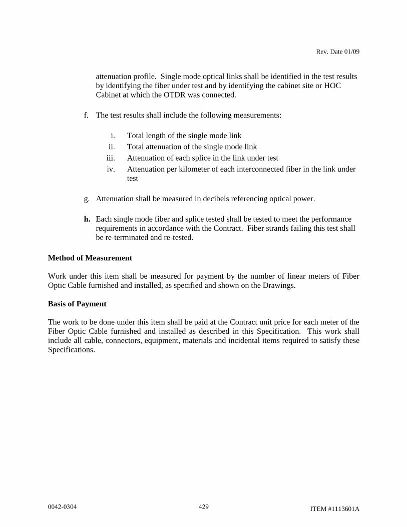
Rev. Date 01/09
ITEM #1113601A
attenuation profile. Single mode optical links shall be identified in the test results
by identifying the fiber under test and by identifying the cabinet site or HOC
Cabinet at which the OTDR was connected.
f. The test results shall include the following measurements:
i. Total length of the single mode link
ii. Total attenuation of the single mode link
iii. Attenuation of each splice in the link under test
iv. Attenuation per kilometer of each interconnected fiber in the link under
test
g. Attenuation shall be measured in decibels referencing optical power.
h. Each single mode fiber and splice tested shall be tested to meet the performance
requirements in accordance with the Contract. Fiber strands failing this test shall
be re-terminated and re-tested.
Method of Measurement
Work under this item shall be measured for payment by the number of linear meters of Fiber
Optic Cable furnished and installed, as specified and shown on the Drawings.
Basis of Payment
The work to be done under this item shall be paid at the Contract unit price for each meter of the
Fiber Optic Cable furnished and installed as described in this Specification. This work shall
include all cable, connectors, equipment, materials and incidental items required to satisfy these
Specifications.
0042-0304 429

Rev. Date 12/02/02
ITEM #1131002A
ITEM #1131002A - REMOTE CONTROLLED CHANGEABLE MESSAGE
SIGN
11.31.01 - Description: Work under this item shall include furnishing and maintaining a trailer-
mounted, “Changeable Message Sign”, “Remote Controlled Changeable Message Sign”,
“Changeable Message Sign with Radar”, or “Remote Controlled Changeable Message Sign with
Radar” whichever is applicable, at the locations indicated on the plans or as directed by the
Engineer.
11.31.02 - Materials: The full matrix, internally illuminated variable message sign shall consist
of a LED, fiber optic, lamp matrix, or hybrid magnetically operated matrix – LED message
board; and a computer operated interface, all mounted on a towable, heavy duty trailer.
The sign shall have a minimum horizontal dimension of 115 inches and rotate a complete 360
degrees atop the lift mechanism.
In the raised position, the bottom of the sign shall be at least 7 feet above the roadway. The
messages displayed shall be visible from a distance of 1/2 mile and be clearly legible from a
distance of 900 feet during both the day and night.
The lighting system shall be controlled both manually and by a photocell for automatic sign
dimming during nighttime use.
The sign shall be capable of storing a minimum of 100 preprogrammed messages and be able to
display any one of those messages upon call from the trailer mounted terminal and/or through the
cellular telephone hookup for the remote controlled sign.
The sign shall be a full matrix sign that is able to display messages composed of any
combination of alphanumeric text, punctuation symbols, and graphic images (notwithstanding
NTCIP limitations). The display shall be capable of producing arrow functions. Full- matrix
displays shall allow the use of graphics, traffic safety symbols and various character heights.
Standard messages shall be displayed in a three-line message format with 8 characters per line.
The letter height shall not be less than 18 inches.
The sign shall utilize yellow green for the display with a black background. Each matrix shall
have a minimum size of 6 x 9 pixels. Each pixel shall utilize a minimum of four high output
yellow green LEDs or equivalent light source. The LEDs or light source shall have a minimum
1.4 candela luminance intensity, 22 degrees viewing angle, and wavelength of 590 (+/- 3)
nanometers.
0042-0304 430

Rev. Date 12/02/02
ITEM #1131002A
For hybrid magnetically operated matrix – LED matrix, each pixel shall have one single shutter
faced with yellow green retro-reflective sheeting with a minimum of four high output yellow
green LEDs or equivalent light source. The hybrid magnetically operated matrix – LED matrix
sign shall be capable of operating in three display modes; shutter only, LED only, and both LED
and shutter. These modes shall be automatically controlled by a photocell for day and night
conditions and also capable of being manually controlled through the software.
The sign shall be controlled by an on-board computer. The sign shall automatically change to a
preselected default message upon failure. That default message shall remain on display until the
problem is corrected.
The sign shall include all necessary controls, including, but not limited to, personal computer,
keyboard or alphanumeric hand-held keyboard, and software. The sign shall interface with PCs,
cellular phones, and radar speed detection devices as required.
Controls shall be furnished for raising and lowering the message board, aligning the message
board and, for solar powered units, a read-out of the battery bank charge.
Power shall be provided by a self-contained solar maintained power source or a diesel engine
driven generator. Hardware for connection to a 110-volt power source shall also be provided.
Solar powered signs shall display programmed messages with the solar panel disconnected, in
full night conditions, for a minimum of 30 consecutive days.
Remote Controlled Changeable Message Signs shall include one (1) industrial-grade cellular
telephone and be equipped with a modem to control the sign and a security system to prevent
unauthorized access. The security system shall allow access only through use of a code or
password unique to that sign. If the proper code or password is not entered within 60 seconds of
initial telephone contact, the call will be terminated. Remote control for the Remote Controlled
Changeable Message Sign shall be by cellular telephone and touch tone modem decoder.
The radar equipped signs shall include a high-speed electronic control module (ECM-X), Radar
SI transceiver, signal processing board and radar logging software.
The radar software will operate the sign in four modes:
1) The sign will display words “YOUR SPEED” followed by the speed (2 digits). The
display will repeat the message as long as vehicles are detected. The sign will blank
when no vehicles are present.
2) The sign will display a series of up to six messages (programmed by the user) when a
preset speed (programmed by the user) is exceeded. The sign will blank when no
vehicles are present.
3) Will perform like mode #2 with the addition of displaying the actual speed with it.
0042-0304 431
Rev. Date 12/02/02
ITEM #1131002A
4) The sign will work as a standard Changeable Message Sign or Remote Controlled
Changeable Message Sign with no radar.
11.31.03 - Construction Methods: The Contractor shall furnish, place, operate, maintain and
relocate the sign as required. When the sign is no longer required, it shall be removed and
become the property of the Contractor. The cellular telephone required for the Remote
Controlled Changeable Message Sign shall be provided to the Engineer for his use, and
subsequently returned to the Contractor.
When the sign is not in use, it shall either be turned off with a blank display or turned from view.
Any signs that are missing, damaged, defaced or improperly functioning so that they are not
effective, as determined by the Engineer and in accordance with the ATSSA guidelines
contained in “Quality Standards for Work Zone Traffic Control Devices,” shall be replaced by
the Contractor at no cost to the State.
11.31.04 - Method of Measurement: This work will be measured for payment for each
“Changeable Message Sign”, “Remote Controlled Changeable Message Sign”, “Changeable
Message Sign with Radar”, or “Remote Controlled Changeable Message Sign with Radar”,
whichever applies, furnished and installed, for the number of calendar days that the sign is in
place and in operation, measured to the nearest day. When a sign is in operation for less than a
day, such a period of time shall be considered to be a full day regardless of actual time in
operation.
11.31.05 - Basis of Payment: This work will be paid for at the Contract unit price per day for
each “Changeable Message Sign”, “Remote Controlled Changeable Message Sign”,
“Changeable Message Sign with Radar”, or “Remote Controlled Changeable Message Sign with
Radar” which price shall include placing, maintaining, relocating and removing the sign and its
appurtenances and all material, labor, tools and equipment incidental thereto. Additionally, for
the “Remote Controlled Changeable Message Sign”, or “Remote Controlled Changeable
Message Sign with Radar”, the cellular telephone service and telephone charges shall be
included.
0042-0304 432

Rev. Date 12/02/02
ITEM #1131002A
Pay Item Pay Unit
Remote Controlled Changeable Message Sign Day
0042-0304 433
Revision 10/19/12
ITEM #1201804A
ITEM #1201804A – 4 CHORD TRUSS CANTILEVER SIGN STRUCTURE
Description: Work under this item shall consist of designing, fabricating and installing a sign
support structure to carry extruded aluminum traffic signs, on a prepared foundation, in
accordance with the details shown on the plans, in accordance with these specifications and as
ordered by the Engineer. For the purposes of this specification, the sign support structure shall
be composed of a cantilevered 4 chord truss supported by a single linear tubular pole member.
Materials: The poles shall be tubular members with either a round or multisided cross-section.
The round tubular members shall be fabricated from steel pipe with a tabulated yield stress no
less than 35,000 psi. The multisided tubular members shall be fabricated from steel plate
conforming to the requirements of ASTM A709, Grade 50T2.
The truss chord members shall be tubular members with a round cross-section fabricated from
steel pipe with a tabulated yield stress no less than 35,000 psi. Truss chord members fabricated
from tubular members with a multisided cross-section are not permitted.
The truss bracing members shall be tubular members with a round cross-section fabricated from
steel pipe with a tabulated yield stress no less than 35,000 psi.
The structural plate components, such as the baseplates, connection/flange/splice plates, gusset
plates, and plates in the truss to pole connection shall be made of steel that conforms to the
requirements of ASTM A709, Grade 50T2.
The handholes shall be fabricated from either steel plate or rectangular tubular steel members.
The steel plate shall conform to the requirements of ASTM A709, Grade 50T2. The rectangular
tubular steel members shall conform to ASTM A500, Grade B.
Anchorage plates shall conform to the requirements of ASTM A709, Grade 50T2.
The non-structural components, such as hand hole covers, cap plates and sign panel support
members, shall conform to the requirements of ASTM A709, Grade 50T2.
The use of steel plate or rolled shapes with a tabulated yield stress less than 50 ksi is not
permitted.
The steel for pole, truss chord members, structural plate components, such as the baseplates,
connection/flange/splice plates, gusset plates, and plates in the truss to pole connection; and
handholes shall meet the following Charpy V-notch impact testing requirements:
0042-0304 434
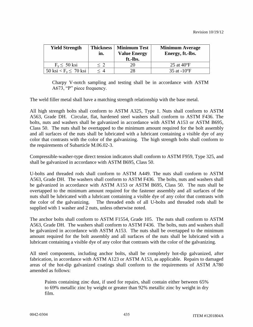
Revision 10/19/12
ITEM #1201804A
Yield Strength Thickness
in.
Minimum Test
Value Energy
ft.-lbs.
Minimum Average
Energy, ft.-lbs.
Fy ≤ 50 ksi ≤ 2 20 25 at 40ºF
50 ksi < Fy ≤ 70 ksi ≤ 4 28 35 at -10ºF
Charpy V-notch sampling and testing shall be in accordance with ASTM
A673, “P” piece frequency.
The weld filler metal shall have a matching strength relationship with the base metal.
All high strength bolts shall conform to ASTM A325, Type 1. Nuts shall conform to ASTM
A563, Grade DH. Circular, flat, hardened steel washers shall conform to ASTM F436. The
bolts, nuts and washers shall be galvanized in accordance with ASTM A153 or ASTM B695,
Class 50. The nuts shall be overtapped to the minimum amount required for the bolt assembly
and all surfaces of the nuts shall be lubricated with a lubricant containing a visible dye of any
color that contrasts with the color of the galvanizing. The high strength bolts shall conform to
the requirements of Subarticle M.06.02-3.
Compressible-washer-type direct tension indicators shall conform to ASTM F959, Type 325, and
shall be galvanized in accordance with ASTM B695, Class 50.
U-bolts and threaded rods shall conform to ASTM A449. The nuts shall conform to ASTM
A563, Grade DH. The washers shall conform to ASTM F436. The bolts, nuts and washers shall
be galvanized in accordance with ASTM A153 or ASTM B695, Class 50. The nuts shall be
overtapped to the minimum amount required for the fastener assembly and all surfaces of the
nuts shall be lubricated with a lubricant containing a visible dye of any color that contrasts with
the color of the galvanizing. The threaded ends of all U-bolts and threaded rods shall be
supplied with 1 washer and 2 nuts, unless otherwise noted.
The anchor bolts shall conform to ASTM F1554, Grade 105. The nuts shall conform to ASTM
A563, Grade DH. The washers shall conform to ASTM F436. The bolts, nuts and washers shall
be galvanized in accordance with ASTM A153. The nuts shall be overtapped to the minimum
amount required for the bolt assembly and all surfaces of the nuts shall be lubricated with a
lubricant containing a visible dye of any color that contrasts with the color of the galvanizing.
All steel components, including anchor bolts, shall be completely hot-dip galvanized, after
fabrication, in accordance with ASTM A123 or ASTM A153, as applicable. Repairs to damaged
areas of the hot-dip galvanized coatings shall conform to the requirements of ASTM A780
amended as follows:
Paints containing zinc dust, if used for repairs, shall contain either between 65%
to 69% metallic zinc by weight or greater than 92% metallic zinc by weight in dry
film.
0042-0304 435
Revision 10/19/12
ITEM #1201804A
The silicone sealant shall be a 1-component, 100% silicone sealant recommended for use with
galvanized steel.
Neoprene gasket material for the access openings shall conform to ASTM D1056, Grade 2A2 or
2A3.
Bare copper grounding conductor shall be #8 AWG stranded bare copper wire conforming to
M.15.13. The grounding bolt shall be galvanized steel with a hex head.
All materials used in the finished structure shall be new. The use of materials that have been
previously used in a structure or salvaged from a structure is not permitted.
The Contractor shall submit Certified Test Reports and Materials Certificates in conformance
with Article 1.06.07 for the steel used in the support members and components, high-strength
bolts (including nuts and washers), anchor bolts (including nuts and washers), U-bolts (including
nuts and washers) and threaded rods (including nuts and washers). In addition, the following
shall be submitted:
a. Mill test reports that indicate the place where the material was melted and
manufactured.
b. High-strength bolt test results for proof load tests, wedge tests, and rotational-
capacity tests that indicate where the tests were performed, date of tests,
location of where the components were manufactured and lot numbers.
c. Galvanized material test results that indicate the thickness of the galvanizing.
Prior to incorporation into the work, the Contractor shall submit samples in conformance with
Article 1.06.02 for the steel used in the support members and components, high-strength bolts
(including nuts and washers), anchor bolts (including nuts and washers), U-bolts (including nuts
and washers) and threaded rods (including nuts and washers).
Construction Methods: The design and fabrication of the sign support structure, including its
anchorage (into the foundation) and the hardware and structural members required to support the
traffic appurtenances, shall conform to the requirements of the latest edition of the AASHTO
Standard Specifications for Structural Supports for Highway Signs, Luminaries and Traffic
Signals, including the latest interim specifications, amended as follows:
The dead load of the sign panels, sign panel support members and hardware shall
be no less than the 8 psf.
The design wind speed shall be 120 mph. The computation of wind pressures in
accordance with Appendix C is not permitted.
The minimum design life for the structures shall be 50 years.
0042-0304 436
Revision 10/19/12
ITEM #1201804A
The wind importance factor, Ir, for wind pressure shall be 1.00.
The wind drag coefficient, Cd, for traffic signs shall be 1.3.
The height and exposure factor, Kz, shall be determined based on the highest
elevation of the structure or the supported sign panels. The factor shall be
considered constant in all pressure calculations required for the design of the
structure. The height and exposure factor shall be no less than 1.05.
The sign structure shall be designed for fatigue category I. The sign structure
shall be designed for the wind load effects due to natural wind gusts and truck-
induced gusts. The design of the sign structure for galloping-induced cyclic loads
is optional. The design pressure for the truck-induced gust shall be based on a
truck speed of 65 mph. The sign structure shall be designed assuming that
vibration mitigation devices will not be installed.
The vertical deflection of the free end of the truss due to the wind load effects of
truck-induced gusts shall not exceed 8”.
The fixity of the structure connections shall be as follows:
Welded gusset plate, bracing member to chord connections shall be
considered rigid in the plane of the gusset plate and pinned perpendicular
to the plane of the gusset plate.
Flange plate chord to chord connections shall be considered rigid with
respect to both axes.
Baseplate to anchor bolt connection shall be considered rigid with respect
to both axes.
The minimum effective length factor, K, shall be as follows:
For the pole, k = 2.1
For truss chord and bracing, k ≥ 1.0
The fatigue stress categories at the gusset plate to chord fillet welded connection
shall be conform to AASHTO Standard Specifications for Structural Supports for
Highway Signs, Luminaries and Traffic Signals, Table 11-2, Note a .
The maximum stress ratio (the ratio of the computed stress to the allowable stress)
or combined stress ratio in any sign structure component due to each group load
shall not exceed 0.85.
0042-0304 437
Revision 10/19/12
ITEM #1201804A
The truss shall be cambered to compensate for the dead load deflections. The
truss shall have a permanent camber no less than L/1000 and no greater than
L/500. L
is the span length of the cantilever truss measured from centerline of the pole to
the end of the truss. The permanent camber is in addition to the dead load
camber. The total camber shall be obtained with the use of through chord
connection plates installed at an angle.
The maximum span length of the truss shall be 45’-0”, measured from the
centerline of the pole to the end of the truss.
The truss chord members shall be tubular members with a round cross-section.
Truss chord members fabricated from tubular members with a multisided cross-
section are not permitted. All truss chords shall have the same cross-sectional
properties and material designations. The minimum wall thickness of the truss
chord members shall be 5/16".
The truss bracing members shall be tubular members with a round cross-section.
All truss bracing shall have the same cross-sectional properties and material
designations. The steel pipe bracing shall have a minimum nominal diameter of
2½”. The steel pipe bracing shall have a minimum thickness of 0.203”. The steel
pipe bracing shall be connected to tower post and truss chord gusset plates with
slotted tube connections. The bracing slot shall have a coped hole at the end of
the slot. A minimum of 10% of the bracing gusset plate to truss chord
connections, 100% of the fillet welds on each side of the connection, shall be non-
destructively tested in accordance with the magnetic particle method.
One pair of crossing diagonal bracing members shall be provided at each end of
the truss to provide stability of the structure. Also if the span of the arm is longer
then 25’-0”, a pair of crossing diagonal bracing members shall be placed at a
panel point at midspan of the truss.
The minimum diameter of the pole shall be 2’-0”. The maximum diameter of the
pole shall be 2’-6”. The minimum wall thickness of the pole member shall be 5/16".
The pole shall be a tubular member with either a round or multisided cross-
section. Multisided tubular members with other than 16 sides are not permitted.
Multisided tubular member with fluted sides are not permitted.
The pole shall be fabricated from a single piece of material. Splicing 2 or more
pieces together to form one member is not permitted.
The tubular members may be fabricated with no more than 1 longitudinal seam
weld.
0042-0304 438
Revision 10/19/12
ITEM #1201804A
The longitudinal seam welds within 6” of the member ends shall be complete
joint penetration groove welds. The seam welds shall be ground smooth and flush
with the adjacent base metal.
Partial joint penetration longitudinal seam welds shall be non-destructively tested
in accordance with the magnetic particle method. Complete joint penetration
longitudinal seam welds shall be non-destructively tested in accordance with the
ultrasonic method.
Slip-type field splices are not permitted in any member. The wall thickness of the
component members shall be uniform throughout their lengths. The use of
multiple plies (laminations) to obtain the required member thickness is not
permitted. The use of shop-fabricated stepped members is not permitted.
All tubular member to transverse plate connections shall be made with a complete
joint penetration groove weld with a backing ring attached to the plate with a
continuous fillet weld. 100% of the complete joint penetration groove welds shall
be non-destructively tested by the ultrasonic method. After galvanizing, the joint
between the backing ring and tubular member shall be sealed with silicone
sealant.
The use of stiffeners at tubular member to transverse plate connections is not
permitted.
The strength of a connection made with a complete joint penetration groove weld
shall be no greater than the strength of the base metal. In connections joining
base metal with different yield strengths, the base metal with the lower yield
strength shall govern the design.
The minimum base plate and splice plate thickness shall be 2”. The determination
of the plate thickness in the tubular member to transverse plate connections shall
consider the potential for the plate to warp due to the heat from welding.
Consideration should be given to the use of thicker plates to allow for subsequent
machining of warped plates to a flat surface so that removal of material will not
compromise the required strength of the plate.
All high-strength bolted connections shall be designed as slip critical connections
with standard holes, unless otherwise noted. The high-strength bolts shall
conform to the maximum spacing requirements for sealing and stitch fasteners.
The high-strength bolts shall conform to the edge distance requirement for
fasteners. Consideration should be given to the use of smaller diameter bolts
since they require lower specified minimum bolt tensions.
The minimum number of high-strength bolts in flange splices shall be 6.
0042-0304 439
Revision 10/19/12
ITEM #1201804A
The minimum thickness of the truss to pole connection plates shall be ¾”. The
minimum thickness of the truss bracing gusset plates and the stiffener plates shall
be ½”.
The minimum size fillet weld shall be ¼”, unless noted otherwise. The use of seal
and tack welds is not permitted. No welding shall be performed after galvanizing.
The anchor bolt to base plate connection shall be designed as a double-nut
connection with shear holes. The anchor bolts shall use an embedded anchorage
plate, ¾” minimum thickness, to transmit loads from the pole base to the concrete
foundation. The use of hooked anchor bolts is not permitted. The minimum
number of anchor bolts shall be 12. The minimum anchor bolt diameter shall be
2”. The minimum anchor bolt embedment, the distance from the top of the
foundation to the top of the embedded anchorage plate, shall be 3’-6” or the
tension development length of the vertical foundation reinforcement plus the end
concrete cover, whichever is greater. Each anchor bolt shall be supplied with 5
nuts and 4 washers. Washers shall be placed on the top and bottom surfaces of
the pole base plate and anchorage plate. Welding to the anchor bolts is not
permitted.
The approximate dimensions of the truss and the pole heights are shown in plan and elevation on
the traffic sheets. The actual sign support dimensions shall be determined by the Contractor
based on a the horizontal and vertical clearances shown on the plans, a field survey of the
finished grade at the site, the elevation of the top of the finished foundation, the locations of
overhead and subsurface utilities, the location of the drainage facilities and noise barrier wall
locations.
The minimum vertical clearance from the top of the finished road to the bottom of the sign
panels and the centerline of the truss shall be as shown on the sign support drawings as amended
by the sign support elevation on the traffic sheets.
Sign panels shall be installed symmetrically about the centerline of the truss. The bottom of all
signs shall be level. Sign panels shall be installed at an angle of 5° from the vertical, with the top
edge tilting toward oncoming traffic.
The sign panels and crown panels, if applicable, shall be connected to sign panel support
members. The support members shall extend full height of the sign and crown panels. The
number and spacing of support members shall be determined by the Contractor based on the
width of the sign and crown panels and the support member spacing parameters shown on the
plans. Sign panels shall be supported by no less than 3 support members. Crown panels shall be
supported by no less than 2 support members. The faying surface between the sign panel support
member and the rear face of the sign panel shall be a flange so that panel clips may be placed on
both sides of the flange to connect the panel. The outside support members for each sign panel
0042-0304 440
Revision 10/19/12
ITEM #1201804A
shall include a sign stop at the bottom of the member and a sign hook at the top of the member to
support and carry the sign panels.
The sign panel support members shall be designed to be vertically adjustable to compensate for
the truss camber. The supports members shall be designed to be installed at any location along
the truss. The use of U-bolts and threaded rods is permitted. No less than 2 U-bolts or 4
threaded rods shall be used at each chord connection. The threaded ends of these fasteners shall
have double nuts.
The minimum thickness of the sign panel support members and the plate and rolled shape
components used in the connection to the sign support shall be ¼”.
The sign support shall be designed for the load effects due to the actual sign panels that it will
carry unless otherwise shown on the plans. The sign supports shall also be designed for the load
effects of sign panels during all stages of construction which may exist during the project under
which the supports are installed. The load effects on the sign support from the sign and crown
panels shall include forces and moments due to the eccentricity of the sign and crown panels and
the unbalanced lateral loads on the crown panel. The sign support and its component parts shall
also be designed for the load effects resulting from the transportation and erection of the support.
The sign support shall be designed so that the pole extends into the truss and is connected at each
chord. Connection plates, through each chord, shall be fastened with high-strength bolts to
stiffened connection plates fillet welded to the pole. 100% of the fillet welds used in the truss to
pole connection shall be non-destructively tested in accordance with the magnetic particle
method. All bolts, nuts and washers used in the connection shall be visible. The use of tapped
holes in the plates of the connection is not permitted.
Vent and drain holes shall be provided for galvanizing. The number, size and location of vent
and drain holes should be coordinated with the galvanizer prior to the submission of the sign
support design. The area of vent and drain holes at each end of a member shall be at least 30%
of the inside area of the member for members 3” in diameter and greater and 45% of the inside
area of the member for members smaller than 3” in diameter. The vent and drain holes shall be
strategically located for reducing stress and for proper galvanizing. The holes shall be made by
drilling. Flame cut holes are not permitted. The edges of all holes shall be rounded by grinding.
After galvanizing, exposed holes placed in the sign support components for galvanizing shall be
sealed with neoprene plugs.
The pole shall have a handhole centered 2'-9" from the top of the base plate. The pole handhole
shall be located away from traffic.
Handholes shall be reinforced with a frame having a minimum 4" wide by minimum 6" high
clear opening. The minimum thickness of the handhole frame shall be no less than the thickness
of the tubular member. The handhole frame shall be connected to the tubular member with a
partial joint penetration groove weld reinforced with a fillet weld. The weld shall be non-
destructively tested in accordance with the magnetic particle method. Each handhole shall have
0042-0304 441
Revision 10/19/12
ITEM #1201804A
a cover connected to the handhole frame with no less than 4 stainless steel screws. The cover
shall be installed with a neoprene gasket. A stainless steel chain shall be bolted to the cover
inside face of the cover with a stainless steel bolt with a lock nut and bolted to the inside side
face of the handhole frame with a stainless steel bolt. On pole hand hole frames, the opposite
side face of the handhole shall have a hole with a nut welded to outside face for a stainless steel
grounding bolt.
Handhole frames fabricated from steel plate and bent to form a closed shape shall be joined with
a complete joint penetration groove weld. All surfaces of the groove weld shall be ground
smooth and flush with the adjacent base metal.
The ends of each chord member shall be sealed with a removable end cap plate attached to the
member with a threaded fastener. The joint between the member and plate shall be sealed with a
neoprene gasket.
The design of the sign support and the anchorage shall be coordinated with the design of the
foundation to ensure that the foundation is adequate for the support reactions and to avoid
conflicts between the embedded anchorage and the foundation reinforcement.
Prior to performing a field survey for each sign support, the Contractor shall coordinate with the
Engineer to locate and stake each support foundation. The foundations shall be located to avoid
conflicts with both subsurface and overhead utilities and subsurface drainage structures. In
accordance with Article 1.05.15, the Contractor shall contact “Call Before You Dig” to identify
the subsurface utilities that are located in the vicinity of each foundation. Once the location of
each foundation has been found acceptable to the Engineer, the Contractor shall perform a field
survey to obtain the information necessary to prepare a roadway cross-section with details of
each sign support and supporting foundation(s).
The Contractor shall prepare and submit one copy of a cross-section (elevation) drawing based
on a field survey for each sign support to the Engineer for review and approval. Each cross-
section drawing shall be submitted in paper form and shall be printed on an ANSI B (11” x 17”;
Ledger/Tabloid) sheet. Each drawing shall have a border and title block. Located in the lower
right hand corner of the drawing adjacent to the title block, each drawing shall have a rectangular
box, 2 ¼” wide x 1 ¾” high, for the reviewers stamp. On the ANSI B sheets, the minimum text
height and width shall be 1/16”. All letter characters shall be uppercase. Only one sign support
cross-section shall be shown on each drawing.
The cross-sections shall include, but not be limited to the following:
Project number, town, location (route number, direction, mileage), station,
structure number, sign location number, and site number
Location and dimensions of travel lanes and shoulders
Location and elevation of the high point of the road
0042-0304 442
Revision 10/19/12
ITEM #1201804A
Top and bottom of slope elevations. Slope of finished grade at foundations
Locations of utilities (both overhead and subsurface)
Locations of drainage facilities
Locations of noise barriers, including elevation of top of wall
Type of protection (metal beam rail/barrier), and the dimension from the front
face of metal beam rail /barrier to the edge of the foundation and centerline of the
foundation
Elevation of the top of the foundation(s). The top of the foundation(s) shall
project 6” to 12” above the level ground or 6” to 12” above the finished grade at
the high side of a sloping grade.
Dimension from top foundation to finish grade (existing or proposed as
applicable).
Span, dimension from centerline to centerline of foundations
Dimensions of sign panel(s)
Location of sign panel(s) relative to the centerline of the foundations/poles
Location of sign panel(s) relative to the roadway travel lanes
Dimension from top of foundation to centerline of truss
Minimum dimensions from high point of the road to the centerline of the truss and
the bottom of the sign panel(s)
Elevation of centerline of truss
The Contractor shall submit the cross-section drawings to the project’s “Engineer of Record” for
review and approval. The project’s “Engineer of Record” is identified in the signature block on
the sign support traffic cross-section contract plans. A copy of the transmittal shall be sent to the
District Construction office administering the project.
The reviewed and stamped cross-section drawings shall be sent by the reviewer, along with a
recommendation regarding acceptance, to the District Construction office for review, comment
and distribution. The approval of cross-section drawings does not relieve the Contractor from
verifying that all dimensions are correct. If there are any changes to the proposed location of the
0042-0304 443

Revision 10/19/12
ITEM #1201804A
sign support and foundations prior to the construction of the foundations, the cross-section shall
be re-submitted for review and approval.
Prior to fabrication, the Contractor shall submit working drawings and design computations for
each sign support, based on the approved cross-section, to the engineer for review in accordance
with Article 1.05.02. An individual, independently packaged set of working drawings and
computations, with all details and documents necessary for fabrication and erection of the
structure and its components, including a copy of the certificate of insurance, shall be prepared
and submitted for each support. A single set of drawings with tabulated data for multiple
sign support locations is not permitted. The alpha-numeric support identifier shall be included
on these documents. The working drawings and computations shall be prepared in Customary
U.S. units.
The packaged set of working drawings and computations for each support shall be submitted
either in paper (hard copy) form or in an electronic portable document format (.pdf) with
appropriate bookmarks. The packaged set submitted in paper form shall be bound with a staple.
The packaged set submitted in an electronic portable document format (.pdf) shall be in an
individual file and the file shall be enabled for commenting. The packaged set shall include the
following:
title sheet
table of contents
contact information for designer, fabricator and galvanizer – contact
information should include name and address of each firm and the name of
contact person with phone number and email address
copy of the certificate of insurance
copy of fabricator’s AISC certification
copy of the approved cross-section
sign support working drawings
sign support design computations
welding procedures
sign support installation procedure, including the method to plumb the poles
Combining of a non-approved cross-section with the sign support working drawings and
calculations into one packaged set for review is not permitted.
The working drawings and design computations shall be signed, dated and sealed by a
Professional Engineer licensed in the State of Connecticut, who shall also be available for
consultation in interpreting his computations and drawings, and in the resolution of any problems
which may occur during the performance of the work. Each working drawing shall be signed,
dated and sealed. The cover/first sheet for the computations shall be signed, dated and sealed.
Working drawings submitted in paper form shall be printed on ANSI B (11” x 17”;
Ledger/Tabloid) sheets. Each drawing shall have a border and title block. Located in the lower
right hand corner of the drawing adjacent to the title block, each drawing shall have a rectangular
0042-0304 444
Revision 10/19/12
ITEM #1201804A
box, 2 ¼” wide x 1 ¾” high, for the reviewers stamp. On the ANSI B sheets, the minimum text
height and width shall be 1/16”. All letter characters shall be uppercase. Design computations,
procedures and other supporting data shall be submitted on ANSI A (8 ½" x 11"; Letter) sheets.
Working drawings submitted in an electronic portable document format (.pdf) shall be created on
ANSI D (22” x 34”) full scale (1” electronic file = 1” paper) sheets. (The purpose of creating the
drawings on ANSI D sheets is so that the sheets may be printed/plotted at that size or smaller
without loss of legibility.) Each drawing shall have a border and title block. Located in the
lower right hand corner of the drawing adjacent to the title block, each drawing shall have a
rectangular box, 2 ¼” wide x 1 ¾” high, for the reviewers stamp. On the ANSI D full scale
sheets, the minimum text height and width shall be 1/8”. All letter characters shall be uppercase.
The electronic files for the design computations, procedures and other supporting data shall be
created on ANSI A (8 ½" x 11"; Letter) sheets.
The working drawings shall include complete details of all sign support components. The
drawings shall include, but not be limited to the following:
the project number, town and support identification number
reference to the design specifications, including interim specifications
reference to the design specifications design criteria, such as design wind
speed, minimum design life, etc.
material specifications/designations for all components
non-destructive weld testing requirements
details of the location of the longitudinal seam weld in the pole
vent and drain holes for galvanizing
dead load and permanent camber
a plan view of the anchor bolt layout relative to the orientation of the span
anchor bolt dimensions, including embedment and projection
support installation procedure, including the method to plumb the pole
The design computations shall include, but not be limited to the following:
the project number, town and support identification number
0042-0304 445
Revision 10/19/12
ITEM #1201804A
references to design specifications, including interim specifications, and the
applicable code section and articles
description/documentation for all computer programs used in the design
drawings/models of the structure, components and connections, with
dimensions, loads and references to the local and global coordinate systems
used (as applicable), to facilitate review of the results
Tabulation of the section properties of the tubular members at each analyzed
section. The tabulated values should include the diameter, D (if round
member); effective width, b (if multisided member, AASHTO 5.5.2);
equivalent diameter (if multisided member, AASHTO 5.6), wall thickness, t;
inside bend radius, rb (if multisided member, AASHTO 5.5.2), cross-sectional
area, A; moment of inertia, I; section modulus, S; radius of gyration, r.
AASHTO Table B-1 may be used to determine the section properties. If
Table B-1 is used, the radius measured to the mid-thickness of the wall shall
also be provided.
coefficients and factors used in the design
results of all group loads and load combinations
stress ratios and combined stress ratios for all group loads and load
combinations
maximum vertical deflection due to dead loads
maximum vertical deflection due to ice loads
vertical deflection of the free end of the truss due to the wind load effects of
truck-induced gusts
total camber and permanent camber
The Contractor shall submit the packaged set of working drawings and calculations to the
project’s “Engineer of Record”. The project’s “Engineer of Record” is identified in the signature
block on the sign support structural contract plans. A copy of the transmittal shall be sent to the
District Construction office administering the project.
The reviewed and stamped working drawings and calculations shall be sent by the reviewer,
along with a recommendation regarding acceptance, to the District Construction office for
review, comment and distribution. After the District Construction office has reviewed the
working drawings and calculations, ensured all comments have been addressed and have found
0042-0304 446

Revision 10/19/12
ITEM #1201804A
the submittal to be acceptable, in addition to distributing copies of the working drawings and
calculations to the Contractor and District offices, a copy of each packaged set of working
drawings and calculations shall be sent to the following Department offices:
Bridge Safety and Evaluation
Research and Materials
Traffic Engineering
Engineer of Record
If the as-built condition of the foundation(s), such as the location or elevation, will impact the
design, final erection or assembly of the sign support for conformance with the requirements
herein, the cross-section shall be re-submitted for review and approval. Subsequently, the
working drawings and calculations shall be resubmitted to conform to the revised cross-section
and the requirements herein.
The support shall be fabricated in accordance with the latest edition of the AASHTO LRFD
Bridge Construction Specifications, including the latest interim specifications, amended herein.
The steel fabricator shall be AISC certified for the fabrication of Simple Steel Bridges (SBR).
Fabrication of the support may begin only after the working drawings and design computations
have been reviewed and the Engineer has authorized fabrication to begin. The Contractor shall
submit to the Engineer, no less than 2 weeks prior to the start of fabrication, the name and
location of the fabrication shop where the work will be done so that arrangements can be made
for an audit of the facility and the assignment of the Department Quality Assurance (QA)
inspector. No fabrication will be accepted unless the QA inspector is present during fabrication.
No changes may be made during fabrication without prior written approval by the Department.
The Contractor shall furnish facilities for the inspection of material and workmanship in the shop
by the Engineer. The Engineer and his representative shall be allowed free access to the
necessary parts of the premises.
The Engineer will provide QA inspection at the fabrication shop to assure that all applicable
Quality Control plans and inspections are adequately adhered to and maintained by the
Contractor during all phases of the fabrication. A thorough inspection of a random selection of
elements at the fabrication shop may serve as the basis of this assurance.
Prior to shipment to the project, each individual piece of steel shall be marked in a clear and
permanent fashion by a representative of the fabricators’ Quality Control (QC) Department to
indicate complete final inspection by the fabricator and conformance to the project specifications
for that piece. The mark must be dated. A Materials Certificate in accordance with Article
1.06.07 may be used in lieu of individual stamps or markings, for all material in a single
shipment. The Materials Certificate must list each piece within the shipment and accompany the
shipment to the project site.
0042-0304 447

Revision 10/19/12
ITEM #1201804A
Following the final inspection by the fabricator’s QC personnel, the Engineer may select pieces
of steel for re-inspection by the Department’s QA inspector. Should non-conforming pieces be
identified, all similar pieces must be re-inspected by the fabricator and repair procedure(s)
submitted to the Engineer for approval. Repairs will be made at the Contractor’s expense.
The pieces selected for re-inspection and found to be in conformance, or adequately repaired
pieces, may be marked by the QA inspector. Such markings indicate the Engineer takes no
exception to the pieces being sent to the project site. Such marking does not indicate acceptance
or approval of the material by the Engineer.
Fabrication of the supports shall conform to the requirements of Articles 6.03.04, 6.03.05,
6.03.06 and 6.03.10, 6.03.11, 6.03.12 and 6.03.13.
All welding details, procedures and nondestructive testing shall conform to the requirements of
AWS D1.1 Structural Welding Code - Steel.
Personnel performing the nondestructive testing shall be certified as a NDT Level II technician
in accordance with the American Society for Non Destructive Testing (ASNT), Recommended
Practice SNT-TC-1A and approved by the Engineer.
All nondestructive testing shall be witnessed by Engineer. Certified reports of all tests shall be
submitted to the Engineer for examination. Each certified report shall identify the structure,
member, and location of weld or welds tested. Each report shall also list the length and location
of any defective welds and include information on the corrective action taken and results of all
retests of repaired welds.
The Department reserves the right to perform additional testing as determined by the Engineer.
Should the Engineer require nondestructive testing on welds not designated in the contract, the
cost of such inspection shall be borne by the Contractor if the testing indicates that any weld(s)
are defective. If the testing indicates the weld(s) to be satisfactory, the actual cost of such
inspection will be paid by the Department.
All members and components shall be hot-dip galvanized in a single dip. Double-dipping of
members and components is not permitted. All exterior and interior surfaces of the sign support
members and components shall be completely galvanized.
Galvanized members and components shall be free from uncoated areas, blisters, flux deposits,
and gross inclusions. Lumps, projections, globules, or heavy deposits of zinc which will
interfere with the intended use of the material will not be permitted.
All damaged areas of the hot-dip galvanized surfaces shall be repaired in accordance with the
requirements of ASTM A780. If paint containing zinc dust is used for repairs, the dry coating
thickness shall be at least 50% greater than the thickness of the adjacent hot-dip galvanized
coating, but no greater than 4.0 mils. The paint shall be brush applied. The use of aerosol spray
0042-0304 448
Revision 10/19/12
ITEM #1201804A
cans shall not be permitted. The color of the finished repair area shall match the color of the
adjacent hot-dip galvanized surface at the time of the repair to the satisfaction of the Engineer.
Prior to shipping, all galvanized surfaces of the members and components shall be inspected, in
the presence of the Engineer, to determine the acceptability of the galvanized coating.
Galvanized coatings may be found acceptable by the Engineer if all surfaces of the members and
components meet the galvanizing requirements herein. Only sign support members and
components with acceptable galvanized coatings shall be shipped. If the galvanized coating on
any member or component is found not acceptable, the Contractor shall submit a repair
procedure to the Engineer for review.
The sign support structure number shall be stenciled in black paint on the pole centered
approximately 5’ off the ground and visible from the roadway. The numeric characters shall be
3” to 4” high and placed vertically so that they may be read from top to bottom.
After fabrication, the sign support components shall be assembled in the fabricator's shop, in the
presence of the Engineer, to determine the acceptability of the bolted connections and to confirm
the permanent camber. The faying surfaces of the connections shall be free of dirt, loose scale,
burrs, other foreign material and other defects that would prevent solid seating of the parts. Prior
to assembly, the galvanized faying surfaces shall be scored by wire brushing. The faying
surfaces of the connection plates shall be checked with a straight edge to ensure that the surfaces
are not distorted and the entire faying surface of each plate will be in contact when assembled.
The high-strength bolts, including nuts and washes, shall be installed and tensioned in
accordance with Subarticle 6.03.03-4(f). A connection may be found acceptable by the Engineer if
the faying surfaces of the connection plates are in firm, continuous contact after properly tensioning
the bolts. Only sign supports with acceptable connections shall be shipped. If a bolted
connection is found not acceptable, the Contractor shall submit a procedure to repair the
connection to the Engineer for review. Galvanized surfaces damaged by the repair procedure
shall be hot dip galvanized. Repair of the damaged galvanized surfaces in accordance with the
requirements of ASTM A780 or with a galvanizing repair stick is not permitted. Bolts, nuts and
washers used for the trial shop fit-up shall not be reused in the final field assembly. The
permanent camber shall be measured at the end of the truss and the structure shall be rejected if
the camber does not meet the following:
L/1000 ≤ Permanent Camber ≥
L/500
where L is the span length of the overhead member measured from centerline to the end
of the truss.
The finished members and components shall be protected with sufficient dunnage and padding to
protect them from damage and distortion during transportation. Damage to any material during
transportation, improper storage, faulty erection, or undocumented fabrication errors may be
cause for rejection of said material at the project site. All costs associated with any corrective
action will be borne by the Contractor.
0042-0304 449
Revision 10/19/12
ITEM #1201804A
Following delivery to the project site, the Engineer will perform a visual inspection of all
material to verify shipping documents, fabricator markings, and that there was no damage to the
material or coatings during transportation and handling.
The Engineer is not responsible for approving or accepting any fabricated materials prior to final
erection and assembly at the project site.
High-strength bolts, nuts and washers shall be stored in accordance with Subarticle 6.03.03-4(f).
The support shall be erected, assembled and installed in accordance with these specifications and
the procedures and methods submitted with the working drawings. The Contractor and the
support designer are responsible to ensure that the erection and assembly procedures and
methods in this specification are acceptable for use with the support. Changes to these methods
and procedures shall be submitted with the working drawings and computations.
Prior to installation of the support, the threads of the embedded anchor bolts shall be cleaned of
accumulated dirt and concrete. The anchor bolt nuts shall be re-lubricated with a lubricant
containing a visible dye of any color that contrasts with the color of the galvanizing. On each
anchor bolt, all the nuts shall be run down by hand on the anchor bolt threads.
The space between the bottom of the baseplate and the top of the foundation shall not be sealed
with closed cell elastomer or filled with grout, unless otherwise noted.
During the erection of the pole, the leveling nuts and washers shall be inspected, and if necessary
adjusted, so that they are in full contact with the bottom surface of the baseplate. Subsequently,
the top nuts and washers shall be inspected, and if necessary adjusted, so that they are snug tight
(in full contact with the baseplate). Snug tight is defined as the condition where the nuts and
washers are in full contact with the baseplate and the snug tight condition was the result of the
full effort of a person using a 12” wrench.
With the top nuts snug tight, the top nuts shall be tightened one-sixth of a turn beyond snug tight.
After the top nuts are tightened, the leveling nuts should be retightened to assure the full contact
has been maintained. After tightening, lock nuts shall be installed over the top anchor nuts. The
top nuts shall have full thread engagement. The distance from the bottom of the leveling nuts to
the top of the foundation shall not exceed 1".
High-strength bolts, including nuts and washes, shall be installed and tensioned in accordance
with Subarticle 6.03.03-4(f). The truss shall be temporarily and fully supported while all the high-
strength bolts are installed and tensioned. The temporary support of the truss shall not be removed
until the Engineer has confirmed that the faying surfaces of the connection/flange plates are in firm,
continuous contact and the high-strength bolts were properly installed and tensioned. All high-
strength bolts in the bolted connections shall be inspected (in accordance with Subarticle 6.03.03-
4(f)) to confirm the high-strength bolts were properly tensioned.
0042-0304 450
Revision 10/19/12
ITEM #1201804A
After erecting the support, the support shall be electrically grounded by attaching the bare copper
grounding conductor to the inside of the handhole frame with a galvanized steel bolt and to the
ground rod with a ground clamp. The rigid metal conduit shall be electrically grounded by
attaching the bare copper grounding conductor to the insulated bonding bushing and to the
ground rod with a ground clamp.
After erection of the support and before the installation of the sign panels, if the structure
exhibits excessive vibration, oscillations or deflections as determined by the Engineer, the
Contractor shall immediately stabilize the structure to the satisfaction of the Engineer.
Stabilizing the structure may require the removal of a portion of the structure or the entire
structure.
The sign panels shall be located and mounted on the truss as shown in the working drawings.
After installation of the sign panels, the anchor bolts nuts (leveling and top anchor nut) and
washers shall be in full contact with the top and bottom surfaces of the pole baseplate and the
centerline of the pole shall be plumb.
After erection of the support and after the installation of the sign panels, if the structure exhibits
excessive vibration, oscillations or deflections as determined by the Engineer, the Contractor
shall design and construct devices to mitigate the movements. The Contractor is responsible for
immediately stabilizing the structure to the satisfaction of the Engineer. Stabilizing the structure
may require the removal of the sign panels or the entire structure. Prior to installation of any
mitigation device, the Contractor shall submit drawings, design computations other
documentation to the Engineer for review in accordance with Article 1.05.02.
Method of Measurement: This work will be measured for payment by the number of cantilever
sign structures, completed and accepted in place.
Basis of Payment: This work will be paid for at the contract unit price each for "4 Chord Truss
Cantilever Sign Structure", complete in place, which price shall include field survey, equipment,
materials, tools and labor incidental to the design, fabrication and installation, including
anchorage materials, sign panel support members and mitigation devices, if required, of the
supports at the locations specified on the plans.
0042-0304 451
Revision 03/18/14
ITEM #1202999A
ITEM #1202999A – DRILLED SHAFT TRAFFIC STRUCTURE
FOUNDATION
Description: Work under this item shall consist of the subsurface investigation, design and
construction of drilled shaft foundations for traffic structures, in accordance with the details shown
on the plans, in accordance with these specifications and as ordered by the Engineer. For the
purposes of this specification, a traffic structure support may be an overhead cantilever or bridge
type sign support structure.
Materials: The reinforcing steel shall be uncoated, ASTM A615, Grade 60 reinforcement
conforming to the requirements of Article M.06.01.
The concrete for the drilled shaft shall be dense, homogeneous, fluid, resistant to segregation and
consolidate under self-weight. The concrete for the drilled shaft shall be a Contractor designed
Portland cement concrete with a 3/8” (No. 8) maximum coarse aggregate size and a minimum of
705 lbs/cubic yard of cementitious materials. The initial concrete slump shall be 7” + 1”. The
concrete shall maintain a minimum 4” slump for the duration of the concrete placement. The
concrete shall contain 1% - 7% air entrainment. The 28 day minimum compressive strength of
the concrete in the constructed foundation shall be 4,000 psi. The concrete mix design, including
admixtures, shall be submitted to the Engineer for approval.
The concrete for the formed pedestal shall conform to Article M.03 for Class ‘F’ Concrete. The
28 day minimum compressive strength of the concrete in the constructed pedestal shall be 4,400
psi. The concrete mix design, including admixtures, shall be submitted to the Engineer for
approval.
The slurry shall be Contractor designed mineral slurry that meets the range of values listed
herein. The slurry mix design, including admixtures, shall be submitted to the Engineer for
approval.
Rigid metal conduit, ground rod sleeves and related hardware, and end caps shall be galvanized
steel conduit, and shall conform to Article M.15.09.
Ground rods shall be 5/8” in diameter by 12’-0” long copper clad steel. The copper cladding
shall be a minimum thickness of 0.128”. The ground clamp shall be a square-head bolt type,
approved for direct burial.
Bare copper wire shall conform to Article M.15.13.
Topsoil shall conform to Article M.13.01.
Fertilizer shall conform to Article M.13.03.
Seed mixture shall conform to Article M.13.04.
0042-0304 452
Revision 03/18/14
ITEM #1202999A
Mulch shall conform to Article M.13.05.
Erosion control matting shall conform to Article M.13.09.
Construction Methods:
Subsurface Conditions for Bidding: For the purpose of bidding this item, the Contractor shall
assume that the subsurface conditions for each foundation location consists of cohesionless
medium dense granular soil (AASHTO A-1 or A-2) with cobbles present and a high groundwater
table which requires the use of wet construction/concreting methods.
Subsurface Conditions for Foundation Design: As early as possible and prior to preparation
of the foundation design, the Contractor shall perform a subsurface investigation for each sign
foundation location. The subsurface data obtained in the exploration program at each site shall
be used in the design of the foundation at that site. Use of the assumed subsurface condition
(that was provided for the purpose of bidding), an assumed conservative subsurface condition or
any other assumed subsurface condition shall not be allowed for use in the foundation design nor
shall any assumed subsurface condition relieve the Contractor from their responsibility of
obtaining a test boring at each foundation site. The subsurface investigation program should be
prepared and executed in accordance with the most recent editions of the AASHTO Manual on
Subsurface Investigations and ConnDOT Geotechnical Engineering Manual. The Contractor
shall provide a full-time inspector to oversee the subsurface exploration program. The subsurface
investigations and all related cost will not be measured for payment and shall be included in the
cost of the foundation.
The Contractor shall review results of their subsurface investigation to determine if subsurface
conditions for sign foundation locations differ materially from those assumed at the time of bid.
Should the subsurface investigation(s) encounter conditions that differ materially, the Contractor
shall notify the Engineer in writing prior to the submission of the working drawings and
calculations. All matters regarding increased cost relating to agreed upon change in subsurface
conditions will be handled per Section 1.04.04 – Differing Site Conditions.
Foundation Design: The design of drilled shaft traffic structure foundations shall conform to the
requirements of AASHTO Standard Specifications for Structural Supports for Highway Signs,
Luminaries and Traffic Signals – latest edition, including the latest interim specifications, available
prior to the advertising date of the contract, amended as follows:
The foundation shall be designed for the soils and rock properties and parameters
based on the subsurface conditions (character of the soil and rock, presence of
ground water, etc.) in the location of, adjacent to and below the drilled shaft
foundation excavation determined by the subsurface investigation.
0042-0304 453
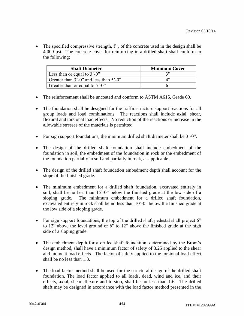
Revision 03/18/14
ITEM #1202999A
The specified compressive strength, f’c, of the concrete used in the design shall be
4,000 psi. The concrete cover for reinforcing in a drilled shaft shall conform to
the following:
Shaft Diameter Minimum Cover
Less than or equal to 3’-0” 3”
Greater than 3’-0” and less than 5’-0” 4”
Greater than or equal to 5’-0” 6”
The reinforcement shall be uncoated and conform to ASTM A615, Grade 60.
The foundation shall be designed for the traffic structure support reactions for all
group loads and load combinations. The reactions shall include axial, shear,
flexural and torsional load effects. No reduction of the reactions or increase in the
allowable stresses of the materials is permitted.
For sign support foundations, the minimum drilled shaft diameter shall be 3’-0”.
The design of the drilled shaft foundation shall include embedment of the
foundation in soil, the embedment of the foundation in rock or the embedment of
the foundation partially in soil and partially in rock, as applicable.
The design of the drilled shaft foundation embedment depth shall account for the
slope of the finished grade.
The minimum embedment for a drilled shaft foundation, excavated entirely in
soil, shall be no less than 15’-0” below the finished grade at the low side of a
sloping grade. The minimum embedment for a drilled shaft foundation,
excavated entirely in rock shall be no less than 10’-0” below the finished grade at
the low side of a sloping grade.
For sign support foundations, the top of the drilled shaft pedestal shall project 6”
to 12” above the level ground or 6” to 12” above the finished grade at the high
side of a sloping grade.
The embedment depth for a drilled shaft foundation, determined by the Brom’s
design method, shall have a minimum factor of safety of 3.25 applied to the shear
and moment load effects. The factor of safety applied to the torsional load effect
shall be no less than 1.3.
The load factor method shall be used for the structural design of the drilled shaft
foundation. The load factor applied to all loads, dead, wind and ice, and their
effects, axial, shear, flexure and torsion, shall be no less than 1.6. The drilled
shaft may be designed in accordance with the load factor method presented in the
0042-0304 454
Revision 03/18/14
ITEM #1202999A
latest edition of the Building Code Requirements for Reinforced Concrete”, ACI
318.
The structural design of the drilled shaft shall be based on stress and strain
compatibility in the circular drilled shaft cross section. The use of methods
equating circular to rectangular drilled shaft cross sections is not permitted.
The drilled shaft foundation shall be reinforced with longitudinal and transverse
reinforcement. The area of longitudinal reinforcement should be no less than the
sum of the reinforcement required for flexure and the longitudinal reinforcement
required for torsion. The area of transverse reinforcement should be no less than
the sum of the reinforcement required for shear and the transverse reinforcement
required for torsion.
In drilled shaft foundations for cantilever sign structures, the area of transverse
reinforcement provided shall prevent the concrete breakout at the edge of the
foundation due to the torsional load on the anchor bolt group. The area of
transverse reinforcement provided shall be considered adequate to prevent this
condition if the nominal torsional strength of the foundation is greater than the
concrete breakout strength. The concrete breakout strength shall be determined in
accordance with the latest edition of the Building Code Requirements for
Reinforced Concrete”, ACI 318, Appendix D.
The minimum number of longitudinal reinforcing bars shall be 16. The minimum
size of longitudinal reinforcing bars shall be #8. The minimum area of
longitudinal reinforcing bars shall be no less than 1% of the gross cross-sectional
area of the shaft. The minimum clear distance between longitudinal reinforcing
bars shall be no less than 5 times the maximum aggregate size or 5”, whichever is
greater. The reinforcement shall extend full length of the drilled shaft foundation,
including the pedestal. Splicing of the longitudinal reinforcement is not
permitted.
The drilled shaft foundation shall be transversely reinforced with spirals or
circular, one piece, enclosed ties. The minimum size of the transverse
reinforcement shall be #4. The maximum spacing/pitch of the transverse
reinforcement shall be no more than 6”. The minimum spacing/pitch of the
transverse reinforcement shall be no more than 4”. The maximum spacing/pitch
of the transverse reinforcement in the top 2’-0” of the foundation shall be no more
than 4”. The spiral reinforcement shall be terminated at the top and the bottom
with 1 ½ turns of the reinforcing and a 135° standard hook. Spirals may be
spliced with lap splices or mechanical connectors. For spirals, the minimum lap
splice length shall be 1.7 times the tension development length (including
modification factors) of the bar or 48 bar diameters, whichever is greater. For
spirals, the mechanical connectors shall develop both in tension and compression
125% of the specified yield strength of the bar and conform to the latest edition of
0042-0304 455

Revision 03/18/14
ITEM #1202999A
the AASHTO LRFD Bridge Design Specifications, including the latest interim
specifications. For ties, the minimum lap splice length shall be no less than 1.7
times the tension development length (including modification factors) of the bar.
Tie lap splices shall be alternated. The ends of the bars in lap splices shall be
anchored with a 135° standard hook around longitudinal reinforcement.
For sign support foundations, the top of the drilled shaft shall be designed with a
square pedestal to facilitate the installation of the anchor bolts and rigid metal
conduits. The plan dimensions of the pedestal shall equal the diameter of the
drilled shaft. The top and sides of the pedestal shall be reinforced with a grillage
of reinforcement. The minimum size reinforcement shall be #5. The minimum
concrete cover shall be 3”
The design of the foundation shall be coordinated with the traffic structure
support to avoid conflicts between the embedded support anchorage and the
foundation reinforcement.
The Contractor’s foundation designer shall obtain a Professional Liability Insurance Policy in
accordance with the requirements of Article 1.05.02-2a. A Contractor shall submit a copy of the
certificate of insurance to the Engineer in accordance with the requirements of Article 1.05.02-
2a.
Prior to excavating for the foundation, the Contractor shall submit working drawings and design
computations for the foundation(s) at each sign support, based on the approved cross-section, to
the Engineer for review in accordance with Article 1.05.02. An individual, independently
packaged set of working drawings and computations, with all details and documents necessary
for fabrication and construction, including a copy of the certificate of insurance, shall be
prepared and submitted for the foundation(s) at each support. A single set of drawings with
tabulated data for multiple foundation locations is not permitted. The alpha-numeric
support identifier shall be included on these documents. The working drawings and
computations shall be prepared in Customary U.S. units.
The packaged set of working drawings and computations for the foundation(s) at each support
shall be submitted in an individual file in electronic portable document format (.pdf) with
appropriate bookmarks commenting enabled. The packaged set shall include the following:
title sheet
table of contents
contact information for designer – contact information should include name and
address of design firm, name of contact person with phone number and email
address
copy of the certificate of insurance
copy of the approved cross-section
results of subsurface investigation, including boring logs and geotechnical design
recommendations
0042-0304 456
Revision 03/18/14
ITEM #1202999A
foundation working drawings
foundation design computations
Combining the foundation working drawings and calculations with sign support working
drawings and calculations into one packaged set for review is not permitted.
The working drawings and design computations shall be signed, dated and sealed by a
Professional Engineer licensed in the State of Connecticut, who shall also be available for
consultation in interpreting his computations and drawings, and in the resolution of any problems
which may occur during the performance of the work. Each working drawing shall be signed,
dated and sealed. The cover/first sheet for the computations shall be signed, dated and sealed.
The electronic portable document format (.pdf) working drawings shall be created on ANSI D
(22” x 34”) full scale (1” electronic file = 1” paper) sheets. (The purpose of creating the
drawings on ANSI D sheets is so that the sheets may be printed/plotted at that size or smaller
without loss of legibility.) Each drawing shall have a border and title block. Located in the
lower right hand corner of the drawing adjacent to the title block, each drawing shall have a
rectangular box, 2 ¼” wide x 1 ¾” high, for the reviewers stamp. On the ANSI D full scale
sheets, the minimum text height and width shall be 1/8”. All letter characters shall be uppercase.
The electronic files for the design computations, procedures and other supporting data shall be
created on ANSI A (8 ½” x 11”) letter sheets.
The working drawings shall include complete details of all foundation components. The
drawings shall include, but not be limited to the following:
the project number, town and support identification number
reference to the design specifications, including interim specifications
material specifications for all components
embedment depths for foundation in soil, rock and a combination of soil and rock
anchor bolt details, including dimensions, embedment and projection
The design computations shall include, but not be limited to the following:
the project number, town and support identification number
references to design specifications, including interim specifications, and the
applicable code section and articles
description/documentation for all computer programs used in the design
0042-0304 457
Revision 03/18/14
ITEM #1202999A
drawings/models of the foundation with dimensions, loads and references to the
local and global coordinate systems used (as applicable), to facilitate review of
the results
sign support reactions of all group loads and load combinations
soil and rock design parameters
computations demonstrating the geotechnical and structural capacity of the drilled shaft is
adequate for all group load combinations
The Contractor shall submit the packaged set of working drawings and calculations to the
project’s “Engineer of Record”. The project’s “Engineer of Record” is identified in the signature
block on the sign support structural contract plans. A copy of the transmittal shall be sent to the
District Construction office administering the project.
The reviewed and stamped working drawings and calculations shall be sent by the reviewer,
along with a recommendation regarding acceptance, to the District Construction office for
review, comment and distribution. After the District Construction office has reviewed the
working drawings and calculations, ensured all comments have been addressed and have found
the submittal to be acceptable, in addition to distributing copies of the working drawings and
calculations to the Contractor and District offices, a copy of each packaged set of working
drawings and calculations shall be sent to the project’s “Engineer of Record”.
Foundation Construction: The Contractor performing the work described in this specification
shall have installed drilled shafts of both diameter and length similar to those required for the
traffic structures for a minimum of 3 years prior to the bid date for this project. The Contractor
shall submit a list containing at least 3 projects completed in the last 3 years on which the
Contractor has installed drilled shafts of a diameter and length similar to those shown on the
plans. The list of projects shall contain names and phone numbers of owner's representatives
who can verify the Contractors' participation on those projects. The Contractor shall provide a
list identifying the on-site supervisor(s) and drill operator(s) for approval by the Engineer. The
on-site supervisor(s) shall have a minimum 2 years experience in supervising the construction of
drilled shafts of a diameter and length similar to those shown on the plans. The drill operator(s)
shall have a minimum 1 year experience in drilling for the construction of drilled shafts of a
diameter and length similar to those shown on the plans. The list shall contain a summary of
each individual’s experience. Should the Contractor elect to change personnel during
construction of the shaft, the same approval process will need to be completed for the new
personnel prior to them starting work on the project. The Contractor shall not be compensated
for any delays resulting from their changing of personnel.
Prior to excavating for the foundation, the Contractor shall submit the following:
Reinforcing Steel Shop Drawings: Based on the accepted foundation design,
the Contractor shall prepare reinforcing steel shop drawings for each foundation
0042-0304 458
Revision 03/18/14
ITEM #1202999A
in accordance with Subarticle 1.05.02-3. The drawings shall be reviewed and
stamped approved (or approved as noted) by the foundation designer. Four copies
of each reviewed and stamped drawing shall be submitted to the Engineer at the
District Construction office. One copy of each reviewed and stamped drawing
shall be submitted to the project’s “Engineer of Record”.
Concrete and Slurry Mix Designs: The Contractor shall submit to the Engineer
at the District Construction office the concrete mix designs and the slurry mix
design, including admixtures, for review.
Foundation Construction Procedure: The Contractor shall submit to the
Engineer at the District Construction office a written foundation construction
procedure outlining the equipment; drilling procedure for soil and rock, including
how spoils will be handled; temporary casing placement and removal; slurry
placement; reinforcement, anchor bolt and conduit placement; and concrete
placement required for the drilled shaft foundation construction for review. The
procedure should include contingencies for the various soil, rock and subsurface
water conditions that may be encountered during the foundation construction.
Also required in this submission are the following;
list of proposed equipment to be used, including cranes, drills, augers,
bailing buckets, final cleaning equipment, desanding equipment, slurry
pumps, core sampling equipment, tremies or concrete pumps, casing, etc.
details of overall construction operation sequence and the sequence of
shaft construction in bents or groups
details of shaft excavation methods
when the use of slurry is anticipated, details of the mix design and its
suitability for the subsurface conditions at the construction site, mixing
and storage methods, maintenance methods, and disposal procedures
details of methods to clean the shaft excavation
details of reinforcement placement, including support and centralization
methods
details of concrete mix design and test results of both a trial mix and a
slump loss test. The tests shall be conducted by an approved testing
laboratory using approved methods to demonstrate that the concrete meets
slump loss requirements
0042-0304 459
Revision 03/18/14
ITEM #1202999A
details of concrete placement, including proposed operational procedures
for free fall, tremie or pumping methods, proposed concreting log form
and computations for time duration of shaft pour estimates
details of casing installation and removal methods
details of methods for removal of obstructions. Obstructions the
Contractor shall provide details of methods for removal include, but are
not necessarily be limited to, boulders, concrete, riprap, steel, timber, etc.
The Engineer will evaluate the foundation construction procedure for
conformance with the plans, specifications and special provisions and will
then notify the Contractor of any additional information required and/or
changes necessary to meet the contract requirements. All procedural
approvals given by the Engineer shall be subject to trial in the field and
shall not relieve the Contractor of the responsibility to satisfactorily
complete the work as detailed in the plans and specifications. The
Contractor shall not commence construction of the drilled shafts until the
Engineer has accepted the foundation construction procedure.
Excavations required for shafts shall be performed through whatever materials are encountered,
to the dimensions and elevations in the working drawings or as ordered by the Engineer. The
methods and equipment used shall be suitable for the intended purpose and materials
encountered. Shaft excavation may be performed by combinations of augering, rotary drilling,
down-the-hole hammer, reverse circulation drilling, clamming, scraping, or other means
approved by the Engineer. Generally, either the dry method, wet method, or temporary casing
method may be used, as necessary, to produce sound, durable concrete foundation shafts free of
defects. The Contractor shall select and use the method that is needed to properly accomplish
the work, as determined by site conditions and subject to the approval of the Engineer. The
Contractor is responsible for maintaining the stability of the shaft excavation during all phases of
construction.
The dry method consists of drilling the shaft excavation, removing accumulated water and loose
material from the excavation, and placing the shaft concrete in a relatively dry excavation. The
dry construction method shall be used only at sites where the groundwater table and site
conditions are suitable to permit construction of the shaft in a relatively dry excavation, and
where the sides and bottom of the shaft are stable and may be visually inspected prior to placing
the concrete. The use of the dry construction method is permitted if less than one foot of water
accumulates in the bottom of a hole without pumping over a one hour period, the excavation
remains stable and any loose material and water can be removed prior to placement of concrete.
The wet construction method shall be used at sites where a dry excavation cannot be maintained
for placement of the shaft concrete. Wet construction methods consist of using a mineral slurry
to maintain stability of the hole perimeter while advancing the excavation to final depth, placing
the reinforcing cage and shaft concrete. This procedure may require desanding and cleaning the
0042-0304 460
Revision 03/18/14
ITEM #1202999A
slurry; final cleaning of the excavation by means of a bailing bucket, air lift, submersible pump
or other devices; and placing the shaft concrete with a tremie. Unless it is demonstrated to the
satisfaction of the Engineer that the surface casing is not required, temporary surface casings
shall be provided to aid shaft alignment and position, and to prevent sloughing of the top of the
shaft excavation. Surface casing is defined as the amount of casing required from the ground
surface to a point in the shaft excavation where sloughing of the surrounding soil does not occur.
The temporary casing construction method shall be used at all sites where the dry or wet
construction methods are inappropriate. Temporary casing construction method consists of
advancing the excavation through caving material by the wet method. Temporary casing may
be installed by driving or vibratory procedures in advance of excavation to the lower limits of the
caving material. When a nearly impervious formation is reached, a casing is placed in the hole
and sealed in the nearly impervious formation. After the drilling fluid is removed from the
casing, drilling may proceed as with the dry method except that the casing is withdrawn when
the shaft concrete is placed. If seepage conditions prevent use of the dry method, excavation is
completed using the wet method. Temporary casing may be installed by driving or vibratory
procedures in advance of excavation to the lower limits of the caving material. Slurry may be
omitted if the casing can be installed with only minor caving of the hole.
If the Engineer determines that the foundation material encountered during excavation is
unsuitable or differs from that anticipated in the design of the shaft, or if rock is encountered at
an unanticipated elevation, the Contractor’s foundation designer shall determine if the foundation
embedment should be revised from that shown on the working drawings. If rock is encountered,
the Engineer shall be notified to inspect and determine the elevation of the top of competent
rock. Any revisions to the foundation embedment during construction shall be reviewed by the
Engineer.
Excavated materials which are removed from the shaft excavation and any drilled fluids used
shall be disposed of by the Contractor as directed by the Engineer and in accordance with
Section 1.10.
Casings shall be metal, smooth, clean, watertight, and of ample strength to withstand both
handling and driving stresses and the pressure of both concrete and the surrounding earth
materials. The outside diameter of casing shall not be less than the specified size of the shaft.
Temporary casings shall be removed while the concrete remains workable (i.e., a slump of 4” or
greater). Before the casing is withdrawn and while the casing is being withdrawn, a 5’-0”
minimum head of fresh concrete in the casing shall be maintained so that all the fluid trapped
behind the casing is displaced upward without contaminating the shaft concrete. The required
minimum concrete head may have to be increased to counteract groundwater head outside the
casing. Separation of the concrete by hammering or otherwise vibrating the casing, during
withdrawal operations, shall be avoided. Casing extraction shall be at a slow, uniform rate with
the pull in line with the shaft axis.
Slurry used in the drilling process shall be a mineral slurry. The slurry shall have both a mineral
grain size that will remain in suspension and sufficient viscosity and gel characteristics to
0042-0304 461
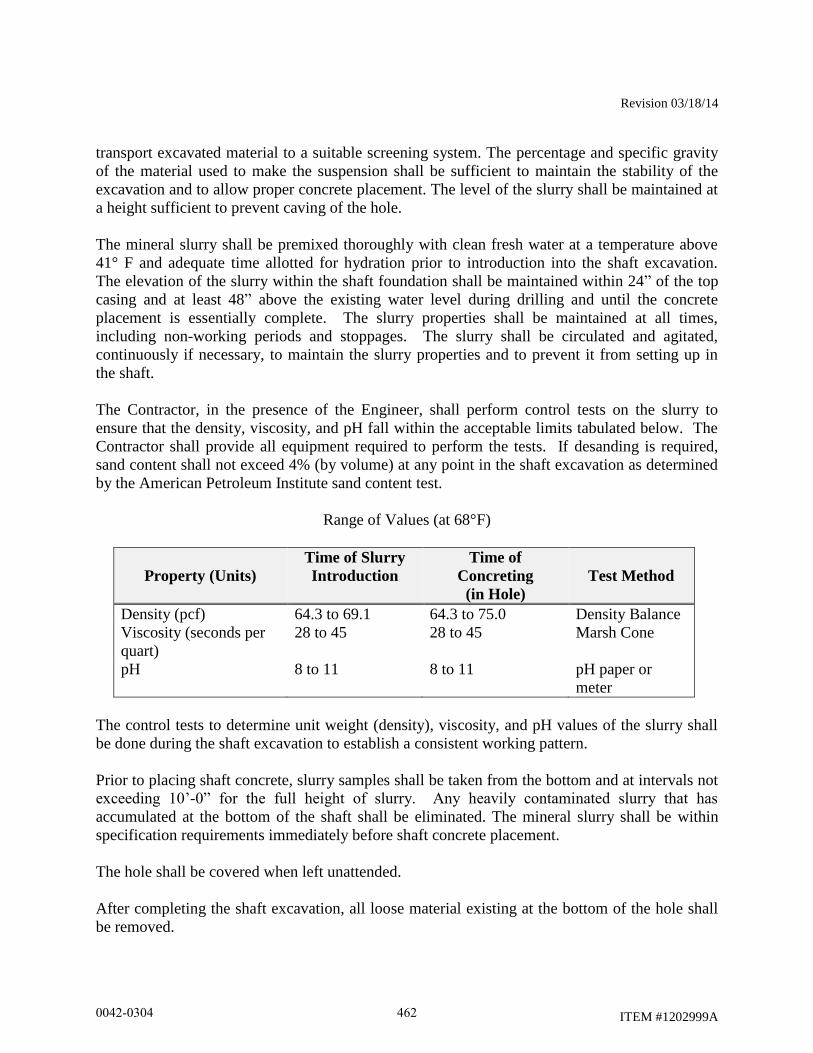
Revision 03/18/14
ITEM #1202999A
transport excavated material to a suitable screening system. The percentage and specific gravity
of the material used to make the suspension shall be sufficient to maintain the stability of the
excavation and to allow proper concrete placement. The level of the slurry shall be maintained at
a height sufficient to prevent caving of the hole.
The mineral slurry shall be premixed thoroughly with clean fresh water at a temperature above
41° F and adequate time allotted for hydration prior to introduction into the shaft excavation.
The elevation of the slurry within the shaft foundation shall be maintained within 24” of the top
casing and at least 48” above the existing water level during drilling and until the concrete
placement is essentially complete. The slurry properties shall be maintained at all times,
including non-working periods and stoppages. The slurry shall be circulated and agitated,
continuously if necessary, to maintain the slurry properties and to prevent it from setting up in
the shaft.
The Contractor, in the presence of the Engineer, shall perform control tests on the slurry to
ensure that the density, viscosity, and pH fall within the acceptable limits tabulated below. The
Contractor shall provide all equipment required to perform the tests. If desanding is required,
sand content shall not exceed 4% (by volume) at any point in the shaft excavation as determined
by the American Petroleum Institute sand content test.
Range of Values (at 68°F)
Property (Units)
Time of Slurry
Introduction
Time of
Concreting
(in Hole)
Test Method
Density (pcf) 64.3 to 69.1 64.3 to 75.0 Density Balance
Viscosity (seconds per
quart)
28 to 45 28 to 45 Marsh Cone
pH 8 to 11 8 to 11 pH paper or
meter
The control tests to determine unit weight (density), viscosity, and pH values of the slurry shall
be done during the shaft excavation to establish a consistent working pattern.
Prior to placing shaft concrete, slurry samples shall be taken from the bottom and at intervals not
exceeding 10’-0” for the full height of slurry. Any heavily contaminated slurry that has
accumulated at the bottom of the shaft shall be eliminated. The mineral slurry shall be within
specification requirements immediately before shaft concrete placement.
The hole shall be covered when left unattended.
After completing the shaft excavation, all loose material existing at the bottom of the hole shall
be removed.
0042-0304 462
Revision 03/18/14
ITEM #1202999A
Prior to placing the reinforcement into the shaft, the Contractor, in the presence of the Engineer,
shall determine the shaft dimensions, depth and alignment of the shaft. The concrete shaft shall
not be out of plumb by more than ¼ inch per foot of depth. The Contractor shall provide all
equipment necessary for checking the shaft excavation. The Engineer shall inspect the shaft and
verify that it has been properly cleaned.
The reinforcing steel shall be fabricated and assembled in accordance with Article 6.02.03. All
reinforcement shall be assembled with wire ties. Welding to assemble the reinforcement is not
permitted.
Immediately after the shaft excavation has been inspected and approved by the Engineer and
prior to placement of the concrete, the assembled reinforcing steel cage, including cage stiffener
bars, spacers, centralizers, and other necessary appurtenances, shall be carefully placed into the
shaft excavation as a unit. Dropping or forcing cages into the shaft will not be allowed. The
reinforcing steel in the shaft shall be tied and supported so that the reinforcing steel will remain
within allowable tolerances of its intended position until the concrete will support the reinforcing
steel. When concrete is placed by tremie methods, temporary hold-down devices shall be used to
prevent uplifting of the reinforcing steel cage during concrete placement. Concrete spacers or
other approved noncorrosive spacing devices shall be used at sufficient intervals not exceeding
5’-0” along the shaft to insure concentric location of the cage within the shaft excavation. When
the size of the longitudinal reinforcing steel is larger than a #8 bar, such spacing shall not exceed
10’-0”. After placement of the reinforcing cage, the Engineer shall inspect the shaft to ensure
that it has remained clean. If the inspection indicates that loose material has accumulated at the
bottom of shaft excavation, the Contractor shall remove the reinforcing cage and reclean the
shaft.
Concrete shall be placed in the shaft excavation as soon as possible, but no more than 4 hours
after completion of excavation and cleaning of the bottom of the excavation, and no more than 2
hours after placement of the reinforcing steel cage. Concrete shall be placed in a continuous
operation to the top of the shaft. The concrete level shall be horizontal during the pouring
operations. Concrete placement shall continue after the shaft is full until good quality concrete is
evident at the top of the shaft. The elapsed time from the beginning of concrete placement in the
shaft to the completion of placement shall not exceed 2 hours.
In dry construction, concrete shall be placed in a single continuous operation with the flow of
concrete down the center of the shaft excavation so as to consolidate the concrete on impact.
During placement operations, the concrete is not permitted to hit the reinforcing steel. A
dropchute, consisting of a hopper and flexible hose, may be used to direct the concrete down the
center of the foundation and prevent the concrete from hitting the reinforcing steel.
Accumulated water shall be removed before placing the concrete. At the time of concrete
placement, no more than 2” of water may exist at the bottom of the excavation and loose
sediment no more than ½” over one-half the base is acceptable.
In wet (slurry) construction, concrete to be placed by the tremie method, where the concrete
displaces the slurry from bottom of the excavation to the top. The concrete shall be placed
0042-0304 463
Revision 03/18/14
ITEM #1202999A
through a top metal hopper and into a rigid leak-proof elephant trunk tremie tube, sufficiently
large enough to permit free flow of concrete. The tremie tube shall be positioned so that it can
be removed without disturbing the reinforcing. Initially, the discharge end of the tremie tube
shall be sealed closed (plugged) to prevent slurry from entering the tube after it is placed in the
excavation and before the tube is filled with concrete. After concrete placement has started, the
tremie tube shall be kept full of concrete to the bottom of the hopper to maintain a positive
concrete head. The flow of concrete shall be induced by slightly raising the discharge end of the
tube, always keeping the tube end in the deposited concrete. No horizontal movement of the
tremie tube will be permitted.
The shaft concrete shall be vibrated or rodded to a depth of 5’-0” below the ground surface
except where soft uncased soil or slurry remaining in the excavation will possibly mix with the
concrete.
Exposed concrete shall be cured and finished in accordance with Subarticle 6.01.03-7, 9 and 10.
Anchor bolt assemblies shall be embedded in the concrete as shown on the working drawings. A
template plate shall be used to hold the anchor bolt assemblies, conduits and ground rod sleeve in
the correct position. The anchor bolts shall be installed plumb.
All conduit ends terminating below grade shall be capped with a malleable iron caps. All above-
grade conduit ends shall be terminated with an insulated bonding bushing with tinned insert.
Ground rod and ground wire shall be installed as shown on the plans.
No construction operations that would cause soil movement adjacent to the shaft, other than mild
vibration, shall be conducted for at least 48 hours after shaft concrete has been placed.
The top of the foundations shall be backfilled and the adjacent disturbed ground surfaces restored
to match the surrounding area after the concrete has cured and the forms are removed.
Placement of topsoil shall conform to Articles 9.44.01 and 9.44.03. Turf establishment shall
conform to Article 9.50.03.
After the foundation has cured, the Contractor shall obtain the as-built top of foundation
elevations based on a field survey.
The traffic structures shall not be erected on the foundation until the concrete in the shaft has
attained a 28 day compressive strength, f’c, greater than or equal to 4,000 psi and the concrete in
the pedestal has attained a 28 day compressive strength, f’c, greater than or equal to 4,400 psi.
Method of Measurement: This work will be measured for payment by the number of
foundation units, each completely installed and accepted. One foundation unit is required to
support each cantilever sign support. Two foundation units are required to support each bridge
sign support.
0042-0304 464

Revision 03/18/14
ITEM #1202999A
Basis of Payment: The work will be paid for at the contract unit price each for “Drilled Shaft
Traffic Structure Foundation,” completed and accepted in place, which price shall include all
equipment, materials, tools and labor incidental to the design, fabrication, construction and
disposal of drilling spoils, of the foundations at the locations specified on the plans.
No additional payment will be made for the Contractor to test the slurry when it is used to
construct a drilled shaft foundation. No additional payment will be made for subsurface
investigations performed by the Contractor.
The removal of existing roadside barrier systems, installation and removal of temporary roadside
barrier systems and resetting existing roadside barrier systems will not be paid for separately, but
will be included as part of the work.
The temporary support, protection and restoration of utilities (if necessary), including existing
underground wiring, conduits, drainage structures, pipes and underdrain systems within the
excavation limits will not be paid for separately, but will be included as part of the work.
Backfilling and restoration of adjacent ground surfaces (pavement, slope protection, topsoil &
seed, etc.) in all areas disturbed by the work will not be paid for separately, but will be included
as part of the work. The Engineer will determine the type, thickness and horizontal limits of the
surface treatments to be restored.
The installation of new or upgraded permanent roadside barrier systems, if required, will not be
paid for as part of this work, but will be paid for under separate items.
0042-0304 465
Rev. Date 1/5/12
ITEM #1206023A
ITEM #1206023A - REMOVAL AND RELOCATION OF EXISTING SIGNS
12.06.01 – Description: Add the following:
Work under this item shall consist of the removal and/or relocation of designated side-mounted
extruded aluminum and sheet aluminum signs, sign posts, sign supports, and foundations where
indicated on the plans or as directed by the Engineer. Work under this item shall also include
furnishing and installing new sign posts and associated hardware for signs designated for relocation.
12.06.03 - Construction Methods: Add the following:
The Contractor shall take care during the removal and relocation of existing signs, sign posts, and
sign supports that are to be relocated so that they are not damaged. Any material that is damaged
shall be replaced by the Contractor at no cost to the State.
Foundations and other materials designated for removal shall be removed and disposed of by the
Contractor as directed by the Engineer and in accordance with existing standards for Removal of
Existing Signing.
Sheet aluminum signs designated for relocation are to be re-installed on new sign posts.
The Contractor, Engineer and a representative from DOT Maintenance shall perform an inventory
of the signs prior to removal and storage.
12.06.04 - Method of Measurement: Add the following:
Payment under Removal and Relocation of Existing Signs shall be at the contract lump sum price
which shall include all extruded aluminum and sheet aluminum signs, sign posts, and sign supports
designated for relocation, all new sign posts and associated hardware for signs designated for
relocation, all extruded aluminum signs, sheet aluminum signs, sign posts and sign supports
designated for scrap, and foundations and other materials designated for removal and disposal, and
all work and equipment required.
12.06.05 -Basis of Payment: Add the following:
This work will be paid for at the contract lump sum price for “Removal and Relocation of Existing
Signs” which price shall include relocating designated extruded aluminum and sheet aluminum
signs, sign posts, and sign supports, providing new posts and associated hardware for relocated
signs, removing and disposing of foundations and other materials, and all equipment, material, tools
and labor incidental thereto. This price shall also include removing, loading, transporting, and
unloading of extruded aluminum signs, sheet aluminum signs, sign posts, and sign supports
designated for scrap and all equipment, material, tools and labor incidental thereto.
A schedule of values for payment shall be submitted to the Department for review and comment
prior to payment.
Pay Item Pay Unit
Removal and Relocation of Existing Signs L.S.
0042-0304 466
Rev. Date 10/21/14
ITEM #1207034A
ITEM #1207034A – SIGN FACE - EXTRUDED ALUMINUM (TYPE IV
RETROREFLECTIVE SHEETING)
Article 12.07.01 – Description is revised as follows: This item shall consist of furnishing and
installing sign face extruded aluminum with Type IV retroreflective sheeting at locations
indicated on the plans or as ordered and in conformance with the plans and these specifications.
Sign Face – Extruded Aluminum is supplemented with the sign details that follow.
Article 12.07.02 – Materials is supplemented as follows: For Article M.18.10.02, the heading
“2. Type III Reflective Sheeting” shall be replaced with “2. Type IV Retroreflective Sheeting”.
Article 12.07.03 – Construction Methods is supplemented as follows: All overhead sign
foundations shall be field staked and the locations approved by an engineer from the Division of
Traffic Engineering a minimum of seven days prior to installation.
For all side mounted signs, the edge of the sign closest to the roadway and the sign foundations
shall be field staked and approved by an engineer from the Division of Traffic Engineering a
minimum of seven days prior to installation.
For side-mounted signs, the offset to the near edge of sign face shall exceed the maximum
deflection of the guide rail unless otherwise shown on the plans or otherwise directed by the
Engineer.
Pay Item Pay Unit
Sign Face - Extruded Aluminum (Type IV Retroreflective Sheeting) S.F. (S.M.)
0042-0304 467
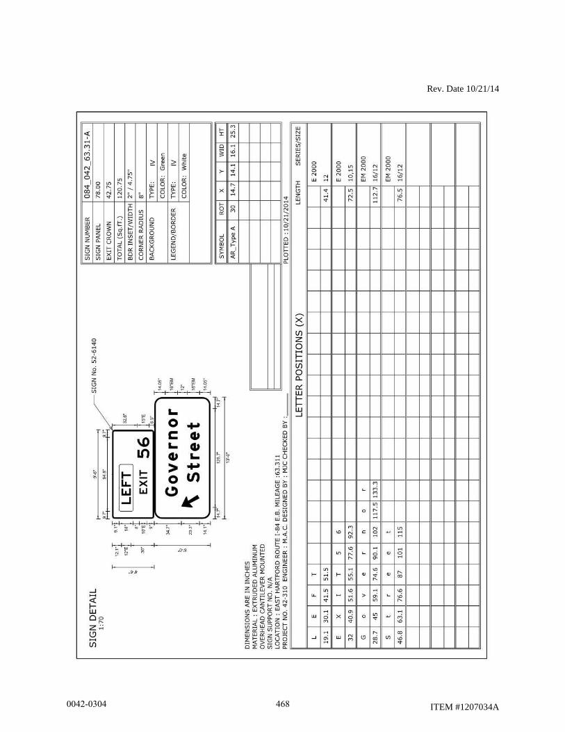
Rev. Date 10/21/14
ITEM #1207034A
0042-0304 468

Rev. Date 02/14
ITEM #1210101A
ITEM #1210102A
ITEM #1210103A
ITEM #1210104A
ITEM #1210105A
ITEM #1210101A – 4” (100 mm) WHITE EPOXY RESIN PAVEMENT
MARKINGS
ITEM # 1210102A – 4” (100 mm) YELLOW EPOXY RESIN PAVEMENT
MARKINGS
ITEM #1210103A – 6” (150 mm) WHITE EPOXY RESIN PAVEMENT
MARKINGS
ITEM #1210104A – 8” (200 mm) WHITE EPOXY RESIN PAVEMENT
MARKINGS
ITEM #1210105A – EPOXY RESIN PAVEMENT MARKINGS, SYMBOLS
AND LEGENDS
SECTION 12.10 – EPOXY RESIN PAVEMENT MARKINGS, SYMBOLS AND
LEGENDS is amended as follows:
Delete “SYMBOLS AND LEGENDS” from the title of the section.
12.10.03 – Construction Methods: Add the following:
Delete the entire sections titled “3. Performance and Warranty:” and “WARRANTY:” and
replace them with the following:
3. Initial Performance: The retroreflectivity of the markings applied must be measured by the
Contractor three (3) to fourteen (14) days after installation. A Certified Test Report (CTR), in
accordance with Section 1.06.07, must be submitted to the Engineer no later than ten (10) days
after the measurements are taken using the procedures and equipment detailed below:
Test Lots - The following test lots shall be randomly selected by the Engineer to represent the
line markings applied:
Table 3.1: Line Test Lots
Length of line Number of Lots Length of Test Lot
< 1.0 mi. (1.5 km) 1 1000 ft. (300 m)
≥1.0 mi. (1.5 km) 1 per 1.0 mi. (1.5 km) 1000 ft. (300 m)
0042-0304 469
Rev. Date 02/14
ITEM #1210101A
ITEM #1210102A
ITEM #1210103A
ITEM #1210104A
ITEM #1210105A
Measurement Equipment and Procedure
Portable Retroreflectometer
1. Skip line measurements shall be obtained for every other stripe, taking no more than two
readings per stripe with readings no closer than 20 in. (0.5 m) from either end of the
marking.
2. Solid line test lots shall be divided into ten sub-lots of 100 ft. (30 m) length and
measurements obtained at one randomly select location within each sublot.
3. For symbols and legends, 10 percent of each type shall be measured by obtaining five (5)
measurements at random locations on the symbol or legend.
4. The Apparatus and Measurements shall be made in accordance with ASTM E1710
(Standard Test Method for Measurement of Retroreflective Pavement Marking Materials
with CEN-Prescribed Geometry Using a Portable Retroreflectometer) and evaluated in
accordance with ASTM D7585/D7585M (Standard Practice for Evaluating
Retroreflective Pavement Markings Using Portable Hand-Operated Instruments).
Mobile Retroreflectometer
1. Calibration of the instruments shall be in accordance with the manufacturer’s
instructions.
2. Retroreflectivity shall be measured in a manner proposed by the Contractor and approved
by the Engineer. The basis of approval of the test method will be conformance to a
recognized standard test method or provisional standard test method.
The measurements shall be obtained when the pavement surface is clean and dry and shall be
reported in millicandellas per square foot per foot candle - mcd/ft2/fc (millicandelas per square
meter per lux (mcd/m2/lux)). Measurements shall be obtained sequentially in the direction of
traffic flow.
0042-0304 470
Rev. Date 02/14
ITEM #1210101A
ITEM #1210102A
ITEM #1210103A
ITEM #1210104A
ITEM #1210105A
Additional Contents of Certified Test Report
The CTR shall also list:
Project and Route number
Geographical location of the test site(s), including distance from the nearest reference
point.
Manufacturer and model of retroreflectometer used.
Most recent calibration date for equipment used.
Grand Average and standard deviation of the retroreflectivity readings for each line,
symbol or legend.
Initial Performance:
In order to be accepted, all epoxy resin pavement markings must meet the following minimum
retroreflectivity reading requirement:
White Epoxy: minimum retroreflectivity reading of 400 mcd/ft2/fc (mcd/m
2/lux)
Yellow Epoxy: minimum retroreflectivity reading of 325 mcd/ft2/fc (mcd/m
2/lux)
At the discretion of the Engineer, the Contractor shall replace, at its expense, such amount of
lines, symbols and legends that the grand average reading falls below the minimum value for
retro-reflectivity. The Engineer will determine the areas and lines to be replaced. The cost of
replacement shall include all materials, equipment, labor and work incidental thereto.
0042-0304 471
ITEM #1216020A
ITEM #1216021A
ITEM #1216020A - 6” BLACK AGGREGATE COVER-UP RESIN
PAVEMENT MARKINGS
ITEM #1216021A - 8” BLACK AGGREGATE COVER-UP RESIN
PAVEMENT MARKINGS
Description:
This item shall consist of furnishing and installing black aggregate cover-up resin pavement
markings of the width specified to cover existing markings in accordance with this section and in
conformance with the plans or as directed by the Engineer.
The black aggregate cover-up resin pavement markings shall be a highly durable, skid resistant,
non-reflective material designed to cover existing pavement markings.
The black aggregate cover-up resin pavement marking material, when applied according to the
recommendations of the manufacturer, shall provide a neat, durable masking that will not flow or
distort. The black aggregate cover-up resin pavement marking material shall be weather resistant
and, through normal traffic wear, shall show no wearing which would significantly impair the
intended usage.
Materials:
Materials for this work shall conform to the following requirements:
Black Cover-up Resin Pavement Markings:
Identification: Each container shall have a label affixed to it with the following information
thereon: name and address of manufacturer, shipping point, grade production batch number, date
of manufacture, grade name and/or identification number, type of material, number of liters,
contract number, use intended, directions for application, and formula. Improperly labeled
samples and deliveries shall be rejected.
Certification: For each batch of black cover-up resin, a Certified Test Reports conforming to
Article 1.06.07 shall be submitted from an independent testing laboratory and approved by the
Engineer, prior to installation on the project.
Detailed Requirements:
(a) Cover-up Resin Material: The material shall be composed of resins and pigments only.
(b) Composition: Component Percent by Weight (Mass)
Carbon Black 7 ± 2
(ASTM D 476 Type III)
0042-0304 472
ITEM #1216020A
ITEM #1216021A
Talc 14 ± 2
Resins 79 ± 4
(c) Black Aggregate: The moisture resistant aggregate shall meet the gradation requirements as
follows:
Sieve Size Percent Retained
#20 (850 µm) 23 - 38
#50 (300 µm) 58 - 74
#270 (53 µm) 1 - 6
Pan 0 - 0.5
The moisture resistant aggregate shall have a urethane coating. The aggregate shall be angular
with no dry dispensement pigment allowed.
(d) Adhesion: The black resin pavement marking material shall be formulated so as to adhere to
the pavement and existing pavement markings under climatic and traffic conditions normally
encountered in the construction work zone.
(e) Abrasion Resistance: When the abrasion resistance of the material is tested according to
ASTM D 4060 with a CS-17 wheel under a load of 1000 grams for 1000 cycles, the wear index
shall be no greater than 82.
(f) Hardness: The Type D durometer hardness of the material shall not be less than 75 nor more
than 90 when tested according to ASTM D 2240 after the material has cured for 72 hours at
73.5° F ± 3.5° F.
(g) Compressive Strength: The compressive strength of the material, when tested according to
ASTM D 695, shall not be less than 12,000 psi after 72 hours cured at 73.5° F ± 3.5° F.
Construction Methods:
The black aggregate cover-up resin pavement markings shall be applied strictly in accordance
with the manufacturer’s recommendations and installed as shown on the plans and to the control
points as established by the Engineer.
The areas to be covered shall be dry and sufficiently cleaned of sand and debris so as to provide
an acceptable bond. All surfaces which are power washed shall be allowed to dry sufficiently
prior to the application of the black aggregate cover-up resin pavement markings. The areas that
have been pre-marked shall be broom cleaned immediately prior to the application of the black
aggregate cover-up resin pavement markings.
Operations shall be conducted only when the road surface temperatures are 32° F or greater.
Operations shall be discontinued during periods of rain, and shall not continue until the Engineer
determines that the pavement surface is dry enough to achieve adhesion. The cover-up resin
pavement markings shall be applied uniformly to a prepared surface in a manner that ensures a
wet film thickness (without black aggregate) of 20 mils +/- 1 mils.
0042-0304 473
ITEM #1216020A
ITEM #1216021A
Black aggregate shall be applied at a rate of 100 pounds per gallon of black aggregate pavement
marking material. The black aggregate shall be applied using a double drop bead system, with
each drop distributing 50 pounds per gallon of black aggregate pavement marking material.
The black aggregate cover-up resin pavement markings shall extend approximately 1 inch
beyond the edges of the existing markings which are to be covered.
After application, the pavement markings shall be protected from crossing vehicles for a time at
least equivalent to the drying time of the material, as specified by the manufacturer.
Initial, In-Service Retro-Reflectivity and Serviceability for Cover-Up Long-Lines: In order
to be acceptable, the applied cover-up markings shall meet the following maximum retro-
reflectivity and minimum serviceability readings, as measured by the Engineer using a LTL 2000
Retrometer with 30-meter geometry:
1. Initial Retro-reflectivity: shall measure up to a maximum of 20 milli-candelas per square
meter per lux, or as otherwise approved by the Engineer, when tested within 14 days of
installation.
2. In-service retro-reflectivity: shall measure up to a maximum of 30 milli-candelas per
square meter per lux, or as otherwise approved by the Engineer when tested at anytime
within one (1) year of installation.
The Contractor shall replace, at its own expense, such amount of cover-up resin pavement
markings that fail the initial or in-service retro-reflectivity when, in the opinion of the Engineer,
it is no longer effective for the intended use or do not meet the requirements, as specified herein.
Servicibility: shall retain a minimum of 95% linear feet. Determination of percentages of
serviceability values will be made anytime within one (1) year by the Contractor’s representative
and by the Engineer. The decision of the Engineer shall be final. The term "percentage of
serviceability" shall be defined as the percentage of the total linear feet for cover-up resin
pavement markings measured on the project for payment.
The Contractor shall replace, at its own expense, such amount of markings, if any, required to
meet the above stated percentage. The Engineer will indicate the areas and lines to be replaced
to meet the above stated percentages.
Replacement under either situation shall include all materials, equipment, labor and work
incidental thereto.
Removal of Cover-up Resin Pavement Markings: The cover-up resin pavement markings
shall be removed by the Contractor by an appropriate mechanical means that ensures complete
removal with minimal pavement scarring, to the satisfaction of the Engineer. Painting over
existing pavement markings with black paint or spraying with asphalt shall not be accepted as a
substitute for removal or obliteration of pavement markings.
0042-0304 474
ITEM #1216020A
ITEM #1216021A
Method of Measurement:
Black aggregate cover-up resin pavement markings shall be measured for payment by the actual
number of linear feet (meters) of black aggregate cover-up resin pavement markings acceptably
installed on and removed from the pavement when it is no longer applicable or when its removal
is directed by the Engineer.
Basis of Payment:
This work shall be paid for at the contract unit price per linear foot (meter) for "Black Aggregate
Cover-up Resin Pavement Markings" of the width specified, acceptably installed on and
removed from the pavement. This price shall be for all the work required by this section
including the cleaning and preparing of the pavement surface, installation and removal, and all
materials, equipment, tools, and labor incidental thereto.
Any black aggregate cover-up resin pavement marking material which is not effective, in the
opinion of the Engineer, shall be replaced by the Contractor at no cost to the State.
Pay Item Pay Unit
6” Black Aggregate Cover-Up Resin Pavement Markings l.f.
8” Black Aggregate Cover-Up Resin Pavement Markings l.f.
0042-0304 475
Rev. Date 1/5/12
ITEM #1220013A
ITEM #1220013A – CONSTRUCTION SIGNS - BRIGHT FLUORESCENT
SHEETING
Article 12.20.01 – Description: The Contractor shall furnish construction signs with bright
fluorescent sheeting and their required portable supports or metal sign posts that conform to the
requirements of NCHRP Report 350 (TL-3). The construction signs and their required portable
supports or metal sign posts shall conform to the signing requirements stated in Article 9.71
"Maintenance and Protection of Traffic", as shown on the plans and/or as directed by the Engineer.
Article 12.20.02 – Materials: Prior to using the construction signs and their portable supports, the
Contractor shall submit to the Engineer a copy of the Letter of Acceptance issued by the FHWA to
the manufacturer documenting that the devices (both sign and portable support tested together)
conform to NCHRP Report 350 (TL-3).
Portable sign supports shall be designed and fabricated so as to prevent signs from being blown
over or displaced by the wind from passing vehicles. Portable sign supports shall be approved by
the Engineer before they are used. Mounting height of signs on portable sign supports shall be a
minimum of 1 foot and a maximum of 2 feet, measured from the pavement to the bottom of the
sign.
All sign faces shall be rigid and reflectorized. Sheet aluminum sign blanks shall conform to the
requirements of Article M.18.13. Metal sign posts shall conform to the requirements of Article
M.18.14. Application of reflective sheeting, legends, symbols, and borders shall conform to the
requirements specified by the reflective sheeting manufacturer. Attachments shall be provided so
that the signs can be firmly attached to the portable sign supports or metal posts without causing
damage to the signs. A Materials Certificate and Certified Test Report conforming to Article
1.06.07 shall be required for the reflective sheeting.
The following types of construction signs shall not be used: mesh, non-rigid, roll-up, corrugated
or waffle board types substrates, foam core and composite aluminum sign substrates.
Reflective sheeting shall conform to the following:
The fluorescent orange prismatic retroreflective sheeting shall consist of prismatic lenses formed in
a transparent fluorescent orange synthetic resin, sealed, and backed with an aggressive pressure
sensitive adhesive protected by a removable liner. The sheeting shall have a smooth surface.
Physical Properties:
A. Photometric - Coefficient of Retroreflection RA
When the sheeting applied on test panels is measured in accordance with ASTM E 810, it
shall have minimum coefficient of retroreflection values as shown in Table I. The rotation
angle shall be as designated by the manufacturer for test purposes, the observation angles
0042-0304 476
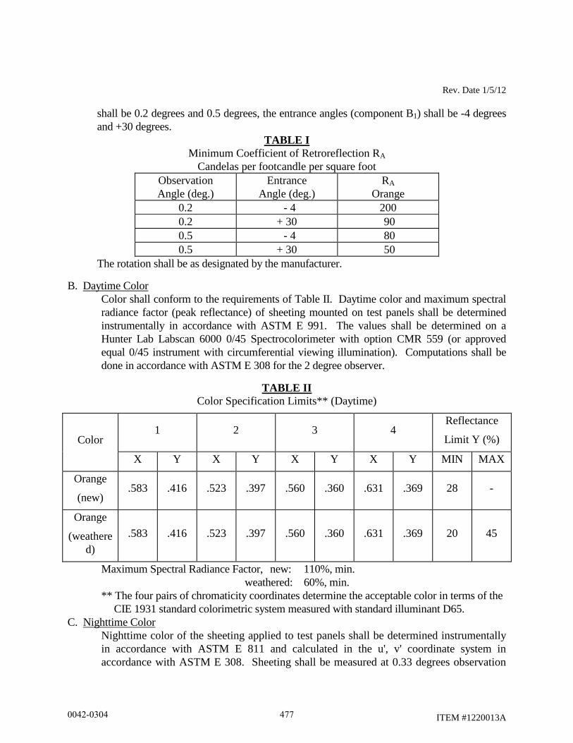
Rev. Date 1/5/12
ITEM #1220013A
shall be 0.2 degrees and 0.5 degrees, the entrance angles (component B1) shall be -4 degrees
and +30 degrees.
TABLE I
Minimum Coefficient of Retroreflection RA
Candelas per footcandle per square foot
Observation
Angle (deg.)
Entrance
Angle (deg.)
RA
Orange
0.2 - 4 200
0.2 + 30 90
0.5 - 4 80
0.5 + 30 50
The rotation shall be as designated by the manufacturer.
B. Daytime Color
Color shall conform to the requirements of Table II. Daytime color and maximum spectral
radiance factor (peak reflectance) of sheeting mounted on test panels shall be determined
instrumentally in accordance with ASTM E 991. The values shall be determined on a
Hunter Lab Labscan 6000 0/45 Spectrocolorimeter with option CMR 559 (or approved
equal 0/45 instrument with circumferential viewing illumination). Computations shall be
done in accordance with ASTM E 308 for the 2 degree observer.
TABLE II
Color Specification Limits** (Daytime)
Color 1 2 3 4
Reflectance
Limit Y (%)
X Y X Y X Y X Y MIN MAX
Orange
(new) .583 .416 .523 .397 .560 .360 .631 .369 28 -
Orange
(weathere
d)
.583 .416 .523 .397 .560 .360 .631 .369 20 45
Maximum Spectral Radiance Factor, new: 110%, min.
weathered: 60%, min.
** The four pairs of chromaticity coordinates determine the acceptable color in terms of the
CIE 1931 standard colorimetric system measured with standard illuminant D65.
C. Nighttime Color
Nighttime color of the sheeting applied to test panels shall be determined instrumentally
in accordance with ASTM E 811 and calculated in the u', v' coordinate system in
accordance with ASTM E 308. Sheeting shall be measured at 0.33 degrees observation
0042-0304 477
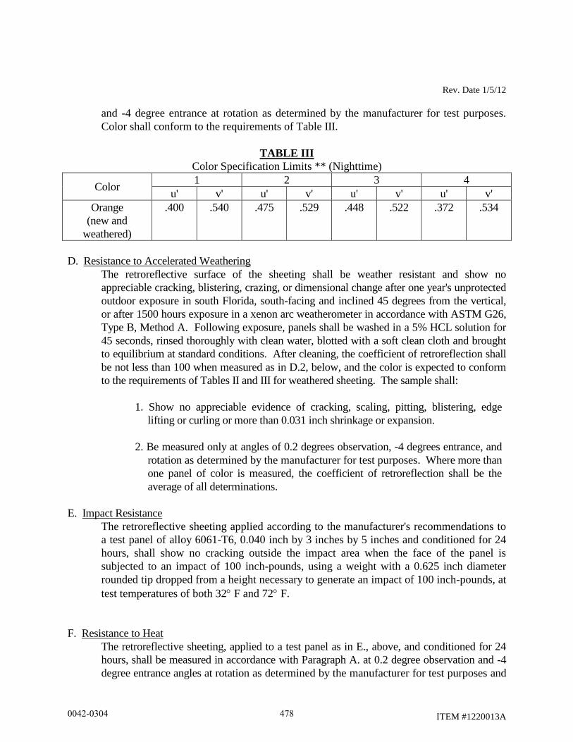
Rev. Date 1/5/12
ITEM #1220013A
and -4 degree entrance at rotation as determined by the manufacturer for test purposes.
Color shall conform to the requirements of Table III.
TABLE III
Color Specification Limits ** (Nighttime)
Color 1 2 3 4
u' v' u' v' u' v' u' v'
Orange
(new and
weathered)
.400 .540 .475 .529 .448 .522 .372 .534
D. Resistance to Accelerated Weathering
The retroreflective surface of the sheeting shall be weather resistant and show no
appreciable cracking, blistering, crazing, or dimensional change after one year's unprotected
outdoor exposure in south Florida, south-facing and inclined 45 degrees from the vertical,
or after 1500 hours exposure in a xenon arc weatherometer in accordance with ASTM G26,
Type B, Method A. Following exposure, panels shall be washed in a 5% HCL solution for
45 seconds, rinsed thoroughly with clean water, blotted with a soft clean cloth and brought
to equilibrium at standard conditions. After cleaning, the coefficient of retroreflection shall
be not less than 100 when measured as in D.2, below, and the color is expected to conform
to the requirements of Tables II and III for weathered sheeting. The sample shall:
1. Show no appreciable evidence of cracking, scaling, pitting, blistering, edge
lifting or curling or more than 0.031 inch shrinkage or expansion.
2. Be measured only at angles of 0.2 degrees observation, -4 degrees entrance, and
rotation as determined by the manufacturer for test purposes. Where more than
one panel of color is measured, the coefficient of retroreflection shall be the
average of all determinations.
E. Impact Resistance
The retroreflective sheeting applied according to the manufacturer's recommendations to
a test panel of alloy 6061-T6, 0.040 inch by 3 inches by 5 inches and conditioned for 24
hours, shall show no cracking outside the impact area when the face of the panel is
subjected to an impact of 100 inch-pounds, using a weight with a 0.625 inch diameter
rounded tip dropped from a height necessary to generate an impact of 100 inch-pounds, at
test temperatures of both 32 F and 72 F.
F. Resistance to Heat
The retroreflective sheeting, applied to a test panel as in E., above, and conditioned for 24
hours, shall be measured in accordance with Paragraph A. at 0.2 degree observation and -4
degree entrance angles at rotation as determined by the manufacturer for test purposes and
0042-0304 478
Rev. Date 1/5/12
ITEM #1220013A
exposed to 170 5 F for 24 hours in an air circulating oven. After heat exposure the
sheeting shall retain a minimum of 70% of the original coefficient of retroreflection.
G. Field Performance:
Retroreflective sheeting processed and applied to sign blank materials in accordance with
the sheeting manufacturer's recommendations, shall perform effectively for a minimum of 3
years. The retroreflective sheeting will be considered unsatisfactory if it has deteriorated
due to natural causes to the extent that: (1) the sign is ineffective for its intended purpose
when viewed from a moving vehicle under normal day and night driving conditions; or (2)
the coefficient of retroreflection is less than 100 when measured at 0.2 degrees observation
and -4 degree entrance. All measurements shall be made after sign cleaning according to
the sheeting manufacturer's recommendations.
Article 12.20.03 – Construction Methods: Ineffective signs, as determined by the Engineer and
in accordance with the ATSSA guidelines contained in "Quality Standards for Work Zone Traffic
Control Devices”, shall be replaced by the Contractor at no cost to the State.
Signs and their portable sign supports or metal posts that are no longer required shall be removed
from the project and shall remain the property of the Contractor.
Article 12.20.04 – Method of Measurement: Construction Signs - Bright Fluorescent Sheeting
will be measured for payment by the number of square feet of sign face. Sign supports will not
be measured for payment.
Article 12.20.05 – Basis of Payment: "Construction Signs - Bright Fluorescent Sheeting"
required and used on the project will be paid for at the Contact unit price per square foot. This
price shall include the furnishing and maintenance of the signs, portable sign supports, metal sign
posts and all hardware. Each sign and support or posts will be paid for once, regardless of the
number of times it is used.
Pay Item Pay Unit
Construction Signs – Bright Fluorescent Sheeting S.F.
0042-0304 479
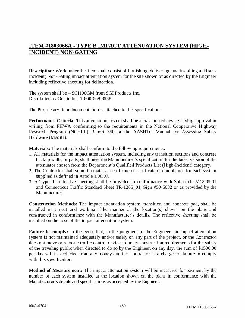
ITEM #1803066A
ITEM #1803066A - TYPE B IMPACT ATTENUATION SYSTEM (HIGH-
INCIDENT) NON-GATING
Description: Work under this item shall consist of furnishing, delivering, and installing a (High -
Incident) Non-Gating impact attenuation system for the site shown or as directed by the Engineer
including reflective sheeting for delineation.
The system shall be – SCI100GM from SGI Products Inc.
Distributed by Onsite Inc. 1-860-669-3988
The Proprietary Item documentation is attached to this specification.
Performance Criteria: This attenuation system shall be a crash tested device having approval in
writing from FHWA conforming to the requirements in the National Cooperative Highway
Research Program (NCHRP) Report 350 or the AASHTO Manual for Assessing Safety
Hardware (MASH).
Materials: The materials shall conform to the following requirements:
1. All materials for the impact attenuation system, including any transition sections and concrete
backup walls, or pads, shall meet the Manufacturer’s specification for the latest version of the
attenuator chosen from the Department’s Qualified Products List (High-Incident) category.
2. The Contractor shall submit a material certificate or certificate of compliance for each system
supplied as defined in Article 1.06.07.
3. A Type III reflective sheeting shall be provided in conformance with Subarticle M18.09.01
and Connecticut Traffic Standard Sheet TR-1205_01, Sign #50-5032 or as provided by the
Manufacturer.
Construction Methods: The impact attenuation system, transition and concrete pad, shall be
installed in a neat and workman like manner at the location(s) shown on the plans and
constructed in conformance with the Manufacturer’s details. The reflective sheeting shall be
installed on the nose of the impact attenuation system.
Failure to comply: In the event that, in the judgment of the Engineer, an impact attenuation
system is not maintained adequately and/or safely on any part of the project, or the Contractor
does not move or relocate traffic control devices to meet construction requirements for the safety
of the traveling public when directed to do so by the Engineer, on any day, the sum of $1500.00
per day will be deducted from any money due the Contractor as a charge for failure to comply
with this specification.
Method of Measurement: The impact attenuation system will be measured for payment by the
number of each system installed at the location shown on the plans in conformance with the
Manufacturer’s details and specifications as accepted by the Engineer.
0042-0304 480

ITEM #1803066A
Basis of Payment: The impact attenuation systems will be paid for at the Contract unit price for
each "Type B Impact Attenuation System (High-Incident) Non-Gating" as specified on the plans.
This price shall include all materials, excavation, concrete pad and reinforcement, backup system,
transition section, reflective sheeting, site preparation, and transportation, removal of surplus
material, equipment, tools and labor incidental to complete the installation.
Pay Item Pay Unit
Type B Impact Attenuation System (High-Incident) Non-Gating ea.
0042-0304 481
GENERAL
PERMITS AND/OR SUPPLEMENTAL TO FORM 816 AND REQUIRED PROVISIONS:
The following Permits and/or Supplemental to Form 816 and Required Provisions follow this page and are
hereby made part of this Contract.
PERMITS AND/OR PERMIT APPLICATIONS
Inland Wetland (General Certification) Anticipated: February 15, 2015 (see waiver)
Storm Water Discharge Permit Acquisition occurs during construction
Flood Management (General Certification) Acquired: September 9, 2014
SUPPLEMENTAL SPECIFICATIONS TO STANDARD SPECIFICATIONS FORM 816
Construction Contracts - Required Contract Provisions (FHWA Funded Contracts)
TRANSPORTATION MANAGEMENT PLAN
0042-0304 482
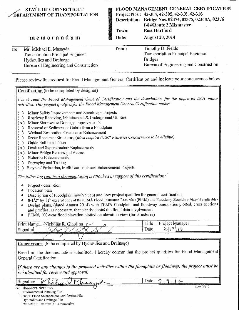

TransportationManagementPlan
Rehabilitation of Bridges
Site No. State Project No. Bridge No. Location
1 42-304 02374 SR 500 TR 805
over I-84 Connector
2 42-305 02375 SR 500 TR 801
over I-84 Eastbound and I-84 Connector
3 42-316 02376 I-84 TR 831
over I-84 Eastbound
4 42-310 02368A Route 2 Westbound
over I-84 Eastbound and I-84 connector
Town of East Hartford
November 2014
Prepared for:
Prepared By:
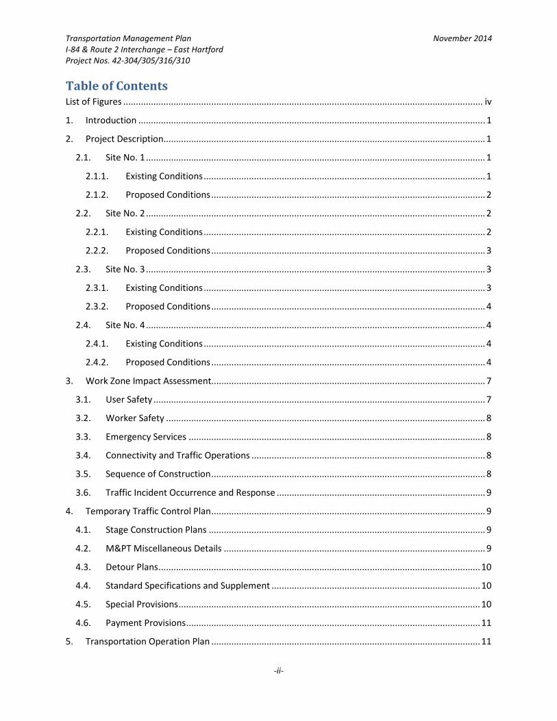
Transportation Management Plan November 2014
I-84 & Route 2 Interchange – East Hartford
Project Nos. 42-304/305/316/310
-ii-
Table of Contents List of Figures ............................................................................................................................................... iv
1. Introduction .......................................................................................................................................... 1
2. Project Description ................................................................................................................................ 1
2.1. Site No. 1 ....................................................................................................................................... 1
2.1.1. Existing Conditions ................................................................................................................ 1
2.1.2. Proposed Conditions ............................................................................................................. 2
2.2. Site No. 2 ....................................................................................................................................... 2
2.2.1. Existing Conditions ................................................................................................................ 2
2.2.2. Proposed Conditions ............................................................................................................. 3
2.3. Site No. 3 ....................................................................................................................................... 3
2.3.1. Existing Conditions ................................................................................................................ 3
2.3.2. Proposed Conditions ............................................................................................................. 4
2.4. Site No. 4 ....................................................................................................................................... 4
2.4.1. Existing Conditions ................................................................................................................ 4
2.4.2. Proposed Conditions ............................................................................................................. 4
3. Work Zone Impact Assessment............................................................................................................. 7
3.1. User Safety .................................................................................................................................... 7
3.2. Worker Safety ............................................................................................................................... 8
3.3. Emergency Services ...................................................................................................................... 8
3.4. Connectivity and Traffic Operations ............................................................................................. 8
3.5. Sequence of Construction ............................................................................................................. 8
3.6. Traffic Incident Occurrence and Response ................................................................................... 9
4. Temporary Traffic Control Plan ............................................................................................................. 9
4.1. Stage Construction Plans .............................................................................................................. 9
4.2. M&PT Miscellaneous Details ........................................................................................................ 9
4.3. Detour Plans ................................................................................................................................ 10
4.4. Standard Specifications and Supplement ................................................................................... 10
4.5. Special Provisions ........................................................................................................................ 10
4.6. Payment Provisions ..................................................................................................................... 11
5. Transportation Operation Plan ........................................................................................................... 11
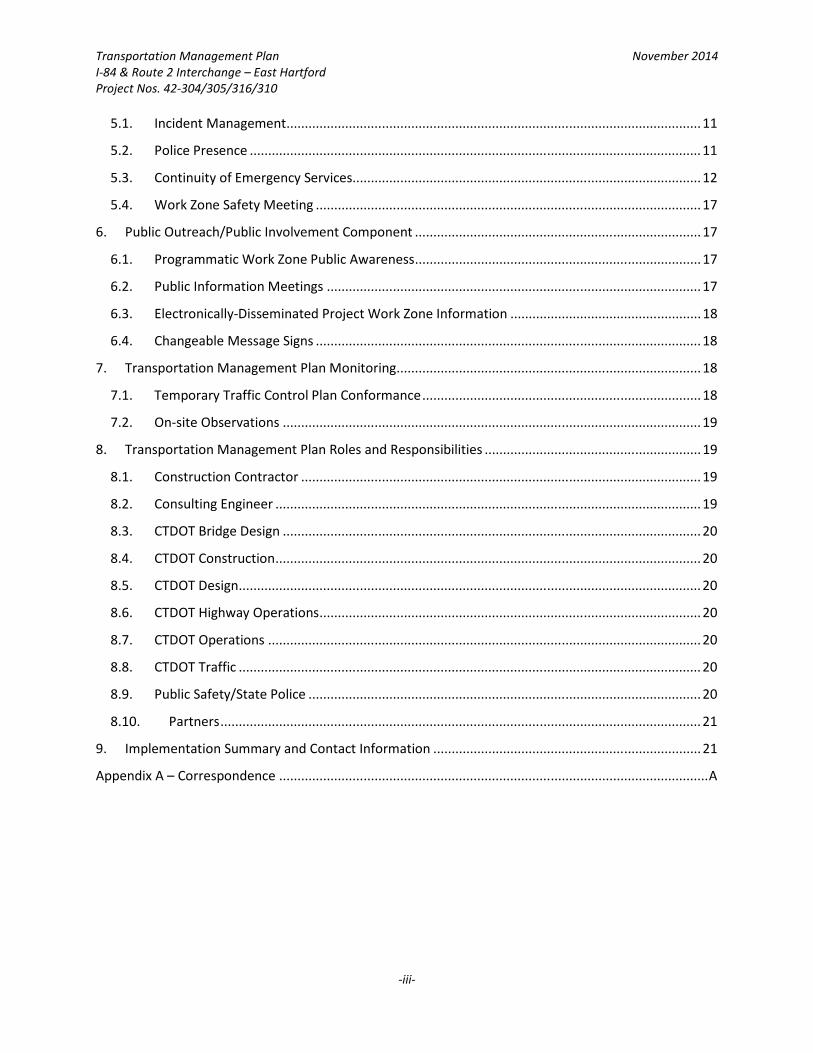
Transportation Management Plan November 2014
I-84 & Route 2 Interchange – East Hartford
Project Nos. 42-304/305/316/310
-iii-
5.1. Incident Management ................................................................................................................. 11
5.2. Police Presence ........................................................................................................................... 11
5.3. Continuity of Emergency Services ............................................................................................... 12
5.4. Work Zone Safety Meeting ......................................................................................................... 17
6. Public Outreach/Public Involvement Component .............................................................................. 17
6.1. Programmatic Work Zone Public Awareness .............................................................................. 17
6.2. Public Information Meetings ...................................................................................................... 17
6.3. Electronically-Disseminated Project Work Zone Information .................................................... 18
6.4. Changeable Message Signs ......................................................................................................... 18
7. Transportation Management Plan Monitoring ................................................................................... 18
7.1. Temporary Traffic Control Plan Conformance ............................................................................ 18
7.2. On-site Observations .................................................................................................................. 19
8. Transportation Management Plan Roles and Responsibilities ........................................................... 19
8.1. Construction Contractor ............................................................................................................. 19
8.2. Consulting Engineer .................................................................................................................... 19
8.3. CTDOT Bridge Design .................................................................................................................. 20
8.4. CTDOT Construction .................................................................................................................... 20
8.5. CTDOT Design .............................................................................................................................. 20
8.6. CTDOT Highway Operations ........................................................................................................ 20
8.7. CTDOT Operations ...................................................................................................................... 20
8.8. CTDOT Traffic .............................................................................................................................. 20
8.9. Public Safety/State Police ........................................................................................................... 20
8.10. Partners ................................................................................................................................... 21
9. Implementation Summary and Contact Information ......................................................................... 21
Appendix A – Correspondence ..................................................................................................................... A
Transportation Management Plan November 2014
I-84 & Route 2 Interchange – East Hartford
Project Nos. 42-304/305/316/310
-iv-
List of Figures Figure 1: Project Location Map ..................................................................................................................... 5
Figure 2: Project Site Locations ..................................................................................................................... 6
Figure 3: State Police Responsibilities ........................................................................................................ 12
Figure 4: Incidents and Responses .............................................................................................................. 13
Figure 5: CTDOT Work Zone Safety Website .............................................................................................. 17
Figure 6: Overview of TMP Responsibilities by Organization ..................................................................... 22
Figure 7: Summary TMP Action Plan ........................................................................................................... 23
Transportation Management Plan November 2014
I-84 & Route 2 Interchange – East Hartford
Project Nos. 42-304/305/316/310
-1-
1. Introduction This Transportation Management Plan (TMP) was developed pursuant to the following:
• The Connecticut Department of Transportation (CTDOT) Highway Design Manual, Chapter 14 –
“Maintenance and Protection of Traffic Through Construction Zones,” and;
• The CTDOT “Policy on Systematic Consideration and Management of Work Zone Impacts”
(Policy Number E&H.O.-57) and the associated Implementation Plan, dated August 6, 2007.
(The CTDOT policy conforms to the updated Federal Highway Administration Work (FHWA) Zone
Safety and Mobility Rule.)
The proposed projects are being governed by CTDOT standards and are included in the State List Bridge
Program administered by CTDOT.
2. Project Description The project area is comprised of four (4) State Bridge Projects: 42-304, 42-305, 42-316, and 42-310. The
projects have been assigned site numbers, as described in the Notice to Contractor provided in the
Contract Documents.
• Site No. 1: Project No. 42-304
• Site No. 2: Project No. 42-305
• Site No. 3: Project No. 42-316
• Site No. 4: Project No. 42-310
The subject bridges are part of the complex directional interchange (The Interchange) located at the
junction of I-84 and Route 2 in the town of East Hartford. All four projects are categorized as Spot
Improvement Projects.
For a project location map, refer to Figure No. 1. For a project site location map, refer to Figure No. 2.
2.1. Site No. 1
Project No. 42-304 involves the replacement of the existing Bridge No. 02374 and the project limits
are contained in an area that is referred to in the Contract Documents and in this document as Site
No. 1.
2.1.1. Existing Conditions
The CTDOT Bridge Safety & Evaluation Unit has identified Bridge No. 02374 as being in need of
repair. The bridge is Structurally Deficient due to the serious condition of the superstructure and
substructure and is Functionally Obsolete due to the inadequate horizontal and vertical under
clearance. As such, Bridge No. 02374 has been recommended for replacement under the List 21
Bridge Program.
Bridge No. 02374 consists of three simply-supported, steel multi-girder spans with a cast-in-
place concrete deck and a bituminous concrete wearing surface. The piers, abutments and u-

Transportation Management Plan November 2014
I-84 & Route 2 Interchange – East Hartford
Project Nos. 42-304/305/316/310
-2-
shaped wingwalls are founded on spread footings. Recent inspections of the bridge indicate
accelerated deterioration of the concrete and a deformation in one of the stringer webs. The
bridge has been placed on a three (3) month inspection cycle due to these concerns.
At the crossing location, SR 500 TR 805 serves as the Governor Street connection to Route 2
Eastbound, while TR 830 is a direct connection from I-84 Westbound to Route 2 Eastbound. Just
north of the bridge, the two ramps merge to form a two-lane on-ramp to Route 2 Eastbound.
The bridge crosses the TR 833 (I-84 Connector), a two-lane expressway that serves as a direct
connection between Route 2 Eastbound and I-84 Eastbound, and TR 831, a left side off-ramp
that provides access to Governor Street from TR 833 (I-84 Connector).
The total average daily traffic (ADT) on the bridge is 9,200 vehicles (CTDOT Traffic Log) with
2,700 vehicles entering from Governor Street (via SR 500 TR 805) and 6,500 vehicles entering
from I-84 Westbound (via TR 830).
2.1.2. Proposed Conditions
The proposed Bridge No. 02374 will consist of an 85-foot simple single-span steel girder and
concrete deck superstructure supported on H-pile founded abutments. The project includes the
reconstruction of approximately 350-feet of approach roadway. The proposed bridge will
provide 15-feet 1-inch of vertical under clearance in the final condition, thereby removing its
functionally obsolete designation.
Traffic will be accommodated through Site No. 1 under a staged construction scenario. SR 500
TR 805 ramp from Governor Street will be closed to traffic at Governor Street and vehicles will
be detoured via local roads as described in the Detour Plan. The substructure repair work will
require the use of full weekend closures as well as off-peak lane and shoulder closures on the I-
84 Connector (TR 833), as described in the Detour Plan and the Contract Documents.
2.2. Site No. 2
Project No. 42-305 involves the rehabilitation of the existing Bridge No. 02375 and the project limits
are contained in an area that is referred to in the Contract Documents and in this document as Site
No. 2.
2.2.1. Existing Conditions
The CTDOT Bridge Safety & Evaluation Unit has identified Bridge No. 02375 as being in need of
repair. The bridge is Structurally Deficient due to the poor condition of the superstructure and is
Functionally Obsolete due to inadequate horizontal and vertical under clearance. The
inadequate vertical under clearance is measured along TR 833 (I-84 Connector) and the
inadequate horizontal clearances are measured along both TR 833 (I-84 Connector) and I-84
Eastbound. As such, Bridge No. 02375 has been recommended for rehabilitation under the List
21 Bridge Program.

Transportation Management Plan November 2014
I-84 & Route 2 Interchange – East Hartford
Project Nos. 42-304/305/316/310
-3-
Bridge No. 02375 is 419-feet long and consists of seven simply-supported, steel multi-girder
spans with a cast-in-place concrete deck and bituminous wearing surface. The piers, abutments
and u-shaped wingwalls are founded on spread footings. The bridge exhibits areas of
deteriorated concrete, structural steel corrosion and deck joint leakage.
At the crossing location, SR 500 TR 801 serves as a single lane connection from Route 2
Westbound to Governor Street. The average daily traffic (ADT) is 3,900 vehicles (CTDOT Traffic
Log).
2.2.2. Proposed Conditions
The proposed rehabilitation of Bridge No. 02375 will consist of concrete patching and repair to
the super- and substructure units, modifying the parapets to safety shape, performing steel
repairs at various locations, painting all beam ends and end diaphragms, replacing expansion
bearings and repairing all fixed bearings. Also included in the scope of the project is replacing
the deck joints and making the deck continuous over the piers by constructing link slabs at pier
locations.
The proposed lane and shoulder configurations will match the existing roadway layout.
Traffic will be accommodated through Site No. 2 under a staged construction scenario. The
proposed repairs will be constructed in two stages allowing one lane of traffic to be maintained
on the bridge during construction. The substructure repair work will require the use of off-peak
lane and shoulder closures on I-84 Eastbound and the I-84 Connector (TR 833), as described in
the Contract Documents.
2.3. Site No. 3
Project No. 42-316 involves the rehabilitation of the existing Bridge No. 02376 and the project limits
are contained in an area that is referred to in the Contract Documents and in this document as Site
No. 3.
2.3.1. Existing Conditions
The CTDOT Bridge Safety & Evaluation Unit has identified Bridge No. 02376 as being in need of
repair. The bridge is Structurally Deficient due to the poor condition of the superstructure and is
Functionally Obsolete due to inadequate vertical under clearance. As such, Bridge No. 02376
has been recommended for rehabilitation under the List 21 Bridge Program.
Bridge No. 02376 is 161-feet long and consists of three simply-supported, steel multi-girder
spans with a cast-in-place concrete deck and bituminous wearing surface. The piers, abutments
and u-shaped wingwalls are founded on spread footings. The bridge exhibits areas of
deteriorated concrete, structural steel corrosion and deck joint leakage.
At the crossing location, TR 831 serves as a single lane connection from TR 833 (I-84 Connector)
to Governor Street. The average daily traffic (ADT) is 7,000 vehicles (CTDOT Traffic Log).
Transportation Management Plan November 2014
I-84 & Route 2 Interchange – East Hartford
Project Nos. 42-304/305/316/310
-4-
2.3.2. Proposed Conditions
The proposed rehabilitation of Bridge No. 02376 will consist of a superstructure replacement
which, in conjunction with a raised vertical roadway profile, will provide 16-feet of vertical
under clearance, thereby removing its functionally obsolete designation. The proposed bridge
will be made continuous across the three spans. The existing abutments, wingwalls, piers and
footings will be modified to accommodate the new superstructure and vertical alignment. The
existing substructure components that are not modified will be repaired as appropriate to
correct minor deficiencies such as spalls and exposed rebar. The project includes approximately
750-feet of full depth roadway reconstruction.
The proposed lane and shoulder configurations will match the existing roadway layout.
During construction, traffic will be detoured around Site No. 3 via local roads, as described in the
Detour Plan and Contract Documents. The substructure repair work will require the use of off-
peak lane and shoulder closures on I-84 Eastbound, as described in the Contract Documents.
2.4. Site No. 4
2.4.1. Existing Conditions
The CTDOT Bridge Safety & Evaluation Unit has identified Bridge No. 02368A as being in need of
repair. The bridge is Structurally Deficient due to the poor condition of the superstructure and
deck. As such, Bridge No. 02368A has been recommended for rehabilitation under the List 21
Bridge Program.
Bridge No. 02368A is 645-feet long and consists of seven simply-supported, curved steel multi-
girder spans with a cast-in-place concrete deck and bituminous wearing surface. The piers,
abutments and u-shaped wingwalls are founded on spread footings. The bridge exhibits areas of
deteriorated concrete, structural steel corrosion and deck joint leakage.
Bridge No. 02368A carries Route 2 Westbound (single lane) as it approaches the Founders
Bridge. The average daily traffic (ADT) is 4,550 vehicles (CTDOT Inspection Report).
2.4.2. Proposed Conditions
The proposed rehabilitation of Bridge No. 02368A will entail a superstructure replacement
consisting of weathering steel girders and a cast-in-place concrete deck. The project includes
approximately 645-feet of approach roadway reconstruction. Roadway safety is expected to be
enhanced by providing increased vertical under clearance and standard bridge rail.
The proposed lane and right shoulder configurations will match the existing roadway layout. The
proposed left shoulder will be wider due to a slight increase in deck width that improves
stopping sight distance around the inside of the horizontal curve along the bridge.
During construction, traffic will be detoured around Site No. 4 via local roads, as described in the
Detour Plan and Contract Documents. The substructure repair work will require the use of full

Transportation Management Plan November 2014
I-84 & Route 2 Interchange – East Hartford
Project Nos. 42-304/305/316/310
-5-
weekend closures as well as off-peak lane and shoulder closures on the I-84 Connector (TR 833),
SR 500 TR 805 from Governor Street to Site No. 1, TR 830 from I-84 Westbound to Site No. 1 and
TR 831 from I-84 Connector to Governor Street as described in the Detour Plan and Contract
Documents.
Figure 1: Project Location Map
Transportation Management Plan November 2014
I-84 & Route 2 Interchange – East Hartford
Project Nos. 42-304/305/316/310
-7-
3. Work Zone Impact Assessment Transportation effects emanate from work zone related interference of normal traffic. The subject four
projects are being combined into a single construction contract and therefore required a comprehensive
investigation into the impact that all the projects would have on traffic within the work zone. A
qualitative assessment of impacts was conducted based on project context, scopes and selected
strategies. Previous relevant experience, interdisciplinary reviews and consultation with local officials
were employed to gauge impacts. In some cases, discretion was employed to essentially “draw a line”
between tolerable and unacceptable impacts. These judgments are the basis for selecting fundamental
work zone strategies. This section outlines various categories of impacts and mitigation measures.
3.1. User Safety
Work zones represent an incremental elevation in motorist risk. Despite extensive research, the
specific factors that elevate accident risk within work zones are uncertain. Consequently, reliance
was placed on subjective knowledge and institutional processes (e.g. review by CTDOT officials, use
of typical installations, adherence to highway safety principles) to identify and mitigate risk factors.
For example, the concept of “positive guidance” was employed to establish easy-to-follow
temporary travel paths. Also, roadside safety principles were used to create separation (e.g.,
distance and/or barrier) between unavoidable roadside hazards and active travel lanes. Based on
traffic volumes, composition (i.e., percent of heavy vehicles) and operating speeds, Route I-84
Eastbound mainline, Route 2 mainline and ramps as well as local roads along the detour routes are
the elements with the greatest potential for adverse safety experience. Signing, delineation and
traffic directors will be employed to reduce the probability of errant vehicles and conflicts.
According to the contract documents, during construction existing lane and shoulder configuration
for Route I-84 and Route 2 are to be maintained as described within Section 1.08 – Prosecution and
Progress. A minimum of an 11-foot paved travel way is to be maintained along turning roads and
ramps associated with Site Nos. 1 and 2 when staged construction techniques are expected to be
employed, as described in the Contract Documents. The major impact of these work zone types on
traffic operating conditions will be a reduction in speed. Signing, delineation and traffic control
devices will be employed to guide traffic through the work zone. With the selected work zone
strategy in place, the impact on traffic operating conditions is not expected to be unmanageable.
According to the contract documents, construction at Site Nos. 1, 3 and 4 will be wholly are partially
constructed while traffic is detoured around the site. The major impact of these work zone types on
traffic operating conditions will be an increased amount of traffic congestion along the detour
routes and increased travel time. The volume of vehicles expected to use the detours will be
accommodated by a temporary restriping of Pitkin Street while the detour associated with Site No. 4
is in place. Temporary timing modifications will also be employed at various signals along Pitkin
Street in an attempt to reduce potential delays associated with the increase volume of traffic along
the local road. Signing, delineation and traffic control devices will also be employed to guide traffic
through the work zones. Additionally, the traffic to be carried by the local road detour routes is
Transportation Management Plan November 2014
I-84 & Route 2 Interchange – East Hartford
Project Nos. 42-304/305/316/310
-8-
largely commuter based and dependent on rush hour. Increased vehicular use along the detour
routes can be expected at the morning or evening rush hours. At other times during the day or
night, traffic volumes along the detour routes will increase only slightly more than normal.
3.2. Worker Safety
National statistics indicate that highway construction workers have substantially higher work-related
injury and death rates than the general population of construction workers. Some worker risks can
be mitigated by programmatic and project-level measures. Driver awareness, positive guidance,
protective clothing and positive protection strategies are included in this project. These concepts are
implemented primarily through the Maintenance and Protection of Traffic plans and special
provisions including Maintenance and Protection of Traffic (e.g., Temporary Precast Concrete Barrier
Curb layout, device design, and specifications related to flagger training and safety garments). The
majority of work on these bridge projects will take place behind temporary concrete barrier curbing
or while live traffic is detoured away from the worksite as shown on the Detour Plans.
3.3. Emergency Services
The work zone will affect emergency medical, law enforcement, and fire service responses. Detours
are associated with work involved at Site Nos. 1, 3 and 4. All detour routes will provide adequate
signage and advanced warning according to the contract plans, and since the detour routes are
relatively short in distance, the effect of the detour on response times would be minimal.
3.4. Connectivity and Traffic Operations
Except for the possible intermittent, short duration closures, Route I-84, Route 2 and most ramps
within the Interchange will be open throughout the project. However, capacity will be negatively
affected by the detours associated with work at Site Nos. 1, 3 and 4, reduced lane widths, changing
traffic patterns, and the presence of the nearby construction activities. The effects on traffic
operations can be expressed using measures such as delay, user cost or queue length. The number
of mainline travel lanes open to traffic will match existing except during the allowable periods as
described in the Contract Documents.
3.5. Sequence of Construction
The sequence of construction is contained within the Section 1.08 – Prosecution and Progress of the
Contract Documents. It is expected that the construction of all four projects will be completed by
the completion date noted in the Contract Time portion of the contract documents. The overall
duration of the construction project is expected to be two construction seasons or approximately
eighteen (18) months.
At the time of this TMP, there are no related ongoing construction projects in the vicinity of the
project area containing Site Nos. 1, 2, 3 and 4.
Transportation Management Plan November 2014
I-84 & Route 2 Interchange – East Hartford
Project Nos. 42-304/305/316/310
-9-
3.6. Traffic Incident Occurrence and Response
Traffic incidents within the work zones are inevitable and work zone conditions may occasionally
become incidents. Further, work zone conditions will probably magnify the effect of some incidents.
The CTDOT District 1 Office of Construction will perform informal reviews of work zone accidents
shortly after the notice of information (accident report) becomes available. Depending on the
circumstances (eg. severity, consistency with pattern), additional countermeasures may be
considered and implemented. Please refer to contract drawings and specifications for all
Maintenance and Protection of Traffic details.
4. Temporary Traffic Control Plan The Temporary Traffic Control Plan (TTC) supports the TMP objectives of efficient transportation and the
safety of workers, motorists and other users. The TTC Plan draws heavily on CTDOT knowledge,
references, and experience. In practical terms, the following are significant TTC Plan elements for the
proposed bridge projects:
• Closing SR 500 TR 805 at Governor Street
• Closing TR 831 at its divergence from the TR 833 (I-84 Connector)
• Closing Route 2 westbound prior to Bridge No. 02368A
• Closing TR 833 (I-84 Connector) during off-peak, night and/or weekend hours
• Shifting traffic from TR 830 in two stages through Site No. 1
• Shifting traffic on SR 500 TR 801 through Site No. 2
• Adequately provide advanced warning signs, systems and Changeable Message Signs
• Shielding permanent and temporary roadside hazards
Nearly all aspects of the TTC Plan are developed during design and will be implemented during
construction. The TTC Plan will be implemented through the construction contract, by the construction
contractor, with oversight by the CTDOT Construction personnel and inspectors. TTC provisions within
the contract documents include plans, standard specifications and special provisions. Key TTC Plan
components and elements include:
4.1. Stage Construction Plans
Construction work at Site Nos. 1 and 2 will involve stage construction plans and documents. Identify
working and staging areas within or in close proximity to the Sites by type for each stage, along with
temporary concrete barrier curb, attenuation systems, temporary pavement markings and signs.
4.2. M&PT Miscellaneous Details
Provide typical construction cross sections and impact attenuation barrier layouts. Utilize
standardized Maintenance and Protection of Traffic configurations as per CTDOT standards when
possible and appropriate.
Transportation Management Plan November 2014
I-84 & Route 2 Interchange – East Hartford
Project Nos. 42-304/305/316/310
-10-
A Notice to Contractor regarding NCHRP 350 Requirements for Work Zone Traffic Control Devices is
included in the Contract Documents. This notice to contract describes requirements that traffic
control devices must meet in order for their use to be approved on the worksite.
4.3. Detour Plans
Provide Detour Plans at Site Nos. 1, 3 and 4. At Site No. 1 traffic from TR 830 will be maintained
across Bridge No. 02374 while vehicles travelling from Governor Street on SR 500 TR 805 will be
detoured via local roads, as described in the Detour Plan and Contract Documents. A Detour Plan
and Contract Documents also describe the detour associated with closing TR 833 (I-84 Connector)
during off peak night and weekend hours. At Site No. 3, vehicles travelling from TR 833 (I-84
Connector) to Governor Street on TR 831 will be detoured via local roads, as described in the Detour
Plan and Contract Plans. At Site No. 4, vehicles traveling from Route 2 westbound to the Founders
Bridge will be detoured via local roads, as described in the Detour Plan and Contract Plans. Detour
Plans and Contract Documents also describe the detours associated with closing TR 833 (I-84
Connector), TR 830, TR 831 and SR 500 TR 805 during off peak night and weekend hours.
4.4. Standard Specifications and Supplement
Standard specification provisions pertain to all projects unless amended by a special provision. This
project is following CTDOT standard specifications dated 2004, and supplemented through July
2014. The Maintenance and Protection of Traffic Standard Specification covers the most generic
requirements. Standard specifications are augmented by special provisions.
4.5. Special Provisions
Project specific special provisions will also cover TTC Plan elements, including the following:
Maintenance and Protection of Traffic (Article 9.71.01) and Prosecution and Progress – Section 1.08
refer to the CTDOT standard maintenance and protection of traffic scope of services but modifies it
for site specific conditions including traffic control restrictions (lane closure restrictions), sequence
of construction, work restrictions, holiday periods for Connecticut and special events in the
Hartford/East Hartford area.
Additional project specific specifications will be developed in conjunction with CTDOT as the project
progresses. They will become part of the Contract Documents and will include, but not be limited
to:
• Construction Signing
• Portable Variable Message Signs and Arrow Boards
• Dedicated Police Service
• Temporary Pavement Markings
• Lighting for Nighttime Operations
Transportation Management Plan November 2014
I-84 & Route 2 Interchange – East Hartford
Project Nos. 42-304/305/316/310
-11-
4.6. Payment Provisions
The final contract documents (Plans, Specifications and Estimates) will include pay items provisions
for implementing the TMP, particularly the TTC Plan. Items are paid for either as lump sum or unit
cost basis. It is usually easier to implement changes for items covered by unit cost based pay items
since construction phase flexibility is needed for unanticipated conditions.
5. Transportation Operation Plan The Transportation Operations (TO) Plan is a selected set of mitigation strategies based primarily on
non-highway infrastructure systems. The Transportation Operations of the work zone will be managed
through the use of Changeable Message Signs (CMSs) that will be used to warn travelers about delays
through the work zone. An Incident Management System (IMS) is operated by CTDOT from a Traffic
Operations Center (TOC) in Newington. The TOC is staffed 24/7 by operators that respond to incidents
and other conditions through established response protocols. TOC staff monitors fixed camera and
Traffic Flow Monitor (TFM) detector stations and disseminate traveler information through the use of
fixed-mounted CMS, Highway Advisory Radio, CTDOT Traveler Information webpage and the Traffic E-
Alert system. An advance warning sign layout will be used on I-84 Eastbound and Route 2 near the
project limits to warn motorists of the upcoming work area and lane shift. Work that interferes with thru
traffic operations on I-84 and Route 2 will not be allowed during peak hours unless noted in the Contract
Plans and Documents. The CTDOT’s strategy to reduce delays during permitted periods is to promote
alternative routes. Traffic delays and travel on parallel routes will be monitored during construction. It is
anticipated that the signal timing at several signalized intersections along Pitkin Street will be modified
during construction in an effort to alleviate potential traffic congestion resulting from detoured traffic,
as noted in the Contract Plans and Documents related to Project No. 42-310.
CTDOT offers motorists an assistance program when incidents occur within the Hartford area. The
Connecticut Highway Assistance Motorist Program (CHAMP) is operated by CTDOT and provides service
throughout the Hartford area, including the area associated with the projects. Services include jump
starting, pushing disabled vehicles to the shoulder, fuel, and changing flat tires. Service patrols also react
to accidents and notify the TOC of the need for State Police, medical, fire and/or other emergency
response.
5.1. Incident Management
Incidents will be reported via the 911 system and will be responded to by the Connecticut State
Police Troop H located in Hartford. Other emergency services (Fire & Emergency Medical Services)
will also be dispatched via the Connecticut State 911 systems.
5.2. Police Presence
The contract includes an appropriate number of Police personnel (State and local) who will be
stationed to help manage traffic and assist and coordinate with emergency responders as needed.
The following charts give a breakdown of State Police responsibilities during construction:
Transportation Management Plan November 2014
I-84 & Route 2 Interchange – East Hartford
Project Nos. 42-304/305/316/310
-12-
Figure 3: State Police Responsibilities
Connecticut State Police
Monitor and Assist with Work Zone
Management
In all work zone areas on State numbered routes and
interchange ramps.
Remove Disabled Vehicles Assist the On-Call tow service
Remove Accidents in one-way ramps
To access the scene, police need to enter either the
beginning of the ramp or, in extenuating circumstances,
the end of the ramp and travel in the wrong direction to
the scene. Note: Officers may have to climb over the
construction or median barrier.
Remove Accident in two (2) Lane section To access the scene police need to utilize one of the
adjacent lanes.
Remove Accident along detour routes No action required; Local police to respond
5.3. Continuity of Emergency Services
Response to an incident within the work zone will require a coordinated effort beginning with 911
Centers located in Harford County and the State of Connecticut. Emergency Responders must know
in what direction they will need to approach the incident and the best place to enter Route I-84,
Route 2, any of the ramps and turning roadways and any of the local roads used for detours.
Communications will be critical to any emergency response within the construction area. Call takers
must attempt to obtain information that is more detailed than normal. Identifying the location, lane
blockage, and type of response needed – EMS, fire department, or police department will be
extremely important.
Below is a series of scenarios and suggested responses. This is by no means a fixed response, nor is
it designed to cover all possibilities. It should serve as a framework for handling emergencies in the
construction area. Incidents will be reviewed with all stake holders on a weekly basis or as needed in
order to improve response.
Transportation Management Plan November 2014
I-84 & Route 2 Interchange – East Hartford
Project Nos. 42-304/305/316/310
-13-
Figure 4: Incidents and Responses
Incident Response Actions
Disabled Vehicle or
Accident
One Lane Blocked
No injuries, Fire or
Entrapment
On-Site Trooper or Post Car with
Push Bumpers if Available
Respond – Assess – Request
Additional Resources if
needed
Push Vehicle(s) to Pull Off
Area or nearest exit if
Possible
Document Response and
Actions
Maintenance / Contractor
Respond with attenuator
truck with arrow panel to
move traffic to open lane.
Transportation Security Operations
Center (TSOC)
Activate appropriate ITS
elements to provide
advanced warning of
incident and potential
backups.
Transportation Management Plan November 2014
I-84 & Route 2 Interchange – East Hartford
Project Nos. 42-304/305/316/310
-14-
Figure 4 continued.
Incident Response Actions
Disabled Vehicle or
Accident
Both Lanes Blocked
No Injuries, Fire, or
Entrapment
State Police w/ push bumpers/
Attenuator truck respond in
opposite direction to assess / verify
lanes closed
Second State Police unit /
Emergency Responders stage
at crossover and will travel in
wrong direction to reach
scene after it is verified that
roadway is closed.
Assess – request additional
resources if needed.
Push vehicle(s) to pull off
area or nearest exit if
possible.
Document response and
actions.
State Police Respond to scene and initiate
Interchange closure with
assistance of Contractor
and/or Maintenance
Coordinate with Traffic
Safety.
Assess / request additional
resources.
Make appropriate
notifications
“H” Unit or other SP unit Respond to appropriate exit
to assist with closing lane(s).
Transportation Security Operations
Center (TSOC)
Activates next VMS past
incident with message for all
traffic to stay right
Maintenance/Contractor Respond with back up truck
to close lanes as required.
Transportation Management Plan November 2014
I-84 & Route 2 Interchange – East Hartford
Project Nos. 42-304/305/316/310
-15-
Figure 4 continued.
Incident Response Actions
Disabled Vehicle or
Accident
Both Lanes Blocked
With Injuries, Fire, or
Entrapment
State Police followed by attenuator
truck respond in the opposite
direction of the incident to assess
the scene and insure that all traffic
is stopped
Second State police unit /
Emergency Responders –
respond in the wrong
direction to reach incident
after verification that traffic
is stopped.
State Police Response – May Requires
Driving Wrong Way on
Interchange.
Ensure Route is Clear for
Additional Response.
Assess – Request Additional
Resources if Needed to Push
Vehicle(s) to Pull Off Area or
nearest exit if Possible.
Document Response and
Actions.
State Police Officer Respond to Scene.
Initiate lane(s) Closure with
Assistance of Contractor
and/or Maintenance.
Contact/Coordinate with
Traffic Safety.
Assess/Request Additional
Resources.
Make Appropriate
Notifications.
“H” Unit or other SP unit Respond to Appropriate Exit
to Assist with lane(s0 Closing
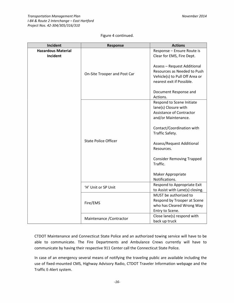
Transportation Management Plan November 2014
I-84 & Route 2 Interchange – East Hartford
Project Nos. 42-304/305/316/310
-16-
Figure 4 continued.
Incident Response Actions
Hazardous Material
Incident
On-Site Trooper and Post Car
Response – Ensure Route is
Clear for EMS, Fire Dept.
Assess – Request Additional
Resources as Needed to Push
Vehicle(s) to Pull Off Area or
nearest exit if Possible.
Document Response and
Actions.
State Police Officer
Respond to Scene Initiate
lane(s) Closure with
Assistance of Contractor
and/or Maintenance.
Contact/Coordination with
Traffic Safety.
Assess/Request Additional
Resources.
Consider Removing Trapped
Traffic.
Maker Appropriate
Notifications.
‘H’ Unit or SP Unit Respond to Appropriate Exit
to Assist with Lane(s) closing.
Fire/EMS
MUST be authorized to
Respond by Trooper at Scene
who has Cleared Wrong Way
Entry to Scene.
Maintenance /Contractor Close lane(s) respond with
back up truck
CTDOT Maintenance and Connecticut State Police and an authorized towing service will have to be
able to communicate. The Fire Departments and Ambulance Crews currently will have to
communicate by having their respective 911 Center call the Connecticut State Police.
In case of an emergency several means of notifying the traveling public are available including the
use of fixed-mounted CMS, Highway Advisory Radio, CTDOT Traveler Information webpage and the
Traffic E-Alert system.

Transportation Management Plan November 2014
I-84 & Route 2 Interchange – East Hartford
Project Nos. 42-304/305/316/310
-17-
5.4. Work Zone Safety Meeting
Prior to construction, a meeting will be convened to review traffic control requirements. Members
of the CTDOT Construction divisions, the contractor, and state and local police personnel will
participate. Subsequent meetings of similar scope and representation will be held as needed.
6. Public Outreach/Public Involvement Component The Public Outreach/Public Information (PO/PI) component of the Transportation Management Plan
includes both programmatic and project-level communications strategies. Programmatic measures are
intended to create a general awareness of important work zone issues. Project-level measures provide
information about a specific work zone to the people and organizations that will be directly affected.
Public involvement and information are scaled to the probable intensity and extent of impacts. The
transportation effects resulting from this project work zone are expected to be noticeable but not
profound. The overall project PO/PI effort will address transportation effects and other subjects of
interest.
6.1. Programmatic Work Zone Public Awareness
The CTDOT disseminates general work zone safety information via the work zone safety page of the
agencies’ Web sites, CTDOT Westbound site:
http://www.ct.gov/dot/cwp/view.asp?a=1410&q=417232
Figure 5: CTDOT Work Zone Safety Website
6.2. Public Information Meetings
This type of forum is routinely conducted during design development and serves a variety of
purposes. In the context of work zone safety and mobility, the meeting will provide the public with
advance notification of construction-phase conditions and transportation impacts. Residents, major
employers, shippers, merchants, transportation-dependent service providers, utility owners and
emergency responders use the information to coordinate their plans with anticipated work zone
conditions. One public information meeting was held on June 13, 2013 (see Appendix A for copy of

Transportation Management Plan November 2014
I-84 & Route 2 Interchange – East Hartford
Project Nos. 42-304/305/316/310
-18-
Report of Meeting) during which all four projects were presented. The project was generally well
received by those in attendance.
Prior to the commencement of construction activities, the CTDOT will notify the general public of
the impending project through press releases to state and local media outlets as well as postings on
the CTDOT website. Additional PIMs may be conducted during various phases of planning and
construction, if deemed necessary.
6.3. Electronically-Disseminated Project Work Zone Information
Standard practices include the posting of project information which is accessible from the CTDOT
homepage www.ct.gov/dot Travel Resource page that includes links to “Traffic Incidents”, “CT Travel
Info Map”, and “Traffic Cams”. “CT Travel Info” is an interactive map displaying icons for ongoing
active construction projects, roadway incidents, traffic camera images, and CMS sign displays by
location. Additionally, motorists can sign up for e-mail news and traffic alerts. The E-Traffic Alerts
are sent via e-mail when there is a traffic incident that will affect travel in a specified area of the
state and the E-News alert sends information on general and construction news (press information)
issued by the CTDOT.
6.4. Changeable Message Signs
Two types of changeable message signs (CMS) will be utilized to provide real-time information of
regional, corridor or location-specific relevance. Portable CMS will be provided through the
construction contract, located in or near the work zone, and controlled by project personnel. CTDOT
fixed-location CMS are located along major highways and are controlled by the respective
authorities.
Portable CMS display messages related to the project work zone. Fixed-location CMS support
regional and corridor movement. There will be occasions, based on other priorities, when fixed-
location CMS messages will be used to mitigate work zone impacts. CMS messages will convey
information on scheduled events and current conditions.
7. Transportation Management Plan Monitoring The various TMP elements and individual strategies will be monitored during implementation, both to
minimize work zone transportation impacts and to assure that State contracts and agreements are
administered properly.
7.1. Temporary Traffic Control Plan Conformance
Nearly all aspects of the TTC Plan are incorporated into the construction contract. The construction
contractor will be responsible for deploying the specified configurations, devices, and conditions.
The Construction Division will administer the construction contract on behalf of the state.
Construction representatives will review and document a myriad of contractor-provided TTC
Transportation Management Plan November 2014
I-84 & Route 2 Interchange – East Hartford
Project Nos. 42-304/305/316/310
-19-
products, services and conditions in relation to contract provisions. Information will be documented
in daily work reports.
7.2. On-site Observations
Ongoing, real-time observations by on-site personnel are a primary means of monitoring TMP
operations and effectiveness. Contractor, inspection, enforcement/police, and service patrol
personnel are likely to observe incidents, situations, and recurring conditions of interest and/or
concern. Construction personnel will record and report significant observations. Responsive action
will vary in consideration of the numerous factors including risk, intensity, persistence, and
frequency of the effects and the cost and feasibility of potential remediation measures. For other
observed conditions of concern, Construction division may elect to: take no action, initiate change,
or seek the advice of another unit.
8. Transportation Management Plan Roles and Responsibilities This TMP encompasses a wide variety of impacts, disciplines and activities. Selecting, refining and
implementing this plan compels an interdisciplinary team approach. Numerous technical and functional
disciplines and organizations, each with relevant expertise and domains of responsibility, collaborated in
the preparation of the TMP. Similarly, implementation will be carried out by many CTDOT units and
external partners. The Consultant has overall responsibility for preparing the TMP and CTDOT
Construction Division will have the primary implementation role. District personnel will monitor,
maintain and revise (as needed) the TMP during construction. Specific information on the roles of
various units and organizations is provided below.
8.1. Construction Contractor
By definition, the contractor fulfills the specified contract requirements. The TTC plan will be
implemented primarily through construction contract provisions. In addition to the lead role for
physically shaping all aspects of the work zone and executing construction operations, the
Contractor makes other contributions to the TMP. An effective public information program can only
be based on credible information regarding construction operations (e.g. intermittent closures,
phase changes). Much of this information is developed by the Contractor.
8.2. Consulting Engineer
The Consulting Engineer for Project Nos. 42-304 and 42-305 (Site Nos. 1 and 2) is McFarland
Johnson, Inc. The Consulting Engineer for Project No. 42-316 (Site No. 3) is Stantec Consulting
Services, Inc. The Consulting Engineer, with aid from the Liaison Engineer, is responsible for design
and preparation of the contract documents, including the Provisions for Maintenance and
Protection of Traffic. The Consultant Engineers will be available to support CTDOT during
construction, especially in situations that require detailed familiarity of design decisions and design
modifications. Assistance of the Consulting Engineer may be needed during the TTC Plan
implementation.
Transportation Management Plan November 2014
I-84 & Route 2 Interchange – East Hartford
Project Nos. 42-304/305/316/310
-20-
8.3. CTDOT Bridge Design
The Design Engineer for Project No. 42-310 (Site No. 4) is State Bridge Design. State Bridge Design,
with aid from the Liaison Engineer, is responsible for design and preparation of the contract
documents, including the Special Provisions for Maintenance and Protection of Traffic. Bridge Design
will be available to support CTDOT during construction, especially in situations that require detailed
familiarity of design decisions and design modifications. Assistance of Bridge Design may be needed
during the TTC Plan implementation.
8.4. CTDOT Construction
Award of the construction contract marks a transfer of principal responsibility between CTDOT units,
from Design to Construction. CTDOT Construction will be responsible for overall monitoring of the
TMP. The designated contact person for CTDOT Construction for this project is Mr. Ravi Chandran,
District Engineer - District 1 (Ph: 860-258-4601).
8.5. CTDOT Design
The Design Division has the primary responsibility for the development of major engineering design
projects and is the lead unit involved in the management of this TMP. Design will support
implementation of this TMP by CTDOT Construction, primarily in the area of public information. The
designated contact person for this project is Mr. Theodore Nezames, Manager of Bridges (Ph: 860-
594-3272.
8.6. CTDOT Highway Operations
The Connecticut Highway Assistance Motorist Program (CHAMP) is operated by CTDOT and provides
service throughout the Route I-84 and Route 2 portion of construction. CHAMP services are
described under the Transportation Operations component. No adjustments of CHAMP services are
planned.
8.7. CTDOT Operations
The location, capabilities and general functions of the TOC are described under the Transportation
Operations Center. The contact for CTDOT Operations is (Ph: 860-594-3447)
8.8. CTDOT Traffic
The project MPT will be reviewed by the CTDOT Traffic Engineering Division, CTDOT Construction,
and CTDOT Design as part of the normal design process prior to advertising. CTDOT Traffic
Engineering will also provide TTC-related construction consultation. The designated contact person
for CTDOT Traffic Engineering is Charles S. Harlow, Manager of Traffic Engineering – Division of
Traffic Engineering (Ph: 860-594-2788)
8.9. Public Safety/State Police
An active project-level State Police presence is planned. The role, conduct, cost and reimbursement
provisions for State Police personnel on CTDOT-administered construction projects are covered by a
Memorandum of Understanding between CTDOT and Connecticut Department of Emergency
Transportation Management Plan November 2014
I-84 & Route 2 Interchange – East Hartford
Project Nos. 42-304/305/316/310
-21-
Services. State Police will be used to assist in work zone management on I-84 eastbound, Route 2
and all associated ramps and turning roadways, while local (East Hartford) police personnel will be
used for local roadways, wherever needed. East Hartford is served by Connecticut State Police Troop
H (Ph: 860-534-1000) and the East Hartford Police Department (Ph: 860-528-4401).
8.10. Partners
This category includes non-CTDOT organizations that provide specialized assistance and support.
These partners include:
• Town of East Hartford (Ph: 860-291-7100)
• Emergency Services
o Emergency Management Coordinator, Fire Marshall (Ph: 860-291-7400)
• Major East Hartford employers
o Pratt & Whitney (Ph: 860-565-4321)
o Fremont Riverview, LLC. (Ph: 860-289-8269)
o Goodwin College (Ph: 860-528-4111)
• Major Hartford employers
o The Hartford (Ph: 860-547-5000)
o Aetna, Inc. (Ph: 860-273-0123)
o Northeast Utilities (Ph: 860-665-5000)
Through routine and close contact with these parties, CTDOT will gain feedback and observations
that can be used for TMP monitoring.
9. Implementation Summary and Contact Information This Transportation Management Plan describes a series of actions, some completed and others planned
for the future. CTDOT unit(s) and other organizations with primary and supporting responsibility are also
identified. This concluding section summarizes and references significant Transportation Management
Plan activates and roles. Contact information for each unit or organization with a designated TMP role is
also provided.
Transportation Management Plan November 2014
I-84 & Route 2 Interchange – East Hartford
Project Nos. 42-304/305/316/310
-22-
Figure 6: Overview of TMP Responsibilities by Organization
Unit or
Organization
Impact
Assessment
TMP Component
Monitoring TTC TO PO/PI
Prep Imp Prep Imp Prep Imp
Construction
Contractor 1 2
Consulting
Engineering 1 2
CTDOT Bridge
Design 1 2 2 1 2
CTDOT
Construction 2 2 2 1 2 1
CTDOT Design 2 2 2 2 2
CTDOT
Highway
Operations
2 2 2
CTDOT
Operations 2 1
CTDOT Traffic 2 2
Public
Safety/State
Police
2 2
1 = Primary Responsibility Prep = Prepare TMP component
2 = Support Responsibility Imp = Implement TMP component
Transportation Management Plan November 2014
I-84 & Route 2 Interchange – East Hartford
Project Nos. 42-304/305/316/310
-23-
Figure 7: Summary TMP Action Plan
TMP
Element Action Item Responsible Party
Te
mp
ora
ry T
raff
ic C
on
tro
l Develop Construction sequence/staging Consulting Engineering
Develop Maintenance and Protection of
Traffic (M&PT)
Consulting Engineering, CTDOT Traffic
Engineering,
Identify and estimate M&PT pay items Consulting Engineering
Fulfill contract requirement, including M&PT Construction Contractor, CTDOT
Construction
Initiate TTC revisions as determined by
monitoring programs
CTDOT Construction, CTDOT Traffic,
Consulting Engineering
Tra
nsp
ort
ati
on
Op
era
tio
ns
Coordinate with Local Officials Consulting Engineering, CTDOT
Construction
Provide advance notice CTDOT Construction
Administer and coordinate with CTDOT CTDOT Construction
Coordinate with emergency response
agencies
Consulting Engineering, CTDOT
Construction
Administer and coordinate dedicated CTDOT Construction, Connecticut State
Police
Establish Construction-Highway Operations CTDOT Construction, CTDOT Highway
Operations, CTDOT Operations
Monitor and document work zone
operational
CTDOT Construction, CTDOT Highway
Operations, CTDOT Operations
Pu
bli
c
Info
rma
tio
n Hold public information meetings
Consulting Engineering, CTDOT
Construction
Prepare Press Releases CTDOT Design, CTDOT Construction
Release, disseminate and post news CTDOT Design, CTDOT Operations
Provide credible and timely information CTDOT Construction, CTDOT Highway
Operations

Transportation Management Plan November 2014
I-84 & Route 2 Interchange – East Hartford
Project Nos. 42-304/305/316/310
-A-
Appendix A – Correspondence


Louis BachoDigitally signed by Louis Bacho DN: cn=Louis Bacho, o=CT Department of Transportation, ou=Consultant Design (Bridge), [email protected], c=US Date: 2013.07.03 16:50:54 -04'00'
State of Connecticut
Department of Transportation
SUPPLEMENTAL SPECIFICATIONS
TO
THE STANDARD SPECIFICATIONS
FOR
ROADS, BRIDGES AND INCIDENTAL CONSTRUCTION
FORM 816
2004
JULY 2014
July 2014
DIVISION I GENERAL REQUIREMENTS AND COVENANTS
SECTION SPECIFICATION NUMBER 1.01 Definition of Terms and Permissible Abbreviations 101 1.02 Proposal Requirements and Conditions 102 1.03 Award and Execution of Contract 103 1.05 Control of the Work 105 1.07 Legal Relations and Responsibilities 107 1.08 Prosecution and Progress 108 1.09 Measurement and Payment 109 1.10 Environmental Compliance 110 1.11 Claims 111 1.20 General Clauses for Facilities Construction 120
July 2014
DIVISION II CONSTRUCTION DETAILS
SECTION SPECIFICATION NUMBER 2.02 Roadway Excavation, Formation of Embankment and Disposal of Surplus Material 202 2.05 Trench Excavation 205 2.12 Subbase 212 2.16 Pervious Structure Backfill 216 3.04 Processed Aggregate Base 304 4.01 Concrete Pavement 401 5.14 Prestressed Concrete Members 514 6.01 Concrete for Structures 601 6.03 Structural Steel 603 6.12 Concrete Cylinder Curing Box 612 6.51 Culverts 651 7.01 Drilled Shafts 701 7.02 Piles 702 7.06 Micropiles 706 8.22 Temporary Precast Concrete Barrier Curb 822 9.01 Bollard 901 9.10 Metal Beam Rail 910 9.18 Three-Cable Guide Railing (I-Beam Post) and Anchorages 918 9.22 Bituminous Concrete Sidewalk Bituminous Concrete Driveway 922 9.44 Topsoil 944 9.49 Furnishing, Planting and Mulching Trees, Shrubs, Vines and Ground Cover Plants 949 9.75 Mobilization and Project Closeout 975 10.00 General Clauses for Highway Illumination and Traffic Signal Projects 1000 10.01 Trenching and Backfilling 1001 10.03 Light Standards 1003 10.09 Cast Iron Junction Box 1009 10.10 Concrete Handhole 1010 10.14 Cable in Duct 1014 10.19 Pre-Assembled Aerial Cable, Aerial Cable (3 No. 2) 1019 10.20 Wood Pole, Temporary Illumination Unit 1020 11.13 Control Cable 1113 12.10 Epoxy Resin Pavement Markings, Symbols and Legends 1210

July 2014
DIVISION III MATERIALS SECTION
SECTION SPECIFICATION NUMBER M.03 Portland Cement Concrete M03 M.06 Metals M06 M.08 Drainage M08 M.11 Masonry Facing, Cement and Dry Rubble Masonry, Brick, Mortar M11 M.13 Roadside Development M13 M.16 Traffic Control Signals M16 M.17 Elastomeric Materials M17 M.18 Signing M18
July 2014 STANDARD SPECIFICATIONS
FOR ROADS, BRIDGES AND INCIDENTAL CONSTRUCTION
FORM 816
ERRATA ARTICLE OR LINE REV. PG. SUBARTICLE NO. CORRECTION DATE i Table of Contents 20 Insert “1.11 Claims”................................................................ July10 iii Table of Contents 10 Insert “7.01 Drilled Shafts”..................................................... July14 iii Table of Contents 15 Insert “7.06 Micropiles”.......................................................... July14 iv Table of Contents 11 Change “Guild” to “Guide” .................................................... Jan05 v Table of Contents 2 Change “Mobilization” to “Mobilization and Project Closeout”................................................................................ July14 12 1.01.03 31 Insert “AOEC – Area of Environmental Concern”.................. Jan05 12 1.01.03 31 Insert “AWG – American Wire Gauge”................................... Jan05 13 1.01.03 16 Insert “HASP – Health and Safety Plan”................................ Jan05 13 1.01.03 29 Insert “PCC – Portland Cement Concrete”............................ Jan05 14 1.01.03 25 Insert “VOC – Volatile Organic Compound”.......................... Jan05 14 1.01.03 26 Insert “WSA – Temporary Waste Stockpile Area”................. Jan05 32 1.05.01 38 Change “Connecticut General Statutes” to “CGS”................ Jan05 97 1.10.03-2 32 Change “D.E.P.” to “DEEP”................................................... Jan14 97 1.10.03-2 39 Change “D.E.P,” to “DEEP,”.................................................. Jan14 98 1.10.03-2.1 13 Change “D.E.P.” to “DEEP”................................................... Jan14 99 1.10.03-2.6 23 Change “D.E.P.” to “DEEP”.................................................... Jan14 100 1.10.03-2.9 32 Change “D.E.P.” to “DEEP”.................................................... Jan14 101 1.10.03-2.12 22 Change “D.E.P.” to “DEEP”.................................................... Jan14 102 1.10.04 26 Change “D.E.P.” to “DEEP”.................................................... Jan14 105 1.20 29 Change “Workmen and Equipment” to “Personnel and Equipment”............................................................................. Jan05 105 1.20 31 Delete “Completion of Construction Work and”..................... Jan05 108 1.20-1.04.01 26 Change “othewise” to “otherwise”.......................................... July07 110 1.20-1.05.02-2 17 Change “DEP” to “DEEP” ..................................................... Jan14 122 1.20-1.06.08 3 Change “Certificate of Compliance” to “C.O.C.”.................... July07 131 1.20-1.08.05 34 Change “Workmen and Equipment” to “Personnel and Equipment”............................................................................ Jan05 132 1.20-1.08.11 12 Change “Certificate of Compliance” to “C.O.C.”.................... July07 133 1.20-1.08.13 7 Delete “Completion of Construction Work and”..................... Jan05 133 1.20-1.08.13 9 Change “Certificate of Compliance” to “C.O.C.”.................... July07 133 1.20-1.08.13 15 Change “Certificate of Compliance” to “C.O.C.”.................... July07 133 1.20-1.08.13 20 Change “Certificate of Compliance” to “C.O.C.”.................... July07 164 2.04.03-1 2 Change “6.01.03-10” to “6.01.03-6”........................................ Jan14 196 3.03.02 33 Change “Article M.03.01” to “Section M.03”........................... Jan14 245 4.06.04 11 Change “Over weight (mass) Adjustments -” and replace with indented “Over weight (mass) Adjustments -” as a subsection of “1. Bituminous Concrete Class ( ).”............. Jan05 256 5.01.02 22 Change “DEP” to “DEEP”...................................................... Jan14 259 5.03.03 24 Change “Such requirements of Article 5.02.03 ... equally to this construction.” to “All such plans prepared by the Contractor JULY 2014 SUPPLEMENT SHEET 1 OF 5 ERRATA
ARTICLE OR LINE REV. PG. SUBARTICLE NO. CORRECTION DATE shall be considered working drawings and shall be submitted with engineering calculations to the Engineer for review in accordance with the requirements of Article 1.05.02.".......... July10 262 5.06.02 26 Change “Article M.03.01” to “Section M.03”.......................... Jan14 262 5.06.02 27 Change “Article M.03.01” to “Section M.03”.......................... Jan14 265 5.07.02 19 Change “Subarticle M.03.01-11” to “Article M.03.09”............ Jan14 265 5.07.02 23 Change “Approved Products List for Geotextiles referred to in Subarticle M.08.01-26.” to “Qualified Products List referred to in Subarticle M.08.01-19 Geotextiles”................ July14 270 5.08.02 4 Change “M.06.02-12” to “M.06.02-4 Welded Stud Shear
Connectors”........................................................................... July10 271 5.09.02 39 Change “M.06.02-12” to “M.06.02-4 Welded Stud Shear
Connectors”........................................................................... July10 272 5.13.02 22 Change “M.08.01-27” to “M.08.01-20 PVC Pipe or M.08.01-21 PVC Gravity Pipe”............................................... July13 378 6.52.02 2 Change “M.08.01-22” to “M.08.01-11 Reinforced Concrete Culvert End”........................................................................... July13 378 6.52.02 3 Change “M.08.01-23” to “M.08.01-6 Metal Culvert End”....... July13 404 7.05.02 11 Change “Article M.03.01” to “Section M.03”........................... Jan14 416 7.51.02-(4) 7 Change “M.08.01-26” to “M.08.01-19 Geotextiles”................ July13 418 7.55.02 26 Change “M.08.01-26” to “M.08.01-19 Geotextiles”................ July13 420 8.11.02 37 Change “Article M.03.01” to “Section M.03”.......................... Jan14 420 8.11.02 38 Change “Article M.03.01” to “Subarticle M.03.08-2”............... Jan14 421 8.11.02 1 Change “Article M.03.01” to “Section M.03”.......................... Jan14 426 8.16.02 28 Change “Subarticle M.03.01-8” to “Article M.03.08”.............. Jan14 428 8.18.02 10 Change “Subarticle M.03.01-11” to “Article M.03.09”............ Jan14 429 8.21.02-6 30 Change “M.03.01-11” to “Article M.03.09”............................. Jan14 430 8.21.03-6 37 Change “M.03.01-11” to “Article M.03.09”............................. Jan14 434 9.04.02 14 Change “Subarticle M.06.02-1” to “Article 6.03.02”............... July10 434 9.04.02 15 Change “M.06.02-9(d) for metal bridge rail (cast post— aluminum)” to “Malleable castings shall conform to the requirements of the specifications for malleable iron castings, ASTM A 47, Grade No. 32510 (22010). Ductile iron castings shall conform to the Specifications for Ductile Iron Castings, ASTM A 536, Grade 60-40-18 (414-276-18) unless otherwise specified. In addition to the specified test coupons, test specimens from parts integral with the castings, such as risers, shall be tested for castings having a weight (mass) of more than 1000 pounds (455 kilograms) to determine that the required quality is obtained in the castings in the finished condition.”.............................................................................. July10 445 9.11.02 14 Change “Subarticle M.03.01-12” to “Article M.03.05”............ Jan14 452 9.14.02 2 Change “Subarticle M.06.02-8” to “ASTM A 53, Type E or S, Grade A, Schedule 40 Black Finish.”................................ July10 452 9.14.02 4 Change “Subarticle M.06.02-9(d) except that the grade shall be 32510” to “the specifications for malleable iron castings, ASTM A 47, Grade No. 32510 (22010). Ductile iron castings shall conform to the Specifications for Ductile Iron Castings, ASTM A 536, Grade 60-40-18 (414-276-18) JULY 2014 SUPPLEMENT SHEET 2 OF 5 ERRATA
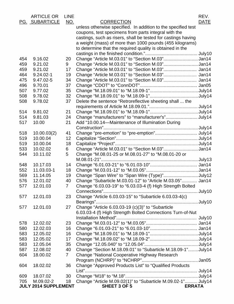
ARTICLE OR LINE REV. PG. SUBARTICLE NO. CORRECTION DATE unless otherwise specified. In addition to the specified test coupons, test specimens from parts integral with the castings, such as risers, shall be tested for castings having a weight (mass) of more than 1000 pounds (455 kilograms) to determine that the required quality is obtained in the castings in the finished condition.”......................................... July10 454 9.16.02 20 Change “Article M.03.01” to “Section M.03”........................... Jan14 459 9.21.02 9 Change “Article M.03.01” to “Section M.03”........................... Jan14 459 9.21.02 17 Change “Article M.03.01” to “Section M.03”.......................... Jan14 464 9.24.02-1 19 Change “Article M.03.01” to “Section M.03”.......................... Jan14 475 9.47.02-5 34 Change “Article M.03.01” to “Section M.03”.......................... Jan14 496 9.70.01 37 Change “CDOT” to “ConnDOT”............................................. Jan05 507 9.77.02 35 Change “M.18.09.01” to “M.18.09-1”...................................... July14 508 9.78.02 32 Change “M.18.09.01” to “M.18.09-1”...................................... July14 508 9.78.02 37 Delete the sentence “Retroreflective sheeting shall ... the requirements of Article M.18.09.01.”...................................... July14 514 9.81.02 21 Change “M.18.09.01” to “M.18.09-1”...................................... July14 514 9.81.03 24 Change “manufacturers” to “manufacturer's”......................... July14 517 10.00 21 Add “10.00.14—Maintenance of Illumination During Construction”.......................................................................... July14 518 10.00.03(2) 41 Change “pre-emotion” to “pre-emption”................................. July14 519 10.00.04 12 Capitalize “Section”................................................................ July14 519 10.00.04 18 Capitalize “Project”................................................................. July14 533 10.02.02 6 Change “Article M.03.01” to “Section M.03”........................... Jan14 544 10.11.02 5 Change “M.08.01-25 or M.08.01-27” to “M.08.01-20 or M.08.01-21”............................................................................ July13 548 10.17.03 14 Change “6.01.03-21” to “6.01.03-10”..................................... Jan14 552 11.03.03-1 18 Change “M.03.01-12” to “M.03.05”......................................... Jan14 569 11.14.05 19 Change “Span Wire” to “Span Wire (Type)”........................... July12 576 12.01.02 40 Change “Subarticle M.03.01-12” to “Article M.03.05”............ Jan14 577 12.01.03 7 Change “6.03.03-19” to “6.03.03-4 (f) High Strength Bolted
Connections”.......................................................................... July10 577 12.01.03 23 Change “Article 6.03.03-15” to “Subarticle 6.03.03-4(c) Bearings”................................................................................ July10 577 12.01.03 27 Change “Article 6.03.03-19 (c)(3)” to “Subarticle 6.03.03-4 (f) High Strength Bolted Connections Turn-of-Nut
Installation Method”............................................................... July10 578 12.02.02 23 Change “M.03.01-12” to “M.03.05”........................................ Jan14 580 12.02.03 16 Change “6.01.03-21” to “6.01.03-10”..................................... Jan14 583 12.05.02 16 Change “M.18.09.01” to “M.18.09-1”...................................... July14 583 12.05.02 17 Change “M.18.09.02” to “M.18.09-2”...................................... July14 583 12.05.04 35 Change “12.05.040” to “12.05.04”.......................................... July14 587 12.08.02 40 Change “Section M.18.09.01” to “Subarticle M.18.09-1”........ July14 604 18.00.02 7 Change “National Cooperative Highway Research Program (NCHRP)” to “NCHRP”............................................ Jan05 604 18.02.02 36 Change “Approved Products List” to “Qualified Products List”........................................................................................ July14 609 18.07.02 30 Change “M18” to “M.18”......................................................... July14 705 M.09.02-2 18 Change “Article M.09.02(1)” to “Subarticle M.09.02-1”.......... July14 JULY 2014 SUPPLEMENT SHEET 3 OF 5 ERRATA
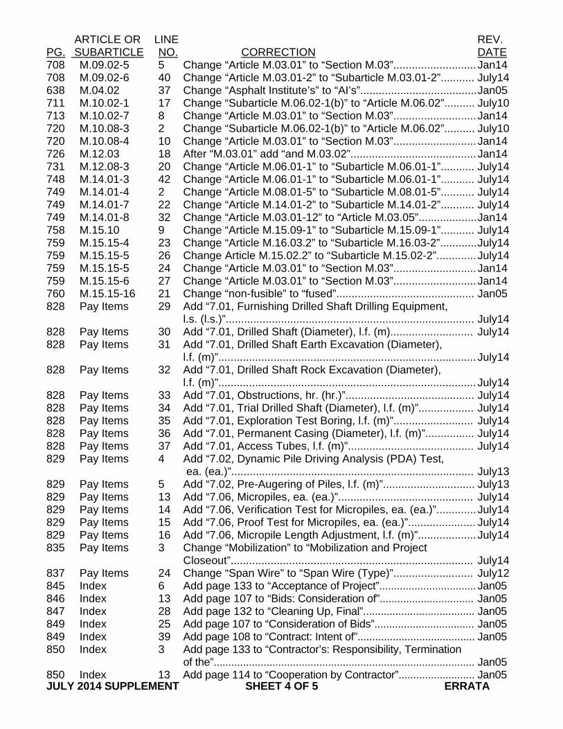
ARTICLE OR LINE REV. PG. SUBARTICLE NO. CORRECTION DATE 708 M.09.02-5 5 Change “Article M.03.01” to “Section M.03”........................... Jan14 708 M.09.02-6 40 Change “Article M.03.01-2” to “Subarticle M.03.01-2”........... July14 638 M.04.02 37 Change “Asphalt Institute’s” to “AI’s”...................................... Jan05 711 M.10.02-1 17 Change “Subarticle M.06.02-1(b)” to “Article M.06.02”.......... July10 713 M.10.02-7 8 Change “Article M.03.01” to “Section M.03”........................... Jan14 720 M.10.08-3 2 Change “Subarticle M.06.02-1(b)” to “Article M.06.02”.......... July10 720 M.10.08-4 10 Change “Article M.03.01” to “Section M.03”........................... Jan14 726 M.12.03 18 After “M.03.01” add “and M.03.02”......................................... Jan14 731 M.12.08-3 20 Change “Article M.06.01-1” to “Subarticle M.06.01-1”........... July14 748 M.14.01-3 42 Change “Article M.06.01-1” to “Subarticle M.06.01-1”........... July14 749 M.14.01-4 2 Change “Article M.08.01-5” to “Subarticle M.08.01-5”........... July14 749 M.14.01-7 22 Change “Article M.14.01-2” to “Subarticle M.14.01-2”........... July14 749 M.14.01-8 32 Change “Article M.03.01-12” to “Article M.03.05”................... Jan14 758 M.15.10 9 Change “Article M.15.09-1” to “Subarticle M.15.09-1”........... July14 759 M.15.15-4 23 Change “Article M.16.03.2” to “Subarticle M.16.03-2”............ July14 759 M.15.15-5 26 Change Article M.15.02.2” to “Subarticle M.15.02-2”............. July14 759 M.15.15-5 24 Change “Article M.03.01” to “Section M.03”........................... Jan14 759 M.15.15-6 27 Change “Article M.03.01” to “Section M.03”........................... Jan14 760 M.15.15-16 21 Change “non-fusible” to “fused”............................................. Jan05 828 Pay Items 29 Add “7.01, Furnishing Drilled Shaft Drilling Equipment, l.s. (l.s.)”................................................................................. July14 828 Pay Items 30 Add “7.01, Drilled Shaft (Diameter), l.f. (m)........................... July14 828 Pay Items 31 Add “7.01, Drilled Shaft Earth Excavation (Diameter), l.f. (m)”.................................................................................... July14 828 Pay Items 32 Add “7.01, Drilled Shaft Rock Excavation (Diameter), l.f. (m)”.................................................................................... July14 828 Pay Items 33 Add “7.01, Obstructions, hr. (hr.)”.......................................... July14 828 Pay Items 34 Add “7.01, Trial Drilled Shaft (Diameter), l.f. (m)”.................. July14 828 Pay Items 35 Add “7.01, Exploration Test Boring, l.f. (m)”.......................... July14 828 Pay Items 36 Add “7.01, Permanent Casing (Diameter), l.f. (m)”................ July14 828 Pay Items 37 Add “7.01, Access Tubes, l.f. (m)”......................................... July14 829 Pay Items 4 Add “7.02, Dynamic Pile Driving Analysis (PDA) Test, ea. (ea.)”............................................................................... July13 829 Pay Items 5 Add “7.02, Pre-Augering of Piles, l.f. (m)”.............................. July13 829 Pay Items 13 Add “7.06, Micropiles, ea. (ea.)”............................................ July14 829 Pay Items 14 Add “7.06, Verification Test for Micropiles, ea. (ea.)”............. July14 829 Pay Items 15 Add “7.06, Proof Test for Micropiles, ea. (ea.)”...................... July14 829 Pay Items 16 Add “7.06, Micropile Length Adjustment, l.f. (m)”................... July14 835 Pay Items 3 Change “Mobilization” to “Mobilization and Project Closeout”............................................................................... July14 837 Pay Items 24 Change “Span Wire” to “Span Wire (Type)”.......................... July12 845 Index 6 Add page 133 to “Acceptance of Project”................................. Jan05 846 Index 13 Add page 107 to “Bids: Consideration of”................................ Jan05 847 Index 28 Add page 132 to “Cleaning Up, Final”...................................... Jan05 849 Index 25 Add page 107 to “Consideration of Bids”.................................. Jan05 849 Index 39 Add page 108 to “Contract: Intent of”........................................ Jan05 850 Index 3 Add page 133 to “Contractor’s: Responsibility, Termination of the”......................................................................................... Jan05 850 Index 13 Add page 114 to “Cooperation by Contractor”.......................... Jan05 JULY 2014 SUPPLEMENT SHEET 4 OF 5 ERRATA
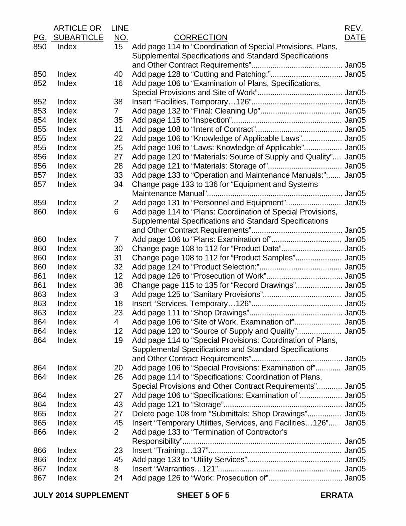
ARTICLE OR LINE REV. PG. SUBARTICLE NO. CORRECTION DATE 850 Index 15 Add page 114 to “Coordination of Special Provisions, Plans, Supplemental Specifications and Standard Specifications and Other Contract Requirements”........................................... Jan05 850 Index 40 Add page 128 to “Cutting and Patching:”.................................. Jan05 852 Index 16 Add page 106 to “Examination of Plans, Specifications, Special Provisions and Site of Work”........................................ Jan05 852 Index 38 Insert “Facilities, Temporary…126”........................................... Jan05 853 Index 7 Add page 132 to “Final: Cleaning Up”...................................... Jan05 854 Index 35 Add page 115 to “Inspection”.................................................... Jan05 855 Index 11 Add page 108 to “Intent of Contract”......................................... Jan05 855 Index 22 Add page 106 to “Knowledge of Applicable Laws”................... Jan05 855 Index 25 Add page 106 to “Laws: Knowledge of Applicable”.................. Jan05 856 Index 27 Add page 120 to “Materials: Source of Supply and Quality”.... Jan05 856 Index 28 Add page 121 to “Materials: Storage of”................................... Jan05 857 Index 33 Add page 133 to “Operation and Maintenance Manuals:”....... Jan05 857 Index 34 Change page 133 to 136 for “Equipment and Systems Maintenance Manual”................................................................ Jan05 859 Index 2 Add page 131 to “Personnel and Equipment”.......................... Jan05 860 Index 6 Add page 114 to “Plans: Coordination of Special Provisions, Supplemental Specifications and Standard Specifications and Other Contract Requirements”........................................... Jan05 860 Index 7 Add page 106 to “Plans: Examination of”................................. Jan05 860 Index 30 Change page 108 to 112 for “Product Data”............................. Jan05 860 Index 31 Change page 108 to 112 for “Product Samples”...................... Jan05 860 Index 32 Add page 124 to “Product Selection:”....................................... Jan05 861 Index 12 Add page 126 to “Prosecution of Work”.................................... Jan05 861 Index 38 Change page 115 to 135 for “Record Drawings”...................... Jan05 863 Index 3 Add page 125 to “Sanitary Provisions”..................................... Jan05 863 Index 18 Insert “Services, Temporary…126”........................................... Jan05 863 Index 23 Add page 111 to “Shop Drawings”............................................ Jan05 864 Index 4 Add page 106 to “Site of Work, Examination of”...................... Jan05 864 Index 12 Add page 120 to “Source of Supply and Quality”..................... Jan05 864 Index 19 Add page 114 to “Special Provisions: Coordination of Plans, Supplemental Specifications and Standard Specifications and Other Contract Requirements”........................................... Jan05 864 Index 20 Add page 106 to “Special Provisions: Examination of”............ Jan05 864 Index 26 Add page 114 to “Specifications: Coordination of Plans, Special Provisions and Other Contract Requirements”............ Jan05 864 Index 27 Add page 106 to “Specifications: Examination of”.................... Jan05 864 Index 43 Add page 121 to “Storage”........................................................ Jan05 865 Index 27 Delete page 108 from “Submittals: Shop Drawings”................ Jan05 865 Index 45 Insert “Temporary Utilities, Services, and Facilities…126”.... Jan05 866 Index 2 Add page 133 to “Termination of Contractor’s Responsibility”........................................................................... Jan05 866 Index 23 Insert “Training…137”............................................................... Jan05 866 Index 45 Add page 133 to “Utility Services”............................................ Jan05 867 Index 8 Insert “Warranties…121”.......................................................... Jan05 867 Index 24 Add page 126 to “Work: Prosecution of”................................... Jan05 JULY 2014 SUPPLEMENT SHEET 5 OF 5 ERRATA
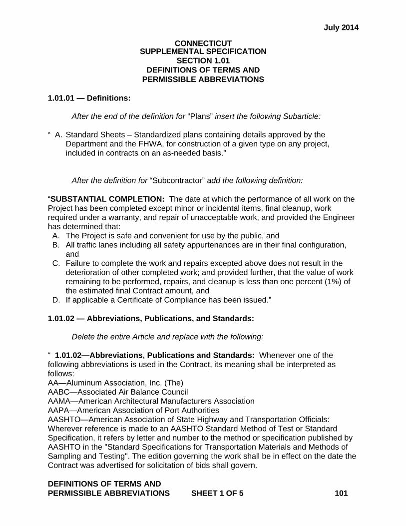
July 2014
CONNECTICUT SUPPLEMENTAL SPECIFICATION
SECTION 1.01 DEFINITIONS OF TERMS AND
PERMISSIBLE ABBREVIATIONS 1.01.01 — Definitions: After the end of the definition for “Plans” insert the following Subarticle: “ A. Standard Sheets – Standardized plans containing details approved by the
Department and the FHWA, for construction of a given type on any project, included in contracts on an as-needed basis.”
After the definition for “Subcontractor” add the following definition: “SUBSTANTIAL COMPLETION: The date at which the performance of all work on the Project has been completed except minor or incidental items, final cleanup, work required under a warranty, and repair of unacceptable work, and provided the Engineer has determined that: A. The Project is safe and convenient for use by the public, and B. All traffic lanes including all safety appurtenances are in their final configuration,
and C. Failure to complete the work and repairs excepted above does not result in the
deterioration of other completed work; and provided further, that the value of work remaining to be performed, repairs, and cleanup is less than one percent (1%) of the estimated final Contract amount, and
D. If applicable a Certificate of Compliance has been issued.” 1.01.02 — Abbreviations, Publications, and Standards: Delete the entire Article and replace with the following: “ 1.01.02—Abbreviations, Publications and Standards: Whenever one of the following abbreviations is used in the Contract, its meaning shall be interpreted as follows: AA—Aluminum Association, Inc. (The) AABC—Associated Air Balance Council AAMA—American Architectural Manufacturers Association AAPA—American Association of Port Authorities AASHTO—American Association of State Highway and Transportation Officials: Wherever reference is made to an AASHTO Standard Method of Test or Standard Specification, it refers by letter and number to the method or specification published by AASHTO in the "Standard Specifications for Transportation Materials and Methods of Sampling and Testing". The edition governing the work shall be in effect on the date the Contract was advertised for solicitation of bids shall govern. DEFINITIONS OF TERMS AND PERMISSIBLE ABBREVIATIONS SHEET 1 OF 5 101
ABMA—American Bearing Manufacturers Association ACGIH—American Council of Government Industrial Hygienists ACI—ACI International (American Concrete Institute) ADAAG—Americans with Disabilities Act (ADA) Accessibility Guidelines for Buildings and Facilities ADSC—The International Association of Foundation Drilling AF&PA—American Forest & Paper Association AGA—American Gas Association AGC—Associated General Contractors of America (The) AHA—American Hardboard Association AHAM—Association of Home Appliance Manufacturers AI—Asphalt Institute AIA—The American Institute of Architects (The) AISC—American Institute of Steel Construction AISI—American Iron and Steel Institute AITC—American Institute of Timber Construction A.L.I.—Automotive Lift Institute ALSC—American Lumber Standard Committee, Incorporated AMCA—Air Movement and Control Association International, Inc. ANLA—American Nursery and Landscape Association ANSI—American National Standards Institute AOAC—AOAC International AOSA—Association of Official Seed Analysts APA—APA-The Engineered Wood Association API—American Petroleum Institute AREMA—American Railway Engineering and Maintenance-of-Way Association ARI—Air-Conditioning & Refrigeration Institute ARTBA—American Road and Transportation Builders Association ASA—Acoustical Society of America ASC—Adhesive and Sealant Council ASCE—American Society of Civil Engineers ASHRAE—American Society of Heating, Refrigerating and Air-Conditioning Engineers ASME—ASME International (The American Society of Mechanical Engineers International) ASSE—American Society of Sanitary Engineering ASTM—American Society of Testing and Materials (ASTM International): Wherever reference is made to an ASTM specification, test method, or practice, it refers by letter, number, or both to standards published by ASTM International in the "ASTM Standards SourceTM Database". The edition governing the work shall be in effect on the date the Contract was advertised for solicitation of bids shall govern. ATSSA—American Traffic Safety Services Association AWI—Architectural Woodwork Institute AWPA—American Wood-Preservers’ Association AWPI—American Wood Preservers Institute AWS—American Welding Society: Wherever reference is made to an AWS materials specification, inspection methods, or welding procedures, it refers by section number to standards of the American Welding Society published in the applicable steel, or aluminum welding code. The edition governing the work shall be in effect on the date the Contract was advertised for solicitation of bids shall govern. DEFINITIONS OF TERMS AND PERMISSIBLE ABBREVIATIONS SHEET 2 OF 5 101

AWWA—American Water Works Association BHMA—Builders Hardware Manufacturers Association BIA—Brick Industry Association (The) BOCA—BOCA International, Inc. CBM—Certified Ballast Manufacturers Association CCRL—Cement and Concrete Reference Laboratory CDA—Copper Development Association (The) CGA—Compressed Gas Association CISCA—Ceilings and Interior Systems Construction Association CLFMI—Chain Link Fence Manufacturers Institute ConnDOT—Connecticut Department of Transportation CFR—Code of Federal Regulations CGS—Connecticut General Statutes CISPI—Cast Iron Soil Pipe Institute CRI—Carpet and Rug Institute (The) CRSI—Concrete Reinforcing Steel Institute CSI—Construction Specifications Institute (The) CSSB—Cedar Shake & Shingle Bureau CTI—Cooling Technology Institute DASMA—Door and Access Systems Manufacturers Association, International DEEP—Connecticut Department of Energy and Environmental Protection DHI—Door and Hardware Institute DOD—Department of Defense Military Specifications and Standards DPUC—Department of Public Utility Control see PURA EIA—Electronic Industries Alliance EPA—Environmental Protection Agency FAA—Federal Aviation Administration FCC—Federal Communications Commission FCICA—Floor Covering Installation Contractors Association FHWA—Federal Highway Administration FMG—FM Global FRA—Federal Railway Administration FS—Wherever reference is made to FS in the contract, it refers by number, letter, or both, to the latest standard or tentative standard of the Federal Specification Unit, General Services Administration, Federal Supply Service, as to materials, specifications, or methods of testing, whichever the case may be. FTA—Federal Transit Administration HPVA—Hardwood Plywood & Veneer Association GA—Gypsum Association GANA—Glass Association of North America GSA—General Services Administration HI—Hydraulics Institute HPVA—Hardwood Plywood & Veneer Association ICC—International Code Council ICC-ES—ICC Evaluation Service, Inc. ICEA—Insulated Cable Engineers Association, Inc. IEC—International Electrotechnical Commission IEEE—Institute of Electrical and Electronics Engineers, Inc. (The) IES—Illuminating Engineers Society DEFINITIONS OF TERMS AND PERMISSIBLE ABBREVIATIONS SHEET 3 OF 5 101
IESNA—Illuminating Engineering Society of North America IGCC—Insulating Glass Certification Council IGMA—Insulating Glass Manufacturers Alliance IMSA—International Municipal Signal Association IRI—HSB Industrial Risk Insurers ISO—International Organization for Standardization ITE—Institute of Traffic Engineers KCMA—Kitchen Cabinet Manufacturers Association LMA—Laminating Materials Association LPI—Lightning Protection Institute MBMA—Metal Building Manufacturers Association MILSPEC—Military Specification and Standards MMA—Monorail Manufacturers Association MSHA—Mine Safety and Health Administration MSS—Manufacturers Standardization Society of The Valve and Fittings the Valve Industry, Inc. MUTCD—Manual on Uniform Traffic Control Devices NAAMM—National Association of Architectural Metal Manufacturers NADCA—National Air Duct Cleaners Association NAIMA—North American Insulation Manufacturers Association (The) NBFU—National Board of Fire Underwriters NCHRP—National Cooperative Highway Research Program NCMA—National Concrete Masonry Association NCPI—National Clay Pipe Institute NEBB—Natural Environmental Balancing Bureau NEC—National Electrical Code NECA—National Electrical Contractors Association NEMA—National Electrical Manufacturers Association NEPCOAT—North East Protective Coatings Committee NESC—National Electrical Safety Code NETA—InterNational Testing Association NFPA—National Fire Protection Association NFRC—National Fenestration Rating Council NHLA—National Hardwood Lumber Association NICET—National Institute for Certification in Engineering Technologies NIOSH—National Institute of Occupational Safety and Health NIST—National Institute of Standards and Technology NLGA—National Lumber Grades Authority NOAA—National Oceanic and Atmospheric Administration NRCA—National Roofing Contractors Association NSF—NSF International NTMA—National Terrazzo and Mosaic Association, Inc. OEO—Office of Equal Opportunity OSHA—Occupational Safety and Health Administration PCA—Portland Cement Association PCI—Precast/Prestressed Concrete Institute PDI—Plumbing & Drainage Institute PTI—Post-Tensioning Institute PURA—Public Utilities Regulatory Authority DEFINITIONS OF TERMS AND PERMISSIBLE ABBREVIATIONS SHEET 4 OF 5 101
RMA—Rubber Manufacturers Association SAE—SAE International SDI—Steel Deck Institute or ......—Steel Door Institute SFPA—Southern Forest Products Association SJI—Steel Joist Institute SMACNA—Sheet Metal and Air Conditioning Contractors National Association SPIB—Southern Pine Inspection Bureau (The) SPRI—Single Ply Roofing Institute SSPC—Where reference is made to SSPC in the Contract, it refers by number, letter, or both, to the latest standard or tentative standard specification of The Society for Protective Coatings, Formerly the Steel Structures Painting Council, as to materials specifications, methods of testing, systems, procedures, inspection or other specification pertaining to any or all phases of cleaning or painting, whichever may apply. SWRI—Sealant, Waterproofing, & Restoration Institute TCA—Tile Council of America, Inc. TIA—Telecommunications Industry Association TIA/EIA—Telecommunications Industry Association/Electronics Industries Alliance TPI—Truss Plate Institute, Inc. TRB—Transportation Research Board UFAS—Uniform Federal Accessibility Standards UL—Underwriters Laboratories Inc. USDA—United States Department of Agriculture USGBC—U.S. Green Building Council WCLIB—West Coast Lumber Inspection Bureau WCSC—Window Covering Safety Council WDMA—Window & Door Manufacturers Association WWPA—Western Wood Products Association” 1.01.03 — Abbreviations and Terms: Add the following abbreviations: “cu.dm - Cubic Decimeter cu.m - Cubic Meters dm³ - Cubic Decimeter m² - Square Meter m³ - Cubic Meters sq.m - Square Meter Vert. M - Vertical Meter vert.m - Vertical Meter” DEFINITIONS OF TERMS AND PERMISSIBLE ABBREVIATIONS SHEET 5 OF 5 101
July 2014
CONNECTICUT SUPPLEMENTAL SPECIFICATION
SECTION 1.02 PROPOSAL REQUIREMENTS AND CONDITIONS
1.02.01–Contract Bidding and Award Replace the entire article with the following: “1.02.01—Contract Bidding and Award: All bids for construction contracts must be submitted electronically. It is the responsibility of each bidder and all other interested parties to obtain all bidding related information and documents from the Department of Administrative Services (DAS) State Contracting Portal. Connecticut Department of Transportation bidding and other information and documents which are obtained from any other source must not be submitted to the Department. Reproduced, reformatted or altered forms of documents are not authorized or acceptable. For information about the bidding and award of Department construction contracts, consult the “State of Connecticut Department of Transportation Construction Contract Bidding and Award Manual,” available from the Division of Contracts. In order to be eligible for award of a Department construction contract, a bidder must follow the requirements of this Bid Manual, and all bidding and award matters regarding Department construction contracts shall be governed by the terms of the Bid Manual, unless treated otherwise in the Contract, including these Specifications.” PROPOSAL REQUIREMENTS AND CONDITIONS SHEET 1 OF 1 102
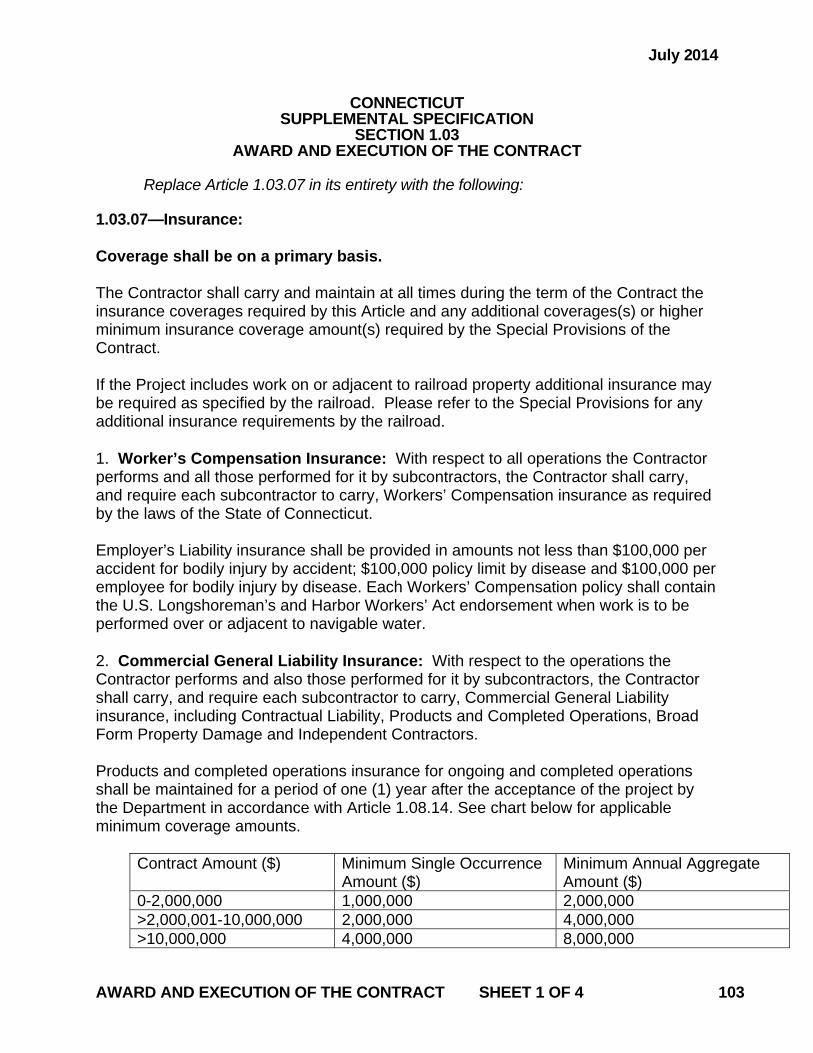
July 2014
CONNECTICUT SUPPLEMENTAL SPECIFICATION
SECTION 1.03 AWARD AND EXECUTION OF THE CONTRACT
Replace Article 1.03.07 in its entirety with the following: 1.03.07—Insurance: Coverage shall be on a primary basis. The Contractor shall carry and maintain at all times during the term of the Contract the insurance coverages required by this Article and any additional coverages(s) or higher minimum insurance coverage amount(s) required by the Special Provisions of the Contract. If the Project includes work on or adjacent to railroad property additional insurance may be required as specified by the railroad. Please refer to the Special Provisions for any additional insurance requirements by the railroad. 1. Worker’s Compensation Insurance: With respect to all operations the Contractor performs and all those performed for it by subcontractors, the Contractor shall carry, and require each subcontractor to carry, Workers’ Compensation insurance as required by the laws of the State of Connecticut. Employer’s Liability insurance shall be provided in amounts not less than $100,000 per accident for bodily injury by accident; $100,000 policy limit by disease and $100,000 per employee for bodily injury by disease. Each Workers’ Compensation policy shall contain the U.S. Longshoreman’s and Harbor Workers’ Act endorsement when work is to be performed over or adjacent to navigable water. 2. Commercial General Liability Insurance: With respect to the operations the Contractor performs and also those performed for it by subcontractors, the Contractor shall carry, and require each subcontractor to carry, Commercial General Liability insurance, including Contractual Liability, Products and Completed Operations, Broad Form Property Damage and Independent Contractors. Products and completed operations insurance for ongoing and completed operations shall be maintained for a period of one (1) year after the acceptance of the project by the Department in accordance with Article 1.08.14. See chart below for applicable minimum coverage amounts.
Contract Amount ($) Minimum Single Occurrence Amount ($)
Minimum Annual Aggregate Amount ($)
0-2,000,000 1,000,000 2,000,000 >2,000,001-10,000,000 2,000,000 4,000,000 >10,000,000 4,000,000 8,000,000
AWARD AND EXECUTION OF THE CONTRACT SHEET 1 OF 4 103
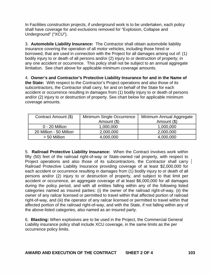
In Facilities construction projects, if underground work is to be undertaken, each policy shall have coverage for and exclusions removed for “Explosion, Collapse and Underground” (“XCU”). 3. Automobile Liability Insurance: The Contractor shall obtain automobile liability insurance covering the operation of all motor vehicles, including those hired or borrowed, that are used in connection with the Project for all damages arising out of: (1) bodily injury to or death of all persons and/or (2) injury to or destruction of property; in any one accident or occurrence. This policy shall not be subject to an annual aggregate limitation. See chart above for applicable minimum coverage amounts. 4. Owner’s and Contractor’s Protective Liability Insurance for and in the Name of the State: With respect to the Contractor’s Project operations and also those of its subcontractors, the Contractor shall carry, for and on behalf of the State for each accident or occurrence resulting in damages from (1) bodily injury to or death of persons and/or (2) injury to or destruction of property. See chart below for applicable minimum coverage amounts.
Contract Amount ($) Minimum Single Occurrence Amount ($)
Minimum Annual Aggregate Amount ($)
0 - 20 Million 1,000,000 1,000,000 20 Million - 50 Million 2,000,000 2,000,000
> 50 Million 4,000,000 4,000,000 5. Railroad Protective Liability Insurance: When the Contract involves work within fifty (50) feet of the railroad right-of-way or State-owned rail property, with respect to Project operations and also those of its subcontractors, the Contractor shall carry Railroad Protective Liability Insurance providing coverage of at least $2,000,000 for each accident or occurrence resulting in damages from (1) bodily injury to or death of all persons and/or (2) injury to or destruction of property, and subject to that limit per accident or occurrence, an aggregate coverage of at least $6,000,000 for all damages during the policy period, and with all entities falling within any of the following listed categories named as insured parties: (i) the owner of the railroad right-of-way, (ii) the owner of any railcar licensed or permitted to travel within that affected portion of railroad right-of-way, and (iii) the operator of any railcar licensed or permitted to travel within that affected portion of the railroad right-of-way, and with the State, if not falling within any of the above-listed categories, also named as an insured party. 6. Blasting: When explosives are to be used in the Project, the Commercial General Liability insurance policy shall include XCU coverage, in the same limits as the per occurrence policy limits. AWARD AND EXECUTION OF THE CONTRACT SHEET 2 OF 4 103
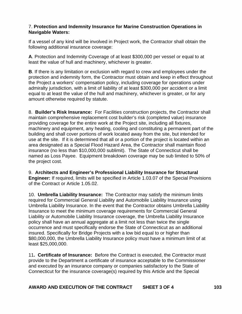
7. Protection and Indemnity Insurance for Marine Construction Operations in Navigable Waters:
If a vessel of any kind will be involved in Project work, the Contractor shall obtain the following additional insurance coverage:
A. Protection and Indemnity Coverage of at least $300,000 per vessel or equal to at least the value of hull and machinery, whichever is greater.
B. If there is any limitation or exclusion with regard to crew and employees under the protection and indemnity form, the Contractor must obtain and keep in effect throughout the Project a workers’ compensation policy, including coverage for operations under admiralty jurisdiction, with a limit of liability of at least $300,000 per accident or a limit equal to at least the value of the hull and machinery, whichever is greater, or for any amount otherwise required by statute. 8. Builder’s Risk Insurance: For Facilities construction projects, the Contractor shall maintain comprehensive replacement cost builder’s risk (completed value) insurance providing coverage for the entire work at the Project site, including all fixtures, machinery and equipment, any heating, cooling and constituting a permanent part of the building and shall cover portions of work located away from the site, but intended for use at the site. If it is determined that all or a portion of the project is located within an area designated as a Special Flood Hazard Area, the Contractor shall maintain flood insurance (no less than $10,000,000 sublimit). The State of Connecticut shall be named as Loss Payee. Equipment breakdown coverage may be sub limited to 50% of the project cost. 9. Architects and Engineer’s Professional Liability Insurance for Structural Engineer: If required, limits will be specified in Article 1.03.07 of the Special Provisions of the Contract or Article 1.05.02. 10. Umbrella Liability Insurance: The Contractor may satisfy the minimum limits required for Commercial General Liability and Automobile Liability Insurance using Umbrella Liability Insurance. In the event that the Contractor obtains Umbrella Liability Insurance to meet the minimum coverage requirements for Commercial General Liability or Automobile Liability Insurance coverage, the Umbrella Liability Insurance policy shall have an annual aggregate at a limit not less than twice the single occurrence and must specifically endorse the State of Connecticut as an additional insured. Specifically for Bridge Projects with a low bid equal to or higher than $80,000,000, the Umbrella Liability Insurance policy must have a minimum limit of at least $25,000,000. 11. Certificate of Insurance: Before the Contract is executed, the Contractor must provide to the Department a certificate of insurance acceptable to the Commissioner and executed by an insurance company or companies satisfactory to the State of Connecticut for the insurance coverage(s) required by this Article and the Special AWARD AND EXECUTION OF THE CONTRACT SHEET 3 OF 4 103
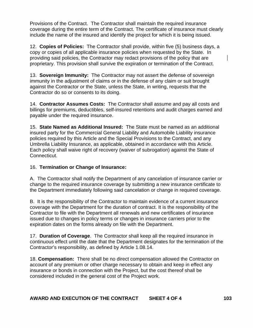
Provisions of the Contract. The Contractor shall maintain the required insurance coverage during the entire term of the Contract. The certificate of insurance must clearly include the name of the insured and identify the project for which it is being issued. 12. Copies of Policies: The Contractor shall provide, within five (5) business days, a copy or copies of all applicable insurance policies when requested by the State. In providing said policies, the Contractor may redact provisions of the policy that are proprietary. This provision shall survive the expiration or termination of the Contract. 13. Sovereign Immunity: The Contractor may not assert the defense of sovereign immunity in the adjustment of claims or in the defense of any claim or suit brought against the Contractor or the State, unless the State, in writing, requests that the Contractor do so or consents to its doing. 14. Contractor Assumes Costs: The Contractor shall assume and pay all costs and billings for premiums, deductibles, self-insured retentions and audit charges earned and payable under the required insurance. 15. State Named as Additional Insured: The State must be named as an additional insured party for the Commercial General Liability and Automobile Liability insurance policies required by this Article and the Special Provisions to the Contract, and any Umbrella Liability Insurance, as applicable, obtained in accordance with this Article. Each policy shall waive right of recovery (waiver of subrogation) against the State of Connecticut. 16. Termination or Change of Insurance: A. The Contractor shall notify the Department of any cancelation of insurance carrier or change to the required insurance coverage by submitting a new insurance certificate to the Department immediately following said cancelation or change in required coverage. B. It is the responsibility of the Contractor to maintain evidence of a current insurance coverage with the Department for the duration of contract. It is the responsibility of the Contractor to file with the Department all renewals and new certificates of insurance issued due to changes in policy terms or changes in insurance carriers prior to the expiration dates on the forms already on file with the Department. 17. Duration of Coverage. The Contractor shall keep all the required insurance in continuous effect until the date that the Department designates for the termination of the Contractor’s responsibility, as defined by Article 1.08.14. 18. Compensation: There shall be no direct compensation allowed the Contractor on account of any premium or other charge necessary to obtain and keep in effect any insurance or bonds in connection with the Project, but the cost thereof shall be considered included in the general cost of the Project work. AWARD AND EXECUTION OF THE CONTRACT SHEET 4 OF 4 103
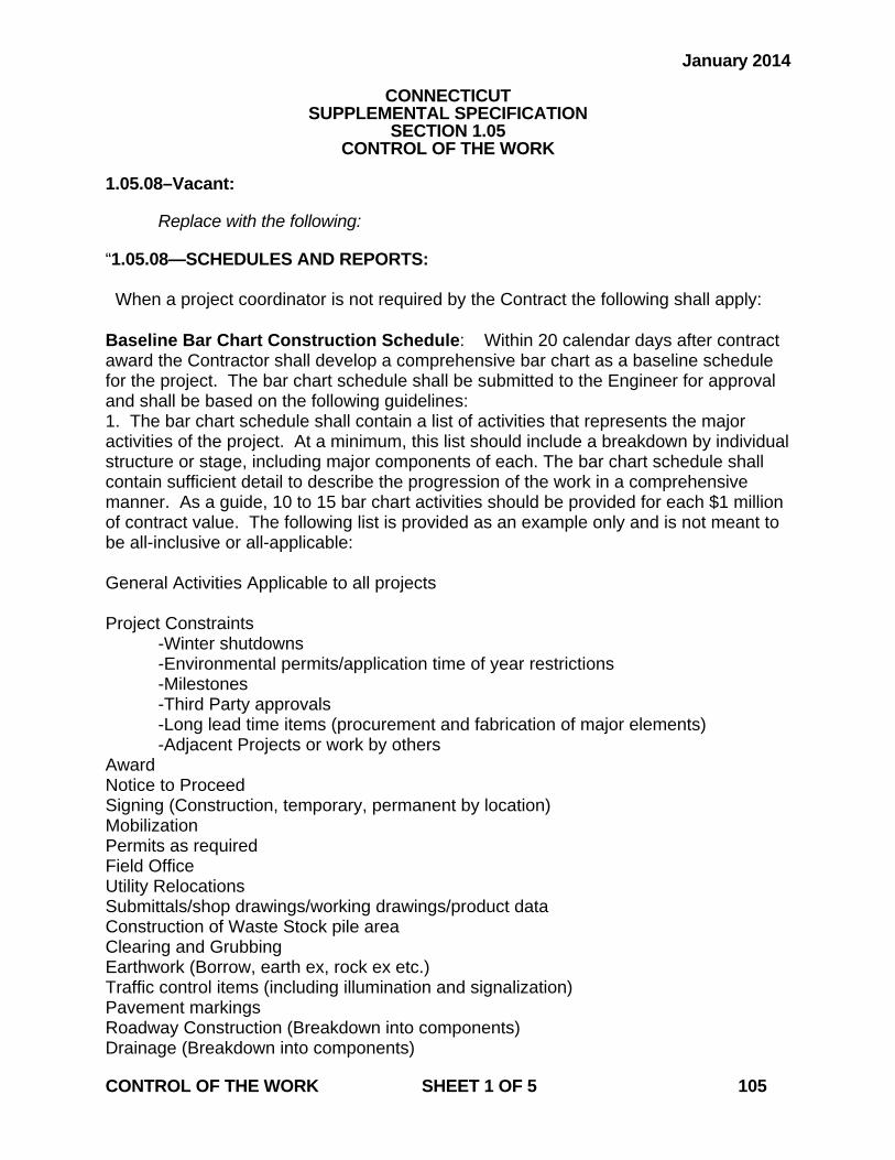
January 2014
CONNECTICUT SUPPLEMENTAL SPECIFICATION
SECTION 1.05 CONTROL OF THE WORK
1.05.08–Vacant: Replace with the following: “1.05.08—SCHEDULES AND REPORTS: When a project coordinator is not required by the Contract the following shall apply: Baseline Bar Chart Construction Schedule: Within 20 calendar days after contract award the Contractor shall develop a comprehensive bar chart as a baseline schedule for the project. The bar chart schedule shall be submitted to the Engineer for approval and shall be based on the following guidelines: 1. The bar chart schedule shall contain a list of activities that represents the major activities of the project. At a minimum, this list should include a breakdown by individual structure or stage, including major components of each. The bar chart schedule shall contain sufficient detail to describe the progression of the work in a comprehensive manner. As a guide, 10 to 15 bar chart activities should be provided for each $1 million of contract value. The following list is provided as an example only and is not meant to be all-inclusive or all-applicable: General Activities Applicable to all projects Project Constraints -Winter shutdowns -Environmental permits/application time of year restrictions -Milestones -Third Party approvals -Long lead time items (procurement and fabrication of major elements) -Adjacent Projects or work by others Award Notice to Proceed Signing (Construction, temporary, permanent by location) Mobilization Permits as required Field Office Utility Relocations Submittals/shop drawings/working drawings/product data Construction of Waste Stock pile area Clearing and Grubbing Earthwork (Borrow, earth ex, rock ex etc.) Traffic control items (including illumination and signalization) Pavement markings Roadway Construction (Breakdown into components) Drainage (Breakdown into components) CONTROL OF THE WORK SHEET 1 OF 5 105

Culverts Plantings (including turf establishment) Semi-final inspection Final Cleanup As required the following may supplement the activities listed above for the specific project types indicated: a. For bridges and other structures, include major components such as abutments, wingwalls, piers, decks and retaining walls; further breakdown by footings, wall sections, parapets etc. Temporary Earth Retention Systems Cofferdam and Dewatering Structure Excavation Piles/test piles Temporary Structures Removal of Superstructure Bearing Pads Structural Steel (Breakdown by fabrication, delivery, installation, painting etc.) Bridge deck b. Multiple location projects such as traffic signal, incident management, lighting, planting and guiderail projects will be broken down first by location and then by operation. Other major activities of these types of projects should include, but are not limited to: Installation of anchors Driving posts Foundations Trenching and Backfilling Installation of Span poles/mast arms Installation of luminaries Installation of cameras Installation of VMS Hanging heads Sawcut loops Energizing equipment c. Facility Projects – Facilities construction shall reflect the same breakdown of the project as the schedule of values: Division 2 – Existing Conditions Division 3 – Concrete Division 4 – Masonry Division 5 – Metals Division 6 – Wood, Plastic, and Composites Division 7 – Thermal and Moisture Protection Division 8 – Openings CONTROL OF THE WORK SHEET 2 OF 5 105
Division 9 – Finishes Division 10 – Specialties Division 11 – Equipment Division 12 - Furnishings Division 13 – Special Construction Division 14 – Conveying Equipment Division 21 – Fire Suppression Division 22 – Plumbing Division 23 – Heating, Ventilating, and Air Conditioning Division 26 – Electrical Division 27 – Communications Division 28 – Electronic Safety and Security Division 31 – Earthwork Division 32 – Exterior Improvements Division 33 - Utilities 2. If the Engineer determines that additional detail is necessary, the Contractor shall provide it. 3. Each activity shall have a separate schedule bar. The schedule timeline shall be broken into weekly time periods with a vertical line to identify the first working day of each week. 4. The bar chart schedule shall show relationships among activities. The critical path for the Project shall be clearly defined on the schedule. The schedule shall show milestones for major elements of work, and shall be prepared on a sheet, or series of sheets of sufficient width to show data for the entire construction period. 5. If scheduling software is used to create the bar chart schedule, related reports such as a predecessor and successor report, a sort by total float, and a sort by early start shall also be submitted. 6. Project activities shall be scheduled to demonstrate that the construction completion date for the Project will occur prior to expiration of the Contract time. In addition, the schedule shall demonstrate conformance with any other dates stipulated in the Contract. 7. The Contractor is responsible to inform its subcontractor(s) and supplier(s) of the project schedule and any relevant updates. 8. There will be no direct payment for furnishing schedules, the cost thereof shall be considered as included in the general cost of the work. 9. For projects without a Mobilization item, 5% of the contract value will be withheld until such time as the Baseline Schedule is approved. Monthly Updates: No later than the 10th day of each month, unless directed otherwise by the Engineer, the Contractor shall deliver to the Engineer three copies of the schedule to show the work actually accomplished during the preceding month, the actual time spent on each activity, and the estimated time needed to complete any activity which has been started but not completed. Each time bar shall indicate, in 10% increments, the estimated percentage of that activity which remains to be completed. As the Project progresses, the Contractor shall place a contrasting mark in each bar to indicate the actual percentage of the activity that has been completed. CONTROL OF THE WORK SHEET 3 OF 5 105

The monthly update shall include revisions of the schedule necessitated by revisions to the Project directed by the Engineer (including, but not limited to extra work), during the month preceding the update. Similarly, any changes of the schedule required due to changes in the Contractor’s planning or progress shall also be included. The Engineer reserves the right to reject any such revisions. If the schedule revisions extend the contract completion date, due to extra or added work or delays beyond the control of the Contractor, the Contractor shall submit a request in writing for an extension of time in accordance with Article 1.08.08. This request shall be supported by an analysis of the schedules submitted previously. Any schedule revisions shall be identified and explained in a cover letter accompanying the monthly update. The letter shall also describe in general terms the progress of the Project since the last schedule update and shall identify any items of special interest. If the Contractor fails to provide monthly schedule updates, the Engineer has the right to hold 10% of the monthly estimated payment, or $5,000, whichever is less, until such time as an update has been provided in accordance with this provision. Biweekly Schedules: Each week, the Contractor shall submit to the Engineer a two week look-ahead schedule. This short-term schedule may be handwritten but shall clearly indicate all work planned for the following two week period. Recovery Schedules: If the updated schedule indicates that the Project has fallen behind schedule, the Contractor shall either submit a time extension request in accordance with 1.08.08 or immediately institute steps acceptable to the Engineer to improve its progress of the Project. In such a case, the Contractor shall submit a recovery plan, as may be deemed necessary by the Engineer, to demonstrate the manner in which an acceptable rate of progress will be regained.” 1.05.12–Payrolls: Replace the first paragraph with the following: “For each week of the Project from the first week during which an employee of the Contractor does Project work to which prevailing wage requirements apply, until the last week on which such an employee does such work, the Contractor shall furnish to the Engineer certified copies of payrolls showing (a) the names of the employees who worked on the Project and whose work is subject to prevailing wage requirements, (b) the specific days and hours and numbers of hours that each such employee worked on the Project, and (c) the amount of money paid to each such employee for Project work. Each such payroll shall include the statement(s) of compliance with prevailing wage laws required by the State of Connecticut and, if applicable, by the Federal government. Said payrolls must contain all information required by Connecticut General Statutes Section 31-53 (as it may be revised). For contracts subject to Federal prevailing wage requirements, each payroll shall also contain the information required by the Davis Bacon and Related Acts (DBR). All of the payroll requirements in this Article shall also apply to the work of any subcontractor or other party that performs work on the Project site, and the Contractor shall be responsible for ensuring that each such party meets said requirements.” CONTROL OF THE WORK SHEET 4 OF 5 105
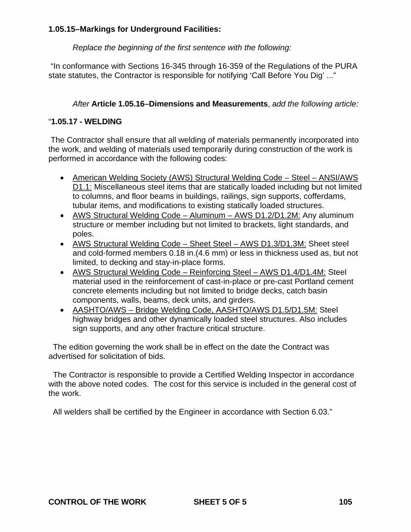
1.05.15–Markings for Underground Facilities: Replace the beginning of the first sentence with the following: “In conformance with Sections 16-345 through 16-359 of the Regulations of the PURA state statutes, the Contractor is responsible for notifying ‘Call Before You Dig’ ...” After Article 1.05.16–Dimensions and Measurements, add the following article: “1.05.17 - WELDING The Contractor shall ensure that all welding of materials permanently incorporated into the work, and welding of materials used temporarily during construction of the work is performed in accordance with the following codes:
• American Welding Society (AWS) Structural Welding Code – Steel – ANSI/AWS D1.1: Miscellaneous steel items that are statically loaded including but not limited to columns, and floor beams in buildings, railings, sign supports, cofferdams, tubular items, and modifications to existing statically loaded structures.
• AWS Structural Welding Code – Aluminum – AWS D1.2/D1.2M: Any aluminum structure or member including but not limited to brackets, light standards, and poles.
• AWS Structural Welding Code – Sheet Steel – AWS D1.3/D1.3M: Sheet steel and cold-formed members 0.18 in.(4.6 mm) or less in thickness used as, but not limited, to decking and stay-in-place forms.
• AWS Structural Welding Code – Reinforcing Steel – AWS D1.4/D1.4M: Steel material used in the reinforcement of cast-in-place or pre-cast Portland cement concrete elements including but not limited to bridge decks, catch basin components, walls, beams, deck units, and girders.
• AASHTO/AWS – Bridge Welding Code, AASHTO/AWS D1.5/D1.5M: Steel highway bridges and other dynamically loaded steel structures. Also includes sign supports, and any other fracture critical structure.
The edition governing the work shall be in effect on the date the Contract was advertised for solicitation of bids. The Contractor is responsible to provide a Certified Welding Inspector in accordance with the above noted codes. The cost for this service is included in the general cost of the work. All welders shall be certified by the Engineer in accordance with Section 6.03.” CONTROL OF THE WORK SHEET 5 OF 5 105
July 2013
CONNECTICUT SUPPLEMENTAL SPECIFICATION
SECTION 1.07 LEGAL RELATIONS AND RESPONSIBILITIES
1.07.05 – Load Restrictions Delete the entire article and replace with the following: “1.07.05 – Load Restrictions (a) Vehicle Weights: This subarticle will apply to travel both on existing pavements and pavements under construction. The Contractor shall comply with all legal load restrictions as to vehicle size, the gross weight of vehicles, and the axle weight of vehicles while hauling materials. Throughout the duration of the contract, the Contractor shall take precautions to ensure existing and newly installed roadway structures and appurtenances are not damaged by construction vehicles or operations. Unless otherwise noted in contract specifications or plans, on and off road equipment of the Contractor, either loaded or unloaded, will not be allowed to travel across any bridge or on any highway when such a vehicle exceeds the statutory limit or posted limit of such bridge or highway. Should such movement of equipment become necessary the Contractor shall apply for a permit from the Department for such travel, as provided in the Connecticut General Statutes (CGS). The movement of any such vehicles within the project limits or detour routes shall be submitted to the Engineer for project record. Such permit or submittal will not excuse the Contractor from liability for damage to the highway caused by its equipment. The Contractor is subject to fines, assessments and other penalties that may be levied as a result of violations by its employees or agents of the legal restrictions as to vehicle size and weight. (b) Storage of Construction Materials/Equipment on Structures: Storage is determined to be non-operating equipment or material. The Contractor shall not exceed the statutory limit or posted limit for either an existing or new structure when storing materials and/or construction equipment. When a structure is not posted, then the maximum weight of equipment or materials stored in each 12 foot wide travel lane of any given span shall be limited to 750 pounds per linear foot combined with a 20,000 pound concentrated load located anywhere within the subject lane. If anticipated storage of equipment or material exceeds the above provision, then the Contractor shall submit his proposal of storage supported by calculations stamped by a Professional Engineer registered in the State of Connecticut, the the Engineer for approval 14 days prior to the storage operation. Operations related to structural steel demolition or erection shall follow the guidelines under Section 6.03. All other submittals shall include a detailed description of the material/equipment to be stored, the quantity of storage if it is stockpiled materials, the storage location, gross weight with supporting calculations if applicable, anticipated duration of storage and any environmental safety, or traffic protection that may be required. Storage location on the structure shall be clearly defined in the field. If structures are in a state of staged construction or demolition, additional structural analysis may be required prior to authorization of storage.” 1.07.18 – Use of State Property After Subarticle (h) add the following sentence:
“Gore areas are not available for disposal of surplus material.” LEGAL RELATIONS AND RESPONSIBILITIES SHEET 1 OF 1 107
January 2014
CONNECTICUT SUPPLEMENTAL SPECIFICATION
SECTION 1.08 PROSECUTION AND PROGRESS
1.08.01 – Transfer of Work or Contract: Replace the last paragraph with the following paragraphs: “ The Contractor shall not sublet, sell, transfer, assign, or otherwise dispose of the Contract or any portion thereof, or of the work provided for therein, or of its right, title, or interest therein, to any individual or entity without the written consent of the Commissioner. No payment will be made for such work until written consent is provided by the Commissioner. The Contractor shall pay the subcontractor for work performed within thirty (30) days after the Contractor receives payment for the work performed by the subcontractor. Withholding retainage by the Contractor, subcontractor or lower tier subcontractors is not allowed. Payment for work that has been performed by a subcontractor does not eliminate the Contractor’s responsibilities for all the work as defined in Article 1.07.12, “Contractor’s Responsibility for Work.” Payment for work that has been performed by a subcontractor also does not release the subcontractor from its responsibility for maintenance and other periods of subcontractor responsibility specified for the subcontractor’s items of work. Failure of a subcontractor to meet its maintenance, warranty or defective work responsibilities may result in administrative action on future Department contracts. For any dispute regarding prompt payment, the alternate dispute resolution provisions of this article shall apply. The above requirements are also applicable to all sub-tier subcontractors and the above provisions shall be made a part of all subcontract agreements. Failure of the Contractor to comply with the provisions of this section may result in a finding that the Contractor is nonresponsible as a bidder for a Department contract.” 1.08.07 – Determination of Contract Time: Replace the fifth paragraph with the following: “ The total elapsed time in calendar days, computed as described above, from the commencement date specified in the Engineer's "Notice to Proceed" to the “Substantial Completion” date specified in the Engineer's "Notice of Substantial Completion" shall be considered as the time used in the performance of the Contract work.” 1.08.09 – Failure to Complete Work on Time: Replace the second paragraph with the following: “ If the last day of the initial Contract time or the initial Contract date determined for PROSECUTION AND PROGRESS SHEET 1 OF 2 108
Substantial Completion is before December 1 in the given year, liquidated damages as specified in the Contract shall be assessed against the Contractor per calendar day (including any days during a winter shutdown period) from that day until the date on which the Project is substantially completed.” 1.08.12—Final Inspection: Replace the first paragraph with the following: “ If the Engineer determines that the work may be substantially complete, a Semi Final Inspection will be held as soon as practical. After the Semi Final Inspection is held and the Engineer determines that the requirements for Substantial Completion have been satisfied the Engineer will prepare a “Notice of Substantial Completion”. When the Contractor has completed all work listed in the “Notice of Substantial Completion” the Contractor shall prepare a written notice requesting a Final Inspection and a “Certificate of Acceptance of Work”. The Engineer will hold an Inspection of the Project as soon as practical after the Engineer determines that the Project may be completed. If the Engineer deems the Project complete, said inspection shall constitute the Final Inspection, and the Engineer will notify the Contractor in writing that the Final Inspection has been performed.” 1.08.13 – Acceptance of Work and Termination of the Contractor’s Responsibility: Replace the only paragraph with the following: “ The Contractor’s responsibility for non-administrative Project work will be considered terminated when the final inspection has been held, any required additional work and final cleaning-up have been completed, all final operation and maintenance manuals have been submitted, and all of the Contractor’s equipment and construction signs have been removed from the Project site. When these requirements have been met to the satisfaction of the Engineer, the Commissioner will accept the work by certifying in writing to the Contractor that the non-administrative Project work has been completed.” PROSECUTION AND PROGRESS SHEET 2 OF 2 108
January 2014
CONNECTICUT SUPPLEMENTAL SPECIFICATION
SECTION 1.09 MEASUREMENT AND PAYMENT
1.09.04 – Extra and Cost-Plus Work Delete existing subarticle (e) and replace with the following:
“(e) Administrative Expense: When extra work on a cost-plus basis is performed by an authorized subcontractor, the Department will pay the Contractor an additional 7.5% for that work; such payment will be in addition to the percentage payments described in (a), (b), (c) and (d) above, as a reimbursement for the Contractor's administrative expense in connection with such work. Approval of such additional payments will be given only after the Contractor provides to the Engineer receipted invoices for all relevant costs.”
1.09.06 – Partial Payments: In the first paragraph under A. Monthly and Semi-monthly Estimates:, delete the second, third and fourth sentences and replace the remainder of subarticle (1) with the following:
“Retainage will not be held.
Exceptions may be made as follows: (a) When not in conflict with the interests of the State, the Contractor may request,
and the Engineer may make, semi-monthly estimates for payment. (b) If, in the judgment of the Assistant District Engineer, the Project is not
proceeding in accordance with the Contract the Engineer may decline to make a payment estimate.
(c) If the total value of the Project work complete since the last estimate amounts to less than $2,500 the Engineer also may decline to make a payment estimate.”
Replace the first paragraph of subarticle B. Payment for Stored Materials: with the following: “B. Payment for Stored Materials: Non-perishable materials that are required for Project construction and that the Contractor has produced or purchased specifically for incorporation into the Project, but which have not yet been so incorporated, may be included in a payment estimate if (i) the materials meet all applicable Contract specifications, (ii) the materials have been delivered to the Project site or to another location
approved by the Engineer, and (iii) the Contractor has submitted to the Engineer, as evidence of the Contractor’s purchase of the materials, either a copy of a receipted bill for same or a Certificate of Title to the materials, in the form approved by the Department, duly-executed by the Contractor and Vendor. MEASUREMENT AND PAYMENT SHEET 1 OF 2 109
The Engineer will decide at what fair and appropriate fraction of the applicable Contract price such materials may be included in a payment estimate.” 1.09.07 – Final Payment: Replace the entire article with the following: “1.09.07 – Final Payment: When the Commissioner has accepted the Project in accordance with Article 1.08.14, the Engineer will prepare a final payment estimate.” MEASUREMENT AND PAYMENT SHEET 2 OF 2 109
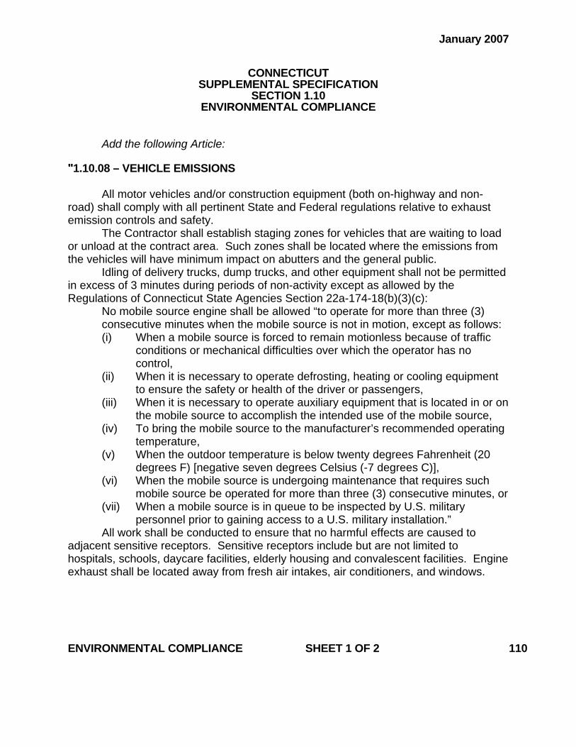
January 2007
CONNECTICUT SUPPLEMENTAL SPECIFICATION
SECTION 1.10 ENVIRONMENTAL COMPLIANCE
Add the following Article: "1.10.08 – VEHICLE EMISSIONS
All motor vehicles and/or construction equipment (both on-highway and non-road) shall comply with all pertinent State and Federal regulations relative to exhaust emission controls and safety.
The Contractor shall establish staging zones for vehicles that are waiting to load or unload at the contract area. Such zones shall be located where the emissions from the vehicles will have minimum impact on abutters and the general public.
Idling of delivery trucks, dump trucks, and other equipment shall not be permitted in excess of 3 minutes during periods of non-activity except as allowed by the Regulations of Connecticut State Agencies Section 22a-174-18(b)(3)(c):
No mobile source engine shall be allowed “to operate for more than three (3) consecutive minutes when the mobile source is not in motion, except as follows: (i) When a mobile source is forced to remain motionless because of traffic
conditions or mechanical difficulties over which the operator has no control,
(ii) When it is necessary to operate defrosting, heating or cooling equipment to ensure the safety or health of the driver or passengers,
(iii) When it is necessary to operate auxiliary equipment that is located in or on the mobile source to accomplish the intended use of the mobile source,
(iv) To bring the mobile source to the manufacturer’s recommended operating temperature,
(v) When the outdoor temperature is below twenty degrees Fahrenheit (20 degrees F) [negative seven degrees Celsius (-7 degrees C)],
(vi) When the mobile source is undergoing maintenance that requires such mobile source be operated for more than three (3) consecutive minutes, or
(vii) When a mobile source is in queue to be inspected by U.S. military personnel prior to gaining access to a U.S. military installation.”
All work shall be conducted to ensure that no harmful effects are caused to adjacent sensitive receptors. Sensitive receptors include but are not limited to hospitals, schools, daycare facilities, elderly housing and convalescent facilities. Engine exhaust shall be located away from fresh air intakes, air conditioners, and windows.
ENVIRONMENTAL COMPLIANCE SHEET 1 OF 2 110
A Vehicle Emissions Mitigation plan will be required for areas where extensive
work will be performed within (less than 50 feet (15 meters)) to sensitive receptors. No work will proceed until a sequence of construction and a Vehicle Emissions Mitigation plan is submitted in writing to the Engineer for review and all comments are addressed in a manner acceptable to the Engineer. The mitigation plan must address the control of vehicle emissions from all vehicles and construction equipment.
Any costs associated with this “Vehicle Emissions” article shall be included in the general cost of the Contract. In addition, there shall be no time granted to the contractor for compliance with this notice. The contractor’s compliance with this notice and any associated regulations shall not be grounds for claims as outlined in Section 1.11 – “Claims.”"
ENVIRONMENTAL COMPLIANCE SHEET 2 OF 2 110
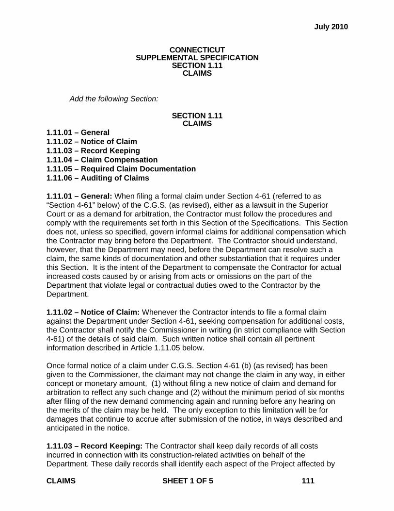
July 2010
CONNECTICUT SUPPLEMENTAL SPECIFICATION
SECTION 1.11 CLAIMS
Add the following Section:
SECTION 1.11 CLAIMS
1.11.01 – General 1.11.02 – Notice of Claim 1.11.03 – Record Keeping 1.11.04 – Claim Compensation 1.11.05 – Required Claim Documentation 1.11.06 – Auditing of Claims 1.11.01 – General: When filing a formal claim under Section 4-61 (referred to as “Section 4-61” below) of the C.G.S. (as revised), either as a lawsuit in the Superior Court or as a demand for arbitration, the Contractor must follow the procedures and comply with the requirements set forth in this Section of the Specifications. This Section does not, unless so specified, govern informal claims for additional compensation which the Contractor may bring before the Department. The Contractor should understand, however, that the Department may need, before the Department can resolve such a claim, the same kinds of documentation and other substantiation that it requires under this Section. It is the intent of the Department to compensate the Contractor for actual increased costs caused by or arising from acts or omissions on the part of the Department that violate legal or contractual duties owed to the Contractor by the Department. 1.11.02 – Notice of Claim: Whenever the Contractor intends to file a formal claim against the Department under Section 4-61, seeking compensation for additional costs, the Contractor shall notify the Commissioner in writing (in strict compliance with Section 4-61) of the details of said claim. Such written notice shall contain all pertinent information described in Article 1.11.05 below. Once formal notice of a claim under C.G.S. Section 4-61 (b) (as revised) has been given to the Commissioner, the claimant may not change the claim in any way, in either concept or monetary amount, (1) without filing a new notice of claim and demand for arbitration to reflect any such change and (2) without the minimum period of six months after filing of the new demand commencing again and running before any hearing on the merits of the claim may be held. The only exception to this limitation will be for damages that continue to accrue after submission of the notice, in ways described and anticipated in the notice. 1.11.03 – Record Keeping: The Contractor shall keep daily records of all costs incurred in connection with its construction-related activities on behalf of the Department. These daily records shall identify each aspect of the Project affected by CLAIMS SHEET 1 OF 5 111
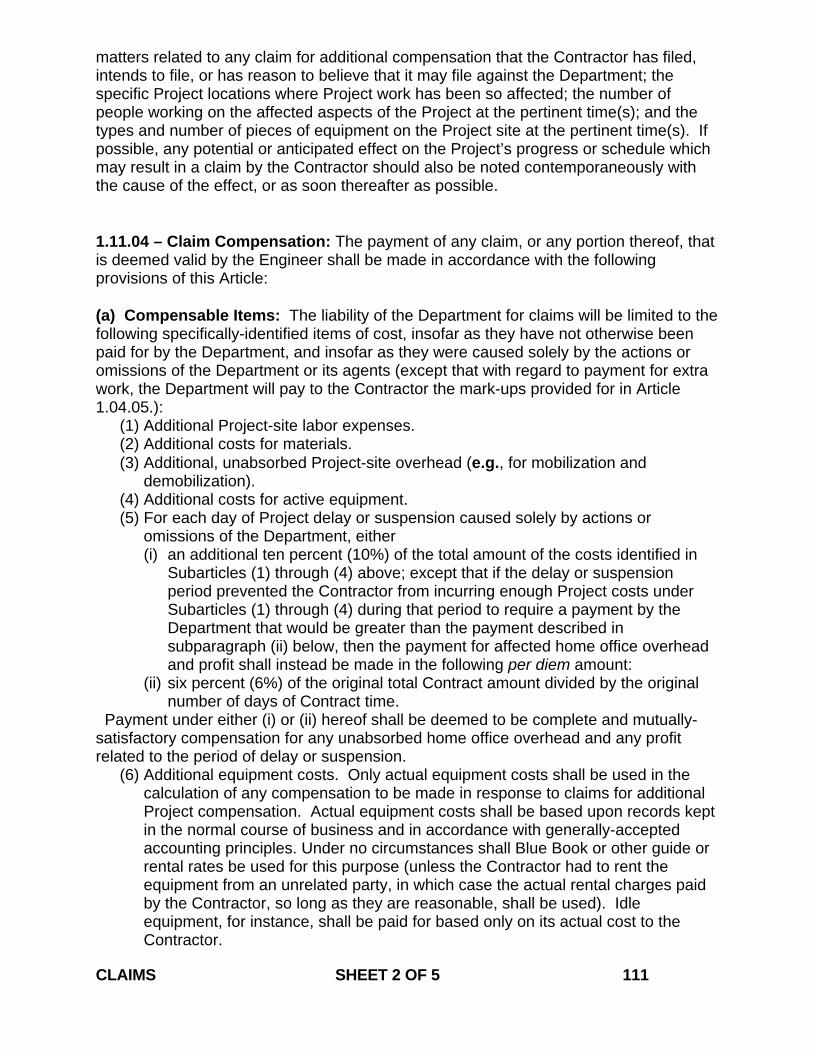
matters related to any claim for additional compensation that the Contractor has filed, intends to file, or has reason to believe that it may file against the Department; the specific Project locations where Project work has been so affected; the number of people working on the affected aspects of the Project at the pertinent time(s); and the types and number of pieces of equipment on the Project site at the pertinent time(s). If possible, any potential or anticipated effect on the Project’s progress or schedule which may result in a claim by the Contractor should also be noted contemporaneously with the cause of the effect, or as soon thereafter as possible. 1.11.04 – Claim Compensation: The payment of any claim, or any portion thereof, that is deemed valid by the Engineer shall be made in accordance with the following provisions of this Article: (a) Compensable Items: The liability of the Department for claims will be limited to the following specifically-identified items of cost, insofar as they have not otherwise been paid for by the Department, and insofar as they were caused solely by the actions or omissions of the Department or its agents (except that with regard to payment for extra work, the Department will pay to the Contractor the mark-ups provided for in Article 1.04.05.):
(1) Additional Project-site labor expenses. (2) Additional costs for materials. (3) Additional, unabsorbed Project-site overhead (e.g., for mobilization and
demobilization). (4) Additional costs for active equipment. (5) For each day of Project delay or suspension caused solely by actions or
omissions of the Department, either (i) an additional ten percent (10%) of the total amount of the costs identified in
Subarticles (1) through (4) above; except that if the delay or suspension period prevented the Contractor from incurring enough Project costs under Subarticles (1) through (4) during that period to require a payment by the Department that would be greater than the payment described in subparagraph (ii) below, then the payment for affected home office overhead and profit shall instead be made in the following per diem amount:
(ii) six percent (6%) of the original total Contract amount divided by the original number of days of Contract time.
Payment under either (i) or (ii) hereof shall be deemed to be complete and mutually-satisfactory compensation for any unabsorbed home office overhead and any profit related to the period of delay or suspension.
(6) Additional equipment costs. Only actual equipment costs shall be used in the calculation of any compensation to be made in response to claims for additional Project compensation. Actual equipment costs shall be based upon records kept in the normal course of business and in accordance with generally-accepted accounting principles. Under no circumstances shall Blue Book or other guide or rental rates be used for this purpose (unless the Contractor had to rent the equipment from an unrelated party, in which case the actual rental charges paid by the Contractor, so long as they are reasonable, shall be used). Idle equipment, for instance, shall be paid for based only on its actual cost to the Contractor.
CLAIMS SHEET 2 OF 5 111
(7) Subcontractor costs limited to, and determined in accordance with, Subarticles (1), (2), (3), (4), and (5) above and applicable statutory and case law. Such subcontractor costs may be paid for by the Department only (a) in the context of an informal claims settlement or (b) if the Contractor has itself paid or legally-assumed, present unconditional liability for those subcontractor costs.
(b) Non-Compensable Items: The Department will have no liability for the following specifically-identified non-compensable items:
(1) Profit, in excess of that provided for herein. (2) Loss of anticipated profit. (3) Loss of bidding opportunities. (4) Reduction of bidding capacity. (5) Home office overhead in excess of that provided for in Article 1.11.04(a)(5)
hereof. (6) Attorneys fees, claims preparation expenses, or other costs of claims
proceedings or resolution. (7) Any other consequential or indirect expenses or costs, such as tort damages, or
any other form of expense or damages not provided for in these Specifications or elsewhere in the Contract.
1.11.05 – Required Claim Documentation: All claims shall be submitted in writing to the Commissioner, and shall be sufficient in detail to enable the Engineer to ascertain the basis and the amount of each claim, and to investigate and evaluate each claim in detail. As a minimum, the Contractor must provide the following information for each and every claim and sub-claim asserted:
(a) A detailed factual statement of the claim, with all dates, locations and items of work pertinent to the claim.
(b) A statement of whether each requested additional amount of compensation or extension of time is based on provisions of the Contract or on an alleged breach of the Contract. Each supporting or breached Contract provision and a statement of the reasons why each such provision supports the claim, must be specifically identified or explained.
(c) Excerpts from manuals or other texts which are standard in the industry, if available, that support the Contractor’s claim.
(d) The details of the circumstances that gave rise to the claim. (e) The date(s) on which any and all events resulting in the claim occurred, and the
date(s) on which conditions resulting in the claim first became evident to the Contractor.
(f) Specific identification of any pertinent document, and detailed description of the substance of any material oral communication, relating to the substance of such claim.
(g) If an extension of time is sought, the specific dates and number of days for which it is sought, and the basis or bases for the extension sought. A critical path method, bar chart, or other type of graphical schedule that supports the extension must be submitted.
(h) When submitting any claim over $50,000, the Contractor shall certify in writing, under oath and in accordance with the formalities required by the contract, as to the following:
(1) That supporting data is accurate and complete to the Contractors best CLAIMS SHEET 3 OF 5 111
knowledge and belief; (2) That the amount of the dispute and the dispute itself accurately reflects what
the Contractor in good faith believes to be the Departments liability; (3) The certification shall be executed by:
a. If the Contractor is an individual, the certification shall be executed by that individual.
b. If the Contractor is not an individual, the certification shall be executed by a senior company official in charge at the Contractor’s plant or location involved or an officer or general partner of the Contractor having overall responsibility for the conduct of the Contractors affairs.
1.11.06 – Auditing of Claims: All claims filed against the Department shall be subject to audit by the Department or its agents at any time following the filing of such claim. The Contractor and its subcontractors and suppliers shall cooperate fully with the Department's auditors. Failure of the Contractor, its subcontractors, or its suppliers to maintain and retain sufficient records to allow the Department or its agents to fully evaluate the claim shall constitute a waiver of any portion of such claim that cannot be verified by specific, adequate, contemporaneous records, and shall bar recovery on any claim or any portion of a claim for which such verification is not produced. Without limiting the foregoing requirements, and as a minimum, the Contractor shall make available to the Department and its agents the following documents in connection with any claim that the Contractor submits:
(1) Daily time sheets and foreman's daily reports. (2) Union agreements, if any. (3) Insurance, welfare, and benefits records. (4) Payroll register. (5) Earnings records. (6) Payroll tax returns. (7) Records of property tax payments. (8) Material invoices, purchase orders, and all material and supply acquisition
contracts. (9) Materials cost distribution worksheets. (10) Equipment records (list of company equipment, rates, etc.). (11) Vendor rental agreements (12) Subcontractor invoices to the Contractor, and the Contractor's certificates of
payments to subcontractors. (13) Subcontractor payment certificates. (14) Canceled checks (payroll and vendors). (15) Job cost reports. (16) Job payroll ledger. (17) General ledger, general journal (if used), and all subsidiary ledgers and
journals, together with all supporting documentation pertinent to entries made in these ledgers and journals.
(18) Cash disbursements journals. (19) Financial statements for all years reflecting the operations on the Project. (20) Income tax returns for all years reflecting the operations on the Project. (21) Depreciation records on all company equipment, whether such records are
maintained by the company involved, its accountant, or others. CLAIMS SHEET 4 OF 5 111
(22) If a source other than depreciation records is used to develop costs for the Contractor's internal purposes in establishing the actual cost of owning and operating equipment, all such other source documents.
(23) All documents which reflect the Contractor's actual profit and overhead during the years that the Project was being performed, and for each of the five years prior to the commencement of the Project.
(24) All documents related to the preparation of the Contractor's bid, including the final calculations on which the bid was based.
(25) All documents which relate to the claim or to any sub-claim, together with all documents that support the amount of damages as to each claim or sub-claim.
(26) Worksheets used to prepare the claim, which indicate the cost components of each item of the claim, including but not limited to the pertinent costs of labor, benefits and insurance, materials, equipment, and subcontractors’ damages, as well as all documents which establish the relevant time periods, individuals involved, and the Project hours and the rates for the individuals.
(27) The name, function, and pertinent activity of each Contractor’s or subcontractor’s official, or employee involved in or knowledgeable about events that give rise to, or facts that relate to, the claim.
(28) The amount(s) of additional compensation sought and a break-down of the amount(s) into the categories specified as payable under Article 1.11.04 above.
(29) The name, function, and pertinent activity of each Department official, employee or agent involved in or knowledgeable about events that give rise to, or facts that relate to, the claim.
CLAIMS SHEET 5 OF 5 111
July 2014
CONNECTICUT SUPPLEMENTAL SPECIFICATION
SECTION 1.20 GENERAL CLAUSES FOR FACILITIES CONSTRUCTION
1.20-1.00 – General: Delete the last sentence of the first paragraph and replace with the following: “Facilities Construction is defined as the type of construction that requires the issuance of a Certificate of Compliance (C.O.C.) by the State Building Inspector or his authorized representative at the completion of a project, and includes site work considered ancillary to this type of construction.” Add the following article: “1.20-1.01.01—Definitions: OWNER: Where used herein, it is synonymous with Department or State.” 1.20-1.02.04 – Examination of Plans, Specifications, Special Provisions and Site of Work: Delete the first sentence of the first paragraph and replace with the following: “CSI-formatted specifications are organized into Divisions and Sections based on the CSI’s “MasterFormat” numbering system.” 1.20-1.02.13 – Knowledge of Applicable Laws: Delete Items 1 through 9 in their entirety and replace with the following: 1. “The 2003 International Building Code with the State Building Code, including
latest Connecticut Supplement and Amendments. 2. The 2003 International Plumbing Code. 3. The 2003 International Mechanical Code. 4. The 2003 International Existing Building Code. 5. The 2009 International Energy Conservation Code. 6. The 2011 NFPA 70 National Electrical Code. 7. The 2003 ICC/ANSI A117.1. 8. The Fire Safety Code, including latest Connecticut Supplement and Amendments. 9. The 2003 International Fire Code. 10. The 2003 NFPA 1 Uniform Fire Code. GENERAL CLAUSES FOR FACILITIES CONSTRUCTION SHEET 1 OF 16 120
11. The 2003 NFPA 101 Life Safety Code.” Add the following as the new last paragraph: “All work to be performed by the Contractor shall comply with the “Americans with Disabilities Act Accessibility Guidelines.”” 1.20-1.03.01 – Consideration of Bids: Delete the entire article and replace with the following: “The apparent low bidder shall submit to the Manager of Contracts a Schedule of Values within 14 days after bid opening. Any other Contractor that the Department may subsequently designate as the apparent lowest bidder shall make the aforesaid submission within 14 days from the date on which the Department notifies said Contractor that it has become the apparent lowest bidder. If, however, the Department deems it necessary for such a subsequently designated Contractor to make said submission within a shorter period of time, the Contractor shall make the submission within the time designated by the Department.
The total in the Schedule of Values shall equal the bid dollar amount for the Major Lump Sum Item (MLSI).
The Schedule of Values shall be divided into “Line Items” listed separately for each CSI Section of the Special Provisions. An additional line item for “Mobilization” shall be incorporated into the Schedule of Values; however, this item may not exceed 7.5% of the value of the MLSI. The “Mobilization” line item will also include costs associated with “General Conditions” and “Insurance/Bonding.” An additional line item for “Project Closeout” shall be incorporated into the Schedule of Values; however, this item must be at least 2.5% of the value of the MLSI. Where requested by the Department, the Contractor shall break down the line items further into more specific line items.
In the event that this Contract is terminated or a portion of this Contract is deleted for any reason or in any way allowable by law under this Contract after the apparent low bidder has been awarded the Contract, the Schedule of Values will not be used for estimating payment due the Contractor for work completed prior to such termination of the Contract or deletion of work thereunder. In the case of Contract termination, payment shall be made in accordance with Article 1.05.14.” 1.20-1.05.02--Shop Drawings, Product Data, Product Samples and Quality Assurance Submittals: Delete the last sentence of the first paragraph and replace with the following: “All facsimiles or other electronic documents from the Contractor shall be followed by an GENERAL CLAUSES FOR FACILITIES CONSTRUCTION SHEET 2 OF 16 120
official transmittal.” Delete the third paragraph and replace with the following: “The Contractor shall number each submittal consecutively: When resubmitting a “Revise and Resubmit” or “Rejected” submittal, the Contractor shall label the transmittal with the original submittal number followed by a letter to designate the additional submission. All submittals shall be numbered conforming to the following examples:” In column B of line 001, line 001a, and line 001b of the table in subsection 1, replace “07511” with “075110.” Add the following to the end of the first paragraph of subsection 2: “The Department reserves the right to return partial submittals unreviewed to the Contractor.” Revise the third paragraph of subsection 2 to read: “The Contractor shall allow at least 60 calendar days for review of any submittal requiring approval by FAA, FTA, any railroad, DEEP, U.S. Coast Guard, Army Corps of Engineers, or any other outside agency.” Delete the third and fourth paragraphs of subsection 3 and replace with the following: “The Designer will not review submittals and the Engineer will not process payment estimates until the initial submittal schedule has been provided. Any delays in construction due to the Contractor's failure to provide a submittal schedule shall be the responsibility of the Contractor. The Contractor must update its submittal schedule at least once a month, and distribute and post each updated schedule in the manner described above. The Engineer reserves the right not to process payment estimates without a recently updated submittal schedule on file.” Replace the first sentence of the first paragraph of subsection 4 with the following: “Shop Drawings consist of fabrication and installation drawings, roughing-in and setting drawings, schedules, patterns, templates and similar drawings, and wiring diagrams showing field-installed wiring, including power, signal, and control wiring.” Replace the second paragraph of subsection 4 with the following: “Shop drawings shall include the following information: Contract number, Project GENERAL CLAUSES FOR FACILITIES CONSTRUCTION SHEET 3 OF 16 120
description, number and title of the drawing, date of drawing, revision number, name of Contractor and subcontractor submitting drawings, dimensions, identification of products, shopwork manufacturing instructions, design calculations, statement of compliance with Contractual standards, notation of dimensions established by field measurement, relationship to adjoining construction clearly indicated, seal and signature of a professional engineer if specified, and any other information required by individual Contract provisions.” Replace the first sentence of the first paragraph of subsection 5 with the following: “Product data consist of printed information such as manufacturer’s product specifications, manufacturer’s installation instructions, manufacturer’s catalog cuts, standard color charts, wiring diagrams showing factory-installed wiring, printed performance curves, operational range diagrams, and mill reports.” Replace the first sentence of the first paragraph of subsection 7 with the following: “Quality assurance submittals consist of qualification data, design data, certifications, manufacturer’s instructions, manufacturer’s field reports, test reports, Material Safety Data Sheets (MSDSs), and other quality assurance information required by individual Contract provisions.” 1.20-1.05.04—Coordination of Special Provisions, Plans, Supplemental Specifications and Standard Specifications and Other Contract Requirements: Delete the first and second paragraphs and replace with the following: “Industry Standards: Each entity engaged in construction of the Contract shall be familiar with industry standards applicable to that entity's construction activities. If printed standards have been established by organizations referenced in Article 1.01.02 or in the Contract, the Contractor shall obtain copies of said standards directly from the publication source. Unless the Special Provisions include more stringent requirements, applicable construction industry standards have the same force and effect as if bound or copied directly into the Special Provisions to the extent referenced. Such standards are made a part of the Contract by reference.” Add the following article: 1.20-1.05.08—Schedules and Reports: Daily Construction Reports: The Contractor shall assist the Engineer in the preparation of a daily construction report, by ensuring that each of the Contractor’s GENERAL CLAUSES FOR FACILITIES CONSTRUCTION SHEET 4 OF 16 120

employees and subcontractors working on the Project site on a given day signs the Engineer’s sign-in sheet for that day; and by keeping and providing to the Engineer its own daily list of employees and subcontractors who worked on the Project site on that day. Add the following article: 1.20-1.05.23—Requests for Information (RFIs): The Contractor shall forward all RFIs to the Engineer in writing (facsimile or other electronic document) for review. The Engineer will forward the RFI to the Designer for review. Upon receipt of an RFI, the Designer will attempt to determine if additional information is required from the Contractor to respond to the RFI, and request said information from the Engineer. All other RFIs will be responded to within 10 calendar days of receipt by the Designer. 1.20-1.05.24—Project Meetings: Delete the third paragraph under subsection 1. Delete the second paragraph under subsection 2 and replace with the following: “The meeting participants shall review progress of other construction activities and preparations for the particular activity under consideration, including requirements of Contract documents, related requests for interpretations, related construction orders, purchases, deliveries, submittals, review of mockups, possible conflicts, compatibility problems, time schedules, weather limitations, manufacturer’s written recommenda-tions, warranty requirements, compatibility of materials, acceptability of substrates, temporary facilities and controls, space and access limitations, regulations of authorities having jurisdiction, testing and inspecting requirements, installation procedures coordination with other work, required performance results, protection of adjacent work, and protection of construction and personnel.” Delete the second, third and fourth paragraph under subsection 3 and replace with the following: “The Contractor shall provide the Engineer with a detailed agenda for the proposed meeting, specifying what topics will be covered. In addition to representatives of the Engineer, each subcontractor, supplier or other entity concerned with current progress or involved in planning, coordination or performance of future activities shall attend these meetings. All participants at the meeting shall be familiar with the Project and authorized to conclude matters relating to the Project. At each progress meeting, the participants shall (1) review items of significance that could affect progress; (2) discuss topics appropriate to the current status of the Project; GENERAL CLAUSES FOR FACILITIES CONSTRUCTION SHEET 5 OF 16 120
(3) review progress since the last meeting; (4) determine whether each activity is on time, ahead of schedule, or behind schedule, in relation to the Contractor's Construction Schedule; (5) determine how to expedite any Project work that may be behind schedule; (6) discuss whether or not schedule revisions are required to ensure that current and subsequent activities will be completed within the Contract time; and (7) review the present and future needs of each entity represented at the meeting, including such items as interface requirements, time, sequences, deliveries, off-site fabrication problems, access, site utilization, temporary facilities and controls, hours of work, hazards and risks, housekeeping, quality and work standards, status of correction of deficient items, field observations, requests for interpretations, status of proposal requests, pending changes, status of construction orders, and documentation of information for payment requests. The Engineer will distribute copies of minutes of the meeting to the Designer and the Contractor. The Contractor shall distribute copies to parties who were or should have been at the meeting.” Delete article 1.20-1.05.25—Schedules and Reports in its entirety 1.20-1.06.08—Warranties: Delete the eighth and ninth paragraph and replace with the following: “The Contractor shall: (a) Bind warranties in heavy-duty, commercial-quality, durable 3-ring vinyl-covered loose-leaf binders, thick enough to accommodate the contents, and sized to receive 8 1/2-inch x 11-inch paper (216-millimeter x 279-millimeter) paper. (b) Identify the binder’s contents on the binder’s front and spine with the typed or printed title “WARRANTIES,” the Project title or name, and the name of the Contractor. (c) Provide a heavy paper divider with a tab for each separate warranty. (d) Mark the tab to identify the related product or installation. (e) Provide a typed description of the product or installation, including the name of the product, and the name, address and telephone number of the Contractor or pertinent subcontractor. (f) Furnish to the Department a written warranty for all Project work accompanied by a cover letter with the following contents: [Addressed to:] Commissioner of Transportation Department of Transportation P.O. Box 317546 Newington, Connecticut 06131-7546 Project Title and Number [We] hereby warrant all materials and workmanship for all work performed under this Contract for a period of one (1) year from [date of issuance of C.O.C.] against failures of GENERAL CLAUSES FOR FACILITIES CONSTRUCTION SHEET 6 OF 16 120
workmanship and materials in accordance with the Contract. Furthermore, as a condition of this warranty, [we] agree to have in place all insurance coverage identified in the Contract for the performance of any warranty work. [Signature:] [Name of authorized signatory] [Title] (g) Submit to the Engineer, upon completion of installation of materials or assemblies that are required to have either a flame-rating or a fire-endurance hourly rating, a detailed letter certifying that the required rating has been attained. Upon determination by the Engineer that Project work covered by a warranty has failed, the Contractor shall replace or rebuild the work to an acceptable condition complying with Contract requirements. The Contractor is responsible for the cost of replacing or rebuilding defective construction or components and those which may have needed to be damaged or removed in order to cure the defective work including costs of material, equipment, labor, and material disposal, regardless of whether or not the State has benefited from use of the work through a portion of its anticipated useful service life. The Contractor shall respond to the Project Site when Project work covered by a warranty has failed within 3 calendar days, unless in the Engineer’s opinion said failure is deemed to be an emergency, in which case the Contractor shall respond to the Project Site as directed by the Engineer.” 1.20-1.08.03—Prosecution of Work: Under subsection ‘3. Cutting and Patching,’ delete the heading ‘B. Protection of Structural Elements’ and replace with the following: “B. Protection:” Move the existing first and second paragraphs to under the following subparagraph: “1. Structural Elements:” Add the following after the first paragraph under B: “2. Operational Elements: The Contractor shall not cut and patch operating elements and related components in a manner that results in their reducing their capacity to perform as intended or that results in increased maintenance or decreased operational life or safety. 3. Miscellaneous Elements: The Contractor shall not cut and patch miscellaneous elements or related components in a manner that could change their load-carrying capacity, that results reducing their capacity to perform as intended, or that results in increased maintenance or decreased operational life or safety.” GENERAL CLAUSES FOR FACILITIES CONSTRUCTION SHEET 7 OF 16 120
Add the following after subsection 3: “4. Selective Demolition: A. Definitions: Remove: The Contractor shall detach materials from existing construction and legally dispose or recycle them off-site, unless indicated to be removed and salvaged or removed and reinstalled. Except for materials indicated to be reused, salvaged, reinstalled, or otherwise indicated to remain Engineer's property, demolished materials shall become Contractor's property and shall be removed from the Project Site. Remove and Salvage: The Contractor shall detach materials from existing construction and deliver them to Engineer. The Engineer reserves the right to identify other materials for salvage during the course of demolition. Remove and Reinstall: The Contractor shall detach materials from existing construction, prepare them for reuse, and reinstall them where indicated. Existing to Remain: Existing materials of construction that are not to be removed and that are not otherwise indicated to be removed, removed and salvaged, or removed and reinstalled. B. Approval Process: The Contractor shall submit pre-demolition photographs to the Engineer prior to the commencement of Project work to show existing conditions of adjoining construction and site improvements, including finish surfaces, that might be misconstrued as damage caused by selective demolition operations. Well in advance of performing any selective demolition on the Project, the Contractor shall submit to the Engineer a proposal describing the procedures that the Contractor intends to use for same. The Contractor shall include the following information, as applicable, in its proposal: (1) detailed sequence of selective demolition and removal work with starting and ending dates for each activity while ensuring that the Engineer's on-site operations are not disrupted; (2) interruption of utility services; (3) coordination for shutoff, capping, and continuation of utility services; (4) use of elevators and stairs; (5) locations of temporary partitions and means of egress; (6) coordination of Engineer's continuing occupancy of portions of existing building and of Engineer's partial occupancy of completed Project work; and (7) means of protection for items to remain and items in path of waste removal from building. GENERAL CLAUSES FOR FACILITIES CONSTRUCTION SHEET 8 OF 16 120
The Contractor shall comply with (1) governing EPA notification regulations before beginning selective demolition; (2) hauling and disposal regulations of authorities having jurisdiction; (3) ANSI A10.6; and (4) NFPA 241. The Engineer will conduct a Pre-Demolition Meeting at the Project site in accordance with Article 1.20-1.05.24. Said meeting will review the methods and procedures related to selective demolition including, but not limited to, the following: (1) an inspection and discussion of the condition of construction to be selectively demolished; (2) a review of the structural load limitations of the existing structure; (3) a review and finalization of the selective demolition schedule and a verification of the availability of materials, demolition personnel, equipment, and facilities needed to make progress and avoid delays; (4) a review of requirements of Project work performed by other trades that rely on substrates exposed by selective demolition operations; and (5) a review of areas where existing construction is to remain and requires protection. C. Repair Materials: The Contractor shall comply with Article 1.20-1.08.03 subsection 3E for repair materials and shall comply with material and installation requirements specified in other Contract provisions. D. Examination: The Contractor shall (1) verify that utilities have been disconnected and capped; (2) survey existing conditions and correlate with requirements indicated to determine extent of selective demolition required; (3) inventory and record the condition of items to be removed and reinstalled and items to be removed and salvaged; (4) investigate and measure the nature and extent of unanticipated mechanical, electrical, or structural elements that conflict with intended function or design and submit a written report to Engineer; and (5) perform surveys as the Project work progresses to detect hazards resulting from selective demolition activities. E. Utility Services: The Contractor shall (1) maintain existing utility services indicated to remain and protect them against damage during selective demolition operations; (2) not interrupt existing utilities serving occupied or operating facilities unless authorized in writing by the Engineer; (3) provide temporary services during interruptions to existing utilities, as acceptable to Engineer; (4) provide at least 3 calendar days’ notice to the Engineer if shutdown of service is required during changeover; and (5) locate, identify, disconnect, and seal or cap off indicated utilities serving areas to be selectively demolished. The Contractor shall arrange to shut off indicated utilities with utility companies. If utility services are required to be removed, relocated, or abandoned, before proceeding with selective demolition the Contractor shall provide temporary utilities that bypass area of selective demolition and that maintain continuity of service to other parts of building. GENERAL CLAUSES FOR FACILITIES CONSTRUCTION SHEET 9 OF 16 120
The Contractor shall cut off pipe or conduit in walls or partitions to be removed and shall cap, valve, or plug and seal remaining portion of pipe or conduit after bypassing. The Contractor shall refer to other Contract provisions for shutting off, disconnecting, removing, and sealing or capping utilities. The Contractor shall not start selective demolition work until utility disconnecting and sealing have been completed and verified by the Engineer in writing. F. Preparation: The Contractor shall conduct selective demolition and debris-removal operations to ensure minimum interference with adjacent occupied and used facilities on the Project site. The Contractor shall not disrupt the Owner’s operations without the Engineer’s permission. The Contractor shall protect existing site improvements, appurtenances, and landscaping to remain. The Contractor shall provide temporary barricades and other protection required to prevent injury to people and damage to adjacent buildings and facilities to remain. The Contractor shall provide temporary weather protection, during interval between selective demolition of existing construction on exterior surfaces and new construction, to prevent water leakage and damage to structure and interior areas. The Contractor shall protect walls, ceilings, floors, and other existing finish work that are to remain or that are exposed during selective demolition operations. The Contractor shall cover and protect furniture, furnishings, and equipment that have not been removed. The Contractor shall provide temporary enclosures for protection of existing building and construction, in progress and completed, from exposure, foul weather, other construction operations, and similar activities. The Contractor shall provide temporary weathertight enclosure for building exterior. Where heating is needed and permanent enclosure is not complete, the Contractor shall provide insulated temporary enclosures and shall coordinate enclosure with ventilating and material drying or curing requirements to avoid dangerous conditions and effects. The Contractor shall erect and maintain dustproof partitions and temporary enclosures to limit dust and dirt migration and to separate areas from fumes and noise. The Contractor shall provide and maintain interior and exterior shoring, bracing, or structural support to preserve stability and prevent movement, settlement, or collapse of construction to remain, and to prevent unexpected or uncontrolled movement or collapse of construction being demolished. The Contractor shall strengthen or add new supports when required during progress of selective demolition. G. Pollution Controls: The Contractor shall comply with governing regulations pertaining to environmental protection. GENERAL CLAUSES FOR FACILITIES CONSTRUCTION SHEET 10 OF 16 120
The Contractor shall not use water when it may create a hazardous or objectionable condition such as ice, flooding, or pollution. The Contractor shall remove and transport debris in a manner that will prevent spillage on adjacent surfaces and areas. The Contractor shall remove debris from elevated portions of building by chute, hoist, or other device that will convey debris to grade level in a controlled descent. The Contractor shall clean adjacent structures and improvements of dust, dirt, and debris caused by selective demolition operations. The Contractor shall return adjacent areas to condition existing before selective demolition operations began. H. Performance: The Contractor shall not use explosives for demolition purposes. The Contractor shall demolish and remove existing construction only to the extent required by new construction and as indicated. The Contractor shall (1) proceed with selective demolition systematically; (2) neatly cut openings and holes plumb, square, and true to dimensions required; (3) use cutting methods least likely to damage remaining or adjoining construction; (4) use hand tools or small power tools designed for sawing or grinding, not hammering and chopping, to minimize disturbance of adjacent surfaces; (5) temporarily cover openings to remain; (6) cut or drill from the exposed or finished side into concealed surfaces to avoid marring existing finished surfaces; (7) not use cutting torches until work area is cleared of flammable materials; (8) verify condition and contents of concealed spaces such as duct and pipe interiors before starting flame-cutting operations; (9) maintain fire watch and portable fire-suppression devices during flame-cutting operations; (10) maintain adequate ventilation when using cutting torches; (11) remove decayed, vermin-infested, or otherwise dangerous or unsuitable materials and promptly dispose of off-site; (12) remove structural framing members and lower to ground by method suitable to avoid free fall and to prevent ground impact or dust generation; (13) locate selective demolition equipment and remove debris and materials so as not to impose excessive loads on supporting walls, floors, or framing; and (14) dispose of demolished items and materials promptly. The Contractor shall comply with the Engineer's requirements for using and protecting walkways, building entries, and other building facilities during selective demolition operations. The Contractor shall demolish and remove foundations and other below-grade structures completely unless otherwise indicated on the plans. The Contractor shall fill below-grade areas and voids resulting from demolition of structures with granular fill materials. Prior to placement of fill materials, the Contractor shall ensure that the areas GENERAL CLAUSES FOR FACILITIES CONSTRUCTION SHEET 11 OF 16 120
to be filled are free of standing water, frost, frozen material, trash, and debris. After fill placement and compaction, grade surface to meet adjacent contours and provide flow to surface drainage structures. Backfilling and grading related to demolition is included in the Major Lump Sum Item (MLSI) for the Project. There will be no separate payment for this backfilling and grading. The Contractor shall (1) demolish concrete in sections; (2) cut concrete at junctures with construction to remain to the depth shown on the Contract plans and at regular intervals using power-driven saw; and (3) remove concrete between saw cuts. The Contractor shall (1) demolish masonry in small sections; (2) cut masonry at junctures with construction to remain using power-driven saw; and (3) remove masonry between saw cuts. The Contractor shall (1) saw-cut perimeter of concrete slabs-on-grade to be demolished as shown on the Contract plans; and (2) break up and remove concrete slabs-on-grade. The Contractor shall (1) remove floor coverings and adhesive according to recommendations in RFCI-WP and its Addendum; and (2) remove residual adhesive and prepare substrate for new floor coverings by one of the methods recommended by RFCI. The Contractor shall (1) only remove existing roofing in one day to the extent that it can be covered by new roofing; and (2) refer to other Contract provisions for new roofing requirements. The Contractor shall remove air conditioning equipment without releasing refrigerants. I. Reuse of Building Elements: The Contractor shall not demolish building elements beyond what is indicated on the plans without the Engineer’s approval. J. Removed and Salvaged Materials: Unless otherwise directed by the Engineer, the Contractor shall (1) store materials in a secure area until delivery to the owner; (2) transport materials to the owner’s storage area off-site; and (3) protect materials from damage during transport and storage. K. Removed and Reinstalled Materials: Unless otherwise directed by the Engineer, the Contractor shall (1) clean and repair materials to functional condition adequate for intended reuse; (2) paint equipment to match the color of new equipment; (3) protect materials from damage during transport and storage; and (4) reinstall items in locations indicated complying with installation GENERAL CLAUSES FOR FACILITIES CONSTRUCTION SHEET 12 OF 16 120
requirements for new materials and equipment and providing connections, supports, and miscellaneous materials necessary to make item functional for use indicated. L. Existing Materials to Remain: The Contractor shall protect construction indicated to remain against damage and soiling during selective demolition. The Contractor shall drain piping and cap or plug piping with the same or a compatible piping material for piping to be abandoned in place. The Contractor shall cap or plug ducts with the same or a compatible ductwork material for ducts to be abandoned in place. The Contractor shall cut and remove concealed conduits and wiring to be abandoned in place 2-inches (50-mm) below the surface of the adjacent construction, cap the conduit end, and patch the surface to match the existing finish. The Contractor shall cut existing conduits installed in concrete slabs to be abandoned in place flush with the top of the slab and fill conduit end with a minimum of 4-inches (100-mm) of concrete. M. Patching and Repairing: The Contractor shall comply with Article 1.20-1.08.03 subsection 3H for patching and repairing damage to adjacent construction caused by selective demolition operations. N. Disposal of Demolished Materials: The Contractor shall (1) not allow demolished materials to accumulate or be sold on the Project Site; (2) not burn demolished materials on the Project Site; and (3) promptly and legally dispose or recycle demolished materials off the Project Site.” 1.20-1.08.05—Personnel and Equipment: Replace “FM with “FMG” in subsection (a) Add the following article: “1.20-1.08.12—Semi-Final and Final Inspections: 1. Semi-Final Inspection: Before requesting the Semi-Final Inspection, the Con-tractor shall show 100% completion for all Project work claimed as complete. The Contractor shall submit final test/adjust/balance records including the final air and water balance report. For all incomplete Project work, the Contractor shall prepare its own “Punch List” of the incomplete items and reasons the work is not complete. The Contractor shall submit final test/adjust/balance records including the final air and water balance report. GENERAL CLAUSES FOR FACILITIES CONSTRUCTION SHEET 13 OF 16 120
On receipt of a Contractor request for inspection, the Engineer will proceed with inspection or notify the Contractor of unfulfilled requirements. The Engineer will prepare a “Punch List” of unfilled, substandard, or incomplete items. During this inspection, the Contractor shall have all technicians necessary to demonstrate the complete operation of all systems on-site. Examples of such systems include, but are not limited to, the following: boiler, HVAC, fire alarm, and building automation. The Engineer will advise the Contractor of the construction that must be completed or corrected before the issuance of the C.O.C. Results of the completed inspection will form the basis of requirements for the Final Inspection. The Engineer reserves the right to issue the C.O.C. after the Semi-Final Inspection if there are no Building Code or Fire Code compliance issues or any major “Punch List” items. 2. Final Inspection: Before requesting Final Inspection for issuance of the C.O.C., the Contractor shall: (1) submit specific warranties, maintenance service agreements, final certifications and similar documents; (2) submit Record Drawings, Record Specifications, operations and maintenance manuals, final project photographs, property surveys, and similar final record information; (3) deliver spare parts; (4) make final changeover of permanent locks and deliver the keys to the Engineer; (5) complete start-up testing of systems; (6) train the owner's operation and maintenance personnel; (7) discontinue or change over and remove temporary facilities from the Project Site, along with construction tools, mock-ups, and similar elements; (8) complete final cleaning requirements, including touch-up painting; (9) touch-up and otherwise repair and restore marred exposed finishes to eliminate visual defects; (10) submit a certified copy of the Engineer's “Punch List” of items to be completed or corrected, stating that each item has been completed or otherwise resolved for acceptance, and the list has been endorsed and dated by the Engineer; (11) submit final meter readings for utilities, a measured record of stored fuel, and similar data as of the date of Final Inspection, or when the Engineer took possession of and responsibility for corresponding elements of the Project work; and (12) install permanent electrical service. The Contractor shall install permanent electrical service prior to Semi-Final Inspection if requested by the Engineer, or if necessary for the Engineer or Contractor to perform testing of building and other related systems and equipment to certify acceptance and completion of Project work. The Contractor shall submit all outstanding items or unacceptable submissions from the Semi-Final Inspection, or other outstanding items required for submittal, prior to the Final Inspection. On receipt of a Contractor request for inspection, the Engineer will proceed with inspection and notify the Contractor of unfulfilled requirements.” 1.20-1.08.13—Termination of the Contractor’s Responsibility: Add subsection 3 as follows: “3. Insurance Coverage: The Contractor shall have in place all insurance coverage identified in Article 1.03.07 for the performance of any warranty work.” GENERAL CLAUSES FOR FACILITIES CONSTRUCTION SHEET 14 OF 16 120
1.20-1.08.14—Acceptance of Project: Add the following to subsection 2 under the heading “Equipment and Systems Maintenance Manual:” “(j) Copies of maintenance agreements with service agent name and telephone number.” Add the following paragraph in subsection 3 after the second paragraph: “The Contractor shall provide a syllabus prior to the training to ensure that the appropriate owner’s operation and maintenance personnel are in attendance.” Delete the last paragraph and replace with the following: “ The Contractor shall submit to the Engineer for approval, a qualified commercial videographer to videotape the training sessions. The videographer shall be a firm or an individual of established reputation that has been regularly engaged as a professional videographer for not less than 3 years. The Contractor shall video record each training session and provide said video in DVD format to the Engineer for the owner’s future use.” Add the following section: “1.20-1.09.06—Partial Payments: With each payment request under the MLSI, the Contractor shall submit AIA Form G702 (Application and Certificate of Payment) and Form G703 (Continuation Sheet). The Contractor is not required to obtain the Architect’s signature on Form G702. Once approved by the Engineer, the Forms G702 and G703 become the basis of payment under the MLSI.” Add the following section: “1.20-9.75.04—Method of Measurement: Mobilization as defined in Article 1.20-1.03.01 will be paid in the manner described hereinafter; however, the determination of the total contract price earned shall not include the amount of mobilization earned during the period covered by the current monthly estimate – but shall include amounts previously earned and certified for payment: 1. When the first payment estimate is made, 25 percent of the “Mobilization” line item will be certified for payment. GENERAL CLAUSES FOR FACILITIES CONSTRUCTION SHEET 15 OF 16 120
2. When the Baseline Schedule, as specified under Section 1.05.08, is accepted, 50 percent of the “Mobilization” line item, minus any previous payments, will be certified for payment. 3. When 10 percent of the total original contract price is earned and the Baseline Schedule, as specified under Section 1.05.08, is accepted, 75 percent of the “Mobilization” line item, minus any previous payments, will be certified for payment. 4. When 30 percent of the total original contract price is earned and the Baseline Schedule, as specified under Section 1.05.08, is accepted, 100 percent of the “Mobilization” line item, minus any previous payments, will be certified for payment. Project Closeout as defined in Article 1.20-1.03.01 shall include demobilization of plant and equipment, completion of all physical work, and administrative closeout items necessary to satisfy all Contract requirements. Project Closeout will be paid in the manner described hereinafter: 1. When the non-administrative project completion requirements (as specified under Article 1.08.13) and the administrative completion requirements (as specified under Article 1.08.14) have been satisfied, 100 percent of the “Project Closeout” line item will be certified for payment.” GENERAL CLAUSES FOR FACILITIES CONSTRUCTION SHEET 16 OF 16 120
January 2010
CONNECTICUT SUPPLEMENTAL SPECIFICATION
SECTION 2.02 ROADWAY EXCAVATION, FORMATION OF
EMBANKMENT AND DISPOSAL OF SURPLUS MATERIAL
2.02.01 – Description: In the first sentence, insert “, swales” between “channels” and “and other miscellaneous construction to the ...” 2.02.04 – Method of Measurement: In the second to last Paragraph, replace the last sentence with the following: “Bituminous parking areas are considered as bituminous concrete pavement.”
ROADWAY EXCAVATION, FORMATION OF EMBANKMENT AND DISPOSAL OF SURPLUS MATERIAL SHEET 1 OF 1 202

January 2010
CONNECTICUT SUPPLEMENTAL SPECIFICATION
SECTION 2.05 TRENCH EXCAVATION
2.05.01--Description: In Paragraph 2, delete the only sentence and replace with the following: 2) The removal of stormwater drainage structures, stormwater pipes and appurtenances beyond the limits of the roadway and structure excavation. In Sub article 2, Rock in Trench, delete the only sentence and replace with the following: (2) Rock, insofar as it applies to trench excavation, shall be defined as rock in definite ledge formation, boulders, or portions of boulders, cement masonry structures, concrete structures, reinforced concrete pipe, Portland cement concrete pavement or base, of 1/2 cubic yard (0.5 cubic meters) or more in volume, removed as indicated or directed from within the payment lines for trench excavation. 2.05.05 -Basis of Payment In Paragraph 13, delete the entire sentence “There will be no direct payment for the plugging of existing pipes....." and replace with the following: " There will be no direct Payment for the plugging of existing pipes, removal and disposal of metal or plastic pipes or for the breaking up of floors in drainage structures being abandoned. The cost shall be included in the contract unit prices of the drainage and excavation items."
TRENCH EXCAVATION SHEET 1 OF 1 205
July 2013
CONNECTICUT SUPPLEMENTAL SPECIFICATION
SECTION 2.12 SUBBASE
2.12.02 – Materials:
Delete the second sentence:
“Grading ‘B’ shall be used.”
SUBBASE SHEET 1 OF 1 212
July 2014
CONNECTICUT SUPPLEMENTAL SPECIFICATION
SECTION 2.16 PERVIOUS STRUCTURE BACKFILL
2.16.01 - Description: Add the following sentence after the only sentence: “This item shall also consist of furnishing and placing crushed stone or gravel in permeable material bags at the inlet ends of weep holes in structures to the dimensions indicated on the plans or as ordered by the Engineer.” 2.16.02 – Materials: Add the following paragraph after the only sentence: “ The materials for bagged stone shall conform to the following requirements:
1. The crushed stone or gravel shall conform to the grading requirements of Article M.01.01 for No. 3 or No. 4 coarse aggregate or a mixture of both.
2. The bag shall be of permeable material sized to contain 1 c.f. (0.03 cu.m) of loosely packed granular material.”
2.16.03 - Construction Methods: Add the following paragraph at the end of the section: “ Where weep holes are installed, bagged stone shall be placed around the inlet end of each weep hole, to prevent movement of the pervious material into the weep hole. Approximately 1 c.f. (0.03 cu.m) of crushed stone or gravel shall be enclosed in each of the permeable material bags. All bags shall then be securely tied at the neck with cord or wire so that the enclosed material is contained loosely. The filled bags shall be stacked at the weep holes to the dimensions shown on the plans or as directed by the Engineer. The bags shall be unbroken at the time pervious material is placed around them, and bags which are broken or burst prior to or during the placing of the pervious material shall be replaced at the Contractor’s expense.” 2.16.04 - Method of Measurement: Add the following paragraph after the only paragraph: “ There will be no direct payment for bagged stone, but the cost thereof shall be included in the cost of the work for “Pervious Structure Backfill.”” PERVIOUS STRUCTURE BACKFILL SHEET 1 OF 1 216
July 2005
CONNECTICUT SUPPLEMENTAL SPECIFICATION
SECTION 3.04 PROCESSED AGGREGATE BASE
Delete the entire Section and replace with the following: 3.04.01--Description: The base shall consist of a foundation constructed on the prepared subbase or subgrade in accordance with these specifications and in conformity with the lines, grades, compacted thickness and typical cross-section as shown on the plans. 3.04.02--Materials: All materials for this work shall conform to the requirements of Article M.05.01. 3.04.03--Construction Methods: Only one type of coarse aggregate shall be used on a project unless otherwise permitted by the Engineer.
Prior to placing the processed aggregate base, the prepared subbase or subgrade shall be maintained true to line and grade, for a minimum distance of 200 feet (60 meters) in advance of the work. None of the aggregate courses shall be placed more than 500 feet (150 meters) ahead of the compaction and binding operation on that particular course.
The processed aggregate base shall be spread uniformly by a method approved by the Engineer. The thickness of each course shall not be more than 4 inches (100 millimeters) after compaction, unless otherwise ordered.
After the aggregate is spread, it shall be thoroughly compacted and bound by use of equipment specifically manufactured for that purpose. Rollers shall deliver a ground pressure of not less than 300 pounds per lineal inch (52.5 newtons/millimeter) of contact width and shall have a weight (mass) not less than 10 tons (9100 kilograms). Vibratory units shall have a static weight (mass) of not less than 4 tons (3650 kilograms). Water may be used during the compaction and binding operation and shall be applied from an approved watering device. The compacting and binding operation shall begin at the outside edges, overlapping the shoulders for a distance of not less than 6 inches (150 millimeters) and progress towards the middle, parallel with the centerline of the pavement. The work shall cover the entire surface of the course with uniform overlapping of each preceding track or pass. Areas of super-elevation and special cross slope shall be compacted by beginning at the lowest edge and proceeding towards the higher edge, unless otherwise directed by the Engineer. The compacting and binding operation shall be continued until the voids in the aggregates have been reduced to provide a firm and uniform surface satisfactory to the Engineer. The amount of compactive effort shall in no case shall be less than four (4) complete passes of the compacting and binding operations. All aggregate shall be completely compacted and bound at the end of each day’s work or when traffic is to be permitted to operate on the
PROCESSED AGGREGATE BASE SHEET 1 OF 2 304
road. The dry density of each layer of processed aggregate base after compaction shall not be less than 95 percent of the dry density for that material when tested in accordance with AASHTO T180, Method D.
Should the subbase or subgrade material become churned up or mixed with the
processed aggregate base at any time, the Contractor shall, without additional compensation remove the mixture. The Contractor shall add new subbase material, if required, and reshape and recompact the subbase in accordance with the requirements of Article 2.12.03. New aggregate material shall be added, compacted and bound, as hereinbefore specified, to match the surrounding surface.
Any surface irregularities which develop during, or after work on each course, shall be corrected by loosening material already in place and removing or adding aggregate as required. The entire area, including the surrounding surface, shall be re-compacted and rebound until it is brought to a firm and uniform surface satisfactory to the Engineer.
3.04.04--Method of Measurement: Processed Aggregate Base will be measured horizontally in place after final grading and compaction. Materials placed beyond the horizontal limits indicated on the plans will not be measured for payment.
The total thickness shall be as indicated on the plans, or as ordered by the Engineer and within a tolerance of minus three-fourths of an inch (-3/4”) to plus one-half inch (+ 1/2”) (-19 millimeters to +13 millimeters).
Measurements to determine the thickness will be taken by the Engineer at
intervals of 500 feet (150 meters) or less, along lanes, and shall be considered representative of the lane. For the purpose of these measurements, a shoulder will be considered a lane.
If a thickness measurement is taken and found deficient, the Engineer will take
such additional measurements as he considers necessary to determine the longitudinal limits of the deficiency. Areas not within allowable tolerances shall be corrected, as ordered by the Engineer, without additional compensation to the Contractor. 3.04.05--Basis of Payment: This work will be paid for at the contract unit price per cubic yard for “Processed Aggregate Base”, complete in place, which price shall include all materials, tools, equipment and work incidental thereto. Pay Item Pay Unit Processed Aggregate Base c.y. (cu. m)
PROCESSED AGGREGATE BASE SHEET 2 OF 2 304
January 2014
CONNECTICUT SUPPLEMENTAL SPECIFICATION
SECTION 4.01 CONCRETE PAVEMENT
4.01.03-A. Composition: Change the beginning of the first sentence as follows: “The composition of the concrete shall be in accordance with the requirements of Section M.03 - Portland Cement Concrete, as well as the applicable ...” Add the following new paragraph before the last paragraph: “The temperature of the concrete at the time of placement shall not be less than 60˚ F (15.5˚ C) or greater than 90˚ F (32˚ C). For pumped concrete, the temperature shall be determined at the placement end of the pump line. The temperature of the concrete shall be determined in accordance with ASTM C1064.” 4.01.03-E. Hauling Units: 1. Truck mixers and truck agitators: Change the end of the only sentence as follows: “... the requirements of Subarticle 6.01.03-3, ‘Transportation and Delivery of Concrete.’” 4.01.03-F. Placing Concrete: 6. Joints: (e) Load Transfer Devices: Change the only sentence as follows: “Load transfer devices shall conform to the requirements of Article M.03.08.” 7. Curing: (a) Liquid Membrane-Forming Cure: Change the first sentence as follows: “The liquid curing compound shall conform to Subarticle M.03.04-3.” CONCRETE PAVEMENT SHEET 1 OF 2 401
(b) Moist Curing: Change the end of the first sentence as follows: “... moist mats of the size and quality specified in Subarticle M.03.04-2.” (c) Cover Sheet Curing: Change the end of the first sentence as follows: “... paper or polyethylene cover sheets conforming to Subarticle M.03.04-4.” CONCRETE PAVEMENT SHEET 2 OF 2 401
January 2014
CONNECTICUT SUPPLEMENTAL SPECIFICATION
SECTION 5.14 PRESTRESSED CONCRETE MEMBERS
5.14.03 – Construction Methods: 2. Prestressing: Change the outline level of “Final Stressing of Straight Strands:” and “Final Stressing of Draped Strands:” and their subsections as follows: “ A. Final Stressing of Straight Strands: (1) Single-strand tensioning: (2) Multiple-strand tensioning: B. Final Stressing of Draped Strands: (1) Partial stressing and subsequent strains: (2) Final stressing in draped position:” 5. Finishing: Deck Units: Change the first sentence as follows: “Deck units in structures that will have a bituminous concrete wearing surface shall be given a float finish on the top surface as specified in Subarticle 6.01.03-10.” 9. Joining Deck Units: Change the end of the last sentence of the first paragraph as follows: “... shall be filled with non-shrink grout conforming to the requirements of Article M.03.05.” 12. Inspection: Change the beginning of the first sentence as follows: “The provisions of Subarticle 6.03.03-3 (Shop Fabrication), (a) Notification shall apply to the steel items, ...” 16: Methods and Equipment: Change the last sentence as follows: “The results of this investigation, including computations, shall be submitted to the Engineer.” PRESTRESSED CONCRETE MEMBERS SHEET 1 OF 1 514
January 2014
CONNECTICUT SUPPLEMENTAL SPECIFICATION
SECTION 6.01 CONCRETE FOR STRUCTURES
Delete the entire Section and replace it with the following:
SECTION 6.01 CONCRETE FOR STRUCTURES
6.01.01—Description 6.01.02—Materials 6.01.03—Construction Methods 6.01.04—Method of Measurement 6.01.05—Basis of Payment 6.01.01—Description: This item shall include concrete for use in bridges and culverts, walls, catch basins, drop inlets and other incidental construction as required. The concrete shall be composed of Portland cement, pozzolans, fine and coarse aggregate, admixtures and water, prepared and constructed in accordance with these specifications, at the locations and of the form dimensions and class shown on the plans, or as directed by the Engineer. The use of concrete from dry batch or central mixed plants is permitted for all concrete mixtures. 6.01.02—Materials: The materials for this work shall conform to the requirements of Section M.03. 6.01.03—Construction Methods: 1. Falsework and Forms: Falsework is considered to be any temporary structure which supports structural elements of concrete, steel, masonry or other material during the construction or erection. Forms are considered to be the enclosures or panels which contain the fluid concrete and withstand the forces due to its placement and consolidation. Forms may in turn be supported on falsework. This work shall consist of the construction and removal of falsework and forms that are designed by the Contractor in the execution of the work, and whose failure to perform properly could adversely affect the character of the Contract work or endanger the safety of adjacent facilities, property, or the public. Falsework and forms shall be mortar tight and of sufficient rigidity and strength to safely support all loads imposed and to produce in the finished structure the lines and grades indicated in the Contract documents. Forms shall also impart the required surface texture and rustication and shall not detract from the uniformity of color of the formed surfaces. Forms shall be of wood, steel or other material approved by the Engineer. CONCRETE FOR STRUCTURES SHEET 1 OF 26 601
(a) Design: The design of falsework and formwork shall conform to the AASHTO Guide Design Specifications for Bridge Temporary Works, or to other established and generally accepted design codes such as ACI Standard ACI 347 Recommended Practice for Concrete Formwork or specific form or falsework manufacturer specifications. When other than new or undamaged materials are used, appropriate reductions in allowable stresses, and decreases in resistance factors or imposed loads shall be used for design.
(b) Loads: The design of the falsework and forms shall be based on load factors
specified in the AASHTO LRFD Bridge Design Specifications and all applicable load combinations shall be investigated. The design load for falsework shall consist of the sum of appropriate dead and live vertical loads and any horizontal loads.
As a minimum, dead loads shall include the weight (mass) of the falsework and all construction material to be supported. The combined unit weight (density) of concrete, reinforcing and pre-stressing steel and forms that is supported shall be assumed to be not less than: 1. Normal-weight (normal-density) concrete: 0.16 kip/ft3 (2560 kg/m3) 2. Lightweight (low-density) concrete: 0.13 kip/ft3 (2080 kg/m3) Live loads shall consist of the actual weight (mass) of any equipment to be supported, applied as concentrated loads at the points of contact and a uniform load of not less than 0.02 kip/ft2 (0.001 MPa) applied over the area supported, plus 0.075 kip/ft (1.10 N/mm) applied at the outside edge of deck overhangs. The horizontal load used for the design of the falsework bracing system shall be the sum of the horizontal loads due to equipment; construction sequence including unbalanced hydrostatic forces from fluid concrete and traffic control devices; stream flow, when applicable; and an allowance for wind. However, in no case shall the horizontal load to be resisted in any direction be less than two percent (2%) of the total dead load. For post-tensioned structures, the falsework shall also be designed to support any increase in or redistribution of loads caused by tensioning of the structure. Loads imposed by falsework onto existing, new, or partially completed structures shall not exceed those permitted in 6.01.03-12, “Application of Loads.”
(c) Working Drawings: The working drawings for falsework and formwork shall be
prepared in accordance with Article 1.05.02 whenever the falsework or formwork exceeds 14.0 feet (4300 mm) in height or whenever vehicular, marine, or pedestrian traffic may travel under or adjacent to the falsework or formwork. Working drawings shall include the sequence, method and rate of placement of the concrete.
Manufacturer catalog cuts or written installation procedures shall be provided for any clips, braces, hangers or other manufactured parts used with the formwork or falsework.
CONCRETE FOR STRUCTURES SHEET 2 OF 26 601
(d) Construction: Forms and falsework shall be built true to lines and grades, shall be strong, stable, firm, mortar-tight and adequately braced or tied, or both. They shall be designed and constructed to withstand all loads and pressures including those imposed by plastic concrete, taking full account of the stresses due to the rate of placement, effect of vibration and conditions brought about by construction methods. Forms and falsework shall be constructed to compensate for variations in camber of supporting members and allow for deflections.
Falsework and formwork shall be chamfered at all sharp corners, unless otherwise ordered or permitted, and shall be given a slight bevel or draft in the case of projections to ensure satisfactory removal. Materials for falsework and formwork and their supports, ties and bracing, shall be of the type, quality and strength to achieve the structural requirements. Form material in contact with concrete shall provide the finished concrete surface smoothness as specified in 6.01.03-10, “Finishing Concrete Surfaces,” and have a uniform appearance. Falsework and formwork shall be treated with form oil or other release agent approved by the Engineer before the reinforcing steel is placed, or self-releasing forms approved by the Engineer may be used. Release agents which will adhere to or discolor the concrete shall not be used. Falsework and formwork for concrete surfaces exposed to view shall produce a smooth surface of uniform texture, free of voids, indentations, protrusions and bulges. Panels lining falsework and formwork shall be arranged so that the joint lines form a symmetrical pattern conforming to the general lines of the structure. The same type of form-lining material shall be used throughout each element of a structure. Falsework and formwork shall be sufficiently rigid so that the undulation of the concrete surface shall not exceed 1/4 inch (6 mm) when checked with a 4 foot (1200 mm) straightedge or template. For non-exposed surfaces the falsework and formwork shall be sufficiently rigid so that the undulation of the concrete surface shall not exceed 1/2 inch (13 mm) when checked with a 4 foot (1200 mm) straightedge or template. Metal ties and anchors to hold the falsework and formwork in alignment and location shall be so constructed that the metal work can be removed to a depth of at least 2 inches (50 mm) from the concrete surface without damage to the concrete. All cavities resulting from the removal of metal ties shall be filled after removal of forms with cement mortar of the same proportions used in the body of the work or other materials approved by the Engineer, and the surface finished smooth and even, and if exposed in the finished work, shall conform to the texture and color of adjacent surfaces. With permission of the Engineer, the Contractor need not remove from the underneath side of bridge decks portions of metal devices used to support reinforcing steel providing such devices are of material, or are adequately coated with material, that will not rust or corrode. When coated reinforcing steel is required, all metal ties, anchorages, or spreaders that remain in the concrete shall be of corrosion-resistant material or coated with a dielectric material.
CONCRETE FOR STRUCTURES SHEET 3 OF 26 601
Forms shall be clean and clear of all debris. For narrow walls and columns where the bottom of the form is inaccessible, an access opening will be allowed in the form and falsework for cleaning out extraneous material.
(e) Date of Completion: The year in which the superstructure is completed in its
entirety shall be cast in at least two (2) places as shown on the plans unless otherwise ordered by the Engineer. The date shall be placed in diagonally opposite ends of the bridge parapets or as designated by the Engineer. The reverse molds for the date shall be furnished by the Contractor.
(f) Bridge Decks: After erection of beams and prior to placing falsework and forms, the
Contractor shall take elevations along the top of the beam at the points shown on the plans or as directed by the Engineer. The Contractor shall calculate the haunch depths and provide them to the Engineer a minimum of seven (7) days prior to installing the falsework and forms. The Contractor shall also provide calculations for the setting of the overhang brackets based on the final beam deflection. These calculations shall be based on the final proposed deck grade and parapet elevations.
Falsework or formwork for deck forms on girder bridges shall be supported directly on the girders so that there will be no appreciable differential settlement during placing of the concrete. Girders shall be either braced and tied to resist any forces that would cause rotation or torsion in the girders caused by the placing of concrete for diaphragms or decks, or shown to be adequate for those effects. Unless specifically permitted, welding of falsework support brackets or braces to structural steel members or reinforcing steel shall not be allowed.
(g) Stay-In-Place Metal Forms for Bridge Decks: These forms may be used if shown
in the Contract or approved by the Engineer. Prior to the use of such forms and before fabricating any material, the Contractor shall submit working drawings to the Engineer for review in accordance with Article 1.05.02, Working Drawings. These drawings shall include the proposed method of form construction, erection plans including placement plans, attachment details, weld procedure(s), material lists, material designation, gage of all materials, and the details of corrugation. Also, copies of the form design computations shall be submitted with the working drawings. Any changes necessary to accommodate stay-in-place forms, if approved, shall be at no cost to the Department.
The metal forms shall be designed on the basis of the dead load of the form, reinforcement and the plastic concrete, including the additional weight (mass) of concrete [considered to be equivalent to the weight (mass) imposed by an additional concrete thickness equal to three percent (3%) of the proposed deck thickness, but not to exceed 0.3 inches (8 mm)] due to the deflection of the metal forms, plus 50 pounds per square foot (2.40 kilopascals) for construction loads. The allowable stress in the corrugated form and the accessories shall not be greater than 0.725 times the yield strength of the furnished material and the allowable stress shall not exceed 36,000 psi (250 megapascals). The span for design and deflection shall be the clear distance between edges of the beams or girders less 2 inches (50 mm) and shall be measured parallel to the form flutes. The maximum deflection under the weight (mass) of plastic concrete, reinforcement, and forms shall not exceed 1/180 of the form span or 0.5 inches (13 mm), whichever is less. In no case shall the loading
CONCRETE FOR STRUCTURES SHEET 4 OF 26 601
used to estimate this deflection be less than 120 pounds per square foot (586 kilograms per square meter). The permissible form camber shall be based on the actual dead load condition. Camber shall not be used to compensate for deflection in excess of the foregoing limits. The form support angles shall be designed as a cantilever with horizontal leg not more than 3 inches (75 mm). No stay-in-place metal forms shall be placed over or be directly supported by the top flanges of beams or girders. The form supporting steel angles may be supported by or attached to the top flanges. Stay-in-place metal forms shall not be used in bays where longitudinal slab construction joints are located, under cantilevered slabs such as the overhang outside of fascia members, and bridges over a salt-laden body of water with a clearance of less than 15 feet (4.5 m) above mean high water level. Welding to the top flanges of steel beams and girders is not permitted in the areas where the top flanges are in tension, or as indicated on the plans. Alternate installation procedures shall be submitted addressing this condition. Drilling of holes in pre-stressed concrete beams or the use of power-actuated tools on the pre-stressed concrete beams for fastening of the form supports to the pre-stressed concrete beams will not be permitted. Welding of the reinforcing steel to the pre-stressed units is not permitted. All edges of openings cut for drains, pipes, and similar appurtenances shall be independently supported around the entire periphery of the opening. All fabricated stay-in-place metal forms shall be unloaded, stored at the Project site at least 4 inches (100 mm) above the ground on platforms, skids or other suitable supports and shall be protected against corrosion and damage and handled in such a manner as to preclude damage to the forms. Damaged material shall be replaced at no additional cost to the State. Any exposed form or form support metal where the galvanized coating has been damaged, shall be thoroughly cleaned, wire brushed, then coated with two (2) coats of Zinc Dust – Zinc Oxide primer, FS No. TT-P-641d, Type II or another product acceptable to the Engineer. The forms shall be installed from the topside in accordance with the manufacturer's recommended installation procedures. The form supports shall ensure that the forms retain their correct dimensions and positions during use at all times. Form supports shall provide vertical adjustment to maintain design slab thickness at the crest of corrugation, to compensate for variations in camber of beams and girders and to allow for deflections. Stay-in-place metal forms shall have a minimum depth of the form valley equal to 2 inches (50 mm). The forms shall have closed tapered ends. Lightweight filler material shall be used in the form valleys. All field cutting shall be done with a steel cutting saw or shears including the cutting of supports, closures and cutouts Flame cutting of forms is not permitted.
CONCRETE FOR STRUCTURES SHEET 5 OF 26 601
All welding shall be performed by Department certified welders in accordance with the “Welding” Subarticle in Section 6.03. Welding of forms to supports is not permitted. The steel form supports shall be placed in direct contact with the flange of stringer or floor beam flanges and attached by bolts, clips, welding where permitted, or other approved means. Form sheets shall not be permitted to rest directly on the top of the stringer or floor beam flanges. The forms shall be securely fastened to form supports with self-drilling fasteners and shall have a minimum bearing length of 1 inch (25 mm) at each end. In the areas where the form sheets lap, the form sheets shall be securely fastened to one another by fasteners at a maximum spacing of 18 inches (450 mm). The ends of the form sheets shall be securely attached to the support angles with fasteners at a maximum spacing of 18 inches (450 mm), or two (2) corrugation widths, whichever is less. The depth of the concrete slab shall be as shown on the plans and the corrugated forms shall be placed so that the top of the corrugation will coincide with the bottom of the deck slab. No part of the forms or their supports shall protrude into the slab. All reinforcement in the bottom reinforcement mat shall have a minimum concrete cover of 1 inch (25 mm) unless noted otherwise on the plans. The completed stay-in-place metal form system shall be sufficiently tight to prevent leakage of mortar. Where forms or their installation are unsatisfactory in the opinion of the Engineer, either before or during placement of the concrete, the Contractor shall correct the defects before proceeding with the work.
(h) Construction Joints: Construction joints other than those shown on the plans will
not be permitted without prior approval of the Engineer. In joining fresh concrete to concrete that has already set, the work already in place shall have all loose and foreign material removed, and the surface roughened and thoroughly drenched with water.
All reinforcing steel shall extend continuously through joints. Where unplanned construction joints may be needed, they shall be constructed as directed by the Engineer.
(i) Expansion and Contraction Joints: Expansion and contraction joints shall be
constructed at the locations and in accordance with the details specified in the Contract documents. The forming of joint openings shall be dimensioned in accordance with the joint manufacturer’s design requirements. Joints include open joints, filled joints, joints sealed with sealants, joints reinforced with steel armor plates or shapes, paraffin coated joints, and joints with combinations of these features. For mechanical joint systems, the concrete shall be placed in such a manner that does not interfere with the movement of the joint. Open joints shall be placed at locations designated on the plans and shall be formed by the insertion and subsequent removal of templates of wood, metal or other suitable material. The templates shall be so constructed that their removal may be readily accomplished without damage to the work.
CONCRETE FOR STRUCTURES SHEET 6 OF 26 601
Filled joints shall be made with joint filler, the materials for which shall conform to the requirements of the plans and of these specifications.
(j) Pipes, Conduits and Utility Installations: The Contractor shall coordinate the
installation of pipes, conduits and utilities as shown on the plans and in conformance with the Contract documents or as directed by the Engineer. The openings accommodating such pipe, conduit and utility installations shall be incorporated into the formwork by the Contractor.
(k) Anchorages: Anchor bolts and systems shall be set to the requirements of the plans
and Contract documents. Anchor bolts and systems shall be clean and free of dirt, moisture or other foreign materials at the time of installation. The anchor bolts and systems shall be installed prior to placing concrete.
With the Engineer’s approval, the Contractor may install anchorages after placement and setting of the concrete or in formed holes. The anchorages shall be installed into drilled or formed holes having a diameter and a depth suitable to receive the bolts in accordance with the grout manufacturer’s requirements. Such holes shall be located to avoid damage to the existing reinforcement. All holes shall be perpendicular to the plane surface. The Contractor shall take every precaution necessary to prevent damage to the concrete due to freezing of water or grout in anchor bolt holes.
(l) Ornament or Reverse Moulds: Ornamental work, when so noted on the plans, shall
be formed by the use of reverse moulds. These moulds shall be produced by a qualified manufacturer approved by the Engineer. They shall be built in accordance with the general dimensions and appearance shown on the plans. The Contractor shall submit all detailed drawings, models, or carvings for review by the Engineer before the moulds are made.
The Contractor shall be responsible for their condition at all times, and shall be required to remove and replace any damaged or defective moulds at no additional cost to the State. The surfaces of the moulds shall be given a coating of form release agent to prevent the adherence of concrete. Any material which will adhere to or discolor the concrete shall not be used. Form Liners, if required, shall be installed per the Contract Special Provisions.
(m) Removal of Falsework and Forms: The Contractor shall consider the location and
character of the structure, the weather, the materials used in the mix, and other conditions influencing the early strength of the concrete when removing forms and falsework. Methods of removal likely to cause damage to the concrete surface shall not be used. Supports shall be removed in such a manner as to permit the structure to uniformly and gradually take the stresses due to its own weight. For structures of two (2) or more spans, the sequence of falsework release shall be as specified in the Contract documents or as approved by the Engineer.
CONCRETE FOR STRUCTURES SHEET 7 OF 26 601
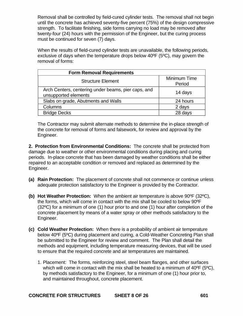
Removal shall be controlled by field-cured cylinder tests. The removal shall not begin until the concrete has achieved seventy-five percent (75%) of the design compressive strength. To facilitate finishing, side forms carrying no load may be removed after twenty-four (24) hours with the permission of the Engineer, but the curing process must be continued for seven (7) days. When the results of field-cured cylinder tests are unavailable, the following periods, exclusive of days when the temperature drops below 40ºF (5ºC), may govern the removal of forms:
Form Removal Requirements
Structure Element Minimum Time Period
Arch Centers, centering under beams, pier caps, and unsupported elements 14 days
Slabs on grade, Abutments and Walls 24 hours Columns 2 days Bridge Decks 28 days
The Contractor may submit alternate methods to determine the in-place strength of the concrete for removal of forms and falsework, for review and approval by the Engineer.
2. Protection from Environmental Conditions: The concrete shall be protected from damage due to weather or other environmental conditions during placing and curing periods. In-place concrete that has been damaged by weather conditions shall be either repaired to an acceptable condition or removed and replaced as determined by the Engineer. (a) Rain Protection: The placement of concrete shall not commence or continue unless
adequate protection satisfactory to the Engineer is provided by the Contractor. (b) Hot Weather Protection: When the ambient air temperature is above 90ºF (32ºC),
the forms, which will come in contact with the mix shall be cooled to below 90ºF (32ºC) for a minimum of one (1) hour prior to and one (1) hour after completion of the concrete placement by means of a water spray or other methods satisfactory to the Engineer.
(c) Cold Weather Protection: When there is a probability of ambient air temperature
below 40ºF (5ºC) during placement and curing, a Cold-Weather Concreting Plan shall be submitted to the Engineer for review and comment. The Plan shall detail the methods and equipment, including temperature measuring devices, that will be used to ensure that the required concrete and air temperatures are maintained.
1. Placement: The forms, reinforcing steel, steel beam flanges, and other surfaces
which will come in contact with the mix shall be heated to a minimum of 40ºF (5ºC), by methods satisfactory to the Engineer, for a minimum of one (1) hour prior to, and maintained throughout, concrete placement.
CONCRETE FOR STRUCTURES SHEET 8 OF 26 601
2. Curing: For the first six (6) days, considered the initial cure period, the concrete shall be maintained at a temperature of not less than 45ºF (7ºC) and the air temperature surrounding the structure shall be maintained at a temperature of not less than 60ºF (16ºC). When the concrete mix includes pozzolans or slag, the initial cure period shall be increased to ten (10) days. After the initial cure period, the air surrounding the structure shall be maintained above 40º F (5ºC) for an additional eight (8) days. If external heating is employed, the heat shall be applied and withdrawn gradually and uniformly so that no part of the concrete surface is heated to more than 90ºF (32ºC) or caused to change temperature by more than 20ºF (11ºC) in eight (8) hours. The Engineer may reduce or increase the amount of time that the structure must be protected or heated based on an indication of in-place concrete strength acceptable to the Engineer.
(d) Additional Requirements for Bridge Decks: Prior to the application of curing
materials, all the concrete placed on bridge decks shall be protected from damage due to rapid evaporation by methods acceptable to the Engineer. During periods of low humidity (less than 60% relative humidity), sustained winds of 25 mph (40 kph) or more, or ambient air temperatures greater than 80ºF (25ºC) the Contractor shall provide written details of additional measures to be taken during placement and curing.
Protection may include increasing the humidity of the surrounding air with fog sprayers and employing wind-breaks or sun-shades. Additional actions may include reduction of the temperature of the concrete prior to placement, scheduling placement during cooler times of days or nights, or a combination of these actions.
(e) Concrete Exposed to Salt Water: No Construction joints shall be formed between
the levels of extreme low water and extreme high water or the upper limit of wave action as determined by the Engineer.
3. Transportation and Delivery of Concrete: All material delivered to the Project shall be supplied by a producer qualified in accordance with Section M.03. The producer shall have sufficient plant capacity and trucks to ensure continuous delivery at the rate required to prevent the formation of cold joints. (a) Material Documentation: All vendors producing concrete must have their weigh
scales and mixing plant automated to provide a detailed ticket. Delivery tickets must include the following information: 1. State of Connecticut printed on ticket 2. Name of producer, identification of plant 3. Date and time of day 4. Type of material 5. Cubic yards (cubic meters) of material loaded into truck 6. Project number, purchase order number, name of Contractor (if Contractor other
than producer) 7. Truck number for specific identification of truck 8. Individual aggregate, cement, water weights (masses) and any admixtures shall
be printed on plant tickets 9. Water/cement ratio, and
10. Additional water allowance in gallons (liters) based on water/cement ratio for mix CONCRETE FOR STRUCTURES SHEET 9 OF 26 601
A State inspector may be present to monitor batching and weighing operations. The Contractor shall notify the Engineer immediately if, during the production day, there is a malfunction of the recording system in the automated plant or weigh scales. Manually written tickets containing all required information may be allowed for up to one (1) hour after malfunction provided they are signed by an authorized representative of the producer.
(b) Transportation of Mixture: Trucks delivering concrete shall be qualified in accordance with Section M.03.
If the concrete mix arrives at the Project with a slump lower than allowed by specification, water may be considered as a means to temper concrete to bring the slump back to within specification. This tempering may only be done prior to discharge with the permission of the Engineer. The quantity of water in gallons (liters) added to the concrete cannot exceed the allowance shown on the delivery ticket. The concrete shall be completely discharged into the forms within one and one-half (1-1/2) hours from the batch time stamped on the delivery ticket. This time may be extended if the measured temperature of the concrete is below 90ºF (32ºC). This time may also be reduced if the temperature of the concrete is over 90ºF (32ºC). Rejected concrete shall be disposed of by the Contractor at no cost to the State. The addition of chemical admixtures or air entrainment admixtures at the Project site, to increase the workability or to alter the time of set, will only be permitted if prior approval has been granted by the Engineer. The addition of air entrainment admixtures at the Project site will only be permitted by the producer’s quality control staff. The Contractor is responsible for follow-up quality control testing to verify compliance with the Specifications.
4. Acceptance Testing and Test Specimens: The Contractor shall furnish the facilities and concrete required for sampling, transport to the testing location in the field, performing field testing and for casting sample cylinders for compressive-strength determinations. The Department will furnish personnel for sampling and casting Acceptance specimens and the number of specimens required will be determined by the Engineer. The equipment for the Department’s testing is provided for elsewhere in the Contract. (a) Temperature, Air Content and Slump: Field testing in accordance with AASHTO T-
23, “Making and Curing Concrete Test Specimens in the Field” will be performed at the point of placement and at a frequency determined by the Engineer.
CONCRETE FOR STRUCTURES SHEET 10 OF 26 601
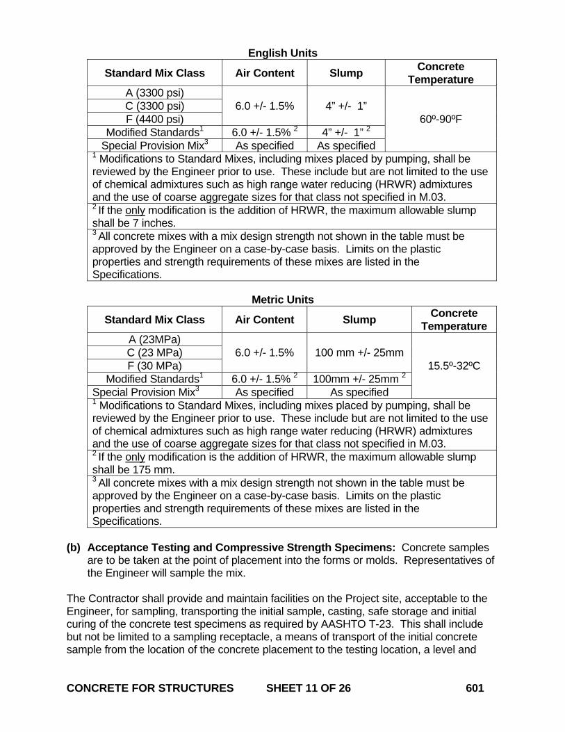
English Units
Standard Mix Class Air Content Slump Concrete Temperature
A (3300 psi) 6.0 +/- 1.5% 4” +/- 1”
60º-90ºF C (3300 psi) F (4400 psi)
Modified Standards1 6.0 +/- 1.5% 2 4” +/- 1” 2 Special Provision Mix3 As specified As specified
1 Modifications to Standard Mixes, including mixes placed by pumping, shall be reviewed by the Engineer prior to use. These include but are not limited to the use of chemical admixtures such as high range water reducing (HRWR) admixtures and the use of coarse aggregate sizes for that class not specified in M.03. 2 If the only modification is the addition of HRWR, the maximum allowable slump shall be 7 inches. 3 All concrete mixes with a mix design strength not shown in the table must be approved by the Engineer on a case-by-case basis. Limits on the plastic properties and strength requirements of these mixes are listed in the Specifications.
Metric Units
Standard Mix Class Air Content Slump Concrete Temperature
A (23MPa) 6.0 +/- 1.5% 100 mm +/- 25mm
15.5º-32ºC C (23 MPa) F (30 MPa)
Modified Standards1 6.0 +/- 1.5% 2 100mm +/- 25mm 2 Special Provision Mix3 As specified As specified 1 Modifications to Standard Mixes, including mixes placed by pumping, shall be reviewed by the Engineer prior to use. These include but are not limited to the use of chemical admixtures such as high range water reducing (HRWR) admixtures and the use of coarse aggregate sizes for that class not specified in M.03. 2 If the only modification is the addition of HRWR, the maximum allowable slump shall be 175 mm. 3 All concrete mixes with a mix design strength not shown in the table must be approved by the Engineer on a case-by-case basis. Limits on the plastic properties and strength requirements of these mixes are listed in the Specifications.
(b) Acceptance Testing and Compressive Strength Specimens: Concrete samples
are to be taken at the point of placement into the forms or molds. Representatives of the Engineer will sample the mix.
The Contractor shall provide and maintain facilities on the Project site, acceptable to the Engineer, for sampling, transporting the initial sample, casting, safe storage and initial curing of the concrete test specimens as required by AASHTO T-23. This shall include but not be limited to a sampling receptacle, a means of transport of the initial concrete sample from the location of the concrete placement to the testing location, a level and CONCRETE FOR STRUCTURES SHEET 11 OF 26 601
protected area of adequate size to perform testing, and a specimen storage container capable of maintaining the temperature and moisture requirements for initial curing of Acceptance specimens. The distance from the location of concrete placement to the location of testing and initial curing shall be 100 feet (30 m) or less, unless otherwise approved by the Engineer. The specimen storage container described in this section is in addition to the concrete cylinder curing box provided for elsewhere in the Contract documents. After initial curing, the test specimens will be transported by Department personnel and stored in the concrete cylinder curing box until they can be transported to the Division of Materials Testing for strength evaluation.
(c) Sampling Procedure for Pumping: It is the responsibility of the Contractor to provide concrete that meets required specifications at the point of placement.
Samples of concrete shall be taken at the discharge end of the pump at the point of placement with the exception of underwater concrete. The Contractor may submit an alternate location to provide a sample from the discharge end of the pump with verification showing that the characteristics of the mix will not be altered from that which would have been attained at the point of placement. The Engineer will review the documentation and other extenuating circumstances when evaluating the request.
In the case of underwater concrete the Contractor shall submit the proposed sampling location with the submittals required in 6.01.03-6(f).
(d) Additional field testing: Additional field testing such as density and yield
measurements may be required at the time of placement as determined by the Engineer.
5. Progression Cylinders and Compressive Strength Specimens: Progression Cylinders outlined in this section are field cured compressive strength specimens taken for information related to when a structure or segment of a structure can be loaded or put into service, adequacy of curing and protection of concrete in the structure, or when formwork or shoring may be removed from the structure. The information produced from strength results of Progression Cylinders will not be considered for acceptance of the concrete. The personnel, equipment, and molds for sampling, casting, curing and testing of Progression Cylinders shall be furnished by the Contractor at no expense to the Department. Sampling, casting, and field curing of the specimens shall be performed in accordance with AASHTO T23 by an ACI Concrete Field Testing Technician Grade 1 or higher and will be witnessed by a representative of the Department. The sample shall be taken at the point of placement into the forms or molds from one (1) or more of the same truck loads that an Acceptance sample is taken from. CONCRETE FOR STRUCTURES SHEET 12 OF 26 601
A minimum of two (2) cylinder results will be used to determine in-place strength. Compression testing shall be performed in accordance with AASHTO T-22 by personnel approved by the Engineer. A Certified Test Report in accordance with Article 1.06.07 shall be provided to the Engineer reporting the Progression Cylinder test results. A copy of the results of the compressive strength testing shall be provided to the Engineer at least twenty-four (24) hours prior to any Project activity that the results may control. 6. Handling and Placing Concrete: Concrete shall be handled, placed, and consolidated by methods acceptable to the Engineer that will not segregate the mix and shall result in a dense homogeneous concrete. The methods used shall not cause displacement of reinforcing steel or other materials to be embedded in the concrete. Concrete shall not be placed until the forms and all materials have been inspected by the Engineer. All mortar from previous placements, debris, and foreign material shall be removed from the forms and steel prior to commencing placement. The forms and subgrade shall be thoroughly moistened with water immediately before concrete is placed. All water that has ponded within the forms shall also be removed. Temporary form spreader devices shall not be left in place. All laitance or unsound material shall be removed before placing substructure concrete onto the surface of any concrete placed underwater. Placement of concrete for each section of the structure shall be performed continuously between construction or expansion joints as shown on the plans. The delivery rate, placing sequence and methods shall be such that fresh concrete is always placed and consolidated against previously placed concrete before initial set has occurred. The temperature of the concrete mixture during placement shall be maintained between 60ºF (16ºC) and 90ºF (32ºC). During and after placement of concrete, care shall be taken not to damage the concrete or break the bond with reinforcing steel. Platforms for workers and equipment shall not be supported directly on any reinforcing steel. Forces that may damage the concrete shall not be applied to the forms or reinforcing steel. (a) Sequence of Placement: The sequence of placement shall be in accordance with
the Contract documents or as permitted by the Engineer.
Concrete for integral horizontal members, such as caps, slabs, or footings shall not be placed until the concrete for the columns, substructure, culvert walls and similar vertical members has achieved sufficient strength as stated in 6.01.03-1(m).
The concrete in arches shall be placed in such a manner as to load the formwork uniformly and symmetrically.
The base slab or footings of cast-in-place box culverts shall reach sufficient strength before the remainder of the culvert is constructed.
(b) Placement Methods: The Contractor shall notify the Engineer at least twenty-four (24) hours in advance of intention to place concrete.
CONCRETE FOR STRUCTURES SHEET 13 OF 26 601
Vibrators shall not be used to shift the fresh concrete horizontally. Vibrators shall be adequate to consolidate the concrete and integrate it with the previous lift. The rate of concrete placement must not produce loadings that exceed those considered in the design of the forms. The use of chutes and pipes for conveying concrete into the forms must be reviewed by the Engineer. Chutes shall be clean, lined with smooth watertight material and, when steep slopes are involved, shall be equipped with baffles or reverses. When the discharge must be intermittent, a hopper or other device for regulating the discharge shall be provided. Aluminum shall not be permanently incorporated into the concrete unless otherwise specified. When placing operations involve dropping the concrete more than 5 feet (1500 mm), the Contractor shall take action to prevent segregation of the mix and spattering of mortar on steel and forms above the elevation of the lift being placed. This restriction shall not apply to cast-in-place pilings. When using stay-in-place forms, concrete shall not be dropped more than 3 feet (1000 mm) above the top of the forms, and the concrete shall be discharged directly over the beams or girders.
(c) Pumping: The Contractor shall use equipment specifically manufactured to pump concrete mixes and that meets the needs of the specific concrete placement.
(d) Consolidation: Unless otherwise specified, all concrete, except concrete placed
under water, shall be sufficiently consolidated by mechanical vibration immediately after placement.
The Contractor shall provide a sufficient number of commercially available mechanical immersion type vibrators to properly consolidate the concrete immediately after it is placed in the forms unless external form vibrators are used. The Contractor shall have an adequate number of operable vibrators available in case of breakdown. External form vibrators may be used if submitted prior to concrete placement and reviewed by the Engineer. Vibration shall not be applied directly to the reinforcement or hardened concrete. Special care shall be taken in placing and consolidating concrete around ornamental moulds, form liners and other embedded items. The vibrator shall not touch these items at any time.
(e) Additional Requirements for Bridge Decks: At least fifteen (15) days before the
erection of the screed rails, the Contractor shall submit screed erection plans, grades and sequence of concrete placement and proposed rate of placing concrete for review by the Engineer. These plans shall include details of equipment to be
CONCRETE FOR STRUCTURES SHEET 14 OF 26 601
used in the placement and finishing of the concrete, including the number and type of personnel who will be engaged in placing the concrete. The screed equipment shall be a commercially available vibratory system. The use of wooden screeds is prohibited. When setting screed rails for mechanical finishing, the Contractor shall take into consideration and make proper allowances for the deflection of the bridge superstructure due to all operations. Screed and runway supports shall not be located on any stay-in-place metal form sheets, form supports or reinforcing steel. The Contractor shall operate the mechanical screed at least twenty-four (24) hours prior to actual placement of the concrete to verify deck survey and equipment operations to the satisfaction of the Engineer. Concrete shall be deposited in a uniform manner across the entire width being placed, and only two (2) passes of the transverse screed will be permitted over a given deck area, unless otherwise allowed by the Engineer. If the Contractor proposes to place concrete outside of daylight hours, an adequate lighting system must be provided. Concrete shall be deposited in accordance with the placement sequence as noted on the plans. If no sequence is indicated, the Contractor shall provide a placement sequence to the Engineer for review. The placement sequence shall proceed in such a manner that the total deflection or settlement of supporting members, and final finishing of the surface will occur before initial set of the concrete takes place. At construction joints, concrete shall not be placed against the previously placed concrete for at least twelve (12) hours unless otherwise allowed by the Engineer.
(f) Underwater Placement: Concrete may only be placed under water within a
cofferdam unless otherwise specified in the documents or otherwise allowed by the Engineer. Placement shall begin following inspection and acceptance of the depth and character of the foundation material by the Engineer.
Underwater concrete mixes are considered non-standard designs and shall be submitted to the Engineer for approval. Typically a minimum of ten percent (10%) additional cement than comparable non-underwater mixes will be required. Underwater concrete shall be placed continuously with the surface of the concrete kept as horizontal as practical. To ensure thorough bonding, each succeeding layer shall be placed before the preceding layer has taken initial set. For large concrete placements, more than one (1) tremie or pump shall be used to ensure compliance with this requirement.
Mass concrete placement requirements, outlined in 6.01.03-6(g), do not apply to underwater concrete.
CONCRETE FOR STRUCTURES SHEET 15 OF 26 601

To prevent segregation, underwater concrete shall be placed in a compact mass, in its final position, by means of a tremie, concrete pump, or other approved method and shall not be disturbed. Still water shall be maintained at the point of deposit. Cofferdams shall be vented during the placement and curing of the concrete to equalize the hydrostatic pressure and thus prevent flow of water through the concrete. If a tremie is used, the method of depositing the concrete shall be detailed in a working drawing submitted to the Engineer for review. The tube shall have watertight couplings and shall permit the free movement of the discharge end over the area of the work.
(g) Mass concrete placement: Mass concrete placement shall be defined as any
placement, excluding underwater concrete placement, in which the concrete being cast has dimensions of 5 feet (1500 mm) or greater in each of three (3) different directions. For placements with a circular cross-section, a mass concrete placement shall be defined as any placement that has a diameter of 6 feet (1800 mm) or greater and a height of 5 feet (1500 mm) or greater. For all mass concrete placements, the mix temperature shall not exceed 85°F (30°C) as measured at point of discharge into the forms.
Any special concrete mix design proposed by the Contractor to meet the above temperature requirements shall be submitted to the Engineer for review.
7. Finishing Plastic Concrete: Unless otherwise specified in the Contract documents, after concrete has been consolidated and prior to final curing, all surfaces of concrete that are not placed against forms shall be struck-off to the planned elevation or slope. The surface shall be finished by floating with an acceptable tool. While the concrete is still in a workable state, all construction and expansion joints shall be tooled with an edger. Joint filler shall be left exposed. For requirements on float finish, refer to 6.01.03-10, “Finishing Concrete Surfaces.” After completion of the placing and finishing operation and for at least twelve (12) hours after the concrete has set, the Contractor shall not operate any equipment in the immediate vicinity of the freshly placed concrete if, in the opinion of the Engineer, it could cause excessive vibration, movement or deflection of the forms. The addition of water to the surface of the concrete to assist in finishing operations will not be permitted. (a) Bridge Decks: After the concrete has been consolidated and brought to the proper
elevation by the screed machine, it shall be finished by use of a suitable float. The Contractor shall not disturb the fresh concrete after it has been finished. All finishing work, including the application of the fog spray and placement of the curing mats, shall be performed from work bridges supported above the deck surface. A work bridge shall be made available to the Engineer for inspection of the concrete work.
CONCRETE FOR STRUCTURES SHEET 16 OF 26 601
Surfaces that are to be covered with a waterproofing membrane shall be finished to a smooth surface, free of mortar ridges and other projections and in accordance with the membrane manufacturer’s recommendations. Unless otherwise noted in the Contract, the concrete wearing surfaces shall be given a skid-resistant texture by dragging, brooming, tining, or by a combination of these methods These methods shall be done after floating and at such time and in such manner that the desired texture will be achieved while minimizing displacement of the larger aggregate particles. 1. Dragging: The surface shall be finished by dragging a seamless strip of damp
burlap over the surface. The burlap to be dragged shall consist of sufficient layers and have sufficient length in contact with the concrete to slightly groove the surface. The burlap shall be drawn longitudinally along the surface in a slow manner so as to leave an even texture. The burlap shall be kept damp, clean, and free of particles of hardened concrete. The Contractor may propose an alternate material for the Engineer’s consideration.
2. Tining: Tining shall be in a transverse direction using a wire broom, comb, or
float having a single row of tines or fins. The tining grooves shall be between 1/16 inch (1.5 mm) and 3/16 inch (5 mm) wide and between 1/8 inch (3 mm) and 3/16 inch (5 mm) deep, spaced 1/2 inch (12.5 mm) to 3/4 inch (20 mm) on centers. Tining shall be discontinued 12 inches (300 mm) from the curb line on bridge decks. The area adjacent to the curbs shall be given a light broom finish longitudinally. As an alternative, tining may be achieved using a machine designed specifically for tining or grooving concrete pavements.
The transverse grooving shall be performed when the grooves can be formed to a maximum depth of 3/16 inch (5 mm) with relative ease and without the walls of the grooves closing in on each other. The tining shall be aligned so as to prevent overlapping of grooves in any two (2) successive transverse passes. The Contractor shall measure the depth of the grooves in the presence of the Engineer with an appropriate device to ensure compliance.
(b) Surface Testing and Correction: The completed surface shall be constructed in accordance with grades and cross slopes shown on the plans. The entire surface shall be checked by the Contractor in the presence of the Engineer, with an acceptable 10 foot (3 meter) straightedge. 1. The surface shall not vary more than +/- 1/8 inch (3 mm) in 10 feet (3 m) for
decks which will not be covered with an overlay.
2. The surface shall not vary more than +/- 1/4 inch (6 mm) in 10 feet (3 m) for decks which will be covered with an overlay.
Variances greater than these, which, in the opinion of the Engineer, may adversely affect the riding qualities of the surface shall be corrected, and this shall be done at the expense of the Contractor. The Contractor shall submit a corrective procedure to the Engineer for review and approval. The procedure shall correct such irregularities by methods such as, but not limited to, concrete planing or grooving.
CONCRETE FOR STRUCTURES SHEET 17 OF 26 601
8. Bearing Surfaces: Concrete surfaces under metallic masonry plates and elastomeric bearings shall have a float finish. After the concrete has set, the area which will be in contact with the masonry plate shall be ground as necessary to provide full and even bearing. The finished surface shall not vary from a straightedge laid on the surface in any direction within the limits of the masonry plate by more than 0.0625 inches (1.5 mm). Surfaces which fail to conform shall be ground or filled until acceptable to the Engineer. 9. Curing Concrete: All newly placed concrete shall be cured so as to prevent loss of water by use of the methods specified. The Engineer may request that the Contractor furnish a curing plan. The duration of the initial and final curing period in total shall continue uninterrupted for a minimum of seven (7) days. (a) Curing Methods:
1. Forms-In-Place Method: Formed surfaces of concrete may be cured by retaining the forms in place without loosening. During periods of hot weather, water shall be applied to the forms until the Engineer determines that it is no longer required.
2. Water Method: Exposed concrete surfaces shall be kept continuously wet by
ponding, spraying, or covering with materials that are kept continuously and thoroughly wet. Such materials may consist of cotton mats, multiple layers of burlap, or other approved materials that do not discolor or otherwise damage the concrete.
3. Waterproof Cover Method: This method shall consist of covering exposed
surfaces with a waterproof sheet material to prevent moisture loss from the concrete. The concrete shall be wet at the time the cover is installed. The sheets shall be of the widest practicable width and adjacent sheets shall overlap a minimum of 6.0 inches (150 mm) to form a waterproof cover of the entire concrete surface and shall be adequately secured. Broken or damaged sheets shall be immediately repaired and the concrete shall be remoistened.
(b) Additional Requirements for Bridge Decks:
1. Curing Plan: The Contractor shall submit to the Engineer, at least fourteen (14) days prior to the placement of concrete for the bridge deck, a detailed curing plan that describes the following: A. the initial and final curing durations, B. equipment and materials to be used for curing concrete and monitoring
concrete temperature, and C. proposed primary and secondary water and heat sources
CONCRETE FOR STRUCTURES SHEET 18 OF 26 601
2. Initial Curing Period: A water fog spray shall be used by the Contractor from the
time of initial placement until the final curing period begins. The amount of fog spray shall be strictly controlled so that accumulations of standing or flowing water on the surface of the concrete shall not occur.
Should atmospheric conditions render the use of fog spray impractical, the Contractor shall request approval from the Engineer to use a curing compound that meets the requirements of Section M.03 in lieu of a fog spray. The application shall be in accordance with the manufacturer’s recommendation and be compatible with the membrane waterproofing.
3. Final Curing: After completion of finishing and as soon as any bleed water has
dissipated and the concrete reaches sufficient strength to avoid marring, the Final curing period shall begin and the entire concrete surface shall be covered with water-retaining materials such as cotton mats, multiple layers of burlap, or other materials approved by the Engineer. Materials used shall be kept saturated by means of an acceptable sprinkler or wetting system.
The Contractor may cover the wet water-retaining material with a suitable
polyethylene film to minimize evaporation during the curing period. The use of the polyethylene film does not relieve the Contractor from maintaining saturation of the curing materials.
4. Temperature Monitoring: The internal temperature of the concrete shall be
monitored with a calibrated continuous recording thermometer for a minimum of seven (7) days. The air temperature at the concrete surface or the air temperature between the concrete surface and its protective covering shall be monitored with a minimum of one (1) recording thermometer.
The number and placement of the thermometers will be determined by the
Engineer. A minimum of two (2) thermometers per concrete placement shall be provided by the Contractor.
The following types of thermometers shall be used to monitor curing
temperatures:
A. Continuously Recording Thermometer: The thermometer shall be capable of continuously recording temperatures within a range of -4 ºF to 122 ºF (-20°C to 50°C) for a minimum of twenty-four (24) hours.
B. Maximum–Minimum Recording Thermometer: For all placements, the
thermometer shall be capable of recording maximum and minimum temperatures in a range of -4 ºF to 122 ºF (-20°C to 50°C).
10. Finishing Concrete Surfaces: Any minor repairs due to fins, bulges, offsets and irregular projections shall be performed immediately following the removal of forms. For areas of newly placed concrete that are honeycombed or segregated the Contractor shall provide a written corrective procedure for review by the Engineer prior to the work being performed. Construction and expansion joints in the completed work shall be left CONCRETE FOR STRUCTURES SHEET 19 OF 26 601
carefully tooled and free of mortar and concrete. The joint filler shall be left exposed for its full length with clean and true edges. The cavities produced by form ties and all other holes, broken corners or edges, and other defects shall be cleaned, saturated with water, pointed and trued with a mortar conforming to M.11.04. Cement similar in color to the exposed surface being repaired shall be added to the mortar. Mortar used in pointing shall be used within one (1) hour of mixing. The concrete shall be finished as defined below if required and the cure continued as previously specified in "Curing Concrete." Finishing work shall not interrupt the curing period unless permitted by the Engineer. The curing period may be extended to provide the minimum total number of days required. Concrete surface finishes shall be classified as follows: (a) Float Finish: This finish shall be achieved by placing an excess of material in the
form and removing or striking off of such excess forcing the coarse aggregate below the mortar surface. Concave surfaces in which water will be retained will not be allowed. After the concrete has been struck off, the surface shall be thoroughly worked and floated. Before this last finish has set, the surface shall be lightly stripped with a fine brush to remove the surface cement film, leaving a fine-grained, smooth, but sanded texture. Curing, as specified elsewhere, shall follow. Any surfaces that will support appurtenances such as light standards, railing, or fences shall be finished in accordance with 6.01.03-8, “Bearing Surfaces.”
(b) Rubbed Finish: The initial rubbing shall only be allowed within three (3) days after
placement. The entire surface shall be thoroughly wet with a brush and rubbed with a No. 16 Carborundum Stone or an abrasive of equal quality, bringing the surface to a paste. The rubbing shall be continued sufficiently to remove all form marks and projections, producing a smooth, dense surface without pits or irregularities. The paste formed by the rubbing may be finished by stripping with a clean brush, or it may be spread uniformly over the surface and allowed to re-set. If all or portions of the rubbed surface are unacceptable to the Engineer or a rubbed finish is not provided within three (3) days after removal of forms, the Contractor will be directed to provide a grout clean down finish.
(c) Grout Clean-Down Finish: As soon as all cavities have been filled as required
elsewhere and the cement mortar has set sufficiently, grout clean-down shall be performed. All burrs, unevenness, laitance, including that in air holes, and any other material which will adversely affect the bond of the grout to the concrete, shall be removed by acceptable methods. This cleaning shall be done from the top or uppermost part of the surface to be finished to the bottom.
A mixture of a fine aggregate and Portland cement shall be thoroughly blended while dry. The proportions shall be such that when mixed with the proper amount of water, the color will match that of the concrete to be finished. Water shall be added to this mixture in an amount which will bring the grout to a workable thick paint-like consistency.
CONCRETE FOR STRUCTURES SHEET 20 OF 26 601
The surface to be treated shall be thoroughly wetted with a sufficient amount of water to prevent the absorption of water from the grout. Grout shall then be applied to the wetted surface before setting of the grout occurs. Grout which has set shall not be re-tempered and shall be disposed of by the Contractor at no cost to the State. The grout shall be uniformly applied over the entire surface, completely filling all air bubbles and holes. Immediately after applying the grout, the surface shall be floated with a suitable float, scouring the surface vigorously. While the grout is still plastic, all excess grout shall be removed. After the final rubbing is completed and the surface has dried, it shall be rubbed to remove loose powder and shall be left free from all unsound patches, paste, powder, and objectionable marks. Wetting, application and removal of excess grout shall be completed in one (1) work shift. All finished surfaces shall be cured for a minimum of twenty-four (24) hours. Horizontal surfaces shall have a float finish and vertical exposed surfaces shall have a rubbed finish. A grout clean down finish may be substituted for a rubbed finish as noted in this section or as directed by the Engineer
11. Mortar, Grout, Epoxy and Joint Seal (a) Mortar and Grout: This work consists of the making and placing of mortar and
grout. At least forty-eight (48) hours prior to the planned use, a copy of the installation instructions and MSDS sheet(s) shall be provided to the Engineer for review and concurrence of their applicability and for verification of proper hole sizes in concrete structures. Such uses include mortar for filling under masonry plates, mortar used to fill voids and repair surface defects, grout used to fill sleeves for anchor bolts, and mortar and grout for other such uses where required or approved.
Concrete areas to be in contact with the mortar or grout shall be cleaned of all loose or foreign material that would in any way prevent bond, and the concrete surfaces shall be flushed with water and allowed to dry until no free-standing water is present.
The mortar or grout shall completely fill and shall be tightly packed into recesses and holes, on surfaces, under structural members, and at other locations specified. After placing, all surfaces of mortar or grout shall be cured as previously specified in 6.01.03-9(a)-2 “Curing Concrete – Water Method," for a period of not less than three (3) days.
(b) Epoxy: The epoxy shall be prepared and placed in accordance with the manufacturer's directions and with the equipment prescribed by the manufacturer. Instructions furnished by the supplier for the safe storage, mixing, handling and
application of the epoxy shall be followed. Contents of damaged or previously opened containers shall not be used.
(c) Joint Seal: This work consists of sealing joints where shown on the plans or as
otherwise directed by the Engineer. CONCRETE FOR STRUCTURES SHEET 21 OF 26 601
Before placement of the sealing material, the joints shall be thoroughly cleaned of all scale, loose concrete, dirt, dust or other foreign matter. Projections of concrete into the joint space shall be removed. The joint shall be clean and dry before the sealing compound is applied. The joint sealant shall be prepared and placed in accordance with the manufacturer's directions and with the equipment prescribed by the manufacturer. The sealing compound shall be flush with, or not more than 1/8 inch (3 mm) above the adjacent surface of concrete, cutting off all excess compounds after the application. The joints shall be sealed in a neat and workmanlike manner and when the work is completed, the joints shall effectively seal against infiltration of moisture and water. The Contractor shall arrange for, and have present at the commencement of the joint-sealing operation, a technically competent manufacturer’s representative knowledgeable in the methods of installation of the sealant. The Contractor shall also arrange to have the representative present at such other times as the Engineer may request.
(d) Closed Cell Elastomer: The closed cell elastomer shall be of the thickness, size and type specified and installed as shown on the plans and shall be in accordance with Section M.03.
12. Application of Loads: Loads shall not be applied to concrete structures until the concrete has attained sufficient strength and, when applicable, sufficient pre-stressing and post tensioning has been completed, so that damage will not occur. The means to determine when the concrete has attained sufficient strength shall be the use of Progression cylinders as defined elsewhere in this specification, or other means approved in advance by the Engineer. (a) Earth Loads: The placement of backfill shall not begin until the concrete is cured
and has reached at least eighty percent (80%) of its specified strength unless otherwise permitted by the Engineer. The sequence of placing backfill around structures shall minimize overturning or sliding forces and flexural stresses in the concrete.
(b) Construction Loads: Light materials and equipment may be hand carried onto
bridge decks only after the concrete has been in place at least twenty-four (24) hours providing curing is not interfered with and the surface texture is not damaged. Prior to the concrete achieving its specified compressive strength, any other live or dead loads imposed on existing, new, or partially completed portions of structures, shall not exceed the reduced load carrying capacity of the structure, or portion of structure. The Contractor may be required to submit calculations to the Engineer that verify these requirements are being met. The compressive strength of concrete (f' c) to be used in computing the load-carrying capacity shall be the smaller of the actual field compressive strength at the time of loading or the specified design strength of the concrete. The means to determine the actual field compressive strength shall be approved by the Engineer.
CONCRETE FOR STRUCTURES SHEET 22 OF 26 601
For post-tensioned structures, no live or dead loads shall be allowed on any span until the steel for that span has been tensioned.
(c) Loading of Completed Elements: Precast concrete or steel girders shall not be placed on substructure elements until the substructure concrete has attained eighty-five percent (85%) of its specified strength.
No load shall be allowed on mortar or grout that has been in place less than seventy-two (72) hours.
(d) Traffic Loads: The concrete deck will not be opened to traffic until at least fourteen (14) days after the last placement of deck concrete and until such concrete has attained its specified strength.
13. Dispute Resolution: The basis of any dispute resolution is side-by-side and quality control testing by the Contractor or the Contractor’s representative. The Contractor and Engineer should perform independent testing on the material to reasonably establish the true characteristics of the material at the time of delivery. Absent of Contractor QC testing, the Engineer’s test results will apply to the quantity of concrete represented by the sample, not to exceed 75 cubic yards (60 cubic meters). (a) Air Content: Contractor QC Testing must be performed by personnel qualified by
The American Concrete Institute as an ACI Concrete Field Testing Technician Grade 1 or higher and performed in accordance with AASHTO T-23. If the Contractor’s test results vary from those of the Engineer, the Contractor shall immediately notify the Engineer of the difference and work cooperatively to determine the reasonable cause and recognize the valid test. Should there be agreement, the result of the valid test will be used for acceptance and adjustment purposes for that lot of material. Should there not be an agreement as to the valid test, an additional set of tests should be performed. Results of all valid tests on the same lot may be averaged and used for acceptance and adjustment purposes. Should the Contractor wish to perform additional QC testing on subsequent material, the lot sizes may be adjusted to the amount of material included in that specific delivery. Any such QC testing must be witnessed and agreed to by the Engineer.
(b) Compressive Strength: Contractor QC testing for compressive strength must be
performed in accordance with AASHTO T-22 by personnel approved by the Engineer. Samples used to dispute the Engineer’s test results must be made simultaneously and from the same batch of concrete. Should the Contractor wish to pursue a dispute resolution with regard to compressive strength, the Contractor shall submit in writing to the Engineer all test results, control charts, or other documentation that may be useful in determining if the specific lot(s) of material met the Contract specifications. The Engineer will consider the submittal and may average specific test results on the disputed lot(s) for acceptance and adjustment purposes. Destructive testing of any kind on the placed concrete structure will not be allowed.
CONCRETE FOR STRUCTURES SHEET 23 OF 26 601
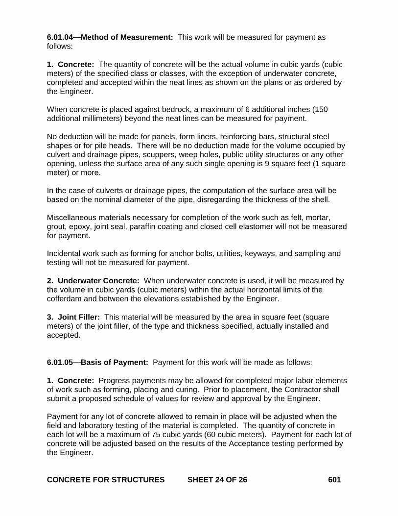
6.01.04—Method of Measurement: This work will be measured for payment as follows: 1. Concrete: The quantity of concrete will be the actual volume in cubic yards (cubic meters) of the specified class or classes, with the exception of underwater concrete, completed and accepted within the neat lines as shown on the plans or as ordered by the Engineer. When concrete is placed against bedrock, a maximum of 6 additional inches (150 additional millimeters) beyond the neat lines can be measured for payment. No deduction will be made for panels, form liners, reinforcing bars, structural steel shapes or for pile heads. There will be no deduction made for the volume occupied by culvert and drainage pipes, scuppers, weep holes, public utility structures or any other opening, unless the surface area of any such single opening is 9 square feet (1 square meter) or more. In the case of culverts or drainage pipes, the computation of the surface area will be based on the nominal diameter of the pipe, disregarding the thickness of the shell. Miscellaneous materials necessary for completion of the work such as felt, mortar, grout, epoxy, joint seal, paraffin coating and closed cell elastomer will not be measured for payment. Incidental work such as forming for anchor bolts, utilities, keyways, and sampling and testing will not be measured for payment. 2. Underwater Concrete: When underwater concrete is used, it will be measured by the volume in cubic yards (cubic meters) within the actual horizontal limits of the cofferdam and between the elevations established by the Engineer. 3. Joint Filler: This material will be measured by the area in square feet (square meters) of the joint filler, of the type and thickness specified, actually installed and accepted. 6.01.05—Basis of Payment: Payment for this work will be made as follows: 1. Concrete: Progress payments may be allowed for completed major labor elements of work such as forming, placing and curing. Prior to placement, the Contractor shall submit a proposed schedule of values for review and approval by the Engineer. Payment for any lot of concrete allowed to remain in place will be adjusted when the field and laboratory testing of the material is completed. The quantity of concrete in each lot will be a maximum of 75 cubic yards (60 cubic meters). Payment for each lot of concrete will be adjusted based on the results of the Acceptance testing performed by the Engineer. CONCRETE FOR STRUCTURES SHEET 24 OF 26 601
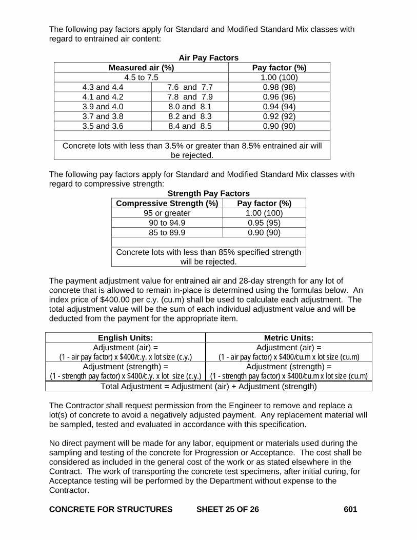
The following pay factors apply for Standard and Modified Standard Mix classes with regard to entrained air content:
Air Pay Factors Measured air (%) Pay factor (%)
4.5 to 7.5 1.00 (100) 4.3 and 4.4 7.6 and 7.7 0.98 (98) 4.1 and 4.2 7.8 and 7.9 0.96 (96) 3.9 and 4.0 8.0 and 8.1 0.94 (94) 3.7 and 3.8 8.2 and 8.3 0.92 (92) 3.5 and 3.6 8.4 and 8.5 0.90 (90)
Concrete lots with less than 3.5% or greater than 8.5% entrained air will
be rejected. The following pay factors apply for Standard and Modified Standard Mix classes with regard to compressive strength:
Strength Pay Factors Compressive Strength (%) Pay factor (%)
95 or greater 1.00 (100) 90 to 94.9 0.95 (95) 85 to 89.9 0.90 (90)
Concrete lots with less than 85% specified strength
will be rejected.
The payment adjustment value for entrained air and 28-day strength for any lot of concrete that is allowed to remain in-place is determined using the formulas below. An index price of $400.00 per c.y. (cu.m) shall be used to calculate each adjustment. The total adjustment value will be the sum of each individual adjustment value and will be deducted from the payment for the appropriate item.
English Units: Metric Units: Adjustment (air) =
(1 - air pay factor) x $400/c.y. x lot size (c.y.) Adjustment (air) =
(1 - air pay factor) x $400/cu.m x lot size (cu.m) Adjustment (strength) =
(1 - strength pay factor) x $400/c.y. x lot size (c.y.) Adjustment (strength) =
(1 - strength pay factor) x $400/cu.m x lot size (cu.m) Total Adjustment = Adjustment (air) + Adjustment (strength)
The Contractor shall request permission from the Engineer to remove and replace a lot(s) of concrete to avoid a negatively adjusted payment. Any replacement material will be sampled, tested and evaluated in accordance with this specification. No direct payment will be made for any labor, equipment or materials used during the sampling and testing of the concrete for Progression or Acceptance. The cost shall be considered as included in the general cost of the work or as stated elsewhere in the Contract. The work of transporting the concrete test specimens, after initial curing, for Acceptance testing will be performed by the Department without expense to the Contractor. CONCRETE FOR STRUCTURES SHEET 25 OF 26 601
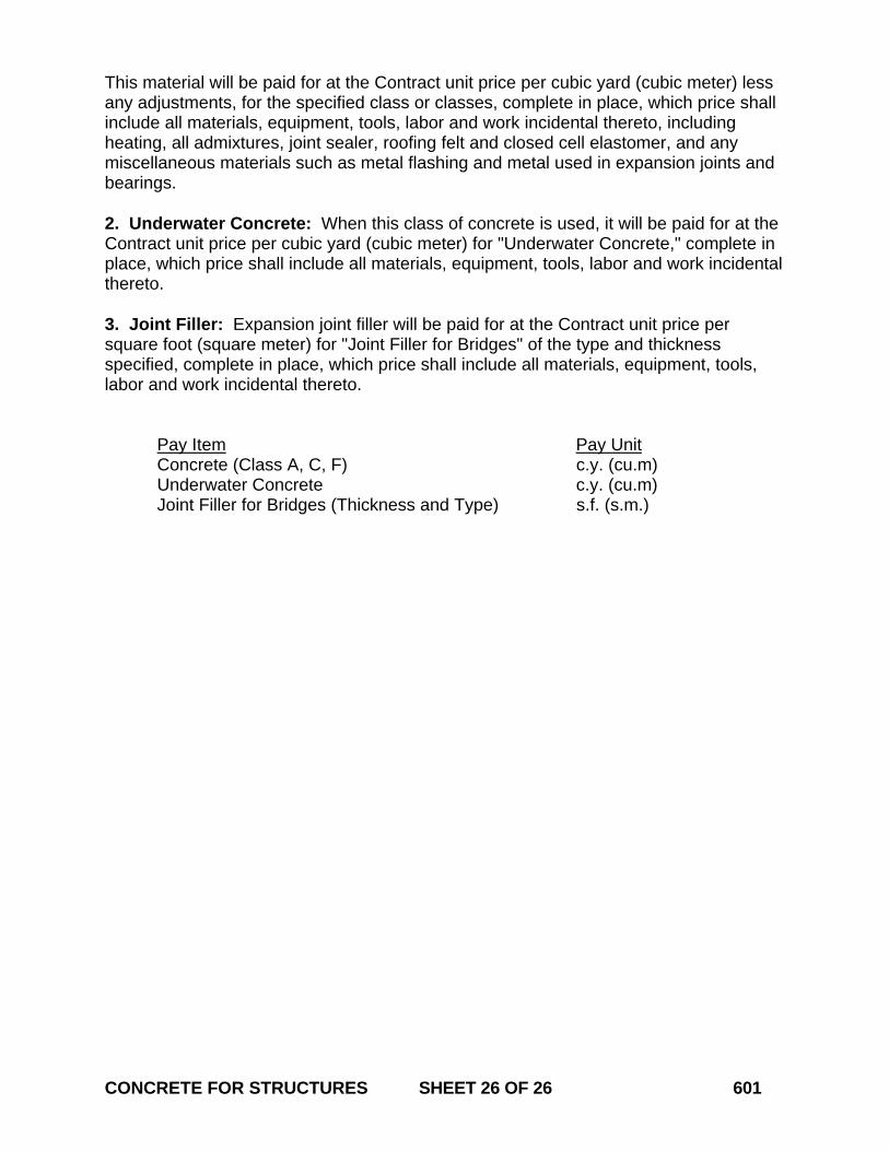
This material will be paid for at the Contract unit price per cubic yard (cubic meter) less any adjustments, for the specified class or classes, complete in place, which price shall include all materials, equipment, tools, labor and work incidental thereto, including heating, all admixtures, joint sealer, roofing felt and closed cell elastomer, and any miscellaneous materials such as metal flashing and metal used in expansion joints and bearings. 2. Underwater Concrete: When this class of concrete is used, it will be paid for at the Contract unit price per cubic yard (cubic meter) for "Underwater Concrete," complete in place, which price shall include all materials, equipment, tools, labor and work incidental thereto. 3. Joint Filler: Expansion joint filler will be paid for at the Contract unit price per square foot (square meter) for "Joint Filler for Bridges" of the type and thickness specified, complete in place, which price shall include all materials, equipment, tools, labor and work incidental thereto. Pay Item Pay Unit Concrete (Class A, C, F) c.y. (cu.m) Underwater Concrete c.y. (cu.m) Joint Filler for Bridges (Thickness and Type) s.f. (s.m.) CONCRETE FOR STRUCTURES SHEET 26 OF 26 601
STRUCTURAL STEEL SHEET 1 OF 20 603
July 2010
CONNECTICUT SUPPLEMENTAL SPECIFICATION
SECTION 6.03 STRUCTURAL STEEL
Delete the entire section and replace it with the following:
SECTION 6.03 STRUCTURAL STEEL
Description: Work under this item shall consist of furnishing, fabricating, transporting, storing, handling and erecting of structural steel of the type and size designated, as shown on the plans, as directed by the Engineer and in accordance with these specifications. All work except as stated in the following paragraph shall conform to the requirements of the AASHTO LRFD Bridge Construction Specifications and the ANSI/AASHTO/AWS D1.5 – Bridge Welding Code. All work subject to railroad loading shall conform to AREMA and the ANSI/AASHTO/AWS D1.5 – Bridge Welding Code. Materials: The materials for this work shall conform to the requirements of Section M.06. Materials for this work shall be stored off the ground before, during, and after fabrication. It shall be kept free from dirt, grease and other contaminants and shall be reasonably protected from corrosion. In addition, weathering steel shall be stored as to allow free drainage and promote the development of the oxide coating and a uniform appearance. Construction Methods: 1. Pre-qualification: (a) Fabricators producing material for Department projects under this item are required to have as a minimum, an active AISC Certification for Simple Steel Bridges. For fabrication of material for use on bridges other than un-spliced rolled beam bridges, AISC Major Steel Bridge Certification is required. If so noted on the plans, additional AISC endorsement for fabrication of fracture critical members is also required. (b) Field Welders: Prior to working on material for Department projects under this specification, all field welders, field welding operators, and field tackers must posses a valid welder certification card issued by the Department’s Division of Materials Testing. If such person has not been engaged in welding operations on a Department project or
STRUCTURAL STEEL SHEET 2 OF 20 603
project acceptable to the Department within a period of six months, or if he cannot produce an approved welding certificate dated within the previous twelve months from a welding agency acceptable to the Engineer, he shall be required to re-qualify through examination. The Engineer may require re-qualification of anyone whose quality of work he questions. 2. Submittals: (a) Shop Drawings: Prior to any fabrication, the Contractor shall submit shop drawings in accordance with Article 1.05.02-3 to the Engineer for review and approval. Shop drawings shall include a cambering procedure and diagram. In the case of trusses, the Contractor is responsible for calculation of the camber (lengthening and shortening) of all truss members. (b) Shop Schedule: The Contractor shall submit a detailed shop fabrication schedule to the Engineer for review within 30 days of the notice to proceed unless otherwise agreed to by the Engineer. At a minimum the schedule shall include the start date, milestone dates, and completion date. Any significant changes shall be brought to the attention of the Engineer immediately. (c) Welding Procedures: Prior to start of fabrication, all weld procedures shall be submitted to the Engineer for review and approval. (d) Working Drawings for Falsework and Erection of Structural Steel: Prior to erecting any steel fabricated under this specification, the Contractor shall submit drawings and supporting calculations, including erection stresses, in accordance with Article1.05.02-2 to the Engineer. The design of temporary supports and falsework shall conform to the AASHTO Specifications, the AASHTO Guide Design Specifications for Bridge Temporary Works or any other standard acceptable to the Engineer. Falsework shall be of sufficient rigidity and strength to safely support all loads imposed and to produce in the finished structure the lines and grades indicated in the contract documents. The submittal shall include at a minimum: • Title block with contract number, project identification number (PIN), town, and
structure number and name. • Plan of the work area showing support structures, roads, railroad tracks, Federal and
State regulated areas as depicted on the plans, utilities or any other information relative to erection.
• A detailed narrative describing the erection sequence for main members and secondary members (cross frames, diaphragms, lateral bracing, portals, etc.), noting use of holding cranes or temporary supports, falsework, or bents.
• Delivery location of each girder. • Location of each crane for each pick. • Capacity chart for each crane and boom length used in the work. • The capacity of the crane and of all lifting and connecting devices shall be adequate
for the total pick load including spreaders and other materials. In the area of railroads and navigable waterways, the capacity shall be as required by Amtrak, Metro North, U.S. Coast Guard or other regulatory authorities. No picks shall be
STRUCTURAL STEEL SHEET 3 OF 20 603
allowed over vehicular or pedestrian traffic unless otherwise noted on the plans or permitted by the Engineer.
• Pick point location(s) on each member. • Lifting weight of each member (including clamps, spreader beams, etc.) • Lift and setting radius for each pick (or maximum lift radius). • Description of lifting devices or other connecting equipment. • Girder tie-down details or other method of stabilizing erected girders. • Bolting requirements, including the minimum number of bolts and erection pins
required to stabilize members during the erection sequence. • Blocking details for stabilizing members supported on expansion bearings and on
bearings that do not limit movement in the transverse direction. • The method and location for temporary supports for field spliced or curved girders,
including shoring, false work, holding cranes, guys, etc. The Engineer will review, but not approve details of temporary supports. The design, erection, and stability of these supports shall be the sole responsibility of the Contractor.
• Offsets necessary to adjust expansion bearings during erection to provide for temperature variance and dead load rotation.
The following notes shall be placed on the Erection Drawings: • Cranes shall be operated in accordance with the Connecticut Department of Public
Safety regulations. • The Contractor shall be responsible for verifying the weight of each lift and for
insuring the stability of each member during all phases of erection. • Members shall be subject to only light drifting to align holes. Any drifting that results
in distortion of the member or damage to the holes will be cause for rejection of the member.
• Field reaming of holes shall not be performed unless required by the Contract Drawing or approved by the Engineer.
The Contractor shall submit these documents to the Engineer at least 60 calendar days in advance of their proposed use. If the proposed method of erection requires additional members or modifications to the existing members of the structure, such additions and modifications shall be made by the Contractor at no expense to the State. 3. Shop Fabrication: Unless otherwise shown on the plans or indicated in the Special Provisions, Structural Steel shall be fabricated in accordance with the AASHTO LRFD Bridge Construction Specifications, amended as follows: (a) Notification: The Contractor shall submit written notification to both the Engineer and the Director of Research and Materials Testing not less than 30 calendar days prior to start of fabrication. No material shall be manufactured or worked in the shop before the Engineer has been so notified. The notification shall include the name and location of the fabrication shop where the work will be done so that arrangements can be made for an audit of the facility and the assignment of a Department Quality Assurance inspector.
STRUCTURAL STEEL SHEET 4 OF 20 603
(b) Camber: All members shall be cambered prior to heat curving and painting. Rolled beams shall be heat cambered by methods approved by the Engineer. Plate girders shall be cambered by cutting the web to the prescribed shape with allowances for shrinkage due to cutting, welding, and heat curving. The fabricator is responsible to determine what allowances should be made. Rolled, plate-rolled, or fabricated sections shall be cambered to the total amount shown on the plans and within the camber deviation tolerances permitted for welded beams and girders, as indicated in the ANSI/AASHTO/AWS D1.5 Bridge Welding Code. The Contractor must submit to the Engineer for approval, a plan for corrective action if the actual camber is not within tolerance. (c) Welding: Unless otherwise indicated on the plans or specifications, all work shall be performed in accordance with ANSI/AASHTO/AWS D1.5 – Bridge Welding Code. (d) Preassembly of Field Connections: Field connections of main members of continuous beams, plate girders, bents, towers, rigid frames, trusses and arches shall be preassembled prior to erection as necessary to verify the geometry of the completed structure or unit and to verify or prepare field splices. The Contractor shall propose an appropriate method of preassembly for review and comment by the Engineer. The method and details of preassembly shall be consistent with the erection procedures shown on the working drawings and camber diagrams. As a minimum, the preassembly procedure shall consist of assembling three contiguous panels accurately adjusted for line and camber. Successive assemblies shall consist of at least one section or panel of the previous assembly plus two or more sections or panels added at the advancing end. In the case of structures longer than 150 feet (45 meters), each assembly shall not be less than 150 feet (45 meters) long regardless of the length of individual continuous panels or section. All falsework, tools, machinery and appliances, including drift pins and bolts necessary for the expeditious handling of the work shall be provided by the Contractor at no cost to the State. (e) Inspection: The Contractor shall furnish facilities for the inspection of material and workmanship in the shop by the Engineer. The Engineer and his representative shall be allowed free access to the necessary parts of the premises.
The Engineer will provide Quality Assurance (QA) inspection at the fabrication shop to assure that all applicable Quality Control plans and inspections are adequately adhered to and maintained by the Contractor during all phases of the fabrication. A thorough inspection of a random selection of elements at the fabrication shop may serve as the basis of this assurance. Prior to shipment to the project, each individual piece of structural steel shall be stamped or marked in a clear and permanent fashion by a representative of the fabricators’ Quality Control (QC) Department to indicate complete final inspection by the fabricator and conformance to the project specifications for that piece. The stamp or mark must be dated. A Materials Certificate in accordance with Article 1.06.07 may be used in lieu of individual stamps or markings, for all material in a single shipment. The Materials Certificate must list each piece within the shipment and accompany the shipment to the project site.
STRUCTURAL STEEL SHEET 5 OF 20 603
Following the final inspection by the fabricator’s QC personnel, the Engineer may select pieces of structural steel for re-inspection by the Department’s QA inspector. Should non-conforming pieces be identified, all similar pieces must be re-inspected by the fabricator and repair procedure(s) submitted to the Engineer for approval. Repairs will be made at the Contractor’s expense. The pieces selected for re-inspection and found to be in conformance, or adequately repaired pieces, may be stamped or marked by the QA inspector. Such markings indicate the Engineer takes no exception to the pieces being sent to the project site. Such marking does not indicate acceptance or approval of the material by the Engineer. Following delivery to the project site, the Engineer will perform a visual inspection of all material to verify shipping documents, fabricator markings, and that there was no damage to the material or coatings during transportation and handling. The Engineer is not responsible for approving or accepting any fabricated materials prior to final erection and assembly at the project site. (f) Nondestructive Testing: All nondestructive testing of structural steel and welding shall be performed as designated on the plans and in the project specifications. Such testing shall be performed by personnel approved by the Engineer. Personnel performing Radiographic, Ultrasonic or Magnetic Particle testing shall be certified as a NDT Level II technician in accordance with the American Society for Non Destructive Testing (ASNT), Recommended Practice SNT-TC-1A. Nondestructive testing shall be performed in accordance with the procedures and standards set forth in the AASHTO/AWS D1.5, Bridge Welding Code. The Department reserves the right to perform additional testing as determined by the Engineer. All nondestructive testing shall be witnessed by an authorized representative of the Department. Certified reports of all tests shall be submitted to the Materials Testing Division for examination. Each certified report shall identify the structure, member, and location of weld or welds tested. Each report shall also list the length and location of any defective welds and include information on the corrective action taken and results of all retests of repaired welds. Should the Engineer require nondestructive testing on welds not designated in the contract, the cost of such inspection shall be borne by the Contractor if the testing indicates that any weld is defective. If the testing indicates the weld to be satisfactory, the actual cost of such inspection will be paid by the Department. (g) Marking: Each member shall be identified with an erection mark corresponding with the member identification mark on the approved shop drawings. Identification marks shall be impressed into the member with a low stress stamp in a location in accordance with standard industry practice.

STRUCTURAL STEEL SHEET 6 OF 20 603
(h) Shipping, Handling, Storage and Receiving: The Contractor shall make all arrangements necessary to properly load, transport, unload, handle and store all material. The Contractor shall furnish to the Engineer copies of all shipping statements. The weight (mass) of the individual members shall be shown on the statements. Members having a weight (mass) of more than 3 tons (2700 kilograms) shall have the weight (mass) marked thereon. All material shall be unloaded promptly upon delivery. The Contractor shall be responsible for any demurrage charges. Damage to any material during transportation, improper storage, faulty erection, or undocumented fabrication errors may be cause for rejection of said material at the project site. Top lateral bracing should be installed in tub girders prior to shipping and erection of the field pieces. All costs associated with any corrective action will be borne by the Contractor. 4. Field Erection: A meeting shall be held on site prior to any erection of structural steel. The Contractor shall name the person responsible for the steel erection work and provide copies of all crane operator licenses. Proposed equipment, rigging, timetable and methods shall be proposed at this meeting. (a) Falsework: Any temporary work shall be constructed in conformance with the working drawings. The Contractor shall verify that the quality of materials and work employed are consistent with their design. All girders shall be stabilized with falsework, temporary braces, or holding cranes until a sufficient number of adjacent girders are erected with all diaphragms and cross frames connected to provide necessary lateral support as shown in the erecting diagrams. Adjustment shall be provided in the falsework and other temporary supports so that the temporary elevation of the structural steel provided by the falsework is consistent with the deflections that will occur as the structure is completed. The elevation of falsework shall be such as to support the girders at the cambered no-load elevation. Unloading of temporary supports should be performed such that all temporary supports at each cross section are unloaded uniformly. Unless specifically permitted by the Engineer, welding of falsework support brackets to structural steel is not allowed. Unless erected by the cantilever method, truss spans shall be erected on blocking. The blocking shall be left in place until the tension chord splices are fully bolted and all other truss connections pinned and bolted and the proper geometric shape is achieved. (b) Anchorages: Anchor bolts and similar materials which are to be placed during the erection of the structural steel shall be carefully and accurately set to the requirements of Article 6.01.03. (c) Bearings: Bearing plates shall have a full and uniform bearing upon the substructure masonry. Bearing plates shall be placed upon bearing areas which are finished according to the requirements of Article 6.01.03.
Prefabricated pads conforming to the requirements of Article M.12.01 shall be installed unless specifically noted otherwise on the contract plans.
STRUCTURAL STEEL SHEET 7 OF 20 603
Each piece shall be the same size as the bearing plate it is to support and the holes to accommodate the anchor bolts shall be clearly and accurately punched before setting the pad in place.
In placing expansion bearings, due consideration shall be given to the temperature at the time of erection and stage construction requirements. The nuts of anchor bolts at expansion bearings shall be adjusted to permit the free movement of the span. (d) Field Assembly: Members and components shall be accurately assembled as shown on the plans and any match marks shall be followed. The material shall be carefully handled so that no components will be bent, broken or otherwise damaged. Hammering which will injure or distort the members is not permitted. Bearing surfaces and surfaces to be in permanent contact shall be cleaned before the members are assembled.
Cylindrical erection pins shall be 1/32 inch (0.8 mm) larger than the nominal diameter of the holes.
Splices and field connections of main stress carrying members shall be made with a minimum of 50% of the holes filled and tightened with high strength bolts before the lifting system is released. The bolts shall be installed uniformly throughout the connection. Lateral stability must be maintained until the deck is placed. The Contractor shall ensure that girders are stable throughout the erection process. The stage of completeness of the bolted connections shall be considered when evaluating the strength and stability of the steel during erection. For Closed Box and Tub Girders the Contractor shall ensure that the cross- section shape of each box is maintained during erection. Top lateral bracing should be installed in tub girders prior to shipping and erection of the field pieces. (e) Welded Connections: Unless otherwise shown on the plans or indicated by the special provisions, welding of structural steel shall be done in accordance with “ANSI/AASHTO/AWS D1.5 Bridge Welding Code.” The Contractor’s welding and inspection procedures for each type of field weld and field tacking must be submitted to the Engineer on the form designated by the Department. All procedures must be approved by the Materials Testing Division prior to any work and must be adhered to at all times. Quality control is the responsibility of the Contractor. The Contractor must provide an AWS Certified Welding Inspector (CWI) in accordance with AWS D1.5. The CWI must be qualified and certified in accordance with the provisions of AWS QC1, Standard for Qualification and Certification of Welding Inspectors. The CWI shall make visual inspection of all welds. The Contractor will perform magnetic particle inspection, ultrasonic testing inspection, or radiographic testing inspection of field welds when required on the plans or special provisions. Each test may be witnessed by an authorized representative of the Engineer.
STRUCTURAL STEEL SHEET 8 OF 20 603
Welds or sections of welds containing imperfections determined to be unacceptable by either the CWI or the Engineer shall be removed and re-welded by the Contractor at their expense. Welds so removed and replaced shall be re-inspected by the CWI. All costs for re-inspection or testing of such welds shall be borne by the Contractor. (f) High Strength Bolted Connections: The assembly of structural connections using ASTM A 325/ A 325M or ASTM A 490/A 490M high-strength bolts shall be installed so as to develop the minimum required bolt tension specified in Table A. The Manufacturer’s certified test report; including the rotational capacity test results must accompany the fastener assemblies. Fastener Assemblies delivered without the certified reports will be rejected. Bolts, nuts and washers from each rotational-capacity lot shall be shipped in the same container. If there is only one production lot number for each size of nut and washer, the nuts and washers may be shipped in separate containers. Each container shall be permanently marked with the rotational-capacity lot number such that identification will be possible at any stage prior to installation. Assemblies of bolts, nuts and washers shall be installed from the same rotational-capacity lot. Pins, small parts and packages of bolts, washers, and nuts shall be shipped in boxes, crates, kegs, or barrels. A list and description of the contained materials shall be plainly marked on the outside of each shipping container. Bolted Parts: All material within the grip of the bolt shall be steel; there shall be no compressible material, such as gaskets or insulation, within the grip. Bolted steel shall fit solidly together after the bolts are tensioned. The length of the bolts shall be such that the end of the bolt will be flush with or outside of the face of the nut when properly installed. Surface Conditions: At the time of assembly, all connection surfaces, including surfaces adjacent to the bolt head and nut, shall be free of scale, except tight mill scale, and shall be free of dirt or other foreign material. Burrs that would prevent solid seating of the connected parts in the snug tight condition shall be removed. Paint is permitted on the faying surface, including slip critical connections, only when shown on the plans. The faying surfaces of slip-critical connections shall meet the requirements of the following paragraphs, as applicable:
• Connections specified to have un-coated faying surfaces: any paint, including any inadvertent over spray, shall be excluded from areas closer than one bolt diameter, but not less than 1.0 in. (25 mm), from the edge of any hole and all areas within the bolt pattern.
• Connections specified to have painted faying surfaces: shall be blast cleaned and
coated in accordance with Section 6.04, and shall not be assembled until the coating system has been properly cured.
STRUCTURAL STEEL SHEET 9 OF 20 603
• Connections specified to have galvanized faying surfaces: shall be hot-dip galvanized in accordance with ASTM A 123/A 123M, and shall subsequently be roughened by means of hand wire brushing. Power wire brushing is not permitted.
Installation: At the pre-erection meeting, the Contractor shall inform the Engineer of their planned method of tensioning high strength bolts. Acceptable methods are: Turn-of-Nut, Calibrated Wrench or Direct Tension Indicator. Fastener Assemblies: A "fastener assembly" is defined as a bolt, a nut, and a washer. Only complete
fastener assemblies of appropriately assigned lot numbers shall be installed. Fastener assemblies shall be stored in an area protected from dirt and moisture.
Only as many fastener assemblies as are anticipated to be installed and tensioned during a work shift shall be taken from protected storage. Fastener assemblies not used shall be returned to protected storage at the end of the shift. Prior to installation, fastener assemblies shall not be cleaned of lubricant. Fastener assemblies which accumulate rust or dirt resulting from site conditions shall be cleaned, relubricated and tested for rotational-capacity prior to installation. All galvanized nuts shall be lubricated with a lubricant containing a visible dye. Plain bolts must be oily to the touch when delivered and installed. Lubricant shall be removed prior to painting.
All bolts shall have a hardened washer under the turned element (nut or bolt
head). All hardened washers shall conform to the requirements of ASTM F 436/F 436M.
Where necessary, washers may be clipped on one side to a point not closer than
7/8 of the bolt diameter from the center of the washer. Circular and beveled washers, when used adjacent to direct tension indicator washers shall not be clipped. Direct tension indicator washers shall not be clipped.
Bolt Tension Measuring Device: The Contractor shall provide a calibrated bolt tension measuring device (a Skidmore-Wilhelm calibrator (Skidmore) or other acceptable bolt tension indicating device) at all times when, and at all locations where high-strength fasteners are being installed and tensioned. The tension measuring device (Skidmore) shall be calibrated by an approved testing agency at least annually. The Skidmore shall be used to perform the rotational-capacity test of the fastener assemblies. The Skidmore will also be used to substantiate (1) the suitability of the fastener assembly to satisfy the requirements of Table A, including lubrication as required, (2) calibration of the installation wrenches, if applicable, and (3) the understanding and proper use by the contractor of the selected method of tensioning to be used.
Complete fastener assemblies shall be installed in properly aligned holes and then tensioned by the Turn-of-Nut, Calibrated Wrench or Direct Tension Indicator method to the minimum tension specified in Table A. Tensioning may be done by turning the bolt while the nut is prevented from rotating when it is impractical to turn the nut. Impact wrenches, if
STRUCTURAL STEEL SHEET 10 OF 20 603
used, shall be of adequate capacity and sufficiently supplied with air to perform the required tensioning of each bolt in approximately 10 seconds. Bolts shall be installed in all holes of the connection and the connection brought to a snug condition. Snug is defined as having all the plies of the connection in firm contact. Snugging shall progress systematically from the most rigid part of the connection to the free edges. The bolts of the connection shall then be tightened in a similar manner as necessary until the connection is properly tensioned. Nuts shall be located, whenever practical, on the side of the connection which will not be visible from the traveled way. Unless otherwise approved by the Engineer fastener assemblies shall be brought to full tension immediately following snugging. Fully tensioned fastener assemblies shall not be reused. Retightening previously tensioned bolts which may have been loosened by the tensioning of adjacent bolts shall not be considered as reuse. Rotational-Capacity Tests: In addition to the certified test reports, on site Rotational-capacity tests may be required by the Engineer. This test shall be performed by the Contractor at the location where the fasteners are installed and tensioned. When performed in the field, the procedure shall conform to the requirements of ASTM A 325/ A 325M Appendix A-1. Turn-of-Nut Installation Method: At the start of the work, the Contractor shall demonstrate that the procedure used by
the bolting crew to develop a snug condition and to control the turns from a snug condition develops the tension required in Table A. To verify their procedure, the Contractor shall test a representative sample of not less than three complete fastener assemblies of each diameter, length and grade to be used in the work. This shall be performed at the start of work using a Skidmore. Periodic retesting shall be performed when ordered by the Engineer.
After snugging the connection, the applicable amount of rotation specified in Table B
shall be achieved. During the tensioning operation there shall be no rotation of the part not turned by the wrench. Tensioning shall progress systematically from the most rigid part of the connection to its free edges.
Calibrated Wrench Installation Method:
Calibrated wrench method may be used only when the installation wrenches are properly calibrated daily, or as determined by the Engineer. Standard torques determined from tables or from formulas which are assumed to relate torque to tension shall not be acceptable.
STRUCTURAL STEEL SHEET 11 OF 20 603
The Contractor shall demonstrate to the Engineer periodically that all equipment and wrenches are providing a torque which has been calibrated to produce the minimum tension specified in Table A. The installation procedures shall be verified periodically, as determined by the Engineer, for each bolt diameter, length and grade using the fastener assemblies that are being installed in the work. This verification testing shall be accomplished in a Skidmore by tensioning three complete fastener assemblies of each diameter, length and grade from those being installed with a hardened washer under the element turned.
When significant difference is noted in the surface condition of the bolts, threads, nuts
or washers, as determined by the Engineer, wrenches shall be recalibrated. The Contractor shall verify during the installation of the assembled steel work that the wrench adjustment selected by the calibration does not produce a nut or bolt head rotation from snug greater than that permitted in Table B. If manual torque wrenches are used, nuts shall be turned in the tensioning direction when torque is measured.
When calibrated wrenches are used to install and tension bolts in a connection, bolts
shall be installed with hardened washers under the element turned to tension the bolts. Once the connection has been snugged, the bolts shall be tensioned using the calibrated wrench. Tensioning shall progress systematically from the most rigid part of the connection to its free edges. A calibrated torque wrench shall be used to "touch up" previously tensioned bolts which may have been relaxed as a result of the subsequent tensioning of adjacent bolts until all bolts are tensioned to the prescribed amount.
Direct Tension Indicator Installation Method:
When Direct Tension Indicators (DTIs) meeting the requirements of Section M.06 are used with high-strength bolts to indicate bolt tension, they shall be subjected to the verification testing described below and installed in accordance with the method specified below. Unless otherwise approved by the Engineer, the DTIs shall be installed under the head of the bolt and the nut turned to tension the bolt. The Manufacturer’s recommendations shall be followed for the proper orientation of the DTI and additional washers, if any, required for the correct use of the DTI. Installation of a DTI under the turned element may be permitted if a washer is used to separate the turned element from the DTI. Verification: Verification testing shall be performed in a Skidmore. A special flat insert shall be used in place of the normal bolt head holding insert. Three verification tests shall be required for each combination of fastener assembly rotational-capacity lot, DTI lot, and DTI position relative to the turned element (bolt head or nut) to be used on the project. The fastener assembly shall be installed in the tension-measuring device with the DTI located in the same position as in the work. The element intended to be stationary (bolt or nut) shall be restrained from rotation. The verification tests shall be conducted in two stages. The bolt nut and DTI assembly shall be installed in a manner so that at least three and preferably not more than five threads are located between the bearing face of the nut and the bolt head. The bolt shall be tensioned first to the load equal to that listed in Table C
STRUCTURAL STEEL SHEET 12 OF 20 603
under Verification Tension for the grade and diameter of the bolt. If an impact wrench is used, the tension developed using the impact wrench shall be no more than two-thirds of the required tension. Subsequently, a manual wrench shall be used to attain the required tension. The number of refusals of the 0.005-in. (0.125-mm) tapered feeler gage in the spaces between the protrusions shall be recorded. The number of refusals for uncoated DTIs under the stationary or turned element, or coated DTIs under the stationary element, shall not exceed the number listed under Maximum Verification Refusals in Table C for the grade and diameter of bolt used. The maximum number of verification refusals for coated DTIs (galvanized, painted, or epoxy-coated), when used under the turned element, shall be no more than the number of spaces on the DTI less one. The DTI lot shall be rejected if the number of refusals exceeds the values in the table or, for coated DTIs if the gage is refused in all spaces. After the number of refusals is recorded at the verification load, the bolt shall be further tensioned until the 0.005-in (0.125-mm) feeler gage is refused at all the spaces and a visible gap exists in at least one space. The load at this condition shall be recorded and the bolt removed from the tension-measuring device. The nut shall be able to be run down by hand for the complete thread length of the bolt excluding thread run-out. If the nut cannot be run down for this thread length, the DTI lot shall be rejected unless the load recorded is less than 95 percent of the average load measured in the rotational capacity test of the fastener lot as specified previously in “Rotational-Capacity Tests.” If the bolt is too short to be tested in the calibration device, the DTI lot shall be verified on a long bolt in a calibrator to determine the number of refusals at the verification tension listed in Table C. The number of refusals shall not exceed the values listed under maximum verification refusals in Table C. Another DTI from the same lot shall then be verified with the short bolt in a convenient hole in the work. The bolt shall be tensioned until the 0.005-in. (0.125-mm) feeler gage is refused in all spaces and a visible gap exists in at least one space. The bolt shall then be removed from the tension-measuring device and the nut shall be able to be run down by hand for the complete thread length of the bolt excluding thread run-out. The DTI lot shall be rejected if the nut cannot be run down this thread length. Installation: Installation of fastener assemblies using DTIs shall be performed in two stages. The stationary element shall be held against rotation during each stage of the installation. The connection shall be first snugged with bolts installed in all holes of the connection and tensioned sufficiently to bring all the plies of the connection into firm contact. The number of spaces in which a 0.005-in. (0.125-mm) feeler gage is refused in the DTI after snugging shall not exceed those listed under maximum verification refusals in Table C. If the number exceeds the values in the table, the fastener assembly shall be removed and another DTI installed and snugged. For uncoated DTIs used under a stationary or turned element and for coated DTIs used under a stationary element, the bolts shall be further tensioned until the number of refusals of the 0.005-in. (0.125-mm) feeler gage shall be equal or greater than the number listed under Minimum Installation Refusals in Table C. If the bolt is
STRUCTURAL STEEL SHEET 13 OF 20 603
tensioned so that no visible gap in any space remains, the bolt and DTI shall be removed and replaced by a new properly tensioned bolt and DTI. When coated DTIs (galvanized, painted or epoxy coated) are used under a turned element, the 0.005-in (0.125-mm) feeler gage shall be refused in all spaces.
Inspection: The Contractor shall provide all the material, equipment, tools and labor necessary for the inspection of the bolted connections. Access to the bolted parts and fastener assemblies, both before and after the fasteners are installed and tensioned, shall be provided. The Contractor is responsible for Quality Control (QC). The Contractor shall review this specification with its project personnel prior to performing the work. The Contractor shall verify the proper markings, surface conditions and storage of fastener assemblies. The Contractor shall inspect the faying surfaces of connections for compliance with the plans and specifications. The Contractor shall provide to the Engineer a copy of their written QC report for each shift of the calibration or verification testing specified. This report shall confirm that the selected procedure is properly used and that the fastener assemblies installed meet the tensions specified in Table A. The Contractor shall monitor the installation of fasteners in the work to assure that the selected procedure, as demonstrated in the initial testing to provide the specified tension, is routinely and properly applied. The Contractor, in the presence of the Engineer, shall inspect the tensioned bolts using an inspection torque wrench, as defined below. If direct tension indicator devices are used, the appropriate feeler gauge will be used. Inspection tests shall be performed within 24 hours of bolt tensioning to prevent possible loss of lubrication or corrosion influence on tensioning torque. The inspection torque wrench shall be calibrated as follows. Three bolts of the same grade, size, and condition as those under inspection shall be placed individually in a device calibrated to measure bolt tension. This calibration operation shall be done at least once each inspection day. There shall be a washer under the part turned in torquing each bolt. In the calibrated device, each bolt shall be tightened by any convenient means to the specified tension. The inspection wrench shall then be applied to the tensioned bolt to determine the torque required to turn the nut or head five degrees in the tightening direction. The average of the torque required for all three bolts shall be defined as the job-inspection torque. Twenty-five percent, but a minimum of two, of the tensioned bolts shall be selected by the Engineer for inspection in each connection. (The Engineer may reduce the number of bolts tested at a connection to 10% based on the Contractor’s past performance and splice location.) The job-inspection torque shall then be applied to each selected assembly with the inspection torque wrench turned in the tightening direction. If all inspected bolt heads or nuts do not turn, the bolts in the connection shall be considered to be properly tensioned. If the torque turns one or more bolt heads or nuts, the job-inspection torque shall then be applied to all bolts in the connection or to the satisfaction of the Engineer. Any bolt whose head or nut turns shall be re-tensioned and re-inspected. The Contractor
STRUCTURAL STEEL SHEET 14 OF 20 603
may, however, re-tension all the bolts in the connection with the inspection torque wrench and resubmit it for inspection, so long as the bolts are not over-tensioned or damaged by this action. (g) Field Corrections and Misfits: Reaming of bolt holes during erection shall be permitted only with approval of the Engineer. No excessive forces shall be applied to any member to provide for proper alignment of the bolt holes.
The correction of minor misfits involving minor amounts of reaming, cutting, grinding and chipping shall be considered a legitimate part of the erection. However, any error in the shop fabrication or deformation resulting from handling and transportation may be cause for rejection. The Contractor shall be responsible for all misfits, errors and damage and shall make the necessary corrections and replacements.
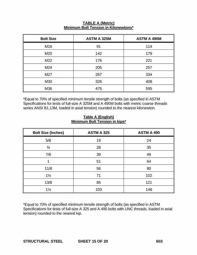
STRUCTURAL STEEL SHEET 15 OF 20 603
TABLE A (Metric) Minimum Bolt Tension in Kilonewtons*
Bolt Size ASTM A 325M ASTM A 490M
M16 91 114
M20 142 179
M22 176 221
M24 205 257
M27 267 334
M30 326 408
M36 475 595 *Equal to 70% of specified minimum tensile strength of bolts (as specified in ASTM Specifications for tests of full-size A 325M and A 490M bolts with metric coarse threads series ANSI B1.13M, loaded in axial tension) rounded to the nearest kilonewton.
Table A (English) Minimum Bolt Tension in kips*
Bolt Size (Inches) ASTM A 325 ASTM A 490
5/8 19 24
¾ 28 35
7/8 39 49
1 51 64
11/8 56 80
1¼ 71 102
13/8 85 121
1½ 103 148 *Equal to 70% of specified minimum tensile strength of bolts (as specified in ASTM Specifications for tests of full-size A 325 and A 490 bolts with UNC threads, loaded in axial tension) rounded to the nearest kip.
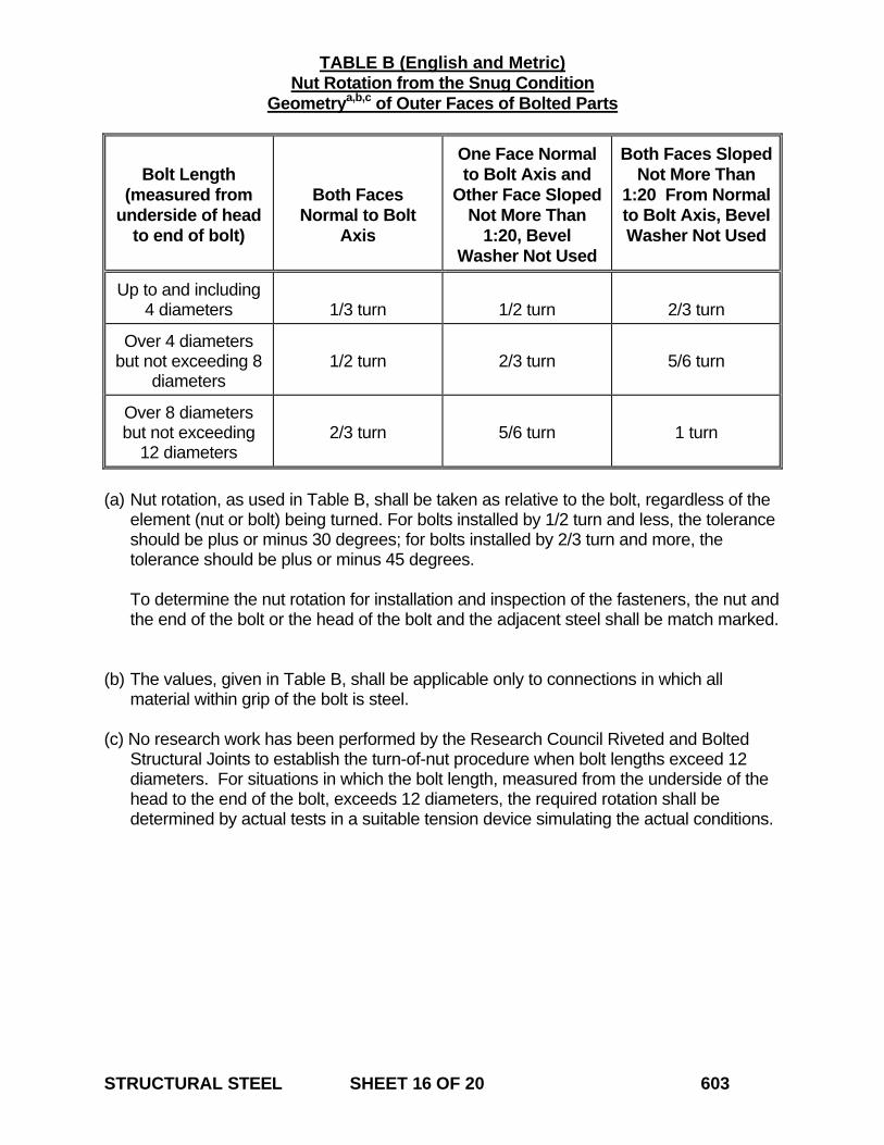
STRUCTURAL STEEL SHEET 16 OF 20 603
TABLE B (English and Metric) Nut Rotation from the Snug Condition Geometrya,b,c of Outer Faces of Bolted Parts
Bolt Length
(measured from underside of head
to end of bolt)
Both Faces Normal to Bolt
Axis
One Face Normal to Bolt Axis and
Other Face Sloped Not More Than
1:20, Bevel Washer Not Used
Both Faces Sloped Not More Than
1:20 From Normal to Bolt Axis, Bevel Washer Not Used
Up to and including 4 diameters
1/3 turn
1/2 turn
2/3 turn
Over 4 diameters but not exceeding 8
diameters
1/2 turn
2/3 turn
5/6 turn
Over 8 diameters but not exceeding
12 diameters
2/3 turn
5/6 turn
1 turn
(a) Nut rotation, as used in Table B, shall be taken as relative to the bolt, regardless of the
element (nut or bolt) being turned. For bolts installed by 1/2 turn and less, the tolerance should be plus or minus 30 degrees; for bolts installed by 2/3 turn and more, the tolerance should be plus or minus 45 degrees.
To determine the nut rotation for installation and inspection of the fasteners, the nut and
the end of the bolt or the head of the bolt and the adjacent steel shall be match marked.
(b) The values, given in Table B, shall be applicable only to connections in which all
material within grip of the bolt is steel. (c) No research work has been performed by the Research Council Riveted and Bolted
Structural Joints to establish the turn-of-nut procedure when bolt lengths exceed 12 diameters. For situations in which the bolt length, measured from the underside of the head to the end of the bolt, exceeds 12 diameters, the required rotation shall be determined by actual tests in a suitable tension device simulating the actual conditions.
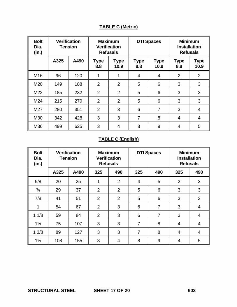
STRUCTURAL STEEL SHEET 17 OF 20 603
TABLE C (Metric)
Bolt Dia. (in.)
Verification Tension
Maximum Verification
Refusals
DTI Spaces Minimum Installation Refusals
A325 A490 Type 8.8
Type 10.9
Type 8.8
Type 10.9
Type 8.8
Type 10.9
M16 96 120 1 1 4 4 2 2
M20 149 188 2 2 5 6 3 3
M22 185 232 2 2 5 6 3 3
M24 215 270 2 2 5 6 3 3
M27 280 351 2 3 6 7 3 4
M30 342 428 3 3 7 8 4 4
M36 499 625 3 4 8 9 4 5
TABLE C (English)
Bolt Dia. (in.)
Verification Tension
Maximum Verification
Refusals
DTI Spaces Minimum Installation Refusals
A325 A490 325 490 325 490 325 490
5/8 20 25 1 2 4 5 2 3
¾ 29 37 2 2 5 6 3 3
7/8 41 51 2 2 5 6 3 3
1 54 67 2 3 6 7 3 4
1 1/8 59 84 2 3 6 7 3 4
1¼ 75 107 3 3 7 8 4 4
1 3/8 89 127 3 3 7 8 4 4
1½ 108 155 3 4 8 9 4 5
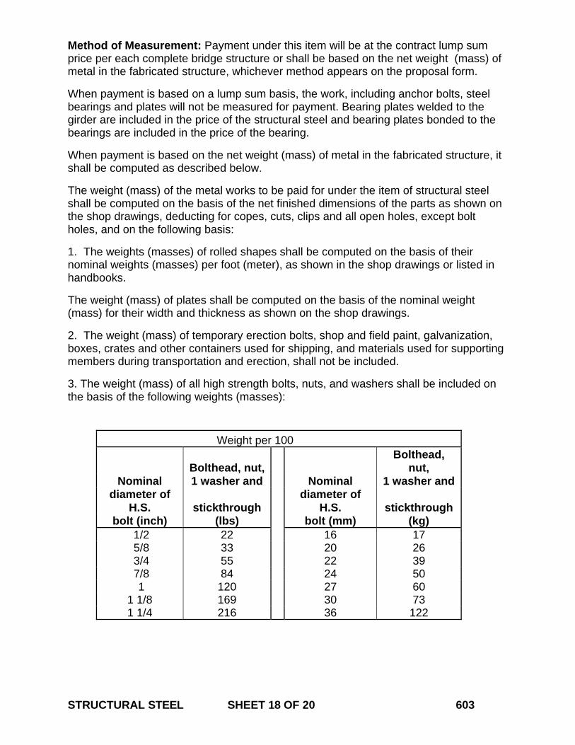
STRUCTURAL STEEL SHEET 18 OF 20 603
Method of Measurement: Payment under this item will be at the contract lump sum price per each complete bridge structure or shall be based on the net weight (mass) of metal in the fabricated structure, whichever method appears on the proposal form.
When payment is based on a lump sum basis, the work, including anchor bolts, steel bearings and plates will not be measured for payment. Bearing plates welded to the girder are included in the price of the structural steel and bearing plates bonded to the bearings are included in the price of the bearing.
When payment is based on the net weight (mass) of metal in the fabricated structure, it shall be computed as described below.
The weight (mass) of the metal works to be paid for under the item of structural steel shall be computed on the basis of the net finished dimensions of the parts as shown on the shop drawings, deducting for copes, cuts, clips and all open holes, except bolt holes, and on the following basis:
1. The weights (masses) of rolled shapes shall be computed on the basis of their nominal weights (masses) per foot (meter), as shown in the shop drawings or listed in handbooks.
The weight (mass) of plates shall be computed on the basis of the nominal weight (mass) for their width and thickness as shown on the shop drawings.
2. The weight (mass) of temporary erection bolts, shop and field paint, galvanization, boxes, crates and other containers used for shipping, and materials used for supporting members during transportation and erection, shall not be included.
3. The weight (mass) of all high strength bolts, nuts, and washers shall be included on the basis of the following weights (masses):
Weight per 100
Bolthead, nut, Bolthead,
nut, Nominal 1 washer and Nominal 1 washer and
diameter of H.S. stickthrough
diameter of H.S. stickthrough
bolt (inch) (lbs) bolt (mm) (kg) 1/2 22 16 17 5/8 33 20 26 3/4 55 22 39 7/8 84 24 50 1 120 27 60
1 1/8 169 30 73 1 1/4 216 36 122
STRUCTURAL STEEL SHEET 19 OF 20 603
4. The weight (mass) of weld metal shall be computed on the basis of the theoretical volume from plan dimensions of the welds.
Size of fillet in Weight of weld in Inches (mm) pounds per foot (kg per meter)
3/16 (5) 0.08 (0.119) ¼ (6) 0.14 (0.208) 5/16 (8) 0.22 (0.327) 3/8 (9.5) 0.30 (0.446) ½ (13) 0.55 (0.818) 5/8 (16) 0.80 (1.190) ¾ (19) 1.10 (1.636) 7/8 (22) 1.50 (2.231) 1 (25) 2.00 (2.974)
5. The weight (mass) of steel shims, filler plates and anchor bolts shall be measured for payment.
When the pay item “Materials for Structural Steel (Site No. )” is included in the Contract, payment for furnishing of the raw steel material for the plates and shape material only, excluding any markup, based on the net weight (mass) required, and the payment will be made under the estimated item “Materials for Structural Steel (Site No.)”. The overruns or wastage shall not exceed ten per cent for straight girders and fifteen per cent for curved girders. All other work specified in this section for the bridge will be deemed paid for under the lump sum price. In the absence of the pay item “Materials for Structural Steel (Site No. )”, the cost of the raw material is included in the Lump Sum payment for this item, “Structural Steel (Site No. )”. Basis of Payment: The structural steel, incorporated in the completed and accepted structure, will be paid for at the contract lump sum price for "Structural Steel (Site No. )," or at the contract unit price per hundred weight (kilogram) for "Structural Steel," whichever is indicated in the contract documents.
Payment for either method shall be for structural steel, complete in place, which price shall include quality control, furnishing, fabricating, transporting, storing, erecting, welding, surface preparation and all materials including fastener assemblies, steel bearing assemblies and anchor bolts, equipment, tools and labor incidental thereto.
When the pay item “Materials for Structural Steel (Site No. )” is included in the Contract, payment for furnishing of the raw steel material for the plates and shape material only,
STRUCTURAL STEEL SHEET 20 OF 20 603
excluding any markup, based on the net weight (mass) required, and the payment will be made under the estimated item “Materials for Structural Steel (Site No.)”. All remaining work including, but not limited to, preparation of shop drawings, fabricating, transporting, storage and handling, erecting, surface preparation and all materials, equipment, tools and labor incidental thereto, will be paid for under “Structural Steel (Site No. )”. In the absence of the pay item “Materials for Structural Steel (Site No. )”, the cost of the raw material is included in the Lump Sum payment for this item, “Structural Steel (Site No. )”. All remaining work including, but not limited to, preparation of shop drawings, fabricating, transporting, storage and handling, erecting, surface preparation and all materials, equipment, tools and labor incidental thereto, will be paid for under “Structural Steel (Site No. )”.
No direct payment will be made for setting anchor bolts, preparing bearing areas, furnishing and placing materials under bearings. No direct payment will be made for non destructive testing as shown on the plans.
Pay Item Pay Unit Structural Steel (Site No. ) l.s. (l.s.) Structural Steel cwt. (kg)
July 2005
CONNECTICUT SUPPLEMENTAL SPECIFICATION
SECTION 6.12 CONCRETE CYLINDER CURING BOX
Delete the entire section and replace with it the following: 6.12.01 –Description: This item shall consist of furnishing a box for curing concrete test cylinders. The box shall be commercially available and manufactured specifically for curing concrete test cylinders. The box will remain the property of the Contractor at the conclusion of the project. The box shall be delivered to a location on the project as directed by the Engineer. 6.12.02 – Materials: A catalog cut listing detailed specifications of the box and operating instructions from the manufacturer must be submitted to the Engineer. The box and its components shall be constructed of non-corroding materials and shall be capable of storing a minimum of 18 test cylinders, 6” X 12” (152 mm X 305 mm) stored vertically with the lid closed. The lid must be watertight when closed and hinged in the back with security latches on the front that can be padlocked. The box must be capable of holding water to a maximum level of one inch above test cylinders placed in the box vertically. A drain hole must be provided in a wall of the box to allow manual drainage of the water that exceeds this level. A drain hole must also be provided at the bottom of the box so that it can be manually emptied. The temperature of the water must be controlled by heating and cooling device capable of maintaining the temperature of the water within a range of 60 to 80º F, +/- 2 ºF (15.5 to 26.7 ºC, +/- 1 ºC) within an outside ambient air temperature range of -10 to 120 º F (-23.3 to 49 ºC). The heating and cooling device must be positioned to allow free circulation of air and water around the cylinders and be rated at 120 volts and 15 amps. A rack must be provided within the box to support the cylinders above the pool of temperature controlled water. The device must be thermostatically controlled with a digital readout that is capable of displaying the high/low water temperature within the box since the last reading was taken. 6.12.03 - Construction Methods: The Contractor shall maintain the curing box in working order and shall provide all necessary electrical service and water so that the curing box can be used properly during the entire course of the project. Any curing box that is not operating properly, as determined by the Engineer, shall be replaced within 24 hours by the Contractor at no expense to the State. The Engineer reserves the right to prohibit placement of fresh concrete on the project until a curing box acceptable to the Engineer is operational on the project site. 6.12.04 - Method of Measurement: The furnishing of the concrete test cylinder curing box will be measured for payment by the number of boxes delivered by the Contractor and accepted by the Engineer. CONCRETE CYLINDER CURING BOX SHEET 1 OF 2 612
6.12.05 – Basis of Payment: This item will be paid for at the contract unit price each for “Concrete Cylinder Curing Box” ordered and accepted on the project, which price shall include all submittals, material, tools, equipment, and labor incidental thereto. The price shall also include all maintenance and operating costs related to the curing box for the duration of the project. Pay Item Pay Unit Concrete Cylinder Curing Box ea. (ea.) CONCRETE CYLINDER CURING BOX SHEET 2 OF 2 612
July 2013
CONNECTICUT SUPPLEMENTAL SPECIFICATION
SECTION 6.51 CULVERTS
6.51.02 – Materials: Delete the 2nd paragraph, “Pipes of the type indicated ... of Article M.02.01.” and insert the following paragraph: “Pipes of the type indicated on the plans and joint sealant shall conform to the requirements of Article M.08.01. Bedding material shall conform to the requirements of Article M.08.03. Granular fill shall conform to the requirements of Article M.02.01.” 6.51.03 – Construction Methods: In the 8th paragraph replace “gravel fill” with “granular fill”. Delete the 13th paragraph, “Bituminous fiber and … as the pipe.” 6.51.04 – Methods of Measurement: In the 7th paragraph, replace “Gravel Fill” with “Granular Fill”. 6.51.05 – Basis of Payment: In the 8th paragraph, replace “Gravel Fill” with “Granular Fill”.
CULVERTS SHEET 1 OF 1 651
July 2014
CONNECTICUT SUPPLEMENTAL SPECIFICATION
SECTION 7.01 DRILLED SHAFTS
Add the following section:
SECTION 7.01 DRILLED SHAFTS
7.01.01 – Description 7.01.02 – Materials 7.01.03 – Construction Methods 7.01.04 – Method of Measurement 7.01.05 – Basis of Payment 7.01.01 - Description: This work shall consist of all labor, materials, equipment and services necessary to complete the Drilled Shaft installation in accordance with the Contract. Drilled shafts shall be made primarily of reinforced or unreinforced concrete. 7.01.02 - Materials: Drilled Shafts shall be made of the following materials: 1. Portland Cement Concrete: Concrete used in the construction of the shaft shall conform
to the plans, Section M.03, and to the following:
(a) The concrete shall have a minimum initial slump of 8 in (200 mm). (b) The concrete mix shall maintain a slump of no less than 4 in (100 mm) for a minimum of
three (3) hours beyond the expected time for placement of concrete and removal of temporary casing (if used), as indicated by trial mixes and physical tests of slump loss. The trial mix and physical tests (slump loss tests) shall be conducted using concrete mix and ambient air temperatures anticipated during concrete placement.
(c) All admixtures, if approved for use, shall be adjusted for the conditions encountered on
the job so as to conform to the slump loss requirements within this specification and must not adversely affect the timing of, taking of or interpretation of any Nondestructive Testing that may be called for in the Contract.
(d) Coarse aggregate shall conform to Article M.01.01, No. 8 Gradation.
2. Reinforcing Steel: Reinforcing steel used in construction of the shaft shall conform to
Article M.06.01. 3. Access Tubes: Access tubes for cross-hole acoustic logging shall be made of Schedule
40 steel pipe conforming to ASTM A 53, Grade A or B, Type E, F, or S. The tubes’ inside diameter shall be at least 1.5 in (38 mm). All access tubes, including all pipe joints, shall
DRILLED SHAFTS SHEET 1 OF 18 701
have a round, regular inside surface free of defects and obstructions, in order to permit the free, unobstructed passage of probes to the bottoms of the tubes. The access tubes shall be watertight, free from corrosion and free of deleterious material on the outside that could prevent bonding with the concrete. All access tubes shall be fitted with watertight caps on the bottom and top.
4. Grout: Grout used for filling Access Tubes shall meet the requirements of Article M.03.05.
The grout shall have strength properties equivalent to or better than those of the drilled shaft concrete.
5. Permanent Casing: Steel casing shall conform to the requirements of ASTM A36 or A252
Grade 2 unless otherwise specified on the plans. Casings shall be smooth, clean, watertight, and of ample strength to withstand handling, installation, and the pressure from surrounding concrete and earth materials. The outside diameter of any casing shall not be less than the specified diameter of the shaft.
7.01.03 - Construction Methods: 1. Qualifications of Drilled Shaft Contractor and Submittals: The Contractor performing
the work described in this specification shall have been installing drilled shafts of both diameter and length similar to those shown on the plans for a minimum of three (3) years prior to the bid date for this Project. The Contractor shall submit a list of projects that it has performed in said three (3) years that met these criteria. The list of projects shall contain names and phone numbers of owner's representatives who can verify the Contractors' participation on those projects, and that they met said criteria.
As early as possible, and no later than thirty (30) days prior to constructing drilled shafts, the Contractor shall submit to the Engineer an Installation Plan for the shafts. This Plan shall provide the following information:
(a) A list identifying the intended on-Site supervisor(s) and drill operator(s), for approval by
the Engineer. The on-Site supervisor(s) shall have a minimum of two (2) years’ experience supervising the construction of drilled shafts of a diameter and length similar to those shown on the plans. The drill operator(s) shall have a minimum of one (1) years’ experience drilling for the construction of drilled shafts of a diameter and length similar to those shown on the plans. The list shall contain a summary of each individual’s experience.
Should the Contractor elect to change any of these intended personnel during construction of the shafts, this same approval process will need to be completed for the new personnel prior to their starting work on the Project. The Contractor shall not be compensated for any delays resulting from such changing of personnel.
(b) List of proposed equipment to be used, including cranes, drills, augers, bailing buckets,
final cleaning equipment, desanding equipment, slurry pumps, core sampling equipment, tremies or concrete pumps, casing and any other equipment required for construction of the shafts.
(c) Details of overall construction operation sequence and the sequence of shaft
DRILLED SHAFTS SHEET 2 OF 18 701
construction in bents or groups. (d) Details of the Contractor’s intended shaft excavation methods.
(e) When the use of slurry is anticipated, details of the mix design and its suitability for the
subsurface conditions at the Site, mixing and storage methods, maintenance methods, and disposal procedures.
(f) Details of methods for cleaning the shaft excavation.
(g) Details of reinforcement placement, including support and centralization methods.
(h) Details of concrete mix design and test results of both a trial mix and a slump loss test.
The tests shall be conducted by an approved testing laboratory, using approved methods to demonstrate that the concrete meets slump loss requirements.
(i) Details of concrete placement, including proposed operational procedures for free fall,
tremie or pumping methods, proposed concreting log form and computations for time duration of shaft pour estimates.
(j) Details of casing installation and removal methods. If welding of casing is proposed,
submit the welding procedure. All welding shall be done in accordance with the current AWS Structural Welding Code.
(k) Details of methods for removal of obstructions. Obstructions for which the Contractor
shall provide details of methods for removal include, but are not necessarily limited to, removal of boulders, concrete, riprap, steel, timber or miscellaneous debris.
(l) Details for any monitoring plan as called for in the Contract.
The Engineer will evaluate the drilled shaft Installation Plan for conformance with the Contract and will then notify the Contractor of any additional information required or changes necessary in order to meet Contract requirements. All procedural approvals given by the Engineer shall be subject to trial in the field and shall not relieve the Contractor of the responsibility to satisfactorily complete Project work as detailed in the plans and specifications. The Contractor shall not commence construction of drilled shafts until the Engineer has approved the Installation Plan.
If integrity or load testing of the drilled shafts is called for by the Contract or the Site conditions, this submittal shall be developed in coordination with and submitted concurrently with working drawing submittals, as required in the testing specifications.
All submittals shall comply with the working drawing submittal requirements outlined in Article 1.05.02.
2. Trial Drilled Shaft Installation and Load Testing: When called for in the Contract, the
Contractor shall demonstrate the adequacy of the proposed methods, techniques and equipment by successfully constructing a trial drilled shaft in accordance with these
DRILLED SHAFTS SHEET 3 OF 18 701
specifications. This trial drilled shaft shall be positioned away from production shafts, in the location shown on the plans or as directed by the Engineer. The trial shaft shall be drilled to the maximum depth shown in the plans. Failure by the Contractor to demonstrate to the Engineer the adequacy of methods and equipment shall be reason for the Engineer to require alterations of the Contractor’s equipment or methods in order to prevent results unacceptable under the Contract or to the Engineer. Any additional trial drilled shaft required to demonstrate the adequacy of altered methods or construction equipment shall be at the Contractor's expense. Once the Engineer approves construction of production shafts, no changes will be permitted in the personnel, materials, methods or equipment used by the Contractor in constructing the satisfactory trial drilled shaft, unless the Contractor obtains the Engineer’s written approval to do so. Unless otherwise shown in the Contract, the trial drilled shaft shall have reinforcing bars, access tubes and concrete placed using the same materials and methods of construction to be used during construction of the production drilled shafts. The trial drilled shaft shall be cut off 2 ft (0.6 m) below finished grade and left in place. The disturbed area(s) at the site(s) of the trial drilled shaft(s) shall be restored as nearly as practical to original conditions.
Should the plans call for load testing of the trial drilled shaft, all necessary loading apparatus, instrumentation and other equipment required for performing the load test will be specified and paid for under a separate item.
All trial drilled shaft(s) and load test(s) must be completed and accepted by the Engineer prior to construction of any production drilled shafts. In the event that there is more than one trial drilled shaft and load test, the Contractor may begin construction of some of the production drilled shafts, in whatever way that the Engineer requires or approves.
3. Protection of Existing Structures: The Contractor shall control drilled shaft operations in
a way that will prevent damage to existing structures or utilities, in accordance with Articles 1.07.09 and 1.07.13. Preventive measures shall include, but are not limited to: selecting construction methods and procedures to prevent caving of the shaft excavation, and that will include monitoring and controlling the vibrations from construction activities such as the driving of casing or sheeting, drilling of the shaft, or from any blasting that the Contract or the Engineer may have permitted.
If monitoring is called for in the Contract, a preconstruction survey of existing facilities shall be performed to establish baseline data, including ambient vibration levels and existing structural defects. In general, monumented survey points shall be established on structures which are located within a distance of either ten (10) shaft diameters or the estimated shaft depth, whichever is greater. These points shall be monitored by the Contractor for vertical and lateral movement in an approved manner to the accuracy required by the Engineer.
When deformations exceed the predetermined amount included in the plans, the Contractor shall immediately stop work and, if directed by the Engineer to do so, backfill the excavated hole. The Contractor shall be responsible for selecting and using equipment and procedures that keep deformations of existing structures within levels specified by the Contract or Engineer.
DRILLED SHAFTS SHEET 4 OF 18 701
When vibrations are to be monitored, the Contractor must engage the services of a professional vibrations consultant to monitor and record vibration levels during drilled shaft construction. Unless the Engineer states otherwise, vibration monitoring equipment must be capable of detecting velocities of 0.1 in/sec (2.5 mm/sec) or less. When vibration levels exceed tolerable levels established by the Contract or Engineer, the Contractor shall immediately stop the work causing the vibrations and take whatever measures are necessary to reduce vibration levels to below tolerable levels. All costs related to vibration monitoring required in the Contract shall be included in the bid price for the Drilled Shaft item.
4. Construction Sequence: Excavation to footing elevation shall be completed before shaft
construction begins unless otherwise noted in the Contract or approved by the Engineer. Any disturbance at or below the footing area caused by shaft installation shall be repaired by the Contractor prior to the footing construction.
When drilled shafts are to be installed in conjunction with embankment placement, the Contractor shall construct drilled shafts after the placement of fills, unless shown otherwise in the Contract or approved by the Engineer.
Drilled shafts, constructed prior to the completion of the fills, shall not be capped until the fills have been placed as near to final grade as possible, leaving only the workroom necessary for construction of the caps.
5. Exploration Test Borings: As soon as possible, the Contractor shall take soil samples or
rock cores, where shown on the plans or as directed by the Engineer, in order to determine the character of the material directly below the completed shaft excavation. The soil samples shall be extracted with a split spoon sampler or undisturbed sample tube. The rock cores shall be cut with an approved triple tube core barrel to a minimum of 10 ft (3 m) below the bottom of the drilled shaft excavation before the excavation is made. The Engineer may require the depth of coring be extended up to a total depth of 20 ft (6 m). Rock core and standard penetration test samples shall be measured, visually identified and described in the Contractor's log. The samples shall be placed in suitable containers, identified by shaft location, elevation, and Project number and shall be delivered with the Contractor's field log to the Engineer within twenty-four (24) hours after each boring exploration is completed. The Engineer will inspect the samples and log in order to determine the final depth of required excavation based on evaluation of the material’s suitability. The Contractor shall not start shaft drilling or construction of the shafts until the Engineer has determined the final depth of required excavation. Two (2) copies of the Contractor’s final typed log shall be furnished to the Engineer within seven (7) calendar days after completion of the borings. The logs shall contain specific information about the drilling equipment and tools used and the rate of hole advancement, as well as descriptions of soil, rock, obstructions, and water encountered. The Contractor shall supply a suitable, secure location on the Site for storage of all soil and rock samples. At no time shall the soil or rock core samples be taken off the Site without the Engineer’s permission to do so.
6. General Methods and Equipment: The Contractor shall perform the excavations required
for shafts through whatever materials are encountered, to the dimensions and elevations shown in the plans or otherwise required by the Contract. The Contractor's methods and equipment shall be suitable for the intended purpose and materials encountered. The
DRILLED SHAFTS SHEET 5 OF 18 701
permanent casing method shall be used only at locations shown on the plans or authorized by the Engineer in writing. Blasting shall be permitted only if specifically authorized on the plans or in writing by the Engineer.
7. Uncased Construction Method: This method consists of using water or slurry (mineral or
polymer) to maintain stability of the borehole perimeter while advancing the excavation to final depth, placing the reinforcing cage, and concreting the shaft. Where drilled shafts are located in open water areas, exterior casings shall be extended from above the anticipated high water elevation into the ground in order to protect the shaft concrete from water action during placement and curing of the concrete. The exterior casing shall be installed in a manner that will produce a positive seal at the bottom of the casing, so that no piping of water or other materials occurs into or from the shaft excavation.
8. Casing Construction Method: The casing method may be used either where shown on
the plans or at sites where uncased construction methods are inadequate to prevent hole caving or excessive deformation of the hole. In using this method, the casing may either be placed in a predrilled hole or advanced through the ground by twisting, driving or vibration before being cleaned out.
9. Excavation and Drilling Equipment: The Contractor’s excavation and drilling equipment
shall have adequate capacity, including power, torque and down-thrust to make it possible to excavate a hole of the maximum diameter and to a depth of twenty percent (20%) beyond the depths shown on the plans.
The excavation and overreaming tools shall be of adequate design, size and strength to perform the work shown in the plans or described herein. When the material encountered cannot be drilled using conventional earth augers with soil or rock teeth, drill buckets, grooving tools, or underreaming tools, the Contractor shall provide special drilling equipment, including but not limited to: rock core barrels, rock tools, air tools, blasting materials, or other equipment as necessary to enable construction of the shaft excavation to the size and depth required. Excavation by blasting may not be performed without the prior written approval of same by the Engineer.
10. Excavation: Shaft excavations shall be made at locations and to the top of shaft
elevations, estimated bottom of shaft elevations, shaft geometry and dimensions shown in the Contract. If material encountered during excavation is unsuitable for these purposes or differs from that anticipated in the design of the drilled shaft, the Contractor shall extend drilled shaft tip (base) elevations as and when the Engineer directs it to do so.
The Contractor shall maintain a construction method log during shaft excavation. The log shall contain information such as the description and approximate top and bottom elevation of each soil or rock material encountered, of seepage or ground water, and any other relevant information or observations, including a description of the tools and drill rigs used and any changes necessitated by changing ground conditions. The Contractor shall dispose of any excavated materials removed from shaft excavations in accordance with the applicable Contract requirements for disposal of excavated materials, including those in Section 1.10.
DRILLED SHAFTS SHEET 6 OF 18 701
The Contractor shall not permit workers to enter the shaft excavation for any reason unless (1) a suitable casing has been installed and the water level has been lowered and stabilized below the level to be occupied, and (2) adequate safety equipment and procedures have been provided to workers entering the excavation. Any placement of workers within the shaft excavation shall be in conformance with OSHA regulations and industry standards.
11. Drilled Shaft Earth Excavation: Drilled shaft earth excavation is (1) excavation accomplished with conventional tools such as augers and drilling buckets attached to drilling equipment of the size, power, torque, and down-thrust (crowd) proposed by the Contractor in a construction procedure approved by the Engineer, or (2) successful construction of a trial drilled shaft. Earth excavation may include, but will not necessarily be limited to, excavation of clay, silt, sand, gravel, cobbles, boulders, weathered rock, and miscellaneous fill.
12. Drilled Shaft Rock Excavation: Drilled shaft rock excavation is (1)excavation of
competent rock, accomplished with conventional rock drilling tools, such as core barrels attached to drilling equipment of the size, power, torque, and down-thrust (crowd) as proposed by the Contractor in a construction procedure approved by the Engineer or (2) successful construction of a trial drilled shaft. Top of competent rock is as shown on the Contract drawings.
13. Obstructions: When obstructions are encountered, the Contractor shall notify the
Engineer of them immediately. Obstructions are defined as impenetrable objects that
(a) cannot be removed or excavated using conventional augers fitted with soil or rock teeth, underreaming tools, or drilling buckets; or
(b) cause a significant decrease in the rate of excavation advancement, relative to the rate
of advancement for the rest of the shaft excavation within the particular strata where the obstruction is located that had been achieved using the techniques and equipment that had previously been used successfully to excavate the shaft.
The Engineer will be the sole judge of the significance of any reduced rate of shaft advancement and of the classification of obstruction excavation. The Engineer will be present at the site of the obstruction in order to evaluate obstructions, to authorize measures for dealing with them, and to approve the designation each obstruction. Sloping bedrock or bedrock that is higher than anticipated by the plans shall not be considered as requiring obstruction excavation. Shallow obstructions are obstructions located within 5 ft (1.5 m) of the top level of the shaft. Shallow obstructions at shaft locations shall be removed at the Contractor’s expense. The Contractor shall remove all subsurface obstructions at drilled shaft locations. Such obstructions may include man-made materials, such as concrete foundations, and natural materials, such as boulders. Subsurface obstruction removal special procedures/tools may include, but are not limited to, chisels, boulder breakers, core barrels, down-the-hole hammers, air tools, hand excavation, temporary casing, and increases of the hole diameter. Blasting shall not be permitted unless specifically approved in advance in writing by the Engineer.
DRILLED SHAFTS SHEET 7 OF 18 701
14. Lost Tools: Drilling tools lost in the excavation shall not be considered obstructions and shall be promptly removed by the Contractor without compensation. All costs due to lost tool removal shall be borne by the Contractor including, but not limited to, costs associated with the repair of hole degradation due to removal operations or due to the hole’s remaining open for an excessively long time.
15. Casing: Casings shall be steel, smooth, clean, watertight, and of ample strength to
withstand both handling and installation and the pressure of both concrete and the surrounding earth materials. The outside diameter of casings shall not be less than the specified diameter of the shaft, and the outside diameter of any excavation made below the casing shall not be less than the specified diameter of the shaft. No extra compensation will be paid for concrete required to fill an oversized casing or oversized excavation. All casings, except permanent casings, shall be removed from shaft excavations. Any length of permanent casing installed below the shaft cutoff elevation shall remain in place. When the shaft extends above ground or through a body of water, the portion exposed above ground or through the water may be formed with removable casing, except when permanent casing is specified. Removable casing shall be stripped from the shaft in a manner that will not damage the concrete. Casings may be removed when the concrete has attained sufficient strength, provided: curing of the concrete is continued for a seventy-two (72) hour period; the shaft concrete is not exposed to salt water or moving water for seven (7) days; and the concrete reaches a compressive strength of at least 2500 psi (17,235 kPa) as determined from concrete cylinder breaks.
16. Temporary Casing: All subsurface casing shall be considered temporary unless specifically shown as permanent casing in the Contract. The Contractor shall be required to remove temporary casing before or immediately after completion of concreting the drilled shaft. Casing shall never be pulled after the concrete begins to set, due to probable entrapment of drilling fluid in the shaft concrete and probable separation of the concrete within the shaft.
If the Contractor elects to remove a casing and substitute a longer or larger-diameter casing through caving soils, the excavation shall either be stabilized with slurry or backfilled before the new casing is installed. Other methods approved by the Engineer may be used to control the stability of the excavation and protect the integrity of foundation materials. Before the casing is withdrawn, the level of fresh concrete in the casing shall be a minimum of 5 ft (1.5 m) above either the hydrostatic water level in the formation or the level of drilling fluid in the annular space behind the casing, whichever is higher. As the casing is withdrawn, care shall be exercised to maintain an adequate level of concrete within the casing, so that fluid trapped behind the casing is displaced upward and discharged at the ground surface without contaminating or displacing the shaft concrete. Temporary casings that become bound or fouled during shaft construction and cannot practicably be removed shall constitute a defect in the drilled shaft. The Contractor shall be responsible to improve such defective shafts to the satisfaction of the Engineer. Improvement may consist of, but not be limited to, removing the shaft concrete and extending the shaft deeper, in order to compensate for loss of frictional capacity in the cased zone; providing straddle shafts to compensate for capacity loss; grouting around the
DRILLED SHAFTS SHEET 8 OF 18 701
exterior of the shaft; or providing a replacement shaft. All corrective measures, including redesign of footings caused by defective shafts, shall be done to the satisfaction of the Engineer by the Contractor without either compensation or an extension of Contract time of the Project. In addition, no compensation will be paid for casing remaining in place.
17. Permanent Casing: Permanent casing shall be used where specified by the Contract. The casing shall be continuous between top and bottom elevations as shown in the plans. After installation is complete, the permanent casing shall be cut off at the prescribed elevation. In cases in which special temporary casings are shown on the plans or authorized in writing by the Engineer to be used in conjunction with permanent casing, the Contractor shall maintain both alignment of the temporary casing with the permanent casing and a positive, watertight seal between the two casings during excavation and concreting operations. Permanent casing shall maintain close contact with the surrounding earth after installation. Use of an oversized hole or temporary casing outside the permanent casing beneath the ground surface will not be allowed without the advance written permission of the Engineer to do so. Should an oversized hole or temporary casing outside the permanent casing beneath the ground surface be allowed by the Engineer, grouting of the exterior annular space shall be provided by the Contractor in order to create close contact between the casing and the surrounding ground. The grouting shall extend from the bottom of the annular space to an elevation determined by the Engineer. No compensation will be paid to the Contractor for grouting of the exterior annular space.
18. Slurry: Mineral or polymer slurries shall be employed when slurry is used in the drilling process, unless other drilling fluids are approved in writing by the Engineer. Mineral slurry shall have both a mineral grain size that will remain in suspension and sufficient viscosity and gel characteristics to allow it to transport excavated material to a suitable screening system. The percentage and specific gravity of the material used to make the mineral suspension shall be sufficient to maintain the stability of the excavation and to allow proper concrete placement.
During construction, the level of the slurry shall be maintained at a height sufficient to prevent caving of the hole. The slurry head shall remain above the piezometric head of the groundwater. This includes initial drilling of the borehole down to the piezometric level. Slurry shall be introduced when the depth of the borehole is still above the piezometric level, not after the inflow of water can be detected and sloughing has begun. In the event of a sudden significant loss of slurry to the hole, the construction of that foundation shall be stopped until either a method to stop slurry loss or an alternate construction procedure has been approved by the Engineer. Mineral slurry shall be premixed thoroughly with clean fresh water and adequate time (as prescribed by the mineral manufacturer) shall be allotted for hydration prior to introduction into the shaft excavation. Slurry tanks of adequate capacity shall be required for slurry circulation, storage, and treatment. No excavated slurry pits will be allowed in lieu of slurry tanks without the written consent of the Engineer to the substitution. Desanding equipment shall be provided by the Contractor as necessary to keep slurry sand content at less than
DRILLED SHAFTS SHEET 9 OF 18 701
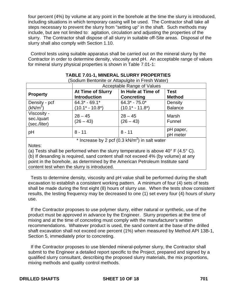
four percent (4%) by volume at any point in the borehole at the time the slurry is introduced, including situations in which temporary casing will be used. The Contractor shall take all steps necessary to prevent the slurry from "setting up" in the shaft. Such methods may include, but are not limited to: agitation, circulation and adjusting the properties of the slurry. The Contractor shall dispose of all slurry in suitable off-Site areas. Disposal of the slurry shall also comply with Section 1.10. Control tests using suitable apparatus shall be carried out on the mineral slurry by the Contractor in order to determine density, viscosity and pH. An acceptable range of values for mineral slurry physical properties is shown in Table 7.01-1:
TABLE 7.01-1, MINERAL SLURRY PROPERTIES (Sodium Bentonite or Attapulgite in Fresh Water)
Acceptable Range of Values
Property At Time of Slurry Introduction
In Hole at Time of Concreting
Test Method
Density - pcf (kN/m2)
64.3* - 69.1* (10.1* - 10.8*)
64.3* - 75.0* (10.1* - 11.8*)
Density Balance
Viscosity - sec./quart (sec./liter)
28 – 45 (26 – 43)
28 – 45 (26 – 43)
Marsh Funnel
pH 8 - 11 8 - 11 pH paper, pH meter
* Increase by 2 pcf (0.3 kN/m2) in salt water Notes: (a) Tests shall be performed when the slurry temperature is above 40° F (4.5° C). (b) If desanding is required, sand content shall not exceed 4% (by volume) at any point in the borehole, as determined by the American Petroleum Institute sand content test when the slurry is introduced.
Tests to determine density, viscosity and pH value shall be performed during the shaft excavation to establish a consistent working pattern. A minimum of four (4) sets of tests shall be made during the first eight (8) hours of slurry use. When the tests show consistent results, the testing frequency may be decreased to one (1) set every four (4) hours of slurry use. If the Contractor proposes to use polymer slurry, either natural or synthetic, use of the product must be approved in advance by the Engineer. Slurry properties at the time of mixing and at the time of concreting must comply with the manufacturer’s written recommendations. Whatever product is used, the sand content at the base of the drilled shaft excavation shall not exceed one percent (1%) when measured by Method API 13B-1, Section 5, immediately prior to concreting. If the Contractor proposes to use blended mineral-polymer slurry, the Contractor shall submit to the Engineer a detailed report specific to the Project, prepared and signed by a qualified slurry consultant, describing the proposed slurry materials, the mix proportions, mixing methods and quality control methods.
DRILLED SHAFTS SHEET 10 OF 18 701
If polymer slurry, or blended mineral-polymer slurry, is proposed, the Contractor’s slurry management plan shall include detailed provisions for controlling the quality of the slurry, including tests to be performed, the frequency of those tests, the test methods, and any maximum or minimum property requirements that must be met in order to ensure that the slurry meets its intended functions in the subsurface conditions at the Project site and with the construction methods to be used. The slurry management plan shall include a set of the slurry manufacturer’s written recommendations and shall include the following tests, as a minimum: Density test (API 13B-1, Section 1), viscosity test (Marsh funnel and cup, API 13B-1, Section 2.2, or approved viscometer), pH test (pH meter, pH paper), and sand content test (API sand content kit, API 13B-1, Section 5). If such a proposal is approved by the Engineer, the Contractor may use water as a drilling fluid. In that case, all of the provisions in Table 7.01-1 for mineral slurries must be met, except that the maximum density shall not exceed 70 pcf (11 kN/m2). The Contractor shall ensure that a heavily-contaminated slurry suspension, which could impair the free flow of concrete, has not accumulated in the bottom of the shaft. Prior to placing concrete in any shaft excavation, the Contractor shall take slurry samples using a sampling tool approved by the Engineer. Slurry samples shall be extracted from the base of the shaft and at intervals not exceeding 10 ft (3 m) up the slurry column in the shaft, until two (2) consecutive samples produce acceptable values for density, viscosity, and pH. When any slurry samples are found to be unacceptable, the Contractor shall take whatever action is necessary to bring the slurry within specification requirements. Concrete shall not be placed until the slurry in the hole is re-sampled and test results produce acceptable values. Reports of all tests specified above, signed by an authorized representative of the Contractor, shall be furnished to the Engineer on completion of each drilled shaft. During construction, the level of mineral or blended mineral-polymer slurry in the shaft excavation shall be maintained at a level not less than 4 ft (1.2 m) above the highest expected piezometric pressure head along the depth of the shaft, and the level of polymer slurry shall be maintained at a level not less than 6 ft (1.8 m) above the highest expected piezometric pressure head along the shaft. If at any time, in the opinion of the Engineer, the slurry construction method fails to produce the desired final results, the Contractor shall discontinue this method and propose an alternate method for approval by the Engineer. Drilling tools shall contain vents to stabilize hydrostatic pressure above and below the tool during insertion and extraction. The rate of tool extraction shall not cause any noticeable turbulence in the slurry column in the borehole. The Contractor shall arrange for the slurry manufacturer’s technical representative to be present at the Site during Project startup, or throughout the entire Project if continual difficulty is expected, in order to ensure that the slurry is mixed and managed properly.
19. Excavation Inspection: The Contractor shall check the dimensions and alignment of each shaft excavation. Final shaft depths shall be measured with a suitable weighted tape or other approved method after final cleaning. The Contractor shall provide equipment and
DRILLED SHAFTS SHEET 11 OF 18 701
access to the Engineer for confirming dimension, alignment, and bottom cleanliness. Acceptable shaft cleanliness will be determined by the Engineer.
20. Construction Tolerances: The following construction tolerances apply to drilled shafts,
unless otherwise stated in the Contract:
(a) The center of the drilled shaft shall be within 3 in (76 mm) of plan position in the horizontal plane at the plan elevation for the top of the shaft.
(b) The vertical alignment of a vertical shaft excavation shall not vary from the plan
alignment by more than 1/4 in/ft (21 mm/m) of depth. (c) After the concrete is placed, the top of the reinforcing steel cage shall be no more than
6 in (150 mm) above and no more than 3 in (76 mm) below plan position.
(d) All casing diameters shown on the plans refer to outside diameter (“OD”) dimensions. The dimensions of casings are subject to American Petroleum Institute tolerances applicable to regular steel pipe. The Contractor may elect to provide a casing larger in diameter than shown in the plans, if the Engineer approves its doing so.
(e) The top elevation of the shaft shall have a tolerance of plus 1 in (25 mm) or minus 3 in
(76 mm) from the plan top-of-shaft elevation. (f) Excavation equipment and methods shall be designed so that the completed shaft
excavation will have a planar bottom. The cutting edges of excavation equipment shall be normal to the vertical axis of the equipment within a tolerance of +/- 3/8 in/ft (+/- 3 mm/m) of diameter.
Drilled shaft excavations and completed shafts not constructed within the required tolerances are unacceptable. The Contractor shall be responsible for correcting all unacceptable shaft excavations and completed shafts to the satisfaction of the Engineer. Materials and work necessary, including engineering analysis and redesign, in order to complete corrections for out-of-tolerance drilled shaft excavations, shall be furnished without cost to the State or extension of Contract time.
21. Reinforcing Steel Cage Construction and Placement: The reinforcing steel cage, consisting of longitudinal bars, ties, cage stiffener bars, spacers, centralizers, and other necessary appurtenances, shall be completely assembled and placed as a unit immediately after the shaft excavation is inspected and accepted, and prior to concrete placement. Internal stiffeners shall be removed as the cage is placed in the borehole, so as not to interfere with the placement of concrete. The reinforcing steel in the shaft shall be tied and supported so that the reinforcing steel will remain within allowable tolerances. Concrete spacers or other approved noncorrosive spacing devices shall be used at sufficient intervals near the bottom and at intervals not exceeding 10 ft (3 m) up the shaft, in order to ensure concentric spacing for the entire cage length. Spacers shall be constructed of approved material, equal in quality and durability to the concrete specified for the shaft. The spacers shall be of adequate dimension to ensure
DRILLED SHAFTS SHEET 12 OF 18 701
a minimum 3 in (76 mm) annular space between the outside of the reinforcing cage and the side of the excavated hole. Approved cylindrical concrete feet (bottom supports) shall be provided to ensure that the bottom of the cage is maintained the proper distance above the base. The elevation of the top of the steel cage shall be checked before and after the concrete is placed. If the upward displacement of the rebar cage exceeds 2 in (51 mm) or if the downward displacement exceeds 6 in per 20 ft (152 mm per 6 m) of shaft length, the drilled shaft will be considered defective. In such a case, corrections shall be made by the Contractor to the satisfaction of the Engineer. No additional shafts shall be constructed until the Contractor has modified the rebar cage support in a manner satisfactory to the Engineer.
22. Concrete Placement: Concrete placement shall be performed in accordance with the
applicable portions of Section 6.01 and with the requirements herein dealing with concrete materials.
Concrete shall be placed as soon as possible after reinforcing steel placement and after the Engineer has accepted the cleanliness of the shaft. The Engineer may re-inspect the shaft for cleanliness should there be any delays between initial acceptance of shaft cleanliness and commencement of the concrete placement. If during such a delay the Engineer has determined that shaft cleanliness has deteriorated, the Engineer may require the Contractor to re-clean the shaft. The Contractor may be required to remove the rebar cage should it be necessary in order to achieve the required shaft cleanliness. The Contractor will not be compensated for any cost or loss of time due to the need to re-clean the shaft. Concrete placement shall be continuous from the bottom to the top elevation of the shaft. Concrete placement shall continue after the shaft excavation is filled and good quality concrete is evident at the top of shaft. Concrete shall be placed by free fall, or through a tremie or concrete pump. Free fall placement will be permitted only in dry holes. Concrete placed by free fall shall fall directly to the base without contacting the rebar cage or hole sidewall. Drop chutes may be used to direct concrete to the base during free fall placement. The Contractor shall maintain Concreting Logs during all concrete placement. The log shall include, but not be limited to, concreting curves plotting Depth-to-Top of Concrete vs. Volume of Concrete Placed (for both theoretical and actual volumes of concrete placed). The Contractor shall provide a copy of each log to the Engineer upon completion of each drilled shaft concrete placement. A sample of the proposed log to be used by the Contractor shall be submitted as part of the Installation Plan working drawing submittal.
23. Tremies: Tremies may be used for concrete placement in either wet or dry holes. Tremies
used to place concrete shall consist of a tube of sufficient length, weight, and diameter to discharge concrete at the shaft base elevation. The tremie shall not contain aluminum parts that may come in contact with the concrete. The tremie’s inside diameter shall be at least six (6) times the maximum size of aggregate used in the concrete mix, but shall not be less than 10 in (254 mm). The inside and outside surfaces of the tremie shall be clean and
DRILLED SHAFTS SHEET 13 OF 18 701
smooth in order to permit flow of concrete and unimpeded withdrawal during concreting. The wall thickness of the tremie shall be adequate to prevent crimping or sharp bends, which would restrict concrete placement. The tremie used for wet excavation concrete placement shall be watertight. Underwater or under-slurry placement shall not begin until the tremie is placed to the shaft base elevation, and the concrete shall be kept completely separated from the water or slurry prior to the time that it is discharged. Valves, bottom plates or plugs may be used for this purpose only if concrete discharge can begin within 1 tremie diameter of the base of the drilled shaft. Plugs shall either be removed from the excavation or be of a material approved by the Engineer that will not cause a defect in the shaft if not removed. The discharge end of the tremie shall be constructed to permit the free radial flow of concrete during placement operations. The tremie discharge end shall be immersed at least 5 ft (1.5 m) in concrete at all times after starting the flow of concrete. The flow of the concrete shall be continuous. The level of the concrete in the tremie shall be maintained above the level of slurry or water in the borehole at all times, in order to prevent water or slurry intrusion into the shaft concrete.
If at any time during the concrete placement, the tremie line orifice is removed from the fluid concrete column and it discharges concrete above the rising concrete level, the shaft will be considered defective. All costs of repair or replacement of defective shafts shall be the responsibility of the Contractor.
24. Pumped Concrete: Concrete pumps and lines may be used for concrete placement in either wet or dry excavations. All pump lines shall have a minimum 4 in (102 mm) diameter and be constructed with watertight joints. Concrete placement shall not begin until the pump line discharge orifice is at the shaft base elevation.
For wet excavations, a plug or similar device shall be used to separate the concrete from the fluid in the hole until pumping begins. The plug shall either be removed from the excavation or be of a material approved by the Engineer that will not cause a defect in the shaft if not removed. The discharge orifice shall remain at least 5 ft (1.5 m) below the surface of the fluid concrete. When lifting the pump line during concreting, the Contractor shall temporarily reduce the line pressure until the orifice has been repositioned at a higher level in the excavation. If at any time during the concrete placement the pump line orifice is removed from the fluid concrete column and it discharges concrete above the rising concrete level, the shaft will be considered defective. All costs of repair or replacement of defective shafts shall be the responsibility of the Contractor.
25. Drop Chutes: Drop chutes may be used to direct placement of free-fall concrete in excavations where the maximum depth of water does not exceed 3 in (76 mm). Free fall placement is not permitted in wet excavations. Drop chutes shall consist of a smooth tube of either one-piece construction or sections that can be added and removed. A drop chute can also be a hopper with a short tube to direct the flow of concrete. Concrete may be placed through either the hopper at the top of the tube or side openings as the drop chute
DRILLED SHAFTS SHEET 14 OF 18 701
is retrieved during concrete placement. If concrete placement causes the shaft excavation to cave or slough, or if the concrete strikes the rebar cage or sidewall, the Contractor shall reduce the height of free fall or reduce the rate of concrete flow into the excavation, or both. If caving or sloughing of the borehole walls occurs during free-fall placement of concrete, the shaft will be considered defective. All costs of repair or replacement of defective shafts shall be the responsibility of the Contractor. If concrete placement cannot be satisfactorily accomplished by free fall, in the opinion of the Engineer, the Contractor shall use either tremie or pumping techniques to accomplish the concrete placement.
26. Access Tubes for Crosshole Acoustic Logging: Access tubes for crosshole acoustic
logging shall be placed on each reinforcing cage designated in the Contract in the position and at the frequency shown on the plans. Access tubes must be firmly secured to the cage. Normally, the tubes shall extend from 6 in (150 mm) above the bottom of the shaft to at least 3 ft (0.9 m) above the top of the shaft, or 2 ft (0.6 m) above the ground surface if the shaft is cut off below the ground surface. If cross-hole acoustic tests are to be performed, the access tubes shall be filled with clean water no later than four (4) hours after placement of the concrete and the tubes capped during concrete placement to keep out concrete and debris. In all cases, the access tubes shall be as nearly parallel as possible and be placed as far from the longitudinal steel bars as possible. Prior to the beginning of downhole logging, the Contractor shall assure that the Cross-Hole Acoustic Logging test probes can pass through every tube to the bottom. If a tube is obstructed, the entire length of the obstructed access tube will not be measured for payment. The Engineer may also require the Contractor to core a hole within the drilled shaft near and to the full depth of the obstructed tube. The cored hole shall be large enough to accommodate the test probe for the full length of the hole. The coring equipment, coring procedure and location of the core hole shall be approved by the Engineer before the coring process may begin. The coring method shall provide for complete core recovery and shall minimize abrasion and erosion of the core. The core hole shall be placed at a position in the shaft that will not produce damage to the reinforcing steel in the shaft. The core hole shall be logged, voids or defects indicated on the log, and the log submitted to the Engineer. Cores shall be preserved and made available for inspection by the Engineer. The core hole will be treated as an access tube for downhole testing. Core holes that are drilled to substitute for a blocked access tube shall be measured and paid for at the Contract unit price for Access Tubes. Upon completion of all tests involving access tubes and after acceptance of the drilled shaft, the access tubes and core holes shall be filled with grout.
27. Evaluation and Acceptance or Rejection of Drilled Shafts: Upon completion and integrity testing (if called for) of a drilled shaft, the Engineer will review all available drilling logs, drilled shaft construction logs, concreting logs, inspection reports, load test results, and integrity test results in order to determine the acceptability of the drilled shaft. If the Engineer determines that available data is inconclusive, the Engineer may call for additional integrity testing, coring, or other appropriate actions necessary for evaluating the drilled shaft. Should the additional integrity testing or coring confirm the presence of anomalies, the Contractor will not be compensated for the cost of the additional integrity testing or coring (even if the anomalies are determined to be non-critical and the shaft is found to be acceptable). Should additional integrity testing or coring demonstrate that anomalies are
DRILLED SHAFTS SHEET 15 OF 18 701
not present (prior to any remedial work), the additional integrity testing or coring will be paid for by the Department. The Contractor may continue to construct drilled shafts before receipt of notice of acceptance of the tested shaft or shafts by the Engineer. If the Engineer finds previously-constructed shaft(s) to be unacceptable, the Contractor shall be required to repair, at its expense, the unacceptable shaft(s) to the satisfaction of the Engineer. The Contractor shall prove to the satisfaction of the Engineer, at no expense to the State, the acceptability of all shafts constructed since the time that the unacceptable shaft was constructed and to prove the acceptability of the procedure to be used in constructing future shafts. If the Engineer deems the construction procedure to be unacceptable, the Contractor shall cease all drilled shaft construction until submittal of a new construction procedure to the Engineer and the Engineer has accepted it.
The Contractor shall submit repair procedures to the Engineer for review and approval. If these plans involve change of or impact on the structural design of the shafts or shaft caps, or the geometry of the shafts, any proposed redesign of the Contractor’s plan shall be performed at the Contractor’s expense by a qualified Professional Engineer registered in the State of Connecticut. The Engineer may require that additional shafts be tested. If the testing of the additional shaft(s) indicates the presence of a defect in any additional shaft, the testing cost for that shaft shall be borne by the Contractor, and the Contractor shall repair the shaft at its own expense, as above. Any additional testing required by the Engineer on repaired drilled shafts shall be considered part of the Contractors remediation plan, to be paid for by the Contractor.
7.01.04 - Method of Measurement: 1. Furnishing Drilled Shaft Drilling Equipment: There will be no measurement of the work
performed under this Lump Sum item. 2. Drilled Shaft will be measured for payment by the length in linear feet (meters) of the
completed and accepted concrete drilled shaft, of the diameter and containing the reinforcement shown on the plans. The length will be determined as the difference between the plan top-of-shaft elevation and the final bottom-of-shaft elevation.
3. Drilled Shaft Earth Excavation will be measured for payment by the length in linear feet
(meters) of completed earth excavation of the diameter shown on the plans (measured along the centerline of the shaft), either from the top of existing grade elevation prior to drilling or from the bottom of the drilled shaft cap elevation (whichever is lower), to either the top of competent rock elevation (if the drilled shaft extends onto or into competent rock) or to the bottom of the shaft elevation (if the shaft does not extend onto or into competent rock).
4. Drilled Shaft Rock Excavation will be measured for payment by the length in linear feet
(meters) of completed rock excavation of the diameter shown on the plans, measured along the centerline of the shaft from the top-of-competent-rock elevation to the bottom-of-the-shaft elevation
5. Obstructions will be measured for payment, after designation as an obstruction by the DRILLED SHAFTS SHEET 16 OF 18 701
Engineer, by the number of hours of work, or fraction thereof per obstruction, required to remove the obstruction.
6. Trial Drilled Shaft will be measured for payment by the authorized linear feet (meters) of
trial shaft holes drilled to the diameter shown on the plans, completed (including backfill and restoration of area, when required) and accepted. The length of trial shaft holes will be determined as the difference between the existing ground surface elevation at the center of the trial shaft hole prior to drilling and the authorized bottom elevation of the hole.
7. Exploration Test Borings will be measured for payment by the length in linear feet
(meters), measured from the existing grade elevation to the bottom elevation of the exploration hole, for each authorized exploration boring drilled.
8. Permanent Casing will be measured for payment by the length in linear feet (meters) of
each diameter casing installed and accepted. The length to be paid will be measured along the casing from the top-of-the-shaft elevation or the top of the casing, whichever is lower, to the bottom of the casing at each shaft location where permanent casing is used.
9. Access Tubes will be measured for payment by the length in linear feet (meters) of
unobstructed access tube, installed and accepted in the drilled shafts, to the depths shown on the plans
7.01.05 - Basis of Payment: 1. Furnishing Drilled Shaft Drilling Equipment: Payment for this item will be at the Contract
lump sum price for “Furnishing Drilled Shaft Drilling Equipment” which will be considered full and complete payment for furnishing and moving the drilling equipment to the Site, setting up the equipment at the required locations, and removing the equipment from the Site.
Payment of sixty percent (60%) of the lump sum amount bid for this item will be made when all drilling equipment is on the Site, assembled and ready to drill foundation shafts. Payment of the remaining forty percent (40%) of the lump sum amount will be made when all shafts have been drilled, all shaft concrete has been placed to the top of the shaft, all defects are repaired, and all drilled shafts have been accepted by the State.
2. Drilled Shaft: Drilled shafts will be paid for at the Contract unit price per linear foot (meter) for “Drilled Shaft (Diameter)” complete and accepted in place, including submittals, concrete and reinforcing steel, all labor, equipment, materials, temporary casings, slurry, slurry technical representative, blasting (if allowed), protection of existing facilities or utilities, vibration monitoring and incidentals necessary to complete the drilled shaft.
3. Drilled Shaft Earth Excavation: This work will be paid for at the Contract unit price per
linear foot (meter) for “Drilled Shaft Earth Excavation (Diameter)” complete, including all labor, equipment, materials, water control, and disposal of excavated material necessary.
4. Drilled Shaft Rock Excavation: Drilled shaft rock excavation will be paid for at the
Contract unit price per linear foot (meter) for “Drilled Shaft Rock Excavation (Diameter)” complete, including all labor, equipment, materials, water control, and disposal of excavated
DRILLED SHAFTS SHEET 17 OF 18 701
material necessary. No payment will be made for additional rock excavation or placement of additional shaft concrete resulting from blasting overbreak (if blasting is allowed).
5. Obstructions: Removal of obstructions will be paid for at the Contract unit price per hour
for “Obstructions” complete, including all labor, equipment, materials, excavation of obstructions, water control, disposal of excavated material necessary. If the Contractor chooses to use a larger shaft diameter for obstruction excavation, no additional compensation will be paid for performing such oversized obstruction excavation.
6. Trial Drilled Shaft: Trial drilled shafts will be paid for at the Contract unit price per linear
foot (meter) for “Trial Drilled Shaft (Diameter)” complete and accepted, including all labor, equipment, materials, excavation of the trial drilled shaft through whatever materials are encountered, to the bottom of shaft elevation shown on the plans or as authorized by the Engineer (using slurry approved by the Engineer as necessary), providing inspection facilities, backfilling the hole, restoring the Site as required, and all other expenses to complete the trial shaft.
7. Exploration Test Borings: Soil samples, rock cores or both, of the diameter and length
required and authorized by the Engineer will be paid for at the Contract unit price per linear foot (meter) for “Exploration Test Boring” complete, including drilling, extracting, packaging and classifying samples or cores, delivery of same to the Engineer, furnishing concrete or grout to fill the core hole, providing a written log of the hole, and all other expenses necessary.
8. Permanent Casing: Permanent casings will be paid for at the Contract price per linear foot
(meter) for “Permanent Casing (Diameter)” complete, including furnishing and placing the permanent casing in the shaft excavation.
9. Access Tubes: Access tubes will be paid for at the Contract unit price per linear foot
(meter) of unobstructed “Access Tubes” complete and accepted, installed in the drilled shafts to the depths shown on the plans, including the post-test grouting of the access tubes.
Pay Item Pay Unit Furnishing Drilled Shaft Drilling Equipment l.s. (l.s.) Drilled Shaft (Diameter) l.f. (m) Drilled Shaft Earth Excavation (Diameter) l.f. (m) Drilled Shaft Rock Excavation (Diameter) l.f. (m) Obstructions hr. (hr.) Trial Drilled Shaft (Diameter) l.f. (m) Exploration Test Boring l.f. (m) Permanent Casing (Diameter) l.f. (m) Access Tubes l.f. (m)
DRILLED SHAFTS SHEET 18 OF 18 701
July 2013
CONNECTICUT SUPPLEMENTAL SPECIFICATION
SECTION 7.02 PILES
Delete the entire section and replace it with the following:
SECTION 7.02 PILES
7.02.01—Description 7.02.02—Materials 7.02.03—Construction Methods 7.02.04—Method of Measurement 7.02.05—Basis of Payment 7.02.01—Description: This item shall consist of furnishing and driving foundation piles of the type and dimensions designated. Piles shall conform to and be installed in accordance with these specifications, and at the location, and to the elevation, penetration and/or capacity shown on the plans, or as directed by the Engineer. If specified in the plans or directed by the Engineer, piles shall be tipped, shaped, reinforced or otherwise pointed and strengthened Test piles shall be piles of the type specified, driven in advance of placing orders for the piles, for the purpose of determining length or bearing capacity of piles. The Contractor shall furnish the piles in accordance with an itemized order list which will be furnished by the Engineer, showing the number and length of all piles. When test piles are specified, the pile lengths shown on the plans are for estimating purposes only. The actual lengths to be furnished for production piles will be determined by the Engineer after the test piles have been driven. 7.02.02—Materials: Piles of the type indicated on the plans shall conform to the requirements of Articles M.09.02 and M.14.01. 7.02.03—Construction Methods 1. Pile Types: (a) Timber Piles: The method of storing and handling timber piles shall be such as to avoid damage to the piles. Special care shall be taken to avoid breaking the surface of treated piles. Cant dogs, hooks, or pike-poles shall not be used. Cuts or breaks in the surface of treated piling shall be given three brush coats of hot creosote oil of approved quality, and hot creosote oil shall be poured into all bolt holes. (b) Steel Piles: The methods of storing and handling steel piles shall be such as to prevent damage to the piles and to protect them from corrosion. (c) Cast-In-Place Concrete Piles: Cast-in-place concrete piles shall be constructed by driving steel shells and filling them with concrete. Shells shall be continuously or incrementally tapered, or cylindrical, or a combination of continuously or incrementally PILES SHEET 1 OF 16 702
tapered lower sections, which are extended with cylindrical upper sections, unless otherwise provided in the plans or special provisions. The tapered portion of piles shall have a minimum tip diameter of 8 inches (200 millimeters) and shall change in diameter not less than 1 inch in every 12 feet (7 millimeters/meter). Cylindrical piles and the cylindrical extension portions of tapered piles shall have a minimum diameter of 12 inches (300 millimeters). Shells for cast-in-place concrete piles shall be formed by joining sections of the same manufacture, unless otherwise permitted by the Engineer. Composite shell piles, which are piles composed of different thicknesses or of different manufacture, shall not be used unless shown on the plans or approved by the Engineer. Prefabricated driving points or other type tip enclosures shall be subject to the approval of the Engineer. The Contractor shall furnish shells of a type and gage which can be driven without distortion. Shells which fail, fracture or otherwise distort during driving or after driving shall be withdrawn or replaced at the Contractor's expense. The metal of shells which are to be driven without a mandrel shall be of sufficient thickness to withstand the driving without failure, fracture or distortion, but in no case shall the thickness be less than No. 7 gage. Shells driven with a mandrel shall have a thickness not less than No. 18 gage. Piles having a shell thickness less than No. 9 gage shall be reinforced as shown on the plans. Composite shell piles formed by extending lower sections of No. 7 or heavier gage, with upper sections of lighter than No. 7 gage, shall be driven with an internal mandrel in such a manner so as to insure shell alignment and maximum hammer energy transmission throughout the pile shell length. All details concerning compatibility of shell and mandrel construction shall be subject to the approval of the Engineer. After driving has been completed, the shell shall be inspected and approved before any concrete is placed. The Contractor shall provide suitable lights and other equipment necessary to inspect each shell throughout its length. All seams, joints and splices in shells shall develop the full strength of the shell and shall be watertight. Damaged shells that are unacceptable to the Engineer shall be filled with sand and a replacement shell or shells shall be driven adjacent thereto. Reinforcement shall be placed in accordance with the requirements of the plans or special provisions. No concrete shall be placed in a pile until all driving within a radius of 15 feet (4.5 meters) from the pile has been completed, or until all the shells for any one bent have been completely driven. If this is not practical, all driving within the above limits shall be discontinued until the concrete in the last pile cast has set at least 7 days. Concrete shall be placed continuously in each pile, care being used to fill every part of the shell, and to work concrete around the reinforcement without displacing it. No concrete shall be placed in shells containing an accumulation of water or any foreign material. Extensions, or "build-ups" on concrete piles, shall be avoided; but when necessary, they shall be made as specified in Subarticle 7.02.03-7. PILES SHEET 2 OF 16 702
(d) Prestressed Concrete Piles (Pretensioned): The piles shall be manufactured in accordance with the provision of Article 5.14.03, except as follows: (1) Forms: The forms for the piles shall be of substantial construction and shall produce a uniformly smooth surface on all formed sides. A minimum concrete cover of 2 inches (50 millimeters) shall be maintained for prestressing elements by the use of spreaders or by bundling in areas adjacent to openings or inserts. Ties shall also have a minimum cover of 2 inches (50 millimeters) at these locations. Side forms carrying no load may be removed after 24 hours with the permission of the Engineer or after the concrete has reached the minimum transfer strength as required by Subarticle M.09.02-6. (2) Finishing: The topside surface of the piles shall be given a uniformly smooth steel trowel finish to match the surface of the formed sides. The prestressing elements shall be cut flush or recessed 1/8 inch (3 millimeters) to the top of the pile. Projecting fins and surface imperfections shall be removed in a workmanlike manner. Exposed jet pipe connections, inserts or other devices shall be removed or recessed to a depth as directed, and the hole or opening patched with non-shrink grout in a workmanlike manner. The patching material shall have a degree of finish comparable to the adjacent surfaces. Additional finishing of piles, if required, shall be as shown on the plans or as otherwise directed. (3) Handling and Storage: Care shall be taken during storage, transporting, hoisting and handling of the prestressed piles to prevent cracking or damage. Damaged piles shall be replaced by the Contractor at his expense. Lifting and support points shall be marked on the piles as required. (4) Pile Extensions: Pile extensions shall normally be fabricated for this purpose in accordance with the specifications. However, sound sections of pile cutoffs or sound portions of rejected piles may be used, subject to the approval of the Engineer. Short pile extensions may, with the permission of the Engineer, be cast-in-place monolithically with the footing or cap.
2. Pile Driving Equipment: (a) Hammers: Piles shall be driven with approved air, steam, diesel, or hydraulic hammers or a combination of acceptable hammer and water jet. The plant and equipment furnished for air/steam hammers shall have sufficient capacity to maintain at the hammer, under working conditions, the volume and pressure specified by the manufacturer. The plant and equipment shall be equipped with accurate pressure gauges which are easily accessible to the Engineer. The valve mechanism and other parts of the hammer shall be properly maintained so that the length of stroke for a single-acting hammer and the number of blows per minute for a double-acting hammer will be obtained. The power plant for hydraulic hammers shall have sufficient capacity to maintain at the hammer, under working conditions, the volume and pressure specified by the manufacturer. The power plant and equipment shall be equipped with accurate pressure gauges which are easily accessible to the Engineer. The size of hammer shall be adapted to the type and size of piles and the driving conditions. Unless otherwise specified, the minimum rated striking energy per blow for PILES SHEET 3 OF 16 702

hammers used shall be 7,000-foot pounds (9,500 joules) for driving timber piles; 15,000-foot pounds (20,000 joules) for driving steel piles and for driving shells for cast-in-place concrete piles; and 19,000-foot pounds (25,000 joules) for driving precast concrete piles and for driving prestressed concrete piles. The hammer model used for the driving of test piles shall be used for the driving of service or production piles, unless a change is authorized by the Engineer in writing. Hammers delivering an energy which the Engineer considers detrimental to the piles shall not be used. Non-impact hammers, such as vibratory hammers, or driving aids such as jets, followers, pre-augered and prebored holes shall not be used unless either specifically permitted in writing by the Engineer or stated in the contract documents. (b) Pile Hammer Approval: All pile driving equipment furnished by the Contractor shall be subject to the approval of the Engineer. All pile driving equipment shall be sized in such a way that the piles can be driven with reasonable effort to the ordered lengths without damage. Approval of pile driving equipment by the Engineer will be based on wave equation analysis and/or other judgments. In no case shall the driving equipment be used without written approval of the Engineer. Prerequisite to such approval, the Contractor shall submit to the Engineer the necessary pile driving equipment information and wave equation analysis at least 30 days prior to driving piles. The wave equation analysis shall be signed, sealed and dated by a Connecticut licensed Professional Engineer. The criteria that the Engineer will use to evaluate the driving equipment consists of both the required number of hammer blows per foot (per 0.25 meters) as well as the pile stresses at the required ultimate pile capacity. The required number of hammer blows indicated by the wave equation at the ultimate pile capacity shall be between 36 and 180 blows per foot (29 and 147 blows per 0.25 meters) for the driving equipment to be acceptable. In addition, for the driving equipment to be acceptable the pile stresses which are indicated by the wave equation to be generated by the driving equipment shall not exceed the maximum driving stresses allowed by the governing design code stated in the contract documents. During pile driving operations, the Contractor shall use the approved system. No variations in the driving system will be permitted without the Engineer's written approval. Any change in the driving system will only be considered after the Contractor has submitted the necessary information for a revised wave equation analysis. If the Engineer determines the Contractor's hammer is unable to transfer sufficient energy to the pile, the hammer shall be removed from service until repaired to the satisfaction of the Engineer.
(c) Drive System Components and Accessories: (1) Hammer Cushion: Impact pile driving equipment designed to be used with a hammer cushion shall be equipped with a suitable thickness of hammer cushion material to prevent damage to the hammer or pile and to insure uniform driving behavior. Hammer cushions shall be made of durable manufactured materials, provided in accordance with the hammer manufacturer's guidelines. Wood, wire rope, and asbestos hammer cushions are specifically disallowed and shall not be PILES SHEET 4 OF 16 702
used. A striker plate as recommended by the hammer manufacturer shall be placed on the hammer cushion to insure uniform compression of the cushion material. The hammer cushion shall be removed from the helmet and inspected prior to beginning pile driving at each structure or after each 100 hours of pile driving, whichever is less. The Contractor shall replace any hammer cushion whose thickness is less than 75% of the original thickness. (2) Helmet: Piles driven with impact hammers require an adequate helmet or drive head to distribute the hammer blow to the pile head. The helmet shall be axially aligned with the hammer and the pile. The helmet shall be guided by the leads and not be free-swinging. The helmet shall fit around the pile head in such a manner as to prevent transfer of torsional forces during driving, while maintaining proper alignment of hammer and pile. For steel and timber piling, the pile heads shall be cut squarely and a helmet, as recommended by the hammer manufacturer, shall be provided to hold the axis of the pile in line with the axis of the hammer. For precast concrete and prestressed concrete piles, the pile head shall be plane and perpendicular to the longitudinal axis of the pile to prevent eccentric impacts from the helmet. For special types of piles, appropriate helmets, mandrels or other devices shall be provided in accordance with the manufacturer's recommendations so that the piles may be driven without damage. (3) Pile Cushion: The heads of concrete piles shall be protected by a pile cushion. Pile cushions shall be made of plywood, hardwood, or composite plywood and hardwood materials. The minimum pile cushion thickness placed on the pile head prior to driving shall be at least 4 inches (100 millimeters). A new pile cushion shall be provided for each pile. In addition the pile cushion shall be replaced if, during the driving of any pile, the cushion is compressed more than one-half the original thickness or it begins to burn. The pile cushion dimensions shall match the cross sectional area of the pile top. The use of manufactured pile cushion materials in lieu of a wood pile cushion shall be evaluated on a case by case basis. (4) Leads: Piles shall be supported in line and position with leads while being driven. Pile driver leads shall be constructed in a manner that affords freedom of movement of the hammer while maintaining alignment of the hammer and the pile to insure concentric impact for each blow. Leads may be either fixed or swinging type. Swinging leads, when used, shall be fitted with a pile gate at the bottom of the leads and, in the case of batter piles, a horizontal brace may be required between the crane and the leads. The pile section being driven shall not extend above the leads. The leads shall be adequately embedded in the ground or the pile constrained in a structural frame such as a template to maintain alignment. The leads shall be of sufficient length to make the use of a follower unnecessary, and shall be so designed as to permit proper alignment of batter piles. (5) Followers: Followers shall only be used when approved in writing by the Engineer, or when specifically stated in the contract documents. In cases where a follower is permitted, the first pile in each bent and every tenth pile driven thereafter shall be driven full length without a follower, to determine that adequate pile penetration is being attained to develop the ultimate pile capacity. The follower and pile shall be held and maintained in equal and proper alignment during driving. The follower shall be of such material and dimensions to permit the piles to be driven to the penetration depth PILES SHEET 5 OF 16 702
determined necessary from the driving of the full length piles. The final position and alignment of the first two piles installed with followers in each substructure unit shall be verified to be within the required location tolerances before additional piles are installed. (6) Jets: Jetting shall only be permitted if approved in writing by the Engineer or when specifically stated in the contract documents. When jetting is not required in the contract documents, but approved after the Contractor's request, the Contractor shall determine the number of jets and the volume and pressure of water at the jet nozzles necessary to freely erode the material adjacent to the pile without affecting the lateral stability of the in place pile. When jetting is specifically required in the contract documents, the plant shall have sufficient capacity to deliver at all times at least 100 psi (700 kilopascals) pressure at two 3/4-inch (19 millimeter) jet nozzles. In either case, unless otherwise indicated by the Engineer, jet pipes shall be removed when the pile toe is a minimum of 5 feet (1.5 meters) above prescribed toe elevation and the pile shall be driven to the required ultimate pile capacity with an impact hammer. Also, the Contractor shall control, treat if necessary, and dispose of all jet water in a manner satisfactory to the Engineer and in accordance with the provisions of Article 1.10. (7) Pre-Augering: When stated in the contract documents, the Contractor shall pre-auger holes at pile locations to the depths shown on the plans. Pre-augered holes shall be of a size smaller than the diameter or diagonal of the pile cross section; however, large enough to allow penetration of the pile to the specified depth. If subsurface obstructions, such as boulders or rock layers, are encountered, the hole diameter may be increased to the least dimension which is adequate for pile installation. Any void space remaining around the pile after completion of driving shall be filled with sand or other approved material. The use of spuds shall not be permitted in lieu of pre-augering. Augering, wet-rotary drilling, or other methods of pre-augering shall be used only when approved by the Engineer. When permitted, such procedures shall be carried out in a manner which will not impair the capacity of the piles already in place or the safety of existing adjacent structures. If the Engineer determines that pre-augering has disturbed the capacities of previously installed piles, those piles that have been disturbed shall be restored to conditions meeting the requirements of this specification by redriving or by other methods acceptable to the Engineer. Redriving or other remedial measures shall be instituted after the pre-augering operations in the area have been completed. 3. Pile Capacity (a) Ultimate Pile Capacity: Piles shall be driven by the Contractor to the penetration depth shown on the plans or to a greater depth if necessary to obtain the ultimate pile capacity. The ultimate pile capacity shall be as defined in the contract documents. Jetting or other methods shall not be used to facilitate pile penetration unless specifically permitted in the contract documents or in writing by the Engineer. The ultimate pile capacity of jetted piles shall be based on driving resistances recorded during impact driving after the jet pipes have been removed. Jetted piles not attaining the ultimate pile capacity at the ordered length shall be spliced, as PILES SHEET 6 OF 16 702
required, at the Contractor's cost, and driven with an impact hammer until the ultimate pile capacity is achieved. The ultimate pile capacity of piles driven with followers shall only be considered acceptable when the follower driven piles attain the same pile toe elevation or top of bedrock elevation as required for the full length piles driven without followers that attained the required ultimate pile capacity. (b) Wave Equation: The ultimate pile capacity shall be determined by the Engineer. Piles shall be driven with the approved driving equipment to the ordered length or other lengths necessary to obtain the required ultimate pile capacity. Jetting or other methods to facilitate pile penetration shall not be used unless specifically permitted either in the contract documents or approved by the Engineer after a revised driving resistance is established from the wave equation analysis. Adequate pile penetration shall be considered to be obtained when the specified wave equation resistance criteria is achieved within 5 feet (1.5 meters) of the pile toe elevation, based on ordered length. Piles not achieving the specified resistance within these limits shall be driven to penetrations established by the Engineer. (c) Static Load Tests: Compression load tests shall be performed by procedures set forth in ASTM D-1143 using the quick load test method, except that the test shall be taken to plunging failure or the capacity of the loading system. Testing equipment and measuring systems shall conform to ASTM D-1143, except that the loading system shall be capable of applying 150% of the ultimate pile capacity as stated in the contract documents, and that a load cell and spherical bearing plate shall be used. The apparatus shall be constructed to allow the various increments of the load to be placed gradually, without causing vibration to the test pile. The Contractor shall submit to the Engineer for approval working drawings of the loading apparatus in accordance with Article 1.05.02. When the approved method requires the use of tension (reaction) piles, the tension piles, when feasible, shall be of the same type and diameter as the production piles, and shall be driven in the location of permanent piles except that timber or tapered piles installed in permanent locations shall not be used as tension piles.
The top elevation of the test pile shall be determined immediately after driving and again just before load testing to check for heave. Any pile which heaves more than 1/4 inch (6 millimeters) shall be redriven or jacked to the original elevation prior to testing. Unless otherwise specified in the contract, a minimum 3-day waiting period shall be observed between the driving of any anchor piles or the load test pile and the commencement of the load test.
On completion of the load testing, any test or anchor piling not a part of the finished structure shall be removed or cut off at least 1 foot (300 millimeters) below either the bottom of footing or the finished ground elevation, if not located within the footing area. (d) Dynamic Pile Driving Analysis (PDA) Test: Dynamic measurements following procedures set forth in ASTM D-4945 will be taken during the driving of piles designated as dynamic monitoring test piles. The Contractor shall employ a qualified specialty Consultant, which has successfully completed no less than ten PILES SHEET 7 OF 16 702
dynamic pile driving tests, to perform the testing and report preparation for all Dynamic Pile Driving Analysis (PDA) Tests to be performed. At least thirty days prior to driving the test piles the Contractor shall submit to the Engineer for review and approval the qualified specialty consultant, as well as the complete installation, and testing procedures. The submittal shall include all necessary pile driving equipment and support facilities to drive the piles to capacities and depths shown on the plans within allowable stress limits. As part of the submittal the Contractor’s Consultant shall perform a wave equation analyses, and a summary report confirming that the pile driving system proposed by the Contractor can meet the capacity, driving resistance and allowable stress limits. All equipment necessary for the dynamic monitoring of the piles such as gages, cables, etc., shall be furnished by the Contractor’s Consultant. The equipment shall conform to the requirements of ASTM D-4945, Standard Test Method for High Strain Dynamic Testing of Piles, and be capable of testing the pile to one and one-half times the ultimate pile capacity. An experienced engineer, who has successfully completed no less than ten dynamic pile driving tests, shall operate the Pile Driving Analyzer in the field. The Contractor shall furnish a shelter within 100 feet (30 meters) of test location(s) to protect the dynamic test equipment from the elements. The shelter shall be a minimum floor size of 400 square feet (40 square meters), with a minimum ceiling height of 7 feet (2 meters), and an inside temperature maintained between 50° and 85°F (10° and 29°C). The Contractor shall provide power to the test pile locations for the duration of the dynamic testing. The power supply shall consist of a power source providing 115-Volt alternating current with a frequency of 60 Hz and a minimum of 2 kilowatts. If field generators are used as the power source, provide functioning meters to monitor power voltage and frequency. Direct current welders or non-constant power sources are unacceptable. Prior to lifting the pile to be dynamically tested, the Contractor shall provide as a minimum 3 feet (1 meter) of clear access to 180 degree opposite faces of the pile for pile preparation. The Contractor or its Consultant shall then drill and prepare holes in the pile for gage attachment. The Contractor or its Consultant shall attach the gages to the pile before driving the piles. Pile driving shall be performed using routine pile installation procedures. When the level of the gages is within 1 foot (300 millimeters) of the ground surface, or obstruction, driving shall be halted to remove the gages from the pile. If additional driving is required, the pile shall be spliced and gages shall be reattached to the head of the next pile segment. With the dynamic testing equipment attached, the Contractor shall drive the pile to the design penetration depth or to a depth determined by the Engineer. The Engineer will use the ultimate pile capacity estimates at the time of driving and/or restriking from dynamic test methods to determine the required pile penetration depth for the ultimate pile capacity. The stresses in the piles will be monitored during driving with the dynamic test equipment to ensure that the actual driving stresses do not exceed the maximum allowed values. If necessary, the Contractor PILES SHEET 8 OF 16 702
shall reduce the driving energy transmitted to the pile by using additional cushions or reducing the energy output of the hammer in order to maintain driving stresses below the maximum values. If non-axial driving is indicated by dynamic test equipment measurements, the Contractor shall immediately realign the driving system. After the initial drive of the pile, the Contractor shall wait 24 hours, or the time specified in the contract documents, and restrike the dynamic monitoring test pile with the dynamic testing instruments attached. A cold hammer shall not be used for the restrike. The hammer shall be warmed up before restrike begins by applying at least 20 blows to another pile. The maximum amount of penetration required during restrike shall be 6 inches (150 millimeters), or 50 hammer blows, whichever occurs first. The Contractor’s Consultant shall provide preliminary estimates of pile capacity of the test pile to the Engineer within 24 hours of the restrike of each tested pile. The Contractor’s Consultant shall also prepare and submit a written report within 5 calendar days of the completion of the testing. This report shall contain a discussion of the pile capacity obtained from the dynamic testing. CAPWAP analyses of the dynamic testing data shall be performed on data obtained at the end of initial driving and the beginning of restrike. The Engineer may request additional analyses at selected pile penetration depths. The report shall also discuss hammer and driving system performance, driving stress levels, and pile integrity. The report is to be prepared, signed, sealed and dated by a Connecticut licensed Professional Engineer. No production piles can be driven until the report has been submitted and approved by the Engineer. 4. Test Piles and Order Lists: Test piles shall be driven at the locations shown on the plans and to the penetration depths specified by the Engineer. Test piles shall be driven to a driving resistance established by the Engineer at the estimated pile toe elevation. The Contractor shall excavate the ground at each test pile to the elevation of the bottom of the footing before the pile is driven. All test piles shall be driven with impact hammers unless specifically stated otherwise in the plans. In general, the specified length of test piles will be greater than the estimated length of production piles in order to provide for variation in soil conditions. The driving equipment used for driving test piles shall be identical to the equipment proposed for driving the production piling. Approval of driving equipment shall conform to the requirements of these Specifications. Test piles that do not attain the specified driving resistance at a depth of 6 inches (150 millimeters) above the estimated pile tip elevation, or are specified as a dynamic monitoring pile, shall be redriven after being allowed to set up. The minimum time period before restrike shall be 24 hours, or as specified in the contract documents. A cold hammer shall not be used for the restrike. The hammer used shall be warmed up by applying at least 20 blows to another pile. Unless otherwise specified in the contract documents, the Contractor shall not order piling to be used in the permanent structure until test pile data has been reviewed and pile order lengths are authorized by the Engineer. The Engineer will provide the pile order list after completion of the test pile(s) and dynamic pile driving analysis (PDA) tests and/or pile loading tests specified in the contract documents. PILES SHEET 9 OF 16 702
When no test piles are specified for a substructure, the estimated pile lengths in the contract documents are taken as the pile order length. The lengths given in the order list will be based on the lengths which are assumed after cutoff to remain in the completed structure. The Contractor shall, without added compensation, increase the lengths to provide for fresh heading and for such additional length as may be necessary to suit the Contractor's method of operation. 5. Pile Preparation and Driving: The heads of all piles shall be plane and perpendicular to the longitudinal axis of the pile before the helmet is attached. Approval of a pile hammer relative to driving stress damage shall not relieve the Contractor of responsibility for piles damaged because of misalignment of the leads, failure of cushion materials, failure of splices, malfunctioning of the pile hammer, or other improper construction methods. Piles damaged for such reasons shall be rejected and replaced at the Contractor's expense when the Engineer determines that the damage impairs the strength of the pile. If it becomes necessary and is authorized by the Engineer to resort to jetting, spudding or pre-holing — and further, if no contract bid price is asked for in the proposal for jetting, spudding, or pre-holing — such work will be paid for as "extra work" in accordance with Articles 1.04.05 and 1.09.04. The use of a hammer with a greater mass, or the use of piles manufactured or designed with pile tips of a nature to provide for better penetration such as but not limited to composite shells, tapered sections or H-pile sections, shall not be considered as extra work. Authorized point reinforcement for piles shall be a separate item. Piles for exposed pile bents shall be driven with pile driver leads and templates. They shall be of rigid design and construction and shall maintain the required position and alignment of the piles within the tolerances hereinafter specified. Templates shall be anchored or spudded into position, shall be capable of guiding all piles required for the bent and shall remain in place until all the piles in the bent are driven. (a) Location and Alignment Tolerance: Piles shall be driven with a variation of not more than 1/4 inch per foot (20 millimeters/meter) from the vertical or from the batter line indicated, except that piles for trestle bents shall be so driven that the cap may be placed in its proper location without inducing excessive stresses in the piles. Upon completion of driving and released from leads, exposed piles such as in bents shall not have a variation of more than 2 inches (50 millimeters) at the cut-off elevation from the position shown on the plans. Unless otherwise permitted in writing by the Engineer, failure to meet this tolerance shall be cause for rejection. Other foundation piles shall not be out of the position shown on the plans more than 6 inches (150 millimeters) after driving. The Engineer may require that driving be stopped in order to check the pile alignment. Pulling laterally on piles to correct misalignment, or splicing a properly aligned section on a misaligned section shall not be permitted. If the location and/or alignment tolerances specified are exceeded, the extent of overloading shall be evaluated by the Engineer. If in the judgment of the Engineer, corrective measures are necessary, suitable measures shall be designed and constructed by the Contractor. PILES SHEET 10 OF 16 702
(b) Heaved Piles: Level readings to measure pile heave after driving shall be made by the Contractor at the start of pile driving operations and shall continue until the Engineer determines that such checking is no longer required. Level readings shall be taken immediately after the pile has been driven and again after piles within a radius of 15 feet (4.5 meters) have been driven. If pile heave is observed, the Contractor shall take accurate level readings referenced to a fixed datum on all piles immediately after installation and periodically thereafter as adjacent piles are driven to determine the pile heave range. All piles that have been heaved more than ¼ inch (6 millimeters) shall be redriven at the Contractor's cost, to the required resistance or penetration. Concrete shall not be placed in pile casings until pile driving has progressed beyond a radius of 15 feet (4.5 meters) from the pile to be concreted. If pile heave is detected for pipe or shell piles which have been filled with concrete, the piles shall be redriven to original position after the concrete has obtained sufficient strength and a proper hammer-pile cushion system, satisfactory to the Engineer, is used. (c) Installation Sequence: The order of placing individual piles in pile groups shall be either starting from the center of the group and proceeding outwards in both directions or starting at the outside row and proceeding progressively across the group. 6. Unsatisfactory Piles: The method used in driving piles shall not subject the piles to excessive or undue abuse producing crushing and spalling of concrete, injurious splitting, splintering, and brooming of the wood, or deformation of the steel. Misaligned piles shall not be forced into proper position. Any pile damaged during driving by reason of internal defects, or by improper driving, or driven out of its proper location, or driven below the designated cutoff elevation, shall be corrected by the Contractor by a method approved by the Engineer. Piles which have been bent during installation shall be considered unsatisfactory unless the ultimate capacity is proven by load tests performed at the Contractor's expense. If such tests indicate inadequate capacity, corrective measures as determined by the Engineer shall be taken, such as use of bent piles at reduced capacity, installation of additional piles, strengthening of bent piles, or replacement of bent piles. A concrete pile will be considered defective if a visible crack, or cracks, appears around the entire periphery of the pile, or if any defect is observed which, as determined by the Engineer, affects the strength or life of the pile.
7. Splicing Piles and Extensions: Full length piles shall be used when practicable; but if splices cannot be avoided, piles or shells for cast-in-place piles may be spliced in accordance with the requirements of the plans. Piles shall not be spliced except with the approval of the Engineer. Splices in excess of two per pile for timber, steel and cast-in-place concrete piles will not be permitted except with special permission of the Engineer. Only one splice per pile will be permitted in precast concrete or prestressed concrete piles. In the absence of splice details in the plans, piles or shells for cast-in-place concrete piles shall be spliced in accordance with the pile or shell manufacturer's recommendations, subject to the approval of the Engineer. Working Drawings for prefabricated splicing devices and their method of installation shall be submitted to the Engineer for review. All seams, joints and splices shall develop the full strength of the pile. PILES SHEET 11 OF 16 702
8. Point Reinforcement: When directed by the Engineer, the contractor shall point-reinforce piles. Such point-reinforcement shall be in accordance with the plans or as directed. 9. Cutoff Lengths: The pile head of all permanent piles and pile casings shall be cutoff at the elevation shown on the plans or as ordered by the Engineer. All cutoff lengths shall become the property of the Contractor, and shall be removed by the Contractor from the site of the work. 10. Painting Steel Piles and Steel Pile Shells: When steel piles or steel pile shells extend above the ground surface or water surface, they shall be painted as specified elsewhere in the contract documents or as ordered by the Engineer. This protection shall extend from an elevation 2 feet (600 millimeters) below the ground or water surface to the top of the exposed steel. 11. Welding on Piles: When required or permitted, all welding on piles shall be done in accordance with the requirements of the current AWS Structural Welding Code. 7.02.04—Method of Measurement 1. Steel Piles-Timber Piles-Precast Concrete Piles: The length of (type) piles which will be the basis for the pay computation to be included under the item of furnishing (type) piles, shall be number of linear feet (meters) of (type) piles authorized by the Engineer or actually furnished by the Contractor, whichever is the lesser amount. Length of pile cutoffs previously paid for under authorized lengths of piles and subsequently incorporated into the work will not be measured for payment. The work, materials, tools, equipment and labor incidental to the disposal of pile cutoffs will not be measured for payment. The amounts to be included under the item for driving (type) piles will be the number of linear feet (meters) of piles actually driven and accepted in the completed structure. 2. Cast-in-Place Concrete Piles: The amount to be included under the item of cast-in-place concrete piles shall be the number of linear feet (meters) of piles actually driven and accepted in place in the completed structure. Cut-off materials from shells shall remain the property of the Contractor. They will be paid for in accordance with the unit cost applying in the Contractor's bill or bills for such shells, except that no payment will be made of material cut off from shells furnished by the Contractor in excess of the ordered length. The unit of measurement will be the unit applying in the Contractor's bill or bills for such shells. Material cut off from shells furnished by the Contractor in lengths in excess of those ordered by the Engineer will not be measured for payment hereunder. The work, materials, tools, equipment and labor incidental to the disposal of cutoffs will not be measured for payment. Reinforcement, if required in cast-in-place concrete piles, will not be measured for payment. PILES SHEET 12 OF 16 702

3. Prestressed Concrete Piles (Pretensioned): The length of the prestressed concrete piles, which will be the basis for the pay computation, shall be the number of linear feet (meters) of piles authorized by the Engineer or actually furnished by the Contractor, whichever is the lesser amount. The length of any specified pile tip protruding from the concrete will be included in the length measured for payment. Also included in the length measured for payment will be the length of precast pile extensions ordered by the Engineer. Not to be included, however, is the length of pile extension furnished in excess of the ordered length. The length of projection dowels shall not be included in the length measured for payment. Extensions to prestressed concrete piles which are poured monolithically with the footing or pier cap will be paid for at the Contract unit prices for the several items involved, which prices shall be full compensation for all materials, tools, equipment and labor necessary to the completion of the work. Cut-offs shall not be used for pile extension. The work, material, tools equipment and labor incidental to the disposal of cutoffs will not be measured for payment. The amounts to be included under the item for driving prestressed concrete piles shall be the number of linear feet (meters) of piles actually driven and accepted in the completed structure. 4. Test Piles: The amounts to be included under the respective items for test piles, of the type and length specified, shall be the number of test piles actually driven and accepted. Lengths of test piles ordered by the Engineer in excess of the length or lengths specified in the contract will be measured for payment by the actual number of linear feet (meters) ordered, furnished and accepted by the Engineer. Driving of such pile extensions will be measured for payment by the actual length driven and left in place. Authorized splices performed on test piles will be measured for payment by the number of authorized splices actually completed and accepted. Splicing of test piles shall not be considered as authorized splices when such splicing is done to complete piles to the test pile length specified in the contract. 5. Static Load Tests: The amount to be included under the item of static loading tests shall be the actual number of static load tests completed and accepted. 6. Dynamic Pile Driving Analysis (PDA) Test: The amount to be included under this item shall be the actual number of piles which are driven and restruck with dynamic monitoring equipment attached, completed and accepted . 7. Splices: The amount to be included under the items for splicing timber, steel, cast-in-place concrete, precast concrete and prestressed concrete piles (pretensioned) shall be the number of authorized pile splices actually completed and accepted. The splicing of timber and steel piles, steel shells for cast-in-place concrete piles, precast concrete piles and prestressed concrete piles (pretensioned) shall not be considered as authorized splices when such splicing is performed to complete piles to the order lengths, as defined in Subarticle 7.02.03-7, or when the furnished lengths of such piles are less than the order lengths approved by the Engineer. PILES SHEET 13 OF 16 702
8. Point Reinforcement for Piles: The amount to be included under the item of "Point Reinforcement for Piles" for the type of piles specified shall be the number of authorized reinforced points actually completed and accepted. 9. Pre-Augering of Piles: The amount to be included under the item “Pre-Augering of Piles” shall be the number of linear feet (meters) of pre-augering completed and accepted by the Engineer. 7.02.05--Basis of Payment: This work will be paid for as follows: 1. Steel Piles: Payment for furnishing steel piles of the lengths authorized will be at the Contract unit price per pound (kilogram) for "Furnishing Steel Piles," which price shall include furnishing, delivery, storage and handling, and all materials, equipment, tools and labor incidental thereto. The weight (mass) of steel pile caps will be included with and paid for under this item. Payment for driving steel piles will be at the contract unit price per linear foot (meter) for "Driving Steel Piles," complete in place, which price shall include all materials, equipment, tools and labor incidental thereto. 2. Timber Piles: Payment for furnishing timber piles or treated timber piles, up to a length 10 feet (3 meters) greater than that specified on the plans or in the proposal form, will be at the Contract unit price per foot (meter) for "Furnishing Timber Piles (‘ Length)" and "Furnishing Treated Timber Piles (‘ Length)," respectively, which price shall include furnishing, delivery, peeling, storage and handling, and all materials, equipment, tools and labor incidental thereto. In case the length of any piles finally ordered is more than 10 feet (3 meters), but less than 20 feet (6 meters), greater than the length specified on the plans or proposal form, payment for furnishing such piles shall be at a price per linear foot (meter) equal to the original contract price, plus 20 percent thereof. In case the length of any piles finally ordered is 20 feet (6 meters) or more greater than the length specified on the plans or proposal form, payment for furnishing such piles shall be at a price per linear foot (meter) equal to the original contract price plus 40 percent thereof. Payment for driving timber piles or treated timber piles will be at the contract unit price per linear foot (meter) for "Driving Timber Piles" and "Driving Treated Timber Piles," respectively, complete in place and regardless of length, which price shall include all materials, equipment, tools and labor incidental thereto. 3. Cast-in-Place Concrete Piles: Payment for cast-in-place concrete piles will be at the contract unit price per linear foot (meter) for "Cast-in-Place Concrete Piles," complete in place, including all materials, equipment, tools and labor incidental thereto. Cut-off materials from shells shall remain the property of the Contractor. They will be paid for in accordance with the unit cost applying in the Contractor's bill or bills for such shells, except that no payment will be made for material cut off from shells furnished by the Contractor in excess of the ordered length. PILES SHEET 14 OF 16 702

4. Prestressed Concrete Piles: Payment for furnishing prestressed concrete piles, of the lengths required, will be at the contract unit price per linear foot (meter) for "Furnishing Prestressed Concrete Piles" of the type and size as shown on the plans, which price shall include furnishing, delivery, storage and handling, and all materials, equipment, tools and labor incidental thereto. Payment for driving prestressed concrete piles will be at the contract unit price per linear foot (meter) for "Driving Prestressed Concrete Piles," complete in place, which price shall include all material, equipment, tools and labor incidental thereto. Also included shall be all work involved in cutting piles to the direct cut-off elevation. 5. Test Piles: Test piles will be paid for at the contract unit price each for "Test Pile," of the type and length specified, which price shall constitute the complete compensation for furnishing and driving test piles and shall include all materials, equipment, tools and labor incidental thereto. Authorized splices to test piles will be paid for at 200 percent of the contract unit price bid for Splicing Timber Piles, Splicing Steel Piles, Splicing Cast-in-Place Piles or Splicing Prestressed Concrete Piles, whichever type of test pile the splice has been performed on; and such payment shall be for all costs including materials, equipment, tools and labor incidental thereto. Extension to test piles in excess of the specified length will be paid for on the following basis, which shall include all equipment, tools, splices, labor and work incidental thereto. (a) Timber Test Piles: Extensions will be paid for at 125 percent of the contract unit price per linear foot (meter) for "Furnishing Timber Piles," of the shortest length specified in the proposal, and at 125 percent of the contract unit price per linear foot (meter) for "Driving Timber Piles." (b) Steel Test Piles: Extensions will be paid for at 125 percent of the contract unit price per pound (kilogram) for "Furnishing Steel Piles" and at 125 percent of the contract unit price per linear foot (meter) for "Driving Steel Piles." (c) Cast-in-Place Concrete Test Piles: Extensions will be paid for at 125 percent of the contract unit price per linear foot (meter) for "Cast-in-Place Concrete Piles." Cut-off materials from shells will be paid for as provided in Subarticle 7.02.05-3. (d) Prestressed Concrete Test Piles: Extensions will be paid for at 125 percent of the contract unit price per linear foot (meter) for "Furnishing Prestressed Concrete Piles," and at 125 percent of the contract unit price per linear foot (meter) for "Driving Prestressed Concrete Piles." 6. Static Load Tests: Loading tests will be paid for at the contract unit price each for "Pile Loading Test," which price shall include all expenses incidental to loading the pile or group of piles and removing the load, platform, etc., upon completion of the test. 7. Dynamic Pile Driving Analysis (PDA) Test: Dynamic monitoring will be paid for at the contract unit price each for “Dynamic Pile Driving Analysis (PDA) Test” which price shall include complete compensation for each pile tested using a pile driving analyzer during driving and restrike, including all materials, equipment, tools and labor incidental thereto, as well as providing preliminary and summary report(s). PILES SHEET 15 OF 16 702
8. Splices: Authorized splices in timber, steel, cast-in-place piles, precast concrete and prestressed concrete piles will be paid for at the contract unit price each for "Splicing Timber Piles," "Splicing Steel Piles," "Splicing Cast-in-Place Concrete Piles," "Splicing Precast Concrete Piles," "Splicing Prestressed Concrete Piles," respectively, which price shall include all materials, except as otherwise noted, and all equipment, tools and labor incidental thereto. In the absence of such prices, authorized splices will be paid for as extra work. 9. Trimming and Cutting: There shall be no direct compensation for cutting off timber, steel, precast concrete or prestressed concrete piles and shells for cast-in-place concrete piles as ordered; but the cost thereof shall be considered as included in the cost of the pile items. 10. Point Reinforcement for Piles: Authorized points for pointing and reinforcing piles will be paid for at the contract unit price each for "Point Reinforcement for Timber Piles," or "Point Reinforcement for Steel Piles," respectively, whichever applies, which price shall include all materials, equipment, tools and labor incidental thereto. In the absence of such prices, authorized points will be paid for as extra work. 11. Pre-Augering of Piles: Payment for “Pre-Augering of Piles” will be at the contract unit price per linear foot (meter) for “Pre-Augering of Piles,” which price shall include which price shall include all materials, and all equipment, tools and labor incidental thereto. 12. Underground Obstructions: If the required pile penetration is not reached due to the presence of underground obstructions which are not the result of the Contractor's operations but are due to the presence of earlier construction at the site, then the cost of removing these obstructions and back-filling the area will be paid for as extra work unless otherwise specified in the contract documents. 13. Painting: There will be no additional payment for painting steel piles and steel pile shells, but the cost thereof shall be considered as included in the cost of furnishing and driving the piles. 14. Disposal of Pile Cutoffs: All costs incidental to the disposal of cutoff material will be included in the price of furnishing of the type of pile specified.
Pay Item Pay Unit Furnishing (Type) Piles (Lengths) lb. (kg) Driving (Type) Piles l.f. (m) Test Pile (Type-Length) ea. (ea.) Splicing (Type) Piles ea. (ea.) Point Reinforcement for (Type) Piles ea. (ea.) Pile Loading Test ea. (ea.) Dynamic Pile Driving Analysis (PDA) Test Pre-Augering of Piles
ea. (ea.) l.f. (m)
PILES SHEET 16 OF 16 702
July 2014
CONNECTICUT SUPPLEMENTAL SPECIFICATION
SECTION 7.06 MICROPILES
Add the following section:
SECTION 7.06 MICROPILES
7.06.01 – Description 7.06.02 – Materials 7.06.03 – Construction Methods 7.06.04 – Method of Measurement 7.06.05 – Basis of Payment 7.06.01 - Description: This work shall consist of constructing micropiles in accordance with the Contract. The Contractor is responsible for furnishing all design, materials, products, accessories, tools, equipment, services, transportation, labor and supervision required for design, installation and testing of micropiles and micropile top attachments for this Project. The Contractor shall select the micropile type, size, pile-top attachment, installation means and methods, and shall estimate the grout-to-ground bond value(s) and determine the required grout bond length and final micropile diameter. The Contractor shall design and install micropiles that will develop the load capacities indicated on the plans. The micropile load capacities shall be confirmed by verification and proof-load testing as required and must meet the test acceptance criteria specified herein. The Contractor’s micropile design shall conform to requirements set forth in this specification and to micropile design minimums/maximums shown on the Contract drawings. 7.06.02 - Materials: Furnish new materials without defects. Materials for micropiles shall comply with the following: 1. Admixtures for Grout: Admixtures shall comply with Article M.03.01 hereof. Accelerators
are not permitted. Expansive admixtures and admixtures containing chlorides are not permitted.
2. Cement: Cement shall conform to ASTM C 150/AASHTO M85, Types II, III or V. 3. Centralizers and Spacers: Centralizers and spacers shall be fabricated from Schedule 40
PVC pipe. 4. Grout: Grout shall consist of neat cement or fine aggregate/cement mixture meeting the
three (3) and twenty-eight-(28-)day required compressive strengths specified in the Contract. The grout shall conform to AASHTO T106/ASTM C109 and to any minimum and
MICROPILES SHEET 1 OF 15 706
maximum properties shown on the plans or in Article M.03.05. 5. Permanent Casing Pipe: Permanent steel casing or steel pipe shall conform to required
minimum and maximum properties shown on the plans. The steel casing or steel pipe shall comply with one or more of the following specifications: ASTM A252 or A106, or API N-80.
6. Reinforcing Bars: Reinforcing steel shall be deformed bars in accordance with ASTM
A615/AASHTO M31. Continuous spiral deformations (i.e., continuous thread bars) shall be used for same. Bar tendon couplers, if required, shall develop the ultimate tensile strength of the bars without evidence of any failure.
7. Encapsulation: Encapsulation (double corrosion protection) shall be shop-fabricated using
high-density, corrugated polyethylene tubing complying with the requirements of ASTM D3350/AASHTO M252 with a nominal wall thickness of 0.03 in (0.8 mm). The inside annulus between the reinforcing bar(s) and the encapsulation tube shall measure a minimum 0.2 in (5 mm) and be fully grouted with non-shrink grout conforming to Section M.03.
7.06.03 - Construction Methods: 1. Contractor’s Experience Requirements: The micropile Contractor shall be experienced
in the construction and load testing of micropiles, having successfully constructed at least five (5) projects in the last five (5) years involving construction totaling at least one hundred (100) micropiles of capacity similar to that required of the ones in these plans and Specifications.
The Contractor shall have previous micropile drilling and grouting experience in soil/rock conditions similar to those on this Project. The Contractor shall submit construction details, structural details and load test results for at least three (3) previous successful micropile load tests from different projects similar in scope to this Project. The Contractor shall assign or hire a professional engineer, licensed in the State of Connecticut, to supervise the micropile work. That engineer shall have experience on at least ten (10) projects of similar scope to this Project, completed over the past five (5) years. The Contractor shall not use manufacturers’ representatives to satisfy the supervising engineer requirements of this Section. The Contractor may use a single independent consultant for this purpose, provided that the consultant has specific experience as described above and operates specifically for the purpose of transferring technology and skills in micropiling to contractors. The on-Site foremen and drill rig operators shall also have experience on at least ten (10) projects over the past five (5) years installing micropiles of equal or greater capacity than is required in these plans and Specifications. The Contractor shall assign or hire a professional engineer, licensed in the State of Connecticut, to design the micropiles. This engineer shall have experience in the design of at least three (3) successfully-completed micropile projects over the past five (5) years, with micropiles of capacity similar to that required in these plans and specifications. This engineer shall also be responsible for design, supervision and reporting of the verification and proof test(s).
MICROPILES SHEET 2 OF 15 706

At least forty-five (45) calendar days before the planned start of micropile construction, the Contractor shall submit five (5) copies of the completed Project reference list and a personnel list. The Project reference list shall include a brief Project description with the owner’s name and current phone number and load test reports. The personnel list shall identify the supervising Project Engineer, drill rig operators, and on-Site foremen to be assigned to this Project by the Contractor. The personnel list shall contain a summary of each individual's experience and be complete enough for the Engineer to determine whether each individual has the required qualifications. Work shall not start, nor materials be ordered, until the Engineer gives written approval of the Contractor’s experience qualifications. The Engineer may suspend work if the Contractor uses non-approved personnel on the Project. If work is suspended for that reason, the Contractor shall be fully liable for all resulting costs, and Department will not make any Contract time adjustments because of the suspension.
2. Micropile Design Requirements and Submittals: The micropiles shall be designed to
meet the specific loading conditions, as shown on the plans and approved working drawings. The micropile design shall conform to all required minimum and maximum properties shown on the plans, the “American Association of State Highway and Transportation Officials (AASHTO) LRFD Bridge Design Specifications” (including the latest Interims), and the “Connecticut Department of Transportation Bridge Design Manual.”
Where called for on the plans, the Contractor shall provide corrosion protection of the internal steel reinforcing bars, consisting of encapsulation, epoxy coating or grout. Where the permanent casing is used for a portion of the micropile, the corrosion protection shall extend at least 5 ft (1.5 m) into the casing. Steel pipe used for micropile permanent casing shall incorporate an additional 1/16 in (1.6 mm) thickness of sacrificial steel for corrosion protection.
The Contractor shall submit working drawings in accordance with Section 1.05 to the Engineer. The working drawings shall include all information required for the design, plans, construction and quality control of the micropile installation. The information shall include, but not necessarily be limited to, the following;
(a) Design Computations
I. A written summary report describing the overall micropile design.
II. A statement of applicable code requirements and design references.
III. Micropile structure critical design cross-section(s) geometry, including soil/rock strata and piezometric levels and location, magnitude and direction of applied loadings, including slope or external surcharge loads.
IV. A description of design criteria to be applied to the work, including, soil/rock shear
strengths (friction angle and cohesion), unit weights, and grout-to-ground bond value(s) and micropile drill-hole diameter assumptions for each soil/rock stratum.
V. A statement of Resistance/Load factors used in the design of the grout-to-ground
MICROPILES SHEET 3 OF 15 706
bond value(s), surcharges, soil/rock and material unit weights, steel, grout and concrete materials.
VI. Design calculation sheets with the Project number, micropile structure location,
designation, date of preparation, initials of designer and checker, and page number at the top of each page. Provide an index page for the design calculations.
VII. Design notes including a list of symbols and computer program used in the design.
VII. Pile-to-footing connection calculations.
(b) Plans
I. A plan view of the micropile structures providing:
i. A reference baseline and elevation datum.
ii. The offset from the construction centerline or baseline to the face of the micropile structure at all changes in horizontal alignment.
iii. Beginning and end of micropile structure stations.
iv. Right-of-way and permanent or temporary construction easement limits, location of
all known active and abandoned utilities, adjacent structures or other potential interference; and the centerline of any drainage structure or drainage pipe behind, passing through or passing under the micropile structure.
v. Subsurface exploration locations shown on the plan view of the proposed
micropile structure alignment with appropriate reference baselines to fix the locations of the exploration relative to the micropile structure.
II. An elevation view of the micropile structure(s) providing:
i. Elevation view showing micropile locations and elevations; vertical and horizontal
spacing; batter and alignment and the location of drainage elements (if applicable).
ii. Existing and finished grade profiles both behind and in front of the micropile structure.
III. Design parameters and applicable codes.
IV. General notes for constructing the micropile structure, including construction
sequencing or other special construction requirements.
V. Horizontal and vertical curve data affecting the micropile structure and micropile structure control points. Match lines or other details to relate micropile structure stationing to centerline stationing.
VI. A listing of the summary of quantities on the elevation drawing of each micropile
structure, showing pay item estimated quantities. MICROPILES SHEET 4 OF 15 706
VII. Micropile typical sections, including micropile spacing and inclination; minimum drill-hole diameter; pipe casing and reinforcing bar size and details; splice type and locations; centralizers and spacers; grout bond zone and casing plunge length (if used); corrosion protection details; and connection details to the substructure footing, anchorages and plates.
VIII. A typical detail of verification and production proof test micropiles defining the
micropile length, minimum drill-hole diameter, inclination, and load test bonded and unbonded test lengths.
IX. Details, dimensions and schedules for all micropiles, casing and reinforcing steel,
including reinforcing bar bending details.
X. Details for constructing micropile structures around drainage facilities (if applicable).
(c) Construction Procedures
I. Detailed step-by-step description of the proposed micropile construction procedure, including personnel, testing and equipment to ensure quality control. This step-by-step procedure shall be shown in sufficient detail to allow the Engineer to monitor the construction and quality of the micropiles.
II. Proposed start date, time schedule and micropile installation schedule providing the
following:
i. Micropile number. ii. Micropile design load. iii. Type and size of rebar. iv. Minimum total bond length. v. Total micropile length. vi. Micropile top footing attachment.
III. If welding of casing is proposed, submit the welding procedure. All welding shall be done in accordance with the current AWS Structural Welding Code.
IV. Information on space requirements for installation equipment that verify the proposed
equipment can perform at the Site.
V. Proposed plan describing how surface water, drill flush, and excess waste grout will be controlled and disposed. This will include computations showing that the proposed equipment used for flushing the micropile during installation (i.e., pumps for water flushing and compressors for air flushing) will maintain up-hole (flushing) velocities necessary to ensure that all of the flush and drill cuttings are returned up through the annulus between the drill rod and casing.
MICROPILES SHEET 5 OF 15 706
VI. Certified mill test reports for the reinforcing steel and for permanent casing. The ultimate strength, yield strength, elongation, and material properties composition shall be included. For API N-80 pipe casing, coupon test results may be submitted in lieu of mill certification.
VII. Proposed Grouting Plan. The grouting plan shall include complete descriptions, and
details for the following:
a. Grout mix design and type of materials to be used in the grout, including certified test data and trial batch reports. The Contractor shall also provide specific gravity of the wet mix design.
b. Methods and equipment for accurately monitoring and recording the grout depth
and grout volume as the grout is being placed.
c. Estimated curing time for grout to achieve specified strength. Previous test results for the proposed grout mix completed within one (1) year of the start of grouting may be submitted for initial verification and acceptance and start of production work. During production, grout shall be tested in accordance with Article M.03.05.
d. Procedure and equipment for Contractor monitoring of grout quality. At a
minimum, the Contractor shall be required to use a Baroid Mud Balance (per API RP-13B-1) to check the specific gravity of the mixed grout prior to placement into each drilled micropile.
(d) Detailed plans for the proposed micropile load testing method. This shall include all
drawings, details, and structural design calculations necessary to clearly describe the proposed test method, reaction load system capacity and equipment setup, types and accuracy of apparatus to be used for applying and measuring the test loads and pile top movements in accordance with this Specification.
(e) Calibration reports and data for each test jack, pressure gauge and master pressure
gauge and electronic load cell to be used. The calibration tests shall have been performed by an independent testing laboratory within ninety (90) calendar days of the date submitted. Testing shall not commence until the Engineer has reviewed and accepted the jack, pressure gauge, master pressure gauge and electronic load cell calibration data.
Work shall not begin until the construction submittals have been received, reviewed, and accepted in writing by the Engineer. Any submittals found to be unacceptable by the Engineer shall be revised, resubmitted and accepted prior to commencing work. 3. Pre-construction Meeting: A pre-construction meeting will be scheduled by the Engineer
and held prior to the start of micropile construction. The Engineer, prime Contractor, micropile specialty Contractor and micropile design engineer shall attend the meeting. Attendance is mandatory. The pre-construction meeting will be conducted in order to clarify the construction requirements for the work, to coordinate the construction schedule and activities, and to identify contractual relationships and delineation of responsibilities among the prime Contractor and the various subcontractors - specifically those pertaining to
MICROPILES SHEET 6 OF 15 706
excavation for micropile structures, installation of temporary sheeting, anticipated subsurface conditions, micropile installation and testing, micropile structure survey control and Site drainage control.
4. Site Drainage Control: The Contractor shall control and properly dispose of drill flush and construction related waste, including excess grout, in accordance with Section 1.10, any related Special Provisions in the Contract, and all applicable codes and regulations. Drill flush shall be conveyed by pipe, hose or conduit away from the location where the micropile is being drilled and away from any adjacent structure or facility. The Engineer will determine the acceptable distance required to convey the drill flush away from the micropile location. The Contractor shall provide positive control and discharge of all surface water that will affect construction of the micropile installation; maintain all pipes or conduits used to control surface water during construction; and repair any damage caused by surface water at no additional cost to the Department. Upon substantial completion of the work, the Contractor shall remove surface water control pipes or conduits from the Site. Alternatively, with the approval of the Engineer, the Contractor may leave pipes or conduits in place if fully grouted.
The Contractor shall immediately contact the Engineer if unanticipated existing subsurface drainage structures or other utilities are discovered during excavation or drilling; and shall suspend work in such areas until remedial measures meeting the Engineer’s approval are implemented.
5. Micropile Allowable Construction Tolerances:
(a) Centerline of piling shall not be more than 3 in (75 mm) from indicated plan location. Centerline of reinforcing steel shall not be more than 0.5 in (13 mm) from the centerline of the pile.
(b) Pile shall be plum or battered within two percent (2%) of total-length plan alignment.
(c) Top elevation of pile shall be plus 1 in (25 mm) or minus 1 in (25 mm) maximum from
vertical elevation indicated. 6. Micropile Installation: The micropile Contractor shall select the drilling method, the
grouting procedure and the grouting pressure used for installation of the micropiles. The micropile Contractor shall also determine the micropile casing size, final drill-hole diameter and bond length, and central tendon reinforcement steel size necessary to develop the specified load capacities and load testing requirements. All micropile material properties and dimensions shall conform to minimum/maximum properties and dimensions as shown in the Contract drawings. The micropile Contractor is also responsible for estimating the grout take. The Department will make no extra payment for grout overruns.
Should the plans require uncased drilling of the micropile into bedrock, the permanent or temporary casing shall be drilled a minimum 6 in (150 mm) into ledge or to a depth within the ledge so as to prevent subsidence of overburden into the uncased and bonded zone portion of the drill-hole (i.e., the rock socket). The plans show estimated permanent casing lengths for each substructure unit. Any difference in the required length of permanent casing accepted by the Engineer from the estimated lengths shown on the plans shall be
MICROPILES SHEET 7 OF 15 706
measured for payment and credit. The Department will make no payment for differences in required length of temporary casing.
The drilling equipment and methods shall be suitable for drilling through the conditions to be encountered, without causing damage to the overburden, any overlying or adjacent structures, buried structures, utilities or services. If called for in the drilling method description, or by the nature of the stratum to be drilled through, the micropile Contractor shall furnish an overburden casing of the type and thickness that can be installed without distortion. Casings that fail, fracture, or otherwise distort during drilling or after drilling shall, unless otherwise directed, be withdrawn or replaced at the micropile Contractor’s expense. The drill-hole must be open along its full length to at least the design minimum drill-hole diameter prior to placing grout and reinforcement.
Temporary casing or other approved method of pile drill-hole support will be required in caving or unstable ground in order to permit the pile shaft to form a drill hole of the minimum design diameter. The Contractor’s proposed method(s) to provide drill-hole support and to prevent detrimental ground movements must be reviewed by the Engineer in advance of its use. Detrimental ground movement is defined as movement that requires remedial repair measures, in order to maintain Site conditions as determined by the Engineer. Drilling and flushing methods shall be selected by the Contractor. Use of drilling fluid containing bentonite or any other non-reverting drilling fluid, however, is not allowed. The drilling and flushing system chosen by the Contractor shall be capable of providing the necessary up-hole velocity so as to ensure that all the flush and drill cuttings are returned up through the annulus between the drill rod and casing. The flush must not be allowed to escape in an uncontrollable fashion into the soil and rock formations outside the casing. The return flush must never be blocked or suppressed within the casing on its way back to the surface. The Contractor shall monitor and modify, as needed, the flush velocity and other elements of its drilling methods that could contribute to return of flush outside the casing. When return of flush is substantially lost during drilling, the Contractor shall halt drilling operations and immediately notify the Engineer of the situation. During construction, the Contractor shall observe the ground conditions in the vicinity of the micropile construction site on a daily basis for signs of ground heave or subsidence, and must immediately notify the Engineer if signs of movements are observed. The micropile Contractor shall immediately suspend or modify drilling or grouting operations if ground heave or subsidence is observed, if the micropile structure is adversely affected, or if adjacent structures are damaged because of the drilling or grouting. If the Engineer determines that the movements require corrective action, the micropile Contractor shall take corrective actions necessary to stop the movement or perform repairs. Reinforcement may be placed prior to grouting the drill-hole. Reinforcement surface shall be free of deleterious substances such as soil, mud, grease or oil that might contaminate the grout or coat the reinforcement and impair bond. Pile reinforcement groups, if used, shall be sufficiently strong to withstand the installation and grouting process without damage or disturbance. The micropile Contractor shall check pile-top elevations and adjust all installed micropiles to the planned elevations.
MICROPILES SHEET 8 OF 15 706
Centralizers and spacers shall be provided at 10 ft (3 m) on center maximum spacing. The uppermost and lowest centralizers shall be located a maximum of 3 ft (0.9 m) from the top and bottom of the micropile. Centralizers and spacers shall be securely attached to the reinforcement, sized to position the reinforcement within 1/2 in (12 mm) of plan location from center of pile, sized to allow grout tremie pipe insertion to the bottom of the drill-hole, and must be of sufficient size to allow grout to flow freely up the drill-hole, up the casing, and between adjacent reinforcing bars. The reinforcing steel shall be inserted into the drill-hole to the desired depth without difficulty. Partially inserted reinforcing bars shall not be driven or forced into the hole. The micropile Contractor shall re-drill and reinsert reinforcing steel when necessary in order to facilitate insertion.
Lengths of casing and reinforcing bars to be spliced shall be secured in proper alignment and in a manner that prevents eccentricity or an angle between the axes of the lengths to be spliced. Splices and threaded joints shall meet the requirements of the rebar material. Threaded pipe casing joints shall be located at least two (2) casing diameters (OD) from a splice in any reinforcing bar. When multiple bars are used, bar splices shall be staggered at least 1 ft (0.3 m). Micropiles shall be grouted on the same day that the load transfer bond length is drilled. The grouting equipment used shall be a colloidal grout plant and shall produce a grout free of lumps and undispersed cement. Paddle type mixers are not acceptable. The micropile Contractor shall have means and methods of measuring the grout quantity and pumping pressures during the grouting operations. The grout pump shall be equipped with a pressure gauge to monitor grout pressure. A second pressure gauge shall be placed at the point of injection into the pile top. The pressure gauge shall be capable of measuring pressures of at least 145 psi (1000 kPa) or two (2) times the actual grout pressure used, whichever is greater. The grout shall be kept in agitation prior to mixing. Grout shall be placed within one (1) hour of mixing. The grouting equipment shall be sized to enable each pile to be grouted in one continuous operation. The grout shall be injected from the lowest point of the drill-hole, and injection shall continue until uncontaminated grout flows from the top of the pile. The grout may be pumped through grout tubes, casing, hollow stem augers or drill rods. Temporary casing, if used, shall be extracted in stages so as to ensure that, after each length of casing is removed, the grout level is brought back up to the ground level before the next length is removed. The tremie pipe or casing shall always extend below the level of the existing grout in the drill-hole. The grout takes shall be controlled to prevent excessive heave or fracturing of rock or soil formations. Upon completion of grouting, the grout tube may remain in the hole, but must be filled with grout.
If the Contractor elects to use a post-grouting system, working drawings and details shall be submitted to the Engineer for review in accordance with Section 1.05.
Grout within the micropile verification and proof test piles shall attain the minimum required three-(3-)day compressive strength prior to load testing. During production, micropile grout shall be tested by the Contractor for compressive strength in accordance with AASHTO T106/ASTM C109 at a frequency of no less than one (1) set of three (3) each 2 in (50 mm) grout cubes, or 3 in (75 mm) cylinders, from each grout plant each day of operation, or per every ten (10) micropiles, whichever occurs more frequently. The compressive strength shall be the average of the three (3) cubes or cylinders tested.
MICROPILES SHEET 9 OF 15 706
Grout consistency as measured by grout density shall be determined by the micropile Contractor per API RP-13B-1 at a frequency of at least one (1) test per pile, conducted just prior to start of pile grouting. The Baroid Mud Balance used in accordance with API RP-13B-1 is an approved device for determining the grout density of neat cement grout.
Provide grout cube or cylinder compressive strength and grout density test results to the Engineer within twenty-four (24) hours of testing.
7. Micropile Installation Records: The micropile Contractor shall prepare and submit to the Engineer full-length installation records for each micropile installed. The records shall be submitted within one (1) work shift after that pile installation is completed. The data shall be recorded on a micropile installation log. A separate log shall be provided for each micropile.
8. Verification and Proof Tests: The Contractor shall perform verification and proof testing
of piles at the locations specified on the plans, and perform compression load testing in accord with ASTM D1143 and tension load testing in accord with ASTM D3689, except as modified herein. If the Contractor designs micropiles using tip resistance, it shall use ASTM 1143 for verification and proof tests thereof.
The Contractor shall perform pre-production verification pile load test(s) to verify the design of the pile system and the construction methods proposed prior to installing any production piles. Sacrificial verification test pile(s) shall be constructed by the Contractor in conformance with the approved working drawings, and shall install verification test pile(s) at the location(s) shown on the plans or at location(s) approved by the Engineer. Verification load test(s) shall be performed in order to verify that the micropiles installed by the Contractor will meet the compression and tensile load capacities and load test acceptance criteria, and to verify that the length of the micropile load transfer bond zone is adequate. The micropile verification load test results must verify the Contractor’s design and installation methods. The drilling method, grouting method, permanent casing length, micropile diameter (cased and uncased) and bond zone length for the verification test pile shall be identical to those specified for the production piles at the given locations. The verification test micropile structural steel sections shall be sized to safely resist the maximum test load. The maximum verification and proof test loads applied to the micropile shall not exceed eighty percent (80%) of the structural capacity of the micropile structural elements, including steel yield in tension, steel yield or buckling in compression, or grout crushing in compression. Any required increase in strength of the verification and proof test pile elements above the strength required for the production piles shall be provided for in the Contractor’s bid price. Testing equipment used in connection with the micropiles shall include dial gauges, dial gauge independent reference frame, jack and pressure gauge, electronic load cell (with readout device), and a reaction frame. The load cell is required only for the creep test portion of the verification test. The Contractor shall provide a description of test setup and jack, pressure gauge and load cell calibration curves as outlined in the Submittals Section.
MICROPILES SHEET 10 OF 15 706
The Contractor shall design the testing reaction frame to be sufficiently rigid and of adequate dimensions to ensure that excessive deformation of the testing equipment does not occur; and must align the jack, bearing plates, and stressing anchorage so that unloading and repositioning of the equipment will not be required during the test. The Contractor shall also apply and measure the test load with a hydraulic jack and pressure gauge. The pressure gauge shall be graduated in 100 psi (690 kPa) increments or less. The jack and pressure gauge shall have a pressure range not exceeding twice the anticipated maximum test pressure. Jack ram travel shall be sufficient to allow the test to be done without resetting the equipment. The Contractor shall monitor the creep-test-load-hold during verification tests with both the pressure gauge and the electronic load cell; and shall use the load cell in order to accurately maintain a constant load hold during the creep-test-load-hold increment of the verification test. The Contractor shall measure the pile top movement with a dial gauge capable of measuring to 0.001 in (0.025 mm). The dial gauge shall have a travel sufficient to allow the test to be done without having to reset the gauge; and the Contractor shall visually align the gauge to be parallel with the axis of the micropile and support the gauge independently from the jack, pile or reaction frame. The Contractor shall also use a minimum of two (2) dial gauges when the test setup requires reaction against the ground or single reaction piles on each side of the test pile.
The Contractor shall test verification piles to the following loads: Alignment Load ("AL"), Maximum Service Limit Pile Load ("SVL") and the Ultimate Pile Capacity ("UPC"). The SVL and UPC loads are provided on the Contract drawings. The AL is the minimum load applied to the micropile during testing needed to keep the testing equipment correctly positioned. The AL shall not exceed five percent (5%) of the SVL. The verification pile load tests shall be made by incrementally loading the micropile in accordance with the cyclic load schedule shown in Table 7.06-1, for both compression and tension loading (test the compression prior to tension).
MICROPILES SHEET 11 OF 15 706
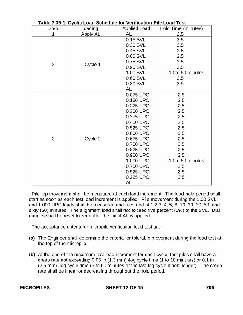
Table 7.06-1, Cyclic Load Schedule for Verification Pile Load Test
Step Loading Applied Load Hold Time (minutes) 1 Apply AL AL 2.5
2 Cycle 1
0.15 SVL 0.30 SVL 0.45 SVL 0.60 SVL 0.75 SVL 0.90 SVL 1.00 SVL 0.60 SVL 0.30 SVL AL
2.5 2.5 2.5 2.5 2.5
2.5 10 to 60 minutes
2.5 2.5
3 Cycle 2
0.075 UPC 0.150 UPC 0.225 UPC 0.300 UPC 0.375 UPC 0.450 UPC 0.525 UPC 0.600 UPC 0.675 UPC 0.750 UPC 0.825 UPC 0.900 UPC 1.000 UPC 0.750 UPC 0.525 UPC 0.225 UPC AL
2.5 2.5 2.5 2.5 2.5 2.5 2.5 2.5 2.5 2.5 2.5 2.5
10 to 60 minutes 2.5 2.5 2.5
Pile-top movement shall be measured at each load increment. The load-hold period shall start as soon as each test load increment is applied. Pile movement during the 1.00 SVL and 1.000 UPC loads shall be measured and recorded at 1,2,3, 4, 5, 6, 10, 20, 30, 50, and sixty (60) minutes. The alignment load shall not exceed five percent (5%) of the SVL. Dial gauges shall be reset to zero after the initial AL is applied.
The acceptance criteria for micropile verification load test are:
(a) The Engineer shall determine the criteria for tolerable movement during the load test at
the top of the micropile. (b) At the end of the maximum test load increment for each cycle, test piles shall have a
creep rate not exceeding 0.05 in (1.3 mm) /log cycle time (1 to 10 minutes) or 0.1 in (2.5 mm) /log cycle time (6 to 60 minutes or the last log cycle if held longer). The creep rate shall be linear or decreasing throughout the hold period.
MICROPILES SHEET 12 OF 15 706
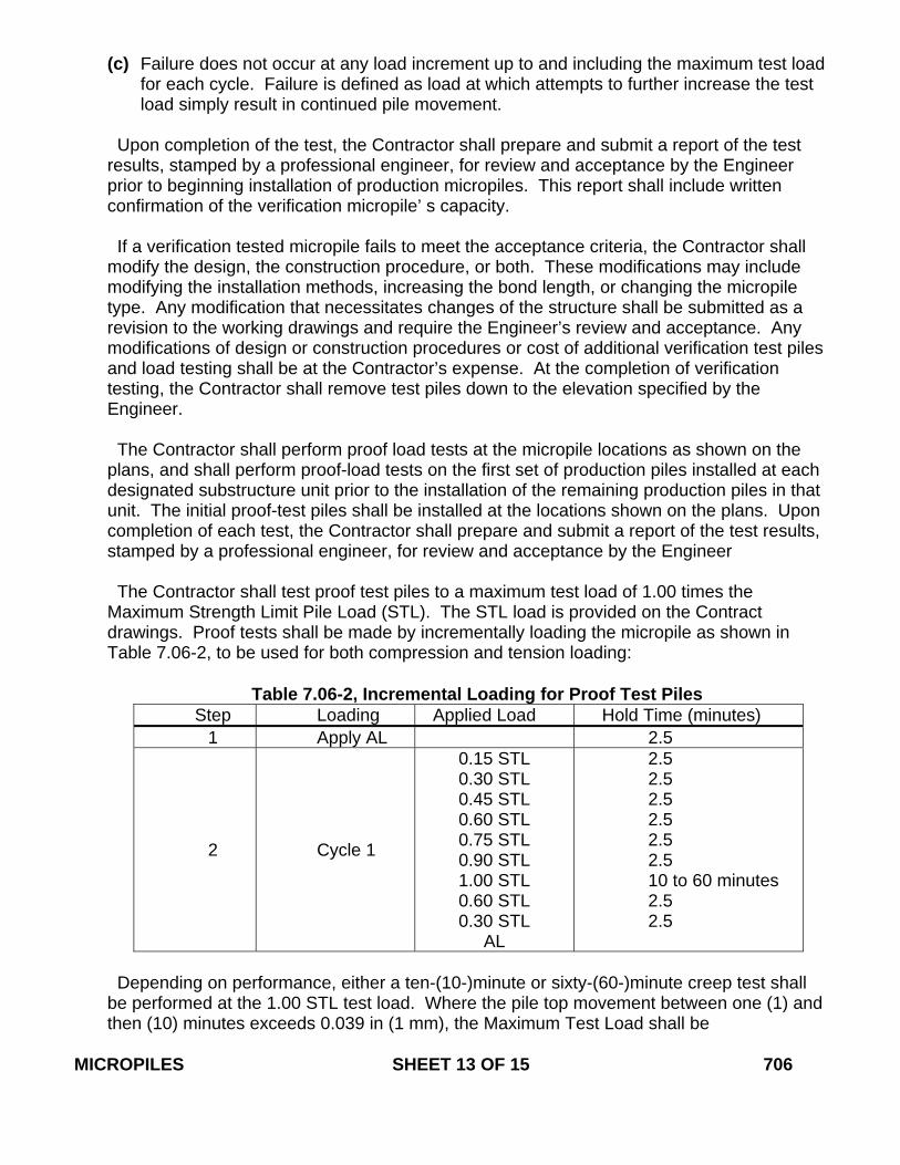
(c) Failure does not occur at any load increment up to and including the maximum test load for each cycle. Failure is defined as load at which attempts to further increase the test load simply result in continued pile movement.
Upon completion of the test, the Contractor shall prepare and submit a report of the test results, stamped by a professional engineer, for review and acceptance by the Engineer prior to beginning installation of production micropiles. This report shall include written confirmation of the verification micropile’ s capacity. If a verification tested micropile fails to meet the acceptance criteria, the Contractor shall modify the design, the construction procedure, or both. These modifications may include modifying the installation methods, increasing the bond length, or changing the micropile type. Any modification that necessitates changes of the structure shall be submitted as a revision to the working drawings and require the Engineer’s review and acceptance. Any modifications of design or construction procedures or cost of additional verification test piles and load testing shall be at the Contractor’s expense. At the completion of verification testing, the Contractor shall remove test piles down to the elevation specified by the Engineer. The Contractor shall perform proof load tests at the micropile locations as shown on the plans, and shall perform proof-load tests on the first set of production piles installed at each designated substructure unit prior to the installation of the remaining production piles in that unit. The initial proof-test piles shall be installed at the locations shown on the plans. Upon completion of each test, the Contractor shall prepare and submit a report of the test results, stamped by a professional engineer, for review and acceptance by the Engineer The Contractor shall test proof test piles to a maximum test load of 1.00 times the Maximum Strength Limit Pile Load (STL). The STL load is provided on the Contract drawings. Proof tests shall be made by incrementally loading the micropile as shown in Table 7.06-2, to be used for both compression and tension loading:
Table 7.06-2, Incremental Loading for Proof Test Piles
Step Loading Applied Load Hold Time (minutes) 1 Apply AL 2.5
2 Cycle 1
0.15 STL 0.30 STL 0.45 STL 0.60 STL 0.75 STL 0.90 STL 1.00 STL 0.60 STL 0.30 STL
AL
2.5 2.5 2.5 2.5 2.5 2.5 10 to 60 minutes 2.5 2.5
Depending on performance, either a ten-(10-)minute or sixty-(60-)minute creep test shall be performed at the 1.00 STL test load. Where the pile top movement between one (1) and then (10) minutes exceeds 0.039 in (1 mm), the Maximum Test Load shall be
MICROPILES SHEET 13 OF 15 706
maintained an additional fifty (50) minutes. Movements shall be recorded at 1, 2, 3, 5, 6, 10, 20, 30, 50 and 60 minutes. The alignment load shall not exceed five percent (5%) of STL. Dial gauges shall be reset to zero after the initial AL is applied. The acceptance criteria for micropile proof load tests are: (a) The Engineer shall determine the criteria for tolerable movement during the load test at
the top of the micropile.
(b) At the end of the 1.00 STL test load increment, test piles shall have a creep rate not exceeding 0.05 in (1.3 mm) /log cycle time (1 to 10 minutes) or 0.1 in (2.5 mm) /log cycle time (6 to 60 minutes). The creep rate shall be linear or decreasing throughout the creep-load hold period.
(c) Failure does not occur at the 1.00 STL maximum test load. Failure is defined as the
load at which attempts to further increase the test load simply result in continued pile movement. If a proof-tested micropile fails to meet the acceptance criteria, the Contractor shall immediately proof test another micropile within that footing. For failed piles and further construction of other piles, the Contractor shall modify the design, the construction procedure, or both. These modifications may include installing replacement micropiles, incorporating piles at not more than fifty percent (50%) of the maximum load attained, post-grouting the tested pile and re-proof testing the pile, modifying installation methods, increasing the bond length, or changing the micropile type. Any modification that necessitates changes of the structure design shall require the Engineer’s prior review and acceptance. Any modifications of design or construction procedures, or cost of additional verification test piles and verification or proof load testing, or replacement production micropiles, shall be at the Contractor’s expense.
7.06.04 - Method of Measurement: 1. Micropiles will be measured for payment by the number of micropiles installed and
accepted. There will be no separate measurement or payment for furnishing the design of the micropiles or developing installation methods to meet these Specifications.
2. Verification Test for Micropiles will be measured for payment by the number of verification
tests performed on sacrificial micropiles. 3. Proof Test for Micropiles will be measured for payment by the number of proof tests
performed on production micropiles. 4. Micropile Length Adjustment will be measured for payment by the length in linear feet
(meter) of the difference between the estimated length of permanent casing, as shown on the plans, and the actual length of permanent casing installed and accepted by the Engineer. (Note that the permanent casing length is measured from the bottom of the pile cap to the permanent casing tip, including the required embedment of casing into rock. Embedment into the pile cap will not be measured for payment because it is considered incidental to micropile construction. Any increase in casing length will be measured for
MICROPILES SHEET 14 OF 15 706
payment to the Contractor, and any decrease in casing length will be measured for credit to the State.)
There will be no separate measurement or payment for mobilization and demobilization associated with this item. 7.06.05 - Basis of Payment: 1. Micropiles will be paid for at the Contract unit price each for “Micropiles” complete and
accepted in place, including all design, development of installation methods, materials, equipment, tools, proper disposal of drilling spoil and labor incidental thereto.
2. Verification Test for Micropiles will be paid for at the Contract unit price each for
“Verification Test for Micropiles” completed on sacrificial micropiles, including all materials, testing equipment, tools, test reports, removal of test piles and labor incidental thereto.
3. Proof Test for Micropiles will be paid for at the Contract unit price each for “Proof Test for
Micropiles” completed on production micropiles, including all materials, testing equipment, tools, test reports and labor incidental thereto.
4. Micropile Length Adjustment will be paid for at the Contract unit price per linear foot
(meter) for “Micropile Length Adjustment” complete and accepted, including all materials, equipment, tools, and labor incidental thereto.
Pay Item Pay Unit Micropiles ea. (ea.) Verification Test for Micropiles ea. (ea.) Proof Test for Micropiles ea. (ea.) Micropile Length Adjustment l.f. (m) MICROPILES SHEET 15 OF 15 706
January 2009
CONNECTICUT SUPPLEMENTAL SPECIFICATION
SECTION 8.22 TEMPORARY PRECAST CONCRETE BARRIER CURB
8.22.04 – Method of Measurement: Add the following sentence to the end of the second paragraph: “Relocation of Temporary Precast Concrete Barrier Curb for access to the work area or for the convenience of the Contractor shall be considered incidental to Maintenance and Protection of Traffic and will not be measured for payment.”
TEMPORARY PRECAST CONCRETE BARRIER CURB SHEET 1 OF 1 822
January 2014
CONNECTICUT SUPPLEMENTAL SPECIFICATION
SECTION 9.10 METAL BEAM RAIL
9.10.02 – Materials: Change the only sentence in Subarticle 1 as follows: “Chemical anchoring material shall meet the requirements of Article M.03.07.” 9.10.04 – Method of Measurement 1 – Metal Beam Rail (Type)
Delete the only sentence and replace with the following: "The length of metal beam rail measured for payment will be the number of linear feet (meters) of accepted rail of the type or designation installed, including radius rail other than Curved Guide Rail Treatment, measured along the top of rail between centers of end posts in each continuous section."
METAL BEAM RAIL SHEET 1 OF 1 910
July 2006
CONNECTICUT SUPPLEMENTAL SPECIFICATION
SECTION 9.18 THREE CABLE GUIDE RAILING
(I-BEAM POSTS) AND ANCHORAGES 9.18.03 – Construction Methods: In the 10th paragraph, replace “MIL” with “MILSPEC.”
THREE CABLE GUIDE RAILING (I-BEAM POSTS) AND ANCHORAGES SHEET 1 OF 1 918
January 2010
CONNECTICUT SUPPLEMENTAL SPECIFICATION
SECTION 9.22 BITUMINOUS CONCRETE SIDEWALK BITUMINOUS CONCRETE DRIVEWAY
9.22.03 – Construction Methods: Replace the first paragraph with the following:
“1. Excavation: Excavation, including saw cutting, removal of any existing sidewalk, or driveway, shall be made to the required depth below the finished grade, as shown on the plans or as directed by the Engineer. All soft and yielding material shall be removed and replaced with suitable material.”
9.22.05 – Basis of Payment: Replace the only paragraph with the following: “This work will be paid for at the contract unit price per square yard (square meter) for "Bituminous Concrete Sidewalk" or "Bituminous Concrete Driveway," as the case may be, complete in place, which price shall include all saw cutting, excavation as specified above, backfill, disposal of surplus material, gravel or reclaimed miscellaneous aggregate base, and all equipment, tools, labor and materials incidental thereto.”
BITUMINOUS CONCRETE SIDEWALK BITUMINOUS CONCRETE DRIVEWAY SHEET 1 OF 1 922
January 2010
CONNECTICUT SUPPLEMENTAL SPECIFICATION
SECTION 9.44 TOPSOIL
9.44.03—Construction Methods: Add the following paragraph to the beginning of the article: “The Contractor shall notify the Engineer of the location of the topsoil at least 15 calendar days prior to delivery. The topsoil and its source shall be inspected and approved by the Engineer before the material is delivered to the project. Any material delivered to the project, which does not meet specifications or which has become mixed with undue amounts of subsoil during any operation at the source or during placing and spreading, will be rejected and shall be replaced by the Contractor with acceptable material.”
TOPSOIL SHEET 1 OF 1 944
January 2010
CONNECTICUT SUPPLEMENTAL SPECIFICATION
SECTION 9.49 FURNISHING, PLANTING and MULCHING
TREES, SHRUBS, VINES and GROUND COVER PLANTS 9.49.03 – Construction Methods: Replace subarticle “5. Pits” with the following: “5. Pits: The pit diameters shall be twice the diameter of the root-spread or container diameters, and shall be 2- inches (50 millimeters) less than the height of the rootball measured from the bottom of the ball to the root collar. (i. e. A 12-inch (300 millimeters) measurement between the root collar and the bottom of the rootball will require a 10-inch (250 millimeters) deep pit). Any excavation in excess of that required shall be replaced with planting soil and compacted to the satisfaction of the Engineer.”
Add the following sentence to subsection “6. Obstructions Below Ground:” “If removal of obstructions results in a deeper hole than needed for planting, backfill material shall be added and compacted to the satisfaction of the Engineer.” Replace subarticle “7. Preparation of Backfill” with the following: “7. Backfill: Backfill shall conform to M.13.01-1 Planting Soil.” Replace subarticle “8. Setting Plants” with the following: “8. Setting Plants: All plants shall be plumb and at a level that is 2-inches (50 millimeters) higher than the surrounding ground. Backfill material for all plants shall be thoroughly and properly settled by firming or tamping. Thorough watering shall accompany backfilling. Saucers capable of holding water shall be formed at individual plants (exclusive of plant beds) by placing ridges of planting soil around each, or as directed by the Engineer.
a. Balled and Burlapped plants: Plants shall be handled in such manner so that the soil will not be loosened from the roots inside of the ball. Carefully place the plant into the prepared pits and backfill with planting soil to one - half the depth of the pit, thoroughly tamp to the satisfaction of the Engineer around the ball. Fill the remaining area of the pit with water. Once water has completely drained, loosen the burlap and peel down the top one third. If wire baskets are used, cut and bend down the top third of the basket. Roots that have been wrapped around the ball within the burlap shall be straightened and the remainder of the pit filled with planting soil tamped to ensure that no air pockets remain.
FURNISHING, PLANTING and MULCHING TREES, SHRUBS, VINES and GROUND COVER PLANTS SHEET 1 OF 3 949
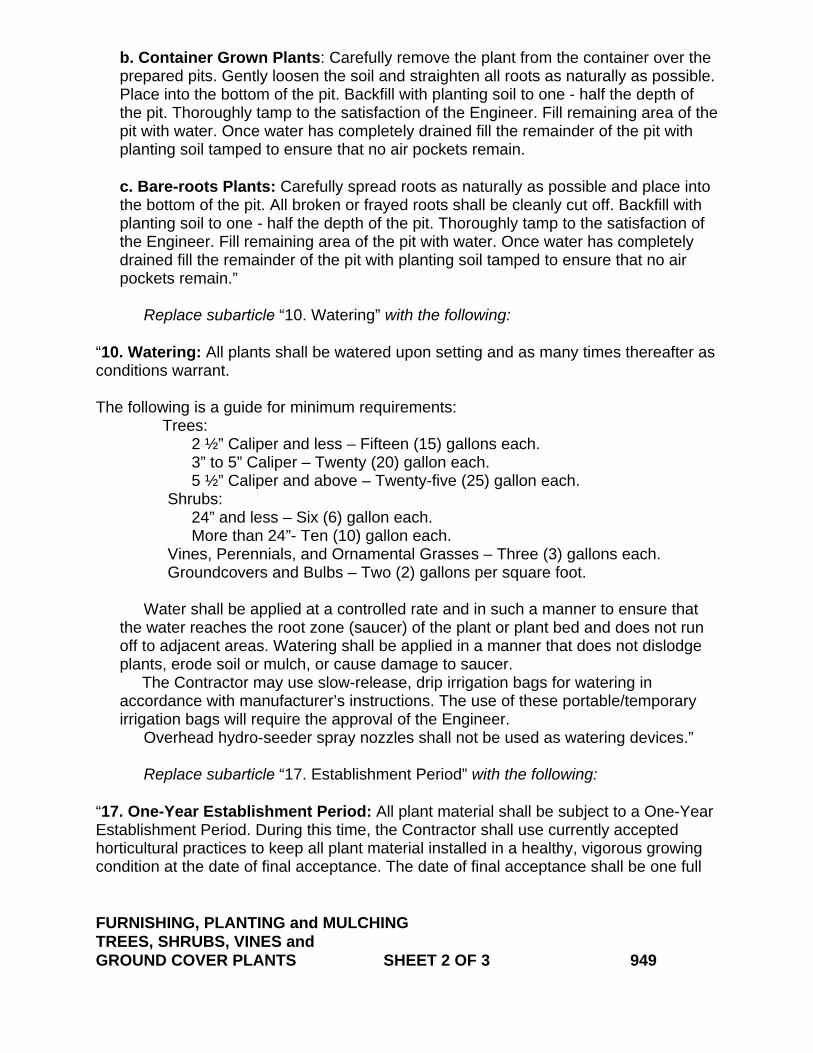
b. Container Grown Plants: Carefully remove the plant from the container over the prepared pits. Gently loosen the soil and straighten all roots as naturally as possible. Place into the bottom of the pit. Backfill with planting soil to one - half the depth of the pit. Thoroughly tamp to the satisfaction of the Engineer. Fill remaining area of the pit with water. Once water has completely drained fill the remainder of the pit with planting soil tamped to ensure that no air pockets remain.
c. Bare-roots Plants: Carefully spread roots as naturally as possible and place into the bottom of the pit. All broken or frayed roots shall be cleanly cut off. Backfill with planting soil to one - half the depth of the pit. Thoroughly tamp to the satisfaction of the Engineer. Fill remaining area of the pit with water. Once water has completely drained fill the remainder of the pit with planting soil tamped to ensure that no air pockets remain.”
Replace subarticle “10. Watering” with the following: “10. Watering: All plants shall be watered upon setting and as many times thereafter as conditions warrant.
The following is a guide for minimum requirements: Trees:
2 ½” Caliper and less – Fifteen (15) gallons each. 3” to 5” Caliper – Twenty (20) gallon each. 5 ½” Caliper and above – Twenty-five (25) gallon each. Shrubs: 24” and less – Six (6) gallon each. More than 24”- Ten (10) gallon each. Vines, Perennials, and Ornamental Grasses – Three (3) gallons each. Groundcovers and Bulbs – Two (2) gallons per square foot. Water shall be applied at a controlled rate and in such a manner to ensure that the water reaches the root zone (saucer) of the plant or plant bed and does not run off to adjacent areas. Watering shall be applied in a manner that does not dislodge plants, erode soil or mulch, or cause damage to saucer. The Contractor may use slow-release, drip irrigation bags for watering in accordance with manufacturer’s instructions. The use of these portable/temporary irrigation bags will require the approval of the Engineer.
Overhead hydro-seeder spray nozzles shall not be used as watering devices.”
Replace subarticle “17. Establishment Period” with the following: “17. One-Year Establishment Period: All plant material shall be subject to a One-Year Establishment Period. During this time, the Contractor shall use currently accepted horticultural practices to keep all plant material installed in a healthy, vigorous growing condition at the date of final acceptance. The date of final acceptance shall be one full FURNISHING, PLANTING and MULCHING TREES, SHRUBS, VINES and GROUND COVER PLANTS SHEET 2 OF 3 949
calendar year following the satisfactory completion of the planting activities as confirmed by the Engineer. An inspection will be held one year from the date of installation with the Contractor, Engineer, and Landscape Designer to determine the acceptability of the plant establishment. An inventory of losses and rejected materials will be made and corrective and necessary clean up measures will be determined at the plant inspection.”
FURNISHING, PLANTING and MULCHING TREES, SHRUBS, VINES and GROUND COVER PLANTS SHEET 3 OF 3 949
July 2014
CONNECTICUT SUPPLEMENTAL SPECIFICATION
SECTION 9.75 MOBILIZATION
Delete the entire section and replace with the following new section:
SECTION 9.75 MOBILIZATION AND PROJECT CLOSEOUT
9.75.01 – Description: This item consists of 1. all work necessary for moving Project personnel and equipment to the Project Site; 2. all work necessary for the establishment of the Contractors’ field offices, buildings and
other facilities necessary for Contract performance; 3. the preparation of work plans and other documents that must be submitted by the
Contractor to the Department prior to the start of physical Project construction. These initial submittals are identified elsewhere in the Contract and may include Project schedules, Project management plans, staging and storage areas, safety plans, quality control plans, erosion and sedimentation control plans, and other documents addressing general Project sequencing or management;
4. demobilization of plant and equipment; 5. completion of all physical work, and 6. completion of administrative closeout items as required by the Contract. The work entailed in this item shall not be subcontracted in whole or part. 9.75.04 – Method of Measurement: This work will be measured for payment in the manner described hereinafter; however, the total Contract amount earned will not include payments for mobilization that were earned during the period covered by the current monthly estimate, but will include those payments for mobilization that were previously earned and certified for payment. 1. When the first Project payment estimate is reviewed by the Engineer, twenty-five
percent (25%) of the lump sum bid price for this item or two and a half percent (2.5%) of the total original Contract price, whichever is less, will be certified for payment as a part of that estimate.
2. When the Contractor's initial Project submittals are accepted by the Engineer, fifty
percent (50%) of the lump sum bid price for this item or five percent (5%) of the total original Contract price, whichever is less, minus any previous Project payments made to the Contractor for this item, will be certified for payment.
3. When the Contractor's initial Project submittals are accepted by the Engineer, and
fifteen percent (15%) of the total original Contract price has been earned by the Contractor, seventy percent (70%) of the lump sum price of this item or seven percent (7%) of the total original Contract price, whichever is less, minus any previous Project payments made to the Contractor for this item, will be certified for payment.
4. When thirty percent (30%) of the total original Contract price has been earned by the
Contractor, eighty-five percent (85%) of the lump sum price of this item or eight and a half percent (8.5%) of the total original Contract price, whichever is less, minus any previous payments made to the Contractor for this item, will be certified for payment.
MOBILIZATION AND PROJECT CLOSEOUT SHEET 1 OF 2 975

5. When the requirements of Article 1.08.13 have been satisfied by the Contractor,
ninety-five percent (95%) of the lump sum price of this item, minus any previous payments made to the Contractor for this item, will be certified for payment.
6. When the requirements of Article 1.08.14 have been satisfied by the Contractor, one
hundred percent (100%) of the lump sum price of this item, minus any previous payments made to the Contractor for this item, will be certified for payment. When this payment is made, the Contractor should have received full Contract payment for this item.
Nothing herein shall be construed to limit or preclude the Department from making partial payments to the Contractor that are provided for elsewhere in this Contract. 9.75.05 – Basis of Payment: The work under this item will be paid for at the Contract lump sum price for “Mobilization and Project Closeout,” which price shall include materials, equipment, tools, transportation, labor and all work incidental thereto. Payment for this item shall be made only once; i.e., for only one instance of mobilization as described in Article 9.75.01 above. If the Contractor mobilizes equipment or facilities more than one time during the course of the Project, due to reasons solely the responsibility of the Department, the additional work entailed therein will be paid for as Extra Work under Section 1.04.05 hereof. Pay Item Pay Unit Mobilization and Project Closeout l.s. (l.s.) MOBILIZATION AND PROJECT CLOSEOUT SHEET 2 OF 2 975

July 2014
CONNECTICUT SUPPLEMENTAL SPECIFICATION
SECTION 10.00 GENERAL CLAUSES FOR HIGHWAY
ILLUMINATION AND TRAFFIC SIGNAL PROJECTS
Add the following new article after 10.00.13 Service Installations: “ 10.00.14- Maintenance of Illumination During Construction: The Contractor shall organize the Project work so that any portion of roadway which has existing roadway illumination and is open for use remains lighted. The Contractor shall also provide illumination on all temporary crossovers, ramps and roadways that are constructed as part of staged construction and that are open for use. Highway illumination may consist of: existing lighting, new lighting, temporary lighting, or any combination thereof. It is the Contractor’s responsibility to stage the installation or relocation of service cabinets, poles, lights, and circuitry so that all roadways of the kind described above remain lighted. If it is necessary to install temporary poles, lights, or circuitry to maintain the integrity of the highway illumination system, such work shall be submitted to the Engineer for approval prior to installation, and will be paid for at the Contract bid unit price for the relevant items. Temporary illumination work not specifically covered by the Contract specifications and pay items will be paid for as extra work at the discretion of the Engineer. If the Contract includes temporary illumination plans, those plans shall serve as a framework for providing roadway illumination during construction. Temporary illumination plans may not represent the full extent of the temporary illumination work required, or the exact quantity of temporary lights required to maintain proper roadway illumination. Prior to the start of any work that will interfere with the existing lighting system, the Contractor and ConnDOT District Electrical Maintenance personnel shall inspect the system for lighting outages, pole knockdowns, and circuit malfunctions. Deficiencies will be noted and repaired by Department forces prior to the start of work by the Contractor. Once the Contractor’s work interferes with or impacts the existing roadway lighting system, maintenance of that system within the Project limits becomes the Contractor’s responsibility. The repair of lighting system malfunctions occurring outside of the project limits, caused by the Contractor’s work, shall also be the Contractor’s responsibility. District Construction personnel will note the start and end date of the Contractor’s responsibility for maintenance of any existing lighting system. GENERAL CLAUSES FOR HIGHWAY ILLUMINATION AND TRAFFIC SIGNAL PROJECTS SHEET 1 OF 3 1000
The Contractor shall maintain the illumination throughout the duration of the Project, until the Project is accepted by the State. The Contractor shall supply to the Project Engineer and to the ConnDOT District Electrical Maintenance Supervisor, the names and phone numbers of a primary and back-up representative, to be contacted should a problem with the lighting system occur. Whoever discovers a lighting outage or pole damage/knockdown within the Project limits shall immediately notify ConnDOT Highway Operations of same as follows:
1. For projects in Districts 1, 2, and 4, call (860) 594-3447. 2. For projects in District 3 and along the Interstate 95 corridor within District 2, call
(203) 696-2690. The following procedures will be followed for lighting outages: 1) Once notified of a lighting outage, ConnDOT Electrical Maintenance personnel will
assess the situation, and in the case of a pole knockdown, may clear the pole from the roadway and make safe any exposed wires.
2) The Project Inspector and the Contractor’s designated representative shall be notified
after the lighting outage has been assessed by ConnDOT Electrical Maintenance, transferring responsibility for further repairs to the Contractor.
3) Upon notification, the Contractor shall be responsible to repair the lighting system
before the normal nighttime turn-on of the lights. If this cannot be achieved, the Contractor shall make the lighting operational prior to the next normal nighttime turn-on of the lights, up to a maximum of 24 hours from the time the Contractor was notified of the problem. The Contractor shall contact the Project Inspector to discuss the situation, the steps to be taken to bring the lighting back on line, and the time frame for doing so.
4) For isolated individual luminaire outages (not a continuous circuit), the Contractor shall
repair such luminaires within 48 hours from the time that the Contractor became aware of the outage.
The Contractor shall follow standard “lock-out,” “tag-out,” and “Call Before You Dig” procedures when working on the lighting circuit. Both the Contractor and ConnDOT Electrical Maintenance shall have mutual access to active lighting control cabinets. The Contractor will be reimbursed for any costs associated with the maintenance of the existing lighting system that are beyond the Contractor’s control. Reimbursements will be for damage caused by the general public and normal system age related component failures (such as lamp burn-out, ballast/starter failure or cable splice failure). However, the Contractor shall be responsible for repair of damage to the existing lighting system incurred as the result of their operations including damage caused by improper wiring methods. All repairs or replacements due to the Contractor’s operations shall be made by the Contractor at their expense. GENERAL CLAUSES FOR HIGHWAY ILLUMINATION AND TRAFFIC SIGNAL PROJECTS SHEET 2 OF 3 1000

The Project Inspector will maintain a log book of any lighting repair work performed, which will include a description of the repairs, and the date the work was performed. The log book will be made accessible to ConnDOT Electrical Maintenance personnel. Temporary illumination circuitry shall consist of pre-assembled aerial cable of the type and size as indicated in the Contract documents or as directed by the Engineer. The Contractor shall notify the Engineer when aerial cable cannot be installed due to construction activities and shall suggest another method for installation of the cable. Alternate options may include installing cable in duct underground, or installing surface-mounted cable in duct or PVC conduit with cable along the backside of a bridge parapet or temporary concrete barrier curbing. Temporary cable in duct/conduit or aerial cable lying directly on the ground will not be allowed. The option of surface-mounting duct or conduit to the backside of a parapet or barrier will be allowed only when construction activities make it necessary, and where the surface-mounted conduit will not expose workers to a high voltage hazard. The Contractor must obtain the Engineer’s approval to do so prior to installing temporary circuitry not installed overhead, unless otherwise indicated on the plans. When temporary circuitry is installed in trench, standard warning tape procedures shall be followed as set forth in Article 1.05.15. When temporary circuitry is surface mounted to the backside of a parapet or barrier wall, the Contractor shall install warning placards which read: “Live Electricity.” Warning placards shall be installed at the beginning, end, and at intermittent points 100 feet (30 meters) apart along the exposed length of the duct/conduit. All temporary lighting circuits shall include a continuous No. 8 bare copper grounding conductor connected to all light standards and effectively grounded as per the NEC.” GENERAL CLAUSES FOR HIGHWAY ILLUMINATION AND TRAFFIC SIGNAL PROJECTS SHEET 3 OF 3 1000
July 2010
CONNECTICUT SUPPLEMENTAL SPECIFICATION
SECTION 10.01 TRENCHING AND BACKFILLING
10.01.01- Description: In the only sentence of the first paragraph after “…satisfactory…” add the following: “clean-up and”. In the only sentence of the second paragraph after “…reconstruction of…” add the following: “bituminous, concrete and granite curbing,”. 10.01.05- Basis of Payment: In the only sentence of the second paragraph after “…mulching…” add the following: “clean-up and”. After “…installing…” add the word “curbing,”. At the end of the third paragraph, add the following: “In the absence of a “Rock in Trench Excavation” item, the work will be compensated as extra work.” In the only sentence of the sixth paragraph, after “…unit price for ‘Concrete Sidewalk’…” add the following: “or as extra work, if no unit price has been established.” TRENCHING AND BACKFILLING SHEET 1 OF 1 1001
January 2014
CONNECTICUT SUPPLEMENTAL SPECIFICATION
SECTION 10.10 CONCRETE HANDHOLE
10.10.02 – Materials: Replace “M.03.01” with “M.03” for both Class A and Class C Concrete. 10.10.05 – Basis of Payment In the first sentence, remove the words “ground wire”.
At the end of the paragraph add the following sentence:
“The ground wire (bonding wire) is included in the Contract unit price under Section 10.08 – Electrical Conduit.”
Add the word “Cover” to the end of the pay item “Cast Iron Handhole”
CONCRETE HANDHOLE SHEET 1 OF 1 1010

July 2006
CONNECTICUT SUPPLEMENTAL SPECIFICATION
SECTION 11.13 CONTROL CABLE
11.13.03 – Construction Methods: In the 1st paragraph of subsection 2 replace “MIL” with “MILSPEC.”
CONTROL CABLE SHEET 1 OF 1 1113
January 2007
CONNECTICUT SUPPLEMENTAL SPECIFICATION
SECTION 12.10 EPOXY RESIN PAVEMENT MARKINGS, SYMBOLS AND LEGENDS
12.10.03—Construction Methods: 2. Procedures:
Insert the following after the sixth paragraph: “The epoxy shall be uniformly applied to the surface to be marked to ensure a wet film thickness of the applied epoxy, without glass beads, of 20 mils +/- 1 mil (500 um +/- 25 um).” EPOXY RESIN PAVEMENT MARKINGS, SYMBOLS AND LEGENDS SHEET 1 OF 1 1210
January 2014
CONNECTICUT SUPPLEMENTAL SPECIFICATION
SECTION M.03 PORTLAND CEMENT CONCRETE
Delete the entire Section and replace it with the following:
SECTION M.03 PORTLAND CEMENT CONCRETE
M.03.01 - Component Materials M.03.02 - Mix Design Requirements M.03.03 - Producer Equipment and Production Requirements M.03.04 - Curing Materials M.03.05 - Non Shrink, Non Staining Grout M.03.06 - Expansive Cement for Anchoring M.03.07 - Chemical Anchors M.03.08 - Joint Materials M.03.09 - Protective Compound/Sealers M.03.10 - Formwork M.03.01 – Component Materials 1. Coarse Aggregate: Coarse aggregate shall be broken stone, gravel, or reclaimed concrete aggregate defined as mortar-coated rock, consisting of clean durable fragments of uniform quality throughout. It shall be free from soft, disintegrated pieces, mud, dirt, organic or other injurious material and shall not contain more than 1 percent of dust by mass, as determined by AASHTO T-11. Coarse aggregate of a size retained on a 1-inch (25 mm) square opening sieve shall not contain more than 8% of flat or elongated pieces, whose longest dimension exceeds 5 times their maximum thickness. Heating or cooling of coarse aggregates may be required to meet concrete mix temperature requirements at time of placement. (a) Soundness: When tested with magnesium sulfate solution for soundness, using
AASHTO Method T 104, coarse aggregate shall not have a loss of more than 10% at the end of 5 cycles.
(b) Loss on Abrasion: When tested by means of the Los Angeles Machine, using AASHTO Method T 96, coarse aggregate shall not have a loss of more than 40%.
(c) Gradation: Grading and stone sizes of the coarse aggregate shall conform to Article M.01.01 as determined by AASHTO T-27. All coarse aggregate proportions shall be approved in advance by the Transportation Division Chief (TDC) as part of the Mix Design requirements.
(d) Storage: Aggregate stockpiles shall be located on smooth, hard, sloped/well-drained areas. Each source and gradation shall have an individual stockpile or bin. Aggregates shall be handled from stockpiles or other sources to the batching plant in such manner as to minimize segregation of the material. Aggregates that have become segregated, or mixed with earth or foreign material, shall not be used.
PORTLAND CEMENT CONCRETE SHEET 1 OF 8 M03
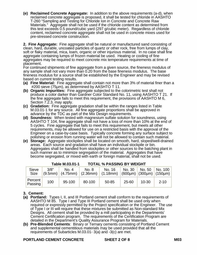
(e) Reclaimed Concrete Aggregate: In addition to the above requirements (a-d), when reclaimed concrete aggregate is proposed, it shall be tested for chloride in AASHTO T-260 “Sampling and Testing for Chloride Ion in Concrete and Concrete Raw Materials.” Aggregate shall not be used if the chloride content as determined from this test exceeds 0.5 pound/cubic yard (297 g/cubic meter). Regardless of chloride content, reclaimed concrete aggregate shall not be used in concrete mixes used for pre-stressed concrete construction.
2. Fine Aggregate: Fine aggregate shall be natural or manufactured sand consisting of clean, hard, durable, uncoated particles of quartz or other rock, free from lumps of clay, soft or flaky material, mica, loam, organic or other injurious material. In no case shall fine aggregate containing lumps of frozen material be used. Heating or cooling of fine aggregates may be required to meet concrete mix temperature requirements at time of placement. For continued shipments of fine aggregate from a given source, the fineness modulus of any sample shall not vary more than 0.20 from the base fineness modulus. The base fineness modulus for a source shall be established by the Engineer and may be revised based on current testing results. (a) Fine Material: Fine aggregate shall contain not more than 3% of material finer than a
#200 sieve (75µm), as determined by AASHTO T 11. (b) Organic Impurities: Fine aggregate subjected to the colorimetric test shall not
produce a color darker than Gardner Color Standard No. 11, using AASHTO T 21. If the fine aggregate fails to meet this requirement, the provisions of AASHTO M 6, Section 7.2.3, may apply.
(c) Gradation: Fine aggregate gradation shall be within the ranges listed in Table M.03.01-1 for any source. All fine aggregate proportions shall be approved in advance by the TDC as part of the Mix Design requirements.
(d) Soundness: When tested with magnesium sulfate solution for soundness, using AASHTO T 104, fine aggregate shall not have a loss of more than 10% at the end of 5 cycles. Fine aggregate that fails to meet this requirement, but meets all other requirements, may be allowed for use on a restricted basis with the approval of the Engineer on a case-by-case basis. Typically concrete forming any surface subject to polishing or erosion from running water will not be allowed to contain such material.
(e) Storage: Aggregate stockpiles shall be located on smooth, hard, sloped/well-drained areas. Each source and gradation shall have an individual stockpile or bin. Aggregates shall be handled from stockpiles or other sources to the batching plant in such manner as to minimize segregation of the material. Aggregates that have become segregated, or mixed with earth or foreign material, shall not be used.
Table M.03.01-1 TOTAL % PASSING BY WEIGHT
Sieve Size
3/8" (9.5mm)
No. 4 (4.75mm)
No. 8 (2.36mm)
No. 16 (1.18mm)
No. 30 (600µm)
No. 50 (300µm)
No. 100 (150µm)
Percent Passing 100 95-100 80-100 50-85 25-60 10-30 2-10
3. Cement: (a) Portland: Types I, II, and III Portland cement shall conform to the requirements of
AASHTO M 85. Type I and Type III Portland cement shall be used only when required or expressly permitted by the Project specification or the Engineer. The use of Type I or III will require that these mixtures be submitted as Non-standard Mix Designs. All cement shall be provided by a mill participating in the Departments’ Cement Certification program. The requirements of the Certification Program are detailed in the Department’s Quality Assurance Program for Materials.
(b) Pre-Blended Cements: Binary or Ternary cements consisting of Portland Cement and supplemental cementitious materials may be used provided that all the requirements of Subarticles M.03.01- 3(a) and -3(c) are met.
PORTLAND CEMENT CONCRETE SHEET 2 OF 8 M03
(c) Replacement Materials: Unless already approved as a Standard Mix Design, any Contractor proposed Mix Designs with partial replacement of Portland Cement (PC) with fly ash or ground granulated blast furnace slag (GGBFS), shall be submitted in writing to the Engineer for approval prior to the start of work, on a project-by-project basis. The type of material, source, and the percentage of the PC replaced shall be clearly indicated. Upon request, a Certified Test Report for the cement replacement material shall be provided to the Engineer for use during the Mix Design review. 1. Fly Ash: Fly ash to be used as a partial replacement for Portland cement shall
meet the requirements of AASHTO M 295, either Class C or Class F, including the uniformity requirements of Table 2A. Loss on Ignition for either class of fly ash shall not exceed 4.0%. Fly ash may be used to replace up to a maximum of 20% of the required Portland cement. The fly ash shall be substituted on a weight (mass) basis, with a minimum of 1 pound (45 kg) of fly ash for 1 pound (45 kg) of Portland cement. Different classes of fly ash or the same class from different sources shall not be permitted on any single project without the written approval of the Engineer.
2. Ground Granulated Blast Furnace Slag (GGBFS): GGBFS used as a partial replacement for Portland cement shall conform to the requirements of AASHTO M 302/ASTM C989, Grade 100 or 120. As determined by the Engineer, GGBFS may be used to replace a maximum of 30% of the required Portland cement. The Engineer may restrict or prohibit the use of GGBFS if ambient temperatures anticipated during the placement and initial curing of the concrete are low. The GGBFS shall be substituted on a weight (mass) basis, with a minimum of 1 pound (45 kg) of slag for 1 pound (45 kg) of Portland cement. Different sources of GGBFS shall not be permitted on any single project without the written approval of the Engineer.
4. Water: All water used in the mixing of concrete shall be clear in appearance and free from oil, salt, acids, alkalis, sugar, and organic matter. Surface water may be used if not taken from shallow or muddy sources; classified as Class C or Class D on the Department of Energy and Environmental Protection (DEEP) Water Quality Classification mapping; and accommodations have been made to prevent contaminants from entering the supply to the satisfaction of the Engineer. The Engineer may request that water from any surface or ground source be tested in accordance with AASHTO T26 and AASHTO D512 if the appearance or scent of the water is suspect. To be acceptable, the pH of the water must not be less than 6.0 or greater than 8.0 and Chloride Ion Concentration of the water must not exceed 250ppm (250 mg/L). Potable water taken directly from a municipal or regional water supply may be used for mixing concrete without testing. Heating or cooling of water may be required to meet mix temperature requirements at time of placement. 5. Admixtures: All admixtures shall perform their function without injurious effects upon the concrete. If requested by the TDC, the Contractor shall present a certified statement from a recognized laboratory attesting to this requirement. A "recognized" laboratory is any cement and concrete laboratory approved and inspected regularly by the Cement and Concrete Reference Laboratory (CCRL). The statement shall contain results of compression tests of cylinder specimens made with concrete utilizing the admixture(s) in proportions equal to those proposed by the Contractor. The results of at least 5 standard 6-inch x 12-inch (150 mm x 300 mm) cylinders of each mix design shall be listed with the results of at least 5 like-sized cylinders not utilizing the admixture(s). Specimens must be made and cured in the laboratory in accordance with AASHTO T 126 and will be tested in accordance with AASHTO T 22. (a) Air-Entraining Admixtures: In the event that air entrained concrete is required, an
admixture conforming to the requirements of AASHTO M 154 may be used. Tests for 7 and 28-day compressive and flexural strengths and resistance to freezing and thawing are required, but tests for bleeding, bond strength and volume change will not be required.
PORTLAND CEMENT CONCRETE SHEET 3 OF 8 M03
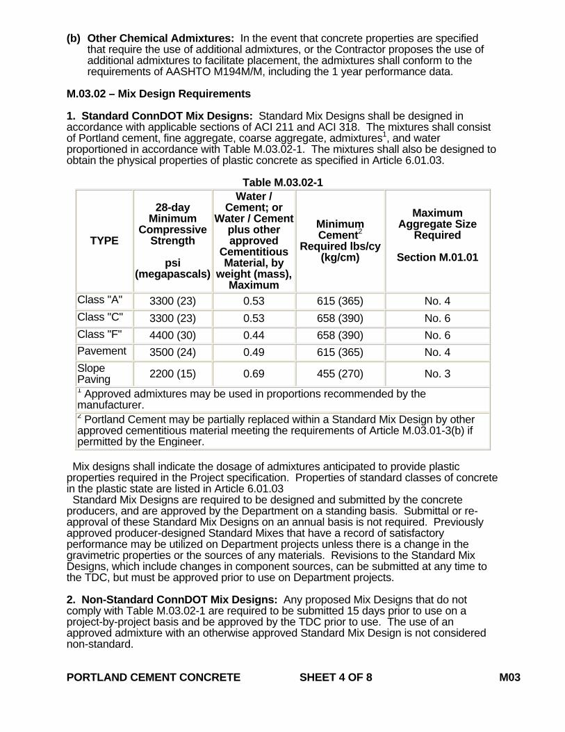
(b) Other Chemical Admixtures: In the event that concrete properties are specified that require the use of additional admixtures, or the Contractor proposes the use of additional admixtures to facilitate placement, the admixtures shall conform to the requirements of AASHTO M194M/M, including the 1 year performance data.
M.03.02 – Mix Design Requirements 1. Standard ConnDOT Mix Designs: Standard Mix Designs shall be designed in accordance with applicable sections of ACI 211 and ACI 318. The mixtures shall consist of Portland cement, fine aggregate, coarse aggregate, admixtures1, and water proportioned in accordance with Table M.03.02-1. The mixtures shall also be designed to obtain the physical properties of plastic concrete as specified in Article 6.01.03.
Table M.03.02-1
TYPE
28-day Minimum
Compressive Strength
psi
(megapascals)
Water / Cement; or
Water / Cement plus other approved
Cementitious Material, by
weight (mass), Maximum
Minimum Cement2
Required lbs/cy (kg/cm)
Maximum Aggregate Size
Required
Section M.01.01
Class "A" 3300 (23) 0.53 615 (365) No. 4 Class "C" 3300 (23) 0.53 658 (390) No. 6 Class "F" 4400 (30) 0.44 658 (390) No. 6 Pavement 3500 (24) 0.49 615 (365) No. 4 Slope Paving 2200 (15) 0.69 455 (270) No. 3 1 Approved admixtures may be used in proportions recommended by the manufacturer. 2 Portland Cement may be partially replaced within a Standard Mix Design by other approved cementitious material meeting the requirements of Article M.03.01-3(b) if permitted by the Engineer.
Mix designs shall indicate the dosage of admixtures anticipated to provide plastic properties required in the Project specification. Properties of standard classes of concrete in the plastic state are listed in Article 6.01.03 Standard Mix Designs are required to be designed and submitted by the concrete producers, and are approved by the Department on a standing basis. Submittal or re-approval of these Standard Mix Designs on an annual basis is not required. Previously approved producer-designed Standard Mixes that have a record of satisfactory performance may be utilized on Department projects unless there is a change in the gravimetric properties or the sources of any materials. Revisions to the Standard Mix Designs, which include changes in component sources, can be submitted at any time to the TDC, but must be approved prior to use on Department projects. 2. Non-Standard ConnDOT Mix Designs: Any proposed Mix Designs that do not comply with Table M.03.02-1 are required to be submitted 15 days prior to use on a project-by-project basis and be approved by the TDC prior to use. The use of an approved admixture with an otherwise approved Standard Mix Design is not considered non-standard. PORTLAND CEMENT CONCRETE SHEET 4 OF 8 M03
All Non-standard Mix Designs used for load-bearing structures shall contain a minimum of 658 lbs/cubic yard (390 kg/cubic meter) of cementitious materials. Concrete used in applications such as flowable fill or controlled low-strength material may be designed with less than 658 lbs/cubic yard (390 kg/cubic meter) of cementitious materials. M.03.03 - Producer Equipment and Production Requirements 1. General Requirements: The source of the concrete must be approved by the Engineer prior to use on Department projects. Specifically the location and capacity of the central mix or dry batch plant, and complement of truck mixers/haulers, shall be adequate for continuous placement of concrete on a typical Department project. Approval may be revoked at any time in accordance with Section 1.06.01. (a) Inspection: The production facility supplying hydraulic cement concrete shall have a
current Certification of Ready Mixed Concrete Production Facilities from the National Ready Mixed Concrete Association (NRMCA), or equivalent certification approved by the Engineer.
(b) In addition to the requirements of approved third party certification, the facility shall produce batch tickets that conform to Subarticle 6.01.03-3(a).
(c) Quality Control: The Contractor is responsible for all aspects of Quality Control (QC). As determined by the Engineer, should material delivered to a project not meet specification, the Contractor may be required to submit to the Engineer a corrective procedure for approval within 3 calendar days. The procedure shall address any minor adjustments or corrections made to the equipment or procedures at the facility.
(d) Suspension: As determined by the Engineer, repeated or frequent delivery of deficient material to a Department project may be grounds for suspension of that source of material. A detailed QC plan that describes all QC policies and procedures for that facility may be required to formally address quality issues. This plan must be approved by the Engineer and fully implemented, prior to reinstatement of that facility.
2. Hand Mixed Concrete: Hand mixing shall be permitted only with the permission of the Engineer. Hand mixed batches shall not exceed 1/2 cubic yard (0.5 cubic meter) in volume. Hand mixing will not be permitted for concrete to be placed under water. M.03.04 - Curing Materials 1. Water: Any water source deemed acceptable by the Engineer for mixing concrete may be used to provide water for curing purposes. Surface water may be used if classified as Class C or Class D on the Department of Energy and Environmental Protection (DEEP) Water Quality Classification mapping and accommodations have been made to prevent contaminants from entering the supply to the satisfaction of the Engineer. In general, water shall not be taken from shallow or muddy sources. In cases where sources of supply are relatively shallow, the intake pipe shall be enclosed to exclude silt, mud, grass, etc.; and the water in the enclosure shall be maintained at a depth of not less than 2 feet (610 mm) under the intake pipe. 2. Mats: Mats for curing concrete shall be capable of maintaining moisture uniformly on the surface of the concrete. The mats shall not contain any materials such as dyes, sugar, etc., that may be injurious to the concrete. The length or width of the mats shall be sufficient to cover all concrete surfaces being cured. Should more than one mat be required, sufficient overlap shall be provided by the Contractor as determined by the Engineer. 3. Liquid Membrane-Forming Compound: Liquid membrane-forming compound shall conform to the requirements of AASHTO M 148 Type 2, Class B, or shall be a water-soluble linseed oil-based compound conforming to the requirements of AASHTO M 148, Type 2. 4. White Polyethylene Sheeting (Film): White polyethylene sheeting (film) shall conform to the requirements of AASHTO M 171. PORTLAND CEMENT CONCRETE SHEET 5 OF 8 M03
M.03.05 - Non Shrink, Non Staining Grout 1. Bagged (pre-mixed): Bagged (pre-mixed) formulations of non-shrink grout shall meet the requirements of ASTM C 1107. The grout shall be mixed with potable water for use. The grout shall be mixed to a flowable consistency as determined by ASTM C 230. All bagged material shall be clearly marked with the manufacturer's name, date of production, batch number, and written instructions for proper mixing, placement and curing of the product. 2. Bulk: The Contractor may formulate and design a grout mix for use on the Project in lieu of using a pre-bagged product. The Contractor shall obtain prior written approval of the Engineer for any such proposed Mix Design. Any such Mix Design shall include the proportions of hydraulic cement, potable water, fine aggregates, expansive agent, and any other necessary additive or admixture. This material shall meet all of the same chemical and physical requirements as shall the pre-bagged grout, in accordance with ASTM C 1107. M.03.06 – Expansive Cement for Anchoring The premixed anchoring cement shall be non-metallic, concrete gray in color and prepackaged. The mix shall consist of hydraulic cement, fine aggregate, expansive admixtures and water conforming to the following requirements: 1. The anchoring cement shall have a minimum 24 hour compressive strength of 2,600
psi (18 megapascals) when tested in accordance with ASTM C 109. 2. The water content of the anchoring cement shall be as recommended by the
manufacturer. Water shall conform to the requirements of Subarticle M.03.01-4. The Contractor shall provide a Certified Test Report and Materials Certificate for the premixed anchoring cement in conformance with Article 1.06.07. The Contractor shall also provide, when requested by the Engineer, samples of the premixed anchoring cement for testing and approval. M.03.07 – Chemical Anchors Chemical anchor material must be listed on the Departments’ Qualified Products List and approved by the Engineer for the specified use. The chemical anchor material shall be epoxy or polyester polymer resin. It shall not contain any metals or other products that promote corrosion of steel. The Contractor shall supply the Engineer with a Certified Test Report and Materials Certificate for the chemical anchor material in conformance with Article 1.06.07. When requested by the Engineer, the Contractor shall also provide samples of the chemical anchor material. M.03.08 – Joint Materials 1. Transverse Joints for Concrete Pavement: Transverse joints shall consist of
corrosion resistant load transfer devices, poured joint seal and in addition, in the case of expansion joints, expansion joint filler all conforming to the following requirements: (a) The corrosion resistant load transfer device shall be coated steel or sleeved steel
or be made of corrosion resistant material. The dimensions of any devices used shall be as shown on the plans, exclusive of any coating or sleeving. Core material of coated or sleeved metallic devices shall be steel meeting the requirements of AASHTO M 255M/M 255 Grade 520, or steel having equal or better properties and approved by the Engineer. Nonmetallic devices shall meet the various strength requirements applicable to metallic devices as well as all other requirements stated herein.
(b) All coated load transfer devices shall conform to the requirements of AASHTO M 254. Uncoated or sleeved load transfer devices shall meet the applicable physical requirements of AASHTO M 254. The use of field applied bond breakers will not be permitted.
PORTLAND CEMENT CONCRETE SHEET 6 OF 8 M03
(c) The basis of acceptance for corrosion resistant load transfer devices shall be the submission by the Contractor of a minimum of 2 samples accompanied by Certified Test Reports conforming to the requirements of Article 1.06.07 demonstrating that the load transfer device conforms to the requirements of AASHTO M 254 for the type of device supplied. The Engineer reserves the right to reject any load transfer device which he deems unsatisfactory for use.
2. Joint Filler for Concrete Curbing: Expansion joint filler shall be either preformed expansion joint filler or wood joint filler as indicated on the plans and shall conform to the following requirements: (a) Preformed expansion joint filler shall be the bituminous cellular type and shall
conform to the requirements of AASHTO M 213. (b) Boards for wood joint filler shall have 2 planed sides and shall be redwood,
cypress or white pine. Redwood and cypress boards shall be of sound heartwood. White pine boards shall be of sound sapwood. Occasional small, sound knots and medium surface checks will be permitted provided the board is free of any defects that will impair its usefulness for the purpose intended. The joint filler may be composed of more than one length of board in the length of the joint, but no board of a length less than 6 feet (1.9 meters) shall be used; and the separate boards shall be held securely to form a straight joint. Boards composed of pieces that are jointed and glued shall be considered as one board.
(c) Dimensions shall be as specified or shown on the plans; and tolerances of plus 1/16-inch (1.6 millimeters) thickness, plus 1/8-inch (3.2 millimeters) depth and plus 1/4-inch (6.4 millimeters) length will be permitted.
(d) All wood joint filler boards shall be given a preservative treatment by brushing with creosote oil conforming to AASHTO M 133. After treatment, the boards shall be stacked in piles, each layer separated from the next by spacers at least 1/4 inch (6.4 millimeters) thick; and the boards shall not be used until 24 hours after treatment. Prior to concreting, all exposed surfaces of the wood filler shall be given a light brush coating of form oil.
(e) Testing of board expansion joint filler shall be in accordance with pertinent sections of AASHTO T 42.
3. Longitudinal Joint Devices: The metal used in the fabrication of longitudinal joint devices shall conform to ASTM requirements for each type of metal used. The dimensions shall be as shown on the plans.
4. Expansion Joint Fillers for Bridges and Bridge Bearings: (a) Preformed expansion joint filler for bridges shall conform to the requirements of
AASHTO M 153, Type I or Type II. (b) Pre-molded expansion joint filler for bridge bearings shall conform to the
requirements of AASHTO M 33. 5. Joint Sealants:
(a) Joint Sealer for Pavement: The joint sealer for pavement shall be a rubber compound of the hot-poured type and shall conform to the requirements of AASHTO M 324 Type II unless otherwise noted on the plans or in the special provisions.
(b) Joint Sealer for Structures: Structure joint sealers shall be one of the following type sealants: 1. Where "Joint Seal" is specified on the plans, it shall conform to the Federal
Specifications SS-S-200-E (Self-leveling type), TT-S-0227E (COM-NBS) Type II-Class A (Non-sag type), or 1 component polyurethane-base elastomeric sealants conforming to FS TT-S-00230C Type II-Class A or an approved equal. A Certified Test Report will be required in accordance with Article 1.06.07, certifying the conformance of the sealant to the requirements set forth in the Federal Specification. Should the consignee noted on a Certified Test Report be other than the Prime Contractor, a Materials Certificate shall be required to identify the shipment.
PORTLAND CEMENT CONCRETE SHEET 7 OF 8 M03
2. Where "Silicone Joint Sealant" is specified on the plans, it shall be one of the following or an approved equal: • Sealant, manufactured by the Dow Corning Corporation, Midland,
Michigan Dow Corning 888 Silicone Joint Sealant or • Dow Corning 888-SL Self-Leveling Silicone Joint 48686-0994
6. Closed Cell Elastomer: The closed cell elastomer shall conform to the requirements of ASTM D1056, Grade RE-41 B2. The elastomer shall have a pressure-sensitive adhesive backing on one side. The Contractor shall deliver the closed cell elastomer to the job site a minimum of 30 days prior to installation. Prior to the delivery of the closed cell elastomer, the Contractor shall notify the Engineer of the date of shipment and the expected date of delivery. Upon delivery of the closed cell elastomer to the job site, the Contractor shall immediately notify the Engineer. Each separate length, roll or container shall be clearly tagged or marked with the manufacturer's name, trademark and lot number. A lot is defined as that amount of closed cell elastomer manufactured at one time from one batch of elastomer. A batch is defined as that amount of elastomer prepared and compounded at one time. The Contractor shall furnish a Certified Test Report in accordance with Article 1.06.07, confirming the conformance of the closed cell elastomer to the requirements set forth in these specifications. Should the co-signee noted on a Certified Test Report be other than the Prime Contractor, a Materials Certificate shall be required to identify shipment. The Contractor shall furnish a 1 foot (305 millimeter) length of closed cell elastomer in each lot for purposes of inspection and testing by the Engineer. The Engineer will cut a 1 foot (305 millimeter) sample from each lot and inspect the sample for conformance to size, and perform physical tests on the sample as deemed necessary. The Engineer shall reject any lot or portion of a lot that does not conform to the requirements stated herein. A rejected lot or portion of a lot may be resubmitted provided the Contractor has removed or corrected, in a manner acceptable to the Engineer, all non-conforming material.
M.03.09 – Protective Compound/Sealers The brand and type of material must be listed on the Department’s Qualified Products List and approved by the Engineer for the specified use. M.03.10 – Formwork 1. Stay-in-place Forms: Material for stay-in-place metal forms shall be made of zinc-
coated (galvanized) steel sheet conforming to ASTM Specification A653 (Structural Steel (SS) Grade 33 through 80). The minimum thickness shall be 20 gage (810 micrometers). Coating weight shall conform to ASTM A924, Class G235, and shall otherwise meet all requirements relevant to steel stay-in-place metal forms and the placing of concrete as specified herein and as noted in the Contract documents. Form supports shall either be fabricated and conform to the same material requirements as the forms, or be fabricated from structural steel conforming to the requirements of ASTM A36 and shall be hot-dip galvanized in accordance with ASTM A123. Lightweight filler material for forms shall be as recommended by the form manufacturer.
2. Temporary Forms and Falsework: Forms and Falsework shall be of wood, steel or other material approved by the Engineer. This approval does not relieve the Contractor from employing adequately sized materials of sufficient rigidity to prevent objectionable distortion of the formed concrete surfaces caused by pressure of the plastic concrete and other loads incidental to the construction operations.
PORTLAND CEMENT CONCRETE SHEET 8 OF 8 M03
July 2010
CONNECTICUT SUPPLEMENTAL SPECIFICATION
SECTION M.06 METALS
M.06.01 – Reinforcing Steel: 1. Bar Reinforcement: Delete the third paragraph and replace it with:
“Epoxy coated bar reinforcement shall conform to the requirements of ASTM A 615/A 615M, Grade 60 (420) and shall be epoxy coated to the requirements of ASTM A 775/A 775M. All field repairs of the epoxy coating shall conform to the requirements of ASTM D 3963/D 3963M.”
M.06.02—Structural Steel and Other Structural Materials: Delete the entire article and replace it with the following: "M.06.02—Structural Steel: The materials for this work shall conform to the following requirements: 1. Structural Steel: Structural steel for bridges shall conform to the designation shown on the plans. Unless otherwise indicated in the plans or specifications, structural steel for non-bridge
related members or components shall conform to ASTM A709/A709M, Grade 36 (250).
All surfaces of steel plates and shapes used in the fabrication of bridge girders shall be
blast cleaned and visually inspected by the Contractor prior to any fabrication or preparation for fabrication. Blast cleaning shall conform to the requirements of SSPC-SP-6-Commercial Blast.
All steel plates and shapes used in the fabrication of bridge girders shall be substantially free from pitting and gouges, regardless of the cause. Substantially free is defined as:
• The measured surface area of all pits and gouges regardless of depth represent less than 1% of the surface area of theplate or shape.
• No pit or gouge greater than 1/32 (0.08mm) inch deep. • No pit or gouge closer than six inches (15.25 cm) from another.
Any repair of plates or shapes will be performed in accordance with ASTM A6/A 6M.
METALS SHEET 1 OF 5 M06
2. Anchor Bolts: Unless otherwise designated on the plans, anchor bolts, including suitable nuts and
washers, shall conform to the following requirements:
Anchor bolt assemblies shall conform to the requirements of ASTM F1554, Grade 36 (250). All components of the bolt assembly shall be galvanized in conformance with ASTM A 153/A 153M. Certified Test Reports and Material Samples: The Contractor shall submit notarized copies of Certified Test Reports in conformance with Article 1.06.07. Prior to incorporation into the work, the Contractor shall submit samples of the anchor bolt assemblies to the Engineer for testing in accordance with the latest edition of the “Schedule of Minimum Requirements for Acceptance Testing”. One sample shall be submitted for each diameter, material designation, grade or coating of anchor bolt assembly.
3. High Strength Bolts: High strength bolts, including suitable nuts and hardened
washers, shall conform to the following requirements: a) High strength bolts shall conform to ASTM A325 or ASTM A490 as shown on
the plans. High-strength bolts used with coated steel shall be mechanically galvanized, unless otherwise specified. High-strength bolts used with uncoated weathering grades of steel shall be Type 3.
Nuts for ASTM A325 bolts shall conform to ASTM A563, grades DH, DH3, C, C3 and D. Where galvanized high-strength bolts are used, the nuts shall be galvanized, heat treated grade DH or DH3. Where Type 3 high-strength bolts are used, the nuts shall be grade C3 or DH3. Nuts for ASTM A490 bolts shall conform to the requirements of ASTM A563, grades DH and DH3. Where Type 3 high-strength bolts are used, the nuts shall be grade DH3. All galvanized nuts shall be lubricated with a lubricant containing a visible dye of any color that contrasts with the color of the galvanizing. Black bolts must be oily to the touch when delivered and installed. Circular flat and square or rectangular beveled, hardened steel washers shall conform to ASTM F436. Unless otherwise specified, galvanized washers shall be furnished when galvanized high-strength bolts are specified, and washers with atmospheric corrosion resistance and weathering characteristics shall be furnished when Type 3 high-strength bolts are specified. Compressible-washer-type direct tension indicator washers, used in conjunction with high strength bolts, shall conform to ASTM F959. Where galvanized high-strength bolts are used, the washers shall be galvanized in accordance with ASTM B695, Class 50. Where Type 3 high-strength bolts are used, the washers shall be galvanized in accordance with ASTM B695, Class 50 and coated with epoxy.
METALS SHEET 2 OF 5 M06
b) Identifying Marks: ASTM A325 for bolts and the specifications referenced therein for nuts require that bolts and nuts manufactured to the specification be identified by specific markings on the top of the bolt head and on one face of the nut. Head markings must identify the grade by the symbol "A325", the manufacturer and the type, if Type 2 or 3. Nut markings must identify the grade, the manufacturer and if Type 3, the type. Markings on direct tension indicators must identify the manufacturer and Type "325". Other washer markings must identify the manufacturer and if Type 3, the type.
ASTM A490 for bolts and the specifications reference therein for nuts require that bolts and nuts manufactured to the specifications be identified by specific markings on the top of the bolt head and on one face of the nut. Head markings must identify the grade by the symbol "A490", the manufacturer and the type, if Type 2 or 3. Nut markings must identify the grade, the manufacturer and if Type 3, the type. Markings on direct tension indicators must identify the manufacturer and Type "490". Other washer markings must identify the manufacturer and if Type 3, the type.
c) Dimensions: Bolt and nuts dimensions shall conform to the requirements for
Heavy Hexagon Structural Bolts and for Heavy Semi-Finished Hexagon Nuts given in ANSI Standard B18.2.1 and B18.2.2, respectively.
d) Galvanized Bolts: Galvanized bolts shall conform to ASTM A325, Type 1.
The bolts shall be hot-dip galvanized in accordance with ASTM A153, Class C or mechanically galvanized in accordance with ASTM B695, Class 50. Bolts, nuts, and washers of any assembly shall be galvanized by the same process. The nuts shall be overtapped to the minimum amount required for the fastener assembly, and shall be lubricated with a lubricant containing a visible dye so a visual check can be made for the lubricant at the time of field installation. Galvanized bolts shall be tension tested after galvanizing. ASTM A 490 bolts shall not be galvanized.
e) Test Requirements: The maximum hardness of A325 bolts 1" or less in
diameter shall be 33 HRC. Plain, ungalvanized nuts shall have a minimum hardness of 89 HRB. Proof load tests, in accordance with the requirements of ASTM F606 Method 1, shall be required for the bolts. Wedge tests of full-size bolts are required in accordance with Section 8.3 of ASTM A325. Galvanized bolts shall be wedge tested after galvanizing. Proof load tests of ASTM A563 are required for nuts. Proof load tests for nuts used with galvanized bolts shall be performed after galvanizing, overtapping and lubricating.
METALS SHEET 3 OF 5 M06
Rotational-capacity tests are required and shall be performed on all plain or galvanized (after galvanizing) bolt, nut and washer assemblies by the manufacturer or distributor prior to shipping and by the Contractor at the job site. The thickness of galvanizing on bolts, nuts and washers shall be measured. On bolts, it shall be measured on the wrench flats or on top of the bolt head, and on nuts it shall be measured on the wrench flats.
f) Certified Test Reports and Materials Certificates: The Contractor shall
submit notarized copies of Certified Test Reports and Materials Certificates in conformance with Article 1.06.07 for fastener assemblies. In addition the Certified Test Reports and Materials Certificates shall include the following:
a. Mill test reports shall indicate the place where the material was
melted and manufactured. b. Test reports for proof load tests, wedge tests, and rotational-
capacity tests shall indicate where the tests were performed, date of tests, location of where the components were manufactured and lot numbers.
c. The test report for galvanized components shall indicate the
thickness of the galvanizing.
g) Material Samples: Prior to incorporation into the work, the Contractor shall submit samples of the bolt assemblies to the Engineer for testing in accordance with the latest edition of the “Schedule of Minimum Requirements for Acceptance Testing”. Samples shall be submitted for each diameter, length, material designation, grade, coating and manufacturer of bolt assembly.
4. Welded Stud Shear Connectors:
a) Materials: Stud shear connectors shall conform to the requirements of ASTM A 108, cold-drawn bar, Grades 1015, 1018 or 1020, either semi- or fully-killed. If flux-retaining caps are used, the steel for the caps shall be of a low carbon grade suitable for welding and shall comply with ASTM A 109.
Stud shear connectors shall be of a design suitable for electrically end-welding to steel with automatically timed stud welding equipment. The studs shall be of the sizes and dimensions noted on the plans. Flux for welding shall be furnished with each stud, either attached to the end of the stud or combined with the arc shield for automatic application in the welding operation. Each stud shall be furnished with a disposable ferrule of sufficient strength to remain intact during the welding operation and not crumble or break; it shall not be detrimental to the weld or create excessive slag.
METALS SHEET 4 OF 5 M06
Tensile properties, as determined by tests of bar stock after drawing or of finished studs, shall conform to the following requirements in which the yield strength is as determined by the 0.2% offset method:
b) Test Methods: Tensile properties shall be determined in accordance with the
applicable sections of ASTM A 370. Tensile tests of finished studs shall be made on studs welded to test plates using a test fixture similar to that shown in Figure 7.2 of the current AASHTO/AWS D1.5 – Bridge Welding Code. If fracture occurs outside of the middle half of the gage length, the test shall be repeated.
c) Finish: Finished studs shall be of uniform quality and condition, free from
injurious laps, fins, seams, cracks, twists, bends or other injurious defects. Finish shall be as produced by cold-drawing, cold-rolling or machining.
d) Certified Test Reports and Materials Certificates: The Contractor shall
submit a certified copy of the in-plant quality control test report in conformance with Article 1.06.07. The Contractor shall submit a Materials Certificate in conformance with Article 1.06.07 for the welded studs.
e) Sample Materials for Testing: Prior to incorporation into the work, the
Contractor shall submit samples of the stud shear connectors to the Engineer for testing in accordance with the latest edition of the “Schedule of Minimum Requirements for Acceptance Testing”. One sample shall be submitted for each diameter and length of welded stud."
METALS SHEET 5 OF 5 M06
Tensile strength (min.) 60,000 psi (415 megapascals)
Yield strength (min.) 50,000 psi (345 megapascals)
Elongation (min.) 20% in 2 inches (50 millimeters)
Reduction of area (min.) 50%
July 2013
CONNECTICUT SUPPLEMENTAL SPECIFICATION
SECTION M.08 DRAINAGE
Delete the entire Section and replace with the following:
SECTION M.08 DRAINAGE
M.08.01 – Pipe General Iron/Steel 1. Cast Iron Pipe 2. Coated Corrugated Metal Pipe and Coated Corrugated Metal Pipe Elbows 3. Perforated or Plain Coated Metal Pipe for Underdrains or Outlets 4. Coated Corrugated Metal Pipe Arches 5. Corrugated Structural Plates and Bolts 6. Metal Culvert Ends Concrete 7. Reinforced Concrete Pipe 8. Reinforced Concrete Elliptical Pipe 9. Perforated Reinforced Concrete Pipe for Underdrains and Outlets 10. Slotted Drain Pipe 11. Reinforced Concrete Culvert Ends Aluminum 12. Corrugated Aluminum Pipe 13. Corrugated Aluminum Pipe for Underdrains and Outlets 14. Corrugated Aluminum Pipe Arches Sealers/Gaskets 15. Cold-Applied Bituminous Sealer 16. Preformed Plastic Gaskets 17. Flexible, Watertight, Rubber-Type Gaskets Plastic 18. Corrugated Polyethylene Pipe 19. Geotextiles 20. Polyvinyl Chloride Plastic Pipe 21. Polyvinyl Chloride Gravity Pipe M.08.02 – Catch Basins, Manholes, and Drop Inlets M.08.03 – Aggregates 1. Bedding Material 2. Aggregates for Underdrains M.08.01 – Pipe General The Contractor shall submit manufacturer's material certifications for all metal and plastic pipes other than PVC, metal pipe-arches, metal fittings and metal coupling bands in accordance with Section 1.06.07. DRAINAGE SHEET 1 OF 11 M08
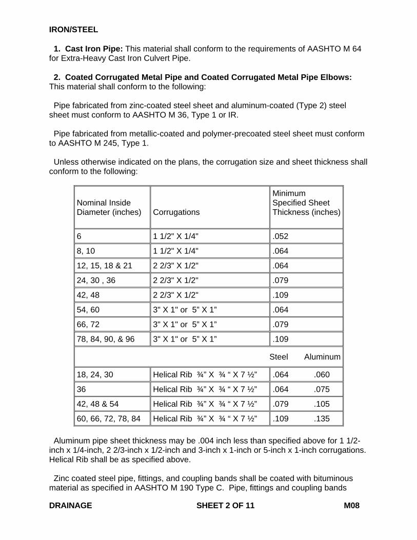
IRON/STEEL 1. Cast Iron Pipe: This material shall conform to the requirements of AASHTO M 64 for Extra-Heavy Cast Iron Culvert Pipe. 2. Coated Corrugated Metal Pipe and Coated Corrugated Metal Pipe Elbows: This material shall conform to the following: Pipe fabricated from zinc-coated steel sheet and aluminum-coated (Type 2) steel sheet must conform to AASHTO M 36, Type 1 or IR. Pipe fabricated from metallic-coated and polymer-precoated steel sheet must conform to AASHTO M 245, Type 1. Unless otherwise indicated on the plans, the corrugation size and sheet thickness shall conform to the following:
Nominal Inside Diameter (inches)
Corrugations
Minimum Specified Sheet Thickness (inches)
6 1 1/2" X 1/4" .052
8, 10 1 1/2" X 1/4" .064
12, 15, 18 & 21 2 2/3" X 1/2" .064
24, 30 , 36 2 2/3" X 1/2" .079
42, 48 2 2/3" X 1/2" .109
54, 60 3" X 1" or 5” X 1” .064
66, 72 3" X 1" or 5” X 1” .079
78, 84, 90, & 96 3" X 1" or 5” X 1” .109
Steel Aluminum
18, 24, 30 Helical Rib ¾” X ¾ “ X 7 ½” .064 .060
36 Helical Rib ¾” X ¾ “ X 7 ½” .064 .075
42, 48 & 54 Helical Rib ¾” X ¾ “ X 7 ½” .079 .105
60, 66, 72, 78, 84 Helical Rib ¾” X ¾ “ X 7 ½” .109 .135 Aluminum pipe sheet thickness may be .004 inch less than specified above for 1 1/2-inch x 1/4-inch, 2 2/3-inch x 1/2-inch and 3-inch x 1-inch or 5-inch x 1-inch corrugations. Helical Rib shall be as specified above. Zinc coated steel pipe, fittings, and coupling bands shall be coated with bituminous material as specified in AASHTO M 190 Type C. Pipe, fittings and coupling bands DRAINAGE SHEET 2 OF 11 M08
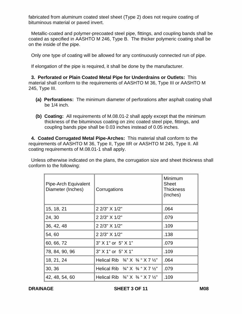
fabricated from aluminum coated steel sheet (Type 2) does not require coating of bituminous material or paved invert. Metallic-coated and polymer-precoated steel pipe, fittings, and coupling bands shall be coated as specified in AASHTO M 246, Type B. The thicker polymeric coating shall be on the inside of the pipe. Only one type of coating will be allowed for any continuously connected run of pipe. If elongation of the pipe is required, it shall be done by the manufacturer. 3. Perforated or Plain Coated Metal Pipe for Underdrains or Outlets: This material shall conform to the requirements of AASHTO M 36, Type III or AASHTO M 245, Type III.
(a) Perforations: The minimum diameter of perforations after asphalt coating shall be 1/4 inch.
(b) Coating: All requirements of M.08.01-2 shall apply except that the minimum
thickness of the bituminous coating on zinc coated steel pipe, fittings, and coupling bands pipe shall be 0.03 inches instead of 0.05 inches.
4. Coated Corrugated Metal Pipe-Arches: This material shall conform to the requirements of AASHTO M 36, Type II, Type IIR or AASHTO M 245, Type II. All coating requirements of M.08.01-1 shall apply. Unless otherwise indicated on the plans, the corrugation size and sheet thickness shall conform to the following:
Pipe-Arch Equivalent Diameter (Inches)
Corrugations
Minimum Sheet Thickness (Inches)
15, 18, 21 2 2/3" X 1/2" .064
24, 30 2 2/3" X 1/2" .079
36, 42, 48 2 2/3" X 1/2" .109
54, 60 2 2/3" X 1/2" .138
60, 66, 72 3" X 1" or 5” X 1” .079
78, 84, 90, 96 3" X 1" or 5” X 1” .109
18, 21, 24 Helical Rib ¾” X ¾ “ X 7 ½” .064
30, 36 Helical Rib ¾” X ¾ “ X 7 ½” .079
42, 48, 54, 60 Helical Rib ¾” X ¾ “ X 7 ½” .109 DRAINAGE SHEET 3 OF 11 M08
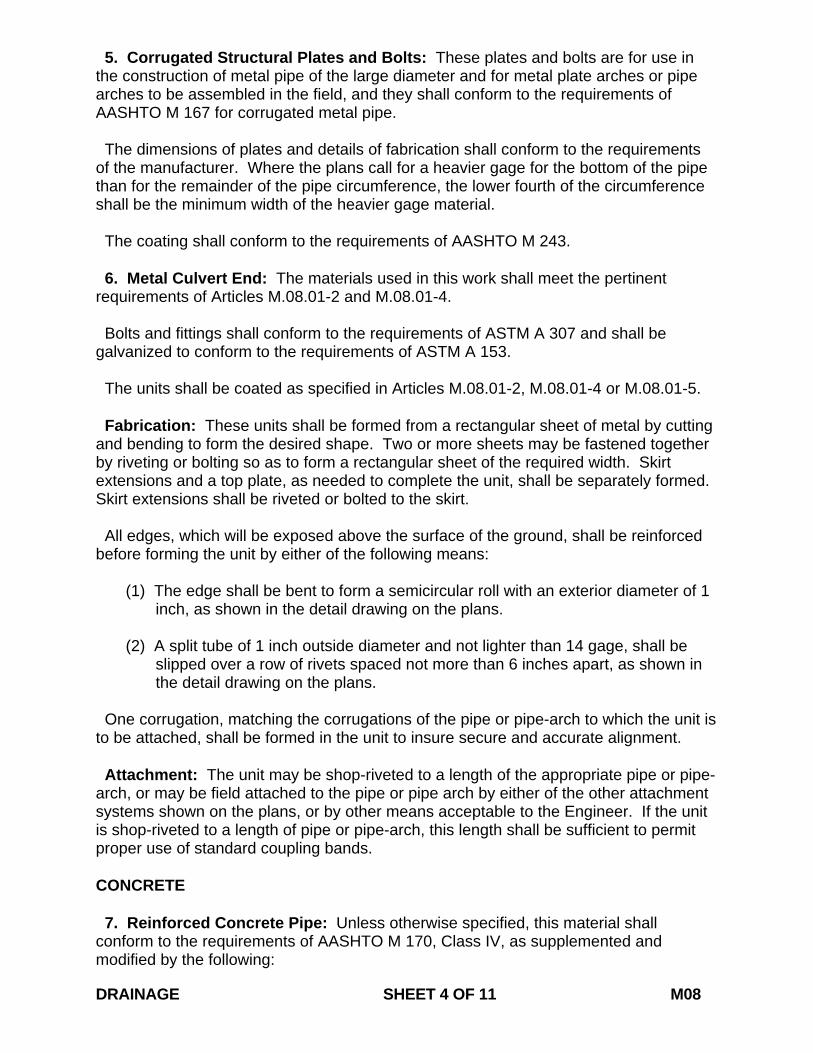
5. Corrugated Structural Plates and Bolts: These plates and bolts are for use in the construction of metal pipe of the large diameter and for metal plate arches or pipe arches to be assembled in the field, and they shall conform to the requirements of AASHTO M 167 for corrugated metal pipe. The dimensions of plates and details of fabrication shall conform to the requirements of the manufacturer. Where the plans call for a heavier gage for the bottom of the pipe than for the remainder of the pipe circumference, the lower fourth of the circumference shall be the minimum width of the heavier gage material. The coating shall conform to the requirements of AASHTO M 243. 6. Metal Culvert End: The materials used in this work shall meet the pertinent requirements of Articles M.08.01-2 and M.08.01-4. Bolts and fittings shall conform to the requirements of ASTM A 307 and shall be galvanized to conform to the requirements of ASTM A 153. The units shall be coated as specified in Articles M.08.01-2, M.08.01-4 or M.08.01-5. Fabrication: These units shall be formed from a rectangular sheet of metal by cutting and bending to form the desired shape. Two or more sheets may be fastened together by riveting or bolting so as to form a rectangular sheet of the required width. Skirt extensions and a top plate, as needed to complete the unit, shall be separately formed. Skirt extensions shall be riveted or bolted to the skirt. All edges, which will be exposed above the surface of the ground, shall be reinforced before forming the unit by either of the following means:
(1) The edge shall be bent to form a semicircular roll with an exterior diameter of 1 inch, as shown in the detail drawing on the plans.
(2) A split tube of 1 inch outside diameter and not lighter than 14 gage, shall be
slipped over a row of rivets spaced not more than 6 inches apart, as shown in the detail drawing on the plans.
One corrugation, matching the corrugations of the pipe or pipe-arch to which the unit is to be attached, shall be formed in the unit to insure secure and accurate alignment. Attachment: The unit may be shop-riveted to a length of the appropriate pipe or pipe-arch, or may be field attached to the pipe or pipe arch by either of the other attachment systems shown on the plans, or by other means acceptable to the Engineer. If the unit is shop-riveted to a length of pipe or pipe-arch, this length shall be sufficient to permit proper use of standard coupling bands. CONCRETE 7. Reinforced Concrete Pipe: Unless otherwise specified, this material shall conform to the requirements of AASHTO M 170, Class IV, as supplemented and modified by the following: DRAINAGE SHEET 4 OF 11 M08
(a) Reinforcement: In circular pipe, only circular reinforcement will be allowed. (b) Laps and Welds: The reinforcement shall be lapped not less than 2 inches and
welded with an electric welding machine. (c) Quality Assurance Testing: Circular and elliptical reinforced concrete pipe shall
be tested by the three-edge bearing method prescribed in AASHTO T 280, except as follows:
1) Modified or special design pipe shall be tested to the 0.01-inch load and the
ultimate load requirements as per AASHTO M 170 and M 207. 2) At the discretion of the Engineer, pipe of standard design, as specified in
AASHTO M 170 and M 207, may be tested to the 0.01-inch requirement plus 10% additional load in lieu of ultimate load testing. Test pipe attaining a 0.01-inch crack will not be acceptable for use on Department projects.
3) Cores for absorption and determination of steel reinforcement shall be taken
on a random basis as determined by the Engineer. The cores shall be at least 6 inches in diameter.
(d) Inspection: The pipe plant, materials, processes of manufacture and the
finished pipe shall be subject to inspection and approval by the Department. The pipe manufacturer's records related to component materials, production and shipment of pipe for Department use shall be made available to the Department on request. The equipment and labor necessary for inspection, sampling and testing as required by the Department shall be furnished by the pipe manufacturer. Test equipment shall be calibrated at least once each 12 months, or as directed by the Engineer. The plant cement and aggregate scales shall be inspected and sealed by the approved agency at least once every twelve months.
(e) Preliminary Tests and Tests for Extended Deliveries: As directed by the
Engineer, the Department shall select for test from the stock of any manufacturer proposing to supply pipe to the Department, 2 of each size pipe up through 30-inch diameter and 1 of each size greater than 30-inch diameter. These sample pipes shall be tested under Department supervision by the three-edge bearing method. For pipe that fails, it shall be necessary for the manufacturer to either physically isolate the rejected pipe at his plant or to provide some means to clearly indicate the unacceptability of the pipe. Either method shall be performed to the satisfaction of the Engineer. When production is resumed on any size, wall thickness or class previously rejected, preliminary tests shall be required. If 95% of all pipe tested at a particular plant from the first of the calendar year to September 30 meet specifications, including both preliminary and extended tests, it will not be necessary to perform the Fall three-edge bearing tests at this plant.
Use of compression tests on representative cylinders or cores to determine the
compressive strength of the concrete incorporated into the pipe products will be at the discretion of the Engineer.
DRAINAGE SHEET 5 OF 11 M08
(f) Shipping: Pipe shall not be shipped until it is at least 7 days old unless earlier shipment is authorized by the Engineer on the basis of tests.
(g) Certification: Pipe will be accepted by the Department on the basis of
manufacturer's certification. The manufacturer shall certify each shipment of pipe on Department Form MAT-073(PC-1), "Certification of Precast Concrete Products." Two (2) copies of this certification shall be furnished with the shipment to the Engineer at the project site.
8. Reinforced Concrete Elliptical Pipe: This material shall conform to the requirements of AASHTO M 207, Class HE IV and supplemented as follows: (a) Manufacturing and testing shall conform to Subarticle M.08.01-7. 9. Perforated Reinforced Concrete Pipe for Underdrains and Outlets: This material shall conform to the requirements of Subarticle M.08.01-7 and shall be slotted in accordance with AASHTO M 175, Type 2, or as shown on the plans. Pipe for outlets shall not be perforated. 10. Slotted Drain Pipe: The pipe shall be asphalt coated and conform to Subarticle M.08.01-2. Concrete shall conform to Article M.03.01, Class "A" or pavement type. Concrete shall be cured in conformance with M.03. The inlet aperture shall be longitudinal on top of the pipe and may be continuous or intermittent. The opening in the pipe wall may be fabricated in the form of continuous bar risers and spacers or of intermittent cut-out segments with structural members supporting a continuous grating as indicated in the plans. End caps shall be as provided by the manufacturer. Elastomeric polymer sealer shall meet the physical requirements of ASTM D 3406 and be accepted on manufacturer's certification. The pipe shall be helically corrugated with a continuous welded or lock seam. Pipe ends shall have 2 rolled annular corrugations on each end for jointing. Bar Riser and Spacer Type: Riser assemblies shall be fabricated from structural steel, in accordance with the dimensions on the plans. The riser assemblies shall be hot dipped galvanized according to ASTM A123. The assemblies shall be welded to the corrugated pipe on each side of the riser at the location of the solid web spacers. The riser shall terminate 1 inch from the ends of each pipe length to allow clearance for single bolt coupling bands. The ends of the riser shall be closed with a suitable welded plate where solid web spacers do not come to the ends of the riser. The maximum deviation from straight in both the vertical and horizontal plane of the riser assembly shall not exceed 3/4 inch in a 20-foot length. Continuous Grating Type: The cut-out pipe segments shall provide a 2-inch wide slot of maximum length between the lock seams. The slot shall be left intact 1 inch on each side of the lock seam and this material shall be utilized to fasten the reinforcing bar in place. A bent epoxy coated reinforcing bar shall cross the slotted opening on 6-inch centers. DRAINAGE SHEET 6 OF 11 M08
The reinforcing bar shall be an ASTM A 615, No. 13, deformed bar epoxy coated with 7 mils of fusion bonded epoxy powder conforming to AASHTO M 284. Grating shall be furnished unless noted in the contract documents. Grating and all bearing bars, cross bars, and bent connecting bars shall be welding quality, mild carbon steel conforming to ASTM A 569 and to the dimensions shown on the plans. Tie down bolts shall be J-Type bolts, plated, ASTM A 307 steel supplied with self-locking nuts. Concrete forms shall be of cellular foam plastic base, fabricated as an integral part of the pipe and reinforcing bar assembly. The form shall be capped with a thick wood or plastic cap resting on top of the foam plastic and reinforcing bar. The maximum deviation from straight in both the vertical and horizontal plane of the completed assembly shall not exceed 3/4 inch in a 20-foot length. All grating and hardware shall be galvanized in conformance with Article M.06.03. Expansion joint filler shall conform to M.03. 11. Reinforced Concrete Culvert End: The barrel shall conform to the requirements of AASHTO M 170, Class II, except that the three-edge bearing tests will not be required. The flare shall be of the same thickness and materials as the barrel and shall have steel reinforcement equaling or exceeding the amount shown on the table for the pertinent size. Tongues and grooves shall be compatible with tongues and grooves of pipe meeting AASHTO M 170, Class IV. Air entrainment shall be added to these units so as to maintain 5 to 8% entrained air. ALUMINUM 12. Corrugated Aluminum Pipe: This material shall conform to the requirements of AASHTO M 196 Type I or Type IR. Sheet thickness shall conform to the requirements of M.08.01-2. 13. Corrugated Aluminum Pipe for Underdrains and Outlets: This material shall conform to the requirements of AASHTO M 196, Type III or Type IIIR. Sheet thickness shall conform to the requirements of M.08.01-2. Pipe for outlets shall not be perforated. 14. Corrugated Aluminum Pipe Arches: These pipe arches shall conform to the requirements of AASHTO M 196, Type II or Type IIR. Sheet thickness shall conform to the requirements of M.08.01-4. SEALERS/GASKETS 15. Cold-Applied Bituminous Sealer: This material, for use in sealing of joints in concrete pipes, shall be free of asbestos and shall meet the following requirements: It shall be of such consistency that it may be spread on the joints with a trowel when DRAINAGE SHEET 7 OF 11 M08
the temperature of the air is between -20° F and 100° F. The bituminous material shall adhere to the concrete pipe so as to make a watertight seal and shall not flow, crack or become brittle when exposed to the atmosphere. Unless otherwise specified, sampling shall be done in accordance with AASHTO T 40. The bituminous sealer shall be delivered to the project in suitable containers for handling and shall be sealed or otherwise protected from contamination. The container shall show the brand name, net mass or volume, and the requirements for application. 16. Preformed Plastic Gaskets: This material for use in sealing of joints in concrete pipe shall conform to the requirements of ASTM C 1478. 17. Flexible, Watertight, Rubber-Type Gaskets: This material for use in sealing concrete pipe joints shall conform to the requirements of ASTM C 443. PLASTIC 18. Corrugated Polyethylene Pipe: Corrugated Polyethylene Pipe, either corrugated interior surface (Type C) or smooth interior surface (Type S) without perforations or with perforations (Type CP or SP), shall conform to AASHTO M 252 or M 294. Type D pipe shall have a smooth interior surface braced circumferentially or spirally with projections or ribs joined to a smooth outer wall. Both surfaces shall be fused to, or be continuous with, the internal supports. Type D shall conform to AASHTO M 294. 19. Geotextiles: The geotextile shall be non-rotting, acid and alkali resistant, and have sufficient strength and permeability for the purpose intended including handling and backfilling operations. Fibers shall be low water absorbent. The fiber network must be dimensionally stable and resistant to delamination. The geotextile shall be free of any chemical treatment or coating that will reduce its permeability. The geotextile shall also be free of any flaws or defects which will alter its physical properties. Torn or punctured geotextiles shall not be used. For each specific use, only geotextiles that are already on the Connecticut Department of Transportation's Qualified Products List for the geotextile type will be used. The Engineer reserves the right to reject any geotextile he deems unsatisfactory for a specific use. The brand name shall be labeled on the geotextile or the geotextile container. Geotextiles that are susceptible to damage from sunlight or heat shall be so identified by suitable warning information on the packaging material. Geotextiles susceptible to sunlight damage shall not be used in any installations where exposure to light will exceed 30 days, unless specifically authorized in writing by the Engineer. 20. Polyvinyl Chloride Plastic Pipe: The pipe shall conform to the requirements of ASTM D 1785. Couplings and elbows shall conform to the requirements of ASTM D 2466 or D 2467. 21. Polyvinyl Chloride Gravity Pipe: This pipe shall conform to one of the following specifications: ASTM F789, ASTM F 679, or ASTM F 794. DRAINAGE SHEET 8 OF 11 M08
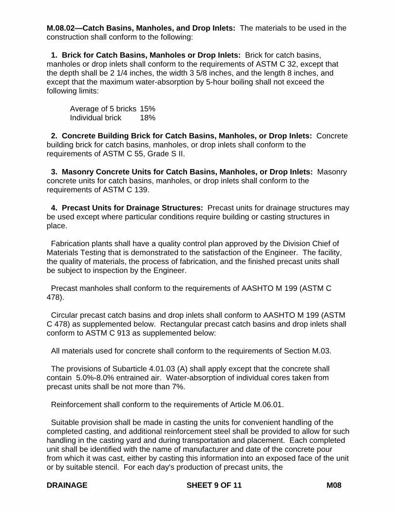
M.08.02—Catch Basins, Manholes, and Drop Inlets: The materials to be used in the construction shall conform to the following: 1. Brick for Catch Basins, Manholes or Drop Inlets: Brick for catch basins, manholes or drop inlets shall conform to the requirements of ASTM C 32, except that the depth shall be 2 1/4 inches, the width 3 5/8 inches, and the length 8 inches, and except that the maximum water-absorption by 5-hour boiling shall not exceed the following limits: Average of 5 bricks 15% Individual brick 18% 2. Concrete Building Brick for Catch Basins, Manholes, or Drop Inlets: Concrete building brick for catch basins, manholes, or drop inlets shall conform to the requirements of ASTM C 55, Grade S II. 3. Masonry Concrete Units for Catch Basins, Manholes, or Drop Inlets: Masonry concrete units for catch basins, manholes, or drop inlets shall conform to the requirements of ASTM C 139. 4. Precast Units for Drainage Structures: Precast units for drainage structures may be used except where particular conditions require building or casting structures in place. Fabrication plants shall have a quality control plan approved by the Division Chief of Materials Testing that is demonstrated to the satisfaction of the Engineer. The facility, the quality of materials, the process of fabrication, and the finished precast units shall be subject to inspection by the Engineer. Precast manholes shall conform to the requirements of AASHTO M 199 (ASTM C 478). Circular precast catch basins and drop inlets shall conform to AASHTO M 199 (ASTM C 478) as supplemented below. Rectangular precast catch basins and drop inlets shall conform to ASTM C 913 as supplemented below: All materials used for concrete shall conform to the requirements of Section M.03. The provisions of Subarticle 4.01.03 (A) shall apply except that the concrete shall contain 5.0%-8.0% entrained air. Water-absorption of individual cores taken from precast units shall be not more than 7%. Reinforcement shall conform to the requirements of Article M.06.01. Suitable provision shall be made in casting the units for convenient handling of the completed casting, and additional reinforcement steel shall be provided to allow for such handling in the casting yard and during transportation and placement. Each completed unit shall be identified with the name of manufacturer and date of the concrete pour from which it was cast, either by casting this information into an exposed face of the unit or by suitable stencil. For each day's production of precast units, the DRAINAGE SHEET 9 OF 11 M08

fabricator shall mold, cure, and test standard cylinders, or cylinders compacted in a similar manner to the parent precast units, for the purpose of determining the compressive strength of the concrete incorporated into the precast units. Concrete used in molding the cylinders shall be representative of the concrete incorporated into the precast units during the production period. Cylinders shall be molded in accordance with AASHTO T 23, cured by the same method as the units they represent, and tested as prescribed in AASHTO T 22. The fabricator shall determine the air content of the concrete used in the day's production of precast units by performing tests as prescribed in AASHTO T 152. The equipment and personnel necessary to perform the required testing shall be furnished by the fabricator and approved by the Engineer. All testing equipment shall be calibrated at least once each 12 months or as directed by the Engineer. The fabricator shall maintain records relative to the production, testing, and shipment of precast units supplied to the Department. Said records shall be available to a representative of the Department upon his request. The Department may accept precast concrete units on the basis of fabricator’s certification. The fabricator shall certify each shipment of precast concrete units on Department Form MAT 314 (PC-1), "Certification of Precast Concrete Products." Two (2) copies of this certification shall be furnished with the shipment to the Engineer at the Project site. Precast units that are cracked, show evidence of honeycomb, or have over 10% of their surface area patched may be subject to rejection, even though meeting other requirements. 5. Metal for Drainage Structures: Metal for catch basins, drop inlet and manhole frames, extensions, covers, and gratings shall be cast iron, cast steel, structural steel or malleable iron conforming to the requirements of the plans. Covers and gratings shall bear uniformly on their supports. Extensions shall be designed so that the existing manhole cover or catch basin grate, when set in place, will have substantially the same bearing, fit, and load carrying capacity as in the existing frame. The extension shall be designed to fit into the original frame, resting specifically on the flange and rim area. The extension shall accept the existing cover or grate so that the cover or grate is seated firmly without movement. Ladder rungs for manholes shall conform to AASHTO M 199 (ASTM C 478). Cast iron shall conform to the requirements of AASHTO M 105, Class 25 for the frames and Class 30 for grates. Cast steel shall conform to the requirements of ASTM A 27, Grade optional, and shall be thoroughly annealed. Structural Steel shall conform to the requirements of ASTM A 36, or A 283, Grade B or better, as to quality and details of fabrication, except that in the chemical composition of the steel, the 2/10 of 1% of copper may be omitted. DRAINAGE SHEET 10 OF 11 M08
Malleable iron shall conform to the requirements of ASTM A 47, Grade 22010. The materials and method of manufacture for drop inlets shall conform to the requirements as stated on the plans or as ordered. M.08.03—Aggregates 1. Bedding Material: Material for pipe bedding shall be sand or sandy soil, all of which passes a 3/8-inch sieve and not more than 10% passes a No. 200 sieve. When ground water is encountered, the Engineer may allow No. 6 stone conforming to Article M.01.01 to be used instead of sand or sandy soil. 2. Aggregates for Underdrains: Materials for filling the trench shall consist of well-graded, clean, non-plastic sands or well-graded, clean, durable broken stone or screened gravel. Unless otherwise noted, the type of material to be used shall be sand. Sand: This material shall meet the requirements of Subarticle M.03.01-2 Broken Stone or Screened Gravel: This material shall conform to the gradation requirements for Size No. 8 under Article M.01.01. DRAINAGE SHEET 11 OF 11 M08
July 2013
CONNECTICUT SUPPLEMENTAL SPECIFICATION
SECTION M.11 MASONRY FACING
CEMENT AND DRY RUBBLE MASONRY BRICK
MORTAR M.11.01 – Masonry Facing: 1. Masonry Facing Stone: Delete the third sentence:
“Preferably, the stone shall be from a quarry the product of which is known to be of satisfactory quality.”
Delete “2. : Vacant:”
M.11.04—Mortar: Delete the entire article and replace it with the following:
M.11.04—Mortar: Mortar shall be either Pre-blended or Pre-packaged material conforming to: ASTM C1714 - Standard Specification for Pre-blended Dry Mortar Mix for Unit Masonry; ASTM C387 - Standard Specification for Packaged, Dry, Combined Materials for Concrete and High Strength Mortar; or be composed of one part Portland cement and two parts, by volume, of surface dry fine aggregate blended on site. Hydrated lime, in an amount not to exceed 4 pounds (1.8 kilograms) of lime to each bag of cement, may be added when the material is blended on site at the option of the Engineer. Cement and hydrated lime shall conform to the following requirements: (a) Portland cement, Types I, II or IS, and water shall conform to the requirements of
Article M.03. (b) Hydrated lime shall conform to the requirements of ASTM C 6.
MASONRY FACING CEMENT AND DRY RUBBLE MASONRY BRICK MORTAR SHEET 1 OF 2 M11
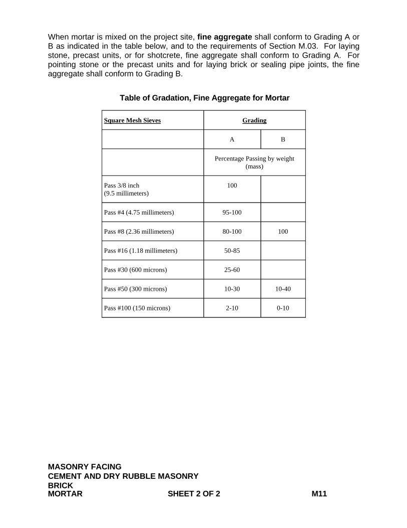
When mortar is mixed on the project site, fine aggregate shall conform to Grading A or B as indicated in the table below, and to the requirements of Section M.03. For laying stone, precast units, or for shotcrete, fine aggregate shall conform to Grading A. For pointing stone or the precast units and for laying brick or sealing pipe joints, the fine aggregate shall conform to Grading B. Table of Gradation, Fine Aggregate for Mortar
Square Mesh Sieves Grading
A B
Percentage Passing by weight (mass)
Pass 3/8 inch (9.5 millimeters)
100
Pass #4 (4.75 millimeters) 95-100
Pass #8 (2.36 millimeters) 80-100 100
Pass #16 (1.18 millimeters) 50-85
Pass #30 (600 microns) 25-60
Pass #50 (300 microns) 10-30 10-40
Pass #100 (150 microns) 2-10 0-10
MASONRY FACING CEMENT AND DRY RUBBLE MASONRY BRICK MORTAR SHEET 2 OF 2 M11
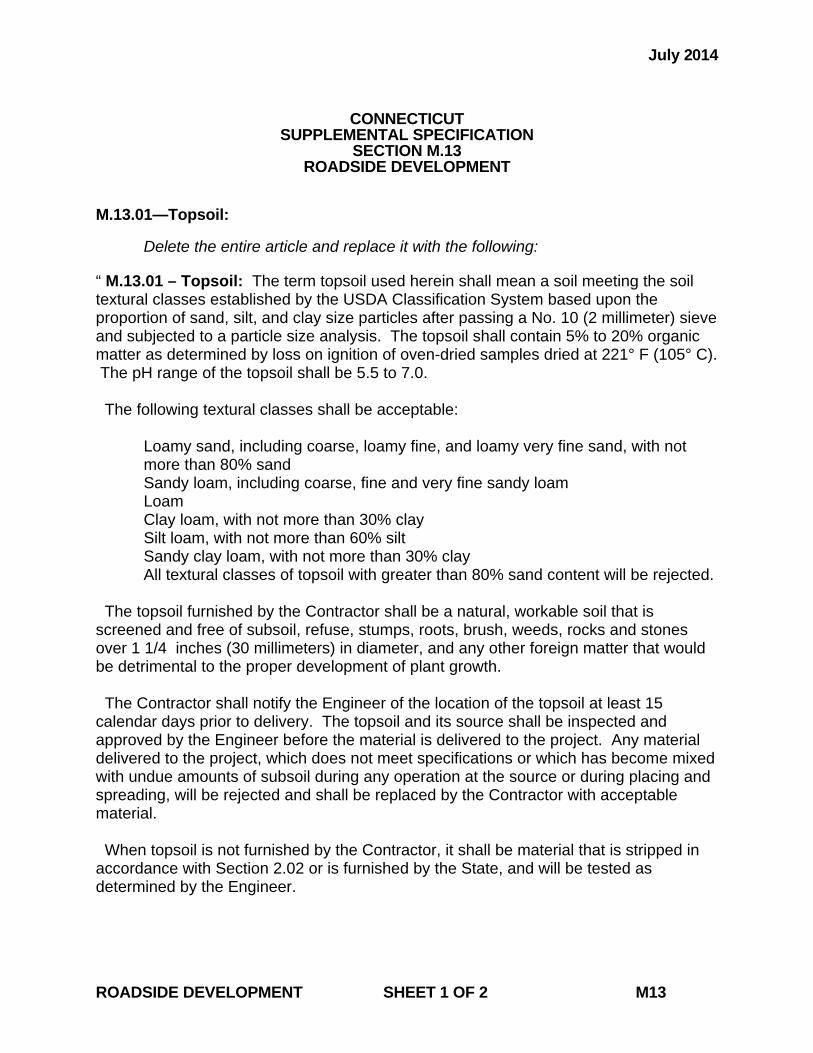
July 2014
CONNECTICUT SUPPLEMENTAL SPECIFICATION
SECTION M.13 ROADSIDE DEVELOPMENT
M.13.01—Topsoil: Delete the entire article and replace it with the following: “ M.13.01 – Topsoil: The term topsoil used herein shall mean a soil meeting the soil textural classes established by the USDA Classification System based upon the proportion of sand, silt, and clay size particles after passing a No. 10 (2 millimeter) sieve and subjected to a particle size analysis. The topsoil shall contain 5% to 20% organic matter as determined by loss on ignition of oven-dried samples dried at 221° F (105° C). The pH range of the topsoil shall be 5.5 to 7.0. The following textural classes shall be acceptable:
Loamy sand, including coarse, loamy fine, and loamy very fine sand, with not more than 80% sand Sandy loam, including coarse, fine and very fine sandy loam Loam Clay loam, with not more than 30% clay Silt loam, with not more than 60% silt Sandy clay loam, with not more than 30% clay All textural classes of topsoil with greater than 80% sand content will be rejected.
The topsoil furnished by the Contractor shall be a natural, workable soil that is screened and free of subsoil, refuse, stumps, roots, brush, weeds, rocks and stones over 1 1/4 inches (30 millimeters) in diameter, and any other foreign matter that would be detrimental to the proper development of plant growth. The Contractor shall notify the Engineer of the location of the topsoil at least 15 calendar days prior to delivery. The topsoil and its source shall be inspected and approved by the Engineer before the material is delivered to the project. Any material delivered to the project, which does not meet specifications or which has become mixed with undue amounts of subsoil during any operation at the source or during placing and spreading, will be rejected and shall be replaced by the Contractor with acceptable material. When topsoil is not furnished by the Contractor, it shall be material that is stripped in accordance with Section 2.02 or is furnished by the State, and will be tested as determined by the Engineer.
ROADSIDE DEVELOPMENT SHEET 1 OF 2 M13
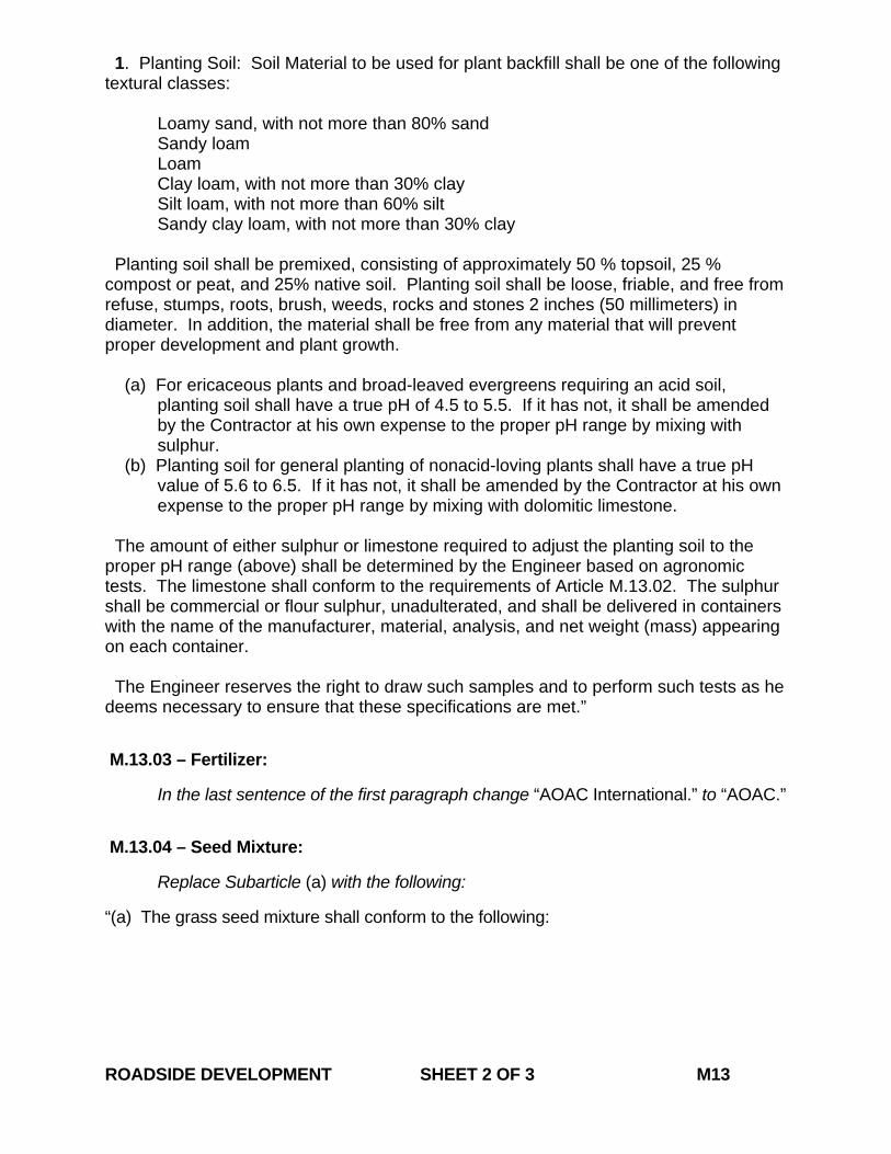
1. Planting Soil: Soil Material to be used for plant backfill shall be one of the following textural classes:
Loamy sand, with not more than 80% sand Sandy loam Loam Clay loam, with not more than 30% clay Silt loam, with not more than 60% silt Sandy clay loam, with not more than 30% clay
Planting soil shall be premixed, consisting of approximately 50 % topsoil, 25 % compost or peat, and 25% native soil. Planting soil shall be loose, friable, and free from refuse, stumps, roots, brush, weeds, rocks and stones 2 inches (50 millimeters) in diameter. In addition, the material shall be free from any material that will prevent proper development and plant growth.
(a) For ericaceous plants and broad-leaved evergreens requiring an acid soil, planting soil shall have a true pH of 4.5 to 5.5. If it has not, it shall be amended by the Contractor at his own expense to the proper pH range by mixing with sulphur.
(b) Planting soil for general planting of nonacid-loving plants shall have a true pH value of 5.6 to 6.5. If it has not, it shall be amended by the Contractor at his own expense to the proper pH range by mixing with dolomitic limestone.
The amount of either sulphur or limestone required to adjust the planting soil to the proper pH range (above) shall be determined by the Engineer based on agronomic tests. The limestone shall conform to the requirements of Article M.13.02. The sulphur shall be commercial or flour sulphur, unadulterated, and shall be delivered in containers with the name of the manufacturer, material, analysis, and net weight (mass) appearing on each container. The Engineer reserves the right to draw such samples and to perform such tests as he deems necessary to ensure that these specifications are met.”
M.13.03 – Fertilizer: In the last sentence of the first paragraph change “AOAC International.” to “AOAC.” M.13.04 – Seed Mixture: Replace Subarticle (a) with the following: “(a) The grass seed mixture shall conform to the following: ROADSIDE DEVELOPMENT SHEET 2 OF 3 M13
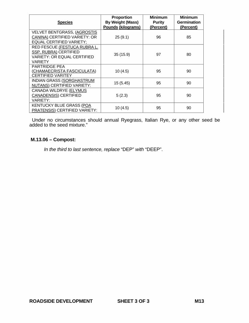
Species
Proportion By Weight (Mass)
Pounds (kilograms)
Minimum Purity
(Percent)
Minimum Germination
(Percent) VELVET BENTGRASS, (AGROSTIS CANINA) CERTIFIED VARIETY: OR EQUAL CERTIFIED VARIETY;
25 (9.1) 96 85
RED FESCUE (FESTUCA RUBRA L. SSP. RUBRA) CERTIFIED VARIETY: OR EQUAL CERTIFIED VARIETY
35 (15.9) 97 80
PARTRIDGE PEA (CHAMAECRISTA FASCICULATA) CERTIFIED VARITEY
10 (4.5) 95 90
INDIAN GRASS (SORGHASTRUM NUTANS) CERTIFIED VARIETY: 15 (5.45) 95 90
CANADA WILDRYE (ELYMUS CANADENSIS) CERTIFIED VARIETY:
5 (2.3) 95 90
KENTUCKY BLUE GRASS (POA PRATENSIS) CERTIFIED VARIETY: 10 (4.5) 95 90
Under no circumstances should annual Ryegrass, Italian Rye, or any other seed be added to the seed mixture.” M.13.06 – Compost: In the third to last sentence, replace “DEP” with “DEEP”. ROADSIDE DEVELOPMENT SHEET 3 OF 3 M13
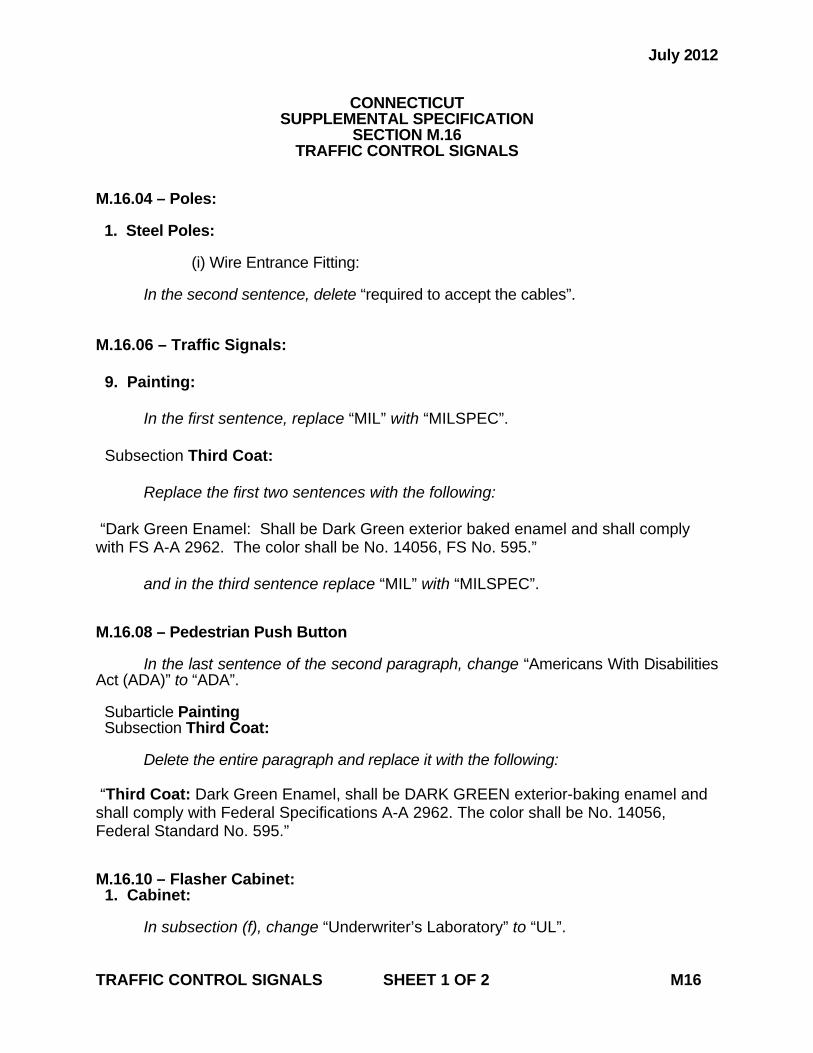
July 2012
CONNECTICUT SUPPLEMENTAL SPECIFICATION
SECTION M.16 TRAFFIC CONTROL SIGNALS
M.16.04 – Poles: 1. Steel Poles: (i) Wire Entrance Fitting:
In the second sentence, delete “required to accept the cables”.
M.16.06 – Traffic Signals: 9. Painting: In the first sentence, replace “MIL” with “MILSPEC”. Subsection Third Coat: Replace the first two sentences with the following: “Dark Green Enamel: Shall be Dark Green exterior baked enamel and shall comply with FS A-A 2962. The color shall be No. 14056, FS No. 595.”
and in the third sentence replace “MIL” with “MILSPEC”. M.16.08 – Pedestrian Push Button In the last sentence of the second paragraph, change “Americans With Disabilities Act (ADA)” to “ADA”. Subarticle Painting Subsection Third Coat:
Delete the entire paragraph and replace it with the following: “Third Coat: Dark Green Enamel, shall be DARK GREEN exterior-baking enamel and shall comply with Federal Specifications A-A 2962. The color shall be No. 14056, Federal Standard No. 595.” M.16.10 – Flasher Cabinet: 1. Cabinet: In subsection (f), change “Underwriter’s Laboratory” to “UL”. TRAFFIC CONTROL SIGNALS SHEET 1 OF 2 M16
M.16.15 – Messenger and Span Wire:
Delete the entire article and replace it with the following: “M.16.15 – Messenger and Span Wire: The materials for this work shall conform to the following requirements: 1. Messenger wire shall be made of double-galvanized 7-strand utilities-grade steel
wire cable, not less than 3/16 inch (4.8 millimeters) in diameter, with at least a 2,400-pound (10.7-killinewton) breaking strength.
2. Span wire: (a) “Span wire” shall be made of double-galvanized 7-strand utilities-grade steel
wire cable, not less than 3/8 inch (9.5 millimeters) in diameter, with at least an 11,200-pound (50-kilonewton) breaking strength.
(b) “Span wire (high strength)” shall be made of double-galvanized 7-strand extra-high-strength-grade steel wire cable, not less than 7/16 inch (11.1 millimeters) in diameter, with at least a 20,800-pound (94-kilonewton) breaking strength.
3. All hardware accessories shown on the plans to be used in span wire or messenger mounting shall be made of high-strength, double-galvanized, first-quality materials.”
TRAFFIC CONTROL SIGNALS SHEET 2 OF 2 M16
July 2006
CONNECTICUT SUPPLEMENTAL SPECIFICATION
SECTION M.17 ELASTOMERIC MATERIALS
M.17.01 – Elastomeric Bearing Pads: 2. Laminae: In the last sentence of Subsection (a), replace “AAA 6061-T6” with “AA 6061-T6”. 4. Adhesive for Bonding: In the 2nd paragraph of Subsection (b), replace “MS MIL” with “MILSPEC”.
ELASTOMERIC MATERIALS SHEET 1 OF 1 M17
July 2014
CONNECTICUT SUPPLEMENTAL SPECIFICATION
SECTION M.18 SIGNING
M.18.10 – Demountable Copy: 2. Type III Reflective Sheeting: In the first paragraph, second sentence replace “Section M.18.09.01” with “Subarticle M.18.09-1.” 3. Non-Reflective Plastic Sheeting: H. Solvent and Chemical Resistance: In the chart under this subsection, replace “MIL” with “MILSPEC.”
SIGNING SHEET 1 OF 1 M18
October 2014
Page 1 of 53
Construction Contracts - Required Contract Provisions (FHWA Funded Contracts)
Index
1. Federal Highway Administration (FHWA) Form 1273 (Revised May 1, 2012)
2. Title VI of the Civil Rights Act of 1964 / Nondiscrimination Requirements
3. Contractor Work Force Utilization (Federal Executive Order 11246) / Specific Equal
Employment Opportunity
4. Requirements of Title 49, CFR , Part 26, Participation by DBEs
5. Contract Wage Rates
6. Americans with Disabilities Act of 1990, as Amended
7. Connecticut Statutory Labor Requirements
a. Construction, Alteration or Repair of Public Works Projects; Wage Rates
b. Debarment List - Limitation on Awarding Contracts
c. Construction Safety and Health Course
d. Awarding of Contracts to Occupational Safety and Health Law Violators Prohibited
e. Residents Preference in Work on Other Public Facilities (Not Applicable to Federal
Aid Contracts)
8. Tax Liability - Contractor’s Exempt Purchase Certificate (CERT – 141)
9. Executive Orders (State of CT)
10. Non Discrimination Requirement (pursuant to section 4a-60 and 4a-60a of the Connecticut
General Statutes, as revised)
11. Whistleblower Provision
12. Connecticut Freedom of Information Act
a. Disclosure of Records
b. Confidential Information
13. Service of Process
14. Substitution of Securities for Retainages on State Contracts and Subcontracts
15. Health Insurance Portability and Accountability Act of 1996 (HIPAA)
16. Forum and Choice of Law
17. Summary of State Ethics Laws
October 2014
Page 2 of 53
18. Audit and Inspection of Plants, Places of Business and Records
19. Campaign Contribution Restriction
20. Tangible Personal Property
21. Bid Rigging and/or Fraud – Notice to Contractor
22. Consulting Agreement Affidavit
Index of Exhibits
EXHIBIT A – FHWA Form 1273 (Begins on page 13)
EXHIBIT B – Title VI Contractor Assurances (page 34)
EXHIBIT C – Contractor Work Force Utilization (Federal Executive Order 11246) / Equal
Employment Opportunity (page 35)
EXHIBIT D – Health Insurance Portability and Accountability Act of 1996 (HIPAA) (page 42)
EXHIBIT E - Campaign Contribution Restriction (page 50)
EXHIBIT F – Federal Wage Rates (Attached at the end)
EXHIBIT G - State Wage Rates (Attached at the end)
October 2014
Page 3 of 53
1. Federal Highway Administration (FHWA) Form 1273
The Contractor shall comply with the Federal Highway Administration (FHWA), Form 1273 attached
at Exhibit A, as revised, which is hereby made part of this contract. The Contractor shall also require
its subcontractors to comply with the FHWA – Form 1273 and include the FHWA – Form 1273 as an
attachment to all subcontracts and purchase orders.
2. Title VI of the Civil Rights Act of 1964 / Nondiscrimination Requirements
The Contractor shall comply with Title VI of the Civil Rights Act of 1964 as amended (42 U.S.C. 2000
et seq.), all requirements imposed by the regulations of the United States Department of Transportation
(49 CFR Part 21) issued in implementation thereof, and the Title VI Contractor Assurances attached
hereto at Exhibit B, all of which are hereby made a part of this Contract.
3. Contractor Work Force Utilization (Federal Executive Order 11246) / Equal Employment
Opportunity
(a) The Contractor shall comply with the Contractor Work Force Utilization (Federal
Executive Order 11246) / Equal Employment Opportunity requirements attached at Exhibit
C and hereby made part of this Contract, whenever a contractor or subcontractor at any tier
performs construction work in excess of $10,000. These goals shall be included in each
contract and subcontract. Goal achievement is calculated for each trade using the hours
worked under each trade.
(b) Companies with contracts, agreements or purchase orders valued at $10,000 or more will
develop and implement an Affirmative Action Plan utilizing the ConnDOT Affirmative
Action Plan Guideline. This Plan shall be designed to further the provision of equal
employment opportunity to all persons without regard to their race, color, religion, sex or
national origin, and to promote the full realization of equal employment opportunity
through a positive continuation program. Plans shall be updated as required by ConnDOT.
4. Requirements of Title 49, Code of Federal Regulations (CFR), Part 26, Participation by DBEs
Pursuant to 49 CFR 26.13, the following paragraph is part of this Contract and shall be included in
each subcontract the Contractor enters into with a subcontractor:
“The Contractor, subrecipient or subcontractor shall not discriminate on the basis of race, color,
national origin, or sex in the performance of this contract. The Contractor shall carry out applicable
requirements of 49 CFR Part 26, Participation by DBEs, in the award and administration of U.S. DOT-
assisted contracts. Failure by the Contractor to carry out these requirements is a material breach of this
Contract, which may result in the termination of this contract or such other remedy as ConnDOT
(recipient) deems appropriate.”
5. Contract Wage Rates
The Contractor shall comply with:
The Federal and State wage rate requirements indicated in Exhibits F and G hereof are hereby made
part of this Contract. If a conflict exists between the Federal and State wage rates, the higher rate shall
govern.

October 2014
Page 4 of 53
Prevailing Wages for Work on State Highways; Annual Adjustments. With respect to contracts for
work on state highways and bridges on state highways, the Contractor shall comply with the provisions
of Section 31-54 and 31-55a of the Connecticut General Statutes, as revised.
As required by section 1.05.12 (Payrolls) of the State of Connecticut, Department of Transportation’s
Standard Specification for Roads, Bridges and Incidental Construction (FORM 816), as may be
revised, every Contractor or subcontractor performing project work on a federal aid project is required
to post the relevant prevailing wage rates as determined by the United States Secretary of Labor. The
wage rate determinations shall be posted in prominent and easily accessible places at the work site.
6. Americans with Disabilities Act of 1990, as Amended
This provision applies to those Contractors who are or will be responsible for compliance with the
terms of the Americans with Disabilities Act of 1990, as amended (42 U.S.C. 12101 et seq.), (Act),
during the term of the Contract. The Contractor represents that it is familiar with the terms of this Act
and that it is in compliance with the Act. Failure of the Contractor to satisfy this standard as the same
applies to performance under this Contract, either now or during the term of the Contract as it may be
amended, will render the Contract voidable at the option of the State upon notice to the contractor. The
Contractor warrants that it will hold the State harmless and indemnify the State from any liability
which may be imposed upon the State as a result of any failure of the Contractor to be in compliance
with this Act, as the same applies to performance under this Contract.
7. Connecticut Statutory Labor Requirements
(a) Construction, Alteration or Repair of Public Works Projects; Wage Rates. The
Contractor shall comply with Section 31-53 of the Connecticut General Statutes, as revised. The
wages paid on an hourly basis to any person performing the work of any mechanic, laborer or
worker on the work herein contracted to be done and the amount of payment or contribution paid
or payable on behalf of each such person to any employee welfare fund, as defined in subsection (i)
of section 31-53 of the Connecticut General Statutes, shall be at a rate equal to the rate customary
or prevailing for the same work in the same trade or occupation in the town in which such public
works project is being constructed. Any contractor who is not obligated by agreement to make
payment or contribution on behalf of such persons to any such employee welfare fund shall pay to
each mechanic, laborer or worker as part of such person’s wages the amount of payment or
contribution for such person’s classification on each pay day.
(b) Debarment List. Limitation on Awarding Contracts. The Contractor shall comply with
Section 3l-53a of the Connecticut General Statutes, as revised.
(c) Construction Safety and Health Course. The Contractor shall comply with section 31-53b
of the Connecticut General Statutes, as revised. The contractor shall furnish proof to the Labor
Commissioner with the weekly certified payroll form for the first week each employee begins work
on such project that any person performing the work of a mechanic, laborer or worker pursuant to
the classifications of labor under section 31-53 of the Connecticut General Statutes, as revised, on
such public works project, pursuant to such contract, has completed a course of at least ten hours in
duration in construction safety and health approved by the federal Occupational Safety and Health
Administration or, has completed a new miner training program approved by the Federal Mine
Safety and Health Administration in accordance with 30 CFR 48 or, in the case of

October 2014
Page 5 of 53
telecommunications employees, has completed at least ten hours of training in accordance with 29
CFR 1910.268.
Any employee required to complete a construction safety and health course as required that has not
completed the course, shall have a maximum of fourteen (14) days to complete the course. If the
employee has not been brought into compliance, they shall be removed from the project until such
time as they have completed the required training.
Any costs associated with this notice shall be included in the general cost of the contract. In
addition, there shall be no time granted to the contractor for compliance with this notice. The
contractor’s compliance with this notice and any associated regulations shall not be grounds for
claims as outlined in Section 1.11 – “Claims”.
(d) Awarding of Contracts to Occupational Safety and Health Law Violators Prohibited. The
Contract is subject to Section 31-57b of the Connecticut General Statutes, as revised.
(e) Residents Preference in Work on Other Public Facilities. NOT APPLICABLE TO
FEDERAL AID CONTRACTS. Pursuant to Section 31-52a of the Connecticut General Statutes,
as revised, in the employment of mechanics, laborers or workmen to perform the work specified
herein, preference shall be given to residents of the state who are, and continuously for at least six
months prior to the date hereof have been, residents of this state, and if no such person is available,
then to residents of other states
8. Tax Liability - Contractor’s Exempt Purchase Certificate (CERT – 141)
The Contractor shall comply with Chapter 219 of the Connecticut General Statutes pertaining to
tangible personal property or services rendered that is/are subject to sales tax. The Contractor is
responsible for determining its tax liability. If the Contractor purchases materials or supplies pursuant
to the Connecticut Department of Revenue Services’ "Contractor’s Exempt Purchase Certificate
(CERT-141)," as may be revised, the Contractor acknowledges and agrees that title to such materials
and supplies installed or placed in the project will vest in the State simultaneously with passage of title
from the retailers or vendors thereof, and the Contractor will have no property rights in the materials
and supplies purchased.
Forms and instructions are available anytime by:
Internet: Visit the DRS website at www.ct.gov/DRS to download and print Connecticut tax forms; or
Telephone: Call 1-800-382-9463 (Connecticut calls outside the Greater Hartford calling area only) and
select Option 2 or call 860-297-4753 (from anywhere).
9. Executive Orders
This Contract is subject to the provisions of Executive Order No. Three of Governor Thomas J. Meskill, promulgated June 16, 1971, concerning labor employment practices, Executive Order No. Seventeen of Governor Thomas J. Meskill, promulgated February 15, 1973, concerning the listing of employment openings and Executive Order No. Sixteen of Governor John G. Rowland promulgated August 4, 1999, concerning violence in the workplace, all of which are incorporated into and are made a part of the Contract as if they had been fully set forth in it. The Contract may also be subject to the applicable parts of Executive Order No. 7C of Governor M. Jodi Rell, promulgated July 13, 2006, concerning contracting reforms and Executive Order No. 14 of Governor M. Jodi Rell, promulgated April 17, 2006, concerning procurement of cleaning products and services, in accordance with their
October 2014
Page 6 of 53
respective terms and conditions. If Executive Orders 7C and 14 are applicable, they are deemed to be incorporated into and are made a part of the Contract as if they had been fully set forth in it. At the Contractor’s request, the Department shall provide a copy of these orders to the Contractor.
10. Non Discrimination Requirement (pursuant to section 4a-60 and 4a-60a of the Connecticut
General Statutes, as revised): References to “minority business enterprises” in this Section are
not applicable to Federal-aid projects/contracts. Federal-aid projects/contracts are instead
subject to the Federal Disadvantaged Business Enterprise Program.
(a) For purposes of this Section, the following terms are defined as follows:
i. "Commission" means the Commission on Human Rights and Opportunities;
ii. "Contract" and “contract” include any extension or modification of the Contract or
contract;
iii. "Contractor" and “contractor” include any successors or assigns of the Contractor or
contractor;
iv. “gender identity or expression" means a person's gender-related identity, appearance or
behavior, whether or not that gender-related identity, appearance or behavior is different
from that traditionally associated with the person's physiology or assigned sex at birth,
which gender-related identity can be shown by providing evidence including, but not
limited to, medical history, care or treatment of the gender-related identity, consistent and
uniform assertion of the gender-related identity or any other evidence that the gender-
related identity is sincerely held, part of a person's core identity or not being asserted for
an improper purpose.
v. “good faith" means that degree of diligence which a reasonable person would exercise in
the performance of legal duties and obligations;
vi. "good faith efforts" shall include, but not be limited to, those reasonable initial efforts
necessary to comply with statutory or regulatory requirements and additional or
substituted efforts when it is determined that such initial efforts will not be sufficient to
comply with such requirements;
vii. "marital status" means being single, married as recognized by the State of Connecticut,
widowed, separated or divorced;
viii. "mental disability" means one or more mental disorders, as defined in the most recent
edition of the American Psychiatric Association's "Diagnostic and Statistical Manual of
Mental Disorders", or a record of or regarding a person as having one or more such
disorders;
ix. "minority business enterprise" means any small contractor or supplier of materials fifty-
one percent or more of the capital stock, if any, or assets of which is owned by a person or
persons: (1) who are active in the daily affairs of the enterprise, (2) who have the power
to direct the management and policies of the enterprise, and (3) who are members of a
minority, as such term is defined in subsection (a) of Connecticut General Statutes § 32-
9n; and
x. “public works contract" means any agreement between any individual, firm or
corporation and the State or any political subdivision of the State other than a
municipality for construction, rehabilitation, conversion, extension, demolition or repair
of a public building, highway or other changes or improvements in real property, or
which is financed in whole or in part by the State, including, but not limited to, matching
expenditures, grants, loans, insurance or guarantees.

October 2014
Page 7 of 53
For purposes of this Section, the terms "Contract" and “contract” do not include a contract where
each contractor is (1) a political subdivision of the State, including, but not limited to, a
municipality, (2) a quasi-public agency, as defined in Conn. Gen. Stat. Section 1-120, (3) any
other state, including but not limited to any federally recognized Indian tribal governments, as
defined in Conn. Gen. Stat. Section 1-267, (4) the federal government, (5) a foreign government,
or (6) an agency of a subdivision, agency, state or government described in the immediately
preceding enumerated items (1), (2), (3), (4) or (5).
(b) (1) The Contractor agrees and warrants that in the performance of the Contract such Contractor
will not discriminate or permit discrimination against any person or group of persons on the
grounds of race, color, religious creed, age, marital status, national origin, ancestry, sex, gender
identity or expression, intellectual disability, mental disability or physical disability, including,
but not limited to, blindness, unless it is shown by such Contractor that such disability prevents
performance of the work involved, in any manner prohibited by the laws of the United States or
of the State of Connecticut; and the Contractor further agrees to take affirmative action to insure
that applicants with job-related qualifications are employed and that employees are treated when
employed without regard to their race, color, religious creed, age, marital status, national origin,
ancestry, sex, gender identity or expression, intellectual disability, mental disability or physical
disability, including, but not limited to, blindness, unless it is shown by the Contractor that such
disability prevents performance of the work involved; (2) the Contractor agrees, in all
solicitations or advertisements for employees placed by or on behalf of the Contractor, to state
that it is an "affirmative action-equal opportunity employer" in accordance with regulations
adopted by the Commission; (3) the Contractor agrees to provide each labor union or
representative of workers with which the Contractor has a collective bargaining Agreement or
other contract or understanding and each vendor with which the Contractor has a contract or
understanding, a notice to be provided by the Commission, advising the labor union or workers’
representative of the Contractor's commitments under this section and to post copies of the notice
in conspicuous places available to employees and applicants for employment; (4) the Contractor
agrees to comply with each provision of this Section and Connecticut General Statutes §§ 46a-
68e and 46a-68f and with each regulation or relevant order issued by said Commission pursuant
to Connecticut General Statutes §§ 46a-56, 46a-68e and 46a-68f; and (5) the Contractor agrees to
provide the Commission on Human Rights and Opportunities with such information requested by
the Commission, and permit access to pertinent books, records and accounts, concerning the
employment practices and procedures of the Contractor as relate to the provisions of this Section
and Connecticut General Statutes § 46a-56. If the contract is a public works contract, the
Contractor agrees and warrants that he will make good faith efforts to employ minority business
enterprises as subcontractors and suppliers of materials on such public works projects.
(c) Determination of the Contractor's good faith efforts shall include, but shall not be limited to, the
following factors: The Contractor's employment and subcontracting policies, patterns and
practices; affirmative advertising, recruitment and training; technical assistance activities and
such other reasonable activities or efforts as the Commission may prescribe that are designed to
ensure the participation of minority business enterprises in public works projects.
(d) The Contractor shall develop and maintain adequate documentation, in a manner prescribed by
the Commission, of its good faith efforts.
(e) The Contractor shall include the provisions of subsection (b) of this Section in every subcontract
or purchase order entered into in order to fulfill any obligation of a contract with the State and
such provisions shall be binding on a subcontractor, vendor or manufacturer unless exempted by
October 2014
Page 8 of 53
regulations or orders of the Commission. The Contractor shall take such action with respect to
any such subcontract or purchase order as the Commission may direct as a means of enforcing
such provisions including sanctions for noncompliance in accordance with Connecticut General
Statutes §46a-56; provided if such Contractor becomes involved in, or is threatened with,
litigation with a subcontractor or vendor as a result of such direction by the Commission, the
Contractor may request the State of Connecticut to enter into any such litigation or negotiation
prior thereto to protect the interests of the State and the State may so enter.
(f) The Contractor agrees to comply with the regulations referred to in this Section as they exist on
the date of this Contract and as they may be adopted or amended from time to time during the
term of this Contract and any amendments thereto.
(g) (1) The Contractor agrees and warrants that in the performance of the Contract such Contractor
will not discriminate or permit discrimination against any person or group of persons on the
grounds of sexual orientation, in any manner prohibited by the laws of the United States or the
State of Connecticut, and that employees are treated when employed without regard to their
sexual orientation; (2) the Contractor agrees to provide each labor union or representative of
workers with which such Contractor has a collective bargaining Agreement or other contract or
understanding and each vendor with which such Contractor has a contract or understanding, a
notice to be provided by the Commission on Human Rights and Opportunities advising the labor
union or workers' representative of the Contractor's commitments under this section, and to post
copies of the notice in conspicuous places available to employees and applicants for employment;
(3) the Contractor agrees to comply with each provision of this section and with each regulation
or relevant order issued by said Commission pursuant to Connecticut General Statutes § 46a-56;
and (4) the Contractor agrees to provide the Commission on Human Rights and Opportunities
with such information requested by the Commission, and permit access to pertinent books,
records and accounts, concerning the employment practices and procedures of the Contractor
which relate to the provisions of this Section and Connecticut General Statutes § 46a-56.
(h) The Contractor shall include the provisions of the foregoing paragraph in every subcontract or
purchase order entered into in order to fulfill any obligation of a contract with the State and such
provisions shall be binding on a subcontractor, vendor or manufacturer unless exempted by
regulations or orders of the Commission. The Contractor shall take such action with respect to
any such subcontract or purchase order as the Commission may direct as a means of enforcing
such provisions including sanctions for noncompliance in accordance with Connecticut General
Statutes § 46a-56; provided, if such Contractor becomes involved in, or is threatened with,
litigation with a subcontractor or vendor as a result of such direction by the Commission, the
Contractor may request the State of Connecticut to enter into any such litigation or negotiation
prior thereto to protect the interests of the State and the State may so enter.”
The Nondiscrimination Certifications can be found at the Office of Policy and Management website.
http://www.ct.gov/opm/cwp/view.asp?a=2982&Q=390928
11. Whistleblower Provision
The following clause is applicable if the Contract has a value of Five Million Dollars ($5,000,000) or
more.
October 2014
Page 9 of 53
Whistleblowing. This Contract may be subject to the provisions of Section 4-61dd of the Connecticut General Statutes. In accordance with this statute, if an officer, employee or appointing authority of the Contractor takes or threatens to take any personnel action against any employee of the Contractor in retaliation for such employee's disclosure of information to any employee of the contracting state or quasi-public agency or the Auditors of Public Accounts or the Attorney General under the provisions of subsection (a) of such statute, the Contractor shall be liable for a civil penalty of not more than five thousand dollars for each offense, up to a maximum of twenty per cent of the value of this Contract. Each violation shall be a separate and distinct offense and in the case of a continuing violation, each calendar day's continuance of the violation shall be deemed to be a separate and distinct offense. The State may request that the Attorney General bring a civil action in the Superior Court for the Judicial District of Hartford to seek imposition and recovery of such civil penalty. In accordance with subsection (f) of such statute, each large state contractor, as defined in the statute, shall post a notice of the provisions of the statute relating to large state contractors in a conspicuous place which is readily available for viewing by the employees of the Contractor. 12. Connecticut Freedom of Information Act
(a) Disclosure of Records. This Contract may be subject to the provisions of section 1-218 of
the Connecticut General Statutes. In accordance with this statute, each contract in excess of two million five hundred thousand dollars between a public agency and a person for the performance of a governmental function shall (a) provide that the public agency is entitled to receive a copy of records and files related to the performance of the governmental function, and (b) indicate that such records and files are subject to FOIA and may be disclosed by the public agency pursuant to FOIA. No request to inspect or copy such records or files shall be valid unless the request is made to the public agency in accordance with FOIA. Any complaint by a person who is denied the right to inspect or copy such records or files shall be brought to the Freedom of Information Commission in accordance with the provisions of sections 1-205 and 1-206 of the Connecticut General Statutes.
(b) Confidential Information. The State will afford due regard to the Contractor’s request
for the protection of proprietary or confidential information which the State receives from
the Contractor. However, all materials associated with the Contract are subject to the terms
of the FOIA and all corresponding rules, regulations and interpretations. In making such a
request, the Contractor may not merely state generally that the materials are proprietary or
confidential in nature and not, therefore, subject to release to third parties. Those particular
sentences, paragraphs, pages or sections that the Contractor believes are exempt from
disclosure under the FOIA must be specifically identified as such. Convincing explanation
and rationale sufficient to justify each exemption consistent with the FOIA must
accompany the request. The rationale and explanation must be stated in terms of the
prospective harm to the competitive position of the Contractor that would result if the
identified material were to be released and the reasons why the materials are legally exempt
from release pursuant to the FOIA. To the extent that any other provision or part of the
Contract conflicts or is in any way inconsistent with this section, this section controls and
shall apply and the conflicting provision or part shall not be given effect. If the Contractor
indicates that certain documentation is submitted in confidence, by specifically and clearly
marking the documentation as “CONFIDENTIAL,” DOT will first review the Contractor’s
claim for consistency with the FOIA (that is, review that the documentation is actually a
trade secret or commercial or financial information and not required by statute), and if
determined to be consistent, will endeavor to keep such information confidential to the
extent permitted by law. See, e.g., Conn. Gen. Stat. §1-210(b)(5)(A-B). The State,
however, has no obligation to initiate, prosecute or defend any legal proceeding or to seek a
protective order or other similar relief to prevent disclosure of any information that is
sought pursuant to a FOIA request. Should the State withhold such documentation from a
October 2014
Page 10 of 53
Freedom of Information requester and a complaint be brought to the Freedom of
Information Commission, the Contractor shall have the burden of cooperating with DOT in
defense of that action and in terms of establishing the availability of any FOIA exemption
in any proceeding where it is an issue. In no event shall the State have any liability for the
disclosure of any documents or information in its possession which the State believes are
required to be disclosed pursuant to the FOIA or other law.
13. Service of Process
The Contractor, if not a resident of the State of Connecticut, or, in the case of a partnership, the
partners, if not residents, hereby appoints the Secretary of State of the State of Connecticut, and his
successors in office, as agent for service of process for any action arising out of or as a result of this
Contract; such appointment to be in effect throughout the life of this Contract and six (6) years
thereafter.
14. Substitution of Securities for Retainages on State Contracts and Subcontracts
This Contract is subject to the provisions of Section 3-ll2a of the General Statutes of the State of
Connecticut, as revised.
15. Health Insurance Portability and Accountability Act of 1996 (HIPAA)
The Contractor shall comply, if applicable, with the Health Insurance Portability and Accountability
Act of 1996 and, pursuant thereto, the provisions attached at Exhibit D, and hereby made part of this
Contract.
16. Forum and Choice of Law
Forum and Choice of Law. The parties deem the Contract to have been made in the City of Hartford, State of Connecticut. Both parties agree that it is fair and reasonable for the validity and construction of the Contract to be, and it shall be, governed by the laws and court decisions of the State of Connecticut, without giving effect to its principles of conflicts of laws. To the extent that any immunities provided by Federal law or the laws of the State of Connecticut do not bar an action against the State, and to the extent that these courts are courts of competent jurisdiction, for the purpose of venue, the complaint shall be made returnable to the Judicial District of Hartford only or shall be brought in the United States District Court for the District of Connecticut only, and shall not be transferred to any other court, provided, however, that nothing here constitutes a waiver or compromise of the sovereign immunity of the State of Connecticut. The Contractor waives any objection which it may now have or will have to the laying of venue of any Claims in any forum and further irrevocably submits to such jurisdiction in any suit, action or proceeding.
17. Summary of State Ethics Laws Pursuant to the requirements of section 1-101qq of the Connecticut General Statutes, the summary of State ethics laws developed by the State Ethics Commission pursuant to section 1-81b of the Connecticut General Statutes is incorporated by reference into and made a part of the Contract as if the summary had been fully set forth in the Contract. 18. Audit and Inspection of Plants, Places of Business and Records
(a) The State and its agents, including, but not limited to, the Connecticut Auditors of Public
Accounts, Attorney General and State’s Attorney and their respective agents, may, at
reasonable hours, inspect and examine all of the parts of the Contractor’s and Contractor
October 2014
Page 11 of 53
Parties’ plants and places of business which, in any way, are related to, or involved in, the
performance of this Contract. For the purposes of this Section, “Contractor Parties” means the
Contractor’s members, directors, officers, shareholders, partners, managers, principal officers,
representatives, agents, servants, consultants, employees or any one of them or any other
person or entity with whom the Contractor is in privity of oral or written contract and the
Contractor intends for such other person or entity to Perform under the Contract in any
capacity. (b) The Contractor shall maintain, and shall require each of the Contractor Parties to maintain,
accurate and complete Records. The Contractor shall make all of its and the Contractor Parties’ Records available at all reasonable hours for audit and inspection by the State and its agents.
(c) The State shall make all requests for any audit or inspection in writing and shall provide the Contractor with at least twenty-four (24) hours’ notice prior to the requested audit and inspection date. If the State suspects fraud or other abuse, or in the event of an emergency, the State is not obligated to provide any prior notice.
(d) The Contractor shall keep and preserve or cause to be kept and preserved all of its and Contractor Parties’ Records until three (3) years after the latter of (i) final payment under this Agreement, or (ii) the expiration or earlier termination of this Agreement, as the same may be modified for any reason. The State may request an audit or inspection at any time during this period. If any Claim or audit is started before the expiration of this period, the Contractor shall retain or cause to be retained all Records until all Claims or audit findings have been resolved.
(e) The Contractor shall cooperate fully with the State and its agents in connection with an audit or inspection. Following any audit or inspection, the State may conduct and the Contractor shall cooperate with an exit conference.
(f) The Contractor shall incorporate this entire Section verbatim into any contract or other agreement that it enters into with any Contractor Party.
19.Campaign Contribution Restriction
For all State contracts, defined in Conn. Gen. Stat. §9-612(g)(1) as having a value in a calendar year of $50,000 or more, or a combination or series of such agreements or contracts having a value of $100,000 or more, the authorized signatory to this Agreement expressly acknowledges receipt of the State Elections Enforcement Commission’s notice advising state contractors of state campaign contribution and solicitation prohibitions, and will inform its principals of the contents of the notice, as set forth in "Notice to Executive Branch State Contractors and Prospective State Contractors of Campaign Contribution and Solicitation Limitations,” attached as Exhibit E. 20. Tangible Personal Property (a) The Contractor on its behalf and on behalf of its Affiliates, as defined below, shall comply with the
provisions of Conn. Gen. Stat. §12-411b, as follows:
(1) For the term of the Contract, the Contractor and its Affiliates shall collect and remit to the State of Connecticut, Department of Revenue Services, any Connecticut use tax due under the provisions of Chapter 219 of the Connecticut General Statutes for items of tangible personal property sold by the Contractor or by any of its Affiliates in the same manner as if the Contractor and such Affiliates were engaged in the business of selling tangible personal property for use in Connecticut and had sufficient nexus under the provisions of Chapter 219 to be required to collect Connecticut use tax;
(2) A customer’s payment of a use tax to the Contractor or its Affiliates relieves the customer of liability for the use tax;
(3) The Contractor and its Affiliates shall remit all use taxes they collect from customers on or before the due date specified in the Contract, which may not be later than the last day of the month next succeeding the end of a calendar quarter or other tax collection period during which the tax was collected;
(4) The Contractor and its Affiliates are not liable for use tax billed by them but not paid to them by a customer; and
October 2014
Page 12 of 53
(5) Any Contractor or Affiliate who fails to remit use taxes collected on behalf of its customers by the due date specified in the Contract shall be subject to the interest and penalties provided for persons required to collect sales tax under chapter 219 of the general statutes.
(b) For purposes of this section of the Contract, the word “Affiliate” means any person, as defined in
section 12-1 of the general statutes, that controls, is controlled by, or is under common control with another person. A person controls another person if the person owns, directly or indirectly, more than ten per cent of the voting securities of the other person. The word “voting security” means a security that confers upon the holder the right to vote for the election of members of the board of directors or similar governing body of the business, or that is convertible into, or entitles the holder to receive, upon its exercise, a security that confers such a right to vote. “Voting security” includes a general partnership interest.
(c) The Contractor represents and warrants that each of its Affiliates has vested in the Contractor plenary authority to so bind the Affiliates in any agreement with the State of Connecticut. The Contractor on its own behalf and on behalf of its Affiliates shall also provide, no later than 30 days after receiving a request by the State’s contracting authority, such information as the State may require to ensure, in the State’s sole determination, compliance with the provisions of Chapter 219 of the Connecticut General Statutes, including, but not limited to, §12-411b.
21. Bid Rigging and/or Fraud – Notice to Contractor The Connecticut Department of Transportation is cooperating with the U.S. Department of Transportation and the Justice Department in their investigation into highway construction contract bid rigging and/or fraud. A toll-free “HOT LINE” telephone number 800-424-9071 has been established to receive information from contractors, subcontractors, manufacturers, suppliers or anyone with knowledge of bid rigging and/or fraud, either past or current. The “HOT LINE” telephone number will be available during normal working hours (8:00 am – 5:00 pm EST). Information will be treated confidentially and anonymity respected. 22. Consulting Agreement Affidavit The Contractor shall comply with Connecticut General Statutes Section 4a-81(a) and 4a-81(b), as revised. Pursuant to Public Act 11-229, after the initial submission of the form, if there is a change in the information contained in the form, a contractor shall submit the updated form, as applicable, either (i) not later than thirty (30) days after the effective date of such change or (ii) prior to execution of any new contract, whichever is earlier. The Affidavit/Form may be submitted in written format or electronic format through the Department of Administrative Services (DAS) website.
October 2014
Page 13 of 53
EXHIBIT A
FHWA-1273 -- Revised May 1, 2012
REQUIRED CONTRACT PROVISIONS
FEDERAL-AID CONSTRUCTION CONTRACTS
I. General
II. Nondiscrimination
III. Nonsegregated Facilities
IV. Davis-Bacon and Related Act Provisions
V. Contract Work Hours and Safety Standards Act Provisions
VI. Subletting or Assigning the Contract
VII. Safety: Accident Prevention
VIII. False Statements Concerning Highway Projects
IX. Implementation of Clean Air Act and Federal Water Pollution Control Act
X. Compliance with Governmentwide Suspension and Debarment Requirements
XI. Certification Regarding Use of Contract Funds for Lobbying
ATTACHMENTS
A. Employment and Materials Preference for Appalachian Development Highway System or
Appalachian Local Access Road Contracts (included in Appalachian contracts only)
I. GENERAL
1. Form FHWA-1273 must be physically incorporated in each construction contract funded under
Title 23 (excluding emergency contracts solely intended for debris removal). The contractor (or
subcontractor) must insert this form in each subcontract and further require its inclusion in all lower
tier subcontracts (excluding purchase orders, rental agreements and other agreements for supplies or
services).
The applicable requirements of Form FHWA-1273 are incorporated by reference for work done under
any purchase order, rental agreement or agreement for other services. The prime contractor shall be
responsible for compliance by any subcontractor, lower-tier subcontractor or service provider.
Form FHWA-1273 must be included in all Federal-aid design-build contracts, in all subcontracts and
in lower tier subcontracts (excluding subcontracts for design services, purchase orders, rental
agreements and other agreements for supplies or services). The design-builder shall be responsible for
compliance by any subcontractor, lower-tier subcontractor or service provider.
Contracting agencies may reference Form FHWA-1273 in bid proposal or request for proposal
documents, however, the Form FHWA-1273 must be physically incorporated (not referenced) in all
contracts, subcontracts and lower-tier subcontracts (excluding purchase orders, rental agreements and
other agreements for supplies or services related to a construction contract).
October 2014
Page 14 of 53
2. Subject to the applicability criteria noted in the following sections, these contract provisions shall
apply to all work performed on the contract by the contractor's own organization and with the
assistance of workers under the contractor's immediate superintendence and to all work performed on
the contract by piecework, station work, or by subcontract.
3. A breach of any of the stipulations contained in these Required Contract Provisions may be
sufficient grounds for withholding of progress payments, withholding of final payment, termination of
the contract, suspension / debarment or any other action determined to be appropriate by the
contracting agency and FHWA.
4. Selection of Labor: During the performance of this contract, the contractor shall not use convict
labor for any purpose within the limits of a construction project on a Federal-aid highway unless it is
labor performed by convicts who are on parole, supervised release, or probation. The term Federal-aid
highway does not include roadways functionally classified as local roads or rural minor collectors.
II. NONDISCRIMINATION
The provisions of this section related to 23 CFR Part 230 are applicable to all Federal-aid construction
contracts and to all related construction subcontracts of $10,000 or more. The provisions of 23 CFR
Part 230 are not applicable to material supply, engineering, or architectural service contracts.
In addition, the contractor and all subcontractors must comply with the following policies: Executive
Order 11246, 41 CFR 60, 29 CFR 1625-1627, Title 23 USC Section 140, the Rehabilitation Act of
1973, as amended (29 USC 794), Title VI of the Civil Rights Act of 1964, as amended, and related
regulations including 49 CFR Parts 21, 26 and 27; and 23 CFR Parts 200, 230, and 633.
The contractor and all subcontractors must comply with: the requirements of the Equal Opportunity
Clause in 41 CFR 60-1.4(b) and, for all construction contracts exceeding $10,000, the Standard Federal
Equal Employment Opportunity Construction Contract Specifications in 41 CFR 60-4.3.
Note: The U.S. Department of Labor has exclusive authority to determine compliance with Executive
Order 11246 and the policies of the Secretary of Labor including 41 CFR 60, and 29 CFR 1625-1627.
The contracting agency and the FHWA have the authority and the responsibility to ensure compliance
with Title 23 USC Section 140, the Rehabilitation Act of 1973, as amended (29 USC 794), and Title
VI of the Civil Rights Act of 1964, as amended, and related regulations including 49 CFR Parts 21, 26
and 27; and 23 CFR Parts 200, 230, and 633.
The following provision is adopted from 23 CFR 230, Appendix A, with appropriate revisions to
conform to the U.S. Department of Labor (US DOL) and FHWA requirements.
1. Equal Employment Opportunity: Equal employment opportunity (EEO) requirements not to
discriminate and to take affirmative action to assure equal opportunity as set forth under laws,
executive orders, rules, regulations (28 CFR 35, 29 CFR 1630, 29 CFR 1625-1627, 41 CFR 60 and 49
CFR 27) and orders of the Secretary of Labor as modified by the provisions prescribed herein, and
imposed pursuant to 23 U.S.C. 140 shall constitute the EEO and specific affirmative action standards
for the contractor's project activities under this contract. The provisions of the Americans with
Disabilities Act of 1990 (42 U.S.C. 12101 et seq.) set forth under 28 CFR 35 and 29 CFR 1630 are
incorporated by reference in this contract. In the execution of this contract, the contractor agrees to
comply with the following minimum specific requirement activities of EEO:

October 2014
Page 15 of 53
a. The contractor will work with the contracting agency and the Federal Government to ensure that it
has made every good faith effort to provide equal opportunity with respect to all of its terms and
conditions of employment and in their review of activities under the contract.
b. The contractor will accept as its operating policy the following statement:
"It is the policy of this Company to assure that applicants are employed, and that employees are
treated during employment, without regard to their race, religion, sex, color, national origin, age or
disability. Such action shall include: employment, upgrading, demotion, or transfer; recruitment or
recruitment advertising; layoff or termination; rates of pay or other forms of compensation; and
selection for training, including apprenticeship, pre-apprenticeship, and/or on-the-job training."
2. EEO Officer: The contractor will designate and make known to the contracting officers an EEO
Officer who will have the responsibility for and must be capable of effectively administering and
promoting an active EEO program and who must be assigned adequate authority and responsibility to
do so.
3. Dissemination of Policy: All members of the contractor's staff who are authorized to hire,
supervise, promote, and discharge employees, or who recommend such action, or who are substantially
involved in such action, will be made fully cognizant of, and will implement, the contractor's EEO
policy and contractual responsibilities to provide EEO in each grade and classification of employment.
To ensure that the above agreement will be met, the following actions will be taken as a minimum:
a. Periodic meetings of supervisory and personnel office employees will be conducted before the
start of work and then not less often than once every six months, at which time the contractor's EEO
policy and its implementation will be reviewed and explained. The meetings will be conducted by the
EEO Officer.
b. All new supervisory or personnel office employees will be given a thorough indoctrination by the
EEO Officer, covering all major aspects of the contractor's EEO obligations within thirty days
following their reporting for duty with the contractor.
c. All personnel who are engaged in direct recruitment for the project will be instructed by the EEO
Officer in the contractor's procedures for locating and hiring minorities and women.
d. Notices and posters setting forth the contractor's EEO policy will be placed in areas readily
accessible to employees, applicants for employment and potential employees.
e. The contractor's EEO policy and the procedures to implement such policy will be brought to the
attention of employees by means of meetings, employee handbooks, or other appropriate means.
4. Recruitment: When advertising for employees, the contractor will include in all advertisements for
employees the notation: "An Equal Opportunity Employer." All such advertisements will be placed in
publications having a large circulation among minorities and women in the area from which the project
work force would normally be derived.
a. The contractor will, unless precluded by a valid bargaining agreement, conduct systematic and
direct recruitment through public and private employee referral sources likely to yield qualified
minorities and women. To meet this requirement, the contractor will identify sources of potential
October 2014
Page 16 of 53
minority group employees, and establish with such identified sources procedures whereby minority
and women applicants may be referred to the contractor for employment consideration.
b. In the event the contractor has a valid bargaining agreement providing for exclusive hiring hall
referrals, the contractor is expected to observe the provisions of that agreement to the extent that the
system meets the contractor's compliance with EEO contract provisions. Where implementation of
such an agreement has the effect of discriminating against minorities or women, or obligates the
contractor to do the same, such implementation violates Federal nondiscrimination provisions.
c. The contractor will encourage its present employees to refer minorities and women as applicants
for employment. Information and procedures with regard to referring such applicants will be discussed
with employees.
5. Personnel Actions: Wages, working conditions, and employee benefits shall be established and
administered, and personnel actions of every type, including hiring, upgrading, promotion, transfer,
demotion, layoff, and termination, shall be taken without regard to race, color, religion, sex, national
origin, age or disability. The following procedures shall be followed:
a. The contractor will conduct periodic inspections of project sites to insure that working conditions
and employee facilities do not indicate discriminatory treatment of project site personnel.
b. The contractor will periodically evaluate the spread of wages paid within each classification to
determine any evidence of discriminatory wage practices.
c. The contractor will periodically review selected personnel actions in depth to determine whether
there is evidence of discrimination. Where evidence is found, the contractor will promptly take
corrective action. If the review indicates that the discrimination may extend beyond the actions
reviewed, such corrective action shall include all affected persons.
d. The contractor will promptly investigate all complaints of alleged discrimination made to the
contractor in connection with its obligations under this contract, will attempt to resolve such
complaints, and will take appropriate corrective action within a reasonable time. If the investigation
indicates that the discrimination may affect persons other than the complainant, such corrective action
shall include such other persons. Upon completion of each investigation, the contractor will inform
every complainant of all of their avenues of appeal.
6. Training and Promotion:
a. The contractor will assist in locating, qualifying, and increasing the skills of minorities and women
who are applicants for employment or current employees. Such efforts should be aimed at developing
full journey level status employees in the type of trade or job classification involved.
b. Consistent with the contractor's work force requirements and as permissible under Federal and
State regulations, the contractor shall make full use of training programs, i.e., apprenticeship, and on-
the-job training programs for the geographical area of contract performance. In the event a special
provision for training is provided under this contract, this subparagraph will be superseded as indicated
in the special provision. The contracting agency may reserve training positions for persons who
receive welfare assistance in accordance with 23 U.S.C. 140(a).

October 2014
Page 17 of 53
c. The contractor will advise employees and applicants for employment of available training
programs and entrance requirements for each.
d. The contractor will periodically review the training and promotion potential of employees who are
minorities and women and will encourage eligible employees to apply for such training and promotion.
7. Unions: If the contractor relies in whole or in part upon unions as a source of employees, the
contractor will use good faith efforts to obtain the cooperation of such unions to increase opportunities
for minorities and women. Actions by the contractor, either directly or through a contractor's
association acting as agent, will include the procedures set forth below:
a. The contractor will use good faith efforts to develop, in cooperation with the unions, joint training
programs aimed toward qualifying more minorities and women for membership in the unions and
increasing the skills of minorities and women so that they may qualify for higher paying employment.
b. The contractor will use good faith efforts to incorporate an EEO clause into each union agreement
to the end that such union will be contractually bound to refer applicants without regard to their race,
color, religion, sex, national origin, age or disability.
c. The contractor is to obtain information as to the referral practices and policies of the labor union
except that to the extent such information is within the exclusive possession of the labor union and
such labor union refuses to furnish such information to the contractor, the contractor shall so certify to
the contracting agency and shall set forth what efforts have been made to obtain such information.
d. In the event the union is unable to provide the contractor with a reasonable flow of referrals within
the time limit set forth in the collective bargaining agreement, the contractor will, through independent
recruitment efforts, fill the employment vacancies without regard to race, color, religion, sex, national
origin, age or disability; making full efforts to obtain qualified and/or qualifiable minorities and
women. The failure of a union to provide sufficient referrals (even though it is obligated to provide
exclusive referrals under the terms of a collective bargaining agreement) does not relieve the contractor
from the requirements of this paragraph. In the event the union referral practice prevents the
contractor from meeting the obligations pursuant to Executive Order 11246, as amended, and these
special provisions, such contractor shall immediately notify the contracting agency.
8. Reasonable Accommodation for Applicants / Employees with Disabilities: The contractor must
be familiar with the requirements for and comply with the Americans with Disabilities Act and all
rules and regulations established there under. Employers must provide reasonable accommodation in
all employment activities unless to do so would cause an undue hardship.
9. Selection of Subcontractors, Procurement of Materials and Leasing of Equipment: The
contractor shall not discriminate on the grounds of race, color, religion, sex, national origin, age or
disability in the selection and retention of subcontractors, including procurement of materials and
leases of equipment. The contractor shall take all necessary and reasonable steps to ensure
nondiscrimination in the administration of this contract.
a. The contractor shall notify all potential subcontractors and suppliers and lessors of their EEO
obligations under this contract.
b. The contractor will use good faith efforts to ensure subcontractor compliance with their EEO
obligations.

October 2014
Page 18 of 53
10. Assurance Required by 49 CFR 26.13(b):
a. The requirements of 49 CFR Part 26, and the State DOT’s U.S. DOT-approved DBE program are
incorporated by reference.
b. The contractor or subcontractor shall not discriminate on the basis of race, color, national origin, or
sex in the performance of this contract. The contractor shall carry out applicable requirements of 49
CFR Part 26, in the award and administration of DOT-assisted contracts. Failure by the contractor to
carry out these requirements is a material breach of this contract, which may result in the termination
of this contract or such other remedy as the contracting agency deems appropriate.
11. Records and Reports: The contractor shall keep such records as necessary to document
compliance with the EEO requirements. Such records shall be retained for a period of three years
following the date of the final payment to the contractor for all contract work and shall be available at
reasonable times and places for inspection by authorized representatives of the contracting agency and
the FHWA.
a. The records kept by the contractor shall document the following:
(1) The number and work hours of minority and non-minority group members and women employed
in each work classification on the project;
(2) The progress and efforts being made in cooperation with unions, when applicable, to increase
employment opportunities for minorities and women; and
(3) The progress and efforts being made in locating, hiring, training, qualifying, and upgrading
minorities and women;
b. The contractors and subcontractors will submit an annual report to the contracting agency each
July for the duration of the project, indicating the number of minority, women, and non-minority group
employees currently engaged in each work classification required by the contract work. This
information is to be reported on Form FHWA-1391. The staffing data should represent the project
work force on board in all or any part of the last payroll period preceding the end of July. If on-the-job
training is being required by special provision, the contractor will be required to collect and report
training data. The employment data should reflect the work force on board during all or any part of the
last payroll period preceding the end of July.
III. NONSEGREGATED FACILITIES
This provision is applicable to all Federal-aid construction contracts and to all related construction
subcontracts of $10,000 or more.
The contractor must ensure that facilities provided for employees are provided in such a manner that
segregation on the basis of race, color, religion, sex, or national origin cannot result. The contractor
may neither require such segregated use by written or oral policies nor tolerate such use by employee
custom. The contractor's obligation extends further to ensure that its employees are not assigned to
perform their services at any location, under the contractor's control, where the facilities are
segregated. The term "facilities" includes waiting rooms, work areas, restaurants and other eating
October 2014
Page 19 of 53
areas, time clocks, restrooms, washrooms, locker rooms, and other storage or dressing areas, parking
lots, drinking fountains, recreation or entertainment areas, transportation, and housing provided for
employees. The contractor shall provide separate or single-user restrooms and necessary dressing or
sleeping areas to assure privacy between sexes.
IV. DAVIS-BACON AND RELATED ACT PROVISIONS
This section is applicable to all Federal-aid construction projects exceeding $2,000 and to all related
subcontracts and lower-tier subcontracts (regardless of subcontract size). The requirements apply to all
projects located within the right-of-way of a roadway that is functionally classified as Federal-aid
highway. This excludes roadways functionally classified as local roads or rural minor collectors,
which are exempt. Contracting agencies may elect to apply these requirements to other projects.
The following provisions are from the U.S. Department of Labor regulations in 29 CFR 5.5 “Contract
provisions and related matters” with minor revisions to conform to the FHWA-1273 format and
FHWA program requirements.
1. Minimum wages
a. All laborers and mechanics employed or working upon the site of the work, will be paid
unconditionally and not less often than once a week, and without subsequent deduction or rebate on
any account (except such payroll deductions as are permitted by regulations issued by the Secretary of
Labor under the Copeland Act (29 CFR part 3)), the full amount of wages and bona fide fringe benefits
(or cash equivalents thereof) due at time of payment computed at rates not less than those contained in
the wage determination of the Secretary of Labor which is attached hereto and made a part hereof,
regardless of any contractual relationship which may be alleged to exist between the contractor and
such laborers and mechanics.
Contributions made or costs reasonably anticipated for bona fide fringe benefits under section 1(b)(2)
of the Davis-Bacon Act on behalf of laborers or mechanics are considered wages paid to such laborers
or mechanics, subject to the provisions of paragraph 1.d. of this section; also, regular contributions
made or costs incurred for more than a weekly period (but not less often than quarterly) under plans,
funds, or programs which cover the particular weekly period, are deemed to be constructively made or
incurred during such weekly period. Such laborers and mechanics shall be paid the appropriate wage
rate and fringe benefits on the wage determination for the classification of work actually performed,
without regard to skill, except as provided in 29 CFR 5.5(a)(4). Laborers or mechanics performing
work in more than one classification may be compensated at the rate specified for each classification
for the time actually worked therein: Provided, That the employer's payroll records accurately set forth
the time spent in each classification in which work is performed. The wage determination (including
any additional classification and wage rates conformed under paragraph 1.b. of this section) and the
Davis-Bacon poster (WH–1321) shall be posted at all times by the contractor and its subcontractors at
the site of the work in a prominent and accessible place where it can be easily seen by the workers.
b. (1) The contracting officer shall require that any class of laborers or mechanics, including helpers,
which is not listed in the wage determination and which is to be employed under the contract shall be
classified in conformance with the wage determination. The contracting officer shall approve an
additional classification and wage rate and fringe benefits therefore only when the following criteria
have been met:
October 2014
Page 20 of 53
(i) The work to be performed by the classification requested is not performed by a classification in
the wage determination; and
(ii) The classification is utilized in the area by the construction industry; and
(iii) The proposed wage rate, including any bona fide fringe benefits, bears a reasonable
relationship to the wage rates contained in the wage determination.
(2) If the contractor and the laborers and mechanics to be employed in the classification (if known),
or their representatives, and the contracting officer agree on the classification and wage rate
(including the amount designated for fringe benefits where appropriate), a report of the action taken
shall be sent by the contracting officer to the Administrator of the Wage and Hour Division,
Employment Standards Administration, U.S. Department of Labor, Washington, DC 20210. The
Administrator, or an authorized representative, will approve, modify, or disapprove every additional
classification action within 30 days of receipt and so advise the contracting officer or will notify the
contracting officer within the 30-day period that additional time is necessary.
(3) In the event the contractor, the laborers or mechanics to be employed in the classification or
their representatives, and the contracting officer do not agree on the proposed classification and wage
rate (including the amount designated for fringe benefits, where appropriate), the contracting officer
shall refer the questions, including the views of all interested parties and the recommendation of the
contracting officer, to the Wage and Hour Administrator for determination. The Wage and Hour
Administrator, or an authorized representative, will issue a determination within 30 days of receipt
and so advise the contracting officer or will notify the contracting officer within the 30-day period
that additional time is necessary.
(4) The wage rate (including fringe benefits where appropriate) determined pursuant to paragraphs
1.b.(2) or 1.b.(3) of this section, shall be paid to all workers performing work in the classification
under this contract from the first day on which work is performed in the classification.
c. Whenever the minimum wage rate prescribed in the contract for a class of laborers or mechanics
includes a fringe benefit which is not expressed as an hourly rate, the contractor shall either pay the
benefit as stated in the wage determination or shall pay another bona fide fringe benefit or an hourly
cash equivalent thereof.
d. If the contractor does not make payments to a trustee or other third person, the contractor may
consider as part of the wages of any laborer or mechanic the amount of any costs reasonably
anticipated in providing bona fide fringe benefits under a plan or program, Provided, That the
Secretary of Labor has found, upon the written request of the contractor, that the applicable standards
of the Davis-Bacon Act have been met. The Secretary of Labor may require the contractor to set aside
in a separate account assets for the meeting of obligations under the plan or program.
2. Withholding
The contracting agency shall upon its own action or upon written request of an authorized
representative of the Department of Labor, withhold or cause to be withheld from the contractor under
this contract, or any other Federal contract with the same prime contractor, or any other federally-
assisted contract subject to Davis-Bacon prevailing wage requirements, which is held by the same
prime contractor, so much of the accrued payments or advances as may be considered necessary to pay
laborers and mechanics, including apprentices, trainees, and helpers, employed by the contractor or
October 2014
Page 21 of 53
any subcontractor the full amount of wages required by the contract. In the event of failure to pay any
laborer or mechanic, including any apprentice, trainee, or helper, employed or working on the site of
the work, all or part of the wages required by the contract, the contracting agency may, after written
notice to the contractor, take such action as may be necessary to cause the suspension of any further
payment, advance, or guarantee of funds until such violations have ceased.
3. Payrolls and basic records
a. Payrolls and basic records relating thereto shall be maintained by the contractor during the course
of the work and preserved for a period of three years thereafter for all laborers and mechanics working
at the site of the work. Such records shall contain the name, address, and social security number of
each such worker, his or her correct classification, hourly rates of wages paid (including rates of
contributions or costs anticipated for bona fide fringe benefits or cash equivalents thereof of the types
described in section 1(b)(2)(B) of the Davis-Bacon Act), daily and weekly number of hours worked,
deductions made and actual wages paid. Whenever the Secretary of Labor has found under 29 CFR
5.5(a)(1)(iv) that the wages of any laborer or mechanic include the amount of any costs reasonably
anticipated in providing benefits under a plan or program described in section 1(b)(2)(B) of the Davis-
Bacon Act, the contractor shall maintain records which show that the commitment to provide such
benefits is enforceable, that the plan or program is financially responsible, and that the plan or program
has been communicated in writing to the laborers or mechanics affected, and records which show the
costs anticipated or the actual cost incurred in providing such benefits. Contractors employing
apprentices or trainees under approved programs shall maintain written evidence of the registration of
apprenticeship programs and certification of trainee programs, the registration of the apprentices and
trainees, and the ratios and wage rates prescribed in the applicable programs.
b. (1) The contractor shall submit weekly for each week in which any contract work is performed a
copy of all payrolls to the contracting agency. The payrolls submitted shall set out accurately and
completely all of the information required to be maintained under 29 CFR 5.5(a)(3)(i), except that full
social security numbers and home addresses shall not be included on weekly transmittals. Instead the
payrolls shall only need to include an individually identifying number for each employee ( e.g. , the
last four digits of the employee's social security number). The required weekly payroll information
may be submitted in any form desired. Optional Form WH–347 is available for this purpose from the
Wage and Hour Division Web site at http://www.dol.gov/esa/whd/forms/wh347instr.htm or its
successor site. The prime contractor is responsible for the submission of copies of payrolls by all
subcontractors. Contractors and subcontractors shall maintain the full social security number and
current address of each covered worker, and shall provide them upon request to the contracting agency
for transmission to the State DOT, the FHWA or the Wage and Hour Division of the Department of
Labor for purposes of an investigation or audit of compliance with prevailing wage requirements. It is
not a violation of this section for a prime contractor to require a subcontractor to provide addresses and
social security numbers to the prime contractor for its own records, without weekly submission to the
contracting agency..
(2) Each payroll submitted shall be accompanied by a “Statement of Compliance,” signed by the
contractor or subcontractor or his or her agent who pays or supervises the payment of the persons
employed under the contract and shall certify the following:
(i) That the payroll for the payroll period contains the information required to be provided under
§5.5 (a)(3)(ii) of Regulations, 29 CFR part 5, the appropriate information is being maintained under
§5.5 (a)(3)(i) of Regulations, 29 CFR part 5, and that such information is correct and complete;

October 2014
Page 22 of 53
(ii) That each laborer or mechanic (including each helper, apprentice, and trainee) employed on
the contract during the payroll period has been paid the full weekly wages earned, without rebate,
either directly or indirectly, and that no deductions have been made either directly or indirectly from
the full wages earned, other than permissible deductions as set forth in Regulations, 29 CFR part 3;
(iii) That each laborer or mechanic has been paid not less than the applicable wage rates and fringe
benefits or cash equivalents for the classification of work performed, as specified in the applicable
wage determination incorporated into the contract.
(3) The weekly submission of a properly executed certification set forth on the reverse side of
Optional Form WH–347 shall satisfy the requirement for submission of the “Statement of
Compliance” required by paragraph 3.b.(2) of this section.
(4) The falsification of any of the above certifications may subject the contractor or subcontractor to
civil or criminal prosecution under section 1001 of title 18 and section 231 of title 31 of the United
States Code.
c. The contractor or subcontractor shall make the records required under paragraph 3.a. of this section
available for inspection, copying, or transcription by authorized representatives of the contracting
agency, the State DOT, the FHWA, or the Department of Labor, and shall permit such representatives
to interview employees during working hours on the job. If the contractor or subcontractor fails to
submit the required records or to make them available, the FHWA may, after written notice to the
contractor, the contracting agency or the State DOT, take such action as may be necessary to cause the
suspension of any further payment, advance, or guarantee of funds. Furthermore, failure to submit the
required records upon request or to make such records available may be grounds for debarment action
pursuant to 29 CFR 5.12.
4. Apprentices and trainees
a. Apprentices (programs of the USDOL).
Apprentices will be permitted to work at less than the predetermined rate for the work they performed
when they are employed pursuant to and individually registered in a bona fide apprenticeship program
registered with the U.S. Department of Labor, Employment and Training Administration, Office of
Apprenticeship Training, Employer and Labor Services, or with a State Apprenticeship Agency
recognized by the Office, or if a person is employed in his or her first 90 days of probationary
employment as an apprentice in such an apprenticeship program, who is not individually registered in
the program, but who has been certified by the Office of Apprenticeship Training, Employer and Labor
Services or a State Apprenticeship Agency (where appropriate) to be eligible for probationary
employment as an apprentice.
The allowable ratio of apprentices to journeymen on the job site in any craft classification shall not be
greater than the ratio permitted to the contractor as to the entire work force under the registered
program. Any worker listed on a payroll at an apprentice wage rate, who is not registered or otherwise
employed as stated above, shall be paid not less than the applicable wage rate on the wage
determination for the classification of work actually performed. In addition, any apprentice performing
work on the job site in excess of the ratio permitted under the registered program shall be paid not less
than the applicable wage rate on the wage determination for the work actually performed. Where a
contractor is performing construction on a project in a locality other than that in which its program is

October 2014
Page 23 of 53
registered, the ratios and wage rates (expressed in percentages of the journeyman's hourly rate)
specified in the contractor's or subcontractor's registered program shall be observed.
Every apprentice must be paid at not less than the rate specified in the registered program for the
apprentice's level of progress, expressed as a percentage of the journeymen hourly rate specified in the
applicable wage determination. Apprentices shall be paid fringe benefits in accordance with the
provisions of the apprenticeship program. If the apprenticeship program does not specify fringe
benefits, apprentices must be paid the full amount of fringe benefits listed on the wage determination
for the applicable classification. If the Administrator determines that a different practice prevails for
the applicable apprentice classification, fringes shall be paid in accordance with that determination.
In the event the Office of Apprenticeship Training, Employer and Labor Services, or a State
Apprenticeship Agency recognized by the Office, withdraws approval of an apprenticeship program,
the contractor will no longer be permitted to utilize apprentices at less than the applicable
predetermined rate for the work performed until an acceptable program is approved.
b. Trainees (programs of the USDOL).
Except as provided in 29 CFR 5.16, trainees will not be permitted to work at less than the
predetermined rate for the work performed unless they are employed pursuant to and individually
registered in a program which has received prior approval, evidenced by formal certification by the
U.S. Department of Labor, Employment and Training Administration.
The ratio of trainees to journeymen on the job site shall not be greater than permitted under the plan
approved by the Employment and Training Administration.
Every trainee must be paid at not less than the rate specified in the approved program for the trainee's
level of progress, expressed as a percentage of the journeyman hourly rate specified in the applicable
wage determination. Trainees shall be paid fringe benefits in accordance with the provisions of the
trainee program. If the trainee program does not mention fringe benefits, trainees shall be paid the full
amount of fringe benefits listed on the wage determination unless the Administrator of the Wage and
Hour Division determines that there is an apprenticeship program associated with the corresponding
journeyman wage rate on the wage determination which provides for less than full fringe benefits for
apprentices. Any employee listed on the payroll at a trainee rate who is not registered and participating
in a training plan approved by the Employment and Training Administration shall be paid not less than
the applicable wage rate on the wage determination for the classification of work actually performed.
In addition, any trainee performing work on the job site in excess of the ratio permitted under the
registered program shall be paid not less than the applicable wage rate on the wage determination for
the work actually performed.
In the event the Employment and Training Administration withdraws approval of a training program,
the contractor will no longer be permitted to utilize trainees at less than the applicable predetermined
rate for the work performed until an acceptable program is approved.
c. Equal employment opportunity. The utilization of apprentices, trainees and journeymen under this
part shall be in conformity with the equal employment opportunity requirements of Executive Order
11246, as amended, and 29 CFR part 30.
d. Apprentices and Trainees (programs of the U.S. DOT).
October 2014
Page 24 of 53
Apprentices and trainees working under apprenticeship and skill training programs which have been
certified by the Secretary of Transportation as promoting EEO in connection with Federal-aid highway
construction programs are not subject to the requirements of paragraph 4 of this Section IV. The
straight time hourly wage rates for apprentices and trainees under such programs will be established by
the particular programs. The ratio of apprentices and trainees to journeymen shall not be greater than
permitted by the terms of the particular program.
5. Compliance with Copeland Act requirements. The contractor shall comply with the
requirements of 29 CFR part 3, which are incorporated by reference in this contract.
6. Subcontracts. The contractor or subcontractor shall insert Form FHWA-1273 in any subcontracts
and also require the subcontractors to include Form FHWA-1273 in any lower tier subcontracts. The
prime contractor shall be responsible for the compliance by any subcontractor or lower tier
subcontractor with all the contract clauses in 29 CFR 5.5.
7. Contract termination: debarment. A breach of the contract clauses in 29 CFR 5.5 may be
grounds for termination of the contract, and for debarment as a contractor and a subcontractor as
provided in 29 CFR 5.12.
8. Compliance with Davis-Bacon and Related Act requirements. All rulings and interpretations of
the Davis-Bacon and Related Acts contained in 29 CFR parts 1, 3, and 5 are herein incorporated by
reference in this contract.
9. Disputes concerning labor standards. Disputes arising out of the labor standards provisions of this
contract shall not be subject to the general disputes clause of this contract. Such disputes shall be
resolved in accordance with the procedures of the Department of Labor set forth in 29 CFR parts 5, 6,
and 7. Disputes within the meaning of this clause include disputes between the contractor (or any of its
subcontractors) and the contracting agency, the U.S. Department of Labor, or the employees or their
representatives.
10. Certification of eligibility.
a. By entering into this contract, the contractor certifies that neither it (nor he or she) nor any person or
firm who has an interest in the contractor's firm is a person or firm ineligible to be awarded
Government contracts by virtue of section 3(a) of the Davis-Bacon Act or 29 CFR 5.12(a)(1).
b. No part of this contract shall be subcontracted to any person or firm ineligible for award of a
Government contract by virtue of section 3(a) of the Davis-Bacon Act or 29 CFR 5.12(a)(1).
c. The penalty for making false statements is prescribed in the U.S. Criminal Code, 18 U.S.C. 1001.
V. CONTRACT WORK HOURS AND SAFETY STANDARDS ACT
The following clauses apply to any Federal-aid construction contract in an amount in excess of
$100,000 and subject to the overtime provisions of the Contract Work Hours and Safety Standards Act.
These clauses shall be inserted in addition to the clauses required by 29 CFR 5.5(a) or 29 CFR 4.6. As
used in this paragraph, the terms laborers and mechanics include watchmen and guards.
1. Overtime requirements. No contractor or subcontractor contracting for any part of the contract
work which may require or involve the employment of laborers or mechanics shall require or permit
October 2014
Page 25 of 53
any such laborer or mechanic in any workweek in which he or she is employed on such work to work
in excess of forty hours in such workweek unless such laborer or mechanic receives compensation at a
rate not less than one and one-half times the basic rate of pay for all hours worked in excess of forty
hours in such workweek.
2. Violation; liability for unpaid wages; liquidated damages. In the event of any violation of the
clause set forth in paragraph (1.) of this section, the contractor and any subcontractor responsible
therefor shall be liable for the unpaid wages. In addition, such contractor and subcontractor shall be
liable to the United States (in the case of work done under contract for the District of Columbia or a
territory, to such District or to such territory), for liquidated damages. Such liquidated damages shall
be computed with respect to each individual laborer or mechanic, including watchmen and guards,
employed in violation of the clause set forth in paragraph (1.) of this section, in the sum of $10 for
each calendar day on which such individual was required or permitted to work in excess of the
standard workweek of forty hours without payment of the overtime wages required by the clause set
forth in paragraph (1.) of this section.
3. Withholding for unpaid wages and liquidated damages. The FHWA or the contacting agency
shall upon its own action or upon written request of an authorized representative of the Department of
Labor withhold or cause to be withheld, from any moneys payable on account of work performed by
the contractor or subcontractor under any such contract or any other Federal contract with the same
prime contractor, or any other federally-assisted contract subject to the Contract Work Hours and
Safety Standards Act, which is held by the same prime contractor, such sums as may be determined to
be necessary to satisfy any liabilities of such contractor or subcontractor for unpaid wages and
liquidated damages as provided in the clause set forth in paragraph (2.) of this section.
4. Subcontracts. The contractor or subcontractor shall insert in any subcontracts the clauses set forth
in paragraph (1.) through (4.) of this section and also a clause requiring the subcontractors to include
these clauses in any lower tier subcontracts. The prime contractor shall be responsible for compliance
by any subcontractor or lower tier subcontractor with the clauses set forth in paragraphs (1.) through
(4.) of this section.
VI. SUBLETTING OR ASSIGNING THE CONTRACT
This provision is applicable to all Federal-aid construction contracts on the National Highway System.
1. The contractor shall perform with its own organization contract work amounting to not less than 30
percent (or a greater percentage if specified elsewhere in the contract) of the total original contract
price, excluding any specialty items designated by the contracting agency. Specialty items may be
performed by subcontract and the amount of any such specialty items performed may be deducted
from the total original contract price before computing the amount of work required to be performed
by the contractor's own organization (23 CFR 635.116).
a. The term “perform work with its own organization” refers to workers employed or leased by the
prime contractor, and equipment owned or rented by the prime contractor, with or without operators.
Such term does not include employees or equipment of a subcontractor or lower tier subcontractor,
agents of the prime contractor, or any other assignees. The term may include payments for the costs of
hiring leased employees from an employee leasing firm meeting all relevant Federal and State
regulatory requirements. Leased employees may only be included in this term if the prime contractor
meets all of the following conditions:
October 2014
Page 26 of 53
(1) the prime contractor maintains control over the supervision of the day-to-day activities of the
leased employees;
(2) the prime contractor remains responsible for the quality of the work of the leased employees;
(3) the prime contractor retains all power to accept or exclude individual employees from work on
the project; and
(4) the prime contractor remains ultimately responsible for the payment of predetermined minimum
wages, the submission of payrolls, statements of compliance and all other Federal regulatory
requirements.
b. "Specialty Items" shall be construed to be limited to work that requires highly specialized
knowledge, abilities, or equipment not ordinarily available in the type of contracting organizations
qualified and expected to bid or propose on the contract as a whole and in general are to be limited to
minor components of the overall contract.
2. The contract amount upon which the requirements set forth in paragraph (1) of Section VI is
computed includes the cost of material and manufactured products which are to be purchased or
produced by the contractor under the contract provisions.
3. The contractor shall furnish (a) a competent superintendent or supervisor who is employed by the
firm, has full authority to direct performance of the work in accordance with the contract requirements,
and is in charge of all construction operations (regardless of who performs the work) and (b) such
other of its own organizational resources (supervision, management, and engineering services) as the
contracting officer determines is necessary to assure the performance of the contract.
4. No portion of the contract shall be sublet, assigned or otherwise disposed of except with the written
consent of the contracting officer, or authorized representative, and such consent when given shall not
be construed to relieve the contractor of any responsibility for the fulfillment of the contract. Written
consent will be given only after the contracting agency has assured that each subcontract is evidenced
in writing and that it contains all pertinent provisions and requirements of the prime contract.
5. The 30% self-performance requirement of paragraph (1) is not applicable to design-build contracts;
however, contracting agencies may establish their own self-performance requirements.
VII. SAFETY: ACCIDENT PREVENTION
This provision is applicable to all Federal-aid construction contracts and to all related subcontracts.
1. In the performance of this contract the contractor shall comply with all applicable Federal, State,
and local laws governing safety, health, and sanitation (23 CFR 635). The contractor shall provide all
safeguards, safety devices and protective equipment and take any other needed actions as it determines,
or as the contracting officer may determine, to be reasonably necessary to protect the life and health of
employees on the job and the safety of the public and to protect property in connection with the
performance of the work covered by the contract.
2. It is a condition of this contract, and shall be made a condition of each subcontract, which the
contractor enters into pursuant to this contract, that the contractor and any subcontractor shall not
permit any employee, in performance of the contract, to work in surroundings or under conditions
which are unsanitary, hazardous or dangerous to his/her health or safety, as determined under
October 2014
Page 27 of 53
construction safety and health standards (29 CFR 1926) promulgated by the Secretary of Labor, in
accordance with Section 107 of the Contract Work Hours and Safety Standards Act (40 U.S.C. 3704).
3. Pursuant to 29 CFR 1926.3, it is a condition of this contract that the Secretary of Labor or authorized
representative thereof, shall have right of entry to any site of contract performance to inspect or
investigate the matter of compliance with the construction safety and health standards and to carry out
the duties of the Secretary under Section 107 of the Contract Work Hours and Safety Standards Act
(40 U.S.C.3704).
VIII. FALSE STATEMENTS CONCERNING HIGHWAY PROJECTS
This provision is applicable to all Federal-aid construction contracts and to all related subcontracts.
In order to assure high quality and durable construction in conformity with approved plans and
specifications and a high degree of reliability on statements and representations made by engineers,
contractors, suppliers, and workers on Federal-aid highway projects, it is essential that all persons
concerned with the project perform their functions as carefully, thoroughly, and honestly as possible.
Willful falsification, distortion, or misrepresentation with respect to any facts related to the project is a
violation of Federal law. To prevent any misunderstanding regarding the seriousness of these and
similar acts, Form FHWA-1022 shall be posted on each Federal-aid highway project (23 CFR 635) in
one or more places where it is readily available to all persons concerned with the project:
18 U.S.C. 1020 reads as follows:
"Whoever, being an officer, agent, or employee of the United States, or of any State or Territory, or
whoever, whether a person, association, firm, or corporation, knowingly makes any false statement,
false representation, or false report as to the character, quality, quantity, or cost of the material used or
to be used, or the quantity or quality of the work performed or to be performed, or the cost thereof in
connection with the submission of plans, maps, specifications, contracts, or costs of construction on
any highway or related project submitted for approval to the Secretary of Transportation; or
Whoever knowingly makes any false statement, false representation, false report or false claim with
respect to the character, quality, quantity, or cost of any work performed or to be performed, or
materials furnished or to be furnished, in connection with the construction of any highway or related
project approved by the Secretary of Transportation; or
Whoever knowingly makes any false statement or false representation as to material fact in any
statement, certificate, or report submitted pursuant to provisions of the Federal-aid Roads Act
approved July 1, 1916, (39 Stat. 355), as amended and supplemented;
Shall be fined under this title or imprisoned not more than 5 years or both."
IX. IMPLEMENTATION OF CLEAN AIR ACT AND FEDERAL WATER POLLUTION
CONTROL ACT
This provision is applicable to all Federal-aid construction contracts and to all related subcontracts.
October 2014
Page 28 of 53
By submission of this bid/proposal or the execution of this contract, or subcontract, as appropriate, the
bidder, proposer, Federal-aid construction contractor, or subcontractor, as appropriate, will be deemed
to have stipulated as follows:
1. That any person who is or will be utilized in the performance of this contract is not prohibited from
receiving an award due to a violation of Section 508 of the Clean Water Act or Section 306 of the
Clean Air Act.
2. That the contractor agrees to include or cause to be included the requirements of paragraph (1) of
this Section X in every subcontract, and further agrees to take such action as the contracting agency
may direct as a means of enforcing such requirements.
X. CERTIFICATION REGARDING DEBARMENT, SUSPENSION, INELIGIBILITY AND
VOLUNTARY EXCLUSION
This provision is applicable to all Federal-aid construction contracts, design-build contracts,
subcontracts, lower-tier subcontracts, purchase orders, lease agreements, consultant contracts or any
other covered transaction requiring FHWA approval or that is estimated to cost $25,000 or more – as
defined in 2 CFR Parts 180 and 1200.
1. Instructions for Certification – First Tier Participants:
a. By signing and submitting this proposal, the prospective first tier participant is providing the
certification set out below.
b. The inability of a person to provide the certification set out below will not necessarily result in
denial of participation in this covered transaction. The prospective first tier participant shall submit an
explanation of why it cannot provide the certification set out below. The certification or explanation
will be considered in connection with the department or agency's determination whether to enter into
this transaction. However, failure of the prospective first tier participant to furnish a certification or an
explanation shall disqualify such a person from participation in this transaction.
c. The certification in this clause is a material representation of fact upon which reliance was placed
when the contracting agency determined to enter into this transaction. If it is later determined that the
prospective participant knowingly rendered an erroneous certification, in addition to other remedies
available to the Federal Government, the contracting agency may terminate this transaction for cause
of default.
d. The prospective first tier participant shall provide immediate written notice to the contracting
agency to whom this proposal is submitted if any time the prospective first tier participant learns that
its certification was erroneous when submitted or has become erroneous by reason of changed
circumstances.
e. The terms "covered transaction," "debarred," "suspended," "ineligible," "participant," "person,"
"principal," and "voluntarily excluded," as used in this clause, are defined in 2 CFR Parts 180 and
1200. “First Tier Covered Transactions” refers to any covered transaction between a grantee or
subgrantee of Federal funds and a participant (such as the prime or general contract). “Lower Tier
Covered Transactions” refers to any covered transaction under a First Tier Covered Transaction (such
as subcontracts). “First Tier Participant” refers to the participant who has entered into a covered

October 2014
Page 29 of 53
transaction with a grantee or subgrantee of Federal funds (such as the prime or general contractor).
“Lower Tier Participant” refers any participant who has entered into a covered transaction with a First
Tier Participant or other Lower Tier Participants (such as subcontractors and suppliers).
f. The prospective first tier participant agrees by submitting this proposal that, should the proposed
covered transaction be entered into, it shall not knowingly enter into any lower tier covered transaction
with a person who is debarred, suspended, declared ineligible, or voluntarily excluded from
participation in this covered transaction, unless authorized by the department or agency entering into
this transaction.
g. The prospective first tier participant further agrees by submitting this proposal that it will include
the clause titled "Certification Regarding Debarment, Suspension, Ineligibility and Voluntary
Exclusion-Lower Tier Covered Transactions," provided by the department or contracting agency,
entering into this covered transaction, without modification, in all lower tier covered transactions and
in all solicitations for lower tier covered transactions exceeding the $25,000 threshold.
h. A participant in a covered transaction may rely upon a certification of a prospective participant in
a lower tier covered transaction that is not debarred, suspended, ineligible, or voluntarily excluded
from the covered transaction, unless it knows that the certification is erroneous. A participant is
responsible for ensuring that its principals are not suspended, debarred, or otherwise ineligible to
participate in covered transactions. To verify the eligibility of its principals, as well as the eligibility of
any lower tier prospective participants, each participant may, but is not required to, check the Excluded
Parties List System website (https://www.epls.gov/), which is compiled by the General Services
Administration.
i. Nothing contained in the foregoing shall be construed to require the establishment of a system of
records in order to render in good faith the certification required by this clause. The knowledge and
information of the prospective participant is not required to exceed that which is normally possessed
by a prudent person in the ordinary course of business dealings.
j. Except for transactions authorized under paragraph (f) of these instructions, if a participant in a
covered transaction knowingly enters into a lower tier covered transaction with a person who is
suspended, debarred, ineligible, or voluntarily excluded from participation in this transaction, in
addition to other remedies available to the Federal Government, the department or agency may
terminate this transaction for cause or default.
* * * * *
2. Certification Regarding Debarment, Suspension, Ineligibility and Voluntary Exclusion – First Tier
Participants:
a. The prospective first tier participant certifies to the best of its knowledge and belief, that it and its
principals:
(1) Are not presently debarred, suspended, proposed for debarment, declared ineligible, or
voluntarily excluded from participating in covered transactions by any Federal department or agency;
(2) Have not within a three-year period preceding this proposal been convicted of or had a civil
judgment rendered against them for commission of fraud or a criminal offense in connection with
October 2014
Page 30 of 53
obtaining, attempting to obtain, or performing a public (Federal, State or local) transaction or contract
under a public transaction; violation of Federal or State antitrust statutes or commission of
embezzlement, theft, forgery, bribery, falsification or destruction of records, making false statements,
or receiving stolen property;
(3) Are not presently indicted for or otherwise criminally or civilly charged by a governmental
entity (Federal, State or local) with commission of any of the offenses enumerated in paragraph (a)(2)
of this certification; and
(4) Have not within a three-year period preceding this application/proposal had one or more public
transactions (Federal, State or local) terminated for cause or default.
b. Where the prospective participant is unable to certify to any of the statements in this certification,
such prospective participant shall attach an explanation to this proposal.
2. Instructions for Certification - Lower Tier Participants:
(Applicable to all subcontracts, purchase orders and other lower tier transactions requiring prior
FHWA approval or estimated to cost $25,000 or more - 2 CFR Parts 180 and 1200)
a. By signing and submitting this proposal, the prospective lower tier is providing the certification
set out below.
b. The certification in this clause is a material representation of fact upon which reliance was placed
when this transaction was entered into. If it is later determined that the prospective lower tier
participant knowingly rendered an erroneous certification, in addition to other remedies available to the
Federal Government, the department, or agency with which this transaction originated may pursue
available remedies, including suspension and/or debarment.
c. The prospective lower tier participant shall provide immediate written notice to the person to
which this proposal is submitted if at any time the prospective lower tier participant learns that its
certification was erroneous by reason of changed circumstances.
d. The terms "covered transaction," "debarred," "suspended," "ineligible," "participant," "person,"
"principal," and "voluntarily excluded," as used in this clause, are defined in 2 CFR Parts 180 and
1200. You may contact the person to which this proposal is submitted for assistance in obtaining a
copy of those regulations. “First Tier Covered Transactions” refers to any covered transaction between
a grantee or subgrantee of Federal funds and a participant (such as the prime or general contract).
“Lower Tier Covered Transactions” refers to any covered transaction under a First Tier Covered
Transaction (such as subcontracts). “First Tier Participant” refers to the participant who has entered
into a covered transaction with a grantee or subgrantee of Federal funds (such as the prime or general
contractor). “Lower Tier Participant” refers any participant who has entered into a covered transaction
with a First Tier Participant or other Lower Tier Participants (such as subcontractors and suppliers).
e. The prospective lower tier participant agrees by submitting this proposal that, should the proposed
covered transaction be entered into, it shall not knowingly enter into any lower tier covered transaction
with a person who is debarred, suspended, declared ineligible, or voluntarily excluded from
participation in this covered transaction, unless authorized by the department or agency with which this
transaction originated.
October 2014
Page 31 of 53
f. The prospective lower tier participant further agrees by submitting this proposal that it will include
this clause titled "Certification Regarding Debarment, Suspension, Ineligibility and Voluntary
Exclusion-Lower Tier Covered Transaction," without modification, in all lower tier covered
transactions and in all solicitations for lower tier covered transactions exceeding the $25,000 threshold.
g. A participant in a covered transaction may rely upon a certification of a prospective participant in
a lower tier covered transaction that is not debarred, suspended, ineligible, or voluntarily excluded
from the covered transaction, unless it knows that the certification is erroneous. A participant is
responsible for ensuring that its principals are not suspended, debarred, or otherwise ineligible to
participate in covered transactions. To verify the eligibility of its principals, as well as the eligibility of
any lower tier prospective participants, each participant may, but is not required to, check the Excluded
Parties List System website (https://www.epls.gov/), which is compiled by the General Services
Administration.
h. Nothing contained in the foregoing shall be construed to require establishment of a system of
records in order to render in good faith the certification required by this clause. The knowledge and
information of participant is not required to exceed that which is normally possessed by a prudent
person in the ordinary course of business dealings.
i. Except for transactions authorized under paragraph e of these instructions, if a participant in a
covered transaction knowingly enters into a lower tier covered transaction with a person who is
suspended, debarred, ineligible, or voluntarily excluded from participation in this transaction, in
addition to other remedies available to the Federal Government, the department or agency with which
this transaction originated may pursue available remedies, including suspension and/or debarment.
* * * * *
Certification Regarding Debarment, Suspension, Ineligibility and Voluntary Exclusion--Lower
Tier Participants:
1. The prospective lower tier participant certifies, by submission of this proposal, that neither it nor its
principals is presently debarred, suspended, proposed for debarment, declared ineligible, or voluntarily
excluded from participating in covered transactions by any Federal department or agency.
2. Where the prospective lower tier participant is unable to certify to any of the statements in this
certification, such prospective participant shall attach an explanation to this proposal.
* * * * *
XI. CERTIFICATION REGARDING USE OF CONTRACT FUNDS FOR LOBBYING
This provision is applicable to all Federal-aid construction contracts and to all related subcontracts
which exceed $100,000 (49 CFR 20).
1. The prospective participant certifies, by signing and submitting this bid or proposal, to the best of
his or her knowledge and belief, that:
a. No Federal appropriated funds have been paid or will be paid, by or on behalf of the undersigned,
to any person for influencing or attempting to influence an officer or employee of any Federal agency,

October 2014
Page 32 of 53
a Member of Congress, an officer or employee of Congress, or an employee of a Member of Congress
in connection with the awarding of any Federal contract, the making of any Federal grant, the making
of any Federal loan, the entering into of any cooperative agreement, and the extension, continuation,
renewal, amendment, or modification of any Federal contract, grant, loan, or cooperative agreement.
b. If any funds other than Federal appropriated funds have been paid or will be paid to any person
for influencing or attempting to influence an officer or employee of any Federal agency, a Member of
Congress, an officer or employee of Congress, or an employee of a Member of Congress in connection
with this Federal contract, grant, loan, or cooperative agreement, the undersigned shall complete and
submit Standard Form-LLL, "Disclosure Form to Report Lobbying," in accordance with its
instructions.
2. This certification is a material representation of fact upon which reliance was placed when this
transaction was made or entered into. Submission of this certification is a prerequisite for making or
entering into this transaction imposed by 31 U.S.C. 1352. Any person who fails to file the required
certification shall be subject to a civil penalty of not less than $10,000 and not more than $100,000 for
each such failure.
3. The prospective participant also agrees by submitting its bid or proposal that the participant shall
require that the language of this certification be included in all lower tier subcontracts, which exceed
$100,000 and that all such recipients shall certify and disclose accordingly.
October 2014
Page 33 of 53
ATTACHMENT A - EMPLOYMENT AND MATERIALS PREFERENCE FOR
APPALACHIAN DEVELOPMENT HIGHWAY SYSTEM OR APPALACHIAN LOCAL
ACCESS ROAD CONTRACTS
This provision is applicable to all Federal-aid projects funded under the Appalachian Regional
Development Act of 1965.
1. During the performance of this contract, the contractor undertaking to do work which is, or
reasonably may be, done as on-site work, shall give preference to qualified persons who regularly
reside in the labor area as designated by the DOL wherein the contract work is situated, or the
subregion, or the Appalachian counties of the State wherein the contract work is situated, except:
a. To the extent that qualified persons regularly residing in the area are not available.
b. For the reasonable needs of the contractor to employ supervisory or specially experienced
personnel necessary to assure an efficient execution of the contract work.
c. For the obligation of the contractor to offer employment to present or former employees as the
result of a lawful collective bargaining contract, provided that the number of nonresident persons
employed under this subparagraph (1c) shall not exceed 20 percent of the total number of employees
employed by the contractor on the contract work, except as provided in subparagraph (4) below.
2. The contractor shall place a job order with the State Employment Service indicating (a) the
classifications of the laborers, mechanics and other employees required to perform the contract work,
(b) the number of employees required in each classification, (c) the date on which the participant
estimates such employees will be required, and (d) any other pertinent information required by the
State Employment Service to complete the job order form. The job order may be placed with the State
Employment Service in writing or by telephone. If during the course of the contract work, the
information submitted by the contractor in the original job order is substantially modified, the
participant shall promptly notify the State Employment Service.
3. The contractor shall give full consideration to all qualified job applicants referred to him by the
State Employment Service. The contractor is not required to grant employment to any job applicants
who, in his opinion, are not qualified to perform the classification of work required.
4. If, within one week following the placing of a job order by the contractor with the State
Employment Service, the State Employment Service is unable to refer any qualified job applicants to
the contractor, or less than the number requested, the State Employment Service will forward a
certificate to the contractor indicating the unavailability of applicants. Such certificate shall be made a
part of the contractor's permanent project records. Upon receipt of this certificate, the contractor may
employ persons who do not normally reside in the labor area to fill positions covered by the certificate,
notwithstanding the provisions of subparagraph (1c) above.
5. The provisions of 23 CFR 633.207(e) allow the contracting agency to provide a contractual
preference for the use of mineral resource materials native to the Appalachian region.
October 2014
Page 34 of 53
EXHIBIT B
TITLE VI CONTRACTOR ASSURANCES
During the performance of this Contract, the contractor, for itself, its assignees and successors in interest
(hereinafter referred to as the "Contractor") agrees as follows:
1. Compliance with Regulations: The Contractor shall comply with the regulations relative to nondiscrimination
in federally assisted programs of the United States Department of Transportation (hereinafter, "USDOT”), Title
49, Code of Federal Regulations, Part 21, as they may be amended from time to time (hereinafter referred to as
the "Regulations"), which are herein incorporated by reference and made a part of this contract.
2. Nondiscrimination: The Contractor, with regard to the work performed by it during the Contract, shall not
discriminate on the grounds of race, color, national origin, sex, age, or disability in the selection and retention of
subcontractors, including procurements of materials and leases of equipment. The Contractor shall not participate
either directly or indirectly in the discrimination prohibited by Subsection 5 of the Regulations, including
employment practices when the Contract covers a program set forth in Appendix B of the Regulations.
3. Solicitations for Subcontracts, Including Procurements of Materials and Equipment:
In all solicitations either by competitive bidding or negotiation made by the Contractor for work to be performed
under a subcontract, including procurements of materials or leases of equipment, each potential subcontractor or
supplier shall be notified by the Contractor of the Contractor’s obligations under this contract and the Regulations
relative to nondiscrimination on the grounds of race, color, national origin, sex, age, or disability.
4. Information and Reports: The Contractor shall provide all information and reports required by the
Regulations or directives issued pursuant thereto and shall permit access to its books, records, accounts, other
sources of information, and its facilities as may be determined by the Connecticut Department of Transportation
(ConnDOT) or the Funding Agency (FHWA, FTA and FAA) to be pertinent to ascertain compliance with such
Regulations, orders, and instructions. Where any information required of a Contractor is in the exclusive
possession of another who fails or refuses to furnish this information, the Contractor shall so certify to ConnDOT
or the Funding Agency, as appropriate, and shall set forth what efforts it has made to obtain the information.
5. Sanctions for Noncompliance: In the event of the Contractor’s noncompliance with the nondiscrimination
provisions of this Contract, the ConnDOT shall impose such sanctions as it or the Funding Agency may
determine to be appropriate, including, but not limited to:
A. Withholding contract payments until the Contractor is in-compliance; and/or
B. Cancellation, termination, or suspension of the Contract, in whole or in part.
6. Incorporation of Provisions: The Contractor shall include the provisions of paragraphs 1 through 5 in every
subcontract, including procurements of materials and leases of equipment, unless exempt by the Regulations or
directives issued pursuant thereto. The Contractor shall take such action with respect to any subcontract or
procurement as the ConnDOT or the Funding Agency may -direct as a means of enforcing such provisions
including sanctions for noncompliance. Provided, however, that in the event a Contractor becomes involved in, or
is threatened with, litigation with a subcontractor or supplier as a result of such direction, the Contractor may
request the ConnDOT to enter into such litigation to protect the interests of the Funding Agency, and, in addition,
the Contractor may request the United States to enter into such litigation to protect the interests of the United
States

October 2014
Page 35 of 53
EXHIBIT C
CONTRACTOR WORKFORCE UTILIZATION (FEDERAL EXECUTIVE ORDER 11246) /
EQUAL EMPLOYMENT OPPORTUNITY
(Federal - FHWA)
1. Project Workforce Utilization Goals:
These goals are applicable to all the Contractor’s construction work (whether or not it is
Federal or Federally assisted or funded) performed in the covered area. If the contractor
performs construction work in a geographical area located outside of the covered area, it shall
apply the goals established for the geographical area where the work is actually performed.
Whenever the Contractor, or any Subcontractor at any tier, subcontracts a portion of the work
involving any construction trade, it shall physically include in each subcontract in excess of
$10,000 the provisions of these specifications which contain the applicable goals for minority
and female participation.
The goals for minority and female utilization are expressed in percentage terms for the contractor’s
aggregate work-force in each trade on all construction work in the covered area, are referenced in
the attached Appendix A.
2. Executive Order 11246
The Contractor’s compliance with Executive Order 11246 and 41-CFR Part 60-4 shall be based on
its implementation of the specific affirmative action obligations required by the specifications set
forth in 41 CFR 60-4.3(A) and its efforts to meet the goals established for the geographical area
where the contract is to be performed. The hours of minority and female employment and training
must be substantially uniform throughout the length of the contract, and in each trade, and the
contractor shall make a good faith effort to employ minorities and women evenly on each of its
projects. The transfer of minority or female employees or trainees from contractor to contractor or
from project to project for the sole purpose of meeting the contractor’s goals shall be a violation of
the contract, the Executive Order and the regulations in 41 CFR Part 60-4. Compliance with the
goals will be measured against the total work hour performed.
If the Contractor is participating (pursuant to 41 CFR 60-4.5) in a Hometown Plan approved by the
U.S. Department of Labor in the covered area either individually or through an association, its
affirmative action obligations on all work in the Plan area (including goals and timetables) shall be
in accordance with that Plan for those trades which have unions participating in the Plan.
Contractors must be able to demonstrate their participation in and compliance with the provisions of
any such Hometown Plan. Each Contractor or Subcontractor participating in an approved Plan is
individually required to comply with its obligations under the EEO clause, and to make a good faith
effort to achieve each goal under the Plan in each trade in which it has employees. The overall good
faith performance by other Contractors or subcontractors toward a goal in an approved Pan does not
excuse any covered Contractor’s of subcontractor’s failure to take good faith efforts to achieve the
plan goals and timetables.
The Contractor shall implement the specific affirmative action standards provided in a through p of
these specifications. The goals set forth in the solicitation from which this contract resulted are
expressed as percentages of the total hours of employment and training of minority and
female utilization the Contractor should reasonably be able to achieve in each construction trade in

October 2014
Page 36 of 53
which it has employees in the covered area. Covered Construction contractors performing
construction work in geographical areas where they do not have a federal or federally assisted
construction contract shall apply the minority and female goals established for the geographical area
where the work is being performed. Goals are published periodically in the Federal Register in
notice form and such notices may be obtained from any Office of Federal Contract Compliance
Programs (OFCCP) Office or from Federal procurement contracting officers. The Contractor is
expected to make substantially uniform progress in meeting its goals in each craft during the period
specified.
Neither the provisions of any collective bargaining agreement, nor the failure by a union with whom
the Contractor has a collective bargaining agreement, to refer either minorities or women shall
excuse the Contractors obligations under these specifications, Executive Order 11246, or the
regulations promulgated pursuant hereto.
In order for the nonworking training hours of apprentices and trainees to be counted in meeting the
goals, such apprentices and trainees must be employed by the Contractor during the training period,
and the Contractor must have made a commitment to employ the apprentices and trainees at the
completion of their training, subject to the availability of employment opportunities. Trainees must
be trained pursuant to training programs approved by the U.S. Department of Labor.
The Contractor shall take specific affirmative actions to ensure equal employment opportunity. The
evaluation of the Contractor’s compliance with these specifications shall be based upon its effort to
achieve maximum results from its actions. The Contractor shall document these efforts fully, and
shall implement affirmative action steps at least as extensive as the following:
a. Ensure and maintain a working environment free of harassment, intimidation, and coercion
at all sites; and in all facilities at which the Contractor’s employees are assigned to work.
The Contractor, where possible, will assign two or more women to each construction
project. The Contractor shall specifically ensure that all foremen, superintendents, and other
on-site supervisory personnel are aware of and carry out the Contractor’s obligation to
maintain such a working environment, with specific attention to minority or female
individuals working at such sites or in such facilities.
b. Establish and maintain a current list of minority and female recruitment sources, provide
written notification to minority and female recruitment sources and to community
organizations when the Contractor or its unions have employment opportunities available,
and maintain a record of the organizations’ responses.
c. Maintain a current file of the names, addresses and telephone numbers of each minority and
female off the street applicant and minority or female referral from a union, a recruitment
source or community organization and of what action was taken with respect to each such
individual. If such individual was sent to the union hiring hall for referral and was not
referred back to the Contractor by the union or, if referred, not employed by the Contractor,
this shall be documented in the file with the reason thereafter; along with whatever
additional actions the Contractor may have taken.
d. Provide immediate written notification to the Director when the Union or Unions with which
the Contractor has a collective bargaining agreement has not referred to the Contractor a
minority person or women sent by the Contractor, or when the Contractor has other

October 2014
Page 37 of 53
information that the Union referral process has impeded the Contractor’s efforts to meet its
obligations.
e. Develop on-the-job training opportunities and/or participate in training programs for the area
which expressly include minorities and women, including upgrading programs and
apprenticeship and trainee programs relevant to the Contractor’s employment needs,
especially those programs funded or approved by the Department of Labor. The Contractor
shall provide notice of these programs to the sources compiled under b above.
f. Disseminate the Contractor’s EEO policy by providing notice of the policy to unions and
training programs and requesting their cooperation in assisting the Contractor in meeting its
EEO obligations; by including it in any policy manual and collective bargaining agreement;
by publicizing it in the company newspaper, annual report, etc.; by specific review of the
policy with all management personnel and with all minority and female employees at least
once a year; and by posting the company EEO Policy on bulletin boards accessible to all
employees at each location where construction work is performed.
g. Review, at least annually, the company EEO Policy and affirmative action obligations under
these specifications with all employees having any responsibility for hiring, assignment,
layoff, termination or other employment, decisions including specific Foreman, etc. prior to
the initiation of construction work at any job site. A written record shall be made and
maintained identifying the time and place of these meetings, persons attending, subject
matter discussed, and disposition of the subject matter.
h. Disseminate the Contractor’s EEO Policy externally by including it in any advertising in the
news media, specifically including minority and female news media, and providing written
notification to and discussing the Contractor’s EEO policy with other Contractors and
subcontractors with whom the Contractor does or anticipates doing business.
i. Direct its recruitment efforts, both oral and written, to minority female and community
organizations, to schools with minority and female students and to minority and female
recruitment and training organizations serving the Contractor’s recruitment area and
employment needs. Not later than one month prior to the date for the acceptance of
applications for apprenticeship or other training by any recruitment source, the contractor
shall send written notification to organizations such as the above, describing the openings,
screening procedures and tests to be used in the selection process.
j. Encourage present minority and female employees to recruit other minority persons and
women and, where reasonable, provide after school, summer and vacation employment to
minority and female youth both on the site and in other areas of a Contractor’s work-force.
k. Validate all tests and other selection requirements where there is an obligation to do so
under 41 CFR Part 60-3.
l. Conduct, at least annually, an inventory and evaluation at least of all minority and female
personnel for promotional opportunities and encourage these employees to seek or to
prepare for, through appropriate training, etc., such opportunities.
m. Ensure that seniority practices, job classifications, work assignments and other personnel
practices, do not have a discriminatory effect by continually monitoring all personnel and
October 2014
Page 38 of 53
employment related activities to ensure that the EEO policy and the Contractor’s obligations
under these specifications are being carried out.
n. Ensure that all facilities and company activities are non-segregated except that separate or
single user toilet and necessary changing facilities shall be provided to assure privacy
between the sexes.
o. Document and maintain a record of all solicitations of offers for subcontracts from minority
and female construction contractors and suppliers, including circulation of solicitations to
minority and female contractor associations and other business associations.
p. Conduct a review at least annually of all supervisors’ adherence to and performance under
the Contractor’s EEO policies and affirmative action obligations.
Contractors are encouraged to participate in voluntary associations which assist in fulfilling one or
more of their affirmative action obligations (a through p). The efforts of a contractor association,
joint contractor union, contractor community, or other similar group of which the contractor is a
member and participant, may be asserted as fulfilling any one or more of its obligations under a
through p of these specifications provided that the contractor actively participates in the group,
makes every effort to assure that the group has a positive impact on the employment of minorities
and women in the industry, ensures that the concrete benefits of the program are reflected in the
Contractor’s minority and female work-force participation, makes a good faith effort to meet with
individual goals and timetables, and can provide access to documentation which demonstrates the
effectiveness of actions taken on behalf of the Contractor. The obligation to comply, however, is
the Contractor’s and failure of such a group to fulfill an obligation shall not be a defense for the
Contractor’s noncompliance.
A single goal for minorities and a separate single goal for women have been established. The
Contractor, however, is required to provide equal employment opportunity and to take affirmative
action for all minority groups, both male and female, and all women, both minority and non-
minority. Consequently, the Contractor may be in violation of Executive Order 11246 if a
particular group is employed in a substantially disparate manner, (for example, even though the
Contractor has achieved its goals for women generally, the Contractor may be in violation of the
Executive Order if a specific minority group of women is under utilized).
The Contractor shall not use the goals and timetables or affirmative action standards to discriminate
against any person because of race, color, religion, sex, or national origin.
The Contractor shall not enter into any Subcontract with any person or firm debarred from
Government contracts pursuant to Executive Order 11246.
The Contractor shall carry out such sanctions and penalties for violation of these specifications and
of the Equal Opportunity Clause, including suspension, termination and cancellation of existing
subcontracts as may be imposed or ordered pursuant to Executive Order 11246, as amended, and its
implementing regulations by the Office of Federal Contract Compliance Programs. Any Contractor
who fails to carry out such sanctions and penalties shall be in violation of these specifications and
Executive Order 11246, as amended.
The Contractor, in fulfilling its obligations under these specifications, shall implement specific
affirmative action steps, at least as extensive as those standards prescribed in these

October 2014
Page 39 of 53
specifications, so as to achieve maximum results from its efforts to ensure equal employment
opportunity. If the Contractor fails to comply with the requirements of the Executive Order, the
implementing regulations, or these specifications, the Director shall proceed in accordance with 41
CFR 60-4 8.
The Contractor shall designate a responsible official to monitor all employment related activity to
ensure that the company EEO policy is being carried out, to submit reports relating to the provisions
hereof as may be required by the Government and to keep records. Records shall at least include
for each employee the name, address, telephone numbers, construction trade, union affiliation if
any, employee identification number when assigned, social security number, race, sex, status, (e.g.
mechanic, apprentice, trainee, helper, or laborer) dates of changes in status, hours worked per week
in the indicated trade, rate of pay, and locations at which the work was performed. Records shall be
maintained in an easily understandable and retrievable form; however, to the degree that existing
records satisfy this requirement, contractors shall not be required to maintain separate records.
Nothing herein provided shall be construed as a limitation upon the application of their laws which
establish different standards of compliance or upon the application of requirements for the hiring of
local or other area residents (e.g. those under the Public Works Employment Act of 1977 and the
Community Development Block Grant Program).
The Director of the Office of Federal Contract Compliance Programs, from time to time, shall issue
goals and timetables for minority and female utilization which shall be based on appropriate work-
force, demographic or other relevant data and which shall cover construction projects or
construction contracts performed in specific geographical areas. The goals, which shall be
applicable to each construction trade in a covered contractor’s or timetables, shall be published as
notices in the Federal Register, and shall be inserted by the Contracting officers and applicants, as
applicable, in the Notice required by 41 CFR 60-4.2.

October 2014
Page 40 of 53
FEDERALLY FUNDED OR ASSISTED PROJECTS
APPENDIX A
(Labor Market Goals)
Standard Metropolitan Statistical Area (SMSA)
Female Minority
Bridgeport – Stamford – Norwalk – Danbury 10.2%
6.9%
Bethel Bridgeport Brookfield Danbury
Darien Derby Easton Fairfield
Greenwich Milford Monroe New Canaan
New Fairfield Newton Norwalk Redding
Shelton Stamford Stratford Trumbull
Weston Westport Wilton
Hartford – Bristol – New Britain 6.9%
6.9%
Andover Avon Berlin Bloomfield
Bolton Bristol Burlington Canton
Colchester Columbia Coventry Cromwell
East Granby East Hampton East Hartford East Windsor
Ellington Enfield Farmington Glastonbury
Granby Hartford Hebron Manchester
Marlborough New Britain New Hartford Newington
Plainville Plymouth Portland Rocky Hill
Simsbury South Windsor Southington Stafford
Suffield Tolland Vernon West Hartford
Wethersfield Willington Windsor Windsor Locks
New Haven – Waterbury – Meriden 9.0%
6.9%
Beacon Falls Bethany Branford Cheshire
Clinton East Haven Guilford Hamden
Madison Meriden Middlebury Naugatuck
New Haven North Branford North Haven Orange
Prospect Southbury Thomaston Wallingford
Waterbury Watertown West Haven Wolcott
Woodbridge Woodbury
New London – Norwich 4.5%
6.9%
Bozrah East Lyme Griswold Groton
Ledyard Lisbon Montville New London
Norwich Old Lyme Old Saybrook Preston
Sprague Stonington Waterford
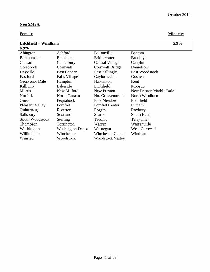
October 2014
Page 41 of 53
Non SMSA
Female Minority
Litchfield – Windham 5.9%
6.9%
Abington Ashford Ballouville Bantam
Barkhamsted Bethlehem Bridgewater Brooklyn
Canaan Canterbury Central Village Cahplin
Colebrook Cornwall Cornwall Bridge Danielson
Dayville East Canaan East Killingly East Woodstock
Eastford Falls Village Gaylordsville Goshen
Grosvenor Dale Hampton Harwinton Kent
Killignly Lakeside Litchfield Moosup
Morris New Milford New Preston New Preston Marble Dale
Norfolk North Canaan No. Grosvenordale North Windham
Oneco Pequabuck Pine Meadow Plainfield
Pleasant Valley Pomfret Pomfret Center Putnam
Quinebaug Riverton Rogers Roxbury
Salisbury Scotland Sharon South Kent
South Woodstock Sterling Taconic Terryville
Thompson Torrington Warren Warrenville
Washington Washington Depot Wauregan West Cornwall
Willimantic Winchester Winchester Center Windham
Winsted Woodstock Woodstock Valley
October 2014
Page 42 of 53
EXHIBIT D
Health Insurance Portability and Accountability Act of 1996 (“HIPAA”).
(a) If the Contactor is a Business Associate under the requirements of the Health Insurance
Portability and Accountability Act of 1996 (“HIPAA”), the Contractor must comply with
all terms and conditions of this Section of the Contract. If the Contractor is not a Business
Associate under HIPAA, this Section of the Contract does not apply to the Contractor for
this Contract.
(b) The Contractor is required to safeguard the use, publication and disclosure of information
on all applicants for, and all clients who receive, services under the Contract in accordance
with all applicable federal and state law regarding confidentiality, which includes but is not
limited to HIPAA, more specifically with the Privacy and Security Rules at 45 C.F.R. Part
160 and Part 164, subparts A, C, and E; and
(c) The State of Connecticut Agency named on page 1 of this Contract (hereinafter the
“Department”) is a “covered entity” as that term is defined in 45 C.F.R. § 160.103; and
(d) The Contractor, on behalf of the Department, performs functions that involve the use or
disclosure of “individually identifiable health information,” as that term is defined in 45
C.F.R. § 160.103; and
(e) The Contractor is a “business associate” of the Department, as that term is defined in 45
C.F.R. § 160.103; and
(f) The Contractor and the Department agree to the following in order to secure compliance
with the HIPAA, the requirements of Subtitle D of the Health Information Technology for
Economic and Clinical Health Act (hereinafter the HITECH Act), (Pub. L. 111-5, sections
13400 to 13423), and more specifically with the Privacy and Security Rules at 45 C.F.R.
Part 160 and Part 164, subparts A, C, and E.
(g) Definitions
(1) “Breach shall have the same meaning as the term is defined in section 13400 of the
HITECH Act (42 U.S.C. §17921(1))
(2) “Business Associate” shall mean the Contractor.
(3) “Covered Entity” shall mean the Department of the State of Connecticut named on page
1 of this Contract.
(4) “Designated Record Set” shall have the same meaning as the term “designated record
set” in 45 C.F.R. § 164.501.
(5) “Electronic Health Record” shall have the same meaning as the term is defined in
section 13400 of the HITECH Act (42 U.S.C. §17921(5))
October 2014
Page 43 of 53
(6) “Individual” shall have the same meaning as the term “individual”’ in 45 C.F.R. §
160.103 and shall include a person who qualifies as a personal representative as defined
in 45 C.F.R. § 164.502(g).
(7) “Privacy Rule” shall mean the Standards for Privacy of Individually Identifiable Health
Information at 45 C.F.R. part 160 and parts 164, subparts A and E.
(8) “Protected Health Information” or “PHI” shall have the same meaning as the term
“protected health information” in 45 C.F.R. § 160.103, limited to information created or
received by the Business Associate from or on behalf of the Covered Entity.
(9) “Required by Law”’ shall have the same meaning as the term “required by law” in 45
C.F.R. § 164.103.
(10) “Secretary” shall mean the Secretary of the Department of Health and Human Services
or his designee.
(11) “More stringent” shall have the same meaning as the term “more stringent” in 45
C.F.R. § 160.202.
(12) “This Section of the Contract” refers to the HIPAA Provisions stated herein, in their
entirety.
(13) “Security Incident” shall have the same meaning as the term “security incident” in
45 C.F.R.§ 164.304.
(14) “Security Rule” shall mean the Security Standards for the Protection of Electronic
Protected Health Information at 45 C.F.R. part 160 and parts 164, subpart A and C.
(15) “Unsecured protected health information” shall have the same meaning
as the term as defined in section 13402(h)(1)(A) of HITECH. Act. (42
U.S.C. §17932(h)(1)(A)).
(h) Obligations and Activities of Business Associates.
(1) Business Associate agrees not to use or disclose PHI other than as permitted or required
by this Section of the Contract or as Required by Law.
(2) Business Associate agrees to use appropriate safeguards to prevent use or disclosure of
PHI other than as provided for in this Section of the Contract.
(3) Business Associate agrees to use administrative, physical and technical safeguards that
reasonably and appropriately protect the confidentiality, integrity, and availability of
electronic protected health information that it creates, receives, maintains, or transmits
on behalf of the Covered Entity.
(4) Business Associate agrees to mitigate, to the extent practicable, any harmful effect that
is known to the Business Associate of a use or disclosure of PHI by Business Associate
in violation of this Section of the Contract.
October 2014
Page 44 of 53
(5) Business Associate agrees to report to Covered Entity any use or disclosure of PHI not
provided for by this Section of the Contract or any security incident of which it
becomes aware.
(6) Business Associate agrees to insure that any agent, including a subcontractor, to whom
it provides PHI received from, or created or received by Business Associate, on behalf
of the Covered Entity, agrees to the same restrictions and conditions that apply through
this Section of the Contract to Business Associate with respect to such information.
(7) Business Associate agrees to provide access, at the request of the Covered Entity, and in
the time and manner agreed to by the parties, to PHI in a Designated Record Set, to
Covered Entity or, as directed by Covered Entity, to an Individual in order to meet the
requirements under 45 C.F.R. § 164.524.
(8) Business Associate agrees to make any amendments to PHI in a Designated Record Set
that the Covered Entity directs or agrees to pursuant to 45 C.F.R. § 164.526 at the
request of the Covered Entity, and in the time and manner agreed to by the parties.
(9) Business Associate agrees to make internal practices, books, and records, including
policies and procedures and PHI, relating to the use and disclosure of PHI received
from, or created or received by, Business Associate on behalf of Covered Entity,
available to Covered Entity or to the Secretary in a time and manner agreed to by the
parties or designated by the Secretary, for purposes of the Secretary determining
Covered Entity’s compliance with the Privacy Rule.
(10)Business Associate agrees to document such disclosures of PHI and information related
to such disclosures as would be required for Covered Entity to respond to a request by
an Individual for an accounting of disclosures of PHI in accordance with 45 C.F.R.
§ 164.528 and section 13405 of the HITECH Act (42 U.S.C. § 17935) and any
regulations promulgated thereunder.
(11)Business Associate agrees to provide to Covered Entity, in a time and manner agreed to
by the parties, information collected in accordance with clause h. (10) of this Section of
the Contract, to permit Covered Entity to respond to a request by an Individual for an
accounting of disclosures of PHI in accordance with 45 C.F.R. § 164.528 and section
13405 of the HITECH Act (42 U.S.C. § 17935) and any regulations promulgated
thereunder. Business Associate agrees at the Covered Entity’s direction to provide an
accounting of disclosures of PHI directly to an individual in accordance with 45 C.F.R.
§ 164.528 and section 13405 of the HITECH Act (42 U.S.C. § 17935) and any
regulations promulgated thereunder.
(12)Business Associate agrees to comply with any state or federal law that is more stringent
than the Privacy Rule.
(13) Business Associate agrees to comply with the requirements of the HITECH Act
relating to privacy and security that are applicable to the Covered Entity and with the
requirements of 45 C.F.R. sections 164.504(e), 164.308, 164.310, 164.312, and
164.316.
October 2014
Page 45 of 53
(14) In the event that an individual requests that the Business Associate (a) restrict
disclosures of PHI; (b) provide an accounting of disclosures of the individual’s PHI; or
(c) provide a copy of the individual’s PHI in an electronic health record, the Business
Associate agrees to notify the covered entity, in writing, within two business days of the
request.
(15) Business Associate agrees that it shall not, directly or indirectly, receive any
remuneration in exchange for PHI of an individual without (1) the written approval of
the covered entity, unless receipt of remuneration in exchange for PHI is expressly
authorized by this Contract and (2) the valid authorization of the individual, except for
the purposes provided under section 13405(d)(2) of the HITECH Act,(42 U.S.C. §
17935(d)(2)) and in any accompanying regulations
(16) Obligations in the Event of a Breach
A. The Business Associate agrees that, following the discovery of a breach of
unsecured protected health information, it shall notify the Covered Entity of such
breach in accordance with the requirements of section 13402 of HITECH (42 U.S.C.
17932(b) and the provisions of this Section of the Contract.
B. Such notification shall be provided by the Business Associate to the Covered Entity
without unreasonable delay, and in no case later than 30 days after the breach is
discovered by the Business Associate, except as otherwise instructed in writing by a
law enforcement official pursuant to section 13402 (g) of HITECH (42 U.S.C.
17932(g)) . A breach is considered discovered as of the first day on which it is, or
reasonably should have been, known to the Business Associate. The notification
shall include the identification and last known address, phone number and email
address of each individual (or the next of kin of the individual if the individual is
deceased) whose unsecured protected health information has been, or is reasonably
believed by the Business Associate to have been, accessed, acquired, or disclosed
during such breach.
C. The Business Associate agrees to include in the notification to the Covered Entity at
least the following information:
1. A brief description of what happened, including the date of the breach and the
date of the discovery of the breach, if known.
2. A description of the types of unsecured protected health information that were
involved in the breach (such as full name, Social Security number, date of birth,
home address, account number, or disability code).
3. The steps the Business Associate recommends that individuals take to protect
themselves from potential harm resulting from the breach.
4. A detailed description of what the Business Associate is doing to investigate the
breach, to mitigate losses, and to protect against any further breaches.
5. Whether a law enforcement official has advised either verbally or in writing the
Business Associate that he or she has determined that notification or notice to
October 2014
Page 46 of 53
individuals or the posting required under section 13402 of the HITECH Act
would impede a criminal investigation or cause damage to national security and;
if so, include contact information for said official.
D. Business Associate agrees to provide appropriate staffing and have established
procedures to ensure that individuals informed by the Covered Entity of a breach by
the Business Associate have the opportunity to ask questions and contact the
Business Associate for additional information regarding the breach. Such
procedures shall include a toll-free telephone number, an e-mail address, a posting
on its Web site and a postal address. Business Associate agrees to include in the
notification of a breach by the Business Associate to the Covered Entity, a written
description of the procedures that have been established to meet these requirements.
Costs of such contact procedures will be borne by the Contractor.
E. Business Associate agrees that, in the event of a breach, it has the burden to
demonstrate that it has complied with all notifications requirements set forth above,
including evidence demonstrating the necessity of a delay in notification to the
Covered Entity.
(i) Permitted Uses and Disclosure by Business Associate.
(1) General Use and Disclosure Provisions Except as otherwise limited in this Section of
the Contract, Business Associate may use or disclose PHI to perform functions,
activities, or services for, or on behalf of, Covered Entity as specified in this Contract,
provided that such use or disclosure would not violate the Privacy Rule if done by
Covered Entity or the minimum necessary policies and procedures of the Covered
Entity.
(2) Specific Use and Disclosure Provisions
(A) Except as otherwise limited in this Section of the Contract, Business Associate may
use PHI for the proper management and administration of Business Associate or to
carry out the legal responsibilities of Business Associate.
(B) Except as otherwise limited in this Section of the Contract, Business Associate may
disclose PHI for the proper management and administration of Business Associate,
provided that disclosures are Required by Law, or Business Associate obtains
reasonable assurances from the person to whom the information is disclosed that it
will remain confidential and used or further disclosed only as Required by Law or
for the purpose for which it was disclosed to the person, and the person notifies
Business Associate of any instances of which it is aware in which the confidentiality
of the information has been breached.
(C) Except as otherwise limited in this Section of the Contract, Business Associate may
use PHI to provide Data Aggregation services to Covered Entity as permitted by 45
C.F.R. § 164.504(e)(2)(i)(B).
(j) Obligations of Covered Entity.
October 2014
Page 47 of 53
(1) Covered Entity shall notify Business Associate of any limitations in its notice of privacy
practices of Covered Entity, in accordance with 45 C.F.R. § 164.520, or to the extent
that such limitation may affect Business Associate’s use or disclosure of PHI.
(2) Covered Entity shall notify Business Associate of any changes in, or revocation of,
permission by Individual to use or disclose PHI, to the extent that such changes may
affect Business Associate’s use or disclosure of PHI.
(3) Covered Entity shall notify Business Associate of any restriction to the use or disclosure
of PHI that Covered Entity has agreed to in accordance with 45 C.F.R. § 164.522, to the
extent that such restriction may affect Business Associate’s use or disclosure of PHI.
(k) Permissible Requests by Covered Entity. Covered Entity shall not request Business
Associate to use or disclose PHI in any manner that would not be permissible under the
Privacy Rule if done by the Covered Entity, except that Business Associate may use and
disclose PHI for data aggregation, and management and administrative activities of
Business Associate, as permitted under this Section of the Contract.
(l) Term and Termination.
(1) Term. The Term of this Section of the Contract shall be effective as of the date the
Contract is effective and shall terminate when the information collected in accordance
with clause h. (10) of this Section of the Contract is provided to the Covered Entity and
all of the PHI provided by Covered Entity to Business Associate, or created or received
by Business Associate on behalf of Covered Entity, is destroyed or returned to
Covered Entity, or, if it is infeasible to return or destroy PHI, protections are extended
to such information, in accordance with the termination provisions in this Section.
(2) Termination for Cause Upon Covered Entity’s knowledge of a material breach by
Business Associate, Covered Entity shall either:
(A) Provide an opportunity for Business Associate to cure the breach or end the
violation and terminate the Contract if Business Associate does not cure the breach
or end the violation within the time specified by the Covered Entity; or
(B) Immediately terminate the Contract if Business Associate has breached a material
term of this Section of the Contract and cure is not possible; or
(C) If neither termination nor cure is feasible, Covered Entity shall report the violation
to the Secretary.
(3) Effect of Termination
(A) Except as provided in (l)(2) of this Section of the Contract, upon termination of this
Contract, for any reason, Business Associate shall return or destroy all PHI received
from Covered Entity, or created or received by Business Associate on behalf of
Covered Entity. Business Associate shall also provide the information collected in
accordance with clause h. (10) of this Section of the Contract to the Covered Entity
October 2014
Page 48 of 53
within ten business days of the notice of termination. This provision shall apply to
PHI that is in the possession of subcontractors or agents of Business Associate.
Business Associate shall retain no copies of the PHI.
(B) In the event that Business Associate determines that returning or destroying the PHI
is infeasible, Business Associate shall provide to Covered Entity notification of the
conditions that make return or destruction infeasible. Upon documentation by
Business Associate that return or destruction of PHI is infeasible, Business
Associate shall extend the protections of this Section of the Contract to such PHI
and limit further uses and disclosures of PHI to those purposes that make return or
destruction infeasible, for as long as Business Associate maintains such PHI.
Infeasibility of the return or destruction of PHI includes, but is not limited to,
requirements under state or federal law that the Business Associate maintains or
preserves the PHI or copies thereof.
(m) Miscellaneous Provisions.
(1) Regulatory References. A reference in this Section of the Contract to a section in the
Privacy Rule means the section as in effect or as amended.
(2) Amendment. The Parties agree to take such action as in necessary to amend this Section
of the Contract from time to time as is necessary for Covered Entity to comply with
requirements of the Privacy Rule and the Health Insurance Portability and
Accountability Act of 1996, Pub. L. No. 104-191.
(3) Survival. The respective rights and obligations of Business Associate shall survive the
termination of this Contract.
(4) Effect on Contract. Except as specifically required to implement the purposes of this
Section of the Contract, all other terms of the Contract shall remain in force and effect.
(5) Construction. This Section of the Contract shall be construed as broadly as necessary to
implement and comply with the Privacy Standard. Any ambiguity in this Section of the
Contract shall be resolved in favor of a meaning that complies, and is consistent with,
the Privacy Standard.
(6) Disclaimer. Covered Entity makes no warranty or representation that compliance with
this Section of the Contract will be adequate or satisfactory for Business Associate’s
own purposes. Covered Entity shall not be liable to Business Associate for any claim,
civil or criminal penalty, loss or damage related to or arising from the unauthorized use
or disclosure of PHI by Business Associate or any of its officers, directors, employees,
contractors or agents, or any third party to whom Business Associate has disclosed PHI
contrary to the provisions of this Contract or applicable law. Business Associate is
solely responsible for all decisions made, and actions taken, by Business Associate
regarding the safeguarding, use and disclosure of PHI within its possession, custody or
control.
(7) Indemnification. The Business Associate shall indemnify and hold the Covered Entity harmless
from and against any and all claims, liabilities, judgments, fines, assessments, penalties, awards and
any statutory damages that may be imposed or assessed pursuant to HIPAA, as amended or the

October 2014
Page 49 of 53
HITECH Act, including, without limitation, attorney’s fees, expert witness fees, costs of investigation,
litigation or dispute resolution, and costs awarded thereunder, relating to or arising out of any violation
by the Business Associate and its agents, including subcontractors, of any obligation of Business
Associate and its agents, including subcontractors, under this section of the contract, under HIPAA, the
HITECH Act, the Privacy Rule and the Security Rule.
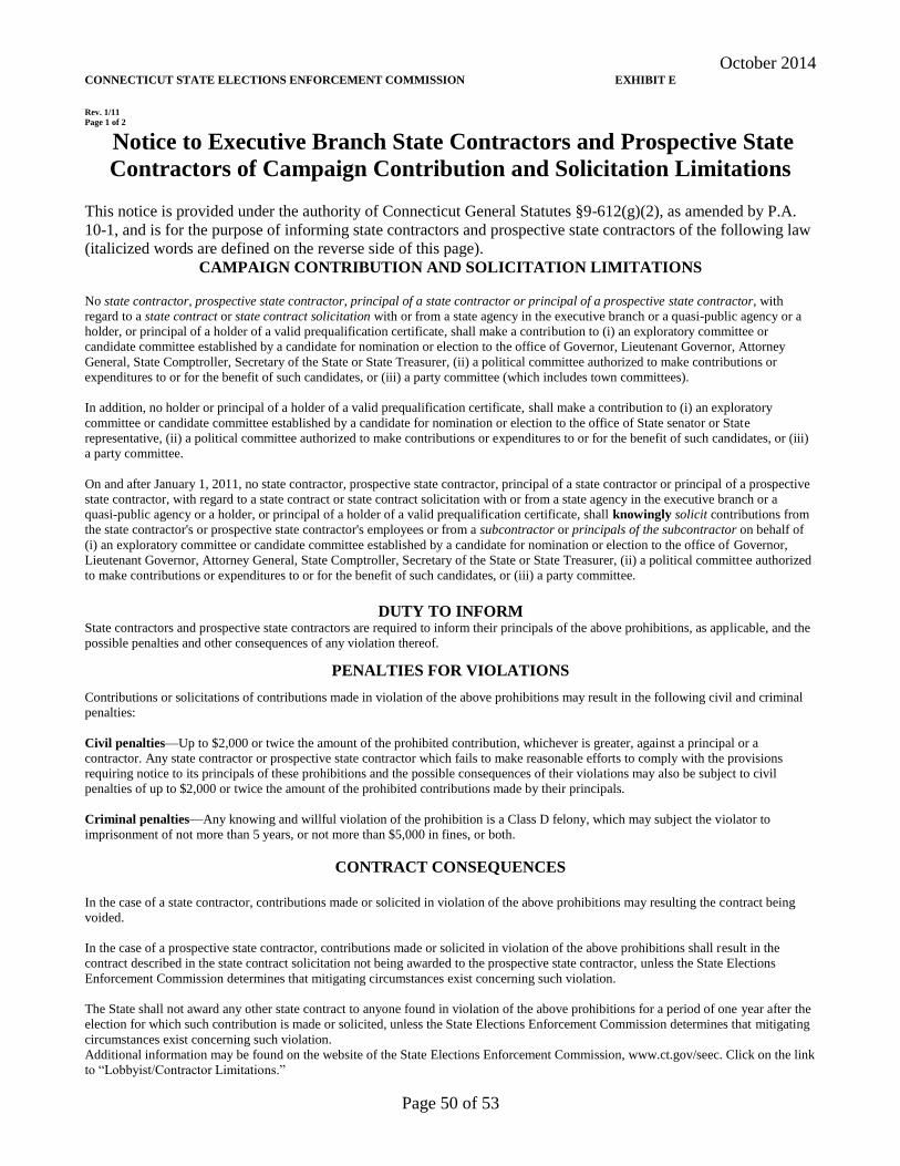
October 2014
Page 50 of 53
CONNECTICUT STATE ELECTIONS ENFORCEMENT COMMISSION EXHIBIT E
Rev. 1/11
Page 1 of 2
Notice to Executive Branch State Contractors and Prospective State
Contractors of Campaign Contribution and Solicitation Limitations
This notice is provided under the authority of Connecticut General Statutes §9-612(g)(2), as amended by P.A.
10-1, and is for the purpose of informing state contractors and prospective state contractors of the following law
(italicized words are defined on the reverse side of this page).
CAMPAIGN CONTRIBUTION AND SOLICITATION LIMITATIONS
No state contractor, prospective state contractor, principal of a state contractor or principal of a prospective state contractor, with
regard to a state contract or state contract solicitation with or from a state agency in the executive branch or a quasi-public agency or a
holder, or principal of a holder of a valid prequalification certificate, shall make a contribution to (i) an exploratory committee or
candidate committee established by a candidate for nomination or election to the office of Governor, Lieutenant Governor, Attorney
General, State Comptroller, Secretary of the State or State Treasurer, (ii) a political committee authorized to make contributions or
expenditures to or for the benefit of such candidates, or (iii) a party committee (which includes town committees).
In addition, no holder or principal of a holder of a valid prequalification certificate, shall make a contribution to (i) an exploratory
committee or candidate committee established by a candidate for nomination or election to the office of State senator or State
representative, (ii) a political committee authorized to make contributions or expenditures to or for the benefit of such candidates, or (iii)
a party committee.
On and after January 1, 2011, no state contractor, prospective state contractor, principal of a state contractor or principal of a prospective
state contractor, with regard to a state contract or state contract solicitation with or from a state agency in the executive branch or a
quasi-public agency or a holder, or principal of a holder of a valid prequalification certificate, shall knowingly solicit contributions from
the state contractor's or prospective state contractor's employees or from a subcontractor or principals of the subcontractor on behalf of
(i) an exploratory committee or candidate committee established by a candidate for nomination or election to the office of Governor,
Lieutenant Governor, Attorney General, State Comptroller, Secretary of the State or State Treasurer, (ii) a political committee authorized
to make contributions or expenditures to or for the benefit of such candidates, or (iii) a party committee.
DUTY TO INFORM State contractors and prospective state contractors are required to inform their principals of the above prohibitions, as applicable, and the
possible penalties and other consequences of any violation thereof.
PENALTIES FOR VIOLATIONS
Contributions or solicitations of contributions made in violation of the above prohibitions may result in the following civil and criminal
penalties:
Civil penalties—Up to $2,000 or twice the amount of the prohibited contribution, whichever is greater, against a principal or a
contractor. Any state contractor or prospective state contractor which fails to make reasonable efforts to comply with the provisions
requiring notice to its principals of these prohibitions and the possible consequences of their violations may also be subject to civil
penalties of up to $2,000 or twice the amount of the prohibited contributions made by their principals.
Criminal penalties—Any knowing and willful violation of the prohibition is a Class D felony, which may subject the violator to
imprisonment of not more than 5 years, or not more than $5,000 in fines, or both.
CONTRACT CONSEQUENCES
In the case of a state contractor, contributions made or solicited in violation of the above prohibitions may resulting the contract being
voided.
In the case of a prospective state contractor, contributions made or solicited in violation of the above prohibitions shall result in the
contract described in the state contract solicitation not being awarded to the prospective state contractor, unless the State Elections
Enforcement Commission determines that mitigating circumstances exist concerning such violation.
The State shall not award any other state contract to anyone found in violation of the above prohibitions for a period of one year after the
election for which such contribution is made or solicited, unless the State Elections Enforcement Commission determines that mitigating
circumstances exist concerning such violation.
Additional information may be found on the website of the State Elections Enforcement Commission, www.ct.gov/seec. Click on the link
to “Lobbyist/Contractor Limitations.”
October 2014
Page 51 of 53
CONNECTICUT STATE ELECTIONS ENFORCEMENT COMMISSION
Rev. 1/11
Page 2 of 2
DEFINITIONS “State contractor” means a person, business entity or nonprofit organization that enters into a state contract. Such person, business entity or nonprofit
organization shall be deemed to be a state contractor until December thirty-first of the year in which such contract terminates. “State contractor” does not
include a municipality or any other political subdivision of the state, including any entities or associations duly created by the municipality or political subdivision exclusively amongst themselves to further any purpose authorized by statute or charter, or an employee in the executive or legislative branch
of state government or a quasi-public agency, whether in the classified or unclassified service and full or part-time, and only in such person's capacity as a
state or quasi-public agency employee.
“Prospective state contractor” means a person, business entity or nonprofit organization that (i) submits a response to a state contract solicitation by the
state, a state agency or a quasi-public agency, or a proposal in response to a request for proposals by the state, a state agency or a quasi-public agency, until the contract has been entered into, or (ii) holds a valid prequalification certificate issued by the Commissioner of Administrative Services under
section 4a-100. “Prospective state contractor” does not include a municipality or any other political subdivision of the state, including any entities or
associations duly created by the municipality or political subdivision exclusively amongst themselves to further any purpose authorized by statute or charter, or an employee in the executive or legislative branch of state government or a quasi-public agency, whether in the classified or unclassified
service and full or part-time, and only in such person's capacity as a state or quasi-public agency employee.
“Principal of a state contractor or prospective state contractor” means (i) any individual who is a member of the board of directors of, or has an ownership
interest of five per cent or more in, a state contractor or prospective state contractor, which is a business entity, except for an individual who is a member
of the board of directors of a nonprofit organization, (ii) an individual who is employed by a state contractor or prospective state contractor, which is a business entity, as president, treasurer or executive vice president, (iii) an individual who is the chief executive officer of a state contractor or prospective
state contractor, which is not a business entity, or if a state contractor or prospective state contractor has no such officer, then the officer who duly
possesses comparable powers and duties, (iv) an officer or an employee of any state contractor or prospective state contractor who has managerial or discretionary responsibilities with respect to a state contract, (v) the spouse or a dependent child who is eighteen years of age or older of an individual
described in this subparagraph, or (vi) a political committee established or controlled by an individual described in this subparagraph or the business entity
or nonprofit organization that is the state contractor or prospective state contractor.
“State contract” means an agreement or contract with the state or any state agency or any quasi-public agency, let through a procurement process or
otherwise, having a value of fifty thousand dollars or more, or a combination or series of such agreements or contracts having a value of one hundred
thousand dollars or more in a calendar year, for (i) the rendition of services, (ii) the furnishing of any goods, material, supplies, equipment or any items of any kind, (iii) the construction, alteration or repair of any public building or public work, (iv) the acquisition, sale or lease of any land or building, (v) a
licensing arrangement, or (vi) a grant, loan or loan guarantee. “State contract” does not include any agreement or contract with the state, any state agency
or any quasi-public agency that is exclusively federally funded, an education loan, a loan to an individual for other than commercial purposes or any agreement or contract between the state or any state agency and the United States Department of the Navy or the United States Department of Defense.
“State contract solicitation” means a request by a state agency or quasi-public agency, in whatever form issued, including, but not limited to, an invitation
to bid, request for proposals, request for information or request for quotes, inviting bids, quotes or other types of submittals, through a competitive
procurement process or another process authorized by law waiving competitive procurement.
“Managerial or discretionary responsibilities with respect to a state contract” means having direct, extensive and substantive responsibilities with respect
to the negotiation of the state contract and not peripheral, clerical or ministerial responsibilities.
“Dependent child” means a child residing in an individual’s household who may legally be claimed as a dependent on the federal income tax of such
individual.
“Solicit” means (A) requesting that a contribution be made, (B) participating in any fund-raising activities for a candidate committee, exploratory
committee, political committee or party committee, including, but not limited to, forwarding tickets to potential contributors, receiving contributions for transmission to any such committee or bundling contributions, (C) serving as chairperson, treasurer or deputy treasurer of any such committee, or (D)
establishing a political committee for the sole purpose of soliciting or receiving contributions for any committee. Solicit does not include: (i) making a
contribution that is otherwise permitted by Chapter 155 of the Connecticut General Statutes; (ii) informing any person of a position taken by a candidate for public office or a public official, (iii) notifying the person of any activities of, or contact information for, any candidate for public office; or (iv) serving
as a member in any party committee or as an officer of such committee that is not otherwise prohibited in this section.
“Subcontractor” means any person, business entity or nonprofit organization that contracts to perform part or all of the obligations of a state contractor's
state contract. Such person, business entity or nonprofit organization shall be deemed to be a subcontractor until December thirty first of the year in which
the subcontract terminates. “Subcontractor” does not include (i) a municipality or any other political subdivision of the state, including any entities or
associations duly created by the municipality or political subdivision exclusively amongst themselves to further any purpose authorized by statute or
charter, or (ii) an employee in the executive or legislative branch of state government or a quasi-public agency, whether in the classified or unclassified
service and full or part-time, and only in such person's capacity as a state or quasi-public agency employee.
“Principal of a subcontractor” means (i) any individual who is a member of the board of directors of, or has an ownership interest of five per cent or more
in, a subcontractor, which is a business entity, except for an individual who is a member of the board of directors of a nonprofit organization, (ii) an individual who is employed by a subcontractor, which is a business entity, as president, treasurer or executive vice president, (iii) an individual who is the
chief executive officer of a subcontractor, which is not a business entity, or if a subcontractor has no such officer, then the officer who duly possesses
comparable powers and duties, (iv) an officer or an employee of any subcontractor who has managerial or discretionary responsibilities with respect to a subcontract with a state contractor, (v) the spouse or a dependent child who is eighteen years of age or older of an individual described in this
subparagraph, or (vi) a political committee established or controlled by an individual described in this subparagraph or the business entity or nonprofit
organization that is the subcontractor.

October 2014
Page 52 of 53
EXHIBIT F
(federal wage rate package will be inserted here)

October 2014
Page 53 of 53
EXHIBIT G
(state wages will be inserted here)
CT3.txtGeneral Decision Number: CT150003 01/30/2015 CT3
Superseded General Decision Number: CT20140003
State: Connecticut
Construction Type: Highway
County: Hartford County in Connecticut.
HIGHWAY CONSTRUCTION PROJECTS
Note: Executive Order (EO) 13658 establishes an hourly minimumwage of $10.10 for 2015 that applies to all contracts subjectto the Davis-Bacon Act for which the solicitation is issued onor after January 1, 2015. If this contract is covered by theEO, the contractor must pay all workers in any classificationlisted on this wage determination at least $10.10 (or theapplicable wage rate listed on this wage determination, if itis higher) for all hours spent performing on the contract. TheEO minimum wage rate will be adjusted annually. Additionalinformation on contractor requirements and worker protectionsunder the EO is available at www.dol.gov/whd/govcontracts.
Modification Number Publication Date 0 01/02/2015 1 01/09/2015 2 01/30/2015
* BRCT0001-003 12/29/2014
Rates Fringes
BRICKLAYER BRICKLAYERS, CEMENT MASONS, CEMENT FINISHERS, PLASTERERS, STONE MASONS....$ 32.50 26.96---------------------------------------------------------------- CARP0024-005 05/05/2014
Rates Fringes
Carpenters: (Berlin, Bristol, Burlington,Canton, Marlborough, New Britain, Newington, Plainville, Southington) CARPENTERS; PILEDRIVERS.....$ 31.00 22.50 DIVER TENDERS...............$ 31.00 22.50 DIVERS......................$ 39.46 22.50 MILLWRIGHTS.................$ 31.60 22.75---------------------------------------------------------------- CARP0043-003 05/05/2014
Rates Fringes
Carpenters: (Avon, Bloomfied, East Granby, East Hartford, East Windsor, Enfield, Farmington, Glastonbury, Granby, Hartford, hartland, Manchester, Rocky Hill,
Page 1
CT3.txtSimsbury, South Windsor, Suffield, West Hartford, Wethersfield, Windsor, Windsor Locks) CARPENTERS; PILEDRIVERS.....$ 31.00 22.50 DIVER TENDERS...............$ 31.00 22.50 DIVERS......................$ 39.46 22.50 MILLWRIGHTS.................$ 31.60 22.75---------------------------------------------------------------- ELEC0035-002 06/01/2014
Rates Fringes
Electricians: Entire County, excluding Berlin, Bristol, Hartland, New Britain, Newington, Plainville and Southington..$ 38.10 23.86---------------------------------------------------------------- ELEC0090-001 06/01/2014
Rates Fringes
Electricians: Berlin, Bristol, New Britain, Newington, Plainville, Southington.....$ 37.05 24.37---------------------------------------------------------------- ELEC0488-004 06/01/2014
Rates Fringes
Electricians:....................$ 37.27 23.37---------------------------------------------------------------- ENGI0478-002 04/06/2014
Rates Fringes
Power equipment operators: GROUP 1....................$ 36.80 22.30 GROUP 2....................$ 36.48 22.30 GROUP 3....................$ 35.74 22.30 GROUP 4....................$ 35.35 22.30 GROUP 5....................$ 34.76 22.30 GROUP 6....................$ 34.45 22.30 GROUP 7....................$ 34.11 22.30 GROUP 8....................$ 33.71 22.30 GROUP 9....................$ 33.28 22.30 GROUP 10....................$ 31.24 22.30 GROUP 11....................$ 31.24 22.30 GROUP 12....................$ 31.18 22.30 GROUP 13....................$ 32.71 22.30 GROUP 14....................$ 30.60 22.30 GROUP 15....................$ 30.29 22.30 GROUP 16....................$ 29.46 22.30 GROUP 17....................$ 29.05 22.30 GROUP 18....................$ 28.40 22.30
Hazardous waste premium $3.00 per hour over classified rate.
Crane with 150 ft. boom (including jib): $1.50 extra.Crane with 200 ft. boom (including jib): $2.50 extra.Crane with 250 ft. boom (including jib): $5.00 extra.
Page 2
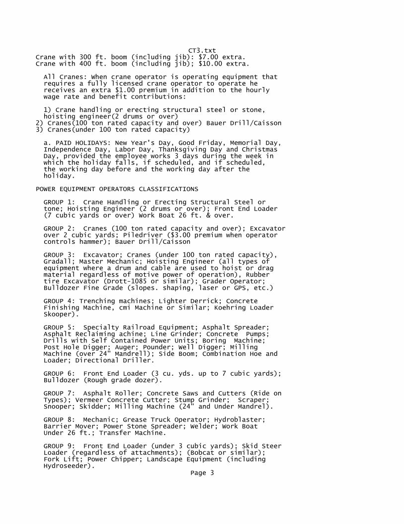
CT3.txtCrane with 300 ft. boom (including jib): $7.00 extra. Crane with 400 ft. boom (including jib); $10.00 extra.
All Cranes: When crane operator is operating equipment that requires a fully licensed crane operator to operate he receives an extra $1.00 premium in addition to the hourly wage rate and benefit contributions:
1) Crane handling or erecting structural steel or stone, hoisting engineer(2 drums or over)2) Cranes(100 ton rated capacity and over) Bauer Drill/Caisson3) Cranes(under 100 ton rated capacity)
a. PAID HOLIDAYS: New Year's Day, Good Friday, Memorial Day, Independence Day, Labor Day, Thanksgiving Day and Christmas Day, provided the employee works 3 days during the week in which the holiday falls, if scheduled, and if scheduled, the working day before and the working day after the holiday.
POWER EQUIPMENT OPERATORS CLASSIFICATIONS
GROUP 1: Crane Handling or Erecting Structural Steel or tone; Hoisting Engineer (2 drums or over); Front End Loader (7 cubic yards or over) Work Boat 26 ft. & over.
GROUP 2: Cranes (100 ton rated capacity and over); Excavator over 2 cubic yards; Piledriver ($3.00 premium when operator controls hammer); Bauer Drill/Caisson
GROUP 3: Excavator; Cranes (under 100 ton rated capacity), Gradall; Master Mechanic; Hoisting Engineer (all types of equipment where a drum and cable are used to hoist or drag material regardless of motive power of operation), Rubber tire Excavator (Drott-1085 or similar); Grader Operator; Bulldozer Fine Grade (slopes. shaping, laser or GPS, etc.)
GROUP 4: Trenching machines; Lighter Derrick; Concrete Finishing Machine, cmi Machine or Similar; Koehring Loader Skooper).
GROUP 5: Specialty Railroad Equipment; Asphalt Spreader; Asphalt Reclaiming achine; Line Grinder; Concrete Pumps; Drills with Self Contained Power Units; Boring Machine; Post Hole Digger; Auger; Pounder; Well Digger; Milling Machine (over 24" Mandrell); Side Boom; Combination Hoe and Loader; Directional Driller.
GROUP 6: Front End Loader (3 cu. yds. up to 7 cubic yards); Bulldozer (Rough grade dozer).
GROUP 7: Asphalt Roller; Concrete Saws and Cutters (Ride on Types); Vermeer Concrete Cutter; Stump Grinder; Scraper; Snooper; Skidder; Milling Machine (24" and Under Mandrel).
GROUP 8: Mechanic; Grease Truck Operator; Hydroblaster; Barrier Mover; Power Stone Spreader; Welder; Work Boat Under 26 ft.; Transfer Machine.
GROUP 9: Front End Loader (under 3 cubic yards); Skid Steer Loader (regardless of attachments); (Bobcat or similar); Fork Lift; Power Chipper; Landscape Equipment (including Hydroseeder).
Page 3
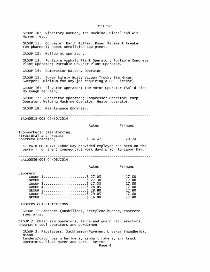
CT3.txt
GROUP 10: Vibratory Hammer, Ice Machine, Diesel and Air Hammer, etc.
GROUP 11: Conveyor; Earth Roller; Power Pavement Breaker (Whiphammer); Robot Demolition Equipment.
GROUP 12: Wellpoint Operator.
GROUP 13: Portable Asphalt Plant Operator; Portable Concrete Plant Operator; Portable Crusher Plant Operator.
GROUP 14: Compressor Battery Operator.
GROUP 15: Power Safety Boat; Vacuum Truck; Zim Mixer; Sweeper; (Minimum for any job requiring a CDL License)
GROUP 16: Elevator Operator; Tow Motor Operator (Solid Tire No Rough Terrain).
GROUP 17: Generator Operator; Compressor Operator; Pump Operator; Welding Machine Operator; Heater operator.
GROUP 18: Maintenance Engineer.
---------------------------------------------------------------- IRON0015-002 06/30/2014
Rates Fringes
Ironworkers: (Reinforcing, Structural and Precast Concrete Erection)...............$ 34.47 29.74
a. PAID HOLIDAY: Labor Day provided employee has been on the payroll for the 5 consecutive work days prior to Labor Day.
---------------------------------------------------------------- LABO0056-003 04/06/2014
Rates Fringes
Laborers: GROUP 1.....................$ 27.05 17.80 GROUP 2.....................$ 27.30 17.80 GROUP 3.....................$ 27.55 17.80 GROUP 4.....................$ 28.05 17.80 GROUP 5.....................$ 28.80 17.80 GROUP 6.....................$ 29.05 17.80 GROUP 7.....................$ 16.00 17.80
LABORERS CLASSIFICATIONS GROUP 1: Laborers (Unskilled), acetylene burner, concrete specialist GROUP 2: Chain saw operators, fence and guard rail erectors, pneumatic tool operators and powdermen. GROUP 3: Pipelayers, Jackhammer/Pavement breaker (handheld), mason tenders/catch basin builders, asphalt rakers, air track operators, block paver and curb setter
Page 4
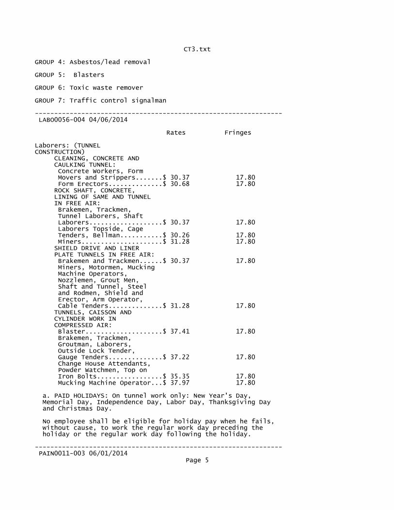
CT3.txt GROUP 4: Asbestos/lead removal GROUP 5: Blasters GROUP 6: Toxic waste remover
GROUP 7: Traffic control signalman
---------------------------------------------------------------- LABO0056-004 04/06/2014
Rates Fringes
Laborers: (TUNNEL CONSTRUCTION) CLEANING, CONCRETE AND CAULKING TUNNEL: Concrete Workers, Form Movers and Strippers.......$ 30.37 17.80 Form Erectors..............$ 30.68 17.80 ROCK SHAFT, CONCRETE, LINING OF SAME AND TUNNEL IN FREE AIR: Brakemen, Trackmen, Tunnel Laborers, Shaft Laborers...................$ 30.37 17.80 Laborers Topside, Cage Tenders, Bellman...........$ 30.26 17.80 Miners.....................$ 31.28 17.80 SHIELD DRIVE AND LINER PLATE TUNNELS IN FREE AIR: Brakemen and Trackmen......$ 30.37 17.80 Miners, Motormen, Mucking Machine Operators, Nozzlemen, Grout Men, Shaft and Tunnel, Steel and Rodmen, Shield and Erector, Arm Operator, Cable Tenders..............$ 31.28 17.80 TUNNELS, CAISSON AND CYLINDER WORK IN COMPRESSED AIR: Blaster....................$ 37.41 17.80 Brakemen, Trackmen, Groutman, Laborers, Outside Lock Tender, Gauge Tenders..............$ 37.22 17.80 Change House Attendants, Powder Watchmen, Top on Iron Bolts.................$ 35.35 17.80 Mucking Machine Operator...$ 37.97 17.80
a. PAID HOLIDAYS: On tunnel work only: New Year's Day, Memorial Day, Independence Day, Labor Day, Thanksgiving Day and Christmas Day.
No employee shall be eligible for holiday pay when he fails, without cause, to work the regular work day preceding the holiday or the regular work day following the holiday.
---------------------------------------------------------------- PAIN0011-003 06/01/2014
Page 5
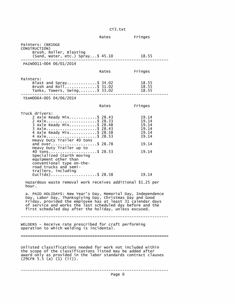
CT3.txt
Rates Fringes
Painters: (BRIDGE CONSTRUCTION) Brush, Roller, Blasting (Sand, Water, etc.) Spray...$ 45.10 18.55---------------------------------------------------------------- PAIN0011-004 06/01/2014
Rates Fringes
Painters: Blast and Spray.............$ 34.02 18.55 Brush and Roll..............$ 31.02 18.55 Tanks, Towers, Swing........$ 33.02 18.55---------------------------------------------------------------- TEAM0064-005 04/06/2014
Rates Fringes
Truck drivers: 2 Axle Ready Mix............$ 28.43 19.14 2 Axle......................$ 28.33 19.14 3 Axle Ready Mix............$ 28.48 19.14 3 Axle......................$ 28.43 19.14 4 Axle Ready Mix............$ 28.58 19.14 4 Axle......................$ 28.53 19.14 Heavy Duty Trailer 40 tons and over....................$ 28.78 19.14 Heavy Duty Trailer up to 40 tons.....................$ 28.53 19.14 Specialized (Earth moving equipment other than conventional type on-the- road trucks and semi- trailers, including Euclids)....................$ 28.58 19.14
Hazardous waste removal work receives additional $1.25 per hour.
a. PAID HOLIDAYS: New Year's Day, Memorial Day, Independence Day, Labor Day, Thanksgiving Day, Christmas Day and Good Friday, provided the employee has at least 31 calendar days of service and works the last scheduled day before and the first scheduled day after the holiday, unless excused.
----------------------------------------------------------------
WELDERS - Receive rate prescribed for craft performingoperation to which welding is incidental.
================================================================
Unlisted classifications needed for work not included withinthe scope of the classifications listed may be added afteraward only as provided in the labor standards contract clauses(29CFR 5.5 (a) (1) (ii)).
----------------------------------------------------------------Page 6
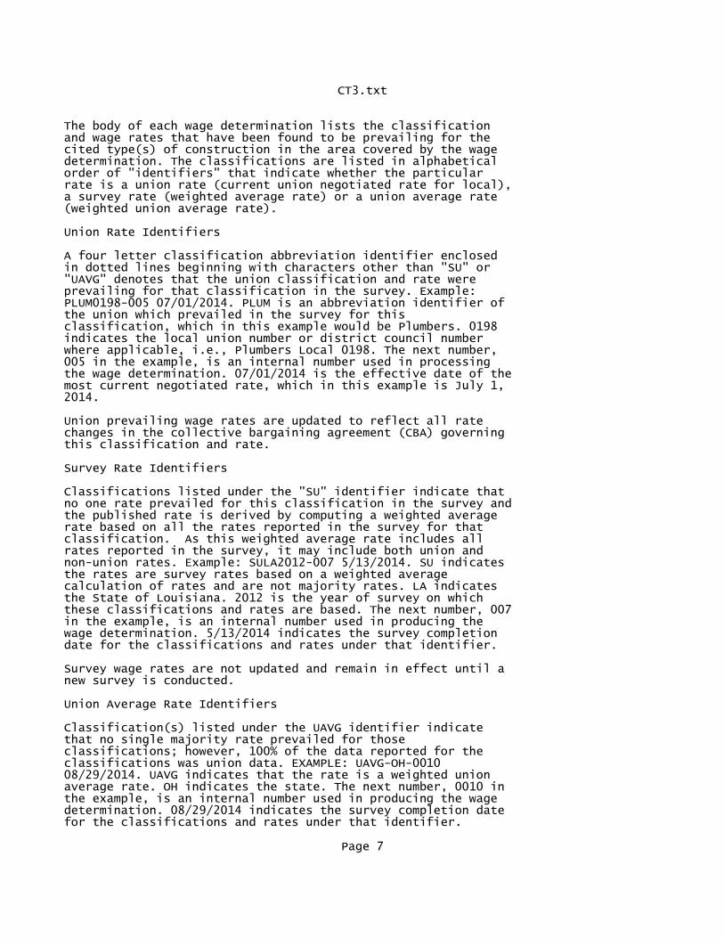
CT3.txt
The body of each wage determination lists the classificationand wage rates that have been found to be prevailing for thecited type(s) of construction in the area covered by the wagedetermination. The classifications are listed in alphabeticalorder of "identifiers" that indicate whether the particularrate is a union rate (current union negotiated rate for local),a survey rate (weighted average rate) or a union average rate(weighted union average rate).
Union Rate Identifiers
A four letter classification abbreviation identifier enclosedin dotted lines beginning with characters other than "SU" or"UAVG" denotes that the union classification and rate wereprevailing for that classification in the survey. Example:PLUM0198-005 07/01/2014. PLUM is an abbreviation identifier ofthe union which prevailed in the survey for thisclassification, which in this example would be Plumbers. 0198indicates the local union number or district council numberwhere applicable, i.e., Plumbers Local 0198. The next number,005 in the example, is an internal number used in processingthe wage determination. 07/01/2014 is the effective date of themost current negotiated rate, which in this example is July 1,2014.
Union prevailing wage rates are updated to reflect all ratechanges in the collective bargaining agreement (CBA) governingthis classification and rate.
Survey Rate Identifiers
Classifications listed under the "SU" identifier indicate thatno one rate prevailed for this classification in the survey andthe published rate is derived by computing a weighted averagerate based on all the rates reported in the survey for thatclassification. As this weighted average rate includes allrates reported in the survey, it may include both union andnon-union rates. Example: SULA2012-007 5/13/2014. SU indicatesthe rates are survey rates based on a weighted averagecalculation of rates and are not majority rates. LA indicatesthe State of Louisiana. 2012 is the year of survey on whichthese classifications and rates are based. The next number, 007in the example, is an internal number used in producing thewage determination. 5/13/2014 indicates the survey completiondate for the classifications and rates under that identifier.
Survey wage rates are not updated and remain in effect until anew survey is conducted.
Union Average Rate Identifiers
Classification(s) listed under the UAVG identifier indicatethat no single majority rate prevailed for thoseclassifications; however, 100% of the data reported for theclassifications was union data. EXAMPLE: UAVG-OH-001008/29/2014. UAVG indicates that the rate is a weighted unionaverage rate. OH indicates the state. The next number, 0010 inthe example, is an internal number used in producing the wagedetermination. 08/29/2014 indicates the survey completion datefor the classifications and rates under that identifier.
Page 7
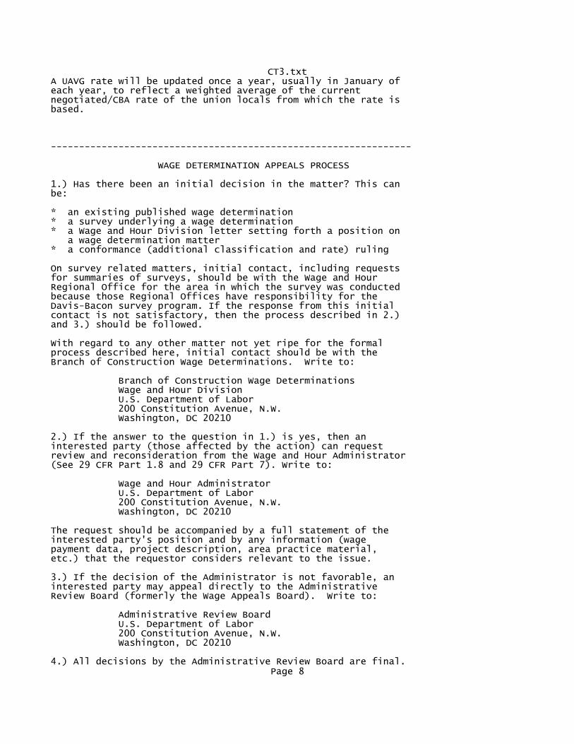
CT3.txtA UAVG rate will be updated once a year, usually in January ofeach year, to reflect a weighted average of the currentnegotiated/CBA rate of the union locals from which the rate isbased.
----------------------------------------------------------------
WAGE DETERMINATION APPEALS PROCESS
1.) Has there been an initial decision in the matter? This canbe:
* an existing published wage determination* a survey underlying a wage determination* a Wage and Hour Division letter setting forth a position on a wage determination matter* a conformance (additional classification and rate) ruling
On survey related matters, initial contact, including requestsfor summaries of surveys, should be with the Wage and HourRegional Office for the area in which the survey was conductedbecause those Regional Offices have responsibility for theDavis-Bacon survey program. If the response from this initialcontact is not satisfactory, then the process described in 2.)and 3.) should be followed.
With regard to any other matter not yet ripe for the formalprocess described here, initial contact should be with theBranch of Construction Wage Determinations. Write to:
Branch of Construction Wage Determinations Wage and Hour Division U.S. Department of Labor 200 Constitution Avenue, N.W. Washington, DC 20210
2.) If the answer to the question in 1.) is yes, then aninterested party (those affected by the action) can requestreview and reconsideration from the Wage and Hour Administrator(See 29 CFR Part 1.8 and 29 CFR Part 7). Write to:
Wage and Hour Administrator U.S. Department of Labor 200 Constitution Avenue, N.W. Washington, DC 20210
The request should be accompanied by a full statement of theinterested party's position and by any information (wagepayment data, project description, area practice material,etc.) that the requestor considers relevant to the issue.
3.) If the decision of the Administrator is not favorable, aninterested party may appeal directly to the AdministrativeReview Board (formerly the Wage Appeals Board). Write to:
Administrative Review Board U.S. Department of Labor 200 Constitution Avenue, N.W. Washington, DC 20210
4.) All decisions by the Administrative Review Board are final.Page 8

CT3.txt
================================================================
END OF GENERAL DECISION
Page 9
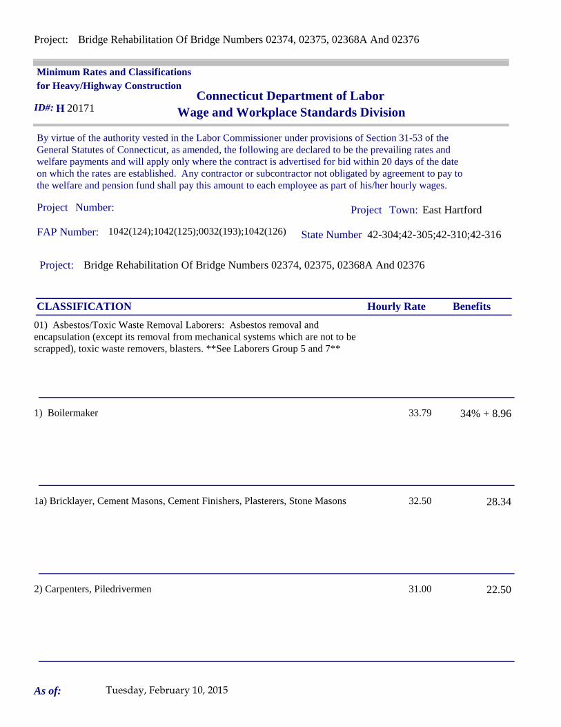
Project: Bridge Rehabilitation Of Bridge Numbers 02374, 02375, 02368A And 02376
Project: Bridge Rehabilitation Of Bridge Numbers 02374, 02375, 02368A And 02376
Project Project East Hartford
By virtue of the authority vested in the Labor Commissioner under provisions of Section 31-53 of the General Statutes of Connecticut, as amended, the following are declared to be the prevailing rates and welfare payments and will apply only where the contract is advertised for bid within 20 days of the date on which the rates are established. Any contractor or subcontractor not obligated by agreement to pay to the welfare and pension fund shall pay this amount to each employee as part of his/her hourly wages.
Minimum Rates and Classifications for Heavy/Highway Construction
Connecticut Department of LaborWage and Workplace Standards Division
FAP Number: 1042(124);1042(125);0032(193);1042(126) State Number 42-304;42-305;42-310;42-316
Town:
H 20171
Number:
ID#:
Hourly Rate BenefitsCLASSIFICATION
01) Asbestos/Toxic Waste Removal Laborers: Asbestos removal and encapsulation (except its removal from mechanical systems which are not to be scrapped), toxic waste removers, blasters. **See Laborers Group 5 and 7**
1) Boilermaker 33.79 34% + 8.96
1a) Bricklayer, Cement Masons, Cement Finishers, Plasterers, Stone Masons 32.50 28.34
2) Carpenters, Piledrivermen 31.00 22.50
As of: Tuesday, February 10, 2015
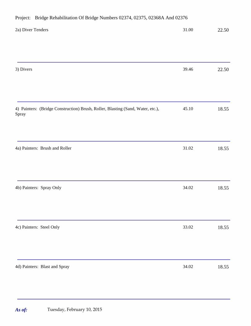
Project: Bridge Rehabilitation Of Bridge Numbers 02374, 02375, 02368A And 02376
2a) Diver Tenders 31.00 22.50
3) Divers 39.46 22.50
4) Painters: (Bridge Construction) Brush, Roller, Blasting (Sand, Water, etc.), Spray
45.10 18.55
4a) Painters: Brush and Roller 31.02 18.55
4b) Painters: Spray Only 34.02 18.55
4c) Painters: Steel Only 33.02 18.55
4d) Painters: Blast and Spray 34.02 18.55
As of: Tuesday, February 10, 2015
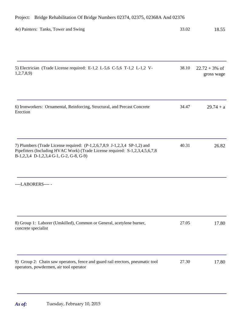
Project: Bridge Rehabilitation Of Bridge Numbers 02374, 02375, 02368A And 02376
4e) Painters: Tanks, Tower and Swing 33.02 18.55
5) Electrician (Trade License required: E-1,2 L-5,6 C-5,6 T-1,2 L-1,2 V-1,2,7,8,9)
38.10 22.72 + 3% of gross wage
6) Ironworkers: Ornamental, Reinforcing, Structural, and Precast Concrete Erection
34.47 29.74 + a
7) Plumbers (Trade License required: (P-1,2,6,7,8,9 J-1,2,3,4 SP-1,2) and Pipefitters (Including HVAC Work) (Trade License required: S-1,2,3,4,5,6,7,8 B-1,2,3,4 D-1,2,3,4 G-1, G-2, G-8, G-9)
40.31 26.82
----LABORERS---- -
8) Group 1: Laborer (Unskilled), Common or General, acetylene burner, concrete specialist
27.05 17.80
9) Group 2: Chain saw operators, fence and guard rail erectors, pneumatic tool operators, powdermen, air tool operator
27.30 17.80
As of: Tuesday, February 10, 2015
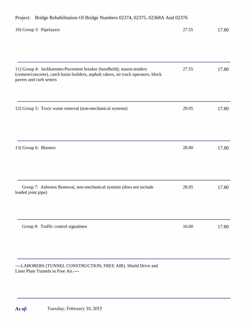
Project: Bridge Rehabilitation Of Bridge Numbers 02374, 02375, 02368A And 02376
10) Group 3: Pipelayers 27.55 17.80
11) Group 4: Jackhammer/Pavement breaker (handheld); mason tenders (cement/concrete), catch basin builders, asphalt rakers, air track operators, block pavers and curb setters
27.55 17.80
12) Group 5: Toxic waste removal (non-mechanical systems) 29.05 17.80
13) Group 6: Blasters 28.80 17.80
Group 7: Asbestos Removal, non-mechanical systems (does not include leaded joint pipe)
28.05 17.80
Group 8: Traffic control signalmen 16.00 17.80
----LABORERS (TUNNEL CONSTRUCTION, FREE AIR). Shield Drive and Liner Plate Tunnels in Free Air.----
As of: Tuesday, February 10, 2015
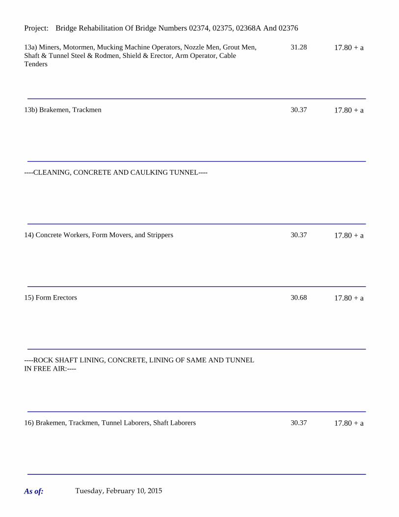
Project: Bridge Rehabilitation Of Bridge Numbers 02374, 02375, 02368A And 02376
13a) Miners, Motormen, Mucking Machine Operators, Nozzle Men, Grout Men, Shaft & Tunnel Steel & Rodmen, Shield & Erector, Arm Operator, Cable Tenders
31.28 17.80 + a
13b) Brakemen, Trackmen 30.37 17.80 + a
----CLEANING, CONCRETE AND CAULKING TUNNEL----
14) Concrete Workers, Form Movers, and Strippers 30.37 17.80 + a
15) Form Erectors 30.68 17.80 + a
----ROCK SHAFT LINING, CONCRETE, LINING OF SAME AND TUNNEL IN FREE AIR:----
16) Brakemen, Trackmen, Tunnel Laborers, Shaft Laborers 30.37 17.80 + a
As of: Tuesday, February 10, 2015
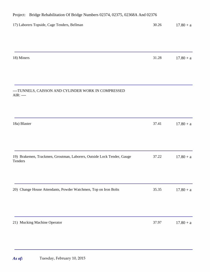
Project: Bridge Rehabilitation Of Bridge Numbers 02374, 02375, 02368A And 02376
17) Laborers Topside, Cage Tenders, Bellman 30.26 17.80 + a
18) Miners 31.28 17.80 + a
----TUNNELS, CAISSON AND CYLINDER WORK IN COMPRESSED AIR: ----
18a) Blaster 37.41 17.80 + a
19) Brakemen, Trackmen, Groutman, Laborers, Outside Lock Tender, Gauge Tenders
37.22 17.80 + a
20) Change House Attendants, Powder Watchmen, Top on Iron Bolts 35.35 17.80 + a
21) Mucking Machine Operator 37.97 17.80 + a
As of: Tuesday, February 10, 2015

Project: Bridge Rehabilitation Of Bridge Numbers 02374, 02375, 02368A And 02376
----TRUCK DRIVERS----(*see note below)
Two axle trucks 28.33 19.14 + a
Three axle trucks; two axle ready mix 28.43 19.14 + a
Three axle ready mix 28.48 19.14 + a
Four axle trucks, heavy duty trailer (up to 40 tons) 28.53 19.14 + a
Four axle ready-mix 28.58 19.14 + a
Heavy duty trailer (40 tons and over) 28.78 19.14 + a
As of: Tuesday, February 10, 2015
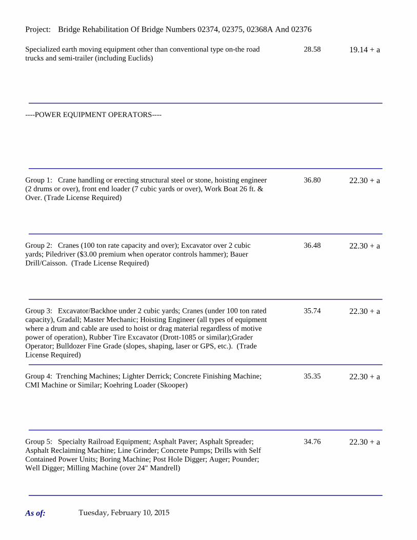
Project: Bridge Rehabilitation Of Bridge Numbers 02374, 02375, 02368A And 02376
Specialized earth moving equipment other than conventional type on-the road trucks and semi-trailer (including Euclids)
28.58 19.14 + a
----POWER EQUIPMENT OPERATORS----
Group 1: Crane handling or erecting structural steel or stone, hoisting engineer (2 drums or over), front end loader (7 cubic yards or over), Work Boat 26 ft. & Over. (Trade License Required)
36.80 22.30 + a
Group 2: Cranes (100 ton rate capacity and over); Excavator over 2 cubic yards; Piledriver ($3.00 premium when operator controls hammer); Bauer Drill/Caisson. (Trade License Required)
36.48 22.30 + a
Group 3: Excavator/Backhoe under 2 cubic yards; Cranes (under 100 ton rated capacity), Gradall; Master Mechanic; Hoisting Engineer (all types of equipment where a drum and cable are used to hoist or drag material regardless of motive power of operation), Rubber Tire Excavator (Drott-1085 or similar);Grader Operator; Bulldozer Fine Grade (slopes, shaping, laser or GPS, etc.). (Trade License Required)
35.74 22.30 + a
Group 4: Trenching Machines; Lighter Derrick; Concrete Finishing Machine; CMI Machine or Similar; Koehring Loader (Skooper)
35.35 22.30 + a
Group 5: Specialty Railroad Equipment; Asphalt Paver; Asphalt Spreader; Asphalt Reclaiming Machine; Line Grinder; Concrete Pumps; Drills with Self Contained Power Units; Boring Machine; Post Hole Digger; Auger; Pounder; Well Digger; Milling Machine (over 24" Mandrell)
34.76 22.30 + a
As of: Tuesday, February 10, 2015

Project: Bridge Rehabilitation Of Bridge Numbers 02374, 02375, 02368A And 02376
Group 5 continued: Side Boom; Combination Hoe and Loader; Directional Driller.
34.76 22.30 + a
Group 6: Front End Loader (3 up to 7 cubic yards); Bulldozer (rough grade dozer).
34.45 22.30 + a
Group 7: Asphalt Roller; Concrete Saws and Cutters (ride on types); Vermeer Concrete Cutter; Stump Grinder; Scraper; Snooper; Skidder; Milling Machine (24" and Under Mandrel).
34.11 22.30 + a
Group 8: Mechanic, Grease Truck Operator, Hydroblaster, Barrier Mover, Power Stone Spreader; Welder; Work Boat under 26 ft.; Transfer Machine.
33.71 22.30 + a
Group 9: Front End Loader (under 3 cubic yards), Skid Steer Loader regardless of attachments (Bobcat or Similar); Fork Lift, Power Chipper; Landscape Equipment (including hydroseeder).
33.28 22.30 + a
Group 10: Vibratory Hammer, Ice Machine, Diesel and Air Hammer, etc. 31.24 22.30 + a
Group 11: Conveyor, Earth Roller; Power Pavement Breaker (whiphammer), Robot Demolition Equipment.
31.24 22.30 + a
As of: Tuesday, February 10, 2015

Project: Bridge Rehabilitation Of Bridge Numbers 02374, 02375, 02368A And 02376
Group 12: Wellpoint Operator. 31.18 22.30 + a
Group 13: Compressor Battery Operator. 30.60 22.30 + a
Group 14: Elevator Operator; Tow Motor Operator (Solid Tire No Rough Terrain).
29.46 22.30 + a
Group 15: Generator Operator; Compressor Operator; Pump Operator; Welding Machine Operator; Heater Operator.
29.05 22.30 + a
Group 16: Maintenance Engineer/Oiler 28.40 22.30 + a
Group 17: Portable asphalt plant operator; portable crusher plant operator; portable concrete plant operator.
32.71 22.30 + a
Group 18: Power Safety Boat; Vacuum Truck; Zim Mixer; Sweeper; (minimum for any job requiring CDL license).
30.29 22.30 + a
As of: Tuesday, February 10, 2015
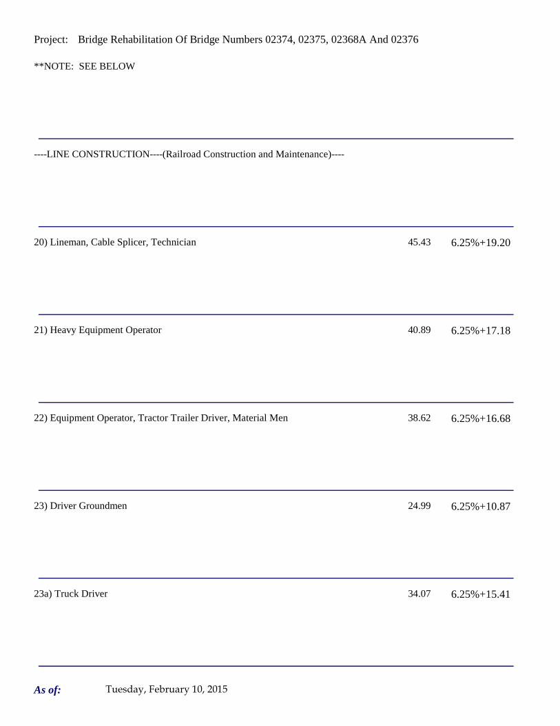
Project: Bridge Rehabilitation Of Bridge Numbers 02374, 02375, 02368A And 02376
**NOTE: SEE BELOW
----LINE CONSTRUCTION----(Railroad Construction and Maintenance)----
20) Lineman, Cable Splicer, Technician 45.43 6.25%+19.20
21) Heavy Equipment Operator 40.89 6.25%+17.18
22) Equipment Operator, Tractor Trailer Driver, Material Men 38.62 6.25%+16.68
23) Driver Groundmen 24.99 6.25%+10.87
23a) Truck Driver 34.07 6.25%+15.41
As of: Tuesday, February 10, 2015
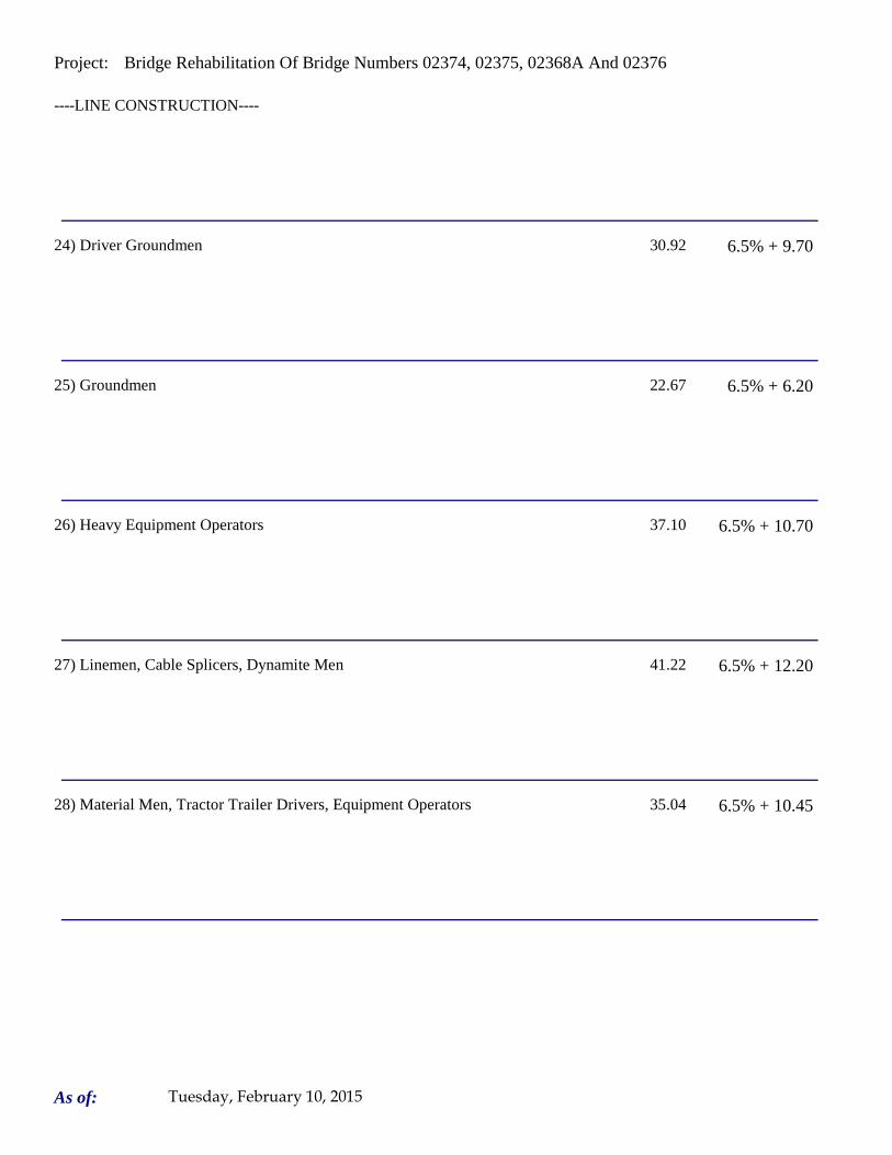
Project: Bridge Rehabilitation Of Bridge Numbers 02374, 02375, 02368A And 02376
----LINE CONSTRUCTION----
24) Driver Groundmen 30.92 6.5% + 9.70
25) Groundmen 22.67 6.5% + 6.20
26) Heavy Equipment Operators 37.10 6.5% + 10.70
27) Linemen, Cable Splicers, Dynamite Men 41.22 6.5% + 12.20
28) Material Men, Tractor Trailer Drivers, Equipment Operators 35.04 6.5% + 10.45
As of: Tuesday, February 10, 2015
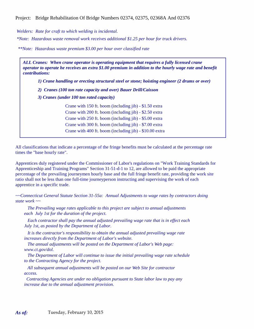
Project: Bridge Rehabilitation Of Bridge Numbers 02374, 02375, 02368A And 02376
Welders: Rate for craft to which welding is incidental.
*Note: Hazardous waste removal work receives additional $1.25 per hour for truck drivers.
**Note: Hazardous waste premium $3.00 per hour over classified rate
Crane with 150 ft. boom (including jib) - $1.50 extra Crane with 200 ft. boom (including jib) - $2.50 extraCrane with 250 ft. boom (including jib) - $5.00 extraCrane with 300 ft. boom (including jib) - $7.00 extra
All classifications that indicate a percentage of the fringe benefits must be calculated at the percentage rate times the "base hourly rate".
Apprentices duly registered under the Commissioner of Labor's regulations on "Work Training Standards for Apprenticeship and Training Programs" Section 31-51-d-1 to 12, are allowed to be paid the appropriate percentage of the prevailing journeymen hourly base and the full fringe benefit rate, providing the work site ratio shall not be less than one full-time journeyperson instructing and supervising the work of each apprentice in a specific trade.
Each contractor shall pay the annual adjusted prevailing wage rate that is in effect each July 1st, as posted by the Department of Labor.
It is the contractor's responsibility to obtain the annual adjusted prevailing wage rate increases directly from the Department of Labor's website. The annual adjustments will be posted on the Department of Labor's Web page:
www.ct.gov/dol. The Department of Labor will continue to issue the initial prevailing wage rate schedule
to the Contracting Agency for the project.
All subsequent annual adjustments will be posted on our Web Site for contractor access.
The Prevailing wage rates applicable to this project are subject to annual adjustments each July 1st for the duration of the project.
Crane with 400 ft. boom (including jib) - $10.00 extra
~~Connecticut General Statute Section 31-55a: Annual Adjustments to wage rates by contractors doing state work ~~
Contracting Agencies are under no obligation pursuant to State labor law to pay any increase due to the annual adjustment provision.
ALL Cranes: When crane operator is operating equipment that requires a fully licensed crane operator to operate he receives an extra $1.00 premium in addition to the hourly wage rate and benefit contributions:
1) Crane handling or erecting structural steel or stone; hoisting engineer (2 drums or over)
2) Cranes (100 ton rate capacity and over) Bauer Drill/Caisson
3) Cranes (under 100 ton rated capacity)
As of: Tuesday, February 10, 2015
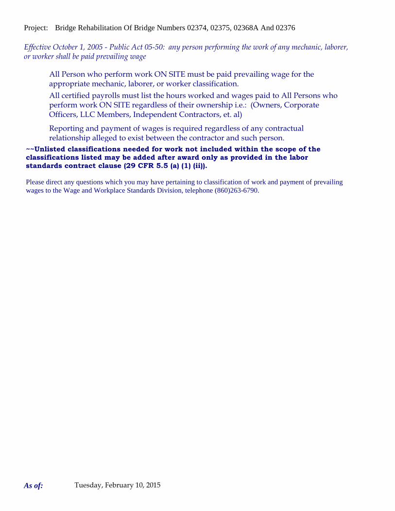
Project: Bridge Rehabilitation Of Bridge Numbers 02374, 02375, 02368A And 02376
Please direct any questions which you may have pertaining to classification of work and payment of prevailing wages to the Wage and Workplace Standards Division, telephone (860)263-6790.
Effective October 1, 2005 - Public Act 05-50: any person performing the work of any mechanic, laborer, or worker shall be paid prevailing wage
All Person who perform work ON SITE must be paid prevailing wage for the appropriate mechanic, laborer, or worker classification.
All certified payrolls must list the hours worked and wages paid to All Persons who perform work ON SITE regardless of their ownership i.e.: (Owners, Corporate Officers, LLC Members, Independent Contractors, et. al)
Reporting and payment of wages is required regardless of any contractual relationship alleged to exist between the contractor and such person.
~~Unlisted classifications needed for work not included within the scope of the classifications listed may be added after award only as provided in the labor standards contract clause (29 CFR 5.5 (a) (1) (ii)).
As of: Tuesday, February 10, 2015

Connecticut Department of Labor Wage and Workplace Standards Division
FOOTNOTES
Please Note: If the “Benefits” listed on the schedule for the following occupations includes a letter(s) (+ a or + a+b for instance), refer to the information below.
Benefits to be paid at the appropriate prevailing wage rate for the listed occupation. If the “Benefits” section for the occupation lists only a dollar amount, disregard the information below.
Bricklayers, Cement Masons, Cement Finishers, Concrete Finishers, Stone Masons (Building Construction) and
(Residential- Hartford, Middlesex, New Haven, New London and Tolland Counties)
a. Paid Holiday: Employees shall receive 4 hours for Christmas Eve holiday provided the employee works the regularly scheduled day before and after the holiday. Employers may schedule work on Christmas Eve and employees shall receive pay for actual hours worked in addition to holiday pay.
Elevator Constructors: Mechanics
a. Paid Holidays: New Year’s Day, Memorial Day, Independence Day, Labor Day,
Veterans’ Day, Thanksgiving Day, Christmas Day, plus the Friday after Thanksgiving.
b. Vacation: Employer contributes 8% of basic hourly rate for 5 years or more
of service or 6% of basic hourly rate for 6 months to 5 years of service as vacation pay credit.
Glaziers
a. Paid Holidays: Labor Day and Christmas Day.
Power Equipment Operators (Heavy and Highway Construction & Building Construction)
a. Paid Holidays: New Year’s Day, Good Friday, Memorial day, Independence Day,
Labor Day, Thanksgiving Day and Christmas Day, provided the employee works 3 days during the week in which the holiday falls, if scheduled, and if scheduled, the working day before and the working day after the holiday. Holidays falling on Saturday may be observed on Saturday, or if the employer so elects, on the preceding Friday.
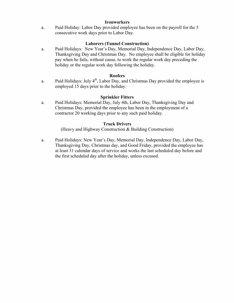
Ironworkers a. Paid Holiday: Labor Day provided employee has been on the payroll for the 5
consecutive work days prior to Labor Day.
Laborers (Tunnel Construction) a. Paid Holidays: New Year’s Day, Memorial Day, Independence Day, Labor Day,
Thanksgiving Day and Christmas Day. No employee shall be eligible for holiday pay when he fails, without cause, to work the regular work day preceding the holiday or the regular work day following the holiday.
Roofers
a. Paid Holidays: July 4th, Labor Day, and Christmas Day provided the employee is employed 15 days prior to the holiday.
Sprinkler Fitters
a. Paid Holidays: Memorial Day, July 4th, Labor Day, Thanksgiving Day and Christmas Day, provided the employee has been in the employment of a contractor 20 working days prior to any such paid holiday.
Truck Drivers
(Heavy and Highway Construction & Building Construction)
a. Paid Holidays: New Year’s Day, Memorial Day, Independence Day, Labor Day, Thanksgiving Day, Christmas day, and Good Friday, provided the employee has at least 31 calendar days of service and works the last scheduled day before and the first scheduled day after the holiday, unless excused.
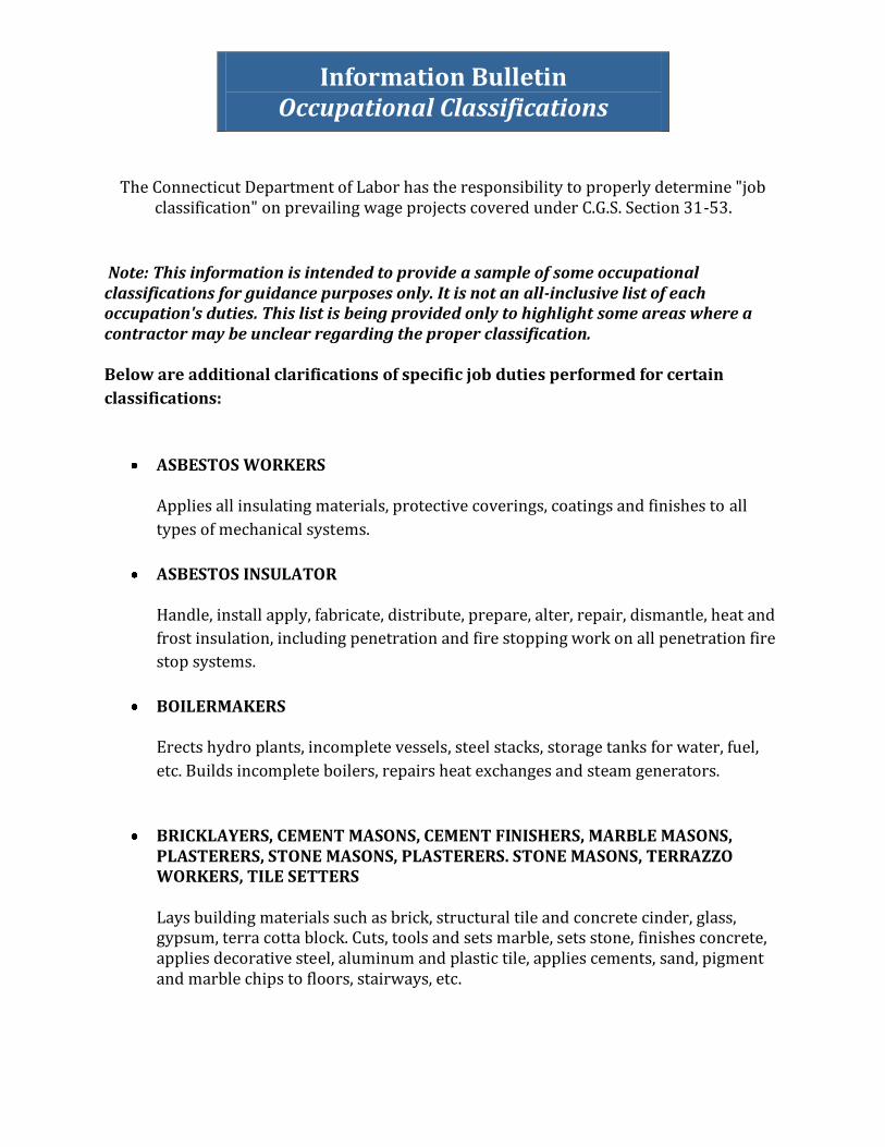
Information Bulletin Occupational Classifications
The Connecticut Department of Labor has the responsibility to properly determine "job
classification" on prevailing wage projects covered under C.G.S. Section 31-53.
Note: This information is intended to provide a sample of some occupational classifications for guidance purposes only. It is not an all-inclusive list of each occupation's duties. This list is being provided only to highlight some areas where a contractor may be unclear regarding the proper classification. Below are additional clarifications of specific job duties performed for certain
classifications:
ASBESTOS WORKERS
Applies all insulating materials, protective coverings, coatings and finishes to all
types of mechanical systems.
ASBESTOS INSULATOR
Handle, install apply, fabricate, distribute, prepare, alter, repair, dismantle, heat and
frost insulation, including penetration and fire stopping work on all penetration fire
stop systems.
BOILERMAKERS
Erects hydro plants, incomplete vessels, steel stacks, storage tanks for water, fuel,
etc. Builds incomplete boilers, repairs heat exchanges and steam generators.
BRICKLAYERS, CEMENT MASONS, CEMENT FINISHERS, MARBLE MASONS, PLASTERERS, STONE MASONS, PLASTERERS. STONE MASONS, TERRAZZO WORKERS, TILE SETTERS
Lays building materials such as brick, structural tile and concrete cinder, glass, gypsum, terra cotta block. Cuts, tools and sets marble, sets stone, finishes concrete, applies decorative steel, aluminum and plastic tile, applies cements, sand, pigment and marble chips to floors, stairways, etc.
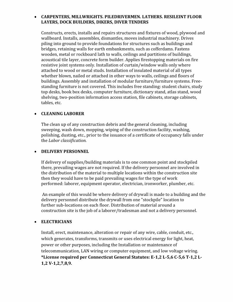
CARPENTERS, MILLWRIGHTS. PILEDRIVERMEN. LATHERS. RESILEINT FLOOR LAYERS, DOCK BUILDERS, DIKERS, DIVER TENDERS Constructs, erects, installs and repairs structures and fixtures of wood, plywood and wallboard. Installs, assembles, dismantles, moves industrial machinery. Drives piling into ground to provide foundations for structures such as buildings and bridges, retaining walls for earth embankments, such as cofferdams. Fastens wooden, metal or rockboard lath to walls, ceilings and partitions of buildings, acoustical tile layer, concrete form builder. Applies firestopping materials on fire resistive joint systems only. Installation of curtain/window walls only where attached to wood or metal studs. Installation of insulated material of all types whether blown, nailed or attached in other ways to walls, ceilings and floors of buildings. Assembly and installation of modular furniture/furniture systems. Free-standing furniture is not covered. This includes free standing: student chairs, study top desks, book box desks, computer furniture, dictionary stand, atlas stand, wood shelving, two-position information access station, file cabinets, storage cabinets, tables, etc.
CLEANING LABORER
The clean up of any construction debris and the general cleaning, including sweeping, wash down, mopping, wiping of the construction facility, washing, polishing, dusting, etc., prior to the issuance of a certificate of occupancy falls under the Labor classification.
DELIVERY PERSONNEL
If delivery of supplies/building materials is to one common point and stockpiled there, prevailing wages are not required. If the delivery personnel are involved in the distribution of the material to multiple locations within the construction site then they would have to be paid prevailing wages for the type of work performed: laborer, equipment operator, electrician, ironworker, plumber, etc. An example of this would be where delivery of drywall is made to a building and the delivery personnel distribute the drywall from one "stockpile" location to further sub‐locations on each floor. Distribution of material around a construction site is the job of a laborer/tradesman and not a delivery personnel.
ELECTRICIANS
Install, erect, maintenance, alteration or repair of any wire, cable, conduit, etc.,
which generates, transforms, transmits or uses electrical energy for light, heat,
power or other purposes, including the Installation or maintenance of
telecommunication, LAN wiring or computer equipment, and low voltage wiring.
*License required per Connecticut General Statutes: E-1,2 L-5,6 C-5,6 T-1,2 L-
1,2 V-1,2,7,8,9.
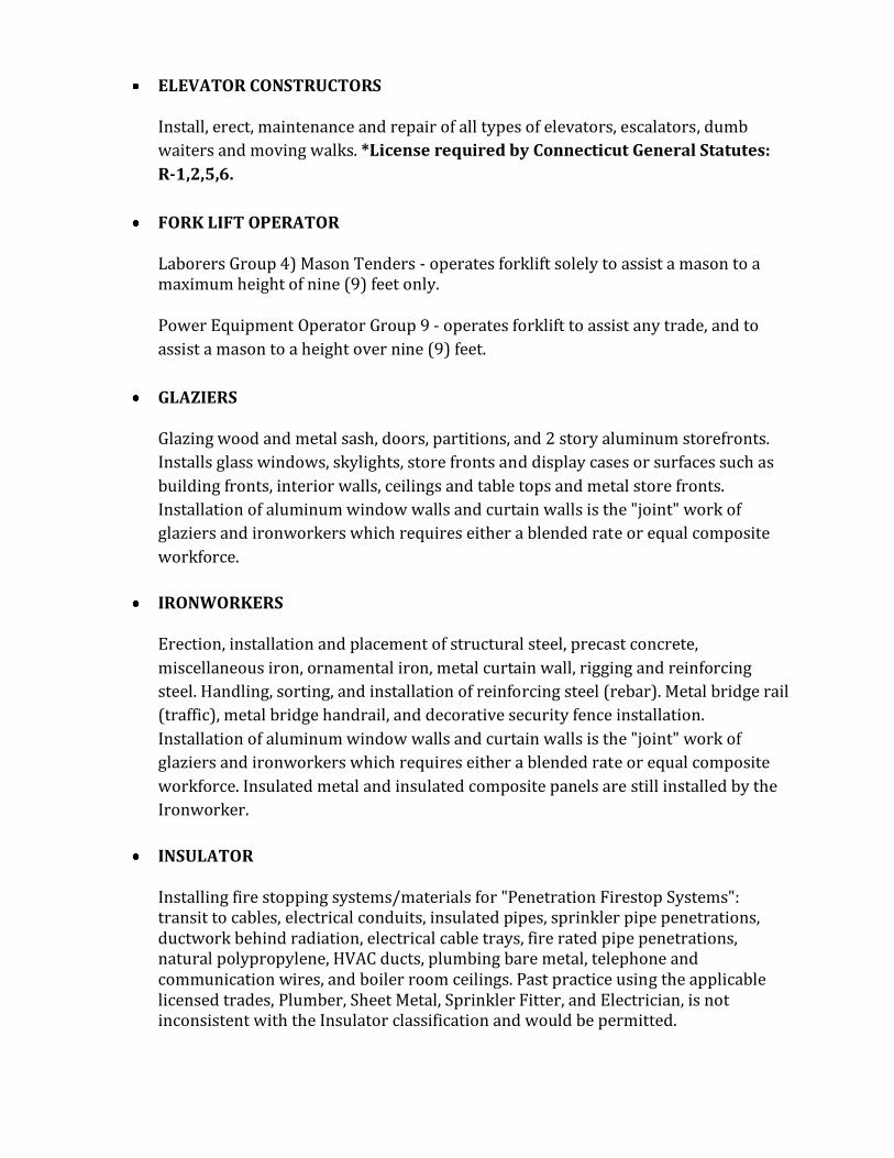
ELEVATOR CONSTRUCTORS
Install, erect, maintenance and repair of all types of elevators, escalators, dumb
waiters and moving walks. *License required by Connecticut General Statutes:
R-1,2,5,6.
FORK LIFT OPERATOR
Laborers Group 4) Mason Tenders - operates forklift solely to assist a mason to a maximum height of nine (9) feet only. Power Equipment Operator Group 9 ‐ operates forklift to assist any trade, and to
assist a mason to a height over nine (9) feet.
GLAZIERS
Glazing wood and metal sash, doors, partitions, and 2 story aluminum storefronts.
Installs glass windows, skylights, store fronts and display cases or surfaces such as
building fronts, interior walls, ceilings and table tops and metal store fronts.
Installation of aluminum window walls and curtain walls is the "joint" work of
glaziers and ironworkers which requires either a blended rate or equal composite
workforce.
IRONWORKERS
Erection, installation and placement of structural steel, precast concrete,
miscellaneous iron, ornamental iron, metal curtain wall, rigging and reinforcing
steel. Handling, sorting, and installation of reinforcing steel (rebar). Metal bridge rail
(traffic), metal bridge handrail, and decorative security fence installation.
Installation of aluminum window walls and curtain walls is the "joint" work of
glaziers and ironworkers which requires either a blended rate or equal composite
workforce. Insulated metal and insulated composite panels are still installed by the
Ironworker.
INSULATOR
Installing fire stopping systems/materials for "Penetration Firestop Systems": transit to cables, electrical conduits, insulated pipes, sprinkler pipe penetrations, ductwork behind radiation, electrical cable trays, fire rated pipe penetrations, natural polypropylene, HVAC ducts, plumbing bare metal, telephone and communication wires, and boiler room ceilings. Past practice using the applicable licensed trades, Plumber, Sheet Metal, Sprinkler Fitter, and Electrician, is not inconsistent with the Insulator classification and would be permitted.
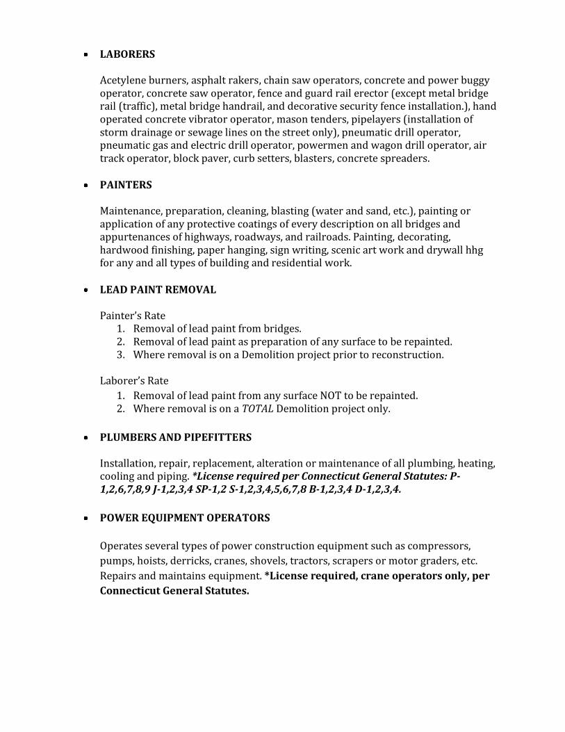
LABORERS
Acetylene burners, asphalt rakers, chain saw operators, concrete and power buggy operator, concrete saw operator, fence and guard rail erector (except metal bridge rail (traffic), metal bridge handrail, and decorative security fence installation.), hand operated concrete vibrator operator, mason tenders, pipelayers (installation of storm drainage or sewage lines on the street only), pneumatic drill operator, pneumatic gas and electric drill operator, powermen and wagon drill operator, air track operator, block paver, curb setters, blasters, concrete spreaders.
PAINTERS
Maintenance, preparation, cleaning, blasting (water and sand, etc.), painting or application of any protective coatings of every description on all bridges and appurtenances of highways, roadways, and railroads. Painting, decorating, hardwood finishing, paper hanging, sign writing, scenic art work and drywall hhg for any and all types of building and residential work.
LEAD PAINT REMOVAL
Painter’s Rate
1. Removal of lead paint from bridges. 2. Removal of lead paint as preparation of any surface to be repainted. 3. Where removal is on a Demolition project prior to reconstruction.
Laborer’s Rate
1. Removal of lead paint from any surface NOT to be repainted. 2. Where removal is on a TOTAL Demolition project only.
PLUMBERS AND PIPEFITTERS
Installation, repair, replacement, alteration or maintenance of all plumbing, heating, cooling and piping. *License required per Connecticut General Statutes: P-1,2,6,7,8,9 J-1,2,3,4 SP-1,2 S-1,2,3,4,5,6,7,8 B-1,2,3,4 D-1,2,3,4.
POWER EQUIPMENT OPERATORS
Operates several types of power construction equipment such as compressors,
pumps, hoists, derricks, cranes, shovels, tractors, scrapers or motor graders, etc.
Repairs and maintains equipment. *License required, crane operators only, per
Connecticut General Statutes.

ROOFERS
Covers roofs with composition shingles or sheets, wood shingles, slate or asphalt
and gravel to waterproof roofs, including preparation of surface. (tear-off and/or
removal of any type of roofing and/or clean-up of any and all areas where a roof is
to be relaid)
SHEETMETAL WORKERS
Fabricate, assembles, installs and repairs sheetmetal products and equipment in
such areas as ventilation, air-conditioning, warm air heating, restaurant equipment,
architectural sheet metal work, sheetmetal roofing, and aluminum gutters.
Fabrication, handling, assembling, erecting, altering, repairing, etc. of coated metal
material panels and composite metal material panels when used on building
exteriors and interiors as soffits, facia, louvers, partitions, wall panel siding,
canopies, cornice, column covers, awnings, beam covers, cladding, sun shades,
lighting troughs, spires, ornamental roofing, metal ceilings, mansards, copings,
ornamental and ventilation hoods, vertical and horizontal siding panels, trim, etc.
The sheet metal classification also applies to the vast variety of coated metal
material panels and composite metal material panels that have evolved over the
years as an alternative to conventional ferrous and non-ferrous metals like steel,
iron, tin, copper, brass, bronze, aluminum, etc. Insulated metal and insulated
composite panels are still installed by the Iron Worker. Fabrication, handling,
assembling, erecting, altering, repairing, etc. of architectural metal roof, standing
seam roof, composite metal roof, metal and composite bathroom/toilet partitions,
aluminum gutters, metal and composite lockers and shelving, kitchen equipment,
and walk‐in coolers.
SPRINKLER FITTERS
Installation, alteration, maintenance and repair of fire protection sprinkler systems.
*License required per Connecticut General Statutes: F-1,2,3,4.
TILE MARBLE AND TERRAZZO FINISHERS
Assists and tends the tile setter, marble mason and terrazzo worker in the performance of their duties.

TRUCK DRIVERS
Definitions:
1) “Site of the work” (29 Code of Federal Regulations (CFR) 5.2(l)(b) is the physical place or
places where the building or work called for in the contract will remain and any other site
where a significant portion of the building or work is constructed, provided that such site is
established specifically for the performance of the contact or project;
(a) Except as provided in paragraph (l) (3) of this section, job headquarters, tool yards,
batch plants, borrow pits, etc. are part of the “site of the work”; provided they are dedicated
exclusively, or nearly so, to the performance of the contract or project, and provided they
are adjacent to “the site of work” as defined in paragraph (e)(1) of this section;
(b) Not included in the “site of the work” are permanent home offices, branch plant
establishments, fabrication plants, tool yards etc, of a contractor or subcontractor whose
location and continuance in operation are determined wholly without regard to a
particular State or political subdivision contract or uncertain and indefinite periods of time
involved of a few seconds or minutes duration and where the failure to count such time is
due to consideration justified by industrial realities (29 CFR 785.47)
2) “Engaged to wait” is waiting time that belongs to and is controlled by the employer
which is an integral part of the job and is therefore compensable as hours worked. (29 CFR
785.15)
3) “Waiting to be engaged” is waiting time that an employee can use effectively for their
own purpose and is not compensable as hours worked. (29 CFR 785.16)
4) “De Minimus” is a rule that recognizes that unsubstantial or insignificant periods of time
which cannot as a practical administrative matter be precisely recorded for payroll
purposes, may be disregarded. This rule applies only where there are uncertain and
indefinite periods of time involved of a short duration and where the failure to count such
time is due to consideration justified by worksite realities. For example, with respect to
truck drivers on prevailing wage sites, this is typically less than 15 minutes at a time.
Coverage of Truck Drivers on State or Political subdivision Prevailing Wage Projects
Truck drivers are covered for payroll purposes under the following conditions:
Truck Drivers for time spent working on the site of the work.
Truck Drivers for time spent loading and/or unloading materials and supplies on the site of the work, if such time is not de minimus
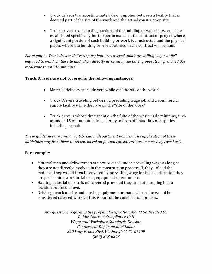
Truck drivers transporting materials or supplies between a facility that is deemed part of the site of the work and the actual construction site.
Truck drivers transporting portions of the building or work between a site established specifically for the performance of the contract or project where a significant portion of such building or work is constructed and the physical places where the building or work outlined in the contract will remain.
For example: Truck drivers delivering asphalt are covered under prevailing wage while”
engaged to wait” on the site and when directly involved in the paving operation, provided the
total time is not “de minimus”
Truck Drivers are not covered in the following instances:
Material delivery truck drivers while off “the site of the work”
Truck Drivers traveling between a prevailing wage job and a commercial supply facility while they are off the “site of the work”
Truck drivers whose time spent on the “site of the work” is de minimus, such as under 15 minutes at a time, merely to drop off materials or supplies, including asphalt.
These guidelines are similar to U.S. Labor Department policies. The application of these
guidelines may be subject to review based on factual considerations on a case by case basis.
For example:
Material men and deliverymen are not covered under prevailing wage as long as they are not directly involved in the construction process. If, they unload the material, they would then be covered by prevailing wage for the classification they are performing work in: laborer, equipment operator, etc.
Hauling material off site is not covered provided they are not dumping it at a location outlined above.
Driving a truck on site and moving equipment or materials on site would be considered covered work, as this is part of the construction process.
Any questions regarding the proper classification should be directed to: Public Contract Compliance Unit
Wage and Workplace Standards Division Connecticut Department of Labor
200 Folly Brook Blvd, Wethersfield, CT 06109 (860) 263-6543

Sec. 31-55a
Statute 31-55a
Last Updated: June 02, 2008
You are here: DOL Web Site Wage and Workplace Issues Statute 31-55a
- Special Notice -
To All State and Political Subdivisions,Their Agents, and Contractors
Connecticut General Statute 31-55a - Annual adjustments to wage rates by contractors doing state work.
Each contractor that is awarded a contract on or after October 1, 2002, for (1) the construction of a state highway or bridge that falls under the provisions of section 31-54 of the general statutes, or (2) the construction, remodeling, refinishing, refurbishing, rehabilitation, alteration or repair of any public works project that falls under the provisions of section 31-53 of the general statutes shall contact the Labor Commissioner on or before July first of each year, for the duration of such contract, to ascertain the prevailing rate of wages on an hourly basis and the amount of payment or contributions paid or payable on behalf of each mechanic, laborer or worker employed upon the work contracted to be done, and shall make any necessary adjustments to such prevailing rate of wages and such payment or contributions paid or payable on behalf of each such employee, effective each July first.
● The prevailing wage rates applicable to any contract or subcontract awarded on or after October 1, 2002 are subject to annual adjustments each July 1st for the duration of any project which was originally advertised for bids on or after October 1, 2002.
● Each contractor affected by the above requirement shall pay the annual adjusted prevailing wage rate that is in effect each July 1st, as posted by the Department of Labor.
● It is the contractor’s responsibility to obtain the annual adjusted prevailing wage rate increases directly from the Department of Labor’s Web Site. The annual adjustments will be posted on the Department of Labor Web page: www.ctdol.state.ct.us. For those without internet access, please contact the division listed below.
● The Department of Labor will continue to issue the initial prevailing wage rate schedule to the Contracting Agency for the project. All subsequent annual adjustments will be posted on our Web Site for contractor access.
Any questions should be directed to the Contract Compliance Unit, Wage and Workplace
http://www.ctdol.state.ct.us/wgwkstnd/laws-regs/statute31-55a.htm (1 of 2) [6/20/2008 8:00:16 AM]

Sec. 31-55a
Standards Division, Connecticut Department of Labor, 200 Folly Brook Blvd., Wethersfield, CT 06109 at (860)263-6790.
Workplace Laws
Published by the Connecticut Department of Labor, Project Management Office
http://www.ctdol.state.ct.us/wgwkstnd/laws-regs/statute31-55a.htm (2 of 2) [6/20/2008 8:00:16 AM]

November 29, 2006
NoticeTo All Mason Contractors and Interested Parties
Regarding Construction Pursuant to Section 31-53 of theConnecticut General Statutes (Prevailing Wage)
The Connecticut Labor Department Wage and Workplace Standards Division is empowered toenforce the prevailing wage rates on projects covered by the above referenced statute.
Over the past few years the Division has withheld enforcement of the rate in effect for workerswho operate a forklift on a prevailing wage rate project due to a potential jurisdictional dispute.
The rate listed in the schedules and in our Occupational Bulletin (see enclosed) has been asfollows:
Forklift Operator:
- Laborers (Group 4) Mason Tenders - operates forklift solely to assist a mason to a maximumheight of nine feet only.
- Power Equipment Operator (Group 9) - operates forklift to assist any trade and to assist amason to a height over nine feet.
The U.S. Labor Department conducted a survey of rates in Connecticut but it has not beenpublished and the rate in effect remains as outlined in the above Occupational Bulletin.
Since this is a classification matter and not one of jurisdiction, effective January 1,2007 the Connecticut Labor Department will enforce the rate on each schedule inaccordance with our statutory authority.
Your cooperation in filing appropriate and accurate certified payrolls is appreciated.
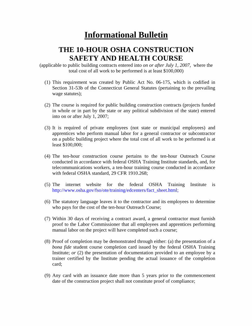
Informational Bulletin
THE 10-HOUR OSHA CONSTRUCTION SAFETY AND HEALTH COURSE
(applicable to public building contracts entered into on or after July 1, 2007, where the total cost of all work to be performed is at least $100,000)
(1) This requirement was created by Public Act No. 06-175, which is codified in
Section 31-53b of the Connecticut General Statutes (pertaining to the prevailing wage statutes);
(2) The course is required for public building construction contracts (projects funded
in whole or in part by the state or any political subdivision of the state) entered into on or after July 1, 2007;
(3) It is required of private employees (not state or municipal employees) and
apprentices who perform manual labor for a general contractor or subcontractor on a public building project where the total cost of all work to be performed is at least $100,000;
(4) The ten-hour construction course pertains to the ten-hour Outreach Course
conducted in accordance with federal OSHA Training Institute standards, and, for telecommunications workers, a ten-hour training course conducted in accordance with federal OSHA standard, 29 CFR 1910.268;
(5) The internet website for the federal OSHA Training Institute is
http://www.osha.gov/fso/ote/training/edcenters/fact_sheet.html;
(6) The statutory language leaves it to the contractor and its employees to determine who pays for the cost of the ten-hour Outreach Course;
(7) Within 30 days of receiving a contract award, a general contractor must furnish
proof to the Labor Commissioner that all employees and apprentices performing manual labor on the project will have completed such a course;
(8) Proof of completion may be demonstrated through either: (a) the presentation of a
bona fide student course completion card issued by the federal OSHA Training Institute; or (2) the presentation of documentation provided to an employee by a trainer certified by the Institute pending the actual issuance of the completion card;
(9) Any card with an issuance date more than 5 years prior to the commencement
date of the construction project shall not constitute proof of compliance;
(10) Each employer shall affix a copy of the construction safety course completion card to the certified payroll submitted to the contracting agency in accordance with Conn. Gen. Stat. § 31-53(f) on which such employee’s name first appears;
(11) Any employee found to be in non-compliance shall be subject to removal from
the worksite if such employee does not provide satisfactory proof of course completion to the Labor Commissioner by the fifteenth day after the date the employee is determined to be in noncompliance;
(12) Any such employee who is determined to be in noncompliance may continue to
work on a public building construction project for a maximum of fourteen consecutive calendar days while bringing his or her status into compliance;
(13) The Labor Commissioner may make complaint to the prosecuting authorities
regarding any employer or agent of the employer, or officer or agent of the corporation who files a false certified payroll with respect to the status of an employee who is performing manual labor on a public building construction project;
(14) The statute provides the minimum standards required for the completion of a
safety course by manual laborers on public construction contracts; any contractor can exceed these minimum requirements; and
(15) Regulations clarifying the statute are currently in the regulatory process, and shall
be posted on the CTDOL website as soon as they are adopted in final form. (16) Any questions regarding this statute may be directed to the Wage and Workplace
Standards Division of the Connecticut Labor Department via the internet website of http://www.ctdol.state.ct.us/wgwkstnd/wgemenu.htm; or by telephone at (860)263-6790.
THE ABOVE INFORMATION IS PROVIDED EXCLUSIVELY AS AN EDUCATIONAL RESOURCE, AND IS NOT INTENDED AS A SUBSTITUTE FOR LEGAL INTERPRETATIONS WHICH MAY ULTMATELY ARISE CONCERNIG THE CONSTRUCTION OF THE STATUTE OR THE REGULATIONS.

Sec. 31-53b. Construction safety and health course. Proof of completion required for employees on public building projects. Enforcement. Regulations. (a) Each contract entered into on or after July 1, 2007, for the construction, remodeling, refinishing, refurbishing, rehabilitation, alteration or repair of any public building project by the state or any of its agents, or by an political subdivision of the state or any of its agents, where the total cost of all work to be performed by all contractors and subcontractors in connection with the contract is at least one hundred thousand dollars, shall contain a provision requiring that, not later than thirty days after the date such contract is awarded, each contractor furnish proof to the Labor Commissioner that all employees performing manual labor on or in such public building, pursuant to such contract, have completed a course of at least ten hours in duration in construction safety and health approved by the federal Occupational Safety and Health Administration or, in the case of telecommunications employees, have completed at least ten hours of training in accordance with 29 CFR 1910.268. (b) Any employee required to complete a construction safety and health course required under subsection (a) of this section who has not completed the course shall be subject to removal from the worksite if the employee does not provide documentation of having completed such course by the fifteenth day after the date the employee is found to be in noncompliance. The Labor Commissioner or said commissioner’s designee shall enforce this section. (c) Not later than January 1, 2007, the Labor Commissioner shall adopt regulations, in accordance with the provisions of chapter 54, to implement the provisions of subsections (a) and (b) of this section. Such regulations shall require that the ten-hour construction safety and health courses required under subsection (a) of this section be conducted in accordance with federal Occupational Safety and Health Administration Training Institute standards, or in accordance with 29 CFR 1910.268, as appropriate. The Labor Commissioner shall accept as sufficient proof of compliance with the provisions of subsection (a) or (b) of this section a student course completion card issued by the federal Occupational Safety and Health Administration Training Institute, or such other proof of compliance said commissioner deems appropriate, dated no earlier than five years before the commencement date of such public works project. (d) For the purposes of this section, “public building” means a structure, paid for in whole or in part with state funds, within a roof and within exterior walls or fire walls, designed for the housing, shelter, enclosure and support or employment of people, animals or property of any kind, including, but not limited to, sewage treatment plants and water treatment plants, “Public building” does not include site work, roads or bridges, rail lines, parking lots or underground water, sewer or drainage systems including pump houses or other utility systems.
CONNECTICUT DEPARTMENT OF LABOR WAGE AND WORKPLACE STANDARDS DIVISION
CONTRACTORS WAGE CERTIFICATION FORM
I, of Officer, Owner, Authorized Rep. Company Name
do hereby certify that the Company Name Street City and all of its subcontractors will pay all workers on the
Project Name and Number
Street and City
the wages as listed in the schedule of prevailing rates required for such project (a copy of which isattached hereto).
Signed
Subscribed and sworn to before me this day of , 2004.
Notary Public
L Return to: Connecticut Department of Labor
Wage & Workplace Standards Division 200 Folly Brook Blvd.
Wethersfield, CT 06109