Embed Size (px)
Citation preview
Journal of the Institute of Engineering, Vol. 7, No. 1, pp. 1-9
© TUTA/IOE/PCU
All rights reserved. Printed in Nepal
Fax: 977-1-5525830
TUTA/IOE/PCU
PURIFICATION AND COMPRESSION OF BIOGAS: A RESEARCH
EXPERIENCE
Er.Tri Ratna Bajracharya, Ph.D. Associate Professor, Mechanical Engineering Department, Pulchowk Campus, Institute of Engineering, Tribhuvan
University
Corresponding Email Address: [email protected]
Er. Alok Dhungana, Er. Nirajan Thapaliya, Er. Gogan Hamal Research Associate, Department of Mechanical Engineering, Pulchowk Campus, Institute of Engineering, Tribhuvan
University
Abstract: Biogas is widely used in villages of Nepal for cooking and lighting. But its commercial
use has never been realized due to difficulties in its storage and transportation. Solution identified
to the problem is to increase the energy density of the gas through removal of incombustible and
corrosive gas and consequent compression which was experimented on a lab-scale model. This
paper presents all the results of removal of CO2 gas from biogas using different chemicals and
relative purity with raw gas. Further, compression of biogas and was carried out by methane
refrigerant compressor and bottled into normal LPG cylinder. Compression of biogas was carried
out under near Isothermal and Adiabatic conditions up to 11bar absolute pressure. The energy
efficiency of compression was determined to be 98.71% and if the gas used for generation of
electricity using a generator with an efficiency of 30%, the net energy efficiency turned out to be
95.72%. Later, a boiling test was conducted whereby the combustibility of the compressed biogas
from the cylinder in normal biogas-stove was tested to validate its use in cooking, the results of
which are included.
Key words: Purification of Biogas, Compression of Biogas, Chemical purification, Energy
efficiency, Combustion test.
1. INTRODUCTION
Biogas is a flammable mixture of different
gases that is produced by decomposition of
biodegradable organic matters by
microorganisms in absence of air (or
oxygen). Biogas is produced by anaerobic
digestion of biological wastes such as cattle
dung, vegetable wastes, sheep and poultry
droppings, municipal solid waste, industrial
wastewater, landfill, etc. Production of
biogas involves a complex physiochemical
and biological processes involving different
factors and stages of change. Main products
of the anaerobic digestion are biogas and
slurry. Biogas is constituted of different
component gases the majority of them being
methane (CH4) and Carbon dioxide (CO2)
with traces of Sulphur Dioxide (H2S) and
Hydrogen (H2) gas. Composition of a typical
biogas sample in Nepal is given in the table
below:
Table 1 Composition of Biogas
Substance Symbol Percentage
Methane CH4 50 – 70
Carbon Dioxide CO2 30 – 40
Hydrogen H2 5 – 10
Nitrogen N2 1 – 2
Water Vapor H2O 0.3
Hydrogen
Sulphide H2S Traces
Source: [2]
Journal of the Institute of Engineering 2
In the above table, we can see the
combustible components of biogas are CH4
and H2. Other gases are not flammable at
normal conditions and have no energy
contribution in biogas. Also, among these
two gases only CH4 is present in a significant
amount and hence, is considered in most
cases involving biogas.
In Nepal, major application of biogas has
only been in cooking and lighting.
Commonly the gas produced in the digester
is transported to desired place say kitchen by
pipe line, on the pressure developed in the
digester dome itself. But this is not sufficient
to transport gas to farther distances from the
generation site. This is why, uses of biogas
are crippled. Moreover, due to its limited use
biogas until now is not produced at a
convincing amount. A large scale biogas
plant producing a large amount of biogas is
often rendered worthless due to the lack of its
effective and efficient use. Due to this lack
of portability of biogas there have been no
efforts whatsoever to commercialize the use
of biogas.
The main problems associated with the
commercialization with biogas are:
• Its low energy content per unit volume.
• It is difficult to liquefy.
• It is not produced in large amount at a same place.
For the commercialization of the biogas, it is
important to make it portable and compatible
for various commercial purposes. For that,
the energy content for a particular volume
must also be increased. This requires
compression of the gas to as higher pressures
as possible. Storage of the gas is another
concern as the cylinder becomes heavy and
bulky for higher pressures. This will increase
the weight of the cylinder and hence, affect
its portability. Hence, other means of
increasing the energy content is to purify the
gas, i.e. to remove incombustible gas present
in biogas.
2. MATERIALS AND
METHODOLOGY OF THE STUDY
The study was carried out on lab scale
models. This topic was never studied before
in Nepal hence experiments were performed
from basic level and improvements were
made through trial and error. Due to
unavailability of standard instruments
required to verify the results, experiments
were limited as a preliminary study and a
very important guide to next level of
research.
Below, different streams of experiment, their
theories, procedures and design are explained
accordingly.
2.1 Purification
In purification, it is intended to enrich the
methane content in the biogas. Primary
option was to use pressurized water scrubber,
which was suitable both from technical and
economic point of view in Nepal at
commercial scale. Other processes like
pressure swing absorber, membrane
separation, activated carbon sieve method,
cryogenic etc. were either too expensive or
technically infeasible. Due to lack of fund to
install the setup, an alternative method for
CO2 removal using suitable chemicals
(alkalis) was considered for the study of
purification and its subsequent compression.
The chemicals used were Calcium Oxide
(CaO), Calcium Hydroxide (Ca(OH)2) and
Ammonium Hydroxide (NH4OH).
2.1.1 Chemical purification Theory
CO2 is an acidic gas; it forms Carbonic Acid
(H2CO3) upon dissolving in water. Hence, for
the absorption of CO2 gas suitable bases have
to be used to result an acid-base
neutralization reaction thereby, absorbing
and reducing the CO2 content in biogas.
Purification and Compression of Biogas: A Research Experience
3
CO2 + H2O 2H+ + CO32- H2CO3
The chemicals used were Calcium Oxide
(CaO), Calcium Hydroxide (Ca(OH)2) and
Ammonium Hydroxide (NH4OH). Chemicals
were changed due to unsatisfactory results
obtained from the experiments. That’s why
we also changed CaO to Ca(OH)2 to obtain
positive results. Basic chemical reactions to
absorb CO2 are mentioned below:
CaO + H2CO3 CaCO3 + H2O
Ca(OH)2 + H2CO3 CaCO3 + H2O
NH4OH + H2CO3 NH4HCO3 + H2O
2NH4OH + H2CO3 (NH4)2CO3 + 2H2O
Regeneration theory
Regeneration of the spent chemical becomes
very important if we are going to
commercially use the chemical for the
purification process. CaCO3 is the product of
both CaO and Ca(OH)2 . Its when heated to
825 oC dissociates back to Calcium Oxide
and Carbon Dioxide. This is how Calcium
Oxide is manufactured from limestone
(Calcium Carbonate). But this requires very
high temperature and long process rendering
it inappropriate for its economical use.
But ammonia can be easily regenerated by
heating ammonia carbonates and
bicarbonates to 60-80 ˚C for 5-10 minutes[8].
Otherwise, these are used as chemical
fertilizer, hence can be sold without
regeneration.
Chemical Purification setup and
methodology:
The purification setup was simple and suited
for low flow-rate. We conducted our
experiments at flow-rates roughly around
300lit/hour. For increasing the flow-rate,
better gas diffusing methods and large
volume of chemical must be used. Besides,
stirrer is also required to ensure the proper
diffusion of the unreacted chemical.
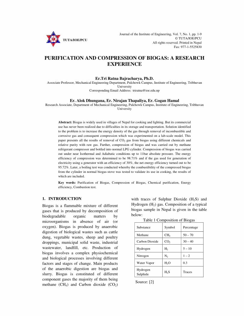
Figure 1 Chemical purification setup line diagram.
In figure 1, raw biogas is stored in
pressurized form at around 5 bar in the
pressure vessel, which is a 33 litres LPG
cylinder. Then the gas is allowed to pass at
low pressure around 10 kPa through the
chemical scrubbing system consisting alkali
solution. Chemical scrubbing system is
fabricated from a recycled 15 litres low
pressure gas cylinder. The gas is bubbled
from a perforated pipe dipped into the
solution for proper mixing. Gas then passes
from H2S scrubber and moisture absorber.
Flow of gas is measure from inline volume
flow meter. Finally the purified gas is stored
in a vehicle tube. Vehicle tube was chose for
(carbonic acid)
Journal of the Institute of Engineering 4
its advantage to be completely evacuated
refilling with different tests gases.
The flow meter is specified to measure the
flow of natural gas at a pressure of upto 10
kPa with a least count of 0.2 litres and can
measure accurately for a flow of 0.0025m3/hr
to 4 m3/hr. The pipes for the purification
setup were 1/4" flexible pipes connected
together using nipple, T-joint and metallic
globe valves.
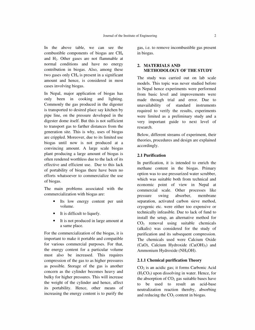
Apart from this setup for normal purification
experiment an additional setup was also used
with an ammonia entrapment mechanism as
shown in figure 2.
Figure 2 Line diagram for gas purification system using aqua ammonia.
This mechanism was used to restrict the
diffusion of Ammonia into biogas from
Ammonia solution. Utilizing the fact that
ammonia has a very high affinity towards
water compared to methane, a jar containing
water was taken and the outlet gas from the
chemical container passed through water as
shown in the figure below. Water would then
absorb ammonia from biogas.
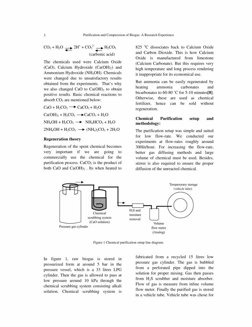
Furthermore to validate the regeneration of
the aqua ammonia, another setup as shown in
figure 3 was designed. Where the same
chemical scrubbing system or the low
pressure cylinder is heated and the gas
coming out is passed through ammonia
entrapment, and remaining CO2 is allowed to
escape in atmosphere. The solution was
heated for 10 minutes maintaining 80˚C
temperature.
Figure 3 Ammonia regeneration setup line diagram
To identify if we have regenerated chemical
or not, we had no other option than to use it
in boiling test under similar condition and
compare the value.
Gas purity testing
Due to unavailability of gas analyser,
calorific value of raw biogas and purified
biogas were compared. Since, only CH4 and
not CO2 contributes to the calorific value,
there exists a direct relation between the
volume of CH4 present in a given volume of
biogas and the corresponding calorific value
of the given biogas. Hence we can
NH3+CO2+vapor CO2
Purification and Compression of Biogas: A Research Experience
5
approximately identify percentage CH4 in
purified gas, assuming an initial standard
composition of raw biogas (60% CH4 and
40% CO2 in our case). The calorific value of
raw biogas measured should not be confused
with the standard value, as our value is
obtained in our laboratory condition.
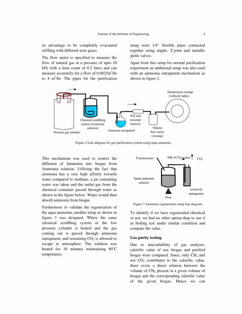
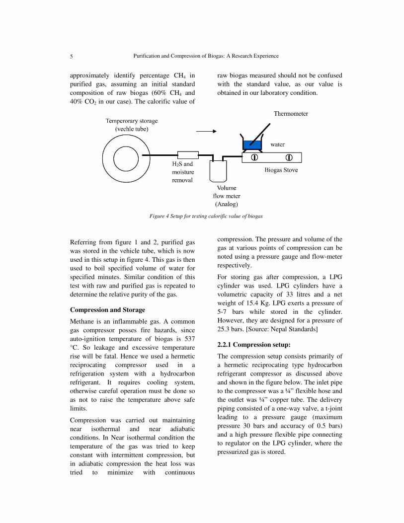
Figure 4 Setup for testing calorific value of biogas
Referring from figure 1 and 2, purified gas
was stored in the vehicle tube, which is now
used in this setup in figure 4. This gas is then
used to boil specified volume of water for
specified minutes. Similar condition of this
test with raw and purified gas is repeated to
determine the relative purity of the gas.
Compression and Storage
Methane is an inflammable gas. A common
gas compressor posses fire hazards, since
auto-ignition temperature of biogas is 537
°C. So leakage and excessive temperature
rise will be fatal. Hence we used a hermetic
reciprocating compressor used in a
refrigeration system with a hydrocarbon
refrigerant. It requires cooling system,
otherwise careful operation must be done so
as not to raise the temperature above safe
limits.
Compression was carried out maintaining
near isothermal and near adiabatic
conditions. In Near isothermal condition the
temperature of the gas was tried to keep
constant with intermittent compression, but
in adiabatic compression the heat loss was
tried to minimize with continuous
compression. The pressure and volume of the
gas at various points of compression can be
noted using a pressure gauge and flow-meter
respectively.
For storing gas after compression, a LPG
cylinder was used. LPG cylinders have a
volumetric capacity of 33 litres and a net
weight of 15.4 Kg. LPG exerts a pressure of
5-7 bars while stored in the cylinder.
However, they are designed for a pressure of
25.3 bars. [Source: Nepal Standards]
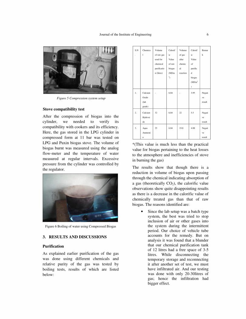
2.2.1 Compression setup:
The compression setup consists primarily of
a hermetic reciprocating type hydrocarbon
refrigerant compressor as discussed above
and shown in the figure below. The inlet pipe
to the compressor was a ¼” flexible hose and
the outlet was ¼” copper tube. The delivery
piping consisted of a one-way valve, a t-joint
leading to a pressure gauge (maximum
pressure 30 bars and accuracy of 0.5 bars)
and a high pressure flexible pipe connecting
to regulator on the LPG cylinder, where the
pressurized gas is stored.
Journal of the Institute of Engineering 6
Figure 5 Compression system setup
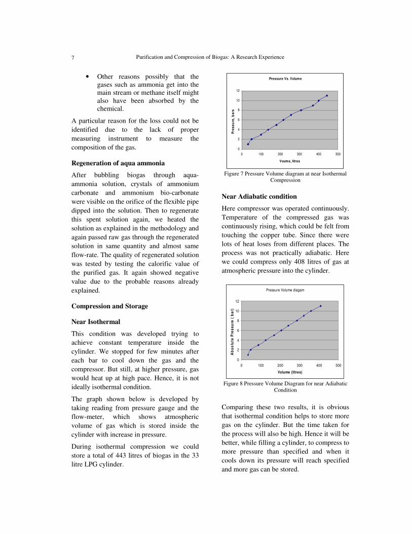
Stove compatibility test
After the compression of biogas into the
cylinder, we needed to verify its
compatibility with cookers and its efficiency.
Here, the gas stored in the LPG cylinder in
compressed form at 11 bar was tested on
LPG and Puxin biogas stove. The volume of
biogas burnt was measured using the analog
flow-meter and the temperature of water
measured at regular intervals. Excessive
pressure from the cylinder was controlled by
the regulator.
Figure 6 Boiling of water using Compressed Biogas
3. RESULTS AND DISCUSSIONS
Purification
As explained earlier purification of the gas
was done using different chemicals and
relative purity of the gas was tested by
boiling tests, results of which are listed
below:
*(This value is much less than the practical
value for biogas pertaining to the heat losses
to the atmosphere and inefficiencies of stove
in burning the gas)
The results show that though there is a
reduction in volume of biogas upon passing
through the chemical indicating absorption of
a gas (theoretically CO2), the calorific value
observations show quite disappointing results
as there is a decrease in the calorific value of
chemically treated gas than that of raw
biogas. The reasons identified are:
• Since the lab setup was a batch type system, the best was tried to stop inclusion of air or other gases into the system during the intermittent period. Our choice of vehicle tube accounts for the remedy. But on analysis it was found that a blunder that our chemical purification tank of 12 litres had a free space of 3-5 litres. While disconnecting the temporary storage and reconnecting it after another set of test, we must have infiltrated air. And our testing was done with only 20-30litres of gas; hence the infiltration had bigger effect.
S.N
.
Chemica
l
Volume
of raw gas
used for
chemical
purificatio
n (litres)
Calorif
ic
Value
of raw
biogas
(MJ/m
3)
Volume
of gas
after
chemic
al
reaction
Calorif
ic
Value
of
purifie
d
biogas
(MJ/m3
)
Remar
k
1. Calcium
Oxide
(lab
grade)
- 6.84 - 3.95 Negati
ve
result
2. Calcium
Hydroxi
de
32 6.84 22 5.5 Negati
ve
result
3. Aqua
Ammoni
a
25 6.84 19.8 4.88 Negati
ve
result
Purification and Compression of Biogas: A Research Experience
7
• Other reasons possibly that the gases such as ammonia get into the main stream or methane itself might also have been absorbed by the chemical.
A particular reason for the loss could not be
identified due to the lack of proper
measuring instrument to measure the
composition of the gas.
Regeneration of aqua ammonia
After bubbling biogas through aqua-
ammonia solution, crystals of ammonium
carbonate and ammonium bio-carbonate
were visible on the orifice of the flexible pipe
dipped into the solution. Then to regenerate
this spent solution again, we heated the
solution as explained in the methodology and
again passed raw gas through the regenerated
solution in same quantity and almost same
flow-rate. The quality of regenerated solution
was tested by testing the calorific value of
the purified gas. It again showed negative
value due to the probable reasons already
explained.
Compression and Storage
Near Isothermal
This condition was developed trying to
achieve constant temperature inside the
cylinder. We stopped for few minutes after
each bar to cool down the gas and the
compressor. But still, at higher pressure, gas
would heat up at high pace. Hence, it is not
ideally isothermal condition.
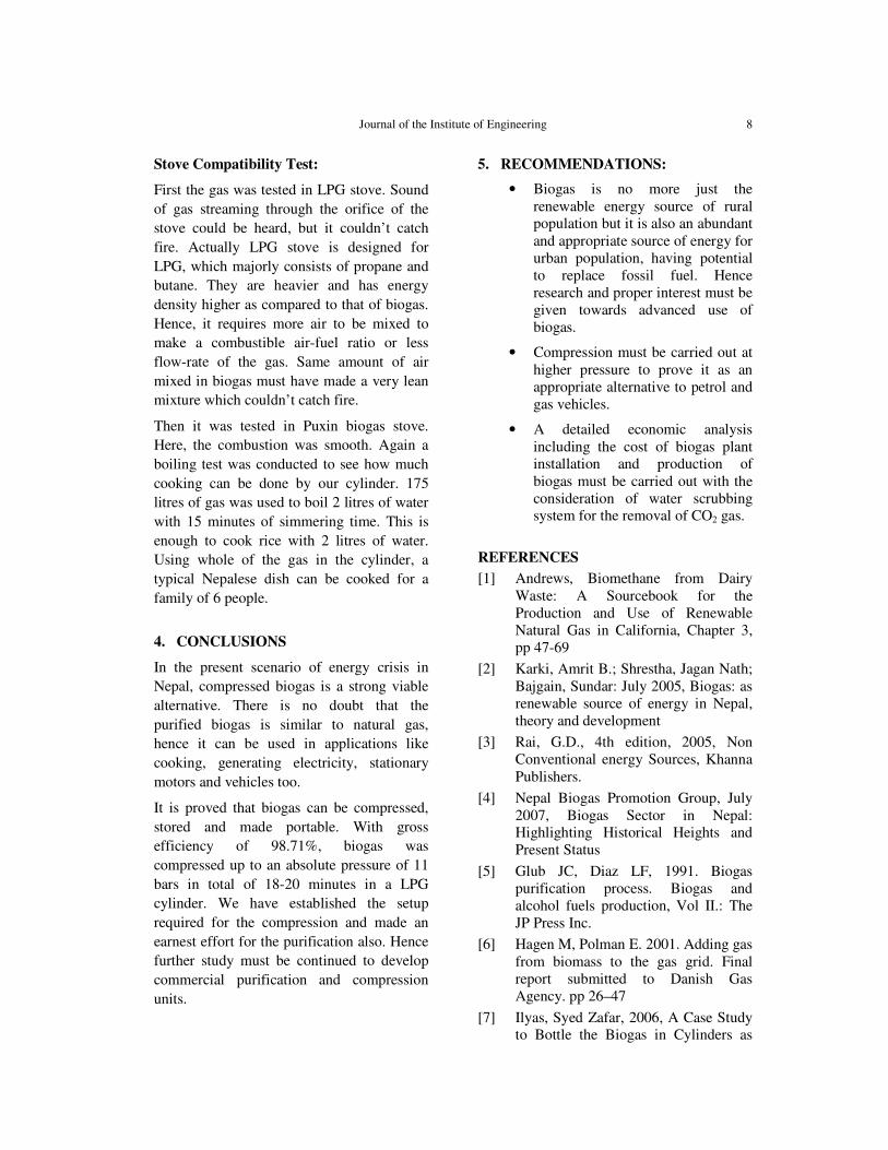
The graph shown below is developed by
taking reading from pressure gauge and the
flow-meter, which shows atmospheric
volume of gas which is stored inside the
cylinder with increase in pressure.
During isothermal compression we could
store a total of 443 litres of biogas in the 33
litre LPG cylinder.
Pressure Vs. Volume
0
2
4
6
8
10
12
0 100 200 300 400 500
Voume, litres
Pre
ss
ure
, b
ars
Figure 7 Pressure Volume diagram at near Isothermal
Compression
Near Adiabatic condition
Here compressor was operated continuously.
Temperature of the compressed gas was
continuously rising, which could be felt from
touching the copper tube. Since there were
lots of heat loses from different places. The
process was not practically adiabatic. Here
we could compress only 408 litres of gas at
atmospheric pressure into the cylinder.
Pressure Volume diagam
0
2
4
6
8
10
12
0 100 200 300 400 500
Volume (litres)
Ab
so
lute
Pre
ss
ure
( b
ar)
Figure 8 Pressure Volume Diagram for near Adiabatic
Condition
Comparing these two results, it is obvious
that isothermal condition helps to store more
gas on the cylinder. But the time taken for
the process will also be high. Hence it will be
better, while filling a cylinder, to compress to
more pressure than specified and when it
cools down its pressure will reach specified
and more gas can be stored.
Journal of the Institute of Engineering 8
Stove Compatibility Test:
First the gas was tested in LPG stove. Sound
of gas streaming through the orifice of the
stove could be heard, but it couldn’t catch
fire. Actually LPG stove is designed for
LPG, which majorly consists of propane and
butane. They are heavier and has energy
density higher as compared to that of biogas.
Hence, it requires more air to be mixed to
make a combustible air-fuel ratio or less
flow-rate of the gas. Same amount of air
mixed in biogas must have made a very lean
mixture which couldn’t catch fire.
Then it was tested in Puxin biogas stove.
Here, the combustion was smooth. Again a
boiling test was conducted to see how much
cooking can be done by our cylinder. 175
litres of gas was used to boil 2 litres of water
with 15 minutes of simmering time. This is
enough to cook rice with 2 litres of water.
Using whole of the gas in the cylinder, a
typical Nepalese dish can be cooked for a
family of 6 people.
4. CONCLUSIONS
In the present scenario of energy crisis in
Nepal, compressed biogas is a strong viable
alternative. There is no doubt that the
purified biogas is similar to natural gas,
hence it can be used in applications like
cooking, generating electricity, stationary
motors and vehicles too.
It is proved that biogas can be compressed,
stored and made portable. With gross
efficiency of 98.71%, biogas was
compressed up to an absolute pressure of 11
bars in total of 18-20 minutes in a LPG
cylinder. We have established the setup
required for the compression and made an
earnest effort for the purification also. Hence
further study must be continued to develop
commercial purification and compression
units.
5. RECOMMENDATIONS:
• Biogas is no more just the renewable energy source of rural population but it is also an abundant and appropriate source of energy for urban population, having potential to replace fossil fuel. Hence research and proper interest must be given towards advanced use of biogas.
• Compression must be carried out at higher pressure to prove it as an appropriate alternative to petrol and gas vehicles.
• A detailed economic analysis including the cost of biogas plant installation and production of biogas must be carried out with the consideration of water scrubbing system for the removal of CO2 gas.
REFERENCES
[1] Andrews, Biomethane from Dairy Waste: A Sourcebook for the Production and Use of Renewable Natural Gas in California, Chapter 3, pp 47-69
[2] Karki, Amrit B.; Shrestha, Jagan Nath; Bajgain, Sundar: July 2005, Biogas: as renewable source of energy in Nepal, theory and development
[3] Rai, G.D., 4th edition, 2005, Non Conventional energy Sources, Khanna Publishers.
[4] Nepal Biogas Promotion Group, July 2007, Biogas Sector in Nepal: Highlighting Historical Heights and Present Status
[5] Glub JC, Diaz LF, 1991. Biogas purification process. Biogas and alcohol fuels production, Vol II.: The JP Press Inc.
[6] Hagen M, Polman E. 2001. Adding gas from biomass to the gas grid. Final report submitted to Danish Gas Agency. pp 26–47
[7] Ilyas, Syed Zafar, 2006, A Case Study to Bottle the Biogas in Cylinders as
Purification and Compression of Biogas: A Research Experience
9
Source of Power for Rural Industries Development in Pakistan. World Applied Sciences Journal 1, Volume 2, ISSN 1818-4952, IDOSI Publications pp 27-130
[8] Resnik, K.P., Yeh, J.T. and Pennline, H.W. 2004 Aqua ammonia process for simultaneous removal of CO2, SO2 and NOx, International Journal Environmental Technology and Management, Vol. 4, Nos. 1/2, pp.89–104.
[9] S.S. Kapdi, V.K. Vijay, S.K. Rajesh, Rajendra Prasad, Posted 8 May 2003; accepted 23 September 2004, Biogas scrubbing, compression and storage: perspective and prospectus in Indian context
[10] Wise DL, Boca Raton, 1981. Analysis of systems for purification of fuel gas. Fuel gas production from biomass, Volume 2, FL: CRC Press
[11] Nepal Beaurea of Standards and Measurements (NBSM), 1998, Code of practice for L.P. Gas cylinders. Gorkha Prints
Websites
[12] http://www.cirmac.com
[13] http://www.fao.org