Embed Size (px)
Citation preview

Registration of motion-distorted interlaced imagescaptured by a scanning vector imaging sensor
A. Avrin, A. Stern, and N. S. Kopeika
We present an algorithm to realign images distorted by motion and vibrations captured in cameras thatuse a scanning vector sensor with an interlaced scheme. In particular, the method is developed for imagescaptured by a staggered time delay and integration camera distorted by motion. The algorithm improvesthe motion-distorted image by adjusting its fields irrespective of the type of motion that occurs during theexposure. The algorithm performs two tasks: estimation of the field relative motion during the exposureby a normal least-squares estimation technique and improvement of the degraded image from suchmotion distortion. The algorithm uses matrix computations; therefore it has a computation advantageover algorithms based on the technique of searching for a match. The algorithm is successfully demon-strated on both simulated and real images. © 2006 Optical Society of America
OCIS codes: 100.0100, 280.0280, 100.2000, 100.6640, 110.3080, 110.6820.
1. Introduction
In this work we consider the motion and vibrationdegradation of images captured by staggered timedelay and integration (TDI) cameras.1,2 The vibrationof the camera may be caused by several sources, suchas internal electrical cooling systems or vibration ofthe imaging platform when installed on a vehicle oraircraft. We analyze the vibration degradation anddevelop a motion restoration algorithm of images cap-tured with scanning interlaced vector sensors such asthe staggered TDI camera.
The TDI camera,1,2 based on a moving vector sen-sor for 1D image scanning, has been designed toachieve high-quality images under low-light-levelimaging conditions. A high signal-to-noise ratio(SNR) is achieved by a long effective exposure time.A typical TDI sensor is constructed from multipleadjacent vector sensors. During the scanning alongthe horizontal direction, the charges accumulatedin each photosensitive cell are transferred oppositeto the scan direction in the appropriate cell of the
subsequent sensor column. A summation of thecharges containing the same object information isdone to obtain an effective long exposure.2 Becauseof manufacturing limitations, TDI cameras oftenuse a composite frame format by interlacing twofields captured with a significant time differencebetween them. This special format of image acqui-sition together with the relatively long effective ex-posure time may cause a significant degradation ofimages captured with vibrating TDI cameras. InSection 2 we provide a more detailed description ofstaggered TDI camera operation principles and theimage degradation induced by mechanical motion.
The image degradation caused by camera motionor vibrations has been investigated previously.3,4
Various image restoration methods have been devel-oped depending on the type of motion and on the apriori information. Typically, those methods were de-veloped for space-invariant distortions encounteredwith imaging systems using focal plane arrays sub-ject to global motion. In Section 2 we show that themotion degradation of images captured with a stag-gered TDI camera is highly space variant; thereforethose methods are not applicable here.
In this work, we consider imaging systems that usea composite frame format, that is, images composedby two interlaced fields.5 This kind of image may bedistorted by two types of motion distortion. The firstis the edge staircase caused when the object appearsin different places in two fields. The second is themotion blur caused by the nonstationarity of the cam-era during the exposure of each field. The motion
The authors are with Ben-Gurion University of the Negev, Beer-Shiva, 84105, Israel. A. Avrin is with the Department of Electricaland Computer Engineering. A. Stern ([email protected]) is with theDepartment of Electro-Optical Engineering. N. S. Kopeika is withboth the Department of Electrical and Computer Engineering andthe Department of Electro-Optical Engineering.
Received 20 June 2005; revised 4 December 2005; accepted 10February 2006; posted 16 February 2006 (Doc. ID 62907).
0003-6935/06/235950-10$15.00/0© 2006 Optical Society of America
5950 APPLIED OPTICS � Vol. 45, No. 23 � 10 August 2006

distortion and blur can be quite significant in low-luminance imaging systems with long exposure timeand also in short-time-exposure systems imple-mented on fast-moving platforms like cars, tanks,aircraft, or ships. In Ref. 5, an algorithm is proposedthat restores the two types of composite frame deg-radation for the case of global linear relative motionbetween the camera and the object. Reference 6 pre-sents a restoration algorithm for staggered TDI im-ages blurred by vibrations caused by the sensorcooling system or due to object motion during theexposure. The restoration in Ref. 6 is based on ablock-matching algorithm. In Ref. 7 a general resto-ration technique for staggered TDI images acquiredin the presence of mechanical vibrations was devel-oped. A differential technique was used for the mo-tion estimation. To restore the degraded image, amethod based on projections on the convex sets wasused. Both in Refs. 6 and 7 an iterative method wasused for motion estimation. Here we present a direct,noniterative algorithm for degraded staggered TDIimage restorations. Therefore the algorithm proposedhere is appropriate for real-time systems.
The algorithm developed in this work performs twosteps: the estimation of field-relative motion duringthe exposure and the restoration of the degraded im-age from such motion distortion. The restoration im-age algorithm is based on a solution of normal least-squares (NLS) equations to evaluate a filter thatmatches blocks in one image field to another. Thelocal image displacement information is embedded inthe estimated filter. Therefore the filter estimation
process is equivalent to the motion estimation pro-cess performed in common motion image restorationalgorithms. The filter estimation is performed re-gardless of the type of motion that occurs during theexposure. By using the estimated filters a registra-tion process is performed to improve the capturedimage quality; the image fields are properly alignedone to another. The entire process is done by matrixcomputations, which gives the proposed algorithm acomputation speed advantage over any system basedon searching for a match technique.
The algorithm was examined both on simulatedmotion-distorted images and on real images capturedwith the TADIR high-resolution thermal imaging sys-tem in the 8 to 13 �m wavelength band manufac-tured by ELOP (Electro Optics Systems, Limited,Rehovot, Israel). A mathematical model of the imag-ing process in the presence of any type of motion wasdeveloped and used for the simulation of motion-degraded images. The simulated images were used toevaluate numerically the performance of the motionestimation and restoration algorithm. The results ofthe simulation show that the algorithm works suc-cessfully and almost independently of the additivenoise. The overall algorithm was implemented onreal images and presented clear visual improvement.The performance of the image restoration algorithm
Fig. 1. Sensor structure illustration: (a) TDI sensor, (b) staggeredTDI. M is the number of sensor rows.
Fig. 2. Scanning process to acquire one pixel with TDI.
Fig. 3. Illustration of the TDI imaging process.
10 August 2006 � Vol. 45, No. 23 � APPLIED OPTICS 5951

was also verified by its implementation in electronichighly zoomed images, where the motion distortion ismost severe and, consequently, the improvement of
the resolution because of the proposed algorithm ismost evident.
2. Definition of the Problem
A. Time Delay and Integration Structure
To understand the complexity of the problem, wedescribe the imaging process using a TDI camera.Figure 1 depicts a TDI sensor constructed of M sensorrows of N photocells each. It can be viewed as Nadjacent vector sensors, each having M pixels, de-signed to scan the scene in the horizontal direction.Each row generates one image pixel. Figure 2 illus-trates the TDI process for capturing one pixel. Duringthe imaging process each cell is exposed to light, andthe charge accumulated in it according to the lightintensity is transferred to the following cell. Thecharge is transferred at the same velocity as the vec-tor is scanning, in an opposite direction. The processcontinues until the Nth cell is exposed and it accu-
Fig. 4. Space variance of motion image degradation. Two blocks ofthe image are enlarged to demonstrate the different types of dis-tortion in different parts of the image.
Fig. 5. Schematic representation of horizontal registration algorithm; horizontal shift between image fields and appropriate filtercoefficients. From the K � (N�2) block (matrix G) of the odd field (upper left) and the ith column of the even field (upper right) the coefficientparameters of the shifting filter hi are calculated. Then filtration of the G matrix performed to estimate the ith column in the field F2
to the appropriate column in the field F1. Three examples of filters are shown for horizontal displacements s of 0, 1, and �2 pixels.
5952 APPLIED OPTICS � Vol. 45, No. 23 � 10 August 2006

mulates all N charges representing the value of oneimage pixel. The process thus involves integration ofthe light intensity returned from the object andtranslated into the electric charge.
The staggered sensor has a structure in which theodd and the even sensors are horizontally separated,as described in Fig. 1(b). The odd rows are shiftedwith regard to the even rows. Because of the stag-gered structure a time delay exists between the ac-quisition of the even and odd image fields.
The main advantage of the TDI camera is that it issensitive to very low light levels and it has high gray-scale resolution. Its main drawback is that the longintegration time causes image degradation and im-age blur if the objects or the camera are in motion.
B. Time Delay and the Integration Imaging Process
Let us denote the object continuous field by f(x, y) andthe captured image by g�k, m� (Fig. 3). Consider theTDI camera motion remainder during imaging ofpixel (k, m) described by curve �k,m�t�. The motionremainder means the motion of the camera withoutthe scanning term, which is assumed to be automat-ically compensated for by the charge translation. Theoverall point-spread function (PSF) of the system,describing its optics, electronics, and sensor, is de-noted by h0�x, y�. If the imaging system is mechani-cally stable, then each image pixel (k, m) sees the
object through a window h0�x, y� centered at location(k, m). Mathematically the image is modeled as asimple convolution of the object field and the PSF.However, if the imaging system moves or vibrates,each image pixel sees the object through h0 over atrajectory �k,m�t� determined by the motion of theimaging system during the acquisition of pixel (k, m).Mathematically the process can be expressed by thefollowing integral:
g�k, m� �1K�
tk,m�te
tk,m ���x,y��Rh�x1,y1��x1,y1���k,m�t�
h0�x � x1, y � y1�
� f�x, y�dxdy�dt, (1)
where �k,m�t� is the trajectory of the sensor’s motionduring the acquisition of pixel �k, m�, tk,m is the initialmoment of exposure, te is the integration duration ofthe N cells, and R�hx1,y1
� is the region of support of theh0�x, y� function (the effective region of the system’sPSF) centered on the points of the �k,m�t� trajectory. Kis a normalization coefficient, depending on the PSFh0 and on the integration time te, given by
Fig. 6. Illustration of the vertical relative motion estimation. Two fields of the image are shown schematically at the top. At the bottomthe process of building a matrix G for vertical relative motion estimation is illustrated.
10 August 2006 � Vol. 45, No. 23 � APPLIED OPTICS 5953

K � te� h0�x, y�dxdy. (2)
It is evident from Eq. (1) that the system is stronglyspace variant; therefore most image restoration meth-ods previously developed for linear space-invariant(LSI) systems are not adequate to solve this problem.
3. Motion Estimation
Motion is often the fundamental source of image deg-radation. To model the image motion and evaluate it,an understanding of the whole imaging process isrequired. In general, image motion is caused by 3Dmotion of the objects and�or by camera vibration.Therefore the camera’s parameters, such as its spacemotion (rotation and translation) or focal length, playa notable role in the process of motion estimation
from the image. If these parameters are known, onlythe object space motion has to be identified. However,this situation is rare; usually we consider imageswith both the camera and the object motions un-known.8 The spatial motion is reflected as a 2D mo-tion in the image plane. Motion estimation in imagesequences is used widely in video processing,9 com-pression,10 and various other fields concerning highcorrelation between sequential images.11–13
Motion estimation algorithms have three mainsteps.8 In the first step, an appropriate motion modelneeds to be considered. Choosing the model and itsparameters depends on the implementation. Thenthe criteria of estimation have to be set. For example,it can be expressed as the mean-square error (MSE)of the block or as a robust criterion that uses satura-tion for the large errors. The third is the strategychosen or the way of computing the parameters of themodel by minimizing the estimation criteria. Themost common motion estimation algorithms are dif-ferential methods7,8,14 and matching techniques.6,8,14
4. Proposed Algorithm
As explained in Section 2, most of the existing motionestimation methods are not appropriate for the casediscussed here. These algorithms were built to esti-mate motion in sequences of images based on a highcorrelation between the sequential images, whereashere only two fields of one image are available. Mostrelated classes of motion estimation algorithms arebased on searching for a technique to match blocks intwo consecutive images. Here we propose an algo-rithm to restore staggered TDI images based on find-ing a filter that defines the relation between columnsor rows in the odd and even field.
Figure 4 demonstrates the shift-variant nature ofthe degradation caused by motion in the staggeredTDI image. We have enlarged two blocks of the imageto demonstrate the different degradation in differentparts of the image. It can be seen that the electric poleat the right of the image is quite straight, whereasthe one on the left is not. A severe staircase effect canbe seen on the left pole, whereas on the right pole itis negligible. Hence the space-variant nature of theimage is evident. The purpose of our work is to builda high-speed registration algorithm for images dis-torted by space-variant degradation of the typeshown in Fig. 4.
The principle of the proposed algorithm is as follows.We assume that for each image row or column i in theodd field there exists a linear filter hi that relates it tothe respective row or column in the even field. Tosolve the registration problem we look for a shiftingfilter, i.e., a filter that shifts the pixels of one field tothe appropriate location in the second field. Figure 5shows schematically the horizontal registration pro-cess. Using a K-column block of the odd field and theith column of the even field, a vector filter hi that hasK coefficients is calculated. Then the K columns in theodd field (the G matrix in Fig. 5) are inverse filteredto move the pixels of the ith column of the odd field to
Fig. 7. (a), (c) Estimated filter coefficients (vertical) as a functionof time (horizontal) and (b), (d) the same parameters in the shift inpixels units; white pixels represent the shift of the column relativeto the appropriate column of the second field.
5954 APPLIED OPTICS � Vol. 45, No. 23 � 10 August 2006

their appropriate location according to the referencein the even field.
Let us consider, for example, a horizontal shift of spixels between the image fields, as illustrated in Fig.5. In Fig. 6 the region of K � 5 columns around the ithcolumn of field F1 is chosen to form the matrix G. Nowwe would like to find a filter that shifts the field F2 toits previous location relative to F1; i.e., for every col-umn i of F1 we want to find a filter hi that, whenapplied on the block G [the matrix of size K ��N�2�], the column i of F2 is obtained. The vertical sizeof G is N�2 because only one field (odd or even) hav-ing N rows is used. The filter coefficients are calcu-lated by the NLS method, which is briefly describedin Subsection 4.A. If, for example, the estimated filtercoefficients are hi � �1 0 0 0 0�, then the ithcolumn in the reference field needs to be shifted twocolumns to the right. In practice, hi is not a pure deltafunction because the displacement may not be aninteger number of pixels and because there might beother distortion sources. In such a case the local dis-placement vector is defined by the location of themaximum value of hi (for instance, if the estimatedfilter is hi � �0.7 0.1 0.05 0.05 0.1�, then the
displacement is approximated as �2 pixels). Resto-ration examples are presented in Section 5.
A. Normal Equations for the Least-Squares Problem
To match a linear model to the set of observationsy�n�,1 � n � N, using the sequences x1�n�,x2�n�, . . . , xm�n�, 1 � n � N, the solution of the NLSproblem can be explored.15 In our case the sequencexi�n� represents the pixels in the G matrix in fieldF1, and the set of observations are the column pixel infield F2 (Fig. 5). The linear model can be described bythe set of parameters �ii�1
N. The estimated signaly�n� is the linear combination of xi�n� approximatingthe y[n]:
y�n� � �1x1�n� � �2x2�n� � · · · � �mxm�n�,1 � n � N. (3)
The sum of squared errors is commonly used as acriterion for approximation quality:
E � �n�1
N
e�i�2, (4)
where e�i� � y�n� � y�n�. Defining the matrix X, andvectors y, �, e as
the error vector is written e � y � X�. Then the sumof squared errors is
X � �x1�1� x2�1� · · · xm�1�x1�2� x2�2� · · · xm�2�
É É Ì É
x1�N� x2�N� · · · xm�N� , y � �
y�1�y�2�É
y�N� , ���
�1
�2
É
�m
, e � �e�1�e�2�É
e�N� , (5)
Fig. 8. Algorithm diagram.
10 August 2006 � Vol. 45, No. 23 � APPLIED OPTICS 5955

E � eHe � yHy � yHX� � �HXXHy � �HXHX�, (6)
where the superscript H denotes the Hermitian con-jugate. The optimal value of � is calculated by settingthe error derivative to zero,
E�
� �XHy � XHy � 2XHX� � 0, (7)
yielding the equation commonly known as the normalequation for the least-square (LS) problem:
XHX� � XHy. (8)
If the XHX matrix is not singular then the solution ofEq. (6) is given by
���XHX��1XHy, (9)
and the minimal value of the error is
Emin � yHy � yHX�. (10)
From the matrix Emin the coefficient vector � can beobtained through the following equation:
�yHy yHXXHy XHX�� 1
���� �Emin
Om�. (11)
An alternative way to obtain Eqs. (7)–(9) is to use theorthogonality principle.16
B. Pseudoinverse Matrix
Equation (9) involves matrix inversion. For matri-ces that do not have a full rank a pseudoinversematrix is usually calculated based on singular valuedecomposition With X being a matrix of size L �M and rank W,
AHXB � �� OO O�,
Fig. 9. (a) Original image, (b) image after simulation of staggeredTDI imaging process, and (c) reconstructed image.
Fig. 10. Relative vertical and horizontal motion function estima-tion. (a) Vertical and (b) horizontal relative motion between imagefields. Vertical axis units are pixels; horizontal axis units are col-umn numbers, which are relative to time because of constant-velocity horizontal scanning.
5956 APPLIED OPTICS � Vol. 45, No. 23 � 10 August 2006

its pseudoinverse pare, denoted by X# is
X# � A���1 OO O�BH, (12)
where ��1 � diag��1�1, �2
�1, . . . , �w�1�. If X is col-
umn full rank matrix, then
X# � �XHX��1XH, (13)
and if it is a row full rank matrix, then
X# � XH�XXH��1. (14)
Considering X� � y, the LS solution of this equationis �. If X is not of full column rank, then the solutionis not unique. However, of all solutions to the NLSproblem, � is the one with the minimum Euclidiannorm; it has a minimum MSE.
C. Implementation
The principle of the restoration algorithm is to findfilters that can adjust one field of the image to an-other by solving the NLS equations. The vertical andhorizontal components of the relative motion functionare found independently. But to reduce the influenceof the vertical motion term on the fields, verticalsmoothing was performed by applying a low-pass fil-ter (LPF). The LPF was chosen to be the same size asthat of the estimation filter hi and it filled the maxi-mal expected shift between the fields.
For estimation of the horizontal motion component,the following process is performed. The TDI image is
of the size N � M, so every field has N�2 � M pixels.From every K column of the odd image field, as shownin Fig. 5, the set of coefficients �ii�1
n is calculated byusing the NLS method. The registration is done byinverse filtering using the estimated filter.
The principle of the vertical motion estimation istransposing parts of the columns and applying thesame procedure as for horizontal estimation. Fromevery column of the even image field the matrix G isconstructed, and it is used to compute one appropri-ate column of the odd image field. The construction ofthe matrix is as shown in Fig. 6. Every K pixel ofcolumn i forms a row of the G matrix in the followingway. The first K pixels form the first row of the Gmatrix, the pixels from the second to �K � 1� form itssecond row, and so on. The solution is the systemcoefficients, obtained from computing a pseudoin-verse matrix. As in the previous case they are trans-lated to units of pixel shift.
Figure 7 shows the result of filter coefficient cal-culations in the 2D motion estimation process.Since, as explained in Section 4 and in Fig. 5, thelocation of the largest estimated filter coefficientrepresents the local displacement between thefields, Fig. 7 depicts indirectly the estimated mo-tion. Figures 7(a) and 7(c) show the estimated filtercoefficients as calculated by the pseudoinverse ma-trix solution, presented in the gray-level units. Fig-ures 7(b) and 7(d) show the maximum values ofthese parameters in pixel shift units. The graphs inFigs. 6(b) and 6(d) are in agreement with the motionduring the simulation of image acquisition, whichwas x�n� � Kn, y�n� � A sin�2�fn�, where K� 8�512, A � 2, and f � 0.005.
Fig. 11. Dependence of horizontal and vertical motion estimation RMSE as a function of SNR. It can be seen that the horizontal motionestimation performance is more sensitive to the amount of noise added. Vertical estimation precision remains almost unchanged.Horizontal RMSE is similar to the horizontal RMSE at low noise levels. At high noise levels the horizontal RMSE increases but remainsless than approximately 0.7 pixels even for a very high amount of noise added.
10 August 2006 � Vol. 45, No. 23 � APPLIED OPTICS 5957

D. Image Registration
The complete reconstruction algorithm is shownin Fig. 8. First, the two fields of the TDI image areseparated. Then the odd image field enters the hori-zontal reconstruction filter (HRF) block and then en-ters the vertical reconstruction filter (VRF) block,where the HRF and the VRF are two matrices of filtercoefficients obtained in the motion estimation processfor horizontal and vertical relative motion term esti-mations, respectively. By combining the two result-ing images, the improved TDI image is obtained.
5. Restoration Examples
A. Restoration of Simulated Images
To evaluate the algorithm performance and to checkthe quality of the motion estimation, we have simu-lated images appropriate to a staggered TDI system.The stages of the distortion and reconstruction pro-cess are illustrated in Fig. 9. In Fig. 9(a) the originalimage is presented. It consists of the high-resolutionundistorted image. An artificial grid is added to vi-sualize the motion influence during the simulation
process. Figure 9(b) shows the same image after stag-gered TDI imaging process simulation, and Fig. 9(c)shows the restored image. In Figs. 9(a) and 9(b) thedegradation of the images can be seen. The effect ofmotion can be seen from the undulation of the arti-ficial grid added. The undulation can be removed byextending the algorithm to detect specific featuressuch as straight lines and using them for restoration.In this work, the reconstruction algorithm is re-stricted to aligning the fields only to keep the com-putational burden low. As shown in Subsection 5.B,even with this restriction the reconstruction is quitesatisfactory.
In Fig. 10 a comparison between the original mo-tion function and the estimated motion using theproposed algorithm is shown. It is evident that thedeviation between the two functions is not signifi-cant. The root-mean-square error (RMSE) of the mo-tion estimation in the vertical direction is 0.24 pixels,and in the horizontal direction it is 0.093 pixels.
To examine the robustness of the algorithm weadded white noise to the image during the simula-tion process. Images with SNRs typical of thermalimages were generated. The dependence of the mo-tion estimation RMSE on the image SNR is shown inFig. 11. It can be seen that the RMSE is approxi-mately constant up to a SNR value of 15 dB (Fig. 11)in horizontal and vertical motion estimation in thenoisy images. The vertical motion estimation perfor-mance is less sensitive to the amount of noise addedthan to the horizontal motion. This is attributed tothe fact that the horizontal estimation is performedon the raw data, whereas the vertical estimation isperformed on horizontally registered fields; thereforeit is more precise. The vertical estimation precisionremains almost unchanged. It can be seen that evenfor very noisy images the vertical motion estimationRMSE remains approximately 0.3 pixels, and thehorizontal displacement estimation is less then 0.65pixels. Thus subpixel precision motion estimation isobtained.
B. Restoration of Real Images
In this section we present the result of application ofthe proposed algorithm on real TDI images. The im-ages were captured with a high-resolution TADIRthermal imaging system of the staggered TDI type.Despite the high level of performance of the camera,vibration distortions as shown in Fig. 4 may occurwith high optical magnification. Such distortions mayoccur even in stabilized conditions due to vibrationcaused by its internal sensor cooling system. In Fig.12(b) the registration of the image shown in Fig. 4 bythe proposed algorithm is shown. It can be seen thatmotion degradation is removed completely. As a re-sult, the image is much clearer and more details canbe recognized.
The performance of the algorithm was also exam-ined on electronically zoomed images, on which theinfluence of motion on resolution is more severe. Fig-ure 13 demonstrates the improvement of electronicallyzoomed images by the proposed registration algorithm.
Fig. 12. Restoration of a motion-degraded staggered TDI image.(a) Degraded and (b) restored images.
5958 APPLIED OPTICS � Vol. 45, No. 23 � 10 August 2006
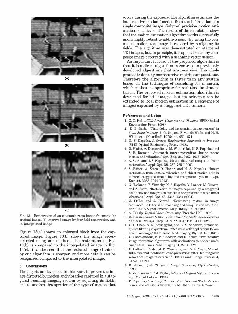
Figure 13(a) shows an enlarged block from the cap-tured image. Figure 13(b) shows the image recon-structed using our method. The restoration in Fig.13(b) is compared to the interpolated image in Fig.13(c). It can be seen that the restored image obtainedby our algorithm is sharper, and more details can berecognized compared to the interpolated image.
6. Conclusions
The algorithm developed in this work improves the im-age distorted by motion and vibration captured in a stag-gered scanning imaging system by adjusting its fields,one to another, irrespective of the type of motion that
occurs during the exposure. The algorithm estimates thelocal relative motion function from the information of asingle composite image. Subpixel precision motion esti-mation is achieved. The results of the simulation showthat the motion estimation algorithm works successfullyand is highly robust to additive noise. By using the esti-mated motion, the image is restored by realigning itsfields. The algorithm was demonstrated on staggeredTDI images, but, in principle, it is applicable to any com-posite image captured with a scanning vector sensor.
An important feature of the proposed algorithm isthat it is a direct algorithm in contrast to previouslydeveloped algorithms that are recursive. The wholeprocess is done by nonrecursive matrix computations.Therefore the algorithm is faster than any systembased on the technique of searching for a match,which makes it appropriate for real-time implemen-tation. The proposed motion estimation algorithm isdeveloped for still images, but its principle can beextended to local motion estimation in a sequence ofimages captured by a staggered TDI camera.
References and Notes1. G. C. Holst, CCD Arrays Cameras and Displays (SPIE Optical
Engineering Press, 1998).2. D. F. Barbe, “Time delay and integration image sensors” in
Solid State Imaging, P. G. Jespers, F. van de Wiele, and M. H.White, eds. (Noordhoff, 1976), pp. 659–671.
3. N. S. Kopeika, A System Engineering Approach to Imaging(SPIE Optical Engineering Press, 1998).
4. O. Hadar, A. Kuntsevitsky, M. Wasserblat, N. S. Kopeika, andS. R. Rotman, “Automatic target recognition during sensormotion and vibration,” Opt. Eng. 34, 3062–3068 (1995).
5. A. Stern and N. S. Kopeika, “Motion-distorted composite-framerestoration,” Appl. Opt. 38, 757–765 (1999).
6. S. Raiter, A. Stern, O. Hadar, and N. S. Kopeika, “Imagerestoration from camera vibration and object motion blur ininfrared staggered time-delay and integration systems,” Opt.Eng. 42, 3253–3264 (2003).
7. G. Hochman, Y. Yitzhaky, N. S. Kopeika, Y. Lauber, M. Citroen,and A. Stern, “Restoration of images captured by a staggeredtime delay and integration camera in the presence of mechanicalvibrations,” Appl. Opt. 43, 4345–4354 (2004).
8. C. Stiller and J. Konrad, “Estimating motion in imagesequences—a tutorial on modeling and computation of 2D mo-tion,” IEEE Signal Process. Mag. 16(4), 70–91 (1999).
9. A. Tekalp, Digital Video Processing (Prentice Hall, 1995).10. Recommendation H.261: Video Codec for Audiovisual Services
at p � 64 kbits�s.” Rep. COM XV-R 37-E (CCITT, 1989).11. C. L. Chan, A. K. Katsaggelos, and A. V. Sahakian, “Image se-
quence filtering in quantum-limited noise with applications to low-dose fluoroscopy,” IEEE Trans. Med. Imaging 12, 610–621 (1993).
12. C. Charalambous, F. K. Ghaddar, and K. Kouris, “Two iterativeimage restoration algorithms with applications to nuclear medi-cine,” IEEE Trans. Med. Imaging 11, 2–8 (1992).
13. H. Soltanian-Zadeh, J. P. Windham, and A. E. Yagle, “A mul-tidimensional nonlinear edge-preserving filter for magneticresonance image restoration,” IEEE Trans. Image Process. 4,147–161 (1995).
14. B. Jähne, Spatio-Temporal Image Processing (Spring-Verlag,1993).
15. G. Zelniker and F. J. Taylor, Advanced Digital Signal Process-ing (Marcel Dekker, 1994).
16. P. Papoulis, Probability, Random Variables, and Stochastic Pro-cesses, 2nd ed. (McGraw-Hill, 1985), Chap. 13, pp. 407–476.
Fig. 13. Registration of an electronic zoom image fragment: (a)original image, (b) improved image by four-field registration, and(c) interpolated image.
10 August 2006 � Vol. 45, No. 23 � APPLIED OPTICS 5959