Embed Size (px)
Citation preview
TECHNICAL REPORTS FOR 1989-1990 APPliED GEOLOGY PROGRAM
compiled by
Bill D. Black
UTAH GEOLOGICAL A..~1) !\1P'ERU SURVEY a division of UTAH DEPARTIvfE~~ OF NATURAL RESOURCES REPORT OF 11'-"'\LSTIGATIO~ 220 1990
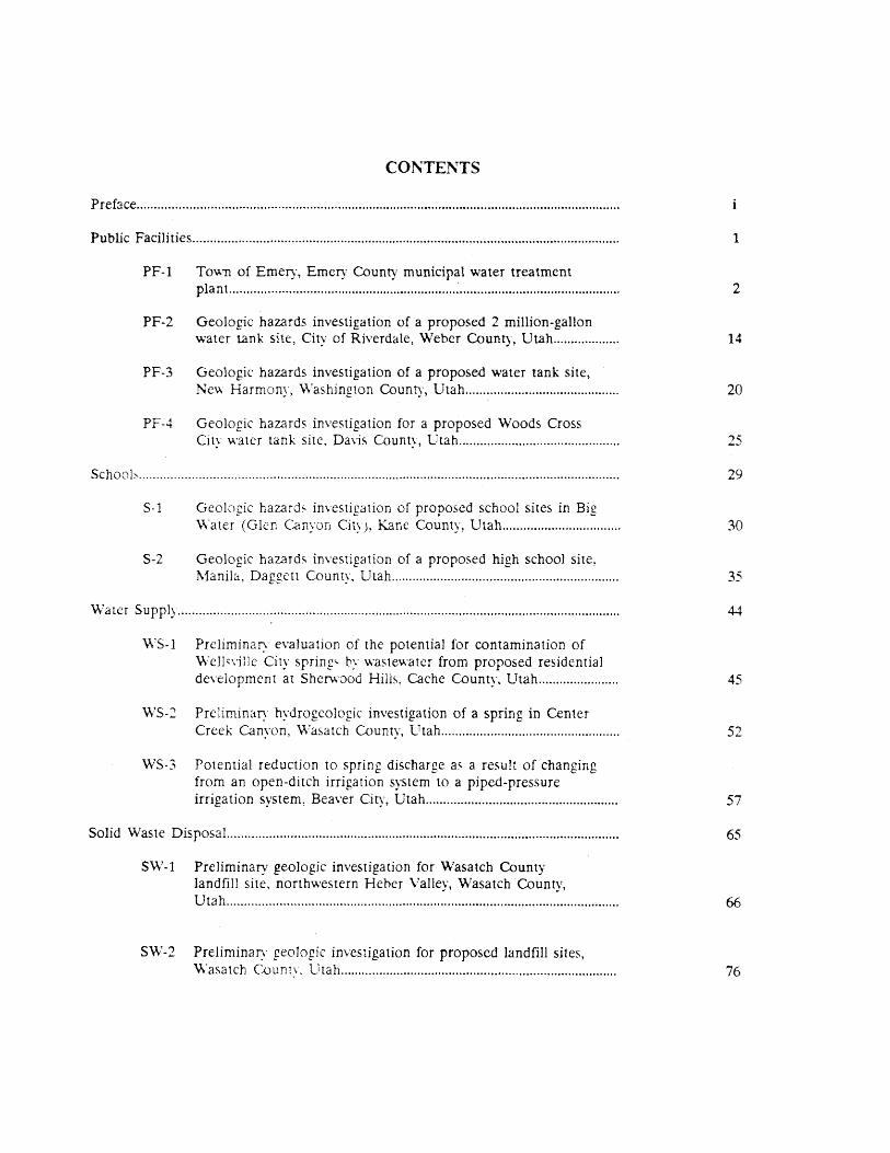
CO~TENTS
Preface ......................................................................................................................................... .
Public Facilities ......................................................................................................................... .
PF-1 TO'wn of Emery, Emery County municipal water treatment plant. ............................................................................................................. ..
PF-2 Geologic hazards investigation of a proposed 2 million-gallon water tank site, City of Riverdale, Weber County, Utah ................. ..
PF-3 Geologic hazards investigation of a proposed water tank site, New Harmony, \Vashington County, Utah ........................................... .
PF-4 Geologic hazards investigation for a proposed Woods Cross City water tank site. Davis County, Utah ............................................ ..
School" ........................................................................................................................................ .
5-1 Geologic hazard5- investigation of proposed school sites in Big \Vater (Glen Canyon City), Kane County, Utah ................................. .
S-2 Geologic hazard~ investigation of a proposed high school site, J\1anib, Daggett County. Utah ................................................................ .
\\7a ter Supply ............................................................................................................................. .
\\'S-1 Preliminary evaluation of the potential for contamination of \Vell'\'ilJe City spring" by wastewater from proposed residential development at Sherwood Hills, Cache County, Utah ...................... .
\\'S-2 Preliminary hydrogeologic investigation of a spring in Center Creek. Canyon, \\7asa tch County, lTtah .................................................. .
WS-3 Potential reduction to spring diSCharge a" a result of changing from an open-ditCh irrigation system to a piped-pressure irrigation system, Beaver City, Utah ..................................................... ..
Solid Waste Disposal ............................................................................................................... .
$\\'-1 Preliminary geologic investigation for Wasatch County landfill site, northwestern Heher Valley, Wasatch County, Utah .............................................................................................................. ..
S\\7-2 Preliminary geoJogic investigation for proposed landfill sites, \\'asatch CDunly. lltah .............................................................................. .
1
2
14
20
25
29
30
35
45
52
57
65
66
76
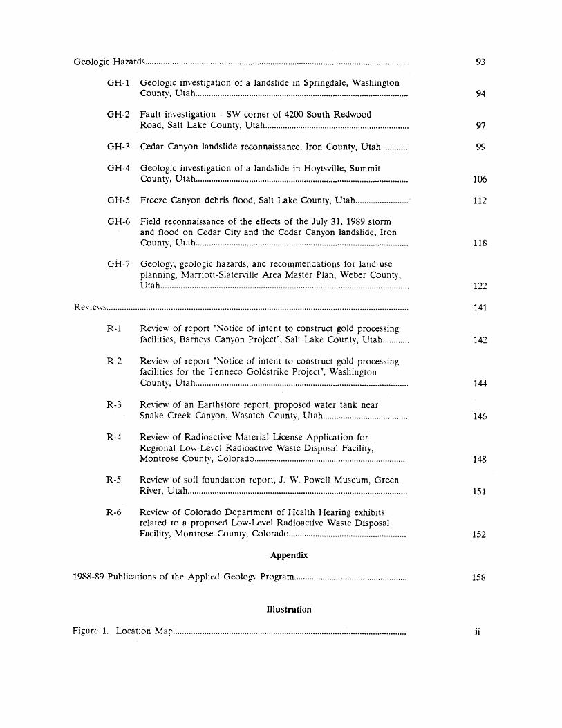
Geologic .Hazards ............................................................... · ..................................................... ..
GH-1 Geologic investigation of a landslide in Springdale, Washington County, Utah ............................................................................................... .
GH-2 Fault investigation - SW corner of 4200 South Redwood Road, Salt l..ake County, Utah ................................................................ .
GH-3 Cedar Canyon landslide reconnaissance, Iron County, Utah ........... .
GH-4 Geologic investigation of a landslide in Hoytsville, Summit County, Utah ............................................................................................... .
GH-5 Freeze Canyon debris flood, Salt Lake County, Utah ...................... ..
GH-6 Field reconnaissance of the effects of the July 31, 1989 storm and flood on Cedar City and the Ce.dar Canyon landslide, Iron County, LTtah ...................................................................................... ; ........ .
GH-7 Geology, geologic hazards, and recommendations for land-use planning, 1\.1arriott-Slaterville Area Master Plan, Weber Count)', Utah ............................................................................................................... .
Re\le\\·s ....................................................................................................................................... .
R-1
R-2
R-3
R-4
R-5
R-6
Review of report "!'otice of intent to construct gold processing facilities, Barneys Canyon Project~, Salt Lake County, Utah ........... .
Review of report ":r-.;otice of intent to construct gold processing facilities for the Tenneco Goldstrike Project", Washington County, Utah ............................................................................................... .
Review of an Earthstore report, proposed water tank near Snake Creek Canyon, \Vasatch County, Utah .................................... ..
Review of Radioactive 1\.1aterial License Application for Regional Low-Level Radioactive Waste Disposal Facility, Montrose County, Colorado .................................................................... .
Re\iew of soil foundation report, J. W. Powell 1\.1useum, Green River, Utah .................................................................................................. .
Review of Colorado Department of Health Hearing exhibits related to a proposed Low-Level Radioactive Waste Disposal Facility, Montrose County, Colorado ................................................... ..
Appendix
1988-89 Publications of the Applied Geology Program .................................................. .
Illustration
Figure 1. weation ~13r ....................................................................................................... ..
93
94
97
99
106
112
118
122
141
142
144
146
148
151
152
158
ii
PREFACE
The Applied Geology Program is a part of the Utah Geological and Mineral Survey. The program is responsible for mapping and defining geDlogic hazards, as well as providing assistance to tax-supported entities (i.e. cities~ to\\-115, counties. state agencies, and school districts) on matters where engineering geologic factors are of concern. In this aspect. emphasis is placed on site evaluations of critical public facilities such as police and fire stations, hospitals, water treatment plants, and schools. The program also conducts investigations to answer specific geologic or hydrologic questions from state and local government agencies, such as evaluations of protection zones required for culinary springs and investigations of slope stability or soil problems in developing areas for county planning departments. These projects are usually of short duration (a month or less) and are performed at no cost to the requesting agency, although services in kind are usually provided. The Applied Geology Program also conducts studies of a longer and more detai1ed nature. These studies arc also intended 10 meet specific needs. and are performed on a cost-Sharing hasis \\ith the entity requesting the qudy. In addition to these projects, the Applied Geology Program reviews and comments on technical reports submitted by consultants to state and lO~31 government agencies.
Infnrm3.tion dissemination is a major g03] of the UG~1S. Applied Geology Program studies considlred 01 general iDlCreq 10 the public are puhlished in seyerdl L7G~1S formats .. Many Applitd Geology Program projects address specific problem" of interest to a limited audience. These studies are commonl: presented in a technical repon or letter and are distributed on a need-t0-know basis. Copies of the repons are m3inlClined in the Applied Geology Program files and are available for inspcctic)fl upon request.
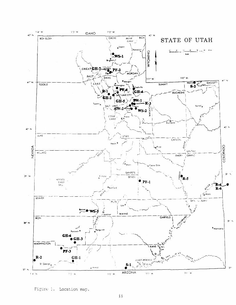
The purpose of this Repon of In\'csligation is to present. in a single document, the 24 techniC2l reports and letters generated by the AprJil:d Geology Program in 1988 and 1985J (fig. 1) which received limited distrihution. The reports are grouped by topic. and the author(s) and requesting agency are indiC2ted on each repon. :Minor ediling ha" been performed for clarity and conformity, but no attempt has been made to up~radc the original ~raphics. most of which were produced on a copying machine. Tni~ report represent~ the sixth periodic compila tion of Applied Geology Profr ... f:1 studies, and i;.; intended to rna k.e the results of the Applied Geology Program projects a\'ailabk to the general public.
Bill D. Black
11'" IN
BOX ELDE~
AI" N.
30' N
~EAYER
38' N.
SFI'JFJi LHJ (c,):
113' W IDAHO
__ . ___ :0---'
WASHINGTON
R·2 • 1 4 - V.
l._., •.. ~._1'-,
PF-3 ~ GH·1
.r-' -'.----!
,/).(
Location map.
112' W
Hf.AH ~ICH
STATE OF UTAH ,; ologor.
\
110' W. Ai' N
l
\
e Mon"c~ho
)
lii'lN ARIZONA Ill- >Iv 11'- v..
ii

PUBLIC FACILITIES
1
P'nied: J.....,est:lJli Ap'Dcy:
Town of Emery, Emery camty Castle Valley Special Municipal Water Trea1::nent Plant Services District,
Mr. D. V. I..eanaste.r, Manager
By: I Datt:
1_
7_
88 I C-", Elrel:y 1.I";~:-Ol(PF-1) W.E. Mulvey
USGS QubaaaJt:
Emery West #633
PURPOSE AND SCOPE
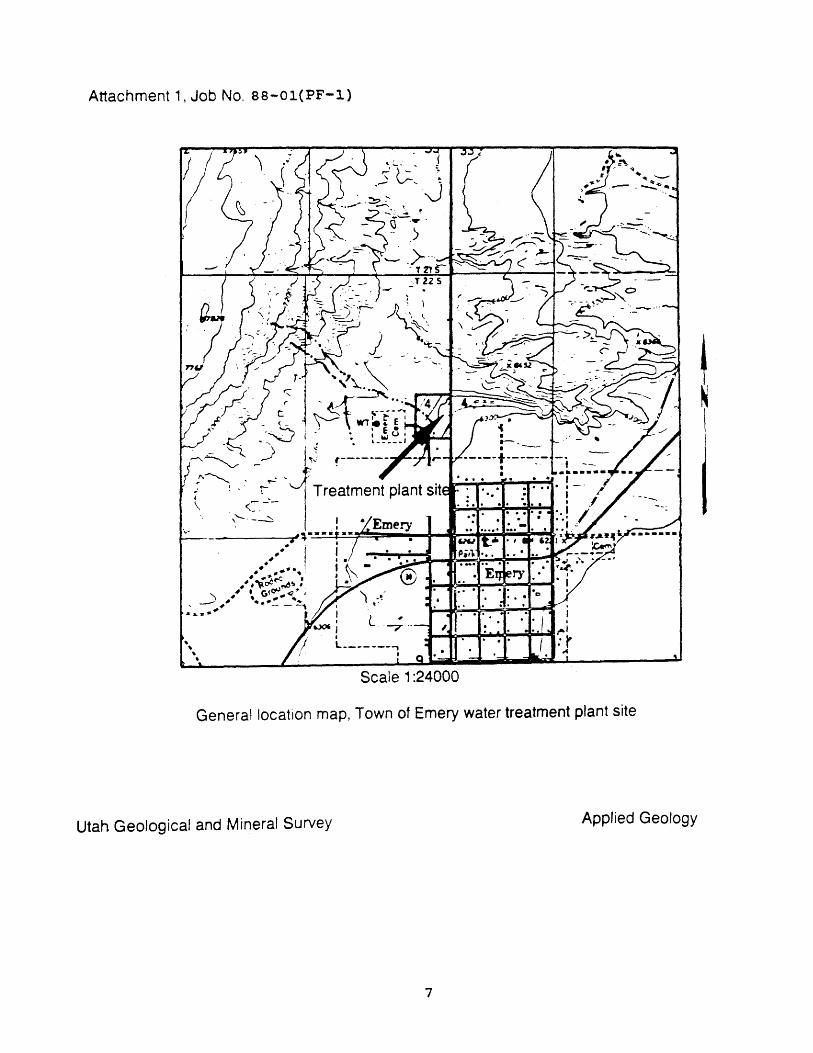
In response to a request by Mr. Darrel V. Leamaster, manager of the Castle Valley Special Services District, the Utah Geological and Mineral Survey made a geologic hazards investigation of the proposed site for a municipal water treatment plant in Emery, Utah. The site is located in T.22 5., R.6 E., section 4, Salt Lake Baseline and Meridian (attachment 1). The investigation was conducted November 11, 1987, for the purpose of evaluating the site for potential geologic hazards that could adversely effect the facility. In addition to the site reconnaissance the scope of the project included a review of available geologic and hydrologic literature for the site vicinity and logging of three test pits.
SETTING
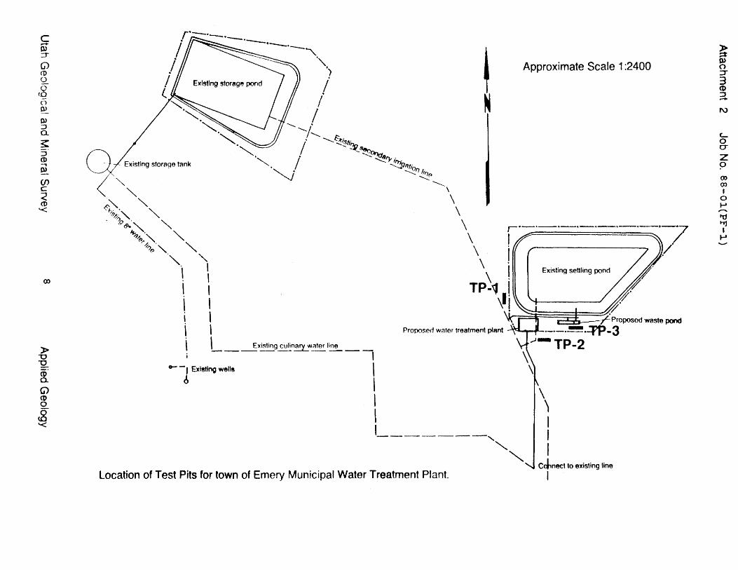
Located immediately northwest of the town of Emery, the water treatment plant will replace an existing pump house which supplies CUlinary water to the town from two nearby ponds (attachment 2). The property is characterized by gentle topography with slopes averaging 1 to 3 degrees on a dissected alluvial fan. Approximately 1/2 mile away, on the northwest portion of the property, slopes steepen to over 30 degrees and rise to a gravel-capped bench (pediment surface). To the west, the Wasatch Plateau rises in a series of steep cliffs.
The alluvial fan at the site originates from a natural amphitheater formed by headward erosion of drainages at the base of the cliffs and bench. Ephemeral drainages on the fan surface are from 2 to 4 feet deep and appear to be actively eroding. Total relief across the property is 120 feet, with elevations ranging from 6440 feet at the top of the bench to 6320 feet i~~ediately east of the building site. Annual precipitation for the region is 6 to 11 inches, supporting a vegetation community of galletagrass, shadescale, and greasewood with some juniper and pinyon pine present on slopes above the site.
GEOLOGY AND SOILS
The site is located in the Colorado Plateau physiographic province in the southwest portion of Castle Valley. Castle Valley is bounded by the Wasatch Plateau on the west and the San Rafael Swell on the east. Locally, the area is characterized by Cretaceous-age bedrock that dips gently to the west and forms the eastern escarpment of the
2
Wasatch Plateau. The escarpment is composed, from oldest to youngest, of the Mancos Shale, Emery Sandstone, Masuk Shale, star Point Sandstone, and Black Hawk Formation. Several normal faults offset these units we$t of the study area in the Wasatch Plateau. The closest is the Paradise fault, approximately 3/4 of a mile away, which forms the eastern boundary of the Joes Valley fault zone (Hayes and Sanchez, 1979). The Joes Valley fault zone has been active during Quaternary time (1.8 my B.P. to present) (Foley and others, 1987).
The predominate bedrock in the site vicinity is th~ Mancos Shale, which underlies the valley floor to a depth of several hundred feet. Castle Valley owes its origin to the soft, easily erodible nature of the Mancos Shale (Stokes and Cohenour, 1956). The Mancos Shale in Castle Valley is overlain by a thin veneer of unconsolidated Quaternary deposits derived from the weathering and erosion of sandstone bedrock units to the west. Alluvial fans cover the Mancos Shale in the site area to a depth of approximately 30 feet as indicated in well log data (D. V. Leamaster, oral commun., 1987). North of the building site, erosional remnants of the Mancos Shale rise above the alluvial fan and form the bench (pediment surface) which is in turn capped by mid-Pleistocene gravels (>150,000 yr B.P.). Gravels on the surface were derived from streams that originated on the Wasatch Plateau.
At the plant site, Quaternary alluvial fans overlie the Mancos Shale. Surface soils consist of the Ravola-Billings-Penoyer association which are generally deep, well to moderately well drained, and medium to moderately fine textured (Swenson and others,1970). Three test pits were excavated within the building area to a depth of 8 to 10 feet (attachment 2). Test pit soils were described according to the Unified Soil Classification System (USeS) (appendix A). All test pits showed similar soils, predominately fine to medium grained; well to poorly graded sand (SP-SW) and sand with silt (SM) (appendix B). These soils were at least 8 to 10 feet thick in the test pits, and it is believed that they extend to a depth of 30 feet below the site.
GEOLOGIC HAZARDS
FLASH FLOODING
Flooding potential for the site is low to moderate. The Federal Emergency Management Agency (FEMA) has not published flood hazard maps for the town of Emery. However, FEMA emphasizes that although the area may not be subject to the 100-year flood, floods of a greater magnitude could occur there and may cause localized damage to structures (FEMA, 1978). Sudden cloudburst storms may cause localized flows in ephemeral streams draining the mountain slopes west of the site. To avert flash-flood damage, a diversion ditch was excavated behind the lower storage pond and has reportedly been successful in containing runoff (attachment 2). However, during large cloudburst storms, this diversion ditch might possibly be overtopped and allow surface water to enter the storage ponds.
3
EROSION
Surface erosion potential on the site is moderate. Lack of vegetation cover and the presence of easily erodible soils is offset by gentle slopes and low annual precipitation. However, sudden r:oudburst storms may cause localized erosion problems. Ephemeral c:ainage channels (2 to 4 feet deep) are actively eroding the fan surface northwest of the building site. These channels drain toward the pond north of the proposed site, and sediment carried in them could partially fill the diversion ditch protecting the pond, reducing its capacity to contain flood waters.
ADVERSE SOIL CONDITIONS
Soils at the site are fine to medium grained and well drained with little or no shrink-swell capacity. The underlying Mancos Shale, however, contains materials which have a high shrink-swell capacity. Should excavation for building foundations expose the Mancos Shale, the potential for damage from shrink-swell soils would greatly increase.
Due to the nature of the alluvial-fan sediments, it is essential that they be properly compacted if used for fill material during construction. Cracks observed in the concrete block pump house now at the site were formed by settlement of the building foundation due to poor compaction during construction. Ponding of surface runoff due to inadequate drainage at the site caused the soils to settle and further damage the structure (D.V. Leamaster, oral commun., 1987).
GROUND WATER
No shallow ground water was encountered in test pits or reported in water well logs in the area. Thus, no hazards are believed to exist at the site relating to shallow ground water. Water wells in the area are deep (1500 feet) and produce water contaminated by alkaline minerals derived from the Mancos Shale (D.V. Leamaster, oral commun., 1987) .
EARTHQUAKE HAZARDS
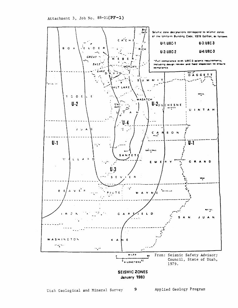
The site is located in seismic zone U-2 as established by the Utah Seismic Safety Advisory Council (USSAC) and in zone 2 of the Uniform Building Code (UBe). These zonations indicate the relative hazard due to ground shaking, and divide utah into four USSAC and three UBC seismic zones, with zone 2 having a low to moderate ground shaking hazard with expected Modified Mercalli intensities of I - VII (attachment 3, appendix A).
No active faults occur at the site. The nearest such fault, the Paradise fault, is located 3/4 mile west of the study area and has been active during the Quaternary (1.8 my B.P.). From stratigraphic relationships observed in a graben at the mouth of Muddy Creek, immediately north of the town of Emery, it was determined that the fault was active prior to 150,000 yr B.P., but has not been active
4
since that time (Foley and others, 1986). Based on these findings, no surface fault rupture hazard is thought to exist at the site. other earthquake hazards such as liquefaction and earthquake-induced slope failures are low because of favorable soil and ground-water conditions and lack of steep slopes at the site.
CONCLUSIONS AND RECOMMENDATIONS
Overall, geologic hazards at the site are few and include chiefly localized erosion and problems associated with the drainage of surface runoff. The structures built on the site should be designed with these geologic limitations in mind. Incised drainages on the alluvialfan surface north of the building site show recent erosion by surface water draining from the mountain front. These drainages flow into a diversion ditch immediately behind the lower storage pond. The ditch is adequate for low intensity cloudburst storms, but may not completely contain water from a high intensity-short duration event. It is recommended that the ditch design be evaluated to determine if modifications are needed to accommodate maximum expected flood flows.
Soil logs from the three test pits excavated on the site indicate that the soils are well drained and have little or no shrink-swell capacity. However, caution should be taken in construction excavations to avoid exposing the Mancos Shale, due to its high shrinkswell capacity and potential for damage to buildings. Poor compaction of construction fill has damaged existing structures. Therefore, the UGMS recommends that a qualified soils engineer conduct a soil foundation investigation to determine soil bearing strengths and provide specifications for compaction of construction fill prior to constructing buildings on the site. Care should be taken to direct surface drainage and roof runoff away from the foundation of the building. The site is in an area where moderate damage may occur due to earthquakes with maximun Modified Mercalli intensities of VII, and buildings should be constructed to conform to UBC seismic zone 2 standards.
5
BIBLIOGRAPHY
Federal Emergency Management Agency, 1978, Flood hazard boundary map, Emery County, Utah: Community No. 490058 0001-0049, scale 1:24,000.
Foley, L.L., Martin, R.A., Jr., and Sullivan, T.J., Seismotectonic study for Joes Valley, Scofield and Huntington north dams, Emery County and Scofield projects, Utah: u.s. Bureau of Reclamation Seismotectonic Report No. 86-7, 132 p.
Hayes, P.T., and Sanchez, J.D., 1979, Geologic map and coal resources of the Emery West Quadrangle, Emery and Sevier Counties, Utah: u.s. Geological Survey Geologic Quadrangle Map C-82, scale 1:24,000.
Hepworth, R.C., 1963, Heaving in the subgrade of highways constructed in the Mancos Shale: Unpub. University of Utah Department of Geology and Geophysics, Masters Thesis, 98 p.
Mundorff, J.C., 1979, Reconnaissance of chemical quality of surface water and fluvial sediment in the Price River Basin, Utah: Utah Department of Natural Resources Technical Publication No. 39, 55 p.
stokes, W.L., and Cohenour, R.E., 1956, Geologic Atlas of Utah, Emery County: Utah Geological and Mineral Survey Bulletin 52, 91 p.
Swenson, J.L. Jr., and others, 1970, Soil survey of the Carbon-Emery area, Utah: U.S. Soil Conservation Service, 78 p.
6
Attachment 1, Job No. 88-01(PF-l)
" . <.~---<'-- ---.::::,
\.-
. .'
Scale 1 :24000
General location map, Town of Emery water treatment plant site
Utah Geological and Mineral Survey Applied Geology
7
c .... OJ :r G) CD o c8 n OJ
0> ::) a. ~ S" eD .., 0>
(J) c: < ('[) '<
())
» u u
~ G> CO o
S '<
'" '" 0';\. '" {~~." '" . ?o <9."~ '"
~. "'-<9~ " "-
". ~"('3 . " '"
'" " . I , I \ , , \
i \ \ \ \ \ E)(i~ting culinarv w::\ter line i -----~---_,
0- -, Existing wells \
o I \ ,
I N
,--------,
Location of Test Pits for town of Emery Municipal Water Treatment Plant.
Approximate Scale 1 :2400
" "
Existing settling pond
\ ') I I I
CJ,nect to existing line
I
~ OJ o =r 3 CD ::::J ...... F\)
to u z 9 (»
OJ I
o ..... ,-..
't1 t"Jj I
.....
Attachment 3, Job No. 88-01(PF-l)
U·2
u·,
l L. A =
E· ;:
WASHINCTO",
o
.- . .;.:, . :' ..
........ .
~'I'""I( 10nt drsi~tiDns CDri'ftPOnd 10 ~;lIT\IC Ion.,
of rht Uniform Building COdt. 1979 Edition, ., fOlio.¥!.
U·1:UBC·1 U·J:UBC·3
U·2:UBC·2 U4:UBC·3
• Full compl •• nc:. with US C·l ... .",ic r-auiret'nef'lu,
comp, .. nc •.
C A
DAGGETT .. r-, .-'- -.-.-.~ ro'--' I /' ~ ·r'" i ""',,-.- ~. i i i I
,
UINTAH
--.-.---~~
BON i c' f \ .., . ,,_.-. __ ._._ --------4-.-.-.-.------1 U·1
..... WAY
~.
" ( .J
5-'!"" JI¥,(. ) \
')
J.
" ~. ~-
G .. A H 0
-. __ . ____ . ___ ._._ . .:i. ____ _ .' (.
'( 'I .
~ ----------.-.--~
L 0
,
I {~ J
r
,..,. ,j
,.j ,;
1-"1.-"
SAN J U A '-
- - - --- - - -.- -.-.-.-.- -'-.1
K A E
c- "'LI' SO
&..1 _+-_---__ -' b .~ .'l.o .. rTI.'·"
SEISMIC ZONES January 1980
~ ~ ... ,)
From: Seismic Safety Advisory Council, State of Utah, 1979.
Utah Geological and Mineral Survey 9 Applied Geology Program
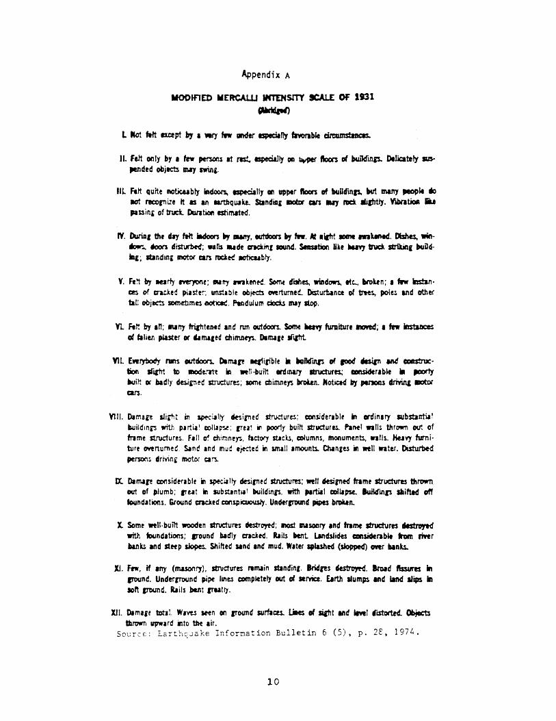
Appendix A
MODJFlED MERCAW INTIHsrrY ICAlE OF llll
CMrid&M)
II. felt only by • In ~ It res!. especi&I1y DC! ~ ftoors of kikf1l11S- DeIic:atety SIS-
pendtd objects IMJ swlni.
ilL Fttt Quite noticubty iAcSoon. especially CII\ upper ftoors of bundinp. 1M many ~M 110 act rec:ornize tt as an Il1'tbquakt. Stindial IDOtDr cars IaIJ na 1h1htlJ. YibrltiaA ... PI s:sini of tnd. Data tioft rstimated.
IV. DurlD, the day ~ iadoors ~ 1Uft)'. tatdocn ., .... lit ltatrt 101M rnUnecf. Dishes. win....... toon d~; .. ns .. de cnci.i'Ir sound. Sesabon liie ...., truck strikift, buDdill; JtJndmi motor can rockK IOticub t,.
Y. Ft!'t by Klriy l"m)IOne; Marty IW1ken~. Somf d"t3iIe1, win~ Itc... brobn; I flow mtanC2S of ended ptl st F.. ~lbl~ objects CMrturne,- [ksturtance of ~ potts and other tall obj~ sommmtS o6OtieaC. P-eDduJum doc:U INY stop.
Yt Fett by an; Nrt)' frirhttMd and run aut6ocn. Some ....,. funliture ftJIIed; I few iftstaDc:e:s 01 taller. pLaster or ~rnaaed c:bilMt)"1. Dartll,t srllht
YlL [wrybody nm outdoc:n. Dimare Itfiiriblt .. a.ancrU\lS of food ~ aM CiDItStnJc· tion sft&1rt to mode-tIt! ~ weYl-built wdawy Itruc:tvres; amiderlb~ .. ,aorty t.unt or bidty ~rn!c! structures; some ctimners brobn. Nottced by peI10nS ctriYin& D:ItDr c::ars.
VlII. o,mare sJiai'lt in ~~Ity tksirned s:tn.;dures; considerJble in Clnfinlry substantia! buildm~ WI plrtil~ coltJP"St: (Tul in poorfy buitt strudurl1. Panel waUs thrown out of frame structures. fall rt chimneys, factory sticks, columns, monumtnn, nils. tiuvy fumibm D"t'trtumed. SInd and mud e;ected in snaIl .mounn. Chin&ts in well nter. Di.sturbe-d persons irrvin, mote.r CI~
EX. DI mire Q:)4'Isidtfl b I r in spec~ It)' desirntd structures; ",II 6esirned frame structures thrown out of plum b; IT utili sub~ n t~ 1 tMJild inlS. with partia I colla pst. 1uild'U\J1 slaifted off toundahons. Ground cracked con~tcuou.sty. Undercround pipes bR»U11.
X. Some wen·built wooden structures dtstrO)'td; I'KISt Nsonry Ind frame structures dlstJo,td with tDundations; IT'Ound badly c:racied. Rails MItt LMcfsJides cansiderat»e hm rirer banks and stHP ~ Shifted Sind Ind mud. W.ter splashed (slopped) ower baftu.
Xl. Few. if any (masonry), stvaures remain standin,. 8ricfres ~. Iroad ftssurts In cround. Underrround pipe linel c:omp~tely out of .rvic:c. Earth slumps and iInd slips In soft en>und. bils bent rrutty.
XU. Dlmart totaL WIVt$ Sftn on ,round surlacu. Liles of siiht and ..... r I"&StortH. Objects thrown upward irlto tbe air.
So~rc~: EarthqJake Information Bulletin 6 (5), p. 2E, 1974.
10
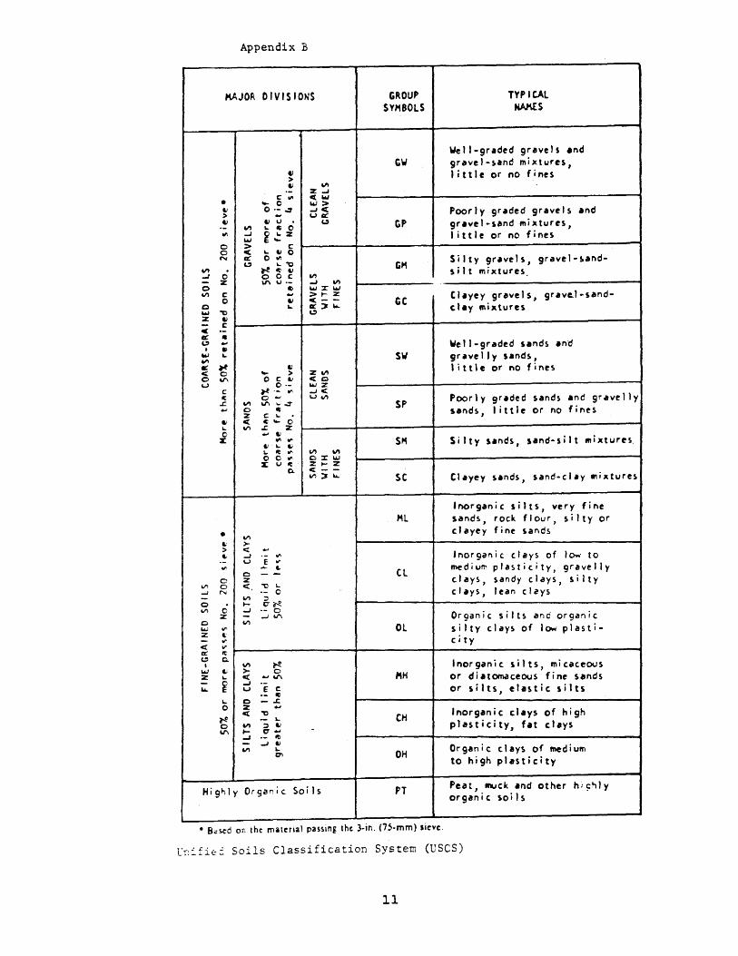
Appendix B
KAJOR DIVISIONS
'"
o o N
-J 0 - z o V') c
o o ~ -,;) Z 1.1 - C C .-cc • C) ..-, . I6J ~ -.1"1 «' ~ < 0 o V\ u
C lit
.c.
• &: > .. o
VI 0 ...J f',j
o VI c z
\. o ~ o V\
1.1 ,..,. > o C &I
0·· ~ .. ." o ....
V') V\..,;-=-o ~ z C \. < It ~ 0 VI.c. z
... 1.1 .,. ."
Ii \. &I ~ ~ ." 00" x U It
VI >-c:: ..-...J •• .,..
u E'" ...... I-
o --z c:: "'tl \. '- 0
~ 6-~ ...J •• 0 - ...J V'\ VI
VI ~ ~ 0 < ... V\ ...J •• u E C
~ C -..c z < -,;)
~
'" ;:, 1.1 .... cr ... ...J .- It - -J 1.1
~ 01
0.
Highly Or9a~jc Soils
GROUP SYMBOLS
cw
CP
eM
ec
SW
SP
SM
sc
Hl
CL
Ol
CH
OH
PT
• B<;~d on the matenal passing the 3·m. (75·mm) Ilevc.
TYP leAL NAKES
well-graded gravels and gravel.~and mixtures, little or no fines
Poorly graded gravels and gravel-sand mixtures, little or no fines
Silty gravels, gravel-~andsilt mixtures
Clayey gravels, grav~l·sandclay mixtures
Well-graded sands and gravelly,ands, little or no fines
Poorly graded sands and gravelly 50 and s, lit tIe 0 r no fin e s
Inorganic silts, very fine sands, rock flour, silty or clayey fine sands
.norganic clays of low to ~diu~ plasticity, gravelly clays, sandy c Jays, s i It y clays, lean clays
Organic silts and organic silty clays of low plasticity
Inorganic silts, micaceous or diat~ceous fine sands or silts, elastic silts
Inorganic clays of hi9~ plasticity, fat clays
Organic clays of medium to hig~ plasticity
Peat, muck and other hi~~ly organ i c soil s
l~~£i~~ Soils Classification System (USCS)
11
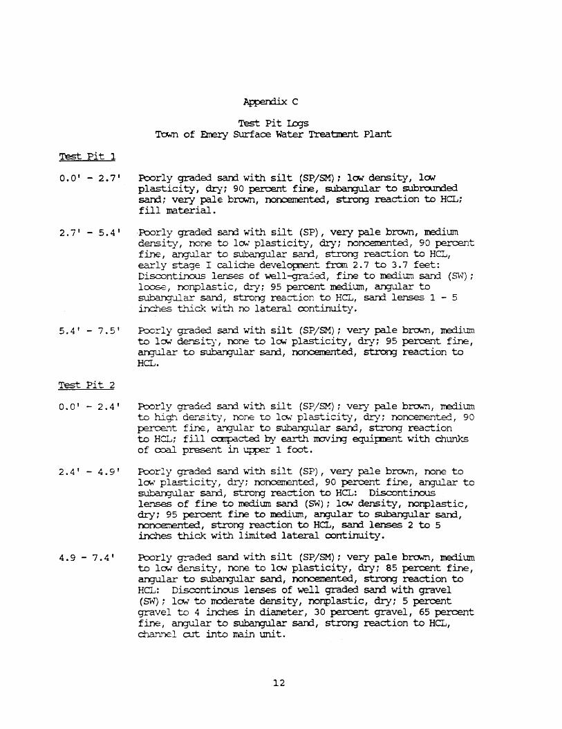
Test pit 1
Ap{:en:ii.x C
Test Pit I..cqs 'J.'a..m of Em:ry SUrface water Treabnent Plant
0.0' - 2.7 1 Poorly graderl sarrl with silt (SP/SM) i low density, low plasticity, dry; 90 percent fine, subargular to subl."O.J.l'rle1 sarrl; very pale brt:1Nl1., noncerrente:l, strorg reaction to HCL; fill material.
2.7' - 5.4 t Poorly graded. sal")j with silt (SP) , very pale b~, ne:lium densi ty, none to 10;.' plasticity, dry; nonc.em::nte:l, 90 percent fine, arqular to sW::an:jular sarrl, stro~ reaction to HCL, early stage I caliche developrent frcxn 2.7 to 3.7 feet: Discontinous lenses of well-gra::ied, fine to rredit.m1 san:1 (SW); lc:ose, nonplastic, d.ry; 95 percent m:rlit.m1, arqular to suba..T'"):j..uar san::l, stton;r reaction to HCL, sa.rrl lenses 1 - 5 inches thick with no lateral continui ty .
5.4 ' - 7.5' Poorly grade:::l sarrl with silt (SP/SM); very pale b!"ClH!1, na:liurn to low' de..'1Sity, none to law plasticity, dry; 95 percent fine, arqular to ~ar san.:1, nonce.m:=nte::l, st:ron; reaction to HCL.
Test Pit 2
0.0' - 2.4'
2.4' - 4.9'
4.9 - 7.4'
Poorly gradro sarrl with silt (SP/SM); very p3.le brown, medit.m1 to high dens i ty, none to lCM' plasticity, dry; nonceme..'1te:J, 90 percent fine, angular to Slll:::enqular sarrl, stro~ reaction to HCL; fill c:x:.rrq::acterl by earth nov i.ng ~pn::nt with chunks of coal present in Ufper 1 foot.
Poorly gradro sarrl with silt (SP), very pale brown, none to lCM plasticity, dry; nol"'lCel.Te..11te:::1, 90 percent fine, angular to ~ar sarri, strong reaction to HCL: Discontinous lenses of fine to nedium sarrl (SW); lOll density, nonplastic, dry; 95 percent fine to ne:lium, arxJUlar to subargular 5aJ"'rl, nonceme.nte:1, strorg reaction to HCL, sam lenses 2 to 5 inches thick with limite:1 lateral continuity.
Poorly graderl sarrl with silt (SP/SM); very pale b~, tre:iium to lCM density, none to lCM plasticity I dryi 85 percent fine, arqular to Slll:::enqular sand, nonc.enente::l I st:ron; reaction to HCL: Discontinous lenses of well grade:1 san::1 with gravel (SW); 10,.; to m:xierate density I nonplastic I dry i 5 percent gravel to 4 i.nc.l-}es in diaIreter I 30 percent gravel I 65 percent fine, arqular to ~ar san:l, strorg reaction to HCL, channel cut into main unit.
12
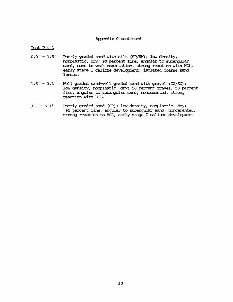
~ c continued
Test Pit 3
0.0' - 1.5' Ptx>rly grade:i sanj with silt (SP/SM): low density, n:>nplastic I d!y; 90 percent fine I an;;JUlar to SL1ban:Jular san::1, rx:ne to -weak ceJIentation, st.ron; reaction with HCL, early stage I calid1e develcpnent: isolata:l coarse san:l lenses.
1. 5' - 3. 3 I Well grade:i sarrl-well graded sam with gravel (GW/SW); low density I oonplastic, dI:y; 50 percent gravel, 50 percent fine, an;ular to ~ar sa.n:l, ~, stroN3' reaction with HCL.
3.3 - 6.1' Poorly graded sarrl (SP); low density, nonplastic, dry: 95 percent fine I an;;JUlar to SL1ban:Jular san:l, noncemented I
stroN3' reaction to HCL, early stage I caliche developnent
13
PNjed: a .... u •• A..I'DC'Y:
Geolcqic hazards investigation of a pl."'OpClSed 2 City of Riverdale million-gal1on water tank site, City of Riverdale, Weber County, utah
-,., . Kimn M. Harty I ~:lO-89 I c...
t7Weter I J .. N •• : (PF-2) 894)1
l1SGS QsaUuaJe: Roy (1346)
RJRFOSE AND SCDPE
'Ihi.s retX'rt presents the results of a utah Geolcx;}ical arrl Mineral survey (tXM5) investigation con:hlcted at a prq:ose1 2 million gallon water tank site for the City of Riverdale in Weber Cc:w'lty. 'nle p.n:pose of the investigation was to identify any exist:i.n; or potential geolcgic hazards that cculd adversely affect the water tank an1 surroun:ii.rx; area. '!he scope of work in:lu:le.1 a review of pertinent p..lbli.she:l arrl unp.lblished lite...~ture arrl maps, review of 1:20,OOO-scale air t=hoto;JraI=hs I arrl a field re::x:>nnai.s.sanc:e on JarnJal:Y 4, 1989. Mr. Dean steel, City Administrator of Riverdale, req..leSted the sbrly arrl was present czin; the field reconnaissance .
GD)r..o:;IC SEl'l'lNG AND SITE DESClUPITON
'!he 5i te is located awroximately 1000 feet scut:h of the center of se:tion 13, T. 5 N., R. :2 W., Salt Lake Baseline an:l Meridian (attachment 1). '!he prq:ose1 water tank wul be locate:i adj acent to an existi.n; 1 million-gallon water tank also 0Ill'led by Riverdale. '!he prc:posed tank will be canst.ructej at abo.lt 4595 feet elevation, the sa.IOO elevation as the existi.n; tank.
'!be site is atop a be.rd1 which is a remnant of a delta ~i ted in arx::ient Lake Bonneville by the Weber River. As the lake receded, the Weber Ri verOlt do.m into the delta, leavin; the bench ave=: 200 feet above the present river level. '!he site is on the northeast rim of the bench, as is the I:a.vis-Weber canal (attacl'ment 1), vmic..~, tn"ltil recentl y , flCMErl between the W'a ter tank site arrl the erlge of the be.rd1. 'lbe canal is currently beirtj re-rooted t.a..;ard the west to a location south of the water tank site (atta~t 1) (Daan Steel, oral c:x:xnrro..m., Jan., 1989).
'nle exist:i.n; water tank is on a srre1l terrace al:out 10 feet higher than the re~ surface (attac.h:rrent 2), am is awroxima.tely 100 feet fran the r.ilD. of the beIrh. '!be proposed "--=ter ta.'1k will be l::uilt partly on this small terrace, ~tely 125 feet fran the riln of the bench. Muc'1 excavation arrl gradin:; will be requi.re::l, as the fcurrlation of the prq:ose1 water tank will be larger than the renain.in; urxieveloped IX>rtion of this terrace surface (attac.1lIrent 2).
SOIL OJNDITICNS AND GEDLCX;IC HAZARI:S
No test pits were dug durin; the field investigation, an:l visual inspection of the grourrl surface was ~ by the presence of a deep sna.N cover. Hc:::fw1ever , sp:>il piles fran the canal :re-routin:1 project arrl previous nearby excavations shew the soil to be prErlaminantl Y sarrl ard gravel. '!he U. S. Deparbnent of Aqriall ture soil survey of the area (Erickson arC I';i.lson, 1968) shows the site vicinity to be covered by two soils I the Kilburn arx:1 F'ra.OCis Series. '!be Kilburn soil (RmA) is a gravelly sandy loam e>dU.bi tin; m:derately rapid to rapid penreabili ty I lCM shrink-
14
swell capacity, high shear strergth, slight c::arpressibility, arrl gcx:rl c::arpaction. In the Unified Soil Classification System, the Kil.bum soil is a silty gravel (GI) or silty sarrl (SM). In addition, the soil absorbs misture readily an::1 is sateWhat excessively drainEd. SUrface runoff occurs slCMly, an::l the hazard fran 'Water erosion is deemed none to slight (Erickson arrl Wilson, 1968). '!he Francis soil (FeB), oo:;urri,n; priIrarily west of the study area, is a loamy fine san:i which exhibits trany of the sarre properties as the Kil.bum soil. A notable exception is that it has a high susceptibility to win:l erosion (Ericksonarxl Wilson, 1968).
Because of the deep sroNeXNer, evidence of aTrf recent lan:1slid.irx] on the bench slc:pe ~near the water tank site could not be detennined. Ian::lslid.irx] alon;;r the bench face has cx:x::urred in the past, haNever, especially durin:] the recent ¥Jet years of 1983-1984. A landslide map of the area (I..c7Ne, 1988) ~ an extensive lan:3sl.ide zone on steep slopes just to the soothe.ast of the pIq)OSed water tank site (attachment 3). Just east of the site, the lal"dslide zone turns oorth, follCMing a lCMer bench slope. Accordi.ng to Mike I.orwe (fo~ Weber Coont:y geolo;;ist, oral c:xmmm., Jan., 1989), clay beds in the bench caused many of these larrlslides, an:i he believes the beds pinch cut where the larrlslide zone diverges northward. It may be that the clay beds were depositErl at the lower bench elevations durin:J a peric:rl when lake Bonneville was deep, arrl that the san::is an:l gravels were deposited on the UfPer bench ~e."1 the lake was regressirg. Near the water tank site, the slope of the bench averages approximately 35 percent, but is steeper in its upper p::>rtion. Metal pipes prot.rudi.n; fran the slope riln just northeast of the site appeared to have been placed as slope re-enforcem:mts, but the exact nature arrl extent of this work cculd not be determined. be:::ause of the S'I'ONCX:Ner. Hooses located at the base of the slope (attachment 2) did not experien=e lan:Jslide problems durin:l 1983-1984 (Dean Steel, oral o:::rmm..ln., Jan., 1989).
Depth to grcurrl water was rot assesse:l durin:] the field investigation. A literature arrl well lex; search reveale:i no data on the depth to the water table at the site. '!he soil survey rep:::>rt for the area in:licates the water table to be deep (Erickson arrl Wilson, 1968). '!he water table is likely near the elevation of the Weber River, nore than 200 feet belcw the bench. Residents Ii virg on the bench slope have reporte::l springs issu.in; fran the base of the slq:e (M. lDHe, oral CX'J'I1IlTIID., Jan., 1989); this in:licates the possibility of perched grourrl-water zones in the bench above river level.
Eart:hquakes present a variety of pX.ential hazards. '!he greatest ea.-thquake hazard to the water tank would be fran grourrl shaki.ng durirq a nxxierate to large earthquake. For the prop:::sed site, there is a 10 percent ~ that peak grrurrl ao::elerations will exceed O.06-0.07g in a lo-year pericxl, 0.25-0.3Cg in a 50-year pericxi, arrl O.SO-o.6Cg in a 2So-year period (Ya.m;s arrl others, 1987). No active faults have been identified at or near the site; the closest such fault is the Wasatch fault al::x::ut five miles to the east. Maps at 1:48,000 scale ~ soil liquefaction potential fran earthquake grourrl shaki.ng (Utah state University, 1988) shcM the bench surface to be in a zone of very lOYl pote.nti.al. '!he bench slope arrl base are in the m:::derate liquefaction potential zone.
CDNCWSIONS AND ~CNS
No geolo;ic hazards are present at the site which would make it unsuitable for o:mstruction of the water tank. rrhe re-routi.rg of the Davis-weber canal away from the rim of the bench near the water tank site will ensure that any future canal leakage will not affect the water tank, the bench slope, or the residential area at
15
the slope base. Nrt surface drainage should be roote:1 away fran the water tank site. Drainage could easily be roote:1 into the new canal. Although 00 lanislides have been identified on the slopes in the immediate vicinity of the water tank, the p:ssibili ty of larxislidin:] exists. To minimize the potential for damage fran slope failure, the water tank should be set back fran the bench slcp: as far as possible. If the tank is to be placed any closer than is presently planned (a~roxiInately 125 feet), a factor of safety analysis of the slope should be considere1. In acXlition, it is reo:nturen:ied that the geotechnical finn perfoI'ln.in; soil foorx:3ation investigations for the water tank be consulted as to the necessity of a slope stab~ity study of the bench to detennine safe setback distarx::es.
'Ihe site lies in Uniform Euilciin3 Ccrle (UBC) seismic zone 3 an::i utah Seismic Safety Advisory ca.m::il (USSAC) zone U-4, areas of highest gram:l shakin;; hazard in the respective zonation~. '!he nost recent work irrlicates peak gram:l acx:elerations of O. 06-0. 07g , 0.25-0.3 Og, arrl 0.50-0. 60g can be expected wi til a 10 percent probability of excee.den:::e for exposure tbnes of 10, 50, arrl 250 years, respectively. Awropriate earthquake-resistant design an:i oonstruction shcW.d be use:1, with careful inspection an::1 IrOni torirq as recanunen::lerl for USSAC zone U-4 (Utah Seismic safety Advisory ca.m::il, 1979). The hazard fran earthquake fault rupture at the site is 10.0;.
Prior to construction, a thorough soil fOlLT')jation investigation by a qualified geotechnical finn shccld be ~~ormed. '!his reFCrt shcW.d address soil arrl groorrlwater con:litions at arrl bela,.; the four-dation level. Because a water tank is a critical facility arrl the as.sessrrent that liquefaction potential at the site is law is base:i on generalized maps, the soil fOlD"rlation investigation should also address liqt.lE;faction potential. Because considerabl e site graciin3 will be requ.irErl, ergineerirg specifications for or-....s and fills shaild be ircl.u:le1.
REFERENCES CITED
Eric... :son, A.J., and Wilson, Ler.:oyne, 1968, Soil survey of ravis-we.ber area, utah: u.s. De~t of Agriculture Soil Conservation Service in cooperation with utah Agricultural Experi.rre.nt Station, 149 p.
!.owe, M.V., 1988, Slope failure inventory ma~ for Weber Co.mty, utah: Weber Co..mty Planni.rq c.epartn=.!1~ unpubli.she:l rreps, scale 1: 24 , 000 .
utah Seismic Safety Ad:visory Council, 1979, Seismic zones for o:>n.struction in Utah; DeJrert B. Ward, Exec;utive Director, 13 p.
Utah state University I 1988, Liquefaction potential maps for Weber ca.mty, utah: Utah state University I:epart:m;mt of Civil Erqineerin;1l.ll"p.lblished maps, scale 1:48,000.
YOLmg'S, R.R., swan, F.R., Pc:lvler, M.S., Schwartz, D.P., an:1 Green, R.K., 1987, Probabilistic analysis of earthquake groon::l sh.aki.rq hazard alan; the Wasatch Front, utah, in Gori, P.L., arrl Hays, W.W., (eds.), Assessrrent of reqional earthquake hazards am risk alon; the Wasatch Front, utah: U.s. Geolo:lical SUrvey Open-File ReJX)rt 87-585, v. II, p. Ml-Ml10.
16
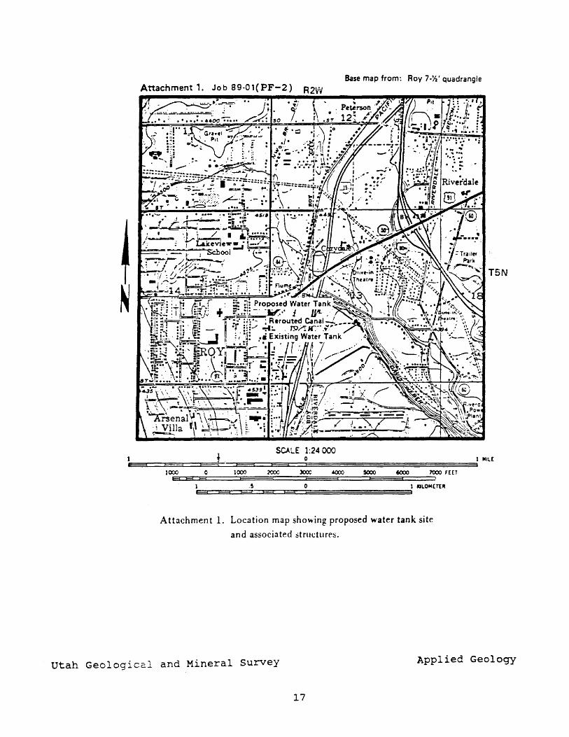
Base map from: Roy 7·~' quadrangle Attachment 1. Job 89.01(PF-2)
T5N
t SCALE 1:24000
0 1 IIIll[
JCX)J 0 l~ 2COO )(XX: <&(XX) 5000 6000 7000FUT El E3 E3
1 .5 0 1 IOLOM£Tt" E3 E:3 c::;a E3 E3
A ttachmen t 1. Location map showing proposed water tank site
and associated structure!::>.
utah Geologiccl and Mineral survey Applied Geology
17
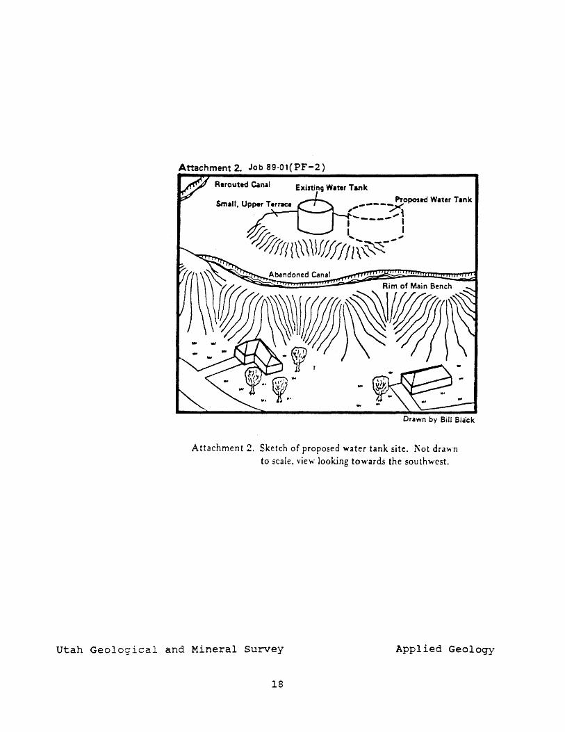
Attachment 2. Job 89·01(PF-2)
Rerouted Canal
Drawn by Bill Bla'ck
Attachment 2. Sketch of proposed water tank site. r\ot drawn to scale. vie",' looking towards the southwest.
Utah Geological and Mineral Survey Applied Geology
18
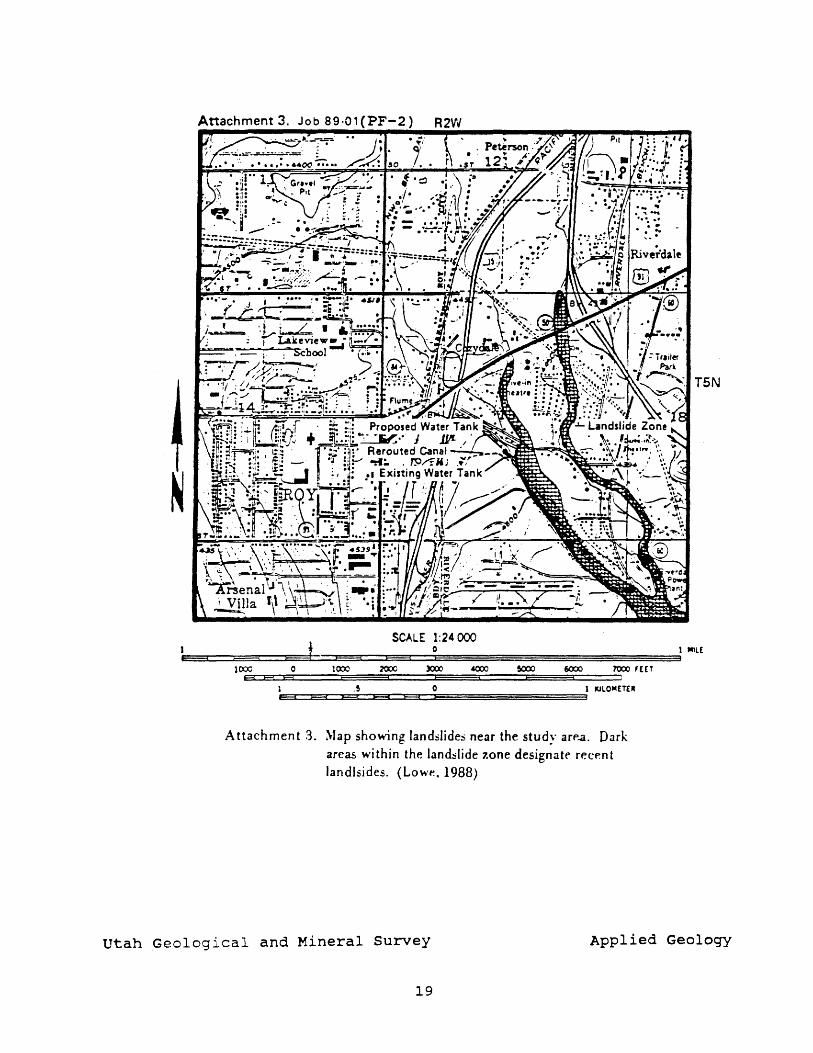
Attachment 3.
t SCALE 1:24000
0
lto:i 0 1(00 ~ )(XX) ~ !()OO 6(XlO 7'000 '[ET H H H
1 .5 0 1 IUlOIIC£TE" FA e=a E? E3 E3
A ttachmen t 3. ~Iap showing landslides near the studv arp..a. Dark areas wi thin the lan&;lide zone designate recp.n t landlsides. (Low~. 1988)
1 III1l[
utah Geological and Mineral Survey Applied Geology
19
Prwtect; a..-u.c~:
Geologic hazards investigation of a proposed Town of New Harmony water tank site, New Harmony, Washington County, Utah
Iy: 11)&1110-20-89 I ~t7: I J .. N •• : (PF-3)
K.M. Harty Washington County 89-14 VSGS Qu.trua d.:
New Harmony (158)
INTRODUCTION AND SCOPE
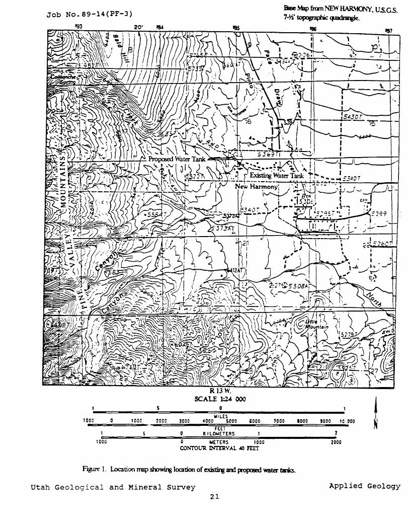
On behalf of the town of New Harmony, Utah, Marvin J. Wilson of Sunrise Engineering requested that the Utah Geological and Mineral Survey perform a geologic hazards investigation for a proposed 100,000-gallon water tank site in New Harmony. The proposed site is in the NE1/4, SE1/4, SW1/4, section 16, T. 38 S., R. 13 W., Salt Lake Baseline and Meridian (fig. 1). The tank is to be built about 15 feet northwest of an existing 150,000-gallon, 16-foot high, 42-foot diameter water tank that currently supplies New Harmony (Marvin Wilson, oral commun., Oct., 1989). Like the existing water tank, the proposed smaller tank will be constructed of reinforced concrete and will be partially buried. The scope of the investigation included a literature search, revie~ of geologic and topographic maps, and a field reconnaissance that took place on October 12, 1989.
SETTING AND GENERAL GEOLOGY
The tow~ of New Harmony, in north-central Washington County, is near the eastern base of the Pine Valley Mountains. About three miles west of the town, the mountains rise to nearly 10,000 feet elevation. On average, the area receives about 20 inches of precipitation annually (Jeppson and others I 1968). Rocks in the Pine Valley Mountains are mainly volcanic in origin, erupted during the late Tertiary Period (34 to about 2 million years ago - Ma) (Cook, 1960). The water tank site is atop alluvial-fan deposits at the base of the mountains on a fingerlike bench that rises approximately 30 feet above the surrounding land surface. The bench is believed to be cC'~-posed of late Pleistocene-age (about 30 to 10 thousand years old - Ka) stream and mud-flow deposits that were left as an uneroded remnant as streams cut down into the older alluvial-fan deposits (Proctor, 1949; Cook, 1957). Vegetation on the bench includes small trees, sagebrush, short grasses, and cacti. Patches of bare soil are especially common in the area surrounding the existing water tank.
SOIL CHARACTERISTICS
No test pits were excavated during the investigation, and there were no vertical soil exposures to examine at the site. However, a soil survey conducted by the U.S. Department of Agriculture (Mortensen and others, 1977) gives an indication of the types of soil to be encountered to a dep~h of five feet. The soil at the surface of the proposed site is poorly sorted, light brown to brown in color, with the fine fraction containing clay, silt, and abundant sand. The survey shows that the site is covered by very stony, sandy loam soils of the Nehar Series. Unified Soil Classification System soil types
20
Job No. 89-14(PF-3)
5 0
1000 0 WILES 1 DOC 700e 3000 4000 SOOO COOO 7000
1000
FEET SDk IL~ETERS
o WETERS 1000 CONTOUR INT'tRV AL 40 IEIT
BEe Map frcm NEW HAR~, U.s.GS. 7..l1J' lopogt3Jlic ~.
j 2
2000
F~ 1. Location Imp sm~ loation of ~ and propostd water ~.
Utah Geological and Mineral Survey Applied Geology 21
represented in the Nehar Series include SC, SM, CL, and GM, with about 45-55 percent by weight coarse fraction greater than three inches (Mortensen and others, 1977). Field observations confirmed this relatively high percentage of coarse material. Cobbles of quartzite and especially igneous volcanic rocks are abundant on the bench. Boulders are less numerous, wi th the largest v isible one measuring three feet in maximum dimension. Thin caliche (calcium carbonate) rinds were observed on a few cobbles at the site.
Nehar soils generally exhibit the following characteristics: moderate shrink-swell potential, medium to low shear strength, low to medium compressibility, low compacted permeability, medium to low susceptibility to piping, slow runoff, and good to fair compaction. In addition, the soils rate a "moderate" in excavation limitation and erosion hazard (Mortensen and others, 1977). A gully four feet deep has formed in the south-facing bench slope where a drainpipe from the existing water tank discharges near the base of the bench.
Ground subsidence in geologically young, sandy and silty alluvial soils containing clay I particularly debris-flow deposits, is well documented in the Hurricane Cliffs area of southwestern Utah. Subsidence or hydrocompaction can occur in void-rich sediments that have been rapidly deposited without sufficient water to allow normal consol idction. The soil survey indicates there may be susceptible soils (SC) at the water tank site. However, because soils at the site are greater than 10,000 years old, sufficient geologic time may have passed since deposition to have permitted adequate consolidation.
GEOLOGIC HAZARDS
Depth to ground water is unknown at the proposed site, but the static water table is greater than about 30 feet below the bench surface. However, zones of perched ground water could exist within the bench. The hazard from stream flooding and erosion is low. There is a large, flat-floored ravine west of the bench that shows evidence of having transported runoff in the past. The proposed site is elevated about 30 feet above the floor of the ravine, and is set back a safe distance.
No evidence of slope instabil i ty was observed during the field reconnaissance, and no landslides appear on maps of the area. The two slopes bordering the proposed site are low to moderate, with the steepest, west-southwest-facing slope averaging about 17 percent grade. The site is far from any cliffs, thus the rock-fall hazard is low. In addition, the potential hazard from debris flows is low due to the elevation of the water tank above potential flow routes.
Surface fault rupture hazard is low. Geologic maps show no active faul ts traversing the proposed si te. The closest known potentially active fault is the Hurricane fault, six miles east of the site at the base of the Hurricane Cliffs. The time of last movement on this portion of the fault is postulated to have been between 10-130 Ka, during the late Pleistocene (Anderson and Christenson, 1989). However, a lack of evidence for surface rupture on the fault during Holocene time (0-10 Ka) indicates that the recurrence rate of surface-rupturing earthquakes on this fault is low (Anderson and Christenson, 1989).
22
The largest historical earthquake in the region (Richter magnitude 6.3) occurred in 1902 near Pine Valley, about 13 miles southwest of New Harmony (Anderson and Christenson, 1989). The greatest hazard posed by earthquakes occurring in the region is from ground shaking. For the proposed site, there is a 10 percent chance that effective maximum peak ground accelerations will exceed 0.15 g in a 50-year period (FEMA-95, 1988). The generally coarse soils and likelihood of ground water greater than 30 feet deep indicate the potential for soil liquefaction during earthquake ground shaking is probably low.
CONCLUSIONS AND RECOMMENDATIONS
No geologic hazards are present at the proposed site that would make it unsuitable for construction of the water tank. The hazard from flooding, landslides, rock falls, debris flows, and surface faul t rupture is low. The water table is below the excavation depth of the water tank, but shallow ground water could be encountered in perched zones.
The site is in an area where the maximum peak effective acceleration is 0.15 g on rock with a 10 percent chance of exceedence in 50 years (FElI..A-95, 1988). This corresponds to Uniform Building Code (UBC) seismic zone 2B, with a Z factor of 0.20 (Uniform Building Code, 1988 edition) . Appropriate earthquake-resistant design and construction should be used in a::ordance with UBC specifications.
Gully erosion has occurred near the existing water tank. Drainage for the proposed water tank should be directed well away from the bench and bench slope, to prevent slope erosion and undermining. Excavation for the foundation could be difficult because of the large quantity of coarse material at the site. Depending on the degree of consolidation of the subsurface soil, excavation walls may require sloping. Prior
_ to site excavation, a thorough soil foundation investigation by a qualified geotechnical firm should be performed. This report should include an assessment of the soil and ground-water conditions at and below the foundation level, and the potential for hydrocompaction. No cracks or other visible signs of foundation distress were observed on the existing water tank, but only the top and upper 12 inches of the structure were visible.
The existing and proposed water tanks are upslope and close to a number of houses in the northwest part of New Harmony. Design plans should consider the impact of floodwaters on these residences should the water tank(s) breach, and provide a pathway for diversion of floodwaters if necessary.
CITED REFERENCES
Anderson, R.E., and Christenson, G.E., 1989, Quaternary faults, folds, and selected volcanic features in the Cedar city 1 degree x 2 degree quadrangle, Utah: Utah Geological and Mineral Survey Miscellaneous Publication 89-6, in press.
Cook, E. F. I 1957 I Geology of the Pine Valley Mountains, Utah: Utah Geological and Mineral Survey Bulletin 58, 111 p.
23
Cook, E. F., 1960, Geologic atlas of Utah, Washington County: Utah Geological and Mineral Survey Bulletin 70, 1234 p.
FEMA-95, 1988, NEHRP recommended provisions for the development of seismic regulations for new buildings: Seismic Safety Council, Earthquake Hazards Reduction Series 17, Part I, 158 p.
Jeppson, R.W., Ashcroft, G.L., Huber, A.L., Skogerboe, G.V., and Bagley, J.M., 1968, Hydrologic atlas of Utah: Utah Water Research Laboratory, Utah Agricultural Experiment station, and Utah State University in cooperation with Utah Division of Water Resources, p. 31.
Mortensen, V. L., Carley I J . A., Crandall, G. C., Donaldson, K. M., and Leishman, G.W., 1977, Soil survey of Washington County area, Utah: U. S . Department of Agriculture Soil Conservation Service, U. s. Department of the Interior Bureau of Land Management and National Park Service in cooperation with Utah Agricultural Experiment station, 140 p.
Proctor, P.D., 1949, Geology of the Harrisburg (Silver Reef) mining district, Washington County, Utah: Ph.D. dissertation, University of I:-.::1iana.
24
........ : Geologic-Hazards Investigation, for a Proposed Woods Cross City Water-Tank site, Davis County, Utah
a.....u.aApMr:
Woods Cross City
~----------------~----------~--------------~---------T~~------~4
Salt Lake cit North
INTRODUCTION
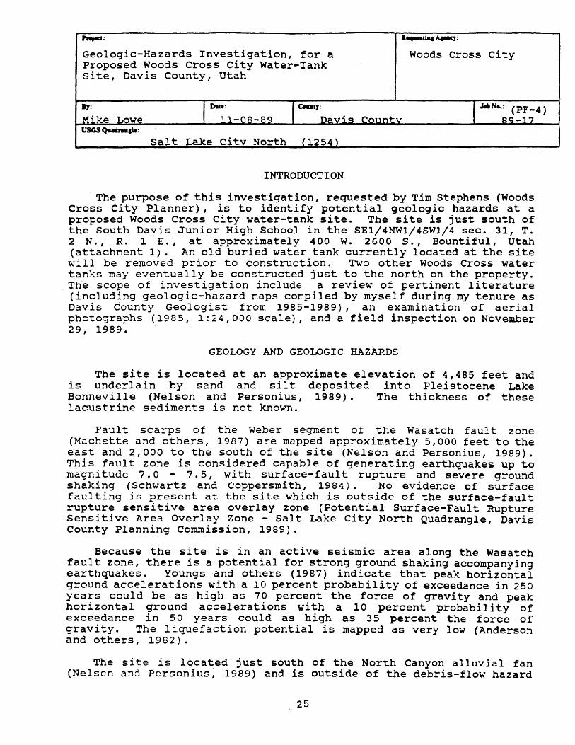
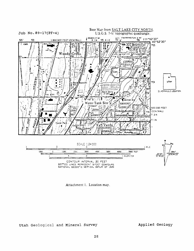
The purpose of this investigation, requested by Tim Stephens (Woods Cross City Planner), is to identify potential geologic hazards at a proposed Woods Cross City water-tank site. The site is just south of the South Davis Junior High School in the SEl/4NWl/4SW1/4 sec. 31, T. 2 N., R. 1 E., at approximately 400 W. 2600 S., Bountiful, Utah (attachment 1). An old buried water tank currently located at the site will be removed prior to construction. Two other Woods Cross water tanks may eventually be constructed just to the north on the property. The scope of investigation include a review of pertinent literature (including geologic-hazard maps compiled by myself during my tenure as Davis County Geologist from 1985-1989), an examination of aerial photographs (1985, 1:24,000 scale), and a field inspection on November 29, 1989.
GEOLOGY AND GEOLOGIC HAZARDS
The site is located at an approximate elevation of 4,485 feet and is underlain by sand and silt deposited into Pleistocene Lake Bonneville (Nelson and Personius, 1989). The thickness of these lacustrine sediments is not known.
Faul t scarps of the Weber segment of the Wasatch faul t zone (Machette and others, 1987) are mapped approximately 5,000 feet to the east and 2,000 to the south of the site (Nelson and Personius, 1989). This fault zone is considered capable of generating earthquakes up to magni tude 7. 0 ... 7.5, with surface-faul t rupture and severe ground shaking (Schwartz and Coppersmith, 1984). No evidence of surface faulting is present at the site which is outside of the surface-fault rupture sensitive area overlay zone (Potential Surface-Fault Rupture Sensitive Area Overlay Zone - Salt Lake City North Quadrangle, Davis County Planning Commission, 1989).
Because the site is in an active seismic area along the Wasatch fault zone, there is a potential for strong ground shaking accompanying earthquakes. Youngs ·and others (1987) indicate that peak horizontal ground accelerations with a 10 percent probability of exceedance in 250 years could be as high as 70 percent the force of gravity and peak horizontal ground accelerations with a 10 percent probability of exceedance in 50 years could as high as 35 percent the force of gravity. The liquefaction potential is mapped as very low (Anderson and others, 1982).
The site is located just south of the North Canyon alluvial fan (Nelsen and Personius, 1989) and is outside of the debris-flow hazard
25
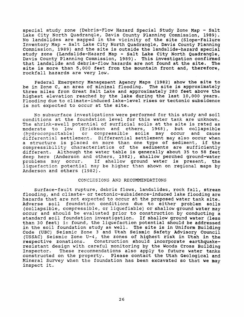
special study zone (Debris-Flow Hazard Special Study Zone Map - Salt Lake City North Quadrangle, Davis County Planning Commission, 1989). No landslides are mapped in the vicinity of the site (Slope-Failure Inventory Map - Salt Lake City North Quadrangle, Davis County Planning Commission, 1989) and the site is outside the landslide-hazard special study zone (Landslide-Hazard Map - Salt Lake City North Quadrangle, Davis County Planning Commission, 1989). This investigation confirmed that landslide and debris-flow hazards are not found at the site. The site is more than 5,000 feet from the mountain front and, therefore, rockfall hazards are very low.
Federal Emergency Management Agency Maps (1982) show the site to be in Zone C, an area of minimal flooding. The site is approximately three miles from Great Salt Lake and approximately 280 feet above the highest elevation reached by the lake during the last 10,000 years. Flooding due to climate-induced lake-level rises or tectonic subsidence is not expected to occur at the site.
No subsurface investigations were performed for this study and soil conditions at the foundation level for this water tank are unknown. The shrink-swell potential of surficial soils at the siteJis rated as moderate to low (Erickson and others, 1968), but collapsible (hydrocompactable) or compressible soils may occur and cause differential settlement. Differential settlement may also occur when a structure is placed on more than one type of sediment, if the compressibili ty characteristics of the sediments are sufficiently different. Although the water table is generally about 35 to 58 feet deep here (Anderson and others, 1982), shallow perched ground-water problems may occur. If shallow ground water is present, the liquefaction potential may be higher than shown on regional maps by Anderson and others (1982).
CONCLUSIONS AND RECOMMENDATIONS
Surface-fault rupture, debris flows, landslides, rock fall, stream flooding, and clirnate- or tectonic-subsidence-induced lake flooding are hazards that are not expected to occur at the proposed water tank site. Adverse soil foundation conditions due to either problem soils (collapsible, compressible, or liquefiable) or shallow ground water may occur and should be evaluated prior to construction by conducting a standard soil foundation investigation. If shallow ground water (less than 30 feet) is found, the liquefaction potential should be addressed in the soil foundation study as well. The site is in Uniform Building Code (UBC) Seismic Zone 3 and Utah Seismic Safety Advisory Council (USSAC) seismic Zone U-4, the zones of highest risk in Utah in the respective zonations. Construction should incorporate earthquakeresistant design with careful monitoring by the Woods Cross Building Inspector. These recommendations also apply to future water tanks constructed on the property. Please contact the Utah Geological and Mineral Survey when the foundation has been excavated so that we may inspect it.
26
REFERENCES CITED
Anderson, L. R., Keaton, J. R., Aubry, Kevin, and Ellis, S. J., 1982, Liquefaction potential map for Davis County, Utah: Department of civil and Environmental Engineering, Utah state University, Logan, Utah, and Dames and Moore Consulting Eng ineers , Salt Lake City, Utah, 50 p.
Erickson, A. J., Wilson, Lemoyne, Hughie, V. K., Neilson, Woodrow, and Chadwick, R. S., 1968, Soil survey of Davis-Weber area, Utah: U. S. Department of Agriculture, Soil Conservation Service, in cooperation with Utah Agricultural Experiment Station, 149 p.
Federal Emergency Management Agency, 1982, Flood insurance rate map, Davis County, Utah, (Unincorporated areas) I panel 255: Federal Emergency Management Agency, 1:1,000 scale.
MachEtte, M. N., Personius, S. F., and Nelson, A. R., 1987, Quaternary geology along the Wasatch fault zone: segmentation, recent investigations, and preliminary conclusions, in Hays, W. W., and Gori, Paula, eds., Assessment of regional earthquake hazards and risk along the Wasatch Front, Utah, Volume I: u. s. Geological Survey Open-File Report 87-585, p. 1-72.
Nelson, A. R., and Personius, S. F., 1989, Surficial geologic map of the Weber segment of the Wasatch fault, Weber and Davis Counties, Utah: U. S. Geological Survey Miscellaneous Investigations Map, 1:50,000 scale, in prep.
Schwartz, D. P., and Coppersmith, K. J., 1984, Fault behavior and characteristic earthquakes: examples from the Wasatch and San Andreas fault zones: Journal of Geophysical Research, v. 89, no. B7, p. 5681-5698.
Youngs, R. R., Swan, F. H., Power, M. S., Schwartz, D. P., and Green, R. K., 1987, Probabilistic analysis of earthquake ground shaking hazard along the Wasatch Front, Utah, in Hays, W. W., and Gori, P. L., eds., Assessment of regional earthquake hazards and risk along the Wasatch Front, Utah, v. II: U. S. Geological Survey Open-File Report 87-585, p. M-1-110.
27
Base Map from SALT LAKE CITY NORTH. Job No. 89-17(PF-4) U.S.G.S. i-Y2' topographic quadrangle.
'23 I 890 000 rEEl ICENTRA.Ui
CONTOU R INTERVAL 20 FEET DOiiED LINES REPRESE~; 5·rOOi CONTouRS NATIOI'fAl GEOOE"IC VERTICAL OATUM or 1929
Attachment 1. Location map.
utah Geological and Mineral Survey
28
Appli~d Geology

SCHOOLS
29
""'ed: .~ApacJ:
Geologic hazards investigation of proposed Kane County SGOOol sites in Big Water (Glen Canyon School District City), Kane County, Utah
.,: I Inu: Ic.utr. I ~N .. ; (S-l) Suzanne Hecker 8-16-90 Kane 89-11
tJSGS~&l.: Glen Canyon City (22)
PURPOSE AND SCOPE
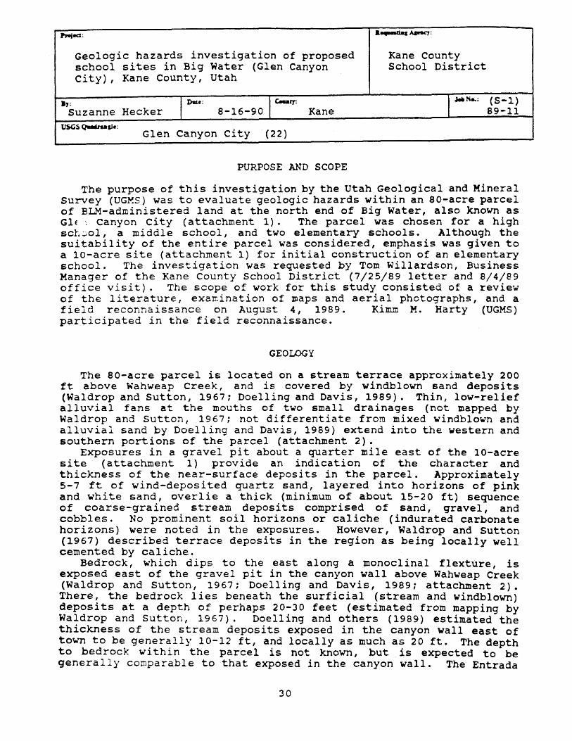
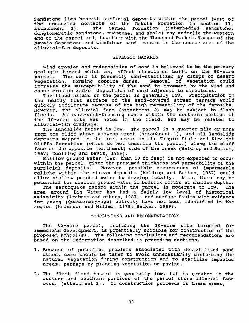
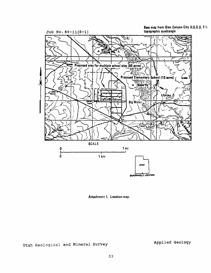
The purpose of this investigation by the Utah Geological and Mineral Survey (UGMS) was to evaluate geologic hazards within an 80-acre parcel of ELM-administered land at the north end of Big Water, also known as Glf: canyon city (attachment 1). The parcel was chosen for a high sCL~ol, a middle school, and two elementary schools. Although the suitability of the entire parcel was considered, emphasis was given to a lO-acre site (attachment 1) for initial construction of an elementary school. The investigation was requested by Tom Willardson, Business Manager of the Kane County School District (7/25/89 letter and 8/4/89 office visit). The scope of work for this study consisted of a review of the literature, examination of maps and aerial photographs, and a field reconnaissance on August 4, 1989. Kimm M. Harty (UGMS) participated in the field reconnaissance.
GEOLOGY
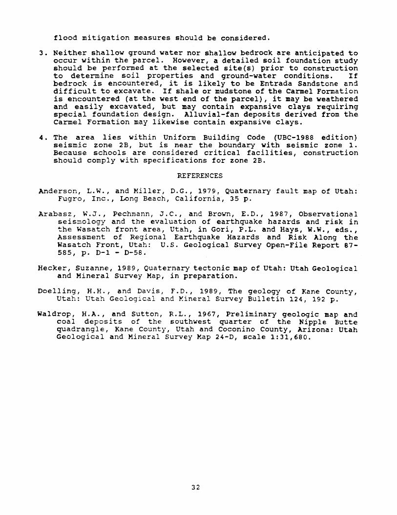
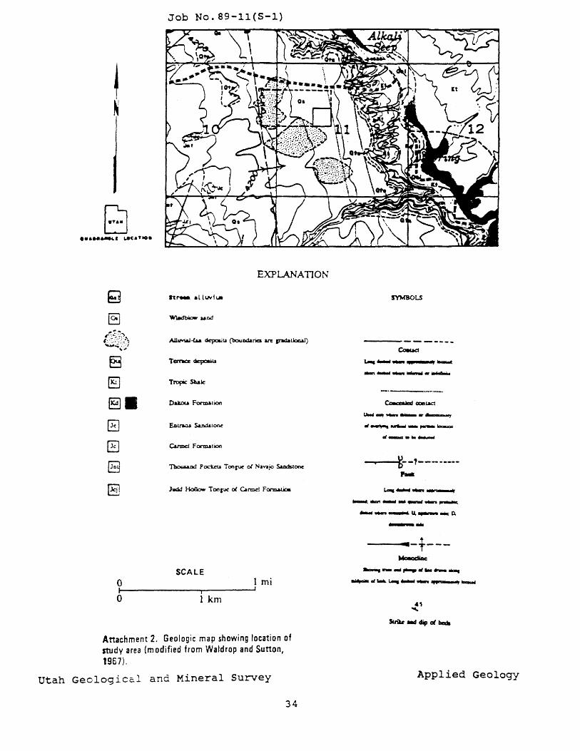
The 80-acre parcel is located on a stream terrace approximately 200 ft above Wahweap Creek, and is covered by windblown sand deposits (Waldrop and sutton, 1967; Doelling and Davis, 1989). Thin, low-relief alluvial fans at the mouths of two small drainages (not mapped by Waldrop and sutton, 1967; not differentiate from mixed windblown and alluvial sand by Doelling and Davis, 1989) extend into the western and southern portions of the parcel (attachment 2).
Exposures in a gravel pit about a quarter mile east of the 10-acre site (attachment 1) provide an indication of the character and thickness of the near-surface deposits in the parcel. Approximately 5-7 ft of wind-deposited quartz sand, layered into horizons of pink and white sand, overlie a thick (minimum of about 15-20 ft) sequence of coarse-grained stream deposits comprised of sand, gravel, and cobbles. No prominent soil horizons or caliche (indurated carbonate horizons) were noted in the exposures. However, Waldrop and Sutton (1967) described terrace deposits in the region as being locally well cemented by caliche.
Bedrock, which dips to the east along a monoclinal flexture, is exposed east of the gravel pit in the canyon wall above Wahweap Creek (Waldrop and sutton, 1967; Doelling and Davis, 1989; attachment 2). There, the bedrock lies beneath the surficial (stream and windblown) deposits at a depth of perhaps 20-30 feet (estimated from mapping by Waldrop and sutton, 1967). Doelling and others (1989) estimated the thickness of the stream deposits exposed in the canyon wall east of town to be generally 10-12 ft, and locally as much as 20 ft. The depth to bedrock wi thin the parcel is not known, but. is expected to be generally comparable to that exposed in the canyon wall. The Entrada
30
Sandstone lies beneath surficial deposits within the parcel (west of the concealed contacts of the Dakota Formation in section 11, attachment 2). The Carmel Formation (interbedded sandstone, conglomeratic sandstone, mudstone, and shale) may underlie the western end of the parcel and, together with the Thousand Pockets Tongue of the Navajo Sandstone and windblown sand, occurs in the source area of the alluvial-fan deposits.
GEOLOGIC HAZARDS
wind erosion and redeposition of sand is believed to be the primary geologic hazard which may affect structures built on the aO-acre parcel. The sand is presently semi-stabilized by clumps of desert vegetation, forming coppice dunes. Removal of vegetation could increase the susceptibility of the sand to movement by the wind and cause erosion and/or deposition of sand adjacent to structures.
The flood hazard on the parcel is generally low. Precipitation on the nearly flat surface of the sand-covered stream terrace would quickly infiltrate because of the high permeability of the deposits. However, the alluvial fans (attachment 2) may be subject to flash floods. An east-west-trending swale within the southern portion of the lO-acre site was noted in the field I and may be related to alluvial-fan drainage.
The landslide hazard is low. The parcel is a quarter mile or more from the cliff above Wahweap Creek (attachment 1), and all landslide deposits mapped in the area occur in the Tropic Shale and straight Cliffs Formation (which do not underlie the parcel) along the cliff face on the opposite (northeast) side of the creek (Waldrop and Sutton, 1967; Doelling and Davis, 1989).
Shallow ground water (le~ than 10 ft deep) is not expected to occur within the parcel, given the presumed thickness and permeability of the surf icial deposits. However, possible occurrences of impermeable caliche within the stream deposits (Waldrop and Sutton, 1967) could allow shallow perched water to develop locally. Also, there may be potential for shallow ground water if bedrock occurs at shallow depths.
The earthquake hazard within the parcel is moderate to low. The area around Big Water has had a fairly low level of historical seismicity (Arabasz and others, 1987), and surface faults with evidence for young (Quaternary-age) activity have not been identified in the region (Anderson and Miller, 1979; Hecker, 1989).
CONCLUSIONS AND RECOMMENDATIONS
The SO-acre parcel, including the la-acre site targeted for immediate development, is potentially suitable for construction of the proposed school(s). The following conclusions and recommendations are based on the information described in preceding sections.
1. Because of potential problems associated with destabilized sand dunes, care should be taken to avoid unnecessarily disturbing the natural vegetation during construction and to stabilize impacted areas, perhaps by planting vegetation or paving.
2. The flash flood hazard is generally low, but is greater in the western and southern portions of the parcel where alluvial fans occur (attachment 2). If construction proceeds in these areas,
31
flood mitigation measures should be considered.
3. Neither shallow ground water nor shallow bedrock are anticipated to occur within the parcel. However, a detailed soil foundation study should be performed at the selected site(s) prior to construction to determine soil properties and ground-water conditions. If bedrock is encountered, it is likely to be Entrada Sandstone an1 difficult to excavate. If shale or mudstone of the Carmel Formation is encountered (at the west end of the parcel), it may be weathered and easily excavated, but may contain expansive clays requiring special foundation design. Alluvial-fan deposits derived from the Carmel Formation may likewise contain expansive clays.
4. The area lies within Uniform Building Code (UBC-1988 edition) seismic zone 2B, but is near the boundary with seismic zone 1. Because schools are considered critical facilities, construction should comply with specifications for zone 2B.
REFERENCES
Anderson, L.W., and Miller, D.G., 1979, Quaternary fault map of Utah: Fugro, Inc., Long Beach, California, 35 p.
Arabasz, W.J., Pechmann, J.e., and Brown, E.D., 1987, Observational seismology and the evaluation of earthquake hazards and risk in ~he Wasatch front area, Utah, in Gori, P.L. and Hays, W.W., eds., Assessment of Regional Earthquake Hazards and Risk Along the Wasatch Front, Utah: u.s. Geological Survey Open-File Report 87-585, p. D-1 - D-58.
Hecker, Suzanne, 1989, Quaternary tectonic map of Utah: Utah Geological and Mineral Survey Map, in preparation.
Doelling, H.H., and Davis, F.D., 1989, The geology of Kane County, Utah: Utah Geological and ¥.ineral Survey Bulletin 124, 192 p.
Waldrop, H.A., and sutton, R.L., 1967, Preliminary geologic map and coal deposits of the southwest quarter of the Nipple Butte quadrangle, Kane County, Utah and Coconino County, Arizona: Utah Geological and Mineral Survey Map 24-D, scale 1:31,680.
32
,I
o I o
SCALE 1 mi
i ,
1 km
Attachment 1. Location map.
utah Geological and Mineral Survey
33
Base map from Glen Canyon City U.s.G.S. 7·Y-. topographic quadrangle
Applied Geology
e3 [§J
(§]II G G [8
[§J
o I o
Job No.89-11(S-1)
EXPLANATION
Oakou Formation
Judd Hollow Ton rue 01. Carmel Formatioa
SCALE mi
i
1 km
Attachment 2. Geologic map showing location of study area (modified from Waldrop and Sutton, 1967).
Utah Geological and Mineral Survey
34
SYMBOLS
"'_ ... ......., _o--f:~-,------....
1-. ........... .....-..
~..." .................. ~ ........... .....,.., u....-- .. D.
.,. .. r---~ ................. "' ...... ....
........ "' ... ~ .......... ............,--...
Applied Geology
Pntecs: I "'F.d..I~:
Geologic hazards investigation of a proposed Daggett County High School site, Manila, Daggett County, School District utah
.,: 10Uc- I c.utr: I .... N .. : (S-2) W.E. Mulvey 10-10-89 Daggett County 89-13
USGS QuUaa&k; Manila (1277)
INTRODUCTION
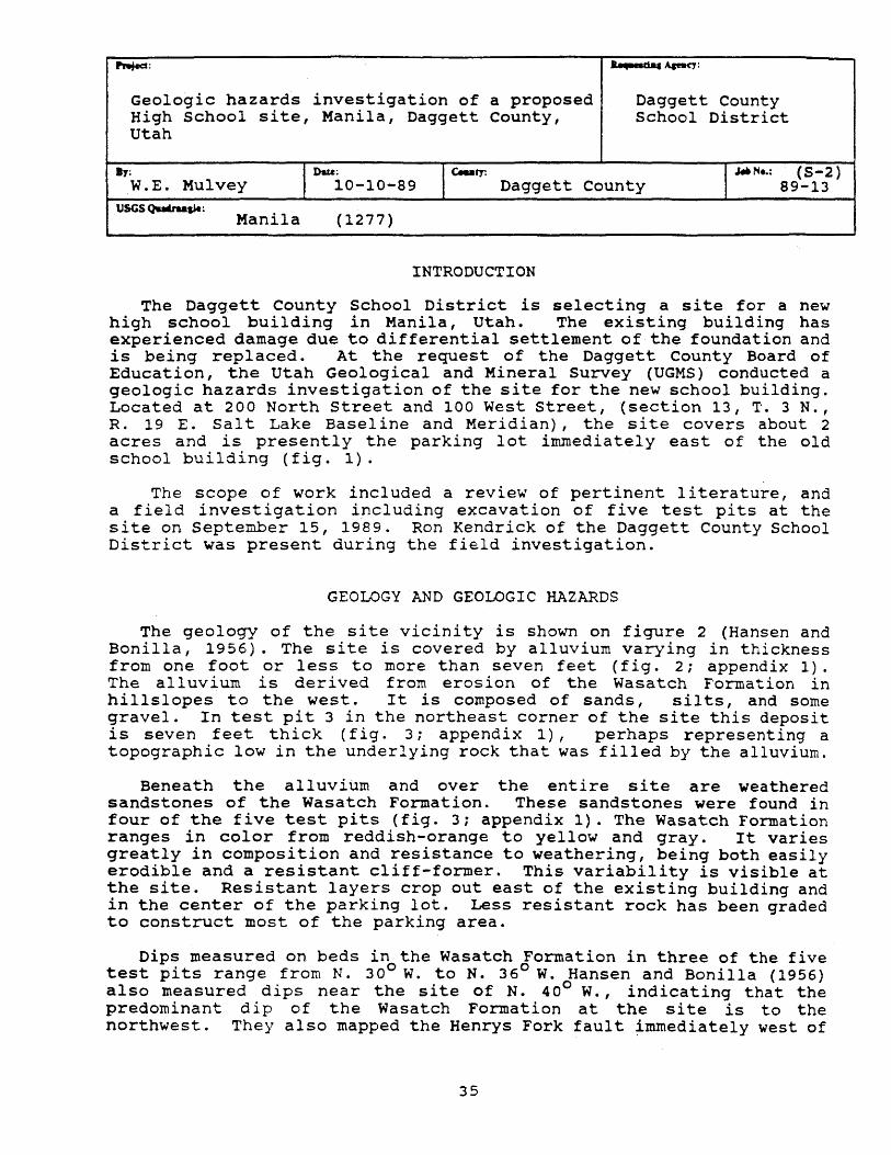
The Daggett County School District is selecting a site for a new high school building in Manila, Utah. The existing building has experienced damage due to differential settlement of the foundation and is being replaced. At the request of the Daggett County Board of Education, the Utah Geological and Mineral Survey (UGMS) conducted a geologic hazards investigation of the site for the new school building. Located at 200 North street and 100 West street, (section 13, T. 3 N., R. 19 E. Sal t Lake Basel ine and Meridian), the site covers about 2 acres and is presently the parking lot immediately east of the old school building (fig. 1).
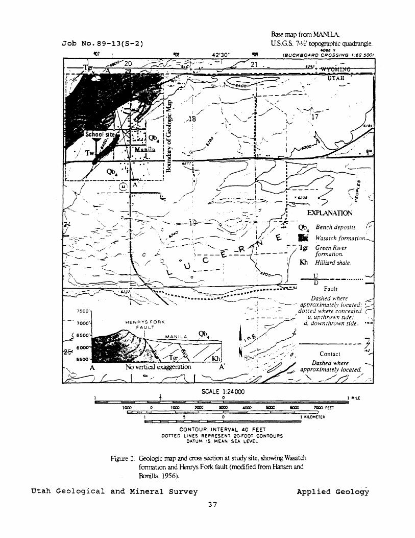
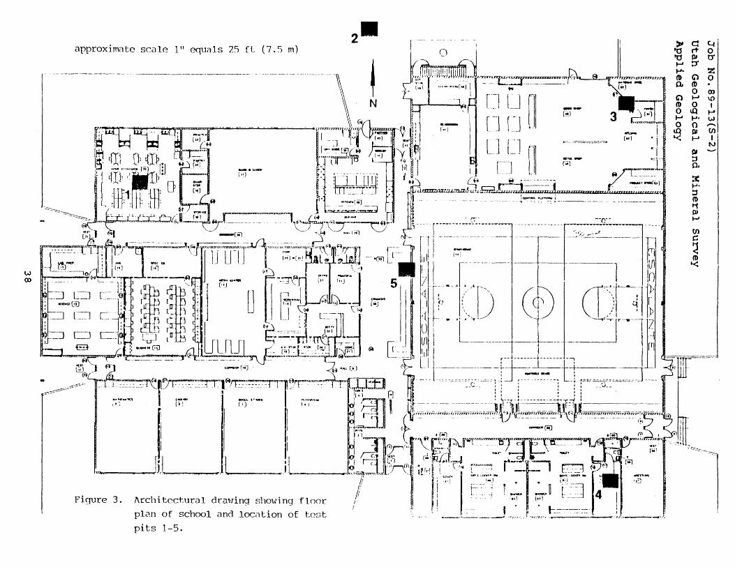
The scope of work included a review of pertinent literature, and a field investigation including excavation of five test pits at the site on September 15, 1989. Ron Kendrick of the Daggett County School District was present during the field investigation.
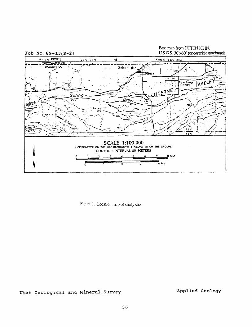
GEOLOGY AND GEOLOGIC HAZARDS
The geology of the site vicinity is shown on figure 2 (Hansen and Bonilla, 1956). The site is covered by alluvium varying in thickness from one foot or less to more than seven feet (fig. 2; appendix 1). The alluvium is derived from erosion of the Wasatch Formation in hillslopes to the west. It is composed of sands, silts, and some gravel. In test pit 3 in the northeast corner of the site this deposit is seven feet thick (fig. 3; appendix 1), perhaps representing a topographic low in the underlying rock that was filled by the alluvium.
Beneath the alluvium and over the entire site are weathered sandstones of the Wasatch Formation. These sandstones were found in four of the five test pits (fig. 3; appendix 1). The Wasatch Formation ranges in color from reddish-orange to yellow and gray. It varies greatly in composition and resistance to weathering, being both easily erodible and a resistant cliff-former. This variability is visible at the site. Resistant layers crop out east of the existing building and in the center of the parking lot. Less resistant rock has been graded to construct most of the parking area.
Dips measured on beds in the Wasatch Formation in three of the five test pits range from N. 300 w. to N. 360 W. Hansen and Bonilla (1956) also measured dips near the site of N. 400 W., indicating that the predominant dip of the Wasatch Formation at the site is to the northwest. They also mapped the Henrys Fork fault ~mmediately west of
35
Base map [rem DlJIU-i JOHN, Job No.89-13(S-2) U.S.G.S. 30'x60' topographic quadrangle.
R 110 'IV ~E 2475 2475 45' FI 109 W 2500 2 SOO ____ t.~~~ _. ___ ~~ ___ . _ ...;_-_____ --
SCALE 1:100 000 1 ~ ON 'THE MAP R.E.PRE.SEJ'(l' 1 KLOM!TEJ! ON THE GROlK>
COl'UOlJR INTER V At SO METERS
Figu;-c 1. Location map of study site.
Utah Geological and Mineral Survey Applied Geology
36
Base map from MA.J"TJ lA. Job No. 89-13(S-2) U.S.G.S. 7-~~' topographic quadrangle.
I .... -- ... _ .. -1.-:::::::-.,.
.e:::------,.. -------.". .. -r--' I,::,
______ / ':::: - L.. ~ -:.... . ....--... -~, --- , ~ ___ ' r")-_,_ '" :", ...• --" ~ -
..... . .• ~.~ '~"."''''';'; __ ' \(1\
A.. .. c ~! '."--.~//,/., I 'iT 1._ I
60fa II (BUCKBOARD CROSSING ':625001
• • # --:,r---,/ ..... Qb
4
~' iii
.,.. . .
'''''.''' ... -- ...,,-- . : :::::- '. ""-- . , -" ",
.. '-. ~ ~- ---~ -=-I :- -. Tgr -+------(
Bench deposits.
Wasatch formatio
Green River formation.
o . C \) ,
'---
: ; ICh Hilliard shale.
( ,)
U ---;;D~- - - - ........ .
Fault Dashed where
--- ,- approximatc(r located: ~ dOfied \'.'here concealed. r
u. up:hrowl1 side: HENRYS FORK
FAUL T d, do ",'11 thrown sidt. ••
I
t SCALE 1:24 (XX)
0
Contact Dalhed where
1 (XX) 0 1~ 20X 3000 .em 5CXlO 6COO 7COJ rEn H H H
1 FA
! 0 Ed Ed e= E+3
CONTOUR INTERVAL 40 FEET DOTTED LINES REPRESENT 2O-F'00T CONTOURS
CATUM IS MEAN SEA LE'JEL
Figure 2. Geologic tmp and cross section at study site, showing Wasatch fonmtion and Henrys Fork fault (trodified from Hansen and Bonilla, 1956),
I
utah Geological and Mineral Survey Applied Geology
37
2-approximate scale 1" equals 25 fL (7.5 m) (')
~ N
(nj,r 1---1 T (1 I • H - f ..
;$ """''''~-arii) r:1 +} [ ... ) _....... : [11
f] I] ~ LJ LJ ' [] 0. []]
[J .-
--( .. ) on-(.,1
.. ' ....... [OO)
~'~~ ~----~--: .. ::. - --- - - -'InmT7nrrl(~l(t~'? I ~,
i', tfDG m .. ;;:~ ,t~j r:; Y, ~ 1 qD' "~t)l!J • ("1 • :- -----cn--: i
{ lJ1 lH [} r:; r , !' J ---rJJ:, 'I"l=u:,,",=' d"=n:!L.. .. n .. I\ ... "',=vJ\=a __ ''''''~''=='''''=·, '[0' II', n:" ~, ~"J'j, ,"" , .., '11
~~-~ ~ I~-': ': ':' ~t.""'""" r ............... ~ .. ,.m~ .. •• .... l 1 - :.- -~ -nl ... --~ .. -:- ~~;,l .... !::} ,..t ______ -- -- '(~~.'\~~:i::..~r-.i u~---· [----.----~.:::..~---.-=l---------------F='. --0-- -
... ., l III - [0] - 4 • .. ",.l ¥: ".', _.~T ("~J Jf;;,._______________ __:-:_- ___ /1 .- _ ----- _ \. (>~ r', ----.-- .-- --- ---.--r- ---.--'----- II r~".n~Q...c:::~~ J.r..;.~~r __ ~.ur~_~ ___ :J..J';.cr ..... _ ...... m .. ___ .... _C.(.l_~ __ .. __ -- rl
(j)
:;: If: J [::j"- 'IT-·~rl i.:~1 i;:j'J' . 5- IUJ ',< ~,k ...... ~I i: [',~ l ' U' ~L 1::' I) 'o,:
,__ r==J CJ~ r' -) l! G : --- Tm~~ I)
>- d C-f ttj rt 0 ttj PI tr ..... ::t ...,. ~ (1) G'l 0 0, (1) .
0 00 G'l ..... \0 (0 0 I 0 \.Q ~ ..... ..... w 0 0
~ S» (/)
..... I N
S» ::s s::L
:J: ..... ::s (1) t1 PI ..... (/)
s:: ~ (0 ~
. ~ c ~~ r - ] ; G ~ --~= [uj '- I L -l IJ E3 L :' __ ~~ l i:J 1 U1 rl~' .~ ~"j I.",", 'rJ-' -'~J ~ G"- VI I I -----'------1-- ---- --- [T1 L " - -- ('.1-- - - ~ - --......r •. ll ' .---- I
;")''';'''~'' '. ~' .. '. ··.:....~.l .-...... .. -....... ~t:; -;~ u .. ----------f~~~~----.~~----.~~ ____ . _' ~~m=----==---J
. ~,<';'Tft:~~~~"TT1 .. rr:''''.,':''TT ~'T~"",,'-i'T- ~ ---~ .. ~~~ I ,.. - '"- "",," ri 8 ~ . _ ! l .. , .L. .. _ ...... L~J : ==
-"~~:-
rj] 1 '1 u r;- j :~:l (» I· III ',-(; .. ;m".. .. ·1 ____ .......,.JJ ... "J. J:-:JO"'ii~."".r_' /n_!t~rr, 1«> .... · ~,;;..,;,... I '!":',OO<JY.
/1 ow'l •. ___ , .. ~ e 0 l~-:!_ J.' I t-- - 1 r n [,.----=1 ;/ " . j :,~ -.-' u - -:.=j 14
Figure 3. Architectural draHing sho\ving floor r . - , . '.',1 r~:l --
plC\n of school and loc<ltion of test I - ___ ~-:_-_'. ~ .• ",_J.":_n_,l-:.::::-:---:-::~=
~-'!]
pits 1-5.
the school site in the Wasatch Formation and determined it to be postEocene in age (57 to 36 million years ago).
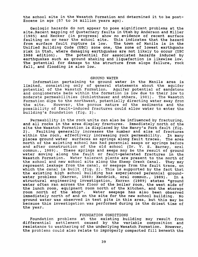
Geologic hazards do not appear to pose significant problems at the site.Recent mapping of Quaternary faults in Utah by Anderson and Miller (1985) and Hecker (in progress) show no evidence of recent surface faulting on or near the school site. This indicates that the hazard from surface faul t rupture is low. The town of Manila is in the Unified Building Code (UBC) zone one, the zone of lowest earthquake risk in Utah, where damaging earthquakes are not likely to occur (UBe 1988 edition). The potential for associated hazards induced by earthquakes such as ground shaking and liquefaction is likewise low. The potential for damage to the structure from slope failure, rock fall, and flooding is also low.
GROUND WATER Information pertaining to ground water in the Manila area is
limited, consisting only of general statements about the aquifer potential of the Wasatch Formation. Aquifer potential of sandstone and conglomerate beds within the formation is low due to their low to moderate permeabilities (Schlotthauer and others, 1981). The Wasatch Formation dips to the northwest, potentially directing water away from the si te. However, the porous nature of the sediments and the possibility of fault-induced fractures could allow water to enter the building's foundation (fig. 2).
Permeability in the rock units can also be influenced by fracturing, and all rocks in the area display fractures. Immediately north of the site the Wasatch Formation is displaced by the Henry's Fork fault (fig. 2) . Faul ting generally increases the number and size of fractures within the rock, effectively increasing rock permeability. In many places ground water surfaces as springs along fault traces. The area north of the existing school has had perennial seeps or springs before and after construction of the old school (Dr. V. S. Barney, oral commun., 1989). These springs and seeps may be the result of ground water moving along the faul t or fault-generated fractures in the Wasatch Formation. Water tolerant plants are present to the north of the school and new school site along the Sheep Creek Canal. They may represent leakage from the canal, or seepage from the fault trace, on which the canal is built (fig. 2). This is supported by the fact that the existing high school building has experienced perennial groundwater problems (Karren, 1989; Kendrick, oral commun., 1989). In a structural engineering investigation, Karren (1989) states "ground water often ran across the floor of the boiler room, the west side of the lunch room, equipment room north of the kitchen, and the storage room north of the shop". Water seepage has also been observed immediately north of and on the site for the new school building. No ground water was observed in test pits in this area, but this may be because this investigation was performed during is the driest time of the year.
FOUNDATION CONDITIONS Foundation problems at the existing building may result from
differential settlement caused by the variable composition and resistance to weathering of the underlying Wasatch Formation. However I the problems could also relate to improperly compacted fill beneath the
39
structure. Exploratory test pits showed that rock at the new site ranges from relatively fresh to highly weathered sandstone and silty sandstone. Consolidation characteristics of these units will vary and, if the foundation is not engineered properly I may cause problems similar to those at the existing building.
Another potential foundation problem involves settling of materials overlying the abandoned buried trench-type wastewater disposal system in the northwest corner of the building site. constructed to filter wastewater, this drainfield is porous and loosely compacted. When loaded I it may settle differentially. Blueprints for the existing school originally served by the system showed the system was only two feet deep.
CONCLUSIONS
No geologic hazards were found at the site which would endanger the structure or preclude its construction. However, this reconnaissance investigation indicates that foundation conditions at the si te are similar to those at the existing high school, and have the potential to cause similar differential settlement problems if not considered in foundation design. Shallow ground water flooding of the new building through fractures in rock or from seepage from springs or the Sheep Creek Canal is also a potential hazard particularly in light of the history of prob1er..s at the existing site. It is recommended that a thorough soil foundation investigation be performed to address these problems. One solution may be to excavate soil and weathered rock over the entire site, including the abandoned wastewater disposal system, and replace it with properly compacted fill. It would also be wise to provide a drainage system in the foundation to collect ground water and to direct it away from the structure.
SELECTED REFERENCES
Anderson, L.W., and Miller, D.G., 1979, Quaternary fault map of Utah: Fugro, Incorporated, Long Beach, California, 35 p.
Christenson, G.E., 1981, Inspection of Captain's Cove Subdivision, ~ani1a, Daggett County: Utah Geological and Mineral Survey Technical MemoranduIn, 4 p.
Hansen, W. R., and Bonilla, M. G. I 1956, Geology of the Manila Quadrangle, Utah - Wyoming: u. S. Geological Survey Miscellaneous Geologic Investigations Map I - 156, scale 1:24,000.
Hansen, W. R. , 1965, Geology of the Flaming Gorge Area Utah - Colorado - Wyoming: U. S. Geological Survey Professional Paper 490, 196 p.
Hecker, Suzanne, in progress, Quaternary tectonic map of Utah: Utah Geological and Mineral Survey Map.
Karren, K. W. 1989, Manila High School Daggett County, Utah: Karren and Associates, P.C. unpublished consultant's report, 6 p.
Montgomery, S. B., 1973, Ground water potential of Daggett County, Manila vicinity: Utah Division of Water Resources memorandum, 6 p.
40

Ravenholt, Hal, in progress, Henrys Fork Area soil survey of Utah -Wyoming, parts of Daggett and Summit Counties Utah, and Sweetwater and Uinta Counties, Wyoming: u.S. Soil Conservation Service.
41
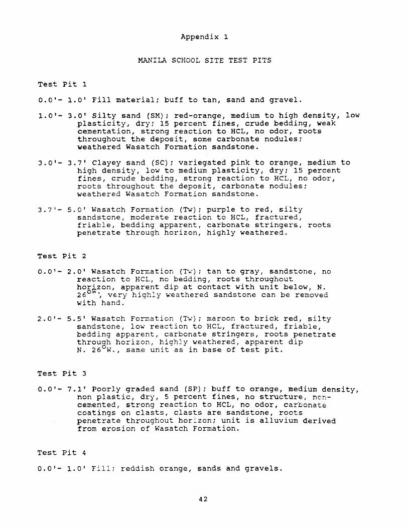
Appendix 1
MANILA SCHOOL SITE TEST PITS
Test pit 1
0.0'- 1.0' Fill material; buff to tan, sand and gravel.
1.0'- 3.0' Silty sand (SM); red-orange, medium to high density, low plasticity, dry; 15 percent fines, crude bedding, weak cementation, strong reaction to HCL, no odor, roots throughout the deposit, some carbonate nodules: weathered Wasatch Formation sandstone.
3.0'- 3.7' Clayey sand (SC); variegated pink to orange, medium to high density, low to medium plasticity, dry; 15 percent fines, crude bedding, strong reaction to HCL , no odor, roots throughout the deposit, carbonate nodules; weathered Wasatch Formation sandstone.
3.7'- 5.0' Wasatch Formation (Tw); purple to red, silty sandstone, moderate reaction to HCL, fractured, friable, bedding apparent, carbonate stringers, roots penetrate through horizon, highly weathered.
Test pit 2
0.0'- 2.0' Wasatch Formation (~.); tan to gray, sandstone, no reaction to HeL, no bedding, roots throughout hor~zon, apparent dip at contact with unit below, N. 26 0
., very highly weathered sandstone can be removed with hand.
2.0'- 5.5' Wasatch Formation (~.); maroon to brick red, silty sandstone, low reaction to HeL, fractured, friable, bedding apparent, carbonate stringers, roots penetrate through horizon, highly weathered, apparent dip N. 26 W., same unit as in base of test pit.
Test pit 3
0.0'- 7.1' Poorly graded sand (SP); buff to orange, medium density, non plastic, dry, 5 percent fines, no structure, noncemented, strong reaction to HeL, no odor, carbonate coatings on clasts, clasts are sandstone, roots penetrate throughout hor:zon; unit is alluvium derived from erosion of Wasatch Formation.
Test Pit 4
0.0'- 1.0' Fill; reddish orange, sands and gravels.
42
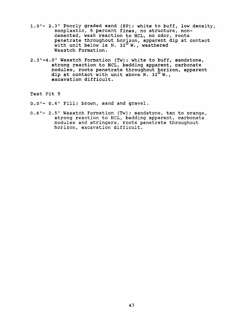
1.0'- 2.3' Poorly graded sand (SP); white to buff, low density, nonplastic, 5 percent fines, no structure, noncemented, weak reaction to HeL, no odor, roots penetrate throughout horizon, apparent dip at contact wi th unit below is N. 32 0 W., weathered Wasatch Formation.
2.3 1 -4.0' Wasatch Formation (Tw); white to buff, sandstone, strong reaction to HeL, bedding apparent, carbonate nodules, roots penetrate throughout horizon, apparent dip at contact with unit above N. 32 0 W. , excavation difficult.
Test Pit 5
0.0'- 0.6' Fill: brown, sand and gravel.
0.6'- 2.5' Wasatch Formation (Tw); sandstone, tan to orange, strong reaction'to HeL, bedding apparent, carbonate nodules and stringers, roots penetrate throughout horizon, excavation difficult.
43

\\'A TER SUPPLY
44
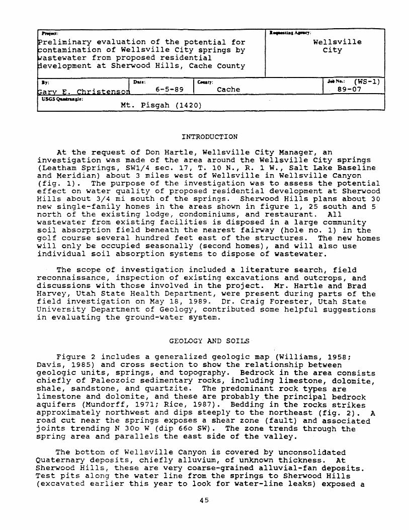
PIwi4Jd:
reliminary evaluation of the potential for ontamination of Wellsville City springs by astewater from proposed residential evelopment at Sherwood Hills, Cache County
Due:
6-5-89 Cache
Mt. Pisgah (1420)
INTRODUCTION
• ....-uaa Apat:y;
Wellsville city
-WIN .. : (WS-l) 89-07
At the request of Don Hartle, Wellsville city Manager, an investigation was made of the area around the Wellsville City springs (Leatham Springs, SW1/4 sec. 17, T. 10 N., R. 1 W., Salt Lake Baseline and Meridian) about 3 miles west of Wellsville in Wellsville Canyon (fig. 1). The purpose of the investigation was to assess the potential effect on water quality of proposed residential development at Sherwood Hills about 3/4 mi south of the springs. Sherwood Hills plans about 30 new single-family homes in the areas shown in figure 1, 25 south and 5 north of the existing lodge, condominiums, and restaurant. All wastewater from existing facilities is disposed in a large community soil absorption field beneath the nearest fairway (hole no. 1) in the golf course several hundred feet east of the structures. The new homes will only be occupied seasonally (second homes), and will also use individual soil absorption systems to dispose of wastewater.
The scope of investigation included a literature search, field reconnaissance, inspection of existing excavations and outcrops, and discussions with those involved in the project. Mr. Hartle and Brad Harvey, Utah state Health Department, were present during parts of the field investigation on May 18, 1989. Dr. Craig Forester, Utah State University Department of Geology, contributed some helpful suggestions in evaluating the ground-water system.
GEOLOGY AND SOILS
Figure 2 includes a generalized geologic map (Williams, 1958; Davis, 1985) and cross section to show the relationship between geologic units, springs, and topography. Bedrock in the area consists chiefly of Paleozoic sedimentary rocks, including limestone, dolomite, shale, sandstone, and quartzite. The predominant rock types are limestone and dolomite, and these are probably the principal bedrock aquifers (Mundorff, 1971; Rice, 1987). Bedding in the rocks strikes approximately northwest and dips steeply to the northeast (fig. 2). A road cut near the springs exposes a shear zone (fault) and associated joints trending N 300 W (dip 660 SW). The zone trends through the spring area and parallels the east side of the valley.
The bottom of Wellsville Canyon is covered by unconsolidated Quaternary deposits, chiefly alluvium, of unknown thickness. At Sherwood Hills, these are very coarse-grained alluvial-fan deposits. Test pits along the water line from the springs to Sherwood Hills (excavated earlier this year to look for water-line leaks) exposed a
45
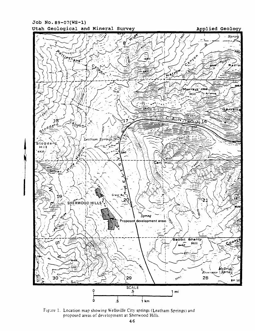
Job No. 89-07(WS-l)
o I o I
.5
SCALE .5 !
I , km
, mi I
Flgure 1. Location map showing Wellsville City spring.s (Leatham Spring.s) and proposed areas of development at Sherwood Hills.
46
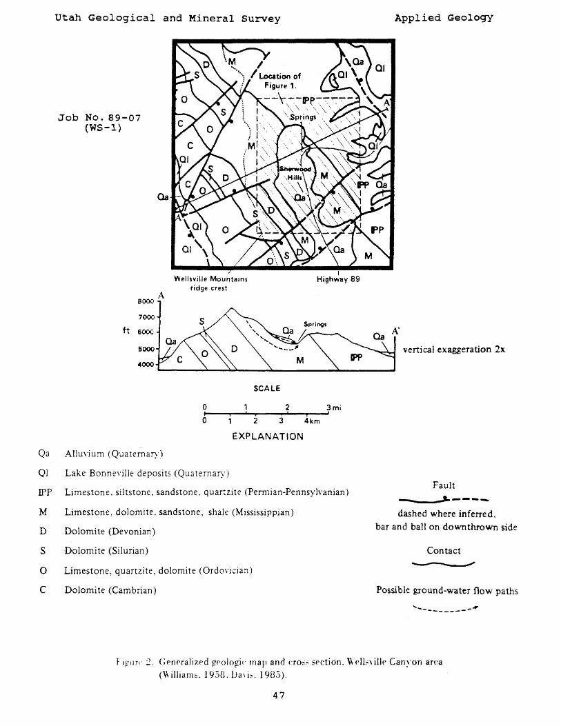
Utah Geological and Mineral Survey
Job No. 89-07 (WS-l)
Qa
A 8000
7000
ft 6000
5000
4000
Wellsville Mountains ridge crest
SCALE
I Highway 89
o 2 3mi ~I--~----~I--~;~!---Ti--~'
o 2 3 4km
EXPLANATION
Qa Alluvium (Quaternary)
Ql Lake Bonneville deposits (Qua ternary)
IPP Limestone. siltstone, sandstone, quartzite (Pennian-Pennsy]\,anian)
M Limestone, dolomite. sandstone, shale (Mississippian)
D Dolomite (Devonian)
S Dolomite (Silurian)
o Limestone, quartzite, dolomite (Ordovician)
C Dolomite (Cambrian)
Applied Geology
vertical exaggeration 2x
Fault
------~-----dashed where inferred.
bar and ball on down thrown side
Contact ...
Possible ground-water flow paths
' ..... - --~ -------
FI?llr(") Gennaliu'd ~('ologi(' map and (:ro~:" section. Well~\ iIJe Can~·on area
(\\ illiam~. 1958. lJa\ i~. 1985).
47
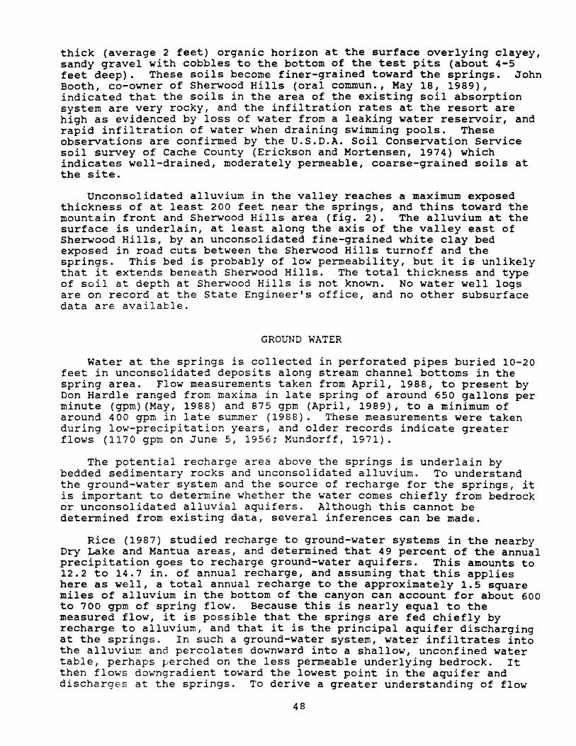
thick (average 2 feet) organic horizon at the surface overlying clayey, sandy gravel with cobbles to the bottom of the test pits (about 4-5 feet deep). These soils become finer-grained toward the springs. John Booth, co-owner of Sherwood Hills (oral commun., May 18, 1989), indicated that the soils in the area of the existing soil absorption system are very rocky, and the infiltration rates at the resort are high as evidenced by loss of water from a leaking water reservoir, and rapid infiltration of water when draining swimming pools. These observations are confirmed by the U.S.D.A. Soil Conservation Service soil survey of Cache County (Erickson and Mortensen, 1974) which indicates well-drained, moderately permeable, coarse-grained soils at the site.
Unconsolidated alluvium in the valley reaches a maximum exposed thickness of at least 200 feet near the springs, and thins toward the mountain front and Sherwood Hills area (fig. 2). The alluvium at the surface is underlain, at least along the axis of the valley east of Sherwood Hills, by an unconsolidated fine-grained white clay bed exposed in road cuts between the Sherwood Hills turnoff and the springs. This bed is probably of low permeability, but it is unlikely that it extends beneath Sherwood Hills. The total thickness and type of soil at depth at Sherwood Hills is not known. No water well logs are on record at the State Engineer's office, and no other subsurface data are available.
GROUND WATER
Water at the springs is collected in perforated pipes buried 10-20 feet in unconsolidated deposits along stream channel bottoms in the spring area. Flow measurements taken from April, 1988, to present by Don HardIe ranged from maxima in late spring of around 650 gallons per minute (gpm) (May, 1988) and 875 gpm (April, 1989), to a minimum of around 400 gpm in late summer (1988). These measurements were taken during low-precipitation years, and older records indicate greater flows (1170 gpm on JuneS, 1956; Mundorff, 1971).
The potential recharge area above the springs is underlain by bedded sedimentary rocks and unconsolidated alluvium. To understand the ground-water system and the source of recharge for the springs, it is important to determine whether the water comes chiefly from bedrock or unconsolidated alluvial aquifers. Although this cannot be determined from existing data, several inferences can be made.
Rice (1987) studied recharge to ground-water systems in the nearby Dry Lake and Mantua areas, and determined that 49 percent of the annual precipitation goes to recharge ground-water aquifers. This amounts to 12.2 to 14.7 in. of annual recharge, and assuming that this applies here as well, a total annual recharge to the approximately 1.5 square miles of alluvium in the bottom of the canyon can account for about 600 to 700 qpm of spring flow. Because this is nearly equal to the measured flow, it is possible that the springs are fed chiefly by recharge to alluvium, and that it is the principal aquifer discharging at the springs. In such a ground-water system, water infiltrates into the alluvium and percolates downward into a shallow, unconfined water table, perhaps perched on the less permeable underlying bedrock. It then flows downgradient toward the lowest point in the aquifer and discharges at the springs. To derive a greater understanding of flow
48
in such a system, monitoring wells in the alluvium would be required. These wells could yield information on the saturated thicknesses of alluvium and elevation of the water table, and from these the quantity of water stored in the system and direction of flow could be estimated.
Despite the fact that calculated recharge to the alluvium can account for most flow at the springs, it is probable that at least some of the recharge to the springs is from deeper circulation through bedrock aquifers. The principal bedrock aquifer supplying the springs would be unit M (fig. 2), which is chiefly limestone. Bedrock is exposed in a road cut south of the lower spring collection box, and bedrock is likely to be very shallow in the spring area. A fault zone and relatively impermeable rock layer (shale at the top of unit M, fig. 2) are found in the spring area, and both may direct water from bedrock aquifers to discharge at the springs. The various bedrock layers in the recharge area probably interconnect along throughgoing fractures and form a single, unconfined bedrock aquifer with water moving along bedding planes and fractures. It is unlikely that primary rock permeability is significant in comparison to fracture permeability, particularly in limestone aquifers (Rice, 1987). The amount of interaction between bedrock and alluvial aquifers in unknown. The cross section in figure 2 shows possible ground-water flow paths to the springs.
POTENTIAL FOR CONTAMINATION OF SPRINGS
The Bear River Health Department reports that no contamination of the springs has been observed due to wastewater disposed at Sherwood Hills to date (Joel Hoyt, oral commun., May 17, 1989). Because soils at Sherwood Hills are coarse grained with little filtering capacity, the ground-water system in the area is relatively susceptible to contamination. However, soils become finer grained toward the springs, and contain more silt and clay important for the renovation of effluent. The lack of contamination to date is probably due to the great distance of travel (about 3/4 mi), dilution of effluent in the ground-water reservoir, and renovation by finer-grained soils as the water moves toward the springs.
Mr. Hartle indicated that Sherwood Hills presently uses about 2 million gallons (mg) of water per month, or about 24 mg/yr. The percentage of this amount that is disposed as wastewater in the soil absorption system is not known, but the total water used accounts for about 5-10 percent of the average annual spring flow of approximately 300-400 mg/yr. If the proposed 30 homes were permanently occupied and each used 8400 gallons/week (estimated for a three-bedroom home in an urban area using guidelines from the Utah State Health Department), this would add an additional 13 mg/yr, or about half again as much as is presently disposed. This is not a major increase, and it is a maximum because these homes will only be occupied seasonally and not all the water used will be contaminated and disposed in the soil absorption system. Although it cannot be determined how much additional wastewater may be disposed in the area before the effects are detectable at the springs, these rough calculations and the lack of contamination to date from the large drainfield, which is closer to the springs than most of the proposed systems, indicate that it is possible that the proposed homes around the lodge will not significantly affect water quality. However, because of the relative susceptibility of the
49
ground-water system to contamination and lack of natural safeguards to protect it, the possibility of contamination cannot be ruled out.
RECOMMENDATIONS
If the proposed development is permitted, it is recommended that special attention be given in approving individual soil absorption systems to see that percolation rates and depths to ground water comply with State and District Health Department regulations. It is possible that percolation rates in some areas may be too high to meet requirements for soil absorption systems, and health officials may wish to consider more strict requirements if percolation rates are uniformly high and near the upper limit allowed.
The State is presently working on developing a wellhead protection program to provide for the protection of public water supplies. The program would apply to both springs and wells, and provide guidance in defining protection zones. At this point, the only existing regulation requires a lS00-foot protection zone upgradient from the springs, and we believe that as a minimum this should be enforced at the Wellsville City springs until more information is available to better define a protection zone.
The conclusions and recommendations included in this report are preliminary and based on very limited information. To make a more definitive determination of the potential for contamination, several types of investigations could be undertaken. A ground-water tracer could be introduced into the soil absorption field presently serving Sherwood Hills, and if it was detected at the springs could help to determine flow paths, velocities, and perhaps dilution factors. However, an approximate calculation of flow time through alluvium from Sherwood Hills to the springs, assuming average hydraulic conductivities and porosities for gravel as given in Freeze and Cherry (1979), indicates that it may take up to several months. Because of this and the possibility that finer grained soils along the flow path may greatly increase this time, this technique has a low likelihood of success.
Subsurface exploration at Sherwood Hills and between the resort and the springs to determine the thickness and types of unconsolidated deposits and depth to water would be helpful. Such an investigation is expensive, but would yield valuable data regarding flow directions, the ability of soils to renovate effluent, and possible interactions between bedrock and alluvial aquifers. Detailed analysis of water chemistry by a hydrochemist may also help to define recharge areas and residence times for this ground-water system.
50
REFERENCES
Bjorklund, L.J., and McGreevy, 1971, Ground-water resources of Cache Valley, Utah and Idaho: Utah Department of Natural Resources Technical Publication No. 36, 72 p.
Davis, F.D., compiler, 1985, Geology of the northern Wasatch Front: Utah Geological and Mineral Survey Map 53-A, scale 1:100,000.
Erickson, A.J., and Mortensen, V.L., 1974, Soil survey of the Cache Valley area, Utah: u.S. Soil Conservation Service and Forest Service in cooperation with Utah Agricultural Experiment Station, 192 p.
Freeze, R.A., and Cherry, J.A., Groundwater: Englewood Cliffs, New Jersey, Prentice-Hall, Inc., 604 p.
Mundorff, J.C., 1971, Nonthermal springs of Utah: Utah Geological and Mineral Survey Water-Resources Bulletin 16, 70 p.
Rice, K.C., 1987, Hydrogeology and hydrochemistry of springs in Mantua Valley and vicinity, north-central Utah: Unpublished Master's Thesis, Utah State University, 113 p.
Williams, J.S., 1958, Geologic atlas of Utah, Cache County: Utah Geological and Mineral Survey Bulletin 64, 104 p.
51
~ ...... tiaa~
Preliminary hydrogeologic investigation Wasatch County of a spring in center Creek Canyon, Health Department Wasatch County
I,.:
Christenson' Dal~_21_89 J c.utr: '''MNa.: (W5-2) Gary E. Wasatch 89-10 VSGS~J1t:
Center Creek (1126)
INTRODUCTION
At the request of Phil Wright, Wasatch County Health Department, an investigation was made of a spring in Center Creek Canyon which the unincorporated community of center Creek would like to use in its culinary water system. The spring is along the east side of the canyon in the SW1/4 sec. 24, T. 4 S., R. 5 E., Salt Lake Baseline and Meridian (fig. 1). The purpose of the investigation was to determine geologic and hydrologic conditions to provide information for delineation of a protection zone around the spring to aid Center Creek in protecting the water quality. At present, no specific plans for development near the spring exist, but it is anticipated that homes with septic tank soil absorption systems may be proposed for the canyon bottom area within the 1500-foot upgradient protection zone defined under state Heath Department guidelines.
The scope of work included a review of literature, air photo interpretation, and field reconnaissance. LeRoy Sweat and John Kocinski of the Center Creek Culinary Water System and Mr. Wright were present during the field investigation on June 12, 1989.
GEOLOGY
The spring is on the east side of Center Creek Canyon at the base of the fill emplaced for the main road providing access along the east side of the canyon (fig. 1). Bedrock in the canyon wall in this area is quartzite of the Wallsburg Ridge Member of the Oquirrh Formation (fig. 2). Bedding dips moderately to the north and northeast (Baker, 1970). Although no outcrops are present near the spring, the rock is believed to be highly fractured as indicated by the cobbly and bouldery talus accumulations above the spring. Rocks of the Keetley Volcanics (rhyodacite and andesitic tuff and breccia) are also present in the potential recharge area of the spring north of center Creek (fig. 2). No detailed geologic mapping has been completed in the area, so little more is known of the bedrock geology.
The floor of center Creek Canyon is covered by gravelly alluvium. Two wells are present in the vicinity of the springs, and the depth to bedrock (thickness of alluvium) varies from 70 to 98 feet (fig. 1). Center Creek is incised 6-8 feet into the alluvium, and flows along the opposite edge of the valley from the spring. Just south of the spring an alluvial fan at the mouth of a small eastern sidecanyon has forced Center Creek to the west side of the valley. The
52
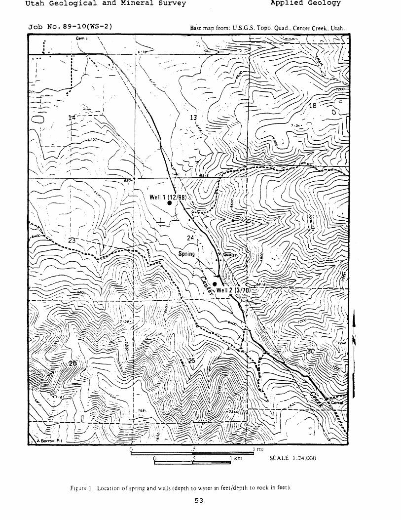
utah Geological and Mineral Survey Applied Geology
Job No. 89-10(WS-2) Base map from: U.S.G.S. Topo. Quad .. Center Creek. Utah.
: I \ \ • c.m: \ It:>'
~~'~' __ ~~~ __ ~\~ ___ l6_'1~ __________ ~~ __ ~~ ... , j ,
I -~-
a.-_' - ---~ .... "
o
/
\ .---e
\ ~"'''-..::.\. .
\ '
\ / 13 \
Ci::,i =====:::::::'ii=" =========!!!!!!~J mJ
(t/======~'65======al~1 SCALE 1 ::?4.000
Fl~U re 1. Location of srring and wells (depth to water in feet/depth to rock in feet).
53
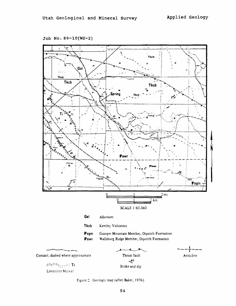
utah Geological and Mineral Survey Applied Geology
Job No. 89-10(WS-2)
... ~ .. -...... -..... '~~ .. -.. -~i·-·i·:-··-···" ,::: .. Tkcb ,: \ '" -.\
: : \:, \',
.....•.... :.. ' , .. : . • 'i \~::; _ ~~······9,-:~·~;:-. ;' - : ( /
.~ ,. . .• or·~:~<:::.:~--·······i·-·-':~· Tkeb
Tkcb .. ~.. t..... ,/' :- \ . , \:
• »-.-" " ••••• /." : \ ~~~ Spring Tkc:b ' .... - - i' .J>" .......... : \ .,.. ... ---:-.~ \. - __ ... C-.., e. \
: ...., -4, '." ; ..... . .... 1 \ ~ ~ \ r-----:l _ ' . ,-. ; " .. : \ I~. '. :. __ , __ ••• _ •••••• __ ••••• __ ••••• __ ._. __ :_._ ••• __ ..:. __ • __ ••• ~_ •• _~:~~ •• _
, i--'-~--''''--' ~_ I \ : . ~.. : \ ..... , ,I '.! " \~\ , .'" ,
00 ': \;" .'.\.\ \ .-.: .; , Ti ~X'Ti: .'-., ~\ '. " ,r-" .... _ ...... _....... :... ; ... .
~ I I;' ! .~~~.~\ \~ 2! ' ....... .1 ~.~ -(~~ .. ~--'l, : ... ~.;..--:;.:.:.-r--.... \ ~ \.-1$ 0 f ........~ ~~~ • .. ~ .'7.:....~ - It .•..• ". • / ., --"
'~~ -' • iJ" 1 ;. r"{ ~~ f,';"" '.~.. : .......... -. ",1 ;--"" -" """0 , I : , ......... ~ J /....... ....... , ...
" " 0' ! ,\. '.~. • _ . "',, ' ,; / ;" '\. .I 0 : : • :" \ '''~ " ~'''''-' : . .: : i .. X 0 '-'5 \ · ,.,. I . '" .... ..., .•.. " . I , ....
o ~. r--:-:--\-;--~,--~- ... ~-~-...-::--=-..::.-:: ... - -~.T----+------·----------·--:"'------~---__ ---------1. " .~-.... _ - ~-~ " , - - ';:";-". ".
I .. " :' .. ;; \. .~t.~-;;.:-::,- --'~-'" ... , ...... ", ", ii' \ '''\ ~.,-:::..... ..... '- .,;. ~~, : '--IS "" _ ... I Ii' ~
" " • 0 - ~ ., • ~ \ '. - .... ~- , : ". .... .... ;, ..! \ " i" :" . : ~ " ' I '- 4 , C' :', '. : .... · " Powr '. ·
'.
. '" I : \ : ___ _ r--··'"'----~---=---=::;:..._=_-----.:~:_'--.:I~ - - - - - - - -\- - - - - --: - - - - - - -
)-., ' \ ,Powr i "
i ', · , O'~ i ..... ) .... . __
I· \,'. ~"'''--= .....
,: .~ ~-q:;$--.-----.--.~ __ : _______________ .. .,L--· ,
l ---.--.. L--. .!.. .. --.-.~~~-:-:+<-------.--.--.. ;,..-._f_o...;g::,..m,_...,I ...
Qal
Tkcb
fogm Powr
Contact. dashed where approximate
0 0 0 0 Cc,r. _ ~ - :- Ti .... " '- ..... ~
O~i========~~======~a2mi o :km t::' ===l~~==i
SCALE 1 :63.360
Alluvium
Keetley Volcanics
Granger Mountain Member, Oquirrh Formation
Wallsburg Ridge Member, Oquirrh Formation
................................ Thrust fault
~o
Strike and dip
Flgure:;. Geologic map (after Baker, 1976).
54
---t---Anticline
!
canyon bottom is flood irrigated, and water was flowing in irrigation ditches at the time of the investigation.
GROUND WATER
In order to delineate a protection zone for the spring, the recharge area and potential zone of influence must be determined. Although no record of flow at the spring has been kept, LeRoy Sweat (oral commum., June 12, 1989) indicated that it flows year-round and was measured at about 90 gallons/minute earlier in the year. Although annual fluctuations have not been recorded, Mr. Sweat indicated that he has not noted any increase in flow during the irrigation season and believes flow to be constant with little variation. Water quality analyses indicate that the water meets drinking water standards.
The spring occurs at a location in the valley bottom near the toe of the alluvial fan depoE~ted from the eastern side-canyon south of the spring. Phreatophyte vegetation and grass in the valley bottom downstream from the spring and fan toe indicates that shallow ground water is present in the alluvium. The well near the spring (well 2, fig. 1) reported a depth to water of 12 feet at the time of drilling, with a static water level of 3 feet after completion on September 11, 1971. This is interpreted to indicate that the depth to the water table in the unconfined alluvial aquifer is 12 feet, but that water in a confined a~~ifer under artesian pressure was encountered deeper in the hole. A test well drilled in the same general area (exact location unknown) recorded a depth to water of 12 feet, and a well downstream about a mile recorded a depth to water of 16 feet (weIll, fig. 1). There is thus a shallow water table in alluvium, probably recharged by irrigation, flow from side canyons, and spring flow. The role of center Creek may change annually from a drain during the irrigation season to a source of recharge during dryer times of the year.
The shallow alluvial aquifer is not, however, the likely source of flow at the spring. Because of its location at the canyon margin slightly above the valley bottom, and the reported constant flow with no noticeable increase during flood irrigation, the spring is believed to be discharging from a bedrock aquifer and not the valleybottom alluvial aquifer. The recharge area is then chiefly in the hills on the east side of Center Creek Canyon. Although the boundaries of the recharge area are unknown, the aquifer feeding the spring is likely fractured bedrock of the Oquirrh Formation. This formation yields water to wells and springs elsewhere (Baker, 1970), and is believed also to be the aquifer tapped by wells in the valley bottom causing the artesian pressure in well 2 near the spring (fig. 1). The presence of the spring indicates a water level in the rock aquifer above the perforated interval in the well (20-143 feet), possibly accounting for the rise of water in the well above the water table in the unconfined alluvial aquifer.
SPRING DEVELOPMENT AND PROTECTION ZONE
If the spring is to be developed as a culinary water source, care will be reqJ:red to ensure that it does not become contaminated. To
55
reduce the possibility that water will be collected from the shallow alluvial aquifer, collection lines and structures should be placed at the present elevation of the spring rather than being buried in the valley bottom. If lines are placed at an elevation below the present spring, it is possible that they will tap the alluvial aquifer as well as the bedrock aquifer, greatly increasing the potential for contamination and requiring the protection zone to include the portion of the 1500-foot protection zone on the valley bottom from center Creek to the road on the east side of the valley.
The spring is already in an area with a high potential for contamination from the road, an irrigation ditch along the fence on the west side of the road, and from cattle in pastures in the hills above and east of the spring. The 1500-foot protection zone above the spring east of the road is needed. If the spring is developed such that only the flow from rock is captured and lines are above the present valley floor, it will probably not be necessary to protect valley bottom areas except along the road at and above the spring. The irrigation ditch between the road and the fence southeast of the spring will need to be abandoned or diverted well upstream to ensure that infiltration from the ditch does not recharge the spring. It would be prudent to define a protection zone in the valley bottom along the road and base of the hill upstream from the spring to minimize the potential for contamination. The width and upstream extent of the zone cannot be determined without a detailed knowledge of ground-water conditions, but it probably need not extend more than 50-100 feet west of the road for 1500 feet upstream.
REFERENCES
Baker, A.A., 1976, Geologic map of the west half of the Strawberry Valley quadrangle, utah: u.s. Geological Survey Miscellaneous Investigations Map I-931, scale 1:63,360.
Baker, C.H., Jr., 1970, Water resources of the Heber-Kamas-Park City area, north-central Utah: Utah Department of Natural Resources Technical Publication No. 27, 79 p.
Lund, W.R., 1983, Unpub. Utah Geological and Mineral Survey letter to Phillip Wright (April 15, 1983) regarding Center Creek springs, 7 p.
56
~; a...,..u..~:
Potential Reduction to Spring Discharge as a Beaver City Result of Changing from an Open-Ditch Irrigation System to a Piped Pressure Irrigation System, Beaver City, utah
.,: Mike Lowe I Da&1~ 1 -1 5 - 8 9
I c...t1:
Beaver Countv I ~N .. : (WS-3)
RQ-1F..
USGS Qwa&ru&l.;
Beaver, Utah (440)
INTRODUCTION
The purpose of this study, requested by Robert H. Lee, Beaver City Mayor, is to assess potential impacts on spring flow in the southwest part of Beaver City that may occur as a result of Beaver City changing from a open-ditch irrigation system to a piped pressure irrigation system. Beaver city is located in Beaver Valley just west of the Tushar Mountains in southwestern Utah (attachment 1). The scope of work included a 2-hour field investigation of the area on November 9, 1989, and a literature review. Mayor Lee and Conrad Grimshaw, City Councilman, were present during the field investigation. During the literature review it was determined that Palmer Wilding, Consulting Enginee~s, had already investigated the potential impact that changing to a pressure irrigation system by Beaver City might have on the spring-fed Beaver Fish Hatchery, and that, to some extent, the conclusions reached by Palmer Wilding probably apply to other springs along the southwest margin of Beaver city as well.
HYDROGEOLOGIC SETTING
Adobe Slough and Big Slough are the principle spring-fed drainages in the southwest portion of Beaver City. The springs are located near the contact between late Pleistocene (10,000 - 125,000 years before present) terrace alluvium (Qty, attachment 2) and Holocene (0 - 10,000 years before present) flood-plain alluvium (Qfp, attachment 2). The terrace alluvium consists of medium to coarse sand and bouldery gravel deposits that form a low terrace which is slightly elevated above the flood-plain alluvium and which was formed by the coalescing late Pleistocene flood-plains of the Beaver River and North Creek (Machette and others, 1984). The Holocene flood-plain alluvium consists of coarse sand and bouldery gravel deposits of the Beaver River which form the broad, slightly dissected surface southwest of Beaver (Machette and others, 1984). Numerous seeps and springs indicate that the groundwater level is near the ground surface in the Holocene flood-plain alluvium. Marsh deposits have also been identified in the flood-plain alluvium (Machette and others, 1984), indicating that shallow ground water may have been present in the area during much of Holocene time. Attachment 3 is a block diagram illustrating ground-water conditions in Beaver Valley. Beaver City would be located on the terrace in the foreground near the base of the Tushar Mountains. As shown on attachment 3, the source of water flowing from springs feeding Adobe Slough and Big Slough is perched and water-table aquifers which intercept the ground surface at the base of the late Pleistocene terrace alluvium.
57
EVALUATION OF CONCLUSIONS IN THE 1982 PALMER WILDING REPORT
The U. s. Geolog ical Survey (Mower, 1978) determined that the irrigation efficiency of Beaver River irrigation water, applied using flood-irrigation methods, was 27 percent and that 73 percent went to recharge the ground-water reservoir. Based on a graph taken from a Division of Water Resources feasibility report, which assumes that the availability of a pressure irrigation system will result in a change from flood irrigation to sprinkler irrigation, Palmer Wilding estimated that the irrigation efficiency of sprinkler-irrigation water would be 60 percent and that a maximum of 40 percent could go to recharge the ground-water reservoir.
Palmer wilding determined from flow measurements taken in 1979 at the Beaver Fish Hatchery, and from the potential irrigation diversion by Beaver City (based on water rights), that during low-flow periods springs and city drains accounted for 25 to 30 percent of streamflow at the fish hatchery. During the irrigation season, Palmer Wilding determined that springs and city drains accounted for 50 to 60 percent of streamflow at the fish hatchery. The lag time between the beginning of irrigation and significant increase in discharge from the drains and springs was determined by Palmer Wilding to be about 2 to 4 weeks.
Approximately 4 to 9 cubic feet per second flowed through the Beaver Fish Hatchery during the 1979 irrigation season (Palmer Wilding, 1982) . Based on the infonnation provided above, Palmer Wilding concluded that a change to a pressure irrigation system using sprinkler-irrigation application methods could theoretically reduce flow at the fish hatchery during the irrigation season to 1 and 2 cubic feet per second.
Although, based on the information in the report, the conclusions reached by Palmer wilding appear reasonable, the effect of changing to a pressure irrigation system may have been overestimated because of their assumptions that:
1) all of the irrigation diversion rights available to Beaver City in 1979 were being used by the city within the area which will now go to pressure irrigation. Not all of the water flowing in the City Ditch is used for irrigation (Conrad Grimshaw, oral commun. 1982). Some of the water eventually reaches other canals, sloughs, and ultimately the Beaver River as surface flow. Seepage from the canal bottoms was determined by the U. S. Geological Survey to be only 2.4 percent of the available water, therefore little of any unused irrigation water would have gone to recharge the ground-water reservoir.
2) the City Ditch was the only irrigation canal contributing to spring flow reaching the Beaver Fish Hatchery. The City Ditch is not the only irrigation canal up gradient (northeast) of springs issuing from southwest Beaver City. Attachment 4 shows the location of some of the other canal systems in the vicinity of Beaver City. Some existing irrigation canals, such as the Willis Ditch, are not shown on attachment 4. Other canals, including the Mammoth Canal which carries more water than the city Ditch (Cruff and Mower, 1976), are also contributing water to the ground-water reservoir. Also, water derived from seasonal spring runoff may be contributing to the ground-water reservoir during the high spring-flow period.
3) the same number of people will use the pressure irrigation system that used the open-ditch irrigation system and that everyone
58
will change to sprinkler-irrigation application methods. Many residents currently living in Beaver City do not maintain green lawns, probably because of the problems associated wi th using the current open-ditch irrigation system (Conrad Grimshaw, oral commun., November 9, 1989). Some of these residents are likely to use the pressure irrigation system in the future due to the relative ease of application. Some of the residents may continue to use floodirrigation methods after the change to a pressure irrigation system.
RECOMMENDATIONS
Geologic evidence indicates that shallow ground water probably existed in the Beaver City area prior to the start of irrigation by man. Irrigation in the Beaver city area has probably increased spring flow, particularly during the irrigation season. Al though it is possible that changing from an open-ditch irrigation system to a piped pressure irrigation system will result in lower summer spring flows~ the resulting lower spring flow may not be as much as indicated in the Palmer Wilding report.
To document the actual effect of changing irrigation systems once it has occurred, it would be necessary to monitor spring flow at several locations before anj after the change. Several locations were ide~tified during the Nove~~er 9, 1989, field investigation that could be used as monitoring points without having to construct flumes. The quanti ty of water pumped from wells and amounts of precipi tation in the Beaver City area for a period before and after the change would also have to be monitored and factored into the analysis.
To estimate in advance the actual reduction of spring flow caused by changing water systems, it would be necessary to work out a complete water balance for the springs and to define recharge areas and aquifer flow directions. Hydrographs for springs showing discharge as a function of time, records of amounts of irrigation flow and schedule of flow in canals and ditches, and records of precipitation and well pu~ping rates would need to be collected. Placement of piezometers in the aquifer with mapping of water-table changes during irrigation would also be helpful in evaluating recharge areas, flow directions, and how much irrigation presently contributes tb flow at each spring. Once that is done, estimates of changes in the amount and efficiency of irrigation wi th the pressure system would need to be made and the resulting difference calculated.
REFERENCES CITED
Cruff, R. W., and Mower, R. W., 1976, Seepage study of canals in Beaver Valley, Beaver County, Utah: Utah State Department of Natural Resources Technical Publication No. 52, 45 p.
Machette, M. N., 1982, Guidebook to the Late Cenozoic geology of the Beaver basin, south-central Utah: U. S. Geological Survey Open-File Report 82-850, 42 p.
Machette, M. N., Steven, T. A., Cunningham, C. G., and Anderson, J. J., 1984, Geologic map of the Beaver Quadrangle, Beaver and Piute Counties, vtah: V. S. Geological Survey Map 1-1520, 1:24,000 scale.
59

Mower, R. W., 1978, Hydrology of the Beaver Valley, Beaver County, Utah, with emphasis on ground water: Utah state Department of Natural Resources Technical Publication No. 63, 90 p.
Palmer Wilding, Consulting Engineers, 1982, Future water supply evaluation for Beaver Fish Hatchery: Consultant's report for Utah Division of Wildlife Resources, 12 p.
60
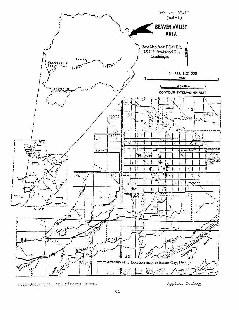
/ '. ,.,.. r.. . .. Job No. 89-16 .. "-'... • -.. •• ./ \ (WS-3)
~ '"\ ,~ ~ BEAVER VAllEY ,./' '-' ~ AREA , ..
,1 '~. • Base Map from BEAVER. t: f U.S.C.S. ProvNc=.I7·~' i!
I ~ . .j" Q.Jadr.mgJe. Z
I ~.'I i Mrs" i II e .A( __ ~ I ..
f i /) D, .. us I (a. .............' / -----------.:
SCALE 1:24000
'\. .) 'a ) /
[' ·~..lll!.r.! ~ ... '"L •. ,.....,. " •• ...- . .Y J:tt.OM£TERS
: 'lOa ,a. , / CONTOUR INTERVAl. 40 FEET
I.~ {' // ~ .. I 'I I • / 41f .:.-J N'''£O,''...J ".! . I L i I \, ............ J.. / ~i!~;"1 I~ " . ' I, --I
I / -_.-: ,_..... ~j~J i .~ · I 1 S I // '., ••• ~ If I 61 t-.... -.-...... ,'.~: ... :'.'~>': :',1 ~ " C'SC! g~ , J
R,.....·r, iii r-"-"···t 'rrf" ......... !
I // .- .. ,,,,, i ' c~ !t·'~J:;:-l~·'----I·:-!·"''!':~I,··~-'/V:lL-.-.-._.J / I,· t;: :"·<t~~" ~ '''" I I ! I /. .' . .,' ... I~ I' I .' --;-...., • I I / 'r--·--rT·-----" 'I -.-.--~~-------'"t ..• _.-~
I / ,;ec'~I' 11 J II .(" ~ -II "if\1 Ii .~~. i .1·--··-·1~C.·j /// - I 1~~;:;. Ij'~·;~\ 1J L7" . j ~ ~~ / ~f5=' :1\\; ,~'; ; i '~~.-~~: T I_~~ • .. ~ ., l' •• - •• _ /., I JIB ~ I 11 I I I }.. I If" ~ I i I r~d'y/'~ \. 1/) I 1\· eaver Ii', ~-~ P.. --:-'\1 : I ==Z> \~~~'~;?i ! I 7.7 : · I y':' 4 I
-=:'~I t.:\~~ ~~.-.. -.A 111··_..... . ,J ~.,/ '7 :
! .~ ~ . ~
! --.'. () '" 1'- -., 1
L~---;j_ .. _~·;~ UTAH
P .. pplied Geology
61
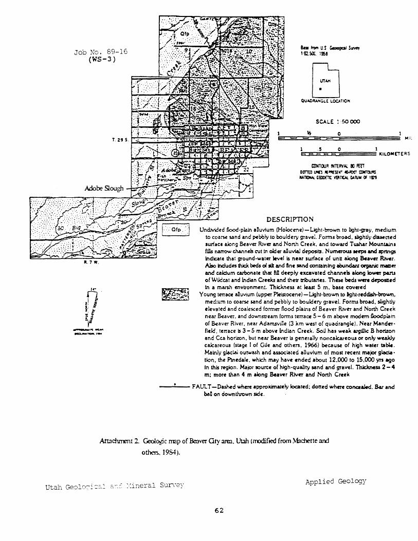
Job No. 89-16 (WS-3)
R.7 W.
-"'---_1-
SCALE ;50 CX)Q
1 * 0 e==ss==
.5 0 1 EH:cES:r.::::Ee=:::::ESDS3:i===== KILO"'EiERS
annOOR MtRVAL Il"l FEn Dorm U'C "~S{l(' C).It'Ia1' a.rtlM III TOW. IiEDOfTl: $ T1:AI. GA NY OF t~
DESCRIPTION
Undh.ided flood-plain aDu"';um CHok>ceTIe)-IJght-brown to light-gray, medium to coarse sand and ~bbly to bouldery gra .... el. Forms broad, sbghtJy dis5ec:ted surface along Beaver Ri .... er and North Creek, and toward Tushar Mowttalns fWs nanow channels cut 10 older alluvial deposits. Numerow _eps and sprtngs indole that ground-water w,.,eJ l$ near surface of untt along Baver RNcr. Also Indudes thick beds 01 Iii and ant sand conminlng abundant organic macer and caldum carbonate that fUI deepty excavated channels along iowa paru of WUdcat and indian Creeks and thu tributaries. These beds were depostlcd In a marsh en .... ironment. Thk:.kness at least 5 m. base covered
Young tm6Ce alluvium (upper P1eistocene) -Light-brown to &ght-reddish-brown. medium to coarse sand and pebbly to bouldery gra .... el. Forms broad. sLghtiy elevated and coalesced former flood plains of Bu .... er River and North Creek nur oover, and dO'Nnstream forms terrace 5 - 6 m above modem floodplain of Beaver River, near AdamsviDe (3 km west of quacirangie). Near Manderfleki, terrace Is 3 - 5 m abo .... , Indl.an Creek. Soil has weu argillic B hortzon and Cca horizon. but near Beaver I.s general}y noncak:.areow or only weakly calcareous (stage I of Glle and others, 1966) because of Mgh water ta~. Mainly gtadal outwash and usocl.ated aUuvlum of most recent ma;or gladation, the P'lnedale. whk:h may have ended about 12.000 to 15,000 yrs ago In thls rrglon. Mapr source of high-qUality sand and gravel. Thk:knas 2 - 4 m; more than 4 m along Beaver RiveT and North Creek
--""'-- F ALn. T -Da..shed where approximately located; dotted wheTe concealed. Bar and baD on downUvo\lr'J'l sade.
Attachrrent 2 GeoIC¥ic rrnp of Beaver ary area, Utah (mxiifJed from Machette an:!
o thets. 1984).
Utah Geolcci =:~~ c.:-.:. :·:ineral Survey Applied Geology
62
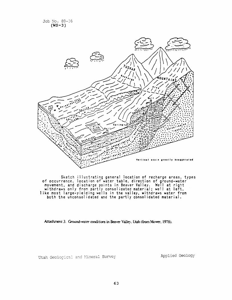
Job No. 89-16 (WS-3)
@ " , ""
~ --. -" ", I 'I'
Sketch j llustrating general location of recharge areas, types of occurrence, location of water table, direction of ground-water movement, and discharge points in Beaver Valley, Well at right withdraws only from partly consol ioated material; well at left,
1 ike most large-yielding wells in the valley, withdraws water from both the unconsol idated and the partly consol idated material.
A.ttadurent 3. Gn:xm:J-water conditions in Beaver Valley. Utah (from Mo\\er. 1978).
Utah Geolog icc::" 2:1C; ~·:i~erc;.l Survey Applied Geology
63
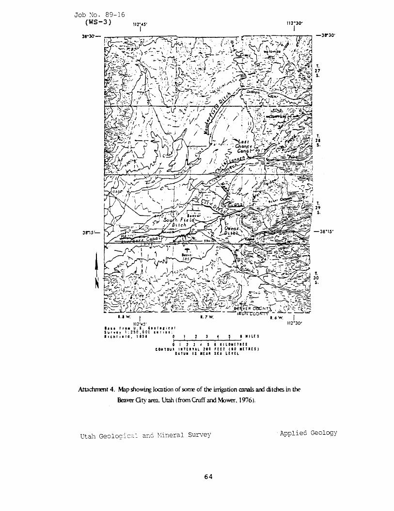
Job No- 89-16 (WS-3)
3 In's '-
•.• w. I 117-"S'
1.7W. I~O~Ot)~
1.6W,
•••• fro. U.s. '.DI"le.' SUI.,} t:250.0CC 'Irlt,: ."IIII'IG.18H 0 " I.,L£S
~I --~~!~--~~--~~! C I 3 4 I IILOMnUS
to.lOU. 'ITt"AL 200 '[[T (10 .[T'[S) DATUM IS It'. $[A L['[L
I 112·30'
Attachrrent 4. Map showing 1000tion of sorre of the irrigation canals arxI ditches in the
Beaver G ty area. Utah (from Cruff and Mo~. 1976).
-3r30'
T. 21 S.
T. 30 $.
Utah Geoloci C~~ an6 Viineral Survey Applied Geology
64
SOLID \\'ASTE DISPOSAL
65
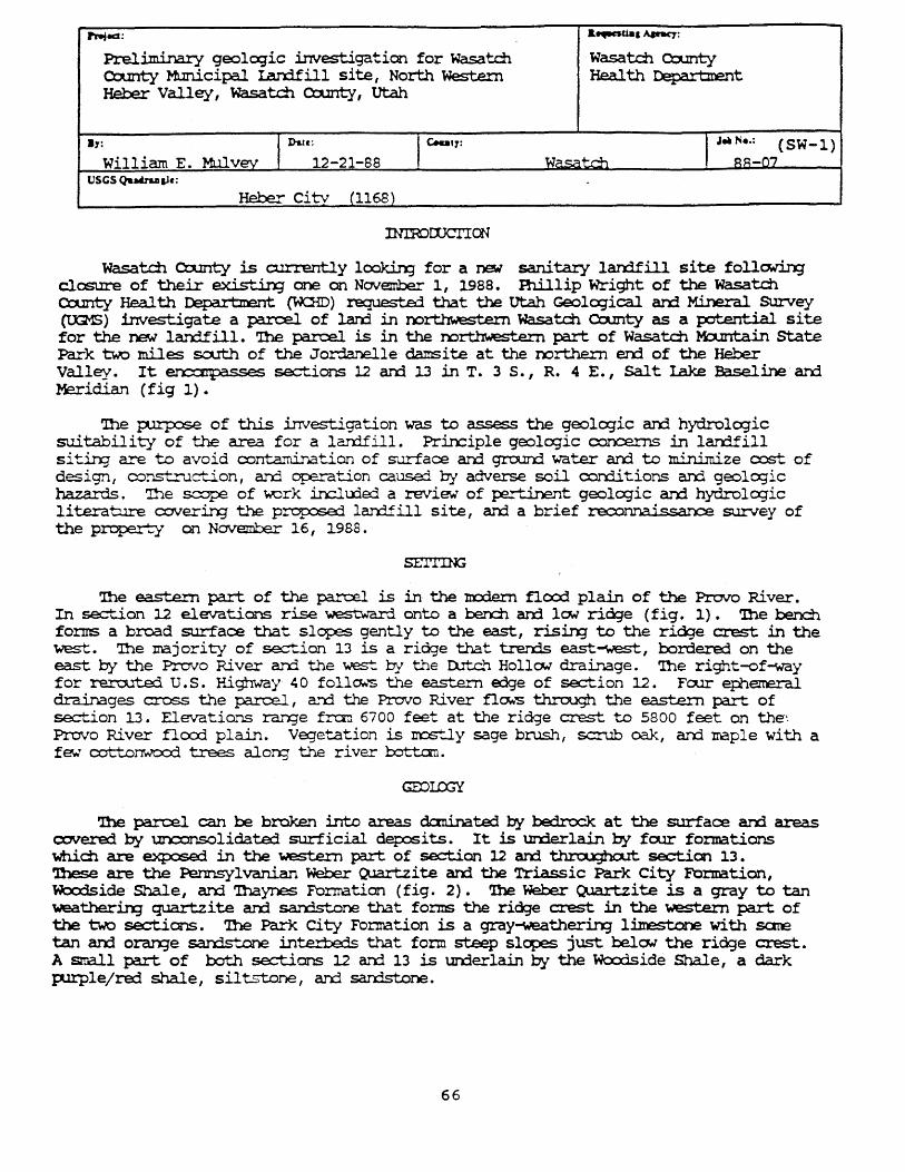
rnted: &..-.uaa A.Inq:
Preli.m.incuy geolcqic investigation for Wasatdl Wasatch County County MLInicipal Larxlfill site, North Western Health Depart:rrent Heber Valley, wasatch County, utah
.,: I Dau:12_21_88 I c.u'r: I J_Ne.: (SW-l) William E. Mulvey Wasat.d1 ~~-(,J7
VSCS QubaD&le:
Heber citv (1168)
nnrorlJCTICN
wasatch County is currently loakin; for a re-I sanitary lardfill site foll~ clcsure of their exi.stin; one on November 1, 1988. Fhillip Wright of the wasatch County Health Department (\'KlID) requeste:3. that the utah Geolo;ical and Mineral SUrvey (t.G1S) investigate a pncel of lard in oorthwestem Wasatch County as a potential site for the 'f')EM lan:ifill. '!he parcel is in the rx>rt.lTwestern part of Wasatdl l-b.mtain state Park 'b.-o miles sa.rth of the JordaTlelle damsite at the nortbern errl of the Heber Valley. It ero::mpa.sses sections 12 an:i 13 in T. 3 S., R. 4 E. , Salt Lake Baseline an.1 Meridian (fig 1).
'lhe ~ of this investigation was to assess the geologic anj hydrolcqic suitability of the area for a larrlfill. Priociple geologic c:x:n::erns in larrlfill sit.inq CLore to avoid conta~tion of S'..Lrface ard groorrl water arrl to minimize o::::st of design f constr..lc""~on , arrl ope.....TQ.tion cau.se:l by adverse soil con::li tions arrl geolo;ic hazards. '!he scope of work in::lu:led a review' of pert..inent geologic arrl hydrologic l.i terature coverin; t.~ prop:se:l larrlfill si te, an:l a brief re.::xmnai.ssan survey of the property on NO\TelIll:)er 16, 1988.
SEl'l'lll;
'!he eastern part of the pc4~ is in· the m:xiern flcx:d plain of the Provo Ri vex. In section 12 elevations rise westward onto a beoch arrl lC1N ri~e (fig. 1). 'Ihe bench forms a broad surface that slopes gently to the east, rising to the ridge crest in the west. '!he majority of ~...ion 13 is a ridge that tren:is east-west, bordered on the east b-.i the Provo River arrl the ~ by t..'r)e I) ... tc.'-1 HollC1N drainage. '!he right-of-way for rercuted u. s. Highway 40 follOw'S the ~....ern edge of section 12. Foor ephemeral drainages cross the pncel, a"'rl the Provo River fl~ through the eas+-~ part of se=tion 13. Elevati~"1S ra.n;e :fra'n 6700 feet at the ridge crest to 5800 feet on the'. Provo River flocx:l plain. Ve;etatian is ~..J.y sage brush, scrub ook, an::l maple with a few' c:ot+'~nwcx:d trees alan; the river bottc::rn.
'!he parcel can be broken into areas daninated by bedrock at the surface an:i areas O:Werec1 b-.i \ll'XXn1SOlidate:1 surficial ciet:osits. It is UOOerlain by four formations ~dl are ~ in the western part of se=tion 12 arxi t.h.rou;ha.It section 13. 'lhese are the Pennsylvanian Weber Q.Jart,zite an:l the Triassic Park city Formation, Woc:dside· Shale, an::i 'lllaynes Fonnation (fig. 2). '!be Weber cuart.zi te is a gray to tan weatherirq quartzite am sarrlstone that forms the rid:Je crest in the western part of the two sections. '!be Paric City Formation is a gray-weathe...,..-mg limestone with sare tan an:l orarge san:ls+-~ inun+€ds that form steep slopes just l::ela.v the ridge crest. A srrall part of 00th sections .12 arrl 13 is un::3erlain by the Woc:dside Shale, a dark P-lIPle/red shale, sil 'b:,-t.one I ar.d sardstone.
66
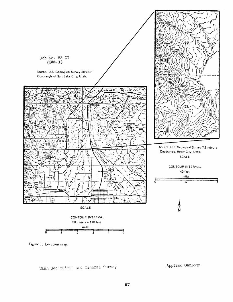
Job No. 88-07 (SW-l)
Source: U.S. Geological Survey 30'x60'
Quadrangle of Salt Lake City, Utah.
b
Fi~"n' 1. Loc'ation map.
SCALE
CONTOUR INTERVAL 50 meters:: 170 feet
miles
2 3 4
o
67
Source: U.S. Geological Survey 7.5 minute
Quadrangle, Heber City. Utah.
SCALE
CONTOUR INTERVAL 40 feet
+ N
miles I
Applied Geology
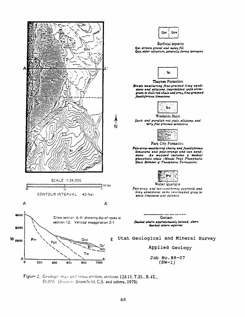
A
6600
&200
W 5800
~ N
SCALE ".24,000 C!:-________ IL..-______ --J! miles
o 'I~ 1
\ \
CONTOUR INTERVAL 40 feet
\ \
A'
Cross section A·A' showing dip of rocks in
section 12. Vertical exaggeration 2: 1
53 Surfi ci;J deposi t.s
Oal • • tnam graPd an.d trGJ.U~ jiU 00., oltJ.,n- a.U"~\lm, gnvrcUl1l /OTT'IU tnTG&6.
Thaynes Formation Brotrfl .... atA..,.;f14 ji" •• ,"A'Md limv .aM
RoN AU ,uutO'M, ifUlrHdd.d "",tIL oli""....,. Co dv.ll-f'Yd , It4U aM g?'C JlIi Moog"' v..-d /NNi,lrro", limuton.
:."::.: .~~ .. , ~ ..... '
, .~-~- ::~. '. Woodside Shale
Dark- aM pt.trpluh-red ,Ja,aJt, l'ilt3tcnw, aM ~ jiM grai1\4d aan.d..lUm.t
E]--' -----=-~~~.~~'
---.-.- ....
Pari City Formation PaU-,ra,..1INa.tArrift.Q CMrtr AU /O'rUi/1"f"'f:nU
li .... Ufw ,,,.d pa.U~"4"" aM ta" .ond,,",,. A, .ap~d iaelwd.. a .... dial ,JuJ..ple.4.ti.c .1t.tJ.U (M,C1iU P,ak Pko,plJ.4tic SAIll4 M~ 0/ Pkorph0ri4 Forma.tic?\)
ti~N Weber Quartzite
Pa.lt..grall- end tC1!-u.'tatJr"·i,,g qucrtzit.t e1l4 1171111 .aMltone; 10 mt j"ftrbtdded grew ~ ",hiu li1M.toM clta dolo mitt
Cont.a.ct ~ VI""""- o~tft4ulW loeaud.; ,It.ort
dG.Ilt.6d ",Iwrc ifl/rrr«i
\ Pw " ,,~pc "" :::::-.......:~ ......... ::::::~ ___
" " '" "l=l i " " ....... -E Utah Geological and Mineral Survey
Applied Geology
" " Tw --" "-A~--------__ ----~ __ --~------A· o 200 400 600 80C 1000
Job No. 88-07 (SW-l)
FigtJrP~. Gf'()lo~i (. rn;J f \ J n r! no~::) !irl't ion. !ipctions 12& 13. T.3S .• RAE .. SLI3\1. (SOtlr('r: Bromfidd. C.S. :mu oth~rs, 1970)
68
Most of section 13 is 1Jl'rlerlain by the 'lbaynes Formation, a b~red to olive green san:lstone, siltstone, an:} shale (Branfield, 1970). It fonns the lOw' ridge that dcminat.es the section an:l nost likely 1Jl'rlerlies the older alluvium coverin;1 the eastern part of section 12. Rocks in section 12 dip to the east, and those in section 13 dip to the sa.rt:heast (fig. 2).
Unconsolidated dep::lsits in both se::t.ions are ccrcp:sed of alluvium of varyin; ages. 'lbe ~ alluvimn is on the m:rlern floc:rl plain of the Provo River an:1 fonns the flat lan::iform on the eastern Edge of the two sections. In section 12 the ben:::h alxwe the m::xler11 flocd plain is covered by an older alluvium. A road cut just north of section 12 in:licates that this older alluvium is up to 15 - 20 feet thick. '!be alluvium in the Provo River flocx:l plain is probably 1IIJCh thicker.
VariOJS geolcgic hazards are f~ in the northern Heber Valley that ccW.d potentially affect the propose:l lan:lfill , although n:>ne appears to pose a significant hazard. Investigations by the u.s. Bureau of Reclamation have not fourrl evideI'X)e of surface faulting, in:licatin; that the hazard fran fault rupture is lCM arrl that large e.a.rthquake.s (nagr-. .:tude 6.5 and larger) are not likely (SUllivan, 1988).
HCMeVer, an earthq\.lake of magnitude 6.5 or less co..lld occur ~nere in the area (Ara.OO..sz an::l ot.he.."'"'S, 1983), p:ssibly causirg str'orq grcun::l shaki.rq at the site. SUch shaY..i.n:j p:ses a threat to stIuctures and Ul1SlJt:POrted excavation walls, but geolo;ic h.aza....-rds asscx::iated with gI."OJ.!'rl sh.a.k.ing such as rockfall, slope failure, an::1 liquefaction ~ to be lOw'.
GeolCX;ic mawin;3' by the u. s. Bureau of Reclanatioo identified several laroslides ; mred ; ately north of section 12 in volcanic bedrock. 'Ihese failure-prone volcanic rocks do rot exterrl into the parcel. Al ~ 00 landslides have been maI=PE!d in .sections 12 arrl 13, ove.rst.eepeni.n; of hillslc::pes by excavation for roads or lan::lfill tren::hes co.lld cause local slope instability, particularly in clayey unconsolidated dep::lsi ts. Flocx:li.rg co.lld occur in the bottans of eq::ilemeral drainages and the Provo River flc:x:::rl plain. Flc:x:::rl p:rt:.ential of the Provo River will be reduced with the carpletion of the Jordanelle tam. Flo:d control measures would be require:i in erbemeral drainages if la.'"rlfill sites or aa:es.s roads are plannerl in the drainages.
SOILS
The U. s. Soil Q:)nse.rvation Se,..ryice (SCS) (Woo:jward ard othe..."'"'S, 1970) iniicates a o:xrplex assemblage of soils in the parcel (fig. 3). 'Ihese soils are classified by the scs usi.n; the unified Soil Classification System (USC5; a~) as mostly silts (SM) an:l lean clays (CL), in the bench am ri~e area to the west, with gravels (GP) in the m:x:iern flcxxi plain of the Provo River. O-lr observations in the bench area of section 12 in:ti.cate that m:my of the soils are clayey gravels (GC) or silty gravels (Gi),and in general are ~ than in:licated by the scs.
'!he SCS in::licates that the majority of soils have severe limitations for trenchtype lardfills due to high clay o:mtent, numaroos cobbles an:i bcW.ders, an:3/or shallCM depths to bedrock. Soils on the bench al:x:rve the m:xiern flocd plain of the Provo River in section 12 are 15 to 20 feet thick, as seen in a road cut to the north. Soils on namtainsides are thin, particularly in the steep hilly terrain in much of section 13.
69
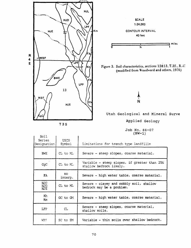
R 4 E
... _ ... ,. HJE
'" ."
13
HJE
T3S
So' 11 Series us:s
Designation Symbol
~~ CL to XL
CgC CL to M:.,
FA no interp.
HJe HJD CL to ML IDE
Kh GC to G1 KIn
LFP CL
\-;'E:- sc to SM
Km
SCALE , :24,000
CONTOUR INTERVAL 40 feet
t:' ======::;r:' ======~i miles o ~ 1
Figure 3. Soil characteristics, sections 12&13, T.3S., RAT (modified from 'Woodward and others, 1976)
~ N
utah Geological and Mineral Surve
Applied Geology
Job No. 88-07 (SW-l)
Limitations for trenc.IJ type landfills
Severe - steep slo:pes, coarse material.
Variable - steep slopes, if greater than st~llo~ bedrock likely.
25%
Severe - high water table, coarse material.
Severe - clayey and oobbly soil, shallow· bedrock may be a problem.
Severe - high water table, coarse material.
Severe - steep slo:pes I coarsema terial , shallow soils.
Variable - thin soils over shallow bedrock.
70
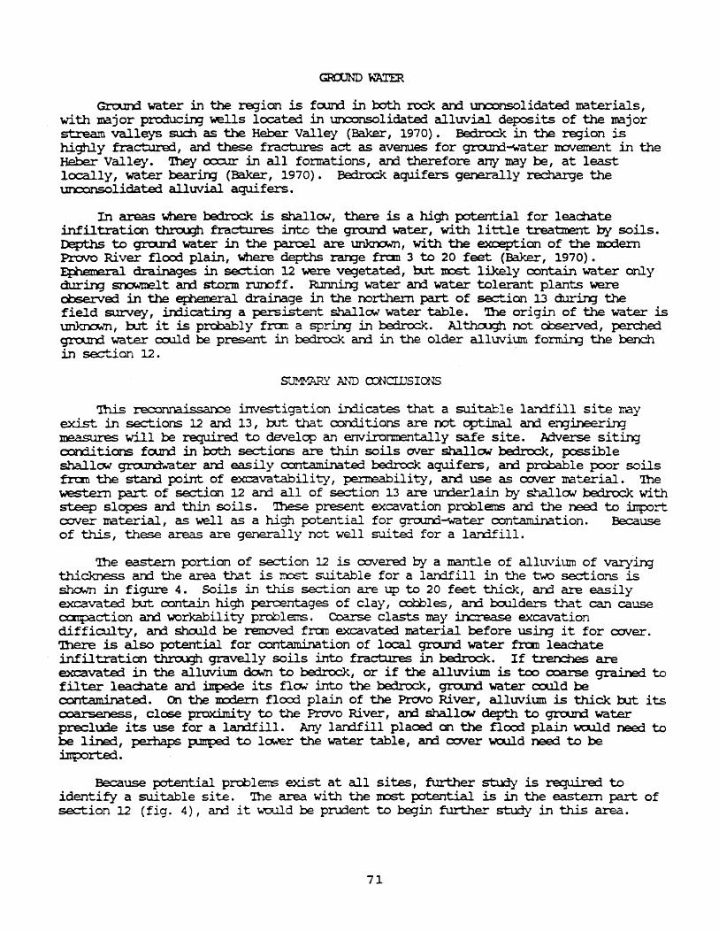
Gro..In:l water in the region is fcorrl in ooth rock arrl un:::onsolidated xraterials, with major prcxiucin;] wells located in un:x:msolidated alluvial deposits of the major stream valleys such as the Heber Valley (Baker, 1970). Bedrock in the region is highly fracture1, arrl these fractures act as avenues for grourrl-v.ater IrOVement in the Heber Valley. '!hey cxx::ur in all fonnations, arrl therefore any may be, at least locally, water bearin;] (Baker, 1970). Bairock aquifers generally recharge the urx::onsolidatej alluvial aquifers.
In areas where bedrock is shallO'.¥, there is a high potential for leachate infiltration t.h.t:'cu3h fractures into the gra,trXi water, with 1i ttle treatment by soils. Depths to grourrl water in the parcel are ~, with the exoaptian of the m:xlern Provo River floc:rl plain I Were depths ra!XJe fran 3 to 20 feet (Baker, 1970). ~ drainages in section 12 were ve:jetate:1, l:ut lOCSt likely ex>ntain water only durin:;; ~t am storm nm:>ff. ~ water am water tolerant plants 'Nere cbsel:ve::l in the ~ drainage in the oorthem part of se:.:+-..J.on 13 durirg the field survey, in:ticatin:; a persistent shallOil water table. '!he origin of the water is ~, b.rt it is prc:bably fran a sprirx] in bedrock. Al't:hc:JJgh not obseIve::1, perched gro..nrl water c.c:uld be present in bedrock an:1 in the older alluvium fornU.n:; the bench in se:;tian 12.
SUMMARY AND a::>NCillSIONS
'Ibis reconna.i.ssano investigation in:licates that a suitable larrlfill si te may exist in sections 12 arrl 13, b..It. that ex>n:li tions are not optiIral arrl ergineering measures will be required to develop an errvironmentally safe site. AiRe:rse si tin:J CXll"rlitions fourxl in l:oth sections are thin soils CNer shallo.-l bedrock, possible shall~ gro.ll'Xlv;ater arrl easily contaminated bedrock aquifers, an:l prcbable poor soils frc:rn the st.arrl JX=lint of exc:avatabili ty, penreabili ty , arrl use as CXNer Ire terial. '!he ~ part of section 12 arrl all of section 13 are urrlerlain by shallON bedrock with steep slopes an:3. thin soils. 'Ihese present excavation problems an:l the need to inport cover material, as well as a high p::>tential for gra,trXi-water contamination. Because of this, these areas are generally not well suit.ej for a larrlfill.
'nle eastern p:lrtion of section 12 is o:1Vere::l by a mantle of alluvium of varying thickness arrl the area that is most suitable for a lan::lfill in the two sections is sha..m in figure 4. Soils in this section are up to 20 feet thick, arrl are easily excavate::l b..rt. contain high percentages of clay, cobbles, a.rxi l:x:ulders that can cause CCI'lpact.ion am workability problems. Coa..'rSe clasts may in:::::rease excavation diffio.ll ty, an1 shruld be I"el!OVe:1 fran excavated material before usin; it for cover. '!here is also potential for contamination of local gra,trXi water fran leachate infiltration t.h.t:'cu3h gravelly soils into fractures in be:irock. If t:ren=hes are excavaterl in the alluvium down to bedrock, or if the alluvium is too (X)ar'Se grained to filter lead'late am inpede its flCN into the bedrock, grourrl water could be CXll"ltam:inate:l. On the m::rlern flcx:rl plain of the Provo River I alluvium is thick b..rt: its coarseness, close proximity to the Provo River, am shallow depth to gram:i water preclu:le its use for a lan:ifill. Arri lardfill placed on the flcxx1 plain wculd need to be lined, perhaps p.mped to lCJHer the water table, an:} caver wculd need to be inp:>rt.ed •
Because potential prd:>lems exist at all sites, further study is required to identify a suitable site. rrbe area with the nost potential is in the eastern part of section 12 (f ig. 4), arrl it would be pnrlent to begin further study in this area.
71
Job No. 88-07 (SW-l)
~ N
SCALE 1 :24,000
CONTOUR INTERVAL 40 feet
... 1 _____ ---'"1 _____ .... ' miles o Yz 1
Figure -i. Potf'ntiall~' suitablf> area (:::::::::) for a landfill in Stctions 12& 13, conditions art> \-ari<lblp and str<ltigraphic investigations are required to df"monstratc ~ik suitability and to provide informZltion for silp dpsign and construction.
utah Geological an:) Ninera2. Survey Applied Geolo;JY
72
SUch stu:1i.es sho..ll.d determine soil depth an:! type, ~-water quality and depth, and geologic hazards. Based on these data, c:x:n::lusioos shculd be made with regard to soil excavatabili ty, penreabili ty , workability, am suitability for use as cover; potential for gro..md water cxmtamination; ani measures needed to reduce inpacts of hazards. '!he ~ is available to review retX'rts fran such stu:1i.es for Wasat.dl Co\.mty up:m request.
REFERENCES
Arabasz, W.J., Jahns, R.H., and Peck, R. B., 1983, Review and analysis of geologic, seismotectonic, and design data for the proposed Jordanelle Dam, Bonneville Unit, Central utah Project, Utah: Unpublished consultant's report for u.s. Bureau of Reclamation, 87 p.
Baker, C.H., Jr., 1970, Water resources of the Heber-Kamas-Park city area, north-central Utah: Utah Department of Natural Resources Technical Publication, No. 27, 79 p.
Bromfield, C.S., Baker, A.A., and crittenden, M.C., Jr., 1970, Geologic map of the Heber Quadrangle, Wasatch and Summit counties, Utah: u.s. Geological Survey Geologic Quadrangle GQ-864.
Christenson, G.E., 1983, Investigation of geology and soil conditions for wastewater disposal, Strawberry Lake Estates Area C, Wasatch County, in Lund, W.R., ed., Technical letters and memoranda for 1983, site Investigation Section: Utah Geological and Mineral Survey Report of Investigation 190, p. 181-186.
Holmes, W.F., Thompson, K.R., and Enright, Michael, 1986, water resources of the Park City area, utah with emphasis on ground water: Utah Department of Natural Resources Technical Publication No. 85, 81 p.
Martin, R.A., Sullivan, J.T., and Foley, L.L., 1988, Seismotectonic study for Jordanelle Dam, Bonneville Unit, Central Utah Project, Utah: U.S. Bureau of Reclamation Seismotectonic Report 88-6, 76 p.
Sullivan, J.T., Nelson, A.R., laForge, R.C., Wood, C.K., and Hansen, R.A., 1988, Final draft - regional seismotectonic study for the back valleys of the Wasatch Mountains in northeastern Utah: u.s. Bureau of Reclamation unpublished report, 317 p.
Unitex Corporation, 1987, A hydrogeologic evaluation of the proposed Jordanelle Reservoir, Utah, for u.s. Department of the Interior Bureau of Reclamation: Unpublished consultant's report, 57 p.
73

Woodward, Lowell, Jensen, E.H., and Harvey, J.L., 1976, Soil survey of the Heber Valley area, utah - parts of Wasatch and Utah Counties: u.S. Soil Conservation Service, 124 p.
74
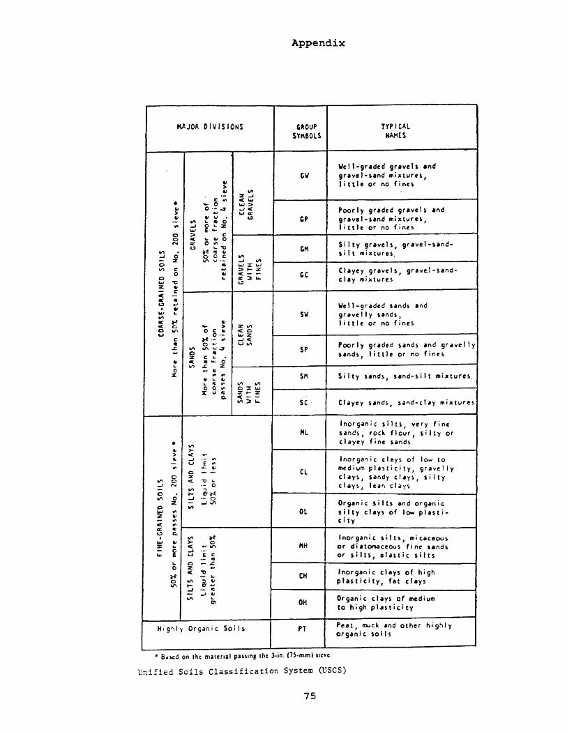
Appendix
KAJOR DIVISIONS GROUP TVP I CAL SY~BOLS NAAES
Welt-gr.ded gr.vels and CW 9ravel·~and mi_tures,
" > t i tt 1 e or no fines
" VI .- %-1 C '" <loW • ,.... 0 w>
" o ':'~ -'< Poorly graded gravels and > u «
" " u u GP 9ravel·~and mi_tures, .- VI ~ .. 0
'" -J ~.!: % lit t J e or no fines ...., 0 ::- c 0 <: ~
" 0 Silty gravels, gravel-und-N a:. 0 '" U ~." GM VI 0 ~ IV "
,i 1 t mixtures -I 0 o c VI - % Iol'I 1./.- -J VI 0 II 1.o.I;:r....,
gr ... ·e.l-sand-VI c .., >~;z CI.yey gravels, 0 " <:-- GC c ~ a:.~~ chy mixtures
1.0.1 ." c.,:)
Z " C c -Ie " Well-graded sand~ and c.,:) .., I ~ .... ~ SW 9' ave 1 I Y sands,
VI Ie ~ " little or no fines < 0
,.... > ZVI 0 VI 0 C &I <.0 u 0·- 1.0.12
C ~.- .... -'< gravelly ~ 0'" U VI Poorl y graded sands and L- VI Iol'IU~ SP .., 0 " sands, I j tt Ie or no fines
Z c ~ ,; ~ <- II~
~ VI L Z 0 - " Sind-silt ",i.tures. X .... '" SM S i I ty sands,
" ~ &I L ~ "" VI VI 0 0 "" o::rw x u ~ :z~:z:
Q. c:[--VI~~ SC Clayey sands, sand-chy mi.tures
'norganic s i Its, very fine Ml sand~, rock flour J s i I t Y or
• clayey fine sand~ VI
&I >-> c:( ..,
'nor9ani c. c.1 ays of 10 .... to " -' .. .... - u 1. '" .,.. &I ~djum plasticity, 9' ave 11 y 0 - - CL chys, sandy c.lays, 5 i I t Y 0 ;z
VI 0 <. "C ~
-' N .- 0 cl.ys, lean cI ars - VI :l 0 ~ cr~ VI 0 -J •• 0
Organic 5 i Its and organic. z - ..J VI C VI Ol silty chys of low plasti-..., '" ::it ti ci ty '" ct '" « II c.,:) Q.
~ 'norganic. silts, mi c.ac.coos I VI 1.0.1 " >- 0 "H d i "Otn.l Ctou s fine sands ::it ~ c( .., VI or - i -J ..
s i Its I elutic. sitts .. u E c or II
\,. 0 -~ 0 % - Inorganic clays of high <. ~ CH ~ - \,.
plasticity, fat cl.ys 0 VI :l &I VI .... cr-
.oJ .- ~ - .oJ Ii Organic days of rned i um VI ~ OH c:n to high plasticity
Highly Organic Soi I s P1 Peat, muck and other highly organic soi Is
• 8,,!.Cd on the malerlal paning the l·in. (75·mm) SIeve.
Unified Soils Classification System (USeS)
75
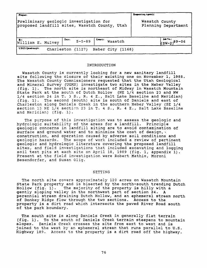
Pl9jed: • ..,.aUDI A.&nq:
Preliminary geologic investigation for Wasatch County proposed landfill sites, Wasatch County, Utah Planning Department
By: Mul vey I Date: 5-5-89 1 c.uty: Wasatch k;~·~ )89-06 William E.
llSGS Q'IIa&I"u&1e: Charleston (1127) Heber City (1168)
INTRODUCTION
Wasatch County is currently looking for a new sanitary landfill site following the closure of their existing one on November I, 1988. The Wasatch County Commissioners requested that the Utah Geological and Mineral Survey (UGMS) investigate two sites in the Heber Valley (fig. 1). The north site is northeast of Midway in Wasatch Mountain state Park at the mou~h of Dutch Hollow (NE 1/4 section 23 and NW 1/4 section 24 in T. 35., R. 4 E., Salt Lake Baseline and Meridian) (fig. 1). The second (south) site is south of Daniels and east of Charleston along Daniels Creek in the southern Heber Valley (SE 1/4 section 13 NE 1/4 secticn 23 in T. 4 5., R. 4 E., Salt Lake Baseline and Meridian) (fig. 1).
The purpose of this investigation was to assess the geologic and hydrologic suitability of the areas for a landfill. Principle geologic concerns in landfill siting are to avoid contamination of surface and ground water and to minimize the cost of design, ' construction, and operation caused by adverse soil conditions and geologic hazards. The scope of work included a review of pertinent geologic and hydrologic literature covering the proposed landfill sites, and field investigations that included excavating and logging soil test pits at each site on April 18, 1989 (fig. I, appendix 1). Present at the field investigation were Robert Mathis, Moroni Besendorfer, and Susan Oligo
SETTING
The north site covers approximately 120 acres on Wasatch Mountain state Park property and is bisected by the north-south trending Dutch Hollow (fig. 1). The majority of the property is hilly with a gently sloping valley in the northwest part of section 24. A perennial stream draining Dutch Hollow, and an ephemeral stream north of Donkey Ridge flow through the two sections. Access to the property is a dirt road which intersects the paved River Road south of the park boundary.
The south site is along Daniels Creek in generally flat terrain (fig. 1). To the south of Daniels Creek terrain steepens to mountain slopes. Daniels Creek crosses the site from east to west and is joined to the west by an ephemeral stream that runs parallel to U.s. Highway 189. Access to the property is a dirt road off the highway.
76
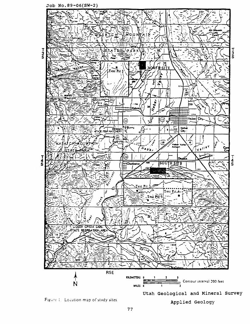
T 3 S .-....:-~,,-, -.'-
+ R5E
N
FigL:r:: 1 _ LO~;J[ion mJp of study sicc!s.
lJlOME'T'ERS 0 , 2
77
M4'= Contour Interval ~OO feet MIUS 0 1
utah Geological and Mineral survey
Applied Geology
GEOLOGY
Both the north and south sites are along mountain fronts with bedrock exposed in hillside areas and unconsolidated surficial deposits on flat valley floors. The north site is underlain by the Triassic Thaynes Formation, a brown/red to olive green sandstone, siltstone, and shale (Bromfield, 1970) (fig. 2). It forms the crest of Donkey Ridge and the ridge east of the creek in Dutch Hollow. Unconsolidated late Pleistocene alluvial deposits cover the floor and side slopes along Dutch Hollow. These deposits overlie the Thaynes Formation and are of an unknown thickness.
The Wallsburg Ridge Member of the Pennsylvanian Oquirrh Formation is the only bedrock unit exposed at the south site (fig. 2). It is a light-gray to red quartzite and forms steep slopes to the south. The majority of the site is underlain by Pleistocene alluvium, into whicb Daniels Creek has incised its channel.
Various geologic hazards are found in and around the Heber Valley that could potentially effect the proposed landfill, although none appear to pose a major hazard. Investigations by the u.s. Bureau of Reclar~tion have not found any evidence of surface faulting at the north site, and geologic mapping by Baker (1970) shows similar conclusions for the south site. This was confirmed during our site investigation, and indicates that the hazard from surface fault rupture at the sites is low. Large earthquakes (magnitude 6.5 and larger) may occur in the area however, as evidence for Quaternary-age surface fault rupture is present in Round Valley, 6 miles southwest of the south site (Sullivan, 1988). A moderate earthquake without associated surface rupture could occur anywhere in the area (Arabasz and others, 1983), possibly causing strong ground motion at either site. Such ground motion can damage structures and cause unsupported excavation walls to collapse. Figure 3 shows peak ground accelerations in soil that have a 10% probability of being exceeded in 10, 50, and 250 years in the area and indicate that both sites are in a ·seismic impact zone" as defined in the proposed EPA regulations. Landfills in such zones must be engineered to withstand the expected maximum horizontal acceleration in bedrock, (appendix 2) which at these sites is approximately 0.048 g. Geologic hazards associated with ground shaking such as rockfall, slope failure, and liquefaction appear to be lo~.
No landslides have been mapped in either the north or south sites, but oversteepening of hillslopes by excavation for roads or landfill trenches could cause local slope instability, particularly in unconsolidated deposits. Flooding could occur in the bottoms of epheBeral streams and drainages, and along Daniels Creek from cloudburst storms or snowmelt runoff. Flood control measures will be required in these areas if landfill sites or access roads are planned in or near the drainages.
SOILS
The u.s. Soil Conservation Service (SCS) maps a complex assemblage of soils in both sites (Woodward and others, 1970) (fig. 4). At the north site the SCS classifies the soil as silts (ML) and lean clays eeL) to a depth of five feet (fig. 4). We inspected a test pit at the site anj fcu~d lean clays to a depth of 2.5 feet, and fat clays
78
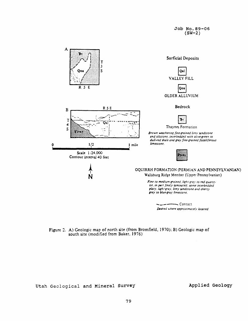
A r-~-"'"'!"'"OO __
R S E
B
T 3 S
RSE ~ .....
I /::- .-- - - . --= '"--,-\.~ : T~-~
~ ~,G~~~':j =". ···~·.:.~·I~ . - - I ,
..,,-. -- ____ J _ '"40--_-
o 1/2 1 mile .' ................. 1 ................. '
Scale 1 :24,000 Contour interval 40 feet
Job No.89-06 (SW-2)
Surficial Deposits
8 VALLEY FILL
EJ OLDER ALLUVIUM
Bedrock
r:::l .•.. tb
Thaynes Formation
Brown we.arhuing fiM-grained limy sandstone and sillstone. interbedded with oiJ'I't-pttn to duli-red shale and pay fine-rained fossiliferous limestone.
f N
OQUIRRH FORMATION (PER..\iIAN AND PENNSYLVANIAN) Wallsburg Ridge Member (Upper Pennsylvanian)
Fine to medium-pained, Jignr.grcy to red quart:ile, in pGrf {inely 14minared. some interbedded p14t)" light-rra),. limy sandstone Dnd cherry tray to blue-gray limestone.
-_--- Contact Dtzshed where approximauly JoCtJItd
Figure 1_ A) Geologic map of north site (from Bromfield, 1970): B) Geologic map of south site (modified from Baker, 1976)
Utah Geological and Mineral survey Applied Geology
79
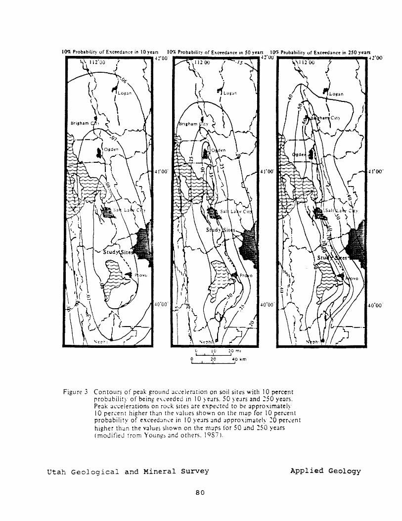
10% Probability of E:oo;ceedance in 10 years 1O'k Probablliry or Exceedance In SO years to-;;. Probability of Excee<i3nce in 2S0 ye:lT1
"-.-~-~~--"'.41·OO' 42'00' 42'00 .' ·is
J \ (
,,'LOg~n \ I
(, 1(; ~o m, ~, --i..--..I..' _-,,'
o 20 40 km I I ,
Figure 3, Contours of peak ground ~H.:~:elt'rJtion on soil sitt's with 10 percent probability of being eXI.:eeded in 10 yeJrs. 50 years and :50 years. Peak al.:<.:elerations on rOl.:k sites are expected to bt' approximately 10 percent higher than the values shown on the map for 10 pen:ent probabiiity of exceed:m...:e in 10 years and approximately :0 perl.'en t higher than the values ~hown on the \11;JpS for 50 and 250 years (moLl j fieLl trom YOllng~ and others. 1 9S i).
Utah Geological and Mineral Survey Applied Geology
80
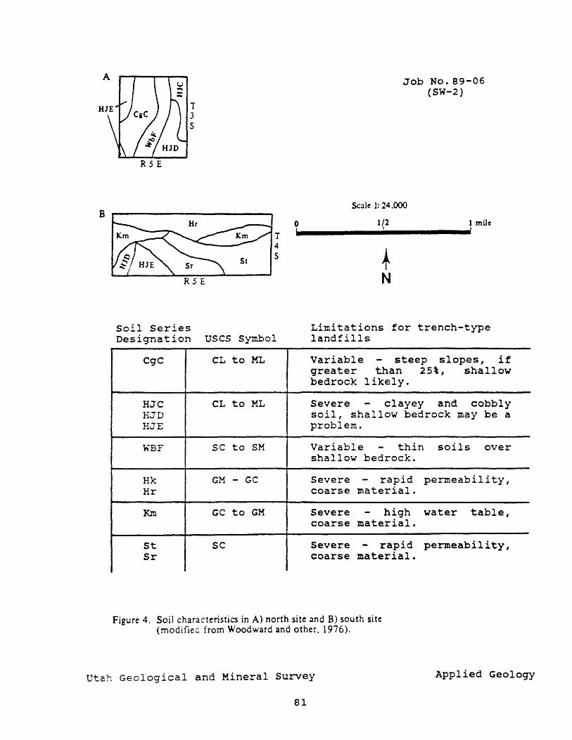
B
T 3 S
RSE
soil series
T 4 S
Designation USCS Symbol
CgC CL to ML
HJC CL to ML HJD HJE
WBF SC to SM
Hk GM - GC Hr
Km GC to GM
St sc Sr
0 b
Job No. 89-06 (SW-2)
Scale 1: 24.000
1/2 1 mile , I
+ N
Limitations for trench-type landfills
Variable - steep slopes, if greater than 25%, shallow bedrock likely.
Severe - clayey and cobbly soil, shallow bedrock may be a problem.
Variable - thin soils over shallow bedrock.
Severe - rapid permeability, coarse material.
Severe - high water table, coarse material.
Severe - rapid permeability, coarse material.
Figure 4. Soil characteristics in A) north site and B) south site (moditiec from Woodward and other. 1976).
utah Geological and Mineral Survey Applied Geology
81
to the pit floor at six feet (appendix 1).
In contrast to the north site, soils in the south site along Daniels Creek are classified by the SCS as clayey and silty gravels (GC-GM) (fig. 4). Our inspection of a test pit at the site confirmed this. On slopes immediately to the south, two additional pits were excavated to examine soils for use as liner material for the landfill. Both pits exposed soils that were fat clays for the entire depth of the pit (appendix 1).
For both north and south sites soils the data indicate that there are severe limitations for trench type landfills (fig. 4). Both sites require an impermeable liner to protect surface and ground water. Therefore, the type of soil present at each site does not influence siting criteria. Coarse soils at the south site make it especially susceptible to ground water contamination by landfill leachate.
GROUND WATER
Ground water in the region is found in both rock and unconsolidated materials, with major producing wells located in unconsolidated alluvial deposits of the major stream valleys such as the Heber Valley (Baker, 1970). Bedrock in the region is highly fractured, and these fractures act as conduits for ground-water movement into the Heber Valley. They occur in all formations, and therefore any formation may be, at least locally, water bearing (Baker, 1970). Bedrock aquifers generally recharge the unconsolidated alluvial aquifers.
In areas where bedrock is shallow, there is a high potential for leachate infiltration through fractures into the ground water with little treatment by soils. However, in areas covered by alluvium, ground water may be shallow, less than thirty feet (Hecker and others, 1987), and leachate may also reach the water table with little treatment by soils. Depths to ground water in the north study site are unknown except at the mouth of Dutch Hollow, where depths to ground water are 5 to 10 feet (Baker, 1970). Unconsolidated deposits in the south site have ground water at depths of 10 to 40 feet, depending on time of year (Baker, 1970). Ground water was not encountered in any of the test pits dug for this investigation. Daniels Creek crosses the property from east to west, but is diverted for irrigation during the spring and summer months. During these times the channel of the creek is dry.
SUMMARY AND CONCLUSIONS
This reconnaissance investigation indicates that suitable areas for a landfill may exist at both the north and south sites. No major adverse conditions were observed at either site, but engineering measures will be required to develop an environrnently safe landfill at both locations. At the north site, soils are clayey and provide suitable material if compacted properly, to provide a low permeability liner for a landfill. Because they are clayey, these soils will pose wcrkability problems during wet periods and are also not suitable for use as cover for refuse material each day. Blending with imported granular material may be required to provide suitable
82
cower. Because the depth to ground water and bedrock is unknown but probably shallow at this site, it will be important to define these depths and to determine the potential for contamination of ground water by leachate fr.om the landfill if this site is chosen.
!he south site is in alluvium that covers the Heber Valley to depths of 800 feet in places (Baker,1970). This material is a mixtl:!'"e of cobbles and gravel, and is not well suited for a landfill due t;~ its high permeability, poor compactability, and workability prOblems. Its coarseness and lack of filtering capacity increases the potential for contamination of the local ground water with leachate from a landfill. Test pits 2 and 3 immediately south of this site contain fat clays which can be used as liner material, and to blend with on-site granular soils to provide suitable cover. The close proximity to Daniels Creek is a hazard, and leachate and refuse fram the landfill has the potential to contaminate the creek and ultimately Deer Creek Reservoir downstream. This hazard will need to be considered in the design of the site to prevent flooding and coDtamination of surface waters.
wewly proposed EPA regulations regarding lanefill siting, which may potentially affect the sites, are included in appendix 2. Specific regulations that effect the proposed sites are those concerning groand shaking (seismic impact zone) and flood plains. The ground shaking restriction applies to both the north and south sites which are in a "seismic impact zone," and proposes that the landfill be designed to resist the maximum horizontal acceleration at the site. Flood-plain restrictions apply chiefly to the south site due its close proximity of Daniels Creek. Restrictions state that the laDdfill shall not restrict the flow or result in a washout of solid waste from the landfill.
A ground water monitoring well system approved by the state must be installed as close as possible from the landfill boundary based on pr~osed EPA regulations included in the appendix. This system is designed to sample the uppermost aquifer in the region and insure that it is not contaminated by landfill leachate. Both north and south sites have ground water at shallow depths, and would require monitoring wells to detect contamination of these ground water sources.
REFERENCES
Arahasz, W.J., Jahns, R.H., and Peck, R. B., 1983, Review and analysis of geologic, seismotectonic, and design data for tbe proposed Jordanelle Dam, Bonneville Unit, Central Utah Project, Utah: Unpublished consultant's report for u.s. Bureau of Reclamation, 87 p.
Baker, C.H., Jr., 1970, Water resources of the Heber-Kamas-Park City area, north-central Utah: Utah Department of Natural Besources Technical Publication No. 27, 79 p.
Braafield, C.S., Baker, A.A., and Crittenden, M.C., Jr., 1970, Geologic map of the Heber Quadrangle, Wasatch and summit COUnties, Utah: U.S. Geological Survey Geologic Quadrangle GQ-864.
83
Christenson, G.E., 1983, Investigation of geology and soil conditions for wastewater disposal, Strawberry Lake Estates Area C, Wasatch County, in Lund, W.R., ed., Technical letters and memoranda for 1983, Site Investigation section: Utah Geological and Mineral Survey Report of Investigation 190, p. 181-186.
Hecker, Suzanne, Harty, K.M., and Christenson, G.E., 1988, Shallow ground water and related hazards in utah: Utah Geological and Mineral Survey Map 110, 17 p.
Holaes, W.F., Thompson, K.R., and Enright, Michael, 1986, Water resources of the Park City area, Utah with emphasis on ground water: Utah Department of Natural Resources Technical Publication No. 85, 81 p.
Lund, W.R., and Black, B.D., 1987, Field reconnaissance of four proposed sanitary landfill sites in Wasatch County, Utah: utah Geological and Mineral Survey Report of Investigation 87-017, 14 p.
Martin, R.A., Sullivan, J.T., and Foley, L.L., 1988, Seisreotectonic study for Jordanelle Dam, Bonneville Unit, Central Utah Project, Utah: U.s. Bureau of Reclamation Seismotectonic Report 88-6, 76 p.
Mulvey, W.E., 1988, Preliminary geologic investigation for Wasatch County Municipal Landfill site, northwestern Heber Valley, Wasatch County, Utah: Utah Geological and Mineral Survey Technical Report 88-07, 11 p.
Sullivan, J.T., Nelson, A.R., laForge, R.C., Wood t C.K., and Hansen, R.A., 1988, Final draft - regional seismotectonic study for the back valleys of the Wasatch Mountains in northeastern Utah: U.S. Bureau of Recla~ation unpublished report, 317 p.
Unitex Corporation, 1987, A hydrogeologic evaluation of the proposed Jordanelle Reservoir, Utah, for U.S. Department of the Interior Bureau of Reclamation: Unpublished consultant's report, 57 p.
Woodward, Lowell, Jensen, E.H., and Harvey, J.L., 1976, Soil survey of the Heber Valley area, Utah - parts of Wasatch and Utah Counties: U.S. Soil Conservation Service, 124 p.
Youngs, R.R., Swan, F.H., Power, M.S., Schwartz, D.P., Green, R.K., 1987, Probabilistic analysis of earthquake ground shaking hazard along the Wasatch Front, Utah: U.S. Geological Survey Open-File Report 87-585, p. M1-110.
84
APPENDIX 1 Test Pit Logs
85
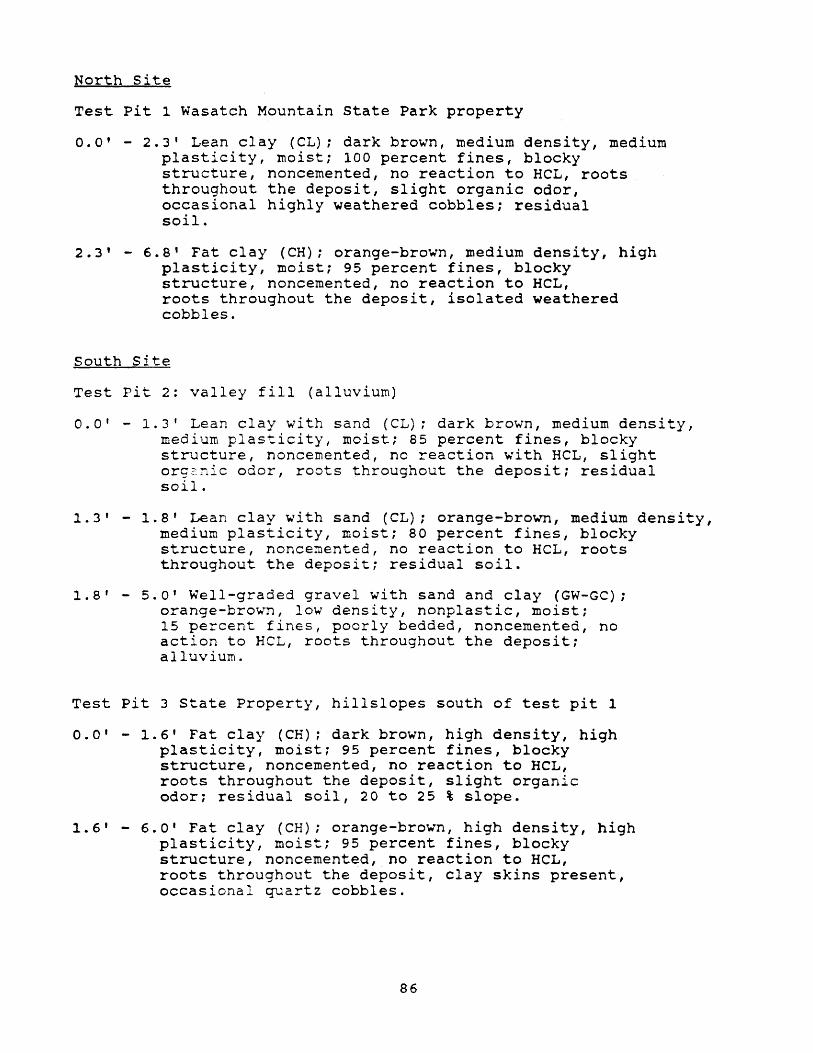
North Site
Test pit 1 Wasatch Mountain state Park property
0.0' - 2.3' Lean clay (CL); dark brown, medium density, medium plasticity, moist; 100 percent fines, blocky structure, noncemented, no reaction to HCL, roots throughout the deposit, slight organic odor, occasional highly weathered cobbles; residual soil.
2.3' - 6.8' Fat clay (CH); orange-brown, medium density, high plasticity, moist; 95 percent fines, blocky structure, noncemented, no reaction to HCL, roots throughout the deposit, isolated weathered cobbles.
South Site
Test pit 2: valley fill (alluvium)
0.0' - 1.3' Lean clay with sand (CL); dark brown, medium density, medium plasticity, moist; 85 percent fines, blocky structure, noncemented, no reaction with HCL , slight org~nic odor, roots throughout the deposit; residual soil.
1.3' - 1.8' Lean clay with sand (CL); orange-brown, medium density, medium plasticity, moist; 80 percent fines, blocky structure, noncemented, no reaction to HCL , roots throughout the deposit; residual soil.
1.8' - 5.0' Well-graded gravel with sand and clay (GW-GC); orange-bro~~, low density, nonplastic, moist; 15 percent fines, poorly bedded, noncemented, no action to HeL, roots throughout the deposit; alluvium.
Test pit 3 state Property, hillslopes south of test pit 1
0.0' - 1.6' Fat clay (CH); dark brown, high density, high plasticity, moist; 95 percent fines, blocky structure, noncemented, no reaction to HeL, roots throughout the deposit, slight organic odor: residual soil, 20 to 25 % slope.
1.6' - 6.0' Fat clay (CH); orange-brown, high density, high plasticity, moist; 95 percent fines, blocky structure, noncemented, no reaction to HCL, roots throughout the deposit, clay skins present, occasional quartz cobbles.
86
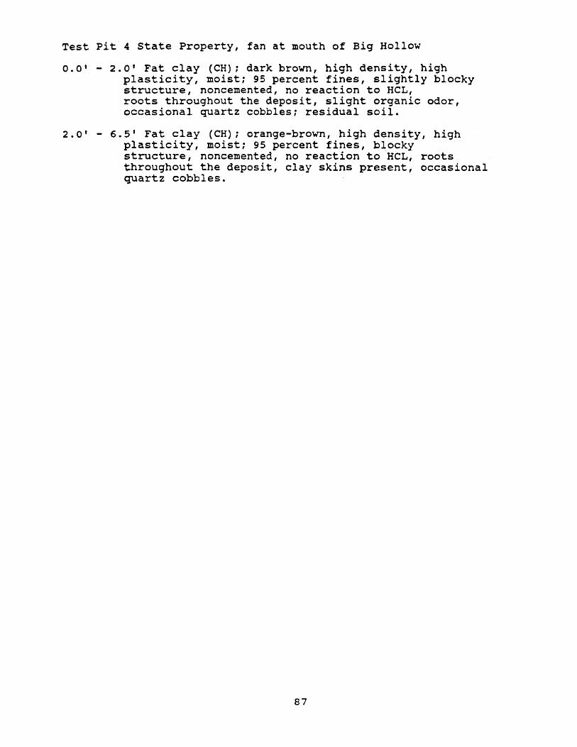
Test pit 4 state Property, fan at mouth of Big Hollow
0.0' - 2.0' Fat clay (CH); dark brown, high density, high plasticity, moist; 95 percent fines, slightly blocky structure, noncemented, no reaction to HCL , roots throughout the deposit, slight organic odor, occasional quartz cobbles; residual soil.
2.0' - 6.5' Fat clay (CH); orange-brown, high density, high plasticity, moist; 95 percent fines, blocky structure, noncemented, no reaction to HCL, roots throughout the deposit, clay skins present, occasional quartz cobbles.
87
APPENDIX 2 Excerpts from proposed EPA
regulations for location and design of landfills
88
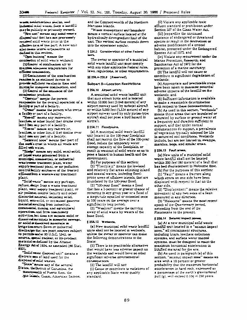
w .... ~.~sca....d ~L eoi.iJ -.......a.e... $.war a. .... d£ U m.,"~'1cwpri~~
-:w. ..aa"': ....... asy aoii.d ~., ~~t~lb..~pa*,,~ .~ JoOoljd wu ~ pnor 1.0 tbe e,&.c:iIn ciA I.e. gj UI.w. p.iU"":.. A n c- c.::U I a.U.o~~~~'" doa.S.a.d lID ~ ~
-0,0 ~- ......oa the co=-Uon o{ I-OUC ~I:e WlthcNt:
(1) ~ Dl C"'"n b- we t\AO tJ:r to m~ e.Q,..;r .... ' e ~ tl:r:ro for ~~
(2) Cae!. in tT)CDI ollbe c::oaa bY. 000 r.a.c::::ia fa a.a ~ c)c v)oe to p~ ~Q,[ r'8II.c.e:c ce t1z,e and ~f« romp;""" ~ a.nd
(3) ~ 01 u... erH'.j.?C 01 ~ co~~ -~'~lbe~ I"U~ kx ~ O¥c-all opcttioao o:l .. fa cW9" pert 01 a fa.cU1 ry • -~ ~ l.h.. pc-n.ou ""he OW"""-I
• r. City or p.e..rt c.! • r..o.l,j ty • ~ ~ &n:J' ~aJe.
Ie. d.at.. or 00C.her ~ tbA t d.r:..t:.t ~ W d ~ ~'i ~ 0-( .. !.a.cili ry .
~ga...QQ. ~ u:y rW:::I W'lI tc'.
Ie a.c::.... r.c <>l.b.eI ~ d ~ a1 ~ 0"Ye: 1&.:ld a8l arry .,.., of. a. ~.
-sont.eci ~ -~ tbe I p.a::rt c f the, .... '.~ I.r.l-~ e.ll ~ A1"'e fiIle-d ~ wataL
-s.u.ip-~ wry ..xJd.. ~ on .liqWIi -uta ~..c from • m=q.J.. men..o..l or ~ WU t~ trMtJI:)C:Q1. pi a.::s:1. ... tc" nzppty ... trMrQ ' ~ or U po(> tioo. coe t:'t'Il JaC.!i:y IIX~ \I"e ai t.b.e tM:I::e t.e-d c~frvm .. WIt:tI1.e_ a \:c::" tr't::!l t::"lCll pwt. -SOl.ld~"1M8..OII cy ~~
reJw e... ~ f:-oc:! 6 .. e.c::a tre:e t::l:l.e:::ll pl&J:lt. WIlle ~y ~l p~t. OT
air ~ ~ !.at:.ill t'J Ul d O'tba ~~ u.-lr<riz~ ~Qd. llqWd.. ~Ud. or cocta.J..::.'.ed ~ ~~ iroco ~..aJ. O'X"...,.......: ~ I.bd ~ opc:ra Q ... and fr-:iw. ~ ... rPrtCf:J a cti vi ti e&. Do l c:.a.. a 0( .0.0. 8CiI:Od ~ ~v"''''~.'' rbc~ or aoUd ....... 9C'<i ~ * i.rri3 atioa ft!U."':l Co W'I OT lo.d Col tr'..a.l dilod:lalJD ~ t ..,.. poc:n tOIS.I"C:lM n bi.ect 10 pe rmJ:III ~ ti' 13 u.s.c.. u.u. or .oure&. ~ zracle,u, or ~ lDa~tial_~ b, u.e A~ E.cerv Ac:1G!:~ u ~OG..e<i lC8 SLat. nl}.,
""'SoU.d -~ ~ W t- :>e 1U"..a a dJ'O"ete -=a o( ll.tld ~ [or the cll.poNJ_.aLd WU~
-st.u. -"&nil &111 oC fh.:. ~., ~ Statea. tbe~a 0( ~ e-.c - ~~~Rx::c..,t.!:>.e .~ ~ ~ A:;:...en.:,... ~
.nd l.be C~~.lth oCthe North~m M.n~ ldA.Dcia.
"w u.tr Cl &.D4'8 r.::.e n I .ru f bouzs d.a.ry mNm .. vertic.l .uriaa: loc:alt'd at t!".e hy d. .... c.hc::a.liy dCWTl8Ml'di en t funj I af tk u.aj L 1"h:i.3 n:rtSca.l s:u.rl. a rxtend, ~ i.e I 0 the aoppc:: ~ f • q"tT.! er .
,:.s.a...l ~ of oth« F..o..raJ ~
Th e 0 wn.u or- 090U a tor of • mu.c.i.C p.a.l .oli.e! wa.a t2 l.t.n.d.f ill Wli' m w..l C':OCD ply wi th lay otl.er a pplka bl.o r edc: a.l Nl es. I. w •• ~ c.oa.., or Q lhet requiremclU-
H ::sa., .. %'Sl!..J (R~
~ 8-l..oc:atX>n R •• trk:1k>na
I 2:S&. 10 JJrport 661. ry •
A. ~ aobd ..... te 1&.Ddfill u:::lit that c.ay .rtrIIC1 bi."tia and;" loafed W1th.in 10.00) leet (J.~ melen) of any airport rc:::rrw., ~ by mrbo;e t t.Lrc-a.ft or wi t.hln 5...IXJ) f e-e 1 {1..!.24 Cl e t.e.n) 0 r DJ'1 • i1yor1 J"Q.O .... ay c..t e-d by 0 cly pu too- ty?e a i.r.:-a..h ah.a.!.l l'lO I po..: a bird hu.a..-.i to airc-a{L
1:.s&.11 ~
( .) A m urJ cipaJ JoOlj d W .. t e l.a.n d.5ll unit locatEC in t!le lCl).ye&:' n~laio .h&.ll n.ot rut:ic:. tbe Dow of \.be l~Jee: nood..red~ tb.e ~ WI1Cf"
• ton.g.e CJ pi ci ty c.! th. D-oodpla In or ruult i.n wu~out ot lOad wut.e 10 U to ~ a h.u.a.rd. to bt.:..r:l.U!. be&1:b &.Cd t.be ellviro 1lC ell to
(b) F or p~ 5oe' of th.i.t JeCtioa.: (ll ""f1ooc;llai;:- meca the lowl.a.c.d
cd relatively flat L"'eU adjoining irJa.nd aDd c:.outaJ Wilen.. m~ flood-p roo e L""n I ai c..th.bore i" 1nxia.. th.a t L""t
i: u:l cia td try t!;..e 1.00-reu flood.. (2) ""l CO-J"C.C fi ood - mca.tl.S a flood
th.a t b.a. .. 1· pc::rc=:: t or g::et te cb a.oc.e of ~ ±:l c:::y ~e.o. yecr or a !'Aod of • ml gr'j r-..:.c.e eqna ~ 0: U ~ once f..a 100 yean O'tl t.b::e a~ oYer a • ig::.i.5 a.:: :J y 1 oc.g ~ nod..
(J) -w ~ ~ r- ::l C"CU th.e cs...·,ying .way of IoOUd .. ut. by ""lotn 01 the b~ flood.
t :s&.12 Weo.xx.
(.) N e-w muniC p.aJ .0 l:k! wu t.e l.t D d5.ll uni Lt .J:Wl DO' be lcx.a t.td ill ~1la.nd a. uN e,. the C7WnU 01' opocn tor CI.D mili the toUowu:.g oemon"t;-acon. to the State:
(1) TIl ~ La DO pra.c.ti C!I bt.e all co:n.a ti~ th.1 wouJd b.aH l~ .d~ impect on the 'Well.a.nd.a LDd would Dave DO othc • i gnj n c.a.n tid v e r.s.e c::x7VU"OCm co ~ I co ruocq ~ DC.t:t.:
(2) The I.a..odJ JJ will c.o t (i) CaCbe (7r cocC'ibote !.O rioLation, o(
any .p'puQ)b!e $ute wal~ qu.a....~ ,randa.rd.
89
Hi) Viol. Ie any IP'?liabJ.e tOAte effluent ,1.nd:1rd or prohibItion under Sectio n ':JJ7 o! til e Cl.u:1 W & ler AcJ..
(iii} Ieo?arC.::e t!:.e c:.c..'\~ CJUslence of endangered or thrnfcned • ~ t5 0 r ~,uJ lin tll r doc-. 0"UC.tian 01'
adver'3c !:'Iodification oC a cnlJc.a1 habitat, protected u.."lder the £.nd.t.ngered Species Act of l~i:l .• nd
(iv} Vio~\.e any rtq~t ~r tbe Marine ?:-otecUon. ~ .PCi S&.ocnJa:ie.l A.ct oJ l~Z !or the prol~tion of. maMe 'l.I\cruary:
(3) The landJill will noe Q\.\Je 01
contribute to 'l.g:'I.ificLQI d~c:Lation oC wetlands:
(4} Appropriate a.cd ~cticable stt~ have been tuen to Dl,&,AJau:z:r poc.c.ndaJ advene i.::::PICt. ollhe 1.D<i!lU on the wetland,: &1ld
(5) Sufficjenl i.cIOrQ.llti.oc ... vailable to male I rea~oablt ~t.tr::li::::'.&ti.oc wi lh res p.ect \.0 th.ue dea>oo.I tra Don s..
(b) AI clee in th.U ~ ~d&Wmea Q.I til 0 s e a.rea.a lha I &..r'Y tEnmd .. 1 ed or a.atu.rltee by .u:face or ~d 1II"1!IIer rl • freque.."lC)' L"ld du.--ation ~cic:::::! to .uppo~ .. L":d !.!Ja t cr.de:- nor.:.u crcum.t.acce, do ~po.r .. • prevalC"'t)C6 of v~eta:lc.:l t}"?iwy a..ci.a~ tor 1ile 1.a sa ru.. .... ted .oil con~ WeUa."lcU ind ud e. hu 1 &1'1: D01 limi 1.e:O t.o. ~ manbe •. bogs.. .Dd s::::m.i.l:a.r ~a.
I 25&.13 F..uI't IIt'1IIU.
Ca) New u.nit.l or, C'lW"..idpaI scUd waste l.ncL~ shaH not be IDultd witJ:Wl21X> feet (eo cete:"'31 or t rawt ~at has be-d ~le~ tIl J~tx%:'>e tm>e.
(b} For t.~e PU.70S~ of t.":ls sedon: (1) -Faul:- eea .. :" a fre~ along
'W' hi c:b .tt"! t1I on em e ~ Ce he 'r'e be-o di.piac.e-: W"iO n:=p~: to th.ar ~ tbe oth.er side.
(2) -oi"place~e::~- l:Ie!.U ~ £'dative t:lovtJ:en t c.! iJl Y t'W'O • ..c..u or & fal1lt· me." ured i.e &..D Y ci.irec':lo:a.
(3) -HoLoc..ene" z:o.c.a c.a the ~t teCt"n f epoch of the cta~ rt~ ~ ext eDdin 8 fro:: tb-e e"!'td 0{ :.t-e Pleistocene 10 the prese.::ll
f 2SL'( s.4~ Irn.peC't .......
fa) At • new mwtic:ipal.oUd waste ·landIill c::rtit located c ... ..e,jamic impact zone.. - aU couta.i.c.mect .CNc~. i:1cJw:ilil.g lir..e....,.. lea cll.a I.e c.oUec:UOQ .)' s t.t:m'- and a.urf ac.a w & fer CXW1~ 'Y'te.au. mu.al ~ d~ t.o n::aut \he z:ca.xim um bo n.:.oc:.al • c.c.e lu & I.i 00 in litlillied ma 1e..-iaJ Cor tla ..itt.
(b) A, u,ed in parigreph (al of this section. -.e::IrT\JC icnpaC't z::oot'" rDe.an& .0
.ru with • 10 pe!"Cent or ~.ter probab;l1ry that the- tn8X~ nonzonl.f Icceleat)Q'n In h.srd rode. e~ft"'d a, • perce"nl.~ of t.~~ ~ert."'·' ~v;IDrionc' pull (8). 14"l!l ~~ 0 1 ~ In ::5IJ yeen.
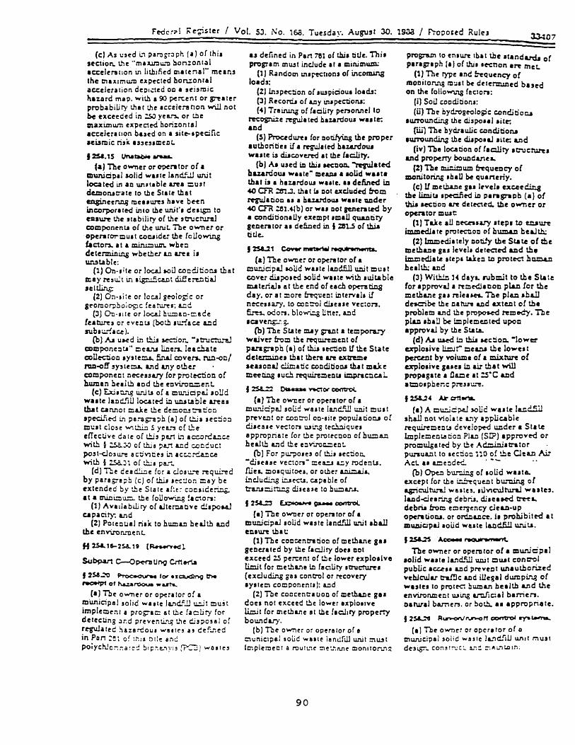
Fe-dcr?! i'e~sler ! Vol. SJ. No. 158. Tuesday. August 30. 1m / f'ropo.ed Rulf3 lJ407
CcJ As \:3cd i., ~ar.lb~:lph (a) or Ihi. section. the "mu.lt:ll.:.."'!l bon:ont~l acceleration tn litl:ufied cn.tenal~ means Ihe maxImum expected bon:onral acceleration de:H.:tcd 00 • sei,l'tlic haurd map. W;tb a 90 percent or greater probabiLity that lhe Icceleranon will not be exceed cd in :.sJ yea..'"l. or tbe maximu.m expected bonzontal acceleration based on a si te- I pectic acuruic risit U,cSlmctlL.
12Sa.15 IJN~.,..,..".
(a) The owner or O?Crator of I municipal solid wute lancif..!.J Wl.H
located in aD unltlble area cust demonac-ate 10 t.be Stale lba' en;ineen.c..g mellurel hIve b«n in CO r'J)OrI ted into tbe u.n.if. deai.g::l to el2s~ t.~e 'tabiliry oC the 'C\Jctu.r1l.l COr:cponenu o{ the unit. The o....-ner or operarorQu.t c.oc.Jide.r the (oUowing fadOrs. It. m.iru.:::l wn. wb eo determillit:.g woe ther Ltl are a i. ~table:
(1) On·,;le or loceJ s.oiJ coeciitioCli that ~ay~'~tm.~~t~e~ti~ Jetilin.g:
(2) On·site or local geologic or Sf'Onlo'?ooJopc !ea t".l..""C'; cd
(JJ Do-'IIC or locaJ bumae-,:::!ce feature, or eveou (bor.!l .u."'1ace a.Dd S\lb'1.!.';I~ ).
(b) Iv. UJoed L"'l t.b..i.J s.ec:::ior .. -.tn.tct'.l.~ ccmponenu" oea.:'1.1 lillen... Ieac!ute coUectiOQ .yJte~ 5naJ coven.. nJ:l-oo/ ra.a-o f! 'y 51 e tc..L. an d IJ'l Y 0 t.b er component ne-ce"a.ry for protectioo of human bulr.b aed the eDvi."'On=~nt.
(e) E.x.l.o.r..g \.l.:uu of a mtl:"..ic:ipaJ .oUd wa.te lanc!!iU loeate-d i.e WlJuble &reU that cannot Que the demot:.! t:"a con 'pecii1e-d L"l pl:as:--a~b (a) of tl:l.i. JectiO:l
CUlt clo,e W'\~ .5 yea.~ oC u:e effective date of t.!:.i, part b accorCClu with § :.s.a..).O or th.i. pa..."'t &.cd ::.cocuct po,t~o,ure ac:i...,Ce, i.., ac:::..:::-"...cc:.e with § lSaJ1 of ~, par ..
Cd} 11.e cead.li=le for a clo'L!..""'e requi.""'ed by parlSTs;;b Ie) or this .~:.!on cay be extended by the Stale af!e~ cocJide~~ at a a'WlQ\J.l:l. !.be roll~ !acton:
(1) Avadabiliry of ~terc.atlve cii.pot4l c.a paot)": a.nd
(2) PotectJaI riJk to humLtl bealth LCd the env\ror".rtlenL
H 2.S&.15-2sa..a (~~~
$'-Ibpart C-<>~ u~ em e1'U
f 2sa~ ~ for .I[~ thoe ~ of huarooua _ a.rt&..
Ca) The o....,.."er or o~rllor of a mUni6pel solid W"le Ja.J'H~f..ll u.:..it cu;t implelllent a prog:-ac::: at the facti!), for delectin; Jr.d preventir..q t."e ciisposal or rqrulatec ~a%8r-dou. WSlI(', at cef .. "led in Pun :~1 0: rhl! ntle anc poiychJo:",.:-:a ~C:: bi~~e.."\yi' ['F'C'J) wo,te,
a~ defined in Part 781 of !.hi. tiLle. Thi. pMlgram tn\Ut include .1 I minimum:
(1 J R.ndom 1n.~tlonJ o( incoming loads:
(ZJ In,pe-ction of .u"piciou. 101ds: (3) Record. o( 1Jl)' in.pection.a: (4) Train.Ln.g of flcury penoMtl to
~ognUe regulate-d haunjou. WI.tt: and
(5) Ptoc.rdun. for DOtilying thf proper authoribe. if I ~a'e-d haz.8.rdexa wute is cilicovere-d It tbe lacility.
(b) A. und in tbj. Henon. ~ated haurdou. Wille" melUll a lOUd wa,le that is I nu.ardoUl wutf. II defined in 40 aR :61..J. tha ( 11 DOC excJude'Cf fn)m I"q'UlltiOQ u a haurdou.a Wille UDder 40 CfR :.el.4(b) or WU Dot re,nerated by a conditionally e.xempt .mlU qu&.Dtity SHlerator II de5.0ed in I m..s of t.hia ti tle..
1lS&..21 c:,o.,..r ~ r-.q .. WP....-rtL,
(a) The owoer or opera tor ot • municpals.olid waste landfill unit cu.t cover clliPOle-d ~Ud Wille ~th .wtable materi~. at the end o( each OpcTat:i:lg
day. or at ::lore fre.queDt i:ltervlla if n~euary. to coct:'Ol cllieue vec:Or1. fun. odors. blow\:.g Une:. ADd • CI veng;.:. So
(b) The State may gra,ot • teropof"a.:,), waiver free the n:qw..rement 01 parag:-apb (a) of t.b.iJ ,M::1oo 11 the State dete:::::Uoe. that tbere are extreme leasocal cli.c:atic: cooditioc.l t.b..t mue mee ti.c.a • U cll requ.ireroen 1.1 impraCtiC4 L
J:s&....::2 ~ netOf' control
Ca) The o~er or operator o( I mu:'licpeJ solid wute la..."lc.."ill u.o.it cu.! preve.a! or coc::-ol oo·.ite populatiotll o[ di.eue VC1:tors u.si. ... .g te~q\Je. a ppropria t e Cor r.!le prote-COOQ oC bu:=8.ll beaJt.b and the e::l .... .t'Oc.:::eot.
(bJ For pu..j:)o.es o( th.i •• ec::on. "di.ease vectors- =e~ a=y rodenu. fliea. ~O.qu.iloe •• or olber a.c.i::::.aJa.., i.."'lciudi."'l.8 i=.aec-..l. c.a pa ble o( tra.."I.I:tirti.!:.g di,eue :0 bu::lA1'..I.
J 2S1....Zl ~ • ~ ~ COI'I"trOl
Ca) The owner or opentor o( I C:l\u:jcjpaJ .oUd waste landJill u.~t .ball en.un that:
(1) The cODcentn tioo o( methane sa. geiletated by tbe faciliry dou Dot exceed :.s percent of tbe lower explo.ive limi t for c e th a.n e l.o ! a ciLi ty ftnu:ru.re. (excJudir..g 881 concrol or recovery Iy.tem cOQPonentJ): Cld
(2) The coccene-llioo or metha.ne gaa doe. no! exceed tbe lower explolive limit (or cncthu.e at the faollry property boundary.
(bl The owner or opera/or or e t:"1uniclpal lolie wUle landfill unit !':'\u.st
hnplemecl a routt."1e ::'Ie~":Me t:lonllor .. ':::
90
program to en.ure tbat the .tand&rd" or paragraph (a) o( thi. le-enon .~ met.
(l) The rype and e-equency o( mODilonn,s nl:J.1 be de1enruned bued on the ColloW'\."\g (ecton:
(i) Soil coedition.: (ill The bydrogeoloslc condjtiora
IWTOunding the c1lspoul .itt: run The bydraulic c:.ondition.a
lun"OundU\a the diJ po .. J .ite: all d (iv) The loc.atiOQ o( (ac.llry Itnlc:turu
and properTy boucdl.11eL (%) The m.i.nicum frequency oC
IDOnitoring .hln be qUlrterly. Ce) U met.b.a.ne 8" Irveb exeee~
the lim.itl .peQf)ed iD Plragrapb (al o{ thiJ teCtlOQ are deteaed. tbe owner or operator mUlt:
(1) Ta.ke aU De-enury .tep. to e.!aun: immed!lte prote-etloe of buman beaJtb.:
(2) Lmmedi. tely no!l.~ the St& t.e o{ the methane 8" levelt dcteaed and the i.m.clediale .tep. tUe!l to protC'd h~ beal~ ud
(3) Witb..!.n H daya. rubmH to the Slate for appl"O'V&1 I rem~. coe pl..a.c for the methane gu releatn.. The pla.n .b411 de.cibe lbe caron IJld axte.nt of lb. problem and the propot.ed reme-dy. The pla.n .hail be iroplece:ltt'd upon approv~ by the SLate..
(d) AI w.ed in thiI HCtiO~ -lo ..... e:!'
explo.ive l.1m.it'" cea.na !.be lowes t percellt by volume of a mixture or explo.ive sue. in air that will J)l"OpaSlte. !la.me It :S·C &%ld at::lo.pbenc pre.uu.""'e.
f lSI..:" Air~.na..
Ca) A cu=..ic~ soue ..... ute I~c!5.ll shall not vioiate L'Y applicable requ.ireceotJ ceveJo~ Ullder a St. t.e Implemeot.aooo PIC) (SIP) appreve-d or promulgated by the Ad.::linj.trator punua..:lt to Itt:iO~ no of the Clean Aj: Act. II a.me:lded.. ... - . ..
(b) Opeo bW"'"'..i.:lg of .oUd ..... uta.. except for the i.:!....~qUeJ:lt bu.."Uin.g of agric:ultunl ..... ute3 .• ilvicultu.n.l wute,. la.tld-dur..n.g cebr.l. d,jaeaw-d ~L, debru from e:::lergency cleua-up operatioc.a. or ordD&Jlce. it prob,jbite-d at IDwUCJpal loud wule la.cdfill u...uu.
12.S&.2S .Ac.:ceeI ~
The owner or operolor oC a an,n.icj:a! .olid wI.le land..'ill unit ::::nut conC"OI public Ic.c:..e .. Ltld pl"eve%l! unauthorized vehJcular tn1!ic ud iUe~al dumpir~ o{ wules 10 prole-<:": !:uman health and t.he envirtmmeo! Wine L"'tl.fic:al barrien. Darural ba..rnen. or bot!l.. al IPPl"'Opriate.
I 2S&...""'e R.....-on.! run-o t1 com:roI ry" ~
fa) The owner or opera tor of 0
cnwUcip.1 solid waste lL"lCJilJ W\Jt r:'lUJt
de,~~ con~t~::~ .1..":= =.A .. "1UlIn;
Federal Re-gist.er !Vol. 53. No. 168. Tuesdav. Au~st 30. 1988 I Proposed Rules 3J..tll
£N- to , 2..S&.a( b}: EPA. i.a c:cw;mdtn.l:3 alter.bns lO the 1 X 10·' to 1 x 10-·n,u r&D8t.. The Ait.:lC)lI~c.fic.a.lly ~ueslS COa:uDr:tlt 00 a fixeci ~s.I. level o.! 1 X 10·' or an a~per boW\d risk ~evel or 1. X 10-' (wlth the Stata haVIng di.~oon 10 be more str..o.gent) .. &lIIr:m.cv~ to the ='l"'Of;)ose-d r.u: r.nlfe. A !xed tiak I~'iel of 1 X 10·' would proV1d~ a cWaaD Lenl o! prolPC:tlOO 'a"OU .U St.It'S. OD 1M olobe: hand.. st'~ an upper bound riIk !Irfti of 1 X 10-' wowd &.Uow SUI tC"t
,.... llUJ bill ty tn 1':1 IJI bUslWl.8 more Itz"Ullmt n..U ievels bu.e-d OD ~te apec.fic CGDdiCions 1.
Ce) Wben establis.hio.g the desigD Decessa..ry to comply Wlth parag::-apb fa} of this JKtlOIl. the Slate ihliJ corwdu at least the folloWUl.g facto~:
(1) The byd.rog~10g1C cilaracte.rutio oJ the fa c:ili ty all d surro u..ociing 1&:1 d;
(21 The climatic fac.lo~ of the area.; (3) The volume and POy!ICal
c:b.&ntctensoc:..s of the le8chat~ (4) Proci:r..i ty of gOlJ.Dd-wa te: use:!:
and (51 Q-.J8Uty o( ground wete.!. (d) A Sta Ie tIlay estabLish an
alte!mstJve b.ow:ca..ry to be ~ed ~ lieU' of the waste rna::.a.e=ent u.. .... ..lt bOtlDda...ry. Tb e al t e f:l a OV e bo un c:i a:')' shan oot e.x~ 150 =ete~ f:-<om ~e wam ma.n.egeme::lt u:..:t bou....,CLry' &.:Id ahaA be located on i8llC owne<i by the OWDer or ope:-ator of tbe MSV .... U. The Htab'iebme.Dt of the alte!'natlve bouDd.ary sh all be D. ~ 0 D a..c aJ Y' is and C:OD..&H:luatiOO of atleut the follcwmg facto:-s:
(l)The bydrogeoiogic c.haracteruti~ of tbr fa c.ili ty at: d ! WT'Oun d..U:I g 1 an ci:
(Z) The voiume and pbysica...i aLe chemic.aJ cila.racte!1s0c! of the leac.hate:
{3} The quanoiy', quabt)'. a.nd d.i.nctJO:l of flow of ground water.
(4) The proXJ.!ru!)' and wJL~cirawa1 rate of the ground-wile!' u.!e~
(5) The av8..1lability of &Jtemative clrinkin.g water sl.O;;?Lie!;
{II To e e X.lI nn.g q u a.b ry 0 r :!J e g::"Q u..o d Wallu. iDcluci.in.g ot..her lou.:"ua of coat&.m..!..cation and tiJell cumwaove impaCti 00 the ground water:
(7] Public healtb.. safery. and weilan e1f'ecu;and
(IJ Pracucablt c.a~bility of th. owner or operator.
(e) Ex..lltUl8 municipal ,olid wute landfill wuLJ mUlt be eqwpped It c:l0llll"r Wltb a finiJ cover .ya tem that La desiJned to p~\lent i.nIiltra tJoo of uqwd throag.b. the cover &nd Ulto t.hff .... lIte.
H 251.C1-2s.&.CI [A~l
Subper1 E~W.t., MOf'Mtoring and CorrKttwe Ac1k>rt
t2R..SO ~. (a) The 1'eq\l.l..""!"':l~t.s l.D thJ. Pa..rt apply
to ~ c p aJ acb.c 1If &oJ ! e 1an.:iE.ll UJl.l ts..
acept .. provided ill paragrapb (b) of this tectlon.
(b) Ground-water mOnitoring reqwrements under I zsa.Sl through t ZS8..S5 of Uus Part Wlll be ,u.pende-d for an MS'h1..F unit jf t.b~ owner or operator can demonstrate to the State that there is no potential for m.i.gr3tion of hu.a.rdous constltuent" from that unit to the upper.nost aquifer durin~ tbe activ~ We. mcludi.::.g :.he clo.ure penod. of the Wlit Il1d d unng po5t~o.ure c.are. Tb.is demOtatratlOD must be certified by • qualified 8!'Olo~st or geoleocbrucaJ ef1lin~r. and must incorpora~ reliable lite-specfic data. II deta..Lled hydrogeologic data are unava.ilable.. the owner or operator must proVlde an adequate m~ of safety in the predicnon of potential ~ nOll of huardo~ cOnJtltuents by baung such predictiOM 00 assumptions that ma.x.i.mlZe the M!!e of huardoa.! con.situtent nugratioD..
(c) Wit.b.i.o 6 monrJu of the eiTective date of the rule. the State must .pecify a • che<luie for the o\llr'Ilen or operatO:3 of MSWLF UIl.lt! to comply with the ground-w at e.r :::l on. to n.n.g ~ ui!'e.!:l en ~ I ptei5ed ~ I § 25a.S 1-z..sa..s.5. Tba IcheduJe mus t b. speC.l£ed to ensure that:.s percent of MS\-\1..F tUUt..s a.re m. compliance witbin Z years of the effective date of this rule; SO ~nt (~) of La.ncif.ll unl t.a are in com pu anc:e withiD 3 yea...""S oC the effective date of thiJ rul e: 75 poe F..e D t 0 f th e la.c.ti5ll u.:li t5 are in compliance W1Uu.n .. yeL' of the e%iectlve date of tilla rule: and alll&.Ild.fill unit..s are in co::Jplience witb.in 5 yea...., of the effective cia te of L'ti5 rJ.1e. In setting the complia:lce Iche-dule. the State ~U!lt consider poteetial risk. pos~ by the MSVw1...F urut to human heelth Uld the enVU'OnmenL The (oUo~ (!cto~ should be C'Oosidere-d in detum.uJ.ing potennal nax:
(ll Pro JJ1Ill ty of b w:::J an aD d eDVU'OnmentaJ receptorT.'
(%) DUlgn of the ia.ndflll urn t (3l Age of the landfilJ urut and (4) Reaource va.lue oJ the underlying
aquifer. mc:lud..ing: (il CutTeIrt and future UUi: (ii) Prc..x.un1ry a.od Wltha:awa.l rate or
unrs: and (iii) Ground-water quality and
quantity. (d) U the State does not set I sc.bedul.
for complian~ .. 1pe'C'1f11'd in paragraph (c) of tb.it Section. th. foUowins compUICCI .eb.dul. Ih.U Ipply:
(1) Exa~ lancUUl unJtI leou than 1 mile from a ctruU:ln.3 wat.r inlU' (.un.ca C1f nlblurlace) must be In com p U an.c.a W"1 th th. grou.n d-w. t f!1'
mOCJtOT1r18 ~aJeDt. ~f1ttd in II %.54.Sl-2.3a 50S wi th..Ln 3 yea l"I of the effectlve dal. of t.hj. rultr.
91
(%) £xj'tins landfill unit, ~ater than 1 mile butle .. than % aules from a d.rinltio.s water intake {surface or
. ,ub.w1ace} must be ill complia.cce with th~ ground-water mon..ito~ ~qu.inmenu ,pecifi~ In II :58..51-%.58.S5 within 4 yean of the effectlve date of t.lili rule:
(3) £xjsting landfill u:liu grea ter than % miles from a c:frin.king water intake (surface or !Ub!Urlac:e) must be in compliance Wlth t!le ground-water morutoring requirements spec:i5ed in II %Sa.51-ZSB.SS within 5 yean of the effective date of thiJ rule; and
(4) A new landfill unit must be in ccmplia.c.ce with the ground-water mOllltori!l3 requiremeo~ speC!ied in II :.sa.sl-ZS8.S5 before waste c.a.n be placed in the uniL
(e) Onc.e establi!hed at a unit. groundwater monitoring Ihall be conducted throughout the active life LCd pOltclosure care of that municipal solid waste liUld5.li unit as Ipeci5ed in I zsa.Jl .
f2SL51 ~mon./toring ayst.m&.
(a} A ground-water 1:lonitoring weU SYltem appl"OV~ by the State must be in.ttalled at the closest pacticable diJt&nc! from the waste management mtit bounda.ry or the altemative .boundary specified by the State under '%5!.40. Where rubsurface coaditiotU cause buardoUJ cOlUtituentl to migrate hOrUonla.lly paat the bounda.ry spec.fied UDder this pa:agrapb before de-tcelld..i.c.s to the uppumOIt aqui!u. til. Slate Call desig:lltt LOother appropnat.. downgradien t loea tion for the groundwater mocitonng welli..
(b) A ground-water rnonitoriJ:lg system mUlt COrulSt of a sufficient number of wella. wt&lled at appropriate locations and depth •. to yieJd gTOund-wlter u.mpiel from the uppermoataquifer that
(1) Represent the quality of background ground water that h.u Dot bH.t1 affected by leuage from a land!lll w:Lit and
(2) Repreaent the qua.lJty 01 p'Ound water palling the location. 'pec:i..fied under paragraph (a) of tml section.
(e) JJ approved by the State. '.pante JrOWld-warer moc.itori.n8 Iystem. a..re Dot ~quired (or .ac.b landfilJ unit -hen the facility hal Mveral1andfill ~t •• provided the mul ti-unit ground-.. ter monJtorin8 'Y.t~m will be .. protKtlve of humaD health and the env1J"onme-nf •• 1Dctividua.l mon..itOr"..ng 'Y'tem. tor .ach Q.DJl
(d) Monitoring welJ. mu.rt be c:.aled in a ma.n.l"ler that matnt.i.M the Lnte-g::"ity of the monitoring wen bore hole. nil
.13412 Fedaral R~t:er I VoL S3. No. 168.. Tue.day. August 30. 1988 I Propoled Rule •
cuina mut be tcreened or perforat~ aDd packed with gravel or .and. where DKeuary. to en.able coUection of IfOWld-water ... mplea. The annular apace (i.e. the .pace between the hare bole and well ea.ing) above the aampling depth mu.t be sealed to prevent conta..mmaoon of .ample. aDd the ground water.
(1) The delign. inltallation. dnelopmenL and decomma.ioo of a.cy monitoring wella. piezometers and othe:lDu.uremenL J&mpling. and a.na..lytiw device. mUlt be documented in the opera ti.ns record; and
(2) The monitorillg well •. piezometers. and other mea.uremeoL sampling. and aa.alytic.al devices mUlt be operated a.nd m.a.inu.:..ned .0 that they perform to dea~ .pecifieationa throughout the life of the mooitonng program.
(e) The number. Ipacing. and depthJ of monitoring 'Yltem.! .hill be proposed by the owner or opera tor a.nd approv~ by the Slate baaed upon lite-'pecillc tec.h.c..i cal in! 0 rm a ti 0 n th a t m u.s t be developed by the o .... -ner or operator and mUlt iDc.lude tborougb c.h..e..,ctenutioo of:
(1) Aquifer thlckneu. Dow nte. and flow ~ctiOI:.: &.DC
(2) Sa~ated Illd uruaturated reo10gic wtit.lllld fill matenall OVer1)'Ulg the uppermost aquifer. iD.cJud.i.D.g. but Dot limited to: thicl::De.ael .• tra tigra phi'. li tho logy. hydraulic conductivibes. a.nd poro,itiea.
12:5&.52 ~ 01 orour.o-w.lei .....,~
(a) The Sta te mUit elta blish. before a Pha.e 1 morutormg prog:-a.m is irJtis tee.. ground·water tngger levels that L"'e
protective of bUl::lan bealth and the etrVi.ron:oent for all Appendix n cclatitueou.
fb) The leveLa 8J"e to be .peci5ed by the St.a te U:
(1) MAxlmum Contami.:le..ntuve1 (MCL) promul~ated under ~ 1412 of the S&1'e ~ \-\late: Act (codified) a::nder 40 O'R Par. 141. Subpart B: or
(%) For conatituenu for wruch MCI....a have not bee%: promulgated. an appropriate health-bued level HtabUlbed by the State that NtisSet the following citena:
(I) The level a cienved in a manner conai.tent ¥with Agency ,wdellne. for ... e.lling the bealth n.ka of environmental poUutanu (51 FR 339'92-34OCI6. 340'14. J.4OZS);
(il) 11 bated on ICientifically valid atudie. conducted in accordance ",'it.\:. the Toxic Substance. Control Act Good Laboratory Practice Stande.rd..i (40 CFR Part 7g:) or eqwvalent.;
(iii) FC'~ c.arcUlogenl. th~ level represe,aJ I concer.::-ano:-; Uloc-latee.
with an excel' U!etime cancer ril" level (due to continuous Wetlme eXJ)Olure) witbiD ~ 1 X10-' to 1 X10-' ran,e; and
(tv) for 'Yltemic toxicant.. the level repreaenu a concentraOon to whic.b the baman populabon (including .eruibve .ubgroup.) could be expoaed to Oll a cWJy bUI' that i. likely to be without appreeable riak. of deleterioUi eBecti ciW"ing a We time.
(Noca to I z.sa..s:(b)(%)(UJ): EPA La caaaicUnD8 Iltern. flv" to the 1 X 10- t to t xW t n&k ratI.8't. The Afear:y 'pe:::iIie&lly ...... ta commeat oa • fixed ri,k. level of lXlo-'or an up~r bound riak Iml of tXlo- t (wnb tbe Statu D.aVln8 c:hlcretioa to be more Itr'\n,ent)aa altHMflVe, to the propoaed n.k rIJlIe· A fixed nllt Inel of tXlo-'wouJd proY1dt. wWon:c In.l of prDt.ec:tJon IC"OII all Slat". On the other band.. Httln8 IJ'I ap~r bound ri ... l"e) of tXlo-·wo\IJd allow Sl.Ale. ,"Iter flexibility iD esubiiahlng more .~at Nit Inel.l bued on lite .pecifle coadJeoru}.
(3) For constiruentJ for which DO health-bued le\'el is available that meets the citeria in 12.58.52(a)(1) or {2} the State mey establish I trigger level that ahall be:
(il AIl indi~tor ro~ proteC'tion or buman health and the environment. using the expo.ure a .. umptionJ Jpecifi~ under I :sa.52(e)(2}. or
(il) The bl~und concentratioc... (4) For con..Jtituenta for which the
background level iJ hi8her than health-bue-d levela establisbed under I %5a.52[b)(lH3). the ~er level.hall be the ba~d concentratioc...
1251.53 GrounO-wate-r umpIlng and ~ r.,qutrefMntl.
(a) The ground-wlter monitoring prog:r8.!Il mu.st include coruistent RmP~ &.no analysis procedu.res that are deslgned to enlurt monito:"in.g remlu t..Cst provide &!l accurate reprue=tauon oi ~ou...,d·watl'· quality at the bac:XgroUDd and do~ c .:!.lent wen. i.n.Italied in compUance 'Wlth 12M.51(b) of tna par .. At a mirwnum. the pro~ ClUJ! be documented iI! the operaong record InC must include procedures and tec.hruques far:
(1) Sample coUectlon.; (2) Sample f'reJer'\'ltion and .hjpmeIlt (3) Analyucal procedunl; (4) Cha1Il of custody control: and (5) Quality a.lurance and quaUty
control. (b) The p-Dund-water monitoring
program mUlt include .ampling and analytical method. that a.re appropriate for ground·water .a..mpl~ and t.h.at accurately measure ba%.l~doUi conabtuenu and other monitoring par&melen in ground-water lamplet.
(c) The lampitng pl'ocedure. and &equency mu.t be protect1Ve of human bealth and the enVlT'Or.menL The
92
-aampling requirement IIlU.t en.ure that the .tatl..local pl"OUdure used to evaluate .ample. h .. an acceptably low probability of faili.n& to idtntify ccnt.amina tl on..
(d) Ground·water ele'VatioN mUlt be measured in each weD Jmmediately prior to umplmg.Tht owner or operator mUlt determme the rate and cilrection oC lfOund.water flow in tht uppermo.t aquifer each tune ground-water Jradient ch.a~e. a. indiea ted b)' previoul aampling penod elevation me.uremenls.
(e) The owner or operator mUit establilb ba~und ground-water quality on a bydrluhcally upgradient well(.) for each of \he monitoMi pa.r1UDeten or COD.tituenU reql!ll"ed in the p&r'tlcula: ground/wlter :ncmitonng program that appliel to the municipal .olid watte landfill unit. II determined under I :sa.s4ia). or t zsa.s5{a) of thJ. part. Tbe minimum number or aamplea Uled to eatabU,b background ~und· wlter quallty mUlt be CODli.ten! with the appropriate .tatiatical proe.eCU."'e1 determL'lec punuant to paragraph (b) of this .ection.
(f) Background ground-water quality at e.xi.tmg unita m!y be bued on aampling of wells that are Dot apgradien: b"o= the wllte management a.ru where.:
(1) Hyd.rop~logic conditiON do not allow the owner or opera t01' to d.etmnme what wellJ are uppdient and
(2) SamplL"Lg at othtr well. ~'ill provide all inrueabon or bac:kgroUDd gr'Ou.ad-wate!' quality that i. I. represent8:JV! or more !'eprue=tative than tha t pro\;ded by up~a ciJer. t wells.
(g) The State ma~' dete::Il.U1e alternate ba~unc p"Ound·wltef qua.lit:' on I
.ite-.peciflc: bui, if true bl~u...,d ground·water qua.bty cannot be detected on .ite. The alternate b8c:.k~u..,d grouod·water quality .bould be based OIl monitor-oIlS data £::-0:::: the uppermost aquifer that 1. Ivailabie to the Sts teo
(b) Sta olDea! procedure. are .. followa.:
(1) Ground-water monitoring data for each phase of the morutonng JJrogra.ma of t, :se~. 2Sa.SS and any other a"pbablt .ection of thil rule will be collected from bacJcpound well. (except a. allowed in I ZS&.53(g)). and at monJt0l"in8 weIll a •• pecified pW"Iuant to I !.5a..53{a). Based on the .ite-specific conctitions identified Ul § 2.58.504(c). the owner or operator mu.t .elect the appropriate atati.ocal procedure to determint if a .tanlnully lignificaDt in~ate onr background value for each parameter or consotuent has occu.."Ted.
(2) Toe oYl'TIer or operator must employ ont of the folloW1nS .ta cltiul

GEOLOGIC HAZARDS
93
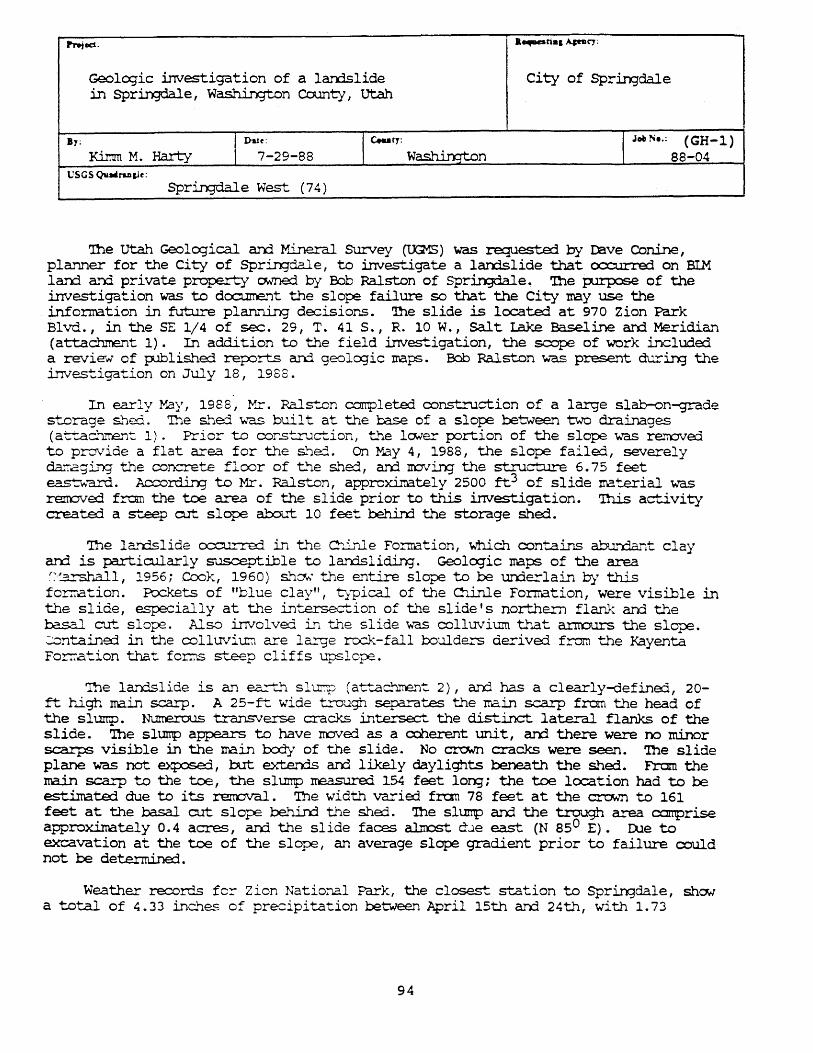
1"r.tec1. .. ...,art., ApDq:
Geologic investigation of a landslide City of Springdale in Springdale, Wash.i.ngton Cotmty I utah
By; I Dt1;:"'29_88 I c.ur,.: I J"" •. ' (GH-l)
Kilnm M. Harty Wash.inqton 88-04 USGS Qvllliru,k
Springdale West (74)
lbe utah Geolo;rical arrl It''..ineral SUrvey (l.X;1S) was requested by rBve Conine, planner for the City of Springdale, to inves+"'Jgate a lan:islide that cx::curred on BIM lan:1 arrl private property CMned by B:ili Ralston of Sprin;Jdale. '!he ~ of the investigation was to doo..nnent the slope failure so that the City may use the infonration in future planni.rq decisions. '!he slide is lcx::at..ed at 970 Zion Park Blvd., in the SE 1/4 of sec. 29, T. 41 5., R. 10 W., Salt Lake Baseline arrl Meridian (attachment 1). In addition to the field investigation, the scope of work included. a review of published reFCrts arrl geolc:gic IraPS;. Bob Ralston was present ~in:; the invest.igation on July 18, 1988.
In early May, 1988, }'x. Ralston COI!1pleted construction of a large slab-on-grade s+---orage s.."1Eri. The s.."1e:l w"a,S built at the base of a slope between two drainages (attac~-rne.n-:' 1). Prior to cons::.ru.ction, t.l)e lowe1:" portion of the slope "w'aS re.."7OV'ed to pro\Tide a flat area for the s..'1ed. On ¥J03.y 4, 1988, the slope failed, severely dar.agi.T'XJ t.~e concrete floor of t.~e s..~ed, ard rrovin; the structl.L.re 6.75 feet ea.st"warcl. Accordi.n:j to Mr. Ralston, approxinately 2500 ft3 of slide reterial was rem::JVecl from the toe area of the slide prior to this investigation. 'Ihi.s activity created a ~--eep a..It slope aboL.~ 10 feet be.h..i.rrl the storage shoo.
'!he la~lide cx:ctL..~ in t.~e C'"'..inle Fornation, whic.~ contains ab . ..l.l"rla.l'1t Clay arrl is particularly susceptible to lan:isliding. Geoloqic maps of the area f~~""'Sl'"'cll, 1956; Cc:x:Jk, 1960) s.."'1CJy.' the entire slope to be urrle=lain by this for::-ation. Pockets of "blue clay", typical of the Chinle Fornation, were visible in the slide, especially at the int:.er'sa.-tion of the slide's northe.n1 flarJ~ ard the basal cut slope. Also involved in t."'1e slide was colluvium t.r-..at a.nrours the slope . .::.:ontainerl in the colluvim, are large rock-fall oould~-s de=ived. freIT', the Kayenta For::-ation that forr.s ~ueep cliffs upslope.
The 1~"Xl51ide is aT') ec:th slU':'p (att.ac..~'"T'e..'1t 2), an:3. has a clearly~efined, 20-ft high main scarp. A 2S-ft wide L~ugh sep:L"Otes the rrain scarp fram the head of the slurrp. Numerous transverse cracks int:.e."'"'SeC't the distinct lateral flanks of the slide. '!he slurrp appears to have m:::rved as a coherent unit, arrl there were no minor sca.."'J)S visible in the n-ain b:::dy of the slide. No crown cracks were seen. '!he slide plane was not ~, but exten:is arrl likely daylights beneath the shoo. From the main sca....---p to the toe, the slurrp measured 154 feet Ion;: the toe lo::ation had to be estimated due to its rem::Nal. '!he width varied fram 78 feet at the C!"C1wm to 161 feet at the basal cut slope be.."'1.i.rrl t11e she::L '!he slurrp arrl the trgugh area o:mprise approximately 0.4 acres, arrl the slide faces a.l..nost d...le east (N 8S0 E). D..le to excavation at the toe of the slo:pe, an average slope gradient prior to failure could not be determined.
Weather rec:o~--s fo:::- Zion National Park, the closest ~lAtion to Sprir:qdale, shC1W a total of 4.33 mC"1e5 of precipitation between April 15th ard 24~~, with 1.73
94
irdles fallin; on April 21st, arrl 0.5 in::hes on the followirq day. With the exception of slight precipitation on May 1st, none was recorde::1 between April 25th an:J May 4th.
'!he sll.l'Irp was probably caused. by excavation of the base of the slope, which rerrove::1 sut:POrt. Nearly 3 inches of rain fell in the six-day pericrl between April 19th arrl April 24th, ten days before the slide occurred. Infiltratin; precipitation nay have facilitated the slope failure. Accordi..ng to Mr. Ralston I s obse.Ivations shortly after the slide oo::urre::l, the nain scarp v.;as wet from the groon:l surface d~ about four feet. No m:::>isture was obsel:ved anywhere in the slide vicinity durin; this investigation.
Mr. Ralston said that the slide has not nove::1 sinc.e its initial failure. At present, the basal cut slope behin:i the shoo is abcut 17 feet high. Mr. Ralston iIxticated he interds to grade the slurrp to a 3: 1 slope by I'eIIOVlrg additional material· fran the main bcrly, an:l rebuild the shed at approximately the same location. I advised him that should the slide reactivate, either :in its present fonn or after m:difications, it could further ilIpact the shed. I also advise:J f-4f..r. Ralston against rebuild.i.n; the shed in its present location. '!he slide would likely not affect Mr. Ralston I shouse, ",mch is far-J1er d~lope. Mr. Ralston in:licate:i he does not int.errl to ncdify the 20-ft high nain scarp of the lan::lslide. '!his 5Ca..""p, as well as t.l)e upper portion of the slurrp, is on BIM larrl. '!he main scarp is steep, arrl left in its current state will probably slough material into the trough belcw. It is unlikely tr~t this activity will inpact any ~w:uctures.
References Cited
Cook, E. F ., 1960, Geolcgic atlas of utah: utah Geolo;ical arrl Mineralo;;ical Stl....--vey Bulletin 70, 124 p.
Y~l, C.H., 1956, Fhot:.cx:1eolo;ic map of the Virgin NE QJad.r'an3le, Wa.sh.in;ton County I Utah: u. S . (;e:)lo;ical SUl:vey ~..iscellaneous Geologic Investigations ~~p 1-161, Scale 1;24,000.
Varnes, D.J., 1978, Slope :rrove..'TleJ1t types am processes, in Sc..~us""...e.r I R. L. , arrl Krizek, R.J., (eds.) , la.'"rlslides-analysis an::l control: National Academy of scie.nc::e.s TrarlSportation BJard SpEcial Report 176, p. 12 - 33 .
95
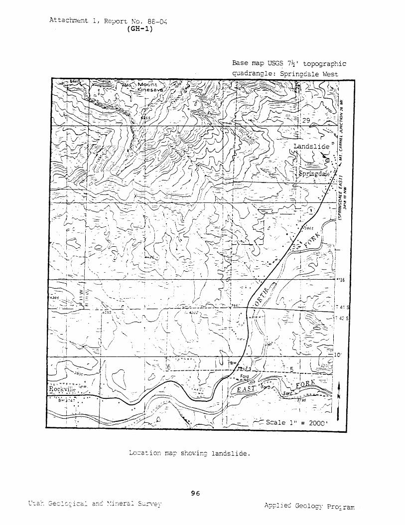
Attach~c~t 1, Report ~o. 88-0~ (GH-l)
Base map USG~ 7~' topographic
----- 1
1" = 2000'
l..o=a:.ioD rna;; shov:ir.;; landslide.
96
Appliec GeOlo;y Pro;rarr:
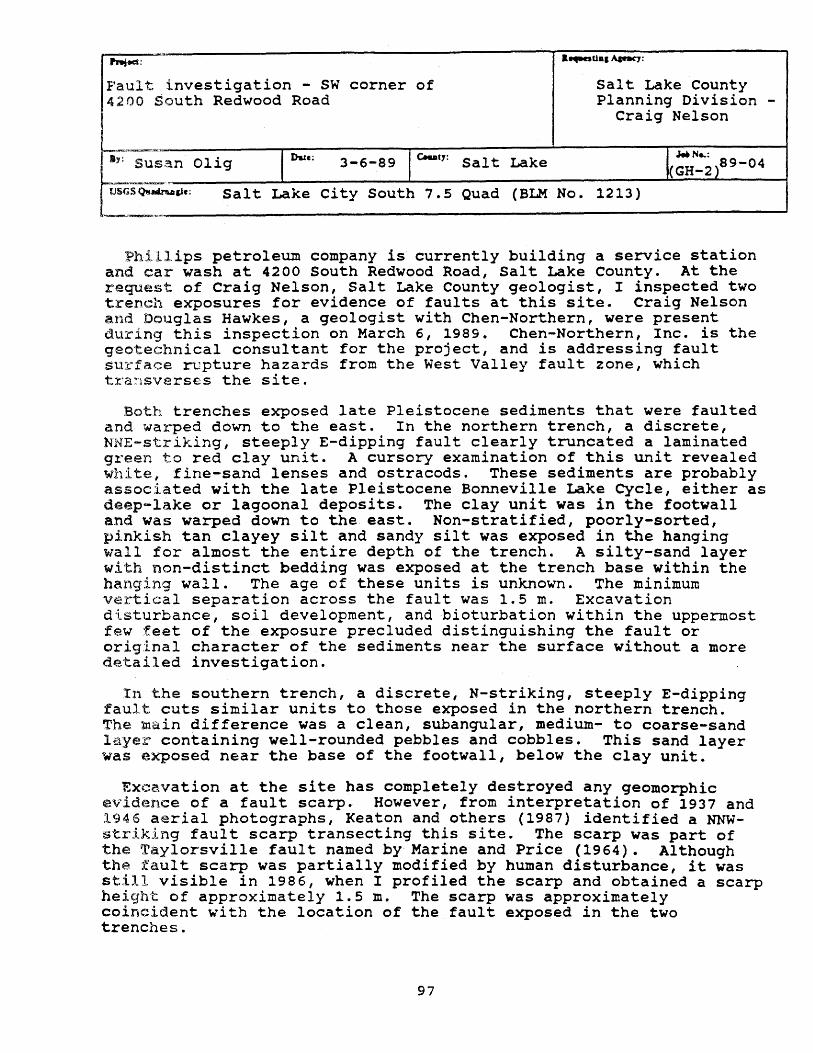
Pnjed:
Fault investigation - Sw corner of 4200 south Redwood Road
Salt Lake County Planning Division -
Craig Nelson
L~~=-______ ~ ______ ~ ______ ~-----.~~--~ ~~.s .... ~_n __ O_l_i_9 ______ I~~-e-;---3---6---8-9--I~Yu---t1-:-S_a __ l_t __ La __ k_e ____________ ~I(_~_H_~_~~1'_8_9_-_0_4__1 L:SQo-""" Salt Lake City South 7.5 Quad (BLM No. 1213)
Phillips petroleum company is currently building a service station and car wash at 4200 South Redwood Road, Salt Lake County. At the request of Craig Nelson, Salt Lake County geologist, I inspected two tren.ch exposures for evidence of faults at this site. Craig Nelson and Douglas Hawkes, a geologist with Chen-Northern, were present during this inspection on March 6, 1989. Chen-Northern, Inc. is the geotechnical consultant for the project, and is addressing fault surface rupture hazards from the West Valley fault zone, which tra~sverses the site.
Both trenches exposed late Pleistocene sediments that were faulted and warped down to the east. In the northern trench, a discrete, NNE-striking, steeply E-dipping fault clearly truncated a laminated green to red clay unit. A cursory examination of this unit revealed white, fine-sand lenses and ostracods. These sediments are probably associated with the late Pleistocene Bonneville Lake Cycle, either as deep-lake or lagoonal deposits. The clay unit was in the footwall and was warped down to the east. Non-stratified, poorly-sorted, pinkish tan clayey silt and sandy silt was exposed in the hanging wall for almost the entire depth of the trench. A silty-sand layer with non-distinct bedding was exposed at the trench base within the hanging wall. The age of these units is unknown. The minimum vertical separation across the fault was 1.5 m. Excavation disturbance, soil development, and bioturbation within the uppermost few feet of the exposure precluded distinguishing the fault or original character of the sediments near the surface without a more detailed investigation.
In the southern trench, a discrete, N-striking, steeply E-dipping fault cuts similar units to those exposed in the northern trench. The main difference was a clean, subangular, medium- to coarse-sand layer containing well-rounded pebbles and cobbles. This sand layer was exposed near the base of the footwall, below the clay unit.
Excavation at the site has completely destroyed any geomorphic evidence of a fault scarp. However, from interpretation of 1937 and 1946 aerial photographs, Keaton and others (1987) identified a NNWstriking fault scarp transecting this site. The scarp was part of the Taylorsville fault named by Marine and Price (1964). Although the fault scarp was partially modified by human disturbance, it was still visible in 1986, when I profiled the scarp and obtained a scarp height of approximately 1.5 m. The scarp was approximately coincident with the location of the fault exposed in the two trenches.
97
The age of the last movement of the Taylorsville fault at this site can only be constrained as post-Lake Bonneville. However, approximately 4 km to the north, the Taylorsville fault offsets deposits of the Gilbert shoreline, indicating movement within the last 12 ka (Keaton and others, 1987).
Keaton, J. R., CUrrey, D. R., and Olig, S. J., 1987, Paleoseismicity and earthquake hazards evaluation of the West Valley fault zone, Salt Lake City urban area, Utah: Report to U. S. Geological Survey, contract no. 14-08-0001-22048, 88 p.
Marine, I. W., and Price, D., 1964, Geology and ground-water resources of the Jordan Valley, Utah: Utah Geological and Mineral survey Water-Resources Bulletin 7, 63 p.
98
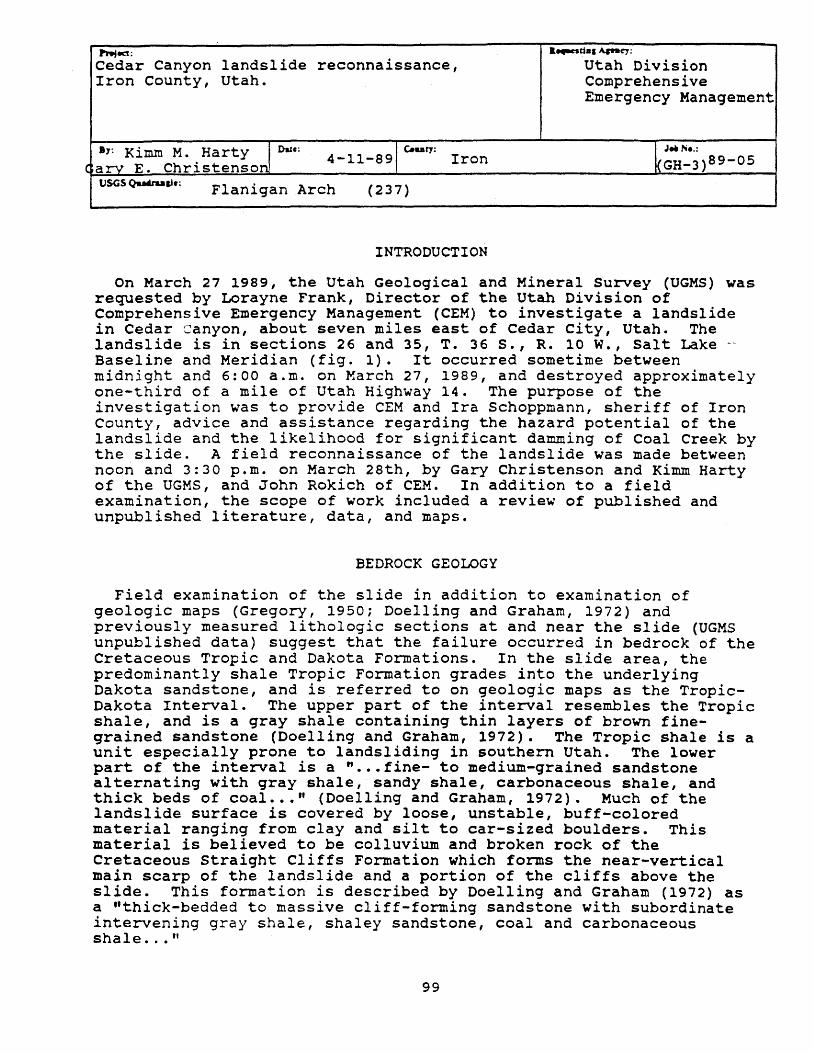
""ted: .. ...,net.1 Apa~;
Cedar Canyon landslide reconnaissance, Utah Division Iron County, Utah. Comprehensive
Emergency Management
.,: Kimm M. Harty In! Dale:
(arv E. Christenso 4-11-89 I C .. ary: Iron l(~-;;:~ )89-05
tJSGS Qu&ru&Je: Flanigan Arch (237)
INTRODUCTION
On March 27 1989, the Utah Geological and Mineral Survey (UGMS) was requested by Lorayne Frank, Director of the utah Division of Comprehensive Emergency Management (CEM) to investigate a landslide in Cedar canyon, about seven miles east of Cedar City, Utah. The landslide is in sections 26 and 35, T. 36 S., R. 10 W., Salt Lake -Baseline and Meridian (fig. 1). It occurred sometime between midnight and 6:00 a.m. on March 27, 1989, and destroyed approximately one-third of a mile of Utah Highway 14. The purpose of the investigation was to provide CEM and Ira Schoppmann, sheriff of Iron County, advice and assistance regarding the hazard potential of the landslide and the likelihood for significant damming of Coal Creek by the slide. A field reconnaissance of the landslide was made between noon and 3:30 p.m. on March 28th, by Gary Christenson and Kimm Harty of the UGMS, and John Rokich of eEM. In addition to a field examination, the scope of work included a review of published and unpublished literature, data, and maps.
BEDROCK GEOLOGY
Field examination of the slide in addition to examination of geologic maps (Gregory, 1950; Doelling and Graham, 1972) and previously measured lithologic sections at and near the slide (UGMS unpublished data) suggest that the failure occurred in bedrock of the Cretaceous Tropic and Dakota Formations. In the slide area, the predominantly shale Tropic Formation grades into the underlying Dakota sandstone, and is_referred to on geologic maps as the TropicDakota Interval. The upper part of the interval resembles the Tropic shale, and is a gray shale containing thin layers of brown fineqrained sandstone (Doelling and Graham, 1972). The Tropic shale is a unit especially prone to landsliding in southern Utah. The lower part of the interval is a " ••• fine- to medium-grained sandstone alternating with gray shale, sandy shale, carbonaceous shale, and thick beds of coal .•• " (Doelling and Graham, 1972). Much of the landslide surface is covered by loose, unstable, buff-colored material ranging from clay and silt to car-sized boulders. This material is believed to be colluvium and broken rock of the Cretaceous straight Cliffs Formation which forms the near-vertical main scarp of the landslide and a portion of the cliffs above the slide. This formation is described by Doelling and Graham (1972) as a "thick-bedded to massive cliff-forming sandstone with subordinate intervening gray shale, shaley sandstone, coal and carbonaceous shale ... "
99
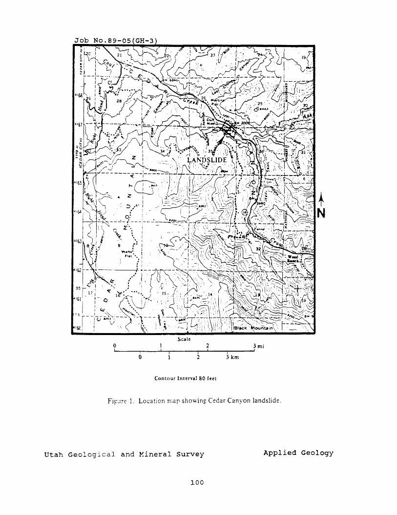
+ N
Scale o 2 3mi ~! -------ri----~--~------~I--~I----~i------~'
o 2 3 km
Contour Interval 80 feet
Fi~~re 1. Location mar showing Cedar Canyon landslide.
Utah Geological and Y.ineral survey Applied Geology
100
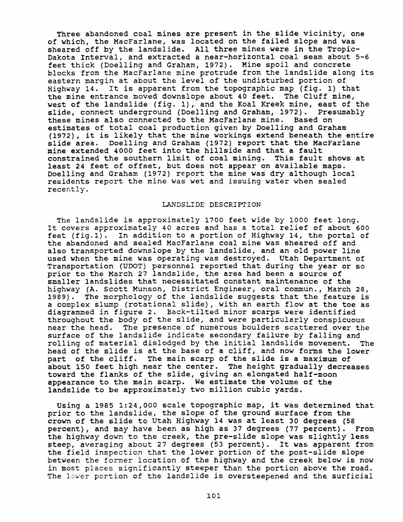
Three abandoned coal mines are present in the slide vicinity, one of which, the MacFarlane, was located on the failed slope and was sheared off by the landslide. All three mines were in the TropicDakota Interval, and extracted a near-horizontal coal seam about 5-6 feet thick (Doelling and Graham, 1972). Mine spoil and concrete blocks from the MacFarlane mine protrude from the landslide along its eastern margin at about the level of the undisturbed portion of Highway 14. It is apparent from the topographic map (fig. 1) that the mine entrance moved downslope about 40 feet. The Cluff mine, west of the landslide (fig. 1), and the Koal Kreek mine, east of the slide, connect underground (Doelling and Graham, 1972). Presumably these mines also connected to the MacFarlane mine. Based on estimates of total coal production given by Doelling and Graham (1972), it is likely that the mine workings extend beneath the entire slide area. Doelling and Graham (1972) report that the MacFarlane mine extended 4000 feet into the hillside and that a fault constrained the southern limit of coal mining. This fault shows at least 24 feet of offset, but does not appear on available maps. Doelling and Graham (1972) report the mine was dry although local residents report the mine was wet and issuing water when sealed recently.
LANDSLIDE DESCRIPTION
The landslide is approximately 1700 feet wide by 1000 feet long. It covers approximately 40 acres and has a total relief of about 600 feet (fig.1). In addition to a portion of Highway 14, the portal of the abandoned and sealed MacFarlane coal mine was sheared off and also transported downslope by the landslide, and an old power line used when the mine was operating was destroyed. Utah Department of Transportation (UDOT) personnel reported that during the year or so prior to the March 27 landslide, the area had been a source of smaller landslides that necessitated constant maintenance of the highway (A. Scott Munson, District Engineer, oral commun., March 28, 1989). The morphology of the landslide suggests that the feature is a complex slump (rotational slide), with an earth flow at the toe as diagrammed in figure 2. Back-tilted minor scarps were identified throughout the body of the slide, and were particularly conspicuous near the head. The presence of numerous boulders scattered over the surface of the landslide indicate secondary failure by falling and rolling of material dislodged by the initial landslide movement. The head of the slide is at the base of a cliff, and now forms the lower part of the cliff. The main scarp of the slide is a maximum of about 150 feet high near the center. The height gradually decreases toward the flanks of the slide, giving an elongated half-moon appearance to the main scarp. We estimate the volume of the landslide to be approximately two million cubic yards.
Using a 1985 1:24,000 scale topographic map, it was determined that prior to the landslide, the slope of the ground surface from the crown of the slide to Utah Highway 14 was at least 30 degrees (58 percent), and may have been as high as 37 degrees (77 percent). From the highway down to the creek, the pre-slide slope was slightly less steep, averaging about 27 degrees (53 percent). It was apparent from the field inspection that the lower portion of the post-slide slope between the former location of the highway and the creek below is now in most places significantly steeper than the portion above the road. The l~~er portion of the landslide is oversteepened and the surficial
101
materials are very unstable and were actively sliding downslope during the reconnaissance.
The surface of rupture at the base of the slide appears to be complex, and the landslide moved downslope in a series of simultaneously-moving slumps and slides rather than as a single, intact, cohesive mass. In the western part of the slide, an intact but severely damaged portion of Highway 14 moved about 100 feet downslope but was not buried by landslide debris. The surface of rupture is thus below the present position of the highway here. Elsewhere, the road disappears beneath the landslide, with patches of crushed asphalt locally present on the landslide surface. The break in slope that roughly parallels the former location of the highway may indicate the location of the rupture surface of the landslide. No evidence of a daylighted rupture surface was observed in the field; it is likely that it was buried by debris.
It is unlikely that the surface of rupture is at or below the level of the creek. The toe of the landslide spilled into the canyon bottom and blocked portions of Coal Creek, but did not as a whole, slide into the creek. Although the creek was blocked in places, there is no evidence it was significantly shifted or uplifted by the slide. Blockage of the creek was probably produced by both tumbling rock material and by slumping and sliding within localized areas at the toe of the landslide. The creek cut through and breached the blockages before substantial ponding or flooding could occur. Aside from a noticeable instability of surficial soil and rocks, the landslide did not appear to be moving during the field investigation. Very little water was observed on the slide except where small isolated snow patches were preserved and melting.
POSSIBLE CAUSES
In addition to reports of the recent history of instability in this slope from UDOT personnel, there is geologic evidence for longer-term instability in the form of older (probably prehistoric) inactive landslide scarps and heads near the top of the slope. Evidence indicates a potentially unstable slope that may not have required a significant change in conditions to cause failure. Although it was not the purpose of this investigation to determine the cause of the failure, we did investigate several possible causes. No earthquakes were reported in the area near the time of the landslide (Sue Nava, University of Utah Seis::qraph Stations, oral commun., April 11, 1989), so ground shaking is not a likely cause.
possible weather-related factors include both longer-term annual and seasonal precipitation trends, and shorter-term storm or snowmelt events. The National Weather Service (1989) reported that as of March 1, 1989, stream flow in Coal Creek was about 70 percent of normal. As of February 28, 1989, soil moisture indices for the south-central region of Utah, which includes Cedar City, indicate the area to ,De experiencing a "mild drought" (Office of the Utah State Climatologist, 1989a). In addition, precipitation received in the south-central region from February 24 to March 31 averaged only 76 percent of normal (Office of the Utah State Climatologist, 1989b). Most of the snow in the area had melted, with localized snow remaining mostly on north-facing slopes. Southern Utah is under
103
below-average precipitation and moisture conditions for the current water year. Based on this information, it is difficult to attribute the landslide failure to longer-term weather-related causes.
Local precipitation records from a weather station located in Cedar Canyon about two miles west of the slide indicate that the area received nearly 0.4 inches of precipitation the day before the slide occurred. Previous to this rainfall event, no precipitation other than a trace amount was recorded since March 3, when 0.81 inches fell (Dudley Alger, Cedar City Water Department, written commun., April 10, 1989). It is possible that the rain that fell the day before the landslide occurred may have triggered the event, but significant instability already existed in the area prior to landslide movement.
Possible man-related factors which may have contributed to slope instability include highway- and mining-related alterations to the slope, drainage, and ground-water hydrology. The destroyed MacFarlane mine portal is located near the level of the hypothesized landslide rupture surface, at least along the east flank. It is possible that the landslide failed along a plane at the elevation of the mine workings, but further analysis is needed to verify or reject this possibility. It is unknown whether the hydrology of the mine or changes caused by sealing the portal contributed to the landslide.
HAZARD POTENTIAL AND RECOMMENDATIONS
The principal slide movement has occurred, but it is likely that minor slides, rock falls, and settlement will continue within the slide mass. In particular, rock falls may continue to occur along the landslide's cliff-forming main scarp. Cracks which connect with the main scarp extend along the base of the cliff west of the slide for several hundred feet. The slope below these cracks shows evidence of movement. These cracks probably formed contemporaneously with the main slide, and indicate that remaining slopes adjacent to the slide are potentially unstable.
The main purpose of this reconnaissance was to assess the potential for damming of Coal Creek by continued slide movement, posing a flood hazard downstream should the landslide dam fail. The rupture surface of the slide appears to be above the creek, and the damming that has occurred to date has been from material spilling over from the toe of the landslide into the creek. A certain amount of this will continue because slopes in the toe area are oversteepened and unstable. Coal Creek has been able to maintain its channel so far, and even if this type of movement continues, we believe the potential for damming with sufficient impoundment of water to pose a major flood hazard downstream is low. However, the possibility of renewed movement of the slide cannot be ruled out, and it was recommended that the toe area and downstream flow in Coal Creek be monitored regularly, and that the local government authorities prepare a plan for evacuation of low-lying areas along the creek, particularly in Cedar City, in case the slide does dam the creek. We estimate that it would take about an hour for flooding to reach Cedar City from the landslide area (W.F. Case, UGMS, oral commun., March 29, 1989). Because the channel of Coal Creek in Cedar City is relatively shallow with limited water-carrying capacity, and development has occurred adjacent to the creek in low-lying areas, it would not necessarily
104
require failure of a large impoundment to cause damage. For this reason, it is important to monitor the landslide closely for continued movement, particularly in the toe area in the canyon bottom along Coal Creek.
cited References
Doelling, H.H., and Graham, R.L., 1972, Southwestern Utah coal fields: Alton, Kaiparowits Plateau and Kolob-Harmony: Utah Geological and Mineral Survey Monograph Series No.1, p. 302.
Gregory, H.E., 1950, Reconnaissance geologic map of eastern Iron County, Utah: Utah Geological and Mineral Survey Map 1, also Reprint no. 37, scale 63,360.
National Weather Service, 1989, Water supply outlook for Utah as of March 1, 1989: Colorado Basin River Forecast Center unpublished report, 10 p.
Office of the Utah state Climatologist, 1989a, Preliminary soil moisture and Palmer indices for the month ending February 28, 1989: Utah state University unpublished report, 2 p.
Office of the Utah State Climatologist, 1989b, Precipitation update for the weeks ending March 3, March 10, March 17, March 24, and March 31, 1989: Utah State University unpublished reports, 2 p. each.
Varnes, D.J., 1978, Slope movement types and processes, in Schuster, R.L., and Krizek, R.J., eds., Landslides - analysis and control: National Academy of Sciences Transportation and Research Board Report 176, p. 12-33.
105
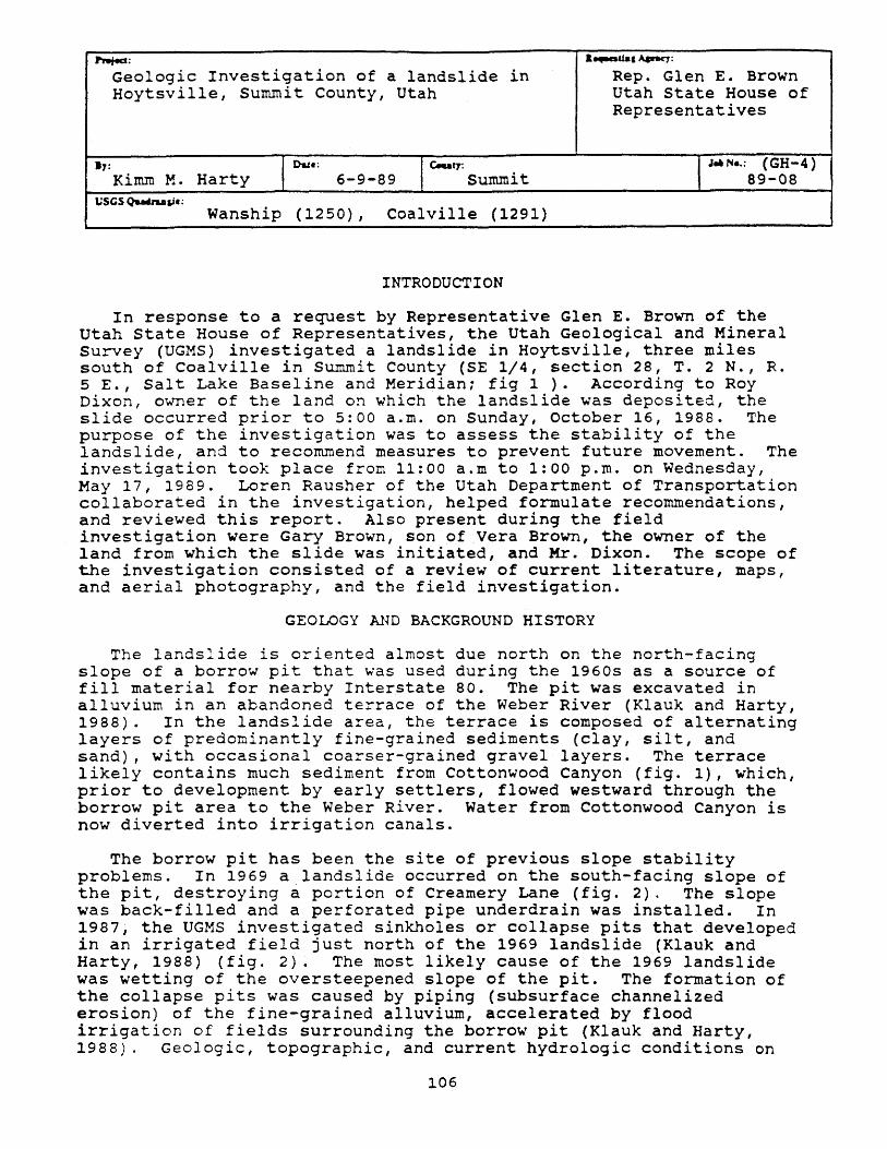
~: &..-.ual~:
Geologic Investigation of a landslide in Rep. Glen E. Brown Hoytsville, Summit County, Utah Utah State House of
Representatives
": I Due: Ic.u~ I J_N •• : (GH-4) Kimm M. Harty 6-9-89 Summit 89-08
USGS Qu.buaJe; Wanship (1250) , Coalville (1291)
INTRODUCTION
In response to a request by Representative Glen E. Brown of the Utah State House of Representatives, the Utah Geological and Mineral Survey (UGMS) investigated a landslide in Hoytsville, three miles south of Coalville in summit County (SE 1/4, section 28, T. 2 N., R. 5 E., Salt Lake Baseline and Meridian; fig 1). According to Roy Dixon, owner of the land on which the landslide was deposited, the slide occurred prior to 5:00 a.m. on Sunday, October 16, 1988. The purpose of the investigation was to assess the stability of the landslide, and to recommend measures to prevent future movement. The investigation took place from 11:00 a.m to 1:00 p.m. on Wednesday, May 17, 1989. Loren Rausher of the Utah Department of Transportation collaborated in the investigation, helped formulate recommendations, and reviewed this report. Also present during the field investigation were Gary Brown, son of Vera Brown, the owner of the land from which the slide was initiated, and Mr. Dixon. The scope of the investigation consisted of a review of current literature, maps, and aerial photography, and the field investigation.
GEOLOGY AND BACKGROUND HISTORY
The landslide is oriented almost due north on the north-facing slope of a borrow pit that was used during the 1960s as a source of fill material for nearby Interstate 80. The pit was excavated in alluvium in an abandoned terrace of the Weber River (Klauk and Harty, 1988). In the landslide area, the terrace is composed of alternating layers of predominantly fine-grained sediments (clay, silt, and sand), with occasional coarser-grained gravel layers. The terrace likely contains much sediment from Cottonwood Canyon (fig. 1), Which, prior to development by early settlers, flowed westward through the borrow pit area to the Weber River. Water from Cottonwood Canyon is now diverted into irrigation canals.
The borrow pit has been the site of previous slope stability problems. In 1969 a landslide occurred on the south-facing slope of the pit, destroying a portion of Creamery Lane (fig. 2). The slope was back-filled and a perforated pipe underdrain was installed. In 1987, the UGMS investigated sinkholes or collapse pits that developed in an irrigated field just north of the 1969 landslide (Klauk and Harty, 1988) (fig. 2). The most likely cause of the 1969 landslide was wetting of the oversteepened slope of the pit. The formation of the collapse pits was caused by piping (subsurface channelized erosion) of the fine-grained alluvium, accelerated by flood irrigation of fields surrounding the borrow pit (Klauk and Harty, 1988). Geologic, topographic, and current hydrologic conditions on
106
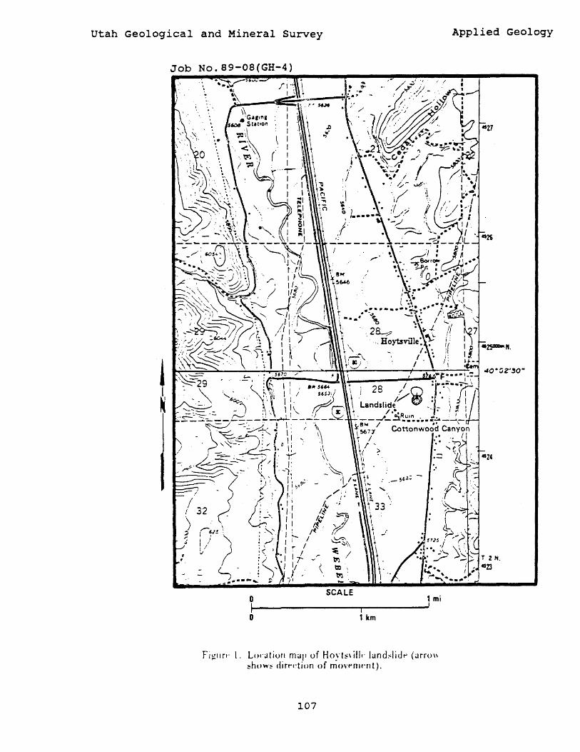
utah Geological and Mineral Survey
Job No. 89-08(GH-4)
o I o
... . ~' . ~".
t )'
:\ \I' .. .. . . . ~ l •••• • L·
,{ ,:
SCALE
i 1 km
i /'
1 mi !
Fj~tlrt, l. Locatioll mup of Hoyt!'\ illf' land~liJt-' (arro\\ ~how~ dirt'dion of mO"f'nlt'nt).
107
Applied Geology
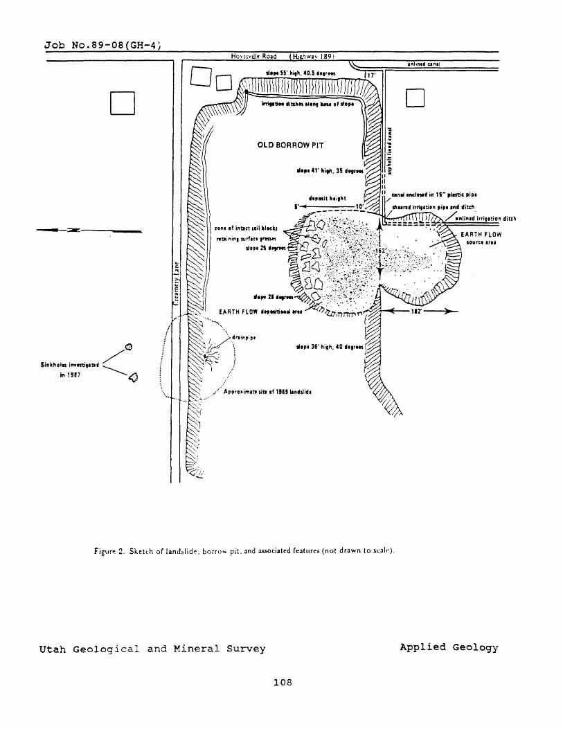
Job No.89-08(GH-4,
D
-----~~-------------
<l)
$j"khola imtstifltlf ~ m 1917 ~<) i
/ f i i
" ' ..
Hov\svtlJe Road Hj~ .. hwa\l 189)
OLD BORROW PIT
Figllrp. 2, Sketch of land!llid~, borrow pit. Olnd :tS5ociatcd rt!:ltur~s (not drawn to sc.:Ollf~).
utah Geological and Mineral Survey
108
unlln.d Un,l
o
Applied Geology
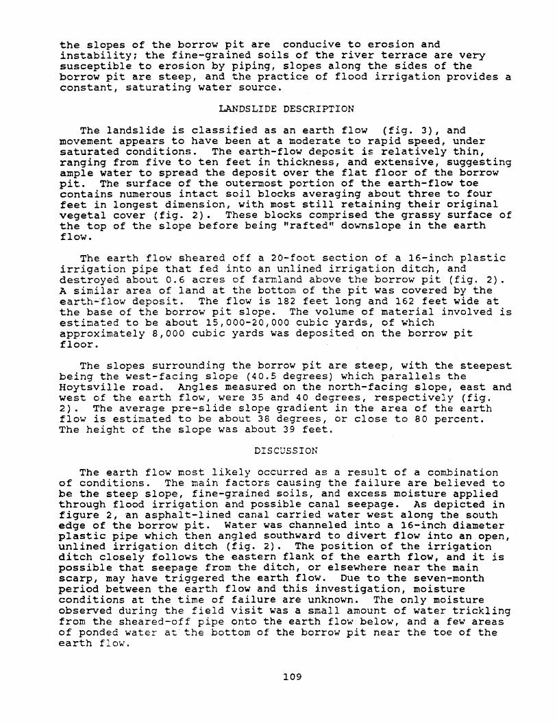
the slopes of the borrow pit are conducive to erosion and instability; the fine-grained soils of the river terrace are very susceptible to erosion by piping, slopes along the sides of the borrow pit are steep, and the practice of flood irrigation provides a constant, saturating water source.
LANDSLIDE DESCRIPTION
The landslide is classified as an earth flow (fig. 3), and movement appears to have been at a moderate to rapid speed, under saturated conditions. The earth-flow deposit is relatively thin, ranging from five to ten feet in thickness, and extensive, suggesting ample water to spread the deposit over the flat floor of the borrow pit. The surface of the outermost portion of the earth-flow toe contains numerous intact soil blocks averaging about three to four feet in longest dimension, with most still retaining their original vegetal cover (fig. 2). These blocks comprised the grassy surface of the top of the slope before being "rafted" downslope in the earth flow.
The earth flow sheared off a 20-foot section of a 16-inch plastic irrigation pipe that fed into an unlined irrigation ditch, and . destroyed about 0.6 acres of farmland above the borrow pit (fig. 2). A similar area of land at the bottom of the pit was covered by the earth~flow deposit. The flow is 182 feet long and 162 feet wide at the base of the borrow pit slope. The volume of material involved is estimated to be about 15,000-20,000 cubic yards, of which approximately 8,000 cubic yards was deposited on the borrow pit floor.
The slopes surrounding the borrow pit are steep, with the steepest being the west-facing slope (40.5 degrees) which parallels the Hoytsville road. Angles measured on the north-facing slope, east and west of the earth flow, were 35 and 40 degrees, respectively (fig. 2). The average pre-slide slope gradient in the area of the earth flow is estimated to be about 38 degrees, or close to 80 percent. The height of the slope was about 39 feet.
DISCUSSION
The earth flow most likely occurred as a result of a combination of conditions. The main factors causing the failure are believed to be the steep slope, fine-grained soils, and excess moisture applied through flood irrigation and possible canal seepage. As depicted in figure 2, an asphalt-lined canal carried water west along the south edge of the borrow pit. Water was channeled into a 16-inch diameter plastic pipe which then angled southward to divert flow into an open, unlined irrigation ditch (fig. 2). The position of the irrigation ditch closely follows the eastern flank of the earth flow, and it is possible that seepage from the ditch, or elsewhere near the main scarp, may have triggered the earth flow. Due to the seven-month period between the earth flow and this investigation, moisture conditions at the time of failure are unknown. The only moisture observed during the field visit was a small amount of water trickling from the sheared-off pipe onto the earth flow below, and a few areas of ponded water at the bottom of the borrow pit near the toe of the earth flow.
109
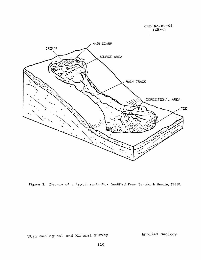
Job No.89-08 (GH-4)
F'lgure 3. Dlc.gr~ of' 0. typlCo.l eo.rth flow (Modified ;,..0,... Zo.,..ubo. L Mencle .. 1969).
utah Geological and Mineral survey Applied Geology
110
There was no indication that the landslide has moved since its failure last October. However, the main scarp is nearly vertical and reaches 15 feet in height along the northeastern portion of the earth-flow source area, beneath the sheared irrigation pipe. Shearing and toppling of soil blocks from the main scarp will probably occur until the scarp erodes naturally to form a more stable slope, or is graded.
Under current geologic conditions and irrigation practices, the slopes surrounding the entire borrow pit are considered to be susceptible to continued landslide activity. The slopes are high, steep, and composed of fine-grained alluvium. The west-facing slope face currently shows evidence of surface instability in the form of horizontal gaps that parallel the slope; tracts of vegetation have moved short distances downslope, exposing bare soil. This 40.5-degree slope stands about 55 feet high, and an unlined canal is only 17 feet from the southern portion of this slope (fig. 2). In addition, Roy Dixon reported that flood waters from cottonwood Canyon occasionally flow into the pit over this slope. Added moisture, whether through precipitation, canal seepage, or surface runoff, could create a reduction in the internal strength of this slope, which already appears to be in an unstable state. Should a landslide of similar magnitude to the recent earth flow form on this westfacing slope, the Hoytsville Road, 27 feet behind the borrow pit, and residential areas across the road would be impacted.
RECOMMENDATIONS
The two principal factors responsible for the slope failure are believed to be the addition of water to the slope through irrigation, and the extreme height and steepness of the slope. To ensure stability of existing slopes, these factors must be controlled. A reduction in flood irrigation with lining of canals, or a change to sprinkler irrigation, with care taken to avoid watering near the earth flow, will reduce the amount of water added to the slope. This course of action has thus far been successful in halting enlargement and reappearance of collapse pits in the field above the 1969 landslide. Grading of the earth flow, especially near the main scarp, will reduce the potential hazard from soil block failures. A maximum stable slope angle for these materials is about 2:1 (26 degrees). To fully evaluate the stability of borrow pit slopes, potential for future landslides, and measures needed to ensure stable slopes, a thorough soils and slope stability investigation by a qualified geotechnical firm would be required.
CITED REFERENCES
Klauk, R.H., and Harty, R.M., 1988, Sinkhole and landslide investigation in Summit County, Utah, in Black, B.D., (comp.), Technical Reports for 1987, site Investigation section: utah Geological and Mineral Survey Report of Investigation 216, p. 99-103.
Zaruba, Q., and Mencle, V., 1969, Landslides and their control: Elsevier, Amsterdam, 205 p.
111
~: • .,.-.u..I~:
Freeze Canyon debris flood, Utah Division of Salt Lake County, Utah Comprehensive Emergency
Management
a,: J D~, Ic...rr. ' .... N .. : (GH-5)
Kimm M. Harty 6-14-89 Salt Lake 89-09 VSGS~llc:
Mountain Dell (1252) Ft. Douglas (1253)
On Monday, June 12, 1989, an interdisciplinary team of specialists (table 1) visited the site of a debris flood in a tributary of Emigration Canyon, Salt Lake County, Utah. The purpose of the visit was to observe the relationship between a burned area and the flood, and the effectiveness of flood control structures placed immediately after the fire. Two hazard mitigation plans concerning the relationship between forest fires and flash floods are currently being prepared for other areas of Utah by Fred May of the Utah Division of Comprehensive Emergency Management who coordinated this effort, and organized this survey team to lend some insight into hazard mitigation in Emigration Canyon. A second visit to the canyon was made on June 16, 1989, with Gary Christenson of the Utah Geological and Mineral Survey, to investigate the source area of the flood.
In ear~y September, 1988, a wildfire burned over 5600 acres of woodland in a portion of Emigration Canyon (Nelson and Rasely, 1989) (fig. 1). The fire burned approximately 90 percent of Freeze Canyon, and 80 percent of the adjacent Brigham Fork watershed. These areas experienced a damaging flood nine months later, on the evening of June 9, 1989, as a result of an intense thunderstorm. More than 1 inch of water fell over these small watersheds between 9:30 and 11:30 p.m. Hydrologists from the U. S. Soil Conservation Service estimate that floodwaters seven-feet deep surged down Freeze Canyon toward Emigration Canyon and residences belo\o,T. No lives were lost, but damage in residential areas included flooding and sediment deposition in yards, basements, garages I driveways I and access roads. Other damage included culvert wash-outs and blockages, undercutting and partial collapse of roads by stream erosion, and shearing of underground utility lines.
Although flooding occurred in Brigham Fork as well as Freeze Canyon, only the latter was visited. In the middle portion of the canyon, grasses, small herbaceous plants, and some small « 6 inches high) woody-stemmed plants such as chokecherry have re-established since the fire. Tall trees still stand, but many are dead with very little forest canopy.
Freeze Canyon has an east and west fork in the headwaters area, and the confluence is at approximately 6400 feet elevation. Farther downstream, at about 6200 feet elevation, the channel gradient becomes more gentle and the canyon widens (fig. 2). The lower portion of Freeze Canyon is underlain by the Cretaceous Kelvin Formation, consisting of reddish sandstone and pale-gray limestone (Van Horn and Crittenden, 1987). Most of middle portion of the canyon is underlain by Jurassic-age T\o,rin Creek Limestone which is .predominantly gray colored. The upper part of the canyon, above the confluence of the two
112
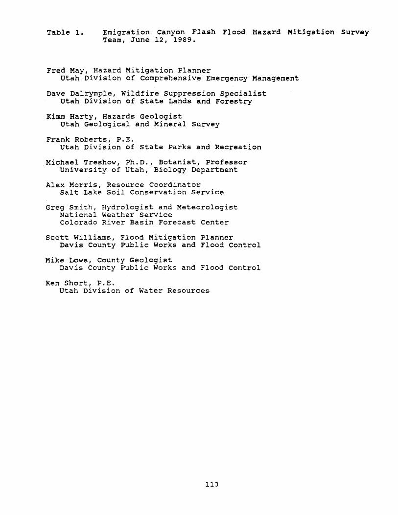
Table 1. Emigration Canyon Flash Flood Hazard Mitigation Survey Team, June 12, 1989.
Fred May, Hazard Mitigation Planner Utah Division of Comprehensive Emergency Management
Dave Dalrymple, Wildfire suppression Specialist utah Division of State Lands and Forestry
Kimm Harty, Hazards Geologist Utah Geological and Mineral Survey
Frank Roberts, P.E. Utah Division of State Parks and Recreation
Michael Treshow, Ph.D., Botanist, Professor University of Utah, Biology Department
Alex Morris, Resource Coordinator Salt Lake Soil Conservation Service
Greg Smith, Hydrologist and Meteorologist National Weather Service Colorado River Basin Forecast Center
Scott Williams, Flood Mitigation Planner Davis County Public Works and Flood Control
Mike Lowe, County Geologist Davis County Public Works and Flood Control
Ken Short, P.E. utah Division of Water Resources
113
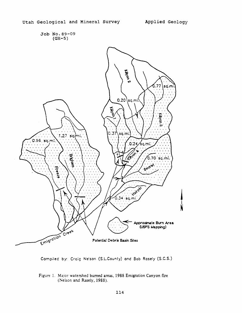
utah Geological and Mineral survey Applied Geology
Job No.89-09 (GH-5)
~- Appf"oxmate Bt.rn Area ~ (USFS Mapping)
Potential Debris Basi'-. Sites
Compiled by: Creig Ne!son (S.L-County) ond Sob Rosely (S.C.S.)
Figure 1. Major watershed burned areas, 1988 Emigration Canyon fITe (Nelson and Rasely, 1988).
114
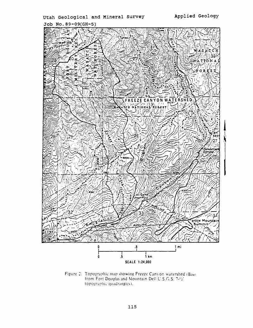
utah Geological and Mineral Survey
Job No.B9-09(GH-5)
0 .5
f I I
0 .5 I 1 km
SCALE 1 :24,000
Applied Geology
1 mi I
Figure:. Toro~rJphic map showing Fret:!zl' C;.tnyon watershed (B;lSt'
from Fort Douglas and MOllntJin Del! L".S.G.S. 7- 1:'
(Oro:!r;J!~hj\ .. : qll;lJr;ll1gll'!'l1.
115
drainage channels is underlain by pink to light orange-colored Nugget Sandstone.
Recognizing the potential for flooding and erosion on the denuded watershed, the u.s. Soil Conservation Service working with Salt Lake County installed about five gabion structures and numerous short wire fences in the channel of Freeze Creek wi thin 30 days after the September wildfire. These structures are designed to alter the channel gradient, causing deposition of sediment, and to retard floodwater velocity, thereby reducing the potential for catastrophic flooding. Field observations showed that many of the fences, although heavily damaged during the flood, were effective in trapping debris, including cobble to boulder-sized rocks, that oth~rwise could have washed farther downstream toward residential areas.
Examination of the confluence area of Freeze Creek showed that flood damage (channel erosion and overbank flooding) was more severe in the east than in the west fork. The head of the east fork is a bowl-snaped amphitheater with severe fire damage to vegetation. Just downstream from this amphitheater is a relatively unburned area along the bottom of the drainage. The head of the east fork is mantled by a deep, loose, friable organic soil. Before the fire, this area had supported mostly shrubs and grass, with trees only at the bottom of the hollow along the channel. With little post-fire vegetation remaining to retard overland flow, the amphitheater funneled runoff into the narrow channel, causing floodwaters to rise quickly. Most of the coarse debris (cobbles, boulders) entrained by floodwaters was scoured from the channel below this area. Floodwater and finer-grained debris were also contributed from other hillsides and small ephemeral drainages and gullies in middle Freeze Canyon as evidenced by channel scour and hillside rilling and erosion.
Much of the larger material transported in the channel was deposited in the middle and lower reaches of the watershed, where the channel gradient decreases, and flood-control structures were emplaced. Damage to downstream residences could have been greater had not the gabions and fences been installed in Freeze Creek. The floodwaters that damaged residences in lower Freeze and Emigration Canyons carried finer sediment such as silt, sand, and gravel which was deposited in basements and garages of homes and buildings near the mouth of Freeze Creek. u.s. Soil Conservation hydrologists estimate the depth of the flood~aters could have reached at least 14 feet instead of 7 feet had not the flood control structures been emplaced (R.C. Rasely, U.S.S.c.s Geologist, oral commun., June 13, 1989).
At present, the head region of the watershed is subject to continued erosion and possible flooding. The lower and middle portions of the stream bed of Freeze and Brigham Fork Creeks now contain sediment and debris deposited behind flood-control structures. In the event of another severe flood, this material could become entrained in a debris flood or flow and again cause damage in downstream areas. Reestablishment of the vegetation to a pre-fire state, especially at the head of the watershed, and/or repair of some of the flood-control structures would help lessen the impact of such an event.
116
CITED REFERENCES
Nelson, C.V., and Rasely, R.C., 1988, Affleck Park fire sediment yield analysis: Salt Lake County Public Works Department unpublished memorandum, 5 p.
Nelson, C. V., and Rasely, R. C., 1989, Evaluating the debris flow potential after a wildfire; rapid response using the PSIAC method, Salt Lake County, Utah: Geological Society of America Abstracts with Programs, v. 21, no. 5, p. 121.
Van Horn, Richard, and crittenden, M. D., Jr., 1987, Map showing surficial units and bedrock geology of the Fort Douglas Quadrangle and parts of the Mountain Dell and Salt Lake City North Quadrangles, Davis, Salt Lake, and Morgan Counties, Utah: U.S. Geological Survey Miscellaneous Investigations Series Map I-1762, Scale 1:24,000.
117
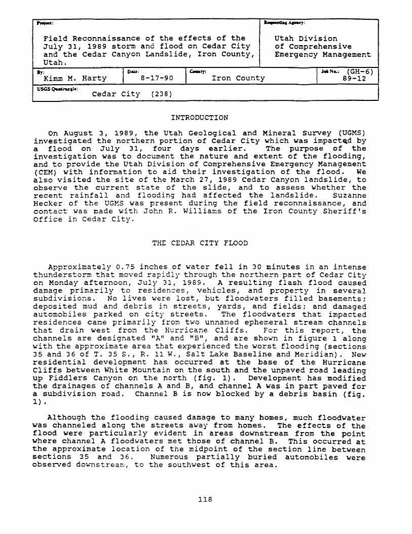
~: '-,-Ch::; ~:
Field Reconnaissance of the effects of the Utah Division July 31, 1989 storm and flood on Cedar city of Comprehensive and the Cedar Canyon Landslide, Iron County, Emergency Management Utah.
Bl': Kimm M. Harty
I Dm.: 8-17-90 Ic.a~ Iron County
I'"' N .. : (GH-6) 89-12
tlSGS QuUusJ.: Cedar city (238)
INTRODUCTION
On August 3, 1989, the Utah Geological and Mineral survey (UGMS) investigated the northern portion of Cedar City which was impact~d by a flood on July 31, four days earlier. The purpose of the investigation was to document the nature and extent of the flooding, and to provide the Utah Division of Comprehensive Emergency Management (CEM) with information to aid their investigation of the flood. We also visited the site of the March 27, 1989 Cedar Canyon landslide, to observe the current state of the slide, and to assess whether the recent rainfall and flooding had affected the landslide. Suzanne Hecker of the UGMS was present during the field reconnaissance, and contact was made with John R. Williams of the Iron County Sheriff's Office in Cedar city.
THE CEDAR CITY FLOOD
Approximately 0.75 inches of water fell in 30 minutes in an intense thunderstorm that moved rapidly through the northern part of Cedar City on Monday afternoon, July 31, 1989. A resulting flash flood caused damage prilnarily to residences, vehicles, and property in several subdivisions. No lives were lost, but floodwaters filled basements: deposited mud and debris in streets, yards, and fields; and damaged automobiles parked on city streets. The floodwaters that impacted residences came primarily from two unnamed ephemeral stream channels that drain west from the Hurricane Cliffs. For this report, the channels are designated "A" and liB", and are shown in figure 1 along with the approximate area that experienced the worst flooding (sections 35 and 36 of T. 35 S., R. 11 W., Salt Lake Baseline and Meridian). New residential development has occurred at the base of the Hurricane Cliffs between White Mountain on the south and the unpaved road leading up Fiddlers Canyon on the north (fig. 1). Development has modified the drainages of channels A and B, and channel A was in part paved for a subdivision road. Channel B is now blocked by a debris basin (fig. 1) •
Although the flooding caused damage to many homes, much floodwater was channeled along the streets away from homes. The effects of the flood were particularly evident in areas downstream from the point where channel A floodwaters met those of channel B. This occurred at the approximate location of the midpoint of the section line between sections 35 and 36. Numerous partially buried automobiles were observed downstream, to the southwest of this area.
118
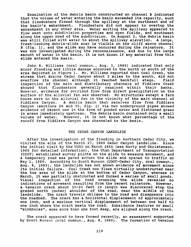
Examination of the debris basin constructed on channel B indicated that the volume of water entering the basin exceeded its capacity, such that floodwaters flowed through the spillway at the northeast end of the basin I s embankment. Floodwaters did not appear to overtop the embankment in any other area. Water exiting the spillway appeared to flow west onto subdivision properties and open fields, and southwest along the upper road of the subdivision. On August 3, the debris basin was still filled with water to about the spillway elevation. A large, fresh-looking debris-slide scar is visible on the cliff above channel B (fig. 1), and the slide may have occurred during the rainstorm. It was not investigated during the reconnaissance, and due to the large amount of water in the basin, it is not known if any material from this slide entered the basin.
John R. Williams (oral commun., Aug. 3, 1989) indicated that only minor flooding and little damage occurred to the north or south of the area depicted in figure 1. Mr. Williams reported that Coal Creek, the stream that drains Cedar Canyon about 3 miles to the south, did not overflow its channel al though it reached bankfull stage. Field inspection of the main and distributary channels of Fiddlers Creek showed that floodwaters generally remained within their banks. However, evidence for overland flow from direct precipitation on the surface of the alluvial fan was observed. No structures except a farm house were on the alluvial fan in the vicinity of the main channel of Fiddlers Canyon. A debris basin that receives flow from Fiddlers· Canyon (sections 26 and 35, fig. 1) via two underground pipes showed evidence of recent use in the form of ponded water and flattened grass in areas immediately upstream. The debris basin contained only a small volume of water. However, it is not known what percentage of the runoff from Fiddlers Canyon was channeled to the basin.
THE CEDAR CANYON LANDSLIDE
After the investigation of the flooding in northern Cedar City, we visited the site of the March 27, 1989 Cedar Canyon landslide. Since the initial visit by the UG~S on March 28th (see Harty and Christenson, 1989 for detailed information), the Utah Department of Transportation (UDOT) established survey points on the slide to measure movement, and a temporary road was paved across the slide and opened to traffic on May 1, 1989. According to Scott Munson (UOOT-Cedar City, oral commun. I
Aug. 8, 1989), the landslide has not shown evidence of movement since its initial failure. Coal Creek now flows virtually unobstructed near the toe area of the slide at the bottom of Cedar Canyon, whereas in March, it was partially obstructed and formed a series of small ponds. Visual inspection of the road crossing the slide revealed no indications of movement resulting from the recent rainstorm. However, a tension crack about 15-20 feet in length was discovered atop the graded north (outer) shoulder of the road, near the middle of the landslide. The crack travels oblique to the road and disappears into the roadbed. The crack has a horizontal displacement of approximately one inch, and a maximum vertical displacement of between one half to one inch where the crack meets the road. Subsidence features or small "sinkholes", some more than one foot deep, are aligned along the crack.
The crack appeared to have formed recently, an assessment supported by Scott Munson (oral commun., Aug. 8, 1989). The formation of tension
119
cracks is usually a sign of slope instability, and is often the first warning sign of an impending slope failure. Should a failure occur along the tension crack, it is likely that the road would be damaged. It would be wise to monitor the crack regularly for signs of additional widening or downslope movement, and to devise a method for warning motorists of possible road damage in the area.
REFERENCE CITED
Harty, K.M. I and Christenson, G.E., reconnaissance, Iron County, Utah: Survey unpublished report, 7 p.
120
1989, Cedar Canyon landslide utah Geological and Mineral
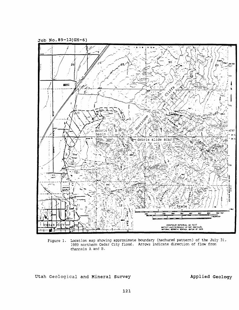
Job No.89-12(GH-6)
Figure 1.
CONTOU'" INT(IN"L 40 FEr1 . DOTT[D LI"[~ 1I["'[YHr 10 rOOl eoo<TOVIIS MolTlON4;. Ci[OO(lIC w:nlCA:. DlTV" Of 192'9
Location map shm.-ing approximate boundary (hachured pattern) of the July 31, 1989 northern Cedar City flood. Arr~'s indicate direction of fl~' from cha~~els A and B.
Utah Geological and Mineral Survey Applied Geology
121
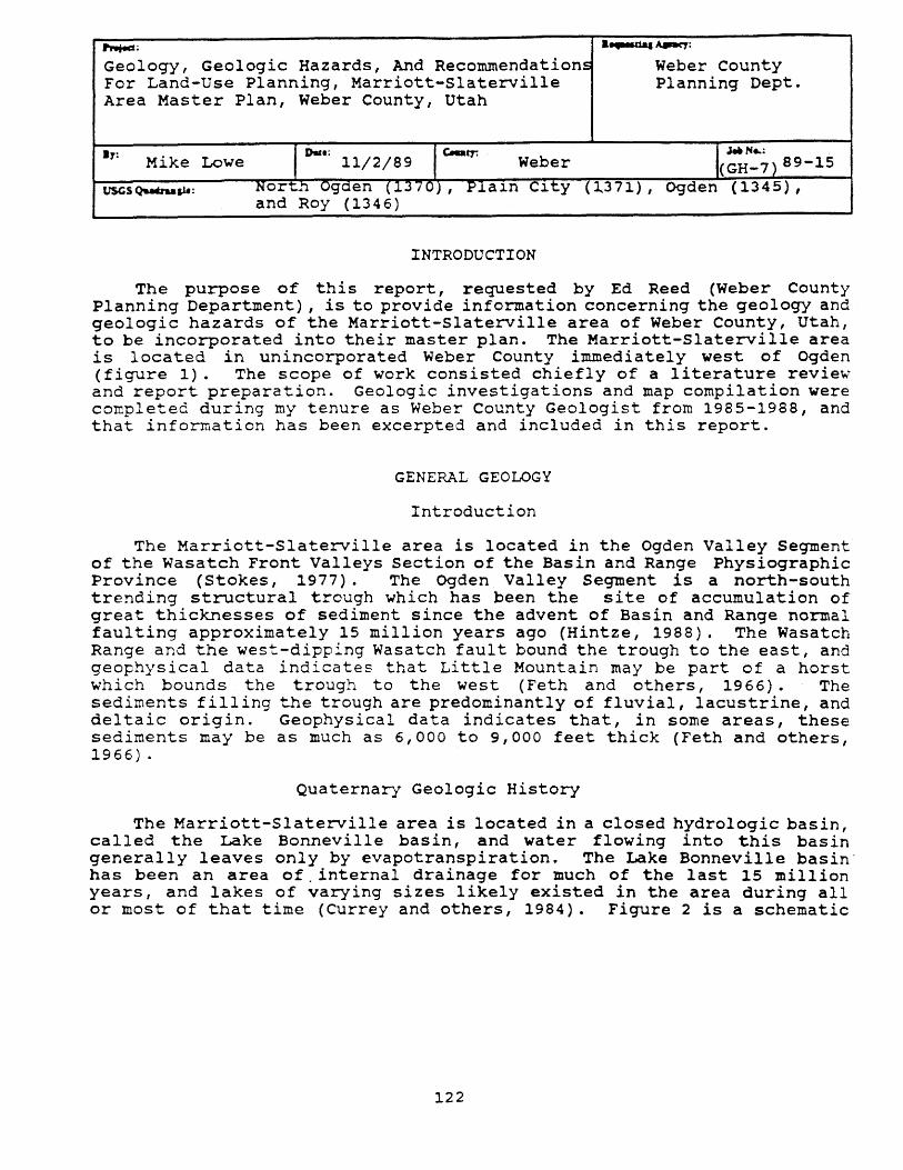
~; a....-ua.~:
Geology, Geologic Hazards, And Recommendations Weber County For Land-Use Planning, Marriott-Slaterville Planning Dept. Area Master Plan, Weber County, Utah
IT: Mike Lowe I 0..: 11/2/89 Ic..arr. Weber I~ ".. N .. : (GH-7) 89-15 t1SGS~p.: Nort.~ Ogden (13 -; 0) , PlaJ..n CJ..ty ( 1.371) , Ogden (1345),
and Roy (1346)
INTRODUCTION
The purpose of this report, requested by Ed Reed (Weber County Planning Department), is to provide information concerning the geology and geologic hazards of the Marriott-Slaterville area of Weber County, Utah, to be incorporated into their master plan. The Marriott-Slaterville area is located in unincorporated Weber County immediately west of Ogden (figure 1). The scope of work consisted chiefly of a literature review and report preparation. Geologic investigations and map compilation were completed during my tenure as Weber County Geologist from 1985-1988, and that information has been excerpted and included in this report.
GENERAL GEOLOGY
Introduction
The Marriott-Slaterville area is located in the Ogden Valley Segment of the Wasatch Front Valleys section of the Basin and Range Physiographic Province (Stokes, 1977). The Ogden Valley Segment is a north-south trending structural trough which has been the site of accumulation of great thicknesses of sediment since the advent of Basin and Range normal faulting approximately 15 million years ago (Hintze, 1988). The Wasatch Range and the west-dipping Wasatch fault bound the trough to the east, and geophysical data indicates that Little Mountain may be part of a horst which bounds the trough to the west (Feth and others, 1966). The sediments filling the trough are predominantly of fluvial, lacustrine, and deltaic origin. Geophysical data indicates that, in some areas, these sediments may be as much as 6,000 to 9,000 feet thick (Feth and others, 1966) .
Quaternary Geologic History
The Marriott-Slaterville area is located in a closed hydrologic basin, called the Lake Bonneville basin, and water flowing into this basin generally leaves only by evapotranspiration. The Lake Bonneville basin' has been an area of,internal drainage for much of the last 15 million years, and lakes of varying sizes likely existed in the area during all or most of that time (Currey and others, 1984). Figure 2 is a schematic
122
Job No.89-15(GH-? Base Map from CXjDEN m:f PRClrfCNroRY roM
u.s.Gs. I: 100.COO topographic ~
SCALE 1:100 000 I CDmJoc£ 1 EJ( ON Tl£ NA? IIID"'R£SENiS I KJl.OM['TEJt 01'( n£ CItOt.N)
CONTOUR INTERVAL SO METERS
U.OMETERS , • AOH
MUS F c=a ==0
Figure ,1. Loc:atioo map of Marriott-Slaterville ~ snxty area.
utah Geological and Mineral survey
123
Applied Geology
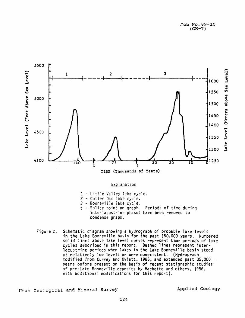
5500
5000
4500
4100
1 2 3
Job No.89-15 (GH-7)
t-+--------4- - - --It----41-- - - - - - ... 1 --------t 1600
TIME (Thousands of Years)
Explanation
1 - Little Valley lake cycle. 2 - Cutler Dam lake cycle. 3 - Bonneville lake cycle. t - Splice point on graph. Periods of time durinq
interlacustrine phases have been removed to -condense graph.
150Q
1450
1400
1350
1300
Figure 2. Schematic diagram showing a hydrograph of probable lake levels in the Lake Bonneville basin for the past 150,000 years. Numbered solid lines above lake level curves represent time periods of lake cycles described in this report. Dashed lines represent interlacustrine periods when lakes in the Lake Bonneville basin stood at relatively low levels or were nonexistent. (Hydr09raph modified ~rom Currey and Oviatt, 1985, and extended past 35,000 years before present on the basis of recent statigraphic studies of pre-Lake Bonneville deposits by Machette and others, 1986, with additional modifications for this report).
Utah Geological and Mineral Survey Applied Geology
124
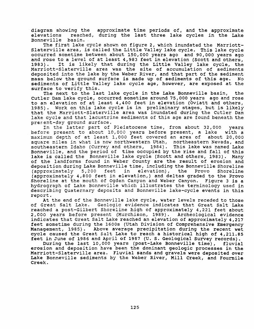
diagram showing the elevations reached, Bonneville basin.
approximate time periods of, and the approximate during the last three lake cycles in the Lake
The first lake cycle shown on figure 2, which inundated the MarriottSlaterville area, is called the Little Valley lake cycle. This lake cycle occurred sometime between about 150,000 years ago and 90,000 years ago and rose to a level of at least 4,983 feet in elevation (Scott and others, 1983) • It is likely that during the Little Valley lake cycle, the Marriott-Slaterville area was the site of accumulation of sediments deposited into the lake by the Weber River, and that part of the sediment mass below the ground surface is made up of sediments of this age. No sediments of Little Valley lake cycle age, however, are exposed at the surface to verify this.
The next to the last lake cycle in the Lake Bonneville basin, the Cutler Dam lake cycle, occurred sometime around 75,000 years ago and rose to an elevation of at least 4,400 feet in elevation (Oviatt and others, 1985). Work on this lake cycle is in preliminary stages, but is likely that the Marriott-Slaterville area was inundated during the Cutler Dam lake cycle and that lacustrine sediments of this age are found beneath the present-day ground surface.
In the latter part of Pleistocene time, from about 32,000 years befo~e present to about 10,000 years before present, a lake wi th a maximum depth of at least 1,000 feet covered an area of about 20,000 square miles in what is now northwestern Utah, northeastern Nevada, and southeastern Idaho (Currey and others, 1984). This lake was named Lake Bonneville, and the period of time occupied by the rise and fall of this lake is called the Bonneville lake cycle (Scott and others, 1983). Many of the landforms found in Weber County are the result of erosion and deposition during Lake Bonneville time, including the Bonneville Shoreline (approximately 5,200 feet in elevation), the Provo Shoreline (approximately 4,800 feet in elevation,) and deltas graded to the Provo Shoreline at the mouth of Ogden Canyon and Weber Canyon. Figure 3 is a hydrograph of Lake Bonneville which illustrates the terminology used in describing Quaternary deposits and Bonneville lake-cycle events in this report.
At the end of the Bonneville lake cycle, water levels receded to those of Great Sal t Lake. Geologic evidence indicates that Great Salt Lake reached a post-Gilbert Shoreline high of approximately 4,221 feet about 2 , 000 years be fore present (Murchison, 1989). Archeological evidence indicates that Great Sal t Lake reached an elevation of approximately 4,217 feet sometime during the 1600s (Utah Division of Comprehensive Emergency Management, 1985). Above average precipitation during the recent wet cycle caused the Great Salt Lake to reach a historical high of 4,211.85 feet in June of 1986 and April of 1987 (U. S. Geological Survey records).
During the last 10,000 years (post-Lake Bonneville time), fluvial erosion and deposition have been the dominant geologic processes in the Marriott-Slaterville area. Fluvial sands and gravels were deposited over Lake Bonneville sediments by the Weber River, Mill Creek, and Fourmile Creek.
125
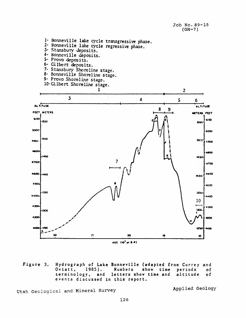
•
1- Bonneville lake cycle transgressive phase. 2 - SOMe vi 11 e l3ke cycle regress i \"e phase. 3- S t:msbuty c.Jeposi ts. 4- Bonneville deposits. 5- Provo deposi ts. 6- Gi lbe rt depos its. 7- Stansbury Sooreline stage. 8- Bonneville Shoreline stage. 9- Provo Shoreline stage. IO-Gilbert Shoreline stage.
1
3 4 ~ 'ITyO(
~UT -UlJtS
/, -J 7
I---f ,. / - \ \.-
&Gl 110',.. I.~'
•
8 9
~-, I , i ! I
o \
Job No. 89-15 (GH-7 )
2
5 6 I • <ITu.«
..:T'tItS PU T
SlOO ~
sooo
~o 41100
.....00
M
4100
4600 "00
~c:o
-...00
4)00
4ZOO
460Q
10
.Figure 3. Hydrograph of Lake Bonneville (adapted from Currey and Oviatt, 1985). Numbers show time periods of terminology, and letters show time and altitude of events discussed in this report.
Utah Geological and Mineral Survey Applied Geology
126

Surficial Geology
Figure 4 is a geologic map of Marriott-Slaterville area, Weber County. This map is from a 1:100,000 scale map by Davis (1985). Surficial deposits in the Marriott-Slaterville area include two types: Bonneville lake-cycle offshore lacustrine sediment (primarily Provo deposits), and post-Lake Bonneville fluvial sediments.
The oldest sediments exposed in the Marriott-Slaterville study area are Bonneville lake-cycle offshore deposits (figure 4, Qlop and Qlob). These are predominately silt, clay, and sand which settled to the lake bottom in offshore quiet water. These offshore deposits are well stratified and sorted. At the ground surface in most areas these offshore sediments were deposited when the lake was at the Provo Shoreline level, but at depth were deposited when the lake was at the Bonneville Shoreline level. Bonneville-level offshore deposits occur at the ground surface south of the Mill Creek Youth Center.
Post-Lake Bonneville fluvial deposits (figure 3, Qfp) are found along the drainages of Mill Creek, Fourmile Creek, and the Weber River. These sediments consist primarily of sands and gravels deposited in the stream channels I and silt and clay overbank sediments deposited during flood stages. These drainages have eroded into and deposited fluvial sediments over the Bonneville lake-cycle offshore deposits.
GEOLOGIC HAZARDS
Introduction
Potential geologic hazards in the Wasatch Front area include earthquake hazards (ground shaking I surface fault rupture, tectonic subsidence, liquefaction, seismically-induced slope failure and/or flooding), slope failures, problem soils, flooding, and shallow ground water. This report presents a preliminary evaluation of potential geologic hazards affecting the Marriott-Slaterville area and identifies areas in which si te-specific studies should be completed prior to development.
Earthquake Hazards
The study area is in an active earthquake zone called the Intermountain seismic belt which extends from northwestern Montana to southwestern Utah (Smith and Sbar, 1974). In the Weber County area, the largest magnitUde earthquake during historical time occurred in 1914 near Ogden and was an estimated Richter magnitude 5.5 (Arabasz and others, 1979). Numerous smaller earthquakes have occurred in the Weber County area within the last 120 years. Many of these earthquakes cannot be attributed to known active faults, although faults capable of generating earthquakes are present in the area. The Wasatch fault, which trends north-south along the mountain front east of the Marriott-Slaterville area, is the one of most concern because of its recency of movement, potential for generating large earthquakes, and proximity to the study area. It consists of a zone of faults and crustal deformation, sometimes
127
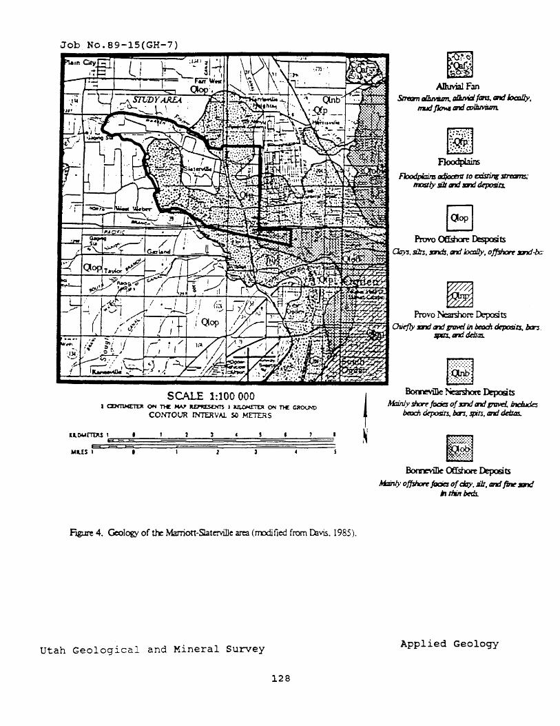
Job No.89-15(GH-7)
SCALE 1:100000 J ~ ON n£ ~ JlD'M:SD(T'S J kll..O'<!TDt ON ll€ CROLND
CONTOtJ'R INTERVAl.. so METERS
ll.OMETEM I t , HSH
MusF F5 ~ l
Mgure 4. Geology of the Marriott-~terville are3 (rrodi tied from Divis. 1985).
Utah Geological and Mineral Survey
128
ADuvialFan Strmm IIIJuvium. a/i.MIi faJU. IIItd 1oaJIJy,
nuJ ~ and co/bMJ.lm.
~ BomeYiIle Neat g lOre DepcSts
!W:inJy ~ focic of D1ti tnt! gavd.. int:Judes bmc:h dq:Iosin, Ixrl. spfl, tn1 ddIa:i.
BomeYiIle Offshore DepcSts
M:zinJ)' offshcn ~ of c:i7y. Jilt, and /W D7d ;, tIM bftb.
Applied Geology
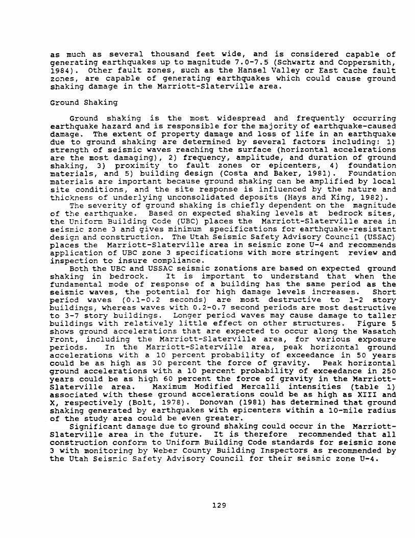
as much as several thousand feet wide, and is considered capable of generating earthquakes up to magnitude 7.0-7.5 (Schwartz and Coppersmith, 1984). Other fault zones, such as the Hansel Valley or East Cache fault zo~es, are capable of generating earthquakes which could cause ground shaking damage in the Marriott-Slaterville area.
Ground Shaking
Ground shaking is the most widespread and frequently occurring earthquake hazard and is responsibl e for the maj ori ty of earthquake-caused damage. The extent of property damage and loss of life in an earthquake due to ground shaking are determined by several factors including: 1) strength of seismic waves reaching the surface (horizontal accelerations are the most damaging), 2) frequency, amplitude, and duration of ground shaking, 3) proximity to fault zones or epicenters, 4) foundation materials, and 5) building design (Costa and Baker, 1981). Foundation materials are important because ground shaking can be amplified by local site conditions, and the site response is influenced by the nature and thickness of underlying unconsolidated deposits (Hays and King, 1982).
The severity of ground shaking is chiefly dependent on the magnitude of the earthquake. Based on expected shaking levels at bedrock sites, the Uniform Building Code (UBC) places the Marriott-Slaterville area in seismic zone 3 and gives minimum specifications for earthquake-resistant design and construction. The Utah Seismic Safety Advisory Council (USSAC) places the Marriott-Slaterville area in seismic zone U-4 and recommends application of UBC zone 3 specifications with more stringent review and inspection to insure compliance.
Both the UBC and USSAC seismic zonations are based on expected ground shaking in bedrock. It is important to understand that when the fundamental mode of response of a building has the same period as the seismic waves, the potential for high damage levels increases. Short period waves (0.1-0.2 seconds) are most destructive to 1-2 story buildings, whereas waves with 0.2-0.7 second periods are most destructive to 3-7 story buildings. Longer period waves may cause damage to taller buildings with relatively little effect on other structures. Figure 5 shows ground accelerations that are expected to occur along the Wasatch Front, including the Marriott-Slaterville area, for various exposure periods. In the Marriott-Slaterville area, peak horizontal ground accelerations with a 10 percent probability of exceedance in 50 years could be as high as 30 percent the force of gravity. Peak horizontal ground accelerations with a 10 percent probability of exceedance in 250 years could be as high 60 percent the force of gravity in the MarriottSlaterville area. Maximum Modified Mercalli intensities (table 1) associated with these ground accelerations could be as high as XIII and X, respectively (Bolt, 1978). Donovan (1981) has determined that ground shaking generated by earthquakes with epicenters within a 10-mile radius of the study area could be even greater.
Significant damage due to ground shaking could occur in the MarriottSlaterville area in the future. It is therefore recommended that all construction conform to Uniform Building Code standards for seismic zone 3 with monitoring by Weber County Building Inspectors as recommended by the Utah Seismic Safety Advisory Council for their seismic zone U-4.
129
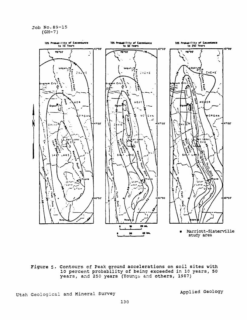
Job No.89-15 (GH-7)
lOS ~111t'l of Uc~ t. 10 , ... ,.,
lOS ......... tltt'.,~. t. 50 I""
• • "IlL \.' ....1_.1.' __ ",,1
• .. .... , I ,
lOS ........ 1 t t, of [a:...-..ce hi %SO , ... ,.,
r---~--~----~~------~.J~ '\
r'
' ..
• Marriott-Slaterville study area
Figure 5. Contours of Peak ground accelerations on soil sites with 10 percent probability of being exceeded in 10 years, 50 years, and 250 years (Youn;~ and others, 1987)
utah Geological and Mineral Survey Applied Geology
130
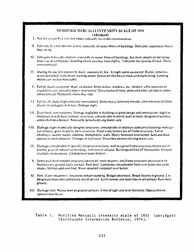
\IOOlfIED 'IER(,AI.I.lI'TE'SITY SCALE OF 19.31 (..\ b ri d a: ~d )
I. !\()II ..... IlI.·'~·I.·Pl..,~.J \~r~ h:v. un("h:r~'P'I!~lall~ f..l\orJhkdr\,'unlStan(c!s.
II. fdt pnl~ ..,~ .Ili.:" per","'.J1 r~'t. ~!\I\C\"I.JII~ nn uJ"J'I.!r noors ufbuildin¥s. D~li\.'alely sus~nd~cJ oh.icl.'ts may ~ .. m~
III. Fdl 4uil~ n()lll:~.Jbly incJoors, ~'rl\,!'(i.llly on upper noors nf builcJings. but many (\Cople do not f~'O~· nile it a~.1n CJrlh4UJk~. St.anJin~ nHllor (ars ma) fO\:k sli~hlly. \'ibralion like PJ~sin~ orlru(k. Dura· lum e:'IIn1..aI~cJ.
1\'. l.)urlng the: Ja~ kll inJuor, h~ moln~·, outdoors b~' f~ ... Al ni~hl some aWiJken~d. DIshes. winc.Jo~'t. \.Ioor'\ JI:'\tur~I.L ,,;.aIls molI,h: (r..ld.,"~ ~uncJ. S~ns.lllOn like heOlvy lruck strikin¥ building: standin~ mulor (ar, rt~·ke:c.J nutic.:cably.
v, Felt by n~.HI~ c!\c!f)·one. man) .J~.Jkc!ned. Some dishes, ,,·indo,,·s. etc .• broken: OJ rew instances of crackc:d plJSlc:r: un'it..lblc Ob)CI.."I~ Oyc!rlurncu. Disturbance of trees, poles and other tall objel.'ts some· times nOllI.'I!LI. Pendulum c.:ltxb m..a, SlOp.
\'1. F~lt b~' oJ", many "ri~hl~ned anJ run outdoors. Some he.Pi)' furniture mo ... 'ed~ a fe..- instJnces or f;.!ll~n pliJ!)ter or J.Jm;,agcu \,:t'llmneys. DiJm.J~1! sli~hl.
\11. E \ c:ry bouy run"i outuoors. ()JmJ~C: nc:~li~iblc: in buildings of ~OO<J desi¥n and \:onslruction: 'Ii~ht (0
mou~r;.at~ In ~1.'II·bullt ordinary ,lru\.·lurcs: (onsld~r.Jbk in roorl)' built Of badly tksigned struc.:lures: ~on\e ~hlmneys broken. NOlU':,"~ by ~r ... (}ns ori\ in~ mOlor ~ars.
VIII. Dam;.agc ,light in spedally ('ksigned stru<.'tures: consider.lbl~ in ordinary subsl..lntial buitdinw.s y.-·ilh par· tl;.!1 coIlOJr~l!. greiJ( in poorly buill strU<.1ures. Panel ~'alls thro .. n out offrOlme stru~ .. tures. F.,II of chimnc:y." factory ,ti.l(k~. \,'olumns, monum~nls. "ails. Heavy furniture overturned. Sand .and mud c:jectc:J in ,mall amounts. Changes in ~dl"·OJtc!r. Disturbed persons dri'ling motor c;.!rs.
IX. DamOJge ,,:nn,idcf;.!ble in spcc.:lally \.k'i~n\!J structures: .. ell dc~igned frame structures IhroVo'n OUI of plumb,: ~rc.J[ in "iubstJntlal builuings, .. uh parlliJll.'oll.lp:,e. BullJlngs shifted ofTfoumt.1tions. Ground crac.:keu I.·on,picuousl). Underground PIpeS bro~en.
X. Some y.-·dl·hurit .... ooden ~tru'tures c.Jestro)ed; mOSl maSonQ and frame structure~ destroyed with founuallon" ~round hauly cral.:kcd. Ralls ~nl. Landslides ~onsiderOible from "\'C'r banks ami \lc:ep slo~~_ Shlfteu \.otnu anu mud. Waler ~plashed c slopped) o\er banks,
X I. Few. if any (masonry'. 'lructure~ remain standing. BricJges cJestroye=. Broad fissures in ground. Ln· dergrounu PIpe: lanes (ompielely out of sef\'I\.·e, Earth slumps and land slips in ~ft ~round. R~uls ~nt ,re~lly.
XU. DOlmagc 101011. Waves seen on grounc.J surfaces. Lin~s o(sight and level distorted. Objects thrown upw .. ru '"to 'he air.
Table 1. Modified Mercalli intensity scale of 1931 (abridged) (Earthquake Information Bulletin, 1974).
131
Surface Fault Rupture
Studies along the Wasatch fault zone (Schwartz and Coppersmith, 1984) and elsewhere indicate that the most likely areas for surface fault rupture are along areas of previous (prehistoric) rupture. These areas are identified by mapping fault scarps, and the nearest scarps are along the Weber segment of the Wasatch fault, about 3 1/2 miles east of the study area. There is no evidence of surface fault rupture hazard in the Marriott-Slaterville study area.
Tectonic Subsidence
Large-scale tectonic subsidence may accompany surface faulting during large earthquakes as the downthrown block undergoes regional downdropping and tilting toward the fault (Keaton, 1987). This subsidence may occur over tens of miles from surface faults. Tectonic deformation maps (figure 6) for the Wasatch fault indicate that predicted subsidence due to the "characteristic" Wasatch fault earthquake (Richter magnitude 7.0-7.5) is less than 5 feet in the Marriott-Slaterville area (Keaton, 1987). Tilting of the g~ound surface to the east may be as much as 0.5 feet/mile, however (Keaton, 1987). These maps also indicate that flooding caused by tectonic subsidence could occur due to ponded shallow ground water in the eastern portion of the Marriott-Slaterville area. Tectonic subsidence is most likely to affect lake shorelines, tall buildings, and gravity-flow systems such as sanitary sewers, storm sewers, and canals.
Liquefaction
Liquefaction is a phenomenon which may occur during earthquakes of magnitude 5.0 and larger (Kuribayashi and Tatsuoka, 1975, 1977; Youd, 1977). Liquefaction occurs when loose, saturated, fine-sand deposits are subjected to earthquake shaking, causing the loss of essentially all shear strength as pressures are rapidly transferred from the granular structure of the soil to pore water (Anderson and others, 1982). Depending on slope, four types of ground failure are commonly associated with liquefaction (Tinsley and others, 1985; Anderson and others, 1982): 1) flow landslides (slopes steeper than about 5.0 percent), 2) lateral spread landslides (slopes between about 0.5 percent and 5.0 percent), 3) ground oscillation (slopes less than about 0.5 percent, liquefaction at depth) and 4) bearing-capacity failures (slopes less than about 0.5 percent, liquefaction at the ground surface). Clays in excess of 15 percent may preclude liquefaction (Anderson and others, 1982), as do confining pressures at depths below about 30 feet (Youd, T. L., oral commun., May 19, 1986).
Liquefaction potential maps by Bay (1987) indicate that the MarriottSlaterville area is in a high liquefaction potential zone. The "high" rating means that the probability of the earthquake-generated critical acceleration needed to induce liquefaction in susceptible soils has a greater than 50 percent chance of being exceeded during the next 100 years. The ground-surface slope in the Marriott-Slaterville area is generally gentler than 0.5 percent, so ground oscillation and bearing
132
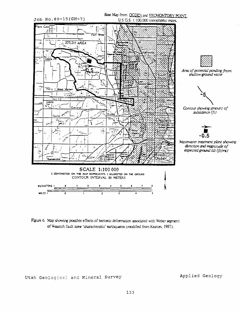
Job No.89-15(GH-7) Base Map from O:;PE!> aOO PRCMC,?N1PRY roIi'T.
U.S G.S. 1: 1 OO.OCO t~phjc rrops..
;, '
. :
SCALE 1:100 000 I ~ ON Tli[ """" R~£.NTS J ~ 0f'4 n£ ~
COr-,'TOUR IN"TERVAl 5{) ME1'ERS ! I
~
FlgI..tre 6. Map showing ;xlSS:ble efTects of tectonic deformation ~ted vvith Weber segrrent
of Wasatch fault zone 'characteristic' ~uakes (m:xiified from Keaton, 1987).
Utah Geolcgical and Mineral survey
133
Area of p:Jtentiallxmding from shallow ground ~ter
Conrow shcr.ving am:JW".! 01 subsiden..,r-e (It)
~ • -0.5 k-mtf!\A.fl1er treJ:l.t1ren1 plant showing
direction ard rrvgnitude of o:pected ground. tilt (Irlm)
Applied Geology
capacity failures are the most likely types of ground failure to accompany liquefaction. Slopes are locally steeper along the banks of strea~s and the Weber River, and liquefaction-induced lateral spreads and landslides could occur in those areas. Si te-specif ic studies to evaluate the liquefaction potential and, if necessary, recommend mitigative measures, should be performed prior to construction.
Earthquake-Induced Slope Failure And/Or Flooding
Earthquakes of magnitUde 4.0 or greater are generally required to induce slope failure (Keefer, 1984). The role of earthquake ground shaking in initiating slope failures is not well understood and no studies assessing seismic slope stability in the Marriott-Slaterville area have been completed. Those slopes most susceptible to non-seismically induced landsl iding are most I ikely to fail during an earthquake, and it is recommended that all slope-stability studies (see next section) include analyses under seismic conditions during both moderate and large earthquakes.
Flooding due to earthquake events may resul t from dam fc ilure, tectonic subsidence, discharge of ground water, and diversion of sJrface drainage. Earthquake-induced flooding in the Marriott-Slaterville area is most likely to occur along the Weber River due to dam failure upstrea~ on either the Ogden or Weber River (U. S. Bureau of Reclamation, 1983; Harty and Christenson, 1988), or ponding of shallo~ ground water due to tectonic subsidence (Keaton, 1987).
Slope Failure
No slope failures have been identified in the Marriott-Slaterville area. Slope failures co~ld occ~r along drainages where stream erosion has created steep bluffs. Development, where possible, should be set back from those bluffs where slopes are steeper than 2.5 horizontal to 1 vertical. Prudent setback distances can be determined on a site-specific basis by projecting a plane at a 2.5 (horizontal) to 1 (vertical) slope (40 percent) through the center of the steep slopes, and not building closer than where this plane intersects the present ground surface. These setback distances would generally not be large in the Marriott-Slaterville area because the bluffs are not high, and would also serve to protect developrr.er-,t from being unde:r-rr.ined by stream erosion. Should development within this setback distance be necessary, site-specific slope-stability and erosion-potential studies should be performed prior to approval of the proposed development.
Problem Soils
Potential problem soils include collapsible (hydrocompactable) soils, compressible organic soils, and soils with a high shrink-swell potential. Problems with soils can also occur due to differential compaction when construction occurs on sediments with different characteristics. Erickson and others (1968) mapped the soils in the Marriott-Slaterville area. Soils in the study a~ea mostly have only low to moderate shrink-swell potential, but soils of the Kirkham series also occur and these soils have
134
a high shrink-swell potential (Erickson and others, 1968). Compressible organic soils may occur in areas of former swamps or shallow lakes. Standard soil and foundation investigations should be conducted prior to development so that problem soils may be identified and, if necessary, mitigative measures may be suggested.
Shallow Ground Water
Depth to shallow ground-water maps have not been produced for the Marriott-Slaterville area. Regional maps indicate that depth to ground water may be less than 10 feet, however (Hecker and Harty, 1988). It is likely that perched ground water is present in some areas, especially in the vicinity of the drainages. The presence of shallow ground water and potential problems may be identified and, if necessary, mitigative measures suggested by conducting standard soil and foundation investigations prior to development.
Flooding
Floods are most likely to occur in response to cloudburst storrus or rapid spring snowmelt and runoff, with the most serious flooding usually occurring along the ~eber River. The primary cause of flooding along the Keber River is rapidly melting snow from late April to early July (Federal Eruergency Management AgencYr 1982a). The largest snowmelt flood.s of record on the Weber River occurred in 1896, 1907, 1909, 1920, 1922, and 1952 (Federal Emergency Management Agency, 1982a).
The potential 100-year flood plains in the Marriott-Slaterville area are sho~~ in National Flood Insurance Program Flood Insurance Rate Maps for unincorporated Weber County (Federal Emergency Management Agency, 1982b). Flood hazards in the Marriott-Slaterville area occur principally along the Weber River. Figure 7 is a floodway schematic showing ter.ms associated with the lOO-year flood. The 100-year flood is divided into a floodway and a floodway fringe. Development should not be permitted in floodway areas. Development may take place in floodway fringe areas by raising the ground elevation. Care must be taken when allowing development in the floodway fringe because encroachment on floodplains reduces the flood-carry ing capaci ty, increases the flood heights of streams and rivers, and increases flood hazards in areas beyond the encroachment itself (Federal Emergency Management Agency, 1982a). Weber County has adopted the National Flood Insurance Program and Federal Emergency Management Agency guidelines for development in flood hazard areas should be followed.
RECOMMENDATIONS
Geologic hazards affecting the Marriott-Slaterville area have been identified in this report. Potential loss of life and property due to these hazards can be lessened if the proper site-specific studies are completed prior to development and, if necessary, mi tigati ve measures are taken. Site-specific liquefaction studies are recommended prior to construction because the entire area is in a high liquefaction potential
135
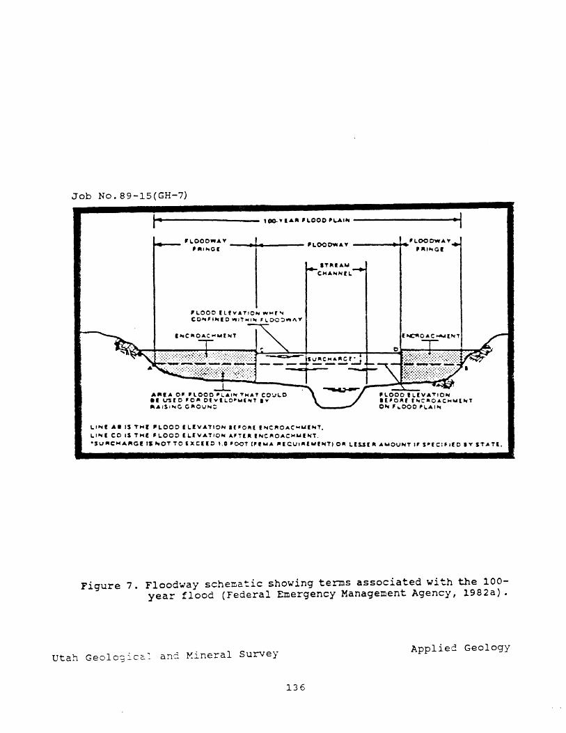
Job No. 89-15(GH-7)
I"~"'---------- , 00-","''' , LOOO 'I..A'~ -----------..... 1 ~ __ ,,-000,,,.1." __ ...... ____ 'LOOOW."
'''''·.01
'LOOO ILf"AT,O ... Wtool'" CO""I~IO Wll~I'" , I.C>O~"'''''
-L A"IA 0' 'lOOO "1..1., ... T~AT CO~LO •• VS[O '0'- 0' ... 11.0 .... ( .. ' • ., """SI""IC C"OIJ"':;
IT"I.'" ·C ... A ... NfL
L''''''' A. IS "'Hr "LOOO (L(VATIO'" .(lro~( I,"",C"O.t.C~"'f"'T. LI""'( co IS TMf 'LOOO (LIVATIO'" .t.'TUII,"",C.O.t.CtooIWIJo(T.
·Su,.CMA"cr tS "'OT TO (xerlO 1.0 'COT ("WA "leIJ,.'''''''''T) 0" L.lur" .t.WOUNT " S"[CIFIEO'" ST .. T(.
Figure 7. Flood~ay schematic sho~ing terms associated with the 100-year flood (Federal Emergency Management Agency, 1982a).
ut h G 1 . -~ a~.d ~ineral survey a.l. eo OglCc.- d
Applied Geology
136
zone. Standard soil and foundation studies to identify problem soils and shallow ground water are recommended prior to the construction of all permanent structures throughout the study area. Slope-stability studies including factor of safety analysis under both static and earthquake ground-shaking conditions (using both moderate and large magnitude earthquake parameters) should be completed prior to any development in close proximity to erosional bluffs exceeding slopes of 2.5 horizontal to 1 vertical. No permanent structures should be placed in the lOO-year floodway, and development in floodway fringe areas should follow Federal Emergency Management Agency guidelines. Approval of proposed development should be contingent upon review and acceptance of completed engineering geologic and soil foundation reports by a qualified engineering geologist and the Weber County Engineer.
Maps in this report were excerpted from hazard maps available at the Weber County Planning Department. Maps depicting other geologic hazards not present in the Marriott-Slaterville area (surface faul t rupture, landslides, debris flows, and rock fall) are also available at the Weber County Planning Department.
REFERENCES CITED
Anderson, L. R. , Keaton, J. R., Aubry, Kevin, and Ellis, S. J., 1982, Liquefaction potential map for Davis County, Utah: Department of Civil and Environmental Engineering, utah State University, Logan, Utah, and Dames & Moore Consulting Engineers, Salt Lake City, utah, so p.
Arabasz, W. J., Smith, R. B., and Richins, W. D., editors, 1979, Earthquake studies in Utah, 1850-1978: University of Utah Seismograph Stations, Department of Geology and Geophysics, Salt Lake City, Utah, 548 p.
Bay, J. A., 1987, Liquefaction potential mapping of Weber, Box Elder, and Cache Counties, Utah (M. s. thesis): Utah State University, Logan, Utah, 140 p.
Bolt, B. A., 1978, Earthquakes: A Primer: San Francisco, W. H. Freeman and Company, 241 p.
Costa, J. E., and Baker, V. R., 1981, Surficial Geology; Building with the Earth: New York, John Wiley and Sons, 498 p.
currey, D. R., Atwood, Genevieve, and Mabey, D. R., 1984, Major levels of Great Salt Lake and Lake Bonneville: Utah Geological and Mineral Survey Map 73, 1:750,000 scale.
137
currey, D. R., and oviatt, C. G., 1985, Durations, average rates, and probable causes of Lake Bonneville expansions, stillstands, and contractions during the last deep-lake cycle, 32,000 to 10,000 years ago, in Kay, P. A., and Diaz, H. F., eds., Problems of and prospects for predicting Great Salt Lake levels: Conference proceedings, Center for Public Affairs and Administration, University of Utah, Salt Lake City, Utah, p. 9-24.
Dav is, F. D., 1985, The geology of the northern Wasatch Front: Utah Geological and Mineral Survey Map 53-A, 1:100,000 scale.
Donovan, Neville, 1986, Ground motion issues for base isolation: National Science Foundation, Applied Technology Council, Proceedings of a Seminar and Workshop on Base Isolation and Passive Energy Dissipation, March 12-14, 1986, p. 343-353.
Erickson, A. J., wilson, Lemoyne, Hughie, V. K., Nielson, Woodrow, and Chadwick, R. S., 1968, Soil survey of Davis-Weber area, Utah: U. S. Department of Agriculture, Soil Conservation Service, in cooperation with utah Agricultural Experiment Station, 149 p.
Federal Emergency Management Agency, 1982a, Flood insurance study, Weber County, Utah I unincorporated areas: Federal Emergency Management Agency community Number 490187, Washington D. C., 25 p.
----1982b, Flood Insurance Rate Map, Weber County, Utah, unincorporated areas: Federal Emergency Management Agency Panel Numbers 490187 0001 0600, Washington D. C., 1:6,000 scale.
Feth, J. H., Barker, D. A., Moore, L. G., Brown, R. J., and Veirs, C. E., 1966, Lake Bonneville: geology and hydrology of the Weber Delta District, including Ogden, Utah: U. S. Geological Survey Professional Paper 518, 76 p.
Harty, K. M., 1988, Flood hazard from lakes and failure of dams in utah: utah Geological and Mineral Survey Map 111, 1:750,000 scale.
Hays, W. W., and King, K. W., 1982, Zoning of earthquake ground shaking hazard along the Wasatch fault zone, Utah: Seattle, Third International Earthquake Microzonation Conference, V. 3, p. 1307-1318.
Hecker, Suzanne, and Harty, K. M., 1988, Shallow ground water and related hazards in Utah: Utah Geological and Mineral Survey Map 110, 1:750,000 scale.
Hintze, L. F., 1988, Geologic history of Utah: Brigham Young University Geology Studies Special Publication 7, 202.
Keaton, J. R., 1987, Potential earthquake-induced tectonic subsidence along the Wasatch Front, north-central Utah, in McCalpin, James, ed., Proceedings of the 23rd Symposium on Engineering Geology and Soils Engineering: Utah state University, Logan, Utah, p. 19-34.
138
Keefer, D. K., 1984, Landslides caused by earthquakes: Geological Society of America Bulletin, v. 95, p. 402-421.
Kuribayashi, Eiichi, and Tatsuoka, Fumio, 1975, Brief review of liquefaction during earthquakes in Japan: Soils and Foundations, v. 15, no 4, p. 81-92.
----1977, History of earthquake-induced liquefaction in Japan: Japan Ministry of Construction, Public Works Research Institute Bulletin, v. 31, 26 p.
Machette, M. N., Personius, S. F., and Nelson, A. R., 1987, Quaternary geology .along the Wasatch fa.ul t zone: segmentation, recent investigations, and preliminary conclusions, in Gori, P. L., and Hays I W. W., eds., Assessment of regional earthquake hazards and risk along the Wasatch Front, Utah, v. I: U. S. Geological Survey Open-File Report 87-585, p. A-1-72.
Murchison, S. B., 1989, Fluctuation history of Great Satl Lake, Utah, during the last 13,000 years (M.S. thesis): University of Utah, Salt Lake City, Utah, 137 p.
oviatt, C. G., McCoy, W. D., and Reider, R. G., Quaternary lacustrine stratigraphy along the lower Bear River, Utah; evidence for a shallow early Wisconsin lake in the Bonneville basin: Geological Society of America Abstracts with Programs, V. 17, no. 4, p. 260.
Schwartz, D. P., and Coppersmith, K. J., 1984, Fault behavior and characteristic earthquakes: examples from the Wasatch and San Andreas fault zones: Journal of Geophysical Research, v. 89, no. B7, p. 5681-5698.
Scott, W. E., McCoy, W. D., Shroba, R. R., and Rubin, Meyer, 1983, Reinterpretation of the exposed record of the last two cycles of Lake Bonneville, western United States: Quaternary Research, v. 20, p. 261-285.
Smith, R. B., and Sbar, M. L., 1974, Contemporary tectonics and seismicity of the western united states with emphasis on the Intermountain Seismic Belt: Geologic Society of America Bulletin, v. 85, p. 1205-1218.
u.S. Bureau of Reclamation, 1983, Technical report on dam failure inundation study, Echo Dam (Weber River Project, Utah): Unpublished report, 9 p.
Stokes, W. L., 1977, Subdivisions of the major physiographic provinces in Utah: Utah Geology, v. 4, no. 1, p. 1-17.
139
utah state Division of Comprehensive Emergency Management, 1985, Hazard mi tigation plan - executive summary I Great Sal t Lake Beneficial Development Area - Utah, 1985: Utah Department of Public Safety, 21 p.
Tinsley, J. C., Youd, T. L., Perkins, D. M., and Chen, A. T. F., 1985, Evaluating earthquake potential, in Ziony, J. r., ed., Evaluating earthquake hazards in the Los Angeles region; an earth science perspective: u. S. Geological Survey Professional Paper 1360, p. 263-315.
Youd, T. L., 1977, Discussion of "Brief review of liquefaction during earthquakes in Japan" by Kuribayashi, Eiichi, and Tatsuoka, Fumio, 1975: Soils and Foundations, v. 17, no. 1, p. 82-85.
Youngs, R. R., Swan, F. H., Power, M. S., Schwartz, D. P., and Green, R. R. , 1987, Probabilistic analysis of earthquake ground shaking hazard along the Wasatch Front, Utah, in Hays, W. W., and Gori, P. L., eds., Assessment of regional earthquake hazards and risk along the Wasatch Front, Utah, v. II: U. S. Geological Survey Open-File Report 87-585, p. M-l-l10.
140

REVIE\\'S
141
"""'ect~ .~tiDI Apaq;
Review of rep:>rt ''Notice of intent to Envi.ronnental Health c:x:nst.ruct gold processi.n;; facilities, Bureau of Water Barneys Canyon Project tI Pollution CO! ltrol
I)': G.E. O1ristensan I Os" I C.UDty: Salt Lake 1(;:~·;88-o2 W.F. case VSG S Qa.&n.D&Jt:
!ark ~1173
In resp:nse to a request. fran Olarlie Dietz, aJreau of water Pollutioo Control, a review of the seismic hazards section of the "Notice of Intent (N01) to Cbnst.ruct Gold Prc::x:essln; Facilities, BaIneys canyoo Project" (JER Consultants GraJp, 1988) was o::rrpleted. '!he scq:e of work for this review in::lu:lOO a sb.x1y of the geot.echnical rep:>rts for the site by Sergent, Hauskins, an:l Beckwith (1988a, 1988b) a1 \lWhid1 the IDI was based. No field investigation or air Ifloto interpretation was made for the review' arrl only sei SIDi c hazards were oonsidered. 'D1e site geolo;ic rorrli tions a.rrl p::1t.e.T1tial for envi.rorme.ntal cnntamination urrler static con:ii tions have been revieWEd by B.lreau of water Pollution Control geolcqists arrl en;inee.rs.
'!be prq:osej. proj ect invol ves deve1c:p:rent. of a heap learn system cansi.st..i.n:J of li.ne::l leach pads arrl p:n:ls. '!he system is desigrej to cxntain all solutioos so that the potential for envi.rc:n:Iental cx:rrtamination is 1011. In evaluat.irq eart.hquake hazards at a site such as this, the prin:::ipal cx:nsideratioo is to m.i.nimi.ze the possibility of rupt:uri.n; p:.n:l or pad liners or causirx1 failure of E!Ibankments all~ escape of soluticns to the envi.ra-ment. '!he earthquake hazards '«hi.ch CXlUld pote..,-tially do this l.rcl\rle: 1) StL"'"face fault rupture, 2) gI'O.lTd shakirg, 3) liquefacticn-in::luoed gI'O.lTd failure, an::1 4) seismically-in:i1 x,,-:d slc:pe failure.
'!he report adequately ad:iresses surface faul t rupture hazards by stat.irq the location of the nearest faults arrl irrlicati.ng a lack of evide.rx:la for surface taul t.irq at the site. '!he West Valley taul t zcne in West Valley City is ani tted fran their analysis, b...rt it is abo.lt 15 miles to the oorthwest arrl does n:n: traverse the site.
Gro.lrrl shakirg is ad:lresse:1 in the rep::lrt try cal culati.n:1 the peak horizcrrt:a1 grourrl aa::eleratioo for the site COl. 1 esp::>l rli.n:J to a 500 yr re::ur:ren:::e i.ntexval. 'Ibis is the ~ o:::mronly used in bJ.ildi.r'q arrl site design, arrl the value of 0.18 9 ootained in this analysis COIIespOIOs \Ir'el.l with recent generalized prd:labilistic stu:ties which yielde::l values ran:;Jirq fran slightly less than 0.2 9 (Algermissen arrl others, 1982) to slightly greater than 0.20 9 (Yc::un;s arrl others, 1987) • Gro.lrrl shaki.n3 itself is unlikely to directly effect liners or etbanlatent:s, b.rt: is inportant because it may ~ liquefactioo or sl~ failure.
Liquefaction ~al is rot ad:lressed in the OOI rep:>rt, b.It is i:aplied in the geot..e::hnica1 rep::>rt (Sergent, Hauskins, am Beckwith, 1988a, p. 54) to be low an1 was eliminated as a fail UTe m:rle in the seismic slq:e stability analysis. I..ocal pe.rc.hed water tables cxx:ur at depths of between 23 am 47 feet (p. 28), an::} site soils are p::orly sorterl with nudl clay arrl gravel. 'Ihese cxn:litions in:licate a low liquefaction }X'tential. Also, generalized liquefaction p::7t.ential ma~ for Salt lake County (1: 48,000 scale) do not sh~T a liquefaction hazard here, altha.tgh the
142
area is at the ed:Je of the map an:! perhaps rutside the stlxiy area (Arx:iersa'l an:i others, 1986).
The seismically ird lCEd slope failure pote.ntial as suxmarized in the ooI rep:>rt is \.mClear, b..rt is di scusse:l in detail in the geote::imical reports (Sergent, Hauskins, am Beckwith, 1988a, 1988b) for both the waste dunps arrl leach heaps. '!he tn1S is not qualified to cx:mrent 00 the erqineerirg aspects of the evaluatioo, rut assunri.n:J the calallate:1 factors of safety are CX)rrect, it is irxlicated that leadl heaps at the prq:n;ed slope of 1: 1.38 may experience failUre lm:1er the design ao:el.eration of 0.18. 9 with displaoerrent of less than 6 :in:hes (Sergent, Hauskins, arxl Beckwith, 1988a, p. 55-56). 'D1is is cxnsidere::1 to be within safe limits by Sergent, Hauskins, an:l Beckwith. Alt.hcu;:Jh the usage of the term "safe" is l.IrX::lear, it seems likely that sud1 a ctisplaoerrent cxWd rupture the pad liner aliO'Nirg escape of leach fluids into lm:1erlYID; soils. SUc:tl a possibility is rot d; SCJ)Sse1, bIt may cause envi.ronrrental cx:rrt:amination arrl ren::ler the pad urrusable until repaired.
In conclusioo, the prin:ipal ea.rthqllake hazards have been adequately acX1ressed ani the site ~ to be suitable for the prq:n;ed use, at least fran the st:.arrlp:>int of ea.rthqllake hazards. (he JXSSibili ty rot CXWere:l is that of rupbJ.re of the artificial liner result.in.J fran a seismic sl~ failure, arrl the result.i.rX] potential for err·,rircnnental cx:rrt:amination. If the SJreau of Water Fbllutia1 Qmtrol considers this to be a significant ooncern in view of their analysis of site soils, liner design I arrl potential for conta:mination, we ~ this issue be aO:lresse:l prior to a,wroval.
Algermissen, S.T., Perldns, D.M., 'lhenhaus, P.C., Hansai, S.L., am Ben:ier, B. L., 1982, P'rcXlabili.stic estiJ:r:ates of maxi.m.Jm acceleratia'l am velocity in roc.k in the a:ntigurus Uni te:1 States: tJ. S. Geolc:qical Sul:vey cp:mFile Report 82-1003, 99 p.
Jm. Consul tams GroJp, 1988, Notice of intent to CXlISb:uct gold processi.n3 facilities, Ba!neys canyon Project, sul:Initted to utah SJreau of water Pollutioo a:ntrol: Unplb. CXXlSUl tant 's report for Kennecctt Exploraticns (Australia) IlID, Salt lake City, 75 p.
Sergent, Hauskins, an:l Beckwith, 1988a, Geoted'lni.cal investigaticns :report, heap leach pads, Ba!neys Project , Salt lake ca.mt:y, Utah: Unplb. cxnsul tant I s retXlrt (SHB Job No. E87-2038A) for BP Minerals, Sal t lake City, 71 p.
- 1988b, Geot:.e:.hn.ical investigation retX'rt, waste rock dunps, Barneys canyon Project , Salt lake ca.mt:y, Utah: Unplb. cxnsul tant I s report (SHB Job No. E87-2038B) for BP Mirerals, Salt Lake City, 33 p.
Ya.IllgS, R.R., swan, F .H., PcJNer, M.S., SctJwartz, D.P., an:! Green, R. K., 1987, P1:d:labilistic analysis of ea.rthqllake grwrrl shak.irg hazard aIm; the Wasat..dl Fra1t, utah, in Gori, P.L., am Hays, W.W., editors, Assessment of regicnal earthquake hazards an:l risk alc:n;; the Wasatdl Front, Utah: U. s. GeolCX;ical survey cp:m-File Report 87-585, p. M-1 - M-110.
143
P"r-;ect: a ...... t1.,~:
Review of report "Notice of intent to Environmental Health construct gold processirg facilities Bureau of Water for the Tenneco Goldstri.ke Proj ect." Pollution Control
By:
G.E. Clr~...enson I 0al';:-6_88 j c.uly: Washington
I J .. N •• : (R-2) 88-03
VSGS~aJr; Go ldstr ike (163)
In response to a request :fran Charlie Dietz, Bureau of Water Pollution Cont.."'"'Ol, a review of the seismic hazards section of the ''Notice of Intent (NOI) to Const..~ct Gold Processi.n:r Facilities, for the Tenneco Goldstrike Proj ect" (JER Consultants GroJp, 1988) was c:::arpleted. No field iIwestigation or air photo :i.nte...""Pretation was made for the review an::l only se j SID j c hazards were considered. '!he site geolo:;;ic cordi tions a.n::i lX'tential for envi..rorDnental contamination un::ier static o::n::iitions have been reviewe:3. by Bureau of Water Pollution Control geolo;ists arrl en; ineers ·
'!he prop:sed proj ect involves developrent of a heap leach system consi..st.in; of lined leac...~ pads arrl P='n:is. !be S'jStem is designed to contain all solutions so that the pote:".t.ial for e.'1V'ircrne.~tal conta."7lination is l~. In evaluati.,r,q eart."1quake haza.r4.....s at a si te suc..~ as 't.'1i.s I the principal consideration is to mini."ni.ze t~e t=OSSibili~.1 of ~~~ l=Crrl or p3.d li.ne-.""'S or causi.'"q failure of emba:·"Ucr~ .. '"lts allc::r..r....ng escape of solutions to the envi ronment. 'nle earthquake hazards whic.~ could ~.tially do this in::lude: 1) surface fault rupture, 2) gro..m::l shaki.."B, 3) liquefaction-in:Iuce:l gro..m::l failure, an:! 4) seismically-irrluced slope failu..~.
'!he report di~lsses 't.~e probability of Qua~ry-age surface fault rupture on the Gu.T"llcx:k fault, w'hich is the neare.st. active fault. Because it doos not t...."Ova.'t"Se the si te, the surface fault rupb.l.re haza.."'ti is low.
Grot:rrl shak.L~ is addresse::l in the rep:;rt by irx:licatin; 't.'1at a lateral ao::e.le....."'O.ticn of 0.1 g is ~~i.kely to be expe.rie.~ durin3' the ope.....-rationaJ. life of t.'1e site (6-7 yrs). The peak horizontal grourrl acceleration 'for the site corr-esporrli..."")::j to a 500 year reC'-.L7ence inte.....rval frem recent ge."1e..."C.l.izerl prol:.ebilistic stu:lies ranges fram 0.1 to 0.2 9 (Alge.....~ arrl ot.'1e...."""S, 1982). Fo~ a site wi.t:~ an ope...."'O.tional life of 6-7 years, it nay be nore appropriate to use the 100-year ~ (10% prol:.ebility of exceedence in 10 yea..~) values 'Whic.~ are between O. 04 an:l O. 1 g, in gene.....~ a~t wi t.h those in the rep::>rt. Grourrl shaki.n:; itself is unlikely to dL.~..J.y effect liners or eml:::ank:trents, but is .inportant because it may irrluce liquefac+-~on or slope failure.
Liquefaction p:>t.ential is not addressed in the NOr report, but can be conside.....-red Vert low because the leac:..~ pads will be on bedrock arrl granular fill in whic..'1 a wat"..e~ table is unlikely to develop.
The seismic slope stability is disolsSEri in the report in general tenns based on a literature study only. Because leach heaps are granular material subject ItOre to "an;le of rep::se" rave11in; arrl slough.i.ng than rotational failures, a.n:::1 slopes will be held to 2: 1, se~--1eme..'1t of the heap arrl slough.i.ng ~""'OUrrl the erlges would be the nost likely affect of groun:l shak.in; durin; an eart.'1quake (as iniicated on page 22). 'The greatest haza..""":l would be due to a failure of the rock bela..; t.'1e heaps. No
144
laroslides are ~ in the geologic map or cross sections of the leach pad, am Brian alCk of JBR O:lnsultants (oral O"JIDTIm., July 1, 1988) :in:ticated that the rock is o::mpetent ani aver lyin; soils will be renoved prior to construction of the pad. '!he heap will be set back fran the edge of the pad, also reducirq the likel.ihocxl of failure.
In conclusion, the principal earthquake hazards do not ~ a threat to the site ard it cq:pears to be suitable for the ptOfX06ed use, at least :fran the stanjpoint of earthquake hazards. 'lbe possibility of failure of natural materials beneath the pad is oot ad:lresse::l in the t'ep:)rt, bJt is considera:i to be low by JER O:lnsul tants an::1 00 eviden::e exists to in:licate otherwise.
Referen=es Cited
Alqemisse.n, S.T., Perkins, D.M., 'nlenhaus, p.e., Hanson, S.L., am Berx:ler, B.L., 1982, Probabilistic estimates of maxim.Im acceleration ard velocity in rock in the contiguous United States: U.S. Geological SUrvey Open-File Report 82-1003, 99 p.
JBR Consul ~I.S Gl:'D.Jp, 19BB, Notice of inte..'1t to construct gold processirq facilities for the Goldstrike Tenneco Proj ect I sul::mi. tterl to Utah B..lreau of water Pollution Control: ~. consul tant • s report for Tenneco Minerals COmpany I st.. George, Utah, 60 p.
145
PNtec:l: Review of an Earthstore report,
~~:
Utah Division of prq:osed water tank near Snake Parks am Recreation creek canyon, Wasatch ca.mty, utah
.f;~u ..... ...~ ";.1 .1 Dee: Gary E. Olristenson 9-19-88 Ic.a~ Wasatch 1 "..N .. : 88-05 (R-3 )
tJSGS QuUu&!c: Brighton (1169)
At the request of Frarlk L. Robe..."'ts of the utah Division of Parks am Recreation, the utah GeoICXJical arx:1 Mineral survey ~) reviewed an Earthstore en;ineerirq geolcgy/geotechnical en;ineerirq report (Jab no. 17363-001-47) for a proposed 117,000-gallon water tank near Snake Creek canyon, about 6 miles northwest of Heber City in Wasatch Ccm1ty. '!be prq:osed water tank site is in the SE 114 of section 18, T. E S., R. 4 E., Salt Lake Baseline and Meridian, and is to provide water to the nearby K & J SUl:rlivision. '!he propose::l site is on state larrl C7wtJned by the utah Division of Parks an::1 Recreation (UDPR), arrl the Earthstore retx'rt was prepared for the Snake Creek Property Owners Association in re5p)nse to a request fran UDPR. '!he scope of the revierw was lind. te::l to an evaluation of the Ea.rt.h,s+'l.oOre report I arrl other geolcg ie literatu..~ available for the area SU! ... o~ the site. No field \VOrk was urrle...."tak:e..'1, an:::l only the sec+---ions of the report relati..n:j to slope stability were reviewed. 'D1e UG1S does not maintain staff expertise needed to revie!N the geotechnical e.n;;-inee.rin:; sect.ions cove.::-i.n; e.az+~ \VOrk a..'"ri fou.~tions.
'!he !"ep:)rt. satisfac-;...Orily explains the geolog-ic corrlitions at the v.'at.er tank site. ~.J:1 the :r.ar-~;...Ore retX'rt ard one car:-plete::i by the ~ (Klauk an::l Mulvey, 1987) est.in'ate the large larrlslide at the site to be old (early Holcx:::ene or late Pleisto:::::ene). Base:3. on the larrlslide I s estimated age arrl the obseIVation that the slide did not reactivate durL~ the rec:e.nt wet cycle (1982-1986), Earthstore classifies the lanislide as stable. Although this evidexre irrlicates that the large lardslide is prabatly stable, it is not uncornrron to have smaller parts of these old, large la.n:islides lIO've irrlepe.rrlenUy, particularly when disturbed by Ira'1. '!he best way to dete..."'"Inine the S"-~i;ili ty at a pa=t.icular site on a slide is to pe...~orm a factor of safety analysis based on seil, slope, a1"');j grourrl-v.:ater rorxiitions at the site. E.a.rJ'ls"-l.-Ore apparently did not consider it necessa..ry to perfonn such a study, but makes several rec:orn:nen::lations to re:luce the risk of failure which should be closely follCMe:l. One of these is to ins---...all subdrains beneath the water tank (p. 12) and anot..~er is to drain disc...'1a...--ge to an area well away an::l dams 1 ope from the site. Given the nature of the area, with its susceptibility to earth flCM'S, debris slides, arrl debris fla...'S, adequate drainage of stL.~ace runoff as well as any potential leaY..s fram either the water tank or conveyance pipes is st..."'"On:;ly recx:m:nerx:lec.
Examination of top:ylapUc maps irrlicates that shc:W.d the water tank fail, by slOFE DXWenent or other IIea!"'S, flood waters wcW.d likely drain dOtmSlope into an UI'll'laIre:l ~ creek wru.c::h flCMS east:ward through the K & J SUl:di vision. It would be prudent for the responsible party to consider the possibility that flocx:l water fran a failure of the tank may fla.; through the sulxlivision, an:::l determine W'hether such fl0cxti.n3 would present hazard to life or property.
In conclusion, the retX'rt adequately documents geologic corrlitions in the site area, an:::l the asses.sroont that the large lanislide is presently stable arrl has been stable for at least the past ff2!,t..' thousan.1 years is reasonable. '!he reIX'rt addresses the lX'tential for loc.aJ. slope ins"-~ility at the site caused by grading an::l disruption
146
of drainage by makirg several t"e:I 1;4!enjations, particularly with regard to drainage, that are very inportant. care shculd be taken during c::xJnStruction to see that these are followed. Because a factor of safety analysis was not done, it is inportant to urrlerstarxl that the stability assessnent is based a'l qualitative ju:1qement an:l experience, an::l does rct. preclu::ie the possibility that a failure affect.ing the site may occur.
REFERENCE CITED
Klauk, R.H., arrl M.llvey, W.E., 1987, Stu:ly of lanislides west of the K & J SUbdivision in snake Creek canyon, wasatch Ccmrt:y, utah: utah Geological. an1 Mineral SUIvey Report of Investigation, 00. 214, 28 p.
147
f'r9jed: ...... ti.a& ApaQ:
Review of Radioactive Material License utah Division of Awlication for Regional l.cM-I.evel Environmental Health Radioactive waste Disposal Facility, Bureau of Radiation Montrose co..mty, Colorado Control
B}: I ~t: I Cau11' I J~ N •. ~ (R-4) Barry J. SOlaron 9-19-88 Montrose 88-06
USGS Q.IliraDJlt:
Uravan, M:>ntrose Co..mty, Colorado
In response to a request fran larry An:1erson, Director, Bureau of Radiation Control, a review of the geoteclmi.cal portion of the Radioactive Material License Application for the proposed Regional I.o.v-I.eve1 Radioactive waste Disposal Facility, Montrose Co..mty, Colorado, was perfonred. No field investigation or detailed Ii terature search was CX)rrlucted for this review. '!he license application was prepared by Umetco VJ..nera.ls Corpc:>ration. Included. with the application as Appen:ii.x A "Were
extracted sections fran an environmental rep::>rt prepared by Gibbs & Hill, In::. '!he Gibbs & Hill report surrtrrarizes geotechnical investigations perfonned by Olen & As so:: iates , Inc. '!he original Gibbs & Hill arrl Olen & Associates documents, hCMever, were not revierwed. An earlier review- of the license application was corrlucted by '!he MARK Group Erxjineers arrl GeoICXJists, Inc. (1988). Draft comments by rrbe MARK Group indicate serious shortcarJnqs of the Umetco license application, arrl many of t..~eir comments are corrol::Drated in this revier .... ·.
The prq:cserl facil i ty 1 ies on the sout.bwes+"...e.m edge of Spri..n; Creek Mesa I approxinately 20 mi (32 kIn) east of the Utah border. '!be site lies within the San Miguel River SUb-Basin, a portion of the I):)lores River Drainage Basin. 'lhe Dolores River, in turn, flChlS northwestward into utah an:l joins the Colorado River abc:ut 15 mi (24 krn) northeast of Arches National Park. If a release of contaminants fran the facility occurre::l, a significant potential for degradation of water quality in southeastern Utah 'WOUld exist. '!he p.n:pose for review of this license aFPlication in Colorado is to safa;uard the health arrl safety of the people da..'l"lStreaIn in southeastern utah.
'!he nost obvicus arrl serious deficieI'lC'j of the tJrretco awlication is the lack of site-specific geotechnical infonration. A two-phasej approad'~ is prq:cserl by Urretco for developrent of the facility: 1) Fhase I includes the design, construction, operation, IrOnitor~, arrl closure of a surface facility for disposal of radiumcontar.i.nated soils arrl debris, arrl 2) Fhase II includes developrent of a deep un:::3.e....-rgra.rrrl site for disp::&li of lCJ.\'-level radioactive wastes generaterl in the Rocky Mountain I.a.v-level Radioactive W~...e Q:rrpact. '!he geotechnical infornation t.1neto::> relies upon, hCMeVer, was not collected fran either Phase I or Fhase II sites. 'lhe infonration, in fact, was not eve..") generated for this project. 'nle Gi.l:::bs & Hill report (Appen:lix. A) arrl the Olen & A.sscciates geotechnical stlrly were prepared for an earlier Union carbide proposal for a tailings arrl effluent ilrpo.m::ment project asscx::iate::3 with ne.arl:rj ~. TIle tailirgs project was prq:cserl for the flat tresa top, whereas the radioactive waste disposal project is proposed to the sa..rt:hwest on the steeper flanks of the zresa. The proje=t areas are not the sa'7e, arrl. sitespecific data collected at one can.'"lOt be used at the other. In addition, the taili.n:Js project did not encarpass any aspect of deep un::lergrourrl burial, ~ch is a very inportant part of Fhase II of the 1 icense application for the radioactive Yw'aSt.e disposal proje::t. The 'Urretco application states that "The license application is not
148
for final approval" of the Fhase II (\.Il"rlergroJr) site, t'}:ut is interrled to present a basic design an1 disposal concept alorq with the appropriate environmental information so that public C':CI'LIIT'e!1' can be ~...ainedll (final pa.."'Cgrap.'1, Executive SUriaTia..""Y). Nonsite-specific envirormental information, though, is not "awropriate" for a license application. SUch information may be suitable for a site selection arrl scree.nirq prcx:::ess, but a license application shoold be well beyorrl the conceptual design :fhase. Detaile:1 site characterization should be Ul"rlertaken prior to application su1:m:ittal, arrl site-specific characterization data shruld be an integral part of the license application. Cclrmants fran int.erestErl parties should arise fran an adequate data base. '!hat the data is inadequate is evident fran camnents of '!he MARK Grollp, sane of ~ch are para~ belCM.
'!he WffiK Grollp draft review oontains several camnents on the adequacy of l:x>th natural arrl ergineere:1 barriers to oontain leachate. Of prilnary inportance to utah is the potential for t.ransp:::>rt of leachate into gro.m:l arrl surface water am ultimate migration of contaminants into the state. '!he host roc.k is not a gocd natural barrier , with significant potential for migration of leachate through the natural system by flON in a well-developed joint system noted by Gibbs & Hill, an1 in fault zones, serre of which are present in the area. As stated in the license application, several faults in the region are oonsidered potentially active (Kirkham an1 Regers, 1981). '!he p:>tential for rupture of en:;ineere:1 barriers at both surface a.rrl subsurface facilities by fault lTCIVerre.nt has not bee..~ addressed in the report, b..rt such rupture ccW.c damage r~ diJ:es ard clayey liners in the surface facility arrl waste pacl:ages in the sul:::surface facility.
'!he MARK Grollp has irrlicated that the integrity of the si te may be further CClipranise:l by at least two other geolcqic factors: ~ine:l, pe..."1I'Ieable fluvial channel deposits in the host ro:::k, arrl failure of slcpes. Gravel channels may be present in the host ro::k, ard their presence an:l signifi~ as pathways for oont.a:ninant lOC7Vement 1t'l.1St be considered. Slope failures could oontr.i.l:ute to loss of radioactive waste material fran the su..."""face disposal facilities a.rrl contairanent s-wuctures, resul ti.n:3 in dOn~-....rearn transport of wastes.
In their IrOre detailed re\'ierv.1, '!he MA..~ Group also m:3kes scme quantitative
estimates of several factors v.hlch the applicant ITU.lSt resporrl to prior to proj ect developrent. '!he estimates relate to grourd-water geochemistry, design of clay 1 iners arrl cover, anj seismic analysis. In addition, adequate pro;rams to noni tor gro.m:l water lTOVement anj soil a.~ rock nove:rent at the site must be developed a.rrl institut.erl prior to resul:tnittal of the license application. Finally, the potential effects of historical Ininin:; an:l minerals exploration acti vi ty has not been investigat:e:l, or a thorou:;h borehole. search arrl characterization prc:::gram corrlucte::l to ensure that previous acti vi ties have not created pcithways between the waste arrl water-bearirg l.m.:i.ts .
'!he license application sul::In:itted by Umetco Minerals Corporation is inadequate to ~rt develcpnent of a regional low-level radioactive waste cti.sp:)sal facility in M:>ntrose County, Colorado. '!he Utah Geolc:x;;ical and Mineral SUrvey, while not en:lorsiJ"g each specific revia-.· c:x:rnrrent of the MARK Group, agrees with their conclusion that " ... the application ard prop::se:l action have seriCRlS technical short.o::mings, nost of which will require additional data collection an:l analysis ... ". '!he lack of sitespecific data, arrl the e.htralX'lation of data from an adjacent area, is not responsive to ronoerns over potential grourd arrl surface water contamination \thUch may affect southeast..e.rn utah. We recamme.rrl that the state of Utah follow the p~ of this license application a""d continue to o:::JI't1l'!ent' where necessary to ensure that all prudent precautions are takeJ"'l prior to development.
149
Kirkham, R.M., an::l Regers, W.P., 1981, Earthquake potential in Colorado, a preliminary evaluation: Colorado Geolc:qical &urvej Bulletin 43.
'!he MARK Gro..lp, 1988, Draft review, re;iooal lChl level radioactive waste disp::>sal facility, Uravan, Colorado, 38 p.
150
~: • I 'If"~ Review of soil foundation report, community Impact J. w. Powell Museum, Green River, Utah. Board
11: Mul vey I Dau: Ic.arr. I J .. N .. : (R-5)
william E. 2-22-89 Emery County 89-02 VSGS QuUuJ,l.:
Green River (625)
As a part of the Utah Geological and Mineral Survey (UGMS) contract with the Department of Community and Economic Development, the UGMS has reviewed the Soil and Foundation Investigation conducted by Rollins, Brown and Gunnell, Inc. for the J. W. Powell Museum in Green River, Utah. The purpose of the review was to evaluate whether geologic hazards at the site were adequately addressed. We realize that the building is now under construction, and our comments are given to make the owners aware of possible hazards and to consider reme1ial actior.s that reay be taken.
The building is in the lOO-year flood plain of the Green River, as designated by the Federal Emergency Management Agency (FEMA) Flood Ins~rance Rate Map for the City of Green River. Although we have not evaluated the FEY~ study for accuracy, the presence of the site in the flood plain indicates a hazard may exist and that the site is covered under the federal flood insurance program (if adopted by the city). Engineers for the building should be made aware that the building is in a designated flood plain, and contact F~~ to decide an appropriate action.
A concern regarding foundation stability is the presence of the Mancos Shale beneath coarse alluvial gravels ten feet below the surface in test holes 1 and 4. The Mancos Shale is known to have a high shrink-swell potential and has damaged improperly designed structures in Green River and elsewhere. The coarse alluvium overlying the shale may allow surface water to percolate downward and reach the shale, causing shrink-swell problems. Although we cannot assess the adequacy of the foundation design to account for shrinking and swelling in the shale, we recommend that precautions be taken in landscape design to avoid changes in moisture content in the Mancos Shale. Such precautions include collecting runoff from the roof and ground and diverting it away from the building. Attention should also be paid to water requirements of vegetation planted near the building foundation; it is advisable not to apply water to soils around the foundation or to let the water table rise beneath the building if it can be avoided.
151
~: .... r-lial A.pKy:
Review of Colorado Department of Health Utah Division of Hearing Exhibits Related to a Proposed Low- Environmental Level Radioactive Waste Disposal Facility, Health, Bureau of Montrose County, Colorado Radiation Control
.y: Barry J. Solomon I Du.: 3-1-89 I c.urr. Montrose (Colorado)
I.I .. N .. : (R-6) 89-03
\lSGS Qulliraaale: Uravan 7-1/2 minute
Introduction
In response to a request from Larry Anderson, Director, Bureau of Radiation Control, a review was performed of the geotechnical portions of exhibits presented to a hearing before the Colorado Department of Health on November 17 and 18, 1988. The hearing was in regard to the application of Umetco Minerals Corporation for a Specific Radioactive Material License for a Regional Low-Level Radioactive Waste Disposal Facility. Particular emphasis of the review was placed on the: 1) Ground Water Investigation Report, prepared for Umetco by Bishop-Brogden Associates, Inc., September, 1988i 2) Geotechnical study, prepared for Umetco by Western Engineers, Inc., September, 1988i 3) Hydrology Study, prepared for Umetco by Western Engineers, Inc., September, 1988; and 4) reporter's transcript of proceedings. This material reflected the results of field and laboratory investigations conducted after the preparation of the License Application by Umetco, which was reviewed by UGMS on September 19, 1988.
The proposed facility lies on the southwestern edge of Spring Creek Mesa, approximately 20 mi (32 km) east of the Utah border. The site is on the San Miguel River in the Dolores River Drainage Basin. The Dolores River flows northwestward into Utah and joins the Colorado River about 15 mi (24 kID) northeast of Arches National Park. If a release of contaminants from the facility occurred, a potential for degradation of water quality in southeastern Utah would exist. The ~urpose for this review is to help safeguard the health and safety of the people in southeastern utah downstream of the proposed facility by determining the likelihood of contamination of the San Miguel River.
The integrity of the facility will depend upon a combination of engineered and natural barriers. Engineered barriers include a clay cap, clay liner, ring dike, and grouting and sealing of fractures. The cap and ring dike are to retard infiltration of surface water into the facility and to protect it from erosion. The liner, grouting and sealing are to prevent any possible transport of contaminants from the facility into aquifers. The Umetco proposal presumes that there are no "fatal flaws" to the site, and that the only geologic limitation to the site is its "low to moderate fracturing." This premise appears correct because no "fatal flaws"
152
are positively identified; however, there are indications of possible geohydrologic shortcomings. Also, the dependence of site integrity upon engineered barriers is not sound practice. Engineered barriers for such a critical facility should only serve as backup to natural barriers.
Geohydrology
Two aquifers exist in the site vicinity: 1) the Kayenta-Wingate aquifer of Triassic age, which occurs about 360 feet below the surface at the proposed site, and 2) the Salt Wash Member of the Morrison Formation of Jurassic age, which occurs at the site beneath a thin veneer of Quaternary alluvial deposits (Bishop-Brogden Groundwater Investigation Report, 1988). Rocks at the site strike northwest and dip gently to the northeast.
The Kayenta-Wingate system is the principal ground-water aquifer beneath the site. Infiltration through overlying, relatively impermeable beds of the Mo:::-rison and Summerville Formations occurs at a very low rate, according to the Bishop-Brogden Ground Water Investigation Report. The construction of engineered barriers for the repository will slow the rate of infiltration even further, with a travel time of 1800 years for water to infiltrate to the KayentaWingate from the surface as calculated by Bishop-Brogden. Should ground water reach this aquifer by flow through fractures in overlying beds, however, contaminants might be discharged into the San Miguel River through outcrops of the Kayenta near the base of Spring Creek Mesa; this would be of particular concern to Utah. A review of the grouting and sealing program to inhibit fracture flow, and a review of input into the hydrologic models and methods of analysis, should be performed to confirm study conclusions, but are beyond the scope of this review.
The presence of saturated flow within the Salt Wash Member beneath the site, and a mechanism for recharge, are points of contention that may require further study. Umetco believes the Salt Wash Member is essentially dry at the site and that whatever ground water exists in the Salt Wash Member offsite is not recharged by infiltration onsite. Several wells have been drilled in the vicinity of the proposed site (figure 1). Well H-31, 2900 feet northeast of the site down dip, contains free water immediately below the Salt Wash Member in the Summerville Formation. '1 :.e Tabequache #2 and Spring Creek #1 wells, about 2 miles southeast of the site along strike, yield 120 gpm from the Salt Wash M£-~er. Well H-35, located 560 feet east of the site, encountered water from depths of 123 to 127 feet in the upper part of the Salt Wash Member, but did not test the lower part; the well was pumped dry within 75 minutes, with an estimated production of less than 0.2 gallons per minute. Six other wells on or near the site did not encounter water in the Salt Wash Member. Wells H-31, Tabequache #2, and Spring Creek #1 were drilled prior to 1988 for purposes unrelated to the present study. Well H-35 and the six other wells were drilled in August, 1988 for characterization of the Umetco site.
153
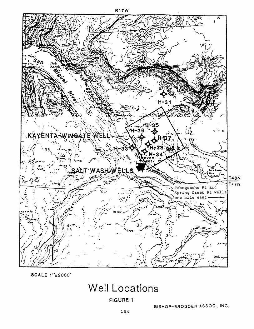
. " ./
SCALE 1" :2000'
W ell Locations FIGURE 1
BISHOP-B 154
"" "L 'vy a, \ V·
/ ,. I ~ r"'
.~"/ ., if , ,.
-~~ .. ~ . , .. ,~.
ROGDEN ASSOC., INC.
Umetco believes that the Salt Wash Member receives no significant recharge from drainage into, and infiltration through, the site because of the small size of the area. The hydrology study (Western Engineers, Inc., 1988, p. 1) states that "The total area tributary to the developed site is approximately 47 acres inclusive of the site." However, it was not proven that no recharge occurs and it is possible that during the course of a year, drainage from 47 acres may infiltrate the site, enter the Salt Wash Member, and travel down dip toward potentially potable ground water northeast of the site. Production that was encountered in H-35 was tested for only one day in a dry season (August, 1988), and was not monitored over a period of ti~;e to account for differences in precipitation and infiltration.
To clarify the potential for infiltration and recharge of the Salt Wash Member onsite, well H-35 should be deepened to the base of the Salt Wash Member and monitored during the spring to determine water levels in the period of maximum potential infiltration. Should significant water be encountered, additional wells should be drilled and tested 1) updip, toward the site to trace the extent of waterbearing strata; and 2) along strike to determine the hydraulic connection, if any, between well H-35 and other wells with known production from the Salt Wash Member. Because sandstone in the Salt Wash Me~~er was deposited in fluvial channels, these discontinuous channel deposits may not have been accurately detected by the initial drilling program; water-bearing strata in H-35 may not have been encountered on-site due to lateral variations in lithology.
Contamination of the Salt Wash aquifer, though, is of less concern to Utah than to Colorado because ground water flow in the salt Wash Member is to the northeast, away from the San Miguel River. The Salt Wash Member occurs below the level of adjacent creeks north and east of the site, and would not likely contaminate surface water flowing from the San Miguel River into Utah.
Geologic Hazards
Geologic hazards may reduce the effectiveness of engineered barriers. The liner, grout, and seals might be broken by surface faulting, and cap material and protective ring dikes may be destroyed through mass movement from adjacent slopes in the overlying, slideprone Brushy Basin Member of the Morrison Formation. Existing information suggests that these events are unlikely during operation and post-closure monitoring of the facility, but opportunity should be taken prior to licensing to assess these potential impacts. Active faulting might create a hazard for Utah by rupturing liners and other engineered protection and providing a direct pathway for contaminants to enter the Kayenta-Wingate aquifer and ultimately the San Miguel River. Mass movement may create a hazard by damaging the cap, liner, or ring dike, disrupting drainage and exposing the material to erosion by surface water with eventual flow into the San Miguel River.
155
Three faults have been identified in the vicinity of the site (Cater and others, 1955; McKay, 1955), the closest lying 1.5 miles to the northwest and trending southeast toward the slope at the northeast edge of the site. No minimum age of movement has been placed upon these faults, but the site lies between potentially active faulting of the Uncompahgre Plateau and the Paradox Valley (Kirkham and Rogers, 1981). Although no active faults have been identified onsite, there is no indication that Umetco has undertaken a detailed study of air photo lineaments and Quaternary surficial materials to address this possibility. Additional studies of this type are recommended for complete assurance of site integrity.
Landslide potential is a particular threat in the Brushy Basin Member which underlies the slopes one-quarter mile north and east of the site. During periods of increased rainfall, and along fracture or fault planes, the bentonitic shales are particularly susceptible to failure, similar to occurrences in the Brushy Basin elsewhere in Colorado and Utah. No discussion was presented by Umetco regarding the presence or absence of landslides on slopes adjacent to the proposed site, or the hazard they may pose.
Conclusions and Reconmendations
No "fatal flaws" have been identified at the proposed site of a low-level radioactive waste disposal facility in Montrose County, Colorado. The existence of such flaws appears unlikely, but minimal effort would contribute to confidence in the suitability of the site. Ground-water recharge through the site, rupture of the site and engineered barriers by active faulting, and disruption of engineered barriers by landslides from adjacent slopes are all possibilities whose potential could be accurately determined with a more complete site characterization program. This program may include geophysical surveys, additional drilling and ground-water monitoring as required, and detailed study of Quaternary deposits and geologic structures. Studies directed toward potential faulting and landslides are of more concern to utah because these hazards may introduce contaminants into the San Miguel River. Although the geohydrologic studies are important to Colorado because they address the possibility of contamination of the Salt Wash Member aquifer, they are of less concern to Utah because this aquifer near the site does not discharge to the San Miguel River, and its contamination would likely have no downstream effect in Utah.
Review of engineered barrier design and of hydrologic modeling, which is beyond the scope of this review, should be conducted by the state of Utah. Dependence upon engineered barriers as the primary protection against potential site failure is not sound engineering practice; the natural environment should be capable of waste containment for such a critical facility.
156
References
Cater, F. W., 1970, c~ology of the Salt Anticline Region in Southwestern Colorado: U.S. Geological Survey Professional Paper 637, 80 p.
Cater, F. W., Butler, A. P., Jr., and McKay, E. J., 1955, Geologic map of the Uravan Quadrangle, Colorado: U.s. Geological Survey Geologic Quadrangle Map GQ-78, scale 1:24,000.
Kirkham, R. M., and Rogers, w. P., 1981, Earthquake potential in Colorado, a preliminary evaluation: Colorado Geological Survey Bulletin 43, 171 p.
McKay, E. J., 1955, Geologic map of the Atkinson Creek Quadr,~gle, Colorado: u.s. Geological Survey Geologic Quadrangle Map GQ-57, scale 1:24,000.
157
MAPS
Appendix
1988·89 Publications of the Applied Geology Program
Hecker, Suzanne, Harty, KM., and Christenson, G.E., compilers, 1988, Shallow ground water and related hazards in Utah: Utah Geological and Mineral Survey Map 110, scale 1:750,000.
Harty, K~1., and Christenson, G.E., 1988, Flood hazards from lakes and failures of dams in Utah: Utah Geological and Mineral Survey Map 111, scale 1:750,000.
CIRCUIARS
Christenson, G.E., 1987 (reprint), Suggested approach to geologic hazards ordinances in Utah: Utah Geological and Mineral Survey Circular 79, 16 p.
J\HSCELLA!\EOVS PL'BLICATIO~S
Kaliser, B.~., and Slossen, J.E., 1988, Geologic consequences of the 1983 wet year in Utah: Utah Geological and Mineral Survey Miscellaneous Publication 88-3, 109 p.
Kaliser, B.N., 1989, \Vater-related geologic problems of 1983 - Utah occurrences by county: Utah Geological and 1\1ineral Survey Miscellaneous Publication 89-4, 24 p.
Anderson, R.E., and Christenson, G.E.~ 1989, Quaternary faults, folds, and selected volcanic features in the Cedar City 1'- x 20 quadrangle, Utah: Utah Geological and Mineral Survey 1\1iscellaneous publicalion ~9-f). sc;~lf' 1 :?.:;nom
REPORTS or Il'\,'ESTIGATIO~
Black, B.D., compiler. 1988, Technical reports for 1987 - Site Investigation Section: Utah Geological and ~1ineral Survey Report of Investigation 216, 115 p.
Black, B.D., and Christenson, G.E., compilers, 1988, Technical repons of the \Vasatch Front county geologists, June 1985 - June 1988: Utah Geological and Mineral Survey Report of Investigation 21K 154 p.
OPEr-;·FILE REPORTS
Sprinkel, D.A., 1987 (revised 1988), Potential radon hazard map of Utah: Utah Geologica1 and !\1ineral Survey Open-File Report lOS, scale 1:1,000,000.
Atwood, Genevieve. Noonan, Mary, Case, \V.F., and Mabey, Don, 1988, Earthquake response strategies for UG~1S and the earth-science community: Utah Geological and Mineral Survey Open-File Report 115, 33 p.
Case, \V.F., 1988, Maximum extent of potential flooding due to simultaneous failure of dams in Salt Lake County. Utah: Utah Geological and Mineral Survey Open-File Report 127, approximate scale 1 :79,200.
158

KJauk, R.H., 1988, Causes of shallow ground-water problems in part of Spanish Valley, Grand County, Utah: Utah Geological and Mineral Survey Open-File Report 129, 46 p.
Case, \V.F., 1988, Acid neutralizing capacity map of Utah: Utah Geological and Mineral Survey Open-File Repon 132, scale 1:500,000.
Kaliser, B.N., 1988, Thematic mapping applied to hazards reduction, Davis County, Utah: Utah Geological and Mineral Survey Open-File Report 135, 18 p.
159