Embed Size (px)
Citation preview
1DL30-G USERS MANUAL EM-8571-G Rev.7
WEB-ENABLEDREMOTE TERMINAL UNIT
Model: DL30-G
USERS MANUAL
https://www.m-system.co.jp/
5-2-55, Minamitsumori, Nishinari-ku, Osaka 557-0063 JAPANTel: +81-6-6659-8201 Fax: +81-6-6659-8510
E-mail: [email protected]
2DL30-G USERS MANUAL EM-8571-G Rev.7
Table of Contents
1. Introduction 10
1.1 Corresponding Versions ................................................................................................................... 10
1.2 Precautions ...................................................................................................................................... 11
1.3 Component identification .................................................................................................................12
2. Installation 15
2.1 Things to prepare .............................................................................................................................15Modules .......................................................................................................................................... 15
Other than modules ........................................................................................................................ 15
2.2 Installation and wiring ......................................................................................................................15
2.3 Preparation of configurator software ................................................................................................162.3.1 Configurator software for DL30-G: DL30GCFG ....................................................................................... 16
Installing DL30GCFG ..................................................................................................................... 16
Starting DL30GCFG ....................................................................................................................... 16
2.3.2 Configurator software for I/O modules: R30CFG ..................................................................................... 18
Installing R30CFG .......................................................................................................................... 18
Starting R30CFG ............................................................................................................................ 18
2.4 Explanation about basic working and terms ....................................................................................19
3. Setting 20
3.1 Setting flow ......................................................................................................................................20
3.2 Initial startup setting ........................................................................................................................21
3.3 Network setting ................................................................................................................................233.3.1 Connecting via local area network (LAN) ................................................................................................24
3.3.2 Connecting via Internet (WAN) ................................................................................................................24
3.3.3 IP address setting ....................................................................................................................................25
3.3.4 Enabling configuration via network (remote access authorization) ..........................................................27
3.4 System setting .................................................................................................................................30Name ..............................................................................................................................................31
Time zone .......................................................................................................................................31
Sampling adjustment at time correction..........................................................................................31
Language ........................................................................................................................................31
3.5 I/O module setting ...........................................................................................................................323.5.1 R30 I/O module setting ............................................................................................................................32
3.5.2 Remote I/O device setting ........................................................................................................................33
3.5.3 SLMP device connection setting ..............................................................................................................34
3.6 I/O setting ........................................................................................................................................353.6.1 I/O slave setting .......................................................................................................................................37
Assigning remote I/O ......................................................................................................................37
Assigning SLMP device ..................................................................................................................39
Communication setting ...................................................................................................................40
3DL30-G USERS MANUAL EM-8571-G Rev.7
3.6.2 Analog input (AI) ......................................................................................................................................41
Assigning I/O module to AI .............................................................................................................41
Assigning remote I/O to AI ..............................................................................................................43
Assigning SLMP device to AI ..........................................................................................................45
Assigning control input to AI ...........................................................................................................47
Assigning time input to AI ...............................................................................................................48
Basic setting (AI).............................................................................................................................49
Alarm zone setting (AI) ...................................................................................................................51
Upward/downward transition setting (AI) ........................................................................................53
MD alarm output (AI) ......................................................................................................................54
DO alarm output (AI) ......................................................................................................................55
GDO alarm output (AI) ...................................................................................................................56
Resetting PI totalized value (AI) ......................................................................................................57
Resetting MA function value (AI) ....................................................................................................58
3.6.3 Discrete input (DI) ....................................................................................................................................60
Assigning I/O module to DI .............................................................................................................60
Assigning remote I/O to DI ..............................................................................................................62
Assigning SLMP device to DI .........................................................................................................63
Assigning analog input (AI) to DI ....................................................................................................64
Assigning control input to DI ...........................................................................................................65
Basic setting (DI) ............................................................................................................................66
Resetting PI totalized value (DI) .....................................................................................................67
Resetting MA function value (DI) ....................................................................................................68
3.6.4 Pulse input (PI) ........................................................................................................................................69
Assigning I/O module to PI .............................................................................................................69
Assigning remote I/O to PI ..............................................................................................................71
Assigning SLMP device to PI ..........................................................................................................73
Assigning discrete input (DI) to PI ..................................................................................................75
Assigning control input to PI ...........................................................................................................77
Assigning analog accumulation to PI ..............................................................................................78
Assigning binary accumulation to PI ...............................................................................................80
Basic setting (PI).............................................................................................................................81
Alarm zone setting (PI) ...................................................................................................................82
Upward/downward transition setting (PI) ........................................................................................84
MD alarm output (PI) ......................................................................................................................85
DO alarm output (PI) ......................................................................................................................86
GDO alarm output (PI) ...................................................................................................................87
Resetting totalized value (PI) ..........................................................................................................88
Resetting MA function value (PI) ....................................................................................................89
Resetting PI counts in regular intervals ..........................................................................................91
3.6.5 Analog function register (MA) ...................................................................................................................93
Basic setting (MA)...........................................................................................................................93
Alarm zone setting (MA) .................................................................................................................97
Upward/Downward transition setting (MA) ......................................................................................98
MD alarm output (MA) ....................................................................................................................99
DO alarm output (MA) .................................................................................................................. 100
GDO alarm output (MA) ............................................................................................................... 101
Resetting totalized value (MA) ...................................................................................................... 102
Resetting function value (MA) ....................................................................................................... 103
Control on Web browser (MA) ...................................................................................................... 104
4DL30-G USERS MANUAL EM-8571-G Rev.7
3.6.6 Digital function register (MD) ................................................................................................................. 105
Basic setting (MD) ........................................................................................................................ 105
Control on Web browser (MD) ...................................................................................................... 109
Resetting PI totalized value (MD) ..................................................................................................111
Resetting MA function value (MD) ................................................................................................ 112
Which functions assigned to MD? ................................................................................................ 113
3.6.7 Analog output (AO) ................................................................................................................................ 114
Assigning I/O module to AO.......................................................................................................... 114
Assigning remote I/O to AO .......................................................................................................... 116
Assigning SLMP device to AO ...................................................................................................... 117
Basic setting (AO) ......................................................................................................................... 118
Control on browser (AO) ............................................................................................................... 119
I/O mapping (AO) ......................................................................................................................... 120
3.6.8 Discrete output (DO) .............................................................................................................................. 121
Assigning I/O module to DO ......................................................................................................... 121
Assigning remote I/O to DO .......................................................................................................... 123
Assigning SLMP device to DO ...................................................................................................... 124
Basic setting (DO)......................................................................................................................... 125
Control on browser (DO) ............................................................................................................... 126
I/O mapping (DO) ......................................................................................................................... 128
Which functions assigned to DO?................................................................................................. 129
3.6.9 Grouped digital output (GDO) ................................................................................................................ 130
Basic setting (GDO) ...................................................................................................................... 130
Grouped channels ........................................................................................................................ 132
Control on browser (GDO) ............................................................................................................ 133
I/O mapping (GDO) ...................................................................................................................... 135
Which functions assigned to GDO? .............................................................................................. 136
3.6.10 Copying CH setting .............................................................................................................................. 137
3.6.11 Applying setting .................................................................................................................................... 138
3.7 I/O mapping setting .......................................................................................................................139I/O mapping for analog output ...................................................................................................... 139
I/O mapping for discrete output .................................................................................................... 139
3.8 Logging function setting .................................................................................................................1403.8.1 Data logging ........................................................................................................................................... 141
Logging data format ...................................................................................................................... 141
Logging setting ............................................................................................................................. 142
Starting logging automatically ...................................................................................................... 145
Automatically deleting logging data in SD card............................................................................. 145
3.8.2 Event log ................................................................................................................................................ 146
Event data format ......................................................................................................................... 146
Event log setting ........................................................................................................................... 148
System log setting ......................................................................................................................... 148
Communication log setting ........................................................................................................... 149
Schedule log setting ..................................................................................................................... 149
Automatically deleting event data in SD card................................................................................ 149
3.9 Report form setting ........................................................................................................................1503.9.1 Report format ......................................................................................................................................... 150
Daily report ................................................................................................................................... 150
Monthly report ............................................................................................................................... 150
Yearly report ................................................................................................................................. 151
5DL30-G USERS MANUAL EM-8571-G Rev.7
3.9.2 Report form setting ................................................................................................................................ 152
Report form contents setting......................................................................................................... 154
E-mailing report forms .................................................................................................................. 157
Automatically deleting report forms in SD card ............................................................................. 158
Report data sampling start time ................................................................................................... 158
3.10 Mail reporting setting ...................................................................................................................1593.10.1 Mail server setting ................................................................................................................................ 160
3.10.2 Mail template setting ............................................................................................................................ 163
Registering address list ................................................................................................................ 163
Creating mail templates ................................................................................................................ 164
Original html tag ........................................................................................................................... 167
3.10.3 Regular reporting ................................................................................................................................. 168
3.10.4 Report failure output............................................................................................................................. 169
3.10.5 E-mailing calendar ............................................................................................................................... 170
3.10.6 Test mail ............................................................................................................................................... 172
3.11 Web server setting .......................................................................................................................1733.11.1 Top screen header name and image setting ......................................................................................... 174
Name ............................................................................................................................................ 174
Images 1, 2, and 3 ........................................................................................................................ 174
3.11.2 Trend graph setting ............................................................................................................................... 175
Pen setting .................................................................................................................................... 175
Page setting .................................................................................................................................. 177
3.11.3 Data display setting ............................................................................................................................... 178
3.11.4 Login ID / password / port address setting (web browser access) ........................................................ 179
3.12 Communication function setting ...................................................................................................1823.12.1 FTP server ........................................................................................................................................... 183
3.12.2 FTP client ............................................................................................................................................. 184
FTP data setting ........................................................................................................................... 185
Communication failure output ....................................................................................................... 187
3.12.3 Modbus/TCP slave ............................................................................................................................... 188
3.12.4 SNTP (automatic time correction) ........................................................................................................ 189
3.13 Scheduling function setting ..........................................................................................................1903.13.1 Pattern setting ...................................................................................................................................... 191
3.13.2 Schedule unit setting ............................................................................................................................ 193
3.13.3 Maintenance SW setting ...................................................................................................................... 194
3.14 Process operation monitor function setting ..................................................................................1953.14.1 Process operation monitor setting ........................................................................................................ 196
3.14.2 Setting analog data to process ............................................................................................................. 197
3.14.3 Setting digital data to process .............................................................................................................. 199
3.15 Other settings .............................................................................................................................. 2013.15.1 Skipping access mode confirmation in DL30GCFG............................................................................. 201
3.15.2 Status monitoring .................................................................................................................................202
Status monitoring via DL30GCFG ................................................................................................202
Status monitoring via Terminal software program .........................................................................203
4. How to use the Web server 204
4.1 Common menu bar ........................................................................................................................205Menu button ..................................................................................................................................205
SD card indicator ..........................................................................................................................205
Error indicator ...............................................................................................................................205
Screen lock indicator ....................................................................................................................205
6DL30-G USERS MANUAL EM-8571-G Rev.7
4.2 Data display ...................................................................................................................................2064.2.1 Data display page contents ....................................................................................................................206
4.2.2 Data display operation ...........................................................................................................................206
Switching pages ...........................................................................................................................206
Manipulating output signals ..........................................................................................................206
Changing screen refresh rate .......................................................................................................207
4.3 Trend graph ....................................................................................................................................2084.3.1 Trend graph page contents ....................................................................................................................208
Page name ...................................................................................................................................208
Digital display................................................................................................................................209
4.3.2 Trend graph operation ............................................................................................................................ 210
Switching pages ........................................................................................................................... 210
Changing maximum/minimum scale values ................................................................................. 210
Hiding pens ................................................................................................................................... 211
Expanding/compressing time axis ................................................................................................ 212
Comparing graphs (shifting graph along scale) ............................................................................ 213
Comparing graphs (expanding/contracting scale) ........................................................................ 214
Changing screen refresh rate ....................................................................................................... 215
Resetting local calibration ............................................................................................................. 215
4.4 Event summary .............................................................................................................................2164.4.1 Event summary page contents .............................................................................................................. 216
4.4.2 Event summary operation ...................................................................................................................... 217
Switching pages ........................................................................................................................... 217
Changing log history range ........................................................................................................... 217
Changing screen refresh rate ....................................................................................................... 217
Event No. filter............................................................................................................................... 218
4.5 Report form ...................................................................................................................................2194.5.1 Report form page contents .................................................................................................................... 219
4.5.2 Report form operation ............................................................................................................................220
Switching pages ...........................................................................................................................220
Opening a report form ..................................................................................................................220
4.6 Data file download .........................................................................................................................2214.6.1 Download page contents .......................................................................................................................221
4.6.2 Download operation ...............................................................................................................................222
Switching pages ...........................................................................................................................222
Choosing/downloading files ..........................................................................................................222
Deleting files .................................................................................................................................222
4.7 Schedule .......................................................................................................................................2234.7.1 Display contents .....................................................................................................................................223
4.7.2 Selecting units ........................................................................................................................................224
4.7.3 One-time schedule .................................................................................................................................225
4.7.4 Permanent schedule ...............................................................................................................................226
4.7.5 Output type maintenance .......................................................................................................................227
4.8 Process operation monitor .............................................................................................................2284.8.1 Display contents .....................................................................................................................................228
Gantt chart ....................................................................................................................................228
Andon screen ...............................................................................................................................230
4.8.2 Operations .............................................................................................................................................231
Switching pages ...........................................................................................................................231
Locking the screen........................................................................................................................231
Gantt chart history ........................................................................................................................231
7DL30-G USERS MANUAL EM-8571-G Rev.7
4.9 Setting change on browser ............................................................................................................2324.9.1 E-mail setting .........................................................................................................................................233
Address list setting ........................................................................................................................233
Mail template setting .....................................................................................................................234
Test mail .......................................................................................................................................235
4.9.2 Trend page setting ..................................................................................................................................236
4.9.3 Alarm zone setting .................................................................................................................................238
4.9.4 Pattern setting ........................................................................................................................................240
4.10 Maintenance ................................................................................................................................242
4.11 User defined web browser view ...................................................................................................243
5. Unit operation 244
5.1 SD card .........................................................................................................................................244Inserting SD card ..........................................................................................................................244
Removing SD card ........................................................................................................................244
SD CARD lamp .............................................................................................................................244
5.2 Data logging ..................................................................................................................................245Starting data logging ....................................................................................................................245
Stopping data logging ...................................................................................................................245
LOGGING lamp ............................................................................................................................245
5.3 Function setting DIP switch ...........................................................................................................246Halting e-mail reporting ................................................................................................................246
Switching to maintenance mode ...................................................................................................246
5.4 Stopping the unit ...........................................................................................................................246
6. Maintenance 247
6.1 Maintenance on DL30GCFG .........................................................................................................2476.1.1 Saving/reading setting values (DL30GCFG) ..........................................................................................247
Saving setting file ..........................................................................................................................247
Reading setting file .......................................................................................................................248
6.1.2 Maintenance menu (DL30GCFG) ..........................................................................................................249
Time correction .............................................................................................................................250
Applying preset count for PI ..........................................................................................................250
Starting/stopping data logging ......................................................................................................251
One-time schedule assignment ....................................................................................................252
Permanent schedule assignment .................................................................................................253
Schedule output type maintenance ..............................................................................................254
Checking system log .....................................................................................................................255
Clearing trend data .......................................................................................................................256
Clearing event logs .......................................................................................................................256
Initializing internal memory ...........................................................................................................257
Confirming disk usage status .......................................................................................................258
FTP client test ...............................................................................................................................258
Test mail .......................................................................................................................................259
Importing user defined imagery data ............................................................................................260
Importing user defined browser view ............................................................................................261
Confirming MAC address..............................................................................................................261
Confirming unit version .................................................................................................................261
Restarting DL30-G........................................................................................................................262
8DL30-G USERS MANUAL EM-8571-G Rev.7
6.2 Maintenance on Web browser .......................................................................................................2636.2.1 Saving/reading setting values (Web) ......................................................................................................263
Saving setting file in SD card ........................................................................................................263
Reading setting file from SD card .................................................................................................264
6.2.2 Maintenance menu (Web) ......................................................................................................................266
Time correction .............................................................................................................................266
Downloading/deleting SD card files ..............................................................................................267
Test mail .......................................................................................................................................268
7. User defined browser view 269
Step 1: Create a working folder ....................................................................................................269
Step 2: Create HTML files .............................................................................................................269
Step 3: Upload to the DL30-G ......................................................................................................270
Step 4: Confirm on the web browser .............................................................................................271
8. Appendix 272
8.1 Troubleshooting .............................................................................................................................2728.1.1 Status indicator LED lamps ....................................................................................................................272
8.1.2 Error indicator on browser ......................................................................................................................272
8.1.3 RUN contact ...........................................................................................................................................273
8.1.4 SD card ..................................................................................................................................................273
8.1.5 R30 I/O module ......................................................................................................................................273
8.1.6 DL30GCFG ............................................................................................................................................ 274
8.1.7 LAN connection ......................................................................................................................................275
8.1.8 Wi-Fi connection .....................................................................................................................................275
8.1.9 Internet ................................................................................................................................................... 276
8.1.10 Web server ........................................................................................................................................... 276
8.1.11 E-mail reporting ....................................................................................................................................277
8.1.12 Modbus/TCP slave ...............................................................................................................................278
8.1.13 Modbus/TCP master .............................................................................................................................278
8.1.14 FTP server ............................................................................................................................................279
8.1.15 FTP client .............................................................................................................................................279
8.2 Reference documents ...................................................................................................................2808.2.1 Compatible terminals and browsers .......................................................................................................280
8.2.2 Web server .............................................................................................................................................280
8.2.3 Internal memory .....................................................................................................................................281
Internal memory basic specifications ...........................................................................................281
Memory block ...............................................................................................................................281
8.2.4 SD card ..................................................................................................................................................282
SD card basic specifications .........................................................................................................282
Specified SD card type .................................................................................................................282
SD card formatter .........................................................................................................................282
Automatic file deleting function .....................................................................................................282
Approximate file size .....................................................................................................................283
8.2.5 Data file configurations ..........................................................................................................................284
Data transfer to SD card ...............................................................................................................284
File names ....................................................................................................................................285
Folder structure in internal memory ..............................................................................................287
Folder structure in SD card ...........................................................................................................287

9DL30-G USERS MANUAL EM-8571-G Rev.7
8.2.6 Modbus/TCP slave .................................................................................................................................288
Modbus register map ....................................................................................................................288
Internal registers ...........................................................................................................................302
Modbus commands ......................................................................................................................307
Data range ....................................................................................................................................308
8.2.7 SLMP Client ...........................................................................................................................................309
Request Message .........................................................................................................................309
SLMP command list ...................................................................................................................... 310
SLMP command list (continued) ................................................................................................... 311
SLMP command list (continued) ................................................................................................... 312
SLMP command list (continued) ................................................................................................... 313
8.2.8 FTP server ............................................................................................................................................. 314
8.2.9 FTP client ............................................................................................................................................... 315
8.2.10 Mail reporting ....................................................................................................................................... 315
8.2.11 Schedule .............................................................................................................................................. 316
Terminology .................................................................................................................................. 316
Schedule output ............................................................................................................................ 316
Disabling schedule output ............................................................................................................ 317
One-time schedule pattern storage period ................................................................................... 318
8.2.12 Process operation monitor function ...................................................................................................... 319
8.2.13 Maximum number of characters used in DL30GCFG .......................................................................... 319
8.2.14 Number of characters that can be displayed on browser .....................................................................320
8.2.15 Data files for user defined web browser view .......................................................................................321
Header ..........................................................................................................................................321
Authorization level ........................................................................................................................321
AI data ..........................................................................................................................................322
DI data ..........................................................................................................................................324
PI data ..........................................................................................................................................325
MA data ........................................................................................................................................327
MD data ........................................................................................................................................329
AO data ........................................................................................................................................330
DO data ........................................................................................................................................331
GDO data .....................................................................................................................................332
XML format data ...........................................................................................................................333
8.2.16 Operation on touch panel .....................................................................................................................334
8.2.17 System log display items ......................................................................................................................335
8.3 Version history ...............................................................................................................................3368.3.1 DL30-G version 2.1 revision history .......................................................................................................336
8.3.2 DL30-G version 2.2 revision history .......................................................................................................336
8.3.3 DL30-G version 2.3 revision history .......................................................................................................336
8.3.4 DL30-G version 2.4 revision history .......................................................................................................336
8.3.5 DL30-G version 2.5 revision history .......................................................................................................336
8.3.6 DL30-G version 2.6 revision history .......................................................................................................336
8.4 Licenses ........................................................................................................................................337
10DL30-G USERS MANUAL EM-8571-G Rev.7
1. IntroductionThank you for choosing M-System.Before use, check the following information.
1.1 Corresponding VersionsThis Users Manual corresponds to the following versions of M-System's products.
■ UNIT VERSION
This Users Manual corresponds to model DL30-G Unit version 2.6 or later.Refer to the section on [Maintenance] for the method to confirm the unit version.➔ 6.1.2 Maintenance menu (DL30GCFG) > Confirming unit version
■ DL30GCFG CONFIGURATOR SOFTWARE VERSION
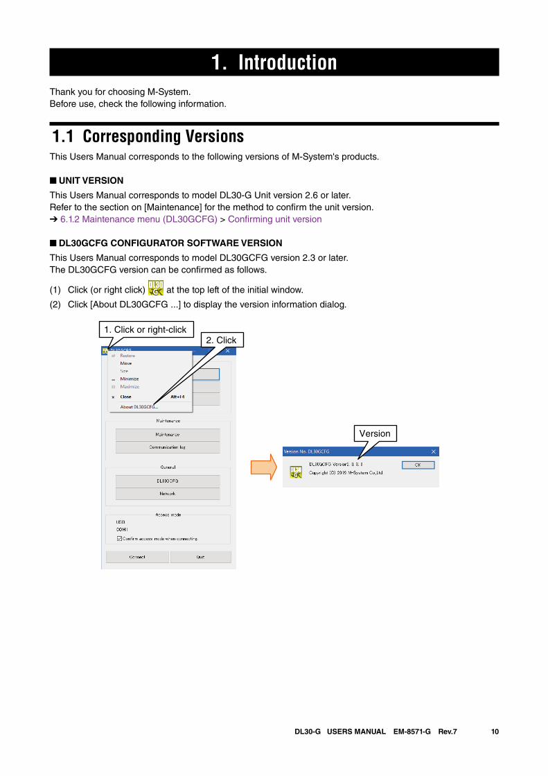
This Users Manual corresponds to model DL30GCFG version 2.3 or later.The DL30GCFG version can be confirmed as follows.
(1) Click (or right click) at the top left of the initial window.
(2) Click [About DL30GCFG ...] to display the version information dialog.
1. Click or right-click2. Click
Version
11DL30-G USERS MANUAL EM-8571-G Rev.7
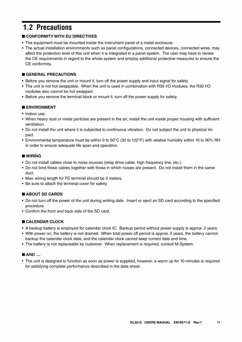
1.2 Precautions ■ CONFORMITY WITH EU DIRECTIVES
• The equipment must be mounted inside the instrument panel of a metal enclosure.• The actual installation environments such as panel configurations, connected devices, connected wires, may
affect the protection level of this unit when it is integrated in a panel system. The user may have to review the CE requirements in regard to the whole system and employ additional protective measures to ensure the CE conformity.
■ GENERAL PRECAUTIONS
• Before you remove the unit or mount it, turn off the power supply and input signal for safety.• The unit is not hot swappable. When the unit is used in combination with R30 I/O modules, the R30 I/O
modules also cannot be hot swapped.• Before you remove the terminal block or mount it, turn off the power supply for safety.
■ ENVIRONMENT
• Indoor use.• When heavy dust or metal particles are present in the air, install the unit inside proper housing with sufficient
ventilation.• Do not install the unit where it is subjected to continuous vibration. Do not subject the unit to physical im-
pact.• Environmental temperature must be within 0 to 50°C (32 to 122°F) with relative humidity within 10 to 90% RH
in order to ensure adequate life span and operation.
■ WIRING
• Do not install cables close to noise sources (relay drive cable, high frequency line, etc.).• Do not bind these cables together with those in which noises are present. Do not install them in the same
duct.• Max. wiring length for FE terminal should be 3 meters.• Be sure to attach the terminal cover for safety.
■ ABOUT SD CARDS
• Do not turn off the power of the unit during writing data. Insert or eject an SD card according to the specified procedure.
• Confirm the front and back side of the SD card.
■ CALENDAR CLOCK
• A backup battery is employed for calendar clock IC. Backup period without power supply is approx. 2 years.• With power on, the battery is not drained. When total power off period is approx. 2 years, the battery cannot
backup the calendar clock data, and the calendar clock cannot keep correct date and time.• The battery is not replaceable by customer. When replacement is required, consult M-System.
■ AND ....
• The unit is designed to function as soon as power is supplied, however, a warm up for 10 minutes is required for satisfying complete performance described in the data sheet.
12DL30-G USERS MANUAL EM-8571-G Rev.7
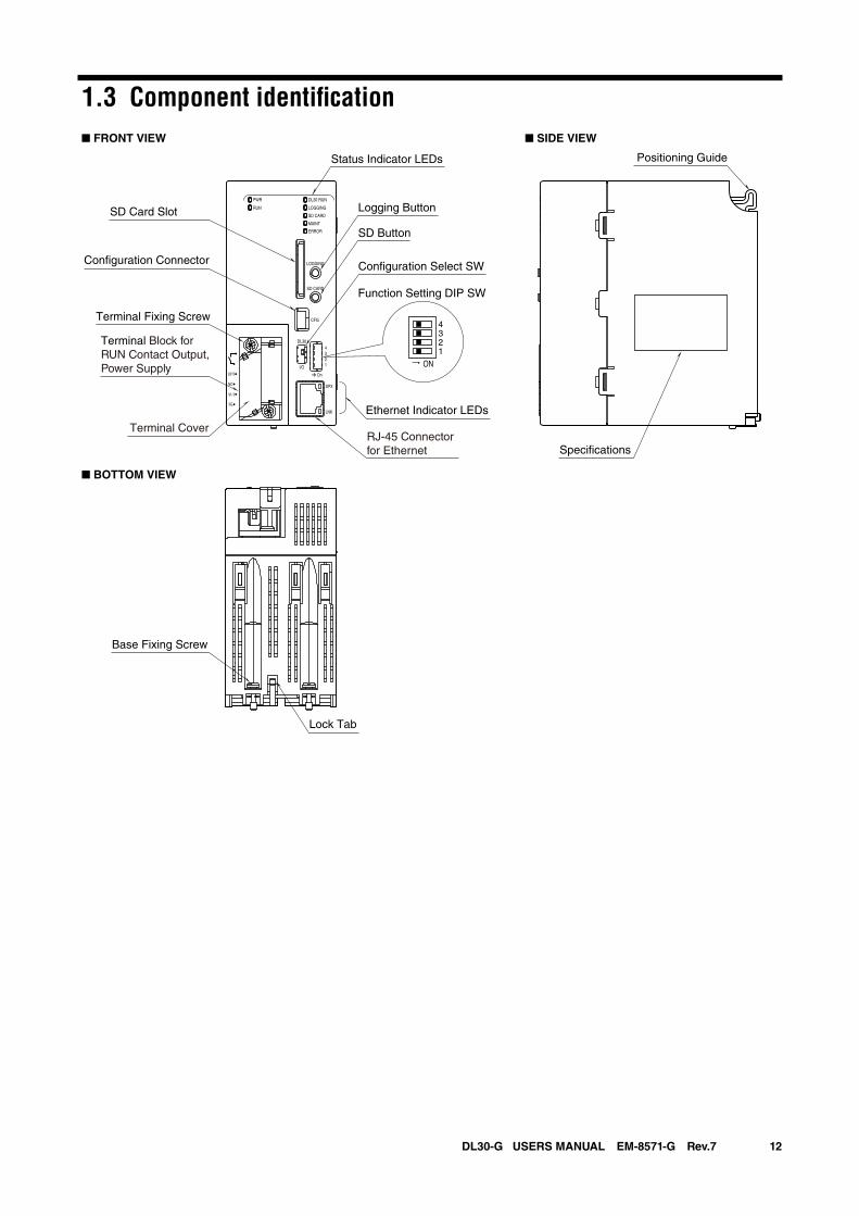
1.3 Component identification
Status Indicator LEDs
RJ-45 Connector for Ethernet
Lock Tab
Specifications
Ethernet Indicator LEDs
SD Card Slot
■ FRONT VIEW
■ BOTTOM VIEW
■ SIDE VIEW
Configuration Select SW
Logging Button
SD Button
Function Setting DIP SW
Terminal Block for RUN Contact Output,Power Supply
Terminal Fixing Screw
Base Fixing Screw
ON
4321
DL30 RUN
LOGGING
SD CARD
MAINT
PWR
RUN
ERROR
CFG
DPX
LNK
LOGGING
SD CARD
DL30
2
I/O
On
43
1
Configuration Connector
U(+)
NC
V(-)
FE
Positioning Guide
Terminal Cover
13DL30-G USERS MANUAL EM-8571-G Rev.7
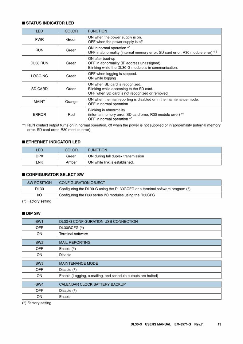
■ STATUS INDICATOR LED
LED COLOR FUNCTION
PWR GreenON when the power supply is on.OFF when the power supply is off.
RUN GreenON in normal operation *1
OFF in abnormality (internal memory error, SD card error, R30 module error) *1
DL30 RUN GreenON after boot-upOFF in abnormality (IP address unassigned)Blinking while the DL30-G module is in communication.
LOGGING GreenOFF when logging is stopped.ON while logging
SD CARD GreenON when SD card is recognized.Blinking while accessing to the SD card.OFF when SD card is not recognized or removed.
MAINT OrangeON when the mail reporting is disabled or in the maintenance mode.OFF in normal operation
ERROR RedBlinking in abnormality (internal memory error, SD card error, R30 module error) *1
OFF in normal operation *1
*1. RUN contact output turns on in normal operation, off when the power is not supplied or in abnormality (internal memory error, SD card error, R30 module error).
■ ETHERNET INDICATOR LED
LED COLOR FUNCTION
DPX Green ON during full duplex transmission
LNK Amber ON while link is established.
■ CONFIGURATOR SELECT SW
SW POSITION CONFIGURATION OBJECT
DL30 Configuring the DL30-G using the DL30GCFG or a terminal software program (*)
I/O Configuring the R30 series I/O modules using the R30CFG
(*) Factory setting
■ DIP SW
SW1 DL30-G CONFIGURATION USB CONNECTION
OFF DL30GCFG (*)
ON Terminal software
SW2 MAIL REPORTING
OFF Enable (*)
ON Disable
SW3 MAINTENANCE MODE
OFF Disable (*)
ON Enable (Logging, e-mailing, and schedule outputs are halted)
SW4 CALENDAR CLOCK BATTERY BACKUP
OFF Disable (*)
ON Enable
(*) Factory setting
14DL30-G USERS MANUAL EM-8571-G Rev.7
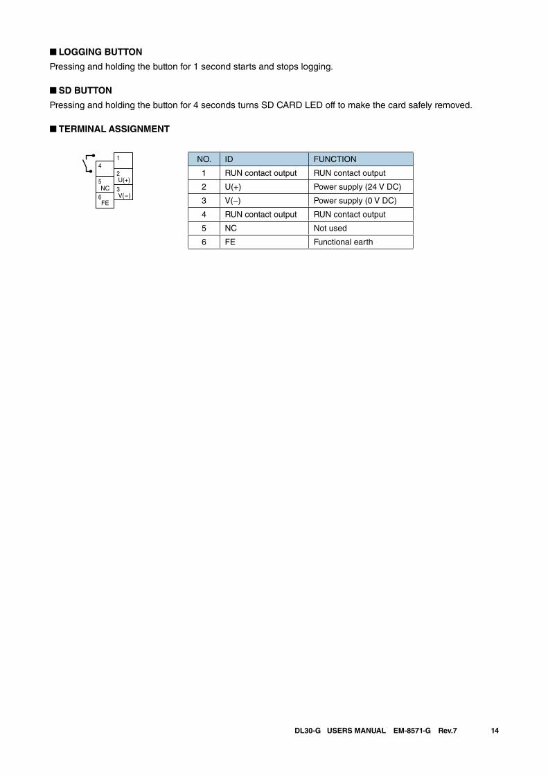
■ LOGGING BUTTON
Pressing and holding the button for 1 second starts and stops logging.
■ SD BUTTON
Pressing and holding the button for 4 seconds turns SD CARD LED off to make the card safely removed.
■ TERMINAL ASSIGNMENT
NO. ID FUNCTION
1 RUN contact output RUN contact output
2 U(+) Power supply (24 V DC)
3 V(−) Power supply (0 V DC)
4 RUN contact output RUN contact output
5 NC Not used
6 FE Functional earth
4
5NC
FE6
1
2U(+)3V(-)
15DL30-G USERS MANUAL EM-8571-G Rev.7
2. Installation
2.1 Things to prepare
Modules • Web data logger model: DL30-G (hereinafter also referred to as “DL30,” “unit,” or “device”)
• R30 series I/O modules
• Installation base model: R30BS
Other than modules • PC
• USB cable (USB (A) male - USB (mini B) male)
• SD card (See [8.2.4 SD card] for specified SD cards.)
• DL30-G configurator software (Model: DL30GCFG) *1
• R30 configurator software (Model: R30CFG) *1
• Instruction/Users Manual for each of the above *1
*1. The software programs and manuals are available for downloading at M-System web site:➔ http://www.m-system.co.jp/
Depending on the system configuration, a Wi-Fi router or a fixed IP address contract is necessary.
2.2 Installation and wiringMount the DL30-G and R30 series I/O Modules on the Installation Base (Model: R30BS).For details, see the instruction manual (EM-8571-A) supplied with the device and those for the respective I/O modules.
16DL30-G USERS MANUAL EM-8571-G Rev.7
2.3 Preparation of configurator softwareInstall the configurator software programs on a PC in order to set up the DL30-G and each I/O module.
2.3.1 Configurator software for DL30-G: DL30GCFG
Installing DL30GCFG
Download DL30GCFG from the website of M-System, and complete the installation simply by extracting it into any folder.Use a shortcut to DL30GCFG.exe which has been extracted to the desktop as required.
Starting DL30GCFG
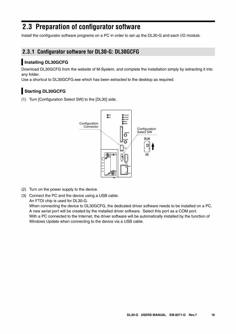
(1) Turn [Configuration Select SW] to the [DL30] side.
(2) Turn on the power supply to the device.
(3) Connect the PC and the device using a USB cable. An FTDI chip is used for DL30-G. When connecting the device to DL30GCFG, the dedicated driver software needs to be installed on a PC. A new serial port will be created by the installed driver software. Select this port as a COM port. With a PC connected to the Internet, the driver software will be automatically installed by the function of
Windows Update when connecting to the device via a USB cable.
DL30 RUN
LOGGING
SD CARD
MAINT
PWR
RUN
ERROR
CFG
DPX
LNK
LOGGING
SD CARD
DL30
2
I/O
On
43
1
U(+)
NC
V(-)
FE
DL30
I/O
ConfigurationSelect SW
ConfigurationConnector
17DL30-G USERS MANUAL EM-8571-G Rev.7
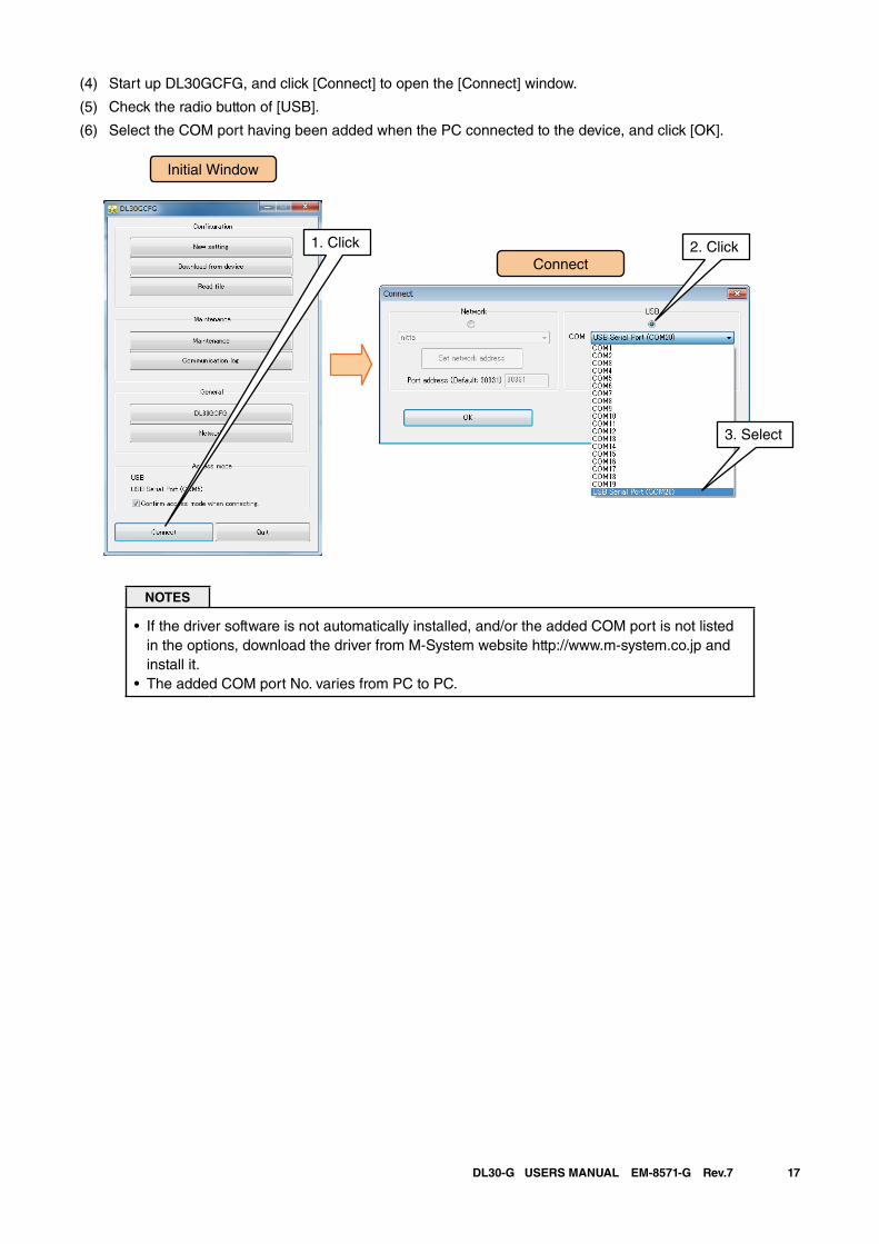
(4) Start up DL30GCFG, and click [Connect] to open the [Connect] window.
(5) Check the radio button of [USB].
(6) Select the COM port having been added when the PC connected to the device, and click [OK].
NOTES
• If the driver software is not automatically installed, and/or the added COM port is not listed in the options, download the driver from M-System website http://www.m-system.co.jp and install it.
• The added COM port No. varies from PC to PC.
Initial Window
Connect
1. Click 2. Click
3. Select
18DL30-G USERS MANUAL EM-8571-G Rev.7
2.3.2 Configurator software for I/O modules: R30CFG
Installing R30CFG
Refer to the R30CFG Users Manual to install the software program.
Starting R30CFG
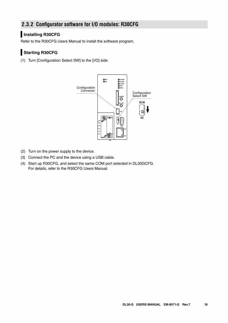
(1) Turn [Configuration Select SW] to the [I/O] side.
(2) Turn on the power supply to the device.
(3) Connect the PC and the device using a USB cable.
(4) Start up R30CFG, and select the same COM port selected in DL30GCFG. For details, refer to the R30CFG Users Manual.
DL30 RUN
LOGGING
SD CARD
MAINT
PWR
RUN
ERROR
CFG
DPX
LNK
LOGGING
SD CARD
DL30
2
I/O
On
43
1
U(+)
NC
V(-)
FE
DL30
I/O
ConfigurationSelect SW
ConfigurationConnector
19DL30-G USERS MANUAL EM-8571-G Rev.7
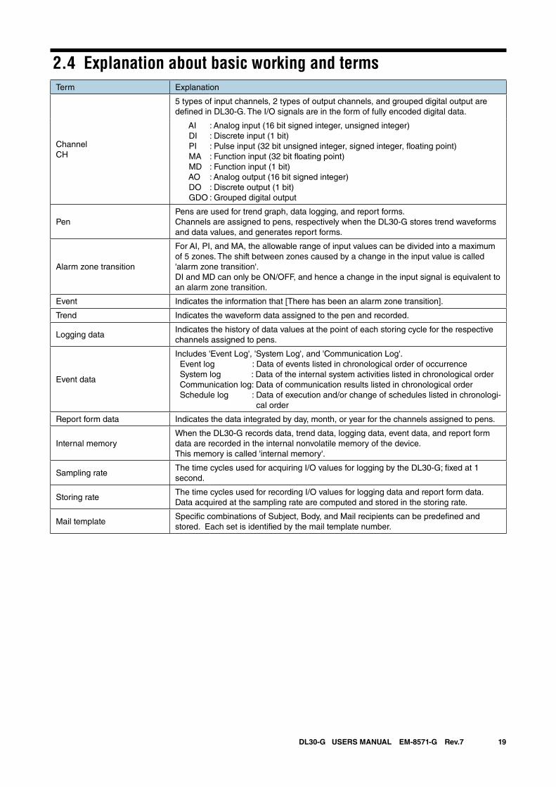
2.4 Explanation about basic working and termsTerm Explanation
ChannelCH
5 types of input channels, 2 types of output channels, and grouped digital output are defined in DL30-G. The I/O signals are in the form of fully encoded digital data.
AI DI PI MA MD AO DO GDO
: Analog input (16 bit signed integer, unsigned integer): Discrete input (1 bit): Pulse input (32 bit unsigned integer, signed integer, floating point): Function input (32 bit floating point): Function input (1 bit): Analog output (16 bit signed integer): Discrete output (1 bit): Grouped digital output
PenPens are used for trend graph, data logging, and report forms.Channels are assigned to pens, respectively when the DL30-G stores trend waveforms and data values, and generates report forms.
Alarm zone transition
For AI, PI, and MA, the allowable range of input values can be divided into a maximum of 5 zones. The shift between zones caused by a change in the input value is called 'alarm zone transition'.DI and MD can only be ON/OFF, and hence a change in the input signal is equivalent to an alarm zone transition.
Event Indicates the information that [There has been an alarm zone transition].
Trend Indicates the waveform data assigned to the pen and recorded.
Logging dataIndicates the history of data values at the point of each storing cycle for the respective channels assigned to pens.
Event data
Includes 'Event Log', 'System Log', and 'Communication Log'. Event log : Data of events listed in chronological order of occurrence System log : Data of the internal system activities listed in chronological order Communication log: Data of communication results listed in chronological order Schedule log : Data of execution and/or change of schedules listed in chronologi-
cal order
Report form data Indicates the data integrated by day, month, or year for the channels assigned to pens.
Internal memoryWhen the DL30-G records data, trend data, logging data, event data, and report form data are recorded in the internal nonvolatile memory of the device. This memory is called 'internal memory'.
Sampling rateThe time cycles used for acquiring I/O values for logging by the DL30-G; fixed at 1 second.
Storing rateThe time cycles used for recording I/O values for logging data and report form data. Data acquired at the sampling rate are computed and stored in the storing rate.
Mail templateSpecific combinations of Subject, Body, and Mail recipients can be predefined and stored. Each set is identified by the mail template number.
20DL30-G USERS MANUAL EM-8571-G Rev.7
3. Setting
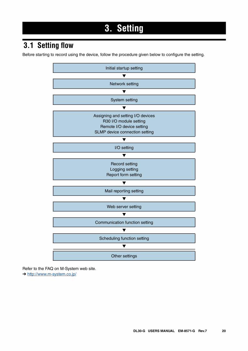
3.1 Setting flowBefore starting to record using the device, follow the procedure given below to configure the setting.
Initial startup setting
▼
Network setting
▼
System setting
▼
Assigning and setting I/O devicesR30 I/O module setting
Remote I/O device settingSLMP device connection setting
▼
I/O setting
▼
Record settingLogging setting
Report form setting
▼
Mail reporting setting
▼
Web server setting
▼
Communication function setting
▼
Scheduling function setting
▼
Other settings
Refer to the FAQ on M-System web site.➔ http://www.m-system.co.jp/
21DL30-G USERS MANUAL EM-8571-G Rev.7
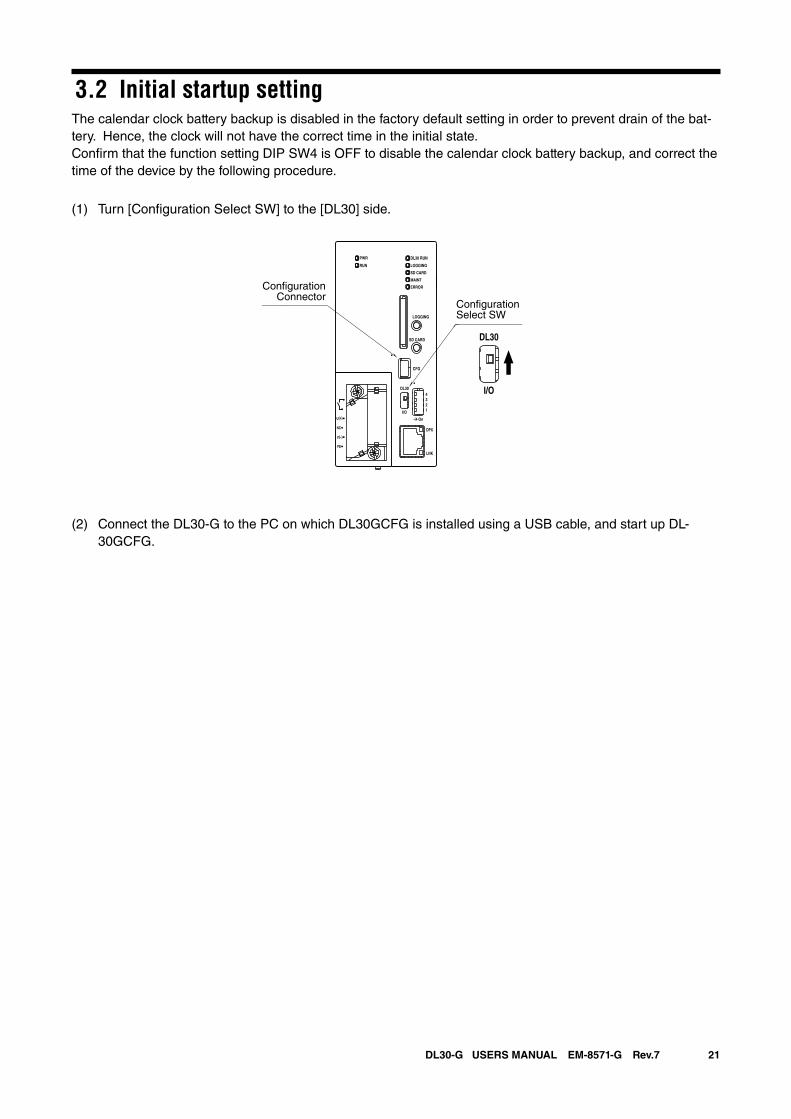
3.2 Initial startup settingThe calendar clock battery backup is disabled in the factory default setting in order to prevent drain of the bat-tery. Hence, the clock will not have the correct time in the initial state.Confirm that the function setting DIP SW4 is OFF to disable the calendar clock battery backup, and correct the time of the device by the following procedure.
(1) Turn [Configuration Select SW] to the [DL30] side.
(2) Connect the DL30-G to the PC on which DL30GCFG is installed using a USB cable, and start up DL-30GCFG.
DL30 RUN
LOGGING
SD CARD
MAINT
PWR
RUN
ERROR
CFG
DPX
LNK
LOGGING
SD CARD
DL30
2
I/O
On
43
1
U(+)
NC
V(-)
FE
DL30
I/O
ConfigurationSelect SW
ConfigurationConnector
22DL30-G USERS MANUAL EM-8571-G Rev.7
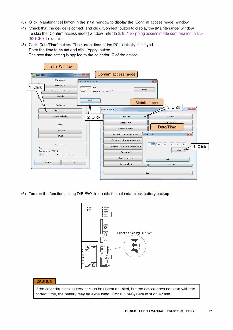
(3) Click [Maintenance] button in the initial window to display the [Confirm access mode] window.
(4) Check that the device is correct, and click [Connect] button to display the [Maintenance] window. To skip the [Confirm access mode] window, refer to 3.15.1 Skipping access mode confirmation in DL-30GCFG for details.
(5) Click [Date/Time] button. The current time of the PC is initially displayed. Enter the time to be set and click [Apply] button.
The new time setting is applied to the calendar IC of the device.
(6) Turn on the function setting DIP SW4 to enable the calendar clock battery backup.
CAUTION
If the calendar clock battery backup has been enabled, but the device does not start with the correct time, the battery may be exhausted. Consult M-System in such a case.
1. Click
Initial Window
Con�rm access mode
Maintenance3. Click
Date/Time
4. Click
2. Click
ON
4321
DL30 RUN
LOGGING
SD CARD
MAINT
PWR
RUN
ERROR
CFG
DPX
LNK
LOGGING
SD CARD
DL30
2
I/O
On
43
1
U(+)
NC
V(-)
FE
Function Setting DIP SW
23DL30-G USERS MANUAL EM-8571-G Rev.7
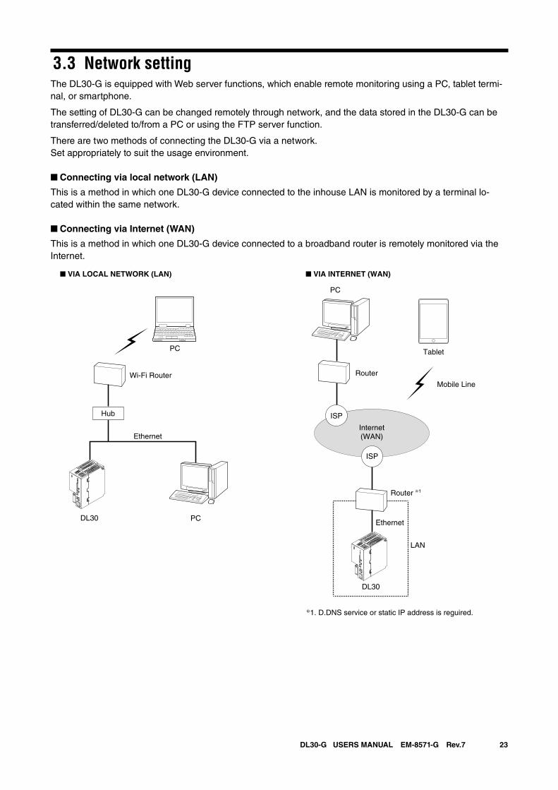
3.3 Network settingThe DL30-G is equipped with Web server functions, which enable remote monitoring using a PC, tablet termi-nal, or smartphone.
The setting of DL30-G can be changed remotely through network, and the data stored in the DL30-G can be transferred/deleted to/from a PC or using the FTP server function.
There are two methods of connecting the DL30-G via a network.Set appropriately to suit the usage environment.
■ Connecting via local network (LAN)
This is a method in which one DL30-G device connected to the inhouse LAN is monitored by a terminal lo-cated within the same network.
■ Connecting via Internet (WAN)
This is a method in which one DL30-G device connected to a broadband router is remotely monitored via the Internet.
Router
Ethernet
LAN
PC
DL30
Tablet
Router *1
Internet(WAN)
■ VIA INTERNET (WAN)
ISP
ISP
Mobile Line
*1. D.DNS service or static IP address is reguired.
Wi-Fi Router
■ VIA LOCAL NETWORK (LAN)
Ethernet
PCDL30
Hub
PC
24DL30-G USERS MANUAL EM-8571-G Rev.7
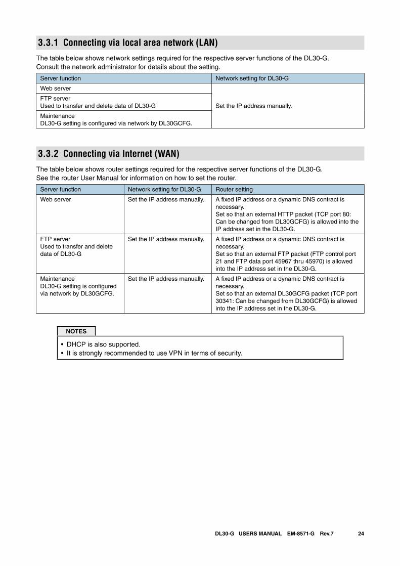
3.3.1 Connecting via local area network (LAN)The table below shows network settings required for the respective server functions of the DL30-G.Consult the network administrator for details about the setting.
Server function Network setting for DL30-G
Web server
Set the IP address manually.FTP serverUsed to transfer and delete data of DL30-G
MaintenanceDL30-G setting is configured via network by DL30GCFG.
3.3.2 Connecting via Internet (WAN)The table below shows router settings required for the respective server functions of the DL30-G.See the router User Manual for information on how to set the router.
Server function Network setting for DL30-G Router setting
Web server Set the IP address manually. A fixed IP address or a dynamic DNS contract is necessary.Set so that an external HTTP packet (TCP port 80: Can be changed from DL30GCFG) is allowed into the IP address set in the DL30-G.
FTP serverUsed to transfer and delete data of DL30-G
Set the IP address manually. A fixed IP address or a dynamic DNS contract is necessary.Set so that an external FTP packet (FTP control port 21 and FTP data port 45967 thru 45970) is allowed into the IP address set in the DL30-G.
MaintenanceDL30-G setting is configured via network by DL30GCFG.
Set the IP address manually. A fixed IP address or a dynamic DNS contract is necessary.Set so that an external DL30GCFG packet (TCP port 30341: Can be changed from DL30GCFG) is allowed into the IP address set in the DL30-G.
NOTES
• DHCP is also supported.• It is strongly recommended to use VPN in terms of security.
25DL30-G USERS MANUAL EM-8571-G Rev.7
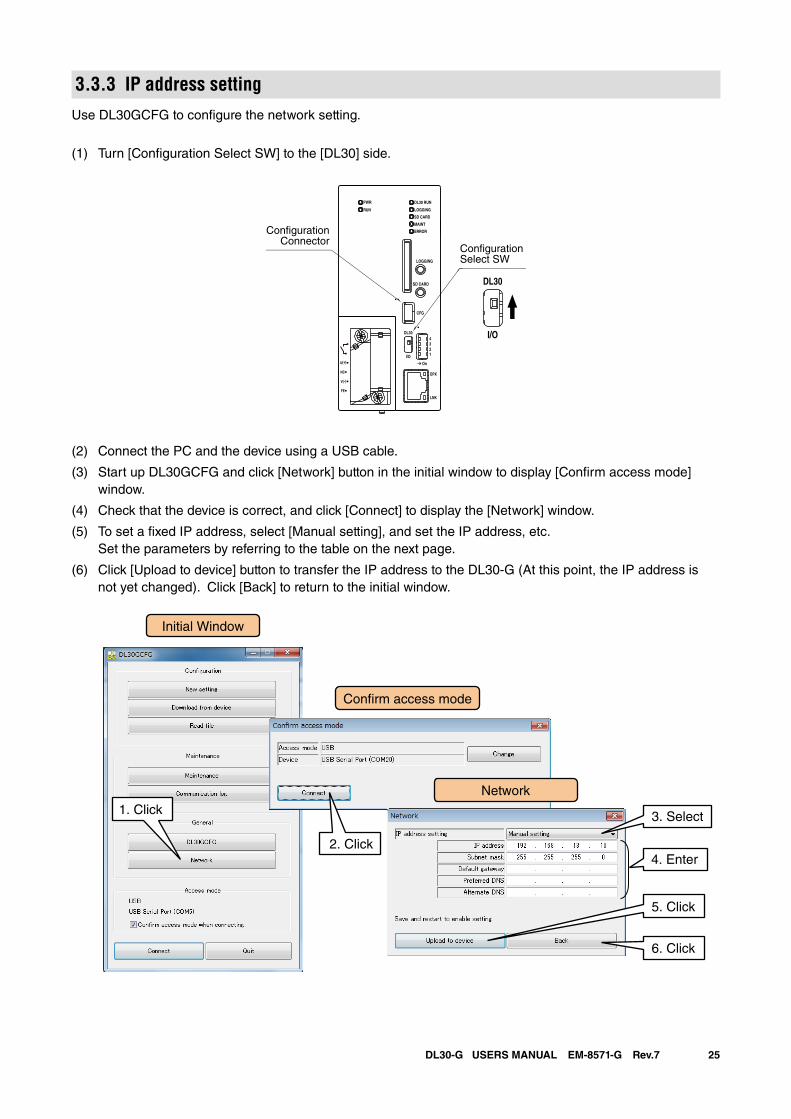
3.3.3 IP address settingUse DL30GCFG to configure the network setting.
(1) Turn [Configuration Select SW] to the [DL30] side.
(2) Connect the PC and the device using a USB cable.
(3) Start up DL30GCFG and click [Network] button in the initial window to display [Confirm access mode] window.
(4) Check that the device is correct, and click [Connect] to display the [Network] window.
(5) To set a fixed IP address, select [Manual setting], and set the IP address, etc. Set the parameters by referring to the table on the next page.
(6) Click [Upload to device] button to transfer the IP address to the DL30-G (At this point, the IP address is not yet changed). Click [Back] to return to the initial window.
DL30 RUN
LOGGING
SD CARD
MAINT
PWR
RUN
ERROR
CFG
DPX
LNK
LOGGING
SD CARD
DL30
2
I/O
On
43
1
U(+)
NC
V(-)
FE
DL30
I/O
ConfigurationSelect SW
ConfigurationConnector
Initial Window
Network1. Click
Con�rm access mode
4. Enter
3. Select
6. Click
5. Click
2. Click
26DL30-G USERS MANUAL EM-8571-G Rev.7
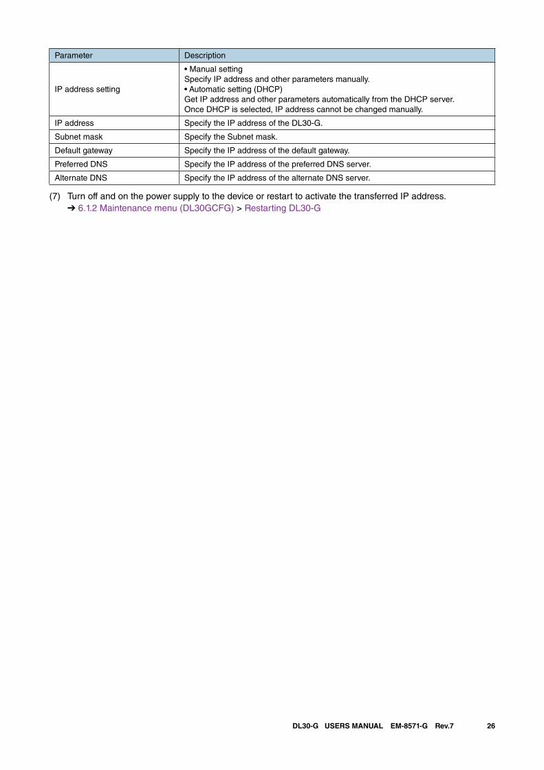
Parameter Description
IP address setting
• Manual settingSpecify IP address and other parameters manually.• Automatic setting (DHCP)Get IP address and other parameters automatically from the DHCP server.Once DHCP is selected, IP address cannot be changed manually.
IP address Specify the IP address of the DL30-G.
Subnet mask Specify the Subnet mask.
Default gateway Specify the IP address of the default gateway.
Preferred DNS Specify the IP address of the preferred DNS server.
Alternate DNS Specify the IP address of the alternate DNS server.
(7) Turn off and on the power supply to the device or restart to activate the transferred IP address. ➔ 6.1.2 Maintenance menu (DL30GCFG) > Restarting DL30-G
27DL30-G USERS MANUAL EM-8571-G Rev.7
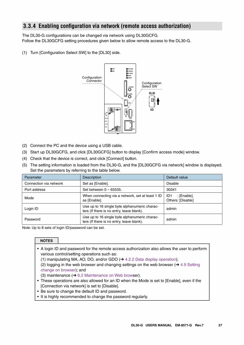
3.3.4 Enabling configuration via network (remote access authorization)The DL30-G configurations can be changed via network using DL30GCFG. Follow the DL30GCFG setting procedures given below to allow remote access to the DL30-G.
(1) Turn [Configuration Select SW] to the [DL30] side.
(2) Connect the PC and the device using a USB cable.
(3) Start up DL30GCFG, and click [DL30GCFG] button to display [Confirm access mode] window.
(4) Check that the device is correct, and click [Connect] button.
(5) The setting information is loaded from the DL30-G, and the [DL30GCFG via network] window is displayed. Set the parameters by referring to the table below.
Parameter Description Default value
Connection via network Set as [Enable]. Disable
Port address Set between 0 – 65535. 30341
ModeWhen connecting via a network, set at least 1 ID as [Enable].
ID1 : [Enable].Others: [Disable]
Login IDUse up to 16 single byte alphanumeric charac-ters (If there is no entry, leave blank).
admin
PasswordUse up to 16 single byte alphanumeric charac-ters (If there is no entry, leave blank).
admin
Note: Up to 8 sets of login ID/password can be set.
NOTES
• A login ID and password for the remote access authorization also allows the user to perform various control/setting operations such as: (1) manipulating MA, AO, DO, and/or GDO (➔ 4.2.2 Data display operation); (2) logging in the web browser and changing settings on the web browser (➔ 4.9 Setting change on browser); and (3) maintenance (➔ 6.2 Maintenance on Web browser).
• These operations are also allowed for an ID when the Mode is set to [Enable], even if the [Connection via network] is set to [Disable].
• Be sure to change the default ID and password.• It is highly recommended to change the password regularly.
DL30 RUN
LOGGING
SD CARD
MAINT
PWR
RUN
ERROR
CFG
DPX
LNK
LOGGING
SD CARD
DL30
2
I/O
On
43
1
U(+)
NC
V(-)
FE
DL30
I/O
ConfigurationSelect SW
ConfigurationConnector
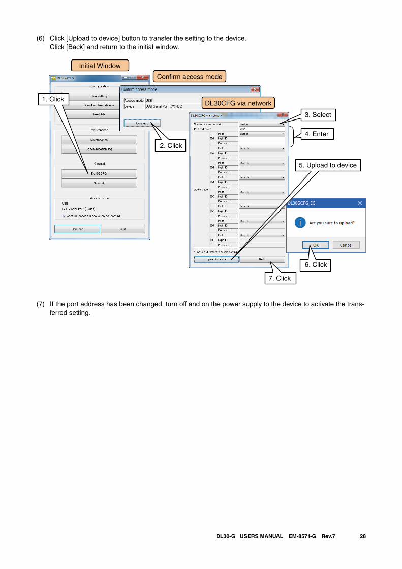
28DL30-G USERS MANUAL EM-8571-G Rev.7
(6) Click [Upload to device] button to transfer the setting to the device. Click [Back] and return to the initial window.
(7) If the port address has been changed, turn off and on the power supply to the device to activate the trans-ferred setting.
Initial Window
DL30CFG via network1. Click
Con�rm access mode
4. Enter
3. Select
6. Click
7. Click
2. Click
5. Upload to device
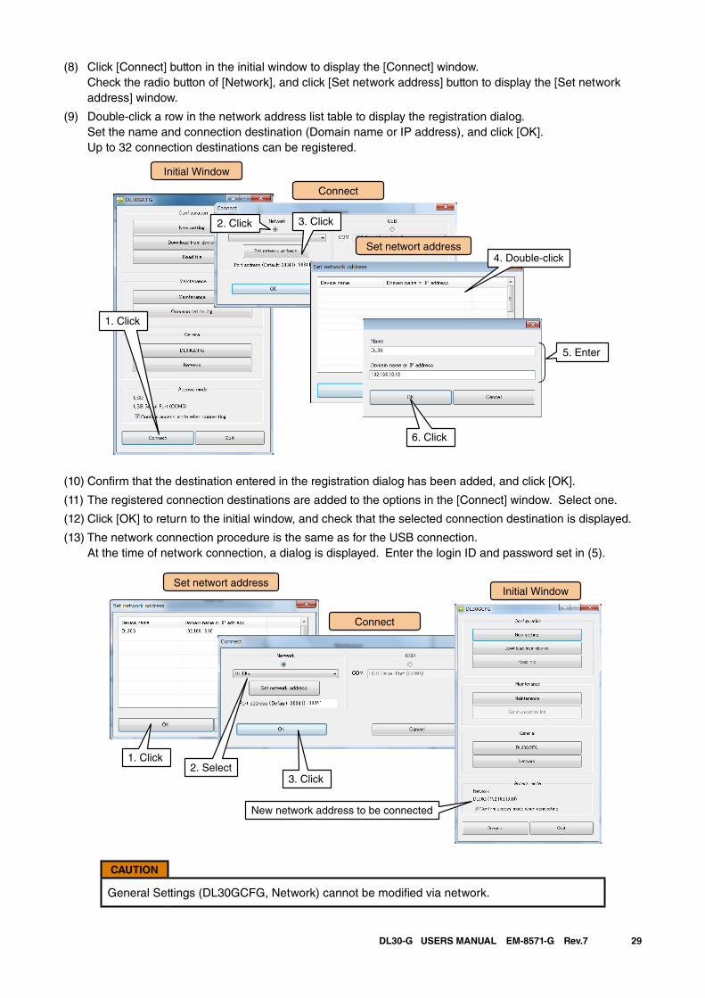
29DL30-G USERS MANUAL EM-8571-G Rev.7
(8) Click [Connect] button in the initial window to display the [Connect] window. Check the radio button of [Network], and click [Set network address] button to display the [Set network address] window.
(9) Double-click a row in the network address list table to display the registration dialog. Set the name and connection destination (Domain name or IP address), and click [OK].
Up to 32 connection destinations can be registered.
Initial Window
Set networt address
1. Click
Connect
3. Click
4. Double-click
5. Enter
6. Click
2. Click
(10) Confirm that the destination entered in the registration dialog has been added, and click [OK].
(11) The registered connection destinations are added to the options in the [Connect] window. Select one.
(12) Click [OK] to return to the initial window, and check that the selected connection destination is displayed.
(13) The network connection procedure is the same as for the USB connection. At the time of network connection, a dialog is displayed. Enter the login ID and password set in (5).
New network address to be connected
Initial Window
Connect
Set networt address
1. Click2. Select
3. Click
CAUTION
General Settings (DL30GCFG, Network) cannot be modified via network.
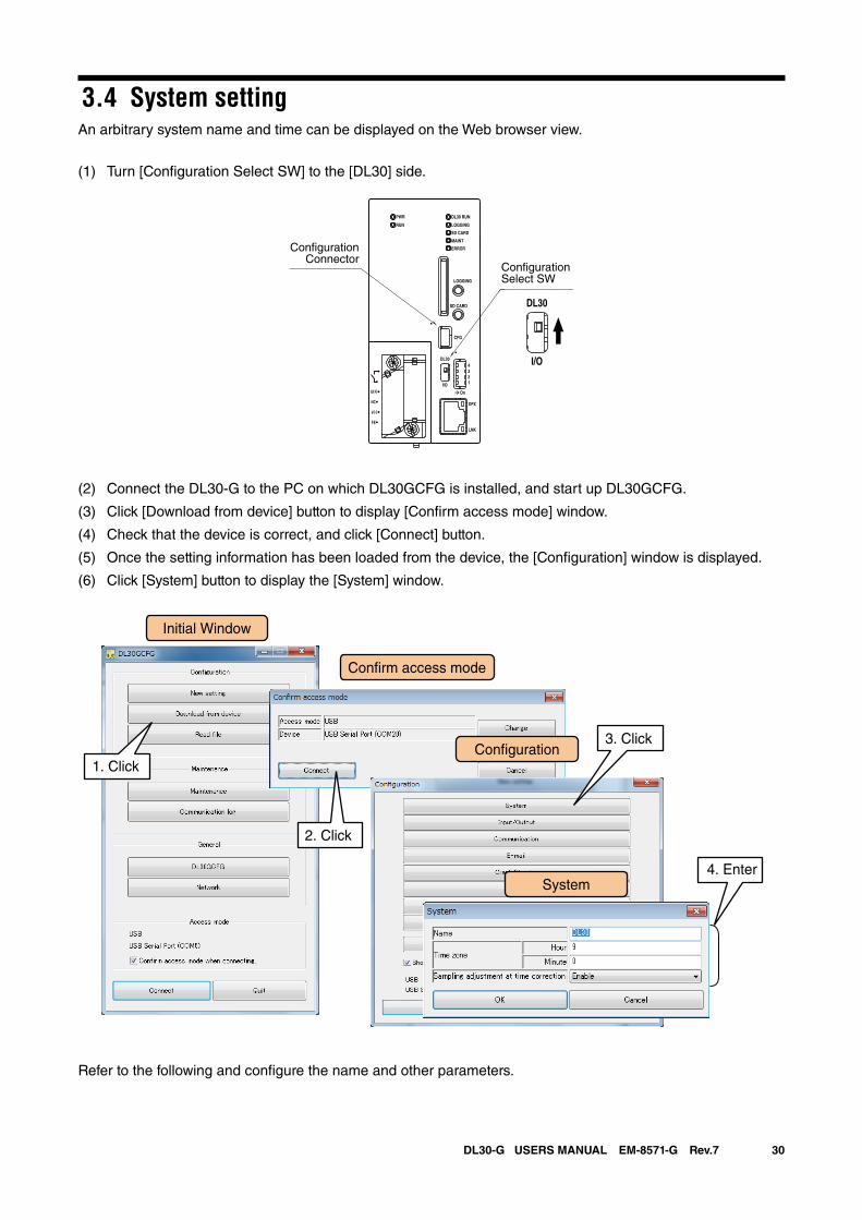
30DL30-G USERS MANUAL EM-8571-G Rev.7
3.4 System settingAn arbitrary system name and time can be displayed on the Web browser view.
(1) Turn [Configuration Select SW] to the [DL30] side.
DL30 RUN
LOGGING
SD CARD
MAINT
PWR
RUN
ERROR
CFG
DPX
LNK
LOGGING
SD CARD
DL30
2
I/O
On
43
1
U(+)
NC
V(-)
FE
DL30
I/O
ConfigurationSelect SW
ConfigurationConnector
(2) Connect the DL30-G to the PC on which DL30GCFG is installed, and start up DL30GCFG.
(3) Click [Download from device] button to display [Confirm access mode] window.
(4) Check that the device is correct, and click [Connect] button.
(5) Once the setting information has been loaded from the device, the [Configuration] window is displayed.
(6) Click [System] button to display the [System] window.
Refer to the following and configure the name and other parameters.
Initial Window
System
Con�guration1. Click
Con�rm access mode
4. Enter
2. Click
3. Click
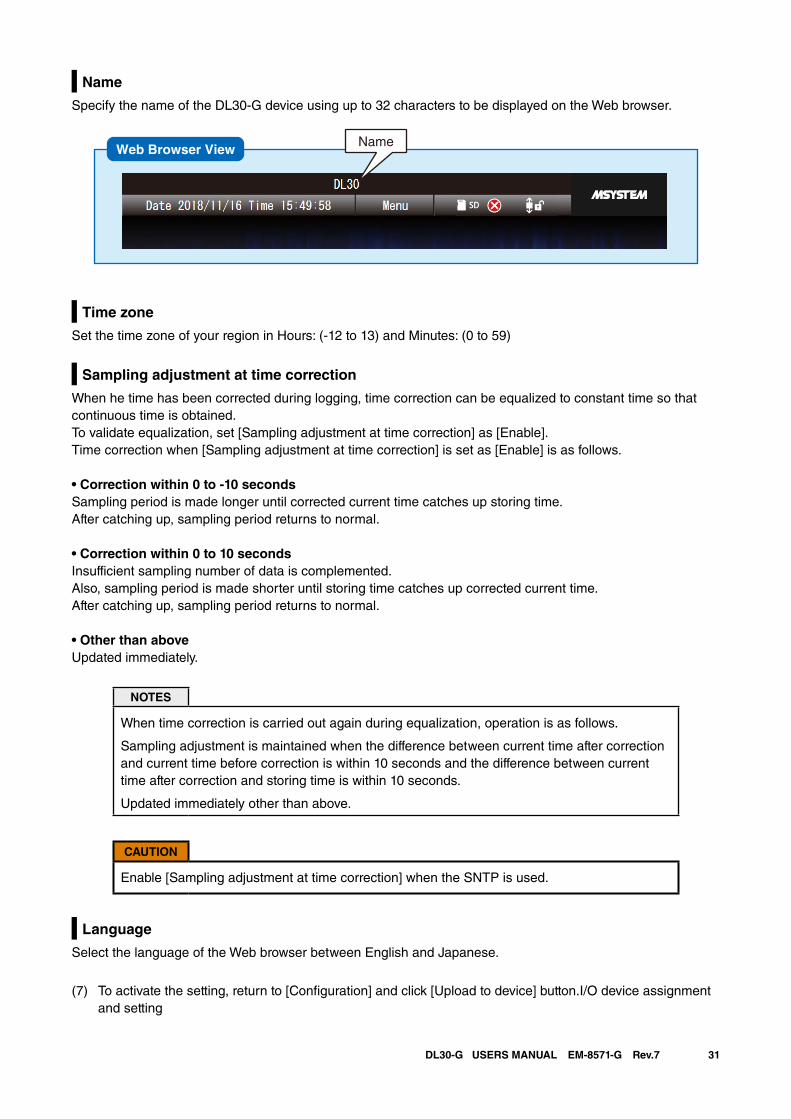
31DL30-G USERS MANUAL EM-8571-G Rev.7
Name
Specify the name of the DL30-G device using up to 32 characters to be displayed on the Web browser.
Time zone
Set the time zone of your region in Hours: (-12 to 13) and Minutes: (0 to 59)
Sampling adjustment at time correction
When he time has been corrected during logging, time correction can be equalized to constant time so that continuous time is obtained. To validate equalization, set [Sampling adjustment at time correction] as [Enable].Time correction when [Sampling adjustment at time correction] is set as [Enable] is as follows.
• Correction within 0 to -10 secondsSampling period is made longer until corrected current time catches up storing time. After catching up, sampling period returns to normal.
• Correction within 0 to 10 secondsInsufficient sampling number of data is complemented. Also, sampling period is made shorter until storing time catches up corrected current time. After catching up, sampling period returns to normal.
• Other than aboveUpdated immediately.
NOTES
When time correction is carried out again during equalization, operation is as follows.
Sampling adjustment is maintained when the difference between current time after correction and current time before correction is within 10 seconds and the difference between current time after correction and storing time is within 10 seconds.
Updated immediately other than above.
CAUTION
Enable [Sampling adjustment at time correction] when the SNTP is used.
Language
Select the language of the Web browser between English and Japanese.
(7) To activate the setting, return to [Configuration] and click [Upload to device] button.I/O device assignment and setting
NameWeb Browser View
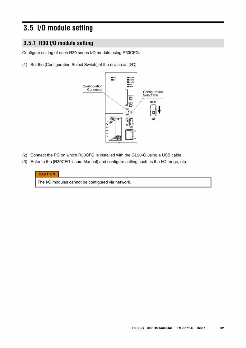
32DL30-G USERS MANUAL EM-8571-G Rev.7
3.5 I/O module setting
3.5.1 R30 I/O module settingConfigure setting of each R30 series I/O module using R30CFG.
(1) Set the [Configuration Select Switch] of the device as [I/O].
DL30 RUN
LOGGING
SD CARD
MAINT
PWR
RUN
ERROR
CFG
DPX
LNK
LOGGING
SD CARD
DL30
2
I/O
On
43
1
U(+)
NC
V(-)
FE
DL30
I/O
ConfigurationSelect SW
ConfigurationConnector
(2) Connect the PC on which R30CFG is installed with the GL30-G using a USB cable.
(3) Refer to the [R30CFG Users Manual] and configure setting such as the I/O range, etc.
CAUTION
The I/O modules cannot be configured via network.
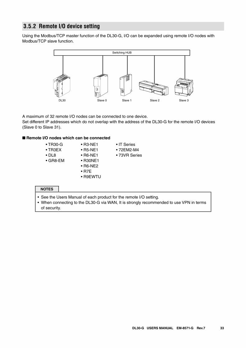
33DL30-G USERS MANUAL EM-8571-G Rev.7
3.5.2 Remote I/O device settingUsing the Modbus/TCP master function of the DL30-G, I/O can be expanded using remote I/O nodes with Modbus/TCP slave function.
A maximum of 32 remote I/O nodes can be connected to one device. Set different IP addresses which do not overlap with the address of the DL30-G for the remote I/O devices (Slave 0 to Slave 31).
■ Remote I/O nodes which can be connected
• TR30-G • R3-NE1 • IT Series • TR3EX • R5-NE1 • 72EM2-M4 • DL8 • R6-NE1 • 73VR Series • GR8-EM • R30NE1 • R6-NE2 • R7E • R9EWTU
NOTES
• See the Users Manual of each product for the remote I/O setting.• When connecting to the DL30-G via WAN, It is strongly recommended to use VPN in terms
of security.
Switching HUB
Slave 0 Slave 1 Slave 2 Slave 3DL30
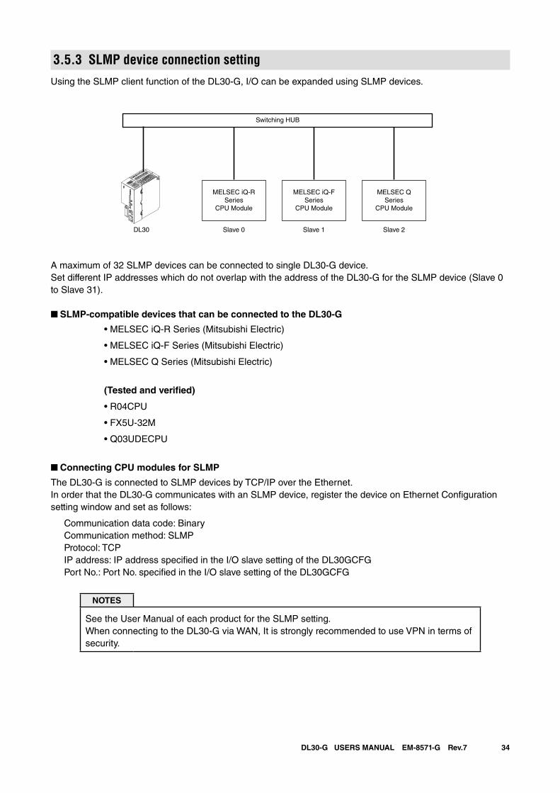
34DL30-G USERS MANUAL EM-8571-G Rev.7
3.5.3 SLMP device connection settingUsing the SLMP client function of the DL30-G, I/O can be expanded using SLMP devices.
A maximum of 32 SLMP devices can be connected to single DL30-G device. Set different IP addresses which do not overlap with the address of the DL30-G for the SLMP device (Slave 0 to Slave 31).
■ SLMP-compatible devices that can be connected to the DL30-G
• MELSEC iQ-R Series (Mitsubishi Electric)
• MELSEC iQ-F Series (Mitsubishi Electric)
• MELSEC Q Series (Mitsubishi Electric)
(Tested and verified)
• R04CPU
• FX5U-32M
• Q03UDECPU
■ Connecting CPU modules for SLMP
The DL30-G is connected to SLMP devices by TCP/IP over the Ethernet.In order that the DL30-G communicates with an SLMP device, register the device on Ethernet Configuration setting window and set as follows:
Communication data code: Binary Communication method: SLMP Protocol: TCP IP address: IP address specified in the I/O slave setting of the DL30GCFG Port No.: Port No. specified in the I/O slave setting of the DL30GCFG
NOTES
See the User Manual of each product for the SLMP setting.When connecting to the DL30-G via WAN, It is strongly recommended to use VPN in terms of security.
Switching HUB
Slave 0DL30
MELSEC iQ-RSeries
CPU Module
Slave 1
MELSEC iQ-FSeries
CPU Module
Slave 2
MELSEC QSeries
CPU Module
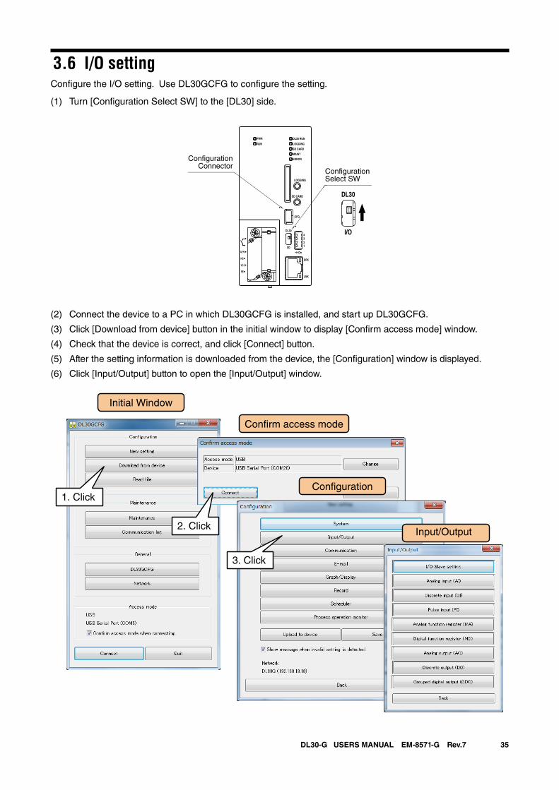
35DL30-G USERS MANUAL EM-8571-G Rev.7
3.6 I/O settingConfigure the I/O setting. Use DL30GCFG to configure the setting.
(1) Turn [Configuration Select SW] to the [DL30] side.
(2) Connect the device to a PC in which DL30GCFG is installed, and start up DL30GCFG.
(3) Click [Download from device] button in the initial window to display [Confirm access mode] window.
(4) Check that the device is correct, and click [Connect] button.
(5) After the setting information is downloaded from the device, the [Configuration] window is displayed.
(6) Click [Input/Output] button to open the [Input/Output] window.
DL30 RUN
LOGGING
SD CARD
MAINT
PWR
RUN
ERROR
CFG
DPX
LNK
LOGGING
SD CARD
DL30
2
I/O
On
43
1
U(+)
NC
V(-)
FE
DL30
I/O
ConfigurationSelect SW
ConfigurationConnector
Initial Window
Con�guration
Con�rm access mode
3. Click
2. Click
1. Click
Input/Output
36DL30-G USERS MANUAL EM-8571-G Rev.7
NOTES
The parameters for which the engineering unit value is set in DL30GCFG can be set between ±10,000,000,000.
The maximum number of digits that can be entered after the decimal point equals the number of digits which is displayed on the window.
For example, since the scale 0% for the analog input has an initial value of 0.000, when [123.4567890] is entered, it is rounded off to 3 digits after the decimal point to match the initial value 0.000, and therefore becomes [123.457] (The 4th digit after the decimal point is round-ed off).
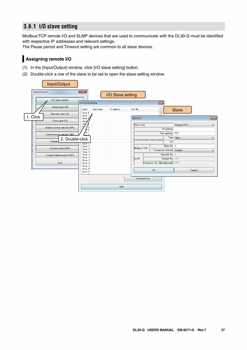
37DL30-G USERS MANUAL EM-8571-G Rev.7
3.6.1 I/O slave settingModbus/TCP remote I/O and SLMP devices that are used to communicate with the DL30-G must be identified with respective IP addresses and relevant settings. The Pause period and Timeout setting are common to all slave devices.
Assigning remote I/O
(1) In the [Input/Output] window, click [I/O slave setting] button.
(2) Double-click a row of the slave to be set to open the slave setting window.
Input/Output
I/O Slave setting
1. Click
Slave
2. Double-click
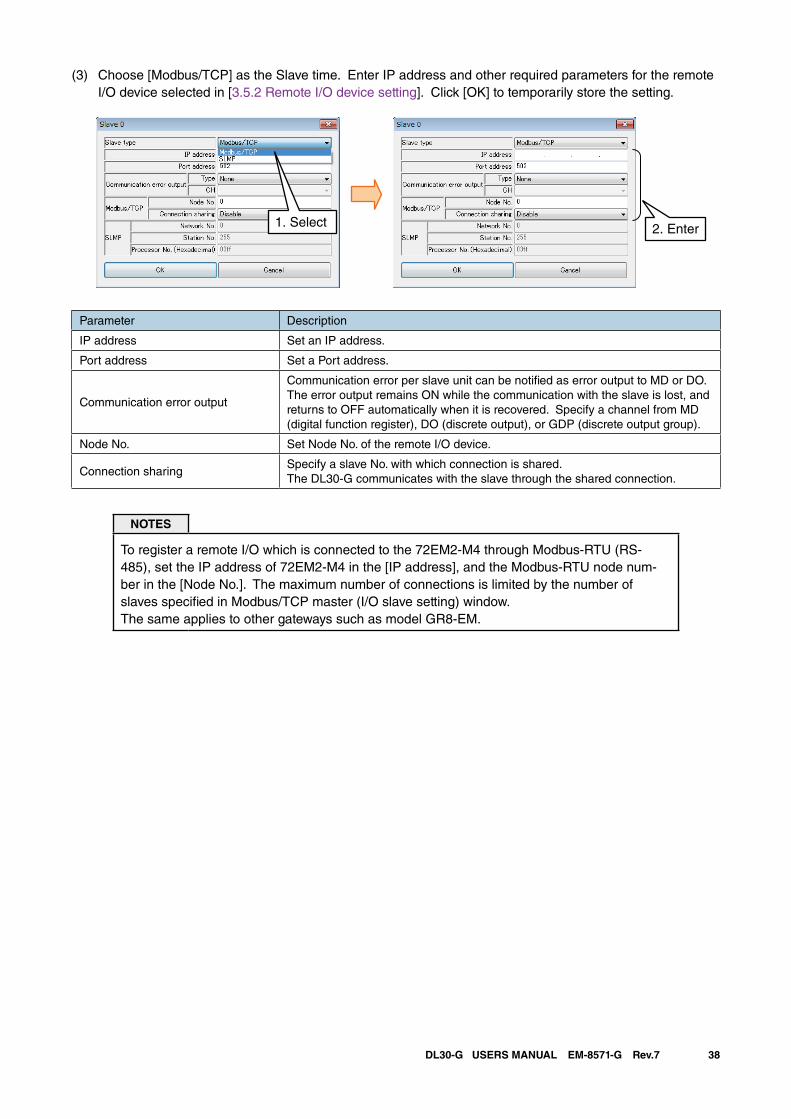
38DL30-G USERS MANUAL EM-8571-G Rev.7
(3) Choose [Modbus/TCP] as the Slave time. Enter IP address and other required parameters for the remote I/O device selected in [3.5.2 Remote I/O device setting]. Click [OK] to temporarily store the setting.
2. Enter1. Select
Parameter Description
IP address Set an IP address.
Port address Set a Port address.
Communication error output
Communication error per slave unit can be notified as error output to MD or DO. The error output remains ON while the communication with the slave is lost, and returns to OFF automatically when it is recovered. Specify a channel from MD (digital function register), DO (discrete output), or GDP (discrete output group).
Node No. Set Node No. of the remote I/O device.
Connection sharingSpecify a slave No. with which connection is shared. The DL30-G communicates with the slave through the shared connection.
NOTES
To register a remote I/O which is connected to the 72EM2-M4 through Modbus-RTU (RS-485), set the IP address of 72EM2-M4 in the [IP address], and the Modbus-RTU node num-ber in the [Node No.]. The maximum number of connections is limited by the number of slaves specified in Modbus/TCP master (I/O slave setting) window.The same applies to other gateways such as model GR8-EM.
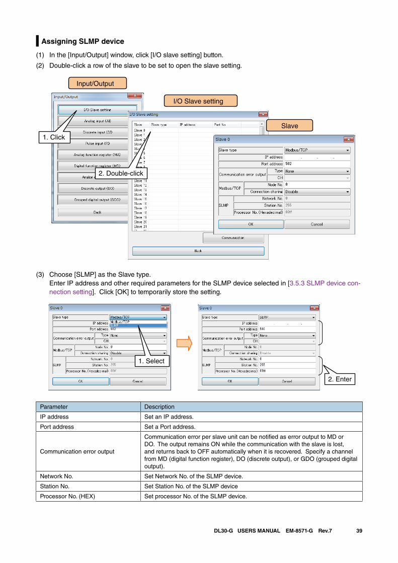
39DL30-G USERS MANUAL EM-8571-G Rev.7
Assigning SLMP device
(1) In the [Input/Output] window, click [I/O slave setting] button.
(2) Double-click a row of the slave to be set to open the slave setting.
Input/Output
I/O Slave setting
1. Click
Slave
2. Double-click
(3) Choose [SLMP] as the Slave type. Enter IP address and other required parameters for the SLMP device selected in [3.5.3 SLMP device con-nection setting]. Click [OK] to temporarily store the setting.
2. Enter
1. Select
Parameter Description
IP address Set an IP address.
Port address Set a Port address.
Communication error output
Communication error per slave unit can be notified as error output to MD or DO. The output remains ON while the communication with the slave is lost, and returns back to OFF automatically when it is recovered. Specify a channel from MD (digital function register), DO (discrete output), or GDO (grouped digital output).
Network No. Set Network No. of the SLMP device.
Station No. Set Station No. of the SLMP device
Processor No. (HEX) Set processor No. of the SLMP device.
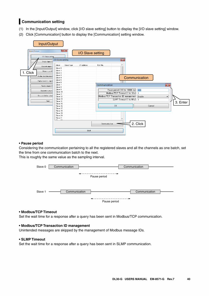
40DL30-G USERS MANUAL EM-8571-G Rev.7
Communication setting
(1) In the [Input/Output] window, click [I/O slave setting] button to display the [I/O slave setting] window.
(2) Click [Communication] button to display the [Communication] setting window.
Input/Output
I/O Slave setting
1. Click
Communication
2. Click
3. Enter
• Pause periodConsidering the communication pertaining to all the registered slaves and all the channels as one batch, set the time from one communication batch to the next.This is roughly the same value as the sampling interval.
• Modbus/TCP TimeoutSet the wait time for a response after a query has been sent in Modbus/TCP communication.
• Modbus/TCP Transaction ID managementUnintended messages are skipped by the management of Modbus message IDs.
• SLMP TimeoutSet the wait time for a response after a query has been sent in SLMP communication.
Communication CommunicationSlave 0
Pause period
Communication CommunicationSlave 1
Pause period
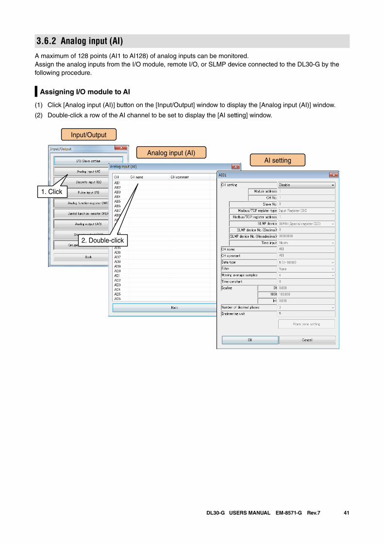
41DL30-G USERS MANUAL EM-8571-G Rev.7
3.6.2 Analog input (AI)A maximum of 128 points (AI1 to AI128) of analog inputs can be monitored.Assign the analog inputs from the I/O module, remote I/O, or SLMP device connected to the DL30-G by the following procedure.
Assigning I/O module to AI
(1) Click [Analog input (AI)] button on the [Input/Output] window to display the [Analog input (AI)] window.
(2) Double-click a row of the AI channel to be set to display the [AI setting] window.
Input/Output
Analog input (AI)
1. Click
AI setting
2. Double-click
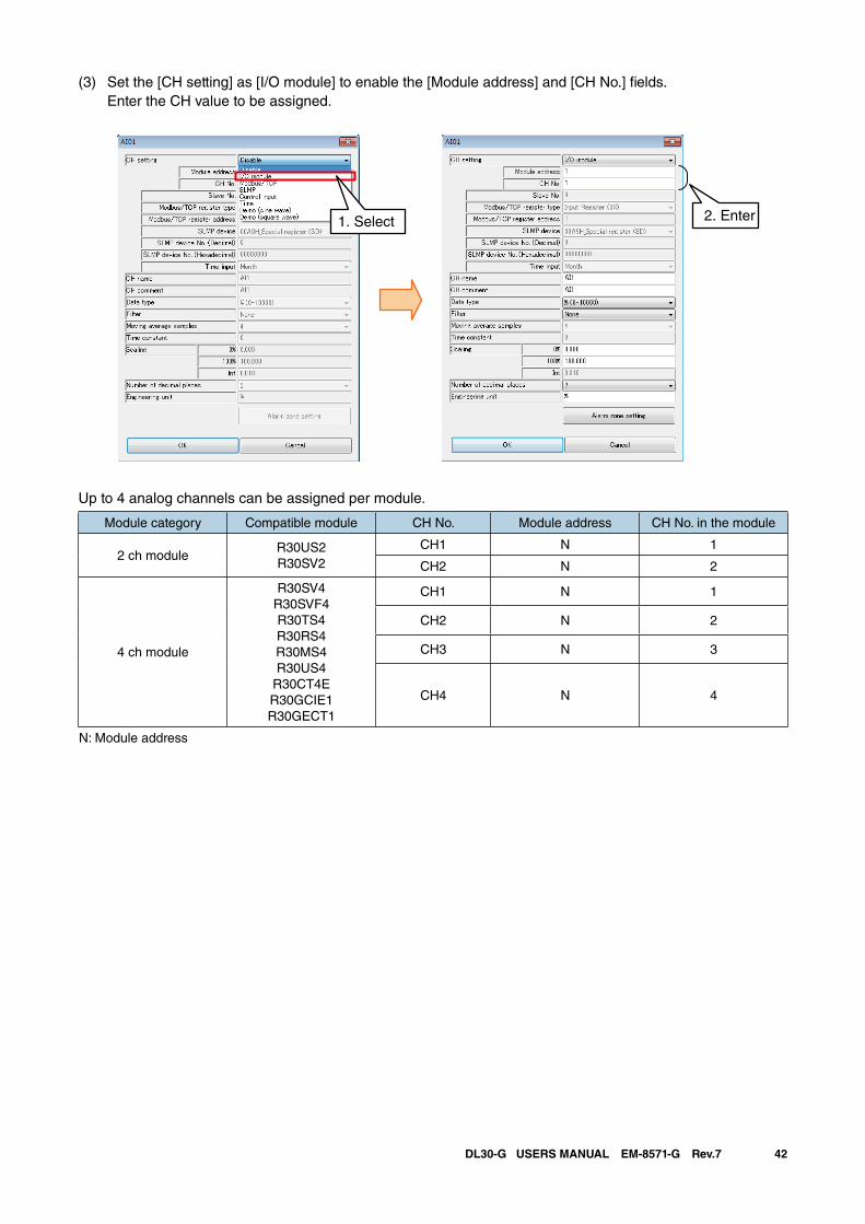
42DL30-G USERS MANUAL EM-8571-G Rev.7
(3) Set the [CH setting] as [I/O module] to enable the [Module address] and [CH No.] fields. Enter the CH value to be assigned.
Up to 4 analog channels can be assigned per module.
Module category Compatible module CH No. Module address CH No. in the module
2 ch moduleR30US2R30SV2
CH1 N 1
CH2 N 2
4 ch module
R30SV4R30SVF4R30TS4R30RS4R30MS4R30US4
R30CT4ER30GCIE1R30GECT1
CH1 N 1
CH2 N 2
CH3 N 3
CH4 N 4
N: Module address
2. Enter1. Select
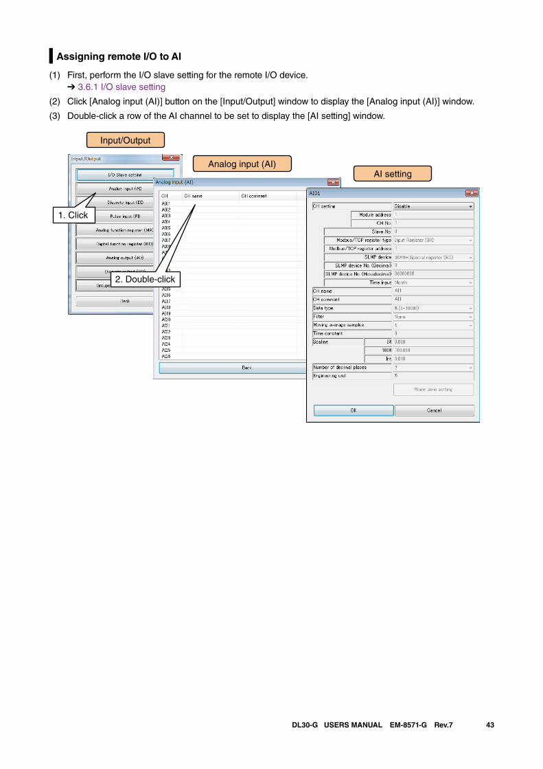
43DL30-G USERS MANUAL EM-8571-G Rev.7
Assigning remote I/O to AI
(1) First, perform the I/O slave setting for the remote I/O device. ➔ 3.6.1 I/O slave setting
(2) Click [Analog input (AI)] button on the [Input/Output] window to display the [Analog input (AI)] window.
(3) Double-click a row of the AI channel to be set to display the [AI setting] window.
Input/Output
Analog input (AI)
1. Click
AI setting
2. Double-click
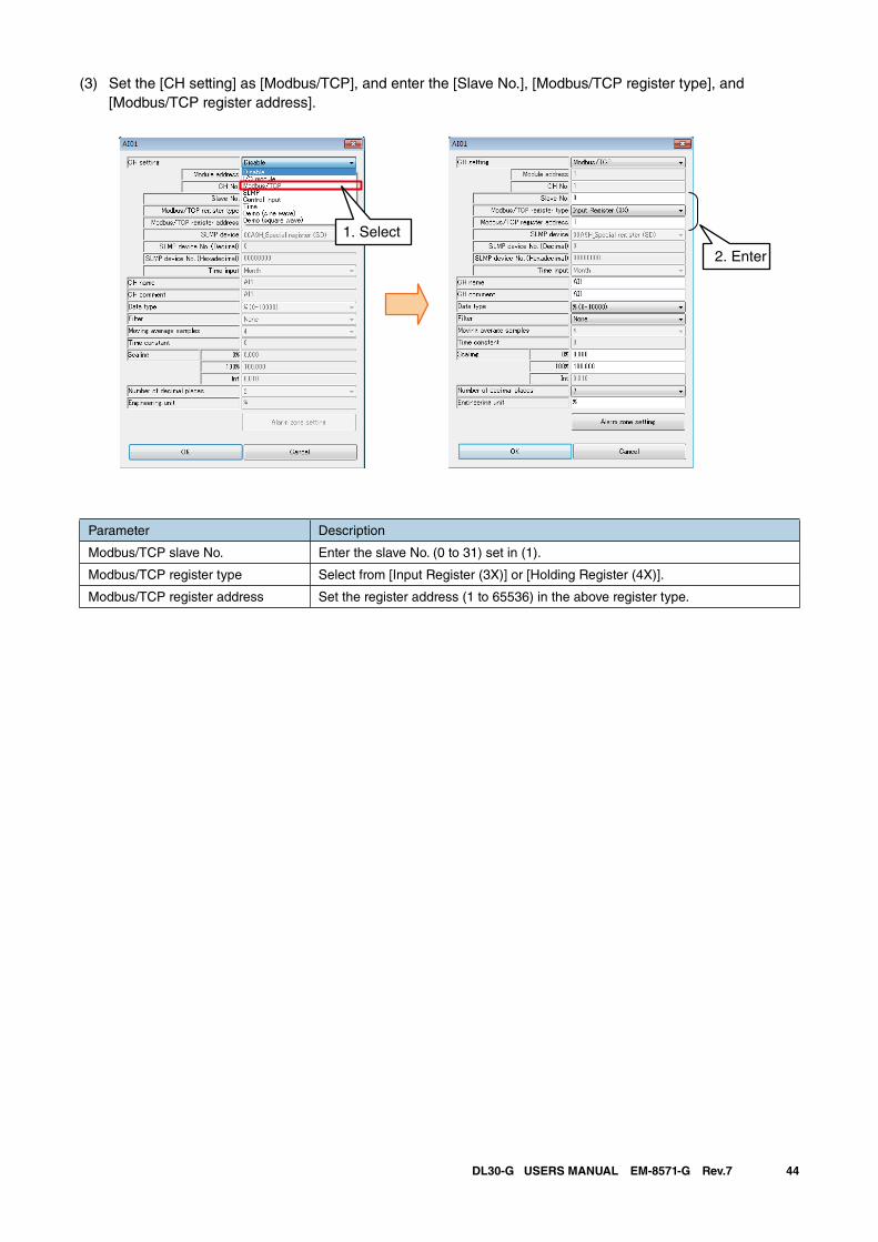
44DL30-G USERS MANUAL EM-8571-G Rev.7
(3) Set the [CH setting] as [Modbus/TCP], and enter the [Slave No.], [Modbus/TCP register type], and [Modbus/TCP register address].
Parameter Description
Modbus/TCP slave No. Enter the slave No. (0 to 31) set in (1).
Modbus/TCP register type Select from [Input Register (3X)] or [Holding Register (4X)].
Modbus/TCP register address Set the register address (1 to 65536) in the above register type.
2. Enter
1. Select
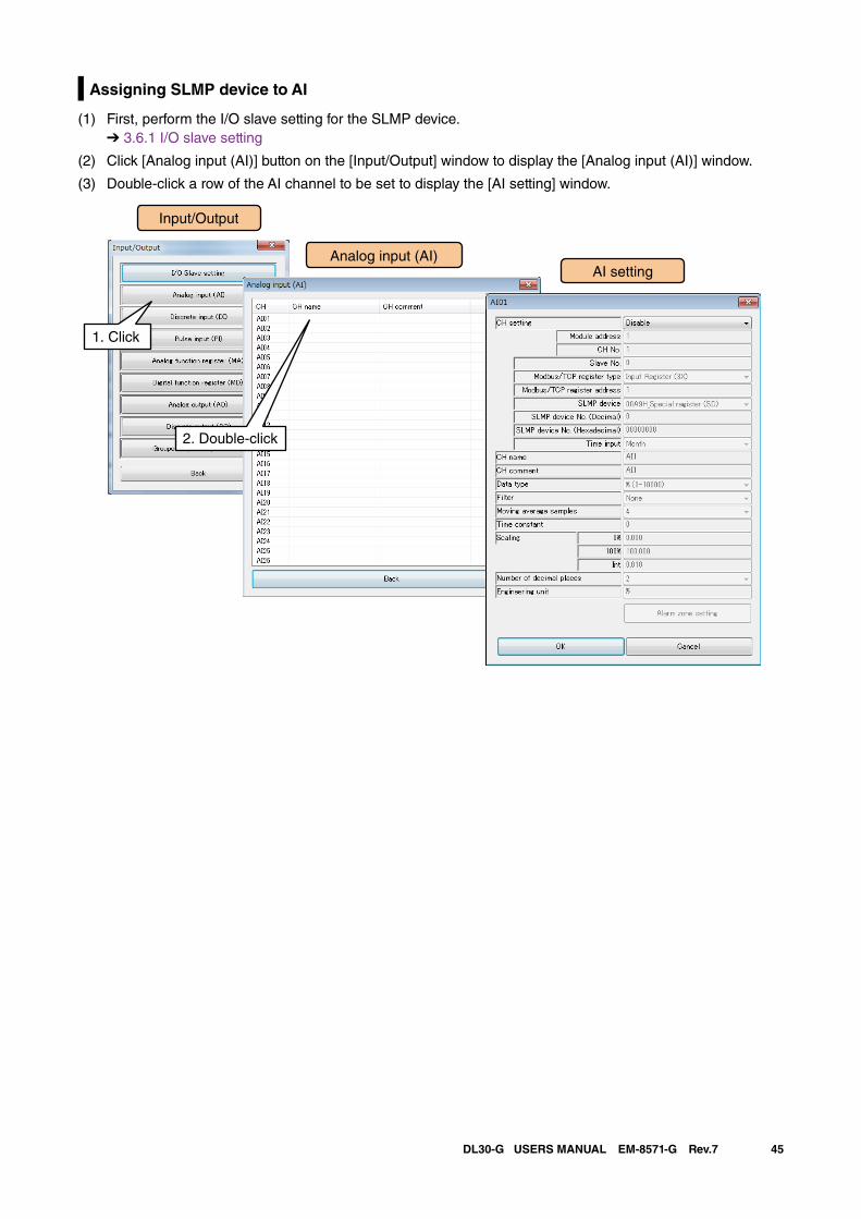
45DL30-G USERS MANUAL EM-8571-G Rev.7
Assigning SLMP device to AI
(1) First, perform the I/O slave setting for the SLMP device. ➔ 3.6.1 I/O slave setting
(2) Click [Analog input (AI)] button on the [Input/Output] window to display the [Analog input (AI)] window.
(3) Double-click a row of the AI channel to be set to display the [AI setting] window.
Input/Output
Analog input (AI)
1. Click
AI setting
2. Double-click
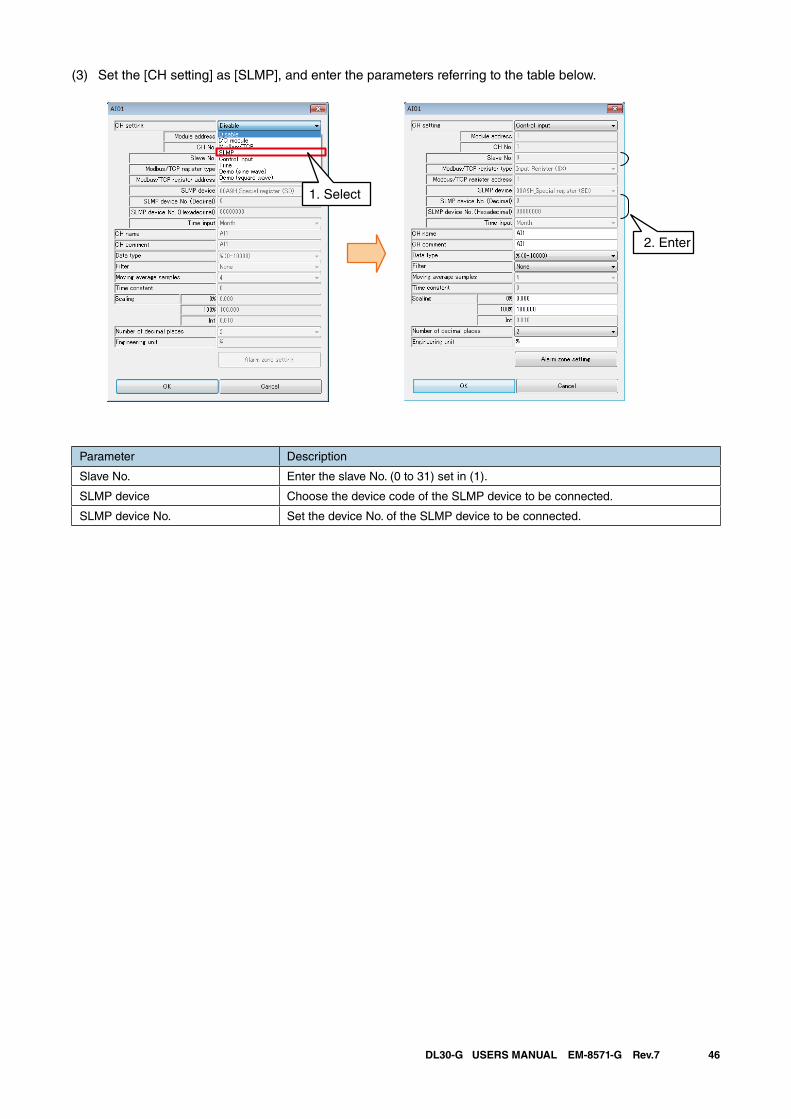
46DL30-G USERS MANUAL EM-8571-G Rev.7
(3) Set the [CH setting] as [SLMP], and enter the parameters referring to the table below.
2. Enter
1. Select
Parameter Description
Slave No. Enter the slave No. (0 to 31) set in (1).
SLMP device Choose the device code of the SLMP device to be connected.
SLMP device No. Set the device No. of the SLMP device to be connected.
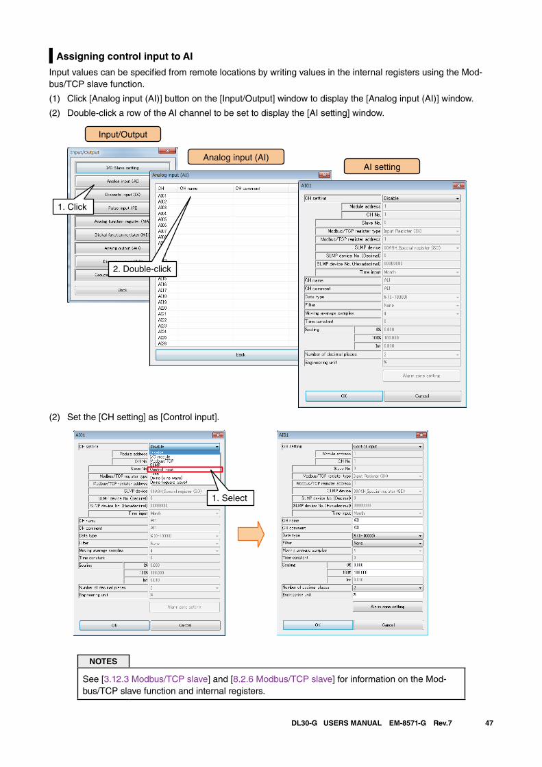
47DL30-G USERS MANUAL EM-8571-G Rev.7
Assigning control input to AI
Input values can be specified from remote locations by writing values in the internal registers using the Mod-bus/TCP slave function.
(1) Click [Analog input (AI)] button on the [Input/Output] window to display the [Analog input (AI)] window.
(2) Double-click a row of the AI channel to be set to display the [AI setting] window.
Input/Output
Analog input (AI)
1. Click
AI setting
2. Double-click
(2) Set the [CH setting] as [Control input].
1. Select
NOTES
See [3.12.3 Modbus/TCP slave] and [8.2.6 Modbus/TCP slave] for information on the Mod-bus/TCP slave function and internal registers.
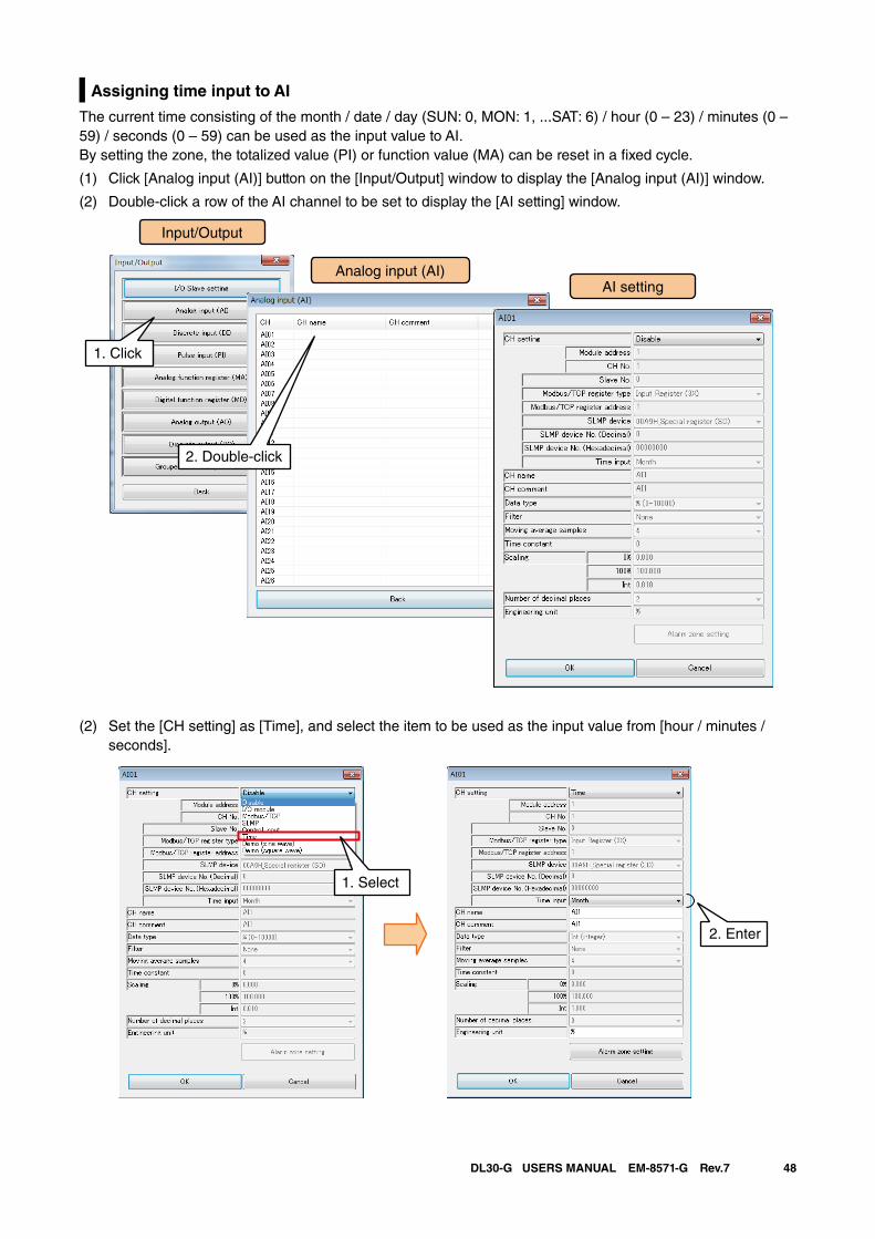
48DL30-G USERS MANUAL EM-8571-G Rev.7
Assigning time input to AI
The current time consisting of the month / date / day (SUN: 0, MON: 1, ...SAT: 6) / hour (0 – 23) / minutes (0 – 59) / seconds (0 – 59) can be used as the input value to AI. By setting the zone, the totalized value (PI) or function value (MA) can be reset in a fixed cycle.
(1) Click [Analog input (AI)] button on the [Input/Output] window to display the [Analog input (AI)] window.
(2) Double-click a row of the AI channel to be set to display the [AI setting] window.
Input/Output
Analog input (AI)
1. Click
AI setting
2. Double-click
(2) Set the [CH setting] as [Time], and select the item to be used as the input value from [hour / minutes / seconds].
1. Select
2. Enter
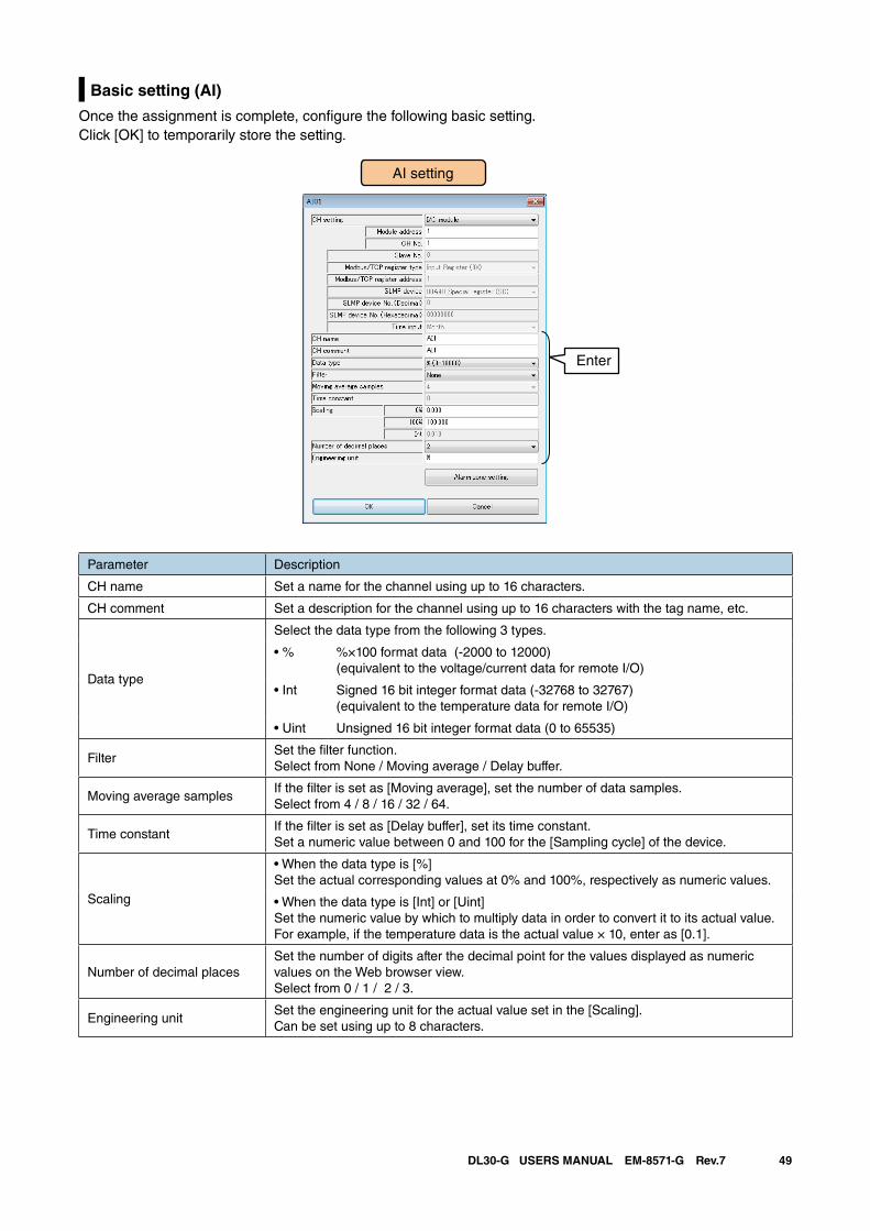
49DL30-G USERS MANUAL EM-8571-G Rev.7
Basic setting (AI)
Once the assignment is complete, configure the following basic setting. Click [OK] to temporarily store the setting.
AI setting
Enter
Parameter Description
CH name Set a name for the channel using up to 16 characters.
CH comment Set a description for the channel using up to 16 characters with the tag name, etc.
Data type
Select the data type from the following 3 types.
• % %×100 format data (-2000 to 12000)(equivalent to the voltage/current data for remote I/O)
• Int Signed 16 bit integer format data (-32768 to 32767)(equivalent to the temperature data for remote I/O)
• Uint Unsigned 16 bit integer format data (0 to 65535)
FilterSet the filter function. Select from None / Moving average / Delay buffer.
Moving average samplesIf the filter is set as [Moving average], set the number of data samples.Select from 4 / 8 / 16 / 32 / 64.
Time constantIf the filter is set as [Delay buffer], set its time constant.Set a numeric value between 0 and 100 for the [Sampling cycle] of the device.
Scaling
• When the data type is [%]Set the actual corresponding values at 0% and 100%, respectively as numeric values.
• When the data type is [Int] or [Uint]Set the numeric value by which to multiply data in order to convert it to its actual value. For example, if the temperature data is the actual value × 10, enter as [0.1].
Number of decimal placesSet the number of digits after the decimal point for the values displayed as numeric values on the Web browser view.Select from 0 / 1 / 2 / 3.
Engineering unitSet the engineering unit for the actual value set in the [Scaling].Can be set using up to 8 characters.
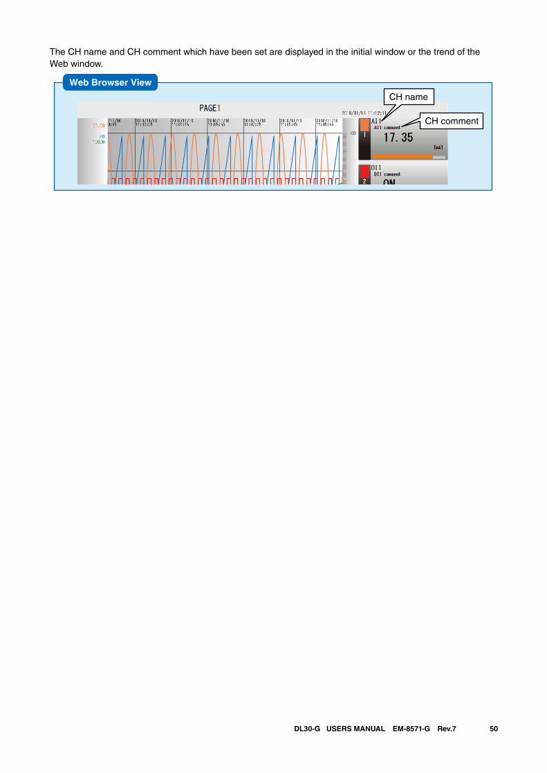
50DL30-G USERS MANUAL EM-8571-G Rev.7
The CH name and CH comment which have been set are displayed in the initial window or the trend of the Web window.
Web Browser View
CH comment
CH name
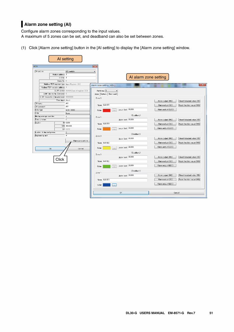
51DL30-G USERS MANUAL EM-8571-G Rev.7
Alarm zone setting (AI)
Configure alarm zones corresponding to the input values. A maximum of 5 zones can be set, and deadband can also be set between zones.
(1) Click [Alarm zone setting] button in the [AI setting] to display the [Alarm zone setting] window.
AI setting
AI alarm zone setting
Click
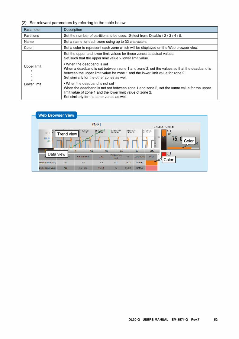
52DL30-G USERS MANUAL EM-8571-G Rev.7
(2) Set relevant parameters by referring to the table below.
Parameter Description
Partitions Set the number of partitions to be used. Select from: Disable / 2 / 3 / 4 / 5.
Name Set a name for each zone using up to 32 characters.
Color Set a color to represent each zone which will be displayed on the Web browser view.
Upper limit : : :Lower limit
Set the upper and lower limit values for these zones as actual values. Set such that the upper limit value > lower limit value.
• When the deadband is setWhen a deadband is set between zone 1 and zone 2, set the values so that the deadband is between the upper limit value for zone 1 and the lower limit value for zone 2. Set similarly for the other zones as well.
• When the deadband is not setWhen the deadband is not set between zone 1 and zone 2, set the same value for the upper limit value of zone 1 and the lower limit value of zone 2. Set similarly for the other zones as well.
Web Browser View
Color
Trend view
Data viewColor
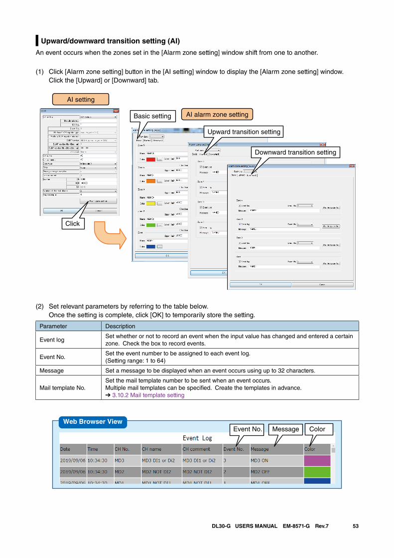
53DL30-G USERS MANUAL EM-8571-G Rev.7
Upward/downward transition setting (AI)
An event occurs when the zones set in the [Alarm zone setting] window shift from one to another.
(1) Click [Alarm zone setting] button in the [AI setting] window to display the [Alarm zone setting] window. Click the [Upward] or [Downward] tab.
(2) Set relevant parameters by referring to the table below. Once the setting is complete, click [OK] to temporarily store the setting.
Parameter Description
Event logSet whether or not to record an event when the input value has changed and entered a certain zone. Check the box to record events.
Event No.Set the event number to be assigned to each event log.(Setting range: 1 to 64)
Message Set a message to be displayed when an event occurs using up to 32 characters.
Mail template No.Set the mail template number to be sent when an event occurs. Multiple mail templates can be specified. Create the templates in advance.➔ 3.10.2 Mail template setting
AI setting
AI alarm zone setting
Click
Basic setting
Upward transition setting
Downward transition setting
Event No. Message ColorWeb Browser View
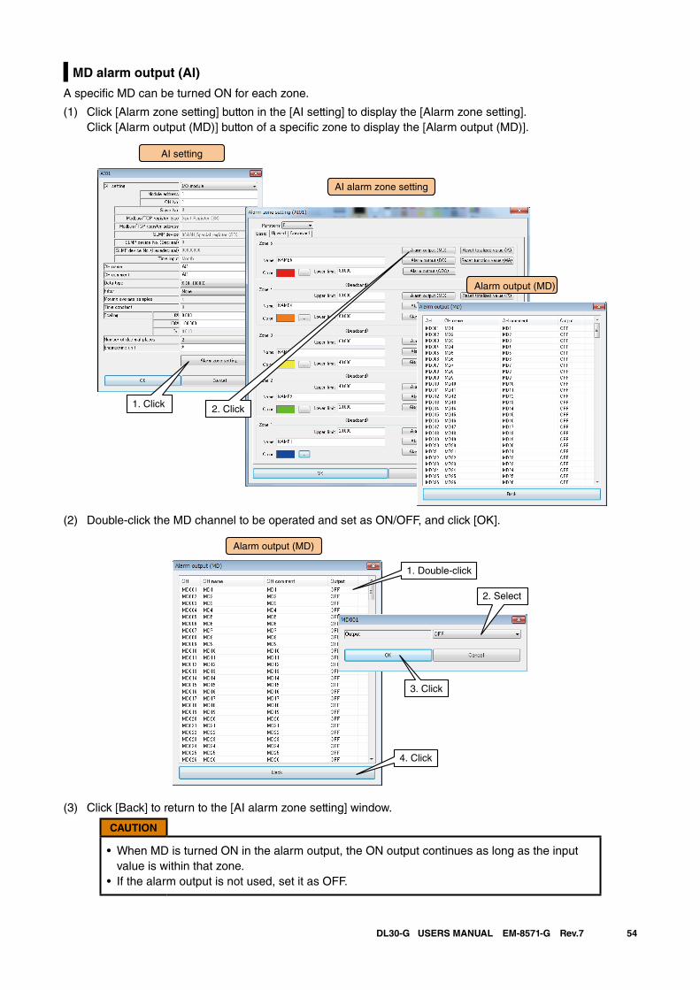
54DL30-G USERS MANUAL EM-8571-G Rev.7
MD alarm output (AI)
A specific MD can be turned ON for each zone.
(1) Click [Alarm zone setting] button in the [AI setting] to display the [Alarm zone setting]. Click [Alarm output (MD)] button of a specific zone to display the [Alarm output (MD)].
AI setting
AI alarm zone setting
Alarm output (MD)
1. Click 2. Click
(2) Double-click the MD channel to be operated and set as ON/OFF, and click [OK].
Alarm output (MD)
1. Double-click
2. Select
4. Click
3. Click
(3) Click [Back] to return to the [AI alarm zone setting] window.
CAUTION
• When MD is turned ON in the alarm output, the ON output continues as long as the input value is within that zone.
• If the alarm output is not used, set it as OFF.
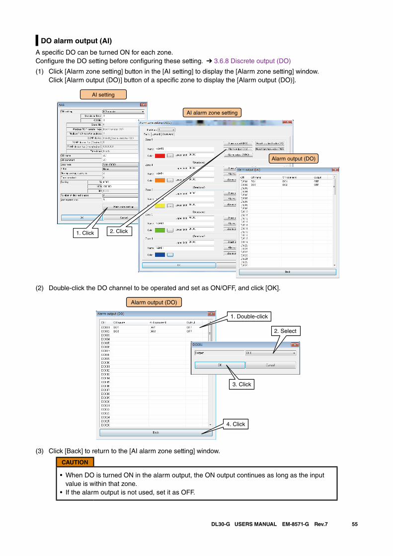
55DL30-G USERS MANUAL EM-8571-G Rev.7
DO alarm output (AI)
A specific DO can be turned ON for each zone.Configure the DO setting before configuring these setting. ➔ 3.6.8 Discrete output (DO)
(1) Click [Alarm zone setting] button in the [AI setting] to display the [Alarm zone setting] window. Click [Alarm output (DO)] button of a specific zone to display the [Alarm output (DO)].
AI setting
AI alarm zone setting
1. Click 2. Click
Alarm output (DO)
(2) Double-click the DO channel to be operated and set as ON/OFF, and click [OK].
Alarm output (DO)
1. Double-click
2. Select
4. Click
3. Click
(3) Click [Back] to return to the [AI alarm zone setting] window.
CAUTION
• When DO is turned ON in the alarm output, the ON output continues as long as the input value is within that zone.
• If the alarm output is not used, set it as OFF.
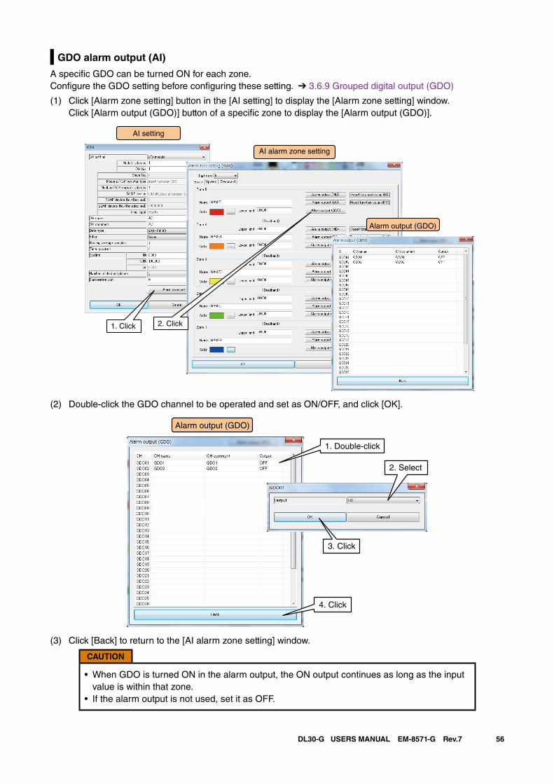
56DL30-G USERS MANUAL EM-8571-G Rev.7
GDO alarm output (AI)
A specific GDO can be turned ON for each zone.Configure the GDO setting before configuring these setting. ➔ 3.6.9 Grouped digital output (GDO)
(1) Click [Alarm zone setting] button in the [AI setting] to display the [Alarm zone setting] window. Click [Alarm output (GDO)] button of a specific zone to display the [Alarm output (GDO)].
AI setting
AI alarm zone setting
1. Click 2. Click
Alarm output (GDO)
(2) Double-click the GDO channel to be operated and set as ON/OFF, and click [OK].
Alarm output (GDO)
1. Double-click
4. Click
3. Click
2. Select
(3) Click [Back] to return to the [AI alarm zone setting] window.
CAUTION
• When GDO is turned ON in the alarm output, the ON output continues as long as the input value is within that zone.
• If the alarm output is not used, set it as OFF.
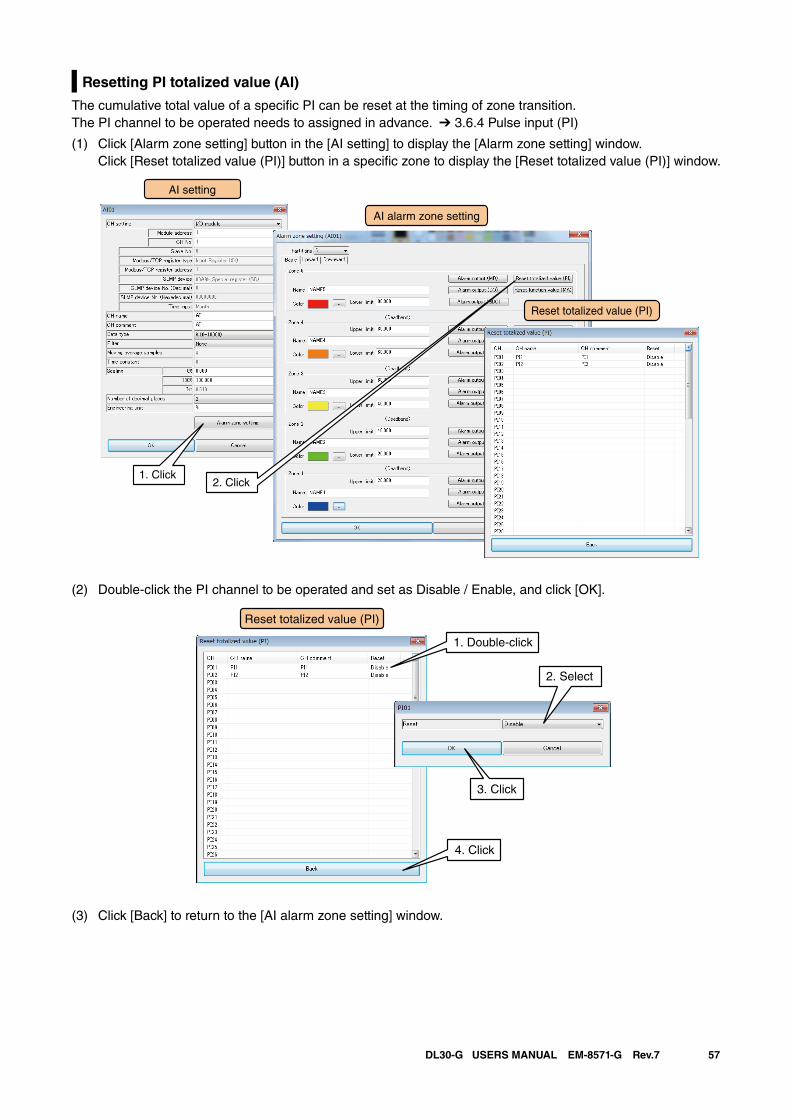
57DL30-G USERS MANUAL EM-8571-G Rev.7
Resetting PI totalized value (AI)
The cumulative total value of a specific PI can be reset at the timing of zone transition.The PI channel to be operated needs to assigned in advance. ➔ 3.6.4 Pulse input (PI)
(1) Click [Alarm zone setting] button in the [AI setting] to display the [Alarm zone setting] window. Click [Reset totalized value (PI)] button in a specific zone to display the [Reset totalized value (PI)] window.
AI setting
AI alarm zone setting
Reset totalized value (PI)
1. Click2. Click
(2) Double-click the PI channel to be operated and set as Disable / Enable, and click [OK].
1. Double-click
2. Select
Reset totalized value (PI)
4. Click
3. Click
(3) Click [Back] to return to the [AI alarm zone setting] window.
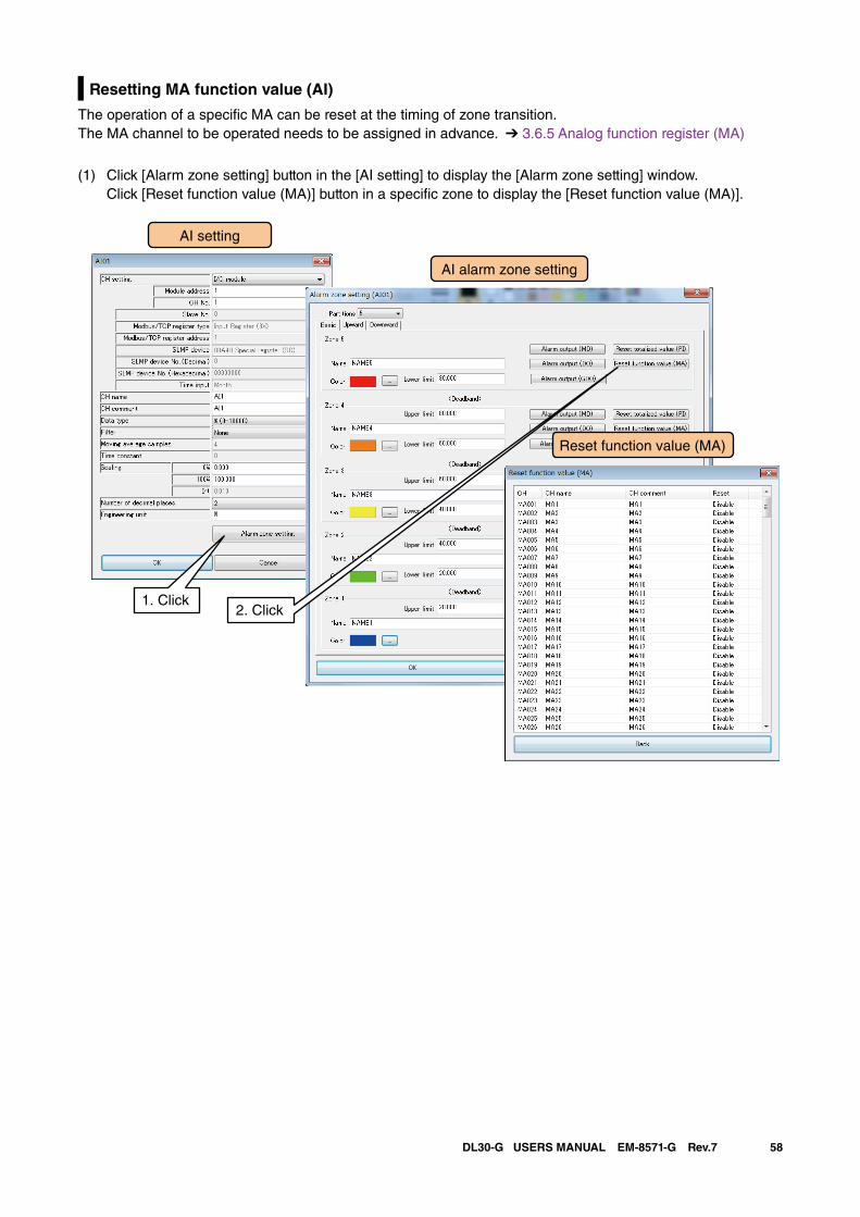
58DL30-G USERS MANUAL EM-8571-G Rev.7
Resetting MA function value (AI)
The operation of a specific MA can be reset at the timing of zone transition.The MA channel to be operated needs to be assigned in advance. ➔ 3.6.5 Analog function register (MA)
(1) Click [Alarm zone setting] button in the [AI setting] to display the [Alarm zone setting] window. Click [Reset function value (MA)] button in a specific zone to display the [Reset function value (MA)].
AI setting
AI alarm zone setting
Reset function value (MA)
1. Click2. Click
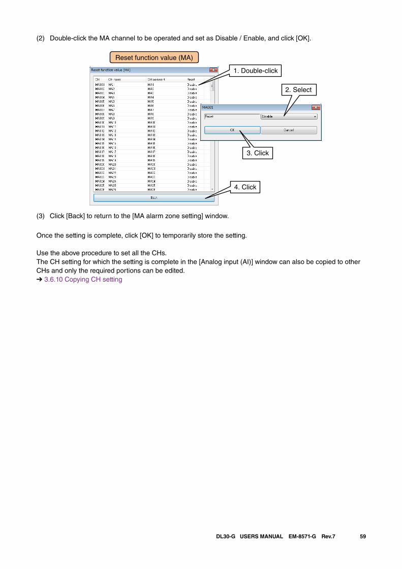
59DL30-G USERS MANUAL EM-8571-G Rev.7
(2) Double-click the MA channel to be operated and set as Disable / Enable, and click [OK].
(3) Click [Back] to return to the [MA alarm zone setting] window.
Once the setting is complete, click [OK] to temporarily store the setting.
Use the above procedure to set all the CHs.The CH setting for which the setting is complete in the [Analog input (AI)] window can also be copied to other CHs and only the required portions can be edited.➔ 3.6.10 Copying CH setting
1. Double-click
2. Select
Reset function value (MA)
4. Click
3. Click
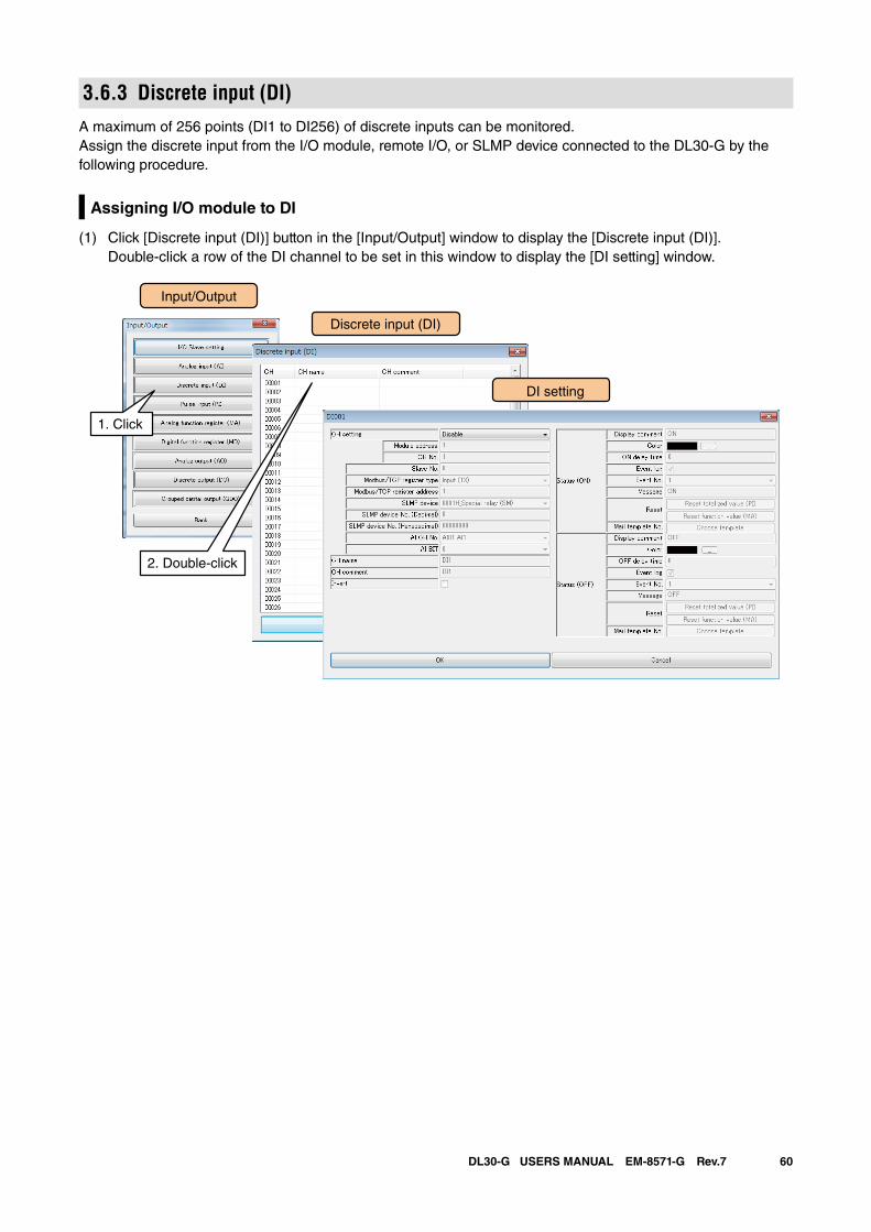
60DL30-G USERS MANUAL EM-8571-G Rev.7
3.6.3 Discrete input (DI)A maximum of 256 points (DI1 to DI256) of discrete inputs can be monitored.Assign the discrete input from the I/O module, remote I/O, or SLMP device connected to the DL30-G by the following procedure.
Assigning I/O module to DI
(1) Click [Discrete input (DI)] button in the [Input/Output] window to display the [Discrete input (DI)]. Double-click a row of the DI channel to be set in this window to display the [DI setting] window.
Input/Output
Discrete input (DI)
1. Click
DI setting
2. Double-click
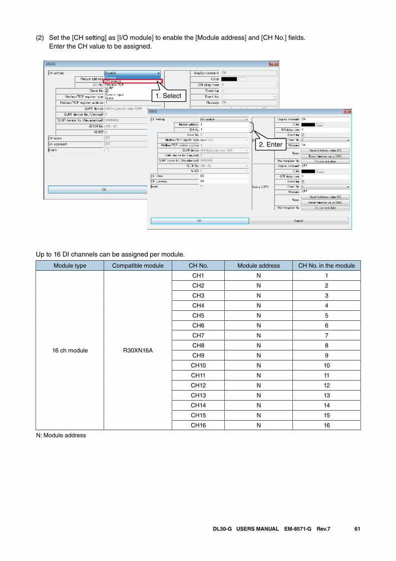
61DL30-G USERS MANUAL EM-8571-G Rev.7
(2) Set the [CH setting] as [I/O module] to enable the [Module address] and [CH No.] fields. Enter the CH value to be assigned.
Up to 16 DI channels can be assigned per module.
Module type Compatible module CH No. Module address CH No. in the module
16 ch module R30XN16A
CH1 N 1
CH2 N 2
CH3 N 3
CH4 N 4
CH5 N 5
CH6 N 6
CH7 N 7
CH8 N 8
CH9 N 9
CH10 N 10
CH11 N 11
CH12 N 12
CH13 N 13
CH14 N 14
CH15 N 15
CH16 N 16
N: Module address
1. Select
2. Enter
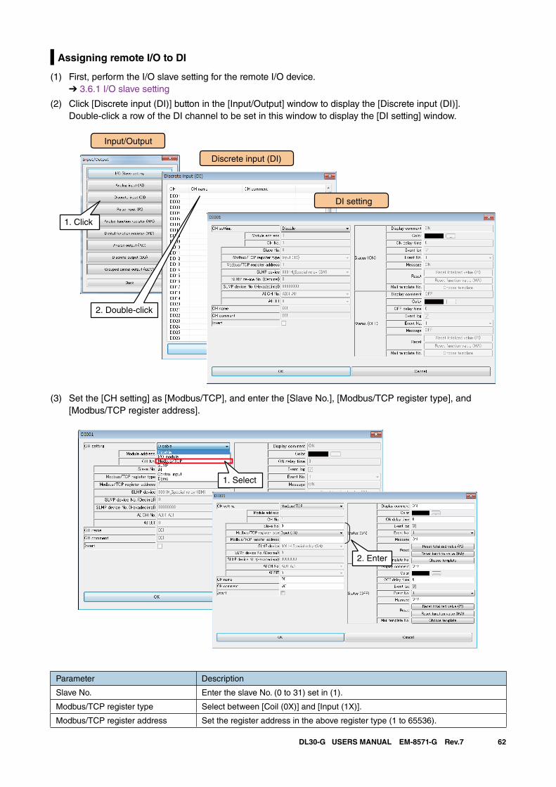
62DL30-G USERS MANUAL EM-8571-G Rev.7
Assigning remote I/O to DI
(1) First, perform the I/O slave setting for the remote I/O device. ➔ 3.6.1 I/O slave setting
(2) Click [Discrete input (DI)] button in the [Input/Output] window to display the [Discrete input (DI)]. Double-click a row of the DI channel to be set in this window to display the [DI setting] window.
(3) Set the [CH setting] as [Modbus/TCP], and enter the [Slave No.], [Modbus/TCP register type], and [Modbus/TCP register address].
Parameter Description
Slave No. Enter the slave No. (0 to 31) set in (1).
Modbus/TCP register type Select between [Coil (0X)] and [Input (1X)].
Modbus/TCP register address Set the register address in the above register type (1 to 65536).
Input/Output
Discrete input (DI)
1. Click
DI setting
2. Double-click
1. Select
2. Enter
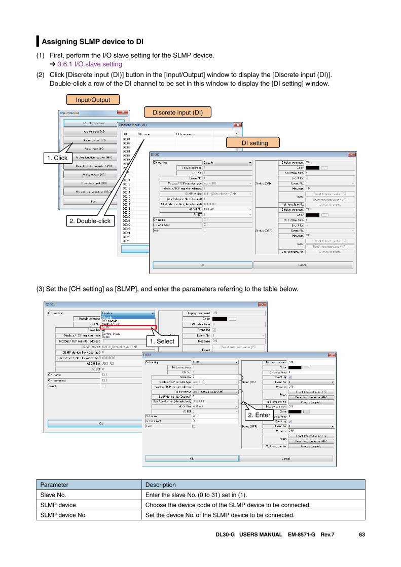
63DL30-G USERS MANUAL EM-8571-G Rev.7
Assigning SLMP device to DI
(1) First, perform the I/O slave setting for the SLMP device. ➔ 3.6.1 I/O slave setting
(2) Click [Discrete input (DI)] button in the [Input/Output] window to display the [Discrete input (DI)]. Double-click a row of the DI channel to be set in this window to display the [DI setting] window.
Input/Output
Discrete input (DI)
1. Click
DI setting
2. Double-click
(3) Set the [CH setting] as [SLMP], and enter the parameters referring to the table below.
1. Select
2. Enter
Parameter Description
Slave No. Enter the slave No. (0 to 31) set in (1).
SLMP device Choose the device code of the SLMP device to be connected.
SLMP device No. Set the device No. of the SLMP device to be connected.
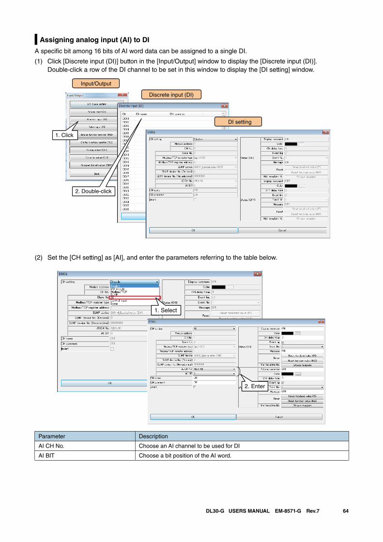
64DL30-G USERS MANUAL EM-8571-G Rev.7
Assigning analog input (AI) to DI
A specific bit among 16 bits of AI word data can be assigned to a single DI.
(1) Click [Discrete input (DI)] button in the [Input/Output] window to display the [Discrete input (DI)]. Double-click a row of the DI channel to be set in this window to display the [DI setting] window.
(2) Set the [CH setting] as [AI], and enter the parameters referring to the table below.
Parameter Description
AI CH No. Choose an AI channel to be used for DI
AI BIT Choose a bit position of the AI word.
Input/Output
Discrete input (DI)
1. Click
DI setting
2. Double-click
1. Select
2. Enter
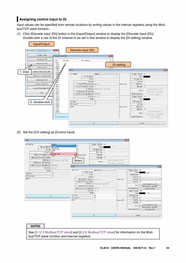
65DL30-G USERS MANUAL EM-8571-G Rev.7
Assigning control input to DI
Input values can be specified from remote locations by writing values in the internal registers using the Mod-bus/TCP slave function.
(1) Click [Discrete input (DI)] button in the [Input/Output] window to display the [Discrete input (DI)]. Double-click a row of the DI channel to be set in this window to display the [DI setting] window.
(2) Set the [CH setting] as [Control input].
NOTES
See [3.12.3 Modbus/TCP slave] and [8.2.6 Modbus/TCP slave] for information on the Mod-bus/TCP slave function and internal registers.
Input/Output
Discrete input (DI)
1. Click
DI setting
2. Double-click
Select
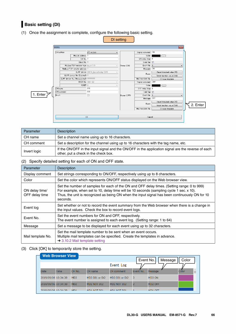
66DL30-G USERS MANUAL EM-8571-G Rev.7
Basic setting (DI)
(1) Once the assignment is complete, configure the following basic setting.
DI setting
2. Enter
1. Enter
Parameter Description
CH name Set a channel name using up to 16 characters.
CH comment Set a description for the channel using up to 16 characters with the tag name, etc.
Invert logicIf the ON/OFF in the input signal and the ON/OFF in the application signal are the reverse of each other, put a check in the check box.
(2) Specify detailed setting for each of ON and OFF state.
Parameter Description
Display comment Set strings corresponding to ON/OFF, respectively using up to 8 characters.
Color Set the color which represents ON/OFF status displayed on the Web browser view.
ON delay time/OFF delay time
Set the number of samples for each of the ON and OFF delay times. (Setting range: 0 to 999)For example, when set to 10, delay time will be 10 seconds (sampling cycle 1 sec. x 10). Thus, the unit is recognized as being ON when the input signal has been continuously ON for 10 seconds.
Event logSet whether or not to record the event summary from the Web browser when there is a change in the input values. Check the box to record event logs.
Event No.Set the event numbers for ON and OFF, respectively. The event number is assigned to each event log. (Setting range: 1 to 64)
Message Set a message to be displayed for each event using up to 32 characters.
Mail template No.Set the mail template number to be sent when an event occurs. Multiple mail templates can be specified. Create the templates in advance.➔ 3.10.2 Mail template setting
(3) Click [OK] to temporarily store the setting.
Event No. Message ColorWeb Browser View
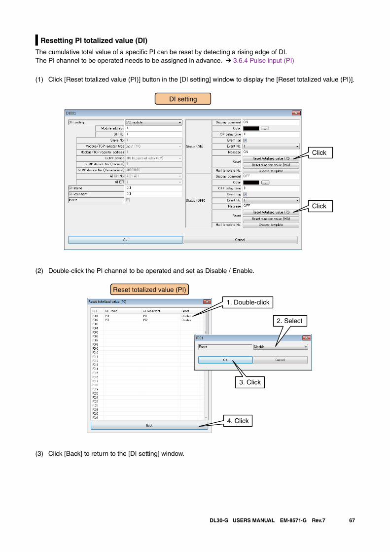
67DL30-G USERS MANUAL EM-8571-G Rev.7
Resetting PI totalized value (DI)
The cumulative total value of a specific PI can be reset by detecting a rising edge of DI.The PI channel to be operated needs to be assigned in advance. ➔ 3.6.4 Pulse input (PI)
(1) Click [Reset totalized value (PI)] button in the [DI setting] window to display the [Reset totalized value (PI)].
(2) Double-click the PI channel to be operated and set as Disable / Enable.
(3) Click [Back] to return to the [DI setting] window.
DI setting
Click
Click
1. Double-click
2. Select
Reset totalized value (PI)
4. Click
3. Click
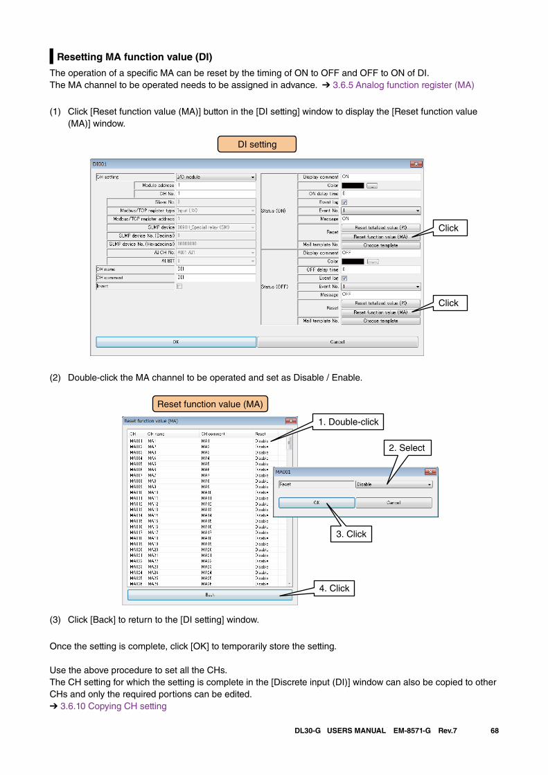
68DL30-G USERS MANUAL EM-8571-G Rev.7
Resetting MA function value (DI)
The operation of a specific MA can be reset by the timing of ON to OFF and OFF to ON of DI.The MA channel to be operated needs to be assigned in advance. ➔ 3.6.5 Analog function register (MA)
(1) Click [Reset function value (MA)] button in the [DI setting] window to display the [Reset function value (MA)] window.
(2) Double-click the MA channel to be operated and set as Disable / Enable.
(3) Click [Back] to return to the [DI setting] window.
Once the setting is complete, click [OK] to temporarily store the setting.
Use the above procedure to set all the CHs.The CH setting for which the setting is complete in the [Discrete input (DI)] window can also be copied to other CHs and only the required portions can be edited.➔ 3.6.10 Copying CH setting
DI setting
Click
Click
1. Double-click
2. Select
Reset function value (MA)
4. Click
3. Click
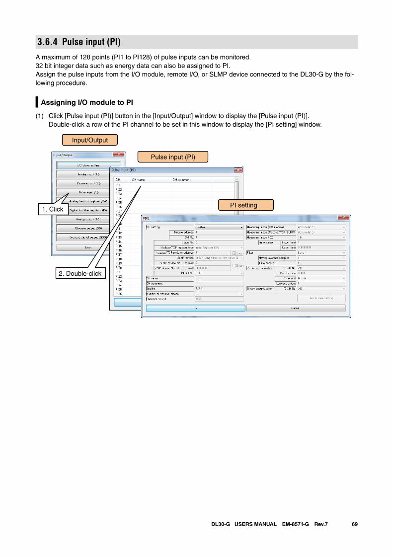
69DL30-G USERS MANUAL EM-8571-G Rev.7
3.6.4 Pulse input (PI)A maximum of 128 points (PI1 to PI128) of pulse inputs can be monitored. 32 bit integer data such as energy data can also be assigned to PI.Assign the pulse inputs from the I/O module, remote I/O, or SLMP device connected to the DL30-G by the fol-lowing procedure.
Assigning I/O module to PI
(1) Click [Pulse input (PI)] button in the [Input/Output] window to display the [Pulse input (PI)]. Double-click a row of the PI channel to be set in this window to display the [PI setting] window.
Input/Output
Pulse input (PI)
1. ClickPI setting
2. Double-click
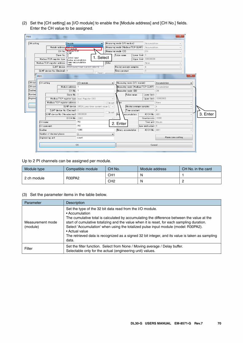
70DL30-G USERS MANUAL EM-8571-G Rev.7
(2) Set the [CH setting] as [I/O module] to enable the [Module address] and [CH No.] fields. Enter the CH value to be assigned.
1. Select
2. Enter
3. Enter
Up to 2 PI channels can be assigned per module.
Module type Compatible module CH No. Module address CH No. in the card
2 ch module R30PA2CH1 N 1
CH2 N 2
(3) Set the parameter items in the table below.
Parameter Description
Measurement mode(module)
Set the type of the 32 bit data read from the I/O module.• AccumulationThe cumulative total is calculated by accumulating the difference between the value at the start of cumulative totalizing and the value when it is reset, for each sampling duration. Select 'Accumulation' when using the totalized pulse input module (model: R30PA2).• Actual valueThe retrieved data is recognized as a signed 32 bit integer, and its value is taken as sampling data.
FilterSet the filter function. Select from None / Moving average / Delay buffer.Selectable only for the actual (engineering unit) values.
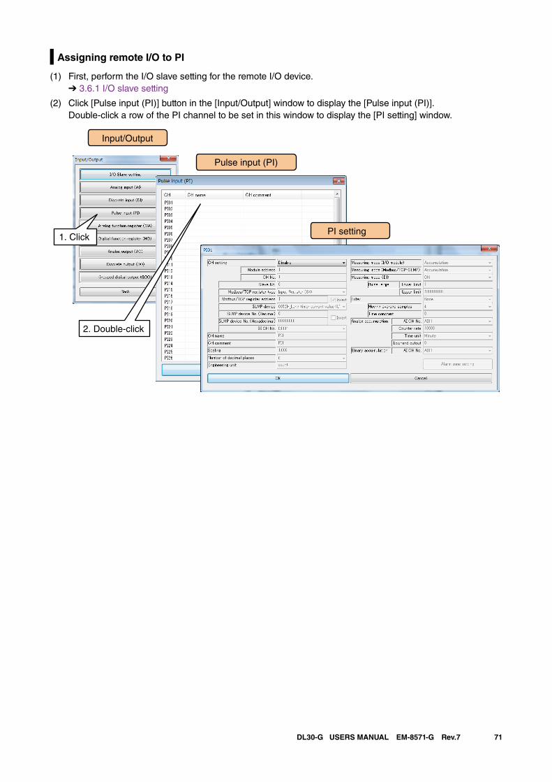
71DL30-G USERS MANUAL EM-8571-G Rev.7
Assigning remote I/O to PI
(1) First, perform the I/O slave setting for the remote I/O device. ➔ 3.6.1 I/O slave setting
(2) Click [Pulse input (PI)] button in the [Input/Output] window to display the [Pulse input (PI)]. Double-click a row of the PI channel to be set in this window to display the [PI setting] window.
Input/Output
Pulse input (PI)
1. ClickPI setting
2. Double-click
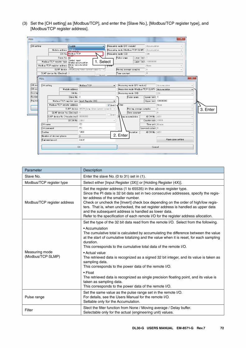
72DL30-G USERS MANUAL EM-8571-G Rev.7
(3) Set the [CH setting] as [Modbus/TCP], and enter the [Slave No.], [Modbus/TCP register type], and [Modbus/TCP register address].
Parameter Description
Slave No. Enter the slave No. (0 to 31) set in (1).
Modbus/TCP register type Select either [Input Register (3X)] or [Holding Register (4X)].
Modbus/TCP register address
Set the register address (1 to 65535) in the above register type.Since the PI data is 32 bit data set in two consecutive addresses, specify the regis-ter address of the smaller number.Check or uncheck the [Invert] check box depending on the order of high/low regis-ters. That is, when unchecked, the set register address is handled as upper data and the subsequent address is handled as lower data. Refer to the specification of each remote I/O for the register address allocation.
Measuring mode(Modbus/TCP·SLMP)
Set the type of the 32 bit data read from the remote I/O. Select from the following.
• AccumulationThe cumulative total is calculated by accumulating the difference between the value at the start of cumulative totalizing and the value when it is reset, for each sampling duration. This corresponds to the cumulative total data of the remote I/O.
• Actual valueThe retrieved data is recognized as a signed 32 bit integer, and its value is taken as sampling data. This corresponds to the power data of the remote I/O.
• FloatThe retrieved data is recognized as single precision floating point, and its value is taken as sampling data. This corresponds to the power data of the remote I/O.
Pulse rangeSet the same value as the pulse range set in the remote I/O. For details, see the Users Manual for the remote I/O. Settable only for the Accumulation.
FilterSlect the filter function from None / Moving average / Delay buffer.Selectable only for the actual (engineering unit) values.
1. Select
2. Enter
3. Enter
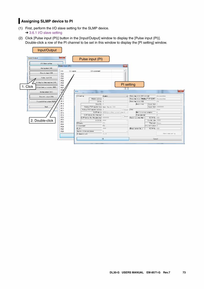
73DL30-G USERS MANUAL EM-8571-G Rev.7
Assigning SLMP device to PI
(1) First, perform the I/O slave setting for the SLMP device. ➔ 3.6.1 I/O slave setting
(2) Click [Pulse input (PI)] button in the [Input/Output] window to display the [Pulse input (PI)]. Double-click a row of the PI channel to be set in this window to display the [PI setting] window.
Input/Output
Pulse input (PI)
1. ClickPI setting
2. Double-click
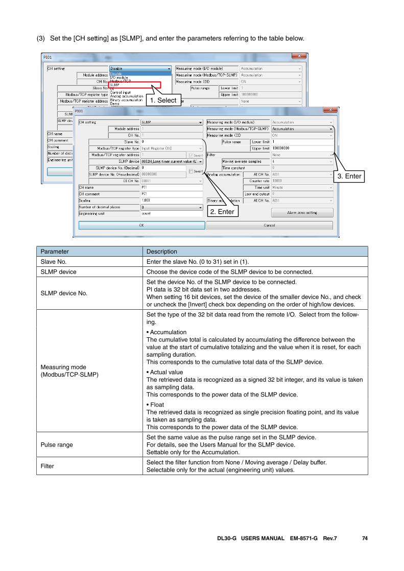
74DL30-G USERS MANUAL EM-8571-G Rev.7
(3) Set the [CH setting] as [SLMP], and enter the parameters referring to the table below.
Parameter Description
Slave No. Enter the slave No. (0 to 31) set in (1).
SLMP device Choose the device code of the SLMP device to be connected.
SLMP device No.
Set the device No. of the SLMP device to be connected.PI data is 32 bit data set in two addresses.When setting 16 bit devices, set the device of the smaller device No., and check or uncheck the [Invert] check box depending on the order of high/low devices.
Measuring mode(Modbus/TCP·SLMP)
Set the type of the 32 bit data read from the remote I/O. Select from the follow-ing.
• AccumulationThe cumulative total is calculated by accumulating the difference between the value at the start of cumulative totalizing and the value when it is reset, for each sampling duration. This corresponds to the cumulative total data of the SLMP device.
• Actual valueThe retrieved data is recognized as a signed 32 bit integer, and its value is taken as sampling data. This corresponds to the power data of the SLMP device.
• FloatThe retrieved data is recognized as single precision floating point, and its value is taken as sampling data. This corresponds to the power data of the SLMP device.
Pulse rangeSet the same value as the pulse range set in the SLMP device. For details, see the Users Manual for the SLMP device.Settable only for the Accumulation.
FilterSelect the filter function from None / Moving average / Delay buffer.Selectable only for the actual (engineering unit) values.
1. Select
2. Enter
3. Enter
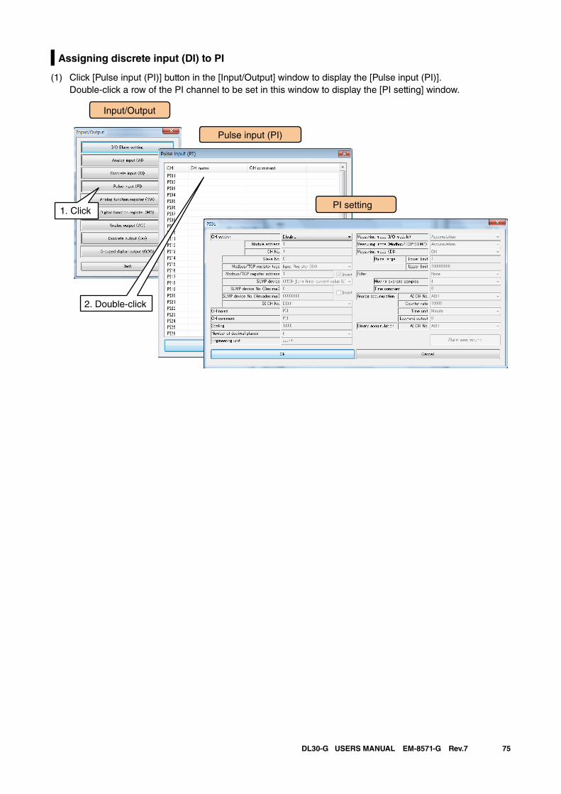
75DL30-G USERS MANUAL EM-8571-G Rev.7
Assigning discrete input (DI) to PI
(1) Click [Pulse input (PI)] button in the [Input/Output] window to display the [Pulse input (PI)]. Double-click a row of the PI channel to be set in this window to display the [PI setting] window.
Input/Output
Pulse input (PI)
1. ClickPI setting
2. Double-click
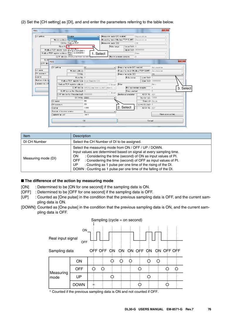
76DL30-G USERS MANUAL EM-8571-G Rev.7
(2) Set the [CH setting] as [DI], and and enter the parameters referring to the table below.
1. Select
2. Select
3. Select
Item Description
DI CH Number Select the CH Number of DI to be assigned.
Measuring mode (DI)
Select the measuring mode from ON / OFF / UP / DOWN. Input values are determined based on signal at every sampling time.ON : Considering the time (second) of ON as input values of PI.OFF : Considering the time (second) of OFF as input values of PI.UP : Counting as 1 pulse per one time of the rising of the DI.DOWN : Counting as 1 pulse per one time of the falling of the DI.
■ The difference of the action by measuring mode
[ON] : Determined to be [ON for one second] if the sampling data is ON. [OFF] : Determined to be [OFF for one second] if the sampling data is OFF. [UP] : Counted as [One pulse] in the condition that the previous sampling data is OFF, and the current sam-
pling data is ON.[DOWN]: Counted as [One pulse] in the condition that the previous sampling data is ON, and the current sam-
pling data is OFF.
* Counted if the previous sampling data is ON and not counted if OFF.
Real input signal
ON
Sampling (cycle = on second)
OFF
OFF OFF OFF OFF OFFON ONSampling data
ON
OFF
UP
DOWN
Measuring mode
ONON ON
*
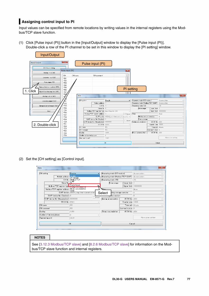
77DL30-G USERS MANUAL EM-8571-G Rev.7
Assigning control input to PI
Input values can be specified from remote locations by writing values in the internal registers using the Mod-bus/TCP slave function.
(1) Click [Pulse input (PI)] button in the [Input/Output] window to display the [Pulse input (PI)]. Double-click a row of the PI channel to be set in this window to display the [PI setting] window.
(2) Set the [CH setting] as [Control input].
NOTES
See [3.12.3 Modbus/TCP slave] and [8.2.6 Modbus/TCP slave] for information on the Mod-bus/TCP slave function and internal registers.
Input/Output
Pulse input (PI)
1. ClickPI setting
2. Double-click
Select
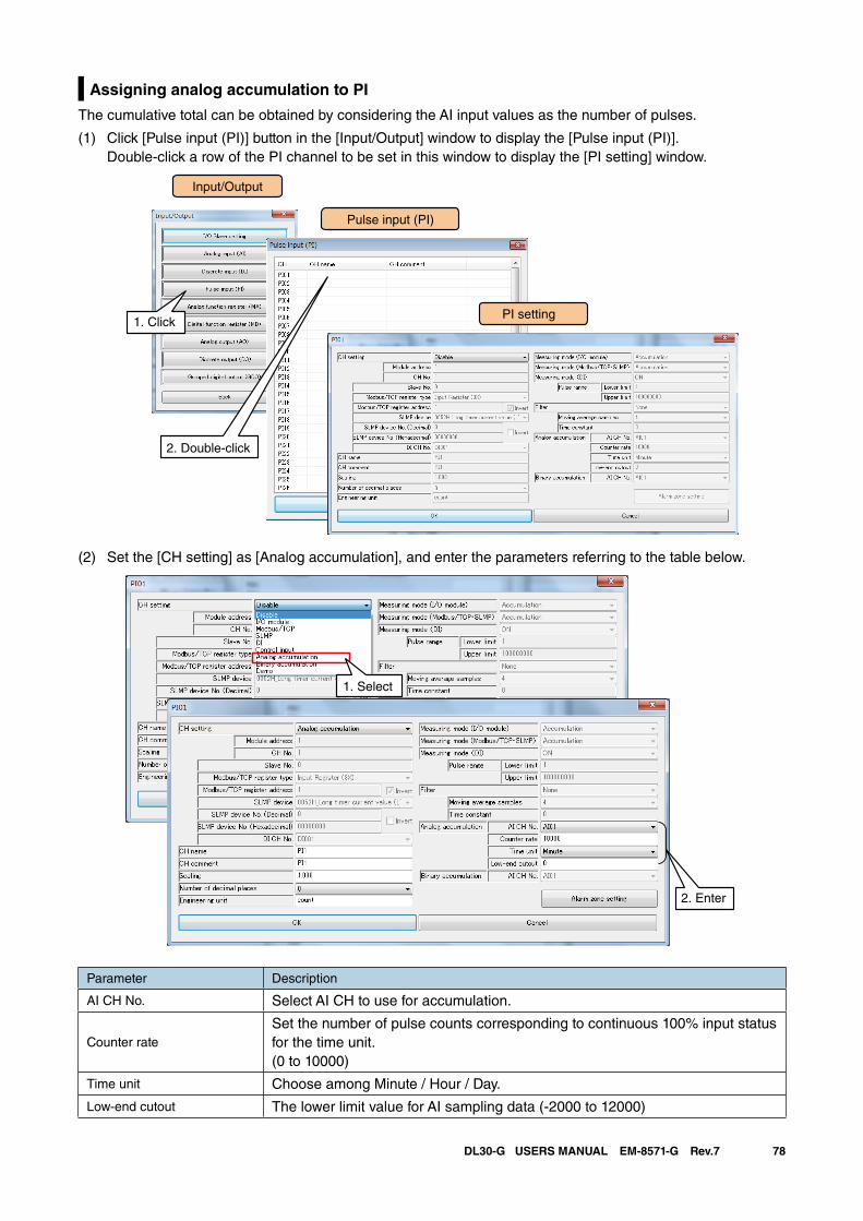
78DL30-G USERS MANUAL EM-8571-G Rev.7
Assigning analog accumulation to PI
The cumulative total can be obtained by considering the AI input values as the number of pulses.
(1) Click [Pulse input (PI)] button in the [Input/Output] window to display the [Pulse input (PI)]. Double-click a row of the PI channel to be set in this window to display the [PI setting] window.
(2) Set the [CH setting] as [Analog accumulation], and enter the parameters referring to the table below.
1. Select
2. Enter
Parameter Description
AI CH No. Select AI CH to use for accumulation.
Counter rateSet the number of pulse counts corresponding to continuous 100% input status for the time unit. (0 to 10000)
Time unit Choose among Minute / Hour / Day.
Low-end cutout The lower limit value for AI sampling data (-2000 to 12000)
Input/Output
Pulse input (PI)
1. ClickPI setting
2. Double-click
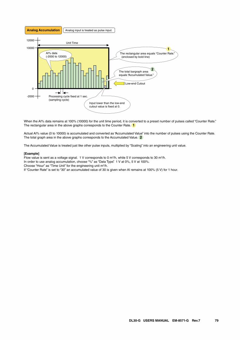
79DL30-G USERS MANUAL EM-8571-G Rev.7
0
-2000
12000
10000
Analog Accumulation Analog input is treated as pulse input.
Processing cycle fixed at 1 sec.(sampling cycle)
Unit Time
AI% data(-2000 to 12000)
The rectangular area equals “Counter Rate.” (enclosed by bold line)
The total bargraph area equals “Accumulated Value.”
Low-end Cutout
Input lower than the low-end cutout value is fixed at 0.
1
2
When the AI% data remains at 100% (10000) for the unit time period, it is converted to a preset number of pulses called “Counter Rate.”The rectangular area in the above graphs corresponds to the Counter Rate.
Actual AI% value (0 to 10000) is accumulated and converted as “Accumulated Value” into the number of pulses using the Counter Rate.The total graph area in the above graphs corresponds to the Accumulated Value.
The Accumulated Value is treated just like other pulse inputs, multiplied by “Scaling” into an engineering unit value.
[Example]Flow value is sent as a voltage signal. 1 V corresponds to 0 m3/h, while 5 V corresponds to 30 m3/h.In order to use analog accumulation, choose “%” as “Data Type”. 1 V at 0%, 5 V at 100%.Choose “Hour” as “Time Unit” for the engineering unit m3/h.If “Counter Rate” is set to “30” an accumulated value of 30 is given when AI remains at 100% (5 V) for 1 hour.
1
2
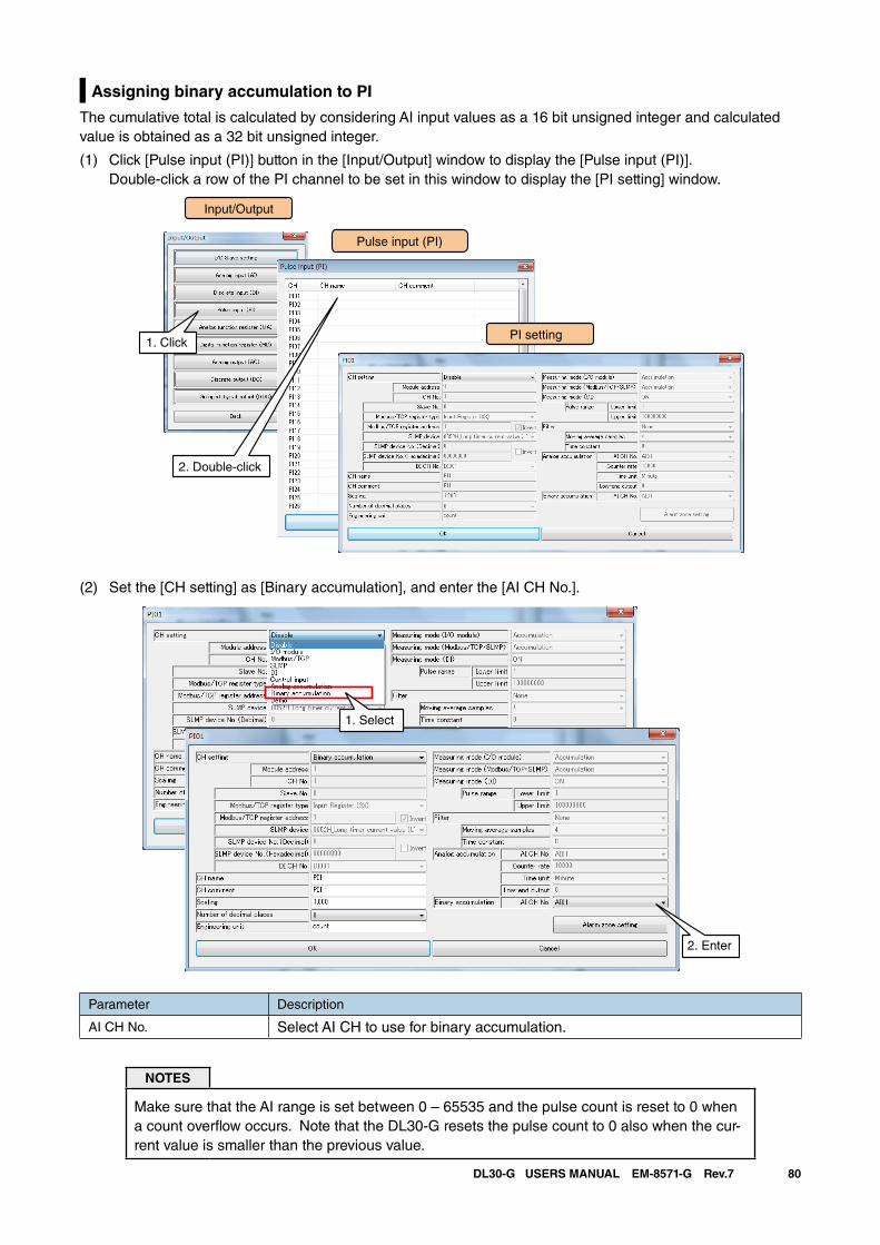
80DL30-G USERS MANUAL EM-8571-G Rev.7
Assigning binary accumulation to PI
The cumulative total is calculated by considering AI input values as a 16 bit unsigned integer and calculated value is obtained as a 32 bit unsigned integer.
(1) Click [Pulse input (PI)] button in the [Input/Output] window to display the [Pulse input (PI)]. Double-click a row of the PI channel to be set in this window to display the [PI setting] window.
(2) Set the [CH setting] as [Binary accumulation], and enter the [AI CH No.].
1. Select
2. Enter
Parameter Description
AI CH No. Select AI CH to use for binary accumulation.
NOTES
Make sure that the AI range is set between 0 – 65535 and the pulse count is reset to 0 when a count overflow occurs. Note that the DL30-G resets the pulse count to 0 also when the cur-rent value is smaller than the previous value.
Input/Output
Pulse input (PI)
1. ClickPI setting
2. Double-click
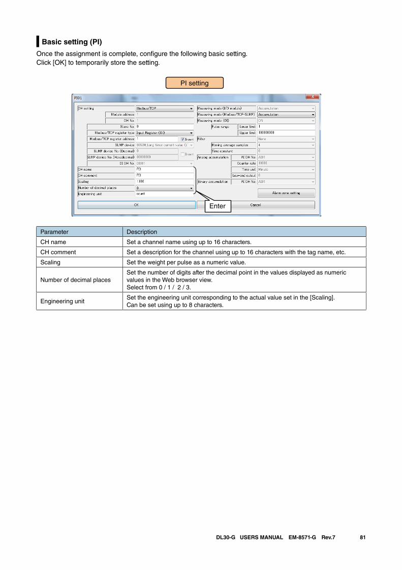
81DL30-G USERS MANUAL EM-8571-G Rev.7
Basic setting (PI)
Once the assignment is complete, configure the following basic setting. Click [OK] to temporarily store the setting.
Parameter Description
CH name Set a channel name using up to 16 characters.
CH comment Set a description for the channel using up to 16 characters with the tag name, etc.
Scaling Set the weight per pulse as a numeric value.
Number of decimal placesSet the number of digits after the decimal point in the values displayed as numeric values in the Web browser view.Select from 0 / 1 / 2 / 3.
Engineering unitSet the engineering unit corresponding to the actual value set in the [Scaling].Can be set using up to 8 characters.
Enter
PI setting
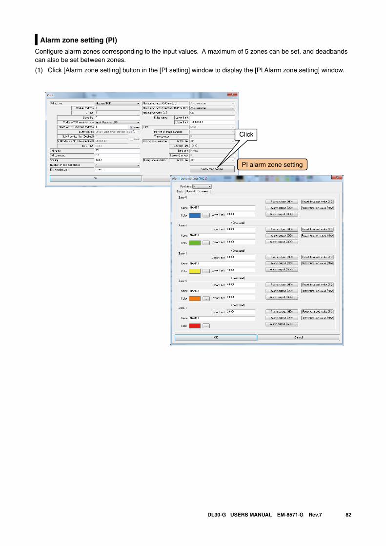
82DL30-G USERS MANUAL EM-8571-G Rev.7
Alarm zone setting (PI)
Configure alarm zones corresponding to the input values. A maximum of 5 zones can be set, and deadbands can also be set between zones.
(1) Click [Alarm zone setting] button in the [PI setting] window to display the [PI Alarm zone setting] window.
PI alarm zone setting
Click
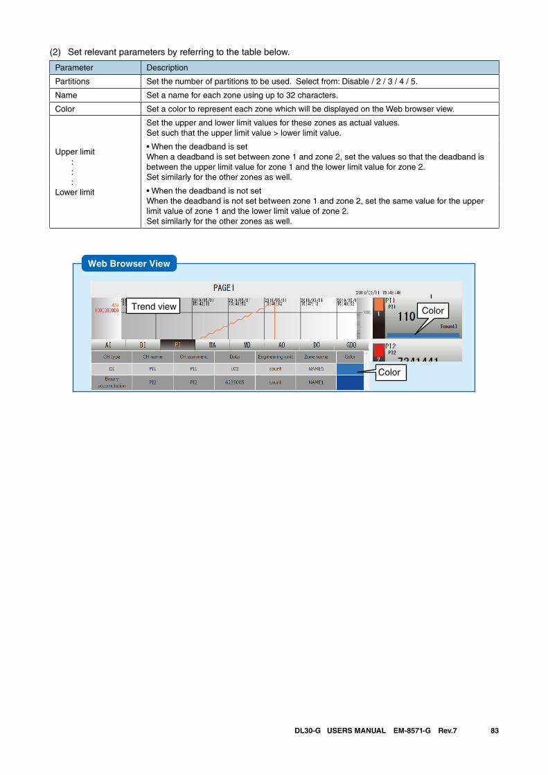
83DL30-G USERS MANUAL EM-8571-G Rev.7
(2) Set relevant parameters by referring to the table below.
Parameter Description
Partitions Set the number of partitions to be used. Select from: Disable / 2 / 3 / 4 / 5.
Name Set a name for each zone using up to 32 characters.
Color Set a color to represent each zone which will be displayed on the Web browser view.
Upper limit : : :Lower limit
Set the upper and lower limit values for these zones as actual values. Set such that the upper limit value > lower limit value.
• When the deadband is set When a deadband is set between zone 1 and zone 2, set the values so that the deadband is between the upper limit value for zone 1 and the lower limit value for zone 2. Set similarly for the other zones as well.
• When the deadband is not setWhen the deadband is not set between zone 1 and zone 2, set the same value for the upper limit value of zone 1 and the lower limit value of zone 2. Set similarly for the other zones as well.
Web Browser View
ColorTrend view
Data view
Color
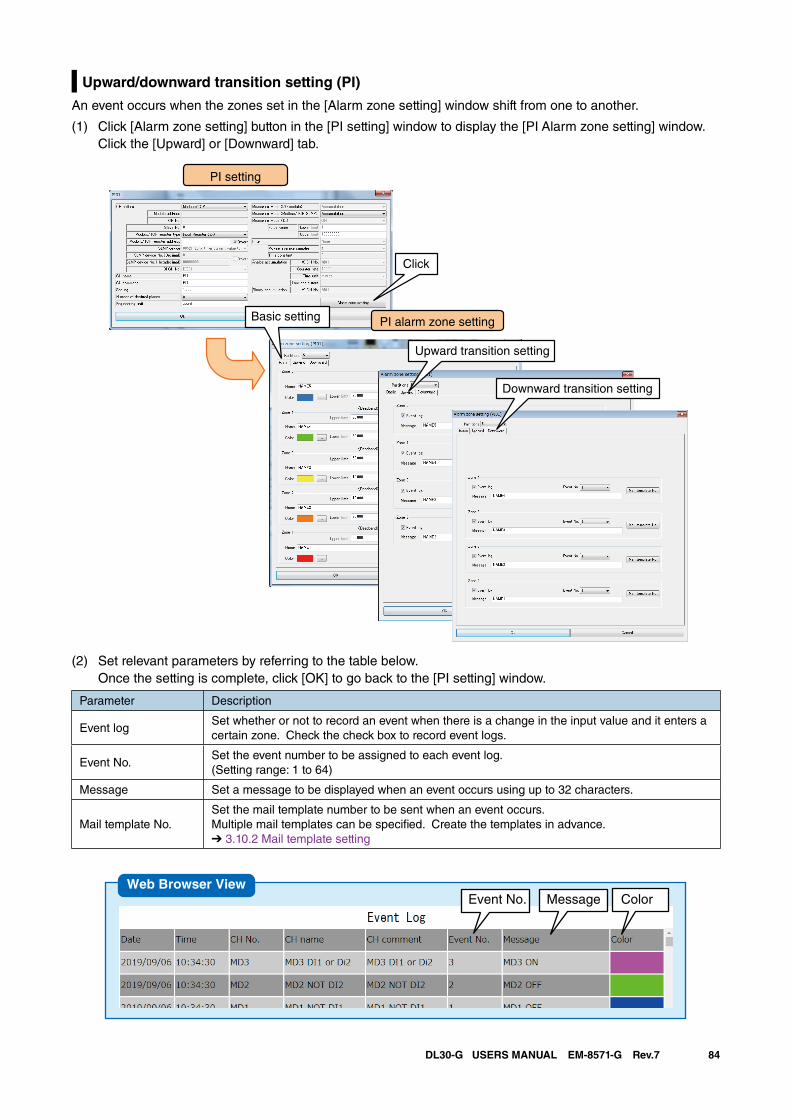
84DL30-G USERS MANUAL EM-8571-G Rev.7
Upward/downward transition setting (PI)
An event occurs when the zones set in the [Alarm zone setting] window shift from one to another.
(1) Click [Alarm zone setting] button in the [PI setting] window to display the [PI Alarm zone setting] window. Click the [Upward] or [Downward] tab.
PI setting
PI alarm zone settingBasic setting
Upward transition setting
Downward transition setting
Click
(2) Set relevant parameters by referring to the table below. Once the setting is complete, click [OK] to go back to the [PI setting] window.
Parameter Description
Event logSet whether or not to record an event when there is a change in the input value and it enters a certain zone. Check the check box to record event logs.
Event No.Set the event number to be assigned to each event log.(Setting range: 1 to 64)
Message Set a message to be displayed when an event occurs using up to 32 characters.
Mail template No.Set the mail template number to be sent when an event occurs. Multiple mail templates can be specified. Create the templates in advance.➔ 3.10.2 Mail template setting
Event No. Message ColorWeb Browser View
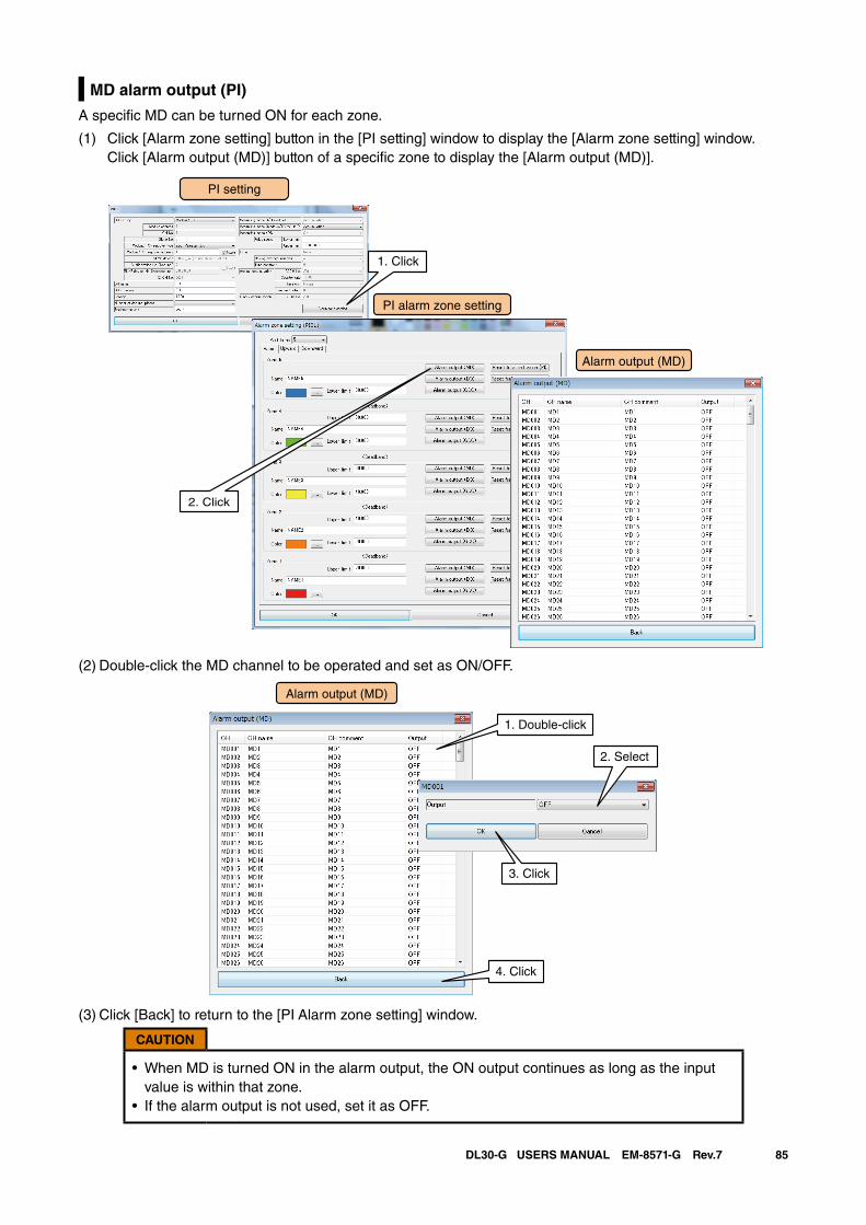
85DL30-G USERS MANUAL EM-8571-G Rev.7
MD alarm output (PI)
A specific MD can be turned ON for each zone.
(1) Click [Alarm zone setting] button in the [PI setting] window to display the [Alarm zone setting] window. Click [Alarm output (MD)] button of a specific zone to display the [Alarm output (MD)].
PI setting
PI alarm zone setting
1. Click
Alarm output (MD)
2. Click
(2) Double-click the MD channel to be operated and set as ON/OFF.
Alarm output (MD)
1. Double-click
2. Select
4. Click
3. Click
(3) Click [Back] to return to the [PI Alarm zone setting] window.
CAUTION
• When MD is turned ON in the alarm output, the ON output continues as long as the input value is within that zone.
• If the alarm output is not used, set it as OFF.
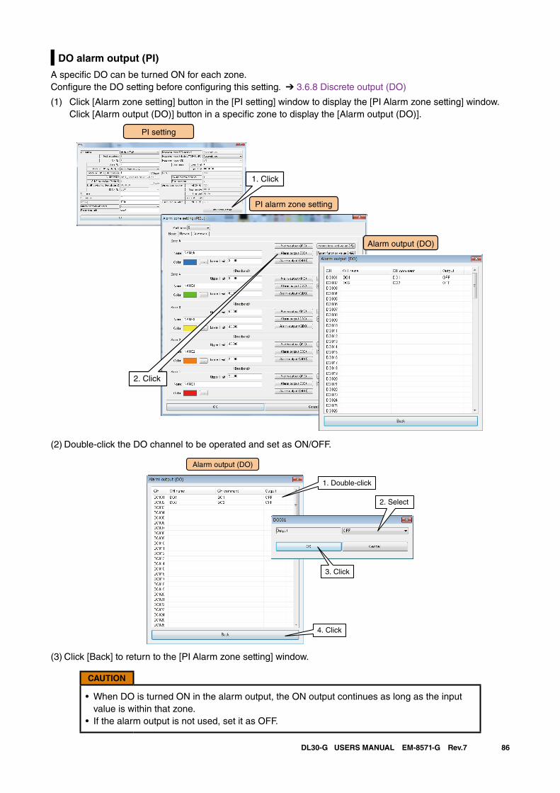
86DL30-G USERS MANUAL EM-8571-G Rev.7
DO alarm output (PI)
A specific DO can be turned ON for each zone.Configure the DO setting before configuring this setting. ➔ 3.6.8 Discrete output (DO)
(1) Click [Alarm zone setting] button in the [PI setting] window to display the [PI Alarm zone setting] window. Click [Alarm output (DO)] button in a specific zone to display the [Alarm output (DO)].
PI setting
PI alarm zone setting
1. Click
Alarm output (DO)
2. Click
(2) Double-click the DO channel to be operated and set as ON/OFF.
Alarm output (DO)
1. Double-click
2. Select
4. Click
3. Click
(3) Click [Back] to return to the [PI Alarm zone setting] window.
CAUTION
• When DO is turned ON in the alarm output, the ON output continues as long as the input value is within that zone.
• If the alarm output is not used, set it as OFF.
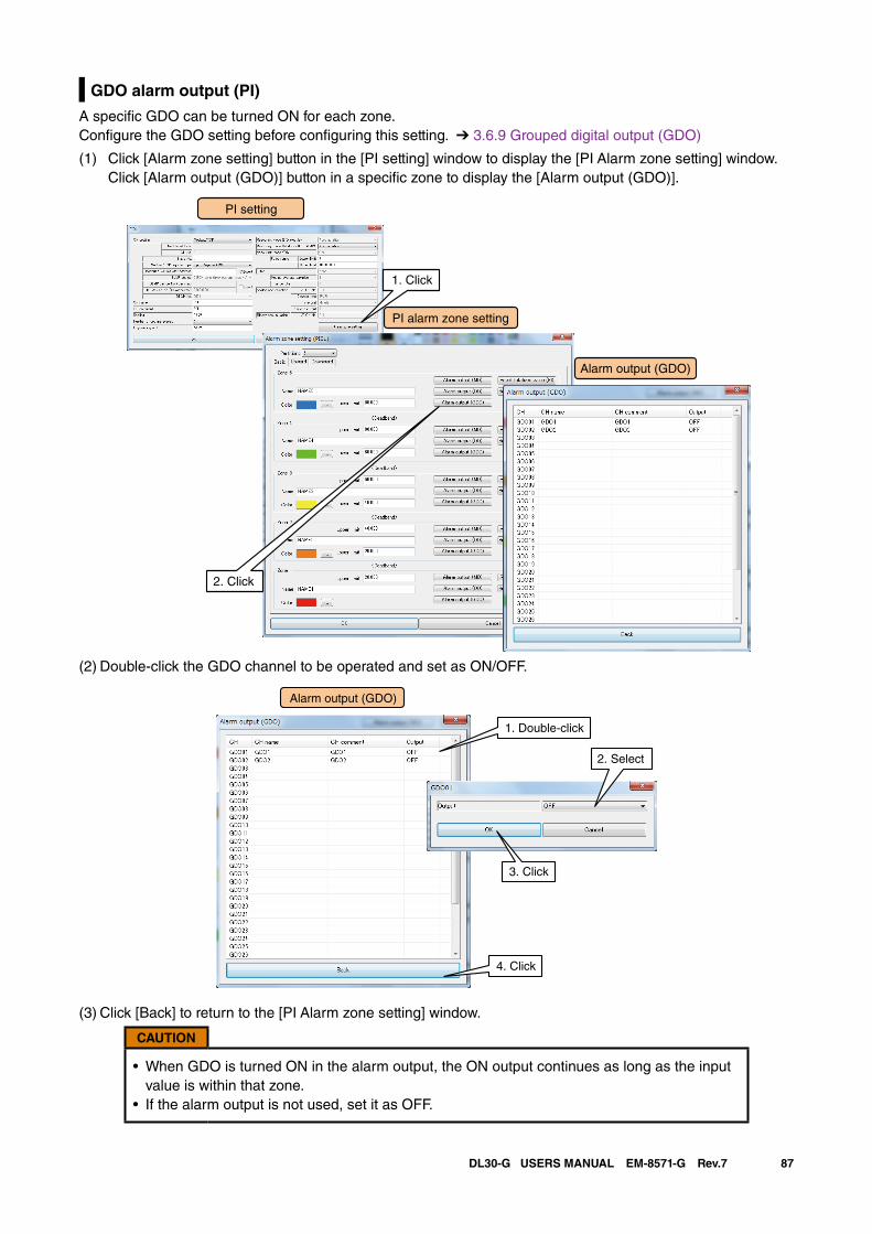
87DL30-G USERS MANUAL EM-8571-G Rev.7
GDO alarm output (PI)
A specific GDO can be turned ON for each zone.Configure the GDO setting before configuring this setting. ➔ 3.6.9 Grouped digital output (GDO)
(1) Click [Alarm zone setting] button in the [PI setting] window to display the [PI Alarm zone setting] window. Click [Alarm output (GDO)] button in a specific zone to display the [Alarm output (GDO)].
PI setting
PI alarm zone setting
1. Click
Alarm output (GDO)
2. Click
(2) Double-click the GDO channel to be operated and set as ON/OFF.
Alarm output (GDO)
1. Double-click
2. Select
4. Click
3. Click
(3) Click [Back] to return to the [PI Alarm zone setting] window.
CAUTION
• When GDO is turned ON in the alarm output, the ON output continues as long as the input value is within that zone.
• If the alarm output is not used, set it as OFF.
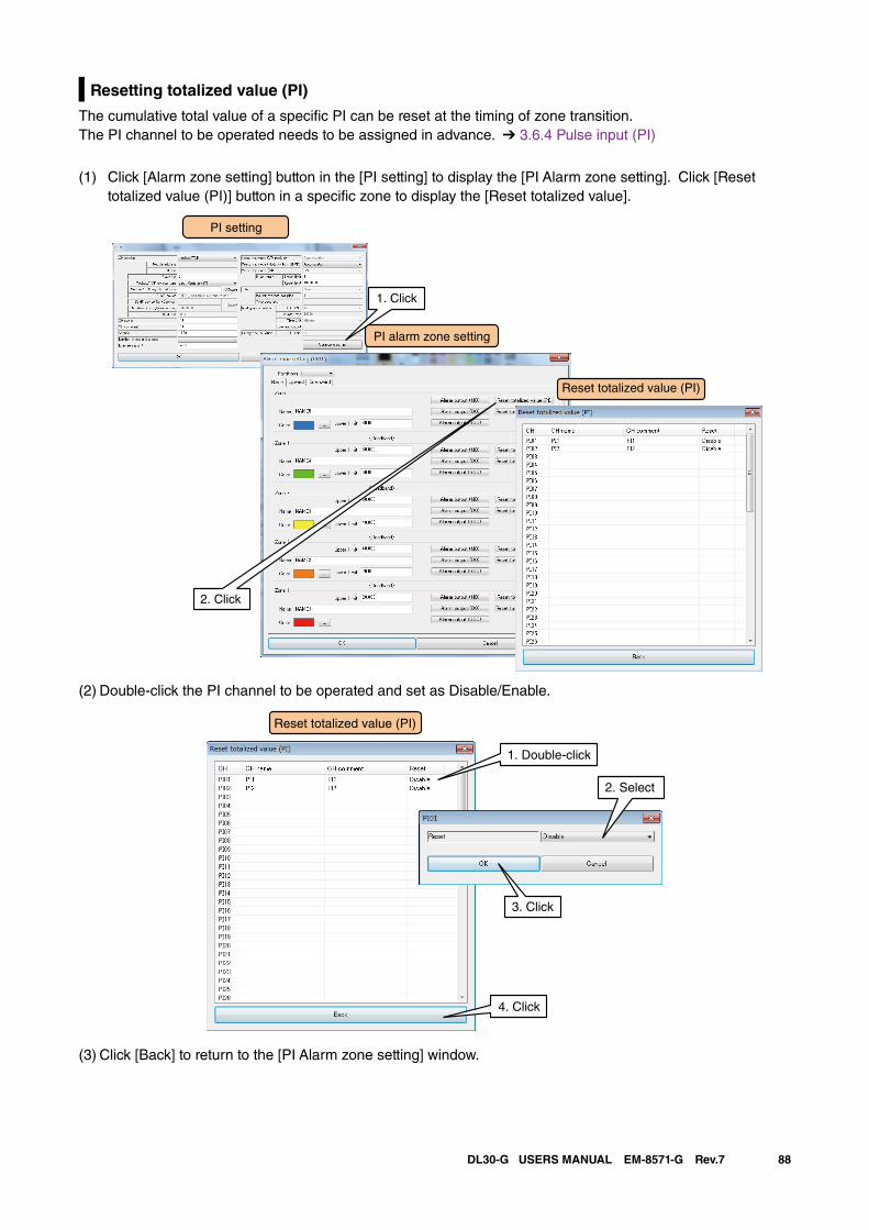
88DL30-G USERS MANUAL EM-8571-G Rev.7
Resetting totalized value (PI)
The cumulative total value of a specific PI can be reset at the timing of zone transition.The PI channel to be operated needs to be assigned in advance. ➔ 3.6.4 Pulse input (PI)
(1) Click [Alarm zone setting] button in the [PI setting] to display the [PI Alarm zone setting]. Click [Reset totalized value (PI)] button in a specific zone to display the [Reset totalized value].
PI setting
PI alarm zone setting
1. Click
Reset totalized value (PI)
2. Click
(2) Double-click the PI channel to be operated and set as Disable/Enable.
1. Double-click
2. Select
4. Click
3. Click
Reset totalized value (PI)
(3) Click [Back] to return to the [PI Alarm zone setting] window.
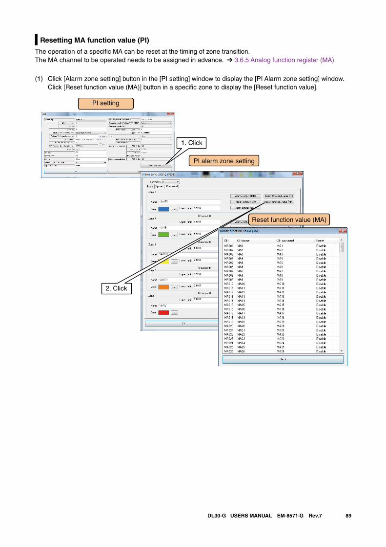
89DL30-G USERS MANUAL EM-8571-G Rev.7
Resetting MA function value (PI)
The operation of a specific MA can be reset at the timing of zone transition.The MA channel to be operated needs to be assigned in advance. ➔ 3.6.5 Analog function register (MA)
(1) Click [Alarm zone setting] button in the [PI setting] window to display the [PI Alarm zone setting] window. Click [Reset function value (MA)] button in a specific zone to display the [Reset function value].
PI setting
PI alarm zone setting
1. Click
2. Click
Reset function value (MA)
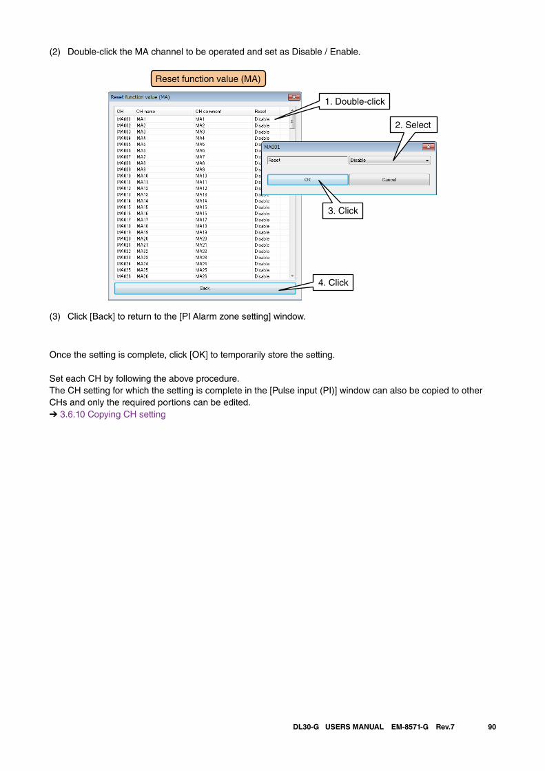
90DL30-G USERS MANUAL EM-8571-G Rev.7
(2) Double-click the MA channel to be operated and set as Disable / Enable.
(3) Click [Back] to return to the [PI Alarm zone setting] window.
Once the setting is complete, click [OK] to temporarily store the setting.
Set each CH by following the above procedure.The CH setting for which the setting is complete in the [Pulse input (PI)] window can also be copied to other CHs and only the required portions can be edited.➔ 3.6.10 Copying CH setting
1. Double-click
2. Select
4. Click
3. Click
Reset function value (MA)
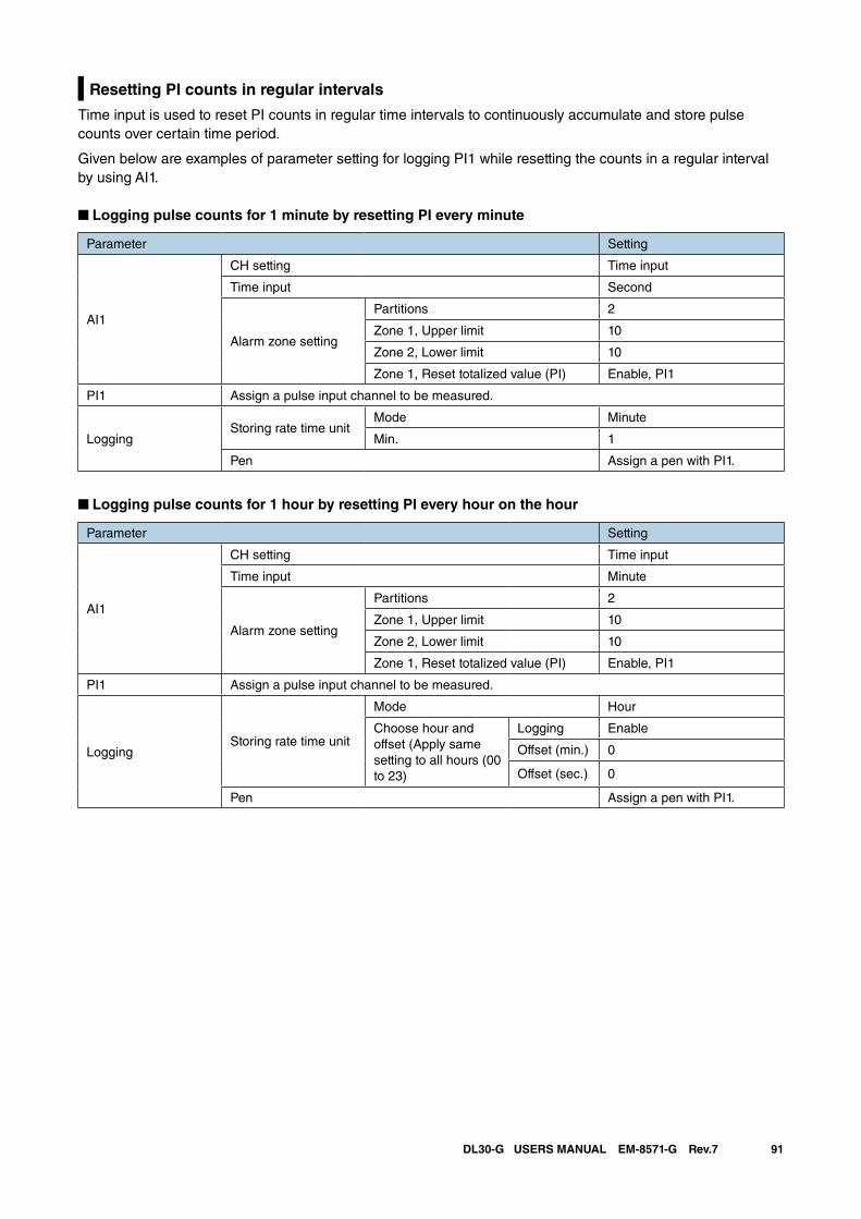
91DL30-G USERS MANUAL EM-8571-G Rev.7
Resetting PI counts in regular intervals
Time input is used to reset PI counts in regular time intervals to continuously accumulate and store pulse counts over certain time period.
Given below are examples of parameter setting for logging PI1 while resetting the counts in a regular interval by using AI1.
■ Logging pulse counts for 1 minute by resetting PI every minute
Parameter Setting
AI1
CH setting Time input
Time input Second
Alarm zone setting
Partitions 2
Zone 1, Upper limit 10
Zone 2, Lower limit 10
Zone 1, Reset totalized value (PI) Enable, PI1
PI1 Assign a pulse input channel to be measured.
LoggingStoring rate time unit
Mode Minute
Min. 1
Pen Assign a pen with PI1.
■ Logging pulse counts for 1 hour by resetting PI every hour on the hour
Parameter Setting
AI1
CH setting Time input
Time input Minute
Alarm zone setting
Partitions 2
Zone 1, Upper limit 10
Zone 2, Lower limit 10
Zone 1, Reset totalized value (PI) Enable, PI1
PI1 Assign a pulse input channel to be measured.
LoggingStoring rate time unit
Mode Hour
Choose hour and offset (Apply same setting to all hours (00 to 23)
Logging Enable
Offset (min.) 0
Offset (sec.) 0
Pen Assign a pen with PI1.
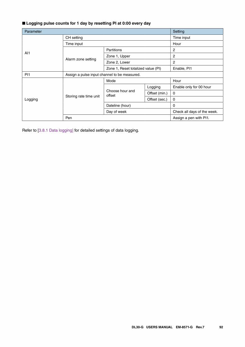
92DL30-G USERS MANUAL EM-8571-G Rev.7
■ Logging pulse counts for 1 day by resetting PI at 0:00 every day
Parameter Setting
AI1
CH setting Time input
Time input Hour
Alarm zone setting
Partitions 2
Zone 1, Upper 2
Zone 2, Lower 2
Zone 1, Reset totalized value (PI) Enable, PI1
PI1 Assign a pulse input channel to be measured.
LoggingStoring rate time unit
Mode Hour
Choose hour and offset
Logging Enable only for 00 hour
Offset (min.) 0
Offset (sec.) 0
Dateline (hour) 0
Day of week Check all days of the week.
Pen Assign a pen with PI1.
Refer to [3.8.1 Data logging] for detailed settings of data logging.
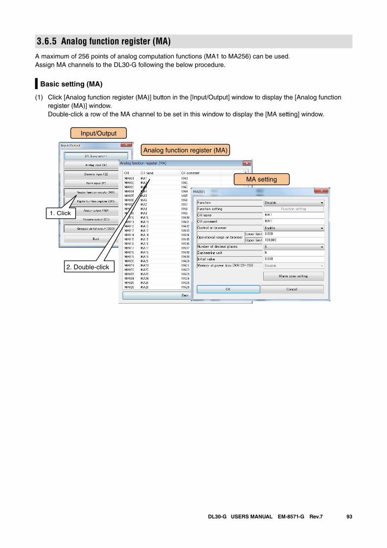
93DL30-G USERS MANUAL EM-8571-G Rev.7
3.6.5 Analog function register (MA)A maximum of 256 points of analog computation functions (MA1 to MA256) can be used.Assign MA channels to the DL30-G following the below procedure.
Basic setting (MA)
(1) Click [Analog function register (MA)] button in the [Input/Output] window to display the [Analog function register (MA)] window. Double-click a row of the MA channel to be set in this window to display the [MA setting] window.
Input/Output
Analog function register (MA)
1. Click
2. Double-click
MA setting
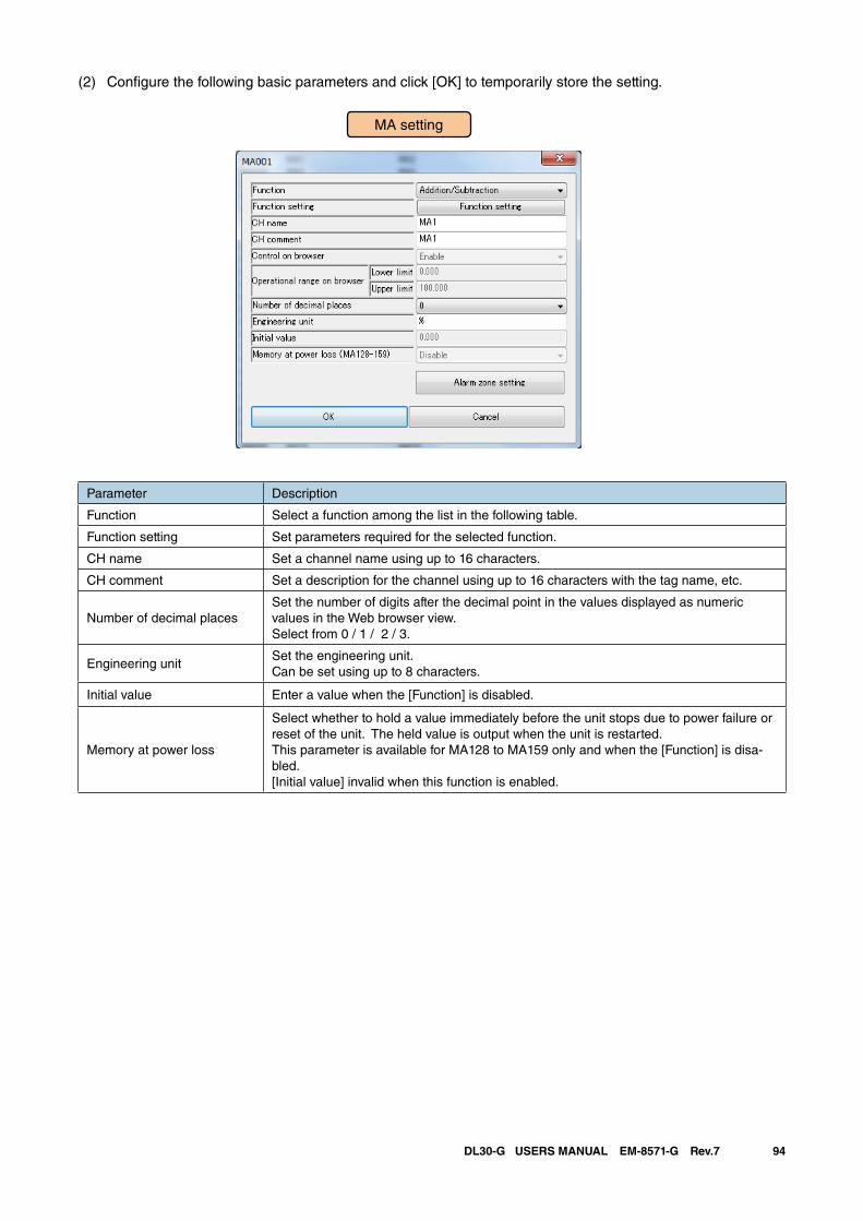
94DL30-G USERS MANUAL EM-8571-G Rev.7
(2) Configure the following basic parameters and click [OK] to temporarily store the setting.
Parameter Description
Function Select a function among the list in the following table.
Function setting Set parameters required for the selected function.
CH name Set a channel name using up to 16 characters.
CH comment Set a description for the channel using up to 16 characters with the tag name, etc.
Number of decimal placesSet the number of digits after the decimal point in the values displayed as numeric values in the Web browser view.Select from 0 / 1 / 2 / 3.
Engineering unitSet the engineering unit.Can be set using up to 8 characters.
Initial value Enter a value when the [Function] is disabled.
Memory at power loss
Select whether to hold a value immediately before the unit stops due to power failure or reset of the unit. The held value is output when the unit is restarted.This parameter is available for MA128 to MA159 only and when the [Function] is disa-bled. [Initial value] invalid when this function is enabled.
MA setting
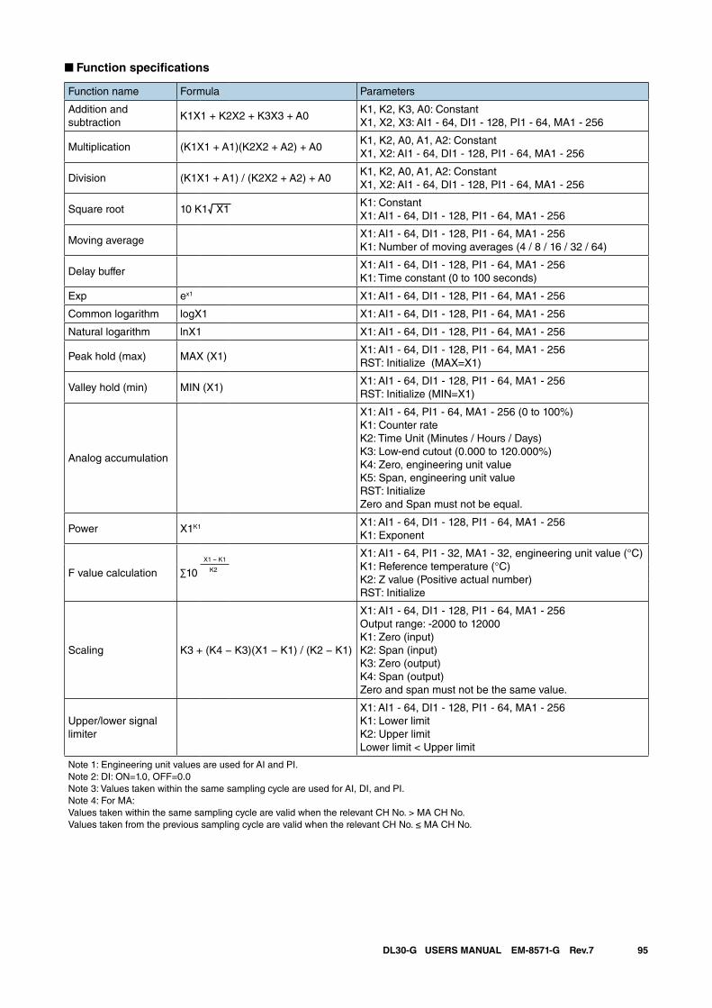
95DL30-G USERS MANUAL EM-8571-G Rev.7
■ Function specifications
Function name Formula Parameters
Addition and subtraction
K1X1 + K2X2 + K3X3 + A0K1, K2, K3, A0: ConstantX1, X2, X3: AI1 - 64, DI1 - 128, PI1 - 64, MA1 - 256
Multiplication (K1X1 + A1)(K2X2 + A2) + A0K1, K2, A0, A1, A2: ConstantX1, X2: AI1 - 64, DI1 - 128, PI1 - 64, MA1 - 256
Division (K1X1 + A1) / (K2X2 + A2) + A0K1, K2, A0, A1, A2: ConstantX1, X2: AI1 - 64, DI1 - 128, PI1 - 64, MA1 - 256
Square root 10 K1√ X1 K1: ConstantX1: AI1 - 64, DI1 - 128, PI1 - 64, MA1 - 256
Moving averageX1: AI1 - 64, DI1 - 128, PI1 - 64, MA1 - 256K1: Number of moving averages (4 / 8 / 16 / 32 / 64)
Delay bufferX1: AI1 - 64, DI1 - 128, PI1 - 64, MA1 - 256K1: Time constant (0 to 100 seconds)
Exp ex1 X1: AI1 - 64, DI1 - 128, PI1 - 64, MA1 - 256
Common logarithm logX1 X1: AI1 - 64, DI1 - 128, PI1 - 64, MA1 - 256
Natural logarithm lnX1 X1: AI1 - 64, DI1 - 128, PI1 - 64, MA1 - 256
Peak hold (max) MAX (X1)X1: AI1 - 64, DI1 - 128, PI1 - 64, MA1 - 256RST: Initialize (MAX=X1)
Valley hold (min) MIN (X1)X1: AI1 - 64, DI1 - 128, PI1 - 64, MA1 - 256RST: Initialize (MIN=X1)
Analog accumulation
X1: AI1 - 64, PI1 - 64, MA1 - 256 (0 to 100%)K1: Counter rateK2: Time Unit (Minutes / Hours / Days)K3: Low-end cutout (0.000 to 120.000%)K4: Zero, engineering unit valueK5: Span, engineering unit valueRST: InitializeZero and Span must not be equal.
Power X1K1 X1: AI1 - 64, DI1 - 128, PI1 - 64, MA1 - 256K1: Exponent
F value calculation ∑10X1 − K1
X1: AI1 - 64, PI1 - 32, MA1 - 32, engineering unit value (°C)K1: Reference temperature (°C)K2: Z value (Positive actual number)RST: Initialize
K2
Scaling K3 + (K4 − K3)(X1 − K1) / (K2 − K1)
X1: AI1 - 64, DI1 - 128, PI1 - 64, MA1 - 256Output range: -2000 to 12000K1: Zero (input)K2: Span (input)K3: Zero (output)K4: Span (output)Zero and span must not be the same value.
Upper/lower signal limiter
X1: AI1 - 64, DI1 - 128, PI1 - 64, MA1 - 256K1: Lower limitK2: Upper limitLower limit < Upper limit
Note 1: Engineering unit values are used for AI and PI.Note 2: DI: ON=1.0, OFF=0.0Note 3: Values taken within the same sampling cycle are used for AI, DI, and PI.Note 4: For MA:Values taken within the same sampling cycle are valid when the relevant CH No. > MA CH No.Values taken from the previous sampling cycle are valid when the relevant CH No. ≤ MA CH No.
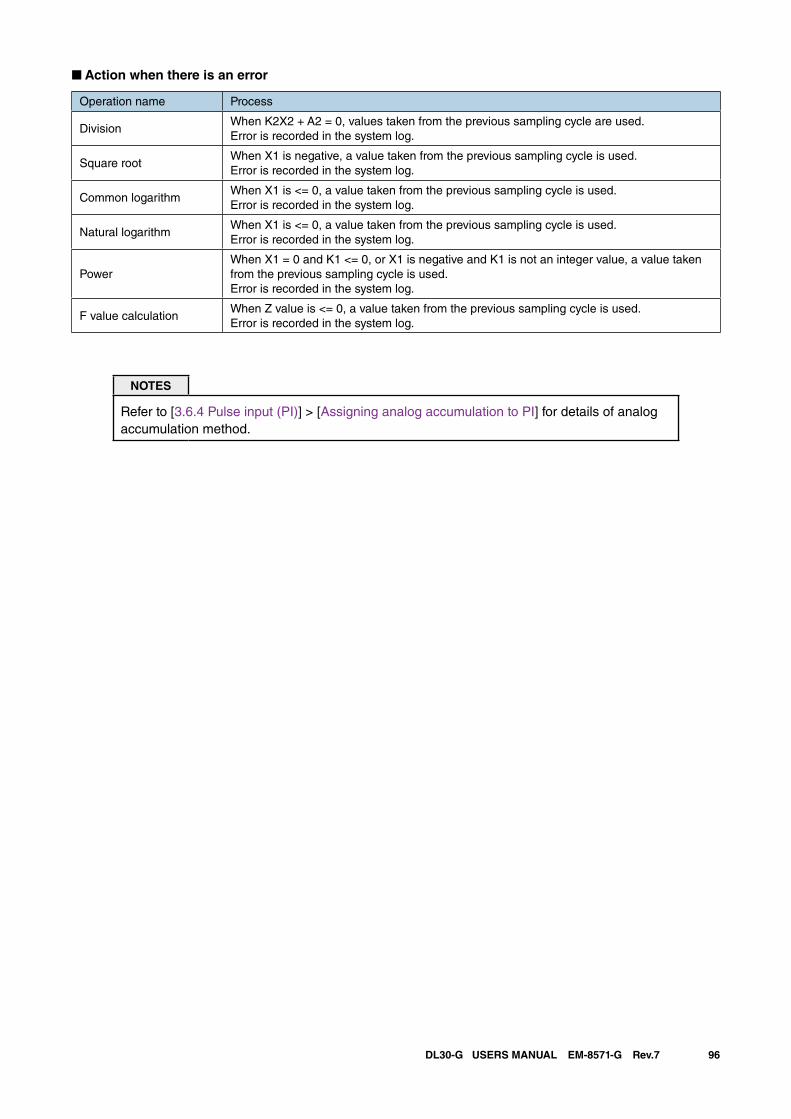
96DL30-G USERS MANUAL EM-8571-G Rev.7
■ Action when there is an error
Operation name Process
DivisionWhen K2X2 + A2 = 0, values taken from the previous sampling cycle are used.Error is recorded in the system log.
Square rootWhen X1 is negative, a value taken from the previous sampling cycle is used.Error is recorded in the system log.
Common logarithmWhen X1 is <= 0, a value taken from the previous sampling cycle is used.Error is recorded in the system log.
Natural logarithmWhen X1 is <= 0, a value taken from the previous sampling cycle is used.Error is recorded in the system log.
PowerWhen X1 = 0 and K1 <= 0, or X1 is negative and K1 is not an integer value, a value taken from the previous sampling cycle is used.Error is recorded in the system log.
F value calculationWhen Z value is <= 0, a value taken from the previous sampling cycle is used.Error is recorded in the system log.
NOTES
Refer to [3.6.4 Pulse input (PI)] > [Assigning analog accumulation to PI] for details of analog accumulation method.
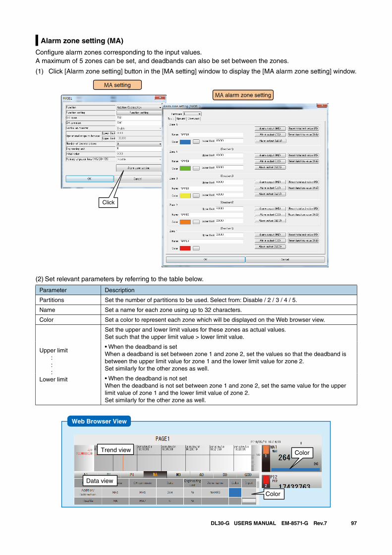
97DL30-G USERS MANUAL EM-8571-G Rev.7
Alarm zone setting (MA)
Configure alarm zones corresponding to the input values. A maximum of 5 zones can be set, and deadbands can also be set between the zones.
(1) Click [Alarm zone setting] button in the [MA setting] window to display the [MA alarm zone setting] window.
MA setting
MA alarm zone setting
Click
(2) Set relevant parameters by referring to the table below.
Parameter Description
Partitions Set the number of partitions to be used. Select from: Disable / 2 / 3 / 4 / 5.
Name Set a name for each zone using up to 32 characters.
Color Set a color to represent each zone which will be displayed on the Web browser view.
Upper limit : : :Lower limit
Set the upper and lower limit values for these zones as actual values. Set such that the upper limit value > lower limit value.
• When the deadband is setWhen a deadband is set between zone 1 and zone 2, set the values so that the deadband is between the upper limit value for zone 1 and the lower limit value for zone 2. Set similarly for the other zones as well.
• When the deadband is not setWhen the deadband is not set between zone 1 and zone 2, set the same value for the upper limit value of zone 1 and the lower limit value of zone 2. Set similarly for the other zone as well.
Web Browser View
ColorTrend view
Data view
Color
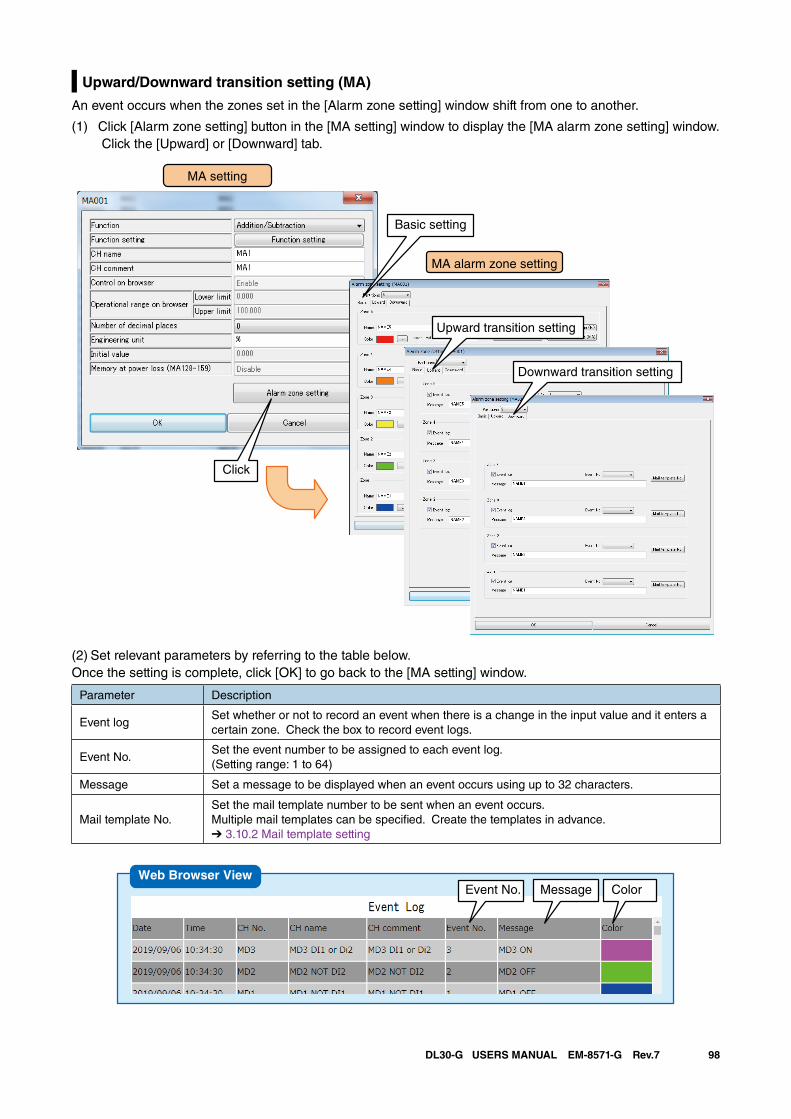
98DL30-G USERS MANUAL EM-8571-G Rev.7
Upward/Downward transition setting (MA)
An event occurs when the zones set in the [Alarm zone setting] window shift from one to another.
(1) Click [Alarm zone setting] button in the [MA setting] window to display the [MA alarm zone setting] window. Click the [Upward] or [Downward] tab.
MA alarm zone setting
Upward transition setting
Downward transition setting
MA setting
Basic setting
Click
(2) Set relevant parameters by referring to the table below. Once the setting is complete, click [OK] to go back to the [MA setting] window.
Parameter Description
Event logSet whether or not to record an event when there is a change in the input value and it enters a certain zone. Check the box to record event logs.
Event No.Set the event number to be assigned to each event log.(Setting range: 1 to 64)
Message Set a message to be displayed when an event occurs using up to 32 characters.
Mail template No.Set the mail template number to be sent when an event occurs. Multiple mail templates can be specified. Create the templates in advance.➔ 3.10.2 Mail template setting
Event No. Message ColorWeb Browser View
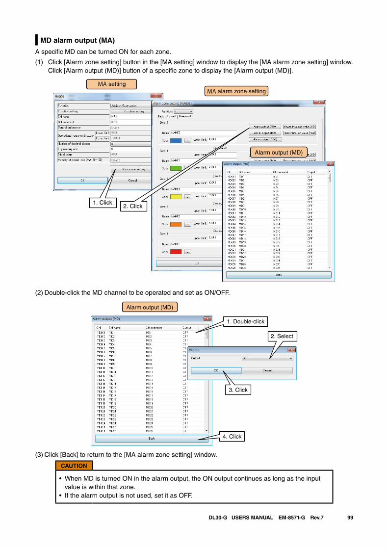
99DL30-G USERS MANUAL EM-8571-G Rev.7
MD alarm output (MA)
A specific MD can be turned ON for each zone.
(1) Click [Alarm zone setting] button in the [MA setting] window to display the [MA alarm zone setting] window.Click [Alarm output (MD)] button of a specific zone to display the [Alarm output (MD)].
MA settingMA alarm zone setting
1. Click2. Click
Alarm output (MD)
(2) Double-click the MD channel to be operated and set as ON/OFF.
Alarm output (MD)
1. Double-click
2. Select
4. Click
3. Click
(3) Click [Back] to return to the [MA alarm zone setting] window.
CAUTION
• When MD is turned ON in the alarm output, the ON output continues as long as the input value is within that zone.
• If the alarm output is not used, set it as OFF.
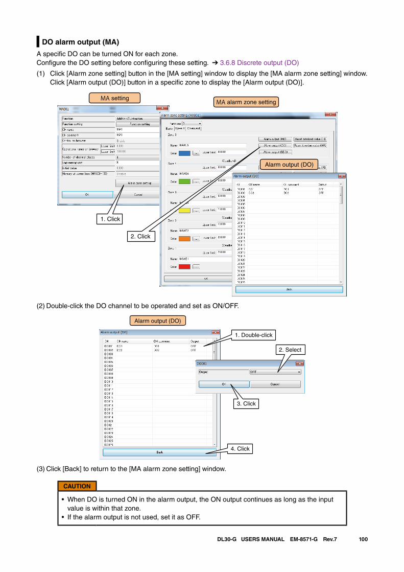
100DL30-G USERS MANUAL EM-8571-G Rev.7
DO alarm output (MA)
A specific DO can be turned ON for each zone.Configure the DO setting before configuring these setting. ➔ 3.6.8 Discrete output (DO)
(1) Click [Alarm zone setting] button in the [MA setting] window to display the [MA alarm zone setting] window.Click [Alarm output (DO)] button in a specific zone to display the [Alarm output (DO)].
MA settingMA alarm zone setting
1. Click
2. Click
Alarm output (DO)
(2) Double-click the DO channel to be operated and set as ON/OFF.
Alarm output (DO)
1. Double-click
2. Select
4. Click
3. Click
(3) Click [Back] to return to the [MA alarm zone setting] window.
CAUTION
• When DO is turned ON in the alarm output, the ON output continues as long as the input value is within that zone.
• If the alarm output is not used, set it as OFF.
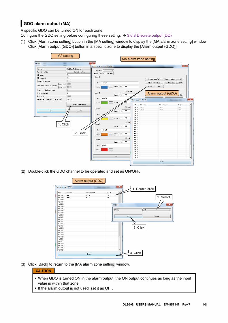
101DL30-G USERS MANUAL EM-8571-G Rev.7
GDO alarm output (MA)
A specific GDO can be turned ON for each zone.Configure the GDO setting before configuring these setting. ➔ 3.6.8 Discrete output (DO)
(1) Click [Alarm zone setting] button in the [MA setting] window to display the [MA alarm zone setting] window.Click [Alarm output (GDO)] button in a specific zone to display the [Alarm output (GDO)].
MA settingMA alarm zone setting
1. Click
2. Click
Alarm output (GDO)
(2) Double-click the GDO channel to be operated and set as ON/OFF.
Alarm output (GDO)
1. Double-click
2. Select
4. Click
3. Click
(3) Click [Back] to return to the [MA alarm zone setting] window.
CAUTION
• When GDO is turned ON in the alarm output, the ON output continues as long as the input value is within that zone.
• If the alarm output is not used, set it as OFF.
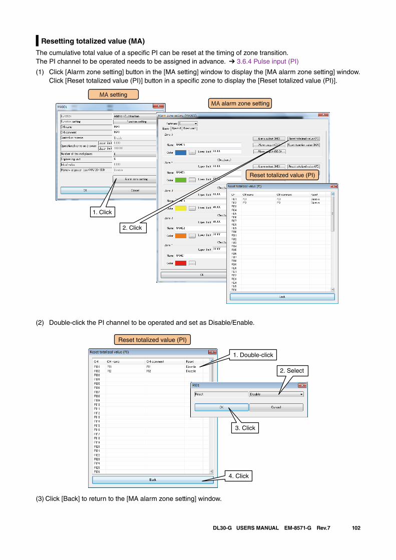
102DL30-G USERS MANUAL EM-8571-G Rev.7
Resetting totalized value (MA)
The cumulative total value of a specific PI can be reset at the timing of zone transition.The PI channel to be operated needs to be assigned in advance. ➔ 3.6.4 Pulse input (PI)
(1) Click [Alarm zone setting] button in the [MA setting] window to display the [MA alarm zone setting] window.Click [Reset totalized value (PI)] button in a specific zone to display the [Reset totalized value (PI)].
MA setting
MA alarm zone setting
1. Click
2. Click
Reset totalized value (PI)
(2) Double-click the PI channel to be operated and set as Disable/Enable.
1. Double-click
2. Select
4. Click
3. Click
Reset totalized value (PI)
(3) Click [Back] to return to the [MA alarm zone setting] window.
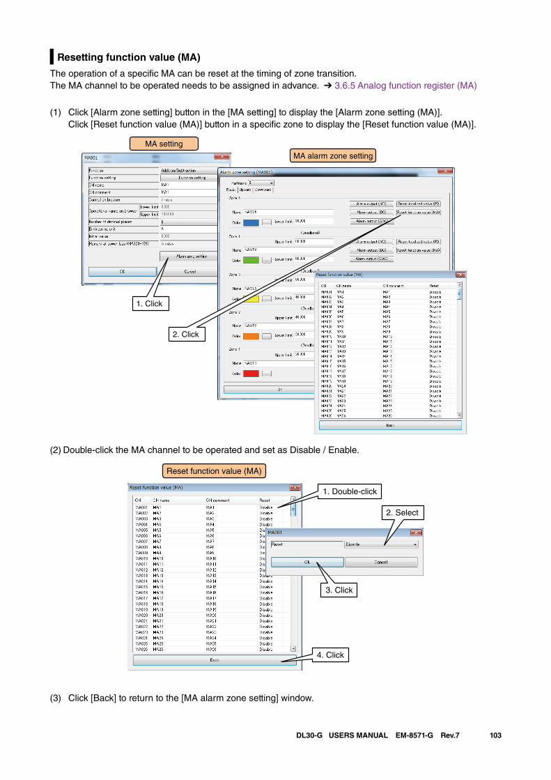
103DL30-G USERS MANUAL EM-8571-G Rev.7
Resetting function value (MA)
The operation of a specific MA can be reset at the timing of zone transition.The MA channel to be operated needs to be assigned in advance. ➔ 3.6.5 Analog function register (MA)
(1) Click [Alarm zone setting] button in the [MA setting] to display the [Alarm zone setting (MA)]. Click [Reset function value (MA)] button in a specific zone to display the [Reset function value (MA)].
MA setting
MA alarm zone setting
1. Click
Reset function value (MA)
2. Click
(2) Double-click the MA channel to be operated and set as Disable / Enable.
1. Double-click
2. Select
4. Click
3. Click
Reset function value (MA)
(3) Click [Back] to return to the [MA alarm zone setting] window.
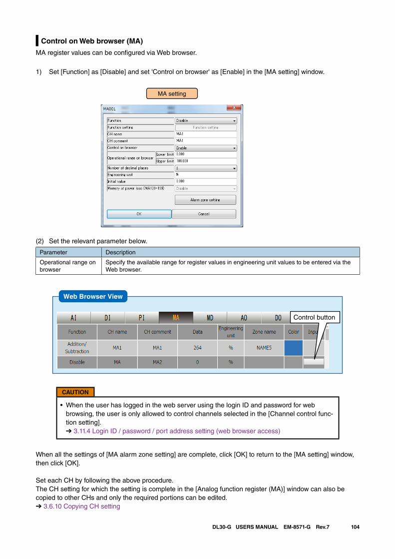
104DL30-G USERS MANUAL EM-8571-G Rev.7
Control on Web browser (MA)
MA register values can be configured via Web browser.
1) Set [Function] as [Disable] and set 'Control on browser' as [Enable] in the [MA setting] window.
MA setting
(2) Set the relevant parameter below.
Parameter Description
Operational range on browser
Specify the available range for register values in engineering unit values to be entered via the Web browser.
Web Browser View
Control button
CAUTION
• When the user has logged in the web server using the login ID and password for web browsing, the user is only allowed to control channels selected in the [Channel control func-tion setting]. ➔ 3.11.4 Login ID / password / port address setting (web browser access)
When all the settings of [MA alarm zone setting] are complete, click [OK] to return to the [MA setting] window, then click [OK].
Set each CH by following the above procedure.The CH setting for which the setting is complete in the [Analog function register (MA)] window can also be copied to other CHs and only the required portions can be edited.➔ 3.6.10 Copying CH setting
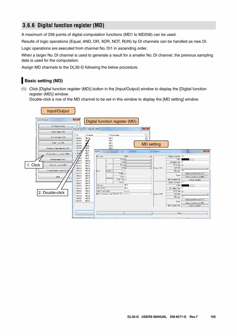
105DL30-G USERS MANUAL EM-8571-G Rev.7
3.6.6 Digital function register (MD)A maximum of 256 points of digital computation functions (MD1 to MD256) can be used.
Results of logic operations (Equal, AND, OR, XOR, NOT, RUN) by DI channels can be handled as new DI.
Logic operations are executed from channel No. DI1 in ascending order.
When a larger No. DI channel is used to generate a result for a smaller No. DI channel, the previous sampling data is used for the computation.
Assign MD channels to the DL30-G following the below procedure.
Basic setting (MD)
(1) Click [Digital function register (MD)] button in the [Input/Output] window to display the [Digital function register (MD)] window. Double-click a row of the MD channel to be set in this window to display the [MD setting] window.
Input/Output
Digital function register (MD)
1. Click
MD setting
2. Double-click
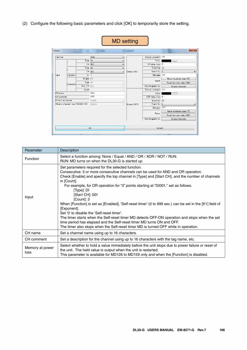
106DL30-G USERS MANUAL EM-8571-G Rev.7
(2) Configure the following basic parameters and click [OK] to temporarily store the setting.
Parameter Description
FunctionSelect a function among: None / Equal / AND / OR / XOR / NOT / RUN.RUN: MD turns on when the DL30-G is started up.
Input
Set parameters required for the selected function.Consecutive: 3 or more consecutive channels can be used for AND and OR operation. Check [Enable] and specify the top channel in [Type] and [Start CH], and the number of channels in [Count]. For example, for OR operation for “3” points starting at “DI001," set as follows. [Type]: DI
[Start CH]: 001 [Count]: 3
When [Function] is set as [Enabled], 'Self-reset timer' (0 to 999 sec.) can be set in the [K1] field of [Exponent].Set '0' to disable the 'Self-reset timer'.The timer starts when the Self-reset timer MD detects OFF-ON operation and stops when the set time period has elapsed and the Self-reset timer MD turns ON and OFF.The timer also stops when the Self-reset timer MD is turned OFF while in operation.
CH name Set a channel name using up to 16 characters.
CH comment Set a description for the channel using up to 16 characters with the tag name, etc.
Memory at power loss
Select whether to hold a value immediately before the unit stops due to power failure or reset of the unit. The held value is output when the unit is restarted.This parameter is available for MD128 to MD159 only and when the [Function] is disabled.
MD setting
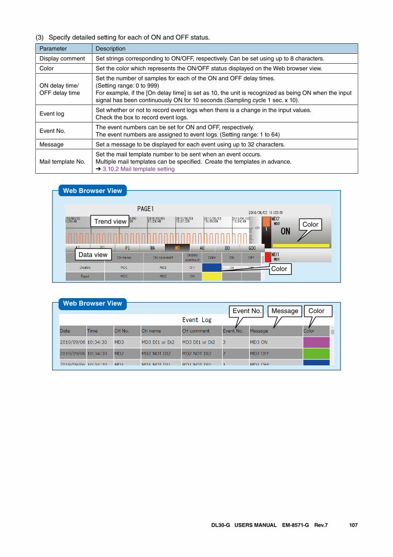
107DL30-G USERS MANUAL EM-8571-G Rev.7
(3) Specify detailed setting for each of ON and OFF status.
Parameter Description
Display comment Set strings corresponding to ON/OFF, respectively. Can be set using up to 8 characters.
Color Set the color which represents the ON/OFF status displayed on the Web browser view.
ON delay time/OFF delay time
Set the number of samples for each of the ON and OFF delay times.(Setting range: 0 to 999)For example, if the [On delay time] is set as 10, the unit is recognized as being ON when the input signal has been continuously ON for 10 seconds (Sampling cycle 1 sec. x 10).
Event logSet whether or not to record event logs when there is a change in the input values. Check the box to record event logs.
Event No.The event numbers can be set for ON and OFF, respectively. The event numbers are assigned to event logs. (Setting range: 1 to 64)
Message Set a message to be displayed for each event using up to 32 characters.
Mail template No.Set the mail template number to be sent when an event occurs. Multiple mail templates can be specified. Create the templates in advance.➔ 3.10.2 Mail template setting
Web Browser View
ColorTrend view
Data view
Color
Event No. Message ColorWeb Browser View
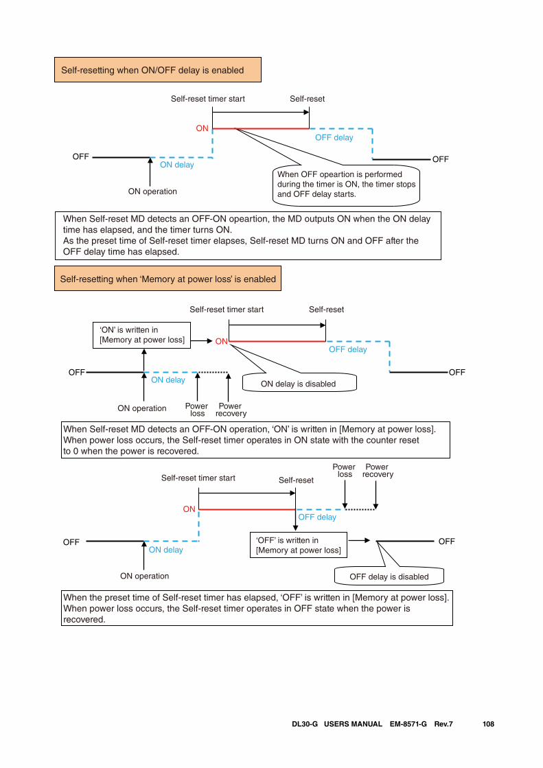
108DL30-G USERS MANUAL EM-8571-G Rev.7
OFF
ON
OFF
OFFOFF
ON
OFFOFF
ON
Self-resetting when ON/OFF delay is enabled
Self-reset timer start Self-reset
OFF delay
ON delay
ON operation
When OFF opeartion is performed during the timer is ON, the timer stops and OFF delay starts.
When Self-reset MD detects an OFF-ON opeartion, the MD outputs ON when the ON delay time has elapsed, and the timer turns ON. As the preset time of Self-reset timer elapses, Self-reset MD turns ON and OFF after the OFF delay time has elapsed.
Self-resetting when ‘Memory at power loss’ is enabled
Self-reset timer start Self-reset
ON delay
OFF delay
ON delay is disabled
‘ON’ is written in [Memory at power loss]
ON operation Power loss
Power recovery
Power recovery
Power loss
Self-reset Self-reset timer start
OFF delay
ON delay‘OFF’ is written in [Memory at power loss]
OFF delay is disabledON operation
When Self-reset MD detects an OFF-ON operation, ‘ON’ is written in [Memory at power loss]. When power loss occurs, the Self-reset timer operates in ON state with the counter reset to 0 when the power is recovered.
When the preset time of Self-reset timer has elapsed, ‘OFF’ is written in [Memory at power loss].When power loss occurs, the Self-reset timer operates in OFF state when the power is recovered.
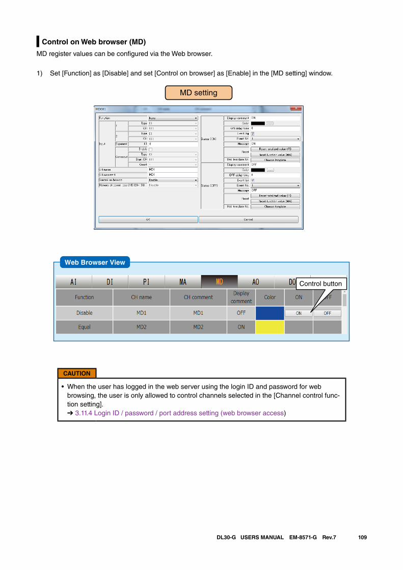
109DL30-G USERS MANUAL EM-8571-G Rev.7
Control on Web browser (MD)
MD register values can be configured via the Web browser.
1) Set [Function] as [Disable] and set [Control on browser] as [Enable] in the [MD setting] window.
MD setting
Web Browser View
Control button
CAUTION
• When the user has logged in the web server using the login ID and password for web browsing, the user is only allowed to control channels selected in the [Channel control func-tion setting]. ➔ 3.11.4 Login ID / password / port address setting (web browser access)
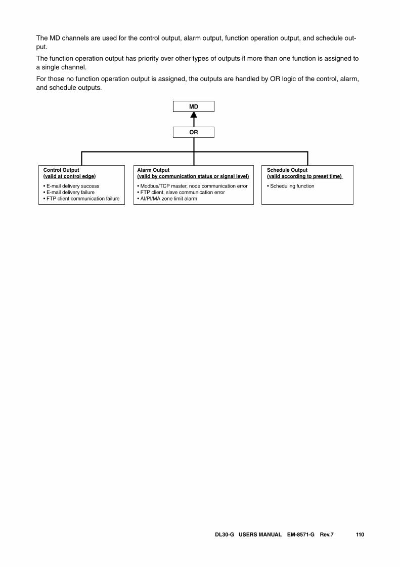
110DL30-G USERS MANUAL EM-8571-G Rev.7
The MD channels are used for the control output, alarm output, function operation output, and schedule out-put.
The function operation output has priority over other types of outputs if more than one function is assigned to a single channel.
For those no function operation output is assigned, the outputs are handled by OR logic of the control, alarm, and schedule outputs.
MD
OR
Control Output(valid at control edge)
• E-mail delivery success• E-mail delivery failure• FTP client communication failure
Schedule Output(valid according to preset time)
• Scheduling function
Alarm Output(valid by communication status or signal level)
• Modbus/TCP master, node communication error • FTP client, slave communication error • AI/PI/MA zone limit alarm
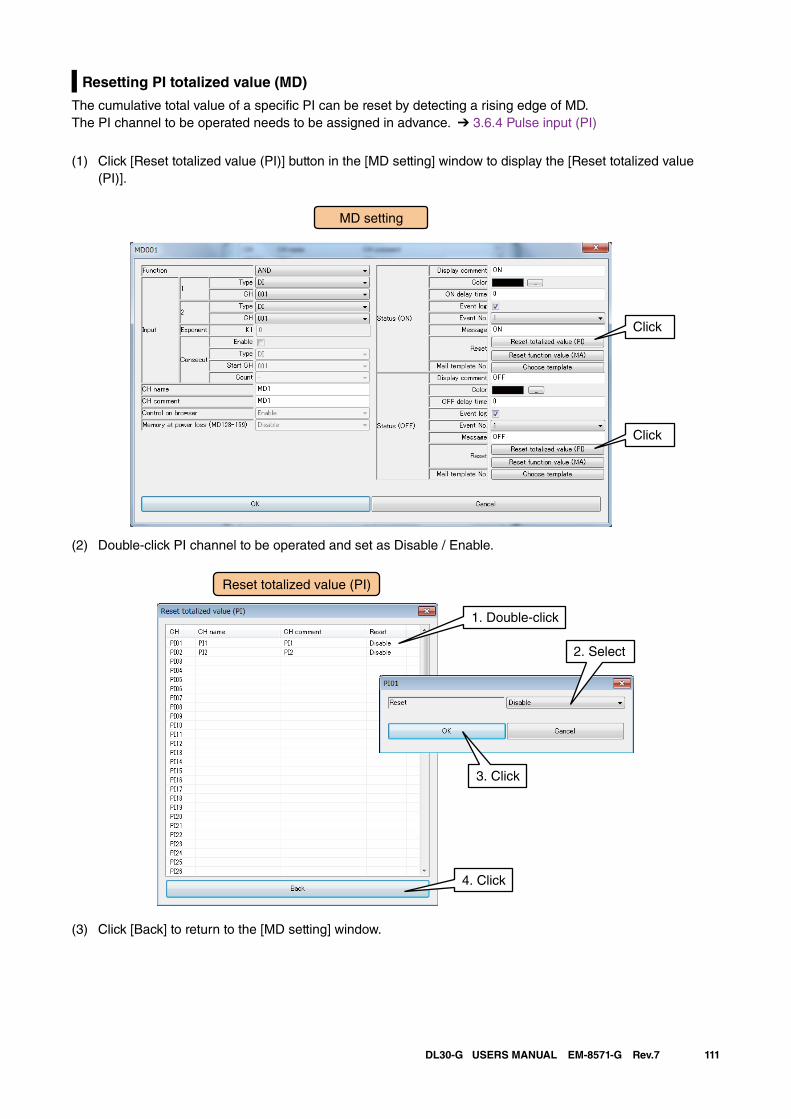
111DL30-G USERS MANUAL EM-8571-G Rev.7
Resetting PI totalized value (MD)
The cumulative total value of a specific PI can be reset by detecting a rising edge of MD.The PI channel to be operated needs to be assigned in advance. ➔ 3.6.4 Pulse input (PI)
(1) Click [Reset totalized value (PI)] button in the [MD setting] window to display the [Reset totalized value (PI)].
(2) Double-click PI channel to be operated and set as Disable / Enable.
(3) Click [Back] to return to the [MD setting] window.
MD setting
Click
Click
1. Double-click
2. Select
4. Click
3. Click
Reset totalized value (PI)
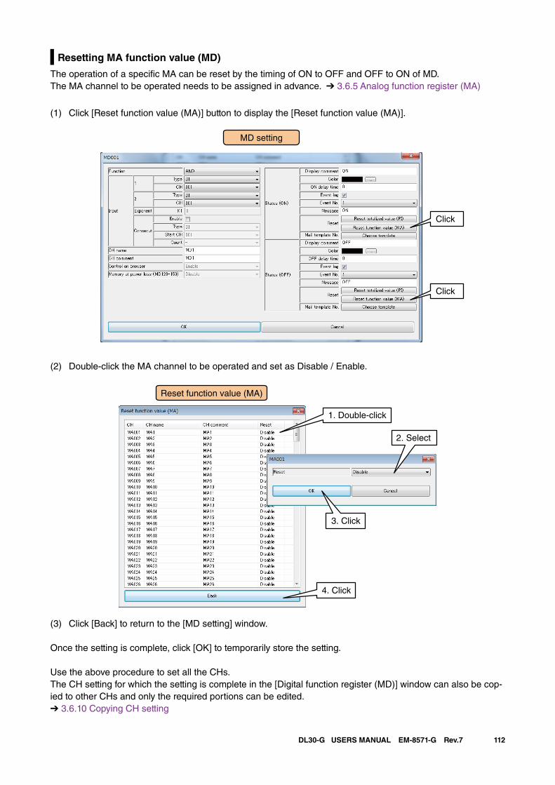
112DL30-G USERS MANUAL EM-8571-G Rev.7
Resetting MA function value (MD)
The operation of a specific MA can be reset by the timing of ON to OFF and OFF to ON of MD.The MA channel to be operated needs to be assigned in advance. ➔ 3.6.5 Analog function register (MA)
(1) Click [Reset function value (MA)] button to display the [Reset function value (MA)].
MD setting
Click
Click
(2) Double-click the MA channel to be operated and set as Disable / Enable.
(3) Click [Back] to return to the [MD setting] window.
Once the setting is complete, click [OK] to temporarily store the setting.
Use the above procedure to set all the CHs.The CH setting for which the setting is complete in the [Digital function register (MD)] window can also be cop-ied to other CHs and only the required portions can be edited.➔ 3.6.10 Copying CH setting
1. Double-click
2. Select
4. Click
3. Click
Reset function value (MA)
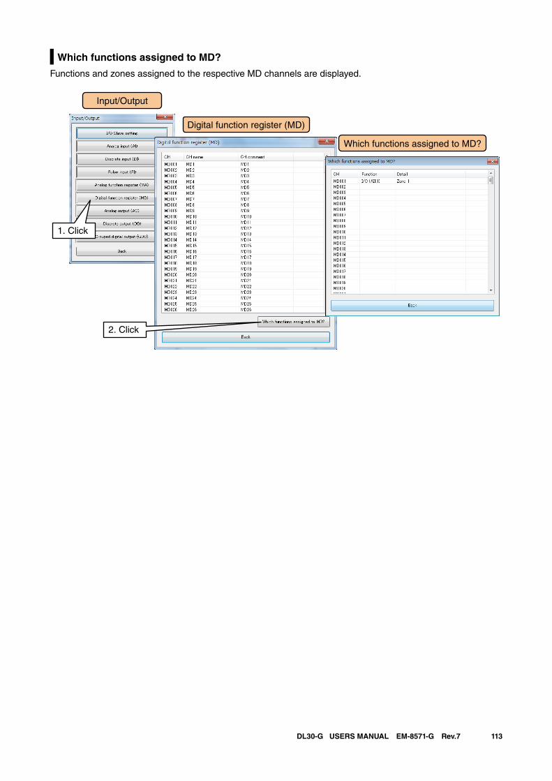
113DL30-G USERS MANUAL EM-8571-G Rev.7
Which functions assigned to MD?
Functions and zones assigned to the respective MD channels are displayed.
Input/Output
Digital function register (MD)
1. Click
Which functions assigned to MD?
2. Click
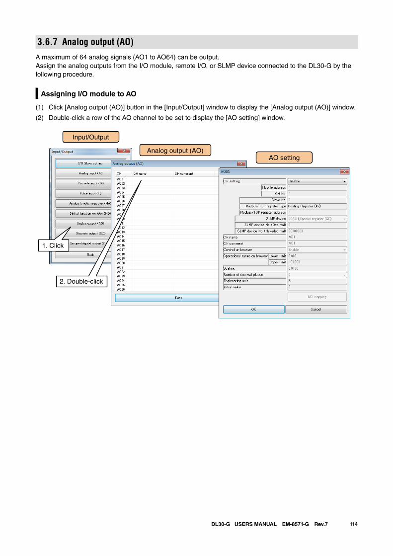
114DL30-G USERS MANUAL EM-8571-G Rev.7
3.6.7 Analog output (AO)A maximum of 64 analog signals (AO1 to AO64) can be output.Assign the analog outputs from the I/O module, remote I/O, or SLMP device connected to the DL30-G by the following procedure.
Assigning I/O module to AO
(1) Click [Analog output (AO)] button in the [Input/Output] window to display the [Analog output (AO)] window.
(2) Double-click a row of the AO channel to be set to display the [AO setting] window.
Input/Output
Analog output (AO)
1. Click
AO setting
2. Double-click
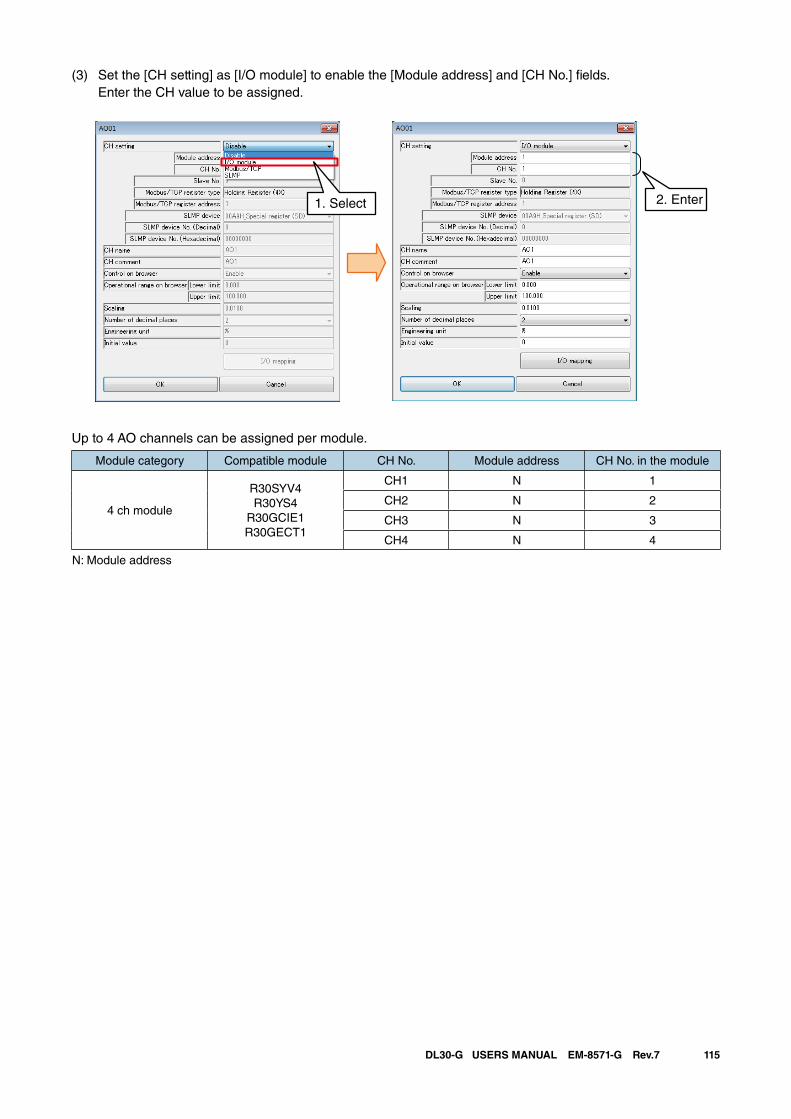
115DL30-G USERS MANUAL EM-8571-G Rev.7
(3) Set the [CH setting] as [I/O module] to enable the [Module address] and [CH No.] fields. Enter the CH value to be assigned.
Up to 4 AO channels can be assigned per module.
Module category Compatible module CH No. Module address CH No. in the module
4 ch module
R30SYV4R30YS4
R30GCIE1R30GECT1
CH1 N 1
CH2 N 2
CH3 N 3
CH4 N 4
N: Module address
2. Enter1. Select
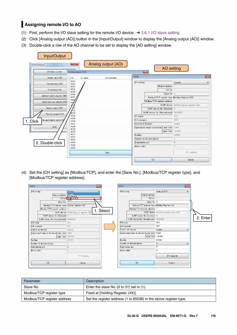
116DL30-G USERS MANUAL EM-8571-G Rev.7
Assigning remote I/O to AO
(1) First, perform the I/O slave setting for the remote I/O device. ➔ 3.6.1 I/O slave setting
(2) Click [Analog output (AO)] button in the [Input/Output] window to display the [Analog output (AO)] window.
(3) Double-click a row of the AO channel to be set to display the [AO setting] window.
Input/Output
Analog output (AO)
1. Click
AO setting
2. Double-click
(4) Set the [CH setting] as [Modbus/TCP], and enter the [Save No.], [Modbus/TCP register type], and [Modbus/TCP register address].
2. Enter
1. Select
Parameter Description
Slave No. Enter the slave No. (0 to 31) set in (1).
Modbus/TCP register type Fixed at [Holding Register (4X)].
Modbus/TCP register address Set the register address (1 to 65536) in the above register type.
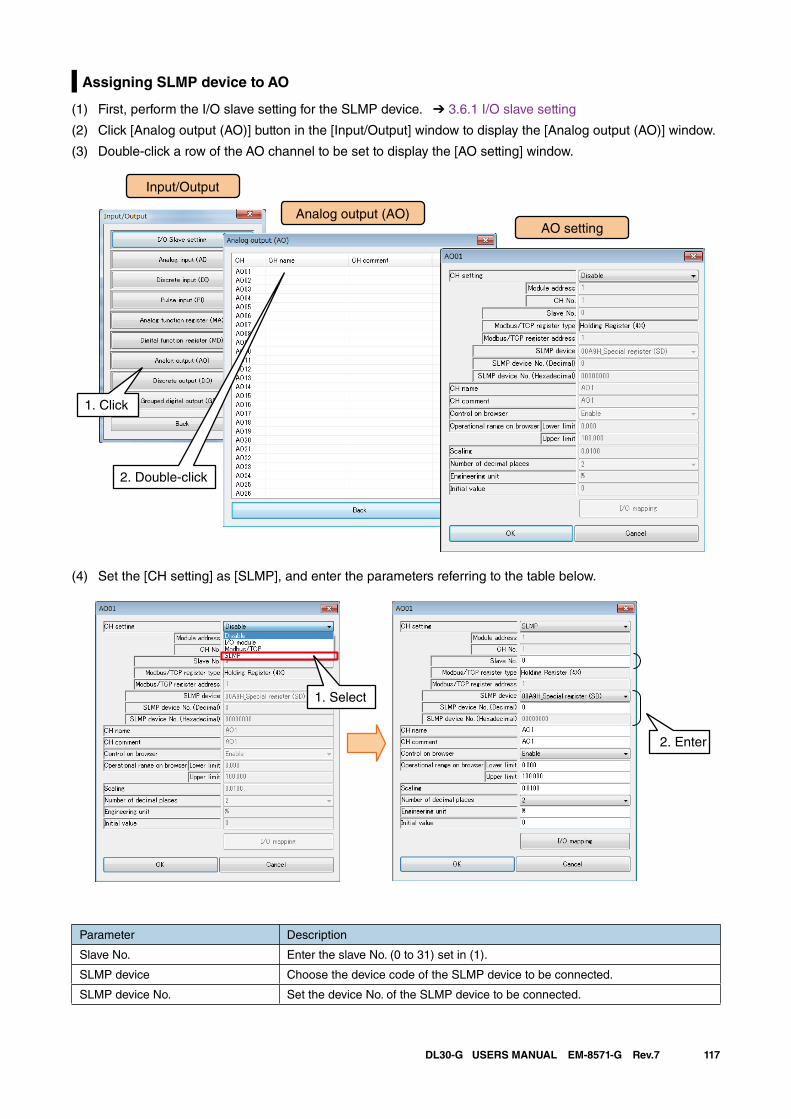
117DL30-G USERS MANUAL EM-8571-G Rev.7
Assigning SLMP device to AO
(1) First, perform the I/O slave setting for the SLMP device. ➔ 3.6.1 I/O slave setting
(2) Click [Analog output (AO)] button in the [Input/Output] window to display the [Analog output (AO)] window.
(3) Double-click a row of the AO channel to be set to display the [AO setting] window.
Input/Output
Analog output (AO)
1. Click
AO setting
2. Double-click
(4) Set the [CH setting] as [SLMP], and enter the parameters referring to the table below.
2. Enter
1. Select
Parameter Description
Slave No. Enter the slave No. (0 to 31) set in (1).
SLMP device Choose the device code of the SLMP device to be connected.
SLMP device No. Set the device No. of the SLMP device to be connected.
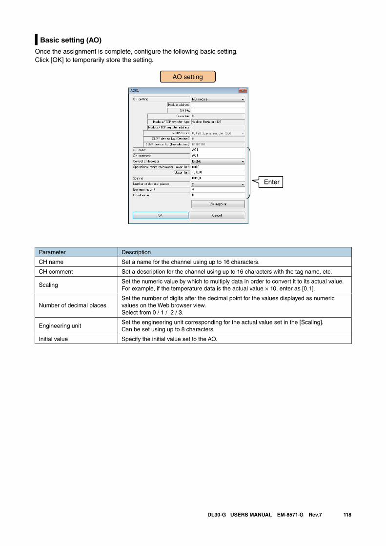
118DL30-G USERS MANUAL EM-8571-G Rev.7
Basic setting (AO)
Once the assignment is complete, configure the following basic setting. Click [OK] to temporarily store the setting.
AO setting
Enter
Parameter Description
CH name Set a name for the channel using up to 16 characters.
CH comment Set a description for the channel using up to 16 characters with the tag name, etc.
ScalingSet the numeric value by which to multiply data in order to convert it to its actual value. For example, if the temperature data is the actual value × 10, enter as [0.1].
Number of decimal placesSet the number of digits after the decimal point for the values displayed as numeric values on the Web browser view.Select from 0 / 1 / 2 / 3.
Engineering unitSet the engineering unit corresponding for the actual value set in the [Scaling].Can be set using up to 8 characters.
Initial value Specify the initial value set to the AO.
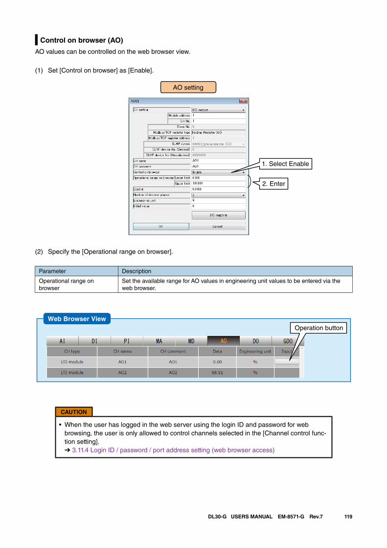
119DL30-G USERS MANUAL EM-8571-G Rev.7
Control on browser (AO)
AO values can be controlled on the web browser view.
(1) Set [Control on browser] as [Enable].
AO setting
2. Enter
1. Select Enable
(2) Specify the [Operational range on browser].
Parameter Description
Operational range on browser
Set the available range for AO values in engineering unit values to be entered via the web browser.
CAUTION
• When the user has logged in the web server using the login ID and password for web browsing, the user is only allowed to control channels selected in the [Channel control func-tion setting]. ➔ 3.11.4 Login ID / password / port address setting (web browser access)
Web Browser ViewOperation button
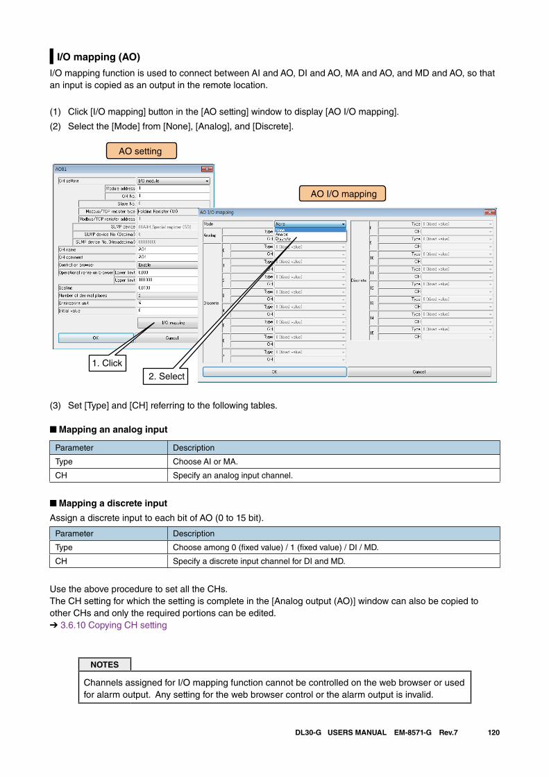
120DL30-G USERS MANUAL EM-8571-G Rev.7
I/O mapping (AO)
I/O mapping function is used to connect between AI and AO, DI and AO, MA and AO, and MD and AO, so that an input is copied as an output in the remote location.
(1) Click [I/O mapping] button in the [AO setting] window to display [AO I/O mapping].
(2) Select the [Mode] from [None], [Analog], and [Discrete].
AO setting
AO I/O mapping
1. Click2. Select
(3) Set [Type] and [CH] referring to the following tables.
■ Mapping an analog input
Parameter Description
Type Choose AI or MA.
CH Specify an analog input channel.
■ Mapping a discrete input
Assign a discrete input to each bit of AO (0 to 15 bit).
Parameter Description
Type Choose among 0 (fixed value) / 1 (fixed value) / DI / MD.
CH Specify a discrete input channel for DI and MD.
Use the above procedure to set all the CHs.The CH setting for which the setting is complete in the [Analog output (AO)] window can also be copied to other CHs and only the required portions can be edited.➔ 3.6.10 Copying CH setting
NOTES
Channels assigned for I/O mapping function cannot be controlled on the web browser or used for alarm output. Any setting for the web browser control or the alarm output is invalid.
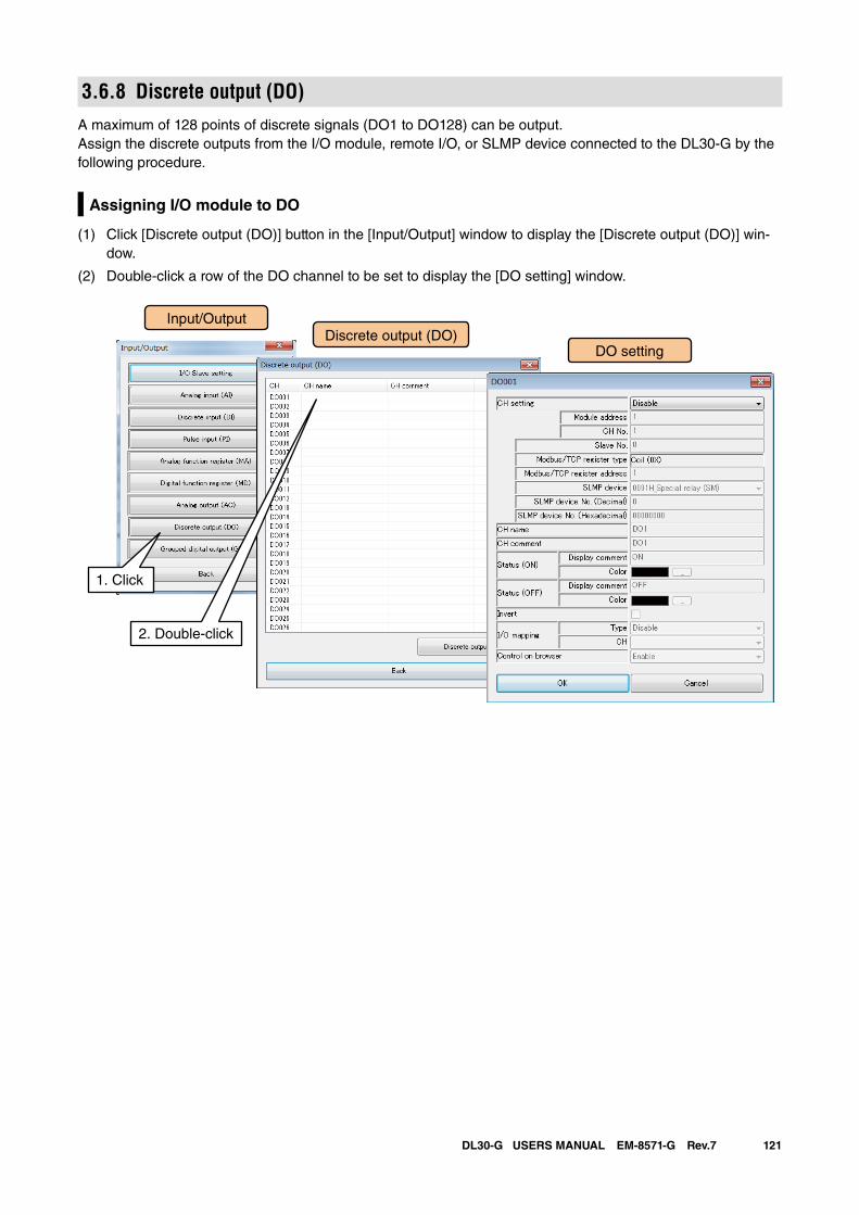
121DL30-G USERS MANUAL EM-8571-G Rev.7
3.6.8 Discrete output (DO)A maximum of 128 points of discrete signals (DO1 to DO128) can be output.Assign the discrete outputs from the I/O module, remote I/O, or SLMP device connected to the DL30-G by the following procedure.
Assigning I/O module to DO
(1) Click [Discrete output (DO)] button in the [Input/Output] window to display the [Discrete output (DO)] win-dow.
(2) Double-click a row of the DO channel to be set to display the [DO setting] window.
Input/OutputDiscrete output (DO)
1. Click
DO setting
2. Double-click
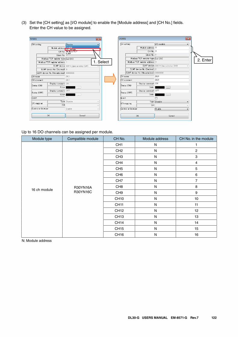
122DL30-G USERS MANUAL EM-8571-G Rev.7
(3) Set the [CH setting] as [I/O module] to enable the [Module address] and [CH No.] fields. Enter the CH value to be assigned.
Up to 16 DO channels can be assigned per module.
Module type Compatible module CH No. Module address CH No. in the module
16 ch moduleR30YN16AR30YN16C
CH1 N 1
CH2 N 2
CH3 N 3
CH4 N 4
CH5 N 5
CH6 N 6
CH7 N 7
CH8 N 8
CH9 N 9
CH10 N 10
CH11 N 11
CH12 N 12
CH13 N 13
CH14 N 14
CH15 N 15
CH16 N 16
N: Module address
2. Enter1. Select
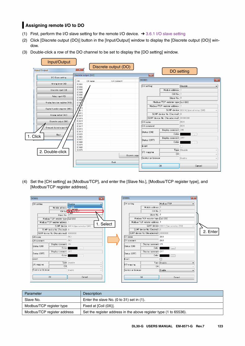
123DL30-G USERS MANUAL EM-8571-G Rev.7
Assigning remote I/O to DO
(1) First, perform the I/O slave setting for the remote I/O device. ➔ 3.6.1 I/O slave setting
(2) Click [Discrete output (DO)] button in the [Input/Output] window to display the [Discrete output (DO)] win-dow.
(3) Double-click a row of the DO channel to be set to display the [DO setting] window.
Input/OutputDiscrete output (DO)
1. Click
DO setting
2. Double-click
(4) Set the [CH setting] as [Modbus/TCP], and enter the [Slave No.], [Modbus/TCP register type], and [Modbus/TCP register address].
Parameter Description
Slave No. Enter the slave No. (0 to 31) set in (1).
Modbus/TCP register type Fixed at [Coil (0X)].
Modbus/TCP register address Set the register address in the above register type (1 to 65536).
2. Enter
1. Select
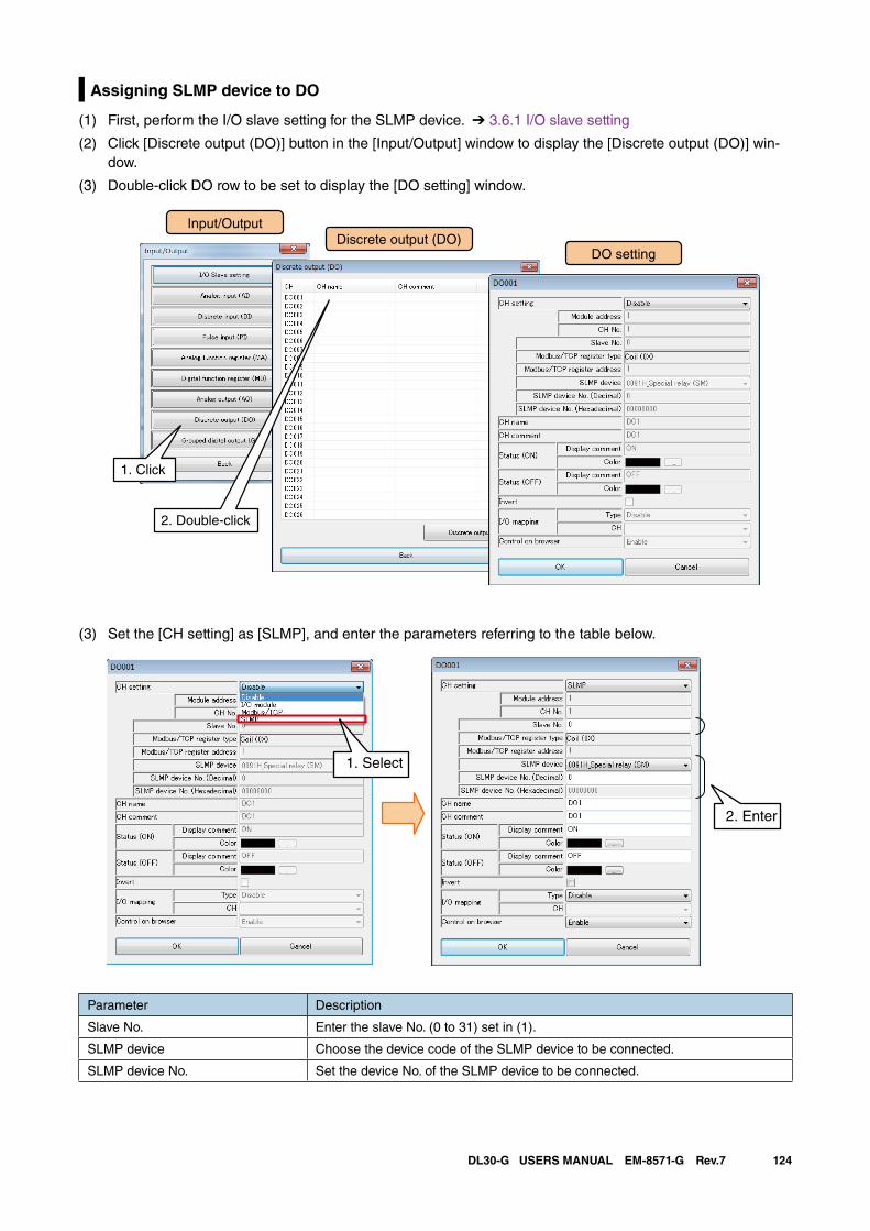
124DL30-G USERS MANUAL EM-8571-G Rev.7
Assigning SLMP device to DO
(1) First, perform the I/O slave setting for the SLMP device. ➔ 3.6.1 I/O slave setting
(2) Click [Discrete output (DO)] button in the [Input/Output] window to display the [Discrete output (DO)] win-dow.
(3) Double-click DO row to be set to display the [DO setting] window.
Input/OutputDiscrete output (DO)
1. Click
DO setting
2. Double-click
(3) Set the [CH setting] as [SLMP], and enter the parameters referring to the table below.
2. Enter
1. Select
Parameter Description
Slave No. Enter the slave No. (0 to 31) set in (1).
SLMP device Choose the device code of the SLMP device to be connected.
SLMP device No. Set the device No. of the SLMP device to be connected.
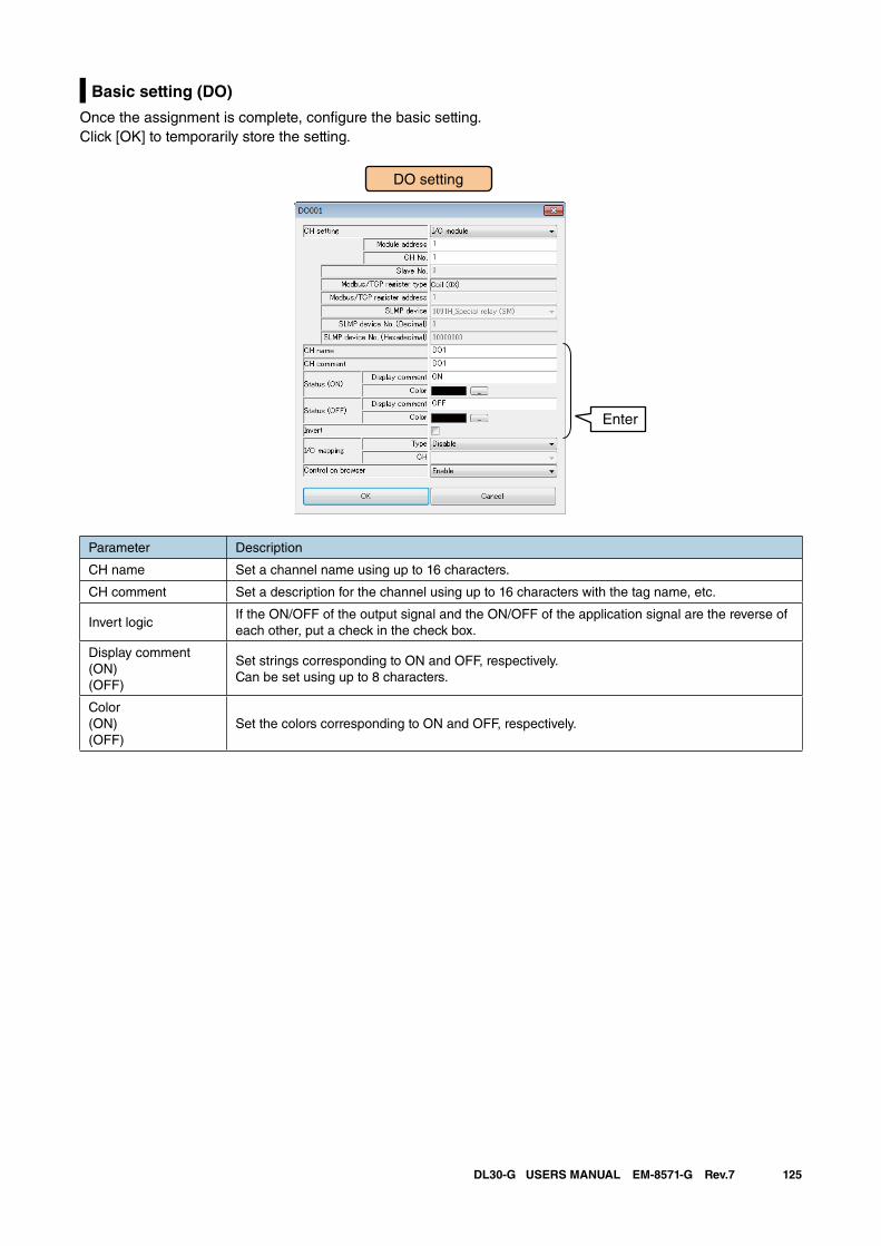
125DL30-G USERS MANUAL EM-8571-G Rev.7
Basic setting (DO)
Once the assignment is complete, configure the basic setting. Click [OK] to temporarily store the setting.
Parameter Description
CH name Set a channel name using up to 16 characters.
CH comment Set a description for the channel using up to 16 characters with the tag name, etc.
Invert logicIf the ON/OFF of the output signal and the ON/OFF of the application signal are the reverse of each other, put a check in the check box.
Display comment(ON)(OFF)
Set strings corresponding to ON and OFF, respectively. Can be set using up to 8 characters.
Color(ON)(OFF)
Set the colors corresponding to ON and OFF, respectively.
DO setting
Enter
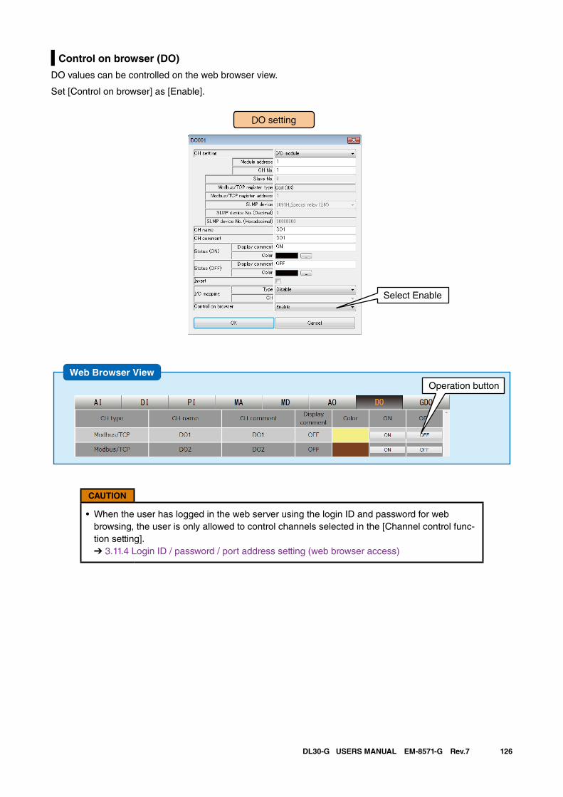
126DL30-G USERS MANUAL EM-8571-G Rev.7
Control on browser (DO)
DO values can be controlled on the web browser view.
Set [Control on browser] as [Enable].
DO setting
Select Enable
CAUTION
• When the user has logged in the web server using the login ID and password for web browsing, the user is only allowed to control channels selected in the [Channel control func-tion setting]. ➔ 3.11.4 Login ID / password / port address setting (web browser access)
Web Browser ViewOperation button
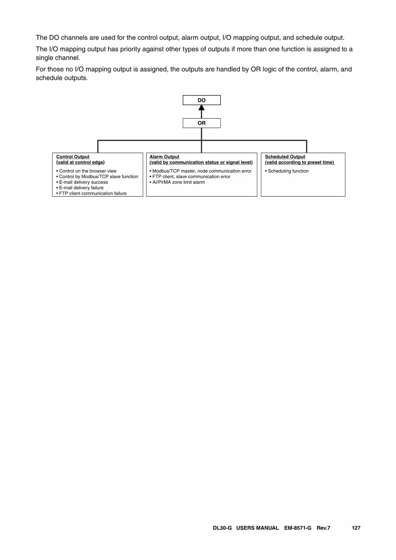
127DL30-G USERS MANUAL EM-8571-G Rev.7
The DO channels are used for the control output, alarm output, I/O mapping output, and schedule output.
The I/O mapping output has priority against other types of outputs if more than one function is assigned to a single channel.
For those no I/O mapping output is assigned, the outputs are handled by OR logic of the control, alarm, and schedule outputs.
DO
OR
Control Output(valid at control edge)
• Control on the browser view• Control by Modbus/TCP slave function• E-mail delivery success• E-mail delivery failure• FTP client communication failure
Scheduled Output(valid according to preset time)
• Scheduling function
Alarm Output(valid by communication status or signal level)
• Modbus/TCP master, node communication error • FTP client, slave communication error • AI/PI/MA zone limit alarm
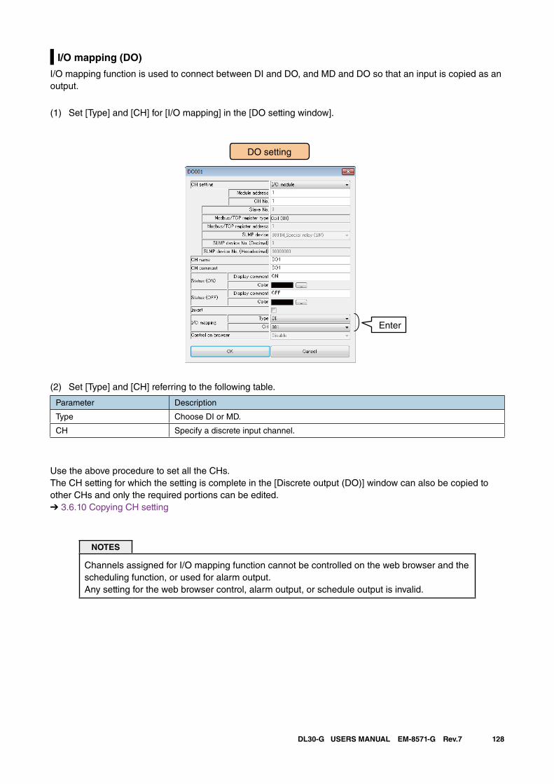
128DL30-G USERS MANUAL EM-8571-G Rev.7
I/O mapping (DO)
I/O mapping function is used to connect between DI and DO, and MD and DO so that an input is copied as an output.
(1) Set [Type] and [CH] for [I/O mapping] in the [DO setting window].
DO setting
Enter
(2) Set [Type] and [CH] referring to the following table.
Parameter Description
Type Choose DI or MD.
CH Specify a discrete input channel.
Use the above procedure to set all the CHs.The CH setting for which the setting is complete in the [Discrete output (DO)] window can also be copied to other CHs and only the required portions can be edited.➔ 3.6.10 Copying CH setting
NOTES
Channels assigned for I/O mapping function cannot be controlled on the web browser and the scheduling function, or used for alarm output. Any setting for the web browser control, alarm output, or schedule output is invalid.
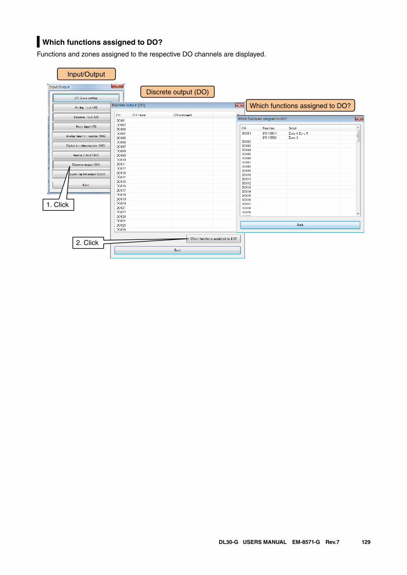
129DL30-G USERS MANUAL EM-8571-G Rev.7
Which functions assigned to DO?
Functions and zones assigned to the respective DO channels are displayed.
Input/Output
Discrete output (DO)
1. Click
Which functions assigned to DO?
2. Click
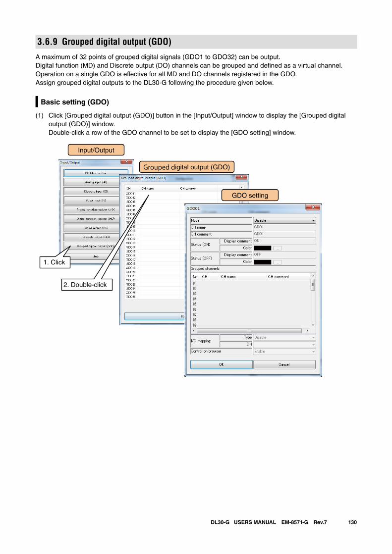
130DL30-G USERS MANUAL EM-8571-G Rev.7
3.6.9 Grouped digital output (GDO)A maximum of 32 points of grouped digital signals (GDO1 to GDO32) can be output.Digital function (MD) and Discrete output (DO) channels can be grouped and defined as a virtual channel.Operation on a single GDO is effective for all MD and DO channels registered in the GDO.Assign grouped digital outputs to the DL30-G following the procedure given below.
Basic setting (GDO)
(1) Click [Grouped digital output (GDO)] button in the [Input/Output] window to display the [Grouped digital output (GDO)] window. Double-click a row of the GDO channel to be set to display the [GDO setting] window.
Input/Output
Grouped digital output (GDO)
1. Click
2. Double-click
GDO setting
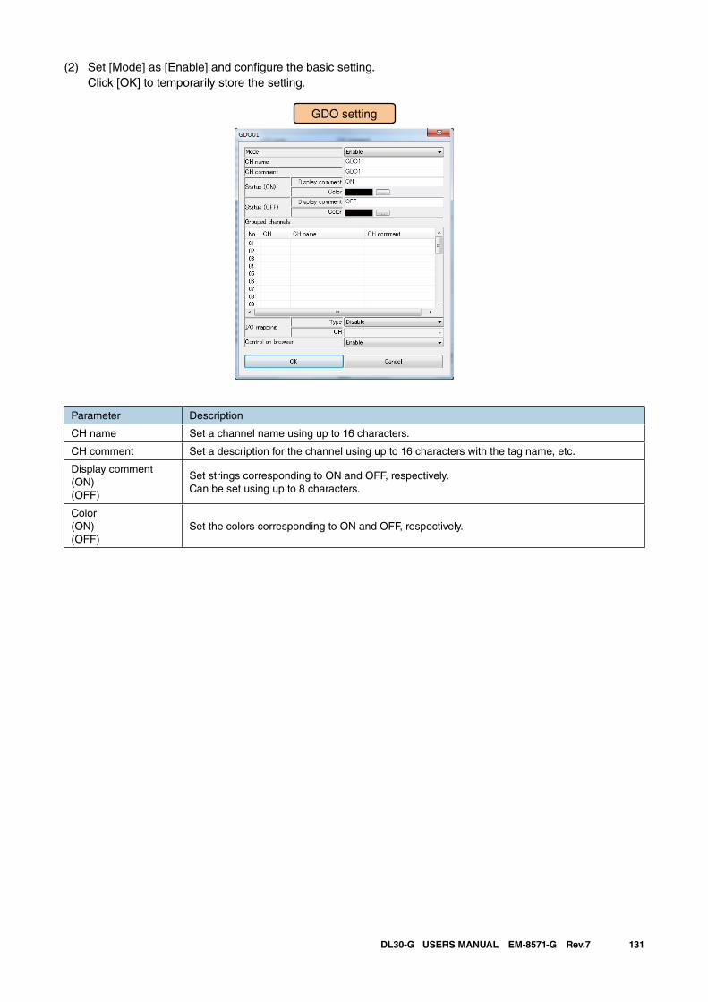
131DL30-G USERS MANUAL EM-8571-G Rev.7
(2) Set [Mode] as [Enable] and configure the basic setting. Click [OK] to temporarily store the setting.
GDO setting
Parameter Description
CH name Set a channel name using up to 16 characters.
CH comment Set a description for the channel using up to 16 characters with the tag name, etc.
Display comment(ON)(OFF)
Set strings corresponding to ON and OFF, respectively. Can be set using up to 8 characters.
Color(ON)(OFF)
Set the colors corresponding to ON and OFF, respectively.
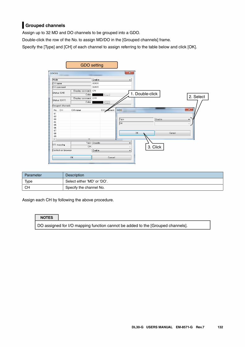
132DL30-G USERS MANUAL EM-8571-G Rev.7
Grouped channels
Assign up to 32 MD and DO channels to be grouped into a GDO.
Double-click the row of the No. to assign MD/DO in the [Grouped channels] frame.
Specify the [Type] and [CH] of each channel to assign referring to the table below and click [OK].
1. Double-click2. Select
3. Click
GDO setting
Parameter Description
Type Select either 'MD' or 'DO'.
CH Specify the channel No.
Assign each CH by following the above procedure.
NOTES
DO assigned for I/O mapping function cannot be added to the [Grouped channels].
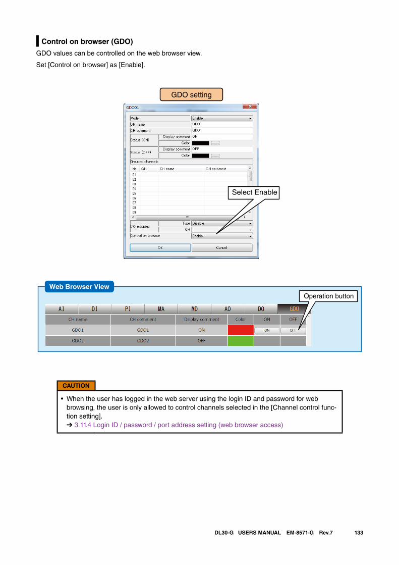
133DL30-G USERS MANUAL EM-8571-G Rev.7
Control on browser (GDO)
GDO values can be controlled on the web browser view.
Set [Control on browser] as [Enable].
GDO setting
Select Enable
Web Browser ViewOperation button
CAUTION
• When the user has logged in the web server using the login ID and password for web browsing, the user is only allowed to control channels selected in the [Channel control func-tion setting]. ➔ 3.11.4 Login ID / password / port address setting (web browser access)
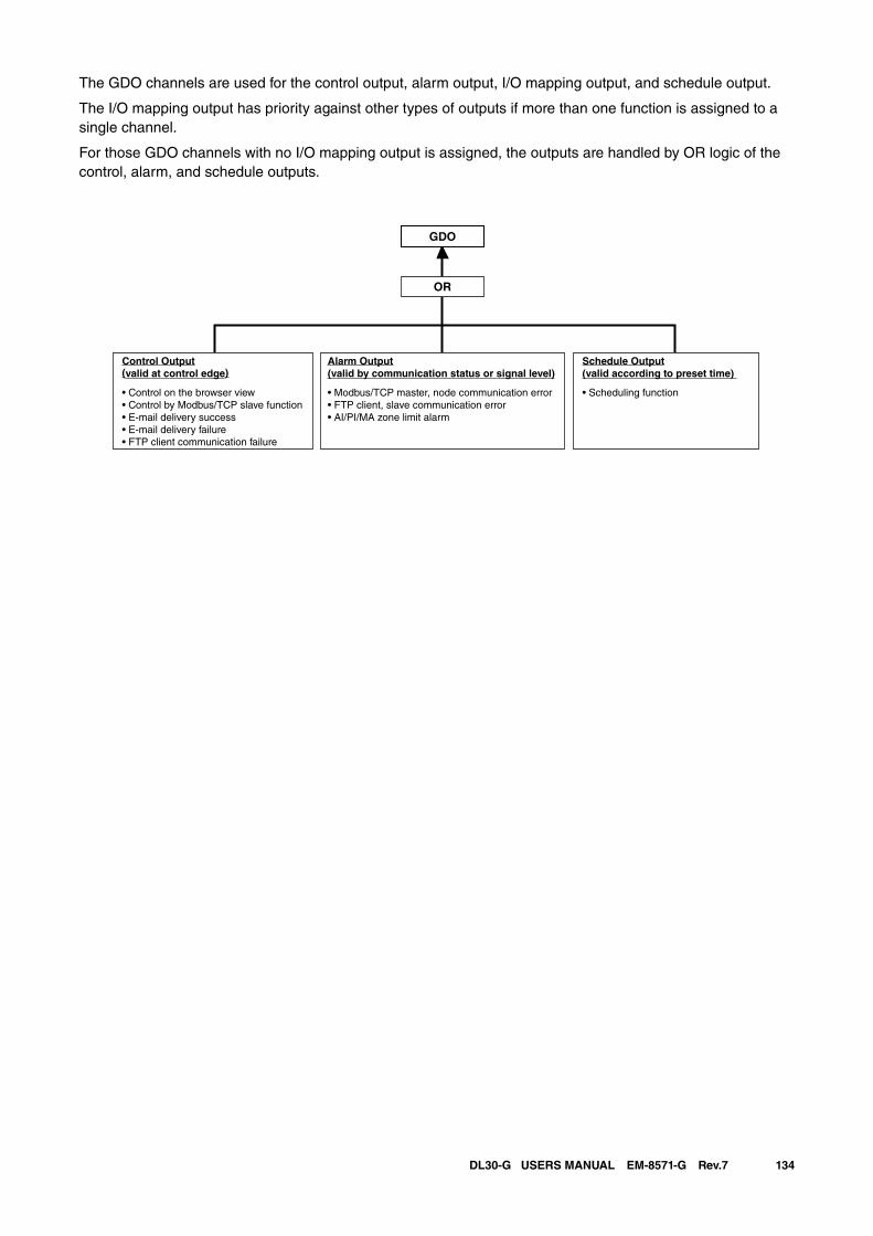
134DL30-G USERS MANUAL EM-8571-G Rev.7
The GDO channels are used for the control output, alarm output, I/O mapping output, and schedule output.
The I/O mapping output has priority against other types of outputs if more than one function is assigned to a single channel.
For those GDO channels with no I/O mapping output is assigned, the outputs are handled by OR logic of the control, alarm, and schedule outputs.
GDO
OR
Control Output(valid at control edge)
• Control on the browser view• Control by Modbus/TCP slave function• E-mail delivery success• E-mail delivery failure• FTP client communication failure
Schedule Output(valid according to preset time)
• Scheduling function
Alarm Output(valid by communication status or signal level)
• Modbus/TCP master, node communication error • FTP client, slave communication error • AI/PI/MA zone limit alarm
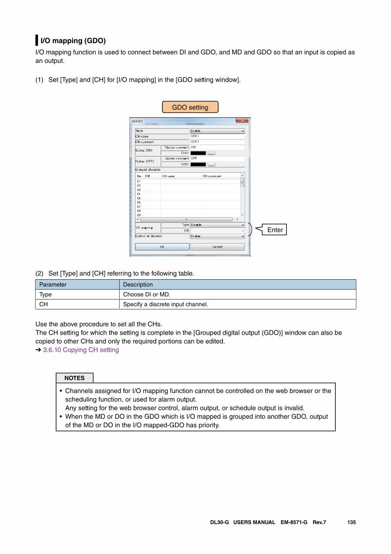
135DL30-G USERS MANUAL EM-8571-G Rev.7
I/O mapping (GDO)
I/O mapping function is used to connect between DI and GDO, and MD and GDO so that an input is copied as an output.
(1) Set [Type] and [CH] for [I/O mapping] in the [GDO setting window].
GDO setting
Enter
(2) Set [Type] and [CH] referring to the following table.
Parameter Description
Type Choose DI or MD.
CH Specify a discrete input channel.
Use the above procedure to set all the CHs.The CH setting for which the setting is complete in the [Grouped digital output (GDO)] window can also be copied to other CHs and only the required portions can be edited.➔ 3.6.10 Copying CH setting
NOTES
• Channels assigned for I/O mapping function cannot be controlled on the web browser or the scheduling function, or used for alarm output. Any setting for the web browser control, alarm output, or schedule output is invalid.
• When the MD or DO in the GDO which is I/O mapped is grouped into another GDO, output of the MD or DO in the I/O mapped-GDO has priority.
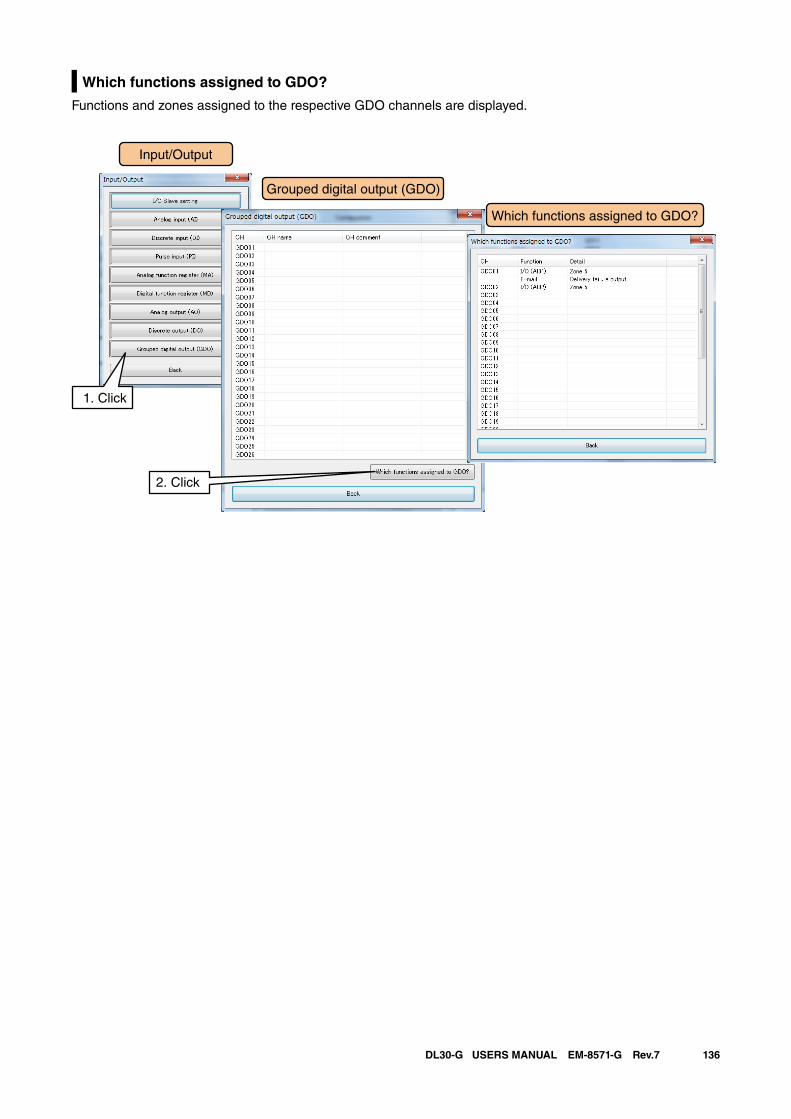
136DL30-G USERS MANUAL EM-8571-G Rev.7
Which functions assigned to GDO?
Functions and zones assigned to the respective GDO channels are displayed.
Input/Output
Grouped digital output (GDO)
1. Click
Which functions assigned to GDO?
2. Click
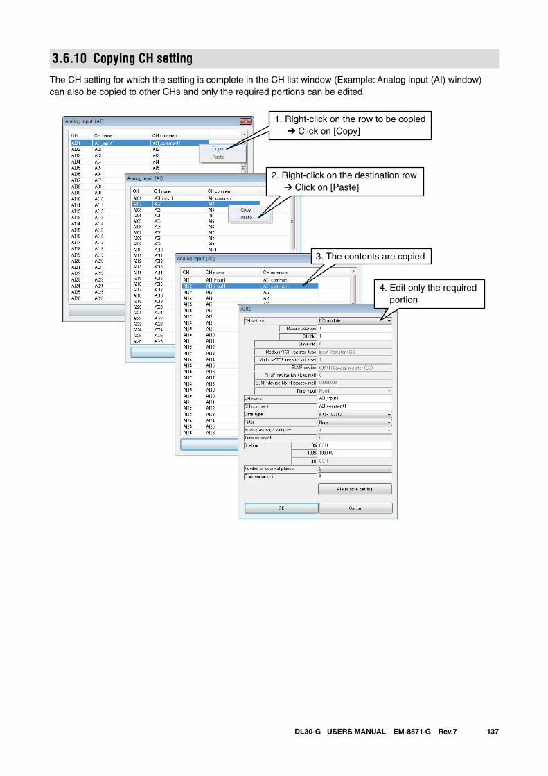
137DL30-G USERS MANUAL EM-8571-G Rev.7
3.6.10 Copying CH settingThe CH setting for which the setting is complete in the CH list window (Example: Analog input (AI) window) can also be copied to other CHs and only the required portions can be edited.
1. Right-click on the row to be copied ➔ Click on [Copy]
2. Right-click on the destination row ➔ Click on [Paste]
3. The contents are copied
4. Edit only the required portion
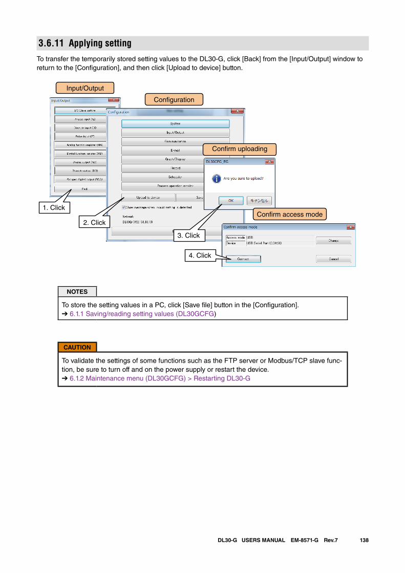
138DL30-G USERS MANUAL EM-8571-G Rev.7
3.6.11 Applying settingTo transfer the temporarily stored setting values to the DL30-G, click [Back] from the [Input/Output] window to return to the [Configuration], and then click [Upload to device] button.
NOTES
To store the setting values in a PC, click [Save file] button in the [Configuration].➔ 6.1.1 Saving/reading setting values (DL30GCFG)
CAUTION
To validate the settings of some functions such as the FTP server or Modbus/TCP slave func-tion, be sure to turn off and on the power supply or restart the device. ➔ 6.1.2 Maintenance menu (DL30GCFG) > Restarting DL30-G
Input/Output
Con�guration
1. Click
Con�rm uploading
Con�rm access mode2. Click
3. Click
4. Click
139DL30-G USERS MANUAL EM-8571-G Rev.7
3.7 I/O mapping settingI/O mapping function is used to connect between specific inputs and outputs so that an input is copied as an output in the remote location, for the purpose of multiplexing and telemetering.
I/O mapping for analog output
Signal connection is possible between AI and AO, DI and AO, MA and AO, and MD and AO.Refer to [3.6.7 Analog output (AO)] > [I/O mapping (AO)] for detailed information.
I/O mapping for discrete output
Signal connection is possible between DI and DO, MD and DO, DI and GDO, and MD and GDO.Refer to [3.6.8 Discrete output (DO)], and [3.6.9 Grouped digital output (GDO)] for detailed information.
NOTES
• Channels assigned for I/O mapping function cannot be controlled on the web browser or used for alarm output. Any setting for the web browser control or the alarm output is invalid.
• MD and DO grouped in the GDO which is assigned for I/O mapping cannot be controlled on the web browser or used for alarm output. Any setting for the web browser control or the alarm output is invalid.
• Values applied for I/O mapping: % (AI): Input values are applied as they are to the output. Int, Uint (AI): Engineering unit values are applied to the output. DI, MD: Current state is applied to the output.
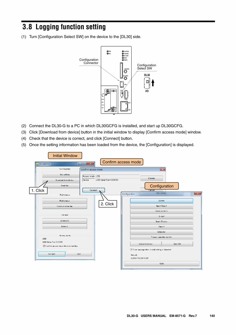
140DL30-G USERS MANUAL EM-8571-G Rev.7
3.8 Logging function setting(1) Turn [Configuration Select SW] on the device to the [DL30] side.
(2) Connect the DL30-G to a PC in which DL30GCFG is installed, and start up DL30GCFG.
(3) Click [Download from device] button in the initial window to display [Confirm access mode] window.
(4) Check that the device is correct, and click [Connect] button.
(5) Once the setting information has been loaded from the device, the [Configuration] is displayed.
DL30 RUN
LOGGING
SD CARD
MAINT
PWR
RUN
ERROR
CFG
DPX
LNK
LOGGING
SD CARD
DL30
2
I/O
On
43
1
U(+)
NC
V(-)
FE
DL30
I/O
ConfigurationSelect SW
ConfigurationConnector
Initial Window
Con�rm access mode
Con�guration1. Click
2. Click
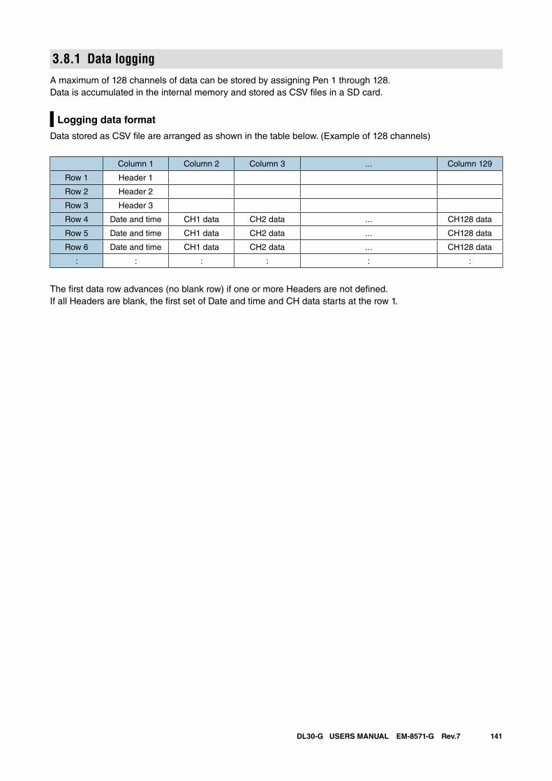
141DL30-G USERS MANUAL EM-8571-G Rev.7
3.8.1 Data loggingA maximum of 128 channels of data can be stored by assigning Pen 1 through 128.Data is accumulated in the internal memory and stored as CSV files in a SD card.
Logging data format
Data stored as CSV file are arranged as shown in the table below. (Example of 128 channels)
Column 1 Column 2 Column 3 ... Column 129
Row 1 Header 1
Row 2 Header 2
Row 3 Header 3
Row 4 Date and time CH1 data CH2 data ... CH128 data
Row 5 Date and time CH1 data CH2 data ... CH128 data
Row 6 Date and time CH1 data CH2 data ... CH128 data
: : : : : :
The first data row advances (no blank row) if one or more Headers are not defined. If all Headers are blank, the first set of Date and time and CH data starts at the row 1.
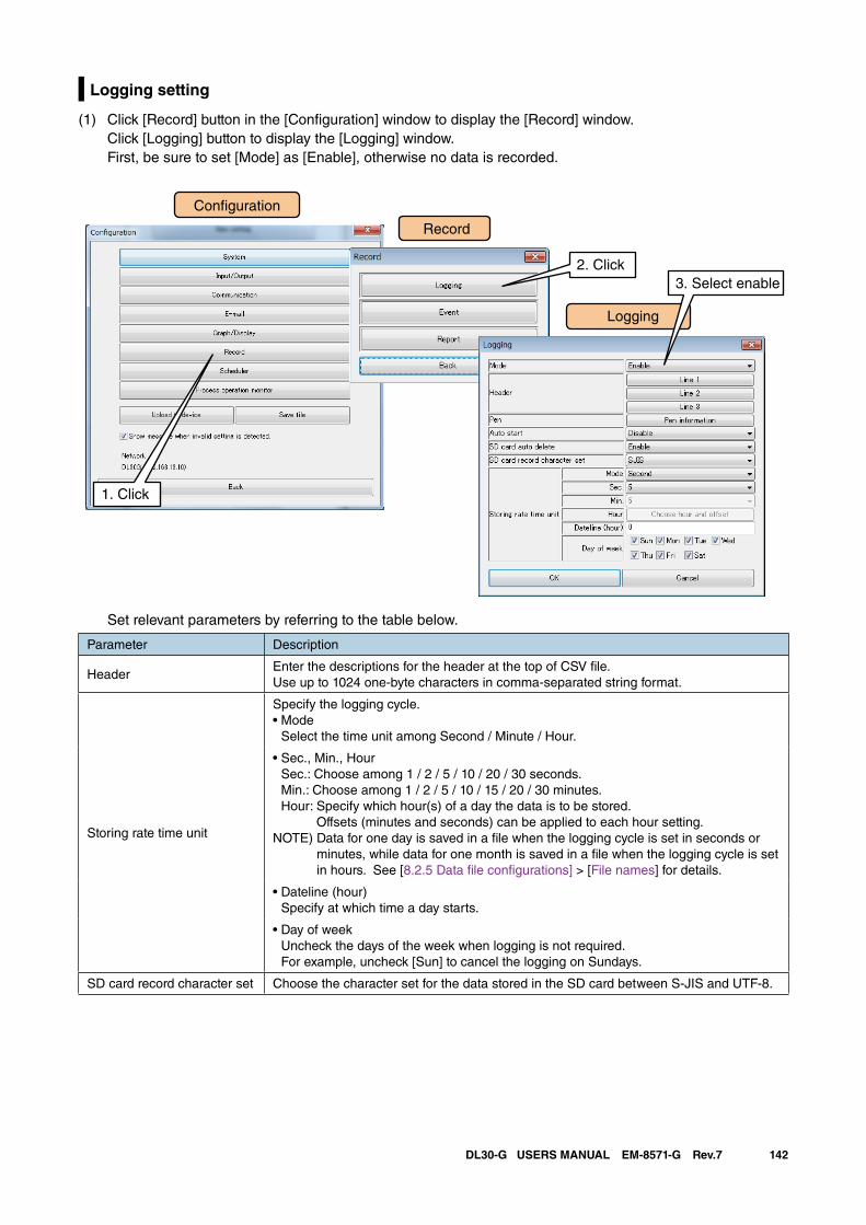
142DL30-G USERS MANUAL EM-8571-G Rev.7
Logging setting
(1) Click [Record] button in the [Configuration] window to display the [Record] window. Click [Logging] button to display the [Logging] window. First, be sure to set [Mode] as [Enable], otherwise no data is recorded.
Set relevant parameters by referring to the table below.
Parameter Description
HeaderEnter the descriptions for the header at the top of CSV file.Use up to 1024 one-byte characters in comma-separated string format.
Storing rate time unit
Specify the logging cycle.• Mode
Select the time unit among Second / Minute / Hour.
• Sec., Min., Hour Sec.: Choose among 1 / 2 / 5 / 10 / 20 / 30 seconds. Min.: Choose among 1 / 2 / 5 / 10 / 15 / 20 / 30 minutes. Hour: Specify which hour(s) of a day the data is to be stored.
Offsets (minutes and seconds) can be applied to each hour setting.NOTE) Data for one day is saved in a file when the logging cycle is set in seconds or
minutes, while data for one month is saved in a file when the logging cycle is set in hours. See [8.2.5 Data file configurations] > [File names] for details.
• Dateline (hour) Specify at which time a day starts.
• Day of week Uncheck the days of the week when logging is not required. For example, uncheck [Sun] to cancel the logging on Sundays.
SD card record character set Choose the character set for the data stored in the SD card between S-JIS and UTF-8.
Con�guration
Record
Logging
1. Click
2. Click3. Select enable
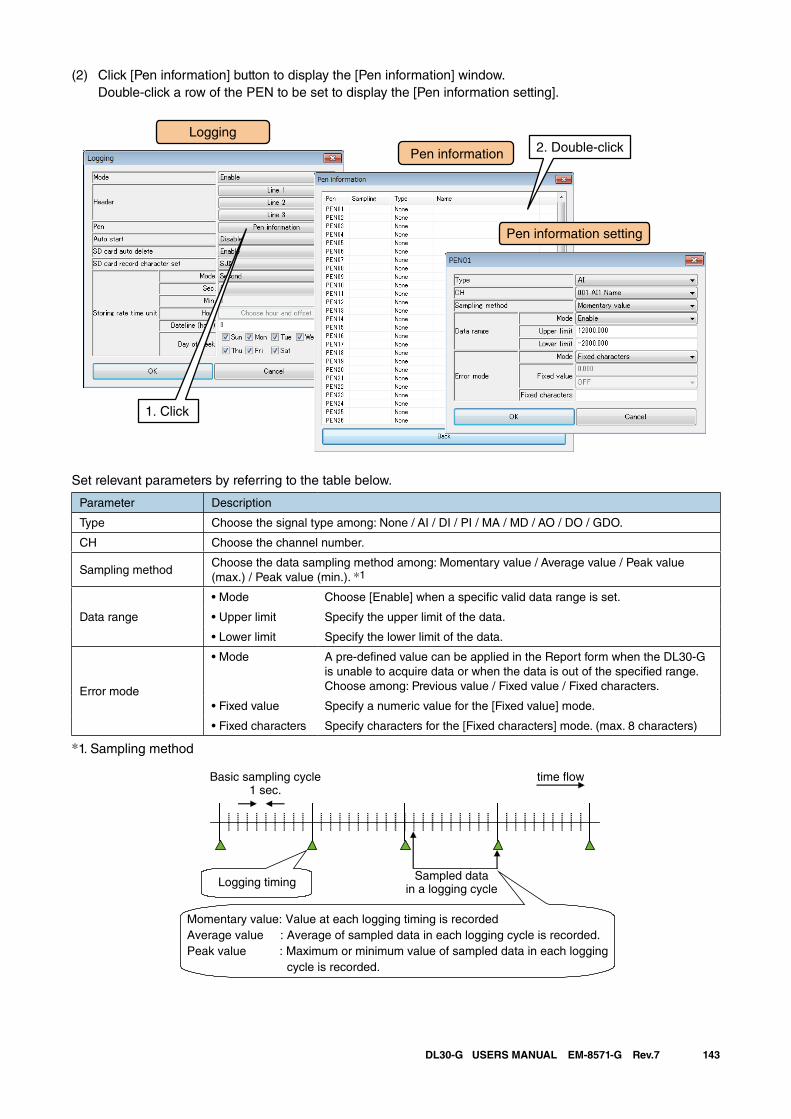
143DL30-G USERS MANUAL EM-8571-G Rev.7
(2) Click [Pen information] button to display the [Pen information] window. Double-click a row of the PEN to be set to display the [Pen information setting].
Set relevant parameters by referring to the table below.
Parameter Description
Type Choose the signal type among: None / AI / DI / PI / MA / MD / AO / DO / GDO.
CH Choose the channel number.
Sampling methodChoose the data sampling method among: Momentary value / Average value / Peak value (max.) / Peak value (min.). *1
Data range
• Mode Choose [Enable] when a specific valid data range is set.
• Upper limit Specify the upper limit of the data.
• Lower limit Specify the lower limit of the data.
Error mode
• Mode A pre-defined value can be applied in the Report form when the DL30-G is unable to acquire data or when the data is out of the specified range. Choose among: Previous value / Fixed value / Fixed characters.
• Fixed value Specify a numeric value for the [Fixed value] mode.
• Fixed characters Specify characters for the [Fixed characters] mode. (max. 8 characters)
*1. Sampling method
Basic sampling cycle1 sec.
Logging timing Sampled datain a logging cycle
time �ow
Momentary value: Value at each logging timing is recordedAverage value : Average of sampled data in each logging cycle is recorded. Peak value : Maximum or minimum value of sampled data in each logging cycle is recorded.
Pen information
Logging
1. Click
Pen information setting
2. Double-click
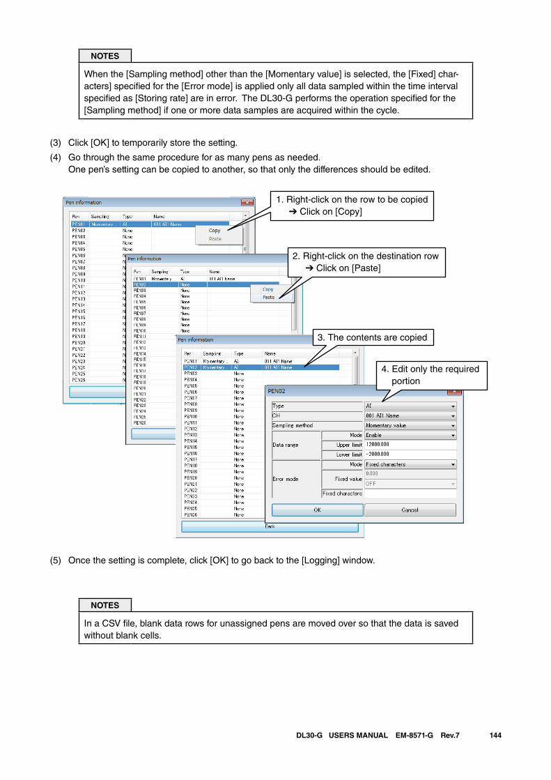
144DL30-G USERS MANUAL EM-8571-G Rev.7
NOTES
When the [Sampling method] other than the [Momentary value] is selected, the [Fixed] char-acters] specified for the [Error mode] is applied only all data sampled within the time interval specified as [Storing rate] are in error. The DL30-G performs the operation specified for the [Sampling method] if one or more data samples are acquired within the cycle.
(3) Click [OK] to temporarily store the setting.
(4) Go through the same procedure for as many pens as needed. One pen’s setting can be copied to another, so that only the differences should be edited.
(5) Once the setting is complete, click [OK] to go back to the [Logging] window.
NOTES
In a CSV file, blank data rows for unassigned pens are moved over so that the data is saved without blank cells.
1. Right-click on the row to be copied ➔ Click on [Copy]
2. Right-click on the destination row ➔ Click on [Paste]
3. The contents are copied
4. Edit only the required portion
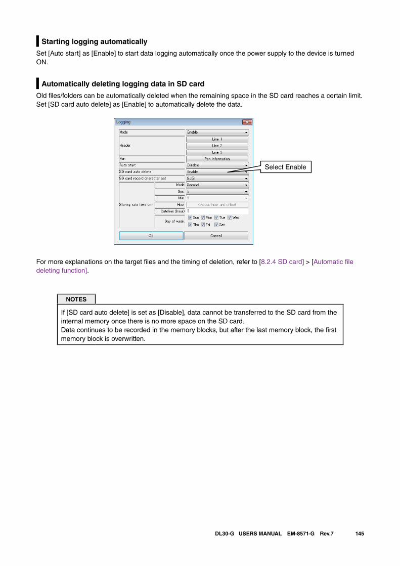
145DL30-G USERS MANUAL EM-8571-G Rev.7
Starting logging automatically
Set [Auto start] as [Enable] to start data logging automatically once the power supply to the device is turned ON.
Automatically deleting logging data in SD card
Old files/folders can be automatically deleted when the remaining space in the SD card reaches a certain limit. Set [SD card auto delete] as [Enable] to automatically delete the data.
For more explanations on the target files and the timing of deletion, refer to [8.2.4 SD card] > [Automatic file deleting function].
NOTES
If [SD card auto delete] is set as [Disable], data cannot be transferred to the SD card from the internal memory once there is no more space on the SD card. Data continues to be recorded in the memory blocks, but after the last memory block, the first memory block is overwritten.
Select Enable
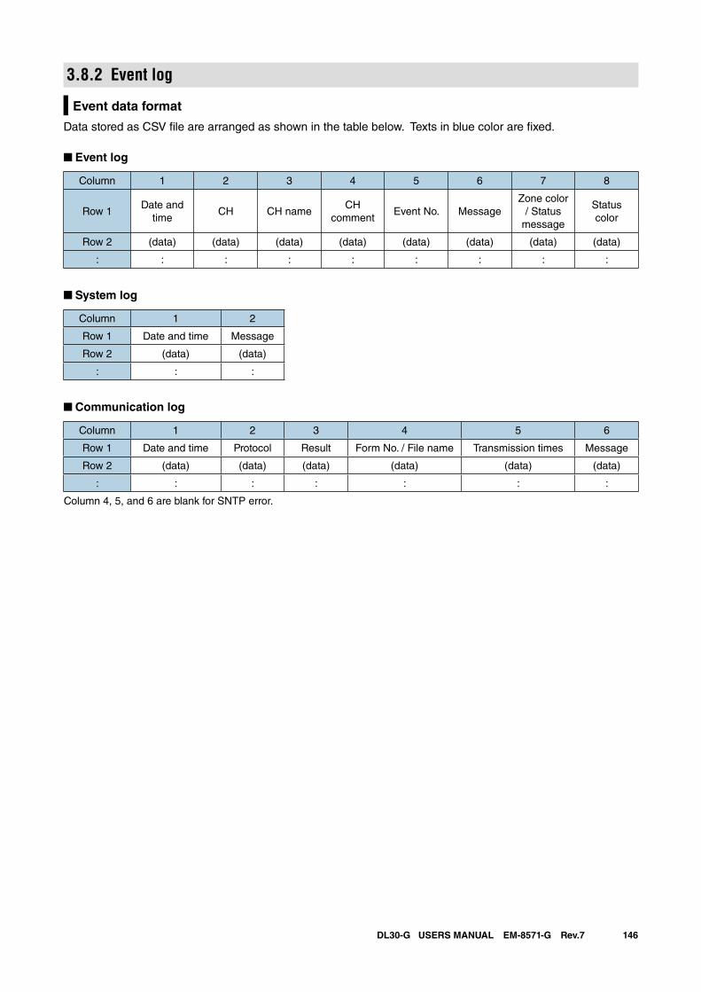
146DL30-G USERS MANUAL EM-8571-G Rev.7
3.8.2 Event log
Event data format
Data stored as CSV file are arranged as shown in the table below. Texts in blue color are fixed.
■ Event log
Column 1 2 3 4 5 6 7 8
Row 1Date and
timeCH CH name
CHcomment
Event No. MessageZone color
/ Status message
Status color
Row 2 (data) (data) (data) (data) (data) (data) (data) (data)
: : : : : : : : :
■ System log
Column 1 2
Row 1 Date and time Message
Row 2 (data) (data)
: : :
■ Communication log
Column 1 2 3 4 5 6
Row 1 Date and time Protocol Result Form No. / File name Transmission times Message
Row 2 (data) (data) (data) (data) (data) (data)
: : : : : : :
Column 4, 5, and 6 are blank for SNTP error.
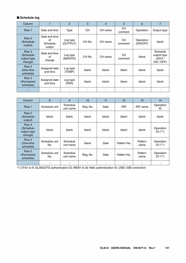
147DL30-G USERS MANUAL EM-8571-G Rev.7
■ Schedule log
Column 1 2 3 4 5 6 7
Row 1 Date and time Type CH CH nameCH
comnentOperation Output type
Row 2(Schedule
output)
Date and time of
Schedule output
Log type(OUTPUT)
CH No. CH nameCH
commentOperation(ON/OFF)
blank
Row 3(Schedule output type
change)
Date and time of
change
Log type(MAINTE)
CH No. CH nameCH
commentblank
Schedule output type
(SCH /ON / OFF)
Row 4(One-time schedule)
Assigned date and time
Log type(TEMP)
blank blank blank blank blank
Row 5(Permanent schedule)
Assigned date and time
Log type(PER)
blank blank blank blank blank
: : : : : : : :
Column 8 9 10 11 12 13 14
Row 1 Schedule unitSchedule unit name
Reg. No. Date PAT PAT nameOperation
ID
Row 2(Schedule
output)blank blank blank blank blank blank blank
Row 3(Schedule output type
change)
blank blank blank blank blank blankOperation
ID (*1)
Row 4(One-time schedule)
Schedule unit No.
Schedule unit name
blank Date Pattern No.Pattern name
Operation ID (*1)
Row 5(Permanent schedule)
Schedule unit No.
Schedule unit name
Reg. No. Date Pattern No.Pattern name
Operation ID (*1)
: : : : : : : :
*1. CFG1 to 8: DL30GCFG authentication ID, WEB1 to 32: Web authentication ID, USB: USB connection
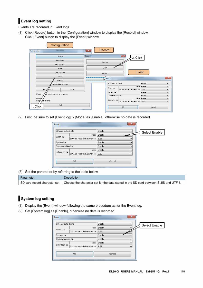
148DL30-G USERS MANUAL EM-8571-G Rev.7
Event log setting
Events are recorded in Event logs.
(1) Click [Record] button in the [Configuration] window to display the [Record] window. Click [Event] button to display the [Event] window.
Con�guration
Record
Event
1. Click
2. Click
(2) First, be sure to set [Event log] > [Mode] as [Enable], otherwise no data is recorded.
Select Enable
(3) Set the parameter by referring to the table below.
Parameter Description
SD card record character set Choose the character set for the data stored in the SD card between S-JIS and UTF-8.
System log setting
(1) Display the [Event] window following the same procedure as for the Event log.
(2) Set [System log] as [Enable], otherwise no data is recorded.
Select Enable
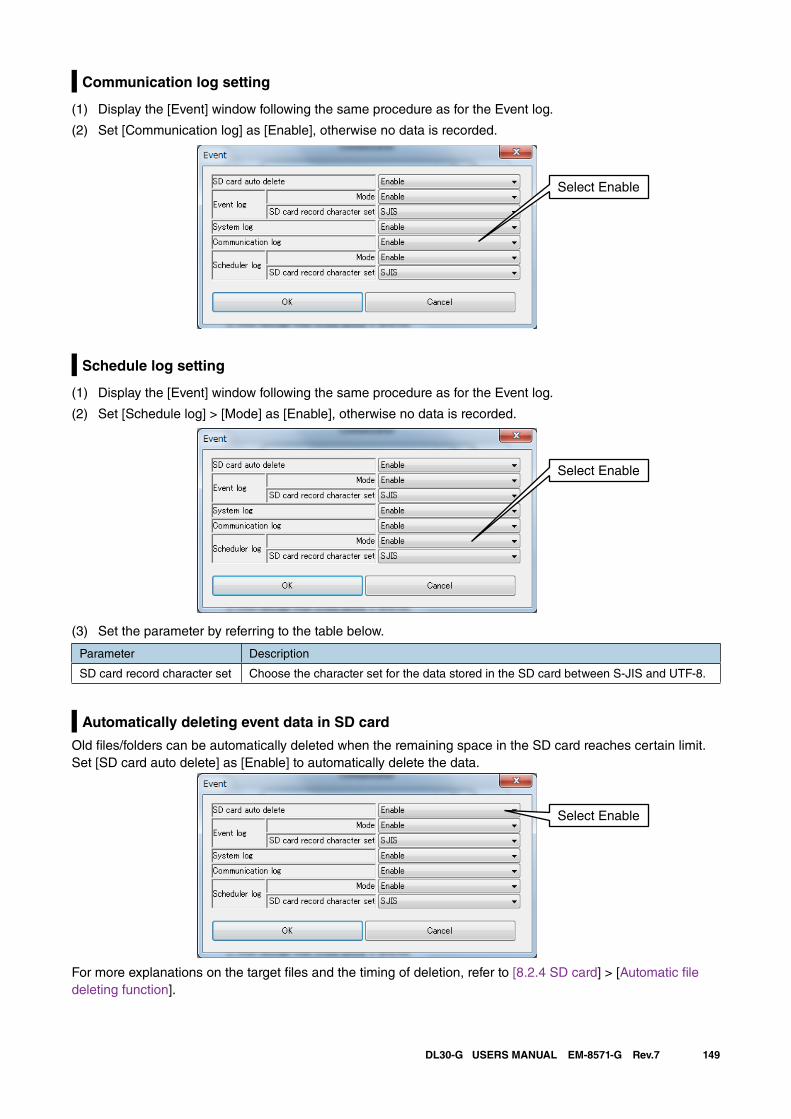
149DL30-G USERS MANUAL EM-8571-G Rev.7
Communication log setting
(1) Display the [Event] window following the same procedure as for the Event log.
(2) Set [Communication log] as [Enable], otherwise no data is recorded.
Select Enable
Schedule log setting
(1) Display the [Event] window following the same procedure as for the Event log.
(2) Set [Schedule log] > [Mode] as [Enable], otherwise no data is recorded.
Select Enable
(3) Set the parameter by referring to the table below.
Parameter Description
SD card record character set Choose the character set for the data stored in the SD card between S-JIS and UTF-8.
Automatically deleting event data in SD card
Old files/folders can be automatically deleted when the remaining space in the SD card reaches certain limit. Set [SD card auto delete] as [Enable] to automatically delete the data.
Select Enable
For more explanations on the target files and the timing of deletion, refer to [8.2.4 SD card] > [Automatic file deleting function].
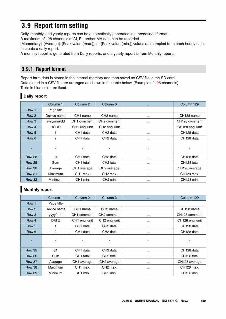
150DL30-G USERS MANUAL EM-8571-G Rev.7
3.9 Report form settingDaily, monthly, and yearly reports can be automatically generated in a predefined format. A maximum of 128 channels of AI, PI, and/or MA data can be recorded.[Momentary], [Average], [Peak value (max.)], or [Peak value (min.)] values are sampled from each hourly data to create a daily report.A monthly report is generated from Daily reports, and a yearly report is from Monthly reports.
3.9.1 Report formatReport form data is stored in the internal memory and then saved as CSV file in the SD card.Data stored in a CSV file are arranged as shown in the table below. (Example of 128 channels)Texts in blue color are fixed.
Daily report
Column 1 Column 2 Column 3 ... Column 129
Row 1 Page title
Row 2 Device name CH1 name CH2 name ... CH128 name
Row 3 yyyy/mm/dd CH1 comment CH2 comment ... CH128 comment
Row 4 HOUR CH1 eng. unit CH2 eng. unit ... CH128 eng. unit
Row 5 1 CH1 data CH2 data ... CH128 data
Row 6 2 CH1 data CH2 data ... CH128 data
: : : : : :
Row 28 24 CH1 data CH2 data ... CH128 data
Row 29 Sum CH1 total CH2 total ... CH128 total
Row 30 Average CH1 average CH2 average ... CH128 average
Row 31 Maximum CH1 max. CH2 max. ... CH128 max.
Row 32 Minimum CH1 min. CH2 min. ... CH128 min.
Monthly report
Column 1 Column 2 Column 3 ... Column 129
Row 1 Page title
Row 2 Device name CH1 name CH2 name ... CH128 name
Row 3 yyyy/mm CH1 comment CH2 comment ... CH128 comment
Row 4 DATE CH1 eng. unit CH2 eng. unit ... CH128 eng. unit
Row 5 1 CH1 data CH2 data ... CH128 data
Row 6 2 CH1 data CH2 data ... CH128 data
: : : : : :
Row 35 31 CH1 data CH2 data ... CH128 data
Row 36 Sum CH1 total CH2 total ... CH128 total
Row 37 Average CH1 average CH2 average ... CH128 average
Row 38 Maximum CH1 max. CH2 max. ... CH128 max.
Row 39 Minimum CH1 min. CH2 min. ... CH128 min.
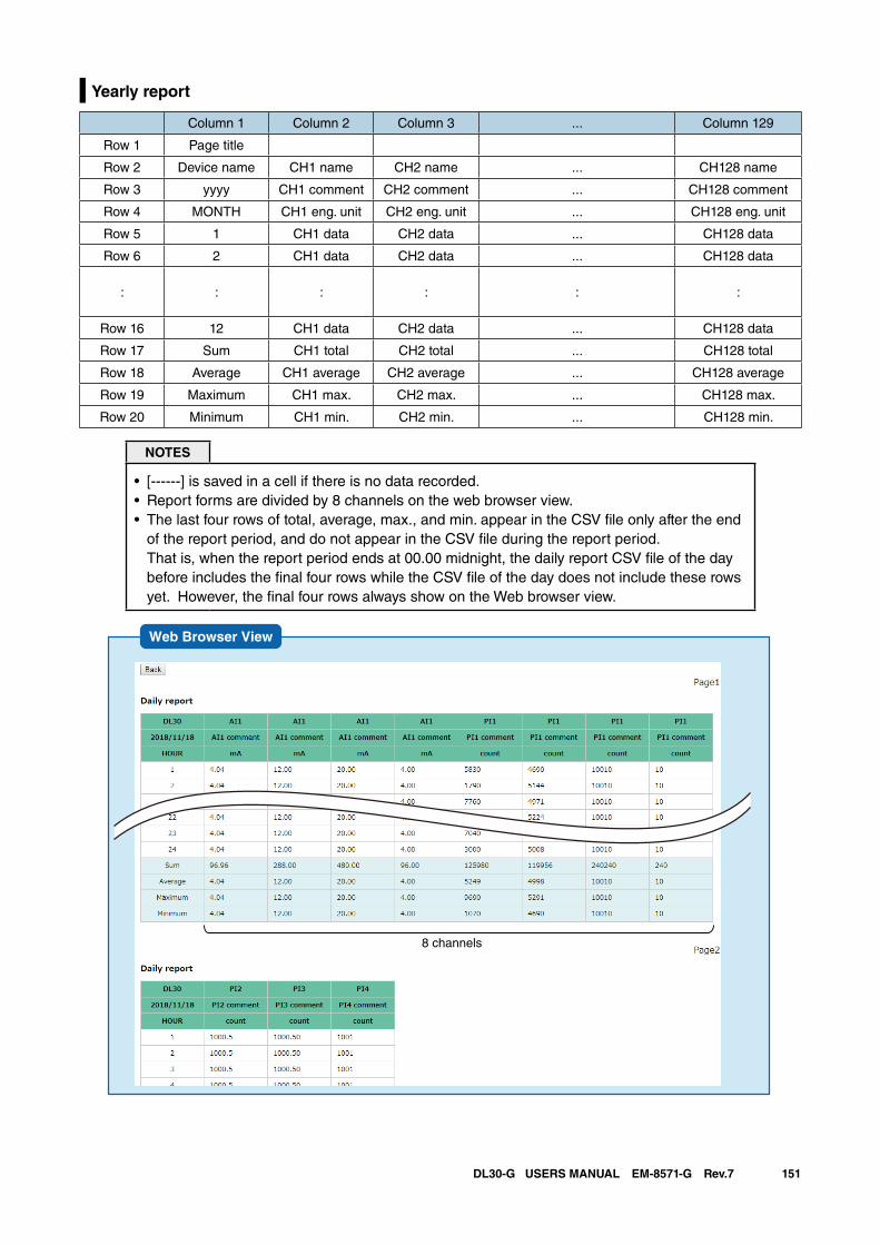
151DL30-G USERS MANUAL EM-8571-G Rev.7
Yearly report
Column 1 Column 2 Column 3 ... Column 129
Row 1 Page title
Row 2 Device name CH1 name CH2 name ... CH128 name
Row 3 yyyy CH1 comment CH2 comment ... CH128 comment
Row 4 MONTH CH1 eng. unit CH2 eng. unit ... CH128 eng. unit
Row 5 1 CH1 data CH2 data ... CH128 data
Row 6 2 CH1 data CH2 data ... CH128 data
: : : : : :
Row 16 12 CH1 data CH2 data ... CH128 data
Row 17 Sum CH1 total CH2 total ... CH128 total
Row 18 Average CH1 average CH2 average ... CH128 average
Row 19 Maximum CH1 max. CH2 max. ... CH128 max.
Row 20 Minimum CH1 min. CH2 min. ... CH128 min.
NOTES
• [------] is saved in a cell if there is no data recorded.• Report forms are divided by 8 channels on the web browser view.• The last four rows of total, average, max., and min. appear in the CSV file only after the end
of the report period, and do not appear in the CSV file during the report period. That is, when the report period ends at 00.00 midnight, the daily report CSV file of the day before includes the final four rows while the CSV file of the day does not include these rows yet. However, the final four rows always show on the Web browser view.
Web Browser View
8 channels
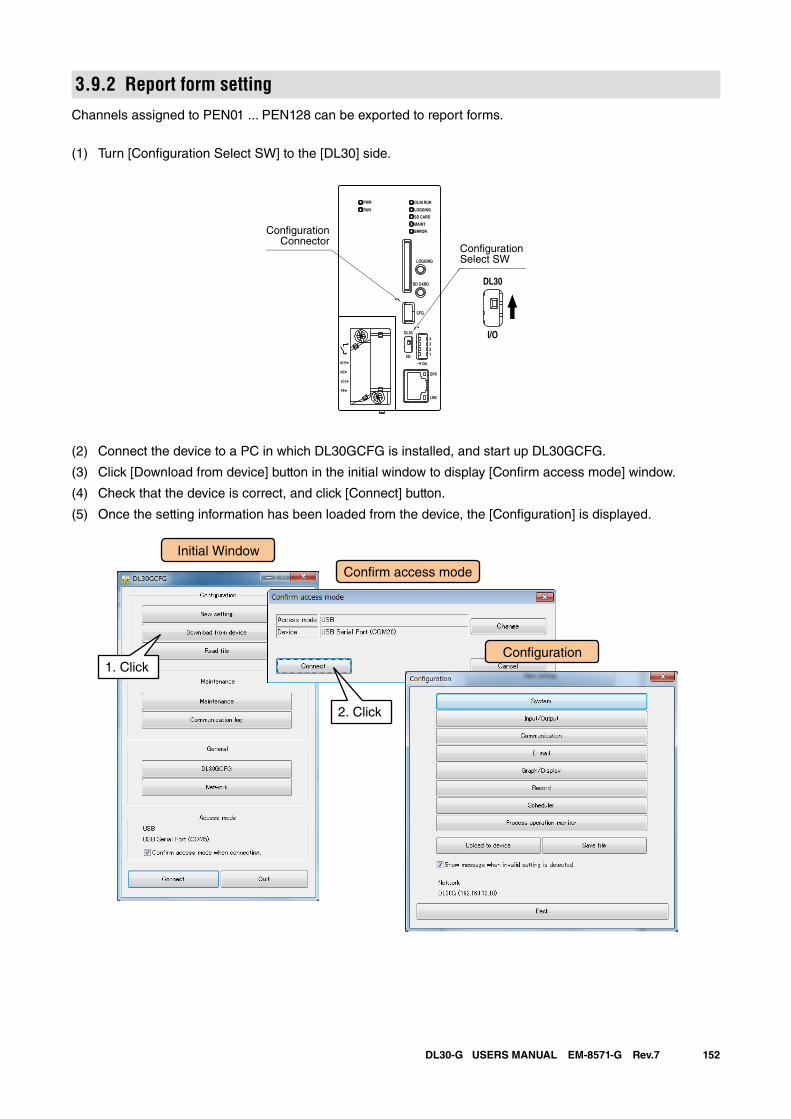
152DL30-G USERS MANUAL EM-8571-G Rev.7
3.9.2 Report form settingChannels assigned to PEN01 ... PEN128 can be exported to report forms.
(1) Turn [Configuration Select SW] to the [DL30] side.
(2) Connect the device to a PC in which DL30GCFG is installed, and start up DL30GCFG.
(3) Click [Download from device] button in the initial window to display [Confirm access mode] window.
(4) Check that the device is correct, and click [Connect] button.
(5) Once the setting information has been loaded from the device, the [Configuration] is displayed.
DL30 RUN
LOGGING
SD CARD
MAINT
PWR
RUN
ERROR
CFG
DPX
LNK
LOGGING
SD CARD
DL30
2
I/O
On
43
1
U(+)
NC
V(-)
FE
DL30
I/O
ConfigurationSelect SW
ConfigurationConnector
Initial Window
Con�rm access mode
Con�guration1. Click
2. Click
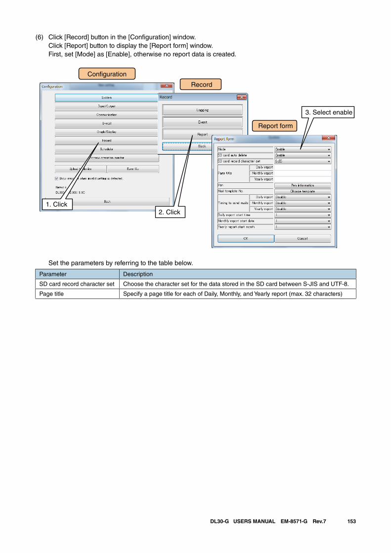
153DL30-G USERS MANUAL EM-8571-G Rev.7
(6) Click [Record] button in the [Configuration] window. Click [Report] button to display the [Report form] window. First, set [Mode] as [Enable], otherwise no report data is created.
Set the parameters by referring to the table below.
Parameter Description
SD card record character set Choose the character set for the data stored in the SD card between S-JIS and UTF-8.
Page title Specify a page title for each of Daily, Monthly, and Yearly report (max. 32 characters)
Con�guration
Record
Report form
1. Click2. Click
3. Select enable
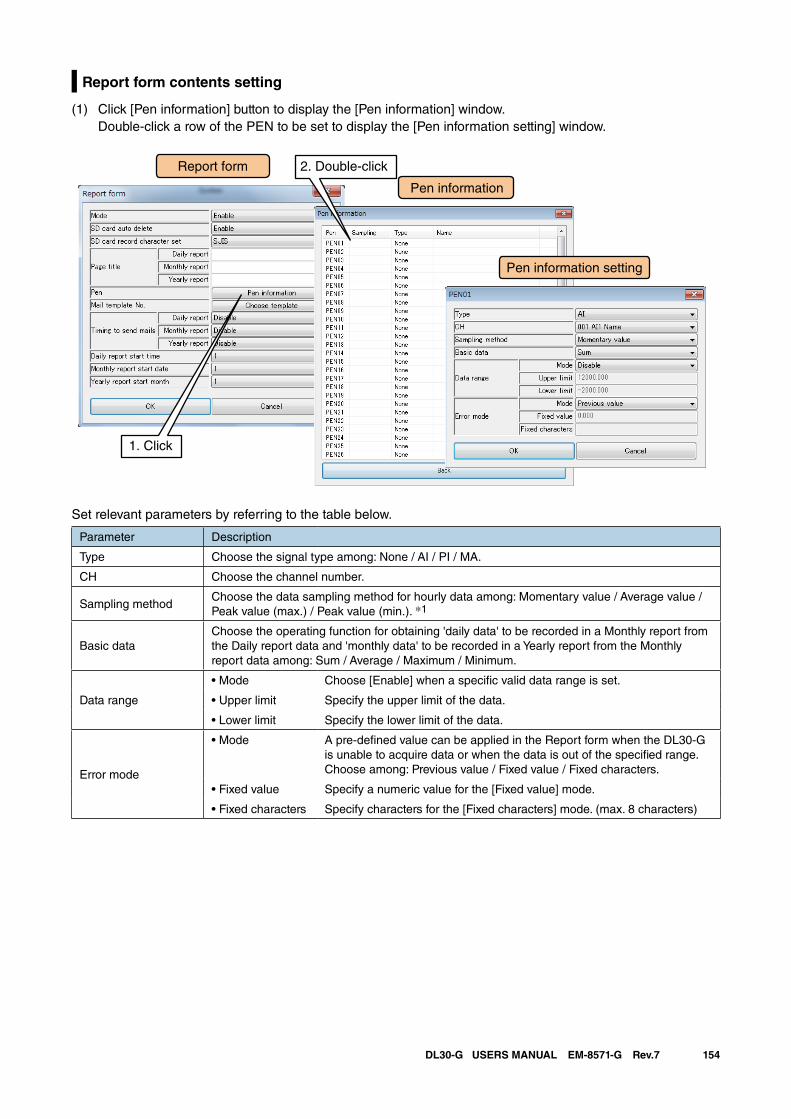
154DL30-G USERS MANUAL EM-8571-G Rev.7
Report form contents setting
(1) Click [Pen information] button to display the [Pen information] window. Double-click a row of the PEN to be set to display the [Pen information setting] window.
Set relevant parameters by referring to the table below.
Parameter Description
Type Choose the signal type among: None / AI / PI / MA.
CH Choose the channel number.
Sampling methodChoose the data sampling method for hourly data among: Momentary value / Average value / Peak value (max.) / Peak value (min.). *1
Basic dataChoose the operating function for obtaining 'daily data' to be recorded in a Monthly report from the Daily report data and 'monthly data' to be recorded in a Yearly report from the Monthly report data among: Sum / Average / Maximum / Minimum.
Data range
• Mode Choose [Enable] when a specific valid data range is set.
• Upper limit Specify the upper limit of the data.
• Lower limit Specify the lower limit of the data.
Error mode
• Mode A pre-defined value can be applied in the Report form when the DL30-G is unable to acquire data or when the data is out of the specified range. Choose among: Previous value / Fixed value / Fixed characters.
• Fixed value Specify a numeric value for the [Fixed value] mode.
• Fixed characters Specify characters for the [Fixed characters] mode. (max. 8 characters)
Pen information
Report form
1. Click
Pen information setting
2. Double-click
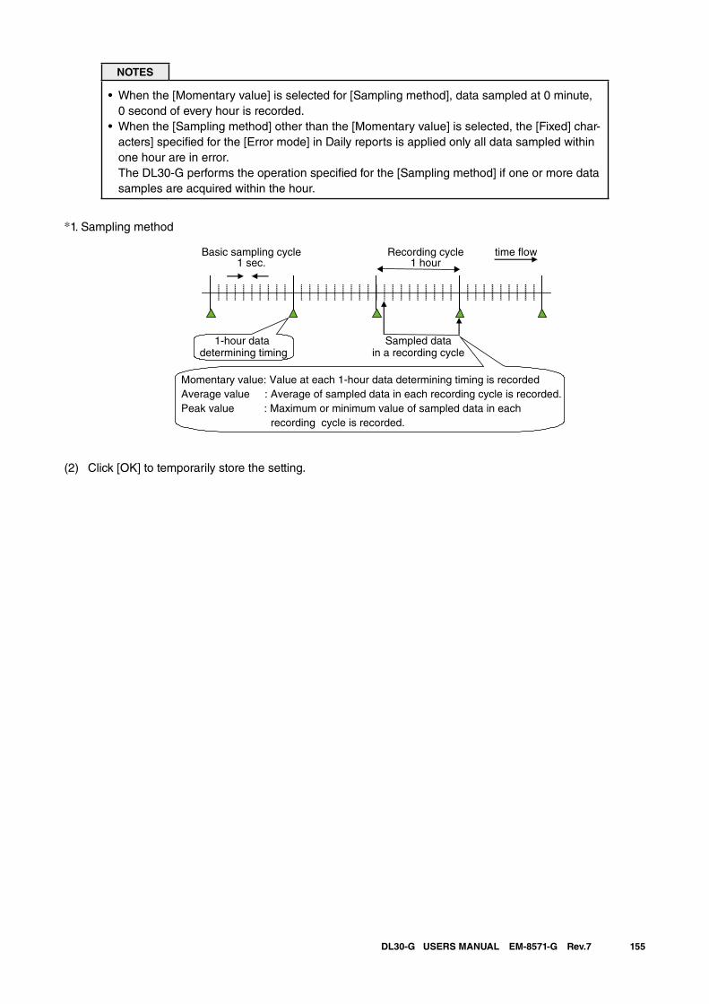
155DL30-G USERS MANUAL EM-8571-G Rev.7
NOTES
• When the [Momentary value] is selected for [Sampling method], data sampled at 0 minute, 0 second of every hour is recorded.
• When the [Sampling method] other than the [Momentary value] is selected, the [Fixed] char-acters] specified for the [Error mode] in Daily reports is applied only all data sampled within one hour are in error. The DL30-G performs the operation specified for the [Sampling method] if one or more data samples are acquired within the hour.
*1. Sampling method
Basic sampling cycle1 sec.
1-hour data determining timing
Sampled datain a recording cycle
time �ow
Momentary value: Value at each 1-hour data determining timing is recordedAverage value : Average of sampled data in each recording cycle is recorded. Peak value : Maximum or minimum value of sampled data in each recording cycle is recorded.
Recording cycle1 hour
(2) Click [OK] to temporarily store the setting.
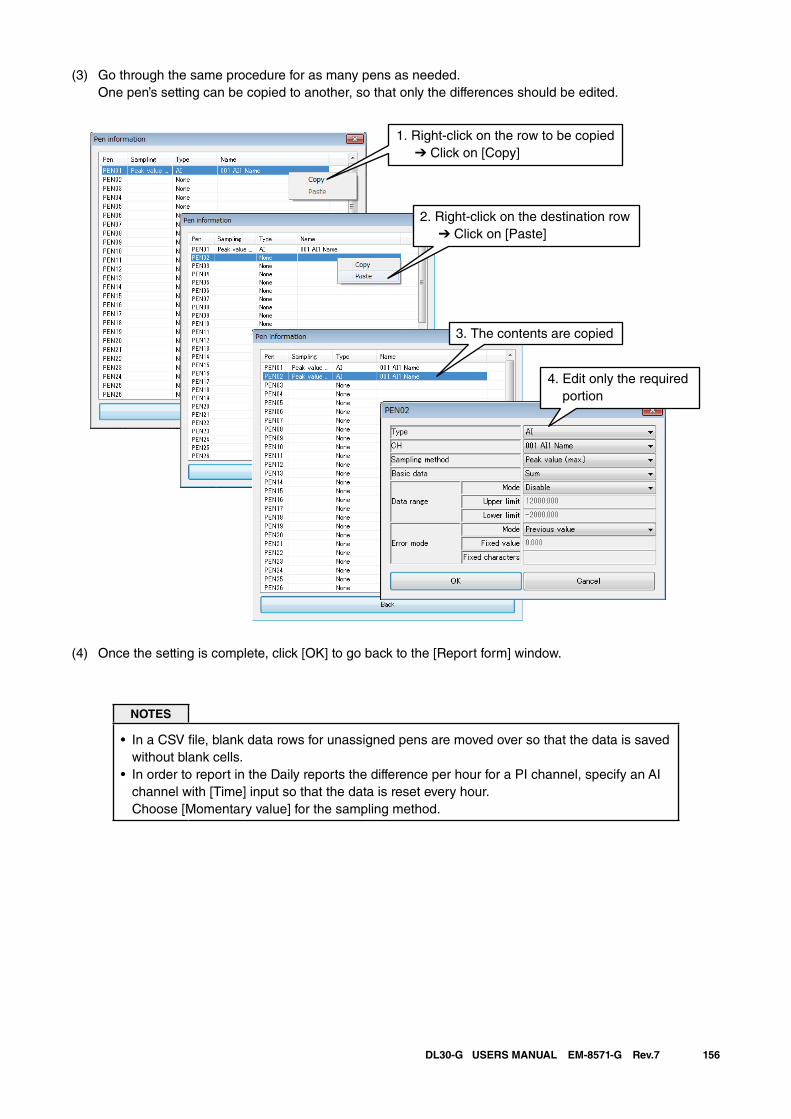
156DL30-G USERS MANUAL EM-8571-G Rev.7
(3) Go through the same procedure for as many pens as needed. One pen’s setting can be copied to another, so that only the differences should be edited.
(4) Once the setting is complete, click [OK] to go back to the [Report form] window.
NOTES
• In a CSV file, blank data rows for unassigned pens are moved over so that the data is saved without blank cells.
• In order to report in the Daily reports the difference per hour for a PI channel, specify an AI channel with [Time] input so that the data is reset every hour. Choose [Momentary value] for the sampling method.
1. Right-click on the row to be copied ➔ Click on [Copy]
2. Right-click on the destination row ➔ Click on [Paste]
3. The contents are copied
4. Edit only the required portion
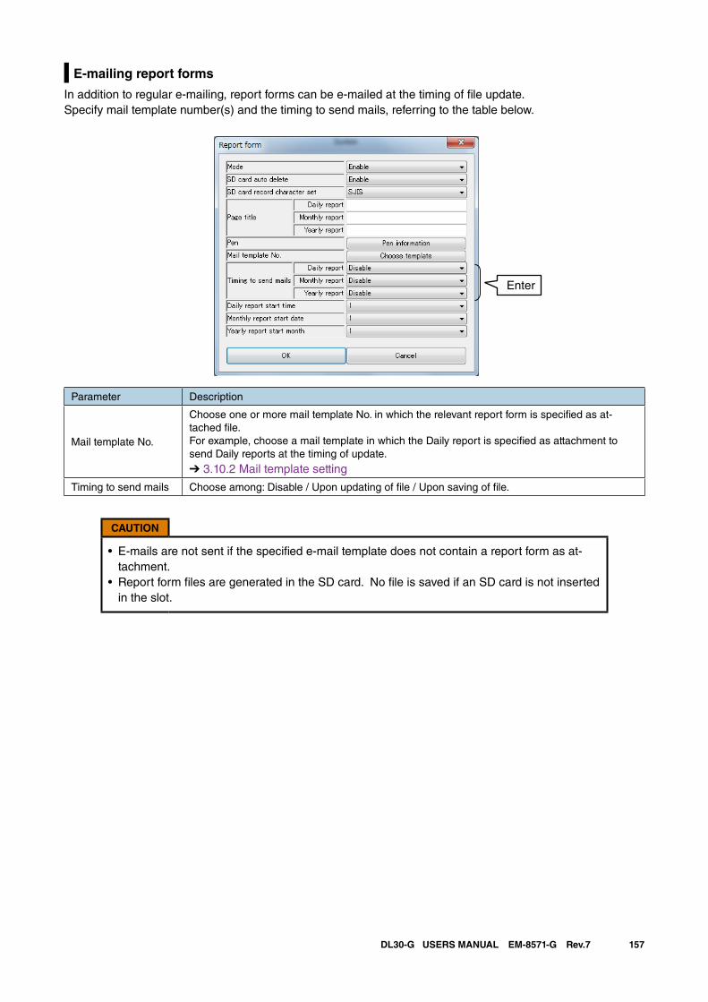
157DL30-G USERS MANUAL EM-8571-G Rev.7
E-mailing report forms
In addition to regular e-mailing, report forms can be e-mailed at the timing of file update.Specify mail template number(s) and the timing to send mails, referring to the table below.
Parameter Description
Mail template No.
Choose one or more mail template No. in which the relevant report form is specified as at-tached file. For example, choose a mail template in which the Daily report is specified as attachment to send Daily reports at the timing of update.
➔ 3.10.2 Mail template setting
Timing to send mails Choose among: Disable / Upon updating of file / Upon saving of file.
CAUTION
• E-mails are not sent if the specified e-mail template does not contain a report form as at-tachment.
• Report form files are generated in the SD card. No file is saved if an SD card is not inserted in the slot.
Enter
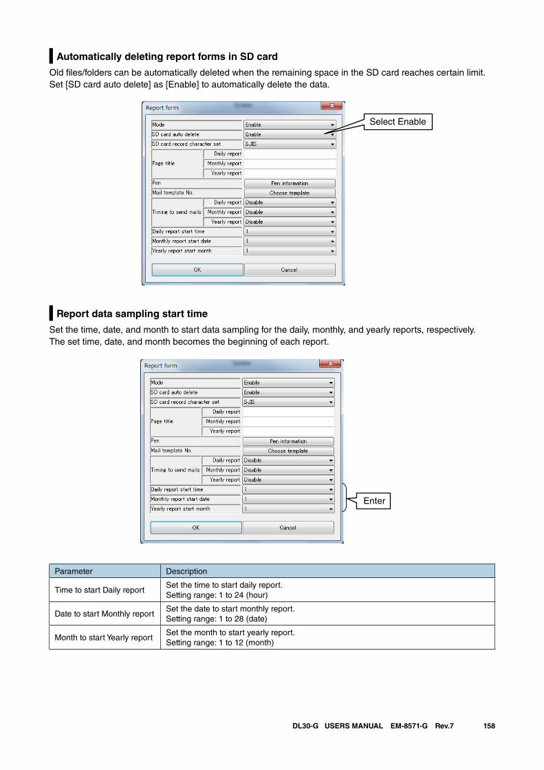
158DL30-G USERS MANUAL EM-8571-G Rev.7
Automatically deleting report forms in SD card
Old files/folders can be automatically deleted when the remaining space in the SD card reaches certain limit. Set [SD card auto delete] as [Enable] to automatically delete the data.
Report data sampling start time
Set the time, date, and month to start data sampling for the daily, monthly, and yearly reports, respectively.The set time, date, and month becomes the beginning of each report.
Parameter Description
Time to start Daily reportSet the time to start daily report. Setting range: 1 to 24 (hour)
Date to start Monthly reportSet the date to start monthly report. Setting range: 1 to 28 (date)
Month to start Yearly reportSet the month to start yearly report. Setting range: 1 to 12 (month)
Select Enable
Enter
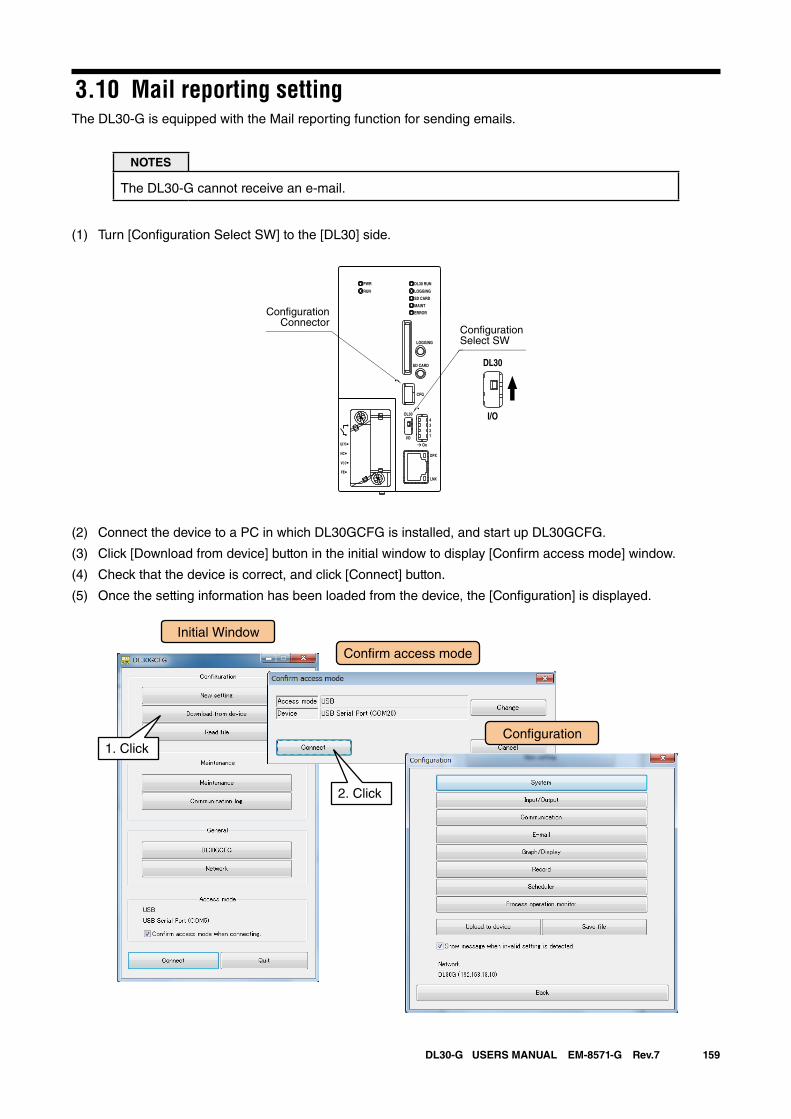
159DL30-G USERS MANUAL EM-8571-G Rev.7
3.10 Mail reporting settingThe DL30-G is equipped with the Mail reporting function for sending emails.
NOTES
The DL30-G cannot receive an e-mail.
(1) Turn [Configuration Select SW] to the [DL30] side.
(2) Connect the device to a PC in which DL30GCFG is installed, and start up DL30GCFG.
(3) Click [Download from device] button in the initial window to display [Confirm access mode] window.
(4) Check that the device is correct, and click [Connect] button.
(5) Once the setting information has been loaded from the device, the [Configuration] is displayed.
DL30 RUN
LOGGING
SD CARD
MAINT
PWR
RUN
ERROR
CFG
DPX
LNK
LOGGING
SD CARD
DL30
2
I/O
On
43
1
U(+)
NC
V(-)
FE
DL30
I/O
ConfigurationSelect SW
ConfigurationConnector
Initial Window
Con�rm access mode
Con�guration1. Click
2. Click
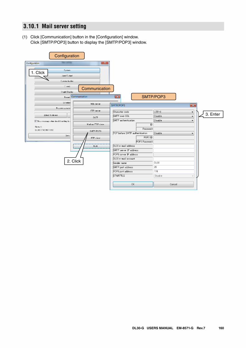
160DL30-G USERS MANUAL EM-8571-G Rev.7
3.10.1 Mail server setting
(1) Click [Communication] button in the [Configuration] window. Click [SMTP/POP3] button to display the [SMTP/POP3] window.
Con�guration
SMTP/POP3
Communication
1. Click
3. Enter
2. Click
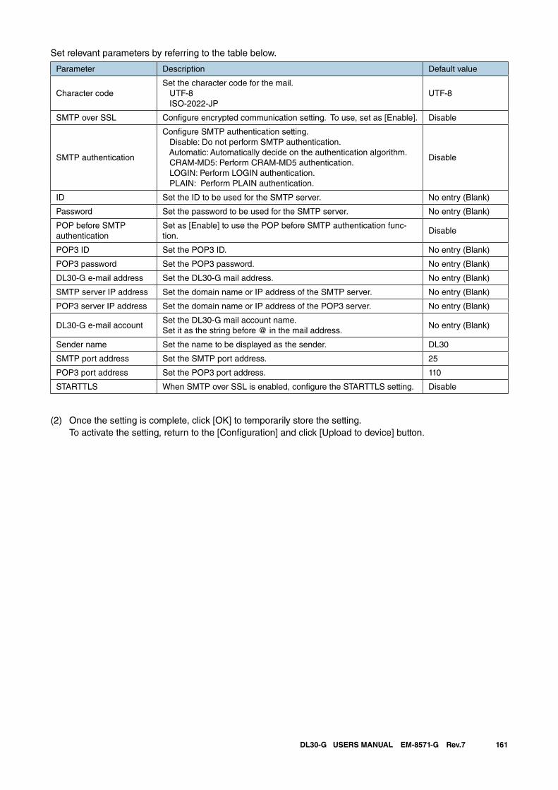
161DL30-G USERS MANUAL EM-8571-G Rev.7
Set relevant parameters by referring to the table below.
Parameter Description Default value
Character codeSet the character code for the mail. UTF-8 ISO-2022-JP
UTF-8
SMTP over SSL Configure encrypted communication setting. To use, set as [Enable]. Disable
SMTP authentication
Configure SMTP authentication setting. Disable: Do not perform SMTP authentication. Automatic: Automatically decide on the authentication algorithm. CRAM-MD5: Perform CRAM-MD5 authentication. LOGIN: Perform LOGIN authentication. PLAIN: Perform PLAIN authentication.
Disable
ID Set the ID to be used for the SMTP server. No entry (Blank)
Password Set the password to be used for the SMTP server. No entry (Blank)
POP before SMTP authentication
Set as [Enable] to use the POP before SMTP authentication func-tion.
Disable
POP3 ID Set the POP3 ID. No entry (Blank)
POP3 password Set the POP3 password. No entry (Blank)
DL30-G e-mail address Set the DL30-G mail address. No entry (Blank)
SMTP server IP address Set the domain name or IP address of the SMTP server. No entry (Blank)
POP3 server IP address Set the domain name or IP address of the POP3 server. No entry (Blank)
DL30-G e-mail accountSet the DL30-G mail account name.Set it as the string before @ in the mail address.
No entry (Blank)
Sender name Set the name to be displayed as the sender. DL30
SMTP port address Set the SMTP port address. 25
POP3 port address Set the POP3 port address. 110
STARTTLS When SMTP over SSL is enabled, configure the STARTTLS setting. Disable
(2) Once the setting is complete, click [OK] to temporarily store the setting. To activate the setting, return to the [Configuration] and click [Upload to device] button.
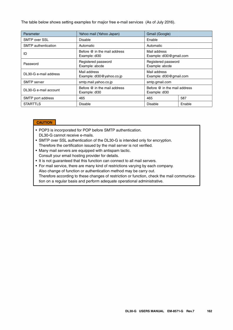
162DL30-G USERS MANUAL EM-8571-G Rev.7
The table below shows setting examples for majior free e-mail services (As of July 2016).
Parameter Yahoo mail (Yahoo Japan) Gmail (Google)
SMTP over SSL Disable Enable
SMTP authentication Automatic Automatic
IDBefore @ in the mail addressExample: dl30
Mail addressExample: [email protected]
PasswordRegistered passwordExample: abcde
Registered passwordExample: abcde
DL30-G e-mail addressMail addressExample: [email protected]
Mail addressExample: [email protected]
SMTP server smtp.mail.yahoo.co.jp smtp.gmail.com
DL30-G e-mail accountBefore @ in the mail addressExample: dl30
Before @ in the mail addressExample: dl30
SMTP port address 465 465 587
STARTTLS Disable Disable Enable
CAUTION
• POP3 is incorporated for POP before SMTP authentication. DL30-G cannot receive e-mails.
• SMTP over SSL authentication of the DL30-G is intended only for encryption. Therefore the certification issued by the mail server is not verified.
• Many mail servers are equipped with antispam tactic. Consult your email hosting provider for details.
• It is not guaranteed that this function can connect to all mail servers.• For mail service, there are many kind of restrictions varying by each company.
Also change of function or authentication method may be carry out. Therefore according to these changes of restriction or function, check the mail communica-tion on a regular basis and perform adequate operational administrative.
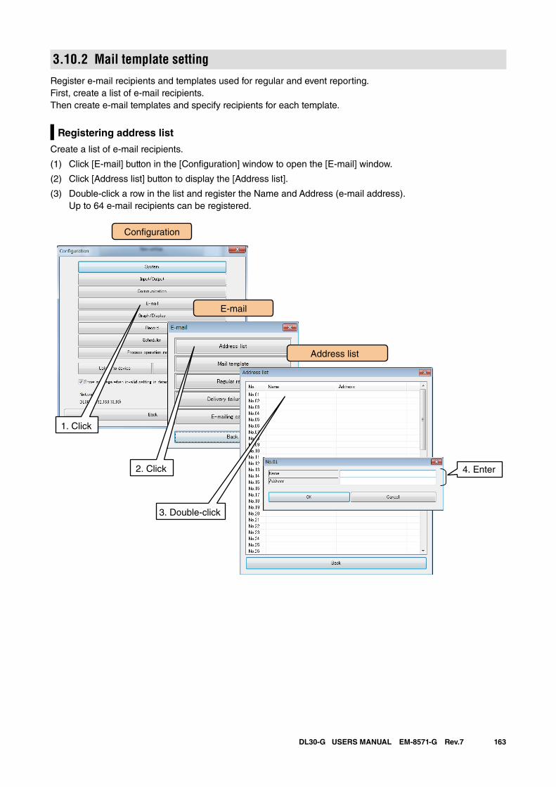
163DL30-G USERS MANUAL EM-8571-G Rev.7
3.10.2 Mail template settingRegister e-mail recipients and templates used for regular and event reporting. First, create a list of e-mail recipients. Then create e-mail templates and specify recipients for each template.
Registering address list
Create a list of e-mail recipients.
(1) Click [E-mail] button in the [Configuration] window to open the [E-mail] window.
(2) Click [Address list] button to display the [Address list].
(3) Double-click a row in the list and register the Name and Address (e-mail address). Up to 64 e-mail recipients can be registered.
Con�guration
Address list
4. Enter
1. Click
2. Click
3. Double-click
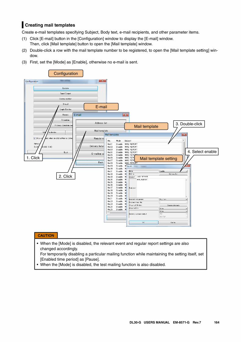
164DL30-G USERS MANUAL EM-8571-G Rev.7
Creating mail templates
Create e-mail templates specifying Subject, Body text, e-mail recipients, and other parameter items.
(1) Click [E-mail] button in the [Configuration] window to display the [E-mail] window. Then, click [Mail template] button to open the [Mail template] window.
(2) Double-click a row with the mail template number to be registered, to open the [Mail template setting] win-dow.
(3) First, set the [Mode] as [Enable], otherwise no e-mail is sent.
CAUTION
• When the [Mode] is disabled, the relevant event and regular report settings are also changed accordingly. For temporarily disabling a particular mailing function while maintaining the setting itself, set [Enabled time period] as [Pause].
• When the [Mode] is disabled, the test mailing function is also disabled.
Con�guration
Mail template
Mail template setting
1. Click
2. Click
3. Double-click
4. Select enable
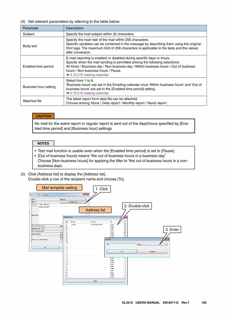
165DL30-G USERS MANUAL EM-8571-G Rev.7
(4) Set relevant parameters by referring to the table below.
Parameter Description
Subject Specify the mail subject within 32 characters.
Body text
Specify the main text of the mail within 256 characters.Specific variables can be contained in the message by describing them using the original html tags. The maximum limit of 256 characters is applicable to the texts and the values after conversion.
Enabled time period
E-mail reporting is enabled or disabled during specific days or hours. Specify when the mail sending is permitted among the following selections: All times / Business day / Non-business day / Within business hours / Out of business hours / Non-business hours / Pause.➔ 3.10.5 E-mailing calendar
Business hour setting
Select from 1 to 6.'Business hours' are set in the Emailing calendar once 'Within business hours' and 'Out of business hours' are set in the [Enabled time period] setting.➔ 3.10.5 E-mailing calendar
Attached fileThe latest report form data file can be attached.Choose among: None / Daily report / Monthly report / Yearly report.
CAUTION
No mail for the event report or regular report is sent out of the days/hours specified by [Ena-bled time period] and [Business hour] settings.
NOTES
• Test mail function is usable even when the [Enabled time period] is set to [Pause].• [Out of business hours] means “the out of business hours in a business day”.
Choose [Non-business hours] for applying the filter to “the out of business hours in a non-business days.
(5) Click [Address list] to display the [Address list]. Double-click a row of the recipient name and choose [To].
Mail template setting
Address list
1. Click
2. Double-click
3. Enter
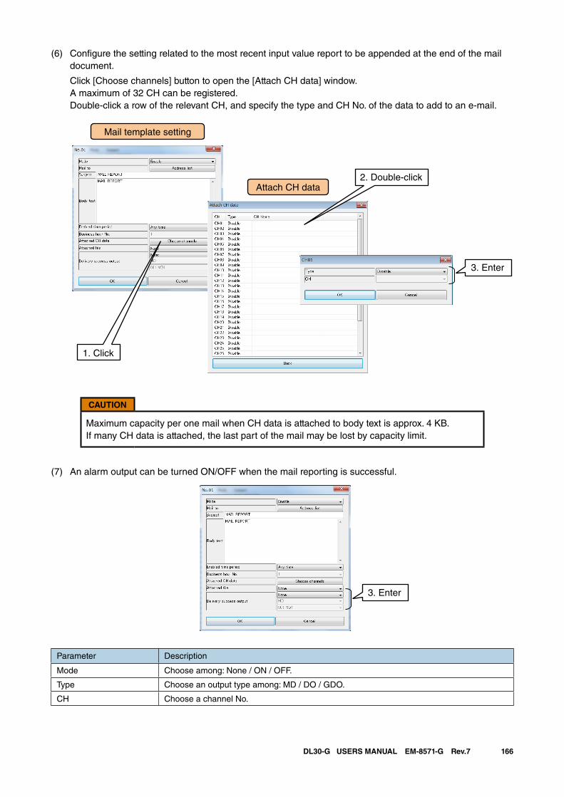
166DL30-G USERS MANUAL EM-8571-G Rev.7
(6) Configure the setting related to the most recent input value report to be appended at the end of the mail document.
Click [Choose channels] button to open the [Attach CH data] window. A maximum of 32 CH can be registered. Double-click a row of the relevant CH, and specify the type and CH No. of the data to add to an e-mail.
CAUTION
Maximum capacity per one mail when CH data is attached to body text is approx. 4 KB. If many CH data is attached, the last part of the mail may be lost by capacity limit.
(7) An alarm output can be turned ON/OFF when the mail reporting is successful.
3. Enter
Parameter Description
Mode Choose among: None / ON / OFF.
Type Choose an output type among: MD / DO / GDO.
CH Choose a channel No.
Mail template setting
Attach CH data2. Double-click
1. Click
3. Enter
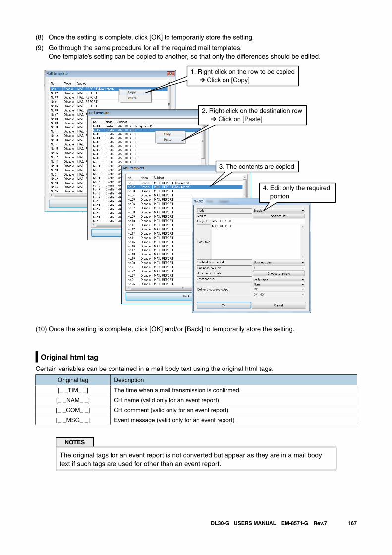
167DL30-G USERS MANUAL EM-8571-G Rev.7
(8) Once the setting is complete, click [OK] to temporarily store the setting.
(9) Go through the same procedure for all the required mail templates. One template’s setting can be copied to another, so that only the differences should be edited.
1. Right-click on the row to be copied ➔ Click on [Copy]
2. Right-click on the destination row ➔ Click on [Paste]
3. The contents are copied
4. Edit only the required portion
(10) Once the setting is complete, click [OK] and/or [Back] to temporarily store the setting.
Original html tag
Certain variables can be contained in a mail body text using the original html tags.
Original tag Description
[_ _TIM_ _] The time when a mail transmission is confirmed.
[_ _NAM_ _] CH name (valid only for an event report)
[_ _COM_ _] CH comment (valid only for an event report)
[_ _MSG_ _] Event message (valid only for an event report)
NOTES
The original tags for an event report is not converted but appear as they are in a mail body text if such tags are used for other than an event report.
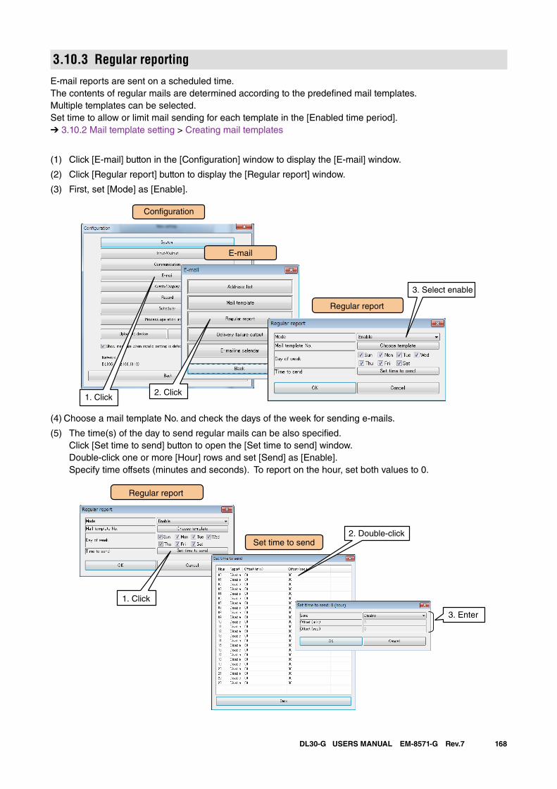
168DL30-G USERS MANUAL EM-8571-G Rev.7
3.10.3 Regular reportingE-mail reports are sent on a scheduled time.The contents of regular mails are determined according to the predefined mail templates. Multiple templates can be selected.Set time to allow or limit mail sending for each template in the [Enabled time period].➔ 3.10.2 Mail template setting > Creating mail templates
(1) Click [E-mail] button in the [Configuration] window to display the [E-mail] window.
(2) Click [Regular report] button to display the [Regular report] window.
(3) First, set [Mode] as [Enable].
Regular report
1. Click2. Click
3. Select enable
Con�guration
(4) Choose a mail template No. and check the days of the week for sending e-mails.
(5) The time(s) of the day to send regular mails can be also specified. Click [Set time to send] button to open the [Set time to send] window. Double-click one or more [Hour] rows and set [Send] as [Enable]. Specify time offsets (minutes and seconds). To report on the hour, set both values to 0.
Regular report
Set time to send2. Double-click
1. Click
3. Enter
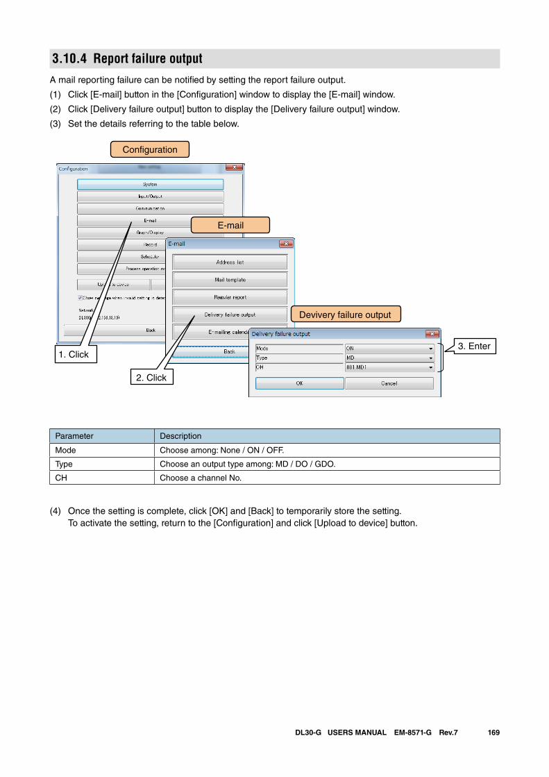
169DL30-G USERS MANUAL EM-8571-G Rev.7
3.10.4 Report failure outputA mail reporting failure can be notified by setting the report failure output.
(1) Click [E-mail] button in the [Configuration] window to display the [E-mail] window.
(2) Click [Delivery failure output] button to display the [Delivery failure output] window.
(3) Set the details referring to the table below.
Parameter Description
Mode Choose among: None / ON / OFF.
Type Choose an output type among: MD / DO / GDO.
CH Choose a channel No.
(4) Once the setting is complete, click [OK] and [Back] to temporarily store the setting. To activate the setting, return to the [Configuration] and click [Upload to device] button.
Con�guration
Devivery failure output
1. Click
2. Click
3. Enter
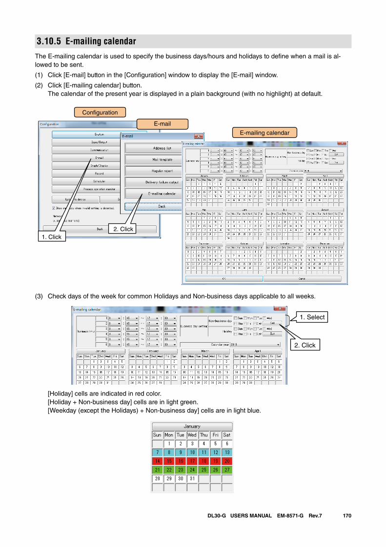
170DL30-G USERS MANUAL EM-8571-G Rev.7
3.10.5 E-mailing calendarThe E-mailing calendar is used to specify the business days/hours and holidays to define when a mail is al-lowed to be sent.
(1) Click [E-mail] button in the [Configuration] window to display the [E-mail] window.
(2) Click [E-mailing calendar] button. The calendar of the present year is displayed in a plain background (with no highlight) at default.
Con�guration
E-mailing calendar
1. Click
2. Click
(3) Check days of the week for common Holidays and Non-business days applicable to all weeks.
1. Select
2. Click
[Holiday] cells are indicated in red color. [Holiday + Non-business day] cells are in light green. [Weekday (except the Holidays) + Non-business day] cells are in light blue.
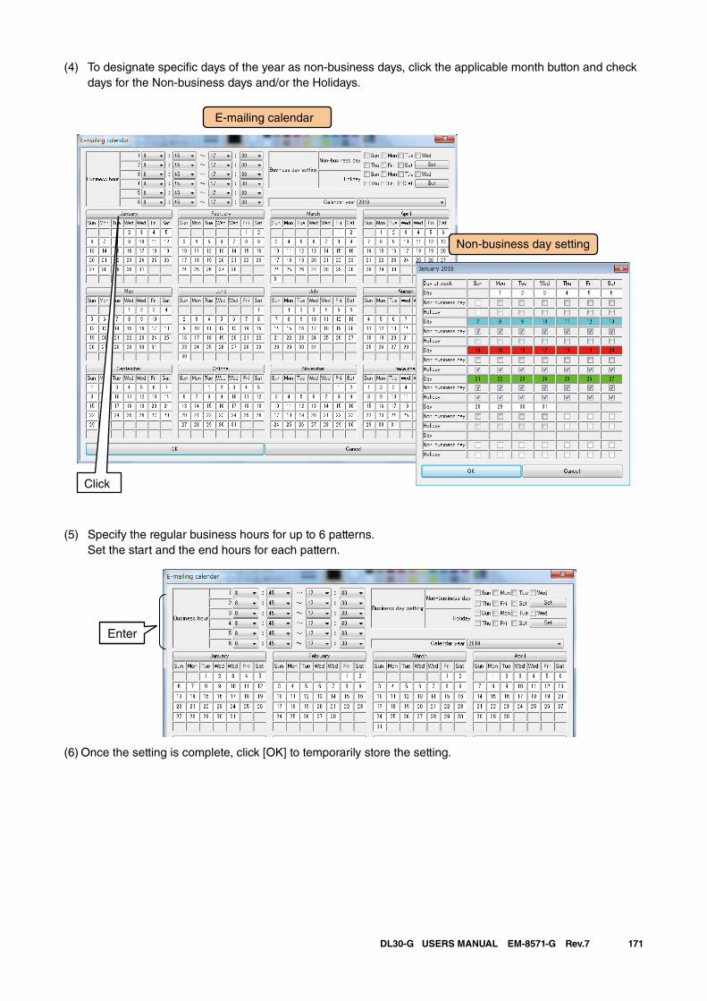
171DL30-G USERS MANUAL EM-8571-G Rev.7
(4) To designate specific days of the year as non-business days, click the applicable month button and check days for the Non-business days and/or the Holidays.
(5) Specify the regular business hours for up to 6 patterns. Set the start and the end hours for each pattern.
Enter
(6) Once the setting is complete, click [OK] to temporarily store the setting.
E-mailing calendar
Non-business day setting
Click
172DL30-G USERS MANUAL EM-8571-G Rev.7
3.10.6 Test mailEvent reporting and regular mailing can be tested on the DL30GCFG.
➔ 6.1.2 Maintenance menu (DL30GCFG) > Test mail
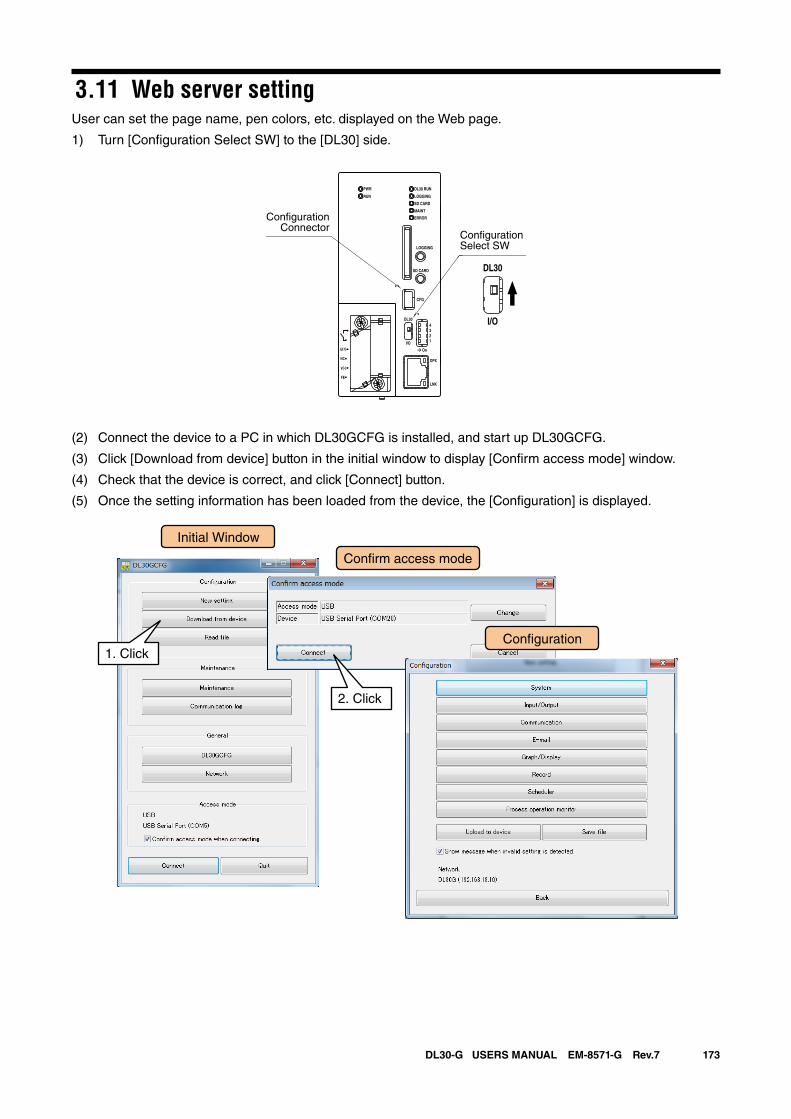
173DL30-G USERS MANUAL EM-8571-G Rev.7
3.11 Web server settingUser can set the page name, pen colors, etc. displayed on the Web page.
1) Turn [Configuration Select SW] to the [DL30] side.
(2) Connect the device to a PC in which DL30GCFG is installed, and start up DL30GCFG.
(3) Click [Download from device] button in the initial window to display [Confirm access mode] window.
(4) Check that the device is correct, and click [Connect] button.
(5) Once the setting information has been loaded from the device, the [Configuration] is displayed.
DL30 RUN
LOGGING
SD CARD
MAINT
PWR
RUN
ERROR
CFG
DPX
LNK
LOGGING
SD CARD
DL30
2
I/O
On
43
1
U(+)
NC
V(-)
FE
DL30
I/O
ConfigurationSelect SW
ConfigurationConnector
Initial Window
Con�rm access mode
Con�guration1. Click
2. Click
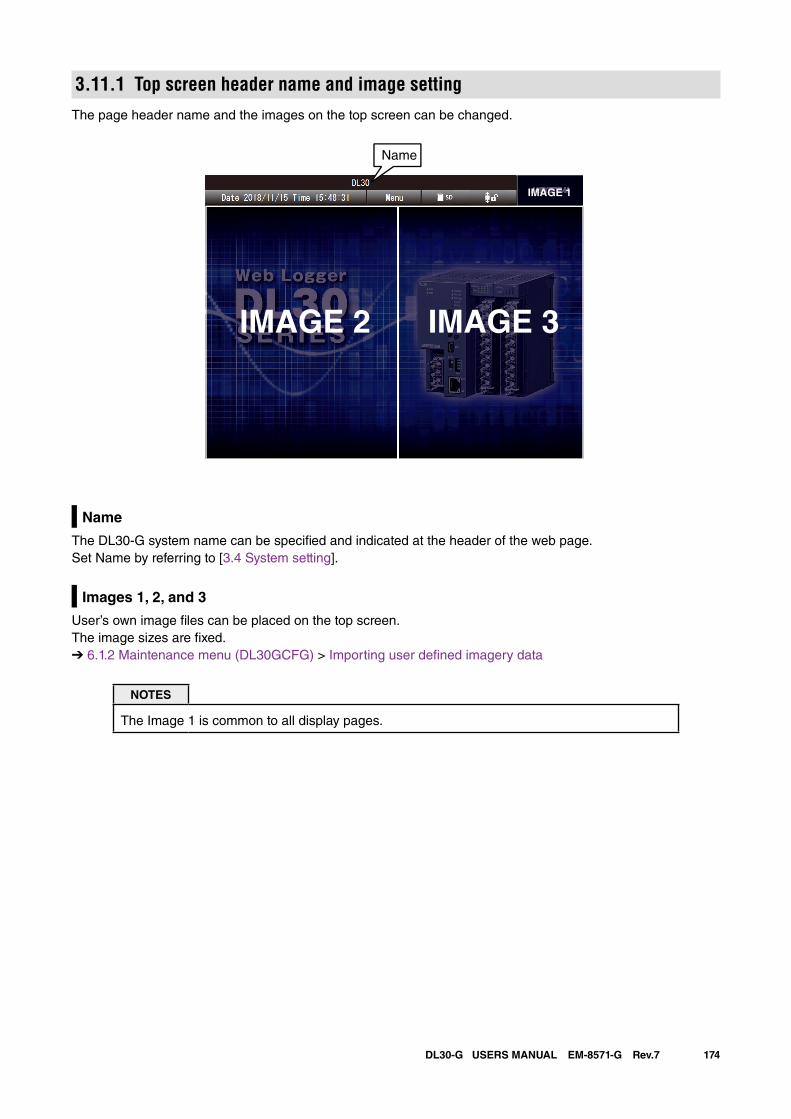
174DL30-G USERS MANUAL EM-8571-G Rev.7
3.11.1 Top screen header name and image settingThe page header name and the images on the top screen can be changed.
Name
The DL30-G system name can be specified and indicated at the header of the web page.Set Name by referring to [3.4 System setting].
Images 1, 2, and 3
User’s own image files can be placed on the top screen. The image sizes are fixed.➔ 6.1.2 Maintenance menu (DL30GCFG) > Importing user defined imagery data
NOTES
The Image 1 is common to all display pages.
Name
IMAGE 1
IMAGE 2 IMAGE 3
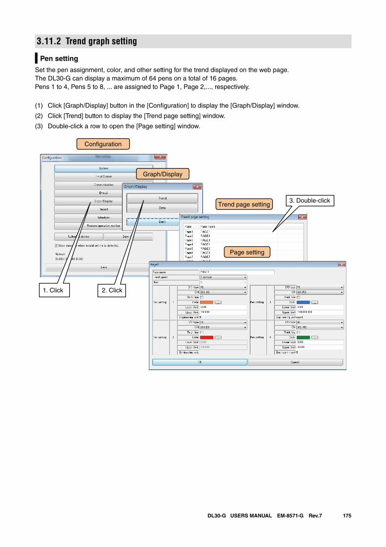
175DL30-G USERS MANUAL EM-8571-G Rev.7
3.11.2 Trend graph setting
Pen setting
Set the pen assignment, color, and other setting for the trend displayed on the web page.The DL30-G can display a maximum of 64 pens on a total of 16 pages.Pens 1 to 4, Pens 5 to 8, ... are assigned to Page 1, Page 2,..., respectively.
(1) Click [Graph/Display] button in the [Configuration] to display the [Graph/Display] window.
(2) Click [Trend] button to display the [Trend page setting] window.
(3) Double-click a row to open the [Page setting] window.
Con�guration
Trend page setting
Page setting
Graph/Display
1. Click 2. Click
3. Double-click
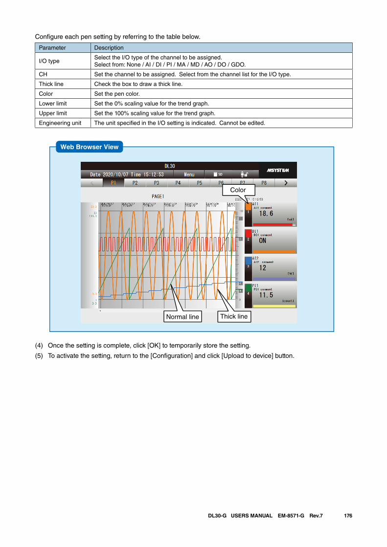
176DL30-G USERS MANUAL EM-8571-G Rev.7
Configure each pen setting by referring to the table below.
Parameter Description
I/O typeSelect the I/O type of the channel to be assigned. Select from: None / AI / DI / PI / MA / MD / AO / DO / GDO.
CH Set the channel to be assigned. Select from the channel list for the I/O type.
Thick line Check the box to draw a thick line.
Color Set the pen color.
Lower limit Set the 0% scaling value for the trend graph.
Upper limit Set the 100% scaling value for the trend graph.
Engineering unit The unit specified in the I/O setting is indicated. Cannot be edited.
Web Browser View
Color
Thick lineNormal line
(4) Once the setting is complete, click [OK] to temporarily store the setting.
(5) To activate the setting, return to the [Configuration] and click [Upload to device] button.
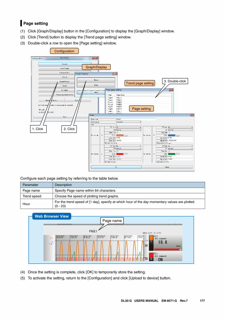
177DL30-G USERS MANUAL EM-8571-G Rev.7
Page setting
(1) Click [Graph/Display] button in the [Configuration] to display the [Graph/Display] window.
(2) Click [Trend] button to display the [Trend page setting] window.
(3) Double-click a row to open the [Page setting] window.
Con�guration
Trend page setting
Page setting
Graph/Display
1. Click 2. Click
3. Double-click
Configure each page setting by referring to the table below.
Parameter Description
Page name Specify Page name within 64 characters.
Trend speed Choose the speed of plotting trend graphs.
HourFor the trend speed of [1 day], specify at which hour of the day momentary values are plotted.(0 - 23)
Web Browser ViewPage name
(4) Once the setting is complete, click [OK] to temporarily store the setting.
(5) To activate the setting, return to the [Configuration] and click [Upload to device] button.
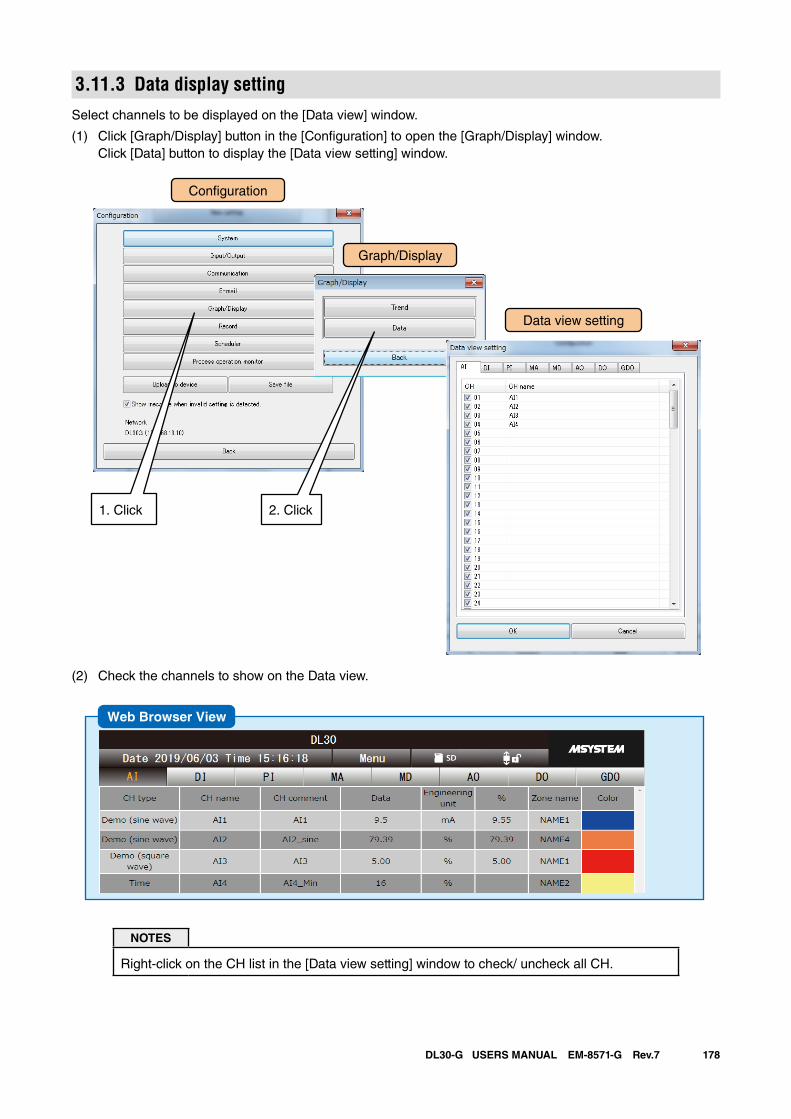
178DL30-G USERS MANUAL EM-8571-G Rev.7
3.11.3 Data display settingSelect channels to be displayed on the [Data view] window.
(1) Click [Graph/Display] button in the [Configuration] to open the [Graph/Display] window. Click [Data] button to display the [Data view setting] window.
(2) Check the channels to show on the Data view.
NOTES
Right-click on the CH list in the [Data view setting] window to check/ uncheck all CH.
Con�guration
Data view setting
Graph/Display
1. Click 2. Click
Web Browser View
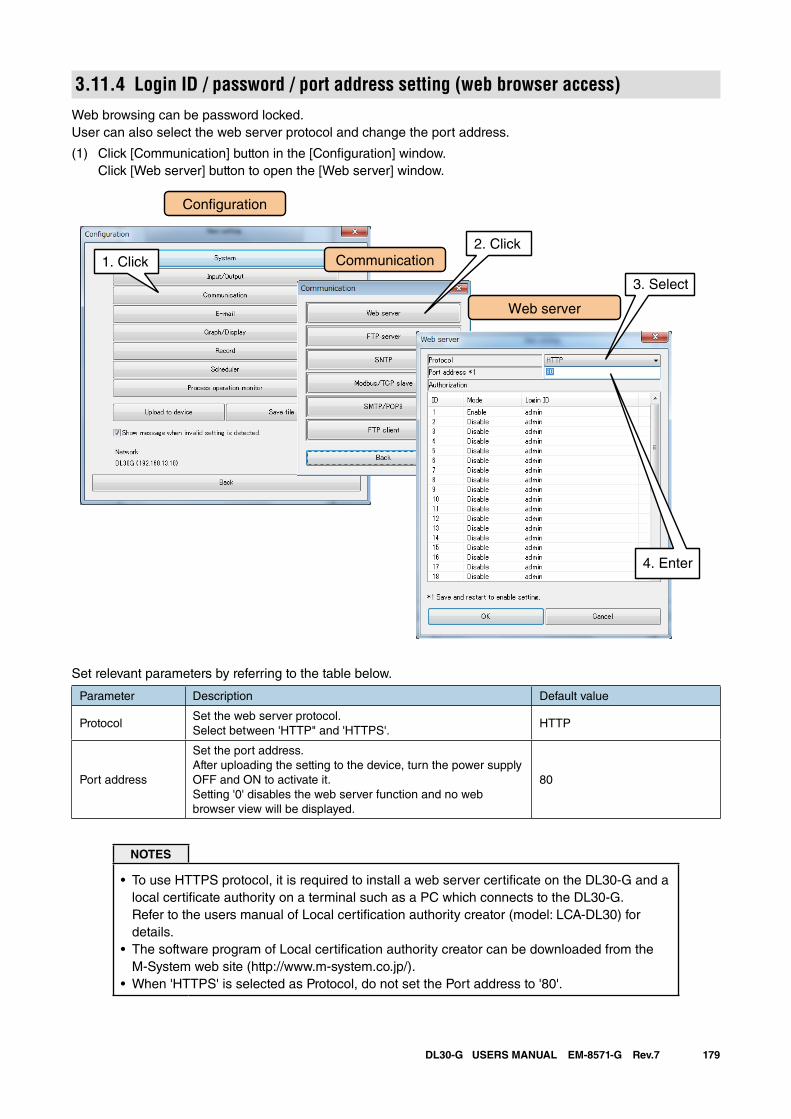
179DL30-G USERS MANUAL EM-8571-G Rev.7
3.11.4 Login ID / password / port address setting (web browser access)Web browsing can be password locked.User can also select the web server protocol and change the port address.
(1) Click [Communication] button in the [Configuration] window. Click [Web server] button to open the [Web server] window.
Con�guration
Web server
Communication1. Click
3. Select
2. Click
4. Enter
Set relevant parameters by referring to the table below.
Parameter Description Default value
ProtocolSet the web server protocol.Select between 'HTTP" and 'HTTPS'.
HTTP
Port address
Set the port address. After uploading the setting to the device, turn the power supply OFF and ON to activate it.Setting '0' disables the web server function and no web browser view will be displayed.
80
NOTES
• To use HTTPS protocol, it is required to install a web server certificate on the DL30-G and a local certificate authority on a terminal such as a PC which connects to the DL30-G. Refer to the users manual of Local certification authority creator (model: LCA-DL30) for details.
• The software program of Local certification authority creator can be downloaded from the M-System web site (http://www.m-system.co.jp/).
• When 'HTTPS' is selected as Protocol, do not set the Port address to '80'.
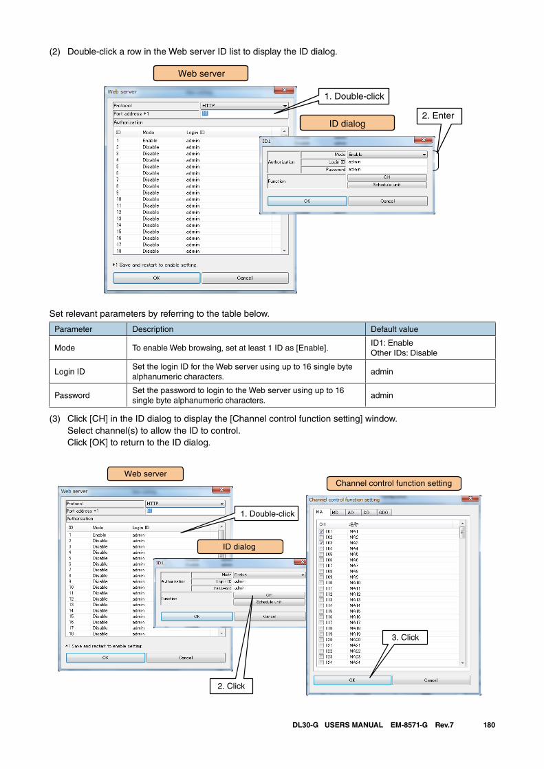
180DL30-G USERS MANUAL EM-8571-G Rev.7
(2) Double-click a row in the Web server ID list to display the ID dialog.
Web server
1. Double-click
2. EnterID dialog
Set relevant parameters by referring to the table below.
Parameter Description Default value
Mode To enable Web browsing, set at least 1 ID as [Enable]. ID1: EnableOther IDs: Disable
Login IDSet the login ID for the Web server using up to 16 single byte alphanumeric characters.
admin
PasswordSet the password to login to the Web server using up to 16 single byte alphanumeric characters.
admin
(3) Click [CH] in the ID dialog to display the [Channel control function setting] window. Select channel(s) to allow the ID to control. Click [OK] to return to the ID dialog.
Web server
1. Double-click 2. Enter
ID dialog
Channel control function setting
2. Click
3. Click
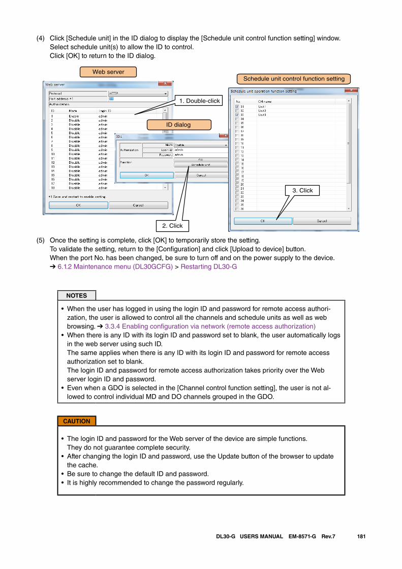
181DL30-G USERS MANUAL EM-8571-G Rev.7
(4) Click [Schedule unit] in the ID dialog to display the [Schedule unit control function setting] window. Select schedule unit(s) to allow the ID to control. Click [OK] to return to the ID dialog.
Web server
1. Double-click 2. Enter
ID dialog
Schedule unit control function setting
2. Click
3. Click
(5) Once the setting is complete, click [OK] to temporarily store the setting. To validate the setting, return to the [Configuration] and click [Upload to device] button. When the port No. has been changed, be sure to turn off and on the power supply to the device. ➔ 6.1.2 Maintenance menu (DL30GCFG) > Restarting DL30-G
NOTES
• When the user has logged in using the login ID and password for remote access authori-zation, the user is allowed to control all the channels and schedule units as well as web browsing. ➔ 3.3.4 Enabling configuration via network (remote access authorization)
• When there is any ID with its login ID and password set to blank, the user automatically logs in the web server using such ID. The same applies when there is any ID with its login ID and password for remote access authorization set to blank. The login ID and password for remote access authorization takes priority over the Web server login ID and password.
• Even when a GDO is selected in the [Channel control function setting], the user is not al-lowed to control individual MD and DO channels grouped in the GDO.
CAUTION
• The login ID and password for the Web server of the device are simple functions. They do not guarantee complete security.
• After changing the login ID and password, use the Update button of the browser to update the cache.
• Be sure to change the default ID and password.• It is highly recommended to change the password regularly.
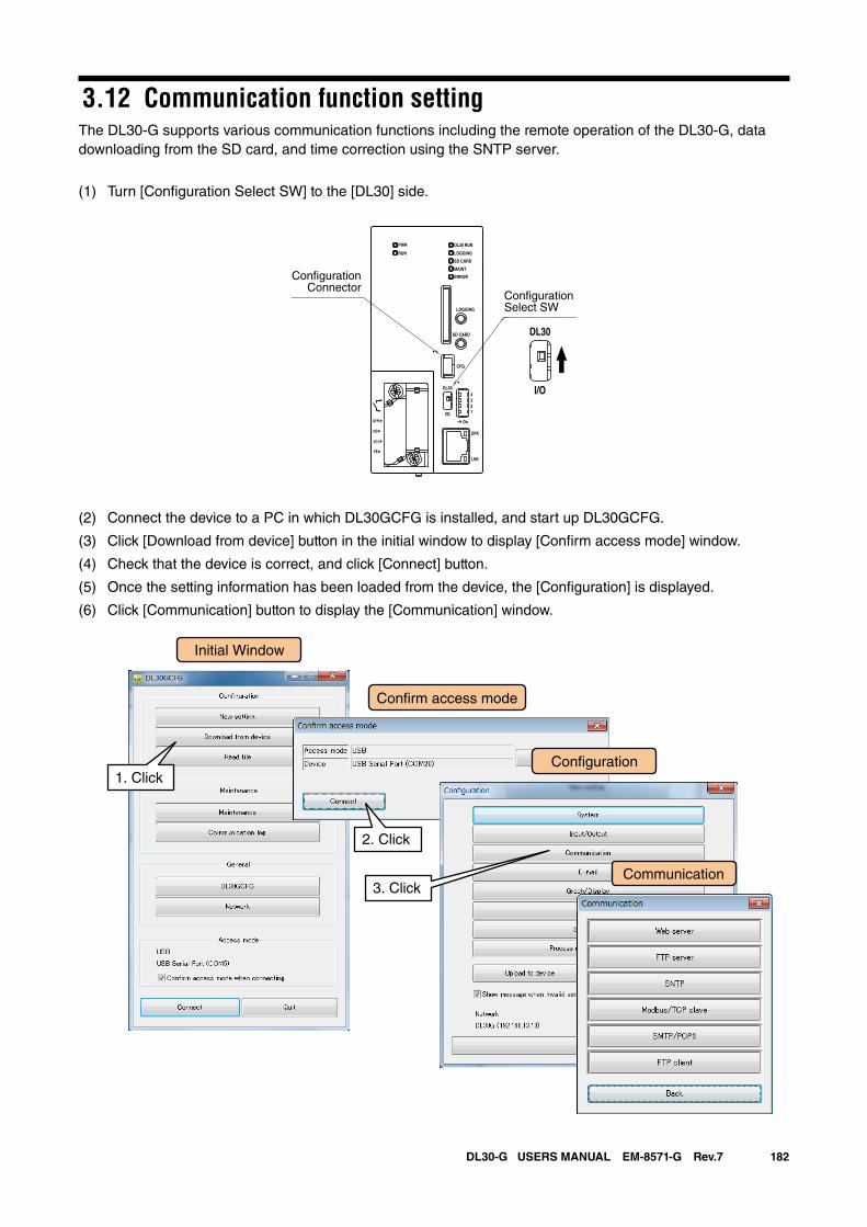
182DL30-G USERS MANUAL EM-8571-G Rev.7
3.12 Communication function settingThe DL30-G supports various communication functions including the remote operation of the DL30-G, data downloading from the SD card, and time correction using the SNTP server.
(1) Turn [Configuration Select SW] to the [DL30] side.
(2) Connect the device to a PC in which DL30GCFG is installed, and start up DL30GCFG.
(3) Click [Download from device] button in the initial window to display [Confirm access mode] window.
(4) Check that the device is correct, and click [Connect] button.
(5) Once the setting information has been loaded from the device, the [Configuration] is displayed.
(6) Click [Communication] button to display the [Communication] window.
DL30 RUN
LOGGING
SD CARD
MAINT
PWR
RUN
ERROR
CFG
DPX
LNK
LOGGING
SD CARD
DL30
2
I/O
On
43
1
U(+)
NC
V(-)
FE
DL30
I/O
ConfigurationSelect SW
ConfigurationConnector
Initial Window
Con�rm access mode
Con�guration1. Click
2. Click
3. ClickCommunication
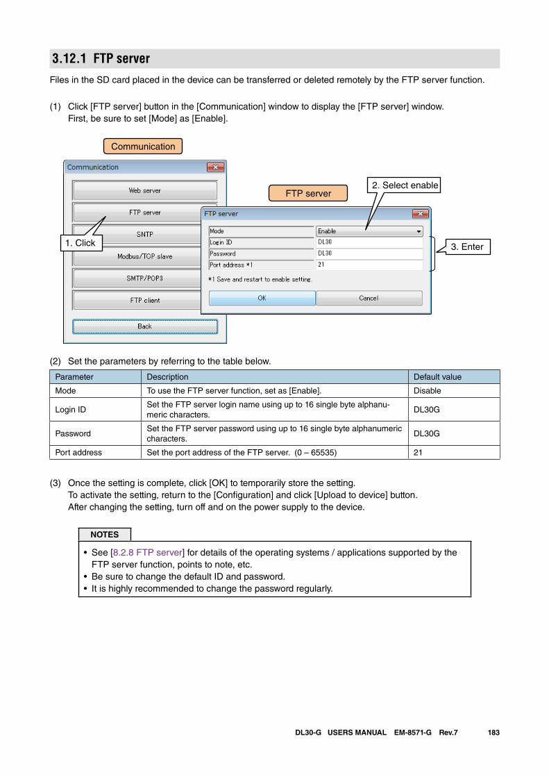
183DL30-G USERS MANUAL EM-8571-G Rev.7
3.12.1 FTP serverFiles in the SD card placed in the device can be transferred or deleted remotely by the FTP server function.
(1) Click [FTP server] button in the [Communication] window to display the [FTP server] window. First, be sure to set [Mode] as [Enable].
(2) Set the parameters by referring to the table below.
Parameter Description Default value
Mode To use the FTP server function, set as [Enable]. Disable
Login IDSet the FTP server login name using up to 16 single byte alphanu-meric characters.
DL30G
PasswordSet the FTP server password using up to 16 single byte alphanumeric characters.
DL30G
Port address Set the port address of the FTP server. (0 – 65535) 21
(3) Once the setting is complete, click [OK] to temporarily store the setting. To activate the setting, return to the [Configuration] and click [Upload to device] button. After changing the setting, turn off and on the power supply to the device.
NOTES
• See [8.2.8 FTP server] for details of the operating systems / applications supported by the FTP server function, points to note, etc.
• Be sure to change the default ID and password.• It is highly recommended to change the password regularly.
FTP server
Communication
1. Click
2. Select enable
3. Enter
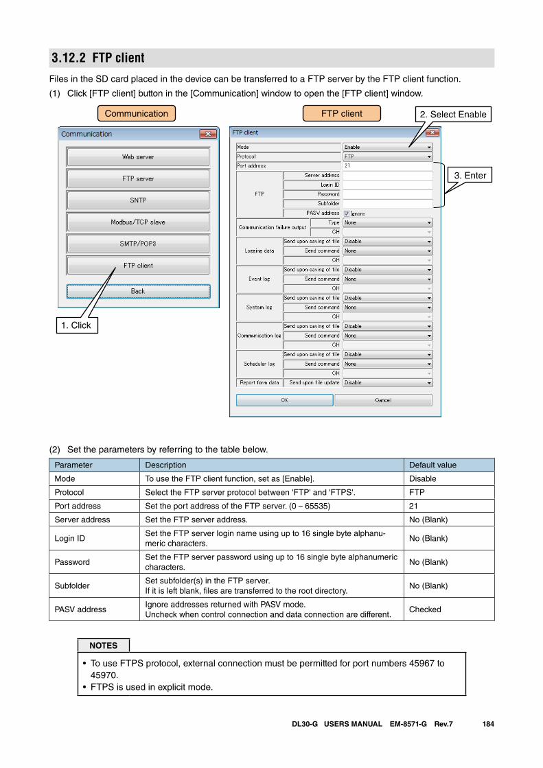
184DL30-G USERS MANUAL EM-8571-G Rev.7
3.12.2 FTP clientFiles in the SD card placed in the device can be transferred to a FTP server by the FTP client function.
(1) Click [FTP client] button in the [Communication] window to open the [FTP client] window.
FTP clientCommunication
1. Click
2. Select Enable
3. Enter
(2) Set the parameters by referring to the table below.
Parameter Description Default value
Mode To use the FTP client function, set as [Enable]. Disable
Protocol Select the FTP server protocol between 'FTP' and 'FTPS'. FTP
Port address Set the port address of the FTP server. (0 – 65535) 21
Server address Set the FTP server address. No (Blank)
Login IDSet the FTP server login name using up to 16 single byte alphanu-meric characters.
No (Blank)
PasswordSet the FTP server password using up to 16 single byte alphanumeric characters.
No (Blank)
SubfolderSet subfolder(s) in the FTP server.If it is left blank, files are transferred to the root directory.
No (Blank)
PASV addressIgnore addresses returned with PASV mode.Uncheck when control connection and data connection are different.
Checked
NOTES
• To use FTPS protocol, external connection must be permitted for port numbers 45967 to 45970.
• FTPS is used in explicit mode.
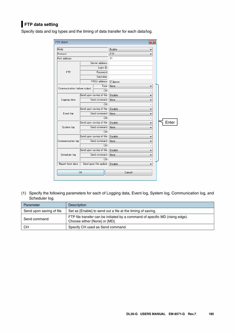
185DL30-G USERS MANUAL EM-8571-G Rev.7
FTP data setting
Specify data and log types and the timing of data transfer for each data/log.
(1) Specify the following parameters for each of Logging data, Event log, System log, Communication log, and Scheduler log.
Parameter Description
Send upon saving of file Set as [Enable] to send out a file at the timing of saving.
Send commandFTP file transfer can be initiated by a command of specific MD (rising edge). Choose either [None] or [MD].
CH Specify CH used as Send command.
Enter
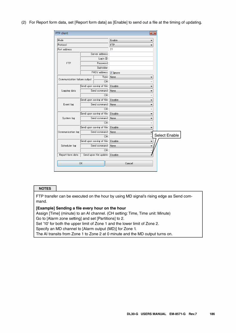
186DL30-G USERS MANUAL EM-8571-G Rev.7
(2) For Report form data, set [Report form data] as [Enable] to send out a file at the timing of updating.
NOTES
FTP transfer can be executed on the hour by using MD signal’s rising edge as Send com-mand.
[Example] Sending a file every hour on the hourAssign [Time] (minute) to an AI channel. (CH setting: Time, Time unit: Minute)Go to [Alarm zone setting] and set [Partitions] to 2. Set '10' for both the upper limit of Zone 1 and the lower limit of Zone 2.Specify an MD channel to [Alarm output (MD)] for Zone 1.The AI transits from Zone 1 to Zone 2 at 0 minute and the MD output turns on.
Select Enable
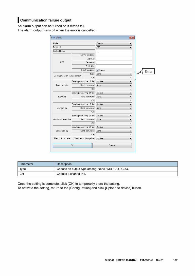
187DL30-G USERS MANUAL EM-8571-G Rev.7
Communication failure output
An alarm output can be turned on if retries fail. The alarm output turns off when the error is cancelled.
Enter
Parameter Description
Type Choose an output type among: None / MD / DO / GDO.
CH Choose a channel No.
Once the setting is complete, click [OK] to temporarily store the setting.To activate the setting, return to the [Configuration] and click [Upload to device] button.
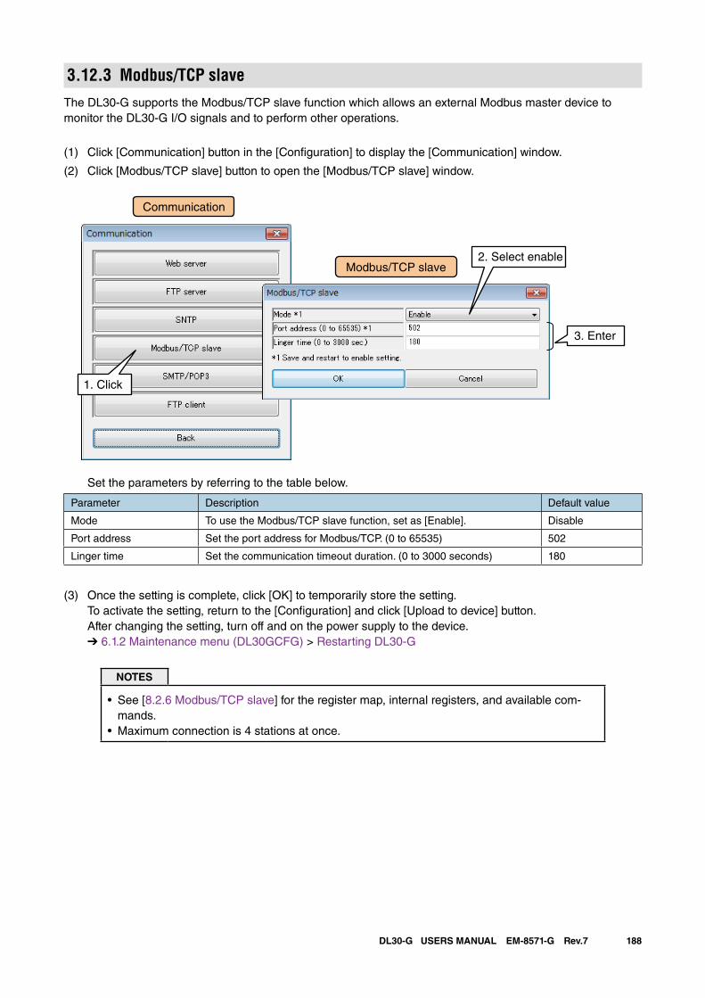
188DL30-G USERS MANUAL EM-8571-G Rev.7
3.12.3 Modbus/TCP slaveThe DL30-G supports the Modbus/TCP slave function which allows an external Modbus master device to monitor the DL30-G I/O signals and to perform other operations.
(1) Click [Communication] button in the [Configuration] to display the [Communication] window.
(2) Click [Modbus/TCP slave] button to open the [Modbus/TCP slave] window.
Set the parameters by referring to the table below.
Parameter Description Default value
Mode To use the Modbus/TCP slave function, set as [Enable]. Disable
Port address Set the port address for Modbus/TCP. (0 to 65535) 502
Linger time Set the communication timeout duration. (0 to 3000 seconds) 180
(3) Once the setting is complete, click [OK] to temporarily store the setting. To activate the setting, return to the [Configuration] and click [Upload to device] button. After changing the setting, turn off and on the power supply to the device. ➔ 6.1.2 Maintenance menu (DL30GCFG) > Restarting DL30-G
NOTES
• See [8.2.6 Modbus/TCP slave] for the register map, internal registers, and available com-mands.
• Maximum connection is 4 stations at once.
Modbus/TCP slave
Communication
1. Click
2. Select enable
3. Enter
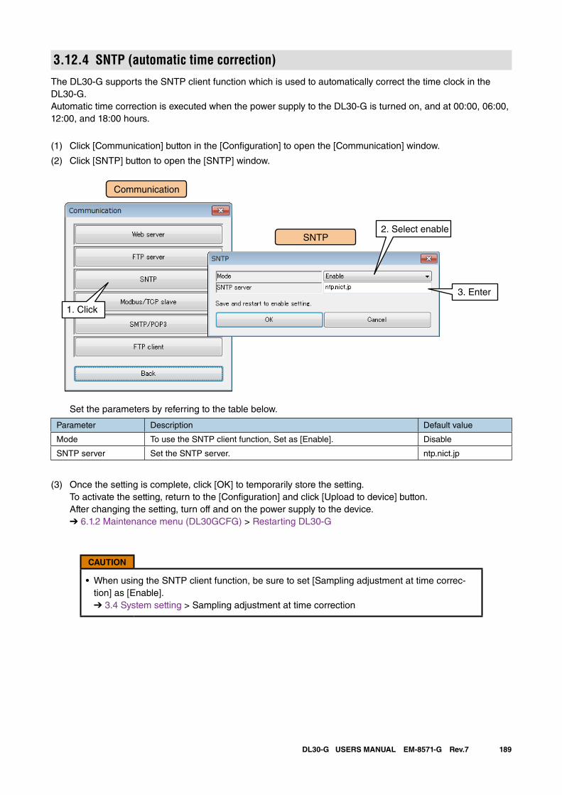
189DL30-G USERS MANUAL EM-8571-G Rev.7
3.12.4 SNTP (automatic time correction)The DL30-G supports the SNTP client function which is used to automatically correct the time clock in the DL30-G.Automatic time correction is executed when the power supply to the DL30-G is turned on, and at 00:00, 06:00, 12:00, and 18:00 hours.
(1) Click [Communication] button in the [Configuration] to open the [Communication] window.
(2) Click [SNTP] button to open the [SNTP] window.
Set the parameters by referring to the table below.
Parameter Description Default value
Mode To use the SNTP client function, Set as [Enable]. Disable
SNTP server Set the SNTP server. ntp.nict.jp
(3) Once the setting is complete, click [OK] to temporarily store the setting. To activate the setting, return to the [Configuration] and click [Upload to device] button. After changing the setting, turn off and on the power supply to the device. ➔ 6.1.2 Maintenance menu (DL30GCFG) > Restarting DL30-G
CAUTION
• When using the SNTP client function, be sure to set [Sampling adjustment at time correc-tion] as [Enable]. ➔ 3.4 System setting > Sampling adjustment at time correction
SNTP
Communication
1. Click
2. Select enable
3. Enter
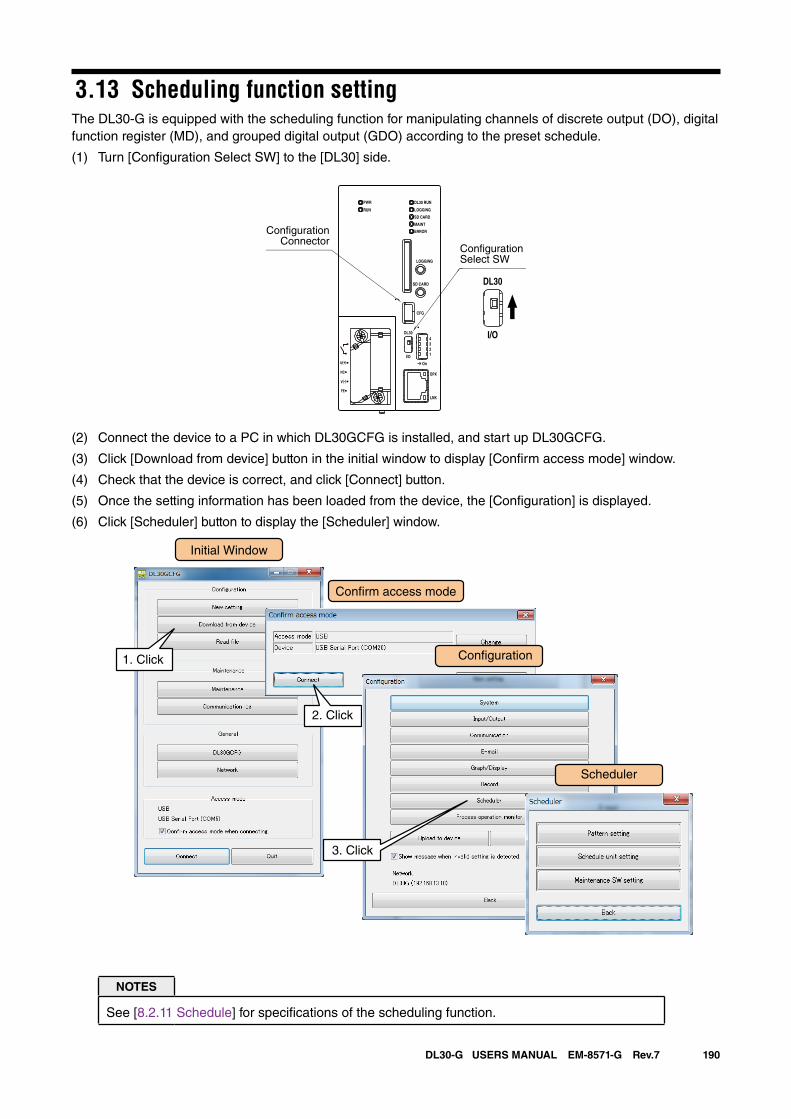
190DL30-G USERS MANUAL EM-8571-G Rev.7
3.13 Scheduling function settingThe DL30-G is equipped with the scheduling function for manipulating channels of discrete output (DO), digital function register (MD), and grouped digital output (GDO) according to the preset schedule.
(1) Turn [Configuration Select SW] to the [DL30] side.
(2) Connect the device to a PC in which DL30GCFG is installed, and start up DL30GCFG.
(3) Click [Download from device] button in the initial window to display [Confirm access mode] window.
(4) Check that the device is correct, and click [Connect] button.
(5) Once the setting information has been loaded from the device, the [Configuration] is displayed.
(6) Click [Scheduler] button to display the [Scheduler] window.
Initial Window
Con�rm access mode
Con�guration1. Click
2. Click
3. Click
Scheduler
NOTES
See [8.2.11 Schedule] for specifications of the scheduling function.
DL30 RUN
LOGGING
SD CARD
MAINT
PWR
RUN
ERROR
CFG
DPX
LNK
LOGGING
SD CARD
DL30
2
I/O
On
43
1
U(+)
NC
V(-)
FE
DL30
I/O
ConfigurationSelect SW
ConfigurationConnector
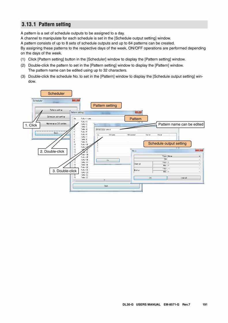
191DL30-G USERS MANUAL EM-8571-G Rev.7
3.13.1 Pattern settingA pattern is a set of schedule outputs to be assigned to a day. A channel to manipulate for each schedule is set in the [Schedule output setting] window.A pattern consists of up to 8 sets of schedule outputs and up to 64 patterns can be created.By assigning these patterns to the respective days of the week, ON/OFF operations are performed depending on the days of the week.
(1) Click [Pattern setting] button in the [Scheduler] window to display the [Pattern setting] window.
(2) Double-click the pattern to set in the [Pattern setting] window to display the [Pattern] window. The pattern name can be edited using up to 32 characters.
(3) Double-click the schedule No. to set in the [Pattern] window to display the [Schedule output setting] win-dow.
Scheduler
Pattern setting
Pattern
1. Click
2. Double-click
Schedule output setting
3. Double-click
Pattern name can be edited
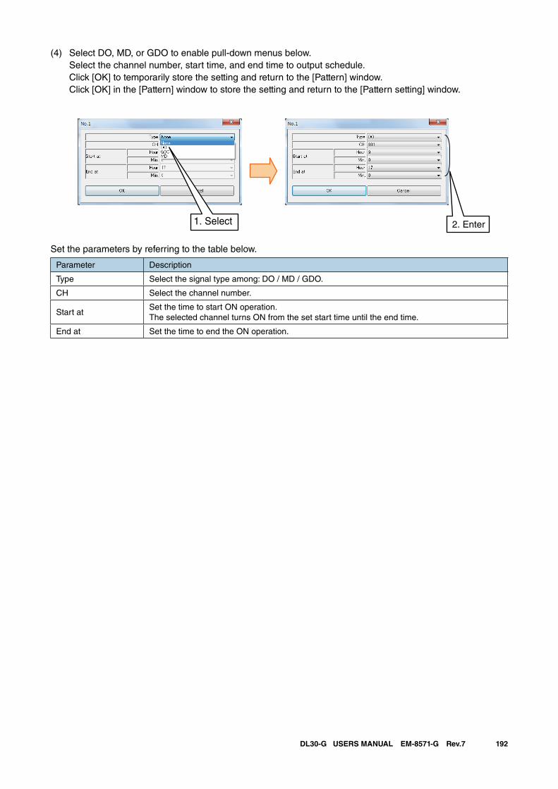
192DL30-G USERS MANUAL EM-8571-G Rev.7
(4) Select DO, MD, or GDO to enable pull-down menus below. Select the channel number, start time, and end time to output schedule. Click [OK] to temporarily store the setting and return to the [Pattern] window. Click [OK] in the [Pattern] window to store the setting and return to the [Pattern setting] window.
2. Enter1. Select
Set the parameters by referring to the table below.
Parameter Description
Type Select the signal type among: DO / MD / GDO.
CH Select the channel number.
Start atSet the time to start ON operation.The selected channel turns ON from the set start time until the end time.
End at Set the time to end the ON operation.
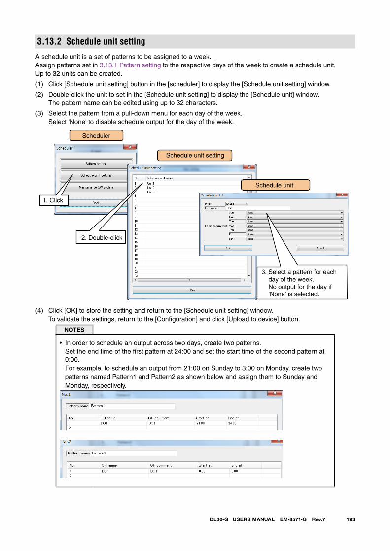
193DL30-G USERS MANUAL EM-8571-G Rev.7
3.13.2 Schedule unit settingA schedule unit is a set of patterns to be assigned to a week.Assign patterns set in 3.13.1 Pattern setting to the respective days of the week to create a schedule unit.Up to 32 units can be created.
(1) Click [Schedule unit setting] button in the [scheduler] to display the [Schedule unit setting] window.
(2) Double-click the unit to set in the [Schedule unit setting] to display the [Schedule unit] window. The pattern name can be edited using up to 32 characters.
(3) Select the pattern from a pull-down menu for each day of the week. Select 'None' to disable schedule output for the day of the week.
Scheduler
Schedule unit setting
1. Click
2. Double-click
Schedule unit
3. Select a pattern for each day of the week. No output for the day if ‘None’ is selected.
(4) Click [OK] to store the setting and return to the [Schedule unit setting] window. To validate the settings, return to the [Configuration] and click [Upload to device] button.
NOTES
• In order to schedule an output across two days, create two patterns. Set the end time of the first pattern at 24:00 and set the start time of the second pattern at 0:00. For example, to schedule an output from 21:00 on Sunday to 3:00 on Monday, create two patterns named Pattern1 and Pattern2 as shown below and assign them to Sunday and Monday, respectively.
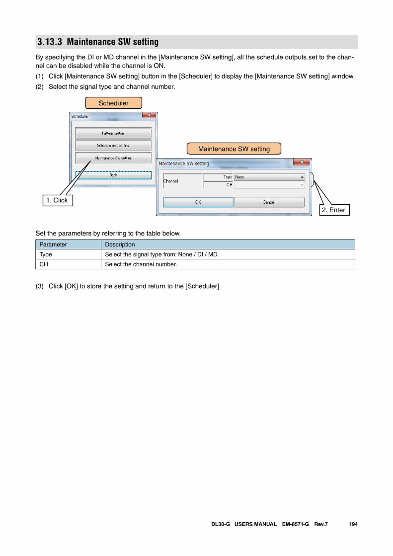
194DL30-G USERS MANUAL EM-8571-G Rev.7
3.13.3 Maintenance SW settingBy specifying the DI or MD channel in the [Maintenance SW setting], all the schedule outputs set to the chan-nel can be disabled while the channel is ON.
(1) Click [Maintenance SW setting] button in the [Scheduler] to display the [Maintenance SW setting] window.
(2) Select the signal type and channel number.
Scheduler
1. Click
Maintenance SW setting
2. Enter
Set the parameters by referring to the table below.
Parameter Description
Type Select the signal type from: None / DI / MD.
CH Select the channel number.
(3) Click [OK] to store the setting and return to the [Scheduler].
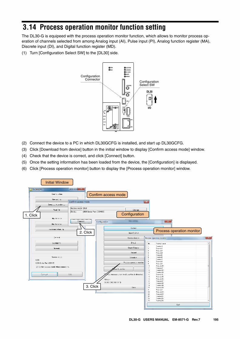
195DL30-G USERS MANUAL EM-8571-G Rev.7
3.14 Process operation monitor function settingThe DL30-G is equipeed with the process operation monitor function, which allows to monitor process op-eration of channels selected from among Analog input (AI), Pulse input (PI), Analog function register (MA), Discrete input (DI), and Digital function register (MD).
(1) Turn [Configuration Select SW] to the [DL30] side.
(2) Connect the device to a PC in which DL30GCFG is installed, and start up DL30GCFG.
(3) Click [Download from device] button in the initial window to display [Confirm access mode] window.
(4) Check that the device is correct, and click [Connect] button.
(5) Once the setting information has been loaded from the device, the [Configuration] is displayed.
(6) Click [Process operation monitor] button to display the [Process operation monitor] window.
Initial Window
Con�rm access mode
Con�guration1. Click
2. Click Process operation monitor
3. Click
DL30 RUN
LOGGING
SD CARD
MAINT
PWR
RUN
ERROR
CFG
DPX
LNK
LOGGING
SD CARD
DL30
2
I/O
On
43
1
U(+)
NC
V(-)
FE
DL30
I/O
ConfigurationSelect SW
ConfigurationConnector
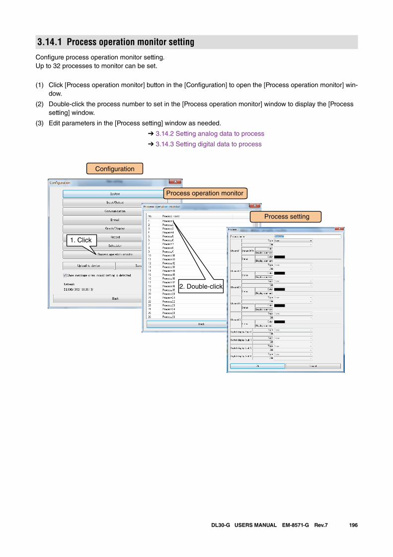
196DL30-G USERS MANUAL EM-8571-G Rev.7
3.14.1 Process operation monitor settingConfigure process operation monitor setting.Up to 32 processes to monitor can be set.
(1) Click [Process operation monitor] button in the [Configuration] to open the [Process operation monitor] win-dow.
(2) Double-click the process number to set in the [Process operation monitor] window to display the [Process setting] window.
(3) Edit parameters in the [Process setting] window as needed.
➔ 3.14.2 Setting analog data to process
➔ 3.14.3 Setting digital data to process
Con�guration
Process operation monitor
1. Click
Process setting
2. Double-click
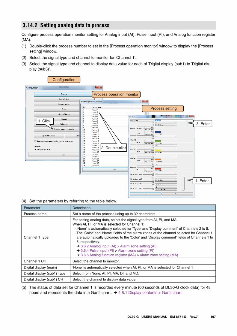
197DL30-G USERS MANUAL EM-8571-G Rev.7
3.14.2 Setting analog data to processConfigure process operation monitor setting for Analog input (AI), Pulse input (PI), and Analog function register (MA).
(1) Double-click the process number to set in the [Process operation monitor] window to display the [Process setting] window.
(2) Select the signal type and channel to monitor for 'Channel 1'.
(3) Select the signal type and channel to display data value for each of 'Digital display (sub1) to 'Digital dis-play (sub3)'.
Con�guration
Process operation monitor
1. Click
Process setting
2. Double-click
3. Enter
4. Enter
(4) Set the parameters by referring to the table below.
Parameter Description
Process name Set a name of the process using up to 32 characters
Channel 1 Type
For setting analog data, select the signal type from AI, PI, and MA.When AI, PI, or MA is selected for Channel 1: - 'None' is automatically selected for 'Type' and 'Display comment' of Channels 2 to 5. - The 'Color' and 'Name' fields of the alarm zones of the channel selected for Channel 1
are automatically uploaded to the 'Color' and 'Display comment' fields of Channels 1 to 5, respectively. ➔ 3.6.2 Analog input (AI) > Alarm zone setting (AI) ➔ 3.6.4 Pulse input (PI) > Alarm zone setting (PI) ➔ 3.6.5 Analog function register (MA) > Alarm zone setting (MA)
Channel 1 CH Select the channel to monitor.
Digital display (main) 'None' is automatically selected when AI, PI, or MA is selected for Channel 1.
Digital display (sub1) Type Select from None, AI, PI, MA, DI, and MD.
Digital display (sub1) CH Select the channel to display data value.
(5) The status of data set for Channel 1 is recorded every minute (00 seconds of DL30-G clock data) for 48 hours and represents the data in a Gantt chart. ➔ 4.8.1 Display contents > Gantt chart
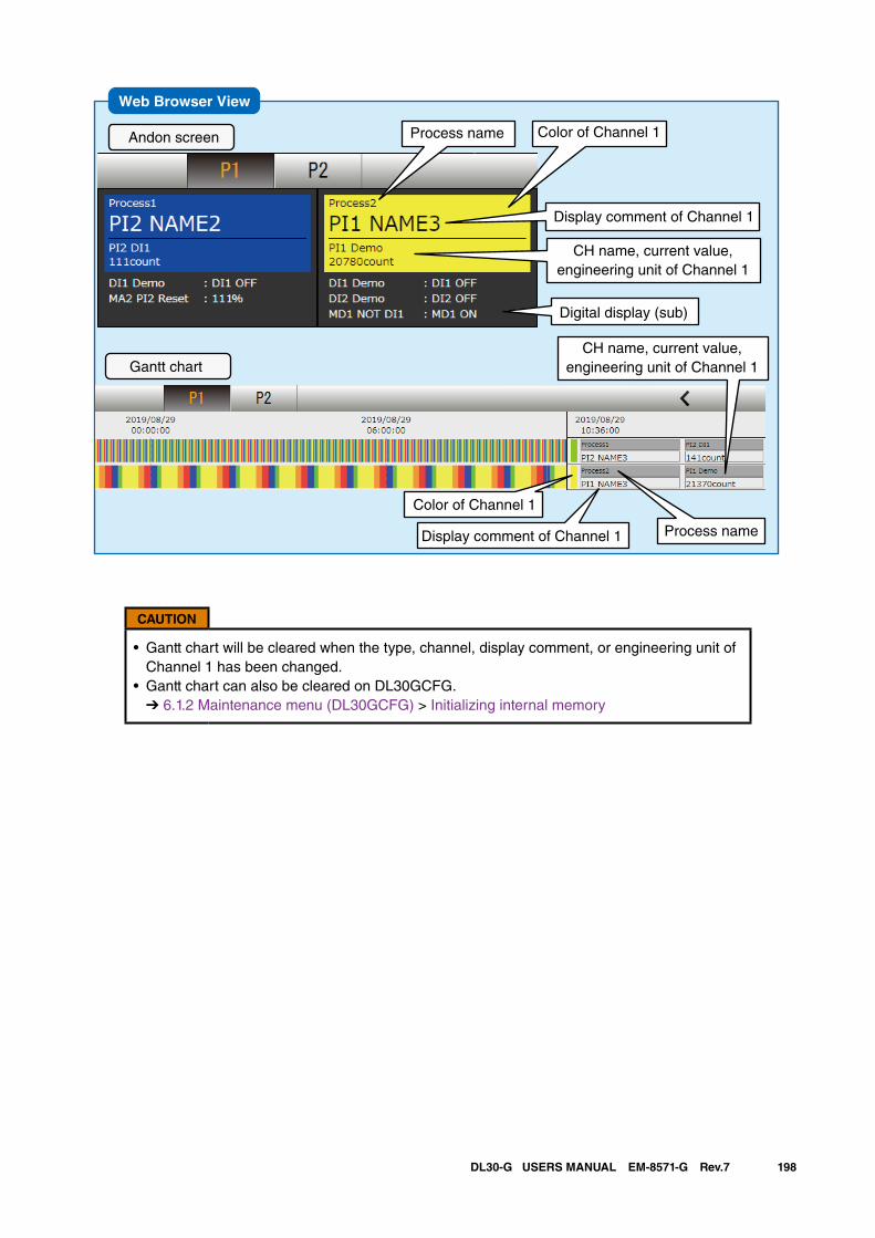
198DL30-G USERS MANUAL EM-8571-G Rev.7
Web Browser View
Andon screen
Gantt chart
Process name Color of Channel 1
Display comment of Channel 1
Digital display (sub)
CH name, current value, engineering unit of Channel 1
Color of Channel 1
Process nameDisplay comment of Channel 1
CH name, current value, engineering unit of Channel 1
CAUTION
• Gantt chart will be cleared when the type, channel, display comment, or engineering unit of Channel 1 has been changed.
• Gantt chart can also be cleared on DL30GCFG. ➔ 6.1.2 Maintenance menu (DL30GCFG) > Initializing internal memory
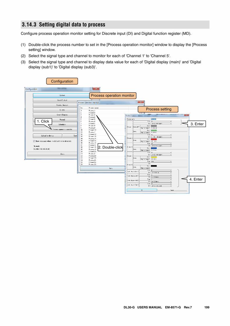
199DL30-G USERS MANUAL EM-8571-G Rev.7
3.14.3 Setting digital data to processConfigure process operation monitor setting for Discrete input (DI) and Digital function register (MD).
(1) Double-click the process number to set in the [Process operation monitor] window to display the [Process setting] window.
(2) Select the signal type and channel to monitor for each of 'Channel 1' to 'Channel 5'.
(3) Select the signal type and channel to display data value for each of 'Digital display (main)' and 'Digital display (sub1)' to 'Digital display (sub3)'.
Con�guration
Process operation monitor
1. Click
Process setting
2. Double-click
3. Enter
4. Enter
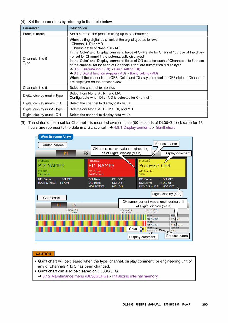
200DL30-G USERS MANUAL EM-8571-G Rev.7
(4) Set the parameters by referring to the table below.
Parameter Description
Process name Set a name of the process using up to 32 characters
Channels 1 to 5Type
When setting digital data, select the signal type as follows. Channel 1: DI or MD Channels 2 to 5: None / DI / MDIn the 'Color' and 'Display comment' fields of OFF state for Channel 1, those of the chan-nel set for Channel 1 are automatically displayed.In the 'Color' and 'Display comment' fields of ON state for each of Channels 1 to 5, those of the channel set for each of Channels 1 to 5 are automatically displayed. ➔ 3.6.3 Discrete input (DI) > Basic setting (DI) ➔ 3.6.6 Digital function register (MD) > Basic setting (MD)When all the channels are OFF, 'Color' and 'Display comment' of OFF state of Channel 1 are displayed on the browser view.
Channels 1 to 5 Select the channel to monitor.
Digital display (main) TypeSelect from None, AI, PI, and MA. Configurable when DI or MD is selected for Channel 1.
Digital display (main) CH Select the channel to display data value.
Digital display (sub1) Type Select from None, AI, PI, MA, DI, and MD.
Digital display (sub1) CH Select the channel to display data value.
(5) The status of data set for Channel 1 is recorded every minute (00 seconds of DL30-G clock data) for 48 hours and represents the data in a Gantt chart. ➔ 4.8.1 Display contents > Gantt chart
Web Browser View
Andon screen
Gantt chart
Process name
Display comment
Color
Process nameDisplay comment
CH name, current value, engineering unit of Digital display (main)
Digital display (sub)
CH name, current value, engineeringunit of Digital display (main)
CAUTION
• Gantt chart will be cleared when the type, channel, display comment, or engineering unit of any of Channels 1 to 5 has been changed.
• Gantt chart can also be cleared on DL30GCFG. ➔ 6.1.2 Maintenance menu (DL30GCFG) > Initializing internal memory
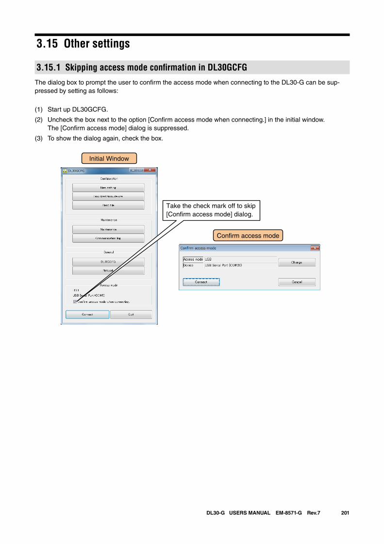
201DL30-G USERS MANUAL EM-8571-G Rev.7
3.15 Other settings
3.15.1 Skipping access mode confirmation in DL30GCFGThe dialog box to prompt the user to confirm the access mode when connecting to the DL30-G can be sup-pressed by setting as follows:
(1) Start up DL30GCFG.
(2) Uncheck the box next to the option [Confirm access mode when connecting.] in the initial window. The [Confirm access mode] dialog is suppressed.
(3) To show the dialog again, check the box.
Initial Window
Con�rm access mode
Take the check mark off to skip [Con�rm access mode] dialog.
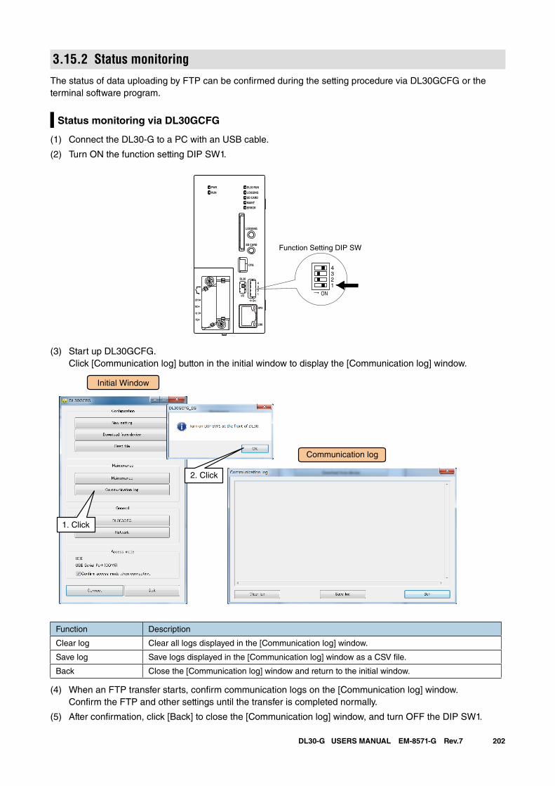
202DL30-G USERS MANUAL EM-8571-G Rev.7
3.15.2 Status monitoringThe status of data uploading by FTP can be confirmed during the setting procedure via DL30GCFG or the terminal software program.
Status monitoring via DL30GCFG
(1) Connect the DL30-G to a PC with an USB cable.
(2) Turn ON the function setting DIP SW1.
(3) Start up DL30GCFG. Click [Communication log] button in the initial window to display the [Communication log] window.
Initial Window
Communication log
1. Click
2. Click
Function Description
Clear log Clear all logs displayed in the [Communication log] window.
Save log Save logs displayed in the [Communication log] window as a CSV file.
Back Close the [Communication log] window and return to the initial window.
(4) When an FTP transfer starts, confirm communication logs on the [Communication log] window. Confirm the FTP and other settings until the transfer is completed normally.
(5) After confirmation, click [Back] to close the [Communication log] window, and turn OFF the DIP SW1.
ON
4321
DL30 RUN
LOGGING
SD CARD
MAINT
PWR
RUN
ERROR
CFG
DPX
LNK
LOGGING
SD CARD
DL30
2
I/O
On
43
1
U(+)
NC
V(-)
FE
Function Setting DIP SW
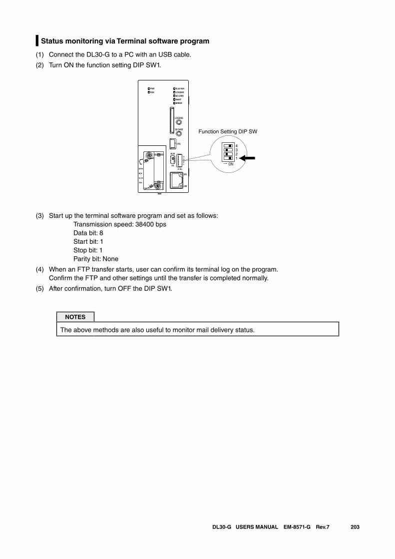
203DL30-G USERS MANUAL EM-8571-G Rev.7
Status monitoring via Terminal software program
(1) Connect the DL30-G to a PC with an USB cable.
(2) Turn ON the function setting DIP SW1.
(3) Start up the terminal software program and set as follows: Transmission speed: 38400 bps Data bit: 8 Start bit: 1 Stop bit: 1 Parity bit: None
(4) When an FTP transfer starts, user can confirm its terminal log on the program. Confirm the FTP and other settings until the transfer is completed normally.
(5) After confirmation, turn OFF the DIP SW1.
NOTES
The above methods are also useful to monitor mail delivery status.
ON
4321
DL30 RUN
LOGGING
SD CARD
MAINT
PWR
RUN
ERROR
CFG
DPX
LNK
LOGGING
SD CARD
DL30
2
I/O
On
43
1
U(+)
NC
V(-)
FE
Function Setting DIP SW

204DL30-G USERS MANUAL EM-8571-G Rev.7
4. How to use the Web serverEnter the domain name or IP address in the URL entry field of the browser to open the top page of the DL30-G web server.
Descriptions in this section are based on the operations on a PC.
NOTES
• See [8.2.1 Compatible terminals and browsers] for information on compatible terminals.• To go back to the top page from any DL30-G web page, click [Menu button ]
and select [Top ].
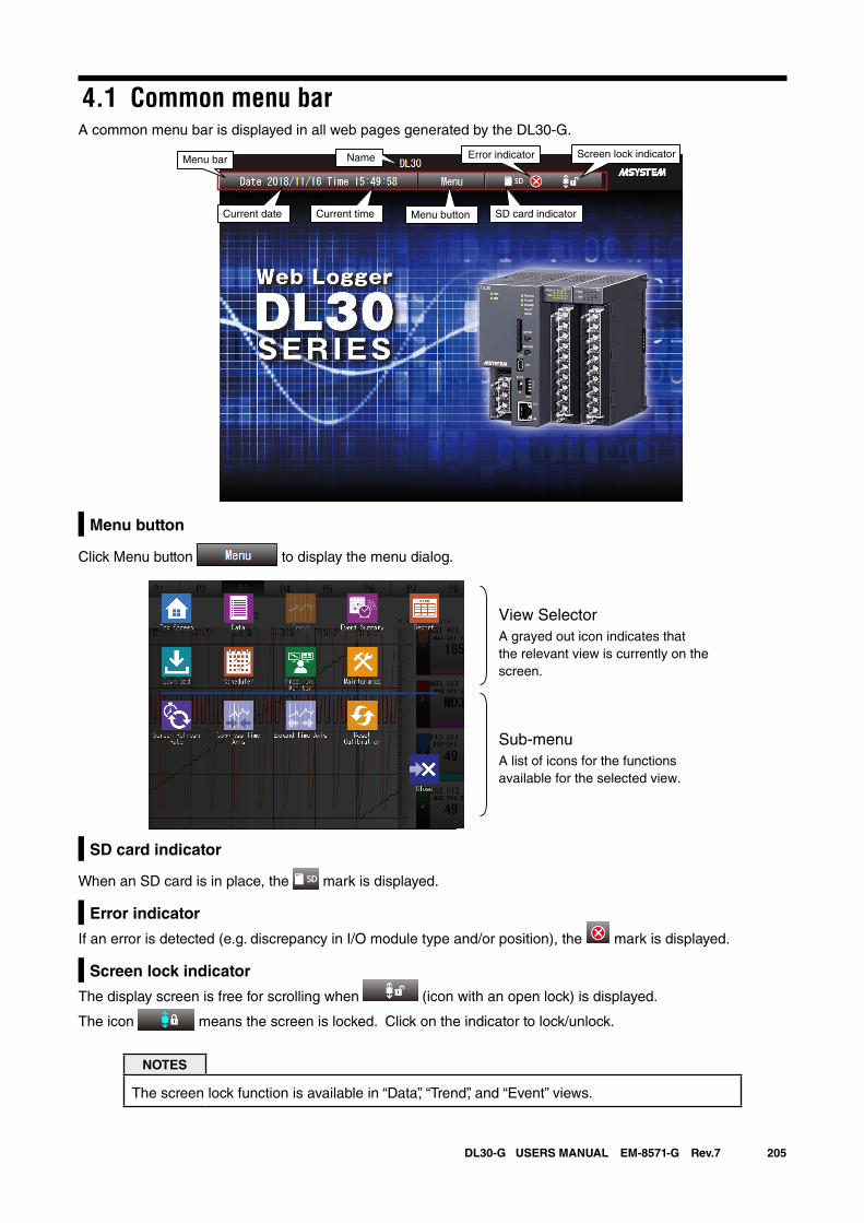
205DL30-G USERS MANUAL EM-8571-G Rev.7
4.1 Common menu barA common menu bar is displayed in all web pages generated by the DL30-G.
Current date Current time SD card indicatorMenu button
Error indicator Screen lock indicatorNameMenu bar
Menu button
Click Menu button to display the menu dialog.
View SelectorA grayed out icon indicates thatthe relevant view is currently on the screen.
Sub-menuA list of icons for the functionsavailable for the selected view.
SD card indicator
When an SD card is in place, the mark is displayed.
Error indicator
If an error is detected (e.g. discrepancy in I/O module type and/or position), the mark is displayed.
Screen lock indicator
The display screen is free for scrolling when (icon with an open lock) is displayed.
The icon means the screen is locked. Click on the indicator to lock/unlock.
NOTES
The screen lock function is available in “Data”, “Trend”, and “Event” views.
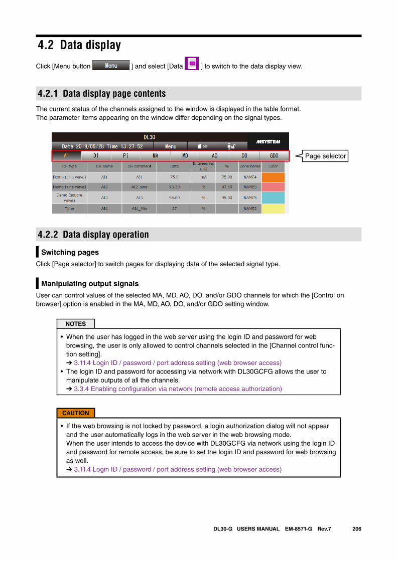
206DL30-G USERS MANUAL EM-8571-G Rev.7
4.2 Data display
Click [Menu button ] and select [Data ] to switch to the data display view.
4.2.1 Data display page contentsThe current status of the channels assigned to the window is displayed in the table format.The parameter items appearing on the window differ depending on the signal types.
4.2.2 Data display operation
Switching pages
Click [Page selector] to switch pages for displaying data of the selected signal type.
Manipulating output signals
User can control values of the selected MA, MD, AO, DO, and/or GDO channels for which the [Control on browser] option is enabled in the MA, MD, AO, DO, and/or GDO setting window.
NOTES
• When the user has logged in the web server using the login ID and password for web browsing, the user is only allowed to control channels selected in the [Channel control func-tion setting]. ➔ 3.11.4 Login ID / password / port address setting (web browser access)
• The login ID and password for accessing via network with DL30GCFG allows the user to manipulate outputs of all the channels. ➔ 3.3.4 Enabling configuration via network (remote access authorization)
CAUTION
• If the web browsing is not locked by password, a login authorization dialog will not appear and the user automatically logs in the web server in the web browsing mode. When the user intends to access the device with DL30GCFG via network using the login ID and password for remote access, be sure to set the login ID and password for web browsing as well. ➔ 3.11.4 Login ID / password / port address setting (web browser access)
Page selector
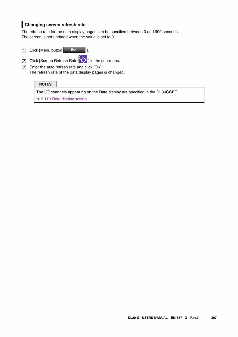
207DL30-G USERS MANUAL EM-8571-G Rev.7
Changing screen refresh rate
The refresh rate for the data display pages can be specified between 0 and 999 seconds. The screen is not updated when the value is set to 0.
(1) Click [Menu button ].
(2) Click [Screen Refresh Rate ] in the sub-menu.
(3) Enter the auto refresh rate and click [OK]. The refresh rate of the data display pages is changed.
NOTES
The I/O channels appearing on the Data display are specified in the DL30GCFG.
➔ 3.11.3 Data display setting
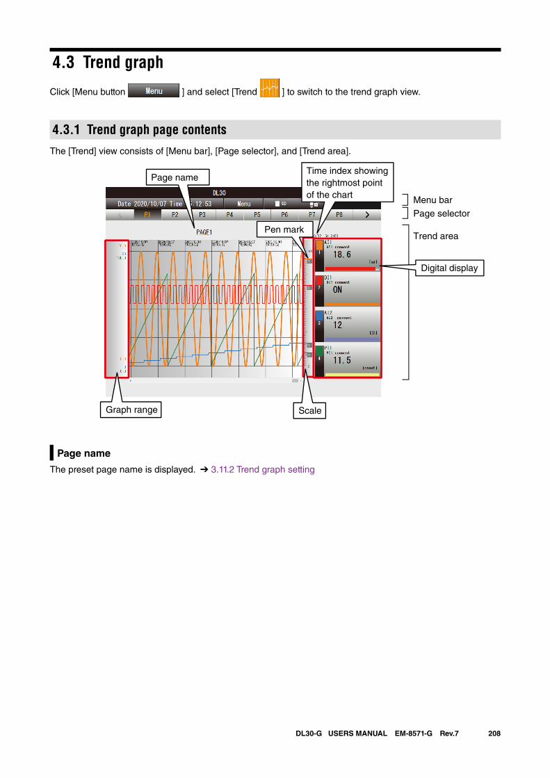
208DL30-G USERS MANUAL EM-8571-G Rev.7
4.3 Trend graph
Click [Menu button ] and select [Trend ] to switch to the trend graph view.
4.3.1 Trend graph page contentsThe [Trend] view consists of [Menu bar], [Page selector], and [Trend area].
Menu bar
Trend area
Page selector
Time index showing the rightmost point of the chart
ScaleGraph range
Page name
Digital display
Pen mark
Page name
The preset page name is displayed. ➔ 3.11.2 Trend graph setting
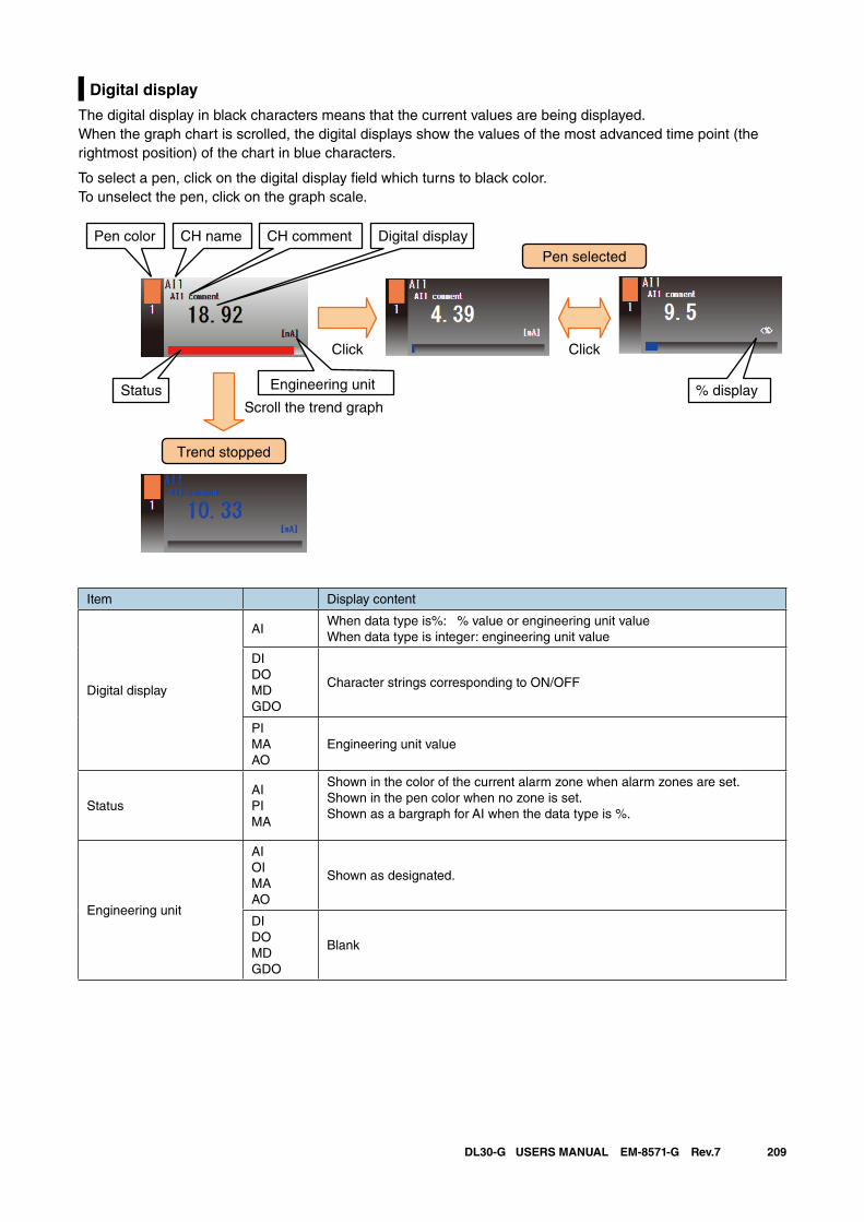
209DL30-G USERS MANUAL EM-8571-G Rev.7
Digital display
The digital display in black characters means that the current values are being displayed.When the graph chart is scrolled, the digital displays show the values of the most advanced time point (the rightmost position) of the chart in blue characters.
To select a pen, click on the digital display field which turns to black color.To unselect the pen, click on the graph scale.
Item Display content
Digital display
AIWhen data type is%: % value or engineering unit valueWhen data type is integer: engineering unit value
DIDOMDGDO
Character strings corresponding to ON/OFF
PIMAAO
Engineering unit value
StatusAIPIMA
Shown in the color of the current alarm zone when alarm zones are set.Shown in the pen color when no zone is set.Shown as a bargraph for AI when the data type is %.
Engineering unit
AIOIMAAO
Shown as designated.
DIDOMDGDO
Blank
Scroll the trend graph
Click Click
Pen selected
Trend stopped
Pen color CH name CH comment Digital display
% displayStatus Engineering unit
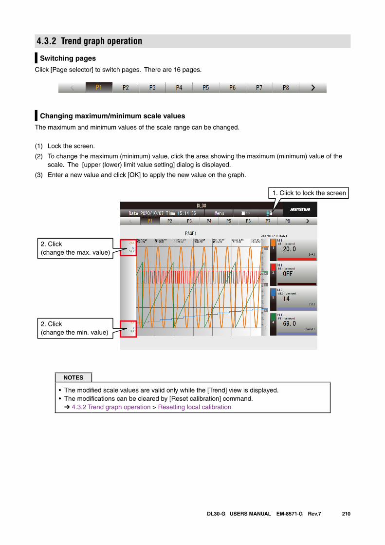
210DL30-G USERS MANUAL EM-8571-G Rev.7
4.3.2 Trend graph operation
Switching pages
Click [Page selector] to switch pages. There are 16 pages.
Changing maximum/minimum scale values
The maximum and minimum values of the scale range can be changed.
(1) Lock the screen.
(2) To change the maximum (minimum) value, click the area showing the maximum (minimum) value of the scale. The [upper (lower) limit value setting] dialog is displayed.
(3) Enter a new value and click [OK] to apply the new value on the graph.
1. Click to lock the screen
2. Click(change the max. value)
2. Click(change the min. value)
NOTES
• The modified scale values are valid only while the [Trend] view is displayed.• The modifications can be cleared by [Reset calibration] command.
➔ 4.3.2 Trend graph operation > Resetting local calibration
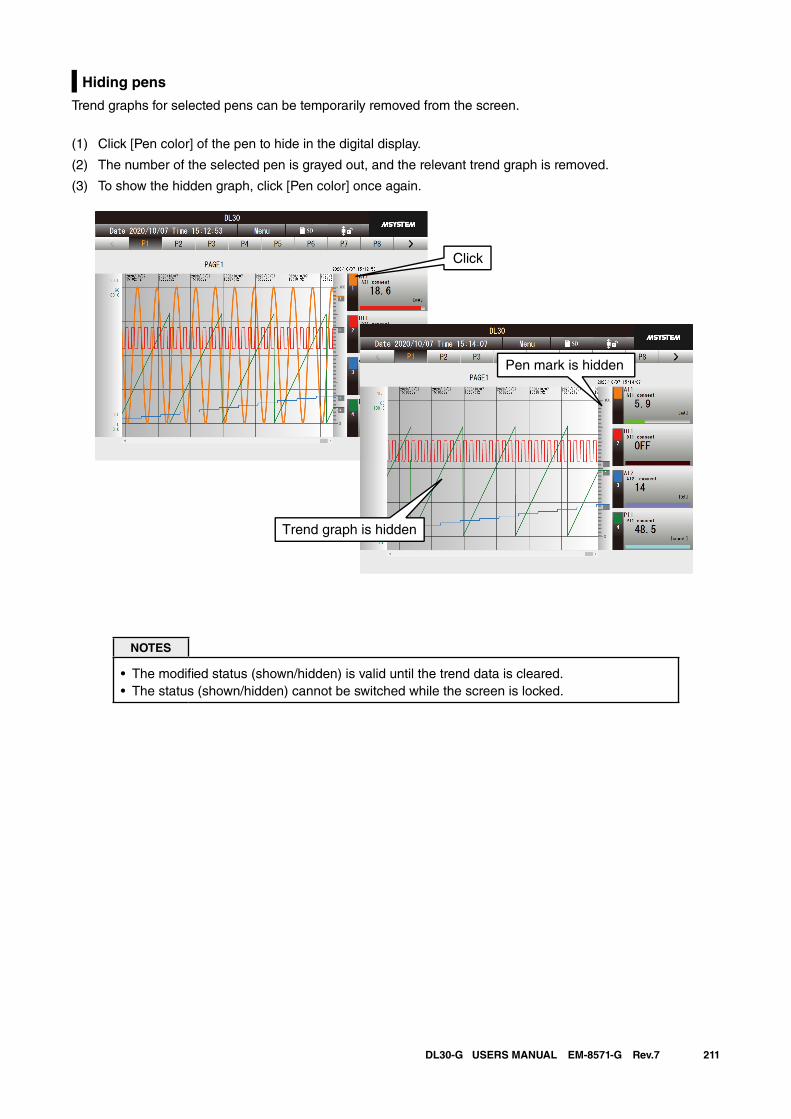
211DL30-G USERS MANUAL EM-8571-G Rev.7
Hiding pens
Trend graphs for selected pens can be temporarily removed from the screen.
(1) Click [Pen color] of the pen to hide in the digital display.
(2) The number of the selected pen is grayed out, and the relevant trend graph is removed.
(3) To show the hidden graph, click [Pen color] once again.
Click
Trend graph is hidden
Pen mark is hidden
NOTES
• The modified status (shown/hidden) is valid until the trend data is cleared.• The status (shown/hidden) cannot be switched while the screen is locked.
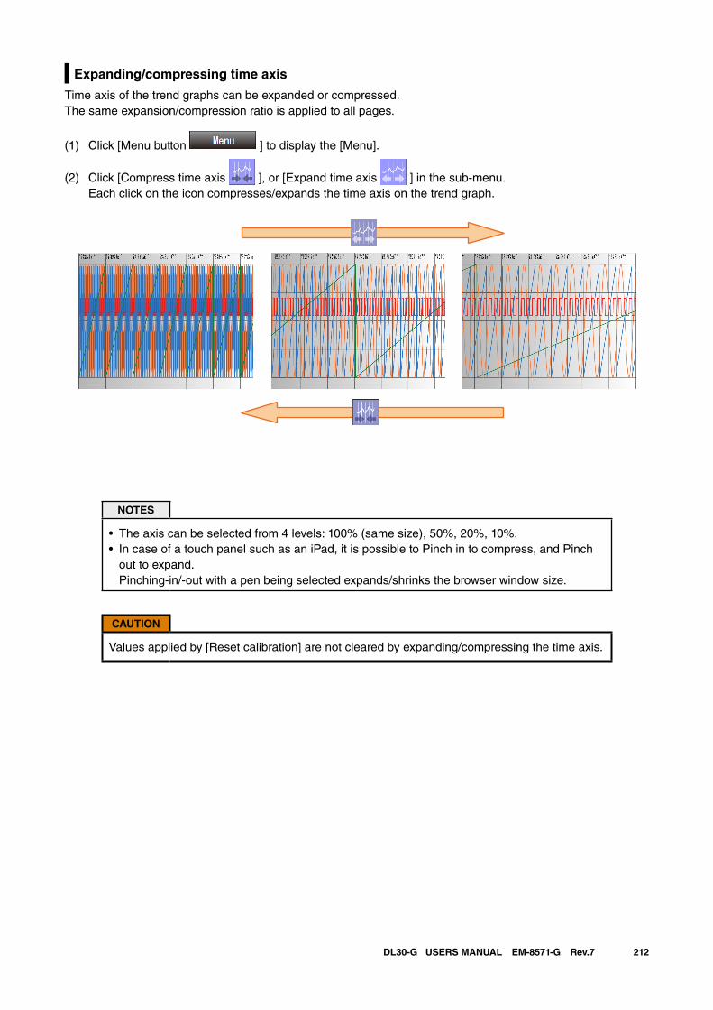
212DL30-G USERS MANUAL EM-8571-G Rev.7
Expanding/compressing time axis
Time axis of the trend graphs can be expanded or compressed. The same expansion/compression ratio is applied to all pages.
(1) Click [Menu button ] to display the [Menu].
(2) Click [Compress time axis ], or [Expand time axis ] in the sub-menu. Each click on the icon compresses/expands the time axis on the trend graph.
NOTES
• The axis can be selected from 4 levels: 100% (same size), 50%, 20%, 10%.• In case of a touch panel such as an iPad, it is possible to Pinch in to compress, and Pinch
out to expand. Pinching-in/-out with a pen being selected expands/shrinks the browser window size.
CAUTION
Values applied by [Reset calibration] are not cleared by expanding/compressing the time axis.
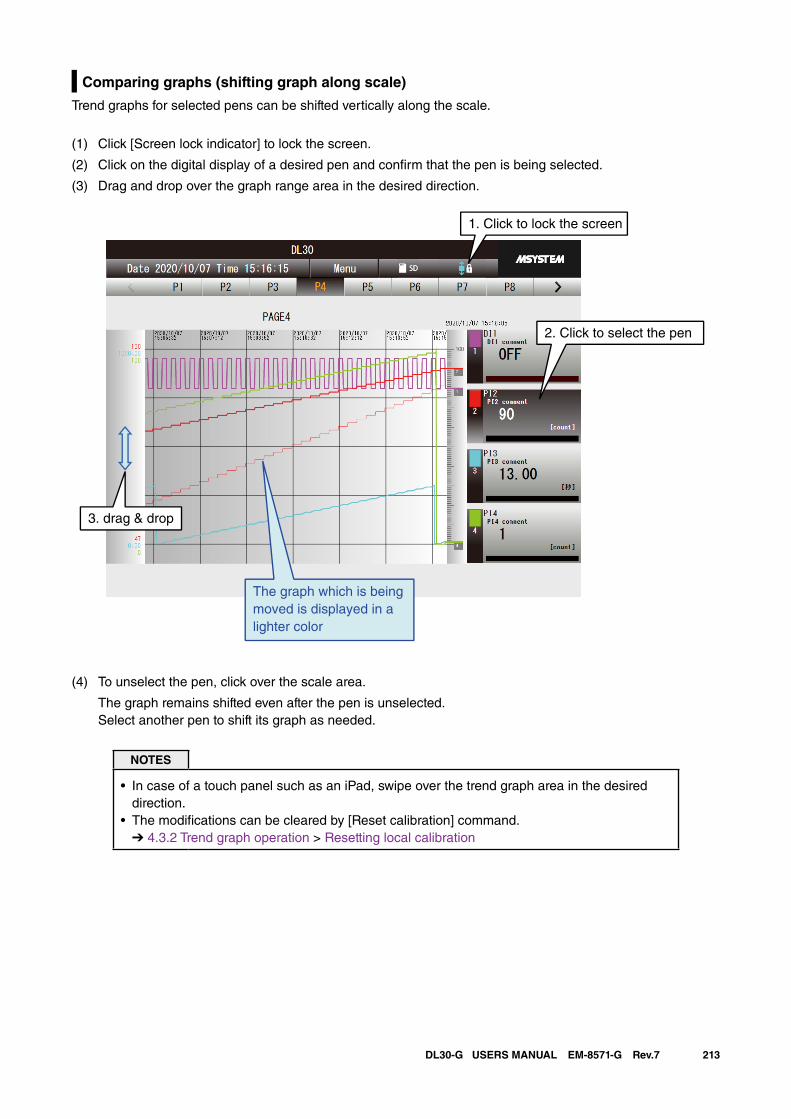
213DL30-G USERS MANUAL EM-8571-G Rev.7
Comparing graphs (shifting graph along scale)
Trend graphs for selected pens can be shifted vertically along the scale.
(1) Click [Screen lock indicator] to lock the screen.
(2) Click on the digital display of a desired pen and confirm that the pen is being selected.
(3) Drag and drop over the graph range area in the desired direction.
The graph which is beingmoved is displayed in a lighter color
3. drag & drop
1. Click to lock the screen
2. Click to select the pen
(4) To unselect the pen, click over the scale area.
The graph remains shifted even after the pen is unselected. Select another pen to shift its graph as needed.
NOTES
• In case of a touch panel such as an iPad, swipe over the trend graph area in the desired direction.
• The modifications can be cleared by [Reset calibration] command.➔ 4.3.2 Trend graph operation > Resetting local calibration
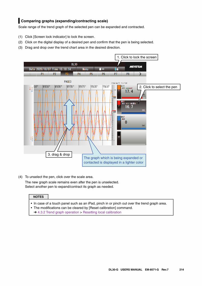
214DL30-G USERS MANUAL EM-8571-G Rev.7
Comparing graphs (expanding/contracting scale)
Scale range of the trend graph of the selected pen can be expanded and contracted.
(1) Click [Screen lock indicator] to lock the screen.
(2) Click on the digital display of a desired pen and confirm that the pen is being selected.
(3) Drag and drop over the trend chart area in the desired direction.
The graph which is being expanded or contacted is displayed in a lighter color
3. drag & drop
1. Click to lock the screen
2. Click to select the pen
(4) To unselect the pen, click over the scale area.
The new graph scale remains even after the pen is unselected. Select another pen to expand/contract its graph as needed.
NOTES
• In case of a touch panel such as an iPad, pinch in or pinch out over the trend graph area.• The modifications can be cleared by [Reset calibration] command.
➔ 4.3.2 Trend graph operation > Resetting local calibration
215DL30-G USERS MANUAL EM-8571-G Rev.7
Changing screen refresh rate
The refresh rate for the trend graph pages can be specified between 1 and 999 seconds. The screen is not updated when the value is set to 0.
(1) Click [Menu button ].
(2) Click [Screen refresh rate ] in the sub-menu.
(3) Enter the auto refresh rate and click [OK]. The refresh rate of the trend graph pages is changed.
Resetting local calibration
User can reset the modification applied locally on the trend graphs, such as the upper/lower range values for each pen.
(1) Click the [Menu button ].
(2) Click [Reset calibration ] in the sub-menu.
(3) The calibration confirmation dialog will appear. Click [OK].
(4) Local calibration values are reset and the trend graphs return to their initial state.
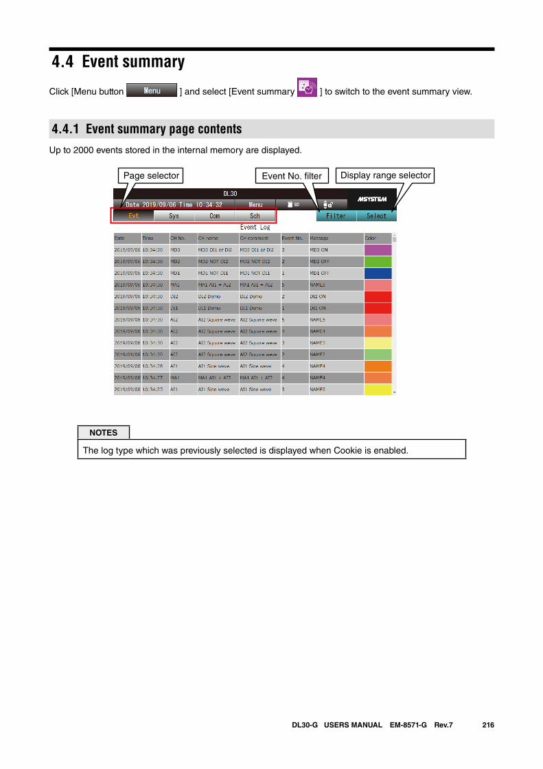
216DL30-G USERS MANUAL EM-8571-G Rev.7
4.4 Event summary
Click [Menu button ] and select [Event summary ] to switch to the event summary view.
4.4.1 Event summary page contentsUp to 2000 events stored in the internal memory are displayed.
Page selector Event No. �lter Display range selector
NOTES
The log type which was previously selected is displayed when Cookie is enabled.
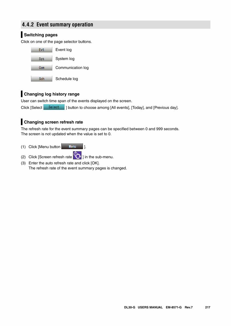
217DL30-G USERS MANUAL EM-8571-G Rev.7
4.4.2 Event summary operation
Switching pages
Click on one of the page selector buttons.
Event log
System log
Communication log
Schedule log
Changing log history range
User can switch time span of the events displayed on the screen.
Click [Select ] button to choose among [All events], [Today], and [Previous day].
Changing screen refresh rate
The refresh rate for the event summary pages can be specified between 0 and 999 seconds. The screen is not updated when the value is set to 0.
(1) Click [Menu button ].
(2) Click [Screen refresh rate ] in the sub-menu.
(3) Enter the auto refresh rate and click [OK]. The refresh rate of the event summary pages is changed.
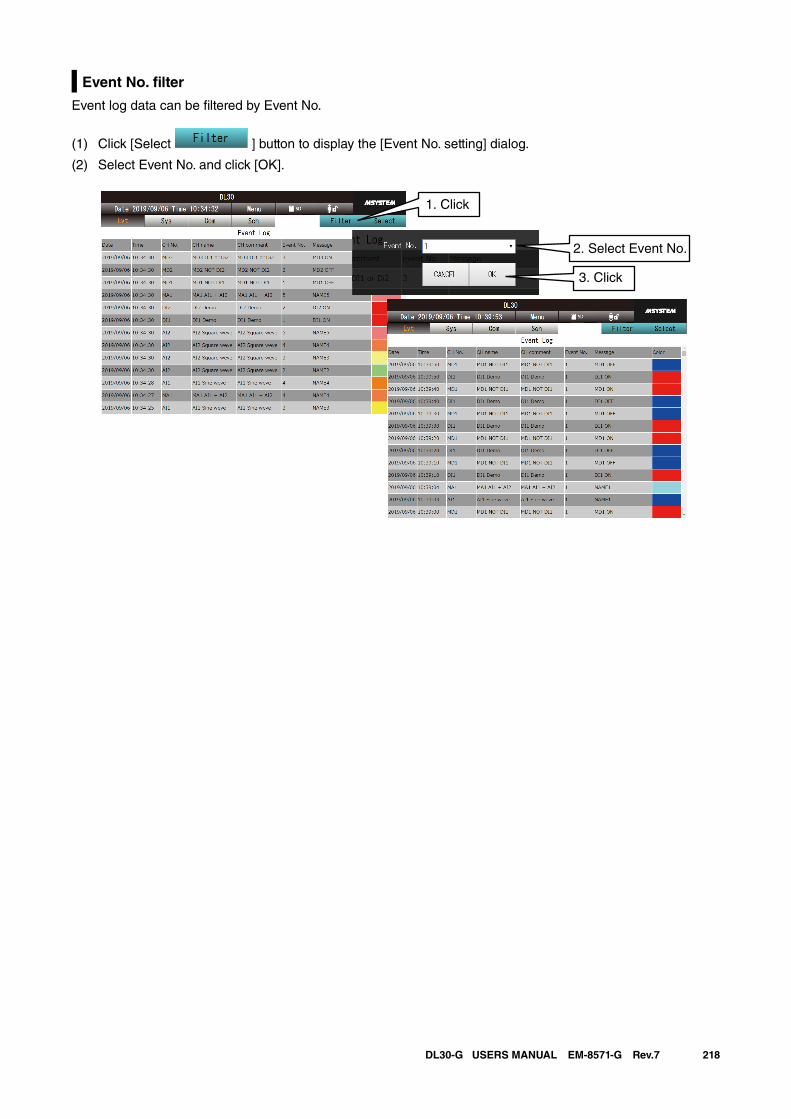
218DL30-G USERS MANUAL EM-8571-G Rev.7
Event No. filter
Event log data can be filtered by Event No.
(1) Click [Select ] button to display the [Event No. setting] dialog.
(2) Select Event No. and click [OK].
2. Select Event No.
3. Click
1. Click
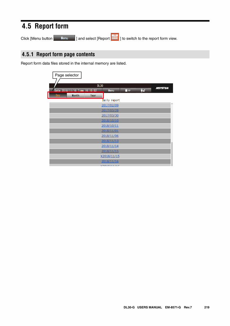
219DL30-G USERS MANUAL EM-8571-G Rev.7
4.5 Report form
Click [Menu button ] and select [Report ] to switch to the report form view.
4.5.1 Report form page contentsReport form data files stored in the internal memory are listed.
Page selector
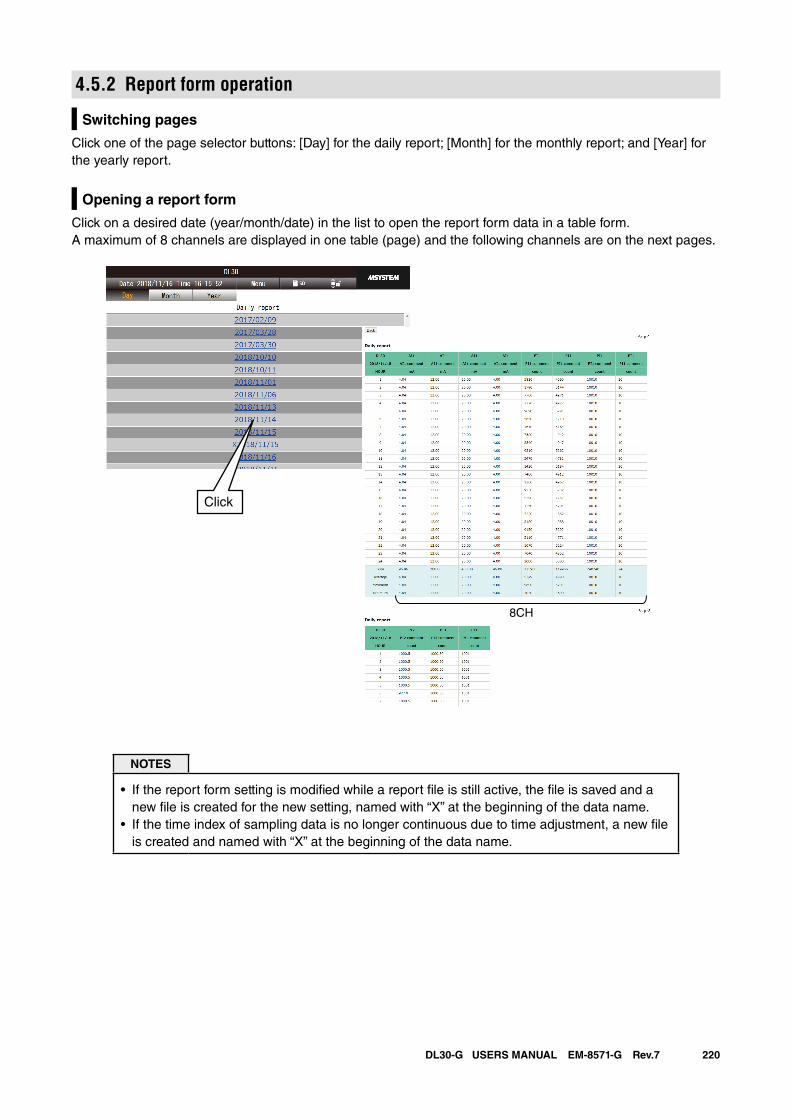
220DL30-G USERS MANUAL EM-8571-G Rev.7
4.5.2 Report form operation
Switching pages
Click one of the page selector buttons: [Day] for the daily report; [Month] for the monthly report; and [Year] for the yearly report.
Opening a report form
Click on a desired date (year/month/date) in the list to open the report form data in a table form.A maximum of 8 channels are displayed in one table (page) and the following channels are on the next pages.
NOTES
• If the report form setting is modified while a report file is still active, the file is saved and a new file is created for the new setting, named with “X” at the beginning of the data name.
• If the time index of sampling data is no longer continuous due to time adjustment, a new file is created and named with “X” at the beginning of the data name.
Click
8CH
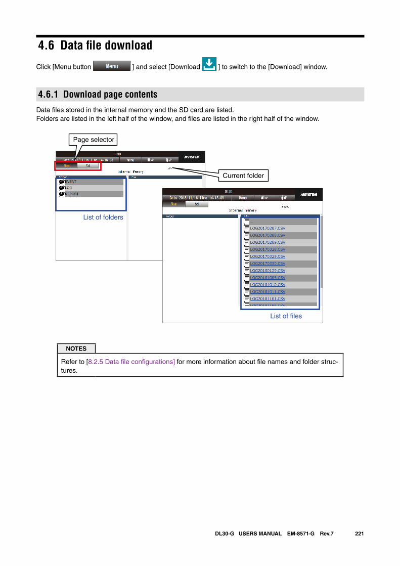
221DL30-G USERS MANUAL EM-8571-G Rev.7
4.6 Data file download
Click [Menu button ] and select [Download ] to switch to the [Download] window.
4.6.1 Download page contentsData files stored in the internal memory and the SD card are listed.Folders are listed in the left half of the window, and files are listed in the right half of the window.
NOTES
Refer to [8.2.5 Data file configurations] for more information about file names and folder struc-tures.
Current folder
List of �les
Page selector
List of folders
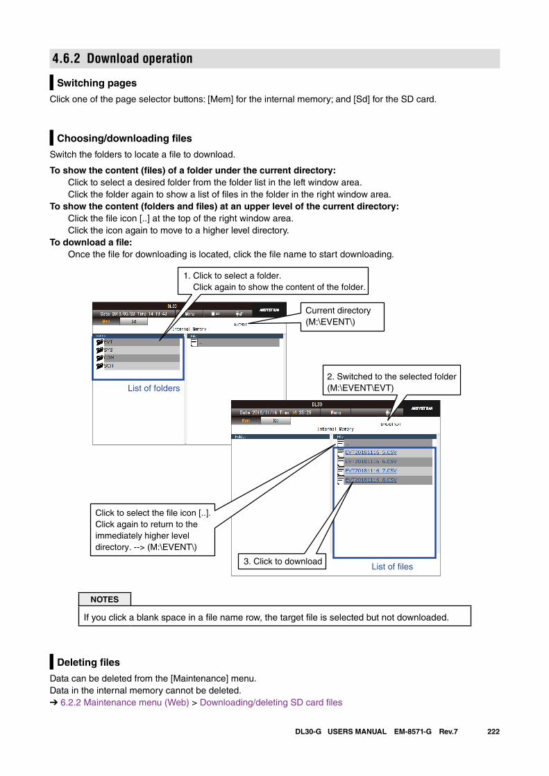
222DL30-G USERS MANUAL EM-8571-G Rev.7
4.6.2 Download operation
Switching pages
Click one of the page selector buttons: [Mem] for the internal memory; and [Sd] for the SD card.
Choosing/downloading files
Switch the folders to locate a file to download.
To show the content (files) of a folder under the current directory: Click to select a desired folder from the folder list in the left window area.
Click the folder again to show a list of files in the folder in the right window area.To show the content (folders and files) at an upper level of the current directory: Click the file icon [..] at the top of the right window area.
Click the icon again to move to a higher level directory.To download a file: Once the file for downloading is located, click the file name to start downloading.
List of �les
List of folders2. Switched to the selected folder(M:\EVENT\EVT)
1. Click to select a folder. Click again to show the content of the folder.
Click to select the �le icon [..].Click again to return to theimmediately higher leveldirectory. --> (M:\EVENT\)
Current directory(M:\EVENT\)
3. Click to download
NOTES
If you click a blank space in a file name row, the target file is selected but not downloaded.
Deleting files
Data can be deleted from the [Maintenance] menu. Data in the internal memory cannot be deleted.➔ 6.2.2 Maintenance menu (Web) > Downloading/deleting SD card files
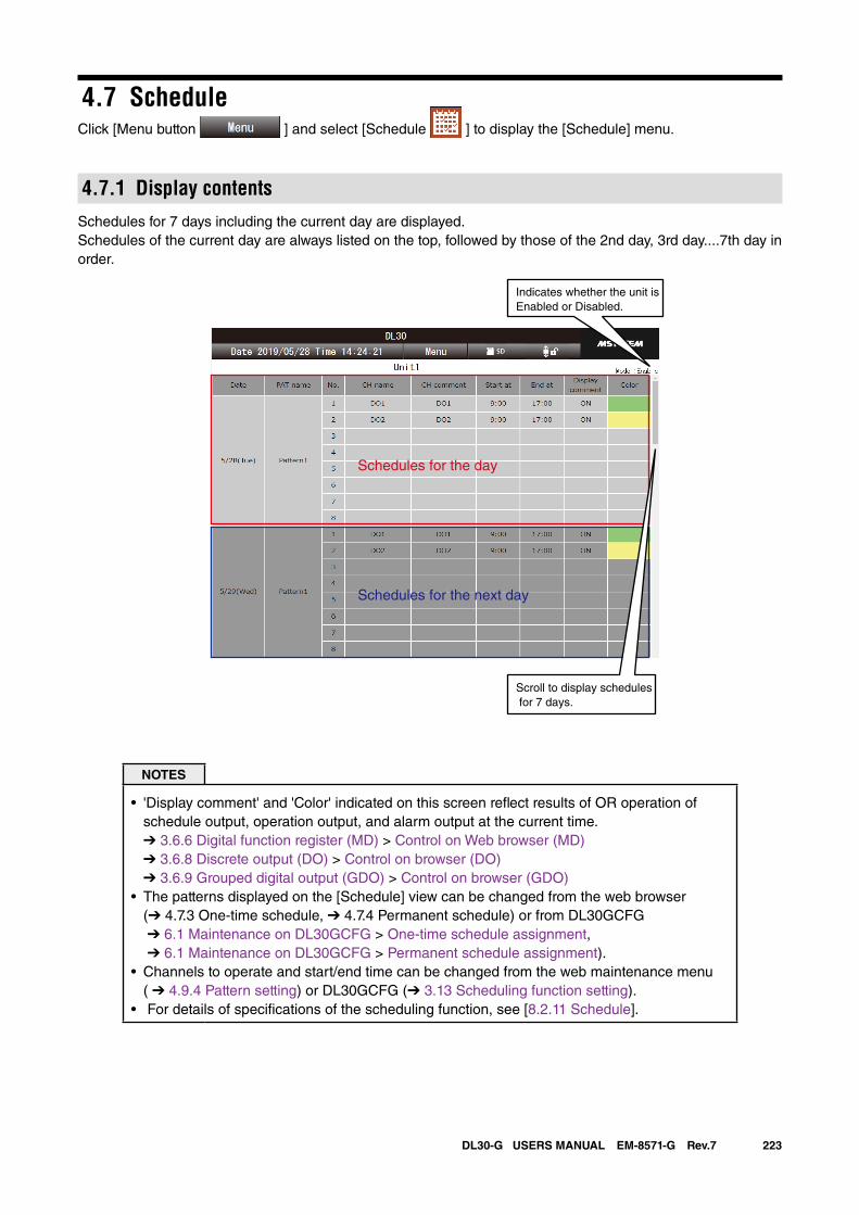
223DL30-G USERS MANUAL EM-8571-G Rev.7
4.7 ScheduleClick [Menu button ] and select [Schedule ] to display the [Schedule] menu.
4.7.1 Display contentsSchedules for 7 days including the current day are displayed. Schedules of the current day are always listed on the top, followed by those of the 2nd day, 3rd day....7th day in order.
Indicates whether the unit isEnabled or Disabled.
Schedules for the day
Schedules for the next day
Scroll to display schedules for 7 days.
NOTES
• 'Display comment' and 'Color' indicated on this screen reflect results of OR operation of schedule output, operation output, and alarm output at the current time.➔ 3.6.6 Digital function register (MD) > Control on Web browser (MD) ➔ 3.6.8 Discrete output (DO) > Control on browser (DO) ➔ 3.6.9 Grouped digital output (GDO) > Control on browser (GDO)
• The patterns displayed on the [Schedule] view can be changed from the web browser (➔ 4.7.3 One-time schedule, ➔ 4.7.4 Permanent schedule) or from DL30GCFG ➔ 6.1 Maintenance on DL30GCFG > One-time schedule assignment, ➔ 6.1 Maintenance on DL30GCFG > Permanent schedule assignment).
• Channels to operate and start/end time can be changed from the web maintenance menu ( ➔ 4.9.4 Pattern setting) or DL30GCFG (➔ 3.13 Scheduling function setting).
• For details of specifications of the scheduling function, see [8.2.11 Schedule].
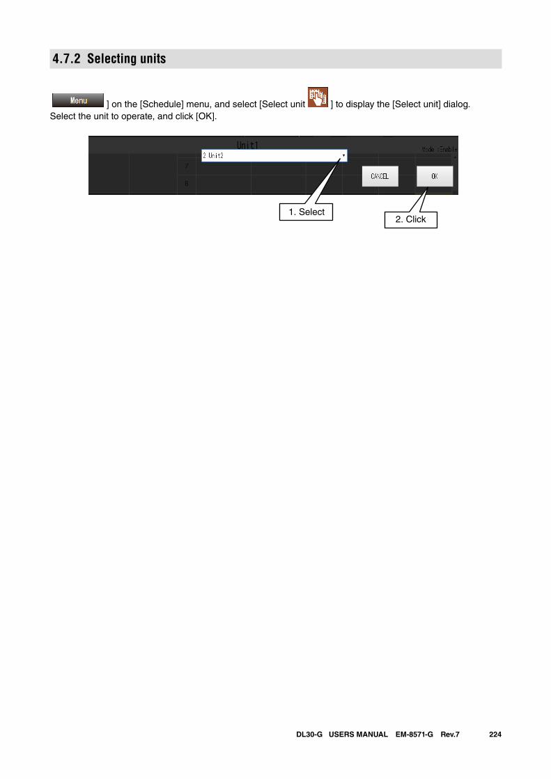
224DL30-G USERS MANUAL EM-8571-G Rev.7
4.7.2 Selecting units
] on the [Schedule] menu, and select [Select unit ] to display the [Select unit] dialog.Select the unit to operate, and click [OK].
2. Click1. Select
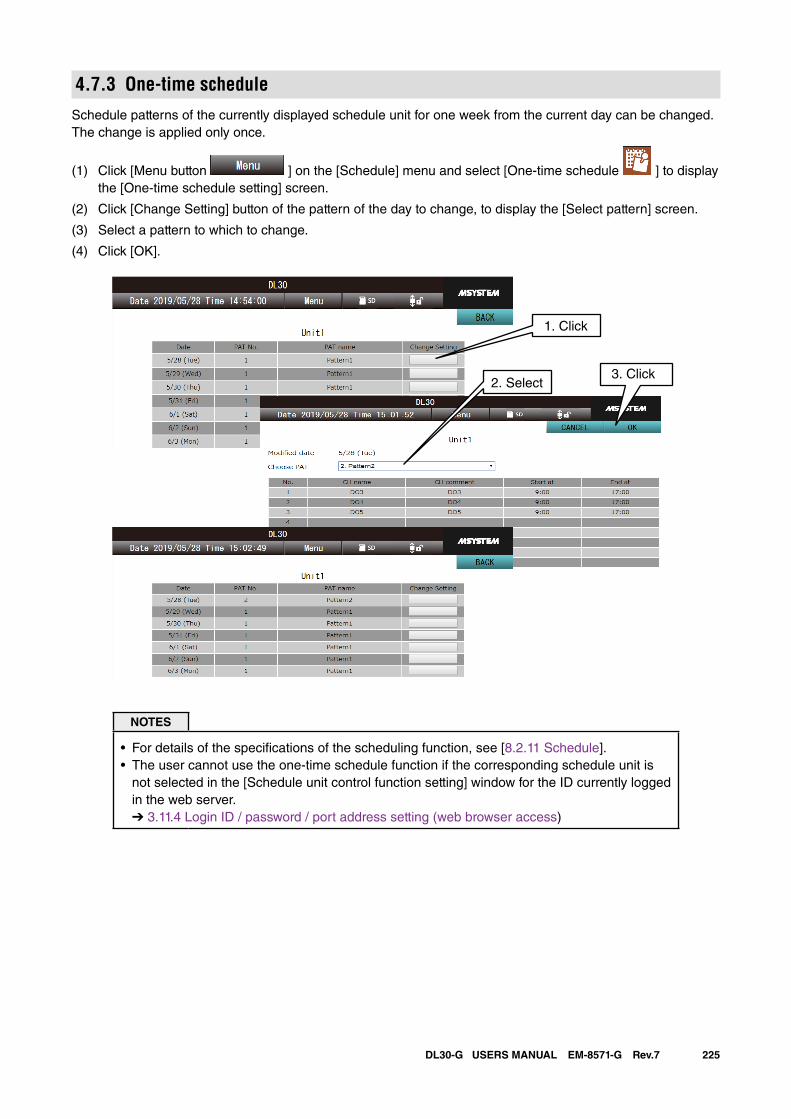
225DL30-G USERS MANUAL EM-8571-G Rev.7
4.7.3 One-time scheduleSchedule patterns of the currently displayed schedule unit for one week from the current day can be changed. The change is applied only once.
(1) Click [Menu button ] on the [Schedule] menu and select [One-time schedule ] to display the [One-time schedule setting] screen.
(2) Click [Change Setting] button of the pattern of the day to change, to display the [Select pattern] screen.
(3) Select a pattern to which to change.
(4) Click [OK].
1. Click
2. Select3. Click
NOTES
• For details of the specifications of the scheduling function, see [8.2.11 Schedule].• The user cannot use the one-time schedule function if the corresponding schedule unit is
not selected in the [Schedule unit control function setting] window for the ID currently logged in the web server. ➔ 3.11.4 Login ID / password / port address setting (web browser access)
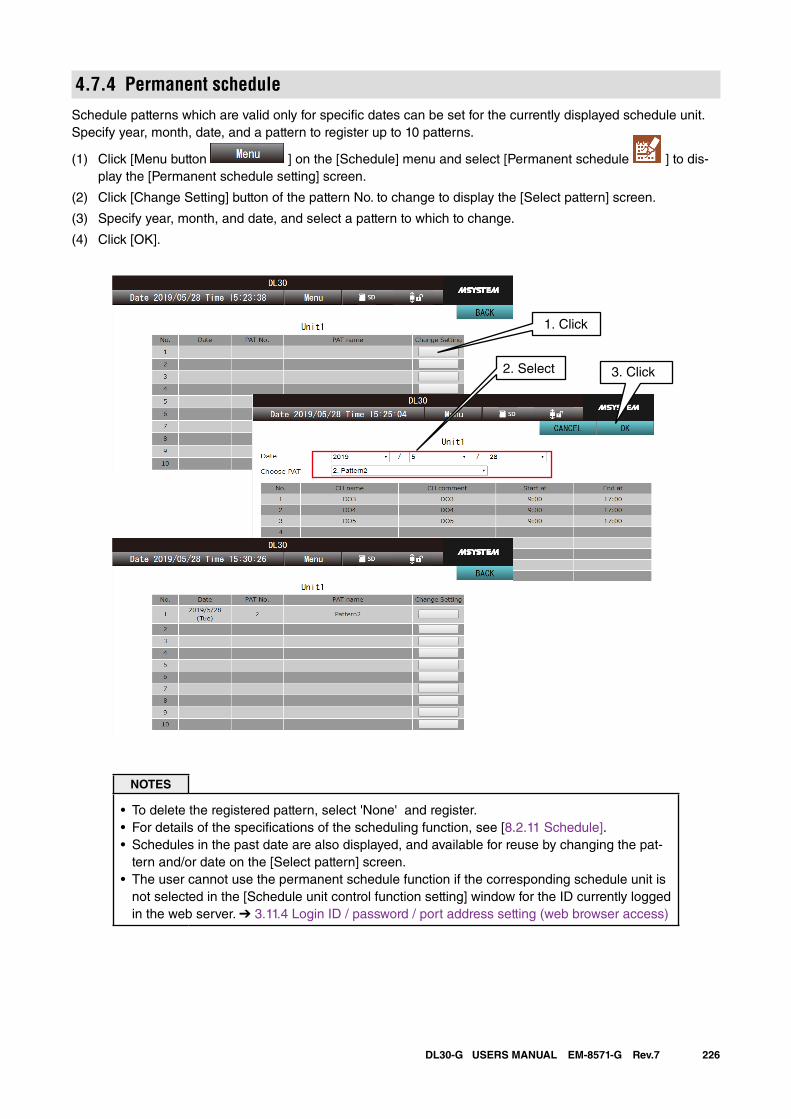
226DL30-G USERS MANUAL EM-8571-G Rev.7
4.7.4 Permanent scheduleSchedule patterns which are valid only for specific dates can be set for the currently displayed schedule unit. Specify year, month, date, and a pattern to register up to 10 patterns.
(1) Click [Menu button ] on the [Schedule] menu and select [Permanent schedule ] to dis-play the [Permanent schedule setting] screen.
(2) Click [Change Setting] button of the pattern No. to change to display the [Select pattern] screen.
(3) Specify year, month, and date, and select a pattern to which to change.
(4) Click [OK].
1. Click
2. Select 3. Click
NOTES
• To delete the registered pattern, select 'None' and register.• For details of the specifications of the scheduling function, see [8.2.11 Schedule].• Schedules in the past date are also displayed, and available for reuse by changing the pat-
tern and/or date on the [Select pattern] screen. • The user cannot use the permanent schedule function if the corresponding schedule unit is
not selected in the [Schedule unit control function setting] window for the ID currently logged in the web server. ➔ 3.11.4 Login ID / password / port address setting (web browser access)
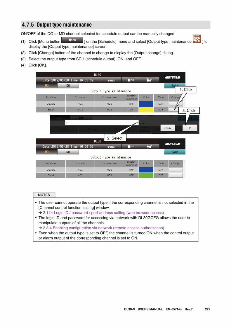
227DL30-G USERS MANUAL EM-8571-G Rev.7
4.7.5 Output type maintenanceON/OFF of the DO or MD channel selected for schedule output can be manually changed.
(1) Click [Menu button ] on the [Schedule] menu and select [Output type maintenance ] to display the [Output type maintenance] screen.
(2) Click [Change] button of the channel to change to display the [Output change] dialog.
(3) Select the output type from SCH (schedule output), ON, and OFF.
(4) Click [OK].
2. Select
1. Click
3. Click
NOTES
• The user cannot operate the output type if the corresponding channel is not selected in the [Channel control function setting] window. ➔ 3.11.4 Login ID / password / port address setting (web browser access)
• The login ID and password for accessing via network with DL30GCFG allows the user to manipulate outputs of all the channels. ➔ 3.3.4 Enabling configuration via network (remote access authorization)
• Even when the output type is set to OFF, the channel is turned ON when the control output or alarm output of the corresponding channel is set to ON.
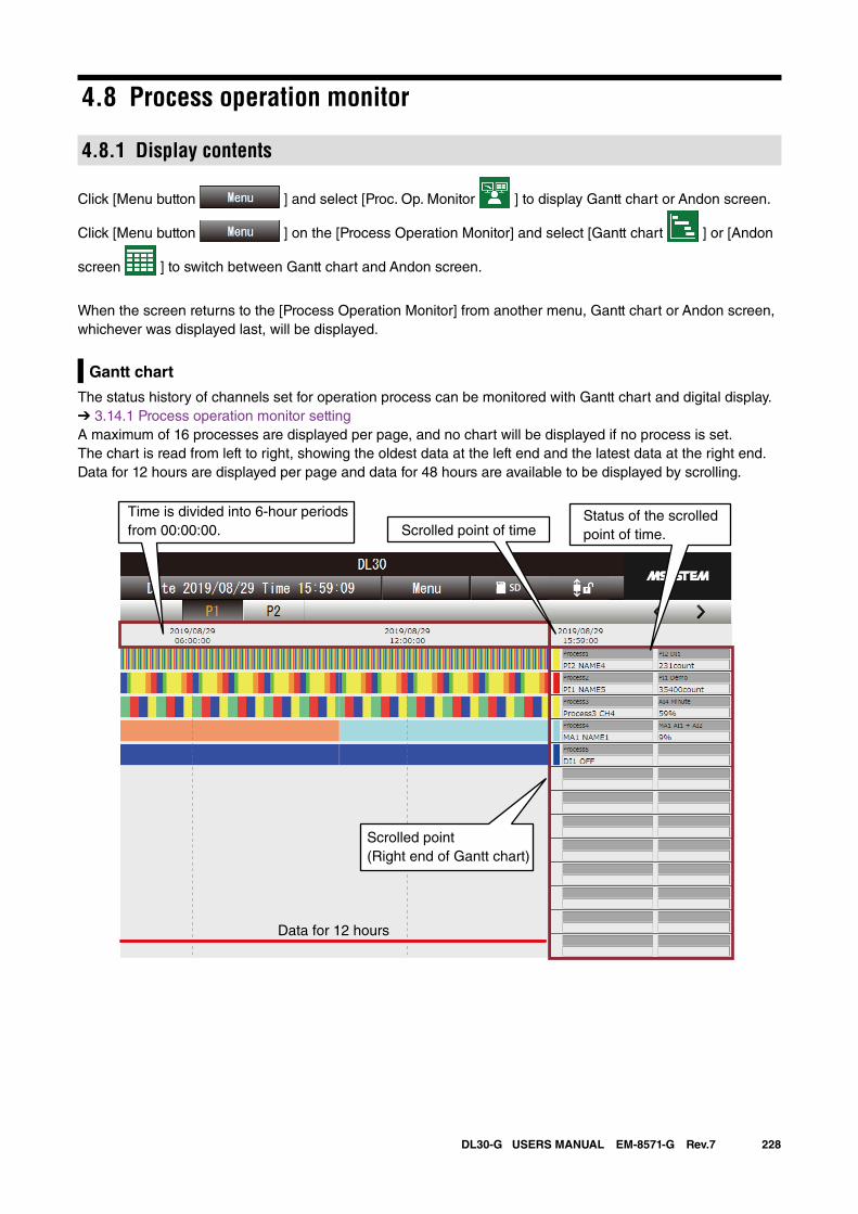
228DL30-G USERS MANUAL EM-8571-G Rev.7
4.8 Process operation monitor
4.8.1 Display contents
Click [Menu button ] and select [Proc. Op. Monitor ] to display Gantt chart or Andon screen.
Click [Menu button ] on the [Process Operation Monitor] and select [Gantt chart ] or [Andon
screen ] to switch between Gantt chart and Andon screen.
When the screen returns to the [Process Operation Monitor] from another menu, Gantt chart or Andon screen, whichever was displayed last, will be displayed.
Gantt chart
The status history of channels set for operation process can be monitored with Gantt chart and digital display. ➔ 3.14.1 Process operation monitor settingA maximum of 16 processes are displayed per page, and no chart will be displayed if no process is set.The chart is read from left to right, showing the oldest data at the left end and the latest data at the right end.Data for 12 hours are displayed per page and data for 48 hours are available to be displayed by scrolling.
Status of the scrolled point of time.
Time is divided into 6-hour periodsfrom 00:00:00. Scrolled point of time
Data for 12 hours
Scrolled point(Right end of Gantt chart)
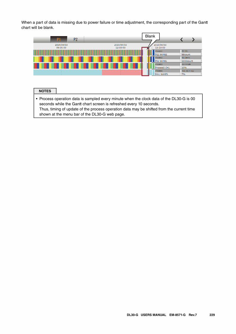
229DL30-G USERS MANUAL EM-8571-G Rev.7
When a part of data is missing due to power failure or time adjustment, the corresponding part of the Gantt chart will be blank.
Blank
NOTES
• Process operation data is sampled every minute when the clock data of the DL30-G is 00 seconds while the Gantt chart screen is refreshed every 10 seconds. Thus, timing of update of the process operation data may be shifted from the current time shown at the menu bar of the DL30-G web page.
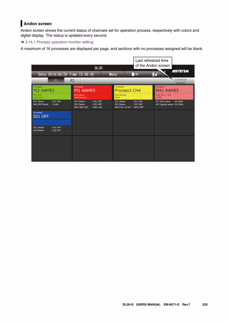
230DL30-G USERS MANUAL EM-8571-G Rev.7
Andon screen
Andon screen shows the current status of channels set for operation process, respectively with colors and digital display. The status is updated every second.
➔ 3.14.1 Process operation monitor setting
A maximum of 16 processes are displayed per page, and sections with no processes assigned will be blank.
Last refreshed timeof the Andon screen
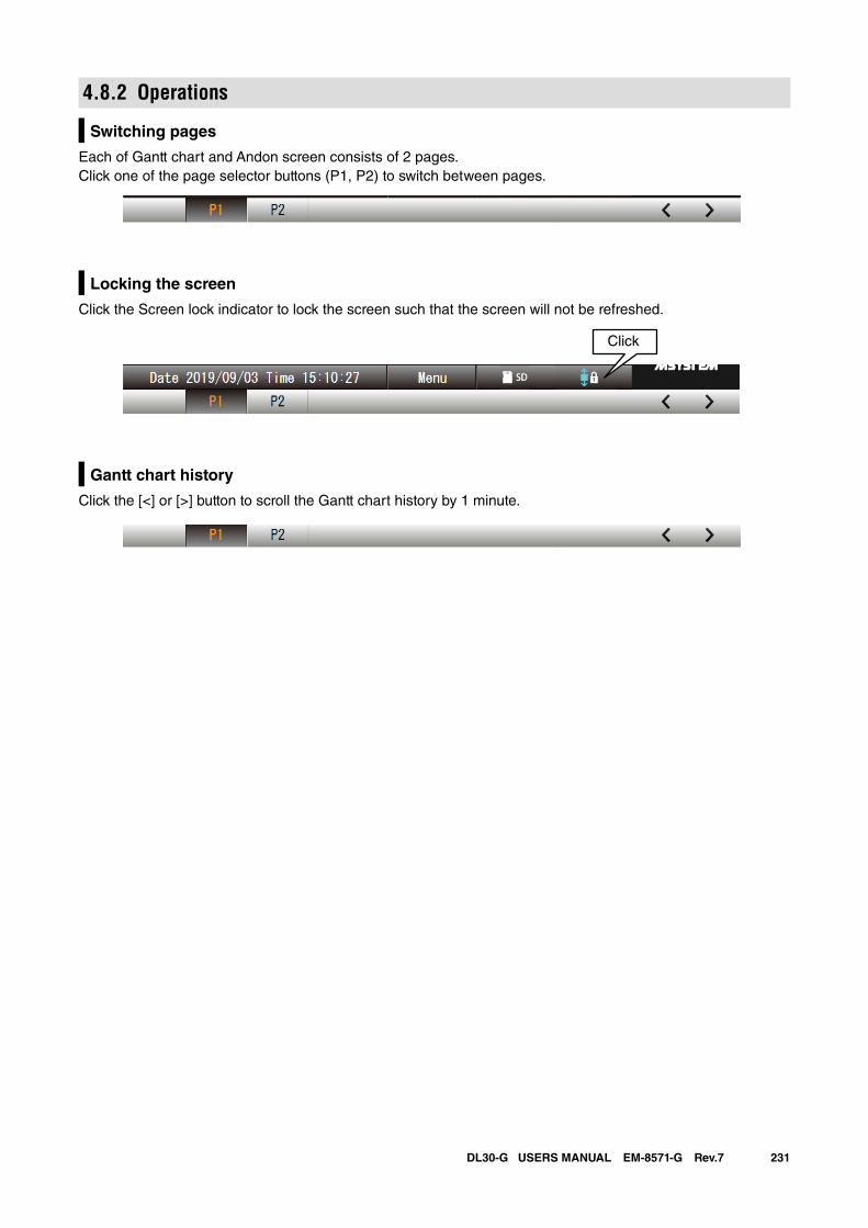
231DL30-G USERS MANUAL EM-8571-G Rev.7
4.8.2 Operations
Switching pages
Each of Gantt chart and Andon screen consists of 2 pages. Click one of the page selector buttons (P1, P2) to switch between pages.
Click
Locking the screen
Click the Screen lock indicator to lock the screen such that the screen will not be refreshed.
Click
Gantt chart history
Click the [<] or [>] button to scroll the Gantt chart history by 1 minute.
Click
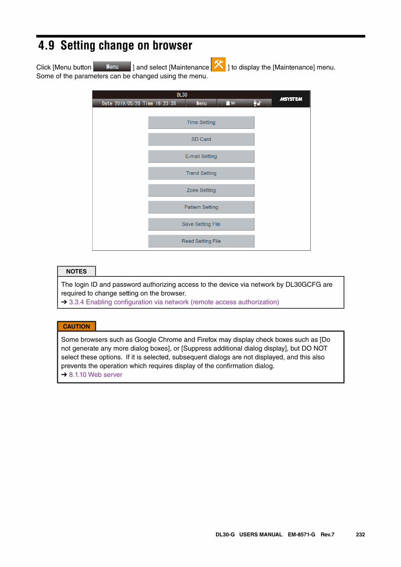
232DL30-G USERS MANUAL EM-8571-G Rev.7
4.9 Setting change on browser
Click [Menu button ] and select [Maintenance ] to display the [Maintenance] menu.Some of the parameters can be changed using the menu.
NOTES
The login ID and password authorizing access to the device via network by DL30GCFG are required to change setting on the browser.➔ 3.3.4 Enabling configuration via network (remote access authorization)
CAUTION
Some browsers such as Google Chrome and Firefox may display check boxes such as [Do not generate any more dialog boxes], or [Suppress additional dialog display], but DO NOT select these options. If it is selected, subsequent dialogs are not displayed, and this also prevents the operation which requires display of the confirmation dialog.➔ 8.1.10 Web server
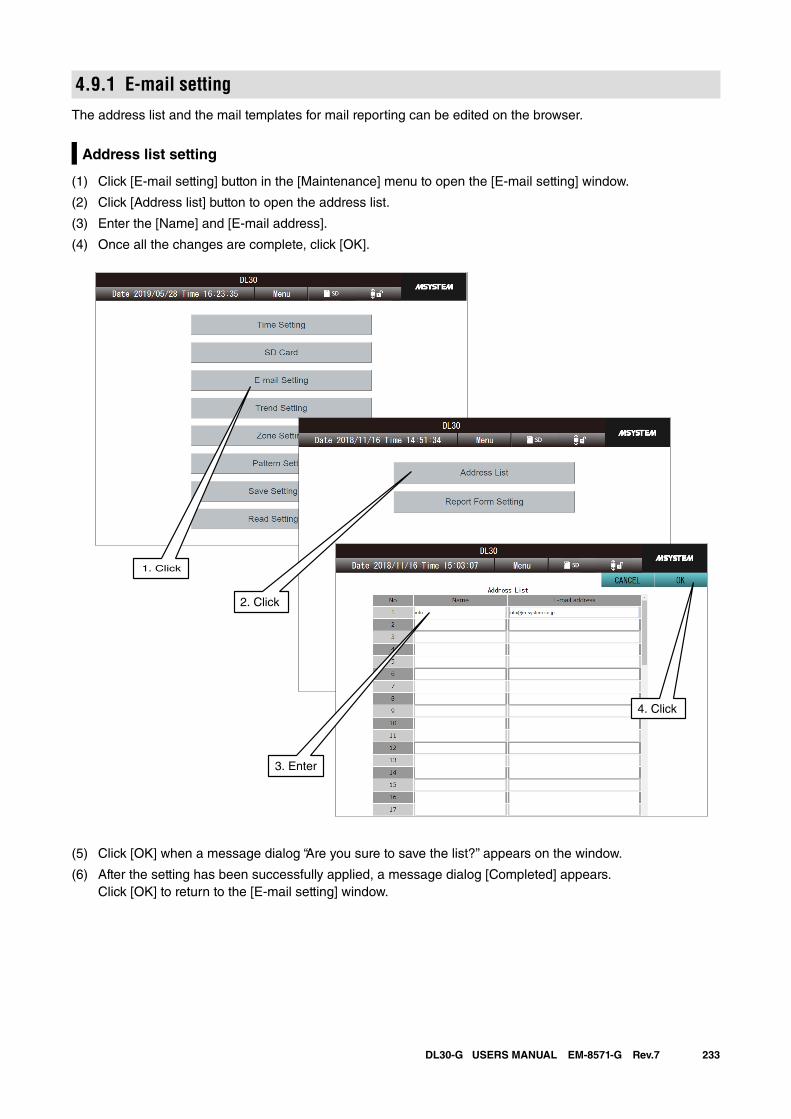
233DL30-G USERS MANUAL EM-8571-G Rev.7
4.9.1 E-mail settingThe address list and the mail templates for mail reporting can be edited on the browser.
Address list setting
(1) Click [E-mail setting] button in the [Maintenance] menu to open the [E-mail setting] window.
(2) Click [Address list] button to open the address list.
(3) Enter the [Name] and [E-mail address].
(4) Once all the changes are complete, click [OK].
(5) Click [OK] when a message dialog “Are you sure to save the list?” appears on the window.
(6) After the setting has been successfully applied, a message dialog [Completed] appears. Click [OK] to return to the [E-mail setting] window.
1. Click
3. Enter
4. Click
2. Click
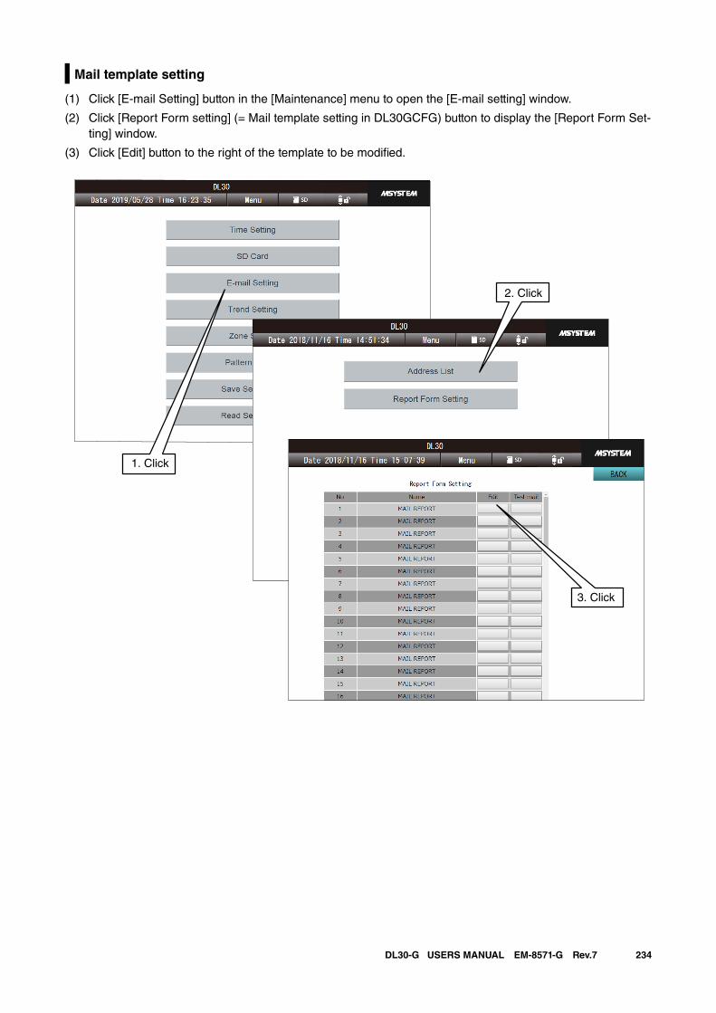
234DL30-G USERS MANUAL EM-8571-G Rev.7
Mail template setting
(1) Click [E-mail Setting] button in the [Maintenance] menu to open the [E-mail setting] window.
(2) Click [Report Form setting] (= Mail template setting in DL30GCFG) button to display the [Report Form Set-ting] window.
(3) Click [Edit] button to the right of the template to be modified.
1. Click
2. Click
3. Click
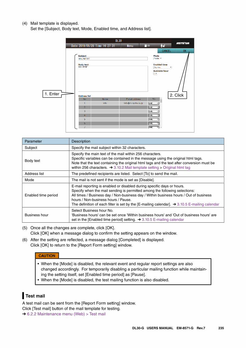
235DL30-G USERS MANUAL EM-8571-G Rev.7
(4) Mail template is displayed. Set the [Subject, Body text, Mode, Enabled time, and Address list].
Parameter Description
Subject Specify the mail subject within 32 characters.
Body text
Specify the main text of the mail within 256 characters.Specific variables can be contained in the message using the original html tags. Note that the text containing the original html tags and the text after conversion must be within 256 characters. ➔ 3.10.2 Mail template setting > Original html tag
Address list The predefined recipients are listed. Select [To] to send the mail.
Mode The mail is not sent if the mode is set as [Disable].
Enabled time period
E-mail reporting is enabled or disabled during specific days or hours. Specify when the mail sending is permitted among the following selections: All times / Business day / Non-business day / Within business hours / Out of business hours / Non-business hours / Pause.The definition of each filter is set by the [E-mailing calendar]. ➔ 3.10.5 E-mailing calendar
Business hourSelect Business hour No.'Business hours' can be set once 'Within business hours' and 'Out of business hours' are set in the [Enabled time period] setting. ➔ 3.10.5 E-mailing calendar
(5) Once all the changes are complete, click [OK]. Click [OK] when a message dialog to confirm the setting appears on the window.
(6) After the setting are reflected, a message dialog [Completed] is displayed. Click [OK] to return to the [Report Form setting] window.
CAUTION
• When the [Mode] is disabled, the relevant event and regular report settings are also changed accordingly. For temporarily disabling a particular mailing function while maintain-ing the setting itself, set [Enabled time period] as [Pause].
• When the [Mode] is disabled, the test mailing function is also disabled.
Test mail
A test mail can be sent from the [Report Form setting] window. Click [Test mail] button of the mail template for testing.➔ 6.2.2 Maintenance menu (Web) > Test mail
1. Enter 2. Click
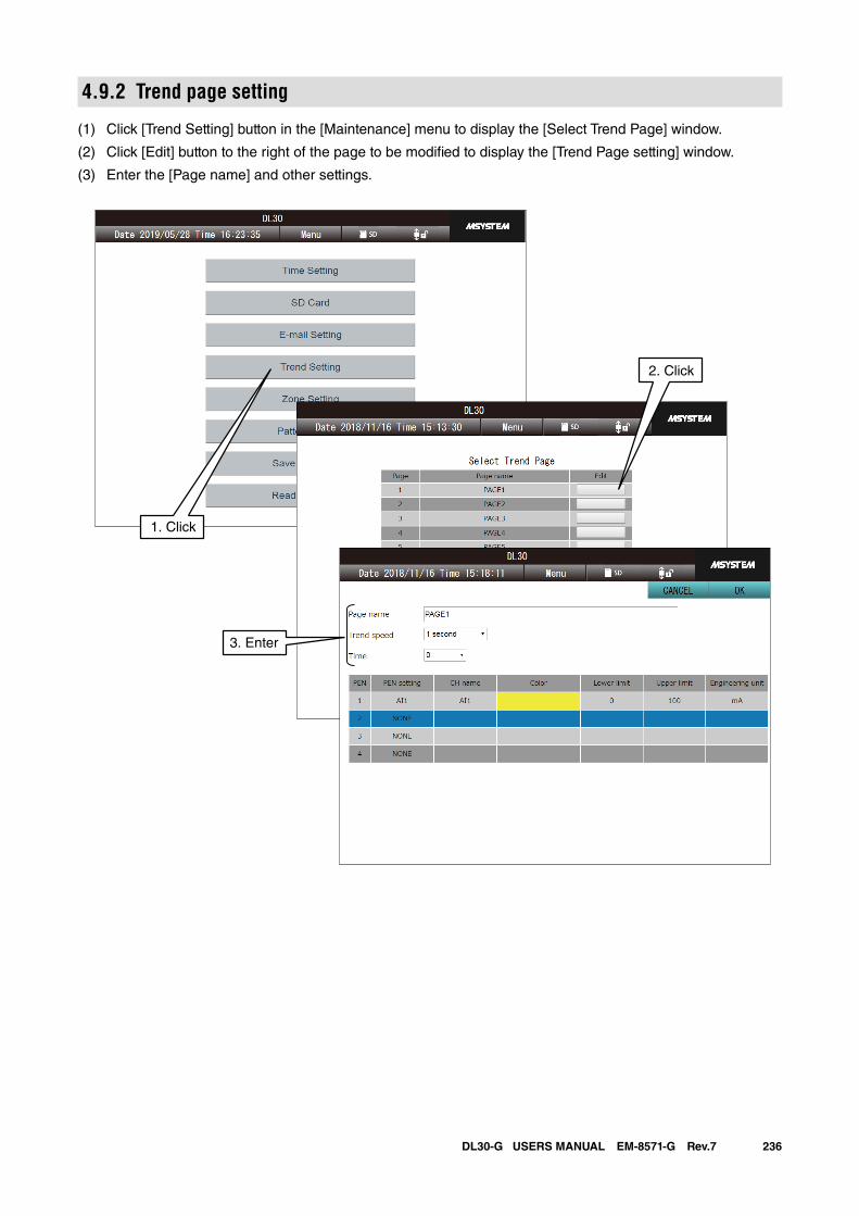
236DL30-G USERS MANUAL EM-8571-G Rev.7
4.9.2 Trend page setting
(1) Click [Trend Setting] button in the [Maintenance] menu to display the [Select Trend Page] window.
(2) Click [Edit] button to the right of the page to be modified to display the [Trend Page setting] window.
(3) Enter the [Page name] and other settings.
1. Click
2. Click
3. Enter
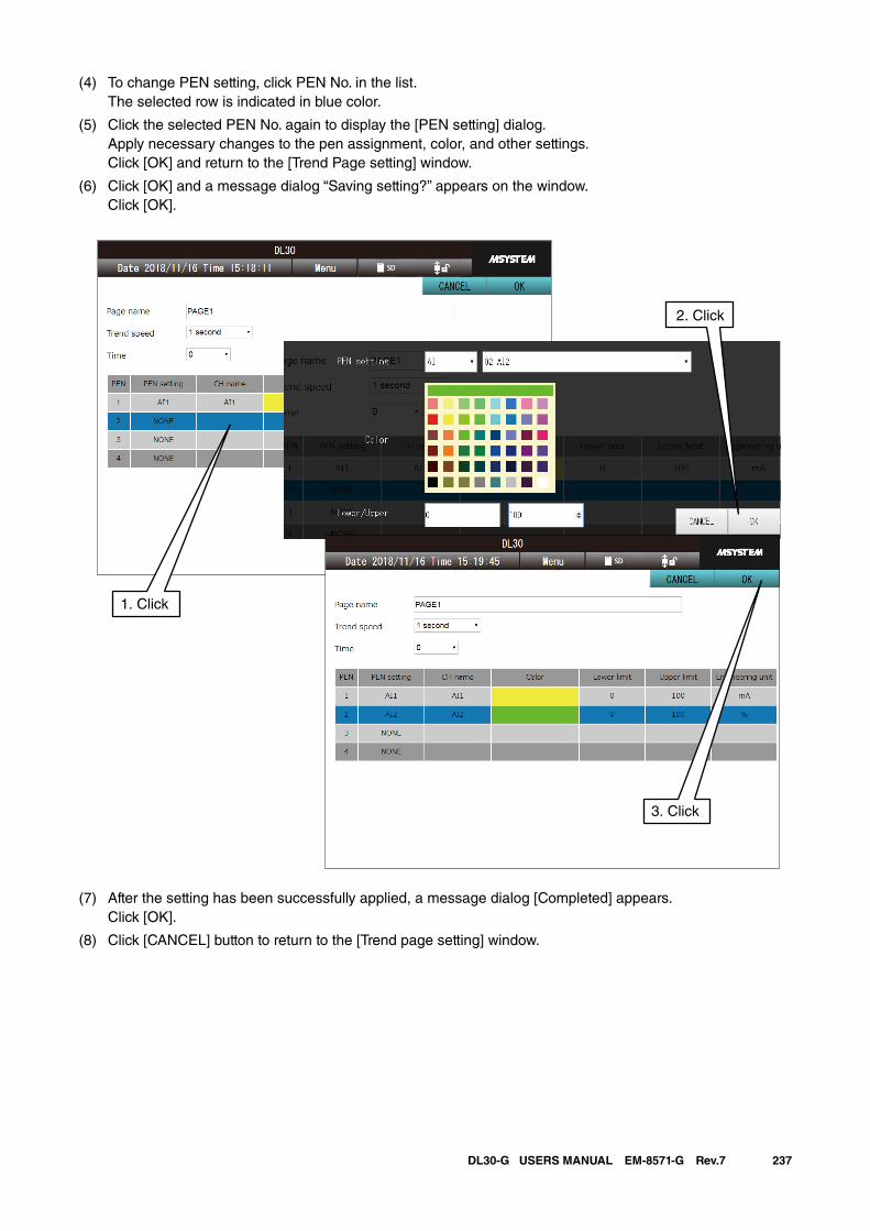
237DL30-G USERS MANUAL EM-8571-G Rev.7
(4) To change PEN setting, click PEN No. in the list. The selected row is indicated in blue color.
(5) Click the selected PEN No. again to display the [PEN setting] dialog. Apply necessary changes to the pen assignment, color, and other settings. Click [OK] and return to the [Trend Page setting] window.
(6) Click [OK] and a message dialog “Saving setting?” appears on the window. Click [OK].
(7) After the setting has been successfully applied, a message dialog [Completed] appears. Click [OK].
(8) Click [CANCEL] button to return to the [Trend page setting] window.
1. Click
2. Click
3. Click
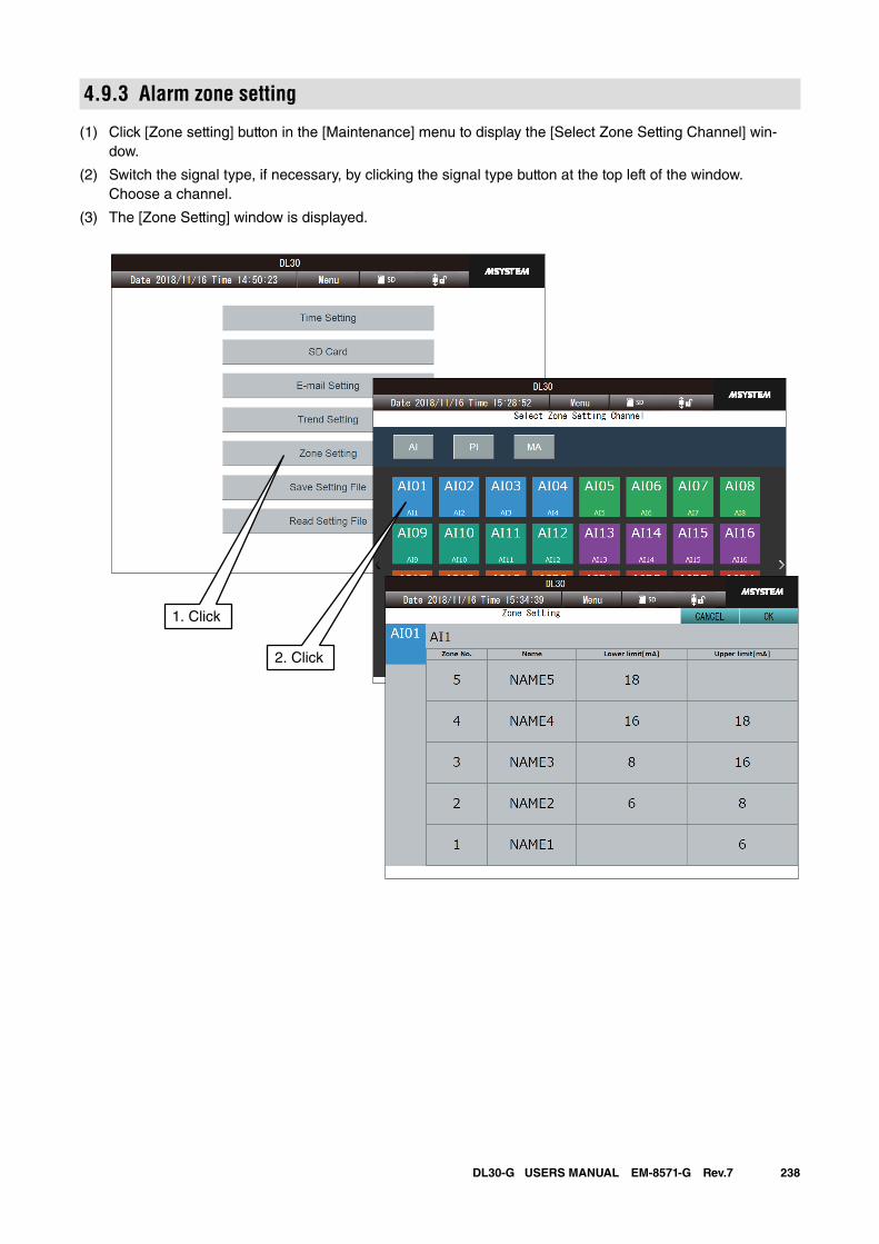
238DL30-G USERS MANUAL EM-8571-G Rev.7
4.9.3 Alarm zone setting
(1) Click [Zone setting] button in the [Maintenance] menu to display the [Select Zone Setting Channel] win-dow.
(2) Switch the signal type, if necessary, by clicking the signal type button at the top left of the window. Choose a channel.
(3) The [Zone Setting] window is displayed.
1. Click
2. Click
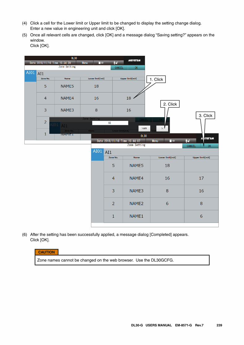
239DL30-G USERS MANUAL EM-8571-G Rev.7
(4) Click a cell for the Lower limit or Upper limit to be changed to display the setting change dialog. Enter a new value in engineering unit and click [OK].
(5) Once all relevant cells are changed, click [OK] and a message dialog “Saving setting?” appears on the window. Click [OK].
(6) After the setting has been successfully applied, a message dialog [Completed] appears. Click [OK].
CAUTION
Zone names cannot be changed on the web browser. Use the DL30GCFG.
2. Click
1. Click
3. Click
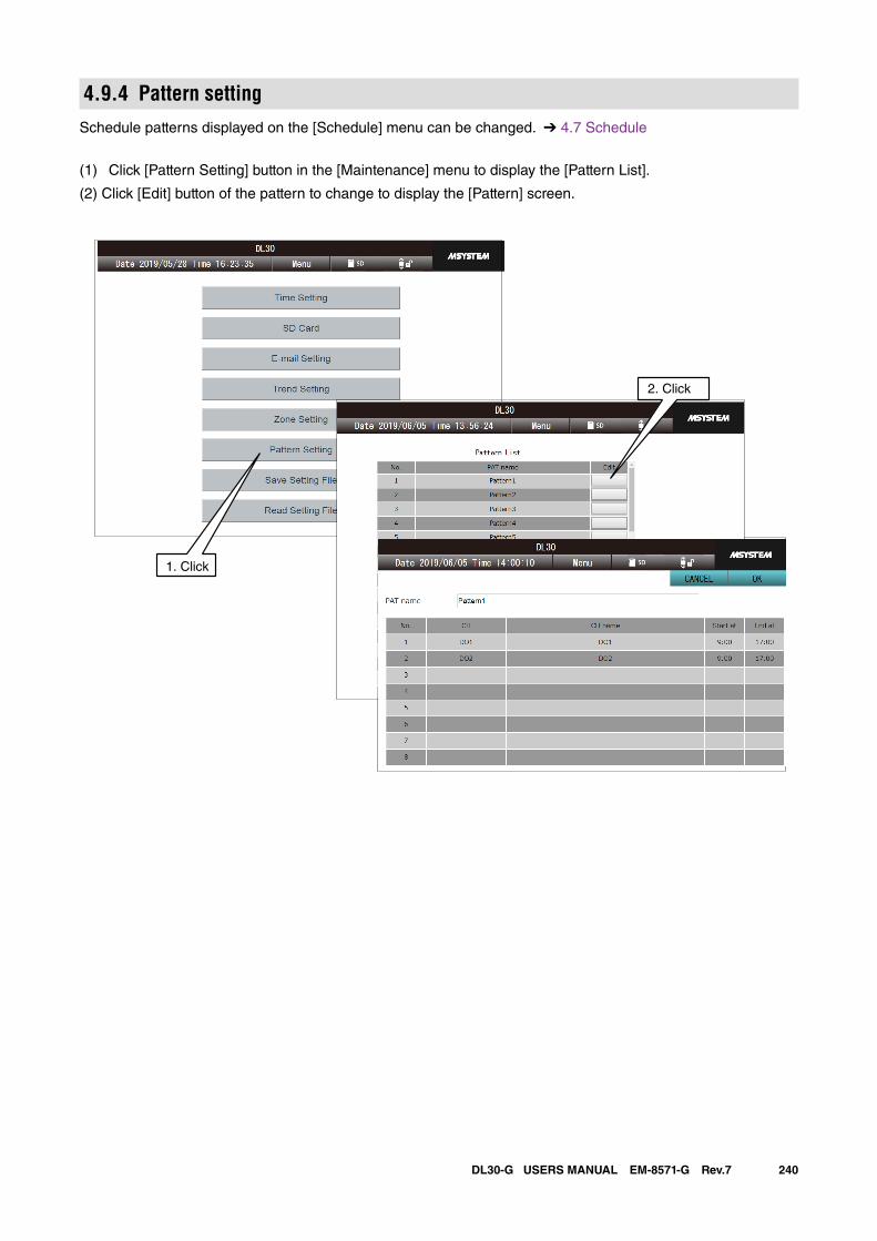
240DL30-G USERS MANUAL EM-8571-G Rev.7
4.9.4 Pattern settingSchedule patterns displayed on the [Schedule] menu can be changed. ➔ 4.7 Schedule
(1) Click [Pattern Setting] button in the [Maintenance] menu to display the [Pattern List].
(2) Click [Edit] button of the pattern to change to display the [Pattern] screen.
4. Click
2. Click
1. Click
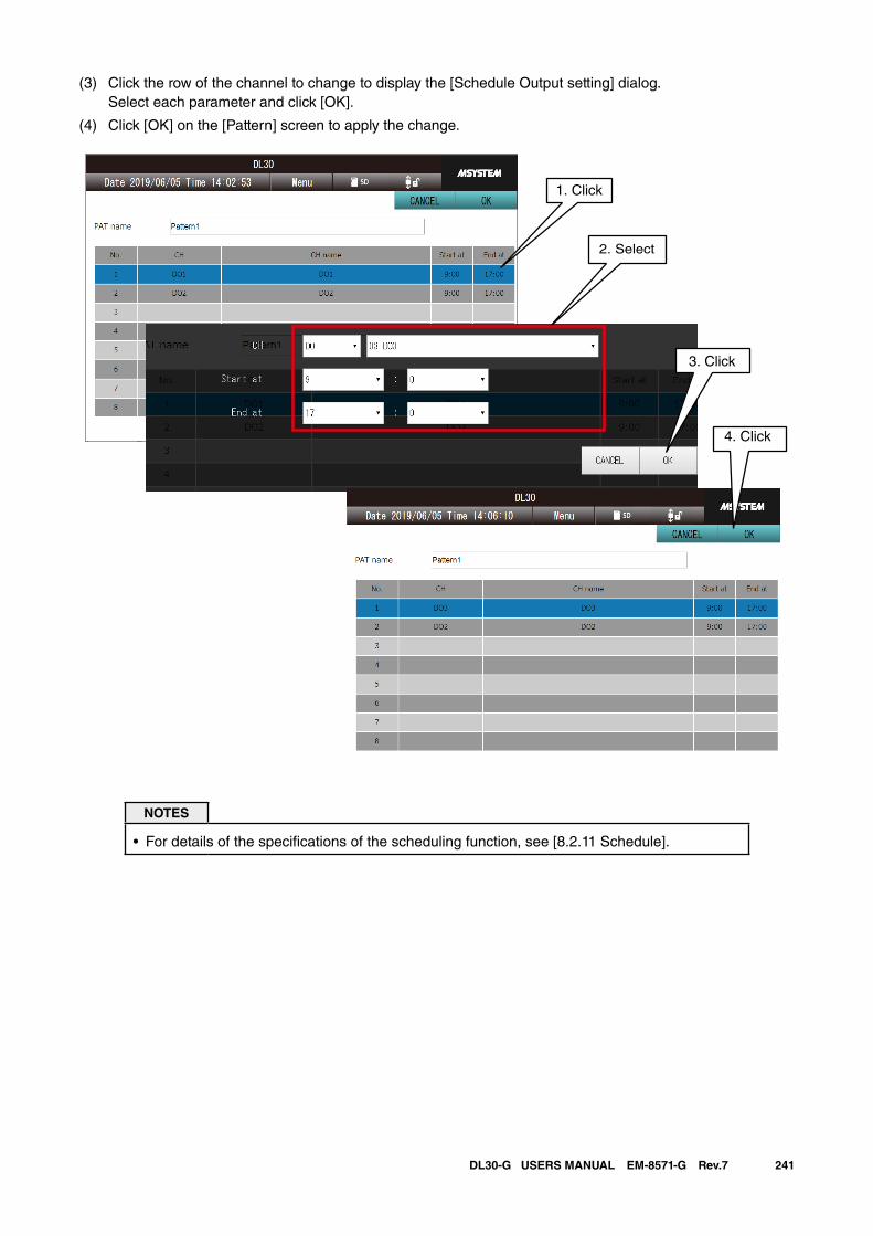
241DL30-G USERS MANUAL EM-8571-G Rev.7
(3) Click the row of the channel to change to display the [Schedule Output setting] dialog. Select each parameter and click [OK].
(4) Click [OK] on the [Pattern] screen to apply the change.
2. Select
1. Click
3. Click
4. Click
NOTES
• For details of the specifications of the scheduling function, see [8.2.11 Schedule].
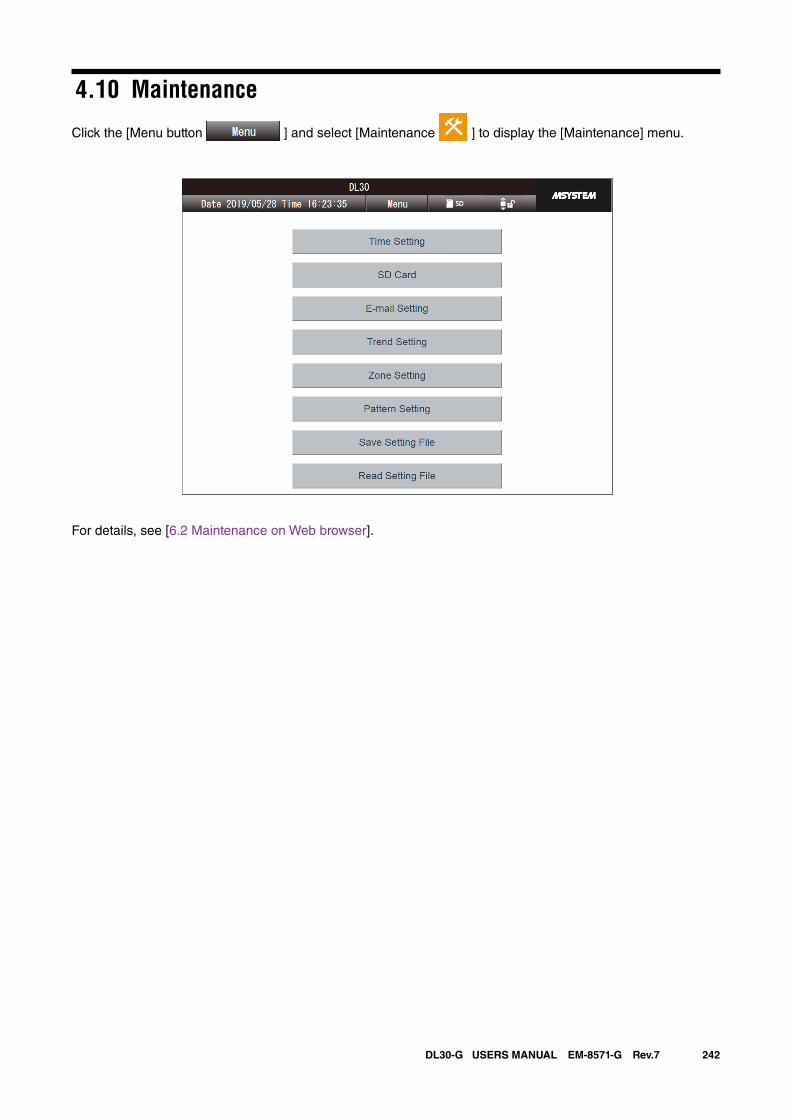
242DL30-G USERS MANUAL EM-8571-G Rev.7
4.10 Maintenance
Click the [Menu button ] and select [Maintenance ] to display the [Maintenance] menu.
For details, see [6.2 Maintenance on Web browser].
243DL30-G USERS MANUAL EM-8571-G Rev.7
4.11 User defined web browser viewUser is allowed to freely create Web screens Using HTML or JavaScript.
Access [http://<DL30G-IP address>/user/<content file name>] from the browser to show the user defined win-dows.
See [7. User defined browser view] for detailed information.
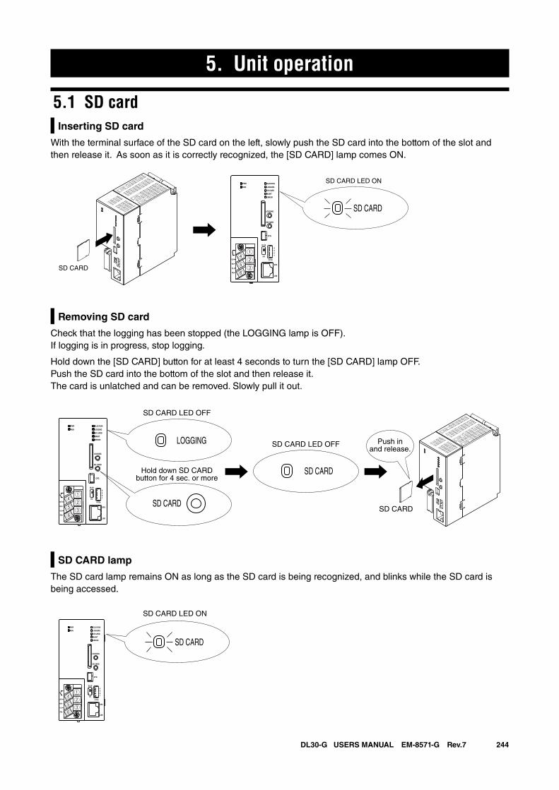
244DL30-G USERS MANUAL EM-8571-G Rev.7
5. Unit operation
5.1 SD cardInserting SD card
With the terminal surface of the SD card on the left, slowly push the SD card into the bottom of the slot and then release it. As soon as it is correctly recognized, the [SD CARD] lamp comes ON.
Removing SD card
Check that the logging has been stopped (the LOGGING lamp is OFF). If logging is in progress, stop logging.
Hold down the [SD CARD] button for at least 4 seconds to turn the [SD CARD] lamp OFF.Push the SD card into the bottom of the slot and then release it. The card is unlatched and can be removed. Slowly pull it out.
SD CARD lamp
The SD card lamp remains ON as long as the SD card is being recognized, and blinks while the SD card is being accessed.
SD CARD
SD CARD
SD CARD LED ONDL30 RUN
LOGGING
SD CARD
PWR
RUN
ERROR
MAINT
CFG
DPX
LNK
LOGGING
SD CARD
DL30
2
I/O
On
43
1
U(+)
NC
V(-)
FE
LOGGING
SD CARD
SD CARD
SD CARD LED OFF
SD CARD LED OFF
SD CARD
DL30 RUN
LOGGNG
SD CARD
PWR
RUN
ERROR
MAINT
CFG
DPX
LNK
LOGGNG
SD CARD
DL30
2
I/O
On
43
1①②③
④⑤⑥
U(+)
NC
V(-)
FE
Hold down SD CARDbutton for 4 sec. or more
Push inand release.
SD CARD
DL30 RUN
LOGGING
SD CARD
PWR
RUN
ERROR
MAINT
CFG
DPX
LNK
LOGGING
SD CARD
DL30
2
I/O
On
43
1①②③
④⑤⑥
U(+)
NC
V(-)
FE
SD CARD LED ON
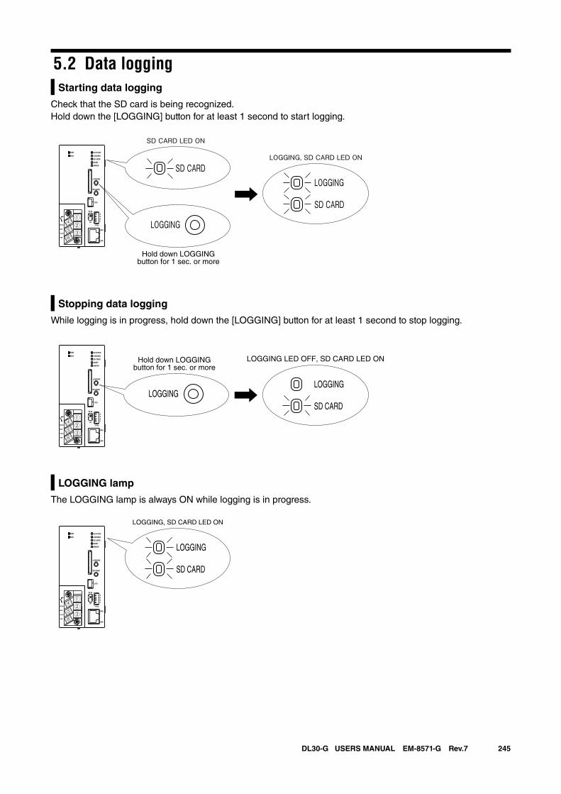
245DL30-G USERS MANUAL EM-8571-G Rev.7
5.2 Data loggingStarting data logging
Check that the SD card is being recognized.Hold down the [LOGGING] button for at least 1 second to start logging.
Stopping data logging
While logging is in progress, hold down the [LOGGING] button for at least 1 second to stop logging.
LOGGING lamp
The LOGGING lamp is always ON while logging is in progress.
SD CARD
LOGGING
LOGGING
SD CARD
SD CARD LED ON
LOGGING, SD CARD LED ONDL30 RUN
LOGGING
SD CARD
PWR
RUN
ERROR
CFG
DPX
LNK
SD CARD
DL30
2
I/O
On
43
1①②③
④⑤⑥
U(+)
NC
V(-)
FE
Hold down LOGGINGbutton for 1 sec. or more
MAINT
LOGGING
LOGGINGLOGGING
SD CARD
LOGGING LED OFF, SD CARD LED ONPWR
RUN
CFG
DPX
LNK
SD CARD
DL30
2
I/O
On
43
1①②③
④⑤⑥
U(+)
NC
V(-)
FE
Hold down LOGGINGbutton for 1 sec. or more
DL30 RUN
LOGGING
SD CARD
ERROR
MAINT
LOGGING
LOGGING
SD CARD
LOGGING, SD CARD LED ON
DL30 RUN
LOGGING
SD CARD
PWR
RUN
ERROR
CFG
DPX
LNK
SD CARD
DL30
2
I/O
On
43
1①②③
④⑤⑥
U(+)
NC
V(-)
FE
MAINT
LOGGING
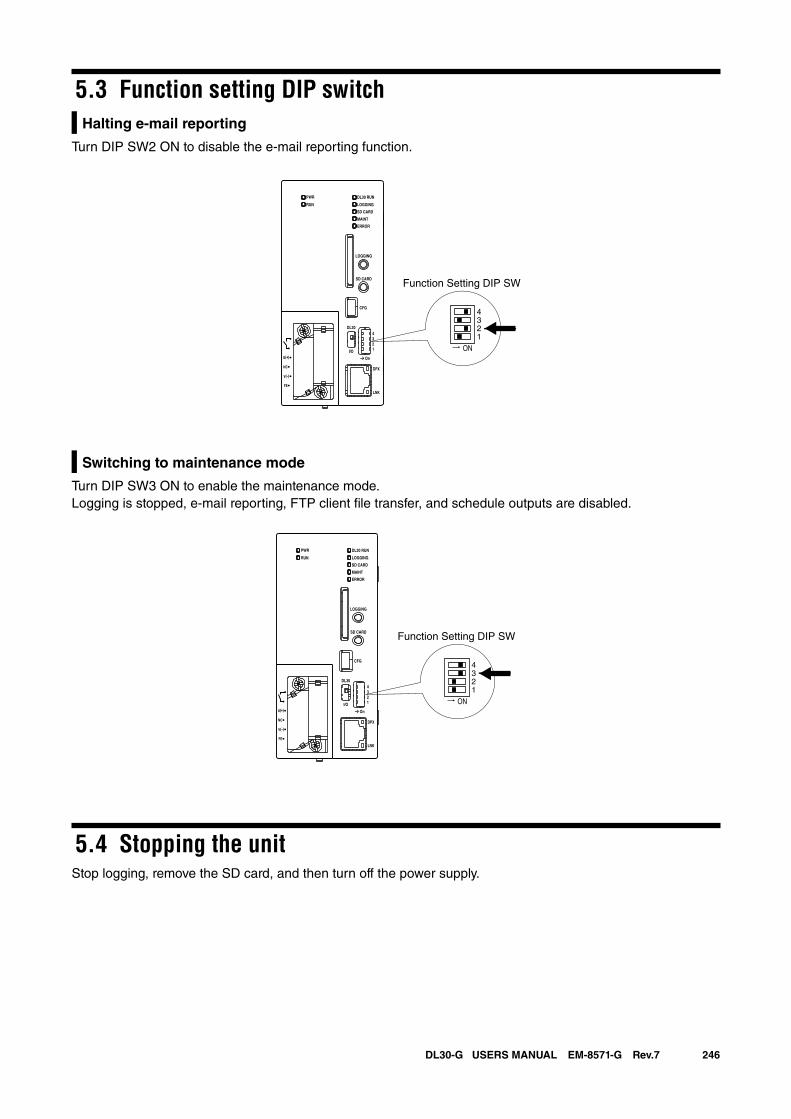
246DL30-G USERS MANUAL EM-8571-G Rev.7
5.3 Function setting DIP switchHalting e-mail reporting
Turn DIP SW2 ON to disable the e-mail reporting function.
Switching to maintenance mode
Turn DIP SW3 ON to enable the maintenance mode.Logging is stopped, e-mail reporting, FTP client file transfer, and schedule outputs are disabled.
5.4 Stopping the unitStop logging, remove the SD card, and then turn off the power supply.
ON
4321
DL30 RUN
LOGGING
SD CARD
MAINT
PWR
RUN
ERROR
CFG
DPX
LNK
LOGGING
SD CARD
DL30
2
I/O
On
43
1
U(+)
NC
V(-)
FE
Function Setting DIP SW
ON
4321
DL30 RUN
LOGGING
SD CARD
MAINT
PWR
RUN
ERROR
CFG
DPX
LNK
LOGGING
SD CARD
DL30
2
I/O
On
43
1
U(+)
NC
V(-)
FE
Function Setting DIP SW
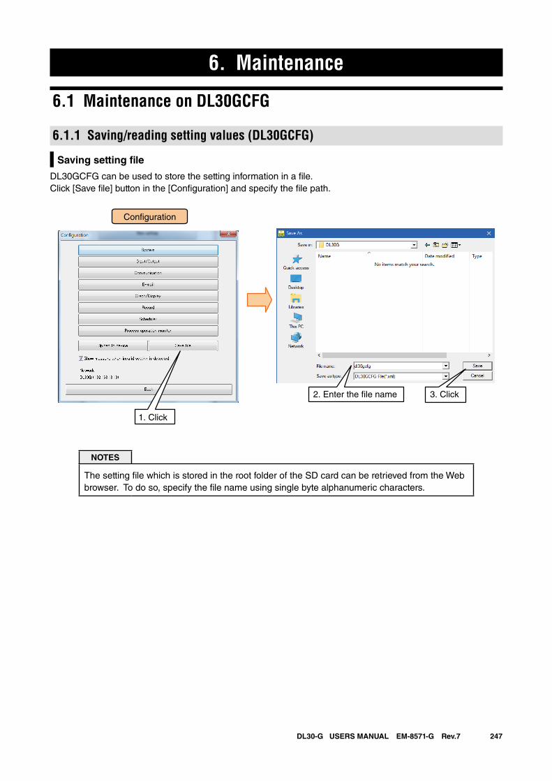
247DL30-G USERS MANUAL EM-8571-G Rev.7
6. Maintenance
6.1 Maintenance on DL30GCFG
6.1.1 Saving/reading setting values (DL30GCFG)
Saving setting file
DL30GCFG can be used to store the setting information in a file.Click [Save file] button in the [Configuration] and specify the file path.
NOTES
The setting file which is stored in the root folder of the SD card can be retrieved from the Web browser. To do so, specify the file name using single byte alphanumeric characters.
3. Click2. Enter the �le name
Con�guration
1. Click
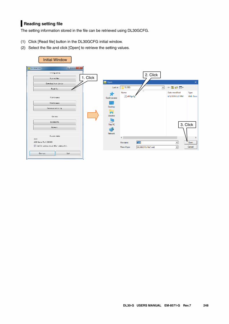
248DL30-G USERS MANUAL EM-8571-G Rev.7
Reading setting file
The setting information stored in the file can be retrieved using DL30GCFG.
(1) Click [Read file] button in the DL30GCFG initial window.
(2) Select the file and click [Open] to retrieve the setting values.
Initial Window
1. Click2. Click
3. Click
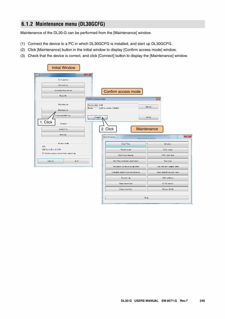
249DL30-G USERS MANUAL EM-8571-G Rev.7
6.1.2 Maintenance menu (DL30GCFG)Maintenance of the DL30-G can be performed from the [Maintenance] window.
(1) Connect the device to a PC in which DL30GCFG is installed, and start up DL30GCFG.
(2) Click [Maintenance] button in the initial window to display [Confirm access mode] window.
(3) Check that the device is correct, and click [Connect] button to display the [Maintenance] window.
Initial Window
Maintenance
Con�rm access mode
1. Click
2. Click
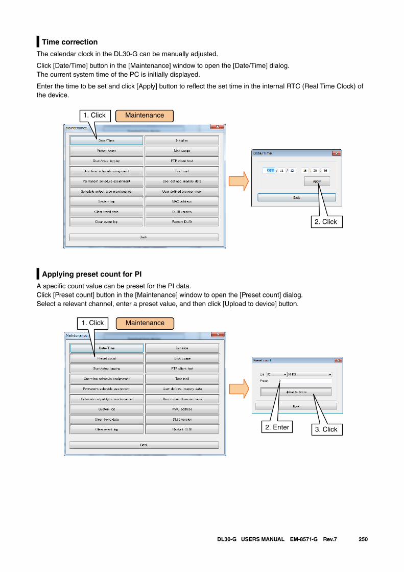
250DL30-G USERS MANUAL EM-8571-G Rev.7
Time correction
The calendar clock in the DL30-G can be manually adjusted.
Click [Date/Time] button in the [Maintenance] window to open the [Date/Time] dialog. The current system time of the PC is initially displayed.
Enter the time to be set and click [Apply] button to reflect the set time in the internal RTC (Real Time Clock) of the device.
Applying preset count for PI
A specific count value can be preset for the PI data.Click [Preset count] button in the [Maintenance] window to open the [Preset count] dialog.Select a relevant channel, enter a preset value, and then click [Upload to device] button.
Maintenance1. Click
2. Click
Maintenance1. Click
2. Enter 3. Click
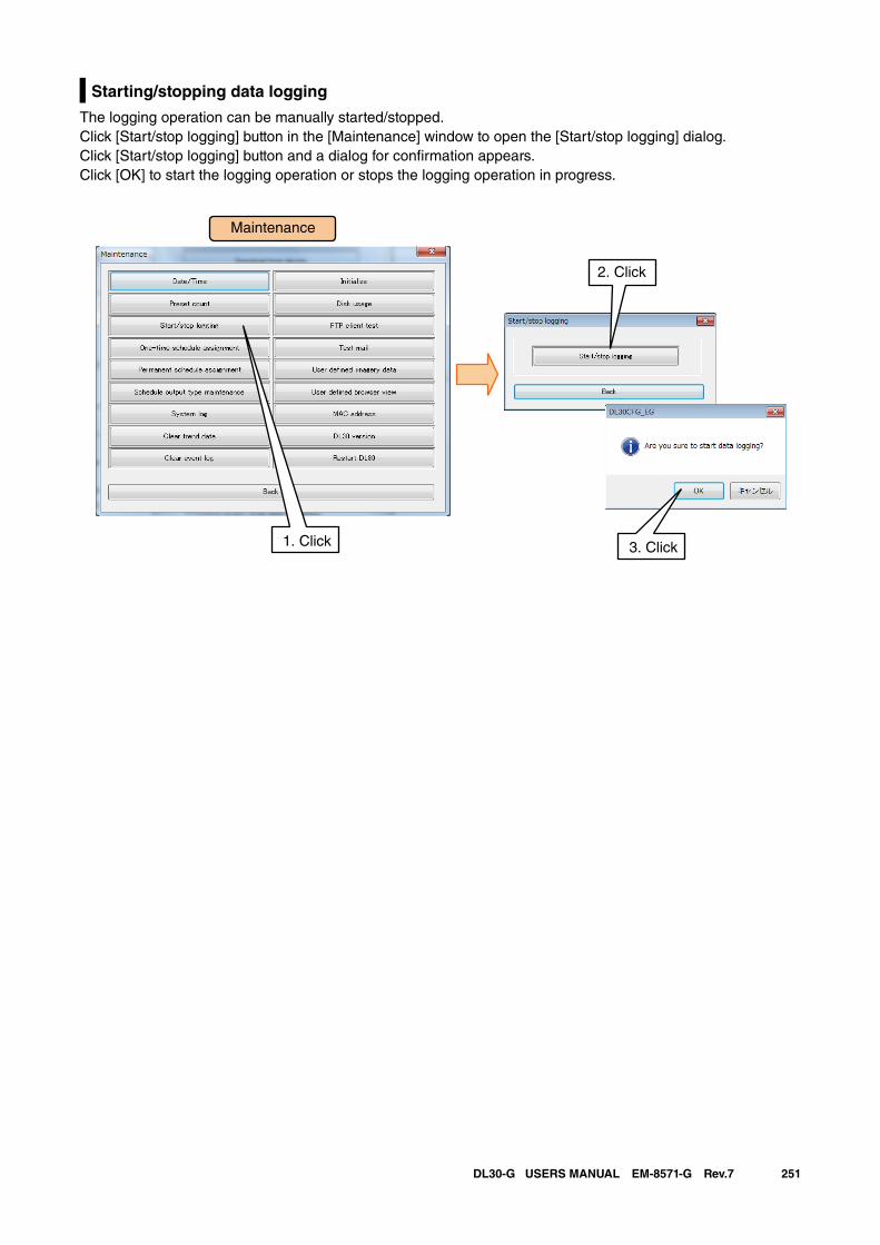
251DL30-G USERS MANUAL EM-8571-G Rev.7
Starting/stopping data logging
The logging operation can be manually started/stopped.Click [Start/stop logging] button in the [Maintenance] window to open the [Start/stop logging] dialog.Click [Start/stop logging] button and a dialog for confirmation appears. Click [OK] to start the logging operation or stops the logging operation in progress.
Maintenance
2. Click
3. Click1. Click
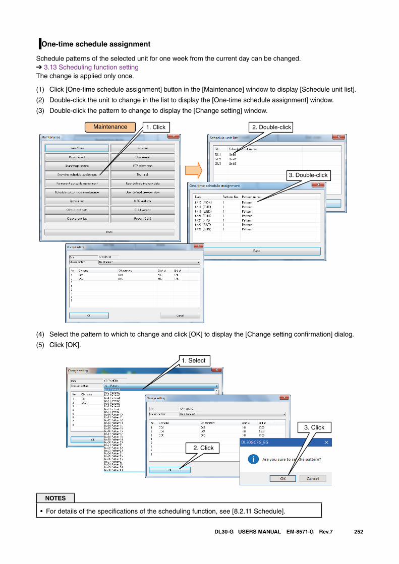
252DL30-G USERS MANUAL EM-8571-G Rev.7
One-time schedule assignment
Schedule patterns of the selected unit for one week from the current day can be changed. ➔ 3.13 Scheduling function setting The change is applied only once.
(1) Click [One-time schedule assignment] button in the [Maintenance] window to display [Schedule unit list].
(2) Double-click the unit to change in the list to display the [One-time schedule assignment] window.
(3) Double-click the pattern to change to display the [Change setting] window.
Maintenance 1. Click 2. Double-click
3. Double-click
(4) Select the pattern to which to change and click [OK] to display the [Change setting confirmation] dialog.
(5) Click [OK].
1. Select
2. Click
3. Click
NOTES
• For details of the specifications of the scheduling function, see [8.2.11 Schedule].
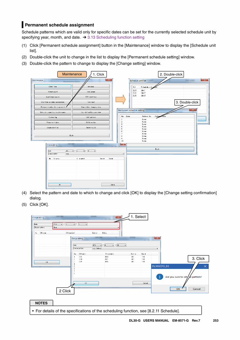
253DL30-G USERS MANUAL EM-8571-G Rev.7
Permanent schedule assignment
Schedule patterns which are valid only for specific dates can be set for the currently selected schedule unit by specifying year, month, and date. ➔ 3.13 Scheduling function setting
(1) Click [Permanent schedule assignment] button in the [Maintenance] window to display the [Schedule unit list].
(2) Double-click the unit to change in the list to display the [Permanent schedule setting] window.
(3) Double-click the pattern to change to display the [Change setting] window.
Maintenance 1. Click 2. Double-click
3. Double-click
(4) Select the pattern and date to which to change and click [OK] to display the [Change setting confirmation] dialog.
(5) Click [OK].
2 Click
1. Select
3. Click
NOTES
• For details of the specifications of the scheduling function, see [8.2.11 Schedule].
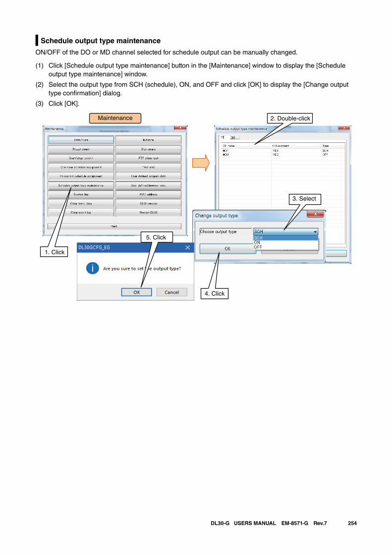
254DL30-G USERS MANUAL EM-8571-G Rev.7
Schedule output type maintenance
ON/OFF of the DO or MD channel selected for schedule output can be manually changed.
(1) Click [Schedule output type maintenance] button in the [Maintenance] window to display the [Schedule output type maintenance] window.
(2) Select the output type from SCH (schedule), ON, and OFF and click [OK] to display the [Change output type confirmation] dialog.
(3) Click [OK].
Maintenance
1. Click
3. Double-click
1. Click
2. Double-click
3. Select
5. Click
4. Click
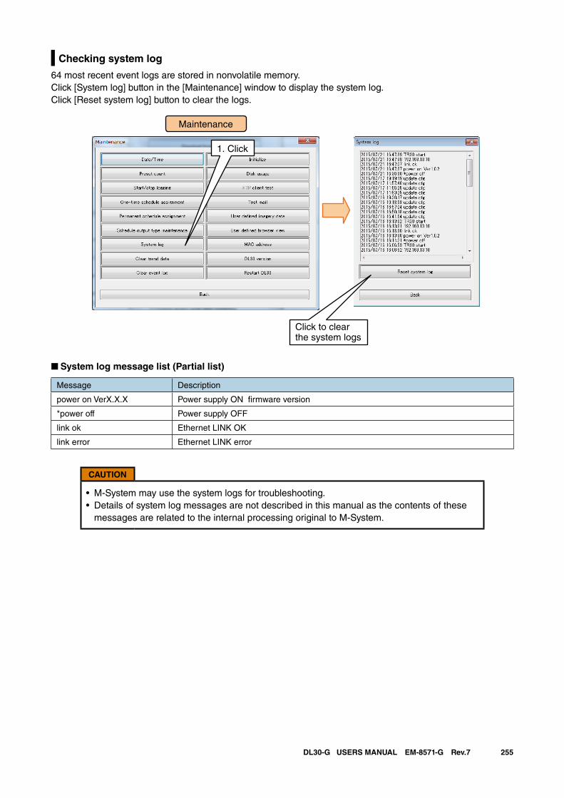
255DL30-G USERS MANUAL EM-8571-G Rev.7
Checking system log
64 most recent event logs are stored in nonvolatile memory.Click [System log] button in the [Maintenance] window to display the system log.Click [Reset system log] button to clear the logs.
1. Click
Maintenance
Click to clearthe system logs
■ System log message list (Partial list)
Message Description
power on VerX.X.X Power supply ON firmware version
*power off Power supply OFF
link ok Ethernet LINK OK
link error Ethernet LINK error
CAUTION
• M-System may use the system logs for troubleshooting.• Details of system log messages are not described in this manual as the contents of these
messages are related to the internal processing original to M-System.
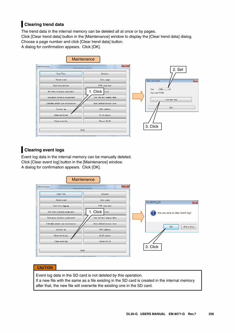
256DL30-G USERS MANUAL EM-8571-G Rev.7
Clearing trend data
The trend data in the internal memory can be deleted all at once or by pages.Click [Clear trend data] button in the [Maintenance] window to display the [Clear trend data] dialog.Choose a page number and click [Clear trend data] button. A dialog for confirmation appears. Click [OK].
Clearing event logs
Event log data in the internal memory can be manually deleted.Click [Clear event log] button in the [Maintenance] window. A dialog for confirmation appears. Click [OK].
CAUTION
Event log data in the SD card is not deleted by this operation. If a new file with the same as a file existing in the SD card is created in the internal memory after that, the new file will overwrite the existing one in the SD card.
Maintenance
1. Click
2. Set
3. Click
Maintenance
1. Click
3. Click
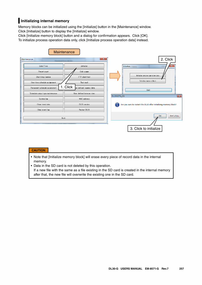
257DL30-G USERS MANUAL EM-8571-G Rev.7
Initializing internal memory
Memory blocks can be initialized using the [Initialize] button in the [Maintenance] window.Click [Initialize] button to display the [Initialize] window.Click [Initialize memory block] button and a dialog for confirmation appears. Click [OK].To initialize process operation data only, click [Initialize process operation data] instead.
Maintenance
1. Click
2. Click
3. Click to initialize
CAUTION
• Note that [Initialize memory block] will erase every piece of record data in the internal memory.
• Data in the SD card is not deleted by this operation. If a new file with the same as a file existing in the SD card is created in the internal memory after that, the new file will overwrite the existing one in the SD card.
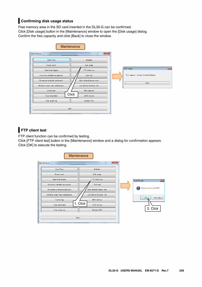
258DL30-G USERS MANUAL EM-8571-G Rev.7
Confirming disk usage status
Free memory area in the SD card inserted in the DL30-G can be confirmed.Click [Disk usage] button in the [Maintenance] window to open the [Disk usage] dialog.Confirm the free capacity and click [Back] to close the window.
FTP client test
FTP client function can be confirmed by testing.Click [FTP client test] button in the [Maintenance] window and a dialog for confirmation appears.Click [OK] to execute the testing.
Maintenance
Click
Maintenance
1. Click
2. Click
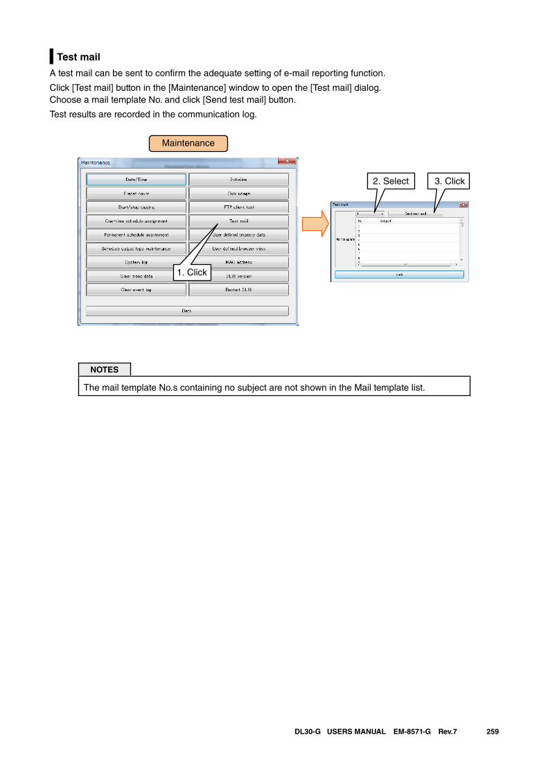
259DL30-G USERS MANUAL EM-8571-G Rev.7
Test mail
A test mail can be sent to confirm the adequate setting of e-mail reporting function.
Click [Test mail] button in the [Maintenance] window to open the [Test mail] dialog.Choose a mail template No. and click [Send test mail] button.
Test results are recorded in the communication log.
NOTES
The mail template No.s containing no subject are not shown in the Mail template list.
Maintenance
1. Click
2. Select 3. Click
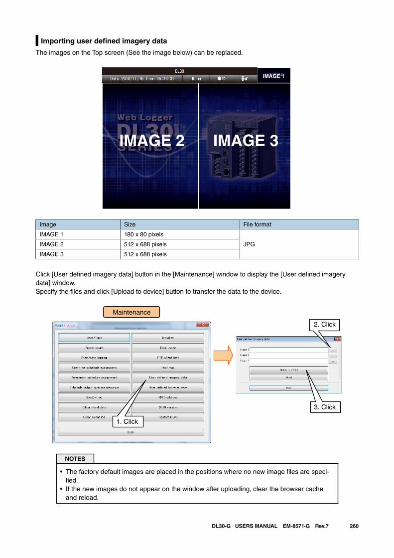
260DL30-G USERS MANUAL EM-8571-G Rev.7
Importing user defined imagery data
The images on the Top screen (See the image below) can be replaced.
Image Size File format
IMAGE 1 180 x 80 pixels
JPGIMAGE 2 512 x 688 pixels
IMAGE 3 512 x 688 pixels
Click [User defined imagery data] button in the [Maintenance] window to display the [User defined imagery data] window. Specify the files and click [Upload to device] button to transfer the data to the device.
NOTES
• The factory default images are placed in the positions where no new image files are speci-fied.
• If the new images do not appear on the window after uploading, clear the browser cache and reload.
IMAGE 1
IMAGE 2 IMAGE 3
Maintenance
1. Click
3. Click
2. Click
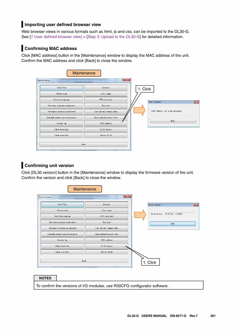
261DL30-G USERS MANUAL EM-8571-G Rev.7
Importing user defined browser view
Web browser views in various formats such as html, js and css, can be imported to the DL30-G.See [7. User defined browser view] > [Step 3: Upload to the DL30-G] for detailed information.
Confirming MAC address
Click [MAC address] button in the [Maintenance] window to display the MAC address of the unit.Confirm the MAC address and click [Back] to close the window.
Confirming unit version
Click [DL30 version] button in the [Maintenance] window to display the firmware version of the unit.Confirm the version and click [Back] to close the window.
NOTES
To confirm the versions of I/O modules, use R30CFG configurator software.
Maintenance
1. Click
Maintenance
1. Click
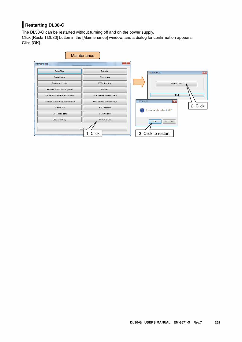
262DL30-G USERS MANUAL EM-8571-G Rev.7
Restarting DL30-G
The DL30-G can be restarted without turning off and on the power supply.Click [Restart DL30] button in the [Maintenance] window, and a dialog for confirmation appears. Click [OK].
Maintenance
1. Click 3. Click to restart
2. Click
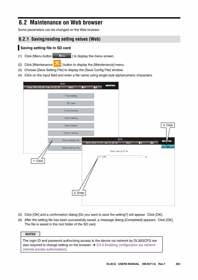
263DL30-G USERS MANUAL EM-8571-G Rev.7
6.2 Maintenance on Web browserSome parameters can be changed on the Web browser.
6.2.1 Saving/reading setting values (Web)
Saving setting file in SD card
(1) Click [Menu button ] to display the menu screen.
(2) Click [Maintenance ] button to display the [Maintenance] menu.
(3) Choose [Save Setting File] to display the [Save Config File] window.
(4) Click on the input field and enter a file name using single byte alphanumeric characters.
(5) Click [OK] and a confirmation dialog [Do you want to save the setting?] will appear. Click [OK].
(6) After the setting file has been successfully saved, a message dialog [Completed] appears. Click [OK]. The file is saved in the root folder of the SD card.
NOTES
The login ID and password authorizing access to the device via network by DL30GCFG are also required to change setting on the browser. ➔ 3.3.4 Enabling configuration via network (remote access authorization).
1. Click
2. Enter
3. Click
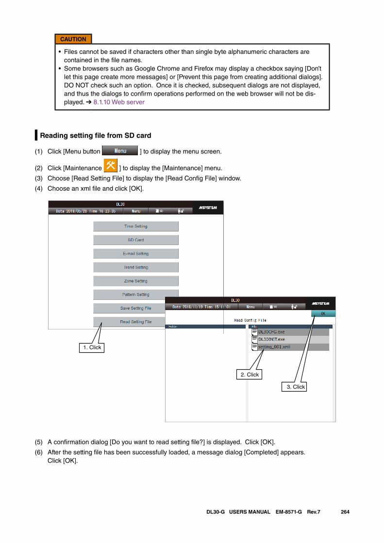
264DL30-G USERS MANUAL EM-8571-G Rev.7
CAUTION
• Files cannot be saved if characters other than single byte alphanumeric characters are contained in the file names.
• Some browsers such as Google Chrome and Firefox may display a checkbox saying [Don’t let this page create more messages] or [Prevent this page from creating additional dialogs]. DO NOT check such an option. Once it is checked, subsequent dialogs are not displayed, and thus the dialogs to confirm operations performed on the web browser will not be dis-played. ➔ 8.1.10 Web server
Reading setting file from SD card
(1) Click [Menu button ] to display the menu screen.
(2) Click [Maintenance ] to display the [Maintenance] menu.
(3) Choose [Read Setting File] to display the [Read Config File] window.
(4) Choose an xml file and click [OK].
(5) A confirmation dialog [Do you want to read setting file?] is displayed. Click [OK].
(6) After the setting file has been successfully loaded, a message dialog [Completed] appears. Click [OK].
1. Click
2. Click
3. Click
265DL30-G USERS MANUAL EM-8571-G Rev.7
NOTES
• The file name of a setting file is [*****.xml].• User can also retrieve setting files saved in the DL30GCFG.
CAUTION
• Use single byte alphanumeric characters for the file name. We cannot guarantee that the files can be properly saved/read if characters other than sin-gle byte alphanumeric characters are contained in the file names.
• Some browsers such as Google Chrome and Firefox may display a checkbox saying [Don’t let this page create more messages] or [Prevent this page from creating additional dialogs]. DO NOT check such an option. Once it is checked, subsequent dialogs are not displayed, and thus the dialogs to confirm operations performed on the web browser will not be dis-played. ➔ 8.1.10 Web server
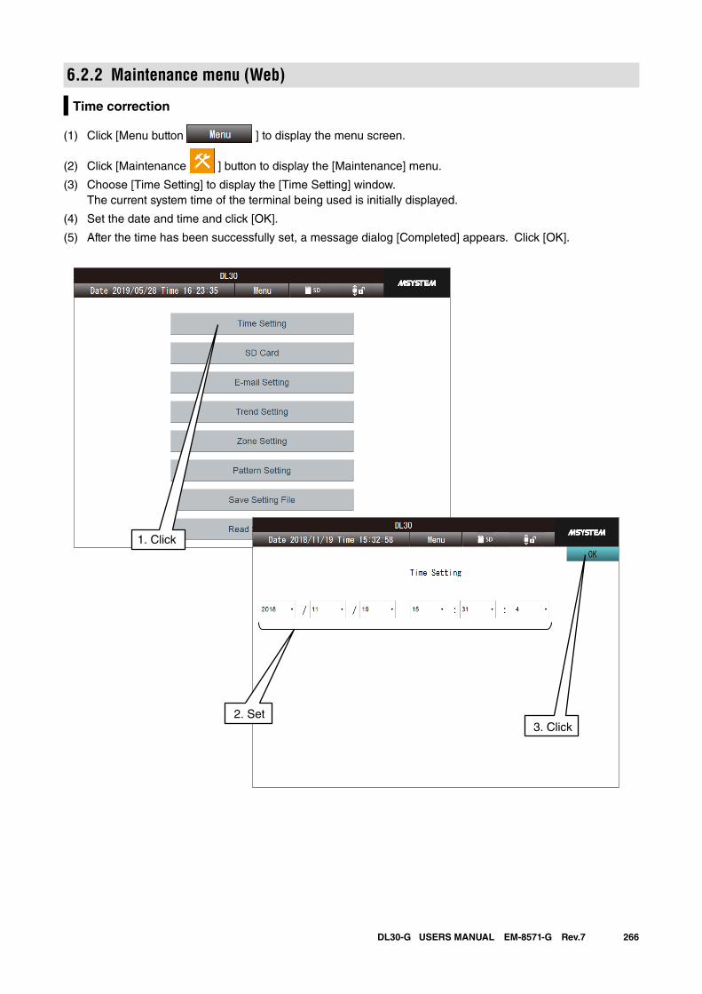
266DL30-G USERS MANUAL EM-8571-G Rev.7
6.2.2 Maintenance menu (Web)
Time correction
(1) Click [Menu button ] to display the menu screen.
(2) Click [Maintenance ] button to display the [Maintenance] menu.
(3) Choose [Time Setting] to display the [Time Setting] window. The current system time of the terminal being used is initially displayed.
(4) Set the date and time and click [OK].
(5) After the time has been successfully set, a message dialog [Completed] appears. Click [OK].
1. Click
2. Set3. Click
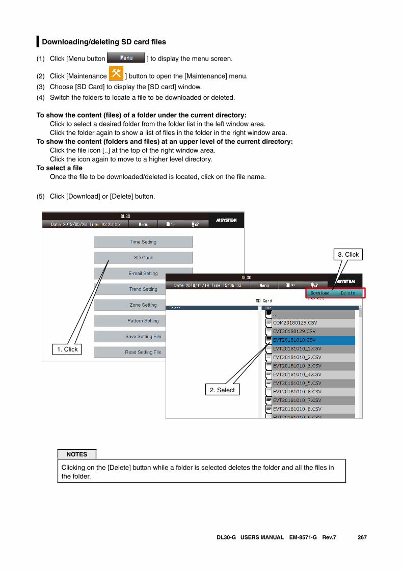
267DL30-G USERS MANUAL EM-8571-G Rev.7
Downloading/deleting SD card files
(1) Click [Menu button ] to display the menu screen.
(2) Click [Maintenance ] button to open the [Maintenance] menu.
(3) Choose [SD Card] to display the [SD card] window.
(4) Switch the folders to locate a file to be downloaded or deleted.
To show the content (files) of a folder under the current directory: Click to select a desired folder from the folder list in the left window area.
Click the folder again to show a list of files in the folder in the right window area.To show the content (folders and files) at an upper level of the current directory: Click the file icon [..] at the top of the right window area.
Click the icon again to move to a higher level directory.To select a file Once the file to be downloaded/deleted is located, click on the file name.
(5) Click [Download] or [Delete] button.
NOTES
Clicking on the [Delete] button while a folder is selected deletes the folder and all the files in the folder.
1. Click
2. Select
3. Click
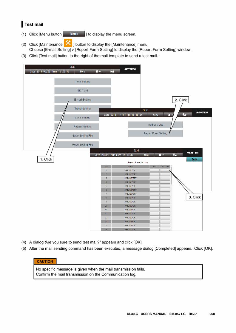
268DL30-G USERS MANUAL EM-8571-G Rev.7
Test mail
(1) Click [Menu button ] to display the menu screen.
(2) Click [Maintenance ] button to display the [Maintenance] menu. Choose [E-mail Setting] > [Report Form Setting] to display the [Report Form Setting] window.
(3) Click [Test mail] button to the right of the mail template to send a test mail.
(4) A dialog “Are you sure to send test mail?” appears and click [OK].
(5) After the mail sending command has been executed, a message dialog [Completed] appears. Click [OK].
CAUTION
No specific message is given when the mail transmission fails. Confirm the mail transmission on the Communication log.
1. Click
2. Click
3. Click
269DL30-G USERS MANUAL EM-8571-G Rev.7
7. User defined browser viewUser can freely design Web pages using HTML, JavaScript, etc.Or, use M-System's web page designing software (model: DL30 Web Designer) which allows User to easily create web pages and transfer them to the DL-30G.
The software program can be downloaded from the M-System web site:➔ http://www.m-system.co.jp/See Users Manual of DL30 Web Designer for details.
User can retrieve the current data measured using the device as JavaScript data files.See [8.2.15 Data files for user defined web browser view].
The DL30-G is only capable of basic web server function for file I/O handling, and NOT capable of running programs such as CGI or Script, provided from the server side.
Access [http://<DL30-IP address>/user/<content file name>] from the browser.
CAUTION
This function is intended for users who have knowledge about the Web in terms of HTML, Javascript, etc. Note that we will be unable to entertain queries about the Web.
NOTES
The Top screen images can be replaced using the procedures explained in [6.1.2 Mainte-nance menu (DL30GCFG) ] > [Importing user defined imagery data].
Step 1: Create a working folder
First, create a working folder in a PC. Only the files directly under this folder are transferred to the DL30-G device but not subfolders and files in them.
NOTES
• The maximum number of files that can be stored in a working folder is 1024.• The maximum total size of files in a working folder is 4 MB.
Step 2: Create HTML files
Describe user’s original browser view data in the working folder using HTML, Javascript, CSS and other lan-guages/formats. Refer to tutorial documents for them.
NOTES
• Set a file name which is 24 single byte alphanumeric characters or less, including the exten-sion.
• The maximum size of 1 file is 1 MB.
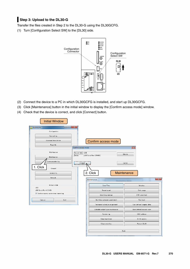
270DL30-G USERS MANUAL EM-8571-G Rev.7
Step 3: Upload to the DL30-G
Transfer the files created in Step 2 to the DL30-G using the DL30GCFG.
(1) Turn [Configuration Select SW] to the [DL30] side.
(2) Connect the device to a PC in which DL30GCFG is installed, and start up DL30GCFG.
(3) Click [Maintenance] button in the initial window to display the [Confirm access mode] window.
(4) Check that the device is correct, and click [Connect] button.
DL30 RUN
LOGGING
SD CARD
MAINT
PWR
RUN
ERROR
CFG
DPX
LNK
LOGGING
SD CARD
DL30
2
I/O
On
43
1
U(+)
NC
V(-)
FE
DL30
I/O
ConfigurationSelect SW
ConfigurationConnector
Initial Window
Maintenance
Con�rm access mode
1. Click
2. Click
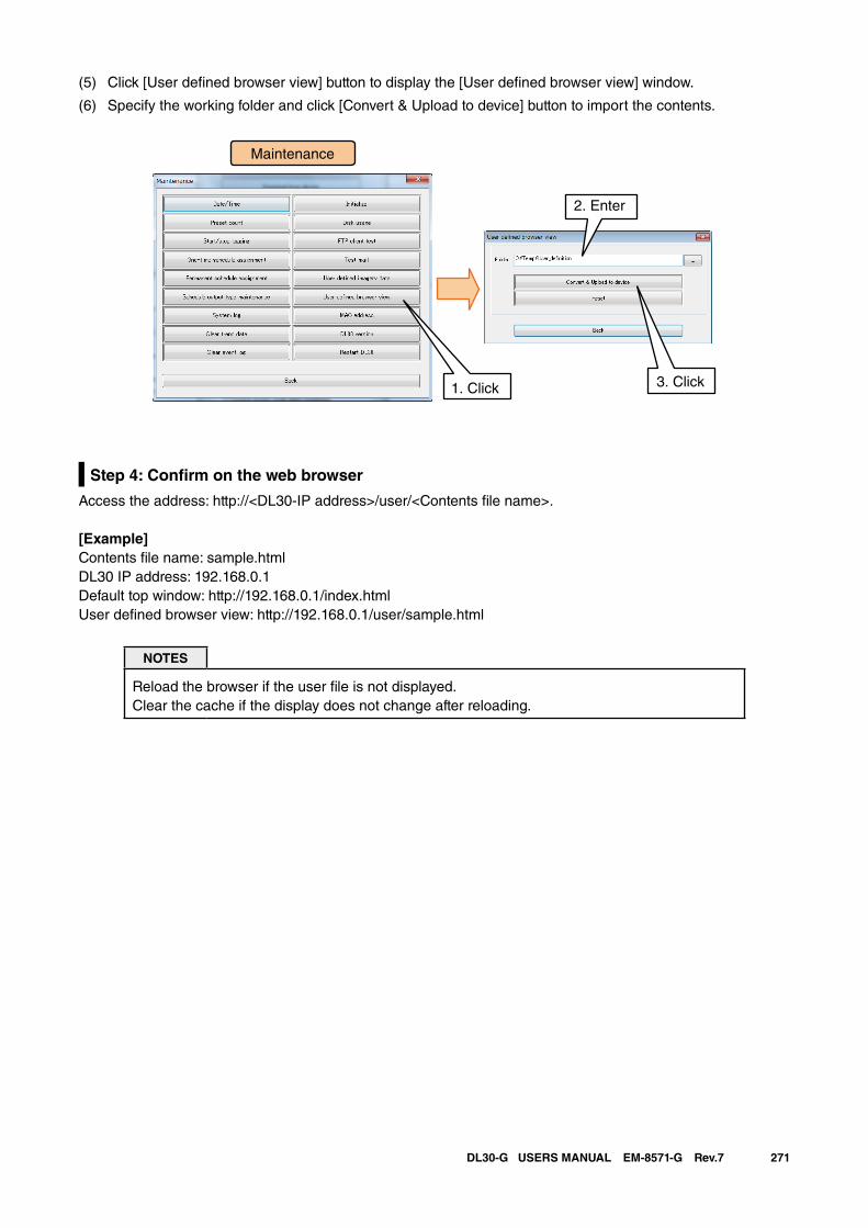
271DL30-G USERS MANUAL EM-8571-G Rev.7
(5) Click [User defined browser view] button to display the [User defined browser view] window.
(6) Specify the working folder and click [Convert & Upload to device] button to import the contents.
Step 4: Confirm on the web browser
Access the address: http://<DL30-IP address>/user/<Contents file name>.
[Example]Contents file name: sample.htmlDL30 IP address: 192.168.0.1Default top window: http://192.168.0.1/index.htmlUser defined browser view: http://192.168.0.1/user/sample.html
NOTES
Reload the browser if the user file is not displayed. Clear the cache if the display does not change after reloading.
Maintenance
2. Enter
1. Click 3. Click
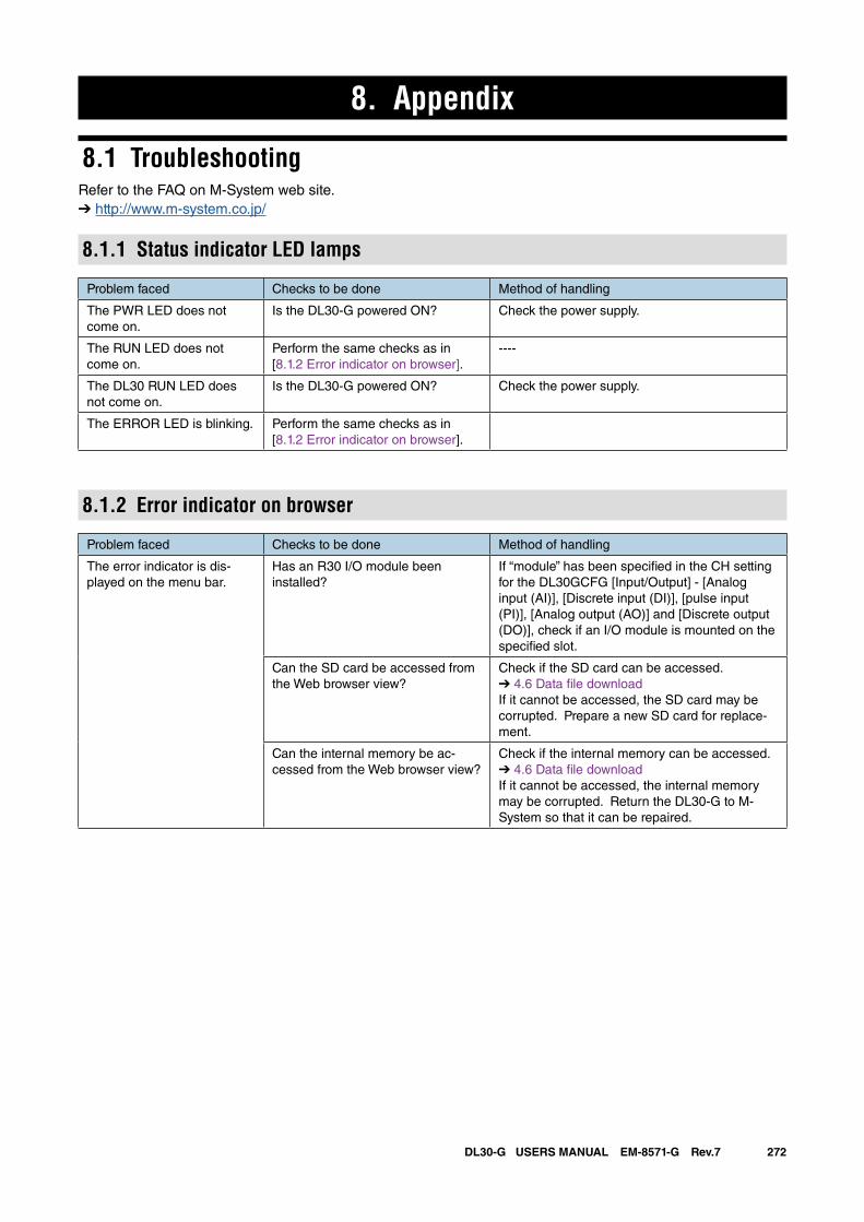
272DL30-G USERS MANUAL EM-8571-G Rev.7
8. Appendix
8.1 TroubleshootingRefer to the FAQ on M-System web site.➔ http://www.m-system.co.jp/
8.1.1 Status indicator LED lamps
Problem faced Checks to be done Method of handling
The PWR LED does not come on.
Is the DL30-G powered ON? Check the power supply.
The RUN LED does not come on.
Perform the same checks as in [8.1.2 Error indicator on browser].
----
The DL30 RUN LED does not come on.
Is the DL30-G powered ON? Check the power supply.
The ERROR LED is blinking. Perform the same checks as in [8.1.2 Error indicator on browser].
8.1.2 Error indicator on browser
Problem faced Checks to be done Method of handling
The error indicator is dis-played on the menu bar.
Has an R30 I/O module been installed?
If “module” has been specified in the CH setting for the DL30GCFG [Input/Output] - [Analog input (AI)], [Discrete input (DI)], [pulse input (PI)], [Analog output (AO)] and [Discrete output (DO)], check if an I/O module is mounted on the specified slot.
Can the SD card be accessed from the Web browser view?
Check if the SD card can be accessed.➔ 4.6 Data file downloadIf it cannot be accessed, the SD card may be corrupted. Prepare a new SD card for replace-ment.
Can the internal memory be ac-cessed from the Web browser view?
Check if the internal memory can be accessed.➔ 4.6 Data file downloadIf it cannot be accessed, the internal memory may be corrupted. Return the DL30-G to M-System so that it can be repaired.
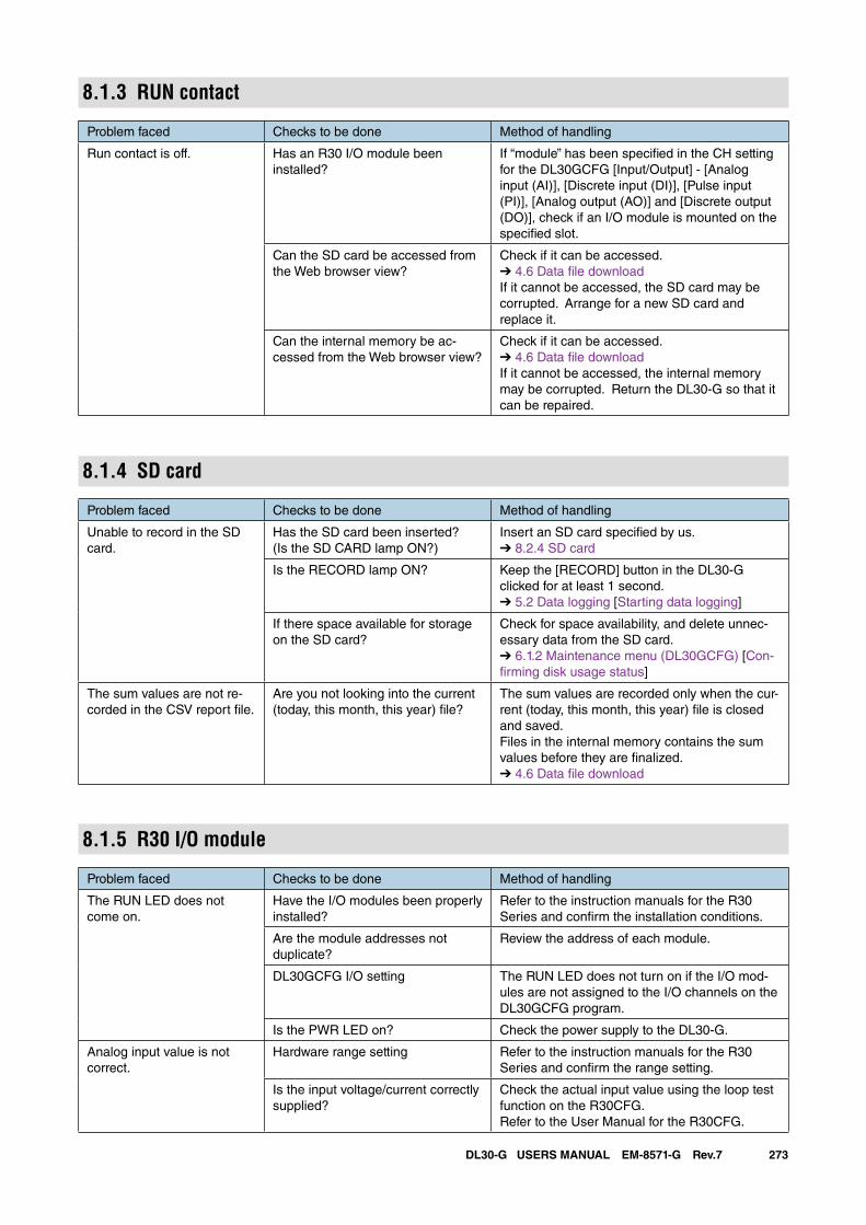
273DL30-G USERS MANUAL EM-8571-G Rev.7
8.1.3 RUN contact
Problem faced Checks to be done Method of handling
Run contact is off. Has an R30 I/O module been installed?
If “module” has been specified in the CH setting for the DL30GCFG [Input/Output] - [Analog input (AI)], [Discrete input (DI)], [Pulse input (PI)], [Analog output (AO)] and [Discrete output (DO)], check if an I/O module is mounted on the specified slot.
Can the SD card be accessed from the Web browser view?
Check if it can be accessed.➔ 4.6 Data file downloadIf it cannot be accessed, the SD card may be corrupted. Arrange for a new SD card and replace it.
Can the internal memory be ac-cessed from the Web browser view?
Check if it can be accessed. ➔ 4.6 Data file downloadIf it cannot be accessed, the internal memory may be corrupted. Return the DL30-G so that it can be repaired.
8.1.4 SD card
Problem faced Checks to be done Method of handling
Unable to record in the SD card.
Has the SD card been inserted?(Is the SD CARD lamp ON?)
Insert an SD card specified by us.➔ 8.2.4 SD card
Is the RECORD lamp ON? Keep the [RECORD] button in the DL30-G clicked for at least 1 second.➔ 5.2 Data logging [Starting data logging]
If there space available for storage on the SD card?
Check for space availability, and delete unnec-essary data from the SD card.➔ 6.1.2 Maintenance menu (DL30GCFG) [Con-firming disk usage status]
The sum values are not re-corded in the CSV report file.
Are you not looking into the current (today, this month, this year) file?
The sum values are recorded only when the cur-rent (today, this month, this year) file is closed and saved.Files in the internal memory contains the sum values before they are finalized.➔ 4.6 Data file download
8.1.5 R30 I/O module
Problem faced Checks to be done Method of handling
The RUN LED does not come on.
Have the I/O modules been properly installed?
Refer to the instruction manuals for the R30 Series and confirm the installation conditions.
Are the module addresses not duplicate?
Review the address of each module.
DL30GCFG I/O setting The RUN LED does not turn on if the I/O mod-ules are not assigned to the I/O channels on the DL30GCFG program.
Is the PWR LED on? Check the power supply to the DL30-G.
Analog input value is not correct.
Hardware range setting Refer to the instruction manuals for the R30 Series and confirm the range setting.
Is the input voltage/current correctly supplied?
Check the actual input value using the loop test function on the R30CFG. Refer to the User Manual for the R30CFG.
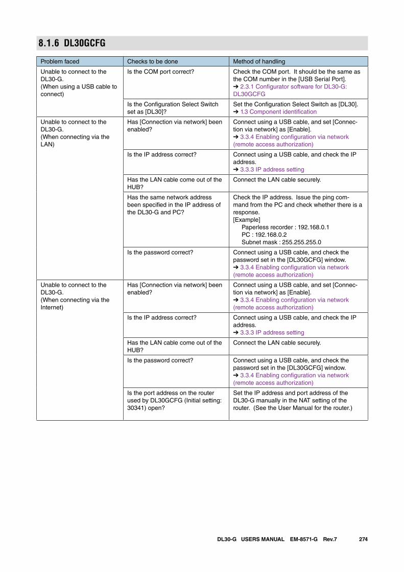
274DL30-G USERS MANUAL EM-8571-G Rev.7
8.1.6 DL30GCFG
Problem faced Checks to be done Method of handling
Unable to connect to the DL30-G.(When using a USB cable to connect)
Is the COM port correct? Check the COM port. It should be the same as the COM number in the [USB Serial Port].➔ 2.3.1 Configurator software for DL30-G: DL30GCFG
Is the Configuration Select Switch set as [DL30]?
Set the Configuration Select Switch as [DL30].➔ 1.3 Component identification
Unable to connect to the DL30-G.(When connecting via the LAN)
Has [Connection via network] been enabled?
Connect using a USB cable, and set [Connec-tion via network] as [Enable].➔ 3.3.4 Enabling configuration via network (remote access authorization)
Is the IP address correct? Connect using a USB cable, and check the IP address.➔ 3.3.3 IP address setting
Has the LAN cable come out of the HUB?
Connect the LAN cable securely.
Has the same network address been specified in the IP address of the DL30-G and PC?
Check the IP address. Issue the ping com-mand from the PC and check whether there is a response.[Example] Paperless recorder : 192.168.0.1 PC : 192.168.0.2 Subnet mask : 255.255.255.0
Is the password correct? Connect using a USB cable, and check the password set in the [DL30GCFG] window.➔ 3.3.4 Enabling configuration via network (remote access authorization)
Unable to connect to the DL30-G.(When connecting via the Internet)
Has [Connection via network] been enabled?
Connect using a USB cable, and set [Connec-tion via network] as [Enable].➔ 3.3.4 Enabling configuration via network (remote access authorization)
Is the IP address correct? Connect using a USB cable, and check the IP address.➔ 3.3.3 IP address setting
Has the LAN cable come out of the HUB?
Connect the LAN cable securely.
Is the password correct? Connect using a USB cable, and check the password set in the [DL30GCFG] window.➔ 3.3.4 Enabling configuration via network (remote access authorization)
Is the port address on the router used by DL30GCFG (Initial setting: 30341) open?
Set the IP address and port address of the DL30-G manually in the NAT setting of the router. (See the User Manual for the router.)
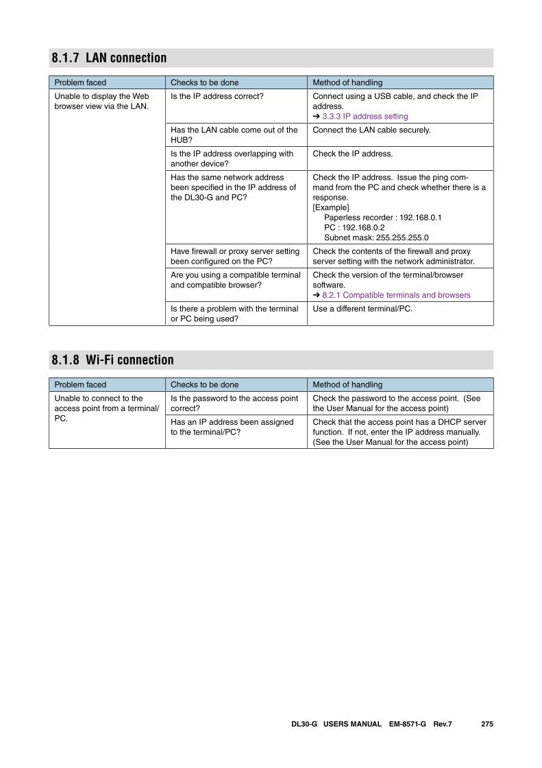
275DL30-G USERS MANUAL EM-8571-G Rev.7
8.1.7 LAN connection
Problem faced Checks to be done Method of handling
Unable to display the Web browser view via the LAN.
Is the IP address correct? Connect using a USB cable, and check the IP address.➔ 3.3.3 IP address setting
Has the LAN cable come out of the HUB?
Connect the LAN cable securely.
Is the IP address overlapping with another device?
Check the IP address.
Has the same network address been specified in the IP address of the DL30-G and PC?
Check the IP address. Issue the ping com-mand from the PC and check whether there is a response.[Example] Paperless recorder : 192.168.0.1 PC : 192.168.0.2 Subnet mask: 255.255.255.0
Have firewall or proxy server setting been configured on the PC?
Check the contents of the firewall and proxy server setting with the network administrator.
Are you using a compatible terminal and compatible browser?
Check the version of the terminal/browser software.➔ 8.2.1 Compatible terminals and browsers
Is there a problem with the terminal or PC being used?
Use a different terminal/PC.
8.1.8 Wi-Fi connection
Problem faced Checks to be done Method of handling
Unable to connect to the access point from a terminal/PC.
Is the password to the access point correct?
Check the password to the access point. (See the User Manual for the access point)
Has an IP address been assigned to the terminal/PC?
Check that the access point has a DHCP server function. If not, enter the IP address manually. (See the User Manual for the access point)
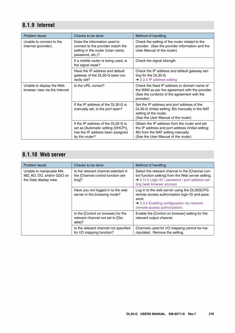
276DL30-G USERS MANUAL EM-8571-G Rev.7
8.1.9 Internet
Problem faced Checks to be done Method of handling
Unable to connect to the Internet (provider).
Does the information used to connect to the provider match the setting in the router (User name, password, etc.)?
Check the setting of the router related to the provider. (See the provider information and the User Manual of the router)
If a mobile router is being used, is the signal weak?
Check the signal strength.
Have the IP address and default gateway of the DL30-G been cor-rectly set?
Check the IP address and default gateway set-ting for the DL30-G.➔ 3.3.3 IP address setting
Unable to display the Web browser view via the Internet.
Is the URL correct? Check the fixed IP address or domain name of the WAN as per the agreement with the provider. (See the contents of the agreement with the provider)
If the IP address of the DL30-G is manually set, is the port open?
Set the IP address and port address of the DL30-G (Initial setting: 80) manually in the NAT setting of the router.(See the User Manual of the router)
If the IP address of the DL30-G is set as [Automatic setting (DHCP)], has the IP address been assigned by the router?
Obtain the IP address from the router and set the IP address and port address (Initial setting: 80) from the NAT setting manually. (See the User Manual of the router)
8.1.10 Web server
Problem faced Checks to be done Method of handling
Unable to manipulate MA, MD, AO, DO, and/or GDO on the Data display view.
Is the relevant channel selected in the [Channel control function set-ting]?
Select the relevant channel in the [Channel con-trol function setting] from the Web server setting.➔ 3.11.4 Login ID / password / port address set-ting (web browser access)
Have you not logged in to the web server in the browsing mode?
Log in to the web server using the DL30GCFG remote access authorization login ID and pass-word.➔ 3.3.4 Enabling configuration via network (remote access authorization)
Is the [Control on browser] for the relevant channel not set to [Dis-able]?
Enable the [Control on browser] setting for the relevant output channel.
Is the relevant channel not specified for I/O mapping function?
Channels used for I/O mapping cannot be ma-nipulated. Remove the setting.
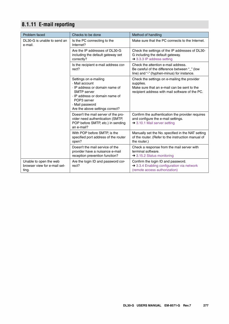
277DL30-G USERS MANUAL EM-8571-G Rev.7
8.1.11 E-mail reporting
Problem faced Checks to be done Method of handling
DL30-G is unable to send an e-mail.
Is the PC connecting to theInternet?
Make sure that the PC connects to the Internet.
Are the IP addresses of DL30-G including the default gateway set correctly?
Check the settings of the IP addresses of DL30-G including the default gateway.➔ 3.3.3 IP address setting
Is the recipient e-mail address cor-rect?
Check the attention e-mail address.Be careful of the difference between “_” (low line) and “-” (hyphen-minus) for instance.
Settings on e-mailing· Mail account· IP address or domain name of SMTP server· IP address or domain name of POP3 server· Mail passwordAre the above settings correct?
Check the settings on e-mailing the provider supplies.Make sure that an e-mail can be sent to the recipient address with mail software of the PC.
Doesn’t the mail server of the pro-vider need authentication (SMTP, POP before SMTP, etc.) in sending an e-mail?
Confirm the authentication the provider requires and configure the e-mail settings.➔ 3.10.1 Mail server setting
With POP before SMTP, is the specified port address of the router open?
Manually set the No. specified in the NAT setting of the router. (Refer to the instruction manual of the router.)
Doesn’t the mail service of the provider have a nuisance e-mail reception prevention function?
Check a response from the mail server with terminal software.➔ 3.15.2 Status monitoring
Unable to open the web browser view for e-mail set-ting.
Are the login ID and password cor-rect?
Confirm the login ID and password.➔ 3.3.4 Enabling configuration via network (remote access authorization)
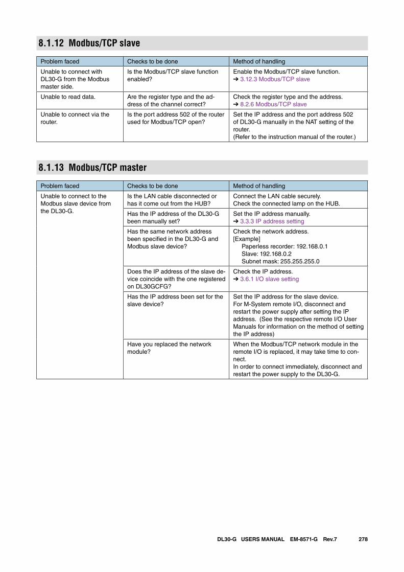
278DL30-G USERS MANUAL EM-8571-G Rev.7
8.1.12 Modbus/TCP slave
Problem faced Checks to be done Method of handling
Unable to connect with DL30-G from the Modbus master side.
Is the Modbus/TCP slave function enabled?
Enable the Modbus/TCP slave function.➔ 3.12.3 Modbus/TCP slave
Unable to read data. Are the register type and the ad-dress of the channel correct?
Check the register type and the address.➔ 8.2.6 Modbus/TCP slave
Unable to connect via the router.
Is the port address 502 of the router used for Modbus/TCP open?
Set the IP address and the port address 502 of DL30-G manually in the NAT setting of the router.(Refer to the instruction manual of the router.)
8.1.13 Modbus/TCP master
Problem faced Checks to be done Method of handling
Unable to connect to the Modbus slave device from the DL30-G.
Is the LAN cable disconnected or has it come out from the HUB?
Connect the LAN cable securely. Check the connected lamp on the HUB.
Has the IP address of the DL30-G been manually set?
Set the IP address manually.➔ 3.3.3 IP address setting
Has the same network address been specified in the DL30-G and Modbus slave device?
Check the network address.[Example] Paperless recorder: 192.168.0.1 Slave: 192.168.0.2 Subnet mask: 255.255.255.0
Does the IP address of the slave de-vice coincide with the one registered on DL30GCFG?
Check the IP address.➔ 3.6.1 I/O slave setting
Has the IP address been set for the slave device?
Set the IP address for the slave device. For M-System remote I/O, disconnect and restart the power supply after setting the IP address. (See the respective remote I/O User Manuals for information on the method of setting the IP address)
Have you replaced the network module?
When the Modbus/TCP network module in the remote I/O is replaced, it may take time to con-nect. In order to connect immediately, disconnect and restart the power supply to the DL30-G.
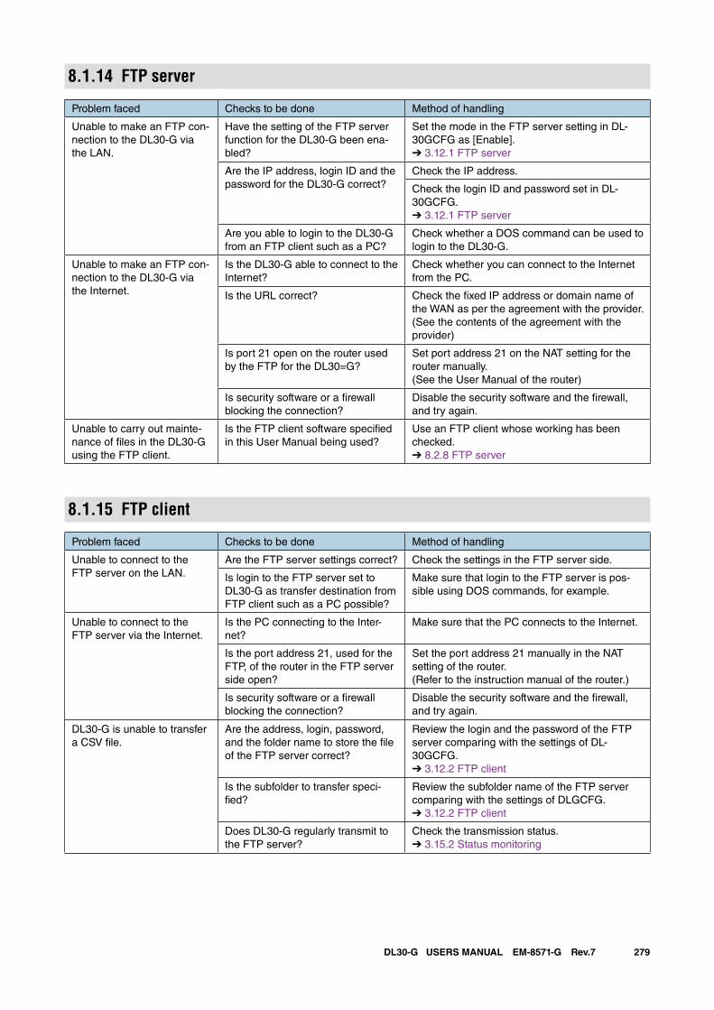
279DL30-G USERS MANUAL EM-8571-G Rev.7
8.1.14 FTP server
Problem faced Checks to be done Method of handling
Unable to make an FTP con-nection to the DL30-G via the LAN.
Have the setting of the FTP server function for the DL30-G been ena-bled?
Set the mode in the FTP server setting in DL-30GCFG as [Enable].➔ 3.12.1 FTP server
Are the IP address, login ID and the password for the DL30-G correct?
Check the IP address.
Check the login ID and password set in DL-30GCFG.➔ 3.12.1 FTP server
Are you able to login to the DL30-G from an FTP client such as a PC?
Check whether a DOS command can be used to login to the DL30-G.
Unable to make an FTP con-nection to the DL30-G via the Internet.
Is the DL30-G able to connect to the Internet?
Check whether you can connect to the Internet from the PC.
Is the URL correct? Check the fixed IP address or domain name of the WAN as per the agreement with the provider. (See the contents of the agreement with the provider)
Is port 21 open on the router used by the FTP for the DL30=G?
Set port address 21 on the NAT setting for the router manually. (See the User Manual of the router)
Is security software or a firewall blocking the connection?
Disable the security software and the firewall, and try again.
Unable to carry out mainte-nance of files in the DL30-G using the FTP client.
Is the FTP client software specified in this User Manual being used?
Use an FTP client whose working has been checked.➔ 8.2.8 FTP server
8.1.15 FTP client
Problem faced Checks to be done Method of handling
Unable to connect to the FTP server on the LAN.
Are the FTP server settings correct? Check the settings in the FTP server side.
Is login to the FTP server set to DL30-G as transfer destination from FTP client such as a PC possible?
Make sure that login to the FTP server is pos-sible using DOS commands, for example.
Unable to connect to the FTP server via the Internet.
Is the PC connecting to the Inter-net?
Make sure that the PC connects to the Internet.
Is the port address 21, used for the FTP, of the router in the FTP server side open?
Set the port address 21 manually in the NAT setting of the router. (Refer to the instruction manual of the router.)
Is security software or a firewall blocking the connection?
Disable the security software and the firewall, and try again.
DL30-G is unable to transfer a CSV file.
Are the address, login, password, and the folder name to store the file of the FTP server correct?
Review the login and the password of the FTP server comparing with the settings of DL-30GCFG.➔ 3.12.2 FTP client
Is the subfolder to transfer speci-fied?
Review the subfolder name of the FTP server comparing with the settings of DLGCFG.➔ 3.12.2 FTP client
Does DL30-G regularly transmit to the FTP server?
Check the transmission status.➔ 3.15.2 Status monitoring
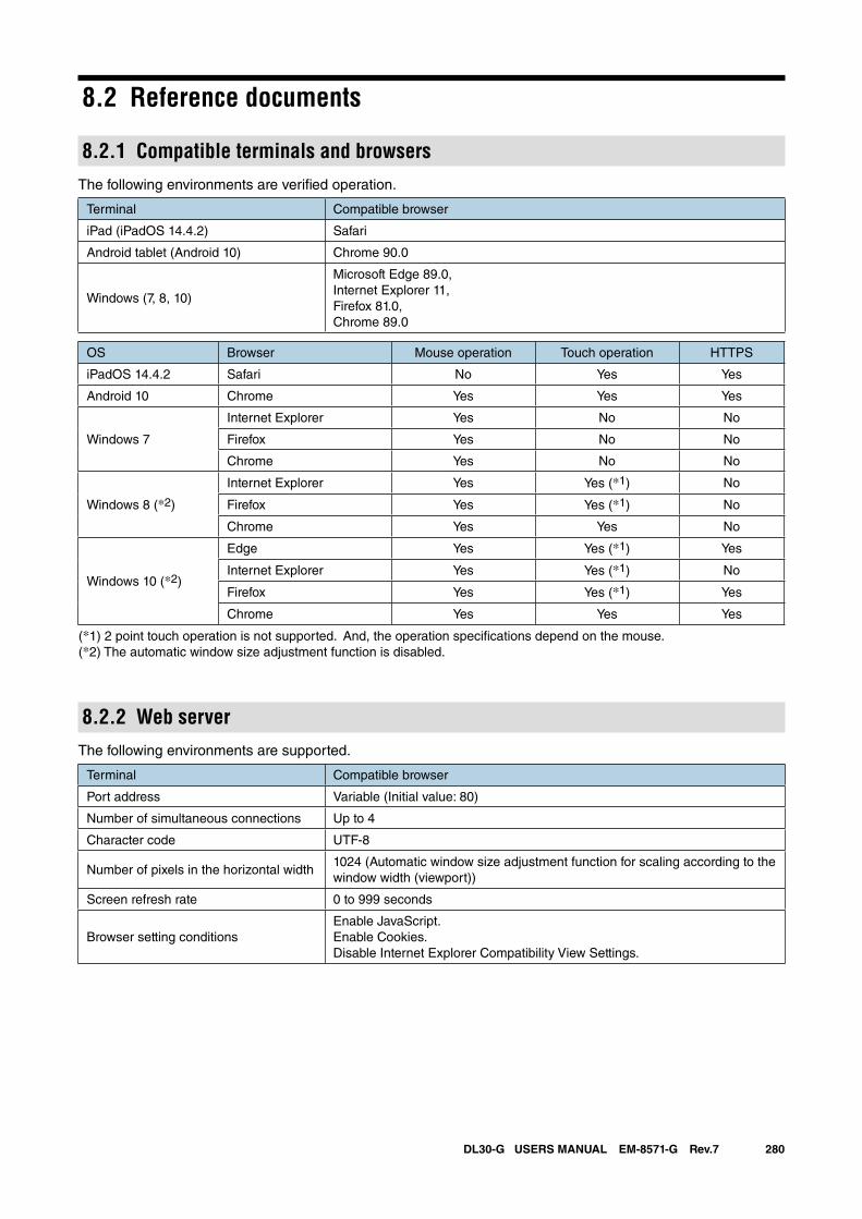
280DL30-G USERS MANUAL EM-8571-G Rev.7
8.2 Reference documents
8.2.1 Compatible terminals and browsersThe following environments are verified operation.
Terminal Compatible browser
iPad (iPadOS 14.4.2) Safari
Android tablet (Android 10) Chrome 90.0
Windows (7, 8, 10)
Microsoft Edge 89.0,Internet Explorer 11, Firefox 81.0, Chrome 89.0
OS Browser Mouse operation Touch operation HTTPS
iPadOS 14.4.2 Safari No Yes Yes
Android 10 Chrome Yes Yes Yes
Windows 7
Internet Explorer Yes No No
Firefox Yes No No
Chrome Yes No No
Windows 8 (*2)
Internet Explorer Yes Yes (*1) No
Firefox Yes Yes (*1) No
Chrome Yes Yes No
Windows 10 (*2)
Edge Yes Yes (*1) Yes
Internet Explorer Yes Yes (*1) No
Firefox Yes Yes (*1) Yes
Chrome Yes Yes Yes
(*1) 2 point touch operation is not supported. And, the operation specifications depend on the mouse.(*2) The automatic window size adjustment function is disabled.
8.2.2 Web serverThe following environments are supported.
Terminal Compatible browser
Port address Variable (Initial value: 80)
Number of simultaneous connections Up to 4
Character code UTF-8
Number of pixels in the horizontal width1024 (Automatic window size adjustment function for scaling according to the window width (viewport))
Screen refresh rate 0 to 999 seconds
Browser setting conditionsEnable JavaScript.Enable Cookies.Disable Internet Explorer Compatibility View Settings.
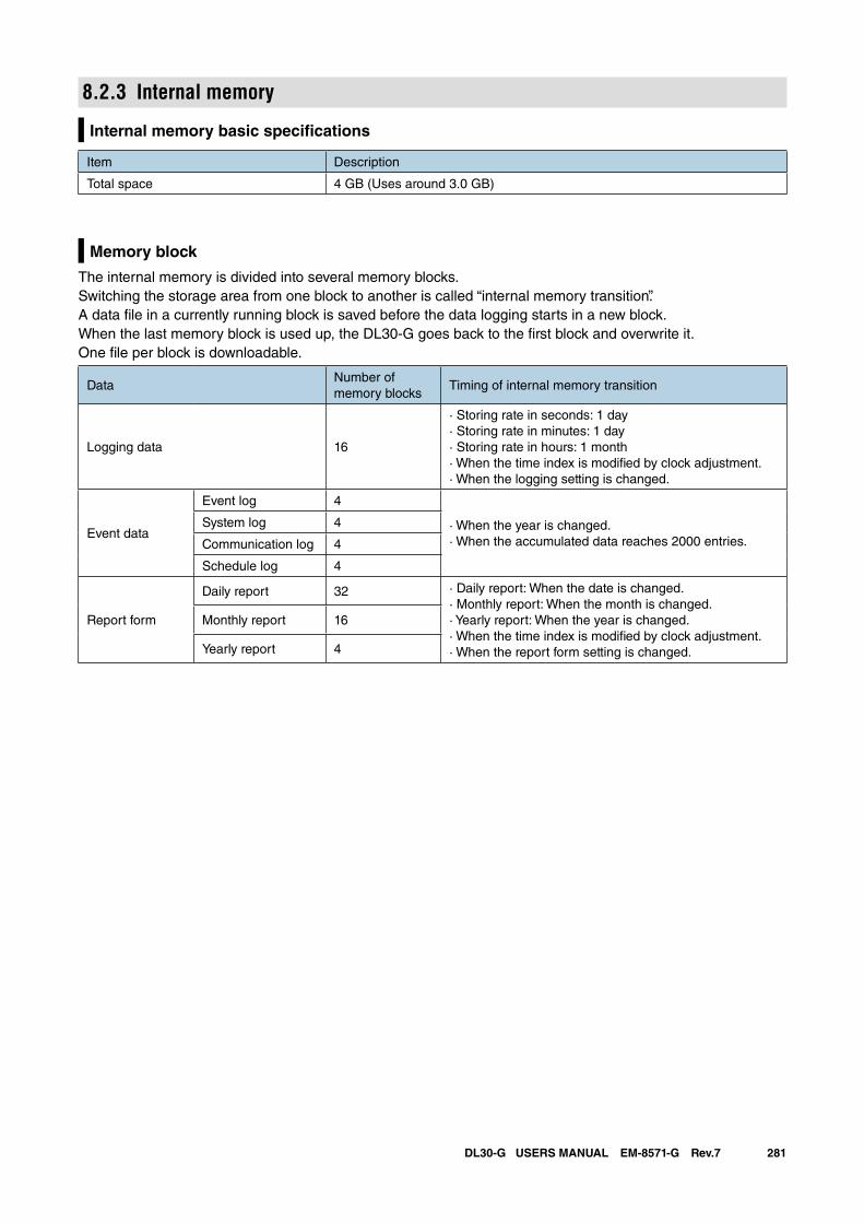
281DL30-G USERS MANUAL EM-8571-G Rev.7
8.2.3 Internal memory
Internal memory basic specifications
Item Description
Total space 4 GB (Uses around 3.0 GB)
Memory block
The internal memory is divided into several memory blocks.Switching the storage area from one block to another is called “internal memory transition”. A data file in a currently running block is saved before the data logging starts in a new block. When the last memory block is used up, the DL30-G goes back to the first block and overwrite it.One file per block is downloadable.
DataNumber of memory blocks
Timing of internal memory transition
Logging data 16
· Storing rate in seconds: 1 day· Storing rate in minutes: 1 day· Storing rate in hours: 1 month· When the time index is modified by clock adjustment.· When the logging setting is changed.
Event data
Event log 4
· When the year is changed.· When the accumulated data reaches 2000 entries.
System log 4
Communication log 4
Schedule log 4
Report form
Daily report 32 · Daily report: When the date is changed.· Monthly report: When the month is changed.· Yearly report: When the year is changed.· When the time index is modified by clock adjustment.· When the report form setting is changed.
Monthly report 16
Yearly report 4
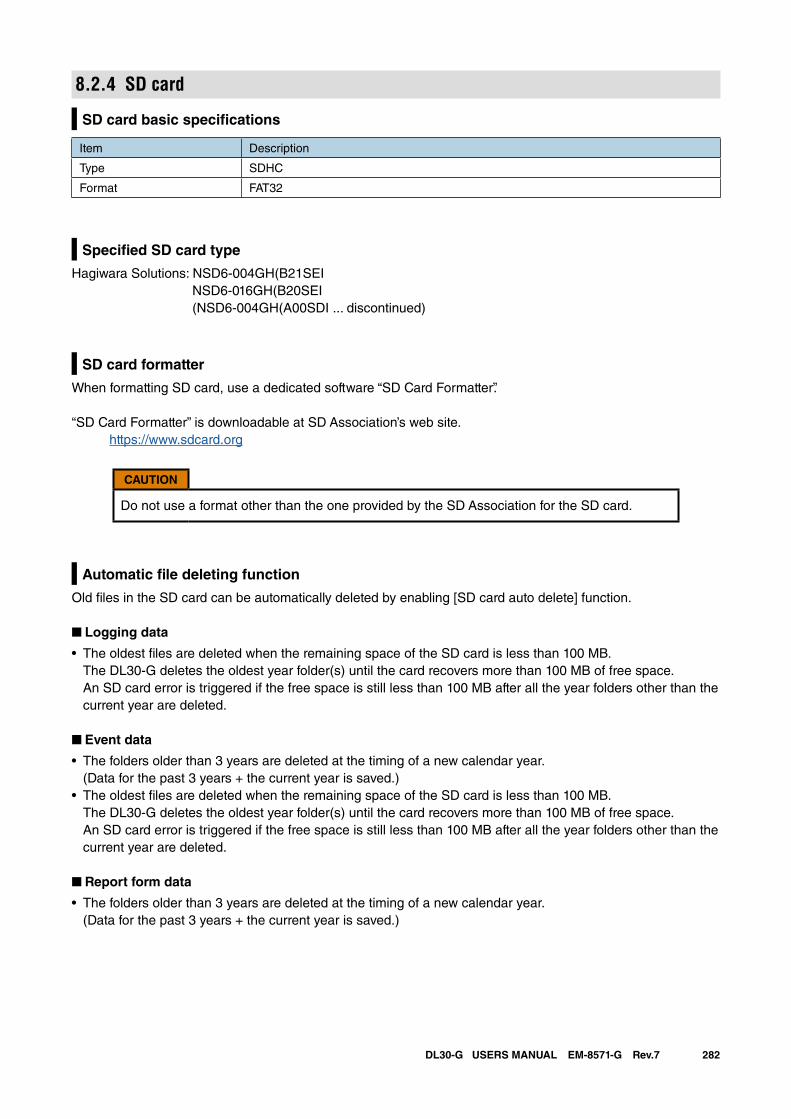
282DL30-G USERS MANUAL EM-8571-G Rev.7
8.2.4 SD card
SD card basic specifications
Item Description
Type SDHC
Format FAT32
Specified SD card type
Hagiwara Solutions: NSD6-004GH(B21SEI NSD6-016GH(B20SEI (NSD6-004GH(A00SDI ... discontinued)
SD card formatter
When formatting SD card, use a dedicated software “SD Card Formatter”.
“SD Card Formatter” is downloadable at SD Association’s web site. https://www.sdcard.org
CAUTION
Do not use a format other than the one provided by the SD Association for the SD card.
Automatic file deleting function
Old files in the SD card can be automatically deleted by enabling [SD card auto delete] function.
■ Logging data
• The oldest files are deleted when the remaining space of the SD card is less than 100 MB.The DL30-G deletes the oldest year folder(s) until the card recovers more than 100 MB of free space. An SD card error is triggered if the free space is still less than 100 MB after all the year folders other than the current year are deleted.
■ Event data
• The folders older than 3 years are deleted at the timing of a new calendar year. (Data for the past 3 years + the current year is saved.)
• The oldest files are deleted when the remaining space of the SD card is less than 100 MB.The DL30-G deletes the oldest year folder(s) until the card recovers more than 100 MB of free space. An SD card error is triggered if the free space is still less than 100 MB after all the year folders other than the current year are deleted.
■ Report form data
• The folders older than 3 years are deleted at the timing of a new calendar year. (Data for the past 3 years + the current year is saved.)
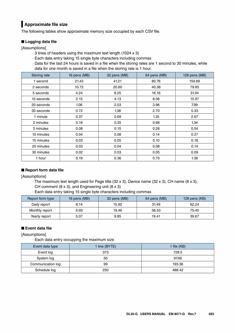
283DL30-G USERS MANUAL EM-8571-G Rev.7
Approximate file size
The following tables show approximate memory size occupied by each CSV file.
■ Logging data file
[Assumptions] · 3 lines of headers using the maximum text length (1024 x 3) · Each data entry taking 15 single byte characters including commas · Data for the last 24 hours is saved in a file when the storing rates are 1 second to 30 minutes, while
data for one month is saved in a file when the storing rate is 1 hour.
Storing rate 16 pens (MB) 32 pens (MB) 64 pens (MB) 128 pens (MB)
1 second 21.43 41.21 80.76 159.69
2 seconds 10.72 20.60 40.38 79.85
5 seconds 4.24 8.25 16.16 31.94
10 seconds 2.15 4.13 8.08 15.97
20 seconds 1.06 2.03 3.96 7.99
30 seconds 0.72 1.38 2.70 5.33
1 minute 0.37 0.69 1.35 2.67
2 minutes 0.19 0.35 0.68 1.34
5 minutes 0.08 0.15 0.28 0.54
10 minutes 0.04 0.08 0.14 0.27
15 minutes 0.03 0.05 0.10 0.18
20 minutes 0.03 0.04 0.08 0.14
30 minutes 0.02 0.03 0.05 0.09
1 hour 0.19 0.36 0.70 1.38
■ Report form data file
[Assumptions] · The maximum text length used for Page title (32 x 3), Device name (32 x 3), CH name (8 x 3), CH comment (8 x 3), and Engineering unit (8 x 3) · Each data entry taking 15 single byte characters including commas
Report form type 16 pens (MB) 32 pens (MB) 64 pens (MB) 128 pens (KB)
Daily report 8.14 15.92 31.49 62.24
Monthly report 9.93 19.46 38.53 75.40
Yearly report 5.07 9.85 19.41 39.67
■ Event data file
[Assumptions] · Each data entry occupying the maximum size
Event data type 1 line (BYTE) 1 file (KB)
Event log 373 728.5
System log 50 97.66
Communication log 99 193.36
Schedule log 250 488.42
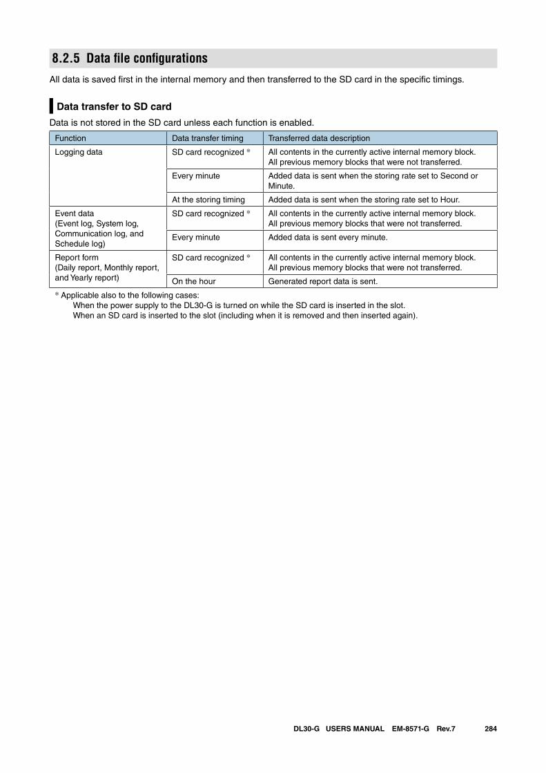
284DL30-G USERS MANUAL EM-8571-G Rev.7
8.2.5 Data file configurationsAll data is saved first in the internal memory and then transferred to the SD card in the specific timings.
Data transfer to SD card
Data is not stored in the SD card unless each function is enabled.
Function Data transfer timing Transferred data description
Logging data SD card recognized * All contents in the currently active internal memory block.All previous memory blocks that were not transferred.
Every minute Added data is sent when the storing rate set to Second or Minute.
At the storing timing Added data is sent when the storing rate set to Hour.
Event data(Event log, System log, Communication log, and Schedule log)
SD card recognized * All contents in the currently active internal memory block.All previous memory blocks that were not transferred.
Every minute Added data is sent every minute.
Report form(Daily report, Monthly report, and Yearly report)
SD card recognized * All contents in the currently active internal memory block.All previous memory blocks that were not transferred.
On the hour Generated report data is sent.
* Applicable also to the following cases: When the power supply to the DL30-G is turned on while the SD card is inserted in the slot. When an SD card is inserted to the slot (including when it is removed and then inserted again).
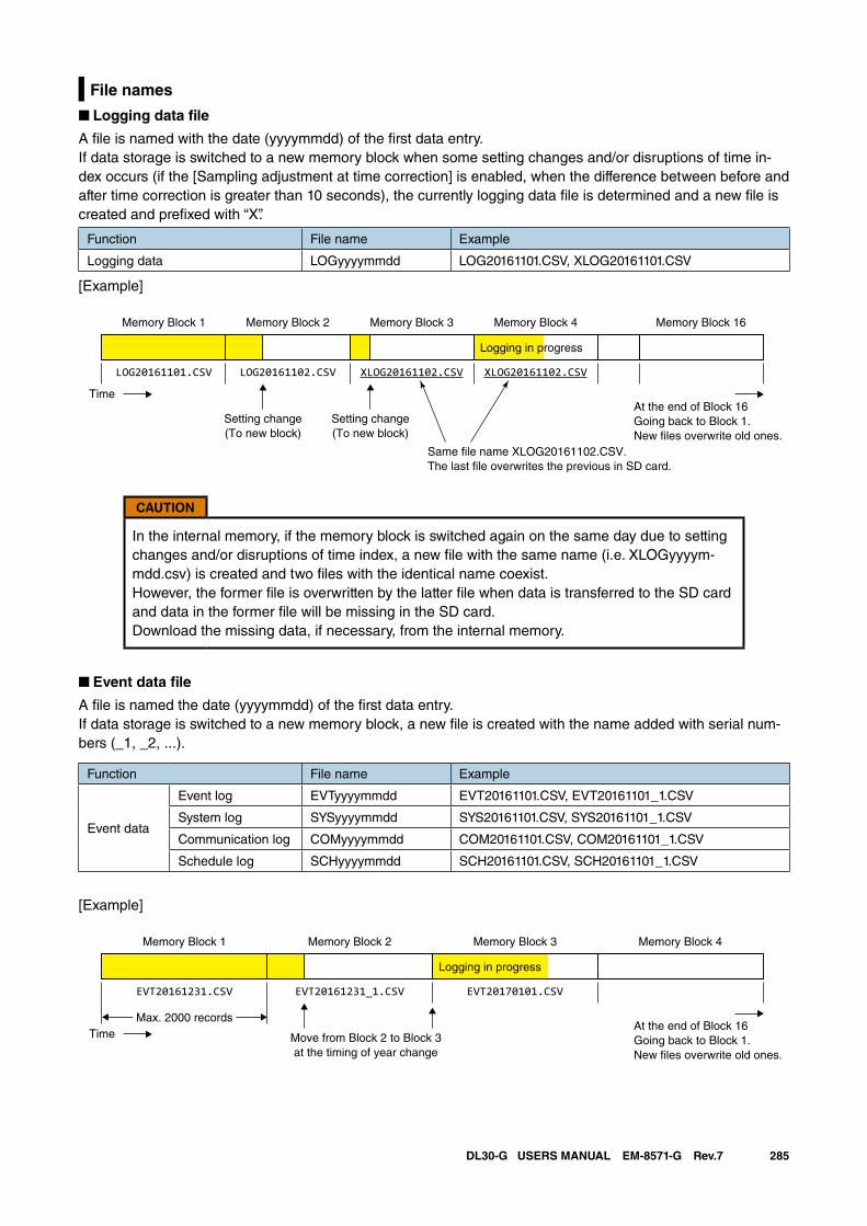
285DL30-G USERS MANUAL EM-8571-G Rev.7
File names
■ Logging data file
A file is named with the date (yyyymmdd) of the first data entry.If data storage is switched to a new memory block when some setting changes and/or disruptions of time in-dex occurs (if the [Sampling adjustment at time correction] is enabled, when the difference between before and after time correction is greater than 10 seconds), the currently logging data file is determined and a new file is created and prefixed with “X”.
Function File name Example
Logging data LOGyyyymmdd LOG20161101.CSV, XLOG20161101.CSV
[Example]
CAUTION
In the internal memory, if the memory block is switched again on the same day due to setting changes and/or disruptions of time index, a new file with the same name (i.e. XLOGyyyym-mdd.csv) is created and two files with the identical name coexist.However, the former file is overwritten by the latter file when data is transferred to the SD card and data in the former file will be missing in the SD card. Download the missing data, if necessary, from the internal memory.
■ Event data file
A file is named the date (yyyymmdd) of the first data entry.If data storage is switched to a new memory block, a new file is created with the name added with serial num-bers (_1, _2, ...).
Function File name Example
Event data
Event log EVTyyyymmdd EVT20161101.CSV, EVT20161101_1.CSV
System log SYSyyyymmdd SYS20161101.CSV, SYS20161101_1.CSV
Communication log COMyyyymmdd COM20161101.CSV, COM20161101_1.CSV
Schedule log SCHyyyymmdd SCH20161101.CSV, SCH20161101_1.CSV
[Example]
Memory Block 1 Memory Block 2 Memory Block 4
LOG20161101.CSV LOG20161102.CSV
Memory Block 3
XLOG20161102.CSV XLOG20161102.CSV
Memory Block 16
Logging in progress
Time
Setting change(To new block)
Setting change(To new block)
At the end of Block 16Going back to Block 1.New �les overwrite old ones.
Same �le name XLOG20161102.CSV.The last �le overwrites the previous in SD card.
Memory Block 1 Memory Block 2 Memory Block 3
EVT20161231.CSV EVT20161231_1.CSV EVT20170101.CSV
Memory Block 4
Logging in progress
Time Move from Block 2 to Block 3at the timing of year change
At the end of Block 16Going back to Block 1.New �les overwrite old ones.
Max. 2000 records
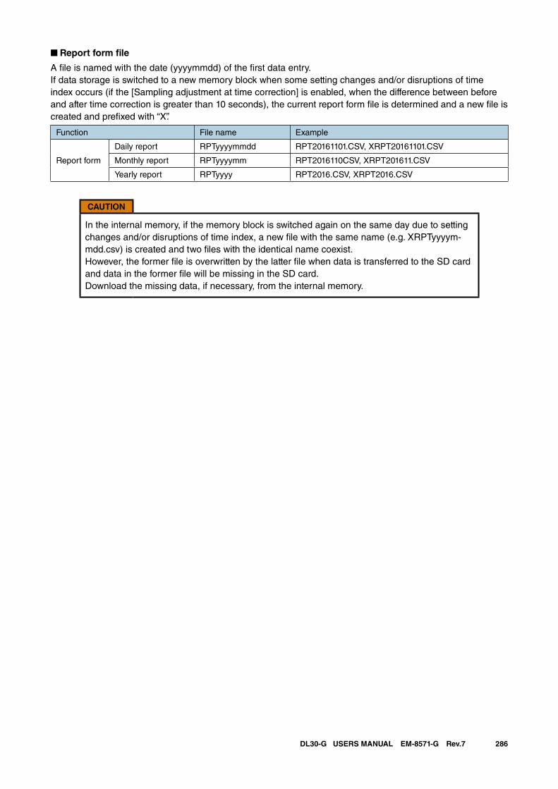
286DL30-G USERS MANUAL EM-8571-G Rev.7
■ Report form file
A file is named with the date (yyyymmdd) of the first data entry.If data storage is switched to a new memory block when some setting changes and/or disruptions of time index occurs (if the [Sampling adjustment at time correction] is enabled, when the difference between before and after time correction is greater than 10 seconds), the current report form file is determined and a new file is created and prefixed with “X”.
Function File name Example
Report form
Daily report RPTyyyymmdd RPT20161101.CSV, XRPT20161101.CSV
Monthly report RPTyyyymm RPT2016110CSV, XRPT201611.CSV
Yearly report RPTyyyy RPT2016.CSV, XRPT2016.CSV
CAUTION
In the internal memory, if the memory block is switched again on the same day due to setting changes and/or disruptions of time index, a new file with the same name (e.g. XRPTyyyym-mdd.csv) is created and two files with the identical name coexist.However, the former file is overwritten by the latter file when data is transferred to the SD card and data in the former file will be missing in the SD card. Download the missing data, if necessary, from the internal memory.
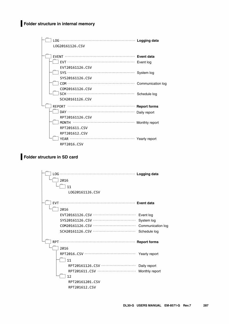
287DL30-G USERS MANUAL EM-8571-G Rev.7
Folder structure in internal memory
Folder structure in SD card
�
��
�
�
� Report forms
�
� Monthly report
Daily report
� Yearly report
LOG20161126.CSVLOG
EVENTEVT
.......................................................
...................................................
.................................................
Logging data
Event data
Event log
Communication log
System log
EVT20161126.CSVSYS .................................................
SYS20161126.CSVCOM .................................................
COM20161126.CSV
REPORTDAY
.................................................
.................................................
RPT20161126.CSVMONTH .............................................
RPT201611.CSVRPT201612.CSVYEAR ...............................................
RPT2016.CSV
�SCH .................................................
SCH20161126.CSVSchedule log
��
�
��
��
�
�
Event data
Event log
LOG ....................................................... Logging data
2016
EVT .......................................................
...............................
...............................
.........................
...............................
............................
2016
RPT .......................................................
.....................................
2016
11LOG20161126.CSV
EVT20161126.CSVSYS20161126.CSVCOM20161126.CSV Communication log
System log
RPT2016.CSV
11RPT20161126.CSVRPT201611.CSV12RPT20161201.CSVRPT201612.CSV
Report forms
Monthly report
Daily report
Yearly report
...............................SCH20161126.CSV Schedule log

288DL30-G USERS MANUAL EM-8571-G Rev.7
8.2.6 Modbus/TCP slave
Modbus register map
0X
Register Channel Register Channel Register Channel Register Channel
00001 DO1 00033 DO33 00065 DO65 00097 DO97
00002 DO2 00034 DO34 00066 DO66 00098 DO98
00003 DO3 00035 DO35 00067 DO67 00099 DO99
00004 DO4 00036 DO36 00068 DO68 00100 DO100
00005 DO5 00037 DO37 00069 DO69 00101 DO101
00006 DO6 00038 DO38 00070 DO70 00102 DO102
00007 DO7 00039 DO39 00071 DO71 00103 DO103
00008 DO8 00040 DO40 00072 DO72 00104 DO104
00009 DO9 00041 DO41 00073 DO73 00105 DO105
00010 DO10 00042 DO42 00074 DO74 00106 DO106
00011 DO11 00043 DO43 00075 DO75 00107 DO107
00012 DO12 00044 DO44 00076 DO76 00108 DO108
00013 DO13 00045 DO45 00077 DO77 00109 DO109
00014 DO14 00046 DO46 00078 DO78 00110 DO110
00015 DO15 00047 DO47 00079 DO79 00111 DO111
00016 DO16 00048 DO48 00080 DO80 00112 DO112
00017 DO17 00049 DO49 00081 DO81 00113 DO113
00018 DO18 00050 DO50 00082 DO82 00114 DO114
00019 DO19 00051 DO51 00083 DO83 00115 DO115
00020 DO20 00052 DO52 00084 DO84 00116 DO116
00021 DO21 00053 DO53 00085 DO85 00117 DO117
00022 DO22 00054 DO54 00086 DO86 00118 DO118
00023 DO23 00055 DO55 00087 DO87 00119 DO119
00024 DO24 00056 DO56 00088 DO88 00120 DO120
00025 DO25 00057 DO57 00089 DO89 00121 DO121
00026 DO26 00058 DO58 00090 DO90 00122 DO122
00027 DO27 00059 DO59 00091 DO91 00123 DO123
00028 DO28 00060 DO60 00092 DO92 00124 DO124
00029 DO29 00061 DO61 00093 DO93 00125 DO125
00030 DO30 00062 DO62 00094 DO94 00126 DO126
00031 DO31 00063 DO63 00095 DO95 00127 DO127
00032 DO32 00064 DO64 00096 DO96 00128 DO128
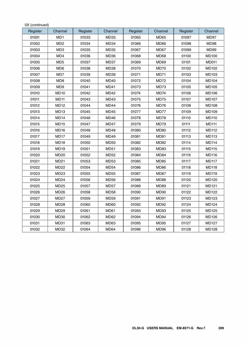
289DL30-G USERS MANUAL EM-8571-G Rev.7
0X (continued)
Register Channel Register Channel Register Channel Register Channel
01001 MD1 01033 MD33 01065 MD65 01097 MD97
01002 MD2 01034 MD34 01066 MD66 01098 MD98
01003 MD3 01035 MD35 01067 MD67 01099 MD99
01004 MD4 01036 MD36 01068 MD68 01100 MD100
01005 MD5 01037 MD37 01069 MD69 01101 MD011
01006 MD6 01038 MD38 01070 MD70 01102 MD102
01007 MD7 01039 MD39 01071 MD71 01103 MD103
01008 MD8 01040 MD40 01072 MD72 01104 MD104
01009 MD9 01041 MD41 01073 MD73 01105 MD105
01010 MD10 01042 MD42 01074 MD74 01106 MD106
01011 MD11 01043 MD43 01075 MD75 01107 MD107
01012 MD12 01044 MD44 01076 MD76 01108 MD108
01013 MD13 01045 MD45 01077 MD77 01109 MD109
01014 MD14 01046 MD46 01078 MD78 01110 MD110
01015 MD15 01047 MD47 01079 MD79 01111 MD111
01016 MD16 01048 MD48 01080 MD80 01112 MD112
01017 MD17 01049 MD49 01081 MD81 01113 MD113
01018 MD18 01050 MD50 01082 MD82 01114 MD114
01019 MD19 01051 MD51 01083 MD83 01115 MD115
01020 MD20 01052 MD52 01084 MD84 01116 MD116
01021 MD21 01053 MD53 01085 MD85 01117 MD117
01022 MD22 01054 MD54 01086 MD86 01118 MD118
01023 MD23 01055 MD55 01087 MD87 01119 MD119
01024 MD24 01056 MD56 01088 MD88 01120 MD120
01025 MD25 01057 MD57 01089 MD89 01121 MD121
01026 MD26 01058 MD58 01090 MD90 01122 MD122
01027 MD27 01059 MD59 01091 MD91 01123 MD123
01028 MD28 01060 MD60 01092 MD92 01124 MD124
01029 MD29 01061 MD61 01093 MD93 01125 MD125
01030 MD30 01062 MD62 01094 MD94 01126 MD126
01031 MD31 01063 MD63 01095 MD95 01127 MD127
01032 MD32 01064 MD64 01096 MD96 01128 MD128
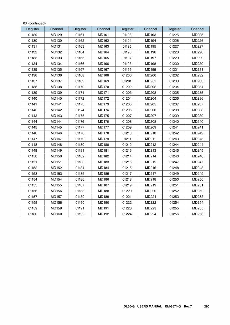
290DL30-G USERS MANUAL EM-8571-G Rev.7
0X (continued)
Register Channel Register Channel Register Channel Register Channel
01129 MD129 01161 MD161 01193 MD193 01225 MD225
01130 MD130 01162 MD162 01194 MD194 01226 MD226
01131 MD131 01163 MD163 01195 MD195 01227 MD227
01132 MD132 01164 MD164 01196 MD196 01228 MD228
01133 MD133 01165 MD165 01197 MD197 01229 MD229
01134 MD134 01166 MD166 01198 MD198 01230 MD230
01135 MD135 01167 MD167 01199 MD199 01231 MD231
01136 MD136 01168 MD168 01200 MD200 01232 MD232
01137 MD137 01169 MD169 01201 MD201 01233 MD233
01138 MD138 01170 MD170 01202 MD202 01234 MD234
01139 MD139 01171 MD171 01203 MD203 01235 MD235
01140 MD140 01172 MD172 01204 MD204 01236 MD236
01141 MD141 01173 MD173 01205 MD205 01237 MD237
01142 MD142 01174 MD174 01206 MD206 01238 MD238
01143 MD143 01175 MD175 01207 MD207 01239 MD239
01144 MD144 01176 MD176 01208 MD208 01240 MD240
01145 MD145 01177 MD177 01209 MD209 01241 MD241
01146 MD146 01178 MD178 01210 MD210 01242 MD242
01147 MD147 01179 MD179 01211 MD211 01243 MD243
01148 MD148 01180 MD180 01212 MD212 01244 MD244
01149 MD149 01181 MD181 01213 MD213 01245 MD245
01150 MD150 01182 MD182 01214 MD214 01246 MD246
01151 MD151 01183 MD183 01215 MD215 01247 MD247
01152 MD152 01184 MD184 01216 MD216 01248 MD248
01153 MD153 01185 MD185 01217 MD217 01249 MD249
01154 MD154 01186 MD186 01218 MD218 01250 MD250
01155 MD155 01187 MD187 01219 MD219 01251 MD251
01156 MD156 01188 MD188 01220 MD220 01252 MD252
01157 MD157 01189 MD189 01221 MD221 01253 MD253
01158 MD158 01190 MD190 01222 MD222 01254 MD254
01159 MD159 01191 MD191 01223 MD223 01255 MD255
01160 MD160 01192 MD192 01224 MD224 01256 MD256
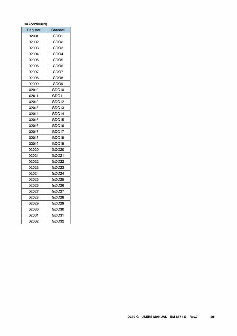
291DL30-G USERS MANUAL EM-8571-G Rev.7
0X (continued)
Register Channel
02001 GDO1
02002 GDO2
02003 GDO3
02004 GDO4
02005 GDO5
02006 GDO6
02007 GDO7
02008 GDO8
02009 GDO9
02010 GDO10
02011 GDO11
02012 GDO12
02013 GDO13
02014 GDO14
02015 GDO15
02016 GDO16
02017 GDO17
02018 GDO18
02019 GDO19
02020 GDO20
02021 GDO21
02022 GDO22
02023 GDO23
02024 GDO24
02025 GDO25
02026 GDO26
02027 GDO27
02028 GDO28
02029 GDO29
02030 GDO30
02031 GDO31
02032 GDO32

292DL30-G USERS MANUAL EM-8571-G Rev.7
1X
Register Channel Register Channel Register Channel Register Channel
10001 DI1 10033 DI33 10065 DI65 10097 DI97
10002 DI2 10034 DI34 10066 DI66 10098 DI98
10003 DI3 10035 DI35 10067 DI67 10099 DI99
10004 DI4 10036 DI36 10068 DI68 10100 DI100
10005 DI5 10037 DI37 10069 DI69 10101 DI101
10006 DI6 10038 DI38 10070 DI70 10102 DI102
10007 DI7 10039 DI39 10071 DI71 10103 DI103
10008 DI8 10040 DI40 10072 DI72 10104 DI104
10009 DI9 10041 DI41 10073 DI73 10105 DI105
10010 DI10 10042 DI42 10074 DI74 10106 DI106
10011 DI11 10043 DI43 10075 DI75 10107 DI107
10012 DI12 10044 DI44 10076 DI76 10108 DI108
10013 DI13 10045 DI45 10077 DI77 10109 DI109
10014 DI14 10046 DI46 10078 DI78 10110 DI110
10015 DI15 10047 DI47 10079 DI79 10111 DI111
10016 DI16 10048 DI48 10080 DI80 10112 DI112
10017 DI17 10049 DI49 10081 DI81 10113 DI113
10018 DI18 10050 DI50 10082 DI82 10114 DI114
10019 DI19 10051 DI51 10083 DI83 10115 DI115
10020 DI20 10052 DI52 10084 DI84 10116 DI116
10021 DI21 10053 DI53 10085 DI85 10117 DI117
10022 DI22 10054 DI54 10086 DI86 10118 DI118
10023 DI23 10055 DI55 10087 DI87 10119 DI119
10024 DI24 10056 DI56 10088 DI88 10120 DI120
10025 DI25 10057 DI57 10089 DI89 10121 DI121
10026 DI26 10058 DI58 10090 DI90 10122 DI122
10027 DI27 10059 DI59 10091 DI91 10123 DI123
10028 DI28 10060 DI60 10092 DI92 10124 DI124
10029 DI29 10061 DI61 10093 DI93 10125 DI125
10030 DI30 10062 DI62 10094 DI94 10126 DI126
10031 DI31 10063 DI63 10095 DI95 10127 DI127
10032 DI32 10064 DI64 10096 DI96 10128 DI128
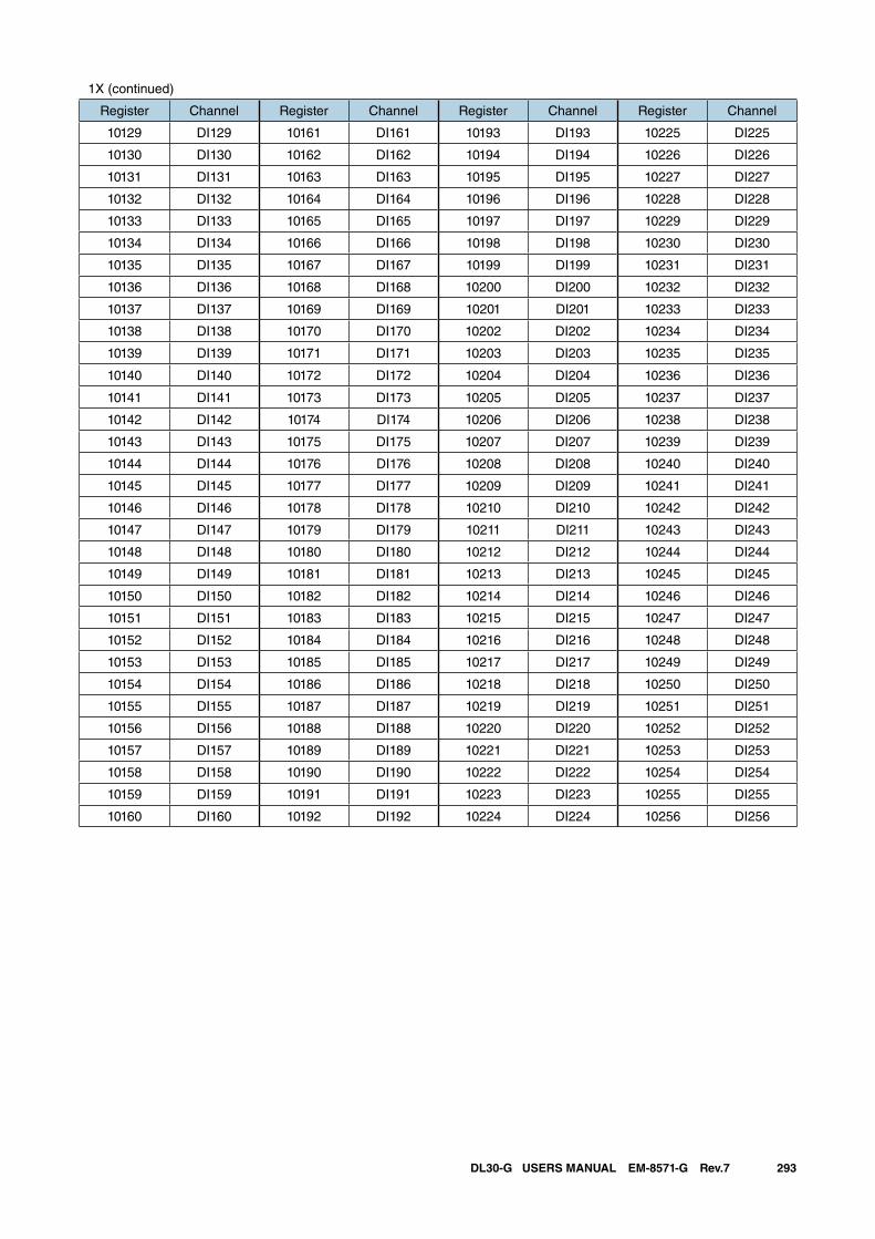
293DL30-G USERS MANUAL EM-8571-G Rev.7
1X (continued)
Register Channel Register Channel Register Channel Register Channel
10129 DI129 10161 DI161 10193 DI193 10225 DI225
10130 DI130 10162 DI162 10194 DI194 10226 DI226
10131 DI131 10163 DI163 10195 DI195 10227 DI227
10132 DI132 10164 DI164 10196 DI196 10228 DI228
10133 DI133 10165 DI165 10197 DI197 10229 DI229
10134 DI134 10166 DI166 10198 DI198 10230 DI230
10135 DI135 10167 DI167 10199 DI199 10231 DI231
10136 DI136 10168 DI168 10200 DI200 10232 DI232
10137 DI137 10169 DI169 10201 DI201 10233 DI233
10138 DI138 10170 DI170 10202 DI202 10234 DI234
10139 DI139 10171 DI171 10203 DI203 10235 DI235
10140 DI140 10172 DI172 10204 DI204 10236 DI236
10141 DI141 10173 DI173 10205 DI205 10237 DI237
10142 DI142 10174 DI174 10206 DI206 10238 DI238
10143 DI143 10175 DI175 10207 DI207 10239 DI239
10144 DI144 10176 DI176 10208 DI208 10240 DI240
10145 DI145 10177 DI177 10209 DI209 10241 DI241
10146 DI146 10178 DI178 10210 DI210 10242 DI242
10147 DI147 10179 DI179 10211 DI211 10243 DI243
10148 DI148 10180 DI180 10212 DI212 10244 DI244
10149 DI149 10181 DI181 10213 DI213 10245 DI245
10150 DI150 10182 DI182 10214 DI214 10246 DI246
10151 DI151 10183 DI183 10215 DI215 10247 DI247
10152 DI152 10184 DI184 10216 DI216 10248 DI248
10153 DI153 10185 DI185 10217 DI217 10249 DI249
10154 DI154 10186 DI186 10218 DI218 10250 DI250
10155 DI155 10187 DI187 10219 DI219 10251 DI251
10156 DI156 10188 DI188 10220 DI220 10252 DI252
10157 DI157 10189 DI189 10221 DI221 10253 DI253
10158 DI158 10190 DI190 10222 DI222 10254 DI254
10159 DI159 10191 DI191 10223 DI223 10255 DI255
10160 DI160 10192 DI192 10224 DI224 10256 DI256

294DL30-G USERS MANUAL EM-8571-G Rev.7
3X
Register Channel Register Channel Register Channel Register Channel
30001 AI1 30033 AI33 30065 AI65 30097 AI97
30002 AI2 30034 AI34 30066 AI66 30098 AI98
30003 AI3 30035 AI35 30067 AI67 30099 AI99
30004 AI4 30036 AI36 30068 AI68 30100 AI100
30005 AI5 30037 AI37 30069 AI69 30101 AI101
30006 AI6 30038 AI38 30070 AI70 30102 AI102
30007 AI7 30039 AI39 30071 AI71 30103 AI103
30008 AI8 30040 AI40 30072 AI72 30104 AI104
30009 AI9 30041 AI41 30073 AI73 30105 AI105
30010 AI10 30042 AI42 30074 AI74 30106 AI106
30011 AI11 30043 AI43 30075 AI75 30107 AI107
30012 AI12 30044 AI44 30076 AI76 30108 AI108
30013 AI13 30045 AI45 30077 AI77 30109 AI109
30014 AI14 30046 AI46 30078 AI78 30110 AI110
30015 AI15 30047 AI47 30079 AI79 30111 AI111
30016 AI16 30048 AI48 30080 AI80 30112 AI112
30017 AI17 30049 AI49 30081 AI81 30113 AI113
30018 AI18 30050 AI50 30082 AI82 30114 AI114
30019 AI19 30051 AI51 30083 AI83 30115 AI115
30020 AI20 30052 AI52 30084 AI84 30116 AI116
30021 AI21 30053 AI53 30085 AI85 30117 AI117
30022 AI22 30054 AI54 30086 AI86 30118 AI118
30023 AI23 30055 AI55 30087 AI87 30119 AI119
30024 AI24 30056 AI56 30088 AI88 30120 AI120
30025 AI25 30057 AI57 30089 AI89 30121 AI121
30026 AI26 30058 AI58 30090 AI90 30122 AI122
30027 AI27 30059 AI59 30091 AI91 30123 AI123
30028 AI28 30060 AI60 30092 AI92 30124 AI124
30029 AI29 30061 AI61 30093 AI93 30125 AI125
30030 AI30 30062 AI62 30094 AI94 30126 AI126
30031 AI31 30063 AI63 30095 AI95 30127 AI127
30032 AI32 30064 AI64 30096 AI96 30128 AI128
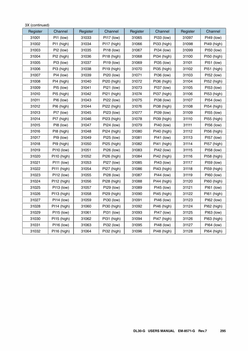
295DL30-G USERS MANUAL EM-8571-G Rev.7
3X (continued)
Register Channel Register Channel Register Channel Register Channel
31001 PI1 (low) 31033 PI17 (low) 31065 PI33 (low) 31097 PI49 (low)
31002 PI1 (high) 31034 PI17 (high) 31066 PI33 (high) 31098 PI49 (high)
31003 PI2 (low) 31035 PI18 (low) 31067 PI34 (low) 31099 PI50 (low)
31004 PI2 (high) 31036 PI18 (high) 31068 PI34 (high) 31100 PI50 (high)
31005 PI3 (low) 31037 PI19 (low) 31069 PI35 (low) 31101 PI51 (low)
31006 PI3 (high) 31038 PI19 (high) 31070 PI35 (high) 31102 PI51 (high)
31007 PI4 (low) 31039 PI20 (low) 31071 PI36 (low) 31103 PI52 (low)
31008 PI4 (high) 31040 PI20 (high) 31072 PI36 (high) 31104 PI52 (high)
31009 PI5 (low) 31041 PI21 (low) 31073 PI37 (low) 31105 PI53 (low)
31010 PI5 (high) 31042 PI21 (high) 31074 PI37 (high) 31106 PI53 (high)
31011 PI6 (low) 31043 PI22 (low) 31075 PI38 (low) 31107 PI54 (low)
31012 PI6 (high) 31044 PI22 (high) 31076 PI38 (high) 31108 PI54 (high)
31013 PI7 (low) 31045 PI23 (low) 31077 PI39 (low) 31109 PI55 (low)
31014 PI7 (high) 31046 PI23 (high) 31078 PI39 (high) 31110 PI55 (high)
31015 PI8 (low) 31047 PI24 (low) 31079 PI40 (low) 31111 PI56 (low)
31016 PI8 (high) 31048 PI24 (high) 31080 PI40 (high) 31112 PI56 (high)
31017 PI9 (low) 31049 PI25 (low) 31081 PI41 (low) 31113 PI57 (low)
31018 PI9 (high) 31050 PI25 (high) 31082 PI41 (high) 31114 PI57 (high)
31019 PI10 (low) 31051 PI26 (low) 31083 PI42 (low) 31115 PI58 (low)
31020 PI10 (high) 31052 PI26 (high) 31084 PI42 (high) 31116 PI58 (high)
31021 PI11 (low) 31053 PI27 (low) 31085 PI43 (low) 31117 PI59 (low)
31022 PI11 (high) 31054 PI27 (high) 31086 PI43 (high) 31118 PI59 (high)
31023 PI12 (low) 31055 PI28 (low) 31087 PI44 (low) 31119 PI60 (low)
31024 PI12 (high) 31056 PI28 (high) 31088 PI44 (high) 31120 PI60 (high)
31025 PI13 (low) 31057 PI29 (low) 31089 PI45 (low) 31121 PI61 (low)
31026 PI13 (high) 31058 PI29 (high) 31090 PI45 (high) 31122 PI61 (high)
31027 PI14 (low) 31059 PI30 (low) 31091 PI46 (low) 31123 PI62 (low)
31028 PI14 (high) 31060 PI30 (high) 31092 PI46 (high) 31124 PI62 (high)
31029 PI15 (low) 31061 PI31 (low) 31093 PI47 (low) 31125 PI63 (low)
31030 PI15 (high) 31062 PI31 (high) 31094 PI47 (high) 31126 PI63 (high)
31031 PI16 (low) 31063 PI32 (low) 31095 PI48 (low) 31127 PI64 (low)
31032 PI16 (high) 31064 PI32 (high) 31096 PI48 (high) 31128 PI64 (high)
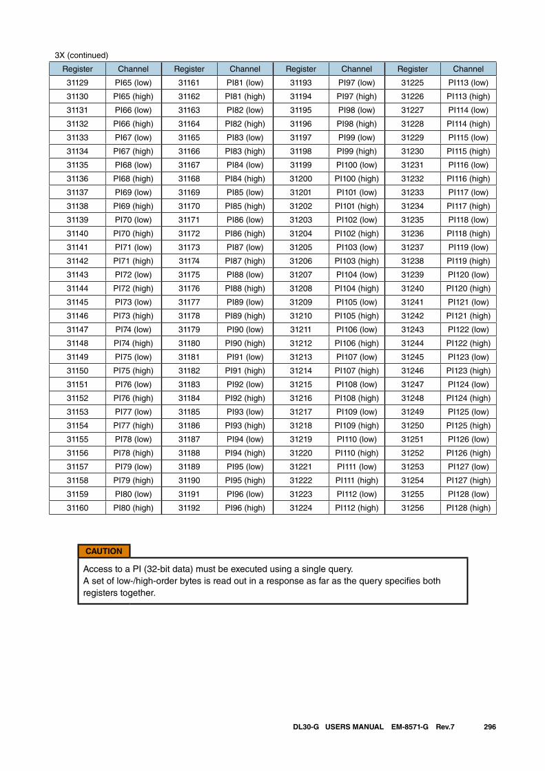
296DL30-G USERS MANUAL EM-8571-G Rev.7
3X (continued)
Register Channel Register Channel Register Channel Register Channel
31129 PI65 (low) 31161 PI81 (low) 31193 PI97 (low) 31225 PI113 (low)
31130 PI65 (high) 31162 PI81 (high) 31194 PI97 (high) 31226 PI113 (high)
31131 PI66 (low) 31163 PI82 (low) 31195 PI98 (low) 31227 PI114 (low)
31132 PI66 (high) 31164 PI82 (high) 31196 PI98 (high) 31228 PI114 (high)
31133 PI67 (low) 31165 PI83 (low) 31197 PI99 (low) 31229 PI115 (low)
31134 PI67 (high) 31166 PI83 (high) 31198 PI99 (high) 31230 PI115 (high)
31135 PI68 (low) 31167 PI84 (low) 31199 PI100 (low) 31231 PI116 (low)
31136 PI68 (high) 31168 PI84 (high) 31200 PI100 (high) 31232 PI116 (high)
31137 PI69 (low) 31169 PI85 (low) 31201 PI101 (low) 31233 PI117 (low)
31138 PI69 (high) 31170 PI85 (high) 31202 PI101 (high) 31234 PI117 (high)
31139 PI70 (low) 31171 PI86 (low) 31203 PI102 (low) 31235 PI118 (low)
31140 PI70 (high) 31172 PI86 (high) 31204 PI102 (high) 31236 PI118 (high)
31141 PI71 (low) 31173 PI87 (low) 31205 PI103 (low) 31237 PI119 (low)
31142 PI71 (high) 31174 PI87 (high) 31206 PI103 (high) 31238 PI119 (high)
31143 PI72 (low) 31175 PI88 (low) 31207 PI104 (low) 31239 PI120 (low)
31144 PI72 (high) 31176 PI88 (high) 31208 PI104 (high) 31240 PI120 (high)
31145 PI73 (low) 31177 PI89 (low) 31209 PI105 (low) 31241 PI121 (low)
31146 PI73 (high) 31178 PI89 (high) 31210 PI105 (high) 31242 PI121 (high)
31147 PI74 (low) 31179 PI90 (low) 31211 PI106 (low) 31243 PI122 (low)
31148 PI74 (high) 31180 PI90 (high) 31212 PI106 (high) 31244 PI122 (high)
31149 PI75 (low) 31181 PI91 (low) 31213 PI107 (low) 31245 PI123 (low)
31150 PI75 (high) 31182 PI91 (high) 31214 PI107 (high) 31246 PI123 (high)
31151 PI76 (low) 31183 PI92 (low) 31215 PI108 (low) 31247 PI124 (low)
31152 PI76 (high) 31184 PI92 (high) 31216 PI108 (high) 31248 PI124 (high)
31153 PI77 (low) 31185 PI93 (low) 31217 PI109 (low) 31249 PI125 (low)
31154 PI77 (high) 31186 PI93 (high) 31218 PI109 (high) 31250 PI125 (high)
31155 PI78 (low) 31187 PI94 (low) 31219 PI110 (low) 31251 PI126 (low)
31156 PI78 (high) 31188 PI94 (high) 31220 PI110 (high) 31252 PI126 (high)
31157 PI79 (low) 31189 PI95 (low) 31221 PI111 (low) 31253 PI127 (low)
31158 PI79 (high) 31190 PI95 (high) 31222 PI111 (high) 31254 PI127 (high)
31159 PI80 (low) 31191 PI96 (low) 31223 PI112 (low) 31255 PI128 (low)
31160 PI80 (high) 31192 PI96 (high) 31224 PI112 (high) 31256 PI128 (high)
CAUTION
Access to a PI (32-bit data) must be executed using a single query. A set of low-/high-order bytes is read out in a response as far as the query specifies both registers together.
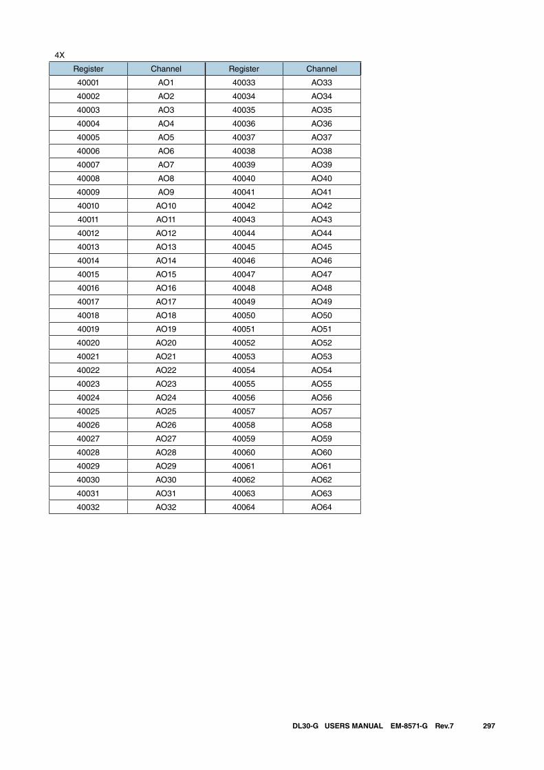
297DL30-G USERS MANUAL EM-8571-G Rev.7
4X
Register Channel Register Channel
40001 AO1 40033 AO33
40002 AO2 40034 AO34
40003 AO3 40035 AO35
40004 AO4 40036 AO36
40005 AO5 40037 AO37
40006 AO6 40038 AO38
40007 AO7 40039 AO39
40008 AO8 40040 AO40
40009 AO9 40041 AO41
40010 AO10 40042 AO42
40011 AO11 40043 AO43
40012 AO12 40044 AO44
40013 AO13 40045 AO45
40014 AO14 40046 AO46
40015 AO15 40047 AO47
40016 AO16 40048 AO48
40017 AO17 40049 AO49
40018 AO18 40050 AO50
40019 AO19 40051 AO51
40020 AO20 40052 AO52
40021 AO21 40053 AO53
40022 AO22 40054 AO54
40023 AO23 40055 AO55
40024 AO24 40056 AO56
40025 AO25 40057 AO57
40026 AO26 40058 AO58
40027 AO27 40059 AO59
40028 AO28 40060 AO60
40029 AO29 40061 AO61
40030 AO30 40062 AO62
40031 AO31 40063 AO63
40032 AO32 40064 AO64
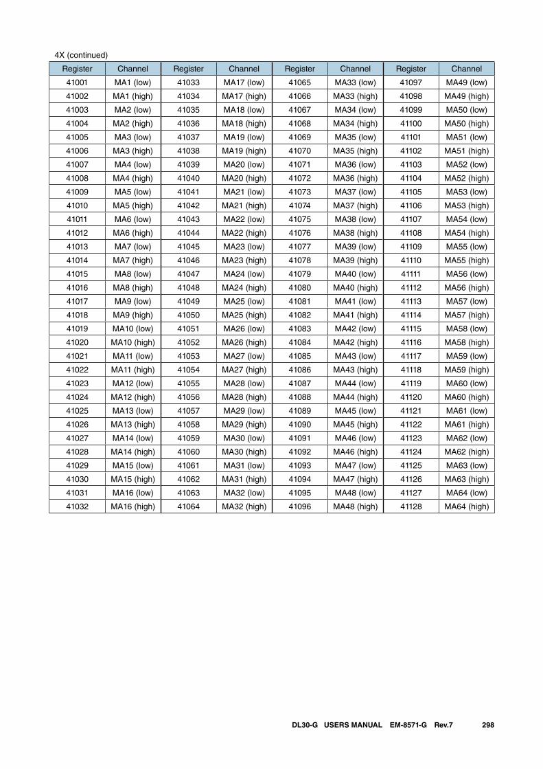
298DL30-G USERS MANUAL EM-8571-G Rev.7
4X (continued)
Register Channel Register Channel Register Channel Register Channel
41001 MA1 (low) 41033 MA17 (low) 41065 MA33 (low) 41097 MA49 (low)
41002 MA1 (high) 41034 MA17 (high) 41066 MA33 (high) 41098 MA49 (high)
41003 MA2 (low) 41035 MA18 (low) 41067 MA34 (low) 41099 MA50 (low)
41004 MA2 (high) 41036 MA18 (high) 41068 MA34 (high) 41100 MA50 (high)
41005 MA3 (low) 41037 MA19 (low) 41069 MA35 (low) 41101 MA51 (low)
41006 MA3 (high) 41038 MA19 (high) 41070 MA35 (high) 41102 MA51 (high)
41007 MA4 (low) 41039 MA20 (low) 41071 MA36 (low) 41103 MA52 (low)
41008 MA4 (high) 41040 MA20 (high) 41072 MA36 (high) 41104 MA52 (high)
41009 MA5 (low) 41041 MA21 (low) 41073 MA37 (low) 41105 MA53 (low)
41010 MA5 (high) 41042 MA21 (high) 41074 MA37 (high) 41106 MA53 (high)
41011 MA6 (low) 41043 MA22 (low) 41075 MA38 (low) 41107 MA54 (low)
41012 MA6 (high) 41044 MA22 (high) 41076 MA38 (high) 41108 MA54 (high)
41013 MA7 (low) 41045 MA23 (low) 41077 MA39 (low) 41109 MA55 (low)
41014 MA7 (high) 41046 MA23 (high) 41078 MA39 (high) 41110 MA55 (high)
41015 MA8 (low) 41047 MA24 (low) 41079 MA40 (low) 41111 MA56 (low)
41016 MA8 (high) 41048 MA24 (high) 41080 MA40 (high) 41112 MA56 (high)
41017 MA9 (low) 41049 MA25 (low) 41081 MA41 (low) 41113 MA57 (low)
41018 MA9 (high) 41050 MA25 (high) 41082 MA41 (high) 41114 MA57 (high)
41019 MA10 (low) 41051 MA26 (low) 41083 MA42 (low) 41115 MA58 (low)
41020 MA10 (high) 41052 MA26 (high) 41084 MA42 (high) 41116 MA58 (high)
41021 MA11 (low) 41053 MA27 (low) 41085 MA43 (low) 41117 MA59 (low)
41022 MA11 (high) 41054 MA27 (high) 41086 MA43 (high) 41118 MA59 (high)
41023 MA12 (low) 41055 MA28 (low) 41087 MA44 (low) 41119 MA60 (low)
41024 MA12 (high) 41056 MA28 (high) 41088 MA44 (high) 41120 MA60 (high)
41025 MA13 (low) 41057 MA29 (low) 41089 MA45 (low) 41121 MA61 (low)
41026 MA13 (high) 41058 MA29 (high) 41090 MA45 (high) 41122 MA61 (high)
41027 MA14 (low) 41059 MA30 (low) 41091 MA46 (low) 41123 MA62 (low)
41028 MA14 (high) 41060 MA30 (high) 41092 MA46 (high) 41124 MA62 (high)
41029 MA15 (low) 41061 MA31 (low) 41093 MA47 (low) 41125 MA63 (low)
41030 MA15 (high) 41062 MA31 (high) 41094 MA47 (high) 41126 MA63 (high)
41031 MA16 (low) 41063 MA32 (low) 41095 MA48 (low) 41127 MA64 (low)
41032 MA16 (high) 41064 MA32 (high) 41096 MA48 (high) 41128 MA64 (high)
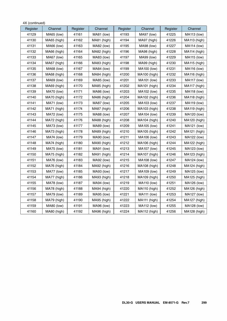
299DL30-G USERS MANUAL EM-8571-G Rev.7
4X (continued)
Register Channel Register Channel Register Channel Register Channel
41129 MA65 (low) 41161 MA81 (low) 41193 MA97 (low) 41225 MA113 (low)
41130 MA65 (high) 41162 MA81 (high) 41194 MA97 (high) 41226 MA113 (high)
41131 MA66 (low) 41163 MA82 (low) 41195 MA98 (low) 41227 MA114 (low)
41132 MA66 (high) 41164 MA82 (high) 41196 MA98 (high) 41228 MA114 (high)
41133 MA67 (low) 41165 MA83 (low) 41197 MA99 (low) 41229 MA115 (low)
41134 MA67 (high) 41166 MA83 (high) 41198 MA99 (high) 41230 MA115 (high)
41135 MA68 (low) 41167 MA84 (low) 41199 MA100 (low) 41231 MA116 (low)
41136 MA68 (high) 41168 MA84 (high) 41200 MA100 (high) 41232 MA116 (high)
41137 MA69 (low) 41169 MA85 (low) 41201 MA101 (low) 41233 MA117 (low)
41138 MA69 (high) 41170 MA85 (high) 41202 MA101 (high) 41234 MA117 (high)
41139 MA70 (low) 41171 MA86 (low) 41203 MA102 (low) 41235 MA118 (low)
41140 MA70 (high) 41172 MA86 (high) 41204 MA102 (high) 41236 MA118 (high)
41141 MA71 (low) 41173 MA87 (low) 41205 MA103 (low) 41237 MA119 (low)
41142 MA71 (high) 41174 MA87 (high) 41206 MA103 (high) 41238 MA119 (high)
41143 MA72 (low) 41175 MA88 (low) 41207 MA104 (low) 41239 MA120 (low)
41144 MA72 (high) 41176 MA88 (high) 41208 MA104 (high) 41240 MA120 (high)
41145 MA73 (low) 41177 MA89 (low) 41209 MA105 (low) 41241 MA121 (low)
41146 MA73 (high) 41178 MA89 (high) 41210 MA105 (high) 41242 MA121 (high)
41147 MA74 (low) 41179 MA90 (low) 41211 MA106 (low) 41243 MA122 (low)
41148 MA74 (high) 41180 MA90 (high) 41212 MA106 (high) 41244 MA122 (high)
41149 MA75 (low) 41181 MA91 (low) 41213 MA107 (low) 41245 MA123 (low)
41150 MA75 (high) 41182 MA91 (high) 41214 MA107 (high) 41246 MA123 (high)
41151 MA76 (low) 41183 MA92 (low) 41215 MA108 (low) 41247 MA124 (low)
41152 MA76 (high) 41184 MA92 (high) 41216 MA108 (high) 41248 MA124 (high)
41153 MA77 (low) 41185 MA93 (low) 41217 MA109 (low) 41249 MA125 (low)
41154 MA77 (high) 41186 MA93 (high) 41218 MA109 (high) 41250 MA125 (high)
41155 MA78 (low) 41187 MA94 (low) 41219 MA110 (low) 41251 MA126 (low)
41156 MA78 (high) 41188 MA94 (high) 41220 MA110 (high) 41252 MA126 (high)
41157 MA79 (low) 41189 MA95 (low) 41221 MA111 (low) 41253 MA127 (low)
41158 MA79 (high) 41190 MA95 (high) 41222 MA111 (high) 41254 MA127 (high)
41159 MA80 (low) 41191 MA96 (low) 41223 MA112 (low) 41255 MA128 (low)
41160 MA80 (high) 41192 MA96 (high) 41224 MA112 (high) 41256 MA128 (high)
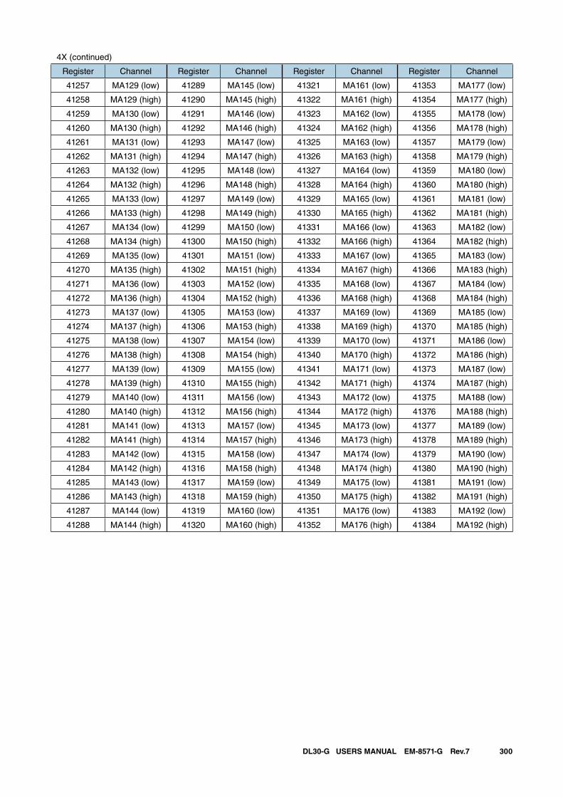
300DL30-G USERS MANUAL EM-8571-G Rev.7
4X (continued)
Register Channel Register Channel Register Channel Register Channel
41257 MA129 (low) 41289 MA145 (low) 41321 MA161 (low) 41353 MA177 (low)
41258 MA129 (high) 41290 MA145 (high) 41322 MA161 (high) 41354 MA177 (high)
41259 MA130 (low) 41291 MA146 (low) 41323 MA162 (low) 41355 MA178 (low)
41260 MA130 (high) 41292 MA146 (high) 41324 MA162 (high) 41356 MA178 (high)
41261 MA131 (low) 41293 MA147 (low) 41325 MA163 (low) 41357 MA179 (low)
41262 MA131 (high) 41294 MA147 (high) 41326 MA163 (high) 41358 MA179 (high)
41263 MA132 (low) 41295 MA148 (low) 41327 MA164 (low) 41359 MA180 (low)
41264 MA132 (high) 41296 MA148 (high) 41328 MA164 (high) 41360 MA180 (high)
41265 MA133 (low) 41297 MA149 (low) 41329 MA165 (low) 41361 MA181 (low)
41266 MA133 (high) 41298 MA149 (high) 41330 MA165 (high) 41362 MA181 (high)
41267 MA134 (low) 41299 MA150 (low) 41331 MA166 (low) 41363 MA182 (low)
41268 MA134 (high) 41300 MA150 (high) 41332 MA166 (high) 41364 MA182 (high)
41269 MA135 (low) 41301 MA151 (low) 41333 MA167 (low) 41365 MA183 (low)
41270 MA135 (high) 41302 MA151 (high) 41334 MA167 (high) 41366 MA183 (high)
41271 MA136 (low) 41303 MA152 (low) 41335 MA168 (low) 41367 MA184 (low)
41272 MA136 (high) 41304 MA152 (high) 41336 MA168 (high) 41368 MA184 (high)
41273 MA137 (low) 41305 MA153 (low) 41337 MA169 (low) 41369 MA185 (low)
41274 MA137 (high) 41306 MA153 (high) 41338 MA169 (high) 41370 MA185 (high)
41275 MA138 (low) 41307 MA154 (low) 41339 MA170 (low) 41371 MA186 (low)
41276 MA138 (high) 41308 MA154 (high) 41340 MA170 (high) 41372 MA186 (high)
41277 MA139 (low) 41309 MA155 (low) 41341 MA171 (low) 41373 MA187 (low)
41278 MA139 (high) 41310 MA155 (high) 41342 MA171 (high) 41374 MA187 (high)
41279 MA140 (low) 41311 MA156 (low) 41343 MA172 (low) 41375 MA188 (low)
41280 MA140 (high) 41312 MA156 (high) 41344 MA172 (high) 41376 MA188 (high)
41281 MA141 (low) 41313 MA157 (low) 41345 MA173 (low) 41377 MA189 (low)
41282 MA141 (high) 41314 MA157 (high) 41346 MA173 (high) 41378 MA189 (high)
41283 MA142 (low) 41315 MA158 (low) 41347 MA174 (low) 41379 MA190 (low)
41284 MA142 (high) 41316 MA158 (high) 41348 MA174 (high) 41380 MA190 (high)
41285 MA143 (low) 41317 MA159 (low) 41349 MA175 (low) 41381 MA191 (low)
41286 MA143 (high) 41318 MA159 (high) 41350 MA175 (high) 41382 MA191 (high)
41287 MA144 (low) 41319 MA160 (low) 41351 MA176 (low) 41383 MA192 (low)
41288 MA144 (high) 41320 MA160 (high) 41352 MA176 (high) 41384 MA192 (high)
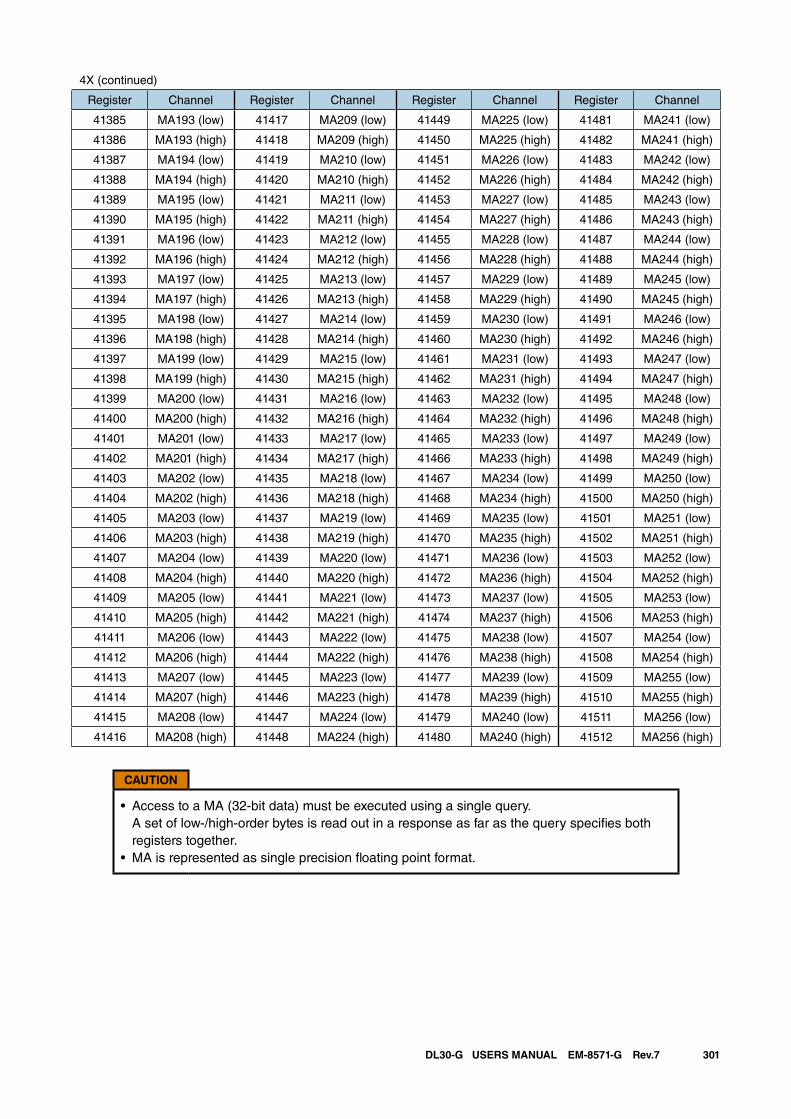
301DL30-G USERS MANUAL EM-8571-G Rev.7
4X (continued)
Register Channel Register Channel Register Channel Register Channel
41385 MA193 (low) 41417 MA209 (low) 41449 MA225 (low) 41481 MA241 (low)
41386 MA193 (high) 41418 MA209 (high) 41450 MA225 (high) 41482 MA241 (high)
41387 MA194 (low) 41419 MA210 (low) 41451 MA226 (low) 41483 MA242 (low)
41388 MA194 (high) 41420 MA210 (high) 41452 MA226 (high) 41484 MA242 (high)
41389 MA195 (low) 41421 MA211 (low) 41453 MA227 (low) 41485 MA243 (low)
41390 MA195 (high) 41422 MA211 (high) 41454 MA227 (high) 41486 MA243 (high)
41391 MA196 (low) 41423 MA212 (low) 41455 MA228 (low) 41487 MA244 (low)
41392 MA196 (high) 41424 MA212 (high) 41456 MA228 (high) 41488 MA244 (high)
41393 MA197 (low) 41425 MA213 (low) 41457 MA229 (low) 41489 MA245 (low)
41394 MA197 (high) 41426 MA213 (high) 41458 MA229 (high) 41490 MA245 (high)
41395 MA198 (low) 41427 MA214 (low) 41459 MA230 (low) 41491 MA246 (low)
41396 MA198 (high) 41428 MA214 (high) 41460 MA230 (high) 41492 MA246 (high)
41397 MA199 (low) 41429 MA215 (low) 41461 MA231 (low) 41493 MA247 (low)
41398 MA199 (high) 41430 MA215 (high) 41462 MA231 (high) 41494 MA247 (high)
41399 MA200 (low) 41431 MA216 (low) 41463 MA232 (low) 41495 MA248 (low)
41400 MA200 (high) 41432 MA216 (high) 41464 MA232 (high) 41496 MA248 (high)
41401 MA201 (low) 41433 MA217 (low) 41465 MA233 (low) 41497 MA249 (low)
41402 MA201 (high) 41434 MA217 (high) 41466 MA233 (high) 41498 MA249 (high)
41403 MA202 (low) 41435 MA218 (low) 41467 MA234 (low) 41499 MA250 (low)
41404 MA202 (high) 41436 MA218 (high) 41468 MA234 (high) 41500 MA250 (high)
41405 MA203 (low) 41437 MA219 (low) 41469 MA235 (low) 41501 MA251 (low)
41406 MA203 (high) 41438 MA219 (high) 41470 MA235 (high) 41502 MA251 (high)
41407 MA204 (low) 41439 MA220 (low) 41471 MA236 (low) 41503 MA252 (low)
41408 MA204 (high) 41440 MA220 (high) 41472 MA236 (high) 41504 MA252 (high)
41409 MA205 (low) 41441 MA221 (low) 41473 MA237 (low) 41505 MA253 (low)
41410 MA205 (high) 41442 MA221 (high) 41474 MA237 (high) 41506 MA253 (high)
41411 MA206 (low) 41443 MA222 (low) 41475 MA238 (low) 41507 MA254 (low)
41412 MA206 (high) 41444 MA222 (high) 41476 MA238 (high) 41508 MA254 (high)
41413 MA207 (low) 41445 MA223 (low) 41477 MA239 (low) 41509 MA255 (low)
41414 MA207 (high) 41446 MA223 (high) 41478 MA239 (high) 41510 MA255 (high)
41415 MA208 (low) 41447 MA224 (low) 41479 MA240 (low) 41511 MA256 (low)
41416 MA208 (high) 41448 MA224 (high) 41480 MA240 (high) 41512 MA256 (high)
CAUTION
• Access to a MA (32-bit data) must be executed using a single query. A set of low-/high-order bytes is read out in a response as far as the query specifies both registers together.
• MA is represented as single precision floating point format.
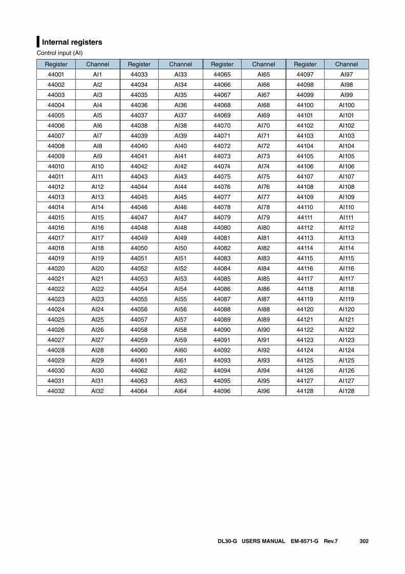
302DL30-G USERS MANUAL EM-8571-G Rev.7
Internal registersControl input (AI)
Register Channel Register Channel Register Channel Register Channel
44001 AI1 44033 AI33 44065 AI65 44097 AI97
44002 AI2 44034 AI34 44066 AI66 44098 AI98
44003 AI3 44035 AI35 44067 AI67 44099 AI99
44004 AI4 44036 AI36 44068 AI68 44100 AI100
44005 AI5 44037 AI37 44069 AI69 44101 AI101
44006 AI6 44038 AI38 44070 AI70 44102 AI102
44007 AI7 44039 AI39 44071 AI71 44103 AI103
44008 AI8 44040 AI40 44072 AI72 44104 AI104
44009 AI9 44041 AI41 44073 AI73 44105 AI105
44010 AI10 44042 AI42 44074 AI74 44106 AI106
44011 AI11 44043 AI43 44075 AI75 44107 AI107
44012 AI12 44044 AI44 44076 AI76 44108 AI108
44013 AI13 44045 AI45 44077 AI77 44109 AI109
44014 AI14 44046 AI46 44078 AI78 44110 AI110
44015 AI15 44047 AI47 44079 AI79 44111 AI111
44016 AI16 44048 AI48 44080 AI80 44112 AI112
44017 AI17 44049 AI49 44081 AI81 44113 AI113
44018 AI18 44050 AI50 44082 AI82 44114 AI114
44019 AI19 44051 AI51 44083 AI83 44115 AI115
44020 AI20 44052 AI52 44084 AI84 44116 AI116
44021 AI21 44053 AI53 44085 AI85 44117 AI117
44022 AI22 44054 AI54 44086 AI86 44118 AI118
44023 AI23 44055 AI55 44087 AI87 44119 AI119
44024 AI24 44056 AI56 44088 AI88 44120 AI120
44025 AI25 44057 AI57 44089 AI89 44121 AI121
44026 AI26 44058 AI58 44090 AI90 44122 AI122
44027 AI27 44059 AI59 44091 AI91 44123 AI123
44028 AI28 44060 AI60 44092 AI92 44124 AI124
44029 AI29 44061 AI61 44093 AI93 44125 AI125
44030 AI30 44062 AI62 44094 AI94 44126 AI126
44031 AI31 44063 AI63 44095 AI95 44127 AI127
44032 AI32 44064 AI64 44096 AI96 44128 AI128
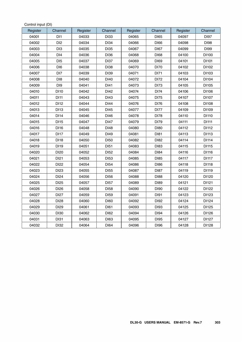
303DL30-G USERS MANUAL EM-8571-G Rev.7
Control input (DI)
Register Channel Register Channel Register Channel Register Channel
04001 DI1 04033 DI33 04065 DI65 04097 DI97
04002 DI2 04034 DI34 04066 DI66 04098 DI98
04003 DI3 04035 DI35 04067 DI67 04099 DI99
04004 DI4 04036 DI36 04068 DI68 04100 DI100
04005 DI5 04037 DI37 04069 DI69 04101 DI101
04006 DI6 04038 DI38 04070 DI70 04102 DI102
04007 DI7 04039 DI39 04071 DI71 04103 DI103
04008 DI8 04040 DI40 04072 DI72 04104 DI104
04009 DI9 04041 DI41 04073 DI73 04105 DI105
04010 DI10 04042 DI42 04074 DI74 04106 DI106
04011 DI11 04043 DI43 04075 DI75 04107 DI107
04012 DI12 04044 DI44 04076 DI76 04108 DI108
04013 DI13 04045 DI45 04077 DI77 04109 DI109
04014 DI14 04046 DI46 04078 DI78 04110 DI110
04015 DI15 04047 DI47 04079 DI79 04111 DI111
04016 DI16 04048 DI48 04080 DI80 04112 DI112
04017 DI17 04049 DI49 04081 DI81 04113 DI113
04018 DI18 04050 DI50 04082 DI82 04114 DI114
04019 DI19 04051 DI51 04083 DI83 04115 DI115
04020 DI20 04052 DI52 04084 DI84 04116 DI116
04021 DI21 04053 DI53 04085 DI85 04117 DI117
04022 DI22 04054 DI54 04086 DI86 04118 DI118
04023 DI23 04055 DI55 04087 DI87 04119 DI119
04024 DI24 04056 DI56 04088 DI88 04120 DI120
04025 DI25 04057 DI57 04089 DI89 04121 DI121
04026 DI26 04058 DI58 04090 DI90 04122 DI122
04027 DI27 04059 DI59 04091 DI91 04123 DI123
04028 DI28 04060 DI60 04092 DI92 04124 DI124
04029 DI29 04061 DI61 04093 DI93 04125 DI125
04030 DI30 04062 DI62 04094 DI94 04126 DI126
04031 DI31 04063 DI63 04095 DI95 04127 DI127
04032 DI32 04064 DI64 04096 DI96 04128 DI128
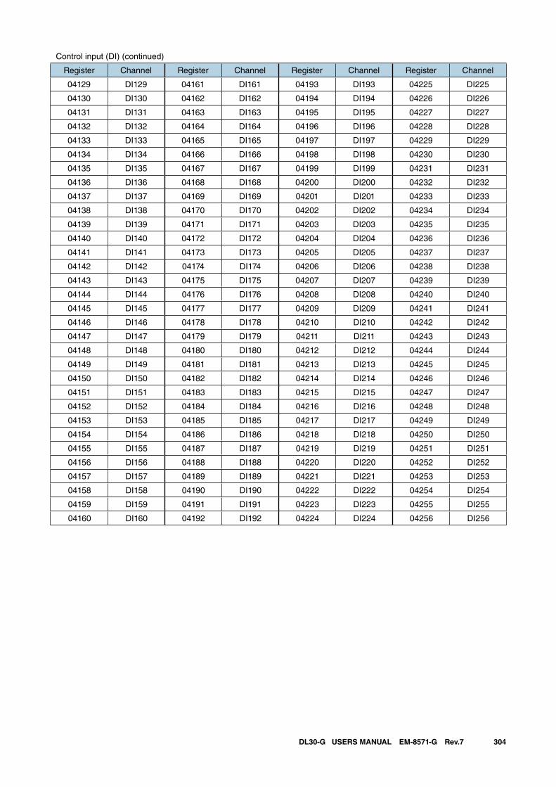
304DL30-G USERS MANUAL EM-8571-G Rev.7
Control input (DI) (continued)
Register Channel Register Channel Register Channel Register Channel
04129 DI129 04161 DI161 04193 DI193 04225 DI225
04130 DI130 04162 DI162 04194 DI194 04226 DI226
04131 DI131 04163 DI163 04195 DI195 04227 DI227
04132 DI132 04164 DI164 04196 DI196 04228 DI228
04133 DI133 04165 DI165 04197 DI197 04229 DI229
04134 DI134 04166 DI166 04198 DI198 04230 DI230
04135 DI135 04167 DI167 04199 DI199 04231 DI231
04136 DI136 04168 DI168 04200 DI200 04232 DI232
04137 DI137 04169 DI169 04201 DI201 04233 DI233
04138 DI138 04170 DI170 04202 DI202 04234 DI234
04139 DI139 04171 DI171 04203 DI203 04235 DI235
04140 DI140 04172 DI172 04204 DI204 04236 DI236
04141 DI141 04173 DI173 04205 DI205 04237 DI237
04142 DI142 04174 DI174 04206 DI206 04238 DI238
04143 DI143 04175 DI175 04207 DI207 04239 DI239
04144 DI144 04176 DI176 04208 DI208 04240 DI240
04145 DI145 04177 DI177 04209 DI209 04241 DI241
04146 DI146 04178 DI178 04210 DI210 04242 DI242
04147 DI147 04179 DI179 04211 DI211 04243 DI243
04148 DI148 04180 DI180 04212 DI212 04244 DI244
04149 DI149 04181 DI181 04213 DI213 04245 DI245
04150 DI150 04182 DI182 04214 DI214 04246 DI246
04151 DI151 04183 DI183 04215 DI215 04247 DI247
04152 DI152 04184 DI184 04216 DI216 04248 DI248
04153 DI153 04185 DI185 04217 DI217 04249 DI249
04154 DI154 04186 DI186 04218 DI218 04250 DI250
04155 DI155 04187 DI187 04219 DI219 04251 DI251
04156 DI156 04188 DI188 04220 DI220 04252 DI252
04157 DI157 04189 DI189 04221 DI221 04253 DI253
04158 DI158 04190 DI190 04222 DI222 04254 DI254
04159 DI159 04191 DI191 04223 DI223 04255 DI255
04160 DI160 04192 DI192 04224 DI224 04256 DI256

305DL30-G USERS MANUAL EM-8571-G Rev.7
Control input (PI)
Register Channel Register Channel Register Channel Register Channel
45001 PI1 (low) 45033 PI17 (low) 45065 PI33 (low) 45097 PI49 (low)
45002 PI1 (high) 45034 PI17 (high) 45066 PI33 (high) 45098 PI49 (high)
45003 PI2 (low) 45035 PI18 (low) 45067 PI34 (low) 45099 PI50 (low)
45004 PI2 (high) 45036 PI18 (high) 45068 PI34 (high) 45100 PI50 (high)
45005 PI3 (low) 45037 PI19 (low) 45069 PI35 (low) 45101 PI51 (low)
45006 PI3 (high) 45038 PI19 (high) 45070 PI35 (high) 45102 PI51 (high)
45007 PI4 (low) 45039 PI20 (low) 45071 PI36 (low) 45103 PI52 (low)
45008 PI4 (high) 45040 PI20 (high) 45072 PI36 (high) 45104 PI52 (high)
45009 PI5 (low) 45041 PI21 (low) 45073 PI37 (low) 45105 PI53 (low)
45010 PI5 (high) 45042 PI21 (high) 45074 PI37 (high) 45106 PI53 (high)
45011 PI6 (low) 45043 PI22 (low) 45075 PI38 (low) 45107 PI54 (low)
45012 PI6 (high) 45044 PI22 (high) 45076 PI38 (high) 45108 PI54 (high)
45013 PI7 (low) 45045 PI23 (low) 45077 PI39 (low) 45109 PI55 (low)
45014 PI7 (high) 45046 PI23 (high) 45078 PI39 (high) 45110 PI55 (high)
45015 PI8 (low) 45047 PI24 (low) 45079 PI40 (low) 45111 PI56 (low)
45016 PI8 (high) 45048 PI24 (high) 45080 PI40 (high) 45112 PI56 (high)
45017 PI9 (low) 45049 PI25 (low) 45081 PI41 (low) 45113 PI57 (low)
45018 PI9 (high) 45050 PI25 (high) 45082 PI41 (high) 45114 PI57 (high)
45019 PI10 (low) 45051 PI26 (low) 45083 PI42 (low) 45115 PI58 (low)
45020 PI10 (high) 45052 PI26 (high) 45084 PI42 (high) 45116 PI58 (high)
45021 PI11 (low) 45053 PI27 (low) 45085 PI43 (low) 45117 PI59 (low)
45022 PI11 (high) 45054 PI27 (high) 45086 PI43 (high) 45118 PI59 (high)
45023 PI12 (low) 45055 PI28 (low) 45087 PI44 (low) 45119 PI60 (low)
45024 PI12 (high) 45056 PI28 (high) 45088 PI44 (high) 45120 PI60 (high)
45025 PI13 (low) 45057 PI29 (low) 45089 PI45 (low) 45121 PI61 (low)
45026 PI13 (high) 45058 PI29 (high) 45090 PI45 (high) 45122 PI61 (high)
45027 PI14 (low) 45059 PI30 (low) 45091 PI46 (low) 45123 PI62 (low)
45028 PI14 (high) 45060 PI30 (high) 45092 PI46 (high) 45124 PI62 (high)
45029 PI15 (low) 45061 PI31 (low) 45093 PI47 (low) 45125 PI63 (low)
45030 PI15 (high) 45062 PI31 (high) 45094 PI47 (high) 45126 PI63 (high)
45031 PI16 (low) 45063 PI32 (low) 45095 PI48 (low) 45127 PI64 (low)
45032 PI16 (high) 45064 PI32 (high) 45096 PI48 (high) 45128 PI64 (high)
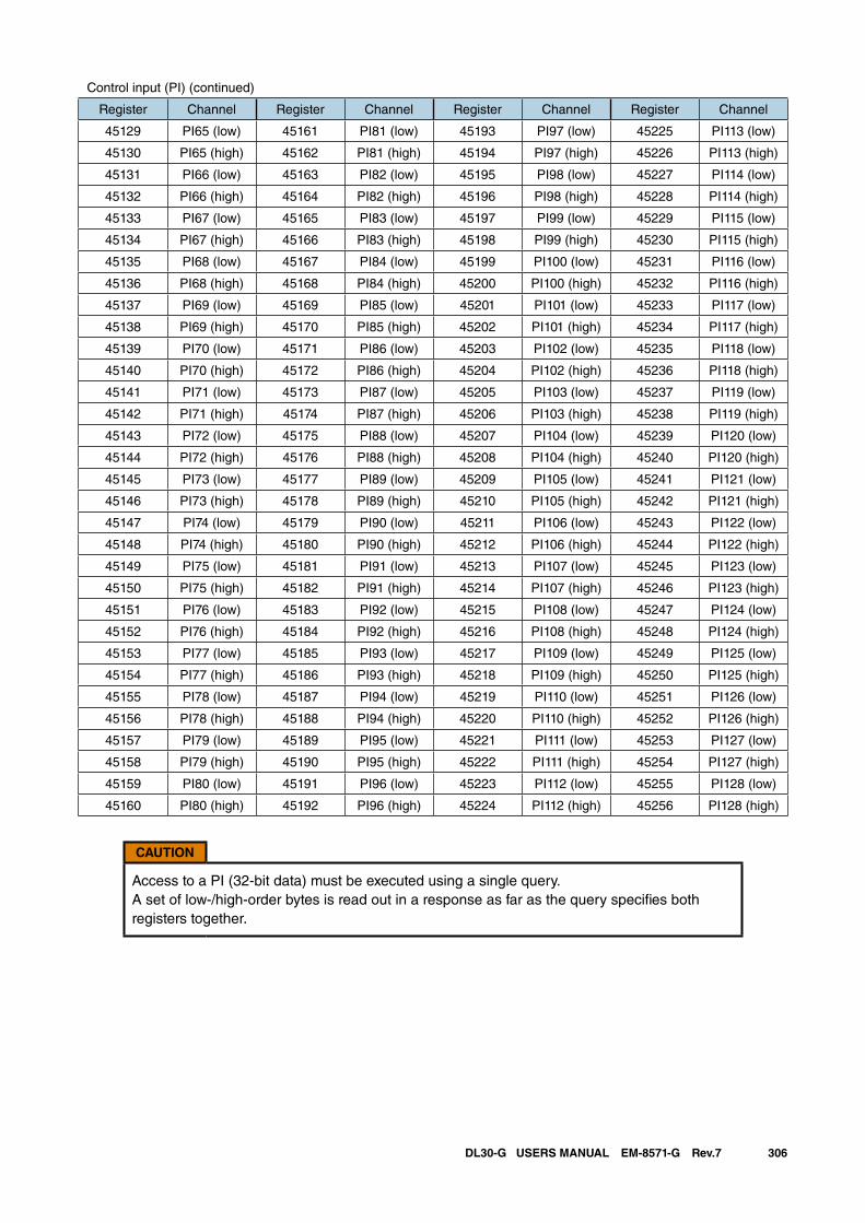
306DL30-G USERS MANUAL EM-8571-G Rev.7
Control input (PI) (continued)
Register Channel Register Channel Register Channel Register Channel
45129 PI65 (low) 45161 PI81 (low) 45193 PI97 (low) 45225 PI113 (low)
45130 PI65 (high) 45162 PI81 (high) 45194 PI97 (high) 45226 PI113 (high)
45131 PI66 (low) 45163 PI82 (low) 45195 PI98 (low) 45227 PI114 (low)
45132 PI66 (high) 45164 PI82 (high) 45196 PI98 (high) 45228 PI114 (high)
45133 PI67 (low) 45165 PI83 (low) 45197 PI99 (low) 45229 PI115 (low)
45134 PI67 (high) 45166 PI83 (high) 45198 PI99 (high) 45230 PI115 (high)
45135 PI68 (low) 45167 PI84 (low) 45199 PI100 (low) 45231 PI116 (low)
45136 PI68 (high) 45168 PI84 (high) 45200 PI100 (high) 45232 PI116 (high)
45137 PI69 (low) 45169 PI85 (low) 45201 PI101 (low) 45233 PI117 (low)
45138 PI69 (high) 45170 PI85 (high) 45202 PI101 (high) 45234 PI117 (high)
45139 PI70 (low) 45171 PI86 (low) 45203 PI102 (low) 45235 PI118 (low)
45140 PI70 (high) 45172 PI86 (high) 45204 PI102 (high) 45236 PI118 (high)
45141 PI71 (low) 45173 PI87 (low) 45205 PI103 (low) 45237 PI119 (low)
45142 PI71 (high) 45174 PI87 (high) 45206 PI103 (high) 45238 PI119 (high)
45143 PI72 (low) 45175 PI88 (low) 45207 PI104 (low) 45239 PI120 (low)
45144 PI72 (high) 45176 PI88 (high) 45208 PI104 (high) 45240 PI120 (high)
45145 PI73 (low) 45177 PI89 (low) 45209 PI105 (low) 45241 PI121 (low)
45146 PI73 (high) 45178 PI89 (high) 45210 PI105 (high) 45242 PI121 (high)
45147 PI74 (low) 45179 PI90 (low) 45211 PI106 (low) 45243 PI122 (low)
45148 PI74 (high) 45180 PI90 (high) 45212 PI106 (high) 45244 PI122 (high)
45149 PI75 (low) 45181 PI91 (low) 45213 PI107 (low) 45245 PI123 (low)
45150 PI75 (high) 45182 PI91 (high) 45214 PI107 (high) 45246 PI123 (high)
45151 PI76 (low) 45183 PI92 (low) 45215 PI108 (low) 45247 PI124 (low)
45152 PI76 (high) 45184 PI92 (high) 45216 PI108 (high) 45248 PI124 (high)
45153 PI77 (low) 45185 PI93 (low) 45217 PI109 (low) 45249 PI125 (low)
45154 PI77 (high) 45186 PI93 (high) 45218 PI109 (high) 45250 PI125 (high)
45155 PI78 (low) 45187 PI94 (low) 45219 PI110 (low) 45251 PI126 (low)
45156 PI78 (high) 45188 PI94 (high) 45220 PI110 (high) 45252 PI126 (high)
45157 PI79 (low) 45189 PI95 (low) 45221 PI111 (low) 45253 PI127 (low)
45158 PI79 (high) 45190 PI95 (high) 45222 PI111 (high) 45254 PI127 (high)
45159 PI80 (low) 45191 PI96 (low) 45223 PI112 (low) 45255 PI128 (low)
45160 PI80 (high) 45192 PI96 (high) 45224 PI112 (high) 45256 PI128 (high)
CAUTION
Access to a PI (32-bit data) must be executed using a single query. A set of low-/high-order bytes is read out in a response as far as the query specifies both registers together.
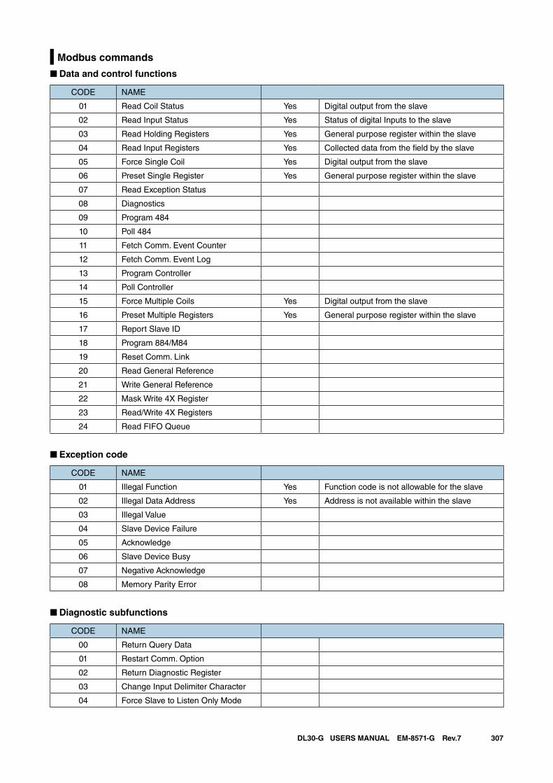
307DL30-G USERS MANUAL EM-8571-G Rev.7
Modbus commands
■ Data and control functions
CODE NAME
01 Read Coil Status Yes Digital output from the slave
02 Read Input Status Yes Status of digital Inputs to the slave
03 Read Holding Registers Yes General purpose register within the slave
04 Read Input Registers Yes Collected data from the field by the slave
05 Force Single Coil Yes Digital output from the slave
06 Preset Single Register Yes General purpose register within the slave
07 Read Exception Status
08 Diagnostics
09 Program 484
10 Poll 484
11 Fetch Comm. Event Counter
12 Fetch Comm. Event Log
13 Program Controller
14 Poll Controller
15 Force Multiple Coils Yes Digital output from the slave
16 Preset Multiple Registers Yes General purpose register within the slave
17 Report Slave ID
18 Program 884/M84
19 Reset Comm. Link
20 Read General Reference
21 Write General Reference
22 Mask Write 4X Register
23 Read/Write 4X Registers
24 Read FIFO Queue
■ Exception code
CODE NAME
01 Illegal Function Yes Function code is not allowable for the slave
02 Illegal Data Address Yes Address is not available within the slave
03 Illegal Value
04 Slave Device Failure
05 Acknowledge
06 Slave Device Busy
07 Negative Acknowledge
08 Memory Parity Error
■ Diagnostic subfunctions
CODE NAME
00 Return Query Data
01 Restart Comm. Option
02 Return Diagnostic Register
03 Change Input Delimiter Character
04 Force Slave to Listen Only Mode
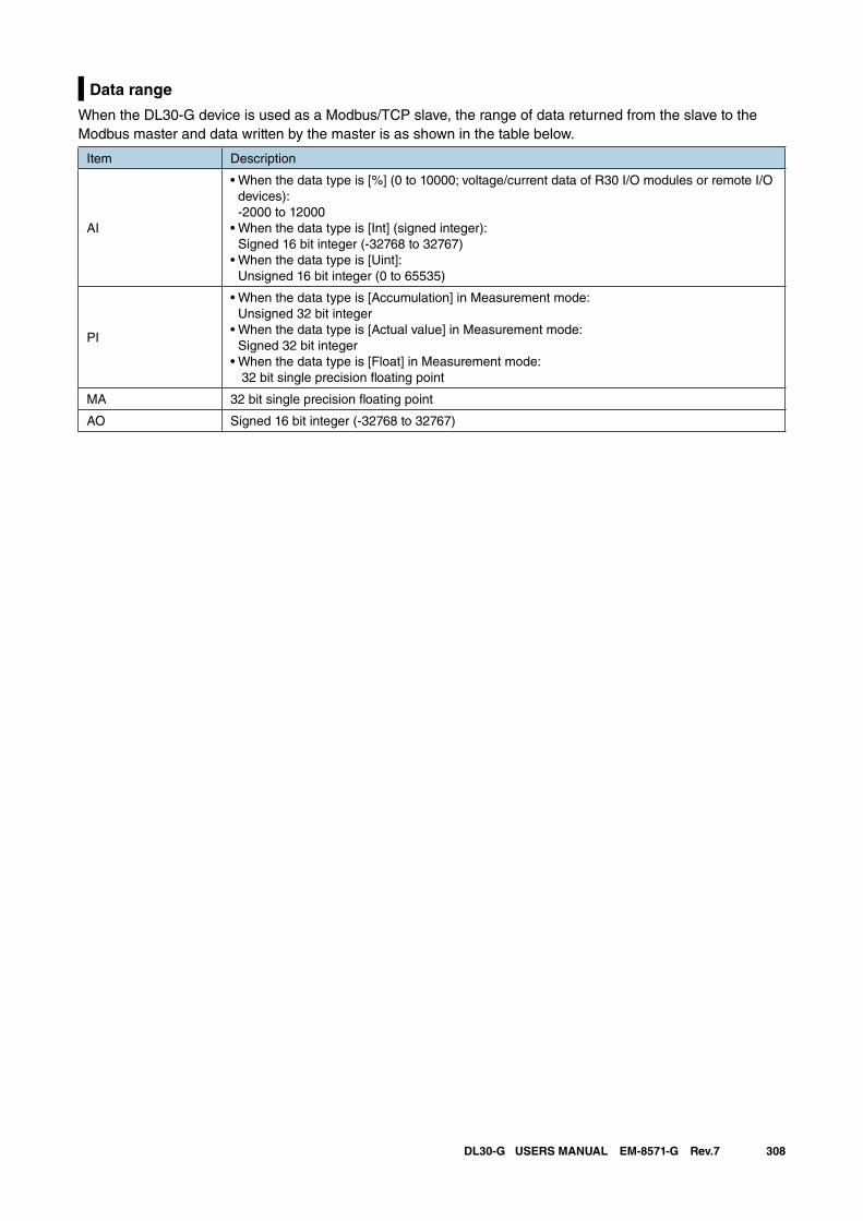
308DL30-G USERS MANUAL EM-8571-G Rev.7
Data range
When the DL30-G device is used as a Modbus/TCP slave, the range of data returned from the slave to the Modbus master and data written by the master is as shown in the table below.
Item Description
AI
• When the data type is [%] (0 to 10000; voltage/current data of R30 I/O modules or remote I/O devices): -2000 to 12000
• When the data type is [Int] (signed integer): Signed 16 bit integer (-32768 to 32767)
• When the data type is [Uint]: Unsigned 16 bit integer (0 to 65535)
PI
• When the data type is [Accumulation] in Measurement mode: Unsigned 32 bit integer
• When the data type is [Actual value] in Measurement mode: Signed 32 bit integer
• When the data type is [Float] in Measurement mode: 32 bit single precision floating point
MA 32 bit single precision floating point
AO Signed 16 bit integer (-32768 to 32767)
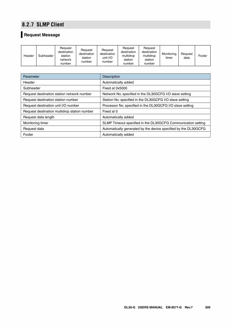
309DL30-G USERS MANUAL EM-8571-G Rev.7
8.2.7 SLMP Client
Request Message
Header Subheader
Requestdestination
stationnetworknumber
Requestdestination
stationnumber
Requestdestination
unit I/Onumber
Requestdestinationmultidrop
stationnumber
Requestdestinationmultidrop
stationnumber
Monitoring timer
Request data
Footer
Parameter Description
Header Automatically added
Subheader Fixed at 0x5000
Request destination station network number Network No. specified in the DL30GCFG I/O slave setting
Request destination station number Station No. specified in the DL30GCFG I/O slave setting
Request destination unit I/O number Processor No. specified in the DL30GCFG I/O slave setting
Request destination multidrop station number Fixed at 0
Request data length Automatically added
Monitoring timer SLMP Timeout specified in the DL30GCFG Communication setting
Request data Automatically generated by the device specified by the DL30GCFG
Footer Automatically added
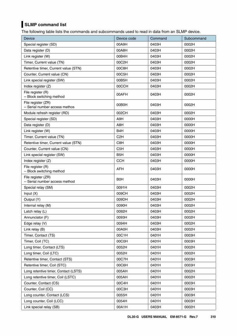
310DL30-G USERS MANUAL EM-8571-G Rev.7
SLMP command list
The following table lists the commands and subcommands used to read in data from an SLMP device.
Device Device code Command Subcommand
Special register (SD) 00A9H 0403H 0002H
Data register (D) 00A8H 0403H 0002H
Link register (W) 00B4H 0403H 0002H
Timer, Current value (TN) 00C2H 0403H 0002H
Retentive timer, Current value (STN) 00C8H 0403H 0002H
Counter, Current value (CN) 00C5H 0403H 0002H
Link special register (SW) 00B5H 0403H 0002H
Index register (Z) 00CCH 0403H 0002H
File register (R)-- Block switching method
00AFH 0403H 0002H
File register (ZR)-- Serial number access methos
00B0H 0403H 0002H
Module refresh register (RD) 002CH 0403H 0002H
Special register (SD) A9H 0403H 0000H
Data register (D) A8H 0403H 0000H
Link register (W) B4H 0403H 0000H
Timer, Current value (TN) C2H 0403H 0000H
Retentive timer, Current value (STN) C8H 0403H 0000H
Counter, Current value (CN) C5H 0403H 0000H
Link special register (SW) B5H 0403H 0000H
Index register (Z) CCH 0403H 0000H
File register (R)-- Block switching method
AFH 0403H 0000H
File register (ZR)-- Serial number access method
B0H 0403H 0000H
Special relay (SM) 0091H 0403H 0002H
Input (X) 009CH 0403H 0002H
Output (Y) 009DH 0403H 0002H
Internal relay (M) 0090H 0403H 0002H
Latch relay (L) 0092H 0403H 0002H
Annunciator (F) 0093H 0403H 0002H
Edge relay (V) 0094H 0403H 0002H
Link relay (B) 00A0H 0403H 0002H
Timer, Contact (TS) 00C1H 0401H 0003H
Timer, Coil (TC) 00C0H 0401H 0003H
Long timer, Contact (LTS) 0052H 0401H 0002H
Long timer, Coil (LTC) 0052H 0401H 0002H
Retentive timer, Contact (STS) 00C7H 0401H 0003H
Retentive timer, Coil (STC) 00C6H 0401H 0003H
Long retentive timer, Contact (LSTS) 005AH 0401H 0002H
Long retentive timer, Coil (LSTC) 005AH 0401H 0002H
Counter, Contact (CS) 00C4H 0401H 0003H
Counter, Coil (CC) 00C3H 0401H 0003H
Long counter, Contact (LCS) 0055H 0401H 0003H
Long counter, Coil (LCC) 0054H 0401H 0003H
Link special relay (SB) 00A1H 0403H 0002H
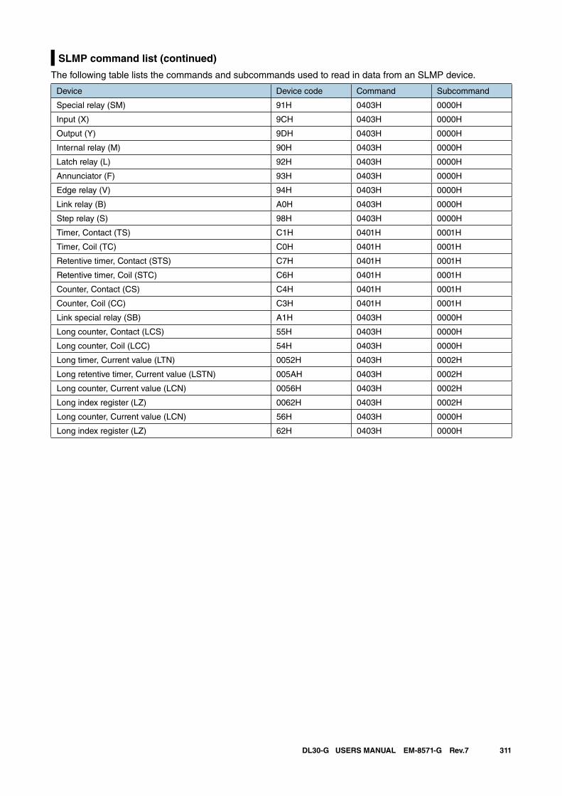
311DL30-G USERS MANUAL EM-8571-G Rev.7
SLMP command list (continued)
The following table lists the commands and subcommands used to read in data from an SLMP device.
Device Device code Command Subcommand
Special relay (SM) 91H 0403H 0000H
Input (X) 9CH 0403H 0000H
Output (Y) 9DH 0403H 0000H
Internal relay (M) 90H 0403H 0000H
Latch relay (L) 92H 0403H 0000H
Annunciator (F) 93H 0403H 0000H
Edge relay (V) 94H 0403H 0000H
Link relay (B) A0H 0403H 0000H
Step relay (S) 98H 0403H 0000H
Timer, Contact (TS) C1H 0401H 0001H
Timer, Coil (TC) C0H 0401H 0001H
Retentive timer, Contact (STS) C7H 0401H 0001H
Retentive timer, Coil (STC) C6H 0401H 0001H
Counter, Contact (CS) C4H 0401H 0001H
Counter, Coil (CC) C3H 0401H 0001H
Link special relay (SB) A1H 0403H 0000H
Long counter, Contact (LCS) 55H 0403H 0000H
Long counter, Coil (LCC) 54H 0403H 0000H
Long timer, Current value (LTN) 0052H 0403H 0002H
Long retentive timer, Current value (LSTN) 005AH 0403H 0002H
Long counter, Current value (LCN) 0056H 0403H 0002H
Long index register (LZ) 0062H 0403H 0002H
Long counter, Current value (LCN) 56H 0403H 0000H
Long index register (LZ) 62H 0403H 0000H
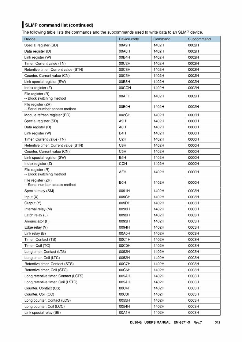
312DL30-G USERS MANUAL EM-8571-G Rev.7
SLMP command list (continued)
The following table lists the commands and the subcommands used to write data to an SLMP device.
Device Device code Command Subcommand
Special register (SD) 00A9H 1402H 0002H
Data register (D) 00A8H 1402H 0002H
Link register (W) 00B4H 1402H 0002H
Timer, Current value (TN) 00C2H 1402H 0002H
Retentive timer, Current value (STN) 00C8H 1402H 0002H
Counter, Current value (CN) 00C5H 1402H 0002H
Link special register (SW) 00B5H 1402H 0002H
Index register (Z) 00CCH 1402H 0002H
File register (R)-- Block switching method
00AFH 1402H 0002H
File register (ZR)-- Serial number access methos
00B0H 1402H 0002H
Module refresh register (RD) 002CH 1402H 0002H
Special register (SD) A9H 1402H 0000H
Data register (D) A8H 1402H 0000H
Link register (W) B4H 1402H 0000H
Timer, Current value (TN) C2H 1402H 0000H
Retentive timer, Current value (STN) C8H 1402H 0000H
Counter, Current value (CN) C5H 1402H 0000H
Link special register (SW) B5H 1402H 0000H
Index register (Z) CCH 1402H 0000H
File register (R)-- Block switching method
AFH 1402H 0000H
File register (ZR)-- Serial number access method
B0H 1402H 0000H
Special relay (SM) 0091H 1402H 0003H
Input (X) 009CH 1402H 0003H
Output (Y) 009DH 1402H 0003H
Internal relay (M) 0090H 1402H 0003H
Latch relay (L) 0092H 1402H 0003H
Annunciator (F) 0093H 1402H 0003H
Edge relay (V) 0094H 1402H 0003H
Link relay (B) 00A0H 1402H 0003H
Timer, Contact (TS) 00C1H 1402H 0003H
Timer, Coil (TC) 00C0H 1402H 0003H
Long timer, Contact (LTS) 0052H 1402H 0003H
Long timer, Coil (LTC) 0052H 1402H 0003H
Retentive timer, Contact (STS) 00C7H 1402H 0003H
Retentive timer, Coil (STC) 00C6H 1402H 0003H
Long retentive timer, Contact (LSTS) 005AH 1402H 0003H
Long retentive timer, Coil (LSTC) 005AH 1402H 0003H
Counter, Contact (CS) 00C4H 1402H 0003H
Counter, Coil (CC) 00C3H 1402H 0003H
Long counter, Contact (LCS) 0055H 1402H 0003H
Long counter, Coil (LCC) 0054H 1402H 0003H
Link special relay (SB) 00A1H 1402H 0003H
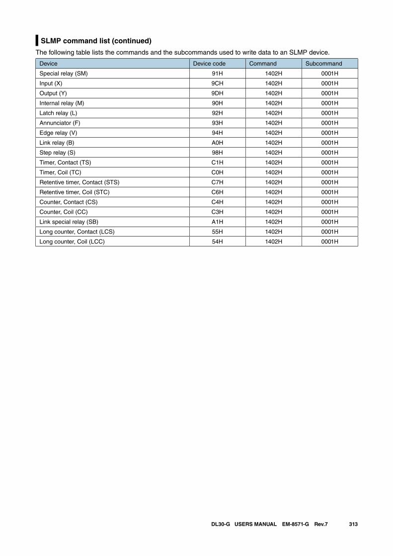
313DL30-G USERS MANUAL EM-8571-G Rev.7
SLMP command list (continued)
The following table lists the commands and the subcommands used to write data to an SLMP device.
Device Device code Command Subcommand
Special relay (SM) 91H 1402H 0001H
Input (X) 9CH 1402H 0001H
Output (Y) 9DH 1402H 0001H
Internal relay (M) 90H 1402H 0001H
Latch relay (L) 92H 1402H 0001H
Annunciator (F) 93H 1402H 0001H
Edge relay (V) 94H 1402H 0001H
Link relay (B) A0H 1402H 0001H
Step relay (S) 98H 1402H 0001H
Timer, Contact (TS) C1H 1402H 0001H
Timer, Coil (TC) C0H 1402H 0001H
Retentive timer, Contact (STS) C7H 1402H 0001H
Retentive timer, Coil (STC) C6H 1402H 0001H
Counter, Contact (CS) C4H 1402H 0001H
Counter, Coil (CC) C3H 1402H 0001H
Link special relay (SB) A1H 1402H 0001H
Long counter, Contact (LCS) 55H 1402H 0001H
Long counter, Coil (LCC) 54H 1402H 0001H
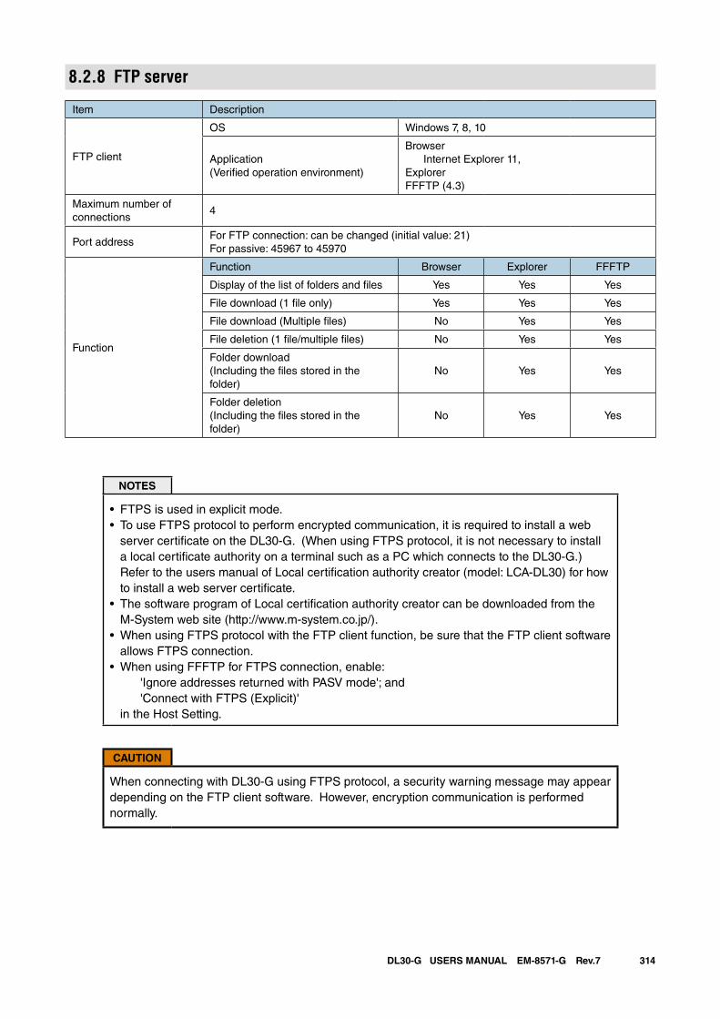
314DL30-G USERS MANUAL EM-8571-G Rev.7
8.2.8 FTP server
Item Description
FTP client
OS Windows 7, 8, 10
Application(Verified operation environment)
Browser Internet Explorer 11,ExplorerFFFTP (4.3)
Maximum number of connections
4
Port addressFor FTP connection: can be changed (initial value: 21)For passive: 45967 to 45970
Function
Function Browser Explorer FFFTP
Display of the list of folders and files Yes Yes Yes
File download (1 file only) Yes Yes Yes
File download (Multiple files) No Yes Yes
File deletion (1 file/multiple files) No Yes Yes
Folder download (Including the files stored in the folder)
No Yes Yes
Folder deletion (Including the files stored in the folder)
No Yes Yes
NOTES
• FTPS is used in explicit mode.• To use FTPS protocol to perform encrypted communication, it is required to install a web
server certificate on the DL30-G. (When using FTPS protocol, it is not necessary to install a local certificate authority on a terminal such as a PC which connects to the DL30-G.) Refer to the users manual of Local certification authority creator (model: LCA-DL30) for how to install a web server certificate.
• The software program of Local certification authority creator can be downloaded from the M-System web site (http://www.m-system.co.jp/).
• When using FTPS protocol with the FTP client function, be sure that the FTP client software allows FTPS connection.
• When using FFFTP for FTPS connection, enable: 'Ignore addresses returned with PASV mode'; and 'Connect with FTPS (Explicit)' in the Host Setting.
CAUTION
When connecting with DL30-G using FTPS protocol, a security warning message may appear depending on the FTP client software. However, encryption communication is performed normally.
315DL30-G USERS MANUAL EM-8571-G Rev.7
8.2.9 FTP clientFile transfer by FTP client function is executed as follows.• Logging data, event logs, and report forms are registered in a transmission queue.
They are sent to the FTP server in order of registering in the queue.• Maximum 16 sets of data are stored in the queue.
The data exceeded the max. limit is not registered and discarded.• When a transfer is failed, it is resent after 2 minutes.
Failed file transfers are retried up to 3 times. Data is discarded after the 3 times of unsuccessful retries.
• The transmission queue is reset when the DL30-G is switched to the maintenance mode.
8.2.10 Mail reportingEvent reports, regular reports and report forms are sent as follows.• Occurred event reports, regular reports and report forms are registered in a report queue.
Mail is sent in order of registering in the report queue.• A maximum of 128 reports are stored in the report queue.
The reports exceeding the limit is not registered and discarded.• When a mail reporting failure is detected, the mail is resent in 30 seconds after the detection.
Retransmission is repeated up to 3 times, and the report is discarded if a reporting failure is detected for the fourth time.
• The report queue is reset when the DL30-G is switched to the maintenance mode, or by cancelling the mail report function.
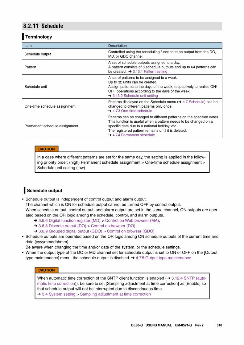
316DL30-G USERS MANUAL EM-8571-G Rev.7
8.2.11 Schedule
Terminology
Item Description
Schedule outputControlled using the scheduling function to be output from the DO, MD, or GDO channel.
PatternA set of schedule outputs assigned to a day. A pattern consists of 8 schedule outputs and up to 64 patterns can be created. ➔ 3.13.1 Pattern setting
Schedule unit
A set of patterns to be assigned to a week.Up to 32 units can be created.Assign patterns to the days of the week, respectively to realize ON/OFF operations according to the days of the week. ➔ 3.13.2 Schedule unit setting
One-time schedule assignmentPatterns displayed on the Schedule menu (➔ 4.7 Schedule) can be changed to different patterns only once. ➔ 4.7.3 One-time schedule
Permanent schedule assignment
Patterns can be changed to different patterns on the specified dates.This function is useful when a pattern needs to be changed on a specific date due to a national holiday, etc.The registered pattern remains until it is deleted. ➔ 4.7.4 Permanent schedule
CAUTION
In a case where different patterns are set for the same day, the setting is applied in the follow-ing priority order: (high) Permanent schedule assignment > One-time schedule assignment > Schedule unit setting (low).
Schedule output
• Schedule output is independent of control output and alarm output. The channel which is ON for schedule output cannot be turned OFF by control output. When schedule output, control output, and alarm output are set in the same channel, ON outputs are oper-ated based on the OR logic among the schedule, control, and alarm outputs. ➔ 3.6.6 Digital function register (MD) > Control on Web browser (MA), ➔ 3.6.8 Discrete output (DO) > Control on browser (DO), ➔ 3.6.9 Grouped digital output (GDO) > Control on browser (GDO)
• Schedule outputs are operated based on the OR logic among ON schedule outputs of the current time and date (yyyymmddhhmm). Be aware when changing the time and/or date of the system, or the schedule settings.
• When the output type of the DO or MD channel set for schedule output is set to ON or OFF on the [Output type maintenance] menu, the schedule output is disabled. ➔ 4.7.5 Output type maintenance
CAUTION
When automatic time correction of the SNTP client function is enabled (➔ 3.12.4 SNTP (auto-matic time correction)), be sure to set [Sampling adjustment at time correction] as [Enable] so that schedule output will not be interrupted due to discontinuous time. ➔ 3.4 System setting > Sampling adjustment at time correction
317DL30-G USERS MANUAL EM-8571-G Rev.7
Disabling schedule output
Schedule outputs can be forcibly disabled by any of the following methods.
• Specify the DI or MD channel on the [Maintenance SW setting] of DL30GCFG. Schedule outputs of the specified channel are disabled while the channel is ON. ➔ 3.13.3 Maintenance SW setting
• Set the function setting DIP switch to the maintenance mode. ➔ 5.3 Function setting DIP switch
CAUTION
• Schedule outputs are turned ON as soon as the 'Enabled' state is cancelled. • Schedule outputs are turned ON when the channel is turned ON by control outputs or alarm
outputs even if the schedule outputs are disabled by the above methods.
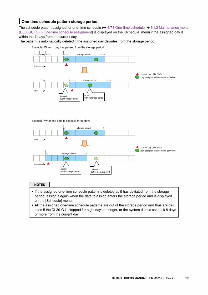
318DL30-G USERS MANUAL EM-8571-G Rev.7
One-time schedule pattern storage period
The schedule pattern assigned for one-time schedule (➔ 4.7.3 One-time schedule, ➔ 6.1.2 Maintenance menu (DL30GCFG) > One-time schedule assignment) is displayed on the [Schedule] menu if the assigned day is within the 7 days from the current day. The pattern is automatically deleted if the assigned day deviates from the storage period.
Example) When 1 day has passed from the storage period
1 day
1 day
storage period
storage period
time
time
deleted;out of storage perod
stored;within storage perod
: current day of DL30-G
: day assigned with one-time schedule
Example) When the date is set back three days
storage period
storage period
time
time
: current day of DL30-G
: day assigned with one-time schedule
stored;within storage perod
deleted;out of storage perod
NOTES
• If the assigned one-time schedule pattern is deleted as it has deviated from the storage period, assign it again when the date to assign enters the storage period and is displayed on the [Schedule] menu.
• All the assigned one-time schedule patterns are out of the storage period and thus are de-leted if the DL30-G is stopped for eight days or longer, or the system date is set back 8 days or more from the current day.
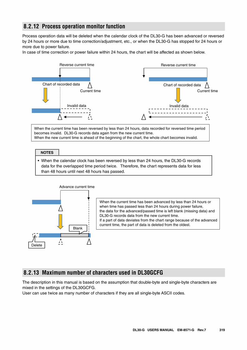
319DL30-G USERS MANUAL EM-8571-G Rev.7
8.2.12 Process operation monitor functionProcess operation data will be deleted when the calendar clock of the DL30-G has been advanced or reversed by 24 hours or more due to time correction/adjustment, etc., or when the DL30-G has stopped for 24 hours or more due to power failure.In case of time correction or power failure within 24 hours, the chart will be affected as shown below.
Reverse current time
Chart of recorded data Chart of recorded data
Current time Current time
Invalid data Invalid data
When the current time has been reversed by less than 24 hours, data recorded for reversed time period becomes invalid. DL30-G records data again from the new current time.When the new current time is ahead of the beginning of the chart, the whole chart becomes invalid.
Reverse current time
NOTES
• When the calendar clock has been reversed by less than 24 hours, the DL30-G records data for the overlapped time period twice. Therefore, the chart represents data for less than 48 hours until next 48 hours has passed.
Advance current time
Delete
Blank
When the current time has been advanced by less than 24 hours or when time has passed less than 24 hours during power failure, the data for the advanced/passed time is left blank (missing data) andDL30-G records data from the new current time.If a part of data deviates from the chart range because of the advancedcurrent time, the part of data is deleted from the oldest.
8.2.13 Maximum number of characters used in DL30GCFGThe description in this manual is based on the assumption that double-byte and single-byte characters are mixed in the settings of the DL30GCFG.User can use twice as many number of characters if they are all single-byte ASCII codes.
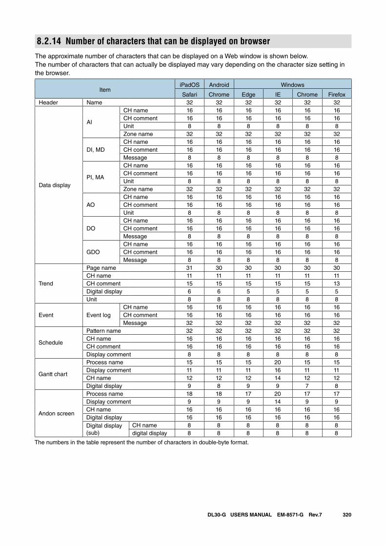
320DL30-G USERS MANUAL EM-8571-G Rev.7
8.2.14 Number of characters that can be displayed on browserThe approximate number of characters that can be displayed on a Web window is shown below. The number of characters that can actually be displayed may vary depending on the character size setting in the browser.
ItemiPadOS Android Windows
Safari Chrome Edge IE Chrome FirefoxHeader Name 32 32 32 32 32 32
Data display
AI
CH name 16 16 16 16 16 16CH comment 16 16 16 16 16 16Unit 8 8 8 8 8 8Zone name 32 32 32 32 32 32
DI, MDCH name 16 16 16 16 16 16CH comment 16 16 16 16 16 16Message 8 8 8 8 8 8
PI, MA
CH name 16 16 16 16 16 16CH comment 16 16 16 16 16 16Unit 8 8 8 8 8 8Zone name 32 32 32 32 32 32
AOCH name 16 16 16 16 16 16CH comment 16 16 16 16 16 16Unit 8 8 8 8 8 8
DOCH name 16 16 16 16 16 16CH comment 16 16 16 16 16 16Message 8 8 8 8 8 8
GDOCH name 16 16 16 16 16 16CH comment 16 16 16 16 16 16Message 8 8 8 8 8 8
Trend
Page name 31 30 30 30 30 30CH name 11 11 11 11 11 11CH comment 15 15 15 15 15 13Digital display 6 6 5 5 5 5Unit 8 8 8 8 8 8
Event Event logCH name 16 16 16 16 16 16CH comment 16 16 16 16 16 16Message 32 32 32 32 32 32
Schedule
Pattern name 32 32 32 32 32 32CH name 16 16 16 16 16 16CH comment 16 16 16 16 16 16Display comment 8 8 8 8 8 8
Gantt chart
Process name 15 15 15 20 15 15Display comment 11 11 11 16 11 11CH name 12 12 12 14 12 12Digital display 9 8 9 9 7 8
Andon screen
Process name 18 18 17 20 17 17Display comment 9 9 9 14 9 9CH name 16 16 16 16 16 16Digital display 16 16 16 16 16 16Digital display (sub)
CH name 8 8 8 8 8 8digital display 8 8 8 8 8 8
The numbers in the table represent the number of characters in double-byte format.
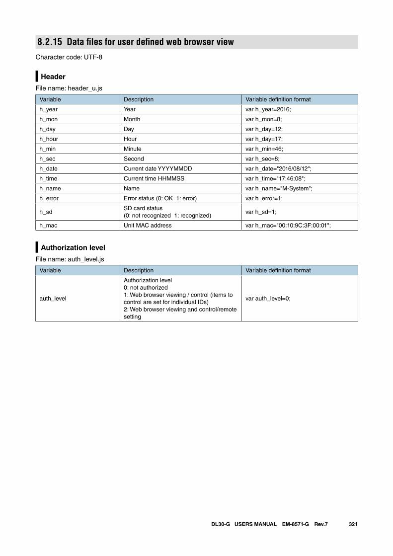
321DL30-G USERS MANUAL EM-8571-G Rev.7
8.2.15 Data files for user defined web browser viewCharacter code: UTF-8
Header
File name: header_u.js
Variable Description Variable definition format
h_year Year var h_year=2016;
h_mon Month var h_mon=8;
h_day Day var h_day=12;
h_hour Hour var h_day=17;
h_min Minute var h_min=46;
h_sec Second var h_sec=8;
h_date Current date YYYYMMDD var h_date="2016/08/12";
h_time Current time HHMMSS var h_time="17:46:08";
h_name Name var h_name="M-System";
h_error Error status (0: OK 1: error) var h_error=1;
h_sdSD card status(0: not recognized 1: recognized)
var h_sd=1;
h_mac Unit MAC address var h_mac="00:10:9C:3F:00:01";
Authorization level
File name: auth_level.js
Variable Description Variable definition format
auth_level
Authorization level0: not authorized1: Web browser viewing / control (items to control are set for individual IDs) 2: Web browser viewing and control/remote setting
var auth_level=0;
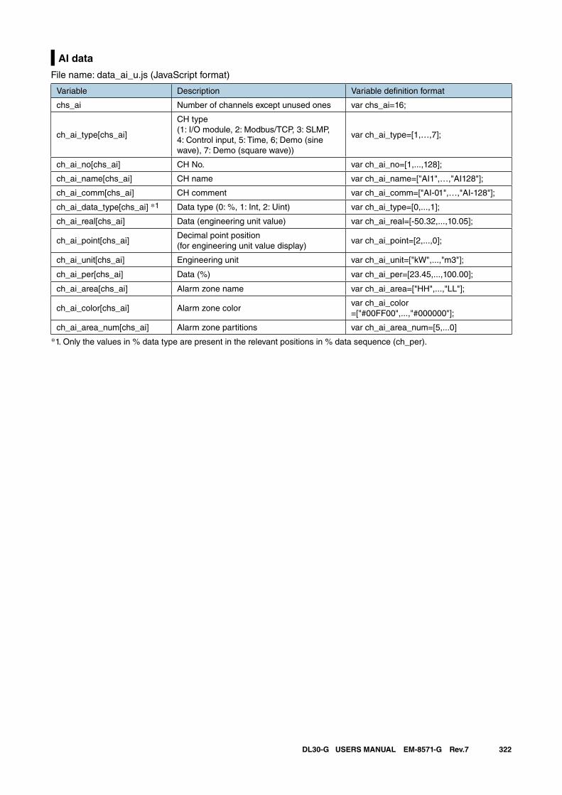
322DL30-G USERS MANUAL EM-8571-G Rev.7
AI data
File name: data_ai_u.js (JavaScript format)
Variable Description Variable definition format
chs_ai Number of channels except unused ones var chs_ai=16;
ch_ai_type[chs_ai]
CH type(1: I/O module, 2: Modbus/TCP, 3: SLMP, 4: Control input, 5: Time, 6; Demo (sine wave), 7: Demo (square wave))
var ch_ai_type=[1,…,7];
ch_ai_no[chs_ai] CH No. var ch_ai_no=[1,...,128];
ch_ai_name[chs_ai] CH name var ch_ai_name=["AI1",…,"AI128"];
ch_ai_comm[chs_ai] CH comment var ch_ai_comm=["AI-01",…,"AI-128"];
ch_ai_data_type[chs_ai] *1 Data type (0: %, 1: Int, 2: Uint) var ch_ai_type=[0,...,1];
ch_ai_real[chs_ai] Data (engineering unit value) var ch_ai_real=[-50.32,...,10.05];
ch_ai_point[chs_ai]Decimal point position(for engineering unit value display)
var ch_ai_point=[2,...,0];
ch_ai_unit[chs_ai] Engineering unit var ch_ai_unit=["kW",...,"m3"];
ch_ai_per[chs_ai] Data (%) var ch_ai_per=[23.45,...,100.00];
ch_ai_area[chs_ai] Alarm zone name var ch_ai_area=["HH",...,"LL"];
ch_ai_color[chs_ai] Alarm zone colorvar ch_ai_color=["#00FF00",...,"#000000"];
ch_ai_area_num[chs_ai] Alarm zone partitions var ch_ai_area_num=[5,...0]
*1. Only the values in % data type are present in the relevant positions in % data sequence (ch_per).
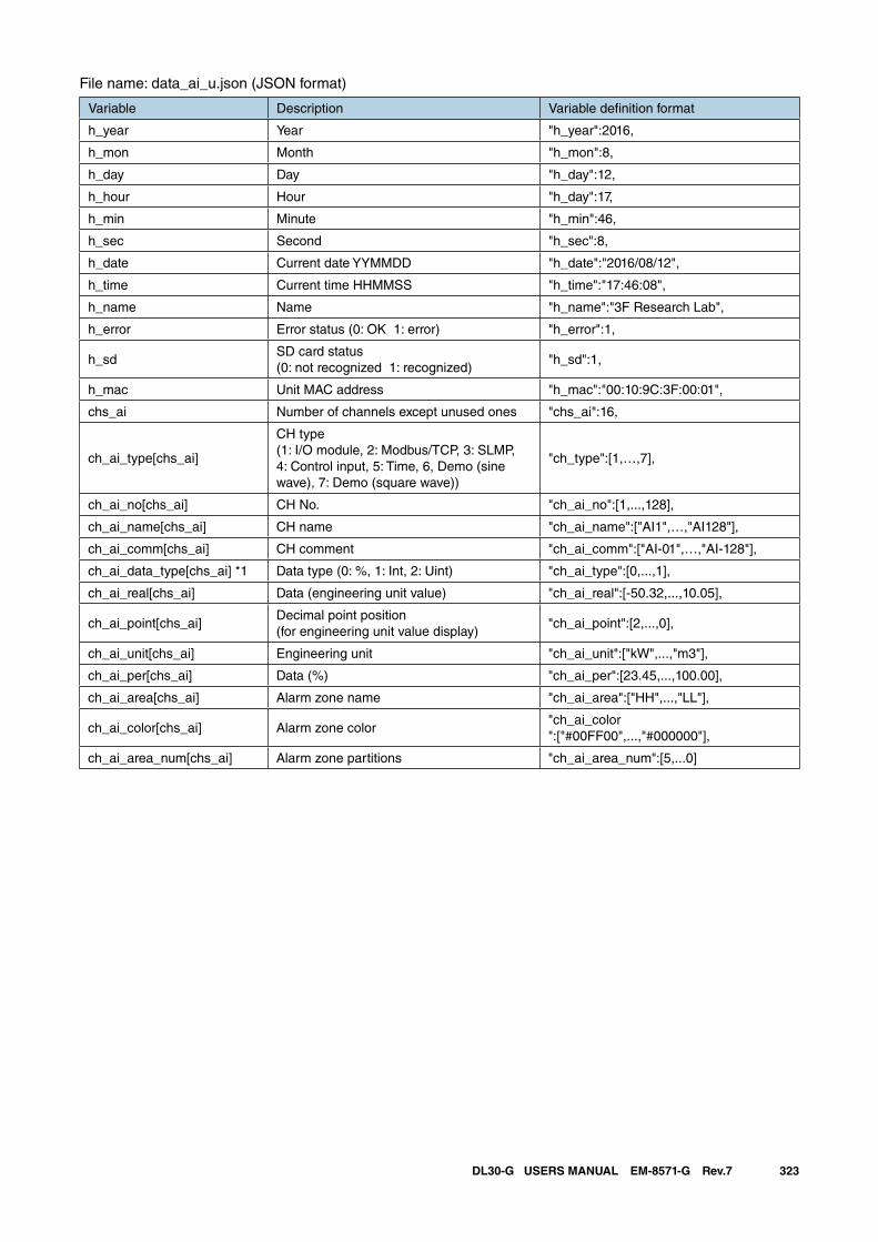
323DL30-G USERS MANUAL EM-8571-G Rev.7
File name: data_ai_u.json (JSON format)
Variable Description Variable definition format
h_year Year "h_year":2016,
h_mon Month "h_mon":8,
h_day Day "h_day":12,
h_hour Hour "h_day":17,
h_min Minute "h_min":46,
h_sec Second "h_sec":8,
h_date Current date YYMMDD "h_date":"2016/08/12",
h_time Current time HHMMSS "h_time":"17:46:08",
h_name Name "h_name":"3F Research Lab",
h_error Error status (0: OK 1: error) "h_error":1,
h_sdSD card status(0: not recognized 1: recognized)
"h_sd":1,
h_mac Unit MAC address "h_mac":"00:10:9C:3F:00:01",
chs_ai Number of channels except unused ones "chs_ai":16,
ch_ai_type[chs_ai]
CH type(1: I/O module, 2: Modbus/TCP, 3: SLMP, 4: Control input, 5: Time, 6, Demo (sine wave), 7: Demo (square wave))
"ch_type":[1,…,7],
ch_ai_no[chs_ai] CH No. "ch_ai_no":[1,...,128],
ch_ai_name[chs_ai] CH name "ch_ai_name":["AI1",…,"AI128"],
ch_ai_comm[chs_ai] CH comment "ch_ai_comm":["AI-01",…,"AI-128"],
ch_ai_data_type[chs_ai] *1 Data type (0: %, 1: Int, 2: Uint) "ch_ai_type":[0,...,1],
ch_ai_real[chs_ai] Data (engineering unit value) "ch_ai_real":[-50.32,...,10.05],
ch_ai_point[chs_ai]Decimal point position(for engineering unit value display)
"ch_ai_point":[2,...,0],
ch_ai_unit[chs_ai] Engineering unit "ch_ai_unit":["kW",...,"m3"],
ch_ai_per[chs_ai] Data (%) "ch_ai_per":[23.45,...,100.00],
ch_ai_area[chs_ai] Alarm zone name "ch_ai_area":["HH",...,"LL"],
ch_ai_color[chs_ai] Alarm zone color"ch_ai_color":["#00FF00",...,"#000000"],
ch_ai_area_num[chs_ai] Alarm zone partitions "ch_ai_area_num":[5,...0]
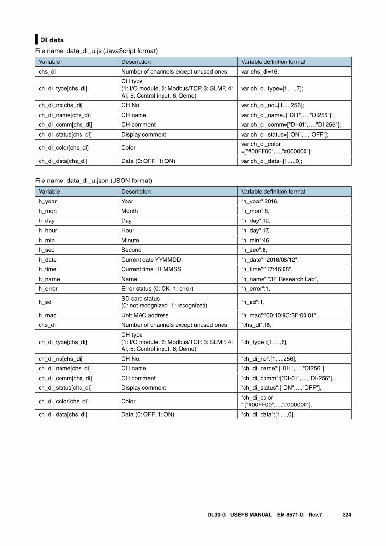
324DL30-G USERS MANUAL EM-8571-G Rev.7
DI dataFile name: data_di_u.js (JavaScript format)
Variable Description Variable definition format
chs_di Number of channels except unused ones var chs_di=16;
ch_di_type[chs_di]CH type(1: I/O module, 2: Modbus/TCP, 3: SLMP, 4: AI, 5: Control input, 6; Demo)
var ch_di_type=[1,…,7];
ch_di_no[chs_di] CH No. var ch_di_no=[1,...,256];
ch_di_name[chs_di] CH name var ch_di_name=["DI1",…,"DI256"];
ch_di_comm[chs_di] CH comment var ch_di_comm=["DI-01",…,"DI-256"];
ch_di_status[chs_di] Display comment var ch_di_status=["ON",...,"OFF"];
ch_di_color[chs_di] Colorvar ch_di_color=["#00FF00",...,"#000000"];
ch_di_data[chs_di] Data (0: OFF 1: ON) var ch_di_data=[1,...,0];
File name: data_di_u.json (JSON format)
Variable Description Variable definition format
h_year Year "h_year":2016,
h_mon Month "h_mon":8,
h_day Day "h_day":12,
h_hour Hour "h_day":17,
h_min Minute "h_min":46,
h_sec Second "h_sec":8,
h_date Current date YYMMDD "h_date":"2016/08/12",
h_time Current time HHMMSS "h_time":"17:46:08",
h_name Name "h_name":"3F Research Lab",
h_error Error status (0: OK 1: error) "h_error":1,
h_sdSD card status(0: not recognized 1: recognized)
"h_sd":1,
h_mac Unit MAC address "h_mac":"00:10:9C:3F:00:01",
chs_di Number of channels except unused ones "chs_di":16,
ch_di_type[chs_di]CH type(1: I/O module, 2: Modbus/TCP, 3: SLMP, 4: AI, 5: Control input, 6; Demo)
"ch_type":[1,…,6],
ch_di_no[chs_di] CH No. "ch_di_no":[1,...,256],
ch_di_name[chs_di] CH name "ch_di_name":["DI1",…,"DI256"],
ch_di_comm[chs_di] CH comment "ch_di_comm":["DI-01",…,"DI-256"],
ch_di_status[chs_di] Display comment "ch_di_status":["ON",...,"OFF"],
ch_di_color[chs_di] Color"ch_di_color":["#00FF00",...,"#000000"],
ch_di_data[chs_di] Data (0: OFF, 1: ON) "ch_di_data":[1,...,0],
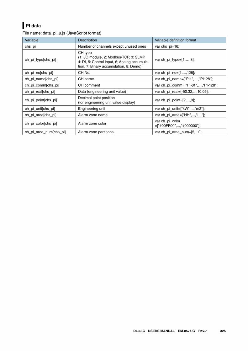
325DL30-G USERS MANUAL EM-8571-G Rev.7
PI data
File name: data_pi_u.js (JavaScript format)
Variable Description Variable definition format
chs_pi Number of channels except unused ones var chs_pi=16;
ch_pi_type[chs_pi]
CH type(1: I/O module, 2: Modbus/TCP, 3: SLMP, 4: DI, 5: Control input, 6; Analog accumula-tion, 7: Binary accumulation, 8: Demo)
var ch_pi_type=[1,…,8];
ch_pi_no[chs_pi] CH No. var ch_pi_no=[1,...,128];
ch_pi_name[chs_pi] CH name var ch_pi_name=["PI1",…,"PI128"];
ch_pi_comm[chs_pi] CH comment var ch_pi_comm=["PI-01",…,"PI-128"];
ch_pi_real[chs_pi] Data (engineering unit value) var ch_pi_real=[-50.32,...,10.05];
ch_pi_point[chs_pi]Decimal point position (for engineering unit value display)
var ch_pi_point=[2,...,0];
ch_pi_unit[chs_pi] Engineering unit var ch_pi_unit=["kW",...,"m3"];
ch_pi_area[chs_pi] Alarm zone name var ch_pi_area=["HH",...,"LL"];
ch_pi_color[chs_pi] Alarm zone colorvar ch_pi_color=["#00FF00",...,"#000000"];
ch_pi_area_num[chs_pi] Alarm zone partitions var ch_pi_area_num=[5,...0]
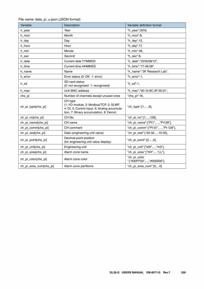
326DL30-G USERS MANUAL EM-8571-G Rev.7
File name: data_pi_u.json (JSON format)
Variable Description Variable definition format
h_year Year "h_year":2016,
h_mon Month "h_mon":8,
h_day Day "h_day":12,
h_hour Hour "h_day":17,
h_min Minute "h_min":46,
h_sec Second "h_sec":8,
h_date Current date YYMMDD "h_date":"2016/08/12",
h_time Current time HHMMSS "h_time":"17:46:08",
h_name Name "h_name":"3F Research Lab",
h_error Error status (0: OK 1: error) "h_error":1,
h_sdSD card status(0: not recognized 1: recognized)
"h_sd":1,
h_mac Unit MAC address "h_mac":"00:10:9C:3F:00:01",
chs_pi Number of channels except unused ones "chs_pi":16,
ch_pi_type[chs_pi]
CH type(1: I/O module, 2: Modbus/TCP, 3: SLMP, 4: DI, 5: Control input, 6; Analog accumula-tion, 7: Binary accumulation, 8: Demo)
"ch_type":[1,…,8],
ch_pi_no[chs_pi] CH No. "ch_pi_no":[1,...,128],
ch_pi_name[chs_pi] CH name "ch_pi_name":["PI1",…,"PI128"],
ch_pi_comm[chs_pi] CH comment "ch_pi_comm":["PI-01",…,"PI-128"],
ch_pi_real[chs_pi] Data (engineering unit value) "ch_pi_real":[-50.32,...,10.05],
ch_pi_point[chs_pi]Decimal point position(for engineering unit value display)
"ch_pi_point":[2,...,0],
ch_pi_unit[chs_pi] Engineering unit "ch_pi_unit":["kW",...,"m3"],
ch_pi_area[chs_pi] Alarm zone name "ch_pi_area":["HH",...,"LL"],
ch_pi_color[chs_pi] Alarm zone color"ch_pi_color":["#00FF00",...,"#000000"],
ch_pi_area_num[chs_pi] Alarm zone partitions "ch_pi_area_num":[5,...0]
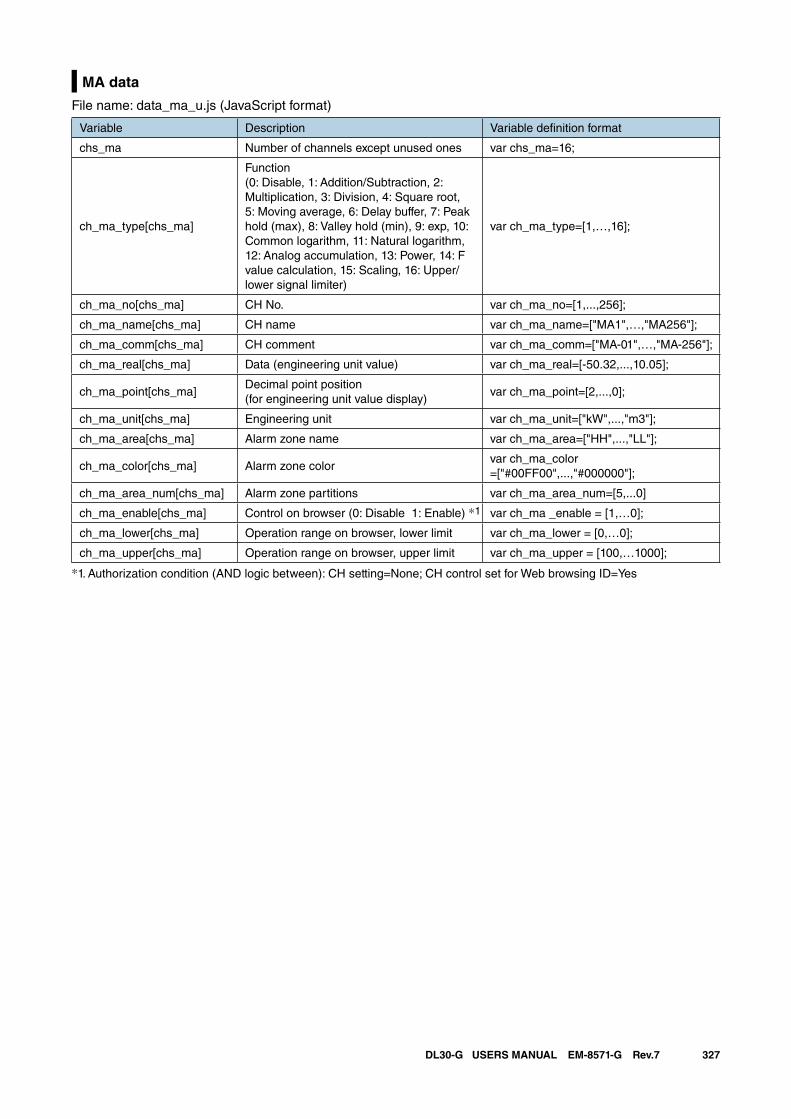
327DL30-G USERS MANUAL EM-8571-G Rev.7
MA data
File name: data_ma_u.js (JavaScript format)
Variable Description Variable definition format
chs_ma Number of channels except unused ones var chs_ma=16;
ch_ma_type[chs_ma]
Function(0: Disable, 1: Addition/Subtraction, 2: Multiplication, 3: Division, 4: Square root, 5: Moving average, 6: Delay buffer, 7: Peak hold (max), 8: Valley hold (min), 9: exp, 10: Common logarithm, 11: Natural logarithm, 12: Analog accumulation, 13: Power, 14: F value calculation, 15: Scaling, 16: Upper/lower signal limiter)
var ch_ma_type=[1,…,16];
ch_ma_no[chs_ma] CH No. var ch_ma_no=[1,...,256];
ch_ma_name[chs_ma] CH name var ch_ma_name=["MA1",…,"MA256"];
ch_ma_comm[chs_ma] CH comment var ch_ma_comm=["MA-01",…,"MA-256"];
ch_ma_real[chs_ma] Data (engineering unit value) var ch_ma_real=[-50.32,...,10.05];
ch_ma_point[chs_ma]Decimal point position (for engineering unit value display)
var ch_ma_point=[2,...,0];
ch_ma_unit[chs_ma] Engineering unit var ch_ma_unit=["kW",...,"m3"];
ch_ma_area[chs_ma] Alarm zone name var ch_ma_area=["HH",...,"LL"];
ch_ma_color[chs_ma] Alarm zone colorvar ch_ma_color=["#00FF00",...,"#000000"];
ch_ma_area_num[chs_ma] Alarm zone partitions var ch_ma_area_num=[5,...0]
ch_ma_enable[chs_ma] Control on browser (0: Disable 1: Enable) *1 var ch_ma _enable = [1,…0];
ch_ma_lower[chs_ma] Operation range on browser, lower limit var ch_ma_lower = [0,…0];
ch_ma_upper[chs_ma] Operation range on browser, upper limit var ch_ma_upper = [100,…1000];
*1. Authorization condition (AND logic between): CH setting=None; CH control set for Web browsing ID=Yes
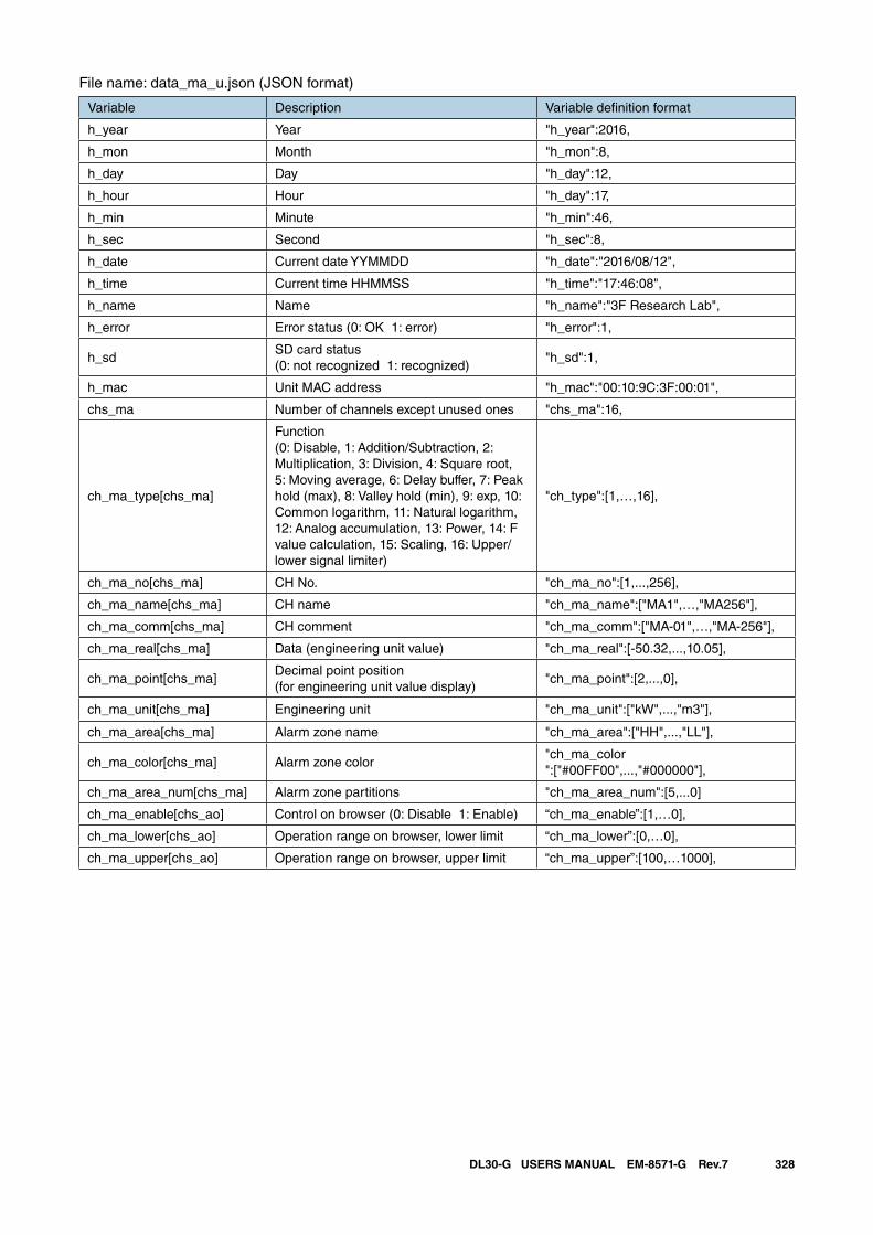
328DL30-G USERS MANUAL EM-8571-G Rev.7
File name: data_ma_u.json (JSON format)
Variable Description Variable definition format
h_year Year "h_year":2016,
h_mon Month "h_mon":8,
h_day Day "h_day":12,
h_hour Hour "h_day":17,
h_min Minute "h_min":46,
h_sec Second "h_sec":8,
h_date Current date YYMMDD "h_date":"2016/08/12",
h_time Current time HHMMSS "h_time":"17:46:08",
h_name Name "h_name":"3F Research Lab",
h_error Error status (0: OK 1: error) "h_error":1,
h_sdSD card status(0: not recognized 1: recognized)
"h_sd":1,
h_mac Unit MAC address "h_mac":"00:10:9C:3F:00:01",
chs_ma Number of channels except unused ones "chs_ma":16,
ch_ma_type[chs_ma]
Function(0: Disable, 1: Addition/Subtraction, 2: Multiplication, 3: Division, 4: Square root, 5: Moving average, 6: Delay buffer, 7: Peak hold (max), 8: Valley hold (min), 9: exp, 10: Common logarithm, 11: Natural logarithm, 12: Analog accumulation, 13: Power, 14: F value calculation, 15: Scaling, 16: Upper/lower signal limiter)
"ch_type":[1,…,16],
ch_ma_no[chs_ma] CH No. "ch_ma_no":[1,...,256],
ch_ma_name[chs_ma] CH name "ch_ma_name":["MA1",…,"MA256"],
ch_ma_comm[chs_ma] CH comment "ch_ma_comm":["MA-01",…,"MA-256"],
ch_ma_real[chs_ma] Data (engineering unit value) "ch_ma_real":[-50.32,...,10.05],
ch_ma_point[chs_ma]Decimal point position(for engineering unit value display)
"ch_ma_point":[2,...,0],
ch_ma_unit[chs_ma] Engineering unit "ch_ma_unit":["kW",...,"m3"],
ch_ma_area[chs_ma] Alarm zone name "ch_ma_area":["HH",...,"LL"],
ch_ma_color[chs_ma] Alarm zone color"ch_ma_color":["#00FF00",...,"#000000"],
ch_ma_area_num[chs_ma] Alarm zone partitions "ch_ma_area_num":[5,...0]
ch_ma_enable[chs_ao] Control on browser (0: Disable 1: Enable) “ch_ma_enable”:[1,…0],
ch_ma_lower[chs_ao] Operation range on browser, lower limit “ch_ma_lower”:[0,…0],
ch_ma_upper[chs_ao] Operation range on browser, upper limit “ch_ma_upper”:[100,…1000],
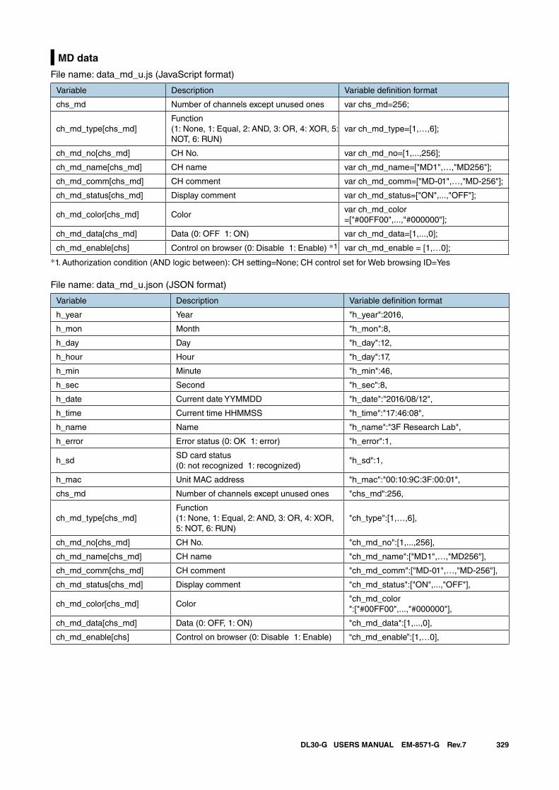
329DL30-G USERS MANUAL EM-8571-G Rev.7
MD data
File name: data_md_u.js (JavaScript format)
Variable Description Variable definition format
chs_md Number of channels except unused ones var chs_md=256;
ch_md_type[chs_md]Function (1: None, 1: Equal, 2: AND, 3: OR, 4: XOR, 5: NOT, 6: RUN)
var ch_md_type=[1,…,6];
ch_md_no[chs_md] CH No. var ch_md_no=[1,...,256];
ch_md_name[chs_md] CH name var ch_md_name=["MD1",…,"MD256"];
ch_md_comm[chs_md] CH comment var ch_md_comm=["MD-01",…,"MD-256"];
ch_md_status[chs_md] Display comment var ch_md_status=["ON",...,"OFF"];
ch_md_color[chs_md] Colorvar ch_md_color=["#00FF00",...,"#000000"];
ch_md_data[chs_md] Data (0: OFF 1: ON) var ch_md_data=[1,...,0];
ch_md_enable[chs] Control on browser (0: Disable 1: Enable) *1 var ch_md_enable = [1,…0];
*1. Authorization condition (AND logic between): CH setting=None; CH control set for Web browsing ID=Yes
File name: data_md_u.json (JSON format)
Variable Description Variable definition format
h_year Year "h_year":2016,
h_mon Month "h_mon":8,
h_day Day "h_day":12,
h_hour Hour "h_day":17,
h_min Minute "h_min":46,
h_sec Second "h_sec":8,
h_date Current date YYMMDD "h_date":"2016/08/12",
h_time Current time HHMMSS "h_time":"17:46:08",
h_name Name "h_name":"3F Research Lab",
h_error Error status (0: OK 1: error) "h_error":1,
h_sdSD card status(0: not recognized 1: recognized)
"h_sd":1,
h_mac Unit MAC address "h_mac":"00:10:9C:3F:00:01",
chs_md Number of channels except unused ones "chs_md":256,
ch_md_type[chs_md]Function (1: None, 1: Equal, 2: AND, 3: OR, 4: XOR, 5: NOT, 6: RUN)
"ch_type":[1,…,6],
ch_md_no[chs_md] CH No. "ch_md_no":[1,...,256],
ch_md_name[chs_md] CH name "ch_md_name":["MD1",…,"MD256"],
ch_md_comm[chs_md] CH comment "ch_md_comm":["MD-01",…,"MD-256"],
ch_md_status[chs_md] Display comment "ch_md_status":["ON",...,"OFF"],
ch_md_color[chs_md] Color"ch_md_color":["#00FF00",...,"#000000"],
ch_md_data[chs_md] Data (0: OFF, 1: ON) "ch_md_data":[1,...,0],
ch_md_enable[chs] Control on browser (0: Disable 1: Enable) “ch_md_enable”:[1,…0],
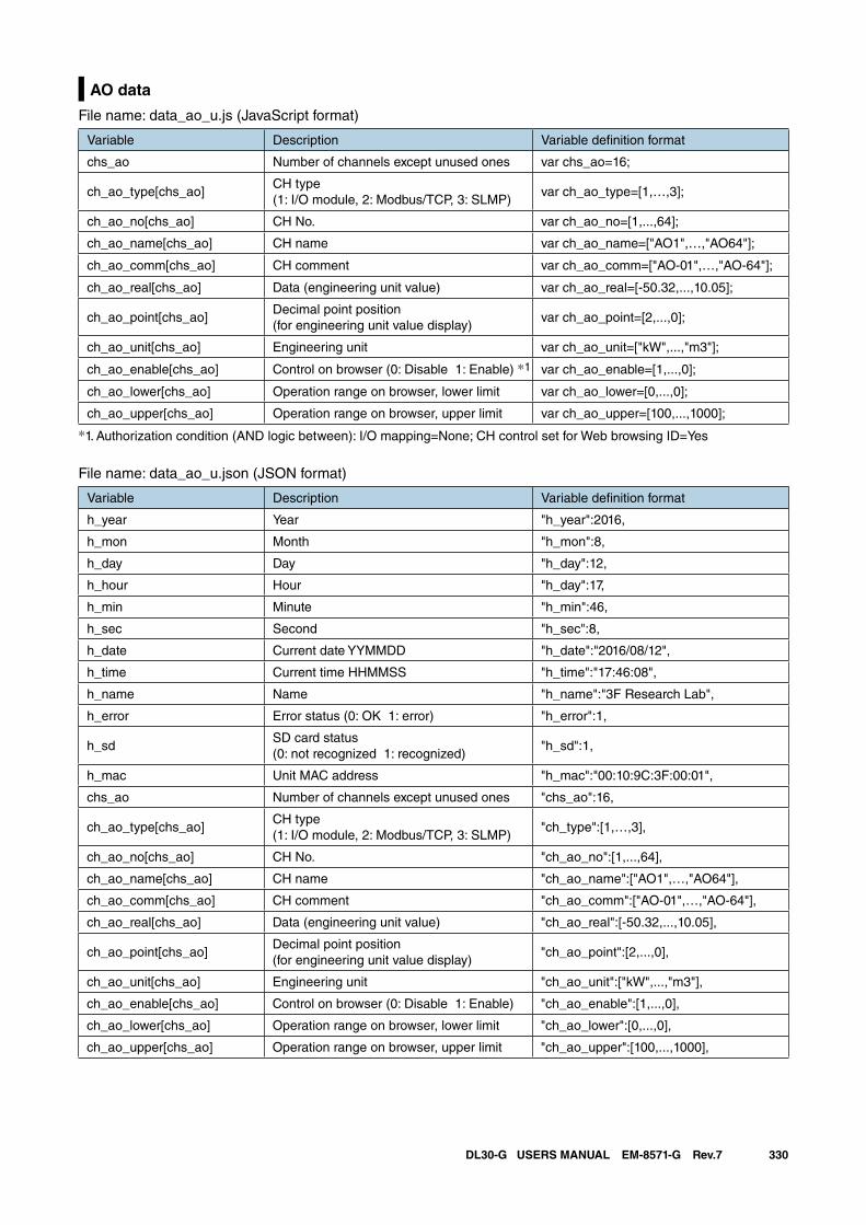
330DL30-G USERS MANUAL EM-8571-G Rev.7
AO data
File name: data_ao_u.js (JavaScript format)
Variable Description Variable definition format
chs_ao Number of channels except unused ones var chs_ao=16;
ch_ao_type[chs_ao]CH type(1: I/O module, 2: Modbus/TCP, 3: SLMP)
var ch_ao_type=[1,…,3];
ch_ao_no[chs_ao] CH No. var ch_ao_no=[1,...,64];
ch_ao_name[chs_ao] CH name var ch_ao_name=["AO1",…,"AO64"];
ch_ao_comm[chs_ao] CH comment var ch_ao_comm=["AO-01",…,"AO-64"];
ch_ao_real[chs_ao] Data (engineering unit value) var ch_ao_real=[-50.32,...,10.05];
ch_ao_point[chs_ao]Decimal point position(for engineering unit value display)
var ch_ao_point=[2,...,0];
ch_ao_unit[chs_ao] Engineering unit var ch_ao_unit=["kW",...,"m3"];
ch_ao_enable[chs_ao] Control on browser (0: Disable 1: Enable) *1 var ch_ao_enable=[1,...,0];
ch_ao_lower[chs_ao] Operation range on browser, lower limit var ch_ao_lower=[0,...,0];
ch_ao_upper[chs_ao] Operation range on browser, upper limit var ch_ao_upper=[100,...,1000];
*1. Authorization condition (AND logic between): I/O mapping=None; CH control set for Web browsing ID=Yes
File name: data_ao_u.json (JSON format)
Variable Description Variable definition format
h_year Year "h_year":2016,
h_mon Month "h_mon":8,
h_day Day "h_day":12,
h_hour Hour "h_day":17,
h_min Minute "h_min":46,
h_sec Second "h_sec":8,
h_date Current date YYMMDD "h_date":"2016/08/12",
h_time Current time HHMMSS "h_time":"17:46:08",
h_name Name "h_name":"3F Research Lab",
h_error Error status (0: OK 1: error) "h_error":1,
h_sdSD card status(0: not recognized 1: recognized)
"h_sd":1,
h_mac Unit MAC address "h_mac":"00:10:9C:3F:00:01",
chs_ao Number of channels except unused ones "chs_ao":16,
ch_ao_type[chs_ao]CH type(1: I/O module, 2: Modbus/TCP, 3: SLMP)
"ch_type":[1,…,3],
ch_ao_no[chs_ao] CH No. "ch_ao_no":[1,...,64],
ch_ao_name[chs_ao] CH name "ch_ao_name":["AO1",…,"AO64"],
ch_ao_comm[chs_ao] CH comment "ch_ao_comm":["AO-01",…,"AO-64"],
ch_ao_real[chs_ao] Data (engineering unit value) "ch_ao_real":[-50.32,...,10.05],
ch_ao_point[chs_ao]Decimal point position(for engineering unit value display)
"ch_ao_point":[2,...,0],
ch_ao_unit[chs_ao] Engineering unit "ch_ao_unit":["kW",...,"m3"],
ch_ao_enable[chs_ao] Control on browser (0: Disable 1: Enable) "ch_ao_enable":[1,...,0],
ch_ao_lower[chs_ao] Operation range on browser, lower limit "ch_ao_lower":[0,...,0],
ch_ao_upper[chs_ao] Operation range on browser, upper limit "ch_ao_upper":[100,...,1000],
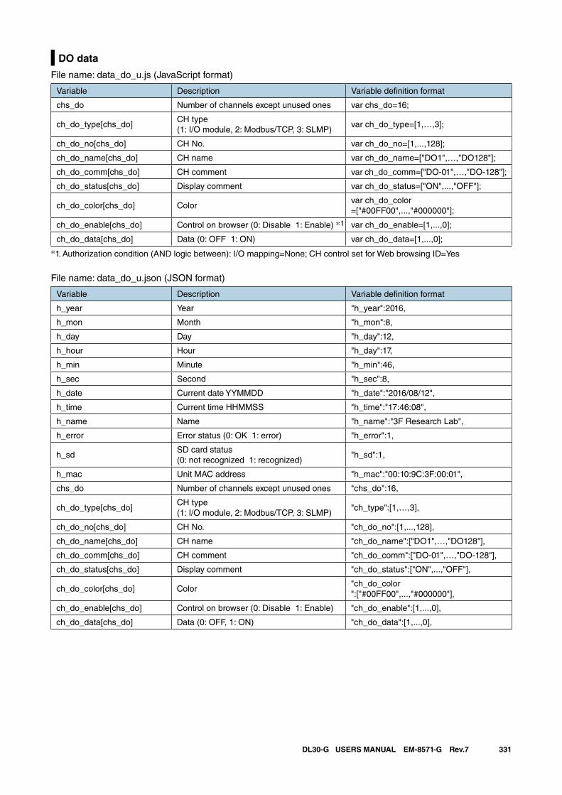
331DL30-G USERS MANUAL EM-8571-G Rev.7
DO data
File name: data_do_u.js (JavaScript format)
Variable Description Variable definition format
chs_do Number of channels except unused ones var chs_do=16;
ch_do_type[chs_do]CH type(1: I/O module, 2: Modbus/TCP, 3: SLMP)
var ch_do_type=[1,…,3];
ch_do_no[chs_do] CH No. var ch_do_no=[1,...,128];
ch_do_name[chs_do] CH name var ch_do_name=["DO1",…,"DO128"];
ch_do_comm[chs_do] CH comment var ch_do_comm=["DO-01",…,"DO-128"];
ch_do_status[chs_do] Display comment var ch_do_status=["ON",...,"OFF"];
ch_do_color[chs_do] Colorvar ch_do_color=["#00FF00",...,"#000000"];
ch_do_enable[chs_do] Control on browser (0: Disable 1: Enable) *1 var ch_do_enable=[1,...,0];
ch_do_data[chs_do] Data (0: OFF 1: ON) var ch_do_data=[1,...,0];
*1. Authorization condition (AND logic between): I/O mapping=None; CH control set for Web browsing ID=Yes
File name: data_do_u.json (JSON format)
Variable Description Variable definition format
h_year Year "h_year":2016,
h_mon Month "h_mon":8,
h_day Day "h_day":12,
h_hour Hour "h_day":17,
h_min Minute "h_min":46,
h_sec Second "h_sec":8,
h_date Current date YYMMDD "h_date":"2016/08/12",
h_time Current time HHMMSS "h_time":"17:46:08",
h_name Name "h_name":"3F Research Lab",
h_error Error status (0: OK 1: error) "h_error":1,
h_sdSD card status(0: not recognized 1: recognized)
"h_sd":1,
h_mac Unit MAC address "h_mac":"00:10:9C:3F:00:01",
chs_do Number of channels except unused ones "chs_do":16,
ch_do_type[chs_do]CH type(1: I/O module, 2: Modbus/TCP, 3: SLMP)
"ch_type":[1,…,3],
ch_do_no[chs_do] CH No. "ch_do_no":[1,...,128],
ch_do_name[chs_do] CH name "ch_do_name":["DO1",…,"DO128"],
ch_do_comm[chs_do] CH comment "ch_do_comm":["DO-01",…,"DO-128"],
ch_do_status[chs_do] Display comment "ch_do_status":["ON",...,"OFF"],
ch_do_color[chs_do] Color"ch_do_color":["#00FF00",...,"#000000"],
ch_do_enable[chs_do] Control on browser (0: Disable 1: Enable) "ch_do_enable":[1,...,0],
ch_do_data[chs_do] Data (0: OFF, 1: ON) "ch_do_data":[1,...,0],
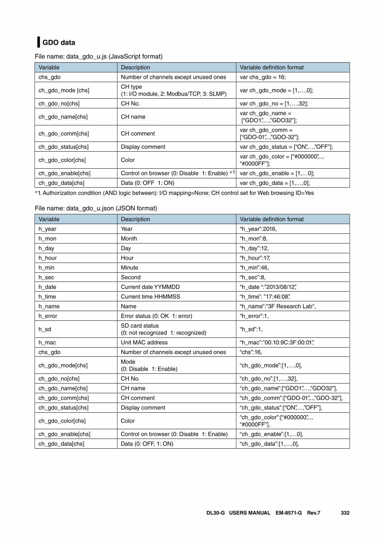
332DL30-G USERS MANUAL EM-8571-G Rev.7
GDO data
File name: data_gdo_u.js (JavaScript format)
Variable Description Variable definition format
chs_gdo Number of channels except unused ones var chs_gdo = 16;
ch_gdo_mode [chs]CH type(1: I/O module, 2: Modbus/TCP, 3: SLMP)
var ch_gdo_mode = [1,…,0];
ch_gdo_no[chs] CH No. var ch_gdo_no = [1,…,32];
ch_gdo_name[chs] CH namevar ch_gdo_name = [“GDO1”,…,”GDO32”];
ch_gdo_comm[chs] CH commentvar ch_gdo_comm = [“GDO-01”,..,”GDO-32”];
ch_gdo_status[chs] Display comment var ch_gdo_status = [“ON”,…,”OFF”];
ch_gdo_color[chs] Colorvar ch_gdo_color = [“#000000”,..,“#0000FF”];
ch_gdo_enable[chs] Control on browser (0: Disable 1: Enable) *1 var ch_gdo_enable = [1,…0];
ch_gdo_data[chs] Data (0: OFF 1: ON) var ch_gdo_data = [1,…,0];
*1. Authorization condition (AND logic between): I/O mapping=None; CH control set for Web browsing ID=Yes
File name: data_gdo_u.json (JSON format)
Variable Description Variable definition format
h_year Year “h_year”:2016,
h_mon Month “h_mon”:8,
h_day Day “h_day”:12,
h_hour Hour “h_hour”:17,
h_min Minute “h_min”:46,
h_sec Second “h_sec”:8,
h_date Current date YYMMDD “h_date “:”2013/08/12”,
h_time Current time HHMMSS “h_time”: ”17:46:08”,
h_name Name “h_name”:”3F Research Lab",
h_error Error status (0: OK 1: error) “h_error”:1,
h_sdSD card status(0: not recognized 1: recognized)
“h_sd”:1,
h_mac Unit MAC address “h_mac”:”00:10:9C:3F:00:01”,
chs_gdo Number of channels except unused ones “chs”:16,
ch_gdo_mode[chs]Mode(0: Disable 1: Enable)
“ch_gdo_mode”:[1,…,0],
ch_gdo_no[chs] CH No. “ch_gdo_no”:[1,…,32],
ch_gdo_name[chs] CH name “ch_gdo_name”:[“GDO1”,…,”GDO32”],
ch_gdo_comm[chs] CH comment “ch_gdo_comm”:[“GDO-01”,..,”GDO-32”],
ch_gdo_status[chs] Display comment “ch_gdo_status”:[“ON”,…,”OFF”],
ch_gdo_color[chs] Color“ch_gdo_color”:[“#000000”,..,“#0000FF”],
ch_gdo_enable[chs] Control on browser (0: Disable 1: Enable) “ch_gdo_enable”:[1,…0],
ch_gdo_data[chs] Data (0: OFF, 1: ON) “ch_gdo_data”:[1,…,0],
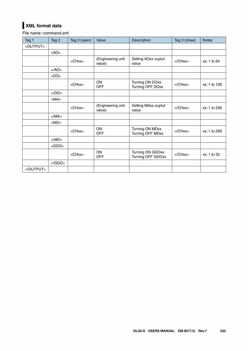
333DL30-G USERS MANUAL EM-8571-G Rev.7
XML format data
File name: command.xml
Tag 1 Tag 2 Tag 3 (open) Value Description Tag 3 (close) Notes
<OUTPUT>
<AO>
<CHxx>(Engineering unit value)
Setting AOxx ouptut value
</CHxx> xx: 1 to 64
</AO>
<DO>
<CHxx>ONOFF
Turning ON DOxxTurning OFF DOxx
</CHxx> xx: 1 to 128
</DO>
<MA>
<CHxx>(Engineering unit value)
Setting MAxx ouptut value
</CHxx> xx: 1 to 256
</MA>
<MD>
<CHxx>ONOFF
Turning ON MDxxTurning OFF MDxx
</CHxx> xx: 1 to 256
</MD>
<GDO>
<CHxx>ONOFF
Turning ON GDOxxTurning OFF GDOxx
</CHxx> xx: 1 to 32
</GDO>
</OUTPUT>
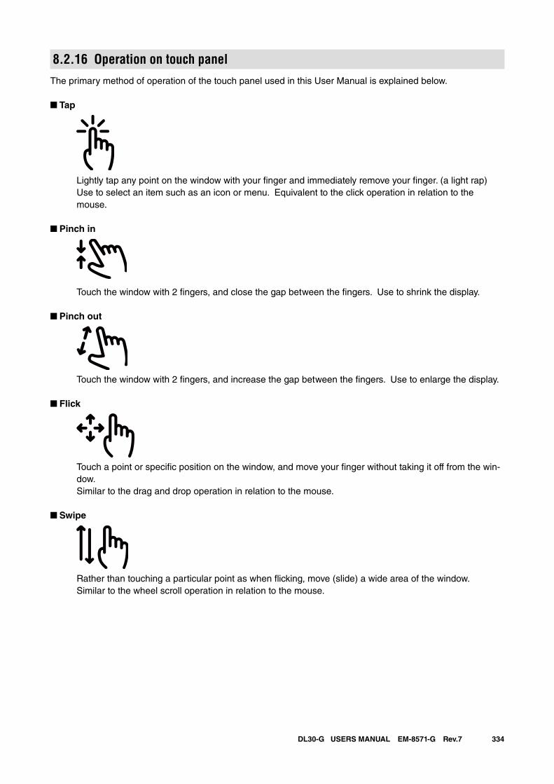
334DL30-G USERS MANUAL EM-8571-G Rev.7
8.2.16 Operation on touch panelThe primary method of operation of the touch panel used in this User Manual is explained below.
■ Tap
Lightly tap any point on the window with your finger and immediately remove your finger. (a light rap) Use to select an item such as an icon or menu. Equivalent to the click operation in relation to the
mouse.
■ Pinch in
Touch the window with 2 fingers, and close the gap between the fingers. Use to shrink the display.
■ Pinch out
Touch the window with 2 fingers, and increase the gap between the fingers. Use to enlarge the display.
■ Flick
Touch a point or specific position on the window, and move your finger without taking it off from the win-dow.
Similar to the drag and drop operation in relation to the mouse.
■ Swipe
Rather than touching a particular point as when flicking, move (slide) a wide area of the window. Similar to the wheel scroll operation in relation to the mouse.
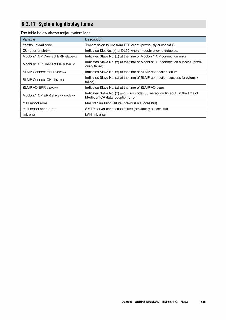
335DL30-G USERS MANUAL EM-8571-G Rev.7
8.2.17 System log display itemsThe table below shows major system logs.
Variable Description
ftpc:ftp upload error Transmission failure from FTP client (previously successful)
CUnet error slot=x Indicates Slot No. (x) of DL30 where module error is detected.
Modbus/TCP Connect ERR slave=x Indicates Slave No. (x) at the time of Modbus/TCP connection error
Modbus/TCP Connect OK slave=xIndicates Slave No. (x) at the time of Modbus/TCP connection success (previ-ously failed)
SLMP Connect ERR slave=x Indicates Slave No. (x) at the time of SLMP connection failure
SLMP Connect OK slave=xIndicates Slave No. (x) at the time of SLMP connection success (previously failed)
SLMP AO ERR slave=x Indicates Slave No. (x) at the time of SLMP AO scan
Modbus/TCP ERR slave=x code=xIndicates Salve No. (x) and Error code (50: reception timeout) at the time of Modbus/TCP data reception error
mail report error Mail transmission failure (previously successful)
mail report open error SMTP server connection failure (previously successful)
link error LAN link error
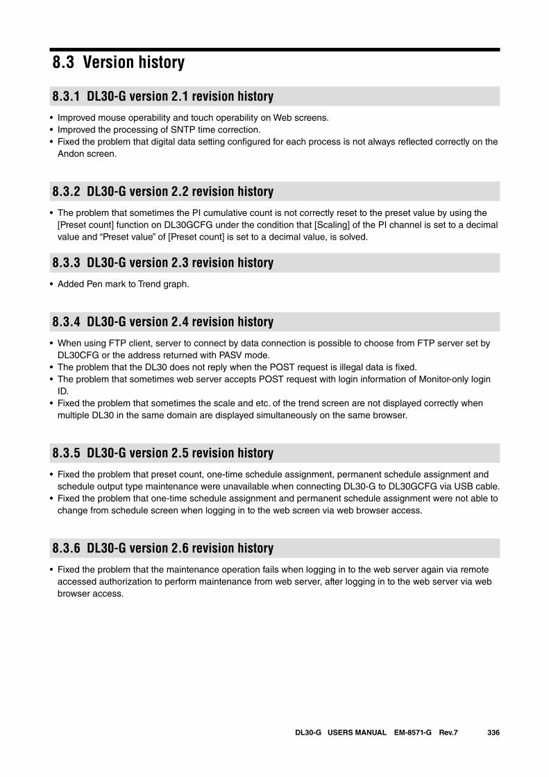
336DL30-G USERS MANUAL EM-8571-G Rev.7
8.3 Version history
8.3.1 DL30-G version 2.1 revision history• Improved mouse operability and touch operability on Web screens.• Improved the processing of SNTP time correction.• Fixed the problem that digital data setting configured for each process is not always reflected correctly on the
Andon screen.
8.3.2 DL30-G version 2.2 revision history• The problem that sometimes the PI cumulative count is not correctly reset to the preset value by using the
[Preset count] function on DL30GCFG under the condition that [Scaling] of the PI channel is set to a decimal value and “Preset value” of [Preset count] is set to a decimal value, is solved.
8.3.3 DL30-G version 2.3 revision history• Added Pen mark to Trend graph.
8.3.4 DL30-G version 2.4 revision history• When using FTP client, server to connect by data connection is possible to choose from FTP server set by
DL30CFG or the address returned with PASV mode.• The problem that the DL30 does not reply when the POST request is illegal data is fixed.• The problem that sometimes web server accepts POST request with login information of Monitor-only login
ID.• Fixed the problem that sometimes the scale and etc. of the trend screen are not displayed correctly when
multiple DL30 in the same domain are displayed simultaneously on the same browser.
8.3.5 DL30-G version 2.5 revision history• Fixed the problem that preset count, one-time schedule assignment, permanent schedule assignment and
schedule output type maintenance were unavailable when connecting DL30-G to DL30GCFG via USB cable.• Fixed the problem that one-time schedule assignment and permanent schedule assignment were not able to
change from schedule screen when logging in to the web screen via web browser access.
8.3.6 DL30-G version 2.6 revision history• Fixed the problem that the maintenance operation fails when logging in to the web server again via remote
accessed authorization to perform maintenance from web server, after logging in to the web server via web browser access.
337DL30-G USERS MANUAL EM-8571-G Rev.7
8.4 LicensesexPat is built into DL30-G and DL30GCFG.
Copyright (c) 1998, 1999, 2000 Thai Open Source Software Center Ltd and Clark CooperCopyright (c) 2001, 2002, 2003, 2004, 2005, 2006 Expat maintainers.
Permission is hereby granted, free of charge, to any person obtaining a copy of this software and associated documen-tation files (the "Software"), to deal in the Software without restriction, including without limitation the rights to use, copy, modify, merge, publish, distribute, sublicense, and/or sell copies of the Software, and to permit persons to whom the Software is furnished to do so, subject to the following conditions:
The above copyright notice and this permission notice shall be included in all copies or substantial portions of the Soft-ware.
THE SOFTWARE IS PROVIDED "AS IS", WITHOUT WARRANTY OF ANY KIND, EXPRESS OR IMPLIED, INCLUD-ING BUT NOT LIMITED TO THE WARRANTIES OF MERCHANTABILITY, FITNESS FOR A PARTICULAR PURPOSE AND NONINFRINGEMENT.IN NO EVENT SHALL THE AUTHORS OR COPYRIGHT HOLDERS BE LIABLE FOR ANY CLAIM, DAMAGES OR OTHER LIABILITY, WHETHER IN AN ACTION OF CONTRACT, TORT OR OTHERWISE, ARISING FROM, OUT OF OR IN CONNECTION WITH THE SOFTWARE OR THE USE OR OTHER DEALINGS IN THE SOFTWARE.
DL30-G and DL30GCFG contain software to which the following Camellia licence is applicable.
camellia.c ver 1.2.0
Copyright (c) 2006,2007NTT (Nippon Telegraph and Telephone Corporation). All rights reserved.
Redistribution and use in source and binary forms, with or without modification, are permitted provided that the following conditions are met:
1.
2.
Redistributions of source code must retain the above copyright notice, this list of conditions and the following dis-claimer as the first lines of this file unmodified.Redistributions in binary form must reproduce the above copyright notice, this list of conditions and the following disclaimer in the documentation and/or other materials provided with the distribution.
THIS SOFTWARE IS PROVIDED BY NTT ''AS IS'' AND ANY EXPRESS OR IMPLIED WARRANTIES, INCLUDING, BUT NOT LIMITED TO, THE IMPLIED WARRANTIES OF MERCHANTABILITY AND FITNESS FOR A PARTICULAR PURPOSE ARE DISCLAIMED.IN NO EVENT SHALL NTT BE LIABLE FOR ANY DIRECT, INDIRECT, INCIDENTAL, SPECIAL, EXEMPLARY, OR CONSEQUENTIAL DAMAGES (INCLUDING, BUT NOT LIMITED TO, PROCUREMENT OF SUBSTITUTE GOODS OR SERVICES; LOSS OF USE, DATA, OR PROFITS; OR BUSINESS INTERRUPTION) HOWEVER CAUSED AND ON ANY THEORY OF LIABILITY, WHETHER IN CONTRACT, STRICT LIABILITY, OR TORT (INCLUDING NEGLIGENCE OR OTHERWISE) ARISING IN ANY WAY OUT OF THE USE OF THIS SOFTWARE, EVEN IF ADVISED OF THE POS-SIBILITY OF SUCH DAMAGE.
DL30-G incorporates MD5.
Copyright (c) 1991-2, RSA Data Security, Inc. Created 1991. All rights reserved.
License to copy and use this software is granted provided that it is identified as the "RSA Data Security, Inc. MD5 Message-Digest Algorithm" in all material mentioning or referencing this software or this function.
License is also granted to make and use derivative works provided that such works are identified as "derived from the RSA Data Security, Inc. MD5 Message-Digest Algorithm" in all material mentioning or referencing the derived work.
RSA Data Security, Inc. makes no representations concerning either the merchantability of this software or the suitabil-ity of this software for any particular purpose. It is provided "as is" without express or implied warranty of any kind.
These notices must be retained in any copies of any part of this documentation and/or software.