Embed Size (px)
Citation preview
XtraDrive (XD-) SERIESAC Servo Driver
USER’S ManUal
Manual No. 8U0108-E1-01
XtraDrive (XD
-) SeriesU
SER’S M
an
Ua
l
ii
Copyright 2003 by YET, Yaskawa Eshed Technology Ltd.
XtraDrive User Manual
Catalog No.8U0108, Revision C
November 2003
All rights reserved. No part of this publication may be stored in a retrieval
system, or reproduced in any way, including but not limited to photocopy,
photography, magnetic or other recording, without the prior agreement and
written permission of the publisher. Program listings may be entered, stored and
executed in a computer system, but not reproduced for publication.
This guide is designed to provide information about the XtraDrive hardware.
Every effort has been made to make this guide complete and as accurate as
possible. However, no warranty of suitability, purpose or fitness is made or
implied. YET Ltd. is not liable or responsible to any person or entity for loss or
damage in connection with or stemming from the use of XtraDrive and/or the
information contained in this publication
YET Ltd. bears no responsibility for errors, which may appear in this
publication and retains the right to make changes to the products and the guide
without prior notice.
YET Ltd. ISRAEL YET US Inc.
13 Hamelacha St., 531 King St.,
Afeq Industrial Estate Unit 1
Rosh Ha’ayin 48091 Littleton, MA 01460
ISRAEL USA
Tel: +972-3-9004114 Tel: +1-866-YET-8080
Fax: +972-3-9030412 Fax: +1-978-952-6821
[email protected] [email protected]
web site: www.yetmotion.com
iii
WARNING
YET manufactures component parts that can be used in a wide variety of industrial applications.
The selection and application of YET products remain the responsibility of the equipment designer
or end user. YET accepts no responsibility for the way its products are incorporated into the final
system design.
Under no circumstances should any YET product be incorporated into any product or design as the
exclusive or sole safety control. Without exception, all controls should be designed to detect faults
dynamically and fail safely under all circumstances. All products designed to incorporate a
component part manufactured by YET must be supplied to the end user with appropriate warnings
and instructions as to that part’s safe use and operation. Any warnings provided by YET must be
promptly provided to the end user.
YET offers an express warranty only as to the quality of its products in conforming to standards and
specifications published in YET’s manual. NO OTHER WARRANTY, EXPRESS OR IMPLIED,
IS OFFERED. YET assumes no liability for any personal injury, property damage, losses, or claims
arising from misapplication of its products.

iv
This page intentionally left blank.
v
Safety Information
The following defines the symbols used in this manual to indicate varying
degrees of safety precautions and to identify the corresponding level of hazard
inherent to each. Failure to follow precautions provided in this manual can
result in serious, possibly even fatal, injury, and/or damage to the persons,
products, or related equipment and systems.
WARNING
• WARNING: Indicates a potentially hazardous situation, which, if not heeded, could result in
death or serious injury.
CAUTION
• CAUTION: Indicates a potentially hazardous situation, which, if not avoided, may result in
minor or moderate injury.

vi
This page intentionally left blank.
XtraDrive User Manual Table of Contents/Preface
vii
Table of Contents
1. Checking Product and Part Names .................................................................1-1
1.1. Checking the XtraDrive Series Products on Delivery................................... 1-2
1.1.1. Servo Amplifiers....................................................................................... 1-2
1.2. Product Part Names........................................................................................ 1-3
1.2.1. Servo Amplifiers....................................................................................... 1-3
1.2.2. Model Numbers ........................................................................................ 1-4
2. Installation. ............................................................................…………………2-1
2.1. Servo Amplifiers ............................................................................................ 2-2
2.1.1. Storage Conditions.................................................................................... 2-2
2.1.2. Installation Site ......................................................................................... 2-2
2.1.3. Orientation................................................................................................. 2-3
2.1.4. Installation................................................................................................. 2-3
3. Wiring…… ........................................................................................................3-1
3.1. Connecting to Peripheral Devices.................................................................. 3-2
3.1.1. Single-Phase 200V Main Circuit Specifications ..................................... 3-3
3.1.2. Single-Phase 0.8kW 200V Main Circuit Specifications ......................... 3-4
3.1.3. Three-phase 200V Main Circuit Specifications....................................... 3-5
3.1.4. Three-Phase 400V Main Circuit Specifications ...................................... 3-6
3.2. XtraDrive Internal Block Diagrams............................................................... 3-7
3.2.1. Single-phase 30W to 800W, 200V Models ............................................. 3-7
3.2.2. Three-phase 1kW to 3kW, 200V Models ................................................ 3-8
3.2.3. Three-phase 0.5kW to 3.0kW, 400V Models .......................................... 3-9
3.3. Main Circuit Wiring ..................................................................................... 3-10
3.3.1. Names and Descriptions of Main Circuit Terminal............................... 3-11
3.3.2. Typical Main Circuit Wiring Example .................................................. 3-12
3.3.3. Servo Amplifier Power Losses............................................................... 3-13
3.3.4. Wiring Main Circuit Terminal Blocks ................................................... 3-14
3.4. I/O Signals .................................................................................................... 3-15
3.4.1. Example of Typical I/O Signal Connections ......................................... 3-15
3.4.2. List of CN1 Terminals............................................................................ 3-16
3.4.3. I/O Signal Names and Functions............................................................ 3-17
3.4.4. Interface Circuits..................................................................................... 3-19
3.5. Wiring Encoders (for SGMGH and SGMSH Motors Only) ...................... 3-23
3.5.1. Encoder Connections.............................................................................. 3-23
3.5.2. CN2 Encoder Connector Terminal Layout and Types.......................... 3-25
3.5.3. Encoder Cables Interconnections ........................................................... 3-26
3.6. Examples of Standard Connections ............................................................. 3-28
4. Trial Operation .................................................................................................4-1
4.1. Two-Step Trial Operation .............................................................................. 4-2
4.1.1. Step 1: Trial Operation for Servomotor without Load ............................ 4-3
4.1.2. Step 2: Trial Operation with Servomotor Connected to Machine........... 4-9
4.2. Additional Setup Procedures in Trial Operation ......................................... 4-10
4.2.1. Servomotors with Brakes ....................................................................... 4-10
4.2.2. Position Control by Host Controller....................................................... 4-11
4.3. Minimum Parameters and Input Signals ..................................................... 4-12
4.3.1. Parameters............................................................................................... 4-12
4.3.2. Input Signals ........................................................................................... 4-12
XtraDrive User Manual Table of Contents/Preface
viii
5. Parameter Settings and Functions ..................................................................5-1
5.1. Settings According to Device Characteristics ............................................... 5-4
5.1.1. Switching Servomotor Rotation Direction............................................... 5-4
5.1.2. Setting the Overtravel Limit Function ..................................................... 5-5
5.1.3. Limiting Torque........................................................................................ 5-8
5.2. Settings According to Host Controller......................................................... 5-12
5.2.1. Speed Reference ..................................................................................... 5-12
5.2.2. Position Reference .................................................................................. 5-14
5.2.3. Using the Encoder Signal Output........................................................... 5-20
5.2.4. Sequence I/O Signals.............................................................................. 5-23
5.2.5. Using the Electronic Gear Function....................................................... 5-25
5.2.6. Contact Input Speed Control .................................................................. 5-29
5.2.7. Using Torque Control............................................................................. 5-34
5.2.8. Torque Feed-Forward Function ............................................................. 5-40
5.2.9. Torque Limiting by Analog Voltage Reference .................................... 5-42
5.2.10. Reference Pulse Inhibit Function (/INHIBIT) ....................................... 5-44
5.3. Setting Up the Servo Amplifier ................................................................... 5-45
5.3.1. Parameters............................................................................................... 5-45
5.3.2. JOG Speed .............................................................................................. 5-46
5.3.3. Input Circuit Signal Allocation .............................................................. 5-46
5.3.4. Output Circuit Signal Allocation............................................................ 5-50
5.3.5. Control Mode Selection.......................................................................... 5-52
5.4. Setting Stop Functions ................................................................................. 5-54
5.4.1. Adjusting Offset...................................................................................... 5-54
5.4.2. Servo OFF Stop Mode Selection............................................................ 5-55
5.4.3. Using the Zero Clamp Function............................................................. 5-56
5.4.4. Using the Holding Brake ........................................................................ 5-58
5.5. Forming a Protective Sequence ................................................................... 5-61
5.5.1. Using Servo Alarm and Alarm Code Outputs ....................................... 5-61
5.5.2. Using the Servo ON Input Signal (/S-ON) ............................................ 5-63
5.5.3. Using the Positioning Completed Output Signal (/COIN).................... 5-64
5.5.4. Speed Coincidence Output (/V-CMP) ................................................... 5-65
5.5.5. Using the Running Output Signal (/TGON).......................................... 5-67
5.5.6. Using the Servo Ready Output Signal (/S-RDY) .................................. 5-68
5.5.7. Using the Warning Output Signal (/WARN)......................................... 5-69
5.5.8. Handling Power Loss.............................................................................. 5-71
5.6. Selecting a Regenerative Resistor................................................................ 5-72
5.6.1. External Regenerative Resistor .............................................................. 5-73
5.6.2. Calculating the Regenerative Power Capacity....................................... 5-74
5.7. Absolute Encoders........................................................................................ 5-78
5.7.1. Interface Circuit ...................................................................................... 5-79
5.7.2. Configuring an Absolute Encoder.......................................................... 5-80
5.7.3. Absolute Encoder Setup ......................................................................... 5-81
5.7.4. Absolute Encoder Reception Sequence ................................................. 5-84
5.8. AB Encoders................................................................................................. 5-89
5.9. Configuration of Serial Commands for AB Encoders ................................ 5-91
5.9.1. Position Control ...................................................................................... 5-91
5.9.1.1. Defining User Units for Motion Profiles ............................................... 5-91
5.9.1.2. Position Units.......................................................................................... 5-91
5.9.1.3. Speed Units ............................................................................................. 5-92
XtraDrive User Manual Table of Contents/Preface
ix
5.9.1.4. Acceleration Units .................................................................................. 5-93
5.9.1.5. Setting Default Motion Profile Parameters............................................ 5-94
5.9.1.6. Profile Speed (Pn2A2, Pn2A3) .............................................................. 5-95
5.9.1.7. Profile Acceleration (Pn2A4, Pn2A5).................................................... 5-95
5.9.1.8. Jerk Smoothing Time (Pn2A6) .............................................................. 5-95
5.9.1.9. Quick Stop Deceleration (Pn2A8, Pn2A9) ............................................ 5-96
5.9.1.10. Motion End Window (Pn2C0) ............................................................... 5-96
5.9.2. Torque Control........................................................................................ 5-96
5.9.2.1. Torque Slope (Pn2C1) ..............................................................5-96
5.9.3. Homing.................................................................................................... 5-97
5.9.4. Digital I/O ............................................................................................... 5-98
5.9.5. Auto Tuning............................................................................................ 5-99
5.10. Auto Running a User Program..................................................................... 5-99
6. Servo Adjustment..............................................................................................6-1
6.1. Selection of Control Mode............................................................................. 6-2
6.2. Analog Input or Contact Input Velocity Control........................................... 6-3
6.2.1. Principle and Block Diagram of the Velocity Control ............................ 6-3
6.2.2. Parameters of the Velocity Control .......................................................... 6-4
6.2.3. Setting the Input Gain............................................................................... 6-4
6.2.4. Adjusting Offset........................................................................................ 6-5
6.2.5. Using the Soft Start Function ................................................................... 6-6
6.2.6. Load Inertia Setting................................................................................... 6-7
6.2.7. Adjusting Speed Loop Gain ..................................................................... 6-8
6.2.8. Setting the Torque Reference Filter Time Constant ................................ 6-9
6.2.9. Notch Filter ............................................................................................... 6-9
6.2.10. Gain Setting Reference Values............................................................... 6-10
6.3. NCT Position Control................................................................................... 6-12
6.3.1. Load Inertia Setting................................................................................. 6-12
6.3.2. Position Control Block Diagram............................................................ 6-14
6.3.3. NCT Gain Parameters............................................................................. 6-15
6.3.4. OCA - Oscillation Canceling Algorithm ............................................... 6-16
6.3.5. Additional Parameters Tuning................................................................ 6-17
6.3.6. Filters....................................................................................................... 6-17
6.3.7. Flexible System Parameters ................................................................... 6-18
6.3.8. Gain Factor.............................................................................................. 6-19
6.3.9. Integral Clear Parameters ....................................................................... 6-19
6.3.10. Tuning Procedure for Position Control Parameters............................... 6-20
6.4. Analog Monitor ............................................................................................ 6-22
7. Using the Panel Operator.................................................................................7-1
7.1. Basic Operation .............................................................................................. 7-2
7.1.1. Panel Operator .......................................................................................... 7-2
7.1.2. Resetting Servo Alarms............................................................................ 7-3
7.1.3. Basic Mode Selection ............................................................................... 7-3
7.1.4. Status Display Mode................................................................................. 7-4
7.1.5. Operation in Parameter Setting Mode...................................................... 7-6
7.1.6. Operation in Monitor Mode ................................................................... 7-11
7.2. Applied Operation ........................................................................................ 7-16
7.2.1. Operation in Alarm Traceback Mode .................................................... 7-17
7.2.2. JOG Operation ........................................................................................ 7-18
7.2.3. Automatic Adjustment of Speed and Torque Reference Offset............ 7-20
XtraDrive User Manual Table of Contents/Preface
x
7.2.4. Manual Adjustment of Speed and Torque Reference Offset ................ 7-22
7.2.5. Clearing Alarm Traceback Data............................................................. 7-25
7.2.6. Checking the Motor Model .................................................................... 7-26
7.2.7. Checking the Software Version.............................................................. 7-27
7.2.8. Origin Search Mode................................................................................ 7-28
7.2.9. Initializing Parameter Settings................................................................ 7-30
7.2.10. Manual Zero Adjustment and Gain Adjustment of Analog Monitor Output
7-31
7.2.11. Adjusting the Motor Current Detection Offset ...................................... 7-34
7.2.12. Write Protection Setting ......................................................................... 7-36
7.2.13. Clearing the Option Unit Detection Alarm............................................ 7-37
8. Ratings, Specifications and Dimensional Drawings.......................................8-1
8.1. Ratings and Specifications ............................................................................. 8-2
8.2. Single-phase 200V XtraDrive and Motors Combinations ............................ 8-6
8.3. Three-phase 200V XtraDrive and Motor Combinations............................... 8-7
8.4. Three-phase 400V XtraDrive and Motors Combinations ............................. 8-8
8.5. Base-mounted Dimensional Drawings ........................................................ 8-10
8.5.1. XD-P3 to -02 (1-phase 200V, 30 to 200 W).......................................... 8-10
8.5.2. XD-04 (1-phase 200 V, 400 W)............................................................. 8-11
8.5.3. XD-08 (1-phase 200V, 0.75kW) and XD-10 (3-phase 200V, 1.0kW).8-12
8.5.4. XD-05, 10, 15 (3-phase 400V, 0.5 to 1.5kW) ....................................... 8-13
8.5.5. XD-20, -30 (3-phase 200V,400V, 2.0 and 3.0 kW) .............................. 8-14
8.6. Rack-mounted Dimensional Drawings........................................................ 8-15
8.6.1. XD-P3 to -02 (1-phase 200V, 30 to 200 W).......................................... 8-15
8.6.2. XD-04 (1-phase 200 V, 400 W)............................................................. 8-16
8.6.3. XD-08 (1-phase 200V, 0.75kW) and XD-10 (3-phase 200V, 1.0kW).8-17
8.6.4. XD-05, 10, 15 (3-phase 400V, 0.5 to 1.5kW) ....................................... 8-18
8.6.5. XD-20, -30 (3-phase 200V,400V, 2.0 and 3.0 kW) .............................. 8-19
9. Inspection, Maintenance, and Troubleshooting.............................................9-1
9.1. XtraDrive Inspection and Maintenance ......................................................... 9-2
9.1.1. Servomotor Inspection.............................................................................. 9-2
9.1.2. Servo Amplifier Inspection ...................................................................... 9-2
9.1.3. Replacing the Battery for the Absolute Encoder ..................................... 9-3
9.2. Troubleshooting.............................................................................................. 9-4
9.2.1. Troubleshooting Problems with Alarm Displays .................................... 9-4
9.2.2. Troubleshooting Problems with No Alarm Display.............................. 9-25
9.2.3. Alarm Display Table............................................................................... 9-26
9.2.4. Warning Displays ................................................................................... 9-28
Appendix A. Host Controller Connection Examples ......................................A-1
A.1. Connecting the GL-series MC20 Motion Module ........................................A-2
A.2. Connecting the CP-9200SH Servo Controller Module (SVA).....................A-3
A.3. Connecting the GL-series B2813 Positioning Module .................................A-4
A.4. Connecting OMRON's C500-NC222 Position Control Unit........................A-5
A.5. Connecting OMRON's C500-NC112 Position Control Unit........................A-6
A.6. Connecting MITSUBISHI's AD72 Positioning Unit ....................................A-7
A.7. Connecting MITSUBISHI's AD75 Positioning Unit ....................................A-8
Appendix B. Special Wiring ..............................................................................B-1
B.1. Wiring Precautions .........................................................................................B-2
B.2. Wiring for Noise Control ...............................................................................B-5
B.3. Using More Than One XtraDrive ..................................................................B-9
XtraDrive User Manual Table of Contents/Preface
xi
B.4. Extending Encoder Cables ...........................................................................B-10
B.5. 400V Power Supply Voltage .......................................................................B-12
B.6. Reactor for Harmonic Suppression..............................................................B-14
Appendix C. Specifications for Peripheral Devices.........................................C-1 C.1. Connector Terminal Block Converter Unit JUSP-TA50P............................C-2
C.2. External Regenerative Resistors ....................................................................C-4
C.3. DC Reactors for Power Supplies Designed for Minimum Harmonics........C-6
C.4. Brake Power Supplies ....................................................................................C-8
C.5. Surge Suppressor ............................................................................................C-9
C.6. Magnetic Contactor ........................................................................................C-9
C.7. Variable Resistor for Speed Setting...............................................................C-9
C.8. CN1 I/O Signal Connector.............................................................................C-9
C.9. Connecting Pulse A/B Encoder without C Pulse (Index Pulse) .................C-10
C.10. Absolute Encoder Battery ............................................................................C-11
C.11. Cables for Connecting PC to XtraDrive ......................................................C-12
C.11.1. RS-232 Communication Cable ............................................................... C-12
C.11.2. Cable with RS-232 to RS-422 Active Adapter...................................... C-14
C.12. Connecting Regenerative Resistors .............................................................C-15
C.13. Connecting Yaskawa Option Board ............................................................C-19
C.13.1. Attaching the Option Board .................................................................... C-19
C.13.2. Detaching the Option Board.................................................................... C-19
Appendix D. List of Parameters........................................................................D-1 D.1. Parameters ......................................................................................................D-2
D.2. Switches..........................................................................................................D-7
D.3. Input Signal Selections.................................................................................D-11
D.3.1. Home Switches ........................................................................................D-12
D.3.2. Extended input signal selection...............................................................D-12
D.4. Output Signal Selections ..............................................................................D-13
D.4.1. Extended Output Signal Selection ..........................................................D-13
D.5. Auxiliary Functions......................................................................................D-14
D.6. Monitor Modes .............................................................................................D-14

XtraDrive User Manual Table of Contents/Preface
xii
This page intentionally left blank.
XtraDrive User Manual Table of Contents/Preface
xiii
Using This Manual
Intended Audience
This manual is intended for the following users.
• Those designing XtraDrive XD- Series servodrive systems.
• Those installing or wiring XtraDrive XD- Series servodrives.
• Those performing trial operation or adjustments of XtraDrive XD-
Series servodrives.
• Those maintaining or inspecting XtraDrive XD- Series
servodrives.
Description of Technical Terms
In this manual, the following terms are defined as follows:
• Servomotor = SGMAH/SGMPH/SGMGH/SGMSH or other
compatible servomotor.
• Servo Amplifier = XtraDrive Series XD- servo amplifier.
• Servodrive = A set including a servomotor and servo amplifier.
• Servo System = A servo control system that includes the
combination of a servodrive with a host computer and peripheral
devices.
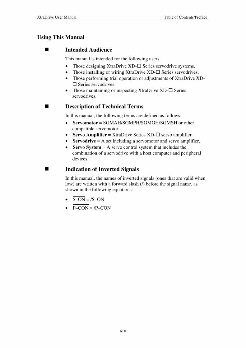
Indication of Inverted Signals
In this manual, the names of inverted signals (ones that are valid when
low) are written with a forward slash (/) before the signal name, as
shown in the following equations:
• S–ON = /S–ON
• P–CON = /P–CON
XtraDrive User Manual Table of Contents/Preface
xiv
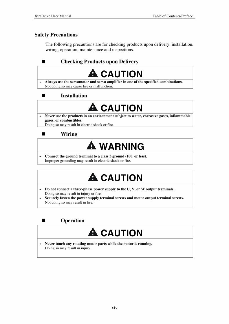
Safety Precautions
The following precautions are for checking products upon delivery, installation,
wiring, operation, maintenance and inspections.
Checking Products upon Delivery
CAUTION • Always use the servomotor and servo amplifier in one of the specified combinations.
Not doing so may cause fire or malfunction.
Installation
CAUTION • Never use the products in an environment subject to water, corrosive gases, inflammable
gases, or combustibles.
Doing so may result in electric shock or fire.
Wiring
WARNING
• Connect the ground terminal to a class 3 ground (100. or less).
Improper grounding may result in electric shock or fire.
CAUTION • Do not connect a three-phase power supply to the U, V, or W output terminals.
Doing so may result in injury or fire.
• Securely fasten the power supply terminal screws and motor output terminal screws.
Not doing so may result in fire.
Operation
CAUTION • Never touch any rotating motor parts while the motor is running.
Doing so may result in injury.
XtraDrive User Manual Table of Contents/Preface
xv
CAUTION • Conduct trial operation on the servomotor alone with the motor shaft disconnected from
machine to avoid any unexpected accidents.
Not doing so may result in injury.
• Before starting operation with a machine connected, change the settings to match the
parameters of the machine.
Starting operation without matching the proper settings may cause the machine to run out of
control or malfunction.
• Before starting operation with a machine connected, make sure that an emergency stop
can be applied at any time.
Not doing so may result in injury.
• Do not touch the heat sinks during operation.
Not doing so may result in burns due to high temperatures.
Maintenance and Inspection
WARNING
• Do not remove the panel cover while the power is ON.
Doing so carries a risk of electric shock.
• Do not touch terminals for five minutes after the power has been turned OFF.
Residual voltage may cause electric shock.
• Never touch the inside of the servo amplifier.
Doing so may result in electric shock.
CAUTION • Do not disassemble the servomotor.
Doing so may result in electric shock or injury
• Do not attempt to change wiring while the power is ON.
Doing so may result in electric shock or injury
XtraDrive User Manual Table of Contents/Preface
xvi
General Precautions
NOTE THE FOLLOWING TO ENSURE
SAFE APPLICATION: • The drawings presented in this manual are sometimes shown without covers or protective
guards. Always replace the cover or protective guard as specified first, and then operate the
products in accordance with the manual.
• The drawings presented in this manual are typical examples and may not match the product you
received.
• This manual is subject to change due to product improvement, specification modification, and
manual improvement. When this manual is revised, the manual code is updated, and the new
manual is published as a next edition. The edition number appears on the front and back covers.
• If the manual must be ordered due to loss or damage, inform your nearest YET representative or
one of the offices listed on the back of this manual.
• YET will not take responsibility for the results of unauthorized modifications of this product.
YET shall not be liable for any damages or troubles resulting from unauthorized modification.

XtraDrive User Manual Chapter 1: Checking Product and Part Names
1-1
1. Checking Product and Part Names
This chapter describes the procedure for checking products upon delivery as
well as names for product parts.
1. Checking Product and Part Names .................................................................1-1 1.1. Checking the XtraDrive Series Products on Delivery ................................1-2
1.1.1. Servo Amplifiers .................................................................................1-2
1.2. Product Part Names.....................................................................................1-3
1.2.1. Servo Amplifiers .................................................................................1-3
1.2.2. Model Numbers ..................................................................................1-4
XtraDrive User Manual Chapter 1: Checking Product and Part Names
1-2
1.1. Checking the XtraDrive Series Products on Delivery
The following procedure is suggested to check XtraDrive series products
upon delivery.
Use the following checklist when XtraDrive series products are delivered.
Initial Inspection Comments
Are the delivered products the ones that were ordered?
Check the model numbers marked on the nameplates of the servomotor and servo amplifier. (Refer to the descriptions of model numbers on following pages)
Does the servomotor shaft rotate smoothly?
The servomotor shaft is normal if it can be turned smoothly by hand. Servomotors with brakes, however, cannot be turned manually.
Is there any damage? Check the overall appearance, and check for damage or scratches that may have occurred during shipping.
Are there any loose screws? Check screws for looseness using a screwdriver.
If any of the above are faulty or incorrect, contact YET or an authorized
distributor.
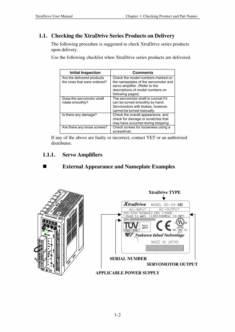
1.1.1. Servo Amplifiers
n External Appearance and Nameplate Examples
APPLICABLE POWER SUPPLY
SERIAL NUMBER
SERVOMOTOR OUTPUT
XtraDrive TYPE
MS
XtraDrive User Manual Chapter 1: Checking Product and Part Names
1-3
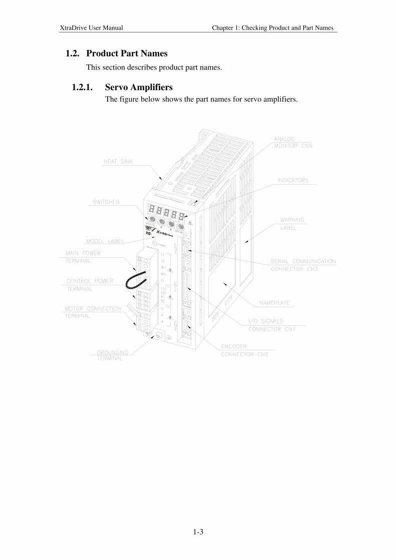
1.2. Product Part Names
This section describes product part names.
1.2.1. Servo Amplifiers
The figure below shows the part names for servo amplifiers.
XtraDrive User Manual Chapter 1: Checking Product and Part Names
1-4
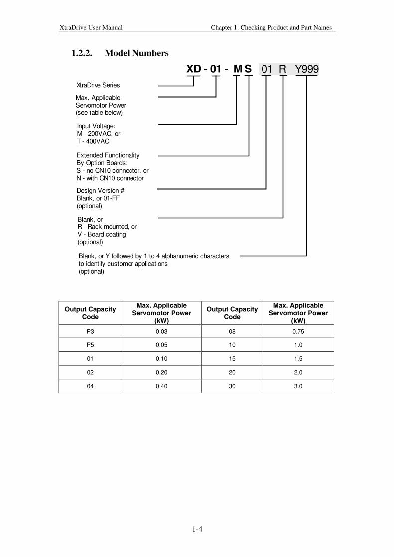
1.2.2. Model Numbers
XD - 01 - M S
XtraDrive Series
Max. ApplicableServomotor Power(see table below)
Input Voltage:M - 200VAC, orT - 400VAC
Extended FunctionalityBy Option Boards:S - no CN10 connector, orN - with CN10 connector
Design Version #Blank, or 01-FF(optional)
Blank, orR - Rack mounted, orV - Board coating(optional)
Blank, or Y followed by 1 to 4 alphanumeric charactersto identify customer applications(optional)
01 R Y999
Output Capacity Code
Max. Applicable Servomotor Power
(kW)
Output Capacity Code
Max. Applicable Servomotor Power
(kW)
P3 0.03 08 0.75
P5 0.05 10 1.0
01 0.10 15 1.5
02 0.20 20 2.0
04 0.40 30 3.0

XtraDrive User Manual Chapter 2: Inst a lla t i o n
2-1
2. Installat ion
This chapter describes precautions for XtraDrive Series servomotor and servo
amplifier installation.
2.1. Servo Amplifiers .........................................................................................2-2
2.1.1. Storage Conditions..............................................................................2-2
2.1.2. Installation Site ...................................................................................2-2
2.1.3. Orientation ..........................................................................................2-3
2.1.4. Installation...........................................................................................2-3
XtraDrive User Manual Chapter 2: Installation
2-2
2.1. Servo Amplifiers
The XtraDrive servo amplifiers are base-mounted. Incorrect installation will
cause problems. Follow the installation instructions below.
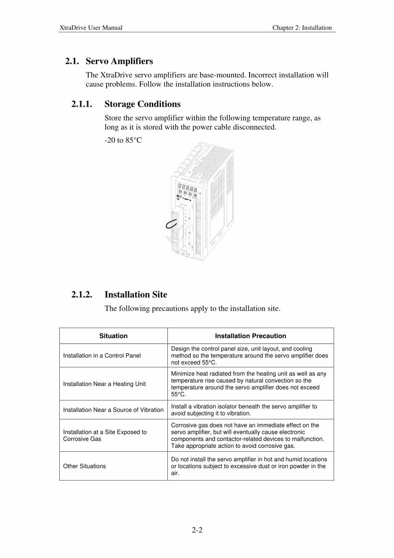
2.1.1. Storage Conditions
Store the servo amplifier within the following temperature range, as
long as it is stored with the power cable disconnected.
-20 to 85°C
2.1.2. Installation Site
The following precautions apply to the installation site.
Situation Installation Precaution
Installation in a Control Panel Design the control panel size, unit layout, and cooling method so the temperature around the servo amplifier does not exceed 55°C.
Installation Near a Heating Unit
Minimize heat radiated from the heating unit as well as any temperature rise caused by natural convection so the temperature around the servo amplifier does not exceed 55°C.
Installation Near a Source of Vibration Install a vibration isolator beneath the servo amplifier to avoid subjecting it to vibration.
Installation at a Site Exposed to Corrosive Gas
Corrosive gas does not have an immediate effect on the servo amplifier, but will eventually cause electronic components and contactor-related devices to malfunction. Take appropriate action to avoid corrosive gas.
Other Situations Do not install the servo amplifier in hot and humid locations or locations subject to excessive dust or iron powder in the air.
XtraDrive User Manual Chapter 2: Installation
2-3
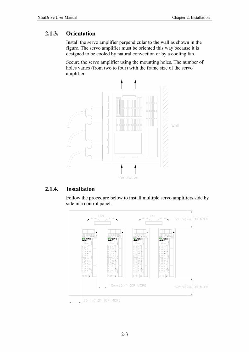
2.1.3. Orientation
Install the servo amplifier perpendicular to the wall as shown in the
figure. The servo amplifier must be oriented this way because it is
designed to be cooled by natural convection or by a cooling fan.
Secure the servo amplifier using the mounting holes. The number of
holes varies (from two to four) with the frame size of the servo
amplifier.
2.1.4. Installation
Follow the procedure below to install multiple servo amplifiers side by
side in a control panel.
XtraDrive User Manual Chapter 2: Installation
2-4
Servo Amplifier Orientation
Install the servo amplifier perpendicular to the wall so the front panels’
connectors faces outward.
Cooling
As shown in the figure above, allow sufficient space around each servo
amplifier for cooling by cooling fans or natural convection.
Side-by-side Installation
When installing servo amplifiers side by side as shown in the figure
above, allow at least 0.39in (10mm) between and at least 1.97in
(50mm) above and below each servo amplifier. Install cooling fans
above the servo amplifiers to avoid excessive temperature rise and to
maintain even temperature inside the control panel.
Environmental Conditions in the Control Panel
• Ambient Temperature: 0 to 55°C
• Humidity: 90% RH or less
• Vibration: 0.5 G (4.9m/s2)
• Condensation and Freezing: None
• Ambient Temperature for Long-term Reliability: 45°C max.
XtraDrive User Manual Chapter 3: Wiring
3-1
3. Wiring
This chapter describes the procedure used to connect XtraDrive Series products
to peripheral devices and gives typical examples of main circuit wiring as well
as I/O signal connections.
3.1. Connecting to Peripheral Devices...............................................................3-2
3.1.1. Single-Phase 200V Main Circuit Specifications.................................3-3
3.1.2. Single-Phase 0.8kW 200V Main Circuit Specifications.....................3-4
3.1.3. Three-phase 200V Main Circuit Specifications..................................3-5
3.1.4. Three-Phase 400V Main Circuit Specifications .................................3-6
3.2. XtraDrive Internal Block Diagrams............................................................3-7
3.2.1. Single-phase 30W to 800W, 200V Models ........................................3-7
3.2.2. Three-phase 1kW to 3kW, 200V Models ...........................................3-8
3.2.3. Three-phase 0.5kW to 3.0kW, 400V Models .....................................3-9
3.3. Main Circuit Wiring..................................................................................3-10
3.3.1. Names and Descriptions of Main Circuit Terminal ..........................3-11
3.3.2. Typical Main Circuit Wiring Example .............................................3-12
3.3.3. Servo Amplifier Power Losses .........................................................3-13
3.3.4. Wiring Main Circuit Terminal Blocks..............................................3-14
3.4. I/O Signals ................................................................................................3-15
3.4.1. Example of Typical I/O Signal Connections ....................................3-15
3.4.2. List of CN1 Terminals ......................................................................3-16
3.4.3. I/O Signal Names and Functions ......................................................3-17
3.4.4. Interface Circuits...............................................................................3-19
3.5. Wiring Encoders (for SGMGH and SGMSH Motors Only) ....................3-23
3.5.1. Encoder Connections ........................................................................3-23
3.5.2. CN2 Encoder Connector Terminal Layout and Types .....................3-25
3.5.3. Encoder Cables Interconnections......................................................3-26
3.6. Examples of Standard Connections ..........................................................3-28

XtraDrive User Manual Chapter 3: Wiring
3-2
3.1. Connecting to Peripheral Devices
This section provides examples of standard XtraDrive Series product
connections to peripheral devices.
It also briefly explains how to connect each peripheral device.
XtraDrive User Manual Chapter 3: Wiring
3-3
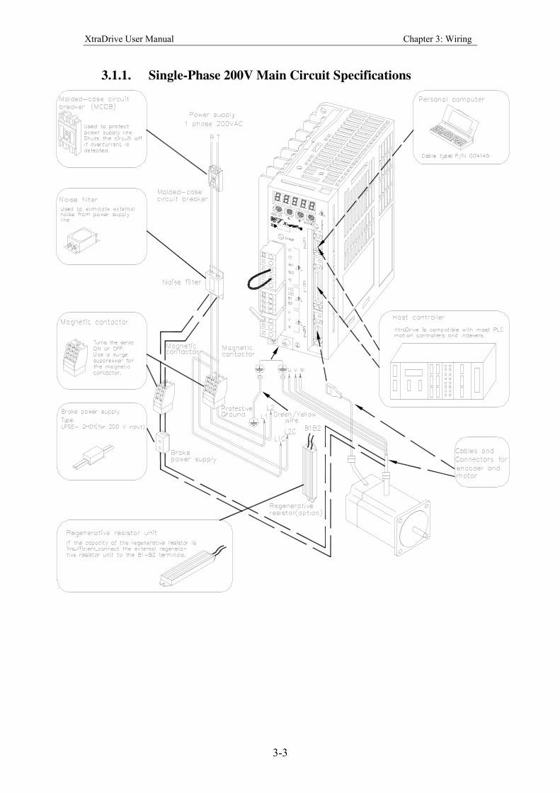
3.1.1. Single-Phase 200V Main Circuit Specifications
XtraDrive User Manual Chapter 3: Wiring
3-4
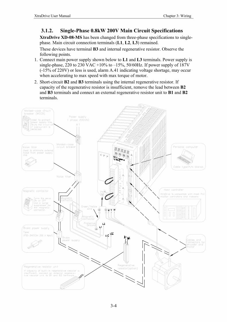
3.1.2. Single-Phase 0.8kW 200V Main Circuit Specifications
XtraDrive XD-08-MS has been changed from three-phase specifications to single-
phase. Main circuit connection terminals (L1, L2, L3) remained.
These devices have terminal B3 and internal regenerative resistor. Observe the
following points.
1. Connect main power supply shown below to L1 and L3 terminals. Power supply is
single-phase, 220 to 230 VAC +10% to –15%, 50/60Hz. If power supply of 187V
(-15% of 220V) or less is used, alarm A.41 indicating voltage shortage, may occur
when accelerating to max speed with max torque of motor.
2. Short-circuit B2 and B3 terminals using the internal regenerative resistor. If
capacity of the regenerative resistor is insufficient, remove the lead between B2
and B3 terminals and connect an external regenerative resistor unit to B1 and B2
terminals.
XtraDrive User Manual Chapter 3: Wiring
3-5
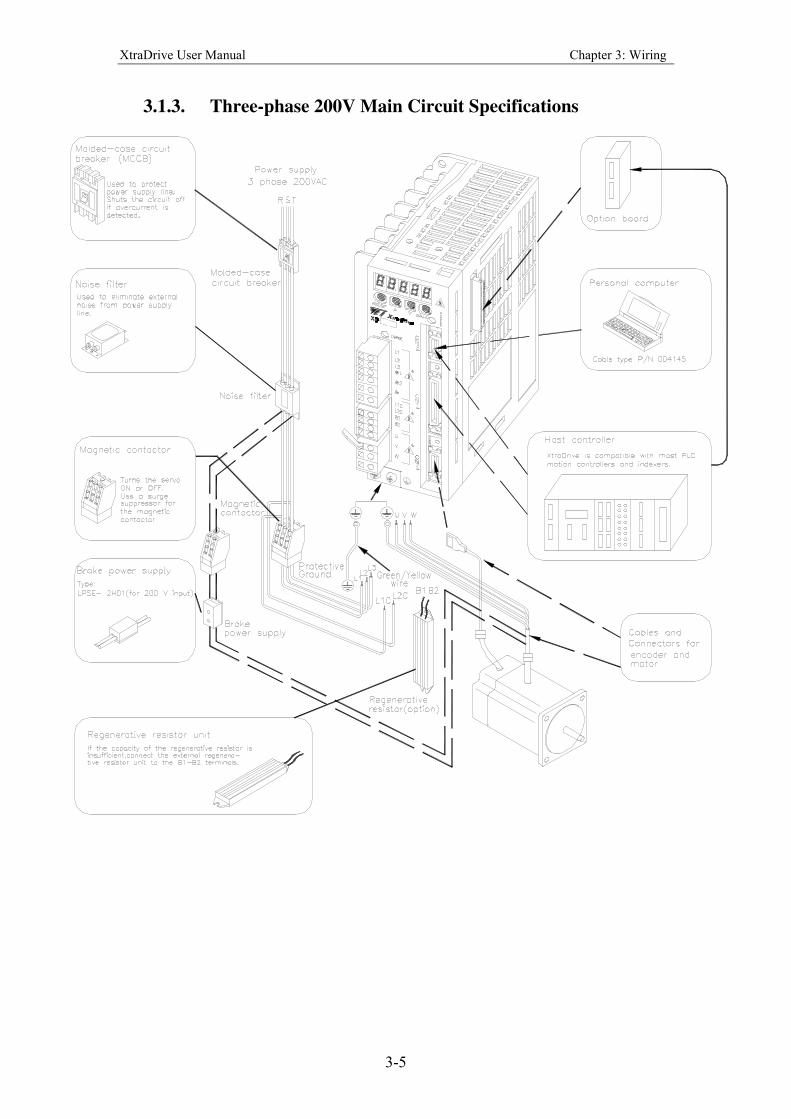
3.1.3. Three-phase 200V Main Circuit Specifications
XtraDrive User Manual Chapter 3: Wiring
3-6
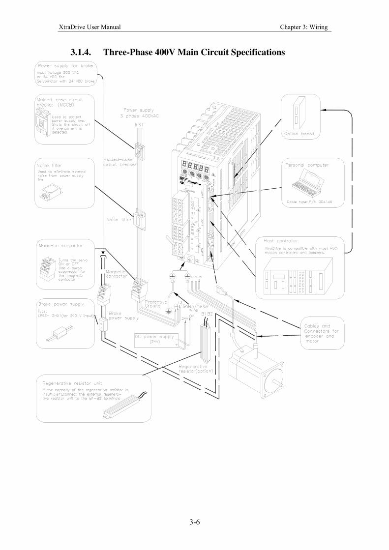
3.1.4. Three-Phase 400V Main Circuit Specifications
XtraDrive User Manual Chapter 3: Wiring
3-7
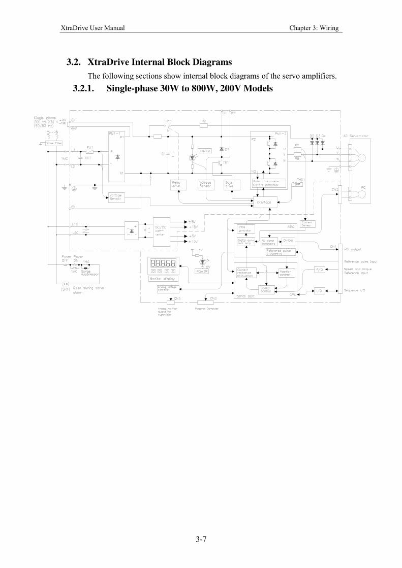
3.2. XtraDrive Internal Block Diagrams
The following sections show internal block diagrams of the servo amplifiers.
3.2.1. Single-phase 30W to 800W, 200V Models
XtraDrive User Manual Chapter 3: Wiring
3-8
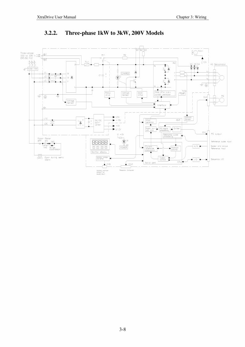
3.2.2. Three-phase 1kW to 3kW, 200V Models
XtraDrive User Manual Chapter 3: Wiring
3-9
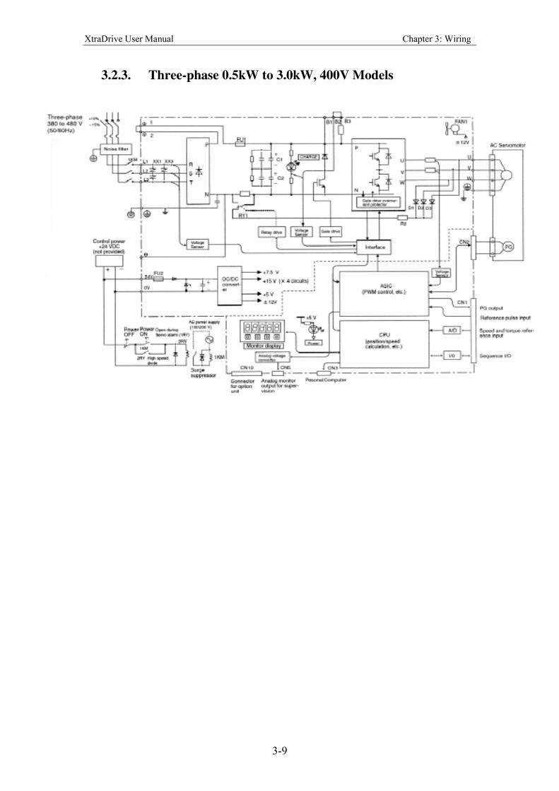
3.2.3. Three-phase 0.5kW to 3.0kW, 400V Models
XtraDrive User Manual Chapter 3: Wiring
3-10
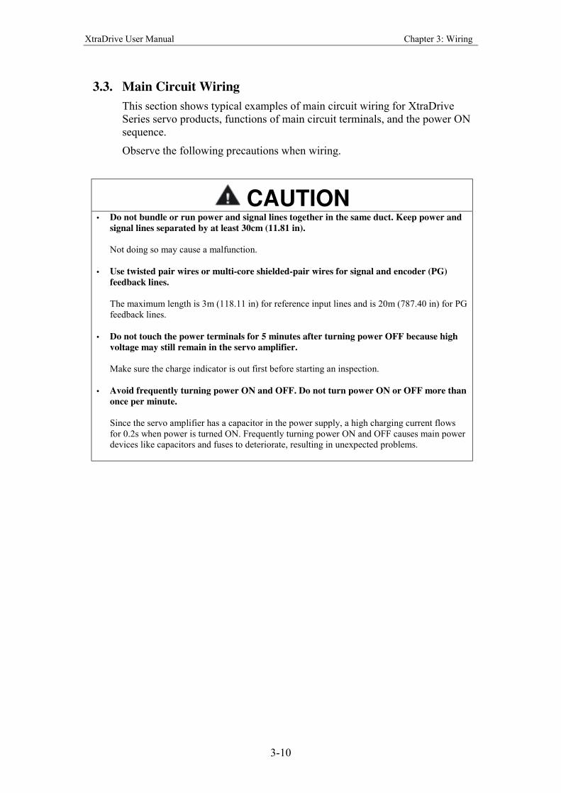
3.3. Main Circuit Wiring
This section shows typical examples of main circuit wiring for XtraDrive
Series servo products, functions of main circuit terminals, and the power ON
sequence.
Observe the following precautions when wiring.
CAUTION • Do not bundle or run power and signal lines together in the same duct. Keep power and
signal lines separated by at least 30cm (11.81 in).
Not doing so may cause a malfunction.
• Use twisted pair wires or multi-core shielded-pair wires for signal and encoder (PG)
feedback lines.
The maximum length is 3m (118.11 in) for reference input lines and is 20m (787.40 in) for PG
feedback lines.
• Do not touch the power terminals for 5 minutes after turning power OFF because high
voltage may still remain in the servo amplifier.
Make sure the charge indicator is out first before starting an inspection.
• Avoid frequently turning power ON and OFF. Do not turn power ON or OFF more than
once per minute.
Since the servo amplifier has a capacitor in the power supply, a high charging current flows
for 0.2s when power is turned ON. Frequently turning power ON and OFF causes main power
devices like capacitors and fuses to deteriorate, resulting in unexpected problems.
XtraDrive User Manual Chapter 3: Wiring
3-11
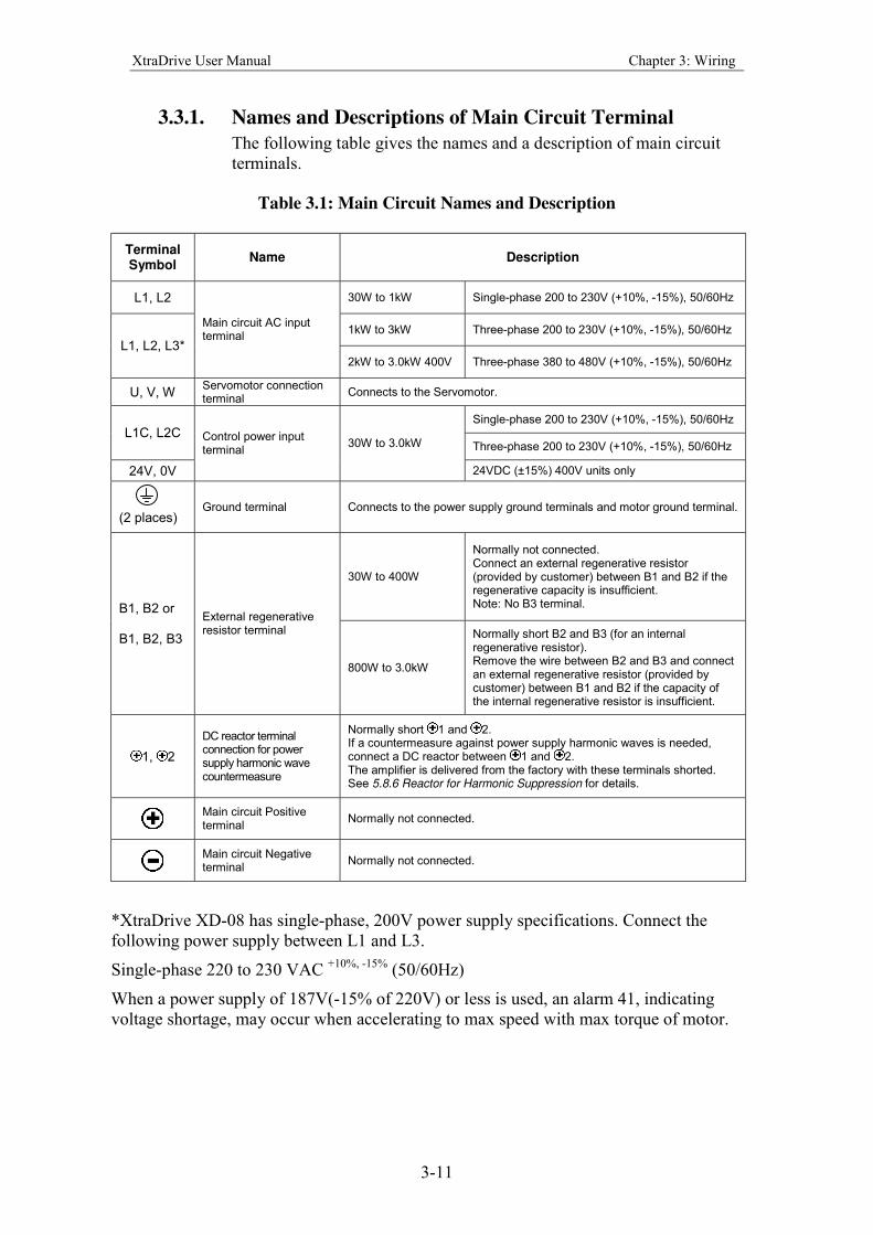
3.3.1. Names and Descriptions of Main Circuit Terminal
The following table gives the names and a description of main circuit
terminals.
Table 3.1: Main Circuit Names and Description
Terminal Symbol
Name Description
L1, L2 30W to 1kW Single-phase 200 to 230V (+10%, -15%), 50/60Hz
1kW to 3kW Three-phase 200 to 230V (+10%, -15%), 50/60Hz
L1, L2, L3*
Main circuit AC input terminal
2kW to 3.0kW 400V Three-phase 380 to 480V (+10%, -15%), 50/60Hz
U, V, W Servomotor connection terminal
Connects to the Servomotor.
Single-phase 200 to 230V (+10%, -15%), 50/60Hz
L1C, L2C Three-phase 200 to 230V (+10%, -15%), 50/60Hz
24V, 0V
Control power input terminal
30W to 3.0kW
24VDC (±15%) 400V units only
(2 places) Ground terminal Connects to the power supply ground terminals and motor ground terminal.
30W to 400W
Normally not connected. Connect an external regenerative resistor (provided by customer) between B1 and B2 if the regenerative capacity is insufficient. Note: No B3 terminal. B1, B2 or
B1, B2, B3
External regenerative resistor terminal
800W to 3.0kW
Normally short B2 and B3 (for an internal regenerative resistor). Remove the wire between B2 and B3 and connect an external regenerative resistor (provided by customer) between B1 and B2 if the capacity of the internal regenerative resistor is insufficient.
1, 2
DC reactor terminal connection for power supply harmonic wave countermeasure
Normally short 1 and 2. If a countermeasure against power supply harmonic waves is needed, connect a DC reactor between 1 and 2. The amplifier is delivered from the factory with these terminals shorted. See 5.8.6 Reactor for Harmonic Suppression for details.
Main circuit Positive terminal
Normally not connected.
Main circuit Negative terminal
Normally not connected.
*XtraDrive XD-08 has single-phase, 200V power supply specifications. Connect the
following power supply between L1 and L3.
Single-phase 220 to 230 VAC +10%, -15%
(50/60Hz)
When a power supply of 187V(-15% of 220V) or less is used, an alarm 41, indicating
voltage shortage, may occur when accelerating to max speed with max torque of motor.
XtraDrive User Manual Chapter 3: Wiring
3-12
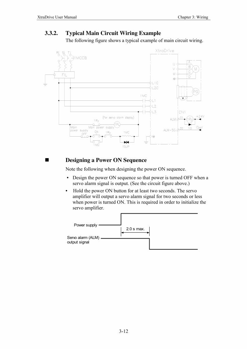
3.3.2. Typical Main Circuit Wiring Example
The following figure shows a typical example of main circuit wiring.
! Designing a Power ON Sequence
Note the following when designing the power ON sequence.
• Design the power ON sequence so that power is turned OFF when a
servo alarm signal is output. (See the circuit figure above.)
• Hold the power ON button for at least two seconds. The servo
amplifier will output a servo alarm signal for two seconds or less
when power is turned ON. This is required in order to initialize the
servo amplifier.
2.0 s max.Power supply
Servo alarm (ALM)output signal
XtraDrive User Manual Chapter 3: Wiring
3-13
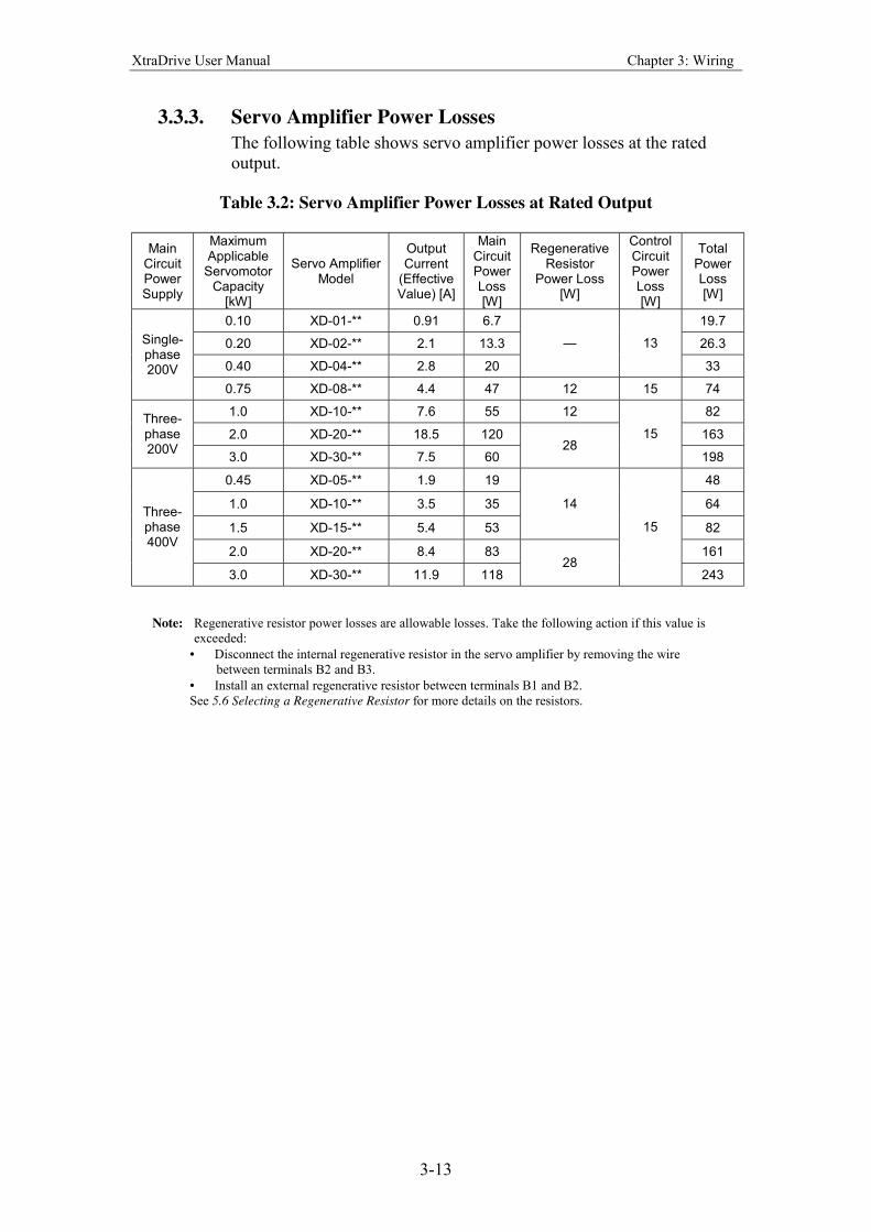
3.3.3. Servo Amplifier Power Losses
The following table shows servo amplifier power losses at the rated
output.
Table 3.2: Servo Amplifier Power Losses at Rated Output
Main Circuit Power Supply
Maximum Applicable
Servomotor Capacity
[kW]
Servo Amplifier Model
Output Current
(Effective Value) [A]
Main Circuit Power Loss [W]
Regenerative Resistor
Power Loss [W]
Control Circuit Power Loss [W]
Total Power Loss [W]
0.10 XD-01-** 0.91 6.7 19.7
0.20 XD-02-** 2.1 13.3 26.3
0.40 XD-04-** 2.8 20
13
33
Single-phase 200V
0.75 XD-08-** 4.4 47 12 15 74
1.0 XD-10-** 7.6 55 12 82
2.0 XD-20-** 18.5 120 163
Three-phase 200V
3.0 XD-30-** 7.5 60 28
15
198
0.45 XD-05-** 1.9 19 48
1.0 XD-10-** 3.5 35 64
1.5 XD-15-** 5.4 53
14
82
2.0 XD-20-** 8.4 83 161
Three-phase 400V
3.0 XD-30-** 11.9 118 28
15
243
Note: Regenerative resistor power losses are allowable losses. Take the following action if this value is
exceeded:
• Disconnect the internal regenerative resistor in the servo amplifier by removing the wire
between terminals B2 and B3.
• Install an external regenerative resistor between terminals B1 and B2.
See 5.6 Selecting a Regenerative Resistor for more details on the resistors.
XtraDrive User Manual Chapter 3: Wiring
3-14
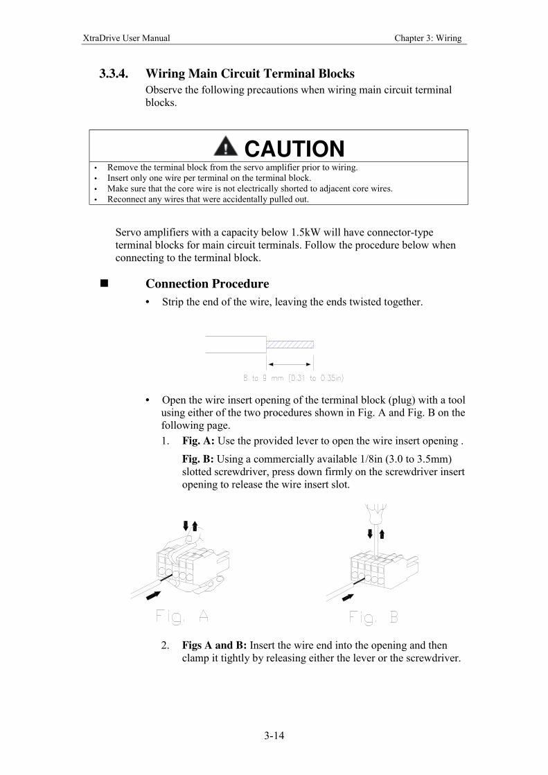
3.3.4. Wiring Main Circuit Terminal Blocks
Observe the following precautions when wiring main circuit terminal
blocks.
CAUTION • Remove the terminal block from the servo amplifier prior to wiring.
• Insert only one wire per terminal on the terminal block.
• Make sure that the core wire is not electrically shorted to adjacent core wires.
• Reconnect any wires that were accidentally pulled out.
Servo amplifiers with a capacity below 1.5kW will have connector-type
terminal blocks for main circuit terminals. Follow the procedure below when
connecting to the terminal block.
! Connection Procedure
• Strip the end of the wire, leaving the ends twisted together.
• Open the wire insert opening of the terminal block (plug) with a tool
using either of the two procedures shown in Fig. A and Fig. B on the
following page.
1. Fig. A: Use the provided lever to open the wire insert opening .
Fig. B: Using a commercially available 1/8in (3.0 to 3.5mm)
slotted screwdriver, press down firmly on the screwdriver insert
opening to release the wire insert slot.
2. Figs A and B: Insert the wire end into the opening and then
clamp it tightly by releasing either the lever or the screwdriver.
XtraDrive User Manual Chapter 3: Wiring
3-15
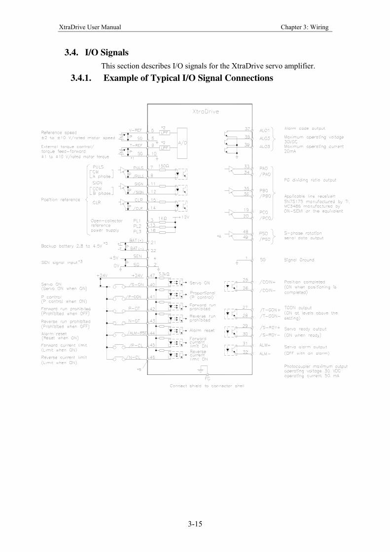
3.4. I/O Signals
This section describes I/O signals for the XtraDrive servo amplifier.
3.4.1. Example of Typical I/O Signal Connections
XtraDrive User Manual Chapter 3: Wiring
3-16
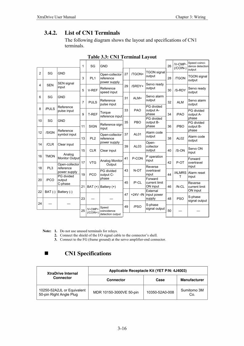
3.4.2. List of CN1 Terminals
The following diagram shows the layout and specifications of CN1
terminals.
Table 3.3: CN1 Terminal Layout
2 SG GND
4 SEN SEN signal input
6 SG GND
8 /PULS Reference pulse input
10 SG GND
12 /SIGN Reference symbol input
14 /CLR Clear input
16 TMON Analog
Monitor Output
18 PL3 Open-collector reference power supply
20 /PCO PG divided output C-phase
22 BAT (-) Battery (-)
24
1 SG GND
3 PL1 Open-collector reference power supply
5 V-REF Reference speed input
7 PULS Reference pulse input
9 T-REF Torque reference input
11 SIGN Reference sign input
13 PL2 Open-collector reference power supply
15 CLR Clear input
17 VTG Analog Monitor
Output
19 PCO PG divided output C-phase
21 BAT (+) Battery (+)
23
25 /V-CMP+ (/COIN+)
Speed coincidence detection output
27 /TGON+ TGON signal output
29 /SRDY+ Servo ready output
31 ALM+ Servo alarm output
33 PAO PG divided output A-phase
35 PBO PG divided output B-phase
37 AL01 Alarm code output
39 AL03 Open-collector output
41 P-CON P operation input
43 N-OT Reverse overtravel input
45 /P-CL Forward current limit ON input
47 +24V -IN External input power supply
49 /PSO S-phase signal output
26 /V-CMP-(/COIN-)
Speed coinci-dence detection output
28 /TGON TGON signal output
30 /S-RDY Servo ready output
32 ALM Servo alarm output
34 /PAO PG divided output A-phase
36 /PBO PG divided output B-phase
38 AL02 Alarm code output
40 /S-ON Servo ON input
42 P-OT Forward overtravel input
44 /ALMRS
T Alarm reset input
46 /N-CL Reverse current limit ON input
48 PSO S-phase signal output
50
Note: 1. Do not use unused terminals for relays.
2. Connect the shield of the I/O signal cable to the connectors shell.
3. Connect to the FG (frame ground) at the servo amplifier-end connector.
! CN1 Specifications
Applicable Receptacle Kit (YET P/N: 4J4003) XtraDrive Internal
Connector Connector Case Manufacturer
10250-52A2JL or Equivalent 50-pin Right Angle Plug
MDR 10150-3000VE 50-pin 10350-52A0-008 Sumitomo 3M
Co.
XtraDrive User Manual Chapter 3: Wiring
3-17
3.4.3. I/O Signal Names and Functions
The following section describes servo amplifier I/O signal names and
functions.
! Input Signals
Signal Name Pin No.
Function Refer-ence
/S-ON 40 Servo ON: Turns ON the servomotor when the gate block in the inverter is released.
5.5.2
* Function selected via parameter. 5.2.1 5.2.7
Proportional operation reference
Switches the speed control loop from PI (proportional/integral) to P (proportional) control when ON.
5.2.1
Direction reference
With internal reference speed selected: Switches the direction of rotation.
5.2.6
Position Speed
Speed Torque Control mode
switching Torque Speed
Enables control mode switching.
5.2.7
Zero-clamp reference
Speed control with zero-clamp function: reference speed is zero when ON.
5.4.3
Common
/P-CON 41
Reference pulse block
Position control with reference pulse stop: stops reference pulse input when ON.
5.2.10
P-OT N-OT
42 43
Forward Run prohibited
Reverse Run prohibited
Overtravel prohibited: stops servomotor when movable part travels beyond the allowable range of motion.
5.1.2
* Function selected with a parameter.
Forward current limit ON
Reverse current limit ON
Current limit function used when ON. 5.1.3
/P-CL /N-CL
45 46
Internal speed
switching
With internal reference speed selected: switches the internal speed settings.
5.2.6
/ALM -RST
44 Alarm reset: Releases the servo alarm state. 5.5.1
+24VIN 47 Control power supply input for sequence signals: users must provide the +24V power supply.
5.2.4
SEN 4 (2) Initial data request signal when using an absolute encoder. 5.2.3
BAT+ BAT-
21 22
Connecting pins for the absolute encoder backup battery. 5.2.3
Speed Reference
V-REF 5 (6) Speed reference input: ±2 to ±10V/rated motor speed (Input gain can be modified with a parameter.)
5.2.1
Torque Reference
T-REF 9
(10) Torque reference input: ±1 to ±10V/rated motor speed (Input gain can be modified with a parameter.)
5.2.1
Position Reference
PULS /PULS SIGN /SIGN
7 8
11 12
Corresponds to reference pulse input Line-driver
Open-collector
Input mode • Code + pulse string
• CCW/CW pulse
• Two-phase pulse (90° phase differential)
5.2.1
CLR /CLR
15 14
Error counter clear: Clears the error counter during position control.
5.2.1
PL1 PL2 PL3
3 13 18
+12V pull-up power supply when PULS, SIGN and CLR reference signals is open-collector outputs (+12V power supply is built into the servo amplifier).
5.2.1
Note: 1. The functions allocated to /S-ON, /P-CON. P-OT, N-OT, /ALM-RST, /P-CL, and /N-CL input
signals can be changed with parameters. (See 5.3.3 Input Circuit Signal Allocation.)
2. Pin numbers in parenthesis ( ) indicate signal grounds.
3. The voltage input range for speed and torque references is a maximum of ±12V.
XtraDrive User Manual Chapter 3: Wiring
3-18
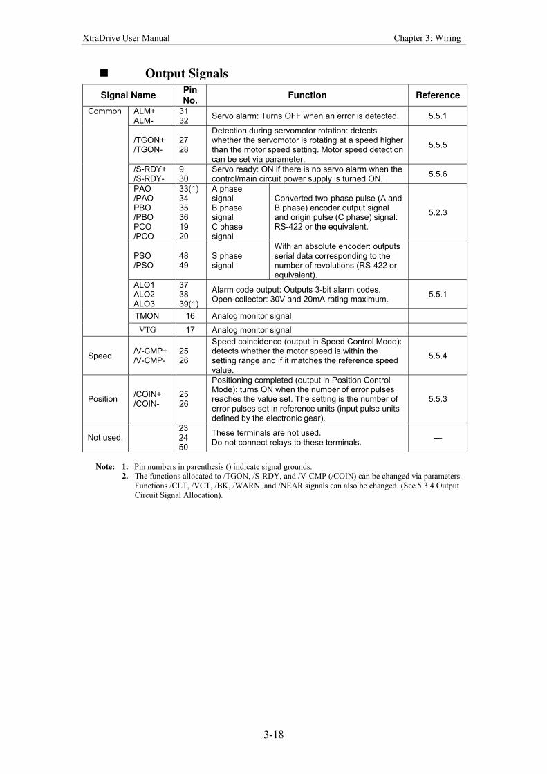
! Output Signals
Signal Name Pin No.
Function Reference
ALM+ ALM-
31 32
Servo alarm: Turns OFF when an error is detected. 5.5.1
/TGON+ /TGON-
27 28
Detection during servomotor rotation: detects whether the servomotor is rotating at a speed higher than the motor speed setting. Motor speed detection can be set via parameter.
5.5.5
/S-RDY+ /S-RDY-
9 30
Servo ready: ON if there is no servo alarm when the control/main circuit power supply is turned ON.
5.5.6
PAO /PAO PBO /PBO PCO /PCO
33(1) 34 35 36 19 20
A phase signal B phase signal C phase signal
Converted two-phase pulse (A and B phase) encoder output signal and origin pulse (C phase) signal: RS-422 or the equivalent.
5.2.3
PSO /PSO
48 49
S phase signal
With an absolute encoder: outputs serial data corresponding to the number of revolutions (RS-422 or equivalent).
ALO1 ALO2 ALO3
37 38 39(1)
Alarm code output: Outputs 3-bit alarm codes. Open-collector: 30V and 20mA rating maximum.
5.5.1
TMON 16 Analog monitor signal
Common
VTG 17 Analog monitor signal
Speed /V-CMP+ /V-CMP-
25 26
Speed coincidence (output in Speed Control Mode): detects whether the motor speed is within the setting range and if it matches the reference speed value.
5.5.4
Position /COIN+ /COIN-
25 26
Positioning completed (output in Position Control Mode): turns ON when the number of error pulses reaches the value set. The setting is the number of error pulses set in reference units (input pulse units defined by the electronic gear).
5.5.3
Not used. 23 24 50
These terminals are not used. Do not connect relays to these terminals.
Note: 1. Pin numbers in parenthesis () indicate signal grounds.
2. The functions allocated to /TGON, /S-RDY, and /V-CMP (/COIN) can be changed via parameters.
Functions /CLT, /VCT, /BK, /WARN, and /NEAR signals can also be changed. (See 5.3.4 Output
Circuit Signal Allocation).
XtraDrive User Manual Chapter 3: Wiring
3-19
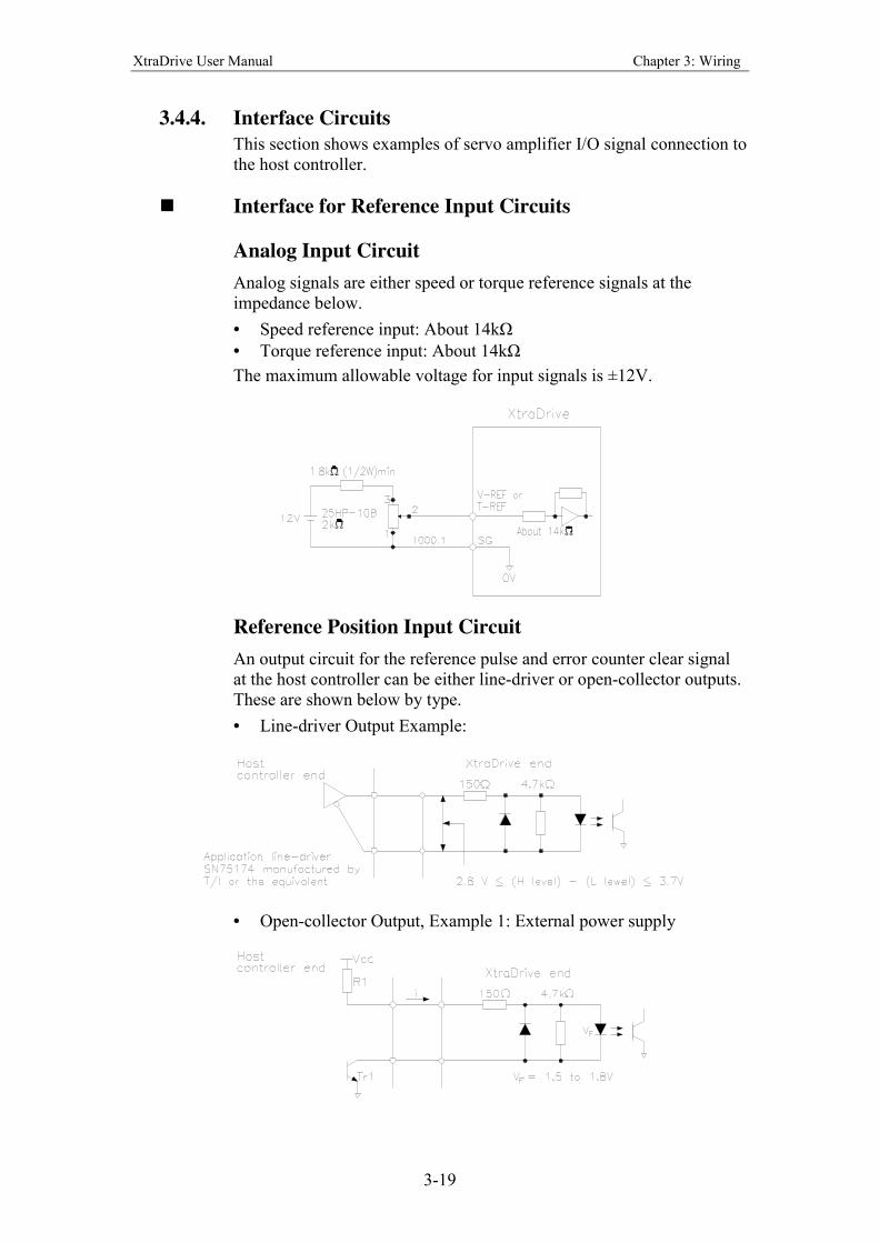
3.4.4. Interface Circuits
This section shows examples of servo amplifier I/O signal connection to
the host controller.
! Interface for Reference Input Circuits
Analog Input Circuit
Analog signals are either speed or torque reference signals at the
impedance below.
• Speed reference input: About 14kΩ
• Torque reference input: About 14kΩ
The maximum allowable voltage for input signals is ±12V.
Reference Position Input Circuit
An output circuit for the reference pulse and error counter clear signal
at the host controller can be either line-driver or open-collector outputs.
These are shown below by type.
• Line-driver Output Example:
• Open-collector Output, Example 1: External power supply
XtraDrive User Manual Chapter 3: Wiring
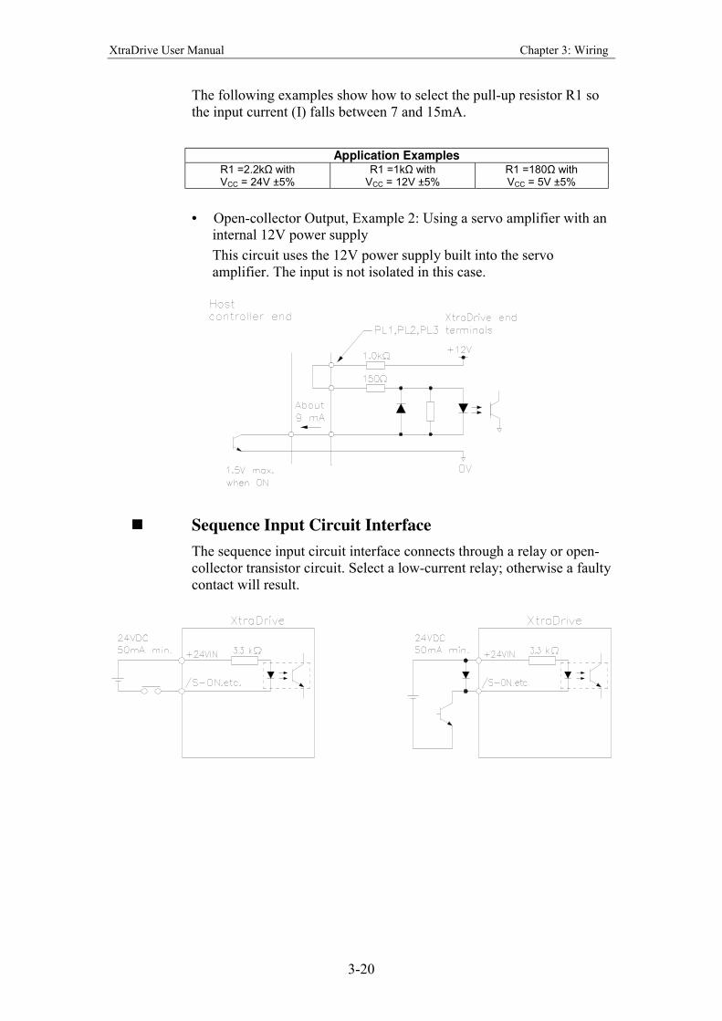
3-20
The following examples show how to select the pull-up resistor R1 so
the input current (I) falls between 7 and 15mA.
Application Examples R1 =2.2kΩ with VCC = 24V ±5%
R1 =1kΩ with VCC = 12V ±5%
R1 =180Ω with VCC = 5V ±5%
• Open-collector Output, Example 2: Using a servo amplifier with an
internal 12V power supply
This circuit uses the 12V power supply built into the servo
amplifier. The input is not isolated in this case.
! Sequence Input Circuit Interface
The sequence input circuit interface connects through a relay or open-
collector transistor circuit. Select a low-current relay; otherwise a faulty
contact will result.
XtraDrive User Manual Chapter 3: Wiring
3-21
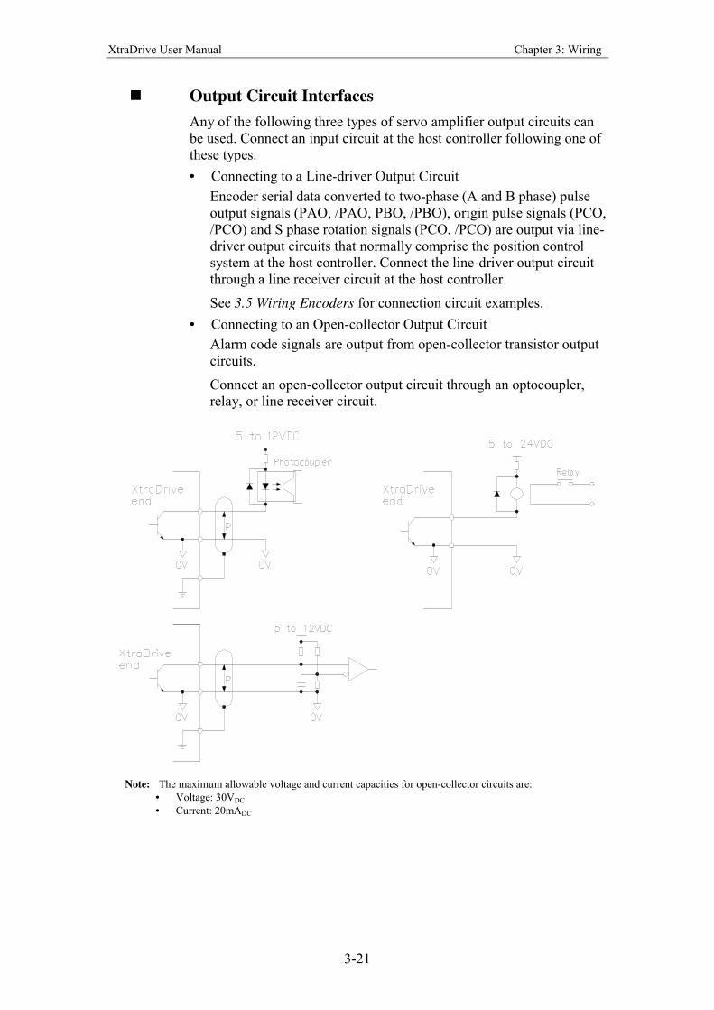
! Output Circuit Interfaces
Any of the following three types of servo amplifier output circuits can
be used. Connect an input circuit at the host controller following one of
these types.
• Connecting to a Line-driver Output Circuit
Encoder serial data converted to two-phase (A and B phase) pulse
output signals (PAO, /PAO, PBO, /PBO), origin pulse signals (PCO,
/PCO) and S phase rotation signals (PCO, /PCO) are output via line-
driver output circuits that normally comprise the position control
system at the host controller. Connect the line-driver output circuit
through a line receiver circuit at the host controller.
See 3.5 Wiring Encoders for connection circuit examples.
• Connecting to an Open-collector Output Circuit
Alarm code signals are output from open-collector transistor output
circuits.
Connect an open-collector output circuit through an optocoupler,
relay, or line receiver circuit.
Note: The maximum allowable voltage and current capacities for open-collector circuits are:
• Voltage: 30VDC
• Current: 20mADC
XtraDrive User Manual Chapter 3: Wiring
3-22
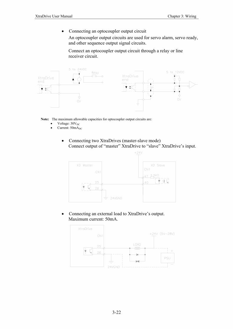
• Connecting an optocoupler output circuit
An optocoupler output circuits are used for servo alarm, servo ready,
and other sequence output signal circuits.
Connect an optocoupler output circuit through a relay or line
receiver circuit.
Note: The maximum allowable capacities for optocoupler output circuits are:
• Voltage: 30VDC
• Current: 50mADC
• Connecting two XtraDrives (master-slave mode)
Connect output of “master” XtraDrive to “slave” XtraDrive’s input.
• Connecting an external load to XtraDrive’s output.
Maximum current: 50mA.
XtraDrive User Manual Chapter 3: Wiring
3-23
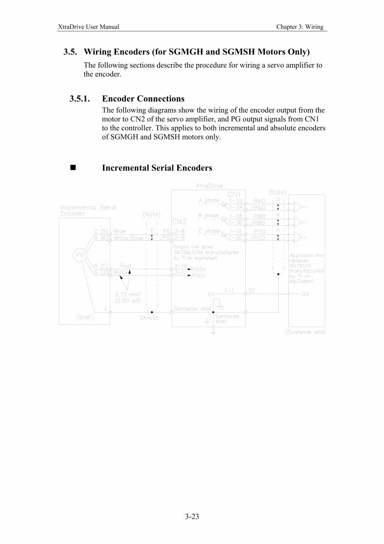
3.5. Wiring Encoders (for SGMGH and SGMSH Motors Only)
The following sections describe the procedure for wiring a servo amplifier to
the encoder.
3.5.1. Encoder Connections
The following diagrams show the wiring of the encoder output from the
motor to CN2 of the servo amplifier, and PG output signals from CN1
to the controller. This applies to both incremental and absolute encoders
of SGMGH and SGMSH motors only.
Incremental Serial Encoders
XtraDrive User Manual Chapter 3: Wiring
3-24
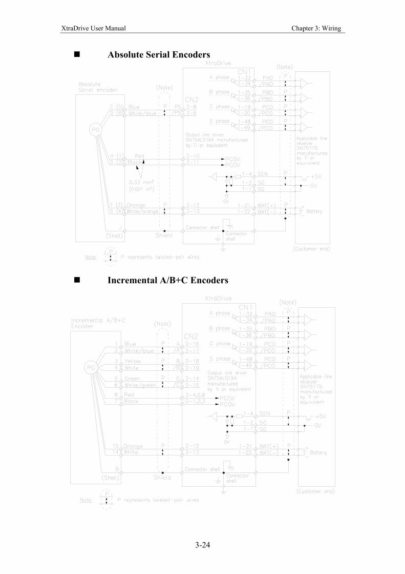
Absolute Serial Encoders
Incremental A/B+C Encoders
XtraDrive User Manual Chapter 3: Wiring
3-25
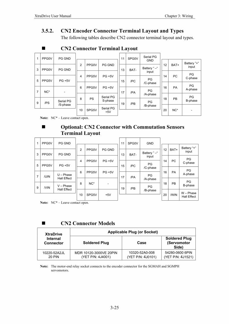
3.5.2. CN2 Encoder Connector Terminal Layout and Types
The following tables describe CN2 connector terminal layout and types.
CN2 Connector Terminal Layout
1 PPG0V PG GND
3 PPG0V PG GND
5 PPG5V PG +5V
7 NC* -
9 /PS Serial PG /S-phase
2 PPG0V PG GND
4 PPG5V PG +5V
6 PPG5V PG +5V
8 PS Serial PG S-phase
10 SPG5V Serial PG
+5V
11 SPG0V Serial PG
GND
13 BAT- Battery “ –“
input
15 /PC PG
/C-phase
17 /PA PG
/A-phase
19 /PB PG
/B-phase
12 BAT+ Battery ”+”
input
14 PC PG
C-phase
16 PA PG
A-phase
18 PB PG
B-phase
20 NC* -
Note: NC* – Leave contact open.
Optional: CN2 Connector with Commutation Sensors
Terminal Layout
1 PPG0V PG GND
3 PPG0V PG GND
5 PPG5V PG +5V
7 /UIN U – Phase Hall Effect
9 /VIN V – Phase Hall Effect
2 PPG0V PG GND
4 PPG5V PG +5V
6 PPG5V PG +5V
8 NC* -
10 SPG5V +5V
11 SPG0V GND
13 BAT- Battery ” –“
input
15 /PC PG
/C-phase
17 /PA PG
/A-phase
19 /PB PG
/B-phase
12 BAT+ Battery “+”
input
14 PC PG
C-phase
16 PA PG
A-phase
18 PB PG
B-phase
20 /WIN W – Phase Hall Effect
Note: NC* – Leave contact open.
CN2 Connector Models
Applicable Plug (or Socket) XtraDrive Internal
Connector Soldered Plug Case Soldered Plug (Servomotor
Side)
10220-52A2JL 20 PIN
MDR 10120-3000VE 20PIN (YET P/N: 4J4001)
10320-52A0-008
(YET P/N: 4J0101)
54280-0600 6PIN
(YET P/N: 4J1521)
Note: The motor-end relay socket connects to the encoder connector for the SGMAH and SGMPH
servomotors.
XtraDrive User Manual Chapter 3: Wiring
3-26
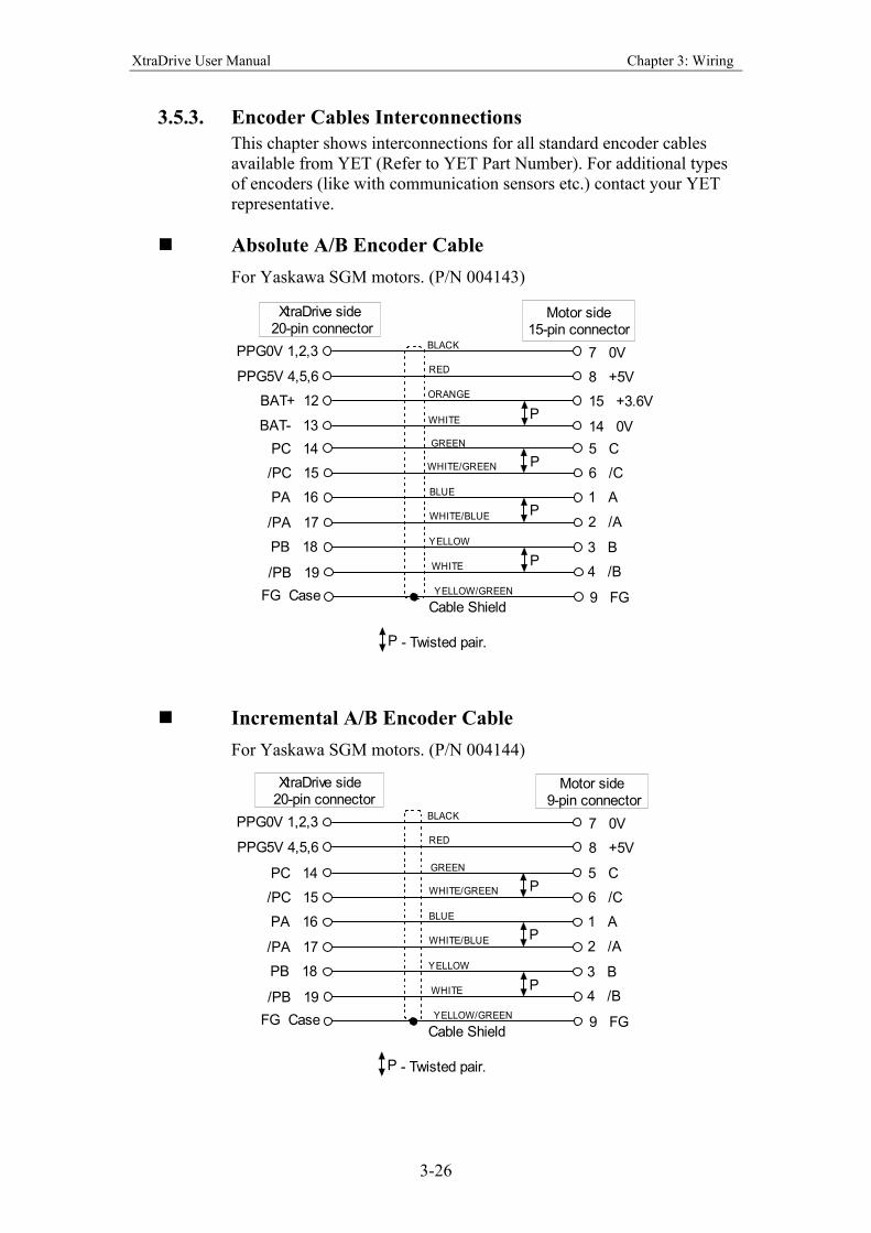
3.5.3. Encoder Cables Interconnections
This chapter shows interconnections for all standard encoder cables
available from YET (Refer to YET Part Number). For additional types
of encoders (like with communication sensors etc.) contact your YET
representative.
Absolute A/B Encoder Cable
For Yaskawa SGM motors. (P/N 004143)
PPG0V 1,2,3
PPG5V 4,5,6
FG Case
7 0V
8 +5V
15 +3.6V
9 FGCable Shield
14 0V
BAT+ 12
BAT- 13P
P - Twisted pair.
XtraDrive side 20-pin connector
Motor side15-pin connector
P
P
P
PC 14
/PC 15
PA 16
/PA 17
PB 18
/PB 19YELLOW/GREEN
WHITE
YELLOW
WHITE/BLUE
BLUE
WHITE/GREEN
GREEN
WHITE
ORANGE
RED
BLACK
5 C
6 /C
1 A
2 /A
3 B
4 /B
Incremental A/B Encoder Cable
For Yaskawa SGM motors. (P/N 004144)
PPG0V 1,2,3
PPG5V 4,5,6
FG Case
7 0V
8 +5V
9 FGCable Shield
P - Twisted pair.
XtraDrive side 20-pin connector
Motor side 9-pin connector
P
P
P
PC 14
/PC 15
PA 16
/PA 17
PB 18
/PB 19YELLOW/GREEN
WHITE
YELLOW
WHITE/BLUE
BLUE
WHITE/GREEN
GREEN
RED
BLACK
5 C
6 /C
1 A
2 /A
3 B
4 /B
XtraDrive User Manual Chapter 3: Wiring
3-27
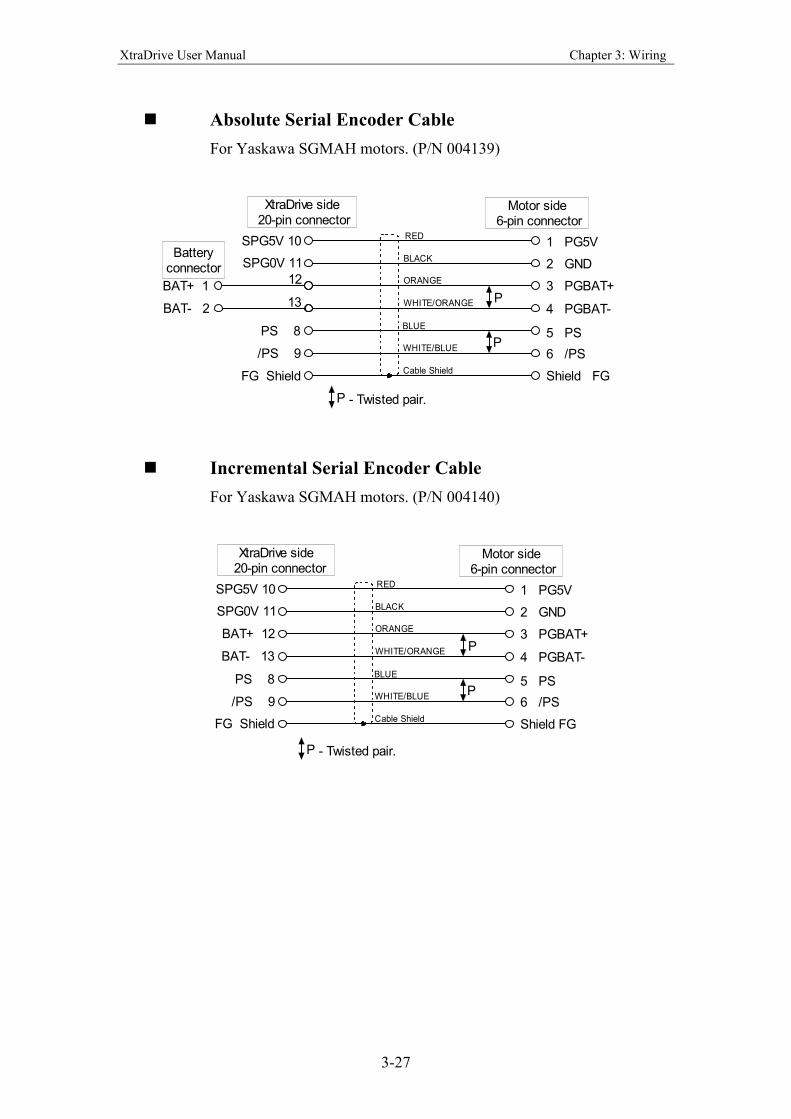
Absolute Serial Encoder Cable
For Yaskawa SGMAH motors. (P/N 004139)
SPG5V 10
SPG0V 11
12
FG Shield
1 PG5V
2 GND
3 PGBAT+
Shield FG
4 PGBAT-
5 PS
6 /PS/PS 9
PS 8
13
BAT+ 1
BAT- 2
P
P
P - Twisted pair.
XtraDrive side 20-pin connector
Motor side 6-pin connector
Cable Shield
WHITE/BLUE
BLUE
WHITE/ORANGE
ORANGE
BLACK
RED
Batteryconnector
Incremental Serial Encoder Cable
For Yaskawa SGMAH motors. (P/N 004140)
SPG5V 10
SPG0V 11
FG Shield
1 PG5V
2 GND
3 PGBAT+
Shield FG
4 PGBAT-
5 PS
6 /PS/PS 9
PS 8
BAT+ 12
BAT- 13
P
P
P - Twisted pair.
XtraDrive side 20-pin connector
Motor side 6-pin connector
Cable Shield
WHITE/BLUE
BLUE
WHITE/ORANGE
ORANGE
BLACK
RED
XtraDrive User Manual Chapter 3: Wiring
3-28
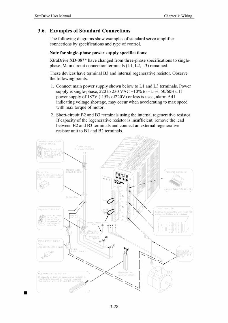
3.6. Examples of Standard Connections
The following diagrams show examples of standard servo amplifier
connections by specifications and type of control.
Note for single-phase power supply specifications:
XtraDrive XD-08** have changed from three-phase specifications to single-
phase. Main circuit connection terminals (L1, L2, L3) remained.
These devices have terminal B3 and internal regenerative resistor. Observe
the following points.
1. Connect main power supply shown below to L1 and L3 terminals. Power
supply is single-phase, 220 to 230 VAC +10% to –15%, 50/60Hz. If
power supply of 187V (-15% of220V) or less is used, alarm A41
indicating voltage shortage, may occur when accelerating to max speed
with max torque of motor.
2. Short-circuit B2 and B3 terminals using the internal regenerative resistor.
If capacity of the regenerative resistor is insufficient, remove the lead
between B2 and B3 terminals and connect an external regenerative
resistor unit to B1 and B2 terminals.
XtraDrive User Manual Chapter 3: Wiring
3-29
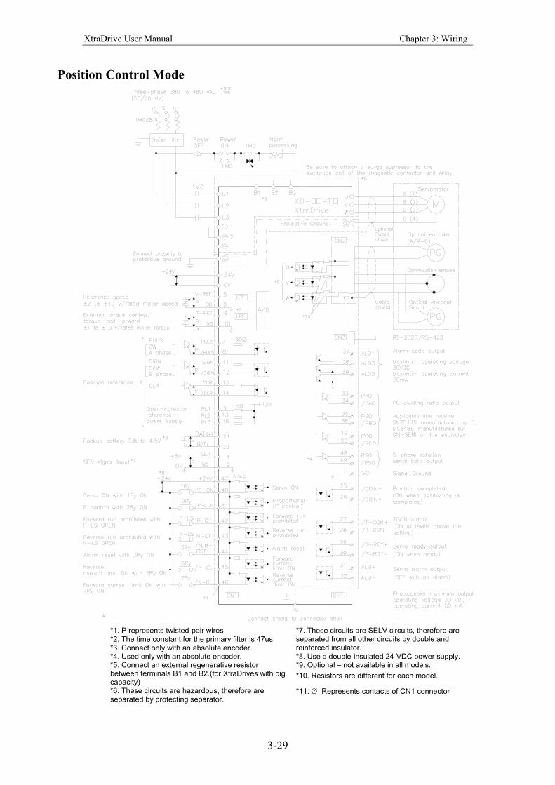
Position Control Mode
*1. P represents twisted-pair wires
*2. The time constant for the primary filter is 47us. *3. Connect only with an absolute encoder.
*7. These circuits are SELV circuits, therefore are separated from all other circuits by double and reinforced insulator.
*4. Used only with an absolute encoder. *8. Use a double-insulated 24-VDC power supply. *9. Optional – not available in all models. *5. Connect an external regenerative resistor
between terminals B1 and B2.(for XtraDrives with big capacity)
*10. Resistors are different for each model.
*6. These circuits are hazardous, therefore are separated by protecting separator.
*11. ∅ Represents contacts of CN1 connector
XtraDrive User Manual Chapter 3: Wiring
3-30
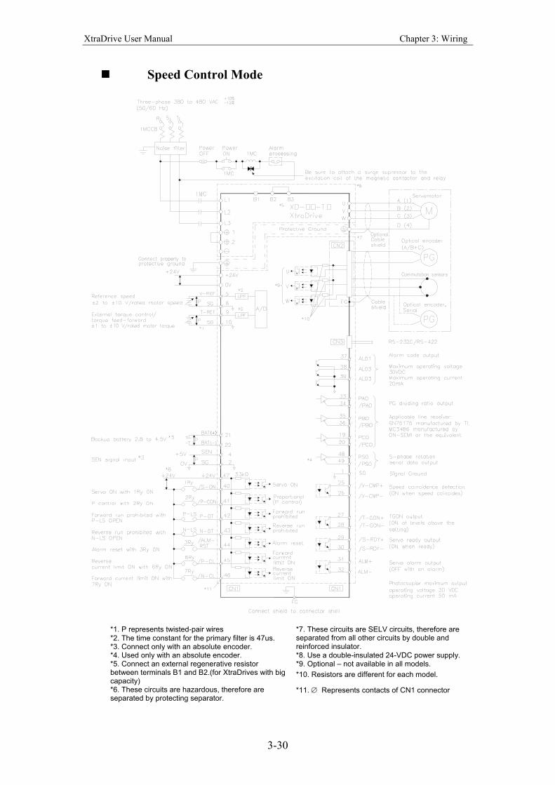
Speed Control Mode
*1. P represents twisted-pair wires
*2. The time constant for the primary filter is 47us. *3. Connect only with an absolute encoder.
*7. These circuits are SELV circuits, therefore are separated from all other circuits by double and reinforced insulator.
*4. Used only with an absolute encoder. *8. Use a double-insulated 24-VDC power supply. *9. Optional – not available in all models. *5. Connect an external regenerative resistor
between terminals B1 and B2.(for XtraDrives with big capacity)
*10. Resistors are different for each model.
*6. These circuits are hazardous, therefore are separated by protecting separator.
*11. ∅ Represents contacts of CN1 connector
XtraDrive User Manual Chapter 3: Wiring
3-31
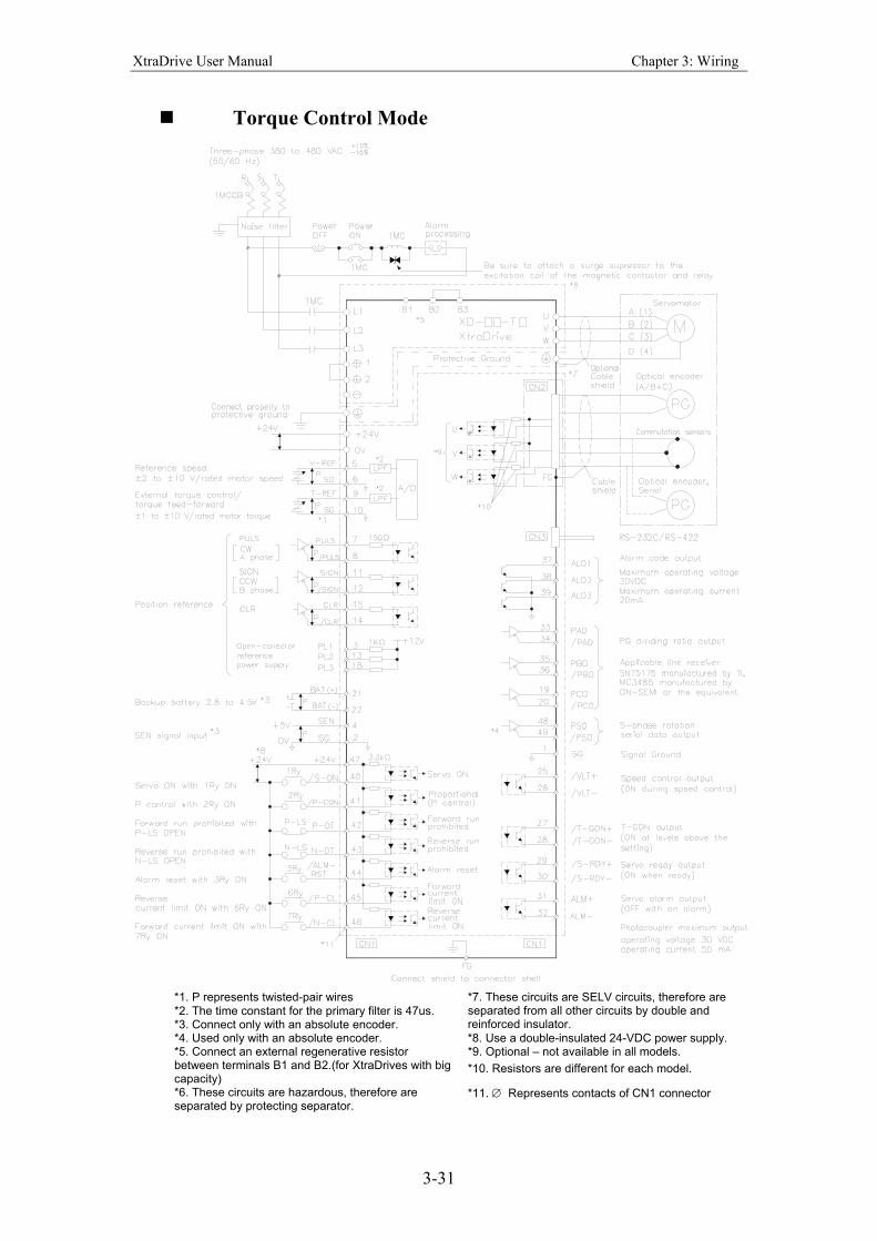
Torque Control Mode
*1. P represents twisted-pair wires
*2. The time constant for the primary filter is 47us. *3. Connect only with an absolute encoder.
*7. These circuits are SELV circuits, therefore are separated from all other circuits by double and reinforced insulator.
*4. Used only with an absolute encoder. *8. Use a double-insulated 24-VDC power supply. *9. Optional – not available in all models. *5. Connect an external regenerative resistor
between terminals B1 and B2.(for XtraDrives with big capacity)
*10. Resistors are different for each model.
*6. These circuits are hazardous, therefore are separated by protecting separator.
*11. ∅ Represents contacts of CN1 connector

XtraDrive User Manual Chapter 3: Wiring
3-32
This page intentionally left blank.
XtraDrive User Manual Chapter 4: Trial Operation
4-1
4. Tria l Operat ion
This chapter describes a two-step trial operation. Be sure to complete step 1
before proceeding to step 2.
4.1. Two-Step Trial Operation ...........................................................................4-2
4.1.1. Step 1: Trial Operation for Servomotor without Load........................4-3
4.1.2. Step 2: Trial Operation with Servomotor Connected to Machine .....4-9
4.2. Additional Setup Procedures in Trial Operation.......................................4-10
4.2.1. Servomotors with Brakes ..................................................................4-10
4.2.2. Position Control by Host Controller .................................................4-11
4.3. Minimum Parameters and Input Signals...................................................4-12
4.3.1. Parameters.........................................................................................4-12
4.3.2. Input Signals .....................................................................................4-12
XtraDrive User Manual Chapter 4: Trial Operation
4-2
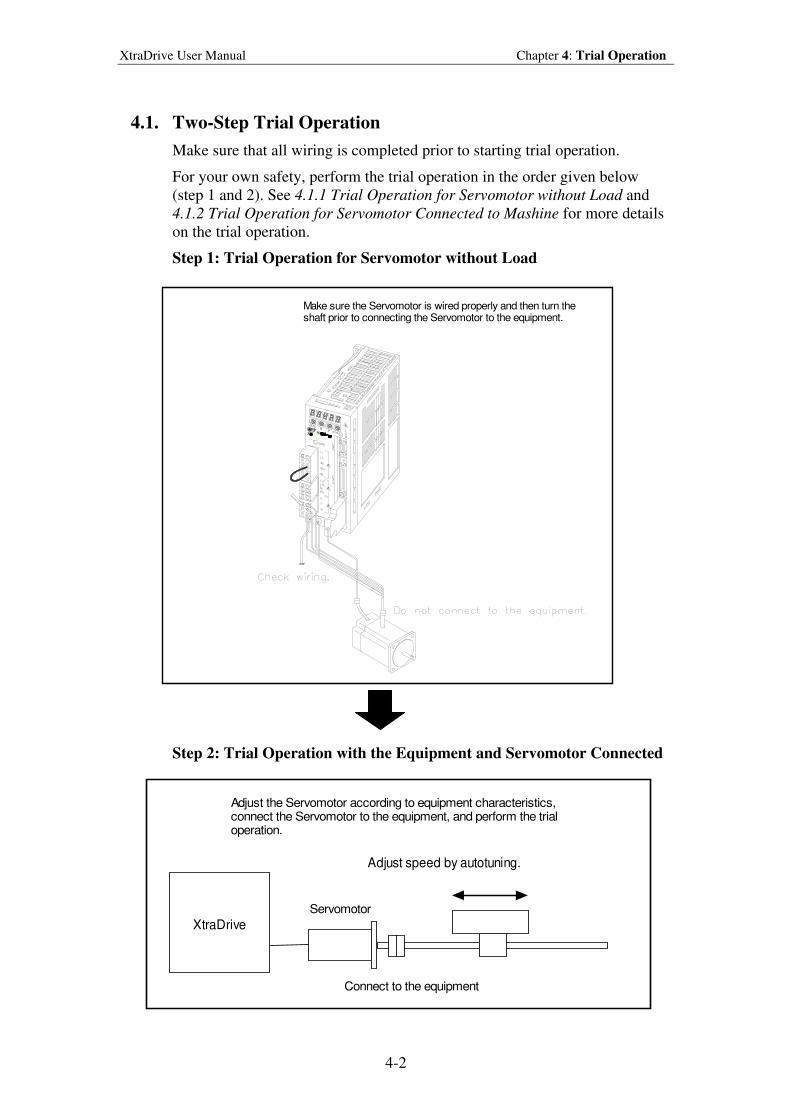
4.1. Two-Step Trial Operation
Make sure that all wiring is completed prior to starting trial operation.
For your own safety, perform the trial operation in the order given below
(step 1 and 2). See 4.1.1 Trial Operation for Servomotor without Load and
4.1.2 Trial Operation for Servomotor Connected to Mashine for more details
on the trial operation.
Step 1: Trial Operation for Servomotor without Load
Make sure the Servomotor is wired properly and then turn theshaft prior to connecting the Servomotor to the equipment.
Step 2: Trial Operation with the Equipment and Servomotor Connected
XtraDrive
Adjust speed by autotuning.
Servomotor
Connect to the equipment
Adjust the Servomotor according to equipment characteristics,connect the Servomotor to the equipment, and perform the trialoperation.
XtraDrive User Manual Chapter 4: Trial Operation
4-3
4.1.1. Step 1: Trial Operation for Servomotor without Load
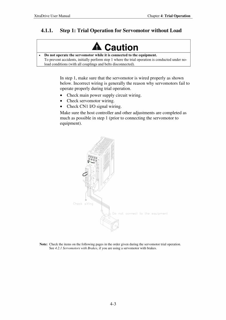
Caution • Do not operate the servomotor while it is connected to the equipment.
To prevent accidents, initially perform step 1 where the trial operation is conducted under no-
load conditions (with all couplings and belts disconnected).
In step 1, make sure that the servomotor is wired properly as shown
below. Incorrect wiring is generally the reason why servomotors fail to
operate properly during trial operation.
• Check main power supply circuit wiring.
• Check servomotor wiring.
• Check CN1 I/O signal wiring.
Make sure the host controller and other adjustments are completed as
much as possible in step 1 (prior to connecting the servomotor to
equipment).
Note: Check the items on the following pages in the order given during the servomotor trial operation.
See 4.2.1 Servomotors with Brakes, if you are using a servomotor with brakes.
XtraDrive User Manual Chapter 4: Trial Operation
4-4
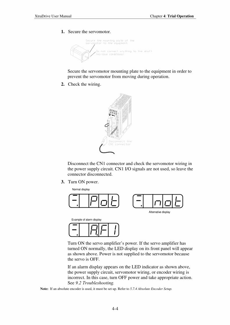
1. Secure the servomotor.
Secure the servomotor mounting plate to the equipment in order to
prevent the servomotor from moving during operation.
2. Check the wiring.
Disconnect the CN1 connector and check the servomotor wiring in
the power supply circuit. CN1 I/O signals are not used, so leave the
connector disconnected.
3. Turn ON power.
Normal display
Alternative display
Example of alarm display
Turn ON the servo amplifier’s power. If the servo amplifier has
turned ON normally, the LED display on its front panel will appear
as shown above. Power is not supplied to the servomotor because
the servo is OFF.
If an alarm display appears on the LED indicator as shown above,
the power supply circuit, servomotor wiring, or encoder wiring is
incorrect. In this case, turn OFF power and take appropriate action.
See 9.2 Troubleshooting.
Note: If an absolute encoder is used, it must be set up. Refer to 5.7.4 Absolute Encoder Setup.
XtraDrive User Manual Chapter 4: Trial Operation
4-5
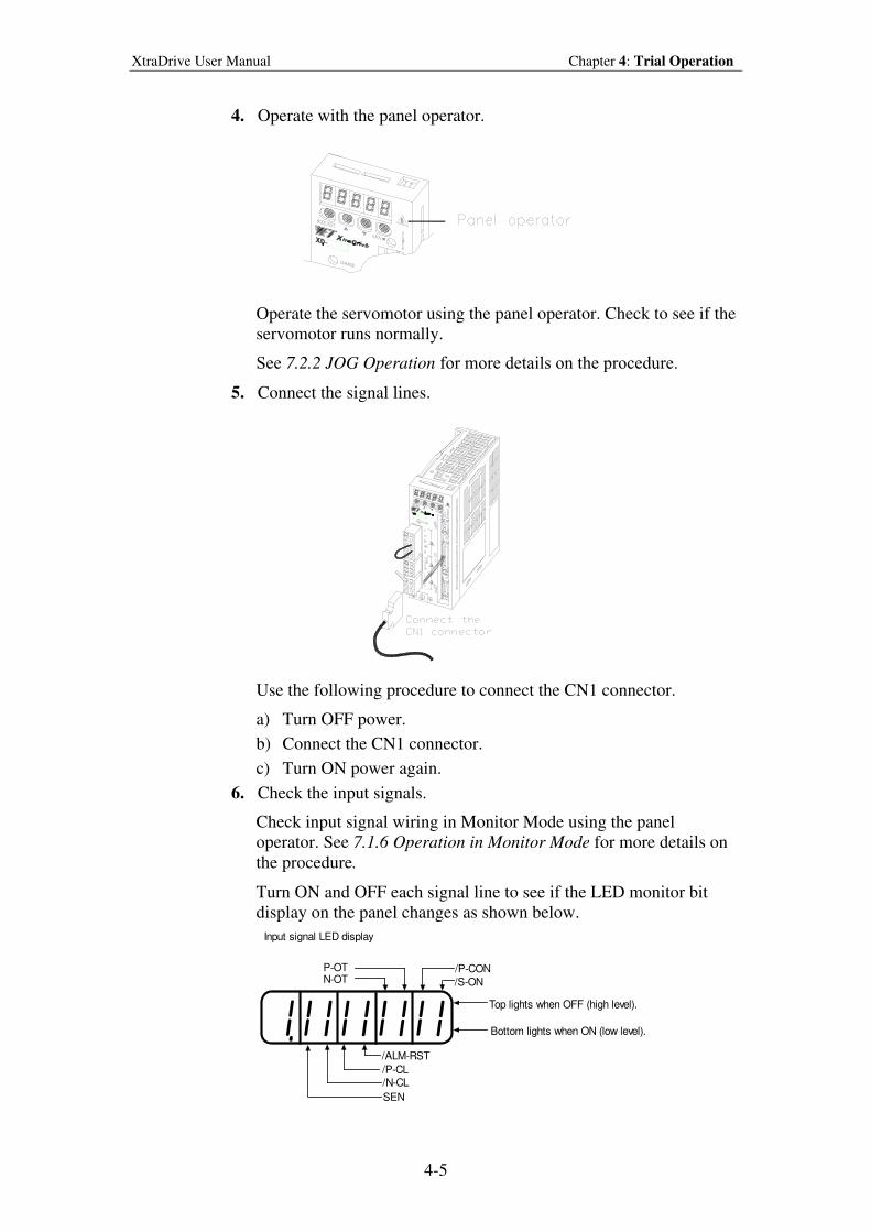
4. Operate with the panel operator.
Operate the servomotor using the panel operator. Check to see if the
servomotor runs normally.
See 7.2.2 JOG Operation for more details on the procedure.
5. Connect the signal lines.
Use the following procedure to connect the CN1 connector.
a) Turn OFF power.
b) Connect the CN1 connector.
c) Turn ON power again.
6. Check the input signals.
Check input signal wiring in Monitor Mode using the panel
operator. See 7.1.6 Operation in Monitor Mode for more details on
the procedure.
Turn ON and OFF each signal line to see if the LED monitor bit
display on the panel changes as shown below.
/ALM-RST
/P-CL/N-CL
SEN
/S-ON
/P-CONN-OTP-OT
Top lights when OFF (high level).
Bottom lights when ON (low level).
Input signal LED display
XtraDrive User Manual Chapter 4: Trial Operation
4-6
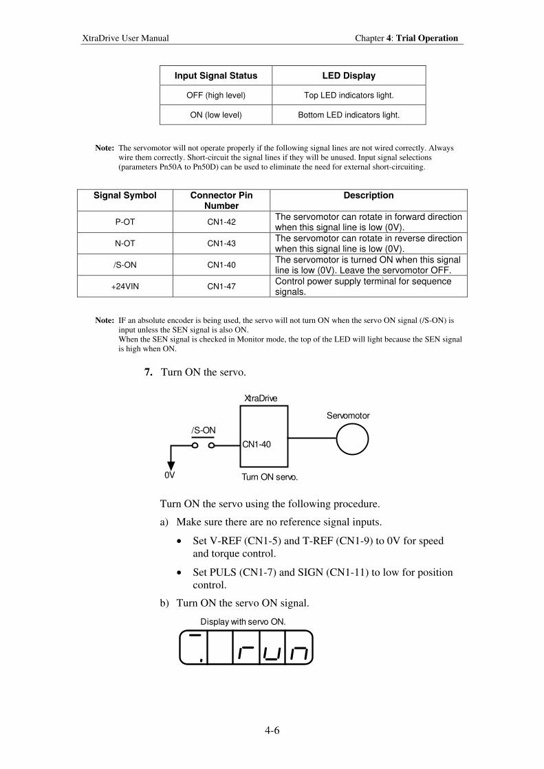
Input Signal Status LED Display
OFF (high level) Top LED indicators light.
ON (low level) Bottom LED indicators light.
Note: The servomotor will not operate properly if the following signal lines are not wired correctly. Always
wire them correctly. Short-circuit the signal lines if they will be unused. Input signal selections
(parameters Pn50A to Pn50D) can be used to eliminate the need for external short-circuiting.
Signal Symbol Connector Pin Number
Description
P-OT CN1-42 The servomotor can rotate in forward direction when this signal line is low (0V).
N-OT CN1-43 The servomotor can rotate in reverse direction when this signal line is low (0V).
/S-ON CN1-40 The servomotor is turned ON when this signal line is low (0V). Leave the servomotor OFF.
+24VIN CN1-47 Control power supply terminal for sequence signals.
Note: IF an absolute encoder is being used, the servo will not turn ON when the servo ON signal (/S-ON) is
input unless the SEN signal is also ON.
When the SEN signal is checked in Monitor mode, the top of the LED will light because the SEN signal
is high when ON.
7. Turn ON the servo.
XtraDrive
CN1-40
Servomotor
Turn ON servo.0V
/S-ON
Turn ON the servo using the following procedure.
a) Make sure there are no reference signal inputs.
• Set V-REF (CN1-5) and T-REF (CN1-9) to 0V for speed
and torque control.
• Set PULS (CN1-7) and SIGN (CN1-11) to low for position
control.
b) Turn ON the servo ON signal.
Display with servo ON.
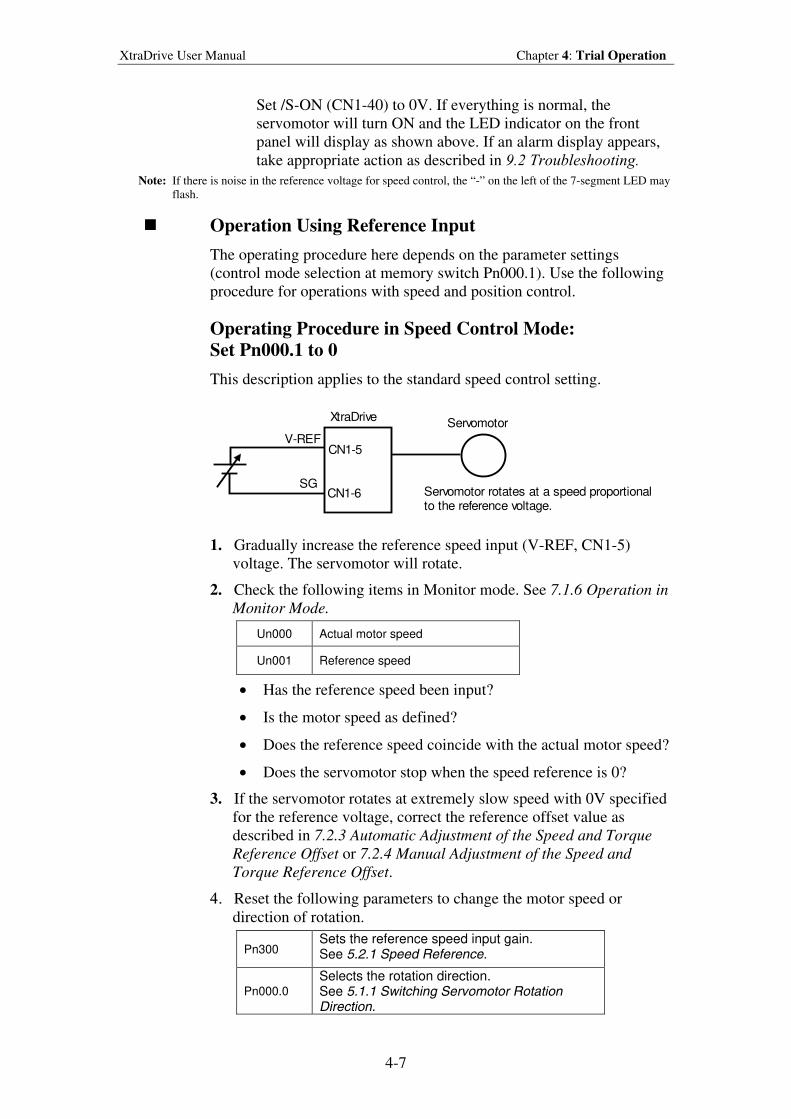
XtraDrive User Manual Chapter 4: Trial Operation
4-7
Set /S-ON (CN1-40) to 0V. If everything is normal, the
servomotor will turn ON and the LED indicator on the front
panel will display as shown above. If an alarm display appears,
take appropriate action as described in 9.2 Troubleshooting.
Note: If there is noise in the reference voltage for speed control, the “-” on the left of the 7-segment LED may
flash.
Operation Using Reference Input
The operating procedure here depends on the parameter settings
(control mode selection at memory switch Pn000.1). Use the following
procedure for operations with speed and position control.
Operating Procedure in Speed Control Mode:
Set Pn000.1 to 0
This description applies to the standard speed control setting.
XtraDrive
CN1-6
Servomotor
CN1-5V-REF
SGServomotor rotates at a speed proportionalto the reference voltage.
1. Gradually increase the reference speed input (V-REF, CN1-5)
voltage. The servomotor will rotate.
2. Check the following items in Monitor mode. See 7.1.6 Operation in
Monitor Mode.
Un000 Actual motor speed
Un001 Reference speed
• Has the reference speed been input?
• Is the motor speed as defined?
• Does the reference speed coincide with the actual motor speed?
• Does the servomotor stop when the speed reference is 0?
3. If the servomotor rotates at extremely slow speed with 0V specified
for the reference voltage, correct the reference offset value as
described in 7.2.3 Automatic Adjustment of the Speed and Torque
Reference Offset or 7.2.4 Manual Adjustment of the Speed and
Torque Reference Offset.
4. Reset the following parameters to change the motor speed or
direction of rotation.
Pn300 Sets the reference speed input gain. See 5.2.1 Speed Reference.
Pn000.0
Selects the rotation direction. See 5.1.1 Switching Servomotor Rotation Direction.
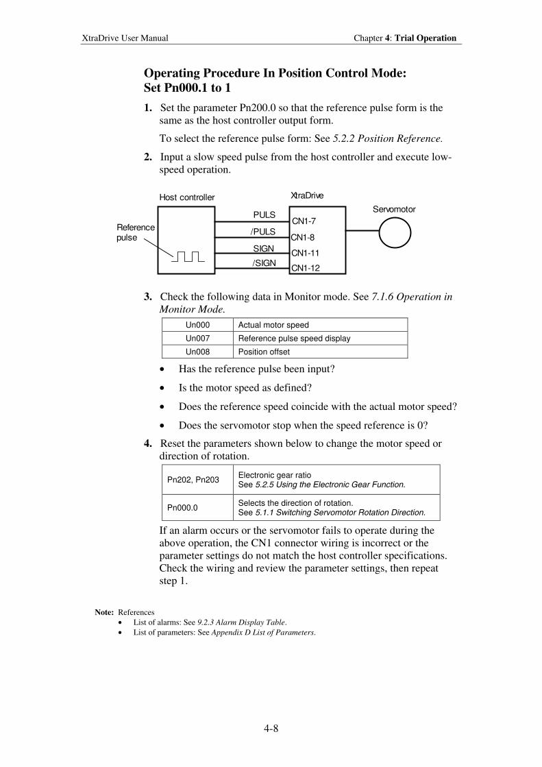
XtraDrive User Manual Chapter 4: Trial Operation
4-8
Operating Procedure In Position Control Mode:
Set Pn000.1 to 1
1. Set the parameter Pn200.0 so that the reference pulse form is the
same as the host controller output form.
To select the reference pulse form: See 5.2.2 Position Reference.
2. Input a slow speed pulse from the host controller and execute low-
speed operation.
Host controller XtraDrive
Referencepulse
ServomotorPULS
/PULS
/SIGN
SIGN
CN1-7
CN1-8
CN1-11
CN1-12
3. Check the following data in Monitor mode. See 7.1.6 Operation in
Monitor Mode.
Un000 Actual motor speed
Un007 Reference pulse speed display
Un008 Position offset
• Has the reference pulse been input?
• Is the motor speed as defined?
• Does the reference speed coincide with the actual motor speed?
• Does the servomotor stop when the speed reference is 0?
4. Reset the parameters shown below to change the motor speed or
direction of rotation.
Pn202, Pn203 Electronic gear ratio See 5.2.5 Using the Electronic Gear Function.
Pn000.0 Selects the direction of rotation. See 5.1.1 Switching Servomotor Rotation Direction.
If an alarm occurs or the servomotor fails to operate during the
above operation, the CN1 connector wiring is incorrect or the
parameter settings do not match the host controller specifications.
Check the wiring and review the parameter settings, then repeat
step 1.
Note: References
• List of alarms: See 9.2.3 Alarm Display Table.
• List of parameters: See Appendix D List of Parameters.
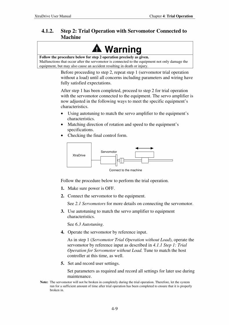
XtraDrive User Manual Chapter 4: Trial Operation
4-9
4.1.2. Step 2: Trial Operation with Servomotor Connected to
Machine
Warning Follow the procedure below for step 2 operation precisely as given.
Malfunctions that occur after the servomotor is connected to the equipment not only damage the
equipment, but may also cause an accident resulting in death or injury.
Before proceeding to step 2, repeat step 1 (servomotor trial operation
without a load) until all concerns including parameters and wiring have
fully satisfied expectations.
After step 1 has been completed, proceed to step 2 for trial operation
with the servomotor connected to the equipment. The servo amplifier is
now adjusted in the following ways to meet the specific equipment’s
characteristics.
• Using autotuning to match the servo amplifier to the equipment’s
characteristics.
• Matching direction of rotation and speed to the equipment’s
specifications.
• Checking the final control form.
XtraDrive Servomotor
Connect to the machine
Follow the procedure below to perform the trial operation.
1. Make sure power is OFF.
2. Connect the servomotor to the equipment.
See 2.1 Servomotors for more details on connecting the servomotor.
3. Use autotuning to match the servo amplifier to equipment
characteristics.
See 6.3 Autotuning.
4. Operate the servomotor by reference input.
As in step 1 (Servomotor Trial Operation without Load), operate the
servomotor by reference input as described in 4.1.1 Step 1: Trial
Operation for Servomotor without Load. Tune to match the host
controller at this time, as well.
5. Set and record user settings.
Set parameters as required and record all settings for later use during
maintenance.
Note: The servomotor will not be broken in completely during the trial operation. Therefore, let the system
run for a sufficient amount of time after trial operation has been completed to ensure that it is properly
broken in.
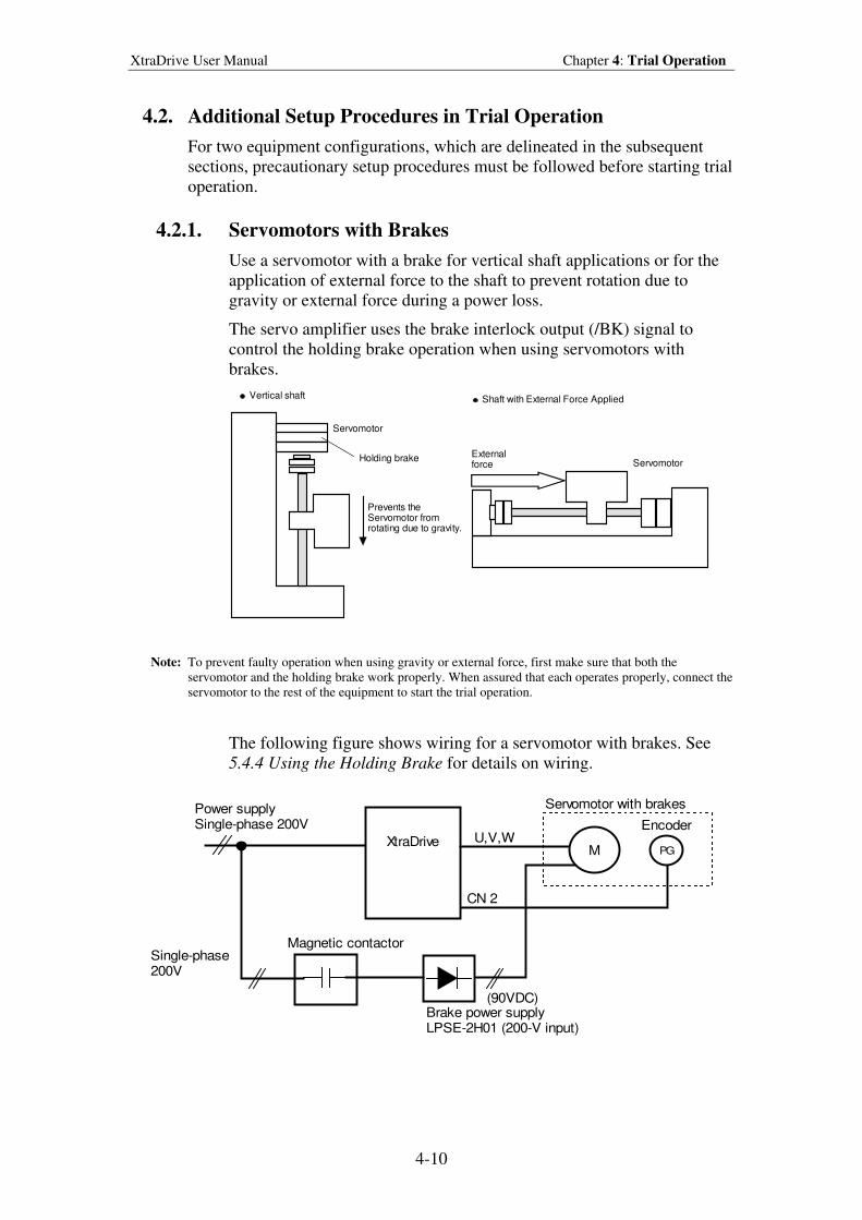
XtraDrive User Manual Chapter 4: Trial Operation
4-10
4.2. Additional Setup Procedures in Trial Operation
For two equipment configurations, which are delineated in the subsequent
sections, precautionary setup procedures must be followed before starting trial
operation.
4.2.1. Servomotors with Brakes
Use a servomotor with a brake for vertical shaft applications or for the
application of external force to the shaft to prevent rotation due to
gravity or external force during a power loss.
The servo amplifier uses the brake interlock output (/BK) signal to
control the holding brake operation when using servomotors with
brakes.
Externalforce Servomotor
Servomotor
Holding brake
Prevents theServomotor fromrotating due to gravity.
Vertical shaft Shaft with External Force Applied
Note: To prevent faulty operation when using gravity or external force, first make sure that both the
servomotor and the holding brake work properly. When assured that each operates properly, connect the
servomotor to the rest of the equipment to start the trial operation.
The following figure shows wiring for a servomotor with brakes. See
5.4.4 Using the Holding Brake for details on wiring.
XtraDriveM PG
Servomotor with brakes
EncoderU,V,W
CN 2
Power supplySingle-phase 200V
Single-phase200V
Magnetic contactor
(90VDC)Brake power supplyLPSE-2H01 (200-V input)
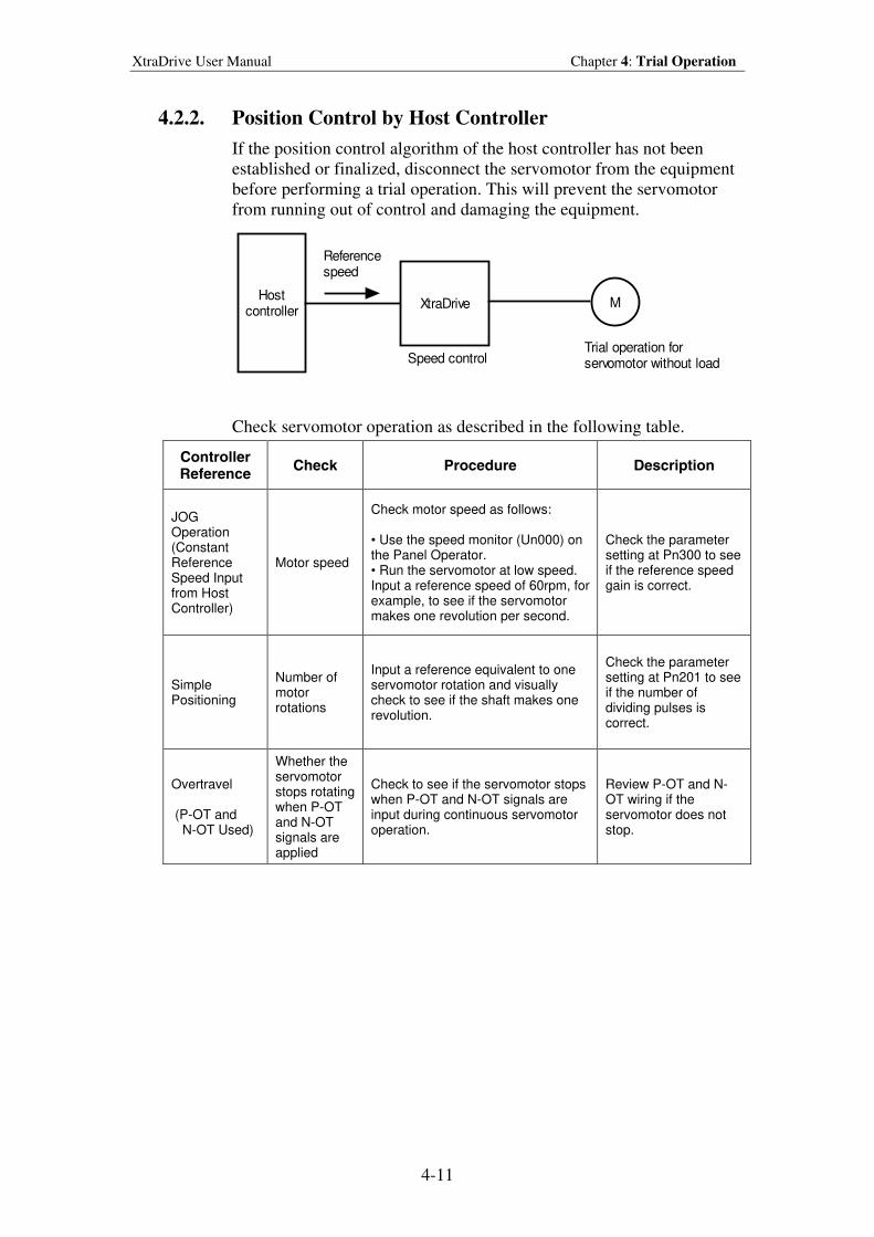
XtraDrive User Manual Chapter 4: Trial Operation
4-11
4.2.2. Position Control by Host Controller
If the position control algorithm of the host controller has not been
established or finalized, disconnect the servomotor from the equipment
before performing a trial operation. This will prevent the servomotor
from running out of control and damaging the equipment.
Hostcontroller
XtraDrive M
Referencespeed
Speed controlTrial operation forservomotor without load
Check servomotor operation as described in the following table.
Controller Reference
Check Procedure Description
JOG Operation (Constant Reference Speed Input from Host Controller)
Motor speed
Check motor speed as follows: • Use the speed monitor (Un000) on the Panel Operator. • Run the servomotor at low speed. Input a reference speed of 60rpm, for example, to see if the servomotor makes one revolution per second.
Check the parameter setting at Pn300 to see if the reference speed gain is correct.
Simple Positioning
Number of motor rotations
Input a reference equivalent to one servomotor rotation and visually check to see if the shaft makes one revolution.
Check the parameter setting at Pn201 to see if the number of dividing pulses is correct.
Overtravel (P-OT and N-OT Used)
Whether the servomotor stops rotating when P-OT and N-OT signals are applied
Check to see if the servomotor stops when P-OT and N-OT signals are input during continuous servomotor operation.
Review P-OT and N-OT wiring if the servomotor does not stop.
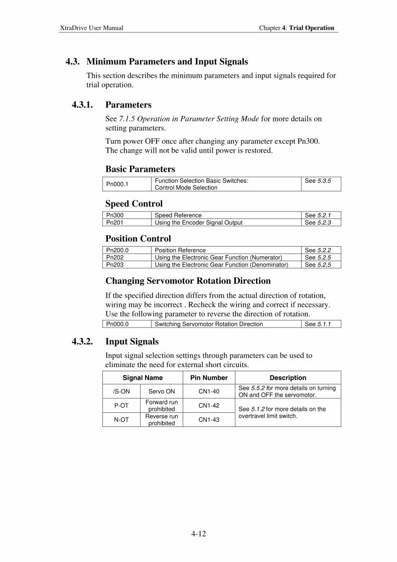
XtraDrive User Manual Chapter 4: Trial Operation
4-12
4.3. Minimum Parameters and Input Signals
This section describes the minimum parameters and input signals required for
trial operation.
4.3.1. Parameters
See 7.1.5 Operation in Parameter Setting Mode for more details on
setting parameters.
Turn power OFF once after changing any parameter except Pn300.
The change will not be valid until power is restored.
Basic Parameters
Pn000.1 Function Selection Basic Switches: Control Mode Selection
See 5.3.5
Speed Control
Pn300 Speed Reference See 5.2.1 Pn201 Using the Encoder Signal Output See 5.2.3
Position Control
Pn200.0 Position Reference See 5.2.2
Pn202 Using the Electronic Gear Function (Numerator) See 5.2.5
Pn203 Using the Electronic Gear Function (Denominator) See 5.2.5
Changing Servomotor Rotation Direction
If the specified direction differs from the actual direction of rotation,
wiring may be incorrect . Recheck the wiring and correct if necessary.
Use the following parameter to reverse the direction of rotation.
Pn000.0 Switching Servomotor Rotation Direction See 5.1.1
4.3.2. Input Signals
Input signal selection settings through parameters can be used to
eliminate the need for external short circuits.
Signal Name Pin Number Description
/S-ON Servo ON CN1-40 See 5.5.2 for more details on turning ON and OFF the servomotor.
P-OT Forward run prohibited
CN1-42
N-OT Reverse run prohibited
CN1-43
See 5.1.2 for more details on the overtravel limit switch.
XtraDrive User Manual Chapter 5: Parameter Settings and Functions
5-1
5. Parameter Sett ings and Funct ions
5.1. Settings According to Device Characteristics.............................................5-4
5.1.1. Switching Servomotor Rotation Direction..........................................5-4
5.1.2. Setting the Overtravel Limit Function ................................................5-5
5.1.3. Limiting Torque ..................................................................................5-8
5.2. Settings According to Host Controller......................................................5-12
5.2.1. Speed Reference................................................................................5-12
5.2.2. Position Reference ............................................................................5-14
5.2.3. Using the Encoder Signal Output .....................................................5-20
5.2.4. Sequence I/O Signals ........................................................................5-23
5.2.5. Using the Electronic Gear Function..................................................5-24
5.2.6. Contact Input Speed Control.............................................................5-29
5.2.7. Using Torque Control .......................................................................5-34
5.2.8. Torque Feed-Forward Function ........................................................5-40
5.2.9. Torque Limiting by Analog Voltage Reference ...............................5-42
5.2.10. Reference Pulse Inhibit Function (/INHIBIT) ..................................5-44
5.3. Setting Up the Servo Amplifier ................................................................5-45
5.3.1. Parameters.........................................................................................5-45
5.3.2. JOG Speed ........................................................................................5-46
5.3.3. Input Circuit Signal Allocation.........................................................5-46
5.3.4. Output Circuit Signal Allocation ......................................................5-50
5.3.5. Control Mode Selection ....................................................................5-52
5.4. Setting Stop Functions ..............................................................................5-54
5.4.1. Adjusting Offset................................................................................5-54
5.4.2. Servo OFF Stop Mode Selection ......................................................5-55
5.4.3. Using the Zero Clamp Function........................................................5-56
5.4.4. Using the Holding Brake ..................................................................5-58
5.5. Forming a Protective Sequence ................................................................5-61
5.5.1. Using Servo Alarm and Alarm Code Outputs ..................................5-61
5.5.2. Using the Servo ON Input Signal (/S-ON) .......................................5-63
5.5.3. Using the Positioning Completed Output Signal (/COIN) ...............5-64
5.5.4. Speed Coincidence Output (/V-CMP) ..............................................5-65
5.5.5. Using the Running Output Signal (/TGON) .....................................5-67
5.5.6. Using the Servo Ready Output Signal (/S-RDY) .............................5-68
5.5.7. Using the Warning Output Signal (/WARN)....................................5-69
5.5.8. Handling Power Loss ........................................................................5-71
5.6. Selecting a Regenerative Resistor.............................................................5-72
5.6.1. External Regenerative Resistor.........................................................5-73
5.6.2. Calculating the Regenerative Power Capacity..................................5-74
5.7. Absolute Encoders ....................................................................................5-78
5.7.1. Interface Circuit ................................................................................5-79
5.7.2. Configuring an Absolute Encoder ....................................................5-80
5.7.3. Absolute Encoder Setup....................................................................5-81
5.7.4. Absolute Encoder Reception Sequence ............................................5-84
5.8. AB Encoders .............................................................................................5-89
5.9. Configuration of Serial Commands for AB Encoders ..............................5-91
5.9.1. Position Control ................................................................................5-91
5.9.1.1. Defining User Units for Motion Profiles ......................................5-91
XtraDrive User Manual Chapter 5: Parameter Settings and Functions
5-2
5.9.1.3. Speed Units ...................................................................................5-92
5.9.1.4. Acceleration Units ........................................................................5-93
5.9.1.5. Setting Default Motion Profile Parameters...................................5-94
5.9.1.6. Profile Speed (Pn2A2, Pn2A3) .....................................................5-95
5.9.1.7. Profile Acceleration (Pn2A4, Pn2A5) ..........................................5-95
5.9.1.8. Jerk Smoothing Time (Pn2A6) .....................................................5-95
5.9.1.9. Quick Stop Deceleration (Pn2A8, Pn2A9) ...................................5-96
5.9.1.10. Motion End Window (Pn2C0) ......................................................5-96
5.9.2. Torque Control..................................................................................5-96
5.9.3. Homing .............................................................................................5-97
5.9.4. Digital I/O .........................................................................................5-98
5.9.5. Auto Tuning ......................................................................................5-99
5.10. Auto Running a User Program..............................................................5-99
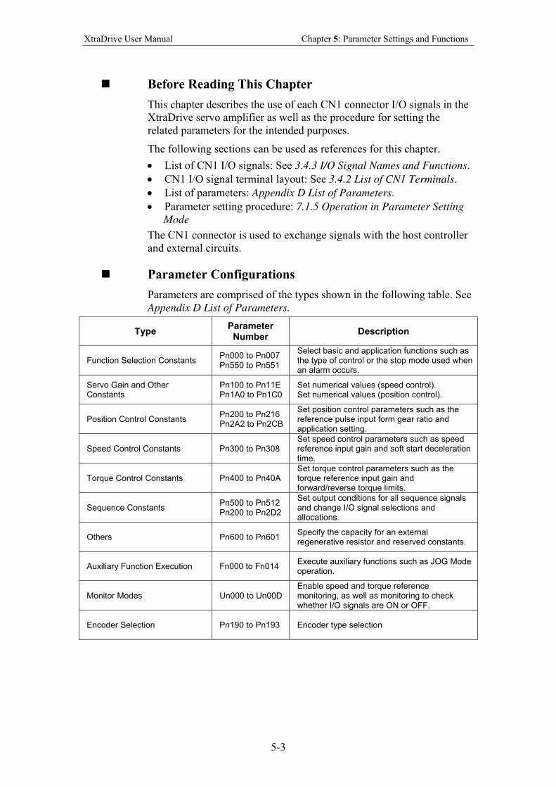
XtraDrive User Manual Chapter 5: Parameter Settings and Functions
5-3
Before Reading This Chapter
This chapter describes the use of each CN1 connector I/O signals in the
XtraDrive servo amplifier as well as the procedure for setting the
related parameters for the intended purposes.
The following sections can be used as references for this chapter.
• List of CN1 I/O signals: See 3.4.3 I/O Signal Names and Functions.
• CN1 I/O signal terminal layout: See 3.4.2 List of CN1 Terminals.
• List of parameters: Appendix D List of Parameters.
• Parameter setting procedure: 7.1.5 Operation in Parameter Setting
Mode
The CN1 connector is used to exchange signals with the host controller
and external circuits.
Parameter Configurations
Parameters are comprised of the types shown in the following table. See
Appendix D List of Parameters.
Type Parameter
Number Description
Function Selection Constants Pn000 to Pn007 Pn550 to Pn551
Select basic and application functions such as the type of control or the stop mode used when an alarm occurs.
Servo Gain and Other Constants
Pn100 to Pn11E Pn1A0 to Pn1C0
Set numerical values (speed control). Set numerical values (position control).
Position Control Constants Pn200 to Pn216 Pn2A2 to Pn2CB
Set position control parameters such as the reference pulse input form gear ratio and application setting.
Speed Control Constants Pn300 to Pn308 Set speed control parameters such as speed reference input gain and soft start deceleration time.
Torque Control Constants Pn400 to Pn40A Set torque control parameters such as the torque reference input gain and forward/reverse torque limits.
Sequence Constants Pn500 to Pn512 Pn200 to Pn2D2
Set output conditions for all sequence signals and change I/O signal selections and allocations.
Others Pn600 to Pn601 Specify the capacity for an external regenerative resistor and reserved constants.
Auxiliary Function Execution Fn000 to Fn014 Execute auxiliary functions such as JOG Mode operation.
Monitor Modes Un000 to Un00D Enable speed and torque reference monitoring, as well as monitoring to check whether I/O signals are ON or OFF.
Encoder Selection Pn190 to Pn193 Encoder type selection
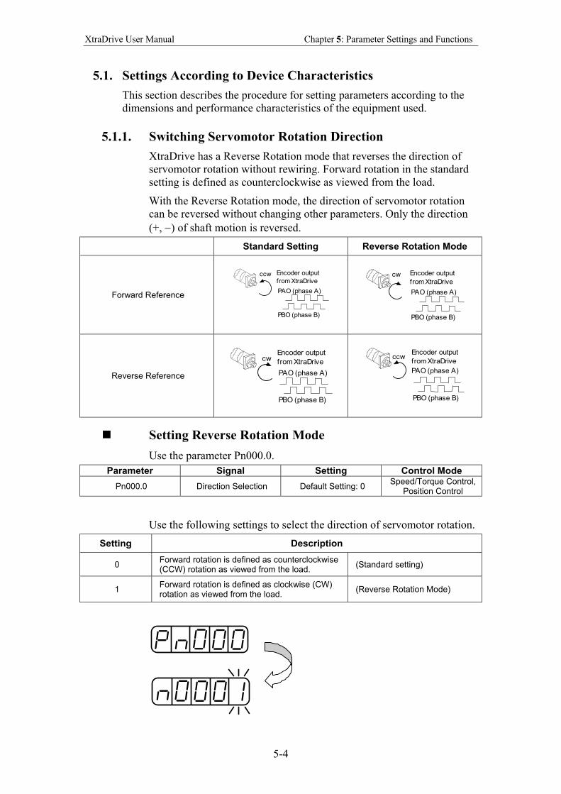
XtraDrive User Manual Chapter 5: Parameter Settings and Functions
5-4
5.1. Settings According to Device Characteristics
This section describes the procedure for setting parameters according to the
dimensions and performance characteristics of the equipment used.
5.1.1. Switching Servomotor Rotation Direction
XtraDrive has a Reverse Rotation mode that reverses the direction of
servomotor rotation without rewiring. Forward rotation in the standard
setting is defined as counterclockwise as viewed from the load.
With the Reverse Rotation mode, the direction of servomotor rotation
can be reversed without changing other parameters. Only the direction
(+, −) of shaft motion is reversed.
Standard Setting Reverse Rotation Mode
Forward Reference
Encoder output
from XtraDrive
PAO (phase A)
PBO (phase B)
ccw
Encoder output
from XtraDrive
PAO (phase A)
PBO (phase B)
cw
Reverse Reference
Encoder output
from XtraDrive
PAO (phase A)
PBO (phase B)
cw
Encoder output
from XtraDrive
PAO (phase A)
PBO (phase B)
ccw
Setting Reverse Rotation Mode
Use the parameter Pn000.0.
Parameter Signal Setting Control Mode
Pn000.0 Direction Selection Default Setting: 0 Speed/Torque Control,
Position Control
Use the following settings to select the direction of servomotor rotation.
Setting Description
0 Forward rotation is defined as counterclockwise (CCW) rotation as viewed from the load.
(Standard setting)
1 Forward rotation is defined as clockwise (CW) rotation as viewed from the load.
(Reverse Rotation Mode)
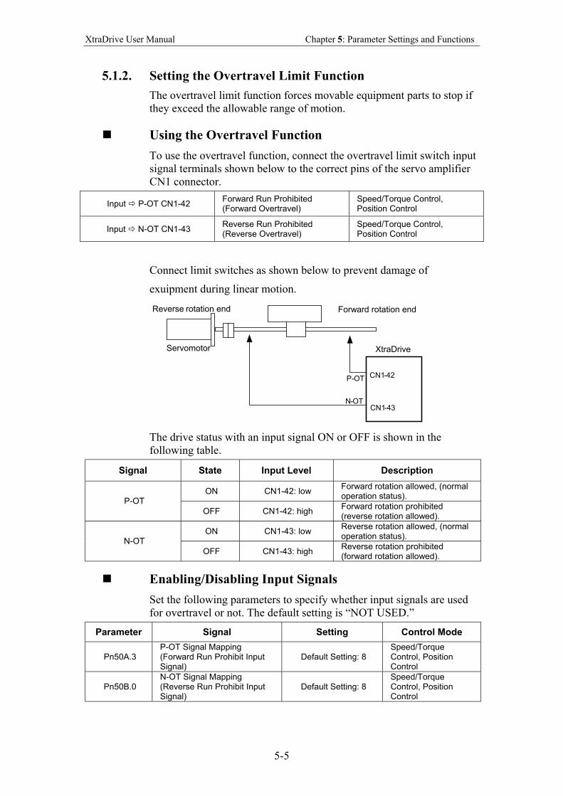
XtraDrive User Manual Chapter 5: Parameter Settings and Functions
5-5
5.1.2. Setting the Overtravel Limit Function
The overtravel limit function forces movable equipment parts to stop if
they exceed the allowable range of motion.
Using the Overtravel Function
To use the overtravel function, connect the overtravel limit switch input
signal terminals shown below to the correct pins of the servo amplifier
CN1 connector.
Input P-OT CN1-42 Forward Run Prohibited (Forward Overtravel)
Speed/Torque Control, Position Control
Input N-OT CN1-43 Reverse Run Prohibited (Reverse Overtravel)
Speed/Torque Control, Position Control
Connect limit switches as shown below to prevent damage of
exuipment during linear motion.
Reverse rotation end
Servomotor
Forward rotation end
XtraDrive
CN1 -42
CN1 -43
P- OT
N - OT
The drive status with an input signal ON or OFF is shown in the
following table.
Signal State Input Level Description
ON CN1-42: low Forward rotation allowed, (normal operation status).
P-OT
OFF CN1-42: high Forward rotation prohibited (reverse rotation allowed).
ON CN1-43: low Reverse rotation allowed, (normal operation status).
N-OT
OFF CN1-43: high Reverse rotation prohibited (forward rotation allowed).
Enabling/Disabling Input Signals
Set the following parameters to specify whether input signals are used
for overtravel or not. The default setting is “NOT USED.”
Parameter Signal Setting Control Mode
Pn50A.3 P-OT Signal Mapping (Forward Run Prohibit Input Signal)
Default Setting: 8 Speed/Torque Control, Position Control
Pn50B.0 N-OT Signal Mapping (Reverse Run Prohibit Input Signal)
Default Setting: 8 Speed/Torque Control, Position Control
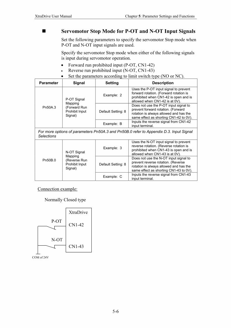
XtraDrive User Manual Chapter 5: Parameter Settings and Functions
5-6
Servomotor Stop Mode for P-OT and N-OT Input Signals
Set the following parameters to specify the servomotor Stop mode when
P-OT and N-OT input signals are used.
Specify the servomotor Stop mode when either of the following signals
is input during servomotor operation.
• Forward run prohibited input (P-OT, CN1-42)
• Reverse run prohibited input (N-OT, CN1-43)
• Set the parameters according to limit switch type (NO or NC).
Parameter Signal Setting Description
Example: 2
Uses the P-OT input signal to prevent forward rotation. (Forward rotation is prohibited when CN1-42 is open and is allowed when CN1-42 is at 0V).
Default Setting: 8
Does not use the P-OT input signal to prevent forward rotation. (Forward rotation is always allowed and has the same effect as shorting CN1-42 to 0V).
Pn50A.3
P-OT Signal Mapping (Forward Run Prohibit Input Signal)
Example: B Inputs the reverse signal from CN1-42 input terminal.
For more options of parameters Pn50A.3 and Pn50B.0 refer to Appendix D.3. Input Signal Selections
Example: 3
Uses the N-OT input signal to prevent reverse rotation. (Reverse rotation is prohibited when CN1-43 is open and is allowed when CN1-43 is at 0V).
Default Setting: 8
Does not use the N-OT input signal to prevent reverse rotation. (Reverse rotation is always allowed and has the same effect as shorting CN1-43 to 0V).
Pn50B.0
N-OT Signal Mapping (Reverse Run Prohibit Input Signal)
Example: C Inputs the reverse signal from CN1-43 input terminal.
Connection example:
Normally Closed type
P-OT
N-OT
COM of 24V
XtraDrive
CN1-42
CN1-43
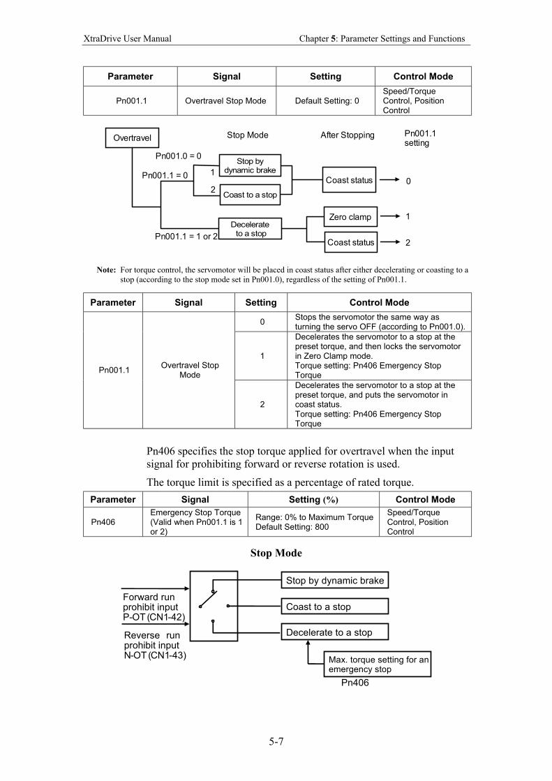
XtraDrive User Manual Chapter 5: Parameter Settings and Functions
5-7
Parameter Signal Setting Control Mode
Pn001.1 Overtravel Stop Mode Default Setting: 0 Speed/Torque Control, Position Control
Overtravel
Stop bydynamic brake
Coast to a stop
Coast status
Zero clamp
Coast status
Decelerate to a stop
Stop Mode After Stopping
Pn001.0 = 0
Pn001.1 = 0
Pn001.1 = 1 or 2
1
2
Pn001.1setting
0
1
2
Note: For torque control, the servomotor will be placed in coast status after either decelerating or coasting to a
stop (according to the stop mode set in Pn001.0), regardless of the setting of Pn001.1.
Parameter Signal Setting Control Mode
0 Stops the servomotor the same way as turning the servo OFF (according to Pn001.0).
1
Decelerates the servomotor to a stop at the preset torque, and then locks the servomotor in Zero Clamp mode. Torque setting: Pn406 Emergency Stop Torque
Pn001.1 Overtravel Stop
Mode
2
Decelerates the servomotor to a stop at the preset torque, and puts the servomotor in coast status. Torque setting: Pn406 Emergency Stop Torque
Pn406 specifies the stop torque applied for overtravel when the input
signal for prohibiting forward or reverse rotation is used.
The torque limit is specified as a percentage of rated torque.
Parameter Signal Setting (%) Control Mode
Pn406 Emergency Stop Torque (Valid when Pn001.1 is 1 or 2)
Range: 0% to Maximum Torque Default Setting: 800
Speed/Torque Control, Position Control
Stop Mode
Stop by dynamic brake
Coast to a stop
Decelerate to a stop
Max. torque setting for an emergency stop
Forward run prohibit input P- OT ( CN1 -42)
Reverse run prohibit input N - OT ( CN1 -43)
Pn406
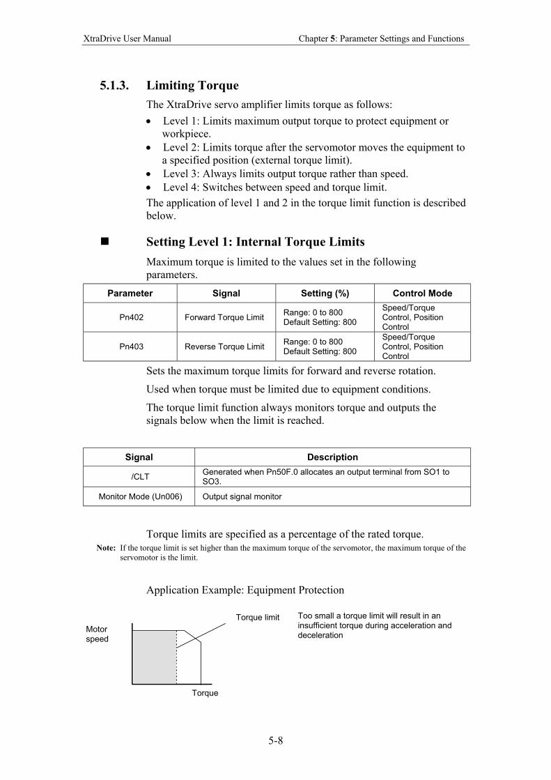
XtraDrive User Manual Chapter 5: Parameter Settings and Functions
5-8
5.1.3. Limiting Torque
The XtraDrive servo amplifier limits torque as follows:
• Level 1: Limits maximum output torque to protect equipment or
workpiece.
• Level 2: Limits torque after the servomotor moves the equipment to
a specified position (external torque limit).
• Level 3: Always limits output torque rather than speed.
• Level 4: Switches between speed and torque limit.
The application of level 1 and 2 in the torque limit function is described
below.
Setting Level 1: Internal Torque Limits
Maximum torque is limited to the values set in the following
parameters.
Parameter Signal Setting (%) Control Mode
Pn402 Forward Torque Limit Range: 0 to 800 Default Setting: 800
Speed/Torque Control, Position Control
Pn403 Reverse Torque Limit Range: 0 to 800 Default Setting: 800
Speed/Torque Control, Position Control
Sets the maximum torque limits for forward and reverse rotation.
Used when torque must be limited due to equipment conditions.
The torque limit function always monitors torque and outputs the
signals below when the limit is reached.
Signal Description
/CLT Generated when Pn50F.0 allocates an output terminal from SO1 to SO3.
Monitor Mode (Un006) Output signal monitor
Torque limits are specified as a percentage of the rated torque.
Note: If the torque limit is set higher than the maximum torque of the servomotor, the maximum torque of the
servomotor is the limit.
Application Example: Equipment Protection
Torque limit
Motor speed
Torque
Too small a torque limit will result in an insufficient torque during acceleration and deceleration
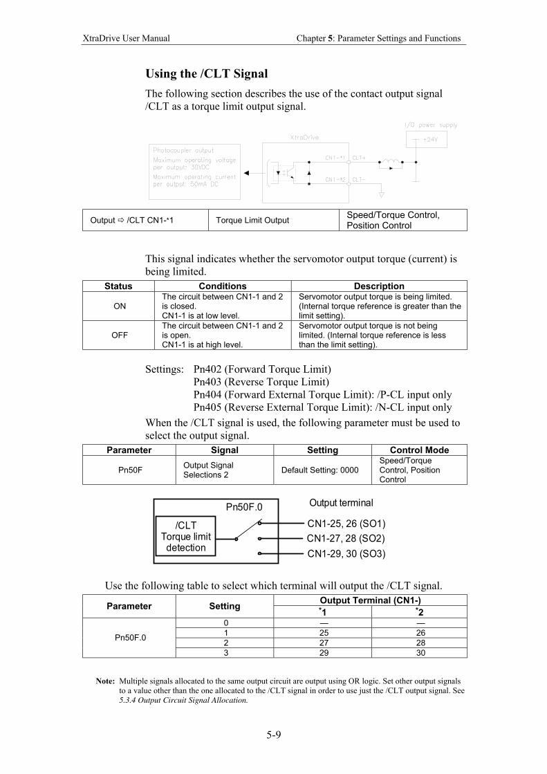
XtraDrive User Manual Chapter 5: Parameter Settings and Functions
5-9
Using the /CLT Signal
The following section describes the use of the contact output signal
/CLT as a torque limit output signal.
Output /CLT CN1-*1 Torque Limit Output Speed/Torque Control, Position Control
This signal indicates whether the servomotor output torque (current) is
being limited.
Status Conditions Description
ON The circuit between CN1-1 and 2 is closed. CN1-1 is at low level.
Servomotor output torque is being limited. (Internal torque reference is greater than the limit setting).
OFF The circuit between CN1-1 and 2 is open. CN1-1 is at high level.
Servomotor output torque is not being limited. (Internal torque reference is less than the limit setting).
Settings: Pn402 (Forward Torque Limit)
Pn403 (Reverse Torque Limit)
Pn404 (Forward External Torque Limit): /P-CL input only
Pn405 (Reverse External Torque Limit): /N-CL input only
When the /CLT signal is used, the following parameter must be used to
select the output signal.
Parameter Signal Setting Control Mode
Pn50F Output Signal Selections 2
Default Setting: 0000 Speed/Torque Control, Position Control
CN1-25, 26 (SO1)
CN1-27, 28 (SO2)
CN1-29, 30 (SO3)
Pn50F.0
/CLTTorque limitdetection
Output terminal
Use the following table to select which terminal will output the /CLT signal.
Output Terminal (CN1-) Parameter Setting
*1 *2 0 — —
1 25 26
2 27 28 Pn50F.0
3 29 30
Note: Multiple signals allocated to the same output circuit are output using OR logic. Set other output signals
to a value other than the one allocated to the /CLT signal in order to use just the /CLT output signal. See
5.3.4 Output Circuit Signal Allocation.
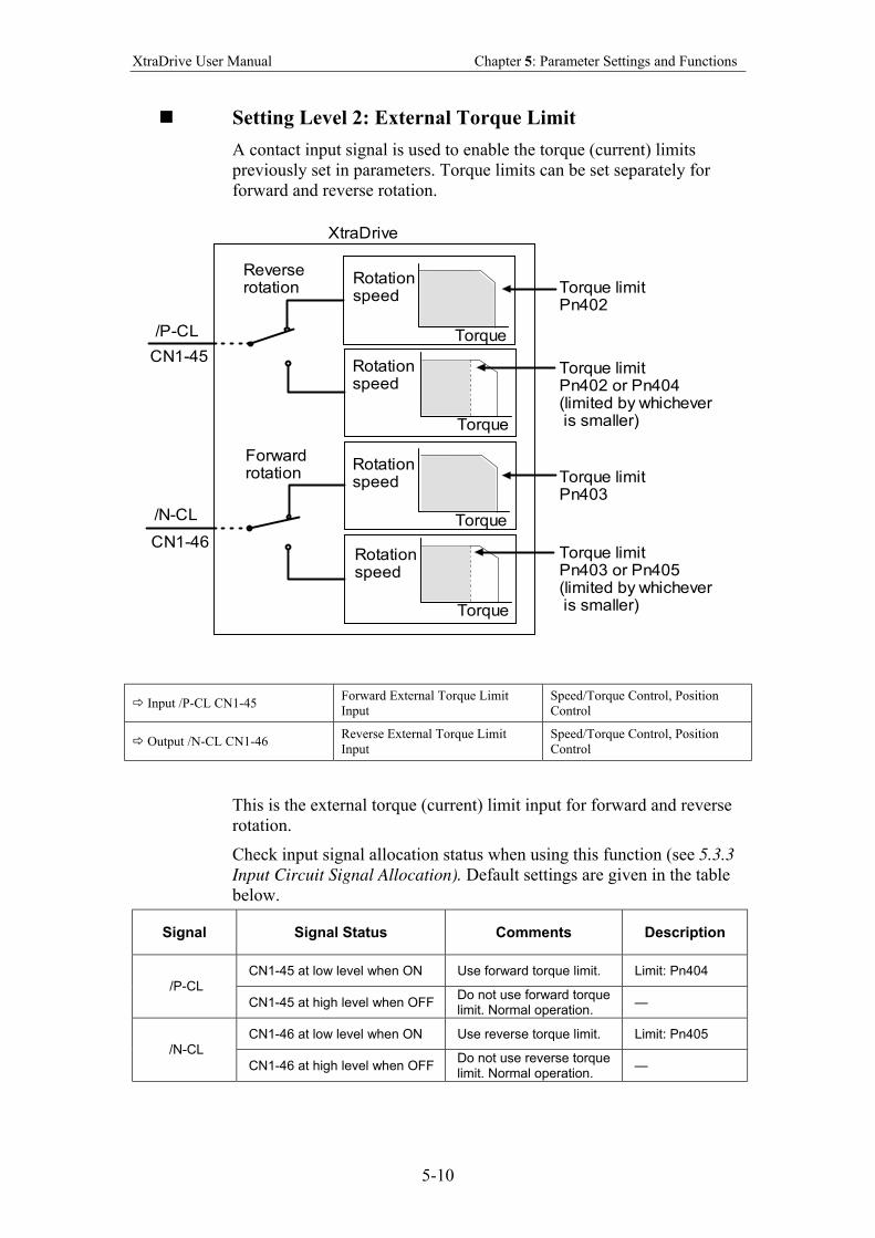
XtraDrive User Manual Chapter 5: Parameter Settings and Functions
5-10
Setting Level 2: External Torque Limit
A contact input signal is used to enable the torque (current) limits
previously set in parameters. Torque limits can be set separately for
forward and reverse rotation.
Torque limitPn402
Rotationspeed
Torque
Torque
Torque
Torque
Rotationspeed
Rotationspeed
Rotationspeed
Torque limitPn402 or Pn404(limited by whichever is smaller)
Torque limitPn403
Torque limitPn403 or Pn405(limited by whichever is smaller)
Reverserotation
Forwardrotation
/P-CL
/N-CL
CN1-45
CN1-46
XtraDrive
Input /P-CL CN1-45 Forward External Torque Limit
Input
Speed/Torque Control, Position
Control
Output /N-CL CN1-46 Reverse External Torque Limit
Input
Speed/Torque Control, Position
Control
This is the external torque (current) limit input for forward and reverse
rotation.
Check input signal allocation status when using this function (see 5.3.3
Input Circuit Signal Allocation). Default settings are given in the table
below.
Signal Signal Status Comments Description
CN1-45 at low level when ON Use forward torque limit. Limit: Pn404 /P-CL
CN1-45 at high level when OFF Do not use forward torque limit. Normal operation.
—
CN1-46 at low level when ON Use reverse torque limit. Limit: Pn405 /N-CL
CN1-46 at high level when OFF Do not use reverse torque limit. Normal operation.
—
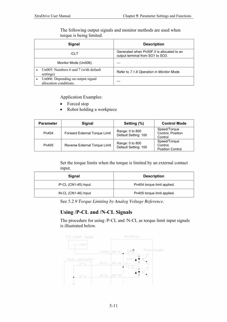
XtraDrive User Manual Chapter 5: Parameter Settings and Functions
5-11
The following output signals and monitor methods are used when
torque is being limited.
Signal Description
/CLT Generated when Pn50F.0 is allocated to an output terminal from SO1 to SO3.
Monitor Mode (Un006) —
• Un005: Numbers 6 and 7 (with default
settings) Refer to 7.1.6 Operation in Monitor Mode.
• Un006: Depending on output signal
allocation conditions. —
Application Examples:
• Forced stop
• Robot holding a workpiece
Parameter Signal Setting (%) Control Mode
Pn404 Forward External Torque Limit Range: 0 to 800 Default Setting: 100
Speed/Torque Control, Position Control
Pn405 Reverse External Torque Limit Range: 0 to 800 Default Setting: 100
Speed/Torque Control, Position Control
Set the torque limits when the torque is limited by an external contact
input.
Signal Description
/P-CL (CN1-45) Input Pn404 torque limit applied.
/N-CL (CN1-46) Input Pn405 torque limit applied.
See 5.2.9 Torque Limiting by Analog Voltage Reference.
Using /P-CL and /N-CL Signals
The procedure for using /P-CL and /N-CL as torque limit input signals
is illustrated below.
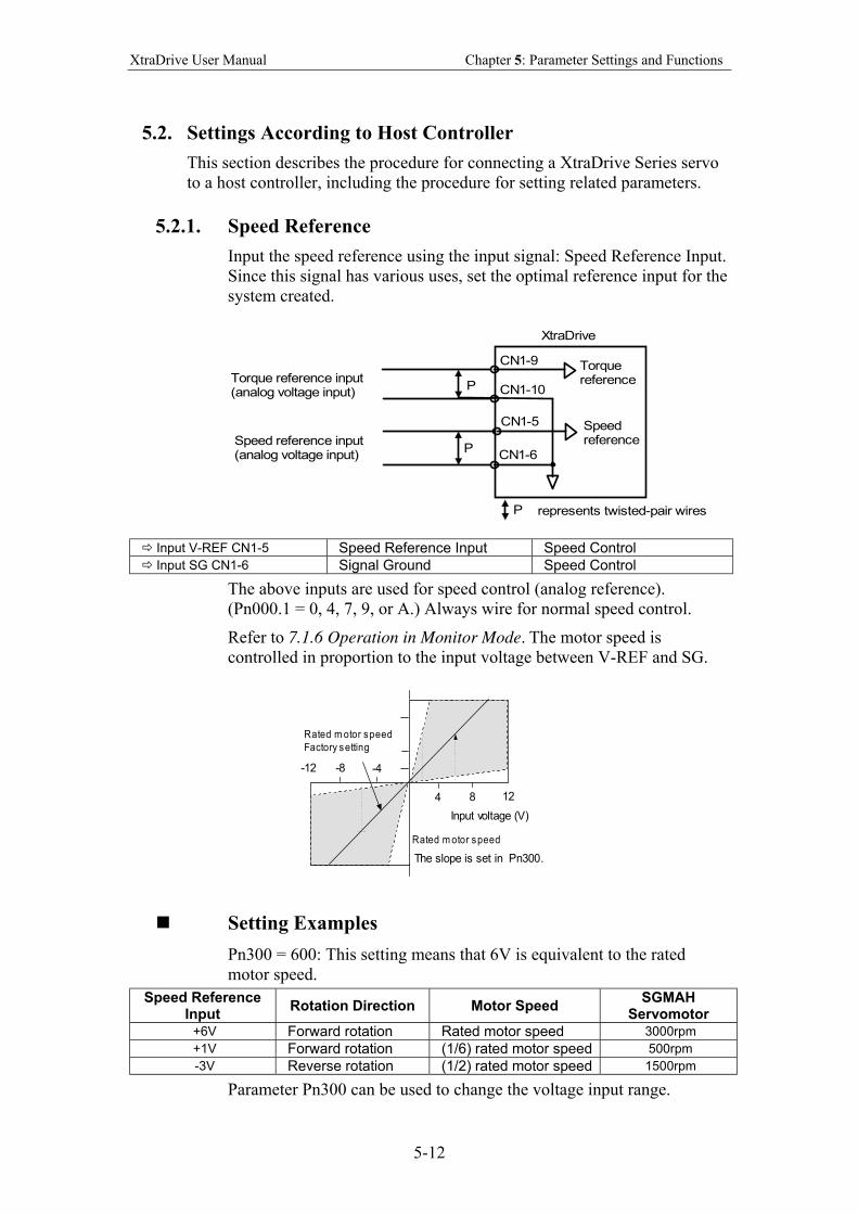
XtraDrive User Manual Chapter 5: Parameter Settings and Functions
5-12
5.2. Settings According to Host Controller
This section describes the procedure for connecting a XtraDrive Series servo
to a host controller, including the procedure for setting related parameters.
5.2.1. Speed Reference
Input the speed reference using the input signal: Speed Reference Input.
Since this signal has various uses, set the optimal reference input for the
system created.
XtraDrive
Torquereference
Speedreference
CN1-9
CN1-10
CN1-5
CN1-6
represents twisted-pair wiresP
P
P
Torque reference input(analog voltage input)
Speed reference input(analog voltage input)
Input V-REF CN1-5 Speed Reference Input Speed Control Input SG CN1-6 Signal Ground Speed Control
The above inputs are used for speed control (analog reference).
(Pn000.1 = 0, 4, 7, 9, or A.) Always wire for normal speed control.
Refer to 7.1.6 Operation in Monitor Mode. The motor speed is
controlled in proportion to the input voltage between V-REF and SG.
Rated m otor speed
Factory setting
-4-8-12
4 8 12
Input voltage (V)
Rated m otor speed
The slope is set in Pn300.
Setting Examples
Pn300 = 600: This setting means that 6V is equivalent to the rated
motor speed.
Speed Reference Input
Rotation Direction Motor Speed SGMAH
Servomotor +6V Forward rotation Rated motor speed 3000rpm
+1V Forward rotation (1/6) rated motor speed 500rpm
-3V Reverse rotation (1/2) rated motor speed 1500rpm
Parameter Pn300 can be used to change the voltage input range.
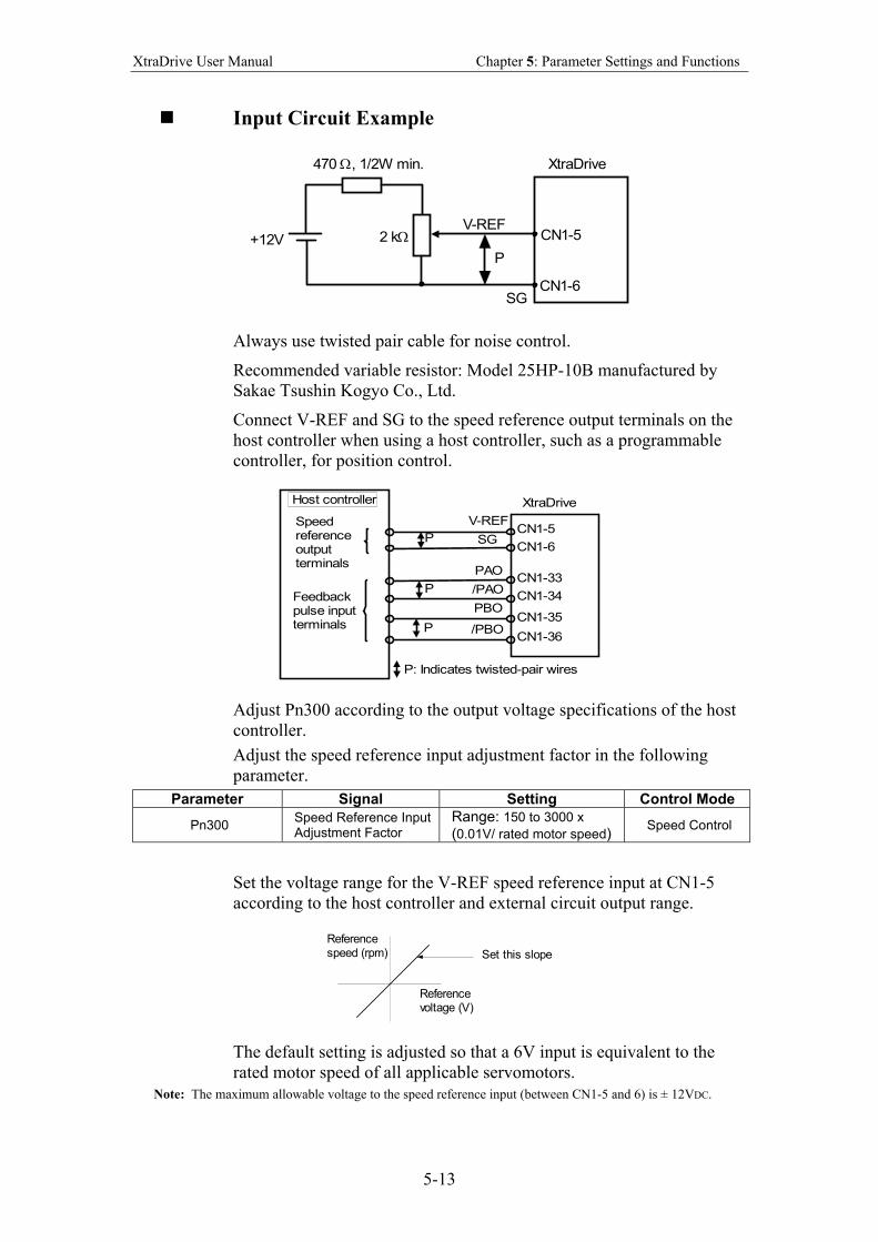
XtraDrive User Manual Chapter 5: Parameter Settings and Functions
5-13
Input Circuit Example
P
V-REF2 kΩ
470 Ω, 1/2W min.
+12V
SG
CN1-5
CN1-6
XtraDrive
Always use twisted pair cable for noise control.
Recommended variable resistor: Model 25HP-10B manufactured by
Sakae Tsushin Kogyo Co., Ltd.
Connect V-REF and SG to the speed reference output terminals on the
host controller when using a host controller, such as a programmable
controller, for position control.
CN1-5
CN1-6
XtraDrive
CN1-33
CN1-34
CN1-35
CN1-36
V-REF
SGP
PAO
/PAO
PBO
/PBO
P
P
Speedreferenceoutputterminals
Feedbackpulse inputterminals
Host controller
P: Indicates twisted-pair wires
Adjust Pn300 according to the output voltage specifications of the host
controller.
Adjust the speed reference input adjustment factor in the following
parameter.
Parameter Signal Setting Control Mode
Pn300 Speed Reference Input Adjustment Factor
Range: 150 to 3000 x
(0.01V/ rated motor speed) Speed Control
Set the voltage range for the V-REF speed reference input at CN1-5
according to the host controller and external circuit output range.
Set this slope
Referencespeed (rpm)
Referencevoltage (V)
The default setting is adjusted so that a 6V input is equivalent to the
rated motor speed of all applicable servomotors.
Note: The maximum allowable voltage to the speed reference input (between CN1-5 and 6) is ± 12VDC.
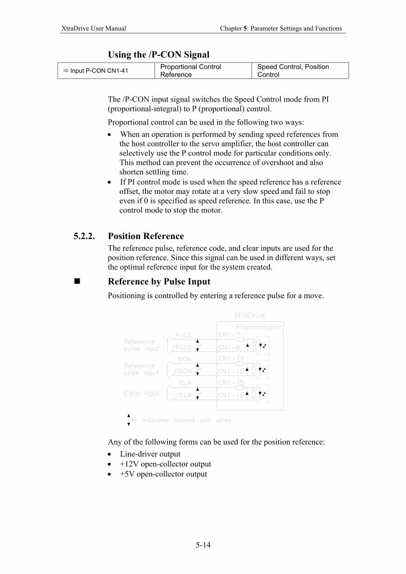
XtraDrive User Manual Chapter 5: Parameter Settings and Functions
5-14
Using the /P-CON Signal
Input P-CON CN1-41 Proportional Control Reference
Speed Control, Position Control
The /P-CON input signal switches the Speed Control mode from PI
(proportional-integral) to P (proportional) control.
Proportional control can be used in the following two ways:
• When an operation is performed by sending speed references from
the host controller to the servo amplifier, the host controller can
selectively use the P control mode for particular conditions only.
This method can prevent the occurrence of overshoot and also
shorten settling time.
• If PI control mode is used when the speed reference has a reference
offset, the motor may rotate at a very slow speed and fail to stop
even if 0 is specified as speed reference. In this case, use the P
control mode to stop the motor.
5.2.2. Position Reference
The reference pulse, reference code, and clear inputs are used for the
position reference. Since this signal can be used in different ways, set
the optimal reference input for the system created.
Reference by Pulse Input
Positioning is controlled by entering a reference pulse for a move.
Any of the following forms can be used for the position reference:
• Line-driver output
• +12V open-collector output
• +5V open-collector output
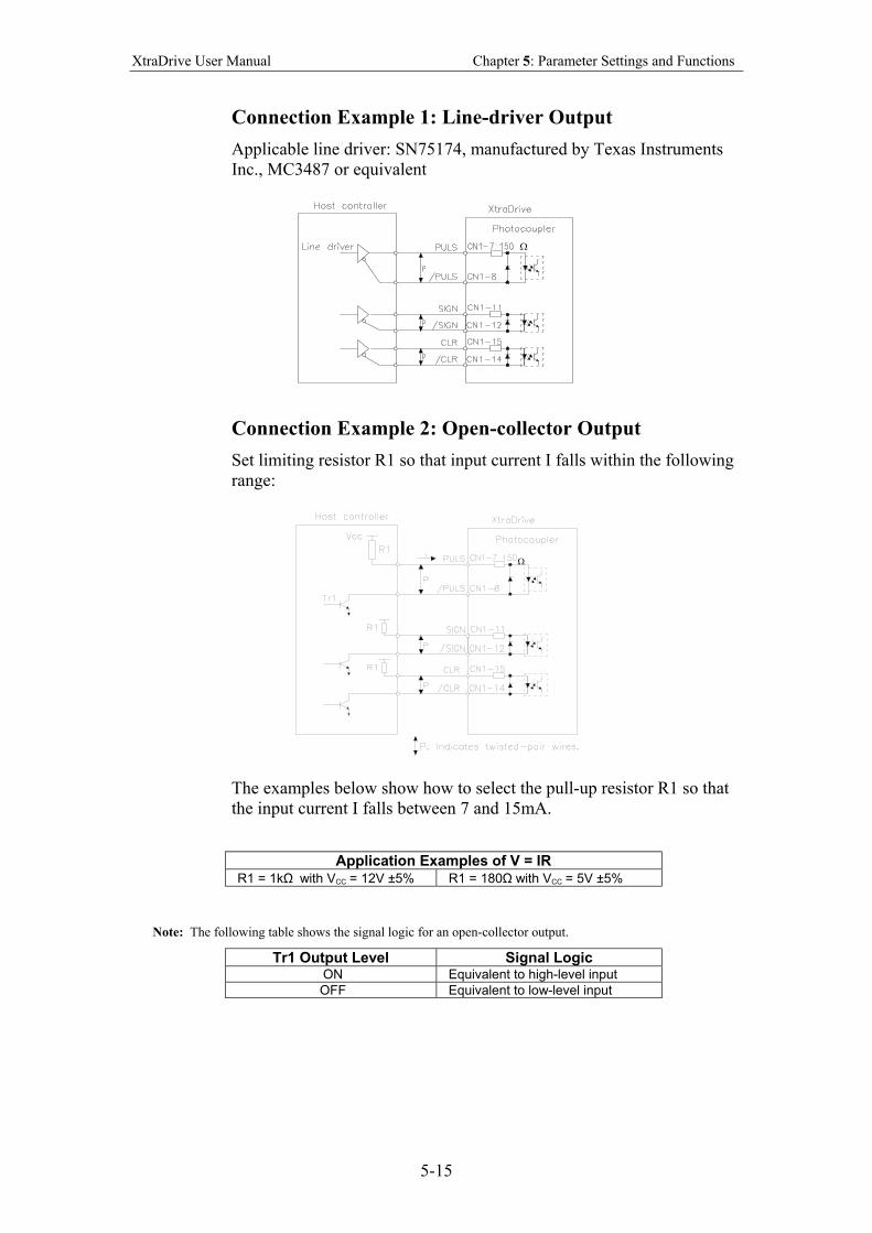
XtraDrive User Manual Chapter 5: Parameter Settings and Functions
5-15
Connection Example 1: Line-driver Output
Applicable line driver: SN75174, manufactured by Texas Instruments
Inc., MC3487 or equivalent
Ω
Connection Example 2: Open-collector Output
Set limiting resistor R1 so that input current I falls within the following
range:
Ω
The examples below show how to select the pull-up resistor R1 so that
the input current I falls between 7 and 15mA.
Application Examples of V = IR
R1 = 1kΩ with VCC = 12V ±5% R1 = 180Ω with VCC = 5V ±5%
Note: The following table shows the signal logic for an open-collector output.
Tr1 Output Level Signal Logic ON Equivalent to high-level input
OFF Equivalent to low-level input
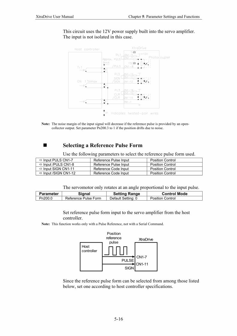
XtraDrive User Manual Chapter 5: Parameter Settings and Functions
5-16
This circuit uses the 12V power supply built into the servo amplifier.
The input is not isolated in this case.
Ω
Ω
Note: The noise margin of the input signal will decrease if the reference pulse is provided by an open-
collector output. Set parameter Pn200.3 to 1 if the position drifts due to noise.
Selecting a Reference Pulse Form
Use the following parameters to select the reference pulse form used.
Input PULS CN1-7 Reference Pulse Input Position Control
Input /PULS CN1-8 Reference Pulse Input Position Control
Input SIGN CN1-11 Reference Code Input Position Control
Input /SIGN CN1-12 Reference Code Input Position Control
The servomotor only rotates at an angle proportional to the input pulse.
Parameter Signal Setting Range Control Mode Pn200.0 Reference Pulse Form Default Setting: 0 Position Control
Set reference pulse form input to the servo amplifier from the host
controller.
Note: This function works only with a Pulse Reference, not with a Serial Command.
CN1-7
CN1-11PULSE
SIGN
Positionreference
pulseXtraDrive
Hostcontroller
Since the reference pulse form can be selected from among those listed
below, set one according to host controller specifications.
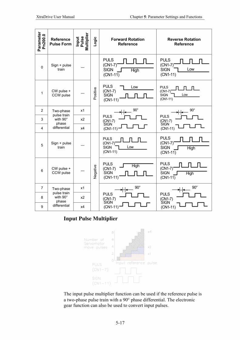
XtraDrive User Manual Chapter 5: Parameter Settings and Functions
5-17
Para
mete
r P
n200.0
Reference
Pulse Form Inp
ut
Pu
lse
Mu
ltip
lier
Lo
gic
Forward Rotation Reference
Reverse Rotation Reference
0 Sign + pulse
train ---
High
PULS(CN1-7)SIGN(CN1-11)
Low
PULS(CN1-7)SIGN(CN1-11)
1 CW pulse + CCW pulse
---
LowPULS(CN1-7)SIGN(CN1-11)
Low
PULS(CN1-7)SIGN(CN1-11)
2 x1
3 x2
4
Two-phase pulse train with 90° phase
differential x4
Positiv
e
PULS(CN1-7)SIGN(CN1-11)
90°
PULS(CN1-7)SIGN(CN1-11)
90°
5 Sign + pulse
train --- Low
PULS(CN1-7)SIGN(CN1-11)
High
PULS(CN1-7)SIGN(CN1-11)
6 CW pulse + CCW pulse
---
HighPULS(CN1-7)SIGN(CN1-11)
High
PULS(CN1-7)SIGN(CN1-11)
7 x1
8 x2
9
Two-phase pulse train with 90° phase
differential x4
Negative
PULS(CN1-7)SIGN(CN1-11)
90°
PULS(CN1-7)SIGN(CN1-11)
90°
Input Pulse Multiplier
The input pulse multiplier function can be used if the reference pulse is
a two-phase pulse train with a 90° phase differential. The electronic
gear function can also be used to convert input pulses.
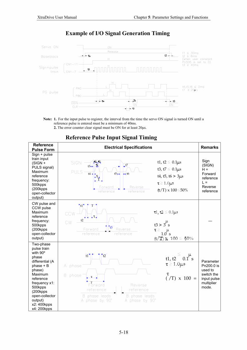
XtraDrive User Manual Chapter 5: Parameter Settings and Functions
5-18
Example of I/O Signal Generation Timing
t2
t6
µ
Note: 1. For the input pulse to register, the interval from the time the servo ON signal is turned ON until a
reference pulse is entered must be a minimum of 40ms.
2. The error counter clear signal must be ON for at least 20µs.
Reference Pulse Input Signal Timing
Reference Pulse Form
Electrical Specifications Remarks
Sign + pulse train input (SIGN + PULS signal) Maximum reference frequency: 500kpps (200kpps open-collector output)
t7t1, t2 0.1 s
t4, t5, t6 > 3 s
t3, t7 0.1 st3
t4
T
t6t5
( /T) x 100 50%
Sign (SIGN) H = Forward reference L = Reverse reference
CW pulse and CCW pulse Maximum reference frequency: 500kpps (200kpps open-collector output)
t3 > 3 s
1.0 s
t3
t1
t2
T
—
Two-phase pulse train with 90º phase differential (A phase + B phase) Maximum reference frequency x1: 500kpps (200kpps open-collector output) x2: 400kpps x4: 200kpps
t1, t2 0.1 s
( /T) x 100 =
t1
T
t2
Parameter Pn200.0 is used to switch the input pulse multiplier mode.
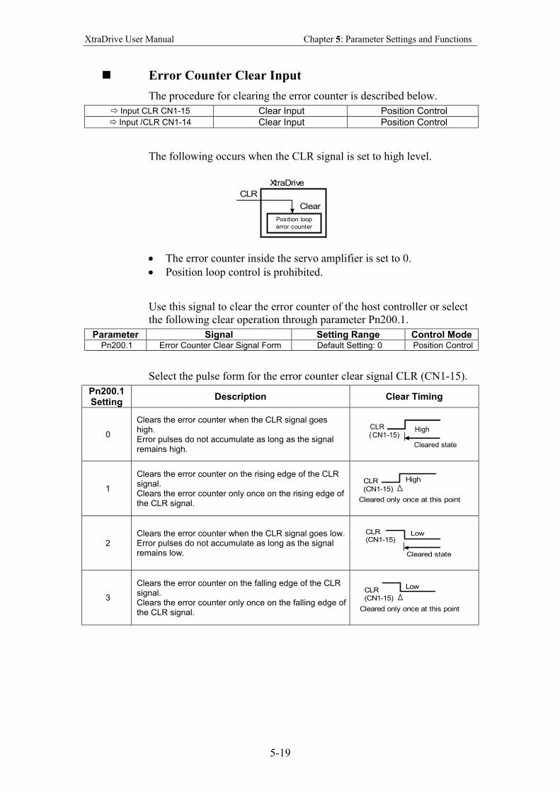
XtraDrive User Manual Chapter 5: Parameter Settings and Functions
5-19
Error Counter Clear Input
The procedure for clearing the error counter is described below.
Input CLR CN1-15 Clear Input Position Control Input /CLR CN1-14 Clear Input Position Control
The following occurs when the CLR signal is set to high level.
XtraDrive
Position loop
error counter
Clear
CLR
• The error counter inside the servo amplifier is set to 0.
• Position loop control is prohibited.
Use this signal to clear the error counter of the host controller or select
the following clear operation through parameter Pn200.1.
Parameter Signal Setting Range Control Mode Pn200.1 Error Counter Clear Signal Form Default Setting: 0 Position Control
Select the pulse form for the error counter clear signal CLR (CN1-15).
Pn200.1 Setting
Description Clear Timing
0
Clears the error counter when the CLR signal goes high. Error pulses do not accumulate as long as the signal remains high.
CLR(CN1-15)
High
Cleared state
1
Clears the error counter on the rising edge of the CLR signal. Clears the error counter only once on the rising edge of the CLR signal.
CLR(CN1-15)
High
Cleared only once at this point
2 Clears the error counter when the CLR signal goes low. Error pulses do not accumulate as long as the signal remains low.
CLR(CN1-15)
Low
Cleared state
3
Clears the error counter on the falling edge of the CLR signal. Clears the error counter only once on the falling edge of the CLR signal.
CLR(CN1-15)
Low
Cleared only once at this point
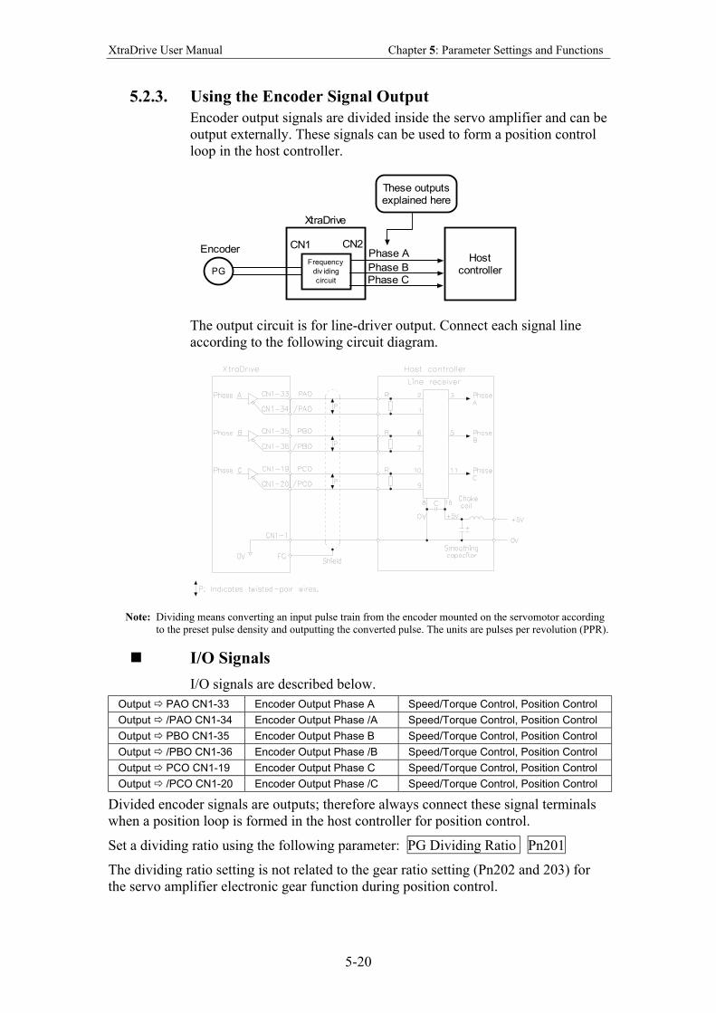
XtraDrive User Manual Chapter 5: Parameter Settings and Functions
5-20
5.2.3. Using the Encoder Signal Output
Encoder output signals are divided inside the servo amplifier and can be
output externally. These signals can be used to form a position control
loop in the host controller.
XtraDrive
Frequency
div iding
circuit
Encoder CN1 CN2
PG
Hostcontroller
These outputsexplained here
Phase A
Phase BPhase C
The output circuit is for line-driver output. Connect each signal line
according to the following circuit diagram.
Note: Dividing means converting an input pulse train from the encoder mounted on the servomotor according
to the preset pulse density and outputting the converted pulse. The units are pulses per revolution (PPR).
I/O Signals
I/O signals are described below.
Output PAO CN1-33 Encoder Output Phase A Speed/Torque Control, Position Control
Output /PAO CN1-34 Encoder Output Phase /A Speed/Torque Control, Position Control
Output PBO CN1-35 Encoder Output Phase B Speed/Torque Control, Position Control
Output /PBO CN1-36 Encoder Output Phase /B Speed/Torque Control, Position Control
Output PCO CN1-19 Encoder Output Phase C Speed/Torque Control, Position Control
Output /PCO CN1-20 Encoder Output Phase /C Speed/Torque Control, Position Control
Divided encoder signals are outputs; therefore always connect these signal terminals
when a position loop is formed in the host controller for position control.
Set a dividing ratio using the following parameter: PG Dividing Ratio Pn201
The dividing ratio setting is not related to the gear ratio setting (Pn202 and 203) for
the servo amplifier electronic gear function during position control.
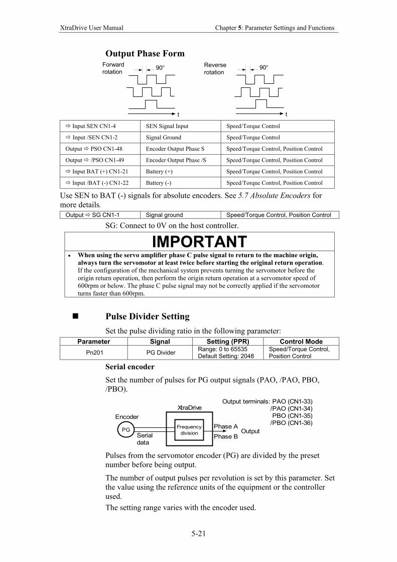
XtraDrive User Manual Chapter 5: Parameter Settings and Functions
5-21
Output Phase Form
t t
Reverse rotation
Forward rotation
90 ° 90 °
Input SEN CN1-4 SEN Signal Input Speed/Torque Control
Input /SEN CN1-2 Signal Ground Speed/Torque Control
Output PSO CN1-48 Encoder Output Phase S Speed/Torque Control, Position Control
Output /PSO CN1-49 Encoder Output Phase /S Speed/Torque Control, Position Control
Input BAT (+) CN1-21 Battery (+) Speed/Torque Control, Position Control
Input /BAT (-) CN1-22 Battery (-) Speed/Torque Control, Position Control
Use SEN to BAT (-) signals for absolute encoders. See 5.7 Absolute Encoders for
more details.
Output SG CN1-1 Signal ground Speed/Torque Control, Position Control
SG: Connect to 0V on the host controller.
IMPORTANT • When using the servo amplifier phase C pulse signal to return to the machine origin,
always turn the servomotor at least twice before starting the original return operation.
If the configuration of the mechanical system prevents turning the servomotor before the
origin return operation, then perform the origin return operation at a servomotor speed of
600rpm or below. The phase C pulse signal may not be correctly applied if the servomotor
turns faster than 600rpm.
Pulse Divider Setting
Set the pulse dividing ratio in the following parameter:
Parameter Signal Setting (PPR) Control Mode
Pn201 PG Divider Range: 0 to 65535 Default Setting: 2048
Speed/Torque Control, Position Control
Serial encoder
Set the number of pulses for PG output signals (PAO, /PAO, PBO,
/PBO).
XtraDrive
Frequency
division
Encoder
PGPhase A
Phase BSerialdata
Output
Output terminals: PAO (CN1-33)/PAO (CN1-34)PBO (CN1-35)
/PBO (CN1-36)
Pulses from the servomotor encoder (PG) are divided by the preset
number before being output.
The number of output pulses per revolution is set by this parameter. Set
the value using the reference units of the equipment or the controller
used.
The setting range varies with the encoder used.
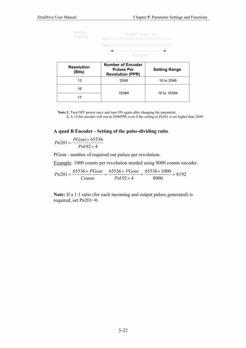
XtraDrive User Manual Chapter 5: Parameter Settings and Functions
5-22
Resolution (Bits)
Number of Encoder Pulses Per
Revolution (PPR) Setting Range
13 2048 16 to 2048
16
17
16384 16 to 16384
Note: 1. Turn OFF power once and turn ON again after changing the parameter.
2. A 13-bit encoder will run at 2048PPR even if the setting at Pn201 is set higher than 2049.
A quad B Encoder - Setting of the pulse-dividing ratio.
4192
65536201
××
=Pn
PGoutPn
PGout - number of required out pulses per revolution.
Example: 1000 counts per revolution needed using 8000 counts encoder.
81928000
100065536
4192
6553665536201 =
×=
××
=×
=Pn
PGout
Counts
PGoutPn
Note: If a 1:1 ratio (for each incoming and output pulses generated) is
required, set Pn201=0.
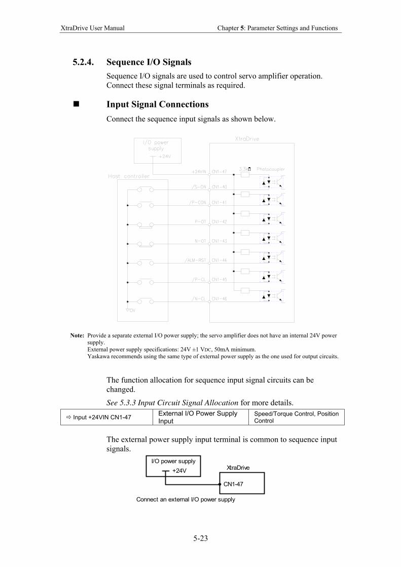
XtraDrive User Manual Chapter 5: Parameter Settings and Functions
5-23
5.2.4. Sequence I/O Signals
Sequence I/O signals are used to control servo amplifier operation.
Connect these signal terminals as required.
Input Signal Connections
Connect the sequence input signals as shown below.
Note: Provide a separate external I/O power supply; the servo amplifier does not have an internal 24V power
supply.
External power supply specifications: 24V ±1 VDC, 50mA minimum.
Yaskawa recommends using the same type of external power supply as the one used for output circuits.
The function allocation for sequence input signal circuits can be
changed.
See 5.3.3 Input Circuit Signal Allocation for more details.
Input +24VIN CN1-47 External I/O Power Supply Input
Speed/Torque Control, Position Control
The external power supply input terminal is common to sequence input
signals.
XtraDrive
CN1-47
I/O power supply
+24V
Connect an external I/O power supply
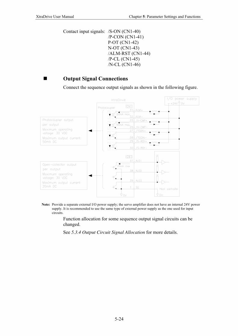
XtraDrive User Manual Chapter 5: Parameter Settings and Functions
5-24
Contact input signals: /S-ON (CN1-40)
/P-CON (CN1-41)
P-OT (CN1-42)
N-OT (CN1-43)
/ALM-RST (CN1-44)
/P-CL (CN1-45)
/N-CL (CN1-46)
Output Signal Connections
Connect the sequence output signals as shown in the following figure.
Note: Provide a separate external I/O power supply; the servo amplifier does not have an internal 24V power
supply. It is recommended to use the same type of external power supply as the one used for input
circuits.
Function allocation for some sequence output signal circuits can be
changed.
See 5.3.4 Output Circuit Signal Allocation for more details.
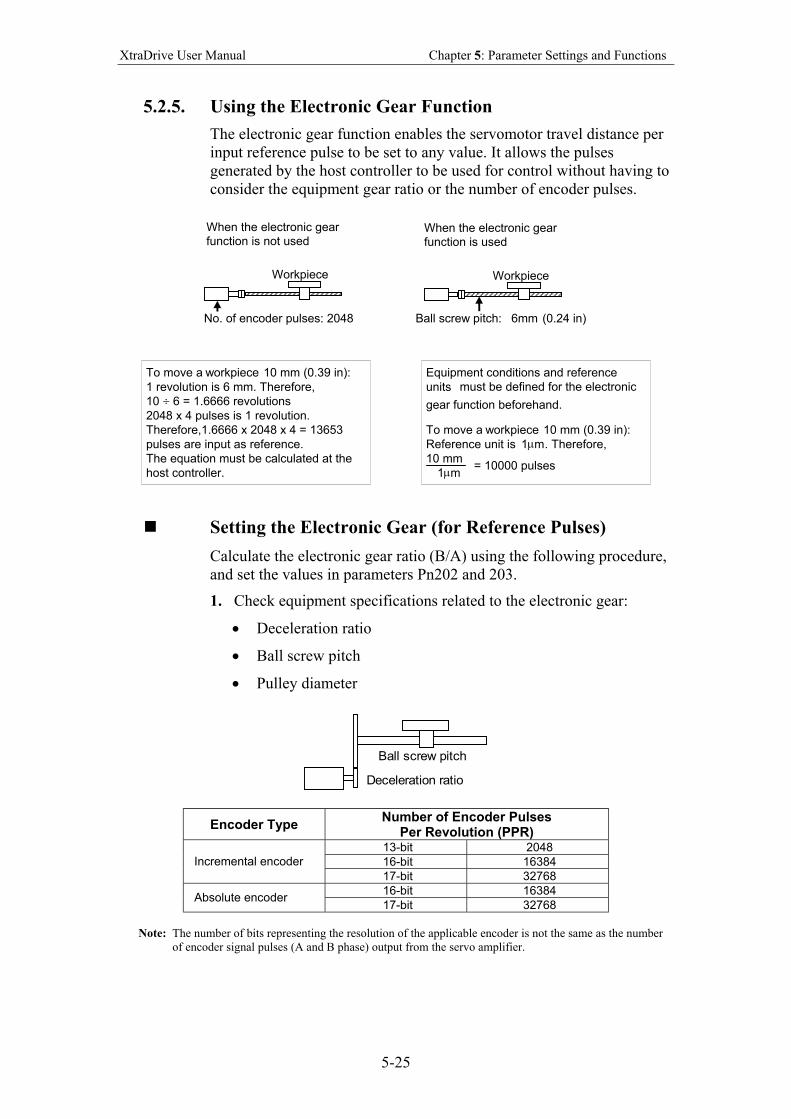
XtraDrive User Manual Chapter 5: Parameter Settings and Functions
5-25
5.2.5. Using the Electronic Gear Function
The electronic gear function enables the servomotor travel distance per
input reference pulse to be set to any value. It allows the pulses
generated by the host controller to be used for control without having to
consider the equipment gear ratio or the number of encoder pulses.
When the electronic gear function is not used
When the electronic gear function is used
Workpiece Workpiece
Ball screw pitch: 6mm (0.24 in) No. of encoder pulses: 2048
To move a workpiece 10 mm (0.39 in): 1 revolution is 6 mm. Therefore, 10 ÷ 6 = 1.6666 revolutions 2048 x 4 pulses is 1 revolution. Therefore,1.6666 x 2048 x 4 = 13653 pulses are input as reference. The equation must be calculated at the host controller.
Equipment conditions and reference units must be defined for the electronic gear function beforehand.
To move a workpiece 10 mm (0.39 in): Reference unit is 1 µ m . Therefore, 10 mm
1 µ m = 10000 pulses
Setting the Electronic Gear (for Reference Pulses)
Calculate the electronic gear ratio (B/A) using the following procedure,
and set the values in parameters Pn202 and 203.
1. Check equipment specifications related to the electronic gear:
• Deceleration ratio
• Ball screw pitch
• Pulley diameter
Ball screw pitch
Deceleration ratio
Encoder Type Number of Encoder Pulses
Per Revolution (PPR) 13-bit 2048
16-bit 16384 Incremental encoder
17-bit 32768
16-bit 16384 Absolute encoder
17-bit 32768
Note: The number of bits representing the resolution of the applicable encoder is not the same as the number
of encoder signal pulses (A and B phase) output from the servo amplifier.
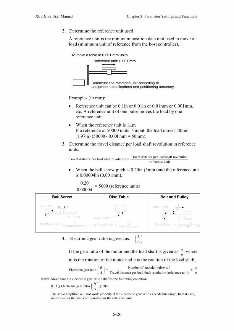
XtraDrive User Manual Chapter 5: Parameter Settings and Functions
5-26
2. Determine the reference unit used.
A reference unit is the minimum position data unit used to move a
load (minimum unit of reference from the host controller).
Reference unit: 0.001 mm
Determine the reference unit according toequipment specifications and positioning accuracy.
To move a table in 0.001 mm units
Examples (in mm):
• Reference unit can be 0.1in or 0.01in or 0.01mm or 0.001mm,
etc. A reference unit of one pulse moves the load by one
reference unit.
• When the reference unit is 1µm
If a reference of 50000 units is input, the load moves 50mm
(1.97in) (50000 ⋅ 0.001mm = 50mm).
3. Determine the travel distance per load shaft revolution in reference
units.
Travel distance per load shaft revolution = UnitReference
revolutionshaft loadper distance Travel
• When the ball screw pitch is 0.20in (5mm) and the reference unit
is 0.00004in (0.001mm),
00004.0
20.0 = 5000 (reference units)
Ball Screw Disc Table Belt and Pulley
π
π
4. Electronic gear ratio is given as:
A
B
If the gear ratio of the motor and the load shaft is given as:n
m where
m is the rotation of the motor and n is the rotation of the load shaft,
Electronic gear ratio
A
B =
unit) (reference revolutionshaft loadper distance Travel
4x pulsesencoder ofNumber x
n
m
Note: Make sure the electronic gear ratio satisfies the following condition:
0.01 ≤ Electronic gear ratio
A
B ≤ 100
The servo amplifier will not work properly if the electronic gear ratio exceeds this range. In that case,
modify either the load configuration or the reference unit.
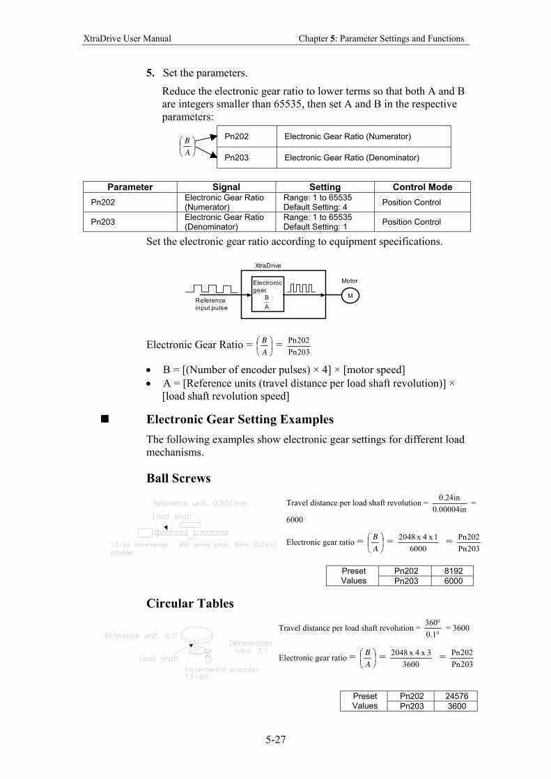
XtraDrive User Manual Chapter 5: Parameter Settings and Functions
5-27
5. Set the parameters.
Reduce the electronic gear ratio to lower terms so that both A and B
are integers smaller than 65535, then set A and B in the respective
parameters:
Pn202 Electronic Gear Ratio (Numerator)
A
B
Pn203 Electronic Gear Ratio (Denominator)
Parameter Signal Setting Control Mode
Pn202 Electronic Gear Ratio (Numerator)
Range: 1 to 65535 Default Setting: 4
Position Control
Pn203 Electronic Gear Ratio (Denominator)
Range: 1 to 65535 Default Setting: 1
Position Control
Set the electronic gear ratio according to equipment specifications.
M
Electronic
gear
B_
A
Motor
XtraDrive
Reference
input pulse
Electronic Gear Ratio =
A
B =
203Pn
202Pn
• B = [(Number of encoder pulses) × 4] × [motor speed]
• A = [Reference units (travel distance per load shaft revolution)] ×
[load shaft revolution speed]
Electronic Gear Setting Examples
The following examples show electronic gear settings for different load
mechanisms.
Ball Screws
Travel distance per load shaft revolution = in00004.0
in24.0 =
6000
Electronic gear ratio =
A
B =
6000
1x 4x 2048 =
203Pn
202Pn
Pn202 8192 Preset Values Pn203 6000
Circular Tables
Travel distance per load shaft revolution = °°
1.0
360 = 3600
Electronic gear ratio =
A
B =
3600
3x 4x 2048 =
203Pn
202Pn
Pn202 24576 Preset Values Pn203 3600
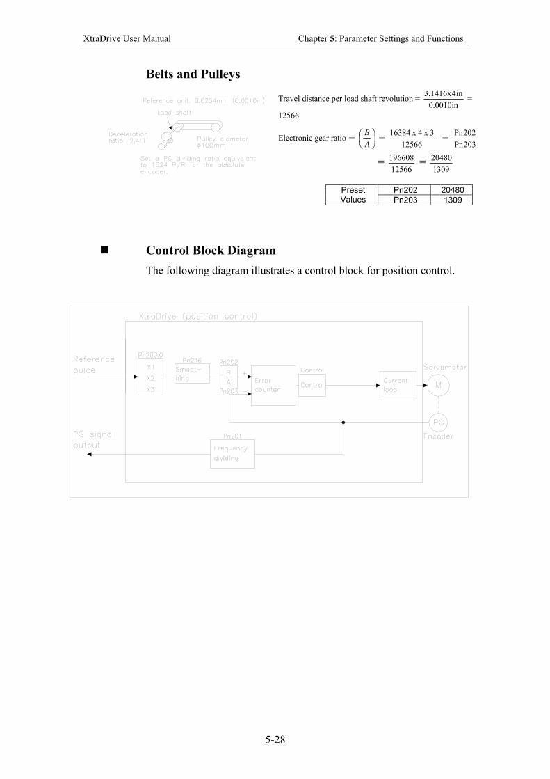
XtraDrive User Manual Chapter 5: Parameter Settings and Functions
5-28
Belts and Pulleys
Travel distance per load shaft revolution = in0010.0
in4x1416.3 =
12566
Electronic gear ratio =
A
B =
12566
3x 4x 16384 =
203Pn
202Pn
= 12566
196608 =
1309
20480
Pn202 20480 Preset Values Pn203 1309
Control Block Diagram
The following diagram illustrates a control block for position control.
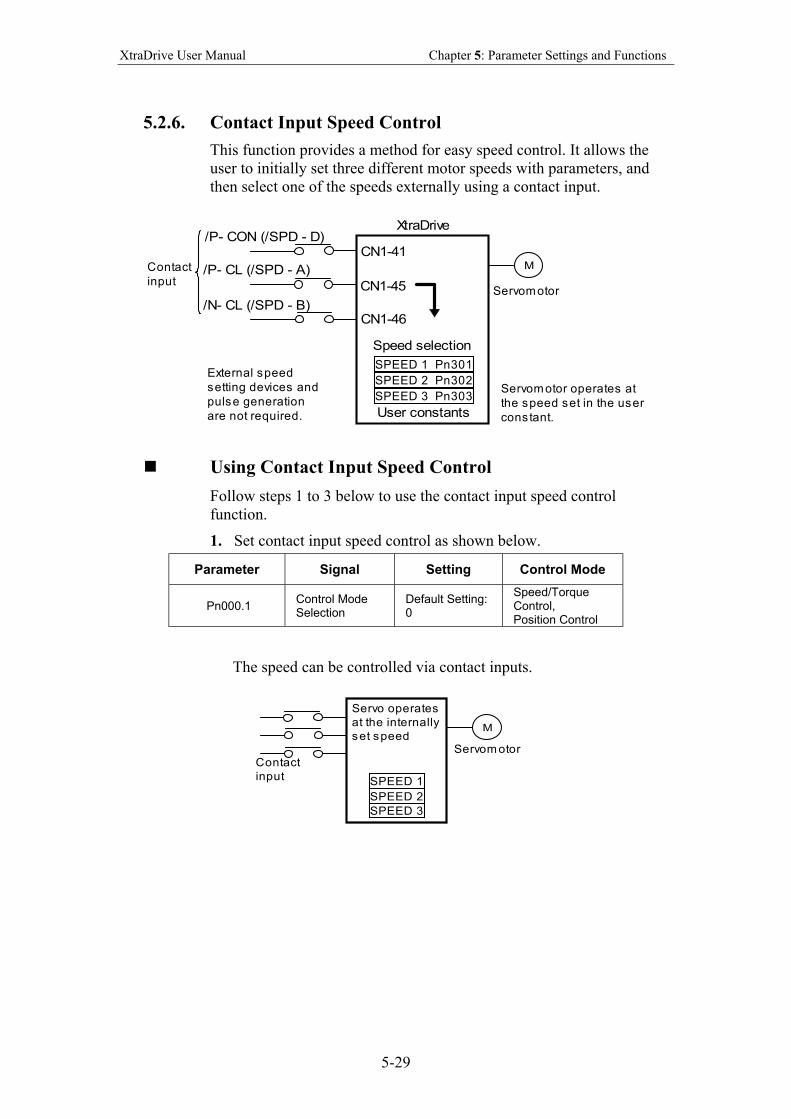
XtraDrive User Manual Chapter 5: Parameter Settings and Functions
5-29
5.2.6. Contact Input Speed Control
This function provides a method for easy speed control. It allows the
user to initially set three different motor speeds with parameters, and
then select one of the speeds externally using a contact input.
Speed selection
SPEED 1 Pn301
SPEED 2 Pn302
SPEED 3 Pn303
M
Servomotor
Contact
input
/P- CON (/SPD - D)
/P- CL (/SPD - A)
/N- CL (/SPD - B)
CN1-41
CN1-45
CN1-46
External speed
setting devices and
pulse generation
are not required. User constants
XtraDrive
Servomotor operates at
the speed set in the user
constant.
Using Contact Input Speed Control
Follow steps 1 to 3 below to use the contact input speed control
function.
1. Set contact input speed control as shown below.
Parameter Signal Setting Control Mode
Pn000.1 Control Mode Selection
Default Setting: 0
Speed/Torque Control, Position Control
The speed can be controlled via contact inputs.
Servo operates
at the internally
set speed
SPEED 1
SPEED 2
SPEED 3
M
Servom otorContact
input
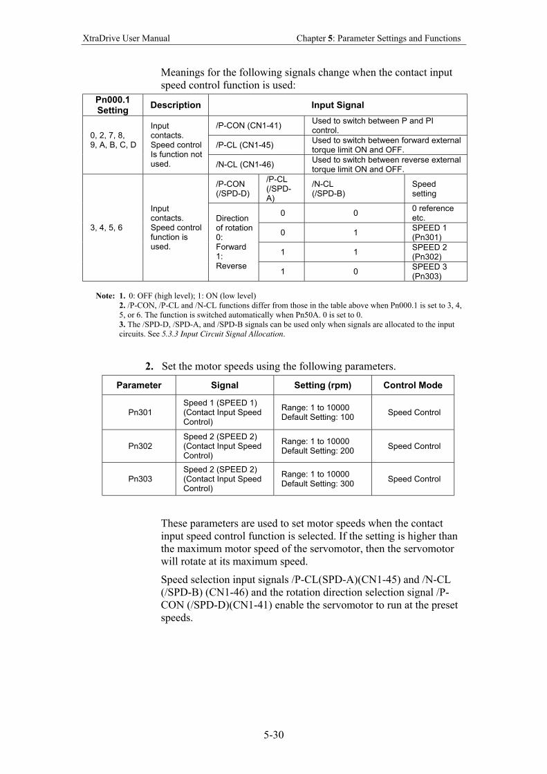
XtraDrive User Manual Chapter 5: Parameter Settings and Functions
5-30
Meanings for the following signals change when the contact input
speed control function is used:
Pn000.1 Setting
Description Input Signal
/P-CON (CN1-41) Used to switch between P and PI control.
/P-CL (CN1-45) Used to switch between forward external torque limit ON and OFF.
0, 2, 7, 8, 9, A, B, C, D
Input contacts. Speed control Is function not used. /N-CL (CN1-46)
Used to switch between reverse external torque limit ON and OFF.
/P-CON (/SPD-D)
/P-CL (/SPD-A)
/N-CL (/SPD-B)
Speed setting
0 0 0 reference etc.
0 1 SPEED 1 (Pn301)
1 1 SPEED 2 (Pn302)
3, 4, 5, 6
Input contacts. Speed control function is used.
Direction of rotation 0: Forward 1: Reverse
1 0 SPEED 3 (Pn303)
Note: 1. 0: OFF (high level); 1: ON (low level)
2. /P-CON, /P-CL and /N-CL functions differ from those in the table above when Pn000.1 is set to 3, 4,
5, or 6. The function is switched automatically when Pn50A. 0 is set to 0.
3. The /SPD-D, /SPD-A, and /SPD-B signals can be used only when signals are allocated to the input
circuits. See 5.3.3 Input Circuit Signal Allocation.
2. Set the motor speeds using the following parameters.
Parameter Signal Setting (rpm) Control Mode
Pn301 Speed 1 (SPEED 1) (Contact Input Speed Control)
Range: 1 to 10000 Default Setting: 100
Speed Control
Pn302 Speed 2 (SPEED 2) (Contact Input Speed Control)
Range: 1 to 10000 Default Setting: 200
Speed Control
Pn303 Speed 2 (SPEED 2) (Contact Input Speed Control)
Range: 1 to 10000 Default Setting: 300
Speed Control
These parameters are used to set motor speeds when the contact
input speed control function is selected. If the setting is higher than
the maximum motor speed of the servomotor, then the servomotor
will rotate at its maximum speed.
Speed selection input signals /P-CL(SPD-A)(CN1-45) and /N-CL
(/SPD-B) (CN1-46) and the rotation direction selection signal /P-
CON (/SPD-D)(CN1-41) enable the servomotor to run at the preset
speeds.
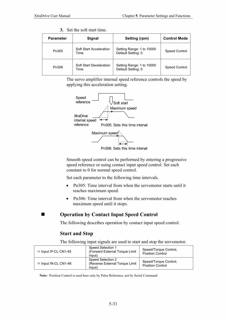
XtraDrive User Manual Chapter 5: Parameter Settings and Functions
5-31
3. Set the soft start time.
Parameter Signal Setting (rpm) Control Mode
Pn305 Soft Start Acceleration Time
Setting Range: 1 to 10000 Default Setting: 0
Speed Control
Pn306 Soft Start Deceleration Time
Setting Range: 1 to 10000 Default Setting: 0
Speed Control
The servo amplifier internal speed reference controls the speed by
applying this acceleration setting.
Soft start
Speedreference
XtraDriveinternal speedreference
Maximum speed
Maximum speed
Pn305: Sets this time interval
Pn306: Sets this time interval
Smooth speed control can be performed by entering a progressive
speed reference or using contact input speed control. Set each
constant to 0 for normal speed control.
Set each parameter to the following time intervals.
• Pn305: Time interval from when the servomotor starts until it
reaches maximum speed.
• Pn306: Time interval from when the servomotor reaches
maximum speed until it stops.
Operation by Contact Input Speed Control
The following describes operation by contact input speed control.
Start and Stop
The following input signals are used to start and stop the servomotor.
Input /P-CL CN1-45
Speed Selection 1 (Forward External Torque Limit Input)
Speed/Torque Control, Position Control
Input /N-CL CN1-46
Speed Selection 2 (Reverse External Torque Limit Input)
Speed/Torque Control, Position Control
Note: Position Control is used here only by Pulse Reference, not by Serial Command
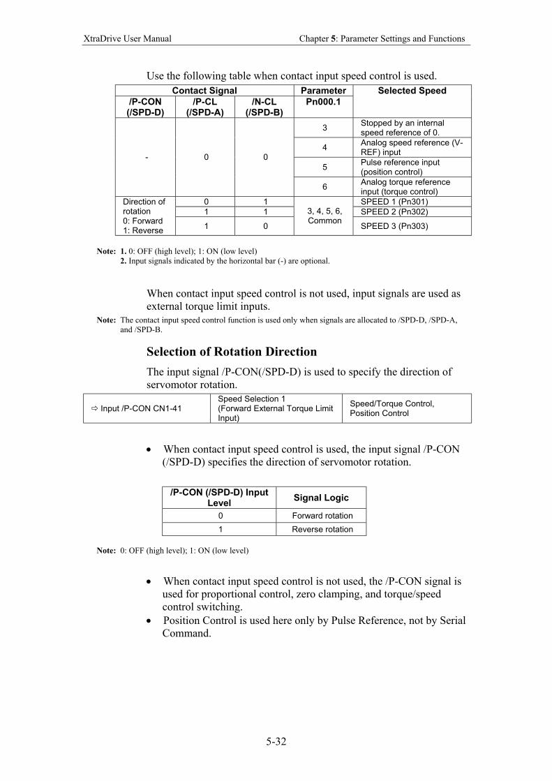
XtraDrive User Manual Chapter 5: Parameter Settings and Functions
5-32
Use the following table when contact input speed control is used.
Contact Signal Parameter
/P-CON (/SPD-D)
/P-CL (/SPD-A)
/N-CL (/SPD-B)
Pn000.1
Selected Speed
3 Stopped by an internal speed reference of 0.
4 Analog speed reference (V-REF) input
5 Pulse reference input (position control)
- 0 0
6 Analog torque reference input (torque control)
0 1 SPEED 1 (Pn301)
1 1 SPEED 2 (Pn302)
Direction of rotation 0: Forward 1: Reverse
1 0
3, 4, 5, 6, Common
SPEED 3 (Pn303)
Note: 1. 0: OFF (high level); 1: ON (low level)
2. Input signals indicated by the horizontal bar (-) are optional.
When contact input speed control is not used, input signals are used as
external torque limit inputs.
Note: The contact input speed control function is used only when signals are allocated to /SPD-D, /SPD-A,
and /SPD-B.
Selection of Rotation Direction
The input signal /P-CON(/SPD-D) is used to specify the direction of
servomotor rotation.
Input /P-CON CN1-41
Speed Selection 1 (Forward External Torque Limit Input)
Speed/Torque Control, Position Control
• When contact input speed control is used, the input signal /P-CON
(/SPD-D) specifies the direction of servomotor rotation.
/P-CON (/SPD-D) Input Level
Signal Logic
0 Forward rotation
1 Reverse rotation
Note: 0: OFF (high level); 1: ON (low level)
• When contact input speed control is not used, the /P-CON signal is
used for proportional control, zero clamping, and torque/speed
control switching.
• Position Control is used here only by Pulse Reference, not by Serial
Command.
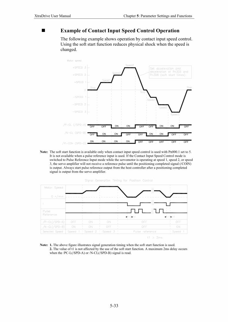
XtraDrive User Manual Chapter 5: Parameter Settings and Functions
5-33
Example of Contact Input Speed Control Operation
The following example shows operation by contact input speed control.
Using the soft start function reduces physical shock when the speed is
changed.
OFF OFF ON ON OFFOFF ON ON OFF
OFF ON ON ON ON OFF OFF
ON ON ON ON OFF OFF OFF OFF OFF
OFF OFF
Note: The soft start function is available only when contact input speed control is used with Pn000.1 set to 5.
It is not available when a pulse reference input is used. If the Contact Input Speed Control mode is
switched to Pulse Reference Input mode while the servomotor is operating at speed 1, speed 2, or speed
3, the servo amplifier will not receive a reference pulse until the positioning completed signal (/COIN)
is output. Always start pulse reference output from the host controller after a positioning completed
signal is output from the servo amplifier.
Note: 1. The above figure illustrates signal generation timing when the soft start function is used.
2. The value of t1 is not affected by the use of the soft start function. A maximum 2ms delay occurs
when the /PC-L(/SPD-A) or /N-CL(/SPD-B) signal is read.
XtraDrive User Manual Chapter 5: Parameter Settings and Functions
5-34
5.2.7. Using Torque Control
The XtraDrive servo amplifier limits torque as shown below.
• Level 1: Limits maximum output torque to protect equipment or
workpiece.
• Level 2: Limits torque after the servomotor moves the equipment to
a specified position (external torque limit).
• Level 3: Controls torque output rather than speed output.
• Level 4: Switches between speed and torque control.
The following describes uses for levels 3 and 4 in the torque control
function.
Torque Control Selection
Set the following parameter to select the type of control described in
levels 3 and 4.
Parameter Signal Setting Control Mode
Pn000.1 Control Method Selection
Default Setting: 0 Speed/Torque Control, Position Control
For further explanation of settings, see Appendix D.2 Switches.
A torque reference is entered from the host controller to the servo
amplifier in order to control torque.
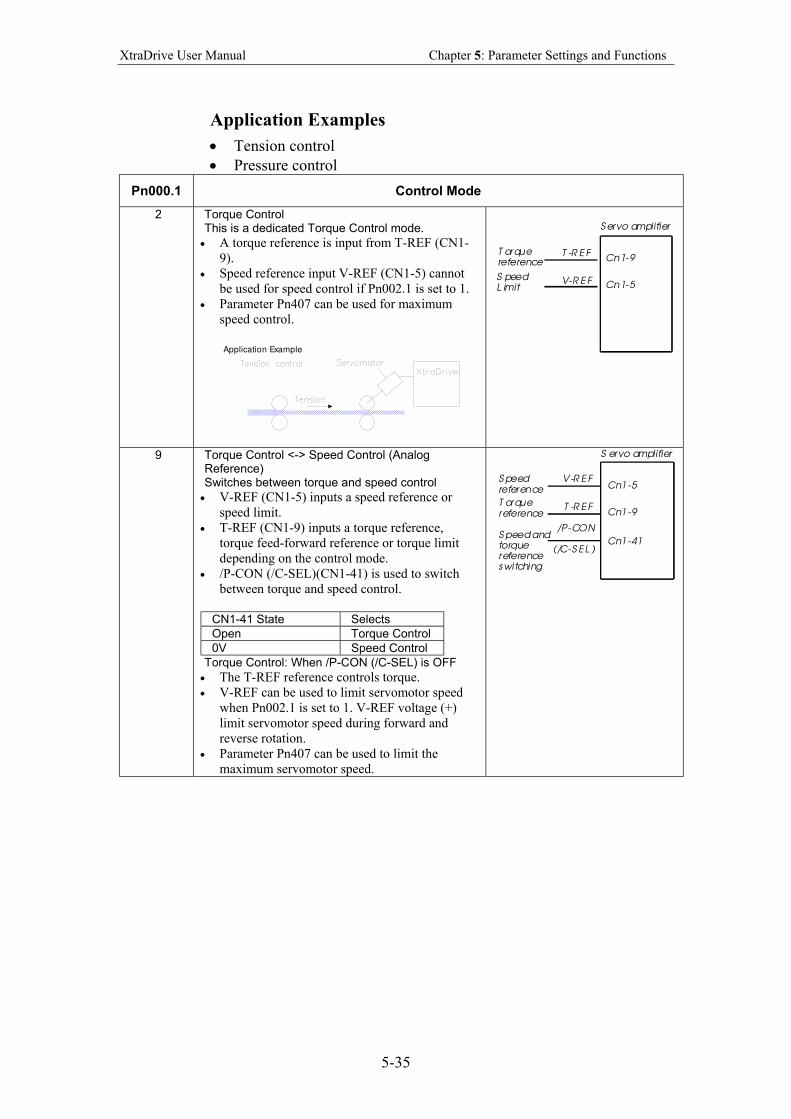
XtraDrive User Manual Chapter 5: Parameter Settings and Functions
5-35
Application Examples
• Tension control
• Pressure control
Pn000.1 Control Mode
2 Torque Control This is a dedicated Torque Control mode.
• A torque reference is input from T-REF (CN1-
9).
• Speed reference input V-REF (CN1-5) cannot
be used for speed control if Pn002.1 is set to 1.
• Parameter Pn407 can be used for maximum
speed control.
Application Example
S ervo amplifier
T -R E F
V-R E F
Cn1-9
Cn1-5
T orquereference
S peedL imit
9 Torque Control <-> Speed Control (Analog Reference) Switches between torque and speed control
• V-REF (CN1-5) inputs a speed reference or
speed limit.
• T-REF (CN1-9) inputs a torque reference,
torque feed-forward reference or torque limit
depending on the control mode.
• /P-CON (/C-SEL)(CN1-41) is used to switch
between torque and speed control.
CN1-41 State Selects
Open Torque Control
0V Speed Control
Torque Control: When /P-CON (/C-SEL) is OFF
• The T-REF reference controls torque.
• V-REF can be used to limit servomotor speed
when Pn002.1 is set to 1. V-REF voltage (+)
limit servomotor speed during forward and
reverse rotation.
• Parameter Pn407 can be used to limit the
maximum servomotor speed.
S ervo amplifier
V-R E F
T -R E F
Cn1-5
Cn1-9
S peedreference
T orquereference
S peed andtorquereferenceswitching
/P-CON
(/C-S EL )Cn1-41
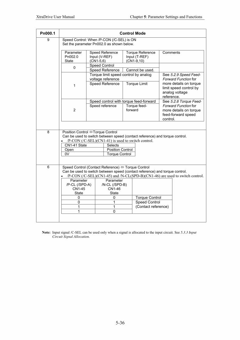
XtraDrive User Manual Chapter 5: Parameter Settings and Functions
5-36
Pn000.1 Control Mode
9 Speed Control: When /P-CON (/C-SEL) is ON Set the parameter Pn002.0 as shown below.
Parameter Pn002.0 State
Speed Reference Input (V-REF) (CN1-5,6)
Torque Reference Input (T-REF) (CN1-9,10)
Comments
Speed Control 0
Speed Reference Cannot be used.
Torque limit speed control by analog voltage reference
1 Speed Reference Torque Limit
See 5.2.9 Speed Feed-
Forward Function for more details on torque limit speed control by analog voltage reference.
Speed control with torque feed-forward
2 Speed reference Torque feed-
forward
See 5.2.8 Torque Feed-
Forward Function for more details on torque feed-forward speed control.
8 Position Control Torque Control Can be used to switch between speed (contact reference) and torque control.
• /P-CON (/C-SEL)(CN1-41) is used to switch control. CN1-41 State Selects
Open Position Control
0V Torque Control
6 Speed Control (Contact Reference) Torque Control Can be used to switch between speed (contact reference) and torque control.
• /P-CON (/C-SEL)(CN1-45) and /N-CL(SPD-B)(CN1-46) are used to switch control. Parameter
/P-CL (/SPD-A) CN1-45 State
Parameter /N-CL (/SPD-B)
CN1-46 State
0 0 Torque Control
0 1
1 1
1 0
Speed Control (Contact reference)
Note: Input signal /C-SEL can be used only when a signal is allocated to the input circuit. See 5.3.3 Input
Circuit Signal Allocation.
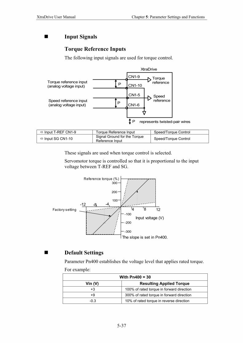
XtraDrive User Manual Chapter 5: Parameter Settings and Functions
5-37
Input Signals
Torque Reference Inputs
The following input signals are used for torque control.
XtraDrive
Torquereference
Speedreference
CN1-9
CN1-10
CN1-5
CN1-6
represents twisted-pair wiresP
P
P
Torque reference input(analog voltage input)
Speed reference input(analog voltage input)
Input T-REF CN1-9 Torque Reference Input Speed/Torque Control
Input SG CN1-10 Signal Ground for the Torque Reference Input
Speed/Torque Control
These signals are used when torque control is selected.
Servomotor torque is controlled so that it is proportional to the input
voltage between T-REF and SG.
Reference torque (%)
-4-8-12
4 8 12
Input voltage (V)
The slope is set in Pn400.
Factory setting
100
200
300
-100
-200
-300
Default Settings
Parameter Pn400 establishes the voltage level that applies rated torque.
For example:
With Pn400 = 30
Vin (V) Resulting Applied Torque
+3 100% of rated torque in forward direction
+9 300% of rated torque in forward direction
-0.3 10% of rated torque in reverse direction
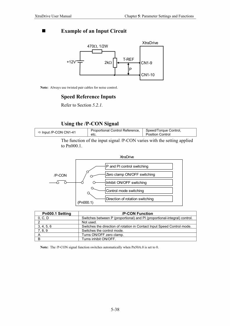
XtraDrive User Manual Chapter 5: Parameter Settings and Functions
5-38
Example of an Input Circuit
+12V
470Ω, 1/2W
T-REF
XtraDrive
CN1-9
CN1-10
P
2kΩ
Note: Always use twisted pair cables for noise control.
Speed Reference Inputs
Refer to Section 5.2.1.
Using the /P-CON Signal
Input /P-CON CN1-41 Proportional Control Reference, etc.
Speed/Torque Control, Position Control
The function of the input signal /P-CON varies with the setting applied
to Pn000.1.
P and PI control switching
Zero clamp ON/OFF switching
Inhibit ON/OFF switching
Control mode switching
Direction of rotation switching
XtraDrive
/P-CON
(Pn000.1)
Pn000.1 Setting /P-CON Function 0, C, D Switches between P (proportional) and PI (proportional-integral) control.
2 Not used.
3, 4, 5, 6 Switches the direction of rotation in Contact Input Speed Control mode.
7, 8, 9 Switches the control mode.
A Turns ON/OFF zero clamp.
B Turns inhibit ON/OFF.
Note: The /P-CON signal function switches automatically when Pn50A.0 is set to 0.
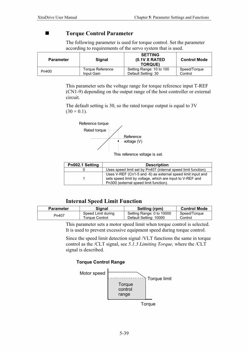
XtraDrive User Manual Chapter 5: Parameter Settings and Functions
5-39
Torque Control Parameter
The following parameter is used for torque control. Set the parameter
according to requirements of the servo system that is used.
Parameter Signal SETTING
(0.1V X RATED TORQUE)
Control Mode
Pn400 Torque Reference Input Gain
Setting Range: 10 to 100 Default Setting: 30
Speed/Torque Control
This parameter sets the voltage range for torque reference input T-REF
(CN1-9) depending on the output range of the host controller or external
circuit.
The default setting is 30, so the rated torque output is equal to 3V
(30 × 0.1).
This reference voltage is set.
Reference torque
Referencevoltage (V)
Rated torque
Pn002.1 Setting Description 0 Uses speed limit set by Pn407 (internal speed limit function).
1 Uses V-REF (Cn1-5 and -6) as external speed limit input and sets speed limit by voltage, which are input to V-REF and Pn300 (external speed limit function).
Internal Speed Limit Function
Parameter Signal Setting (rpm) Control Mode
Pn407 Speed Limit during Torque Control
Setting Range: 0 to 10000 Default Setting: 10000
Speed/Torque Control
This parameter sets a motor speed limit when torque control is selected.
It is used to prevent excessive equipment speed during torque control.
Since the speed limit detection signal /VLT functions the same in torque
control as the /CLT signal, see 5.1.3 Limiting Torque, where the /CLT
signal is described.
Torque limit Motor speed
Torque
Torque control range
Torque Control Range
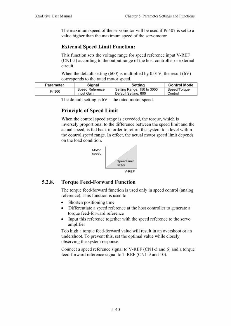
XtraDrive User Manual Chapter 5: Parameter Settings and Functions
5-40
The maximum speed of the servomotor will be used if Pn407 is set to a
value higher than the maximum speed of the servomotor.
External Speed Limit Function:
This function sets the voltage range for speed reference input V-REF
(CN1-5) according to the output range of the host controller or external
circuit.
When the default setting (600) is multiplied by 0.01V, the result (6V)
corresponds to the rated motor speed.
Parameter Signal Setting Control Mode
Pn300 Speed Reference Input Gain
Setting Range: 150 to 3000 Default Setting: 600
Speed/Torque Control
The default setting is 6V = the rated motor speed.
Principle of Speed Limit
When the control speed range is exceeded, the torque, which is
inversely proportional to the difference between the speed limit and the
actual speed, is fed back in order to return the system to a level within
the control speed range. In effect, the actual motor speed limit depends
on the load condition.
Motorspeed
V-REF
Speed limitrange
5.2.8. Torque Feed-Forward Function
The torque feed-forward function is used only in speed control (analog
reference). This function is used to:
• Shorten positioning time
• Differentiate a speed reference at the host controller to generate a
torque feed-forward reference
• Input this reference together with the speed reference to the servo
amplifier
Too high a torque feed-forward value will result in an overshoot or an
undershoot. To prevent this, set the optimal value while closely
observing the system response.
Connect a speed reference signal to V-REF (CN1-5 and 6) and a torque
feed-forward reference signal to T-REF (CN1-9 and 10).
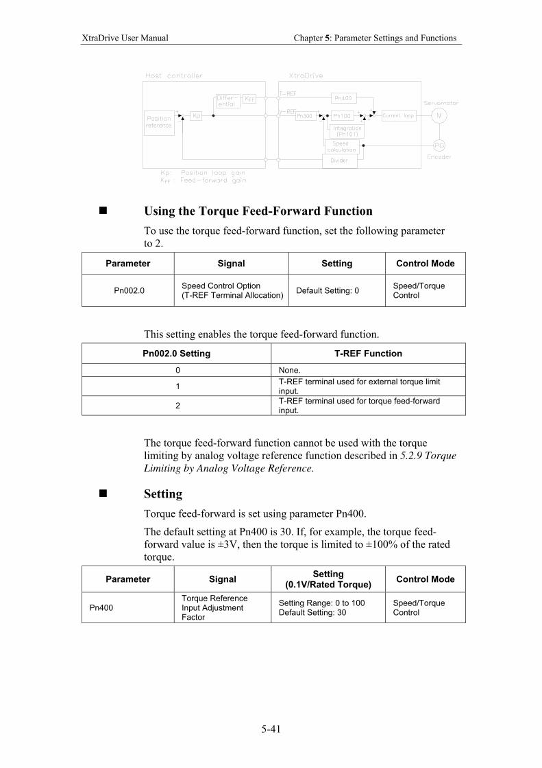
XtraDrive User Manual Chapter 5: Parameter Settings and Functions
5-41
Using the Torque Feed-Forward Function
To use the torque feed-forward function, set the following parameter
to 2.
Parameter Signal Setting Control Mode
Pn002.0 Speed Control Option (T-REF Terminal Allocation)
Default Setting: 0 Speed/Torque Control
This setting enables the torque feed-forward function.
Pn002.0 Setting T-REF Function
0 None.
1 T-REF terminal used for external torque limit input.
2 T-REF terminal used for torque feed-forward input.
The torque feed-forward function cannot be used with the torque
limiting by analog voltage reference function described in 5.2.9 Torque
Limiting by Analog Voltage Reference.
Setting
Torque feed-forward is set using parameter Pn400.
The default setting at Pn400 is 30. If, for example, the torque feed-
forward value is ±3V, then the torque is limited to ±100% of the rated
torque.
Parameter Signal Setting
(0.1V/Rated Torque) Control Mode
Pn400 Torque Reference Input Adjustment Factor
Setting Range: 0 to 100 Default Setting: 30
Speed/Torque Control
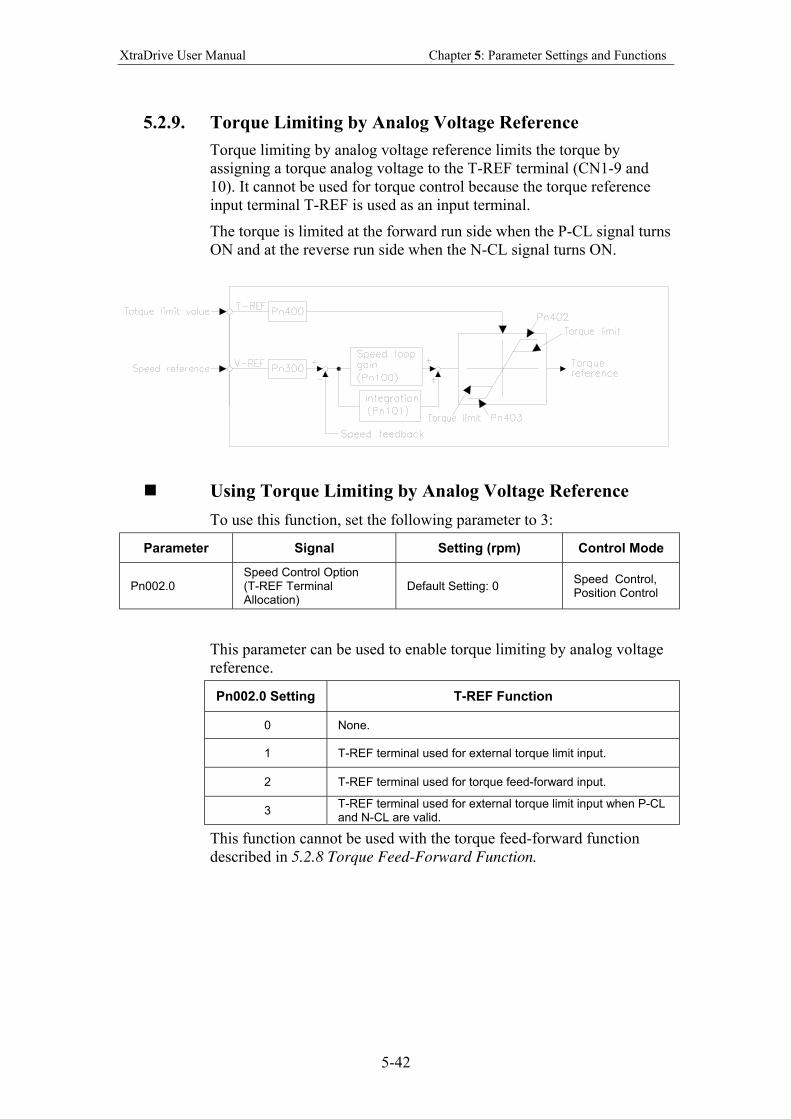
XtraDrive User Manual Chapter 5: Parameter Settings and Functions
5-42
5.2.9. Torque Limiting by Analog Voltage Reference
Torque limiting by analog voltage reference limits the torque by
assigning a torque analog voltage to the T-REF terminal (CN1-9 and
10). It cannot be used for torque control because the torque reference
input terminal T-REF is used as an input terminal.
The torque is limited at the forward run side when the P-CL signal turns
ON and at the reverse run side when the N-CL signal turns ON.
Using Torque Limiting by Analog Voltage Reference
To use this function, set the following parameter to 3:
Parameter Signal Setting (rpm) Control Mode
Pn002.0 Speed Control Option (T-REF Terminal Allocation)
Default Setting: 0 Speed Control, Position Control
This parameter can be used to enable torque limiting by analog voltage
reference.
Pn002.0 Setting T-REF Function
0 None.
1 T-REF terminal used for external torque limit input.
2 T-REF terminal used for torque feed-forward input.
3 T-REF terminal used for external torque limit input when P-CL and N-CL are valid.
This function cannot be used with the torque feed-forward function
described in 5.2.8 Torque Feed-Forward Function.
XtraDrive User Manual Chapter 5: Parameter Settings and Functions
5-43
To use this function, verify how input signals have been allocated.
(Refer to section 5.3.3 Input Circuit Signal Allocation). The following
table outlines factory default settings.
Input Signal Signal Level Description Comments
CN1-45 is at “L” level when ON
Torque is limited at the forward run side.
Limit value: either Pn404 or T-REF input, whichever is smaller.
/P-CL
CN1-45 is at “H” level when OFF
Torque is not limited at the forward run side. Normal Operation
—
CN1-46 is at “L” level when ON
Torque is limited at the reverse run side.
Limit value: either Pn405 or T-REF input, whichever is smaller.
/N-CL
CN1-46 is at “H” level when OFF
Torque is not limited at the forward run side. Normal operation.
—
Setting
The torque limit is set using parameter Pn400.
The default setting for Pn400 is 30. If, for example, the torque limit is
±3V, then torque is limited to 100% of the rated torque. (A torque value
higher than 100% torque is clamped at 100%.)
Parameter Signal Setting
(0.1V/Rated Torque) Control Mode
Pn400 Torque Reference Input Adjustment Factor
Setting Range: 0 to 100 Default Setting: 30
Speed/Torque Control
When either the P-CL or the N-CL signal is turned ON, the following
torque limits become valid simultaneously.
Parameter Signal Setting
(0.1V/Rated Torque) Control Mode
Pn404 Forward Run Side External Torque Limit
Setting Range: 0 to 800 Default Setting: 100
Speed/Torque Control, Position Control
Pn405 Reverse Run Side External Torque Limit
Setting Range: 0 to 800 Default Setting: 100
Speed/Torque Control, Position Control
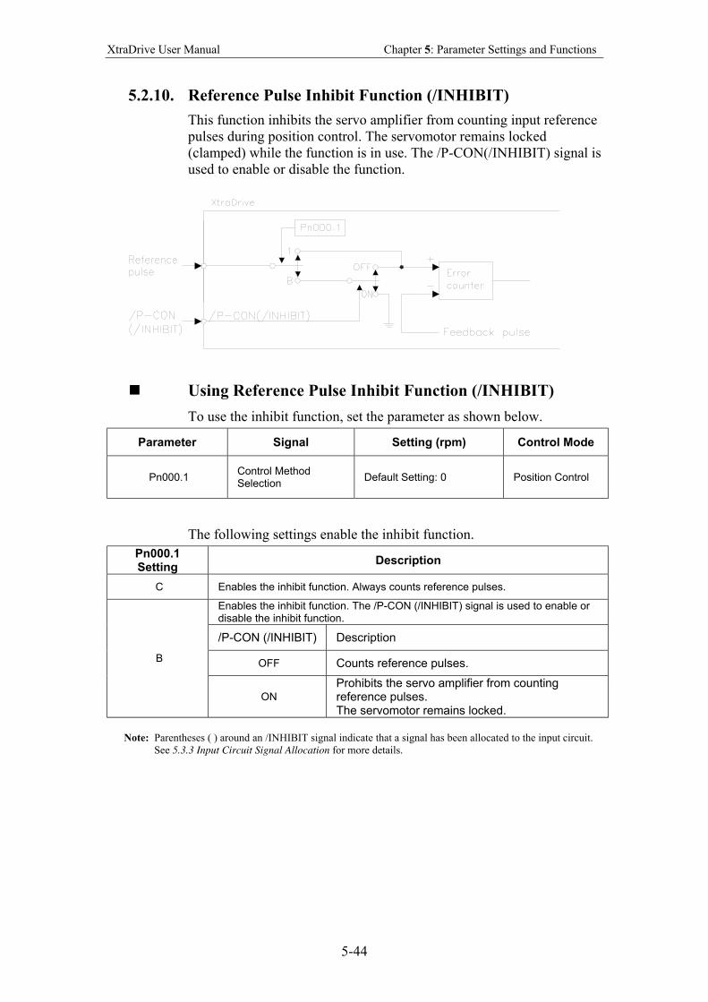
XtraDrive User Manual Chapter 5: Parameter Settings and Functions
5-44
5.2.10. Reference Pulse Inhibit Function (/INHIBIT)
This function inhibits the servo amplifier from counting input reference
pulses during position control. The servomotor remains locked
(clamped) while the function is in use. The /P-CON(/INHIBIT) signal is
used to enable or disable the function.
Using Reference Pulse Inhibit Function (/INHIBIT)
To use the inhibit function, set the parameter as shown below.
Parameter Signal Setting (rpm) Control Mode
Pn000.1 Control Method Selection
Default Setting: 0 Position Control
The following settings enable the inhibit function.
Pn000.1 Setting
Description
C Enables the inhibit function. Always counts reference pulses.
Enables the inhibit function. The /P-CON (/INHIBIT) signal is used to enable or disable the inhibit function.
/P-CON (/INHIBIT) Description
OFF Counts reference pulses. B
ON
Prohibits the servo amplifier from counting reference pulses. The servomotor remains locked.
Note: Parentheses ( ) around an /INHIBIT signal indicate that a signal has been allocated to the input circuit.
See 5.3.3 Input Circuit Signal Allocation for more details.
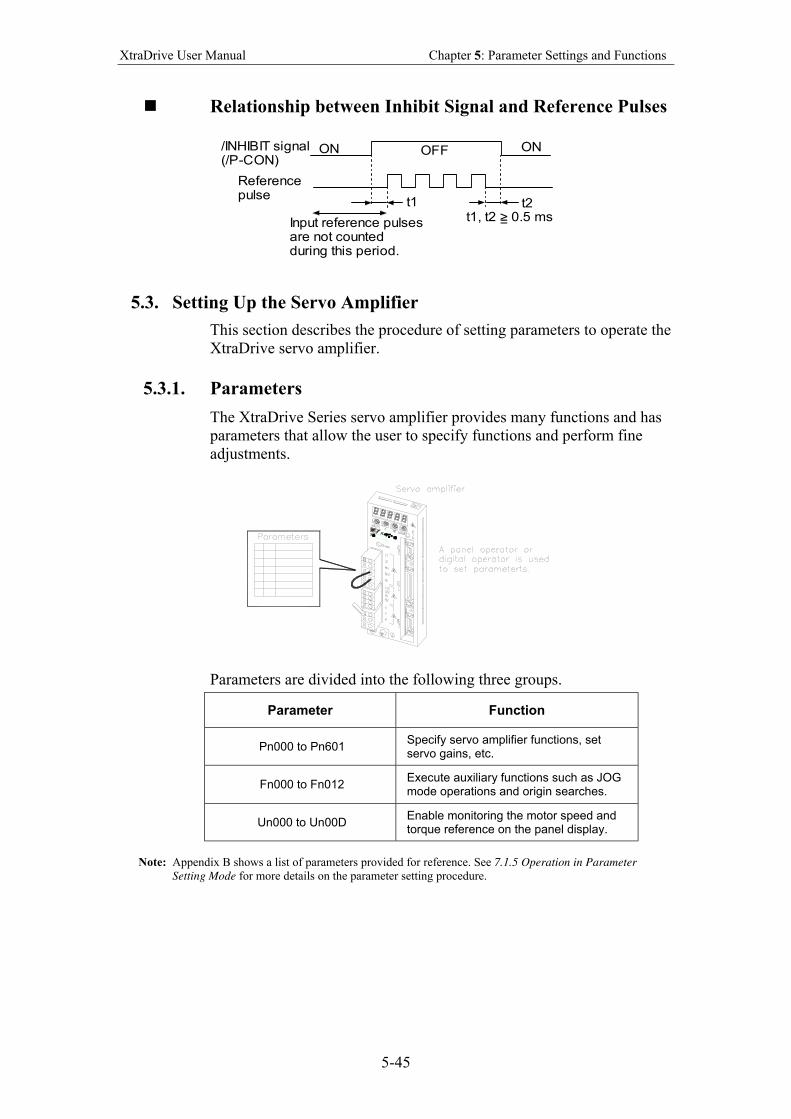
XtraDrive User Manual Chapter 5: Parameter Settings and Functions
5-45
Relationship between Inhibit Signal and Reference Pulses
t1 t2
ON OFF ON
t1, t2 > 0.5 ms=Input reference pulsesare not countedduring this period.
/INHIBIT signal(/P-CON)
Referencepulse
5.3. Setting Up the Servo Amplifier
This section describes the procedure of setting parameters to operate the
XtraDrive servo amplifier.
5.3.1. Parameters
The XtraDrive Series servo amplifier provides many functions and has
parameters that allow the user to specify functions and perform fine
adjustments.
Parameters are divided into the following three groups.
Parameter Function
Pn000 to Pn601 Specify servo amplifier functions, set servo gains, etc.
Fn000 to Fn012 Execute auxiliary functions such as JOG mode operations and origin searches.
Un000 to Un00D Enable monitoring the motor speed and torque reference on the panel display.
Note: Appendix B shows a list of parameters provided for reference. See 7.1.5 Operation in Parameter
Setting Mode for more details on the parameter setting procedure.
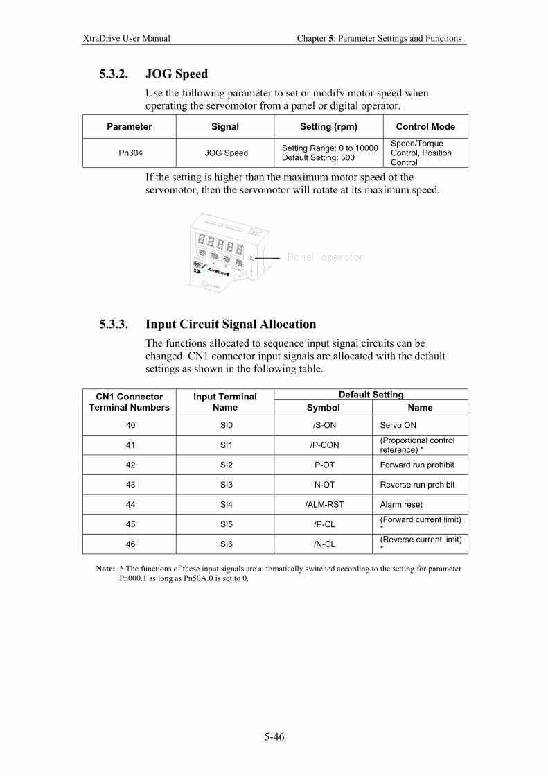
XtraDrive User Manual Chapter 5: Parameter Settings and Functions
5-46
5.3.2. JOG Speed
Use the following parameter to set or modify motor speed when
operating the servomotor from a panel or digital operator.
Parameter Signal Setting (rpm) Control Mode
Pn304 JOG Speed Setting Range: 0 to 10000 Default Setting: 500
Speed/Torque Control, Position Control
If the setting is higher than the maximum motor speed of the
servomotor, then the servomotor will rotate at its maximum speed.
5.3.3. Input Circuit Signal Allocation
The functions allocated to sequence input signal circuits can be
changed. CN1 connector input signals are allocated with the default
settings as shown in the following table.
Default Setting CN1 Connector Terminal Numbers
Input Terminal Name Symbol Name
40 SI0 /S-ON Servo ON
41 SI1 /P-CON (Proportional control reference) *
42 SI2 P-OT Forward run prohibit
43 SI3 N-OT Reverse run prohibit
44 SI4 /ALM-RST Alarm reset
45 SI5 /P-CL (Forward current limit) *
46 SI6 /N-CL (Reverse current limit) *
Note: * The functions of these input signals are automatically switched according to the setting for parameter
Pn000.1 as long as Pn50A.0 is set to 0.
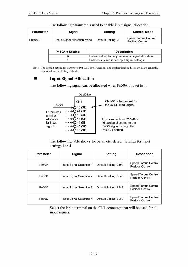
XtraDrive User Manual Chapter 5: Parameter Settings and Functions
5-47
The following parameter is used to enable input signal allocation.
Parameter Signal Setting Control Mode
Pn50A.0 Input Signal Allocation Mode Default Setting: 0 Speed/Torque Control, Position Control
Pn50A.0 Setting Description
0 Default setting for sequence input signal allocation.
1 Enables any sequence input signal settings.
Note: The default setting for parameter Pn50A.0 is 0. Functions and applications in this manual are generally
described for the factory defaults.
Input Signal Allocation
The following signal can be allocated when Pn50A.0 is set to 1.
/S-ON
Determinesterminalallocationfor inputsignals.
CN1
XtraDrive
40 (SI0)
44 (SI4)
45 (SI5)
46 (SI6)
41 (SI1)
42 (SI2)
43 (SI3)
CN1-40 is factory set forthe /S-ON input signal.
Any terminal from CN1-40 to46 can be allocated to the/S-ON signal through thePn50A.1 setting.
The following table shows the parameter default settings for input
settings 1 to 4.
Parameter Signal Setting Description
Pn50A Input Signal Selection 1 Default Setting: 2100 Speed/Torque Control, Position Control
Pn50B Input Signal Selection 2 Default Setting: 6543 Speed/Torque Control, Position Control
Pn50C Input Signal Selection 3 Default Setting: 8888 Speed/Torque Control, Position Control
Pn50D Input Signal Selection 4 Default Setting: 8888 Speed/Torque Control, Position Control
Select the input terminal on the CN1 connector that will be used for all
input signals.
XtraDrive User Manual Chapter 5: Parameter Settings and Functions
5-48
Examples of Input Signal Allocation
The procedure used to allocate sequence input signals is described using
the /S-ON signal as a typical example.
Pn50A.1 Setting
Description
0 Inputs the /S-ON signal from the SI0 (CN1-40) input terminal.
1 Inputs the /S-ON signal from the SI1 (CN1-41) input terminal.
2 Inputs the /S-ON signal from the SI2 (CN1-42) input terminal.
3 Inputs the /S-ON signal from the SI3 (CN1-43) input terminal.
4 Inputs the /S-ON signal from the SI4 (CN1-44) input terminal.
5 Inputs the /S-ON signal from the SI5 (CN1-45) input terminal.
6 Inputs the /S-ON signal from the SI6 (CN1-46) input terminal.
Signal polarity: Normal. Servo ON signal is valid when low (ON)
7 Sets /S-ON signal so that it is always valid.
8 Sets /S-ON signal so that it is always invalid.
Set the Servo-ON signal (/S-ON) so that it is always valid or always invalid.
9 Inputs the S-ON signal from the SI0 (CN1-40) input terminal.
A Inputs the/S-ON signal from the SI1 (CN1-41) input terminal.
B Inputs the S-ON signal from the SI2 (CN1-42) input terminal.
C Inputs the S-ON signal from the SI3 (CN1-43) input terminal.
D Inputs the S-ON signal from the SI4 (CN1-44) input terminal.
E Inputs the S-ON signal from the SI5 (CN1-45) input terminal.
F Inputs the/S-ON signal from the SI6 (CN1-46) input terminal.
Signal polarity: Inversion. Valid at OFF (H level) with Servo ON signal
As shown in the table above, the /S-ON signal can be allocated to any
input terminal from SI0 to SI6. /S-ON is always input when Pn50A.1 is
set to 7, and an external signal line would therefore not be needed
because the servo amplifier will determine whether the servo is ON or
OFF.
The /S-ON signal is not used when Pn50A.1 is set to 8. This setting is
meaningful only in the following instances.
• When the factory set input signal is to be replaced by another input
signal.
• The signal must be left ON (low level) during normal operation to
make the signal valid when OFF (high level) when forward run
prohibit (P-OT) and reverse run prohibit (N-OT) are input. The
input terminal signal line must be left ON even in system
configurations that do not require this signal, but unnecessary wiring
can be eliminated by setting Pn50A.1 to 8.
• By setting 9 to F, the signal polarity can be reversed.
Note: Several signals can be allocated to the same input circuit.
When the servo is ON, the forward run prohibit or reverse run prohibit signal is used.
At a setting with inverted polarity, the failed safe operation may not be possible in the case of signal
line disconnection.
XtraDrive User Manual Chapter 5: Parameter Settings and Functions
5-49
Allocating Other Input Signals
Input signal allocation can be changed as shown below.
Input Signal Parameter Description
Name Applicable
Logic Number Setting
0 Inputs the specified signal from SI0 (CN1-40).
1 Inputs the specified signal from SI1 (CN1-41).
2 Inputs the specified signal from SI2 (CN1-42).
3 Inputs the specified signal from SI3 (CN1-43).
4 Inputs the specified signal from SI4 (CN1-44).
5 Inputs the specified signal from SI5 (CN1-45).
6 Inputs the specified signal from SI6 (CN1-46).
7 Sets the specified signal to always enabled.
8 Sets the specified signal to always disabled.
9 Inputs the specified inverse signal from SI0 (CN1-40).
A Inputs the specified inverse signal from SI1 (CN1-41).
B Inputs the specified inverse signal from SI2 (CN1-42).
C Inputs the specified inverse signal from SI3 (CN1-43).
D Inputs the specified inverse signal from SI4 (CN1-44).
E Inputs the specified inverse signal from SI5 (CN1-45).
Proportional Control Reference (/P-CON)
ON (low level)
Pn50A.2
F Inputs the specified inverse signal from SI6 (CN1-46).
Forward Run Prohibit (P-OT)
Pn50A.3
Reverse Run Prohibit (N-OT)
OFF (high level)
Pn50B.0
Alarm Reset (/ARM-RST)
Pn50B.1
Forward Current Limit (/P-CL)
Pn50B.2
Reverse Current Limit (/N-CL)
ON (low level)
Pn50B.3
Contact Input Speed Control Selection (/SPD-D)
Pn50C.0
Contact Input Speed Control Selection (/SPD-A)
Pn50C.1
Contact Input Speed Control Selection (/SPD-B)
—
Pn50C.2
Control Mode Selection (/C-SEL)
Pn50C.3
Zero Clamp (/ZCLAMP)
Pn50D.0
Reference Pulse Inhibit (/INHIBIT)
Pn50D.1
Gain Switching (/G-SEL)
ON (low level)
Pn50D.2
0 to F Same as above.*
Note: *Same as above” means that input signals and terminals SI0 to SI6 are enabled or disabled through
parameter settings 0 to 8.
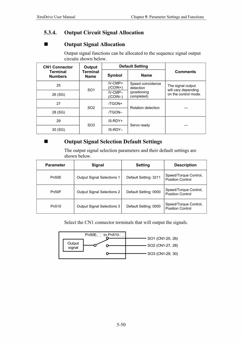
XtraDrive User Manual Chapter 5: Parameter Settings and Functions
5-50
5.3.4. Output Circuit Signal Allocation
Output Signal Allocation
Output signal functions can be allocated to the sequence signal output
circuits shown below.
Default Setting CN1 Connector Terminal Numbers
Output Terminal
Name Symbol Name Comments
25 /V-CMP+ (/COIN+)
26 (SG)
SO1 /V-CMP– (/COIN–)
Speed coincidence detection (positioning completed)
The signal output will vary depending on the control mode.
27 /TGON+
28 (SG)
SO2
/TGON–
Rotation detection —
29 /S-RDY+
30 (SG)
SO3
/S-RDY–
Servo ready —
Output Signal Selection Default Settings
The output signal selection parameters and their default settings are
shown below.
Parameter Signal Setting Description
Pn50E Output Signal Selections 1 Default Setting: 3211 Speed/Torque Control, Position Control
Pn50F Output Signal Selections 2 Default Setting: 0000 Speed/Torque Control, Position Control
Pn510 Output Signal Selections 3 Default Setting: 0000 Speed/Torque Control, Position Control
Select the CN1 connector terminals that will output the signals.
Outputsignal
SO1 (CN1-25, 26)
SO2 (CN1-27, 28)
SO3 (CN1-29, 30)
Pn50E. to Pn510.
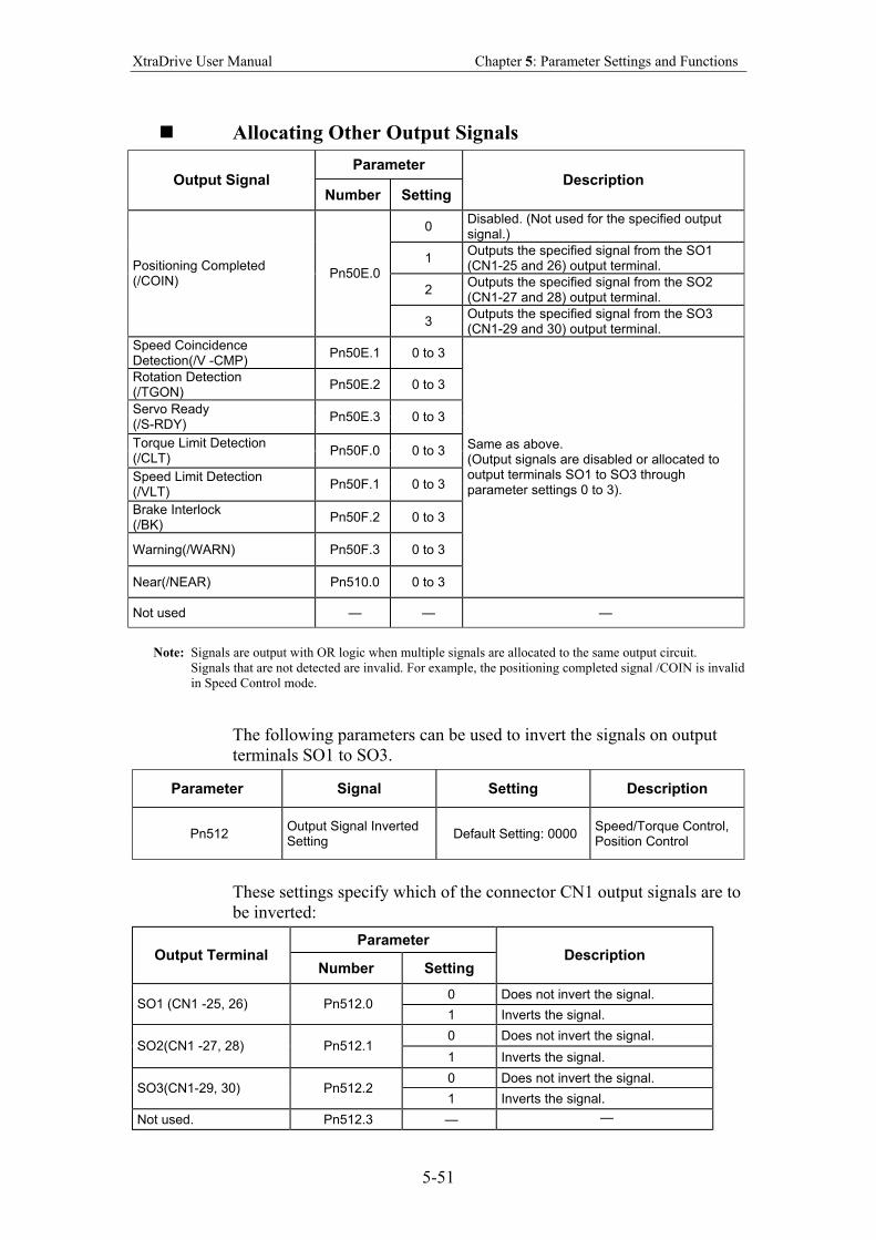
XtraDrive User Manual Chapter 5: Parameter Settings and Functions
5-51
Allocating Other Output Signals
Parameter Output Signal
Number Setting Description
0 Disabled. (Not used for the specified output signal.)
1 Outputs the specified signal from the SO1 (CN1-25 and 26) output terminal.
2 Outputs the specified signal from the SO2 (CN1-27 and 28) output terminal.
Positioning Completed (/COIN)
Pn50E.0
3 Outputs the specified signal from the SO3 (CN1-29 and 30) output terminal.
Speed Coincidence Detection(/V -CMP)
Pn50E.1 0 to 3
Rotation Detection (/TGON)
Pn50E.2 0 to 3
Servo Ready (/S-RDY)
Pn50E.3 0 to 3
Torque Limit Detection (/CLT)
Pn50F.0 0 to 3
Speed Limit Detection (/VLT)
Pn50F.1 0 to 3
Brake Interlock (/BK)
Pn50F.2 0 to 3
Warning(/WARN) Pn50F.3 0 to 3
Near(/NEAR) Pn510.0 0 to 3
Same as above. (Output signals are disabled or allocated to output terminals SO1 to SO3 through parameter settings 0 to 3).
Not used — — —
Note: Signals are output with OR logic when multiple signals are allocated to the same output circuit.
Signals that are not detected are invalid. For example, the positioning completed signal /COIN is invalid
in Speed Control mode.
The following parameters can be used to invert the signals on output
terminals SO1 to SO3.
Parameter Signal Setting Description
Pn512 Output Signal Inverted Setting
Default Setting: 0000 Speed/Torque Control, Position Control
These settings specify which of the connector CN1 output signals are to
be inverted:
Parameter Output Terminal
Number Setting Description
0 Does not invert the signal. SO1 (CN1 -25, 26) Pn512.0
1 Inverts the signal.
0 Does not invert the signal. SO2(CN1 -27, 28) Pn512.1
1 Inverts the signal.
0 Does not invert the signal. SO3(CN1-29, 30) Pn512.2
1 Inverts the signal.
Not used. Pn512.3 — —
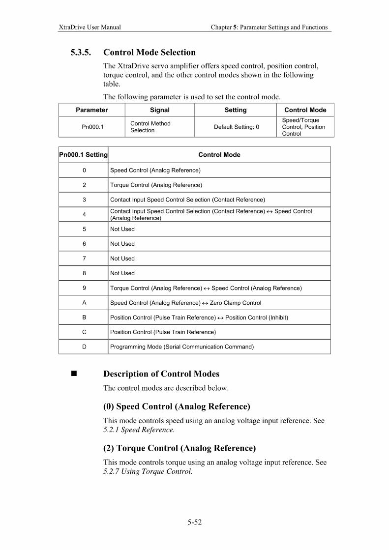
XtraDrive User Manual Chapter 5: Parameter Settings and Functions
5-52
5.3.5. Control Mode Selection
The XtraDrive servo amplifier offers speed control, position control,
torque control, and the other control modes shown in the following
table.
The following parameter is used to set the control mode.
Parameter Signal Setting Control Mode
Pn000.1 Control Method Selection
Default Setting: 0 Speed/Torque Control, Position Control
Pn000.1 Setting Control Mode
0 Speed Control (Analog Reference)
2 Torque Control (Analog Reference)
3 Contact Input Speed Control Selection (Contact Reference)
4 Contact Input Speed Control Selection (Contact Reference) ↔ Speed Control (Analog Reference)
5 Not Used
6 Not Used
7 Not Used
8 Not Used
9 Torque Control (Analog Reference) ↔ Speed Control (Analog Reference)
A Speed Control (Analog Reference) ↔ Zero Clamp Control
B Position Control (Pulse Train Reference) ↔ Position Control (Inhibit)
C Position Control (Pulse Train Reference)
D Programming Mode (Serial Communication Command)
Description of Control Modes
The control modes are described below.
(0) Speed Control (Analog Reference)
This mode controls speed using an analog voltage input reference. See
5.2.1 Speed Reference.
(2) Torque Control (Analog Reference)
This mode controls torque using an analog voltage input reference. See
5.2.7 Using Torque Control.
XtraDrive User Manual Chapter 5: Parameter Settings and Functions
5-53
(3) Contact Input Speed Control Selection (Contact
Reference)
This mode uses the /P-CON (/SPD-D), /P-CL (/SPD-A), and /N-CL
(/SPD-B) input signals to control speed as it switches among the three
preset operating speeds in the servo amplifier. See 5.2.6 Contact Input
Speed Control.
(4) Contact Input Speed Control Selection (Contact
Reference) Speed Control (Analog Reference)
This mode controls speed by switching between contact reference and
analog voltage reference speed control. Analog voltage reference speed
control is enabled when both /P-CL (/SPD-A) and /N-CL (/SPD-B)
input signals are OFF (high level). See 5.2.6 Contact Input Speed
Control.
(9) Torque Control (Analog Reference) Speed Control
(Analog Reference)
This mode switches between torque and speed control through the /P-
CON (/C-SEL) signal. See 5.2.7 Using Torque Control.
(A) Speed Control (Analog Reference) Zero Clamp
This speed control mode is used to set the zero clamp function when the
servo amplifier is stopped. Zero clamp operates when the /P-CON
(/ZCLAMP) signal is ON (low level). See 5.4.3 Using the Zero Clamp
Function.
(B) Position Control (Pulse Train Reference) Position
Control (Inhibit)
This mode controls positioning by inhibiting reference pulse input
through the /P-CON (/INHIBIT) signal. See 5.2.10 Reference Pulse
Inhibit Function (INHIBIT)
(C) Position Control (Pulse Train Reference)
This mode controls positioning using a pulse train input reference. See
5.2.2 Position Reference.
(D) Programming Mode (Serial Communication
Command)
This mode controls positioning and torque using a serial
communication. See 5.9 Configuration of Serial Command for AB
Encoders.
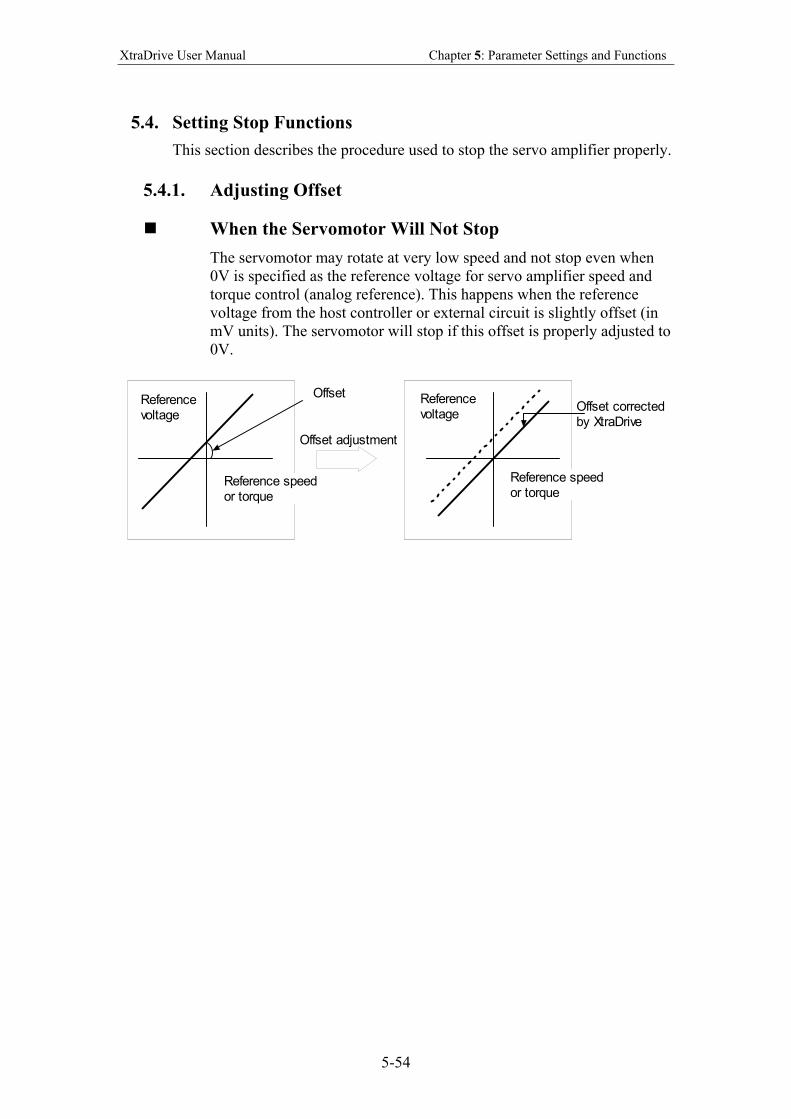
XtraDrive User Manual Chapter 5: Parameter Settings and Functions
5-54
5.4. Setting Stop Functions
This section describes the procedure used to stop the servo amplifier properly.
5.4.1. Adjusting Offset
When the Servomotor Will Not Stop
The servomotor may rotate at very low speed and not stop even when
0V is specified as the reference voltage for servo amplifier speed and
torque control (analog reference). This happens when the reference
voltage from the host controller or external circuit is slightly offset (in
mV units). The servomotor will stop if this offset is properly adjusted to
0V.
OffsetReferencevoltage
Referencevoltage
Reference speedor torque
Offset correctedby XtraDrive
Reference speedor torque
Offset adjustment
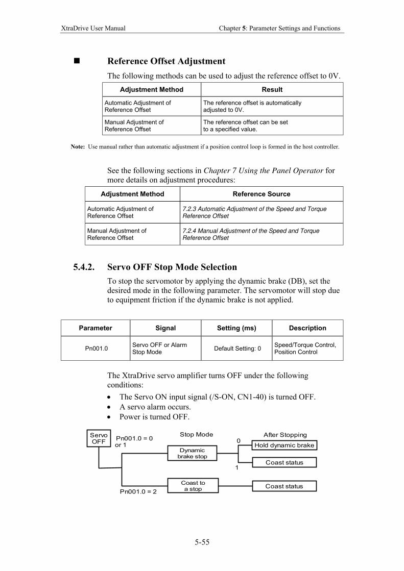
XtraDrive User Manual Chapter 5: Parameter Settings and Functions
5-55
Reference Offset Adjustment
The following methods can be used to adjust the reference offset to 0V.
Adjustment Method Result
Automatic Adjustment of Reference Offset
The reference offset is automatically adjusted to 0V.
Manual Adjustment of Reference Offset
The reference offset can be set to a specified value.
Note: Use manual rather than automatic adjustment if a position control loop is formed in the host controller.
See the following sections in Chapter 7 Using the Panel Operator for
more details on adjustment procedures:
Adjustment Method Reference Source
Automatic Adjustment of Reference Offset
7.2.3 Automatic Adjustment of the Speed and Torque Reference Offset
Manual Adjustment of Reference Offset
7.2.4 Manual Adjustment of the Speed and Torque Reference Offset
5.4.2. Servo OFF Stop Mode Selection
To stop the servomotor by applying the dynamic brake (DB), set the
desired mode in the following parameter. The servomotor will stop due
to equipment friction if the dynamic brake is not applied.
Parameter Signal Setting (ms) Description
Pn001.0 Servo OFF or Alarm Stop Mode
Default Setting: 0 Speed/Torque Control, Position Control
The XtraDrive servo amplifier turns OFF under the following
conditions:
• The Servo ON input signal (/S-ON, CN1-40) is turned OFF.
• A servo alarm occurs.
• Power is turned OFF.
ServoOFF
Dynamicbrake stop
Coast status
Hold dynamic brake
Coast status
Coast toa stop
Stop Mode After StoppingPn001.0 = 0or 1
Pn001.0 = 2
0
1
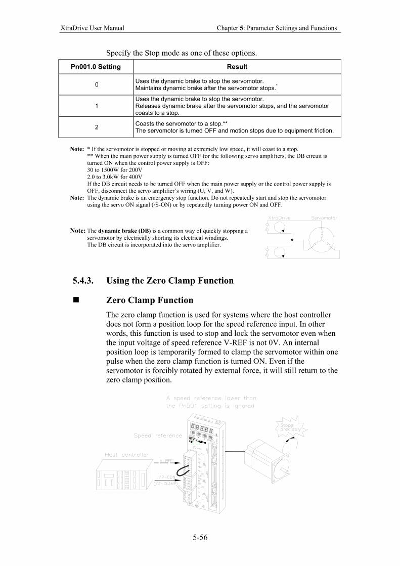
XtraDrive User Manual Chapter 5: Parameter Settings and Functions
5-56
Specify the Stop mode as one of these options.
Pn001.0 Setting Result
0 Uses the dynamic brake to stop the servomotor. Maintains dynamic brake after the servomotor stops.
*
1 Uses the dynamic brake to stop the servomotor. Releases dynamic brake after the servomotor stops, and the servomotor coasts to a stop.
2 Coasts the servomotor to a stop.** The servomotor is turned OFF and motion stops due to equipment friction.
Note: * If the servomotor is stopped or moving at extremely low speed, it will coast to a stop.
** When the main power supply is turned OFF for the following servo amplifiers, the DB circuit is
turned ON when the control power supply is OFF:
30 to 1500W for 200V
2.0 to 3.0kW for 400V
If the DB circuit needs to be turned OFF when the main power supply or the control power supply is
OFF, disconnect the servo amplifier’s wiring (U, V, and W).
Note: The dynamic brake is an emergency stop function. Do not repeatedly start and stop the servomotor
using the servo ON signal (/S-ON) or by repeatedly turning power ON and OFF.
Note: The dynamic brake (DB) is a common way of quickly stopping a
servomotor by electrically shorting its electrical windings.
The DB circuit is incorporated into the servo amplifier.
5.4.3. Using the Zero Clamp Function
Zero Clamp Function
The zero clamp function is used for systems where the host controller
does not form a position loop for the speed reference input. In other
words, this function is used to stop and lock the servomotor even when
the input voltage of speed reference V-REF is not 0V. An internal
position loop is temporarily formed to clamp the servomotor within one
pulse when the zero clamp function is turned ON. Even if the
servomotor is forcibly rotated by external force, it will still return to the
zero clamp position.
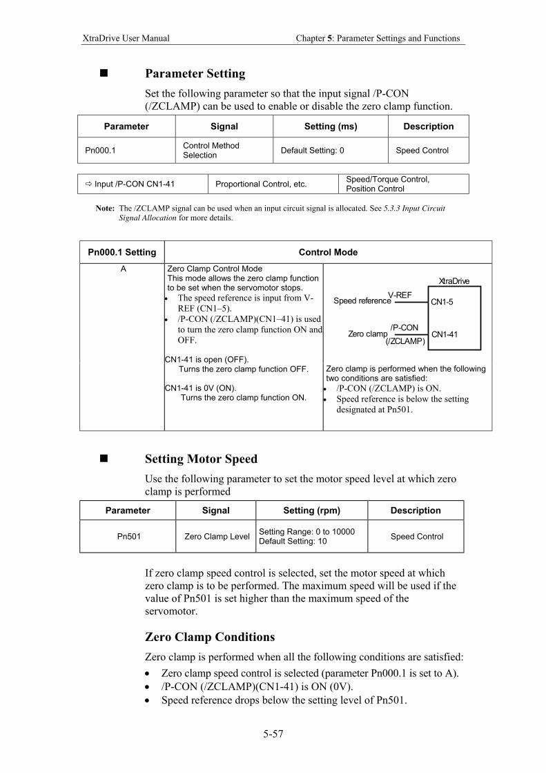
XtraDrive User Manual Chapter 5: Parameter Settings and Functions
5-57
Parameter Setting
Set the following parameter so that the input signal /P-CON
(/ZCLAMP) can be used to enable or disable the zero clamp function.
Parameter Signal Setting (ms) Description
Pn000.1 Control Method Selection
Default Setting: 0 Speed Control
Input /P-CON CN1-41 Proportional Control, etc. Speed/Torque Control, Position Control
Note: The /ZCLAMP signal can be used when an input circuit signal is allocated. See 5.3.3 Input Circuit
Signal Allocation for more details.
Pn000.1 Setting Control Mode
CN1-5
CN1-41
V-REF
/P-CON
(/ZCLAMP)Zero clamp
Speed reference
XtraDrive
A Zero Clamp Control Mode This mode allows the zero clamp function to be set when the servomotor stops.
• The speed reference is input from V-
REF (CN1–5).
• /P-CON (/ZCLAMP)(CN1–41) is used
to turn the zero clamp function ON and
OFF. CN1-41 is open (OFF).
Turns the zero clamp function OFF. CN1-41 is 0V (ON).
Turns the zero clamp function ON.
Zero clamp is performed when the following two conditions are satisfied:
• /P-CON (/ZCLAMP) is ON.
• Speed reference is below the setting
designated at Pn501.
Setting Motor Speed
Use the following parameter to set the motor speed level at which zero
clamp is performed
Parameter Signal Setting (rpm) Description
Pn501 Zero Clamp Level Setting Range: 0 to 10000 Default Setting: 10
Speed Control
If zero clamp speed control is selected, set the motor speed at which
zero clamp is to be performed. The maximum speed will be used if the
value of Pn501 is set higher than the maximum speed of the
servomotor.
Zero Clamp Conditions
Zero clamp is performed when all the following conditions are satisfied:
• Zero clamp speed control is selected (parameter Pn000.1 is set to A).
• /P-CON (/ZCLAMP)(CN1-41) is ON (0V).
• Speed reference drops below the setting level of Pn501.
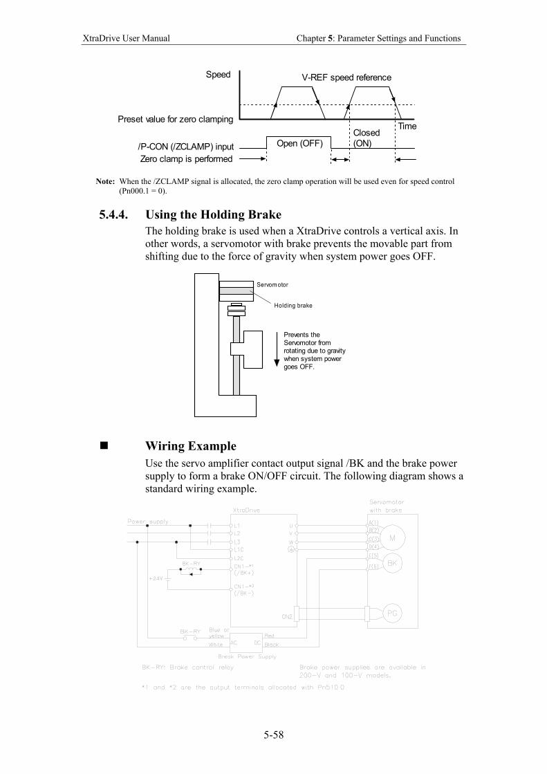
XtraDrive User Manual Chapter 5: Parameter Settings and Functions
5-58
V-REF speed referenceSpeed
Preset value for zero clamping
/P-CON (/ZCLAMP) input Open (OFF)Closed(ON)
Time
Zero clamp is performed
Note: When the /ZCLAMP signal is allocated, the zero clamp operation will be used even for speed control
(Pn000.1 = 0).
5.4.4. Using the Holding Brake
The holding brake is used when a XtraDrive controls a vertical axis. In
other words, a servomotor with brake prevents the movable part from
shifting due to the force of gravity when system power goes OFF.
Servom otor
Holding brake
Prevents theServomotor fromrotating due to gravitywhen system powergoes OFF.
Wiring Example
Use the servo amplifier contact output signal /BK and the brake power
supply to form a brake ON/OFF circuit. The following diagram shows a
standard wiring example.
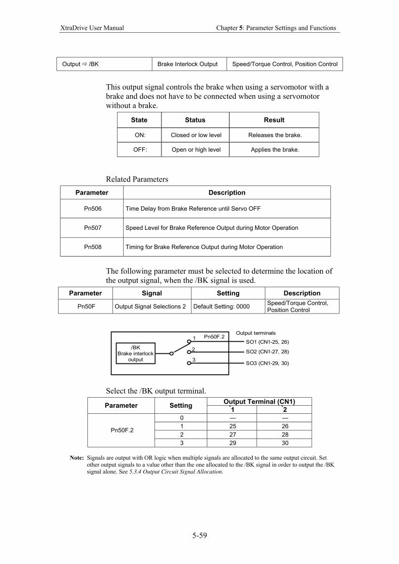
XtraDrive User Manual Chapter 5: Parameter Settings and Functions
5-59
Output /BK Brake Interlock Output Speed/Torque Control, Position Control
This output signal controls the brake when using a servomotor with a
brake and does not have to be connected when using a servomotor
without a brake.
State Status Result
ON: Closed or low level Releases the brake.
OFF: Open or high level Applies the brake.
Related Parameters
Parameter Description
Pn506 Time Delay from Brake Reference until Servo OFF
Pn507 Speed Level for Brake Reference Output during Motor Operation
Pn508 Timing for Brake Reference Output during Motor Operation
The following parameter must be selected to determine the location of
the output signal, when the /BK signal is used.
Parameter Signal Setting Description
Pn50F Output Signal Selections 2 Default Setting: 0000 Speed/Torque Control, Position Control
/BKBrake interlock
output
SO1 (CN1-25, 26)
SO2 (CN1-27, 28)
SO3 (CN1-29, 30)
Pn50F.21
2
3
Output terminals
Select the /BK output terminal.
Output Terminal (CN1) Parameter Setting *
1 *2
0 — —
1 25 26
2 27 28 Pn50F.2
3 29 30
Note: Signals are output with OR logic when multiple signals are allocated to the same output circuit. Set
other output signals to a value other than the one allocated to the /BK signal in order to output the /BK
signal alone. See 5.3.4 Output Circuit Signal Allocation.
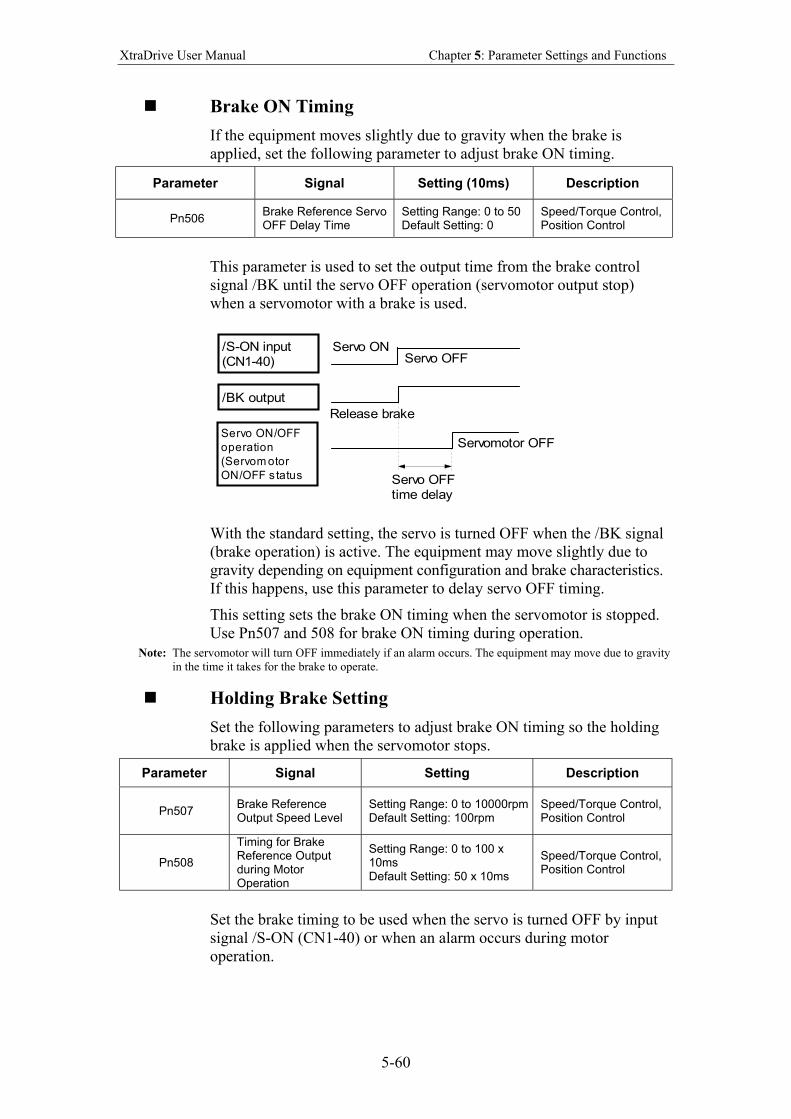
XtraDrive User Manual Chapter 5: Parameter Settings and Functions
5-60
Brake ON Timing
If the equipment moves slightly due to gravity when the brake is
applied, set the following parameter to adjust brake ON timing.
Parameter Signal Setting (10ms) Description
Pn506 Brake Reference Servo OFF Delay Time
Setting Range: 0 to 50 Default Setting: 0
Speed/Torque Control, Position Control
This parameter is used to set the output time from the brake control
signal /BK until the servo OFF operation (servomotor output stop)
when a servomotor with a brake is used.
/S-ON input(CN1-40)
/BK output
Servo ON/OFF
operation
(Servom otor
ON/OFF s tatus
Servo ON
Release brake
Servo OFF
Servomotor OFF
Servo OFFtime delay
With the standard setting, the servo is turned OFF when the /BK signal
(brake operation) is active. The equipment may move slightly due to
gravity depending on equipment configuration and brake characteristics.
If this happens, use this parameter to delay servo OFF timing.
This setting sets the brake ON timing when the servomotor is stopped.
Use Pn507 and 508 for brake ON timing during operation.
Note: The servomotor will turn OFF immediately if an alarm occurs. The equipment may move due to gravity
in the time it takes for the brake to operate.
Holding Brake Setting
Set the following parameters to adjust brake ON timing so the holding
brake is applied when the servomotor stops.
Parameter Signal Setting Description
Pn507 Brake Reference Output Speed Level
Setting Range: 0 to 10000rpm Default Setting: 100rpm
Speed/Torque Control, Position Control
Pn508
Timing for Brake Reference Output during Motor Operation
Setting Range: 0 to 100 x 10ms Default Setting: 50 x 10ms
Speed/Torque Control, Position Control
Set the brake timing to be used when the servo is turned OFF by input
signal /S-ON (CN1-40) or when an alarm occurs during motor
operation.
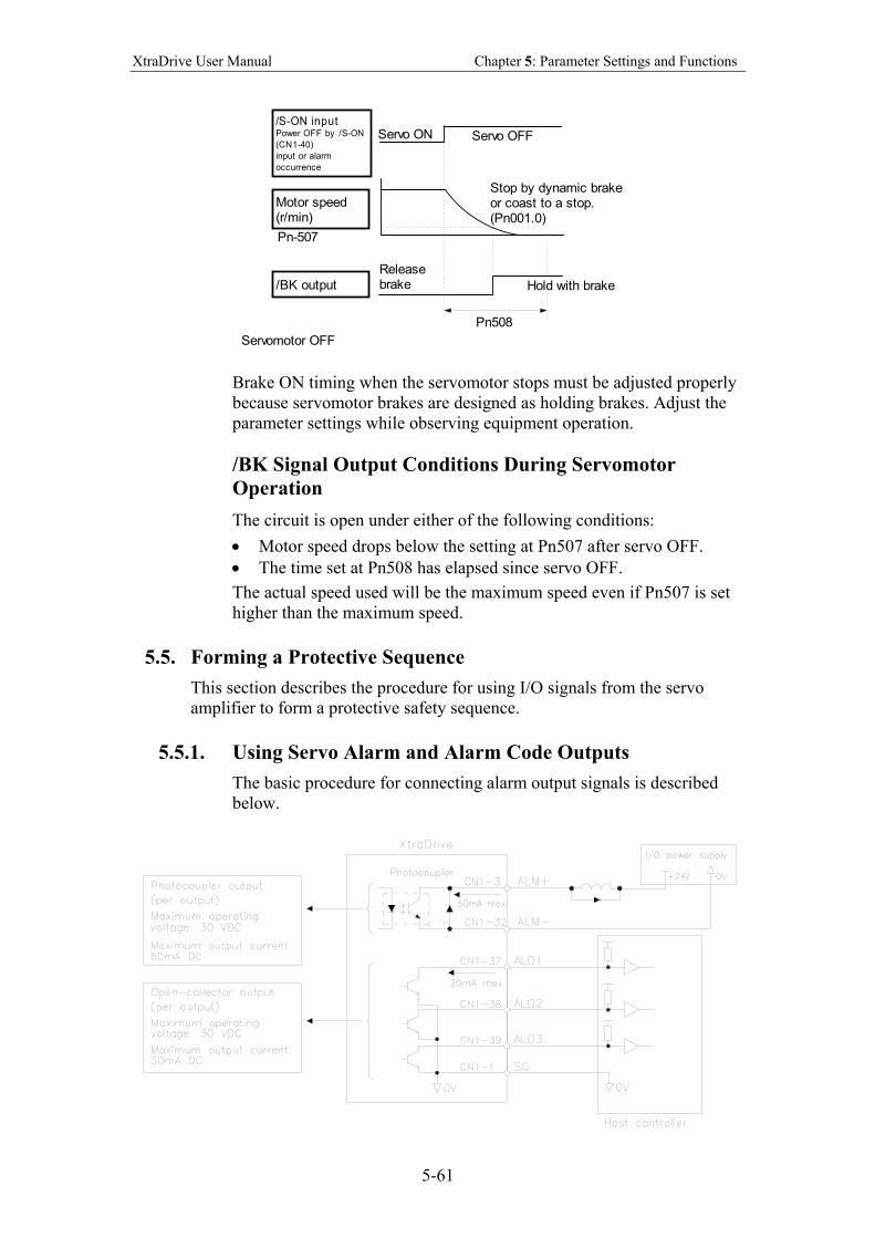
XtraDrive User Manual Chapter 5: Parameter Settings and Functions
5-61
Motor speed(r/min)
/BK output
/S-ON inputPower OFF by /S-ON
(CN1-40)
input or alarm
occurrence
Servo ON Servo OFF
Servomotor OFF
Stop by dynamic brakeor coast to a stop.(Pn001.0)
Hold with brake
Pn508
Releasebrake
Pn-507
Brake ON timing when the servomotor stops must be adjusted properly
because servomotor brakes are designed as holding brakes. Adjust the
parameter settings while observing equipment operation.
/BK Signal Output Conditions During Servomotor
Operation
The circuit is open under either of the following conditions:
• Motor speed drops below the setting at Pn507 after servo OFF.
• The time set at Pn508 has elapsed since servo OFF.
The actual speed used will be the maximum speed even if Pn507 is set
higher than the maximum speed.
5.5. Forming a Protective Sequence
This section describes the procedure for using I/O signals from the servo
amplifier to form a protective safety sequence.
5.5.1. Using Servo Alarm and Alarm Code Outputs
The basic procedure for connecting alarm output signals is described
below.
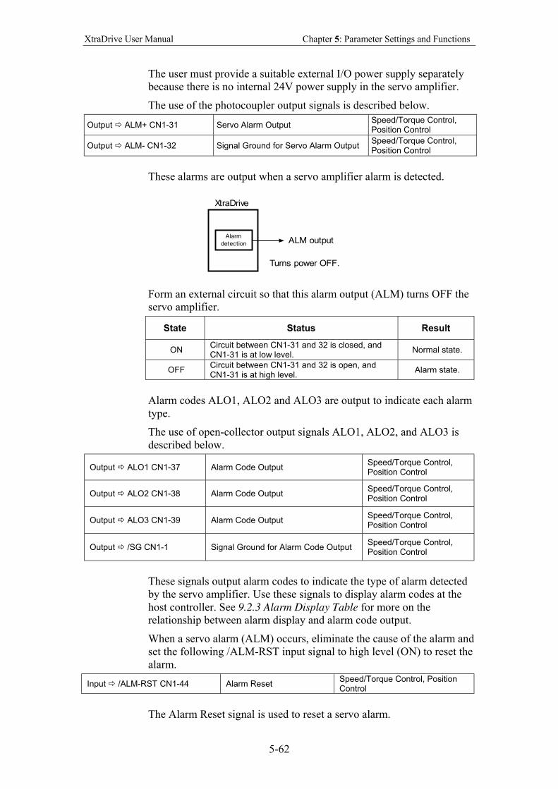
XtraDrive User Manual Chapter 5: Parameter Settings and Functions
5-62
The user must provide a suitable external I/O power supply separately
because there is no internal 24V power supply in the servo amplifier.
The use of the photocoupler output signals is described below.
Output ALM+ CN1-31 Servo Alarm Output Speed/Torque Control, Position Control
Output ALM- CN1-32 Signal Ground for Servo Alarm Output Speed/Torque Control, Position Control
These alarms are output when a servo amplifier alarm is detected.
ALM output
Turns power OFF.
Alarm
detection
XtraDrive
Form an external circuit so that this alarm output (ALM) turns OFF the
servo amplifier.
State Status Result
ON Circuit between CN1-31 and 32 is closed, and CN1-31 is at low level.
Normal state.
OFF Circuit between CN1-31 and 32 is open, and CN1-31 is at high level.
Alarm state.
Alarm codes ALO1, ALO2 and ALO3 are output to indicate each alarm
type.
The use of open-collector output signals ALO1, ALO2, and ALO3 is
described below.
Output ALO1 CN1-37 Alarm Code Output Speed/Torque Control, Position Control
Output ALO2 CN1-38 Alarm Code Output Speed/Torque Control, Position Control
Output ALO3 CN1-39 Alarm Code Output Speed/Torque Control, Position Control
Output /SG CN1-1 Signal Ground for Alarm Code Output Speed/Torque Control, Position Control
These signals output alarm codes to indicate the type of alarm detected
by the servo amplifier. Use these signals to display alarm codes at the
host controller. See 9.2.3 Alarm Display Table for more on the
relationship between alarm display and alarm code output.
When a servo alarm (ALM) occurs, eliminate the cause of the alarm and
set the following /ALM-RST input signal to high level (ON) to reset the
alarm.
Input /ALM-RST CN1-44 Alarm Reset Speed/Torque Control, Position Control
The Alarm Reset signal is used to reset a servo alarm.
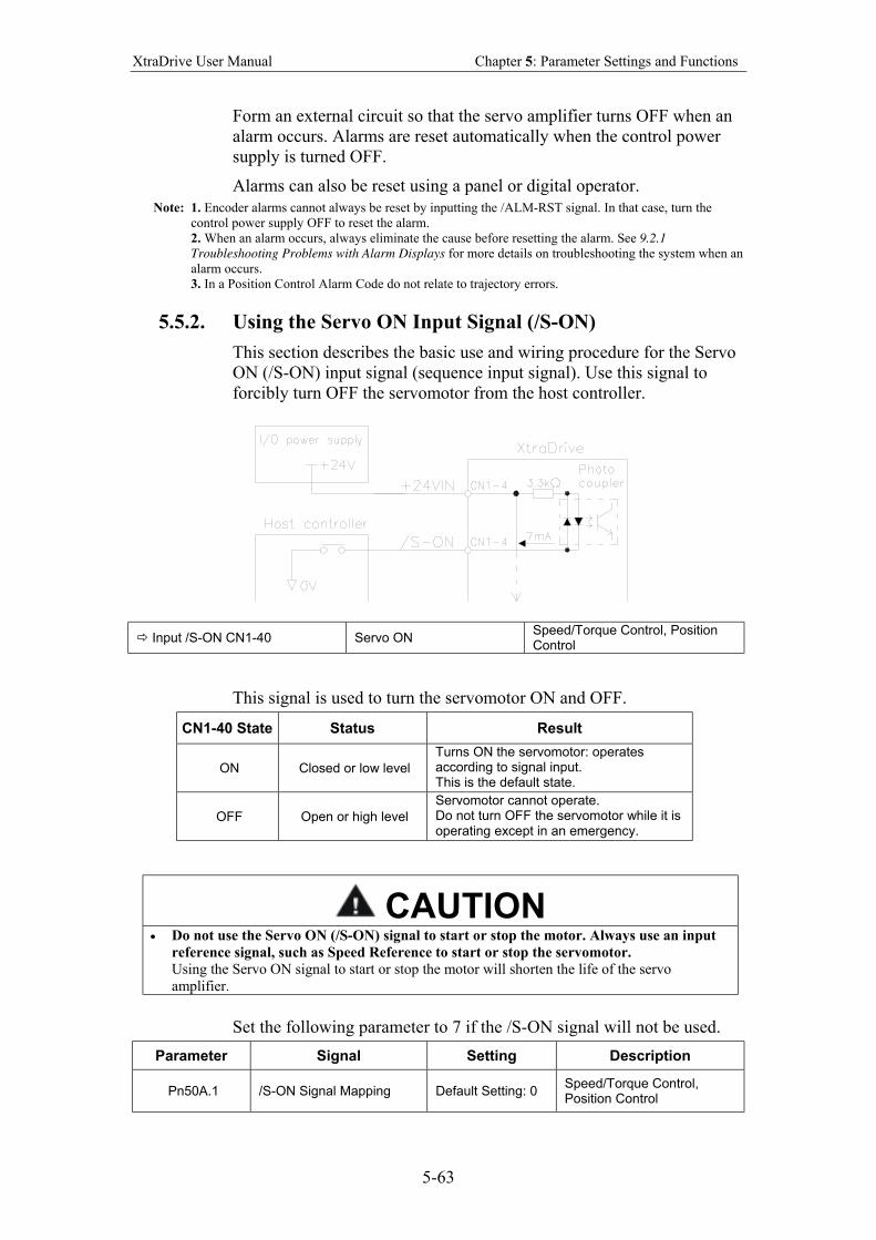
XtraDrive User Manual Chapter 5: Parameter Settings and Functions
5-63
Form an external circuit so that the servo amplifier turns OFF when an
alarm occurs. Alarms are reset automatically when the control power
supply is turned OFF.
Alarms can also be reset using a panel or digital operator.
Note: 1. Encoder alarms cannot always be reset by inputting the /ALM-RST signal. In that case, turn the
control power supply OFF to reset the alarm.
2. When an alarm occurs, always eliminate the cause before resetting the alarm. See 9.2.1
Troubleshooting Problems with Alarm Displays for more details on troubleshooting the system when an
alarm occurs.
3. In a Position Control Alarm Code do not relate to trajectory errors.
5.5.2. Using the Servo ON Input Signal (/S-ON)
This section describes the basic use and wiring procedure for the Servo
ON (/S-ON) input signal (sequence input signal). Use this signal to
forcibly turn OFF the servomotor from the host controller.
Input /S-ON CN1-40 Servo ON Speed/Torque Control, Position Control
This signal is used to turn the servomotor ON and OFF.
CN1-40 State Status Result
ON Closed or low level
Turns ON the servomotor: operates according to signal input. This is the default state.
OFF Open or high level
Servomotor cannot operate. Do not turn OFF the servomotor while it is operating except in an emergency.
CAUTION • Do not use the Servo ON (/S-ON) signal to start or stop the motor. Always use an input
reference signal, such as Speed Reference to start or stop the servomotor.
Using the Servo ON signal to start or stop the motor will shorten the life of the servo
amplifier.
Set the following parameter to 7 if the /S-ON signal will not be used.
Parameter Signal Setting Description
Pn50A.1 /S-ON Signal Mapping Default Setting: 0 Speed/Torque Control, Position Control
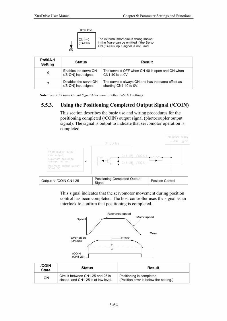
XtraDrive User Manual Chapter 5: Parameter Settings and Functions
5-64
CN1-40(/S-ON)
The external short-circuit wiring shownin the figure can be omitted if the ServoON (/S-ON) input signal is not used.
XtraDrive
0V
Pn50A.1 Setting
Status Result
0 Enables the servo ON (/S-ON) input signal.
The servo is OFF when CN-40 is open and ON when CN1-40 is at 0V.
7 Disables the servo ON (/S-ON) input signal.
The servo is always ON and has the same effect as shorting CN1-40 to 0V.
Note: See 5.3.3 Input Circuit Signal Allocation for other Pn50A.1 settings.
5.5.3. Using the Positioning Completed Output Signal (/COIN)
This section describes the basic use and wiring procedures for the
positioning completed (/COIN) output signal (photocoupler output
signal). The signal is output to indicate that servomotor operation is
completed.
Output /COIN CN1-25 Positioning Completed Output Signal
Position Control
This signal indicates that the servomotor movement during position
control has been completed. The host controller uses the signal as an
interlock to confirm that positioning is completed.
Reference speed
SpeedMotor speed
Time
Error pulse(Un008)
/COIN(CN1-25)
Pn500
/COIN State
Status Result
ON Circuit between CN1-25 and 26 is closed, and CN1-25 is at low level.
Positioning is completed. (Position error is below the setting.)
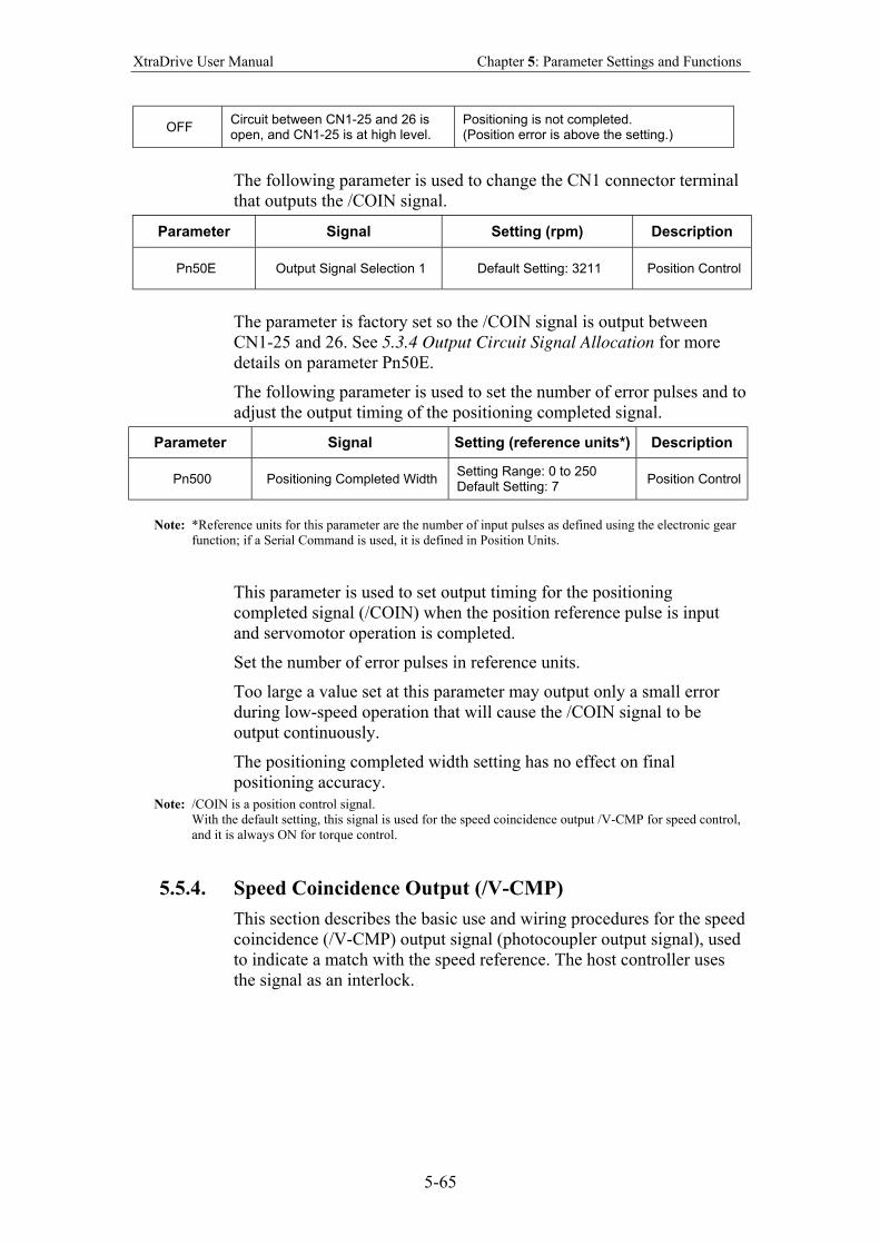
XtraDrive User Manual Chapter 5: Parameter Settings and Functions
5-65
OFF Circuit between CN1-25 and 26 is open, and CN1-25 is at high level.
Positioning is not completed. (Position error is above the setting.)
The following parameter is used to change the CN1 connector terminal
that outputs the /COIN signal.
Parameter Signal Setting (rpm) Description
Pn50E Output Signal Selection 1 Default Setting: 3211 Position Control
The parameter is factory set so the /COIN signal is output between
CN1-25 and 26. See 5.3.4 Output Circuit Signal Allocation for more
details on parameter Pn50E.
The following parameter is used to set the number of error pulses and to
adjust the output timing of the positioning completed signal.
Parameter Signal Setting (reference units*) Description
Pn500 Positioning Completed Width Setting Range: 0 to 250 Default Setting: 7
Position Control
Note: *Reference units for this parameter are the number of input pulses as defined using the electronic gear
function; if a Serial Command is used, it is defined in Position Units.
This parameter is used to set output timing for the positioning
completed signal (/COIN) when the position reference pulse is input
and servomotor operation is completed.
Set the number of error pulses in reference units.
Too large a value set at this parameter may output only a small error
during low-speed operation that will cause the /COIN signal to be
output continuously.
The positioning completed width setting has no effect on final
positioning accuracy.
Note: /COIN is a position control signal.
With the default setting, this signal is used for the speed coincidence output /V-CMP for speed control,
and it is always ON for torque control.
5.5.4. Speed Coincidence Output (/V-CMP)
This section describes the basic use and wiring procedures for the speed
coincidence (/V-CMP) output signal (photocoupler output signal), used
to indicate a match with the speed reference. The host controller uses
the signal as an interlock.
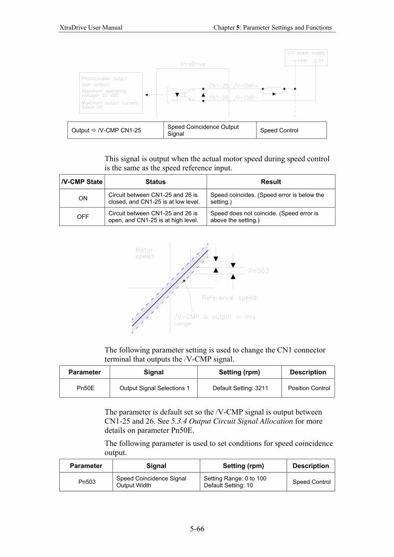
XtraDrive User Manual Chapter 5: Parameter Settings and Functions
5-66
Output /V-CMP CN1-25 Speed Coincidence Output Signal
Speed Control
This signal is output when the actual motor speed during speed control
is the same as the speed reference input.
/V-CMP State Status Result
ON Circuit between CN1-25 and 26 is closed, and CN1-25 is at low level.
Speed coincides. (Speed error is below the setting.)
OFF Circuit between CN1-25 and 26 is open, and CN1-25 is at high level.
Speed does not coincide. (Speed error is above the setting.)
The following parameter setting is used to change the CN1 connector
terminal that outputs the /V-CMP signal.
Parameter Signal Setting (rpm) Description
Pn50E Output Signal Selections 1 Default Setting: 3211 Position Control
The parameter is default set so the /V-CMP signal is output between
CN1-25 and 26. See 5.3.4 Output Circuit Signal Allocation for more
details on parameter Pn50E.
The following parameter is used to set conditions for speed coincidence
output.
Parameter Signal Setting (rpm) Description
Pn503 Speed Coincidence Signal Output Width
Setting Range: 0 to 100 Default Setting: 10
Speed Control
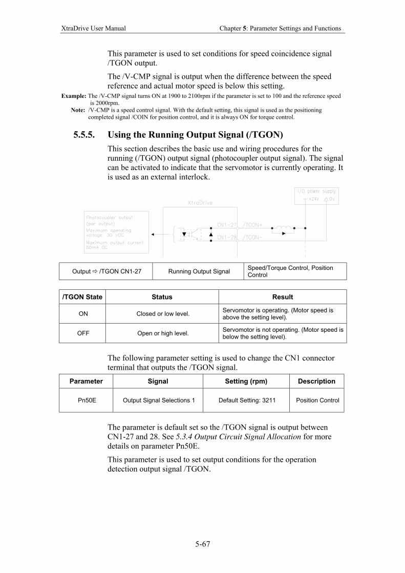
XtraDrive User Manual Chapter 5: Parameter Settings and Functions
5-67
This parameter is used to set conditions for speed coincidence signal
/TGON output.
The /V-CMP signal is output when the difference between the speed
reference and actual motor speed is below this setting.
Example: The /V-CMP signal turns ON at 1900 to 2100rpm if the parameter is set to 100 and the reference speed
is 2000rpm.
Note: /V-CMP is a speed control signal. With the default setting, this signal is used as the positioning
completed signal /COIN for position control, and it is always ON for torque control.
5.5.5. Using the Running Output Signal (/TGON)
This section describes the basic use and wiring procedures for the
running (/TGON) output signal (photocoupler output signal). The signal
can be activated to indicate that the servomotor is currently operating. It
is used as an external interlock.
Output /TGON CN1-27 Running Output Signal Speed/Torque Control, Position Control
/TGON State Status Result
ON Closed or low level. Servomotor is operating. (Motor speed is above the setting level).
OFF Open or high level. Servomotor is not operating. (Motor speed is below the setting level).
The following parameter setting is used to change the CN1 connector
terminal that outputs the /TGON signal.
Parameter Signal Setting (rpm) Description
Pn50E Output Signal Selections 1 Default Setting: 3211 Position Control
The parameter is default set so the /TGON signal is output between
CN1-27 and 28. See 5.3.4 Output Circuit Signal Allocation for more
details on parameter Pn50E.
This parameter is used to set output conditions for the operation
detection output signal /TGON.
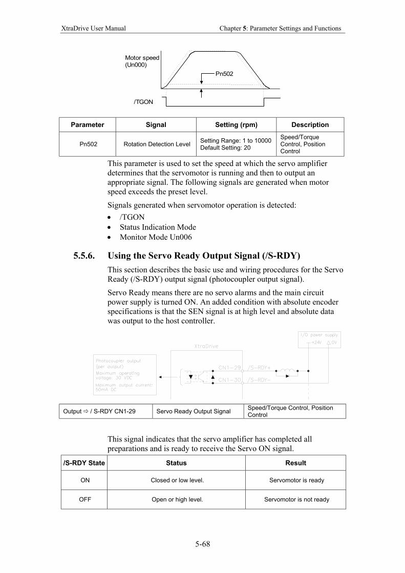
XtraDrive User Manual Chapter 5: Parameter Settings and Functions
5-68
Motor speed(Un000)
/TGON
Pn502
Parameter Signal Setting (rpm) Description
Pn502 Rotation Detection Level Setting Range: 1 to 10000 Default Setting: 20
Speed/Torque Control, Position Control
This parameter is used to set the speed at which the servo amplifier
determines that the servomotor is running and then to output an
appropriate signal. The following signals are generated when motor
speed exceeds the preset level.
Signals generated when servomotor operation is detected:
• /TGON
• Status Indication Mode
• Monitor Mode Un006
5.5.6. Using the Servo Ready Output Signal (/S-RDY)
This section describes the basic use and wiring procedures for the Servo
Ready (/S-RDY) output signal (photocoupler output signal).
Servo Ready means there are no servo alarms and the main circuit
power supply is turned ON. An added condition with absolute encoder
specifications is that the SEN signal is at high level and absolute data
was output to the host controller.
Output / S-RDY CN1-29 Servo Ready Output Signal Speed/Torque Control, Position Control
This signal indicates that the servo amplifier has completed all
preparations and is ready to receive the Servo ON signal.
/S-RDY State Status Result
ON Closed or low level. Servomotor is ready
OFF Open or high level. Servomotor is not ready
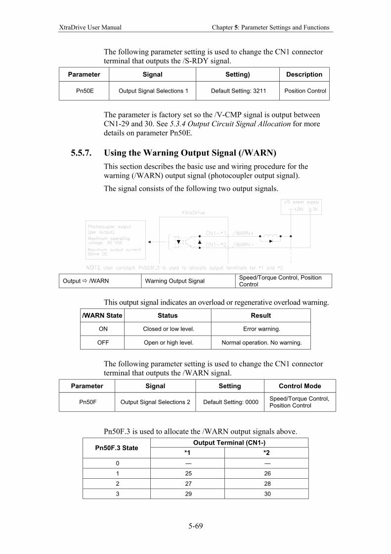
XtraDrive User Manual Chapter 5: Parameter Settings and Functions
5-69
The following parameter setting is used to change the CN1 connector
terminal that outputs the /S-RDY signal.
Parameter Signal Setting) Description
Pn50E Output Signal Selections 1 Default Setting: 3211 Position Control
The parameter is factory set so the /V-CMP signal is output between
CN1-29 and 30. See 5.3.4 Output Circuit Signal Allocation for more
details on parameter Pn50E.
5.5.7. Using the Warning Output Signal (/WARN)
This section describes the basic use and wiring procedure for the
warning (/WARN) output signal (photocoupler output signal).
The signal consists of the following two output signals.
Output /WARN Warning Output Signal Speed/Torque Control, Position Control
This output signal indicates an overload or regenerative overload warning.
/WARN State Status Result
ON Closed or low level. Error warning.
OFF Open or high level. Normal operation. No warning.
The following parameter setting is used to change the CN1 connector
terminal that outputs the /WARN signal.
Parameter Signal Setting Control Mode
Pn50F Output Signal Selections 2 Default Setting: 0000 Speed/Torque Control, Position Control
Pn50F.3 is used to allocate the /WARN output signals above.
Output Terminal (CN1-) Pn50F.3 State
*1 *2
0 — —
1 25 26
2 27 28
3 29 30
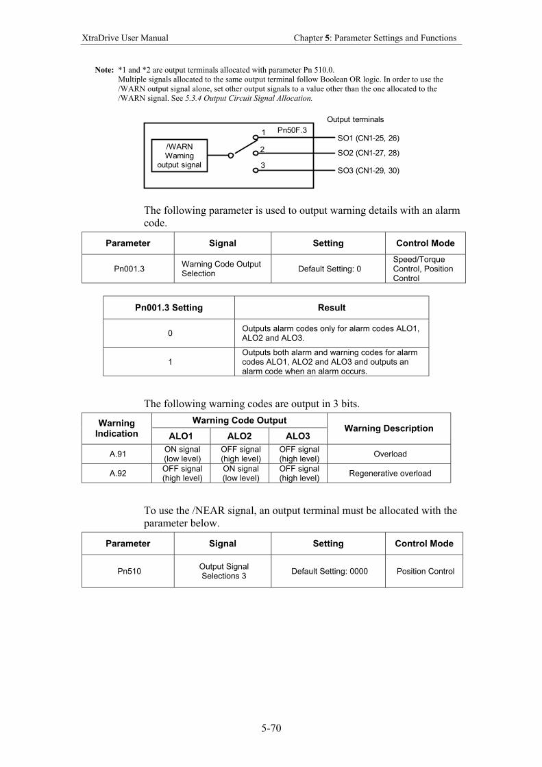
XtraDrive User Manual Chapter 5: Parameter Settings and Functions
5-70
Note: *1 and *2 are output terminals allocated with parameter Pn 510.0.
Multiple signals allocated to the same output terminal follow Boolean OR logic. In order to use the
/WARN output signal alone, set other output signals to a value other than the one allocated to the
/WARN signal. See 5.3.4 Output Circuit Signal Allocation.
/WARNWarning
output signal
SO1 (CN1-25, 26)
SO2 (CN1-27, 28)
SO3 (CN1-29, 30)
Pn50F.31
2
3
Output terminals
The following parameter is used to output warning details with an alarm
code.
Parameter Signal Setting Control Mode
Pn001.3 Warning Code Output Selection
Default Setting: 0 Speed/Torque Control, Position Control
Pn001.3 Setting Result
0 Outputs alarm codes only for alarm codes ALO1, ALO2 and ALO3.
1 Outputs both alarm and warning codes for alarm codes ALO1, ALO2 and ALO3 and outputs an alarm code when an alarm occurs.
The following warning codes are output in 3 bits.
Warning Code Output Warning Indication ALO1 ALO2 ALO3
Warning Description
A.91 ON signal (low level)
OFF signal (high level)
OFF signal (high level)
Overload
A.92 OFF signal (high level)
ON signal (low level)
OFF signal (high level)
Regenerative overload
To use the /NEAR signal, an output terminal must be allocated with the
parameter below.
Parameter Signal Setting Control Mode
Pn510 Output Signal Selections 3
Default Setting: 0000 Position Control
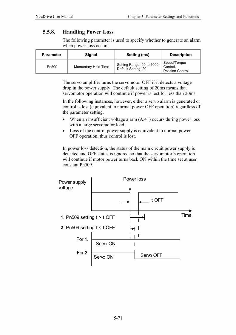
XtraDrive User Manual Chapter 5: Parameter Settings and Functions
5-71
5.5.8. Handling Power Loss
The following parameter is used to specify whether to generate an alarm
when power loss occurs.
Parameter Signal Setting (ms) Description
Pn509 Momentary Hold Time Setting Range: 20 to 1000 Default Setting: 20
Speed/Torque Control, Position Control
The servo amplifier turns the servomotor OFF if it detects a voltage
drop in the power supply. The default setting of 20ms means that
servomotor operation will continue if power is lost for less than 20ms.
In the following instances, however, either a servo alarm is generated or
control is lost (equivalent to normal power OFF operation) regardless of
the parameter setting.
• When an insufficient voltage alarm (A.41) occurs during power loss
with a large servomotor load.
• Loss of the control power supply is equivalent to normal power
OFF operation, thus control is lost.
In power loss detection, the status of the main circuit power supply is
detected and OFF status is ignored so that the servomotor’s operation
will continue if motor power turns back ON within the time set at user
constant Pn509.
Time
Power supplyvoltage
t OFF
Power loss
1. Pn509 setting t > t OFF
2. Pn509 setting t < t OFF
For 1.
For 2.
Servo ON
Servo ON Servo OFF
5
Settings and Functions
XtraDrive User Manual Chapter 5: Parameter Settings and Functions
5-72
5.6. Selecting a Regenerative Resistor
When the servomotor operates in Generator mode, power is returned to the
servo amplifier side. This is called regenerative power. The regenerative
power is absorbed by charging the smoothing capacitor, but when the
capacitor’s charging limit is exceeded, the regenerative power is then reduced
by the regenerative resistor.
The servomotor is driven in regeneration (generator) mode in the following
conditions:
• While decelerating to a stop during acceleration/deceleration
operation.
• With a load on the vertical axis.
• During continuous operation with the servomotor driven from the load
side (negative load).
The capacity of the servo amplifier’s built-in regenerative resistor is designed
for short-term operation only, such as the deceleration stop period. Operation
under a negative load is not possible.
If the regenerative power exceeds the processing capacity of the servo
amplifier, install an external regenerative resistor. The following table shows
the examples of specifications for servo amplifier’s built-in resistor and the
amount of regenerative power (average values) that it can process.
Built-in Resistor Specifications
Applicable Servo Amplifiers
Resistance (Ω)
Capacity (W)
Regenerative Power
Processed by Built-in
Resistor* (W)
Minimum Allowable
Resistance (Ω)
XD-P3-** to –04-** — — — Single-phase
200V XD-08-** 50 60 12
40
Three-phase 400V
XD-20DE to -30DE 45 140 28 44
Note: The amount of regenerative power (average value) that can be processed is rated at 20% of the capacity of
the servo amplifier’s built-in regenerative resistor.
When installing an external regenerative resistor, make sure that the
resistance is the same as that of the servo amplifier’s built-in resistor. If you
combine multiple small-capacity regenerative resistors to increase the
regenerative resistor capacity (W), select the resistors in a way that the
resistance value including error is at least as high as the minimum allowable
resistance shown in the table above.
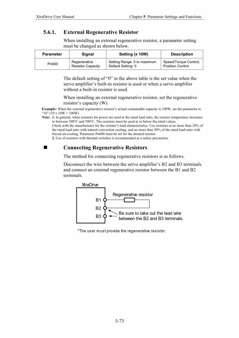
XtraDrive User Manual Chapter 5: Parameter Settings and Functions
5-73
5.6.1. External Regenerative Resistor
When installing an external regenerative resistor, a parameter setting
must be changed as shown below.
Parameter Signal Setting (x 10W) Description
Pn600 Regenerative Resistor Capacity
Setting Range: 0 to maximum Default Setting: 0
Speed/Torque Control, Position Control
The default setting of “0” in the above table is the set value when the
servo amplifier’s built-in resistor is used or when a servo amplifier
without a built-in resistor is used.
When installing an external regenerative resistor, set the regenerative
resistor’s capacity (W).
Example: When the external regenerative resistor’s actual consumable capacity is 100W, set the parameter to
“10” (10 x 10W = 100W)
Note: 1. In general, when resistors for power are used at the rated load ratio, the resistor temperature increases
to between 200°C and 300°C. The resistors must be used at or below the rated values.
Check with the manufacturer for the resistor’s load characteristics. Use resistors at no more than 20% of
the rated load ratio with natural convection cooling, and no more than 50% of the rated load ratio with
forced air-cooling. Parameter Pn600 must be set for the derated resistor.
2. Use of resistors with thermal switches is recommended as a safety precaution.
Connecting Regenerative Resistors
The method for connecting regenerative resistors is as follows.
Disconnect the wire between the servo amplifier’s B2 and B3 terminals
and connect an external regenerative resistor between the B1 and B2
terminals.
Regenerative resistor
B1
B2
XtraDrive
*The user m us t provide the regenerative res is tor.
B3Be sure to take out the lead wirebetween the B2 and B3 terminals.
XtraDrive User Manual Chapter 5: Parameter Settings and Functions
5-74
5.6.2. Calculating the Regenerative Power Capacity
Simple Calculation Method
When driving a servomotor normally along the horizontal axis, check
the external regenerative resistor requirements using the calculation
method shown below.
Servo Amplifiers with a Capacity of 400W or Less
Servo amplifiers with a capacity of 400W or less do not have built-in
regenerative resistors. The energy that can be absorbed by capacitors is
shown in the following table. If the rotational energy in the servo
system exceeds these values, then connect a regenerative resistor
externally.
Voltage Applicable Servo
Amplifiers
Regenerative Energy that Can Be Processed
(Joules) Comments
XD-P3-**, -P5-** 18.5 200V
XD-01-** to -04-** 37.1
Value when the input voltage is 200V AC
Calculate the rotational energy in the servo system using the following
equation:
ES = ( )
12566
Nx J 2
M
Joules
Where: J = JM + JL
JM: Servomotor rotor inertia (kg·m2) (oz·in·s
2)
JL: Motor axis conversion load inertia (kg·m2) (oz·in·s
2)
NM: Rotation speed of the servomotor (rpm)
Servo Amplifier Capacity of 0.8 to 3.0kW
Servomotors with a capacity of 500W to 5kW have built-in regenerative
resistors. The allowable frequencies for just the servomotor during
acceleration/deceleration operation, in the run cycle from 0
maximum rotation speed 0, are summarized in the following table.
Convert the data into the values obtained with actual rotation speed
used and load inertia to determine whether an external regenerative
resistor is needed.
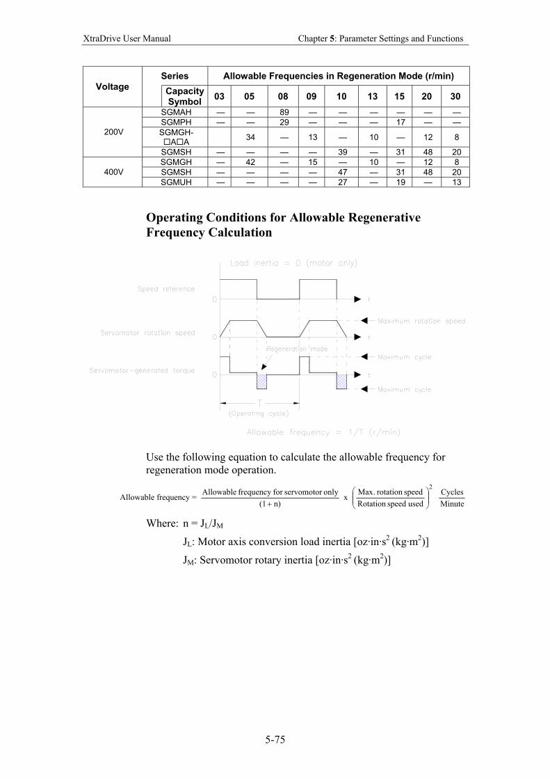
XtraDrive User Manual Chapter 5: Parameter Settings and Functions
5-75
Series Allowable Frequencies in Regeneration Mode (r/min) Voltage
Capacity Symbol
03 05 08 09 10 13 15 20 30
SGMAH — — 89 — — — — — —
SGMPH — — 29 — — — 17 — —
SGMGH- A A
34 — 13 — 10 — 12 8 200V
SGMSH — — — — 39 — 31 48 20
SGMGH — 42 — 15 — 10 — 12 8
SGMSH — — — — 47 — 31 48 20 400V
SGMUH — — — — 27 — 19 — 13
Operating Conditions for Allowable Regenerative
Frequency Calculation
Use the following equation to calculate the allowable frequency for
regeneration mode operation.
Allowable frequency = n) (1
only servomotorfor frequency Allowable
+ x
2
used speed Rotation
speed rotation .Max
Minute
Cycles
Where: n = JL/JM
JL: Motor axis conversion load inertia [oz·in·s2 (kg·m
2)]
JM: Servomotor rotary inertia [oz·in·s2 (kg·m
2)]
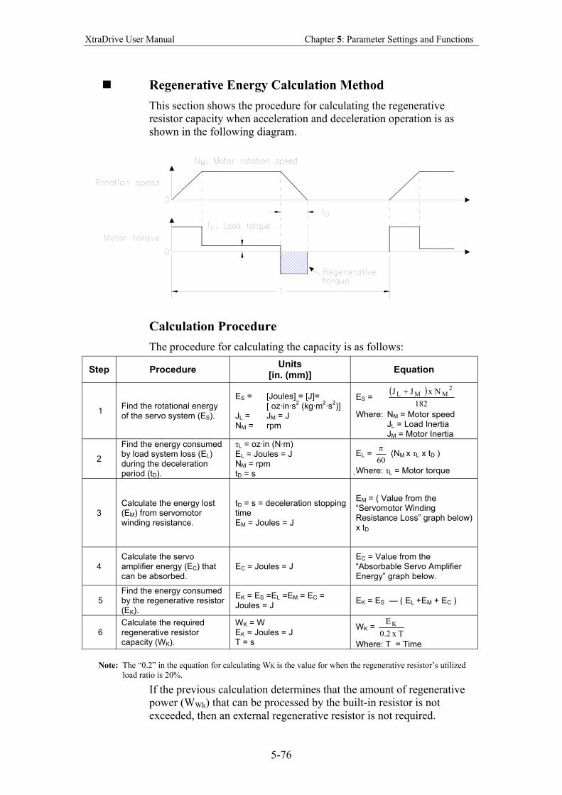
XtraDrive User Manual Chapter 5: Parameter Settings and Functions
5-76
Regenerative Energy Calculation Method
This section shows the procedure for calculating the regenerative
resistor capacity when acceleration and deceleration operation is as
shown in the following diagram.
Calculation Procedure
The procedure for calculating the capacity is as follows:
Step Procedure Units
[in. (mm)] Equation
1 Find the rotational energy of the servo system (ES).
ES = [Joules] = [J]= [ oz·in·s
2 (kg·m
2·s
2)]
JL = JM = J NM = rpm
ES = ( )
182
Nx J J2
MML +
Where: NM = Motor speed JL = Load Inertia JM = Motor Inertia
2
Find the energy consumed by load system loss (EL) during the deceleration period (tD).
τL = oz·in (N·m) EL = Joules = J NM = rpm tD = s
EL = 60
π (NM x τL x tD )
Where: τL = Motor torque
3
Calculate the energy lost (EM) from servomotor winding resistance.
tD = s = deceleration stopping time EM = Joules = J
EM = ( Value from the “Servomotor Winding Resistance Loss” graph below) x tD
4
Calculate the servo amplifier energy (EC) that can be absorbed.
EC = Joules = J
EC = Value from the “Absorbable Servo Amplifier Energy” graph below.
5 Find the energy consumed by the regenerative resistor (EK).
EK = ES =EL =EM = EC = Joules = J
EK = ES — ( EL +EM + EC )
6 Calculate the required regenerative resistor capacity (WK).
WK = W EK = Joules = J T = s
WK = Tx 2.0
E K
Where: T = Time
Note: The “0.2” in the equation for calculating WK is the value for when the regenerative resistor’s utilized
load ratio is 20%.
If the previous calculation determines that the amount of regenerative
power (WWk) that can be processed by the built-in resistor is not
exceeded, then an external regenerative resistor is not required.
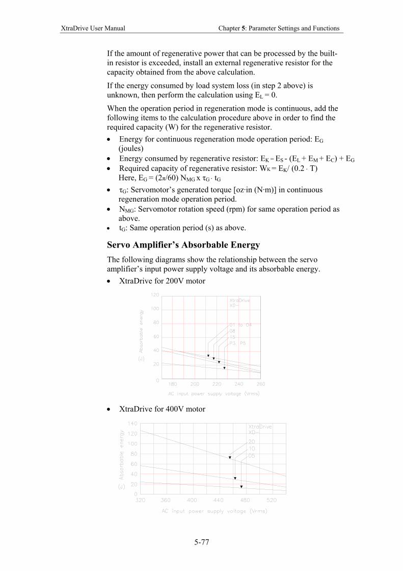
XtraDrive User Manual Chapter 5: Parameter Settings and Functions
5-77
If the amount of regenerative power that can be processed by the built-
in resistor is exceeded, install an external regenerative resistor for the
capacity obtained from the above calculation.
If the energy consumed by load system loss (in step 2 above) is
unknown, then perform the calculation using EL = 0.
When the operation period in regeneration mode is continuous, add the
following items to the calculation procedure above in order to find the
required capacity (W) for the regenerative resistor.
• Energy for continuous regeneration mode operation period: EG
(joules)
• Energy consumed by regenerative resistor: EK = ES - (EL + EM + EC) + EG
• Required capacity of regenerative resistor: WK = EK/ (0.2 ⋅ T)
Here, EG = (2π/60) NMG x τG ⋅ tG
• τG: Servomotor’s generated torque [oz·in (N·m)] in continuous
regeneration mode operation period.
• NMG: Servomotor rotation speed (rpm) for same operation period as
above.
• tG: Same operation period (s) as above.
Servo Amplifier’s Absorbable Energy
The following diagrams show the relationship between the servo
amplifier’s input power supply voltage and its absorbable energy.
• XtraDrive for 200V motor
• XtraDrive for 400V motor
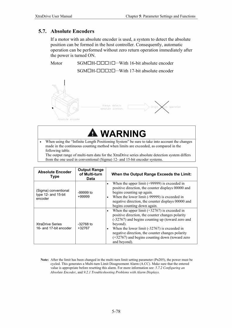
XtraDrive User Manual Chapter 5: Parameter Settings and Functions
5-78
5.7. Absolute Encoders
If a motor with an absolute encoder is used, a system to detect the absolute
position can be formed in the host controller. Consequently, automatic
operation can be performed without zero return operation immediately after
the power is turned ON.
Motor SGM H- 1 ···With 16-bit absolute encoder
SGM H- 2 ···With 17-bit absolute encoder
WARNING
• When using the “Infinite Length Positioning System” be sure to take into account the changes
made in the continuous counting method when limits are exceeded, as compared in the
following table.
The output range of multi-turn data for the XtraDrive series absolute detection system differs
from the one used in conventional (Sigma) 12- and 15-bit encoder systems.
Absolute Encoder Type
Output Range of Multi-turn
Data When the Output Range Exceeds the Limit:
(Sigma) conventional type 12- and 15-bit encoder
-99999 to +99999
• When the upper limit (+99999) is exceeded in
positive direction, the counter displays 00000 and
begins counting up again.
• When the lower limit (-99999) is exceeded in
negative direction, the counter displays 00000 and
begins counting down again.
XtraDrive Series 16- and 17-bit encoder
-32768 to +32767
• When the upper limit (+32767) is exceeded in
positive direction, the counter changes polarity
(-32767) and begins counting up (toward zero and
beyond).
• When the lower limit (-32767) is exceeded in
negative direction, the counter changes polarity
(+32767) and begins counting down (toward zero
and beyond).
Note: After the limit has been changed in the multi-turn limit setting parameter (Pn205), the power must be
cycled. This generates a Multi-turn Limit Disagreement Alarm (A.CC). Make sure that the entered
value is appropriate before resetting this alarm. For more information see: 5.7.2 Configuring an
Absolute Encoder, and 9.2.1 Troubleshooting Problems with Alarm Displays.
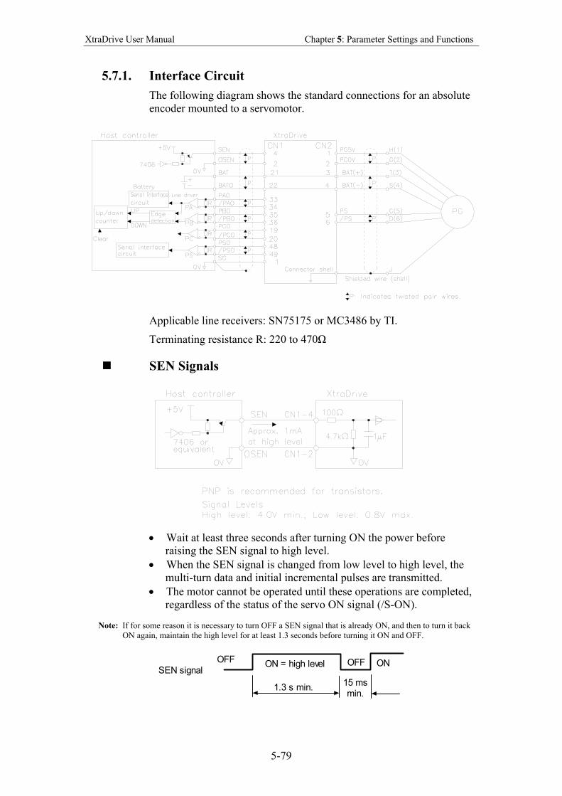
XtraDrive User Manual Chapter 5: Parameter Settings and Functions
5-79
5.7.1. Interface Circuit
The following diagram shows the standard connections for an absolute
encoder mounted to a servomotor.
Applicable line receivers: SN75175 or MC3486 by TI.
Terminating resistance R: 220 to 470Ω
SEN Signals
• Wait at least three seconds after turning ON the power before
raising the SEN signal to high level.
• When the SEN signal is changed from low level to high level, the
multi-turn data and initial incremental pulses are transmitted.
• The motor cannot be operated until these operations are completed,
regardless of the status of the servo ON signal (/S-ON).
Note: If for some reason it is necessary to turn OFF a SEN signal that is already ON, and then to turn it back
ON again, maintain the high level for at least 1.3 seconds before turning it ON and OFF.
OFFON = high level OFF ON
1.3 s min.15 msmin.
SEN signal
XtraDrive User Manual Chapter 5: Parameter Settings and Functions
5-80
5.7.2. Configuring an Absolute Encoder
Select the absolute encoder’s application with the following parameter.
Parameter Signal Setting Control Mode
Pn002.2 Absolute Encoder Application
Setting Range: 0 or 1
Default Setting: 0
Speed/Torque Control, Position Control
Either “0” or “1” in the following table must be set in order to enable
the absolute encoder.
Pn002.2 Setting Result
0 Uses the absolute encoder as an absolute encoder.
1 Uses the absolute encoder as an incremental encoder.
The following parameter is used to periodically clear the encoder’s
counter (return the setting to 0) after a designated ratio of motor to load
axis revolutions. This function is called the multi-turn limit.
Note: The term Multi-turn Limit refers to the highest number of rotations the encoder’s counter will display
before returning the counter to 0.
Parameter Signal Setting Control Mode
Pn205 Multi-turn Limit Setting Setting Range: 0 to 65535 Default Setting: 65535
Speed/Torque Control, Position Control
• When Pn205 is set to the default (65535), multi-turn data varies in
the range of −32768 to +32767.
• With any other Pn205 value entered, data varies from 0 to the set
value. Note: To activate reassignment of this value, the user must first enter the change to the parameter, and then
cycle (turn OFF and then turn ON) the power.
Since the encoder’s multi-turn limit value is set by default to 65535, the
following alarm occurs if the servo amplifier’s power supply is cycled
(turned OFF and ON) after changing parameter Pn205:
Alarm Code Output Alarm Display
ALO1 ALO2 ALO3 Description
A.CC O X O Encoder multi-turn limit value does not match with that of the servo amplifier.
Note: O: ON (“L”) signal
X: OFF (“H”) signal
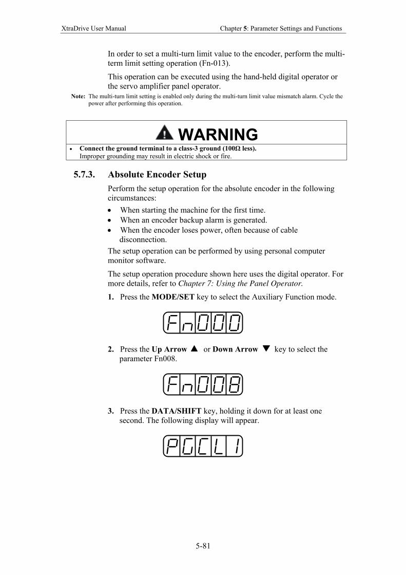
XtraDrive User Manual Chapter 5: Parameter Settings and Functions
5-81
In order to set a multi-turn limit value to the encoder, perform the multi-
term limit setting operation (Fn-013).
This operation can be executed using the hand-held digital operator or
the servo amplifier panel operator.
Note: The multi-turn limit setting is enabled only during the multi-turn limit value mismatch alarm. Cycle the
power after performing this operation.
WARNING
• Connect the ground terminal to a class-3 ground (100Ω less).
Improper grounding may result in electric shock or fire.
5.7.3. Absolute Encoder Setup
Perform the setup operation for the absolute encoder in the following
circumstances:
• When starting the machine for the first time.
• When an encoder backup alarm is generated.
• When the encoder loses power, often because of cable
disconnection.
The setup operation can be performed by using personal computer
monitor software.
The setup operation procedure shown here uses the digital operator. For
more details, refer to Chapter 7: Using the Panel Operator.
1. Press the MODE/SET key to select the Auxiliary Function mode.
2. Press the Up Arrow or Down Arrow key to select the
parameter Fn008.
3. Press the DATA/SHIFT key, holding it down for at least one
second. The following display will appear.
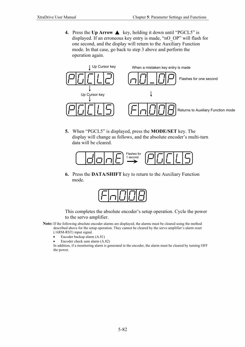
XtraDrive User Manual Chapter 5: Parameter Settings and Functions
5-82
4. Press the Up Arrow key, holding it down until “PGCL5” is
displayed. If an erroneous key entry is made, “nO_OP” will flash for
one second, and the display will return to the Auxiliary Function
mode. In that case, go back to step 3 above and perform the
operation again.
Up Cursor key
Up Cursor key
When a mistaken key entry is made
Flashes for one second
Returns to Auxiliary Function mode
5. When “PGCL5” is displayed, press the MODE/SET key. The
display will change as follows, and the absolute encoder’s multi-turn
data will be cleared.
Flashes for1 second.
6. Press the DATA/SHIFT key to return to the Auxiliary Function
mode.
This completes the absolute encoder’s setup operation. Cycle the power
to the servo amplifier.
Note: If the following absolute encoder alarms are displayed, the alarms must be cleared using the method
described above for the setup operation. They cannot be cleared by the servo amplifier’s alarm reset
(/ARM-RST) input signal. • Encoder backup alarm (A.81)
• Encoder check sum alarm (A.82)
In addition, if a monitoring alarm is generated in the encoder, the alarm must be cleared by turning OFF
the power.

XtraDrive User Manual Chapter 5: Parameter Settings and Functions
5-83
Multi-turn Setup
1. Press the MODE/SET key to select the Auxiliary Function mode.
2. Press the Up Arrow or Down Arrow key to select the
parameter Fn013.
3. Press the DATA/SHIFT key. The following display will appear.
4. Press the MODE/SET key. The display will change as follows, and
the absolute encoder’s multi-turn limit setting operation will be
performed.
Flashes for1 second.
5. Press the DATA/SHIFT key to return to the Auxiliary Function
mode.
This completes the absolute encoder’s multi-turn limit setting operation.
Cycle the power to the servo amplifier.
WARNING
• The multi-turn limit value should be changed only for special applications.
Changing it inappropriately or unintentionally can be dangerous.
• If the Multi-turn Limit Value Disagreement Alarm occurs, check the setting of parameter
Pn205 in the servo amplifier to be sure that it is correct. If Fn013 is executed when an
incorrect value is set in Pn205, that same incorrect value will be set in the encoder. There
will not be an additional alarm, even if an incorrect value is set, but incorrect positions
will be detected.
This results in a potentially dangerous situation where the machine will move to an unexpected
position.
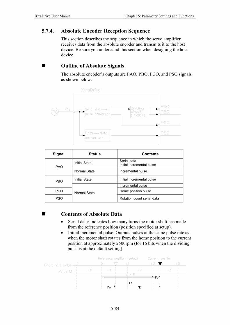
XtraDrive User Manual Chapter 5: Parameter Settings and Functions
5-84
5.7.4. Absolute Encoder Reception Sequence
This section describes the sequence in which the servo amplifier
receives data from the absolute encoder and transmits it to the host
device. Be sure you understand this section when designing the host
device.
Outline of Absolute Signals
The absolute encoder’s outputs are PAO, PBO, PCO, and PSO signals
as shown below.
Signal Status Contents
Initial State Serial data Initial incremental pulse
PAO
Normal State Incremental pulse
Initial State Initial incremental pulse PBO
Incremental pulse
PCO Home position pulse
PSO
Normal State
Rotation count serial data
Contents of Absolute Data
• Serial data: Indicates how many turns the motor shaft has made
from the reference position (position specified at setup).
• Initial incremental pulse: Outputs pulses at the same pulse rate as
when the motor shaft rotates from the home position to the current
position at approximately 2500rpm (for 16 bits when the dividing
pulse is at the default setting).
Πσ ΠµΠε
Πο
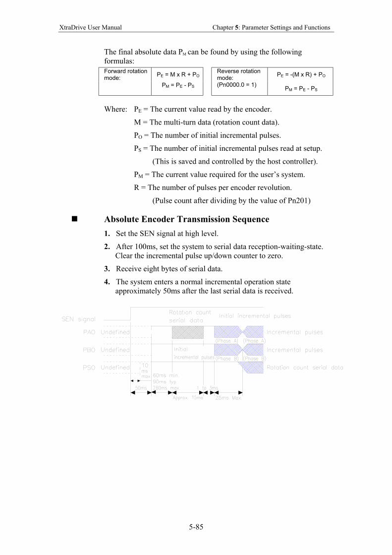
XtraDrive User Manual Chapter 5: Parameter Settings and Functions
5-85
The final absolute data PM can be found by using the following
formulas:
Forward rotation mode:
PE = M x R + PO
PE = -(M x R) + PO
PM = PE - PS
Reverse rotation mode: (Pn0000.0 = 1)
PM = PE - PS
Where: PE = The current value read by the encoder.
M = The multi-turn data (rotation count data).
PO = The number of initial incremental pulses.
PS = The number of initial incremental pulses read at setup.
(This is saved and controlled by the host controller).
PM = The current value required for the user’s system.
R = The number of pulses per encoder revolution.
(Pulse count after dividing by the value of Pn201)
Absolute Encoder Transmission Sequence
1. Set the SEN signal at high level.
2. After 100ms, set the system to serial data reception-waiting-state.
Clear the incremental pulse up/down counter to zero.
3. Receive eight bytes of serial data.
4. The system enters a normal incremental operation state
approximately 50ms after the last serial data is received.
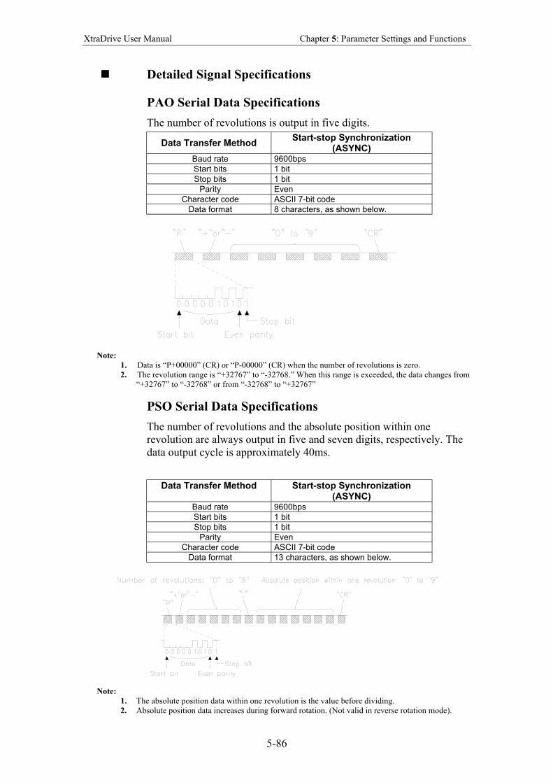
XtraDrive User Manual Chapter 5: Parameter Settings and Functions
5-86
Detailed Signal Specifications
PAO Serial Data Specifications
The number of revolutions is output in five digits.
Data Transfer Method Start-stop Synchronization
(ASYNC) Baud rate 9600bps
Start bits 1 bit
Stop bits 1 bit
Parity Even
Character code ASCII 7-bit code
Data format 8 characters, as shown below.
Note:
1. Data is “P+00000” (CR) or “P-00000” (CR) when the number of revolutions is zero.
2. The revolution range is “+32767” to “-32768.” When this range is exceeded, the data changes from
“+32767” to “-32768” or from “-32768” to “+32767”
PSO Serial Data Specifications
The number of revolutions and the absolute position within one
revolution are always output in five and seven digits, respectively. The
data output cycle is approximately 40ms.
Data Transfer Method Start-stop Synchronization (ASYNC)
Baud rate 9600bps
Start bits 1 bit
Stop bits 1 bit
Parity Even
Character code ASCII 7-bit code
Data format 13 characters, as shown below.
Note:
1. The absolute position data within one revolution is the value before dividing.
2. Absolute position data increases during forward rotation. (Not valid in reverse rotation mode).
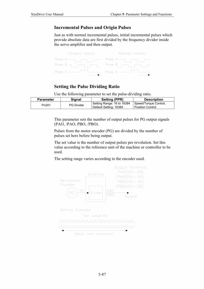
XtraDrive User Manual Chapter 5: Parameter Settings and Functions
5-87
Incremental Pulses and Origin Pulses
Just as with normal incremental pulses, initial incremental pulses which
provide absolute data are first divided by the frequency divider inside
the servo amplifier and then output.
Setting the Pulse Dividing Ratio
Use the following parameter to set the pulse-dividing ratio.
Parameter Signal Setting (PPR) Description
Setting Range: 16 to 16384 Speed/Torque Control, Pn201 PG Divider
Default Setting: 16384 Position Control
This parameter sets the number of output pulses for PG output signals
(PAO, /PAO, PBO, /PBO).
Pulses from the motor encoder (PG) are divided by the number of
pulses set here before being output.
The set value is the number of output pulses per revolution. Set this
value according to the reference unit of the machine or controller to be
used.
The setting range varies according to the encoder used.
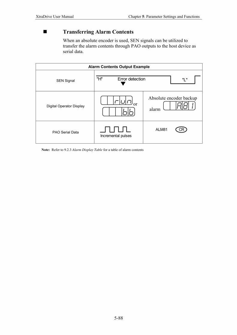
XtraDrive User Manual Chapter 5: Parameter Settings and Functions
5-88
Transferring Alarm Contents
When an absolute encoder is used, SEN signals can be utilized to
transfer the alarm contents through PAO outputs to the host device as
serial data.
Alarm Contents Output Example
SEN Signal "L""H" Error detection
Digital Operator Display or
Absolute encoder backup
alarm
PAO Serial Data
Incremental pulses
ALM81 CR
Note: Refer to 9.2.3 Alarm Display Table for a table of alarm contents
XtraDrive User Manual Chapter 5: Parameter Settings and Functions
5-89
5.8. AB Encoders
The XtraDrive supports both square wave (A quad B) and serial (Yaskawa’s
standard) encoder types. Yaskawa serial encoders are automatically detected
by the XtraDrive and require no additional settings (please refer to chapter 5.7
for detailed information). In applications where standard A quad B encoders
are used, certain parameters related to the motor and characteristics must be
set manually. The following parameters should be set according to the
specific encoder manually. Please note that these parameters become active
only after restarting the driver.
Note: There are some parameters related to the motor electro-mechanical
characteristics that cannot be set by the user. Contact the manufacturer in
order to get a setup file containing these parameters.
First set the AB encoder by Pn190.2 to 1. Pn190.2 Setting Results
0 Yaskawa Serial Encoder
1 AB Encoder
Set Pn190.0 according to the following table:
Pn190.0 Setting Results 0 Yaskawa AB model SGM
1 Yaskawa AB model SGMP
2 Other motor brand with A quad B encoder
Absolute/Incremental encoder. Set the following parameter to choose
between an absolute encoder and an incremental encoder.
Pn190.1 Setting Results 0 Incremental Encoder
1 Yaskawa absolute A quad B encoder
To use the absolute encoder properly you will need a battery that will power
the encoder memory to keep its position.
C-pulse – Set the following parameter to choose between motor with and
without C-pulse.
Pn190.3 Setting Results 0 C-pulse used
1 C-pulse not used
Set the resolution of A quad B encoder in Pn192, Pn193. Note that the value
in Pn192 should be set as the physical (optical) resolution, excluding the x4
multiplication done by the driver internally.
Parameter Setting [pulses/rev] Unit Signal
Pn192 Setting range 0-9999 Default setting: 2048
Pulse / Rev. Pulse number of A quad B encoder (Low bit)
Pn193 Setting range 0-419 Default setting: 0
Pulse*10000 / Rev. Pulse number of A quad B encoder (High bit)

XtraDrive User Manual Chapter 5: Parameter Settings and Functions
5-90
Set the direction of electrical phase. This parameter used to find the electrical
phase in the AB encoder (other than Yaskawa); if you don’t know the
direction, just set unknown direction and XtraDrive will find it automatically.
Pn191.0 Setting Results 0 Unknown direction
1 UVW
2 UWV
As mentioned before, the new parameter settings become active only after
the driver has been restarted.
XtraDrive User Manual Chapter 5: Parameter Settings and Functions
5-91
5.9. Configuration of Serial Commands for AB Encoders
5.9.1. Position Control
5.9.1.1. Defining User Units for Motion Profiles
XtraDrive’s built-in programming capability enables the user to define
various motion profiles without the need for an external motion
controller. Having first defined the relationship between the actual
encoder resolution and the units employed, the user uses units such as
radians, millimeters, etc. to write motion commands. These user units
(aka Engineering Units) are automatically converted by XtraDrive to
encoder units.
Each user unit is comprised of three different factors: Position units,
Speed units and Acceleration units, where each factor has both a
numerator and a denominator.
5.9.1.2. Position Units
Use the following parameters to convert position units from
[Encoder counts] to [User units]:
Parameter Setting Default Setting
Signal
Pn2B0 Setting range 1-65535 1 Position units ratio numerator
Pn2B1 Setting range 0-16383 0 Position units ratio numerator (high bits*)
Pn2B2 Setting range 1-65535 1 Position units ratio denominator
Pn2B3 Setting range 0-16383 0 Position units ratio denominator (high bits*)
Position user units are calculated according to the formula:
[ ] [ ]atordenoratiounitsPosition
numeratorratiounitsPositioncountsUUnitPositionUser
min1 ==
U – The number of encoder counts in each user position unit.
The number need not be an integer.
The maximum value of numerator (Pn2B0) or denominator (Pn2B2) is
65535. In cases where greater values are required, it is possible to use
parameters Pn2B1 and Pn2B3 for storing the high bits of numerator and
denominator, respectively, according to the following formula:
65536
65536
⋅−=
==
HBNBitsLow
NofpartIntegerHBBitsHigh
where N - required value.
XtraDrive User Manual Chapter 5: Parameter Settings and Functions
5-92
Example:
A rotary motion system uses a motor with a 17-bit encoder. The user
wants to program the system in units of 0.1 degree:
17-bit encoder produces 131072 [counts] per revolution.
360 [degree] = 3600 [0.1 degree]
[ ] [ ]atordenoratiounitsPosition
numeratorratiounitsPositioncountsree
min3600
131072deg1.01 ==
First option: Second option:
Both options are equivalent.
5.9.1.3. Speed Units
Use the following parameters to convert speed units from [encoder
counts/msec] to [user speed units]:
Parameter Setting Default Setting
Signal
Pn2B4 Setting range 1-65535 1 Speed units ratio numerator
Pn2B5 Setting range 0-16383 0 Speed units ratio numerator (high bits*)
Pn2B6 Setting range 1-65535 1 Speed units ratio denominator
Pn2B7 Setting range 0-16383 0 Speed units ratio denominator (high bits*)
Speed user units are calculated according to the formula:
1[User speed unit] = [ ]
[ ] [ ]rdenominato ratio units Speed
numerator ratio units Speed
msT=
countsU
U – number of encoder counts in one speed unit.
T – time of speed units in ms.
The maximum value of numerator (Pn2B4) or denominator (Pn2B6) is
65535. In cases where greater values are required, it is possible to use
parameters Pn2B5 and Pn2B7 for storing the high bits of numerator and
denominator, respectively, according to the following formula:
65535
NtofIntegerparHBHighBit ==
65536•−= HBNLowBits , where N- required value.
It is possible to reduce the
fraction so that both the
numerator and denominator are
smaller than 65536:
131072 / 3600 = 32768 / 900
Reduction
Pn2B0 = 32768
Pn2B1 = 0
Pn2B2 = 900
Pn2B3 = 0
Without reduction of the fraction:
High Bits = HB = Integer part of
N/65536 = Integer part of 131072
/ 65536 = 2
Low Bits = N – HB*65536 =
131072 – 2 * 65536 = 0
Pn2B0 = 0
Pn2B1 = 2
Pn2B2 = 3600
Pn2B3 = 0
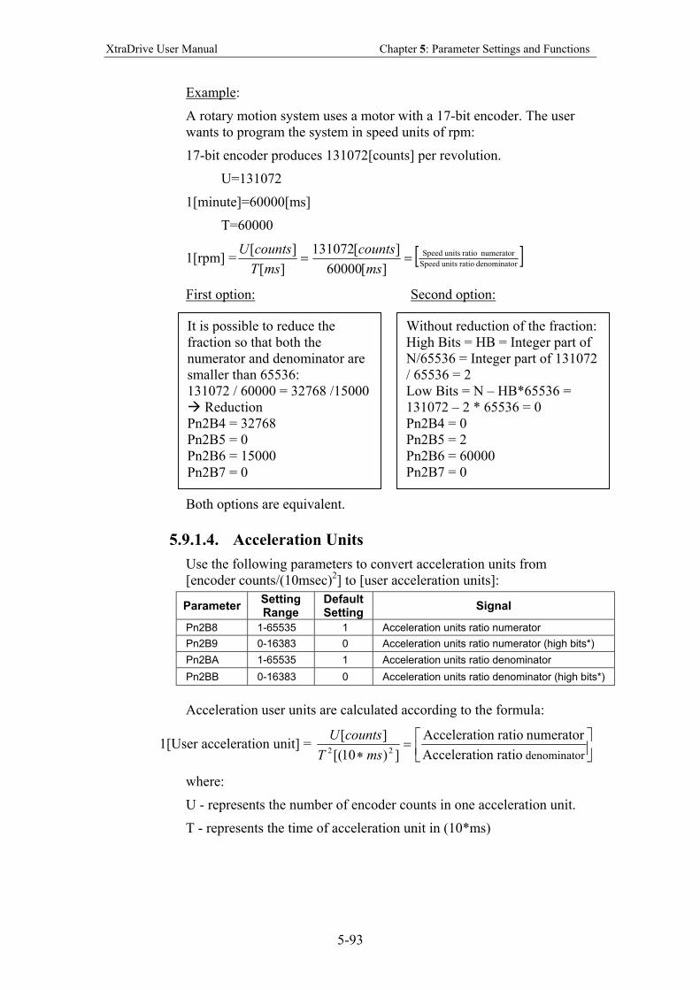
XtraDrive User Manual Chapter 5: Parameter Settings and Functions
5-93
Example:
A rotary motion system uses a motor with a 17-bit encoder. The user
wants to program the system in speed units of rpm:
17-bit encoder produces 131072[counts] per revolution.
U=131072
1[minute]=60000[ms]
T=60000
1[rpm] = [ ]rdenominato ratio units Speed
numerator ratio units Speed
][60000
][131072
][
][==
ms
counts
msT
countsU
First option: Second option:
Both options are equivalent.
5.9.1.4. Acceleration Units
Use the following parameters to convert acceleration units from
[encoder counts/(10msec)2] to [user acceleration units]:
Parameter Setting Range
Default Setting
Signal
Pn2B8 1-65535 1 Acceleration units ratio numerator
Pn2B9 0-16383 0 Acceleration units ratio numerator (high bits*)
Pn2BA 1-65535 1 Acceleration units ratio denominator
Pn2BB 0-16383 0 Acceleration units ratio denominator (high bits*)
Acceleration user units are calculated according to the formula:
1[User acceleration unit] =
=
∗ rdenominato ratioon Accelerati
numerator ratioon Accelerati
])10[(
][22 msT
countsU
where:
U - represents the number of encoder counts in one acceleration unit.
T - represents the time of acceleration unit in (10*ms)
It is possible to reduce the
fraction so that both the
numerator and denominator are
smaller than 65536:
131072 / 60000 = 32768 /15000
Reduction
Pn2B4 = 32768
Pn2B5 = 0
Pn2B6 = 15000
Pn2B7 = 0
Without reduction of the fraction:
High Bits = HB = Integer part of
N/65536 = Integer part of 131072
/ 65536 = 2
Low Bits = N – HB*65536 =
131072 – 2 * 65536 = 0
Pn2B4 = 0
Pn2B5 = 2
Pn2B6 = 60000
Pn2B7 = 0
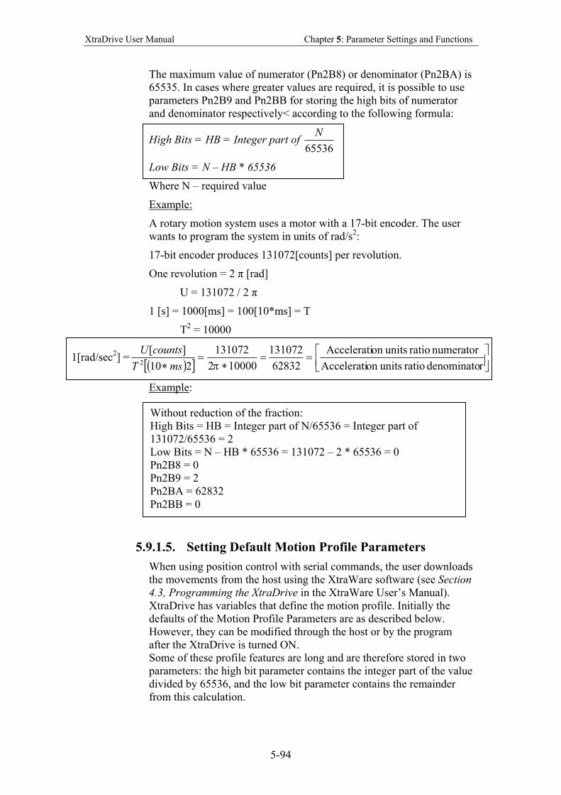
XtraDrive User Manual Chapter 5: Parameter Settings and Functions
5-94
The maximum value of numerator (Pn2B8) or denominator (Pn2BA) is
65535. In cases where greater values are required, it is possible to use
parameters Pn2B9 and Pn2BB for storing the high bits of numerator
and denominator respectively< according to the following formula:
High Bits = HB = Integer part of 65536
N
Low Bits = N – HB * 65536
Where N – required value
Example:
A rotary motion system uses a motor with a 17-bit encoder. The user
wants to program the system in units of rad/s2:
17-bit encoder produces 131072[counts] per revolution.
One revolution = 2 π [rad]
U = 131072 / 2 π
1 [s] = 1000[ms] = 100[10*ms] = T
T2 = 10000
1[rad/sec2] = ( )[ ]
==
∗=
∗ rdenominato ratio unitson Accelerati
numerator ratio unitson Accelerati
62832
131072
100002
131072
210
][2 πmsT
countsU
Example:
5.9.1.5. Setting Default Motion Profile Parameters
When using position control with serial commands, the user downloads
the movements from the host using the XtraWare software (see Section
4.3, Programming the XtraDrive in the XtraWare User’s Manual).
XtraDrive has variables that define the motion profile. Initially the
defaults of the Motion Profile Parameters are as described below.
However, they can be modified through the host or by the program
after the XtraDrive is turned ON.
Some of these profile features are long and are therefore stored in two
parameters: the high bit parameter contains the integer part of the value
divided by 65536, and the low bit parameter contains the remainder
from this calculation.
Without reduction of the fraction:
High Bits = HB = Integer part of N/65536 = Integer part of
131072/65536 = 2
Low Bits = N – HB * 65536 = 131072 – 2 * 65536 = 0
Pn2B8 = 0
Pn2B9 = 2
Pn2BA = 62832
Pn2BB = 0
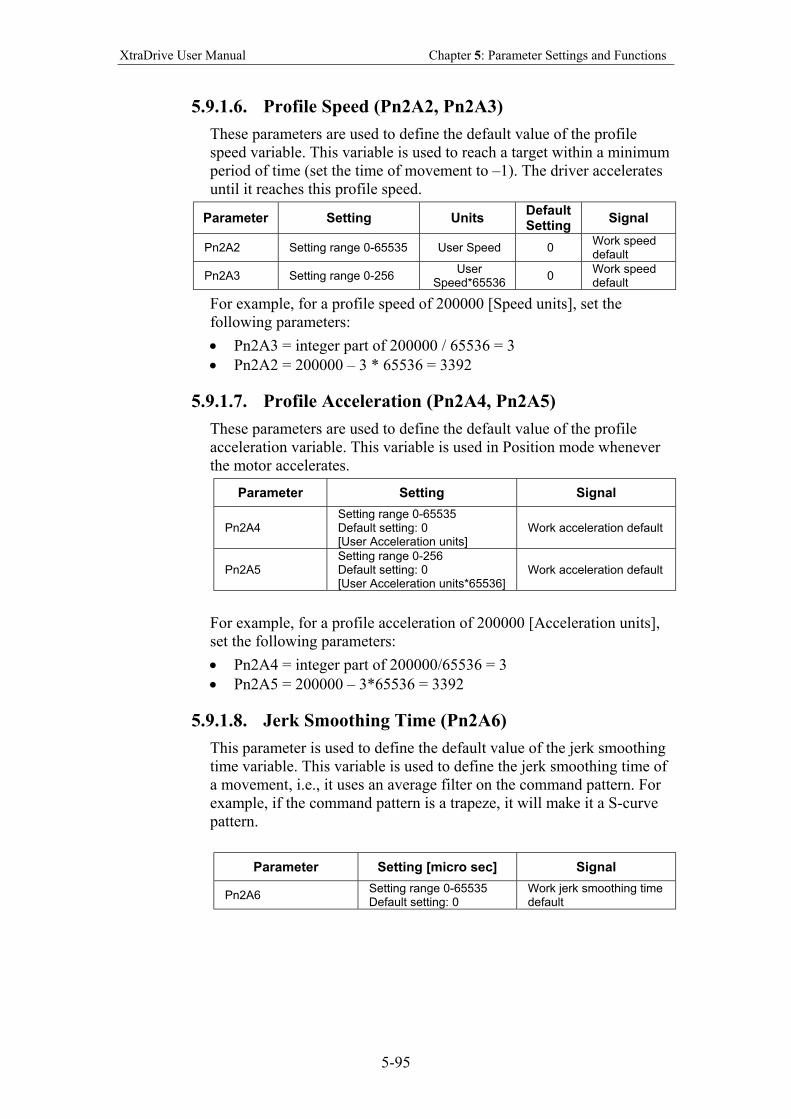
XtraDrive User Manual Chapter 5: Parameter Settings and Functions
5-95
5.9.1.6. Profile Speed (Pn2A2, Pn2A3)
These parameters are used to define the default value of the profile
speed variable. This variable is used to reach a target within a minimum
period of time (set the time of movement to –1). The driver accelerates
until it reaches this profile speed.
Parameter Setting Units Default Setting
Signal
Pn2A2 Setting range 0-65535 User Speed 0 Work speed default
Pn2A3 Setting range 0-256 User
Speed*65536 0
Work speed default
For example, for a profile speed of 200000 [Speed units], set the
following parameters:
• Pn2A3 = integer part of 200000 / 65536 = 3
• Pn2A2 = 200000 – 3 * 65536 = 3392
5.9.1.7. Profile Acceleration (Pn2A4, Pn2A5)
These parameters are used to define the default value of the profile
acceleration variable. This variable is used in Position mode whenever
the motor accelerates.
Parameter Setting Signal
Pn2A4 Setting range 0-65535 Default setting: 0 [User Acceleration units]
Work acceleration default
Pn2A5 Setting range 0-256 Default setting: 0 [User Acceleration units*65536]
Work acceleration default
For example, for a profile acceleration of 200000 [Acceleration units],
set the following parameters:
• Pn2A4 = integer part of 200000/65536 = 3
• Pn2A5 = 200000 – 3*65536 = 3392
5.9.1.8. Jerk Smoothing Time (Pn2A6)
This parameter is used to define the default value of the jerk smoothing
time variable. This variable is used to define the jerk smoothing time of
a movement, i.e., it uses an average filter on the command pattern. For
example, if the command pattern is a trapeze, it will make it a S-curve
pattern.
Parameter Setting [micro sec] Signal
Pn2A6 Setting range 0-65535 Default setting: 0
Work jerk smoothing time default
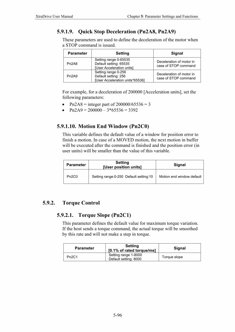
XtraDrive User Manual Chapter 5: Parameter Settings and Functions
5-96
5.9.1.9. Quick Stop Deceleration (Pn2A8, Pn2A9)
These parameters are used to define the deceleration of the motor when
a STOP command is issued.
Parameter Setting Signal
Pn2A8 Setting range 0-65535 Default setting: 65535 [User Acceleration units]
Deceleration of motor in case of STOP command
Pn2A9 Setting range 0-256 Default setting: 256 [User Acceleration units*65536]
Deceleration of motor in case of STOP command
For example, for a deceleration of 200000 [Acceleration units], set the
following parameters:
• Pn2A8 = integer part of 200000/65536 = 3
• Pn2A9 = 200000 – 3*65536 = 3392
5.9.1.10. Motion End Window (Pn2C0)
This variable defines the default value of a window for position error to
finish a motion. In case of a MOVED motion, the next motion in buffer
will be executed after the command is finished and the position error (in
user units) will be smaller than the value of this variable.
Parameter Setting
[User position units] Signal
Pn2C0 Setting range:0-250 Default setting:10 Motion end window default
5.9.2. Torque Control
5.9.2.1. Torque Slope (Pn2C1)
This parameter defines the default value for maximum torque variation.
If the host sends a torque command, the actual torque will be smoothed
by this rate and will not make a step in torque.
Parameter Setting
[0.1% of rated torque/ms] Signal
Pn2C1 Setting range 1-8000 Default setting: 8000
Torque slope
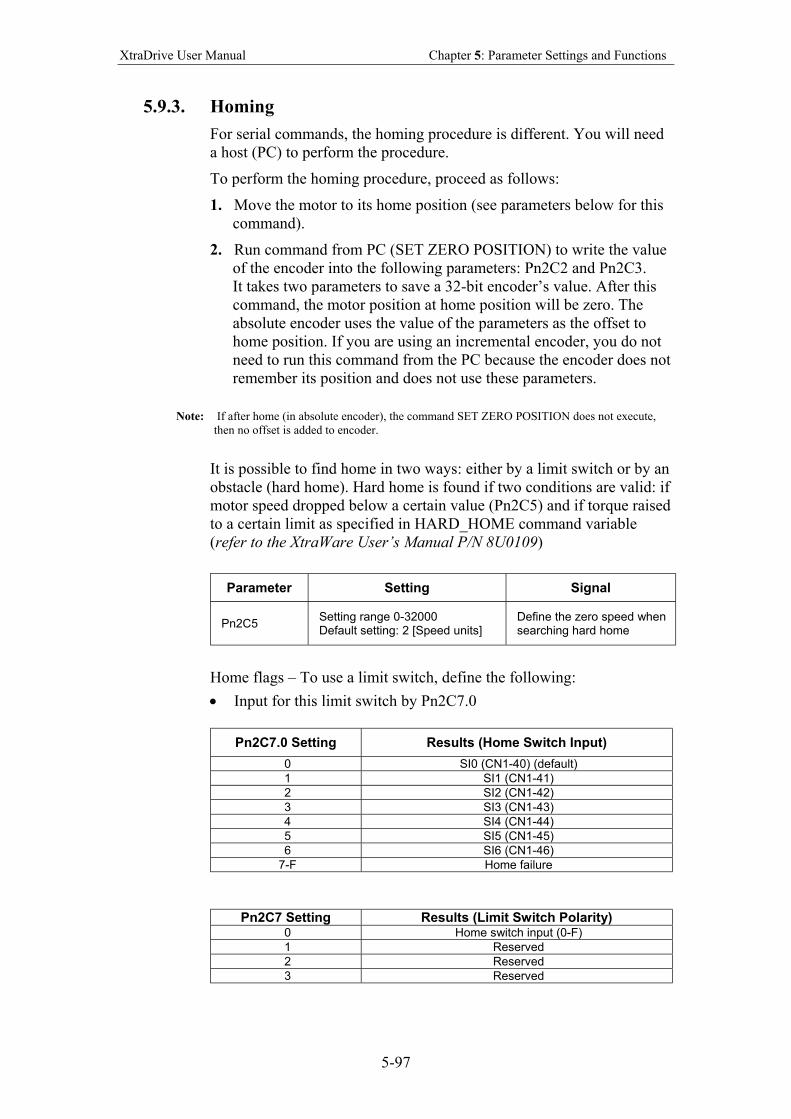
XtraDrive User Manual Chapter 5: Parameter Settings and Functions
5-97
5.9.3. Homing
For serial commands, the homing procedure is different. You will need
a host (PC) to perform the procedure.
To perform the homing procedure, proceed as follows:
1. Move the motor to its home position (see parameters below for this
command).
2. Run command from PC (SET ZERO POSITION) to write the value
of the encoder into the following parameters: Pn2C2 and Pn2C3.
It takes two parameters to save a 32-bit encoder’s value. After this
command, the motor position at home position will be zero. The
absolute encoder uses the value of the parameters as the offset to
home position. If you are using an incremental encoder, you do not
need to run this command from the PC because the encoder does not
remember its position and does not use these parameters.
Note: If after home (in absolute encoder), the command SET ZERO POSITION does not execute,
then no offset is added to encoder.
It is possible to find home in two ways: either by a limit switch or by an
obstacle (hard home). Hard home is found if two conditions are valid: if
motor speed dropped below a certain value (Pn2C5) and if torque raised
to a certain limit as specified in HARD_HOME command variable
(refer to the XtraWare User’s Manual P/N 8U0109)
Parameter Setting Signal
Pn2C5 Setting range 0-32000 Default setting: 2 [Speed units]
Define the zero speed when searching hard home
Home flags – To use a limit switch, define the following:
• Input for this limit switch by Pn2C7.0
Pn2C7.0 Setting Results (Home Switch Input)
0 SI0 (CN1-40) (default)
1 SI1 (CN1-41)
2 SI2 (CN1-42)
3 SI3 (CN1-43)
4 SI4 (CN1-44)
5 SI5 (CN1-45)
6 SI6 (CN1-46)
7-F Home failure
Pn2C7 Setting Results (Limit Switch Polarity)
0 Home switch input (0-F)
1 Reserved
2 Reserved
3 Reserved
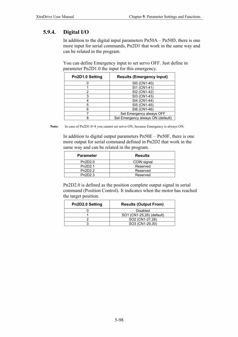
XtraDrive User Manual Chapter 5: Parameter Settings and Functions
5-98
5.9.4. Digital I/O
In addition to the digital input parameters Pn50A – Pn50D, there is one
more input for serial commands, Pn2D1 that work in the same way and
can be related in the program.
You can define Emergency input to set servo OFF. Just define in
parameter Pn2D1.0 the input for this emergency.
Pn2D1.0 Setting Results (Emergency Input)
0 SI0 (CN1-40)
1 SI1 (CN1-41)
2 SI2 (CN1-42)
3 SI3 (CN1-43)
4 SI4 (CN1-44)
5 SI5 (CN1-45)
6 SI6 (CN1-46)
7 Set Emergency always OFF
8 Set Emergency always ON (default)
Note: In case of Pn2D1.0=8 you cannot set servo ON, because Emergency is always ON.
In addition to digital output parameters Pn50E – Pn50F, there is one
more output for serial command defined in Pn2D2 that work in the
same way and can be related in the program.
Parameter Results
Pn2D2.0 COIN signal
Pn2D2.1 Reserved
Pn2D2.2 Reserved
Pn2D2.3 Reserved
Pn2D2.0 is defined as the position complete output signal in serial
command (Position Control). It indicates when the motor has reached
the target position.
Pn2D2.0 Setting Results (Output From)
0 Disabled
1 SO1 (CN1-25,26) (default)
2 SO2 (CN1-27,28)
3 SO3 (CN1-29,30)
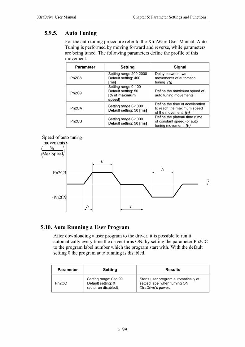
XtraDrive User Manual Chapter 5: Parameter Settings and Functions
5-99
5.9.5. Auto Tuning
For the auto tuning procedure refer to the XtraWare User Manual. Auto
Tuning is performed by moving forward and reverse, while parameters
are being tuned. The following parameters define the profile of this
movement.
Parameter Setting Signal
Pn2C8 Setting range 200-2000 Default setting: 400 [ms]
Delay between two movements of automatic tuning (t1)
Pn2C9
Setting range 0-100 Default setting: 50 [% of maximum speed]
Define the maximum speed of auto tuning movements.
Pn2CA Setting range 0-1000 Default setting: 50 [ms]
Define the time of acceleration to reach the maximum speed of the movement. (t2)
Pn2CB Setting range 0-1000 Default setting: 50 [ms]
Define the plateau time (time of constant speed) of auto tuning movement. (t3)
t
Speed of auto tuning movements %Max.speed
Pn2C9
-Pn2C9
t3
t3
t1t2
5.10. Auto Running a User Program
After downloading a user program to the driver, it is possible to run it
automatically every time the driver turns ON, by setting the parameter Pn2CC
to the program label number which the program start with. With the default
setting 0 the program auto running is disabled.
Parameter Setting Results
Pn2CC Setting range: 0 to 99 Default setting: 0 (auto run disabled)
Starts user program automatically at settled label when turning ON XtraDrive’s power.
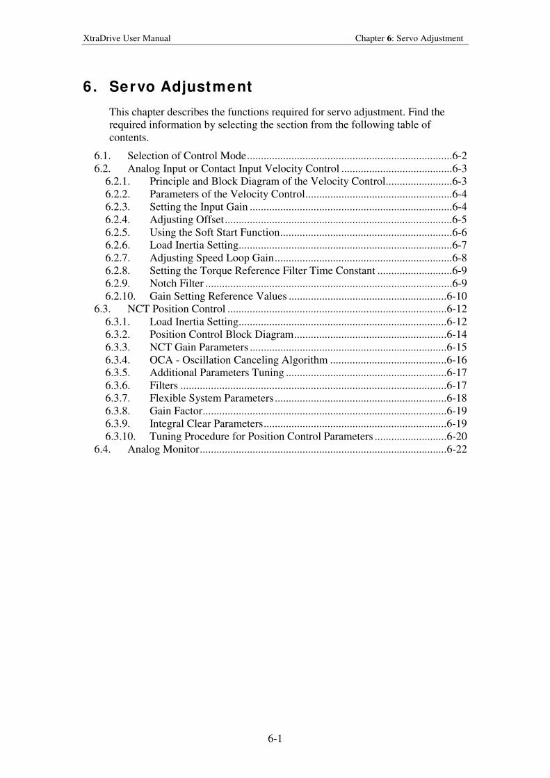
XtraDrive User Manual Chapter 6: Servo Adjustment
6-1
6. Servo Adjustment
This chapter describes the functions required for servo adjustment. Find the
required information by selecting the section from the following table of
contents.
6.1. Selection of Control Mode..........................................................................6-2
6.2. Analog Input or Contact Input Velocity Control ........................................6-3
6.2.1. Principle and Block Diagram of the Velocity Control........................6-3
6.2.2. Parameters of the Velocity Control.....................................................6-4
6.2.3. Setting the Input Gain .........................................................................6-4
6.2.4. Adjusting Offset..................................................................................6-5
6.2.5. Using the Soft Start Function..............................................................6-6
6.2.6. Load Inertia Setting.............................................................................6-7
6.2.7. Adjusting Speed Loop Gain................................................................6-8
6.2.8. Setting the Torque Reference Filter Time Constant ...........................6-9
6.2.9. Notch Filter .........................................................................................6-9
6.2.10. Gain Setting Reference Values .........................................................6-10
6.3. NCT Position Control ...............................................................................6-12
6.3.1. Load Inertia Setting...........................................................................6-12
6.3.2. Position Control Block Diagram.......................................................6-14
6.3.3. NCT Gain Parameters .......................................................................6-15
6.3.4. OCA - Oscillation Canceling Algorithm ..........................................6-16
6.3.5. Additional Parameters Tuning ..........................................................6-17
6.3.6. Filters ................................................................................................6-17
6.3.7. Flexible System Parameters ..............................................................6-18
6.3.8. Gain Factor........................................................................................6-19
6.3.9. Integral Clear Parameters..................................................................6-19
6.3.10. Tuning Procedure for Position Control Parameters ..........................6-20
6.4. Analog Monitor.........................................................................................6-22
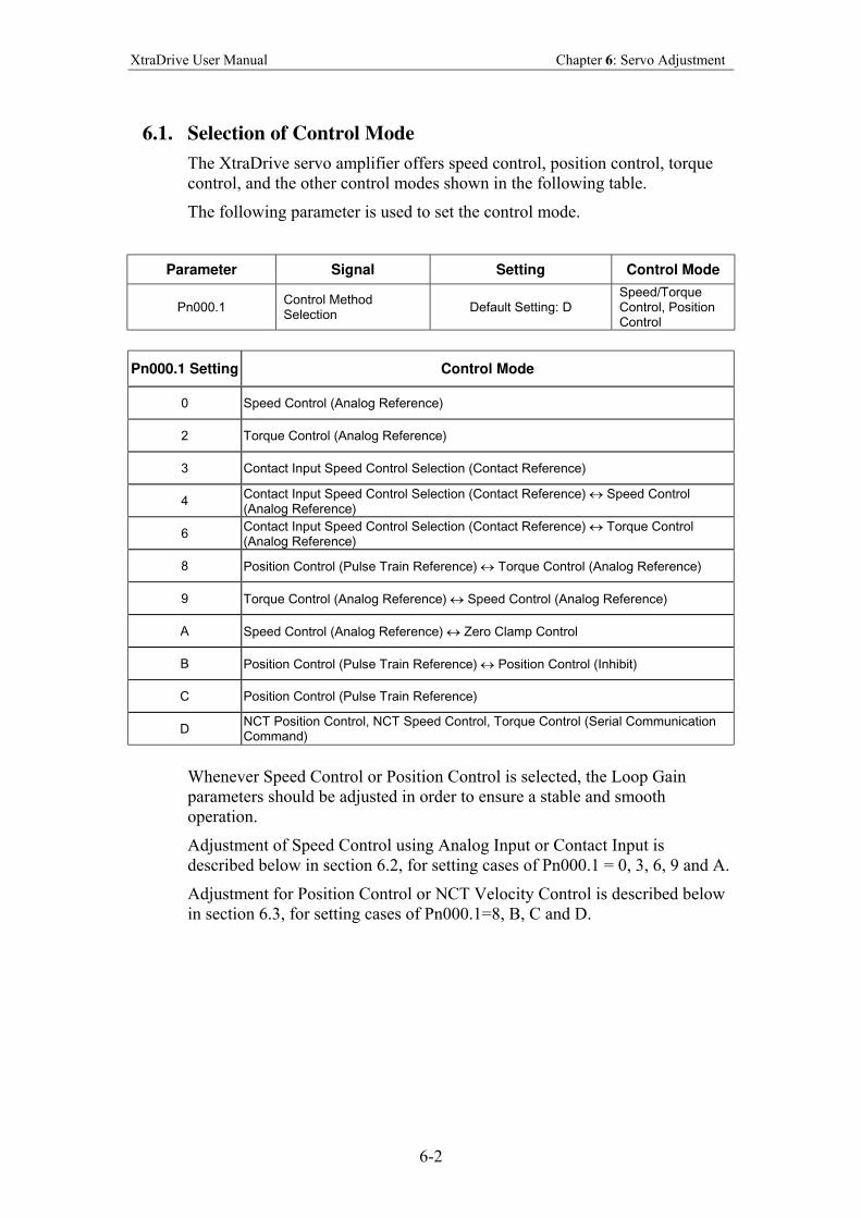
XtraDrive User Manual Chapter 6: Servo Adjustment
6-2
6.1. Selection of Control Mode
The XtraDrive servo amplifier offers speed control, position control, torque
control, and the other control modes shown in the following table.
The following parameter is used to set the control mode.
Parameter Signal Setting Control Mode
Pn000.1 Control Method Selection
Default Setting: D Speed/Torque Control, Position Control
Pn000.1 Setting Control Mode
0 Speed Control (Analog Reference)
2 Torque Control (Analog Reference)
3 Contact Input Speed Control Selection (Contact Reference)
4 Contact Input Speed Control Selection (Contact Reference) ↔ Speed Control (Analog Reference)
6 Contact Input Speed Control Selection (Contact Reference) ↔ Torque Control (Analog Reference)
8 Position Control (Pulse Train Reference) ↔ Torque Control (Analog Reference)
9 Torque Control (Analog Reference) ↔ Speed Control (Analog Reference)
A Speed Control (Analog Reference) ↔ Zero Clamp Control
B Position Control (Pulse Train Reference) ↔ Position Control (Inhibit)
C Position Control (Pulse Train Reference)
D NCT Position Control, NCT Speed Control, Torque Control (Serial Communication Command)
Whenever Speed Control or Position Control is selected, the Loop Gain
parameters should be adjusted in order to ensure a stable and smooth
operation.
Adjustment of Speed Control using Analog Input or Contact Input is
described below in section 6.2, for setting cases of Pn000.1 = 0, 3, 6, 9 and A.
Adjustment for Position Control or NCT Velocity Control is described below
in section 6.3, for setting cases of Pn000.1=8, B, C and D.
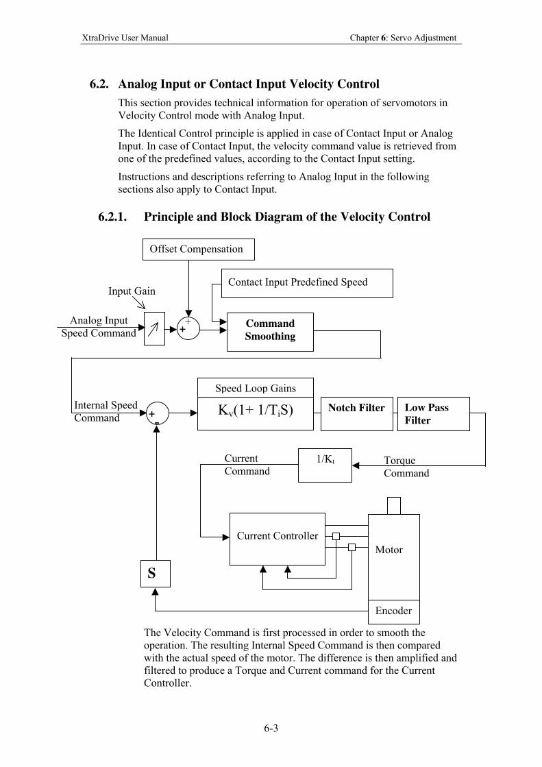
XtraDrive User Manual Chapter 6: Servo Adjustment
6-3
6.2. Analog Input or Contact Input Velocity Control
This section provides technical information for operation of servomotors in
Velocity Control mode with Analog Input.
The Identical Control principle is applied in case of Contact Input or Analog
Input. In case of Contact Input, the velocity command value is retrieved from
one of the predefined values, according to the Contact Input setting.
Instructions and descriptions referring to Analog Input in the following
sections also apply to Contact Input.
6.2.1. Principle and Block Diagram of the Velocity Control
The Velocity Command is first processed in order to smooth the
operation. The resulting Internal Speed Command is then compared
with the actual speed of the motor. The difference is then amplified and
filtered to produce a Torque and Current command for the Current
Controller.
Command
Smoothing
Analog Input
Speed Command + +
Offset Compensation
Input Gain
Kv(1+ 1/TiS) Notch Filter Low Pass
Filter
Internal Speed
Command
1/Kt Torque
Command
Current Controller
Motor
Encoder
Current
Command
S
+ -
Speed Loop Gains
Contact Input Predefined Speed
XtraDrive User Manual Chapter 6: Servo Adjustment
6-4
6.2.2. Parameters of the Velocity Control
The following parameters are related to Velocity Control:
Pn305 Soft Start Acceleration time
Pn306 Soft Stop Deceleration time
Pn103 Inertia Ratio
Pn300 Speed Reference Input gain
Pn100 Speed Loop Gain
Pn101 Speed Loop Integral Time constant
Pn401 Torque Reference Filter Time Constant
Pn408.0 Notch Filter activation
Pn409 Notch Filter Frequency
Pn40A Notch Filter Width
6.2.3. Setting the Input Gain
Parameter 300 defines the ratio between Analog Voltage and equivalent
speed command.
Normally, this parameter should be set so that a 10Volt input will
produce a speed command slightly superior to the maximum allowable
speed of the system.
The units of that parameter are (0.01Volt)/(Rated Speed)
Example: With the default setting 600,
6Volt input will result in a rated speed command.
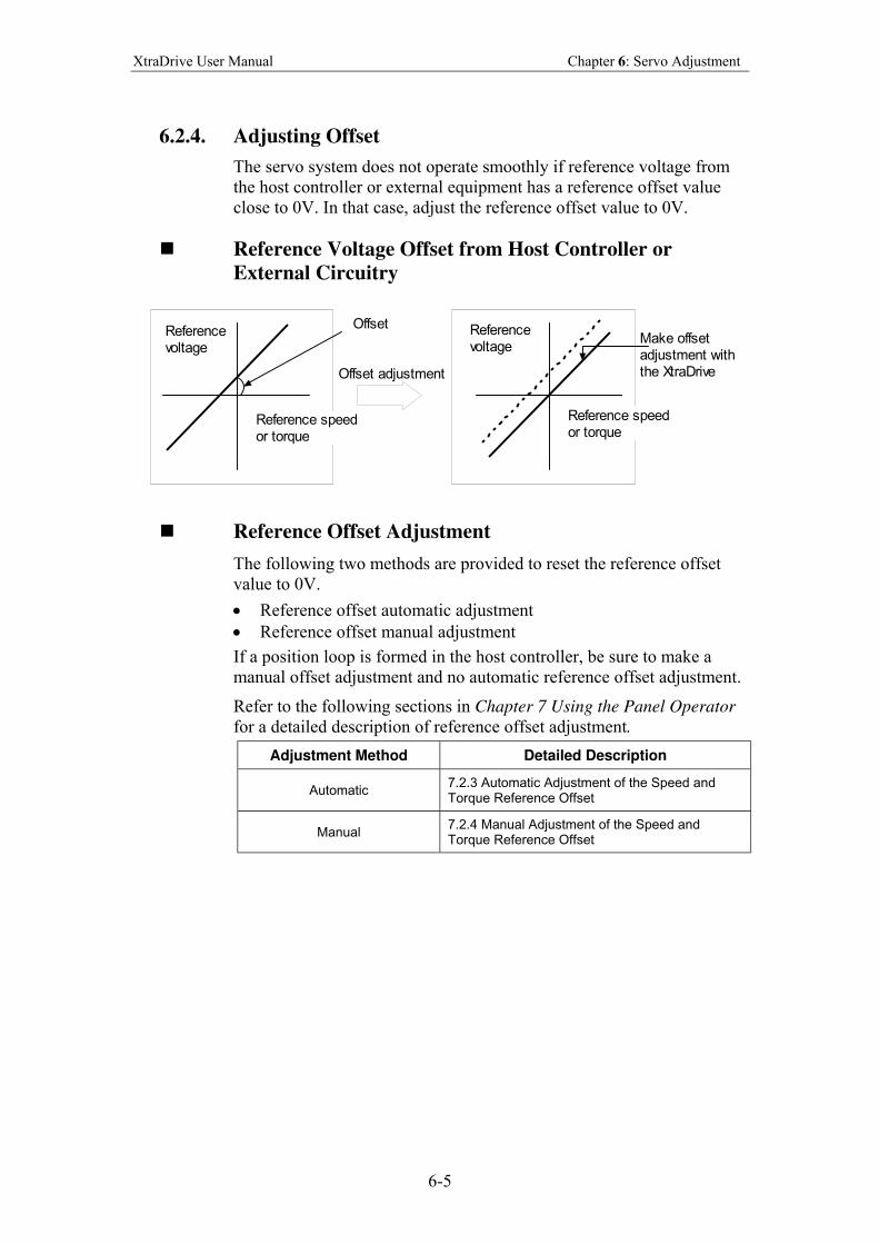
XtraDrive User Manual Chapter 6: Servo Adjustment
6-5
6.2.4. Adjusting Offset
The servo system does not operate smoothly if reference voltage from
the host controller or external equipment has a reference offset value
close to 0V. In that case, adjust the reference offset value to 0V.
Reference Voltage Offset from Host Controller or
External Circuitry
OffsetReferencevoltage
Referencevoltage
Reference speedor torque
Make offsetadjustment withthe XtraDrive
Reference speedor torque
Offset adjustment
Reference Offset Adjustment
The following two methods are provided to reset the reference offset
value to 0V.
• Reference offset automatic adjustment
• Reference offset manual adjustment
If a position loop is formed in the host controller, be sure to make a
manual offset adjustment and no automatic reference offset adjustment.
Refer to the following sections in Chapter 7 Using the Panel Operator
for a detailed description of reference offset adjustment.
Adjustment Method Detailed Description
Automatic 7.2.3 Automatic Adjustment of the Speed and Torque Reference Offset
Manual 7.2.4 Manual Adjustment of the Speed and Torque Reference Offset
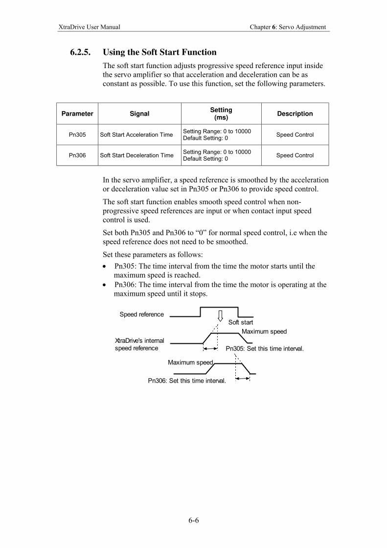
XtraDrive User Manual Chapter 6: Servo Adjustment
6-6
6.2.5. Using the Soft Start Function
The soft start function adjusts progressive speed reference input inside
the servo amplifier so that acceleration and deceleration can be as
constant as possible. To use this function, set the following parameters.
Parameter Signal Setting
(ms) Description
Pn305 Soft Start Acceleration Time Setting Range: 0 to 10000 Default Setting: 0
Speed Control
Pn306 Soft Start Deceleration Time Setting Range: 0 to 10000 Default Setting: 0
Speed Control
In the servo amplifier, a speed reference is smoothed by the acceleration
or deceleration value set in Pn305 or Pn306 to provide speed control.
The soft start function enables smooth speed control when non-
progressive speed references are input or when contact input speed
control is used.
Set both Pn305 and Pn306 to “0” for normal speed control, i.e when the
speed reference does not need to be smoothed.
Set these parameters as follows:
• Pn305: The time interval from the time the motor starts until the
maximum speed is reached.
• Pn306: The time interval from the time the motor is operating at the
maximum speed until it stops.
Speed reference
Soft start
Maximum speed
Pn305: Set this time interval.
Pn306: Set this time interval.
XtraDrive's internalspeed reference
Maximum speed
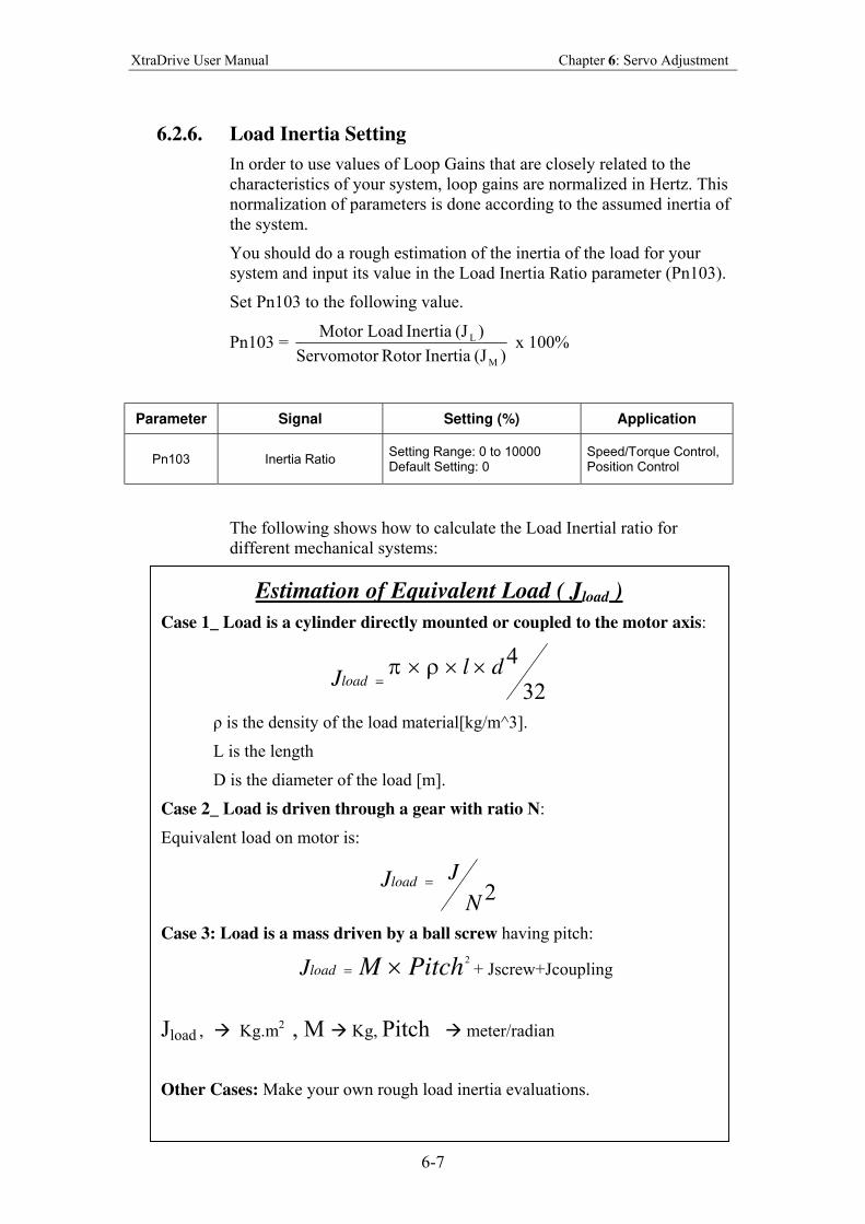
XtraDrive User Manual Chapter 6: Servo Adjustment
6-7
6.2.6. Load Inertia Setting
In order to use values of Loop Gains that are closely related to the
characteristics of your system, loop gains are normalized in Hertz. This
normalization of parameters is done according to the assumed inertia of
the system.
You should do a rough estimation of the inertia of the load for your
system and input its value in the Load Inertia Ratio parameter (Pn103).
Set Pn103 to the following value.
Pn103 = )(JInertia Rotor Servomotor
)(JInertia Motor Load
M
L x 100%
Parameter Signal Setting (%) Application
Pn103 Inertia Ratio Setting Range: 0 to 10000 Default Setting: 0
Speed/Torque Control, Position Control
The following shows how to calculate the Load Inertial ratio for
different mechanical systems:
Estimation of Equivalent Load ( J load )
Case 1_ Load is a cylinder directly mounted or coupled to the motor axis:
32
4dl
Jload×××
=ρπ
ρ is the density of the load material[kg/m^3].
L is the length
D is the diameter of the load [m].
Case 2_ Load is driven through a gear with ratio N:
Equivalent load on motor is:
2N
JJload =
Case 3: Load is a mass driven by a ball screw having pitch:
2
PitchMloadJ ×= + Jscrew+Jcoupling
Jload , Kg.m2
, M Kg, Pitch meter/radian
Other Cases: Make your own rough load inertia evaluations.
XtraDrive User Manual Chapter 6: Servo Adjustment
6-8
6.2.7. Adjusting Speed Loop Gain
The purpose of the Speed Control is to maintain the Speed Error, i.e. the
difference between Internal Speed Command and Actual Speed, as
small as possible.
This is obtained by raising the Speed Loop Gain Kv (Pn100) and the
Speed Loop Integration time Ti(Pn101).
However, if Kv is too high, or Ti is too small, oscillations may occur.
Usually, a too high Kv will produce high frequency oscillations, while a
too small Ti will produce lower frequency oscillations.
Parameter Signal Setting Application
Pn100 Speed Loop Gain (Kv) Setting Range: 1 to 2000Hz Default Setting: 40Hz
Speed/Torque Control
Pn101 Speed Loop Integral Time Constant (Ti)
Setting Range: 15 to 51200 x 0.01ms Default Setting: 2000 x 0.01ms
Speed/Torque Control
Tuning can be done by observing the load and listening to the acoustic
noise of the eventual vibrations. For more precise tuning, you may
monitor the velocity error using an oscilloscope and the analog
monitoring outputs provided by the XtraDrive. Refer to Section 6.4
The tuning procedure is as follows:
1. Start with a Ti at maximum value and a low value of Kv, so that
system will be stable upon Servo Enabling.
2. Enable the Servo, then progressively rise the value of Kv, until
oscillations or overshoots are observed.
3. Decrease Kv by about 10 to 20%.
4. Decrease Ti until lower frequency oscillations or overshoots are
observed, then raise Ti back by about 20%
In the particular case where position control is done in a host
system and outputs an Analog command for feedback:
It is possible to increase input gain in order to increase the position loop
gain of your system.
If torque filter and notch filter are optimally tuned, then loop gain can
be raised to a higher value, and the speed error will be smaller.
The adjustment of Speed Loop Gains is an iterative process in
interaction with the adjustment of Notch Filter and Torque
Filter. Before executing it, you should read sections 6.1.7 and
6.1.8.
These tuning steps should be repeated each time torque filter or
notch filter settings are modified.
XtraDrive User Manual Chapter 6: Servo Adjustment
6-9
6.2.8. Setting the Torque Reference Filter Time Constant
If there is machine vibration, which may be caused by the servo drive,
try adjusting the filter time constant in Pn401. This may stop the
vibration.
Parameter Signal Setting
(x 0.01ms) Application
Pn401 Torque Reference Filter Time Constant
Setting Range: 0 to 65535 Default Setting: 100
Speed/Torque Control, Position Control
The constant above is the filter time constant of the torque reference to
be set in the servo amplifier. The smaller the value, the faster the speed
control response will be. There is, however, a limit, depending on
machine conditions.
In order to find the optimal value of the torque filter, repeat steps 1 and
2 of previous section for each new try of the torque filter. Finally select
the optimal torque filter value as the one who results in the highest Kv.
6.2.9. Notch Filter
Vibration in the machine can sometimes be eliminated by using a notch
filter for the frequency at which the vibration is occurring.
Parameter Signal Setting Application
Pn408.0 Notch Filter Selection Default Setting: 0 Speed/Torque Control, Position Control
This parameter can be set to enable the notch filter.
Pn408.0 Setting Result
0 None.
1 Enables notch filter for torque reference.
2 Use net notch (not implemented)
3 Use both.
Use the following parameter to set the frequency at which the filter is
effective.
Parameter Signal Setting(Hz) Application
Pn409 Notch Filter Frequency Setting Range: 50 to 2000 Default Setting: 2000
Speed/Torque Control, Position Control
Pn40A Notch Filter Width Setting Range: 70 to 1000 Default Setting: 70
Speed/Torque Control, Position Control
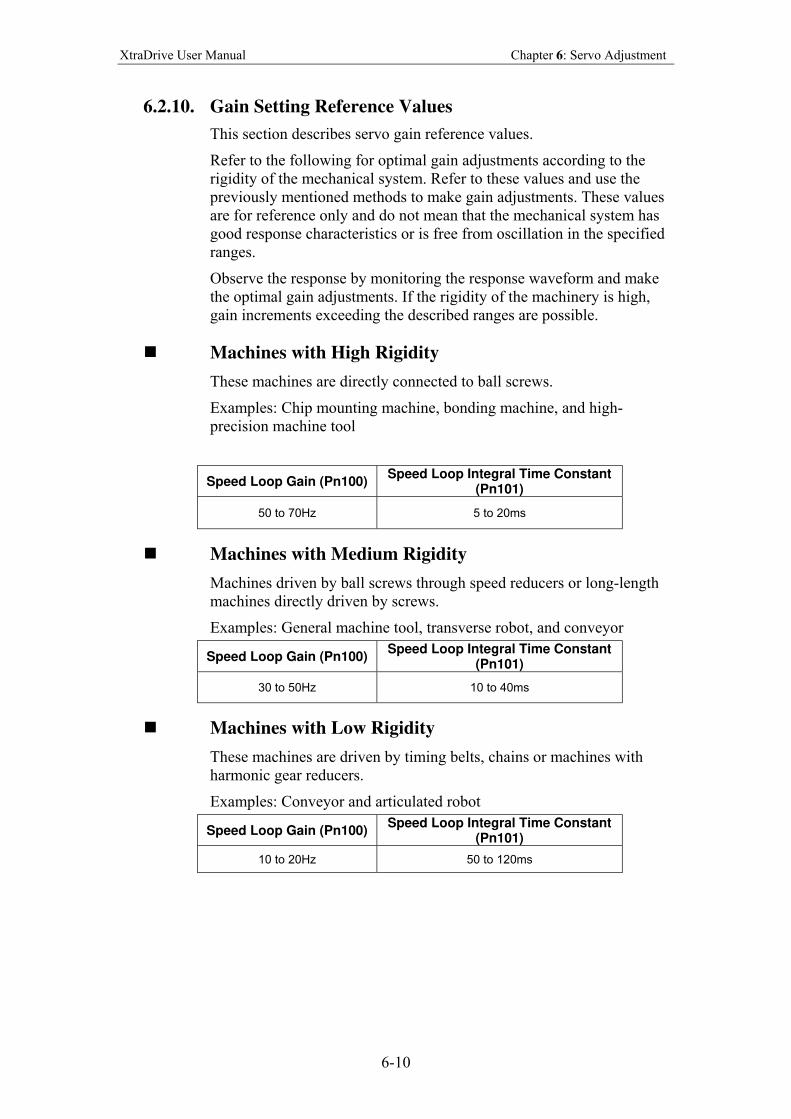
XtraDrive User Manual Chapter 6: Servo Adjustment
6-10
6.2.10. Gain Setting Reference Values
This section describes servo gain reference values.
Refer to the following for optimal gain adjustments according to the
rigidity of the mechanical system. Refer to these values and use the
previously mentioned methods to make gain adjustments. These values
are for reference only and do not mean that the mechanical system has
good response characteristics or is free from oscillation in the specified
ranges.
Observe the response by monitoring the response waveform and make
the optimal gain adjustments. If the rigidity of the machinery is high,
gain increments exceeding the described ranges are possible.
Machines with High Rigidity
These machines are directly connected to ball screws.
Examples: Chip mounting machine, bonding machine, and high-
precision machine tool
Speed Loop Gain (Pn100) Speed Loop Integral Time Constant
(Pn101)
50 to 70Hz 5 to 20ms
Machines with Medium Rigidity
Machines driven by ball screws through speed reducers or long-length
machines directly driven by screws.
Examples: General machine tool, transverse robot, and conveyor
Speed Loop Gain (Pn100) Speed Loop Integral Time Constant
(Pn101)
30 to 50Hz 10 to 40ms
Machines with Low Rigidity
These machines are driven by timing belts, chains or machines with
harmonic gear reducers.
Examples: Conveyor and articulated robot
Speed Loop Gain (Pn100) Speed Loop Integral Time Constant
(Pn101)
10 to 20Hz 50 to 120ms
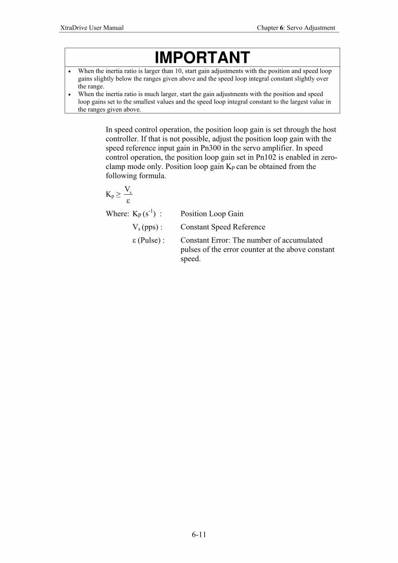
XtraDrive User Manual Chapter 6: Servo Adjustment
6-11
IMPORTANT
• When the inertia ratio is larger than 10, start gain adjustments with the position and speed loop
gains slightly below the ranges given above and the speed loop integral constant slightly over
the range.
• When the inertia ratio is much larger, start the gain adjustments with the position and speed
loop gains set to the smallest values and the speed loop integral constant to the largest value in
the ranges given above.
In speed control operation, the position loop gain is set through the host
controller. If that is not possible, adjust the position loop gain with the
speed reference input gain in Pn300 in the servo amplifier. In speed
control operation, the position loop gain set in Pn102 is enabled in zero-
clamp mode only. Position loop gain Kp can be obtained from the
following formula.
Kp ≥ ε
sV
Where: Kp (s-1
) : Position Loop Gain
Vs (pps) : Constant Speed Reference
ε (Pulse) : Constant Error: The number of accumulated
pulses of the error counter at the above constant
speed.
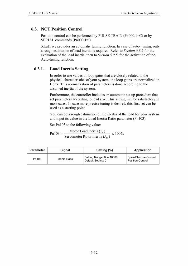
XtraDrive User Manual Chapter 6: Servo Adjustment
6-12
6.3. NCT Position Control
Position control can be performed by PULSE TRAIN (Pn000.1=C) or by
SERIAL commands (Pn000.1=D.
XtraDrive provides an automatic tuning function. In case of auto- tuning, only
a rough estimation of load inertia is required. Refer to Section 6.3.2 for the
evaluation of the load inertia, then to Section 5.9.5. for the activation of the
Auto-tuning function.
6.3.1. Load Inertia Setting
In order to use values of loop gains that are closely related to the
physical characteristics of your system, the loop gains are normalized in
Hertz. This normalization of parameters is done according to the
assumed inertia of the system.
Furthermore, the controller includes an automatic set up procedure that
set parameters according to load size. This setting will be satisfactory in
most cases. In case more precise tuning is desired, this first set can be
used as a starting point
You can do a rough estimation of the inertia of the load for your system
and input its value in the Load Inertia Ratio parameter (Pn103).
Set Pn103 to the following value:
Pn103 = )(JInertia Rotor Servomotor
)(JInertia Motor Load
M
L x 100%
Parameter Signal Setting (%) Application
Pn103 Inertia Ratio Setting Range: 0 to 10000 Default Setting: 0
Speed/Torque Control, Position Control
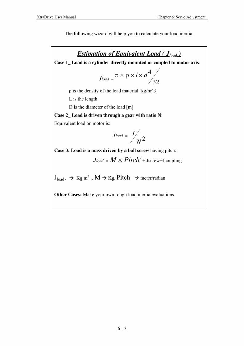
XtraDrive User Manual Chapter 6: Servo Adjustment
6-13
The following wizard will help you to calculate your load inertia.
Estimation of equivalent load ( Jload )
To tune your system, you should have an approximate estimation of the
Inertia (Jload ) of the load attached to the motor.
If a cylinder load is mountain directly on motor axis you should use
the following formula to calculate load inertia:
32
4dl
Jload×××
=ρπ
Where ρ is the characteristic weight of the load [kg/m^3].
L is the length and d is the diameter of the load [m].
Estimation of Equivalent Load ( J load )
Case 1_ Load is a cylinder directly mounted or coupled to motor axis:
32
4dl
Jload×××
=ρπ
ρ is the density of the load material [kg/m^3]
L is the length
D is the diameter of the load [m]
Case 2_ Load is driven through a gear with ratio N:
Equivalent load on motor is:
2N
JJload =
Case 3: Load is a mass driven by a ball screw having pitch:
2
PitchMloadJ ×= + Jscrew+Jcoupling
Jload , Kg.m2
, M Kg, Pitch meter/radian
Other Cases: Make your own rough load inertia evaluations.
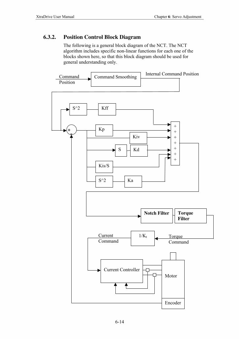
XtraDrive User Manual Chapter 6: Servo Adjustment
6-14
6.3.2. Position Control Block Diagram
The following is a general block diagram of the NCT. The NCT
algorithm includes specific non-linear functions for each one of the
blocks shown here, so that this block diagram should be used for
general understanding only.
Kp
S
Kis/S
Kd
S^2 Ka
+
+
+
+
+
+
+
S^2 Kff
Kiv
Command Smoothing Command
Position
Internal Command Position
Notch Filter Torque
Filter
1/Kt Torque
Command
Current Controller
Motor
Encoder
Current
Command
+ -
XtraDrive User Manual Chapter 6: Servo Adjustment
6-15
6.3.3. NCT Gain Parameters
The following are the main parameters of NCT servo control:
Kd Pn1AC Differential gain
Kp Pn1AA Proportional gain
Kiv Pn1AB Additional proportional gain
Kis Pn1A9 Integral feedback gain
Ka Pn1AD Acceleration gain
These parameters should be tuned in the order of the list above.
• Kd (Pn1AC) range 0-2000 [Hz] default 30:
This parameter is equivalent to a velocity loop gain. It produces
damping of the movement.
The higher this parameter can be increased, the better the final
tuning will be. However, the increase is limited by the flexibility of
the mechanical system driven.
A too high value of Kd will cause high frequency oscillations of the
system.
For tuning, raise the value of that parameter progressively until
oscillations are observed or acoustic noise is heard. Then reduce
back to a safe value (around 10 to 20%, depending on the system).
• Kp (Pn1AA) range 0-500 [Hz] default 40:
This parameter sets the position loop gain.
For tight control, increase it until overshoot or oscillations are
observed. Then reduce back and set according to the level of
overshoot/undershoot desired.
Value 30*(Jtotal/Jmotor)^0.5 can be used as a reference value.
• Kiv (Pn1AB) range 0-500 [Hz], default 30:
This parameter is an additional position loop gain. Using proprietary
NCT technique, this gain increases stiffness and reduces the position
error during the trajectory following, without causing overshoot or
oscillations.
Proceed as for Kp for tuning. Normally, the range of this parameter
is
Kp/2 < Kiv < Kp
• Kis (Pn1A9) range 0-500 [Hz] default 40:
This parameter is the equivalent of the integral loop gain. It cancels
the position error at stop and minimizes it during movement.
As for previous gains, increase until vibrations occur, then reduce
back to a safe value.
The oscillations observed when a too high Kis is used are usually at
lower frequency.
XtraDrive User Manual Chapter 6: Servo Adjustment
6-16
• Ka (Pn1AD) range 0-500 [%], default 0. Filter Pn1AE range 0-
2500 [0.01ms] default 300:
This parameter is the acceleration gain. It can be used when there is
a high-resolution encoder. In most cases, a 0 value is used, but in
some cases it can improve the control quality.
• Kff (Pn1AF) range 0-200 [%] default 0. This parameter is used
only in a serial command (Pn000.1=D):
This parameter is the feed forward of command acceleration into the
command torque. Tune this parameter after you finished tuning the
previous parameters. It reduces position error during movement and
during acceleration and deceleration phase.
6.3.4. OCA - Oscillation Canceling Algorithm
Version XtraDrive
Version
XtraWare
Version
The following
description
relates to:
2.8 2.5.3
General Description
OCA is used to dynamically eliminate vibrations during motion. The
frequency of Speed Error vibrations (within the range of 500 – 2000
Hz) detected by the driver are eliminated on the fly, allowing increase
of gain and reduction of noise.
Recommendations:
• Since autotuning takes the OCA into account, it is advisable to run
autotuning in the same OCA mode (active or non-active) as that in
which the system works.
• Use a very low Torque Filter when the OCA is active.
• It is possible to activate OCA together with the notch filter.
• In cases of stiff machines where coupling with the load is very
strong (no backlash, no coupling or very stiff coupling), better
performance can be obtained without OCA.
Setting
Parameter Name Setting Description Default
0 OCA is not active
Pn2D4
Oscillation
Canceling
Mode 1 OCA is active
1
XtraDrive User Manual Chapter 6: Servo Adjustment
6-17
6.3.5. Additional Parameters Tuning
After having set the default value for a given load, additional tuning
may be done. Typically, the following parameters can be further tuned:
Torque Filters Pn1A2-Pn1A5
To prevent vibrations with
flexible coupling and poor
damping.
Command Smoothing Pn216 To smooth movement in
case of flexible system.
Tightness Pn1A0 To increase/decrease gain.
Variable gain Pn1B5-Pn1B9 To increase gain during
movement.
Flexible system Pn1BB-Pn1BD
To compensate the
overshoot and smooth the
movement.
6.3.6. Filters
Filters are used to avoid vibrations, thus allowing a higher value of loop
gain.
Filters should be set in an iterative way, where each time a new filter
value is tried; the velocity loop gain is re-tuned. Typically, the final
value selected for the filter will be the one that allows the highest Kd.
• Kd Filter (Pn1A2), Range 30-3200[0.01ms], Default 40:
This parameter sets a low pass filter on differential gain, a good
starting value is about Pn103/10, where the minimum value is 30
[0.01ms]. A low value for this parameter will make noise in high
frequency.
Typically, this parameter will have to be increased if load coupling
is flexible, and damping is poor.
• Torque Filter (Pn1A4), Range 0-2500[0.01ms], Default 20:
This parameter sets a low pass filter on torque command. A good
starting value is about Pn103/10, if you use notch filter (Pn408.0=1)
(see 6.1.6). It is better not to use torque filter or to use a small value.
Typically, this parameter will have to be increased if load coupling
is flexible, and damping is poor.
This parameter should be set to a value only slightly higher than the
value at which oscillations disappear. Using an unnecessary high
value will degrade the control quality. Typically, chose the value
that allows the highest value setting of Kd.
XtraDrive User Manual Chapter 6: Servo Adjustment
6-18
• Second Order Torque Filter (Pn1A5), Range 0-1000 [0.1%],
Default 0:
This parameter is a part of the second order torque filter. It has good
influence in many cases, even if the first order torque filter is not
active.
After tuning Pn1A4, raise this parameter progressively until
vibrations occur. In many systems, values for this parameter will be
in the 500—700 (0.1%).
• Command Smoothing (Pn216), Range 0-65536 [0.1ms],
Default 0: (See 6.1.2)
In case of a flexible system, if command acceleration is not applied
progressively, the system will oscillate around the command
position after every discontinuity of the command acceleration (even
if the oscillation is not seen). The command-smoothing smoothes
the command acceleration to avoid these oscillations.
Using a command filter will delay the arrival of the command to the
final target position. The value of this filter should be set higher than
the period of self-oscillations, but not too high to keep good settling
time.
6.3.7. Flexible System Parameters
• KffSpring (Pn1BB) range 10-2000 [Hz] default 2000:
This parameter compensates the position error during the
acceleration and deceleration phase and the overshoot observed
when stopping at the end of a deceleration phase. Typically, this
overshoot is caused by the elasticity of the system; a wind up occurs
during the deceleration phase and relaxes after stop. The KffSpring
parameter compensates for that wind up.
The frequency of this parameter relates to the self-oscillation
frequency of the system. It can be adjusted to avoid overshoot and
minimize settling time.
Default value is 2000 Hertz. This value is well beyond the frequency
response of usual systems, so that it has no influence.
To adjust, decrease this value progressively, while monitoring the
position error, until overshoot is canceled or position error in the
acceleration and deceleration phase are minimized.
• KfbSpring (Pn1BD) range 10-2000 [Hz] default 2000:
This parameter compensates the vibrations of the motor, it smoothes
the control in case of a flexible system. Usually it should be tuned to
the low resonance of the system.
You can tune this parameter by progressively decreasing its value
until vibrations occur. Then use a higher value for setting (~20%).
XtraDrive User Manual Chapter 6: Servo Adjustment
6-19
6.3.8. Gain Factor
• Tightness (Pn1A0), Range 0-500[%], Default 60:
This parameter changes the frequencies of feedback parameter
linearly, keeping their relative ratio, so that system rigidity can be
changed without getting unstable. A good starting value is 60[%].
After setting the default values for load, one can increase or
decrease the stiffness of the servo control by changing this
parameter.
This can be done while monitoring the position error during the
movement and thus choosing the optimal value for the system
application.
• Maximum of Variable Gain MAXKG (Pn1B5), Range 100-1000
[%], Default 160:
This parameter sets the maximum variable gain during movement.
To cancel variable gain, set this parameter to 100[%]. To use
variable gain, increase it, usually 160-200% is enough. If one sets
this parameter to 200%, it means that gain can be raised to 200% of
the written parameter value during movement.
6.3.9. Integral Clear Parameters
• Integral Clear Mode (Pn1A7, digit 0):
This parameter activates a special treatment of integral at the end of
a decelerating ramp.
When using a command having a trapezoid speed profile, at the end
of the deceleration there is a discontinuity of acceleration; at this
point, deceleration abruptly changes its value from maximum to
zero. Normally, this would create an overshoot of the system. This
discontinuity is compensated by addition of a calculated value to the
integral at that particular time, thus avoiding the overshoot.
Software detects the end of a command deceleration phase,
calculates the compensating value and adds it to the integral.
o In case of point-to-point movements with trapezoid profile: set to 1.
o In case of very smoothed command acceleration: reset to zero.
• Integral clear timing (Pn1BF), Range 1-15, Default 3:
This parameter defines the timing of a clear integral. Reducing this
parameter will delay the clear integral, and increasing will speed up
the clear integral.
• Integral Offset Averaging Time (Pn1C0), Range 0-25[ms],
Default 0:
This parameter defines the time needed to calculate a steady torque
at stop.This value is used to execute a more precise integral
modification at the end of the movement.
In horizontal systems, this parameter should be zero.
XtraDrive User Manual Chapter 6: Servo Adjustment
6-19
This parameter changes the frequencies of feedback parameter
linearly, keeping their relative ratio, so that system rigidity can be
changed without getting unstable. A good starting value is 60[%].
After setting the default values for load, one can increase or
decrease the stiffness of the servo control by changing this
parameter.
This can be done while monitoring the position error during the
movement and thus choosing the optimal value for the system
application.
• Maximum of Variable Gain MAXKG (Pn1B5), Range 100-1000
[%], Default 160:
This parameter sets the maximum variable gain during movement.
To cancel variable gain, set this parameter to 100[%]. To use
variable gain, increase it, usually 160-200% is enough. If one sets
this parameter to 200%, it means that gain can be raised to 200% of
the written parameter value during movement.
6.3.9. Integral Clear Parameters
• Integral Clear Mode (Pn1A7, digit 0):
This parameter activates a special treatment of integral at the end of
a decelerating ramp.
When using a command having a trapezoid speed profile, at the end
of the deceleration there is a discontinuity of acceleration; at this
point, deceleration abruptly changes its value from maximum to
zero. Normally, this would create an overshoot of the system. This
discontinuity is compensated by addition of a calculated value to the
integral at that particular time, thus avoiding the overshoot.
Software detects the end of a command deceleration phase,
calculates the compensating value and adds it to the integral.
o In case of point-to-point movements with trapezoid profile: set to 1.
o In case of very smoothed command acceleration: reset to zero.
• Integral clear timing (Pn1BF), Range 1-15, Default 3:
This parameter defines the timing of a clear integral. Reducing this
parameter will delay the clear integral, and increasing will speed up
the clear integral.
• Integral Offset Averaging Time (Pn1C0), Range 0-25[ms],
Default 0:
This parameter defines the time needed to calculate a steady torque
at stop.This value is used to execute a more precise integral
modification at the end of the movement.
In horizontal systems, this parameter should be zero.
XtraDrive User Manual Chapter 6: Servo Adjustment
6-20
6.3.10. Tuning Procedure for Position Control Parameters
System Requirements
Use any command input to the XtraDrive, and watch the performance
of control (see analog output).
It is recommended to use commands that include a constant speed
section (plateau of trapeze for example). Potential vibrations of the
system may not be observed during the tuning procedure if no constant
speed section is used.
Tuning is done while checking the items of the control quality required
for the specific application. These items can vary, depending on the
application.
Typically, items of control quality are:
• Smoothness: Can be estimated by the behavior of the position error
with time. If the position error changes sign rapidly and/or with
great amplitude, then smoothness is poor.
• Settling time: Can be measured as the time it takes to reach a zero
position error after the command speed reaches zero.
• Stiffness: Can be measured by monitoring the position error
amplitude resulting from a perturbation.
This perturbation can be an abrupt change in command acceleration,
for example by using a triangle shape for the speed profile of a
command, or a physical impact applied on shaft or load.
• Overshoot: Can be measured by the sign of position error after
movement stops.
The Tuning Steps
During each tuning step, the quality of control is monitored with the
user-required movements according to the user’s criteria.
1. Use Fast Tuning in order to load a starting set of parameters for the
given load.
2. Tune the following parameters:
a) Set the Torque Filter (Pn1A4) to zero.
b) Raise Kd (Pn1AC) to the maximum possible value for a smooth
movement, then decrease that value by about 20%.
c) Increase the torque filter and repeat Step b. Continue increasing
the torque filter until the maximum value of Kd is obtained.
d) Raise Kp(Pn1AA) to the maximum value that gives a smooth
movement, then decrease that value by about 20%.
e) Raise Kis (Pn1A9) till there is no overshoot.
XtraDrive User Manual Chapter 6: Servo Adjustment
6-21
f) Increase the Second Order torque filter (Pn1A5) to obtain
smoothed movement, very helpful in flexible systems. You can
increase it till 60 to 70 percentages.
g) If necessary, repeat sub-steps b) to d) until an optimal value is
obtained.
h) You can try to increase Ka (Pn1AD), this will sometimes
improve results. You must have some filter on acceleration
feedback (Pn1AE).
3. Tune flexible system parameters.
a) KffSpring (Pn1BB). This parameter may be used to suppress
overshoot, to reduce it progressively, or to cancel overshoot.
b) KfbSpring (Pn1BD). This parameter may be used to suppress
oscillations in a flexible system. Default value is 2000Hz.
Decrease progressively, or try values close to the suspected low
self-oscillation frequencies.
4. Advanced parameter:
Integral Offset Averaging Time (Pn1C0). If this parameter is set
(>0), then each time the system is stopped (no command input), an
average value of the steady torque is calculated. This value is then
used as an adaptive offset for the torque command. The averaging
time for this offset is set by the value of Pn1C0. Increase it if you
have some force on the motor in a steady state, like gravity.
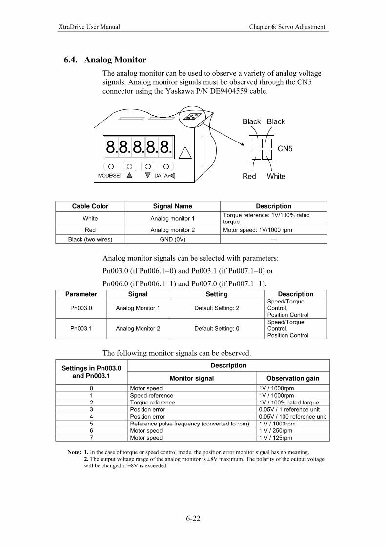
XtraDrive User Manual Chapter 6: Servo Adjustment
6-22
6.4. Analog Monitor
The analog monitor can be used to observe a variety of analog voltage
signals. Analog monitor signals must be observed through the CN5
connector using the Yaskawa P/N DE9404559 cable.
8. 8.8.8.8.
DATA/MODE/SET
CN5
Black Black
Red White
Cable Color Signal Name Description
White Analog monitor 1 Torque reference: 1V/100% rated torque
Red Analog monitor 2 Motor speed: 1V/1000 rpm
Black (two wires) GND (0V) —
Analog monitor signals can be selected with parameters:
Pn003.0 (if Pn006.1=0) and Pn003.1 (if Pn007.1=0) or
Pn006.0 (if Pn006.1=1) and Pn007.0 (if Pn007.1=1).
Parameter Signal Setting Description
Pn003.0 Analog Monitor 1 Default Setting: 2 Speed/Torque Control, Position Control
Pn003.1 Analog Monitor 2 Default Setting: 0 Speed/Torque Control, Position Control
The following monitor signals can be observed.
Description Settings in Pn003.0 and Pn003.1 Monitor signal Observation gain
0 Motor speed 1V / 1000rpm
1 Speed reference 1V / 1000rpm
2 Torque reference 1V / 100% rated torque
3 Position error 0.05V / 1 reference unit
4 Position error 0.05V / 100 reference unit
5 Reference pulse frequency (converted to rpm) 1 V / 1000rpm
6 Motor speed 1 V / 250rpm
7 Motor speed 1 V / 125rpm
Note: 1. In the case of torque or speed control mode, the position error monitor signal has no meaning.
2. The output voltage range of the analog monitor is ±8V maximum. The polarity of the output voltage
will be changed if ±8V is exceeded.
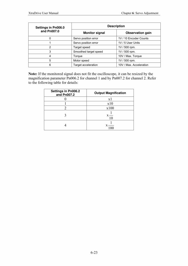
XtraDrive User Manual Chapter 6: Servo Adjustment
6-23
Description Settings in Pn006.0 and Pn007.0
Monitor signal Observation gain
0 Servo position error 1V / 10 Encoder Counts
1 Servo position error 1V / 5 User Units
2 Target speed 1V / 500 rpm.
3 Smoothed target speed 1V / 500 rpm.
4 Torque 10V / Max. Torque
5 Motor speed 1V / 500 rpm.
6 Target acceleration 10V / Max. Acceleration
Note: If the monitored signal does not fit the oscilloscope, it can be resized by the
magnification parameter Pn006.2 for channel 1 and by Pn007.2 for channel 2. Refer
to the following table for details:
Settings in Pn006.2
and Pn007.2 Output Magnification
0 x1
1 x10
2 x100
3 x10
1
4 x100
1
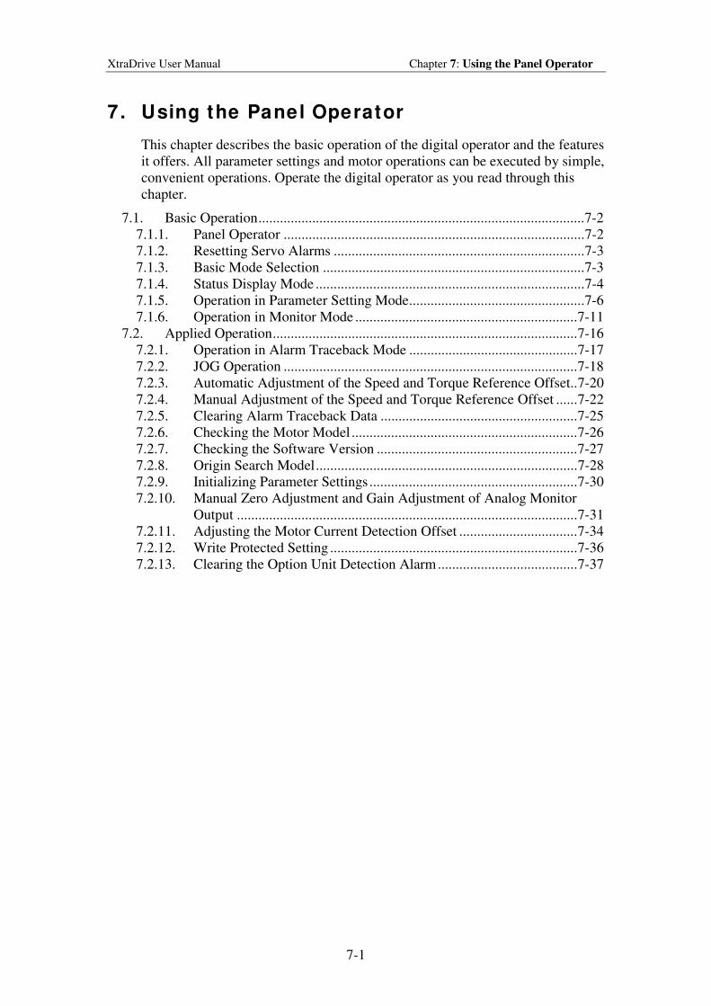
XtraDrive User Manual Chapter 7: Using the Panel Operator
7-1
7. Using the Panel Operator
This chapter describes the basic operation of the digital operator and the features
it offers. All parameter settings and motor operations can be executed by simple,
convenient operations. Operate the digital operator as you read through this
chapter.
7.1. Basic Operation...........................................................................................7-2
7.1.1. Panel Operator ....................................................................................7-2
7.1.2. Resetting Servo Alarms ......................................................................7-3
7.1.3. Basic Mode Selection .........................................................................7-3
7.1.4. Status Display Mode ...........................................................................7-4
7.1.5. Operation in Parameter Setting Mode.................................................7-6
7.1.6. Operation in Monitor Mode ..............................................................7-11
7.2. Applied Operation.....................................................................................7-16
7.2.1. Operation in Alarm Traceback Mode ...............................................7-17
7.2.2. JOG Operation ..................................................................................7-18
7.2.3. Automatic Adjustment of the Speed and Torque Reference Offset..7-20
7.2.4. Manual Adjustment of the Speed and Torque Reference Offset ......7-22
7.2.5. Clearing Alarm Traceback Data .......................................................7-25
7.2.6. Checking the Motor Model ...............................................................7-26
7.2.7. Checking the Software Version ........................................................7-27
7.2.8. Origin Search Model.........................................................................7-28
7.2.9. Initializing Parameter Settings ..........................................................7-30
7.2.10. Manual Zero Adjustment and Gain Adjustment of Analog Monitor
Output ...............................................................................................7-31
7.2.11. Adjusting the Motor Current Detection Offset .................................7-34
7.2.12. Write Protected Setting .....................................................................7-36
7.2.13. Clearing the Option Unit Detection Alarm.......................................7-37
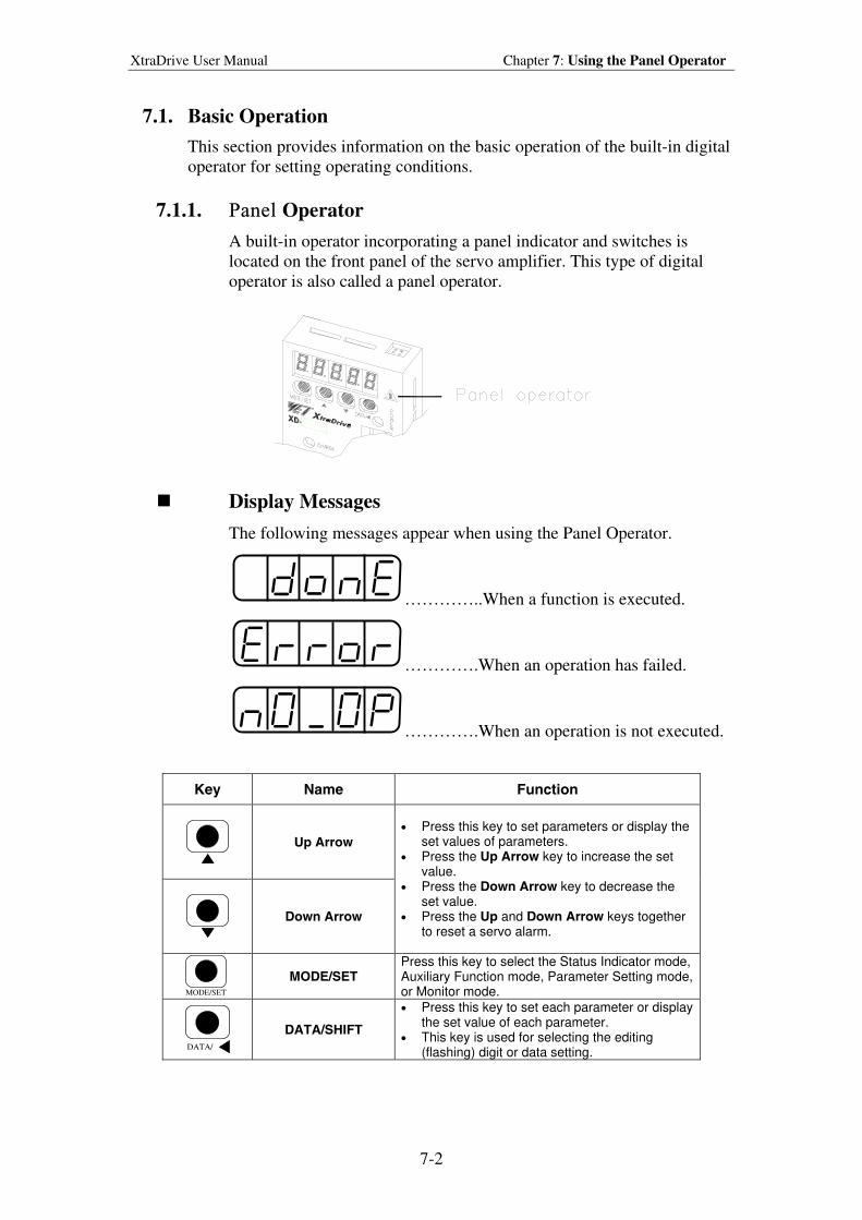
XtraDrive User Manual Chapter 7: Using the Panel Operator
7-2
7.1. Basic Operation
This section provides information on the basic operation of the built-in digital
operator for setting operating conditions.
7.1.1. Panel Operator
A built-in operator incorporating a panel indicator and switches is
located on the front panel of the servo amplifier. This type of digital
operator is also called a panel operator.
Display Messages
The following messages appear when using the Panel Operator.
…………..When a function is executed.
………….When an operation has failed.
………….When an operation is not executed.
Key Name Function
Up Arrow
Down Arrow
• Press this key to set parameters or display the set values of parameters.
• Press the Up Arrow key to increase the set value.
• Press the Down Arrow key to decrease the set value.
• Press the Up and Down Arrow keys together to reset a servo alarm.
MODE/SET
MODE/SET Press this key to select the Status Indicator mode, Auxiliary Function mode, Parameter Setting mode, or Monitor mode.
DATA/
DATA/SHIFT
• Press this key to set each parameter or display the set value of each parameter.
• This key is used for selecting the editing (flashing) digit or data setting.
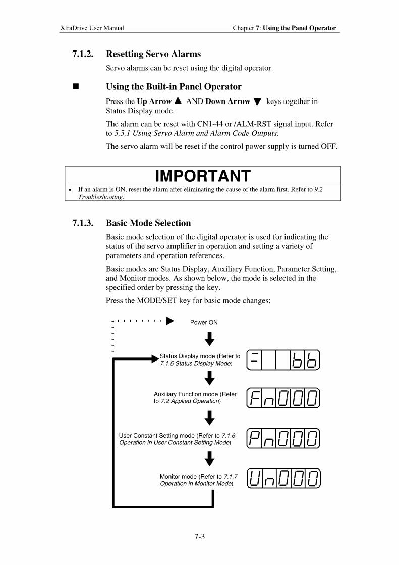
XtraDrive User Manual Chapter 7: Using the Panel Operator
7-3
7.1.2. Resetting Servo Alarms
Servo alarms can be reset using the digital operator.
Using the Built-in Panel Operator
Press the Up Arrow AND Down Arrow keys together in
Status Display mode.
The alarm can be reset with CN1-44 or /ALM-RST signal input. Refer
to 5.5.1 Using Servo Alarm and Alarm Code Outputs.
The servo alarm will be reset if the control power supply is turned OFF.
IMPORTANT
• If an alarm is ON, reset the alarm after eliminating the cause of the alarm first. Refer to 9.2
Troubleshooting.
7.1.3. Basic Mode Selection
Basic mode selection of the digital operator is used for indicating the
status of the servo amplifier in operation and setting a variety of
parameters and operation references.
Basic modes are Status Display, Auxiliary Function, Parameter Setting,
and Monitor modes. As shown below, the mode is selected in the
specified order by pressing the key.
Press the MODE/SET key for basic mode changes:
Status Display mode (Refer to 7.1.5 Status Display Mode)
Auxiliary Function mode (Refer to 7.2 Applied Operation)
User Constant Setting mode (Refer to 7.1.6 Operation in User Constant Setting Mode)
Monitor mode (Refer to 7.1.7 Operation in Monitor Mode)
Power ON
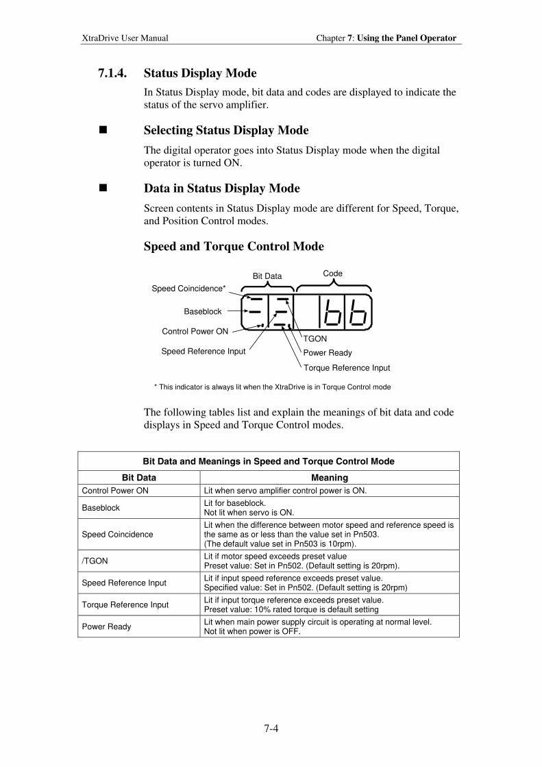
XtraDrive User Manual Chapter 7: Using the Panel Operator
7-4
7.1.4. Status Display Mode
In Status Display mode, bit data and codes are displayed to indicate the
status of the servo amplifier.
Selecting Status Display Mode
The digital operator goes into Status Display mode when the digital
operator is turned ON.
Data in Status Display Mode
Screen contents in Status Display mode are different for Speed, Torque,
and Position Control modes.
Speed and Torque Control Mode
Bit Data Code
Speed Coincidence*
Baseblock
Control Power ON
Speed Reference Input
TGON
Power Ready
Torque Reference Input
* This indicator is always lit when the XtraDrive is in Torque Control mode
The following tables list and explain the meanings of bit data and code
displays in Speed and Torque Control modes.
Bit Data and Meanings in Speed and Torque Control Mode
Bit Data Meaning
Control Power ON Lit when servo amplifier control power is ON.
Baseblock Lit for baseblock. Not lit when servo is ON.
Speed Coincidence Lit when the difference between motor speed and reference speed is the same as or less than the value set in Pn503. (The default value set in Pn503 is 10rpm).
/TGON Lit if motor speed exceeds preset value Preset value: Set in Pn502. (Default setting is 20rpm).
Speed Reference Input Lit if input speed reference exceeds preset value. Specified value: Set in Pn502. (Default setting is 20rpm)
Torque Reference Input Lit if input torque reference exceeds preset value. Preset value: 10% rated torque is default setting
Power Ready Lit when main power supply circuit is operating at normal level. Not lit when power is OFF.
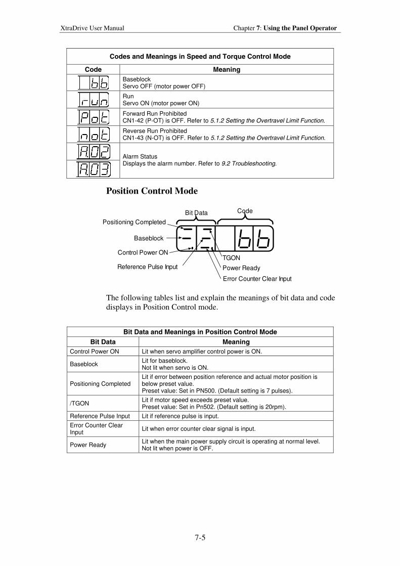
XtraDrive User Manual Chapter 7: Using the Panel Operator
7-5
Codes and Meanings in Speed and Torque Control Mode
Code Meaning
Baseblock Servo OFF (motor power OFF)
Run Servo ON (motor power ON)
Forward Run Prohibited CN1-42 (P-OT) is OFF. Refer to 5.1.2 Setting the Overtravel Limit Function.
Reverse Run Prohibited CN1-43 (N-OT) is OFF. Refer to 5.1.2 Setting the Overtravel Limit Function.
Alarm Status Displays the alarm number. Refer to 9.2 Troubleshooting.
Position Control Mode
Bit Data Code
Positioning Completed
Baseblock
Control Power ON
Reference Pulse Input
TGON
Power Ready
Error Counter Clear Input
The following tables list and explain the meanings of bit data and code
displays in Position Control mode.
Bit Data and Meanings in Position Control Mode
Bit Data Meaning
Control Power ON Lit when servo amplifier control power is ON.
Baseblock Lit for baseblock. Not lit when servo is ON.
Positioning Completed Lit if error between position reference and actual motor position is below preset value. Preset value: Set in PN500. (Default setting is 7 pulses).
/TGON Lit if motor speed exceeds preset value. Preset value: Set in Pn502. (Default setting is 20rpm).
Reference Pulse Input Lit if reference pulse is input.
Error Counter Clear Input
Lit when error counter clear signal is input.
Power Ready Lit when the main power supply circuit is operating at normal level. Not lit when power is OFF.
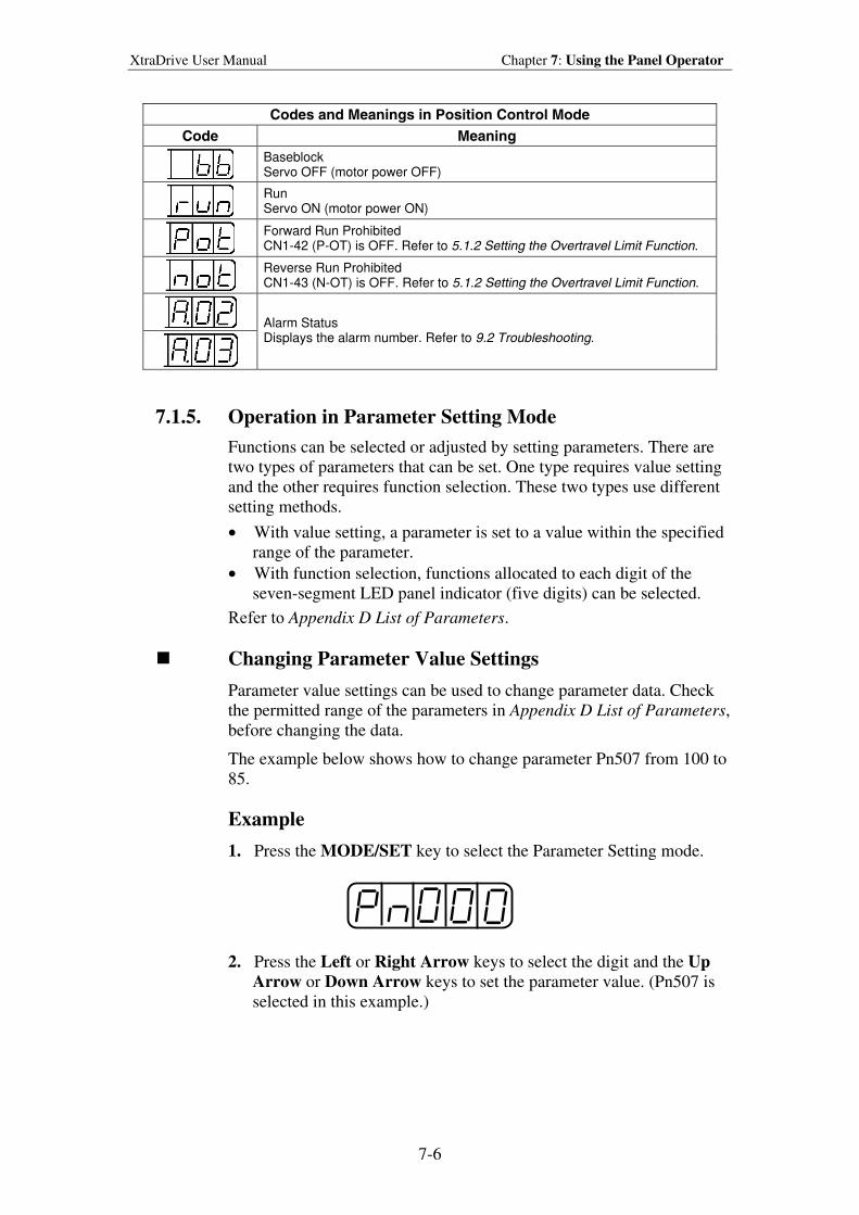
XtraDrive User Manual Chapter 7: Using the Panel Operator
7-6
Codes and Meanings in Position Control Mode
Code Meaning
Baseblock Servo OFF (motor power OFF)
Run Servo ON (motor power ON)
Forward Run Prohibited CN1-42 (P-OT) is OFF. Refer to 5.1.2 Setting the Overtravel Limit Function.
Reverse Run Prohibited CN1-43 (N-OT) is OFF. Refer to 5.1.2 Setting the Overtravel Limit Function.
Alarm Status Displays the alarm number. Refer to 9.2 Troubleshooting.
7.1.5. Operation in Parameter Setting Mode
Functions can be selected or adjusted by setting parameters. There are
two types of parameters that can be set. One type requires value setting
and the other requires function selection. These two types use different
setting methods.
• With value setting, a parameter is set to a value within the specified
range of the parameter.
• With function selection, functions allocated to each digit of the
seven-segment LED panel indicator (five digits) can be selected.
Refer to Appendix D List of Parameters.
Changing Parameter Value Settings
Parameter value settings can be used to change parameter data. Check
the permitted range of the parameters in Appendix D List of Parameters,
before changing the data.
The example below shows how to change parameter Pn507 from 100 to
85.
Example
1. Press the MODE/SET key to select the Parameter Setting mode.
2. Press the Left or Right Arrow keys to select the digit and the Up
Arrow or Down Arrow keys to set the parameter value. (Pn507 is
selected in this example.)
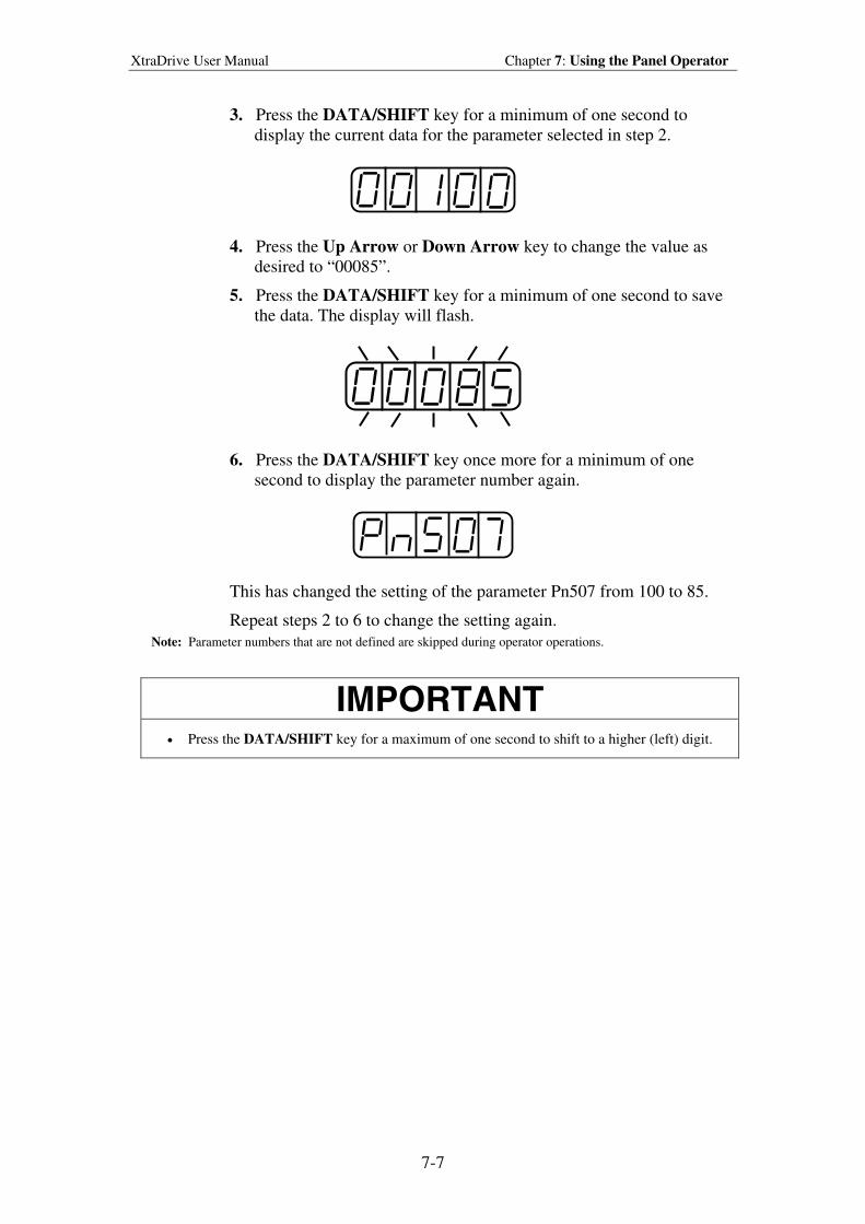
XtraDrive User Manual Chapter 7: Using the Panel Operator
7-7
3. Press the DATA/SHIFT key for a minimum of one second to
display the current data for the parameter selected in step 2.
4. Press the Up Arrow or Down Arrow key to change the value as
desired to “00085”.
5. Press the DATA/SHIFT key for a minimum of one second to save
the data. The display will flash.
6. Press the DATA/SHIFT key once more for a minimum of one
second to display the parameter number again.
This has changed the setting of the parameter Pn507 from 100 to 85.
Repeat steps 2 to 6 to change the setting again.
Note: Parameter numbers that are not defined are skipped during operator operations.
IMPORTANT
• Press the DATA/SHIFT key for a maximum of one second to shift to a higher (left) digit.
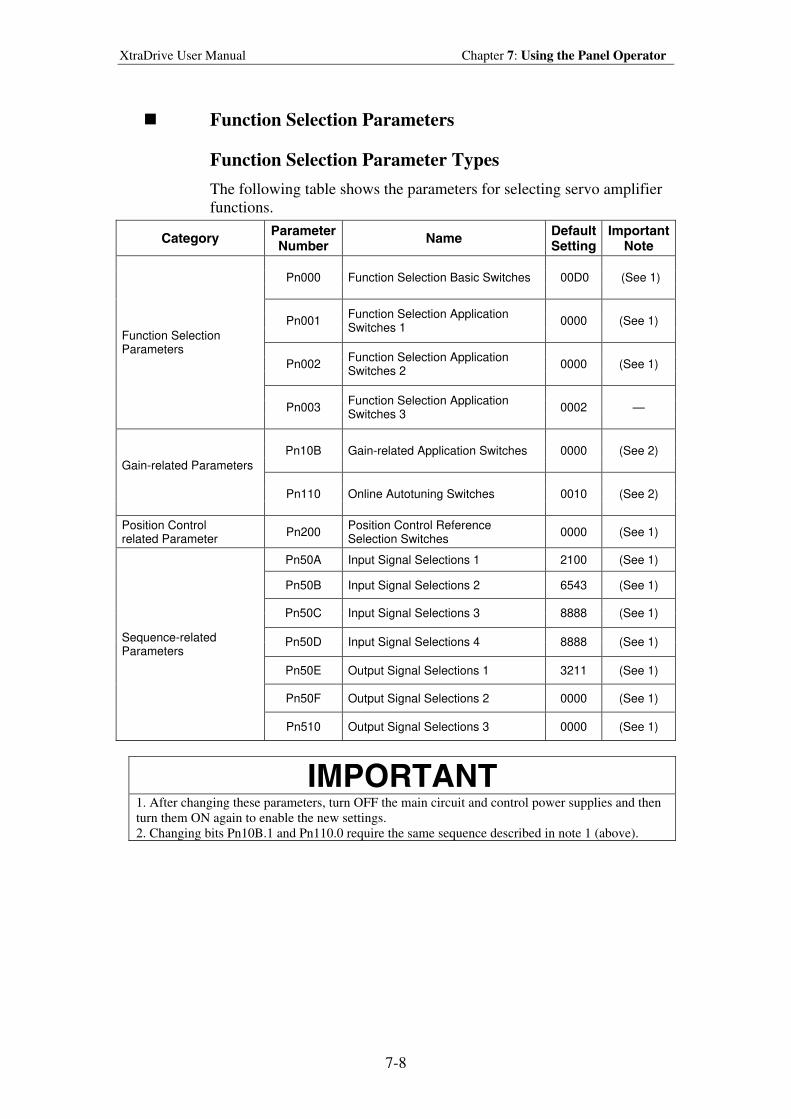
XtraDrive User Manual Chapter 7: Using the Panel Operator
7-8
Function Selection Parameters
Function Selection Parameter Types
The following table shows the parameters for selecting servo amplifier
functions.
Category ParameterNumber
Name Default Setting
Important Note
Pn000 Function Selection Basic Switches 00D0 (See 1)
Pn001 Function Selection Application Switches 1
0000 (See 1)
Pn002 Function Selection Application Switches 2
0000 (See 1)
Function Selection Parameters
Pn003 Function Selection Application Switches 3
0002 —
Pn10B Gain-related Application Switches 0000 (See 2)
Gain-related Parameters
Pn110 Online Autotuning Switches 0010 (See 2)
Position Control related Parameter
Pn200 Position Control Reference Selection Switches
0000 (See 1)
Pn50A Input Signal Selections 1 2100 (See 1)
Pn50B Input Signal Selections 2 6543 (See 1)
Pn50C Input Signal Selections 3 8888 (See 1)
Pn50D Input Signal Selections 4 8888 (See 1)
Pn50E Output Signal Selections 1 3211 (See 1)
Pn50F Output Signal Selections 2 0000 (See 1)
Sequence-related Parameters
Pn510 Output Signal Selections 3 0000 (See 1)
IMPORTANT
1. After changing these parameters, turn OFF the main circuit and control power supplies and then
turn them ON again to enable the new settings.
2. Changing bits Pn10B.1 and Pn110.0 require the same sequence described in note 1 (above).
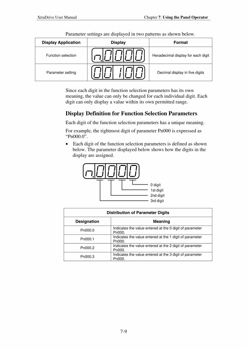
XtraDrive User Manual Chapter 7: Using the Panel Operator
7-9
Parameter settings are displayed in two patterns as shown below.
Display Application Display Format
Function selection
Hexadecimal display for each digit
Parameter setting
Decimal display in five digits
Since each digit in the function selection parameters has its own
meaning, the value can only be changed for each individual digit. Each
digit can only display a value within its own permitted range.
Display Definition for Function Selection Parameters
Each digit of the function selection parameters has a unique meaning.
For example, the rightmost digit of parameter Pn000 is expressed as
“Pn000.0”.
• Each digit of the function selection parameters is defined as shown
below. The parameter displayed below shows how the digits in the
display are assigned.
0 digit
1st digit
2nd digit
3rd digit
Distribution of Parameter Digits
Designation Meaning
Pn000.0 Indicates the value entered at the 0 digit of parameter Pn000.
Pn000.1 Indicates the value entered at the 1 digit of parameter Pn000.
Pn000.2 Indicates the value entered at the 2 digit of parameter Pn000.
Pn000.3 Indicates the value entered at the 3 digit of parameter Pn000.
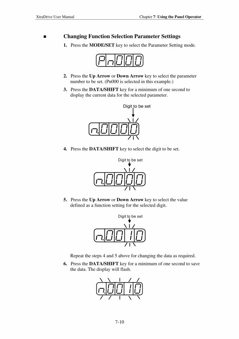
XtraDrive User Manual Chapter 7: Using the Panel Operator
7-10
Changing Function Selection Parameter Settings
1. Press the MODE/SET key to select the Parameter Setting mode.
2. Press the Up Arrow or Down Arrow key to select the parameter
number to be set. (Pn000 is selected in this example.)
3. Press the DATA/SHIFT key for a minimum of one second to
display the current data for the selected parameter.
Digit to be set
4. Press the DATA/SHIFT key to select the digit to be set.
Digit to be set
5. Press the Up Arrow or Down Arrow key to select the value
defined as a function setting for the selected digit.
Digit to be set
Repeat the steps 4 and 5 above for changing the data as required.
6. Press the DATA/SHIFT key for a minimum of one second to save
the data. The display will flash.
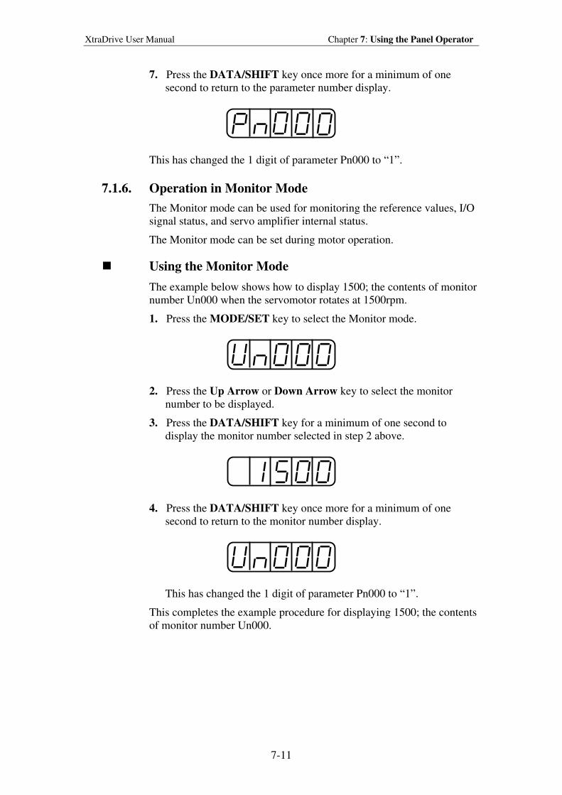
XtraDrive User Manual Chapter 7: Using the Panel Operator
7-11
7. Press the DATA/SHIFT key once more for a minimum of one
second to return to the parameter number display.
This has changed the 1 digit of parameter Pn000 to “1”.
7.1.6. Operation in Monitor Mode
The Monitor mode can be used for monitoring the reference values, I/O
signal status, and servo amplifier internal status.
The Monitor mode can be set during motor operation.
Using the Monitor Mode
The example below shows how to display 1500; the contents of monitor
number Un000 when the servomotor rotates at 1500rpm.
1. Press the MODE/SET key to select the Monitor mode.
2. Press the Up Arrow or Down Arrow key to select the monitor
number to be displayed.
3. Press the DATA/SHIFT key for a minimum of one second to
display the monitor number selected in step 2 above.
4. Press the DATA/SHIFT key once more for a minimum of one
second to return to the monitor number display.
This has changed the 1 digit of parameter Pn000 to “1”.
This completes the example procedure for displaying 1500; the contents
of monitor number Un000.
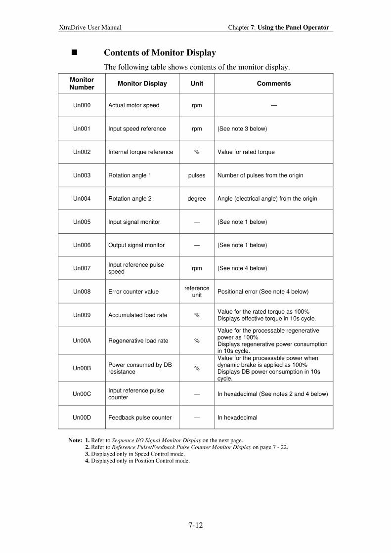
XtraDrive User Manual Chapter 7: Using the Panel Operator
7-12
Contents of Monitor Display
The following table shows contents of the monitor display.
Monitor Number
Monitor Display Unit Comments
Un000 Actual motor speed rpm —
Un001 Input speed reference rpm (See note 3 below)
Un002 Internal torque reference % Value for rated torque
Un003 Rotation angle 1 pulses Number of pulses from the origin
Un004 Rotation angle 2 degree Angle (electrical angle) from the origin
Un005 Input signal monitor — (See note 1 below)
Un006 Output signal monitor — (See note 1 below)
Un007 Input reference pulse speed
rpm (See note 4 below)
Un008 Error counter value reference
unit Positional error (See note 4 below)
Un009 Accumulated load rate % Value for the rated torque as 100% Displays effective torque in 10s cycle.
Un00A Regenerative load rate %
Value for the processable regenerative power as 100% Displays regenerative power consumption in 10s cycle.
Un00B Power consumed by DB resistance
%
Value for the processable power when dynamic brake is applied as 100% Displays DB power consumption in 10s cycle.
Un00C Input reference pulse counter
— In hexadecimal (See notes 2 and 4 below)
Un00D Feedback pulse counter — In hexadecimal
Note: 1. Refer to Sequence I/O Signal Monitor Display on the next page.
2. Refer to Reference Pulse/Feedback Pulse Counter Monitor Display on page 7 - 22.
3. Displayed only in Speed Control mode.
4. Displayed only in Position Control mode.
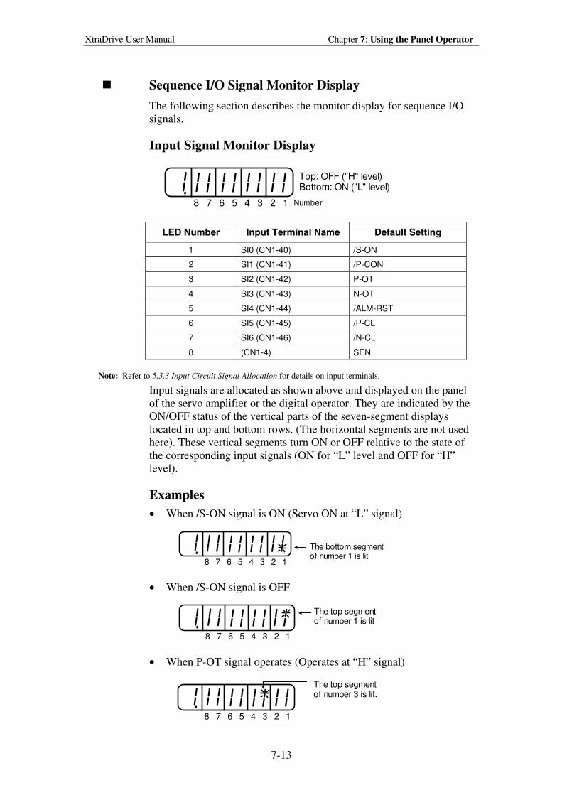
XtraDrive User Manual Chapter 7: Using the Panel Operator
7-13
Sequence I/O Signal Monitor Display
The following section describes the monitor display for sequence I/O
signals.
Input Signal Monitor Display
8 7 6 5 4 3 2 1
Top: OFF ("H" level)Bottom: ON ("L" level)
Number
LED Number Input Terminal Name Default Setting
1 SI0 (CN1-40) /S-ON
2 SI1 (CN1-41) /P-CON
3 SI2 (CN1-42) P-OT
4 SI3 (CN1-43) N-OT
5 SI4 (CN1-44) /ALM-RST
6 SI5 (CN1-45) /P-CL
7 SI6 (CN1-46) /N-CL
8 (CN1-4) SEN
Note: Refer to 5.3.3 Input Circuit Signal Allocation for details on input terminals.
Input signals are allocated as shown above and displayed on the panel
of the servo amplifier or the digital operator. They are indicated by the
ON/OFF status of the vertical parts of the seven-segment displays
located in top and bottom rows. (The horizontal segments are not used
here). These vertical segments turn ON or OFF relative to the state of
the corresponding input signals (ON for “L” level and OFF for “H”
level).
Examples
• When /S-ON signal is ON (Servo ON at “L” signal)
8 7 6 5 4 3 2 1
The bottom segmentof number 1 is lit
• When /S-ON signal is OFF
8 7 6 5 4 3 2 1
The top segmentof number 1 is lit
• When P-OT signal operates (Operates at “H” signal)
8 7 6 5 4 3 2 1
The top segmentof number 3 is lit.
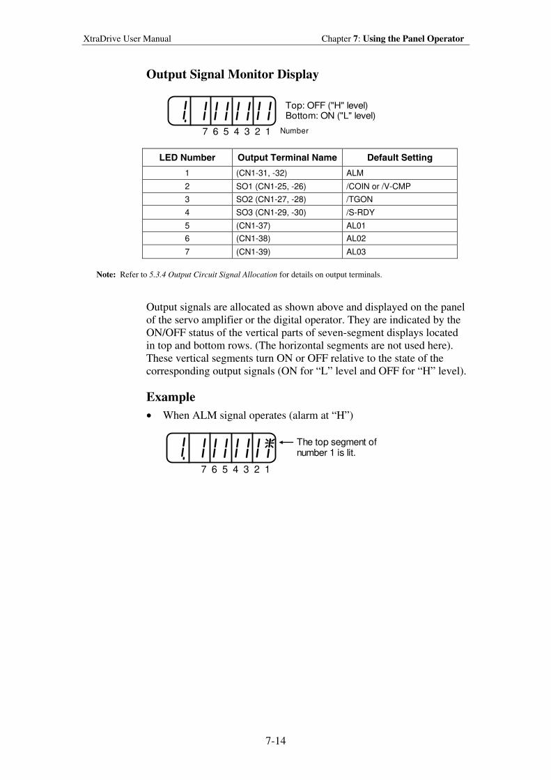
XtraDrive User Manual Chapter 7: Using the Panel Operator
7-14
Output Signal Monitor Display
7 6 5 4 3 2 1
Top: OFF ("H" level)Bottom: ON ("L" level)
Number
LED Number Output Terminal Name Default Setting
1 (CN1-31, -32) ALM
2 SO1 (CN1-25, -26) /COIN or /V-CMP
3 SO2 (CN1-27, -28) /TGON
4 SO3 (CN1-29, -30) /S-RDY
5 (CN1-37) AL01
6 (CN1-38) AL02
7 (CN1-39) AL03
Note: Refer to 5.3.4 Output Circuit Signal Allocation for details on output terminals.
Output signals are allocated as shown above and displayed on the panel
of the servo amplifier or the digital operator. They are indicated by the
ON/OFF status of the vertical parts of seven-segment displays located
in top and bottom rows. (The horizontal segments are not used here).
These vertical segments turn ON or OFF relative to the state of the
corresponding output signals (ON for “L” level and OFF for “H” level).
Example
• When ALM signal operates (alarm at “H”)
7 6 5 4 3 2 1
The top segment ofnumber 1 is lit.
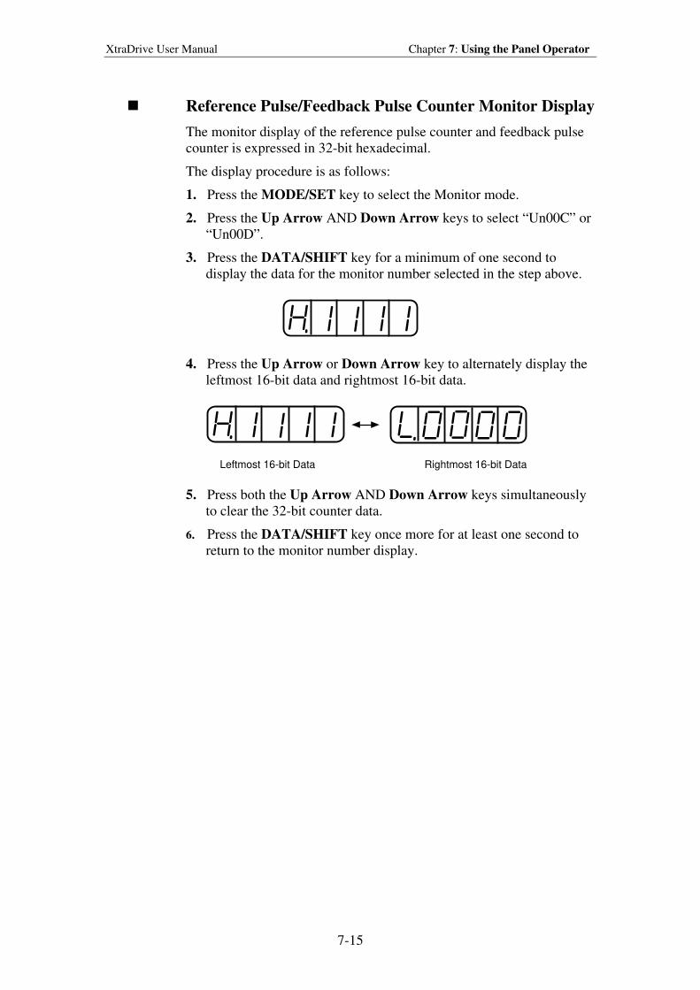
XtraDrive User Manual Chapter 7: Using the Panel Operator
7-15
Reference Pulse/Feedback Pulse Counter Monitor Display
The monitor display of the reference pulse counter and feedback pulse
counter is expressed in 32-bit hexadecimal.
The display procedure is as follows:
1. Press the MODE/SET key to select the Monitor mode.
2. Press the Up Arrow AND Down Arrow keys to select “Un00C” or
“Un00D”.
3. Press the DATA/SHIFT key for a minimum of one second to
display the data for the monitor number selected in the step above.
4. Press the Up Arrow or Down Arrow key to alternately display the
leftmost 16-bit data and rightmost 16-bit data.
Leftmost 16-bit Data Rightmost 16-bit Data
5. Press both the Up Arrow AND Down Arrow keys simultaneously
to clear the 32-bit counter data.
6. Press the DATA/SHIFT key once more for at least one second to
return to the monitor number display.
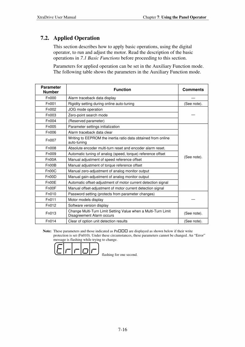
XtraDrive User Manual Chapter 7: Using the Panel Operator
7-16
7.2. Applied Operation
This section describes how to apply basic operations, using the digital
operator, to run and adjust the motor. Read the description of the basic
operations in 7.1 Basic Functions before proceeding to this section.
Parameters for applied operation can be set in the Auxiliary Function mode.
The following table shows the parameters in the Auxiliary Function mode.
Parameter Number
Function Comments
Fn000 Alarm traceback data display —
Fn001 Rigidity setting during online auto-tuning (See note).
Fn002 JOG mode operation
Fn003 Zero-point search mode
Fn004 (Reserved parameter)
—
Fn005 Parameter settings initialization
Fn006 Alarm traceback data clear
Fn007 Writing to EEPROM the inertia ratio data obtained from online auto-tuning
Fn008 Absolute encoder multi-turn reset and encoder alarm reset.
Fn009 Automatic tuning of analog (speed, torque) reference offset
Fn00A Manual adjustment of speed reference offset
Fn00B Manual adjustment of torque reference offset
Fn00C Manual zero-adjustment of analog monitor output
Fn00D Manual gain-adjustment of analog monitor output
Fn00E Automatic offset-adjustment of motor current detection signal
Fn00F Manual offset-adjustment of motor current detection signal
(See note).
Fn010 Password setting (protects from parameter changes)
Fn011 Motor models display
Fn012 Software version display
—
Fn013 Change Multi-Turn Limit Setting Value when a Multi-Turn Limit Disagreement Alarm occurs
(See note).
Fn014 Clear of option unit detection results (See note).
Note: These parameters and those indicated as Pn are displayed as shown below if their write
protection is set (Fn010). Under these circumstances, these parameters cannot be changed. An “Error”
message is flashing while trying to change.
flashing for one second.
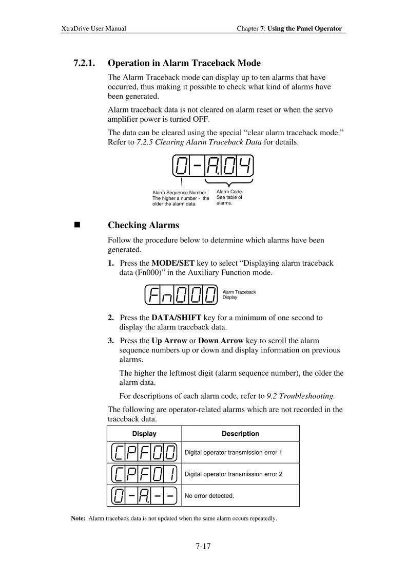
XtraDrive User Manual Chapter 7: Using the Panel Operator
7-17
7.2.1. Operation in Alarm Traceback Mode
The Alarm Traceback mode can display up to ten alarms that have
occurred, thus making it possible to check what kind of alarms have
been generated.
Alarm traceback data is not cleared on alarm reset or when the servo
amplifier power is turned OFF.
The data can be cleared using the special “clear alarm traceback mode.”
Refer to 7.2.5 Clearing Alarm Traceback Data for details.
Alarm Sequence Number. The higher a number - the older the alarm data.
Alarm Code.See table of alarms.
Checking Alarms
Follow the procedure below to determine which alarms have been
generated.
1. Press the MODE/SET key to select “Displaying alarm traceback
data (Fn000)” in the Auxiliary Function mode.
Alarm TracebackDisplay
2. Press the DATA/SHIFT key for a minimum of one second to
display the alarm traceback data.
3. Press the Up Arrow or Down Arrow key to scroll the alarm
sequence numbers up or down and display information on previous
alarms.
The higher the leftmost digit (alarm sequence number), the older the
alarm data.
For descriptions of each alarm code, refer to 9.2 Troubleshooting.
The following are operator-related alarms which are not recorded in the
traceback data.
Display Description
Digital operator transmission error 1
Digital operator transmission error 2
No error detected.
Note: Alarm traceback data is not updated when the same alarm occurs repeatedly.
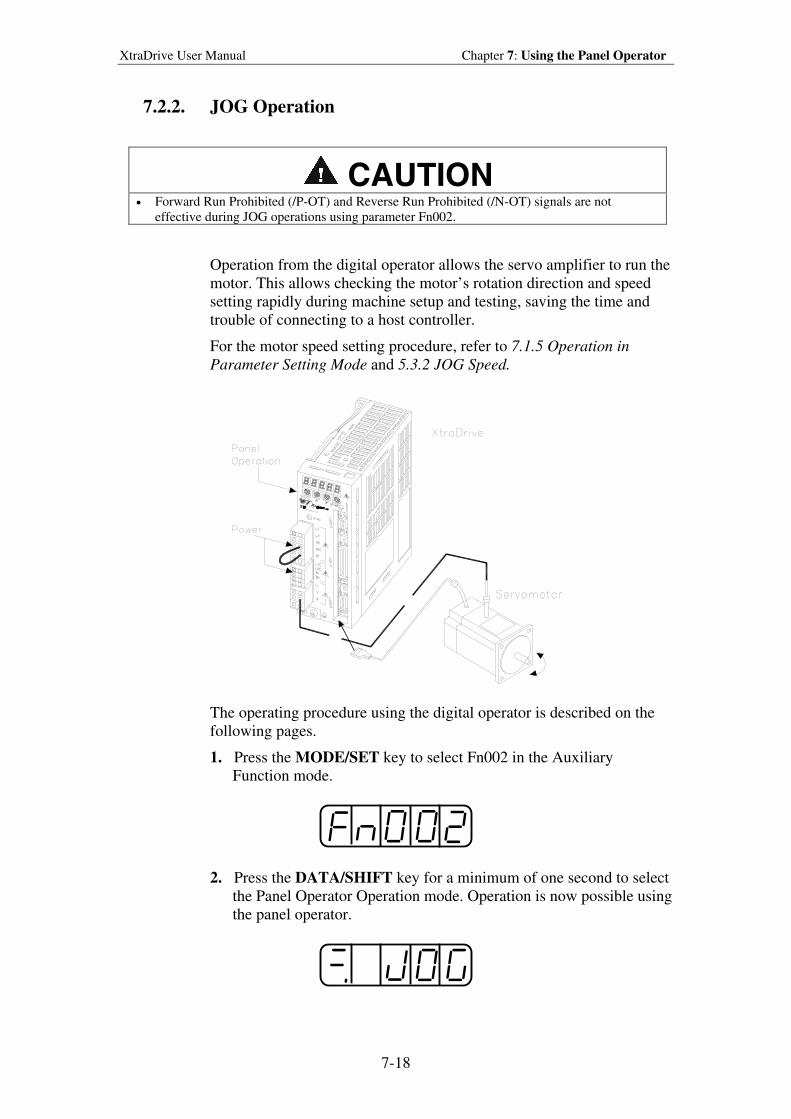
XtraDrive User Manual Chapter 7: Using the Panel Operator
7-18
7.2.2. JOG Operation
CAUTION • Forward Run Prohibited (/P-OT) and Reverse Run Prohibited (/N-OT) signals are not
effective during JOG operations using parameter Fn002.
Operation from the digital operator allows the servo amplifier to run the
motor. This allows checking the motor’s rotation direction and speed
setting rapidly during machine setup and testing, saving the time and
trouble of connecting to a host controller.
For the motor speed setting procedure, refer to 7.1.5 Operation in
Parameter Setting Mode and 5.3.2 JOG Speed.
The operating procedure using the digital operator is described on the
following pages.
1. Press the MODE/SET key to select Fn002 in the Auxiliary
Function mode.
2. Press the DATA/SHIFT key for a minimum of one second to select
the Panel Operator Operation mode. Operation is now possible using
the panel operator.
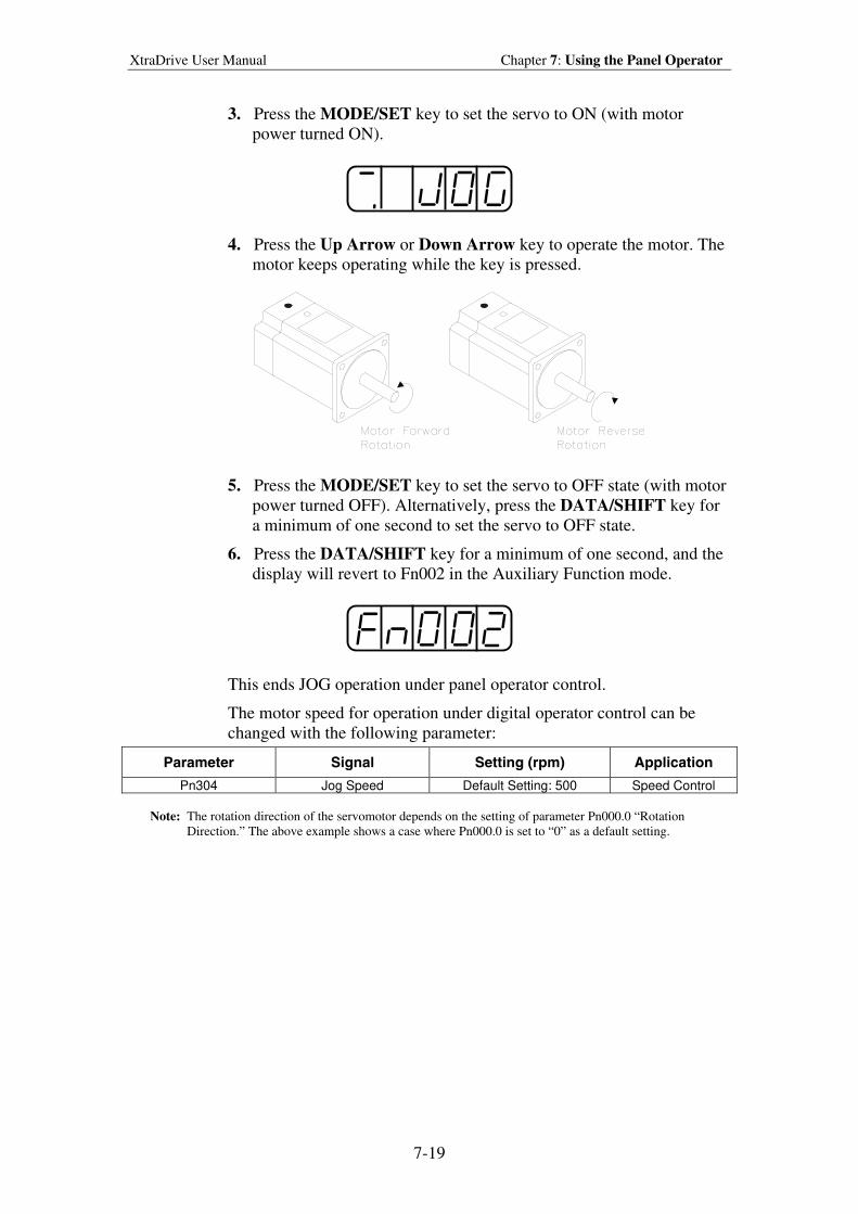
XtraDrive User Manual Chapter 7: Using the Panel Operator
7-19
3. Press the MODE/SET key to set the servo to ON (with motor
power turned ON).
4. Press the Up Arrow or Down Arrow key to operate the motor. The
motor keeps operating while the key is pressed.
5. Press the MODE/SET key to set the servo to OFF state (with motor
power turned OFF). Alternatively, press the DATA/SHIFT key for
a minimum of one second to set the servo to OFF state.
6. Press the DATA/SHIFT key for a minimum of one second, and the
display will revert to Fn002 in the Auxiliary Function mode.
This ends JOG operation under panel operator control.
The motor speed for operation under digital operator control can be
changed with the following parameter:
Parameter Signal Setting (rpm) Application
Pn304 Jog Speed Default Setting: 500 Speed Control
Note: The rotation direction of the servomotor depends on the setting of parameter Pn000.0 “Rotation
Direction.” The above example shows a case where Pn000.0 is set to “0” as a default setting.
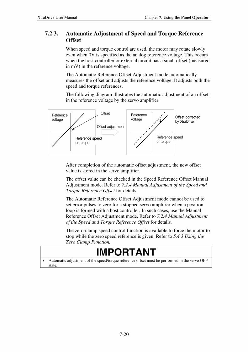
XtraDrive User Manual Chapter 7: Using the Panel Operator
7-20
7.2.3. Automatic Adjustment of Speed and Torque Reference
Offset
When speed and torque control are used, the motor may rotate slowly
even when 0V is specified as the analog reference voltage. This occurs
when the host controller or external circuit has a small offset (measured
in mV) in the reference voltage.
The Automatic Reference Offset Adjustment mode automatically
measures the offset and adjusts the reference voltage. It adjusts both the
speed and torque references.
The following diagram illustrates the automatic adjustment of an offset
in the reference voltage by the servo amplifier.
OffsetReferencevoltage
Referencevoltage
Reference speedor torque
Offset correctedby XtraDrive
Reference speedor torque
Offset adjustment
After completion of the automatic offset adjustment, the new offset
value is stored in the servo amplifier.
The offset value can be checked in the Speed Reference Offset Manual
Adjustment mode. Refer to 7.2.4 Manual Adjustment of the Speed and
Torque Reference Offset for details.
The Automatic Reference Offset Adjustment mode cannot be used to
set error pulses to zero for a stopped servo amplifier when a position
loop is formed with a host controller. In such cases, use the Manual
Reference Offset Adjustment mode. Refer to 7.2.4 Manual Adjustment
of the Speed and Torque Reference Offset for details.
The zero-clamp speed control function is available to force the motor to
stop while the zero speed reference is given. Refer to 5.4.3 Using the
Zero Clamp Function.
IMPORTANT
• Automatic adjustment of the speed/torque reference offset must be performed in the servo OFF
state.
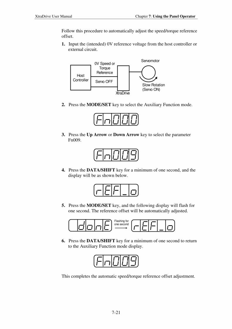
XtraDrive User Manual Chapter 7: Using the Panel Operator
7-21
Follow this procedure to automatically adjust the speed/torque reference
offset.
1. Input the (intended) 0V reference voltage from the host controller or
external circuit.
HostController
0V Speed orTorque
Reference
Servo OFFSlow Rotation(Servo ON)
XtraDrive
Servomotor
2. Press the MODE/SET key to select the Auxiliary Function mode.
3. Press the Up Arrow or Down Arrow key to select the parameter
Fn009.
4. Press the DATA/SHIFT key for a minimum of one second, and the
display will be as shown below.
5. Press the MODE/SET key, and the following display will flash for
one second. The reference offset will be automatically adjusted.
Flashing forone second
6. Press the DATA/SHIFT key for a minimum of one second to return
to the Auxiliary Function mode display.
This completes the automatic speed/torque reference offset adjustment.
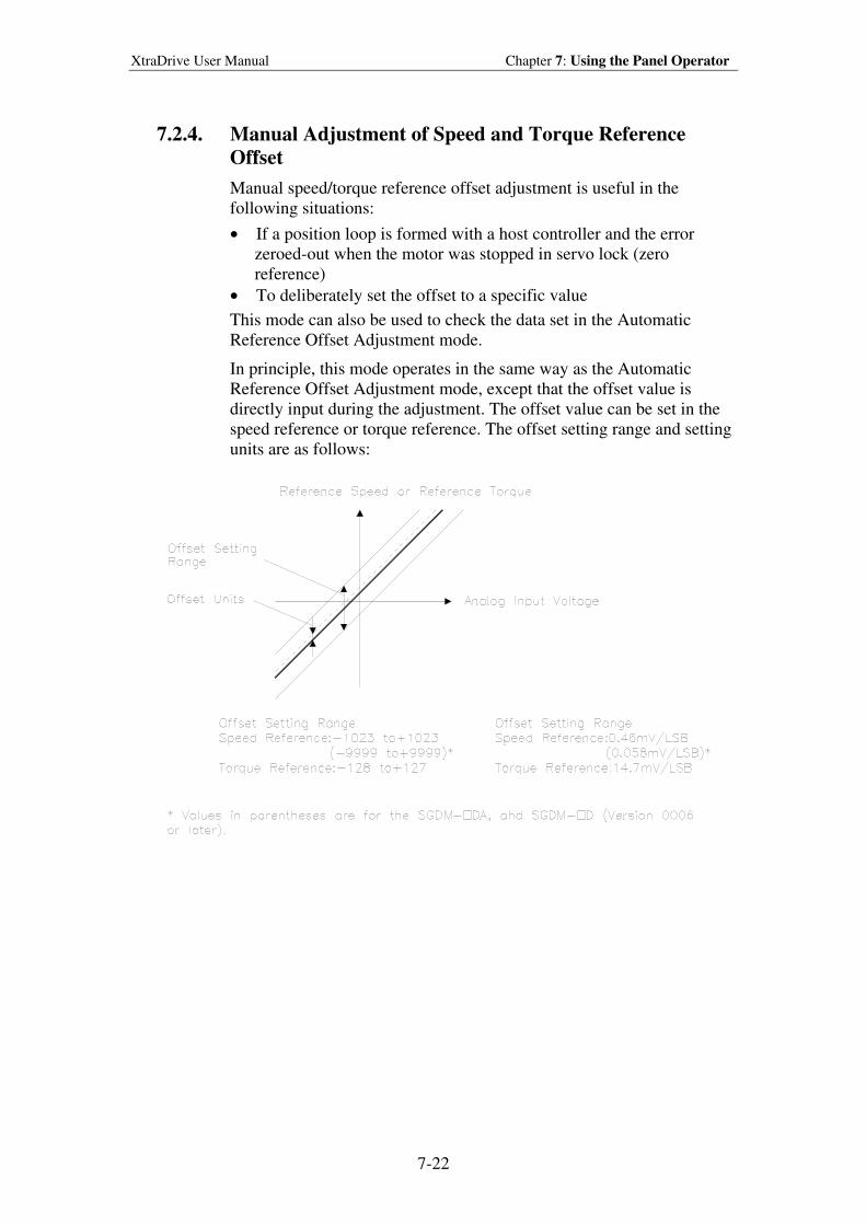
XtraDrive User Manual Chapter 7: Using the Panel Operator
7-22
7.2.4. Manual Adjustment of Speed and Torque Reference
Offset
Manual speed/torque reference offset adjustment is useful in the
following situations:
• If a position loop is formed with a host controller and the error
zeroed-out when the motor was stopped in servo lock (zero
reference)
• To deliberately set the offset to a specific value
This mode can also be used to check the data set in the Automatic
Reference Offset Adjustment mode.
In principle, this mode operates in the same way as the Automatic
Reference Offset Adjustment mode, except that the offset value is
directly input during the adjustment. The offset value can be set in the
speed reference or torque reference. The offset setting range and setting
units are as follows:
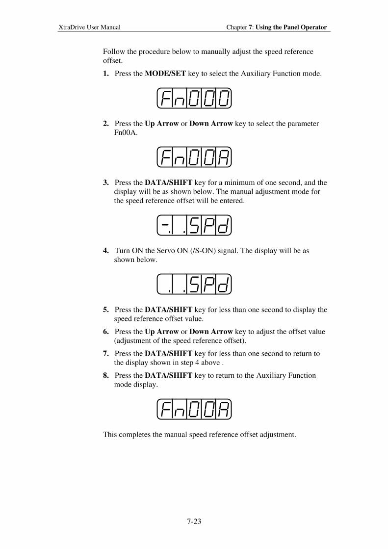
XtraDrive User Manual Chapter 7: Using the Panel Operator
7-23
Follow the procedure below to manually adjust the speed reference
offset.
1. Press the MODE/SET key to select the Auxiliary Function mode.
2. Press the Up Arrow or Down Arrow key to select the parameter
Fn00A.
3. Press the DATA/SHIFT key for a minimum of one second, and the
display will be as shown below. The manual adjustment mode for
the speed reference offset will be entered.
4. Turn ON the Servo ON (/S-ON) signal. The display will be as
shown below.
5. Press the DATA/SHIFT key for less than one second to display the
speed reference offset value.
6. Press the Up Arrow or Down Arrow key to adjust the offset value
(adjustment of the speed reference offset).
7. Press the DATA/SHIFT key for less than one second to return to
the display shown in step 4 above .
8. Press the DATA/SHIFT key to return to the Auxiliary Function
mode display.
This completes the manual speed reference offset adjustment.
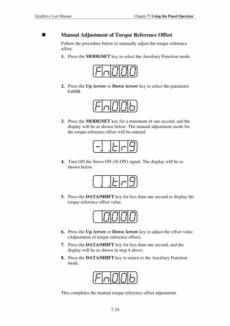
XtraDrive User Manual Chapter 7: Using the Panel Operator
7-24
Manual Adjustment of Torque Reference Offset
Follow the procedure below to manually adjust the torque reference
offset.
1. Press the MODE/SET key to select the Auxiliary Function mode.
2. Press the Up Arrow or Down Arrow key to select the parameter
Fn00B.
3. Press the MODE/SET key for a minimum of one second, and the
display will be as shown below. The manual adjustment mode for
the torque reference offset will be entered.
4. Turn ON the Servo ON (/S-ON) signal. The display will be as
shown below.
5. Press the DATA/SHIFT key for less than one second to display the
torque reference offset value.
6. Press the Up Arrow or Down Arrow key to adjust the offset value
(Adjustment of torque reference offset).
7. Press the DATA/SHIFT key for less than one second, and the
display will be as shown in step 4 above.
8. Press the DATA/SHIFT key to return to the Auxiliary Function
mode.
This completes the manual torque reference offset adjustment.
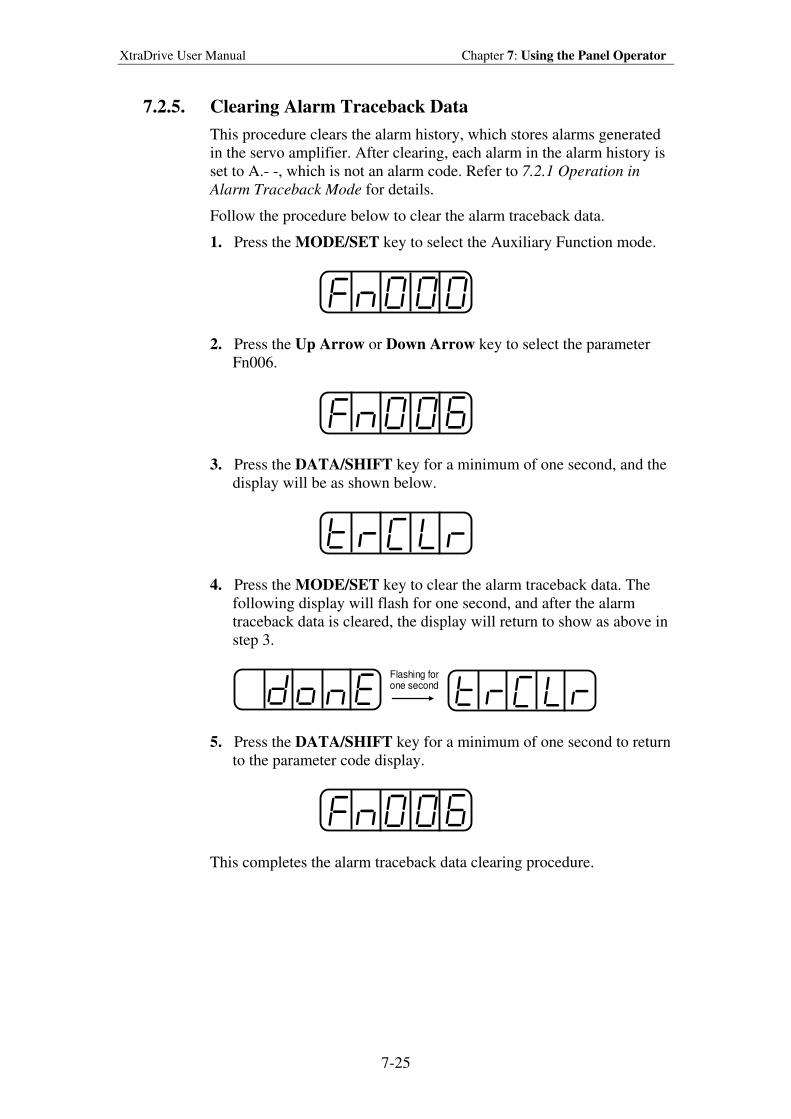
XtraDrive User Manual Chapter 7: Using the Panel Operator
7-25
7.2.5. Clearing Alarm Traceback Data
This procedure clears the alarm history, which stores alarms generated
in the servo amplifier. After clearing, each alarm in the alarm history is
set to A.- -, which is not an alarm code. Refer to 7.2.1 Operation in
Alarm Traceback Mode for details.
Follow the procedure below to clear the alarm traceback data.
1. Press the MODE/SET key to select the Auxiliary Function mode.
2. Press the Up Arrow or Down Arrow key to select the parameter
Fn006.
3. Press the DATA/SHIFT key for a minimum of one second, and the
display will be as shown below.
4. Press the MODE/SET key to clear the alarm traceback data. The
following display will flash for one second, and after the alarm
traceback data is cleared, the display will return to show as above in
step 3.
Flashing forone second
5. Press the DATA/SHIFT key for a minimum of one second to return
to the parameter code display.
This completes the alarm traceback data clearing procedure.
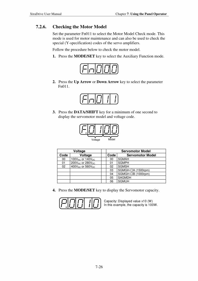
XtraDrive User Manual Chapter 7: Using the Panel Operator
7-26
7.2.6. Checking the Motor Model
Set the parameter Fn011 to select the Motor Model Check mode. This
mode is used for motor maintenance and can also be used to check the
special (Y-specification) codes of the servo amplifiers.
Follow the procedure below to check the motor model.
1. Press the MODE/SET key to select the Auxiliary Function mode.
2. Press the Up Arrow or Down Arrow key to select the parameter
Fn011.
3. Press the DATA/SHIFT key for a minimum of one second to
display the servomotor model and voltage code.
Voltage Model
Voltage Servomotor Model
Code Voltage Code Servomotor Model 00 100VAC or 140VDC 00 SGMAH
01 200VAC or 280VDC 01 SGMPH
02 400VAC or 560VDC 02 SGMSH 03 SGMGH-A (1500rpm) 04 SGMGH-B (1000rpm) 05 SAGMDH 06 SGMUH
4. Press the MODE/SET key to display the Servomotor capacity.
Capacity: Displayed value x10 (W)In this example, the capacity is 100W.
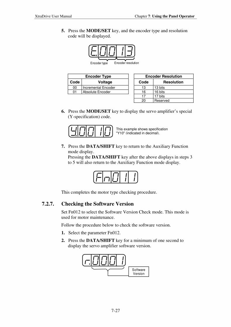
XtraDrive User Manual Chapter 7: Using the Panel Operator
7-27
5. Press the MODE/SET key, and the encoder type and resolution
code will be displayed.
Encoder type Encoder resolution
Encoder Type Encoder Resolution
Code Voltage Code Resolution
00 Incremental Encoder 13 13 bits
01 Absolute Encoder 16 16 bits
17 17 bits
20 Reserved
6. Press the MODE/SET key to display the servo amplifier’s special
(Y-specification) code.
This example shows specification " Y10" (indicated in decimal).
7. Press the DATA/SHIFT key to return to the Auxiliary Function
mode display.
Pressing the DATA/SHIFT key after the above displays in steps 3
to 5 will also return to the Auxiliary Function mode display.
This completes the motor type checking procedure.
7.2.7. Checking the Software Version
Set Fn012 to select the Software Version Check mode. This mode is
used for motor maintenance.
Follow the procedure below to check the software version.
1. Select the parameter Fn012.
2. Press the DATA/SHIFT key for a minimum of one second to
display the servo amplifier software version.
SoftwareVersion
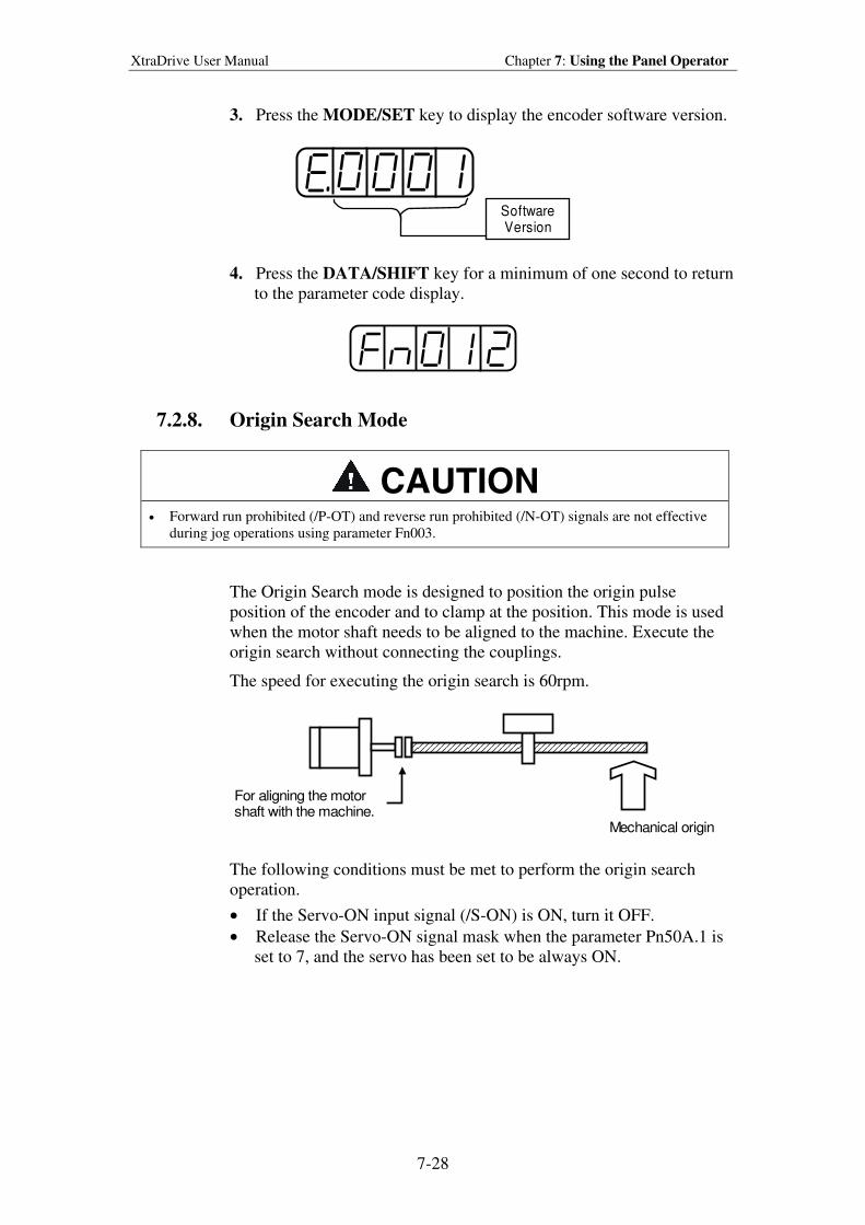
XtraDrive User Manual Chapter 7: Using the Panel Operator
7-28
3. Press the MODE/SET key to display the encoder software version.
SoftwareVersion
4. Press the DATA/SHIFT key for a minimum of one second to return
to the parameter code display.
7.2.8. Origin Search Mode
CAUTION • Forward run prohibited (/P-OT) and reverse run prohibited (/N-OT) signals are not effective
during jog operations using parameter Fn003.
The Origin Search mode is designed to position the origin pulse
position of the encoder and to clamp at the position. This mode is used
when the motor shaft needs to be aligned to the machine. Execute the
origin search without connecting the couplings.
The speed for executing the origin search is 60rpm.
Mechanical origin
For aligning the motorshaft with the machine.
The following conditions must be met to perform the origin search
operation.
• If the Servo-ON input signal (/S-ON) is ON, turn it OFF.
• Release the Servo-ON signal mask when the parameter Pn50A.1 is
set to 7, and the servo has been set to be always ON.
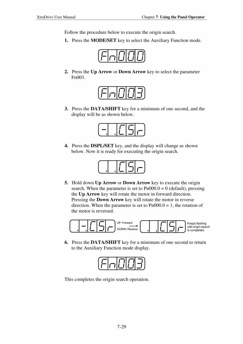
XtraDrive User Manual Chapter 7: Using the Panel Operator
7-29
Follow the procedure below to execute the origin search.
1. Press the MODE/SET key to select the Auxiliary Function mode.
2. Press the Up Arrow or Down Arrow key to select the parameter
Fn003.
3. Press the DATA/SHIFT key for a minimum of one second, and the
display will be as shown below.
4. Press the DSPL/SET key, and the display will change as shown
below. Now it is ready for executing the origin search.
5. Hold down Up Arrow or Down Arrow key to execute the origin
search. When the parameter is set to Pn000.0 = 0 (default), pressing
the Up Arrow key will rotate the motor in forward direction.
Pressing the Down Arrow key will rotate the motor in reverse
direction. When the parameter is set to Pn000.0 = 1, the rotation of
the motor is reversed.
UP: Forward
DOWN: Reverse
Keeps flashinguntil origin searchis completed.
6. Press the DATA/SHIFT key for a minimum of one second to return
to the Auxiliary Function mode display.
This completes the origin search operation.
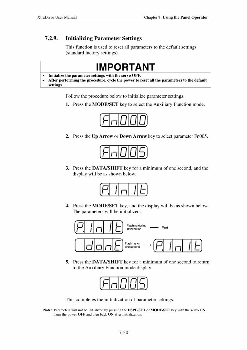
XtraDrive User Manual Chapter 7: Using the Panel Operator
7-30
7.2.9. Initializing Parameter Settings
This function is used to reset all parameters to the default settings
(standard factory settings).
IMPORTANT
• Initialize the parameter settings with the servo OFF.
• After performing the procedure, cycle the power to reset all the parameters to the default
settings.
Follow the procedure below to initialize parameter settings.
1. Press the MODE/SET key to select the Auxiliary Function mode.
2. Press the Up Arrow or Down Arrow key to select parameter Fn005.
3. Press the DATA/SHIFT key for a minimum of one second, and the
display will be as shown below.
4. Press the MODE/SET key, and the display will be as shown below.
The parameters will be initialized.
Flashing duringinitialization End
Flashing forone second
5. Press the DATA/SHIFT key for a minimum of one second to return
to the Auxiliary Function mode display.
This completes the initialization of parameter settings.
Note: Parameters will not be initialized by pressing the DSPL/SET or MODE/SET key with the servo ON.
Turn the power OFF and then back ON after initialization.
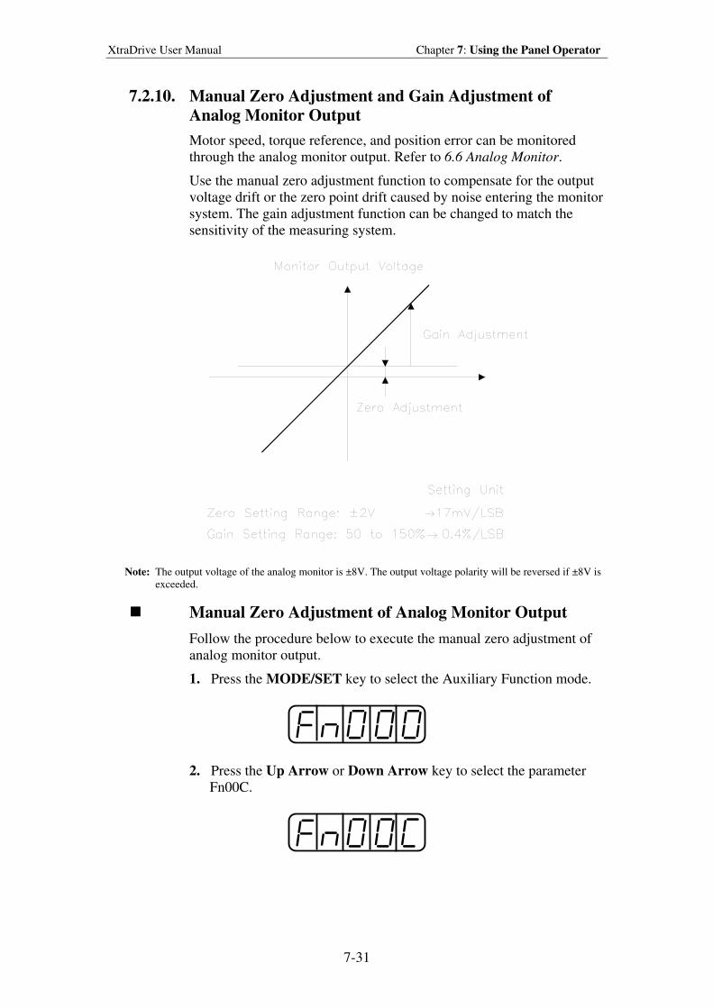
XtraDrive User Manual Chapter 7: Using the Panel Operator
7-31
7.2.10. Manual Zero Adjustment and Gain Adjustment of
Analog Monitor Output
Motor speed, torque reference, and position error can be monitored
through the analog monitor output. Refer to 6.6 Analog Monitor.
Use the manual zero adjustment function to compensate for the output
voltage drift or the zero point drift caused by noise entering the monitor
system. The gain adjustment function can be changed to match the
sensitivity of the measuring system.
Note: The output voltage of the analog monitor is ±8V. The output voltage polarity will be reversed if ±8V is
exceeded.
Manual Zero Adjustment of Analog Monitor Output
Follow the procedure below to execute the manual zero adjustment of
analog monitor output.
1. Press the MODE/SET key to select the Auxiliary Function mode.
2. Press the Up Arrow or Down Arrow key to select the parameter
Fn00C.
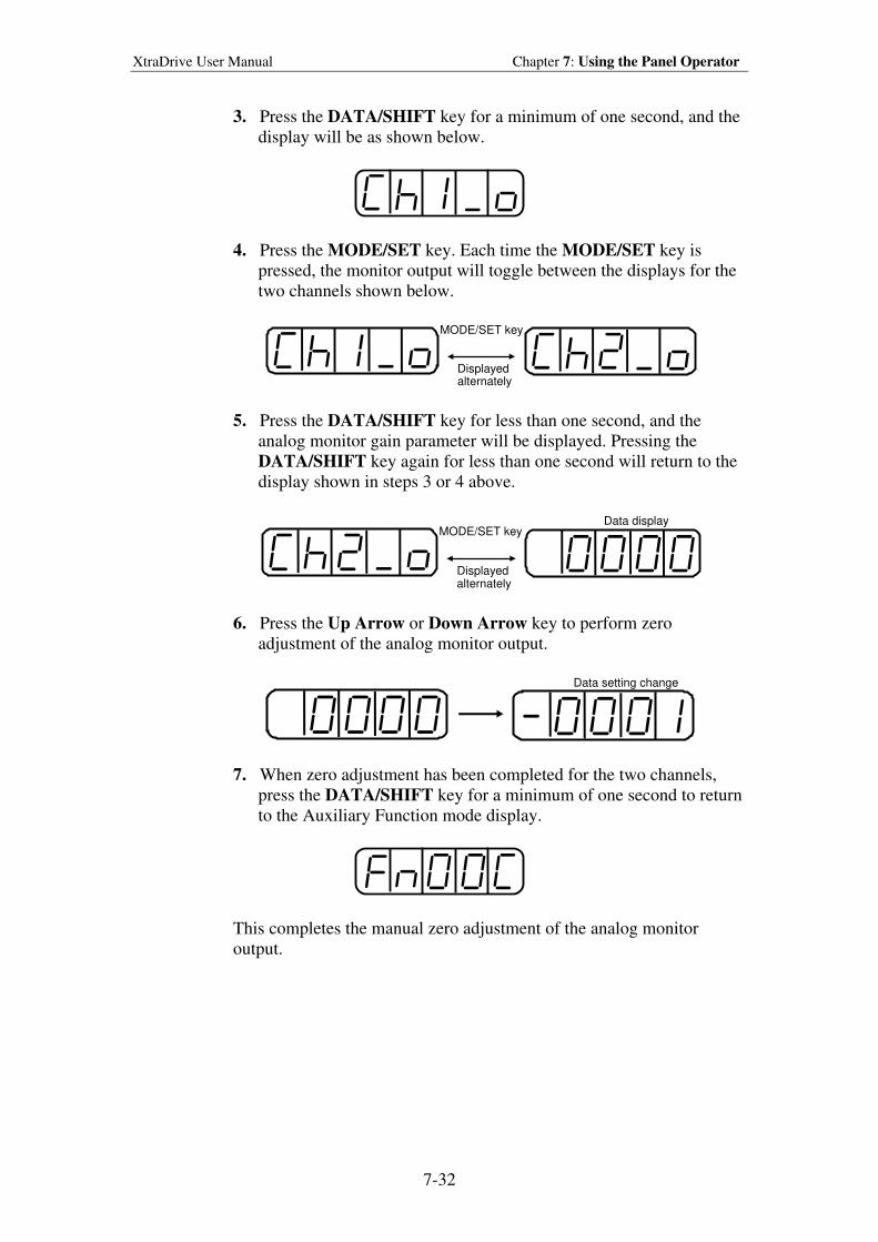
XtraDrive User Manual Chapter 7: Using the Panel Operator
7-32
3. Press the DATA/SHIFT key for a minimum of one second, and the
display will be as shown below.
4. Press the MODE/SET key. Each time the MODE/SET key is
pressed, the monitor output will toggle between the displays for the
two channels shown below.
MODE/SET key
Displayed alternately
5. Press the DATA/SHIFT key for less than one second, and the
analog monitor gain parameter will be displayed. Pressing the
DATA/SHIFT key again for less than one second will return to the
display shown in steps 3 or 4 above.
MODE/SET key
Displayed alternately
Data display
6. Press the Up Arrow or Down Arrow key to perform zero
adjustment of the analog monitor output.
Data setting change
7. When zero adjustment has been completed for the two channels,
press the DATA/SHIFT key for a minimum of one second to return
to the Auxiliary Function mode display.
This completes the manual zero adjustment of the analog monitor
output.
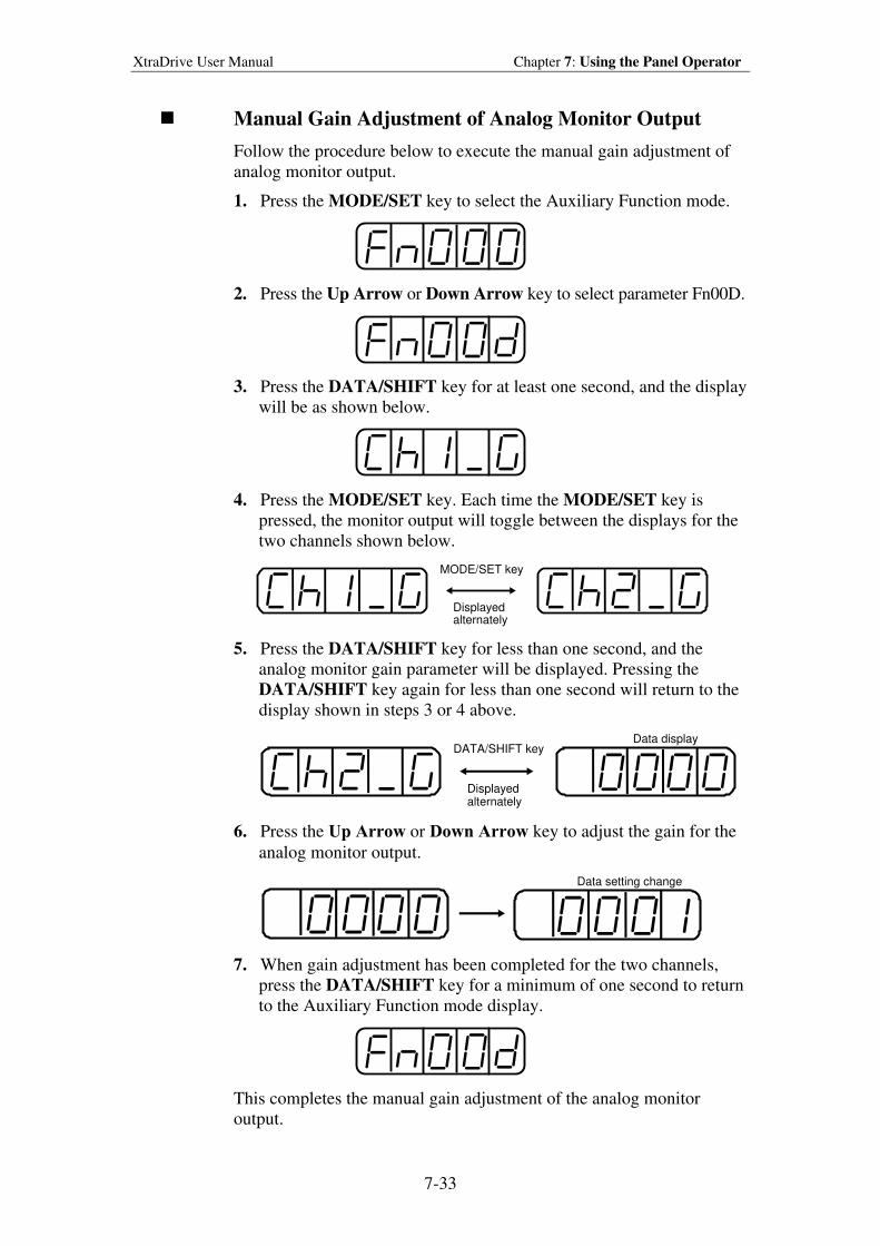
XtraDrive User Manual Chapter 7: Using the Panel Operator
7-33
Manual Gain Adjustment of Analog Monitor Output
Follow the procedure below to execute the manual gain adjustment of
analog monitor output.
1. Press the MODE/SET key to select the Auxiliary Function mode.
2. Press the Up Arrow or Down Arrow key to select parameter Fn00D.
3. Press the DATA/SHIFT key for at least one second, and the display
will be as shown below.
4. Press the MODE/SET key. Each time the MODE/SET key is
pressed, the monitor output will toggle between the displays for the
two channels shown below.
MODE/SET key
Displayed alternately
5. Press the DATA/SHIFT key for less than one second, and the
analog monitor gain parameter will be displayed. Pressing the
DATA/SHIFT key again for less than one second will return to the
display shown in steps 3 or 4 above.
DATA/SHIFT key
Displayed alternately
Data display
6. Press the Up Arrow or Down Arrow key to adjust the gain for the
analog monitor output.
Data setting change
7. When gain adjustment has been completed for the two channels,
press the DATA/SHIFT key for a minimum of one second to return
to the Auxiliary Function mode display.
This completes the manual gain adjustment of the analog monitor
output.
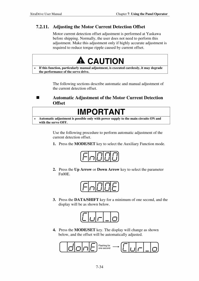
XtraDrive User Manual Chapter 7: Using the Panel Operator
7-34
7.2.11. Adjusting the Motor Current Detection Offset
Motor current detection offset adjustment is performed at Yaskawa
before shipping. Normally, the user does not need to perform this
adjustment. Make this adjustment only if highly accurate adjustment is
required to reduce torque ripple caused by current offset.
CAUTION • If this function, particularly manual adjustment, is executed carelessly, it may degrade
the performance of the servo drive.
The following sections describe automatic and manual adjustment of
the current detection offset.
Automatic Adjustment of the Motor Current Detection
Offset
IMPORTANT
• Automatic adjustment is possible only with power supply to the main circuits ON and
with the servo OFF.
Use the following procedure to perform automatic adjustment of the
current detection offset.
1. Press the MODE/SET key to select the Auxiliary Function mode.
2. Press the Up Arrow or Down Arrow key to select the parameter
Fn00E.
3. Press the DATA/SHIFT key for a minimum of one second, and the
display will be as shown below.
4. Press the MODE/SET key. The display will change as shown
below, and the offset will be automatically adjusted.
Flashing forone second
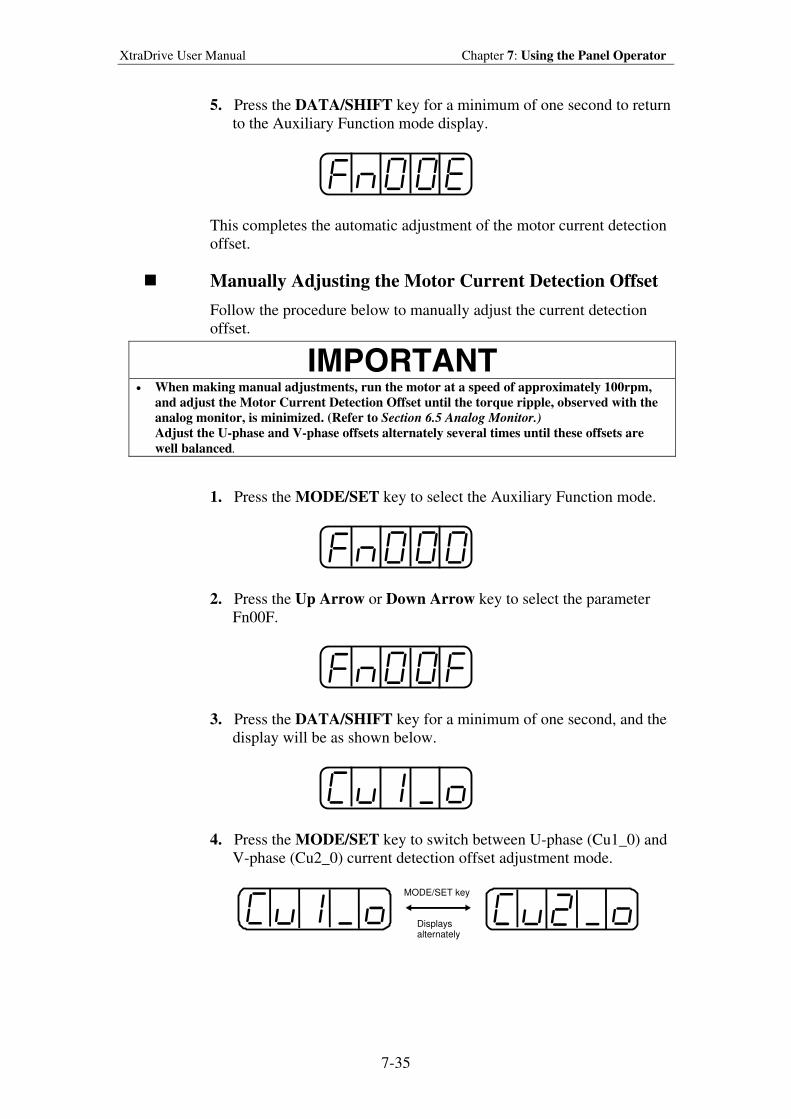
XtraDrive User Manual Chapter 7: Using the Panel Operator
7-35
5. Press the DATA/SHIFT key for a minimum of one second to return
to the Auxiliary Function mode display.
This completes the automatic adjustment of the motor current detection
offset.
Manually Adjusting the Motor Current Detection Offset
Follow the procedure below to manually adjust the current detection
offset.
IMPORTANT
• When making manual adjustments, run the motor at a speed of approximately 100rpm,
and adjust the Motor Current Detection Offset until the torque ripple, observed with the
analog monitor, is minimized. (Refer to Section 6.5 Analog Monitor.)
Adjust the U-phase and V-phase offsets alternately several times until these offsets are
well balanced.
1. Press the MODE/SET key to select the Auxiliary Function mode.
2. Press the Up Arrow or Down Arrow key to select the parameter
Fn00F.
3. Press the DATA/SHIFT key for a minimum of one second, and the
display will be as shown below.
4. Press the MODE/SET key to switch between U-phase (Cu1_0) and
V-phase (Cu2_0) current detection offset adjustment mode.
MODE/SET key
Displays alternately
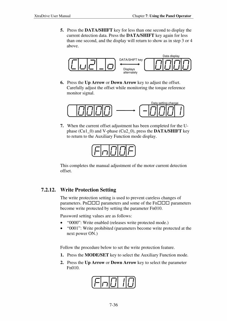
XtraDrive User Manual Chapter 7: Using the Panel Operator
7-36
5. Press the DATA/SHIFT key for less than one second to display the
current detection data. Press the DATA/SHIFT key again for less
than one second, and the display will return to show as in step 3 or 4
above.
DATA/SHIFT key
Displays alternately
Data display
6. Press the Up Arrow or Down Arrow key to adjust the offset.
Carefully adjust the offset while monitoring the torque reference
monitor signal.
Data setting change
7. When the current offset adjustment has been completed for the U-
phase (Cu1_0) and V-phase (Cu2_0), press the DATA/SHIFT key
to return to the Auxiliary Function mode display.
This completes the manual adjustment of the motor current detection
offset.
7.2.12. Write Protection Setting
The write protection setting is used to prevent careless changes of
parameters. Pn parameters and some of the Fn parameters
become write protected by setting the parameter Fn010.
Password setting values are as follows:
• “0000”: Write enabled (releases write protected mode.)
• “0001”: Write prohibited (parameters become write protected at the
next power ON.)
Follow the procedure below to set the write protection feature.
1. Press the MODE/SET key to select the Auxiliary Function mode.
2. Press the Up Arrow or Down Arrow key to select the parameter
Fn010.
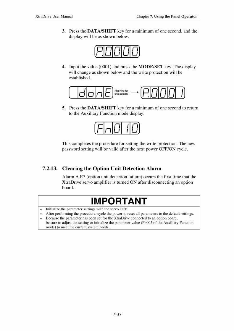
XtraDrive User Manual Chapter 7: Using the Panel Operator
7-37
3. Press the DATA/SHIFT key for a minimum of one second, and the
display will be as shown below.
4. Input the value (0001) and press the MODE/SET key. The display
will change as shown below and the write protection will be
established.
Flashing forone second
5. Press the DATA/SHIFT key for a minimum of one second to return
to the Auxiliary Function mode display.
This completes the procedure for setting the write protection. The new
password setting will be valid after the next power OFF/ON cycle.
7.2.13. Clearing the Option Unit Detection Alarm
Alarm A.E7 (option unit detection failure) occurs the first time that the
XtraDrive servo amplifier is turned ON after disconnecting an option
board.
IMPORTANT
• Initialize the parameter settings with the servo OFF.
• After performing the procedure, cycle the power to reset all parameters to the default settings.
• Because the parameter has been set for the XtraDrive connected to an option board,
be sure to adjust the setting or initialize the parameter value (Fn005 of the Auxiliary Function
mode) to meet the current system needs.
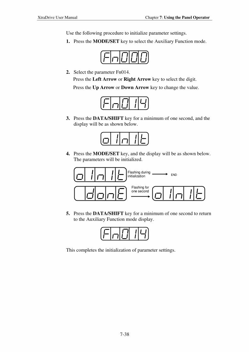
XtraDrive User Manual Chapter 7: Using the Panel Operator
7-38
Use the following procedure to initialize parameter settings.
1. Press the MODE/SET key to select the Auxiliary Function mode.
2. Select the parameter Fn014.
Press the Left Arrow or Right Arrow key to select the digit.
Press the Up Arrow or Down Arrow key to change the value.
3. Press the DATA/SHIFT key for a minimum of one second, and the
display will be as shown below.
4. Press the MODE/SET key, and the display will be as shown below.
The parameters will be initialized.
Flashing duringinitialization END
Flashing forone second
5. Press the DATA/SHIFT key for a minimum of one second to return
to the Auxiliary Function mode display.
This completes the initialization of parameter settings.
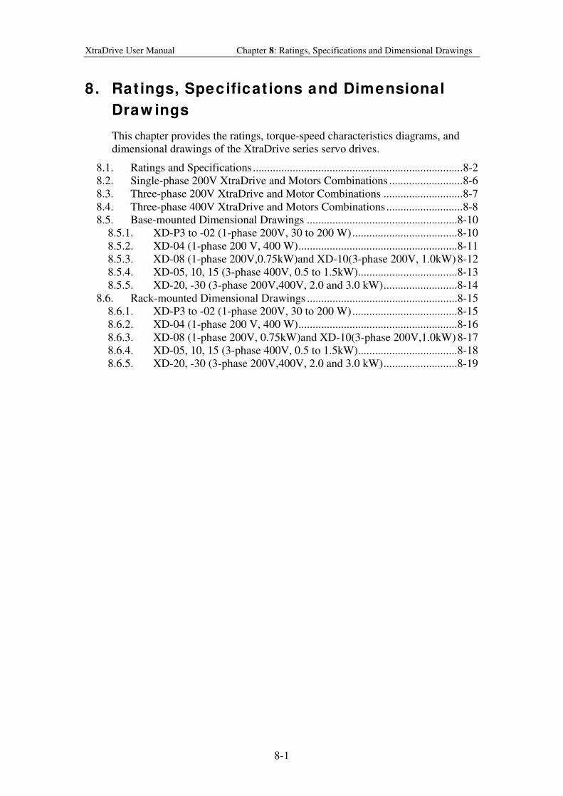
XtraDrive User Manual Chapter 8: Ratings, Specifications and Dimensional Drawings
8-1
8. Rat ings, Specificat ions and Dimensional
Draw ings
This chapter provides the ratings, torque-speed characteristics diagrams, and
dimensional drawings of the XtraDrive series servo drives.
8.1. Ratings and Specifications..........................................................................8-2
8.2. Single-phase 200V XtraDrive and Motors Combinations ..........................8-6
8.3. Three-phase 200V XtraDrive and Motor Combinations ............................8-7
8.4. Three-phase 400V XtraDrive and Motors Combinations...........................8-8
8.5. Base-mounted Dimensional Drawings .....................................................8-10
8.5.1. XD-P3 to -02 (1-phase 200V, 30 to 200 W).....................................8-10
8.5.2. XD-04 (1-phase 200 V, 400 W)........................................................8-11
8.5.3. XD-08 (1-phase 200V,0.75kW)and XD-10(3-phase 200V, 1.0kW) 8-12
8.5.4. XD-05, 10, 15 (3-phase 400V, 0.5 to 1.5kW)...................................8-13
8.5.5. XD-20, -30 (3-phase 200V,400V, 2.0 and 3.0 kW)..........................8-14
8.6. Rack-mounted Dimensional Drawings .....................................................8-15
8.6.1. XD-P3 to -02 (1-phase 200V, 30 to 200 W).....................................8-15
8.6.2. XD-04 (1-phase 200 V, 400 W)........................................................8-16
8.6.3. XD-08 (1-phase 200V, 0.75kW)and XD-10(3-phase 200V,1.0kW) 8-17
8.6.4. XD-05, 10, 15 (3-phase 400V, 0.5 to 1.5kW)...................................8-18
8.6.5. XD-20, -30 (3-phase 200V,400V, 2.0 and 3.0 kW)..........................8-19
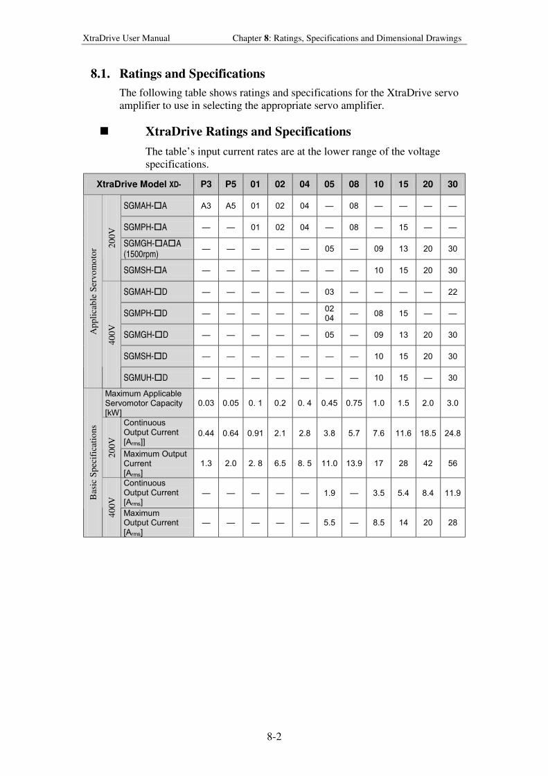
XtraDrive User Manual Chapter 8: Ratings, Specifications and Dimensional Drawings
8-2
8.1. Ratings and Specifications
The following table shows ratings and specifications for the XtraDrive servo
amplifier to use in selecting the appropriate servo amplifier.
! XtraDrive Ratings and Specifications
The table’s input current rates are at the lower range of the voltage
specifications.
XtraDrive Model XD- P3 P5 01 02 04 05 08 10 15 20 30
SGMAH-#A A3 A5 01 02 04 08
SGMPH-#A 01 02 04 08 15
SGMGH-#A#A (1500rpm)
05 09 13 20 30 20
0V
SGMSH-#A 10 15 20 30
SGMAH-#D 03 22
SGMPH-#D 02 04
08 15
SGMGH-#D 05 09 13 20 30
SGMSH-#D 10 15 20 30
Ap
pli
cab
le S
ervo
mo
tor
40
0V
SGMUH-#D 10 15 30
Maximum Applicable Servomotor Capacity [kW]
0.03 0.05 0. 1 0.2 0. 4 0.45 0.75 1.0 1.5 2.0 3.0
Continuous Output Current [Arms]]
0.44 0.64 0.91 2.1 2.8 3.8 5.7 7.6 11.6 18.5 24.8
20
0V
Maximum Output Current [Arms]
1.3 2.0 2. 8 6.5 8. 5 11.0 13.9 17 28 42 56
Continuous Output Current [Arms]
1.9 3.5 5.4 8.4 11.9
Bas
ic S
pec
ific
atio
ns
40
0V
Maximum Output Current [Arms]
5.5 8.5 14 20 28
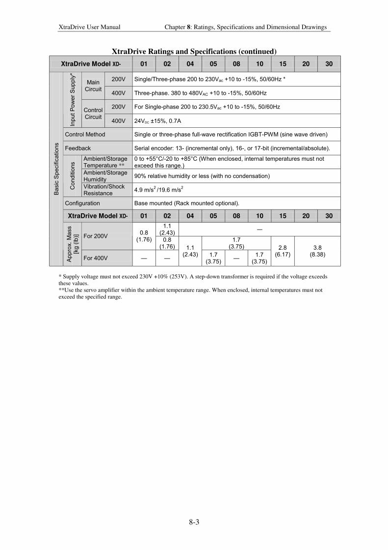
XtraDrive User Manual Chapter 8: Ratings, Specifications and Dimensional Drawings
8-3
XtraDrive Ratings and Specifications (continued)
XtraDrive Model XD- 01 02 04 05 08 10 15 20 30
200V Single/Three-phase 200 to 230Vac +10 to -15%, 50/60Hz * Main
Circuit 400V Three-phase. 380 to 480VAC +10 to -15%, 50/60Hz
200V For Single-phase 200 to 230.5Vac +10 to -15%, 50/60Hz
Inp
ut
Po
we
r S
up
ply
*
Control Circuit
400V 24VDC ±15%, 0.7A
Control Method Single or three-phase full-wave rectification IGBT-PWM (sine wave driven)
Feedback Serial encoder: 13- (incremental only), 16-, or 17-bit (incremental/absolute).
Ambient/Storage Temperature **
0 to +55°C/-20 to +85°C (When enclosed, internal temperatures must not exceed this range.)
Ambient/Storage Humidity
90% relative humidity or less (with no condensation)
Co
nd
itio
ns
Vibration/Shock Resistance
4.9 m/s2 /19.6 m/s
2
Configuration Base mounted (Rack mounted optional).
XtraDrive Model XD- 01 02 04 05 08 10 15 20 30
1.1 (2.43)
For 200V 0.8
(1.76) 0.8 (1.76)
1.7 (3.75)
Ba
sic
Sp
ecific
atio
ns
Ap
pro
x.
Ma
ss
[kg
(lb
)]
For 400V
1.1 (2.43) 1.7
(3.75)
1.7 (3.75)
2.8 (6.17)
3.8 (8.38)
* Supply voltage must not exceed 230V +10% (253V). A step-down transformer is required if the voltage exceeds
these values.
**Use the servo amplifier within the ambient temperature range. When enclosed, internal temperatures must not
exceed the specified range.
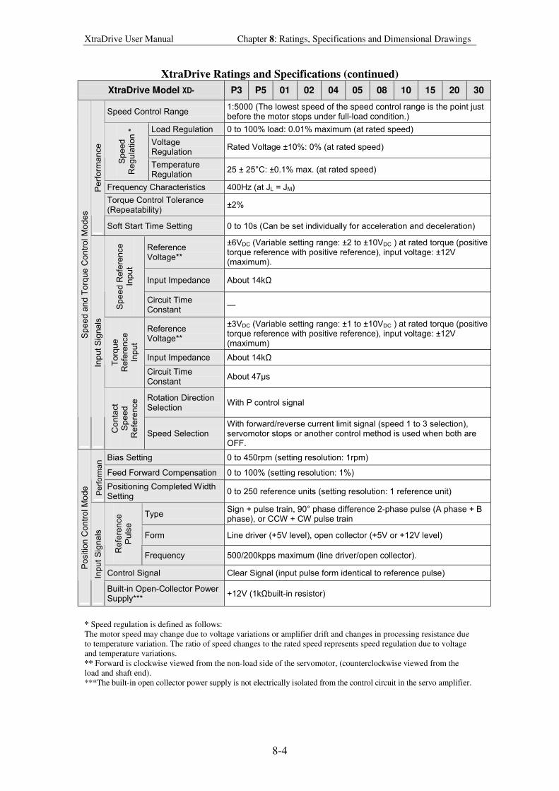
XtraDrive User Manual Chapter 8: Ratings, Specifications and Dimensional Drawings
8-4
XtraDrive Ratings and Specifications (continued)
XtraDrive Model XD- P3 P5 01 02 04 05 08 10 15 20 30
Speed Control Range 1:5000 (The lowest speed of the speed control range is the point just before the motor stops under full-load condition.)
Load Regulation 0 to 100% load: 0.01% maximum (at rated speed)
Voltage Regulation
Rated Voltage ±10%: 0% (at rated speed)
Sp
ee
d
Re
gu
latio
n *
Temperature Regulation
25 ± 25°C: ±0.1% max. (at rated speed)
Frequency Characteristics 400Hz (at JL = JM)
Torque Control Tolerance (Repeatability)
±2%
Pe
rfo
rma
nce
Soft Start Time Setting 0 to 10s (Can be set individually for acceleration and deceleration)
Reference Voltage**
±6VDC (Variable setting range: ±2 to ±10VDC ) at rated torque (positive torque reference with positive reference), input voltage: ±12V (maximum).
Input Impedance About 14kΩ
Sp
ee
d R
efe
rence
In
pu
t
Circuit Time Constant
Reference Voltage**
±3VDC (Variable setting range: ±1 to ±10VDC ) at rated torque (positive torque reference with positive reference), input voltage: ±12V (maximum)
Input Impedance About 14kΩ
To
rqu
e
Re
fere
nce
In
pu
t
Circuit Time Constant
About 47µs
Rotation Direction Selection
With P control signal
Sp
ee
d a
nd
To
rque
Co
ntr
ol M
od
es
Inp
ut
Sig
na
ls
Co
nta
ct
Sp
ee
d
Re
fere
nce
Speed Selection With forward/reverse current limit signal (speed 1 to 3 selection), servomotor stops or another control method is used when both are OFF.
Bias Setting 0 to 450rpm (setting resolution: 1rpm)
Feed Forward Compensation 0 to 100% (setting resolution: 1%)
Perf
orm
an
Positioning Completed Width Setting
0 to 250 reference units (setting resolution: 1 reference unit)
Type Sign + pulse train, 90° phase difference 2-phase pulse (A phase + B phase), or CCW + CW pulse train
Form Line driver (+5V level), open collector (+5V or +12V level)
Re
fere
nce
P
uls
e
Frequency 500/200kpps maximum (line driver/open collector).
Control Signal Clear Signal (input pulse form identical to reference pulse)
Po
sitio
n C
on
trol M
od
e
Inp
ut
Sig
na
ls
Built-in Open-Collector Power Supply***
+12V (1kΩbuilt-in resistor)
* Speed regulation is defined as follows:
The motor speed may change due to voltage variations or amplifier drift and changes in processing resistance due
to temperature variation. The ratio of speed changes to the rated speed represents speed regulation due to voltage
and temperature variations.
** Forward is clockwise viewed from the non-load side of the servomotor, (counterclockwise viewed from the
load and shaft end).
***The built-in open collector power supply is not electrically isolated from the control circuit in the servo amplifier.
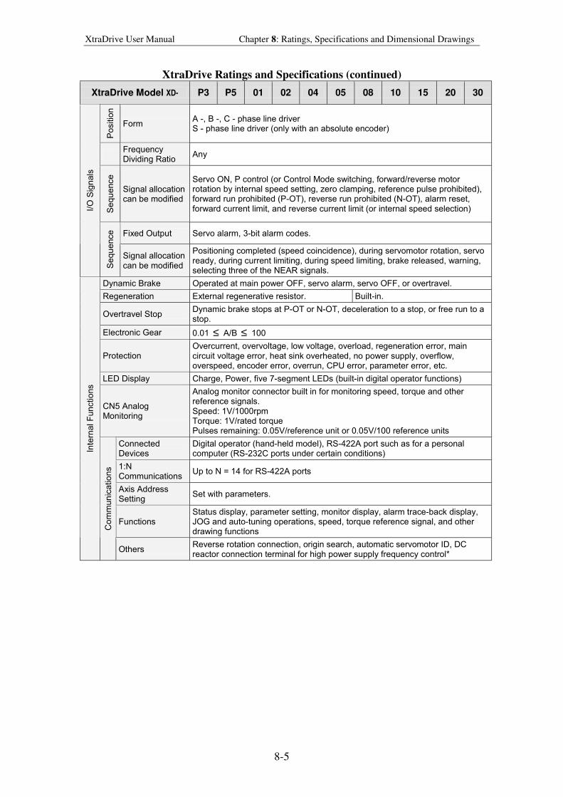
XtraDrive User Manual Chapter 8: Ratings, Specifications and Dimensional Drawings
8-5
XtraDrive Ratings and Specifications (continued)
XtraDrive Model XD- P3 P5 01 02 04 05 08 10 15 20 30
Po
sitio
n
Form A -, B -, C - phase line driver S - phase line driver (only with an absolute encoder)
Frequency Dividing Ratio
Any
Se
qu
ence
Signal allocation can be modified
Servo ON, P control (or Control Mode switching, forward/reverse motor rotation by internal speed setting, zero clamping, reference pulse prohibited), forward run prohibited (P-OT), reverse run prohibited (N-OT), alarm reset, forward current limit, and reverse current limit (or internal speed selection)
Fixed Output Servo alarm, 3-bit alarm codes.
I/O
Sig
nals
Se
qu
ence
Signal allocation can be modified
Positioning completed (speed coincidence), during servomotor rotation, servo ready, during current limiting, during speed limiting, brake released, warning, selecting three of the NEAR signals.
Dynamic Brake Operated at main power OFF, servo alarm, servo OFF, or overtravel.
Regeneration External regenerative resistor. Built-in.
Overtravel Stop Dynamic brake stops at P-OT or N-OT, deceleration to a stop, or free run to a stop.
Electronic Gear 0.01 ≤ A/B ≤ 100
Protection Overcurrent, overvoltage, low voltage, overload, regeneration error, main circuit voltage error, heat sink overheated, no power supply, overflow, overspeed, encoder error, overrun, CPU error, parameter error, etc.
LED Display Charge, Power, five 7-segment LEDs (built-in digital operator functions)
CN5 Analog Monitoring
Analog monitor connector built in for monitoring speed, torque and other reference signals. Speed: 1V/1000rpm Torque: 1V/rated torque Pulses remaining: 0.05V/reference unit or 0.05V/100 reference units
Connected Devices
Digital operator (hand-held model), RS-422A port such as for a personal computer (RS-232C ports under certain conditions)
1:N Communications
Up to N = 14 for RS-422A ports
Axis Address Setting
Set with parameters.
Functions Status display, parameter setting, monitor display, alarm trace-back display, JOG and auto-tuning operations, speed, torque reference signal, and other drawing functions
Inte
rnal F
un
ctio
ns
Co
mm
un
ica
tio
ns
Others Reverse rotation connection, origin search, automatic servomotor ID, DC reactor connection terminal for high power supply frequency control*

XtraDrive User Manual Chapter 8: Ratings, Specifications and Dimensional Drawings
8-6
8.2. Single-phase 200V XtraDrive and Motors Combinations
XtraDrive Model XD- P3-** P5-** 01-** 02-** 04-** 08-**
Model SGMAH- A3A A5A 01A 02A 04A 08A
Capacity (KW) 0.03 0.05 0.1 0.2 0.4 0.75
Ap
plic
able
S
erv
om
oto
r
Motor Speed (Rpm) Rated 3000/maximum 5000
Applicable Encoder YASKAWA serial or incremental A quad B or absolute encoder.
DIFFERENT incremental A quad B encoders
Continuous Output Current Arms 0.44 0.64 0.91 2.1 2.8 4.4
Maximum Output Current Arms 1.3 2.0 2.8 6.5 8.5 13.4
SG
MA
H S
eri
es
(Ya
ska
wa
or
com
pa
tib
le)
Allowable Regenerative Energy* (Joules)
18.5 37.1 ―
Model SGMPH- ― ― 01A 02A 04A 08A
Capacity (KW) ― ― 0.1 0.2 0.4 0.75
Ap
plic
able
S
erv
om
oto
r
Motor Speed (Rpm) Rated 3000/maximum 5000
Applicable Encoder YASKAWA serial or incremental A quad B or absolute encoder.
DIFFERENT incremental A quad B encoders
Continuous Output Current Arms ― ― 0.89 2.0 2.6 4.1
Maximum Output Current Arms ― ― 2.8 6.0 8.0 13.9
SG
MP
H S
eri
es
(Ya
ska
wa
or
com
pa
tib
le)
Allowable Regenerative Energy* (Joules)
― 37.1 ―
* Allowable regenerative energy is the value with an AC input power supply voltage of 200 Vrms. The allowable
regenerative energy may vary with power supply fluctuations.
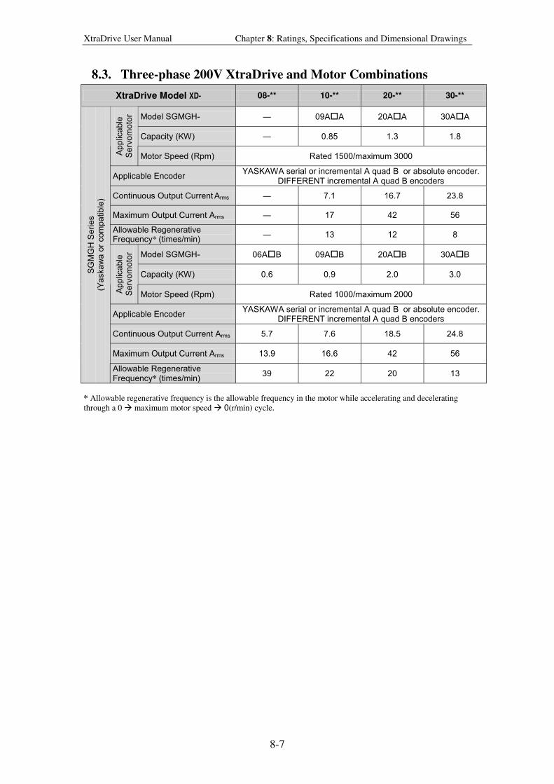
XtraDrive User Manual Chapter 8: Ratings, Specifications and Dimensional Drawings
8-7
8.3. Three-phase 200V XtraDrive and Motor Combinations
XtraDrive Model XD- 08-** 10-** 20-** 30-**
Model SGMGH- ― 09A#A 20A#A 30A#A
Capacity (KW) ― 0.85 1.3 1.8
Ap
plic
able
S
erv
om
oto
r
Motor Speed (Rpm) Rated 1500/maximum 3000
Applicable Encoder YASKAWA serial or incremental A quad B or absolute encoder.
DIFFERENT incremental A quad B encoders
Continuous Output Current Arms ― 7.1 16.7 23.8
Maximum Output Current Arms ― 17 42 56
Allowable Regenerative Frequency* (times/min)
― 13 12 8
Model SGMGH- 06A#B 09A#B 20A#B 30A#B
Capacity (KW) 0.6 0.9 2.0 3.0
Ap
plic
able
S
erv
om
oto
r
Motor Speed (Rpm) Rated 1000/maximum 2000
Applicable Encoder YASKAWA serial or incremental A quad B or absolute encoder.
DIFFERENT incremental A quad B encoders
Continuous Output Current Arms 5.7 7.6 18.5 24.8
Maximum Output Current Arms 13.9 16.6 42 56
SG
MG
H S
eri
es
(Ya
ska
wa
or
com
pa
tib
le)
Allowable Regenerative Frequency* (times/min)
39 22 20 13
* Allowable regenerative frequency is the allowable frequency in the motor while accelerating and decelerating
through a 0 $ maximum motor speed $ 0(r/min) cycle.
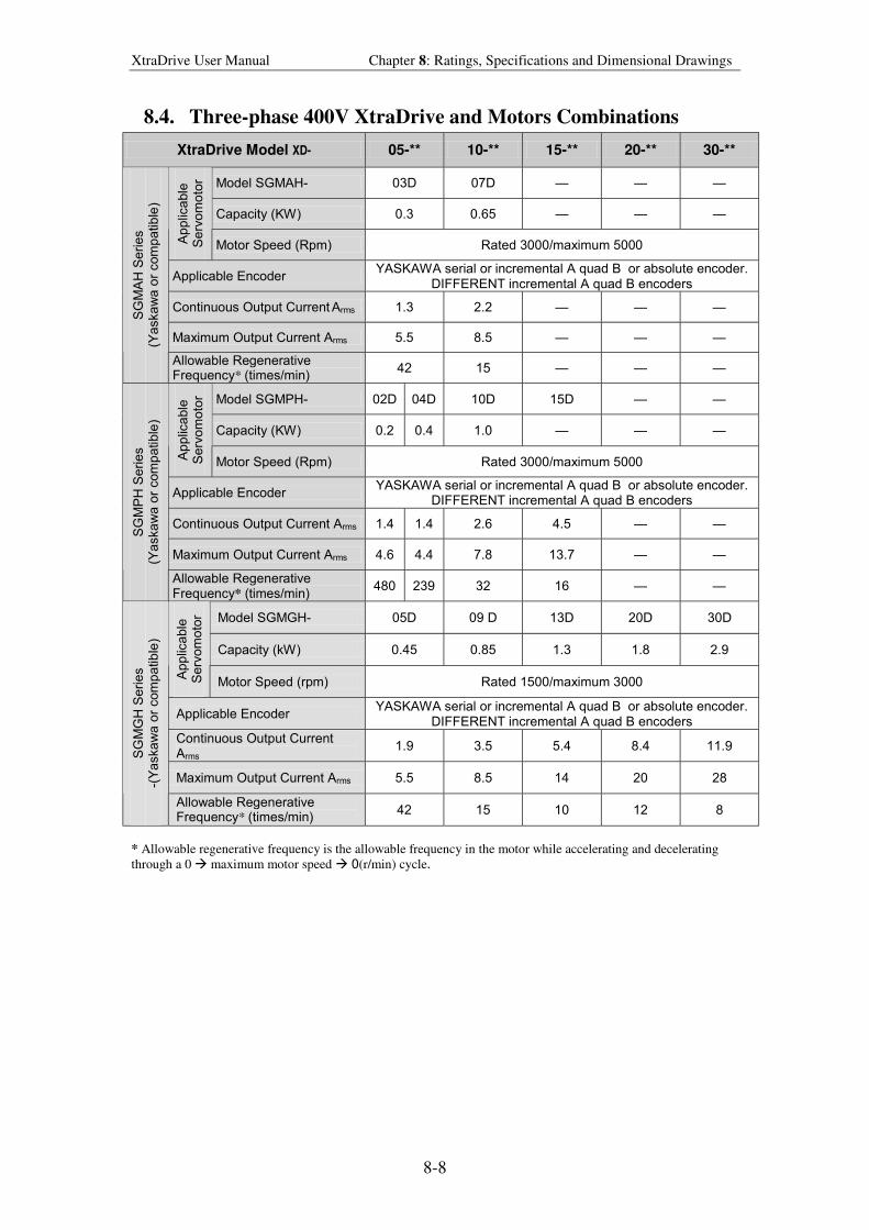
XtraDrive User Manual Chapter 8: Ratings, Specifications and Dimensional Drawings
8-8
8.4. Three-phase 400V XtraDrive and Motors Combinations
XtraDrive Model XD- 05-** 10-** 15-** 20-** 30-**
Model SGMAH- 03D 07D
Capacity (KW) 0.3 0.65
Ap
plic
able
S
erv
om
oto
r
Motor Speed (Rpm) Rated 3000/maximum 5000
Applicable Encoder YASKAWA serial or incremental A quad B or absolute encoder.
DIFFERENT incremental A quad B encoders
Continuous Output Current Arms 1.3 2.2
Maximum Output Current Arms 5.5 8.5
SG
MA
H S
eri
es
(Ya
ska
wa
or
com
pa
tib
le)
Allowable Regenerative Frequency* (times/min)
42 15
Model SGMPH- 02D 04D 10D 15D
Capacity (KW) 0.2 0.4 1.0
Ap
plic
able
S
erv
om
oto
r
Motor Speed (Rpm) Rated 3000/maximum 5000
Applicable Encoder YASKAWA serial or incremental A quad B or absolute encoder.
DIFFERENT incremental A quad B encoders
Continuous Output Current Arms 1.4 1.4 2.6 4.5
Maximum Output Current Arms 4.6 4.4 7.8 13.7
SG
MP
H S
eri
es
(Ya
ska
wa
or
com
pa
tib
le)
Allowable Regenerative Frequency* (times/min)
480 239 32 16
Model SGMGH- 05D 09 D 13D 20D 30D
Capacity (kW) 0.45 0.85 1.3 1.8 2.9
Ap
plic
able
S
erv
om
oto
r
Motor Speed (rpm) Rated 1500/maximum 3000
Applicable Encoder YASKAWA serial or incremental A quad B or absolute encoder.
DIFFERENT incremental A quad B encoders
Continuous Output Current
Arms 1.9 3.5 5.4 8.4 11.9
Maximum Output Current Arms 5.5 8.5 14 20 28
SG
MG
H S
eri
es
-(Y
aska
wa
or
com
pa
tib
le)
Allowable Regenerative Frequency* (times/min)
42 15 10 12 8
* Allowable regenerative frequency is the allowable frequency in the motor while accelerating and decelerating
through a 0 $ maximum motor speed $ 0(r/min) cycle.
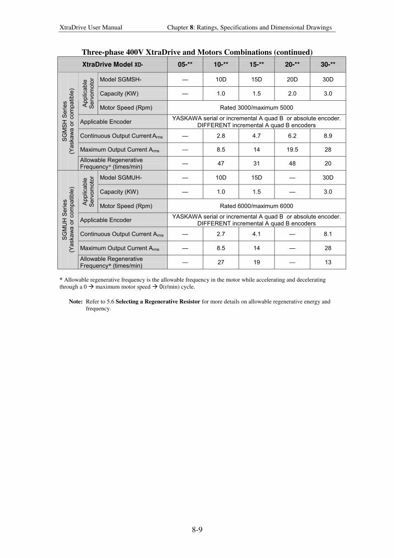
XtraDrive User Manual Chapter 8: Ratings, Specifications and Dimensional Drawings
8-9
Three-phase 400V XtraDrive and Motors Combinations (continued)
XtraDrive Model XD- 05-** 10-** 15-** 20-** 30-**
Model SGMSH- 10D 15D 20D 30D
Capacity (KW) 1.0 1.5 2.0 3.0
Ap
plic
able
S
erv
om
oto
r
Motor Speed (Rpm) Rated 3000/maximum 5000
Applicable Encoder YASKAWA serial or incremental A quad B or absolute encoder.
DIFFERENT incremental A quad B encoders
Continuous Output Current Arms 2.8 4.7 6.2 8.9
Maximum Output Current Arms 8.5 14 19.5 28
SG
MS
H S
eri
es
(Ya
ska
wa
or
com
pa
tib
le)
Allowable Regenerative Frequency* (times/min)
47 31 48 20
Model SGMUH- 10D 15D 30D
Capacity (KW) 1.0 1.5 3.0
Ap
plic
able
S
erv
om
oto
r
Motor Speed (Rpm) Rated 6000/maximum 6000
Applicable Encoder YASKAWA serial or incremental A quad B or absolute encoder.
DIFFERENT incremental A quad B encoders
Continuous Output Current Arms 2.7 4.1 8.1
Maximum Output Current Arms 8.5 14 28
SG
MU
H S
eri
es
(Ya
ska
wa
or
com
pa
tib
le)
Allowable Regenerative Frequency* (times/min)
27 19 13
* Allowable regenerative frequency is the allowable frequency in the motor while accelerating and decelerating
through a 0 $ maximum motor speed $ 0(r/min) cycle.
Note: Refer to 5.6 Selecting a Regenerative Resistor for more details on allowable regenerative energy and
frequency.
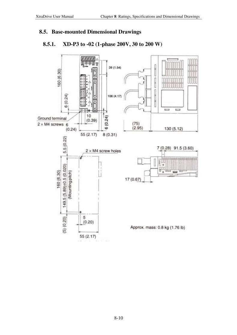
XtraDrive User Manual Chapter 8: Ratings, Specifications and Dimensional Drawings
8-10
8.5. Base-mounted Dimensional Drawings
8.5.1. XD-P3 to -02 (1-phase 200V, 30 to 200 W)
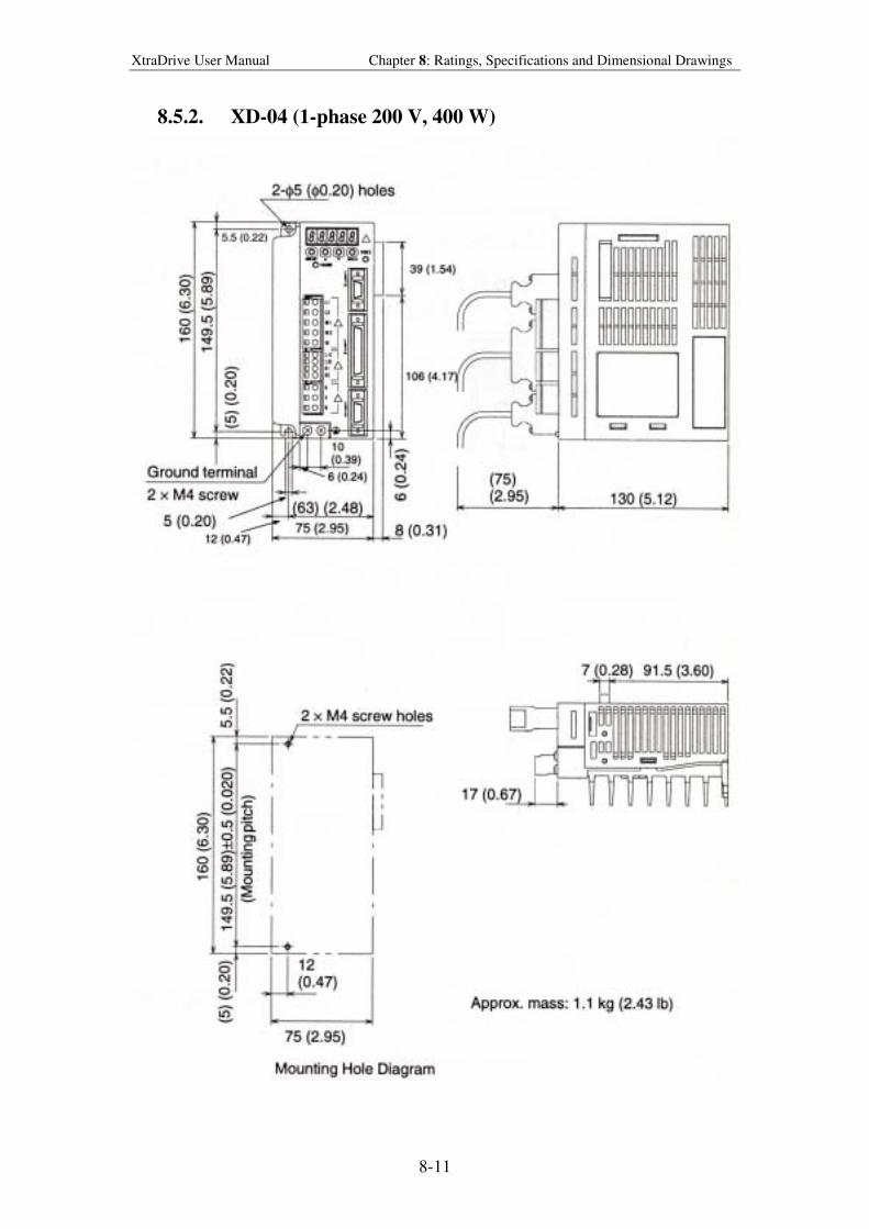
XtraDrive User Manual Chapter 8: Ratings, Specifications and Dimensional Drawings
8-11
8.5.2. XD-04 (1-phase 200 V, 400 W)
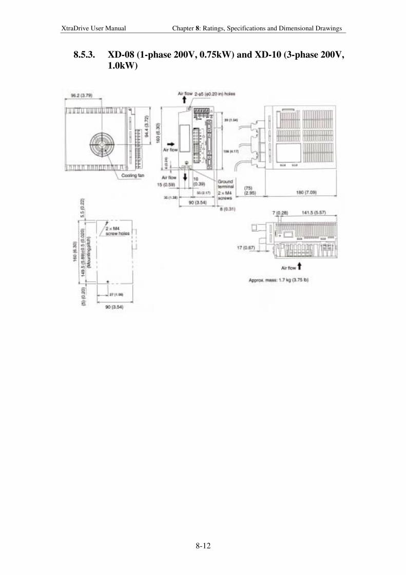
XtraDrive User Manual Chapter 8: Ratings, Specifications and Dimensional Drawings
8-12
8.5.3. XD-08 (1-phase 200V, 0.75kW) and XD-10 (3-phase 200V,
1.0kW)
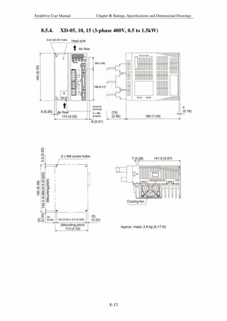
XtraDrive User Manual Chapter 8: Ratings, Specifications and Dimensional Drawings
8-13
8.5.4. XD-05, 10, 15 (3-phase 400V, 0.5 to 1.5kW)
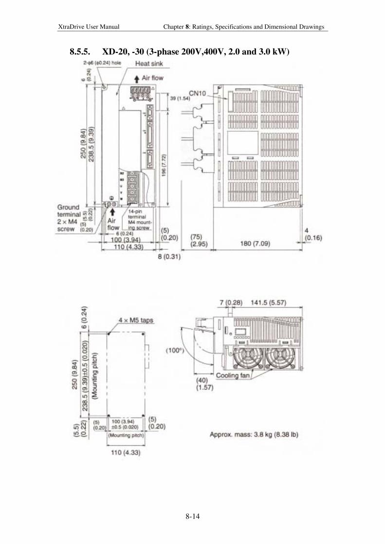
XtraDrive User Manual Chapter 8: Ratings, Specifications and Dimensional Drawings
8-14
8.5.5. XD-20, -30 (3-phase 200V,400V, 2.0 and 3.0 kW)
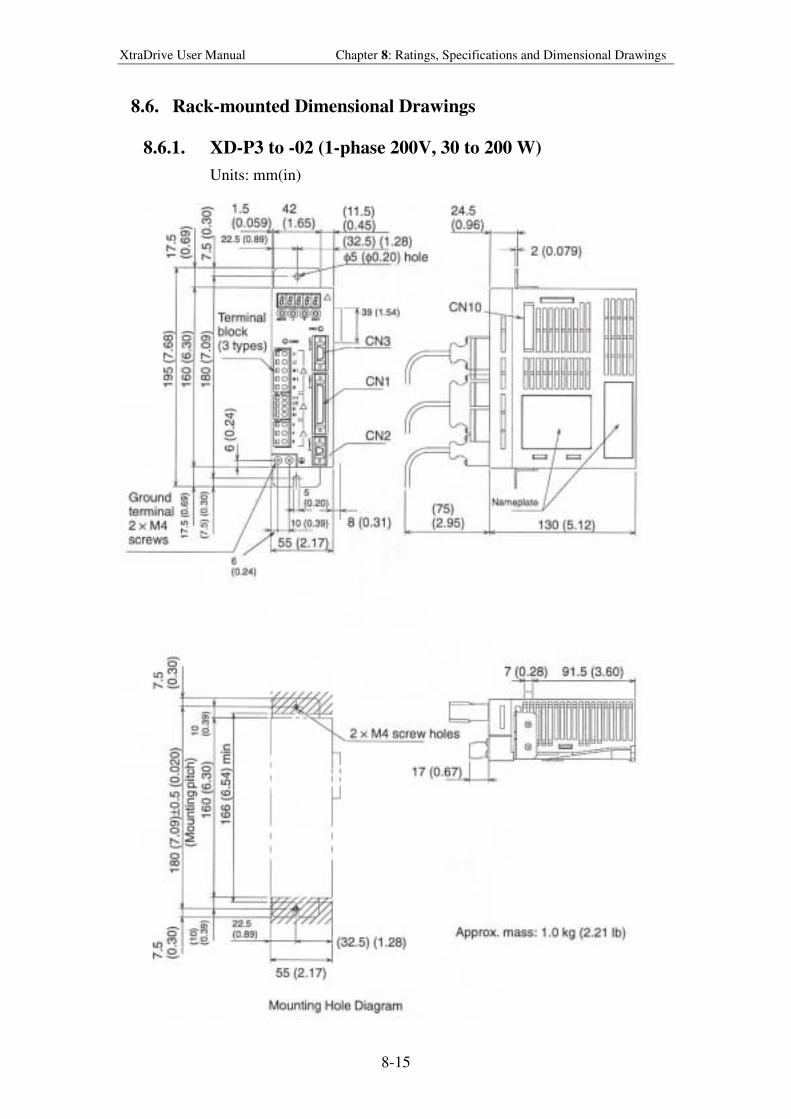
XtraDrive User Manual Chapter 8: Ratings, Specifications and Dimensional Drawings
8-15
8.6. Rack-mounted Dimensional Drawings
8.6.1. XD-P3 to -02 (1-phase 200V, 30 to 200 W)
Units: mm(in)
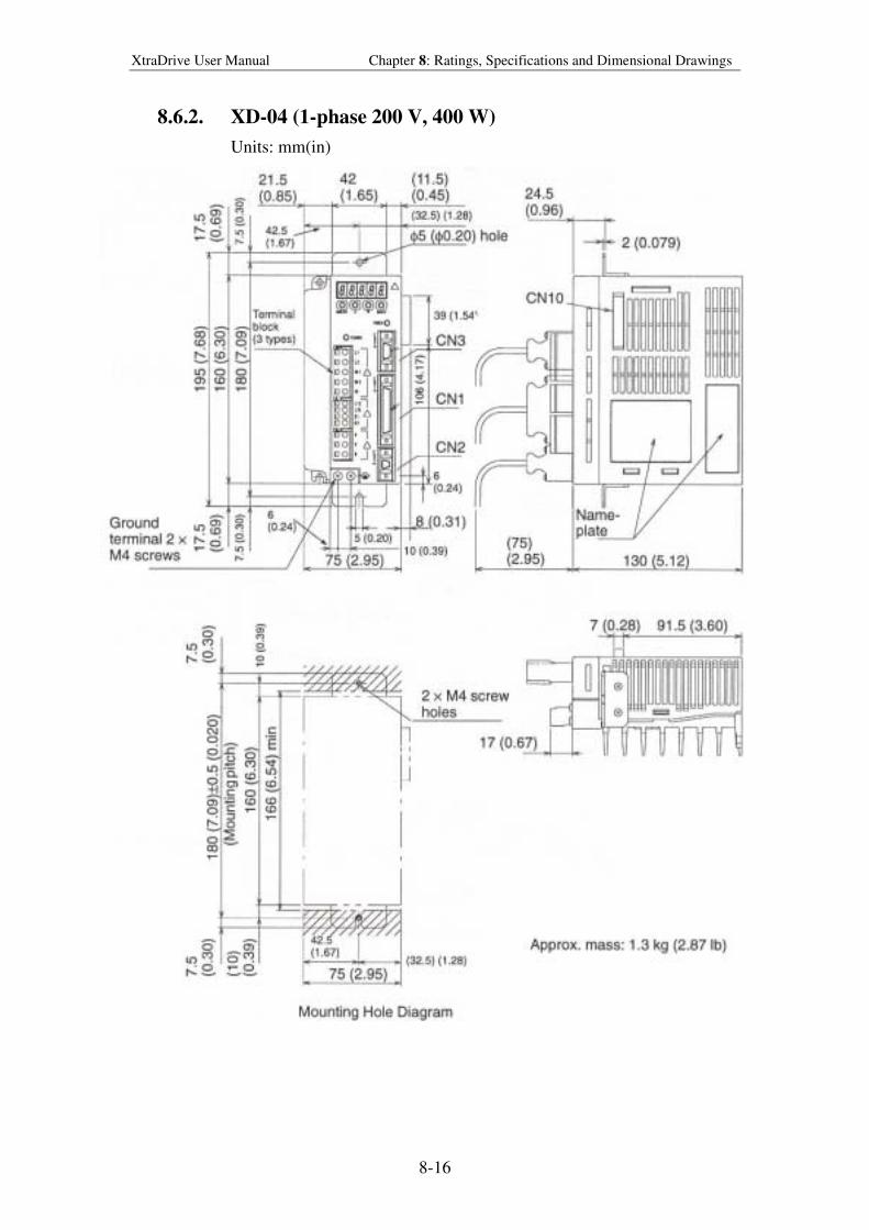
XtraDrive User Manual Chapter 8: Ratings, Specifications and Dimensional Drawings
8-16
8.6.2. XD-04 (1-phase 200 V, 400 W)
Units: mm(in)
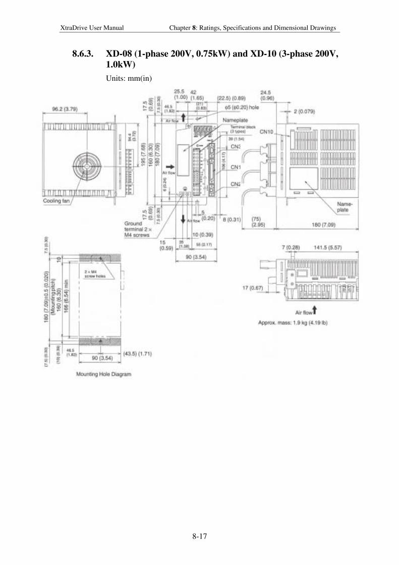
XtraDrive User Manual Chapter 8: Ratings, Specifications and Dimensional Drawings
8-17
8.6.3. XD-08 (1-phase 200V, 0.75kW) and XD-10 (3-phase 200V,
1.0kW)
Units: mm(in)
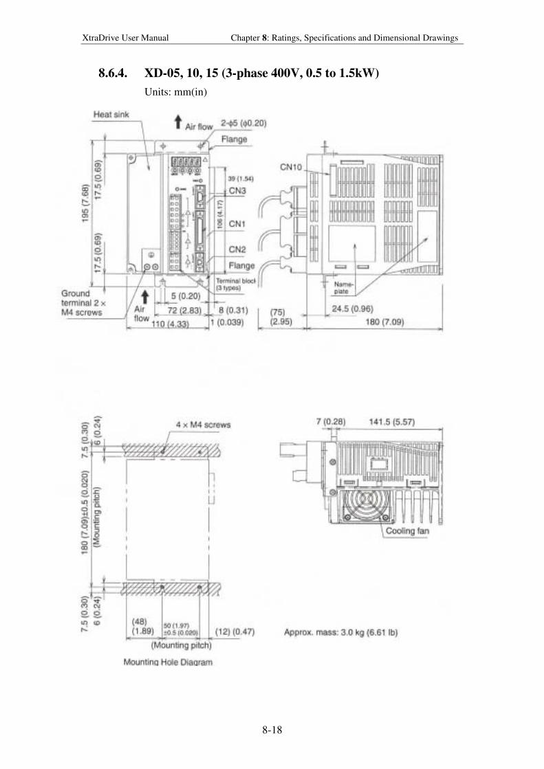
XtraDrive User Manual Chapter 8: Ratings, Specifications and Dimensional Drawings
8-18
8.6.4. XD-05, 10, 15 (3-phase 400V, 0.5 to 1.5kW)
Units: mm(in)
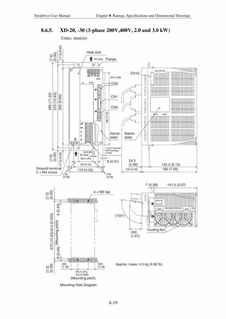
XtraDrive User Manual Chapter 8: Ratings, Specifications and Dimensional Drawings
8-19
8.6.5. XD-20, -30 (3-phase 200V,400V, 2.0 and 3.0 kW)
Units: mm(in)
XtraDrive User Manual Chapter 9: Inspection, Maintenance, and Troubleshooting
9-1
9. Inspect ion, Maintenance, and
Troubleshoot ing
This chapter describes the basic inspection and maintenance to be carried out by
the user. In addition, troubleshooting procedures are described for problems,
which generate an alarm display, and for problems, which result in no alarm
display.
9.1. XtraDrive Inspection and Maintenance ......................................................9-2
9.1.1. Servomotor Inspection ........................................................................9-2
9.1.2. Servo Amplifier Inspection.................................................................9-2
9.1.3. Replacing the Battery for the Absolute Encoder ................................9-3
9.2. Troubleshooting ..........................................................................................9-4
9.2.1. Troubleshooting Problems with Alarm Displays................................9-4
9.2.2. Troubleshooting Problems with No Alarm Display .........................9-25
9.2.3. Alarm Display Table.........................................................................9-26
9.2.4. Warning Displays..............................................................................9-28
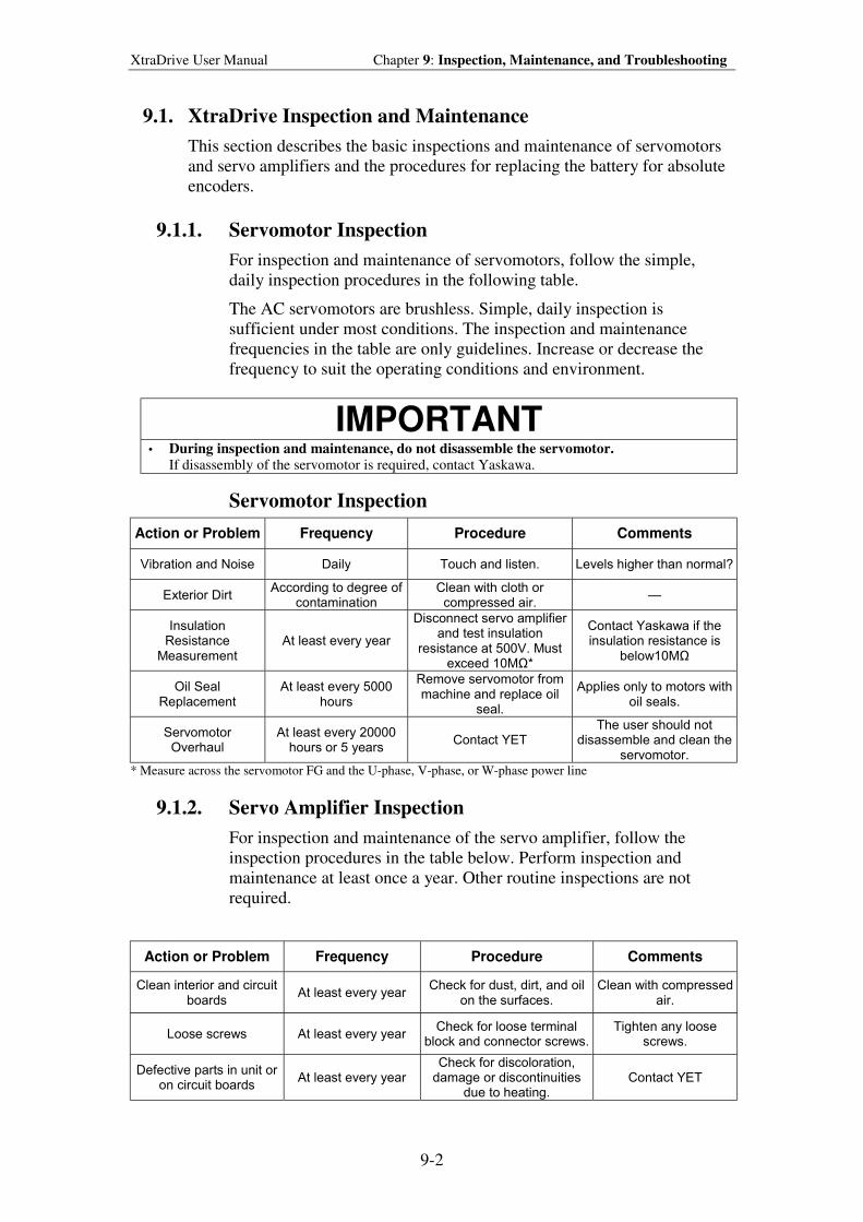
XtraDrive User Manual Chapter 9: Inspection, Maintenance, and Troubleshooting
9-2
9.1. XtraDrive Inspection and Maintenance
This section describes the basic inspections and maintenance of servomotors
and servo amplifiers and the procedures for replacing the battery for absolute
encoders.
9.1.1. Servomotor Inspection
For inspection and maintenance of servomotors, follow the simple,
daily inspection procedures in the following table.
The AC servomotors are brushless. Simple, daily inspection is
sufficient under most conditions. The inspection and maintenance
frequencies in the table are only guidelines. Increase or decrease the
frequency to suit the operating conditions and environment.
IMPORTANT
• During inspection and maintenance, do not disassemble the servomotor. If disassembly of the servomotor is required, contact Yaskawa.
Servomotor Inspection
Action or Problem Frequency Procedure Comments
Vibration and Noise Daily Touch and listen. Levels higher than normal?
Exterior Dirt According to degree of
contamination Clean with cloth or
compressed air.
Insulation Resistance
Measurement At least every year
Disconnect servo amplifier and test insulation
resistance at 500V. Must exceed 10MΩ*
Contact Yaskawa if the insulation resistance is
below10MΩ
Oil Seal Replacement
At least every 5000 hours
Remove servomotor from machine and replace oil
seal.
Applies only to motors with oil seals.
Servomotor Overhaul
At least every 20000 hours or 5 years
Contact YET The user should not
disassemble and clean the servomotor.
* Measure across the servomotor FG and the U-phase, V-phase, or W-phase power line
9.1.2. Servo Amplifier Inspection
For inspection and maintenance of the servo amplifier, follow the
inspection procedures in the table below. Perform inspection and
maintenance at least once a year. Other routine inspections are not
required.
Action or Problem Frequency Procedure Comments
Clean interior and circuit boards
At least every year Check for dust, dirt, and oil
on the surfaces. Clean with compressed
air.
Loose screws At least every year Check for loose terminal
block and connector screws. Tighten any loose
screws.
Defective parts in unit or on circuit boards
At least every year Check for discoloration,
damage or discontinuities due to heating.
Contact YET
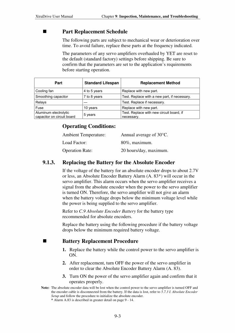
XtraDrive User Manual Chapter 9: Inspection, Maintenance, and Troubleshooting
9-3
! Part Replacement Schedule
The following parts are subject to mechanical wear or deterioration over
time. To avoid failure, replace these parts at the frequency indicated.
The parameters of any servo amplifiers overhauled by YET are reset to
the default (standard factory) settings before shipping. Be sure to
confirm that the parameters are set to the application’s requirements
before starting operation.
Part Standard Lifespan Replacement Method
Cooling fan 4 to 5 years Replace with new part.
Smoothing capacitor 7 to 8 years Test. Replace with a new part, if necessary.
Relays Test. Replace if necessary.
Fuse 10 years Replace with new part.
Aluminum electrolytic capacitor on circuit board
5 years Test. Replace with new circuit board, if necessary.
Operating Conditions:
Ambient Temperature: Annual average of 30°C.
Load Factor: 80%, maximum.
Operation Rate: 20 hours/day, maximum.
9.1.3. Replacing the Battery for the Absolute Encoder
If the voltage of the battery for an absolute encoder drops to about 2.7V
or less, an Absolute Encoder Battery Alarm (A. 83*) will occur in the
servo amplifier. This alarm occurs when the servo amplifier receives a
signal from the absolute encoder when the power to the servo amplifier
is turned ON. Therefore, the servo amplifier will not give an alarm
when the battery voltage drops below the minimum voltage level while
the power is being supplied to the servo amplifier.
Refer to C.9 Absolute Encoder Battery for the battery type
recommended for absolute encoders.
Replace the battery using the following procedure if the battery voltage
drops below the minimum required battery voltage.
! Battery Replacement Procedure
1. Replace the battery while the control power to the servo amplifier is
ON.
2. After replacement, turn OFF the power of the servo amplifier in
order to clear the Absolute Encoder Battery Alarm (A. 83).
3. Turn ON the power of the servo amplifier again and confirm that it
operates properly.
Note: The absolute encoder data will be lost when the control power to the servo amplifier is turned OFF and
the encoder cable is disconnected from the battery. If the data is lost, refer to 5.7.3 I. Absolute Encoder
Setup and follow the procedure to initialize the absolute encoder.
* Alarm A.83 is described in greater detail on page 9 - 14.
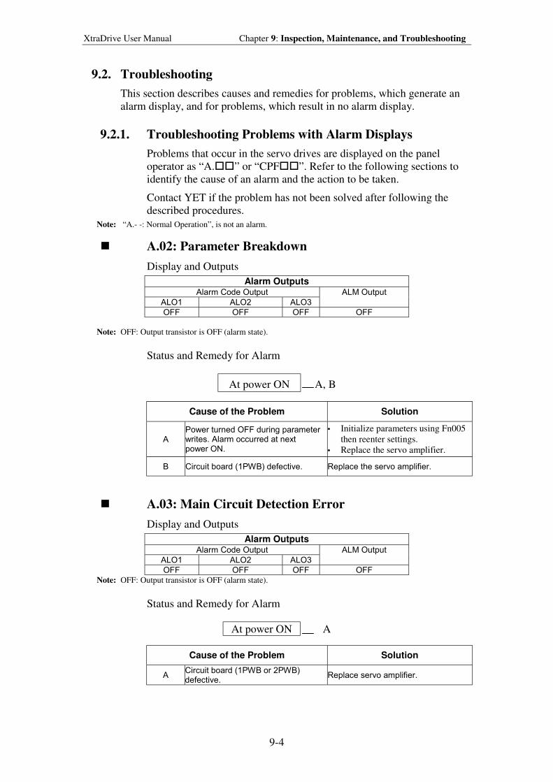
XtraDrive User Manual Chapter 9: Inspection, Maintenance, and Troubleshooting
9-4
9.2. Troubleshooting
This section describes causes and remedies for problems, which generate an
alarm display, and for problems, which result in no alarm display.
9.2.1. Troubleshooting Problems with Alarm Displays
Problems that occur in the servo drives are displayed on the panel
operator as “A.##” or “CPF##”. Refer to the following sections to
identify the cause of an alarm and the action to be taken.
Contact YET if the problem has not been solved after following the
described procedures.
Note: “A.- -: Normal Operation”, is not an alarm.
! A.02: Parameter Breakdown
Display and Outputs
Alarm Outputs Alarm Code Output
ALO1 ALO2 ALO3
ALM Output
OFF OFF OFF OFF
Note: OFF: Output transistor is OFF (alarm state).
Status and Remedy for Alarm
AAt power ONA A, B
Cause of the Problem Solution
A Power turned OFF during parameter writes. Alarm occurred at next power ON.
• Initialize parameters using Fn005
then reenter settings.
• Replace the servo amplifier.
B Circuit board (1PWB) defective. Replace the servo amplifier.
! A.03: Main Circuit Detection Error
Display and Outputs
Alarm Outputs Alarm Code Output
ALO1 ALO2 ALO3
ALM Output
OFF OFF OFF OFF
Note: OFF: Output transistor is OFF (alarm state).
Status and Remedy for Alarm
AAt power ONA A
Cause of the Problem Solution
A Circuit board (1PWB or 2PWB) defective.
Replace servo amplifier.
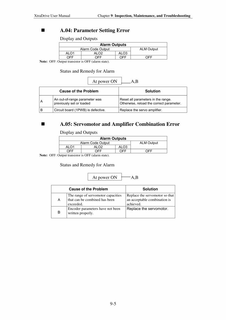
XtraDrive User Manual Chapter 9: Inspection, Maintenance, and Troubleshooting
9-5
! A.04: Parameter Setting Error
Display and Outputs
Alarm Outputs Alarm Code Output
ALO1 ALO2 ALO3
ALM Output
OFF OFF OFF OFF
Note: OFF: Output transistor is OFF (alarm state).
Status and Remedy for Alarm
AAt power ONA A,B
Cause of the Problem Solution
A An out-of-range parameter was previously set or loaded
Reset all parameters in the range. Otherwise, reload the correct parameter.
B Circuit board (1PWB) is defective. Replace the servo amplifier.
! A.05: Servomotor and Amplifier Combination Error
Display and Outputs
Alarm Outputs Alarm Code Output
ALO1 ALO2 ALO3
ALM Output
OFF OFF OFF OFF
Note: OFF: Output transistor is OFF (alarm state).
Status and Remedy for Alarm
AAt power ONA A,B
Cause of the Problem Solution
A
The range of servomotor capacities
that can be combined has been
exceeded.
Replace the servomotor so that
an acceptable combination is
achieved.
B Encoder parameters have not been
written properly. Replace the servomotor.
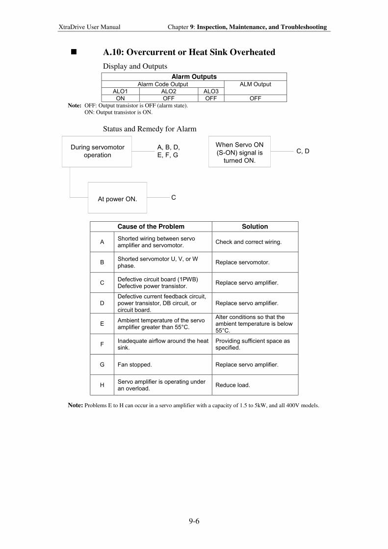
XtraDrive User Manual Chapter 9: Inspection, Maintenance, and Troubleshooting
9-6
! A.10: Overcurrent or Heat Sink Overheated
Display and Outputs
Alarm Outputs Alarm Code Output
ALO1 ALO2 ALO3
ALM Output
ON OFF OFF OFF
Note: OFF: Output transistor is OFF (alarm state). ON: Output transistor is ON.
Status and Remedy for Alarm
During servomotor
operation
At power ON.
When Servo ON
(S-ON) signal is
turned ON.
A, B, D,
E, F, GC, D
C
Cause of the Problem Solution
A Shorted wiring between servo amplifier and servomotor.
Check and correct wiring.
B Shorted servomotor U, V, or W phase.
Replace servomotor.
C Defective circuit board (1PWB) Defective power transistor.
Replace servo amplifier.
D Defective current feedback circuit, power transistor, DB circuit, or circuit board.
Replace servo amplifier.
E Ambient temperature of the servo amplifier greater than 55°C.
Alter conditions so that the ambient temperature is below 55°C.
F Inadequate airflow around the heat sink.
Providing sufficient space as specified.
G Fan stopped. Replace servo amplifier.
H Servo amplifier is operating under an overload.
Reduce load.
Note: Problems E to H can occur in a servo amplifier with a capacity of 1.5 to 5kW, and all 400V models.
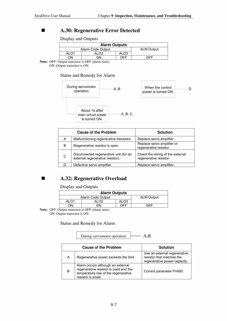
XtraDrive User Manual Chapter 9: Inspection, Maintenance, and Troubleshooting
9-7
! A.30: Regenerative Error Detected
Display and Outputs
Alarm Outputs Alarm Code Output
ALO1 ALO2 ALO3
ALM Output
ON ON OFF OFF
Note: OFF: Output transistor is OFF (alarm state). ON: Output transistor is ON.
Status and Remedy for Alarm
During servomotor
operation
About 1s after
main circuit power
is turned ON.
When the control
power is turned ON.A, B D
A, B, C
Cause of the Problem Solution
A Malfunctioning regenerative transistor. Replace servo amplifier.
B Regenerative resistor is open. Replace servo amplifier or regenerative resistor.
C Disconnected regenerative unit (for an external regenerative resistor).
Check the wiring of the external regenerative resistor.
D Defective servo amplifier. Replace servo amplifier.
! A.32: Regenerative Overload
Display and Outputs
Alarm Outputs Alarm Code Output
ALO1 ALO2 ALO3
ALM Output
ON ON OFF OFF
Note: OFF: Output transistor is OFF (alarm state). ON: Output transistor is ON.
Status and Remedy for Alarm
ADuring servomotor operationA A,B
Cause of the Problem Solution
A Regenerative power exceeds the limit. Use an external regenerative resistor that matches the regenerative power capacity.
B
Alarm occurs although an external regenerative resistor is used and the temperature rise of the regenerative resistor is small.
Correct parameter Pn600.
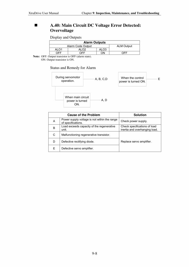
XtraDrive User Manual Chapter 9: Inspection, Maintenance, and Troubleshooting
9-8
! A.40: Main Circuit DC Voltage Error Detected:
Overvoltage
Display and Outputs
Alarm Outputs Alarm Code Output
ALO1 ALO2 ALO3
ALM Output
OFF OFF ON OFF
Note: OFF: Output transistor is OFF (alarm state). ON: Output transistor is ON.
Status and Remedy for Alarm
During servomotor
operation.
When main circuit
power is turned
ON.
When the control
power is turned ON.A, B, C,D E
A, D
Cause of the Problem Solution
A Power supply voltage is not within the range of specifications.
Check power supply.
B Load exceeds capacity of the regenerative unit.
Check specifications of load inertia and overhanging load.
C Malfunctioning regenerative transistor.
D Defective rectifying diode.
E Defective servo amplifier.
Replace servo amplifier.
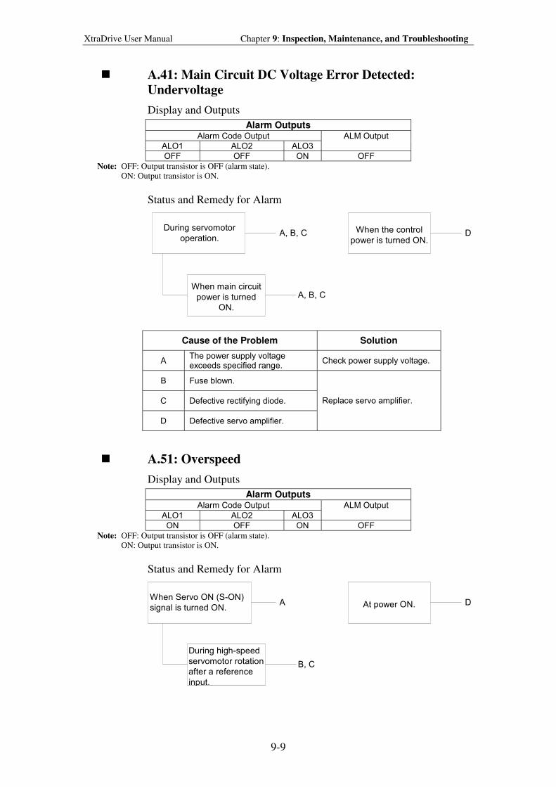
XtraDrive User Manual Chapter 9: Inspection, Maintenance, and Troubleshooting
9-9
! A.41: Main Circuit DC Voltage Error Detected:
Undervoltage
Display and Outputs
Alarm Outputs Alarm Code Output
ALO1 ALO2 ALO3
ALM Output
OFF OFF ON OFF
Note: OFF: Output transistor is OFF (alarm state). ON: Output transistor is ON.
Status and Remedy for Alarm
During servomotor
operation.
When main circuit
power is turned
ON.
When the control
power is turned ON.A, B, C D
A, B, C
Cause of the Problem Solution
A The power supply voltage exceeds specified range.
Check power supply voltage.
B Fuse blown.
C Defective rectifying diode.
D Defective servo amplifier.
Replace servo amplifier.
! A.51: Overspeed
Display and Outputs
Alarm Outputs Alarm Code Output
ALO1 ALO2 ALO3
ALM Output
ON OFF ON OFF
Note: OFF: Output transistor is OFF (alarm state). ON: Output transistor is ON.
Status and Remedy for Alarm
When Servo ON (S-ON)
signal is turned ON.
During high-speed
servomotor rotation
after a reference
input.
At power ON.A D
B, C
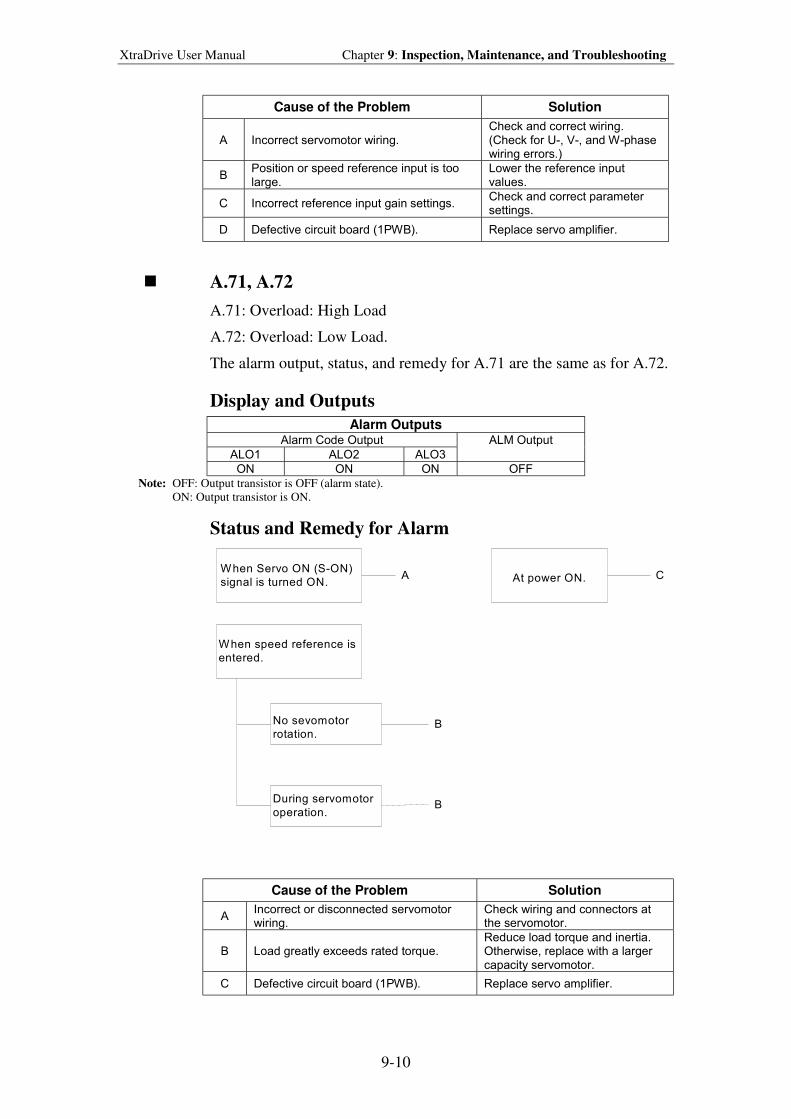
XtraDrive User Manual Chapter 9: Inspection, Maintenance, and Troubleshooting
9-10
Cause of the Problem Solution
A Incorrect servomotor wiring. Check and correct wiring. (Check for U-, V-, and W-phase wiring errors.)
B Position or speed reference input is too large.
Lower the reference input values.
C Incorrect reference input gain settings. Check and correct parameter settings.
D Defective circuit board (1PWB). Replace servo amplifier.
! A.71, A.72
A.71: Overload: High Load
A.72: Overload: Low Load.
The alarm output, status, and remedy for A.71 are the same as for A.72.
Display and Outputs
Alarm Outputs Alarm Code Output
ALO1 ALO2 ALO3
ALM Output
ON ON ON OFF
Note: OFF: Output transistor is OFF (alarm state). ON: Output transistor is ON.
Status and Remedy for Alarm
When speed reference is
entered.
No sevomotor
rotation.
At power ON.
B
CAWhen Servo ON (S-ON)
signal is turned ON.
BDuring servomotor
operation.
Cause of the Problem Solution
A Incorrect or disconnected servomotor wiring.
Check wiring and connectors at the servomotor.
B Load greatly exceeds rated torque. Reduce load torque and inertia. Otherwise, replace with a larger capacity servomotor.
C Defective circuit board (1PWB). Replace servo amplifier.
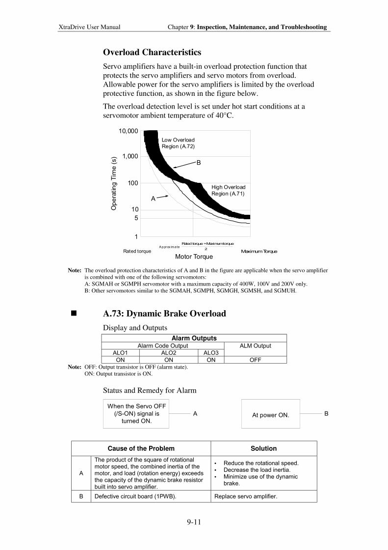
XtraDrive User Manual Chapter 9: Inspection, Maintenance, and Troubleshooting
9-11
Overload Characteristics
Servo amplifiers have a built-in overload protection function that
protects the servo amplifiers and servo motors from overload.
Allowable power for the servo amplifiers is limited by the overload
protective function, as shown in the figure below.
The overload detection level is set under hot start conditions at a
servomotor ambient temperature of 40°C.
Note: The overload protection characteristics of A and B in the figure are applicable when the servo amplifier
is combined with one of the following servomotors:
A: SGMAH or SGMPH servomotor with a maximum capacity of 400W, 100V and 200V only.
B: Other servomotors similar to the SGMAH, SGMPH, SGMGH, SGMSH, and SGMUH.
! A.73: Dynamic Brake Overload
Display and Outputs
Alarm Outputs Alarm Code Output
ALO1 ALO2 ALO3
ALM Output
ON ON ON OFF
Note: OFF: Output transistor is OFF (alarm state). ON: Output transistor is ON.
Status and Remedy for Alarm
When the Servo OFF
(/S-ON) signal is
turned ON.At power ON.A B
Cause of the Problem Solution
A
The product of the square of rotational motor speed, the combined inertia of the motor, and load (rotation energy) exceeds the capacity of the dynamic brake resistor built into servo amplifier.
• Reduce the rotational speed. • Decrease the load inertia. • Minimize use of the dynamic
brake.
B Defective circuit board (1PWB). Replace servo amplifier.
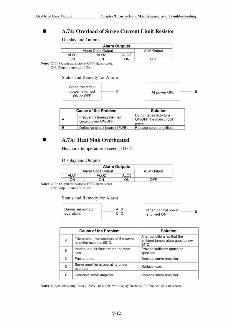
XtraDrive User Manual Chapter 9: Inspection, Maintenance, and Troubleshooting
9-12
! A.74: Overload of Surge Current Limit Resistor
Display and Outputs
Alarm Outputs Alarm Code Output
ALO1 ALO2 ALO3
ALM Output
ON ON ON OFF
Note: OFF: Output transistor is OFF (alarm state). ON: Output transistor is ON.
Status and Remedy for Alarm
When the circuit
power is turned
ON or OFFAt power ON.A B
Cause of the Problem Solution
A Frequently turning the main circuit power ON/OFF.
Do not repeatedly turn ON/OFF the main circuit power.
B Defective circuit board (1PWB). Replace servo amplifier.
! A.7A: Heat Sink Overheated
Heat sink temperature exceeds 100°C.
Display and Outputs
Alarm Outputs Alarm Code Output
ALO1 ALO2 ALO3
ALM Output
ON ON ON OFF
Note: OFF: Output transistor is OFF (alarm state). ON: Output transistor is ON.
Status and Remedy for Alarm
During servomotor
operation.When control power
is turned ON.
A, B
C, DE
Cause of the Problem Solution
A The ambient temperature of the servo amplifier exceeds 55°C.
Alter conditions so that the ambient temperature goes below 55°C.
B Inadequate air flow around the heat sink .
Provide sufficient space as specified.
C Fan stopped. Replace servo amplifier.
D Servo amplifier is operating under overload.
Reduce load.
E Defective servo amplifier. Replace servo amplifier.
Note: Larger servo amplifiers (1.5kW., or larger) will display alarm A.10 if the heat sink overheats.
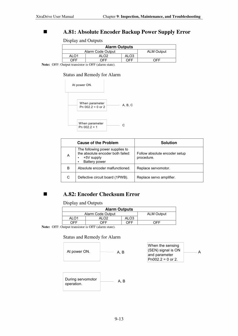
XtraDrive User Manual Chapter 9: Inspection, Maintenance, and Troubleshooting
9-13
! A.81: Absolute Encoder Backup Power Supply Error
Display and Outputs
Alarm Outputs Alarm Code Output
ALO1 ALO2 ALO3
ALM Output
OFF OFF OFF OFF
Note: OFF: Output transistor is OFF (alarm state).
Status and Remedy for Alarm
At power ON.
When parameter
Pn 002.2 = 0 or 2A, B, C
CWhen parameter
Pn 002.2 = 1
Cause of the Problem Solution
A
The following power supplies to the absolute encoder both failed: • +5V supply • Battery power
Follow absolute encoder setup procedure.
B Absolute encoder malfunctioned. Replace servomotor.
C Defective circuit board (1PWB). Replace servo amplifier.
! A.82: Encoder Checksum Error
Display and Outputs
Alarm Outputs Alarm Code Output
ALO1 ALO2 ALO3
ALM Output
OFF OFF OFF OFF
Note: OFF: Output transistor is OFF (alarm state).
Status and Remedy for Alarm
When the sensing
(SEN) signal is ON
and parameter
Pn002.2 = 0 or 2.
A, B A
A, BDuring servomotor
operation.
At power ON.
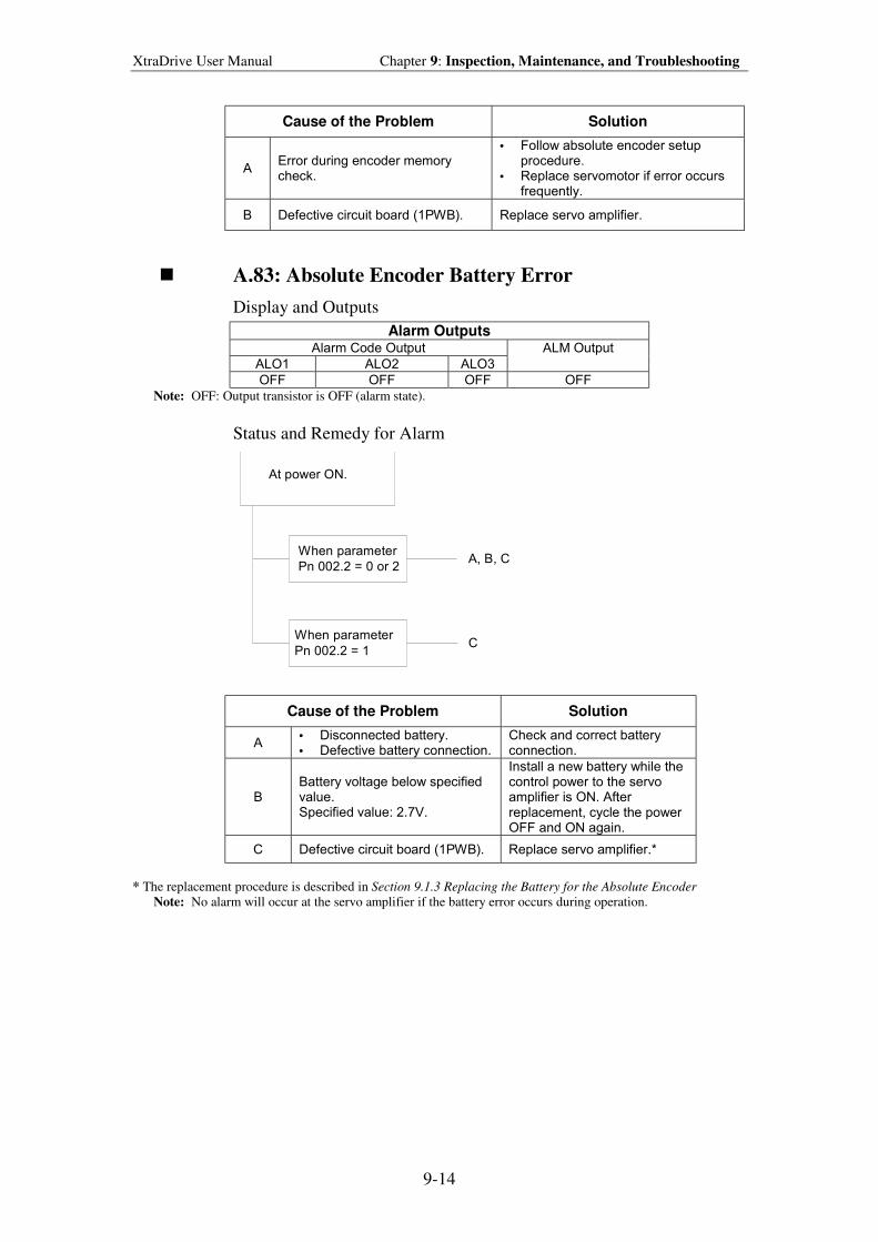
XtraDrive User Manual Chapter 9: Inspection, Maintenance, and Troubleshooting
9-14
Cause of the Problem Solution
A Error during encoder memory check.
• Follow absolute encoder setup procedure.
• Replace servomotor if error occurs frequently.
B Defective circuit board (1PWB). Replace servo amplifier.
! A.83: Absolute Encoder Battery Error
Display and Outputs
Alarm Outputs Alarm Code Output
ALO1 ALO2 ALO3
ALM Output
OFF OFF OFF OFF
Note: OFF: Output transistor is OFF (alarm state).
Status and Remedy for Alarm
At power ON.
When parameter
Pn 002.2 = 0 or 2A, B, C
CWhen parameter
Pn 002.2 = 1
Cause of the Problem Solution
A • Disconnected battery. • Defective battery connection.
Check and correct battery connection.
B Battery voltage below specified value. Specified value: 2.7V.
Install a new battery while the control power to the servo amplifier is ON. After replacement, cycle the power OFF and ON again.
C Defective circuit board (1PWB). Replace servo amplifier.*
* The replacement procedure is described in Section 9.1.3 Replacing the Battery for the Absolute Encoder
Note: No alarm will occur at the servo amplifier if the battery error occurs during operation.
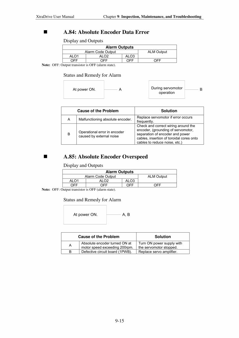
XtraDrive User Manual Chapter 9: Inspection, Maintenance, and Troubleshooting
9-15
! A.84: Absolute Encoder Data Error
Display and Outputs
Alarm Outputs Alarm Code Output
ALO1 ALO2 ALO3
ALM Output
OFF OFF OFF OFF
Note: OFF: Output transistor is OFF (alarm state).
Status and Remedy for Alarm
At power ON. During servomotor
operationA B
Cause of the Problem Solution
A Malfunctioning absolute encoder. Replace servomotor if error occurs frequently.
B Operational error in encoder caused by external noise
Check and correct wiring around the encoder, (grounding of servomotor, separation of encoder and power cables, insertion of toroidal cores onto cables to reduce noise, etc.)
! A.85: Absolute Encoder Overspeed
Display and Outputs
Alarm Outputs Alarm Code Output
ALO1 ALO2 ALO3
ALM Output
OFF OFF OFF OFF
Note: OFF: Output transistor is OFF (alarm state).
Status and Remedy for Alarm
At power ON. A, B
Cause of the Problem Solution
A Absolute encoder turned ON at motor speed exceeding 200rpm.
Turn ON power supply with the servomotor stopped.
B Defective circuit board (1PWB). Replace servo amplifier.
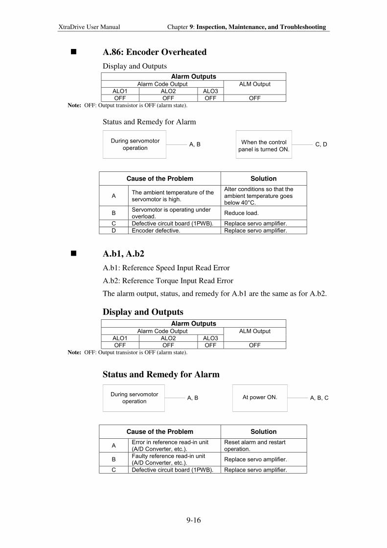
XtraDrive User Manual Chapter 9: Inspection, Maintenance, and Troubleshooting
9-16
! A.86: Encoder Overheated
Display and Outputs
Alarm Outputs Alarm Code Output
ALO1 ALO2 ALO3
ALM Output
OFF OFF OFF OFF
Note: OFF: Output transistor is OFF (alarm state).
Status and Remedy for Alarm
During servomotor
operationWhen the control
panel is turned ON.A, B C, D
Cause of the Problem Solution
A The ambient temperature of the servomotor is high.
Alter conditions so that the ambient temperature goes below 40°C.
B Servomotor is operating under overload.
Reduce load.
C Defective circuit board (1PWB). Replace servo amplifier.
D Encoder defective. Replace servo amplifier.
! A.b1, A.b2
A.b1: Reference Speed Input Read Error
A.b2: Reference Torque Input Read Error
The alarm output, status, and remedy for A.b1 are the same as for A.b2.
Display and Outputs
Alarm Outputs Alarm Code Output
ALO1 ALO2 ALO3
ALM Output
OFF OFF OFF OFF
Note: OFF: Output transistor is OFF (alarm state).
Status and Remedy for Alarm
During servomotor
operationAt power ON.A, B A, B, C
Cause of the Problem Solution
A Error in reference read-in unit (A/D Converter, etc.).
Reset alarm and restart operation.
B Faulty reference read-in unit (A/D Converter, etc.).
Replace servo amplifier.
C Defective circuit board (1PWB). Replace servo amplifier.
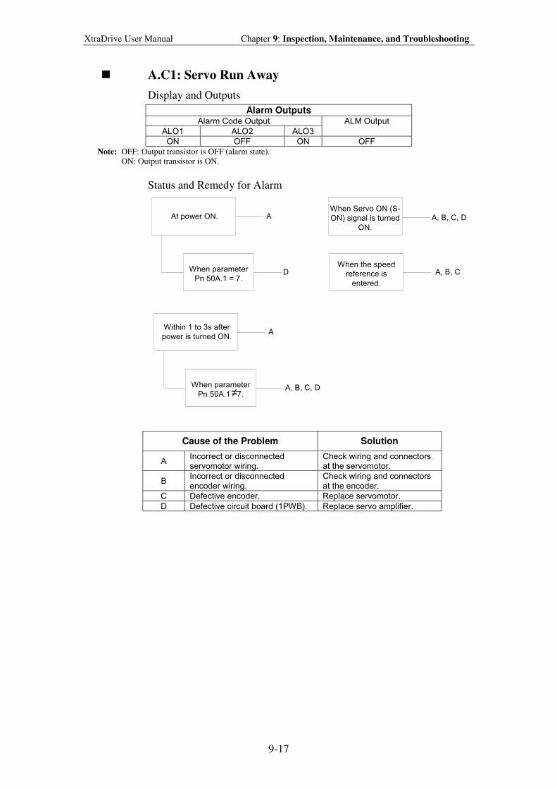
XtraDrive User Manual Chapter 9: Inspection, Maintenance, and Troubleshooting
9-17
! A.C1: Servo Run Away
Display and Outputs
Alarm Outputs Alarm Code Output
ALO1 ALO2 ALO3
ALM Output
ON OFF ON OFF
Note: OFF: Output transistor is OFF (alarm state). ON: Output transistor is ON.
Status and Remedy for Alarm
At power ON.
When parameter
Pn 50A.1 = 7.
When Servo ON (S-
ON) signal is turned
ON.
A A, B, C, D
DWhen the speed
reference is
entered.
Within 1 to 3s after
power is turned ON.
When parameter
Pn 50A.1 7.
A
A, B, C, D
A, B, C
≠
Cause of the Problem Solution
A Incorrect or disconnected servomotor wiring.
Check wiring and connectors at the servomotor.
B Incorrect or disconnected encoder wiring.
Check wiring and connectors at the encoder.
C Defective encoder. Replace servomotor.
D Defective circuit board (1PWB). Replace servo amplifier.
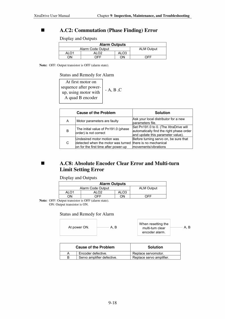
XtraDrive User Manual Chapter 9: Inspection, Maintenance, and Troubleshooting
9-18
! A.C2: Commutation (Phase Finding) Error
Display and Outputs
Alarm Outputs Alarm Code Output
ALO1 ALO2 ALO3
ALM Output
ON OFF ON OFF
Note: OFF: Output transistor is OFF (alarm state).
Status and Remedy for Alarm
- A, B ,C
Cause of the Problem Solution
A Motor parameters are faulty Ask your local distributor for a new parameters file.
B The initial value of Pn191.0 (phase order) is not correct
Set Pn191.0 to 0. (The XtraDrive will automatically find the right phase order and update this parameter value).
C Undesired motor motion was detected when the motor was turned on for the first time after power-up
Before turning servo on, be sure that there is no mechanical movements/vibrations
! A.C8: Absolute Encoder Clear Error and Multi-turn
Limit Setting Error
Display and Outputs
Alarm Outputs Alarm Code Output
ALO1 ALO2 ALO3
ALM Output
ON OFF ON OFF
Note: OFF: Output transistor is OFF (alarm state). ON: Output transistor is ON.
Status and Remedy for Alarm
At power ON.When resetting the
multi-tum clear
encoder alarm.
A, B A, B
Cause of the Problem Solution
A Encoder defective. Replace servomotor.
B Servo amplifier defective. Replace servo amplifier.
At first motor on
sequence after power-
up, using motor with
A quad B encoder
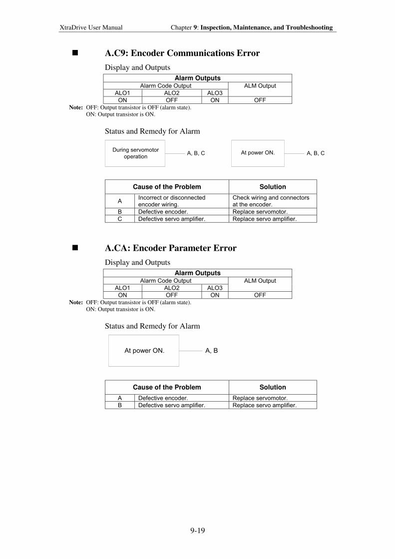
XtraDrive User Manual Chapter 9: Inspection, Maintenance, and Troubleshooting
9-19
! A.C9: Encoder Communications Error
Display and Outputs
Alarm Outputs Alarm Code Output
ALO1 ALO2 ALO3
ALM Output
ON OFF ON OFF
Note: OFF: Output transistor is OFF (alarm state). ON: Output transistor is ON.
Status and Remedy for Alarm
During servomotor
operationAt power ON.A, B, C A, B, C
Cause of the Problem Solution
A Incorrect or disconnected encoder wiring.
Check wiring and connectors at the encoder.
B Defective encoder. Replace servomotor.
C Defective servo amplifier. Replace servo amplifier.
! A.CA: Encoder Parameter Error
Display and Outputs
Alarm Outputs Alarm Code Output
ALO1 ALO2 ALO3
ALM Output
ON OFF ON OFF
Note: OFF: Output transistor is OFF (alarm state). ON: Output transistor is ON.
Status and Remedy for Alarm
At power ON. A, B
Cause of the Problem Solution
A Defective encoder. Replace servomotor.
B Defective servo amplifier. Replace servo amplifier.
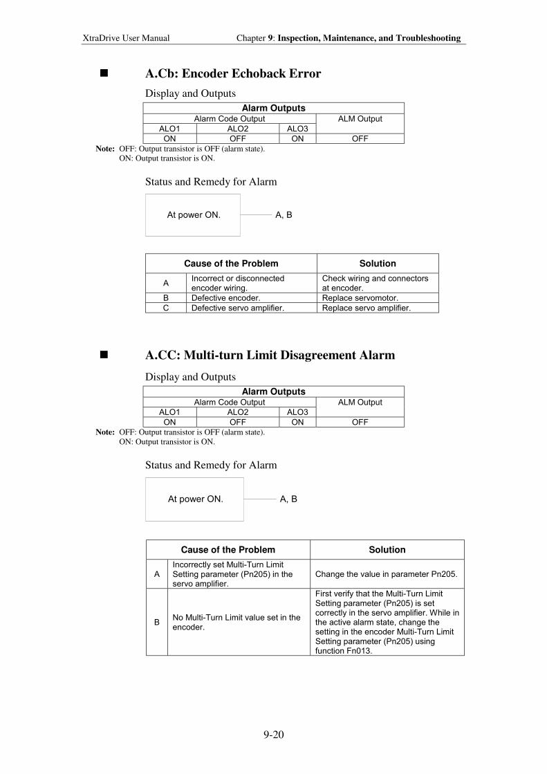
XtraDrive User Manual Chapter 9: Inspection, Maintenance, and Troubleshooting
9-20
! A.Cb: Encoder Echoback Error
Display and Outputs
Alarm Outputs Alarm Code Output
ALO1 ALO2 ALO3
ALM Output
ON OFF ON OFF
Note: OFF: Output transistor is OFF (alarm state).
ON: Output transistor is ON.
Status and Remedy for Alarm
At power ON. A, B
Cause of the Problem Solution
A Incorrect or disconnected encoder wiring.
Check wiring and connectors at encoder.
B Defective encoder. Replace servomotor.
C Defective servo amplifier. Replace servo amplifier.
! A.CC: Multi-turn Limit Disagreement Alarm
Display and Outputs
Alarm Outputs Alarm Code Output
ALO1 ALO2 ALO3
ALM Output
ON OFF ON OFF
Note: OFF: Output transistor is OFF (alarm state).
ON: Output transistor is ON.
Status and Remedy for Alarm
At power ON. A, B
Cause of the Problem Solution
A Incorrectly set Multi-Turn Limit Setting parameter (Pn205) in the servo amplifier.
Change the value in parameter Pn205.
B No Multi-Turn Limit value set in the encoder.
First verify that the Multi-Turn Limit Setting parameter (Pn205) is set correctly in the servo amplifier. While in the active alarm state, change the setting in the encoder Multi-Turn Limit Setting parameter (Pn205) using function Fn013.
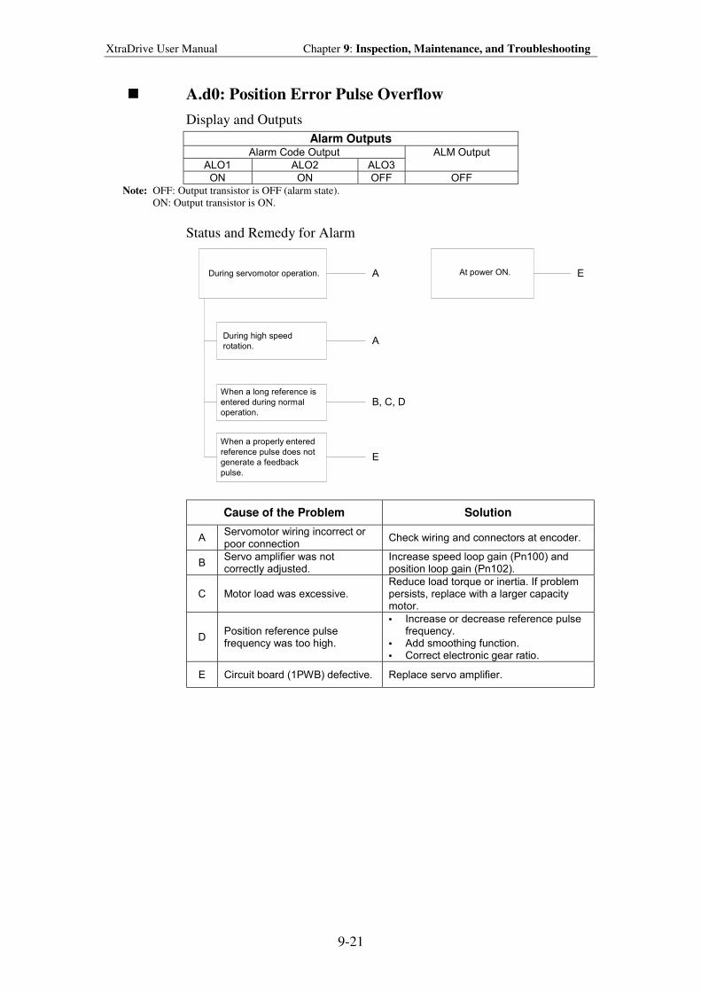
XtraDrive User Manual Chapter 9: Inspection, Maintenance, and Troubleshooting
9-21
! A.d0: Position Error Pulse Overflow
Display and Outputs
Alarm Outputs Alarm Code Output
ALO1 ALO2 ALO3
ALM Output
ON ON OFF OFF
Note: OFF: Output transistor is OFF (alarm state). ON: Output transistor is ON.
Status and Remedy for Alarm
During servomotor operation. At power ON.A E
During high speed
rotation.
When a long reference is
entered during normal
operation.
When a properly entered
reference pulse does not
generate a feedback
pulse.
A
B, C, D
E
Cause of the Problem Solution
A Servomotor wiring incorrect or poor connection
Check wiring and connectors at encoder.
B Servo amplifier was not correctly adjusted.
Increase speed loop gain (Pn100) and position loop gain (Pn102).
C Motor load was excessive. Reduce load torque or inertia. If problem persists, replace with a larger capacity motor.
D Position reference pulse frequency was too high.
• Increase or decrease reference pulse frequency.
• Add smoothing function. • Correct electronic gear ratio.
E Circuit board (1PWB) defective. Replace servo amplifier.
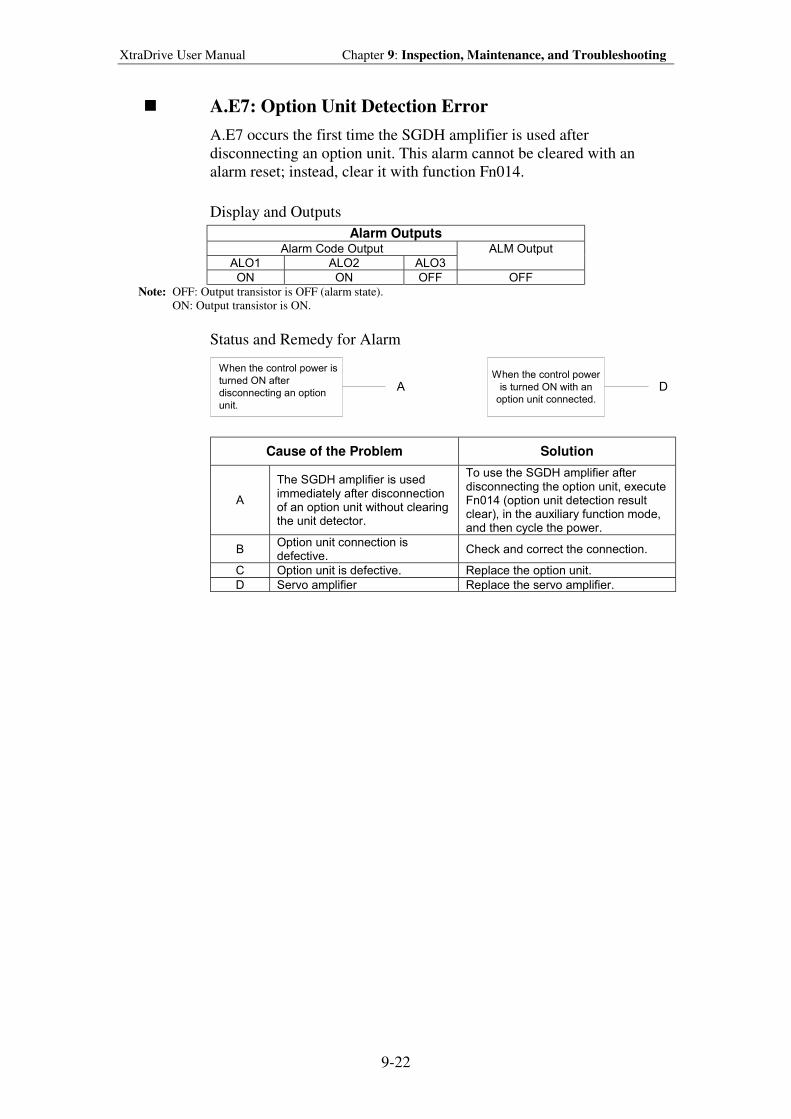
XtraDrive User Manual Chapter 9: Inspection, Maintenance, and Troubleshooting
9-22
! A.E7: Option Unit Detection Error
A.E7 occurs the first time the SGDH amplifier is used after
disconnecting an option unit. This alarm cannot be cleared with an
alarm reset; instead, clear it with function Fn014.
Display and Outputs
Alarm Outputs Alarm Code Output
ALO1 ALO2 ALO3
ALM Output
ON ON OFF OFF
Note: OFF: Output transistor is OFF (alarm state).
ON: Output transistor is ON.
Status and Remedy for Alarm
When the control power is
turned ON after
disconnecting an option
unit.
When the control power
is turned ON with an
option unit connected.A D
Cause of the Problem Solution
A
The SGDH amplifier is used immediately after disconnection of an option unit without clearing the unit detector.
To use the SGDH amplifier after disconnecting the option unit, execute Fn014 (option unit detection result clear), in the auxiliary function mode, and then cycle the power.
B Option unit connection is defective.
Check and correct the connection.
C Option unit is defective. Replace the option unit.
D Servo amplifier Replace the servo amplifier.
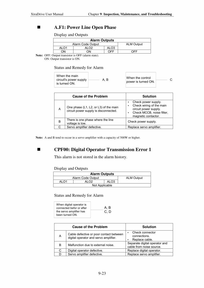
XtraDrive User Manual Chapter 9: Inspection, Maintenance, and Troubleshooting
9-23
! A.F1: Power Line Open Phase
Display and Outputs
Alarm Outputs Alarm Code Output
ALO1 ALO2 ALO3
ALM Output
ON ON OFF OFF
Note: OFF: Output transistor is OFF (alarm state).
ON: Output transistor is ON.
Status and Remedy for Alarm
When the main
circuit's power supply
is turned ON.
When the control
power is turned ON.A, B C
Cause of the Problem Solution
A One phase (L1, L2, or L3) of the main circuit power supply is disconnected.
• Check power supply. • Check wiring of the main
circuit power supply. • Check MCCB, noise filter,
magnetic contactor.
B There is one phase where the line voltage is low.
Check power supply.
C Servo amplifier defective. Replace servo amplifier.
Note: A and B tend to occur in a servo amplifier with a capacity of 500W or higher.
! CPF00: Digital Operator Transmission Error 1
This alarm is not stored in the alarm history.
Display and Outputs
Alarm Outputs Alarm Code Output
ALO1 ALO2 ALO3
ALM Output
Not Applicable
Status and Remedy for Alarm
When digital operator is
connected befor or after
the servo amplifier has
been turned ON.
A, B
C, D
Cause of the Problem Solution
A Cable defective or poor contact between digital operator and servo amplifier.
• Check connector connections.
• Replace cable.
B Malfunction due to external noise. Separate digital operator and cable from noise source.
C Digital operator defective. Replace digital operator.
D Servo amplifier defective. Replace servo amplifier.
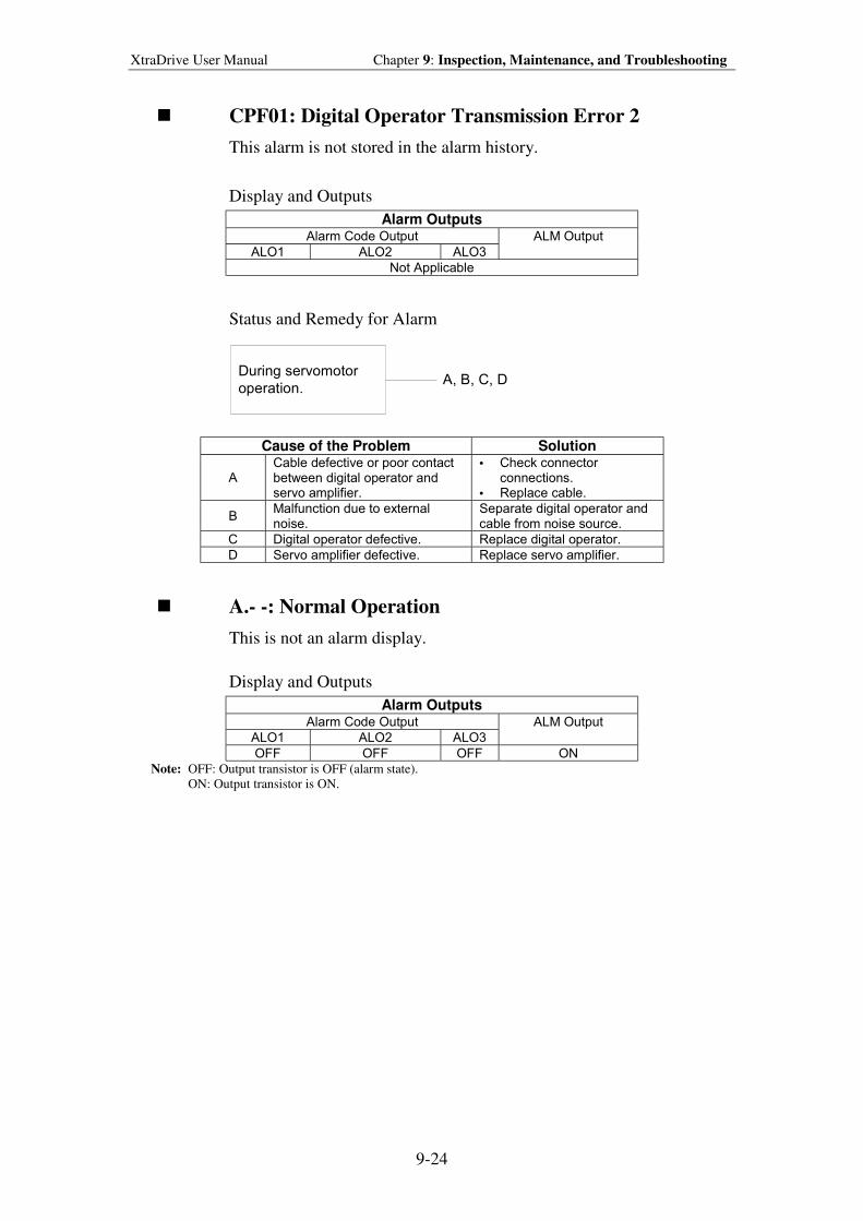
XtraDrive User Manual Chapter 9: Inspection, Maintenance, and Troubleshooting
9-24
! CPF01: Digital Operator Transmission Error 2
This alarm is not stored in the alarm history.
Display and Outputs
Alarm Outputs Alarm Code Output
ALO1 ALO2 ALO3
ALM Output
Not Applicable
Status and Remedy for Alarm
During servomotor
operation.A, B, C, D
Cause of the Problem Solution
A Cable defective or poor contact between digital operator and servo amplifier.
• Check connector connections.
• Replace cable.
B Malfunction due to external noise.
Separate digital operator and cable from noise source.
C Digital operator defective. Replace digital operator.
D Servo amplifier defective. Replace servo amplifier.
! A.- -: Normal Operation
This is not an alarm display.
Display and Outputs
Alarm Outputs Alarm Code Output
ALO1 ALO2 ALO3
ALM Output
OFF OFF OFF ON
Note: OFF: Output transistor is OFF (alarm state). ON: Output transistor is ON.
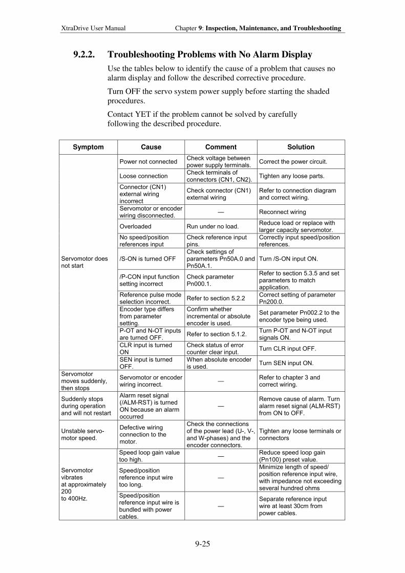
XtraDrive User Manual Chapter 9: Inspection, Maintenance, and Troubleshooting
9-25
9.2.2. Troubleshooting Problems with No Alarm Display
Use the tables below to identify the cause of a problem that causes no
alarm display and follow the described corrective procedure.
Turn OFF the servo system power supply before starting the shaded
procedures.
Contact YET if the problem cannot be solved by carefully
following the described procedure.
Symptom Cause Comment Solution
Power not connected Check voltage between power supply terminals.
Correct the power circuit.
Loose connection Check terminals of connectors (CN1, CN2).
Tighten any loose parts.
Connector (CN1) external wiring incorrect
Check connector (CN1) external wiring
Refer to connection diagram and correct wiring.
Servomotor or encoder wiring disconnected.
Reconnect wiring
Overloaded Run under no load. Reduce load or replace with larger capacity servomotor.
No speed/position references input
Check reference input pins.
Correctly input speed/position references.
/S-ON is turned OFF Check settings of parameters Pn50A.0 and Pn50A.1.
Turn /S-ON input ON.
/P-CON input function setting incorrect
Check parameter Pn000.1.
Refer to section 5.3.5 and set parameters to match application.
Reference pulse mode selection incorrect.
Refer to section 5.2.2 Correct setting of parameter Pn200.0.
Encoder type differs from parameter setting.
Confirm whether incremental or absolute encoder is used.
Set parameter Pn002.2 to the encoder type being used.
P-OT and N-OT inputs are turned OFF.
Refer to section 5.1.2. Turn P-OT and N-OT input signals ON.
CLR input is turned ON
Check status of error counter clear input.
Turn CLR input OFF.
Servomotor does not start
SEN input is turned OFF.
When absolute encoder is used.
Turn SEN input ON.
Servomotor moves suddenly, then stops
Servomotor or encoder wiring incorrect.
Refer to chapter 3 and correct wiring.
Suddenly stops during operation and will not restart
Alarm reset signal (/ALM-RST) is turned ON because an alarm occurred
Remove cause of alarm. Turn alarm reset signal (ALM-RST) from ON to OFF.
Unstable servo- motor speed.
Defective wiring connection to the motor.
Check the connections of the power lead (U-, V-, and W-phases) and the encoder connectors.
Tighten any loose terminals or connectors
Speed loop gain value too high.
Reduce speed loop gain (Pn100) preset value.
Speed/position reference input wire too long.
Minimize length of speed/ position reference input wire, with impedance not exceeding several hundred ohms
Servomotor vibrates at approximately 200 to 400Hz.
Speed/position reference input wire is bundled with power cables.
Separate reference input wire at least 30cm from power cables.
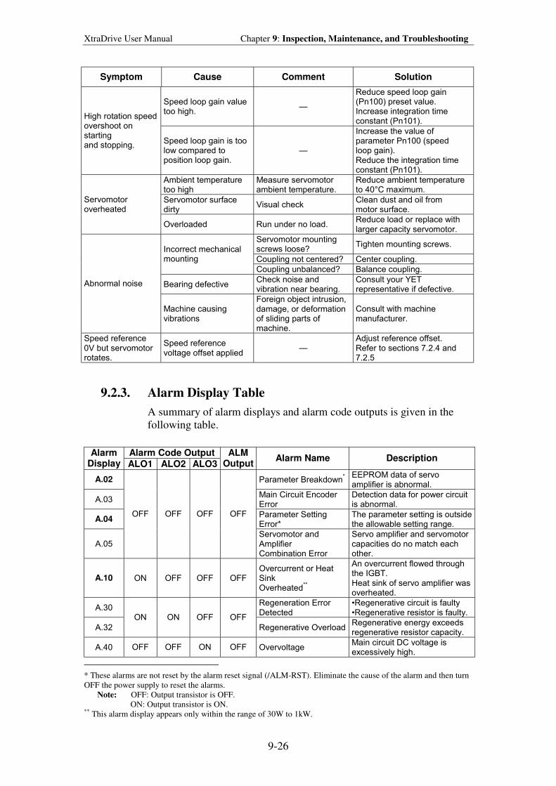
XtraDrive User Manual Chapter 9: Inspection, Maintenance, and Troubleshooting
9-26
Symptom Cause Comment Solution
Speed loop gain value too high.
Reduce speed loop gain (Pn100) preset value. Increase integration time constant (Pn101).
High rotation speed overshoot on starting and stopping.
Speed loop gain is too low compared to position loop gain.
Increase the value of parameter Pn100 (speed loop gain). Reduce the integration time constant (Pn101).
Ambient temperature too high
Measure servomotor ambient temperature.
Reduce ambient temperature to 40°C maximum.
Servomotor surface dirty
Visual check Clean dust and oil from motor surface.
Servomotor overheated
Overloaded Run under no load. Reduce load or replace with larger capacity servomotor.
Servomotor mounting screws loose?
Tighten mounting screws.
Coupling not centered? Center coupling.
Incorrect mechanical mounting
Coupling unbalanced? Balance coupling.
Bearing defective Check noise and vibration near bearing.
Consult your YET representative if defective.
Abnormal noise
Machine causing vibrations
Foreign object intrusion, damage, or deformation of sliding parts of machine.
Consult with machine manufacturer.
Speed reference 0V but servomotor rotates.
Speed reference voltage offset applied
Adjust reference offset. Refer to sections 7.2.4 and 7.2.5
9.2.3. Alarm Display Table
A summary of alarm displays and alarm code outputs is given in the
following table.
Alarm Code Output Alarm Display ALO1 ALO2 ALO3
ALM Output
Alarm Name Description
A.02 Parameter Breakdown*
EEPROM data of servo amplifier is abnormal.
A.03 Main Circuit Encoder Error
Detection data for power circuit is abnormal.
A.04 Parameter Setting Error*
The parameter setting is outside the allowable setting range.
A.05
OFF OFF OFF OFF
Servomotor and Amplifier Combination Error
Servo amplifier and servomotor capacities do no match each other.
A.10 ON OFF OFF OFF Overcurrent or Heat Sink Overheated
**
An overcurrent flowed through the IGBT. Heat sink of servo amplifier was overheated.
A.30 Regeneration Error Detected
Regenerative circuit is faulty Regenerative resistor is faulty.
A.32
ON ON OFF OFF
Regenerative Overload Regenerative energy exceeds regenerative resistor capacity.
A.40 OFF OFF ON OFF Overvoltage Main circuit DC voltage is excessively high.
* These alarms are not reset by the alarm reset signal (/ALM-RST). Eliminate the cause of the alarm and then turn
OFF the power supply to reset the alarms.
Note: OFF: Output transistor is OFF.
ON: Output transistor is ON. ** This alarm display appears only within the range of 30W to 1kW.
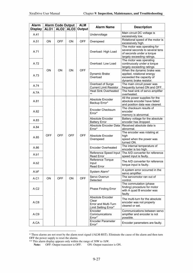
XtraDrive User Manual Chapter 9: Inspection, Maintenance, and Troubleshooting
9-27
Alarm Code Output Alarm Display ALO1 ALO2 ALO3
ALM Output
Alarm Name Description
A.41
Undervoltage Main circuit DC voltage is excessively low.
A.51 ON OFF ON OFF Overspeed Rotational speed of the motor is excessively high.
A.71 Overload: High Load
The motor was operating for several seconds to several tens of seconds under a torque largely exceeding ratings.
A.72 Overload: Low Load The motor was operating continuously under a torque largely exceeding ratings
A.73 Dynamic Brake Overload
When the dynamic brake was applied, rotational energy exceeded the capacity of dynamic brake resistor.
A.74 Overload of Surge Current Limit Resistor
The main circuit power was frequently turned ON and OFF.
A.7A
ON ON ON OFF
Heat Sink Overheated **
The heat sink of servo amplifier overheated.
A.81 Absolute Encoder Backup Error*
All the power supplies for the absolute encoder have failed and position data was cleared.
A.82 Encoder Checksum Error*
The checksum results of encoder memory is abnormal.
A.83 Absolute Encoder Battery Error
Battery voltage for the absolute encoder has dropped.
A.84 Absolute Encoder Data Error*
Received absolute data is abnormal.
A.85 Absolute Encoder Overspeed
The encoder was rotating at high speed when the power was turned ON.
A.86 Encoder Overheated The internal temperature of encoder is too high.
A.b1 Reference Speed Input Read Error
The A/D converter for reference speed input is faulty.
A.b2 Reference Torque Input Read Error
The A/D converter for reference torque input is faulty.
A.bF
OFF OFF OFF OFF
System Alarm* A system error occurred in the servo amplifier.
A.C1 Servo Overrun Detected
The servomotor ran out of control.
A.C2 Phase Finding Error
The commutation (phase finding) procedure for motor with A quad B encoder was faulty
A.C8
Absolute Encoder Clear Error and Multi-Turn Limit Setting Error*
The multi-turn for the absolute encoder was not properly cleared or set.
A.C9 Encoder Communications Error*
*
Communications between servo amplifier and encoder is not possible.
A.CA
ON OFF ON OFF
Encoder Parameter Error*
Encoder parameters are faulty.
* These alarms are not reset by the alarm reset signal (/ALM-RST). Eliminate the cause of the alarm and then turn
OFF the power supply to reset the alarms.
** This alarm display appears only within the range of 30W to 1kW.
Note: OFF: Output transistor is OFF. ON: Output transistor is ON.
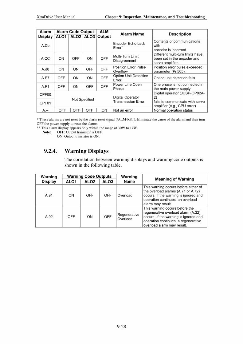
XtraDrive User Manual Chapter 9: Inspection, Maintenance, and Troubleshooting
9-28
Alarm Code Output Alarm Display ALO1 ALO2 ALO3
ALM Output
Alarm Name Description
A.Cb
Encoder Echo back Error*
Contents of communications with encoder is incorrect.
A.CC ON OFF ON OFF Multi-Turn Limit Disagreement
Different multi-turn limits have been set in the encoder and servo amplifier.
A.d0 ON ON OFF OFF Position Error Pulse Overflow
Position error pulse exceeded parameter (Pn505).
A.E7 OFF ON ON OFF Option Unit Detection Error
Option unit detection fails.
A.F1 OFF ON OFF OFF Power Line Open Phase
One phase is not connected in the main power supply
CPF00
CPF01 Not Specified
Digital Operator Transmission Error
Digital operator (JUSP-OP02A-2) fails to communicate with servo amplifier (e.g., CPU error).
A.-- OFF OFF OFF ON Not an error Normal operation status
* These alarms are not reset by the alarm reset signal (/ALM-RST). Eliminate the cause of the alarm and then turn
OFF the power supply to reset the alarms.
** This alarm display appears only within the range of 30W to 1kW.
Note: OFF: Output transistor is OFF.
ON: Output transistor is ON.
9.2.4. Warning Displays
The correlation between warning displays and warning code outputs is
shown in the following table.
Warning Code Outputs Warning Display ALO1 ALO2 ALO3
Warning Name
Meaning of Warning
A.91 ON OFF OFF Overload
This warning occurs before either of the overload alarms (A.71 or A.72) occurs. If the warning is ignored and operation continues, an overload alarm may result.
A.92 OFF ON OFF Regenerative Overload
This warning occurs before the regenerative overload alarm (A.32) occurs. If the warning is ignored and operation continues, a regenerative overload alarm may result.
XtraDrive User Manual Appendix A: Host Controller Connection Examples
A-1
Appendix A. Host Controller Connect ion
Examples
This appendix provides examples for XtraDrive servo amplifiers connected to
typical host controllers. Refer to the manuals for the host controller when
actually connecting to them.
A.1. Connecting the GL-series MC20 Motion Module .....................................A-2
A.2. Connecting the CP-9200SH Servo Controller Module (SVA) ..................A-3
A.3. Connecting the GL-series B2813 Positioning Module ..............................A-4
A.4. Connecting OMRON's C500-NC221 Position Control Unit .....................A-5
A.5. Connecting OMRON's C500-NC112 Position Control Unit .....................A-6
A.6. Connecting MITSUBISHI's AD72 Positioning Unit.................................A-7
A.7. Connecting MITSUBISHI's AD75 Positioning Unit.................................A-8
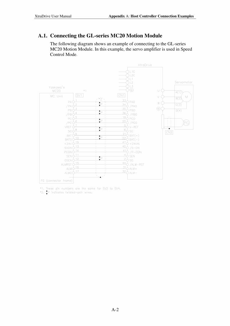
XtraDrive User Manual Appendix A: Host Controller Connection Examples
A-2
A.1. Connecting the GL-series MC20 Motion Module
The following diagram shows an example of connecting to the GL-series
MC20 Motion Module. In this example, the servo amplifier is used in Speed
Control Mode.
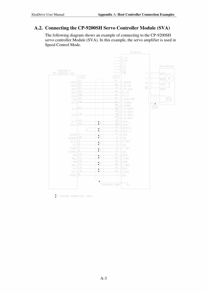
XtraDrive User Manual Appendix A: Host Controller Connection Examples
A-3
A.2. Connecting the CP-9200SH Servo Controller Module (SVA)
The following diagram shows an example of connecting to the CP-9200SH
servo controller Module (SVA). In this example, the servo amplifier is used in
Speed Control Mode.
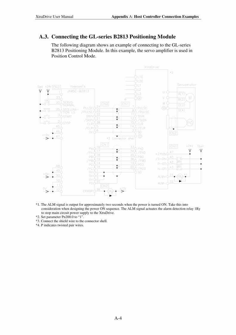
XtraDrive User Manual Appendix A: Host Controller Connection Examples
A-4
A.3. Connecting the GL-series B2813 Positioning Module
The following diagram shows an example of connecting to the GL-series
B2813 Positioning Module. In this example, the servo amplifier is used in
Position Control Mode.
*1. The ALM signal is output for approximately two seconds when the power is turned ON. Take this into
consideration when designing the power ON sequence. The ALM signal actuates the alarm detection relay 1Ry
to stop main circuit power supply to the XtraDrive.
*2. Set parameter Pn200.0 to “1”.
*3. Connect the shield wire to the connector shell.
*4. P indicates twisted pair wires.
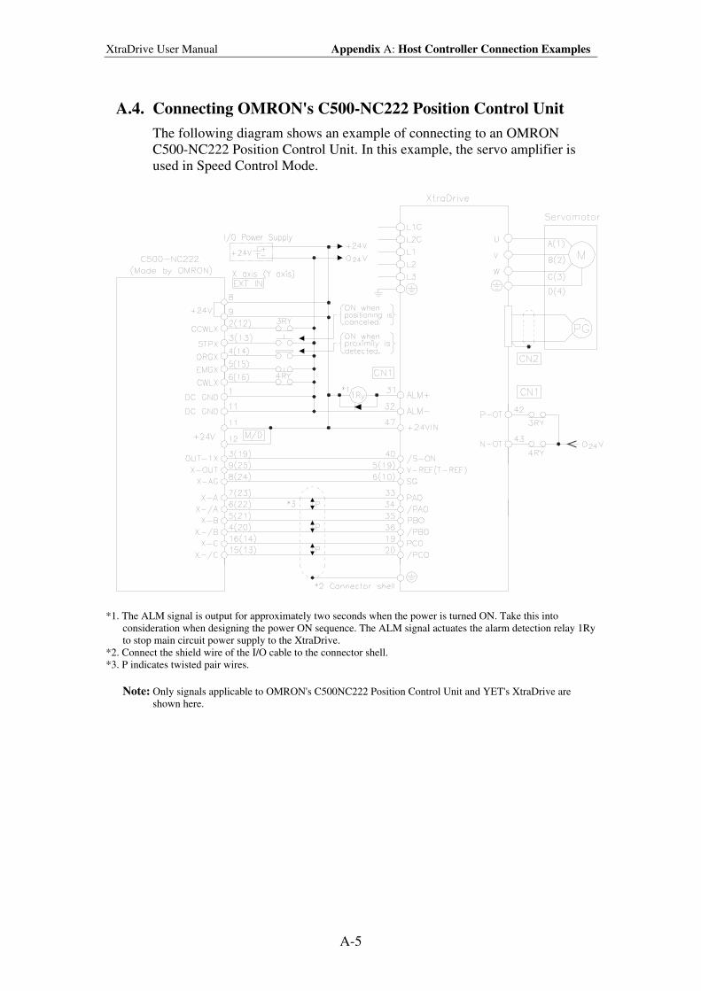
XtraDrive User Manual Appendix A: Host Controller Connection Examples
A-5
A.4. Connecting OMRON's C500-NC222 Position Control Unit
The following diagram shows an example of connecting to an OMRON
C500-NC222 Position Control Unit. In this example, the servo amplifier is
used in Speed Control Mode.
*1. The ALM signal is output for approximately two seconds when the power is turned ON. Take this into
consideration when designing the power ON sequence. The ALM signal actuates the alarm detection relay 1Ry
to stop main circuit power supply to the XtraDrive.
*2. Connect the shield wire of the I/O cable to the connector shell.
*3. P indicates twisted pair wires.
Note: Only signals applicable to OMRON's C500NC222 Position Control Unit and YET's XtraDrive are
shown here.
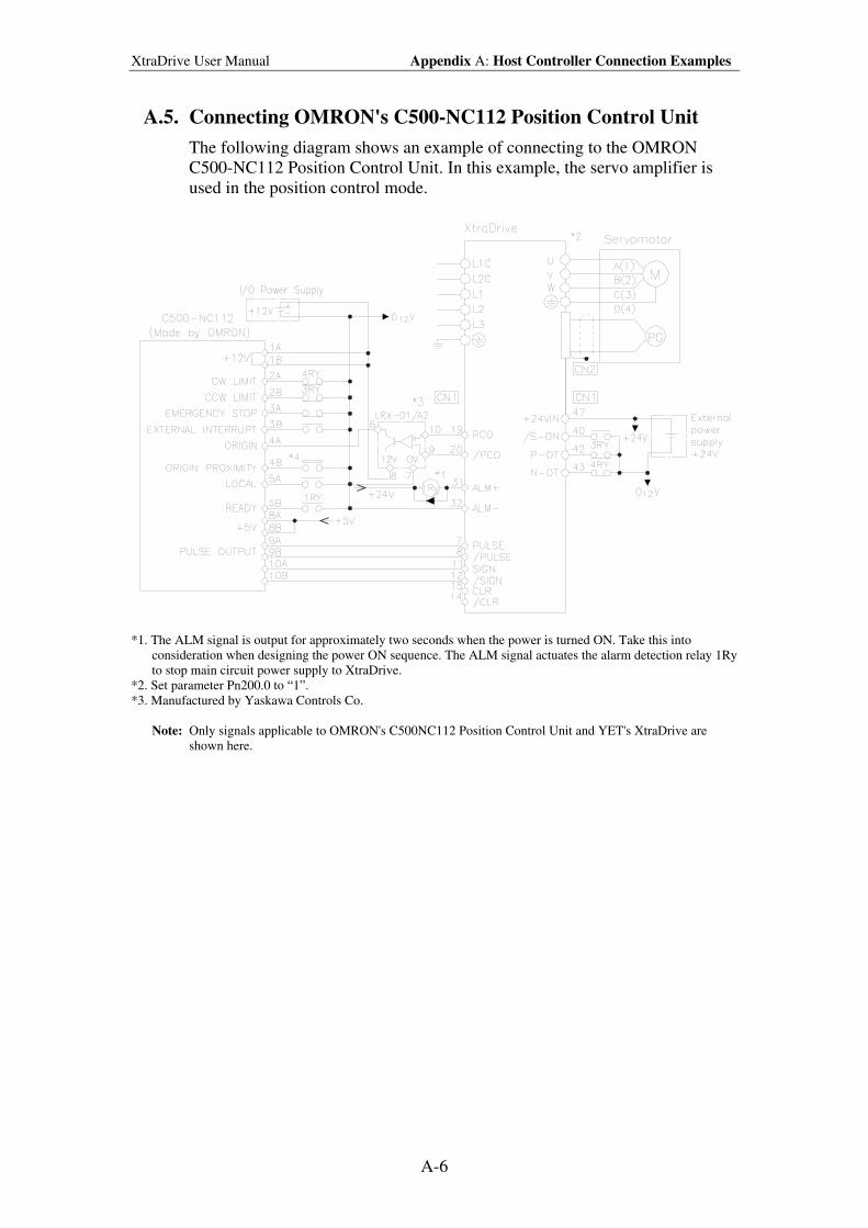
XtraDrive User Manual Appendix A: Host Controller Connection Examples
A-6
A.5. Connecting OMRON's C500-NC112 Position Control Unit
The following diagram shows an example of connecting to the OMRON
C500-NC112 Position Control Unit. In this example, the servo amplifier is
used in the position control mode.
*1. The ALM signal is output for approximately two seconds when the power is turned ON. Take this into
consideration when designing the power ON sequence. The ALM signal actuates the alarm detection relay 1Ry
to stop main circuit power supply to XtraDrive.
*2. Set parameter Pn200.0 to “1”.
*3. Manufactured by Yaskawa Controls Co.
Note: Only signals applicable to OMRON's C500NC112 Position Control Unit and YET's XtraDrive are
shown here.
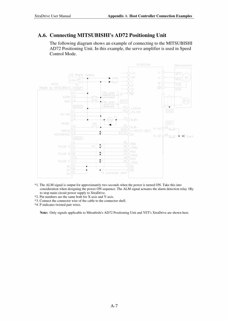
XtraDrive User Manual Appendix A: Host Controller Connection Examples
A-7
A.6. Connecting MITSUBISHI's AD72 Positioning Unit
The following diagram shows an example of connecting to the MITSUBISHI
AD72 Positioning Unit. In this example, the servo amplifier is used in Speed
Control Mode.
*1. The ALM signal is output for approximately two seconds when the power is turned ON. Take this into
consideration when designing the power ON sequence. The ALM signal actuates the alarm detection relay 1Ry
to stop main circuit power supply to XtraDrive.
*2. Pin numbers are the same both for X-axis and Y-axis.
*3. Connect the connector wire of the cable to the connector shell.
*4. P indicates twisted pair wires.
Note: Only signals applicable to Mitsubishi's AD72 Positioning Unit and YET's XtraDrive are shown here.
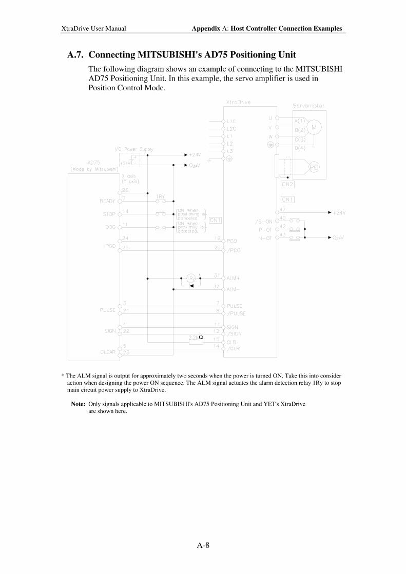
XtraDrive User Manual Appendix A: Host Controller Connection Examples
A-8
A.7. Connecting MITSUBISHI's AD75 Positioning Unit
The following diagram shows an example of connecting to the MITSUBISHI
AD75 Positioning Unit. In this example, the servo amplifier is used in
Position Control Mode.
Ω
* The ALM signal is output for approximately two seconds when the power is turned ON. Take this into consider
action when designing the power ON sequence. The ALM signal actuates the alarm detection relay 1Ry to stop
main circuit power supply to XtraDrive.
Note: Only signals applicable to MITSUBISHI's AD75 Positioning Unit and YET's XtraDrive
are shown here.

XtraDrive User Manual Appendix B: Special Wiring
B-1
Appendix B. Special Wiring
This appendix provides examples for XtraDrive servo amplifiers connected to
typical host controllers. Refer to the manuals for the host controller when
actually connecting to them.
B.1. Wiring Precautions.....................................................................................B-2
B.2. Wiring for Noise Control ...........................................................................B-5
B.3. Using More Than One XtraDrive ..............................................................B-9
B.4. Extending Encoder Cables .......................................................................B-10
B.5. 400V Power Supply Voltage ...................................................................B-12
B.6. Reactor for Harmonic Suppression..........................................................B-14
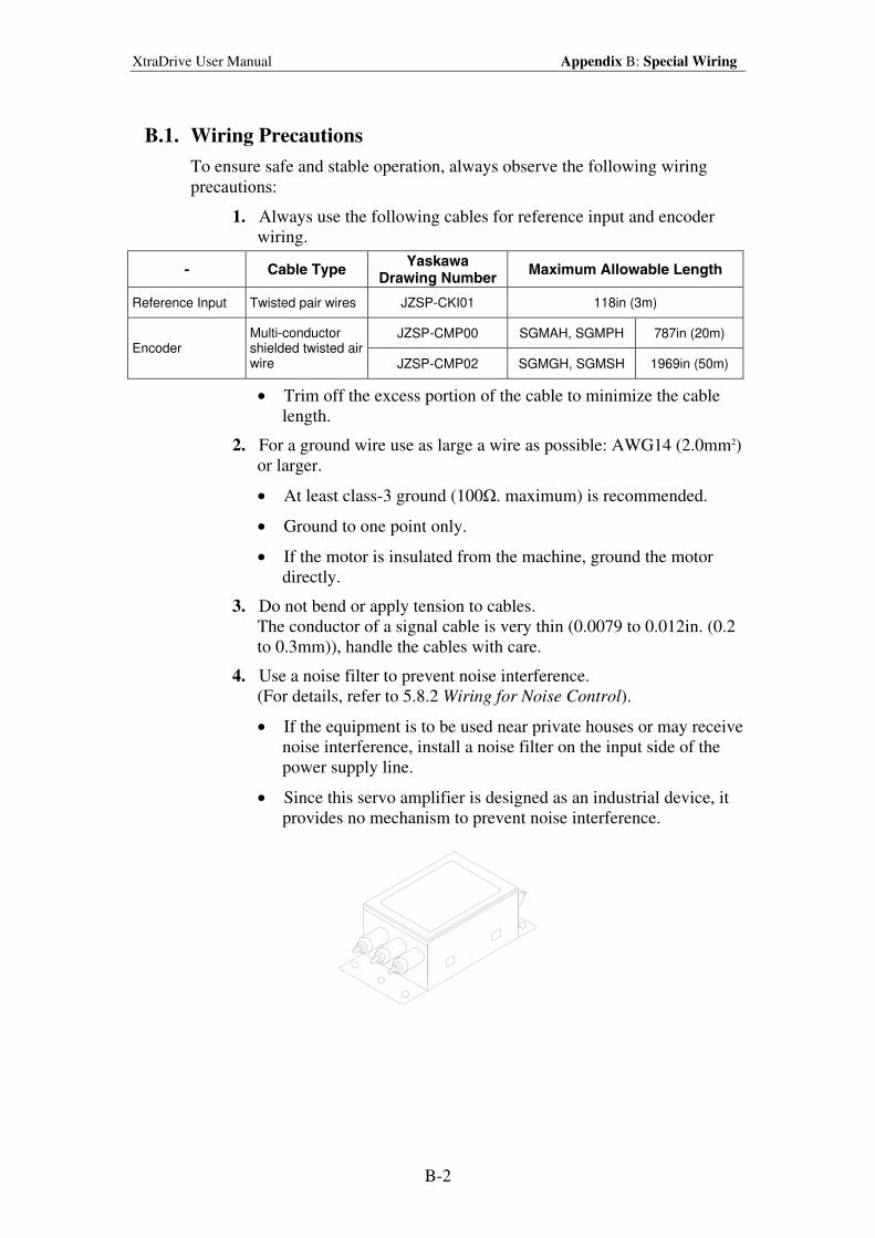
XtraDrive User Manual Appendix B: Special Wiring
B-2
B.1. Wiring Precautions
To ensure safe and stable operation, always observe the following wiring
precautions:
1. Always use the following cables for reference input and encoder
wiring.
- Cable Type Yaskawa
Drawing Number Maximum Allowable Length
Reference Input Twisted pair wires JZSP-CKI01 118in (3m)
JZSP-CMP00 SGMAH, SGMPH 787in (20m) Encoder
Multi-conductor shielded twisted air wire JZSP-CMP02 SGMGH, SGMSH 1969in (50m)
• Trim off the excess portion of the cable to minimize the cable
length.
2. For a ground wire use as large a wire as possible: AWG14 (2.0mm2)
or larger.
• At least class-3 ground (100Ω. maximum) is recommended.
• Ground to one point only.
• If the motor is insulated from the machine, ground the motor
directly.
3. Do not bend or apply tension to cables.
The conductor of a signal cable is very thin (0.0079 to 0.012in. (0.2
to 0.3mm)), handle the cables with care.
4. Use a noise filter to prevent noise interference.
(For details, refer to 5.8.2 Wiring for Noise Control).
• If the equipment is to be used near private houses or may receive
noise interference, install a noise filter on the input side of the
power supply line.
• Since this servo amplifier is designed as an industrial device, it
provides no mechanism to prevent noise interference.
XtraDrive User Manual Appendix B: Special Wiring
B-3
5. To prevent malfunction due to noise, take the following actions:
• Position the input reference device and noise filter as close to the
servo amplifier as possible.
• Always install a surge absorber circuit in the relay, solenoid, and
electromagnetic contactor coils.
• The distance between a power line (such as a power supply line
or motor cable) and a signal line must be at least 11.8in (30cm).
Do not put the power and signal lines in the same duct or bundle
them together.
• Do not share the power supply with an electric welder or
electrical discharge machine. When the servo amplifier is placed
near a high-frequency oscillator, install a noise filter on the input
side of the power supply line.
Note: 1. Since the servo amplifier uses high-speed switching elements, signal lines may receive noise.
To prevent this, always take the above precautions.
2. For details on grounding and noise filters, refer to 5.8.2 Wiring for Noise Control.
6. Use a UL listed molded-case circuit breaker (MCCB) or fuse in
accordance with the National Electrical Code (NEC) to protect the
power supply line from high voltage.
• This servo amplifier connects directly to a commercial power
supply without a transformer, so always use an MCCB or fuse to
protect the servo system from accidental high voltage.
• Select an appropriate MCCB or fuse according to the servo
amplifier capacity and the number of servo amplifiers to be used
as shown in the following table.
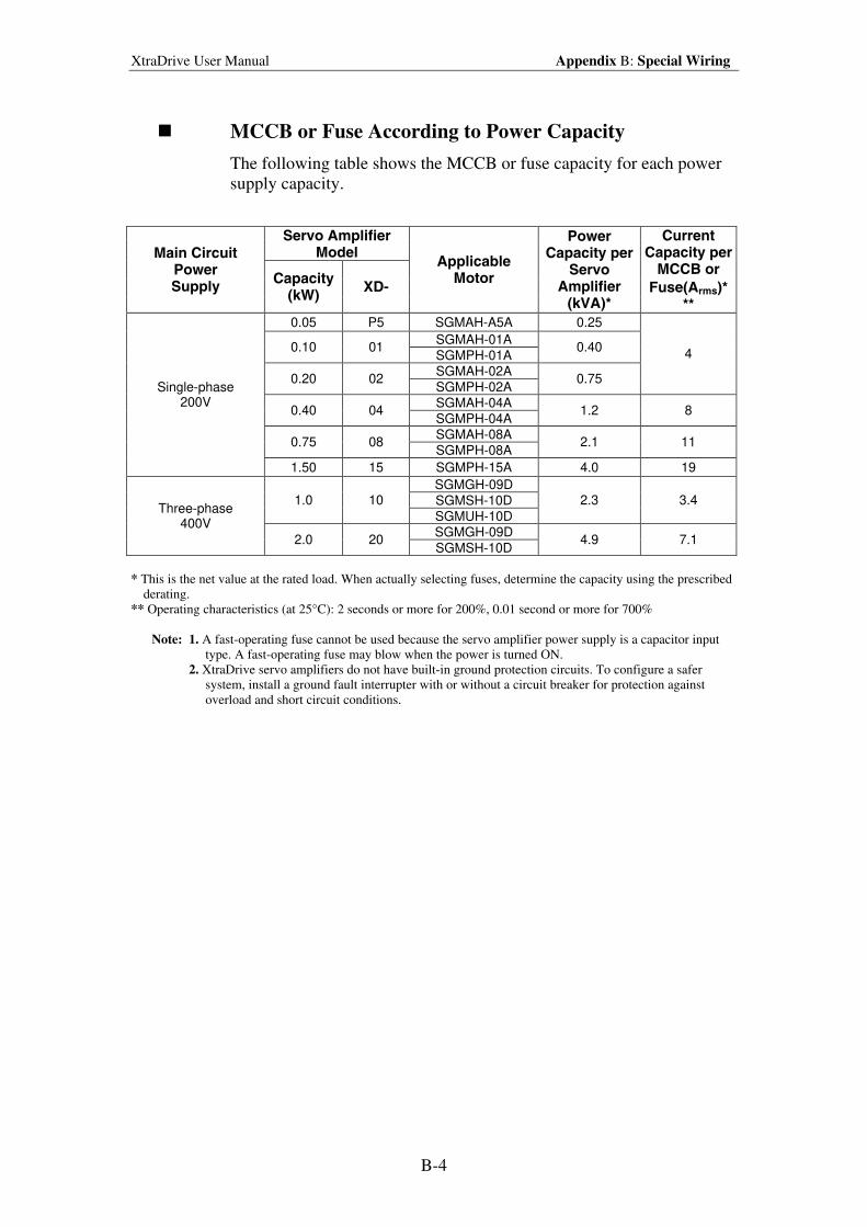
XtraDrive User Manual Appendix B: Special Wiring
B-4
MCCB or Fuse According to Power Capacity
The following table shows the MCCB or fuse capacity for each power
supply capacity.
Servo Amplifier Model Main Circuit
Power Supply
Capacity (kW)
XD-
Applicable Motor
Power Capacity per
Servo Amplifier
(kVA)*
Current Capacity per
MCCB or
Fuse(Arms)* **
0.05 P5 SGMAH-A5A 0.25
SGMAH-01A 0.10 01
SGMPH-01A 0.40
SGMAH-02A 0.20 02
SGMPH-02A 0.75
4
SGMAH-04A 0.40 04
SGMPH-04A 1.2 8
SGMAH-08A 0.75 08
SGMPH-08A 2.1 11
Single-phase 200V
1.50 15 SGMPH-15A 4.0 19
SGMGH-09D
SGMSH-10D 1.0 10
SGMUH-10D
2.3 3.4
SGMGH-09D
Three-phase 400V
2.0 20 SGMSH-10D
4.9 7.1
* This is the net value at the rated load. When actually selecting fuses, determine the capacity using the prescribed
derating.
** Operating characteristics (at 25°C): 2 seconds or more for 200%, 0.01 second or more for 700%
Note: 1. A fast-operating fuse cannot be used because the servo amplifier power supply is a capacitor input
type. A fast-operating fuse may blow when the power is turned ON.
2. XtraDrive servo amplifiers do not have built-in ground protection circuits. To configure a safer
system, install a ground fault interrupter with or without a circuit breaker for protection against
overload and short circuit conditions.
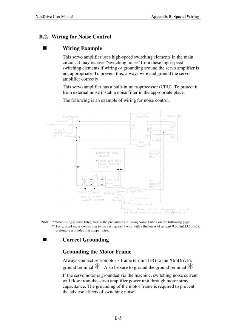
XtraDrive User Manual Appendix B: Special Wiring
B-5
B.2. Wiring for Noise Control
Wiring Example
This servo amplifier uses high-speed switching elements in the main
circuit. It may receive “switching noise” from these high-speed
switching elements if wiring or grounding around the servo amplifier is
not appropriate. To prevent this, always wire and ground the servo
amplifier correctly.
This servo amplifier has a built-in microprocessor (CPU). To protect it
from external noise install a noise filter in the appropriate place.
The following is an example of wiring for noise control.
Ω
Note: * When using a noise filter, follow the precautions in Using Noise Filters on the following page.
** For ground wires connecting to the casing, use a wire with a thickness of at least 0.005in2 (3.5mm2),
preferably a braided flat copper wire.
Correct Grounding
Grounding the Motor Frame
Always connect servomotor’s frame terminal FG to the XtraDrive’s
ground terminal . Also be sure to ground the ground terminal .
If the servomotor is grounded via the machine, switching noise current
will flow from the servo amplifier power unit through motor stray
capacitance. The grounding of the motor frame is required to prevent
the adverse effects of switching noise.
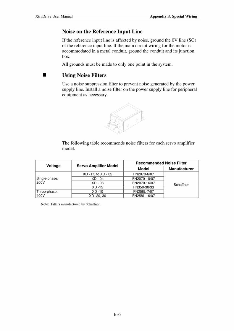
XtraDrive User Manual Appendix B: Special Wiring
B-6
Noise on the Reference Input Line
If the reference input line is affected by noise, ground the 0V line (SG)
of the reference input line. If the main circuit wiring for the motor is
accommodated in a metal conduit, ground the conduit and its junction
box.
All grounds must be made to only one point in the system.
Using Noise Filters
Use a noise suppression filter to prevent noise generated by the power
supply line. Install a noise filter on the power supply line for peripheral
equipment as necessary.
The following table recommends noise filters for each servo amplifier
model.
Recommended Noise Filter Voltage Servo Amplifier Model
Model Manufacturer
XD - P3 to XD - 02 FN2070-6/07
XD - 04 FN2070-10/07
XD - 08 FN2070-16/07
Single-phase, 200V
XD -15 FN350-30/33
XD -10 FN258L-7/07 Three-phase, 400V XD -20, 30 FN258L-16/07
Schaffner
Note: Filters manufactured by Schaffner.
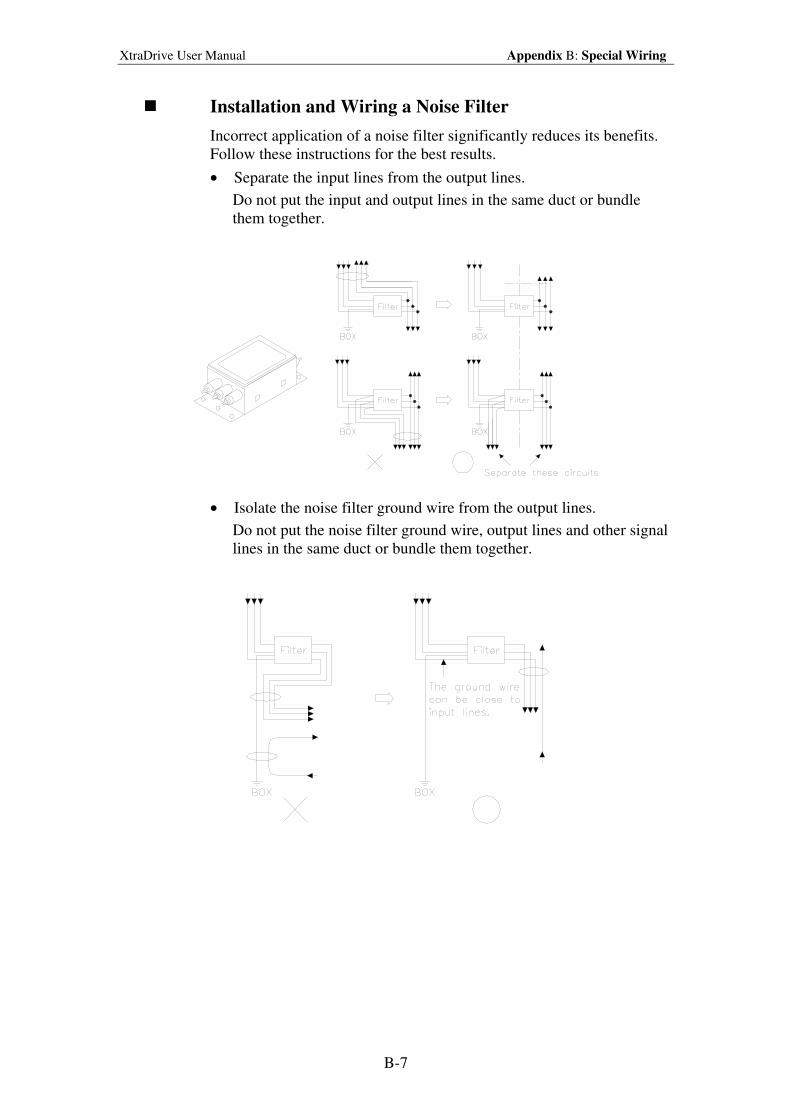
XtraDrive User Manual Appendix B: Special Wiring
B-7
Installation and Wiring a Noise Filter
Incorrect application of a noise filter significantly reduces its benefits.
Follow these instructions for the best results.
• Separate the input lines from the output lines.
Do not put the input and output lines in the same duct or bundle
them together.
• Isolate the noise filter ground wire from the output lines.
Do not put the noise filter ground wire, output lines and other signal
lines in the same duct or bundle them together.
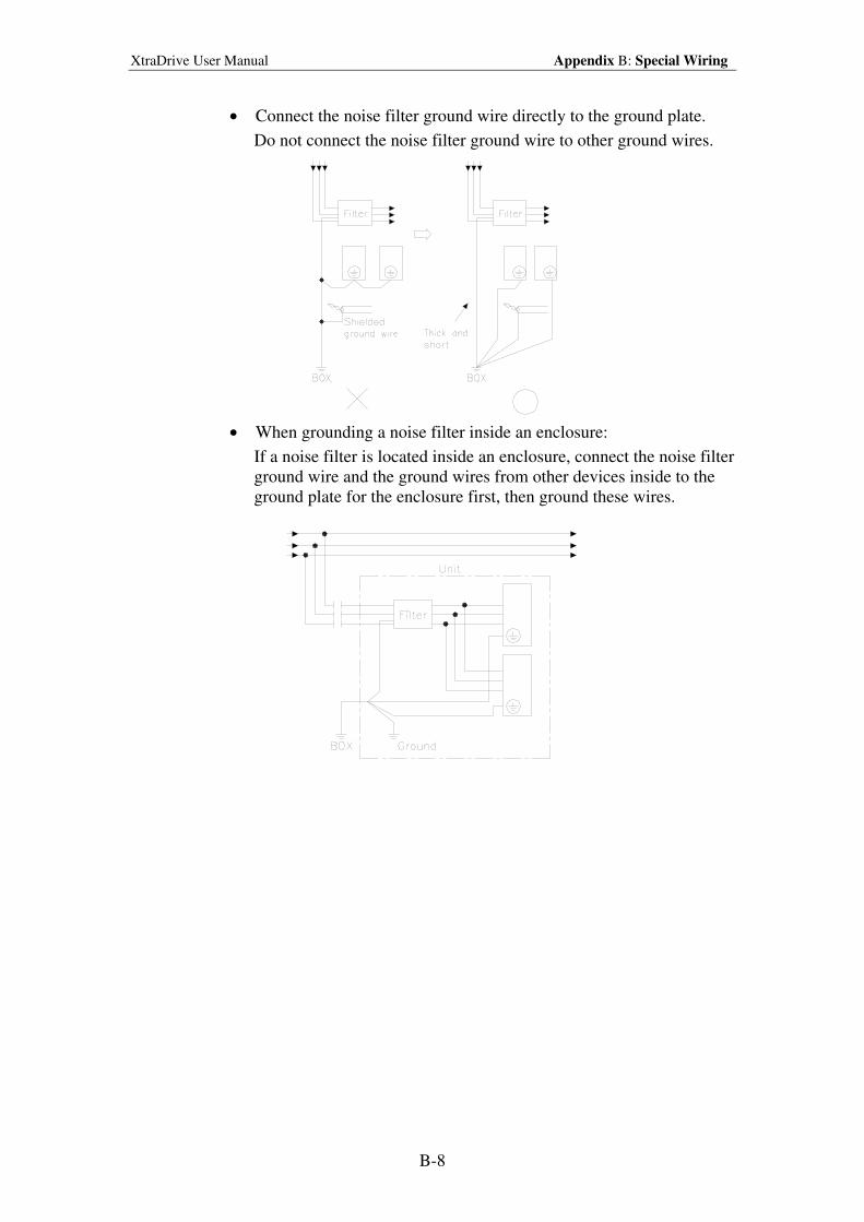
XtraDrive User Manual Appendix B: Special Wiring
B-8
• Connect the noise filter ground wire directly to the ground plate.
Do not connect the noise filter ground wire to other ground wires.
• When grounding a noise filter inside an enclosure:
If a noise filter is located inside an enclosure, connect the noise filter
ground wire and the ground wires from other devices inside to the
ground plate for the enclosure first, then ground these wires.
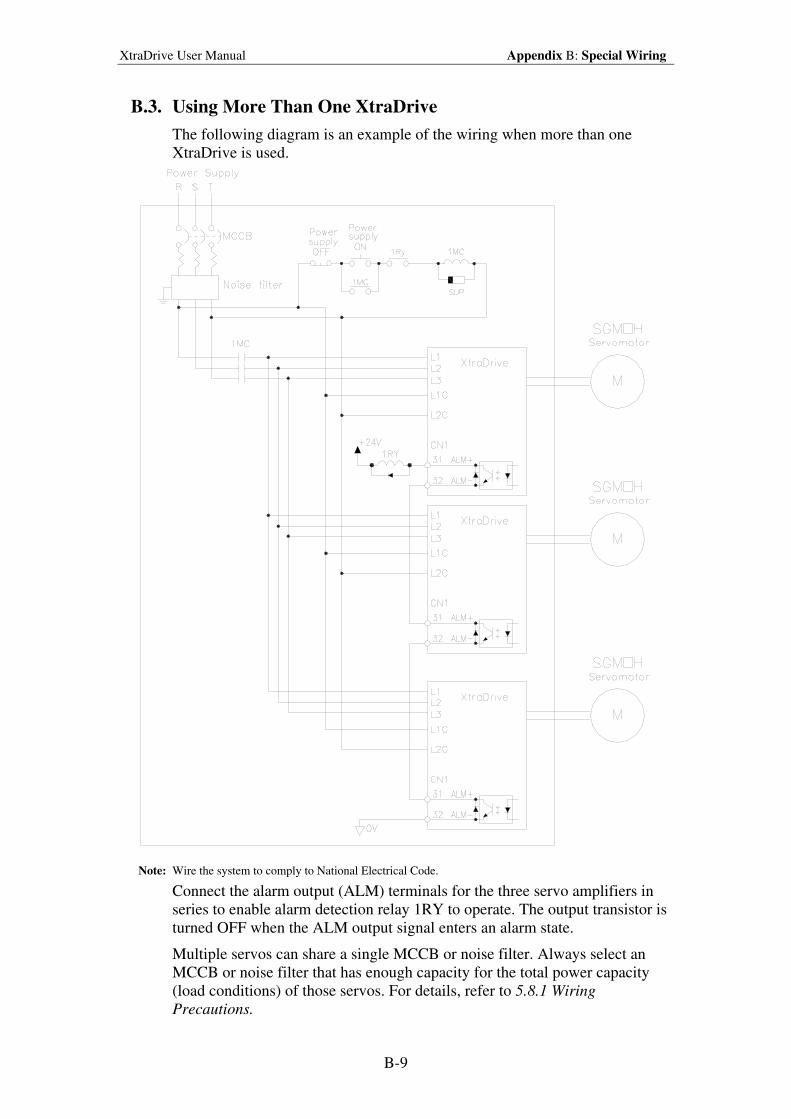
XtraDrive User Manual Appendix B: Special Wiring
B-9
B.3. Using More Than One XtraDrive
The following diagram is an example of the wiring when more than one
XtraDrive is used.
Note: Wire the system to comply to National Electrical Code.
Connect the alarm output (ALM) terminals for the three servo amplifiers in
series to enable alarm detection relay 1RY to operate. The output transistor is
turned OFF when the ALM output signal enters an alarm state.
Multiple servos can share a single MCCB or noise filter. Always select an
MCCB or noise filter that has enough capacity for the total power capacity
(load conditions) of those servos. For details, refer to 5.8.1 Wiring
Precautions.
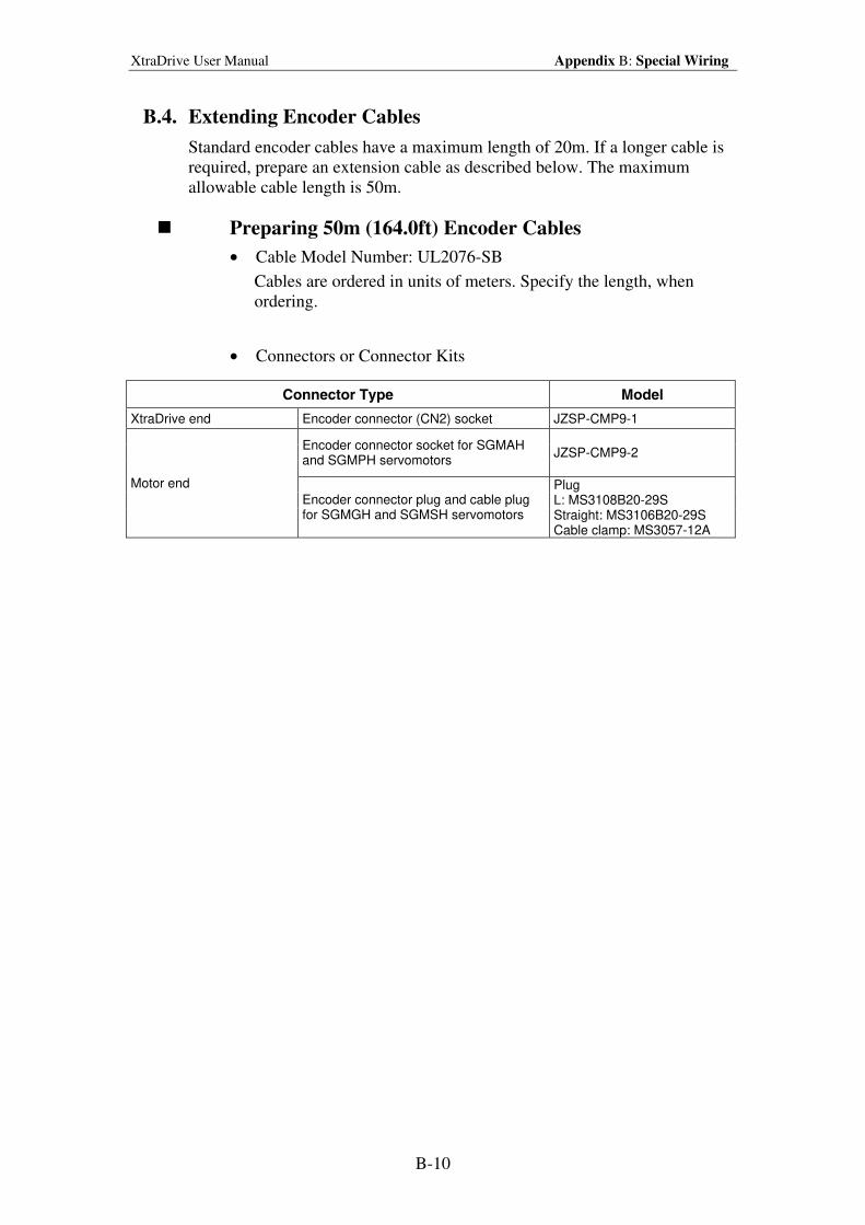
XtraDrive User Manual Appendix B: Special Wiring
B-10
B.4. Extending Encoder Cables
Standard encoder cables have a maximum length of 20m. If a longer cable is
required, prepare an extension cable as described below. The maximum
allowable cable length is 50m.
Preparing 50m (164.0ft) Encoder Cables
• Cable Model Number: UL2076-SB
Cables are ordered in units of meters. Specify the length, when
ordering.
• Connectors or Connector Kits
Connector Type Model
XtraDrive end Encoder connector (CN2) socket JZSP-CMP9-1
Encoder connector socket for SGMAH and SGMPH servomotors
JZSP-CMP9-2
Motor end
Encoder connector plug and cable plug for SGMGH and SGMSH servomotors
Plug L: MS3108B20-29S Straight: MS3106B20-29S Cable clamp: MS3057-12A
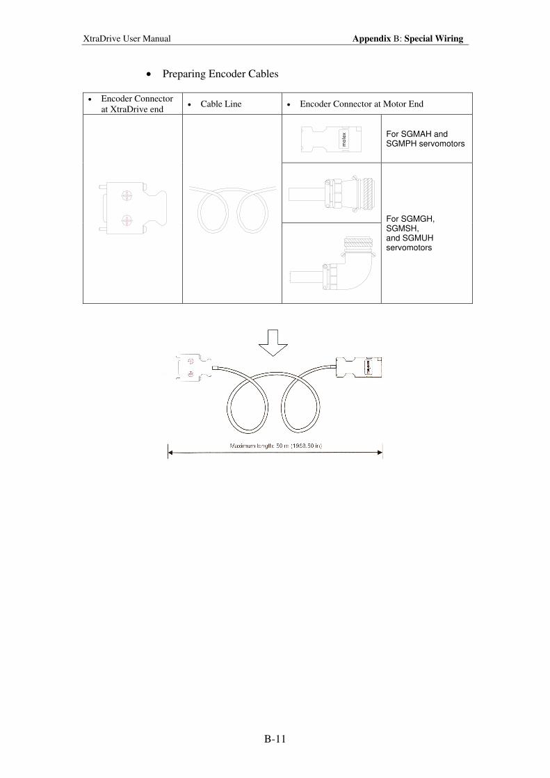
XtraDrive User Manual Appendix B: Special Wiring
B-11
• Preparing Encoder Cables
• Encoder Connector
at XtraDrive end • Cable Line • Encoder Connector at Motor End
mo
lex
For SGMAH and SGMPH servomotors
For SGMGH, SGMSH, and SGMUH servomotors
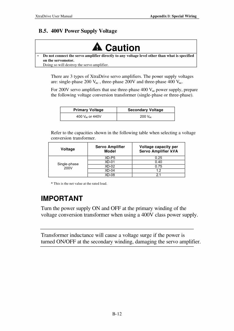
XtraDrive User Manual Appendix B: Special Wiring
B-12
B.5. 400V Power Supply Voltage
Caution • Do not connect the servo amplifier directly to any voltage level other than what is specified
on the servomotor.
Doing so will destroy the servo amplifier.
There are 3 types of XtraDrive servo amplifiers. The power supply voltages are: single-phase 200 Vac , three-phase 200V and three-phase 400 Vac.
For 200V servo amplifiers that use three-phase 400 Vac power supply, prepare the following voltage conversion transformer (single-phase or three-phase).
Primary Voltage Secondary Voltage
400 Vac or 440V 200 Vac
Refer to the capacities shown in the following table when selecting a voltage conversion transformer.
Voltage Servo Amplifier
Model Voltage capacity per Servo Amplifier
* kVA
XD-P5 0.25 XD-01 0.40
XD-02 0.75 XD-04 1.2
Single-phase 200V
XD-08 2.1
* This is the net value at the rated load.
IMPORTANT
Turn the power supply ON and OFF at the primary winding of the
voltage conversion transformer when using a 400V class power supply.
Transformer inductance will cause a voltage surge if the power is
turned ON/OFF at the secondary winding, damaging the servo amplifier.
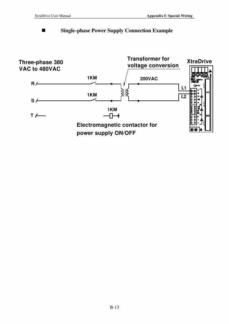
XtraDrive User Manual Appendix B: Special Wiring
B-13
n Single-phase Power Supply Connection Example
NC
NC
3
1
C
2N
1KM
1KM
Transformer for
voltage conversion
200VAC
L1
L2
Electromagnetic contactor for
power supply ON/OFF
R
S
T
XtraDrive
1KM
VAC to 480VAC
Three-phase 380
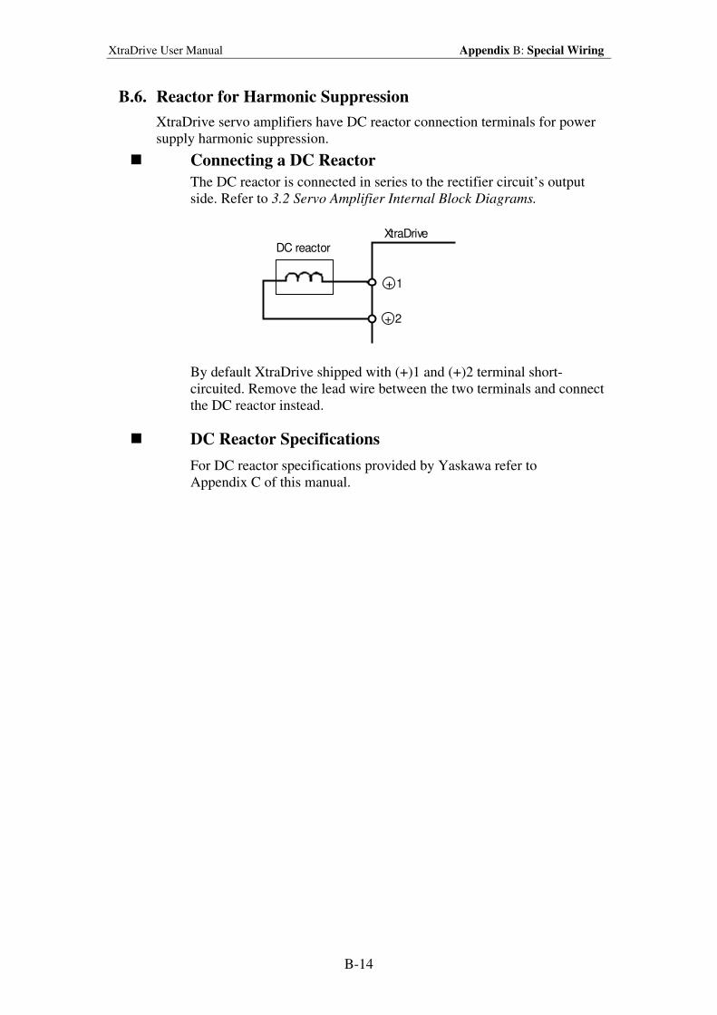
XtraDrive User Manual Appendix B: Special Wiring
B-14
B.6. Reactor for Harmonic Suppression
XtraDrive servo amplifiers have DC reactor connection terminals for power
supply harmonic suppression.
Connecting a DC Reactor
The DC reactor is connected in series to the rectifier circuit’s output
side. Refer to 3.2 Servo Amplifier Internal Block Diagrams.
+ 1
+ 2
DC reactorXtraDrive
By default XtraDrive shipped with (+)1 and (+)2 terminal short-
circuited. Remove the lead wire between the two terminals and connect
the DC reactor instead.
DC Reactor Specifications
For DC reactor specifications provided by Yaskawa refer to
Appendix C of this manual.
XtraDrive User Manual Appen dix C: Specifications for Peripheral Devices
C-1
Appendix C. Specificat ions for Peripheral
Devices
This chapter provides specifications and dimensional drawings for peripheral
devices required in XtraDrive Series Servo System.
C.1. Connector Terminal Block Converter Unit JUSP-TA50P.........................C-2
C.2. External Regenerative Resistors ................................................................C-4
C.3. DC Reactors for Power Supplies Designed for Minimum Harmonics .....C-6
C.4. Brake Power Supplies ................................................................................C-8
C.5. Surge Suppressor .......................................................................................C-9
C.6. Magnetic Contactor....................................................................................C-9
C.7. Variable Resistor for Speed Setting...........................................................C-9
C.8. CN1 I/O Signal Connector.........................................................................C-9
C.9. Connecting Pulse A/B Encoder without C Pulse (Index Pulse) ..............C-10
C.10. Absolute Encoder Battery ....................................................................C-11
C.11. Cables for Connecting PC to XtraDrive ..............................................C-12
C.11.1. RS-232 Communication Cable ........................................................C-12
C.11.2. Cable with RS-232 to RS-422 Active Adapter ................................C-14
C.12. Connecting Regenerative Resistors .....................................................C-15
C.13. Connecting Yaskawa Option Board.....................................................C-19
C.13.1. Attaching the Option Board .............................................................C-19
C.13.2. Detaching the Option Board ............................................................C-19
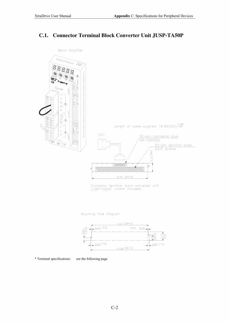
XtraDrive User Manual Appendix C: Specifications for Peripheral Devices
C-2
C.1. Connector Terminal Block Converter Unit JUSP-TA50P
* Terminal specifications: see the following page
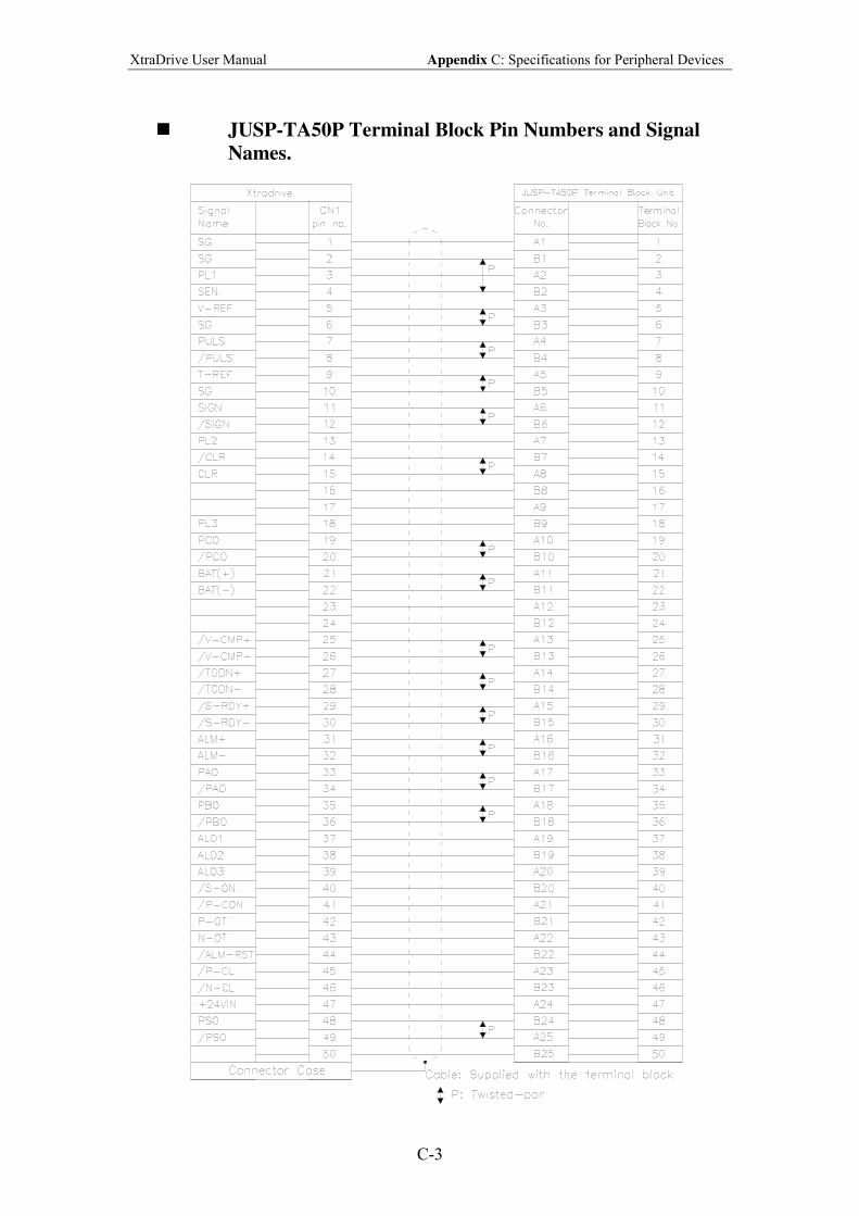
XtraDrive User Manual Appendix C: Specifications for Peripheral Devices
C-3
! JUSP-TA50P Terminal Block Pin Numbers and Signal
Names.
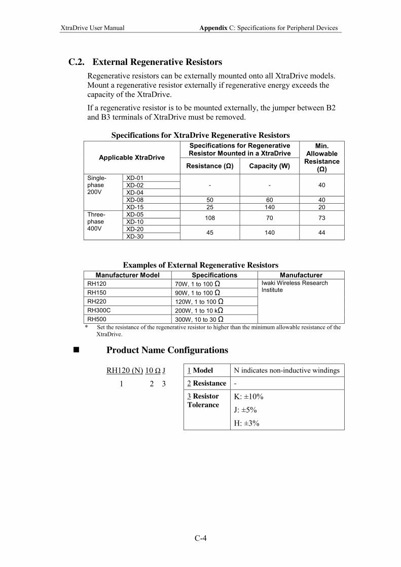
XtraDrive User Manual Appendix C: Specifications for Peripheral Devices
C-4
C.2. External Regenerative Resistors
Regenerative resistors can be externally mounted onto all XtraDrive models.
Mount a regenerative resistor externally if regenerative energy exceeds the
capacity of the XtraDrive.
If a regenerative resistor is to be mounted externally, the jumper between B2
and B3 terminals of XtraDrive must be removed.
Specifications for XtraDrive Regenerative Resistors
Specifications for Regenerative Resistor Mounted in a XtraDrive
Applicable XtraDrive
Resistance (Ω) Capacity (W)
Min. Allowable
Resistance (Ω)
XD-01
XD-02
XD-04
- - 40
XD-08 50 60 40
Single-phase 200V
XD-15 25 140 20
XD-05
XD-10 108 70 73
XD-20
Three-phase 400V
XD-30 45 140 44
Examples of External Regenerative Resistors
Manufacturer Model Specifications Manufacturer
RH120 70W, 1 to 100 Ω
RH150 90W, 1 to 100 Ω
RH220 120W, 1 to 100 Ω
RH300C 200W, 1 to 10 kΩ
RH500 300W, 10 to 30 Ω
Iwaki Wireless Research Institute
* Set the resistance of the regenerative resistor to higher than the minimum allowable resistance of the
XtraDrive.
! Product Name Configurations
RH120 (N) 10 Ω J
1 2 3
1 Model N indicates non-inductive windings
2 Resistance -
3 Resistor
Tolerance K: ±10%
J: ±5%
H: ±3%
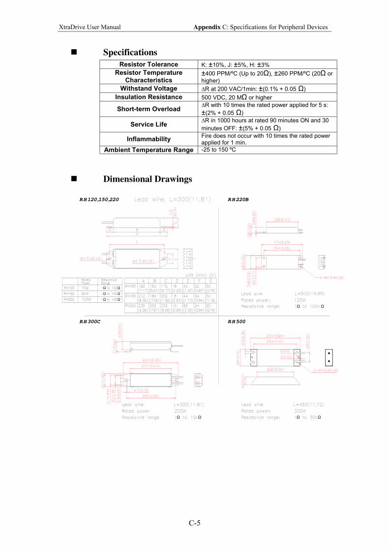
XtraDrive User Manual Appendix C: Specifications for Peripheral Devices
C-5
! Specifications
Resistor Tolerance K: ±10%, J: ±5%, H: ±3%
Resistor Temperature Characteristics
±400 PPM/ºC (Up to 20Ω), ±260 PPM/ºC (20Ω or
higher)
Withstand Voltage ∆R at 200 VAC/1min: ±(0.1% + 0.05 Ω)
Insulation Resistance 500 VDC, 20 MΩ or higher
Short-term Overload ∆R with 10 times the rated power applied for 5 s:
±(2% + 0.05 Ω)
Service Life ∆R in 1000 hours at rated 90 minutes ON and 30
minutes OFF: ±(5% + 0.05 Ω)
Inflammability Fire does not occur with 10 times the rated power applied for 1 min.
Ambient Temperature Range -25 to 150 ºC
! Dimensional Drawings
RH120,150,220 RH220B
RH300C RH500
Ω
Ω
ΩΩ
ΩΩ ΩΩ Ω
Ω
ΩΩ
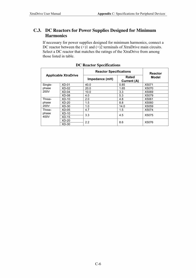
XtraDrive User Manual Appendix C: Specifications for Peripheral Devices
C-6
C.3. DC Reactors for Power Supplies Designed for Minimum
Harmonics
If necessary for power supplies designed for minimum harmonics, connect a
DC reactor between the (+)1 and (+)2 terminals of XtraDrive main circuits.
Select a DC reactor that matches the ratings of the XtraDrive from among
those listed in table.
DC Reactor Specifications
Reactor Specifications Applicable XtraDrive
Impedance (mH) Rated
Current (A)
Reactor Model
XD-01 40.0 0.85 X5071
XD-02 20.0 1.65 X5070
XD-04 10.0 3.3 X5069
Single-phase 200V
XD-08 4.0 5.3 X5079
XD-10 2.0 4.8 X5061
XD-20 1.5 8.8 X5060
Three-phase 200V XD-30 1.0 14.0 X5059
XD-05 4.7 1.5 X5074
XD-10
XD-15 3.3 4.5 X5075
XD-20
Three-phase 400V
XD-30 2.2 8.6 X5076
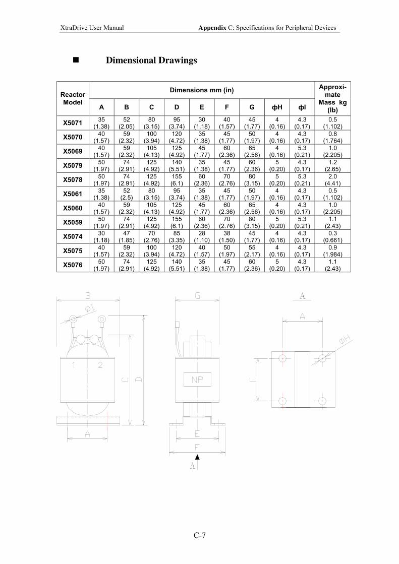
XtraDrive User Manual Appendix C: Specifications for Peripheral Devices
C-7
! Dimensional Drawings
Dimensions mm (in) Reactor Model
A B C D E F G фH фI
Approxi-mate
Mass kg (lb)
X5071 35
(1.38) 52
(2.05) 80
(3.15) 95
(3.74) 30
(1.18) 40
(1.57) 45
(1.77) 4
(0.16) 4.3
(0.17) 0.5
(1.102)
X5070 40
(1.57) 59
(2.32) 100
(3.94) 120
(4.72) 35
(1.38) 45
(1.77) 50
(1.97) 4
(0.16) 4.3
(0.17) 0.8
(1.764)
X5069 40
(1.57) 59
(2.32) 105
(4.13) 125
(4.92) 45
(1.77) 60
(2.36) 65
(2.56) 4
(0.16) 5.3
(0.21) 1.0
(2.205)
X5079 50
(1.97) 74
(2.91) 125
(4.92) 140
(5.51) 35
(1.38) 45
(1.77) 60
(2.36) 5
(0.20) 4.3
(0.17) 1.2
(2.65)
X5078 50
(1.97) 74
(2.91) 125
(4.92) 155 (6.1)
60 (2.36)
70 (2.76)
80 (3.15)
5 (0.20)
5.3 (0.21)
2.0 (4.41)
X5061 35
(1.38) 52
(2.5) 80
(3.15) 95
(3.74) 35
(1.38) 45
(1.77) 50
(1.97) 4
(0.16) 4.3
(0.17) 0.5
(1.102)
X5060 40
(1.57) 59
(2.32) 105
(4.13) 125
(4.92) 45
(1.77) 60
(2.36) 65
(2.56) 4
(0.16) 4.3
(0.17) 1.0
(2.205)
X5059 50
(1.97) 74
(2.91) 125
(4.92) 155 (6.1)
60 (2.36)
70 (2.76)
80 (3.15)
5 (0.20)
5.3 (0.21)
1.1 (2.43)
X5074 30
(1.18) 47
(1.85) 70
(2.76) 85
(3.35) 28
(1.10) 38
(1.50) 45
(1.77) 4
(0.16) 4.3
(0.17) 0.3
(0.661)
X5075 40
(1.57) 59
(2.32) 100
(3.94) 120
(4.72) 40
(1.57) 50
(1.97) 55
(2.17) 4
(0.16) 4.3
(0.17) 0.9
(1.984)
X5076 50
(1.97) 74
(2.91) 125
(4.92) 140
(5.51) 35
(1.38) 45
(1.77) 60
(2.36) 5
(0.20) 4.3
(0.17) 1.1
(2.43)
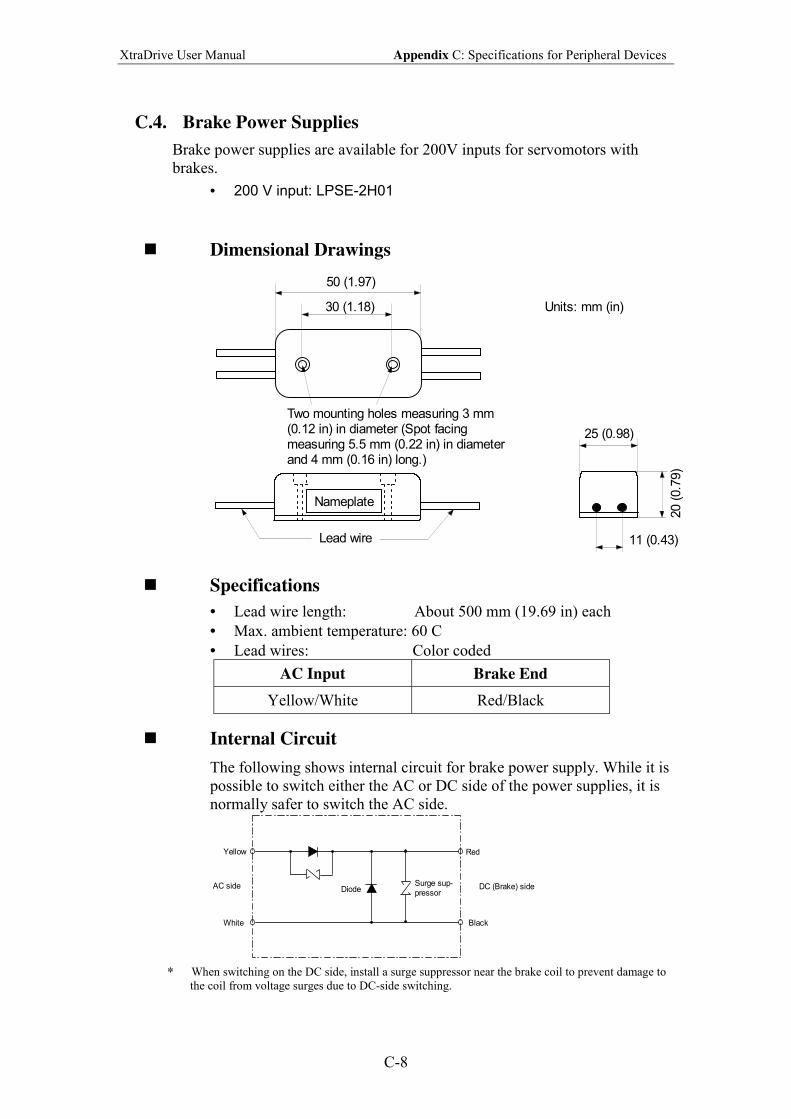
XtraDrive User Manual Appendix C: Specifications for Peripheral Devices
C-8
C.4. Brake Power Supplies
Brake power supplies are available for 200V inputs for servomotors with
brakes.
• 200 V input: LPSE-2H01
! Dimensional Drawings
Nameplate
Lead wire
Two mounting holes measuring 3 mm(0.12 in) in diameter (Spot facingmeasuring 5.5 mm (0.22 in) in diameterand 4 mm (0.16 in) long.)
50 (1.97)
30 (1.18)
20 (
0.7
9)
25 (0.98)
11 (0.43)
Units: mm (in)
! Specifications
• Lead wire length: About 500 mm (19.69 in) each
• Max. ambient temperature: 60 C
• Lead wires: Color coded
AC Input Brake End
Yellow/White Red/Black
! Internal Circuit
The following shows internal circuit for brake power supply. While it is
possible to switch either the AC or DC side of the power supplies, it is
normally safer to switch the AC side.
Surge sup-
pressorDiode
Yellow
AC side
White
Red
DC (Brake) side
Black
* When switching on the DC side, install a surge suppressor near the brake coil to prevent damage to
the coil from voltage surges due to DC-side switching.
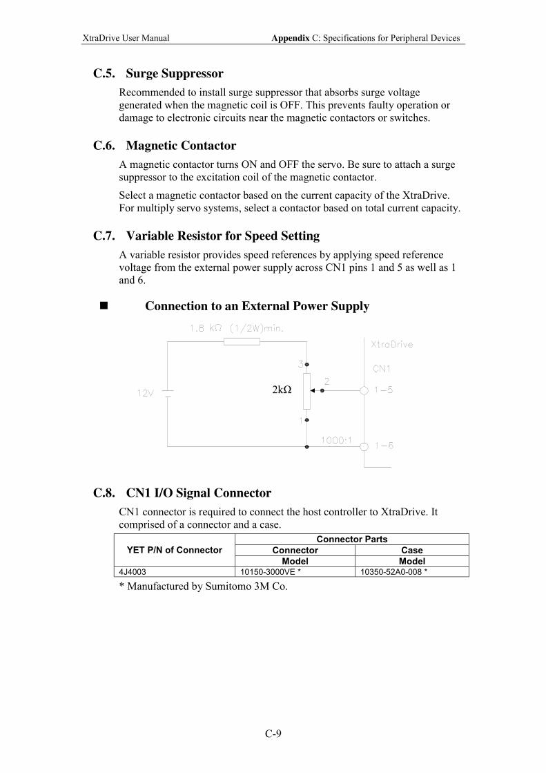
XtraDrive User Manual Appendix C: Specifications for Peripheral Devices
C-9
C.5. Surge Suppressor
Recommended to install surge suppressor that absorbs surge voltage
generated when the magnetic coil is OFF. This prevents faulty operation or
damage to electronic circuits near the magnetic contactors or switches.
C.6. Magnetic Contactor
A magnetic contactor turns ON and OFF the servo. Be sure to attach a surge
suppressor to the excitation coil of the magnetic contactor.
Select a magnetic contactor based on the current capacity of the XtraDrive.
For multiply servo systems, select a contactor based on total current capacity.
C.7. Variable Resistor for Speed Setting
A variable resistor provides speed references by applying speed reference
voltage from the external power supply across CN1 pins 1 and 5 as well as 1
and 6.
! Connection to an External Power Supply
C.8. CN1 I/O Signal Connector
CN1 connector is required to connect the host controller to XtraDrive. It
comprised of a connector and a case.
Connector Parts
Connector Case YET P/N of Connector
Model Model 4J4003 10150-3000VE * 10350-52A0-008 *
* Manufactured by Sumitomo 3M Co.
2kΩ
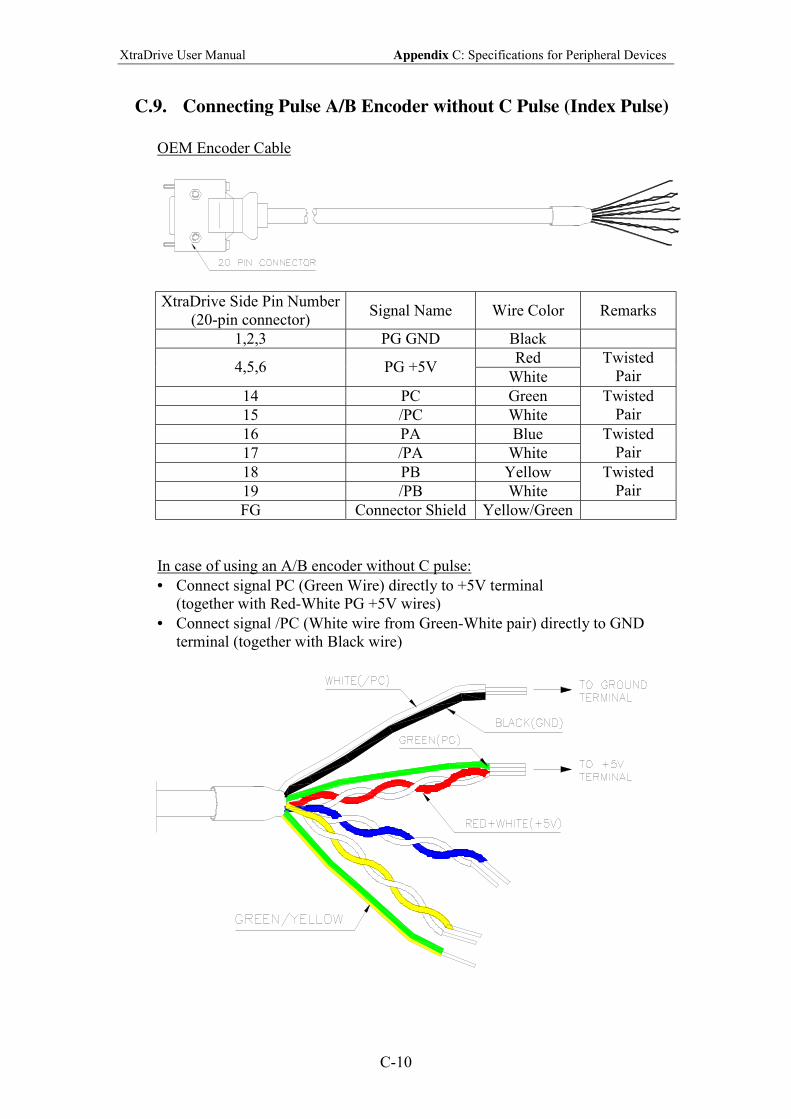
XtraDrive User Manual Appendix C: Specifications for Peripheral Devices
C-10
C.9. Connecting Pulse A/B Encoder without C Pulse (Index Pulse)
OEM Encoder Cable
XtraDrive Side Pin Number
(20-pin connector) Signal Name Wire Color Remarks
1,2,3 PG GND Black
Red 4,5,6 PG +5V
White
Twisted
Pair
14 PC Green
15 /PC White
Twisted
Pair
16 PA Blue
17 /PA White
Twisted
Pair
18 PB Yellow
19 /PB White
Twisted
Pair
FG Connector Shield Yellow/Green
In case of using an A/B encoder without C pulse:
• Connect signal PC (Green Wire) directly to +5V terminal
(together with Red-White PG +5V wires)
• Connect signal /PC (White wire from Green-White pair) directly to GND
terminal (together with Black wire)
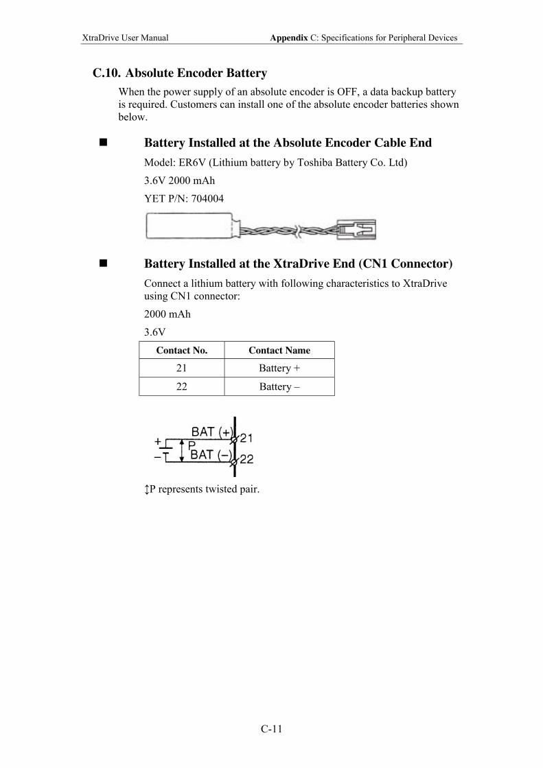
XtraDrive User Manual Appendix C: Specifications for Peripheral Devices
C-11
C.10. Absolute Encoder Battery
When the power supply of an absolute encoder is OFF, a data backup battery
is required. Customers can install one of the absolute encoder batteries shown
below.
! Battery Installed at the Absolute Encoder Cable End
Model: ER6V (Lithium battery by Toshiba Battery Co. Ltd)
3.6V 2000 mAh
YET P/N: 704004
! Battery Installed at the XtraDrive End (CN1 Connector)
Connect a lithium battery with following characteristics to XtraDrive
using CN1 connector:
2000 mAh
3.6V
Contact No. Contact Name
21 Battery +
22 Battery
P represents twisted pair.
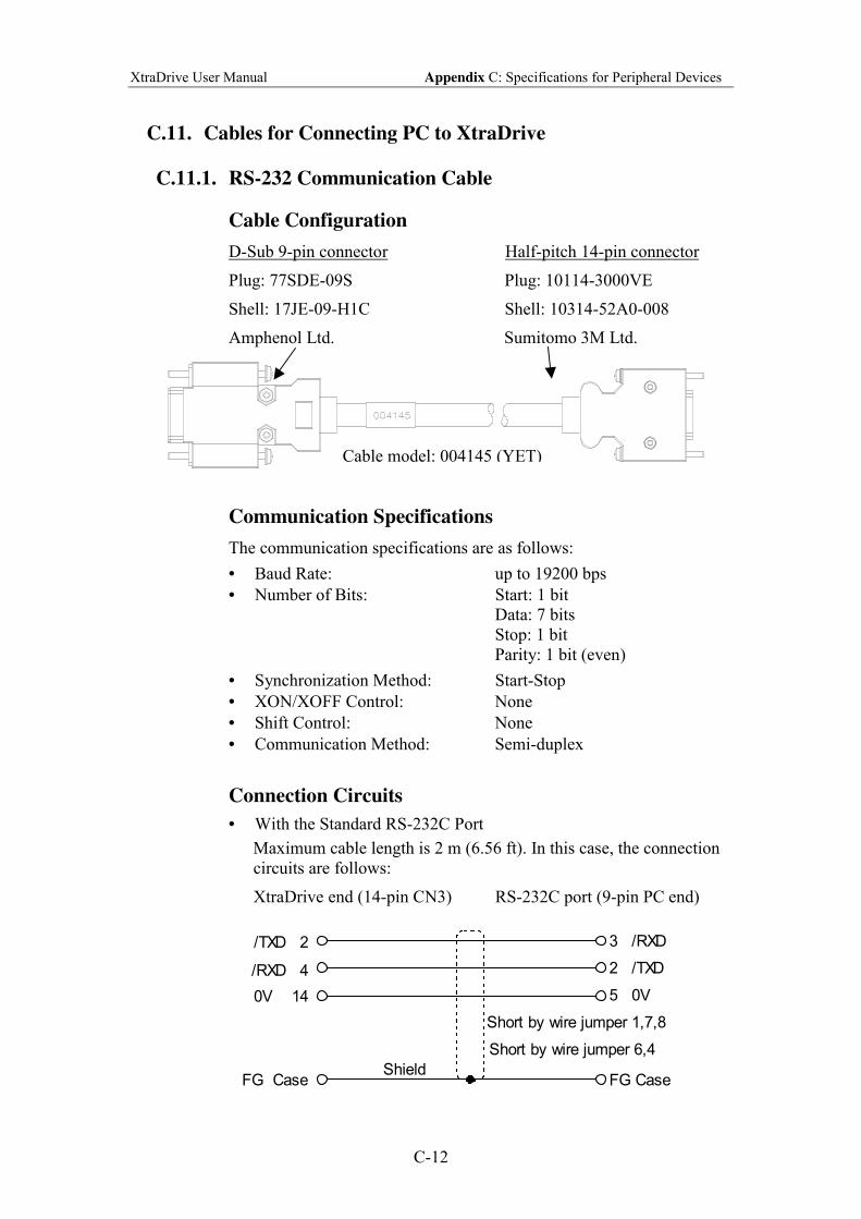
XtraDrive User Manual Appendix C: Specifications for Peripheral Devices
C-12
C.11. Cables for Connecting PC to XtraDrive
C.11.1. RS-232 Communication Cable
Cable Configuration
D-Sub 9-pin connector Half-pitch 14-pin connector
Plug: 77SDE-09S Plug: 10114-3000VE
Shell: 17JE-09-H1C Shell: 10314-52A0-008
Amphenol Ltd. Sumitomo 3M Ltd.
Communication Specifications
The communication specifications are as follows:
• Baud Rate: up to 19200 bps
• Number of Bits: Start: 1 bit
Data: 7 bits
Stop: 1 bit
Parity: 1 bit (even)
• Synchronization Method: Start-Stop
• XON/XOFF Control: None
• Shift Control: None
• Communication Method: Semi-duplex
Connection Circuits
• With the Standard RS-232C Port
Maximum cable length is 2 m (6.56 ft). In this case, the connection
circuits are follows:
XtraDrive end (14-pin CN3) RS-232C port (9-pin PC end)
/TXD 2
/RXD 4
0V 14
FG Case
3 /RXD
2 /TXD
5 0V
FG Case
Short by wire jumper 1,7,8
Short by wire jumper 6,4
Shield
Cable model: 004145 (YET)
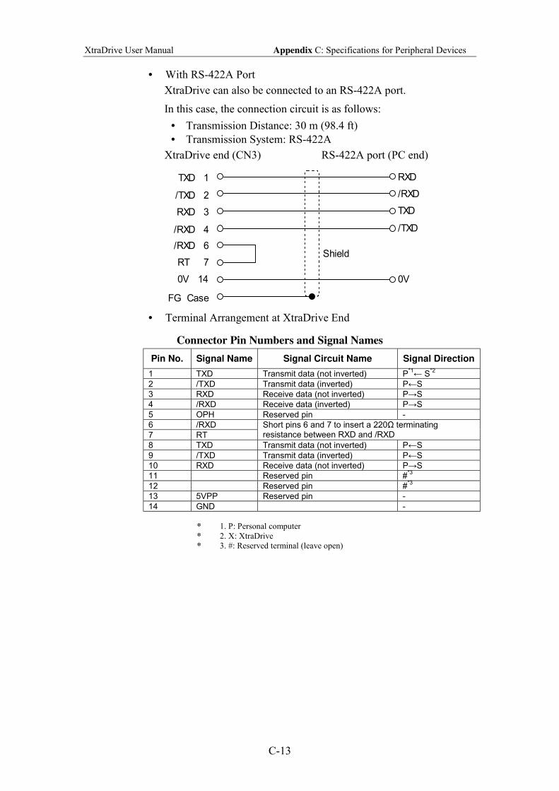
XtraDrive User Manual Appendix C: Specifications for Peripheral Devices
C-13
• With RS-422A Port
XtraDrive can also be connected to an RS-422A port.
In this case, the connection circuit is as follows:
• Transmission Distance: 30 m (98.4 ft)
• Transmission System: RS-422A
XtraDrive end (CN3) RS-422A port (PC end)
TXD 1
/TXD 2
RXD 3
FG Case
RXD
/RXD
TXD
0V
Shield
/TXD/RXD 4
/RXD 6
RT 7
0V 14
• Terminal Arrangement at XtraDrive End
Connector Pin Numbers and Signal Names
Pin No. Signal Name Signal Circuit Name Signal Direction
1 TXD Transmit data (not inverted) P*1← S
*2
2 /TXD Transmit data (inverted) P←S
3 RXD Receive data (not inverted) P→S
4 /RXD Receive data (inverted) P→S
5 OPH Reserved pin -
6 /RXD
7 RT
Short pins 6 and 7 to insert a 220Ω terminating resistance between RXD and /RXD
8 TXD Transmit data (not inverted) P←S
9 /TXD Transmit data (inverted) P←S
10 RXD Receive data (not inverted) P→S
11 Reserved pin #*3
12 Reserved pin #*3
13 5VPP Reserved pin -
14 GND -
* 1. P: Personal computer
* 2. X: XtraDrive
* 3. #: Reserved terminal (leave open)
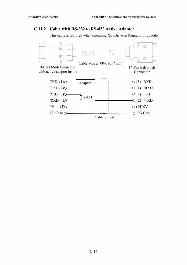
XtraDrive User Manual Appendix C: Specifications for Peripheral Devices
C-14
C.11.2. Cable with RS-232 to RS-422 Active Adapter
This cable is required when operating XtraDrive in Programming mode.
TXD (1) (3) RXD
/TXD (2) (4) /RXD
RXD (3) (1) TXD
/RXD (4) (2) /TXD
0V (5) (14) 0V
FG Case FG Case
Cable Model: 004197 (YET) 9-Pin D-Sub Connector
with active adapter inside 14-Pin Half Pitch
Connector
Adapter
220Ω
Cable Shield
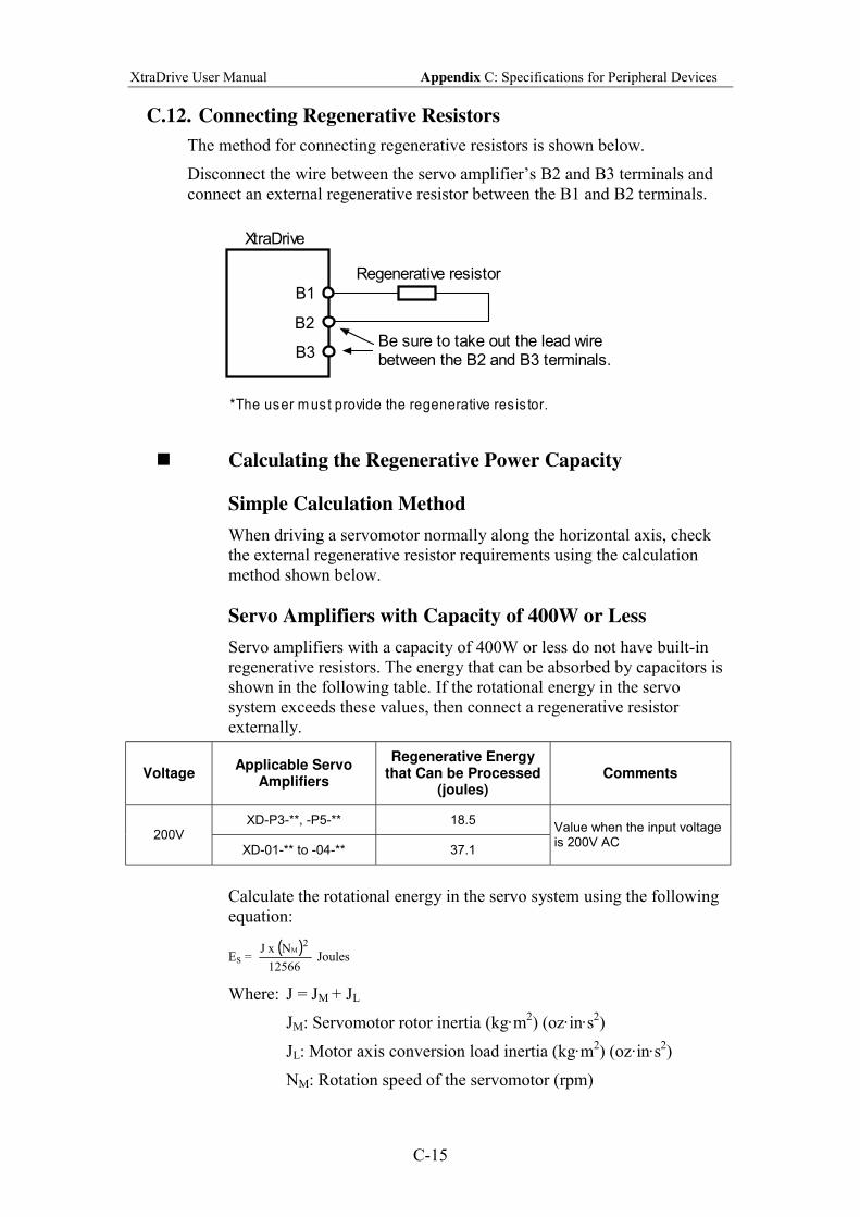
XtraDrive User Manual Appendix C: Specifications for Peripheral Devices
C-15
C.12. Connecting Regenerative Resistors
The method for connecting regenerative resistors is shown below.
Disconnect the wire between the servo amplifiers B2 and B3 terminals and
connect an external regenerative resistor between the B1 and B2 terminals.
Regenerative resistor
B1
B2
XtraDrive
*The user m us t provide the regenerative res is tor.
B3Be sure to take out the lead wirebetween the B2 and B3 terminals.
! Calculating the Regenerative Power Capacity
Simple Calculation Method
When driving a servomotor normally along the horizontal axis, check
the external regenerative resistor requirements using the calculation
method shown below.
Servo Amplifiers with Capacity of 400W or Less
Servo amplifiers with a capacity of 400W or less do not have built-in
regenerative resistors. The energy that can be absorbed by capacitors is
shown in the following table. If the rotational energy in the servo
system exceeds these values, then connect a regenerative resistor
externally.
Voltage Applicable Servo
Amplifiers
Regenerative Energy that Can be Processed
(joules) Comments
XD-P3-**, -P5-** 18.5 200V
XD-01-** to -04-** 37.1
Value when the input voltage is 200V AC
Calculate the rotational energy in the servo system using the following
equation:
ES = ( )
12566
Nx J 2
M
Joules
Where: J = JM + JL
JM: Servomotor rotor inertia (kg·m2) (oz·in·s
2)
JL: Motor axis conversion load inertia (kg·m2) (oz·in·s
2)
NM: Rotation speed of the servomotor (rpm)
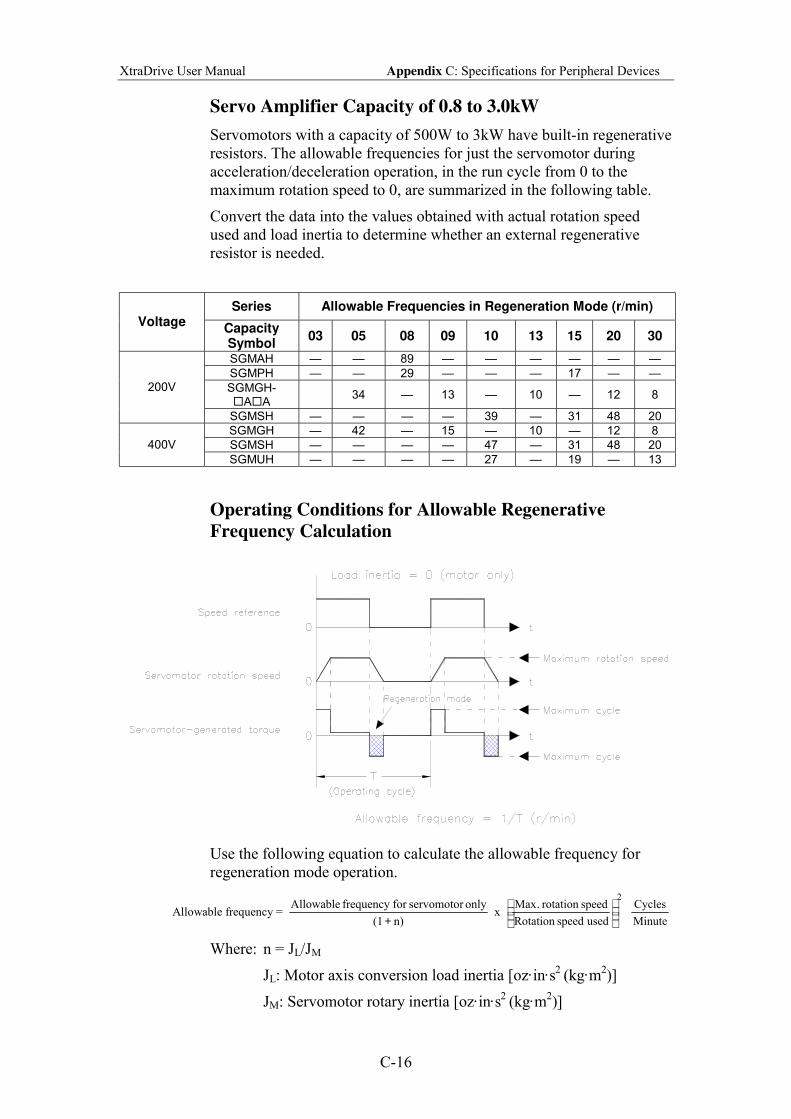
XtraDrive User Manual Appendix C: Specifications for Peripheral Devices
C-16
Servo Amplifier Capacity of 0.8 to 3.0kW
Servomotors with a capacity of 500W to 3kW have built-in regenerative
resistors. The allowable frequencies for just the servomotor during
acceleration/deceleration operation, in the run cycle from 0 to the
maximum rotation speed to 0, are summarized in the following table.
Convert the data into the values obtained with actual rotation speed
used and load inertia to determine whether an external regenerative
resistor is needed.
Series Allowable Frequencies in Regeneration Mode (r/min) Voltage
Capacity Symbol
03 05 08 09 10 13 15 20 30
SGMAH 89
SGMPH 29 17
SGMGH- #A#A
34 13 10 12 8 200V
SGMSH 39 31 48 20
SGMGH 42 15 10 12 8
SGMSH 47 31 48 20 400V
SGMUH 27 19 13
Operating Conditions for Allowable Regenerative
Frequency Calculation
Use the following equation to calculate the allowable frequency for
regeneration mode operation.
Allowable frequency = n) (1
only servomotorfor frequency Allowable
+ x
2
used speed Rotation
speed rotation .Max
Minute
Cycles
Where: n = JL/JM
JL: Motor axis conversion load inertia [oz·in·s2 (kg·m
2)]
JM: Servomotor rotary inertia [oz·in·s2 (kg·m
2)]
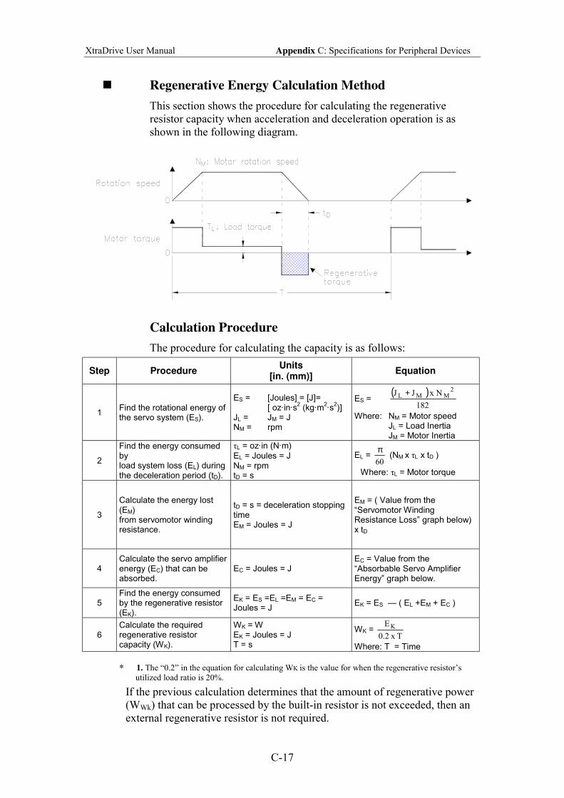
XtraDrive User Manual Appendix C: Specifications for Peripheral Devices
C-17
! Regenerative Energy Calculation Method
This section shows the procedure for calculating the regenerative
resistor capacity when acceleration and deceleration operation is as
shown in the following diagram.
Calculation Procedure
The procedure for calculating the capacity is as follows:
Step Procedure Units
[in. (mm)] Equation
1 Find the rotational energy of the servo system (ES).
ES = [Joules] = [J]= [ oz·in·s
2 (kg·m
2·s
2)]
JL = JM = J NM = rpm
ES = ( )
182
Nx J J2
MML +
Where: NM = Motor speed JL = Load Inertia JM = Motor Inertia
2
Find the energy consumed by load system loss (EL) during the deceleration period (tD).
τL = oz·in (N·m)
EL = Joules = J NM = rpm tD = s
EL = 60
π (NM x τL x tD )
Where: τL = Motor torque
3
Calculate the energy lost (EM) from servomotor winding resistance.
tD = s = deceleration stopping time EM = Joules = J
EM = ( Value from the Servomotor Winding Resistance Loss graph below) x tD
4
Calculate the servo amplifier energy (EC) that can be absorbed.
EC = Joules = J
EC = Value from the Absorbable Servo Amplifier Energy graph below.
5 Find the energy consumed by the regenerative resistor (EK).
EK = ES =EL =EM = EC = Joules = J
EK = ES ( EL +EM + EC )
6 Calculate the required regenerative resistor capacity (WK).
WK = W EK = Joules = J T = s
WK = Tx 2.0
E K
Where: T = Time
* 1. The 0.2 in the equation for calculating WK is the value for when the regenerative resistors
utilized load ratio is 20%.
If the previous calculation determines that the amount of regenerative power
(WWk) that can be processed by the built-in resistor is not exceeded, then an
external regenerative resistor is not required.
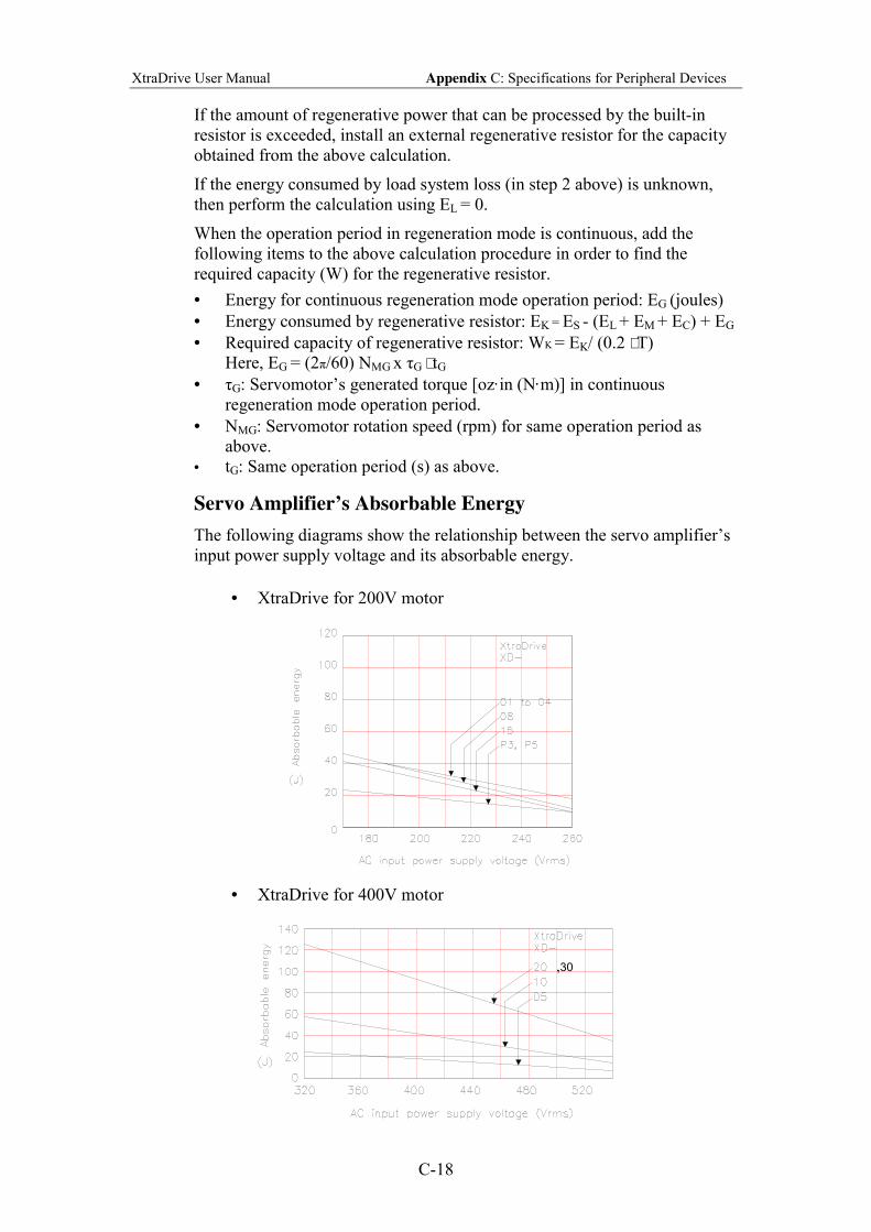
XtraDrive User Manual Appendix C: Specifications for Peripheral Devices
C-18
If the amount of regenerative power that can be processed by the built-in
resistor is exceeded, install an external regenerative resistor for the capacity
obtained from the above calculation.
If the energy consumed by load system loss (in step 2 above) is unknown,
then perform the calculation using EL = 0.
When the operation period in regeneration mode is continuous, add the
following items to the above calculation procedure in order to find the
required capacity (W) for the regenerative resistor.
• Energy for continuous regeneration mode operation period: EG (joules)
• Energy consumed by regenerative resistor: EK = ES - (EL + EM + EC) + EG
• Required capacity of regenerative resistor: WK = EK/ (0.2 ⋅ T)
Here, EG = (2π/60) NMG x τG ⋅ tG
• τG: Servomotors generated torque [oz·in (N·m)] in continuous
regeneration mode operation period.
• NMG: Servomotor rotation speed (rpm) for same operation period as
above.
• tG: Same operation period (s) as above.
Servo Amplifier’s Absorbable Energy
The following diagrams show the relationship between the servo amplifiers
input power supply voltage and its absorbable energy.
• XtraDrive for 200V motor
• XtraDrive for 400V motor
,30
XtraDrive User Manual Appendix C: Specifications for Peripheral Devices
C-19
C.13. Connecting Yaskawa Option Board
XtraDrive supports Yaskawa option boards. When connecting the Yaskawa
option board, XtraDrive acts as an SGDH servo amplifier, includes control
loops, which are not NCT (standard control loop of XtraDrive).
Note: XtraDrives digital I/O allocation input (Pn50A Pn510) default is
different than SGDH default.
C.13.1. Attaching the Option Board
XtraDrive parameter settings
1. Set Pn000.1=1 for Option Board detection.
Set Pn191.3
2. Restart XtraDrive
Note: These settings done automatically by selecting Yaskawa Option
Board during wizard.
Parameter Dig. Name Setting Description Default
0 Option board enabled Pn191 3
Option
Board
Enable 1 Option board ignored 0
Mounting the Option Board to XtraDrive
1. Turn XtraDrive power supply off.
2. Remove the connector cover from the CN10 connector on the
XtraDrive.
3. Insert the lower two mounting notches into the mounting holes at the
bottom right of the XtraDrive.
4. Push the Option Board, inserting the upper mounting notches of the
board into the upper mounting holes on the right side of the XtraDrive.
5. For grounding, connect the ground wire of the board to the point
marked G on the XtraDrive.
C.13.2. Detaching the Option Board
1. Turn XtraDrive power supply off.
2. Disconnect the ground wire of the board from the XtraDrive.
3. Push the upper mounting notch (single) of the board out off the upper
mounting holes on the right side of the XtraDrive.
4. Turn XtraDrive power supply on.
5. Alarm A.E7 will appear. To clear the alarm executes Fn014 (option
unit detection result clear), in the auxiliary function mode, and then
cycle the power. See 7.2.13
6. Set Pn000.1 to the required control method and reset the XtraDrive.
XtraDrive User Manual Appendix D: List of Parameters
D-1
Appendix D. List of Parameters
This appendix lists the parameters, switches, and input signal selections, out put
signal selections, auxiliary functions, and monitor modes for XtraDrive servo
amplifiers.
D.1. Parameters..................................................................................................D-2
D.2. Switches .....................................................................................................D-7
D.3. Input Signal Selections ............................................................................D-11
D.3.1. Home Switches ................................................................................D-12
D.3.2. Extended input signal selection. ......................................................D-12
D.4. Output Signal Selections..........................................................................D-13
D.4.1. Extended Output Signal Selection ...................................................D-13
D.5. Auxiliary Functions .................................................................................D-14
D.6. Monitor Modes.........................................................................................D-14
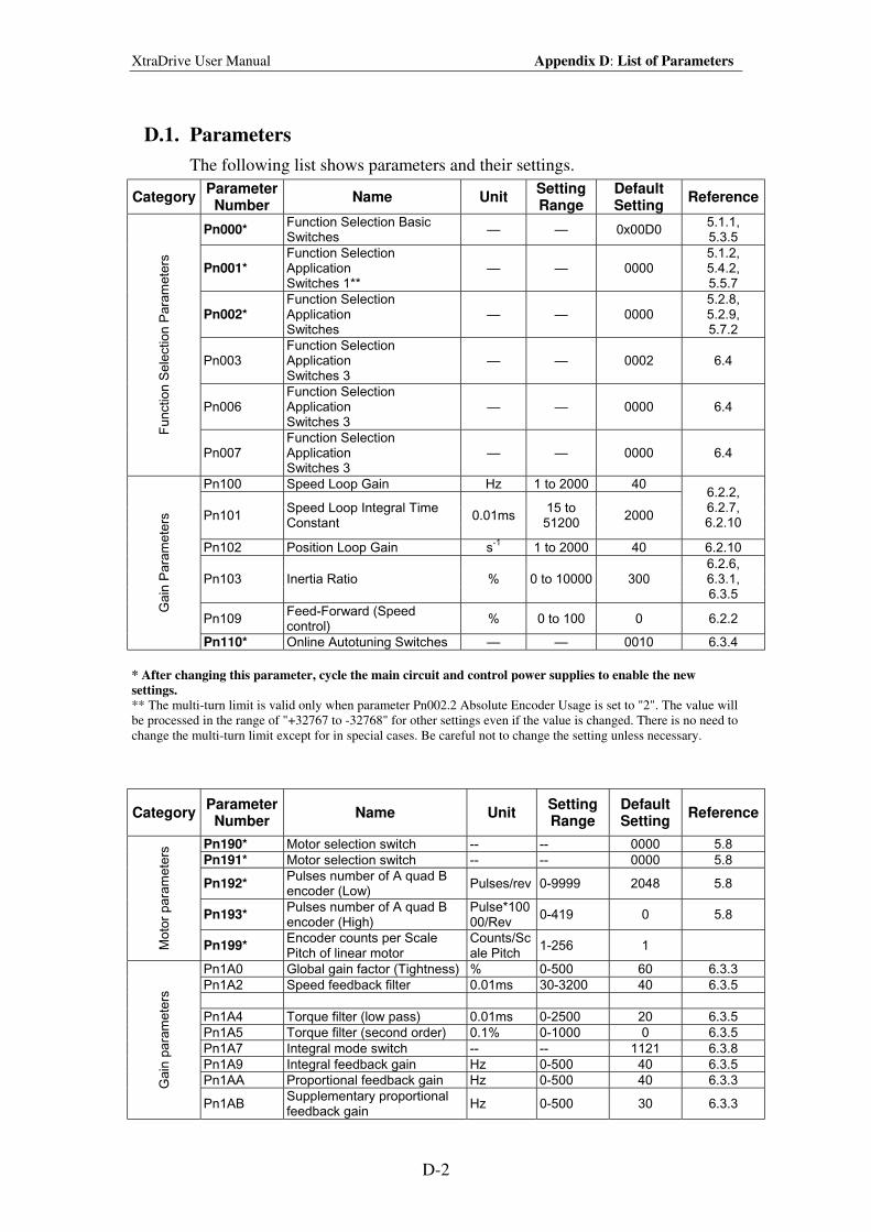
XtraDrive User Manual Appendix D: List of Parameters
D-2
D.1. Parameters
The following list shows parameters and their settings.
Category Parameter
Number Name Unit
Setting Range
Default Setting
Reference
Pn000* Function Selection Basic Switches
— — 0x00D0 5.1.1, 5.3.5
Pn001* Function Selection Application Switches 1**
— — 0000 5.1.2, 5.4.2, 5.5.7
Pn002* Function Selection Application Switches
— — 0000 5.2.8, 5.2.9, 5.7.2
Pn003 Function Selection Application Switches 3
— — 0002 6.4
Pn006 Function Selection Application Switches 3
— — 0000 6.4
Function S
ele
ction P
ara
mete
rs
Pn007 Function Selection Application Switches 3
— — 0000 6.4
Pn100 Speed Loop Gain Hz 1 to 2000 40
Pn101 Speed Loop Integral Time Constant
0.01ms 15 to 51200
2000
6.2.2, 6.2.7, 6.2.10
Pn102 Position Loop Gain s-1
1 to 2000 40 6.2.10
Pn103 Inertia Ratio % 0 to 10000 300 6.2.6, 6.3.1, 6.3.5
Pn109 Feed-Forward (Speed control)
% 0 to 100 0 6.2.2
Ga
in P
ara
me
ters
Pn110* Online Autotuning Switches — — 0010 6.3.4
* After changing this parameter, cycle the main circuit and control power supplies to enable the new
settings.
** The multi-turn limit is valid only when parameter Pn002.2 Absolute Encoder Usage is set to "2". The value will
be processed in the range of "+32767 to -32768" for other settings even if the value is changed. There is no need to
change the multi-turn limit except for in special cases. Be careful not to change the setting unless necessary.
Category Parameter
Number Name Unit
Setting Range
Default Setting
Reference
Pn190* Motor selection switch -- -- 0000 5.8
Pn191* Motor selection switch -- -- 0000 5.8
Pn192* Pulses number of A quad B encoder (Low)
Pulses/rev 0-9999 2048 5.8
Pn193* Pulses number of A quad B encoder (High)
Pulse*10000/Rev
0-419 0 5.8
Moto
r para
mete
rs
Pn199* Encoder counts per Scale Pitch of linear motor
Counts/Scale Pitch
1-256 1
Pn1A0 Global gain factor (Tightness) % 0-500 60 6.3.3
Pn1A2 Speed feedback filter 0.01ms 30-3200 40 6.3.5
Pn1A4 Torque filter (low pass) 0.01ms 0-2500 20 6.3.5
Pn1A5 Torque filter (second order) 0.1% 0-1000 0 6.3.5
Pn1A7 Integral mode switch -- -- 1121 6.3.8
Pn1A9 Integral feedback gain Hz 0-500 40 6.3.5
Pn1AA Proportional feedback gain Hz 0-500 40 6.3.3 Gain
para
mete
rs
Pn1AB Supplementary proportional feedback gain
Hz 0-500 30 6.3.3
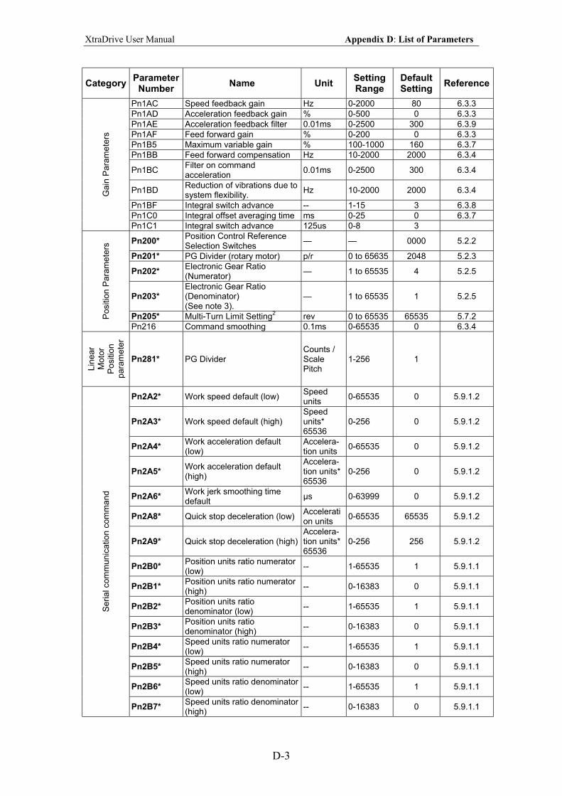
XtraDrive User Manual Appendix D: List of Parameters
D-3
Category Parameter
Number Name Unit
Setting Range
Default Setting
Reference
Pn1AC Speed feedback gain Hz 0-2000 80 6.3.3
Pn1AD Acceleration feedback gain % 0-500 0 6.3.3
Pn1AE Acceleration feedback filter 0.01ms 0-2500 300 6.3.9
Pn1AF Feed forward gain % 0-200 0 6.3.3
Pn1B5 Maximum variable gain % 100-1000 160 6.3.7
Pn1BB Feed forward compensation Hz 10-2000 2000 6.3.4
Pn1BC Filter on command acceleration
0.01ms 0-2500 300 6.3.4
Pn1BD Reduction of vibrations due to system flexibility.
Hz 10-2000 2000 6.3.4
Pn1BF Integral switch advance -- 1-15 3 6.3.8
Pn1C0 Integral offset averaging time ms 0-25 0 6.3.7
Ga
in P
ara
me
ters
Pn1C1 Integral switch advance 125us 0-8 3
Pn200* Position Control Reference Selection Switches
— — 0000 5.2.2
Pn201* PG Divider (rotary motor) p/r 0 to 65635 2048 5.2.3
Pn202* Electronic Gear Ratio (Numerator)
— 1 to 65535 4 5.2.5
Pn203* Electronic Gear Ratio (Denominator) (See note 3).
— 1 to 65535 1 5.2.5
Pn205* Multi-Turn Limit Setting2 rev 0 to 65535 65535 5.7.2 P
ositio
n P
ara
mete
rs
Pn216 Command smoothing 0.1ms 0-65535 0 6.3.4
Lin
ear
Moto
r P
ositio
n
para
mete
r
Pn281* PG Divider Counts / Scale Pitch
1-256 1
Pn2A2* Work speed default (low) Speed units
0-65535 0 5.9.1.2
Pn2A3* Work speed default (high) Speed units* 65536
0-256 0 5.9.1.2
Pn2A4* Work acceleration default (low)
Accelera-tion units
0-65535 0 5.9.1.2
Pn2A5* Work acceleration default (high)
Accelera-tion units* 65536
0-256 0 5.9.1.2
Pn2A6* Work jerk smoothing time default
µs 0-63999 0 5.9.1.2
Pn2A8* Quick stop deceleration (low) Acceleration units
0-65535 65535 5.9.1.2
Pn2A9* Quick stop deceleration (high) Accelera-tion units* 65536
0-256 256 5.9.1.2
Pn2B0* Position units ratio numerator (low)
-- 1-65535 1 5.9.1.1
Pn2B1* Position units ratio numerator (high)
-- 0-16383 0 5.9.1.1
Pn2B2* Position units ratio denominator (low)
-- 1-65535 1 5.9.1.1
Pn2B3* Position units ratio denominator (high)
-- 0-16383 0 5.9.1.1
Pn2B4* Speed units ratio numerator (low)
-- 1-65535 1 5.9.1.1
Pn2B5* Speed units ratio numerator (high)
-- 0-16383 0 5.9.1.1
Pn2B6* Speed units ratio denominator (low)
-- 1-65535 1 5.9.1.1
Serial com
munic
ation c
om
mand
Pn2B7* Speed units ratio denominator (high)
-- 0-16383 0 5.9.1.1
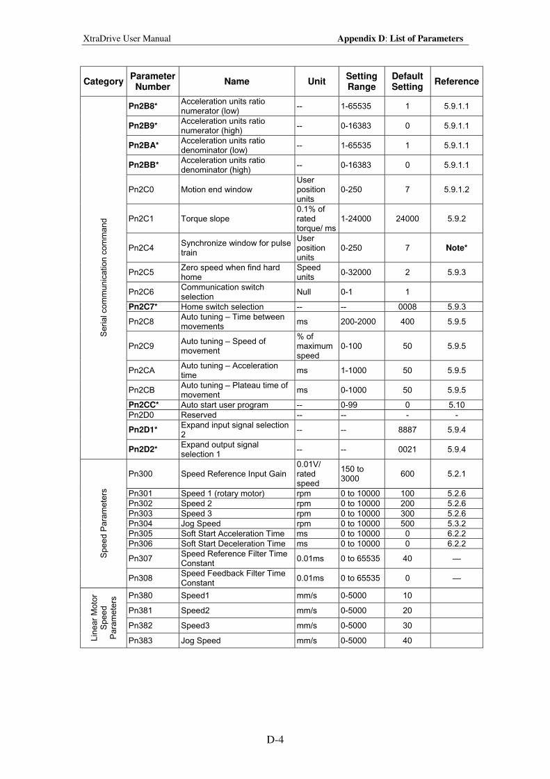
XtraDrive User Manual Appendix D: List of Parameters
D-4
Category Parameter
Number Name Unit
Setting Range
Default Setting
Reference
Pn2B8* Acceleration units ratio numerator (low)
-- 1-65535 1 5.9.1.1
Pn2B9* Acceleration units ratio numerator (high)
-- 0-16383 0 5.9.1.1
Pn2BA* Acceleration units ratio denominator (low)
-- 1-65535 1 5.9.1.1
Pn2BB* Acceleration units ratio denominator (high)
-- 0-16383 0 5.9.1.1
Pn2C0 Motion end window User position units
0-250 7 5.9.1.2
Pn2C1 Torque slope 0.1% of rated torque/ ms
1-24000 24000 5.9.2
Pn2C4 Synchronize window for pulse train
User position units
0-250 7 Note*
Pn2C5 Zero speed when find hard home
Speed units
0-32000 2 5.9.3
Pn2C6 Communication switch selection
Null 0-1 1
Pn2C7* Home switch selection -- -- 0008 5.9.3
Pn2C8 Auto tuning – Time between movements
ms 200-2000 400 5.9.5
Pn2C9 Auto tuning – Speed of movement
% of maximum speed
0-100 50 5.9.5
Pn2CA Auto tuning – Acceleration time
ms 1-1000 50 5.9.5
Pn2CB Auto tuning – Plateau time of movement
ms 0-1000 50 5.9.5
Pn2CC* Auto start user program -- 0-99 0 5.10
Pn2D0 Reserved -- -- - -
Pn2D1* Expand input signal selection 2
-- -- 8887 5.9.4
Serial com
munic
ation c
om
mand
Pn2D2* Expand output signal selection 1
-- -- 0021 5.9.4
Pn300 Speed Reference Input Gain 0.01V/ rated speed
150 to 3000
600 5.2.1
Pn301 Speed 1 (rotary motor) rpm 0 to 10000 100 5.2.6
Pn302 Speed 2 rpm 0 to 10000 200 5.2.6
Pn303 Speed 3 rpm 0 to 10000 300 5.2.6
Pn304 Jog Speed rpm 0 to 10000 500 5.3.2
Pn305 Soft Start Acceleration Time ms 0 to 10000 0 6.2.2
Pn306 Soft Start Deceleration Time ms 0 to 10000 0 6.2.2
Pn307 Speed Reference Filter Time Constant
0.01ms 0 to 65535 40 — Spee
d P
ara
me
ters
Pn308 Speed Feedback Filter Time Constant
0.01ms 0 to 65535 0 —
Pn380 Speed1 mm/s 0-5000 10
Pn381 Speed2 mm/s 0-5000 20
Pn382 Speed3 mm/s 0-5000 30
Lin
ear
Moto
r S
pee
d
Para
mete
rs
Pn383 Jog Speed mm/s 0-5000 40
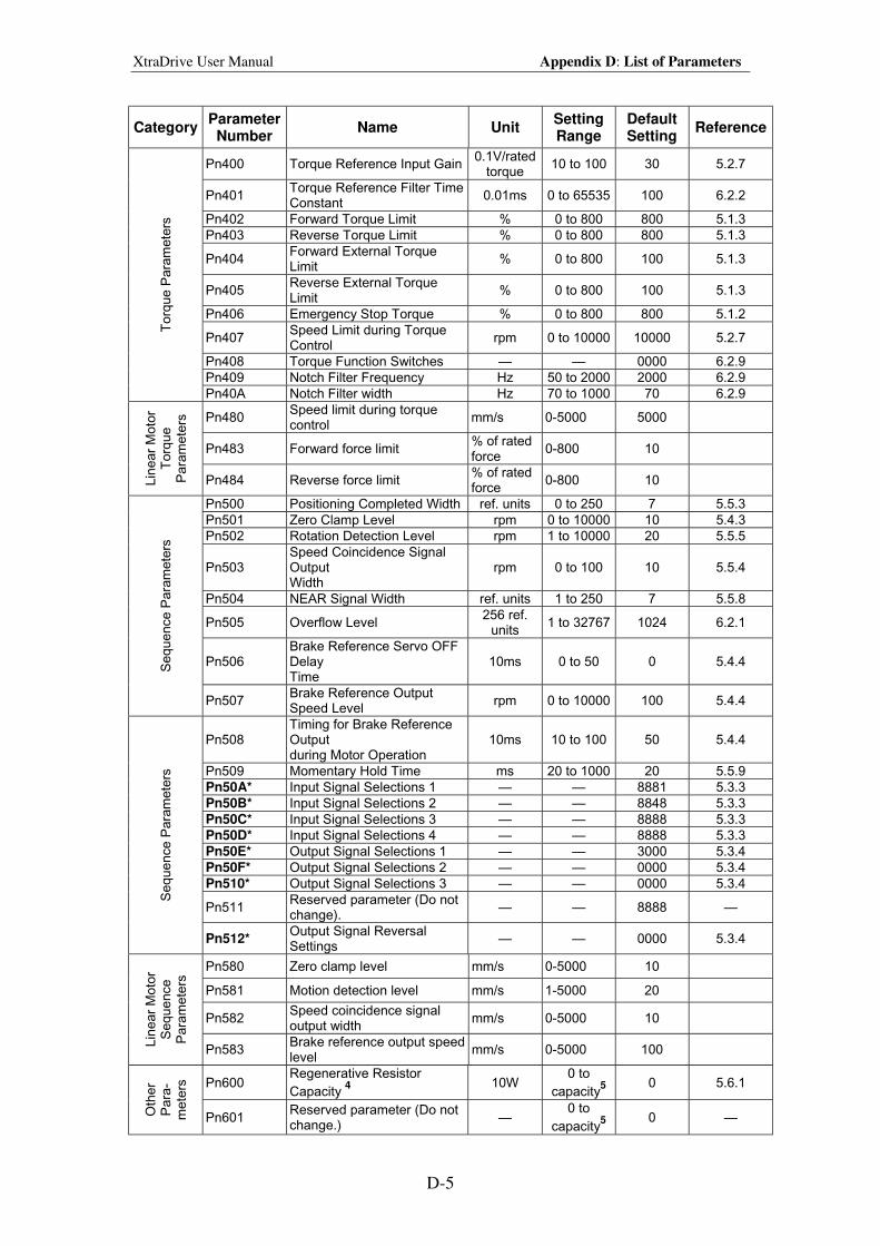
XtraDrive User Manual Appendix D: List of Parameters
D-5
Category Parameter
Number Name Unit
Setting Range
Default Setting
Reference
Pn400 Torque Reference Input Gain 0.1V/rated
torque 10 to 100 30 5.2.7
Pn401 Torque Reference Filter Time Constant
0.01ms 0 to 65535 100 6.2.2
Pn402 Forward Torque Limit % 0 to 800 800 5.1.3
Pn403 Reverse Torque Limit % 0 to 800 800 5.1.3
Pn404 Forward External Torque Limit
% 0 to 800 100 5.1.3
Pn405 Reverse External Torque Limit
% 0 to 800 100 5.1.3
Pn406 Emergency Stop Torque % 0 to 800 800 5.1.2
Pn407 Speed Limit during Torque Control
rpm 0 to 10000 10000 5.2.7
Pn408 Torque Function Switches — — 0000 6.2.9
Pn409 Notch Filter Frequency Hz 50 to 2000 2000 6.2.9
Torq
ue P
ara
mete
rs
Pn40A Notch Filter width Hz 70 to 1000 70 6.2.9
Pn480 Speed limit during torque control
mm/s 0-5000 5000
Pn483 Forward force limit % of rated force
0-800 10
Lin
ear
Moto
r T
orq
ue
Para
mete
rs
Pn484 Reverse force limit % of rated force
0-800 10
Pn500 Positioning Completed Width ref. units 0 to 250 7 5.5.3
Pn501 Zero Clamp Level rpm 0 to 10000 10 5.4.3
Pn502 Rotation Detection Level rpm 1 to 10000 20 5.5.5
Pn503 Speed Coincidence Signal Output Width
rpm 0 to 100 10 5.5.4
Pn504 NEAR Signal Width ref. units 1 to 250 7 5.5.8
Pn505 Overflow Level 256 ref.
units 1 to 32767 1024 6.2.1
Pn506 Brake Reference Servo OFF Delay Time
10ms 0 to 50 0 5.4.4 Sequ
ence P
ara
mete
rs
Pn507 Brake Reference Output Speed Level
rpm 0 to 10000 100 5.4.4
Pn508 Timing for Brake Reference Output during Motor Operation
10ms 10 to 100 50 5.4.4
Pn509 Momentary Hold Time ms 20 to 1000 20 5.5.9
Pn50A* Input Signal Selections 1 — — 8881 5.3.3
Pn50B* Input Signal Selections 2 — — 8848 5.3.3
Pn50C* Input Signal Selections 3 — — 8888 5.3.3
Pn50D* Input Signal Selections 4 — — 8888 5.3.3
Pn50E* Output Signal Selections 1 — — 3000 5.3.4
Pn50F* Output Signal Selections 2 — — 0000 5.3.4
Pn510* Output Signal Selections 3 — — 0000 5.3.4
Pn511 Reserved parameter (Do not change).
— — 8888 —
Sequ
ence P
ara
mete
rs
Pn512* Output Signal Reversal Settings
— — 0000 5.3.4
Pn580 Zero clamp level mm/s 0-5000 10
Pn581 Motion detection level mm/s 1-5000 20
Pn582 Speed coincidence signal output width
mm/s 0-5000 10
Lin
ear
Moto
r S
equ
ence
Para
mete
rs
Pn583 Brake reference output speed level
mm/s 0-5000 100
Pn600 Regenerative Resistor
Capacity 4
10W 0 to
capacity5
0 5.6.1
Oth
er
Para
-m
ete
rs
Pn601 Reserved parameter (Do not change.)
— 0 to
capacity5
0 —

XtraDrive User Manual Appendix D: List of Parameters
D-6
* After changing this parameter, cycle the main circuit and control power supplies to enable the new
settings. 2 The multi-turn limit is valid only when parameter Pn002.2 Absolute Encoder Usage is set to "2". The value will
be processed in the range of "+32767 to -32768" for other settings even if the value is changed. There is no need to
change the multi-turn limit except for in special cases. Be careful not to change the setting unless necessary. 3 The setting of parameter Pn111 is valid only when parameter Pn110.1 is set to 0.
4 Normally set to "0". When using an external regenerative resistor, set the capacity (W) of the regenerative
resistor. 5 The upper limit is the maximum output capacity (W) of the servo amplifier.
Note* Refer to XtraWare User Manual
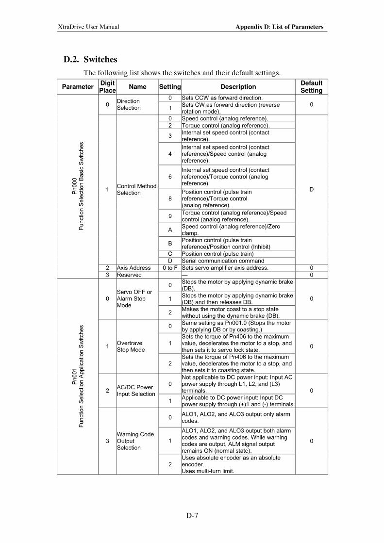
XtraDrive User Manual Appendix D: List of Parameters
D-7
D.2. Switches
The following list shows the switches and their default settings.
Parameter Digit Place
Name Setting Description Default Setting
0 Sets CCW as forward direction. 0
Direction Selection 1
Sets CW as forward direction (reverse rotation mode).
0
0 Speed control (analog reference).
2 Torque control (analog reference).
3 Internal set speed control (contact reference).
4 Internal set speed control (contact reference)/Speed control (analog reference).
6 Internal set speed control (contact reference)/Torque control (analog reference).
8 Position control (pulse train reference)/Torque control (analog reference).
9 Torque control (analog reference)/Speed control (analog reference).
A Speed control (analog reference)/Zero clamp.
B Position control (pulse train reference)/Position control (Inhibit)
C Position control (pulse train)
1 Control Method Selection
D Serial communication command
D
2 Axis Address 0 to F Sets servo amplifier axis address. 0
Pn00
0
Function S
ele
ction B
asic
Sw
itches
3 Reserved — 0
0 Stops the motor by applying dynamic brake (DB).
1 Stops the motor by applying dynamic brake (DB) and then releases DB.
0 Servo OFF or Alarm Stop Mode
2 Makes the motor coast to a stop state without using the dynamic brake (DB).
0
0 Same setting as Pn001.0 (Stops the motor by applying DB or by coasting.)
1 Sets the torque of Pn406 to the maximum value, decelerates the motor to a stop, and then sets it to servo lock state.
1 Overtravel Stop Mode
2 Sets the torque of Pn406 to the maximum value, decelerates the motor to a stop, and then sets it to coasting state.
0
0 Not applicable to DC power input: Input AC power supply through L1, L2, and (L3) terminals. 2
AC/DC Power Input Selection
1 Applicable to DC power input: Input DC power supply through (+)1 and (-) terminals.
0
0 ALO1, ALO2, and ALO3 output only alarm codes.
1
ALO1, ALO2, and ALO3 output both alarm codes and warning codes. While warning codes are output, ALM signal output remains ON (normal state).
Pn00
1
Function S
ele
ction A
pp
lication
Sw
itch
es
3 Warning Code Output Selection
2 Uses absolute encoder as an absolute encoder. Uses multi-turn limit.
0
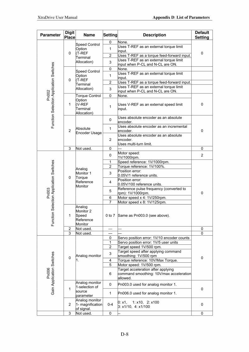
XtraDrive User Manual Appendix D: List of Parameters
D-8
Parameter Digit Place
Name Setting Description Default Setting
0 None.
1 Uses T-REF as an external torque limit input.
2 Uses T-REF as a torque feed-forward input. 0
Speed Control Option (T-REF Terminal Allocation) 3
Uses T-REF as an external torque limit input when P-CL and N-CL are ON.
0
0 None.
1 Uses T-REF as an external torque limit input.
2 Uses T-REF as a torque feed-forward input. 0
Speed Control Option (T-REF Terminal Allocation) 3
Uses T-REF as an external torque limit input when P-CL and N-CL are ON.
0 None.
1
Torque Control Option (V-REF Terminal Allocation)
1 Uses V-REF as an external speed limit input.
0
0 Uses absolute encoder as an absolute encoder.
1 Uses absolute encoder as an incremental encoder. 2
Absolute Encoder Usage
2 Uses absolute encoder as an absolute encoder. Uses multi-turn limit.
0
Pn00
2
Function S
ele
ction A
pp
lication
Sw
itch
es
3 Not used. 0 — 0
0 Motor speed: 1V/1000rpm.
2
1 Speed reference: 1V/1000rpm.
2 Torque reference: 1V/100%.
3 Position error: 0.05V/1 reference units.
4 Position error: 0.05V/100 reference units.
5 Reference pulse frequency (converted to rpm): 1V/1000rpm.
6 Motor speed x 4: 1V/250rpm.
0
Analog Monitor 1 Torque Reference Monitor
7 Motor speed x 8: 1V/125rpm.
1
Analog Monitor 2 Speed Reference Monitor
0 to 7 Same as Pn003.0 (see above).
0
2 Not used. — — 0
Pn00
3
Function S
ele
ction A
pp
lication
Sw
itch
es
3 Not used. — — 0
0 Servo position error: 1V/10 encoder counts
1 Servo position error: 1V/5 user units
2 Target speed 1V/500 rpm.
3 Target speed after applying command smoothing: 1V/500 rpm
4 Torque reference: 10V/Max Torque.
5 Motor speed: 1V/500 rpm.
0 Analog monitor 1.
6 Target acceleration after applying command smoothing: 10V/max acceleration allowed.
0
0 Pn003.0 used for analog monitor 1.
1
Analog monitor 1-selection of source parameter
1 Pn006.0 used for analog monitor 1. 0
Pn00
6
Gain
App
licatio
n S
witches
2 Analog monitor 1- magnification of signal.
0-4 0: x1, 1: x10, 2: x100 3: x1/10, 4: x1/100
0
3 Not used. 0 -- 0
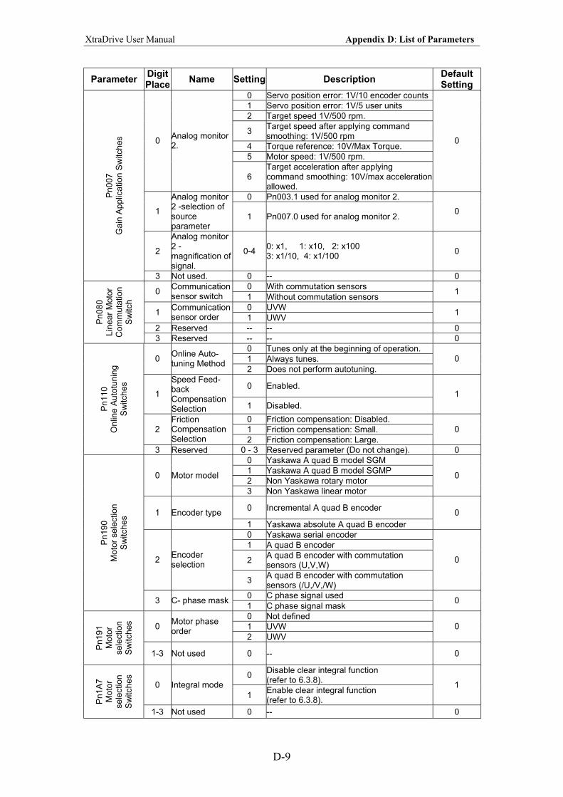
XtraDrive User Manual Appendix D: List of Parameters
D-9
Parameter Digit Place
Name Setting Description Default Setting
0 Servo position error: 1V/10 encoder counts
1 Servo position error: 1V/5 user units
2 Target speed 1V/500 rpm.
3 Target speed after applying command smoothing: 1V/500 rpm
4 Torque reference: 10V/Max Torque.
5 Motor speed: 1V/500 rpm.
0 Analog monitor 2.
6 Target acceleration after applying command smoothing: 10V/max acceleration allowed.
0
0 Pn003.1 used for analog monitor 2.
1
Analog monitor 2 -selection of source parameter
1 Pn007.0 used for analog monitor 2. 0
2
Analog monitor 2 - magnification of signal.
0-4 0: x1, 1: x10, 2: x100 3: x1/10, 4: x1/100
0
Pn00
7
Gain
App
licatio
n S
witches
3 Not used. 0 -- 0
0 With commutation sensors 0
Communication sensor switch 1 Without commutation sensors
1
0 UVW 1
Communication sensor order 1 UWV
1
2 Reserved -- -- 0
Pn08
0
Lin
ear
Moto
r C
om
muta
tion
Sw
itch
3 Reserved -- -- 0
0 Tunes only at the beginning of operation.
1 Always tunes. 0 Online Auto- tuning Method
2 Does not perform autotuning.
0
0 Enabled. 1
Speed Feed-back Compensation Selection 1 Disabled.
1
0 Friction compensation: Disabled.
1 Friction compensation: Small. 2 Friction Compensation Selection 2 Friction compensation: Large.
0
Pn11
0
Onlin
e A
uto
tunin
g
Sw
itches
3 Reserved 0 - 3 Reserved parameter (Do not change). 0
0 Yaskawa A quad B model SGM
1 Yaskawa A quad B model SGMP
2 Non Yaskawa rotary motor 0 Motor model
3 Non Yaskawa linear motor
0
0 Incremental A quad B encoder 1 Encoder type
1 Yaskawa absolute A quad B encoder
0
0 Yaskawa serial encoder
1 A quad B encoder
2 A quad B encoder with commutation sensors (U,V,W)
2 Encoder selection
3 A quad B encoder with commutation sensors (/U,/V,/W)
0
0 C phase signal used
Pn19
0
Mo
tor
se
lectio
n
Sw
itches
3 C- phase mask 1 C phase signal mask
0
0 Not defined
1 UVW 0 Motor phase order
2 UWV
0
Pn19
1
Moto
r sele
ction
Sw
itches
1-3 Not used 0 -- 0
0 Disable clear integral function (refer to 6.3.8).
0 Integral mode
1 Enable clear integral function (refer to 6.3.8).
1
Pn1A
7
Moto
r sele
ction
Sw
itches
1-3 Not used 0 -- 0
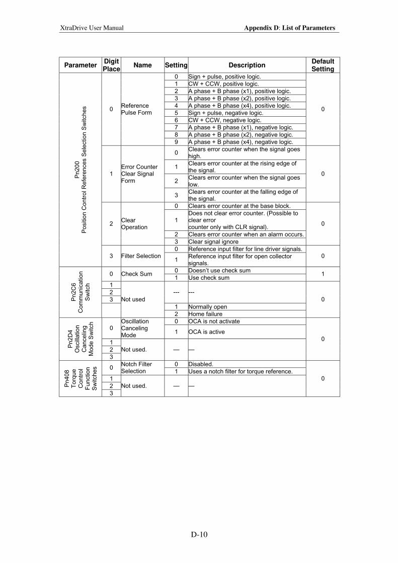
XtraDrive User Manual Appendix D: List of Parameters
D-10
Parameter Digit Place
Name Setting Description Default Setting
0 Sign + pulse, positive logic.
1 CW + CCW, positive logic.
2 A phase + B phase (x1), positive logic.
3 A phase + B phase (x2), positive logic.
4 A phase + B phase (x4), positive logic.
5 Sign + pulse, negative logic.
6 CW + CCW, negative logic.
7 A phase + B phase (x1), negative logic.
8 A phase + B phase (x2), negative logic.
0 Reference Pulse Form
9 A phase + B phase (x4), negative logic.
0
0 Clears error counter when the signal goes high.
1 Clears error counter at the rising edge of the signal.
2 Clears error counter when the signal goes low.
1 Error Counter Clear Signal Form
3 Clears error counter at the falling edge of the signal.
0
0 Clears error counter at the base block.
1 Does not clear error counter. (Possible to clear error counter only with CLR signal).
2 Clears error counter when an alarm occurs.
2 Clear Operation
3 Clear signal ignore
0
0 Reference input filter for line driver signals.
Pn20
0
Positio
n C
ontr
ol R
efe
rences S
ele
ction S
witches
3 Filter Selection 1
Reference input filter for open collector signals.
0
0 Doesn’t use check sum 0 Check Sum
1 Use check sum 1
1
2
3
--- ---
1 Normally open
Pn2C
6
Com
mun
icatio
n
Sw
itch
Not used
2 Home failure
0
0 OCA is not activate 0
Oscillation Canceling Mode
1 OCA is active
1
2
Pn2D
4
Oscill
atio
n
Cancelin
g
Mode S
witch
3
Not used. — —
0
0 Disabled. 0
Notch Filter Selection 1 Uses a notch filter for torque reference.
1
2 Pn40
8
Torq
ue
Contr
ol
Function
Sw
itches
3
Not used. — —
0
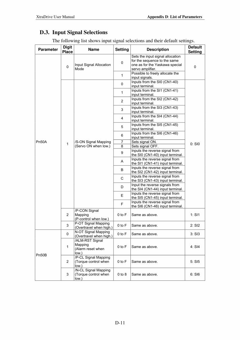
XtraDrive User Manual Appendix D: List of Parameters
D-11
D.3. Input Signal Selections
The following list shows input signal selections and their default settings.
Parameter Digit Place
Name Setting Description Default Setting
0
Sets the input signal allocation for the sequence to the same one as for the Yaskawa special servo amplifier.
0 Input Signal Allocation Mode
1 Possible to freely allocate the input signals.
0
0 Inputs from the SI0 (CN1-40) input terminal.
1 Inputs from the SI1 (CN1-41) input terminal.
2 Inputs from the SI2 (CN1-42) input terminal.
3 Inputs from the SI3 (CN1-43) input terminal.
4 Inputs from the SI4 (CN1-44) input terminal.
5 Inputs from the SI5 (CN1-45) input terminal.
6 Inputs from the SI6 (CN1-46) input terminal.
7 Sets signal ON.
8 Sets signal OFF.
9 Inputs the reverse signal from the SI0 (CN1-40) input terminal.
A Inputs the reverse signal from the SI1 (CN1-41) input terminal.
B Inputs the reverse signal from the SI2 (CN1-42) input terminal.
C Inputs the reverse signal from the SI3 (CN1-43) input terminal.
D Input the reverse signals from the SI4 (CN1-44) input terminal.
E Inputs the reverse signal from the SI5 (CN1-45) input terminal.
1 /S-ON Signal Mapping (Servo ON when low.)
F Inputs the reverse signal from the SI6 (CN1-46) input terminal.
0: SI0
2 /P-CON Signal Mapping (P-control when low.)
0 to F Same as above. 1: SI1
Pn50A
3 P-OT Signal Mapping (Overtravel when high.)
0 to F Same as above. 2: SI2
0 N-OT Signal Mapping (Overtravel when high.)
0 to F Same as above. 3: SI3
1
/ALM-RST Signal Mapping (Alarm reset when low.)
0 to F Same as above. 4: SI4
2 /P-CL Signal Mapping (Torque control when low.)
0 to F Same as above. 5: SI5
Pn50B
3 /N-CL Signal Mapping (Torque control when low.)
0 to 8 Same as above. 6: SI6
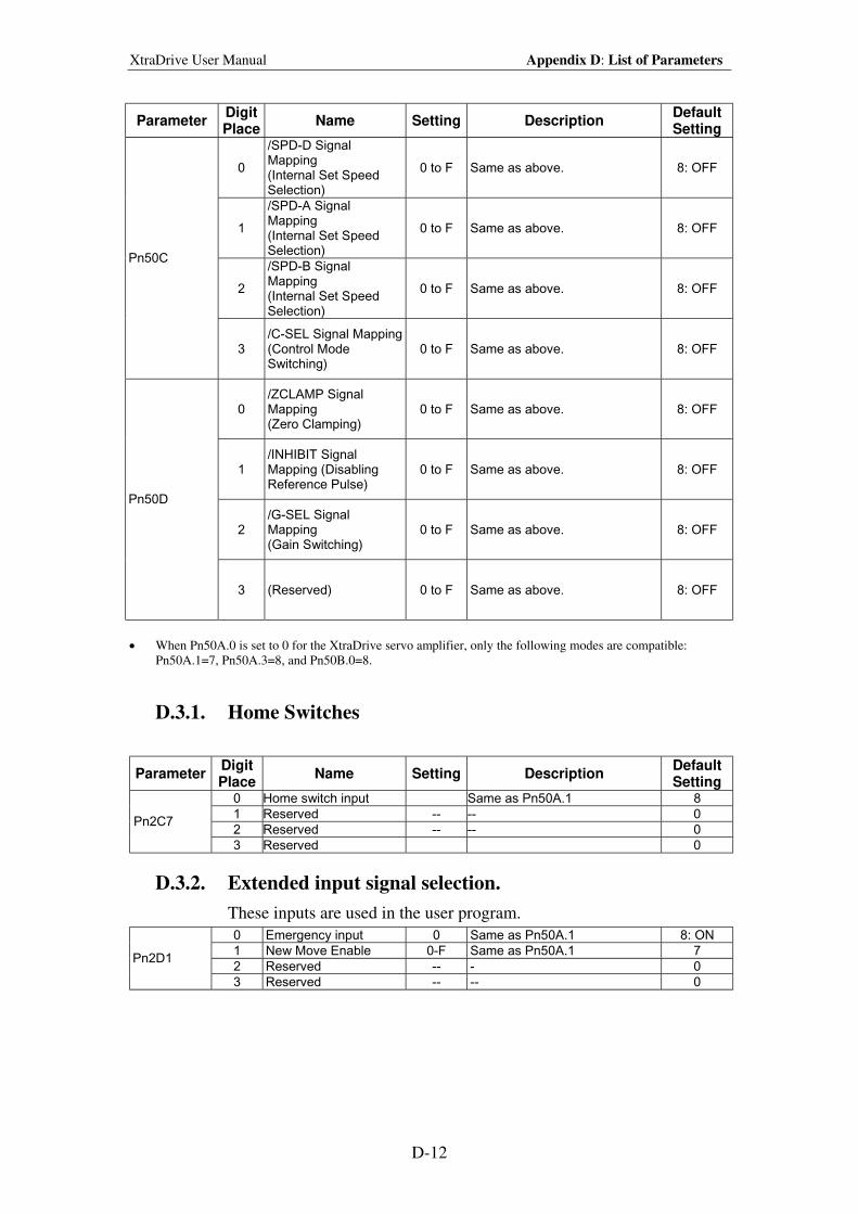
XtraDrive User Manual Appendix D: List of Parameters
D-12
Parameter Digit Place
Name Setting Description Default Setting
0
/SPD-D Signal Mapping (Internal Set Speed Selection)
0 to F Same as above. 8: OFF
1
/SPD-A Signal Mapping (Internal Set Speed Selection)
0 to F Same as above. 8: OFF
2
/SPD-B Signal Mapping (Internal Set Speed Selection)
0 to F Same as above. 8: OFF
Pn50C
3 /C-SEL Signal Mapping (Control Mode Switching)
0 to F Same as above. 8: OFF
0 /ZCLAMP Signal Mapping (Zero Clamping)
0 to F Same as above. 8: OFF
1 /INHIBIT Signal Mapping (Disabling Reference Pulse)
0 to F Same as above. 8: OFF
2 /G-SEL Signal Mapping (Gain Switching)
0 to F Same as above. 8: OFF
Pn50D
3 (Reserved) 0 to F Same as above. 8: OFF
• When Pn50A.0 is set to 0 for the XtraDrive servo amplifier, only the following modes are compatible:
Pn50A.1=7, Pn50A.3=8, and Pn50B.0=8.
D.3.1. Home Switches
Parameter Digit Place
Name Setting Description Default Setting
0 Home switch input Same as Pn50A.1 8
1 Reserved -- -- 0
2 Reserved -- -- 0 Pn2C7
3 Reserved 0
D.3.2. Extended input signal selection.
These inputs are used in the user program.
0 Emergency input 0 Same as Pn50A.1 8: ON
1 New Move Enable 0-F Same as Pn50A.1 7
2 Reserved -- - 0 Pn2D1
3 Reserved -- -- 0
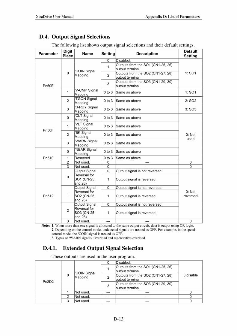
XtraDrive User Manual Appendix D: List of Parameters
D-13
D.4. Output Signal Selections
The following list shows output signal selections and their default settings.
Parameter Digit Place
Name Setting Description Default Setting
0 Disabled.
1 Outputs from the SO1 (CN1-25, 26) output terminal.
2 Outputs from the SO2 (CN1-27, 28) output terminal.
0 /COIN Signal Mapping
3 Outputs from the SO3 (CN1-29, 30) output terminal.
1: SO1
1 /V-CMP Signal Mapping
0 to 3 Same as above 1: SO1
2 /TGON Signal Mapping
0 to 3 Same as above 2: SO2
Pn50E
3 /S-RDY Signal Mapping
0 to 3 Same as above 3: SO3
0 /CLT Signal Mapping
0 to 3 Same as above
1 /VLT Signal Mapping
0 to 3 Same as above
2 /BK Signal Mapping
0 to 3 Same as above
Pn50F
3 /WARN Signal Mapping
0 to 3 Same as above
0 /NEAR Signal Mapping
0 to 3 Same as above
1 Reserved 0 to 3 Same as above
0: Not used
2 Not used. 0 — 0
Pn510
3 Not used. 0 — 0
0 Output signal is not reversed.
0
Output Signal Reversal for SO1 (CN-25 and 26)
1 Output signal is reversed.
0 Output signal is not reversed.
1
Output Signal Reversal for SO2 (CN-25 and 26)
1 Output signal is reversed.
0 Output signal is not reversed.
2
Output Signal Reversal for SO3 (CN-25 and 26)
1 Output signal is reversed.
0: Not reversed Pn512
3 Not used. — — 0
Note: 1. When more than one signal is allocated to the same output circuit, data is output using OR logic.
2. Depending on the control mode, undetected signals are treated as OFF. For example, in the speed
control mode, the /COIN signal is treated as OFF.
3. Types of /WARN signals: Overload and regenerative overload.
D.4.1. Extended Output Signal Selection
These outputs are used in the user program.
0 Disabled.
1 Outputs from the SO1 (CN1-25, 26) output terminal.
2 Outputs from the SO2 (CN1-27, 28) output terminal.
0 /COIN Signal Mapping
3 Outputs from the SO3 (CN1-29, 30) output terminal.
0:disable
1 Not used. — — 0
2 Not used. — — 0
Pn2D2
3 Not used. — — 0
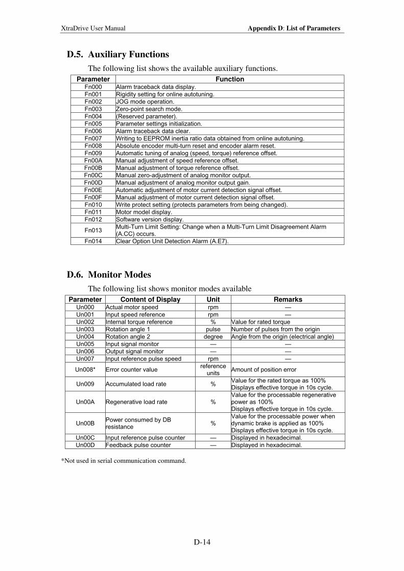
XtraDrive User Manual Appendix D: List of Parameters
D-14
D.5. Auxiliary Functions
The following list shows the available auxiliary functions.
Parameter Function Fn000 Alarm traceback data display.
Fn001 Rigidity setting for online autotuning.
Fn002 JOG mode operation.
Fn003 Zero-point search mode.
Fn004 (Reserved parameter).
Fn005 Parameter settings initialization.
Fn006 Alarm traceback data clear.
Fn007 Writing to EEPROM inertia ratio data obtained from online autotuning.
Fn008 Absolute encoder multi-turn reset and encoder alarm reset.
Fn009 Automatic tuning of analog (speed, torque) reference offset.
Fn00A Manual adjustment of speed reference offset.
Fn00B Manual adjustment of torque reference offset.
Fn00C Manual zero-adjustment of analog monitor output.
Fn00D Manual adjustment of analog monitor output gain.
Fn00E Automatic adjustment of motor current detection signal offset.
Fn00F Manual adjustment of motor current detection signal offset.
Fn010 Write protect setting (protects parameters from being changed).
Fn011 Motor model display.
Fn012 Software version display.
Fn013 Multi-Turn Limit Setting: Change when a Multi-Turn Limit Disagreement Alarm (A.CC) occurs.
Fn014 Clear Option Unit Detection Alarm (A.E7).
D.6. Monitor Modes
The following list shows monitor modes available
Parameter Content of Display Unit Remarks Un000 Actual motor speed rpm —
Un001 Input speed reference rpm —
Un002 Internal torque reference % Value for rated torque
Un003 Rotation angle 1 pulse Number of pulses from the origin
Un004 Rotation angle 2 degree Angle from the origin (electrical angle)
Un005 Input signal monitor — —
Un006 Output signal monitor — —
Un007 Input reference pulse speed rpm —
Un008* Error counter value reference
units Amount of position error
Un009 Accumulated load rate % Value for the rated torque as 100% Displays effective torque in 10s cycle.
Un00A Regenerative load rate % Value for the processable regenerative power as 100% Displays effective torque in 10s cycle.
Un00B Power consumed by DB resistance
% Value for the processable power when dynamic brake is applied as 100% Displays effective torque in 10s cycle.
Un00C Input reference pulse counter — Displayed in hexadecimal.
Un00D Feedback pulse counter — Displayed in hexadecimal.
*Not used in serial communication command.


Short Form Installation Guide Error! Style not defined.
2
YET Ltd. ISRAEL YET US Inc.
13 Hamelacha St., 531 King St.,
Afeq Industrial Estate Unit 1
Rosh Ha’ayin 48091 Littleton, MA 01460
ISRAEL USA
Tel: +972-3-9004114 Tel: +1-866-YET-8080
Fax: +972-3-9030412 Fax: +1-978-952-6821
[email protected] [email protected]
For more information refer to our web site: www.yetmotion.com
Specifications are subject to change without notice due
to ongoing product modifications and improvements.
Catalog No. 8U0108 Rev. C