Embed Size (px)
Citation preview

Users’ Manual
Pub. No. 234-3622-06 / March 2019
Integrated Patient Transport & Loading System™
Read this manual and retainfor future reference.

2 © Ferno-Washington, Inc. / 234-3622-06 / March 2019
DisclaimerThis manual contains general instructions for the use, operation and care of this product. The instructions are not all-inclusive. Safe and proper use of this product is solely at the discretion of the user. Safety information is included as a service to the user. All other safety measures taken by the user should be within and under consideration of applicable regulations and local protocol. Training on the proper use of this product must be provided before using this product in an actual situation.
Retain this manual for future reference. Include it with the product in the event of transfer to new users. Additional free copies are available upon request from Customer Relations.
Proprietary NoticeThe information disclosed in this manual is the property of Ferno-Washington, Inc., Wilmington, Ohio, USA. Ferno-Washington, Inc. reserves all intellectual property rights, proprietary design rights, manufacturing rights, reproduction use rights, and sales use rights thereto, and to any article disclosed therein except to the extent those rights are expressly granted to others or where not applicable to vendor proprietary parts.
Limited Warranty StatementThe products sold by Ferno are covered by a limited warranty, which is printed on all Ferno invoices. The complete terms and conditions of the limited warranty, and the limitations of liability and disclaimers, are also available upon request by calling Ferno at 1.800.733.3766 or 1.937.382.1451.
Ferno Customer RelationsFor ordering assistance or general information:
CANADA AND THE U.S.A.Telephone (Toll-free) 1.877.733.0911Telephone 1.937.382.1451Fax (Toll-free) 1.888.388.1349Fax 1.937.382.1191Internet www.ferno.com
ALL OTHER LOCATIONSFor assistance or information, please contact your Ferno distributor. If you do not have a Ferno distributor, please contact Ferno Customer Relations:
Ferno-Washington, Inc., 70 Weil Way Wilmington, Ohio 45177-9371, U.S.A.
Telephone Country Code +1.937.382.1451Fax Country Code +1.937.382.6569Internet www.ferno.com
FOR IN∫X SUPPORTContact us at [email protected]
1.937.382.1451
Battery Recycling
In the U.S.A. and Canada, contact Call2Recycle toll-free for a nearby location to responsibly dispose of a Ferno rechargeable battery.
Outside the U.S.A. and Canada, contact the government of your country for recycling information.
See “Recycling Notice” on page 55.
iN∫X 36 VDCLithium-iron phosphate (LiFePO4)
UNIQUE DEVICE IDENTITY NOTICEFerno complies with the United States Food and Drug Administration’s Unique Device Identification regulation to identify medical devices. The UDI label contains information in human- and machine-readable form. Device information is online at the FDA’s Global Unique Device Identification Database (GUDID). The public can search and download information at AccessGUDID at www.fda.gov.
The label is located on the patient-left main frame, under battery cover.
Ferno-Washington Inc. | Wilmington, Ohio 45177 USA | +1.937.382.1451
Product Name/Model
(01) Global Trade Item Number
(11) Date of Manufacture
(21) Serial Number
Date of Manufacture
SN Serial Number
Manufacturer GS1 Data Matrix
Enhanced ManualWhen this symbol appears in the manual or on the iN∫X, scan the QR code (using a smart-phone) or click (in the electronic manual) for online information and video content (requires internet access). www.fernoems.com/inx
Read this manual and retain for future reference.A training DVD is also provided. To request additional manuals or DVDs, contact Ferno.

3© Ferno-Washington, Inc. / 234-3622-06 / March 2019
TABLE OF CONTENTS
Ferno Customer Relations __________________________ 21 - Safety Information _______________________________ 4
1.1 Warning ____________________________________ 41.2 Notice _____________________________________ 51.3 Tip ________________________________________ 51.4 Bloodborne Disease Notice ____________________ 51.5 Fastening System Compatibility ________________ 51.6 Symbol Glossary _____________________________ 51.7 Safety and Instruction Labels ___________________ 61.8 Compliance: USA Standard SAE J3027 ____________ 61.9 Compliance: Worldwide _______________________ 7
2 - Operator Focus __________________________________ 82.1 Operator Training ____________________________ 82.2 Operator Height and Strength __________________ 82.3 Daily Operator Duties _________________________ 92.4 No-Lift Loading/Unloading ____________________ 92.5 Controlling the Load __________________________ 92.6 Using Additional Help________________________ 102.7 Terms _____________________________________ 11
3 - iN∫X Overview __________________________________ 123.1 Description ________________________________ 123.2 General Specifications _______________________ 13
4 - Features and Controls ____________________________ 164.1 Display Overview ___________________________ 164.2 Power Switch _______________________________ 174.3 Light Buttons _______________________________ 174.4 Display Zones ______________________________ 184.5 iN∫X Zone _________________________________ 184.6 Timer Zone ________________________________ 184.7 Status Zone ________________________________ 194.8 Audible Alarm ______________________________ 194.9 Battery Zone _______________________________ 194.10 Battery ____________________________________ 204.11 Battery Charger _____________________________ 214.12 Integrated Charging System (ICS®) _____________ 214.13 Extend and Retract Buttons ___________________ 224.14 Sleep Mode ________________________________ 224.15 Mode-Select Button _________________________ 234.16 Telescoping Handles _________________________ 234.17 Position Indicator Lights ______________________ 234.18 Shock Frame _______________________________ 244.19 Backrest ___________________________________ 254.20 Telescoping Frame __________________________ 264.21 Safety-Bar Release Levers _____________________ 264.22 Sidearms __________________________________ 274.23 Mattress ___________________________________ 284.24 Non-Powered Operation (Actuator-Release Handles) ___________________ 294.25 Oxygen Cylinder Holder ______________________ 304.26 Patient Restraint System ______________________ 314.27 Accessory Rail ______________________________ 314.28 Wheel Locks _______________________________ 31
5 - Using the iN∫X __________________________________ 325.1 Before Placing the iN∫X in Service ______________ 325.2 General Guidelines for Use ____________________ 325.3 Status Indicators and Audible Alarm ____________ 325.4 Powered Extending/Retracting ________________ 335.5 Transferring the Patient ______________________ 345.6 Transferring the Patient: Chair Position __________ 355.7 Rolling the iN∫X _____________________________ 365.8 One Operator, Empty iN∫X ____________________ 375.9 Loading the iN∫X ____________________________ 385.10 Unloading the iN∫X __________________________ 405.11 Direct Power Modes _________________________ 425.12 Direct Power: Both Legs ______________________ 435.13 Direct Power: Loading-End Legs _______________ 435.14 Direct Power: Control-End Legs ________________ 435.15 Non-Powered Operation: Extending and Retracting _____________________ 445.16 Non-Powered Operation: Loading ______________ 465.17 Non-Powered Operation: Unloading ____________ 47
6 - Maintenance ___________________________________ 486.1 Maintenance Schedule _______________________ 486.2 Service Life ________________________________ 486.3 Inspecting the iN∫X __________________________ 486.4 Disinfecting Patient Restraints _________________ 496.5 Cleaning Patient Restraints ___________________ 496.6 Disinfecting/Cleaning the Mattress _____________ 496.7 Disinfecting the iN∫X _________________________ 496.8 Cleaning the iN∫X ___________________________ 506.9 Pressure-Washing the iN∫X ____________________ 506.10 Lubricating the iN∫X _________________________ 516.11 Patient Restraints ___________________________ 526.12 Storing the iN∫X ____________________________ 546.13 Charging the Battery ________________________ 546.14 Storing the Battery __________________________ 546.15 Recycling Notice ____________________________ 556.16 Adjusting the Backrest Control Handle Tension ___ 566.17 Adjusting the Position Indicator Lights __________ 566.18 Adjusting Tension Of The Actuator Release Handles _________________ 576.19 Adjusting the Oxygen Cylinder Holder & Cleaning the Straps ________________________ 58
7 - Initial Setup ____________________________________ 607.1 Ambulance Information ______________________ 607.2 Accessories ________________________________ 607.3 Charge and Install the Battery _________________ 607.4 Set the Loading Height _______________________ 61
8 - Technical Data __________________________________ 628.1 Charger Specifications _______________________ 628.2 iN∫X Battery Specifications ____________________ 62
9 - Troubleshooting ________________________________ 639.1 Status Indicators ____________________________ 63
10 - Parts and Service _______________________________ 6410.1 U.S.A. and Canada ___________________________ 6410.2 Worldwide _________________________________ 64
11 - Accessories ____________________________________ 6511.1 Accessories ________________________________ 65
Training Record____________________________________ 66Maintenance Record _______________________________ 67
Section Page Section Page
4 © Ferno-Washington, Inc. / 234-3622-06 / March 2019
1 - SAFETY INFORMATION
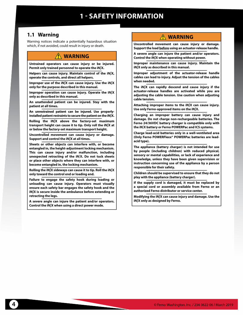
1.1 WarningWarning notices indicate a potentially hazardous situation which, if not avoided, could result in injury or death.
WARNINGUntrained operators can cause injury or be injured. Permit only trained personnel to operate the iN∫X.
Helpers can cause injury. Maintain control of the iN∫X, operate the controls, and direct all helpers.
Improper use of the iN∫X can cause injury. Use the iN∫X only for the purpose described in this manual.
Improper operation can cause injury. Operate the iN∫X only as described in this manual.
An unattended patient can be injured. Stay with the patient at all times.
An unrestrained patient can be injured. Use properly-installed patient restraints to secure the patient on the iN∫X.
Rolling the iN∫X above the factory-set maximum transport height can cause it to tip. Only roll the iN∫X at or below the factory-set maximum transport height.
Uncontrolled movement can cause injury or damage. Support and control the iN∫X at all times.
Sheets or other objects can interfere with, or become entangled in, the height-adjustment locking mechanism. This can cause injury and/or malfunction, including unexpected retracting of the iN∫X. Do not tuck sheets or place other objects where they can interfere with, or become entangled in, the locking mechanism.
Rolling the iN∫X sideways can cause it to tip. Roll the iN∫X only toward the control end or loading end.
Failure to engage the safety hook during loading or unloading can cause injury. Operators must visually ensure each safety bar engages the safety hook and the iN∫X is secure inside the ambulance before extending or retracting the legs.
A severe angle can injure the patient and/or operators. Control the iN∫X when using a direct power mode.
WARNINGUncontrolled movement can cause injury or damage. Support the load before using an actuator-release handle.
A severe angle can injure the patient and/or operators. Control the iN∫X when operating without power.
Improper maintenance can cause injury. Maintain the iN∫X only as described in this manual.
Improper adjustment of the actuator-release handle cables can lead to injury. Adjust the tension of the cables when needed.
The iN∫X can rapidly descend and cause injury if the actuator-release handles are activated while you are adjusting the cable tension. Use caution when adjusting cable tension.
Attaching improper items to the iN∫X can cause injury. Use only Ferno-approved items on the iN∫X.
Charging an improper battery can cause injury and damage. Do not charge non-rechargeable batteries. The Ferno 24/36VDC battery charger is compatible only with the iN∫X battery or Ferno POWERPac and ICS systems.
Charge lead-acid batteries only in a well-ventilated area (Only Ferno POWERFlexx® POWERPac batteries are lead-acid type).
The appliance (battery charger) is not intended for use by people (including children) with reduced physical, sensory or mental capabilities, or lack of experience and knowledge, unless they have been given supervision or instruction concerning use of the appliance by a person responsible for their safety.
Children should be supervised to ensure that they do not play with the appliance (battery charger).
If the supply cord is damaged, it must be replaced by a special cord or assembly available from Ferno or an authorized Ferno distributor or service center.
Modifying the iN∫X can cause injury and damage. Use the iN∫X only as designed by Ferno.

5© Ferno-Washington, Inc. / 234-3622-06 / March 2019
1.3 TipTips provide recommendations for easier use of the product.
1.4 Bloodborne Disease NoticeTo reduce the risk of exposure to blood or other potentially infectious materials when using the iN∫X, follow the disinfecting and cleaning instructions in this manual.
Safety Information
1.5 Fastening System CompatibilityCombining different manufacturers’ products such as a Ferno cot with a non-Ferno fastening system can increase the user’s risk of injury and damage.
Ferno-Washington, Inc. products are designed for use only with Ferno-manufactured fastening systems. Use of a Ferno product with a non-Ferno fastening system is misuse of the Ferno product. The user assumes responsibility for the outcome of known, intentional misuse.
1.6 Symbol GlossaryThe symbols defined below are used on the iN∫X and/or in this users’ manual. Ferno uses symbols recognized by the International Standards Organization (ISO), American National Standards Institute (ANSI) and the emergency medical services industry.
Scene Lights
DC (Direct Current) electricity
Laser Class 2MWarning: Do Not Stare
Into Light
OFF ON
Locked/Unlocked
Manufacturer
General Warning of Potential Injury
Extend Legs Retract Legs
Status Indicator: Low or Medium Priority
Do Not OpenNo User Service
In This Area
Operation RequiresTwo Trained
Operators
Chair Position
WEEE Directive:Dispose of Battery
Properly
Read theUsers’ Manual
Emergency Lights
Lubricate/Do Not Lubricate
European CommunityAuthorized
Representative
Pinch PointKeep Fingers Clear
Status Indicator:High Priority
QR Code(To Access Online Material,
Scan with Smartphone or Click this Link in the
Electronic Manual)
Load Capacity
Recycling Information (USA)
Product Meets European Union Standards
1.2 NoticeNotices emphasize important, but not hazard-related information. Failure to follow Notices could result in product or property damage.
NOTICE

6 © Ferno-Washington, Inc. / 234-3622-06 / March 2019
Safety Information
SAE J3027 Compatibility
To comply with the SAE J3027 Recommended Practice, all three elements are required.
● Compliant ambulance cot
● Compliant restraint system
● Compliant fastening system (cot/litter retention system)
1.7 Safety and Instruction LabelsSafety and instruction labels place important information from the users’ manual on the iN∫X. Read and follow label instructions. Replace worn or damaged labels immediately.
Safety RemindersLocation: Control and Loading Ends
Safety RemindersLocation: Control and Loading Ends
Do Not Open/Laser NoticeLocation: Controller Housing
Ferno Battery OnlyLocation: Battery Cradle
Sidearm Unlock Labels (2 ea.)Location: Sidearm
Non-Powered OperationLocation: Actuator-Release Handles (2)
Do Not OpenLocation: Display Bottom
Laser Emitter Warning (2)Location: Laser Apertures
Non-Powered OperationHandle Lock/Unlock (2)
Location: Handle Mounts
Pinch PointLocation: Actuator Sliding Surface
1.8 Compliance: USA Standard SAE J3027The iN∫X® with iN∫LINE® is compatible with the Society of Automotive Engineers SAE J3027 Recommended Practice (2014) when used with additional Ferno equipment (not supplied, available separately).
To comply with the SAE J3027 Recommended Practice (USA), all three compliant elements must be present:
1. Ambulance cot
2. Transport restraint system (patient restraints)
3. Fastening system (cot/litter retention system)
FERNO COMPLIANT ELEMENTS● iN∫X® Integrated Patient Transport & Loading System™
● iN∫LINE® Fastening System (Short, Medium, or Long)
● Model 417-3 iN∫X® Restraint System

7© Ferno-Washington, Inc. / 234-3622-06 / March 2019
Safety Information
1.9 Compliance: WorldwideSPECIFICATIONS AND STANDARDS
The iN∫X® meets or exceeds the following global specifications and standards. Be aware: standards and specifications are updated periodically. Current guidelines are available from these organizations.
● AMD: Ambulance Manufacturer’s Division (AMD) of the National Truck Equipment Association Standard 004 (Oct. 2014), Litter Retention System Static Test.
● KKK-A-1822 (F): Federal Ambulance Specification KKK-A-1822 revision F (2007), Change Notice 11 (2018) as applicable.
● NFPA: National Fire Protection Association standard NFPA® 1917 (2016 edition).
● SAE: Society of Automotive Engineers SAE J3027 Recommended Practice (2014). See below.
● CAAS: Commission on Accreditation of Ambulance Services Global Vehicle Standard (GVS) v1.0
● IP56: Ingress Protection rating. Tested in compliance with dust and water infiltration standards.
● IEC 60601-1-2 (electrical and electromagnetic medical equipment standards)
● IEC 2007/47
● MDD: Ferno products meet the requirements of the European Medical Device Directive 93/42/EEC as established by the European Union.
CANADA● CSA: Electronic components meet Canadian
Standards Association requirements.
● Ontario: Ontario Land Ambulance Standard, Version 5.0, September 28, 2012; Section 20.1 Main Cot Retention
● BCAS: BCAS Ambulance Performance Test Criteria E2 Stretcher Retention
● Alberta: Alberta Health and Wellness Ambulance Vehicle Standard Code January 2010; Section 17.5 Cot Retention System Test
● AMD: Ambulance Manufacturer’s Division (AMD) of the National Truck Equipment Association Standard 004 (August 2007 edition), Litter Retention System Static Test. (Some areas of Canada follow the U.S. AMD specification.)
AUSTRALIA/NEW ZEALAND● AS/NZS 4535:1999: Meets the requirements of the
Ambulance Restraint Systems test.
EUROPEAN STANDARDS● EN 1789:2007+A2:2014: Vehicle, fastening system,
and crash-test standards.
Specifications/Standards Contact Information
For information about AMD standards:Ambulance Manufacturer’s DivisionNational Truck Equipment Association37400 Hills Tech DriveFarmington Hills, MI, 48331-3414Internet: www.ntea.com
For information about CAAS standards:CAAS1926 Waukegan Road, Suite 300Glenview, IL, 60025-1770Internet: www.caas.org
For information about Federal Ambulance Specification KKK-A-1822 revision F (2007):
Office of Motor Vehicle Management,General Services Administration,2200 Crystal Drive, Suite 1006Arlington, VA, 22202Internet: www.gsa.gov/automotive
For information about NFPA® standards:National Fire Protection Association1 Batterymarch ParkQuincy, MA, 02169-7471Internet: www.nfpa.org
For information about SAE standards:Warrendale, PA, USA - Headquarters400 Commonwealth DriveWarrendale, PA 15096p: +1.724.776.4841f: +1.724.776.0790Internet: www.sae.org
For information in Alberta, Canada:Internet: http://www.albertahealthservices.ca/
For information in British Columbia, Canada:Internet: http://www.bcehs.ca/

© Ferno-Washington, Inc. / 234-3622-06 / March 20198
2 - OPERATOR FOCUS
WARNINGUntrained operators can cause injury or be injured. Permit only trained personnel to operate the iN∫X.
2.1 Operator TrainingOperators using the iN∫X:
● Must read and understand this manual.
● Must have training on proper use of the iN∫X.
● Must have training on emergency-medical service and emergency patient-handling procedures.
● Must have the physical ability to assist the patient.
● Must practice with the iN∫X before use with a patient.
● Must keep training records. For a sample training record sheet, see “Training Record” on page 66.
Ferno cares about operator and patient safety. For operator training videos, visit our iN∫X Quick Start training website.
The Ferno Injury Free program from Ferno provides training on nutrition, exercise, management of stress and fatigue, ergonomics, and injury prevention, all from an emergency-medical services perspective.
See the Tips at right to scan a QR code with a smartphone or tablet, click a link in an electronic version of this manual, or type the web address into a browser.
2.2 Operator Height and StrengthThe iN∫X is designed to minimize the need for lifting. Whenever possible, use the powered hydraulic system to:
● Extend and retract the legs.
● Load the iN∫X into and unload it from an ambulance.
● Transition between surfaces of varying levels.
● Place the iN∫X at good height to establish a proper, ergonomic grasping position for the operators.
An excessive load (exceeding the 700 lb/318 kg load capacity) or non-powered operation may require the operators to lift a portion of the load. Use additional help as needed. See “Using Additional Help” on page 10.
iN∫X Quick Start Training
To supplement this users' manual, visit the iN∫X Quick Start video training support page online:
http://www.fernoems.com/inx/training
Or, scan this QR Code with a smartphone:
EMT: Injury Free Training
For training on nutrition, exercise, ergonomics, injury prevention, and more, visit online:
http://www.fernoems.com/injuryfree
Or, scan this QR Code with a smartphone:
NOTICEIf the ambulance is parked on an uneven surface, the operators (and any helpers) may need to extend the legs higher than the user-set loading height to allow the iN∫X to roll into the ambulance.

© Ferno-Washington, Inc. / 234-3622-06 / March 2019 9
Operator Focus
2.5 Controlling the LoadWhen rolling the iN∫X, both operators (and any helpers) must keep both hands on the main frame (or guide bar), support and balance the load, and maintain control of the iN∫X at all times. Use care on rough or uneven terrain.
Roll the iN∫X only at, or below, the maximum transport height. This height is programmed into the iN∫X. See “Rolling the iN∫X” on page 36. Use additional help if needed; see “Using Additional Help” on page 10.
1
2
No-Lift Loading/Unloading
Do not lift the iN∫X off the ground when using power during the loading or unloading process.
Support and balance the iN∫X while rolling it. Use additional help as needed. See “Using
Additional Help” on page 10.
2.3 Daily Operator DutiesIt is good practice for operators to check equipment at the start of each work shift. To check the iN∫X prior to use, follow the procedures described in this manual:
● Unload the iN∫X from the ambulance.
● Retract the iN∫X to the floor or ground.
● Extend the iN∫X to the recommended rolling height.
● Visually inspect the iN∫X for readiness. See “Inspecting the IN∫X” on page 48.
● Rotate the iN∫X in a circle to verify it rolls easily.
● Load the iN∫X into ambulance and secure it in the iN∫LINE.
● Verify the iN∫X is being charged by the ICS. See “Integrated Charging System (ICS)” on page 21.
2.4 No-Lift Loading/UnloadingThe unique design of the iN∫LINE fastening system holds the iN∫X level with the patient floor as the operators load it into the ambulance (Figure 1), or unload it from the ambulance (Figure 2). During loading and unloading:
● As both operators work together to guide the iN∫X into the iN∫LINE, the Control-end Operator confirms each iN∫X safety bar engages the iN∫LINE safety hook.
● Do not lift the iN∫X. Allow the legs to support the load.
● Verify the legs have clearance before extending or retracting. Look for obstructions such as the ambulance bumper.
● For complete loading and unloading procedures, see “Loading the iN∫X” on page 38 and “Unloading the iN∫X” on page 40. Use additional help if needed; see “Using Additional Help” on page 10.
10 © Ferno-Washington, Inc. / 234-3622-06 / March 2019
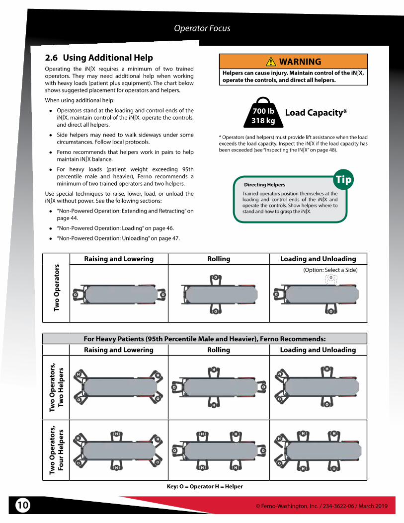
2.6 Using Additional HelpOperating the iN∫X requires a minimum of two trained operators. They may need additional help when working with heavy loads (patient plus equipment). The chart below shows suggested placement for operators and helpers.
When using additional help:
● Operators stand at the loading and control ends of the iN∫X, maintain control of the iN∫X, operate the controls, and direct all helpers.
● Side helpers may need to walk sideways under some circumstances. Follow local protocols.
● Ferno recommends that helpers work in pairs to help maintain iN∫X balance.
● For heavy loads (patient weight exceeding 95th percentile male and heavier), Ferno recommends a minimum of two trained operators and two helpers.
Use special techniques to raise, lower, load, or unload the iN∫X without power. See the following sections:
● “Non-Powered Operation: Extending and Retracting” on page 44.
● “Non-Powered Operation: Loading” on page 46.
● “Non-Powered Operation: Unloading” on page 47.
WARNINGHelpers can cause injury. Maintain control of the iN∫X, operate the controls, and direct all helpers.
Operator Focus
Load Capacity*
* Operators (and helpers) must provide lift assistance when the load exceeds the load capacity. Inspect the iN∫X if the load capacity has been exceeded (see “Inspecting the IN∫X” on page 48).
Directing Helpers
Trained operators position themselves at the loading and control ends of the iN∫X and operate the controls. Show helpers where to stand and how to grasp the iN∫X.
For Heavy Patients (95th Percentile Male and Heavier), Ferno Recommends:Raising and Lowering Rolling Loading and Unloading
Two
Ope
rato
rs,
Two
Hel
pers
Two
Ope
rato
rs,
Four
Hel
pers
Key: O = Operator H = Helper
OO OO
Two
Ope
rato
rs Raising and Lowering Rolling Loading and Unloading
(Option: Select a Side)

11© Ferno-Washington, Inc. / 234-3622-06 / March 2019
Operator Focus
2.7 Terms● ACTUATOR: The actuator is a hydraulic system that extends
and retracts the iN∫X legs. One actuator is attached to each set of legs.
● AUTO-EQUALIZE: During normal operation, if the legs are not equally extended, pressing or will extend or retract one set of legs until both sets of legs are equally extended. Then, both sets of legs extend or retract simultaneously.
● AUTOMATIC STOPS: The iN∫X stops automatically at the maximum safe transport height (factory-set) and at the loading height (user-set). To continue extending or retracting, press or again.
● CONTROL END: The control end of the iN∫X is where the display, telescoping handles and shock frame are located. This area is also known as the foot end.
● DISPLAY: The display provides operators with the status of many iN∫X systems, including the legs, patient surface, battery charge, and alternate operating modes. See “Display Zones” on page 18.
● DRIVE LIGHTS: Drive lights are white lights on the actuators that illuminate the ground around the wheels and increase iN∫X visibility in low light. See “Light Buttons” on page 17.
● EXTENDING (LEGS): In this manual, the term "extending" is used to describe raising the patient surface away from the transport wheels. Extend the legs to increase the height of the patient surface, or when unloading the iN∫X from the ambulance.
● GUIDE BAR: The curved guide bar is used by the control-end operator to guide and maintain control of the iN∫X. The display is affixed between the guide bar and the patient surface. A set of / buttons is attached to the right-hand side.
● iN∫LINE: The iN∫LINE fastening system is a Ferno device designed to secure the iN∫X in a ground-based ambulance.
● INTEGRATED CHARGING SYSTEM (ICS®): The ICS allows the iN∫X to be charged each time it is secured in the iN∫LINE. (Power to the ICS from the ambulance inverter or shore power must be ON). The ICS helps keep the iN∫X battery fully charged.
● INTERACTIVE CONTENT: For training videos and proper use of the iN∫X, scan a QR code in this manual, click a link in an electronic version of this manual or visit our website at http://www.fernoems.com/inx/training.
● LIFT-ASSIST: Under extreme weight conditions (loads), the operators may need to provide lift-assistance. Use additional help if needed. See “Using Additional Help” on page 10.
● LOAD: The load is the overall weight of the patient plus equipment placed on (or attached to) the iN∫X.
● LOADING END: The loading end of the iN∫X is where the backrest, telescoping frame and one of two safety bars are located. This area is also known as the head end.
● LOADING HEIGHT: Users can set the iN∫X to stop at the proper normal loading height for an ambulance. See “Set the Loading Height” on page 61. Extend the iN∫X to the loading height only to load it into an ambulance or unload it from an ambulance.
● OPERATORS: The trained operators are referred to as the Control-end Operator and Loading-end Operator in this manual. The trained operators maintain control of the iN∫X, operate the controls, and direct helpers.
● RETRACTING (LEGS): In this manual, the term "retracting" is used to describe lowering the patient surface toward the transport wheels. Retract the legs to reduce the height of the patient surface, or when loading the iN∫X into an ambulance.
● SURROUND LIGHTS: Surround lights are red and white lights on each side of the iN∫X that provide steady light to illuminate the iN∫X, or flash in an attention-grabbing alert pattern to increase safety. See “Light Buttons” on page 17.
● TELESCOPING HANDLES: Telescoping handles extend or retract to provide the control-end operator with additional ergonomic positions to grasp and guide the iN∫X. A set of / buttons is attached to the right-hand telescoping handle. See “Telescoping Handles” on page 23.
● TRANSPORT HEIGHT: An alarm beeps when the patient surface is higher than the recommended maximum transport height. Keep the iN∫X at or below this height when rolling it.
● SHEETS: Sheets or other articles that are placed, or find their way, beneath the patient surface can become caught in the power system. Do not tuck sheets or place other objects where they can interfere with, or become entangled in, the locking mechanism.
12 © Ferno-Washington, Inc. / 234-3622-06 / March 2019
3 - iN∫X OVERVIEW
3.1 DescriptionThe Ferno® iN∫X® Integrated Patient Transport & Loading System™ is an emergency patient-handling device designed to transport a patient over various terrain, to be loaded into and unloaded from an ambulance, and for transport inside a ground-based ambulance.
In this manual, the term “iN∫X” is used to represent the iN∫X® Integrated Patient Transport & Loading System™.
The iN∫X is for professional use by a minimum of two trained operators. The iN∫X is designed to help reduce the risk of back injury to medical service personnel by eliminating or minimizing the amount of lifting required to extend or retract the legs.
During powered operation, the iN∫X does not require lifting when loading into an ambulance or unloading from an ambulance.
The iN∫X may be operated manually when desired.
COMPATIBLE FASTENING SYSTEMS● Ferno® iN∫LINE® series fastening system
INCLUDED● Ferno® battery charger and adapter cable
● iN∫X battery
● Mattress with heat-sealed vinyl exterior and polyurethane foam pad interior
● Set of patient restraints
● Users’ manual and training DVD
● ICS® charging contacts standard
WARNINGImproper use of the iN∫X can cause injury. Use the iN∫X only for the purpose described in this manual.
FEATURES● 700 lb/318 kg lifting capacity (load capacity)
● Independent-leg, powered transport loading system
● Legs auto-equalize before extending or retracting
● Safety Lighting System
● Variable height adjustment allows level loading into an ambulance with a floor of up to 35" (889 mm)
● User-set loading height (maximum 35"/892 mm)
● Meets IP 56 (Ingress Protection rating) dust, water
● 36-Volt DC power system with dual actuators
● Multifunction display
● Position-indicator lights
● Simple / operation
● Multi-position sidearms
● Telescoping handles (control end)
● Coated handling surfaces keep hands/clothes clean
● Four 6-inch, tri-spoke swivel transport wheels
● 2 Wheel locks
● Pneumatic backrest
● Three-position telescoping loading-end frame
● Two-position shock frame
● Direct power and non-powered backup systems

13© Ferno-Washington, Inc. / 234-3622-06 / March 2019
General specifications are rounded. Metric conversions are calculated before rounding. Ferno reserves the right to change specifications without notice.
1Height: Distance from the ground to the patient surface.2Loading Height: Distance from the ground to the bottom of the loading wheels.3Weight includes battery weight but is without mattress, patient restraints and optional features.4Integrated Charging System Maintains the battery charge when the iN∫X is secured in the iN∫LINE. See “Integrated Charging System (ICS)” on page 21.
Note: The locking patient mattress is sealed.
3.2 General Specifications
iN∫X Construction
Frame Aluminum
Legs Carbon-Fiber Composite
Bed Surface Aluminum
Wheels Stainless steel, sealed bearings; Nonconductive wheels
Position Indicator Lights Class 2M Laser
Power System
Operating Temp. -40°F to 131°F (-40°C to 55°C)
Battery Output 36 Volts DC
Charging Time (1 transport, charge maintained by ICS®)
As little as 15 minutes 4
Charging Time (depleted) Up to 1 hour, 45 minutes
Charger Input 100 – 240 Volts AC
Charger Output Up to 39.6 Volts DC, 2 Amps (for iN∫X LiFePO4 battery)
Load Capacity
Imperial/Metric 700 lbs/318 kg
Stone (UK) 50 st
Weight
Equipped for Ferno®iN∫LINE® Series Fastening System 3 203 lbs/92 kg
iN∫X Overview
Dimensions Imperial Metric
A) Wheels 6" x 1.7" 152 mm x 43 mm
B) Length (Adjustable) 63" – 81" 1594-2045 mm
C) Width (Overall) 24" 597 mm
D) Width (Patient Surface) 16" 406 mm
E) Height 1 (Adjustable) 14" – 49" 356-1245 mm
F) Maximum Transport height (Factory-Preset, measurement is to patient surface) 34" 864 mm
G) Loading Height 2 (Adjustable, measurement is to bottom of loading wheel) 35" Maximum 889 mm Maximum
H) Backrest Adjustment 0°–76°
I) Shock Frame Adjustment 0°–16°
E
F
G
H
I
A
CB
D
Soft Goods
Mattress 72.5"x16.5"x3"/1842x419x73 mm

14 © Ferno-Washington, Inc. / 234-3622-06 / March 2019
iN∫X Overview
Control-End View
EXTEND AND RETRACTBUTTONS (2 Sets)p.22
SURROUND LIGHT(Each Side)
p.17p.20 BATTERY
MATTRESSp.14DISPLAYp.16 p.23POSITION
INDICATOR LIGHT (Each Side)
TELESCOPINGHANDLE (2)p.23
DRIVE LIGHTS(Each Actuator)p.17
WHEEL LOCK (2)p.31

15© Ferno-Washington, Inc. / 234-3622-06 / March 2019
Loading-End View
iN∫X Overview
PATIENT RESTRAINTS (Not Shown)p.52
NON-POWERED OPERATION (Not Shown)p.44
BACKRESTp.25SHOCK FRAMEp.24
SIDEARM(Each Side)p.27
SAFETY-BAR RELEASEp.26
TELESCOPING FRAME
p.26

16 © Ferno-Washington, Inc. / 234-3622-06 / March 2019
4.1 Display Overview
4 - FEATURES AND CONTROLS
Display UV Protection
The display screen inner surface is coated with a layer to protect it against ultraviolet (UV) light and pressure damage. This clear surface is normally invisible but may sometimes be seen as lines of clear "dots" when viewed at an angle. This is normal.
p.18 DISPLAY ZONES
p.35 CHAIR POSITION
MODE-SELECTBUTTON
p.23 p.17 POWER SWITCH
LIGHT BUTTONS (2)p.17
17© Ferno-Washington, Inc. / 234-3622-06 / March 2019
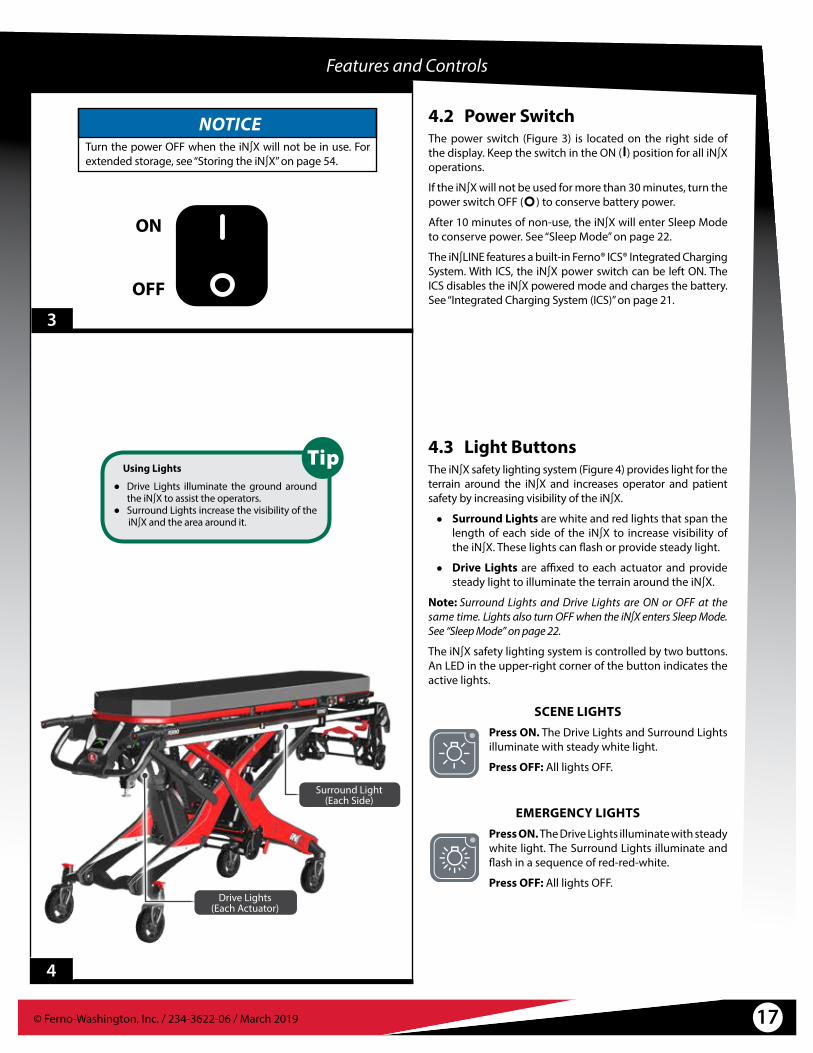
4.2 Power SwitchThe power switch (Figure 3) is located on the right side of the display. Keep the switch in the ON ( ) position for all iN∫X operations.
If the iN∫X will not be used for more than 30 minutes, turn the power switch OFF ( ) to conserve battery power.
After 10 minutes of non-use, the iN∫X will enter Sleep Mode to conserve power. See “Sleep Mode” on page 22.
The iN∫LINE features a built-in Ferno® ICS® Integrated Charging System. With ICS, the iN∫X power switch can be left ON. The ICS disables the iN∫X powered mode and charges the battery. See “Integrated Charging System (ICS)” on page 21.
OFF
ON
Features and Controls
3
4.3 Light ButtonsThe iN∫X safety lighting system (Figure 4) provides light for the terrain around the iN∫X and increases operator and patient safety by increasing visibility of the iN∫X.
● Surround Lights are white and red lights that span the length of each side of the iN∫X to increase visibility of the iN∫X. These lights can flash or provide steady light.
● Drive Lights are affixed to each actuator and provide steady light to illuminate the terrain around the iN∫X.
Note:� Surround Lights and Drive Lights are ON or OFF at the same time. Lights also turn OFF when the iN∫X enters Sleep Mode. See “Sleep Mode” on page 22.
The iN∫X safety lighting system is controlled by two buttons. An LED in the upper-right corner of the button indicates the active lights.
SCENE LIGHTSPress ON. The Drive Lights and Surround Lights illuminate with steady white light.
Press OFF: All lights OFF.
EMERGENCY LIGHTSPress ON. The Drive Lights illuminate with steady white light. The Surround Lights illuminate and flash in a sequence of red-red-white.
Press OFF: All lights OFF.
Using Lights
● Drive Lights illuminate the ground around the iN∫X to assist the operators.
● Surround Lights increase the visibility of the iN∫X and the area around it.
4
Surround Light(Each Side)
Drive Lights(Each Actuator)
NOTICETurn the power OFF when the iN∫X will not be in use. For extended storage, see “Storing the iN∫X” on page 54.

© Ferno-Washington, Inc. / 234-3622-06 / March 201918
Features and Controls
4.6 Timer ZoneA countdown timer is visible in the lower-left corner of the display only when an alternate operating mode is selected (Figure 6). Use the mode-select button to select an alternate operating mode. See “Mode-Select Button” on page 23 and “Direct Power Modes” on page 42.
If the countdown timer is allowed to expire, the iN∫X returns to its default operational mode and normal display screen.
N0115
5
4.4 Display ZonesThe display is ON when the power switch is ON, and OFF when the power switch is OFF or when the iN∫X enters Sleep Mode.
To turn the display ON, use the power switch (see “Power Switch” on page 17). To awaken from Sleep Mode, press . See “Sleep Mode” on page 22.
The display is divided into four zones (Figure 5):
● iN∫X ZONE: This zone displays the iN∫X with areas color-coded to indicate the current status of each area.
● TIMER ZONE: This zone is illuminated when the iN∫X is in an alternate operating mode. It displays a countdown timer. See “Direct Power Modes” on page 42.
● STATUS ZONE: This zone illuminates with indicators to provide function and safety information. Based on the condition, a warning triangle, other symbol, and/or alphanumeric code may be displayed. See “Status Zone” on page 19 and “Status Indicators” on page 63.
● BATTERY ZONE: This zone indicates the charge of the battery. See “Battery Zone” on page 19.
Note:� For alternate-mode screens, see “Direct Power Modes” on page 42 and “Set the Loading Height” on page 61.
4.5 iN∫X ZoneThe main display area shows the iN∫X (Figure 5). The color of the legs and patient surface indicates the current status of these areas. Refer to the iN∫X Zone Indicators table at right.
The iN∫X zone is illuminated whenever the power is ON.
iN∫X Zone Indicators
LEG
Green The legs may be extended and/or retracted.
White The legs will not extend or retract.
Blue The iN∫X is in a direct power mode. The blue legs will move when a button is pressed.
PATIENT SURFACE
White The iN∫X is at a safe transport height.
Yellow/Red The iN∫X is above the maximum recommended transport height. Lower the iN∫X before rolling.
WHEELS
Green/White The iN∫X may be rolled, if the patient surface is at a suitable transport height.
Red Do not roll the iN∫X.
15 N04
6
iN∫X Zone
Timer Zone Status Zone Battery Zone
Countdown Timer
Press Green to Go
To activate the iN∫X after turning the power switch ON, or to wake the iN∫X from Sleep Mode, press . Note: Only the button will activate/wake up the iN∫X.

© Ferno-Washington, Inc. / 234-3622-06 / March 2019 19
4.8 Audible AlarmThe iN∫X will sound a series of beeps when a status indicator is displayed. The number of beeps is dependent on the severity of the situation. The alarm continues to sound until the status returns to normal.
● High-priority: 2+3 beeps, pause, repeat
● Medium-priority: 2 beeps/15 seconds
● Low-priority: 1 beep/minute
4.7 Status ZoneThe status zone alerts the user to important or unsafe conditions, or faults. A warning triangle indicates safety notices. The warning triangle is yellow for medium-level notices, and red for high-priority notices (Figure 7).
The status zone is illuminated only when a status indicator is being displayed. See “Status Indicators” on page 63 for a chart of status indicators.
Features and Controls
4.9 Battery ZoneThe battery zone indicates the charge remaining in the battery. The color of the indicator shows the approximate charge (Figure 8).
Yellow with Lightning Bolt: Connected to ICS, charging
Green with Lightning Bolt: Connected to ICS, full charge
Green: Full charge
Yellow: Moderate charge
Red: Low charge (one-third of the indicator is steady red)
Flashing (final warning): The battery is depleted. The indicator flashes between an empty battery outline and a filled red battery. Swap for a charged battery as soon as possible, or connect to the ICS.
See “Attaching the Battery” on page 20 or “Integrated Charging System (ICS)” on page 21.
The battery zone is illuminated whenever the power is ON or the iN∫X is connected to the powered ICS in the iN∫LINE.15 N01
8
FullFullin ICS
Chargingin ICS
Moderate Low Depleted (Flashing)
Yellow: Low or Medium Priority
N04
N04
Red: High Priority
H01
7
NOTICEThe iN∫X beeps when a status indicator is displayed. The severity of the status determines the number of beeps.

© Ferno-Washington, Inc. / 234-3622-06 / March 201920
4.10 BatteryThe iN∫X is powered by a rechargeable, 36 Volt DC lithium iron phosphate battery (LiFePO4). The battery is installed under the patient surface, behind the display (Figure 9).
BATTERY OVERVIEW● Charge the battery only with the Ferno-provided
charger or by securing the iN∫X to the ICS integrated into the iN∫LINE. See “Battery Charger” on page 21 and “Integrated Charging System (ICS)” on page 21.
● The battery has no “battery memory.” You do not need to fully discharge before recharging.
● Patient weight and extreme temperatures affect the amount of use available from each battery charge.
● Minimum charging time is 15 minutes, after one transport and maintaining the charge using the ICS.
● Maximum charging time is 1 hour, 45 minutes using the battery charger (not with ICS) with a depleted battery.
● Actual charging time varies based on frequency of recharge, depth of discharge, and battery age. If a battery becomes deeply discharged, extend the charging time.
REMOVING THE BATTERY1. Turn the power switch OFF.
2. Raise the shock frame.
3. Place your thumbs under the front corners of the battery cover and lift to remove.
4. Grasp the battery-cable plug and disconnect the cable from the battery port (Figure 10). Do not pull on the cable to disconnect the plug.
5. Use the battery carry handle to lift the battery up and away from the cradle.
ATTACHING THE BATTERY1. Verify the power switch is OFF.
2. Raise the shock frame.
3. Place your thumbs under the front corners of the battery cover and lift to remove.
4. Angle and slide the battery into the cradle. Press down to lock the battery in place in the cradle.
5. Connect the battery cable plug to the battery port.
6. Insert the front tabs of the battery cover into the slots and then press down the area near the display to snap the cover into place.
7. Lower the shock frame.
9
Features and Controls
Battery Tips
You do not need to fully discharge the battery before recharging. Place the battery on the charger at any time to maintain a full charge.
Turn the iN∫X power OFF if it will not be used for more than 30 minutes.
If the iN∫X or battery will be placed in storage, charge the battery first. Store only a fully-charged battery. See “Storing the Battery” on page 54.
10
Battery Carry Handle
Port
Battery CoverPlug
Battery Cable
Port
Battery Carry Handle
Battery Recycling
In the U.S.A. and Canada, contact Call2Recycle toll-free for a nearby location to responsibly dispose of a Ferno rechargeable battery.
Outside the U.S.A. and Canada, contact the government of your country for recycling information.
See “Recycling Notice” on page 55.

© Ferno-Washington, Inc. / 234-3622-06 / March 2019 21
4.11 Battery ChargerUse only the provided Ferno battery charger (Figure 11) to charge Ferno batteries, and charge only Ferno batteries with the charger. A battery-adapter cable (supplied) connects the battery charger to an iN∫X battery. The charger has two indicator lights (red and green). See the chart below.
● Charger Compatibility:○ 110 Volts AC, 50/60 Hz (U.S.A., Canada, Japan)○ 230 Volts AC, 50/60 Hz (Europe and other areas)
● Charger Input: AC ~100-240V, 50~60 Hz, 92W
There are two ways to charge the battery: Secure the iN∫X in an iN∫LINE fastening system, or remove the battery from the iN∫X and connect the battery directly to a Ferno battery charger.
See “Charging the Battery” on page 54.
Features and Controls
11
4.12 Integrated Charging System (ICS®)The Ferno® Integrated Charging System (ICS®), disables powered operation when the iN∫X is locked in the iN∫LINE (Figure 12) and the ICS is connected and powered. The ambulance ignition, inverter, and/or outlet switch may need to be turned ON to supply electrical power to the ICS.
Deeply-Discharged Battery
If the battery is deeply discharged, the ICS may not be able to charge the battery. Connect the battery directly to a charger separate from the ambulance and ICS.
12
AC ConnectorICS Connector
Battery-Adapter Cable
Indicator Lights
Charger Indicator Lights: When Used with iN∫X Battery
Red light (3x slow flash) Initial power on. Battery disconnected/not detected.
No lights (connected to power) Standby/Ready
Red light (solid) Charging
Green light (slow flash) Charging (deeply discharged)
Green light (solid) Charging complete
Alternating Red/Green (slow flash) Battery fault
Green light (fast flash) Charger fault (over voltage)
Red light (3x slow flash)/ Green light (1x flash)
Short circuit protection activated. Once short is no longer present, normal operation resumes.
Fast flash: the light flashes 10 times per second.Slow flash: the light flashes once per second.
NOTICEConnecting a charger directly to the iN∫X can damage cables when the iN∫X is unloaded. Cables can also create a trip hazard. To charge the iN∫X inside an ambulance, use only the Ferno® ICS® built into the iN∫LINE.

© Ferno-Washington, Inc. / 234-3622-06 / March 201922
Features and Controls
4.13 Extend and Retract ButtonsTwo sets of Extend and Retract buttons are affixed to the control end of the iN∫X, where they are accessible to the operator’s right hand. One set is affixed to the telescoping handle, while the other set is affixed to the guide bar (Figure 13). The function of each set of buttons is identical.
AUTO-EQUALIZING FEATUREWhen a button is pressed, one set of legs extends or retracts until both sets of legs are equally-extended. Continue pressing the button to extend or retract the iN∫X.
EXTEND: If the legs are not equally extended, the more-retracted set of legs extends to equalize the legs. Then, both sets of legs extend together.
RETRACT: If the legs are not equally extended, the more-extended set of legs retracts to equalize the legs. Then, both sets of legs retract together.
STOPSIn addition to stopping at the maximum and minimum heights, the iN∫X stops automatically when it reaches the factory-set maximum recommended transport height and the user-set loading height.
When the iN∫X stops at the transport or loading height, press or again to continue extending or retracting the legs.
Note:� The iN∫X stops at the user-set loading height only when extending. To set the loading height, see “Set the Loading Height” on page 61.
LOADING AND UNLOADINGIf the iN∫X is being supported by the ambulance floor, pressing or will extend or retract only one set of legs at a time. See “Loading the iN∫X” on page 38 and “Unloading the iN∫X” on page 40.
4.14 Sleep ModeSleep Mode conserves battery power. If the iN∫X is not in use for more then 10 minutes (no buttons pressed), the system enters Sleep Mode. In Sleep Mode, the display and all lights are OFF.
Press the button to activate the iN∫X. When the display is active, press or to extend or retract the legs.
Automatic Stops
The iN∫X automatically stops at:● the factory-set maximum transport height● the user-set loading heightTo continue, re-press or .
13
Buttons (2 sets)
Extend Legs
Retract Legs
Press Green to Go
To activate the iN∫X after turning the power switch ON, or to wake the iN∫X from Sleep Mode, press . Note: Only the button will activate/wake up the iN∫X.

© Ferno-Washington, Inc. / 234-3622-06 / March 2019 23
16
14
15
4.17 Position Indicator LightsThe position indicator lights (Figure 16) project a red line on the ambulance floor as a visual aid for the operators. The lights have no effect on iN∫X operation.
The position indicator lights are activated during the loading and unloading processes to help the operators visually locate the proper position to stop rolling the iN∫X and extend or retract the control-end legs.
The red line shows the approximate position of the intermediate loading wheels. If the line is visible on the ambulance floor, then the intermediate loading wheels and the majority of the load (the weight on the iN∫X) are also inside the ambulance.
Features and Controls
4.15 Mode-Select ButtonThe mode-select button is located on the left side of the display (Figure 14) and allows the user to cycle between three direct power modes and the set-loading height feature. Direct power modes are rarely used. See “Direct Power Modes” on page 42.
Each button press cycles to the next mode, with matching images on the display. The button-press sequence is:
● Direct power both legs
● Direct power loading-end legs only
● Direct power control-end legs only
● Loading-height set mode. See “Set the Loading Height” on page 61.
● Standard operating mode
4.16 Telescoping HandlesThe telescoping handles lock in two positions: fully retracted and extended (about 9 in/225 mm). Use the telescoping handles only when they are in a locked position.
To change the handle position:
1. Press the red button on the end of the handle (Figure 15), then push or pull the handle to the desired position.
2. Release the button. Push or pull the handle to verify it has locked.
Position Indicator Light(Each Side)
Mode-Select Button
Press Button to Extend or Retract the Handle

© Ferno-Washington, Inc. / 234-3622-06 / March 201924
Features and Controls
17
18
4.18 Shock FrameThe shock position elevates the patient’s feet approximately 16° (Figure 17). Follow your local medical protocols when deciding to use the shock frame.
Use an underhand grip (palms up) to support the shock frame when raising or lowering it. For proper, ergonomically-correct operation, always work from the control end of the iN∫X.
RAISING THE SHOCK FRAME1. Unfasten or loosen the leg restraint.
2. Lift the shock frame with both hands until it locks in the raised position. The support bars engage automatically.
3. Fasten and adjust the leg restraint.
LOWERING THE SHOCK FRAME1. Unfasten or loosen the leg restraint.
2. Support the weight of the shock frame with both hands and lift slightly.
3. Using both thumbs, press the shock frame control levers (Figure 18) to disengage the support bars, then lower the shock frame.
4. Fasten and adjust the leg restraint.
Shock Frame
Control Lever (2)

© Ferno-Washington, Inc. / 234-3622-06 / March 2019 25
4.19 BackrestThe backrest adjusts between 0° and 76° to elevate the patient’s torso for patient comfort or medical necessity (Figure 19).
The gas spring is under pressure to ease raising and lowering. With a heavy patient, support the patient’s weight before adjusting the backrest. With a light patient, control the upward movement of the backrest so it does not move too quickly.
USING THE BACKREST1. Loosen or unbuckle the pelvis and/or chest straps if
needed. See “Patient Restraints” on page 52.
2. Adjust the sidearms. See “Sidearms” on page 27.
3. Support the weight of the backrest and patient before using the control handle.
4. Squeeze either red control handle toward the backrest frame to unlock the backrest (Figure 20).
5. Raise or lower the backrest to the desired position, then release the control handle to lock the backrest.
6. Adjust the sidearms as needed for patient comfort.
7. Adjust and fasten the patient restraints.
Features and Controls
20
19
Backrest
Control Handle (2)
NOTICEDo not lift the iN∫X by the backrest. Lift only by grasping the main frame.

© Ferno-Washington, Inc. / 234-3622-06 / March 201926
Safety-BarRelease Lever
4.20 Telescoping FrameUse the telescoping frame (Figure 21) to shorten the iN∫X and improve maneuverability in tight spaces (Figure 22). There are two locked positions: extended and retracted. A third, unlocked position fully retracts the frame to shorten the iN∫X to its minimum length (when used with a raised backrest).
● Use only a locked position when lifting the iN∫X.
● The telescoping frame must be locked in the extended position before loading the iN∫X into an ambulance or unloading the iN∫X from an ambulance.
● Do not lower the iN∫X to its minimum height with the frame in the fully-retracted position.
USING THE TELESCOPING FRAME1. Loosen or unbuckle the pelvis strap if needed.
2. Raise the backrest.
3. Adjust and fasten the pelvis strap.
4. Squeeze the telescoping frame release handle (Figure 21) toward the lift bar and begin pushing or pulling the frame, then release the handle. Continue pushing or pulling the frame until it locks at the new position.
4.21 Safety-Bar Release LeversUse the safety-bar release levers to disengage each safety bar from the safety hook.
A set of release levers is located on the telescoping frame and on the loading-end legs (Figure 23).
Release each safety bar from the safety hook by turning the bottom of the release lever away from the center of the iN∫X. Also see “Loading the iN∫X” on page 38 and “Unloading the iN∫X” on page 40.
Features and Controls
22
21
23
Using Release Levers
Turn the bottom of the lever away from the center of the iN∫X.
When standing at the patient left side, turn the bottom of the lever counter-clockwise.
When standing at the patient right side, turn the bottom of the lever clockwise.
Telescoping Frame Release Levers
Safety-BarRelease Lever (2)
Lift Bar

© Ferno-Washington, Inc. / 234-3622-06 / March 2019 27
4.22 SidearmsSidearms provide patient security and comfort.
Note:� Each sidearm adjusts independently.
● To rotate a sidearm: Press the red button in the center of the sidearm mount casting (Figure 24) and rotate the sidearm to a new position. Locking positions are at approximately 45° intervals.
● To swing the sidearms outward: Slide the lever away from the mount casting to unlock the sidearm and swing it away from the patient surface (Figure 25). This position is useful for a large patient or to position the patient's arm at a convenient angle for starting intravenous (IV) lines.
● To swing the sidearms inward: Push the sidearm toward the center of the iN∫X to lock the sidearm in the in-line position.
● To store the sidearm: Rotate the sidearm toward the loading end of the iN∫X, aligned with the backrest.
Features and Controls
Sidearm Hole
The small hole in the end of each sidearm allows attachment of handcuffs by law enforcement or other devices (not supplied) to help restrain a combative patient.
25
24
Slide to Swing Sidearm Outward
Press to Rotate Sidearm
NOTICEWhen used in the outward position, sidearms increase the overall width of the iN∫X. Use caution when moving through doorways or other narrow areas. Swing the sidearms to the in-line position if needed.

© Ferno-Washington, Inc. / 234-3622-06 / March 201928
4.23 MattressThe mattress is fitted with eight hooks to secure it on the patient surface (Figure 26). To attach the mattress:
1. Position the mattress on the patient surface, with the hooks oriented at the proper ends of the iN∫X.
2. Raise the backrest and shock frame as needed.
3. Press down the center of the mattress to guide each hook through the patient surface panels (Figure 27).
4. Confirm all eight hooks are engaged with the patient surface (Figure 27).
To remove the mattress, slide your hand between the patient surface and mattress and guide the hooks through the patient surface.
Features and Controls
26
27
Installed Hook
Loading End
Hook (8)
Control End

© Ferno-Washington, Inc. / 234-3622-06 / March 2019 29
Features and Controls
28
4.24 Non-Powered Operation (Actuator-Release Handles)The actuator-release handles allow non-powered operation.Each handle allows one set of legs to be raised or lowered without power. The handles are located:● Control-end legs: below the shock frame (Figure 28)
● Loading-end legs: below the backrest frame (Figure 28)
To unlock a handle from the storage mount, pull the handle straight out of the mount. To re-secure, press the handle into the mount until it snaps into the locked position.
For instructions on operating the iN∫X using the actuator-release handles, see the following sections:● “Non-Powered Operation: Extending and Retracting” on
page 44
● “Non-Powered Operation: Loading” on page 46
● “Non-Powered Operation: Unloading” on page 47
© Ferno-Washington, Inc. / 234-3622-06 / March 201930
Features and Controls
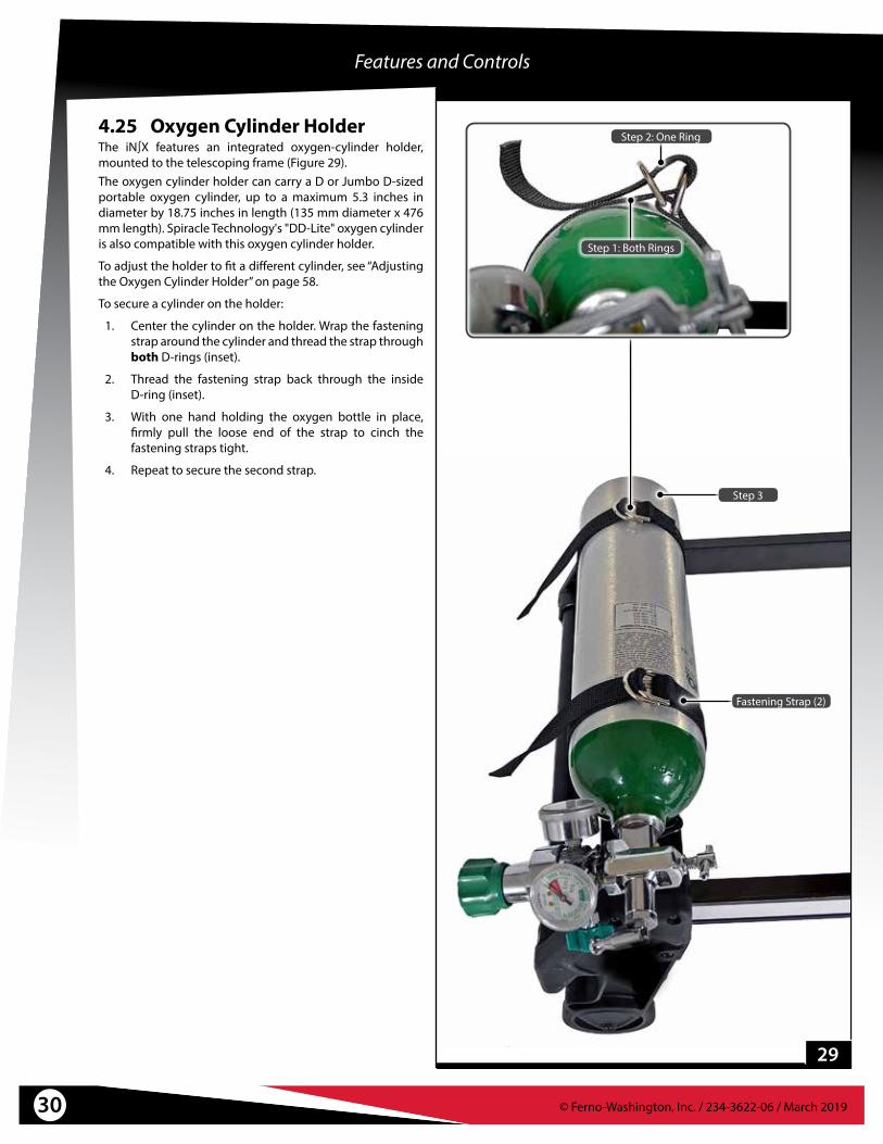
4.25 Oxygen Cylinder HolderThe iN∫X features an integrated oxygen-cylinder holder, mounted to the telescoping frame (Figure 29).The oxygen cylinder holder can carry a D or Jumbo D-sized portable oxygen cylinder, up to a maximum 5.3 inches in diameter by 18.75 inches in length (135 mm diameter x 476 mm length). Spiracle Technology's "DD-Lite" oxygen cylinder is also compatible with this oxygen cylinder holder.
To adjust the holder to fit a different cylinder, see “Adjusting the Oxygen Cylinder Holder” on page 58.
To secure a cylinder on the holder:
1. Center the cylinder on the holder. Wrap the fastening strap around the cylinder and thread the strap through both D-rings (inset).
2. Thread the fastening strap back through the inside D-ring (inset).
3. With one hand holding the oxygen bottle in place, firmly pull the loose end of the strap to cinch the fastening straps tight.
4. Repeat to secure the second strap.
29
Fastening Strap (2)
Step 2: One Ring
Step 1: Both Rings
Step 3

© Ferno-Washington, Inc. / 234-3622-06 / March 2019 31
Features and Controls
4.28 Wheel LocksThe two wheel locks help keep the iN∫X from rolling during patient transfer and certain medical procedures. Wheel locks are attached to the control-end transport wheels.
Press the lock lever down to engage (Figure 31). Press the opposite end of the lock lever to disengage.
● The lock stops the rotation of the wheel when engaged.
● Wheel locks are used to help hold the iN∫X stationary. Do not use wheel locks to slow an iN∫X while it is being rolled.
● Remain with the iN∫X and keep control of it at all times. Do not leave the patient unattended.
4.26 Patient Restraint SystemThe iN∫X features a unique patient-restraint system that includes a combination pelvis strap/shoulder harness, chest strap, and two-piece leg restraint (Figure 30).For instructions on placement, attaching, and using the patient-restraint system, see “Patient Restraints” on page 52.
4.27 Accessory RailThe main frame of the iN∫X acts as an attachment point to secure a variety of accessories to the iN∫X (Figure 30). Accessories may be attached to either side of the iN∫X, with a few limitations.For information on attaching, placing and using accessories, see “Accessories” on page 65.
30
31
Wheel Lock
Accessory Rail (Each Side)
NOTICEWheel locks are not a substitute for operator control. The operators must remain with the iN∫X and keep control of it at all times. Do not leave the patient unattended.
Restraint System

© Ferno-Washington, Inc. / 234-3622-06 / March 201932
5 - USING THE iN∫X
5.1 Before Placing the iN∫X in Service● Before use, personnel who will work with the iN∫X must
read and understand this manual. Appropriate skills and training are also required. See “Operator Training” on page 8.
● Set up the iN∫X. Install any accessories shipped with the iN∫X. See “Initial Setup” on page 60.
● Confirm that the iN∫X operates properly. See “Inspecting the IN∫X” on page 48.
● Set the loading height for the ambulance you will use with the iN∫X. See “Set the Loading Height” on page 61.
5.2 General Guidelines for Use● Medical advice and procedural protocol is beyond the
parameters of this manual.
● It is the users’ responsibility to ensure safe practices for the patient and themselves.
● A minimum of two trained operators is required.
● Follow standard emergency patient-handling procedures when operating the iN∫X.
● Operators must work together and maintain control of the iN∫X at all times.
● Operators must communicate with one another and use coordinated movements to operate the iN∫X.
● Operators must stay with the patient at all times. Do not leave a patient unattended.
● Always use patient restraints to secure the patient on the iN∫X.
● Keep the iN∫X lowered when the load exceeds the load capacity.
● Lift only the weight you can safely handle. Use additional help when working with heavy loads (patient and equipment). For placement of helpers, see “Using Additional Help” on page 10.
● Press to activate the iN∫X after turning the power ON, or to awaken the iN∫X from Sleep Mode. See “Sleep Mode” on page 22.
5.3 Status Indicators and Audible AlarmThe iN∫X has two systems to alert the operators to important or unsafe conditions or faults.
● The Status Zone displays a symbol and code indicating the status of the iN∫X. See “Status Zone” on page 19 and “Status Indicators” on page 63.
● An audible alarm beeps in a pattern corresponding to the priority of the status code. See “Audible Alarm” on page 19.
Audible Alarm
The iN∫X beeps when a status indicator is displayed. The severity of the status determines the number of beeps.
WARNINGImproper operation can cause injury. Operate the iN∫X only as described in this manual.
An unattended patient can be injured. Stay with the patient at all times.
An unrestrained patient can be injured. Use properly-installed patient restraints to secure the patient on the iN∫X.
Rolling the iN∫X above the factory-set maximum transport height can cause it to tip. Only roll the iN∫X at or below the factory-set maximum transport height.
Load Capacity*
* Operators (and helpers) must provide lift assistance when the load exceeds the load capacity. Inspect the iN∫X if the load capacity has been exceeded. See “Inspecting the IN∫X” on page 48.
Press Green to Go
To activate the iN∫X after turning the power switch ON, or to wake the iN∫X from Sleep Mode, press . Note: Only the button will activate/wake up the iN∫X.

© Ferno-Washington, Inc. / 234-3622-06 / March 2019 33
Using the iN∫X
5.4 Powered Extending/RetractingExtending or retracting the legs with a patient on the iN∫X requires a minimum of two trained operators who are communicating, working together, and maintaining control of the iN∫X at all times.
1. Both Operators: Keep both hands on the iN∫X main frame. Maintain control of the iN∫X so it does not shift when extending or retracting the legs.
2. Control Operator: Press to activate the iN∫X after turning the power ON, or to awaken the iN∫X from Sleep Mode.
3. Control Operator: Press or (Figure 32) until the iN∫X reaches the desired height.
4. Both Operators: During the position change, both operators (and any helpers) move with the iN∫X and maintain their grasp on the main frame.
Note:� The color of the display zone assists the operators in understanding the height condition of the iN∫X. See “Display Zones” on page 18.
LOAD CAPACITYThe iN∫X load capacity is 700 lbs/318 kg. Extremely heavy loads may require assistance from the operators (and any helpers). See “Using Additional Help” on page 10.
If the iN∫X will not extend the legs, do the following:1. Both Operators and Helpers: Trained operators stand at
opposite ends of the iN∫X and use an underhand grip to grasp the main frame. Guide helpers where and how to grasp the iN∫X. See “Using Additional Help” on page 10.
2. Control Operator: Press and tell the Loading-end Operator and helpers to help raise the iN∫X.Allow the iN∫X to lift the load. The operators and helpers need to provide lift-assistance only for the portion of the load that exceeds the load capacity.
3. Both Operators and Helpers: Together, raise the iN∫X to the desired height, then hold the iN∫X at that position.
4. Both Operators and Helpers: Slowly lower your hands to test and verify that the iN∫X has stabilized at the new position. Always keep both hands on the main frame and control the iN∫X.
Press Green to Go
To wake the iN∫X from Sleep Mode, press .
Automatic Stops
The iN∫X automatically stops at the:● factory-set maximum transport height● user-set loading height
To continue, press or .
Providing Lift-Assistance
Allow the iN∫X to lift the load. The operators and helpers need to provide lift-assistance only when the load exceeds the load capacity.
Auto-Equalize Feature
When or is pressed, the iN∫X extends or retracts one set of legs until both sets of legs are equally extended. Then, both sets of legs extend or retract simultaneously.
32
Buttons (2 sets)
Extend Legs
Retract Legs
WARNINGUncontrolled movement can cause injury or damage. Support and control the iN∫X at all times.
NOTICEOperators must maintain a firm grasp on the main frame and control the iN∫X at all times. Be prepared to help raise or lower the iN∫X.

© Ferno-Washington, Inc. / 234-3622-06 / March 201934
5.5 Transferring the PatientTRANSFERRING THE PATIENT ONTO THE iN∫X
1. Place the iN∫X beside the patient. Press or to adjust the iN∫X to the patient’s level.
2. Lock the wheel locks.
3. Unfasten the patient restraints. Arrange the straps so they will not interfere with transferring the patient onto the iN∫X.
4. If needed, rotate the sidearms out of the way.
5. Transfer the patient onto the iN∫X using approved emergency-medical procedures and following local protocols.
6. Adjust the backrest, shock frame, and sidearms as needed for patient comfort or medical care.
7. Fasten and adjust the patient restraints (Figure 33).
8. Before moving the iN∫X or changing its position, make sure sheets and other articles will not interfere with iN∫X operation.
9. Unlock the wheel locks.
10. Press or until the iN∫X reaches the desired height. See “Powered Extending/Retracting” on page 33.
With an excessive load (patient plus equipment exceeds the load capacity), the iN∫X legs may not extend when a button is pressed, and/or one or both ends of the iN∫X may settle downward several inches. See the "load capacity" section in “Powered Extending/Retracting” on page 33.
TRANSFERRING THE PATIENT OFF THE iN∫XTo transfer the patient from the iN∫X onto another surface, such as a hospital bed:
1. Roll the iN∫X near the destination surface. Press or to adjust the iN∫X to, or slightly above, the destination surface.
2. Lock the wheel locks.
3. Rotate the sidearms out of the way.
4. Unfasten the patient restraints. Arrange the straps so they will not interfere with transferring the patient off the iN∫X.
5. Transfer the patient onto the destination surface using approved emergency-medical procedures and following local protocols.
6. Fasten and arrange the patient restraints so they will not interfere with using the iN∫X.
7. Before moving the iN∫X or changing its position, make sure sheets and other articles will not interfere with iN∫X operation.
8. Unlock the wheel locks.
9. Press or until the iN∫X patient surface is at a suitable rolling height. See “Powered Extending/Retracting” on page 33 and “Rolling the iN∫X” on page 36.
Using the iN∫X
33
WARNINGSheets or other objects can interfere with, or become entangled in, the height-adjustment locking mechanism. This can cause injury and/or malfunction, including unexpected retracting of the iN∫X legs. Do not tuck sheets or place other objects where they can interfere with, or become entangled in, the locking mechanism.
Press Green to Go
To wake the iN∫X from Sleep Mode, press .

© Ferno-Washington, Inc. / 234-3622-06 / March 2019 35
Using the iN∫X
5.6 Transferring the Patient: Chair PositionThe chair position allows a patient to be transferred to a seated position on the iN∫X patient surface. Follow local protocols to determine the best situations to use chair position. To place the iN∫X in chair position:
1. Roll the iN∫X toward the control-end to position all four swivel wheels in the same orientation.
2. Raise the shock frame.
3. Press the chair-position button (Figure 34).
Note:� When the chair-position button is pressed, a 15-second timer begins. To cancel, press the chair-position button again or allow the timer to expire.
4. Before the timer expires, press . Maintain control of the iN∫X as the legs adjust to place the iN∫X in the chair position (Figure 35).
5. Lock the wheel locks.
6. Unbuckle the restraints. If needed, rotate one or both sidearms out of the way.
7. Adjust the backrest to suit the patient.
8. If needed, have one operator or assistant steady the iN∫X so it will not move as the patient is seated.
9. Assist the patient onto the iN∫X following approved emergency-medical procedures and local protocols.
10. Fasten and adjust the patient restraints.
11. Before moving the iN∫X or changing its position, make sure sheets and other articles will not interfere with iN∫X operation.
12. Inform the patient before adjusting the iN∫X height.
13. Verify the display is not showing the chair position screen: the regular operating screen should appear after the timer expires.
14. Press or until the iN∫X reaches the desired height. See “Powered Extending/Retracting” on page 33.
15. Make further adjustments to the backrest, shock frame, and/or sidearms as needed for patient comfort or medical care.
16. Unlock the wheel locks.
15
34
35
Chair Position
Shock Frame
Sidearm Positioned to Allow Patient Access

© Ferno-Washington, Inc. / 234-3622-06 / March 201936
5.7 Rolling the iN∫XGUIDELINES
● Rolling the iN∫X with a patient on it requires a minimum of two trained operators who are communicating, working together, and maintaining control of the iN∫X at all times.
● Roll the iN∫X on smooth, unobstructed surfaces whenever possible. To cross a low obstacle such as a threshold, each operator lifts slightly as both operators roll the iN∫X across the obstacle. Avoid jarring the patient.
● Roll the iN∫X only at or below the recommended transport height. Rolling above this height can increase the chance for the iN∫X to tip. An audible alarm sounds when the iN∫X is above the maximum transport height.
● Do not roll the iN∫X sideways. Rolling the iN∫X sideways can increase the chance for it to tip and injure the patient and/or operators.
● Use additional help as needed to safely control the weight of the patient and iN∫X. See “Using Additional Help” on page 10.
ROLLING THE iN∫X1. Fasten and adjust the patient restraints.2. Control-end Operator: Press or to adjust the
iN∫X height until the patient surface is at or below the factory-set maximum transport height.
3. Both Operators: Position both operators at the sides of the iN∫X. Grasp and maintain control of the iN∫X using the main frame. If additional help is used, position the helpers at the sides of the iN∫X and the operators at the control and loading ends. See “Using Additional Help” on page 10.
WARNINGRolling the iN∫X above the factory-set maximum transport height can cause it to tip. Only roll the iN∫X at or below the factory-set maximum transport height.
Rolling the iN∫X sideways can cause it to tip. Roll the iN∫X only toward the control end or loading end.
Talk to the PatientReassure the patient. Communicate before adjusting the height and during the loading and unloading processes.
Full 360° MovementThe iN∫X allows full maneuverability at any height, even when fully folded.
Using the iN∫X
Rolling
NOTICERoll the iN∫X downhill control-end first. If it is not medically appropriate to do this, roll with the loading-end first, but to maintain balance, the Loading-end Operator must exert upward force on the main frame.
Operating the iN∫X requires a minimum of two trained operators. They may need additional help when working with heavy loads (patient plus equipment) or when operating the iN∫X manually. See “Using Additional Help” on page 10.

© Ferno-Washington, Inc. / 234-3622-06 / March 2019 37
Using the iN∫X
5.8 One Operator, Empty iN∫XIf local protocols permit, an empty iN∫X (no patient) may be operated by one trained operator. Always use two operators when a patient is on the iN∫X.
Raising/Lowering: Press or to adjust the iN∫X height.
Loading and Unloading: Follow the procedures as for two operators. See “Loading the iN∫X” on page 38 or “Unloading the iN∫X” on page 40.
Guide the iN∫X toward the iN∫LINE so the safety hook will catch the center of each safety bar during loading or unloading. Use the position indicator lights to assist you in the proper times to extend or retract the control-end legs (Figure 37).
Reminder: Do not lift. After the iN∫X is secured by the safety hook, allow the iN∫X legs and iN∫LINE to hold the weight. Raise and lower legs as needed.
36
CROSSING HIGH OBSTACLESThe operators can use the iN∫X auto-equalize feature to cross high obstacles such as curbs and some steps. Use additional help if needed; see “Using Additional Help” on page 10.
To cross a high obstacle:
1. Both Operators: Roll the iN∫X to the obstacle, with one set of transport wheels at the edge of the obstacle. Position the operators at the loading and control ends of the iN∫X.
2. Operator Nearest the Obstacle: Position yourself on firm ground on the destination side of the obstacle. Support the load of your end of the iN∫X (use additional help as needed). Do not lift.
3. Control Operator: Press or to adjust the height. The iN∫X will stop when the leg nearest the obstacle is no longer supporting weight.
4. Operator Nearest the Obstacle: Continue to support the weight of your end of the iN∫X. Do not lift.
5. Control Operator: Press or to adjust the height of the set of legs that will cross the obstacle. Stop when the transport wheels are at the appropriate height to cross or roll onto or over the obstacle.
6. Both Operators: Together, roll the iN∫X partway onto the new surface (Figure 36). The operator nearest the obstacle can relax his/her grasp when the iN∫X is fully supported on the new surface. Continue rolling the iN∫X to position the second operator near the obstacle.
7. Both Operators: Repeat Steps 2-6 with the control-end operator supporting the load, adjusting the iN∫X legs, and with both operators maneuvering the iN∫X over the obstacle and/or onto the new surface.
37
Do Not Lift the iN∫XAfter the iN∫X is secured by the safety hook, allow the iN∫X legs and iN∫LINE to hold the weight.

© Ferno-Washington, Inc. / 234-3622-06 / March 201938
Using the iN∫X
5.9 Loading the iN∫XLoading the iN∫X into an ambulance with a patient on it requires a minimum of two trained operators who are communicating, working together, and maintaining control of the iN∫X at all times. Use additional help if needed; see “Using Additional Help” on page 10.
1. Raise the ambulance folding bumper, if present.
2. Extend the telescoping load frame and verify it is locked in the fully-extended position.
3. Both Operators: Grasp the iN∫X with both hands.
4. Control-end Operator: Press to raise the iN∫X to the user-set loading height (see “Set the Loading Height” on page 61) or, if needed, press and to position the loading wheels level with the ambulance floor.
Note:� If the vehicle loading height (ambulance deck height) is near the programmed transport height of 22-1/2” +/- 1” (572 mm +/- 25 mm), confirm the iN∫X is at the loading height and not the transport height. In some cases, an extra press may be required to fully lower the iN∫X onto the ambulance deck.
5. Both Operators: Align the iN∫X with the iN∫LINE, then roll the iN∫X into the ambulance until the loading wheels and load-frame safety bar pass the safety hook Figure 38).
6. Loading-end Operator: Visually confirm the safety bar has been captured by the hook.
7. Both Operators: Confirm the iN∫X is secure by attempting to pull the iN∫X out of the ambulance. The iN∫X must be stopped by the safety hook (Figure 39). If not, adjust the height and retry.
8. Control-end Operator: Press to begin retracting the loading-end legs. The legs will retract slightly, then stop when they are no longer supporting the weight of the iN∫X. This is a safety check to verify that the load is being supported.
38
39
WARNINGFailure to engage the safety hook during loading or unloading can cause injury. Operators must visually ensure each safety bar engages the safety hook and the iN∫X is secure inside the ambulance before extending or retracting the legs.
Talk to the Patient
Reassure the patient. Communicate before adjusting the height and during the loading and unloading processes.
No-Lift Loading/Unloading
Do not lift the iN∫X off the ground when using power during the loading or unloading process. See “No-Lift Loading/Unloading” on page 9.
Safety Bar
Safety Hook
NOTICEIf the ambulance is parked on an uneven surface, the operators (and any helpers) may need to extend the legs higher than the user-set loading height to allow the iN∫X to roll into the ambulance.
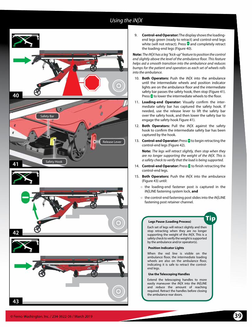
© Ferno-Washington, Inc. / 234-3622-06 / March 2019 39
9. Control-end Operator: The display shows the loading-end legs green (ready to retract) and control-end legs white (will not retract). Press and completely retract the loading-end legs (Figure 40).
Note:� The iN∫X has a leg "kick-up" feature to position the control end slightly above the level of the ambulance floor. This feature helps aid a smooth transition into the ambulance and reduces bumps for the patient and operators as each set of wheels rolls into the ambulance.
10. Both Operators: Push the iN∫X into the ambulance until the intermediate wheels and position indicator lights are on the ambulance floor and the intermediate safety bar passes the safety hook, then stop (Figure 41). Press to lower the intermediate wheels to the floor.
11. Loading-end Operator: Visually confirm the inter-mediate safety bar has captured the safety hook. If needed, use the release lever to lift the safety bar over the safety hook, and then lower the safety bar to engage the safety hook Figure 41).
12. Both Operators: Pull the iN∫X against the safety hook to confirm the intermediate safety bar has been captured by the hook.
13. Control-end Operator: Press to begin retracting the control-end legs (Figure 42).
Note: The legs will retract slightly, then stop when they are no longer supporting the weight of the iN∫X. This is a safety check to verify that the load is being supported.
14. Control-end Operator: Press to finish retracting the control-end legs.
15. Both Operators: Push the iN∫X into the ambulance (Figure 43) until:
○ the loading-end fastener post is captured in the iN∫LINE fastening system lock, and
○ the control-end fastening post slides into the iN∫LINE fastening post retainer channel.
Legs Pause (Loading Process)
Each set of legs will retract slightly and then stop retracting when they are no longer supporting the weight of the iN∫X. This is a safety check to verify the weight is supported by the ambulance and/or operator(s).
Position Indicator Lights
When the red line is visible on the ambulance floor, the intermediate loading wheels are also on the ambulance floor, indicating it is safe to retract the control-end legs.
Use the Telescoping Handles
Extend the telescoping handles to more easily maneuver the iN∫X into the iN∫LINE and reduce the amount of reaching required. Retract the handles before closing the ambulance rear doors.
40
41
42
43
Using the iN∫X
Safety Bar
Safety Hook
Release Lever

© Ferno-Washington, Inc. / 234-3622-06 / March 201940
5.10 Unloading the iN∫XUnloading the iN∫X from an ambulance with a patient on it requires a minimum of two trained operators who are communicating, working together, and maintaining control of the iN∫X at all times. Use additional help if needed; see “Using Additional Help” on page 10.
1. Either Operator: Raise the ambulance folding bumper, if present.
2. Control-end Operator: Press the iN∫LINE release button to unlock the iN∫X from the iN∫LINE, roll it a few inches from the ICS contacts, then press to activate the iN∫X.
3. Both Operators: Grasp the iN∫X with both hands and roll the iN∫X out of the ambulance until the safety hook captures the center of the intermediate safety bar (Figure 44).
4. Visually confirm that the safety bar has been captured by the safety hook.
5. Control-end Operator: Press to extend the control-end legs (Figure 45).
WARNINGFailure to engage the safety hook during loading or unloading can cause injury. Operators must visually ensure each safety bar engages the safety hook and the iN∫X is secure inside the ambulance before extending or retracting the legs.
45
Using the iN∫X
44
Press Green to Go
Unlock the iN∫X from the iN∫LINE, roll it a few inches from the ICS contacts, then press to activate the iN∫X.
Talk to the Patient
Reassure the patient. Communicate before adjusting the height and during the loading and unloading processes.
No-Lift Loading/Unloading
Do not lift the iN∫X off the ground when using power during the loading or unloading process. See “No-Lift Loading/Unloading” on page 9.
Position Indicator Lights
When the red line is visible at the edge of the ambulance floor and the safety bar is engaged with the safety hook, the control-end legs are ready to be extended.

© Ferno-Washington, Inc. / 234-3622-06 / March 2019 41
46
47
Using the iN∫X
6. Control-end Operator: Tell the Loading-end Operator to disengage the intermediate safety bar from the safety hook.
7. Both Operators: Roll the iN∫X out of the ambulance until the safety hook captures the center of the loading-frame safety bar (Figure 46).
8. Control-end Operator: Press to extend the loading-end legs (Figure 47).
9. Control-end Operator: Tell the Loading-end Operator to disengage the load-end safety bar from the hook.
10. Both Operators: While maintaining your grasp on the main frame and guide bar with both hands, roll the iN∫X out of the ambulance, then stop rolling.
11. Control-end Operator: Press to lower the iN∫X to the factory-set transport height.
Safety Hook Release Lever

© Ferno-Washington, Inc. / 234-3622-06 / March 201942
WARNINGA severe angle can injure the patient and/or operators. Control the iN∫X when using a direct power mode.
Direct Power Modes
The direct power modes are easily identified by the icons and white background on the display screen.
During normal operation, the display background remains black.
Use additional help if needed; see “Using Additional Help” on page 10.
Return to Normal Operation
To return to the standard or normal operating mode, wait for the 15-second timer to expire while on any alternate mode screen, or cycle the mode button until the normal screen appears.
5.11 Direct Power ModesManual-power modes allow the operators to independently control one or both sets of legs to raise, lower, load or unload the iN∫X. Use the mode button to select from three manual-power modes. Direct Power is a secondary method of operating the iN∫X. They are not part of normal operation.
Note:� If an obstruction prevents the iN∫X from moving, stop pressing or , carefully remove the obstruction, and continue using the iN∫X. Direct power is not needed.
Note:� When using Direct power, the iN∫X extends and retracts the legs at a slower speed than when using the normal powered mode.
SELECTING DIRECT POWEREach button press cycles to the next mode. The button-press sequence is:
● Direct Power Both Legs. Both sets of legs move when or is pressed. Depending on the weight on the iN∫X,
one set of legs may extend or retract more quickly than the other.
● Direct Power Loading-end Legs Only. Only the loading-end legs move when or is pressed.
● Direct Power Control-end Legs Only. Only the control-end legs move when or is pressed.
Note:� The fourth button-press enters the Load-Height Set Mode. See “Set the Loading Height” on page 61.
Note:� The fifth button-press returns the iN∫X to its standard operating mode.
USING DIRECT POWERUse care when using direct power with a patient on the iN∫X.
In Direct Power, the auto-equalize feature is disabled. The iN∫X will not automatically match or maintain an even extension between the loading-end and control-end legs.
Avoid placing the patient at a severe angle as patient and/or operator injury can occur if the load shifts.
Use additional help if needed; see “Using Additional Help” on page 10.
In each direct power mode, a countdown timer counts down from 15 seconds. If no further action is taken, the iN∫X reverts to its standard operating mode.
Using the iN∫X
NOTICEWhen using direct power, the auto-equalize feature is disabled. Do not place the iN∫X at a severe angle where the patient or equipment could shift and become unbalanced.

© Ferno-Washington, Inc. / 234-3622-06 / March 2019 43
Using the iN∫X
5.12 Direct Power: Both LegsIn this mode, both sets of legs move when or is pressed. Be aware:
● Auto-equalize is off. Operators must maintain control of the iN∫X. Do not put the patient at a severe angle.
● The weight of the patient and equipment may cause the legs to move at different speeds.
● Display (Figure 48):
○ White background
○ Blue legs and double-headed arrows indicates both legs will move.
○ Red wheels indicate that the iN∫X must not be rolled.
○ If the 15-second countdown timer expires, the iN∫X returns to its standard operating mode.
5.13 Direct Power: Loading-End LegsIn this mode, only the loading-end legs move when or is pressed. Be aware:
● Auto-equalize is off. Operators must maintain control of the iN∫X. Do not put the patient at a severe angle.
● Display (Figure 49):
○ White background
○ Blue loading-end legs and double-headed arrow indicates only the loading-end legs will move.
○ Red wheels indicate that the iN∫X must not be rolled.
○ If the 15-second countdown timer expires, the iN∫X returns to its standard operating mode.
5.14 Direct Power: Control-End LegsIn this mode, only the control-end legs function when or is pressed. Be aware:
● Auto-equalize is off. Operators must maintain control of the iN∫X. Do not put the patient at a severe angle.
● Display (Figure 50):
○ White background
○ Blue control-end legs and double-headed arrow indicates only the control-end legs will move.
○ Red wheels indicate that the iN∫X must not be rolled.
○ If the 15-second countdown timer expires, the iN∫X returns to its standard operating mode.
15
48
1549
1550
Countdown Timer
Countdown Timer
Countdown Timer

© Ferno-Washington, Inc. / 234-3622-06 / March 201944
5.15 Non-Powered Operation: Extending and RetractingTo extend or retract the iN∫X legs without power, adjust each leg individually and by a small amount. Repeat until the iN∫X is at the desired height. Use additional help if needed; see “Using Additional Help” on page 10. Refer to the placement of operators in Figure 53 on page 45.
USING TWO OPERATORS: PREPARING TO EXTEND OR RETRACT
1. Both Operators: Stand together at one end of the iN∫X and grasp the main frame. Communicate and work together while extending or retracting the legs. Do not place the patient at a severe angle.
2. Both Operators: Raise the backrest and shock frame (Figure 51) as needed. Release the actuator-release handles from their mounts.
3. Lead Operator: Grasp the main frame with both hands, support and balance the iN∫X.
4. Handle Operator: Be ready to use the actuator-release handle at the proper time and assist with extending or retracting the legs.
EXTENDING1. Lead Operator: Lift the end of the iN∫X several inches
off the ground. Tell the handle-operator you are ready for the position change.
2. Handle Operator: Squeeze the actuator-release handle (Figure 52) and push the legs down until the transport wheels are on the ground. Release the handle to lock the legs.
3. Lead Operator: Maintain your grasp on the iN∫X. Verify it is stable at the new position.
4. Both Operators: Move to the opposite end of the iN∫X and repeat Steps 1-3.
5. Both Operators/Helpers: Repeat Steps 1-4 until the iN∫X is level and is at the desired height.
Using the iN∫X
WARNINGUncontrolled movement can cause injury or damage. Support the load before using an actuator-release handle.
A severe angle can injure the patient and/or operators. Control the iN∫X when operating without power.
51
Control the Load
Lift the iN∫X slightly before squeezing an actuator-release handle. This ensures that you are holding the load.
Non-Powered Recommendation
When extending the iN∫X without power, Ferno recommends you begin at the loading end. Raise the loading-end legs first, then the control-end legs.

© Ferno-Washington, Inc. / 234-3622-06 / March 2019 45
Non-Powered Operation: Extending and Retracting (with Patient)
Non-Powered Operation: Extending and Retracting (No Patient)
Using the iN∫X
RETRACTING1. Lead Operator: Lift until the wheels are off the ground
to confirm you are holding the load. Communicate to the handle-operator that you are ready for the position change.
2. Handle Operator: Grasp the main frame and handle.
3. Both operators: As the handle operator squeezes the handle, both operators assist the retracting process. Release the handle to lock the legs.
4. Lead Operator: Maintain your grasp on the iN∫X. Verify it is stable at the new position.
5. Both Operators: Move to the opposite end of the iN∫X and repeat Steps 1-4.
6. Both Operators: Repeat Steps 1-5 until the iN∫X is level and is at the desired height.
FOLDING WITHOUT A PATIENTTo fold the iN∫X with no patient, the operators stand at opposite ends of the iN∫X and squeeze the handles at the same time. Control the descent of the iN∫X and keep it level as you fold it.
Deploying the Handles
Push the base of the actuator-release handle to remove it from its mount. Position the loading-end handle at the patient-right side of the iN∫X, and the control-end handle at the patient-left side.
Non-Powered Recommendation
When retracting the iN∫X without power, Ferno recommends you begin at the control end. Lower the control-end legs first, then the loading-end legs.
52
Actuator-Release Handle
53

© Ferno-Washington, Inc. / 234-3622-06 / March 201946
Using the iN∫X
Reduce the Load
If medically appropriate, lower the backrest and lay the patient flat. This puts more of the load inside the ambulance and reduces the amount the operators must support during loading.
Urgent Non-Powered Loading
If enough operators and helpers are available, roll the iN∫X to the ambulance and fully retract both sets of legs. Working together, the operators and helpers lift and set the iN∫X inside the ambulance.
Using the Locking Clip
Use the locking clip (illustrated above) to hold the handle in the compressed state. This allows the handle operator to use both hands to maintain control of the iN∫X during
non-powered loading and unloading.
5.16 Non-Powered Operation: LoadingThe independent-leg design of the iN∫X allows the operators to reduce the amount of lifting required even when loading the iN∫X into an ambulance without power. Refer to the placement of operators in Figure 54. Use additional help as needed. See “Using Additional Help” on page 10.
1. Both Operators: Raise the iN∫X to the loading height for your ambulance. See “Non-Powered Operation: Extending and Retracting” on page 44 to raise the iN∫X in stages until it is the desired height. Do not put the patient at an extreme angle.
2. Both Operators: Roll the iN∫X into the ambulance and secure the loading-end safety bar on the safety hook. Verify the iN∫X is engaged with the hook before proceeding.
3. Handle Operator: Remove the loading-end actuator-release handle from its mount under the backrest.
4. Both Operators: Stand together at the loading end of the iN∫X. Grasp the main frame with one hand and the loading-end legs with the other hand.
5. Both Operators: Communicate and work together. As the handle operator squeezes the actuator-release handle, both operators retract the loading-end legs. Release the handle to lock the legs.
6. Both Operators: After retracting the loading-end legs, resume your grasp on the main frame.
7. Both Operators: Roll the iN∫X into the ambulance until the intermediate safety bar passes the safety hook. Verify that the iN∫X is engaged with the hook before proceeding.
8. Handle Operator: Squeeze the actuator-release handle one more time to verify the loading-end legs have completely retracted. Position the handle out of the way so it will not interfere with the iN∫LINE.
9. Handle Operator: Remove the control-end actuator-release handle from its mount under the shock frame.
10. Both Operators: Stand together at the control end of the iN∫X. Grasp the main frame with one hand and the control-end legs with the other hand.
11. Both Operators: Communicate and work together. As the handle operator squeezes the actuator-release handle, both operators retract the control-end legs. Release the handle to lock the legs.
12. Both Operators: Resume your grasp on the main frame, then roll the iN∫X into the ambulance and secure it in the iN∫LINE.
O
O
O
O
O
Non-Powered Operation: Loading
NOTICEAs you load the iN∫X control-end into the ambulance, arrange the actuator-release handles and cables so they will not interfere with the iN∫LINE.
54
Actuator-ReleaseHandle
Locking Clip

© Ferno-Washington, Inc. / 234-3622-06 / March 2019 47
5.17 Non-Powered Operation: UnloadingThe independent-leg design of the iN∫X allows the operators to reduce the amount of lifting required even when unloading the iN∫X from an ambulance without power. Refer to the placement of operators in Figure 55. Use additional help as needed. See “Using Additional Help” on page 10.
1. Either Operator: Remove the control-end actuator-release handle from its mount under the shock frame.
2. Both Operators: Support and balance the load as the iN∫X is rolled out of the ambulance in Step 3.
3. Both Operators: Disengage the iN∫X from the iN∫LINE and roll it out of the ambulance until the intermediate safety bar engages the safety hook. Verify the safety bar is engaged with the hook before proceeding.
4. Both Operators: Use additional help as needed to support the load.
5. Handle Operator: Squeeze the actuator-release handle and extend the control-end legs to the ground. Release the handle to lock the legs in the extended position.
6. Both Operators: As one operator disengages the intermediate safety bar from the safety hook, both operators roll the iN∫X out of the ambulance until the loading-end safety bar engages the safety hook. Verify the iN∫X is engaged with the safety hook before proceeding.
7. Handle Operator: Remove the loading-end actuator-release handle from its mount under the backrest.
8. Both Operators:
○ Lead Operator: Support and balance the load throughout the process.
○ Handle Operator: Squeeze the actuator-release handle and extend the loading-end legs to the ground. Release the handle to lock the legs in the extended position.
9. Either Operator: Disengage the iN∫X from the safety hook. Together, roll the iN∫X out of the ambulance.
10. Both Operators: Lower the iN∫X to a transport height, or fold it. See “Non-Powered Operation” on page 27 to lower each end of the iN∫X in stages, repeating the process until the iN∫X is the desired height. Do not put the patient at an extreme angle.
Using the iN∫X
Non-Powered Unloading
When using the non-powered unloading process, the iN∫X is not at its normal height. The operators and patient may experience a slight bump when the iN∫X is released from the safety hook. Both operators should lift the iN∫X slightly as it is rolled out of the ambulance.
Urgent Non-Powered Unloading
If enough operators and helpers are available, work together to roll the iN∫X out of the ambulance without extending the legs and set it on the ground. Then, raise the iN∫X for rolling.
Using the Locking Clip
Use the locking clip (illustrated above) to hold the handle in the compressed state. This allows the handle operator to use both hands to maintain control of the iN∫X during non-powered loading and unloading.
O
O
O
O
O
Non-Powered Operation: Unloading
Actuator-ReleaseHandle
Locking Clip
55

© Ferno-Washington, Inc. / 234-3622-06 / March 201948
6 - MAINTENANCE
WARNINGImproper maintenance can cause injury. Maintain the iN∫X only as described in this manual.
6.1 Maintenance ScheduleThe iN∫X requires regular maintenance. Set up and follow a maintenance schedule. The table at right represents minimum intervals for maintenance. Keep maintenance records. See “Maintenance Record” on page 67.
When using maintenance products, follow the manufacturers’ directions and read the manufacturers’ material safety data sheets. Minimum
Maintenance Each Use As Needed Monthly
Daily Operator Duties (page 7) •Inspecting (page 48) • •Disinfecting (page 49) •Cleaning (page 50) •Lubricating (page 51) •Check and Adjust Actuator Release Handle Cable Tension (page 57)
• •
6.2 Service LifeMany factors affect a product's service life, including frequency of use (high versus low volume ambulance service); local environment (extreme temperature, high humidity, etc.); maintenance (adherence to the inspection and maintenance schedule); and other factors.
Follow the disinfecting, cleaning, and inspection procedures in this manual to ensure long life for the iN∫X.
6.3 Inspecting the iN∫XA basic inspection is recommended at the beginning of each operator shift. See “Daily Operator Duties” on page 9.
Inspect the iN∫X regularly. See “Maintenance Schedule” on page 48. Have your service’s equipment maintenance personnel follow the checklists at right and operate the iN∫X through all its functions as described in this manual. If inspection shows damage or excessive wear, contact Ferno. See “Ferno Customer Relations” on page 2.
MECHANICAL INSPECTION● Are all components present?
● Is the iN∫X free of excessive wear?
● Is all hardware securely in place?
● Do all moving parts operate smoothly and properly?
● Does the iN∫X load and unload properly?
● Does the safety hook engage each safety bar?
● Do the legs show signs of wear or damage?
● Does the iN∫X roll smoothly?
● Do the wheels show excessive wear or damage?
● Do the wheel locks engage properly and stop wheel rotation?
● Do the wheel casters remain level and perpendicular to the ground through 360° rotation and through the full range of leg motion?
● Are the patient restraints properly installed?
● Is restraint webbing in good condition with no cuts or frayed edges?
● Are restraint buckles free of visible damage and do they operate properly?
● Is the ambulance properly prepared for the iN∫X with an iN∫LINE installed?
● Do installed accessories operate properly without interfering with iN∫X operation?
ELECTRICAL INSPECTION● Does the power switch function properly?
● Do the Extend and Retract buttons function properly?
● Does the powered system operate properly through the full range of motion?
● Does the powered system operate smoothly, without binding or excessive noise?
● Does the controller stop the iN∫X at the transport height, user-set loading height, and at the fully-extended and lowered positions?
● Do the lights and position indicator lights operate as expected?
● Is there visible sign of damage to the controller case, display, battery, or battery charger?
● Does the battery attach properly to the iN∫X?
● Does the display function properly?
● Are all cords and cables free of excessive wear, cuts, and fraying?

© Ferno-Washington, Inc. / 234-3622-06 / March 2019 49
6.4 Disinfecting Patient Restraints1. Remove the patient restraints from the iN∫X.
2. Spray the metal buckles and slide bars with a disinfectant cleaner, following the disinfectant manufacturer’s instruc-tions for application method and contact time. Do not immerse the buckles or slide bars in liquid.
3. Hang the restraints to air-dry if needed. Attach only dry restraints to the iN∫X. See “Patient Restraints” on page 52.
6.7 Disinfecting the iN∫XWipe all surfaces with disinfectant. Follow the disinfectant manufacturer’s instructions for application method and contact time. Inspect the iN∫X for damage as you disinfect it.
6.6 Disinfecting/Cleaning the Mattress
1. Remove the mattress from the iN∫X.
2. To disinfect: Apply disinfectant to the mattress, following the disinfectant manufacturer’s instructions for application method and contact time.
3. To clean: Wash the mattress with warm, soapy water and a soft cloth. Rinse the mattress with clear water. Hang the mattress to dry, or dry it with a towel. To attach the mattress to the iN∫X, see “Mattress” on page 28.
Maintenance
6.5 Cleaning Patient Restraints1. Immerse the restraint webbing in a solution of mild
soap and water. Do not immerse the metal buckles or slide bars in the solution.
2. Repeatedly dip the webbing in clear water to rinse. Do not immerse metal buckles or slide bars in liquid.
3. Hang the restraint to air-dry. Attach only clean, dry restraints to the iN∫X. See “Patient Restraints” on page 52.
Ingress Protection RatingThe iN∫X is rated IP 56. IP stands for Ingress Protection, and indicates the iN∫X has been tested in compliance with dust and water infiltration standards.
Solid Particle Protection (Rating: 5): Dust-protected
Liquid Ingress Protection (Rating: 6): Protected against water infiltration
The IP Rating system was developed by the European Committee for Electrotechnical Standardization (CENELEC) to show compliance of ANSI/IEC 60529, Degrees of Protection Provided by Enclosures (IP Code).
NOTICEDisinfectants and cleaners containing phenolics or iodines can cause damage. Do not use products containing these chemicals. If bleach is used, rinse with plenty of clear water to remove bleach residue.
Using abrasive cleaning compounds or applicators on the iN∫X can cause damage. Do not use abrasive materials to clean the iN∫X.
Metal buckles and slide bars can be damaged by immersion in liquids or by washing-machine action. Disinfect and clean only as described in this manual.

© Ferno-Washington, Inc. / 234-3622-06 / March 201950
Maintenance
6.9 Pressure-Washing the iN∫XUse caution when using pressurized water, spray-wands and equipment when cleaning the iN∫X. Wear all safety equipment recommended by the pressure-sprayer manufacturer.
PREPARING TO PRESSURE-WASH1. Raise or lower the iN∫X to the recommended transport
height. Then, use direct power (see “Direct Power Modes” on page 42) to fold the loading-end legs until the loading wheels are on the ground (Figure 56).
2. Turn the power switch OFF.
3. Engage the wheel locks.
4. Remove the battery cover and battery from the iN∫X (see “Battery” on page 20).
5. Cover the end of the battery cable with a plastic bag, and close the bag. Use a tie wrap or rubber band to make the bag water-tight (Figure 56).
6. Put the battery cover in place.
PRESSURE-WASHING THE IN∫X1. Set the nozzle pressure at or below 3000 psi (20,684
kPa). Ferno recommends you use a nozzle with a wide angle of spray (25° or 40°). Keep the nozzle at least 18 inches (457 mm) away from the iN∫X at all times. Do not spray directly into the control panel or wiring.
2. Spray the patient surface, legs, and wheels of the iN∫X.
3. Allow the iN∫X to sit idle to dry for 10 minutes.
4. Remove the battery cover, tie wrap or rubber band and bag from the battery cable. Attach the battery and put the cover in place.
5. Turn the power switch ON and raise or lower the iN∫X to the desired height.
6. When fully dry, reattach the mattress, restraints, and accessories.
6.8 Cleaning the iN∫X1. Remove the patient restraints, mattress, and
accessories. Verify that all cords, cables, connectors, etc. are connected.
2. Remove the battery. Cover the battery cable plug with a bag. Tie the bag closed or use a rubber band to make a watertight seal around the plug.
3. For battery care, see “Battery” on page 20 and the Battery Care Important box at right.
4. Hand clean all surfaces of the iN∫X with warm water and a mild detergent, or pressure-wash the iN∫X as described below. Do not spray water directly into ports, wire harnesses, cable connections, etc.
5. Rinse with warm, clear water. Dry the iN∫X with a towel or allow it to air-dry.
Battery CareThe battery is water-resistant. Do not submerge the battery in water. Do not open the sealed battery case. Do not dismantle, open or shred the battery.
Wipe the battery terminals with a clean dry cloth if they become dirty or wet.
Before washing or pressure-washing the iN∫X, remove the battery and cover the battery cable plug with a bag.
56
Cover Battery Cable with Tie Wrap and Bag
Before Pressure Washing: Put Cover in Place
18 in(457 mm)
NOTICEThe iN∫X is water-resistant.
● DO: Remove the battery. Cover the battery cable with a plastic bag. Close the bag with a wire tie or rubber band.
● DO: Keep the nozzle pressure setting at 3000 psi/20,684 kPa or less and 4 gallons per minute/15 liters per minute or less.
● DO: Keep the nozzle at least 18 inches/457 mm from the surface of the iN∫X at all times during cleaning.
● DO: Reduce water pressure or increase the distance (more than 18 inches/457 mm) when cleaning the display.
● DO NOT: Spray water upward into the cables or forcibly at or around the display.

© Ferno-Washington, Inc. / 234-3622-06 / March 2019 51
Maintenance
Applying Lubricant
Use a small amount of lubricant (one or two drops). Lubricate identical points on each side of the iN∫X. After applying lubricant, wipe off any excess.
6.10 Lubricating the iN∫XDisinfect and clean the iN∫X before applying lubricant. Use the lubricants designated below to lubricate. Do not lubricate points marked with the “do not lubricate” symbol.
LUBRICATION POINTS1. Safety Bar Pivot (x2) WRL-191S, E-Z-1 light oil2. Slider Rails PTFE* dry-film spray lubricant
LUBRICATION-FREE ITEMS Wheels (sealed bearings) Do not lubricate Legs Do not lubricate Patient Surface Do not lubricate
Safety-Bar Pivot Points: Apply a few drops of lubricant as needed (near the red handle). Wipe off any excess.
Sliding Rails: If the sliding rails squeak during use, clean the rails. If this does not solve the problem, clean and then apply a light coating of PTFE dry-film spray lubricant to the rails.
*PTFE is the generic name of products similar to Teflon® (a registered trademark of the DuPont Company, E. I. du Pont de Nemours and Company or its affiliates.)
Do Not Lubricate
Lubricate
57
Lubricate (Both Sides, Both Ends)
2
1Lubricate in Slot (Both Sides)
NOTICELubricating parts that should not be lubricated allows dirt and foreign particles to collect on those parts, resulting in damage. Lubricate only the numbered reference points shown.

52 © Ferno-Washington, Inc. / 234-3622-06 / March 2019
58
59
6.11 Patient RestraintsThe restraint system includes a pelvis strap, chest strap, harness, and two-piece leg restraint (Figure 58). The patient restraints are positioned both above and below the mattress. To prepare the iN∫X for use, follow the procedures in this section.
Restraint Colors
When buckling the patient restraints, match the color-coded pieces:● Red-to-Red (Harness Links connect
to Pelvis Strap buckle)● Black-to-Black (Harness Chest Strap
and Leg Restraint buckles) Buckle Orientation
Ferno recommends that you attach all patient restraints with the buckles at the same side for operator convenience and efficiency.
Maintenance
WARNINGAn unrestrained patient can be injured. Use properly-installed patient restraints to secure the patient on the iN∫X.
To attach patient restraints, refer to “Bracket-and-Post System” below and the instructions on the next page. Keep the patient restraints buckled when not in use.
1. To secure a patient on the iN∫X, unbuckle the harness, pelvis, and leg restraints and position the straps out of the way.
2. Transfer the patient onto the iN∫X following local protocols. Adjust the backrest, shock frame, and restraint length as needed.
3. Lay the shoulder straps on the patient’s chest, with the links extended to the patient’s waist.
4. Guide the pelvis-strap tang (metal buckle) through the links and fasten the buckle (Figure 58).
5. Adjust the pelvis strap and shoulder straps so they are snug on the patient.
6. Fasten the chest strap across the patient’s rib cage (Figure 58).
7. Fasten the leg restraint over the patient’s legs (Figure 58).
BRACKET-AND-POST SYSTEMThe pelvis strap and harness attach to the iN∫X with a bracket-and-post system. To attach the straps:
1. Orient the bracket on the restraint strap with the bend facing the center of the iN∫X and the tab up (Figure 59).
2. Slide the bracket over the post and pull the bracket upward to seat the post in the small end of the bracket.
3. Insert the retaining plug into the bracket (Figure 59).
Shoulder Strap (2)
Link (2)
Chest Strap
Leg Restraint
Pull Loop
Plug
Post
Metal Tab
Bracket
"Y-Connection Pelvis Strap (2)

53© Ferno-Washington, Inc. / 234-3622-06 / March 2019
3
1
2
Strap Keepers
The shoulder straps have elastic bands to allow excess strap to be stored neatly.
60
Maintenance
REMOVING PATIENT RESTRAINTSUnbuckle the patient restraints.
To detach the pelvis and chest/shoulder straps, use the pull loop (Figure 59) to pull the retaining plugs out of the brackets, then press the brackets down toward the main frame to unseat the post from the bracket. Lift the bracket off the post. If the brackets are difficult to remove, stand on the opposite side of the iN∫X and pull across the patient surface.
To remove the leg restraint, unbuckle the restraint and feed the buckle (or tang) through the loop. Then, remove the loop from the restraint bracket.
1 – ATTACH THE PELVIS STRAPThe pelvis straps have red webbing near the buckles (Figure 60). With the mattress removed, attach each bracket of the Y-strap (two brackets per side) to the mounting posts at each side of the seat panel. Verify the brackets are seated on the posts and the strap is not twisted. Insert the retaining plugs.
2 – ATTACH THE CHEST/SHOULDER STRAPSThe chest straps have only black webbing and are connected to the shoulder straps, which have red webbing near the links (Figure 60). Attach the chest strap brackets to the mounting post at each side of the backrest. Verify the brackets are seated on the posts and the strap is not twisted. Insert the retaining plugs.
3 – ATTACH THE LEG RESTRAINTEach strap of the leg restraint has a loop. Guide the loop through the restraint bracket on the iN∫X, then insert the buckle (or tang) through the loop. Pull the strap to tighten the strap against the restraint bracket (Figure 60).
Restraint Bracket
Plug
Post

© Ferno-Washington, Inc. / 234-3622-06 / March 201954
Deeply-Discharged Battery
If the battery is deeply discharged, the ICS may not be able to charge the battery. Connect the battery directly to the charger separate from the ambulance and ICS.
Charging Inside an Ambulance
To charge a battery inside an ambulance, the Ferno® ICS® must be used.
6.13 Charging the BatteryThere are two ways to charge the battery: Secure the iN∫X in the iN∫LINE (equipped with the Integrated Charging System), or remove and connect the battery directly to a Ferno battery charger.
● To charge the battery using the iN∫LINE: Verify the ambulance power to the iN∫LINE ICS is ON and secure the iN∫X in the iN∫LINE. See “Integrated Charging System (ICS)” on page 21.
● To charge the battery using the charger: Remove the battery from the iN∫X and connect it to a Ferno® battery charger. See “Battery” on page 20.
BATTERY CARE● To store the battery if it will not be used for an extended
period of time, see "Storing the Battery" below.
● The battery is water-resistant and is suitable for outdoor use. Do not submerge the battery in water.
● To clean the battery, wipe the battery port with a clean dry cloth if it becomes dirty or wet.
● Do not open the sealed battery case. Do not dismantle, open or shred the battery.
● Recycle the battery when it can no longer maintain a charge. Do not dispose of batteries with municipal waste. See “Recycling Notice” on page 55.
● Replace a damaged or cracked battery.
61
Maintenance
6.12 Storing the iN∫X1. Lower the iN∫X to the fully-retracted position (Figure
61)and turn the power switch OFF.
2. Remove and charge the battery. See “Charging the Battery” on page 54 and "Storing the Battery" below.
3. Cover the battery cable connector on the iN∫X with a bag. Seal the bag (for example, with a rubber band) to prevent moisture from entering the connector.
Before returning the iN∫X to service:
1. Attach a fully-charged battery.
2. Turn the power switch ON.
3. Have your service’s equipment maintenance personnel inspect the iN∫X. See “Inspecting the IN∫X” on page 48.
6.14 Storing the Battery● Fully-charge the battery before storing it. Do not store
the battery with less than a full charge.
● Store the battery only in a cool, dry place. Battery capacity can be affected if the battery is stored for long periods outside of the recommended temperature range.
● After an extended period of storage, charge the battery fully before use.

© Ferno-Washington, Inc. / 234-3622-06 / March 2019 55
6.15 Recycling NoticeThe iN∫X uses a rechargeable, 36 Volt DC lithium-iron battery (specifically “LiFePO4” as noted on the battery label).
Batteries: Recycle batteries when they can no longer hold a charge. Do not dispose of batteries with municipal waste. Contact the government in your state, territory or country for proper recycling.
Charger: Recycle the charger if it becomes damaged or fails to properly charge the battery. Do not dispose of the charger with municipal waste. Contact your government for proper recycling.
WEEE DIRECTIVE (EUROPEAN UNION)European Union directive 2002/96/EC Waste Electrical and Electronic Equipment (WEEE) limits the disposal of electrical and electronic equipment in landfills. Contact the government in the country in which you reside for recycling information.
U.S.A. AND CANADA "CALL2RECYCLE" 1.800.822.8837
Ferno is a partner with Call2Recycle Inc., a nonprofit corp-oration dedicated to helping consumers locate places to responsibly dispose of rechargeable batteries to meet all U.S. and Canadian requirements.
The iN∫X 36 VDC lithium-iron phosphate battery is licensed with Call2Recycle. Contact Call2Recycle toll-free for a nearby location to send or drop off rechargeable batteries.
Note:� Call2Recycle does not accept the charger. Contact your local EPA to dispose of a damaged or nonfunctional charger.
For further information:
● In the U.S.A., visit http://www.call2recycle.org/
● In Canada, visit http://www.call2recycle.ca/
WEEE DirectiveDo not dispose of batteries in
municipal waste
iN∫X 36 VDCLithium-iron phosphate battery
(LiFePO4)
Maintenance

© Ferno-Washington, Inc. / 234-3622-06 / March 201956
6.16 Adjusting the Backrest Control Handle TensionThe cable attached to the backrest control handle may require occasional adjustment to retain proper function. If the control handle activates too quickly or too slowly, adjust the tension on the cable.
KNOWING WHEN ADJUSTMENT IS NEEDED● If the backrest lowers without operating the control
handle, the cable is too tight. Decrease tension on the cable.
● If the backrest does not lower when the control handle is used, or lowers too slowly, the cable is too loose. Increase tension on the cable.
ADJUSTING THE CABLE TENSIONFollow the same procedure for each control handle.
1. Use a 11 mm wrench to loosen the jam nut (Figure 62).
2. While using the 11 mm wrench to prevent the jam nut from rotating, use an 8 mm wrench to rotate the cable nut (Figure 62) until the control handle functions properly. As you look at the top of the assembly (where the cable attaches to the assembly):
○ Rotate the cable nut counterclockwise to loosen or decrease the tension of the cable.
○ Rotate the cable nut clockwise to tighten or increase the tension of the cable.
3. Tighten the jam nut.
62
Jam Nut
Cable Nut
Tighten (Increase Tension)
Loosen (Decrease Tension)
Control Handle
6.17 Adjusting the Position Indicator LightsTo adjust the indicator lights refer to (Figure 63):
1. Partially-load the iN∫X into the ambulance, with the telescoping frame safety release bail on the safety hook. See ”Loading the iN∫X” on page 38.
2. Loosen the set screw on one or both sides of the iN∫X.
3. Use a slotted screwdriver to slightly rotate the light unit inside the housing.
4. Rotate and align one or both sides to form a straight line on the ground.
5. Tighten the set screw(s).
Laser Class 2MWarning: Do Not Stare
Into LightHousing
Set Screw
Step 4
63
Step 3
Maintenance

© Ferno-Washington, Inc. / 234-3622-06 / March 2019 57
Maintenance
6.18 Adjusting Tension Of The Actuator Release HandlesThe cable attached to the control-end and/or loading-end actuator-release handle may require occasional adjustment to retain proper function. If the handle activates too quickly or too slowly, adjust the tension on the cable.
Note:� See “Figure 52” on page 44 for the location of the control-end and loading-end actuator-release handles.
KNOWING WHEN ADJUSTMENT IS NEEDED● If the iN∫X lowers without removing the actuator-release
handle from its mount in the backrest or shock frame, the cable is too tight. Decrease tension on the cable.
● If the iN∫X does not lower when the actuator-release handle is fully-compressed, or lowers too slowly, the cable is too loose. Increase tension on the cable.
ADJUSTING THE CABLE TENSIONUse caution when adjusting the cable tension. Use a second person (minimum) for assistance.
1. Locate the jam nut (Figure 64) and use a 9/16" or 14 mm open-end wrench to loosen the nut away from the handle.
2. After loosening the nut, hold the cable steady. (Use a wrench to hold the cable nut in place if needed.) Rotate the handle assembly around the cable (Figure 64). As you look at the top of the handle assembly (where the cable attaches to the assembly):
○ Rotate the handle assembly clockwise to loosen or decrease the tension of the cable.
○ Rotate the handle assembly counterclockwise to tighten or increase the tension of the cable.
3. Tighten the jam nut snug-tight. Do not overtighten.
4. Place approximately 150 pounds (68 kg) of weight (for example, use bags of sand) on the iN∫X patient surface. Confirm that each actuator-release handle functions properly. Repeat Step 2 and Step 3 to adjust the tension of each cable until proper handle function is achieved.
If the cable cannot be adjusted satisfactorily, contact Ferno for repair. See “Parts and Service” on page 64.
WARNINGImproper adjustment of the actuator-release handle cables can lead to injury. Adjust the tension of the cables when needed.
The iN∫X can rapidly descend and cause injury if the actuator-release handles are activated while you are adjusting the cable tension. Use caution when adjusting cable tension.
64
Actuator Release Handle Assembly
Tighten (Increase Tension)
Cable Nut
Jam Nut
Loosen (Decrease Tension)
NOTICEImproper cable tension can damage the iN∫X. Adjust the cable for proper function as needed.
Use caution when adjusting the cable tension. Use a second person (minimum) for assistance.
Do not over-tighten the adjustment nut. Overtightening can damage the handle assembly. When you have finished adjusting the tension, snug the nut tight.

58 © Ferno-Washington, Inc. / 234-3622-06 / March 2019
Maintenance
6.19 Adjusting the Oxygen Cylinder Holder & Cleaning the StrapsThe oxygen cylinder holder can be adjusted to fit various oxygen cylinders. The holder must be removed from the telescoping frame to adjust the mount positions and to remove the cylinder-fastening straps for cleaning.
REMOVING THE HOLDER1. Raise the backrest.
2. Extend the telescoping frame.
3. Remove any oxygen cylinders attached to the holder.
4. Use a 4 mm hex wrench to remove the short screw from each of the four corners of the oxygen cylinder mount (Figure 65). Retain the four screws.
5. Remove the oxygen cylinder mount and all washers (4 large, 4 small, 4 rubber).
65
Loctite® 242 - 4x
Telescoping Frame
Properly Seated Oxygen Cylinder Mount
Small Washer (4)
Rubber Washer (4)
Short Screw (4)
Large Washer (4)
Oxygen Cylinder Mount Assembly
NOTICEDo not operate the iN∫X without the oxygen cylinder holder. The holder must be attached to provide structural support for the telescoping frame.
The oxygen cylinder holder must be detached from the telescoping frame to remove the cylinder-fastening straps for cleaning.
Hex Spacer(4)
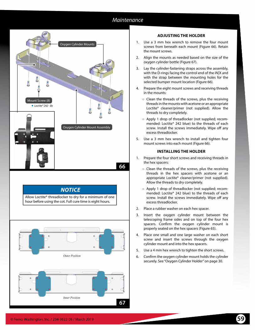
59© Ferno-Washington, Inc. / 234-3622-06 / March 2019
Loctite® 242 - 8x
Mount Screw (8)
Oxygen Cylinder Mounts
Oxygen Cylinder Mount Assembly
67
Maintenance
NOTICEAllow Loctite® threadlocker to dry for a minimum of one hour before using the cot. Full cure time is eight hours.
Outer Position
Inner Position
ADJUSTING THE HOLDER1. Use a 3 mm hex wrench to remove the four mount
screws from beneath each mount (Figure 66). Retain the mount screws.
2. Align the mounts as needed based on the size of the oxygen cylinder bottle (Figure 67).
3. Lay the cylinder-fastening straps across the assembly, with the D-rings facing the control end of the iN∫X and with the strap between the mounting holes for the selected bumper mount location (Figure 66).
4. Prepare the eight mount screws and receiving threads in the mounts:
○ Clean the threads of the screws, plus the receiving threads in the mounts with acetone or an appropriate Loctite® cleaner/primer (not supplied). Allow the threads to dry completely.
○ Apply 1 drop of threadlocker (not supplied; recom-mended: Loctite® 242 blue) to the threads of each screw. Install the screws immediately. Wipe off any excess threadlocker.
5. Use a 3 mm hex wrench to install and tighten four mount screws into each mount (Figure 66).
INSTALLING THE HOLDER1. Prepare the four short screws and receiving threads in
the hex spacers:
○ Clean the threads of the screws, plus the receiving threads in the hex spacers with acetone or an appropriate Loctite® cleaner/primer (not supplied). Allow the threads to dry completely.
○ Apply 1 drop of threadlocker (not supplied; recom-mended: Loctite® 242 blue) to the threads of each screw. Install the screws immediately. Wipe off any excess threadlocker.
2. Place a rubber washer on each hex spacer.
3. Insert the oxygen cylinder mount between the telescoping frame sides and on top of the four hex spacers. Confirm the oxygen cylinder mount is properly seated on the hex spacers (Figure 65).
4. Place one small and one large washer on each short screw and insert the screws through the oxygen cylinder mount and into the hex spacers.
5. Use a 4 mm hex wrench to tighten the short screws.
6. Confirm the oxygen cylinder mount holds the cylinder securely. See “Oxygen Cylinder Holder” on page 30.
66
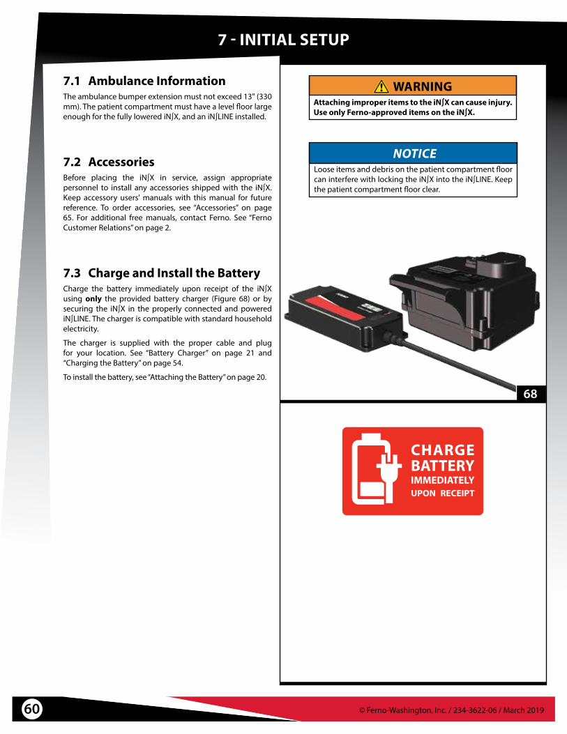
© Ferno-Washington, Inc. / 234-3622-06 / March 201960
7.1 Ambulance InformationThe ambulance bumper extension must not exceed 13" (330 mm). The patient compartment must have a level floor large enough for the fully lowered iN∫X, and an iN∫LINE installed.
WARNINGAttaching improper items to the iN∫X can cause injury. Use only Ferno-approved items on the iN∫X.
7.3 Charge and Install the BatteryCharge the battery immediately upon receipt of the iN∫X using only the provided battery charger (Figure 68) or by securing the iN∫X in the properly connected and powered iN∫LINE. The charger is compatible with standard household electricity.
The charger is supplied with the proper cable and plug for your location. See “Battery Charger” on page 21 and “Charging the Battery” on page 54.
To install the battery, see “Attaching the Battery” on page 20.
68
7 - INITIAL SETUP
7.2 AccessoriesBefore placing the iN∫X in service, assign appropriate personnel to install any accessories shipped with the iN∫X. Keep accessory users' manuals with this manual for future reference. To order accessories, see “Accessories” on page 65. For additional free manuals, contact Ferno. See “Ferno Customer Relations” on page 2.
NOTICELoose items and debris on the patient compartment floor can interfere with locking the iN∫X into the iN∫LINE. Keep the patient compartment floor clear.

© Ferno-Washington, Inc. / 234-3622-06 / March 2019 61
7.4 Set the Loading HeightThe user can set the iN∫X so it stops automatically at the proper loading height for the assigned ambulance. To set or change the loading height:
1. On a level surface, raise or lower the iN∫X until the loading wheels roll directly onto the ambulance floor (Figure 69). Verify that the loading wheels are resting on the ambulance floor, the safety bar is caught by the safety hook, and that the loading-end legs have not lifted off the ground.
2. Press the Mode-Select button four times to enter the load-height set mode. See “Mode-Select Button” on page 23.
○ The background screen is white to indicate the load-height set mode (Figure 70). The wheels are red to indicate that the iN∫X must not be rolled.
○ A blue line is displayed below the loading wheel, and a 15 second countdown timer is shown in the lower-left corner of the display.
○ The symbol is displayed to indicate that pressing the button will set a new loading height.
3. Press and hold to set the loading height before the timer expires. When pressed, a new, 5-second timer appears on the display. Continue holding until the timer expires.
4. Turn the power switch OFF and then ON. See “Power Switch” on page 17.
5. Retract and extend the legs to verify the iN∫X stops at the new loading height. Test loading and unloading the iN∫X with the ambulance.
Error Setting Loading Height
No loading height will be set when the iN∫X is at the factory-set maximum transport height or maximum height.
5
69
70
Initial Setup
Countdown Timer

62 © Ferno-Washington, Inc. / 234-3622-06 / March 2019
8 - TECHNICAL DATA
71
8.1 Charger SpecificationsThe Ferno 24/36VDC battery charger (Figure 71) is capable of charging the iN∫X battery either directly or through the Integrated Charging System (ICS).
The battery charger is also capable of charging a 24 VDC Ferno® POWERFlexx® POWERPac. See the battery charger users' manual for details.
8.2 iN∫X Battery SpecificationsThe iN∫X battery (Figure 72) is a rechargeable, 36-Volt DC battery. The input port is proprietary to Ferno and is compatible only with the Ferno battery charger.
72
WARNINGCharging an improper battery can cause injury and damage. Do not charge non-rechargeable batteries. The Ferno 24/36VDC battery charger is compatible only with the iN∫X battery or Ferno POWERPac and ICS systems.
Charge lead-acid batteries only in a well-ventilated area (Only Ferno POWERFlexx® POWERPac batteries are lead-acid type).
The appliance (battery charger) is not intended for use by people (including children) with reduced physical, sensory or mental capabilities, or lack of experience and knowledge, unless they have been given supervision or instruction concerning use of the appliance by a person responsible for their safety.
Children should be supervised to ensure that they do not play with the appliance (battery charger).
If the supply cord is damaged, it must be replaced by a special cord or assembly available from Ferno or an authorized Ferno distributor or service center.
LEGAL NOTICEThe Ferno 24/36VDC battery charger is not compatible with, or designed to charge automobile batteries. However, the following notice is required by CE standards:
The battery terminal not connected to the chassis must be connected first. The second connection must be made to the chassis, remote from the battery and fuel line. The battery charger is then to be connected to the supply mains.
After charging, disconnect the battery charger from the supply mains. Then remove the chassis connection and then the battery connection.
Charger Specification Imperial Metric
Dimensions 8.125 x 3.75 x 1.5 in 206 x 95 x 38 mm
Charging Cable 6 feet 1.83 meter
Operating Temperature -40°F to 113°F -40 to 45°C
Storage Temperature 32°F to 104°F 0°C to 40°C
Weight 1.7 lbs 770 g
Input AC 100~240V 50~60HZ, 92W
Output DC 39.6V 2A (LiFePO4 p/n 159-0093)DC 29.3V 2A (Lead Acid p/n 082-2012)
iN∫X Battery Charging Time 15 minutes* - 1 hour, 45 minutes
POWERPac Charging Time 1-2 hours
Note:� *Minimum charging time is for one transport, with the battery charge maintained by ICS.
Specifications: Ferno iN∫X Battery
Battery Type 36 VDC, LiFePO4(Lithium iron phosphate)
Number of internal cells 11
Storage Temperature -40°F to 140°F (-40°C to 60°C)
Operating Temperature -20°F to 140°F (-29°C to 60°C)
Battery Output 36 VDC, 2.5 Amp Hours nominal
Charging Time (1 transport, charge maintained by ICS)
15 minutes* minimum
Charging Time (depleted) Up to 1 hour, 45 minutes
Note:� *Minimum charging time is for one transport, with the battery charge maintained by ICS.

63© Ferno-Washington, Inc. / 234-3622-06 / March 2019
9.1 Status IndicatorsStatus codes alert the operator to function or safety issues. The codes are grouped into four priority levels: no priority, low, medium, and high.
Status codes are color-coded. High-priority codes are red; all others are yellow. When a safety issue arises, a warning triangle is displayed next to the error code.
Refer to the chart below. Some codes indicate the need for service. See “Parts and Service” on page 64.
9 - TROUBLESHOOTING
N04
Icon Meaning Solution
N04A button has been pressed longer than the maximum time allowed.
Release the button.
N05Auto-equalize problem. The iN∫X is having trouble equalizing the legs.
If there is an obstruction in the legs, clear the obstruction. Use caution.The load on the iN∫X may exceed the load capacity. Use additional help and provide lift-assistance.Use direct power.
N06The battery is expecting to see charging power, but the iN∫X is not detecting power at the ICS contacts.
Wait 30 seconds. If the error does not resolve itself in this time, there is a problem with the ICS. Report the problem to Ferno (page 2).
N07Both buttons are being pressed at the same time. Stop pressing the buttons. Press only or .
If the situation continues, report the issue to Ferno (page 2).
L01Improper charge voltage (voltage too high). Verify the connections between the iN∫X and the ICS; verify ICS
connections to the ambulance power supply. The ICS or charger may be plugged into an outlet providing an incorrect power voltage.
L04The battery is not charging. Charging power has been detected at the ICS contacts, but the battery is not detecting a charge.
Wait 30 seconds. If the error does not resolve itself in this time, this indicates a possible problem with the ICS, charger, iN∫X, or battery.Report the problem to Ferno (page 2).
L06Battery over-temperature. Allow time for the battery to cool.
Use non-powered operation to complete the transport.
M01The actuator motor has overheated. The actuators are deactivated until the motor cools.
Allow time for the motors to cool.Use non-powered operation to complete the transport.
M02A cable is routed from the controller to each actuator. One or both of these cables is disconnected.
Re-connect the cable(s).
H01 With weight on the iN∫X, the legs are not moving at the proper speed, indicating: 1) Excessive weight on the iN∫X;2) Leg obstruction;3) Mechanical problem.
1) Remove weight from the iN∫X or provide lift-assistance.2) Clear the obstruction from the legs. Use caution.3) Call Ferno for service (page 2).
H02 Without weight on the iN∫X, the legs are not moving at the proper speed, indicating:
1) An obstruction in the legs;2) A mechanical problem.
1) Clear the obstruction from the legs. Use caution.2) Call Ferno for service (page 2).
H03 Communication error. Use direct power to complete the patient transport, and call Ferno for service (page 2).
Patient-surface has been above the maximum safe transport height longer than 30 seconds; is disabled. The patient surface and warning triangle are red. The audible alarm sounds a pattern of 2+3 beeps.
Use to lower the iN∫X to a safe transport height.
Status Indicator Display Location

© Ferno-Washington, Inc. / 234-3622-06 / March 201964
10 - PARTS AND SERVICE
WARNINGModifying the iN∫X can cause injury and damage. Use the iN∫X only as designed by Ferno.
10.1 U.S.A. and CanadaIn the United States and Canada, to order parts or for professional repair, contact EMSAR® – the only agent authorized by Ferno to manage, service, and repair Ferno products.
Telephone (Toll-Free) 1.800.73.EMSARTelephone 1.937.383.1052Fax +1.937.383.1051Internet www.EMSAR.com
10.2 WorldwideTo order Ferno parts, and for professional repair, contact your Ferno distributor. Your distributor is the only agent authorized by Ferno to manage, service, and repair Ferno products.
iN∫X END-USER PARTS KITSDescription PartActuator pins, lower, iN∫X 090-6028Backrest panel only, iN∫X 090-5972Button, +/- set, iN∫X 090-6026Battery iN∫X 082-2480Cable guide links, standard, iN∫X 090-5990Cable guide links, bend in both directions, iN∫X 090-5991Charger adapter cable only, iN∫X 218-3008Mattress, iN∫X 037-4904Oxygen cylinder mount, iN∫X 090-5963Oxygen cylinder mount, iN∫X, bumpers only (qty 6) 090-5964Safety bars (loading-end and intermediate) 090-5981Safety-bar release lever, iN∫X 090-5985Seat frame complete, iN∫X 090-5971Seat panel only, iN∫X 090-6027Shock frame complete, iN∫X 090-5968Shock panel only, iN∫X 090-5969Wheel, transport, iN∫X 090-5987Wheel lock pedal, iN∫X 090-5960Wheel, loading iN∫X 090-5962
FASTENING SYSTEMS COMPLETEDescription PartiN∫LINE 86” Stat Trac Old Mount ILFS86STOLDMNTiN∫LINE 95” Stat Trac Old Mount ILFS95STOLDMNTiN∫LINE 102” Stat Trac Old Mount ILFS102STOLDMNTiN∫LINE 86” Stat Trac New Mount ILFS86STNEWMNTiN∫LINE 95” Stat Trac New Mount ILFS95STNEWMNTiN∫LINE 102” Stat Trac New Mount ILFS102STNEWMNT
FASTENING SYSTEM COMPONENTSDescription PartUniversal Floor Plate 080-0643Universal Floor Plate iN∫LINE Adapter Kit 080-0642Floor Block for iN∫LINE-S (short) 056-7056Floor Block for iN∫LINE-M (medium) or iN∫LINE-L (long) 056-7058
INTEGRATED CHARGING SYSTEM (ICS)Description PartICS for Floor Plate System (iN∫LINE) 082-2476ICS for Floor Block system (Stat Trac or iN∫LINE) 082-2477

© Ferno-Washington, Inc. / 234-3622-06 / March 2019 65
11.1 AccessoriesA variety of accessories are compatible with the iN∫X. For a complete list of accessories, contact Ferno.
Some accessories are designed to mount directly to the iN∫X main frame.
Before placing the iN∫X in service, assign appropriate personnel to install any accessories shipped with the iN∫X. Keep accessory users’ manuals with this manual for future reference. For additional, free manuals, contact Ferno. See “Ferno Customer Relations” on page 2.
11 - ACCESSORIES
PacRac+
IV Pole
WARNINGAttaching improper items to the iN∫X can cause injury. Use only Ferno-approved items on the iN∫X.
Telescoping Frame Storage Net
iN∫X ACCESSORIESDescription Kit NumberiN∫X Charger for USA, w/adapter 082-2463iN∫X Charger for United Kingdom w/adapter 082-2464iN∫X Charger for Europe w/adapter 082-2465iN∫X Charger for Australia w/adapter 082-2466iN∫X Equipment Holder, backrest panel version 082-2451iN∫X Equipment Holder, backrest frame version 082-2452iN∫X IV pole, 3-stage LAIV3SCLiN∫X Mattress 037-4904iN∫X Side Lift Handle (pair) FWESLHiN∫X Storage Net, telescoping frame 082-2453iN∫X Storage Net, loading-end legs 082-2454iN∫X Storage Net, control-end legs 082-2455iN∫X SX - Surface Xtender (pair) FWESXPacRac+ Equipment Platform FWEPRITPatient Shield 082-2097Pedi-Mate Pediatric Restraint 031-3778Pedi-Mate, Pedi-Pal, NeoMate Adaptor for iN∫X 082-2481Pedi-Pal Child Transport Seat 071-4812Restraint, iN∫X Shoulder/Waist, Model 417-iN∫X SAE-Compliant 037-4890Restraint, iN∫X Shoulder (only) 031-4114Restraint, Model 430, 2 pc, 5' black (iN∫X Leg Restraint) 031-3892

66 © Ferno-Washington, Inc. / 234-3622-06 / March 2019
Date Printed Name SignatureTraining Method Trainer
InitialsRead Manual Video/Online Hands-On
TRAINING RECORD

67© Ferno-Washington, Inc. / 234-3622-06 / March 2019
Date Maintenance Performed By
MAINTENANCE RECORD

© Ferno-Washington, Inc. / 234-3622-06 / March 2019