Embed Size (px)
Citation preview
Alexandria Engineering Journal (2016) 55, 2531–2538
HO ST E D BY
Alexandria University
Alexandria Engineering Journal
www.elsevier.com/locate/aejwww.sciencedirect.com
ORIGINAL ARTICLE
Analysis and modeling of different topologies for
linear switched reluctance motor using finite
element method
* Corresponding author.
E-mail address: [email protected] (B. Ganji).
Peer review under responsibility of Faculty of Engineering, Alexandria
University.
http://dx.doi.org/10.1016/j.aej.2016.07.0171110-0168 � 2016 Faculty of Engineering, Alexandria University. Production and hosting by Elsevier B.V.This is an open access article under the CC BY-NC-ND license (http://creativecommons.org/licenses/by-nc-nd/4.0/).
Babak Ganji *, Mohamad Hasan Askari
Faculty of Electrical and Computer Engineering, University of Kashan, Iran
Received 30 January 2015; revised 2 May 2016; accepted 18 July 2016Available online 5 August 2016
KEYWORDS
Linear switched reluctance
motor;
Segmental translator;
Finite element transient
analysis
Abstract In the present paper, an electromagnetic simulation model is introduced for the
conventional type of linear switched reluctance motor (LSRM) in which the dynamic characteristics
of the motor are predicted precisely by carrying out 2D finite element (FE) transient analysis using
ANSYS FE package. The simulation model is created totally in ANSYS parametric design
language (APDL) as a parametric model and it can be used easily for different designs of the
conventional LSRMs. Introducing linear switched reluctance motor with segmental translator as
a new type of LSRM, performance principles and design criteria are presented for two various
topologies of this motor. Carrying out 2D FE transient analysis, dynamic characteristics of these
two motors are predicted and compared to those obtained for the conventional LSRM.� 2016 Faculty of Engineering, Alexandria University. Production and hosting by Elsevier B.V. This is an
open access article under the CC BY-NC-ND license (http://creativecommons.org/licenses/by-nc-nd/4.0/).
1. Introduction
Due to exclusive features of switched reluctance motor (SRM)including simple and robust structure, absence of permanentmagnet and windings on rotor, low manufacturing cost, high
operation reliability, appropriate performance over a vastrange of speed and high output power/weight ratio, specialattention has been paid to this motor in the last three decades
[1,2]. Structure and performance principles of LSRMs are verysimilar to that for the rotary SRM and therefore it can be uti-lized appropriately as a suitable candidate for traction force
applications because of all above-mentioned features.
However, the researchers have concentrated mostly on the
rotary SRM and not many works have been reported forelectromagnetic modeling and design aspects of LSRMs.
A comprehensive magnetic equivalent circuit has been
developed for the LSRM in [2] which can be used properlyfor doing analysis and design of LSRM. A design algorithmis presented in [3] for the longitudinal field LSRM with multi-
ple air gaps. Introducing a transverse flux type of LSRM isconsidered in [4] and its important electromagnetic character-istics including inductances and force are predicted using finiteelement method (FEM). A linear switched reluctance actuator
based on cylindrical variable reluctance configuration has beenintroduced and constructed in [5]. A standard design proce-dure is described in [6] for a single-sided and longitudinal
flux-based LSRM. A design algorithm is introduced for thedouble-sided, double-translator LSRM in [7]. A LSRM driveis designed and manufactured in [8] for a test track of autono-
2532 B. Ganji, M.H. Askari
mous railway vehicles. Construction of LSRM is considered in[9] and its behavior is experimentally verified with two controlmethods.
In the present paper, an electromagnetic simulation modelis developed for conventional type of LSRM with FEM usingANSYS FE package. The simulation model is created totally
in APDL as a parametric model usable for various designs.In addition, linear switched reluctance with segmental transla-tor is introduced and two different topologies for this motor
are described. The simulation results are presented for thesemotors and they are compared to those for conventional typeof LSRM. At the following, the developed electromagneticsimulation model is introduced in Section 2. Two different
topologies for linear switched reluctance with segmental trans-lator are described in Section 3. The simulation results are pre-sented in Section 4 and the paper is concluded in Section 5.
2. Electromagnetic simulation model for LSRM
In order to predict the dynamic characteristics of the LSRM
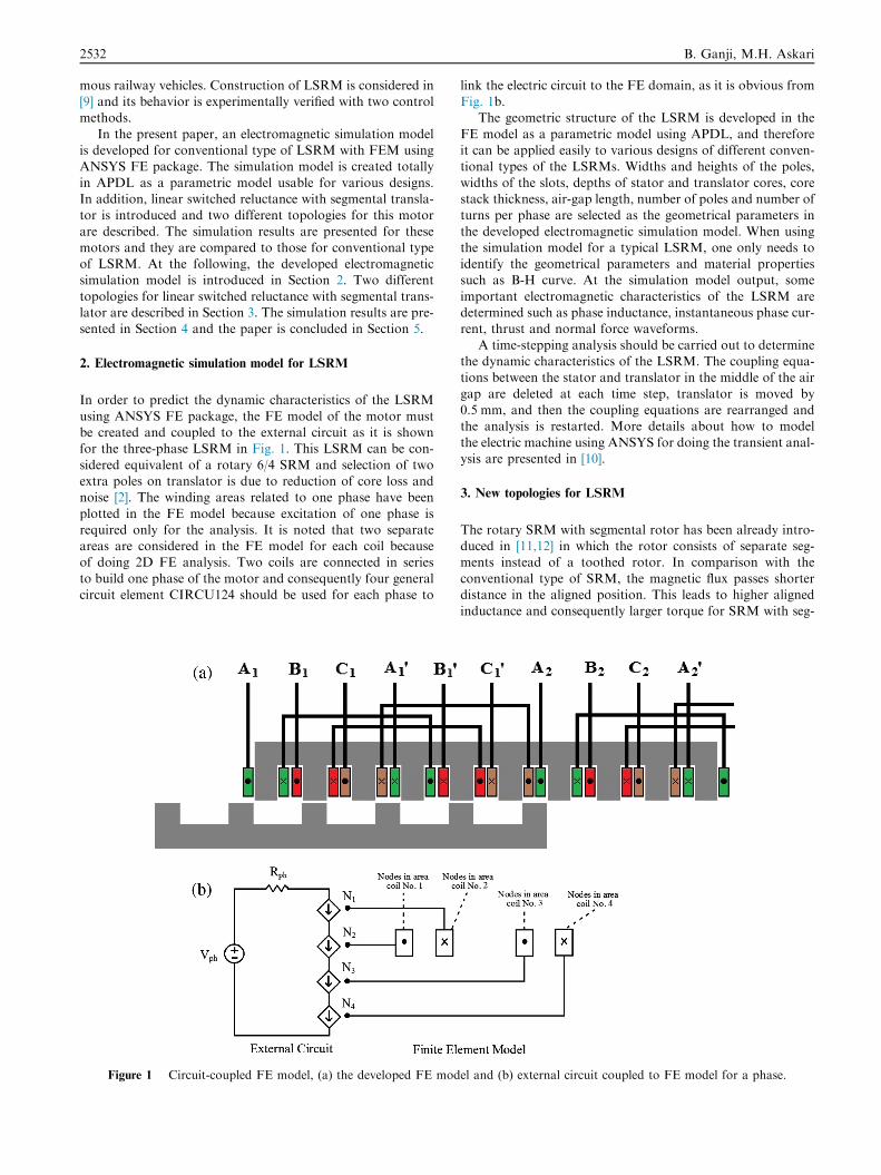
using ANSYS FE package, the FE model of the motor mustbe created and coupled to the external circuit as it is shownfor the three-phase LSRM in Fig. 1. This LSRM can be con-
sidered equivalent of a rotary 6/4 SRM and selection of twoextra poles on translator is due to reduction of core loss andnoise [2]. The winding areas related to one phase have been
plotted in the FE model because excitation of one phase isrequired only for the analysis. It is noted that two separateareas are considered in the FE model for each coil becauseof doing 2D FE analysis. Two coils are connected in series
to build one phase of the motor and consequently four generalcircuit element CIRCU124 should be used for each phase to
Figure 1 Circuit-coupled FE model, (a) the developed FE mod
link the electric circuit to the FE domain, as it is obvious fromFig. 1b.
The geometric structure of the LSRM is developed in the
FE model as a parametric model using APDL, and thereforeit can be applied easily to various designs of different conven-tional types of the LSRMs. Widths and heights of the poles,
widths of the slots, depths of stator and translator cores, corestack thickness, air-gap length, number of poles and number ofturns per phase are selected as the geometrical parameters in
the developed electromagnetic simulation model. When usingthe simulation model for a typical LSRM, one only needs toidentify the geometrical parameters and material propertiessuch as B-H curve. At the simulation model output, some
important electromagnetic characteristics of the LSRM aredetermined such as phase inductance, instantaneous phase cur-rent, thrust and normal force waveforms.
A time-stepping analysis should be carried out to determinethe dynamic characteristics of the LSRM. The coupling equa-tions between the stator and translator in the middle of the air
gap are deleted at each time step, translator is moved by0.5 mm, and then the coupling equations are rearranged andthe analysis is restarted. More details about how to model
the electric machine using ANSYS for doing the transient anal-ysis are presented in [10].
3. New topologies for LSRM
The rotary SRM with segmental rotor has been already intro-duced in [11,12] in which the rotor consists of separate seg-ments instead of a toothed rotor. In comparison with the
conventional type of SRM, the magnetic flux passes shorterdistance in the aligned position. This leads to higher alignedinductance and consequently larger torque for SRM with seg-
el and (b) external circuit coupled to FE model for a phase.
Analysis and modeling of different topologies for linear switched reluctance motor using finite element method 2533
mental rotor. Due to this significant capability, we have intro-duced the segmental translator linear switched reluctancemotor (STLSRM) [13] and two different topologies of this
motor are described at the following.
3.1. The fully-pitched STLSRM
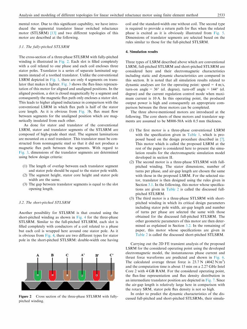
The cross-section of a three-phase STLSRM with fully-pitchedwinding is illustrated in Fig. 2. Each slot is filled completelywith a coil related to one phase and each coil encloses three
stator poles. Translator is a series of separate laminated seg-ments instead of a toothed translator. Unlike the conventionalLSRM depicted in Fig. 1, there are only 4 segments on trans-
lator that makes it lighter. Fig. 3 shows the flux-lines represen-tation of this motor for aligned and unaligned positions. In thealigned position, a slot is closed magnetically by a segment andconsequently the magnetic flux path only encloses a stator slot.
This leads to higher aligned inductance in comparison with theconventional LSRM in which flux path is half of the statorcore length. As it is obvious from Fig. 3b, flux must flow
between segments for the unaligned position which are mag-netically insulated from each other.
As done for stator and translator of the conventional
LSRM, stator and translator segments of the STLSRM arecomposed of high-grade sheet steel. The segment laminationsare mounted on a steel translator. This translator must be con-structed from nonmagnetic steel so that it did not produce a
magnetic flux path between the segments. With regard toFig. 3, dimensions of the translator segments are determinedusing below design criteria:
(1) The length of overlap between each translator segmentand stator pole should be equal to the stator pole width.
(2) The segment height, stator core height and stator polewidth are the same.
(3) The gap between translator segments is equal to the slot
opening length.
3.2. The short-pitched STLSRM
Another possibility for STLSRM is that created using theshort-pitched winding as shown in Fig. 4 for the three-phaseSTLSRM. Similar to the full-pitched STLSRM, each slot is
filled completely with conductors of a coil related to a phasebut each coil is wrapped here around one stator pole. As itis obvious from Fig. 4, there are two different types for stator
pole in the short-pitched STLSRM: double-width one having
Figure 2 Cross section of the three-phase STLSRM with fully-
pitched winding.
coil and the standard-width one without coil. The second typeis required to provide a return path for flux when the relatedphase is excited as it is obviously illustrated from Fig. 5.
Dimensions of translator segments are selected based on therules similar to those for the full-pitched STLSRM.
4. Simulation results
Three types of LSRM described above which are conventionalLSRM, full-pitched STLSRM and short-pitched STLSRM are
considered here and their electromagnetic characteristicsincluding static and dynamic characteristics are compared inthis section. It is noted that all simulation results related to
dynamic analyses are for the operating point: speed = 4 m/s,turn-on angle = 36� (el. degree), turn-off angle = 144� (el.degree) and the current regulation control mode when maxi-
mum current is 10 A. In this operating point, the producedoutput power is high and consequently an appropriate com-parison between the three motors can be completed.
The three above-mentioned motors are introduced at the
following. The core sheets of these motors and translator seg-ments are assumed to be M800-50A with 0.5 mm thickness.
(1) The first motor is a three-phase conventional LSRMwith the specification given in Table 1, which is pro-posed based on the design procedure described in [7].
This motor which is called the proposed LSRM at therest of the paper is considered here to present the simu-lation results for the electromagnetic simulation modeldeveloped in section II.
(2) The second motor is a three-phase STLSRM with full-pitched winding. The stator dimensions, number ofturns per phase, and air-gap length are chosen the same
with those in the proposed LSRM. For the selected sta-tor, translator is then designed using the rules given inSection 3.1. In the following, this motor whose specifica-
tions are given in Table 2 is called the discussed full-pitched STLSRM.
(3) The third motor is a three-phase STLSRM with short-
pitched winding in which its critical design parametersincluding stator pole width, air-gap length and numberof turns per phase are selected the same with thoseobtained for the discussed full-pitched STLSRM. The
other geometric parameters of this motor are then deter-mined as explained in Section 3.2. In the remaining ofpaper, this motor whose specifications are given in
Table 2 is called the discussed short-pitched STLSRM.
Carrying out the 2D FE transient analysis of the proposed
LSRM for the considered operating point using the developedelectromagnetic model, the instantaneous phase current andthrust force waveforms are predicted and shown in Fig. 6.The calculated average thrust force is 23.7 N (4042 N/m3)
and the computation time is about 15 min on a 2.27 GHz IntelCore 2 with 4 GB RAM. For the considered operating point,the flux-line representation and flux density distribution in
an intermediate translator position are depicted in Fig. 7. Sincethe air-gap length is relatively large here in comparison withthe rotary SRM, stator pole flux density is not so high.
In order to predict the dynamic characteristics of the dis-cussed full-pitched and short-pitched STLSRMs, their simula-
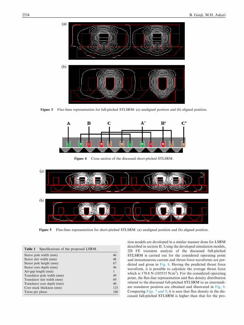
Figure 3 Flux-lines representation for full-pitched STLSRM: (a) unaligned position and (b) aligned position.
Figure 4 Cross section of the discussed short-pitched STLSRM.
Figure 5 Flux-lines representation for short-pitched STLSRM: (a) unaligned position and (b) aligned position.
Table 1 Specifications of the proposed LSRM.
Stator pole width (mm) 46
Stator slot width (mm) 46
Stator pole height (mm) 67
Stator core depth (mm) 46
Air-gap length (mm) 1
Translator pole width (mm) 49
Translator slot width (mm) 89
Translator core depth (mm) 49
Core stack thickness (mm) 125
Turns per phase 160
2534 B. Ganji, M.H. Askari
tion models are developed in a similar manner done for LSRM
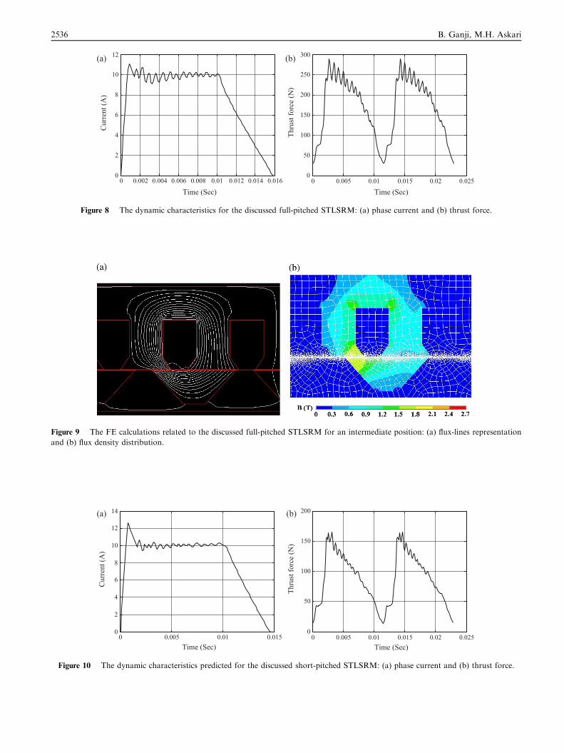
described in section II. Using the developed simulation models,2D FE transient analysis of the discussed full-pitchedSTLSRM is carried out for the considered operating pointand instantaneous current and thrust force waveforms are pre-
dicted and given in Fig. 8. Having the predicted thrust forcewaveform, it is possible to calculate the average thrust forcewhich is 170.8 N (103515 N/m3). For the considered operating
point, the flux-line representation and flux density distributionrelated to the discussed full-pitched STLSRM in an intermedi-ate translator position are obtained and illustrated in Fig. 9.
Comparing Figs. 7 and 9, it is seen that flux density in the dis-cussed full-pitched STLSRM is higher than that for the pro-

Table 2 Specifications of the discussed STLSRMs.
Full-pitch
STLSRM
Short-pitch
STLSRM
Stator pole width (mm) 46 46, 92
Width of stator pole tip
(mm)
51 51, 97
Stator slot width (mm) 46 46
Stator pole height (mm) 67 67
Stator core depth (mm) 46 46
Air-gap length (mm) 1 1
Segment height (mm) 46 46
Segment width (mm) 115, 30.6 115, 30.6
Gap between segments
(mm)
23 23
Core stack thickness
(mm)
125 125
Turns per phase 160 160
Analysis and modeling of different topologies for linear switched reluctance motor using finite element method 2535
posed LSRM. This results in producing a larger thrust forcefor the full-pitched STLSRM as it is clear from Figs. 6
(b) and 8(b).
(a) (b
0 0.005 0.01 0.0150
2
4
6
8
10
12
Cur
rent
(A)
Time (Sec)
Figure 6 The dynamic characteristics predicted for the pr
Figure 7 The FE calculations related to the proposed LSRM for a
density distribution.
For the considered operating point, the 2D FE transientanalysis of the discussed short-pitched STLSRM is carriedout and the predicted instantaneous current and thrust force
waveforms are shown in Fig. 10. The average force derivedfrom the predicted thrust force waveform is 87.5 N(21341 N/m3). For the considered operating point, the flux-
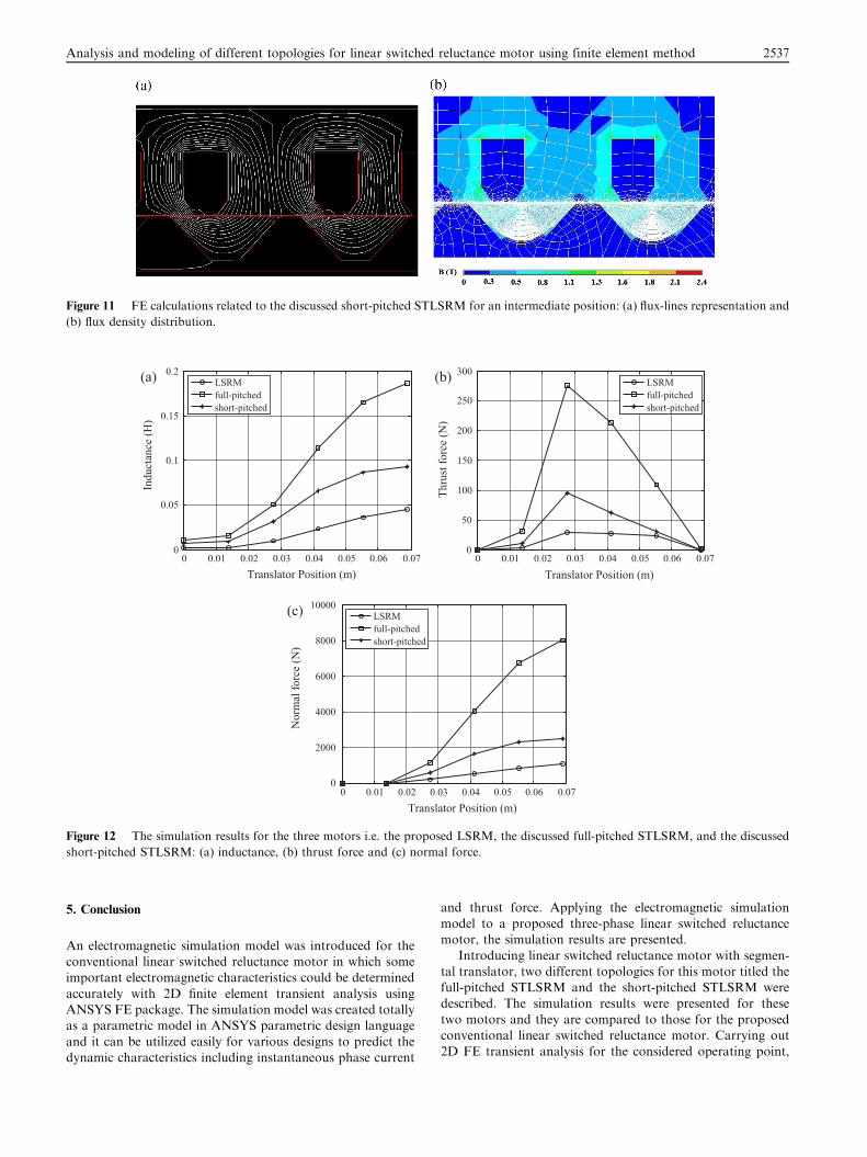
line representation and flux density distribution are predictedin an intermediate translator position and they are shown inFig. 11.
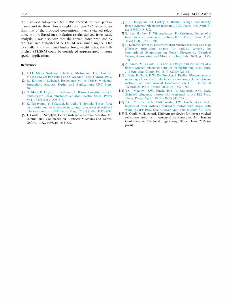
Using the developed electromagnetic simulation models,static analyses of the three above-mentioned motors are alsodone when phase current is 10 A and the obtained simulationresults are compared in Fig. 12. In these figures, 0 indicates to
the unaligned position and 0.07 is related to the aligned posi-tion. As discussed in Section 3 and it is obviously seen fromFig. 12(a), the phase inductance of the discussed full-pitch
STLSRM is much larger than that for the proposed LSRMbecause its magnetic flux path is shorter. As it is clear fromFig. 12, the discussed full-pitched STLSRM has capability to
produce much larger values of both thrust and normal forcesin comparison with the proposed LSRM.
)
0 0.005 0.01 0.015 0.02 0.0255
10
15
20
25
30
35
Thru
st fo
rce
(N)
Time (Sec)
oposed LSRM: (a) phase current and (b) thrust force.
n intermediate position: (a) flux-lines representation and (b) flux
(a) (b)
0 0.002 0.004 0.006 0.008 0.01 0.012 0.014 0.0160
2
4
6
8
10
12
Cur
rent
(A)
Time (Sec)0 0.005 0.01 0.015 0.02 0.025
0
50
100
150
200
250
300
Thru
st fo
rce
(N)
Time (Sec)
Figure 8 The dynamic characteristics for the discussed full-pitched STLSRM: (a) phase current and (b) thrust force.
Figure 9 The FE calculations related to the discussed full-pitched STLSRM for an intermediate position: (a) flux-lines representation
and (b) flux density distribution.
(a) (b)
0 0.005 0.01 0.0150
2
4
6
8
10
12
14
Cur
rent
(A)
Time (Sec)0 0.005 0.01 0.015 0.02 0.025
0
50
100
150
200
Thru
st fo
rce
(N)
Time (Sec)
Figure 10 The dynamic characteristics predicted for the discussed short-pitched STLSRM: (a) phase current and (b) thrust force.
2536 B. Ganji, M.H. Askari
(a) (b)
(c)
0 0.01 0.02 0.03 0.04 0.05 0.06 0.070
0.05
0.1
0.15
0.2
Indu
ctan
ce (H
)
Translator Position (m)
LSRMfull-pitchedshort-pitched
0 0.01 0.02 0.03 0.04 0.05 0.06 0.070
50
100
150
200
250
300
Thru
st fo
rce
(N)
Translator Position (m)
LSRMfull-pitchedshort-pitched
0 0.01 0.02 0.03 0.04 0.05 0.06 0.070
2000
4000
6000
8000
10000
Nor
mal
forc
e (N
)
Translator Position (m)
LSRMfull-pitchedshort-pitched
Figure 12 The simulation results for the three motors i.e. the proposed LSRM, the discussed full-pitched STLSRM, and the discussed
short-pitched STLSRM: (a) inductance, (b) thrust force and (c) normal force.
Figure 11 FE calculations related to the discussed short-pitched STLSRM for an intermediate position: (a) flux-lines representation and
(b) flux density distribution.
Analysis and modeling of different topologies for linear switched reluctance motor using finite element method 2537
5. Conclusion
An electromagnetic simulation model was introduced for theconventional linear switched reluctance motor in which someimportant electromagnetic characteristics could be determined
accurately with 2D finite element transient analysis usingANSYS FE package. The simulation model was created totallyas a parametric model in ANSYS parametric design language
and it can be utilized easily for various designs to predict thedynamic characteristics including instantaneous phase current
and thrust force. Applying the electromagnetic simulationmodel to a proposed three-phase linear switched reluctancemotor, the simulation results are presented.
Introducing linear switched reluctance motor with segmen-tal translator, two different topologies for this motor titled thefull-pitched STLSRM and the short-pitched STLSRM weredescribed. The simulation results were presented for these
two motors and they are compared to those for the proposedconventional linear switched reluctance motor. Carrying out2D FE transient analysis for the considered operating point,
2538 B. Ganji, M.H. Askari
the discussed full-pitched STLSRM showed the best perfor-mance and its thrust force/weight ratio was 25.6 times largerthan that of the proposed conventional linear switched reluc-
tance motor. Based on simulation results derived from staticanalysis, it was also seen that the normal force produced bythe discussed full-pitched STLSRM was much higher. Due
to smaller translator and higher force/weight ratio, the full-pitched STLSRM could be considered appropriately in somespecial applications.
References
[1] T.J.E. Miller, Switched Reluctance Motors and Their Control,
Magna Physics Publishing and Clarendon Press, Oxford, 1993.
[2] R. Krishnan, Switched Reluctance Motor Drive: Modeling,
Simulation, Analysis, Design and Applications, CRC Press,
2001.
[3] D. Matt, R. Goyet, J. Lucidarme, C. Rioux, Longitudinal-field
multi-airgap linear reluctance actuator, Electric Mach. Power
Syst. 13 (5) (1987) 299–313.
[4] K. Takayama, Y. Takasaki, R. Ueda, T. Sonoda, Thrust force
distribution on the surface of stator and rotor poles of switched
reluctance motor, IEEE Trans. Magn. 25 (5) (1989) 3997–3999.
[5] J. Corda, E. Skopljak, Linear switched reluctance actuator, 6th
International Conference on Electrical Machines and Drives,
Oxford, U.K., 1993, pp. 535–539.
[6] U.S. Deshpande, J.J. Cathey, E. Richter, A high force density
linear switched reluctance machine, IEEE Trans. Ind. Appl. 31
(2) (1995) 345–352.
[7] B. Lee, H. Bae, P. Vijayraghavan, R. Krishnan, Design of a
linear switched reluctance machine, IEEE Trans. Indus. Appl.
36 (6) (2000) 1571–1580.
[8] L. Kolomeitsev et al, Linear switched reluctance motor as a high
efficiency propulsion system for railway vehicles, in:
International Symposium on Power Electronics, Electrical
Drives, Automation and Motion, Ischia, Italy, 2008, pp. 155–
160.
[9] A. Santo, M. Calado, C. Cabrita, Design and evaluation of a
linear switched reluctance actuator for positioning tasks, Turk.
J. Electr. Eng. Comp. Sci. 18 (6) (2010) 925–941.
[10] J. Faiz, B. Ganji, R.W. De Doncker, J. Fiedler, Electromagnetic
modeling of switched reluctance motor using finite element
method, in: 32nd Annual Conference on IEEE Industrial
Electronics, Paris, France, 2006, pp. 1557–1562.
[11] B.C. Mecrow, J.W. Finch, E.A. El-Kharashi, A.G. Jack,
Switched reluctance motors with segmental rotors, IEE Proc.
Electr. Power Appl. 149 (4) (2002) 245–254.
[12] B.C. Mecrow, E.A. El-Kharashi, J.W. Finch, A.G. Jack,
Segmental rotor switched reluctance motors with single-tooth
windings, IEE Proc. Electr. Power Appl. 150 (5) (2003) 591–599.
[13] B. Ganji, M.H. Askari, Different topologies for linear switched
reluctance motor with segmental translator, in: 24th Iranian
Conference on Electrical Engineering, Shiraz, Iran, 2016 (in
press).