Embed Size (px)
Citation preview
Automated Computer Systems for Manufacturability Analyses and Tooling Design Applied to the Rotary Draw Bending Process
JOEL JOHANSSON
Department of Product and Production Development CHALMERS UNIVERSITY OF TECHNOLOGY Göteborg, Sweden 2011

THESIS FOR THE DEGREE OF DOCTOR OF PHILOSOPHY
Automated Computer Systems for Manufacturability Analyses and
Tooling Design Applied to the Rotary Draw Bending Process
JOEL JOHANSSON
Department of Mechanical Engineering SCHOOL OF ENGINEERING JÖNKÖPING UNIVERSITY
Jönköping, Sweden
Department of Product and Production Development CHALMERS UNIVERSITY OF TECHNOLOGY
Göteborg, Sweden 2011
Automated Computer Systems for Manufacturability Analyses and Tooling Design Applied to the Rotary Draw Bending Process
Joel Johansson
ISBN 978-91-7385-510-5
© Joel Johansson, 2011
Doktorsavhandlingar vid Chalmers tekniska högskola Ny serie Nr 3191 ISSN 0346-718X
Department of Product and Production Development Chalmers University of Technology SE-412 96 Gothenburg Sweden Telephone + 46 (0)31-772 1000
Chalmers Reproservice Gothenburg, Sweden, 2011
AUTOMATED COMPUTER SYSTEMS FOR MANUFACTURABILITY ANALYSES AND TOOLING DESIGN
APPLIED TO THE ROTARY DRAW BENDING PROCESS
i
ABSTRACT
Intensive competition on the global market puts great pressure on manufacturing companies to develop and produce products that meet requirements from customers and investors. One key factor in meeting these requirements is the efficiency of the product development and the production preparation processes. Design automation is a powerful tool to increase efficiency in these two processes.
The benefits of automating the manufacturability analysis process, a part of the production preparation process, are shortened led-time, improved product perfor-mance, quality assurance, and, ultimately, decreased costs. Further, automation is beneficial as it increases the ability to adapt products to new product specifications with production preparations done in a few or in a single step. During the automation process, knowledge about the manufacturability analysis process is collected and stored in central systems, thus allowing full control over the design of production equipments.
Topics addressed in this thesis include the flexibility of design automation systems, knowledge-bases containing alternative design rules, the automation of the finite element analysis process, manufacturability analysis over several productions steps, and the determination of production limits by looping the automated manufacturabili-ty analysis process. These topics are discussed in connection with the rotary draw bending of aluminum profiles.
It is concluded that the concept of design automation can be applied to the manufactu-rability analysis process at different levels of automation depending on the characte-ristics of the implemented knowledge. The concept of object orientation should be adapted when implementing a knowledge-base and when developing the geometrical representations of the products. This makes a design automation system flexible enough to edit underlying knowledge and to extend the targeted design space. It is possible to automate the process of setting up, running, and interpreting finite element analyses to a great extent, enabling the design automation system to evaluate its own design proposals. It is also possible to enable such systems to consider sequences of manufacturing steps and loop them to develop decision support guiding engineers early in the design process, saving time and money while still assuring high product quality.
Keywords: Design For Manufacturability, Design Automation, Rotary Draw Bend-ing, and Knowledge-based Engineering (KBE).

AUTOMATED COMPUTER SYSTEMS FOR MANUFACTURABILITY ANALYSES AND TOOLING DESIGN
APPLIED TO THE ROTARY DRAW BENDING PROCESS
ii

AUTOMATED COMPUTER SYSTEMS FOR MANUFACTURABILITY ANALYSES AND TOOLING DESIGN
APPLIED TO THE ROTARY DRAW BENDING PROCESS
iii
ACKNOWLEDGEMENTS
The research presented through this thesis has been conducted in a cooperative study between Jönköping University, Sapa Group, Faurecia, and Ekenäs Mekaniska Verkstad. I am very grateful for the funding by Sapa Group and the Knowledge Foundation (in Swedish, KK-stiftelsen). It has allowed me to concentrate on this specific research area that is close to my passion for mechanical engineering and computer programming. I also express my gratitude to Chalmers University of Tech-nology, Department of Product and Production Development and Professor Rikard Söderberg, for kindly accepting me as a PhD student, making this work possible.
I also express my gratitude to my supervisor, Professor Staffan Sunnersjö, for his enthusiasm and belief in my ideas and guidance in my research efforts. I also thank Mikael Cederfeldt, Fredrik Elgh, Dag Raudberget, and Roland Stolt for support and interesting discussions on the subject of design automation and research in general.
Finally, I thank my family, especially my beloved wife, Synnöve Johansson, and my friends who have always stood by me, giving me their support and comfort.
Jönköping, 2011-02-07
_________________________________
Joel Johansson

AUTOMATED COMPUTER SYSTEMS FOR MANUFACTURABILITY ANALYSES AND TOOLING DESIGN
APPLIED TO THE ROTARY DRAW BENDING PROCESS
iv

AUTOMATED COMPUTER SYSTEMS FOR MANUFACTURABILITY ANALYSES AND TOOLING DESIGN
APPLIED TO THE ROTARY DRAW BENDING PROCESS
v
PUBLISHED PAPERS
This thesis is based on the following published and appended papers:
Paper A – J. Johansson and S. Sunnersjö (2006). Automated Design of Rotary Draw Bending Tools – An Approach Based on Generic CAD-Models Driven by Heuristic and Algorithmic Knowledge. EDMMP 2006, Wroclaw, Poland.
Paper B – J. Johansson (2007). A Flexible Design Automation System for Toolsets for the Rotary Draw Bending of Aluminium Tubes. IDETC 2007, Neva-da, USA.
Paper C – J. Johansson (2008). Manufacturability Analysis Using Integrated KBE, CAD and FEM. IDETC 2008, New York, USA.
Paper D – J. Johansson (2009). Automatic Producibility Analysis of the Draw Bending of Aluminium Tubes with Several Bends. NAFEMS World Congress 2009, Hersonissos, Greece.
Paper E – J. Johansson (2009). Automated Manufacturability Analysis of the Draw Bending of Complex Aluminum Profiles. IDETC 2009, San Diego, USA.
Paper F – J. Johansson (2011). Determining of the Manufacturing Limits for the Draw Bending of Aluminum Profiles by Automated FEM-simulations. Submitted to the special issue of Journal of Manufacturing Science and Engineering: Advances in Plastic Forming of Metals.

AUTOMATED COMPUTER SYSTEMS FOR MANUFACTURABILITY ANALYSES AND TOOLING DESIGN
APPLIED TO THE ROTARY DRAW BENDING PROCESS
vi
AUTOMATED COMPUTER SYSTEMS FOR MANUFACTURABILITY ANALYSES AND TOOLING DESIGN
APPLIED TO THE ROTARY DRAW BENDING PROCESS
vii
TABLE OF CONTENTS
Chapter 1 Introduction .................................................................................................. 1 1.1 The importance of design automation for manufacturability analyses .......... 1 1.2 Realization of design automation .................................................................. 1 1.3 Research objective and case of application ................................................... 2 1.4 Research questions ......................................................................................... 4 1.5 Thesis outline ................................................................................................. 5
Chapter 2 Research Method ......................................................................................... 7 2.1 Applying the research method ....................................................................... 8
Chapter 3 Frame of Reference .................................................................................... 11 3.1 Design automation ....................................................................................... 11 3.2 Manufacturability analyses .......................................................................... 13 3.3 Draw bending – a short introduction ........................................................... 14 3.4 Existing systems for the automated design of draw bending toolsets ......... 16 3.5 Identified knowledge gap ............................................................................ 19
Chapter 4 Design Automation Systems With a High Degree of Flexibility ............ 21 4.1 A modular structure of the knowledge-base ................................................ 21 4.2 Adapting object orientation to the product structure ................................... 25 4.3 Stand-alone and CAD-integrated KBE-systems .......................................... 27
Chapter 5 Knowledge-bases Containing Alternative Design Rules ........................ 31 5.1 Different sources of knowledge and meta-knowledge ................................ 31 5.2 Enabling knowledge adaptability ................................................................ 32 5.3 Evaluating knowledge adaptability .............................................................. 36
Chapter 6 Flexible Automation of the Finite Element Analysis Process ................ 41 6.1 FEA in the manufacturability analysis process ........................................... 41 6.2 Evaluating the automation of FEA .............................................................. 42
Chapter 7 Automated Evaluation of Simulated Production Outcome .................. 45 7.1 Wrinkling ..................................................................................................... 45 7.2 Wall thickness .............................................................................................. 47 7.3 Developed length ......................................................................................... 47 7.4 Section collapse for circular tubes ............................................................... 48
Chapter 8 Manufacturability Analyses over Several Process Steps ....................... 49 8.1 Parsing product specification from the customer ........................................ 49 8.2 Generating design proposal ......................................................................... 50 8.3 Simulating the production process ............................................................... 51 8.4 Analyzing the simulated production outcome ............................................. 52
Chapter 9 Generalizing Product Geometry ............................................................... 53 9.1 Parsing product specification from the customer ........................................ 53 9.2 Generate a design proposal .......................................................................... 53 9.3 Simulating the production process ............................................................... 55 9.4 Analyzing the simulated production outcome ............................................. 55
Chapter 10 Determination of the Design Space .......................................................... 57 10.1 The feasible design space ............................................................................ 57
AUTOMATED COMPUTER SYSTEMS FOR MANUFACTURABILITY ANALYSES AND TOOLING DESIGN
APPLIED TO THE ROTARY DRAW BENDING PROCESS
viii
10.2 Searching for valid tool configurations ....................................................... 58
Chapter 11 Discussion .................................................................................................... 61 11.1 Scientific Contributions ............................................................................... 61 11.2 Industrial Contributions ............................................................................... 61 11.3 How general are the results presented in this thesis work? ......................... 61 11.4 Different research cycles ............................................................................. 62 11.5 Verification of results .................................................................................. 62 11.6 Validation .................................................................................................... 64
Chapter 12 Conclusions and Future Work .................................................................. 65 12.1 Answering the research questions ............................................................... 65 12.2 Future work .................................................................................................. 66
Appendix A Implementation of the Rotary Draw Bending Knowledge-base ........... 67
Appendix B Examples of Specialist Knowledge Within Rotary Draw Bending ....... 71
Appended Papers ............................................................................................................ 81
AUTOMATED COMPUTER SYSTEMS FOR MANUFACTURABILITY ANALYSES AND TOOLING DESIGN
APPLIED TO THE ROTARY DRAW BENDING PROCESS
1
CHAPTER 1
INTRODUCTION
This chapter provides an introduction to the thesis, points out the research questions dealt with, and defines the contents of the thesis.
1.1 The importance of design automation for manufactu-rability analyses
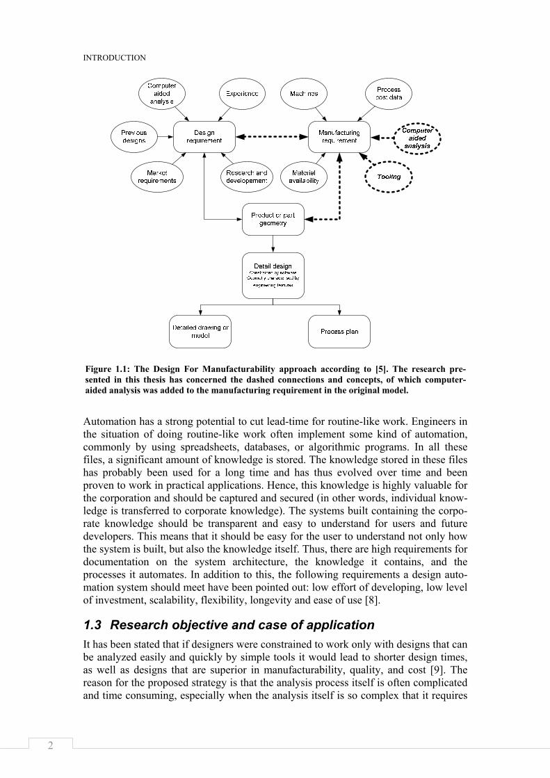
For a manufacturing company to survive on a competitive market, it has to produce products at low cost, in a short time, with high quality, and still meet customer speci-fications [1, 2]. Hence, high pressure is put on the product and the production devel-opment processes to efficiently develop demanded products that are producible. The product and the production development processes are tightly interconnected so that decisions made during the design of a product might have significant effects on the cost, quality, and lead time when producing the product. Since the producibility aspect of the product strongly depends on its manufacturing process, it has proven to be successful to consider manufacturing aspects parallel to the design process, referred to as Concurrent Engineering [3]. During the 1990s, this led to the idea of identifying design elements potentially causing problems for manufacturing and quality control, and providing feedback to the designer so that the designer could change the design to improve its manufacturability [4]. These ideas changed the view of the design process, as is represented in Figure 1.1, referred to as Design For Manufacturability [5].
The following reasons for automating manufacturing activities have been stated: to increase labor productivity, reduce labor cost, mitigate the effects of labor shortages, reduce or eliminate routine manual and clerical tasks, improve worker safety, improve product quality, reduce manufacturing lead time, and accomplish processes that cannot be done manually [6]. With the exception of improved worker safety, all of these reasons are true for the automation of engineering design activates as well. The automation of manufacturability analyses specifically enhances the concept of concur-rent engineering and design for manufacture, making it possible to feed back precise predictions of production outcome to designers at an early stage of the design process.
1.2 Realization of design automation Design automation has been defined as:”Engineering IT-support by implementation of information and knowledge in solutions, tools, or systems, that are pre-planned for reuse and support of the progress of the design process. The scope of the definition encompasses computerized automation of tasks that directly or indirectly are related to the design process in the range of individual components to complete products.” [7] Hence, a design automation system is a computerized system developed to support engineers in the design process. In order to make such systems available, theories from the field of artificial intelligence in computer science are adapted and utilized in the field of product development. Since design automation systems are intended to work within corporations, organizational aspects need to be considered as well (they are not considered in this thesis).
INTRODUCTION
2
Automation has a strong potential to cut lead-time for routine-like work. Engineers in the situation of doing routine-like work often implement some kind of automation, commonly by using spreadsheets, databases, or algorithmic programs. In all these files, a significant amount of knowledge is stored. The knowledge stored in these files has probably been used for a long time and has thus evolved over time and been proven to work in practical applications. Hence, this knowledge is highly valuable for the corporation and should be captured and secured (in other words, individual know-ledge is transferred to corporate knowledge). The systems built containing the corpo-rate knowledge should be transparent and easy to understand for users and future developers. This means that it should be easy for the user to understand not only how the system is built, but also the knowledge itself. Thus, there are high requirements for documentation on the system architecture, the knowledge it contains, and the processes it automates. In addition to this, the following requirements a design auto-mation system should meet have been pointed out: low effort of developing, low level of investment, scalability, flexibility, longevity and ease of use [8].
1.3 Research objective and case of application It has been stated that if designers were constrained to work only with designs that can be analyzed easily and quickly by simple tools it would lead to shorter design times, as well as designs that are superior in manufacturability, quality, and cost [9]. The reason for the proposed strategy is that the analysis process itself is often complicated and time consuming, especially when the analysis itself is so complex that it requires
Figure 1.1: The Design For Manufacturability approach according to [5]. The research pre-sented in this thesis has concerned the dashed connections and concepts, of which computer-aided analysis was added to the manufacturing requirement in the original model.
AUTOMATED COMPUTER SYSTEMS FOR MANUFACTURABILITY ANALYSES AND TOOLING DESIGN
APPLIED TO THE ROTARY DRAW BENDING PROCESS
3
specialists in the organization. It takes a long time to do the analysis, and that process removes the analysis from the designers. One way of solving these problems is to provide designers with good tools which are easy to use, provide results quickly, and answer key design questions. The objective of the research presented in this thesis has been to investigate how engineering design automation can be utilized to provide designers with such easy to use tools to analyze the manufacturability of the products they are designing.
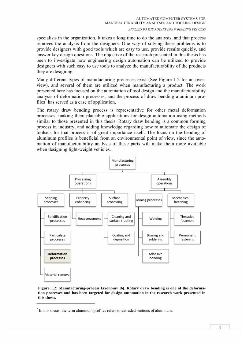
Many different types of manufacturing processes exist (See Figure 1.2 for an over-view), and several of them are utilized when manufacturing a product. The work presented here has focused on the automation of tool design and the manufacturability analysis of deformation processes, and the process of draw bending aluminum pro-files* has served as a case of application.
The rotary draw bending process is representative for other metal deformation processes, making them plausible applications for design automation using methods similar to those presented in this thesis. Rotary draw bending is a common forming process in industry, and adding knowledge regarding how to automate the design of toolsets for that process is of great importance itself. The focus on the bending of aluminum profiles is beneficial from an environmental point of view, since the auto-mation of manufacturability analysis of these parts will make them more available when designing light-weight vehicles.
* In this thesis, the term aluminum profiles refers to extruded sections of aluminum.
Manufacturing processes
Processing operations
Shaping processes
Solidification processes
Particulate processes
Deformation processes
Material removal
Property enhancing
Heat treatment
Surface processing
Cleaning and surface treating
Coating and deposition
Assembly operations
Joining processes
Welding
Brazing and soldering
Adhesive bonding
Mechanical fastening
Threaded fasteners
Permanent fastening
Figure 1.2: Manufacturing-process taxonomy [6]. Rotary draw bending is one of the deforma-tion processes and has been targeted for design automation in the research work presented in this thesis.
INTRODUCTION
4
1.4 Research questions The main research question for the work presented in this thesis has been:
How should the concept of design automation be applied to the tooling design and manufacturability analyses of plastic forming processes, exemplified by the rotary draw bending of aluminum profiles? During the project, this question has been divided into the following six sub-questions:
1. How should design automation systems be built to allow a high degree of flex-ibility? (discussed in Chapter 4)
This question has been addressed since the need for a high degree of flexibility has been pointed out as a key factor for success for design automation systems [8].
2. How should design automation systems be made able to handle the situation when multiple types of knowledge coexist for a single phenomenon? (discussed in Chapter 5)
This question was raised since alternative or even contradicting design rules might occur when developing the knowledge-base.
3. How may design automation systems be built enabling automatic but also flex-ible finite element analyses of the manufacturing process? (discussed in Chap-ter 6)
The deformation of material is frequently simulated using the finite element method. To have an automated system for manufacturability analyses calls for automating the finite element analysis process. Updating FEM and analyzing models are examples of the routine-like activities suitable for automation.
4. How may one enable design automation systems to do manufacturability ana-lyses of products that are put through several manufacturing process steps? (discussed in Chapter 8)
Products are often processed in several manufacturing processes before they are finally ready. It is necessary to simulate all these steps in order to analyze the final product.
5. How may one enable design automation systems to do manufacturability ana-lyses of a wide range of the design space? (discussed in Chapter 9)
The shape (cross-section) of the material put into a deformation process highly affects the resulting product. To enable designers to elaborate with design pro-posals, the automated system has to be able to correspond to a wide range of inputs that might vary parametrically and topologically.
6. How may one loop a design automation system to explore different areas of a design space in order to generate decision support for tooling layout, includ-ing component selections? (discussed in Chapter 10)
By looping a system for automated manufacturability through sequences of design proposals, easy-to-use-guidelines can be developed and brought to the designers for quick responses.
AUTOMATED COMPUTER SYSTEMS FOR MANUFACTURABILITY ANALYSES AND TOOLING DESIGN
APPLIED TO THE ROTARY DRAW BENDING PROCESS
5
In the thesis work, the proposals presented are viewed as hypotheses. They are also described in the chapters along with the prototype systems.
Finally, the manufacturing process and associated tooling for the rotary draw bending of aluminum profiles has served as the case of application for the discussion of all research questions.
1.5 Thesis outline Chapter 2 describes the research method used to conduct the research presented in this thesis. Chapter 3 then provides an introduction to the design automation, which is the research topic; it introduces rotary draw bending, which is the case of application; and it describes manufacturability analysis. After that, Chapter 4 discusses how to achieve a high degree of flexibility of design automation systems. Chapter 5 later describes how to make it possible for a knowledge-base to contain alternative design rules. Chapter 6 then examines the automation of the FEA process. Directions concerning how to automate the evaluation of the simulated production outcome of the draw bending process are provided in Chapter 7. Chapter 8 discusses how to automate the manufacturability analyses to include several process steps. Chapter 9 then discusses how to extend a system for manufacturability to respond to a wider range of inputs. Chapter 10 shows how to loop automated manufacturability analyses to develop decision support. A discussion is presented in Chapter 11. Finally, Chapter 12 con-cludes the research work and suggestions on future work are presented. In addition, there are two appendices. Appendix A contains two tables showing an implemented knowledge-base for the case application. In Appendix B, a knowledge-base developed for the design of toolsets for rotary draw bending is partly presented.

INTRODUCTION
6
AUTOMATED COMPUTER SYSTEMS FOR MANUFACTURABILITY ANALYSES AND TOOLING DESIGN
APPLIED TO THE ROTARY DRAW BENDING PROCESS
7
CHAPTER 2
RESEARCH METHOD
This chapter describes the research method used during the research project.
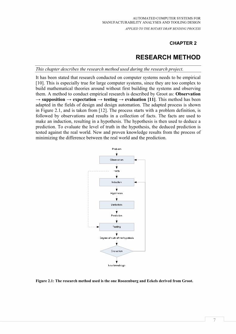
It has been stated that research conducted on computer systems needs to be empirical [10]. This is especially true for large computer systems, since they are too complex to build mathematical theories around without first building the systems and observing them. A method to conduct empirical research is described by Groot as: Observation → supposition → expectation → testing → evaluation [11]. This method has been adapted in the fields of design and design automation. The adapted process is shown in Figure 2.1, and is taken from [12]. The process starts with a problem definition, is followed by observations and results in a collection of facts. The facts are used to make an induction, resulting in a hypothesis. The hypothesis is then used to deduce a prediction. To evaluate the level of truth in the hypothesis, the deduced prediction is tested against the real world. New and proven knowledge results from the process of minimizing the difference between the real world and the prediction.
Figure 2.1: The research method used is the one Roozenburg and Eekels derived from Groot.
RESEARCH METHOD
8
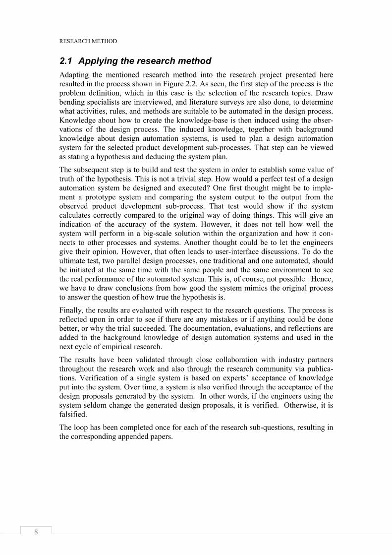
2.1 Applying the research method Adapting the mentioned research method into the research project presented here resulted in the process shown in Figure 2.2. As seen, the first step of the process is the problem definition, which in this case is the selection of the research topics. Draw bending specialists are interviewed, and literature surveys are also done, to determine what activities, rules, and methods are suitable to be automated in the design process. Knowledge about how to create the knowledge-base is then induced using the obser-vations of the design process. The induced knowledge, together with background knowledge about design automation systems, is used to plan a design automation system for the selected product development sub-processes. That step can be viewed as stating a hypothesis and deducing the system plan.
The subsequent step is to build and test the system in order to establish some value of truth of the hypothesis. This is not a trivial step. How would a perfect test of a design automation system be designed and executed? One first thought might be to imple-ment a prototype system and comparing the system output to the output from the observed product development sub-process. That test would show if the system calculates correctly compared to the original way of doing things. This will give an indication of the accuracy of the system. However, it does not tell how well the system will perform in a big-scale solution within the organization and how it con-nects to other processes and systems. Another thought could be to let the engineers give their opinion. However, that often leads to user-interface discussions. To do the ultimate test, two parallel design processes, one traditional and one automated, should be initiated at the same time with the same people and the same environment to see the real performance of the automated system. This is, of course, not possible. Hence, we have to draw conclusions from how good the system mimics the original process to answer the question of how true the hypothesis is.
Finally, the results are evaluated with respect to the research questions. The process is reflected upon in order to see if there are any mistakes or if anything could be done better, or why the trial succeeded. The documentation, evaluations, and reflections are added to the background knowledge of design automation systems and used in the next cycle of empirical research.
The results have been validated through close collaboration with industry partners throughout the research work and also through the research community via publica-tions. Verification of a single system is based on experts’ acceptance of knowledge put into the system. Over time, a system is also verified through the acceptance of the design proposals generated by the system. In other words, if the engineers using the system seldom change the generated design proposals, it is verified. Otherwise, it is falsified.
The loop has been completed once for each of the research sub-questions, resulting in the corresponding appended papers.
AUTOMATED COMPUTER SYSTEMS FOR MANUFACTURABILITY ANALYSES AND TOOLING DESIGN
APPLIED TO THE ROTARY DRAW BENDING PROCESS
9
Figure 2.2: The applied research method was adapted from Roozenburg and Eekels [12].
Observe how design is carried out in the
development process
Induce knowledge about how to create the knowledge base
Deduce principles for design automation systems in current problem domain
Build and test the prediction to reality
Evaluate, reflect and publish
Observe existing design automation systems
Problem
New knowledge about design automation systems
Level of truth
System plan (prediction)
Activiteis, rules, andmethods to automate
Background knowledge about design
automation systems

RESEARCH METHOD
10
AUTOMATED COMPUTER SYSTEMS FOR MANUFACTURABILITY ANALYSES AND TOOLING DESIGN
APPLIED TO THE ROTARY DRAW BENDING PROCESS
11
CHAPTER 3
FRAME OF REFERENCE
The aim of the presented research work has been to apply design automation to manufacturability analyses of deformation manufacture processes, especially the draw bending process. Hence, there are three supporting fields that need to be reviewed: design automation, manufacturability analyses, and draw bending. Design automation is the research topic of this thesis. The manufacturability analyses and rotary draw bending sections are added to give the reader the necessary background information.
3.1 Design automation Design automation can be divided into three areas: design synthesis, design analysis, and plan for manufacture [13]. When developing systems for automating tool design and manufacturability analyses, all three of these areas have to be supported. The manufacturing process has to be generated, the design of the tool components has to be synthesized, and the production outcome has to be simulated and analyzed. Know-ledge based systems can be utilized in the product and production development to achieve this support.
3.1.1 Artificial intelligence and knowledge-based systems Artificial intelligence can be defined as that branch of computer science concerned with the automation of intelligent behavior. Creative thinking is not the scope of design automation. Rather, design automation involves the automation of routine work in order to free humans to do creative thinking. Anyhow, some of the methods found in artificial intelligence have proven to be successful when applied to different routine-like tasks. One example is the design of production tooling layouts. The same types of components are used in every tool-setup for a specific manufacturing process, and the layout is controlled by a set of rules. But creating a computer implementation that designs quality tooling layouts is a hard task when using traditional procedural programming. To solve the problem, several solutions are generated according to implemented rules and searched through using a search method.
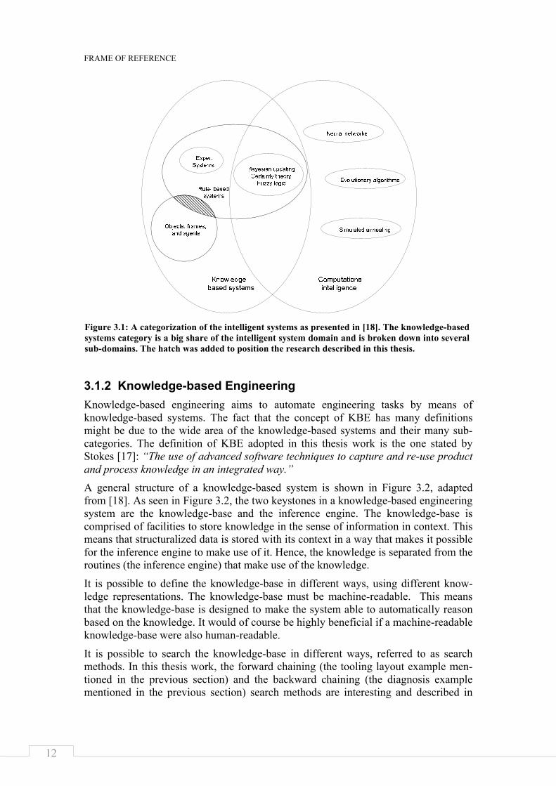
Another problem well-suited for methods from the artificial intelligence is the diagno-sis of systems through logical reasoning. For instance, in automating the diagnosis of why a car does not start, it is possible to define a rule base and search that base for possible failures. In the two examples, knowledge is stored in a knowledge-base searched through by an inference engine; the complete system is called a knowledge-based system. The knowledge-based system is a sub-category of the more general category intelligent systems (See Figure 3.1), and is a result of research in artificial intelligence. The knowledge-based systems can further be divided into sub-sections including agent-based systems, expert systems, and fuzzy logic systems [14-16]. In Figure 3.1, the research presented in this thesis is positioned by the hatched field.
FRAME OF REFERENCE
12
3.1.2 Knowledge-based Engineering Knowledge-based engineering aims to automate engineering tasks by means of knowledge-based systems. The fact that the concept of KBE has many definitions might be due to the wide area of the knowledge-based systems and their many sub-categories. The definition of KBE adopted in this thesis work is the one stated by Stokes [17]: “The use of advanced software techniques to capture and re-use product and process knowledge in an integrated way.”
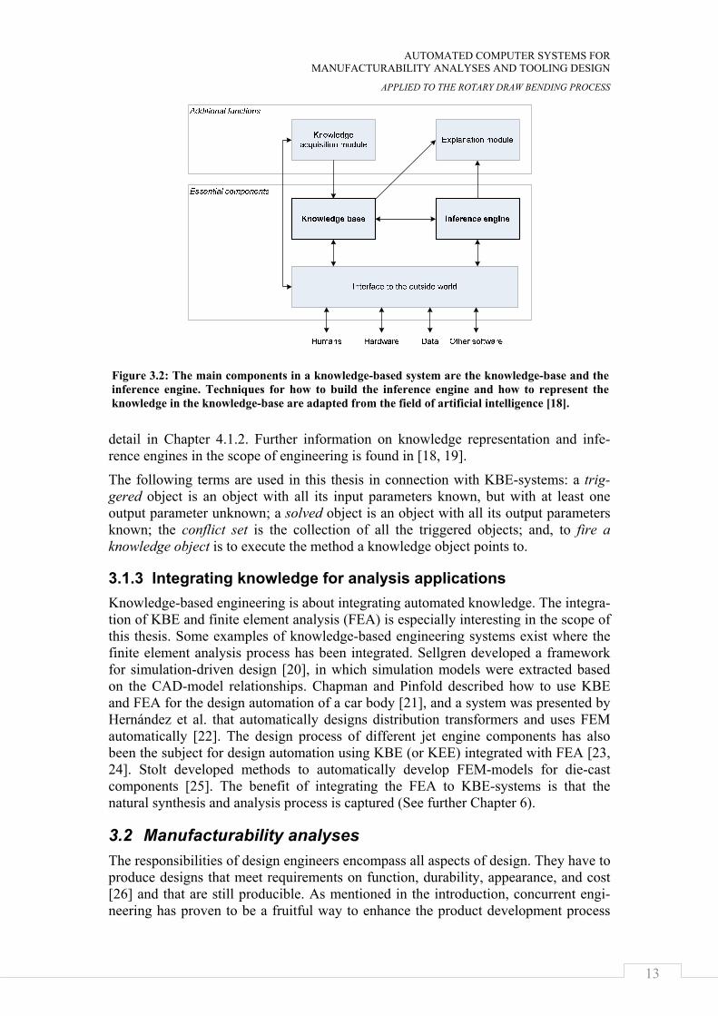
A general structure of a knowledge-based system is shown in Figure 3.2, adapted from [18]. As seen in Figure 3.2, the two keystones in a knowledge-based engineering system are the knowledge-base and the inference engine. The knowledge-base is comprised of facilities to store knowledge in the sense of information in context. This means that structuralized data is stored with its context in a way that makes it possible for the inference engine to make use of it. Hence, the knowledge is separated from the routines (the inference engine) that make use of the knowledge.
It is possible to define the knowledge-base in different ways, using different know-ledge representations. The knowledge-base must be machine-readable. This means that the knowledge-base is designed to make the system able to automatically reason based on the knowledge. It would of course be highly beneficial if a machine-readable knowledge-base were also human-readable.
It is possible to search the knowledge-base in different ways, referred to as search methods. In this thesis work, the forward chaining (the tooling layout example men-tioned in the previous section) and the backward chaining (the diagnosis example mentioned in the previous section) search methods are interesting and described in
Figure 3.1: A categorization of the intelligent systems as presented in [18]. The knowledge-based systems category is a big share of the intelligent system domain and is broken down into several sub-domains. The hatch was added to position the research described in this thesis.
AUTOMATED COMPUTER SYSTEMS FOR MANUFACTURABILITY ANALYSES AND TOOLING DESIGN
APPLIED TO THE ROTARY DRAW BENDING PROCESS
13
detail in Chapter 4.1.2. Further information on knowledge representation and infe-rence engines in the scope of engineering is found in [18, 19].
The following terms are used in this thesis in connection with KBE-systems: a trig-gered object is an object with all its input parameters known, but with at least one output parameter unknown; a solved object is an object with all its output parameters known; the conflict set is the collection of all the triggered objects; and, to fire a knowledge object is to execute the method a knowledge object points to.
3.1.3 Integrating knowledge for analysis applications Knowledge-based engineering is about integrating automated knowledge. The integra-tion of KBE and finite element analysis (FEA) is especially interesting in the scope of this thesis. Some examples of knowledge-based engineering systems exist where the finite element analysis process has been integrated. Sellgren developed a framework for simulation-driven design [20], in which simulation models were extracted based on the CAD-model relationships. Chapman and Pinfold described how to use KBE and FEA for the design automation of a car body [21], and a system was presented by Hernández et al. that automatically designs distribution transformers and uses FEM automatically [22]. The design process of different jet engine components has also been the subject for design automation using KBE (or KEE) integrated with FEA [23, 24]. Stolt developed methods to automatically develop FEM-models for die-cast components [25]. The benefit of integrating the FEA to KBE-systems is that the natural synthesis and analysis process is captured (See further Chapter 6).
3.2 Manufacturability analyses The responsibilities of design engineers encompass all aspects of design. They have to produce designs that meet requirements on function, durability, appearance, and cost [26] and that are still producible. As mentioned in the introduction, concurrent engi-neering has proven to be a fruitful way to enhance the product development process
Figure 3.2: The main components in a knowledge-based system are the knowledge-base and the inference engine. Techniques for how to build the inference engine and how to represent the knowledge in the knowledge-base are adapted from the field of artificial intelligence [18].
FRAME OF REFERENCE
14
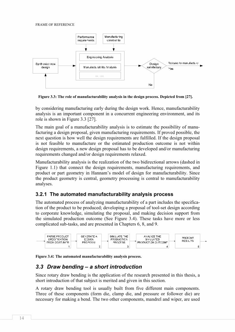
by considering manufacturing early during the design work. Hence, manufacturability analysis is an important component in a concurrent engineering environment, and its role is shown in Figure 3.3 [27].
The main goal of a manufacturability analysis is to estimate the possibility of manu-facturing a design proposal, given manufacturing requirements. If proved possible, the next question is how well the design requirements are fulfilled. If the design proposal is not feasible to manufacture or the estimated production outcome is not within design requirements, a new design proposal has to be developed and/or manufacturing requirements changed and/or design requirements relaxed.
Manufacturability analysis is the realization of the two bidirectional arrows (dashed in Figure 1.1) that connect the design requirements, manufacturing requirements, and product or part geometry in Hannam’s model of design for manufacturability. Since the product geometry is central, geometry processing is central to manufacturability analyses.
3.2.1 The automated manufacturability analysis process The automated process of analyzing manufacturability of a part includes the specifica-tion of the product to be produced; developing a proposal of tool-set design according to corporate knowledge, simulating the proposal, and making decision support from the simulated production outcome (See Figure 3.4). These tasks have more or less complicated sub-tasks, and are presented in Chapters 6, 8, and 9.
Figure 3.4: The automated manufacturability analysis process.
3.3 Draw bending – a short introduction Since rotary draw bending is the application of the research presented in this thesis, a short introduction of that subject is merited and given in this section.
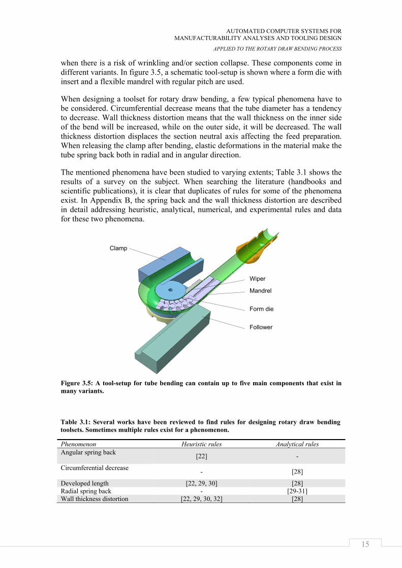
A rotary draw bending tool is usually built from five different main components. Three of these components (form die, clamp die, and pressure or follower die) are necessary for making a bend. The two other components, mandrel and wiper, are used
Figure 3.3: The role of manufacturability analysis in the design process. Depicted from [27].
AUTOMATED COMPUTER SYSTEMS FOR MANUFACTURABILITY ANALYSES AND TOOLING DESIGN
APPLIED TO THE ROTARY DRAW BENDING PROCESS
15
when there is a risk of wrinkling and/or section collapse. These components come in different variants. In figure 3.5, a schematic tool-setup is shown where a form die with insert and a flexible mandrel with regular pitch are used.
When designing a toolset for rotary draw bending, a few typical phenomena have to be considered. Circumferential decrease means that the tube diameter has a tendency to decrease. Wall thickness distortion means that the wall thickness on the inner side of the bend will be increased, while on the outer side, it will be decreased. The wall thickness distortion displaces the section neutral axis affecting the feed preparation. When releasing the clamp after bending, elastic deformations in the material make the tube spring back both in radial and in angular direction.
The mentioned phenomena have been studied to varying extents; Table 3.1 shows the results of a survey on the subject. When searching the literature (handbooks and scientific publications), it is clear that duplicates of rules for some of the phenomena exist. In Appendix B, the spring back and the wall thickness distortion are described in detail addressing heuristic, analytical, numerical, and experimental rules and data for these two phenomena.
Figure 3.5: A tool-setup for tube bending can contain up to five main components that exist in many variants.
Phenomenon Heuristic rules Analytical rules Angular spring back [22] -
Circumferential decrease - [28]
Developed length [22, 29, 30] [28] Radial spring back - [29-31] Wall thickness distortion [22, 29, 30, 32] [28]
Follower
Mandrel
Clamp
Form die
Wiper
Table 3.1: Several works have been reviewed to find rules for designing rotary draw bending toolsets. Sometimes multiple rules exist for a phenomenon.
FRAME OF REFERENCE
16
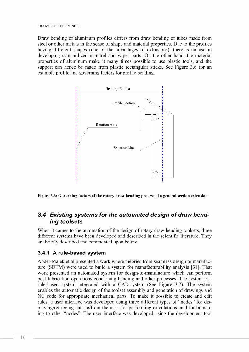
Draw bending of aluminum profiles differs from draw bending of tubes made from steel or other metals in the sense of shape and material properties. Due to the profiles having different shapes (one of the advantages of extrusions), there is no use in developing standardized mandrel and wiper parts. On the other hand, the material properties of aluminum make it many times possible to use plastic tools, and the support can hence be made from plastic rectangular sticks. See Figure 3.6 for an example profile and governing factors for profile bending.
Figure 3.6: Governing factors of the rotary draw bending process of a general section extrusion.
3.4 Existing systems for the automated design of draw bend-ing toolsets
When it comes to the automation of the design of rotary draw bending toolsets, three different systems have been developed and described in the scientific literature. They are briefly described and commented upon below.
3.4.1 A rule-based system Abdel-Malek et al presented a work where theories from seamless design to manufac-ture (SDTM) were used to build a system for manufacturability analysis [31]. That work presented an automated system for design-to-manufacture which can perform post-fabrication operations concerning bending and other processes. The system is a rule-based system integrated with a CAD-system (See Figure 3.7). The system enables the automatic design of the toolset assembly and generation of drawings and NC code for appropriate mechanical parts. To make it possible to create and edit rules, a user interface was developed using three different types of “nodes” for dis-playing/retrieving data to/from the user, for performing calculations, and for branch-ing to other “nodes”. The user interface was developed using the development tool
Profile Section
Rotation Axis
Splitting Line
AUTOMATED COMPUTER SYSTEMS FOR MANUFACTURABILITY ANALYSES AND TOOLING DESIGN
APPLIED TO THE ROTARY DRAW BENDING PROCESS
17
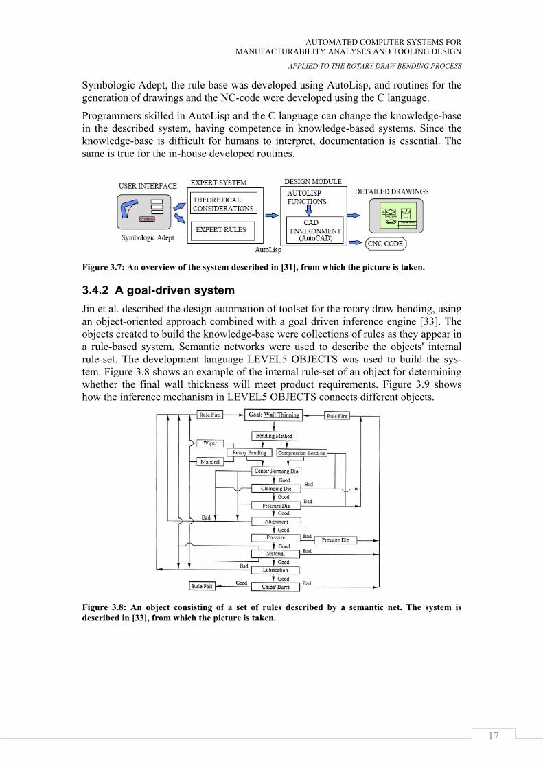
Symbologic Adept, the rule base was developed using AutoLisp, and routines for the generation of drawings and the NC-code were developed using the C language.
Programmers skilled in AutoLisp and the C language can change the knowledge-base in the described system, having competence in knowledge-based systems. Since the knowledge-base is difficult for humans to interpret, documentation is essential. The same is true for the in-house developed routines.
Figure 3.7: An overview of the system described in [31], from which the picture is taken.
3.4.2 A goal-driven system Jin et al. described the design automation of toolset for the rotary draw bending, using an object-oriented approach combined with a goal driven inference engine [33]. The objects created to build the knowledge-base were collections of rules as they appear in a rule-based system. Semantic networks were used to describe the objects' internal rule-set. The development language LEVEL5 OBJECTS was used to build the sys-tem. Figure 3.8 shows an example of the internal rule-set of an object for determining whether the final wall thickness will meet product requirements. Figure 3.9 shows how the inference mechanism in LEVEL5 OBJECTS connects different objects.
Figure 3.8: An object consisting of a set of rules described by a semantic net. The system is described in [33], from which the picture is taken.
FRAME OF REFERENCE
18
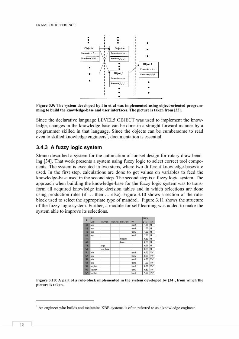
Figure 3.9: The system developed by Jin et al was implemented using object-oriented program-ming to build the knowledge-base and user interfaces. The picture is taken from [33].
Since the declarative language LEVEL5 OBJECT was used to implement the know-ledge, changes in the knowledge-base can be done in a straight forward manner by a programmer skilled in that language. Since the objects can be cumbersome to read even to skilled knowledge engineers*, documentation is essential.
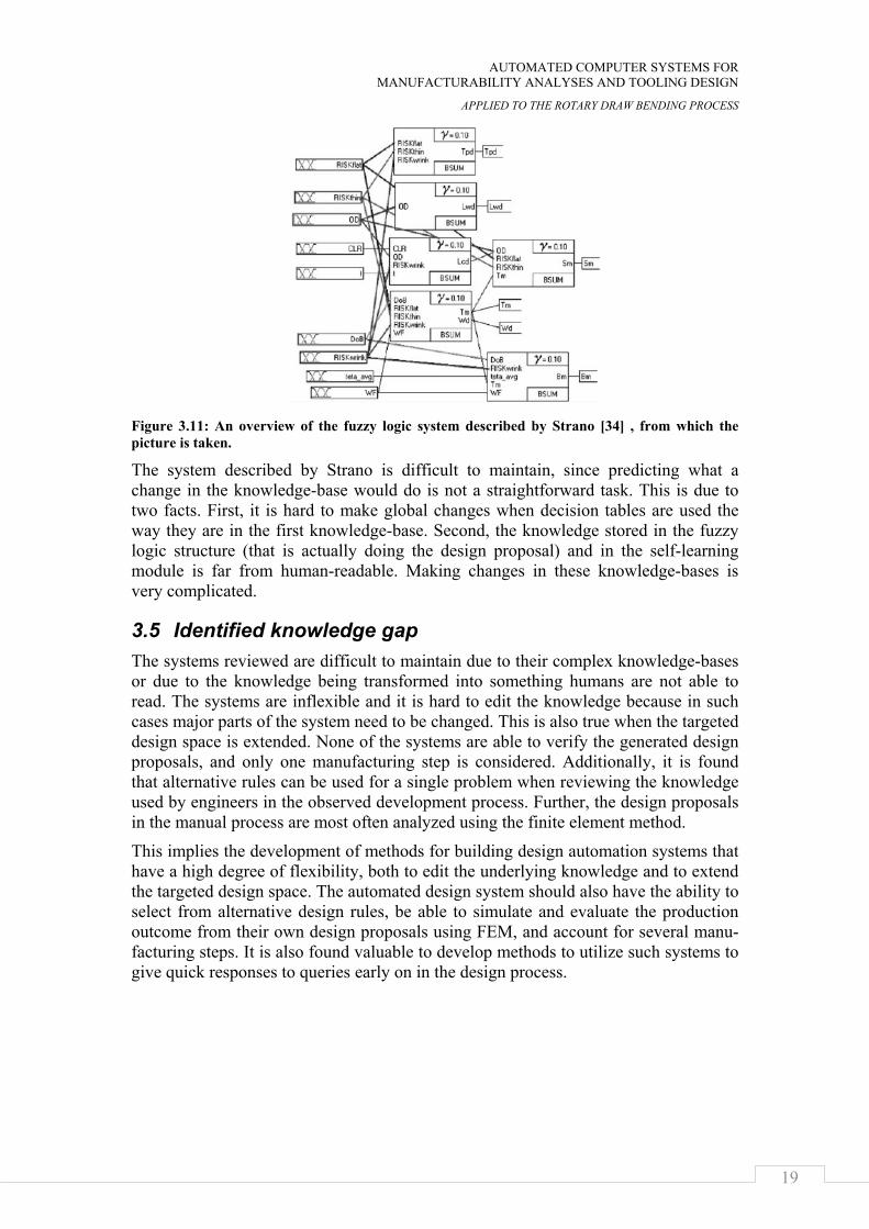
3.4.3 A fuzzy logic system Strano described a system for the automation of toolset design for rotary draw bend-ing [34]. That work presents a system using fuzzy logic to select correct tool compo-nents. The system is executed in two steps, where two different knowledge-bases are used. In the first step, calculations are done to get values on variables to feed the knowledge-base used in the second step. The second step is a fuzzy logic system. The approach when building the knowledge-base for the fuzzy logic system was to trans-form all acquired knowledge into decision tables and in which selections are done using production rules (if … then … else). Figure 3.10 shows a section of the rule-block used to select the appropriate type of mandrel. Figure 3.11 shows the structure of the fuzzy logic system. Further, a module for self-learning was added to make the system able to improve its selections.
Figure 3.10: A part of a rule-block implemented in the system developed by [34], from which the picture is taken.
* An engineer who builds and maintains KBE-systems is often referred to as a knowledge engineer.
AUTOMATED COMPUTER SYSTEMS FOR MANUFACTURABILITY ANALYSES AND TOOLING DESIGN
APPLIED TO THE ROTARY DRAW BENDING PROCESS
19
Figure 3.11: An overview of the fuzzy logic system described by Strano [34] , from which the picture is taken.
The system described by Strano is difficult to maintain, since predicting what a change in the knowledge-base would do is not a straightforward task. This is due to two facts. First, it is hard to make global changes when decision tables are used the way they are in the first knowledge-base. Second, the knowledge stored in the fuzzy logic structure (that is actually doing the design proposal) and in the self-learning module is far from human-readable. Making changes in these knowledge-bases is very complicated.
3.5 Identified knowledge gap The systems reviewed are difficult to maintain due to their complex knowledge-bases or due to the knowledge being transformed into something humans are not able to read. The systems are inflexible and it is hard to edit the knowledge because in such cases major parts of the system need to be changed. This is also true when the targeted design space is extended. None of the systems are able to verify the generated design proposals, and only one manufacturing step is considered. Additionally, it is found that alternative rules can be used for a single problem when reviewing the knowledge used by engineers in the observed development process. Further, the design proposals in the manual process are most often analyzed using the finite element method.
This implies the development of methods for building design automation systems that have a high degree of flexibility, both to edit the underlying knowledge and to extend the targeted design space. The automated design system should also have the ability to select from alternative design rules, be able to simulate and evaluate the production outcome from their own design proposals using FEM, and account for several manu-facturing steps. It is also found valuable to develop methods to utilize such systems to give quick responses to queries early on in the design process.

FRAME OF REFERENCE
20
AUTOMATED COMPUTER SYSTEMS FOR MANUFACTURABILITY ANALYSES AND TOOLING DESIGN
APPLIED TO THE ROTARY DRAW BENDING PROCESS
21
CHAPTER 4
DESIGN AUTOMATION SYSTEMS WITH A HIGH DEGREE OF FLEXIBILITY
The complexity of an artifact may be measured in two dimensions – its physical realization and the knowledge required to comprehend it. There are artifacts that cannot be made from a single person, and there are artifacts that cannot be compre-hended by a single person [35]. The former calls for decomposing the product into modules, and the latter calls for dividing the knowledge into chunks. Two ways of achieving flexibility are shown in this chapter. One is by applying object orientation to the knowledge-base. The other is by applying object orientation to the product structure. Finally, guidelines are stated telling when to implement the knowledge using a CAD-integrated KBE-system and when to use a stand-alone KBE- system.
This chapter is based on results from appended papers A and B.
4.1 A modular structure of the knowledge-base Knowledge change over time and a knowledge-base needs to be flexible so that pieces of knowledge can be easily added, updated, or deleted without disrupting the opera-tion of the system. To make a system flexible in that sense, all the parts building it must be autonomous. Hence, to make the knowledge-base flexible, all the chunks of knowledge must be autonomous. A procedural programming approach is not practical in this case, since changing the knowledge-base would mean changing, compiling, and subsequently distributing the programming code. Instead, a declarative way of implementing the knowledge-base has proven to be fruitful.
In a declarative system, the knowledge-base is separated from the functions that make use of the knowledge-base. Consequently, changing the knowledge-base in a declara-tive system can be performed without any changing of programming code.
Since the knowledge that engineers use when designing manufacturing tools is highly connected to various calculations, the use of object-oriented knowledge bases has proven to be successful. The objects are called knowledge objects, and the routine that deals with knowledge objects is called the inference engine.
4.1.1 Knowledge objects Object-oriented programming offers the possibility to develop highly flexible soft-ware. Objects are closely related to frames. The difference is that a frame is passive in the sense that it does not perform any tasks itself. An object, on the other hand, stores information about itself and performs certain tasks [18].
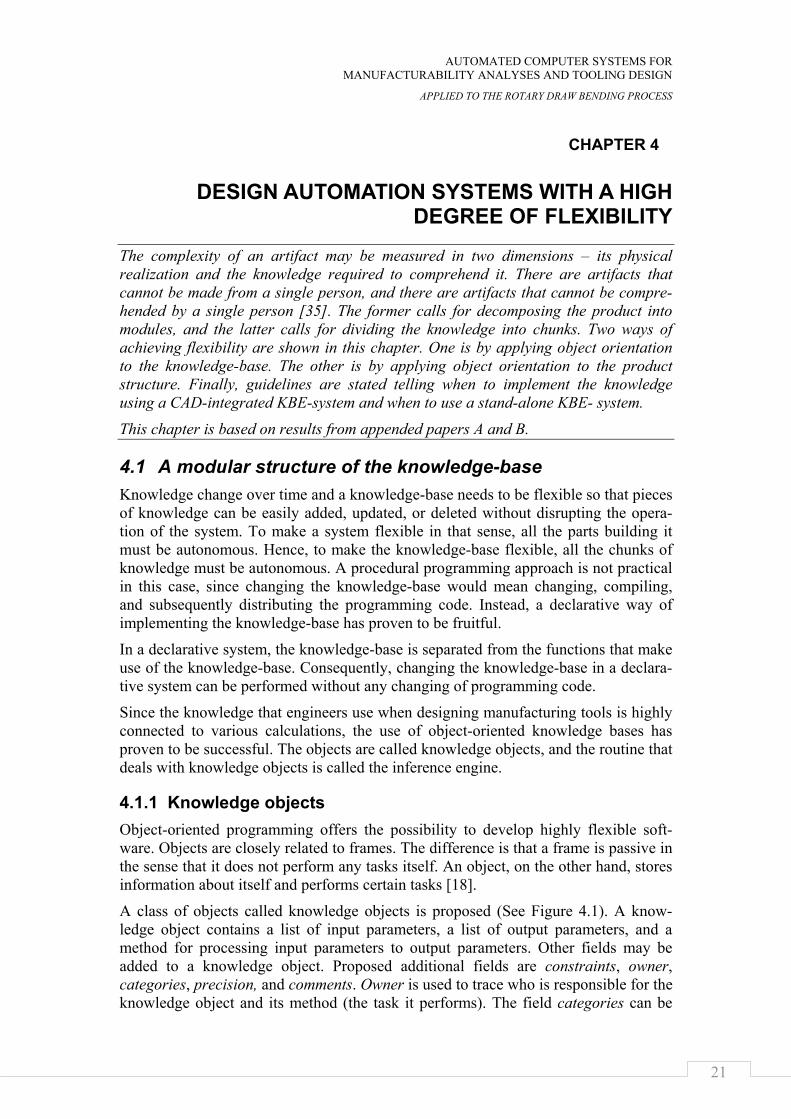
A class of objects called knowledge objects is proposed (See Figure 4.1). A know-ledge object contains a list of input parameters, a list of output parameters, and a method for processing input parameters to output parameters. Other fields may be added to a knowledge object. Proposed additional fields are constraints, owner, categories, precision, and comments. Owner is used to trace who is responsible for the knowledge object and its method (the task it performs). The field categories can be
DESIGN AUTOMATION SYSTEMS WITH A HIGH DEGREE OF FLEXIBILITY
22
used to sort knowledge objects into groups. Comments are used to add information usable for explanation extractions and debugging facilities. Finally, the list of con-straints and the precision value is used to allow knowledge-bases to contain alterna-tive knowledge objects (See further in Chapter 5.2.1).
When implementing the knowledge objects, they should be defined in a way that makes them autonomous. Since the methods used to process information preferably are external software applications, the applications should be selected keeping in mind the list of requirements imposed on the design automation system. They are the following: low effort of developing, user readable and understandable knowledge, longevity, and ease of use [8]. The benefits of developing knowledge objects that are autonomous using common wide-spread applications as methods are two-fold: the knowledge can be used manually without the design automation system, and it is easy to find people skilled enough to use the very same knowledge the design automation system does - it makes the knowledge more human-readable (See Section 3.1.2).
Figure 4.1: In the proposed method, the keystone to achieving a high degree of flexibility in design automation systems is a class of objects called knowledge objects.
The anatomy of the knowledge used when designing toolsets for the rotary draw bending implies the use of knowledge objects. Several distinct tasks have been identi-fied and automated using knowledge objects.
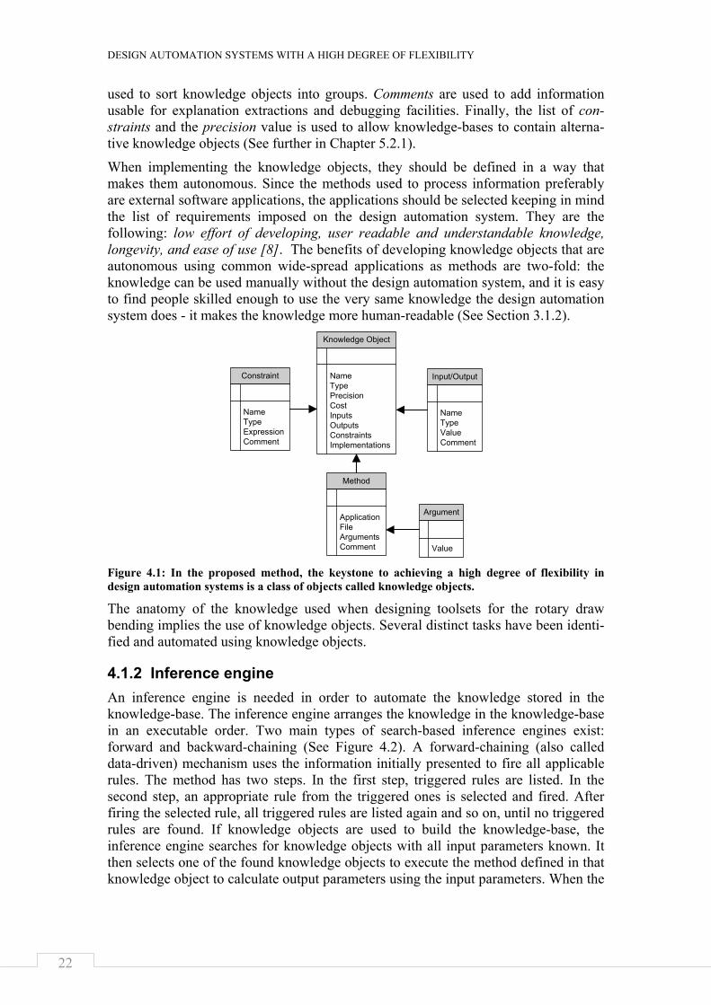
4.1.2 Inference engine An inference engine is needed in order to automate the knowledge stored in the knowledge-base. The inference engine arranges the knowledge in the knowledge-base in an executable order. Two main types of search-based inference engines exist: forward and backward-chaining (See Figure 4.2). A forward-chaining (also called data-driven) mechanism uses the information initially presented to fire all applicable rules. The method has two steps. In the first step, triggered rules are listed. In the second step, an appropriate rule from the triggered ones is selected and fired. After firing the selected rule, all triggered rules are listed again and so on, until no triggered rules are found. If knowledge objects are used to build the knowledge-base, the inference engine searches for knowledge objects with all input parameters known. It then selects one of the found knowledge objects to execute the method defined in that knowledge object to calculate output parameters using the input parameters. When the
Knowledge Object
NameTypePrecisionCostInputsOutputsConstraintsImplementations
Input/Output
NameTypeValueComment
Constraint
NameTypeExpressionComment
Method
ApplicationFileArgumentsComment
Argument
Value
AUTOMATED COMPUTER SYSTEMS FOR MANUFACTURABILITY ANALYSES AND TOOLING DESIGN
APPLIED TO THE ROTARY DRAW BENDING PROCESS
23
method has run, the stock of known parameters is updated, and a new search for executable knowledge objects is initiated (See Figure 4.3).
Figure 4.2: Two main types of search-based inference engines exist: forward- and backward-chaining.
A backward-chaining mechanism (also called goal-driven) is fed with queries con-cerning which variables to determine. The mechanism then searches backward to see how to end up at that state. When knowledge objects are used, the knowledge-base is searched through to see what objects to fire to find the queried parameters. The user is later asked to put in required information.
The backward-chaining mechanism is more effective at runtime than the forward-chaining one. This is because executions of unnecessary methods are avoided. Since all the design parameters need to be calculated when designing toolsets for the rotary draw bending, the use of a forward-chaining mechanism is suitable.
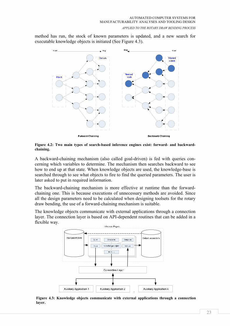
The knowledge objects communicate with external applications through a connection layer. The connection layer is based on API-dependent routines that can be added in a flexible way.
Figure 4.3: Knowledge objects communicate with external applications through a connection layer.
DESIGN AUTOMATION SYSTEMS WITH A HIGH DEGREE OF FLEXIBILITY
24
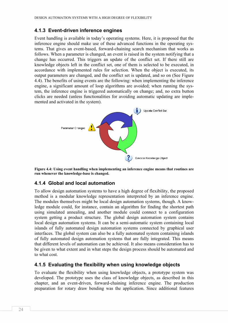
4.1.3 Event-driven inference engines Event handling is available in today’s operating systems. Here, it is proposed that the inference engine should make use of these advanced functions in the operating sys-tems. That gives an event-based, forward-chaining search mechanism that works as follows. When a parameter is changed, an event is raised in the system notifying that a change has occurred. This triggers an update of the conflict set. If there still are knowledge objects left in the conflict set, one of them is selected to be executed, in accordance with implemented rules for selection. When the object is executed, its output parameters are changed, and the conflict set is updated, and so on (See Figure 4.4). The benefits of using events are the following: when implementing the inference engine, a significant amount of loop algorithms are avoided; when running the sys-tem, the inference engine is triggered automatically on change; and, no extra button clicks are needed (unless functionalities for avoiding automatic updating are imple-mented and activated in the system).
Figure 4.4: Using event handling when implementing an inference engine means that routines are run whenever the knowledge-base is changed.
4.1.4 Global and local automation To allow design automation systems to have a high degree of flexibility, the proposed method is a modular knowledge representation interpreted by an inference engine. The modules themselves might be local design automation systems, though. A know-ledge module could, for instance, contain an algorithm for finding the shortest path using simulated annealing, and another module could connect to a configuration system getting a product structure. The global design automation system contains local design automation systems. It can be a semi-automatic system containing local islands of fully automated design automation systems connected by graphical user interfaces. The global system can also be a fully automated system containing islands of fully automated design automation systems that are fully integrated. This means that different levels of automation can be achieved. It also means consideration has to be given to what extent and in what steps the design process should be automated and to what cost.
4.1.5 Evaluating the flexibility when using knowledge objects To evaluate the flexibility when using knowledge objects, a prototype system was developed. The prototype uses the class of knowledge objects, as described in this chapter, and an event-driven, forward-chaining inference engine. The production preparation for rotary draw bending was the application. Since additional features
AUTOMATED COMPUTER SYSTEMS FOR MANUFACTURABILITY ANALYSES AND TOOLING DESIGN
APPLIED TO THE ROTARY DRAW BENDING PROCESS
25
were added in connection with the other research questions, the prototype system is described in Chapter 5.3.
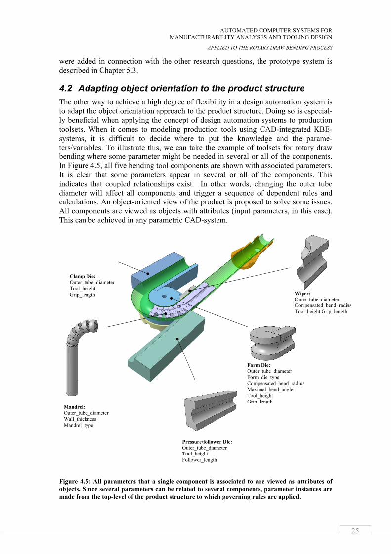
4.2 Adapting object orientation to the product structure The other way to achieve a high degree of flexibility in a design automation system is to adapt the object orientation approach to the product structure. Doing so is especial-ly beneficial when applying the concept of design automation systems to production toolsets. When it comes to modeling production tools using CAD-integrated KBE-systems, it is difficult to decide where to put the knowledge and the parame-ters/variables. To illustrate this, we can take the example of toolsets for rotary draw bending where some parameter might be needed in several or all of the components. In Figure 4.5, all five bending tool components are shown with associated parameters. It is clear that some parameters appear in several or all of the components. This indicates that coupled relationships exist. In other words, changing the outer tube diameter will affect all components and trigger a sequence of dependent rules and calculations. An object-oriented view of the product is proposed to solve some issues. All components are viewed as objects with attributes (input parameters, in this case). This can be achieved in any parametric CAD-system.
Figure 4.5: All parameters that a single component is associated to are viewed as attributes of objects. Since several parameters can be related to several components, parameter instances are made from the top-level of the product structure to which governing rules are applied.
Form Die: Outer_tube_diameter Form_die_type Compensated_bend_radius Maximal_bend_angle Tool_height Grip_length
Clamp Die: Outer_tube_diameter Tool_height Grip_length
Mandrel: Outer_tube_diameter Wall_thickness Mandrel_type
Pressure/follower Die: Outer_tube_diameter Tool_height Follower_length
Wiper: Outer_tube_diameter Compensated_bend_radius Tool_height Grip_length
DESIGN AUTOMATION SYSTEMS WITH A HIGH DEGREE OF FLEXIBILITY
26
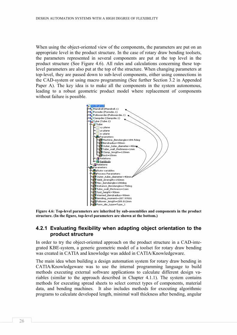
When using the object-oriented view of the components, the parameters are put on an appropriate level in the product structure. In the case of rotary draw bending toolsets, the parameters represented in several components are put at the top level in the product structure (See Figure 4.6). All rules and calculations concerning these top-level parameters are also put at the top of the structure. When changing parameters at top-level, they are passed down to sub-level components, either using connections in the CAD-system or using macro programming (See further Section 3.2 in Appended Paper A). The key idea is to make all the components in the system autonomous, leading to a robust geometric product model where replacement of components without failure is possible.
Figure 4.6: Top-level parameters are inherited by sub-assemblies and components in the product structure. (In the figure, top-level parameters are shown at the bottom.)
4.2.1 Evaluating flexibility when adapting object orientation to the product structure
In order to try the object-oriented approach on the product structure in a CAD-inte-grated KBE-system, a generic geometric model of a toolset for rotary draw bending was created in CATIA and knowledge was added in CATIA/Knowledgeware.
The main idea when building a design automation system for rotary draw bending in CATIA/Knowledgeware was to use the internal programming language to build methods executing external software applications to calculate different design va-riables (similar to the approach described in Chapter 4.1.1). The system contains methods for executing spread sheets to select correct types of components, material data, and bending machines. It also includes methods for executing algorithmic programs to calculate developed length, minimal wall thickness after bending, angular
AUTOMATED COMPUTER SYSTEMS FOR MANUFACTURABILITY ANALYSES AND TOOLING DESIGN
APPLIED TO THE ROTARY DRAW BENDING PROCESS
27
spring back, and section modulus. Some factors were calculated using functionalities in CATIA/Knowledgeware.
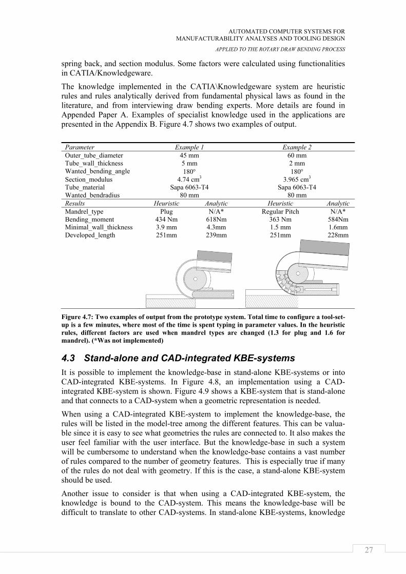
The knowledge implemented in the CATIA\Knowledgeware system are heuristic rules and rules analytically derived from fundamental physical laws as found in the literature, and from interviewing draw bending experts. More details are found in Appended Paper A. Examples of specialist knowledge used in the applications are presented in the Appendix B. Figure 4.7 shows two examples of output.
Parameter Example 1 Example 2 Outer_tube_diameter 45 mm 60 mm Tube_wall_thickness 5 mm 2 mm Wanted_bending_angle 180° 180° Section_modulus 4.74 cm3 3.965 cm3 Tube_material Sapa 6063-T4 Sapa 6063-T4 Wanted_bendradius 80 mm 80 mm Results Heuristic Analytic Heuristic Analytic Mandrel_type Plug N/A* Regular Pitch N/A* Bending_moment 434 Nm 618Nm 363 Nm 584Nm Minimal_wall_thickness 3.9 mm 4.3mm 1.5 mm 1.6mm Developed_length 251mm 239mm 251mm 228mm
Figure 4.7: Two examples of output from the prototype system. Total time to configure a tool-set-up is a few minutes, where most of the time is spent typing in parameter values. In the heuristic rules, different factors are used when mandrel types are changed (1.3 for plug and 1.6 for mandrel). (*Was not implemented)
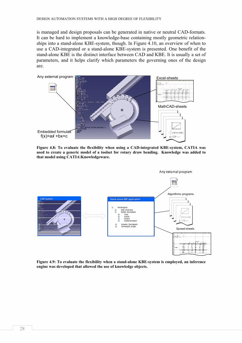
4.3 Stand-alone and CAD-integrated KBE-systems It is possible to implement the knowledge-base in stand-alone KBE-systems or into CAD-integrated KBE-systems. In Figure 4.8, an implementation using a CAD-integrated KBE-system is shown. Figure 4.9 shows a KBE-system that is stand-alone and that connects to a CAD-system when a geometric representation is needed.
When using a CAD-integrated KBE-system to implement the knowledge-base, the rules will be listed in the model-tree among the different features. This can be valua-ble since it is easy to see what geometries the rules are connected to. It also makes the user feel familiar with the user interface. But the knowledge-base in such a system will be cumbersome to understand when the knowledge-base contains a vast number of rules compared to the number of geometry features. This is especially true if many of the rules do not deal with geometry. If this is the case, a stand-alone KBE-system should be used.
Another issue to consider is that when using a CAD-integrated KBE-system, the knowledge is bound to the CAD-system. This means the knowledge-base will be difficult to translate to other CAD-systems. In stand-alone KBE-systems, knowledge
DESIGN AUTOMATION SYSTEMS WITH A HIGH DEGREE OF FLEXIBILITY
28
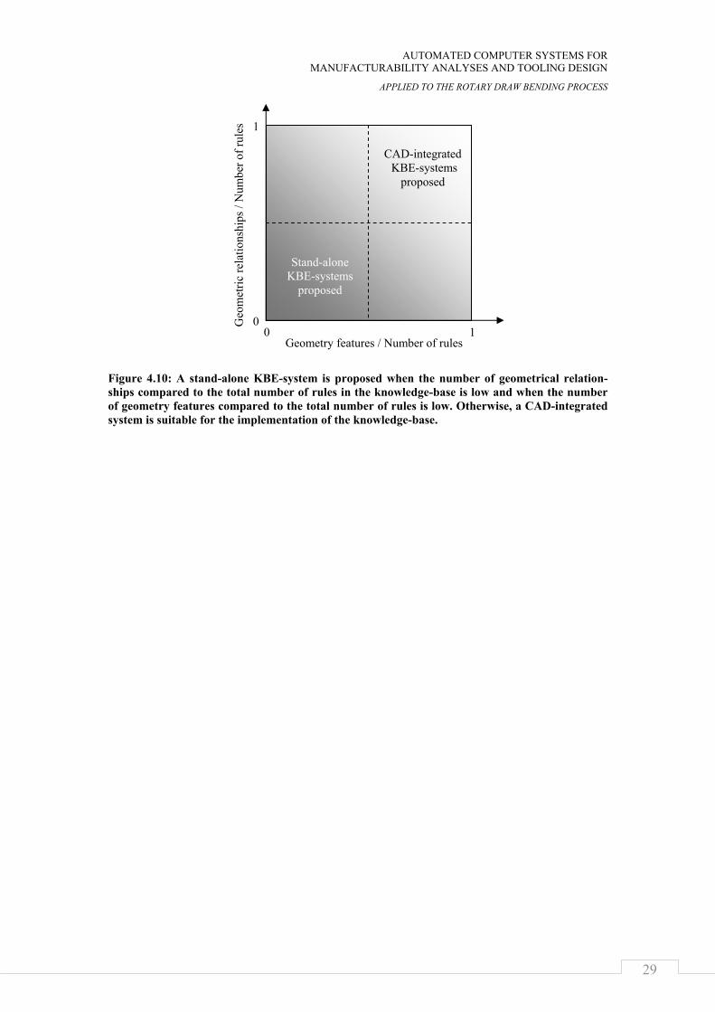
is managed and design proposals can be generated in native or neutral CAD-formats. It can be hard to implement a knowledge-base containing mostly geometric relation-ships into a stand-alone KBE-system, though. In Figure 4.10, an overview of when to use a CAD-integrated or a stand-alone KBE-system is presented. One benefit of the stand-alone KBE is the distinct interface between CAD and KBE. It is usually a set of parameters, and it helps clarify which parameters the governing ones of the design are.
Figure 4.8: To evaluate the flexibility when using a CAD-integrated KBE-system, CATIA was used to create a generic model of a toolset for rotary draw bending. Knowledge was added to that model using CATIA\Knowledgeware.
Figure 4.9: To evaluate the flexibility when a stand-alone KBE-system is employed, an inference engine was developed that allowed the use of knowledge objects.
Embedded formulas
Excel-sheets
MathCAD-sheets
Any external program
f(x)=ax +bx+c2
CAD-systemCAD-system
δ1
0
π
2
α2
π
cos α( )2 k
2 k 3+ 2 cos α( )−
4 k 1+ cos α( )+
888
888
888
d:=
d 1δ1 δ2+
2−
888
888
0.079 m=
MathCAD-sheetsStand-alone KBE applicationStand-alone KBE application
BendingtoolWall_thicknessRadial_Springback
Angular_SpringbackDeveloped_length
TypeInputsOutputImplementation
Spread-sheets
Algorithmic programs
AUTOMATED COMPUTER SYSTEMS FOR MANUFACTURABILITY ANALYSES AND TOOLING DESIGN
APPLIED TO THE ROTARY DRAW BENDING PROCESS
29
Figure 4.10: A stand-alone KBE-system is proposed when the number of geometrical relation-ships compared to the total number of rules in the knowledge-base is low and when the number of geometry features compared to the total number of rules is low. Otherwise, a CAD-integrated system is suitable for the implementation of the knowledge-base.
CAD-integrated KBE-systems
proposed
Stand-alone KBE-systems
proposed
Geo
met
ric re
latio
nshi
ps /
Num
ber o
f rul
es
0 1 0
1
Geometry features / Number of rules

DESIGN AUTOMATION SYSTEMS WITH A HIGH DEGREE OF FLEXIBILITY
30
AUTOMATED COMPUTER SYSTEMS FOR MANUFACTURABILITY ANALYSES AND TOOLING DESIGN
APPLIED TO THE ROTARY DRAW BENDING PROCESS
31
CHAPTER 5
KNOWLEDGE-BASES CONTAINING ALTERNATIVE DESIGN RULES
Often, several sources of knowledge exist, and sometimes there are interferences between these sources. Developing methods for handling such situations will make the design automation systems more adaptable to different situations. This chapter shows how such interferences in a knowledge-base might occur and presents a proposal for how to solve these situations. Finally, a prototype system is described.
This chapter is based on results from append paper B and it forms a basis for the subsequent chapters.
5.1 Different sources of knowledge and meta-knowledge In the scope of metal forming processes, it is often possible to calculate a single vari-able in different ways. Sometimes a heuristic rule can be used, or rules analytically derived from the fundamental laws of physics. But it is also possible to do FEM-calculations or experiments to evaluate a design variable. In addition to these four types of knowledge, an engineer also needs to have the capability to decide when to use what knowledge; this is called meta-knowledge, or knowledge about knowledge.
When more than one type of knowledge source is available in a knowledge-base, the question of when to use what source arises. In one state, the system may be executed in order to make a quotation calculation with only a small set of input parameters available. In the next step, detailed design is the purpose of running the system, with high accuracy as the main focus and with a larger set of input parameters available. Different kinds of knowledge are used in these different contexts, and implementing meta-knowledge would allow for the flexible use of the system. A description of the different types of knowledge is presented below.
5.1.1 Rules of thumb, heuristics Heuristics is generally found in different handbooks or company standards and is based on skilled engineers' experiences. Usually they are easy-to-use relationships that are valid for a small range in the design space. Heuristic rules seldom explain why things happen. The benefit of heuristics is that they have often proven to be correct enough and that they enable fast computer implementations. In reality, many design processes and design automation systems are built on this kind of knowledge.
5.1.2 Knowledge analytically derived from the fundamental laws of physics
Rules analytically derived from the fundamental laws of physics tend to be more complex than heuristics. However, they have the benefit of explaining why things happen and are more general. One benefit of analytical rules is that they are fast to execute when finally implemented in a computer system. Even though analytical rules are built on fundamental physical laws, they still are idealizations of complex prob-lems.
KNOWLEDGE-BASES CONTAINING ALTERNATIVE DESIGN RULES
32
In many situations, it is not economical or even possible to develop analytical expres-sions. In such cases, numerical methods might be utilized or experiments can be performed.
5.1.3 Finite element analysis A number of numerical methods exist for solving different engineering problems. Probably the most common method is the finite element method (FEM). FEM can be used to solve many engineering problems. However, the results depend greatly on what assumptions are made in the simulations.
Using FEM appropriately will give highly reliable data. The drawback is that, com-pared to heuristic and analytical knowledge, FEM is costly to use both in money, competence, and time. In addition, it does not explicitly answer the question of why things happen. The benefit of FEM, however, is that it allows full control over the process so it is easy to scroll in time and space, doing sections and plotting different parameters.
Worth mentioning in this context is that simulation-tools are comparable to instru-ments for measurements (in other words, they must be calibrated). This calibration is done via result feedback. Over time an accurate model is developed.
5.1.4 Experimental data Reality is the truth. Thus, making trial manufacturing will give reliable data. The drawback is that experiments are expensive, have limited range, and do not answer the question of why things happen. To make empirical data usable, experiment planning has to be done beforehand to isolate targeted parameters.
5.2 Enabling knowledge adaptability In this section, a proposal is made regarding how to solve the situation of when multiple sources of knowledge co-exist for a single phenomenon. The proposal is based on the extension of the knowledge objects and the usage of a global parameter list within the system.
5.2.1 Extending the knowledge objects In Section 4.1.1, knowledge objects were introduced to represent the knowledge in the knowledge-base. A list of constraints and a precision value need to be added to the knowledge object class in order to make it possible to have multiple knowledge objects pointing to the same parameter in the knowledge-base. The constraints dictate when the knowledge object is applicable, and the precision value tells how good the outputs are. The precision value ranges between 0 and 1 and might be changed in the design space.
5.2.2 A global parameter list Knowledge objects use external applications as methods. To pass information to the external applications, meta-data is needed (not to be confused with meta-knowledge). That meta-data is locally stored within the knowledge objects. The calculated parame-ter values are stored in a global list of parameters.
AUTOMATED COMPUTER SYSTEMS FOR MANUFACTURABILITY ANALYSES AND TOOLING DESIGN
APPLIED TO THE ROTARY DRAW BENDING PROCESS
33
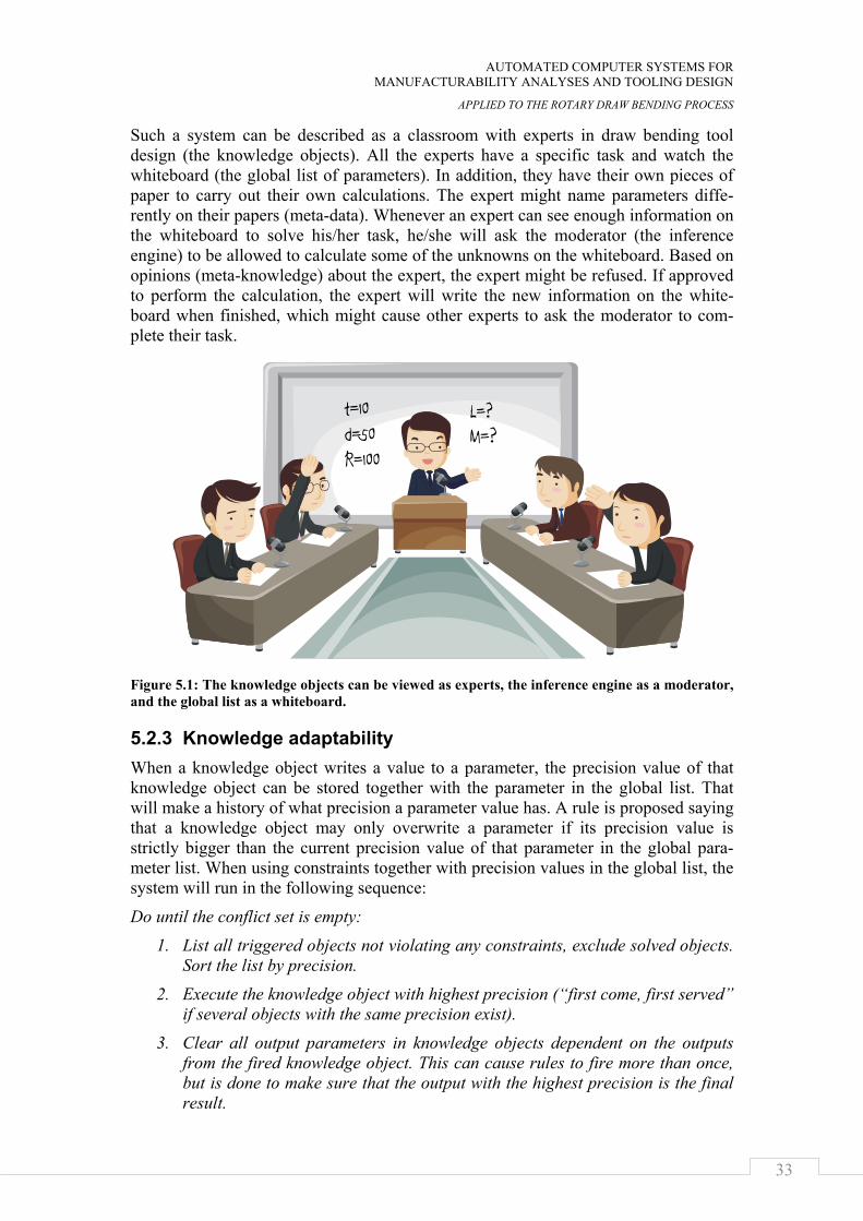
Such a system can be described as a classroom with experts in draw bending tool design (the knowledge objects). All the experts have a specific task and watch the whiteboard (the global list of parameters). In addition, they have their own pieces of paper to carry out their own calculations. The expert might name parameters diffe-rently on their papers (meta-data). Whenever an expert can see enough information on the whiteboard to solve his/her task, he/she will ask the moderator (the inference engine) to be allowed to calculate some of the unknowns on the whiteboard. Based on opinions (meta-knowledge) about the expert, the expert might be refused. If approved to perform the calculation, the expert will write the new information on the white-board when finished, which might cause other experts to ask the moderator to com-plete their task.
Figure 5.1: The knowledge objects can be viewed as experts, the inference engine as a moderator, and the global list as a whiteboard.
5.2.3 Knowledge adaptability When a knowledge object writes a value to a parameter, the precision value of that knowledge object can be stored together with the parameter in the global list. That will make a history of what precision a parameter value has. A rule is proposed saying that a knowledge object may only overwrite a parameter if its precision value is strictly bigger than the current precision value of that parameter in the global para-meter list. When using constraints together with precision values in the global list, the system will run in the following sequence:
Do until the conflict set is empty:
1. List all triggered objects not violating any constraints, exclude solved objects. Sort the list by precision.
2. Execute the knowledge object with highest precision (“first come, first served” if several objects with the same precision exist).
3. Clear all output parameters in knowledge objects dependent on the outputs from the fired knowledge object. This can cause rules to fire more than once, but is done to make sure that the output with the highest precision is the final result.
t=10d=50R=100
L=?M=?
KNOWLEDGE-BASES CONTAINING ALTERNATIVE DESIGN RULES
34
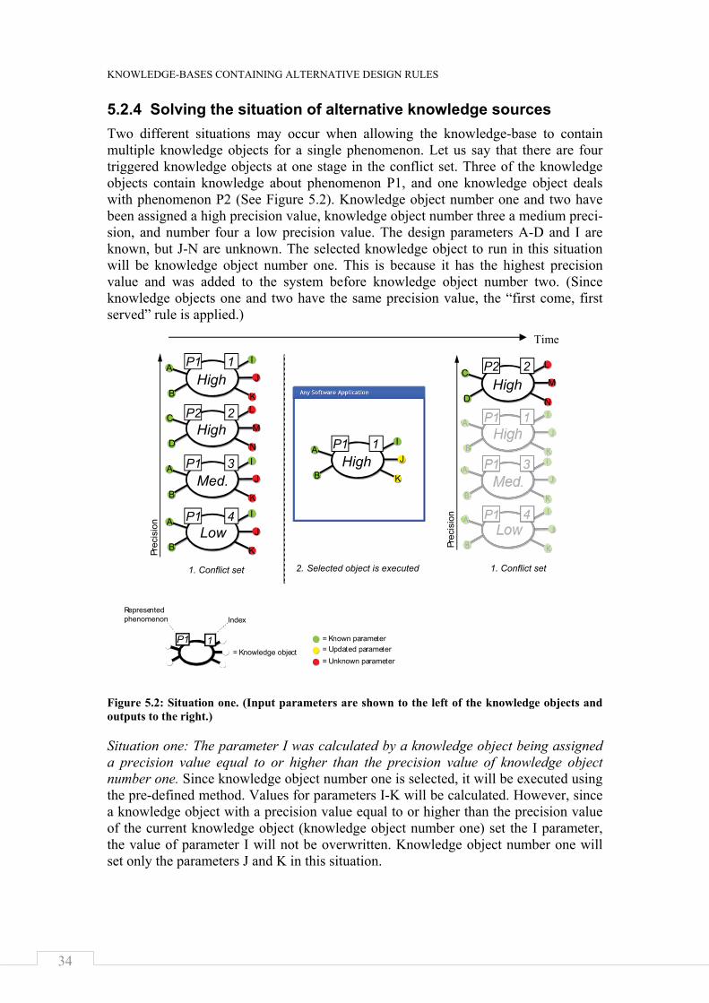
5.2.4 Solving the situation of alternative knowledge sources Two different situations may occur when allowing the knowledge-base to contain multiple knowledge objects for a single phenomenon. Let us say that there are four triggered knowledge objects at one stage in the conflict set. Three of the knowledge objects contain knowledge about phenomenon P1, and one knowledge object deals with phenomenon P2 (See Figure 5.2). Knowledge object number one and two have been assigned a high precision value, knowledge object number three a medium preci-sion, and number four a low precision value. The design parameters A-D and I are known, but J-N are unknown. The selected knowledge object to run in this situation will be knowledge object number one. This is because it has the highest precision value and was added to the system before knowledge object number two. (Since knowledge objects one and two have the same precision value, the “first come, first served” rule is applied.)
Figure 5.2: Situation one. (Input parameters are shown to the left of the knowledge objects and outputs to the right.)
Situation one: The parameter I was calculated by a knowledge object being assigned a precision value equal to or higher than the precision value of knowledge object number one. Since knowledge object number one is selected, it will be executed using the pre-defined method. Values for parameters I-K will be calculated. However, since a knowledge object with a precision value equal to or higher than the precision value of the current knowledge object (knowledge object number one) set the I parameter, the value of parameter I will not be overwritten. Knowledge object number one will set only the parameters J and K in this situation.
High
High
High
Med.
Low
1. Conflict set 1. Conflict set2. Selected object is executed
1P1
P1
P2
P1
P1
2
3
4
1
P1 1
High
Med.
Low
2
3
4
High1
I
J
K
I
J
K
A
A
I
J
K
A
B
I
J
K
A
B
I
J
K
A
B
I
J
K
A
BI
J
K
A
B
L
M
N
C
D
L
M
N
C
D
B
B Prec
isio
n
Prec
isio
n
= Known parameter
= Knowledge object = Updated parameter= Unknown parameter
P2
P1
P1
P1
IndexRepresentedphenomenon
P1 1 = Known parameter
= Knowledge object = Updated parameter= Unknown parameter
IndexRepresentedphenomenon
Time
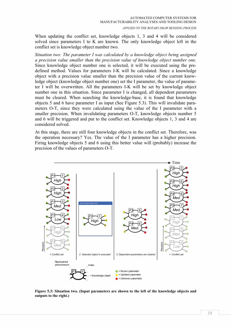
AUTOMATED COMPUTER SYSTEMS FOR MANUFACTURABILITY ANALYSES AND TOOLING DESIGN
APPLIED TO THE ROTARY DRAW BENDING PROCESS
35
When updating the conflict set, knowledge objects 1, 3 and 4 will be considered solved since parameters I to K are known. The only knowledge object left in the conflict set is knowledge object number two.
Situation two: The parameter I was calculated by a knowledge object being assigned a precision value smaller than the precision value of knowledge object number one. Since knowledge object number one is selected, it will be executed using the pre-defined method. Values for parameters I-K will be calculated. Since a knowledge object with a precision value smaller than the precision value of the current know-ledge object (knowledge object number one) set the I parameter, the value of parame-ter I will be overwritten. All the parameters I-K will be set by knowledge object number one in this situation. Since parameter I is changed, all dependent parameters must be cleared. When searching the knowledge-base, it is found that knowledge objects 5 and 6 have parameter I as input (See Figure 5.3). This will invalidate para-meters O-T, since they were calculated using the value of the I parameter with a smaller precision. When invalidating parameters O-T, knowledge objects number 5 and 6 will be triggered and put to the conflict set. Knowledge objects 1, 3 and 4 are considered solved.
At this stage, there are still four knowledge objects in the conflict set. Therefore, was the operation necessary? Yes. The value of the I parameter has a higher precision. Firing knowledge objects 5 and 6 using this better value will (probably) increase the precision of the values of parameters O-T.
Figure 5.3: Situation two. (Input parameters are shown to the left of the knowledge objects and outputs to the right.)
High
High
High
Med.
High
Med.
Low
1.Conflict set 1. Conflict set2. Selected object is executed 3. Dependent parameters are cleared
1P1
P1
P3
P4
P2
P1
P1
2
3
4 1
P1 1
5
6
High
Med.
5
6
High
High
Med.
Low
2
5
3
4
High
Med.
1
6
I
J
K
I
J
K
A
A
I
J
K
A
B
I
J
K
A
B
I
J
K
A
B
I
J
K
A
B
I
J
K
A
B
L
M
N
C
D
L
M
N
C
D
B
B
O
P
Q
I
F
O
P
Q
I
F
R
S
T
G
I
R
S
T
G
H
Med.7 U
V
X
J
KO
P
QR
S
T
I
G
F
I
Prec
isio
n
Prec
isio
n
= Known parameter
= Knowledge object = Updated parameter= Unknown parameter
P4
P3
P2
P3
P4
7P5
P1
P1
P1
IndexRepresentedphenomenon
P1 1 = Known parameter
= Knowledge object = Updated parameter= Unknown parameter
IndexRepresentedphenomenon
Time
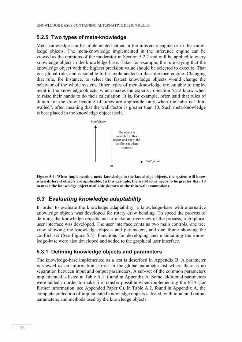
KNOWLEDGE-BASES CONTAINING ALTERNATIVE DESIGN RULES
36
5.2.5 Two types of meta-knowledge Meta-knowledge can be implemented either in the inference engine or in the know-ledge objects. The meta-knowledge implemented in the inference engine can be viewed as the opinions of the moderator in Section 5.2.2 and will be applied to every knowledge object in the knowledge-base. Take, for example, the rule saying that the knowledge object with the highest precision value should be selected to execute. That is a global rule, and is suitable to be implemented in the inference engine. Changing that rule, for instance, to select the fastest knowledge objects would change the behavior of the whole system. Other types of meta-knowledge are suitable to imple-ment in the knowledge objects, which makes the experts in Section 5.2.2 know when to raise their hands to do their calculation. It is, for example, often said that rules of thumb for the draw bending of tubes are applicable only when the tube is “thin-walled”, often meaning that the wall-factor is greater than 10. Such meta-knowledge is best placed in the knowledge object itself.
Figure 5.4: When implementing meta-knowledge in the knowledge objects, the system will know when different objects are applicable. In this example, the wall-factor needs to be greater than 10 to make the knowledge object available (known as the thin-wall assumption).
5.3 Evaluating knowledge adaptability In order to evaluate the knowledge adaptability, a knowledge-base with alternative knowledge objects was developed for rotary draw bending. To speed the process of defining the knowledge objects and to make an overview of the process, a graphical user interface was developed. The user interface contains two main controls, one tree view showing the knowledge objects and parameters, and one frame showing the conflict set (See Figure 5.5). Functions for developing and maintaining the know-ledge-base were also developed and added to the graphical user interface.
5.3.1 Defining knowledge objects and parameters The knowledge-base implemented as a test is described in Appendix B. A parameter is viewed as an information carrier in the global parameter list where there is no separation between input and output parameters. A sub-set of the common parameters implemented is listed in Table A.1, found in Appendix A. Some additional parameters were added in order to make file transfer possible when implementing the FEA (for further information, see Appended Paper C). In Table A.2, found in Appendix A, the complete collection of implemented knowledge objects is listed, with input and output parameters, and methods used by the knowledge objects.
Wall factor
Bend factor
10
The object is available in this
region and put to the conflict set when
triggered
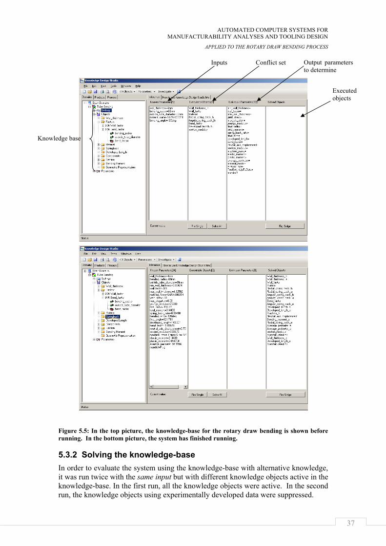
AUTOMATED COMPUTER SYSTEMS FOR MANUFACTURABILITY ANALYSES AND TOOLING DESIGN
APPLIED TO THE ROTARY DRAW BENDING PROCESS
37
Figure 5.5: In the top picture, the knowledge-base for the rotary draw bending is shown before running. In the bottom picture, the system has finished running.
5.3.2 Solving the knowledge-base In order to evaluate the system using the knowledge-base with alternative knowledge, it was run twice with the same input but with different knowledge objects active in the knowledge-base. In the first run, all the knowledge objects were active. In the second run, the knowledge objects using experimentally developed data were suppressed.
Executed objects
Conflict set
Knowledge base
Inputs Output parameters to determine
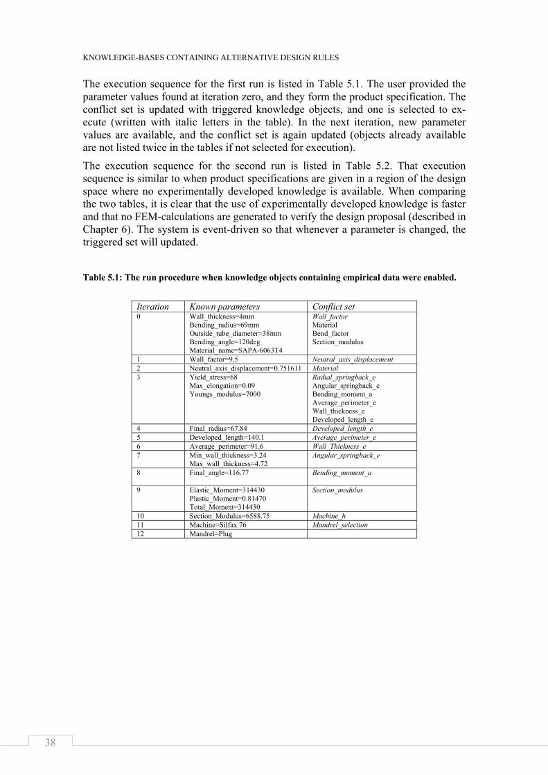
KNOWLEDGE-BASES CONTAINING ALTERNATIVE DESIGN RULES
38
The execution sequence for the first run is listed in Table 5.1. The user provided the parameter values found at iteration zero, and they form the product specification. The conflict set is updated with triggered knowledge objects, and one is selected to ex-ecute (written with italic letters in the table). In the next iteration, new parameter values are available, and the conflict set is again updated (objects already available are not listed twice in the tables if not selected for execution).
The execution sequence for the second run is listed in Table 5.2. That execution sequence is similar to when product specifications are given in a region of the design space where no experimentally developed knowledge is available. When comparing the two tables, it is clear that the use of experimentally developed knowledge is faster and that no FEM-calculations are generated to verify the design proposal (described in Chapter 6). The system is event-driven so that whenever a parameter is changed, the triggered set will updated.
Table 5.1: The run procedure when knowledge objects containing empirical data were enabled.
Iteration Known parameters Conflict set 0 Wall_thickness=4mm
Bending_radius=69mm Outside_tube_diameter=38mm Bending_angle=120deg Material_name=SAPA-6063T4
Wall_factor Material Bend_factor Section_modulus
1 Wall_factor=9.5 Neutral_axis_displacement 2 Neutral_axis_displacement=0.751611 Material 3 Yield_stress=68
Max_elongation=0.09 Youngs_modulus=7000
Radial_springback_e Angular_springback_e Bending_moment_a Average_perimeter_e Wall_thickness_e Developed_length_e
4 Final_radius=67.84 Developed_length_e 5 Developed_length=140.1 Average_perimeter_e 6 Average_perimeter=91.6 Wall_Thickness_e 7 Min_wall_thickness=3.24
Max_wall_thickness=4.72 Angular_springback_e
8 Final_angle=116.77 Bending_moment_a
9 Elastic_Moment=314430 Plastic_Moment=0.81470 Total_Moment=314430
Section_modulus
10 Section_Modulus=6588.75 Machine_h 11 Machine=Silfax 76 Mandrel_selection 12 Mandrel=Plug
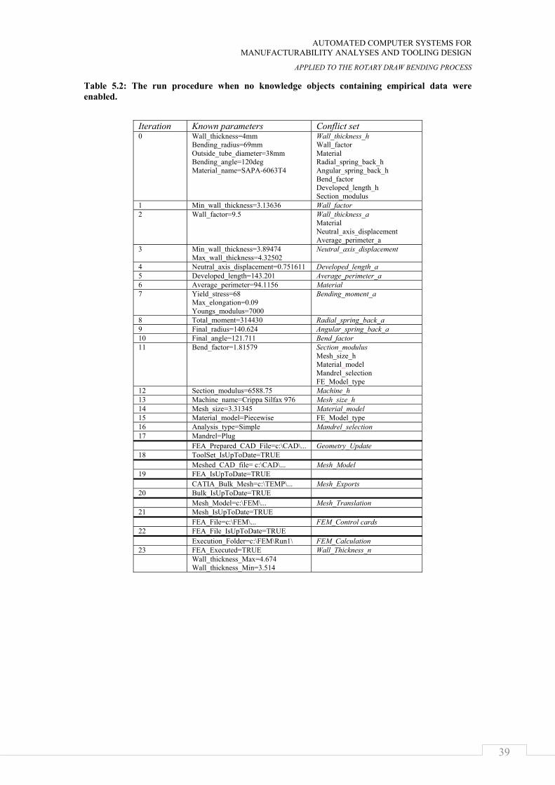
AUTOMATED COMPUTER SYSTEMS FOR MANUFACTURABILITY ANALYSES AND TOOLING DESIGN
APPLIED TO THE ROTARY DRAW BENDING PROCESS
39
Table 5.2: The run procedure when no knowledge objects containing empirical data were enabled.
Iteration Known parameters Conflict set 0 Wall_thickness=4mm
Bending_radius=69mm Outside_tube_diameter=38mm Bending_angle=120deg Material_name=SAPA-6063T4
Wall_thickness_h Wall_factor Material Radial_spring_back_h Angular_spring_back_h Bend_factor Developed_length_h Section_modulus
1 Min_wall_thickness=3.13636 Wall_factor 2 Wall_factor=9.5 Wall_thickness_a
Material Neutral_axis_displacement Average_perimeter_a
3 Min_wall_thickness=3.89474 Max_wall_thickness=4.32502
Neutral_axis_displacement
4 Neutral_axis_displacement=0.751611 Developed_length_a 5 Developed_length=143.201 Average_perimeter_a 6 Average_perimeter=94.1156 Material 7 Yield_stress=68
Max_elongation=0.09 Youngs_modulus=7000
Bending_moment_a
8 Total_moment=314430 Radial_spring_back_a 9 Final_radius=140.624 Angular_spring_back_a 10 Final_angle=121.711 Bend_factor 11 Bend_factor=1.81579 Section_modulus
Mesh_size_h Material_model Mandrel_selection FE_Model_type
12 Section_modulus=6588.75 Machine_h 13 Machine_name=Crippa Silfax 976 Mesh_size_h 14 Mesh_size=3.31345 Material_model 15 Material_model=Piecewise FE_Model_type 16 Analysis_type=Simple Mandrel_selection 17 Mandrel=Plug FEA_Prepared_CAD_File=c:\CAD\... Geometry_Update 18 ToolSet_IsUpToDate=TRUE Meshed_CAD_file= c:\CAD\... Mesh_Model 19 FEA_IsUpToDate=TRUE CATIA_Bulk_Mesh=c:\TEMP\... Mesh_Exports 20 Bulk_IsUpToDate=TRUE Mesh_Model=c:\FEM\... Mesh_Translation 21 Mesh_IsUpToDate=TRUE FEA_File=c:\FEM\... FEM_Control cards 22 FEA_File_IsUpToDate=TRUE Execution_Folder=c:\FEM\Run1\ FEM_Calculation 23 FEA_Executed=TRUE Wall_Thickness_n Wall_thickness_Max=4.674
Wall_thickness_Min=3.514

KNOWLEDGE-BASES CONTAINING ALTERNATIVE DESIGN RULES
40
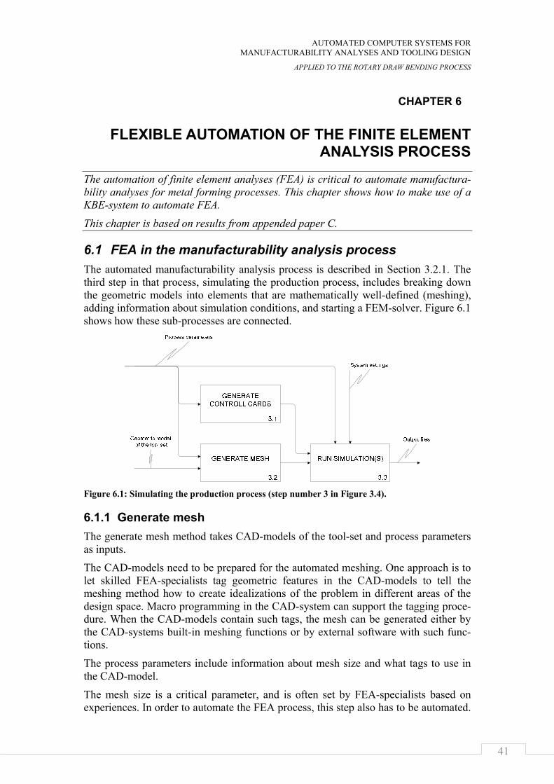
AUTOMATED COMPUTER SYSTEMS FOR MANUFACTURABILITY ANALYSES AND TOOLING DESIGN
APPLIED TO THE ROTARY DRAW BENDING PROCESS
41
CHAPTER 6
FLEXIBLE AUTOMATION OF THE FINITE ELEMENT ANALYSIS PROCESS
The automation of finite element analyses (FEA) is critical to automate manufactura-bility analyses for metal forming processes. This chapter shows how to make use of a KBE-system to automate FEA.
This chapter is based on results from appended paper C.
6.1 FEA in the manufacturability analysis process The automated manufacturability analysis process is described in Section 3.2.1. The third step in that process, simulating the production process, includes breaking down the geometric models into elements that are mathematically well-defined (meshing), adding information about simulation conditions, and starting a FEM-solver. Figure 6.1 shows how these sub-processes are connected.
Figure 6.1: Simulating the production process (step number 3 in Figure 3.4).
6.1.1 Generate mesh The generate mesh method takes CAD-models of the tool-set and process parameters as inputs.
The CAD-models need to be prepared for the automated meshing. One approach is to let skilled FEA-specialists tag geometric features in the CAD-models to tell the meshing method how to create idealizations of the problem in different areas of the design space. Macro programming in the CAD-system can support the tagging proce-dure. When the CAD-models contain such tags, the mesh can be generated either by the CAD-systems built-in meshing functions or by external software with such func-tions.
The process parameters include information about mesh size and what tags to use in the CAD-model.
The mesh size is a critical parameter, and is often set by FEA-specialists based on experiences. In order to automate the FEA process, this step also has to be automated.
FLEXIBLE AUTOMATION OF THE FINITE ELEMENT ANALYSIS PROCESS
42
Two approaches are suggested here. They are to either apply a heuristic rule or per-form experiments in the extreme points of the design space. Inputs to the automated mesh size calculation come from design parameters. Output is either a global value for the mesh size or local values for sub-systems or regions of components. The mesh size calculation knowledge object is put in the KBE-system.
6.1.2 Generate control cards To run a simulation by means of the finite element method information about boun-dary condition, constraints, material properties, contact conditions, and simulation duration need to be defined [36]. This information is stored as recipe-like text files referred to as control cards. The generate control cards method takes process parame-ters as inputs to generate the simulation recipe.
When it comes to material models, quite a large number exist to select from, and it is not always obvious which one is the best. In this case, the FEA-specialist needs to do serious investigations and evaluations in order to select and develop correct material models and rules saying when to use them. This is important continuous work the automation of FEA is intended to free the FEA-specialist to do. Automated methods to select material models are put in the KBE-system.
6.1.3 Running the simulation Usually it is possible to execute a FEM calculation from the command prompt. When this is the case, it is also possible to execute the calculation from a single line in a program using a shell-function, and that can be added to the KBE-system as a know-ledge object. Inputs for such a knowledge object are the input file and environmental values. Outputs include the output files and a Boolean value telling whether the run was successful. In Chapter 7, how to automatically analyze the output files is de-scribed.
6.2 Evaluating the automation of FEA To evaluate the method to automate FEA, routines were developed and implemented. These routines were added to the prototype system described in Section 5.3. The routines were added as methods available to the inference engine through the connec-tion layer (See Figure 4.3). Connections to the routines were made through knowledge objects. The toolsets of the rotary draw bending were then targeted for the FEA automation. The developed routines were used to explore a part of the design space. Sixteen points were selected in the range shown in Figure 6.2. For each point, several calculations were completed changing mesh size, product structure, and material model, as shown in the figure. In Figure 6.3, four examples are presented. A more detailed description of the exploration of this part of the design space is found in [37]. In this case, the inference engine was initiated manually with the design parameters; an experiment to automatically explore a part of the design space is presented in Chapter 10.
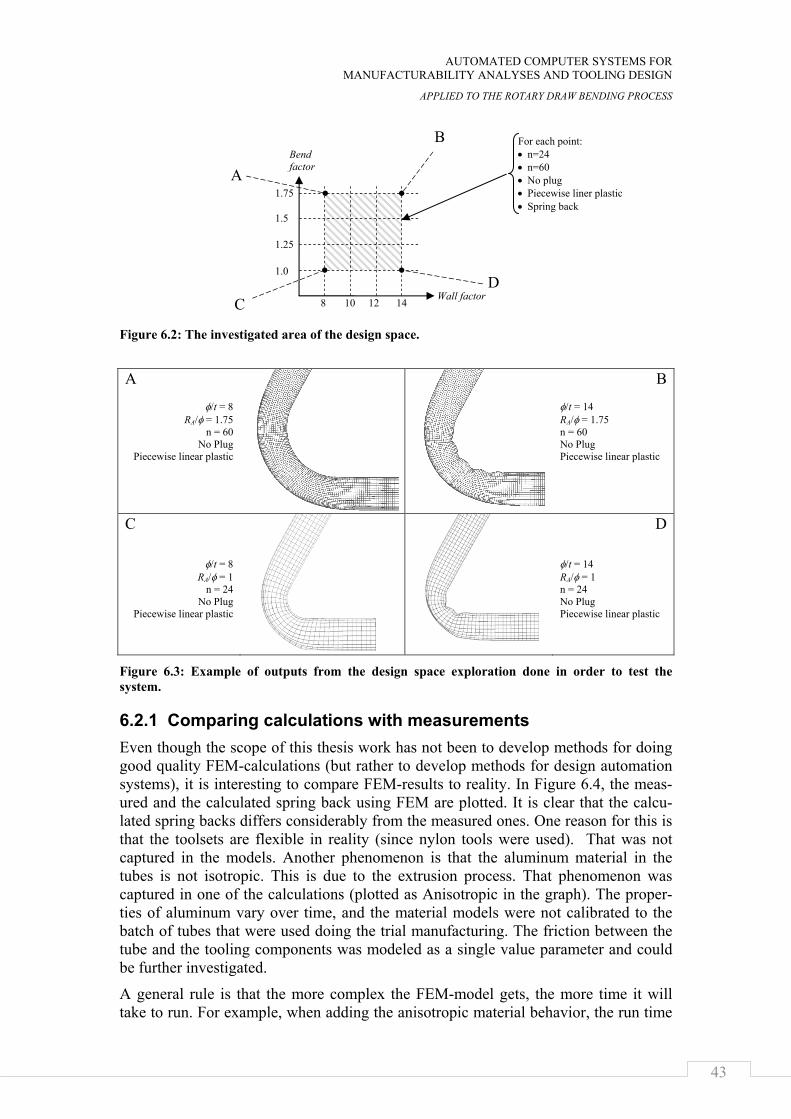
AUTOMATED COMPUTER SYSTEMS FOR MANUFACTURABILITY ANALYSES AND TOOLING DESIGN
APPLIED TO THE ROTARY DRAW BENDING PROCESS
43
Figure 6.2: The investigated area of the design space.
A
φ/t = 8
RA/φ = 1.75 n = 60
No Plug Piecewise linear plastic
B φ/t = 14 RA/φ = 1.75 n = 60 No Plug Piecewise linear plastic
C
φ/t = 8 RA/φ = 1
n = 24 No Plug
Piecewise linear plastic
D φ/t = 14 RA/φ = 1 n = 24 No Plug Piecewise linear plastic
Figure 6.3: Example of outputs from the design space exploration done in order to test the system.
6.2.1 Comparing calculations with measurements Even though the scope of this thesis work has not been to develop methods for doing good quality FEM-calculations (but rather to develop methods for design automation systems), it is interesting to compare FEM-results to reality. In Figure 6.4, the meas-ured and the calculated spring back using FEM are plotted. It is clear that the calcu-lated spring backs differs considerably from the measured ones. One reason for this is that the toolsets are flexible in reality (since nylon tools were used). That was not captured in the models. Another phenomenon is that the aluminum material in the tubes is not isotropic. This is due to the extrusion process. That phenomenon was captured in one of the calculations (plotted as Anisotropic in the graph). The proper-ties of aluminum vary over time, and the material models were not calibrated to the batch of tubes that were used doing the trial manufacturing. The friction between the tube and the tooling components was modeled as a single value parameter and could be further investigated.
A general rule is that the more complex the FEM-model gets, the more time it will take to run. For example, when adding the anisotropic material behavior, the run time
Wall factor
Bend factor
8 10 12 14
1.0
1.25
1.5
1.75
For each point: • n=24 • n=60 • No plug • Piecewise liner plastic • Spring back
D C
A
B
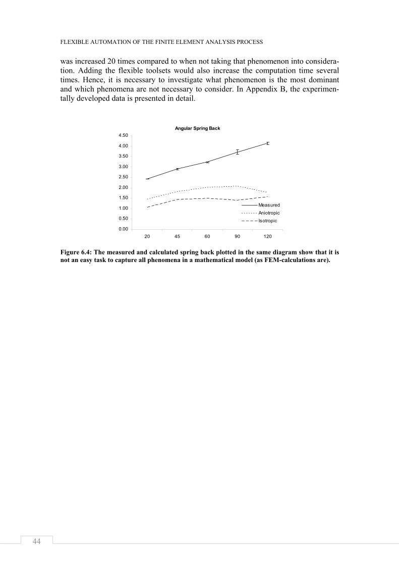
FLEXIBLE AUTOMATION OF THE FINITE ELEMENT ANALYSIS PROCESS
44
was increased 20 times compared to when not taking that phenomenon into considera-tion. Adding the flexible toolsets would also increase the computation time several times. Hence, it is necessary to investigate what phenomenon is the most dominant and which phenomena are not necessary to consider. In Appendix B, the experimen-tally developed data is presented in detail.
Figure 6.4: The measured and calculated spring back plotted in the same diagram show that it is not an easy task to capture all phenomena in a mathematical model (as FEM-calculations are).
Angular Spring Back
0.00
0.50
1.00
1.50
2.00
2.50
3.00
3.50
4.00
4.50
20 45 60 90 120
MeasuredAniotropic
Isotropic
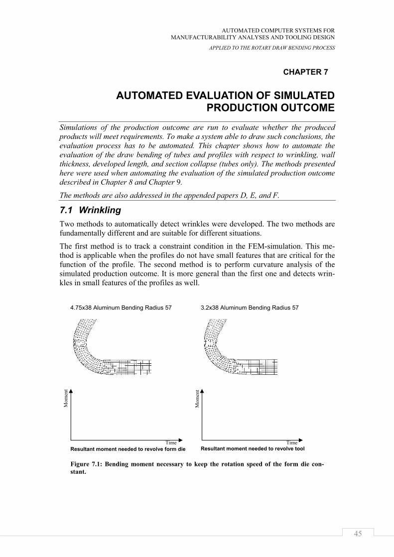
AUTOMATED COMPUTER SYSTEMS FOR MANUFACTURABILITY ANALYSES AND TOOLING DESIGN
APPLIED TO THE ROTARY DRAW BENDING PROCESS
45
CHAPTER 7
AUTOMATED EVALUATION OF SIMULATED PRODUCTION OUTCOME
Simulations of the production outcome are run to evaluate whether the produced products will meet requirements. To make a system able to draw such conclusions, the evaluation process has to be automated. This chapter shows how to automate the evaluation of the draw bending of tubes and profiles with respect to wrinkling, wall thickness, developed length, and section collapse (tubes only). The methods presented here were used when automating the evaluation of the simulated production outcome described in Chapter 8 and Chapter 9.
The methods are also addressed in the appended papers D, E, and F.
7.1 Wrinkling Two methods to automatically detect wrinkles were developed. The two methods are fundamentally different and are suitable for different situations.
The first method is to track a constraint condition in the FEM-simulation. This me-thod is applicable when the profiles do not have small features that are critical for the function of the profile. The second method is to perform curvature analysis of the simulated production outcome. It is more general than the first one and detects wrin-kles in small features of the profiles as well.
4.75x38 Aluminum Bending Radius 57 3.2x38 Aluminum Bending Radius 57
Resultant moment needed to revolve form die
Resultant moment needed to revolve tool
Figure 7.1: Bending moment necessary to keep the rotation speed of the form die con-stant.
Mom
ent
Mom
ent
Time Time
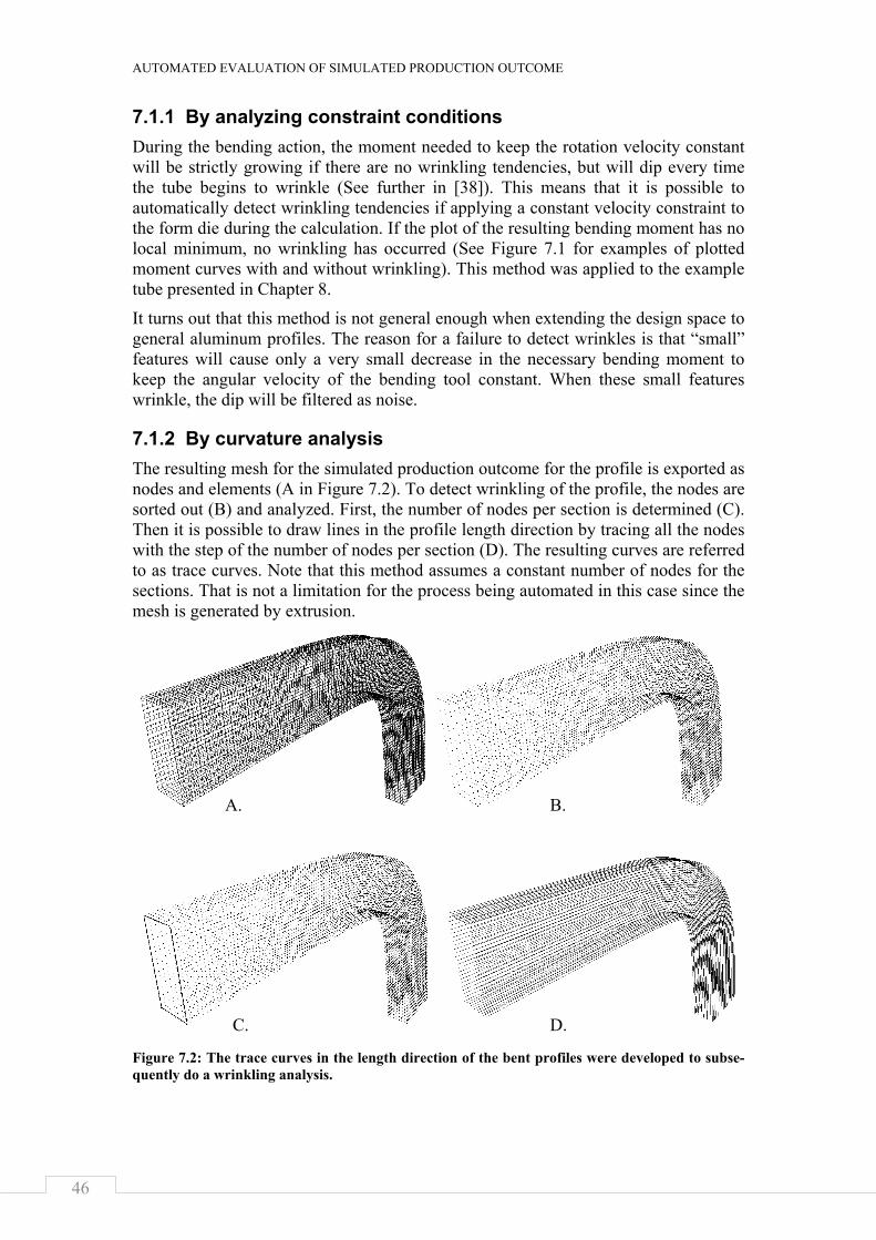
AUTOMATED EVALUATION OF SIMULATED PRODUCTION OUTCOME
46
7.1.1 By analyzing constraint conditions During the bending action, the moment needed to keep the rotation velocity constant will be strictly growing if there are no wrinkling tendencies, but will dip every time the tube begins to wrinkle (See further in [38]). This means that it is possible to automatically detect wrinkling tendencies if applying a constant velocity constraint to the form die during the calculation. If the plot of the resulting bending moment has no local minimum, no wrinkling has occurred (See Figure 7.1 for examples of plotted moment curves with and without wrinkling). This method was applied to the example tube presented in Chapter 8.
It turns out that this method is not general enough when extending the design space to general aluminum profiles. The reason for a failure to detect wrinkles is that “small” features will cause only a very small decrease in the necessary bending moment to keep the angular velocity of the bending tool constant. When these small features wrinkle, the dip will be filtered as noise.
7.1.2 By curvature analysis The resulting mesh for the simulated production outcome for the profile is exported as nodes and elements (A in Figure 7.2). To detect wrinkling of the profile, the nodes are sorted out (B) and analyzed. First, the number of nodes per section is determined (C). Then it is possible to draw lines in the profile length direction by tracing all the nodes with the step of the number of nodes per section (D). The resulting curves are referred to as trace curves. Note that this method assumes a constant number of nodes for the sections. That is not a limitation for the process being automated in this case since the mesh is generated by extrusion.
Figure 7.2: The trace curves in the length direction of the bent profiles were developed to subse-quently do a wrinkling analysis.
C. D.
B. A.
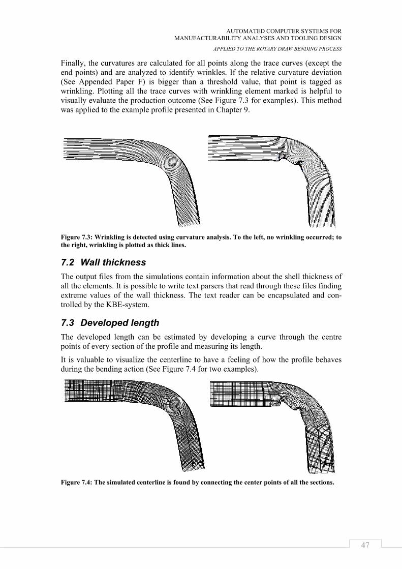
AUTOMATED COMPUTER SYSTEMS FOR MANUFACTURABILITY ANALYSES AND TOOLING DESIGN
APPLIED TO THE ROTARY DRAW BENDING PROCESS
47
Finally, the curvatures are calculated for all points along the trace curves (except the end points) and are analyzed to identify wrinkles. If the relative curvature deviation (See Appended Paper F) is bigger than a threshold value, that point is tagged as wrinkling. Plotting all the trace curves with wrinkling element marked is helpful to visually evaluate the production outcome (See Figure 7.3 for examples). This method was applied to the example profile presented in Chapter 9.
Figure 7.3: Wrinkling is detected using curvature analysis. To the left, no wrinkling occurred; to the right, wrinkling is plotted as thick lines.
7.2 Wall thickness The output files from the simulations contain information about the shell thickness of all the elements. It is possible to write text parsers that read through these files finding extreme values of the wall thickness. The text reader can be encapsulated and con-trolled by the KBE-system.
7.3 Developed length The developed length can be estimated by developing a curve through the centre points of every section of the profile and measuring its length.
It is valuable to visualize the centerline to have a feeling of how the profile behaves during the bending action (See Figure 7.4 for two examples).
Figure 7.4: The simulated centerline is found by connecting the center points of all the sections.
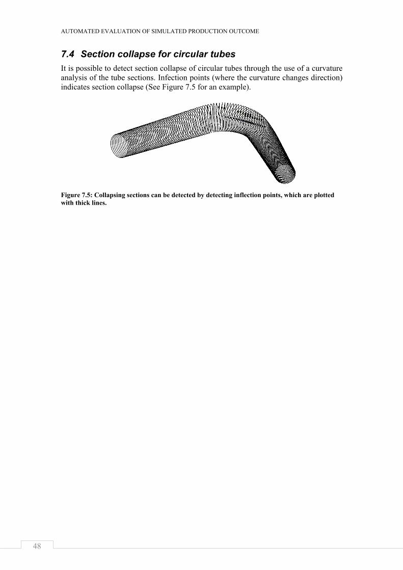
AUTOMATED EVALUATION OF SIMULATED PRODUCTION OUTCOME
48
7.4 Section collapse for circular tubes It is possible to detect section collapse of circular tubes through the use of a curvature analysis of the tube sections. Infection points (where the curvature changes direction) indicates section collapse (See Figure 7.5 for an example).
Figure 7.5: Collapsing sections can be detected by detecting inflection points, which are plotted with thick lines.
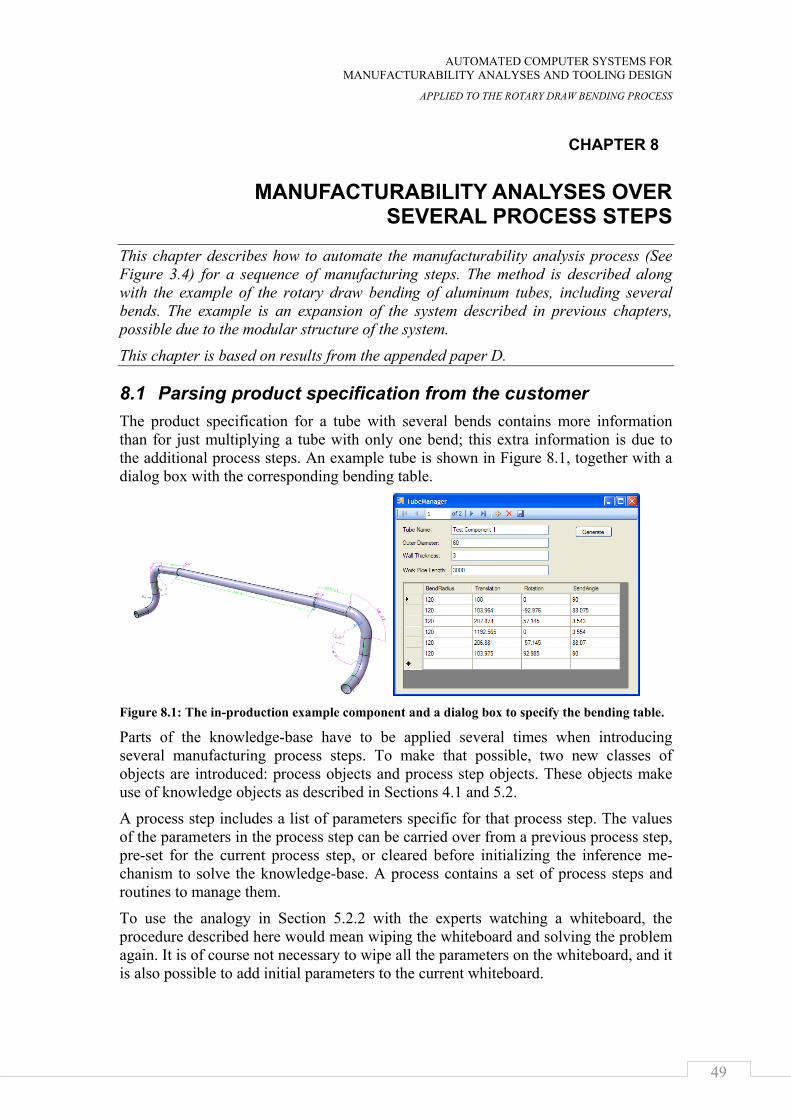
AUTOMATED COMPUTER SYSTEMS FOR MANUFACTURABILITY ANALYSES AND TOOLING DESIGN
APPLIED TO THE ROTARY DRAW BENDING PROCESS
49
CHAPTER 8
MANUFACTURABILITY ANALYSES OVER SEVERAL PROCESS STEPS
This chapter describes how to automate the manufacturability analysis process (See Figure 3.4) for a sequence of manufacturing steps. The method is described along with the example of the rotary draw bending of aluminum tubes, including several bends. The example is an expansion of the system described in previous chapters, possible due to the modular structure of the system.
This chapter is based on results from the appended paper D.
8.1 Parsing product specification from the customer The product specification for a tube with several bends contains more information than for just multiplying a tube with only one bend; this extra information is due to the additional process steps. An example tube is shown in Figure 8.1, together with a dialog box with the corresponding bending table.
Figure 8.1: The in-production example component and a dialog box to specify the bending table.
Parts of the knowledge-base have to be applied several times when introducing several manufacturing process steps. To make that possible, two new classes of objects are introduced: process objects and process step objects. These objects make use of knowledge objects as described in Sections 4.1 and 5.2.
A process step includes a list of parameters specific for that process step. The values of the parameters in the process step can be carried over from a previous process step, pre-set for the current process step, or cleared before initializing the inference me-chanism to solve the knowledge-base. A process contains a set of process steps and routines to manage them.
To use the analogy in Section 5.2.2 with the experts watching a whiteboard, the procedure described here would mean wiping the whiteboard and solving the problem again. It is of course not necessary to wipe all the parameters on the whiteboard, and it is also possible to add initial parameters to the current whiteboard.
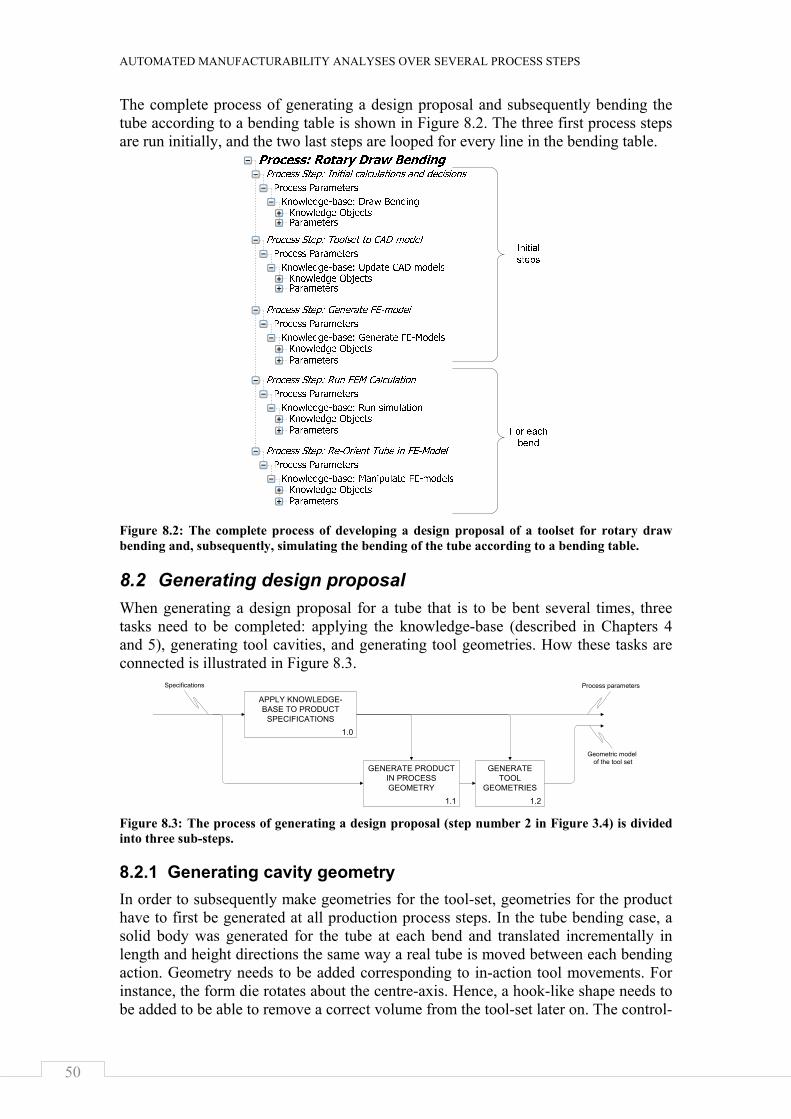
AUTOMATED MANUFACTURABILITY ANALYSES OVER SEVERAL PROCESS STEPS
50
The complete process of generating a design proposal and subsequently bending the tube according to a bending table is shown in Figure 8.2. The three first process steps are run initially, and the two last steps are looped for every line in the bending table.
Figure 8.2: The complete process of developing a design proposal of a toolset for rotary draw bending and, subsequently, simulating the bending of the tube according to a bending table.
8.2 Generating design proposal When generating a design proposal for a tube that is to be bent several times, three tasks need to be completed: applying the knowledge-base (described in Chapters 4 and 5), generating tool cavities, and generating tool geometries. How these tasks are connected is illustrated in Figure 8.3.
Figure 8.3: The process of generating a design proposal (step number 2 in Figure 3.4) is divided into three sub-steps.
8.2.1 Generating cavity geometry In order to subsequently make geometries for the tool-set, geometries for the product have to first be generated at all production process steps. In the tube bending case, a solid body was generated for the tube at each bend and translated incrementally in length and height directions the same way a real tube is moved between each bending action. Geometry needs to be added corresponding to in-action tool movements. For instance, the form die rotates about the centre-axis. Hence, a hook-like shape needs to be added to be able to remove a correct volume from the tool-set later on. The control-
1.1
GENERATE PRODUCT IN PROCESS GEOMETRY
1.2
GENERATE TOOL
GEOMETRIES
1.0
APPLY KNOWLEDGE-BASE TO PRODUCT
SPECIFICATIONS
Process parameters
Geometric modelof the tool set
Specifications
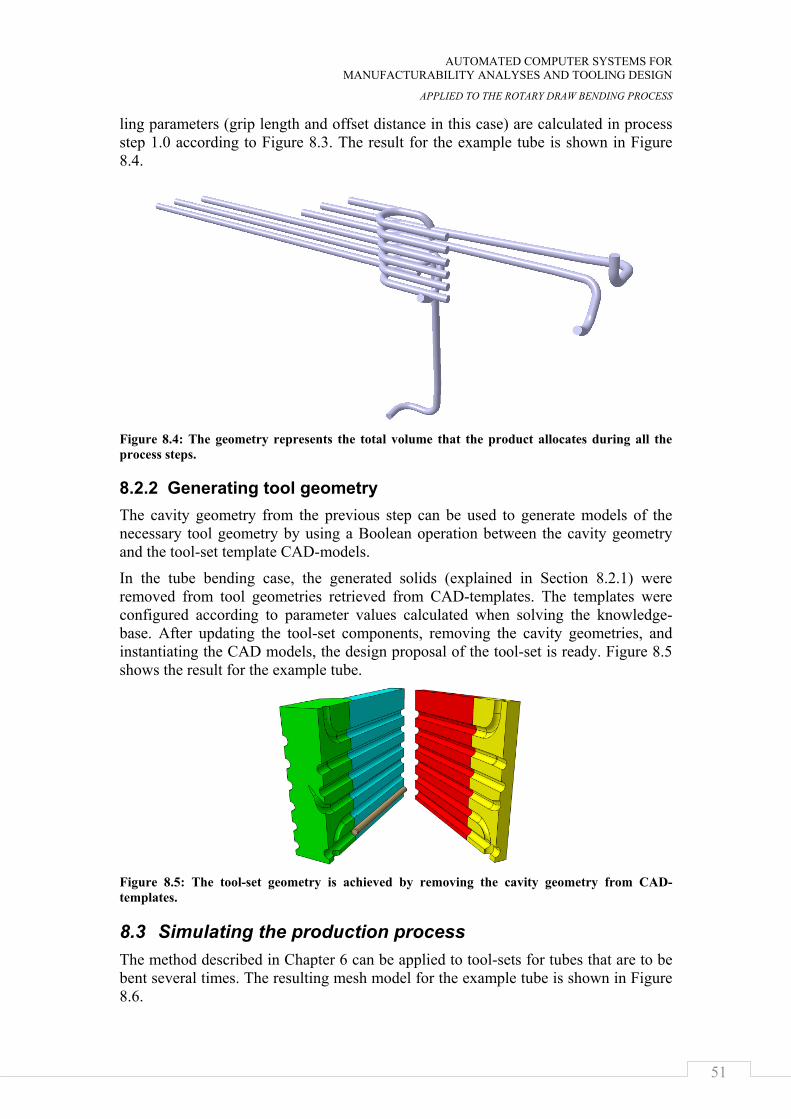
AUTOMATED COMPUTER SYSTEMS FOR MANUFACTURABILITY ANALYSES AND TOOLING DESIGN
APPLIED TO THE ROTARY DRAW BENDING PROCESS
51
ling parameters (grip length and offset distance in this case) are calculated in process step 1.0 according to Figure 8.3. The result for the example tube is shown in Figure 8.4.
Figure 8.4: The geometry represents the total volume that the product allocates during all the process steps.
8.2.2 Generating tool geometry The cavity geometry from the previous step can be used to generate models of the necessary tool geometry by using a Boolean operation between the cavity geometry and the tool-set template CAD-models.
In the tube bending case, the generated solids (explained in Section 8.2.1) were removed from tool geometries retrieved from CAD-templates. The templates were configured according to parameter values calculated when solving the knowledge-base. After updating the tool-set components, removing the cavity geometries, and instantiating the CAD models, the design proposal of the tool-set is ready. Figure 8.5 shows the result for the example tube.
Figure 8.5: The tool-set geometry is achieved by removing the cavity geometry from CAD-templates.
8.3 Simulating the production process The method described in Chapter 6 can be applied to tool-sets for tubes that are to be bent several times. The resulting mesh model for the example tube is shown in Figure 8.6.
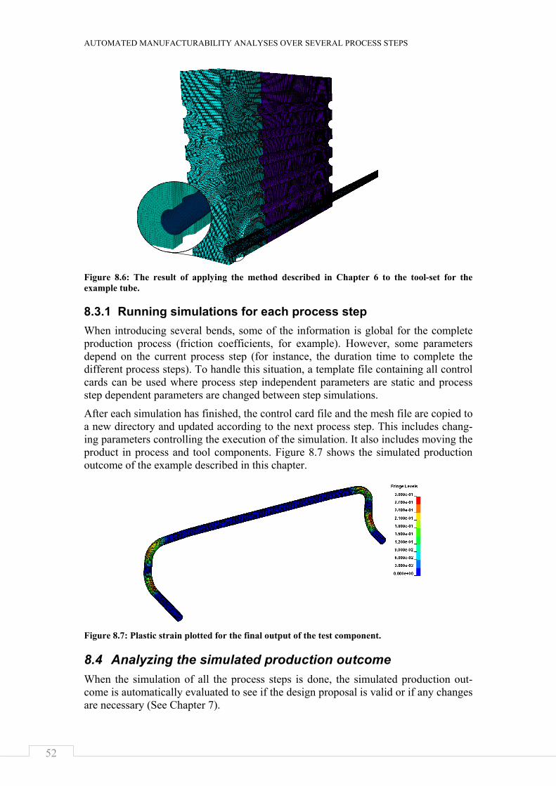
AUTOMATED MANUFACTURABILITY ANALYSES OVER SEVERAL PROCESS STEPS
52
Figure 8.6: The result of applying the method described in Chapter 6 to the tool-set for the example tube.
8.3.1 Running simulations for each process step When introducing several bends, some of the information is global for the complete production process (friction coefficients, for example). However, some parameters depend on the current process step (for instance, the duration time to complete the different process steps). To handle this situation, a template file containing all control cards can be used where process step independent parameters are static and process step dependent parameters are changed between step simulations.
After each simulation has finished, the control card file and the mesh file are copied to a new directory and updated according to the next process step. This includes chang-ing parameters controlling the execution of the simulation. It also includes moving the product in process and tool components. Figure 8.7 shows the simulated production outcome of the example described in this chapter.
Figure 8.7: Plastic strain plotted for the final output of the test component.
8.4 Analyzing the simulated production outcome When the simulation of all the process steps is done, the simulated production out-come is automatically evaluated to see if the design proposal is valid or if any changes are necessary (See Chapter 7).
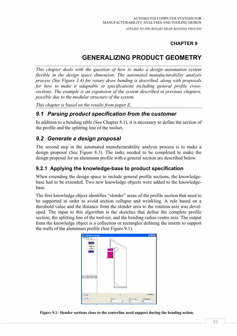
AUTOMATED COMPUTER SYSTEMS FOR MANUFACTURABILITY ANALYSES AND TOOLING DESIGN
APPLIED TO THE ROTARY DRAW BENDING PROCESS
53
CHAPTER 9
GENERALIZING PRODUCT GEOMETRY
This chapter deals with the question of how to make a design automation system flexible in the design space dimension. The automated manufacturability analysis process (See Figure 3.4) for rotary draw bending is described, along with proposals for how to make it adaptable to specifications including general profile cross-sections. The example is an expansion of the system described in previous chapters, possible due to the modular structure of the system.
This chapter is based on the results from paper E.
9.1 Parsing product specification from the customer In addition to a bending table (See Chapter 8.1), it is necessary to define the section of the profile and the splitting line of the toolset.
9.2 Generate a design proposal The second step in the automated manufacturability analysis process is to make a design proposal (See Figure 8.3). The tasks needed to be completed to make the design proposal for an aluminum profile with a general section are described below.
9.2.1 Applying the knowledge-base to product specification When extending the design space to include general profile sections, the knowledge-base had to be extended. Two new knowledge objects were added to the knowledge-base.
The first knowledge object identifies “slender” areas of the profile section that need to be supported in order to avoid section collapse and wrinkling. A rule based on a threshold value and the distance from the slender area to the rotation axis was devel-oped. The input to this algorithm is the sketches that define the complete profile section, the splitting line of the tool-set, and the bending radius centre axis. The output from the knowledge object is a collection or rectangles defining the inserts to support the walls of the aluminum profile (See Figure 9.1).
Figure 9.1: Slender sections close to the centerline need support during the bending action.
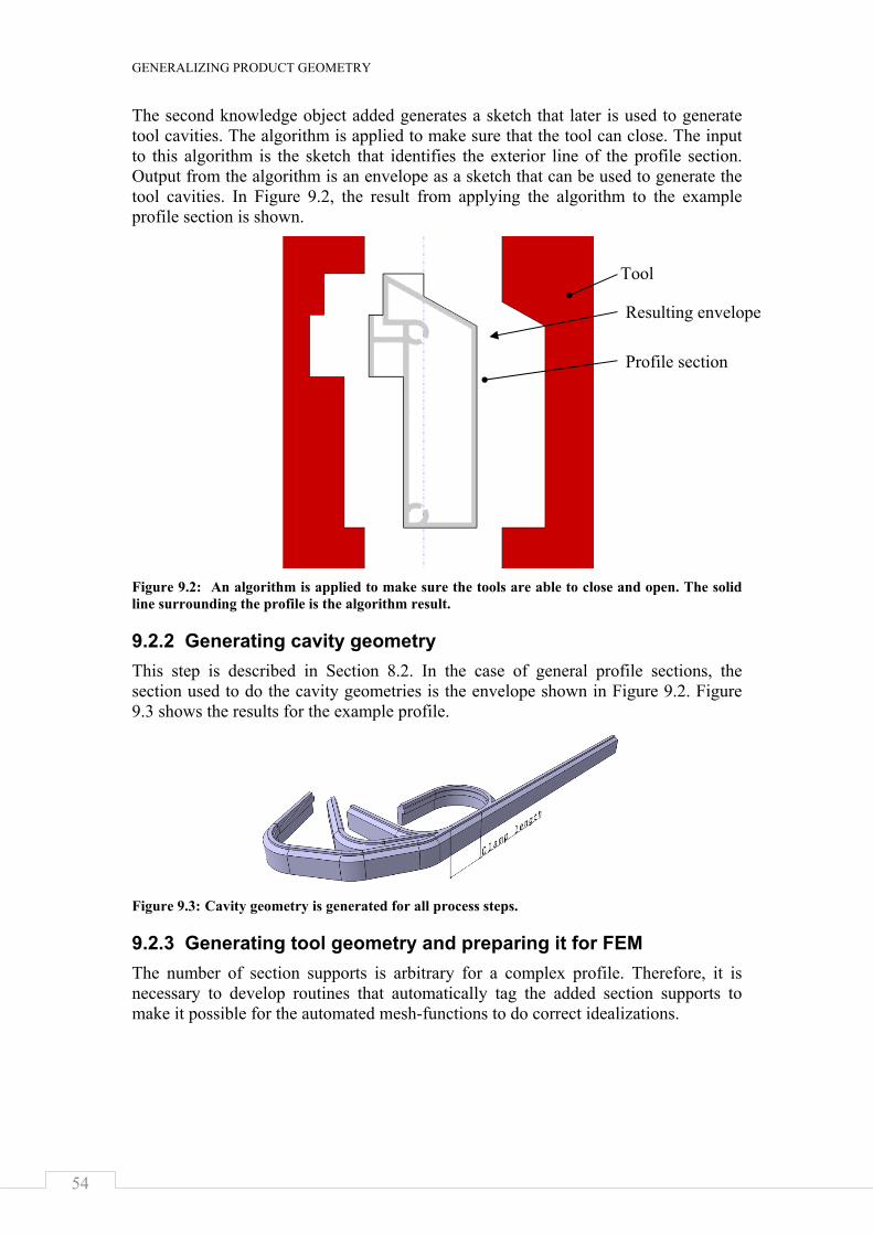
GENERALIZING PRODUCT GEOMETRY
54
The second knowledge object added generates a sketch that later is used to generate tool cavities. The algorithm is applied to make sure that the tool can close. The input to this algorithm is the sketch that identifies the exterior line of the profile section. Output from the algorithm is an envelope as a sketch that can be used to generate the tool cavities. In Figure 9.2, the result from applying the algorithm to the example profile section is shown.
Figure 9.2: An algorithm is applied to make sure the tools are able to close and open. The solid line surrounding the profile is the algorithm result.
9.2.2 Generating cavity geometry This step is described in Section 8.2. In the case of general profile sections, the section used to do the cavity geometries is the envelope shown in Figure 9.2. Figure 9.3 shows the results for the example profile.
Figure 9.3: Cavity geometry is generated for all process steps.
9.2.3 Generating tool geometry and preparing it for FEM The number of section supports is arbitrary for a complex profile. Therefore, it is necessary to develop routines that automatically tag the added section supports to make it possible for the automated mesh-functions to do correct idealizations.
Tool
Resulting envelope
Profile section
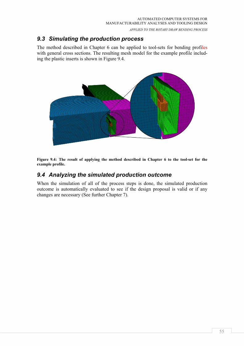
AUTOMATED COMPUTER SYSTEMS FOR MANUFACTURABILITY ANALYSES AND TOOLING DESIGN
APPLIED TO THE ROTARY DRAW BENDING PROCESS
55
9.3 Simulating the production process The method described in Chapter 6 can be applied to tool-sets for bending profiles with general cross sections. The resulting mesh model for the example profile includ-ing the plastic inserts is shown in Figure 9.4.
Figure 9.4: The result of applying the method described in Chapter 6 to the tool-set for the example profile.
9.4 Analyzing the simulated production outcome When the simulation of all of the process steps is done, the simulated production outcome is automatically evaluated to see if the design proposal is valid or if any changes are necessary (See further Chapter 7).

GENERALIZING PRODUCT GEOMETRY
56
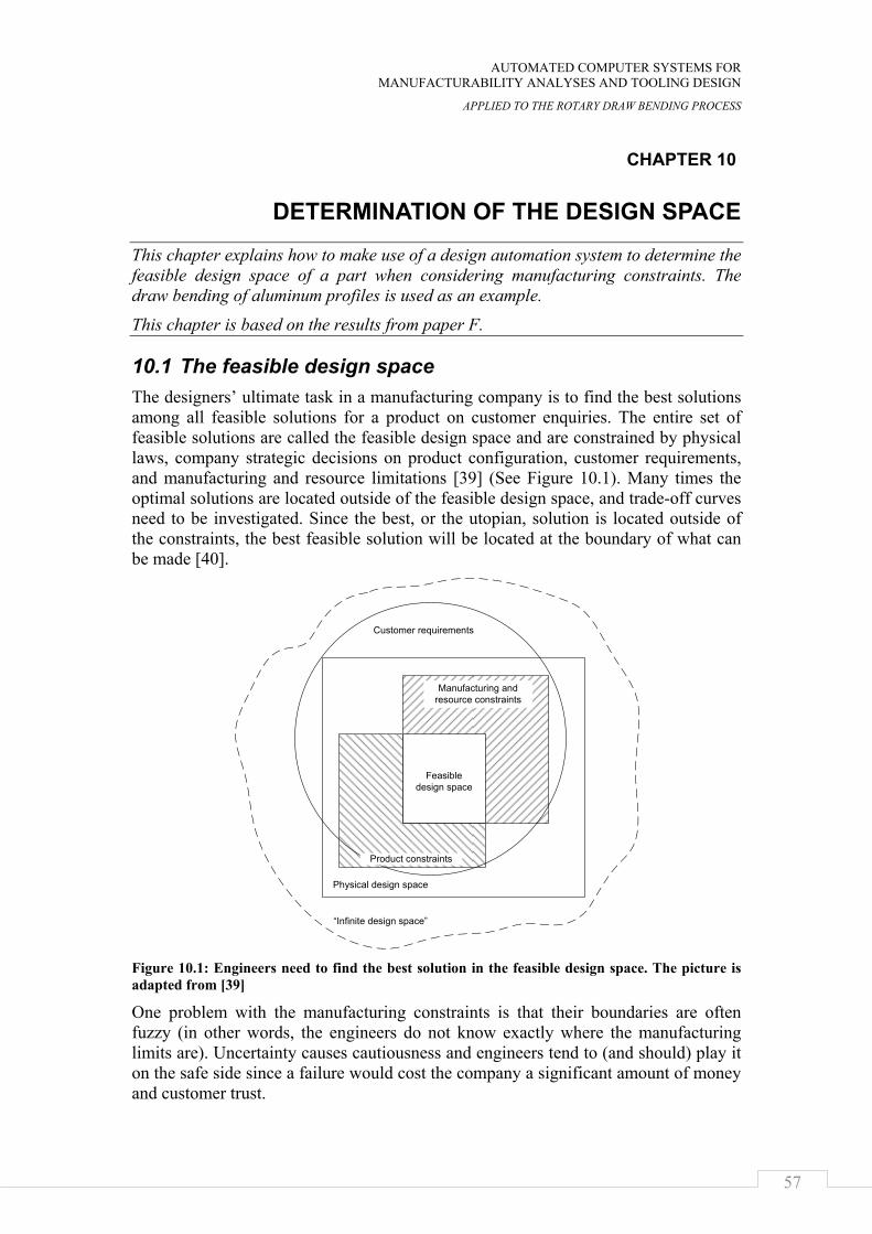
AUTOMATED COMPUTER SYSTEMS FOR MANUFACTURABILITY ANALYSES AND TOOLING DESIGN
APPLIED TO THE ROTARY DRAW BENDING PROCESS
57
CHAPTER 10
DETERMINATION OF THE DESIGN SPACE
This chapter explains how to make use of a design automation system to determine the feasible design space of a part when considering manufacturing constraints. The draw bending of aluminum profiles is used as an example.
This chapter is based on the results from paper F.
10.1 The feasible design space The designers’ ultimate task in a manufacturing company is to find the best solutions among all feasible solutions for a product on customer enquiries. The entire set of feasible solutions are called the feasible design space and are constrained by physical laws, company strategic decisions on product configuration, customer requirements, and manufacturing and resource limitations [39] (See Figure 10.1). Many times the optimal solutions are located outside of the feasible design space, and trade-off curves need to be investigated. Since the best, or the utopian, solution is located outside of the constraints, the best feasible solution will be located at the boundary of what can be made [40].
Figure 10.1: Engineers need to find the best solution in the feasible design space. The picture is adapted from [39]
One problem with the manufacturing constraints is that their boundaries are often fuzzy (in other words, the engineers do not know exactly where the manufacturing limits are). Uncertainty causes cautiousness and engineers tend to (and should) play it on the safe side since a failure would cost the company a significant amount of money and customer trust.
“Infinite design space”
Physical design space
Manufacturing and resource constraints
Feasible design space
Customer requirements
Product constraints
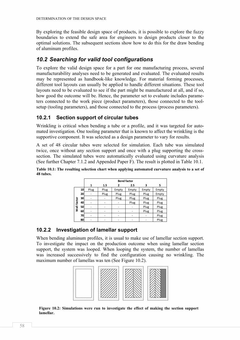
DETERMINATION OF THE DESIGN SPACE
58
By exploring the feasible design space of products, it is possible to explore the fuzzy boundaries to extend the safe area for engineers to design products closer to the optimal solutions. The subsequent sections show how to do this for the draw bending of aluminum profiles.
10.2 Searching for valid tool configurations To explore the valid design space for a part for one manufacturing process, several manufacturability analyses need to be generated and evaluated. The evaluated results may be represented as handbook-like knowledge. For material forming processes, different tool layouts can usually be applied to handle different situations. These tool layouts need to be evaluated to see if the part might be manufactured at all, and if so, how good the outcome will be. Hence, the parameter set to evaluate includes parame-ters connected to the work piece (product parameters), those connected to the tool-setup (tooling parameters), and those connected to the process (process parameters).
10.2.1 Section support of circular tubes Wrinkling is critical when bending a tube or a profile, and it was targeted for auto-mated investigation. One tooling parameter that is known to affect the wrinkling is the supportive component. It was selected as a design parameter to vary for results.
A set of 48 circular tubes were selected for simulation. Each tube was simulated twice, once without any section support and once with a plug supporting the cross-section. The simulated tubes were automatically evaluated using curvature analysis (See further Chapter 7.1.2 and Appended Paper F). The result is plotted in Table 10.1. Table 10.1: The resulting selection chart when applying automated curvature analysis to a set of 48 tubes.
10.2.2 Investigation of lamellar support When bending aluminum profiles, it is usual to make use of lamellar section support. To investigate the impact on the production outcome when using lamellar section support, the system was looped. When looping the system, the number of lamellas was increased successively to find the configuration causing no wrinkling. The maximum number of lamellas was ten (See Figure 10.2).
1 1.5 2 2.5 3 510 Plug Plug Empty Empty Empty Empty20 ‐ Plug Plug Plug Plug Empty30 ‐ ‐ Plug Plug Plug Plug40 ‐ ‐ ‐ Plug Plug Plug50 ‐ ‐ ‐ ‐ Plug Plug60 ‐ ‐ ‐ ‐ Plug Plug70 ‐ ‐ ‐ ‐ ‐ Plug80 ‐ ‐ ‐ ‐ ‐ Plug
Bend factor
Wall factor
Figure 10.2: Simulations were run to investigate the effect of making the section support lamellar.
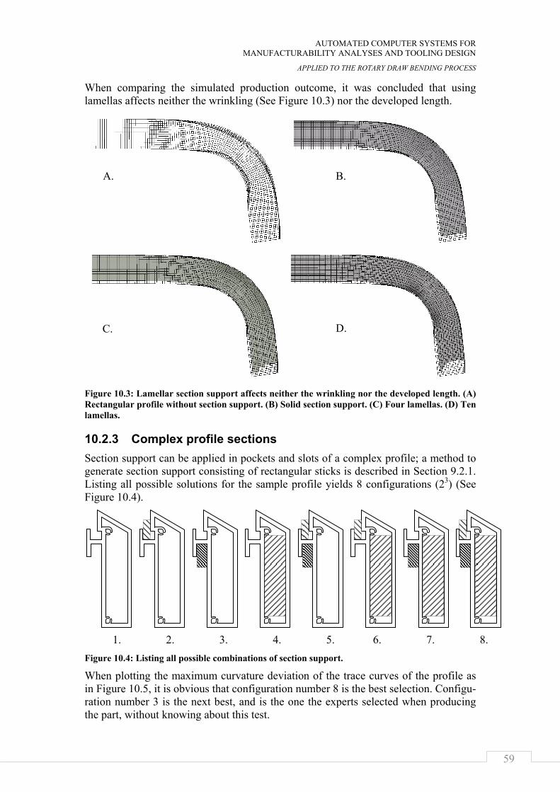
AUTOMATED COMPUTER SYSTEMS FOR MANUFACTURABILITY ANALYSES AND TOOLING DESIGN
APPLIED TO THE ROTARY DRAW BENDING PROCESS
59
When comparing the simulated production outcome, it was concluded that using lamellas affects neither the wrinkling (See Figure 10.3) nor the developed length.
Figure 10.3: Lamellar section support affects neither the wrinkling nor the developed length. (A) Rectangular profile without section support. (B) Solid section support. (C) Four lamellas. (D) Ten lamellas.
10.2.3 Complex profile sections Section support can be applied in pockets and slots of a complex profile; a method to generate section support consisting of rectangular sticks is described in Section 9.2.1. Listing all possible solutions for the sample profile yields 8 configurations (23) (See Figure 10.4).
Figure 10.4: Listing all possible combinations of section support.
When plotting the maximum curvature deviation of the trace curves of the profile as in Figure 10.5, it is obvious that configuration number 8 is the best selection. Configu-ration number 3 is the next best, and is the one the experts selected when producing the part, without knowing about this test.
A. B.
D. C.
1. 2. 3. 4. 5. 6. 7. 8.
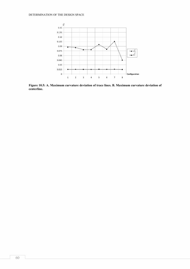
DETERMINATION OF THE DESIGN SPACE
60
Figure 10.5: A. Maximum curvature deviation of trace lines. B. Maximum curvature deviation of centerline.
AUTOMATED COMPUTER SYSTEMS FOR MANUFACTURABILITY ANALYSES AND TOOLING DESIGN
APPLIED TO THE ROTARY DRAW BENDING PROCESS
61
CHAPTER 11
DISCUSSION
In this chapter, the research work presented in this thesis is discussed with respect to generalization, verification, and validity.
11.1 Scientific Contributions The research resulted in methods and suggestions useful when building automated computer systems for tooling design and manufacturability analysis. These methods include the usage of knowledge objects and an event-driven inference mechanism. When applying them, the resulting system will have a high degree of flexibility to edit underlying knowledge and extend the targeted design space without disrupting the operation of the system. Specifically, a method to make an automated design system to have the ability to select from alternative design rules was developed; these rules can be mathematical expressions, selections, or FEM-calculations. A method to account for several manufacturing steps was also developed.
11.2 Industrial Contributions Rotary draw bending is a common manufacturing process and in this thesis know-ledge about it is collected and explained. Further, the methods mentioned in Section 11.1 were applied to the rotary draw bending of tubes and aluminum profiles and routines were developed that automates the natural synthesis and analysis process of designing tool-sets. This provides the designers with a powerful tool to evaluate early design proposals against manufacturing constraints, saving time, money, and assuring high product quality.
11.3 How general are the results presented in this thesis work?
The knowledge objects, the global parameter list, the precision values, and the infe-rence engine presented in this thesis (Chapters 4 and 5) can be viewed as an architec-ture for building flexible automated computer systems for design automation, see Figure 11.1. Also, the method of running sequences of process steps (Chapter 8), and the automated investigation of design spaces (Chapter 10) can be added to that archi-tecture. The knowledge objects implemented for automating the process of setting-up, running, and evaluating FEM-simulations (Chapter 6 and 7) can be viewed as a platform for automating manufacturability analyses of various forming processes, e.g. shape-rolling, die-forging, extrusion, drawing, hydro-forming, and sheet-metal form-ing.
The architecture and the platform were tested by applying them to the rotary draw bending of aluminum tubes and profiles. Applying the platform to another forming process would mean changing the top of the pyramid in Figure 11.1.
The knowledge object architecture can be used to a vast number of applications and will result in modular and flexible design automation systems.

DISCUSSION AND FUTURE WORK
62
Figure 11.1: The results range from a general system architecture to a specific application.
11.4 Different research cycles The first iteration of the empirical cycle included the development of a design auto-mation system for rotary draw bending using dedicated commercial software, pre-sented in Appended Paper 1. During that development phase, additional research questions arose.
Questions come from practice, and answers from theory. Further, when building theory, it is critical to be practical. In this work, interesting research questions arose after the first research cycle. Yet the second cycle raised even more interesting ques-tions. When reflecting over this research work so far, one realizes that many expe-riences have been gained in three domains: how to conduct research, how to build design automation systems, and how to design toolsets for rotary draw bending.
11.5 Verification of results Through experiments, it has been verified that the concept of design automation can be applied to rotary draw bending toolsets using either CAD-integrated or stand-alone KBE-systems. Experienced engineers that have been designing toolsets for rotary draw bending for decades have been part of the project and have had insight into the knowledge-base implemented, including heuristic, analytical, numerical, and experi-mental knowledge.
The system has been built in two versions. The first version employed readily availa-ble software using forward-chaining and production rules. To improve flexibility, the second version was built. It used knowledge objects to represent the knowledge-base and a forward-chaining mechanism to search the knowledge-base, and it can be concluded that the system has the ability to mimic the manual work process. Since the two systems have proven to work within their scope, the results are verified as satis-factory by experienced designers.
11.5.1 The flexibility of the design automation systems In this thesis, it is stated that the flexibility of a design automation system will in-crease if the object-oriented view is adapted to the knowledge-base. This has been verified through the development of an inference engine and a knowledge-base using the object orientation paradigm. In that implementation, it is possible to create, edit,
AUTOMATED COMPUTER SYSTEMS FOR MANUFACTURABILITY ANALYSES AND TOOLING DESIGN
APPLIED TO THE ROTARY DRAW BENDING PROCESS
63
suppress, and remove knowledge chunks without disrupting the operation of the system. The operations can be executed regardless of what order the knowledge was added in. When editing the knowledge-base, the execution sequence will change automatically according to the new knowledge-base. The drawback with the system being that flexible is that it is hard to foresee what effect changes in the knowledge-base will have on system operation.
There are two options for where to put the knowledge-base when implementing a design automation system. Either the knowledge-base is built into the product struc-ture using a CAD-integrated system, or the knowledge-base is built in a stand-alone application. Through experiments, it is suggested that a stand-alone KBE-system is suitable when the number of geometrical relationships is low compared to the total number of rules in the knowledge-base and when the number of geometry features is low compared to the total number of rules. Otherwise, a CAD-integrated system is suitable for the implementation of the knowledge-base.
Flexibility is also said to be increased through an object-oriented view of the product structure as well. The object-oriented view of the product structure makes the systems flexible so that they may edit and suppress product components without disrupting the operation of the system. It has been verified that the object-oriented approach to the product structure increases the flexibility of the system. That was done by imple-menting two systems: a system where macros were used to achieve the object orienta-tion and a system that used tags and external links in the CAD-models.
11.5.2 Allowing alternative design rules in the knowledge-base It has been experimentally verified that it is possible to implement multiple rules for a single phenomenon using knowledge objects, a common parameter list, and precision values. The implemented system has 40 knowledge objects concerning ten different phenomenon or design tasks. Different objects will be executed, depending on what inputs are presented to the system. One difficulty is to get an overview of where in the design space knowledge objects overlap.
11.5.3 Automation of the analysis process It has been verified through experiments that it is possible to automate the finite element analysis process for rotary draw bending. The FEA-model is automatically generated, executed, and evaluated by the system. The automation steps were imple-mented using knowledge objects. The computer routines used by these knowledge objects were specially developed for the experiment, but are general enough to be adapted to other types of metal forming processes.
The FEM-calculations have been performed based on industry standards (material- and friction-models) and have not been the target of research in this project.
11.5.4 Looping through several process steps It was experimentally verified that it is possible to automatically perform manufactu-rability analyses including a set of manufacturing process steps. The experiment was done through the development of a prototype system for draw bending of an in-production tube where the product specification from a customer included several bends.
DISCUSSION AND FUTURE WORK
64
11.5.5 Generalization of the product geometry The high flexibility of a design automation system based on knowledge objects was again verified by extending the prototype system for automated manufacturability analysis of the draw bending of tubes to also be able to perform manufacturability analyses of general profile sections.
11.5.6 Generating decision support for tooling layouts To verify that a system for automated manufacturability actually may be utilized to explore the manufacturing limits and, subsequently, generate decision supports, the prototype system was looped for the draw bending of circular tubes, rectangular tubes, and a general profile. A decision table could be generated from the output for when to apply a plug to support the draw bending of a tube. It was possible to show that making the section support lamellar does not affect the production outcome. Further, it was possible to generate a decision support for tool layouts for the bending of a profile with a general cross section.
11.6 Validation When testing the prototype systems, it was realized that design automation has a large potential to cut lead-time. It takes only a couple of minutes to generate a design proposal and approximately twenty minutes (per bend) to verify the proposal using the automated FEA-process. This should be compared to the manual process that may take a few days. Within the domain of tube and profile bending, the design automa-tion system makes the adaption of different customer specifications fully automated. It also makes it possible to explore the feasible design space making valuable infor-mation available to design engineers early on in the design process, saving time and money while assuring high quality.
AUTOMATED COMPUTER SYSTEMS FOR MANUFACTURABILITY ANALYSES AND TOOLING DESIGN
APPLIED TO THE ROTARY DRAW BENDING PROCESS
65
CHAPTER 12
CONCLUSIONS AND FUTURE WORK
This section presents short answers to the research questions and concludes the thesis.
12.1 Answering the research questions How should the concept of design automation be applied to the tooling design and manufacturability analyses of plastic forming processes, exemplified by the rotary draw bending of aluminum profiles? Depending on the intended level of automation and intended flexibility of the automa-tion system, it is possible to implement heuristic and analytical knowledge into KBE-systems using feed forward-chaining and rule-based or object-based knowledge representation. A decision has to be made as to whether the system should allow alternative design rules. If alternative design rules are found necessary, object-oriented programming can be used to define knowledge objects as the knowledge representation and a search engine can be used to interpret the knowledge-base in different situations.
It is possible to make design automation systems able to evaluate their own design proposals through the automation of the FEA-process. It is also possible to loop parts of a design automation system to perform manufacturability analyses over several process steps.
1. How should design automation systems be built to allow a high degree of flexibil-ity? This is addressed in appended paper B where it is proposed that object-oriented programming helps making design automation systems highly flexible. The knowledge domain is then broken down into chunks of knowledge. Each knowledge chunk is defined as an independent object, with two lists containing inputs and outputs and an attached method for processing the inputs to outputs. An object-oriented view of the product when creating geometric representations has proven to help the design automation system be flexible.
When comparing CAD-integrated KBE-systems to stand-alone KBE-systems, the implementation will be more flexible with the stand-alone KBE-system if two conditions are met: the knowledge-base contains few geometrical relationships compared to the total number of rules and the total number of rules is large com-pared to the number of geometric features in the geometrical representation. Oth-erwise, a CAD-integrated KBE-system allows more flexible implementations. This is found when evaluating results from appended paper A and B.
2. How should design automation systems be made able to handle the situation when multiple types of knowledge coexist for a single phenomenon? Appended paper B addresses this question and suggests the implementation of constraints and precision values on the knowledge objects. This supports the selection of knowledge in different areas of the design space. Meta-rules can be put in the in-ference engine globally, telling how to select knowledge in different situations,
CONCLUSIONS
66
and locally, telling under what circumstances the knowledge is available and how accurate it is.
3. How may design automation systems be built enabling automatic but also flexible finite element analyses of the manufacturing process? In appended paper C it is shown that prepared geometric representations can be used to support the auto-mated mesh creation. It is also possible to use a global KBE-system to make a recipe for how to run the FEM-calculation. The FEM-calculations are then ex-ecuted and interpreted automatically using the KBE-system.
4. How may one enable design automation systems to do manufacturability analyses of products that are put through several manufacturing process steps? Appended paper D suggests that when several process steps are to be analyzed, object-oriented programming can be used to hold the additional information necessary to represent the total manufacturing process. That information contains process pa-rameters for each process step and values for each spatial movement of the prod-uct in the process. Parts of the knowledge base are solved for each process step.
5. How may one enable design automation systems to do manufacturability analyses of a wide range of the design space? Experiments provided in appended paper E have shown that when developing design automation systems based on know-ledge objects and using an object-oriented approach when developing the geome-tric representations, the systems will be flexible enough to extend the targeted de-sign space.
6. How may one loop a design automation system to explore different areas of a design space in order to generate decision support for tooling layout, including component selections? In appended paper F it is concluded that the manufactura-bility analysis process needs to be fully automated, including the design synthe-sis, analysis, and evaluation steps (as described in appended paper B-F). When such a system is at hand, it is possible to feed it with input parameters and subse-quently retrieve output variables. Three different types of parameters exist within the scope of manufacturability analyses: product parameters, process parameters, and tooling parameters. When looping the system to develop knowledge, it is im-portant to identify what parameters are actually influencing the resulting va-riables. (The system can be run to investigate parameter relationships.) Then it is necessary to select which sets of parameter values to evaluate. When the whole set of data is collected, it can be used early on in the design process, saving time and money while still assuring high product quality.
12.2 Future work Continuing the research work presented in this thesis should include the evaluation of how the product and production development processes are affected when using the methods presented. That would include adding more manufacturing processes to the repertoire of automated manufacturability analyses. Finally, in connection with the draw bending, future work should include the refinement of simulation models to correlate better with experiments, the development of methods for evaluating visual requirements often put on aluminum profiles, the development of methods for eva-luating geometrical tolerances, and the enabling of variations of parameter values such as material properties to be taken into account.
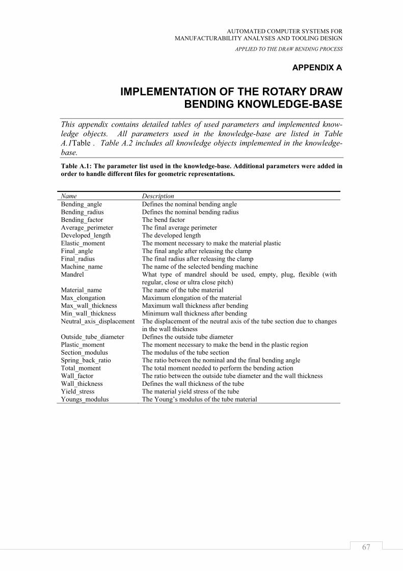
AUTOMATED COMPUTER SYSTEMS FOR MANUFACTURABILITY ANALYSES AND TOOLING DESIGN
APPLIED TO THE DRAW BENDING PROCESS
67
APPENDIX A
IMPLEMENTATION OF THE ROTARY DRAW BENDING KNOWLEDGE-BASE
This appendix contains detailed tables of used parameters and implemented know-ledge objects. All parameters used in the knowledge-base are listed in Table A.1Table . Table A.2 includes all knowledge objects implemented in the knowledge-base. Table A.1: The parameter list used in the knowledge-base. Additional parameters were added in order to handle different files for geometric representations.
Name Description Bending_angle Defines the nominal bending angle Bending_radius Defines the nominal bending radius Bending_factor The bend factor Average_perimeter The final average perimeter Developed_length The developed length Elastic_moment The moment necessary to make the material plastic Final_angle The final angle after releasing the clamp Final_radius The final radius after releasing the clamp Machine_name The name of the selected bending machine Mandrel What type of mandrel should be used, empty, plug, flexible (with
regular, close or ultra close pitch) Material_name The name of the tube material Max_elongation Maximum elongation of the material Max_wall_thickness Maximum wall thickness after bending Min_wall_thickness Minimum wall thickness after bending Neutral_axis_displacement The displacement of the neutral axis of the tube section due to changes
in the wall thickness Outside_tube_diameter Defines the outside tube diameter Plastic_moment The moment necessary to make the bend in the plastic region Section_modulus The modulus of the tube section Spring_back_ratio The ratio between the nominal and the final bending angle Total_moment The total moment needed to perform the bending action Wall_factor The ratio between the outside tube diameter and the wall thickness Wall_thickness Defines the wall thickness of the tube Yield_stress The material yield stress of the tube Youngs_modulus The Young’s modulus of the tube material
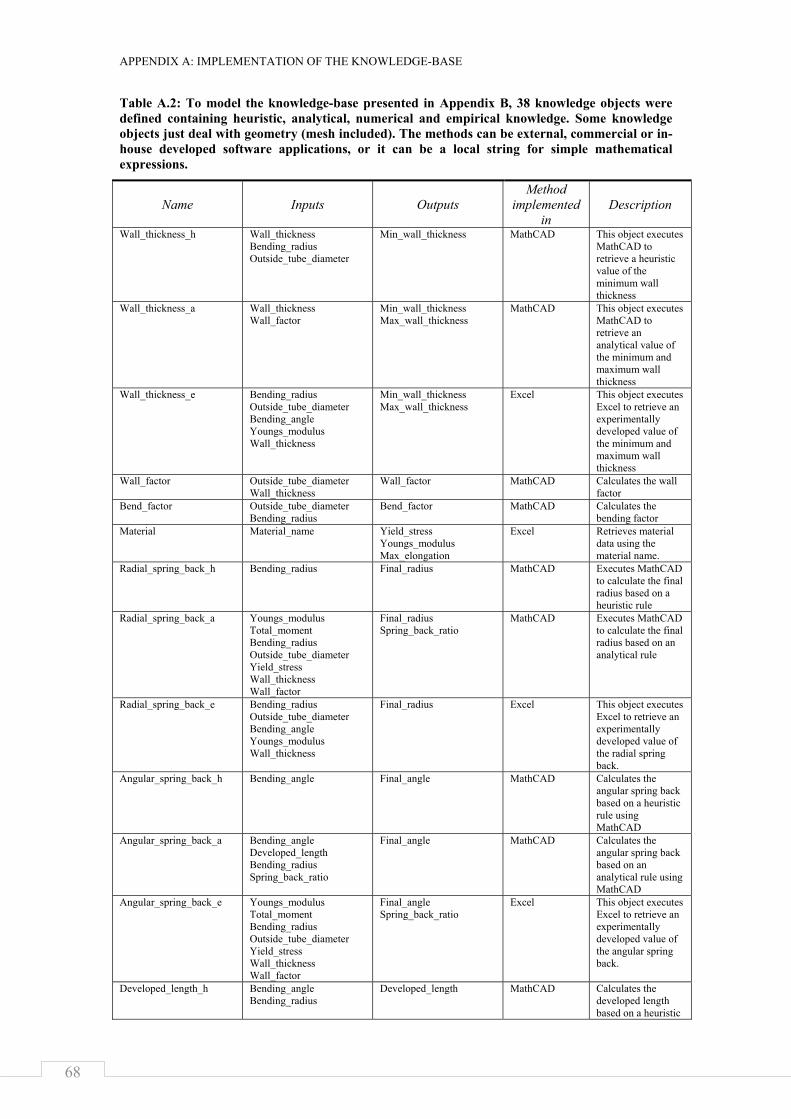
APPENDIX A: IMPLEMENTATION OF THE KNOWLEDGE-BASE
68
Table A.2: To model the knowledge-base presented in Appendix B, 38 knowledge objects were defined containing heuristic, analytical, numerical and empirical knowledge. Some knowledge objects just deal with geometry (mesh included). The methods can be external, commercial or in-house developed software applications, or it can be a local string for simple mathematical expressions.
Name Inputs Outputs Method
implemented in
Description
Wall_thickness_h Wall_thickness Bending_radius Outside_tube_diameter
Min_wall_thickness MathCAD This object executes MathCAD to retrieve a heuristic value of the minimum wall thickness
Wall_thickness_a Wall_thickness Wall_factor
Min_wall_thickness Max_wall_thickness
MathCAD This object executes MathCAD to retrieve an analytical value of the minimum and maximum wall thickness
Wall_thickness_e Bending_radius Outside_tube_diameter Bending_angle Youngs_modulus Wall_thickness
Min_wall_thickness Max_wall_thickness
Excel This object executes Excel to retrieve an experimentally developed value of the minimum and maximum wall thickness
Wall_factor Outside_tube_diameter Wall_thickness
Wall_factor MathCAD Calculates the wall factor
Bend_factor Outside_tube_diameter Bending_radius
Bend_factor MathCAD Calculates the bending factor
Material Material_name Yield_stress Youngs_modulus Max_elongation
Excel Retrieves material data using the material name.
Radial_spring_back_h Bending_radius Final_radius MathCAD Executes MathCAD to calculate the final radius based on a heuristic rule
Radial_spring_back_a Youngs_modulus Total_moment Bending_radius Outside_tube_diameter Yield_stress Wall_thickness Wall_factor
Final_radius Spring_back_ratio
MathCAD Executes MathCAD to calculate the final radius based on an analytical rule
Radial_spring_back_e Bending_radius Outside_tube_diameter Bending_angle Youngs_modulus Wall_thickness
Final_radius Excel This object executes Excel to retrieve an experimentally developed value of the radial spring back.
Angular_spring_back_h Bending_angle
Final_angle MathCAD Calculates the angular spring back based on a heuristic rule using MathCAD
Angular_spring_back_a Bending_angle Developed_length Bending_radius Spring_back_ratio
Final_angle MathCAD Calculates the angular spring back based on an analytical rule using MathCAD
Angular_spring_back_e Youngs_modulus Total_moment Bending_radius Outside_tube_diameter Yield_stress Wall_thickness Wall_factor
Final_angle Spring_back_ratio
Excel This object executes Excel to retrieve an experimentally developed value of the angular spring back.
Developed_length_h Bending_angle Bending_radius
Developed_length MathCAD Calculates the developed length based on a heuristic
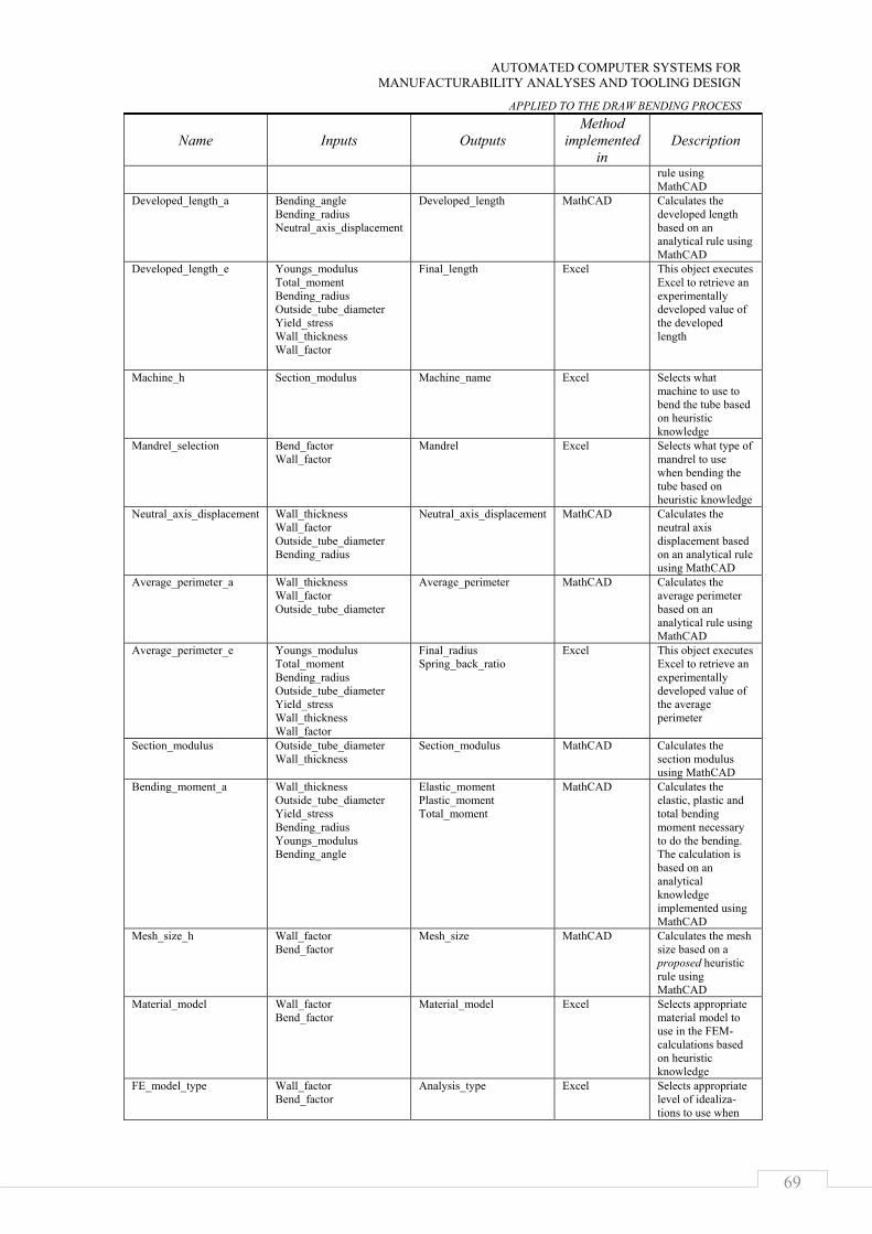
AUTOMATED COMPUTER SYSTEMS FOR MANUFACTURABILITY ANALYSES AND TOOLING DESIGN
APPLIED TO THE DRAW BENDING PROCESS
69
Name Inputs Outputs Method
implemented in
Description
rule using MathCAD
Developed_length_a Bending_angle Bending_radius Neutral_axis_displacement
Developed_length MathCAD Calculates the developed length based on an analytical rule using MathCAD
Developed_length_e Youngs_modulus Total_moment Bending_radius Outside_tube_diameter Yield_stress Wall_thickness Wall_factor
Final_length
Excel This object executes Excel to retrieve an experimentally developed value of the developed length
Machine_h Section_modulus
Machine_name Excel Selects what machine to use to bend the tube based on heuristic knowledge
Mandrel_selection Bend_factor Wall_factor
Mandrel Excel Selects what type of mandrel to use when bending the tube based on heuristic knowledge
Neutral_axis_displacement Wall_thickness Wall_factor Outside_tube_diameter Bending_radius
Neutral_axis_displacement MathCAD Calculates the neutral axis displacement based on an analytical rule using MathCAD
Average_perimeter_a Wall_thickness Wall_factor Outside_tube_diameter
Average_perimeter MathCAD Calculates the average perimeter based on an analytical rule using MathCAD
Average_perimeter_e Youngs_modulus Total_moment Bending_radius Outside_tube_diameter Yield_stress Wall_thickness Wall_factor
Final_radius Spring_back_ratio
Excel This object executes Excel to retrieve an experimentally developed value of the average perimeter
Section_modulus Outside_tube_diameter Wall_thickness
Section_modulus MathCAD Calculates the section modulus using MathCAD
Bending_moment_a Wall_thickness Outside_tube_diameter Yield_stress Bending_radius Youngs_modulus Bending_angle
Elastic_moment Plastic_moment Total_moment
MathCAD Calculates the elastic, plastic and total bending moment necessary to do the bending. The calculation is based on an analytical knowledge implemented using MathCAD
Mesh_size_h Wall_factor Bend_factor
Mesh_size MathCAD Calculates the mesh size based on a proposed heuristic rule using MathCAD
Material_model Wall_factor Bend_factor
Material_model Excel Selects appropriate material model to use in the FEM-calculations based on heuristic knowledge
FE_model_type Wall_factor Bend_factor
Analysis_type Excel Selects appropriate level of idealiza-tions to use when
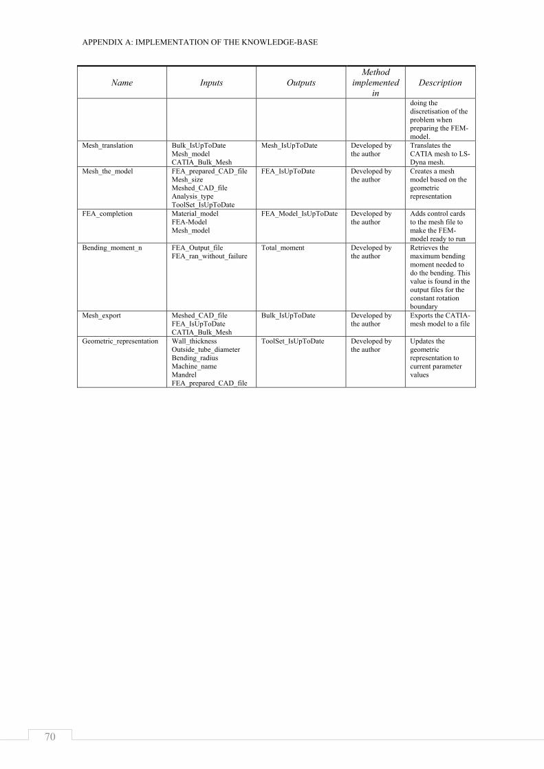
APPENDIX A: IMPLEMENTATION OF THE KNOWLEDGE-BASE
70
Name Inputs Outputs Method
implemented in
Description
doing the discretisation of the problem when preparing the FEM-model.
Mesh_translation Bulk_IsUpToDate Mesh_model CATIA_Bulk_Mesh
Mesh_IsUpToDate Developed by the author
Translates the CATIA mesh to LS-Dyna mesh.
Mesh_the_model FEA_prepared_CAD_file Mesh_size Meshed_CAD_file Analysis_type ToolSet_IsUpToDate
FEA_IsUpToDate Developed by the author
Creates a mesh model based on the geometric representation
FEA_completion Material_model FEA-Model Mesh_model
FEA_Model_IsUpToDate Developed by the author
Adds control cards to the mesh file to make the FEM-model ready to run
Bending_moment_n FEA_Output_file FEA_ran_without_failure
Total_moment Developed by the author
Retrieves the maximum bending moment needed to do the bending. This value is found in the output files for the constant rotation boundary
Mesh_export Meshed_CAD_file FEA_IsUpToDate CATIA_Bulk_Mesh
Bulk_IsUpToDate Developed by the author
Exports the CATIA-mesh model to a file
Geometric_representation Wall_thickness Outside_tube_diameter Bending_radius Machine_name Mandrel FEA_prepared_CAD_file
ToolSet_IsUpToDate Developed by the author
Updates the geometric representation to current parameter values
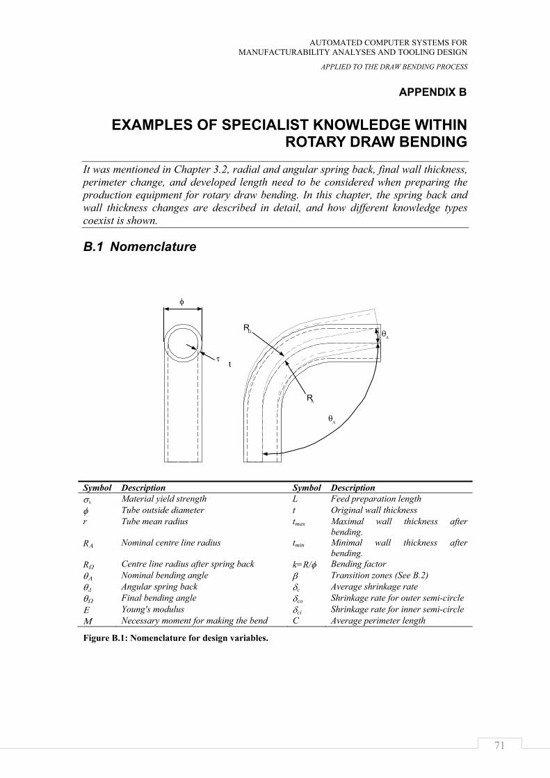
AUTOMATED COMPUTER SYSTEMS FOR MANUFACTURABILITY ANALYSES AND TOOLING DESIGN
APPLIED TO THE DRAW BENDING PROCESS
71
APPENDIX B
EXAMPLES OF SPECIALIST KNOWLEDGE WITHIN ROTARY DRAW BENDING
It was mentioned in Chapter 3.2, radial and angular spring back, final wall thickness, perimeter change, and developed length need to be considered when preparing the production equipment for rotary draw bending. In this chapter, the spring back and wall thickness changes are described in detail, and how different knowledge types coexist is shown.
B.1 Nomenclature
Symbol Description Symbol Description σy Material yield strength L Feed preparation length φ Tube outside diameter t Original wall thickness r Tube mean radius tmax Maximal wall thickness after
bending. RΑ Nominal centre line radius tmin Minimal wall thickness after
bending. RΩ Centre line radius after spring back k=R/φ Bending factor θΑ Nominal bending angle β Transition zones (See B.2) θΔ Angular spring back δc Average shrinkage rate θΩ Final bending angle δco Shrinkage rate for outer semi-circle Ε Young's modulus δci Shrinkage rate for inner semi-circle Μ Necessary moment for making the bend C Average perimeter length
Figure B.1: Nomenclature for design variables.
RΩ
RΑ
θΔ
φ
Αθ
τ t

APPENDIX B: BACKGROUND KNOWLEDGE OF THE ROTARY DRAW BENDING
72
B.2 Heuristic rules When asking skilled engineers that have done production preparation for rotary draw bending for years about spring back and wall thickness change, the answer was similar to what is found in handbooks.
When the bend radius is small, the tool will be manufactured to the nominal bend radius. It will then be decreased during a trial-and-error process until a satisfactory bend radius is found.
An expression for the angular spring back is found by doing linear interpolation between two experiment bends, typically 20 degrees and 120 degrees. A simple software application has been developed to help that process [22].
The minimum wall thickness is usually calculated using the following formula [22, 29, 30, 32]:
tR
Rt
2
min φ+
=
(1)
B.3 Analytically derived rules The scientific literature contains rules analytically derived from fundamental physical laws and theories on the plastic behavior of materials. The rules found make the assumption of ideal plastic material behavior.
To calculate the final radius of the tube after the bend action, the following rule is found [29-31]:
π⋅⋅⋅−=
Ω
Α
trEM
RR
31 (2)
This expression assumes constant plastic regions over the whole bend. In other words, the transition zones are not considered. For bending angles above 90 degrees, this assumption is fair enough. However, when decreasing the bending angle, the spring back will be increased to such an extent that this approximation will fail. The reason is that the transition zones, where the wall thickness is not completely plastic, will play a large role (See B.2figure ).
Figure B.2: The transition zones account for a big part of the spring back at small bending angles.
β
β β
β
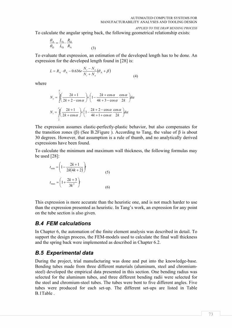
AUTOMATED COMPUTER SYSTEMS FOR MANUFACTURABILITY ANALYSES AND TOOLING DESIGN
APPLIED TO THE DRAW BENDING PROCESS
73
To calculate the angular spring back, the following geometrical relationship exists:
Α
Ω
Ω
Α
Ω
Α ⋅=RR
LL
θθ
(3)
To evaluate that expression, an estimation of the developed length has to be done. An expression for the developed length found in [28] is:
( )βθθ +
+−
−⋅= ΑΑΑoi
oi
NNNN
rRL 636.0 (4)
where
αα
αα
α
π
dkk
kk
kNo ⎟⎠⎞
⎜⎝⎛
−++
−×⎟⎠⎞
⎜⎝⎛
−++
= ∫ 2cos
cos34cos21
cos22122
0
αααα
α
π
π
dkk
kk
kNi ⎟⎠⎞
⎜⎝⎛
++−+
−×⎟⎠⎞
⎜⎝⎛
++
= ∫ 2cos
cos14cos221
cos212
2
The expression assumes elastic-perfectly-plastic behavior, but also compensates for the transition zones (β) (See B.2Figure ). According to Tang, the value of β is about 30 degrees. However, that assumption is a rule of thumb, and no analytically derived expressions have been found.
To calculate the minimum and maximum wall thickness, the following formulas may be used [28]:
( ) tkk
kt ⎟⎟⎠
⎞⎜⎜⎝
⎛+
+−=
242121min
(5)
t
kkt ⎟
⎠⎞
⎜⎝⎛ +
+= 2max 3321
(6)
This expression is more accurate than the heuristic one, and is not much harder to use than the expression presented as heuristic. In Tang’s work, an expression for any point on the tube section is also given.
B.4 FEM calculations In Chapter 6, the automation of the finite element analysis was described in detail. To support the design process, the FEM-models used to calculate the final wall thickness and the spring back were implemented as described in Chapter 6.2.
B.5 Experimental data During the project, trial manufacturing was done and put into the knowledge-base. Bending tubes made from three different materials (aluminum, steel and chromium-steel) developed the empirical data presented in this section. One bending radius was selected for the aluminum tubes, and three different bending radii were selected for the steel and chromium-steel tubes. The tubes were bent to five different angles. Five tubes were produced for each set-up. The different set-ups are listed in Table B.1Table .
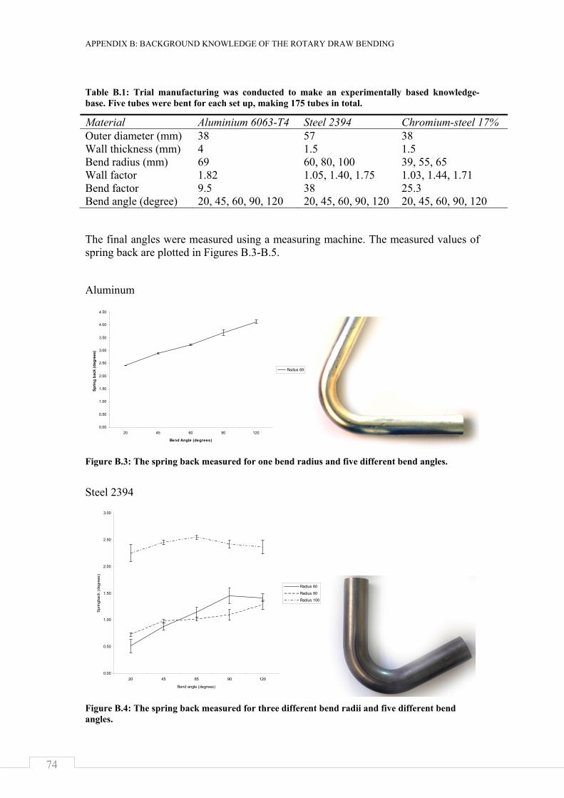
APPENDIX B: BACKGROUND KNOWLEDGE OF THE ROTARY DRAW BENDING
74
Table B.1: Trial manufacturing was conducted to make an experimentally based knowledge-base. Five tubes were bent for each set up, making 175 tubes in total.
Material Aluminium 6063-T4 Steel 2394 Chromium-steel 17% Outer diameter (mm) 38 57 38 Wall thickness (mm) 4 1.5 1.5 Bend radius (mm) 69 60, 80, 100 39, 55, 65 Wall factor 1.82 1.05, 1.40, 1.75 1.03, 1.44, 1.71 Bend factor 9.5 38 25.3 Bend angle (degree) 20, 45, 60, 90, 120 20, 45, 60, 90, 120 20, 45, 60, 90, 120
The final angles were measured using a measuring machine. The measured values of spring back are plotted in Figures B.3-B.5.
Aluminum
Figure B.3: The spring back measured for one bend radius and five different bend angles.
Steel 2394
Figure B.4: The spring back measured for three different bend radii and five different bend angles.
0.00
0.50
1.00
1.50
2.00
2.50
3.00
3.50
4.00
4.50
20 45 60 90 120
Bend Angle (degrees)
Sprin
g ba
ck (d
egre
es)
Radius 69
0.00
0.50
1.00
1.50
2.00
2.50
3.00
20 45 65 90 120
Bend angle (degrees)
Sprin
gbac
k (d
egre
es)
Radius 60
Radius 80
Radius 100
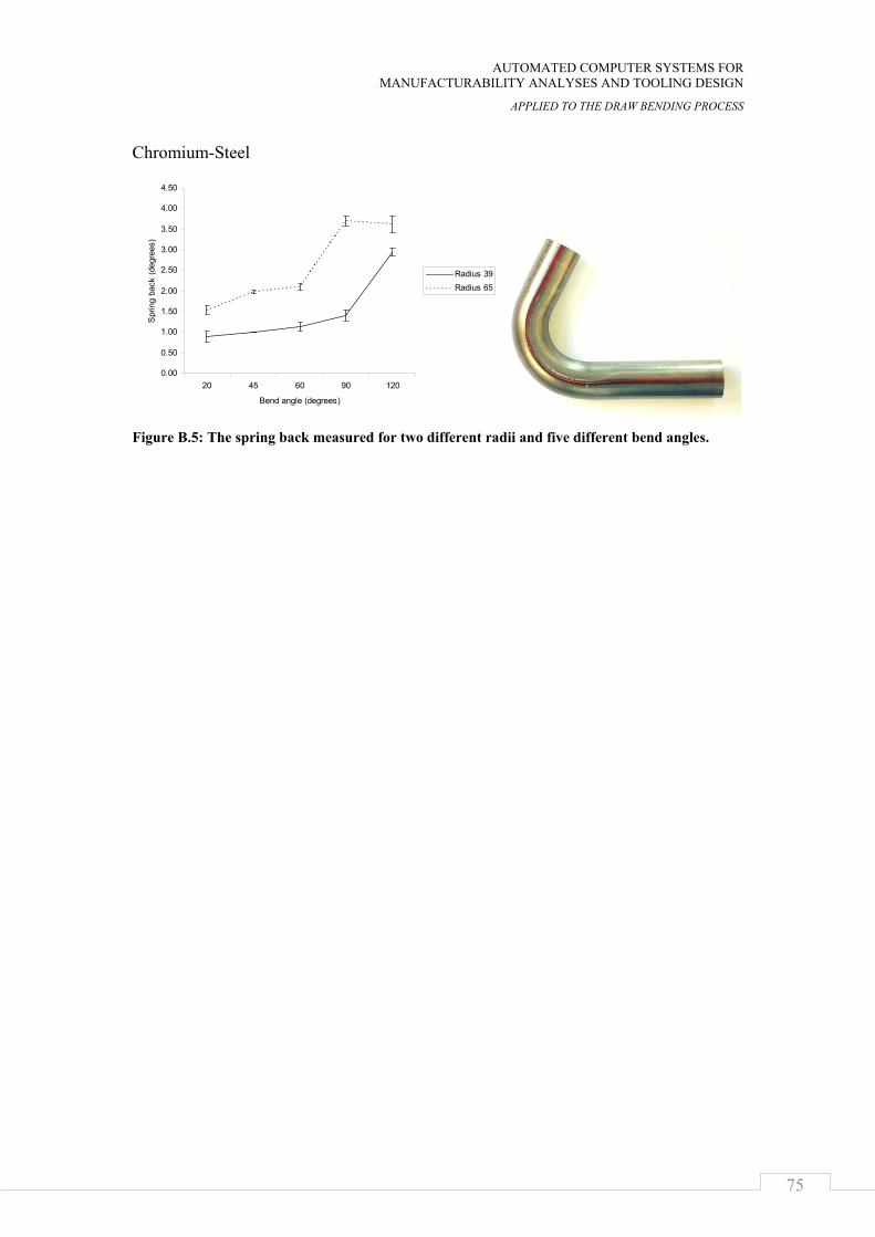
AUTOMATED COMPUTER SYSTEMS FOR MANUFACTURABILITY ANALYSES AND TOOLING DESIGN
APPLIED TO THE DRAW BENDING PROCESS
75
Chromium-Steel
Figure B.5: The spring back measured for two different radii and five different bend angles.
0.00
0.50
1.00
1.50
2.00
2.50
3.00
3.50
4.00
4.50
20 45 60 90 120
Bend angle (degrees)
Spr
ing
back
(deg
rees
)
Radius 39Radius 65

APPENDIX B: BACKGROUND KNOWLEDGE OF THE ROTARY DRAW BENDING
76
AUTOMATED COMPUTER SYSTEMS FOR MANUFACTURABILITY ANALYSES AND TOOLING DESIGN
APPLIED TO THE DRAW BENDING PROCESS
77
REFERENCES
[1] Chang, T.-C., Wysk, R. A., and Wang, H.-P., 2005, Computer integrated manufacturing, Prentice Hall, Harlow.
[2] French, M. J., 1999, Conceptual design for engineers, Springer, London.
[3] Parsaei, H. R., and Sullivan, W. G., 1993, Concurrent engineering : contemporary issues and modern design tools, Chapman & Hall, London; New York.
[4] Nau, D. S., Zhang, G., Gupta, S. K., and Karinthi, R. R., 1993, "Evaluating product machineability for concurrent engineering," Concurrent engineering : contemporary issues and modern design tools, H. R. Parsaei, and W. G. Sullivan, eds., Chapman & Hall, London; New York.
[5] Hannam, R. G., 1996, Computer integrated manufacturing : from concepts to realisation, Addison-Wesley, Harlow.
[6] Groover, M. P., 2007, Automation, production systems, and computer-integrated manufacturing, Prentice Hall, Harlow.
[7] Cederfeldt, M., and Elgh, F., "Design Automation Systems in SMEs : Current State, Potential, Need and Requirements," Proc. Engineering Design and the Global Economy : Proceedings of the 15th International Conference on Engineering Design, August 15-18, 2005, Melbourne, Australia.
[8] Cederfeldt, M., 2007, "Planning Design Automation : A Structured Method and Supporting Tools," Doctoral Thesis, Chalmers university of technology, Gothenburg.
[9] Suri, R., and Shimizu, M., 1989, "Design for analysis: A new strategy to improve the design process," Research in Engineering Design, 1(2), pp. 105-120.
[10] Simon, H. A., 1996, The sciences of the artificial, MIT Press, Cambridge, Massachusetts.
[11] Groot, A. D. d., 1969, Methodology; foundations of inference and research in the behavioral sciences, by Adriaan D. de Groot, Mouton, The Hague.
[12] Roozenburg, N. F. M., and Eekels, J., 1995, Product design : fundamentals and methods, Wiley, Chichester.
[13] Elgh, F., 2007, "Computer-Supported Design for Producibility : Principles and Models for System Realisation and Utilisation," Doctoral Thesis, Chalmers university of technology, Gothenburg.
[14] Luger, G. F., 2005, Artificial intelligence : structures and strategies for complex problem solving, Addison-Wesley, Harlow.
[15] Fulcher, J., 2006, Advances in applied artificial intelligence, Idea Group Pub., Hershey, PA.
[16] Jones, M. T., 2003, AI application programming, Charles River Media, Hingham, Massachusetts.
[17] Stokes, M., and MOKA Consortium, 2001, Managing engineering knowledge : MOKA: methodology for knowledge based engineering applications, Professional Engineering Publ., London.

REFERENCES
78
[18] Hopgood, A. A., 2001, Intelligent systems for engineers and scientists, CRC Press, Boca Raton.
[19] Sriram, R. D., 1997, Intelligent systems for engineering : a knowledge-based approach, Springer, London.
[20] Sellgren, U., 1995, "Simulation drive design : a functional view of the design process," Doctoral Thesis, KTH Royal Institute of Technology, Stockholm.
[21] Chapman, C. B., and Pinfold, M., 2001, "The application of a knowledge based engineering approach to the rapid design and analysis of an automotive structure," Adv. Eng. Softw., 32(12), pp. 903-912.
[22] C. Hernández, and Arjona, M. A., 2007, "Design of distribution transformers based on a knowledge-based system and 2D finite elements," Finite Elem. Anal. Des., 43(8), pp. 659-665.
[23] Sandberg, M., 2007, "Design for Manufacturing - Methods and Pallications using Knowledge Engineering," Doctoral Thesis, Luleå University of Technology, Luleå.
[24] Boart, P., 2007, "The Enabling of Product Information in the Conceptual Phase," Doctoral Thesis, Luleå University of Technology, Luleå.
[25] Stolt, R., 2008, "CAD-Model Parsing for Automated Design and Design Evaluation," Doctoral Thesis, Chalmers university of technology, Gothenburg.
[26] Bralla, J. G., 1999, Design for manufacturability handbook, McGraw-Hill, New York.
[27] Gupta, S. K., Regli, W. C., Das, D., and Nau, D. S., 1997, "Automated Manufacturability Analysis: A Survey," Research in engineering design., 9(3).
[28] Tang, N. C., 2000, "Plastic-deformation analysis in tube bending," International Journal of Pressure Vessels and Piping, 77(12), pp. 751-759.
[29] Gillanders, J., 1994, Pipe and Tube Bending Manual, Rockford, Illinois.
[30] Miller, G., 2003, Tube Forming Processes: A Comprehensive Guide, Society of Manufacturing Engineers, Dearborn.
[31] Abdel-Malek, K., and Maropis, N., 1998, "A design-to-manufacture case study: Automatic design of post-fabrication mechanisms for tubular components," Journal of Manufacturing Systems, 17(3), pp. 183-195.
[32] Cone, M., 2007, "Advanced Tubular Technologies, Home Page," Web Page, http://www.advancedtubular.com/.
[33] Jin, Z., Luo, S., and Daniel Fang, X., 2001, "KBS-aided design of tube bending processes," Engineering Applications of Artificial Intelligence, 14(5), pp. 599-606.
[34] Strano, M., 2005, "Automatic tooling design for rotary draw bending of tubes," The International Journal of Advanced Manufacturing Technology, 26(7), pp. 733-740.
[35] Baldwin, C. Y., and Clark, K. B., 2000, The power of modularity, MIT Press, Cambridge, Massachusetts.
[36] 2003, LS-DYNA keyword user's manual : Version 970, Livermore Software Technology Corp., Livermore, California.

AUTOMATED COMPUTER SYSTEMS FOR MANUFACTURABILITY ANALYSES AND TOOLING DESIGN
APPLIED TO THE DRAW BENDING PROCESS
79
[37] Aniket C., P., and Girish V., C., 2008, "Exploring the Design Space of Aluminum Tubing using Knowledge Objects and FEM," Master Thesis, Jönköping University, Jönköping.
[38] Wang, X., and Cao, J., 2001, "Wrinkling Limit in Tube Bending," Journal of Engineering Materials and Technology, 123(4), pp. 430-435.
[39] Elgh, F., and Cederfeldt, M., 2006, "Producibility Awareness as a Base for Design Automation Development : Analysis and Synthesis Approach to Cost Estimation," Leading the Web in Concurrent Engineering - Next Generation Concurrent Engineering : Proceedings of the 13th ISPE International Conference on Concurrent Engineering: Research and Applications, 18 - 22 September, 2006, Antibes, France, pp. 715-728.
[40] Arora, J. S., 2004, Introduction to optimum design, Elsevier, Amsterdam.

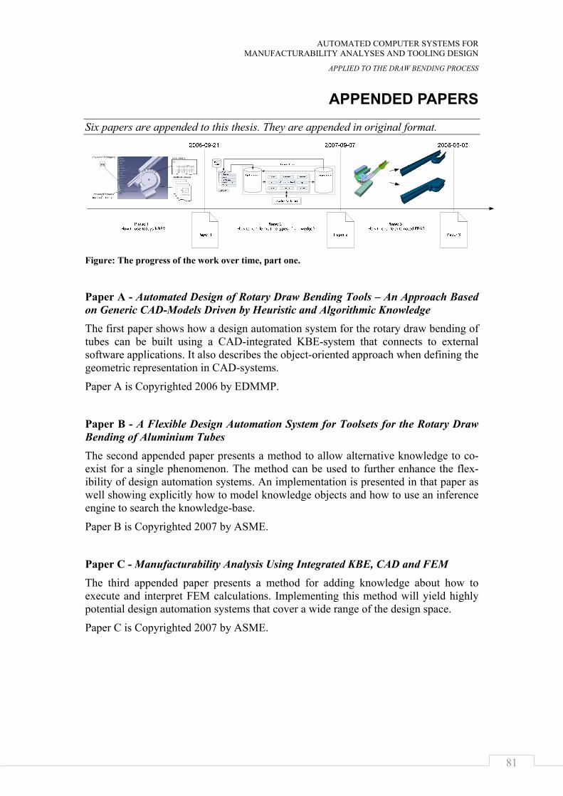
AUTOMATED COMPUTER SYSTEMS FOR MANUFACTURABILITY ANALYSES AND TOOLING DESIGN
APPLIED TO THE DRAW BENDING PROCESS
81
APPENDED PAPERS
Six papers are appended to this thesis. They are appended in original format.
Figure: The progress of the work over time, part one.
Paper A - Automated Design of Rotary Draw Bending Tools – An Approach Based on Generic CAD-Models Driven by Heuristic and Algorithmic Knowledge The first paper shows how a design automation system for the rotary draw bending of tubes can be built using a CAD-integrated KBE-system that connects to external software applications. It also describes the object-oriented approach when defining the geometric representation in CAD-systems.
Paper A is Copyrighted 2006 by EDMMP.
Paper B - A Flexible Design Automation System for Toolsets for the Rotary Draw Bending of Aluminium Tubes The second appended paper presents a method to allow alternative knowledge to co-exist for a single phenomenon. The method can be used to further enhance the flex-ibility of design automation systems. An implementation is presented in that paper as well showing explicitly how to model knowledge objects and how to use an inference engine to search the knowledge-base.
Paper B is Copyrighted 2007 by ASME.
Paper C - Manufacturability Analysis Using Integrated KBE, CAD and FEM The third appended paper presents a method for adding knowledge about how to execute and interpret FEM calculations. Implementing this method will yield highly potential design automation systems that cover a wide range of the design space.
Paper C is Copyrighted 2007 by ASME.
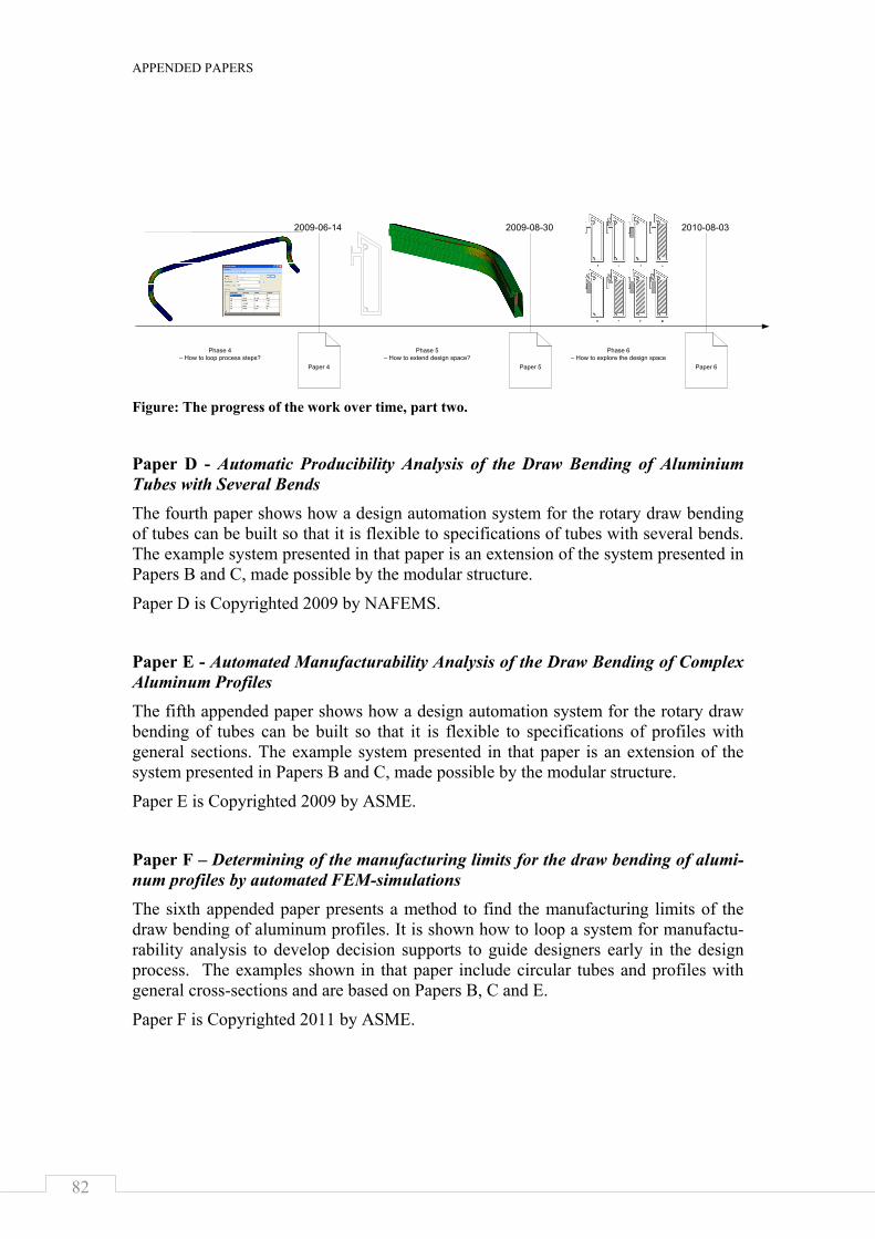
APPENDED PAPERS
82
Figure: The progress of the work over time, part two.
Paper D - Automatic Producibility Analysis of the Draw Bending of Aluminium Tubes with Several Bends The fourth paper shows how a design automation system for the rotary draw bending of tubes can be built so that it is flexible to specifications of tubes with several bends. The example system presented in that paper is an extension of the system presented in Papers B and C, made possible by the modular structure.
Paper D is Copyrighted 2009 by NAFEMS.
Paper E - Automated Manufacturability Analysis of the Draw Bending of Complex Aluminum Profiles The fifth appended paper shows how a design automation system for the rotary draw bending of tubes can be built so that it is flexible to specifications of profiles with general sections. The example system presented in that paper is an extension of the system presented in Papers B and C, made possible by the modular structure.
Paper E is Copyrighted 2009 by ASME.
Paper F – Determining of the manufacturing limits for the draw bending of alumi-num profiles by automated FEM-simulations The sixth appended paper presents a method to find the manufacturing limits of the draw bending of aluminum profiles. It is shown how to loop a system for manufactu-rability analysis to develop decision supports to guide designers early in the design process. The examples shown in that paper include circular tubes and profiles with general cross-sections and are based on Papers B, C and E.
Paper F is Copyrighted 2011 by ASME.
Paper 4 Paper 5 Paper 6
Phase 4– How to loop process steps?
2009-06-14 2009-08-30 2010-08-03
Phase 5– How to extend design space?
Phase 6– How to explore the design space