Embed Size (px)
Citation preview
Transportation Security Administration
Prepared by:
Lockheed Martin System Integration Team
4206 Blackshear Dr. • South Jordan, UT 84009
801.557.5472
Prepared for the
Transportation Security Administration (TSA)
CHECKPOINT DESIGN GUIDE (CDG)
Revision 6.1
June 01, 2016

This Page is Intentionally Left Blank

CHECKPOINT DESIGN GUIDE (CDG) i 2016.06.01 REVISION 6.1
The Transportation Security Administration (TSA) Checkpoint Design Guide (CDG) is prepared to help TSA Headquarters (TSA HQ), local TSA, airport stakeholders, and architectural and engineering (A&E) firms produce a consistent design product.
The CDG is intended to be used as a design guide. Not all answers
to questions in the design process are addressed in this document
and deviations are sometimes warranted. Seek guidance from the
local Federal Security Director (FSD), TSA checkpoint designer,
deployment coordinator, and TSA Occupational Safety, Health and
Environment (OSHE) when the guidelines cannot be applied. As with
any guide, previous experience, knowledge of local and national codes,
and professional judgment are to be integrated with the direction
provided herein to develop the optimum design.
This document is intended to be printed double-sided. Select
flip short edge when printing.
All graphics/drawings contained in this document are not meant to
be scaled.
DISCLAIMER

CHECKPOINT DESIGN GUIDE (CDG) ii 2016.06.01 REVISION 6.1
This guide is organized into 4 parts, in which each are geared to a
specific audience. There are many moving parts in designing TSA
SSCPs and although all the information in this guide is important,
some may not need to have as much specific information for certain
aspects of a checkpoint. Following is summary of each part of this
document to help direct to specific information as it applies to the
required audience.
PART 1 – INTRODUCTION
1-1 - Introduction to Security Screening Checkpoints
Section 1-1 is designed to familiarize the reader of this document with the purpose of TSA Security Checkpoints. General information is provided to inform all audiences and is an aide to direct the reader to the specific information for designing a new SSCP.
PART 2 – SSCP ROLES, RESPONSIBILITIES, & PROJECT PHASING
2-1- Section 2-1 describes the roles, responsibilities, and project phasing of design, installation, and certification of TSA Equipment.
2-2 – Section 2-2 outlines the equipment installation, decommission, and closeout.
PART 3 – SSCP ELEMENTS, LAYOUTS, AND SPECIFICATIONS
3-1 - Standard SSCP Layouts
Section 3-1 identifies the requirements for a new or reconfigured SSCP design including queuing, pre-screening, passenger screening, carry-on screening, and risk based security. This section provides the requirements for equipment spacing and orientation of TSA standard layouts.
3-2 - Transportation Security Equipment (TSE)
Section 3-2 includes detailed specifications and graphics of all the standard TSE currently being deployed to airports for SSCP. The section is organized to introduce TSE as a passenger travels through a checkpoint. Each piece of equipment in a SSCP has specific dimensional and electrical requirements. Attention to specifications is crucial to ensure that the equipment is installed and operates as required.
3-3 - SSCP Electrical, Data, and Safety Requirements
Section 3-3 describes, in more detail, the power and data requirements for each piece of equipment as well as the power and data infrastructure required for a SSCP. Standard layouts and configurations of electrical/ data devices are depicted to improve checkpoint infrastructure consistency. This section also identifies the safety requirements for the checkpoint.
PART 4 – DESIGN AIDES
4-1 – Checklists and Lessons Learned
Section 4-1 is used to aide in SSCP design and TSE Installation by identifying common oversights. Guidance is provided for equipment placement and drawing production standards.
4-2 – Standard Equipment Dimensional Criteria
4-2 includes standard layouts for multiple manufacturers’ AT X-rays with various configurations. When designing a new checkpoint, the designer should refer to a standard layout or a combination of multiple layouts.
4-3 – SSCP Terminology
Section 4-3 provides a list of common acronyms and their definitions which occur throughout this document.
HOW TO USE THIS GUIDE

CHECKPOINT DESIGN GUIDE (CDG) iii 2016.06.01 REVISION 6.1
TABLE OF CONTENTS
PART 1 – Introduction 1-1 INTRODUCTION TO SECURITY SCREENING CHECKPOINTS (SSCP) ............................ 1 1-1.1 GENERAL INFORMATION ........................................................................................................................................ 3
1-1.2 AIRPORT OPERATIONAL TYPES ........................................................................................................................... 5
PART 2 – Roles, Responsibilities, and Project Phasing 2-1 CONSTRUCTION AND PREPARATION ........................................................................................... 7 2-1.1 PROJECT PHASING ............................................................................................................................................... 10
2-1.1.1 PLANNING CONSIDERATIONS ............................................................................................................... 12
2-1.1.2 PROJECT DESIGN PROCESS ................................................................................................................ 13
2-1.1.3 DESIGN PHASES AND DELIVERABLE MILESTONES........................................................................... 14
2-1.2 DEPLOYMENT ........................................................................................................................................................ 16
2-1.2.1 CONSTRUCTION PHASE ........................................................................................................................ 16
2-1.2.2 EQUIPMENT INSTALLATION PHASE ..................................................................................................... 16
2-1.2.3 EQUIPMENT DECOMMISSION ................................................................................................................ 16
2-1.2.4 SHIPPING, RIGGING, AND WAREHOUSING ......................................................................................... 16
2-1.2.5 PROJECT CLOSEOUT PHASE ................................................................................................................ 16
PART 3 – SSCP Elements, Layouts, and Specifications 3-1 STANDARD SSCP LAYOUTS ................................................................................................................ 17 3-1.1 STANDARD SSCP ARRANGEMENT ..................................................................................................................... 18
3-1.2 RISK BASED SECURITY (RBS) ............................................................................................................................. 21
3.-1.2.1 TSAPRE® .............................................................................................................................................. 21
3-1.2.2 QUEUE MANAGEMENT ........................................................................................................................... 24
3-1.2.3 RBS PASSENGER QUEUE LAYOUT EXAMPLES .................................................................................. 24
3-1.3 SSCP BOUNDARIES .............................................................................................................................................. 27
3-1.4 EXIT LANE ............................................................................................................................................................... 27
3-2 TRANSPORTATION SECURITY EQUIPMENT (TSE) ................................................................ 29
3-2.1 PRE-SCREENING PREPARATION INSTRUCTION ZONE ................................................................................... 31
3-2.1.1 TSA MANDATORY SIGNS ....................................................................................................................... 31
3-2.1.2 TSA INSTRUCTIONAL SIGNS ................................................................................................................. 31
3-2.1.3 TSA DIRECTIONAL SIGNS ...................................................................................................................... 31

CHECKPOINT DESIGN GUIDE (CDG) iv 2016.06.01 REVISION 6.1
3-2.1.4 TSA LOCAL SIGNS ................................................................................................................................... 31
3-2.2 QUEUE .................................................................................................................................................................... 32
3-2.2.1 TRAVEL DOCUMENT CHECKER (TDC) & CREDENTIAL AUTHENTICATION TECHNOLOGY (CAT) 33
3-2.3 BIN CART ................................................................................................................................................................ 36
3-2.4 DIVEST TABLE ........................................................................................................................................................ 37
3-2.5 CARRY-ON BAG SCREENING ............................................................................................................................... 38
3-2.6 ADVANCED TECHNOLOGY (AT) X-RAY ............................................................................................................... 39
3-2.6.1 MANUAL DIVERTER ROLLER (MDR) ..................................................................................................... 47
3-2.6.2 COMPOSURE/ EXTENSION ROLLERS .................................................................................................. 48
3-2.7 WALK THROUGH METAL DETECTOR (WTMD) ................................................................................................... 51
3-2.8 ADVANCED IMAGING TECHNOLOGY (AIT) ......................................................................................................... 53
3-2.8.1 AIT WITH CO-LOCATED ETD .................................................................................................................. 54
3-2.8.2 SLOPE TOLERANCE ................................................................................................................................ 54
3-2.9 BARRIERS ............................................................................................................................................................... 57
3-2.10 ADA/ACCESS GATE ............................................................................................................................................... 58
3-2.11 PASSENGER INSPECTION .................................................................................................................................... 59
3-2.11.1 PRIVATE SCREENING ROOM (PSR) .................................................................................................... 59
3-2.12 SECONDARY SCREENING ................................................................................................................................... 61
3-2.12.1 EXPLOSIVE TRACE DETECTION ......................................................................................................... 61
3-2.12.2 BOTTLE LIQUID SCANNER (BLS) ......................................................................................................... 61
3-2.12.3 MOBILE CABINETS ................................................................................................................................ 63
3-2.12.4 BAG SEARCH TABLE ............................................................................................................................. 64
3-2.12.5 PASSENGER SEARCH POSITION ........................................................................................................ 64
3-2.13 COMPOSURE BENCH ............................................................................................................................................ 65
3-2.14 SUPERVISORY TRANSPORTATION SECURITY OFFICER (STSO) PODIUM .................................................. 65
3-3 SSCP ELECTRICAL, DATA AND SAFETY REQUIREMENTS .............................................. 67 3-3.1 DATA REQUIREMENTS ....................................................................................................................................... 67
3-3.2 POWER REQUIREMENTS ................................................................................................................................... 74
3-3.3 POWER/DATA RECEPTACLES ............................................................................................................................ 76
3-3.4 POWER/DATA CONFIGURATIONS ..................................................................................................................... 80
3-3.5 POWER/DATA PLANS ........................................................................................................................................... 84
3-3.6 CCTV REQUIREMENTS ........................................................................................................................................ 86
3-3.7 DURESS ALARM REQUIREMENTS ...................................................................................................................... 88
3-3.8 LIGHTING REQUIREMENTS ................................................................................................................................. 90

CHECKPOINT DESIGN GUIDE (CDG) v 2016.06.01 REVISION 6.1
3-3.9 SAFETY REQUIREMENTS ..................................................................................................................................... 91
PART 4 – Design Aides 4-1 CHECKLISTS AND LESSONS LEARNED ....................................................................................... 92 4-1.1 QC PLAN CHECKLIST ........................................................................................................................................... 93
4-1.2 QC PLAN DIMENSION CRITERIA .......................................................................................................................... 94
4-1.3 BEST PRACTICES .................................................................................................................................................. 95
4-1.4 STANDARD POWER/DATA LAYOUT & CONFIGURATIONS ............................................................................... 96
4-2 STANDARD EQUIPMENT DIMENSIONAL CRITERIA .............................................................. 98 4-2.1 SMITHS LAYOUTS ................................................................................................................................................. 99
4-2.2 RAPISCAN LAYOUTS ........................................................................................................................................... 123
4-3 SSCP STRUCTURAL CONSIDERATIONS .................................................................................. 147
4-4 SSCP TERMINOLOGY ........................................................................................................................... 149

This Page is Intentionally Left Blank

CHECKPOINT DESIGN GUIDE (CDG) vii 2016.06.01 REVISION 6.1
CDG Revision Log
Date Revision No. Description Section(s) Affected
12/17/08 0 Original publication All Sections: 1, 2, 3, 4, 5, & 6
02/11/09 1 Incorporated OIB feedback from the original publication. All Sections: 1, 2, 3, 4, 5, & 6
02/19/10 2 Incorporated power/data requirements for all SSCP equipment. Section 4 Only
03/10/11 3 Updated the SSCP equipment, the arrangements, and the electrical requirements.
All Sections: 1, 2, 3, 4, 5, & 6
08/29/12 4 Updated the SSCP equipment, the arrangements, and the electrical requirements.
All Sections: 1, 2, 3, 4, 5, & 6
11/09/12 4.1 Quarterly update - AIT power location, AWT language, x-ray brand, ETD procurement
Sections 2, 8 (pages 17, 40-
41, and 110-117)
09/23/13 5.0 Updated the SSCP equipment, removed Rapiscan AIT reference,
removed AWT language, updated the arrangements, and the electrical
requirements.
All Sections: 1, 2, 3, 4, 5, 6, 7, 8 & 9
05/07/14 5.1 Updated language in section 1.5, updated Figure 1.4, updates to Section 7.1 Checklist.
Sections 1 & 7
12/30/15 6.0 Reformat document, included Construction, Deployment, and Installation Section, removed references to legacy equipment, update several figures, add L3 Provision2 AIT.
All Sections
06/01/16 6.1 Added requirement for a mirror in the Private Screening Room. Updated all standard layouts with the AIT2. Provided dimensional and weight information for structural analysis guidelines.
Sections 3 & 4

This Page is Intentionally Left Blank

CHECKPOINT DESIGN GUIDE (CDG) 1 2016.06.01 REVISION 6.1
The Transportation Security Administration (TSA) is mandated by
law to screen air travelers and their carry-on bags in order to
intercept prohibited items at the Security Screening Checkpoints
(SSCP) at approximately 450 airports across the United States. Since
each checkpoint represents a point of entry into the aviation system,
each must meet security criteria. SSCPs were less complex pre-9/11.
SSCPs have evolved considerably since the formation of TSA in
2002, and continue to evolve with improved technology and increased
experience. Because the threat environment is constantly changing,
this Checkpoint Design Guide (CDG) was created to communicate
the most current accepted guidelines for checkpoint design.
The intent of this document is to provide a description of the SSCP
equipment that is used today. Also included is information that can be
used to locate equipment within the checkpoint to provide the
highest level of security screening and efficiency beginning at the
queue and continuing through the composure area. The information in
this guide should be used when designing new checkpoints or
reconfiguring existing checkpoints. All designs and reconfigurations
must be coordinated with TSA checkpoint designer and deployment
coordinator, local FSD and staff, and local airport stakeholders so that
the recommended guidelines can be site-adapted for each checkpoint.
This document is a “living” document that is updated when new
technologies or processes are adopted by TSA.
There are multiple layers of security in place at airports today to
facilitate the safe movement of people and commerce throughout
the airport transportation system. These layers are roadblocks to
potential terrorist paths because they are equipped to detect and
minimize threats that could occur. Refer to Figure 1-1.1.
Every airport and airport terminal building is unique in physical
design and operational requirements. A single SSCP solution will
not work for every checkpoint, nor will it work for every checkpoint
at the same airport. Every SSCP location must be reviewed as an
entity of the overall airport security system. The CDG provides
direction and recommendations on how to construct, deploy
equipment, install equipment, and locate and size a new SSCP based
on the following conditions.
Facility Infrastructure & Operations
Current Screening Technology/Equipment
Type of Risk that is Present or Anticipated
Passenger Loads/Number of Enplanements
Improper SSCP design can result in terminal and checkpoint
queue congestion, decreased efficiencies, flight delays, missed
flights, and unnecessary security risks. Proper SSCP design helps
avoid costly problems for the airport, airlines, and TSA. It also
provides a smoother and safer experience for the passenger while
increasing the efficiency of the screening process.
Once the checkpoint is laid out per the design there should be no
adjustments or deviations from its design unless it is reviewed and
approved by the design team.
This document is divided so that each section is directed to a
specific audience. When using this guide, each part and/or section
may be more directed to the scope of work one may be involved in
when installing a new SSCP. Part 1 is included to identify each
section and which information is specific to the reader of this guide.
Part 1 also covers different airport classifications and their
importance to security. It is recommended that an audience who is
new to TSA SSCP design and implantation read through this
section to get an understanding of general TSA screening
information.
1-1 INTRODUCTION TO SECURITY SCREENING CHECKPOINTS (SSCPS)

CHECKPOINT DESIGN GUIDE (CDG) 2 2016.06.01 REVISION 6.1
Figure 1-1.1 Twenty One Layers of Security

CHECKPOINT DESIGN GUIDE (CDG) 3 2016.06.01 REVISION 6.1
SSCPs are a critical element to an airport’s overall terminal design and must be considered in the early stages of planning and conceptual layout.
Security screening is intended to deter and prevent hijackings and the
transport of explosives, incendiary, or dangerous weapons aboard
commercial aircraft. Sterile areas are defined as those areas where
aircraft access is possible only for persons that have undergone
security screening. Non-sterile areas are accessible to the general
public and are generally located near the ticketing counters and areas
before the airport concourse(s).
When designing a new terminal or checkpoint, or reconfiguring an
existing terminal or checkpoint, the following should be considered
during design:
Sufficient square footage to support current TSA technology
and screening processes
Ability to secure exit lanes during operational and non-
operational hours of the SSCP with locking doors and/or
continuous staffed law enforcement officers
Wheelchair accessibility and allowances for persons with
disabilities and/or assistive devices
Minimal interruption or delay to the flow of passengers and
others being screened
Effective and secure handling of goods that are transported
from the non-sterile area to the sterile area
Protection of SSCP equipment during non-operational hours
Equipment maintenance clearances
Operational flexibility in response to changes in passenger
loads, equipment, technology, processes, and security levels
Efficient and effective use of terminal space
Acceptable and comfortable environmental factors, such as air
temperature, humidity, air quality, lighting, and noise
Safe and ergonomic design
Coordination of power, data, fiber optics, CCTV, and lighting
at the SSCP
Contingency plans for power outages and system challenges
(good practice for the airport, but not required by TSA for the
checkpoint)
Allowance for TSA office / support space which needs to be
negotiated through the TSA Office of Real Estate
Staffing efficiency for TSA and other security personnel
1-1.1 GENERAL INFORMATION

CHECKPOINT DESIGN GUIDE (CDG) 4 2016.06.01 REVISION 6.1
Figure 1-1.2 Example SSCP

CHECKPOINT DESIGN GUIDE (CDG) 5 2016.06.01 REVISION 6.1
Airports are typically categorized by the number of enplanements per year. This defines the airport’s category as “X, I, II, III, and IV.” Category X or CAT X airports are the busiest of the Federal Airports, Category IV or CAT IV airports may have only a few flights arriving/ departing each week.
Airports are also classified as a hub, spoke of a hub, or stand-alone. Airports can be characterized as Transfer/Hub, Origin and Destination (O&D), or a combination of the two, with regional and commuter traffic included in all three.
In Transfer/Hub airports, transfer passengers frequently move from gate to gate without passing through an airport SSCP. If concessions are located in the non-sterile area, there is incentive for passengers to exit the sterile area and subsequently re-enter the sterile area through the SSCP, thus increasing the passenger load that might otherwise be unnecessary. In this arrangement, concessions are suggested to be located in the sterile area to allow passengers to move among gates along multiple concourses without needing to be re-screened..
Each airport category may have different SSCP layout requirements and when constructing a new checkpoint, a designer should take into consideration the particular category of that airport. Throughout this guide requirements for different categorized airports are discussed.
1-1.2 AIRPORT OPERATIONAL TYPES

This Page is Intentionally Left Blank

CHECKPOINT DESIGN GUIDE (CDG) 7 2016.06.01 REVISION 6.1
If an airport is constructing a new or modifying an existing TSA security screening checkpoint, close coordination with many stakeholders is required. The responsibilities may vary depending on the conditions of the checkpoint modifications. The following describes typical roles and responsibilities for primary project stakeholders interested in modifying or constructing a new checkpoint.
1. Airport Authority - Local representative of overall airport operations
» Consult on basic engineering, operations, IT, maintenance, master planning, project management, and other appropriate design functions
» Coordinate with project sponsor and TSA Headquarters for specific procedural and funding responsibilities
2. Project Sponsor – Airport owner/operator or airline funding and initiating checkpoint improvements
» Initiation and execution of planning and design
» Initiation and execution of construction
» Provide technical recommendations
» Provide structural, electrical/data, duress alarm and architectural designs
» Produce checkpoint layout design, phasing, and electrical/data design drawings to issue for construction drawings in accordance with the latest CDG
3. TSA Headquarters – Representative from TSA responsible for review and approval of all design submittals, funding of modifications, and prioritization of equipment deployments.
» Operations and maintenance of checkpoint
» Determine the number of lanes required or permitted at a checkpoint based on Airport Category, Unique Security Requirements, and Passenger Volume.
» Provide regular correspondence of lessons learned and regularly update stakeholders of design and process changes
» Perform technical and operational review of designs
» Review impact of screening protocol changes
» Brainstorm operational and policy issues
» Determine the specific equipment type to be used
» Determine the scheduling of deploying new equipment
» Consult with TSA OSHE Specialists as needed
» Ensure optimal design to mitigate unnecessary stress to passengers and TSOs
4. Design/Integration Team – Formed to plan, design, ship/in- stall, and modify checkpoint
» Consult directly with TSA Design Team
» Coordinate shipping, storing, transporting, and installing equipment at the checkpoint
» Coordinate with contractors as required for checkpoint infrastructure improvements
» Consult with project stakeholders
Figure 2-1.1 describes the process and stakeholder coordination when designing and constructing an SSCP.
2-1 ROLES, RESPONSIBILITIES, AND PROJECT PHASING

CHECKPOINT DESIGN GUIDE (CDG) 8 2016.06.01 REVISION 6.1
Figure 2-1.1 Project Stakeholder RACI Chart
Project Phase Project Sponsor TSA Applicable CDG Section
Prepare Construction Documents Responsible 2-1.1
SSCP Design Optimization Review Advise Responsible/Advise 2-1.1 3-1
Equipment Layout Responsible Advise Part 3
Electrical Layout Responsible Advise Section 3-3
Selection of Electrical/Data Device Type Responsible Advise Section 3-3
Designation of IT Cabinet Location Responsible Advise Section 3-3
Design of Fiber optic Connections Responsible Advise Section 3-3
Design of CCTV Responsible Inform/ Advise Section 3-3
Phasing Plans (Equipment Installation) Responsible Inform/Advise Part 2
Phasing Plans (Bldg/Construction) Responsible Part 2
Queue Design Responsible Advise 3-1.2, 3-2.2
Private Screening Room Location Responsible Advise 3-2.11
Airport Modifications Responsible Part 2 22
Structural Engineering Responsible Part 2
Seismic Engineering Responsible Part 2
Equipment Installation Inform Responsible Part 2 / Section 3.2
Equipment Decommission Inform Responsible Part 2
Rigging Advise/Inform Responsible Part 2
Shipping Inform Responsible Part 2
Warehousing Inform Responsible Part 2

CHECKPOINT DESIGN GUIDE (CDG) 9 2016.06.01 REVISION 6.1
Figure 2-1.1 Project Stakeholder RACI Chart (cont.)
Project Phase Project Sponsor TSA Applicable CDG Section
Electrical & Data Infrastructure Installation/Relocation
Responsible Section 3-3
Electrical Outlets Responsible Section 3-3
Electrical Cabling Responsible Section 3-3
Electrical Panel (If Required) Responsible Section 3-3
Data Outlet and Cablings Responsible Section 3-3
Duress Alarm Responsible Section 3-3
IT Cabinet Responsible Inform Section 3-3
Patch Panel(s) Responsible Inform Section 3-3
Data Switch Advise Responsible Section 3-3
Airport Modifications - Construction Responsible Part 2
Permitting Responsible Part 2
Wall Relocation or Demolition Responsible Part 2
Ceiling Height Adjustment Responsible Advise Part 2
Private Screening Room Installation Responsible Advise 3-2.11
CCTV Responsible Advise 3-3.6
Floor Repair Responsible Part 2
Cleanup Responsible Part 2
Responsible - Those who do the work and achieve the task
Advise - Those who recommend subject matter to the responsible party to complete a task
Consult - Those whose opinions are sought, typically subject matter experts; and which there is two-way communication
Inform - Those who are kept up-to-date on progress, often only on completion of the task or deliverable; and which there is just one-way
communication

CHECKPOINT DESIGN GUIDE (CDG) 10 2016.06.01 REVISION 6.1
New construction and checkpoint reconfigurations to the SSCP must be closely coordinated with TSA Checkpoint Designer, Deployment Coordinator, Federal Security Director & Staff, government agencies, and airport/ airline operations. The multiple stakeholders’ involvement is crucial to the ensure proper equipment and resources are deployed to support the changes that heightens security, increases throughput, reduces on-the-job injuries, makes staffing more dynamic, improves passenger experience, and is consistent with this design guide.
Funding for SSCP modifications or reconfigurations will depend on
the scope of work. TSA Checkpoint Designer and Deployment
Coordinator may approve the work, but may not provide all or any of
the funding for it.
It is the Airport Authority’s responsibility to fund and hire the A&E
firms that create the designs for airport-initiated projects and that
will follow the TSA Checkpoint Design Guide. When an airport
adds screening lanes due to new terminal construction, or when
approved as the result of increased passenger throughput, TSA HQ
will provide Transportation Security Equipment (TSE) and fund its
installation. When an Airport Authority builds a new terminal that
will replace an existing one, the Airport Authority is responsible for
funding the required infrastructure and construction, and TSA HQ
will provide Transportation Security Equipment (TSE) and fund its
installation. When Airport Authority-initiated TSE moves become
necessary for other needs (e.g. temp screening location, remodeling,
carpet cleaning, floor tile replacement, etc.), the Airport Authority
will fund the removal and reinstallation of the TSE. The Airport
Authority is responsible to fund all construction and infrastructure
costs associated with the relocation or installation of TSE, and will
do so following the standards identified in the TSA Checkpoint
Design Guide. Depending on scope of work, funding may vary.
However, all designs must be approved by TSA Headquarters
To document a request for movement of TSE in a construction
project, a request must be submitted to TSA HQ. The request
must include language that states the responsibility for funding of
airport-initiated projects by the Airport Authority, and their
acceptance of project funding responsibility. The request language
must also include the acceptance of funding responsibility by the
Airport Authority for any airport-initiated equipment moves
related to other actions (e.g. remodeling, carpet cleaning, floor tile
replacement, etc.).
There may be circumstances when shared cost solutions will be
considered by TSA. TSA checkpoint designer, deployment
coordinator, local TSA, airport stakeholders, and the SSCP
designer should determine funding responsibilities in the early
planning stages of the project before design begins.
An outline of the checkpoint modification process is shown in Figure 2-1.2 starting with project inception all the way to project approval. Local TSA and airport stakeholders should follow this process when modifications to an existing SSCP are needed. Once the project is approved, the appropriate department within TSA HQ helps local TSA and the airport stakeholders execute the project. Tasks vary from shipping equipment to putting the project out for bid.
2-1.1 PROJECT PHASING

CHECKPOINT DESIGN GUIDE (CDG) 11 2016.06.01 REVISION 6.1
Figure 2-1.2 Checkpoint Modification Process

CHECKPOINT DESIGN GUIDE (CDG) 12 2016.06.01 REVISION 6.1
2-1.1.1 PLANNING CONSIDERATIONS
SSCPs are created by combining standard 1- and 2-lane module sets. A
typical 1-lane module set consists of a Travel Document Checker (TDC),
X-ray, Manual Diverter Roller (MDR), Walk Through Metal Detector
(WTMD) and/or Advanced Imaging Technology (AIT), Alternate
Viewing Station (AVS), Explosive Trace Detection (ETD), Bottle Liquid
Scanner (BLS), Passenger Inspection, and Bag Inspection. A 2-lane
module set is the same as a 1-lane module set with the addition of
another X-ray. These module sets are discussed in more detail in Part
3. The module sets are created based on the recommended TSA
spacing for passenger ingress/egress, clearance for maintenance
activities, and prevention of passenger breaches. Separation of sterile
and non-sterile areas provides a controlled and contained screening
environment.
A modular design enables TSA to determine the depth and width
needed for a set number of lanes. The number of lanes is based on the
passenger load and the physical space provided by the airport. Contact
TSA Headquarters to assist with determining the number of lanes
needed to meet the passenger load in the space allotted for the SSCP. As
the number of enplanements per year increases and the equipment and
technology evolve, the SSCP needs to have the flexibility to change and
expand. Allowances for modifications must be included in the Airport
Master Plan.
Vulnerabilities specific to a particular airport will dictate where the
checkpoint is situated within the terminal. Some airports may locate the
SSCP at or near the entrance of the terminal, making all spaces beyond
the SSCP sterile. Thoughtful consideration must be given to passenger
queuing if the SSCP is placed near the terminal entrance. Massing
people in public areas should be avoided. The more common choice is to
position the SSCP deep in the terminal. During periods of elevated
threat or special events, temporary SSCPs may need to be installed. If
this is a potential option, floor space and temporary utilities should be
planned into the terminal design by the airport.
Airports with international flights require a dedicated Federal
Inspection Service (FIS) checkpoint, specifically for arriving
international passengers transferring to a domestic flight. Arriving
international passengers are required to undergo U.S. screening before
transferring to a domestic flight because the U.S. screening process has
different requirements and provisions than screening processes at
non- U.S. origins.
The screening requirements for a FIS checkpoint are the same as
other checkpoints, but the volume varies based on the frequency of
inbound international flights.
Care should be taken to preserve the paths and clearances required by
the local and national building codes to provide for barrier-free
movement in the checkpoint and life safety requirements for exiting.
Observing exiting for airport and TSA staff as well as passengers is
gaining closer scrutiny from the reviewing agencies. Some locations
may require emergency exiting through a checkpoint. Many sites
require exit studies showing how the checkpoint affects the emergency
exiting of the terminal as a whole. This could require modifications or
additions to the checkpoint beyond guidelines set herein.
Airport security technology is a dynamic and rapidly changing field.
No matter how carefully an airport is designed to take maximum
advantage of the current technology, designs must be sufficiently
adaptable to meet the changing threats and support future technology.
Security screening equipment dimensions and/ or processes may
change, requiring the entire airport security managerial infrastructure
to make important decisions regarding modifications, which the
designer must then accommodate. The designer’s task will be easier if
the original design has anticipated the need for change and has
provisions for expansion. Electrical and data infrastructure should also
be flexible. Planning ahead for adaptable electrical/data devices will
best support future changes.
Key TSA individuals (including checkpoint designer, deployment
coordinator, and local FSD /staff), government agencies, and airport/
airline operations should be involved during the SSCP deployment
process. These groups will be able to facilitate dialogue regarding local
building codes, mutual aid agreements with local law
enforcement/emergency responders, and joint commercial/military
entities.
Permitting and approvals may be factors in design and final deliverables.
Depending on site location and project complexity, permits and
approvals may or may not be required. This should be determined
early in the project. Some sites require airport authority approval
only. Permitting or approvals may require additional information in
the deliverable that is beyond the information given in this guideline.
Early determination of approval requirements will avoid inconvenient
and costly changes later in the process.

CHECKPOINT DESIGN GUIDE (CDG) 13 2016.06.01 REVISION 6.1
2-1.1.2 PROJECT DESIGN PROCESS
The design for improving existing TSA security screening
checkpoints is ongoing while new technology is being developed and
deployed to U.S. Federalized airports across the country. The
process for designing a new checkpoint generally includes an initial
30% design, TSA and airport authority review, final design,
construction/ installation, and record drawing completion. Figure
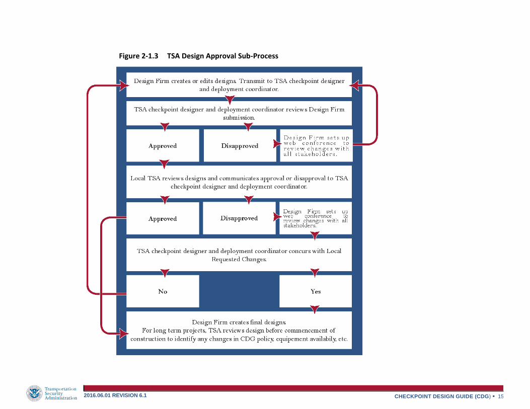
2-1.3 illustrates the TSA design review sub-process. This critical sub-
process ensures designs meet the requirements of the CDG, allows
for TSA review and concurrence with deviations from the CDG,
and allows opportunities to understand the impact to building
infrastructure. The following describes the basic design procedures
for designing a new security screening checkpoint.
When a new checkpoint layout is required, TSA requires the
Architect and Engineering (A&E) designer to begin a design using
the criteria as described in this Checkpoint Design Guide. This
design is based upon the deployment of new equipment and/or
relocation of existing equipment which is typically outlined in a
deployment schedule produced by TSA. Equipment layout and
dimensional requirement checklists are provided in Sections 4-1
and 4-2 to provide quality assurance/quality control that the layout
meets general guidelines for a security checkpoint.
All designs are currently to be produced in AutoCAD 2007 format.
The AutoCAD files should contain a background floor plan of one or
more TSA security screening checkpoints for the airport. All TSA
equipment is represented by dynamic AutoCAD blocks which are
standard for all checkpoint designs and should be obtained from
TSA. The standard equipment dynamic blocks allow the A&E
designer to manipulate and locate the TSA equipment within the
checkpoint while allowing only the available configurations as
specified by the manufacturer for each piece of equipment. When the
A&E designer completes an initial checkpoint layout, existing and
final conditions are plotted to PDF and the 30% design is submitted
by email to TSA for review and approval/rejection. TSA reviews the
layout and replies with approval or rejection for the planned
checkpoint configuration. If the 30% design is not approved,
comments are provided for an improved design.
A telephone conference, including an invite to share the screen of
the AutoCAD format layout, is scheduled/coordinated by the A&E
designer to modify the 30% design. The A&E designer manages
the conference while taking input from all stakeholders and
modifies the layout live to ensure the recommendations are fulfilled.
Then the A&E designer re-submits the 30% design to TSA for
approval/rejection.
Upon approval of the 30% design, the A&E designer completes
the final drawings. The final drawings include equipment delivery
paths, layout modifications, and a schedule for provided and relocated
equipment. Electrical designs should be included to install new or
modify existing electrical/data devices. The final drawings including
electrical/data layout should be submitted to TSA for review before
construction. The A&E firm should coordinate with local airport
authority for approval and/or permitting for construction. During
construction of the checkpoint, changes may occur either initiated
by local TSA, on- site conflicts, airport authority request, or other
instances unforeseen in design. The A&E designer should
coordinate with TSA for solutions of any conflicts.
After completion of the checkpoint installation the A&E designer
is to create Record Drawings from contractor’s red-lines and post-
construction photographs. Following completion of the Record
Drawings, the A&E designer provides both a PDF and AutoCAD
2007 file to the TSA designer.

CHECKPOINT DESIGN GUIDE (CDG) 14 2016.06.01 REVISION 6.1
2-1.1.3 DESIGN PHASES AND DELIVERABLE MILESTONES
The drawings are produced and submitted to TSA for review
in multiple phases to ensure the design of each checkpoint meets the
requirement of this guide. The project milestones are listed as
follows:
30% Design - During this phase the designer determines the
modification scope of the checkpoint including additional
equipment to be deployed and/or relocation of existing
equipment. Once a new layout is created, the existing and
proposed layouts are submitted to TSA and local TSA for
review and approval or requested changes.
100% Design - Upon completion of requested changes, 100%
design of the existing and proposed designs including electrical/
data layout are submitted to TSA for final approval. Refer to
Section 4-1 for drawing checklists and lessons learned for
expected 100% design drawing submittals.
Issue for Construction - Drawings are issued for
construction including:
Equipment Description Sheet
Equipment Delivery Paths
Existing and Proposed Layouts
Electrical/Data Details
Electrical/Data Layouts/ Modifications
Updated Electrical Panel Schedule
Seismic Structural Details
CHECKPOINT DESIGN GUIDE (CDG) 15 2016.06.01 REVISION 6.1
Figure 2-1.3 TSA Design Approval Sub-Process

CHECKPOINT DESIGN GUIDE (CDG) 16 2016.06.01 REVISION 6.1
2-1.2 DEPLOYMENT
2-1.2.1 CONSTRUCTION PHASE
Deployment projects may require modifications to the facility to provide utilities (heating, ventilating, air-conditioning, power, and IT), as well as space for the TSE installation (including wall relocation/demolition, ceiling height adjustments, etc.). These modifications must occur in accordance with local codes/ regulations, performed by contractors familiar with the processes/ requirements of working within an operational airport environment and must be completed prior to the installation of the TSE. The project sponsor is responsible to ensure all construction and supporting infrastructure work is complete and to coordinate the construction schedule with TSA HQ in order to schedule the installation of the equipment. The project sponsor ensures that any floor repairs are complete and the area is cleaned up and ready for operations.
2-1.2.2 EQUIPMENT INSTALLATION PHASE
Equipment is provided by TSA based on passenger volume, aircraft type, and passenger load factor. When equipment is needed for a checkpoint reconfiguration, local TSA should request equipment from the TSA deployment coordinator via the Equipment Request Interface (ERI) at the following URL.
https://team.ishare.tsa.dhs.gov/sites/OST/ERI/default.aspx
TSA is responsible for submitting the equipment request via the ERI. Equipment that is available for the checkpoint can be found in the TSA Passenger Screening Program (PSP) Ancillary Equipment Guide. This most current version of this is available at the ERI Interface. This document includes the following:
Available Equipment
Equipment Ordering Information
Equipment Description
Technical Product Data
Once the request is approved, TSA HQ will coordinate the required contracts to ship, rig and install/remove the equipment. TSA HQ will provide equipment cut sheets upon request.
Once the equipment is installed at its location, it is tested by OEM certified technicians and witnessed by independent test team as required. In some cases, the local TSA will witness the tests.
2-1.2.3 EQUIPMENT DECOMMISSION
All equipment being removed from an airport checkpoint will be decommissioned by OEM certified technicians and witnessed by local TSA as required. The decommissioned equipment will be removed from the airport and shipped to the specified location as documented.
2-1.2.4 SHIPPING, RIGGING AND WAREHOUSING
All equipment being installed in the airport checkpoint will be delivered to the airport at the location and time approved by local TSA and the airport authority. The equipment is unloaded and moved to the install location in accordance with the agreed and documented rigging path. The rigging contractor is responsible to ensure the required equipment and flooring protection is utilized during this process. The equipment is usually stored at a warehouse local to the airport during the deployment process.
2-1.2.5 PROJECT CLOSEOUT PHASE
At the completion of an installation, a complete, accurate, and validated set of installation drawings, which reflect the as-built configuration is required to be submitted to TSA, in both AutoCAD 2007 and PDF digital file formats.

CHECKPOINT DESIGN GUIDE (CDG) 17 2016.06.01 REVISION 6.1
With approximately 730 checkpoints in existence today, it is easy to understand how there are various equipment arrangements based on the approved approach at the time of implementation at the checkpoint. Site conditions and local input also impact the look of a checkpoint. TSA intends for each arrangement to meet baseline standards based on the current threat; however, these standards change often due to the development of new technology intended to detect possible future threats. The following pages illustrate the currently approved arrangements of checkpoint equipment at the time of this guide’s printing that will be common across the approximately 450 federalized airports. It is necessary that designers coordinate with TSA when designing layouts.
Checkpoints consist of standard module sets or combinations of
standard module sets based on a particular arrangement of a given
type and quantity of screening equipment that has been previously
tested by TSA. A module set is either one or two lanes. A 1-lane
module set will typically have an AT X-ray, a Walk Through Metal
Detector (WTMD) and/or an Advanced Imaging Technology (AIT)
unit, passenger containment, and a secondary screening area that
includes Explosive Trace Detection (ETD), Bottle Liquid Scanner
(BLS), Alternate Viewing Station (AVS), and passenger and carry-on
bag inspection. A 2-lane module set is the same as a 1-lane module set
with the addition of another AT X-ray opposite the first X-ray with
the other equipment being located between the two lanes. The
equipment between the lanes is known as the “infield” equipment.
A 2-lane module set or a combination of 2-lane module sets is the
best approach for configuring a checkpoint because it efficiently
utilizes screening equipment and TSA personnel. However, a 1-lane
module set should be used if the peak passenger load only supports
1-lane, the checkpoint has an odd number of lanes, or there is an
obstruction, such as a column, electrical closet, or chase that
prevents adding a 2-lane module set.
Module sets are sometimes categorized by the quantity of X-rays
in the module set compared to the quantity of equipment used to
screen passengers. For example, a 1-to-1 configuration is
considered as one X-ray per one WTMD and/or AIT. A 2-to-1
configuration is considered as two X-rays per one or two
WTMD(s) or two X-rays per one WTMD and one AIT.
The purpose of this section is to illustrate the approved
arrangements and corresponding module set. Refer to the
following pages for an overview of the arrangements.
All designs going forward for new checkpoints or reconfigured
existing checkpoints should be based on the module sets of an
arrangement prescribed by the TSA checkpoint designer and
deployment coordinator in the early stages of planning. A graphic
representation of the arrangement is presented i n Figure 3-1.1.
Note that the secondary screening area is not included with the
module sets in order to maximize the scale of the graphics. Generic
ATs and AITs were used in the module sets and arrangements, but
any manufacturer included in this guide can be applied using the
same recommended spacing. Note that some adjustments to the
layout may be required to account for different equipment
dimensions which can be found in the equipment plan views in
Section 3-2.
3-1 STANDARD SSCP LAYOUTS

CHECKPOINT DESIGN GUIDE (CDG) 18 2016.06.01 REVISION 6.1
The Standard SSCP Arrangement consists of TDC Podiums, AT
equipment, a MDR, a WTMD, an AIT, passenger containment, and a
secondary screening area that includes an ETD, BLS, AVS, and
passenger/ carry-on baggage inspection. Refer to Section 3-2.6 for
additional AT equipment information and specifications.
The designer must evaluate the structural floor prior to placement of
the AT and the AIT, as the live load a floor system can support varies.
With a standard checkpoint arrangement, the equipment will impact a
maximum uniform area load of approximately 85 psf dead load on the
floor.
Designers are reminded to consult applicable codes within the
airport’s region of the country to determine the applicability and
countermeasures to address seismic events for all brands. Brand
manufacturers have brackets available for purchase.
An 8’-0” high or full height wall shall form the exterior perimeter of
the TDC podium(s) in order to deter passengers from bypassing this
function. Strap stanchions can be detached too quickly and easily,
where barrier stanchions have to be disassembled, alerting TSA
personnel and allowing time for a TSO to respond. When an airport is
installing a space for future lanes, the area between proposed and
future space shall be separated by an 8’-0” high or full height
temporary wall.
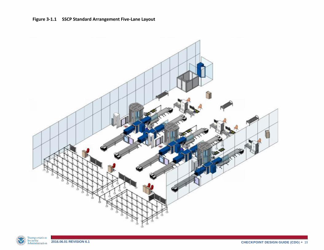
The following pages represent the Standard SSCP Arrangement.
Figure 3-1.1 is an isometric view of five lanes in an optimized
layout. Figure 3-1.2 is a plan view of the same 5-lane layout,
but the recommended spacing between the screening and ancillary
equipment is shown. These dimensions are guidelines to use when
laying out a checkpoint. Adjustments to these dimensions may
need to be made due to site conditions. This is acceptable as long
the as the spacing is within the desired range. Deviations from the
minimum and maximum spacing must receive TSA Headquarters
approval before implementation. Every attempt to achieve the
dimensions listed in Figure 3-1.2 should be made when
designing a checkpoint with Standard SSCP Arrangement
equipment. The spacing requirements are the same regardless of
the make and model of the screening equipment used.
Travel distance between the AIT and WTMD should be
minimized while preserving maintenance clearance, egress, & CDG
requirements.
It is required for the floor to be reinforced or replaced when an AIT
or WTMD is placed on wood floor joists, certain raised floors,
floors over a roadway, floors adjacent to a column, or other
scenarios where electrical conductivity or vibration interference will
affect the operation of the equipment. Careful consideration should
be taken to include this in the design of the checkpoint. When
interference is recognized due to these issues, it is required to
provide additional reinforcement or relocation of utilities, contact
TSA HQ for options to possible solutions.
3-1.1 STANDARD SSCP ARRANGEMENT
CHECKPOINT DESIGN GUIDE (CDG) 19 2016.06.01 REVISION 6.1
Figure 3-1.1 SSCP Standard Arrangement Five-Lane Layout

CHECKPOINT DESIGN GUIDE (CDG) 20 2016.06.01 REVISION 6.1
Figure 3-1.2 SSCP Arrangement Recommended Spacing

CHECKPOINT DESIGN GUIDE (CDG) 21 2016.06.01 REVISION 6.1
3-1.2 RISK BASED SECURITY (RBS) Risk-Based Security uses information gained during pre-screening and through observation and interaction with passengers to determine the proper level of screening that matches the passenger’s risk assessment
3-1.2.1 TSAPre®
TSAPre® is an expedited screening initiative that is expanding to
airports across the country as volumes continue to grow through new Risk Based Security (RBS) initiatives. There is a need to determine
how to absorb volume growth across existing TSAPre®
checkpoints through optimal lane utilization, as well as provide
flexibility to open additional TSAPre® lanes at checkpoints which
without would have insufficient throughput at peak times.
The purpose of this section is to provide guidance on how and when
to expand TSAPre®airports, as well as introduce the concept of a “Dual Use” lane. A Dual Use Lane is a tool that will allow airports to
“flex” TSAPre® to an additional adjacent lane during peak times as volumes dictate. As airports review their current design and layout for near term expansion, they should consider how to look at the checkpoints, terminals, and concourses holistically for a more long
term expansion of TSAPre®. This will provide airports with the
contextual framework in which to target such considerations.
Expanding TSAPre®
Requirements must be met in order to expand one or more lanes
to TSAPre® at a given checkpoint. Requirements include:
Sufficient predicted or realized volume for sustained periods to
open a new lane or expand to an adjacent lane
TSAPre® lane is operated with an AT X-ray
Sufficient personnel are trained and available to run additional
TSAPre® lanes as necessary
Ability to restrict non-TSAPre® passengers from accessing
the TSAPre® lane
Maintain a minimum of one standard lane operating within the
checkpoint
If implementing a dual use lane, provide a visible indicator for
TSOs to identify mode of operation (TSAPre® Standard.)
Depending on the airport configuration and which airlines are increasing in volume, there are three options which an airport may
expand their TSAPre® lane:
Option 1: Move an existing TSAPre® lane to better
accommodate traffic patterns and expansion
Option 2: Add a new TSAPre® lane at a new checkpoint
that previously did not have sufficient volume
Option 3: Expand existing TSAPre® to an adjacent lane
(either full-time or part-time as “Dual Use”)
TSAPre® is growing in popularity and is expected to expand as more airports and airlines increase their screening volume.
Due to a variation of TSAPre® demand at certain times, the checkpoint can be configured to allow for flexing screening lanes.
If at least one TSAPre® lane is currently operational, the checkpoint is capable of expanding to additional lanes as needed. With equipment layout and queue planning, limited reconfiguration and time is required to “flex” from one
TSAPre® lane to additional lanes.
The following examples provide the typical layouts for
existing TSAPre® screening before and after flexing from one to two lanes.

CHECKPOINT DESIGN GUIDE (CDG) 22 2016.06.01 REVISION 6.1
Figure 3-1.3 TSAPre® AT A SINGLE LANE WITH WTMD ONLY
BEFORE FLEXING
This scenario is for a
single, outside TSA
PreCheck lane with WTMD
only. The RBS passengers
flow only one lane before
flexing. Standard passenger
flow is limited to lanes 2 and
3, lane 2 is a dual use lane.
This scenario is for a two
lane TSA PreCheck with
flexing the additional TSA
PreCheck lane to lane 2. Due
to constraints of this
configuration, flexing
requires splitting an adjacent
2 to 1 module set to add the
lane. In this scenario, the
WTMD in adjacent lanes
will need to be reconfigured
to TSA PreCheck security
settings.
AFTER FLEXING

CHECKPOINT DESIGN GUIDE (CDG) 23 2016.06.01 REVISION 6.1
Figure 3-1.4 TSAPre® AT THE WTMD SIDE OF A SPLIT MODULE SET
BEFORE FLEXING
AFTER FLEXING
This scenario is for a single
outside TSA PreCheck lane
with a split module set with
WTMD and AIT. The RBS
passengers flow to only one
lane before flexing. Standard
passenger flow is limited to
lanes 2, 3, and 4; lane 2 is a
dual use lane.
This scenario is a two lane
TSA PreCheck with flexing
the additional TSA PreCheck
lane to lane 2. Flexing TSA
PreCheck lane requires only
relocation of barrier
stanchions from the center of
the module set and allowing
passengers from both lanes
flow to the WTMD. In this
case no reconfiguration is
required for the WTMD.

CHECKPOINT DESIGN GUIDE (CDG) 24 2016.06.01 REVISION 6.1
3-1.2.2 QUEUE MANAGEMENT
Queue Management is a vital component to TSA Pre✓® screening. Not
only does it ensure that populations are segregated appropriately to
ensure only low risk individuals receive TSA Pre✓® screening, but it is
also vital to Capacity Management of the Checkpoint. With the addition
of Managed Inclusion and the resulting blending of TSA Pre✓®
passengers with randomly selected passengers, increased wait times may result if the passenger queues are not managed correctly.
3-1.2.3 RBS PASSENGER QUEUE LAYOUT EXAMPLES
When designing a queue it is important to first determine what space
is available for the passenger queue as a whole. The general rule is
400 SF of space available for each lane. If queue space is less than
400 SF per lane, consider tightening the space between stanchions
to 3ft for all queue types except for ADA/Special Assistance queues.
These need to maintain at least 3.5ft, and preferably have straight-
line access to the TDC podium. For Unknown/High Risk Travelers,
the TDC podium and the bin carts at the divestiture tables should
provide a minimum distance as described in Figure 3-2.7 enabling
passengers to move freely toward their chosen lane. It is
recommended that hard barrier stanchions are installed between TDC
podiums to reduce the risk of passengers’ ability to circumvent the
TDC.
Sample design layouts are included on the following pages. It is not
possible to show examples for every type of checkpoint configuration
or size; however, examples for odd and even numbered checkpoint
lanes are provided and convey the overall intention of the RBS queue
design requirements. These designs can be scaled to encompass the
design requirements of checkpoints with greater or fewer number
of lanes.
Figure 3-1.5 TDC and Queue Layout

CHECKPOINT DESIGN GUIDE (CDG) 25 2016.06.01 REVISION 6.1
Figure 3-1.6 TSAPre® 5 LANE CHECKPOINT – GROWTH 3 RBS LANES

CHECKPOINT DESIGN GUIDE (CDG) 26 2016.06.01 REVISION 6.1
Figure 3-1.7 TSAPre® 5 LANE CHECKPOINT – GROWTH 4 RBS LANES

CHECKPOINT DESIGN GUIDE (CDG) 27 2016.06.01 REVISION 6.1
There is no set boundary of an SSCP. Boundaries of a SSCP will vary by airport based on SSCP configuration and TSA requirements for a particular checkpoint. Typically, the SSCP length starts at the TDC podium(s), extends through the checkpoint elements discussed in this section, and ends at the checkpoint exit, which could be at or near the egress seating area or STSO podium. The SSCP width is the wall-to-wall width of the checkpoint, including all the screening lanes and a co-located exit lane (where applicable.) All walls adjacent to the non-sterile side need to be at least 8’-0” high to prevent the passage of prohibited items from the non-sterile area to the sterile area. An 8’-0” high or full height wall should be installed from the entrance of the TDC to the exit of the checkpoint beyond the screening equipment into the sterile area. Checkpoint boundaries are to be designed according to this document and are to be installed by the airport authority. When an airport is installing a space for future lanes, the area between proposed and future space shall be separated by an 8’-0” high or full height temporary wall.In the future, new technology may extend the current boundaries to include additional equipment and functions within the checkpoint or equipment and functions located remotely within the airport.
An exit lane can be co-located with a checkpoint, or it can be located
independent of the checkpoint. This lane should be easily identifiable
without adversely affecting security. It should also be adequately
sized for deplaning passengers exiting the concourse. All building
code egress path requirements must be met.
A minimum 8’-0” or full height wall is required to separate the
checkpoint from the exit lane or separate the sterile area from the
non-sterile area. This height impairs the ability for un-cleared
passengers to pass prohibited items to a cleared passenger. This
requirement should be coordinated with the airport authority when a
new checkpoint is being discussed or an existing checkpoint is being
reconfigured and the exit lane needs to be modified.
An exit lane is typically equipped with a table, chair, and podium for
a person to monitor the area and deter those attempting to bypass
the SSCP from the non-sterile area. The monitor should be located
so that traffic attempting to enter the exit lane from the wrong
direction can be intercepted. The exit shall also include a duress
alarm system to covertly alarm of any threat to security; Section 3-
3.7 identifies duress alarm requirements. For long exit lanes, there
is typically a monitor at both ends. TSA and the Airport may share
operational responsibility of the exit lane with other parties such as
the airport operator or an airline carrier. These parties contribute
to the design of the exit lane and surrounding area to ensure that
unauthorized entry does not occur.
Unique solutions have been deployed to secure exit lanes such as
adding revolving doors or turnstiles, CCTV systems, and/or
breach alarms. These solutions must allow sufficient space to
accommodate the equipment as well as passengers with baggage
and/or passengers with disabilities. Another simple solution is to
provide clear glass panels when an exit lane is adjacent to the
checkpoint. This often deters breaches since the exit lane
would be highly visible by TSA and airport/airline personnel.
These elements can also be combined to create an integrated
system that utilizes video cameras, video monitors, sensors, and
breach alarms concealed within the architectural elements and tied
to a centralized system. This would further tighten security
around this sensitive area without relying solely on manpower.
In new facility planning and design, SSCP exit lanes should be a
considerable distance from boarding gates to allow for sufficient
time to resolve a breach if one should occur.
3-1.3 SSCP BOUNDARIES
3-1.4 EXIT LANE

This Page is Intentionally Left Blank

CHECKPOINT DESIGN GUIDE (CDG) 29 2016.06.01 REVISION 6.1
The intent of this section is to introduce all of the elements of a standard TSA SSCP. These elements consist of Transportation Security Equipment (TSE) and non-powered ancillary equipment. The equipment in this section is listed in the order that a passenger encounters it, from the non-sterile area to the sterile area. It includes
most but not all of the A&E technical data that a designer would need to configure a checkpoint. This guide is intended to be general and is not a replacement for manufacturer information or recommendations for clearances, power, etc. All SSCP equipment, including private screening rooms, must meet all local code requirements and standards for HVAC.
Every checkpoint has essentially the same elements which are site adapted to the existing conditions. While the queue and composure areas can vary significantly from checkpoint to checkpoint, the screening lanes are fairly consistent with the type of equipment deployed even though the equipment footprint can vary by manufacturer.
Manufacturers for a particular type of equipment are chosen by TSA HQ based on the following criteria:
Manufacturers Deployed at the Hub Airport
Width & Depth of Checkpoint
Lane-to-Lane Spacing
Structural Capacity of the Floor
Floor Construction Type (slab on grade, etc.)
Column Sizes, Quantities, & Locations
Existing Maintenance Contracts
Staff Familiarity with a Manufacturer
Airline Passenger Load Factors
Passengers per Hour
Ceiling Height
Floor Slope
Expansion Joints
A layout of most but not all of the SSCP elements is represented in Figure 3-2.1. Passenger flow goes from left (non-sterile) to right (sterile). All equipment included in this section can be ordered from TSA HQ by following the process outlined in Section 2-2.
3-2 TRANSPORTATION SECURITY EQUIPMENT (TSE)

CHECKPOINT DESIGN GUIDE (CDG) 30 2016.06.01 REVISION 6.1
Figure 3-2.1 SSCP Elements

CHECKPOINT DESIGN GUIDE (CDG) 31 2016.06.01 REVISION 6.1
The Pre-Screening Preparation Instruction Zone begins as early as the curbside ticket counters and typically ends at the Travel Document Checker (TDC) deep in the queue. This zone should incorporate architectural features of the airport and be designed to provide an environment for the passenger with reduced noise, comfortable lighting, adequate spacing and other tranquil features. Signage, instructional videos, and “ambassador” staff or volunteers, when available, should be used to reduce passenger stress and ease movement through the SSCP.
Simple and effective checkpoint signage that has been created and approved in the TSA HQ Office of Public Affairs can be used to direct and instruct passengers on screening requirements and procedures. TSA signs are either 11” by 14” or 22” by 28” frames that can be mounted on top of a floor stanchion. Refer to Figure 3-2.2. The signs are divided into four categories: TSA Mandatory Signs, TSA Instructional Signs, TSA Directional Signs, and TSA Local Signs. Refer to the most current version of the TSA Airport Signage Guidelines, available on the TSA Intranet, for specific sign descriptions and where to locate these signs within the checkpoint. Signage is not typically part of a checkpoint design but space should be allocated for signage when designing a new checkpoint.
3-2.1.1 TSA MANDATORY SIGNS
TSA Mandatory Signs display critical information and TSA policies to the passenger such as listing prohibited items or the liquids, aerosols, and gels (LAGs) policy. These signs need to be visible from both sides, prominent, easy to read, and located along the path of departing passengers without obstructing queue lanes or being a safety hazard. These signs should not be clustered together in a way where larger signs block smaller signs or where multiple instructions create information overload for the passengers.
3-2.1.2 TSA INSTRUCTIONAL SIGNS
TSA Instructional Signs provide passengers with instructions on the screening process. These signs advise passengers on how to properly divest of their possessions and how to place those items in the bins.
These signs can be mounted in the same way as the TSA Mandatory signs or displayed on walls near the divest tables.
3-2.1.3 TSA DIRECTIONAL SIGNS
TSA Directional Signs instruct passengers on where to go during the screening process, including providing direction to separate queue and screening lanes. The goal is to provide clear and concise directions so that passengers react quicker and overall time in the queue is minimized. Directional signs must be elevated so they are easily visible and not hidden by passengers standing in line.
3-2.1.4 TSA LOCAL SIGNS
TSA Local Signs are designed to meet specific local requirements, such as instructions regarding special equipment, local processing instructions, and any other signs deemed necessary by the local FSD. All local signs need to be cleared through the TSA HQ Office of Security Operations OSO RBS War Room [email protected]
Figure 3-2.2 SSCP Signage
3-2.1 PRE-SCREENING PREPARATION INSTRUCTION ZONE

CHECKPOINT DESIGN GUIDE (CDG) 32 2016.06.01 REVISION 6.1
The queue is where passengers stand in line at the front of the checkpoint on the non-sterile side. It is recommended that the queue be bound by double strap stanchions (solid hard stanchions for larger areas) on the perimeter and single strap stanchions inside the perimeter to define the queuing lanes from the queue entrance(s) to the TDC(s)/CAT. Queue lanes are approximately 3’-0” to 5’-0” wide depending on the queue lane function and the queue space available. Refer to Figure 3-2.3 for a graphic of the types of stanchions.
TSA recommends 4 0 0 s q u ar e f e e t in the queue for every checkpoint lane, with 300 square feet minimum per lane. The queue should be big enough to meet the peak passenger demand without interfering with other functions in the terminal such as the ticket counter or checked bag processing. A queue entrance should remain open at all times. Queues should be able to be cordoned off and funneled down to one TDC during off- peak times.
The exclusive use of strap stanchions is inadequate to fully secure the checkpoint. Solid barrier stanchions as shown in Figure 3-2.4, are required along the boundary of TDC/CAT podium positions and the flanking side limits of the queue. The use of solid barrier stanchions is illustrated in Figure 3-2.1.
Figure 3-2.4 Solid Barrier Stanchion Figure 3-2.3 Strap Stanchion
3-2.2 QUEUE

CHECKPOINT DESIGN GUIDE (CDG) 33 2016.06.01 REVISION 6.1
3-2.2.1 TRAVEL DOCUMENT CHECKER (TDC) & CREDENTIAL AUTHENTICATION TECHNOLOGY (CAT)
CAT technology is currently being developed and has not been
deployed to all airports. Please note that designers should still plan
for the necessary infrastructure to be in place for checkpoints. TSA
checks passenger identification and boarding passes at the end of the
queue and is placed as to provide enough space for passage
occurring between the exit of the podium and the screening lanes.
The TDC officer stands or sits at the TDC or CAT podium and
verifies that all the necessary documents are in order. The CAT
integrates different technologies that independently verify travel
documents such as a driver’s license or passport. The CAT analyzes
security features and barcodes on a passenger’s ID to identify
fraudulent documents. The CAT compares the independently verified
ID to validate the passenger’s identity and allow access to the
screening checkpoint.
Refer to Figure 3-2.5 and Figure 3-2.8 for additional
information. The TDC function is critical to the flow of passengers
through the checkpoint as it can become the bottleneck or pinch
point in the passenger screening process. The queue must be set
up properly to feed the TDC, and the TDC must be set up properly
to feed the checkpoint lanes.
The following guidelines should be considered when determining
placement of the TDC:
The TDC, hard building walls, and stanchions (strap and solid
barrier) should be setup so that NO individual can circumvent or
bypass the TDC.
The TDC should be located as described in Figure 3 - 2.7
with enough space from the screening lanes so that
passengers can cross flow to a lane of their choosing.
Lighting should be sufficient for reading documents. Refer to
Section 3-3.8 for lighting guidelines at the SSCP.
There should be one TDC for every two standard screening
lanes.
Additional TDC positions should be added for odd numbered
lanes and TSAPre® and additional or revised queuing space
should be considered.
For checkpoints with more than three TDC positions,
sufficient clearance should be provided between the queue
stanchions and the TDC stanchions so that passengers can
cross flow to a TDC of their choosing.
Recommended queue widths and square footage of the queue
based on the number of lanes should be followed to provide for
an even distribution of passengers to the TDC. Refer to
Section 3-2.2.
Figure 3-2.5 TDC Podium & CAT

CHECKPOINT DESIGN GUIDE (CDG) 34 2016.06.01 REVISION 6.1
Number of
Lanes
Minimum
Distance from Bin
Cart to Podium
Chair (ft)
Number of
Lanes
Minimum
Distance from
First Divest Table
to Podium (ft)
1 4 9 15
2 6 10 15
3 7 11 15
4 9 12 15
5 10 13 15
6 12 14 15
7 13 15 15
8 15 16 15
*Measured as minimum suggested distance. Consult TSA Designer for guidance.
Power/data for the podium or CAT should be provided in a
recessed poke-through flush to the floor and centered under the
podium or CAT to allow for adjustment of the TDC position.
Power/data devices should be spaced at 11’-6” center to center.
When a poke-through is not possible, a power pole is acceptable,
centered with the podium and between two lanes.
Alternating “mini-queues” should be created on both sides of
the TDC by providing at least 5’-0” of stanchions in front of
the TDC along the centerline. This will force the passengers to
form two separate lines for the same TDC. The TDC will process
whichever “mini-queue” passenger is ready.
“Mini-queue” stanchions should be used to close TDC podiums
during non-peak periods of the day.
Barrier stanchions shall form the exterior perimeter of the TDC
podium in order to deter passengers from bypassing this
function. Barrier or double strap stanchions shall also be used
between TDC podiums. Strap stanchions can be detached too
quickly and easily where barrier stanchions have to be
disassembled, alerting TSA personnel and allowing time for a
TSO to respond.
Figure 3-2.7 CAT X, I, and II TDC Podium Dimensioning
Figure 3-2.6 TDC Podium & CAT

CHECKPOINT DESIGN GUIDE (CDG) 35 2016.06.01 REVISION 6.1
Equipment Quantity Power Requirements IT Requirements Additional Information
TDC Podium CAT (generic)
1 per 2 standard
lanes
+1 for odd numbered lanes and TSA PreCheck lanes
+1 if checkpoint feeds international flights
Dedicated circuit for TDC podiums ONLY, maximum of 5
per circuit 20A, 125V, 180VA/podium
2-Pole, 3-Wire Grounding
NEMA 5-20R Duplex Receptacle
Max amp: 0.86A, Steady state amp: 0.44A
Power cord length is unknown at the time of this printing
Data Drops = 2
Cat5e / Cat6 cable
The cable length from the termination point in the IT cabinet to the data outlet in the work area shall not exceed 295’.
The TDC function can be supported by
either a TDC Podium or a CAT.
The CAT may be on wheels or it may sit on floor.
Figure 3-2.8 TDC Podium & CAT

CHECKPOINT DESIGN GUIDE (CDG) 36 2016.06.01 REVISION 6.1
Bins are the gray containers located on a cart at the front and back
of each checkpoint lane. Passengers use bins to divest themselves of
their personal belongings such as purses, carry-on bags, backpacks,
laptops, shoes, jackets, etc. Bin carts are similar to a hand cart or
dolly that allows for the transport of a large number of bins without
requiring excessive lifting or carrying by a TSA agent. In the past,
bin transport by the TSOs was the primary cause of on-the-job
injuries at checkpoints. Hand-carrying of bins is no longer endorsed
by TSA. TSA recommends that bin carts be pushed upstream though
an ADA or access gate. Ideally, an ADA or access gate should exist at
every lane but this is not always possible. When there is
insufficient space for an ADA or access gate, the bin cart should be
pushed upstream against passenger flow through the WTMD. Bin
carts can be one or two bins wide with bins stacked on top to
slightly below the handle which equates to approximately 40 bins.
Each lane requires a bin cart at each end. TSA recommends
maintaining about 60 bins per lane divided across each end.
A fully- loaded bin cart should be located at the start of the divest
tables on the non-sterile side of the lane for passenger pick-up.
The other bin cart should be positioned at the end of the
composure rollers on the sterile side so that the TSA agent can
collect empty bins after passengers have picked up their belongings.
Refer to Figure 3-2.9 for bin cart dimensions. The bin cart width
times two should be factored into the overall length of the
checkpoint lane when designing a new checkpoint or reconfiguring
an existing checkpoint.
Figure 3-2.9 Bin Cart
3-2.3 BIN CART

CHECKPOINT DESIGN GUIDE (CDG) 37 2016.06.01 REVISION 6.1
Divest tables are provided for passengers to stage their bins side-
by-side so they can deposit their personal items into the bins. The
divest table allows passengers to slide their bins to the infeed of the
X-ray. Current checkpoints utilize a variety of table sizes and types;
however, for new checkpoints or checkpoints being reconfigured, the
divest tables are 30” wide and 4 8 ” , 60”, or 72” long. See Figure
3-2.10. Two 72” tables abutted to the infeed roller or loading table
of the X-ray is the preferred divest length, but limited checkpoint
or obstructions may require shorter tables or only one table. Divest
tables are stainless steel with height-adjustable legs from 27” to 32”.
Implementation of these tables will increase sequencing efficiency
through the checkpoint. Lanes that do not have enough depth for
12’-0” of passenger divestiture will have a slower throughput.
48”, 60”, 72”
3-2.4 DIVEST TABLE
Figure 3-2.10 Divest Table

CHECKPOINT DESIGN GUIDE (CDG) 38 2016.06.01 REVISION 6.1
Carry-on bag screening is mandatory at a SSCP and is accomplished by deploying AT equipment. Generally, this equipment has the following components:
Loading Table/Entrance Roller
Queuing Conveyor & Hood (Vendor Specific)
Scanning Belt & Dome
High Speed Conveyor (HSC) & Hood
Extension Rollers
Exit Roller with Bag Stop
Manual Diverter Roller (MDR)
Alternate Viewing Station (AVS)
TSOs are staffed dynamically at the carry-on bag screening units where one or two screeners can perform the functions listed:
Review bag images on the monitors
Remove alarmed bags from the alarm bag cutout or from the
MDR
Place empty bins on the bin carts
Interpreting the bag images on the monitor requires focused concentration by the TSO. The operator should have an ergonomic and distraction-free environment. The space should be designed to minimize glare on the X-ray workstation monitors from interior lighting, glass walls, or sunlight. The monitor height should be at an optimum viewing angle. The operator must also have a clear view of the machine’s entrance and exit conveyor. Columns, power poles, signage, etc. should not prevent the TSO from seeing the bags going in and out of the X-ray unit.
Equipment determination for each lane at an SSCP will be based on the space available, the required number of lanes based on passenger load, and the floor structure. If the checkpoint is being reconfigured, additional consideration needs to be given to the location of the existing electrical outlets, TSO familiarity with a specific manufacturer, and existing maintenance contracts. The TSA HQ POC, local FSD staff, and the checkpoint designer will need to work together to determine the best solution based on the site conditions. The TSA HQ Point of Contact, local FSD staff, and the checkpoint designer should work together to determine the best solution based on the specific site conditions and normal operational procedures.
Carry-on bag screening equipment will have panic buttons/duress alarms installed by the airport directly on the equipment or near the equipment operator. These alarms are typically connected to the airport or local law enforcement. Checkpoint designers should refer to the Airport Security Plan if relocation of panic buttons is required. Duress alarm requirements are outlined in Section 3-3.7.
Equipment discussed in this section covers all primary carry-on bag screening. Alarmed bags may require secondary screening, which is discussed in Section 3-2.12.
3-2.5 CARRY-ON BAG SCREENING

CHECKPOINT DESIGN GUIDE (CDG) 39 2016.06.01 REVISION 6.1
The AT X-ray is the next generation of X-ray equipment that
replaces the TRX. The AT X-ray is wider, longer, heavier, and draws
more power than its TRX counterpart. Refer to Figure 3-2.11. This
larger size improves the screening capability by capturing a bottom
and side view of carry-on bags inside the dome and producing two
high resolution images for TSA to review. TSA currently classifies
the baggage screening equipment as AT. AT represents the
deployment of the AT X-ray units which consists of the Rapiscan
620DV, the Smiths 6040aTiX, and the L3 ACX 6.4-MV. AT includes
an Alternate Viewing Station (AVS) and, in the case of Rapiscan and
L3, a 48” queuing conveyor between the infeed roller and the
scanning belt. Figure 3-2.12, Figure 3-2.14, and Figure 3-2.16
depicts the Rapiscan, Smiths, and L3 AT product specifications.
Standard layouts are reflected in Section 3-1.
The Rapiscan and Smiths AT come standard in a RH configuration
but they can be modified into a LH configuration. The L3 AT comes
standard in a LH configuration only. The standard configurations
are shown on the plan views on the following pages. Unlike the
TRX, the “hand” is dependent on the bump-out orientation rather
than the operator. The bump-out is the side bonnet on the AT X-ray
that juts out from the rectangular shape. This is where the side view
camera is located. On a RH unit, the bump-out is on the right side
of the AT dome when standing on the non-sterile side of the AT
looking at the infeed tunnel. On a LH unit, the bump-out is on the
left side of the AT dome when standing on the non-sterile side of
the AT looking at the infeed tunnel. The RH and LH AT units are
not symmetrical. The LH AT is a 180° rotation of the RH AT with
the infeed and outfeed components interchanged. On the RH AT, the
side view picture is taken last; whereas on the LH AT, the side view
picture is taken first. The bump-out orientation should be specified
prior to manufacture.
The operator workstation can be located on either the bump-out
or the non- bump-out side. This is often referred to as bump-outs
towards operators or bump-outs towards passengers, respectively.
Even though the Rapiscan and L3 AT have a “tethered” independent
operator workstation, the location still needs to be determined prior
to manufacture. The Smiths AT operator workstation will be located
on the AT unit.
In summary, there are four possible configurations of the Rapiscan
and Smiths AT, and two possible configurations of the L3 AT. It is
important to identify the orientation of the bump-out and the
location of the operator early on so that it can be manufactured as
designed as it is arduous and expensive to change in the field.
The orientations are as follows.
Rapiscan 620DV AT and Smiths 6040aTiX AT Configurations:
RH AT with bump-out towards operator
RH AT with bump-out towards passengers
LH AT with bump-out towards operator
LH AT with bump-out towards passengers
L3 ACX 6.4-MV AT Configurations:
LH AT with bump-out towards operator
LH AT with bump-out towards passengers
The AT units are also unique in regard to the composure
length. The Rapiscan 620DV and L3 ACX 6.4-MV have one 1-
meter (3’-3”) extension roller with a bag stop. The Smiths
6040aTiX has one 6’-8” exit roller with a bag stop. AT
compatible TRX or AT extension rollers should be added to
obtain the recommended composure length of 12’-0” and
maximum composure length of 18’-0”. Extension rollers are
discussed further in Section 3-2.6.2.
The AVS is where a TSO can recall the image of an alarmed bag
from the AT while performing a target bag search. For the
Rapiscan and L3 AT, the AVS is a mobile operator cart that is
located approximately 18” to 22” off the back side of a TSA-
provided search table. The cart has one or two monitors, a
keyboard, and a PC tower that can be plugged into the re-
locatable power tap that is mounted to the TSA search table. The
power tap is plugged into a device that feeds the ETD and BLS at
the secondary screening area. The Smiths AVS has two monitors
and a keyboard attached to an arm that is connected to the Smiths-
provided search table. The search table also acts as a cabinet that
houses the PC and UPS. Figure 3-2.13, Figure 3-2.15, and
Figure 3-2.17 depict the Rapiscan, Smiths, and L3 AVS product
specifications.
3-2.6 ADVANCED TECHNOLOGY (AT) X-RAY

CHECKPOINT DESIGN GUIDE (CDG) 40 2016.06.01 REVISION 6.1
Figure 3-2.11 AT Units
Rapiscan 620 DV AVS
Reference Figure 3-2.13
Smiths 6040aTiX AVS
Reference Figure 3-2.15
Rapiscan 620DV AT
Reference Figure 3-2.12
L3 ACX 6.4-MV AT
Reference Figure 3-2.16
Smiths 6040aTiX AT
Reference Figure 3-2.14
L3 ACX 6.4-MV AVS
Reference Figure 3-2.17
MDR
MDR
MDR

CHECKPOINT DESIGN GUIDE (CDG) 41 2016.06.01 REVISION 6.1
Equipment Quantity Power Requirements IT Requirements Additional Information
Rapiscan 620DV AT
1 per lane
Dedicated 20A, 125V, 1800VA/unit
2-Pole, 3-Wire Grounding
NEMA 5-20R Simplex Receptacle
15’ power cord from the AT to the Receptacle
20A, 125V, 360VA/unit
2-Pole, 3-Wire Grounding
NEMA 5-20R Simplex Receptacle Queuing Conveyor
15’ power cord from the queuing conveyor to the
receptacle
20A, 125V, 360VA/unit (Queuing Conv.)
2-Pole, 3-Wire Grounding
NEMA 5-20R Simplex Receptacle 15’ power cord from the queuing conveyor to the
receptacle
Data Drops = 4 Total: 2 from device to IT cabinet, 2
from device to respective AVS/ETD/BLS location Cat5e / Cat6 cable
The cable length from the termination point in the IT
cabinet to the AT data outlet shall not exceed 295’.
All data cabling must be provided by others. Not
Supplied by vendor.
Rapiscan 620DV comes in a RH (shown) or LH
configuration. The LH unit is a 180 degree rotation of the
RH unit. Power and data connections are reversed for a LH
unit.
Rapiscan uses an Ergotron Dual Stand for the AT mobile
operator cart and AVS. The operator cart is attached by a
vendor provided data cable and can move freely around
the unit.
Weight: 2,094 lbs., approx. 350 lbs per leg The HSC can be sloped downwards no more than 12
degrees and upwards no more than 10 degrees. The queuing conveyor and HSC can be sloped downwards no
more than 12 degrees and upwards no more than 10 degrees.
Refer to manufacturer product information for more details.
Figure 3-2.12 AT - Rapiscan
MDR NOT SHOWN FOR CLARITY

CHECKPOINT DESIGN GUIDE (CDG) 42 2016.06.01 REVISION 6.1
Equipment Quantity Power Requirements IT Requirements Additional Information
Rapiscan 620DV
AVS
1 per AT
Non-Dedicated, shared with ETD and BLS circuit
at the same search area 15A, 125V, 252VA/unit, 504VA/2 units 2-Pole, 2-Wire Grounding NEMA 5-20R Receptacle 5’ power cord for two monitors and one PC tower
of the AVS to the relocatable power tap mounted to the TSA search table.
6’ power cord from the relocatable power tap to the receptacle
All data cabling must be provided by others. Not
supplied by vendor. AVS data to be direct from respective AT, see AT
IT Requirements.
AVS is an Ergotron Dual Stand. Located with standard TSA search table.
Figure 3-2.13 AVS - Rapiscan

CHECKPOINT DESIGN GUIDE (CDG) 43 2016.06.01 REVISION 6.1
Equipment Quantity Power Requirements IT Requirements Additional Information
Smiths 6040aTiX
AT
1 per lane
Dedicated 20A, 125V, 1920VA/unit
2-Pole, 3-Wire Grounding
NEMA 5-20R Simplex Receptacle
15’ power cord from the AT to the receptacle
Data Drops = 4 Total: 2 from device to IT cabinet, 2 from device to respective AVS/ETD/BLS location
Cat5e / Cat6 cable
The cable length from the termination point in the IT cabinet to the data outlet in the work area shall not exceed 295’.
All data cabling must be provided by others. Not supplied by vendor.
Smiths 6040aTiX comes in a RH (shown) or LH
configuration. The LH unit is a 180 degree rotation of the RH unit. Power and data connections are reversed for a LH unit.
The operator workstation is mounted to the X-ray. Existing field equipment may have the operator workstation located on a cart.
Refer to manufacturer product information for more details.
Weight: 3,528 lbs.
Figure 3-2.14 AT - Smiths
MDR NOT SHOWN FOR
CLARITY

CHECKPOINT DESIGN GUIDE (CDG) 44 2016.06.01 REVISION 6.1
Equipment Quantity Power Requirements IT Requirements Additional Information
Smiths 6040aTiX AVS
1 per AT Unit
Non-Dedicated, shared with ETD and BLS circuit at the same search area
10A, 125V, 144VA/unit, 288 VA/2 units
2-Pole, 2-Wire Grounding
NEMA 5-20R Receptacle
5’ power cord for two monitors and one PC tower of the AVS to the relocatable power tap provided by the installing contractor for the Smiths search table.
6’ power cord from the relocatable power tap to the receptacle
All data cabling must be provided by others. Not supplied by vendor.
AVS data to be direct from respective AT, see AT IT Requirements.
Search table provided by vendor.
Figure 3-2.15 AVS - Smiths

CHECKPOINT DESIGN GUIDE (CDG) 45 2016.06.01 REVISION 6.1
Equipment
Equipment
Quantity Power Requirements IT Requirements Additional Information
L3 ACX 6.4-MV AT
1 per lane
Non-dedicated circuit 20A, 125V, 350VA/unit
2-Pole, 3-Wire Grounding
NEMA 5-20R Quad or Duplex Receptacle
Data Drops = 4 Total: 2 from device to IT cabinet, 2
from device to respective AVS/ETD/BLS location The cable length from the termination point in the IT
cabinet to the data outlet in the work area shall not
exceed 295’.
Two 17’ Cat5e/ Cat6 cables from the AT to the
operator cart.
Two 25’ Cat5e/ Cat6 cables from the AT to the two
switches of the FDRS.
Two 5’ Cat5e/ Cat6 cables from the two switches to
the FDRS.
L3 AT comes in LH configuration only. The operator
may sit on either side of the unit. Weight: » 2,260 lbs., approx. 380 lbs. per leg The operator cart can move freely around the unit. Refer to manufacturer product information for more
details.
Figure 3-2.16 AT – L3
MDR NOT SHOWN FOR
CLARITY

CHECKPOINT DESIGN GUIDE (CDG) 46 2016.06.01 REVISION 6.1
Equipment Quantity Power Requirements IT Requirements Additional Information
L3 ACX 6.4-MV AVS
1 per AT Unit
AVS:
Non-Dedicated, shared with ETD and BLS circuit at the same search area
6.3A, 125V, 420VA/unit, 840 VA/2 units
2-Pole, 3-Wire Grounding
NEMA 5-20R Receptacle
6’ power cord from the monitor and PC tower of the
AVS to the UPS
UPS (750VA Rating): Non-Dedicated
6.3A, 120V, 758VA/unit
2-Pole, 3-Wire Grounding
NEMA 5-20R Receptacle
6’ power cord from the UPS to the relocatable power tap mounted to the TSA search table. Longer cord lengths are available from the vendor.
6’ power cord from the relocatable power tap to the
receptacle
All data cabling must be provided by others. Not
supplied by vendor.
AVS data to be direct from respective AT, see AT IT
Requirements.
AVS is an Ergotron single monitor stand.
Located with standard TSA search table.
Figure 3-2.17 AVS – L3

CHECKPOINT DESIGN GUIDE (CDG) 47 2016.06.01 REVISION 6.1
3-2.6.1 MANUAL DIVERTER ROLLER (MDR)
The MDR is a non-powered, gravity fed, stand-alone roller located
on the operator side of any AT unit at the alarm bag cutout. See
Figure 3-2.18. The MDR comes in a RH or LH configuration which is
determined by the side of the dome it is located on when standing on
the non-sterile side of the AT looking at the infeed tunnel. The AT
operator will be able to slide alarmed bags onto the MDR so that
bags can be taken to the secondary screening area to be investigated
by a TSO.
The MDR has a Plexiglas® partition that prevents passengers from
accessing their alarmed bags from the other side of the
composure/extension rollers. The MDR slope and height can be
adjusted to align with any AT.
If an MDR does not fit in the operator space due to a column or other
obstruction, a 2’-0” x 2’-0” table may be used at the transition table
location. The use of this table in lieu of an MDR shall be approved by
a TSA Designer. Figure 3-2.18.A depicts a generic 2x2 table.
Figure 3-2.18 MDR
Figure 3-2.18.A 2x2 TABLE

CHECKPOINT DESIGN GUIDE (CDG) 48 2016.06.01 REVISION 6.1
3-2.6.2 COMPOSURE/EXTENSION ROLLERS
The TRX and AT units have a High Speed Conveyor (HSC) covered by a tunnel located directly after the scanning belt. A carry-on bag arrives at the HSC after the bag has cleared the image review by the TSO. The HSC carries cleared bags to the composure/extension rollers where passengers can retrieve their personal items. These rollers are either called composure/extension rollers or exit rollers depending on the vendor and where they are installed on the TRX or AT. Figure 3-2.19 represents a variety of composure/extension rollers that are used today. They attach to the HSC to create length at the back end of the X-ray so passengers can clear the confined screening area and have a more open environment for retrieving their personal belongings and composing. Without extension rollers, bottlenecks would exist at the HSC exit, and passengers would be unable to bypass congestion.
TSA recommends a minimum of 12’-0” of composure length which can be a combination of extension rollers or exit rollers depending on the manufacturer of the TRX or AT. The Rapiscan TRX, Rapiscan AT, and the L3 AT extension rollers come in 1-meter (3’-3”) lengths. The Smiths TRX and AT extension rollers come in 48” and 72” lengths. The Rapiscan 520B 1-meter extension roller is compatible with the Rapiscan 620DV AT. The Smiths 6040i 48” and 72” extension rollers are compatible with the Smiths 6040aTiX. Dimensions of each
extension roller are reflected in Figure 3-2.20, Figure 3-2.21,
and Figure 3-2.22.
Figure 3-2.19 Composure/ Extension Rollers
Rapiscan 520B & 522B
Isometric View
Rapiscan 620DV
Isometric View
Smiths 6040i
Isometric View
L3 ACX 6.4-MV
Isometric View

CHECKPOINT DESIGN GUIDE (CDG) 49 2016.06.01 REVISION 6.1
Figure 3-2.20 Rapiscan Composure/ Extension Rollers
Late Model Extension
Rollers
Rapiscan 520B
Rapiscan 620DV Extension
Rollers

CHECKPOINT DESIGN GUIDE (CDG) 50 2016.06.01 REVISION 6.1
Figure 3-2.22 L3 Composure/ Extension Rollers
Smiths 6040i Extension
Rollers
L3 ACX 6.4-MV Extension
Rollers
Figure 3-2.21 Smiths Composure/ Extension Rollers

CHECKPOINT DESIGN GUIDE (CDG) 51 2016.06.01 REVISION 6.1
The WTMD is used for passenger screening. It is an archway used
to detect concealed metallic items and/or contraband. Refer to
Figure 3-2.23 for an isometric view of the WTMDs currently located
in the field. CEIA is the most common WTMD. CEIA specifications
can be found in Figure 3-2.24. Currently, only the original
equipment manufacturer (OEM) and authorized service providers are
certified and authorized by TSA to relocate, recalibrate, service, and
relocate the power cord to the opposite leg of the WTMD.
In order to minimize environmental and equipment interference with
the WTMD, the following guidelines should be applied.
Align the entrance of the WTMD so that it is 1’-6” behind the
leading edge of the AT queuing conveyor hood and center
between the AT if it is a 2-lane set and not co- located with an
AIT.
Provide power/data from a lane adjacent to the WTMD where
there is no passenger flow between the AT and the WTMD.
The power and data connections can originate from either leg of
the WTMD and can be modified in the field by the OEM or
Siemens if a checkpoint requires that the WTMD be powered
from the opposite lane.
Provide approximately 12” clearance from the legs to all other
equipment, walls, or columns to prevent operational interference.
Non-metallic ancillary equipment such as barriers and ADA gates
can be spaced 2” to 9” from the WTMD legs.
Locate a WTMD a minimum of 18 inches apart from all electrical
fields created by escalators, trains, conveyors, neon fixtures,
speakers, transformers, banks of electrical circuit breakers,
conduit, wire, and receptacles both overhead and beneath the
floor.
Minimize interference from metal in surrounding architecture,
including floors, floor supports, doors, metallic framing, wall
studs, façade systems, columns, etc.
Avoid locating the WTMD across expansion joints or in an
area prone to surface vibrations created by equipment
above, below or immediately adjacent to the checkpoint
such as baggage conveyors, subway trains, heavy truck
traffic, etc.
With floating or raised floors a 10’ x 10’ concrete pad will be
required under the WTMD to eliminate excessive
vibrations.
Provide twist-lock receptacles to prevent the WTMD from
being accidentally disconnected which drains the back-up
battery.
Secure the 13’-0” power cord tight to the barrier on the
sterile side adjacent to the WTMD to prevent the cord from
being run across passenger egress or TSA work paths where
the cord is likely to be a trip hazard or become damaged.
Silicone and/ or bolt the WTMD to the floor.
The WTMD should not be closer than 24” from the x-ray.
The maximum distance from AT to WTMD shall be
determined on a case-by-case basis.
When the WTMD is not in operation while checkpoint is
open or closed; it shall have a barrier or similar on non-
sterile side to prohibit access through the checkpoint.
3-2.7 WALK THROUGH METAL DETECTOR (WTMD)

CHECKPOINT DESIGN GUIDE (CDG) 52 2016.06.01 REVISION 6.1
Figure 3-2.24 WTMD
Equipment Quantity Power Requirements IT Requirements Additional Information
CEIA 02PN20
Garrett PD6500i Metorex 200HDe
Arrangement Dependent
• Dedicated circuit for WTMDs ONLY, maximum
of 10 per circuit
• CEIA: 20A circuit, 15A Receptacle, 125V, 40VA/unit
• Garrett: 20A circuit,15A Receptacle, 125V, 55VA/unit
• Metorex: 20A circuit 15A Receptacle, 125V, 45VA/unit
• 2-Pole, 3-Wire Grounding
• NEMA L5-15R Simplex Receptacle (twist-lock)
• 13’ power cord from the WTMD to the receptacle
• 18” minimum clearance from leg to nearest electrical
conduit or device to prevent false alarms
• Poke-through and pedestal receptacles for the WTMD
can be located in AT device under the lane as long as
it is a separate circuit.
• Data Drops = 2 • Cat5e / Cat6 cable
• The cable length from the termination point in the IT
• Cabinet to the data outlet in the work area shall not
exceed 295’.
• Weight: 200 lbs. • CEIA unit provided with a separate transformer/rectifier
adjacent to the power cord. • Provide power and data beneath all X-Rays.

CHECKPOINT DESIGN GUIDE (CDG) 53 2016.06.01 REVISION 6.1
The Advanced Imaging Technology (AIT) provides an additional
element of passenger screening by being able to detect a broad
spectrum of materials concealed in or under a passenger’s clothing.
The current manufacturer deployed today is shown in Figure 3-
2.25a. The L3 ProVision portal uses millimeter wave imaging
technology, similar to the type of waves a cell phone emits, to
generate clear views of the items in question. Refer to Figure 3-
2.26a for the plan views and power/data requirements. Standard
layouts with the L3 ProVision AIT are reflected in Section 3. The
minimum possible distance between the WTMD and AIT should be
maintained for each checkpoint. Decreased spacing between the
equipment enhances lane security by reducing the opportunity for
contraband exchanges (via “handoff ” of prohibited items) between
yet-to-be screened AIT passengers and screened WTMD passengers
as they move parallel to one another through the lane.
TSA is now deploying L3 ProVision2 AIT units which provide the
same Advanced Imaging Technology in a smaller and less massive
form factor. Refer to Figure 3-2.25b for the isometric view, refer to
Figure 3-2.26b for the plan and profile views and power/data
requirements. Designers are recommended to follow the same
standard checkpoint dimensional requirements for the L3 ProVision
and L3 ProVision2.
It is best to provide power for the AIT and corresponding UPS from
under an adjacent AT X-ray lane. The UPS should be located so
that it is not a trip hazard to passengers and the AIT operator at the
Touch Control Operator Panel (TCOP). When a barrier is located
between the L3 AIT control leg and the AT, the AIT power cord can
extend to the receptacle under the infeed or outfeed conveyors of
the AT along the barrier in appropriate surface mounted raceway.
In some cases, an ADA gate or a WTMD is located between the L3
AIT control leg and the AT. Extending the AIT power cord across
passenger flow is a safety hazard and is not an option. For the L3
AIT only when all other options have been exhausted, the unit can be
rotated 180 degrees in order to locate the control leg adjacent to a
barrier so that the cord can be extended along the barrier in
appropriate surface mounted raceway. When there is passenger
flow on both sides of the AIT, such as an ADA gate and a WTMD,
the potential exists for tripping, damage to cords or unplugging of
equipment. Therefore, a full height ceiling-supported power pole
should be provided. If a full height ceiling-supported power pole is
not acceptable or feasible, a 36” floor-supported power pole should be
provided. The Wiremold Vista column is recommended. Designers
should review and understand the L3 AIT cord lengths to avoid
unnecessarily rotating the AIT.
Designers are reminded to consult applicable codes within their region
of the country to determine the applicability and countermeasures to
address seismic events for AITs. Manufacturers have brackets
available for purchase.
When the AIT is not in operation while checkpoint is open or closed;
it shall have a barrier or similar on non-sterile side to prohibit access
through the checkpoint.
Figure 3-2.25a L3 AIT Unit
3-2.8 ADVANCED IMAGING TECHNOLOGY (AIT)

CHECKPOINT DESIGN GUIDE (CDG) 54 2016.06.01 REVISION 6.1
3-2.8.1 AIT WITH CO-LOCATED ETD
Explosive Trace Detection (ETD) units on a movable stand, cart, or table are located at the exit of the AIT to perform additional screening. This can be on either side of the AIT exit depending on where the power/data is located. The ETD should be fed from the same device but separate circuit feeding the AIT. Designers are advised to provide power and data for the ETD when developing construction drawings to provide maximum installation flexibility for the optional ETD. Ideally, this ETD should not be located at the TCOP or scanning operator (SO) monitor so that the TSO doesn’t have to review images and perform ETD screening in the same small area. Unfortunately, this is not always possible. A 36” space should be provided for the operator when the ETD and AIT are co-located. ETD units are discussed further in Section 2.12.1.
3-2.8.2 SLOPE TOLERANCE
An AIT can be installed on an inclining or a declining floor within
the maximum manufacturer recommended slope. These tolerances
pertain to the technical functionality of the equipment and do not
take into account building codes or ADA accessibility. For ADA
passengers, the slope cannot exceed two percent perpendicular to the
direction of travel.
The L3 ProVision system can be operated as follows.
If the floor slope is parallel to passenger travel, the comfortable
maximum floor slope is 1:16.
If the floor slope is perpendicular to passenger travel, the L3 AIT
cannot be installed unless the unit can be rotated parallel to the
slope. This may be possible at checkpoints with unique shapes.
Depending upon the slope of the surface the system is installed
on, the inner floor of the ProVision system will also be at an
angle.
At the aforementioned maximum 1:16 slope, the internal floor of the
L3 AIT would have a 1:20 slope after adjusting the downhill leveling
screws to their maximum extension. In the normal scanning position,
this is equivalent to standing with one foot elevated approximately 1”
relative to the other and is not normally noticeable.
At the upper maximum slopes, compensatory steps such as leveling
the machine’s feet and/or adjusting the floor mat position may be
necessary. Contact manufacturer’s representative for more
information for installing on a sloped floor.
Figure 3-2.25b L3 AIT2 Unit

CHECKPOINT DESIGN GUIDE (CDG) 55 2016.06.01 REVISION 6.1
Equipment Quantity Power Requirements IT Requirements Additional Information
L3 ProVision
Arrangement Dependent
• Dedicated • 20A, 125V, 1920VA/unit
• 2-Pole, 3-Wire Grounding
• NEMA 5-20R Simplex Receptacle
• Freestanding Tripp Lite UPS provided by vendor
• 25’ power cord from the AIT to the UPS
(originates in control leg)
• 10’ power cord from the UPS to the receptacle
• Refer to Figure 3-2.32 for ETD power and data
requirements.
• Refer to Figure 3- 2.26 equipment plan views for
detailed outlet locations when power is fed from
the adjacent AT lane.
• Data Drops = 2 • The cable length from the
termination point in the IT
cabinet to the data outlet in the
work area shall not exceed
295’.
• An ETD is to be co-located with the AIT for additional pax screening. The ETD
can be located at or on the same side as the control leg.
• Height/Ceiling clearance requirement: 9’-0” / 9’-3”
• Weight: 1,800 lbs. • Can be installed on a floor with a 1:16 floor slope parallel to passenger
travel only. • The Touch Control Operator Panel (TCOP) may not be mounted on control leg.
• Power cord can be positioned up and over unit to avoid rotation.
• The 16’-0” shipped USB cable can be substituted for a 25’-0” cable in the field if
necessary.
• The power cable shipped with the unit may be replaced with TSA Designer approval
• Manufacturer recommends installation on a slope of 1.5% or less. If slope is
between 1.5% and 3.0%, a representative will perform a site validation to determine
whether or not the slope is acceptable.
L3 Co-Located ETD 1 Per AIT • Non-Dedicated
• 20A, 125V, 350VA/unit
• Data Drops = 2
Figure 3-2.26a AIT – L3

CHECKPOINT DESIGN GUIDE (CDG) 56 2016.06.01 REVISION 6.1
Equipment Quantity Power Requirements IT Requirements Additional Information
L3 ProVision2
Arrangement Dependent
• Dedicated • 20A, 125V, 1920VA/unit
• 2-Pole, 3-Wire Grounding
• NEMA 5-20R Simplex Receptacle
• Freestanding Tripp Lite UPS provided by vendor
• 25’ power cord from the AIT to the UPS
(originates in control leg)
• 10’ power cord from the UPS to the receptacle
• Data Drops = 2 • The cable length from the
termination point in the IT
cabinet to the data outlet in the
work area shall not exceed
295’.
• An ETD is to be co-located with the AIT for additional pax screening. The ETD
can be located at or on the same side as the control leg.
• Height/Ceiling clearance requirement: 7’-9” / 8’-0”
• Weight: 1,500 lbs., 53 PSI per support feet, 0.284 PSI overall
• The 16’-0” shipped USB cable can be substituted for a 25’-0” cable in the field if
necessary.
• The power cable shipped with the unit may be replaced with TSA Designer approval
• Maximum slope:
• Parallel to pax travel: 2.86 degrees
• Perpendicular to pax travel: 1.73 degrees
• The floor must be flat and must not vary more than 0.75 in. within the installation
area
L3 Co-Located ETD 1 Per AIT • Non-Dedicated • 20A, 125V, 350VA/unit
• Data Drops = 2
Figure 3-2.26b AIT2 – L3

CHECKPOINT DESIGN GUIDE (CDG) 57 2016.06.01 REVISION 6.1
In order to prevent passengers and items from passing into the sterile
area from the non-sterile area without being screened, barriers must
be installed to close all gaps exceeding 12” across the front width or
façade of the checkpoint. All barriers must be flush with the floor
and be at least 48” above finished floor (AFF). Barriers must be rigid
enough to prevent vibrations that could interfere with the WTMD
and must be self-supporting to reduce any potential hazard to
passengers and personnel at the checkpoint. Standard TSA barriers
are made of transparent material and come in 12”, 24”, 36”, and 48”
widths. See Figure 3-2.27.
Figure 3-2.27 Barriers
48
” H
EIG
HT
Isometric
View
12”, 24”, 36”, 48”
Elevation
Plan View
3-2.9 BARRIERS
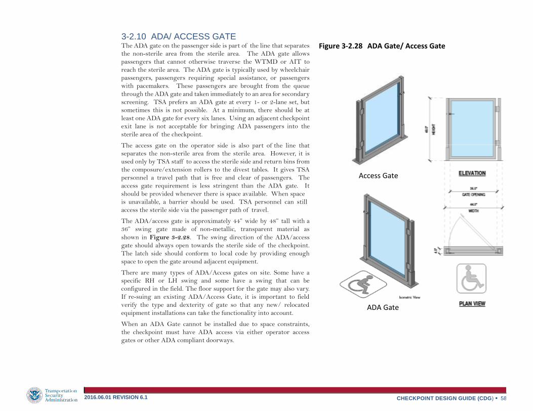
CHECKPOINT DESIGN GUIDE (CDG) 58 2016.06.01 REVISION 6.1
The ADA gate on the passenger side is part of the line that separates
the non-sterile area from the sterile area. The ADA gate allows
passengers that cannot otherwise traverse the WTMD or AIT to
reach the sterile area. The ADA gate is typically used by wheelchair
passengers, passengers requiring special assistance, or passengers
with pacemakers. These passengers are brought from the queue
through the ADA gate and taken immediately to an area for secondary
screening. TSA prefers an ADA gate at every 1- or 2-lane set, but
sometimes this is not possible. At a minimum, there should be at
least one ADA gate for every six lanes. Using an adjacent checkpoint
exit lane is not acceptable for bringing ADA passengers into the
sterile area of the checkpoint.
The access gate on the operator side is also part of the line that
separates the non-sterile area from the sterile area. However, it is
used only by TSA staff to access the sterile side and return bins from
the composure/extension rollers to the divest tables. It gives TSA
personnel a travel path that is free and clear of passengers. The
access gate requirement is less stringent than the ADA gate. It
should be provided whenever there is space available. When space
is unavailable, a barrier should be used. TSA personnel can still
access the sterile side via the passenger path of travel.
The ADA/access gate is approximately 44” wide by 48” tall with a
36” swing gate made of non-metallic, transparent material as
shown in Figure 3-2.28. The swing direction of the ADA/access
gate should always open towards the sterile side of the checkpoint.
The latch side should conform to local code by providing enough
space to open the gate around adjacent equipment.
There are many types of ADA/Access gates on site. Some have a
specific RH or LH swing and some have a swing that can be
configured in the field. The floor support for the gate may also vary.
If re-suing an existing ADA/Access Gate, it is important to field
verify the type and dexterity of gate so that any new/ relocated
equipment installations can take the functionality into account.
When an ADA Gate cannot be installed due to space constraints,
the checkpoint must have ADA access via either operator access
gates or other ADA compliant doorways.
Figure 3-2.28 ADA Gate/ Access Gate
Access Gate
ADA Gate
3-2.10 ADA/ ACCESS GATE

CHECKPOINT DESIGN GUIDE (CDG) 59 2016.06.01 REVISION 6.1
Passenger inspection can occur at the screening lanes, at the
secondary screening area, or in a private room at or near the
checkpoint. Private Screening Rooms should be installed by the
airport using conventional framing, and should meet the general
minimum requirements of the passenger inspection kit. Figure 3-
2.29 represents the common KI Wall glass kits used for passenger
inspection. These kits can be anchored to the floor or secured
overhead by a bridge kit. The manufacturer should always be
consulted when variations are needed. The local TSA is responsible
to ensure all private screening rooms have a mirror and it must be
made available for passengers subjected to secondary screening of
bulky head wear. Passengers will be offered a mirror for re-donning
of head wear and similar apparel.
3-2.11.1 PRIVATE SCREENING ROOM (PSR)
The PSR, shown in Figure 3-2.30, is approximately 6’-0” by 8’-0”
(minimum dimensions) with 8’-0” high glass panels and a 3’-0” door on
either the short wall (S3) or the long wall (S3-A). Larger private
screening rooms of 8’-0” x 8’-0” or greater is optimal. The location
of the PSR should be centralized at the checkpoint when possible in
order to minimize the walking distance for passengers and TSOs
without causing congestion or impeding TSA and/or passenger
flow. For new checkpoints it is preferred that the private
screening room is built into the space by the airport. One PSR per
eight lanes is required. The room must be available to
accommodate passengers who request pat downs out of the public
area. The room needs to be able to accommodate one passenger,
including those with disabilities, up to two TSOs, a passenger
inspection chair and mat, and a bag search table. In some cases,
an escort or interpreter may need to be present. The finish of the
glass panels is opaque so that privacy is maintained. If a
checkpoint does not have the height clearance to support the 8’-0”
tall kit, then a 6’-0” tall kit can be used. It is approximately 6’-0”
by 8’-0” with 6’-0” high glass panels and a 3’-0” door on either the
short wall (T3) or the long wall (T3-A). Glass kits need to have
sufficient clearance from the ceiling so as not to affect HVAC
and/or lighting. If the PSR can be viewed from a concourse above
or if cameras are located above or aimed at the room, then a baffle
kit consisting of slats should be installed to prevent a direct line-of-
sight into the room. Baffle kits can only be installed on S3 or S3-A
kits. There will be a head clearance issue if installed on a T3 or
T3-A. The baffle kit is shown on an S3 glass kit in Figure 3-2.29.
A private screening curtain or an airport-provided room at or near
the checkpoint could also be used for private screening functions.
Curtains are to be selected and purchased by local TSA with TSA
HQ concurrence. Various curtain options can be found at
www.cubiclecurtainfactory.com . TSA HQ does not have a
contract with this vendor. Other vendors can be pursued by local
TSA as long as the PSR requirements are met and TSA HQ approves
the solution. Designers should include power and data for future
technology as shown in Figure 3-2.30.
Private Screening Room
Isometric View
Figure 3-2.29 Passenger Inspection Kits
3-2.11 PASSENGER INSPECTION

CHECKPOINT DESIGN GUIDE (CDG) 60 2016.06.01 REVISION 6.1
Equipment Quantity Power Requirements IT Requirements Additional Information
Private Screening
Room (S3 or S3-A)
1 per 8 lanes
The following requirements occur once inside and
once outside the private screening room:
• Non-dedicated circuit • 20A, 125V, 350VA/unit
• 2-Pole, 3-Wire Grounding
• NEMA 5-20R Quad or Duplex Receptacle
• Data Drops = 2 • Cat5e / Cat6 cable
• The cable length from the termination point in the IT
cabinet to the data outlet in the work area shall not
exceed 295’.
• S3 and S3-A kits have 8’ high glass panels.
• S3 and S3-A kits can have LH or RH door swings.
Power/data should be located based on door configuration.
The default from KI Wall is a RH door swing. LH door swings
must be specified.
• S3 and S3-A kits may be installed with optional baffle kits.
• The PSR should be centralized at the checkpoint when
possible.
• If S3 or S3-A kit is installed adjacent to a solid wall, the
side wall panels may be removed.
• Local TSA will provide a mirror in the PSR.
Figure 3-2.30 Private Screening Room (S3 or S3-A)

CHECKPOINT DESIGN GUIDE (CDG) 61 2016.06.01 REVISION 6.1
Secondary screening is additional screening that may be required for
passengers and their bags when they alarm primary screening
equipment. It is an area that is approximately 3’-0” to 5’-0” from the
end of the screening lanes in order to minimize travel time and the
distance that TSOs have to carry bags. Secondary screening is
typically located in the “dead” operator space on back-to-back lanes or
at the end of the lane for odd numbered lanes. This area should be
clear of exiting passengers. The secondary screening area typically
consists of Explosive Trace Detection (ETD) unit, a Bottle Liquid
Scanner (BLS), an AVS (previously discussed in Section 2.5), a Mobile
Cabinet, a search table and a passenger search chair and mat. Refer to
Figure 3-2.31.
3-2.12.1 EXPLOSIVE TRACE DETECTION (ETD)
ETD units are used to swab carry-on bags that have alarmed at the
AT. These units should be contained within a mobile cabinet but can
sometimes be found sitting directly on a search table. The ETD
machines require operational, testing and maintenance supplies
located within arm’s reach of the working area. If a mobile cabinet is
not used, then alternative storage is required for these items. ETD
manufacturers and their specifications are listed in Figure 3-2.32.
The ETD units should be co-located with one search table for a single
lane and two search tables for back-to-back lanes. These same ETDs
are also located at the exit of AIT units as a method of secondary
screening for passengers who alarm the AIT. This is referred to an
AIT with Co-Located ETD. Refer to Section 3-2.8.1 for additional
information.
ETDs are extremely sensitive to environmental conditions such as
temperature, humidity, and air quality. ETDs should be clear of
fumes and exhaust to prevent malfunctioning. The ETD units also
have a high heat output and should be vented if placed in a non-
standard TSA storage device.
3-2.12.2 BOTTLE LIQUID SCANNER (BLS)
These scanners aid the TSA in identifying explosive, flammable, or
hazardous substances that have been concealed in a benign
container. The containers can be sealed and do not have to be open
to perform the analysis. Through the use of Raman spectroscopy
(laser) and electromagnetic technology, these units are able to
quickly analyze and identify the chemical compositions of a wide
variety of unknown solids and liquids, including explosives that are
currently on the classified threat list. Manufacturers and the
procurement specifications are listed in Figure 3-2.32 with the
ETDs.
Figure 3-2.31 Secondary Screening Area
3-2.12 SECONDARY SCREENING

CHECKPOINT DESIGN GUIDE (CDG) 62 2016.06.01 REVISION 6.1
Figure 3-2.32 ETD & BLS Units
Implant Sciences B220 ETD Smiths RespondeR RCI BLS
CEIA EMA-MS BLS GE IonTrack Itemiser ETD GE IonTrack Itemiser ETD Smiths IonScan
400B ETD
Smiths IonScan 500DT ETD
Equipment Quantity Power Requirements IT Requirements Additional Information
GE IonTrack Itemiser ETD
GE IonTrack
Itemiser3 ETD Smiths IonScan 400B ETD
Smiths IonScan 500DT ETD
Implant Sciences B220 ETD
Per Cabinet: » 1 per 2 lanes
» 1 per odd lane
1 per AIT if available on site
Non-dedicated, shared with the AVS and BLS circuit at the same
search area or queuing conveyor circuit if @ AIT
2-Pole, 3-Wire Grounding
NEMA 5-20R Duplex Receptacle
GE:
20A, 125V, 120VA/unit
6’-6” power cord from the ETD to the receptacle
Smiths: 20A, 125V, 350VA/unit 7’-8” power cord from the ETD to the receptacle
Implant Sciences: AC input: 100-240 VAC, 47-63 Hz Max current: 4 amps
Data Drops = 2 Cat5e / Cat6 cable
The cable length from the termination point in
the IT cabinet to the data outlet in the work area
shall not exceed 295’.
ETDs are located with the AVS/BLS and at the exit of the AIT if available.
Refer to AVS and AIT equipment plan views for outlet
locations.
CEIA EMA-MS BLS
Smiths RespondeR
RCI BLS
Per Cabinet: » 1 per ETD Screening Station to exclude units co-located with AIT.
Non-dedicated, shared with the AVS and ETD circuit at the same search area
2-Pole, 3-Wire Grounding
NEMA 5-20R Duplex Receptacle CEIA:
20A, 125V, 61.2VA/unit
6’-8” power cord from BLS to receptacle
Smiths: 20A, 125V, 216VA/unit
6’-6” power cord from the BLS to the AC/DC converter
6’-6” power cord from the AC/DC converter to the receptacle The AC/DC converter should be secured in the ETD-BLS
mobile cabinet so as to not strain the power adapter connection to the RespondeR unit.
Data Drops = 2 Cat5e / Cat6 cable
The cable length from the termination point in
the IT cabinet to the data outlet in the work area
shall not exceed 295’.
BLS is located with the AVS/ETD. Refer to AVS equipment plan views for outlet locations.
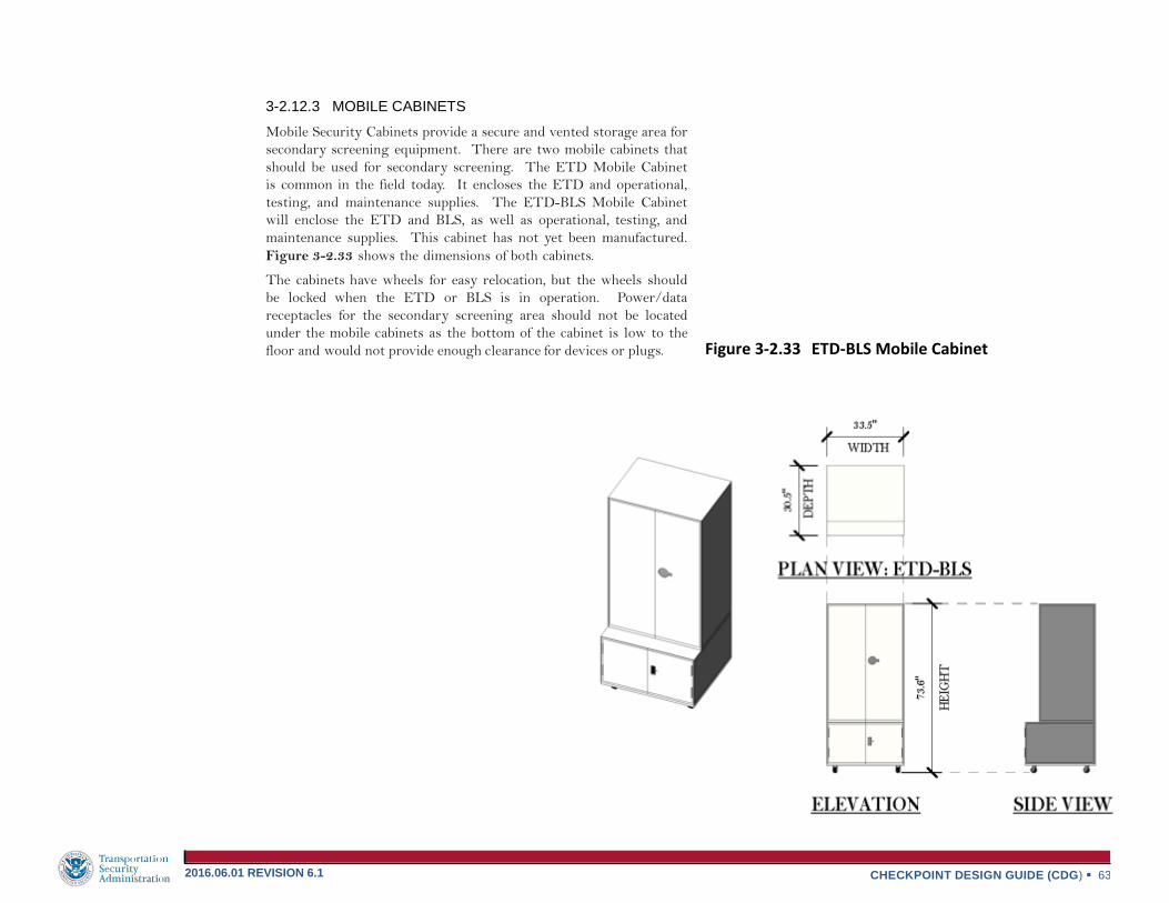
CHECKPOINT DESIGN GUIDE (CDG) 63 2016.06.01 REVISION 6.1
3-2.12.3 MOBILE CABINETS
Mobile Security Cabinets provide a secure and vented storage area for
secondary screening equipment. There are two mobile cabinets that
should be used for secondary screening. The ETD Mobile Cabinet
is common in the field today. It encloses the ETD and operational,
testing, and maintenance supplies. The ETD-BLS Mobile Cabinet
will enclose the ETD and BLS, as well as operational, testing, and
maintenance supplies. This cabinet has not yet been manufactured.
Figure 3-2.33 shows the dimensions of both cabinets.
The cabinets have wheels for easy relocation, but the wheels should
be locked when the ETD or BLS is in operation. Power/data
receptacles for the secondary screening area should not be located
under the mobile cabinets as the bottom of the cabinet is low to the
floor and would not provide enough clearance for devices or plugs. Figure 3-2.33 ETD-BLS Mobile Cabinet

CHECKPOINT DESIGN GUIDE (CDG) 64 2016.06.01 REVISION 6.1
3-2.12.4 BAG SEARCH TABLE
Bag search tables are used for target bag searches, ETD swabbing,
and BLS testing. The stainless steel surface allows TSA to provide a
clean, contaminant-free surface. See Figure 3-2.34. The bag search
tables have wheels for easy relocation, but the wheels should be
locked during ETD, BLS, and bag search functions. The back and
side panels offer privacy during bag searches but are often removed
when the bag search table is located with an AVS.
3-2.12.5 PASSENGER SEARCH POSITION
When a passenger’s body or bag alarms during primary screening,
they are escorted to a passenger search position within the secondary
screening area unless the passenger requests private screening.
Passenger inspection at the secondary screening area consists of a
6’-0” by 6’-0” area that includes a passenger inspection chair and mat.
Refer to Figure 3-2.35. This area needs to be wide enough for a TSO
to screen a standing or wheelchair passenger and for the passenger to
be able to maintain eye contact with his/her belongings and family
members.
Figure 3-2.35 Passenger Search Position Figure 3-2.34 Bag Search Table

CHECKPOINT DESIGN GUIDE (CDG) 65 2016.06.01 REVISION 6.1
Egress seating at the checkpoint is used for passengers to sit down
and compose themselves with their personal belongings after
completing the screening process. The screening experience is
greatly improved if passengers can sit down to put their shoes and
jackets on. TSA provides composure benches approximately 14’-0”
from an AIT depending on the equipment arrangement. This area
is typically out of the main passenger flow. Figure 3-2.36 shows the
dimensions of the TSA-provided composure bench. The airport may
provide additional benches or seating for this same purpose near the
exit of the checkpoint, but they may vary in size.
The Supervisory Transportation Security Officer (STSO) should be positioned at a podium like the one shown in Figure 3-2.37 near the checkpoint exit. Dimensions of the podium as well as the power/data requirements are illustrated in Figure 3-2.38. The STSO should be able to perform administrative duties while viewing and supervising the entire screening operation. The location should have an unobstructed view of the checkpoint.
Figure 3-2.36 Composure Bench Figure 3-2.37 STSO Podium
3-2.13 COMPOSURE BENCH 3-2.13 STSO PODIUM

CHECKPOINT DESIGN GUIDE (CDG) 66 2016.06.01 REVISION 6.1
Equipment Quantity Power Requirements IT Requirements Additional Information
STSO Podium
1 per 4 lanes
Non-dedicated
20A, 125V, 180VA/podium
2-Pole, 3-Wire Grounding
NEMA 5-20R Quad or Duplex Receptacle
6’ to 10’ power cord from the TSA laptop to the receptacle
Data Drops = 2
Cat5e / Cat6 cable The cable length from the termination point in the IT
cabinet to the data outlet in the work area shall not exceed 295’.
Figure 3-2.38 STSO Podium

CHECKPOINT DESIGN GUIDE (CDG) 67 2016.06.01 REVISION 6.1
The power and data requirements for each individual piece of security
screening equipment are included in Section 3-2. This section
attempts to describe all the electrical systems, specifically data, power,
CCTV, and lighting required to support the checkpoint. Familiarity
with these requirements will be essential when designing a new
checkpoint or reconfiguring an existing checkpoint.
The TSA HQ Office of Information Technology (OIT) and Security Technology Integrated Program (STIP) requires most powered security screening equipment to have two data drops consisting of flush-mounted 568B data jacks with the associated data labeling. Both drops, even though one is redundant, should be connected using Cat5e/Cat6 data cable and terminated on the patch panel in the closest TSA IT cabinet located at or near the checkpoint in a secured room. The data cable type should be based on the existing conditions at the checkpoint. The purpose of this connectivity is so that TSA HQ can review statistical data over the network from screening equipment for a particular airport and time period without having to go to the site.
Steps toward this goal were made under the High Speed Operational
Connectivity (Hi-SOC) program where data outlets and cables for a
limited number of locations were connected to the IT cabinet. As
checkpoints are reconfigured, either the project owner’s contractor or
the TSA Headquarters Install, Move, Add, or Change (IMAC) Group
gets involved to relocate and provide new data outlets and cables as
needed to support new technology. If a checkpoint relocation or
reconfiguration is initiated by the airport during an airport
renovation, or a new checkpoint is being designed for a new terminal
or airport as a part of an Airport Authority Mandate, the airport
must restore the checkpoint to its previous state of connectivity
(“make whole”). If a checkpoint reconfiguration is initiated by any
group within TSA HQ as part of an optimization and safety effort,
new technology deployment or any other checkpoint redesign
initiative, the TSA will be responsible for restoring the checkpoint to
its previous state of connectivity (“make whole”), including
development of the scope of work (SOW). Implementation in the
field can occur via the TSA HQ Contractor or via the internal IMAC
group. This will depend on the scope of work and the number of
sites impacted.
In either scenario, a working group must be formed consisting of
representatives from the Airport Authority, FSD staff, TSA HQ,
TSA OSH, and STIP. The group should meet immediately via
conference call once it has been determined that a checkpoint or
checkpoints are going to be reconfigured. This action will ensure
that all aspects of the checkpoint redesign have been identified and
assigned to a specific group for action and funding. This team will
organize the working group members, develop, review and
approve the SOW. The OIT Field Regional Manager (FRM)
should always be consulted when a checkpoint redesign is initiated.
Installation and/or relocation of Cat5e/Cat6 data cabling and
installation and operation of IT cabinets shall meet or exceed the
specifications as per the TSA Structured Cable System Guidelines
dated July 27, 2012. Contact TSA HQ to obtain a copy of the
TSA Structured Cable System Guidelines. Figure 3-3.1
illustrates all of the equipment that must be connected to the IDF
IT cabinet and equipment that must be connected to other
equipment such as the AT to the AVS.
3-3 SSCP ELECTRICAL, DATA, AND SAFETY REQUIREMENTS
3-3.1 DATA REQUIREMENTS

CHECKPOINT DESIGN GUIDE (CDG) 68 2016.06.01 REVISION 6.1
At a minimum, the following guidelines should be considered when
designing a new checkpoint or reconfiguring an existing checkpoint.
If an existing TSA Main Distribution Frame (MDF)/ Intermediate
Distribution Frame (IDF) is within 295’ of the SSCP:
Verify that the existing switches have sufficient open ports to accommodate the required number of drops.
Install an additional switch if the existing switch capacity will not accommodate the required number of drops.
Punch down cabling from the individual SSCP devices in the patch panel of the IT cabinet.
Initiate IMAC group to install jumper cables from the patch
panel to the switch and activate port. This is described later in
this section.
If there is no MDF/IDF within 295’ of the SSCP:
Install an appropriate IT cabinet. Refer to Figure 3-3.3 for the IT
cabinet specifications.
Install fiber optic cable from the IT cabinet to an existing TSA
MDF/IDF.
Punch down cabling from the individual SSCP devices in the
patch panel of the IT cabinet.
Initiate IMAC group to install jumper cables from the patch
panel to the switch and activate port.
The IMAC Process is the course of action required by TSA OIT to
implement an IT request at a checkpoint. Who takes the lead and
who funds the effort will all depend on the group initiating the work.
For example, if TSA HQ is deploying new technology at the
checkpoint, then the TSA Regional Deployment Manager (RDM)
would be responsible for making OIT aware of the airports and
checkpoints receiving new equipment that require new or relocated
data outlets and cabling. Once this initial contact has been made, a
process will need to be identified for each group to execute.
The IMAC process needs to be initiated for the following, which
takes 90 to 120 days to implement unless otherwise noted.
Installation of a new IT cabinet.
Relocation of an existing IT cabinet.
Installation of additional IT equipment.
Relocation or installation of new fiber.
Relocation or installation of new T1 and/or Out of Band
(OOB) Management Analog lines for monitoring modems in
the IT cabinets. This takes approximately 45 to 60 days to
implement.
The preceding durations are determined from the date when the
SOW has been submitted by the OIT FRM and approved by the
IMAC team. Since it can take up to several months to implement IT
modifications, it is imperative to engage each team member as early
as possible in order to avoid any gaps in IT services.
Figure 3-3.4 lists the specifications for the Kronos 4500 Time
Clock Terminal. This clock should be located within 295’ of the
TSA MDF/IDF and it should utilize Power Over the Ethernet
(POE). These terminals need to be deployed at TSA airports and
offsite locations in support of the Electronic Time, Attendance, and
Scheduling (eTAS) Program which monitors and tracks timekeeping
of TSOs across the country. Refer to the TSA Kronos Terminal
Installation and Configuration Guide Version 1.7 dated October 29,
2009 for additional information.

CHECKPOINT DESIGN GUIDE (CDG) 69 2016.06.01 REVISION 6.1
Figure 3-3.1 SSCP Data Connectivity Diagram

CHECKPOINT DESIGN GUIDE (CDG) 70 2016.06.01 REVISION 6.1
Power Data
Device/Space Circuit Type Voltage Receptacle Type* Comments Cable Type/Location/Comments
RAPISCAN 620DV AT
DEDICATED 20A FOR X-RAY
125V
NEMA 5-20R
15’ POWER CORD FROM AT TO RECEPTACLE 2- CAT 6 ROUTED TO TSA IT CABINET (1
PRIMARY 1 REDUNDANT) PLUS 2- CAT 6
ROUTED DIRECT (NOT THROUGH PATCH PANEL)
TO AVS (MAINTAIN LANE ASSOCIATION). (1
PRIMARY 1 REDUNDANT, REDUCTION NOT
ALLOWED)
RAPISCAN 620DV AT
QUEUING CONVEYOR
NON-DEDICATED 20A FOR
QUEUING CONVEYOR,
MAXIMUM OF 2 PER CIRCUIT
W/ ETD @ AIT
125V
NEMA 5-20R
15’ POWER CORD FROM QUEUING CONVEYOR TO
RECEPTACLE
NOT APPLICABLE
RAPISCAN AVS
NON-DEDICATED 15A
125V
NEMA 5-20R
5’ POWER CORD FOR TWO MONITORS AND ONE
PC TOWER OF THE AVS TO THE RELOCATABLE
POWER TAP MOUNTED TO THE TSA SEARCH
TABLE. 6’ POWER CORD FROM THE RELOCATABLE
POWER TAP TO THE RECEPTACLE. CIRCUIT
SHARED WITH ETD AND BLS AT THE SAME SEARCH
AREA VIA RELOCATABLE POWER TAP (FIGURE 3-
2.13)
2- CAT 6 ROUTED DIRECT (NOT THROUGH PATCH
PANEL) TO XRAY (MAINTAIN LANE ASSOCIATION).
(1 PRIMARY 1 REDUNDANT, REDUCTION NOT
ALLOWED)
SMITHS 6040aTiX AT
DEDICATED 20A
125V
NEMA 5-20R
15’ POWER CORD FROM AT TO RECEPTACLE
2- CAT 6 ROUTED TO TSA IT CABINET (1
PRIMARY 1 REDUNDANT) PLUS 2- CAT 6
ROUTED DIRECT (NOT THROUGH PATCH PANEL)
TO AVS (MAINTAIN LANE ASSOCIATION). (1
PRIMARY 1 REDUNDANT, REDUCTION NOT
ALLOWED)
SMITHS AVS
NON-DEDICATED 20A
125V
NEMA 5-20R
5’ POWER CORD FOR TWO MONITORS AND ONE
PC TOWER OF THE AVS TO THE RELOCATABLE
POWER TAP MOUNTED TO THE TSA SEARCH
TABLE. 6’ POWER CORD FROM THE RELOCATABLE
POWER TAP TO THE RECEPTACLE. CIRCUIT
SHARED WITH ETD AND BLS AT THE SAME SEARCH
AREA VIA RELOCATABLE POWER TAP (FIGURE 3-
2.15)
2- CAT 6 ROUTED DIRECT (NOT THROUGH PATCH
PANEL) TO XRAY (MAINTAIN LANE ASSOCIATION).
(1 PRIMARY 1 REDUNDANT, REDUCTION NOT
ALLOWED)
L3 ACX 6.4- MV AT
DEDICATED 20A
125V
NEMA 5-20R
15’ POWER CORD FROM AT TO RECEPTACLE.
OPERATOR CART IS POWERED BY THE AT. FIELD
DATA RECORDING SYSTEM (FDRS) IS POWERED
BY THE AT. UPS IS INTERNAL TO AT
2- CAT 6 ROUTED TO TSA IT CABINET (1
PRIMARY 1 REDUNDANT) PLUS 2- CAT 6
ROUTED DIRECT (NOT THROUGH PATCH PANEL)
TO AVS (MAINTAIN LANE ASSOCIATION). (1
PRIMARY 1 REDUNDANT, REDUCTION NOT
ALLOWED)
L3 AVS
NON-DEDICATED 20A
125V
NEMA 5-20R
6’ POWER CORD FOR ONE MONITOR AND PC
TOWER OF THE AVS TO THE UPS. 6’ POWER CORD
FROM UPS TO RELOCATABLE POWER TAP
MOUNTED TO THE TSA SEARCH TABLE. 6’ POWER
CORD FROM THE RELOCATABLE POWER TAP TO
THE RECEPTACLE. CIRCUIT SHARED WITH ETD
AND BLS AT THE SAME SEARCH AREA VIA
RELOCATABLE POWER TAP (FIGURE 3-2.17)
2- CAT 6 ROUTED DIRECT (NOT THROUGH PATCH
PANEL) TO XRAY (MAINTAIN LANE ASSOCIATION).
(1 PRIMARY 1 REDUNDANT, REDUCTION NOT
ALLOWED)
Figure 3-3.2 Power & Data Requirements Table

CHECKPOINT DESIGN GUIDE (CDG) 71 2016.06.01 REVISION 6.1
Power Data
Device/Space Circuit Type Voltage Receptacle Type* Comments Cable Type/Location/Comments
L3 PRO VISION AIT/
L3 PROVISION AIT2
DEDICATED 20A
125V
NEMA 5-20R
25’ POWER CORD FROM AIT TO UPS. 10’ CORD
FROM UPS TO AIT. 16’ USB CABLE FROM AIT TO
UPS. CABLES CANNOT BE RUN UNDER ENTRY/
EXIT RAMPS. TCOP CANNOT BE MOUNTED ON
CONTROL LEG.
2- CAT 6 ROUTED TO TSA IT CABINET (1
PRIMARY 1 REDUNDANT)
WTMD
DEDICATED 20A
125V
NEMA L5-15R
(TWISTLOCK)
WTMD’S CAN BE GROUPED UP TO 10 PER CIRCUIT.
WTMD MUST BE DEDICATED “WTMD-ONLY”
CIRCUIT.
13’ POWER CORD FROM WTMD TO RECEPTACLE.
18” MINIMUM SPACING FROM WTMD LEG TO
ELECTRICAL CONDUIT OR DEVICE.
2- CAT 6 ROUTED TO TSA IT CABINET (1
PRIMARY 1 REDUNDANT)
ETD & CO-LOCATED ETD
NON-DEDICATED 20A
125V
NEMA 5-20R
NON-DEDICATED CIRCUIT, ETD POWER MAY BE
SHARED WITH AVS AND BLS CIRCUIT AT THE SAME
SEARCH AREA VIA RELOCATABLE POWER TAP. CO-
LOCATED ETD POWER CIRCUIT MAY BE SHARED
WITH THE QUEUING CONVEYOR CIRCUIT @ SAME
MODULE SET. MINIMUM CORD LENGTH 6’-6”.
2- CAT 6 ROUTED TO TSA IT CABINET (1
PRIMARY 1 REDUNDANT)
BLS
NON-DEDICATED 20A
125V
NEMA 5-20R
NON-DEDICATED CIRCUIT, MAY BE SHARED WITH
AVS AND BLS CIRCUIT AT THE SAME SEARCH AREA
VIA RELOCATABLE POWER TAP (FIGURE 3-2.32).
MINIMUM CORD LENGTH 6’-6”
2- CAT 6 ROUTED TO TSA IT CABINET (1
PRIMARY 1 REDUNDANT)
TDC & CAT
DEDICATED 20A
125V
NEMA 5-20R
TDC’S CAN BE GROUPED UP TO 5 PER CIRCUIT.
TDC’S MUST BE DEDICATED “TDC-ONLY” CIRCUIT.
POWER CORD LENGTH UNKNOWN AT THIS TIME.
2- CAT 6 ROUTED TO TSA IT CABINET (1
PRIMARY 1 REDUNDANT)
STSO
NON-DEDICATED 20A
125V
NEMA 5-20R
6’-10’ CORD FROM LAPTOP TO RECEPTACLE
2- CAT 6 ROUTED TO TSA IT CABINET (1
PRIMARY 1 REDUNDANT)
PRIVATE SCREENING
INTERIOR
NON-DEDICATED 20A
125V
NEMA 5-20R
REFER TO FIGURE 3-2.30 FOR RECEPTACLE
LOCATION
2- CAT 6 ROUTED TO TSA IT CABINET (1
PRIMARY 1 REDUNDANT)
PRIVATE SCREENING
EXTERIOR
NON-DEDICATED 20A
125V
NEMA 5-20R
REFER TO FIGURE 3-2.30 FOR RECEPTACLE
LOCATION
2- CAT 6 ROUTED TO TSA IT CABINET (1
PRIMARY 1 REDUNDANT)
PANIC/DURESS
NON-DEDICATED 20A
125V
NEMA 5-20R
VERIFY WIRELESS & WIRED DURESS ALARM
BUTTON, WIRELESS REPEATER, POWER
RECEPTACLES, AND RECEIVING PANEL
REQUIREMENTS
VERIFY WITH VENDER
KRONOS (ETA)
POWER OVER ETHERNET
(POE)
N/A
N/A
REFER TO PLANS FOR LOCATION
2- CAT 6 ROUTED TO TSA IT CABINET (1
PRIMARY 1 REDUNDANT)
Figure 3-3.2 Power & Data Requirements Table (cont.)

CHECKPOINT DESIGN GUIDE (CDG) 72 2016.06.01 REVISION 6.1
Equipment Size Quantity Power Requirements IT Requirements Additional Information
IT Cabinet Size 24H
24.0”H x 27.3”W x 30.0”D Weight: 97 lbs
1 or more per
checkpoint
depending on
size
For 24H, 36H and 48H: Dedicated
30A, 125V, 3KVA/Cabinet 2-Pole, 3-Wire Grounding
NEMA L5-30R Receptacle 3KVA UPS 6’ power cord from the IT cabinet to the
receptacle
Size patch panels to
accommodate all TSA
data outlets at the
checkpoint plus 100%
spares, minimum.
Size giga bit network
switch to accommodate all
data outlets in checkpoint
plus 10%.
Provide a minimum of four
pair single mode fiber
optic cable from IT cabinet
to the TSA main
distribution frame
30” front and rear access is required.
These cabinets will receive all data communication lines from
the SSCP, so the cabinet should be located as close to the
SSCP as possible, but in a secure location in a separate
room. Careful consideration needs to be given to the IT
cabinet location because the exhaust fan for cooling can be
loud when located in a confined space with TSA or airport
personnel.
Equipment racks can be loaded into the cabinet from the front
or the back at the location where the cabinet is installed.
Although not required, side access would improve rack
accessibility and TSA personnel mobility around the cabinet.
Refer to TSA Structured Cable System Guidelines dated July
27, 2012 for cable management and administration of IT
cabinet.
Refer to TSA Structured Cable System Guidelines dated July
27, 2012, for acceptance testing of IT circuits.
Wall-mounted cabinets are an option in some instances, but
must adhere to all applicable local codes and standards.
Recommend consultation with the Field Regional Manager
(FRM) when considering a wall-mounted alternative.
All IT cabinet installations and relocations shall be requested
by a ReMAG and should be requested a minimum of 90 days
prior to installation.
Size 36H 36.0”H x 27.3”W x 30.0”D
Weight: 124 lbs
Size 48H 48.0”H x 27.3”W x 30.0”D
Weight: 151 lbs
Size 60H 60.0”H x 27.3”W x 30.00”D
Weight: 246 lbs
For 60H and 72H: 30A, 208V, 6KVA/Cabinet
NEMA L6-30R Receptacle 6KVA UPS
8’ power cord from the IT cabinet to the
receptacle
Size 72H
72.0”H x 27.3”W x 30.00”D Weight: 274 lbs
Figure 3-3.3 IT Cabinet

CHECKPOINT DESIGN GUIDE (CDG) 73 2016.06.01 REVISION 6.1
9"
MIN
Equipment Size Quantity Power Requirements IT Requirements Additional Information
Kronos 4500 Terminal 11.7”H x 10.7”W x
4.0”D
1 per airport or
checkpoint depending
on TSO population
All Power Over Ethernet
(POE)
Data Drop = 2
Cat5e / Cat6 cable
Kronos Terminal placement
should be within 295’ of existing
TSA IT Cabinet.
Host communication via Ethernet
(10/100 Mbps auto sensing)
Verify switch ports exist in TSA
IT Cabinet prior to installation.
Locate Kronos Terminal in a secure TSA area. Place in protected
area to avoid physical damage.
Mount per ADA requirements. Allowed high side reach shall be no
more than 54” and the allowed low side reach shall be no less than 9”
AFF.
Avoid checkpoint high traffic areas such as exit lanes, queuing areas,
public seating, and composure areas.
No exposed cabling or power outlets allowed.
TSA preferred install is to mount the clock over a LAN port and power
outlet.
Figure 3-3.4 Kronos Time Clock

CHECKPOINT DESIGN GUIDE (CDG) 74 2016.06.01 REVISION 6.1
Most of the new technology being added to the checkpoint today and in the future requires a dedicated circuit. It is recommended to plan for this now, especially if the existing electrical panel(s) has available capacity. Figure 3-3.5 illustrates all of the equipment that must be connected to the SSCP power panel board. All checkpoint circuits should be located together in the same electrical panel or panels with non-dedicated circuits grouped together when possible. This is not possible to do for the WTMD or TDC even though the load is approximately 1A. WTMDs and TDCs can only share a circuit with other WTMDs or TDCs, otherwise the units will not function properly. The checkpoint electrical engineer should not assume an existing circuit is dedicated or expect the electrical contractor to trace an existing circuit and remove any excess load during construction. For new checkpoint design and checkpoint reconfiguration, new dedicated circuits should be provided for most security screening equipment. Each dedicated circuit should have its own neutral. There should be no common neutrals used for any checkpoint equipment circuits. This is necessary to prevent accidental over-voltage conditions and potential equipment damage should a neutral conductor be interrupted.
The electrical panel should be located as close as possible to the
checkpoint. New electrical panels should be designed to have 20% or
more open spaces for future expansion. Each SSCP should have an
electrical panel located in a secured area located at or near the SSCP
and accessible by TSA staff. The standard voltage for SSCP
equipment is 120/208V. SSCP panels can vary in size from 100A, 3-
phase to 225A, 3-phase depending on the number of lanes at the
checkpoint.
During design, it is important for the electrical engineer to determine
the existing electrical system capacity available for checkpoint
equipment. Field verification of the existing electrical panel loads
and availability of power to support new equipment loads is essential.
Circuits from existing electrical panels should be used when available
as indicated by the panel board and corresponding panel
schedule that serves the checkpoint. Understand, however, that the
panel schedule can often lack sufficient detail in regard to what
equipment the circuit is feeding. Sometimes there are other loads
piggy-backed onto a supposedly spare circuit or even a circuit
feeding checkpoint equipment. A load study of the intended
checkpoint power source that satisfies the requirements of NEC
220.87 is strongly recommended.
In some cases, a new electrical panel may be required for new circuits
in support of a new checkpoint or reconfiguration of an existing
checkpoint. This should be determined during the design phase
by the electrical engineer and brought to the attention of TSA
HQ immediately. When TSA HQ is funding the project, they must
approve the cost of the new panel during the design phase as there
could be impacts to the planned budget. This is only for deployment
projects. An airport could provide a new panel at any time.
The electrical design of a new checkpoint or reconfiguration of an
existing checkpoint must meet all applicable national and local
codes in addition to any airport, state, county, and/or city
requirements, depending on the Authority Having Jurisdiction (AHJ).
Uninterrupted Power Supply (UPS) backup power is not required
for SSCPs, although it may exist, or be required at some sites where
power conditions are unstable and/or unreliable.
3-3.2 POWER REQUIREMENTS

CHECKPOINT DESIGN GUIDE (CDG) 75 2016.06.01 REVISION 6.1
Figure 3-3.5 SSCP Power Connectivity Diagram

CHECKPOINT DESIGN GUIDE (CDG) 76 2016.06.01 REVISION 6.1
In Figure 3-3.7, there are five types of TSA-approved electrical distributions and/or devices for SSCPs. In order of preference, TSA would like SSCP equipment to be powered in the following manner unless the Airport Authority states otherwise.
1. Modular surface-mounted pedestals in the floor and wall
2. Recessed power/data poke-through devices in the floor
3. Flush power/data poke-through devices in the floor and wall
4. Multiplex surface box
5. Ceiling or floor-supported power/data poles
The airport A&E firm should coordinate closely with the airport and TSA HQ when designing electrical systems to ensure that the needs of both parties are met.
TSA prefers that modular surface-mounted pedestals be located underneath x-ray conveyors. This type of receptacle is highly versatile and requires a smaller floor penetration. When a modular surface-mounted pedestal is not ideal, TSA prefers the Wiremold Evolution Series Model 6AT/8AT recessed poke-through because of the flexibility it provides when installed flush in the floor and the amount of receptacles, data jacks, grommet openings, and connectors it can hold within one device. This receptacle is ideal for high traffic areas and for locations with moving equipment. The downside is that a 6” core drill is required which is often a concern to an airport or the AHJ, as they do not want to impact the structural integrity of the floor. The location of the poke-throughs with respect to the structural framing, quantity of poke-throughs, and proximity to other poke-throughs must be carefully evaluated by the checkpoint electrical and structural engineer.
Although the poke-through is identified as being “recessed”, the cover actually sits slightly above the floor. This is acceptable at most locations within the checkpoint except for the TDC and CAT or STSO podium, and outside the Private Screening Room. These three locations should have a truly recessed poke-through because the equipment at these locations is not static and TSA wants the flexibility to make adjustments to the equipment in the future without creating trip hazards to passengers and personnel. This truly recessed poke-through can be achieved by providing a structural detail on the construction drawings that specifies for the contractor to core drill a hole approximately ¼” larger than the recessed poke-through cover so that the lip of the cover sits down in the floor. Refer to Figure 3-3.6. This installation is required when power/data is provided to these locations from the floor. Power poles can be used at these locations when a checkpoint is slab-on-grade or power poles are the preferred method of power and data distribution at the checkpoint.
When a checkpoint has a seismic structural slab-on-grade, terrazzo floors or high ceilings with an open plan, it can be a challenge to provide power and data to checkpoint equipment. Freestanding, self-supporting, movable overhead truss systems or modular raised access flooring are viable solutions that have been implemented at a handful of airports in these circumstances. While these options are more expensive up front than some of the other options, they provide TSA a great deal of flexibility to reconfigure the checkpoints in the future or deploy more equipment without incurring significant infrastructure costs.
Power and data receptacles should be of high quality industrial standard to accommodate the high volume traffic at the SSCP. All should be properly mounted and fire-proofed.
3-3.3 POWER/DATA RECEPTACLES

CHECKPOINT DESIGN GUIDE (CDG) 77 2016.06.01 REVISION 6.1
All power/data recessed or flush poke-through devices, modular or made-up surface boxes, power poles, fittings, raised access flooring, self-supporting truss systems, or in-floor Walkerduct systems must be coordinated with the Airport Authority. Typically, the airport prefers consistency in the type, finish, and color of electrical devices. So what is typically used throughout the terminal should also be used at the checkpoint. Exceptions may occur if the AHJ wants to minimize the addition of new core drills or wants to have flexibility to relocate the SSCP in the future. The checkpoint electrical engineer should confirm with the Airport Authority if the electrical distribution needs to match what currently exists at the checkpoint today or if it should be changed to match the terminal or to support future needs. The airport and/or the AHJ may also want to evaluate floor core sizes and quantities as well as locations of any new electrical trenches. Airports with terrazzo floors are especially concerned about excessive penetrations in the floors and having areas where the patching is executed poorly. The airport may prefer modular or made-up surface boxes which require only a 1” to 3” core in lieu of recessed poke-through devices which require a 6” to 8” core. While the surface boxes require a smaller core, more boxes would be required to support all the planned TSE, hence more floor coring. A comparison of this is presented in the following section. If possible, the electrical approach should be discussed with the AHJ as early in the project as possible in order to prevent any delays with the permit. Every attempt to re-use existing floor cores should be made when reconfiguring an existing checkpoint.
Acceptable locations for receptacles are included on the plan views for the equipment in Section 3-2. Recessed, flush, or surface devices should be positioned in such a way as to avoid trip hazards for both passengers and TSA personnel. The AT dome is approximately 2-¾-inch above finished floor (AFF); therefore, pedestals, monuments, devices, or fittings located underneath the X-ray dome will not provide sufficient space to accept a plug. These should be located approximately 18” clear of the dome under the infeed or the outfeed depending on the equipment being fed. Under special circumstances only, an existing floor core located underneath an X-ray dome can be reused by providing a junction box on top of the core and extending it with rigid or flexible conduit to a surface box located under the infeed or the outfeed.
Figure 3-3.6 Recessed Poke-Through Installation Detail

CHECKPOINT DESIGN GUIDE (CDG) 78 2016.06.01 REVISION 6.1
Receptacles should be located within reach of the equipment cords. The equipment cord lengths are included in the tables above the plan views in Section 3-2. Extension cords for permanently installed equipment are unacceptable if the equipment cord is too short to reach a receptacle. Equipment cords must be secured to the floor with tape, pancake raceway, cord clips, etc. Equipment cords should not be placed across passenger walkways or TSA working paths, nor should they be run underneath anti-fatigue mats or the AIT units where they may become a trip hazard, damaged from traffic, or be an NEC violation.
Care must also be taken to ensure that electrical receptacles are protected from damage or inadvertent contact by equipment, passengers, and/or TSA personnel. The receptacles for most SSCP equipment are straight blade NEMA 5-20R except for the WTMD and the IT cabinet where the receptacle needs to be twistlock to prevent power cords from being accidentally disconnected. All data jacks should be flush-mounted with the receptacle housing with no loose wires extending from the housing. Any unused ports should be covered.
Duplex outlets that are split-wired with separate circuits to each receptacle must be fed from a two-pole circuit breaker or two side-by- side single-pole circuit breakers that have an approved link between the circuit breaker operator handles in order to meet the requirements of 2008 NEC 210.7 (B). The 2008 NEC 210.7 (B) states, “where two or more branch circuits supply devices or equipment on the same yoke, a means to simultaneously disconnect ungrounded conductors supplying those devices shall be provided at the point at which the branch circuits originate.”
When existing recessed or flush poke-throughs, modular or made- up surface boxes are no longer needed at an SSCP, the checkpoint designer should specify for the contractor to perform the following tasks.
Remove the power/data outlets and devices.
Pull and remove the existing wiring back to its source.
Repair the floor core opening to restore the floor slab to
its original integrity.
Install a flush cover plate, as required, for the type of
outlet device removed.

CHECKPOINT DESIGN GUIDE (CDG) 79 2016.06.01 REVISION 6.1
Item Service Type Description Pro Con Recommendation
1
Modular Surface Box
Pedestal poke-through with a
2-compartment box
9.25”W x 4.63”D x 2.63”H;
2-3” hole/box, dependent
on manufacturer
2-3” hole in floor depending on
manufacturer
UL listed assembly
Fire-rated
A cover plate can be added if location is
abandoned.
Supports any outlet configuration
Can be plugged in beneath X-ray
Not flush ~ trip hazard
Floor X-ray required in order to avoid
existing steel.
The plug is above floor level and can be
knocked out.
Recommended at checkpoints where a
small floor penetration is desired.
Recommended for use under x-ray
2
Poke-Through – Recessed
Poke-through with recessed
receptacles
7.25” diameter; 6”
hole/device
Completely flush installation ~ minimizes
trip hazards.
Easy/quick installation
UL listed assembly
Fire-rated
Tamper-proof cover
Recessed connections
6” device can support any 20A outlet
configuration
6” hole in floor
Floor X-ray required in order to avoid
existing steel.
Extra coring required to mount lip of the
receptacle flush in terrazzo floor.
Recommended at checkpoints where a
large core drill will not impact the
structural integrity of the floor.
Recommended at checkpoints where a
flush installation is desired.
6” device has smaller surface
presentation than the modular surface
box or the made-up surface box.
3
Poke-Through – Flush
Poke-through with flush
receptacles
7.5” diameter x 5/16” high;
3-4” hole/device,
dependent on
manufacturer
Easy/quick installation
UL listed assembly
Fire-rated
Wide variety of device combinations
Floor X-ray required in order to avoid
existing steel.
Not flush ~ raised lip is a trip hazard.
Electrical devices are proprietary.
The plug is above floor level and can be
knocked out.
The floor cover is plastic, in some cases,
therefore less durable in high traffic areas.
Recommended only for equipment that
does not require a twistlock or simplex
receptacle.
Recommended in low traffic areas,
since these receptacles have
nonmetallic covers that can break easily.
4
Multiplex Surface Box
Surface-mount cast box
8-3/4”W x 6-3/4”D x 3”H,
(2) 1-5/8” hole/outlet
7/8” hole in floor
1/2” Rigid Galvanized Steel (RGS) floor
penetration
Inexpensive
Easy to relocate and repair floor
Can be reconfigured easily
Limited structural impact to floor
Supports any outlet configuration
Not flush ~ trip hazard
Floor X-ray required in order to avoid
existing steel.
Not attractive
The plug is above floor level and can be
knocked out.
Recommended for slab on-grade
checkpoints.
5
Ceiling or Floor-Supported
Power Pole
Floor to ceiling dual channel
metallic raceway;
36” AFF floor-supported
Wiremold Vista Point 5
Column
Inexpensive
Easy to relocate and repair floor/ceiling
Can be reconfigured easily
Supports any outlet configuration
Not attractive
Obscures visibility across the checkpoint.
Safety concern for high traffic areas
Difficult to install at checkpoints with high
ceilings.
Ceiling-supported power poles
recommended for slab-on-grade
checkpoints where floor trenching is not
desired.
Floor-supported power poles
recommended for AIT when there is
passenger flow on both sides of the AIT.
Figure 3-3.7 Power/ Data Device Distribution

CHECKPOINT DESIGN GUIDE (CDG) 80 2016.06.01 REVISION 6.1
Checkpoint equipment can be fed by a power/data device configured to support one or several pieces of equipment. As the device gets larger, more equipment can be supported; however, as the device gets larger, the floor core gets larger which often becomes a roadblock with the airport and/or the permit authority. When designing a checkpoint with any of the electrical distributions/devices described previously, the configuration of the device should be indicated on the drawings so that the contractor knows the combination of receptacles, data jacks, and connectors needed to support equipment located together.
A physical example of the impacts of using different devices is graphically illustrated in Figure 3-3.9 through Figure 3-3.11. The details show how additional devices may be needed in order to achieve the same configuration. Both figures represent how the airport or AHJ may be convinced to use the larger poke-through to support the most equipment in order to reduce the number of holes in the floor. However, they may request a structural analysis to evaluate any impacts before final approval is granted.
3-3.4 POWER/DATA CONFIGURATIONS

CHECKPOINT DESIGN GUIDE (CDG) 81 2016.06.01 REVISION 6.1
TYPICAL- (1) FLOOR-TO-CEILING RACEWAY
TYPICAL - (1) 7-1/2-INCH FLUSH
1) MULTIPLEX
PO
KE
TH
RO
UG
H
PO
WE
R P
OL
E
Figure 3-3.9 Device Comparison

CHECKPOINT DESIGN GUIDE (CDG) 82 2016.06.01 REVISION 6.1
TYPICAL (1) MULTIPLEX
TYPICAL (2) MODULAR
1) MULTIPLEX
TYPICAL (1) MULTIPLEX
TYPICAL (1) MULTIPLEX
SU
RF
AC
E B
OX
ES
TYPICAL (2) MADE UP
1) MULTIPLEX
TYPICAL (1) MULTIPLEX
TYPICAL (1) MULTIPLEX
Figure 3-3.10 Device Comparison (Continued)
SU
RF
AC
E B
OX
ES

CHECKPOINT DESIGN GUIDE (CDG) 83 2016.06.01 REVISION 6.1
TYPICAL- (1) FLUSH/CAST-IN-PLACE
IN-F
LO
OR
BO
XE
S
Figure 3-3.11 Device Comparison

CHECKPOINT DESIGN GUIDE (CDG) 84 2016.06.01 REVISION 6.1
Figure 3-3.12 shows the recommended power/data layout for SSCP
Standard Arrangement. These graphics show the approximate
locations and of various devices that can be used to support multiple
TSE. Recessed, flush, and surface devices are represented by the
hexagon. Most of these devices are concealed under equipment with
enough clearance for the height of the device and the plug. The
truly flush recessed device is shown at the required three locations
mentioned previously and is represented by the clover symbol.
Power poles are represented by a square or oval. Only one type of
distribution should be chosen per location. The power poles should
only be designed when the checkpoint is slab- on-grade or the
preferred distribution is via power pole. The 36” floor-supported
power pole should only be used for the AIT when there is passenger
flow on both sides of the AIT from an ADA Gate or WTMD when a
ceiling-supported power pole is not possible or feasible. Every
attempt should be made to locate receptacles under the lanes to feed
the lanes and all infield equipment; however, this is not always
possible. In some cases, the L3 AIT can be rotated 180 degrees in
order to locate the electrical control leg adjacent to a receptacle
located under the infeed or the outfeed of the AT unit. Group
power/data circuits within the same device as applicable to limit the
number of floor coring required. Each TSE does not need a separate
power/data device however; avoid any possible passenger and/or
TSO trip hazards from power/data cords.
The SSCP Standard Arrangement shows the power/data receptacles
either under the infeed queuing conveyor or under the HSC
depending on where the infield equipment is located. Each lane
shall be equipped with the power cabling for an AT X-ray, queuing
conveyor, WTMD, AIT, co-located ETD, and have space for two
additional standard receptacles regardless of which lane the
equipment serves. Even though the case may exist where
equipment is not installed at a lane within the module set, the
electrical/data devices as described are required on all lanes to
allow TSA the flexibility to move TSE from one lane to another.
Care needs to be given to the location of recessed, flush, or surface
devices so that they are able to support future arrangements.
3-3.5 POWER/DATA PLANS

CHECKPOINT DESIGN GUIDE (CDG) 85 2016.06.01 REVISION 6.1
Figure 3-3.12 SSCP Standard Arrangement Power/ Data Plan
Notes:
1. Each lane shall have electrical/data device(s) to serve AT XRAY, queuing conveyor, WTMD, AIT, and co-located ETD. 2. Refer to section 3-3 for specific electrical device information. 3. Electrical devices are not shown to scale. 4. Choose either floor or power pole device distribution. 5. Refer to Section 3.2 for acceptable area of electrical/data device placement for all equipment. 6. Each power device shall have the capacity to add two additional standard receptacles.

CHECKPOINT DESIGN GUIDE (CDG) 86 2016.06.01 REVISION 6.1
Cameras are not mandatory at an SSCP, but they do increase the
level of security. Cameras deter theft, reduce claims, provide data
in resolving issues, and capture visual records of suspicious activity.
They are particularly helpful at unmanned or closed checkpoints.
The number of cameras to add will vary depending on the size of
the checkpoint, obstructions within the checkpoint, lighting, and
the quality of the CCTV system. A sufficient number of cameras
should be added to cover each lane, all secondary screening areas,
and co-located exit lanes. Figure 4-13 indicates the recommended
CCTV coverage areas of the SSCP. Cameras should not intrude on
passenger privacy by locating them in Private Screening Rooms.
Cameras should be positioned to show the front view of a person’s
face and any other identifying characteristics.
TSA prefers CCTV design as an extension of an existing facility
security system within the airport. When CCTV is part of an
extended system, the equipment should match the existing hardware
in order to minimize maintenance costs and provide operator
familiarity. Storage and retrieval of video footage will need to be
determined on a site-by-site basis. The existing facility security
system should provide a minimum of 30 days of recording. Local
TSA and law enforcement should be able to access the system at or
near the checkpoint. The security system should have a means to
maintain an accurate system time. When a CCTV system exists,
it is shared between the airport, law enforcement, and local TSA.
Sometimes construction documents by the CCTV Owner’s designer
or some other designated firm are required to indicate the CCTV
system scope of work required to relocate or add cameras to support
the checkpoint reconfiguration or additional new equipment. These
documents are typically full sized and consist of the following:
CCTV & Electrical System Abbreviations, Symbols and
General Notes
CCTV Camera Mounting Details
CCTV System Demolition indicating components to remain
or be removed. Also includes a CCTV camera schedule
indicating the focus, aim, mounting, and applicable remarks for
each existing CCTV camera.
New CCTV System Installation indicating components to remain or
to be provided as new. Also includes CCTV camera schedule
indicating the focus, aim, mounting, relocation, disposition, and type
for each new CCTV camera.
These drawings are not typically provided by TSA, but they are part
of a checkpoint construction contract. TSA provides the operational
requirements from the local FSD that provides enough detail for
the system to meet the needs of the program. A typical operational
requirement is “provide a view of people entering and exiting a
WTMD with enough detail to recognize the person and any object
they may be carrying”. Specific questions on the generation of
requirements should be directed to the ASP program at: ost_asp_
Refer to the TSA Recommended Security Guidelines for Airport
Planning, Design and Construction, Part III for additional
information. For CCTV systems that are extensions of existing
building systems, a cost reimbursement program may be available
through TSA HQ.
Typical camera coverage is shown in Figure 4-13. All camera
coverage details need to be discussed with TSA HQ; specific
coverage requirements cannot be detailed in the CDG.
3-3.6 CCTV REQUIREMENTS

CHECKPOINT DESIGN GUIDE (CDG) 87 2016.06.01 REVISION 6.1
Figure 3-3.13 Recommended CCTV Coverage

CHECKPOINT DESIGN GUIDE (CDG) 88 2016.06.01 REVISION 6.1
Duress alarms must be installed at TSA Security Screening Checkpoints their intent is to provide a silent alarm system with no audible or visible alerts at the location where the button is activated. The system will notify the monitoring authority of eminent danger to human life by depressing a button mounted on predetermined locations on TSE. The duress alarm system includes a wireless duress button, repeaters (if required,) auto-dialer (if required) and a monitoring panel. In instances where wireless technology cannot be utilized, wired duress alarm systems shall be installed.
A duress alarm button shall be installed at the following locations:
TDC/CAT Podiums
Known Crew Member (KCM) Locations (not co-located with
TSA-monitored exit lanes)
X-Ray Operator Positions
Supervisor (STOS) Podiums
Exit Lane Locations (where monitored by TSA)
Permanent Private Screening Rooms (PSR) Locations
Explosive Detection System (EDS) locations in terminal lobby
(Checked Baggage)
Following are guidelines for the checkpoint designer or contractor to follow when installing and locating duress alarms:
In instances where wireless technology cannot be utilized, it
shall be required to install wired connectivity.
Ensure that any alarm signals do not interfere with airport
operations.
An alarm button shall be installed at each location as described
above regardless of proximity to other alarms; any deviation
must be approved by TSA HQ.
The system shall have the ability to identify alarm activation by
checkpoint name and location.
The alarm system shall provide maximum battery life capability
(minimum of 1 year.) The system shall have a low battery
indicator for any components that utilize a battery.
The alarm shall be installed in such a way as to be easily accessible, inconspicuous, and so as to avoid accidental activation. The alarm shall not partially or fully cover a panel or any part of the TSE that provides access for maintenance. The system shall have capability to be tested at least once a week and be reset quickly either at the button or the monitoring system.
System Components/Requirements:
If your Airport has an existing TSA installed Duress Alarm system, all new components must be compatible and able to integrate into the existing system.
Fixed Duress Button – battery operated so no infrastructure is required (mounted with industrial Velcro).
Wireless Repeater (if required)– Requires an outlet (within 30’ of Repeater) and flat surface for mounting and must have a 24 hour backup battery in case of power loss.
Wireless Receiver (Monitoring Panel) – Requires an outlet and flat surface for mounting and must have a 24 hour backup battery in case of power loss.
Auto-dialers (if required) – Requires an outlet and flat surface for mounting and must have a 24 hour backup battery in case of power loss. Also requires access to non-VOIP phone line(s). Auto-dialers are approved for use in Category II, III and IV airports. Use of auto-dialers in Category X and Category I airports must be approved by TSA Headquarters.
Category X and Category I airports may opt to install a solution that is integrated with an existing security system or be integrated to utilize an existing network at the airport. These duress alarm systems still include the components listed above but may also include:
Input Control Module (ICM) – for use with an existing access control system. The ICM provides system acknowledgement of monitored wireless Duress Alarms through normally open, normally closed, and supervised circuits.
Area Control Gateway (ACG) – provides integration of the wireless Duress Alarms through an existing Ethernet network connection.
3-3.7 DURESS ALARM REQUIREMENTS
CHECKPOINT DESIGN GUIDE (CDG) 89 2016.06.01 REVISION 6.1
System Control Processor (SCP) – used for communication with the Area Control Gateway. The SCP processes the wireless Duress Alarms for display in an access control software product.
Access Control software for managing wireless Duress Alarms.
The Deployment and Logistics Division can provide system and component details for the TSA Duress Alarms. If an airport opts to install another system, this must be coordinated through their FSD and TSA HQ approval is required in advance.

CHECKPOINT DESIGN GUIDE (CDG) 90 2016.06.01 REVISION 6.1
Lighting requirements for a new checkpoint must meet local and/or national codes and, ideally, should meet the luminance levels identified in ANSI/IESNA RP-104. In locations where critical decisions are made based on visual evaluation (e.g., at bag inspection tables or the TDC podium), a minimum luminance level of 30 fc is required. Emergency lighting as required by the building code, should also be a part of the overall design of SSCPs.
TSA does not provide overhead lighting. The airport is expected to provide sufficient overhead lighting to support the screening functions at the checkpoint.
Additional lighting may be required for a CCTV system at the checkpoint. This lighting should be provided by the group funding and maintaining the CCTV system. Refer to Section 3-3.6 regarding additional information on CCTV.
All lighting designs should be reviewed by the work group as outlined in Section 3-3.1 to identify any issues with window or monitor glare, and to ensure there is enough lighting at the AVS/ETD/BLS locations.
3-3.8 LIGHTING REQUIREMENTS

CHECKPOINT DESIGN GUIDE (CDG) 91 2016.06.01 REVISION 6.1
SSCPs must screen passengers and their carry-on baggage without compromising the safety of either the passengers or the TSOs conducting the screening. Safety requirements and safety-related considerations must be built into the SSCP design from the beginning and should be treated as an integral part of the design process. The standard checkpoint layouts in this document are intended to provide good starting points, but safety Subject Matter Experts (SMEs) should be included in every phase of the design to provide input on concept plans and/or construction drawing packages.
All checkpoints must maintain a minimum of two paths of egress to exit the checkpoint at all times. This is achieved by providing exit from the checkpoint via exit to the airport terminal and egress between the AT X-ray and wall or between two operator sides of the AT X-Ray. All egress paths through the non-sterile side of the checkpoint shall be secured by an access gate as described in this document.
Particular safety issues related to equipment or layouts that are likely to arise in the course of SSCP design are discussed within the appropriate sections within this document; however, this document is not intended to provide an exhaustive list of such issues. Safety experts from each discipline should review all available sources of information, such as national and local building codes, fire codes, best practices, Technical Notes, Job Aids, OSHA/OSHE requirements, and TSO injury data to ensure that the most current knowledge is incorporated into each SSCP design.
The SSCP equipment, including PSRs, must meet all local code requirements and/or ASHRAE standards for heating, ventilation, and air conditioning. When checkpoints are located outside, the AHJ should be consulted.
Indoor air temperature and relative humidity levels should be maintained at a comfortable level based on the occupancy, size, and exposure of the SSCP. Air quality should be monitored at the checkpoint to prevent the build-up of carbon dioxide from human respiration and to minimize odors.
The SSCP must meet all local building, mechanical, and OSHA code requirements. New construction or renovated areas with complete heating, ventilating, and air-conditioning system replacement should achieve minimum ventilation rates and other measures intended to provide acceptable air quality and minimize adverse health effects as specified in ASHRAE 62.1 Ventilation for Acceptable Air Quality. Environmental conditions (indoor air temperature and relative humidity levels) should be maintained at a comfortable level based on the occupancy, size, and exposure of the SSCP. Air quality and environmental conditions will be evaluated during the baseline hazard analysis of the SSCP to identify any potential deficiencies.
3-3.9 SAFETY REQUIREMENTS
CHECKPOINT DESIGN GUIDE (CDG) 92 2016.06.01 REVISION 6.1
The following pages include items which have been identified as
common oversights during checkpoint design and lessons learned
during design and construction. All drawing submittals should be
carefully reviewed for the following issues before submission. Please
contact TSA HQ for additional guidance and review.
4-1 CHECKLISTS AND LESSONS LEARNED

CHECKPOINT DESIGN GUIDE (CDG) 93 2016.06.01 REVISION 6.1
Figure 4-1.1 Checklist Example
The following is a checklist of useful design components found
during coordination with TSA and A&E designers. Some of these
items have been annotated on Figure 4-1.1.
1. Place barrier between all WTMDs and X-Ray infeed conveyors.
2. Place 1’-0” barrier adjacent to the ADA gate/AIT positions.
3. Place WTMD 1’-6” beyond the infeed conveyor to avoid passenger backflow after bag placement.
4. Place ADA gate with proper entrance and exit clearances. At parallel lanes, the ADA gate is close to the WTMD with the trailing edge of the ADA gate “plate” aligned with the leading edge of the entrance ramp to the AIT.
5. Place two wanding mats at the AIT exit and one wanding mat per lane near the ETD table. Wanding areas use stanchions in lieu of glass unless the existing glass is to remain.
6. Center AVS/ETD/BLS on the operator’s side of the TSA aisle. 7. Place AIT exit ahead of high speed conveyor exit unless
directed otherwise.
8. Position AVS closer to the extension roller or MDR than the ETD/BLS.
9. Show TSA access gate to swing toward TSA, not toward passenger divest.
10. Face AVS front toward the TSA work aisle.
11. When passenger flow is on both sides of the AIT, provide a 36” power pole electrical device instead of a floor electrical device (not shown.)
12. Ensure checkpoint ceiling height(s) and floor slope(s) are indicated on each sheet as required.
13. Ensure all lanes are labeled per the standard lane numbering of the airport and/ or TSA requirements.
14. Use only TSA AutoCAD blocks in drawing production (not
shown in Figure 4-1.1.)
4-1.1 QC PLAN CHECKLIST

CHECKPOINT DESIGN GUIDE (CDG) 94 2016.06.01 REVISION 6.1
TSA infield screening equipment is measured from the X-Ray Reference Point (XRP), which is front passenger side corner of the AT X-Ray. Provide the dimensions as shown in Figure 4-1.2 for equipment as follows:
A. X-Ray Reference Point (XRP) to dimensional reference point
tied to building structure
B. XRP to XRP of all X-Rays
C. Operator side X-Ray dome to dome or dome to wall
D. Roller to roller, roller to wall, MDR to MDR, MDR to wall
E. X and Y dimensions of WTMD to XRP or wall/column
F. XRP to entrance of AIT body (not ramp), XRP/wall/column
to edge of AIT on both sides
G. Last composure roller to edge of AVS table
H. X and Y centerline dimensions of all AVS/ETD/BLS locations
I. X and Y centerline dimensions of all TDC/CAT Podiums
4-1.2 QC PLAN DIMENSION CRITERIA
Figure 4-1.2 Minimal Dimensional Criteria

CHECKPOINT DESIGN GUIDE (CDG) 95 2016.06.01 REVISION 6.1
The following is a brief list of lessons learned during design and construction of a TSA security checkpoint. This list should be reviewed during design to limit unforeseen conflicts occurring during checkpoint designs, construction practices, and coordination between stakeholders.
AIT power leg should be installed on sterile side of module set
for TSO emergency shut off location
Verify all X-Rays have the correct handedness on the drawings,
bump out reconfigurations can be difficult on-site
Notify TSA if IT cabinet is to be modified, determine if IT
cabinet is operated by TSA or Airport Authority
Ensure all gaps between all equipment does not exceed 12” at
any location at checkpoint, see Figure 4-1.3.
Validate location of all existing electrical devices below
equipment, mats, etc. and indicate on electrical floor plan
Verify ceiling heights, ceiling types, and ceiling height
transitions at all checkpoint before indicating equipment
installation
Verify slope transitions
Design placement of WTMD on a rigid area of the floor, away
from columns and other possible locations with vibration
and/or electrical current
WTMD placement should be placed away from vibrations in
floor or near in-floor electrical wiring
4-1.3 BEST PRACTICES
Figure 4-1.3 Typical Barrier Locations

CHECKPOINT DESIGN GUIDE (CDG) 96 2016.06.01 REVISION 6.1
The equipment shown represents three different manufacturers for example of outlet placement, each checkpoint typically includes only one manufacturer. Each equipment location shall utilize either floor outlets or power poles but not both types of power/data devices. Refer to Section 3 of this document for alternative types of power/data devices.
4-1.4 STANDARD POWER/DATA LAYOUT & CONFIGURATIONS
Figure 4-1.4 STANDARD POWER/DATA LAYOUT

CHECKPOINT DESIGN GUIDE (CDG) 97 2016.06.01 REVISION 6.1
Figure 4-1.6 STANDARD FLOOR OUTLET CONFIGURATIONS
Figure 4-1.5 MAXIMUM NUMBER OF CIRCUITS PER EQUIPMENT
Equipment Max Number of Equipment
Allowed Per Dedicated Circuit Notes
TDC/CAT 4 PROVIDE FLUSH MOUNTED DEVICE, OUTLET IS DESIGNED
TO SERVE (2) MOBILE ETD UNITS INCLUDED WITH TDCs WTMD 10 L5-15R SIMPLEX RECEPTACLE
AT X-RAY 1 PROVIDE SIMPLEX RECEPTACLE
QUEUING CONVEYOR 2 MAY BE SHARED WITH CO-LOCATED ETD OUTLET WITHIN
THE SAME MODULE SET AIT 1 PROVIDE SIMPLEX RECEPTACLE
CO-LOCATED ETD 2 MAY BE SHARED WITH QUEUING CONVEYOR OUTLET
WITHIN THE SAME MODULE SET AVS/ETD/BLS/AVS 1 SHARED LOCATION OUTLET POWER RELOCATEABLE POWER TAP
PRIVATE SCREENING ROOM
1 ONE OUTLET INSIDE AND ONE OUTLET OUTSIDE OF
PRIVATE SCREENING ROOM STSO PODIUM 2 PROVIDE DUPLEX OUTLET
IT CABINET 1 30A L5-30R RECEPTACLE ALL CIRCUITS TO HAVE 20 AMP SERVICE WITH EXCEPTION TO IT CABINET WHICH SHALL HAVE 30 AMP SERVICE

CHECKPOINT DESIGN GUIDE (CDG) 98 2016.06.01 REVISION 6.1
The intent of this section is to illustrate multiple checkpoint layouts
with different manufacturers’ equipment. The following figures
represent the minimum dimensional requirements for passengers
and screeners operating an effective checkpoint. This should be used
as a guide when designing not only single, two, or three lane
checkpoints, but also the placement of equipment for multiple lane
configurations. There are a wide variety of possibilities and all may not
be shown in this section.
Rapiscan AT X-rays (RATs), Smiths AT X-rays (SATs) and L3 AT
X-rays (LATs) can be installed with the different bump out
configurations in relation to other checkpoint equipment, specifically
the AIT and WTMD. RATs and SATs have the capability to have
both left and right hand bump outs, LATs are only left hand bump
out configurations. When reconfiguring or reusing existing AT X-
Rays, it is important to confirm the existing bump out configuration
in the design.
The following figures each have a naming convention that describes
first the model of the AT X-ray, second the model of the AIT, third
the number of lanes, and last the configurations of the AT bump out
starting from the top of the layout. For example: SAT.LAIT.1.L refers
to a Smiths AT X-ray with an L3 AIT, with a single lane, and left hand
bump out; RAT.LAIT.3.LLL refers to Rapiscan AT X-rays with an L3
AIT, with three lanes, and all three lanes left hand bump outs.
L3 ATs are not included in this section, but the same dimensional
criterion applies to each layout configuration. Refer to section 3-1 for
additional information on standard SSCP Layouts.
For more information or to obtain a copy of the AutoCAD format
blocks and layouts contact the TSA Designer.
4-2 STANDARD EQUIPMENT DIMENSIONAL CRITERIA

CHECKPOINT DESIGN GUIDE (CDG) 99 2016.06.01 REVISION 6.1
4-2.1 SMITHS AT LAYOUTS

CHECKPOINT DESIGN GUIDE (CDG) 100 2016.06.01 REVISION 6.1

CHECKPOINT DESIGN GUIDE (CDG) 101 2016.06.01 REVISION 6.1

CHECKPOINT DESIGN GUIDE (CDG) 102 2016.06.01 REVISION 6.1

CHECKPOINT DESIGN GUIDE (CDG) 103 2016.06.01 REVISION 6.1

CHECKPOINT DESIGN GUIDE (CDG) 104 2016.06.01 REVISION 6.1

CHECKPOINT DESIGN GUIDE (CDG) 105 2016.06.01 REVISION 6.1

CHECKPOINT DESIGN GUIDE (CDG) 106 2016.06.01 REVISION 6.1

CHECKPOINT DESIGN GUIDE (CDG) 107 2016.06.01 REVISION 6.1
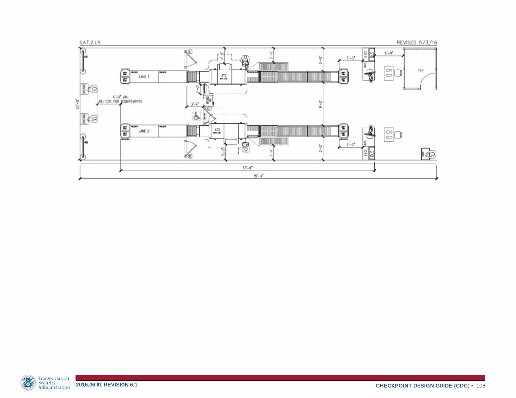
CHECKPOINT DESIGN GUIDE (CDG) 108 2016.06.01 REVISION 6.1

CHECKPOINT DESIGN GUIDE (CDG) 109 2016.06.01 REVISION 6.1

CHECKPOINT DESIGN GUIDE (CDG) 110 2016.06.01 REVISION 6.1

CHECKPOINT DESIGN GUIDE (CDG) 111 2016.06.01 REVISION 6.1

CHECKPOINT DESIGN GUIDE (CDG) 112 2016.06.01 REVISION 6.1
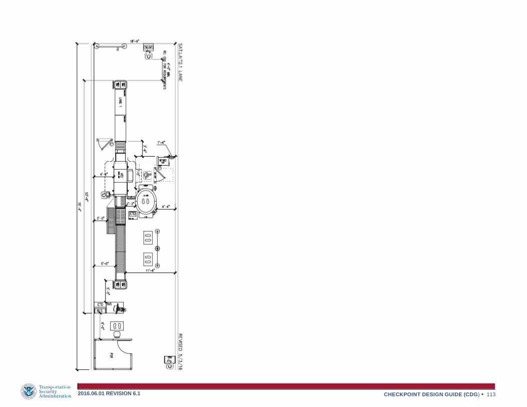
CHECKPOINT DESIGN GUIDE (CDG) 113 2016.06.01 REVISION 6.1

CHECKPOINT DESIGN GUIDE (CDG) 114 2016.06.01 REVISION 6.1

CHECKPOINT DESIGN GUIDE (CDG) 115 2016.06.01 REVISION 6.1

CHECKPOINT DESIGN GUIDE (CDG) 116 2016.06.01 REVISION 6.1

CHECKPOINT DESIGN GUIDE (CDG) 117 2016.06.01 REVISION 6.1
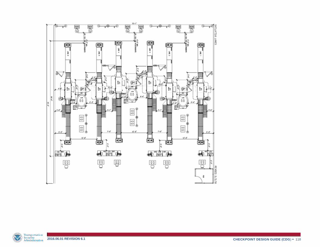
CHECKPOINT DESIGN GUIDE (CDG) 118 2016.06.01 REVISION 6.1

CHECKPOINT DESIGN GUIDE (CDG) 119 2016.06.01 REVISION 6.1

CHECKPOINT DESIGN GUIDE (CDG) 120 2016.06.01 REVISION 6.1

CHECKPOINT DESIGN GUIDE (CDG) 121 2016.06.01 REVISION 6.1

CHECKPOINT DESIGN GUIDE (CDG) 122 2016.06.01 REVISION 6.1

CHECKPOINT DESIGN GUIDE (CDG) 123 2016.06.01 REVISION 6.1
4-2.2 RAPISCAN AT LAYOUTS
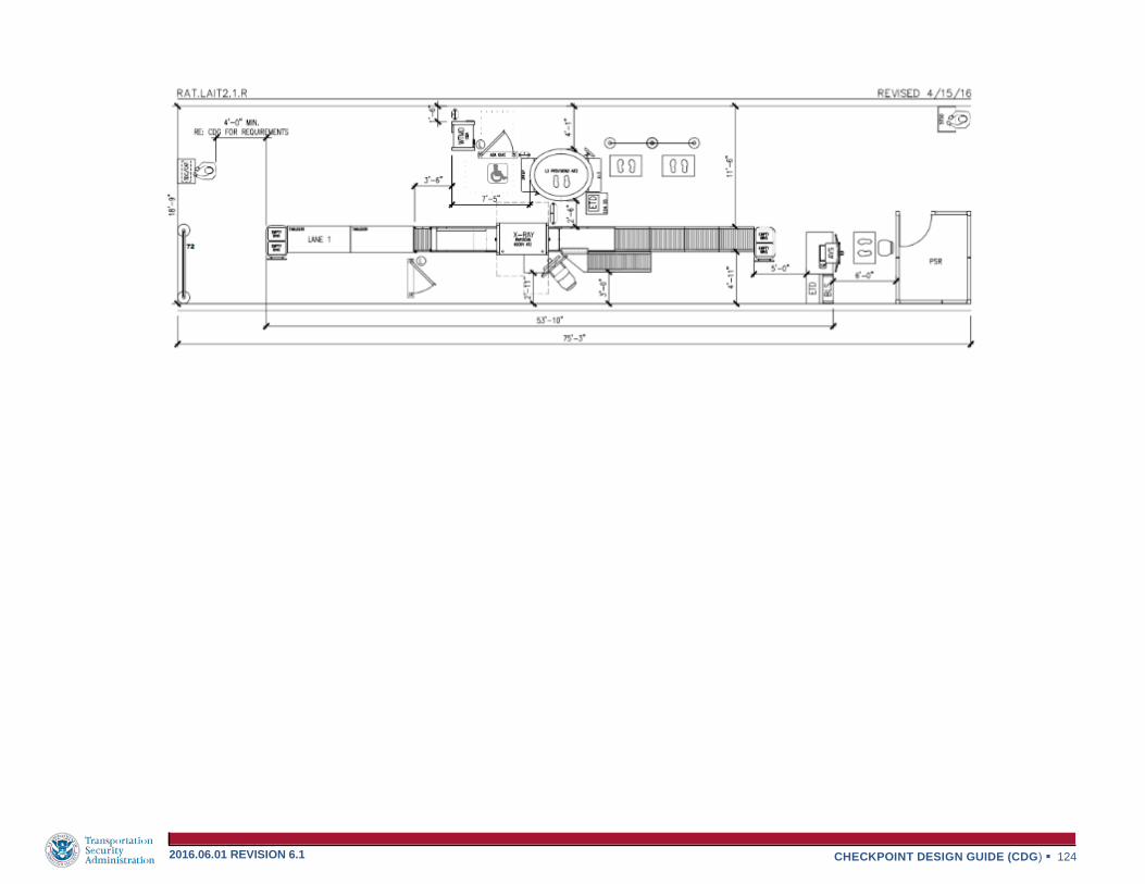
CHECKPOINT DESIGN GUIDE (CDG) 124 2016.06.01 REVISION 6.1

CHECKPOINT DESIGN GUIDE (CDG) 125 2016.06.01 REVISION 6.1

CHECKPOINT DESIGN GUIDE (CDG) 126 2016.06.01 REVISION 6.1

CHECKPOINT DESIGN GUIDE (CDG) 127 2016.06.01 REVISION 6.1

CHECKPOINT DESIGN GUIDE (CDG) 128 2016.06.01 REVISION 6.1
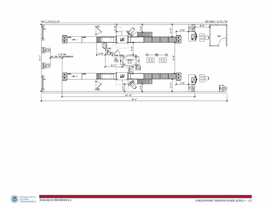
CHECKPOINT DESIGN GUIDE (CDG) 129 2016.06.01 REVISION 6.1

CHECKPOINT DESIGN GUIDE (CDG) 130 2016.06.01 REVISION 6.1

CHECKPOINT DESIGN GUIDE (CDG) 131 2016.06.01 REVISION 6.1

CHECKPOINT DESIGN GUIDE (CDG) 132 2016.06.01 REVISION 6.1

CHECKPOINT DESIGN GUIDE (CDG) 133 2016.06.01 REVISION 6.1

CHECKPOINT DESIGN GUIDE (CDG) 134 2016.06.01 REVISION 6.1

CHECKPOINT DESIGN GUIDE (CDG) 135 2016.06.01 REVISION 6.1

CHECKPOINT DESIGN GUIDE (CDG) 136 2016.06.01 REVISION 6.1

CHECKPOINT DESIGN GUIDE (CDG) 137 2016.06.01 REVISION 6.1

CHECKPOINT DESIGN GUIDE (CDG) 138 2016.06.01 REVISION 6.1

CHECKPOINT DESIGN GUIDE (CDG) 139 2016.06.01 REVISION 6.1

CHECKPOINT DESIGN GUIDE (CDG) 140 2016.06.01 REVISION 6.1

CHECKPOINT DESIGN GUIDE (CDG) 141 2016.06.01 REVISION 6.1

CHECKPOINT DESIGN GUIDE (CDG) 142 2016.06.01 REVISION 6.1

CHECKPOINT DESIGN GUIDE (CDG) 143 2016.06.01 REVISION 6.1

CHECKPOINT DESIGN GUIDE (CDG) 144 2016.06.01 REVISION 6.1
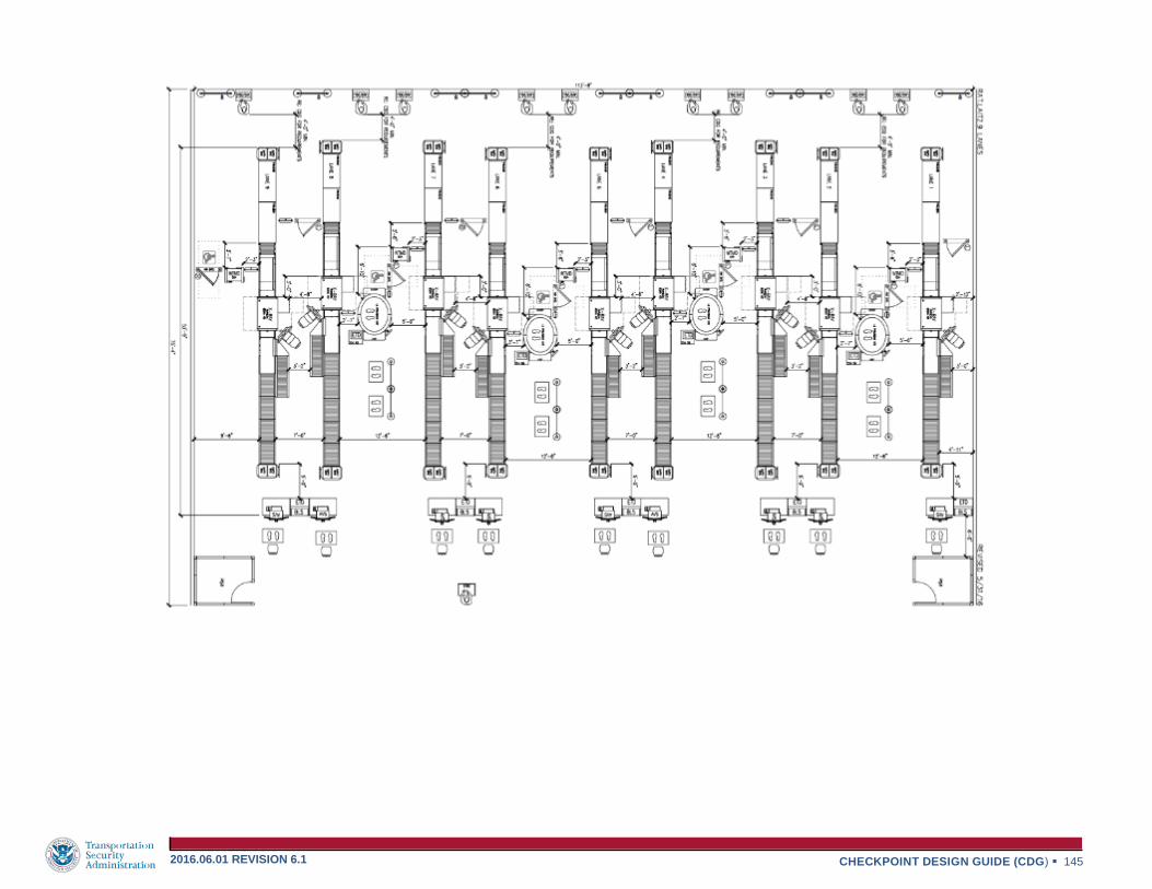
CHECKPOINT DESIGN GUIDE (CDG) 145 2016.06.01 REVISION 6.1

CHECKPOINT DESIGN GUIDE (CDG) 146 2016.06.01 REVISION 6.1

CHECKPOINT DESIGN GUIDE (CDG) 147 2016.06.01 REVISION 6.1
Figure 4-3.1 WEIGHTS AND DIMENSIONS
Project General Requirements: The project shall be designed and constructed
to support all approved TSA designated equipment and building’s dead / live
loads and be built in accordance with the local building codes and other
recognized national standards. The following are items to be considered when
designing the support floor:
Raised floors are permitted, but should meet all design requirements.
When a raised floor is being used a concrete pad under the WTMD
shall be provided. The recommended size of the concrete pad is 10’x10’
by 5” in depth.
Minimize vibrations from floors or equipment below Checkpoint and
around the equipment. Contact equipment manufacture for further
information.
Consideration should be given to electrical interference from conduit, reinforcement, etc. on TSA
equipment.
Floor protection is to be provided when equipment is being moved or relocated.
The following is a list of
weights and sizes for some of
the potential TSA equipment in Figure 4-3.1
4-3 STRUCTURAL CONSIDERATIONS

CHECKPOINT DESIGN GUIDE (CDG) 148 2016.06.01 REVISION 6.1

CHECKPOINT DESIGN GUIDE (CDG) 149 2016.06.01 REVISION 6.1
This Page is Intentionally Left Blank
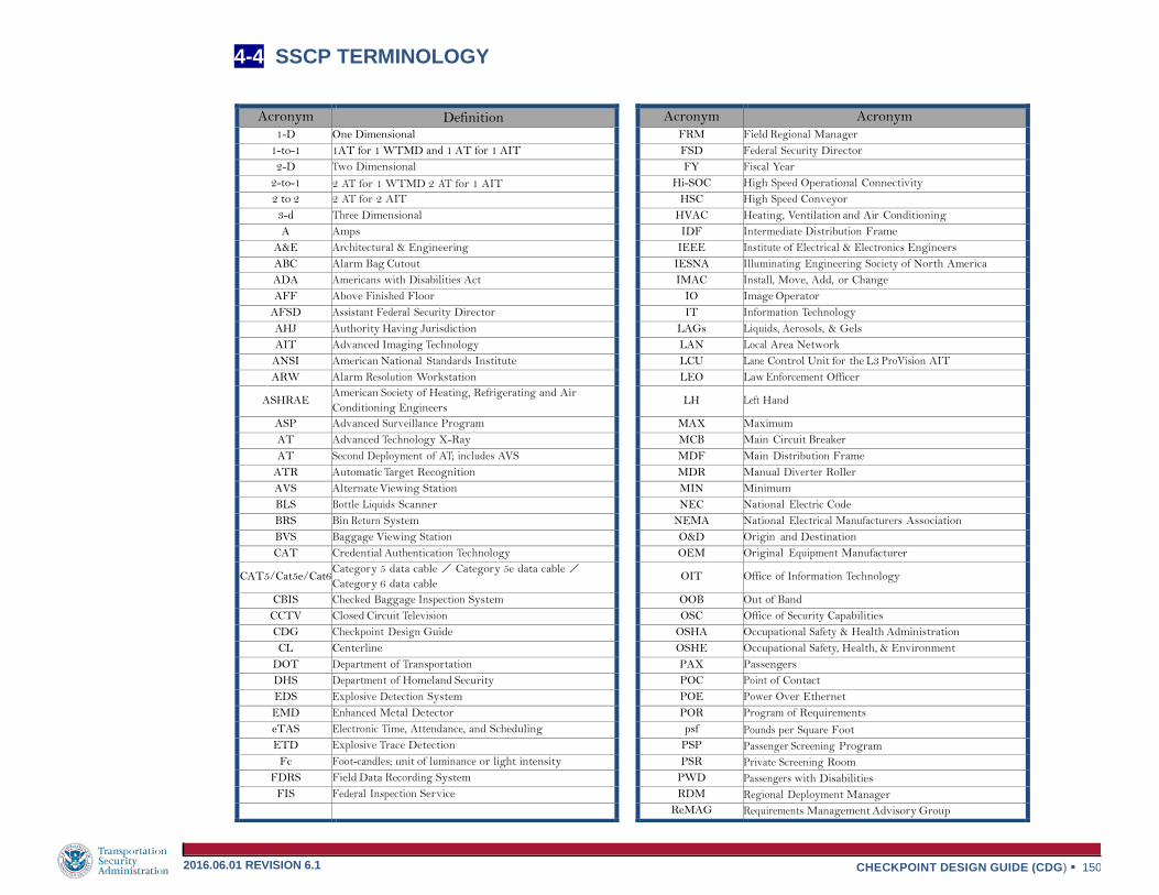
CHECKPOINT DESIGN GUIDE (CDG) 150 2016.06.01 REVISION 6.1
Acronym Definition Acronym Acronym
1-D One Dimensional FRM Field Regional Manager 1-to-1 1AT for 1 WTMD and 1 AT for 1 AIT FSD Federal Security Director 2-D Two Dimensional FY Fiscal Year
2-to-1 2 AT for 1 WTMD 2 AT for 1 AIT Hi-SOC High Speed Operational Connectivity 2 to 2 2 AT for 2 AIT HSC High Speed Conveyor 3-d Three Dimensional HVAC Heating, Ventilation and Air Conditioning A Amps IDF Intermediate Distribution Frame
A&E Architectural & Engineering IEEE Institute of Electrical & Electronics Engineers
ABC Alarm Bag Cutout IESNA Illuminating Engineering Society of North America
ADA Americans with Disabilities Act IMAC Install, Move, Add, or Change
AFF Above Finished Floor IO Image Operator
AFSD Assistant Federal Security Director IT Information Technology
AHJ Authority Having Jurisdiction LAGs Liquids, Aerosols, & Gels
AIT Advanced Imaging Technology LAN Local Area Network
ANSI American National Standards Institute LCU Lane Control Unit for the L3 ProVision AIT
ARW Alarm Resolution Workstation LEO Law Enforcement Officer
ASHRAE American Society of Heating, Refrigerating and Air
Conditioning Engineers LH Left Hand
ASP Advanced Surveillance Program MAX Maximum
AT Advanced Technology X-Ray MCB Main Circuit Breaker
AT Second Deployment of AT; includes AVS MDF Main Distribution Frame
ATR Automatic Target Recognition MDR Manual Diverter Roller
AVS Alternate Viewing Station MIN Minimum
BLS Bottle Liquids Scanner NEC National Electric Code
BRS Bin Return System NEMA National Electrical Manufacturers Association
BVS Baggage Viewing Station O&D Origin and Destination
CAT Credential Authentication Technology OEM Original Equipment Manufacturer
CAT5/Cat5e/Cat6 Category 5 data cable / Category 5e data cable /
Category 6 data cable OIT Office of Information Technology
CBIS Checked Baggage Inspection System OOB Out of Band
CCTV Closed Circuit Television OSC Office of Security Capabilities
CDG Checkpoint Design Guide OSHA Occupational Safety & Health Administration
CL Centerline OSHE Occupational Safety, Health, & Environment
DOT Department of Transportation PAX Passengers
DHS Department of Homeland Security POC Point of Contact
EDS Explosive Detection System POE Power Over Ethernet
EMD Enhanced Metal Detector POR Program of Requirements
eTAS Electronic Time, Attendance, and Scheduling psf Pounds per Square Foot
ETD Explosive Trace Detection PSP Passenger Screening Program
Fc Foot-candles; unit of luminance or light intensity PSR Private Screening Room
FDRS Field Data Recording System PWD Passengers with Disabilities
FIS Federal Inspection Service RDM Regional Deployment Manager
ReMAG Requirements Management Advisory Group
4-4 SSCP TERMINOLOGY

CHECKPOINT DESIGN GUIDE (CDG) 151 2016.06.01 REVISION 6.1
Acronym Definition RF Radio Frequency
RGS Rigid Galvanized Steel
RH Right Hand
S3 6’W x 8’L x 8’H KI glass room with 3’ door on short side. Used for Private Screening Room.
S3-A 8’W x 6’L x 8’H KI glass room with 3’ door on long side. Used for Private Screening Room.
SF Square Foot
SMF Subject Matter Expert
SO Scanning Operator
SOW Scope of Work
SSCP Security Screening Checkpoint
SSI Security Sensitive Information
STIP Security Technology Integrated Program
STSO Supervisory Transportation Security Officer
TCOP Touch Control Operator Panel
TIP Threat Image Projection
TDC Travel Document Checker
TLC TSA Logistics Center
TRX TIP-Ready X-Ray
TSA Transportation Security Administration
TSA HQ Transportation Security Administration - Headquarters
TSAPreCheck Transportation Security Administration PreCheck
TSE Transportation Security Equipment
TSO Transportation Security Officer
UPS Uninterruptible Power Supply
UTP Unshielded Twisted Pair
V Volts
VIPR Visible Intermodal Prevention & Response
WAP Wireless Access Point
WTMD Walk Through Metal Detector

This Page is Intentionally Left Blank