Embed Size (px)
Citation preview

© PHOENIX CONTACT - 2009-09-01104103_en_00
INTERFACE
TRIO-UPS/1AC/24DC/5
Data sheet
1 Description
The TRIO-UPS/1AC/24DC/5 provides an uninterruptible
24 V DC voltage at a maximum load current of up to 5 A in
both an error-free AC power supply network and in the event
of power failure.
It is designed specifically for supplying industrial PCs (IPC).
The power supply unit and the electronic switch-over unit are
housed in the same housing.
In the event of supply voltage failure, buffer mode is
activated without interruption. In this operating mode, the
output voltage is directly dependent on the battery voltage.
In the event of a voltage dip, the IPC continues operating
without interruption, thus increasing system availability.
Uncontrolled shutdown is avoided.
The TRIO-UPS/1AC/24DC/5 can be parameterized using a
service PC and the UPS-CONF configuration and
management software via an IFS-USB-PROG-ADAPTER.
For convenient parameter transfer between various TRIO-
UPS devices, the IFS-CONFSTICK configuration stick is
available as an option.
Features
– Space-saving
The TRIO-UPS combines a power supply unit and
electronic switch-over unit in the same housing
– Flexible
Rechargeable battery module with 1.3, 3.4, 7.2 or 12 Ah
– Autonomous
In the event of AC mains failure, the industrial PC
continues operating without interruption
– Time-saving
When the supply voltage is reapplied, the industrial PC
starts automatically
– Parameterizable
Can be parameterized with the PC or configuration stick
DANGER
Never carry out work when voltage is present.
The device contains dangerous live elements and high levels of stored energy.
Depending on the ambient temperature and load, the housing can become very hot.
Make sure you always use the latest documentation.
It can be downloaded at www.phoenixcontact.net/download.
This data sheet is valid for all products listed under "Ordering data" on page 3.
Uninterruptible power supply with integrated power
supply unit

TRIO-UPS/1AC/24DC/5
104103_en_00 PHOENIX CONTACT 2
2 Table of contents
1 Description.................................................................................................................................. 1
2 Table of contents ........................................................................................................................ 2
3 Ordering data.............................................................................................................................. 3
4 Technical data ............................................................................................................................ 3
4.1 I/O data........................................................................................................................................................... 3
4.2 Battery management ...................................................................................................................................... 4
4.3 Signaling and switching outputs ..................................................................................................................... 5
4.4 Ambient conditions......................................................................................................................................... 5
4.5 Standards/approvals ...................................................................................................................................... 6
5 Safety regulations ....................................................................................................................... 7
6 Connection, operating, and indication elements ......................................................................... 8
6.1 Connection terminal blocks ............................................................................................................................ 8
6.2 Block diagram ................................................................................................................................................ 9
6.3 Input ............................................................................................................................................................... 9
6.4 Output .......................................................................................................................................................... 10
6.5 LED indicators .............................................................................................................................................. 10
7 Installation .................................................................................................................................11
7.1 Narrow mounting position............................................................................................................................. 11
7.2 Flat mounting position .................................................................................................................................. 11
8 Rechargeable battery module....................................................................................................12
9 Method of operation...................................................................................................................13
9.1 Output voltage.............................................................................................................................................. 13
9.2 Remote shutdown ........................................................................................................................................ 13
9.3 Buffer time setting ........................................................................................................................................ 13
9.4 PC mode ...................................................................................................................................................... 13
9.5 PC idle time .................................................................................................................................................. 14
9.6 Battery management .................................................................................................................................... 15
10 Interfaces...................................................................................................................................15
10.1 Config.-Port .................................................................................................................................................. 15
10.2 IFS-USB-PROG-ADAPTER ......................................................................................................................... 15
10.3 IFS-CONFSTICK.......................................................................................................................................... 15
11 UPS-CONF configuration and management software ...............................................................16

TRIO-UPS/1AC/24DC/5
104103_en_00 PHOENIX CONTACT 3
3 Ordering data
4 Technical data
4.1 I/O data
UPS system
Description Type Order No. Pcs./Pkt.
Uninterruptible power supply with integrated power supply unit TRIO-UPS/1AC/24DC/5 2866611 1
The TRIO-UPS/1AC/24DC/5 is supplied without a rechargeable battery module. The rechargeable battery module must be ordered
separately (see accessories).
Accessories
Description Type Order No. Pcs./Pkt.
Rechargeable battery module, 24 V DC, 1.3 Ah MINI-BAT/24DC/1.3AH 2866417 1
Rechargeable battery module, 24 V DC, 3.4 Ah QUINT-BAT/24DC/3.4AH 2866349 1
Rechargeable battery module, 24 V DC, 7.2 Ah QUINT-BAT/24DC/7.2AH 2866352 1
Rechargeable battery module, 24 V DC, 12 Ah QUINT-BAT/24DC/12AH 2866365 1
Configuration and management software UPS-CONF 2320403 1
USB data link cable between the UPS and IPC IFS-USB-PROG-ADAPTER 2811271 1
Configuration stick for parameter transfer between various
TRIO-UPS/1AC/24DC/5 devices
IFS-CONFSTICK 2986122 1
Input data
Nominal input voltage (wide-range input) 100 ... 240 V AC
Input voltage range (nominal load) 85 ... 264 V AC (< 90 V AC derating: 2.5%/V)
100 ... 350 V DC (UL508: 100 ... 250 V)
Frequency 45 ... 65 Hz
Approximate current consumption (mains operation and battery charging/
maximum)
At 230 V AC
At 120 V AC
0.95 A/1.1 A
1.7 A/1.8 A
Inrush current limiting / I²t at 25°C typical < 44 A / < 1.3 A²s
Switch-on time after applying the mains voltage
At 230 V AC
At 120 V AC
150 ms
200 ms
Transient surge protection Varistor
Internal input fuse T 6.3 A
Recommended backup fuse
Circuit breaker 6 A/10 A/16 A (B characteristic)
Discharge current to PE 0.8 mA
Output data
Rise time < 100 ms
Residual ripple < 10 mVPP
Switching peaks < 25 mVPP
Parallel connection to increase the buffer time Yes, 2
Surge protection against internal surge voltages Yes, < 35 V DC
Maximum resistance to return supply 35 V DC

TRIO-UPS/1AC/24DC/5
104103_en_00 PHOENIX CONTACT 4
4.2 Battery management
Output data in mains operation (AC input voltage present)
Nominal output voltage UN 24 V DC
Output voltage (adjustable) 22.5 ... 29.5 V DC
Nominal output current, > 24 V DC constant capacity (-25°C to +70°C) 5 A
Derating (above 55°C) 2.5%/K
Current limit 6 A, approximately
Connection of capacitive loads Yes, unlimited
Control deviation < 1% (static load change 10 ... 90%)
Approximate efficiency (mains operation and battery charging)
At 230 V AC
At 120 V AC
88%
86%
Approximate power dissipation (mains operation and battery charging)
At 230 V AC
At 120 V AC
16 W
20 W
Output data in battery operation (AC input voltage not present)
Nominal output voltage UN 24 V DC
Output voltage (UOUT = UBAT - 0.5 V ) 27.9 ... 19.2 V DC - 0.5 V
Nominal output current (-25°C to +70°C) 5 A
Derating (above 55°C) 2.5%/K
Current limit 6 A, approximately
Connection of capacitive loads Yes, 3300 µF
Efficiency > 86%
Power dissipation
Maximum no load
Maximum nominal load
2 W
4 W
Maximum buffer time (adjustable per minutes) 0.5; 1; 2; 3; 5; 10; 15; 20; PC mode
Overload fuse (electronic) Yes
Remote shutdown Yes
Battery management
Charging characteristic curve I/U
Charging current 1
(preset/minimum/maximum) 1.0 A/0.2 A/1.5 A
End-of-charge voltage 1 (preset/minimum/maximum) 27,6 V DC / 25 V DC / 30 V DC
Temperature compensation 1 (preset/minimum/maximum) 42 mV/K / 0 mV/K / 200 mV/K
Battery presence check/time interval 60 s
Battery quality check 1 (preset/minimum/maximum) 12 h/4 h/200 h
Protection against total discharge 1 (preset/minimum/maximum) 19.2 V DC / 18 V DC / 21 V DC
"Battery almost flat" alarm signaling threshold 1 (preset/minimum/maximum) 20.4 V DC / 18 V DC / 30 V DC
1Can be adjusted via UPS-CONF software

TRIO-UPS/1AC/24DC/5
104103_en_00 PHOENIX CONTACT 5
4.3 Signaling and switching outputs
4.4 Ambient conditions
Status indicators
Mains voltage OK (Power in OK) Green LED, static ON
Alarm
LED indicator
Switching output
Current limit (internal)
Red LED, static ON
24 V DC, active high
200 mA
Battery operation (Battery Mode)
LED indicator
Switching output
Current limit (internal)
Signal options 1
1Can be adjusted via UPS-CONF software
Yellow LED, static ON
24 V DC, active high
200 mA
Bat.-Mode, Bat.-Mode Delayed
Battery charging (Battery Charge)
LED indicator
Switching output
Current limit (internal)
Signal options 1
Yellow LED, flashing
24 V DC, active high
200 mA
Bat.-Charge, Bat.-Mode, Bat.-Mode Delayed, battery almost flat
Climatic requirements
Ambient temperature
Operation (> 55°C derating)
Storage/transport
-25°C ... +70°C
-40°C ... +80°C
Humidity at +25°C, no condensation 95%
Pollution degree according to EN 50178 2
Climatic class 3K3
Mechanical requirements
Vibration (operation) < 15 Hz, amplitude ±2.5 mm according to IEC 60068-2-6
15 Hz ... 150 Hz, 2.3g, 90 min.
Shock according to IEC 60068-2-27 30g in each direction
General data
Insulation voltage I/O (type/routine test) 4 kV AC/2 kV AC
Input/PE (type/routine test) 2 kV AC/2 kV AC
Output/PE (routine test) 500 V DC
Mounting position according to EN 60715
Degree of protection IP20
Protection class (with PE connection) I
MTBF according to IEC 61709 (SN 29500) > 500,000 h
Material Aluminum (AlMg3)/zinc-plated sheet steel
Dimensions (W/H/D) 60 mm x 130 mm x 118 mm
Weight 1.1 kg

TRIO-UPS/1AC/24DC/5
104103_en_00 PHOENIX CONTACT 6
4.5 Standards/approvals
Standards/approvals
Electrical equipment of machines
(surge voltage category III)
EN 60204
Safety transformers for switched-mode power supply units IEC 61558-2-17
Electrical safety
(of information technology equipment)
EN 60950/VDE 0805
UL/C-UL Recognized UL 60950
Industrial control equipment UL/C-UL Listed UL 508
Electronic equipment for use in
power installations
EN 50178 (VDE 0160)
PELV/SELV PELV (EN 60204)/SELV (IEC 60950)
Safe isolation VDE 0100-410
Protection against electric shock DIN 57100-410
Protection against electric shock, basic requirements for safe isolation in
electrical equipment
DIN VDE 0106-101
Limitation of mains harmonic currents EN 61000-3-2
u
U
Conformance with EMC Directive 2004/108/EC, noise immunity according to 2006/95/EC
(electromagnetic compatibility)
Noise immunity according to EN 61000-6-2
Electrostatic discharge according to EN 61000-4-2 Housing
Contact discharge
Air discharge
Remark
Level 3
6 kV
8 kV
Criterion B
Electromagnetic HF field according to EN 61000-4-3 Housing
Frequency range
Field strength
Remark
Level 3
80 MHz ... 2 GHz
10 V/m
Criterion A
Fast transients (burst) according to EN 61000-4-4 Input
Output
Signal
Remark
4 kV (Level 4 - asymmetrical: Cable to ground)
2 kV (Level 4 - asymmetrical: Cable to ground)
1 kV (Level 4 - asymmetrical: Cable to ground)
Criterion B
Surge current loads (surge) according to EN 61000-4-5 Input
Output
Signal
Remark
4 kV (Level 4 - asymmetrical: Cable to ground)
2 kV (Level 4 - asymmetrical: Cable to cable)
2 kV (Level 3 - asymmetrical)
1 kV (Level 3 - symmetrical)
2 kV (Level 3 - asymmetrical)
Criterion B
Conducted interference according to EN 61000-4-6 Input/output/signal
Frequency range
Voltage
Remark
Level 3
10 kHz ... 80 MHz
10 kV
Criterion A
Noise emission according to EN 61000-6-3 Radio interference voltage according
to EN 55011
EN 55011 (EN 55022) Class B, industrial and residential
applications

TRIO-UPS/1AC/24DC/5
104103_en_00 PHOENIX CONTACT 7
5 Safety regulations
Installation notes
Connection notes
NOTE:
– The device must only be installed, operated,
and maintained by qualified personnel.
– Follow the installation instructions.
– When installing and operating the device, the
applicable safety directives (including
national safety directives), accident
prevention regulations, as well as general
technical regulations, must be observed.
– For the safety data, please refer to the
package slip and certificates (conformity
assessment, other approvals, if necessary).
– Do not repair the device yourself, replace it
with an equivalent device.
– Repairs may only be carried out by the
manufacturer. The manufacturer is not liable
for damage resulting from violation.
– The IP20 degree of protection (IEC 60529/
EN 60529) of the device is intended for use in
a clean and dry environment.
– The device must not be subject to
mechanical strain and/or thermal loads,
which exceed the limits described.
NOTE: Electrostatic discharge
The device contains components that can be
damaged or destroyed by electrostatic discharge.
When handling the device, observe the
necessary safety precautions against
electrostatic discharge (ESD) according to
EN 61340-5-1 and EN 61340-5-2.

TRIO-UPS/1AC/24DC/5
104103_en_00 PHOENIX CONTACT 8
6 Connection, operating, and indication elements
Figure 1 TRIO-UPS/1AC/24DC/5 structure
6.1 Connection terminal blocks
Use a screwdriver with the correct blade width for wiring. For
reliable and safe-to-touch connections, strip 8 mm off the
cable ends.
The following cable cross-sections can be connected:
No. Description
1 100 ... 240 V AC input
2 24 V rechargeable battery module connection
3 24 V DC output, buffered
4 22.5 ... 29.5 V DC potentiometer
5 Active switching output: Alarm
6 Active switching output: Bat.-Mode
7 Active switching output: Bat.-Charge
8 Red LED indicator: Alarm
9 Yellow LED indicator: Bat.-Mode/Bat.-Charge
0 Green LED indicator: Power in OK/Overload
! Remote shutdown (R1, R2)
" Buffer time setting
0.5 ... 20 minutes, PC mode, unlimited ∞§ Config.-Port
$ "Confirm" button
Bat.- M
odeBat.- C
hargeRem
oteR
1
Alarm
Battery
3
5
1015
20
PC-M
ode
1
28
+
+
+
OFF
ON
Rem
oteR
2
TR
IOD
C-U
PS
tm
ax min
L
N
Alarm
Adjust
Output D
C24V
5A
Input AC
100-240V
22.5-29.5V
Bat.-M
ode
Bat.-C
harge
Power in
OK
Overload
Config.-Port
(Default 0.5)
Custom
UPS
STICK
DA
TA
1. PressB
uttonand
2. Insert STICK
within
4sec
STICK
UPS
DA
TA
1. Insert STICK
2. PressB
utton>
6sec
(+)
(-)
1
13
14
4
35
6
7
11
2
12
8
9
10
Terminal
block
Rigid Stranded AWG Tightening
torque
No. [mm²] [mm²] [Nm] [lb in]
1 - 3,
5 - 7,
!
0.2 - 2.5 0.2 - 2.5 24 - 12 0.5 - 0.6 3.5 - 4.5
In order to comply with UL approval, use copper
cables that are designed for operating
temperatures >75°C.

TRIO-UPS/1AC/24DC/5
104103_en_00 PHOENIX CONTACT 9
6.2 Block diagram
Figure 2 Block diagram for the TRIO-UPS/1AC/24DC/5
6.3 Input
The 100 ... 240 V AC connection is made using the L (+) and
N (-) screw connections.
Device installation must be carried out according to the
regulations of EN 60950. It must be possible to switch off the
device using a suitable disconnecting device outside the
power supply.
An internal fuse is provided for device protection. Additional
device protection is not required.
Network type
The device can be connected to single-phase AC networks
or to two of the phase conductors of three-phase systems
(TN, TT or IT networks according to VDE 0100-300/IEC
60364-3) with nominal voltages of 100 V AC ... 240 V AC.
Figure 3 Single-phase network systems
t...[min]
��
Output DC
24 V 5 A
Remote
On/Off
2x 12V
Battery
PS
Alarm
Bat.-Charge
Bat.-Mode
IFS Config.-Port
Confirm
L (+)
N (-)
R1
R2
For example, primary side line protection could
be used.
If an internal fuse is blown, this is due to a device
fault. In this case, send the device to Phoenix
Contact for inspection.
For operation using two phase conductors of a
three-phase system, an all-pole disconnecting
device must be provided.
TN-S
L
N
PE
+
L N
-
TT
+
L N
-
L
N
TN-C
L
PEN
+
L N
-
iT
+ -
L N
L1
L2
L3

TRIO-UPS/1AC/24DC/5
104103_en_00 PHOENIX CONTACT 10
6.4 Output
The 24 V DC connection is made using the "OUT DC 24 V,
+, -" screw connections. The output voltage set upon
delivery is 24 V DC. The output voltage can be set from
22.5 V DC to 29.5 V DC on the potentiometer.
Figure 4 Connection
6.5 LED indicators
Figure 5 LED indicators
The signal outputs are connected via the "Alarm", "Bat.-
Mode", and "Bat.-Charge" terminal blocks. There are three
LED status indicators and three active switching outputs for
function monitoring.
No. Description
1 100 ... 240 V AC input
3 24 V DC output, buffered
4 22.5 ... 29.5 V DC potentiometer
No. Description
8 Red LED indicator: Alarm
9 Yellow LED indicator: Bat.-Mode/Bat.-Charge
0 Green LED indicator: Power in OK/Overload
Bat.- M
odeBat.- C
hargeRem
oteR
1
Alarm
Battery
3
5
1015
20
PC-M
ode
1
28
+
+
+
OFF
ON
Rem
oteR
2
TR
IOD
C-U
PS
tm
ax min
L
N
Alarm
Adjust
Output D
C24V
5A
Input AC
100-240V
22.5-29.5V
Bat.-M
ode
Bat.-C
harge
Power in
OK
Overload
Config.-Port
(Default 0.5)
Custom
UPS
STICK
DA
TA
1. PressB
uttonand
2. Insert STICK
within
4sec
STICK
UPS
DA
TA
1. Insert STICK
2. PressB
utton>
6sec
(+)
(-)
4
1
3
8
9
10
Sta
tus
Gre
en
Ye
llo
w
Re
d
Description
1
The UPS is switched off or the UPS
is operating in mains mode, battery
mode is deactivated (remote),
battery management is still active
2
The UPS is starting mains
operation, for the LED test all LEDs
are switched on and off again once
before the current operating state is
indicated
3
The UPS is operating in mains
mode, the battery is OK and
charged
4
The UPS is operating in mains
mode, the battery is OK and is
charging (charge < 85% of nominal
capacity)
5
The UPS is operating in battery
mode, the battery voltage UBAT
is > 20.4 V
6
The UPS is operating in battery
mode, the battery is almost flat
(battery voltage UBAT is < 20.4 V)
7
UPS protection against total
discharge has terminated battery
mode
(battery voltage UBAT = 19.2 V) and
continues indication for a maximum
of 10 hours
8The UPS is operating in mains
mode, the battery is faulty
9
The UPS has been overloaded in
mains mode, the battery is OK and
charged
10The UPS has been overloaded in
mains mode, the battery is faulty
Key
LED OFF
LED ON
LED flashing

TRIO-UPS/1AC/24DC/5
104103_en_00 PHOENIX CONTACT 11
7 Installation
A minimum spacing between other devices does not have to
be observed in order to ensure correct device function.
7.1 Narrow mounting position
The power supply unit can be snapped onto all DIN rails
according to EN 60715 and must be mounted horizontally
(connection terminal blocks facing upwards and
downwards).
Mounting
Position the module with the DIN rail guideway on the top
edge of the DIN rail and then snap it downwards.
Figure 6 Mounting the TRIO-UPS/1AC/24DC/5
Removal
Release the snap-on catch using a screwdriver and then
detach the module from the bottom edge of the DIN rail.
Figure 7 Removing the TRIO-UPS/1AC/24DC/5
7.2 Flat mounting position
A flat mounting position can be achieved by mounting the
module onto the DIN rail at a 90° angle. Mount the DIN rail
adapter (UTA 107) as shown in the figure. The screws that
were previously used to secure the UTA must be used: Torx
T10 (0.8 Nm ... 0.9 Nm tightening torque).
Figure 8 Modification for flat mounting position
BA
A
B

TRIO-UPS/1AC/24DC/5
104103_en_00 PHOENIX CONTACT 12
8 Rechargeable battery module
The rechargeable battery module is connected to the power
supply unit via the "Battery +" and "Battery -" terminal blocks
2.
The following rechargeable battery modules are
recommended:
Figure 9 Characteristic curves for the rechargeable
battery modules
Battery mode can be exited after a predefined time has
elapsed or by means of external shutdown. If the device is
to be shut down after a specific time has elapsed, the time
can be set via the selector switch " on the front of the
device. When the supply voltage is reapplied, the device
can switch to battery mode again.
NOTE: Risk of short circuit
The fuse for the rechargeable battery module
must be removed when installing or replacing the
module.
Rechargeable battery
module
Fuse Recom-
mended
charging
current
1 MINI-BAT/24DC/1.3Ah 15 A 0.8 A 2
2 QUINT-BAT/24DC/3.4Ah 1
1Connection via plug connector, 14 mm
25 A 1.0 A 2
2Can be adjusted via UPS-CONF software
3 QUINT-BAT/24DC/7.2Ah1
2 x 25 A 1.5 A 2
4 QUINT-BAT/24DC/12Ah1
2 x 25 A 1.5 A 2
t [min]
t [h]
I [A]
0 0.5 2 4
1
10
11 1.5 2.5 3 3.5 4.5 5
60
10
30
1234
= 1.3Ah= 3.4Ah= 7.2Ah= 12Ah
4
1 3
2
The batteries are sealed, maintenance-free lead AGM batteries, which are intended for
operating temperatures of 0°C ... 40°C.
They have a service life of six to nine years at an
ambient temperature of 20°C.
In order to ensure immediate availability, all
batteries are supplied fully charged. Startup
should be carried out at the latest after nine
months at 20°C ... 30°C, or after six months at
30°C ... 40°C.

TRIO-UPS/1AC/24DC/5
104103_en_00 PHOENIX CONTACT 13
9 Method of operation
9.1 Output voltage
In mains operation (AC input voltage present) the output
voltage of the TRIO-UPS corresponds to the setting at the
potentiometer 4. In the event of supply voltage failure,
battery mode is activated without interruption. The output
voltage is now directly dependent on the battery voltage and
is UBAT - 0.5 V.
9.2 Remote shutdown
If the connected load cannot be supplied from the power
storage device in the event that the AC voltage fails, the
UPS can be disabled via R1/R2. This shutdown can be
performed during mains operation or while battery mode is
active.
UPS active, remote shutdown deactivated, default upon
delivery:
– Terminal points "R1" and "R2" are short circuited (with
plug-in bridges by default upon delivery) OR 24 V DC is
present at terminal point "R2".
– If the supply voltage fails, the TRIO-UPS switches to
battery mode. UPS not active, remote shutdown
activated:
– Terminal points "R1" and "R2" are not short circuited
AND 0 V DC is present at terminal point "R2".
– All LEDs are OFF.
– If the supply voltage fails, the TRIO-UPS does not
switch to battery mode, the device shuts down.
– The connected loads are supplied and the
rechargeable battery module is charged as long as the
supply voltage is present.
9.3 Buffer time setting
The time after which battery mode is exited is set via the "
selector switch on the front of the device:
– 0.5 to 20 minutes
– Parameterizable time via software
("CUSTOM" switch position, default: 0.5 minutes)
– Unlimited (buffering with the total stored energy)
– PC mode (see Section 9.4 "PC mode" )
9.4 PC mode
In "PC mode", the UPS function follows a chronological
sequence that can be parameterized via the software and
individually optimized for the relevant IPC solution.
Requirements: IFS-USB-PROG-ADAPTER data cable
(Order No. 2811271) and UPS-CONF software
(Order No. 2320403).
To set the parameters, an Interface interface (IFS) is used
for data exchange between the TRIO-UPS and a suitable
user interface on the IPC. The user is supported by help
texts and graphics for the individual parameters.
As an option, parameterization can be carried out using an
IFS-CONFSTICK. Here, a parameter record is transferred
from the TRIO-UPS to the IFS-CONFSTICK. This
parameter record can then be written to any other
TRIO-UPS.
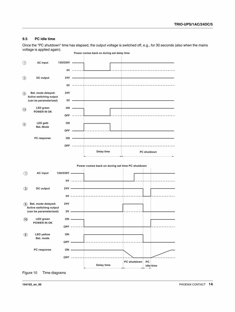
In "PC mode", the UPS function follows a parameterizable
chronological sequence of delay time, IPC shutdown, and
IPC idle time.
Delay time:
If the mains voltage is not applied again within the first 60
seconds of battery mode, for example, "Bat.-Mode" is
indicated in order to shut down an IPC with a delay.
IPC shutdown:
Shutdown is performed via a data cable to the IPC. The IPC
must be connected to the UPS via a USB data cable.
The IPC is supplied by the TRIO-UPS for a parameterizable
period of time, e.g., 2 minutes.
TRIO-UPS/1AC/24DC/5
104103_en_00 PHOENIX CONTACT 14
9.5 PC idle time
Once the "PC shutdown" time has elapsed, the output voltage is switched off, e.g., for 30 seconds (also when the mains
voltage is applied again).
Figure 10 Time diagrams
120/230V
0V
24V
0V
24V
0V
ON
OFF
ON
OFF
ON
OFF
1
3
6
10
9
AC input
DC output
LED green
POWER IN OK
LED gelb
Bat.-Mode
PC response
Delay time PC shutdown
Bat. mode delayed:
Active switching output
(can be parameterized)
Power comes back on during set delay time
1
3
6
10
9
AC input
DC output
LED green
POWER IN OK
LED yellow
Bat. mode
PC response
Bat. mode delayed:
Active switching output
(can be parameterized)
PC shutdown PC
idle time
Power comes back on during set time PC shutdown
Delay time
120/230V
0V
24V
0V
24V
0V
ON
OFF
ON
OFF
ON
OFF
1
3
6
10
9

TRIO-UPS/1AC/24DC/5
104103_en_00 PHOENIX CONTACT 15
9.6 Battery management
Battery management of the TRIO-UPS is divided into two
checks that are performed cyclically during normal
operation.
Battery presence check
The battery presence check is used to detect a correctly
installed battery. If this is not the case, the check is failed
and the green 0 and red 8 LED indicators are controlled
statically.
Battery quality check
The battery quality check is a lifecycle test. It enables
conclusions to be drawn, e.g., regarding the maximum
lifecycle of the battery if the maximum charging time has
been exceeded. In this case, the green 0 and red 8 LED
indicators are controlled statically.
10 Interfaces
10.1 Config.-Port
The TRIO-UPS is connected to the USB connection on the
service PC via the "Config.-Port" using the IFS-USB-PROG-
ADAPTER data cable.
10.2 IFS-USB-PROG-ADAPTER
The programming adapter (Order No. 2811271) represents
the interface between the service PC and the TRIO-UPS
and is required in order to parameterize the TRIO-UPS.
Figure 11 Programming adapter
10.3 IFS-CONFSTICK
The IFS-CONFSTICK is a multi-functional memory block for
easy storage and back up of configuration and parameter
data.
Transferring parameters to the IFS-CONFSTICK
To transfer parameters, proceed as follows:
1. Press and hold down the "Confirm" button.
2. You now have four seconds to carefully insert the
IFS-CONFSTICK in the "Config.-Port" on the
TRIO-UPS, taking care to observe the connection
direction.
3. Parameter transfer is started and indicated by the cyclic
control of the three LED indicators. Sequence: Red -
Yellow - Green
a) Error-free transfer:
Green LED indicator ON
b) Transfer error:
Red LED indicator ON
Transferring parameters to the TRIO-UPS
To transfer parameters, proceed as follows:
1. Carefully insert the IFS-CONFSTICK in the "Config.-
Port" on the TRIO-UPS, taking care to observe the
connection direction.
1. Press and hold down the "Confirm" button for at least
six seconds.
2. Parameter transfer is started and indicated by the cyclic
control of the three LED indicators. Sequence: Green -
Yellow - Red
a) Error-free transfer:
Green LED indicator ON
b) Transfer error:
Red LED indicator ON
The following can be parameterized:
– Times
– Switching outputs
– Battery management
Serial No. XXXXXXXXXX
www.interface.phoenixcontact.com
IFS-USB-PROG-ADAPTER
Ord.-No.: 28 11 27 1
32825 Blomberg, Germany
USB-Programming Adapter
USB

TRIO-UPS/1AC/24DC/5
104103_en_00 16PHOENIX CONTACT GmbH & Co. KG • 32823 Blomberg • Germany • Phone: +49 - 52 35 - 30 0
PHOENIX CONTACT • P.O.Box 4100 • Harrisburg • PA 17111-0100 • USA • Phone: +717-944-1300
www.phoenixcontact.com
11 UPS-CONF configuration and
management software
The Windows-based UPS-CONF configuration and
management software (Order No. 2320403) is used to
parameterize the TRIO-UPS.
Various dialog boxes are available for parameterization.
The current operating status of the TRIO-UPS is always
displayed at the bottom of the dialog box.
Figure 12 Example, TRIO-UPS status display
A distinction is made between the following states:
The UPS-CONF configuration and management
software can be downloaded free of charge at
www.phoenixcontact.net/download.
Status Meaning
Operation mode Preset operating mode at the
selector switch "
Power Source Power source that is currently
active
Battery Condition Current battery charging state
Device Status Current state of the TRIO-UPS
Connection to UPS Connection status between service
PC and TRIO-UPS
If an alarm is detected or an existing online
connection between the IPC and TRIO-UPS is
interrupted, the UPS-CONF dialog box is
automatically displayed on screen.
The status is queried cyclically.