Embed Size (px)
Citation preview
Presenters : Jackie Adams - IBM
Stephen Tisdale - Intel Scott O’Connell - Dell
David Bender - TE Connectivity Tamim Sidiki - DSM
Enabling the Electronics Supply Chain
Reduction of Halogenated Flame-Retardants (HFRs) and
Polyvinylchloride (PVC) August 1, 2011 (North America)
August 29, 2011 Asia TBD for Europe
1
Outline Welcome and Introduction Objective of the Series Introduction of the Speakers 2011 ECE Overview with Respect to HFRs (Br, Cl) and PVC Low-Halogen Standards iNEMI Low-Halogen Position Statement PVC Alternatives Project HFR-Free Leadership Program / HFR-Free High-Reliability PCB
Project Connectors HFR-free HTPA and PVC-free Material Alternatives, Status and
Challenges Summary and a Look Forward
2
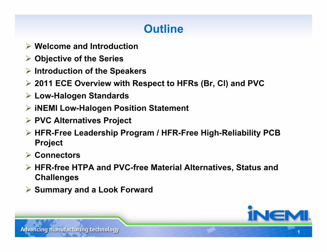
Objectives of Series Objective of this webinar is to share the knowledge collected by the iNEMI membership with respect to reduced halogen technology in the electronics supply chain.
Reduced halogen technology is a driving force when developing alternative materials in both consumer and business applications.
The mantra for this team: “a knowledgeable supply chain is an engaged and effective supply chain”
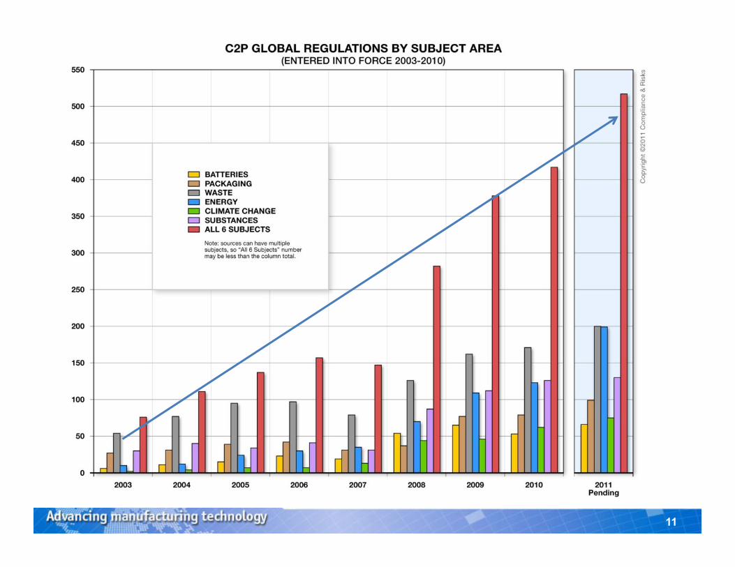
• Jackie Adams will present the ECE iNEMI Roadmap overview relative to HFR and PVC – The Environmentally Conscious Electronics Technology Working Group analysis for 2011 – Brief look a the growth of regulations and type since 2003 – A look at current standards with respect to HFR and PVC – Return at the end for a “look forward”
• Scott O’Connell will present: – iNEMI Low-Halogen Position Statement – PVC Alternatives Project
• Steve Tisdale will present: – HFR-Free Leadership Program – HFR-Free High-Reliability PCB Project
• Dave Bender will present: – Connectors by family and technology, on board, or attached to cabling – Alternatives, challenges, projected availability – Technologies available today for HFR alternatives, challenges, next steps
• Tamim Sidiki will present: – HFR-free HTPA and PVC- free material alternatives, status and challenges
3
Introduction to the Speakers Jackie Adams - IBM
2011 Environmentally Conscious Electronics Roadmap - Co-Chair Environmental Leadership Steering Committee - Member
Stephen Tisdale - Intel HFR-Free Leadership Program – Chair
HFR-Free High-Reliability PCB Project – Chair
Scott O’Connell - Dell PVC Alternatives Project – Chair
David Bender – TE Connectivity iNEMI Technical Committee – Member
Tamim Sidiki – DSM Environmental Leadership Committee – Member
4
Biography
Ms. Adams is currently an IBM Senior Technical Staff Member (STSM) and Chair of the Center of Excellence (CoE) for Product Environmental Compliance. She leads a global cross functional team and is the Subject Matter Expert on product environmental compliance for IBM. Her group reports into the VP of World-wide Integrated Supply Chain Engineering Operations.
In this capacity, Jackie is responsible for all IBM hardware compliance for the Worldwide technical and logistical management systems, Assessment of world wide product environmental regulations,
Identification and deployment of alternative technologies Consortia and Academic Study liaison for global environmental initiates
Over the last several years Jackie has lead the core CoE (Center of Excellence) leadership team and the extended global IBM CoE Subject Matter experts in developing and implementing various IT/tools and processes in support of IBM’s overall product hardware compliance mission.
Ms. Adams has authored and presented several technical internal and external articles related to material science and alternative designs for implementation of recycled resins and engineering alternative technologies. She has been issued several US patents on part design and material science technologies. Jackie has received several external engineering and professional awards for her work on environmental engineering. Ms. Adams brings a wealth of knowledge and education in supportive environmental technology studies, leadership and management system delivery. She draws on over 30 years of environmental leadership in areas of Information technology, alterative technologies, process delivery, logistical planning.
Jackie Adams – IBM Co-Chair 2011 Environmentally Conscious Electronics
Roadmap Environmental Leadership Steering Committee
5
Biography
Scott O’Connell – Dell PVC Alternatives Project – Chair
Scott O’Connell is Director, Environmental Affairs, at Dell, Inc. based in Round Rock, TX. He manages a team of subject matter experts in the areas of energy efficiency requirements (e.g., Energy Star), material content (e.g., RoHS), packaging, recycling, and eco-procurement standards (e.g., EPEAT). His role within Dell also includes engagement with industry partners to help influence global environmental regulations and standards, as well as development of new product environmental technologies. Scott has over 12 years of experience engaging in a number of industry association environmental committees (ITI, CEA, iNEMI, etc). Scott holds a Masters in Environmental Management from Duke University.
6
Biography Stephen Tisdale - Intel
HFR-Free Leadership Program – Chair HFR-Free High-Reliability PCB Project – Chair
Stephen Tisdale has been with Intel for seven years and is the Manager of the Environmental Core Competency group within the Assembly, Test & Technology Development Division.
He received a Bachelors Degree in Chemistry from Holy Cross College, an MBA in Operations Management from U-Mass and a Masters in Program Management from George Washington University. Since joining Intel, he has worked on a number of lead-free and halogen-free projects, and chairs the Lead-Halogen-free Steering Committee, which directs the integration of lead-free and halogen free technology in Intel products.
He is also involved in various standards committees and consortia projects as well as addressing technical impacts and communications regarding proposed global legislation (RoHS II, China RoHS etc).
Prior to joining Intel, Mr. Tisdale held various engineering and R&D management positions within the electronics industry, and holds more than 30 patents covering new material formulations, manufacturing processing and product design.
7
Dave Bender – TE Connectivity iNEMI Technical Committee – Member
Topic – Connectors Dave Bender is the Director of Product Compliance for TE Connectivity (formerly Tyco Electronics). In this capacity he is responsible for establishing the strategies and associated policies, procedures, and systems that are driving the TE Global Business Units to compliance with RoHS, REACH, WEEE and other related initiatives including halogen-free.
Dave has been an active member of several iNEMI committees focused on product compliance activities and has presented at numerous industry forums.
He has held a variety of positions in TE including New Program Management, Product Management, and various IT management positions prior to becoming involved in Product Compliance activities.
Biography
8
Biography Dr. Tamim Peter Sidiki – DSM
Environmental Leadership Committee – Member Topic – Status & Challenges
Tamim is Global Marketing Manager Stanyl ForTii at DSM - one of the world's leading suppliers of quality engineered thermoplastics. Before this appointment he held the position of Innovation Manager Electronics where he was globally coordinating the conversion of DSM to halogen free plastics. Prior to joining DSM Engineering Plastics, Tamim worked for Philips Electronics and NXP Semiconductors for eight years in various management positions. Tamim holds a Master Degree in Physics and a Ph.D. in Electrical Engineering from the University of Wuppertal, Germany. He has published more than 20 scientific papers and is owner of three patents in Semiconductors and Polymer applications.
Environmentally Conscious Electronics
Roadmap – Materials: HFR and PVC
Jackie Adams IBM Senior Technical Staff
Member (STSM) and Chair of the Center of Excellence
(CoE) for Product Environmental Compliance
10
Halogen-Free vs. Low-Halogen • The phrases used to describe the act of reducing BFR and
CFR have been stated in two ways, “Low-Halogen” or “Halogen-Free”.
• Low-Halogen is technically preferred since products may contain small quantities of halogens that are not intentionally added and analytical test methods cannot reach a detection limit of zero to fully confirm they are free of halogen
• In this presentation you will see references to halogen reduction and low-halogen with minimal reference to halogen-free
11
12
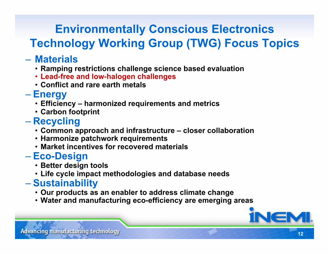
Environmentally Conscious Electronics Technology Working Group (TWG) Focus Topics
– Materials • Ramping restrictions challenge science based evaluation • Lead-free and low-halogen challenges • Conflict and rare earth metals
– Energy • Efficiency – harmonized requirements and metrics • Carbon footprint
– Recycling • Common approach and infrastructure – closer collaboration • Harmonize patchwork requirements • Market incentives for recovered materials
– Eco-Design • Better design tools • Life cycle impact methodologies and database needs
– Sustainability • Our products as an enabler to address climate change • Water and manufacturing eco-efficiency are emerging areas
13
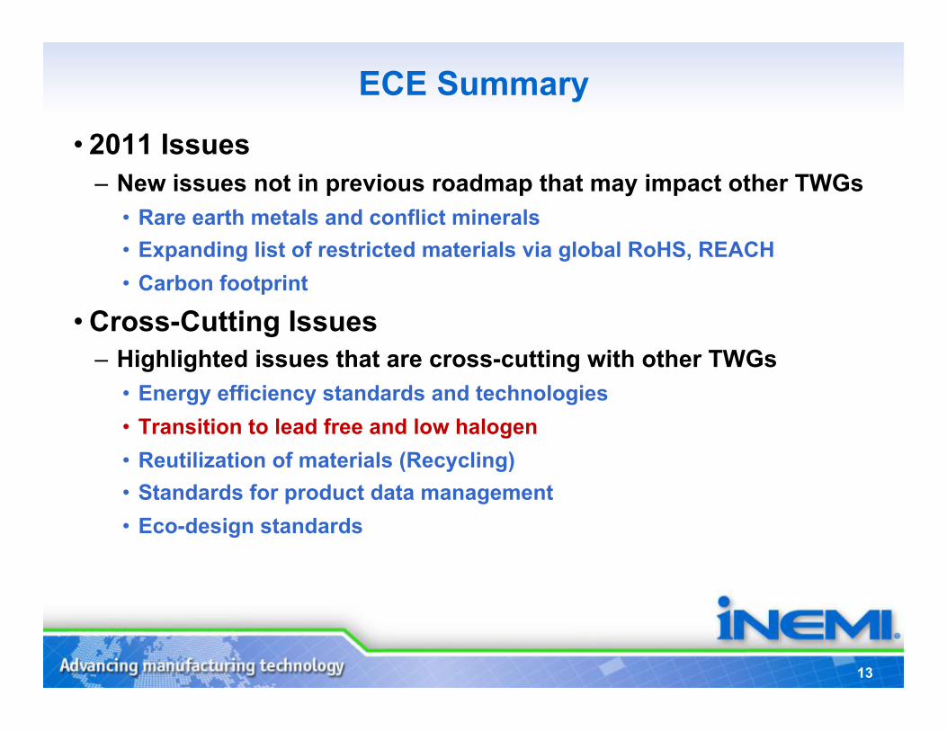
ECE Summary
• 2011 Issues – New issues not in previous roadmap that may impact other TWGs
• Rare earth metals and conflict minerals • Expanding list of restricted materials via global RoHS, REACH • Carbon footprint
• Cross-Cutting Issues – Highlighted issues that are cross-cutting with other TWGs
• Energy efficiency standards and technologies • Transition to lead free and low halogen • Reutilization of materials (Recycling) • Standards for product data management • Eco-design standards
14
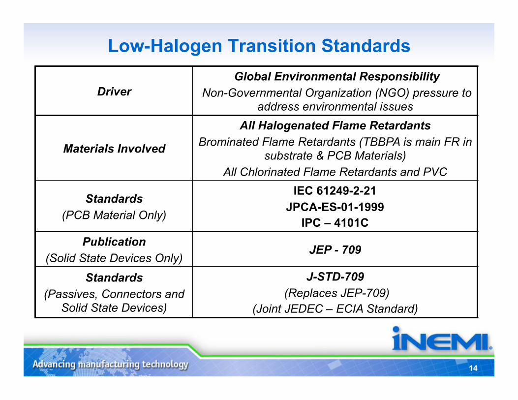
Driver Global Environmental Responsibility
Non-Governmental Organization (NGO) pressure to address environmental issues
Materials Involved
All Halogenated Flame Retardants Brominated Flame Retardants (TBBPA is main FR in
substrate & PCB Materials) All Chlorinated Flame Retardants and PVC
Standards (PCB Material Only)
IEC 61249-2-21 JPCA-ES-01-1999
IPC – 4101C Publication
(Solid State Devices Only) JEP - 709
Standards (Passives, Connectors and
Solid State Devices)
J-STD-709 (Replaces JEP-709)
(Joint JEDEC – ECIA Standard)
Low-Halogen Transition Standards
iNEMI Low- Halogen Position Statement & PVC
Alternatives Project
Scott O’Connell, Dell Director,
Environmental Affairs
16
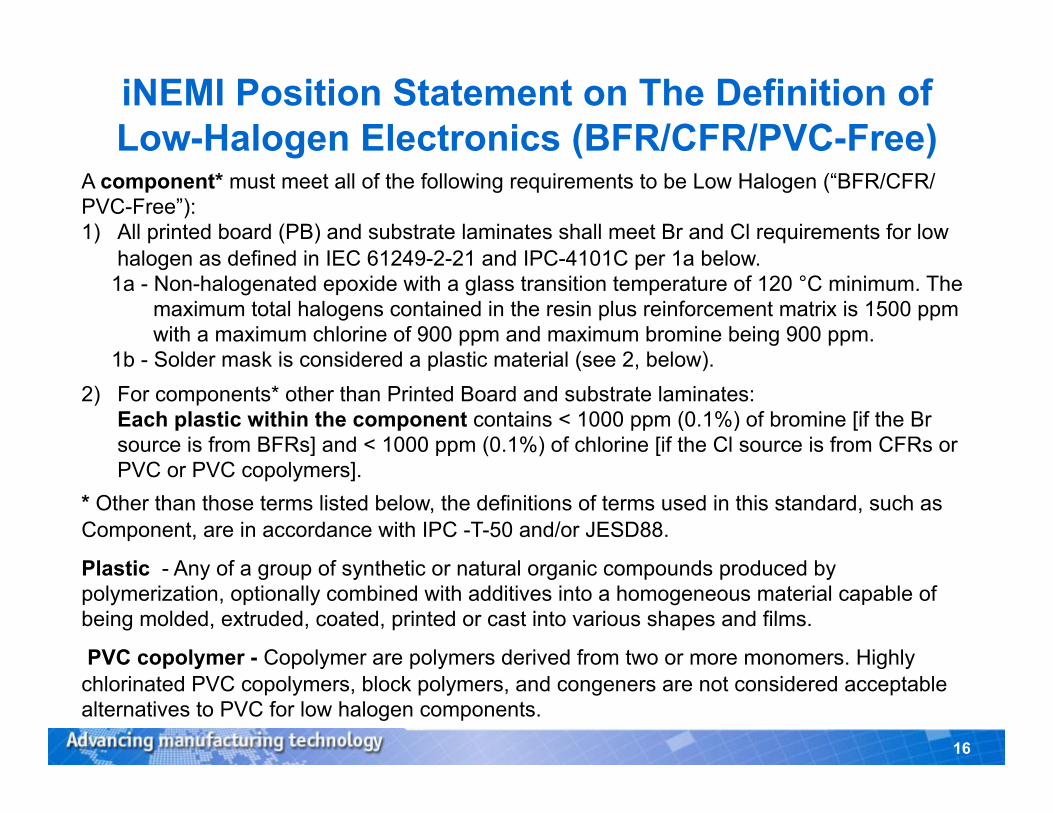
iNEMI Position Statement on The Definition of Low-Halogen Electronics (BFR/CFR/PVC-Free)
A component* must meet all of the following requirements to be Low Halogen (“BFR/CFR/PVC-Free”): 1) All printed board (PB) and substrate laminates shall meet Br and Cl requirements for low
halogen as defined in IEC 61249-2-21 and IPC-4101C per 1a below. 1a - Non-halogenated epoxide with a glass transition temperature of 120 °C minimum. The
maximum total halogens contained in the resin plus reinforcement matrix is 1500 ppm with a maximum chlorine of 900 ppm and maximum bromine being 900 ppm.
1b - Solder mask is considered a plastic material (see 2, below). 2) For components* other than Printed Board and substrate laminates:
Each plastic within the component contains < 1000 ppm (0.1%) of bromine [if the Br source is from BFRs] and < 1000 ppm (0.1%) of chlorine [if the Cl source is from CFRs or PVC or PVC copolymers].
* Other than those terms listed below, the definitions of terms used in this standard, such as Component, are in accordance with IPC -T-50 and/or JESD88.
Plastic - Any of a group of synthetic or natural organic compounds produced by polymerization, optionally combined with additives into a homogeneous material capable of being molded, extruded, coated, printed or cast into various shapes and films.
PVC copolymer - Copolymer are polymers derived from two or more monomers. Highly chlorinated PVC copolymers, block polymers, and congeners are not considered acceptable alternatives to PVC for low halogen components.
17
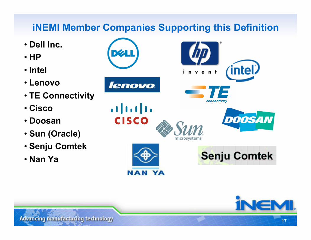
iNEMI Member Companies Supporting this Definition • Dell Inc. • HP • Intel • Lenovo • TE Connectivity • Cisco • Doosan • Sun (Oracle) • Senju Comtek • Nan Ya

PVC Alternatives Project
Co-Chairs: Scott O’Connell, Dell
Jim Arnold, iNEMI
19
Background
19
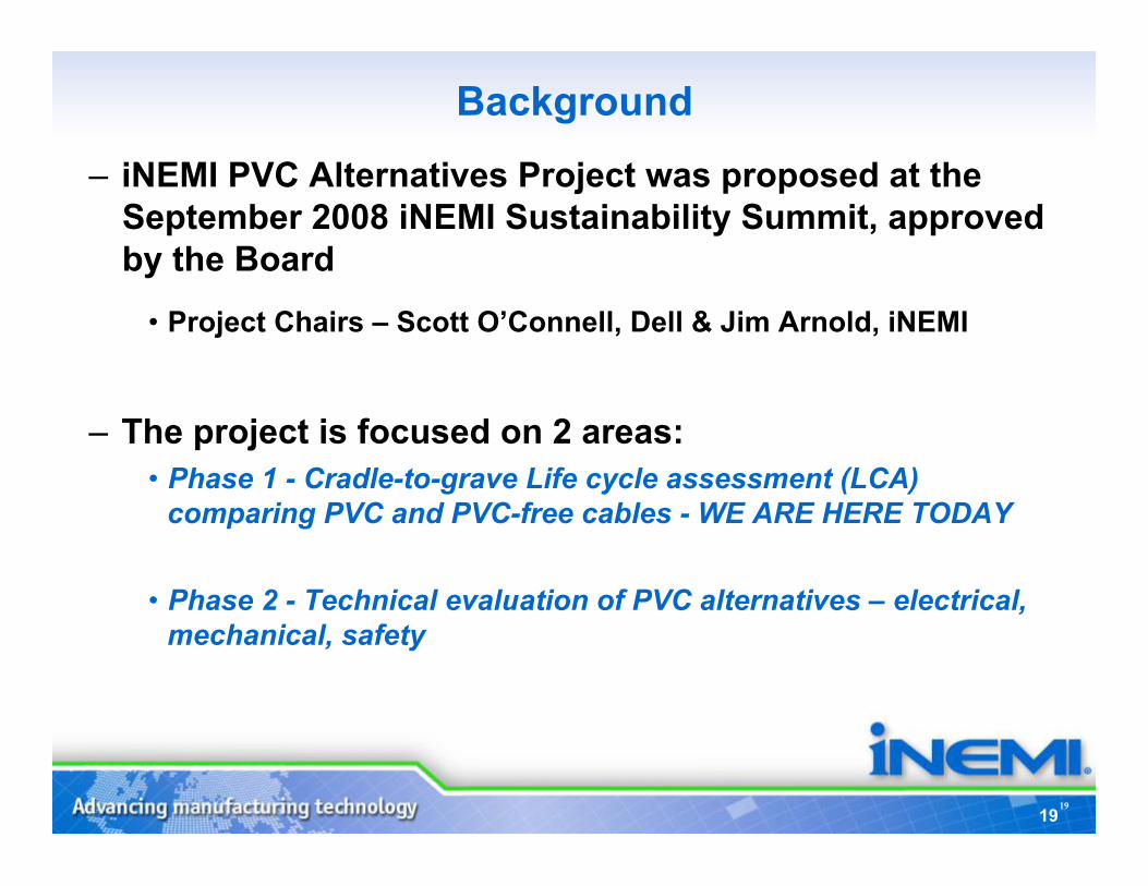
– iNEMI PVC Alternatives Project was proposed at the September 2008 iNEMI Sustainability Summit, approved by the Board
• Project Chairs – Scott O’Connell, Dell & Jim Arnold, iNEMI
– The project is focused on 2 areas: • Phase 1 - Cradle-to-grave Life cycle assessment (LCA)
comparing PVC and PVC-free cables - WE ARE HERE TODAY
• Phase 2 - Technical evaluation of PVC alternatives – electrical, mechanical, safety
Focus Area:
8-11 TIG:
Project Members
Environment
ECE PVC Alternatives Initiative
20
21
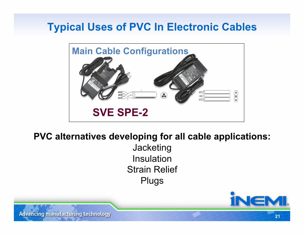
SVE SPE-2
Main Cable Configurations
PVC alternatives developing for all cable applications: Jacketing Insulation
Strain Relief Plugs
Typical Uses of PVC In Electronic Cables
22
Phase 1 – Life Cycle Assessment
(LCA)
23
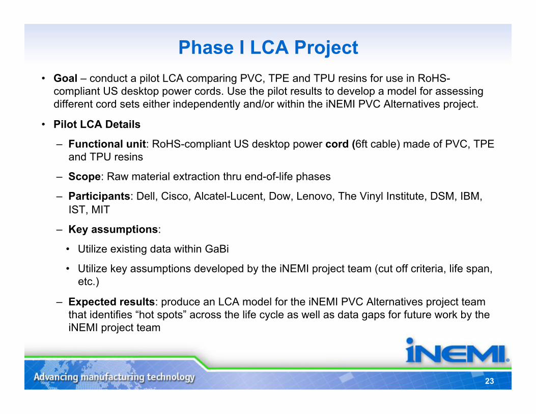
Phase I LCA Project • Goal – conduct a pilot LCA comparing PVC, TPE and TPU resins for use in RoHS-
compliant US desktop power cords. Use the pilot results to develop a model for assessing different cord sets either independently and/or within the iNEMI PVC Alternatives project.
• Pilot LCA Details
– Functional unit: RoHS-compliant US desktop power cord (6ft cable) made of PVC, TPE and TPU resins
– Scope: Raw material extraction thru end-of-life phases
– Participants: Dell, Cisco, Alcatel-Lucent, Dow, Lenovo, The Vinyl Institute, DSM, IBM, IST, MIT
– Key assumptions:
• Utilize existing data within GaBi
• Utilize key assumptions developed by the iNEMI project team (cut off criteria, life span, etc.)
– Expected results: produce an LCA model for the iNEMI PVC Alternatives project team that identifies “hot spots” across the life cycle as well as data gaps for future work by the iNEMI project team
24
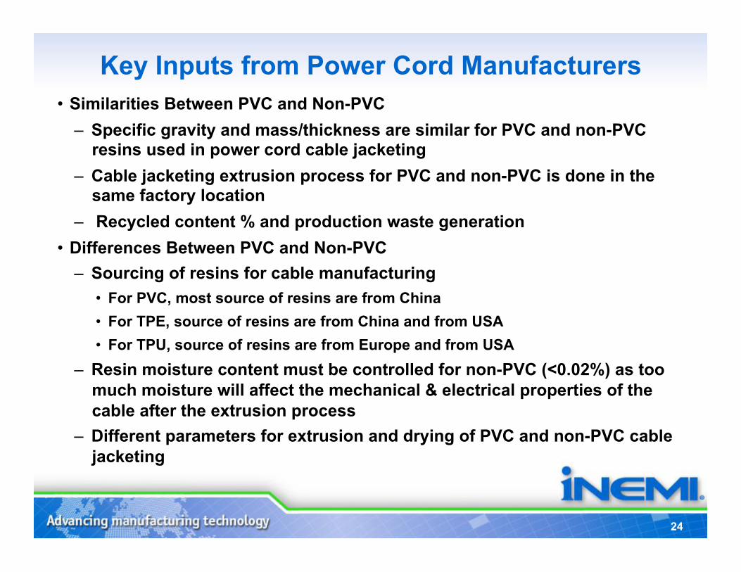
Key Inputs from Power Cord Manufacturers • Similarities Between PVC and Non-PVC
– Specific gravity and mass/thickness are similar for PVC and non-PVC resins used in power cord cable jacketing
– Cable jacketing extrusion process for PVC and non-PVC is done in the same factory location
– Recycled content % and production waste generation • Differences Between PVC and Non-PVC
– Sourcing of resins for cable manufacturing • For PVC, most source of resins are from China • For TPE, source of resins are from China and from USA • For TPU, source of resins are from Europe and from USA
– Resin moisture content must be controlled for non-PVC (<0.02%) as too much moisture will affect the mechanical & electrical properties of the cable after the extrusion process
– Different parameters for extrusion and drying of PVC and non-PVC cable jacketing
25
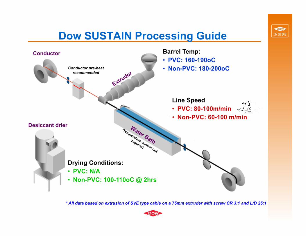
Barrel Temp: • PVC: 160-190oC • Non-PVC: 180-200oC
Conductor
Desiccant drier
Drying Conditions: • PVC: N/A • Non-PVC: 100-110oC @ 2hrs
Line Speed • PVC: 80-100m/min • Non-PVC: 60-100 m/min
Conductor pre-heat recommended
* All data based on extrusion of SVE type cable on a 75mm extruder with screw CR 3:1 and L/D 25:1
Dow SUSTAIN Processing Guide �
26
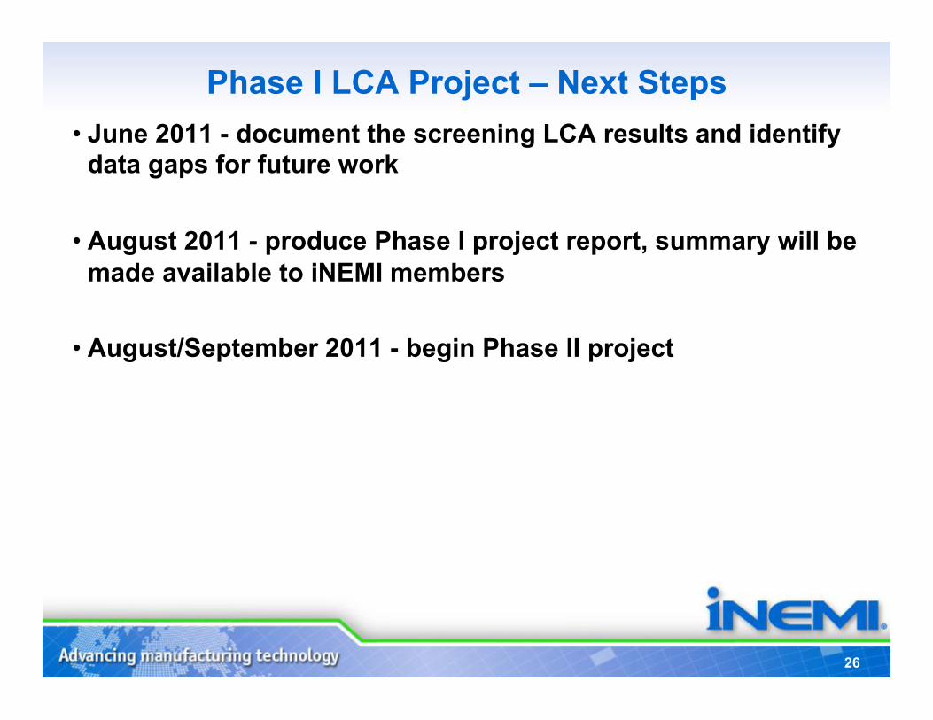
Phase I LCA Project – Next Steps • June 2011 - document the screening LCA results and identify
data gaps for future work
• August 2011 - produce Phase I project report, summary will be made available to iNEMI members
• August/September 2011 - begin Phase II project
27
Phase 2 - Technical Evaluation of PVC Alternatives
27
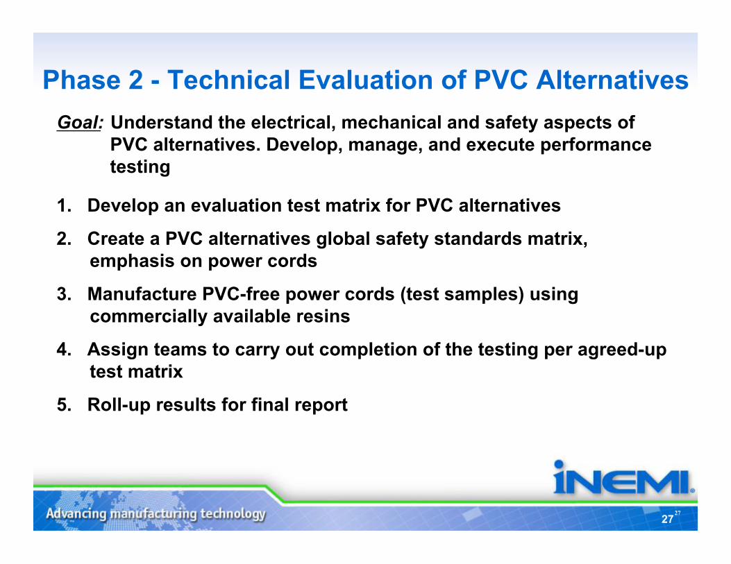
Goal: Understand the electrical, mechanical and safety aspects of PVC alternatives. Develop, manage, and execute performance testing
1. Develop an evaluation test matrix for PVC alternatives
2. Create a PVC alternatives global safety standards matrix, emphasis on power cords
3. Manufacture PVC-free power cords (test samples) using commercially available resins
4. Assign teams to carry out completion of the testing per agreed-up test matrix
5. Roll-up results for final report
HFR-Free High- Reliability PCB
Project
Chair: Stephen Tisdale, Intel
29
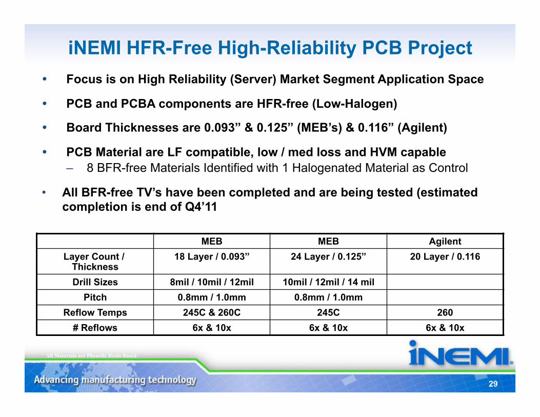
All Materials are Phenolic Resin Based
MEB MEB Agilent Layer Count /
Thickness 18 Layer / 0.093” 24 Layer / 0.125” 20 Layer / 0.116
Drill Sizes 8mil / 10mil / 12mil 10mil / 12mil / 14 mil Pitch 0.8mm / 1.0mm 0.8mm / 1.0mm
Reflow Temps 245C & 260C 245C 260 # Reflows 6x & 10x 6x & 10x 6x & 10x
Focus is on High Reliability (Server) Market Segment Application Space
PCB and PCBA components are HFR-free (Low-Halogen)
Board Thicknesses are 0.093” & 0.125” (MEB’s) & 0.116” (Agilent)
PCB Material are LF compatible, low / med loss and HVM capable – 8 BFR-free Materials Identified with 1 Halogenated Material as Control
• All BFR-free TV’s have been completed and are being tested (estimated completion is end of Q4’11
iNEMI HFR-Free High-Reliability PCB Project
30
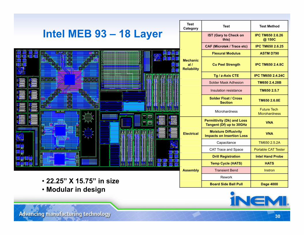
Intel MEB 93 – 18 Layer
• 22.25” X 15.75” in size • Modular in design
Test Category Test Test Method
IST (Gary to Check on this)
IPC TM650 2.6.26 @ 150C
CAF (Microtek / Trace etc) IPC TM650 2.6.25
Flexural Modulus ASTM D790
Mechanical /
Reliability Cu Peel Strength IPC TM650 2.4.8C
Tg / z-Axis CTE IPC TM650 2.4.24C
Solder Mask Adhesion TM650 2.4.28B
Insulation resistance TM650 2.5.7
Solder Float / Cross Section TM650 2.6.8E
Microhardness Future Tech Microhardness
Permittivity (Dk) and Loss Tangent (Df) up to 30GHz VNA
Electrical Moisture Diffusivity Impacts on Insertion Loss VNA
Capacitance TM650 2.5.2A
CAT Trace and Space Portable CAT Tester
Drill Registration Intel Hand Probe
Temp Cycle (HATS) HATS
Assembly Transient Bend Instron
Rework
Board Side Ball Pull Dage 4000
Focus Area:
8-11 TIG:
Project Members
Miniaturization
ECE & Substrates HFR-Free High-Reliability PCB
31
HFR-Free Leadership Program Program Manager:
Stephen Tisdale, Intel
HFR-Free PCB Materials Project Chair: John Davignon, Intel
HFR-Free Signal Integrity Project Chair: Stephen Hall, Intel
Co-chair: David Senk, Cisco
33
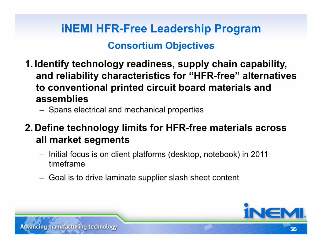
iNEMI HFR-Free Leadership Program Consortium Objectives
33
1. Identify technology readiness, supply chain capability, and reliability characteristics for “HFR-free” alternatives to conventional printed circuit board materials and assemblies – Spans electrical and mechanical properties
2. Define technology limits for HFR-free materials across all market segments – Initial focus is on client platforms (desktop, notebook) in 2011
timeframe
– Goal is to drive laminate supplier slash sheet content
34
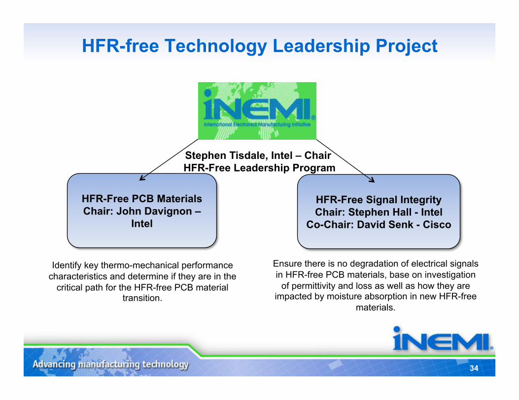
HFR-free Technology Leadership Project
Stephen Tisdale, Intel – Chair HFR-Free Leadership Program
HFR-Free PCB Materials Chair: John Davignon –
Intel
HFR-Free Signal Integrity Chair: Stephen Hall - Intel
Co-Chair: David Senk - Cisco
Identify key thermo-mechanical performance characteristics and determine if they are in the
critical path for the HFR-free PCB material transition.
Ensure there is no degradation of electrical signals in HFR-free PCB materials, base on investigation
of permittivity and loss as well as how they are impacted by moisture absorption in new HFR-free
materials.
HFR-Free Technology
Leadership Program
HFR-Free PCB Materials Project
Chair: John Davignon, Intel
36
iNEMI HFR-Free PCB Materials Project Strategy • Define and implement quantifiable data into the HF Laminate
Suppliers Datasheets that will assist in material selection by users
• Define a “Test Suite Methodology” which models the quality and reliability requirements of the chosen market segments
• Ensure the Industry Laminate Suppliers have the capability and capacity to support the industry HF laminate requirements
37
HFR-Free Materials Project - Phase 2 Update • Two Proof of Concepts (POC) lots have been built
– Verified the Test Suite Methodology test vehicle / coupon design and test methods and ratified the Test Methods
– Determined the repeatability and reproducibility of the test methods across multiple sites
• Final “Test Suite Methodology” Design completed and all test structures finalized
• Completed all laminate builds (6 HFR-free and 3 FR4 laminates)
• Phase 2 Schedule: – Laminate Testing Scheduled Completion - Q3’11 – Final analysis of Phase 2 results – Q4’11
38
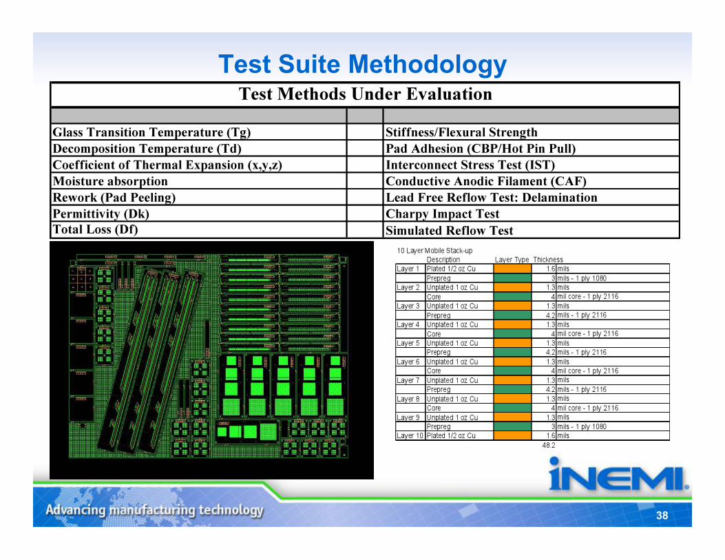
Test Suite Methodology
39
PCB Summary - Benefits • We are looking to change the way that data is reported on the
Laminate datasheets – The test methods were precisely defined – The test methods were performed on a “product like” construction
for more relevant data
• The data reported will enable: – A true comparison of material properties and responses between
laminates – OEM/ODM’s to set envelopes for the material properties based on
the market/BU sector that mitigate risk factors for that sector – PCB Designers to pick cost effective laminate materials that are
suitable to their products/market segment – Method of directing Laminate Suppliers how to improve laminates
by specific properties or responses
HFR-Free Leadership Program
HFR-Free Signal Integrity Project
Chair: Stephen Hall, Intel;
Co-Chair: David Senk, Cisco
41
Problem
The critical electrical properties of many available halide-free dielectrics make high-speed bus design problematic without
increasing the cost of the system
42
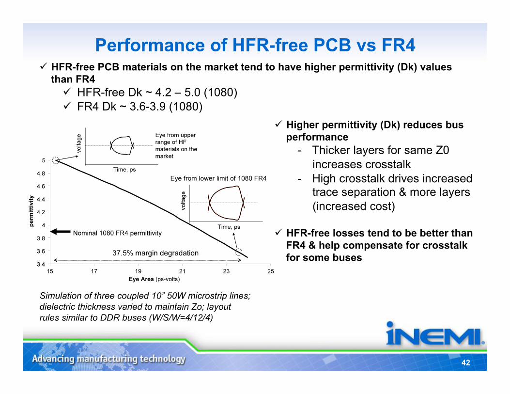
Performance of HFR-free PCB vs FR4 HFR-free PCB materials on the market tend to have higher permittivity (Dk) values
than FR4 HFR-free Dk ~ 4.2 – 5.0 (1080) FR4 Dk ~ 3.6-3.9 (1080)
Simulation of three coupled 10” 50W microstrip lines; dielectric thickness varied to maintain Zo; layout rules similar to DDR buses (W/S/W=4/12/4)
Higher permittivity (Dk) reduces bus performance
- Thicker layers for same Z0 increases crosstalk
- High crosstalk drives increased trace separation & more layers (increased cost)
HFR-free losses tend to be better than FR4 & help compensate for crosstalk for some buses
43
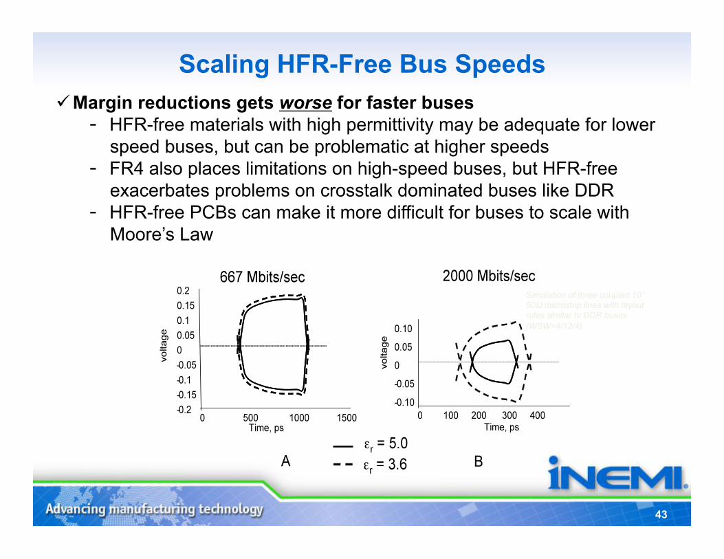
Scaling HFR-Free Bus Speeds
Simulation of three coupled 10” 50Ω microstrip lines with layout rules similar to DDR buses (WSW=4/12/4)
Margin reductions gets worse for faster buses - HFR-free materials with high permittivity may be adequate for lower
speed buses, but can be problematic at higher speeds - FR4 also places limitations on high-speed buses, but HFR-free
exacerbates problems on crosstalk dominated buses like DDR - HFR-free PCBs can make it more difficult for buses to scale with
Moore’s Law
44
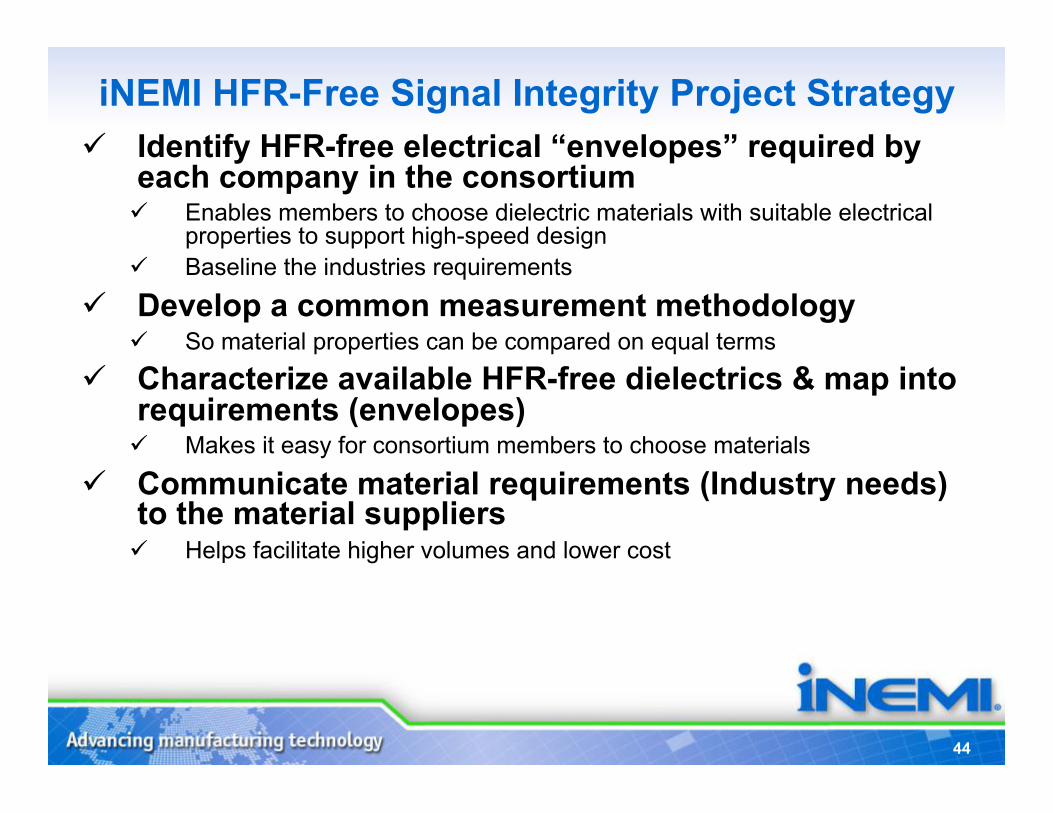
iNEMI HFR-Free Signal Integrity Project Strategy Identify HFR-free electrical “envelopes” required by
each company in the consortium Enables members to choose dielectric materials with suitable electrical
properties to support high-speed design Baseline the industries requirements
Develop a common measurement methodology So material properties can be compared on equal terms
Characterize available HFR-free dielectrics & map into requirements (envelopes) Makes it easy for consortium members to choose materials
Communicate material requirements (Industry needs) to the material suppliers Helps facilitate higher volumes and lower cost
45
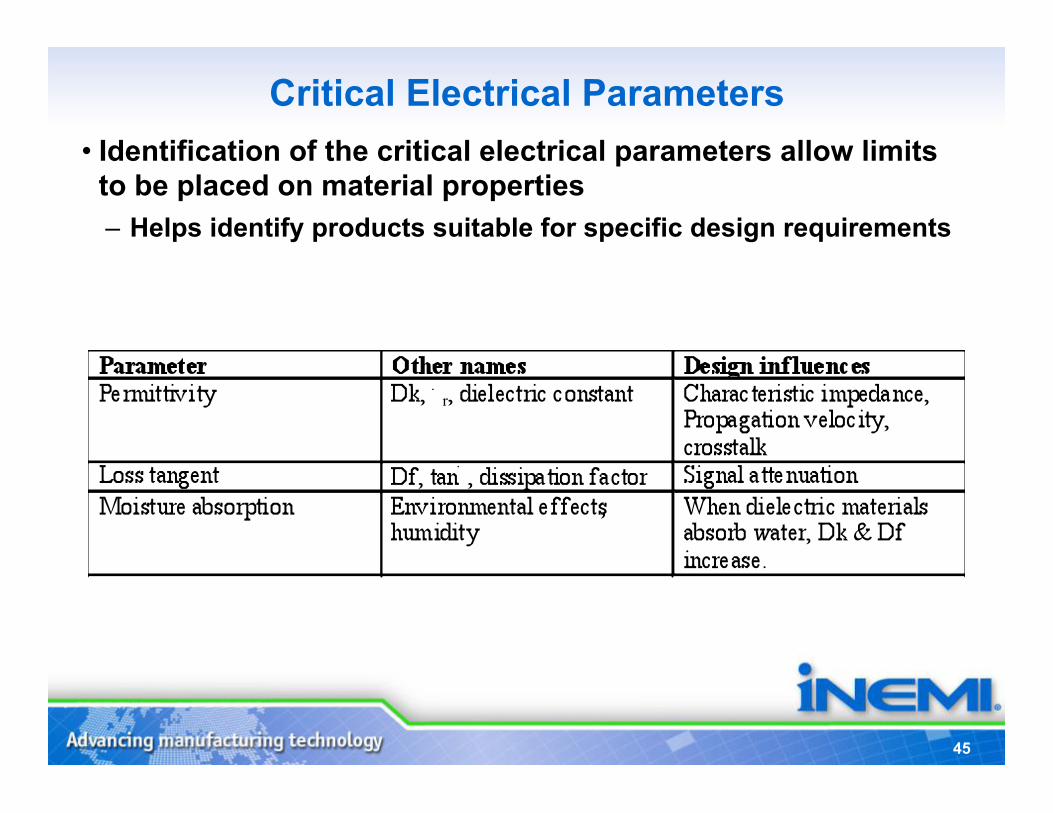
Critical Electrical Parameters • Identification of the critical electrical parameters allow limits
to be placed on material properties – Helps identify products suitable for specific design requirements
46
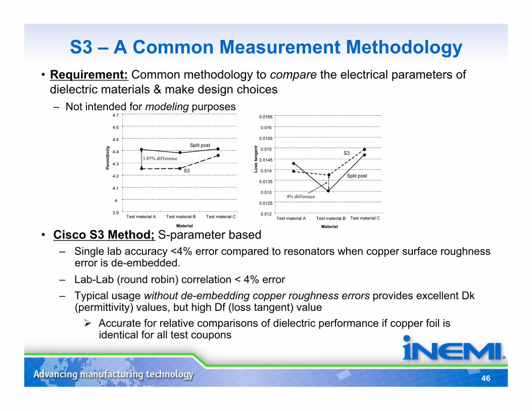
S3 – A Common Measurement Methodology • Requirement: Common methodology to compare the electrical parameters of
dielectric materials & make design choices – Not intended for modeling purposes
• Cisco S3 Method; S-parameter based – Single lab accuracy <4% error compared to resonators when copper surface roughness
error is de-embedded. – Lab-Lab (round robin) correlation < 4% error – Typical usage without de-embedding copper roughness errors provides excellent Dk
(permittivity) values, but high Df (loss tangent) value Accurate for relative comparisons of dielectric performance if copper foil is
identical for all test coupons
47
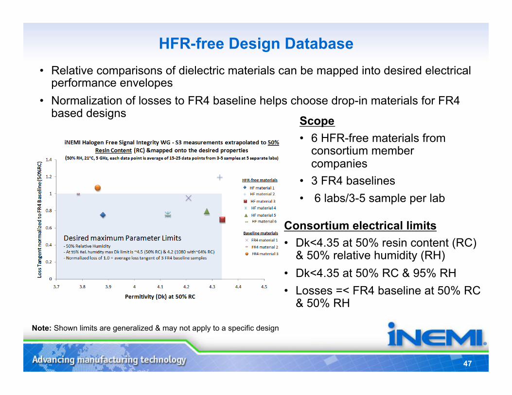
HFR-free Design Database • Relative comparisons of dielectric materials can be mapped into desired electrical
performance envelopes • Normalization of losses to FR4 baseline helps choose drop-in materials for FR4
based designs Scope • 6 HFR-free materials from
consortium member companies
• 3 FR4 baselines • 6 labs/3-5 sample per lab
Consortium electrical limits • Dk<4.35 at 50% resin content (RC)
& 50% relative humidity (RH) • Dk<4.35 at 50% RC & 95% RH • Losses =< FR4 baseline at 50% RC
& 50% RH
Note: Shown limits are generalized & may not apply to a specific design
48
Electrical Summary • HFR-Free Laminates today tend have increased permittivity
(Dk) over FR4
• Higher Dk impacts high speed buses; Biggest impact is DDR interface
• Limits can be placed on the permittivity (Dk) so that FR4 and HFR-free PCBs are interchangeable for a single design
• 2011 Client Platforms simulation and preliminary validation suggests the defined envelope will meet the platform requirements
49
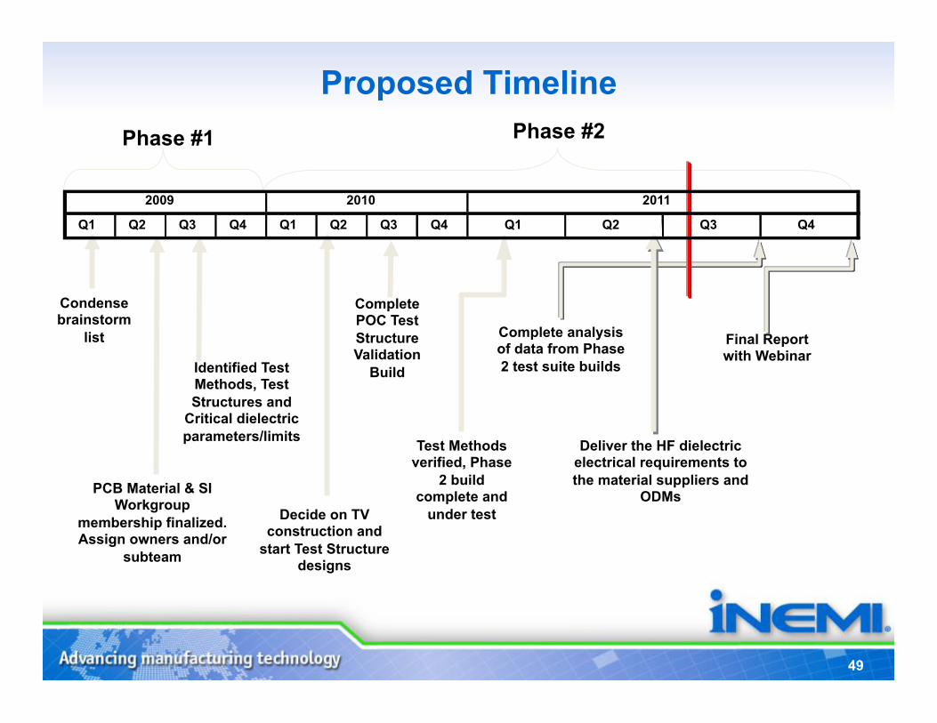
Proposed Timeline
2009 2010
Condense brainstorm
list
PCB Material & SI Workgroup
membership finalized. Assign owners and/or
subteam
Final Report with Webinar
Complete analysis of data from Phase 2 test suite builds Identified Test
Methods, Test Structures and
Critical dielectric parameters/limits
Decide on TV construction and
start Test Structure designs
Deliver the HF dielectric electrical requirements to the material suppliers and
ODMs
Complete POC Test Structure Validation
Build
Test Methods verified, Phase
2 build complete and
under test
Phase #1 Phase #2
Q1 Q2 Q3 Q4 Q1 Q2 Q3 Q4 Q1 Q2 Q3 Q4 2009 2010 2011
Focus Area:
8-11 TIG:
Project Members
Environment
ECE Firms Participating in the Program
50
Low-Halogen Connectors/Cables
Dave Bender, TE Director, Product
Compliance
52
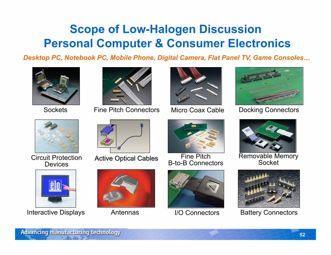
Desktop PC, Notebook PC, Mobile Phone, Digital Camera, Flat Panel TV, Game Consoles…
Antennas Interactive Displays
Sockets Fine Pitch Connectors
Removable Memory Socket
I/O Connectors Battery Connectors
Micro Coax Cable Docking Connectors
Fine Pitch B-to-B Connectors
Circuit Protection Devices
Scope of Low-Halogen Discussion Personal Computer & Consumer Electronics
53
Background Info on Halogen Use • Halogens are used as flame retardants, stabilizers, or
lubricants in certain plastics common to the connector industry – Bromine (most prevalent) and Chlorine are routinely used in flame
retardant (FR) “packages” – Typical concentrations of Br in FR package are15-35% and are not
currently restricted by RoHS (not PBB or PBDE) – Fluorine and Iodine less prevalent, used as stabilizers or
lubricants
• Major driver of halogen use in connector industry is requirement for UL94-V0 flammability rating – Many plastics including widely used Nylon and PBT require
addition of a FR to achieve V0 rating
54
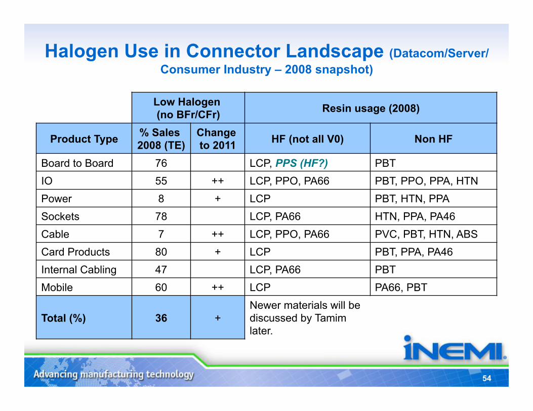
Halogen Use in Connector Landscape (Datacom/Server/Consumer Industry – 2008 snapshot)
Low Halogen (no BFr/CFr) Resin usage (2008)
Product Type % Sales 2008 (TE)
Change to 2011 HF (not all V0) Non HF
Board to Board 76 LCP, PPS (HF?) PBT IO 55 ++ LCP, PPO, PA66 PBT, PPO, PPA, HTN Power 8 + LCP PBT, HTN, PPA Sockets 78 LCP, PA66 HTN, PPA, PA46 Cable 7 ++ LCP, PPO, PA66 PVC, PBT, HTN, ABS Card Products 80 + LCP PBT, PPA, PA46 Internal Cabling 47 LCP, PA66 PBT Mobile 60 ++ LCP PA66, PBT
Total (%) 36 + Newer materials will be discussed by Tamim later.
55
Why the Diversity of Plastic Usage? • Plastic selection criteria is driven by many factors:
– Mechanical properties (e.g. latches) – Moldability (fill characteristics like thin walls) – Solder process requirements (wave vs. reflow vs. lead free reflow) – Cost (material and process) – Global availability – Acquisitions and legacy products add to diversity
• Changing plastics in a connector product is not trivial – Plastics are not “drop-in” replacements due to varying shrink rates – Mold modifications typically required, design changes not uncommon – Plastic change typically requires product testing and re-qualification – Requires significant investment of engineering time and money
56
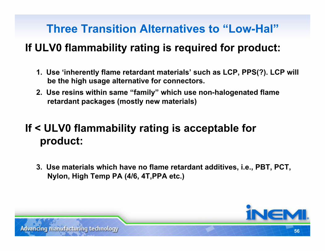
Three Transition Alternatives to “Low-Hal” If ULV0 flammability rating is required for product:
1. Use ‘inherently flame retardant materials’ such as LCP, PPS(?). LCP will be the high usage alternative for connectors.
2. Use resins within same “family” which use non-halogenated flame retardant packages (mostly new materials)
If < ULV0 flammability rating is acceptable for product:
3. Use materials which have no flame retardant additives, i.e., PBT, PCT, Nylon, High Temp PA (4/6, 4T,PPA etc.)
57
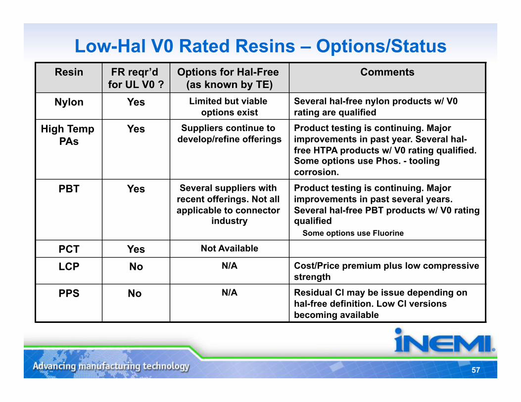
Low-Hal V0 Rated Resins – Options/Status Resin FR reqr’d
for UL V0 ? Options for Hal-Free
(as known by TE) Comments
Nylon Yes Limited but viable options exist
Several hal-free nylon products w/ V0 rating are qualified
High Temp PAs
Yes Suppliers continue to develop/refine offerings
Product testing is continuing. Major improvements in past year. Several hal-free HTPA products w/ V0 rating qualified. Some options use Phos. - tooling corrosion.
PBT Yes Several suppliers with recent offerings. Not all applicable to connector
industry
Product testing is continuing. Major improvements in past several years. Several hal-free PBT products w/ V0 rating qualified
Some options use Fluorine
PCT Yes Not Available
LCP No N/A Cost/Price premium plus low compressive strength
PPS No N/A Residual Cl may be issue depending on hal-free definition. Low Cl versions becoming available
58
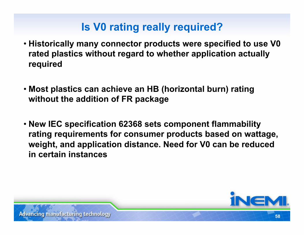
Is V0 rating really required? • Historically many connector products were specified to use V0
rated plastics without regard to whether application actually required
• Most plastics can achieve an HB (horizontal burn) rating without the addition of FR package
• New IEC specification 62368 sets component flammability rating requirements for consumer products based on wattage, weight, and application distance. Need for V0 can be reduced in certain instances
59
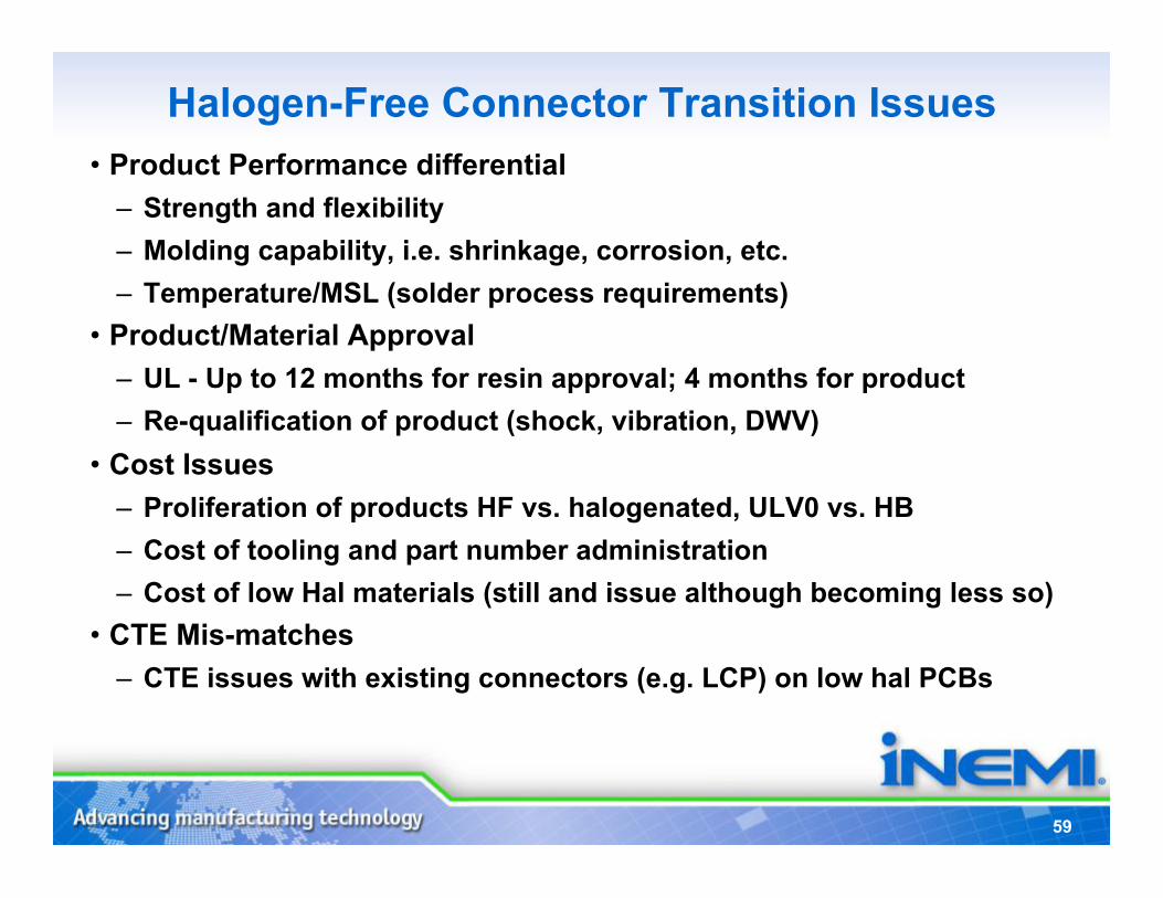
Halogen-Free Connector Transition Issues • Product Performance differential
– Strength and flexibility – Molding capability, i.e. shrinkage, corrosion, etc. – Temperature/MSL (solder process requirements)
• Product/Material Approval – UL - Up to 12 months for resin approval; 4 months for product – Re-qualification of product (shock, vibration, DWV)
• Cost Issues – Proliferation of products HF vs. halogenated, ULV0 vs. HB – Cost of tooling and part number administration – Cost of low Hal materials (still and issue although becoming less so)
• CTE Mis-matches – CTE issues with existing connectors (e.g. LCP) on low hal PCBs
60
LSZH Cable Transition (Low Smoke, Zero Halogen) • Key Performance drivers
– Safety ratings (approvals) – Flexibility – Strength – Electrical performance
• LSZH materials present following challenges – Higher amount of FR present reduces performance/flexibility – Thicker wall sizes may be required to pass flame tests – May require additional shielding from electrical perspective – Strengths and flexibility properties typically not as robust as PVC – Cost is still higher but delta decreasing
61
LSZH Materials Improvements Continuing • Improved flame retarding properties
• Improved physical characteristics to meet UL/CSA requirements
• Improvements in flexibility
• Existing compound suppliers developing new LSZH materials
• New suppliers entering the LSZH market
62
LSZH Cable Availability • 2 pr/4pr High Performance Cable Approvals—Type CMG & Type CL2/
FT-4. 32 AWG through 22/24 AWG • Power Limited Circuit—Multi Conductor and Multi-Pair—Limited
constructions. Approved for CL2/FT4 & CL2R ratings • Communication Cable—Multi Conductor and Multi-Pair—Limited
constructions. Approved for CM CMG & CMR ratings • AWM Rated Cable—Multi Conductor and Multi Pairs—More
constructions passing VW-1,Cable Flame Test & physical testing • DP-1, 2 & 3—Power Cords and Multi Conductor and Multi Pairs—
Limited constructions • Flex Cord Cables approved • Current LSZH Materials cannot meet UL/CSA Plenum rating (as far
as TE is aware)
63
Bottom Line • Major improvements in options/performance of “low-hal”
materials since start of initiative in 2008. Viable substitutes exist for most materials
• Most replacement materials are not “drop-in” replacements
• Still not at cost parity although gap is closing • Most major consumer, communications customers are
communicating plans/initiatives to move to “hal-free”, connector/cable industry ready to support
• New programs are utilizing “low-hal” materials whenever feasible

Low-Halogen Status
Dr. Tamim Sidiki, DSM Global Marketing
Manager
65
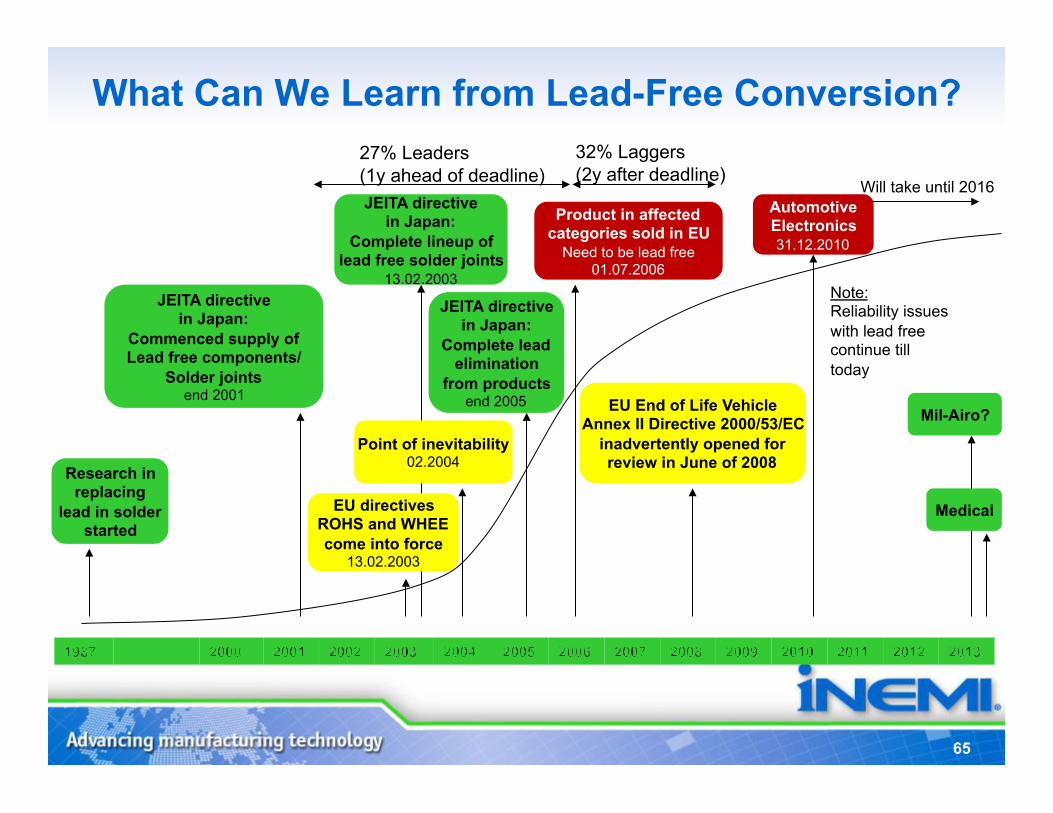
What Can We Learn from Lead-Free Conversion?
EU directives ROHS and WHEE come into force
13.02.2003
Medical
Product in affected categories sold in EU
Need to be lead free 01.07.2006
Research in replacing
lead in solder started
JEITA directive in Japan:
Commenced supply of Lead free components/
Solder joints end 2001
JEITA directive in Japan:
Complete lineup of lead free solder joints
13.02.2003
JEITA directive in Japan:
Complete lead elimination
from products end 2005
Mil-Airo?
27% Leaders (1y ahead of deadline)
32% Laggers (2y after deadline)
EU End of Life Vehicle Annex II Directive 2000/53/EC
inadvertently opened for review in June of 2008
Automotive Electronics 31.12.2010
Will take until 2016
Point of inevitability 02.2004
Note: Reliability issues with lead free continue till today
66
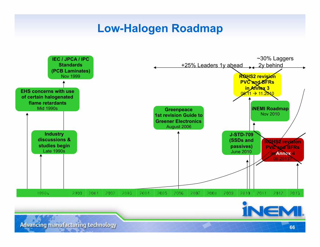
Low-Halogen Roadmap
IEC / JPCA / IPC Standards
(PCB Laminates) Nov 1999
+25% Leaders 1y ahead ~30% Laggers 2y behind
ROHS2 revision PVC and BFRs
in Annex 3 06.11 11.2010 EHS concerns with use
of certain halogenated flame retardants
Mid 1990s
Industry discussions & studies begin
Late 1990s
Greenpeace 1st revision Guide to Greener Electronics
August 2006
J-STD-709 (SSDs and passives) June 2010
ROHS2 revision PVC and BFRs
in Annex 4 06.2013?
iNEMI Roadmap Nov 2010
67
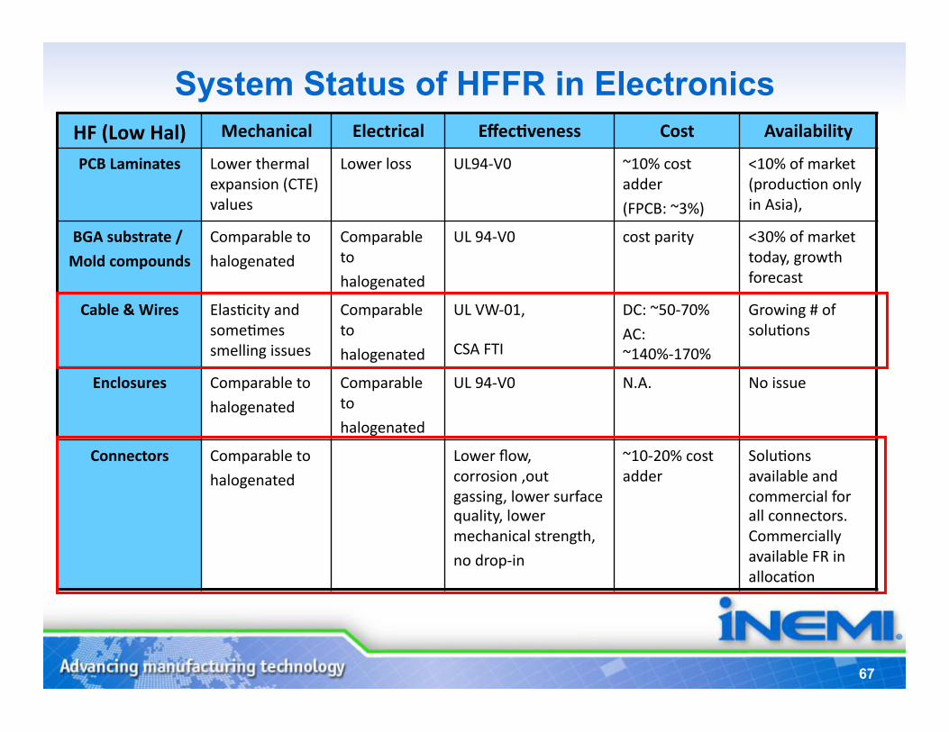
HF (Low Hal) Mechanical Electrical Effec5veness Cost Availability
PCB Laminates Lower thermal expansion (CTE) values
Lower loss UL94-‐V0 ~10% cost adder
(FPCB: ~3%)
<10% of market (producKon only in Asia),
BGA substrate /
Mold compounds
Comparable to
halogenated
Comparable to
halogenated
UL 94-‐V0 cost parity <30% of market today, growth forecast
Cable & Wires ElasKcity and someKmes smelling issues
Comparable to
halogenated
UL VW-‐01,
CSA FTI DC: ~50-‐70%
AC: ~140%-‐170%
Growing # of soluKons
Enclosures Comparable to
halogenated
Comparable to
halogenated
UL 94-‐V0 N.A. No issue
Connectors Comparable to
halogenated
Lower flow, corrosion ,out gassing, lower surface quality, lower mechanical strength,
no drop-‐in
~10-‐20% cost adder
SoluKons available and commercial for all connectors. Commercially available FR in allocaKon
System Status of HFFR in Electronics
68
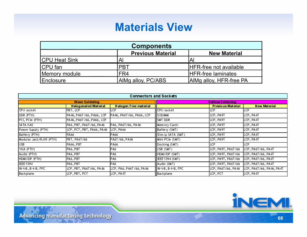
Materials View
Previous Material New Material CPU Heat Sink Al Al CPU fan PBT HFR-free not available Memory module FR4 HFR-free laminates Enclosure AlMg alloy, PC/ABS AlMg alloy, HFR-free PA
Components
69
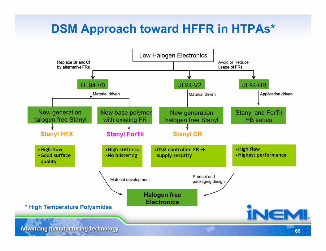
DSM Approach toward HFFR in HTPAs*
UL94 - HB
• High flow • Highest performance
Application driven Material driven
Replace Br and Cl by alternative FRs
Halogen free Electronics
packaging design
New basepolymer with existing FR
Stanyl and ForTii HB series
Stanyl HFX Stanyl ForTii
Low Halogen Electronics
UL94 - V0 UL94 - V0 UL94 - HB
• High flow • Good surface quality
• DSM controlled FR supply security
Application driven Material driven
Replace Br and Cl by alternative FRs
Avoid or Reduce usage of FRs usage of FRs
Product and Material development
New generation halogen free Stanyl
New generation halogen free Stanyl
New base polymer with existing FR
Stanyl and ForTii HB series
UL94 - V0 UL94 - V2
Stanyl CR
New generation halogen free Stanyl
New generation halogen free Stanyl
Material driven
• High stiffness • No blistering
* High Temperature Polyamides
70
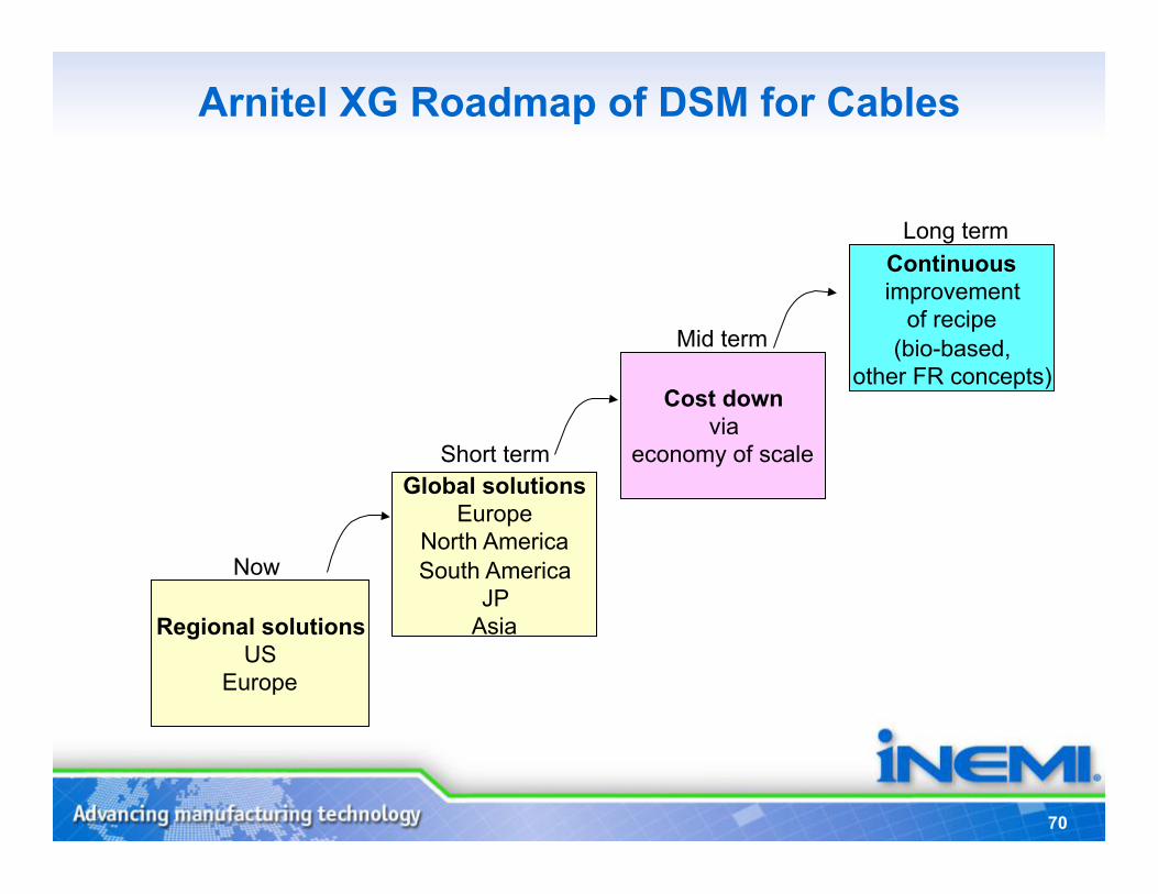
Arnitel XG Roadmap of DSM for Cables
Global solutions Europe
North America South America
JP Asia
Cost down via
economy of scale
Continuous improvement
of recipe (bio-based,
other FR concepts)
Short term
Mid term
Long term
Regional solutions US
Europe
Now
71
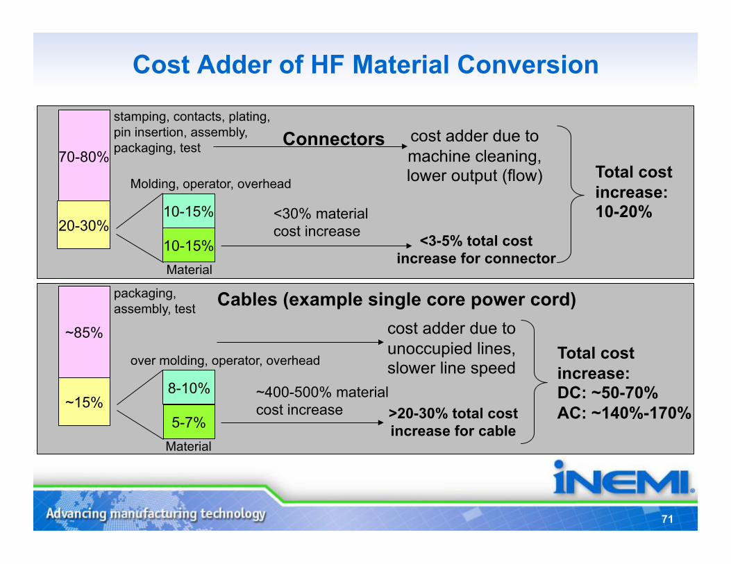
Cost Adder of HF Material Conversion
Connectors 70-80%
20-30% 10-15%
10-15%
<30% material cost increase <3-5% total cost
increase for connector
stamping, contacts, plating, pin insertion, assembly, packaging, test
Molding, operator, overhead
Material
Cables (example single core power cord)
~85%
~15% 8-10%
5-7%
~400-500% material cost increase >20-30% total cost
increase for cable
packaging, assembly, test
over molding, operator, overhead
Material
cost adder due to unoccupied lines, slower line speed
cost adder due to machine cleaning, lower output (flow)
Total cost increase: DC: ~50-70% AC: ~140%-170%
Total cost increase: 10-20%
72
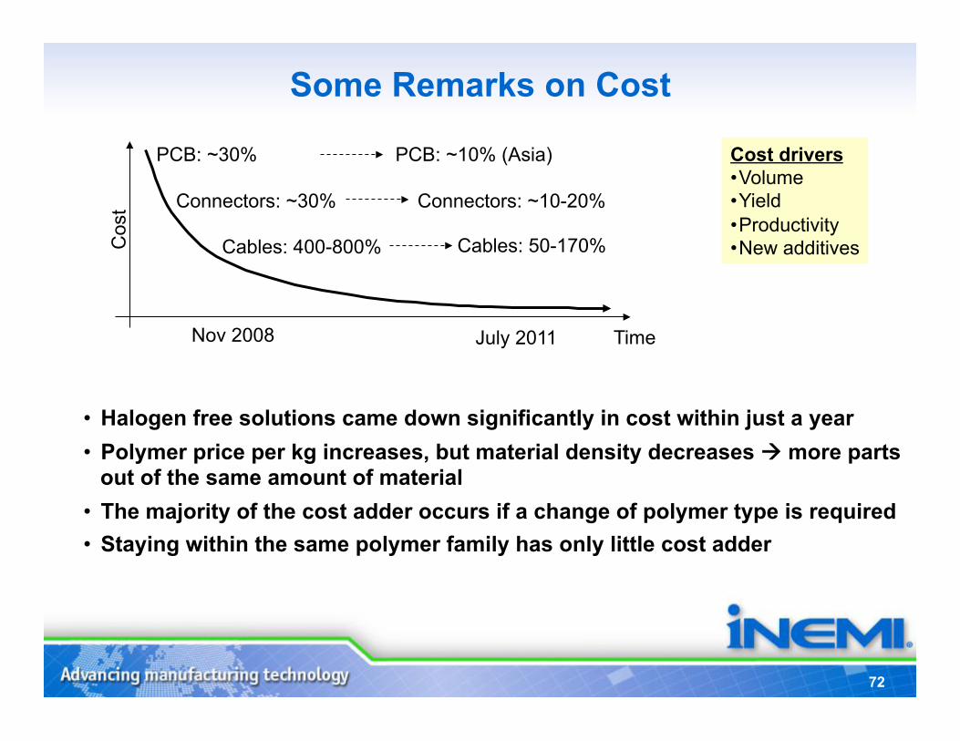
Some Remarks on Cost
• Halogen free solutions came down significantly in cost within just a year • Polymer price per kg increases, but material density decreases more parts
out of the same amount of material • The majority of the cost adder occurs if a change of polymer type is required • Staying within the same polymer family has only little cost adder
Time
Cos
t
Cost drivers • Volume • Yield • Productivity • New additives
PCB: ~30%
Cables: 400-800%
Connectors: ~30%
Nov 2008 July 2011
PCB: ~10% (Asia)
Cables: 50-170%
Connectors: ~10-20%
73
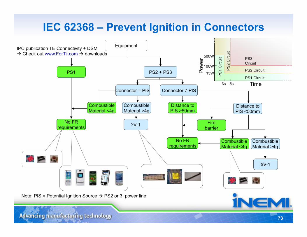
IEC 62368 – Prevent Ignition in Connectors Equipment
PS1
No FR requirements
PS2 + PS3
Connector = PIS Connector ≠ PIS
≥V-1
Distance to PIS >50mm
No FR requirements
Combustible Material <4g
Combustible Material >4g
Distance to PIS <50mm
Combustible Material <4g
Combustible Material >4g
Fire barrier
≥V-1
Pow
er
PS
1 C
ircui
t
PS
2 C
ircui
t
PS3 Circuit
PS2 Circuit
PS1 Circuit
Time 3s
500W
100W
15W
5s
Note: PIS = Potential Ignition Source PS2 or 3, power line
IPC publication TE Connectivity + DSM Check out www.ForTii.com downloads
74
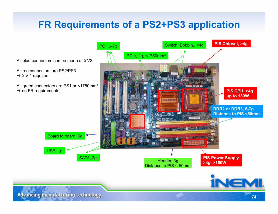
FR Requirements of a PS2+PS3 application
PIS Power Supply >4g, >150W
DDR2 or DDR3, 6-7g Distance to PIS <50mm
Board to board, 6g
SATA, 2g Header, 3g
Distance to PIS < 50mm
PCI, 6-7g
PCIe, 2g, <1750mm3
All blue connectors can be made of ≥ V2
All red connectors are PS2/PS3 ≥ V-1 required
All green connectors are PS1 or <1750mm3 no FR requirements PIS CPU, >4g
up to 130W
USB, 1g
PIS Chipset, >4g Switch, Bobbin,..<4g
75
Summary • Sustainable development will be the main trend in the coming
decade.
• Close cooperation across the value chain is key to have the right materials available in time.
• Connectors/ Sockets and Cables/Wires remain the two top critical aspects in the halogen free conversion.
• After having individual components in halogen free, the next challenge is a complete halogen free system where individual components interplay (CTE).
• Green design will evolve from a differentiator to a qualifier for most industry segments the environment needs a joint commitment of the industry to make it happen
76
Concluding Thoughts • New global environmental requirements continue to multiply – fast
and the industry must work together to effectively respond • Industry needs to be more proactive in developing solutions that:
– Are based on science and engineering, delivering value to customers – Are available in advance of new regulations – Can influence future regulations and stakeholder groups for more
sustainable results • iNEMI and its members are playing a significant role in preparing
industry for these future needs • Sustainability in HFR and PVC alternatives has been a major
undertaking for the electronics industry • Where the technology exists it will be important for the electronic
supply chain to use them where ever applicable
77
Follow-Up • Presentations will be available for download on the iNEMI
website at www.inemi.org (you will need to create a personal account and password)
• Recording of the webinar will be available for download within 24 hours after the conclusion of the webinar. The link to the download is: http://www.inemi.org/node/2118
• Any unanswered questions will be forwarded to the applicable speaker for answers via email
• Anyone interested in getting more information about iNEMI can contact Chuck Richardson at [email protected]
• Thank you all for attending