Embed Size (px)
Citation preview

Lesson learned from a gasifer demonstration – a report on efficiency, performance and security

1(34)
Report on efficiency for small scale CHP plants
Document information:
Title: Report on efficiency, Report on performance, Report on security for a small-scale CHP (förgasare)
Compiled by: Energikontor Sydost AB and Emåmejeriet AB within the Life+ project Life13EN/SE/000113
Quality audited by: Steering group of the project Life13ENV/SE000113 including persons representing Svebio, Swedenergy, VEAB and Linnaeus University
Publisher: Energikontor Sydost AB Smedjegatan 37 352 46 Växjö Sverige
With support from: Life+ programme, Life13ENV/SE/000113 and Swedish Energy Agency
Published: October 2020

2(34)
Report on efficiency for small scale CHP plants
Content 1 Foreword ............................................................................................................................ 4
2 Summary ............................................................................................................................. 5
Aim and Scope of the study ........................................................................................ 6
Delimitation ................................................................................................................ 6
Abbreviation ............................................................................................................... 6
3 Background ......................................................................................................................... 7
Theory – gasification................................................................................................... 7
A small-scale gasification demonstration plant ....................................................... 10
3.2.1 Reasons for the investment .............................................................................. 11
3.2.2 The gasifier technology at the dairy and prerequisites .................................... 11
3.2.3 Technical data ................................................................................................... 12
3.2.4 Modification of existing system........................................................................ 13
4 Report on Performance .................................................................................................... 14
Experiences from rebuilding and installation ........................................................... 15
4.1.1 Summary of lessons learned from rebuilding and procurement ..................... 16
Experience from start of operation .......................................................................... 17
Data collection methods and necessary calculation ................................................ 19
Output indicators ...................................................................................................... 19
Availability, maintenance, and control system ........................................................ 25
4.5.1 Maintenance ..................................................................................................... 26
4.5.2 Control systems ................................................................................................ 26
Lessons learned from operation ............................................................................... 26
5 Report on Efficiency.......................................................................................................... 28
Calculation methods and delimitations .................................................................... 28
Efficiency of the gasifier ........................................................................................... 30
Side effects of the gasifier installation - Biochar ...................................................... 30
6 Report on Security ............................................................................................................ 31
Environmental parameters ....................................................................................... 31
6.1.1 Noise ................................................................................................................. 31
Connection to the power grid .................................................................................. 32
Safety measures ....................................................................................................... 32
Risks .......................................................................................................................... 32
Security of supply ..................................................................................................... 32

3(34)
Report on efficiency for small scale CHP plants
7 Discussion ......................................................................................................................... 33
8 References ........................................................................................................................ 34

4(34)
Report on efficiency for small scale CHP plants
1 Foreword This report includes the technical experience and lessons learned from installing and running one pilot plant within the Life+ project Small Scale CHP from biomass – a demonstration in Southeast Sweden (2014-2020), which has been financed within the EU Life+ programme and partly by the Swedish Energy Agency and Swedenergy. The purpose of the study is to summaries the lessons learned and experience for others to learn from. The data in this report are gathered throughout the whole project and is based on the pilot plant of a gasifier in Hultsfred.
The goal for the demonstration project Small Scale CHP from biomass has been to disseminate experience and knowledge to pave the way for others to invest in small scale CHP technologies.
The authors of the study will give a large thanks to all involved in the work with the demonstration project and especially to the members of the steering group from Svebio, Energiföretagen Sverige, LNU and VEAB.
The study has been possible due to financial support from the EU Life+ programme, the Swedish Energy Agency and Swedenergy.

5(34)
Report on efficiency for small scale CHP plants
2 Summary This study has been conducted by Energikontor Sydost (Energy Agency for southeast Sweden) as a result from a demonstration project running from June 2014 until December 2020. In this report the aim has been to summaries the experience and the lessons learned from installing a pilot plants for small scale cogeneration, based on the gasification technology:
• A 40 kWe gasification unit at a dairy in Hultsfred, Sweden
Europe and Sweden are in the middle of the transition from fossil and nuclear-based electricity to renewable energy resources such as wind, solar and bioenergy. The increasing share of weather dependent electricity (solar, wind power) increases the need for planned electricity production that can guarantee production all year round, such as hydropower and cogeneration from biomass, in combination with energy storage for solar and wind in the future.
Cogeneration, also called combined heat and power, is resource efficient and independent of weather conditions and can supply electricity when needed most – during the winter when it is dark and cold.
For combined heat and power (CHP) plants, to operate in a way that is economically and ecologically beneficial, both the electricity and the heat produced must be utilized. Therefore, all cogeneration is based on the existence of a district heating network or an industry that can receive the heat generated in the process. The district heating industry is an important target group for small scale CHP because the heating base already exists. The sawmill industry is also pointed out as an important industry where small-scale co-generation has great potential.
This report reflects the experience and the lesson learned from installation of a gasifier at a small dairy. The main reason for the investment was a replacement of an existing old oil boiler, and the driving force was both economic and environmental.
The results from the experience and lessons learned shows that the availability of a gasifier installed at a company, which core business is other than energy production can be challenging. A biomass gasifier needs more maintenance compared to an oil boiler, but also a higher knowledge concerning the importance of the quality of the fuel. It is of very high importance that the fuel has a high quality, with the right moisture content and within the right size.
The pilot plant in this report has during the start in September 2015 until October 2020 produced 105 MWh of electricity.

6(34)
Report on efficiency for small scale CHP plants
Aim and Scope of the study The aim of this report is to summaries the technical experience from demonstrating a gasifier between autumn 2015 until December 2020. The experience and lessons learned is disseminated to pave the way for others. By this report, others can learn and take inspiration in their decision for installing this technology or to get inspired for further evaluations.
Delimitation Small Scale CHP = CHP generation with less than 10 MW heat generation.
The results in this report is based on experience and data from the pilot plant at a small local dairy, Emåmejeriet, in Hultsfred Sweden. The structure of that industry and its prerequisites are the base of the results. Different results can appear in other systems with other prerequisites.
Abbreviation CHP - Combined heat and power RFP - request for procurement
Alfa value - The relationship between electricity and heat production in a cogeneration plant, calculated as (electricity generation heat divided by heat generation)
DME- dimethyl ether

7(34)
Report on efficiency for small scale CHP plants
3 Background Small Scale CHP and the EU Life project: Small scale Combined Heat and Power based on biomass in the region of southeast Sweden
Combined Heat and Power (CHP) technologies based on biomass combustion have great potential to reduce CO2 emissions since they use renewable energy sources, such as wood fuels or sawdust. Typical fields of application for biomass CHP plants are wood processing industries, sawmills, district heating systems and industries with a high process heating and cooling demand. For CHP plants to operate in a way that is economically and ecologically beneficial, both the electricity and the heat produced must be utilized.
CHP technology is already available on both Swedish and European markets. Due to the high installation costs, and a lack of information about its efficiency, the technology is currently not widely used in small-scale implementations (less than 10 MWthermal). Extensive research has been undertaken to illustrate the vast environmental potential of CHP technology but a larger initiative that looks at increasing market application is still needed.
Therefore, to meet the gap between commercialization and research, three different techniques for small-scale electricity production of biomass-based cogeneration have been built and demonstrated between 2014 and 2020 in southeast Sweden as part of the project LIFE + Small scale Combined Heat and Power based on biomass in the region of southeast Sweden (short: Small scale CHP). Partners of the project, where the demonstration plants are built, are Emå Dairy in Hultsfred and Ronneby Miljö & Teknik AB and Ronneby Miljöteknik Energi AB in Ronneby. The project is also partly financed by the Swedish Energy Agency.
The aim of this project was to pave the way for a broader application of biomass-based CHP and thereby increase the production of local, renewable electricity. Three different techniques have been demonstrated at three different sites, namely a micro-scale gasifier (50kWe) at a dairy, and two turbine solutions in district heating facilities using wet steam (500kWe) and an Organic Rankine Cycle, so called ORC, (50kWe).
The technical experience and lessons learned from these demonstration plants have been disseminated along the project and is now gathered in one report for each technology in which reports on performance, efficiency and security are summarized. This report concerns the experience from installation and running a gasifier at the Emådairy in Hultsfred.
Theory – gasification Gasification is a thermochemical process were solid or liquid material is converted into a gas. The material is converted, by incomplete combustion (i.e. absence of oxygen), into a gas with a high energy content. The gas can be used for combined heat and power generation, as feedstock to chemical processes or to produce different fuels such as metane, dimethyl ether (DME) and synthetic diesel (s.k. Fischer Trops diesel) or hydrogen.
The gas can be used for power generation both in engines and turbines. When using a gas engine, the gas cleaning requirements are not as severe as when using a turbine (Colmsjö 2008). Studies have also shown that the energy efficiency is higher in gas engines compared to turbines (Trygg et al. 2009).
8(34)
Report on efficiency for small scale CHP plants
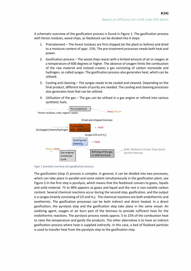
A schematic overview of the gasification process is found in Figure 1. The gasification process with forest residues, wood chips, as feedstock can be divided into 4 steps:
1. Pretratement – The forest residues are first chipped (at the plant or before) and dried to a moisture content of appr. 15%. The pre-treatment processes needs both heat and power.
2. Gasification process – The wood chips reacts with a limited amount of air or oxygen at a temperature of 600 degrees or higher. The absence of oxygen limits the combustion of the raw material and instead creates a gas consisting of carbon monoxide and hydrogen, so called syngas. The gasification process also generates heat, which can be utilized.
3. Cooling and cleaning – The syngas needs to be cooled and cleaned. Depending on the final product, different levels of purity are needed. The cooling and cleaning processes also generates heat that can be utilized.
4. Utilization of the gas – The gas can be utilized in a gas engine or refined into various synthetic fuels.
Figur 1 Scematic overview of a gasification process.
The gasification (step 2) process is complex. In general, it can be divided into two processes, which can take place in parallel and some extent simultaneously in the gasification plant, see Figure 2.In the first step is pyrolysis, which means that the feedstock convers to gases, liquids and solid material. 75 to 90% appears as gases and liquid and the rest is non-volatile carbon content. Several chemical reactions occur during the second step, gasification, and the output is a syngas (mainly consisting of CO and H2). The chemical reactions are both endothermic and exothermic. The gasification processes can be both indirect and direct heated. In a direct gasification, the pyrolysis step and the gasification step take place in the same vessel. An oxidizing agent, oxygen or air burn part of the biomass to provide sufficient heat for the endothermic reactions. The pyrolysis process needs approx. 5 to 15% of the combustion heat to raise the temperature and gasify the products. The other alternative is to have an indirect gasification process where heat is supplied indirectly. In this case, a bed of fluidized particles is used to transfer heat from the pyrolysis step to the gasification step.

9(34)
Report on efficiency for small scale CHP plants
Figur 2 The gasification process and its sub processes and chemical reactions.
There are several different types of gasification processes available. For different gasification techniques, the different process steps (pyrolysis and gasification) can take place in different sequences in the reactor. The fixed bed gasifier is the oldest and most used gasifier. Other types of gasifiers include fluidized bed gasifiers, bubble bed gasifiers and entrained flow gasifiers (Held et al. 2011). The different types are suitable for different flows of biomass. The gasification capacity for each type of technique is shown in Figure 3.
Figure 1. Gasification capacity for different types of gasifier techniques. Odt stands for oven dried tonnes. Source: (E4tech 2009)
For small scale gasification, the downdraft fixed-bed gasifier followed by cleaning and power generation in an engine is the most suitable process. The benefits with a downdraft fix bed gasifier are (Held 2011;Huang et al 2013, E4Tech 2009)):
• Most of the tar is combusted in a downdraft fixed-bed gasifier and only small amount goes into the gas, which allows a simpler gas cleaning.
• Minerals remain in the tar/ashes • The gasifier is tested, simple and have relatively low costs

10(34)
Report on efficiency for small scale CHP plants
• High char content (4-7% of the coal does not convert). If the char can be classified as biochar this could be sold on the market and contribute to additional CO2 emission reduction.
The drawbacks with a downdraft fixed bed gasifier are (Held 2011, Huang et al. 2013, E4Tech 2009)):
• The biomass needs to be dried (<20% moisture) • The syngas has a high temperature out of the gasifier • High char content (4-7% of the coal does not convert)- if not classified as biochar
Downdraft fixed-bed gasifiers are not suitable for large scale gasification, since upscaling creates an uneven gas distribution in the reactor (Ruiz et al. 2012, E4Tech 2009)). The limit is approx.. 10 odt biomass per day (E4Tech 2009).
Feedstock – biomass
Possible biomass material that can be used for gasification is residues from the forest such as branches and tops, chips, and bark. Also, liquids such as black liquor, pyrolysis oil and bio-oils can be used.
The composition of the feedstock has large impact on the final syngas. For biomass, the moisture content highly affects the composition of the syngas. The shape of the fuel and the ratio between area and volume has also large impact on the gasification process. A higher are creates a faster gasification of the fuel. Wood chips are gasified faster than wood pellets (Brunbäck 2011).
The moisture content of the feedstock also affects the energy need for drying in the gasification process. A high moisture content means a high energy demand and will lead to a lower gasification temperature (Ruiz et al. 2012).
Biomass has relatively high moisture content, between 30 to 60% moisture. A suitable moisture content of the fuel for a gasification process is between 10 to 15% (Basu 2009).
A small-scale gasification demonstration plant At Emåmejeriet, a small local dairy owned and operated by farmers, a small-scale gasifier of 40 kWe and 100 kWth has been demonstrated. Except from heat and electricity the gasifier also produces 500 litres of biochar during one week on full capacity, which for example can be sold as soil conditioner improvement. The biochar produced during demonstration has been used for research on the possibilities of biochar.
The full potential for the gasifier at the dairy is 280 MWh electricity generation per year and around 700 MWh heat production per year. At full load, the heat from the gasifier could cover up to 80% of the heating demand at the dairy and the electricity generation could cover approx. 20% of the electricity demand in the dairy process. The feedstock to the gasifier is wood chips.

11(34)
Report on efficiency for small scale CHP plants
3.2.1 Reasons for the investment The Emåmejeriet has a strong local profile and to work with local heat and power generation was in line with their profile.
The reasons for the dairy to change heating system into a combined heat and power biomass gasification was several:
• The existing heating system in need of reinvestment
• Uncertain energy prices (oil)
• No tax reduction for fossil fuels
• Increased environmental awareness of the customers – need of renewable energy system
• Strong interest for new techniques from the owner
The benefits with the gasification process compared to other renewable alternatives, such as a pellet boiler or a biogas boiler was that part of the electricity demand at the dairy could be covered by the gasifier. Other aspects were the goodwill the renewable combined heat and power would add to the local profile. The uncertainties were the risk that comes with new unproven technology.
3.2.2 The gasifier technology at the dairy and prerequisites The gasifier at the Emåmejeriet is a down draft fixed-bed gasifier. The size is 40 kWe and the maximum gasifier capacity is around 0.9 oven dried biomass per day, see Figure 4.
Figure 2. The gasifier at the Emåmejeriet in comparison with different gasifier processes. Sours: E4TEch
The gasifier process at Emåmejeriet includes a feedstock storage, a dryer, a feedstock handling system, the gasifier, heat water system (including an accumulator tank) as well as a back-up boiler. A schematic picture of the total CHP system is found in Figure 5.
The fuel is wood chips. A homogeneous and dried fuel is important for the gasification process. Therefore, at Emåmejeriet, a dryer has been built which dries the fuel with the aid of excess heat that radiates from the gas engine in the CHP system. The excess heat is enough to dry the feedstock from approx. 50% moisture content down to below 15% moisture.
After the dried the wood chips goes into the gas reactor in which the pyrolysis and gasification steps takes place. Out from the gasifier comes a syngas at approx. 900 °C – 1200°C which is cooled in two steps before burning in a gas motor. In the first heat exchanger the gas is cooled from approx. 550 °C to 200°C. After that, the gas goes through a dry filter in which soot, dust

12(34)
Report on efficiency for small scale CHP plants
particles and minerals are removed. The temperature after the filter is 150°C. In the second heat exchanger the gas is cooled down to 60°C. The gas is mixed with air in the gas engine. The temperature of the engine at combustion is around 90°C. Heat is recovered from the gasification process in three steps: the cooling of the gas before and after the filter and also from the motor (from the flue gases and from the refrigerant). The gas engine works best if cooling of the motor is below 80 degrees.
The gasification CHP system is built as a module including feedstock feeder, gas reactor, gas cleaning, gas engine and generator (everything within the dashed lines in Figure 5 is inside the chassis of the module).
Figure 3. Schematic picture of the gasifier CHP system.
Prerequisites needed:
• Dried wood chips – maximum 15% moisture • Homogenous sizes, not to small chips • New investment – relevant if changing heating system/need of new CHP capacity • Works best with uniform load and heat production • High electricity efficiency, between 20 to 30%.
3.2.3 Technical data The gasifier installed at the dairy in Hultsfred is a downdraft fixed-bed gasifier which operates on dried wood chips. The technical data such as pressure, temperature and power capacity are listed in Table 1.
Table 1. Technical data for the gasifier at the dairy (from the supplier). Power Capacity 40 kWe (45kW generator)
Heat Capacity 100 kWth
Feedstock Wood chips
Moisture content <15%
Particle size of the feedstock 8<P<50 mm
Operating pressure -100 pa (0,1atm)
Power demand 1,5 – 2 kW
Maximum operating hours 7 800 h

13(34)
Report on efficiency for small scale CHP plants
Feedstock demand 4,5m3/ day at full capacity (38kg/h)
Feedstock feed “Matarskruv”
Size 4.8 x 1.3 x 2.5
Weight 4.5 tonne
Power consumption 1.5 – 2kW
Compressed air 6-8 bar, consumption 1-2 Nl/s
3.2.4 Modification of existing system Emåmejeriet was founded in 2007. The heating system, which is used to supply the diary process, the washing and the office with heat consisted of a 1 MW oil burner from the 1970s. The heat system before the gasifier is shown in Figure 6.
Figure 4. Schematics of the dairy before the installation of the gasifier CHP system.
In 2014/2015 and in prior to the installation of the gasifier, the heating system needed to be adjusted to fit the new system. Pipes and valves in the heating system were replaced and additional pipes were added. The new system included a biomass storage, a drier, a gasifier with a gas engine. The system was first installed without the accumulator tank, but the fluctuations in the system required an accumulator tank to stabilize the heat demand. Figure 7 illustrates the dairy after modification and installation of new heating system.
Figure 5. Schematics of the dairy after installation of the gasifier CHP system. The dashed lines indicate the new connections and equipment.

14(34)
Report on efficiency for small scale CHP plants
4 Report on Performance The performance report contains a summary of performance indicators which has been measured during the demonstration of the gasifier at Emåmejeriet.
Before starting the procurement of a gasifier, the dairy performed a series of measurements, calculations, and simulations in order to properly design the CHP-unit and coherent systems such as accumulator tanks, heat exchangers and back-up boiler. To find out which boiler size needed, the heat demand during one day at the dairy was evaluated. The measurement data showed a large fluctuation of the heat demand during one day of operation, Figure 8. The heat demand varies between 20 and 500 kW heat during the day.
Figure 6. Heat demand during one day at the dairy.
Three issues were identified during the measurements:
• The large fluctuations in the dairy process heat demand place great demands on the facility’s ability to quickly ramp up and down.
• The dairy process requires a relatively high supply temperature for small scale CHP plants
• The dairy process does not currently run at night, which makes it difficult to get hours of operation at night, which affects the profitability of the CHP plant.
Measurements, calculations, and simulations showed that the dairy could manage to supply most of its heat demand from a small-scale CHP-unit based on thermal gasification. However, a peak load boiler was needed to meet the heat demand of the dairy at the heat peaks. To minimize the fluctuations and to increase the running time for the gasifier, one or two accumulator tanks was needed in the system. A small market analyses also showed that there was at least one supplier that can deliver a gasifier with a relatively high supply temperature (90°C).
Prior to the installation, an evaluation of availability of dry coarse fractioned wood chips within a 100 km radius were performed. The results showed that dry wood chips were not available within reasonable transportation and at reasonable prices. The dairy also did not find dryers

15(34)
Report on efficiency for small scale CHP plants
at reasonable prices in the market that suited the purpose of the gasifier system. The solution for the dryer became a costume build dryer.
The CHP system (dryer + gasifier installed in a dairy) is unique because of the combination with the custom build dryer and in connection to an industrial process with high temperature needs. The demonstrated CHP (gasifier) system is first of its kind. The CHP (gasifier) consists of: Storage for wood chips, accumulator, dryer, gasifier, ash-handling system. The CHP (gasifier) system (Figure 5) is specifically created for the conditions at the dairy. The dryer has been specifically designed, build, re-designed and rebuild during the project period.
The gasifier unit is modified to fit the special conditions for the implementation in a dairy with high temperature needs. The gasifier at the dairy produces much higher feed water temperature than a standard gasifer. The higher feed water temperature has required more modifications than can be considered normal adjustments that is done in “normal” installations of standard type gasifiers. The modifications needed at AB Hultsfred has been new design of the equipment for the cooling system, such as pumps, pipes, and heat exchangers, due to the requirements of a high feedwater temperature (90 degrees.). These equipment’s are larger than the standards equipment’s due to a lower temperature difference. These make the system more sensitive. Unfortunately, this has also led to problems with running the gasifier and has required a lot of work and new solutions to be able to make the system run. The other explanation is the dryer – which has been modified, redesigned and rebuild due to different types of problems during the project period. The dryer is not commercialised or available as serial product. It has no CE- label. The dryer system, which has been modified several times along the way has also required a lot of work, problem solving, development and new solutions to be able to run properly.
Experiences from rebuilding and installation To facilitate the installation of the CHP unit, the existing steam boiler was removed and replaced by a hot water oil fired boiler (with the possibility to use also bio-oil) that will be used for backup- and peak production. It was also needed to rebuild the boiler room to give room for the gasifier, see Figure 9. The preparation started in January 2015 and the gasifier was installed in October 2015.
Figure 7. Left picture shows part of the old boiler room before the installation of the gasifier (January 2015), the picture in the middle is the same room in August 2015. The right picture shows the same room but now with the gasifier installed (October 2015).
The heating system in the dairy was also converted from steam to hot water. To minimize the fluctuations, by even out the heat demand and to increase the running time of the gasifier, it was necessary to reschedule some of the production. A design of a PLC based control system for fuel handling and hot water circuit was made to communicate with the gasifier control system.

16(34)
Report on efficiency for small scale CHP plants
In parallel with the rebuilding of the boiling room and adjusting of the heating system, a platform and space for a dryer and an accumulator tank were build outside the boiler room, see Figure 10. The dryer was installed in September 2016, and the accumulator tank was received in April 2016.
Figure 8. Left picture shows the space outside the dairy in January 2015, the picture in the middle is from August 2015 and the right picture is from April 2016.
Before a storage of the feedstock was built, the wood chips was supplied directly to the dryer. However, during spring 2016 a storage was built. The storage was later equipped with roof and walls to protect from water, see Figure 11 .
Figure 9. The feedstock storage. Left picture is from 2015. During spring 2016 a first version of the storage was ready. The last picture shows the final version of the storage, with both roof and walls.
Prior to the start the local power grid owner were informed to verify that it is allowed to connect the CHP unit to the grid. This required a check on the safety solenoids which were approved. Emåmjeriet had all necessary equipment such as electric meters etc. already installed.
4.1.1 Summary of lessons learned from rebuilding and procurement
• Installing a gasifier at an industry with fluctuating temperature needs an accumulator tank to stabilise and even the heat demand.
• To find chips at right quality and pricing in the area around the dairy was proven hard.
• To find supplier with gasifiers that can guarantee a temperature of 90 °C was in 2014/2015 proven hard. Only one supplier was able to modify their product to be able to meet the requirements of the dairy. It should be noted that the development has continued since 2014 and there are today suppliers that can offer higher outlet temperatures and there are also new suppliers with gasifiers running on the market.

17(34)
Report on efficiency for small scale CHP plants
• The procurement also showed that it was hard to find a standard dryer that fit the requirements of the dairy and the gasifier – which resulted in that the dairy needed to order a custom-made dryer.
Experience from start of operation The gasifier has not been running continuously and on full capacity since the project started. The system has had problems due to both the drier, which has been rebuild and redesigned, and the gasifier, which was been modified to be able to produce feed water at around 90 °C. The main problems with the gasifier have been that the gasifier come up in too high temperatures with the risk of overheating. Most of the time, the gasifier has been running on 50% capacity due to safety reasons. In the end of 2018, the gasifier started to run more continuously, and the capacity was increased.
From the start of the project the average power capacity has been 19,4 kW, which is 50% of full capacity. The average availability in terms of running hours is from the start of the project 40%, and in terms of electricity generation the availability is less than 20%.
Since the start of operation in 2015, several rebuilding’s and modification of the gasifier CHP system has been made to improve the running time of the system. These are:
• Between January 2016 and June 2016, the feeding system of the gasifier was first redesigned and later rebuilt due to problems with the feeding system of the dryer. That lead to a reduction of running hours for the gasifier.
• In April 2016, an accumulator tank was installed to minimize the fluctuations in heat demand.
• In May 2016 after a period of good performance, problems to get the gasifier into correct working temperature arose. The gasifier was disassembled, and the problem was identified to be impurities (gravel) in the fuel which had piled up on the gasifier grate.
• Between June and December 2016, the gasifier only run on 50% capacity. The reason was that sintering issues and control adjustments led to operation of gasifier being unpredictable. The dairy needed to install an emergency cooler to avoid overheating of the gasifier at high return temperatures from the dairy process.
• During spring 2017 reprogramming of the heating system was needed. It was discovered that the heat pipes from the gasifier were too narrow and limited the heat flow to the gasifier which resulted in an insufficient flow to the dairy process. It was solved by by-passing the heating system. During this time, the ash-handling were improved replacing the ash screw and improved mechanics. It was also discovered during this time that the engine needed improved lubrication. The reason is that wood gas is dry compared to, for example diesel, so oil is needed into the valves of the engine.
• From August until November 2017, the gasifier is not running. The reason is that the wood chip dryer is under redesign. The reason is that it did not work satisfactory, the force of the piston was too large. The scraper needed to be rebuilt and the lid needed to be improved.
• The gasifier was up running in November 2017, but after two weeks the dryer broke again. New problems with the steering system between the dryer and the gasifier did arose during this time.

18(34)
Report on efficiency for small scale CHP plants
• The dryer was repaired in February 2018, see Figure 12.
Figure 10. New dryer.
• During spring 2018 wet fuel has led to technical problems in the gasifier. It was also very hard to find biofuels with the right quality during that time. The market for wood chips was during 2018 influenced by a very wet autumn 2017 and a very cold winter early 2018. Due to the problems, the CHP unit (gasifier) was only running partly and not on full capacity during the spring.
• The fuel market situation in 2018 forces the dairy to start buying dried wood chips for the gasifier.
• In May 2018 there are still mechanical problems with gasifier and a manufacturing fault was discovered: The air throust nozzles did not manage the high temperature. Another problem that was corrected during that time was the ash screws, which were replaced to prevent ash in the gasifier.
• In September/October 2018 a large girder/beam/wall stud was mixed with the chips. The large girder/beam/wall stud caused a large pressure on the wall in the dryer and broke parts in of the wall. To prevent the problem from being created again, counters have been built that opens if the pressure gets too high. An automatic switch as a back-up system to the fuel sensors is also under installation. During this time there were again problems with the gasifier. This time the personal missed to change an ignition plug during service – which caused problems in the gasifier. The problem was solved with a new ignition plug.
• Later in October 2018, gasifier stopped again. This time due to contaminations of an ash filter. The problem was solved by replacing one of two filters and change the sealing. However, the problems with the gasifier continued. The reason this time was too fine fractions of wood chips. The gasifier is sensitive for the size of wood chips and the personal therefore tested to install a strainer, which remove the finest fractions and dust, The gasifier run better after installing the strainer. It is possible to install a larger strainer if needed.
• During autumn 2018 a new automatized ash-handling system which consist of a larger barrel was installed. The new barrel is placed outside to minimize the ash-dust. The old barrel is used as a back-up system if the automatized system fails. The atomized system is controlled by the level of fuel in the fuel handling system. The new system also includes an automatic watering of the ash – to increase the moisture content and make the ash easier to handle, see Figure 13.

19(34)
Report on efficiency for small scale CHP plants
Figure 11. Part of the new ash-handling system, with automatic watering.
• Availability of 80% was reached during November 2019
• Availability of 80% was reached during November 2018
• Since March 2019, the gasifier has only generated 1MWh of electricity, corresponding to a running time of approx. 25 hours. The problem has been air leakage, which first was hard to find. The problem was later found and solved but the air leakage problems continued. The air leakage creates a too high combustion temperature, which damage valves and other parts in the gasifier. The cost for continuously reparation is higher than the income.
Data collection methods and necessary calculation
The documentation of the gasification system was in the beginning made manually once a day at the dairy. Since 2018, the data from the gasifier has been collected mainly trough automatically logged numbers. Power capacity, produced electric energy, operating hours and utilization is automatically logged for the gasifier.
Source of errors:
Since the gasifier has not been up running continuously, data collections are missing from periods with very low hours of operations. Most of the data were in the beginning collected manually, once a day. The time for the collection was not the same every day, which can affect the results divided per day. But the errors are less on an aggregated level.
Output indicators Operating hours
The gasifier system is connected to the dairy process which runs around 10 hours per day, six days per week. By installing an accumulator tankFH, the hours of heat demand increase and the running time of the gasifier. The estimated maximum running hours per year for the

20(34)
Report on efficiency for small scale CHP plants
gasifier was in the design phase approx. 6000 hours per year, corresponding to 19 hours running time each day in operation.
The total operating hours for the gasifier since the installation in 2015 is 5506.6h. The total utilization is 13% of expected operation hours since the start of the project. The operating hours for the gasifier divided per year are:
• 2016: 861 hours
• 2017: 2069 hours
• 2018: 1787 hours
• 2019: 405 hours
The actual operating hours for the gasifier are in Figure 14 compared with the expected operating hours of the gasifier. The availability of the gasifier process has been between 7 and 35 % on a yearly basis, which also is indicated in.
Figure 12. Actual versus estimated operating hours for the gasifier.

21(34)
Report on efficiency for small scale CHP plants
Figure 13. The availability of the gasifier (real operating hours divided by expected operating hours) has varied between 7 and 35 % during the project time.
The utilization of the gasifier has been higher specific weeks, but the gasifier has been running very unpredictable and not continuously as expected. As can be seen in Figure 16 the gasifier has been up running more times in 2018 compared to 2017, but with a lower utilisation. The period of reparation was longest in 2019, when the gasifier only was up running during the first two months. The period of total stop was also long in 2017, from week 19 to 48 and described in previous section.
Figure 14. Utilization of the gasifier each week during 2017, 2018 and 2019.
Operating pressure
The gasifier operates at atmospheric pressure. Compressed air is supplied to the gasification reaction, with an inlet pressure of at 6-8 bar.
Power capacity and electricty generation
22(34)
Report on efficiency for small scale CHP plants
The power capacity is 40 kW with a generator capacity of 45 kW. The electrical output can be adjusted between 30% and 100%. Due to the problems during the project period, the gasifier has only been up running at part load (most of the time at 40% of electrical output).
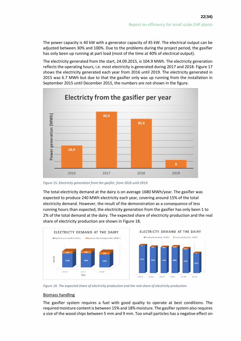
The electricity generated from the start, 24.09.2015, is 104.9 MWh. The electricity generation reflects the operating hours, i.e. most electricity is generated during 2017 and 2018. Figure 17 shows the electricity generated each year from 2016 until 2019. The electricity generated in 2015 was 6.7 MWh but due to that the gasifier only was up running from the installation in September 2015 until December 2015, the numbers are not shown in the figure.
Figure 15. Electricity generation from the gasfier, from 2016 until 2019.
The total electricity demand at the dairy is on average 1680 MWh/year. The gasifier was expected to produce 240 MWh electricity each year, covering around 15% of the total electricity demand. However, the result of the demonstration as a consequence of less running hours than expected, the electricity generation from the gasifier has only been 1 to 2% of the total demand at the dairy. The expected share of electricity production and the real share of electricity production are shown in Figure 18.
Figure 16. The expected share of electricity production and the real share of electricity production.
Biomass handling
The gasifier system requires a fuel with good quality to operate at best conditions. The required moisture content is between 15% and 18% moisture. The gasifier system also requires a size of the wood chips between 5 mm and 9 mm. Too small particles has a negative effect on

23(34)
Report on efficiency for small scale CHP plants
the combustion process and too large particles can get stuck in the feedstock handling system or in the gasification camber. It is also very important that the chips do not contain contaminants, such as e.g. screws or other metal objects. These objects can potentially create great damage in the system.
There are two options for the biomass handling for a gasification system:
1. Buying dried wood chips ready to supply the gasifier
2. Buying wet wood chips to store and to dry at the plant before feeding into the gasifier.
Alternative one is the best option if a gasifier is placed where there is limited space. The drawback is that the transport of wood chips will be more frequent and the prise for dried wood chips is higher.
The first option at Emå dairy was alternative one. However, the transportation cost and the price of dried wood chips became too high. Therefore, it was decided to build a dryer and a storage for the wood chips to be able to quickly fill the dryer and to reduce the transportation of wood chips to the dairy.
In the manual for the gasifier from the supplier it is estimated that the demand of wood chips to the gasifier is 4.5m3/day at full capacity. During the project period the gasifier has been running 5 507hours and the demand of wood chips has been 1120 m31. The results from running the gasifier gives a demand of 4.8 m3/day, which corresponds well to the estimated demand.
Biomass dryer
Since it was decided early in the project that a dryer would be build, an analysis was also initiated early in the project to evaluate the dryer’s energy balance and the moisture content of the wood chips after the dryer. The analysis was made in cooperation with the Linneaus University and performed as a bachelor thesis.
The dryer has been designed for gasification plants and is a combined dryer and fuel storage which consist of a container with a screw that mixes the fuel. The fuel is supplied to the top of the container and dried using hot air formed in the chassis of the gasification plant. The fuel is mixed and fed into the gasifier using a screw.
In the roof of the metal shell there is a fan that suck up the ambient air inside the metal shell, which has been heated by excess heat from the gasification process. The ambient air is then supplied to the dryer to dry the feedstock. During the time of the bachelor thesis the heated air was supplied on the back of the dryer, above the outlet of dried wood chips. Later, after rebuilding the dryer the inlet of the air was changed to the front of the dryer, opposite the outlet. The changes did not affect the drying of the fuel. During the rebuilding the container was also equipped with new screw in more robust material, to stand the weight and force that the compact wood chips creates.
1 The wood chips consumption is based on the quantity purchased to the dairy. The result is an overestimation since some of the chips remain in the storage. The actual amount fed into the gasifier is slightly less.

24(34)
Report on efficiency for small scale CHP plants
Figure 17. Left picture shows the metal shell in which a fan is installed at the roof to suck up the heated air. Right picture shows the pipeline in which the air is transported from the gasifier to the dryer. The right picture shows the final version of the dryer. In the first version of the dryer, which the result of the bachelor thesis is based on, the air was supplied on the other side of the gasifier, where the dried wood chips leave the dryer.
The results from the bachelor thesis (Cedergren 2016) showed that the excess heat in the gasifier was enough to dry the wood chips, i.e. no additional fuel is needed. The measurements of the moisture content of the fuel showed that the dryer succeed to dry the fuel with an initial moisture content of 30-40% down to a moisture content of 5-10%. The results also showed that the input to the dryer was excess heat from the gasifier with an energy content of 23.6 kW and the required energy to vaporize the water content in the fuel was 14.5 kW. In addition, the results show that the air out from the drying process gets a relative humidity of 76% which means that the moisture does not saturate the air in the dryer. This means that the dryer has more potential for drying the fuel. During the measurements different temperatures was obtained in the dryer. One explanation could be that hot air with high flow spreds between the fuel bed and does not contribute to the drying process. This causes a higher temperature and lower relative humidity of the outgoing air. Cedergren 2016 suggest that measures to avoid the problem would be to change how the air is supplied to the dryer or to have a softer fuel bed so that the air is better distributed.
The dryer was rebuilt in 2017 and one improvement was to change the inlet of the heated air to the opposite side from the outlet of the dried chips.
Decreased oil demand at the dairy
Due to the modifications of the existing heating system and upgrading of back-up system (i.e. peak load boiler) to the gasifier the oil demand has decreased at the dairy despite the low availability of the gasifier. Revamp of the heating system and installation of the peak-up boiler was initiated in January 2015. Due to the higher efficiency in the new oil boiler in combination with a lower demand of dairy products, the oil demand was decreased by on average 74% by replacing the existing boiler. With the gasifier also running from time to time, the average oil demand is on average 67% of the initial demand before the project started. The average decrease of CO2 emission per year is 133 tonne/year. However, the decrease is not only connected to the change of the oil boiler, a decrease of dairy products and production at the dairy happened during the same time. A likely approximation is that half of the savings are due to the change of oil boiler.

25(34)
Report on efficiency for small scale CHP plants
Figure 18. Oil deliveries to the dairy from 2014 until 2019. Due to the installation of the gasifier and revamp of the heating system, including a new back up boiler, the oil demand (i.e. oil deliveries) have decreased with an average 33 %.
Availability, maintenance, and control system The gasifier has not been running continuously during these years. The availability was, however, high during autumn 2018. But since spring 2019, the gasifier has only run for a few hours. The reasons are several and described above. However, in general the learnings of parameters effecting the operation hours are:
• Uneven sizes of the feedstock – it is important that the sizes are not too big and not too small. Larger pieces can cause stops in the feeder to the gasifier. Too small particles can cause uneven reactions in the gasifier.
• Good quality fuel gives a clean gas and reliable process – It is very important to understand and check the quality of the fuel
• Moisture content above 15% - The gasifier needs a dry fuel, below 15% moisture. It is also important that the fuel does not get too dried. Both a high moisture content and a too low moisture content cause uneven reactions in the gasifier.
• Uneven monitoring of the process – A process that uses biomass needs continuously monitoring and maintenance. It needs a daily check and the ash-barrel needs to be emptied.
• Do not miss the regular services – The system has several check points (after a number of hours) for smaller or larger service of the system. It is important that all these services are followed.
Unforeseen/unexpected stops
There have been several unforeseen and unexpected stops during the project time of which the most relevant are listed in previous section.
Security in running the plant for longer periods
• The gasifier has not been running continuously during the project period. New problems have arisen when others are fixed. The problems have been of different characteristics and both due to bad quality of the fuel, problems with the dryer technology, problems with the gasifier chamber, problems arose due to lack of maintenance.
• To be able to have the gasifier up running continuously the experience from this project show:

26(34)
Report on efficiency for small scale CHP plants
o The gasifier runs best on continuously mode i.e minimize the number of starts and stops.
o Don’t think that a biomass system can be compared to an oil-system. You need a person dedicated to the system available, that person must know how to handle biomass.
o Don’t miss the daily checks!
o You need to understand the quaily of the feedstock – bad quality gives a bad gas which can create problems in the gasifier.
4.5.1 Maintenance The gasifier CHP system is fully automatised. A daily monitoring is needed. The daily maintenance includes ash emptying, checking engine oil and a check of the system. The monitoring scheme includes:
• Daily: Check of ash barrel, return- and feed water temperature, gasifier throat temperature, gasifier pressure, gas filter differential pressure, checking pressurized air.
• Monthly: Change of engine oil, Cleaning gasifier grate, cleaning the gas filter
• Every six month: Changing gasifier throat cone, changing gasifier centre tube.
• Yearly: Main service of the engine, Changing gas filter fabrics
The experience from the gasifier in Hultsfred is that the daily check has taken 30 minutes, the monthly check takes about the time that is scheduled.
4.5.2 Control systems There is an operation journal for monitoring and the data system continuously logging the running of the gasifier. The gasifier system has several alarming points, which most of them are possible to execute via the mobile.
Lessons learned from operation • Few suppliers for high flow temperature available in 2014 – most gasifiers are most
suitable for output temperatures up to 80°C.
• No environmental permissions are needed for a gasifier < 500kW in a Swedish context.
• Difficult to buy dried steam wood chips – Due to transportation and price. Both easier and cheaper to have a dryer connected to the gasifier.
• A gasifier runs best on continuous effect, changing the effect setting is not even possible on most systems, and shall be done very carefully if needed.
• A heating system that runs on biomass needs more monitoring compared to an oil-fired burner.
• Good care needs to be taken to avoid bad fuel quality into the gasifier.
• The fuel quality is very important, both for the fuel handling and for the gasifier process. A minimum of fine material under 1 mm is very important.

27(34)
Report on efficiency for small scale CHP plants
• Biomass systems needs daily checks of the system. If you neglect maintenance and the daily inspection, it will lead to the system deteriorating.
• The gasification system is very susceptible to air leakage. If air enters the process, the gasification camber becomes very hot and there is a high risk for fire inside. If this happens, parts will be damaged and must be replaced. Due to the negative pressure inside the gasification camber it is very important that all valves are sealed. In Hultsfred, it was the valve which releases the gas to the flare if the gas engine stops working that was not sealed enough. The staff at the dairy suspects that air has leaked in for a long time but that it was not discovered until the damage was great. The workers at the Emådairy have concluded that air leaks have been the root to most of the problems with the gasifier in Hultsfred. Some air leaks have occurred due to valves and sealings has been too hot, and the leaks has led to increasing temperatures, causing more leaks in a negative chain of events.
• The gasifier needs to run under as stable conditions as possible. The accumulator tank should have been installed directly. This would also have enabled the dairy to design the heating control system much more robust and reliable.
• The complexity of the overall control system was underestimated. So instead of using in-house programmers from the dairy, experts would have been hired to design the control system.
• The ash extraction system was under-dimensioned from the start and led to that a lot of time for the maintenance personnel at the dairy needed to be put on resolving problems related to the gasifier ash and char system.

28(34)
Report on efficiency for small scale CHP plants
5 Report on Efficiency A complete report on the experience of the efficiency of the gasifier during continuous operation can not be given because the gasifier has not been running continuously during the project period. Therefore, the reporting on the efficiency is based on a performance test and includes the efficiency of the gasifier. The system boundaries for the efficiency calculations har shown in Figure 21
Data and experience during the whole project period are presented in Section 3.
Figure 19. Schematic picture of the energy flows in and out from the district heating plant.
Calculation methods and delimitations To calculate the efficiency of the gasifier the following parameters has been considered:
• Alfa-value for the gasifier
• Power-efficiency for the gasifier
• Decreased need of electricity • Total energy efficiency for the gasifier • Increase of biomass use at the dairy
Total energy efficiency for the gasifier The total efficiency for the studied system is the relationship between useful energy (heat and power out from the system) and energy supplied to the system. The total efficiency defines the energy losses in the system. In the studies system the energy loss is related to the need of energy for the pump work and the energy loss in the generator (Eq.2).
𝑈𝑈𝑈𝑈𝑈𝑈𝑈𝑈𝑈𝑈𝑈𝑈 𝑈𝑈𝑒𝑒𝑈𝑈𝑒𝑒𝑒𝑒𝑒𝑒 𝑄𝑄 𝑄𝑄𝑛𝑛 = = 𝑜𝑜𝑜𝑜𝑜𝑜 = ℎ𝑒𝑒𝑒𝑒𝑜𝑜,𝑜𝑜𝑜𝑜+𝑄𝑄𝑝𝑝𝑜𝑜𝑝𝑝𝑒𝑒𝑝𝑝𝑡𝑡𝑡𝑡𝑡𝑡 (Eq.1)
𝑆𝑆𝑈𝑈𝑆𝑆𝑆𝑆𝑈𝑈𝑆𝑆𝑈𝑈𝑆𝑆 𝑈𝑈𝑒𝑒𝑈𝑈𝑒𝑒𝑒𝑒𝑒𝑒 𝑄𝑄𝑖𝑖𝑖𝑖 𝑄𝑄𝑏𝑏𝑖𝑖𝑜𝑜𝑏𝑏𝑒𝑒𝑏𝑏𝑏𝑏 𝑖𝑖𝑖𝑖
Alfa value
The alfa value is the relationship between electricity and heat production in a cogeneration plant, calculated as electricity generation divided by heat generation (Eq.2).
𝑃𝑃𝑈𝑈𝑈𝑈𝑈𝑈𝑃𝑃𝑡𝑡𝑒𝑒𝑆𝑆𝑃𝑃𝑆𝑆𝑡𝑡𝑒𝑒𝛼𝛼 = (Eq.2) 𝑃𝑃ℎ𝑈𝑈𝑒𝑒𝑡𝑡,𝑈𝑈𝑡𝑡
Electricity efficiency for the studied system

29(34)
Report on efficiency for small scale CHP plants
The electricity efficiency is defined as electricity generated divided by the energy supplied to the system.
𝑃𝑃𝑡𝑡𝑝𝑝𝑈𝑈𝑒𝑒 𝑈𝑈𝑒𝑒𝑈𝑈𝑒𝑒𝑒𝑒𝑒𝑒 𝑄𝑄𝑛𝑛𝑆𝑆𝑡𝑡𝑝𝑝𝑈𝑈𝑒𝑒 = = 𝑝𝑝𝑜𝑜𝑝𝑝𝑒𝑒𝑝𝑝 (Eq.3) 𝑆𝑆𝑈𝑈𝑆𝑆𝑆𝑆𝑈𝑈𝑆𝑆𝑈𝑈𝑆𝑆 𝑈𝑈𝑒𝑒𝑈𝑈𝑒𝑒𝑒𝑒𝑒𝑒 𝑄𝑄𝐵𝐵𝑖𝑖𝑜𝑜𝑏𝑏𝑒𝑒𝑏𝑏𝑏𝑏,𝑖𝑖𝑖𝑖
Supplied biomass To determine the efficiency of the plant information regarding the supplied energy is needed. Since the efficiency calculations are based on the performance test that varied for a limited time during only one day, theoretical data is used to calculate the heating value of the supplied biomass. The data is based on information from the supplier of the gasifier (Finn 2016) and measures moisture content from the day of testing. The maximum supplied energy was calculated to 172.5 kW, using the data shown in Table 2. Data for calculations of the supplied energy to the gasifier at full load. Table 2. Data for calculations of the supplied energy to the gasifier at full load. Source: Performance report (Finn, 2016)
Parameters Unit Value Source Maximum fuel supply M3s/day 4.5 Supplier Moisture content % 14.1 Measured Efficient calorific value MWh/m3s 0.92 Calculated Maximum supplied energy kW 172.5 Calculated
Delimitations Since the efficiency varies with the load, the composition and moisture content of the fuel reported, the reported efficiency is only measured and theoretically calculated for the case of 100% load. The calculations do not include recovered heat to the fuel dryer, which means that the actual efficiency should be slightly higher. To get a more real efficiency for the plant, information on the amount of biomass, moisture content of the biomass as well as the electricity and heat generation would be measured and calculated for a longer time-period.

30(34)
Report on efficiency for small scale CHP plants
Efficiency of the gasifier Total efficiency, alpha value and the electricity efficiency in the gasification system
The performance test showed a total efficiency of 77.7%. The efficiency calculations do not include that the excess heat is used to dry the wood chips. To also include this would increase the efficiency of the gasifier. The carbon content is rather high in the ashes. Depending on the use of the ashes, that could also influence the efficiency of the gasifier. The alpha value of the system is 0.43 and the electricity efficiency is 24.2%.
The efficiency of the gasifier is summarised by calculating the total efficiency, the alpha value and the electricity efficiency of the gasifier. The result is summarised in Table 3. The total efficiency, alpha value, and electricity efficiency of the gasifier.
Table 3. The total efficiency, alpha value, and electricity efficiency of the gasifier. Source: Performance test (Finn, 2016)
Parameters Unit Load 100% 75% 50% 25%
Total electricity generation kW 41.8 31.3 21.0 10.7 Electricity to dairy kW 36.8 28.8 18.5 8.8 Heat generation to dairy kW 97.3 88.2 66.7 52.9 Alpha value (Ptot,el/Pheat to dairy) α 0.43 0.35 0.31 0.2 Gasifier efficienct (ηgasifier) % 77.7 - - - Power efficiency (ηel) % 24.4
Side effects of the gasifier installation - Biochar Due to the high temperature in the gasifier (ca. 1000°C) the ashes from the gasifier has a high fixed carbon content and a low quantity of volatile matter such as hydrogen and nitrogen and could be classified as biochar.
The biochar is a valuable product with a growing market. The biochar is used in agriculture to enhance soil fertility, in water retention capacity, and to improve plant growth 2.
The growing interest for the biochar is the potential for carbon sequestration when producing and using biochar as soil additive that needs no chemical adjustments. When the biochar from the gasifier is buried in the ground as a soil enhancer, the system become “carbon negative”.
2 http://www.biogreen-energy.com/biochar-carbon-negative/?gclid=CjwKCAjw74b7BRA_EiwAF8yHFAoTL-IMb_sTSTGM6GUHwor9dhN0dXwbKugdJykFFQzM4hwU4sFh1hoC2fAQAvD_BwE

31(34)
Report on efficiency for small scale CHP plants
6 Report on Security Environmental parameters
The gasification process creates flue gases and ashes, which could have an impact on the environment. However, the size of the gasifier in Hultsfred is below the limit for requirements of substances in the flue gases and ashes. The cleaning of the flue gases includes a clay separation in the flue gases, which takes place in a cyclone separator.
Due to the small size of the gasifier, there are no regulations or limitation of the content of substances in the flue gases. However, the flue gases and the ashes were analysed during the performance test (Finn 2016). The amount of substances, oxygen, carbon dioxide, carbon monoxide and nitrogen oxide are listed in Table 4. The flue gas composition will vary with the moisture content and the source of wood shipping. The number in the table therefore reflect the flue gas content with the wood chips quality during the test. The flue gas composition will also vary with the quality of the gasification process, which can vary over time.
Table 4. Flue gas content from an analyse made during the performance test. Source: Performance test (Finn, 2016)
Parameters Unit Load 100% 75% 50% 25%
Flue gas temperature °C 41.8 31.3 21.0 10.7 O2 content % dry gas 36.8 28.8 18.5 8.8 CO2 content % dry gas 97.3 88.2 66.7 52.9 CO content Ppm dry gas 0.43 0.35 0.31 0.2
CO emissions Mg/MJsupplied 77.7 - - - NOx content Ppm dry gas 24.4 Nox emissions (count. As NO2) Mg/MJsupplied MJ/kg dry matter MJ/kg dry matter
Moisture content of the fuel % Unburnt in the ashes %
The CO content was smooth and even during the different loads. The content of CO in the flue gases varied between 135 and 210 ppm. However, during the loads of 75% and 50%, some CO peaks were noted, which indicated a CO content of ca. 1000 ppm. The reason could depend on intermittent operation of the fuel handling system or intermittent operation of the ash handling system. The measurement data is found in Finn 2016.
The ashes contain a high amount of unburnt in the ashes, 65.6%. A more through analyses that was made in 2016, resulted in that the ashes from the gasifier, due to the high amount of coal and low quantity of volatiles it can be classified as char coal. The amount of charcoal produced from the gasifier in Hultsfred is about 3-4% of the fuel input. Each kilo charcoal produced and used as soil enhancement could save up to 2.7 CO2 emissions.
6.1.1 Noise The noise level at the operation panel and 1 meter from the gasifier has been measured and analysed during the performance test. The result showed a noise level of 77 – 78 dBA one meter from the gasifier and 81 dBA at the operation panel.

32(34)
Report on efficiency for small scale CHP plants
Connection to the power grid No interventions were needed in the dairy.
Before the installation, the dairy was in contact with the local power grid owner to verify that they could connect the CHP unit to the grid. This required a check on the safety solenoids, which were approved. The dairy had all necessary equipment such as electric meters etc. already installed.
Safety measures The gasifier has a built-in alarm system, which sends alarms to a mobile phone. Many measures can be handling via the phone.
A CO meter must be used when the staff are working in the same room as the gasifier. This because CO is a very toxic gas which is both odourless and invisible.
Risks The risks are higher with a gasifier compared to a heating system only based on oil. The main reason for the increased risk is both due to that the gasifier has not run as expected and that biomass needs much more control and knowledge than handling oil. No other risk is shown during this project.
Security of supply The gasifier at the dairy only produces, at full load, around 15% of the electricity demand but 80% of the heat demand.
Changing an oil burner to a gasifier will increase the use of local fuel, that will increase the security of the fuel. However, the pilot plant has not been running as expected and therefore the installation at that plant has decreased the security of supply since the heat generation has been very unsure.

33(34)
Report on efficiency for small scale CHP plants
7 Discussion This report reflects the experience and the lesson learned from installation of a gasifier at a small dairy. The main reason for the investment was a replacement of an existing old oil boiler, and the driving force was both economic and environmental.
The results from the experience and lessons learned shows that the availability of a gasifier installed at a company, which core business is other than energy production can be challenging. A biomass gasifier needs more maintenance compared to an oil fired boiler, but also a higher knowledge concerning the importance of the quality of the fuel. It is of very high importance that the fuel has a high quality, with the right moisture content and within the right size.
The best conditions for a gasifier are with constant heat demand at a constant temperature. If fluctuations appear, it can be solved, as was made in Hultsfred, with an energy storage, an accumulator tank.
During this project, that has been several problems that has been solved along the way. During the periods when the gasifier has been up running more continuously, it has shown a high electricity generation. It would therefore be interesting to install a gasifier at a company where the personnel are used to handle biomass and a company that has energy as core business or main focus. From the lessons learned due to the demonstration in Hultsfred, the next owner will have a much better chance to get the gasifier running. However, one critical factor is the maintenance of the gasifier. From the lessons learned in this project there is a need for a technician that has large knowledge of the system and biomass handling. To be able to guarantee a high availability it is necessary to have a storage of spare parts. From the experience in this project and from listen to suppliers in mid-europe, there is a need of a number of gasifiers, around 10, to be able to have a dedicated service person and to be able to hold a storage.

34(34)
Report on efficiency for small scale CHP plants
8 References Basu P. Gasification theory and modeling of gasifiers. Biomass Gasification Design Handbook. Boston: Academic Press, sid. 117–165, maj, 2010. Brunbäck J, 2011, Indirekt förgasning av biomassa - Produktion av bränngas i syfte att ersätta el och olja på ett kartongbruk, Examensarbete Energi- och miljöteknik, Karlstad universitet (In Swedish) Cedergren L, 2016, Analysis of drying process gasifier Emåmejeriet, Linnaeus University, Bachelor thesis. Available: http://www.diva-portal.se/smash/get/diva2:974454/FULLTEXT01.pdf Colmsjö. L, 2008, System- och marknadsstudie för biometan (SNG) från biobränslen, Svenskt gastekniskt center, [PDF] Available: http://www.sgc.se/ckfinder/userfiles/files/SGC185.pdf (In Swedish)
E4tech, Review of Technologies for Gasification of Biomass and Wastes, 2009
Ekbom T, et al, 2014, Drifterfarenheter från förgasningsanläggningar av biobränslen för kraftvärmeproduktion och industriella tillämpningar, Värmeforsk (In Swedish)
Finn T, 2016, Performance report (Mätrapport) Produced within the project.
Huang Y et al. 2013, Comparative techno-economic analysis of biomass fuelled combined heat and power for commercial buildings, Applied energy, vol. 112, sid. 518-525, 15/4 2013 Held. J, 2011, Förgasning - Status och teknik, Svenskt gastekniskt center, [PDF] Available: http://www.sgc.se/ckfinder/userfiles/files/SGC232.pdf (In Swedish)
Nohlgren I, 2014, El från nya och framtida anläggningar 2014, Elforsk, Available https://energiforskmedia.blob.core.windows.net/media/19919/el-fran-nya-och-framtida-anlaggningar-2014-elforskrapport-2014-40.pdf (In Swedish)
Ruiz J.A et al., 2012, Biomass gasification for electricity generation: Review of current technology barriers, Renewable and sustainable energy reviews, vol. 18.sid. 174-183, 2012 Trygg et al., 2009, Optimala fjärrvärmesystem i symbios med industri och samhälle, Svensk fjärrvärme AB (In Swedish)
Figures: Figure 4: E4tech, Review of Technologies for Gasification of Biomass and Wastes, 2009