Embed Size (px)
DESCRIPTION
https://www.uponor.co.uk/~/media/uponor-global/download-centre/smatrix/uponor_qg_smatrix_move_plus_international_10_2015.pdf?version=1
Citation preview

10 | 2015
Uponor Smatrix Move PLUSE N Q U I C K G U I D E
UK
CZ
DE
DK
EE
ES
FI
FR
HR
HU
IT
LT
LV
NL
NO
PL
PT
RO
RU
SE
SK
2 U P O N O R S M AT R I X M O V E P LU S · Q U I C K G U I D E
Q U I C K G U I D E
Contents
Uponor Smatrix Move PLUS components ....................2System example ................................................................2
Copyright and disclaimer ..............................................3
Preface ..........................................................................4Safety instructions ............................................................4Limitations for radio transmission......................................4Correct disposal of this product (Waste Electrical and Electronic Equipment) .......................................................4
Quick Guide ...................................................................5Thermostat operating instruction ......................................5Installation ........................................................................7Register wireless thermostat and outdoor sensor to the controller...........................................................................9Setup the system ............................................................10Operating mode ..............................................................12Heating and cooling curve ..............................................12Factory reset ...................................................................13System integration with other systems (Move PLUS only) ...........................................................13
Technical data .............................................................14
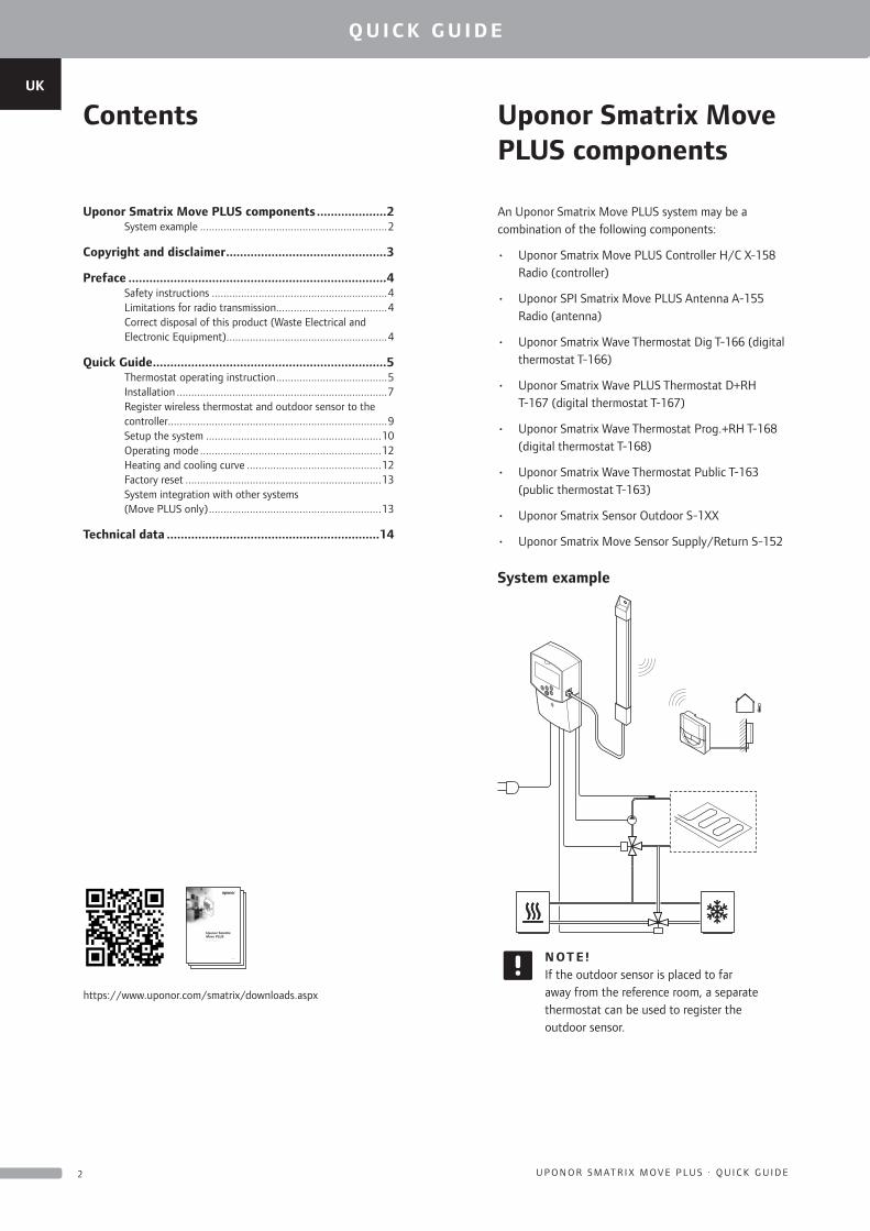
Uponor Smatrix Move PLUS components
An Uponor Smatrix Move PLUS system may be a combination of the following components:
• Uponor Smatrix Move PLUS Controller H/C X-158 Radio (controller)
• Uponor SPI Smatrix Move PLUS Antenna A-155 Radio (antenna)
• Uponor Smatrix Wave Thermostat Dig T-166 (digital thermostat T-166)
• Uponor Smatrix Wave PLUS Thermostat D+RH T-167 (digital thermostat T-167)
• Uponor Smatrix Wave Thermostat Prog.+RH T-168 (digital thermostat T-168)
• Uponor Smatrix Wave Thermostat Public T-163 (public thermostat T-163)
• Uponor Smatrix Sensor Outdoor S-1XX
• Uponor Smatrix Move Sensor Supply/Return S-152
System example
N OT E !If the outdoor sensor is placed to far away from the reference room, a separate thermostat can be used to register the outdoor sensor.
03 | 2015
Uponor Smatrix Move PLUSU K Q U I C K G U I D E
https://www.uponor.com/smatrix/downloads.aspx
UK
CZ
DE
DK
EE
ES
FI
FR
HR
HU
IT
LT
LV
NL
NO
PL
PT
RO
RU
SE
SK
3U P O N O R S M AT R I X M O V E P LU S · Q U I C K G U I D E
Q U I C K G U I D E
Copyright and disclaimer
Uponor has prepared this installation and operation manual and all the content included solely for information purposes. The contents of the manual (including graphics, logos, icons, text, and images) are copyrighted and protected by worldwide copyright laws and treaty provisions. You agree to comply with all copyright laws worldwide in your use of the manual. Modification or use of any of the contents of the manual for any other purpose is a violation of Uponor’s copyright, trademark and other proprietary rights.
The presumption for the manual is that the safety measures have been fully complied with and, further, that Uponor Smatrix Move PLUS, including any components that are part of such system, covered by the manual:
• is selected, planned and installed and put into operation by a licensed and competent planner and installer in compliance with current (at the time of installation) installation instructions provided by Uponor as well as in compliance with all applicable building and plumbing codes and other requirements and guidelines;
• has not been (temporarily or continuously) exposed to temperatures, pressure and/or voltages that exceed the limits printed on the products or stated in any instructions supplied by Uponor;
• remain in its originally installed location and is not repaired, replaced or interfered with, without prior written consent of Uponor;
• is connected to potable water supplies or compatible plumbing, heating and/or cooling products approved or specified by Uponor;
• is not connected to or used with non-Uponor products, parts or components except for those approved or specified by Uponor; and
• does not show evidence of tampering, mishandling, insufficient maintenance, improper storage, neglect or accidental damage before installation and being put into operation.
While Uponor has made efforts to ensure that the manual is accurate, Uponor does not guarantee or warrant the accuracy of the information contained herein. Uponor reserves the right to modify the specifications and features described herein, or discontinue manufacture of Uponor Smatrix Move PLUS described at any time without prior notice or obligation. The manual is provided “as is” without warranties of any kind, either expressed or implied. The information should be independently verified before using it in any manner.
To the fullest extent permissible, Uponor disclaims all warranties, expressed or implied, including, but not limited to, the implied warranties of merchantability, fitness for particular purpose and non-infringement.
This disclaimer applies to, but is not limited to, the accuracy, reliability or correctness of the manual.
Under no circumstances shall Uponor be liable for any indirect, special, incidental or consequential damages or loss that result from the use of or the inability to use the materials or information in the manual, or any claim attributable to errors, omission or other inaccuracies in the manual, even if Uponor has been advised of the possibility of such damages.
This disclaimer and any provisions in the manual do not limit any statutory rights of consumers.
UK
CZ
DE
DK
EE
ES
FI
FR
HR
HU
IT
LT
LV
NL
NO
PL
PT
RO
RU
SE
SK
4 U P O N O R S M AT R I X M O V E P LU S · Q U I C K G U I D E
Q U I C K G U I D E
This quick start guide to serves as a reminder for experienced installers. We strongly recommend reading the full manual before installing the control system.
Safety instructions
Warnings used in this manual
The following symbols are used in the manual to indicate special precautions when installing and operating any Uponor equipment:
Warning!Risk of injury. Ignoring warnings can cause injury or damage components.
Caution!Ignoring cautions can cause malfunctions.
Safety measures
Conform to the following measures when installing and operating any Uponor equipment:
• Read and follow the instructions in the installation and operation manual.
• Installation must be performed by a competent person in accordance with local regulations.
• It is prohibited to make changes or modifications not specified in this manual.
• All power supply must be switched off before starting any wiring work.
• Do not use water to clean Uponor components.
• Do not expose the Uponor components to flammable vapours or gases.
We cannot accept any responsibility for damage or breakdown that can result from ignoring these instructions.
Power
Warning!The Uponor system uses 230 V AC, 50 Hz power. In case of emergency, immediately disconnect the power.
Technical constraints
Caution!To avoid interference, keep installation/data cables away from power cables of more than 50 V.
Limitations for radio transmission
The Uponor system uses radio transmission. The frequency used is reserved for similar applications, and the chances of interference from other radio sources are very low.
However, in some rare cases, it might not be possible to establish perfect radio communication. The transmission range is sufficient for most applications, but each building has different obstacles affecting radio communication and maximum transmission distance. If communication difficulties exist, Uponor recommends relocating the antenna to a more optimal position, and not installing Uponor radio sources to close to each other, for solving exceptional problems.
Correct disposal of this product (Waste Electrical and Electronic Equipment)
N OT E !Applicable in the European Union and other European countries with separate collection systems
This marking shown on the product or its literature indicates that it should not be disposed with other household wasted at the
end of its working life. To prevent possible harm to the environment or human health from uncontrolled waste disposal, please separate this from other types of wastes and recycle it responsibly to promote the sustainable reuse of material resources.
Household users should contact either the retailer where they purchased this product, or their local government office, for details of where and how they can take this item for environmentally safe recycling.
Business users should contact their supplier and check the terms and conditions of the purchase contract. This product should not be mixed with other commercial wastes of disposal.
Preface
UK
CZ
DE
DK
EE
ES
FI
FR
HR
HU
IT
LT
LV
NL
NO
PL
PT
RO
RU
SE
SK
5U P O N O R S M AT R I X M O V E P LU S · Q U I C K G U I D E
Q U I C K G U I D E
Quick Guide
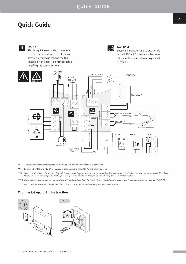
N OT E !This is a quick start guide to serve as a reminder for experienced installers. We strongly recommend reading the full installation and operation manual before installing the control system.
Warning!Electrical installation and service behind secured 230 V AC covers must be carried out under the supervision of a qualified electrician.
230 V AC50 Hz
POWER
N
PUMP P1
PUMP P2 **CONTACTTher ****
OUTSIDE *
WATER RETURN *****
In1/In2 *** In1/In2 *** In1/In2 **
WATER IN
SENSORS
SE
NS
OR
S
HE
ATC
OLD
**
ACTUATOR 230 V
NL
2
4
In2
In1
In1 In2
L
N
L
N
L
Ope
n
Com
mon
Clo
se
230 V 50 Hz
230 V 50 Hz
230 V 50 Hz
230 V 50 Hz
*) The outdoor temperature sensor can be connected to either the controller or to a thermostat.
**) Connect either COLD or PUMP P2 (secondary heating/cooling circuit) to the connection terminal.
***) Select one of the inputs (heating/cooling switch, pump control signal, or immersion thermostat) and set parameter 11 – Wired Input 1 selection, or parameter 12 – Wired Input 2 Selection, accordingly. The heating/cooling option can only be used in systems without a registered wireless thermostat.
****) Optional temperature limiter connection, fitted with a cable bridgre from the factory. Remove the bridge if a temperature limiter is to be used together with PUMP P1.
*****) Optional return sensor. Can only be used, for boost function, in systems without a registered wireless thermostat.
Thermostat operating instruction
T-163T-168T-167T-166
20
5 35
UK
CZ
DE
DK
EE
ES
FI
FR
HR
HU
IT
LT
LV
NL
NO
PL
PT
RO
RU
SE
SK
6 U P O N O R S M AT R I X M O V E P LU S · Q U I C K G U I D E
Q U I C K G U I D E
T-163
T-168T-167T-166T-163
T-168T-167T-166T-163
A B
C D
1
2
3
E F H
I KJ L
M
G
2
1314
5 m
m
A
5 s
1 2 3 4
ON DIP
T-168
T-168T-167T-166
OptionOption
UK
CZ
DE
DK
EE
ES
FI
FR
HR
HU
IT
LT
LV
NL
NO
PL
PT
RO
RU
SE
SK
7U P O N O R S M AT R I X M O V E P LU S · Q U I C K G U I D E
Q U I C K G U I D E
Installation
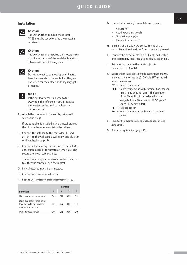
Caution!The DIP switches in public thermostat T-163 must be set before the thermostat is registered.
Caution!The DIP switch in the public thermostat T-163 must be set to one of the available functions, otherwise it cannot be registered.
Caution!Do not attempt to connect Uponor Smatrix Base thermostats to the controller. They are not suited for each other, and they may get damaged.
N OT E !If the outdoor sensor is placed to far away from the reference room, a separate thermostat can be used to register the outdoor sensor.
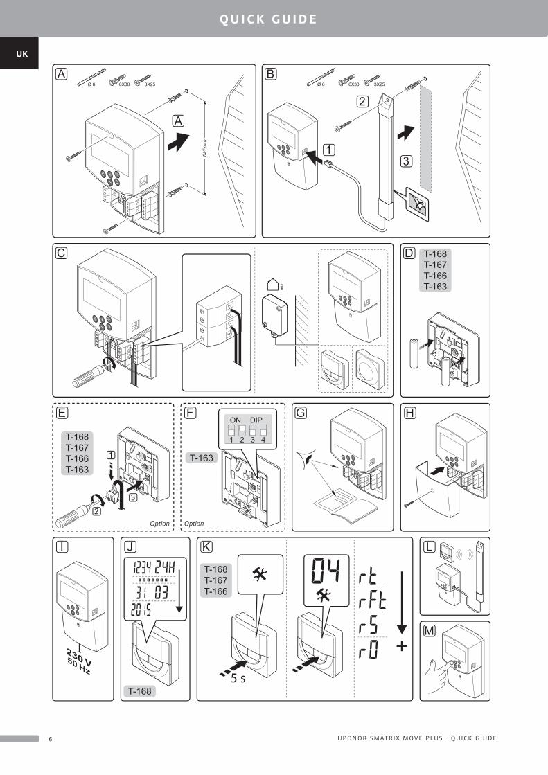
A. Attach the controller to the wall by using wall screws and plugs.
If the controller is installed inside a metal cabinet, then locate the antenna outside the cabinet.
B. Connect the antenna to the controller (1), and attach it to the wall using a wall screw and plug (2) or the adhesive strip (3).
C. Connect additional equipment, such as actuator(s), circulation pump(s), temperature sensors etc, and secure them with cable clamps.
The outdoor temperature sensor can be connected to either the controller or a thermostat.
D. Insert batteries into the thermostats.
E. Connect optional external sensor.
F. Set the DIP switch on public thermostat T-163.
Function
Switch
1 2 3 4
Used as a room thermostat Off Off Off Off
Used as a room thermostat together with an outdoor temperature sensor
Off On Off Off
Use a remote sensor Off On Off On
G. Check that all wiring is complete and correct:
• Actuator(s) • Heating/cooling switch • Circulation pump(s) • Temperature sensor(s)
H. Ensure that the 230 V AC compartment of the controller is closed and the fixing screw is tightened.
I. Connect the power cable to a 230 V AC wall socket, or if required by local regulations, to a junction box.
J. Set time and date on thermostats (digital thermostat T-168 only).
K. Select thermostat control mode (settings menu 04, in digital thermostats only). Default: RT (standard room thermostat).
RT = Room temperature RFT = Room temperature with external floor sensor
(limitations does not affect the operation of the Move PLUS controller, when not integrated to a Wave/Wave PLUS/Space/Space PLUS controller)
RS = Remote sensor RO = Room temperature with remote outdoor
sensor
L. Register the thermostat and outdoor sensor (see next page).
M. Setup the system (see page 10).
UK
CZ
DE
DK
EE
ES
FI
FR
HR
HU
IT
LT
LV
NL
NO
PL
PT
RO
RU
SE
SK
8 U P O N O R S M AT R I X M O V E P LU S · Q U I C K G U I D E
Q U I C K G U I D E
T-163
T-163
0h
5
8 8
8 8
T-166T-167T-168
T-166T-167T-168
T-166T-167T-168
C
8
C
T-166T-167T-168
0h 2 10 12 14 16 18 20
C
P
C
AUTO
22 244 6 8
13
15 15
5
5
1 2 3
5
4
6 7
8 9
10
11 12 13 14
15
15
16
24
17
24
18
1313 15 15
10 s
5 s
5 s5 s
5 s5 s
5 s
UK
CZ
DE
DK
EE
ES
FI
FR
HR
HU
IT
LT
LV
NL
NO
PL
PT
RO
RU
SE
SK
9U P O N O R S M AT R I X M O V E P LU S · Q U I C K G U I D E
Q U I C K G U I D E
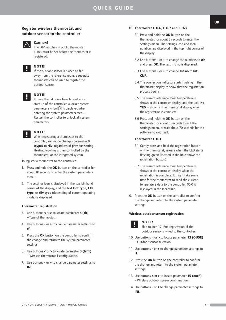
Register wireless thermostat and outdoor sensor to the controller
Caution!The DIP switches in public thermostat T-163 must be set before the thermostat is registered.
N OT E !If the outdoor sensor is placed to far away from the reference room, a separate thermostat can be used to register the outdoor sensor.
N OT E !If more than 4 hours have lapsed since start up of the controller, a locked system parameter symbol is displayed when entering the system parameters menu. Restart the controller to unlock all system parameters.
N OT E !When registering a thermostat to the controller, run mode changes parameter 0 (type) to rEv, regardless of previous setting. Heating/cooling is then controlled by the thermostat, or the integrated system.
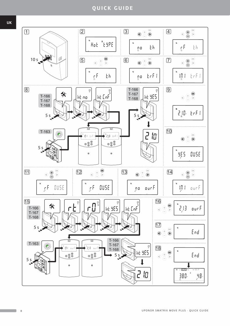
To register a thermostat to the controller:
1. Press and hold the OK button on the controller for about 10 seconds to enter the system parameters menu.
2. The settings icon is displayed in the top left hand corner of the display, and the text Hot type, Cld type, or rEv type (depending of current operating mode) is displayed.
Thermostat registration
3. Use buttons < or > to locate parameter 5 (th) – Type of thermostat.
4. Use buttons - or + to change parameter settings to rf.
5. Press the OK button on the controller to confirm the change and return to the system parameter settings.
6. Use buttons < or > to locate parameter 8 (trF1) – Wireless thermostat 1 configuration.
7. Use buttons - or + to change parameter settings to INI.
8. Thermostat T-166, T-167 and T-168
8.1 Press and hold the OK button on the thermostat for about 5 seconds to enter the settings menu. The settings icon and menu numbers are displayed in the top right corner of the display.
8.2 Use buttons - or + to change the numbers to 09 and press OK. The text Int no is displayed.
8.3. Use buttons - or + to change Int no to Int CNF.
8.4. The connection indicator starts flashing in the thermostat display to show that the registration process begins.
8.5 The current reference room temperature is shown in the controller display, and the text Int YES is shown in the thermostat display when the registration is complete.
8.6 Press and hold the OK button on the thermostat for about 5 seconds to exit the settings menu, or wait about 70 seconds for the software to exit itself.
Thermostat T-163
8.1 Gently press and hold the registration button on the thermostat, release when the LED starts flashing green (located in the hole above the registration button).
8.2 The current reference room temperature is shown in the controller display when the registration is complete. It might take some time for the thermostat to send the current temperature data to the controller. 00.0 is displayed in the meantime.
9. Press the OK button on the controller to confirm the change and return to the system parameter settings.
Wireless outdoor sensor registration
N OT E !Skip to step 17, End registration, if the outdoor sensor is wired to the controller.
10. Use buttons < or > to locate parameter 13 (OUSE) – Outdoor sensor selection.
11. Use buttons - or + to change parameter settings to rf.
12. Press the OK button on the controller to confirm the change and return to the system parameter settings.
13. Use buttons < or > to locate parameter 15 (ourF) – Wireless outdoor sensor configuration.
14. Use buttons - or + to change parameter settings to INI.
UK
CZ
DE
DK
EE
ES
FI
FR
HR
HU
IT
LT
LV
NL
NO
PL
PT
RO
RU
SE
SK
1 0 U P O N O R S M AT R I X M O V E P LU S · Q U I C K G U I D E
Q U I C K G U I D E
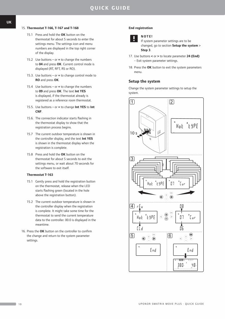
15. Thermostat T-166, T-167 and T-168
15.1 Press and hold the OK button on the thermostat for about 5 seconds to enter the settings menu. The settings icon and menu numbers are displayed in the top right corner of the display.
15.2 Use buttons - or + to change the numbers to 04 and press OK. Current control mode is displayed (RT, RFT, RS or RO).
15.3. Use buttons - or + to change control mode to RO and press OK.
15.4 Use buttons - or + to change the numbers to 09 and press OK. The text Int YES is displayed, if the thermostat already is registered as a reference room thermostat.
15.5. Use buttons - or + to change Int YES to Int CNF.
15.6. The connection indicator starts flashing in the thermostat display to show that the registration process begins.
15.7 The current outdoor temperature is shown in the controller display, and the text Int YES is shown in the thermostat display when the registration is complete.
15.8 Press and hold the OK button on the thermostat for about 5 seconds to exit the settings menu, or wait about 70 seconds for the software to exit itself.
Thermostat T-163
15.1 Gently press and hold the registration button on the thermostat, release when the LED starts flashing green (located in the hole above the registration button).
15.2 The current outdoor temperature is shown in the controller display when the registration is complete. It might take some time for the thermostat to send the current temperature data to the controller. 00.0 is displayed in the meantime.
16. Press the OK button on the controller to confirm the change and return to the system parameter settings.
End registration
N OT E !If system parameter settings are to be changed, go to section Setup the system > Step 3.
17. Use buttons < or > to locate parameter 24 (End) – Exit system parameter settings.
18. Press the OK button to exit the system parameters menu.
Setup the system
Change the system parameter settings to setup the system.
13
14
C
12
15 11
16
C
10
17
1 2 3 4 5 6 7
9
18 8
19
C
7
20 6
21 5
22 4
23 3
24 2
0h
0h
1
1
0h
0h 2 10 12 14 16 18 20
C
P
C
AUTO
22 244 6 8
1 2
3
4
5 6
24 24
10 s
UK
CZ
DE
DK
EE
ES
FI
FR
HR
HU
IT
LT
LV
NL
NO
PL
PT
RO
RU
SE
SK
1 1U P O N O R S M AT R I X M O V E P LU S · Q U I C K G U I D E
Q U I C K G U I D E
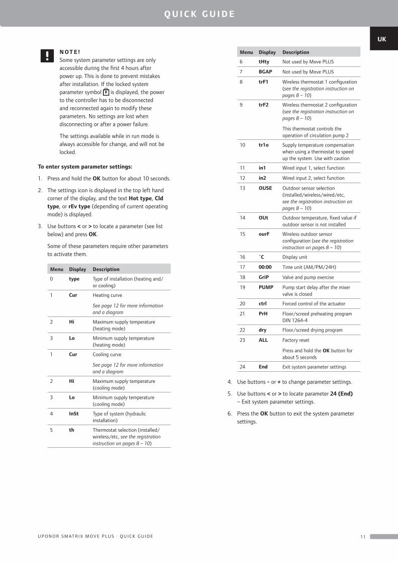
N OT E !Some system parameter settings are only accessible during the first 4 hours after power up. This is done to prevent mistakes after installation. If the locked system parameter symbol is displayed, the power to the controller has to be disconnected and reconnected again to modify these parameters. No settings are lost when disconnecting or after a power failure.
The settings available while in run mode is always accessible for change, and will not be locked.
To enter system parameter settings:
1. Press and hold the OK button for about 10 seconds.
2. The settings icon is displayed in the top left hand corner of the display, and the text Hot type, Cld type, or rEv type (depending of current operating mode) is displayed.
3. Use buttons < or > to locate a parameter (see list below) and press OK.
Some of these parameters require other parameters to activate them.
Menu Display Description
0 type Type of installation (heating and/or cooling)
1 Cur Heating curve
See page 12 for more information and a diagram
2 Hi Maximum supply temperature (heating mode)
3 Lo Minimum supply temperature (heating mode)
1 Cur Cooling curve
See page 12 for more information and a diagram
2 Hi Maximum supply temperature (cooling mode)
3 Lo Minimum supply temperature (cooling mode)
4 InSt Type of system (hydraulic installation)
5 th Thermostat selection (installed/wireless/etc, see the registration instruction on pages 8 – 10)
Menu Display Description
6 tHty Not used by Move PLUS
7 BGAP Not used by Move PLUS
8 trF1 Wireless thermostat 1 configuration (see the registration instruction on pages 8 – 10)
9 trF2 Wireless thermostat 2 configuration (see the registration instruction on pages 8 – 10)
This thermostat controls the operation of circulation pump 2
10 tr1o Supply temperature compensation when using a thermostat to speed up the system. Use with caution
11 in1 Wired input 1, select function
12 in2 Wired input 2, select function
13 OUSE Outdoor sensor selection (installed/wireless/wired/etc, see the registration instruction on pages 8 – 10)
14 OUt Outdoor temperature, fixed value if outdoor sensor is not installed
15 ourF Wireless outdoor sensor configuration (see the registration instruction on pages 8 – 10)
16 ˚C Display unit
17 00:00 Time unit (AM/PM/24H)
18 GriP Valve and pump exercise
19 PUMP Pump start delay after the mixer valve is closed
20 ctrl Forced control of the actuator
21 PrH Floor/screed preheating program DIN 1264-4
22 dry Floor/screed drying program
23 ALL Factory reset
Press and hold the OK button for about 5 seconds
24 End Exit system parameter settings
4. Use buttons - or + to change parameter settings.
5. Use buttons < or > to locate parameter 24 (End) – Exit system parameter settings.
6. Press the OK button to exit the system parameter settings.
UK
CZ
DE
DK
EE
ES
FI
FR
HR
HU
IT
LT
LV
NL
NO
PL
PT
RO
RU
SE
SK
1 2 U P O N O R S M AT R I X M O V E P LU S · Q U I C K G U I D E
Q U I C K G U I D E
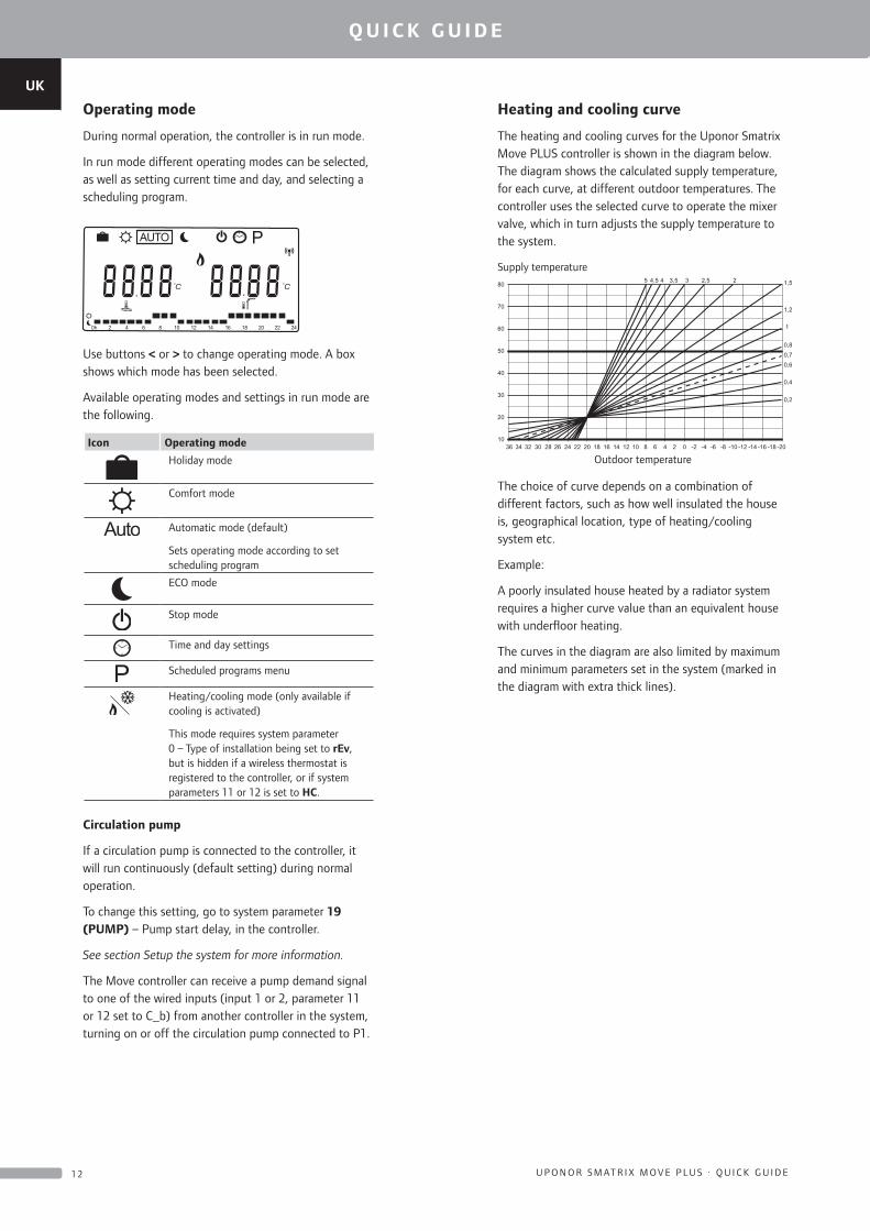
Operating mode
During normal operation, the controller is in run mode.
In run mode different operating modes can be selected, as well as setting current time and day, and selecting a scheduling program.
0h 2 10 12 14 16 18 20
C C
AUTO
22 244 6 8
P
Use buttons < or > to change operating mode. A box shows which mode has been selected.
Available operating modes and settings in run mode are the following.
Icon Operating mode
Holiday mode
Comfort mode
Automatic mode (default)
Sets operating mode according to set scheduling program
ECO mode
Stop mode
Time and day settings
Scheduled programs menu
Heating/cooling mode (only available if cooling is activated)
This mode requires system parameter 0 – Type of installation being set to rEv, but is hidden if a wireless thermostat is registered to the controller, or if system parameters 11 or 12 is set to HC.
Circulation pump
If a circulation pump is connected to the controller, it will run continuously (default setting) during normal operation.
To change this setting, go to system parameter 19 (PUMP) – Pump start delay, in the controller.
See section Setup the system for more information.
The Move controller can receive a pump demand signal to one of the wired inputs (input 1 or 2, parameter 11 or 12 set to C_b) from another controller in the system, turning on or off the circulation pump connected to P1.
Heating and cooling curve
The heating and cooling curves for the Uponor Smatrix Move PLUS controller is shown in the diagram below. The diagram shows the calculated supply temperature, for each curve, at different outdoor temperatures. The controller uses the selected curve to operate the mixer valve, which in turn adjusts the supply temperature to the system.
80
70
60
50
40
30
20
1036 34 32 30 28 26 24 22 20 18 16 14 12 10 8 6 4 2 -2 -4 -6 -8 -10 -12 -14 -16 -18 -200
0,2
0,4
0,60,70,8
1
1,2
1,522,533,544,55
Supply temperature
Outdoor temperature
The choice of curve depends on a combination of different factors, such as how well insulated the house is, geographical location, type of heating/cooling system etc.
Example:
A poorly insulated house heated by a radiator system requires a higher curve value than an equivalent house with underfloor heating.
The curves in the diagram are also limited by maximum and minimum parameters set in the system (marked in the diagram with extra thick lines).

UK
CZ
DE
DK
EE
ES
FI
FR
HR
HU
IT
LT
LV
NL
NO
PL
PT
RO
RU
SE
SK
1 3U P O N O R S M AT R I X M O V E P LU S · Q U I C K G U I D E
Q U I C K G U I D E
To change the heating and/or cooling curve:
1. Press and hold the OK button on the controller for about 10 seconds to enter the system parameters menu.
2. The settings icon is displayed in the top left hand corner of the display, and the text Hot type, Cld type, or rEv type (depending of current operating mode) is displayed.
3. Use buttons < or > to locate parameter 1 (Cur) – Heating curve, or 1 (Cur) – Cooling curve. They are identified using the heating or cooling symbol.
Heating curve: Default: 0.7 Setting range: 0.1 – 5, 0.1 increments
Cooling curve: Default: 0.4 Setting range: 0.1 – 5, 0.1 increments
4. Use buttons - or + to change parameter setting.
5. Press the OK button on the controller to confirm the change and return to the system parameter settings.
6. Repeat steps 3 through 5 to change the other curve settings, if needed.
Factory reset
To perform a factory reset, go to system parameter 23 (ALL) – Factory reset, in the controller.
Press and hold the OK button for about 5 seconds until the controller restarts.
See section Setup the system for more information.
System integration with other systems (Move PLUS only)
The Uponor Smatrix Move PLUS controller can be integrated with another Uponor Smatrix Wave/Wave PLUS/Space/Space PLUS system to enhance the capabilities of the full climate system. At the same time, the integration removes the need of a separate thermostat, and outdoor sensor, for the Move PLUS system.
Shared information
Information regarding system state and reference room temperature is forwarded to the Move PLUS controller, which adjusts the supply temperature accordingly.
Different system states and temperatures which can be forwarded are:
• Comfort/ECO mode*
• Heating/cooling mode
• Holiday mode*
• Reference room temperature and setpoint
• Outdoor temperature (if installed in the thermostat)
• Remote sensor (if installed in the thermostat)
• Indication if the relative humidity exceeds set limits (requires the digital thermostat T-167 or T-168)
*) Through change of setpoint, using the ECO setback value from the integrated system. No indication or change of mode is shown in the Move PLUS controller.
The integration is activated when the thermostat is registered to both controllers (Move PLUS and Wave, Wave PLUS, Space, or Space PLUS).
See the Uponor Smatrix Wave/Wave PLUS documentation on how to register the thermostat to a Wave/Wave PLUS system.
See the Uponor Smatrix Space/Space PLUS documentation on how to register the thermostat to a Space/Space PLUS system.
UK
CZ
DE
DK
EE
ES
FI
FR
HR
HU
IT
LT
LV
NL
NO
PL
PT
RO
RU
SE
SK
1 4 U P O N O R S M AT R I X M O V E P LU S · Q U I C K G U I D E
Q U I C K G U I D E
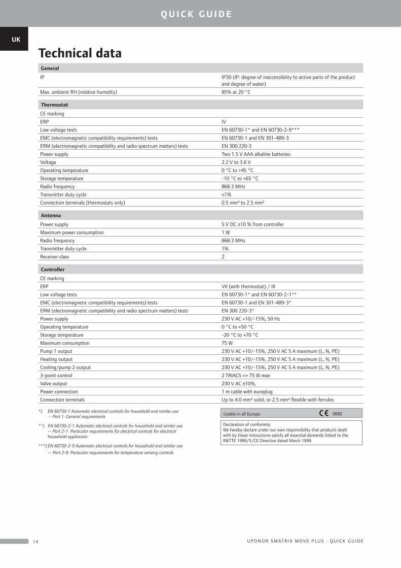
Technical dataGeneral
IP IP30 (IP: degree of inaccessibility to active parts of the product and degree of water)
Max. ambient RH (relative humidity) 85% at 20 °C
Thermostat
CE marking
ERP IV
Low voltage tests EN 60730-1* and EN 60730-2-9***
EMC (electromagnetic compatibility requirements) tests EN 60730-1 and EN 301-489-3
ERM (electromagnetic compatibility and radio spectrum matters) tests EN 300 220-3
Power supply Two 1.5 V AAA alkaline batteries
Voltage 2.2 V to 3.6 V
Operating temperature 0 °C to +45 °C
Storage temperature -10 °C to +65 °C
Radio frequency 868.3 MHz
Transmitter duty cycle <1%
Connection terminals (thermostats only) 0.5 mm² to 2.5 mm²
Antenna
Power supply 5 V DC ±10 % from controller
Maximum power consumption 1 W
Radio frequency 868.3 MHz
Transmitter duty cycle 1%
Receiver class 2
Controller
CE marking
ERP VII (with thermostat) / III
Low voltage tests EN 60730-1* and EN 60730-2-1**
EMC (electromagnetic compatibility requirements) tests EN 60730-1 and EN 301-489-3*
ERM (electromagnetic compatibility and radio spectrum matters) tests EN 300 220-3*
Power supply 230 V AC +10/-15%, 50 Hz
Operating temperature 0 °C to +50 °C
Storage temperature -20 °C to +70 °C
Maximum consumption 75 W
Pump 1 output 230 V AC +10/-15%, 250 V AC 5 A maximum (L, N, PE)
Heating output 230 V AC +10/-15%, 250 V AC 5 A maximum (L, N, PE)
Cooling/pump 2 output 230 V AC +10/-15%, 250 V AC 5 A maximum (L, N, PE)
3-point control 2 TRIACS => 75 W max
Valve output 230 V AC ±10%,
Power connection 1 m cable with europlug
Connection terminals Up to 4.0 mm² solid, or 2.5 mm² flexible with ferrules
*) EN 60730-1 Automatic electrical controls for household and similar use -- Part 1: General requirements
**) EN 60730-2-1 Automatic electrical controls for household and similar use -- Part 2-1: Particular requirements for electrical controls for electrical household appliances
***) EN 60730-2-9 Automatic electrical controls for household and similar use
-- Part 2-9: Particular requirements for temperature sensing controls
0682Usable in all Europe
Declaration of conformity:We hereby declare under our own responsibility that products dealt with by these instructions satisfy all essential demands linked to the R&TTE 1999/5/CE Directive dated March 1999.
UK
CZ
DE
DK
EE
ES
FI
FR
HR
HU
IT
LT
LV
NL
NO
PL
PT
RO
RU
SE
SK
1 5U P O N O R S M AT R I X M O V E P LU S · Q U I C K G U I D E
Q U I C K G U I D E

1068
128
10_
2015
_EN
Prod
uctio
n: U
pono
r AB
; EL,
Virs
bo, S
wed
en
Uponor Corporation www.uponor.com
Uponor reserves the right to make changes, without prior notification, to the specification of incorporated components in line with its policy of continuous improvement and development.