Embed Size (px)
Citation preview
International Journal of EmergingElectric Power Systems
Volume8, Issue3 2007 Article 6
A Novel Modulated Power Filter Compensatorfor Distribution Networks with Distributed
Wind Energy
Adel M. Sharaf∗ Weihua Wang†
Ismail H. Altas‡
∗University of New Brunswick, Dept. of Electrical and Electronics Engineering,[email protected]
†University of New Brunswick, Dept. of Electrical and Computer Engineering, [email protected]‡Karadeniz Technical University, Dept. of Electrical and Electronics Engineering, ihal-
Copyright c©2007 The Berkeley Electronic Press. All rights reserved.
A Novel Modulated Power Filter Compensatorfor Distribution Networks with Distributed
Wind Energy∗
Adel M. Sharaf, Weihua Wang, and Ismail H. Altas
Abstract
During the last two decades, renewable wind energy has become increasingly popular as aconsequence of strong ecological concerns and appealing advantages with regard to economicalenergy solutions in remote communities. Furthermore, with very large wind farms emerging, thedispersed renewable wind energy is required to be fully connected to the electrical distribution net-works. However, the integration of dispersed renewable wind energy will pose a great challengeto the power quality in the distribution networks when the weak nature of the grid in remote areasand the uncertainty of wind are taken into consideration.
This paper presents a novel Modulated Power Filter Compensator (MPFC) for the distributionnetworks with dispersed renewable wind energy interfaced. A tri-loop error driven controller isused to adjust the PWM switching of the modulated power filter compensator. Full power factorcorrection and power quality improvement is validated under different operation conditions, likeload switching and wind velocity excursions. The MPFC device is a member of novel FACTSbased compensators developed by the first author.
KEYWORDS: Modulated Power Filter Compensator, reactive power compensation, power qual-ity, renewable wind energy
∗I. H. Altas wishes to thank the Scientific and Technological Research Council of Turkey for thefinancial support during this work. He is currently a visiting scholar at the University of NewBrunswick.
I. INTRODUCTION Wind is an abundant renewable source of energy, which is usually obtained by converting part of the kinetic energy in the moving air into electricity. Wind renewable energy is also a clean energy source, that is, operating without producing carbon dioxide, sulfur dioxide, particulates or any other type of air pollution[1-2]. Demand for electrical energy from renewable sources is rapidly increasing as industrialized societies are becoming more aware of and concerned about fossil fuel shortage and environmental impacts [3]. Besides hydro-power, which is already well established, wind energy is by far one of the most technically advanced and promising renewable energy sources. In many countries, the potential for wind energy production exceeds by far the local consumption of electricity. By 2005, the worldwide capacity had been increased to 58,982 megawatts and the World Wind Energy Association expects 120,000 MW to be installed globally by 2010. Germany is the leading producer of wind power with a capacity of 18,428 megawatts in 2005, which accounts for 6% of German electricity in the same year [4].
Recently, with the technological improvement in new materials, fabrication technology, as well as new wind blade, gear box and induction generator designs and manufacturing methods, both the size of wind turbine blades and the volume of commercial production have been steadily increasing to the point where typical peak output is currently in the range of several megawatts [5-6]. In this case, the grid integration of large wind renewable energy becomes significant and arouses great interest from the society [2].
However, increased penetration of dispersed and distributed wind energy creates a new serious uncontrollable scenario in electric power grid system. On one hand, dynamic variations and wind velocity excursions cause excessive changes in prime mover power and the corresponding electrical power injected into the grid utility network. Depending on intensity and rate of wind changes, difficulties with generator output frequency variations and severe generator voltage stabilization could result in possible loss of excitation and frequent shutdowns as well as severe power quality issues, such as voltage distortions and variations in its output electrical energy [7]. On the other hand, based on economic and aesthetic considerations, wind farms and distributed wind generation schemes are usually planned and installed in rural, mountain and coastal areas with annual favorable wind utilization regimes, where the
1
Sharaf et al.: MPFC for Distribution Networks with Distributed Wind Energy
Published by The Berkeley Electronic Press, 2007

distribution/utilization electric grid networks are usually of radial structure and are electrically weak with low short circuit ratios [7-8].
From the distribution grid point of view, reactive power compensation is an important issue. Excessive reactive current increases distribution losses, reduces system power factor and causes large variations in bus voltages. Moreover, power quality, voltage swells and sags issues as well as harmonic propagation are other aspects that require attention with dispersed wind energy interface and wind farm installations. Proper studies of impact and penetration levels of the wind farms protection gear mal-operation, islanding hazards and other issues of degraded power quality and harmonics with possibility of harmonic resonances are required to be dealt with. [9]
Consequently, it is necessary to provide effective technical solutions for both power quality and security aspects related to electric grid integration with distributed wind farms and dispersed wind energy schemes. Fortunately, the new emerging FACTS technologies can perform new stabilization and control functions due to rapid power control provided by fast switching devices and especially voltage source converters [10]. The applications of FACTS based schemes for standalone wind energy were studied in [3, 11-12]. By far, the Static VAR Compensator (SVC) has been the extensively utilized FACTS based devices that can maintain a constant voltage by continuously adjusting reactive power flow through the grid-connected WECS. To ensure proper operation of the SVC, various mathematical models and control strategies have been developed. Numerous studies have been performed dealing with the steady state and transient condition using a number of simulation platforms [13]. E.S. Abdin proposed two controllers for the SVC and the digital simulation results have validated good damping and fast system recovery from different types of large disturbances and excursions [14]. A Harmonic mitigation scheme using an Active Power Filter for a wind energy generation system was also investigated in [15]. A Unified Power Flow Controller (UPFC) for power flow control and voltage regulation under different types of wind speed changes was studied in [7].
This paper focuses on the impact of a dispersed renewable wind energy scheme integrated into distribution network on operation, voltage and frequency stabilization, as well as the need of novel FACTS stabilization devices and control strategies such as the low cost Modulated Power Filter Compensator (MPFC) developed by the first author. Comparing with the conventional FACTS devices, the novel MPFC has the advantage of simple structure and low cost, since no line commuted converter is involved in the MPFC scheme. In this paper, the
2
International Journal of Emerging Electric Power Systems, Vol. 8 [2007], Iss. 3, Art. 6
http://www.bepress.com/ijeeps/vol8/iss3/art6
effectiveness of the proposed MPFC scheme for both power quality improvement and power factor correction is fully validated using MATLAB/SIMULINK software environment.
II. Wind Energy Conversion Schemes (WECS)
1. Wind turbine model The wind turbine model is developed based on the steady-state power characteristics of the turbine. The stiffness of the drive train is infinite and the friction factor and the inertia of the turbine must be combined with those of the generator coupled to the turbine [16]. The mechanical power captured by a wind turbine depends on its power utilization coefficient Cp for a given wind velocity v, and can be represented by:
Pm =1/2Cp*S*ρ*v3 (1)
where, ‘S’ is the area swept by the rotor blades, ‘v’ is the wind velocity and ‘ρ’ is its density. Coefficient Cp is a nonlinear function of two magnitudes: the pitch angle β of rotor blades and tip speed ratio λ, which is the quotient between the tangential speed of the rotor blade tips and the undisturbed wind velocity [17]. A general equation used to model Cp (λ, β), based on the modeling turbine characteristics [1], is given by:
3
21 3 4 6( , ) i
c
pi
CC C C C e Cλλ β β λλ
⎛ ⎞= − − +⎜ ⎟
⎝ ⎠ (2)
and with
3
1 1 0.0350.08 1iλ λ β β
= −+ +
. (3)
The coefficients C1 to C6 are: C1= 0.5176, C2= 116, C3= 0.4, C4 = 5, C5 = 21 and C6 = 0.0068. In this research, a constant pitch angle β is used and the value is
3
Sharaf et al.: MPFC for Distribution Networks with Distributed Wind Energy
Published by The Berkeley Electronic Press, 2007
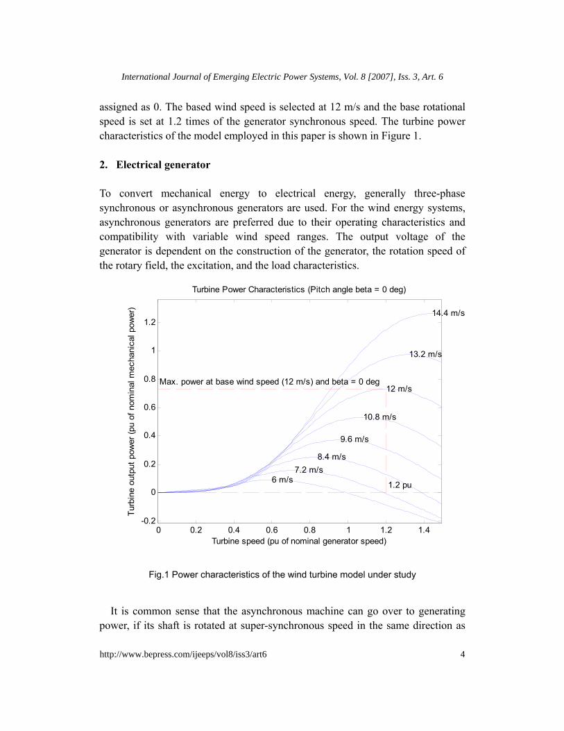
assigned as 0. The based wind speed is selected at 12 m/s and the base rotational speed is set at 1.2 times of the generator synchronous speed. The turbine power characteristics of the model employed in this paper is shown in Figure 1. 2. Electrical generator
To convert mechanical energy to electrical energy, generally three-phase synchronous or asynchronous generators are used. For the wind energy systems, asynchronous generators are preferred due to their operating characteristics and compatibility with variable wind speed ranges. The output voltage of the generator is dependent on the construction of the generator, the rotation speed of the rotary field, the excitation, and the load characteristics.
0 0.2 0.4 0.6 0.8 1 1.2 1.4-0.2
0
0.2
0.4
0.6
0.8
1
1.2
1.2 pu
Max. power at base wind speed (12 m/s) and beta = 0 deg
6 m/s7.2 m/s
8.4 m/s
9.6 m/s
10.8 m/s
12 m/s
13.2 m/s
14.4 m/s
Turbine speed (pu of nominal generator speed)
Turb
ine
outp
ut p
ower
(pu
of n
omin
al m
echa
nica
l pow
er)
Turbine Power Characteristics (Pitch angle beta = 0 deg)
Fig.1 Power characteristics of the wind turbine model under study
It is common sense that the asynchronous machine can go over to generating
power, if its shaft is rotated at super-synchronous speed in the same direction as
4
International Journal of Emerging Electric Power Systems, Vol. 8 [2007], Iss. 3, Art. 6
http://www.bepress.com/ijeeps/vol8/iss3/art6
that of the air gap flux, so that the slip become negative and a negative or regeneration torque is created.
Asynchronous generators with squirrel cage are by far the most common type of generator for mechanical-electrical energy conversion in wind power plants, since they are remarkable for their extremely simple but robust construction. Because of their high operating security, they can be possibly with rough handling.
However, the asynchronous generator can only deliver real power to the grid, but it need reactive power supported by the grid or capacitor bank in parallel connected to its stator terminals. As a result, it may potentially bring heavy reactive power burden to the grid.
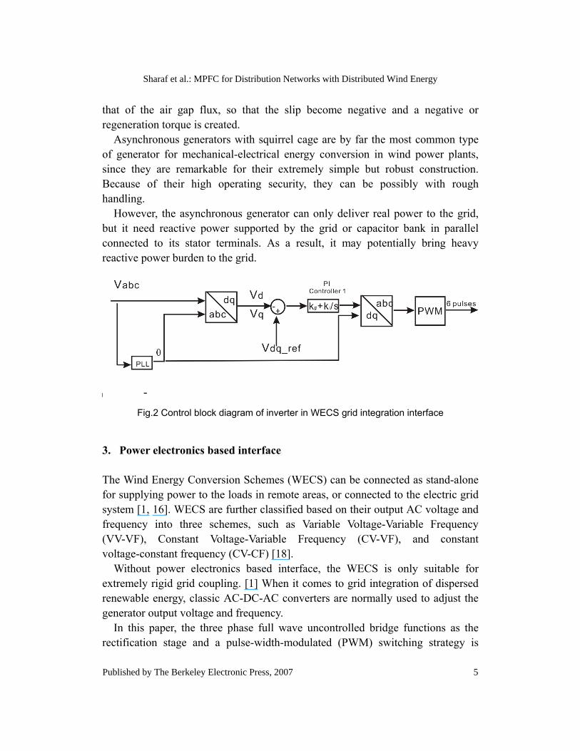
Fig.2 Control block diagram of inverter in WECS grid integration interface
3. Power electronics based interface
The Wind Energy Conversion Schemes (WECS) can be connected as stand-alone for supplying power to the loads in remote areas, or connected to the electric grid system [1, 16]. WECS are further classified based on their output AC voltage and frequency into three schemes, such as Variable Voltage-Variable Frequency (VV-VF), Constant Voltage-Variable Frequency (CV-VF), and constant voltage-constant frequency (CV-CF) [18].
Without power electronics based interface, the WECS is only suitable for extremely rigid grid coupling. [1] When it comes to grid integration of dispersed renewable energy, classic AC-DC-AC converters are normally used to adjust the generator output voltage and frequency.
In this paper, the three phase full wave uncontrolled bridge functions as the rectification stage and a pulse-width-modulated (PWM) switching strategy is
5
Sharaf et al.: MPFC for Distribution Networks with Distributed Wind Energy
Published by The Berkeley Electronic Press, 2007
employed to guarantee a nearly stable voltage and minimal frequency excursions caused by the stochastic temporal nature of wind variations and changes in prime mover power from wind generation scheme. The d-q transformation based Proportional and Integral (PI) controller shown in Figure 2 is designed to generate proper pulses to modulate the switching of the inverter.
The phase locked loop (PLL) is responsible for strict synchronizing the inverter output voltage with the grid voltage [19]. The synchronization signal is obtained from the grid side voltage of the WECS grid integration interface.
III. SYSTEM DESCRIPTION
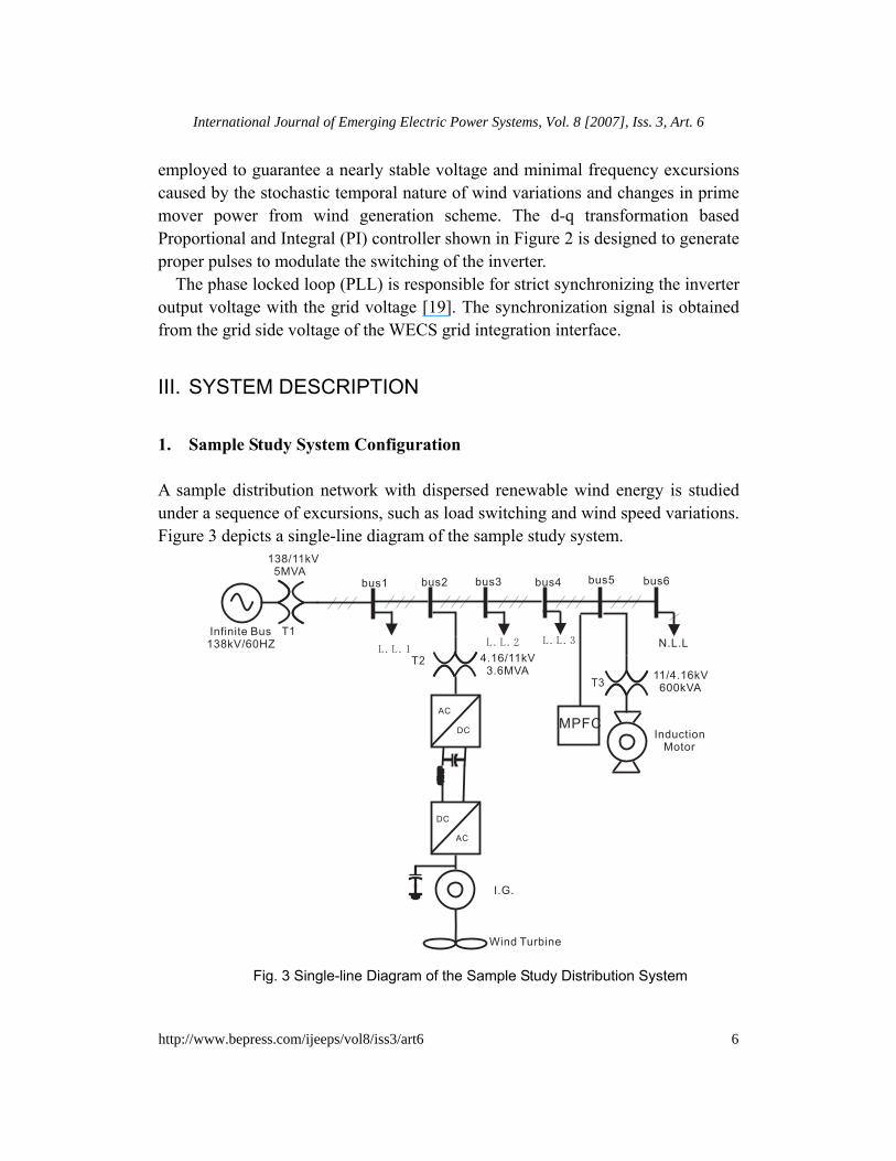
1. Sample Study System Configuration A sample distribution network with dispersed renewable wind energy is studied under a sequence of excursions, such as load switching and wind speed variations. Figure 3 depicts a single-line diagram of the sample study system.
L.L.1
138/11kV
5MVA
Wind Turbine
L.L.2 L.L.3
11/4.16kV
600kVA
Induction
Motor
N.L.L
4.16/11kV
3.6MVA
AC
DC
DC
AC
I.G.
Infinite Bus
138kV/60HZ
bus2bus1 bus3 bus4 bus5 bus6
T2
T1
T3
MPFC
Fig. 3 Single-line Diagram of the Sample Study Distribution System
6
International Journal of Emerging Electric Power Systems, Vol. 8 [2007], Iss. 3, Art. 6
http://www.bepress.com/ijeeps/vol8/iss3/art6

The system shown in Figure 3 is an 11 kV distribution network with dispersed renewable wind energy, 4 linear loads at power factor 0.8 lagging, motorized load and converter type nonlinear load. Except the wind energy interfaced at bus 2 and the one at the main in-feed point representing an infinite bus as 138 kV, there is no other generation unit in the system. In this case, bus3, bus4, bus5 and bus 6 are meshed in radial structure. Two step-down transformers are used at the main in-feed point and at the bus 5 where a 4160V/600kVA motor is connected and a step-up transformer is employed for WECS grid integration. The detail parameters of the system under study are given in Table 1.
The FACTS-based devices were also proposed to be located at the dominant load bus with nonlinear and motorized loads, other than the WECS grid connection interface where traditional reactive compensation schemes are connected. The new idea achieves combined voltage stabilization for the WECS wind interface and the power factor correction at the key nonlinear load bus with improved power quality and reduced harmonics. This arrangement can reduce the number of reactive power compensation devices in the distribution networks and hence reduce the cost.
2. Modulated Power Filter Compensator (MPFC)
The proposed MPFC is a member of novel FACTS based devices and compensators develped by the First Author. Figure 4 displays the function model of the proposed MPFC. The MPFC is composed of a capacitor, an inductor, a resistor, two PWM wave controlled IGBT switches and a three phase diode bridge. The capacitor rating at 225 μF per phase is connected to the AC side of the diode bridge, while a 0.15 ohms resistor and a 0.1 mH inductor are located at DC side of the diode bridge. The two IGBT switches are controlled by two complementary pulses and the topology of the MPFC circuit and hence the equivalent admittance can be changed with different states of the complementary pulses. If S1 is open and S2 is closed, the resistor and inductor will be connected into the circuit; if S1 is closed and S2 is open, the resitor and inductor will be shorted.
7
Sharaf et al.: MPFC for Distribution Networks with Distributed Wind Energy
Published by The Berkeley Electronic Press, 2007
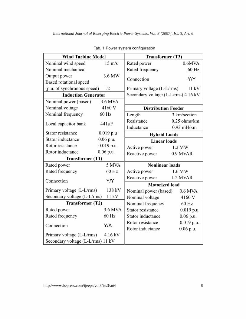
Tab. 1 Power system configuration
Wind Turbine Model Transformer (T3) Nominal wind speed 15 m/s Nominal mechanical Output power 3.6 MW Based rotational speed (p.u. of synchronous speed) 1.2
Induction Generator
Rated power 0.6MVA Rated frequency 60 Hz
Connection Y/Y
Primary voltage (L-L/rms) 11 kV Secondary voltage (L-L/rms) 4.16 kV
Distribution Feeder Length 3 km/section Resistance 0.25 ohms/km Inductance 0.93 mH/km
Hybrid Loads
Nominal power (based) 3.6 MVA Nominal voltage 4160 V Nominal frequency 60 Hz
Local capacitor bank 441μF
Stator resistance 0.019 p.u Stator inductance 0.06 p.u. Rotor resistance 0.019 p.u. Rotor inductance 0.06 p.u.
Transformer (T1)
Linear loads Active power 1.2 MW Reactive power 0.9 MVAR
Nonlinear loads Active power 1.6 MW Reactive power 1.2 MVAR
Rated power 5 MVA Rated frequency 60 Hz
Connection Y/Y
Primary voltage (L-L/rms) 138 kV Secondary voltage (L-L/rms) 11 kV
Transformer (T2) Rated power 3.6 MVA Rated frequency 60 Hz
Connection Y/Δ
Primary voltage (L-L/rms) 4.16 kV Secondary voltage (L-L/rms) 11 kV
Motorized load Nominal power (based) 0.6 MVA Nominal voltage 4160 V Nominal frequency 60 Hz Stator resistance 0.019 p.u Stator inductance 0.06 p.u. Rotor resistance 0.019 p.u. Rotor inductance 0.06 p.u.
8
International Journal of Emerging Electric Power Systems, Vol. 8 [2007], Iss. 3, Art. 6
http://www.bepress.com/ijeeps/vol8/iss3/art6
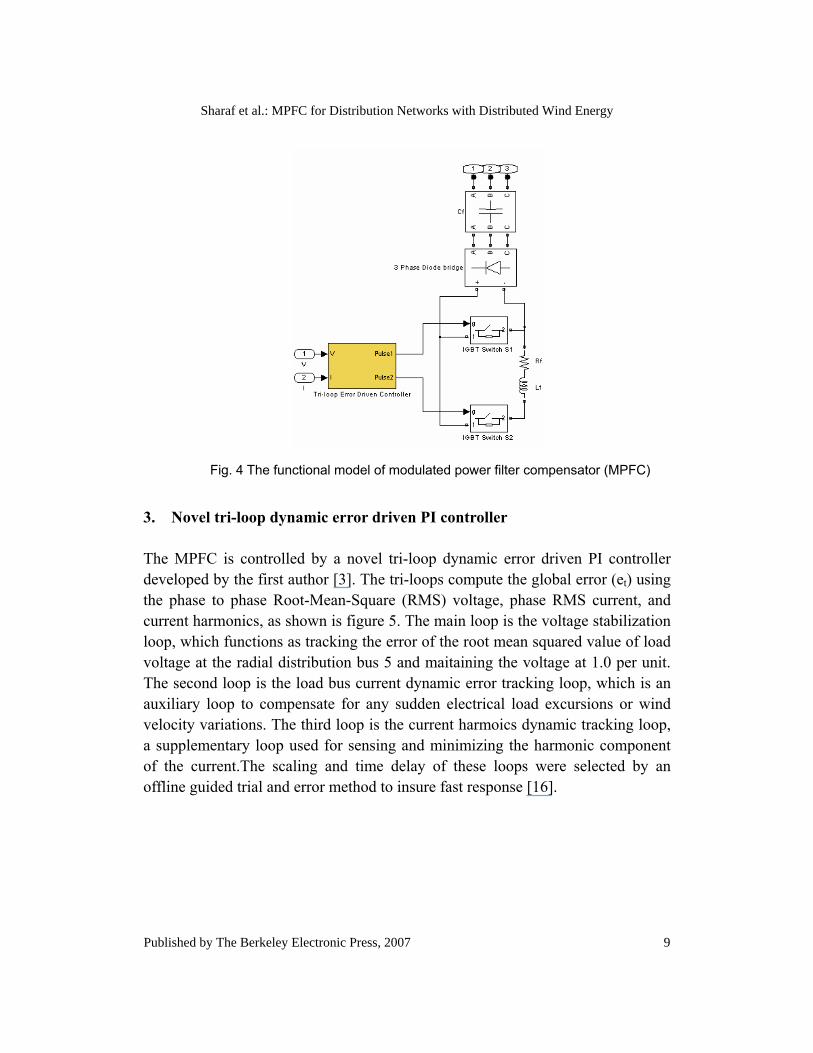
Fig. 4 The functional model of modulated power filter compensator (MPFC)
3. Novel tri-loop dynamic error driven PI controller
The MPFC is controlled by a novel tri-loop dynamic error driven PI controller developed by the first author [3]. The tri-loops compute the global error (et) using the phase to phase Root-Mean-Square (RMS) voltage, phase RMS current, and current harmonics, as shown is figure 5. The main loop is the voltage stabilization loop, which functions as tracking the error of the root mean squared value of load voltage at the radial distribution bus 5 and maitaining the voltage at 1.0 per unit. The second loop is the load bus current dynamic error tracking loop, which is an auxiliary loop to compensate for any sudden electrical load excursions or wind velocity variations. The third loop is the current harmoics dynamic tracking loop, a supplementary loop used for sensing and minimizing the harmonic component of the current.The scaling and time delay of these loops were selected by an offline guided trial and error method to insure fast response [16].
9
Sharaf et al.: MPFC for Distribution Networks with Distributed Wind Energy
Published by The Berkeley Electronic Press, 2007
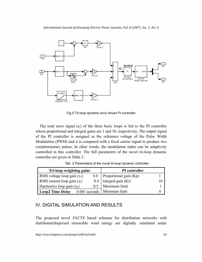
Fig.5 Tri-loop dynamic error driven PI controller
The total error signal (et) of the three basic loops is fed to the PI controller
whose proportional and integral gains are 1 and 10, respectively. The output signal of the PI controller is assigned as the reference voltage of the Pulse Width Modulation (PWM) and it is compared with a fixed carrier signal to produce two complementary pulses. In other words, the modulation index can be adaptively controlled in this controller. The full parameters of the novel tri-loop dynamic controller are given in Table 2.
Tab. 2 Parameters of the novel tri-loop dynamic controller
Tri-loop weighting gains PI controller RMS voltage loop gain (γv) 0.8 RMS current loop gain (γi) 0.4 Harmonics loop gain (γh) 0.5 Loop2 Time Delay 0.001 seconds
Proportional gain (Kp) 1 Integral gain (Ki) 10 Maximum limit 1 Minimum limit 0
IV. DIGITAL SIMULATION AND RESULTS
The proposed novel FACTS based schemes for distribution networks with distributed/dispersed renewable wind energy are digitally simulated under
10
International Journal of Emerging Electric Power Systems, Vol. 8 [2007], Iss. 3, Art. 6
http://www.bepress.com/ijeeps/vol8/iss3/art6

MATLAB/SIMULINK software environment. The built-in functional blocks in SIM-POWER toolbox facilitate the simulation of large and complicated power system. Discrete simulation mode with a sample time of 0.1 milliseconds will be applied to the simulation of the controller to accelerate the simulation speed.
The digital simulation is carried out with and without the controlled MPFC located at Bus5 for 0.8 seconds in order to show its performance in volatge stabilization, harmonic reduction, and reactive power compensation. The dynamic performance of the proposed MPFC is tested under the following disturbance sequence:
At t = 0.1second, induction motor is removed at bus 5 for a duration of 0.1 seconds; At t = 0.3second, linear load is removed at bus 4 for a duration of 0.1 seconds; At t = 0.5 second, wind speed suddenly decreased to 9 m/s for a duration of 0.1 seconds; At t = 0.6second, wind speed suddenly increased to 21 m/s for a duration of 0.1 seconds; At t = 0.7 the system was recovered to its initial state.
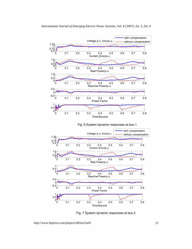
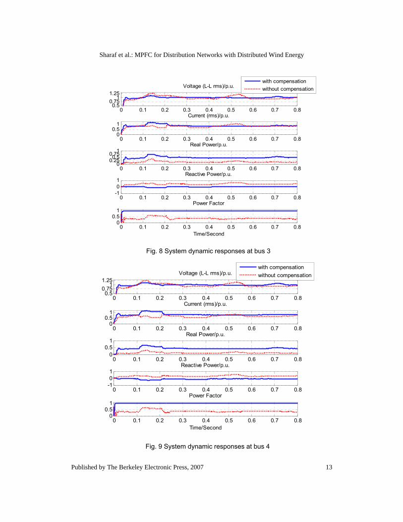
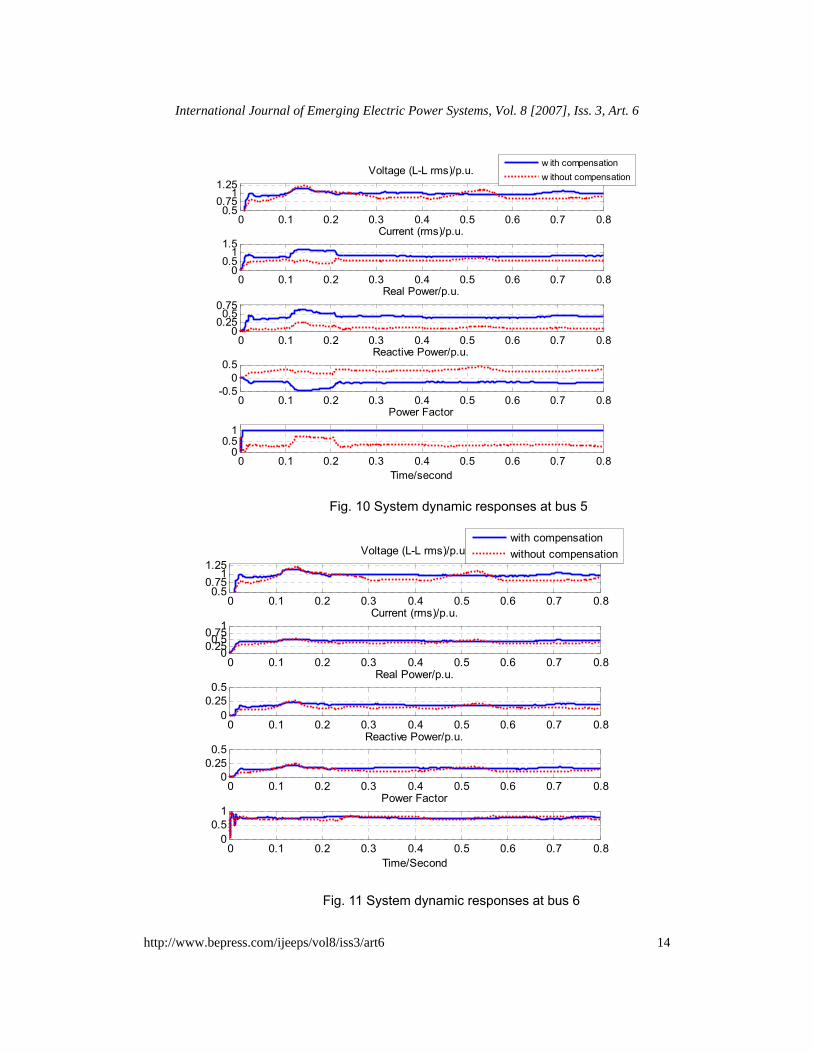
The dynamic responses of voltage, current, real power, reactive power and power factor at each bus are shown from Figure 6 to Figure11.
From the simulation results, significant transients can be observed, when the system is suffering from the disturbances. The transients are dramatically mitigated by using proposed MPFC, since both the amplitude and duration of the oscillation has been reduced.
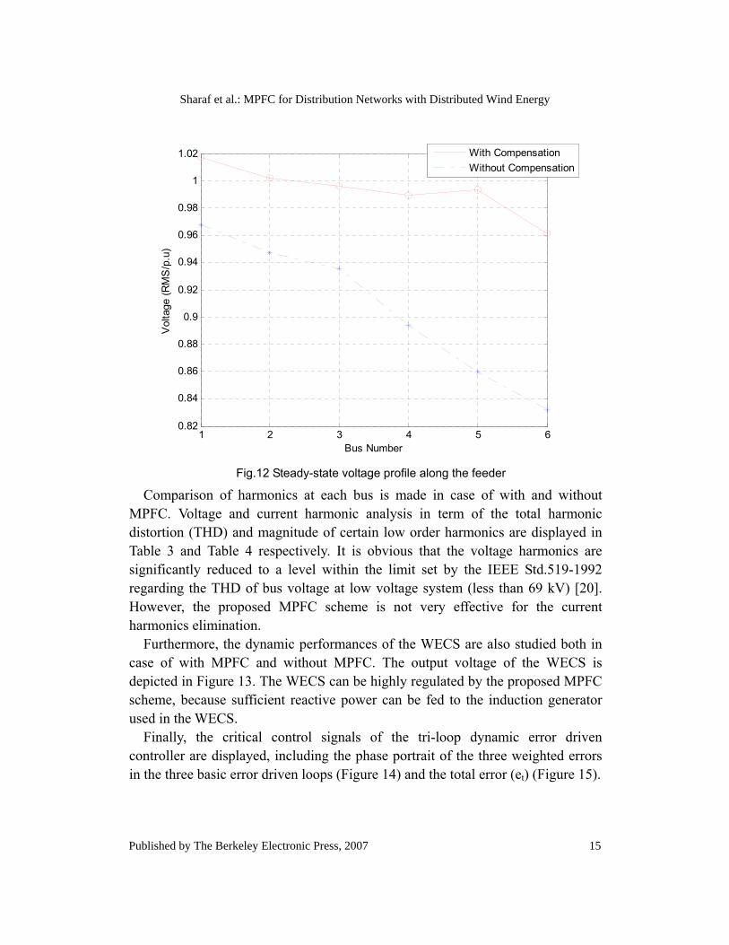
Besides transient mitigation, the proposed MPFC is also powerful for power factor correction and regulating voltage profile along the feeder, since reasonalble amount of reactive power can be injected into the grid according to its demand. It can be observed that all power factors along the feeder are improved above 0.85 and unit power factors are even achieved at bus 3, bus 4 and bus 5. A plot for steady-state voltage profile is depicted in Figure 12. From Fig.12, it can be noticed that the largest voltage drop is only 5.5% in case of with MPFC compensation, while the largest voltage drop comes to 14.0% in case of without MPFC compensation.
11
Sharaf et al.: MPFC for Distribution Networks with Distributed Wind Energy
Published by The Berkeley Electronic Press, 2007
0 0.1 0.2 0.3 0.4 0.5 0.6 0.7 0.80.5
0.751
1.25Voltage (L-L rms)/p.u.
with compensationwithout compensation
0 0.1 0.2 0.3 0.4 0.5 0.6 0.7 0.80
0.51
1.5Current (rms)/p.u.
0 0.1 0.2 0.3 0.4 0.5 0.6 0.7 0.80
0.511.3
Real Power/p.u.
0 0.1 0.2 0.3 0.4 0.5 0.6 0.7 0.8-0.5
00.5
Reactive Power/p.u.
0 0.1 0.2 0.3 0.4 0.5 0.6 0.7 0.80
0.51
Time/Second
Power Factor
Fig. 6 System dynamic responses at bus 1
0 0.1 0.2 0.3 0.4 0.5 0.6 0.7 0.80.5
0.751
1.25Voltage (L-L rms)/p.u.
with compensationwithout compensation
0 0.1 0.2 0.3 0.4 0.5 0.6 0.7 0.80
0.51
1.5Current (rms)/p.u.
0 0.1 0.2 0.3 0.4 0.5 0.6 0.7 0.80
0.51
Real Power/p.u.
0 0.1 0.2 0.3 0.4 0.5 0.6 0.7 0.8-0.5
00.5
Reactive Power/p.u.
0 0.1 0.2 0.3 0.4 0.5 0.6 0.7 0.80
0.51
Time/Second
Power Factor
Fig. 7 System dynamic responses at bus 2
12
International Journal of Emerging Electric Power Systems, Vol. 8 [2007], Iss. 3, Art. 6
http://www.bepress.com/ijeeps/vol8/iss3/art6
0 0.1 0.2 0.3 0.4 0.5 0.6 0.7 0.80.5
0.751
1.25Voltage (L-L rms)/p.u.
with compensationwithout compensation
0 0.1 0.2 0.3 0.4 0.5 0.6 0.7 0.80
0.51
Current (rms)/p.u.
0 0.1 0.2 0.3 0.4 0.5 0.6 0.7 0.80
0.250.50.751Real Power/p.u.
0 0.1 0.2 0.3 0.4 0.5 0.6 0.7 0.8-101
Reactive Power/p.u.
0 0.1 0.2 0.3 0.4 0.5 0.6 0.7 0.80
0.51
Time/Second
Power Factor
Fig. 8 System dynamic responses at bus 3
0 0.1 0.2 0.3 0.4 0.5 0.6 0.7 0.80.5
0.751
1.25Voltage (L-L rms)/p.u.
with compensationwithout compensation
0 0.1 0.2 0.3 0.4 0.5 0.6 0.7 0.80
0.51
Current (rms)/p.u.
0 0.1 0.2 0.3 0.4 0.5 0.6 0.7 0.80
0.51
Real Power/p.u.
0 0.1 0.2 0.3 0.4 0.5 0.6 0.7 0.8-101
Reactive Power/p.u.
0 0.1 0.2 0.3 0.4 0.5 0.6 0.7 0.80
0.51
Time/Second
Power Factor
Fig. 9 System dynamic responses at bus 4
13
Sharaf et al.: MPFC for Distribution Networks with Distributed Wind Energy
Published by The Berkeley Electronic Press, 2007
0 0.1 0.2 0.3 0.4 0.5 0.6 0.7 0.80.5
0.751
1.25Voltage (L-L rms)/p.u.
w ith compensationw ithout compensation
0 0.1 0.2 0.3 0.4 0.5 0.6 0.7 0.80
0.51
1.5Current (rms)/p.u.
0 0.1 0.2 0.3 0.4 0.5 0.6 0.7 0.80
0.250.5
0.75Real Power/p.u.
0 0.1 0.2 0.3 0.4 0.5 0.6 0.7 0.8-0.5
00.5
Reactive Power/p.u.
0 0.1 0.2 0.3 0.4 0.5 0.6 0.7 0.80
0.51
Time/second
Power Factor
Fig. 10 System dynamic responses at bus 5
0 0.1 0.2 0.3 0.4 0.5 0.6 0.7 0.80.5
0.751
1.25Voltage (L-L rms)/p.u.
with compensationwithout compensation
0 0.1 0.2 0.3 0.4 0.5 0.6 0.7 0.800.250.50.751
Current (rms)/p.u.
0 0.1 0.2 0.3 0.4 0.5 0.6 0.7 0.80
0.250.5
Real Power/p.u.
0 0.1 0.2 0.3 0.4 0.5 0.6 0.7 0.80
0.250.5
Reactive Power/p.u.
0 0.1 0.2 0.3 0.4 0.5 0.6 0.7 0.80
0.51
Time/Second
Power Factor
Fig. 11 System dynamic responses at bus 6
14
International Journal of Emerging Electric Power Systems, Vol. 8 [2007], Iss. 3, Art. 6
http://www.bepress.com/ijeeps/vol8/iss3/art6
1 2 3 4 5 60.82
0.84
0.86
0.88
0.9
0.92
0.94
0.96
0.98
1
1.02
Bus Number
Vol
tage
(RM
S/p
.u)
With CompensationWithout Compensation
Fig.12 Steady-state voltage profile along the feeder
Comparison of harmonics at each bus is made in case of with and without MPFC. Voltage and current harmonic analysis in term of the total harmonic distortion (THD) and magnitude of certain low order harmonics are displayed in Table 3 and Table 4 respectively. It is obvious that the voltage harmonics are significantly reduced to a level within the limit set by the IEEE Std.519-1992 regarding the THD of bus voltage at low voltage system (less than 69 kV) [20]. However, the proposed MPFC scheme is not very effective for the current harmonics elimination.
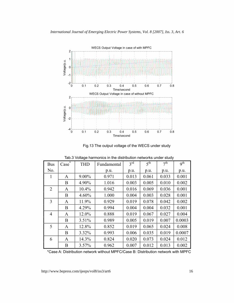
Furthermore, the dynamic performances of the WECS are also studied both in case of with MPFC and without MPFC. The output voltage of the WECS is depicted in Figure 13. The WECS can be highly regulated by the proposed MPFC scheme, because sufficient reactive power can be fed to the induction generator used in the WECS.
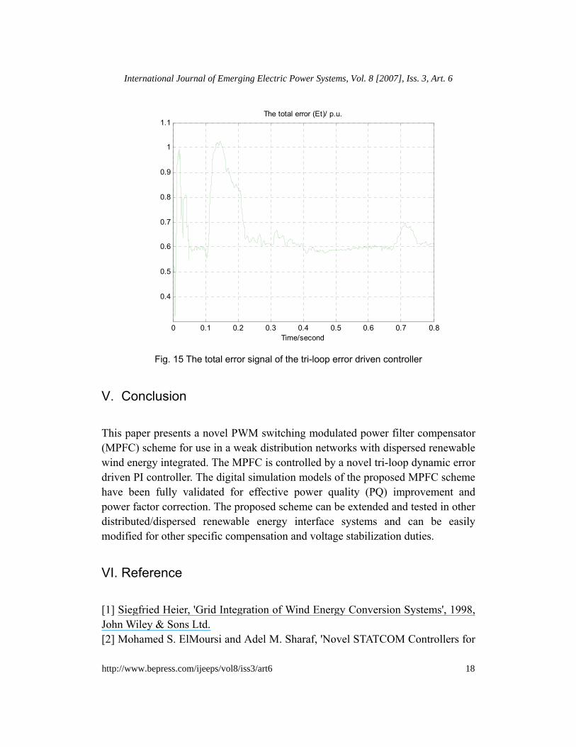
Finally, the critical control signals of the tri-loop dynamic error driven controller are displayed, including the phase portrait of the three weighted errors in the three basic error driven loops (Figure 14) and the total error (et) (Figure 15).
15
Sharaf et al.: MPFC for Distribution Networks with Distributed Wind Energy
Published by The Berkeley Electronic Press, 2007
0 0.1 0.2 0.3 0.4 0.5 0.6 0.7 0.8-2
-1
0
1
2
Time/second
Vol
tage
/p.u
.
WECS Output Voltage in case of with MPFC
0 0.1 0.2 0.3 0.4 0.5 0.6 0.7 0.8-4
-2
0
2
Time/second
Vol
tage
/p.u
.
WECS Output Voltage in case of without MPFC
Fig.13 The output voltage of the WECS under study
Tab.3 Voltage harmonics in the distribution networks under study
Bus No.
Case* THD Fundamentalp.u.
3rd p.u.
5th p.u.
7th p.u.
9th p.u.
A 9.00% 0.971 0.013 0.061 0.033 0.001 1 B 4.90% 1.016 0.003 0.005 0.010 0.002 A 10.4% 0.942 0.016 0.069 0.036 0.001 2 B 4.60% 1.000 0.004 0.003 0.028 0.001 A 11.9% 0.929 0.019 0.078 0.042 0.002 3 B 4.29% 0.994 0.004 0.004 0.032 0.001 A 12.0% 0.888 0.019 0.067 0.027 0.004 4 B 3.51% 0.989 0.005 0.019 0.007 0.0003A 12.8% 0.852 0.019 0.065 0.024 0.008 5 B 3.32% 0.993 0.006 0.035 0.019 0.0007A 14.3% 0.824 0.020 0.073 0.024 0.012 6 B 3.57% 0.962 0.007 0.012 0.013 0.002
*Case A: Distribution network without MPFC/Case B: Distribution network with MPFC
16
International Journal of Emerging Electric Power Systems, Vol. 8 [2007], Iss. 3, Art. 6
http://www.bepress.com/ijeeps/vol8/iss3/art6
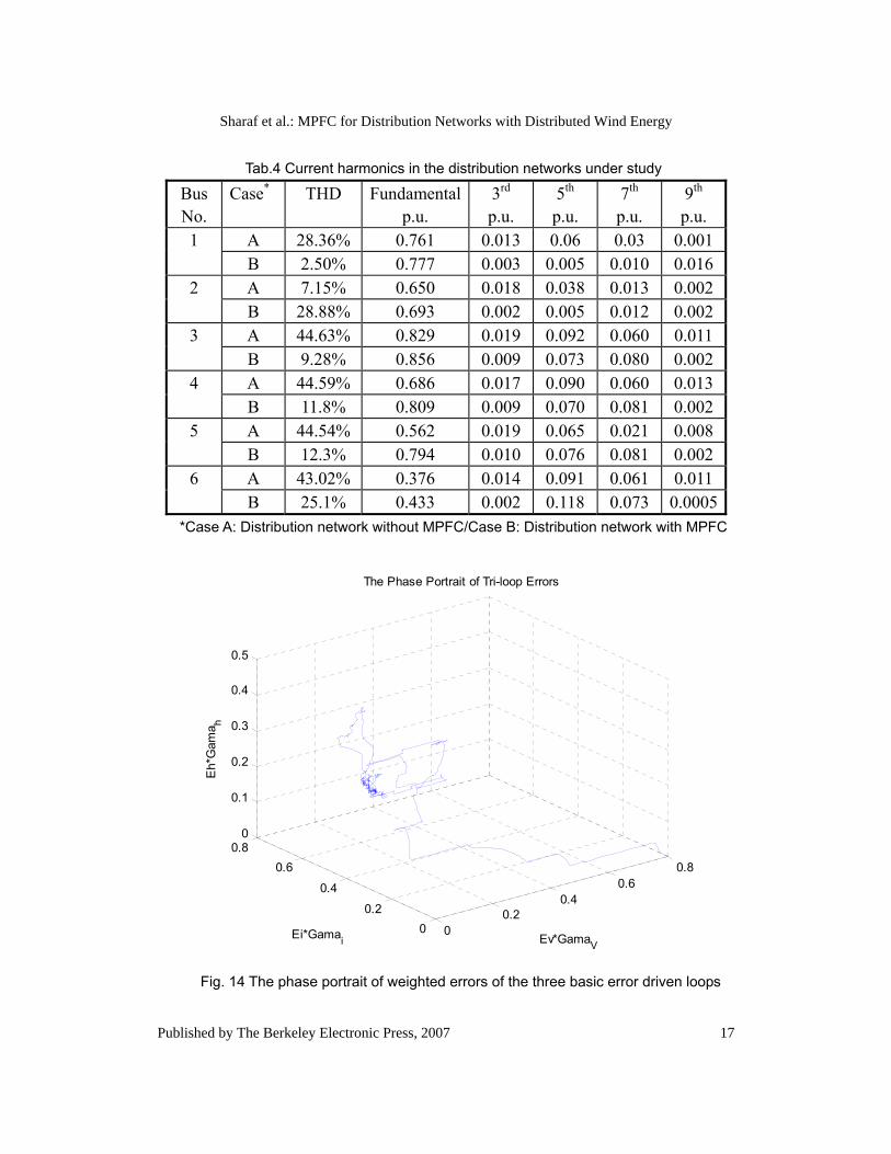
Tab.4 Current harmonics in the distribution networks under study
Bus No.
Case* THD Fundamentalp.u.
3rd p.u.
5th p.u.
7th p.u.
9th p.u.
A 28.36% 0.761 0.013 0.06 0.03 0.001 1 B 2.50% 0.777 0.003 0.005 0.010 0.016 A 7.15% 0.650 0.018 0.038 0.013 0.002 2 B 28.88% 0.693 0.002 0.005 0.012 0.002 A 44.63% 0.829 0.019 0.092 0.060 0.011 3 B 9.28% 0.856 0.009 0.073 0.080 0.002 A 44.59% 0.686 0.017 0.090 0.060 0.013 4 B 11.8% 0.809 0.009 0.070 0.081 0.002 A 44.54% 0.562 0.019 0.065 0.021 0.008 5 B 12.3% 0.794 0.010 0.076 0.081 0.002 A 43.02% 0.376 0.014 0.091 0.061 0.011 6 B 25.1% 0.433 0.002 0.118 0.073 0.0005
*Case A: Distribution network without MPFC/Case B: Distribution network with MPFC
00.2
0.40.6
0.8
00.2
0.4
0.60.8
0
0.1
0.2
0.3
0.4
0.5
Ev*GamaV
The Phase Portrait of Tri-loop Errors
Ei*Gamai
Eh*
Gam
a h
Fig. 14 The phase portrait of weighted errors of the three basic error driven loops
17
Sharaf et al.: MPFC for Distribution Networks with Distributed Wind Energy
Published by The Berkeley Electronic Press, 2007
0 0.1 0.2 0.3 0.4 0.5 0.6 0.7 0.8
0.4
0.5
0.6
0.7
0.8
0.9
1
1.1
Time/second
The total error (Et)/ p.u.
Fig. 15 The total error signal of the tri-loop error driven controller
V. Conclusion
This paper presents a novel PWM switching modulated power filter compensator (MPFC) scheme for use in a weak distribution networks with dispersed renewable wind energy integrated. The MPFC is controlled by a novel tri-loop dynamic error driven PI controller. The digital simulation models of the proposed MPFC scheme have been fully validated for effective power quality (PQ) improvement and power factor correction. The proposed scheme can be extended and tested in other distributed/dispersed renewable energy interface systems and can be easily modified for other specific compensation and voltage stabilization duties.
VI. Reference [1] Siegfried Heier, 'Grid Integration of Wind Energy Conversion Systems', 1998, John Wiley & Sons Ltd. [2] Mohamed S. ElMoursi and Adel M. Sharaf, 'Novel STATCOM Controllers for
18
International Journal of Emerging Electric Power Systems, Vol. 8 [2007], Iss. 3, Art. 6
http://www.bepress.com/ijeeps/vol8/iss3/art6
Voltage Stabilization of Stand Alone Hybrid (Wind/Small Hydro) Schemes', International Journal of Emerging Electric Power Systems, 2006, Vol.7, No. 3, Article 5 [3] A.M. Sharaf and Weihua Wang, 'A Low-cost Voltage Stabilization and Power Quality Enhancement Scheme for a Small Renewable Wind Energy Scheme', Proceedings-International Symposium on Industrial Electronics 2006, ISIE 2006 [4] The World Wind Energy Association (WWEA) web site, 'http://www.wwindea.org/'(2006) [5] Paul S. Veers,.Thomas D. Ashwill, Herbert J. Sutherland, Daniel L. Laird and Donald W. Lobitz, ‘Trends in the design, manufacture and evaluation of wind turbine blades’, Wind Energy, 2003; Vol 6: P245-259 [6] Robert W. Thresher and Darrell M. Dodge, ‘Trends in the evolution of wind turbine generator configurations and systems’, Wind Energy, Vol 1: p70-85, 1998 [7] N. Dizdarevic and M. Majstrovic, 'FACTS-based reactive power compensation of wind energy conversion system', 2003, IEEE Bologna PowerTech (IEEE Cat. No.03EX719), pt. 2, p 8 pp. Vol.2 [8] Domenico Villacci, Gianluca Bontempi and Alfredo Vaccaro, 'An adaptive local learning-based methodology for voltage regulation in distribution networks with dispersed generation', IEEE Transactions on Power Systems, Vol.21, No.3, August 2006 [9] Stavros A. Papathanassiou and Michael P. Papadopoulos, 'Harmonic Analysis in a Power System with Wind Generation', IEEE Transactions on Power Delivery, VOL. 21, NO. 4, OCTOBER 2006 [10] Narain G. Hingorani and Laszlo Gyugyi, 'Understanding FACTS: concepts and techonology of flexible AC transmission system', 2000, Institute of Electrical and Electronics Engineers, Inc. [11]Guosheng Wang, 'Novel Control Strategies and Interface Converters for Stand-alone Wind Energy Conversion Schemes', MSc.E Thesis, 2004, UNB. [12] Liang Zhao “Standalone wind Energy Utilization scheme and Novel control Strategies” MSc.E Thesis, 2005, UNB. [13] R.K. Varma and Tejbir S. Sidhu, 'Bibliographic Review of FACTS and HVDCApplications in Wind Power Systems', International Journal of EmergingElectric Power Systems, Volume 7, Issue2, 2006, Article 7 [14] Abdin, E.S.; Xu, W., 'Control design and dynamic performance analysis of a wind turbine-induction generator unit'Energy Conversion, IEEE Transactions on Volume 15, Issue 1, March 2000 Page(s):91 - 96 (SVC) [15] KATSUJI SHINOHARA, KURATO SHINHATSUBO, KENICHI IIMORI,
19
Sharaf et al.: MPFC for Distribution Networks with Distributed Wind Energy
Published by The Berkeley Electronic Press, 2007
KICHIRO YAMAMOTO,TAKAMICHI SARUBAN, and TAKAHIRO YAMAEMORI, 'Compensation for Harmonic Currents and Reactive Power in Wind Power Generation System Using PWM Inverter', Electrical Engineering in Japan, Vol. 154, No. 2, 2006 [16] El-Moursi, M.S. and Sharaf, A.M. , 'Novel STATCOM controllers for voltage stabilisation of wind energy scheme', Int. J. Global Energy Issues, Vol.26,2006 [17] F.G.R. de Campos and A.A.Jr.Penteado, 'Wind energy generation simulation with asynchronous generator connected to ENERSUL distribution system', 2004 IEEE/PES Transmision and Distribution Conference and Exposition: Latin America (IEEE Cat. No. 04EX956), 2004, p 149-54 [18] J.J. Ding, J. S. Buckeridge, Minpenz” Design Consideration for a Sustainable Hybrid Energy System” IPENZ Transactions, 2000, Vol.27, No.1/EMCH. [19] Sung-Hun Ko, Seong R. Lee, Hooman Dehbonei and Chemmangot V. Nayar, 'Application of Voltage- and Current-Controlled Voltage Source Inverters for Distributed Generation Systems', IEEE Transactions on Energy Conversion, Vol.21, No.3, September 2006 [20] IEEE Std. 519-1992, 'IEEE Recommended Practices and Requirements for Harmonic Control in Electrical Power Systems'
20
International Journal of Emerging Electric Power Systems, Vol. 8 [2007], Iss. 3, Art. 6
http://www.bepress.com/ijeeps/vol8/iss3/art6