Embed Size (px)
Citation preview
A
4l(cmTr©
K
1
npschtals
3t(nml
0d
Available online at www.sciencedirect.com
Electric Power Systems Research 78 (2008) 58–73
Control of a 3-phase 4-leg active power filter undernon-ideal mains voltage condition
Mehmet Ucar, Engin Ozdemir ∗Kocaeli University, Technical Education Faculty, Electrical Education Department, 41380 Umuttepe, Turkey
Received 29 August 2005; received in revised form 2 October 2006; accepted 13 December 2006Available online 25 January 2007
bstract
In this paper, instantaneous reactive power theory (IRP), also known as p–q theory based a new control algorithm is proposed for 3-phase-wire and 4-leg shunt active power filter (APF) to suppress harmonic currents, compensate reactive power and neutral line current and balance theoad currents under unbalanced non-linear load and non-ideal mains voltage conditions. The APF is composed from 4-leg voltage source inverterVSI) with a common DC-link capacitor and hysteresis–band PWM current controller. In order to show validity of the proposed control algorithm,ompared conventional p–q and p–q–r theory, four different cases such as ideal and unbalanced and balanced-distorted and unbalanced-distorted
ains voltage conditions are considered and then simulated. All simulations are performed by using Matlab-Simulink Power System Blockset.he performance of the 4-leg APF with the proposed control algorithm is found considerably effective and adequate to compensate harmonics,eactive power and neutral current and balance load currents under all non-ideal mains voltage scenarios.2006 Elsevier B.V. All rights reserved.
eal m
m4hcrThor
icltrc
eywords: 4-Leg shunt active power filter; Instantaneous power theory; Non-id
. Introduction
The widespread increase of non-linear loads nowadays, sig-ificant amounts of harmonic currents are being injected intoower systems. Harmonic currents flow through the powerystem impedance, causing voltage distortion at the harmonicurrents’ frequencies. The distorted voltage waveform causesarmonic currents to be drawn by other loads connected athe point of common coupling (PCC). The existence of currentnd voltage harmonics in power systems increases losses in theines, decreases the power factor and can cause timing errors inensitive electronic equipments.
The harmonic currents and voltages produced by balanced-phase non-linear loads such as motor drivers, silicon con-rolled rectifiers (SCR), large uninterruptible power suppliesUPS) are positive-sequence harmonics (7th, 13th, etc.) and
egative-sequence harmonics (5th, 11th, etc.). However, har-onic currents and voltages produced by single phase non-linearoads such as switch-mode power supplies in computer equip-
∗ Corresponding author. Tel.: +90 262 3032248; fax: +90 262 3032203.E-mail address: [email protected] (E. Ozdemir).
c
u3[oa
378-7796/$ – see front matter © 2006 Elsevier B.V. All rights reserved.oi:10.1016/j.epsr.2006.12.008
ains voltage; Unbalanced load
ent which are connected phase to neutral in a 3-phase-wire system are third order zero-sequence harmonics (triplenarmonics—3rd, 9th, 15th, 21st, etc.). These triplen harmonicurrents unlike positive and negative-sequence harmonic cur-ents do not cancel but add up arithmetically at the neutral bus.his can result in neutral current that can reach magnitudes asigh as 1.73 times the phase current. In addition to the hazardf cables and transformers overheating the third harmonic caneduce energy efficiency.
The traditional method of current harmonics reductionnvolves passive LC filters, which are its simplicity and lowost. However, passive filters have several drawbacks such asarge size, tuning and risk of resonance problems. On the con-rary, the 4-leg APF can solve problems of current harmonics,eactive power, load current balancing and excessive neutralurrent simultaneously, and can be a much better solution thanonventional approach.
The IRP theory introduced by Akagi et al. [1,2] has beensed very successfully to design and control of the APF for
-phase systems. This theory was extended by Aredes et al.3], for applications in 3-phase 4-wire systems. The IRP the-ry was mostly applied to calculate the compensating currentsssuming ideal mains voltages. However, mains voltage may be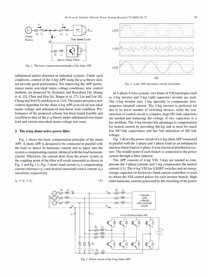
M. Ucar, E. Ozdemir / Electric Power Systems Research 78 (2008) 58–73 59
ucnmmeCcmfel
2
AtsctFcw
i
aTsdsakflv
iats
p
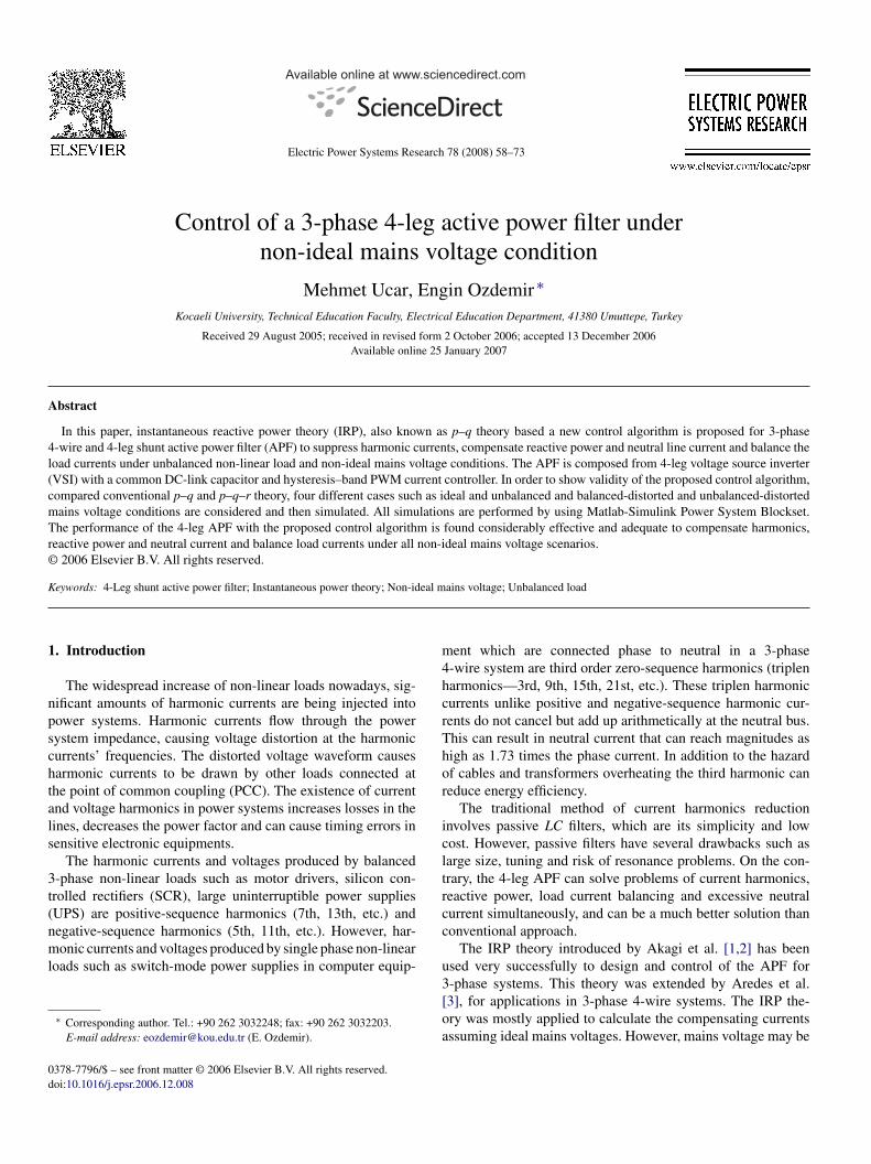
Fig. 1. The basic compensation principle of the shunt APF.
nbalanced and/or distorted in industrial systems. Under suchonditions, control of the 4-leg APF using the p–q theory doesot provide good performance. For improving the APF perfor-ance under non-ideal mains voltage conditions, new controlethods are proposed by Komatsu and Kawabata [4], Huang
t al. [5], Chen and Hsu [6], Haque et al. [7], Lin and Lee [8],hang and Yeh [9] and Kim et al. [10]. This paper presents a newontrol algorithm for the shunt 4-leg APF even for all non-idealains voltage and unbalanced non-linear load condition. Per-
ormance of the proposed scheme has been found feasible andxcellent to that of the p–q theory under unbalanced non-linearoad and various non-ideal mains voltage test cases.
. The 4-leg shunt active power filter
Fig. 1 shows the basic compensation principle of the shuntPF. A shunt APF is designed to be connected in parallel with
he load, to detect its harmonic current and to inject into theystem a compensating current, identical with the load harmonicurrent. Therefore, the current draw from the power system athe coupling point of the filter will result sinusoidal as shown inig. 2 and Eq. (1). Fig. 2 shows load current (iL), compensating
urrent reference (iC) and desired sinusoidal source current (iS)aveform, respectively.S = iL + iC (1)
csto
Fig. 3. Power circuit of th
Fig. 2. Load, APF and source current waveforms.
In 3-phase 4-wire systems, two kinds of VSI topologies suchs 4-leg inverter and 3-leg (split capacitor) inverter are used.he 4-leg inverter uses 1-leg specially to compensate zero-equence (neutral) current. The 3-leg inverter is preferred forue to its lower number of switching devices, while the con-truction of control circuit is complex, huge DC-link capacitorsre needed and balancing the voltage of two capacitors is aey problem. The 4-leg inverter has advantage to compensationor neutral current by providing 4th-leg and to need for muchess DC-link capacitance and has full utilization of DC-linkoltage.
Fig. 3 shows the power circuit of a 4-leg shunt APF connectedn parallel with the 1-phase and 3-phase loads as an unbalancednd non-linear load on 3-phase 4-wire electrical distribution sys-em. The middle point of each branch is connected to the powerystem through a filter inductor.
The APF consists of 4-leg VSI, 3-legs are needed to com-ensate the 3-phase currents and 1-leg compensates the neutral
urrent [11]. The 4-leg VSI has 8 IGBT switches and an energytorage capacitor on hysteresis–band current controllers is usedo obtain the VSI control pulses for each inverter branch. Highrder harmonic currents generated by the switching of the powere 4-leg shunt APF.
6 wer S
sa
3
t
b3il(
⎡⎢⎣
⎡⎢⎣
s⎡⎢⎣
ip
p
D
F
rnt(c
o(pp[
r
i
p
i
�
odsbwo
rdct
⎡
0 M. Ucar, E. Ozdemir / Electric Po
emiconductor devices of the PWM inverter is filtered by usingsmall RC high-pass filter, as shown in Fig. 3.
. The p–q theory based control strategy
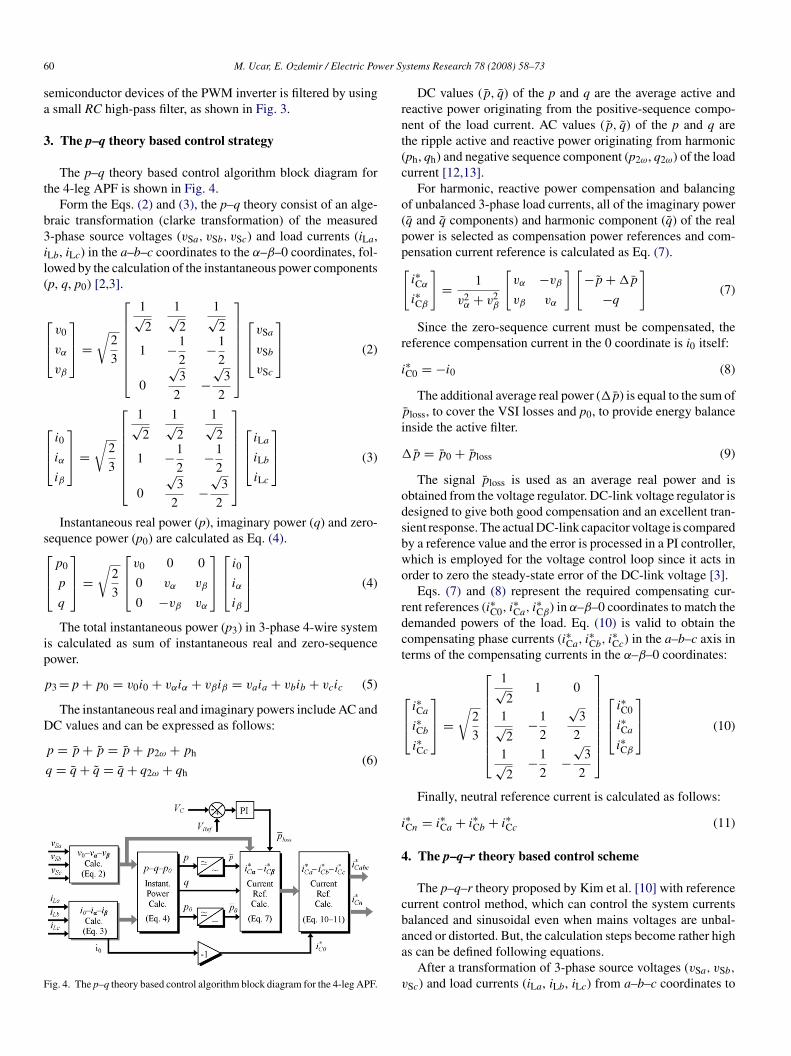
The p–q theory based control algorithm block diagram forhe 4-leg APF is shown in Fig. 4.
Form the Eqs. (2) and (3), the p–q theory consist of an alge-raic transformation (clarke transformation) of the measured-phase source voltages (vSa, vSb, vSc) and load currents (iLa,
Lb, iLc) in the a–b–c coordinates to the α–β–0 coordinates, fol-owed by the calculation of the instantaneous power componentsp, q, p0) [2,3].
v0
vα
vβ
⎤⎥⎦ =
√2
3
⎡⎢⎢⎢⎢⎢⎢⎣
1√2
1√2
1√2
1 −1
2−1
2
0
√3
2−
√3
2
⎤⎥⎥⎥⎥⎥⎥⎦
⎡⎢⎣
vSa
vSb
vSc
⎤⎥⎦ (2)
i0
iα
iβ
⎤⎥⎦ =
√2
3
⎡⎢⎢⎢⎢⎢⎢⎣
1√2
1√2
1√2
1 −1
2−1
2
0
√3
2−
√3
2
⎤⎥⎥⎥⎥⎥⎥⎦
⎡⎢⎣
iLa
iLb
iLc
⎤⎥⎦ (3)
Instantaneous real power (p), imaginary power (q) and zero-equence power (p0) are calculated as Eq. (4).
p0
p
q
⎤⎥⎦ =
√2
3
⎡⎢⎣
v0 0 0
0 vα vβ
0 −vβ vα
⎤⎥⎦
⎡⎢⎣
i0
iα
iβ
⎤⎥⎦ (4)
The total instantaneous power (p3) in 3-phase 4-wire systems calculated as sum of instantaneous real and zero-sequenceower.
3 =p + p0 = v0i0 + vαiα + vβiβ = vaia + vbib + vcic (5)
The instantaneous real and imaginary powers include AC and
C values and can be expressed as follows:p = p + p = p + p2ω + ph
q = q + q = q + q2ω + qh(6)
ig. 4. The p–q theory based control algorithm block diagram for the 4-leg APF.
⎢⎣
i
4
cbaa
v
ystems Research 78 (2008) 58–73
DC values (p, q) of the p and q are the average active andeactive power originating from the positive-sequence compo-ent of the load current. AC values (p, q) of the p and q arehe ripple active and reactive power originating from harmonicph, qh) and negative sequence component (p2ω, q2ω) of the loadurrent [12,13].
For harmonic, reactive power compensation and balancingf unbalanced 3-phase load currents, all of the imaginary powerq and q components) and harmonic component (q) of the realower is selected as compensation power references and com-ensation current reference is calculated as Eq. (7).
i∗Cα
i∗Cβ
]= 1
v2α + v2
β
[vα −vβ
vβ vα
] [−p + �p
−q
](7)
Since the zero-sequence current must be compensated, theeference compensation current in the 0 coordinate is i0 itself:
∗C0 = −i0 (8)
The additional average real power (�p) is equal to the sum of¯ loss, to cover the VSI losses and p0, to provide energy balancenside the active filter.
p = p0 + ploss (9)
The signal ploss is used as an average real power and isbtained from the voltage regulator. DC-link voltage regulator isesigned to give both good compensation and an excellent tran-ient response. The actual DC-link capacitor voltage is comparedy a reference value and the error is processed in a PI controller,hich is employed for the voltage control loop since it acts inrder to zero the steady-state error of the DC-link voltage [3].
Eqs. (7) and (8) represent the required compensating cur-ent references (i∗C0, i
∗Ca, i
∗Cβ) in α–β–0 coordinates to match the
emanded powers of the load. Eq. (10) is valid to obtain theompensating phase currents (i∗Ca, i
∗Cb, i
∗Cc) in the a–b–c axis in
erms of the compensating currents in the α–β–0 coordinates:
i∗Ca
i∗Cb
i∗Cc
⎤⎥⎦ =
√2
3
⎡⎢⎢⎢⎢⎢⎢⎢⎣
1√2
1 0
1√2
−1
2
√3
2
1√2
−1
2−
√3
2
⎤⎥⎥⎥⎥⎥⎥⎥⎦
⎡⎢⎣
i∗C0
i∗Ca
i∗Cβ
⎤⎥⎦ (10)
Finally, neutral reference current is calculated as follows:
∗Cn = i∗Ca + i∗Cb + i∗Cc (11)
. The p–q–r theory based control scheme
The p–q–r theory proposed by Kim et al. [10] with referenceurrent control method, which can control the system currentsalanced and sinusoidal even when mains voltages are unbal-
nced or distorted. But, the calculation steps become rather highs can be defined following equations.After a transformation of 3-phase source voltages (vSa, vSb,
Sc) and load currents (iLa, iLb, iLc) from a–b–c coordinates to
er Systems Research 78 (2008) 58–73 61
α
a(
⎡⎢⎣
w
ta
tt
⎡⎢⎣
5
in(iaattdtafafhiucf
4h
F
vE[
uqaTIt[
tza
eotclto the reference currents generated by the control algorithm. Ahysteresis–band PWM current control is implemented to gener-ate the switching pattern of the VSI. The hysteresis–band PWMcurrent control is the fastest control method with minimum hard-
M. Ucar, E. Ozdemir / Electric Pow
–β–0 coordinates, according to Eqs. (2) and (3), the currentsre transformed from α–β–0 coordinates to p–q–r coordinatesip, iq, ir) as follows:
ip
iq
ir
⎤⎥⎦ = 1
v0αβ
⎡⎢⎢⎢⎢⎣
v0 vα vβ
0 −v0αβvβ
vαβ
v0αβvα
vαβ
vαβ −v0vα
vαβ
−v0vβ
vαβ
⎤⎥⎥⎥⎥⎦
⎡⎢⎣
i0
iα
iβ
⎤⎥⎦ (12)
here v0αβ =√
v20 + v2
α + v2β, vαβ =
√v2α + v2
β.
Therefore, to get the source currents balanced and sinusoidal,he reference compensation currents (i∗Cp, i∗Cq, i
∗Cr) are selected
s Eq. (13).
i∗Cp = ip
i∗Cq = iq
i∗Cr = ir + ipv0
vαβ
(13)
The compensation currents in p–q–r coordinates are inverselyransformed to α–β–0 coordinates (i∗C0, i
∗Cα, i∗Cβ) as Eq. (14) and
hen to a–b–c coordinates (i∗Ca, i∗Cb, i
∗Cc) as Eq. (10).
i∗C0
i∗Cα
i∗Cβ
⎤⎥⎦ = 1
v0αβ
⎡⎢⎢⎢⎢⎣
v0 0 vαβ
vα −v0αβvβ
vαβ
−v0vα
vαβ
vβ
v0αβvα
vαβ
−v0vβ
vαβ
⎤⎥⎥⎥⎥⎦
⎡⎢⎣
i∗Cp
i∗Cq
i∗Cr
⎤⎥⎦ (14)
The neutral reference current is determined as Eq. (11).
. The proposed control algorithm
The p–q theory is suitable for ideal 3-phase systems but isnadequate under non-ideal mains voltage cases. In fact, underon-ideal mains voltage conditions, the sum of componentsv2α + v2
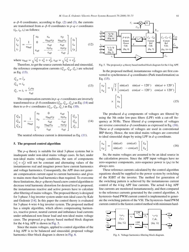
β) will not be constant and alternating values of thenstantaneous real and imaginer power have current harmonicsnd voltage harmonics. Consequently, the APF does not gener-te compensation current equal to current harmonics and giveso mains more than load harmonics than required. To overcomehese limitations, the p–q theory based a new control algorithm toecrease total harmonic distortion for desired level is proposed;he instantaneous reactive and active powers have to calculatefter filtering of mains voltages. The proposed theory is designedor 3-phase 3-leg inverter system under non-ideal cases by Kalend Ozdemir [14]. In this paper the control theory is evaluatedor 3-phase 4-wire 4-leg inverter system. The proposed methodas a simple algorithm, which allows compensating harmon-cs, reactive power, neutral current and imbalance load currentsnder unbalanced non-linear load and non-ideal mains voltageases. The proposed p–q theory based method block diagram
or the 4-leg APF is shown in Fig. 5.Since the mains voltages, applied to control algorithm of the-leg APF is to be balanced and sinusoidal, proposed voltagearmonics filter block diagram is shown in Fig. 6.
ig. 5. The proposed p–q theory based method block diagram for the 4-leg APF.
In the proposed method, instantaneous voltages are first con-erted to synchronous d–q coordinates (Park transformation) asq. (15).
vd
vq
]=
√2
3
[sin(ωt) sin(ωt − 120◦) sin(ωt + 120◦)
cos(ωt) cos(ωt − 120◦) cos(ωt + 120◦)
]
×
⎡⎢⎣
va
vb
vc
⎤⎥⎦ (15)
The produced d–q components of voltages are filtered bysing the 5th order low-pass filters (LPF) with a cut-off fre-uency at 50 Hz. These filtered d–q components of voltagesre reverse converted α–β coordinates as expressed in Eq. (16).hese α–β components of voltages are used in conventional
RP theory. Hence, the non-ideal mains voltages are convertedo ideal sinusoidal shape by using LPF in d–q coordinate.
vα
vβ
]=
[sin(ωt) cos(ωt)
sin(ωt) − cos(ωt)
] [vd
vq
](16)
So, the mains voltages are assumed to be an ideal source inhe calculation process. Since the APF input voltages have noero-sequence components, zero-sequence power is (p0) to belways zero.
These reference currents calculated by the control algorithmquations should be supplied to the power system by switchingf the IGBT of the inverter. The method for generation ofhe switching pattern is achieved by the instantaneous currentontrol of the 4-leg APF line currents. The actual 4-leg APFine currents are monitored instantaneously, and then compared
Fig. 6. Voltage harmonics filtering block diagram.
62 M. Ucar, E. Ozdemir / Electric Power Systems Research 78 (2008) 58–73
tion b
wdt
6
lmacamicab4
lpprs“icipac
6
raactaumaocseac
6
tvois
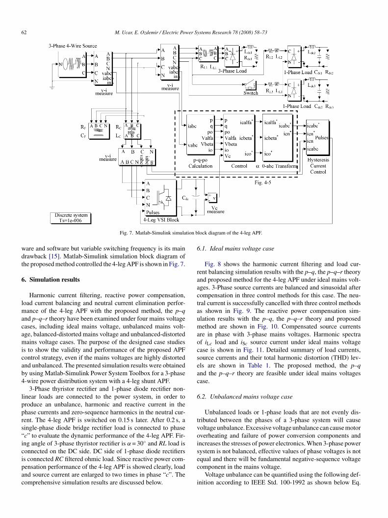
Fig. 7. Matlab-Simulink simula
are and software but variable switching frequency is its mainrawback [15]. Matlab-Simulink simulation block diagram ofhe proposed method controlled the 4-leg APF is shown in Fig. 7.
. Simulation results
Harmonic current filtering, reactive power compensation,oad current balancing and neutral current elimination perfor-
ance of the 4-leg APF with the proposed method, the p–qnd p–q–r theory have been examined under four mains voltageases, including ideal mains voltage, unbalanced mains volt-ge, balanced-distorted mains voltage and unbalanced-distortedains voltage cases. The purpose of the designed case studies
s to show the validity and performance of the proposed APFontrol strategy, even if the mains voltages are highly distortednd unbalanced. The presented simulation results were obtainedy using Matlab-Simulink Power System Toolbox for a 3-phase-wire power distribution system with a 4-leg shunt APF.
3-Phase thyristor rectifier and 1-phase diode rectifier non-inear loads are connected to the power system, in order toroduce an unbalance, harmonic and reactive current in thehase currents and zero-sequence harmonics in the neutral cur-ent. The 4-leg APF is switched on 0.15 s later. After 0.2 s, aingle-phase diode bridge rectifier load is connected to phasec” to evaluate the dynamic performance of the 4-leg APF. Fir-ng angle of 3-phase thyristor rectifier is α = 30◦ and RL load isonnected on the DC side. DC side of 1-phase diode rectifiers
s connected RC filtered ohmic load. Since reactive power com-ensation performance of the 4-leg APF is showed clearly, loadnd source current are enlarged to two times in phase “c”. Theomprehensive simulation results are discussed below.ec
i
lock diagram of the 4-leg APF.
.1. Ideal mains voltage case
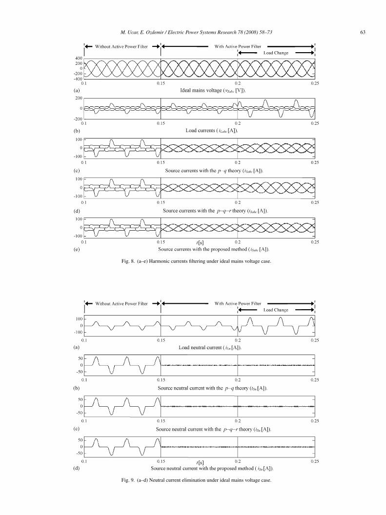
Fig. 8 shows the harmonic current filtering and load cur-ent balancing simulation results with the p–q, the p–q–r theorynd proposed method for the 4-leg APF under ideal mains volt-ges. 3-Phase source currents are balanced and sinusoidal afterompensation in three control methods for this case. The neu-ral current is successfully cancelled with three control methodss shown in Fig. 9. The reactive power compensation sim-lation results with the p–q, the p–q–r theory and proposedethod are shown in Fig. 10. Compensated source currents
re in phase with 3-phase mains voltages. Harmonic spectraf iLc load and iSc source current under ideal mains voltagease is shown in Fig. 11. Detailed summary of load currents,ource currents and their total harmonic distortion (THD) lev-ls are shown in Table 1. The proposed method, the p–qnd the p–q–r theory are feasible under ideal mains voltagesase.
.2. Unbalanced mains voltage case
Unbalanced loads or 1-phase loads that are not evenly dis-ributed between the phases of a 3-phase system will causeoltage unbalance. Excessive voltage unbalance can cause motorverheating and failure of power conversion components andncreases the stresses of power electronics. When 3-phase powerystem is not balanced, effective values of phase voltages is not
qual and there will be fundamental negative-sequence voltageomponent in the mains voltage.Voltage unbalance can be quantified using the following def-nition according to IEEE Std. 100-1992 as shown below Eq.
M. Ucar, E. Ozdemir / Electric Power Systems Research 78 (2008) 58–73 63
Fig. 8. (a–e) Harmonic currents filtering under ideal mains voltage case.
Fig. 9. (a–d) Neutral current elimination under ideal mains voltage case.
64 M. Ucar, E. Ozdemir / Electric Power Systems Research 78 (2008) 58–73
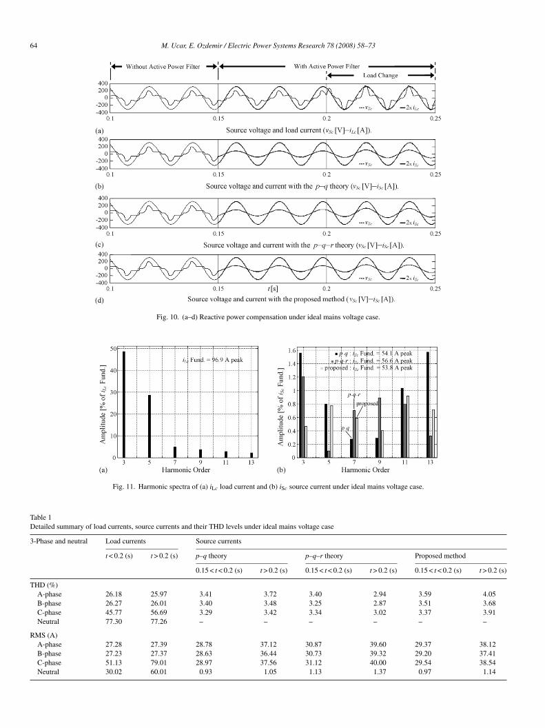
Fig. 10. (a–d) Reactive power compensation under ideal mains voltage case.
Fig. 11. Harmonic spectra of (a) iLc load current and (b) iSc source current under ideal mains voltage case.
Table 1Detailed summary of load currents, source currents and their THD levels under ideal mains voltage case
3-Phase and neutral Load currents Source currents
t < 0.2 (s) t > 0.2 (s) p–q theory p–q–r theory Proposed method
0.15 < t < 0.2 (s) t > 0.2 (s) 0.15 < t < 0.2 (s) t > 0.2 (s) 0.15 < t < 0.2 (s) t > 0.2 (s)
THD (%)A-phase 26.18 25.97 3.41 3.72 3.40 2.94 3.59 4.05B-phase 26.27 26.01 3.40 3.48 3.25 2.87 3.51 3.68C-phase 45.77 56.69 3.29 3.42 3.34 3.02 3.37 3.91Neutral 77.30 77.26 – – – – – –
RMS (A)A-phase 27.28 27.39 28.78 37.12 30.87 39.60 29.37 38.12B-phase 27.23 27.37 28.63 36.44 30.73 39.32 29.20 37.41C-phase 51.13 79.01 28.97 37.56 31.12 40.00 29.54 38.54Neutral 30.02 60.01 0.93 1.05 1.13 1.37 0.97 1.14
M. Ucar, E. Ozdemir / Electric Power Systems Research 78 (2008) 58–73 65
ring u
(
a
v
⎡⎢⎣
sc
s
msbtcsv0twpFi“ttHaoipp
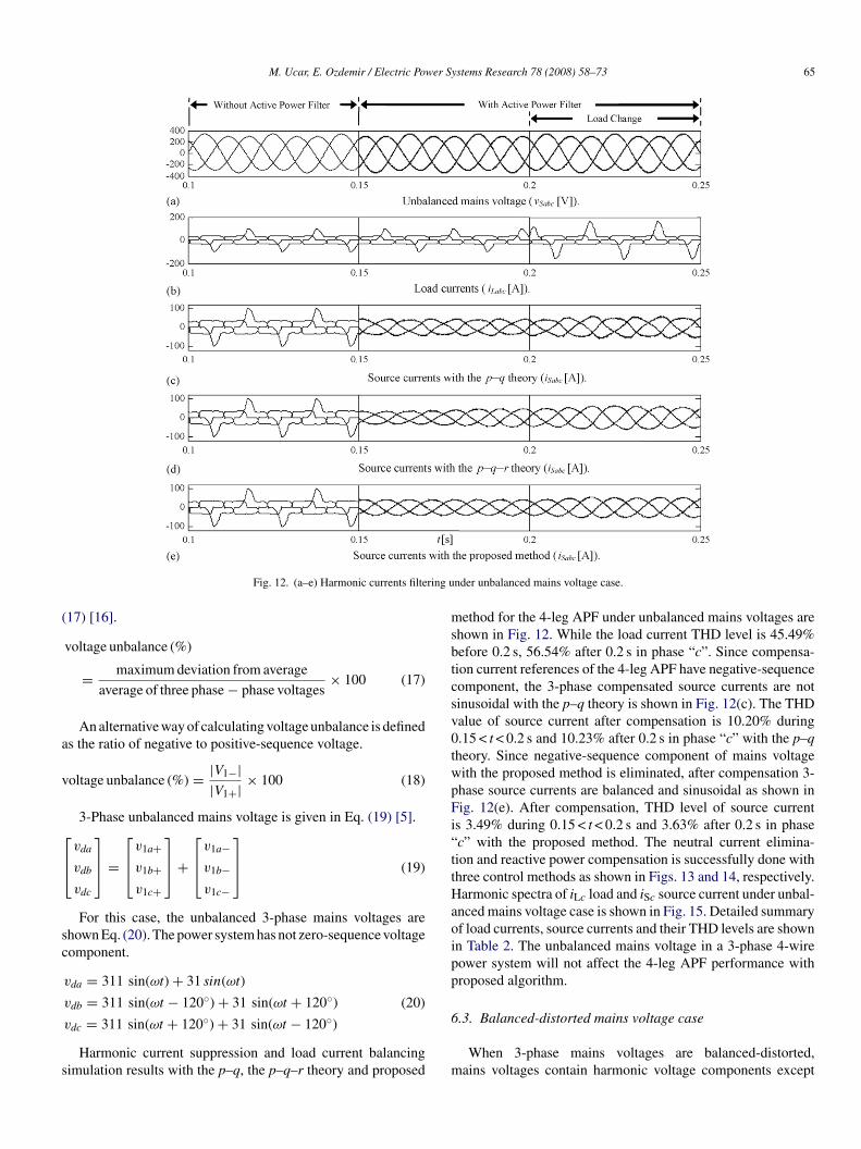
Fig. 12. (a–e) Harmonic currents filte
17) [16].
voltage unbalance (%)
= maximum deviation from average
average of three phase − phase voltages× 100 (17)
An alternative way of calculating voltage unbalance is defineds the ratio of negative to positive-sequence voltage.
oltage unbalance (%) = |V1−||V1+| × 100 (18)
3-Phase unbalanced mains voltage is given in Eq. (19) [5].
vda
vdb
vdc
⎤⎥⎦ =
⎡⎢⎣
v1a+v1b+v1c+
⎤⎥⎦ +
⎡⎢⎣
v1a−v1b−v1c−
⎤⎥⎦ (19)
For this case, the unbalanced 3-phase mains voltages arehown Eq. (20). The power system has not zero-sequence voltageomponent.
vda = 311 sin(ωt) + 31 sin(ωt)
vdb = 311 sin(ωt − 120◦) + 31 sin(ωt + 120◦)
vdc = 311 sin(ωt + 120◦) + 31 sin(ωt − 120◦)
(20)
Harmonic current suppression and load current balancingimulation results with the p–q, the p–q–r theory and proposed
6
m
nder unbalanced mains voltage case.
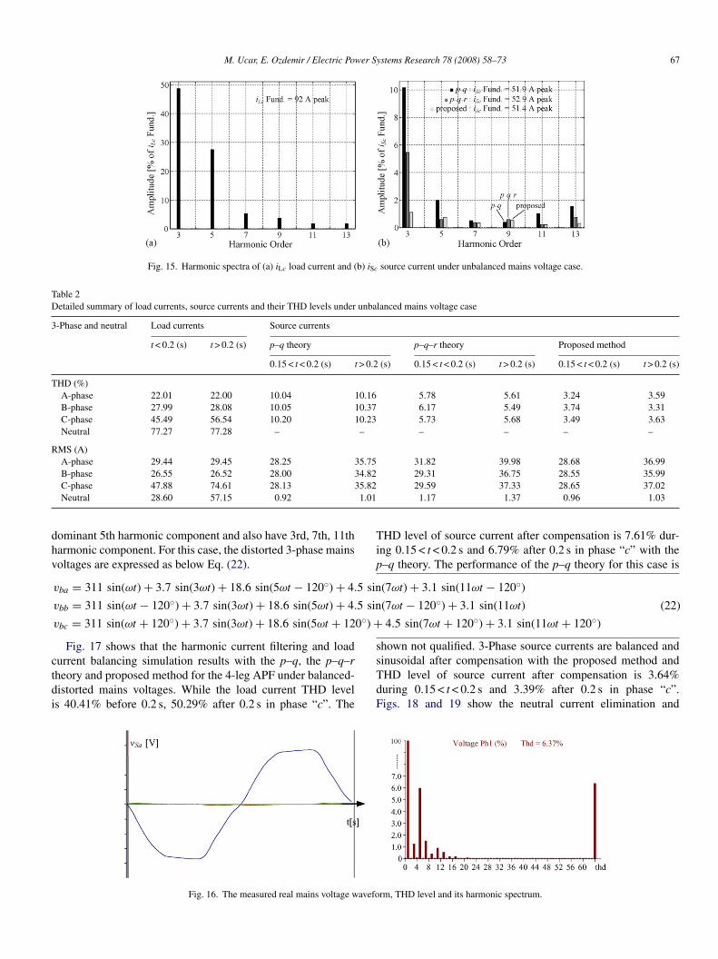
ethod for the 4-leg APF under unbalanced mains voltages arehown in Fig. 12. While the load current THD level is 45.49%efore 0.2 s, 56.54% after 0.2 s in phase “c”. Since compensa-ion current references of the 4-leg APF have negative-sequenceomponent, the 3-phase compensated source currents are notinusoidal with the p–q theory is shown in Fig. 12(c). The THDalue of source current after compensation is 10.20% during.15 < t < 0.2 s and 10.23% after 0.2 s in phase “c” with the p–qheory. Since negative-sequence component of mains voltageith the proposed method is eliminated, after compensation 3-hase source currents are balanced and sinusoidal as shown inig. 12(e). After compensation, THD level of source current
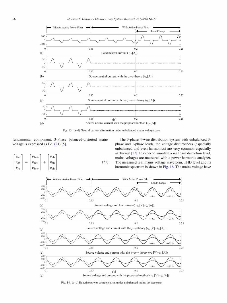
s 3.49% during 0.15 < t < 0.2 s and 3.63% after 0.2 s in phasec” with the proposed method. The neutral current elimina-ion and reactive power compensation is successfully done withhree control methods as shown in Figs. 13 and 14, respectively.armonic spectra of iLc load and iSc source current under unbal-
nced mains voltage case is shown in Fig. 15. Detailed summaryf load currents, source currents and their THD levels are shownn Table 2. The unbalanced mains voltage in a 3-phase 4-wireower system will not affect the 4-leg APF performance withroposed algorithm.
.3. Balanced-distorted mains voltage case
When 3-phase mains voltages are balanced-distorted,ains voltages contain harmonic voltage components except
66 M. Ucar, E. Ozdemir / Electric Power Systems Research 78 (2008) 58–73
tion u
fv
⎡⎢⎣
pu
Fig. 13. (a–d) Neutral current elimina
undamental component. 3-Phase balanced-distorted mainsoltage is expressed as Eq. (21) [5].
vba
vbb
vbc
⎤⎥⎦ =
⎡⎢⎣
v1a+v1b+v1c+
⎤⎥⎦ +
⎡⎢⎣
vah
vbh
vch
⎤⎥⎦ (21)
imTh
Fig. 14. (a–d) Reactive power compensation
nder unbalanced mains voltage case.
The 3-phase 4-wire distribution system with unbalanced 3-hase and 1-phase loads, the voltage disturbances (especiallynbalanced and even harmonics) are very common especially
n Turkey [17]. In order to simulate a real case distortion level,ains voltages are measured with a power harmonic analyzer.he measured real mains voltage waveform, THD level and itsarmonic spectrum is shown in Fig. 16. The mains voltage haveunder unbalanced mains voltage case.
M. Ucar, E. Ozdemir / Electric Power Systems Research 78 (2008) 58–73 67
Fig. 15. Harmonic spectra of (a) iLc load current and (b) iSc source current under unbalanced mains voltage case.
Table 2Detailed summary of load currents, source currents and their THD levels under unbalanced mains voltage case
3-Phase and neutral Load currents Source currents
t < 0.2 (s) t > 0.2 (s) p–q theory p–q–r theory Proposed method
0.15 < t < 0.2 (s) t > 0.2 (s) 0.15 < t < 0.2 (s) t > 0.2 (s) 0.15 < t < 0.2 (s) t > 0.2 (s)
THD (%)A-phase 22.01 22.00 10.04 10.16 5.78 5.61 3.24 3.59B-phase 27.99 28.08 10.05 10.37 6.17 5.49 3.74 3.31C-phase 45.49 56.54 10.20 10.23 5.73 5.68 3.49 3.63Neutral 77.27 77.28 – – – – – –
RMS (A)A-phase 29.44 29.45 28.25 35.75 31.82 39.98 28.68 36.99B-phase 26.55 26.52 28.00 34.82 29.31 36.75 28.55 35.99
5.821.01
dhv
5 sin
5 sin
0◦) +
ctdi
Tip
s
C-phase 47.88 74.61 28.13 3Neutral 28.60 57.15 0.92
ominant 5th harmonic component and also have 3rd, 7th, 11tharmonic component. For this case, the distorted 3-phase mainsoltages are expressed as below Eq. (22).
vba = 311 sin(ωt) + 3.7 sin(3ωt) + 18.6 sin(5ωt − 120◦) + 4.
vbb = 311 sin(ωt − 120◦) + 3.7 sin(3ωt) + 18.6 sin(5ωt) + 4.
vbc = 311 sin(ωt + 120◦) + 3.7 sin(3ωt) + 18.6 sin(5ωt + 12
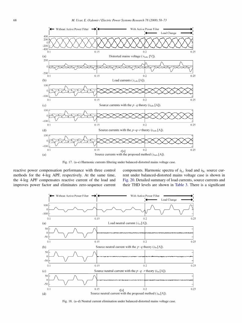
Fig. 17 shows that the harmonic current filtering and load
urrent balancing simulation results with the p–q, the p–q–rheory and proposed method for the 4-leg APF under balanced-istorted mains voltages. While the load current THD levels 40.41% before 0.2 s, 50.29% after 0.2 s in phase “c”. ThesTdF
Fig. 16. The measured real mains voltage wavefo
29.59 37.33 28.65 37.021.17 1.37 0.96 1.03
(7ωt) + 3.1 sin(11ωt − 120◦)
(7ωt − 120◦) + 3.1 sin(11ωt)
4.5 sin(7ωt + 120◦) + 3.1 sin(11ωt + 120◦)
(22)
HD level of source current after compensation is 7.61% dur-ng 0.15 < t < 0.2 s and 6.79% after 0.2 s in phase “c” with the–q theory. The performance of the p–q theory for this case is
hown not qualified. 3-Phase source currents are balanced and
inusoidal after compensation with the proposed method andHD level of source current after compensation is 3.64%uring 0.15 < t < 0.2 s and 3.39% after 0.2 s in phase “c”.igs. 18 and 19 show the neutral current elimination andrm, THD level and its harmonic spectrum.
68 M. Ucar, E. Ozdemir / Electric Power Systems Research 78 (2008) 58–73
unde
rmti
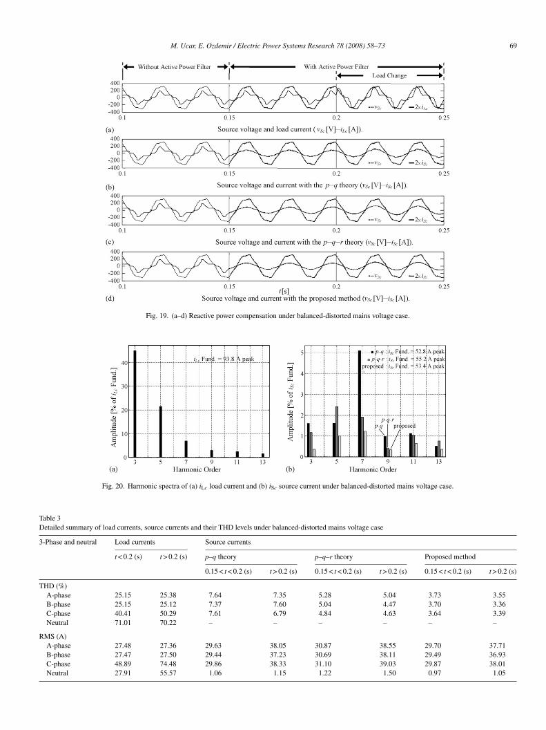
Fig. 17. (a–e) Harmonic currents filtering
eactive power compensation performance with three controlethods for the 4-leg APF, respectively. At the same time,
he 4-leg APF compensates reactive current of the load andmproves power factor and eliminates zero-sequence current
crFt
Fig. 18. (a–d) Neutral current elimination unde
r balanced-distorted mains voltage case.
omponents. Harmonic spectra of iLc load and iSc source cur-ent under balanced-distorted mains voltage case is shown inig. 20. Detailed summary of load currents, source currents and
heir THD levels are shown in Table 3. There is a significant
r balanced-distorted mains voltage case.
M. Ucar, E. Ozdemir / Electric Power Systems Research 78 (2008) 58–73 69
Fig. 19. (a–d) Reactive power compensation under balanced-distorted mains voltage case.
Fig. 20. Harmonic spectra of (a) iLc load current and (b) iSc source current under balanced-distorted mains voltage case.
Table 3Detailed summary of load currents, source currents and their THD levels under balanced-distorted mains voltage case
3-Phase and neutral Load currents Source currents
t < 0.2 (s) t > 0.2 (s) p–q theory p–q–r theory Proposed method
0.15 < t < 0.2 (s) t > 0.2 (s) 0.15 < t < 0.2 (s) t > 0.2 (s) 0.15 < t < 0.2 (s) t > 0.2 (s)
THD (%)A-phase 25.15 25.38 7.64 7.35 5.28 5.04 3.73 3.55B-phase 25.15 25.12 7.37 7.60 5.04 4.47 3.70 3.36C-phase 40.41 50.29 7.61 6.79 4.84 4.63 3.64 3.39Neutral 71.01 70.22 – – – – – –
RMS (A)A-phase 27.48 27.36 29.63 38.05 30.87 38.55 29.70 37.71B-phase 27.47 27.50 29.44 37.23 30.69 38.11 29.49 36.93C-phase 48.89 74.48 29.86 38.33 31.10 39.03 29.87 38.01Neutral 27.91 55.57 1.06 1.15 1.22 1.50 0.97 1.05
70 M. Ucar, E. Ozdemir / Electric Power Systems Research 78 (2008) 58–73
under
rnbdnm
6
mhd⎡⎢⎣
s
t − 1
) + 1
) + 1
r
adiTitcradniFicsudt
Fig. 21. (a–e) Harmonic currents filtering
eduction in harmonic distortion level with the proposed tech-ique. Therefore, the performance of the proposed method isetter than that of the conventional p–q theory. The balanced-istorted mains voltage in a 3-phase 4-wire power system willot affect the 4-leg APF performance by using the proposeethod.
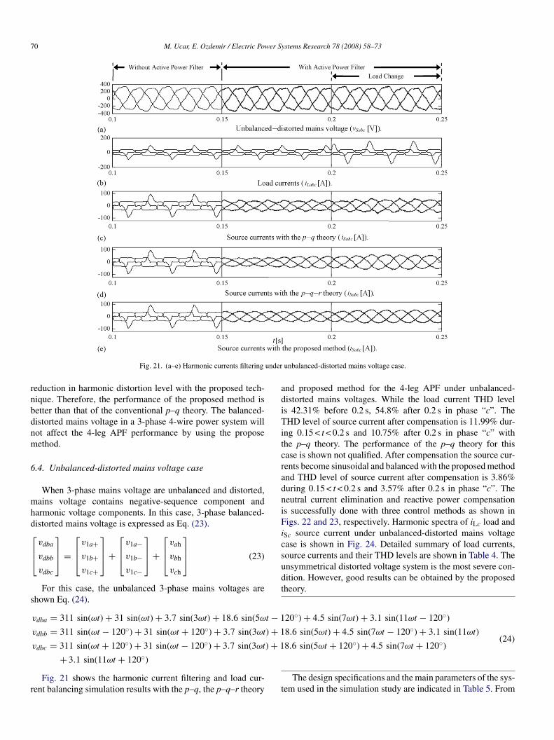
.4. Unbalanced-distorted mains voltage case
When 3-phase mains voltage are unbalanced and distorted,ains voltage contains negative-sequence component and
armonic voltage components. In this case, 3-phase balanced-istorted mains voltage is expressed as Eq. (23).
vdba
vdbb
vdbc
⎤⎥⎦ =
⎡⎢⎣
v1a+v1b+v1c+
⎤⎥⎦ +
⎡⎢⎣
v1a−v1b−v1c−
⎤⎥⎦ +
⎡⎢⎣
vah
vbh
vch
⎤⎥⎦ (23)
For this case, the unbalanced 3-phase mains voltages arehown Eq. (24).
vdba = 311 sin(ωt) + 31 sin(ωt) + 3.7 sin(3ωt) + 18.6 sin(5ω
vdbb = 311 sin(ωt − 120◦) + 31 sin(ωt + 120◦) + 3.7 sin(3ωt
vdbc = 311 sin(ωt + 120◦) + 31 sin(ωt − 120◦) + 3.7 sin(3ωt
+ 3.1 sin(11ωt + 120◦)
Fig. 21 shows the harmonic current filtering and load cur-ent balancing simulation results with the p–q, the p–q–r theory t
unbalanced-distorted mains voltage case.
20◦) + 4.5 sin(7ωt) + 3.1 sin(11ωt − 120◦)
8.6 sin(5ωt) + 4.5 sin(7ωt − 120◦) + 3.1 sin(11ωt)
8.6 sin(5ωt + 120◦) + 4.5 sin(7ωt + 120◦)(24)
nd proposed method for the 4-leg APF under unbalanced-istorted mains voltages. While the load current THD levels 42.31% before 0.2 s, 54.8% after 0.2 s in phase “c”. TheHD level of source current after compensation is 11.99% dur-
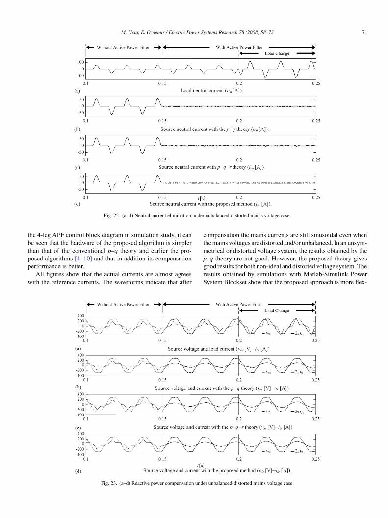
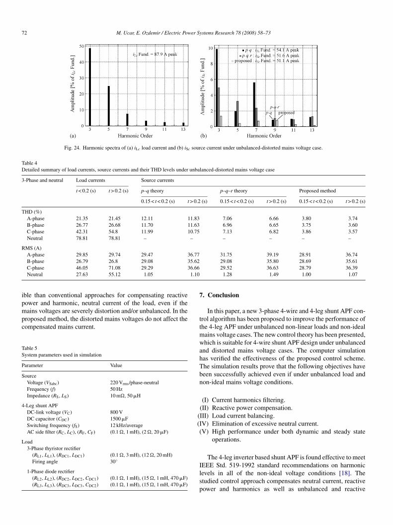
ng 0.15 < t < 0.2 s and 10.75% after 0.2 s in phase “c” withhe p–q theory. The performance of the p–q theory for thisase is shown not qualified. After compensation the source cur-ents become sinusoidal and balanced with the proposed methodnd THD level of source current after compensation is 3.86%uring 0.15 < t < 0.2 s and 3.57% after 0.2 s in phase “c”. Theeutral current elimination and reactive power compensations successfully done with three control methods as shown inigs. 22 and 23, respectively. Harmonic spectra of iLc load and
Sc source current under unbalanced-distorted mains voltagease is shown in Fig. 24. Detailed summary of load currents,ource currents and their THD levels are shown in Table 4. Thensymmetrical distorted voltage system is the most severe con-ition. However, good results can be obtained by the proposedheory.
The design specifications and the main parameters of the sys-em used in the simulation study are indicated in Table 5. From
M. Ucar, E. Ozdemir / Electric Power Systems Research 78 (2008) 58–73 71
under
tbtpp
w
ctm
Fig. 22. (a–d) Neutral current elimination
he 4-leg APF control block diagram in simulation study, it cane seen that the hardware of the proposed algorithm is simplerhan that of the conventional p–q theory and earlier the pro-
osed algorithms [4–10] and that in addition its compensationerformance is better.All figures show that the actual currents are almost agreesith the reference currents. The waveforms indicate that after
pgrS
Fig. 23. (a–d) Reactive power compensation unde
unbalanced-distorted mains voltage case.
ompensation the mains currents are still sinusoidal even whenhe mains voltages are distorted and/or unbalanced. In an unsym-
etrical or distorted voltage system, the results obtained by the
–q theory are not good. However, the proposed theory givesood results for both non-ideal and distorted voltage system. Theesults obtained by simulations with Matlab-Simulink Powerystem Blockset show that the proposed approach is more flex-r unbalanced-distorted mains voltage case.
72 M. Ucar, E. Ozdemir / Electric Power Systems Research 78 (2008) 58–73
Fig. 24. Harmonic spectra of (a) iLc load current and (b) iSc source current under unbalanced-distorted mains voltage case.
Table 4Detailed summary of load currents, source currents and their THD levels under unbalanced-distorted mains voltage case
3-Phase and neutral Load currents Source currents
t < 0.2 (s) t > 0.2 (s) p–q theory p–q–r theory Proposed method
0.15 < t < 0.2 (s) t > 0.2 (s) 0.15 < t < 0.2 (s) t > 0.2 (s) 0.15 < t < 0.2 (s) t > 0.2 (s)
THD (%)A-phase 21.35 21.45 12.11 11.83 7.06 6.66 3.80 3.74B-phase 26.77 26.68 11.70 11.63 6.96 6.65 3.75 3.60C-phase 42.31 54.8 11.99 10.75 7.13 6.82 3.86 3.57Neutral 78.81 78.81 – – – – – –
RMS (A)A-phase 29.85 29.74 29.47 36.77 31.75 39.19 28.91 36.74B-phase 26.79 26.8 29.08 35.62 29.08 35.80 28.69 35.61
6.661.10
ipmpc
TS
P
S
4
L
7
C-phase 46.05 71.08 29.29 3Neutral 27.63 55.12 1.05
ble than conventional approaches for compensating reactiveower and harmonic, neutral current of the load, even if the
ains voltages are severely distortion and/or unbalanced. In theroposed method, the distorted mains voltages do not affect theompensated mains current.
able 5ystem parameters used in simulation
arameter Value
ourceVoltage (VSabc) 220 Vrms/phase-neutralFrequency (f) 50 HzImpedance (RS, LS) 10 m�, 50 �H
-Leg shunt APFDC-link voltage (VC) 800 VDC capacitor (CDC) 1500 �FSwitching frequency (fS) 12 kHz/averageAC side filter (RC, LC), (RF, CF) (0.1 �, 1 mH), (2 �, 20 �F)
oad3-Phase thyristor rectifier
(RL1, LL1), (RDC1, LDC1) (0.1 �, 3 mH), (12 �, 20 mH)Firing angle 30◦
1-Phase diode rectifier(RL2, LL2), (RDC2, LDC2, CDC1) (0.1 �, 1 mH), (15 �, 1 mH, 470 �F)(RL3, LL3), (RDC3, LDC3, CDC2) (0.1 �, 1 mH), (15 �, 1 mH, 470 �F)
ttmwahTbn
((I(
Ilsp
29.52 36.63 28.79 36.391.28 1.49 1.00 1.07
. Conclusion
In this paper, a new 3-phase 4-wire and 4-leg shunt APF con-rol algorithm has been proposed to improve the performance ofhe 4-leg APF under unbalanced non-linear loads and non-ideal
ains voltage cases. The new control theory has been presented,hich is suitable for 4-wire shunt APF design under unbalanced
nd distorted mains voltage cases. The computer simulationas verified the effectiveness of the proposed control scheme.he simulation results prove that the following objectives haveeen successfully achieved even if under unbalanced load andon-ideal mains voltage conditions.
(I) Current harmonics filtering.(II) Reactive power compensation.III) Load current balancing.V) Elimination of excessive neutral current.V) High performance under both dynamic and steady state
operations.
The 4-leg inverter based shunt APF is found effective to meet
EEE Std. 519-1992 standard recommendations on harmonicevels in all of the non-ideal voltage conditions [18]. Thetudied control approach compensates neutral current, reactiveower and harmonics as well as unbalanced and reactive
er Sy
cd
A
1
A
CCii
i
i
iiiiLLLnpp
p
p
pppp�
q
qqRRRRv
v
v
v
v
v
v
v
v
R
[
[
[
[
[
[
[
M. Ucar, E. Ozdemir / Electric Pow
urrent components, and this will be really appreciated by theistribution system.
cknowledgement
This research is supported by TUBITAK Research Fund (No.:03E034-AY-57).
ppendix A. List of symbols
DC DC capacitorF switching harmonics filter capacitor capacitance
Cabc instantaneous compensation currents∗Ca, i
∗Cb, i
∗Cc instantaneous compensation current references inthe a–b–c coordinates
∗C0, i
∗Cα, i∗Cβ instantaneous compensation current references in
the α–β–0 coordinates∗Cp, i∗Cq, i
∗Cr instantaneous compensation current references in
the p–q–r coordinatesLabc instantaneous load currentsSabc instantaneous source currentsα, iβ, i0 instantaneous currents in the α–β–0 coordinatesp, iq, ir instantaneous currents in the p–q–r coordinatesC APF filter inductanceS source inductanceL load filter inductance
neutralinstantaneous real power
¯ average real power˜ oscillating part of real power¯ loss average real power loss0 instantaneous zero-sequence power2ω negative sequence part of real power3 3-phase total instantaneous real powerh harmonic part of real powerp average real power
instantaneous imaginary power¯ average imaginary power˜ oscillating part of imaginary power
2ω negative-sequence part of imaginary powerh harmonic part of imaginary powerC APF filter resistanceF switching harmonics filter resistanceS source internal resistanceL load filter resistanceah, vbh, vch harmonic parts of mains voltageba, vbb, vbc balanced-distorted instantaneous mains voltages
d, vq instantaneous mains voltages in the d–q coordinatesda, vdb, vdc unbalanced instantaneous mains voltagesdba, vdbb, vdbc unbalanced-distorted instantaneous mainsvoltages
[
[
stems Research 78 (2008) 58–73 73
Sabc instantaneous mains voltagesα, vβ, v0 instantaneous mains voltages in the α–β–0 coordi-
nates1a+, v1b+, v1c+ fundamental positive-sequence part of mains
voltage1a−, v1b−, v1c− fundamental negative-sequence part of mains
voltage
eferences
[1] H. Akagi, Y. Kanazawa, A. Nabae, Instantaneous reactive power compen-sators comprising switching devices without energy storage elements, IEEETrans. Ind. Appl. 1A-20 (1984) 625–630.
[2] J. Afonso, C. Couto, J. Martins, Active filters with control based on the p–qtheory, IEEE Ind. Electron. Soc. Newslett. 47 (3) (2000) 5–11.
[3] M. Aredes, J. Hafner, K. Heumann, Three-phase four-wire shunt active filtercontrol strategies, IEEE Trans. Power Electron. 12 (2) (1997) 311–318.
[4] Y. Komatsu, T. Kawabata, A control method for the active power fil-ter in unsymmetrical voltage systems, Int. J. Electron. 86 (10) (1999)1249–1260.
[5] S.J. Huang, et al., A study of three-phase active power filters under non-idealmains voltages, Electr. Power Syst. Res. 49 (1999) 125–137.
[6] C.C. Chen, Y.Y. Hsu, A novel approach to the design of a shunt activefilter for an unbalanced three-phase four-wire system under nonsinusoidalconditions, IEEE Trans. Power Delivery 15 (4) (2000) 1258–1264.
[7] M.T. Haque, T. Ise, S.H. ve Hosseini, A novel control strategy for activefilters usable in harmonic polluted and/or imbalanced utility voltage case of3-phase 4-wire distribution systems, in: Proceedings of Ninth InternationalConference on Harmonics and Quality of Power, 2000, pp. 239–244.
[8] B.R. Lin, Y.C. Lee, Three-phase power quality compensator under theunbalanced sources and nonlinear loads, IEEE Trans. Ind. Electron. 51(5) (2004) 1009–1017.
[9] G.W. Chang, C.M. Yeh, Optimisation-based strategy for shunt active powerfilter control under non-ideal supply voltages, IEE Proc. Electr. Power Appl.152 (2) (2005) 182–190.
10] H. Kim, F. Blaabjerg, B. Bak-Jensen, J. Choi, Instantaneous power com-pensation in three-phase systems by using p–q–r theory, IEEE Trans. PowerElectron. 17 (5) (2002) 701–710.
11] A.N. Segura, G.M. Aguilar, Four branches inverter based active filter forunbalanced 3-phase 4-wires electrical distribution systems, in: Proceedingsof the IEEE-IAS 2000 Annual Meeting, Rome, Italy, 2000, pp. 2503–2508.
12] F.Z. Peng, G.W. Ott, D.J. Adams, Harmonic and reactive power com-pensation based on the generalized instantaneous reactive power theoryfor 3-phase 4-wire systems, IEEE Trans. Power Electron. 13 (6) (1998)1174–1181.
13] E.H. Watanabe, R.M. Stephan, M. Aredes, New concepts of instantaneousactive and reactive powers in electrical systems with generic loads, IEEETrans. Power Delivery 8 (2) (1993) 697–703.
14] M. Kale, E. Ozdemir, Harmonic and reactive power compensation withshunt active power filter under non-ideal mains voltage, Electric PowerSyst. Res. 77 (2005) 363–370.
15] L. Malesani, P. Mattavelli, P. ve Tomasin, High-performance hysteresismodulation technique for active filters, IEEE Trans. Power Electron. 12 (5)(1997) 876–884.
16] The New IEEE Standard Dictionary of Electrical and Electronics Terms,
IEEE Std. 100-1992.17] Ucar, M., Design and implementation of 3-phase 4-wire shunt active powerfilter, Master Thesis, Kocaeli University, Turkey, 2005.
18] IEEE Recommended Practice and Requirements for Harmonic Control inElectrical Power Systems, IEEE Std. 519-1992.