Embed Size (px)
Citation preview
E. TOPOGRAPHIC MAPPING
By W. M. BEAMAN
CHARACTER OF TOPOGRAPHIC MAPS
Definition of a topographic map. A topographic map is a repre sentation on paper that is designed to portray certain selected features of a section of the earth's surface plotted on some form of projection and to a certain scale; that primarily depicts the relief of the country mapped but shows also its drainage and cultural features; and that delineates all features in true latitude and longitude and therefore all parts in a rigidly correct relative position. A reproduction of a part of a topographic map is shown in-Plate 17.
Quadrangles. The topographic maps of the United States Geolog ical Survey are designed to constitute a topographic atlas of the United States for an engineering and geologic base. For the purpose of this atlas the country is divided into quadrangles bounded by parallels of latitude and meridians of longitude. Each sheet of the atlas is a map of some quadrangle. The quadrangle maps are printed on paper of approximately uniform size, about 16 J^ by 20 inches, and the maps themselves are about 17 ̂ inches long and 12 to 15 inches wide according to latitude.
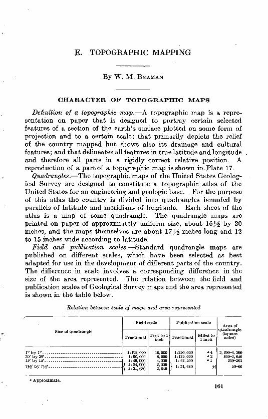
Field and publication scales. Standard quadrangle maps are published on different scales, which have been selected as best adapted for use in the development of different parts of the country. The difference in scale involves a corresponding difference in the size of the area represented. The relation between the field and publication scales of Geological Survey maps and the area represented is shown in the table below.
Relation between scale of maps and area represented
Size of quadrangle
1° by I0 .. 30' by 30'-.--... ___ - __ . __ . ___ .-..-.15' by 15' TW by iyt ......... ...........................
Field scale
Fractional
1:192,000 1:96,000 1:48,000
/ 1:24,000 \ 1:31,680
Feet to 1 inch
16,000 8,000 4,000 2,000 2,640
Publication scale
Fractional
1:250,000 1:125,000 1:62,500
} 1:31,680
Miles to linch
04 °2° 1
X
Area of quadrangle
(square miles)
3, 200-4, 200 800-1, 050
200-26250-66
' Approximate.161
162 TOPOGRAPHIC INSTRUCTIONS OF GEOLOGICAL SURVEY
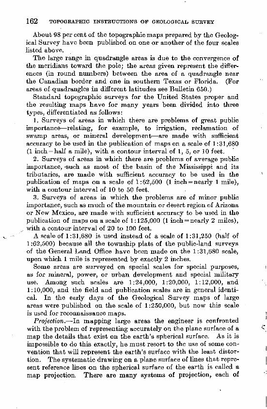
About 98 per cent of the topographic maps prepared by the Geolog ical Survey have been published on one or another of the four scales listed above.
The large range in quadrangle areas is due to the convergence of the meridians toward the pole; the areas given represent the differ ences (in round numbers) between the area of a quadrangle near the Canadian border and one in southern Texas or Florida. (For areas of quadrangles in different latitudes see Bulletin 650.)
Standard topographic surveys for the United States proper and the resulting maps have for many years been divided into three types, differentiated as follows:
1. Surveys of areas in which there are problems of great public importance relating, for example, to irrigation, reclamation of swamp areas, or mineral development are made with sufficient accuracy to be used in the publication of maps on a scale of 1:31,680 (1 inch = half a mile), with a contour interval of 1, 5, or 10 feet.
2. Surveys of areas in which there are problems of average public importance, -such as most of the basin of the Mississippi and its tributaries, are made with sufficient accuracy to be used in the publication of maps on a scale of 1:62,500 (1 inch = nearly 1 mile), with a contour interval of 10 to 50 feet.
3. Surveys of areas in which the problems are of minor public importance, such as much of the mountain or desert region of Arizona or New Mexico, are made with sufficient accuracy to be used in the publication of maps on a scale of 1:125,000 (1 inch = nearly 2 miles), with a contour interval of 20 to 100 feet.
A scale of 1:31,680 is used instead of a scale of 1:31,250 (half of 1:62,500) because all the township plats of the public-land surveys of the General Land Office have been made on the 1:31,680 scale, upon which 1 mile is represented by exactly 2 inches.
Some areas are surveyed on special scales for special purposes, as for mineral, power, or urban development and special military use. Among such scales are 1:24,000, 1:20,000, 1:12,000, and 1:10,000, and the field and publication scales are in general identi cal. In the early days of the Geological Survey maps of large areas were published on the scale of 1:250,000, but now this scale is used for reconnaissance maps.
Projection. In mapping large areas the engineer is confronted with the problem of representing accurately on the plane surface of a map the details that exist on the earth's spherical surface. As it is impossible to do this exactly, he must resort to the use of some con vention that will represent the earth's surface with the least distor tion. The systematic drawing on a plane surface of lines that repre sent reference lines on the spherical surface of the earth is called a map projection. There are many systems of projection, each of
TOPOGRAPHIC MAPPING 163
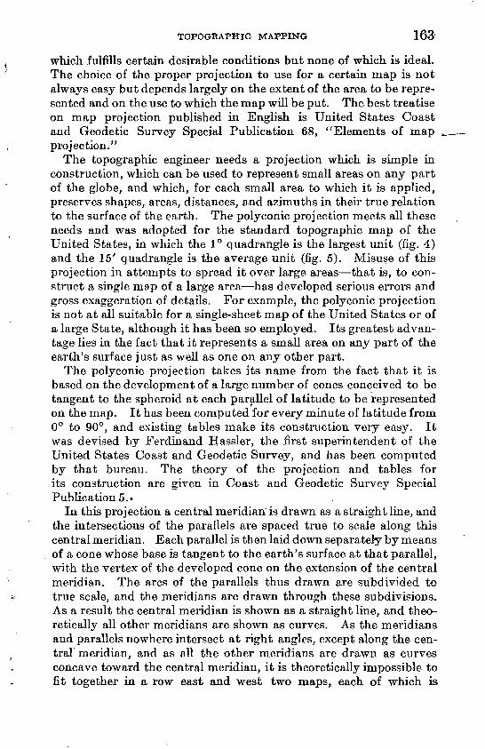
which fulfills certain desirable conditions but none of which is ideal. The choice of the proper projection to use for a certain map is not always easy but depends largely on the extent of the area to be repre sented and on the use to which the map will be put. The best treatise on map projection published in English is United States Coast and Geodetic Survey Special Publication 68, "Elements of map projection."
The topographic engineer needs a projection which is simple in construction, which can be used to represent small areas on any part of the globe, and which, for each small area to which it is applied, preserves shapes, areas, distances, and azimuths in their true relation to the surface of the earth. The poly conic projection meets all these needs and was adopted for the standard topographic map of the United States, in which the 1° quadrangle is the largest unit (fig. 4) and the 15' quadrangle is the average unit (fig. 5). Misuse of this projection in attempts to spread it over large areas that is, to con struct a single map of a large area has developed serious errors and gross exaggeration of details. For example, the poly conic projection is not at all suitable for a single-sheet map of the United States or of a large State, although it has been so employed. Its greatest advan tage lies in the fact that it represents a small area on any part of the earth's surface just as well as one on any other part.
The poly conic projection takes its name from the fact that it is based on the development of a large number of cones conceived to be tangent to the spheroid at each parallel of latitude to be represented on the map. It has been computed for every minute of latitude from 0° to 90°, and existing tables make its construction very easy. It was devised by Ferdinand Hassler, the first superintendent of the United States Coast and Geodetic Survey, and has been computed by that bureau. The theory of the projection and tables for its construction are given in Coast and Geodetic Survey Special Publication 5.-
In this projection a central meridian is drawn as a straight line, and the intersections of the parallels are spaced true to scale along this central meridian. Each parallel is then laid down separately by means of a cone whose base is tangent to the earth's surface at that parallel, with the vertex of the developed cone on the extension of the central meridian. The arcs of the parallels thus drawn are subdivided to true scale, and the meridians are drawn through these subdivisions. As a result the central meridian is shown as a straight line, and theo retically all other meridians are shown as curves. As the meridians and parallels nowhere intersect at right angles, except along the cen- traT meridian, and as all the other meridians are drawn as curves concave toward the central meridian, it is theoretically impossible to fit together in a row east and west two maps, each of which is
164 TOPOGRAPHIC INSTRUCTIONS OF GEOLOGICAL SURVEY
drawn on its own poly conic projection, as their joining edges are curved in opposite directions. However, in practice and within certain limits these conditions do not exist. It is impossible for a draftsman or an engraver to draw the limiting meridians of a 1 ° or smaller quadrangle within the latitudinal limits of the United States other than as straight lines. Therefore, a row of maps east and west will join perfectly, although as the north edge of each map is shorter than the south edge the row will form a curve. A tier of maps north and south will also join perfectly. Theoretically, there will be small gores between the edges of each east-west row of maps and the next row to the north or south, but in actual practice the distortion of map paper due to changes in atmospheric conditions is greater than the error of joining, so a moderate number of maps say live or six each way can be joined as perfectly as any maps can be joined. Seldom, if ever, will a map user wish to join more than five or six quadrangle maps in any direction. The size of tables or wall space makes further extension impracticable, so that the theoretical weakness of this projection can be ignored so far as maps of small quadrangles are concerned.
Features shown. The data shown (pi. 17) are essentially the same for all maps of the topographic atlas and differ only with the limita tions of the different scales. They comprise cultural features, such as all buildings, routes of communication, and other works of man that are permanent in character; the boundaries of civil divisions, reser vations, and grants; the lines of the public-land surveys; the ele vation of bench marks and other accurately determined useful ele vations; drainage features; relief features; and so far as is practicable the names of all features, cultural and natural. Further descriptions of the three principal classes of features shown on topographic maps are given on pages 229, 242, and 245.
Relief expression. For the cartographic representation of land forms several systems are available, but that which Has proved most useful and has become the standard in Geological Survey work is the system of contour lines. The superiority of this system lies in the fact that "hot only is the vertical interval between the lines capable of being regulated to suit the character of the relief, but each contour, being a line of constant elevation, is projected upon the plane of the map with a minimum of distortion. It appears for all practical pur poses with its true length and true deflections and consequently represents with exactness the contour of the ground at a given level.
A contour line may be variously defined as representing (a) an imaginary line on the ground every point of which is at the same height above sea level; (6) a level or grade line; (c) a line of constant elevation; (d) a coast line or other shore line of level water; (e) an
TOPOGRAPHIC MAPPING 165
assumed shore line resulting from, assumed rising of a body of level water.
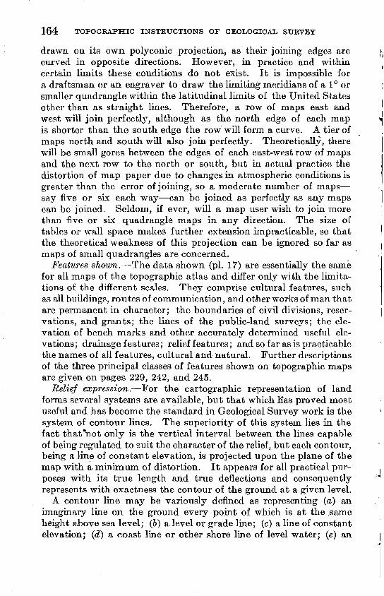
Contour interval. Standard contour intervals are 1, 5, 10, 20, 25, 50, 100, and 200 feet. Intervals of 40 and 250 feet have occasion ally been used, but these intervals are not now standard. Other contour intervals may be used for special purposes, as in the inter national map of the world, where the contour interval is expressed in meters.
The approximate distribution of contour intervals in their relation to Geological Survey map scales is shown in the table below repre senting the 3,167 maps published up to June 30, 1926.
Relation of scale to contour interval in topographic maps published by the Geological Survey up to June SO, 1926
[Figures indicate number of maps]
Scale
1:125,000. .............. -.1:62,500- 1:31,680. .. .1:24,000-----. __ .-- .1:21,120-- 1:12,000-
Contour interval (feet)
250
29
29
200
37
37
100
12 345
24 1
1
383
50
1 252 273
2 5
38
544
40
10
10
25
125
10714
4 4
140
20
145 1,230
4
4 8
1,391
10
I 248
_5
2 2
258
5
1 33
258 1013
315
1
35
35
None"
19
19
Total
80 779
1,934 302 23 13 13 23
3,167
° Entire area less than 5 feet above sea level.
Colors. Cultural features and names are shown in black, drainage features in blue, and relief features in brown. (See pis. 18-23.) Transparent overprints of green and red are used to designate wood land areas and a road classification respectively on certain maps.
PREPARATION FOR FIELD WORK
INSTRUCTIONS AND PERSONNEL
Each permanent employee will receive a letter of instructions signed by the chief of the topographic division to which he is assigned and covering each assignment of field work. In the temporary absence of a division chief or in other emergencies such instructions will be signed by the chief topographic engineer. The field instructions should specify the area to be mapped and the scale and contour inter val for the survey, and as a rule they should outline the general method to be employed. The personnel for the party should be stated, or authority should be given for the employment of additional assistants. The letter should also include such other instructions as may be needed. Supplemental instructions may be issued during the progress of the field work.
166 TOPOGRAPHIC INSTRUCTIONS OF GEOLOGICAL SURVEY
A topographic field party will consist of a topographic engineer (of appropriate grade) as party chief, assisted by one or more engi neers, each of whom will usually have a personal assistant serving as rodman, as recorder, or in some similar capacity. In country of certain types each engineer will have two rodmen and in addition a recorder and sometimes an umbrella man. Where appropriate, ax- men, boatmen, and laborers are employed. Necessary camp hands are included in the personnel.
The instructions given below are for the guidance of party chiefs preparing their own field sheets and assembling their own field ma terial prior to taking the field. Party chiefs are urged to be method ical and thoughtful in their field preparations and to foresee the season's needs so far as practicable. If the field sheets are prepared in the Washington or other headquarters office for shipment to a party chief in the field, similar care and judgment should be used in preparation, and the interests of the field party should be fully kept in mind.
PREPARATION FOR NEW TOPOGRAPHIC SURVEYS
Before starting for the field the topographer should prepare his field sheets in the form best suited to the conditions under which his work is to be carried on. He should make all necessary requisitions for instruments and field supplies and should by inquiry and search collect all available data that may prove helpful during the field season.
PLANE-TABLE PAPER
All topographic maps made by the Geological Survey are plotted on a plane-table sheet that is mounted on a plane table. The plane- table sheet consists of two sheets of drawing paper that have been specially prepared and mounted on both sides of a sheet of cloth, with the gram of the paper on one side at right angles to the grain of that on the other side. When such a double-mounted sheet is well seasoned it will hold its shape and will withstand the ordinary effects of weather conditions that are likely to be encountered in field work. The recent experimental use of drawing paper mounted on thin metal sheets indicates that by this device the distortion of the paper due to changes in atmospheric conditions is reduced to a minimum.
GENERAL FEATURES
Polyconic projections may be constructed by hand, using the in structions and tables published in United States Coast and Geodetic Survey Special Publication 5, which gives the required values in meters on the surface of the spheroid, or using the instructions and
TOPOGRAPHIC MAPPING 167
tables published .in United States Geological Survey Bulletin 650, which gives the measurements in inches on the map scale desired; or they may be constructed mechanically by means of a Bumstead projection plate. (See p. 175.) The practice of the Geological Survey indicates preference in the reverse order from that given above, but the theory is best explained by describing the methods in the order given. In general a central meridian is assumed upon which the inter sections of the parallels are plotted to scale. Each parallel is then drawn separately as an arc of a circle with its center lying in the extension of the central meridian. The arcs of the parallels are sub divided to scale, and the meridians are drawn through the subdivi sions. However,in actual practice on projections of small quadrangles, the parallels are not drawn as arcs of circles, but their intersections with the meridians are plotted from the computed x and y values, and the sections of the parallels between adjacent meridians are drawn as straight lines. In polyconic projections of quadrangles of 1° or smaller meridians may be drawn as straight lines, and in large- scale projections of small quadrangles in low latitudes both meridians and parallels may be drawn as straight lines. For example, the curv ature of the parallels of a projection of a 15' quadrangle on a scale of 1 :48,000 in latitudes from 0° to 30° is so small that it can not be plotted, and for a 7% ' quadrangle on a scale of 1:31,680 or larger the curvature can not be plotted in any latitude.
The meridional distances given in the tables apply to the central meridian of the projection, but for any standard quadrangle the dif ferences in the curvature of the several parallels are so slight that the distances given for the central meridian can be taken for all other meridians.
Whichever method of construction is used, each projection must be subjected to a thorough test by some person other than the one who did the plotting. It is not sufficient merely to check the plottings with the figures first used. A true check consists of independent computations and measurements throughout. The verifier should therefore enter the tables anew, replot the coordinates, and, as a final test, measure the over-all dimensions of the projection and compare the lengths of its diagonals.
For identification, the latitude and longitude must be clearly marked in pencil at each of the four corners of the projection.
COAST AND GEODETIC SURVEY METHOD
For making a polyconic projection by the Coast and Geodetic Survey method the following materials are required: A metal straight edge graduated in centimeters with one centimeter at one end sub divided into tenths of a millimeter, the scale being standardized and the straightedge being as long as the longest dimension of the pro-
168 TOPOGRAPHIC INSTRUCTIONS OF GEOLOGICAL SURVEY
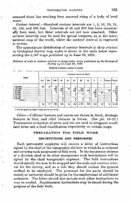
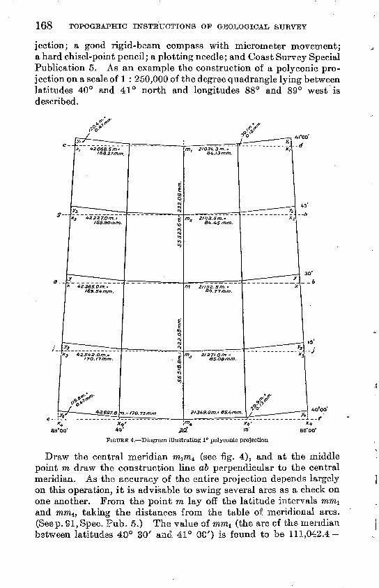
jection; a good rigid-beam compass with micrometer movement; a hard chisel-point pencil; a plotting needle; and Coast Survey Special Publication 5. As an example the construction of a polyconic pro jection on a scale of 1 : 250,000 of the degree quadrangle lying between latitudes 40° and 41° north and longitudes 88° and 89° west is described.
89°00'
FIGURE 4. Diagram illustrating 1° polyconic projection
Draw the central meridian miW4 (see fig. 4), and at the middle point ra draw the construction line ab perpendicular to the central meridian. As the accuracy of the entire projection depends largely on this operation, it is advisable to swing several arcs as a check on one another. From the point m lay off the latitude intervals mmi and mm4, taking the distances from the table of meridional arcs. (Seep. 91, Spec. Pub. 5.) The value of mmi (the arc of the meridian
JQ go' is found to be
TOPOGRAPHIC MAPPING 169
55,518.8 =55,523.6 meters. Likewise the value of rora4 is 55,518.8 0 = 55,518.8 meters.
These values represent meters on the spheroid, and to reduce them to the scale of the projection it is necessary to multiply them by the representative fraction 2 & 0*0 0 0 . The length of the arc mmi in meters on the map is found to be 0.22209 meter, or 222.09 millimeters. Like wise the length of the arc mm4 is found to be 222.08 millimeters. It is therefore evident that for a map of this size on this scale it would have been as well to use the value in meters opposite the argument "30 minutes" from the column "continuous sums of minutes from latitude 40 degrees" for both of these values, as it is impossible to plot 0.01 millimeter. (In preparing to construct a projection it is always best to make a small sketch and set down all the measure ments before beginning actual construction. Fig. 4 serves as such a sketch.) The values of mlm2 and m2m are each found to be lli .04 millimeters (by computation from the table or by taking one- half of the value of mm^}, and of course the values of mm3 and m3m4 are practically the same. The plotting should be checked by testing the length of the degree arc m\m±, which should be 444.17 millimeters.
At the points mi, m2 , ra3 , and ?n4 draw the construction lines cd, gh, ij, and ef parallel to the line ab and perpendicular to the central meridian. These construction lines must be absolutely parallel to each other and all perpendicular to the central meridian. The best results can be obtained by striking arcs from points near the extrem ities of the line db, using the same settings of the beam compass that were used in laying off the distances mm1} mm4 , etc., and then draw ing the lines cmid, em4f, etc., through the proper points on the central meridian and tangent to the proper arcs.
On each one of the construction lines lay off from the central merid ian the proper abscissae of the developed parallel, selecting from the table "Coordinates of curvature" the value of x opposite the proper longitude interval and taking care to interpolate for the desired latitudes not given in the table. As this table for coordinates of curvature is computed for latitude 40° 00', and the values of x change appreciably between 40° and 41°, the values taken directly from the table can be used only for m4x4 on the line ef. The value m^x should be taken from the table on page 93 of Special Publication 5 and values for mx, m^, and m3x3 should be interpolated between the values given in these two tables. Or these three values can be taken from the table of "Arcs of the parallel in meters" on page 90, by multiplying by 6 the value of 5' of longitude given for the proper latitude. For example, on the line ef the interval m4cc4 corresponds to 30 minutes of longitude and the x value is found to be 42,697.8 meters, which is 170.75 millimeters on the map.
170 TOPOGRAPHIC INSTRUCTIONS OF GEOLOGICAL. SURVEY
At the point x4 erect a perpendicular representing the ordinate of the developed parallel, selecting from the table "Coordinates of curvature" the value of y opposite the proper longitude interval. No interpolation is necessary, as the values of y change so slowly for differences of latitude that the values given in the table may be con sidered the average for the latitude interval from 40° to 41°. The value of y4 is found to be 119.8 meters, or 0.47 millimeter on the map. The two points thus constructed (to the left and right of the central meridian) are the lower corners of the projection. It remains to construct the two points atav- These coordinate for 15' of longitude is found to be 21,349.0 meters, or 85.4 millimeters on the map, and the y coordinate is 29.9 meters, or 0.12 millimeter on the map. This y value is so small that it can scarcely be plotted, and the two plotted positions of x4 > may be taken as the proper position of the intersec tion of the 15-minute meridians with the parallel of 40° 00'. In theory this parallel is curved, but as the curvature can not be drawn on a map of a small quadrangle, straight lines are drawn joining all the plotted positions on this parallel. Similarly all the other parallels are developed, and the meridians are drawn through the plotted points. It will be discovered that these points fall exactly on a straight line for each meridian, and the meridians are therefore drawn as straight lines.
To test the construction of the projection set the beam compass to the diagonal distance from the lower right to the upper left corner of the projection and then check the measurement from the lower left to the upper right corner, which should be the same. Continue these diagonal tests in various combinations of small projection blocks equidistant from the central meridian, so as to check the plot ting of every point. Add the proper figures showing latitude and longitude, as shown in Figure 4, and the job is completed.
The Coast and Geodetic Survey employs metal plotting scales giving the values in meters on the spheroid directly in terms of milli meters on the map for each of the map scales used.
GEOIOGICAL SURVEY METHOD
For making a poly conic projection by the Geological Survey method the following materials are required: A metal straightedge graduated in inches with one inch at one end subdivided into hun- dredths of an inch, the scale being standardized and the straight edge being as long as the longest dimension of the projection; a good rigid-beam compass with micrometer movement; a hard chisel- point pencil; a plotting needle; and Geological Survey Bulletin 650.
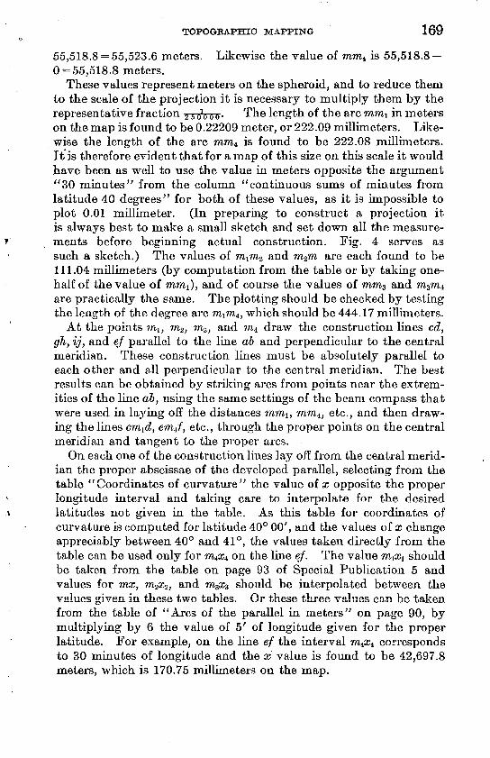
To illustrate this method the construction of a poly conic projec tion on a scale of 1: 48,000 of the 15' quadrangle lying between lati tudes 40° 15' and 40° 30' north and longitudes 88° 00' and 88°
TOPOGRAPHIC MAPPING 171
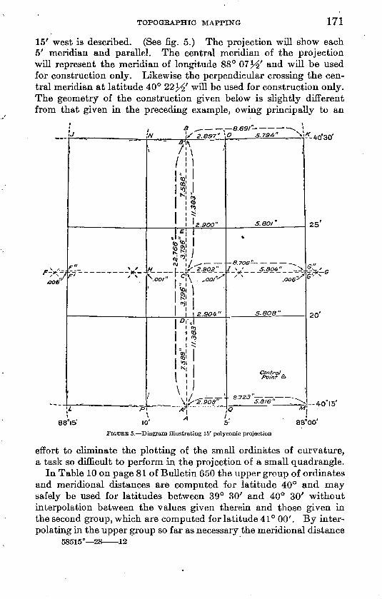
15' west is described, (See fig. 5.) The projection wijl show each 5' meridian and parallel. The central meridian of the projection will represent the meridian of longitude 88° 07}^' and will be used for construction only. Likewise the perpendicular crossing the cen tral meridian at latitude 40° 22^' will be used for construction only. The geometry of the construction given below is slightly different from that given in the preceding example, owing principally to an
,
F V :' V
aoe
88
^ .W \S 2 8S7" *
F * *F' / \
^'l\
v i \
§.N | 0
I 01 *
|
S^iyH 7 ^
//
D 3s"
a.9OO"
^2.902"
\ ,, r c"\ »>^ \oo/ i\ . ,001 -^
**\
i
i nI C
i =
s!
1 ! \ |
2.9O4-"
D0
X
0 5.794" \i
<
J. SO/ *
-S.706 -^
/ ^' 5.304" _^
°°6^
5.808"
Control . Point A
*- 40*30'
25'
20'
^ ' /> A'\ ' 0 "I
°I5' 10' A 5' 88°00'
FIGURE 5. Diagram illustrating 15' polyconic projection
effort to eliminate the plotting of the small ordinates of curvature, a task so difficult to perform in the projection of a small quadrangle.
In Table 10 on page 81 of Bulletin 650 the upper group of ordinates and meridional distances are computed for latitude 40° and may safely be used for latitudes between 39° 30' and 40° 30' without interpolation between the values given therein and those given in the second group, which are computed for latitude 41° 00'. By inter polating in the upper group so far as necessary the meridional distance
58515° 28 12
172 TOPOGEAFTTIC INSTBT7CTIONS OF GEOLOGICAL SURVEY
for iy^' of latitude is found to be 3.796 inches, for 5' 7.588 inches, for 7^' 11.383 inches, for 10' 15.178 inches, and for 15' 22.766 inches. (New tables are being computed in which the meridional distances, ordinates, and abscissas are given without interpolation for all the latitude and longitude intervals needed in the construction of a projection of a standard quadrangle.)
In the part of the table headed "Abscissas of developed parallel" the x values for 2%' and 7^' of longitude in latitude 40° 15' are found to be 2.908 inches and 8.723 inches, respectively. The x values for latitudes 40° 20', 40° 22^, 40° 25', and 40° 30' are shown in Figure 5.
In the upper group of "Ordinates of developed parallel" the y value for 7^' of longitude is found to be 0.006 inch. The ordinate for 2^' of longitude is not given, but as the ordinates vary as the square of the distance from the central meridian the y value for 2 J^' is one-fourth of that given for 5' or one-ninth of that for 7^' that is, 0.0007 inch, or approximately 0.001 inch.
These are all the measurements needed to proceed with the con struction of the projection. It is impossible to plot the y value for 2}^' of longitude and difficult to make an individual plotting of the y value for 7}^' of longitude, but 0.006 can be added to or subtracted from other measurements of meridional arcs and the resultant dis tance measured on the metal scale, and this is done in the following description :
Draw the central construction meridian AB in vertical position near the center of the map, select the middle point C as the center of the projection, and lay off from C the meridional distances for 2^' and 7^j' of latitude, CE (3.796 inches) and CB' (11.383 inches) above and CD (3.796 inches) andCA' (11.383 inches) below. The over-all distance A'B' (22.766 inches) for 15' of latitude should be used to check the plotting. At the point C erect the perpendicular FG, using the points A' and B' as centers for long arcs and the points D and E as centers for short arcs. Lay off on the construction line FG the abscissas of the developed parallel for 2^' and 7^' of longitude, CH and CI (2.902 inches) and OF' and CG' (8.706 inches).
With the points F' and G'.as centers and a radius equal to the meridional distance for 7^' of latitude plus the ordinate for 7^' of longitude (11.383+0.006 = 11.389 inches) strike arcs at J and K. Then with the same points as centers and a radius of 11.377 inches (11.383 0.006) strike arcs at L and M. In striking these arcs use the metal point of the beam compass rather than the pencil point and either scratch the paper lightly or place under the metal point a small piece of carbon paper made by rubbing a piece of thin tracing paper with a hard pencil. This obviates the inaccuracy of using the
TOPOGRAPHIC MAPPING 173
pencil point of the beam compass to take an exact measurement from the scale.
With the points H and I as centers and a radius equal to l}/2 of latitude (11.383 inches) measured along the central meridian, strike arcs at N and O above P and Q below. The true meridional distance as here used should always be taken in constructing the inner me ridional distance for 7^' of latitude on a scale of 1:48,000, or larger, as it is impracticable to use the small ordinate for 2^' of longitude. However, should the more rigid construction be required, it may be done in the folio whig manner: With points H and I as centers and a radius equal to 7 y% of latitude measured along the central meridian plus the ordinate for 2^' of longitude (11.383+0.001 = 11.384 inches) strike arcs at N and O. Then with the same points as centers and a radius equal to the meridional distance minus the 2J^' ordinate (11.383-0.001 = 11.382 inches) strike arcs at P and Q.
With the points B' and A' as centers and radii equal to the proper abscissas, strike arcs at J, K, L, M, N, O, P, and Q. Check the length of the diagonals JM and KL, which should be exactly the same. Draw the straight lines JL and KM through the intersections of the arcs at J, L, K, and M. These lines represent the limiting meridians on the projection. Draw the straight lines NP and OQ through the inter sections of the arcs at.N, P, O, and Q. These lines represent the two inner meridians on the projection, and the four intersections at the top and the four at the bottom of the projection are the exact inter sections of the four meridians with the limiting parallels.
With the beam compass set at the length of the meridional arc for 5' of latitude, plot along all four meridians down from J, N, O, and K and up from L, P, Q, and M, and check the middle 5' sections of the meridians, thus locating the intersections of the four meridians with the parallels 40° 20' and 40° 25'.
All the necessary intersections for the projection of this 15' quad rangle have now been plotted without trying to make an individual plotting of 0.006 inch from the points F' and G', which only the most skilled draftsmen can accomplish, and the same setting of the beam compass has been used for all equal measurements, thereby strength ening the construction. Check the construction by measuring over all distances and by testing corresponding diagonals of all combinations of projection blocks.
Although it is customary to show only the 5' intervals on a pro jection for a 15' quadrangle, it may be desired to develop the central parallel, which, in the projection under construction, would fall on latitude 40° 22}^'. With the beam compass set at the meridional distance for 7^' and plotting along the meridians down from J and K and checking by plotting up from L and M locate the points F" and G", which are the intersections of the limiting meridians with
174
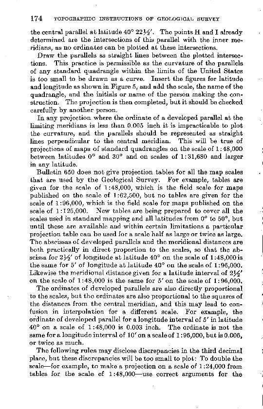
the central parallel at latitude 40° 22^r . The points H and I already determined are the intersections of this parallel with the inner me ridians, as no ordinates can be plotted at these intersections.
Draw the parallels as straight lines between the plotted intersec tions. This practice is permissible as the curvature of the parallels of any standard quadrangle within the limits of the United States is too small to be drawn as a curve. Insert the figures for latitude and longitude as shown hi Figure 5, and add the scale, the name of the quadrangle, and the initials or name of the person making the con struction. The projection is then completed, but it should be checked carefully by another person.
In any projection where the ordinate of a developed parallel at the limiting meridians is less than 0.005 inch it is impracticable to plot the curvature, and the parallels should be represented as straight lines perpendicular to the central meridian. This will be true of projections of maps of standard quadrangles on the scale of 1:48,000 between latitudes 0° and 30° and on scales of 1:31,680 and larger in any latitude.
Bulletin 650 does not give projection tables for all the map scales that are used by the Geological Survey. For example, tables are given for the scale of 1:48,000, which is the field scale for maps published on the scale of 1:62,500, but no tables are given for the scale of 1:96,000, which is the field scale for maps published on the scale of 1:125,000. New tables are being prepared to cover all the scales used in standard mapping and all latitudes from 0° to 50°, but until these are available and within certain limitations a particular projection table can be used for a scale half as large or twice as large. The abscissas of developed parallels and the meridional distances are both practically in direct proportion to the scales, so that the ab scissa for ly^ of longitude at latitude 40° on the scale of 1:48,000 is the same for 5' of longitude at latitude 40° on the scale of 1:96,000. Likewise the meridional distance given for a latitude interval of 2^' on the scale of 1:48,000 is the same for 5' on the scale of 1:96,000.
The ordinates of developed parallels are also directly proportional to the scales, but the ordinates are also proportional to the squares of the distances from the central meridian, and this may lead to con fusion in interpolation for a different scale. For example, the ordinate of developed parallel for a longitude interval of 5' in latitude 40° on a scale of 1:48,000 is 0.003 inch. The ordinate is not the same for a longitude interval of 10' on a scale of 1:96,000, but is 0.006, or twice as much.
The following rules may disclose discrepancies in the third decimal place, but these discrepancies will be too small to plot: To double the scale for example, to make a projection on a scale of 1:24,000 from tables for the scale of 1:48,000 use correct arguments for the
TOPOGHAPHIC MAPPING 175
scale desired and multiply all values given hi the table by 2. To halve the scale for example, to make a projection on a scale of 1:96,000 from tables for the scale of 1:48,000 use correct argu ments for the scale desired and divide all values given in the table by 2.
USE OF BUMSTEAD PROJECTION PLATE
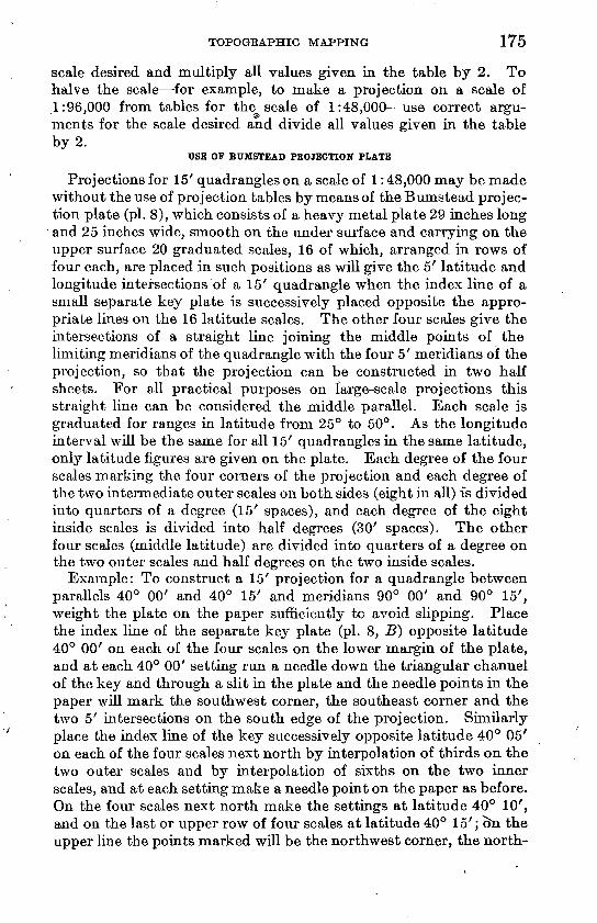
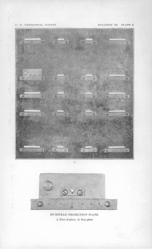
Projections for 15' quadrangles on a scale of 1:48,000 may be made without the use of projection tables by means of the Bumstead projec tion plate (pi. 8), which consists of a heavy metal plate 29 inches long and 25 inches wide, smooth on the under surface and carrying on the upper surface 20 graduated scales, 16 of which, arranged in rows of four each, are placed in such positions as will give the 5' latitude and longitude intersections of a 15' quadrangle when the index line of a small separate key plate is successively placed opposite the appro priate lines on the 16 latitude scales. The other four scales give the intersections of a straight line joining the middle points of the limiting meridians of the quadrangle with the four 5' meridians of the projection, so that the projection can be constructed in two half sheets. For all practical purposes on large-scale projections this straight line can be considered the middle parallel. Each scale is graduated for ranges in latitude from 25° to 50°. As the longitude interval will be the same for all 15' quadrangles in the same latitude, only latitude figures are given on the plate. Each degree of the four scales marking the four corners of the projection and each degree of the two intermediate outer scales on both sides (eight in all) is divided into quarters of a degree (15' spaces), and each degree of the eight inside scales is divided into half degrees (30' spaces). The other four scales (middle latitude) are divided into quarters of a degree on the two outer scales and half degrees on the two inside scales.
Example: To construct a 15' projection for a quadrangle between parallels 40° 00' and 40° 15' and meridians 90° 00' and 90° 15', weight the plate on the paper sufficiently to avoid slipping. Place the index line of the separate key plate (pi. 8, B} opposite latitude 40° 00' on each of the four scales on the lower margin of the plate, and at each 40° 00' setting run a needle down the triangular channel of the key and through a slit in the plate and the needle points in the paper will mark the southwest corner, the southeast corner and the two 5' intersections on the south edge of the projection. Similarly place the index line of the key successively opposite latitude 40° 05' on each of the four scales next north by interpolation of thirds on the two outer scales and by interpolation of sixths on the two inner scales, and at each setting make a needle point on the paper as before. On the four scales next north make the settings at latitude 40° 10', and on the last or upper row of four scales at latitude 40° 15'; cm the upper line the points marked will be the northwest corner, the north-
176 TOPOGKAPHIC INSTRUCTIONS OF GEOLOGICAL SURVEY
east corner, and the two 5' intersections on the north edge of the projection. These 16 plottings give all the 5' intersections of lati tude and longitude for a 15' quadrangle. If a middle latitude line is desired, or if the projection is to be macle in halves, plot the 40° 07' 30" intersections at the four scales across the middle of the plate.
A projection that is made as described above will correctly show a slight curvature of the parallels.
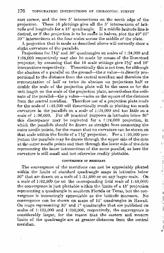
Projections for 7^' and 30' quadrangles on scales of 1:24,000 and 1:96,000 respectively may also be made by means of the Bumstead projector, by assuming that the 16 scale settings give 2^' and 10' intersections respectively. Theoretically this is not true, for although the abscissa of a parallel on the ground the x value is directly pro portional to the distance from the central meridian and therefore the representation of half or twice its abscissa on projections half or double the scale of the projection plate will be the same as for the unit length on the scale of the projection plate, nevertheless the ordi- nate of the parallel the y value varies as the square of the distance from the central meridian. Therefore use of a projection plate made for the scale of 1:48,000 will theoretically result in plotting too much curvature in the parallels on a scale of 1:24,000 and too little on a scale of 1:96,000. For all practical purposes in latitudes below 50° this discrepancy may be neglected for a 1:24,000 projection, in which the parallels should be drawn as straight lines connecting the outer needle points, for the reason that no curvature can be shown on that scale within the limits of a 7^' projection. For a 1:96,000 pro- jec.tion the parallels may be drawn through the upper side of the dots at the outer needle points and then through the lower side of the dots representing the inner intersections of the same parallel, as here the curvature is still small and not otherwise readily plottable.
CONVERGENCE OF MERIDIANS
The convergence of the meridians can not be appreciably plotted within the limits of standard quadrangle maps in latitudes below 50° that are drawn on a scale of 1:31,680 or on any larger scale. On a scale of 1:62,50*0 (or on the corresponding field scale of 1:48,000) the convergence is just plottable within the limits of a 15' projection representing a quadrangle in southern Florida or Texas, but the con vergence is increasingly appreciable as the latitude increases. No convergence can be shown on maps of 15' quadrangles in Hawaii. On maps representing 30' and 1° quadrangles that are published on scales of 1:125,000 and 1:250,000, respectively, the convergence is considerably larger, for the reason that the eastern and western limits of the quadrangle are at greater distances from the central meridian.
TOPOGRAPHIC MAPPING 177
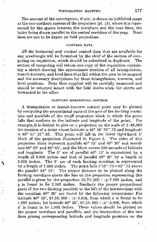
The amount of the convergence, if any, is shown on published maps at the two northern corners of the projection (pi. 15), where it is repre sented by the spaces between the meridians and the neat lines, the latter being drawn parallel to the central meridian of the map. Neat lines are not to be drawn on field projections.
CONTROL DATA
All the horizontal and vertical control data that are available for any quadrangle will be furnished by the chief of the section of com puting on requisition, which should be submitted in duplicate. The section of computing will return one copy of the requisition contain ing a sketch showing the approximate position of all triangulation, transit-traverse, and level lines that fall within the area to be mapped and the necessary descriptions for these triangulation, traverse, and level positions. Data thus supplied will be carefully examined and should be returned intact with the field sheets when the sheets are forwarded to the office.
PLOTTING HORIZONTAL CONTROL
A triangulation or transit-traverse control point may be plotted by computing the proportional parts of the arcs of the limiting merid ians and parallels of the small projection block in which the point falls that conform to the latitude and longitude of the point. For example, it is desired to plot on a projection on the scale of 1:48,000 the position of a point whose latitude is 40° 16' 35".75 and longitude is 88° 01' 27".55. This point will faU in the lower right-hand 5' block of the projection illustrated in Figure 5. The sides of this projection block represent parallels 40° 15' and 40° 20' and merid ians 88° 00' and 88° 05', and the block covers 300 seconds of latitude and longitude. The 5' arc of parallel 40° 15' is represented by a length of 5.816 inches and that of parallel 40° 20' by a length of 5.808 inches. The 5' arc of each limiting meridian is represented by a length of 7.588 inches. The point falls 1'35".75 = 95".75 above the parallel 40° 15'. The proper distance to be plotted along the limiting meridians above the line on the projection representing this parallel is given by the proportion 95.75:300 : :y:7.5S8 inches, and y is found to tie 2.242 inches. . Similarly the proper proportional parts of the two limiting parallels to the left of the intersections with the meridian 88° 00' are found by the following proportions: For latitude 40° 15', 87.55:300 : :x: 5.816, from which x is found to be 1.697 inches; for latitude 40° 20', 87.55:300 : :x': 5.808, from which x' is found to be 1.695 inches. These values should be plotted on the proper meridians and parallels, and the intersection of the two lines joining corresponding latitude and longitude positions on the
178 TOPOGRAPHIC INSTRUCTIONS OF GEOLOGICAL STJRVEY
limiting meridians and parallels will be the location of the control point.
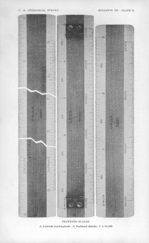
The method described above is laborious, and the plotting of con trol points is facilitated by use of latitude and longitude plotting scales so subdivided that the proper readings in minutes and seconds may be plotted without computation. The plotting scales are avail able for all standard projection scales and are made slightly longer than the corresponding dimensions of the individual projection blocks in the lowest latitude for which their use is intended. The scales are used diagonally between the limiting parallels and meridians, and thus the same plotting scale can be used for a wide range of lati tude. At least two plottings of both latitude and longitude positions are so made as to embrace the position of the point, and the inter section of the lines joining the corresponding plottings will be the position of the point. The plotting scale for 1:48,000 is shown in Plate 9, A.
MAP BORDERS
It is of prime importance that contiguous topographic maps shall join perfectly, so that when they are laid edge to edge the lines on them shall pass without break or offset from one to the next. For this purpose the engineer, before beginning field work on a new quad rangle, should procure photographs, photolithographs, or tracings of adjoining edges of all previous maps (including woodland) that are on the same or larger scales. Data that are on a different scale from the new field work should be reduced to that scale by photog raphy. The strips so furnished should be preserved as a part of the field material and returned for the office files. The data on the strips should be transferred to the field sheets. (See "Map bor ders," p. 227.)
DATA FROM OTHER SURVEYS
Source of material. Existing map material of Federal, State, and municipal surveys and other authenticated organizations should be diligently sought, both before leaving the office and after reaching the field. The files of the map information office of the Federal Board of Surveys and Maps (Interior Department Building) should be consulted freely.
Maps of the General Land Office (see p. 179), the Coast and Geo detic Survey, the Hydrographic Office of the Navy, the Corps of Engineers of the Army, the Mississippi River Commission, the sur vey of the Great Lakes, the national boundary surveys, State bound ary surveys, boundaries of national parks, forests, monuments, game and bird preserves, Indian and military reservations, land grants, surveys made by the Bureau of Reclamation, Forest Service, and Bureau of Soils should be obtained, and such of them as prove,
TI. S. GEOLOGICAL SURVEY BULLETIN 788 PLATE 8
BUMSTEAD PROJECTION PLATE
A, Face of plate; B, Key plate
U. S. GEOLOGICAL SURVEY BULLETIN 788 PLATE 9
PLOTTING SCALES
A, Latitude and longitude B, Burklaud alidade; C, 1: 31,680
TOPOGRAPHIC MAPPING 179
on field examination, to be adequate, should be incorporated in the field sheets, with proper recognition. (See " Credit for outside data," p. 307.) All such material will, upon requisition, be reduced by photography to the field scale.
Land Office data. Before reaching the field party chiefs must pro vide themselves with copies of the latest plats of the public-land surveys, if any, of the assigned areas, and if practicable these plats should be reduced to the scale of mapping. It is important that the data furnished should be the latest available and that they should include any resurveys or retracements and any exterior notes of townships not yet sectionized that fall within the limits of the quadrangle to be surveyed. Inquiry should also be made to ascer tain whether any of the plats are under suspension by the General Land Office.
Before starting work in national forests topographers should check off on forest maps the Land Office corners that have been found by the Forest Service and also corners that have been looked for and not found; such information is on file at the headquarters of each supervisor and also at each district office. Inquiry may also often be advantageously made of county surveyors, deputy mineral sur veyors, and local engineers as to the existence and location of known corners or ties.
Other reference data. The following additional maps and data should be assembled for field use: Post-route and rural-delivery maps; Geological Survey index circular, corrected to date, together with copies of engraved maps or advance sheets of all maps of areas adjoining the proposed new quadrangle; list of incorporated places given in Census reports; alinement maps of railroad valuation sur veys; 1 :500,000 scale State map; State highway and other route maps.
ENDING OFFICE SEASON
At the end of the office season turn in to the section of inspection and editing all map material pertaining to the office season that is not needed for field work. Clear desk and map file cases. Turn in to the division of field equipment all office instruments not needed in the field. Submit office report.
PREPARATION FOR REVISION OF TOPOGRAPHIC MAPS
FIELD SHEETS
The field revision of a topographic map will be made upon a repro duction of the latest print of the map, printed for the purpose on double-mounted drawing paper. The field sheets for revision are printed in relatively weak colors, often referred to as nonphotographic, in order that the revision corrections, where inked in the standard
180 TOPOGEAPHIC INSTRUCTIONS OF GEOLOGICAL, SUKVEY
strong colors, may be reproduced photographically and thus furnish copy for transfers to the plates which are afterward to be corrected. Such field sheets may be prepared under one of the three plans described below:
1. A printed copy of the map may be reproduced by photolithog raphy, enlarged to the usual field scale, and printed in faint blue, which is only weakly photographic. This process should not be used, however, where distortion of the paper on which the'map has been printed has so changed the map projection that its dimensions are long or short in one direction and not proportionately so in the other direction. The projections of maps selected as camera copy for reproduction by this method should be carefully tested before use.
2. Transfers to stone may be made from the three copper plates on which the map was engraved and a special print of the map made in three different weak colors, such as faint blue for culture, light gray for drainage, and light pink for contours, each printing being as carefully registered as for a map printed in the usual way. Such a revision field sheet has the advantage of true scale and of the same use of distinctive colors for the three principal classes of features as is shown on a printed map; but the advantage of the usual field scale is lacking. Plotting scales are provided graduated to both miles and feet on the usual publication scales.
3. The process described in paragraph 2 may be varied to provide for enlargement to field scale before transferring to the printing stones. Revision sheets prepared by this process combine all the advantages of the other two; that is, they are on true scale, are on the field scale, and are printed in three distinctive colors.
The first process described above is the cheapest of the three, and the third is the most expensive. The selection will be based on field and office conditions, the nature of the county represented, and the usual relation between field and publication scales.
CONTROL DATA
A complete set of control notes, both horizontal and vertical, must be obtained before starting field revision. The control data should be requested from the section of computing on a form provided for the purpose.
OTHER REVISION DATA
So much of the material described under "Data from other sur veys" (p. 178) as will apply to the revision work that is to be under taken should be assembled. Of especial importance are post-route map, Land Office data, reservation maps (national forest, etc.), index circular, and maps of adjoining quadrangles.
TOPOGRAPHIC MAPPING 181
FIELD WORK
STANDARDS FOB FIELD WORK
ACCURACY
Accuracy defined. A topographic map, irrespective of scale, is accurate if it is based upon a sufficient amount of well-distributed and well-adjusted control, to which the carefully considered topo graphic features appropriate to that scale have been tied with a maximum of refinement in field measurement and in plotting. (See "Definition of a topographic map," p. 161.)
Accuracy in a topographic map can be truly measured only by a com bined appraisal of the character and amount of its control, its adjust ment, the accuracy with which the field measurements have been taken and plotted, the ease with which the features mapped can be identified, its amount of detail or degree of generalization, the con sistency of its parts, its freedom from errors and omissions, and its date of survey.
Control factor in map accuracy. The control that is necessary for accuracy in a map embraces first the primary control of first, second, or third order both horizontal and vertical, upon which the survey for the map must rest. Of this control but a relatively small amount is needed, for the reason that initial control is expanded and supplemented by further topographic control of another kind, obtained by means of the topographic mapping operations them selves, such as plane-table traverse and plane-table triangulation, as a result of which the area under survey is so gridironed or covered by lines and locations that no essential map feature is so far from a traversed line or located point that it can not be satisfactorily seen and delineated.
Careful judgment will be required to cover the entire quadrangle adequately to the end that no part of the area be mapped that is not properly seen and that too much control and time be not devoted to portions of the area that happen to be easy of access and too little given to other portions that happen to be difficult of access.
Accuracy of adjustment. If a map is in accurate adjustment then all its parts are in correct relative position. This important and desirable quality in topographic maps is insured through the use of control and by means of adjustment. The initial primary control for a map is so tested by the geodetic engineer that it may be accepted as accurate by the topographic engineer, but its plotting on the field sheets must be checked before it is used. Inasmuch as all single observations, such as the measurement of a distance or an angle or the determination of an elevation, are inherently subject to error, however slight, and as continuous lines are subject to errors of accu-
TOPOGRAPHIC INSTRUCTIONS OF GEOLOGICAL, SURVEf
mulation, both in distance and in direction, such map measure ments and observations must be adjusted in order to distribute the small unavoidable errors in such a way that they may be eliminated or made negligible.
An area may therefore be adequately covered by supplementary control and be thoroughly mapped so far as map features go, and yet the map may be out of position locally through the presence of accumulated errors of survey that remain unadjusted. A common source of unadjusted error is the use of unchecked lines of plane- table traverse that may contain unsuspected errors and thus result in the false location on the map of the area affected by the errors; and inasmuch as errors in unchecked lines often result in the forcing of other features into a remaining space on the map paper, topog raphers are cautioned to run spur lines with the utmost care. Another example of possible error through unchecked spur lines appears when each of the opposite sides of a ridge or mountain is mapped from a traverse line that has been run without closure and where the effect of the error on one or both sides of the ridge remains undetected through lack of intervisibility. Obviously large errors are not subject to adjustment and must be located and corrected, and if they can not be located that part of the survey must be rerun or remapped. (See "Errors and omissions," p. 185.)
Accuracy of observations and oj plotting. As it is a waste of effort and expense to execute surveys on the ground with an accuracy greater than can be plotted on the scale of the field sheets, and as it is a failure to get full value from effort and expense already incurred to plot the results of field work with an accuracy less than that of the observations themselves, the topographic engineer should think of ground features in terms of scaled map distances and dimensions and then correctly plot his measurements under all the favorable plotting conditions, such as light, magnification, needle point, and the avoid ance of parallax. Refinement in paper accuracy is therefore quite as important as care in field measurements.
Identification of features. One of the simplest tests of the accuracy of a topographic map is to examine it in the field and note the rel ative ease or certainty with which the features represented on the map may be identified on the ground or the ease with which features seen on the ground may be recognized on the map. In the hands of a trained map reader such a test is one of the most severe to which a map may be subjected, and for this reason it is the preliminary basis for a Geological Survey field inspection of topographic map ping, either in progress or completed. Inasmuch, however, as the topographic engineer sees more on the ground than he can plot on his map, so will the field inspector observe more on the ground than he can find on the map; and inasmuch as the map maker must
TOPOGRAPHIC MAPPING 183
learn to abstract what he sees, so must the inspector or the map reader learn to read the abstract.
If the features shown on the map and the features seen on the ground are thus readily recognized and if several corresponding features appear to be in the same relative position, each to the others, the map may be regarded as accurate in the degree that the map user is himself versed in maps and their interpretation. Correct interpretation of a map is therefore a factor in its best use. To interpret a map it is necessary first to visualize its scale and con tour interval .and become very familiar with them and with their possibilities and limitations. Familiarity with the scale of a map may be acquired in several ways for example, by identifying points in common on the ground and on the map; by orienting the map by means of the points thus identified and sighting others for addi tional identification; where the identification of a first point is un certain, by orienting the map by needle, allowing for magnetic declination; by measuring a distance on the ground and plotting the corresponding distance on the map; or by traveling a road or other recognizable route and comparing ground and map appearances, checking on recognized points or places. The mistaken identification of a map feature is a common source of discouragement to a map user and will tend to increase his perplexity until he locates himself. A map that is found to be accurate by an expert critic will obviously be found accurate by map users who are less critical and less ob servant, but the reverse is not necessarily true.
Detail and generalization. In measuring the accuracy of a map by the faithfulness with which ground detail has been represented on it or appraising it by the success that has been attained in the generalization of such detail as is beyond the scale of the map, it is necessary to understand the uses and the meaning of the terms "detail" and "generalization" and their application to Geological Survey maps. These terms describe two relative conditions that are opposite or complementary. "Detail" implies a refined treat ment and suggests literal mapping; "generalization" signifies a broad treatment and involves an abridgment. The use of the terms may be further defined by an example. A map drawn on a scale of 1 :24,000 should represent a region in detail as compared with a map of the same region drawn on a scale of 1 : 48,000, on which the representation must be confined to a broad generalization of the same features.
"Detail" may refer to a ground topography that is intricate as well as to its refined representation on a map, but "generalization" distinctly refers to a process. When referring to the country rather than to a map we may speak of detailed topography but not of generalized topography. When we speak of generalized topography
184 TOPOGEAPHIC IlSrSTETJCTIONS OF GEOLOGICAL SURVEY
on a map we mean that abridged, condensed, or abstracted treat ment of a detailed ground topography that is made necessary by the limitations of scale, contour interval, and expediency. Ground detail may range in degree or amount from the excessive detail of city culture and bad-land relief to the relatively negligible detail of smooth broad or coastal plains.
Inasmuch as the published topographic maps of the Geological Survey represent greatly reduced abstracts of nature, the topographic engineer must determine what proportion of the ground detail can be adequately shown on the scale of publication. The smaller the publication scale and the more intricate the ground detail the more complicated is his problem; the larger the publication scale and the less intricate the ground detail the larger will be the proportion of it that can be delineated and the simpler will be his task. But whatever the scale or whatever the amount of the ground detail, the resulting map must in a large degree represent a generalization, and his prob lem is first how much must he generalize and second how can he best do it.
Generalization can be further explained by an example: On the larger scale of 1 : 24,000 a stream may be plotted to show all its bends and all its tributaries; on the smaller scale of 1 : 48,000 the smaller bends and the shorter tributaries will be omitted. This example comprises two phases of map generalization: The smallest tributaries have been omitted because they would not show on the small scale, being only microscopic ticks or specks against the main stream; but the smaller bends in the main stream have been disregarded because they are difficult to draft on the small scale and are equally difficult to find on the map, and instead a stream line is plotted in which no at tempt is made to show them. One phase of generalization involves omission; the other substitution. The contour system that is depend ent on the drainage likewise becomes successively generalized as it is mapped on smaller scales. In a similar sense, a small hill may be a conspicuous feature on a detailed map of small contour interval (5 or 10 feet) and yet not be shown on a small-scale map of larger contour interval (50 or 100 feet). Generalization, then, means elimination, and the greater the generalization the more drastic must be the process.
Consistency in accuracy. The map should be as consistently accurate in all its parts as is practicable. If two or more topog raphers are responsible for the mapping of independent areas on the same or adjoining quadrangles, they should compare their maps not only at their common borders but throughout, in order that they may reconcile any differing interpretations of the country or of the instruc tions under which they are working. Such comparisons should include examination of drainage, road and woodland classification,
TOPOGRAPHIC MAPPING 185
and the names of features in common, as well as the discussion of any unusual features.
Errors and omissions. The most obvious source of inaccuracy in a map is error. A map error may be caused by an erroneous measure ment or erroneous plotting of a distance, by the erroneous measure ment of an angle, or by an error in a field computation. A map error may also result from the misinterpretation of the shape of a distant or otherwise veiled feature seen in perspective. If an error is followed by another error that is made in the opposite direction the errors are termed compensating, in that one tends to balance the other. Where compensating errors are nearly equal the results under certain condi tions, as in running a traverse line, may have a false appearance of accuracy in that the line may check out and yet be in error in two places. Small compensating errors may usually be disregarded, but where such errors are large they are a source of perplexity until found and corrected.
In order to provide against error all traverse lines so far as prac ticable should be run in circuits closing on themselves or run from one located point to another; and, barring compensating errors, a line that "closes" or checks is assumed to be correctly plotted. The errors to be chiefly guarded against are therefore those that may result from isolated measurements unrelated to other features and the possible accumulation of errors in unchecked lines.
The plane-table methods employed in topographic mapping enable the topographer to detect and correct most errors in the measurement of distances and most errors in plotting, because such errors usually produce erroneous mapping that will not fit other data that are correctly placed from other control. The topographer can therefore often detect errors in mapping through the appearance of the map alone, because the map is plotted in the field with the country that is being mapped directly in front of him. The check on the accuracy of the map that is thus afforded by its constant comparison with the features themselves as they are being mapped is a test that should be repeatedly applied by topographic engineers.
Inaccuracies in a map may also result from omissions. A house or a name may be omitted through inadvertence, and a spur or a tribu tary stream may be omitted because of lack of sufficient supplemental control. In the first case there has been lack of care, and in the second case the standard of accuracy is deficient. A feature that has been plotted in the field may be lost before it is inked because of faint penciling, or it may be lost during the inking through inadvertent erasure; and a feature that has been inked may be omitted in the engraving or inadvertently brushed off in the transfer operations prior to printing. Firm penciling, care in cleaning the sheets, and faithful proof reading are the safeguards against such omissions.
186 TOPOGRAPHIC INSTRUCTIONS OF GEOLOGICAL SURVEY
The omission of essential features from a map because they were not seen or recognized as such during the progress of the field work can be guarded against only by close observation combined with a control that is fine enough to close up all unseen gaps.
Date of survey. Map accuracy must be considered in terms of the date of the survey. This date is stated on each published map, and the accuracy of the cultural representation must be considered as of that date. Although reasonable effort should be made to obtain information as to all important changes in culture, even though the area affected has been passed by in the survey operations, the policy of the Geological Survey is to plot no feature that has not been constructed on the ground and to show no proposed features. Such features as roads and railroads under construction may be plotted so far as actually graded, but unless they are known to be in use when the map is inked they should be shown on the final drawing in red, as features not to be included on the published map.
SPEED
Speed may be expressed in terms of elapsed time or rate of progress. For example, a quadrangle covering an area of 225 square miles may be reported as mapped in five months or at the rate of 45 square miles a month. The rate at which mapping should progress will differ more for different kinds of country than for different individuals, and in general it will differ more for different mapping scales than for different kinds of country, and to a less extent it will differ with different contour intervals.
Differences in speed between individuals are accounted for in part by differences in natural and developed ability and in part by dif ferent conceptions of the standards of accuracy. Speed is increased by the use of the most efficient mapping methods, through coopera tion, by the advance planning of work, by experience, and by diligence. Speed is reduced by inclement weather and by errors.
Speed through efficient methods. Experience justifies the use of different mapping methods for different types of country and to some extent for different scales. Although the engineer will know in advance and usually before reaching his field of work what general type of topography to expect, he can not anticipate the detailed types to be found, nor anticipate how often or abruptly these types may change within the same quadrangle. The topographic engineer should there fore have so good a working knowledge of all field mapping methods in approved Geological Survey practice that he may be ready to use those methods that are locally best suited to the varying types of country he is called upon to map. There are also many short-cut devices applicable to all methods of mapping, and topographers
TOPOGKAPHIC MAPPING 187
are encouraged to become familiar with them through contact with others and through personal experience.
Speed through cooperation. A topographic engineer seldom works alone, being usually assisted by a rodmanor by a station assistant. He is frequently further assisted by traversemen, each working separately and each in turn assisted by a rodman. The map work of the traverseman is transferred and adjusted into the topographer's map and becomes a part of it. The output of the combined party is credited to the topographic engineer as party chief and is measured in terms of the number of square miles completely mapped each month. Party chiefs therefore should not overlook the possibilities of increas ing the efficiency of their assistants and thereby increasing not only the accuracy but also the speed of the output of the party. Assistants acquire efficiency more rapidly through personal attention and train ing given to them than through unaided experience. Assistants, including junior engineers, should be fully instructed in their duties and should be kept as fully occupied as the nature of their work and their fitness for added duties justifies.
Speed through advance planning. A material factor in the speed of topographic mapping is a well-considered and reasonably complete plan of work for the season, augmented by a daily and weekly laying out of work in advance. The work of engineering assistants, working separately, should be similarly outlined well in advance, in order that it may proceed without delay and that the party chief may have the prompt use of the work of his assistants when he needs it.
Planning involves the selection of areas for initial and subsequent work, selected in the most advantageous sequence in which the work can be taken up for survey and mapping; the advance assignment of tasks and areas to assistants who are working separately; and the appropriate assignment of method to country and to the available personnel in order that the relative strength of supplemental control on which to adjust the completed survey may be maintained in advance. It also provides for the availability of essential outfit when and where it is needed. Planning should include a considera tion of the party personnel, as to whether it is sufficient, too small, or unnecessarily large, and if men can be spared for other work or if further assistance is needed timely notice should be given, in order that there may be the fullest adjustment to the needs of all.
Speed through experience. Experience should be rated in terms of work performed as well as by length of service; and in considering work performed, its variety as well as its amount should receive con sideration. At the outset of an engineer's career a part of his tune will be spent in acquiring a working experience, and in order that he may build soundly his speed at this stage should, be. Q£ secondary
58515° 28 13
188 TOPOGRAPHIC INSTBUCTIONS OF GEOLOGICAL SURVEY
importance, but as experience is gradually gained his rate of progress should increase. Party chiefs have in this respect a responsibility and a constructive opportunity in the proper guidance and instruction of the newer men.
The rate at which mapping experience may be acquired may obviously be increased through close observation and the application of mapping principles and also through the discussion of mapping and its problems with others. Topographers are encouraged to get together in all appropriate ways for the interchange of thought and experiences in connection with the furthering of their work.
Speed through diligence. Diligence is a prerequisite for speed. Diligence, however, must first be used in attaining thoroughness and accuracy, but when these essentials have been adequately acquired further diligence should be directed toward the expedition of the work rather than toward a refinement of the mapping that would be beyond the scale of the field work. Inasmuch as topographic field work is generally done at considerable distances from any office headquarters and involves the expensive maintenance of a party in the field, topographers are expected to prosecute their work with zeal and perseverance and to try so far as possible to overcome the obsta cles that will always in some measure confront them. Among such obstacles are inclement weather, short days, extremes of heat or cold, and country that is difficult of access. The Geological Survey utilizes the favorable working seasons and conditions to the fullest degree practicable, but the exigencies of the public needs frequently demand that topographic work be carried on under less favorable working conditions, and at such times the resources of the engineer should be diligently used in devising ways and means to keep the mapping in progress, even though at reduced speed.
LEGIBILITY
Legibility in general. The relations between the legibility of a field sheet, that of an inked office drawing, and that of a printed map are so close that the need for legibility in field penciling can be best understood when it is considered in connection with the similar need for legibility in inking and in reproduction. The readability of a printed map depends upon the clearness of its reproduction, the detail of its treatment, and the ability of the map user to read it. In meeting demands for detailed maps there is always danger lest more time be spent in obtaining detailed representation in surveys, in drafting, and in reproduction than the scale of the reproduction warrants on the one hand or than the legibility of the resulting map warrants on the other hand. Less detail of treatment, however, does not imply less accuracy (see "Accuracy," p. 181), but it does mean further generalization, and proper generalization is accurate
TOPOGRAPHIC MAPPING 189
in so far as correct placement of the generalized features is concerned. The engineer therefore will do well to consider map generalization (see "Detail and generalization," p. 183), and largely in the degree in which he can apply its principles will his map serve its purpose by being readable.
Standards in map legibility must needs be largely set by the legi bility attainable in map reproduction. To attempt to reproduce a map that contains more detail than can be legibly engraved or otherwise reproduced is obviously uneconomical, and in consequence a topographic map should be inked with the possibilities and limita tions of engraved or other reproduction well in mind and with full allowance for the scale of reproduction. To plot more detail in the field than can be legibly inked in the office or legibly reproduced in the press room is likewise uneconomical, and as a consequence the field engineer should make his survey, plot his observations, and pen cil in his map with the probabilities and limitations of office drafting and inking fully in mind and also with due allowance for the appear ance of the final map when printed.
Legibility of map reproduction. First consideration should be given to the possibilities of engraving or other form of reproduction to be used. Most of the topographic maps published by the Geological Survey are engraved on copper, separate plates being used to repre sent the culture, relief, and drainage. Transfers from the three engraved plates are made to three printing plates (either stone, zinc, or aluminum), from which the map is printed in three colors. The legibility of the printed map is increased in part by the sharpness of the engraved lines, which are faithfully reproduced in the printing, and in part by the contrast afforded by the three colors used to dis tinguish the principal classes of map features. Legibility of repro duction is further increased by good lettering that has been placed in favorable positions for reading and so placed as to avoid unduly covering the map features. The legibility of a printed map is decreased by excessive detail in map expression and by inferior map reproduction.
The legibility with which engraved lines may be reproduced (pi. 17) determines the character of the engraving. For example, if engraved lines are cut too close together their printed reproduction will be "mashed," and if lines are cut too lightly there may be uncertainty in their transfer and printing. Engraving must therefore conform to that which can be legibly reproduced. It is possible, however, to engrave and to print so much detail that the final map may be over loaded and its legibility impaired. This possible condition should be foreseen and prevented so far as practicable, and field work should ordinarily not be executed in more detail than can be reproduced with legibility on a map that is easily readable.
190 TOPOGRAPHIC INSTRUCTIONS OF GEOLOGICAL SURVEY
Legibility of office inking. The standard of legibility for the inking of topographic maps should be based wholly upon quality for repro duction. If the map is to be engraved the inked copy for the engraver need be accurate and legible only, and as a consequence finely exe cuted and expensive drafting may for the greater part be avoided. If the map is to be reproduced by photolithography for regular pub lication the inking must be done with the utmost care and refinement, inasmuch as any defect in the drawing will be repeated in the photo- lithograph.
The engraver's need for inking legibility is twofold. First, the map should be so legibly inked that when it is transferred to copper a process involving photography, transfer to zinc, and a wax impression from the zinc to the copper plate the transfer itself will be legible to the engraver. Second, the map should be so legibly inked that the engraver can easily read it as he constantly refers to it and also that he can pick out with certainty those features that are to be engraved separately on the plates representing the culture, drainage, and relief, inasmuch as the entire map is transferred to each plate.
Inking legibility is increased by the use of the best paper and inks. The inks used must have strong photographic value and should not smear or run. The symbols used, especially those representing the culture, should be so drawn and spaced that when they are trans ferred to the copper plates they will be of approximately the standard gage for engraving. Legibility for the engraver is further increased by the omission of certain lines in the inking not needed as copy and only tending to clog up the transfer. (See last paragraph under "Character" [of inking], p. 278, and ''Cliffs," p. 295.) The inking topographer will do well to bear in mind that he is preparing copy for the engraver rather than an artistic drawing for an exhibit.
Legibility of field 'penciling. The standard of legibility for field penciling should be based first upon furnishing clear copy for the ink ing topographer or draftsman, and then upon furnishing only such copy as can be legibly engraved and reproduced. The field sheet should be so legibly penciled that the office inking may proceed with assurance and dispatch, with no doubt as to the interpretation of the copy. The engineer who excels in ability to draft fine lines, however, should be watchful lest he overrefine in detailed expression and pro duce intricate pencil copy that will call for more skill in inking than may be available or for more detail in engraving than can be legibly reproduced. The topographer should also bear in mind that illeg ibility in field penciling can be overcome in the office only at the expense of accuracy, and that any overrefinement in detail can be overcome only at the expense of a forced generalization of features in the inking, or in the reproduction, or both. Legibility in penciling requires sharp, fine lines that can be made only by a sharp hard pencil,
TOPOGHAPHIC MAPPING 191
evenness of appearance in each line, avoidance of crowding, avoidance of dirt or other soiling of the paper, and the use of such spacings and symbols as will most nearly approximate those that are to be inked on the final drawing. The engineer will also need to learn to use a rubber eraser with a minimum of injury to the surface of the paper.
Legibility through neatness. The legibility of a penciled field sheet may be strikingly increased by neatness and care in the handling of the paper. The use of cover paper of a soft color such as manila will not only aid in keeping the sheet clean but will also relieve the eyes from the glare that is reflected from a wide exposure of clean white drafting paper. If the plane-table sheet is kept mostly covered and portions exposed by means of openings cut into the cover paper only where needed for the day's work (and afterwards pasted over), much dust and dirt will be excluded. Additional dust protection may be obtained by having the cover paper a little larger than the plane-table sheet and folding the edges under the drawing paper. The hands and fingers should touch the paper as little as possible, inasmuch as moisture and oil from the skin may either leave permanent marks or serve as a collecting agent for dust that may afterwards be rubbed in. A sheet of paper or a dry handkerchief may be advantageously used as a rest for the hand, and in warm weather this precaution is imperative in order to keep the sheet clean. Grease spots, dirt, and superfluous soft penciling are all highly photographic and in addition to obscuring the legibility of the essential penciling are serious hin drances in photography, first in the advance-sheet photolithography and finally in the photographic processes used in transferring the mapto copper.
CARE OF INSTRUMENTS
Too much emphasis can not be laid upon the importance of care in the handling and transportation of instruments. Every employee intrusted with instruments in the field will be expected to keep them clean and in adjustment, to protect them from undue wear, and to return them to the custodian in fit order for use.
Minor repairs. Each topographer should provide himself with a few simple tools and supplies, such as a small pair of pliers with side wire cutter, screw drivers of two sizes, small flat and round files, a spool of soft copper or brass wire, a few assorted brass nails and screws, a bottle of oil, a bottle of liquid shellac, spider web, and plaster of Paris, all of which may be used for minor repairs to instruments. Field work should never be delayed by sending an instrument away for repair if the topographer can possibly repair it himself. Even crude repairs may often be made to serve until a new instrument can be procured.
Setting of bubbles. For setting level bubbles a small supply of plaster of Paris should be kept on hand. For use the plaster should
192 TOPOGRAPHIC INSTRUCTIONS OF GEOLOGICAL SURVEY
be mixed with water to the consistency of a thick paste. If plaster is lacking, strips of paper may be used, but these should never be jammed in very tight, as the pressure may distort the glass and thus vitiate the bubble reading by an appreciable amount. A reflecting surface of colored paper should be placed under the bubble in order to make the graduations more readable; a subdued green or blue tint is recommended.
Mounting of cross wires. For mounting cross wires a small bottle containing shellac dissolved in alcohol, a pinch of beeswax, and a pair of dividers or a forked stick are needed. The best spider web is of course a freshly spun one from a small spider, for this will be both clean and elastic; but as spiders are not always available, it is well to keep on hand a spider cocoon. Such a cocoon will furnish webs enough to last for years, although with age the threads become stiff and brittle and therefore more liable to break from a j ar to the instrument. Most webs taken from grass or bushes are rough, coarse, and dirty.
To draw the reticule from the instrument, unscrew and remove the eyepiece slide; then take out two opposite capstan-headed screws and loosen the other two. Using the latter two as handles, revolve the cross-wire ring 90°, insert a pointed stick through the end of the telescope tube into a screw hole in the ring, and, using it as a handle, remove the other capstan screws and draw out the ring. To replace it in the telescope, reverse this procedure. When in place the cross wires should be on the side of the ring toward the eyepiece.
Having pressed a bit of beeswax to each prong of the dividers or forked stick, let a small web fall from the end of one of the prongs, or pick with it from a cocoon a single thread, pressing the thread into the beeswax, stretch the thread moderately and attach to the wax on the other prong. If an old web is used, it should first be dampened by dipping in water for a few seconds. In place of the dividers or forked stick, small sticks or lumps of wax may be attached to the web about 2 inches apart. Place the web across the reticule, using a magnifier to insure its coinciding exactly with the marked lines. Put a small drop of shellac on each end and leave until dry.
Cleaning instruments. Instruments having working parts exposed to air and dust require cleaning from time to tune. Such exposed parts as the threads of tangent screws are particularly liable to col lect dust and grit and should be wiped frequently with an oily rag and then rubbed dry. Only the best quality of clock or watch oil should be used for this purpose. Steel tapes should be cleaned and oiled after use. All moisture or grit must be wiped from them each time they are reeled, or they will deteriorate rapidly. Neither the object glass nor the eyepiece of a telescope should ever be rubbed with rough cloth or with the fingers, as the glass may thus be per-
TOPOGRAPHIC MAPPING 193
manently scratched. The lenses should never be removed from the cell that holds them nor separated from one another.
Packing and shipping. In shipping instruments by freight or express alidade boxes must be filled in with paper or cloth, so that if any part of the instrument should jar loose during the journey it will not roll around in the box and damage other parts. Heavy articles, such as compasses, aneroids, or other small instruments, should never be placed in the instrument box. On no account should any instrument be shipped by express or freight in its own case only. A wooden box, large enough to permit a generous amount of excelsior, hay, or other padding around the instrument case, should be pro vided. The same precautions should be taken when these instru ments are to be transported by pack train. Under such circum stances the instrumental outfit is most conveniently carried in a pair of canvas pack bags (alforjas), which must be properly balanced. A canvas pack cover should be thrown over the whole and tucked in on all sides.
Protection. When in camp instruments, plane-table boards, tri pods, and rods should never be allowed to remain outside overnight, exposed to dew or rain. It should be the regular practice in every field party to place all instruments under shelter as soon as they are brought in at the end of the day.
ADJUSTMENT OF INSTRUMENTS
PRECAUTIONS
The object glasses and eyepieces of all instruments must be properly focused. The cross wires projected against a distant object should appear immovable when the eye only is moved. Before the adjust ments are commenced the instruments must be firmly set up and leveled. An instrument may appear to be out of adjustment simply because some part is loose. The object glass may be partly unscrewed or an adjusting screw may be only partly tightened; level bubbles or cross wires occasionally become loosened. Therefore, before commencing the adjustment of an instrument look out for such defects. When it is thought that an adjustment has been completed, always test it before using the instrument. All adjusting screws should be screwed tight enough to hold, yet not so tight as to injure the threads or put a severe strain on any other part. Espe cial care should be taken not to strain the cross-wire screws.
194 TOPOGRAPHIC INSTRUCTIONS OF GEOLOGICAL SURVEY
TELESCOPIC ALIDADE
The principal adjustments for the telescopic alidade (pi. 11, A) are for level and collimation. These should be tested daily.
Level. Whenever a new vial is inserted in the tube of the striding level an adjustment for side swing should be made. Unscrew the pin that holds the level on the telescope; place the striding level in position, and bring the bubble to the center of the tube by means of the tangent screw; rock the striding level from.side to side through an arc of about 10°. If the bubble stays in the center the adjust ment is perfect, but if not, bring it to the center by means of the side adjusting screws. Then replace the pin.
Clamp the telescope, bring the bubble to the center of the tube with the tangent screw, lift up the level carefully, reverse, and replace it on the telescope. If the bubble runs away from the center, bring it halfway back by means of the tangent screw and the other half by the adjusting screw at one end of the level tube. Repeat this operation till the bubble stays in the center after reversal.
Collimation. With the alidade standing on a level surface test the verticality of the vertical wire by setting the wire on a near-by point and raising and lowering one end of the telescope to see if the point remains on the wire; or by setting the wire on a vertical corner of a building or on a plumb line and raising and lowering the telescope to see if the wire always coincides with the vertical line. If the wire is found not to be in true vertical position, loosen the screws and by a slight shift in the position of the cross-wire ring bring the vertical wire into true vertical position. Point the telescope on a small but well-defined object about half a mile dis tant and while watching this through the telescope revolve the telescope 180° in its supporting sleeve. If the intersection of the cross wires remains centered on the object, the adjustment is perfect; if not, change the cross wires for half the error and repeat the opera tion until they stay on the point selected.
Ruler. So long as but a single alidade and but one edge of the ruler are used, it makes no difference in the results whether the edge of the ruler is parallel to the line of sight or not, except for use with the Baldwin solar chart, when a correction must be applied if appreciable.
Circular level. Place the alidade on a level surface. Bring the bubble to the center of the glass by means of one or two of the three adjusting screws.1
Side level with adjustable vernier. A type of alidade now on the market, which in the near future may be generally adopted (pi. 11,
» The second table on p. 407, Bulletin 650, is erroneous. The right-hand column should be minutes and seconds instead of degrees and minutes.
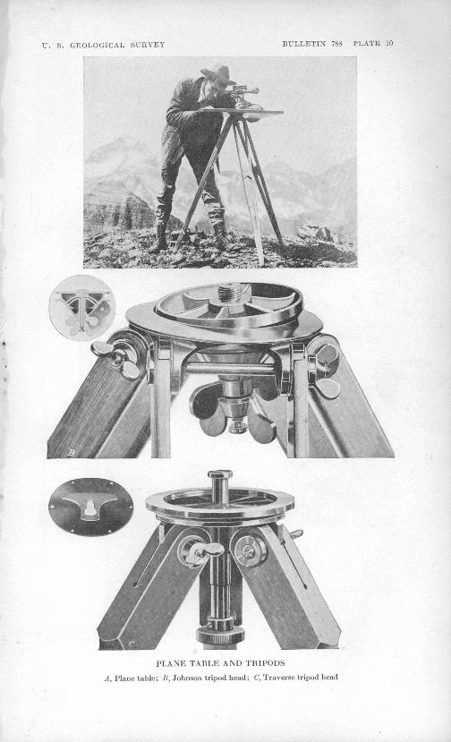
TI. S. GEOLOGICAL SURVEY BULLETIN 788 PLATE 10
PLANE TABLE AND TRIPODS
A, Plane table; B, Johnson tripod head; C, Traverse tripod head
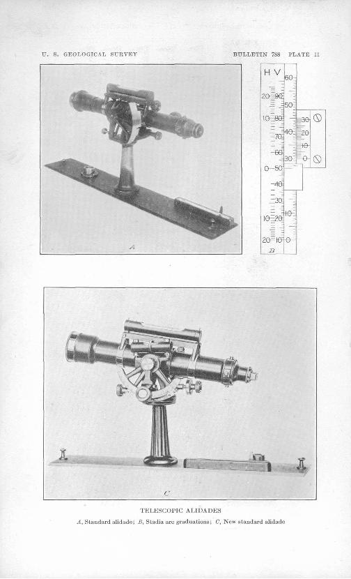
IT. S. GEOLOGICAL SURVEY BULLETIN 788 PLATE 11
H V
503
iG^ee
-60!
G 5S
20= H.B
®
TELESCOPIC ALIDADES
A, Staadard alidade; B, Stadia arc graduations; C, New standard alidade
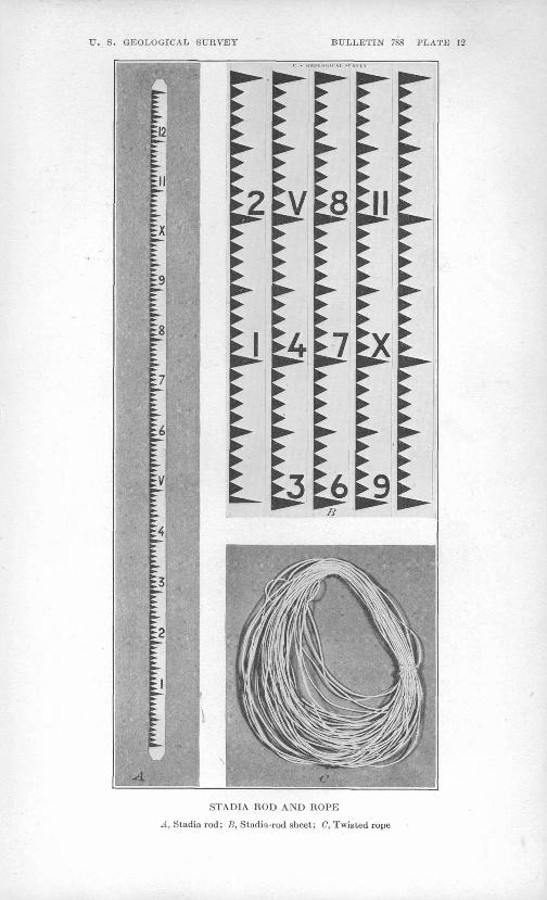
U. S. GEOLOGICAL SURVEY BULLETIN 788 PLATE 12
STADIA ROD AND ROPE
A, Stadia rod; B, Stadia-rod aheet; C, Twisted rope
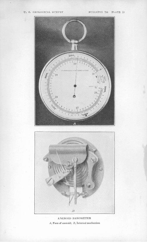
U. S. GEOLOGICAL, SURVEY BULLETIN 7S8 PLATE 13
ANEROID BAROMETER
A, Face of aneroid; B, Internal mechanism
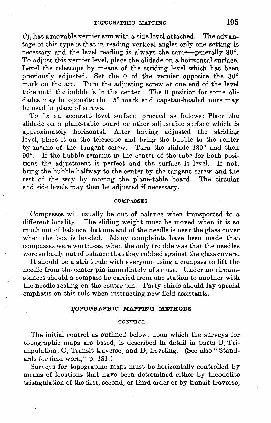
TOPOGRAPHIC MAPPING 195
(7), has a movable vernier arm with a side level attached. The advan tage of this type is that in reading vertical angles only one setting is necessary and the level reading is always the same generally 30°. To adjust this vernier level, place the alidade on a horizontal surface. Level the telescope by means of the striding level which has been previously adjusted. Set the 0 of the vernier opposite the 30° mark on the arc. Turn the adjusting screw at one end of the level tube until the bubble is in the center. The 0 position for some ali dades may be opposite the 15° mark and capstan-headed nuts may be used in place of screws.
To fix an accurate level surface, proceed as follows: Place the alidade on a plane-table board or other adjustable surface which is approximately horizontal. After having adjusted the striding level, place it on the telescope and bring the bubble to the center by means of the tangent screw. Turn the alidade 180° and then 90°. If the bubble remains in the center of the tube for both posi tions the adjustment is perfect and the surface is level. If not, bring the bubble halfway to the center by the tangent screw and the rest of the way by moving the plane-table board. The circular and side levels may then be adjusted if necessary.
COMPASSES
Compasses will usually be out of balance when transported to a different locality. The sliding weight must be moved when it is so much out of balance that one end of the needle is near the glass cover when the box is leveled. Many complaints have been made that compasses were worthless, when the only trouble was that the needles were so badly out of balance that they rubbed against the glass covers.
It should be a strict rule with everyone using a compass to lift the needle from the center pin immediately after use. Under no circum stances should a compass be carried from one station to another with the needle resting on the center pin. Party chiefs should lay special emphasis on this rule when instructing new field assistants.
TOPOGRAPHIC MAPPING METHODS<
CONTROL
The initial control as outlined below, upon which the surveys for topographic maps are based, is described in detail in parts B, Tri- angulation; C, Transit traverse; and D, Leveling. (See also "Stand ards for field work," p. 181.)
Surveys for topographic maps must be horizontally controlled by means of locations that have been determined either by theodolite triangulation of the first, second, or third order or by transit traverse,
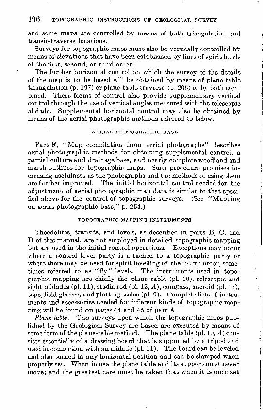
196 TOPOGKAPHIC INSTRUCTIONS OF GEOLOGICAL SURVEY
and some maps are controlled by means of both triangulation and transit-traverse locations.
Surveys for topographic maps must also be vertically controlled by means of elevations that have been established by lines of spirit levels of the first, second, or third order.
The further horizontal control on which the survey of the details of the map is to be based will be obtained by means of plane-table triangulation (p. 197) or plane-table traverse (p. 205) or by both com bined. These forms of control also provide supplementary vertical control through the use of vertical angles measured with the telescopic alidade. Supplemental horizontal control may also be obtained by means of the aerial photographic methods referred to below.
Part F, "Map compilation from aerial photographs" describes aerial photographic methods for obtaining supplemental control, a partial culture and drainage base, and nearly complete woodland and marsh outlines for topographic maps. Such procedure promises in creasing usefulness as the photographs and the methods of using them are further improved. The initial horizontal control needed for the adjustment of aerial photographic map data is similar to that speci fied above for the control of topographic surveys. (See "Mapping on aerial photographic base," p. 254.)
TOPOGRAPHIC MAPPING INSTRUMENTS
Theodolites, transits, and levels, as described in parts B, C, and D of this manual, are not employed in detailed topographic mapping but are used in the initial control operations. Exceptions may occur where a control level party is attached to a topographic party or where there may be need for spirit levelling of the fourth order, some- tunes referred to as "fly" levels. The instruments used in topo graphic mapping are chiefly the plane table (pi. 10), telescopic and sight alidades (pi. 11), stadia rod (pi. 12, A), compass, aneroid (pi. 13), tape, field glasses, and plotting scales (pi. 9). Complete lists of instru ments and accessories needed for different kinds of topographic map ping will be found on pages 44 and 45 of part A.
Plane table. The surveys upon which the topographic maps pub lished by the Geological Survey are based are executed by means of some form of the plane-table method. The plane table (pi. 10, A] con sists essentially of a drawing board that is supported by a tripod and used in connection with an alidade (pi. 11). The board can be leveled and also turned in any horizontal position and can be clamped when properly set. When in use the plane table and its support must never move; and the greatest care must be taken that when it is once set
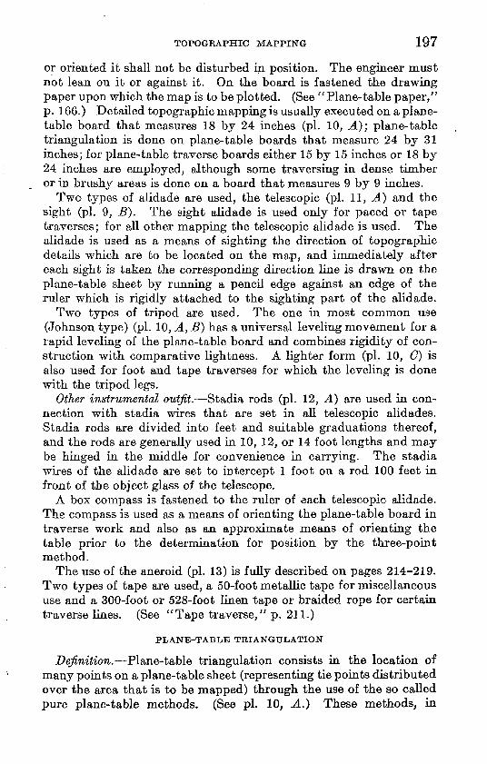
TOPOGRAPHIC MAPPING 197
or oriented it shall not be disturbed in position. The engineer must not lean on it or against it. On the board is fastened the drawing paper upon which the map is to be plotted. (See "Plane-table paper," p. 166.) Detailed topographic mapping is usually executed on a plane- table board that measures 18 by 24 inches (pi. 10, A); plane-table triangulation is done on plane-table boards that measure 24 by 31 inches; for plane-table traverse boards either 15 by 15 inches or 18 by 24 inches are employed, although some traversing in dense timber or in brushy areas is done on a board that measures 9 by 9 inches.
Two types of alidade are used, the telescopic (pi. 11, A) and the sight (pi. 9, B}. The sight alidade is used only for paced or tape traverses; for all other mapping the telescopic alidade is used. The alidade is used as a means of sighting the direction of topographic details which are to be located on the map, and immediately after each sight is taken the corresponding direction line is drawn on the plane-table sheet by running a pencil edge against an edge of the ruler which is rigidly attached to the sighting part of the alidade.
Two types of tripod are used. The one in most common use (Johnson type) (pi. 10, A, B} has a universal leveling movement for a rapid leveling of the plane-table board and combines rigidity of con struction with comparative lightness. A lighter form (pi. 10, C] is also used for foot and tape traverses for which the leveling is done with the tripod legs.
Other instrumental outfit. Stadia rods (pi. 12, A) are used in con nection with stadia wires that are set in all telescopic alidades. Stadia rods are divided into feet and suitable graduations thereof, and the rods are generally used in 10, 12, or 14 foot lengths and may be hinged in the middle for convenience in carrying. The stadia wires of the alidade are set to intercept 1 foot on a rod 100 feet in front of the object glass of the telescope.
A box compass is fastened to the ruler of each telescopic alidade. The compass is used as a means of orienting the plane-table board in traverse work and also as an approximate means of orienting the table prior to the determination for position by the three-point method.
The use of the aneroid (pi. 13) is fully described on pages 21.4-219. Two types of tape are used, a 50-foot metallic tape for miscellaneous use and a 300-foot or 528-foot linen tape or braided rope for certain traverse lines. (See "Tape traverse," p. 211.)
PLANE-TABLE TRIANGULATION
Definition. Plane-table triangulation consists in the location of many points on a plane-table sheet (representing tie points distributed over the area that is to be mapped) through the use of the so called pure plane-table methods. (See pi. 10, A.} These methods, in
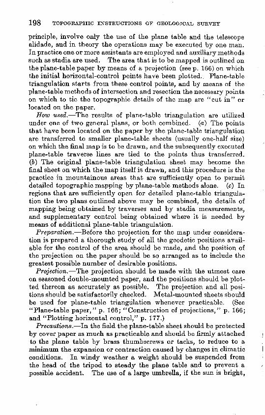
198 TOPOGRAPHIC INSTRUCTIONS OF GEOLOGICAL, SURVEY
principle, involve only the use of the plane table and the telescope alidade, and in theory the operations may be executed by one man. In practice one or more assistants are employed and auxiliary methods such as stadia are used. The area that is to be mapped is outlined on the plane-table paper by means of a projection (seep. 166) on which the initial horizontal-control points have been plotted.. Plane-table triangulation starts from these control points, and by means of the plane-table methods of intersection and resection the necessary points on which to tie the topographic details of the map are "cut in" or located on the paper.
How used. The results of plane-table triangulation are utilized under one of two general plans, or both combined, (a) The points that have been located on the paper by the plane-table triangulation are transferred to smaller plane-table sheets (usually one-half size) on which the final map is to be drawn, and the subsequently executed plane-table traverse lines are tied to the points thus transferred. (6) The original plane-table triangulation sheet may become the final sheet on which the map itself is drawn, and this procedure is the practice in mountainous areas that are sufficiently open to permit detailed topographic mapping by plane-table methods alone, (c) In regions that are sufficiently open for detailed plane-table triangula tion the two plans outlined above may be combined, the details of mapping being obtained by traverses and by stadia measurements, and supplementary control being obtained where it is needed by means of additional plane-table triangulation.
Preparation. Before the projection for the map under considera tion is prepared a thorough study of all the geodetic positions avail able for the control of the area should be made, and the position of the projection on the paper should be so arranged as to include the greatest possible number of desirable positions.
Projection. The projection should be made with the utmost care on seasoned double-mounted paper, and the positions should be plot ted thereon as accurately as possible. The projection and all posi tions should be satisfactorily checked. Metal-mounted sheets should be used for plane-table triangulation whenever practicable. (See "Plane-table paper," p. 166; "Construction of projections," p. 166; and "Plotting horizontal control," p. 177.)
Precautions. In the field the plane-table sheet should be protected by cover paper as much as practicable and should be firmly attached to the plane table by brass thumbscrews or tacks, to reduce to a minimum the expansion or contraction caused by changes in climatic conditions. In windy weather a weight should be suspended from the head of the tripod to steady the plane table and to prevent a possible accident. The use of a large umbrella, if the sun is bright,
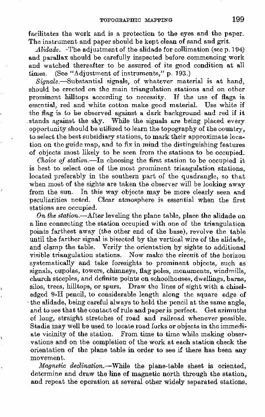
TOPOGRAPHIC MAPPING 199
facilitates the work and is a protection to the eyes and the paper. The instrument and paper should be kept clean of sand and grit.
Alidade. The adjustment of the alidade for collimation (seep. 194) and parallax should be carefully inspected before commencing work and watched thereafter to be assured of its good condition at all times. (See "Adjustment of instruments," p. 193.)
Signals. Substantial signals, of whatever material is at hand, should be erected on the main triangulation stations and on other prominent hilltops according to necessity. If the use of flags is essential, red and white cotton make good material. Use white if the flag is to be observed against a dark background and red if it stands against the sky. While the signals are being placed every opportunity should be utilized to learn the topography of the country, to select the best subsidiary stations, to mark their approximate loca tion on the guide map, and to fix in mind the distinguishing features of objects most likely to be seen from the stations to be occupied.
Choice of station. In choosing the first station to be occupied it is best to select one of the most prominent triangulation stations, located preferably in the southern part of the quadrangle, so that when most of the sights are taken the observer will be looking away from the sun. In this way objects may be more clearly seen and peculiarities noted. Clear atmosphere is essential when the first stations are occupied.
On the station. After leveling the plane table, place the alidade on a line connecting the station occupied with one of the triangulation points farthest away (the other end of the base), revolve the table until the farther signal is bisected by the vertical wire of the alidade, and clamp the table. Verify the orientation by sights to additional visible triangulation stations. Now make the circuit of the horizon systematically and take foresights to prominent objects, such as signals, cupolas, towers, chimneys, flag poles, monuments, windmills, church steeples, and definite points on schoolhouses, dwellings, barns, silos, trees, hilltops, or spurs. Draw the lines of sight with a chisel- edged 9-H pencil, to considerable length along the square edge of
the alidade, being careful always to hold the pencil at the same angle, and to see that the contact of rule and paper is perfect. Get azimuths of long, straight stretches of road and railroad whenever possible. Stadia may well be used to locate road forks or objects in the immedi ate vicinity of the station. From time to time while making obser vations and on the completion of the work at each station check the orientation of the plane table in order to see if there has been any movement.
Magnetic declination. While the plane-table sheet is oriented, determine and draw the line of magnetic north through the station, and repeat the operation at several other widely separated stations.
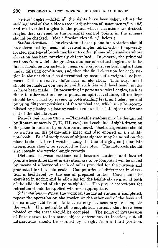
200 TOPOGRAPHIC INSTRUCTIONS OF GEOLOGICAL SURVEY
Vertical angles. After all the sights have been taken adjust the striding level of the alidade (see "Adjustment of instruments," p. 193) and read vertical angles to the points whose elevations are desired. Angles that are read to the principal control points in the scheme should be checked. (See "Station elevation," below.)
Station elevation. The elevation of each plane-table station should be determined by means of vertical angles taken either to specially located spirit-level bench marks or to other plane-table stations whose elevation has been previously determined. In general, the principal stations from which the greatest number of vertical angles are to be taken should be connected by means of reciprocal vertical angles taken under differing conditions, and then the final elevation for each sta tion in the net should be determined by means of a weighted adjust ment of the observed differences in elevation. This adjustment should be made in conjunction with such ties with level bench marks as have been made. In measuring important vertical angles, such as those to other stations or to points on spirit-level lines, all readings should be checked by reversing both striding level and telescope and by using different positions of the vertical arc, which may be accom plished by placing a plotting scale or some other flat object under one end of the alidade ruler.
Records and computations. Plane-table stations may be designated by Roman numerals (I, II, III, etc.), and each line of sight drawn on the plane-table sheet by an Arabic numeral. Such designations should be written on the plane-table sheet and also entered in a suitable notebook. Brief descriptions of objects sighted may be noted on the plane-table sheet and written along the line of sight, and complete descriptions should be recorded in the notes. The notebook should also contain the vertical-angle records.
Distances between stations and between stations and located points whose differences in elevation are to be computed will be scaled by means of a boxwood scale of miles provided for the purpose and graduated for the field scale. Computation of differences in eleva tion is facilitated by the use of prepared tables. Care should be exercised in noting and in allowing for the height above ground both of the alidade and of the point sighted. The proper corrections for refraction should be applied wherever appropriate.
Other stations. When the work on the initial station is completed, repeat the operation on the station at the other end of the base and on as many additional stations as may be necessary to complete the work. If practicable all triangulation stations that have been plotted on the sheet should be occupied. The point of intersection of lines drawn to the same object determines its location, but all intersections should be verified by a sight from a third position.
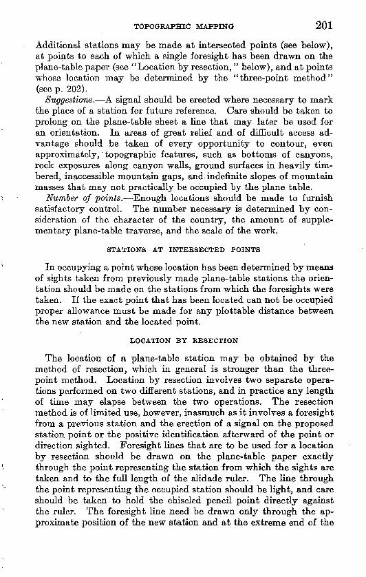
TOPOGRAPHIC MAPPING 201
Additional stations may be made at intersected points (see below), at points to each of which a single foresight has been drawn on the plane-table paper (see "Location by resection," below), and at points whose location may be determined by the "three-point method" (see p. 202).
Suggestions. A signal should be erected where necessary to mark the place of a station for future reference. Care should be taken to prolong on the plane-table sheet a line that may later be used for an orientation. In areas of great relief and of difficult access ad vantage should be taken of every opportunity to contour, even approximately,' topographic features, such as bottoms of canyons, rock exposures along canyon walls, ground surfaces in heavily tim bered, inaccessible mountain gaps, and indefinite slopes of mountain masses that may not practically be occupied by the plane table.
Number of points. Enough locations should be made to furnish satisfactory control. The number necessary is determined by con sideration of the character of the country, the amount of supple mentary plane-table traverse, and the scale of the work.
STATIONS AT INTEESECTED POINTS
In occupying a point whose location has been determined by means of sights taken from previously made plane-table stations the orien tation should be made on the stations from which the foresights were taken. If the exact point that has been located can not be occupied proper allowance must be made for any plottable distance between the new station and the located point.
LOCATION BY RESECTION
The location of a plane-table station may be obtained by the method of resection, which in general is stronger than the three- point method. Location by resection involves two separate opera tions performed on two different stations, and in practice any length of time may elapse between the two operations. The resection method is of limited use, however, inasmuch as it involves a foresight from a previous station and the erection of a signal on the proposed station point or the positive identification afterward of the point or direction sighted. Foresight lines that are to be used for a location by resection should be drawn on the plane-table paper exactly through the point representing the station from which the sights are taken and to the full length of the alidade ruler. The line through the point representing the occupied station should be light, and care should be taken to hold the chiseled pencil point directly against the ruler. The foresight line need be drawn only through the ap proximate position of the new station and at the extreme end of the
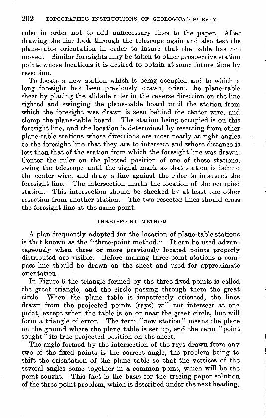
202 TOPOGRAPHIC INSTRUCTIONS OF GEOLOGICAL SURVEY
ruler in order not to add unnecessary lines to the paper. After drawing the line look through the telescope again and also test the plane-table orientation in order to insure that the table has not moved, Similar foresights may be taken to other prospective station points whose locations it is desired to obtain at some future time by resection.
To locate a new station which is being occupied and to which a long foresight has been previously drawn, orient the plane-table sheet by placing the alidade ruler in the reverse direction on the line sighted and swinging the plane-table board until the station from which the foresight was drawn is seen behind the center wire, and clamp the plane-table board. The station being occupied is on this foresight line, and the location is determined by resecting from other plane-table stations whose directions are most nearly at right angles to the foresight line that they are to intersect and whose distance is less than that of the station from which the foresight line was drawn. Center the ruler on the plotted position of one of these stations, swing the telescope until the signal mark at that station is behind the center wire, and draw a line against the ruler to intersect the foresight line. The intersection marks the location of the occupied station. This intersection should be checked by at least one other resection from another station. The two resected lines should cross the foresight line at the same point.
THREE-POINT METHOD
A plan frequently adopted for the location of plane-table stations is that known as the "three-point method." It can be used advan tageously when three or more previously located points properly distributed are visible. Before making three-point stations a com pass line should be drawn on the sheet and used for approximate orientation.
In Figure 6 the triangle formed by the three fixed points is called the great triangle, and the circle passing through them the great circle. When the plane table is imperfectly oriented, the lines drawn from the projected points (rays) will not intersect at one point, except when the table is on or near the great circle, but will form a triangle of error. The term "new station" means the place on the ground where the plane table is set up, and the term "point sought" its true projected position on the sheet.
The angle formed by the intersection of the rays drawn from any two of the fixed points is the correct angle, the problem being to shift the orientation of the plane table so that the vertices of the several angles come together in a common point, which will be the point sought. This fact is the basis for the tracing-paper solution of the three-point problem, which is described under the next heading.
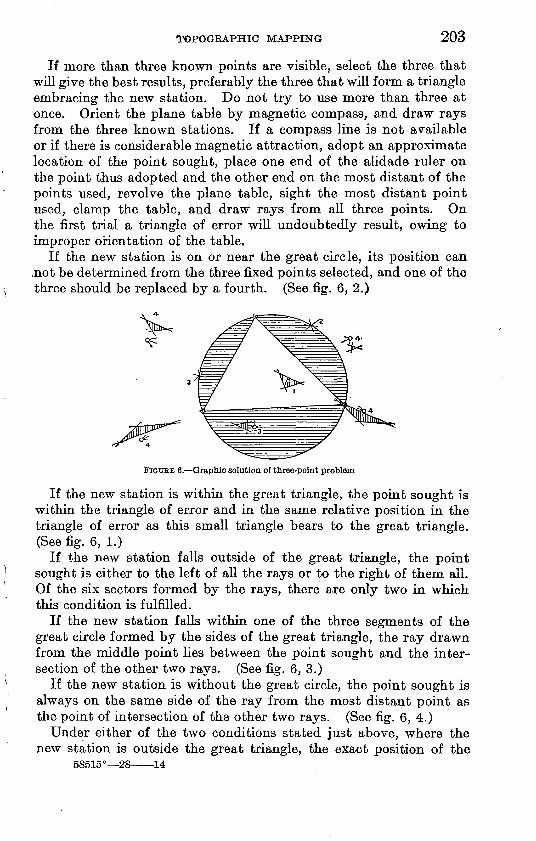
TOPOGRAPHIC MAPPING 203
If more than three known points are visible, select the three that will give the best results, preferably the three that will form a triangle embracing the new station. Do not try to use more than three at once. Orient the plane table by magnetic compass, and draw rays from the three known stations. If a compass line is not available or if there is considerable magnetic attraction, adopt an approximate location of the point sought, place one end of the alidade ruler on the point thus adopted and the other end on the most distant of the points used, revolve the plane table, sight the most distant point used, clamp the table, and draw rays from all three points. On the first trial a triangle of error will undoubtedly result, owing to improper orientation of the table.
If the new station is on or near the great circle, its position can .not be determined from the three fixed points selected, and one of the three should be replaced by a fourth. (See fig. 6, 2.)
FIGURE 6. Graphic solution of three-point problem
If the new station is within the great triangle, the point sought is within the triangle of error and in the same relative position in the triangle of error as this small triangle bears to the great triangle. (See fig. 6, 1.)
If the new station falls outside of the great triangle, the point sought is either to the left of all the rays or to the right of them all. Of the six sectors formed by the rays, there are only two in which this condition is fulfilled.
If the new station falls within one of the three segments of the great circle formed by the sides of the great triangle, the ray drawn from the middle point lies between the point sought and the inter section of the other two rays. (See fig. 6, 3.)
If the new station is without the great circle, the point sought is always on the same side of the ray from the most distant point as the point of intersection of the other two rays. (See fig. 6, 4.)
Under either of the two conditions stated just above, where the new station is outside the great triangle, the exact position of the
58515° 28 14
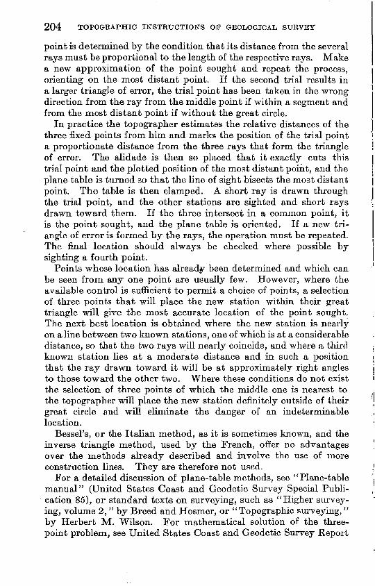
204 TOPOGRAPHIC INSTRUCTIONS OP GEOLOGICAL SURVEY
point is determined by the condition that its distance from the several rays must be proportional to the length of the respective rays. Make a new approximation of the point sought and repeat the process, orienting on the most distant point. If the second trial results in a larger triangle of error, the trial point has been taken in the wrong direction from the ray from the middle point if within a segment and from the most distant point if without the great circle.
In practice the topographer estimates the relative distances of the three fixed points from him and marks the position of the trial point a proportionate distance from the three rays that form the triangle of error. The alidade is then so placed that it exactly cuts this trial point and the plotted position of the most distant point, and the plane table is turned so that the line of sight bisects the most distant point. The table is then clamped. A short ray is drawn through the trial point, and the other stations are sighted and short rays drawn toward them. If the three intersect in a common point, it is the point sought, and the plane table is oriented. If a new tri angle of error is formed by the rays, the operation must be repeated. The final location should always be checked where possible by sighting a fourth point.
Points whose location has already been determined and which can be seen from any one point are usually few. However, where the available control is sufficient to permit a choice of points, a selection of three points that will place the new station within their great triangle will give the most accurate location of the point sought. The next best location is obtained where the new station is nearly on a line between two known stations, one of which is at a considerable distance, so that the two rays will nearly coincide, and where a third known station lies at a moderate distance and in such a position that the ray drawn toward it will be at approximately right angles to those toward the other two. Where these conditions do not exist the selection of three points of which the middle one is nearest to the topographer will place the new station definitely outside of their great circle and will eliminate the danger of an indeterminable location.
Bessel's, or the Italian method, as it is sometimes known, and the inverse triangle method, used by the French, offer no advantages over the methods already described and involve the use of more construction lines. They are therefore not used.
For a detailed discussion of plane-table methods, see "Plane-table manual" (United States Coast and Geodetic Survey Special Publi cation 85), or standard texts on surveying, such as "Higher survey ing, volume 2," by Breed and Hosmer, or "Topographic surveying," by Herbert M. Wilson. For mathematical solution of the three- point problem, see United States Coast and Geodetic Survey Report
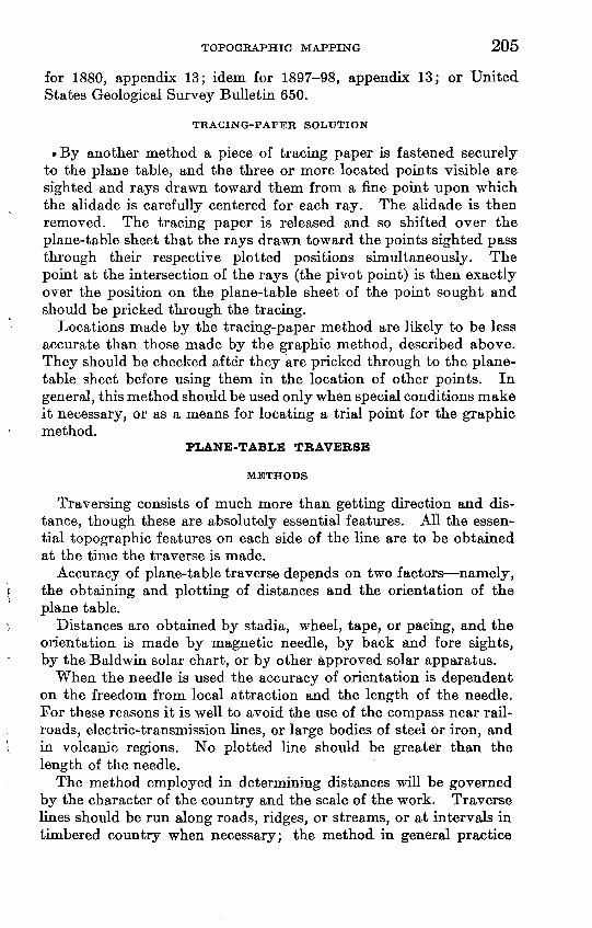
TOPOGRAPHIC MAPPING 205
for 1880, appendix 13; idem for 1897-98, appendix 13; or United States Geological Survey Bulletin 650.
TRACING-PAFER SOLUTION
By another method a piece of tracing paper is fastened securely to the plane table, and the three or more located points visible are sighted and rays drawn toward them from a fine point upon which the alidade is carefully centered for each ray. The alidade is then removed. The tracing paper is released and so shifted over the plane-table sheet that the rays drawn toward the points sighted pass through their respective plotted positions simultaneously. The point at the intersection of the rays (the pivot point) is then exactly over the position on the plane-table sheet of the point sought and should be pricked through the tracing.
Locations made by the tracing-paper method are likely to be less accurate than those made by the graphic method, described above. They should be checked after they are pricked through to the plane- table sheet before using them in the location of other points. In general, this method should be used only when special conditions make it necessary, or as a means for locating a trial point for the graphic method.
PLANE-TABLE TRAVERSE
METHODS
Traversing consists of much more than getting direction and dis tance, though these are absolutely essential features. All the essen tial topographic features on each side of the line are to be obtained at the time the traverse is made.
Accuracy of plane-table traverse depends on two factors namely, the obtaining and plotting of distances and the orientation of the plane table.
Distances are obtained by stadia, wheel, tape, or pacing, and the orientation is made by magnetic needle, by back and fore sights, by the Baldwin solar chart, or by other approved solar apparatus.
When the needle is used the accuracy of orientation is dependent on the freedom from local attraction and the length of the needle. For these reasons it is well to avoid the use of the compass near rail roads, electric-transmission lines, or large bodies of steel or iron, and in volcanic regions. No plotted line should be greater than the length of the needle.
The method employed in determining distances will be governed by the character of the country and the scale of the work. Traverse lines should be run along roads, ridges, or streams, or at intervals in timbered country when necessary; the method in general practice
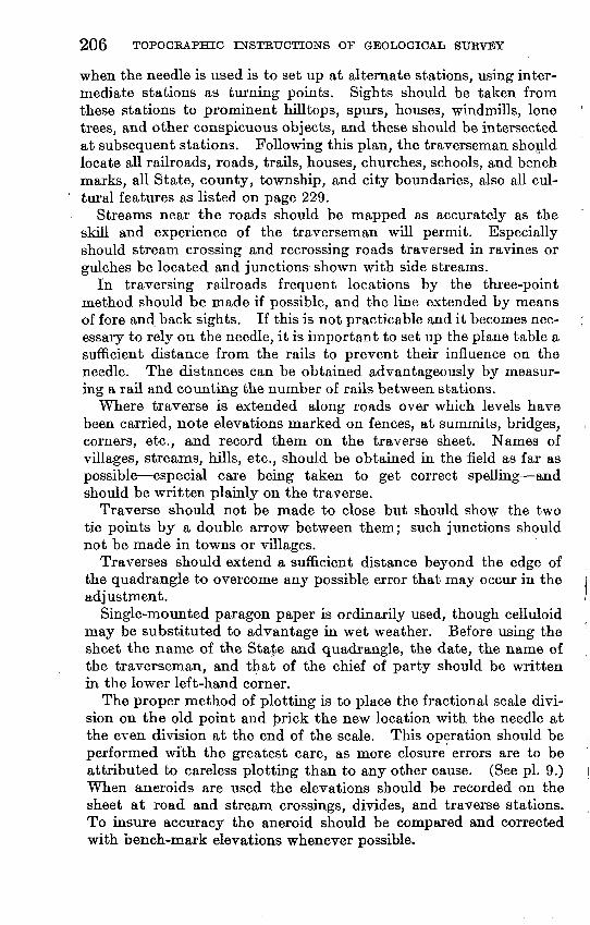
206 TOPOGRAPHIC INSTRUCTIONS OF GEOLOGICAL SURVEY
when the needle is used is to set up at alternate stations, using inter mediate stations as turning points. Sights should be taken from these stations to prominent hilltops, spurs, houses, windmills, lone trees, and other conspicuous objects, and these should be intersected at subsequent stations. Following this plan, the traverseman should locate all railroads, roads, trails, houses, churches, schools, and bench marks, all State, county, township, and city boundaries, also all cul tural features as listed on page 229.
Streams near the roads should be mapped as accurately as the skill and experience of the traverseman will permit. Especially should stream crossing and recrossing roads traversed in ravines or gulches be located and junctions shown with side streams.
In traversing railroads frequent locations by the three-point method should be made if possible, and the line extended by means of fore and back sights. If this is not practicable and it becomes nec essary to rely on the needle, it is important to set up the plane table a sufficient distance from the rails to prevent their influence on the needle. The distances can be obtained advantageously by measur ing a rail and counting the number of rails between stations.
Where traverse is extended along roads over which levels have been carried, note elevations marked on fences, at summits, bridges, corners, etc., and record them on the traverse sheet. Names of villages, streams, hills, etc., should be obtained in the field as far as possible especial care being taken to get correct spelling and should be written plainly on the traverse.
Traverse should not be made to close but should show the two tie points by a double arrow between them; such junctions should not be made in towns or villages.
Traverses should extend a sufficient distance beyond the edge of the quadrangle to overcome any possible error that may occur in the adjustment.
Single-mounted paragon paper is ordinarily used, though celluloid may be substituted to advantage in wet weather. Before using the sheet the name of the State and quadrangle, the date, the name of the traverseman, and that of the chief of party should be written in the lower left-hand corner.
The proper method of plotting is to place the fractional scale divi sion on the old point and prick the new location with the needle at the even division at the end of the scale. This operation should be performed with the greatest care, as more closure errors are to be attributed to careless plotting than to any other cause. (See pi. 9.) When aneroids are used the elevations should be recorded on the sheet at road and stream crossings, divides, and traverse stations. To insure accuracy the aneroid should be compared and corrected with bench-mark elevations whenever possible.
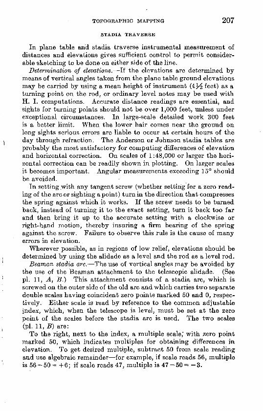
TOPOGRAPHIC MAPPING 207
STADIA TRAVERSE
In plane table and stadia traverse instrumental measurement of distances and elevations gives sufficient control to permit consider able sketching to be done on either side of the line.
Determination of elevations. If the elevations are determined by means of vertical angles taken from the plane table ground elevations may be carried by using a mean height of instrument (4^ feet) as a turning point on the rod, or ordinary level notes may be used with H. I. computations. Accurate distance readings are essential, and sights for turning points should not be over 1,000 feet, unless under exceptional circumstances. In large-scale detailed work 300 feet is a better limit. When the lower hair comes near the ground on long sights serious errors are liable to occur at certain hours of the day through refraction. The Anderson or Johnson stadia tables are probably the most satisfactory for computing differences of elevation and horizontal correction. On scales of 1:48,000 or larger the hori zontal correction can be readily shown in plotting. On larger scales it becomes important. Angular measurements exceeding 15° should be avoided.
In setting with any tangent screw (whether setting for a zero read ing of the arc or sighting a point) turn in the direction that compresses the spring against which it works. If the screw needs to be turned back, instead of turning it to the exact setting, turn it back too far and then bring it up to the accurate setting with a clockwise or right-hand motion, thereby insuring a firm bearing of the spring against the screw. Failure to observe this rule is the cause of many errors in elevation.
Wherever possible, as in regions of low relief, elevations should be determined by using the alidade as a level and the rod as a level rod.
Beaman stadia arc, The use of vertical angles may be avoided by the use of the Beaman attachment to the telescopic alidade. (See pi. 11, A, B.) This attachment consists of a stadia arc, which is screwed on the outer side of the old arc and which carries two separate double scales having coincident zero points marked 50 and 0, respec tively. Either scale is read by reference to the common adjustable index, which, when the telescope is level, must be set at the zero point of the scales before the stadia arc is used. The two scales (pi. 11, B) are:
To the right, next to the index, a multiple scale,' with zero point marked 50, which indicates multiples for obtaining differences in elevation. To get desired multiple, subtract 50 from scale reading and use algebraic remainder for example, if scale reads 56, multiple is 56-50= +6; if scale reads 47, multiple is 47-50= -3.
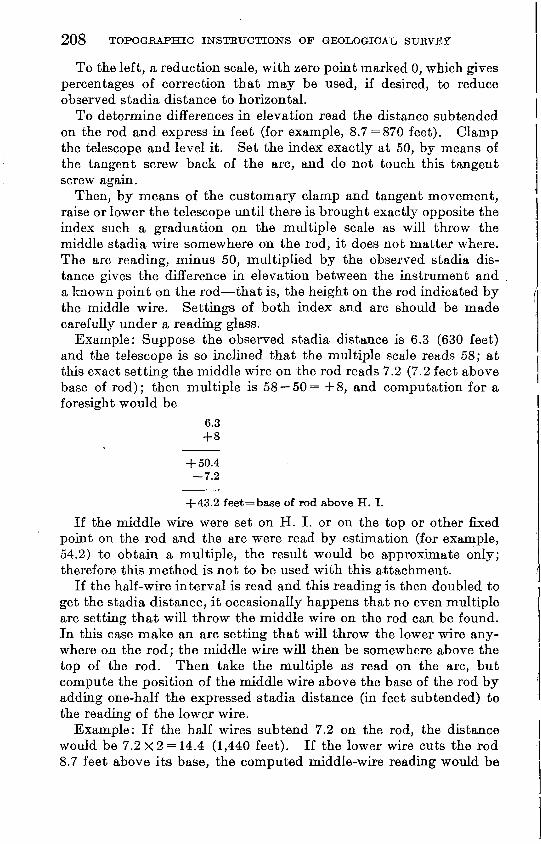
208 TOPOGRAPHIC INSTRUCTIONS OP GEOLOGICAL SURVEY
To the left, a reduction scale, with zero point marked 0, which gives percentages of correction that may be used, if desired, to reduce observed stadia distance to horizontal.
To determine differences in elevation read the distance subtended on the rod and express in feet (for example, 8.7 = 870 feet). Clamp the telescope and level it. Set the index exactly at 50, by means of the tangent screw back of the arc, and do not touch this tangent screw again.
Then, by means of the customary clamp and tangent movement, raise or lower the telescope until there is brought exactly opposite the index such a graduation on the multiple scale as will throw the middle stadia wire somewhere on the rod, it does not matter where. The arc reading, minus 50, multiplied by the observed stadia dis tance gives the difference in elevation between the instrument and a known point on the rod that is, the height on the rod indicated by the middle wire. Settings of both index and arc should be made carefully under a reading glass.
Example: Suppose the observed stadia distance is 6.3 (630 feet) and the telescope is so inclined that the multiple scale reads 58; at this exact setting the middle wire on the rod reads 7.2 (7.2 feet above base of rod); then multiple is 58 50 = + 8, and computation for a foresight would be
6.3
+ 50.4 7.2
+ 43.2 feet=base of rod above H. I.
If the middle wire were set on H. I. or on the top or other fixed point on the rod and the arc were read by estimation (for example, 54.2) to obtain a multiple, the result would be approximate only; therefore this method is not to be used with this attachment.
If the half-wire interval is read and this reading is then doubled to get the stadia distance, it occasionally happens that no even multiple arc setting that will throw the middle wire on the rod can be found. In this case make an arc setting that will throw the lower wire any where on the rod; the middle wire will then be somewhere above the top of the rod. Then take the multiple as read on the arc, but compute the position of the middle wire above the base of the rod by adding one-half the expressed stadia distance (in feet subtended) to the reading of the lower wire.
Example: If the half wires subtend 7.2 on the rod, the distance would be 7.2x2 = 14.4 (1,440 feet). If the lower wire cuts the rod 8.7 feet above its base, the computed middle-wire reading would be
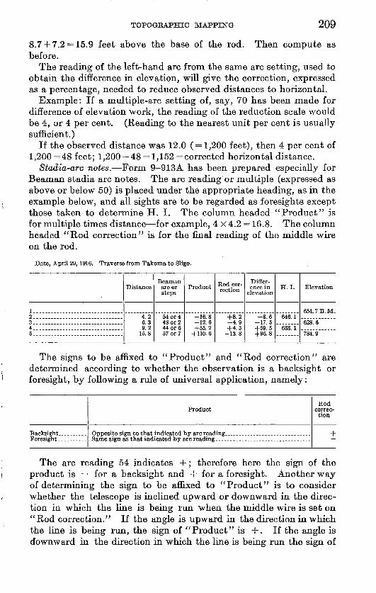
TOPOGRAPHIC MAPPING 209
8.7+7.2 = 15.9 feet above the base of the rod. Then compute as before.
The reading of the left-hand arc from the same arc setting, used to obtain the difference in elevation, will give the correction, expressed as a percentage, needed to reduce observed distances to horizontal.
Example: If a multiple-arc setting of, say, 70 has been made for difference of elevation work, the reading of the reduction scale would be 4, or 4 per cent. (Reading to the nearest unit per cent is usually sufficient.)
If the observed distance was 12.0 (=1,200 feet), then 4 per cent of 1,200 =48 feet; 1,200-48 = 1,152 = corrected horizontal distance.
Stadia-arc notes. Form 9-913A has been prepared especially for Beaman stadia arc notes. The arc reading or multiple (expressed as above or below 50) is placed under the appropriate heading, as in the example below, and all sights are to be regarded as foresights except those taken to determine H. I. The column headed "Product" is for multiple times distance for example, 4X4.2 = 16.8. The column headed "Rod correction" is for the final reading of the middle wire on the rod.
Date, April 29,1916. Traverse from Takoma to Sligo.
2--........-.. ____ ...........3. ..............................4.... ....................... ....5..............................
Distance
4.26.39.2
Beaman arc or steps
48 or 2
57 or 7
Product
-16.8-12.6+55.2
+110. 6
Rod cor rection
+8.2-4.9+4.3
Differ ence in
elevation
-8.6-17.5+59.5+96.8
H.I.
646.1
688.1
Elevation
654.7B.M.
628.6
784.9
The signs to be affixed to "Product" and "Rod correction" are determined according to whether the observation is a backsight or foresight, by following a rule of universal application, namely:
ProductRod
correction
+
The arc reading 54 indicates +; therefore here the sign of the product is for a backsight and + for a foresight. Another way of determining the sign to be affixed to "Product" is to consider whether the telescope is inclined upward or downward in the direc tion in which the line is being run when the middle wire is set on "Rod correction." If the angle is upward in the direction in which the line is being run, the sign of "Product" is +. If the angle is downward in the direction in which the line is being run the sign of
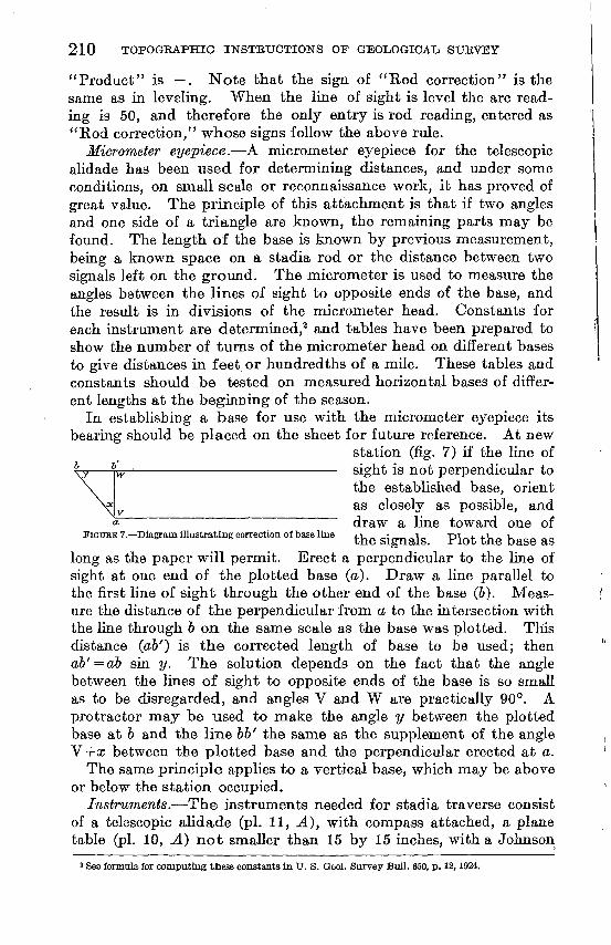
210 TOPOGEAPHIC INSTRUCTIONS OF GEOLOGICAL SURVEY
"Product" is . Note that the sign of "Rod correction" is the same as in leveling. When the line of sight is level the arc read ing is 50, and therefore the only entry is rod reading, entered as "Rod correction," whose signs follow the above rule.
Micrometer eyepiece. A micrometer eyepiece for the telescopic alidade has been used for determining distances, and under some conditions, on small scale or reconnaissance work, it has proved of great value. The principle of this attachment is that if two angles and one side of a triangle are known, the remaining parts may be found. The length of the base is known by previous measurement, being a known space on a stadia rod or the distance between two signals left on the ground. The micrometer is used to measure the angles between the lines of sight to opposite ends of the base, and the result is in divisions of the micrometer head. Constants for each instrument are determined,2 and tables have been prepared to show the number of turns of the micrometer head on different bases to give distances in feet or hundredths of a mile. These tables and constants should be tested on measured horizontal bases of differ ent lengths at the beginning of the season.
In establishing a base for use with the micrometer eyepiece its bearing should be placed on the sheet for future reference. At new
station (fig. 7) if the line of sight is not perpendicular to the established base, orient as closely as possible, and draw a Jme toward one of
FiGUEET.-DiagramillustratmgcorrectionofbaseliBe plofc
long as the paper will permit. Erect a perpendicular to the line of sight at one end of the plotted base (a). Draw a line parallel to the first line of sight through the other end of the base (6). Meas ure the distance of the perpendicular from a to the intersection with the line through & on the same scale as the base was plotted. This distance (#&') is the corrected length of base to be used; then ab' = ab sin y. The solution depends on the fact that the angle between the lines of sight to opposite ends of the base is so small as to be disregarded, and angles V and W are practically 90°. A protractor may be used to make the angle y between the plotted base at 6 and the line lib' the same as the supplement of the angle V+cc between the plotted base and the perpendicular erected at a.
The same principle applies to a vertical base, which may be above or below the station occupied.
Instruments. The instruments needed for stadia traverse consist of a telescopic alidade (pi. 11, A), with compass attached, a plane table (pi. 10, A) not smaller than 15 by 15 inches, with a Johnson
3 See formula for computing these constants in U. S. Qeol. Survey Bull. 650, p. 12, 1924.
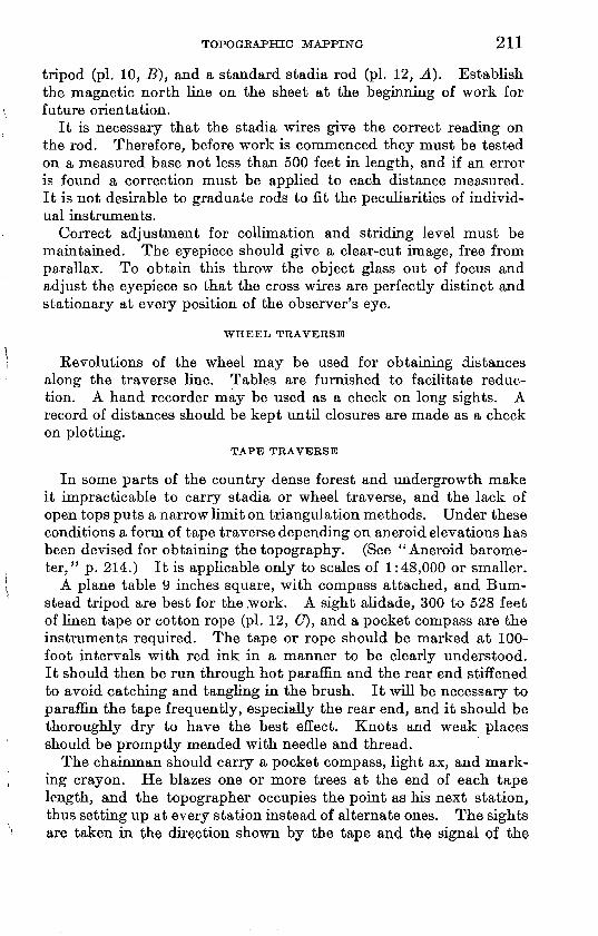
TOPOGRAPHIC MAPPING 211
tripod (pi. 10, B), and a standard stadia rod (pi. 12, A). Establish the magnetic north line on the sheet at the beginning of work for future orientation.
It is necessary that the stadia wires give the correct reading on the rod. Therefore, before work is commenced they must be tested on a measured base not less than 500 feet in length, and if an error is found a correction must be applied to each distance measured. It is not desirable to graduate rods to fit the peculiarities of individ ual instruments.
Correct adjustment for collimation and striding level must be maintained. The eyepiece should give a clear-cut image, free from parallax. To obtain this throw the object glass out of focus and adjust the eyepiece so that the cross wires are perfectly distinct and stationary at every position of the observer's eye.
WHEEL TRAVERSE
Revolutions of the wheel may be used for obtaining distances along the traverse line. Tables are furnished to facilitate reduc tion. A hand recorder may be used as a check on long sights. A record of distances should be kept until closures are made as a check on plotting.
TAPE TRAVERSE
In some parts of the country dense forest and undergrowth make it impracticable to carry stadia or wheel traverse, and the lack of open tops puts a narrow limit on triangulation methods. Under these conditions a form of tape traverse depending on aneroid elevations has been devised for obtaining the topography. (See "Aneroid barome ter." p. 214.) It is applicable only to scales of 1:48,000 or smaller.
A plane table 9 inches square, with compass attached, and Bum- stead tripod are best for the .work. A sight alidade, 300 to 528 feet of linen tape or cotton rope (pi. 12, (7), and a pocket compass are the instruments required. The tape or rope should be marked at 100- foot intervals with red ink in a manner to be clearly understood. It should then be run through hot paraffin and the rear end stiffened to avoid catching and tangling in the brush. It will be necessary to paraffin the tape frequently, especially the rear end, and it should be thoroughly dry to have the best effect. Knots and weak places should be promptly mended with needle and thread.
The chainman should carry a pocket compass, light ax, and mark ing crayon. He blazes one or more trees at the end of each tape length, and the topographer occupies the point as his next station, thus setting up at every station instead of alternate ones. The sights are taken in the direction shown by the tape and the signal of the
212 TOPOGRAPHIC INSTRUCTIONS OF GEOLOGICAL SURVEY
tapeman. It is well to number the stations to avoid error in making closures. Lines should follow natural features, such as ridges, val leys, and spurs, rather than gridiron the territory. The greatest error of the lines comes through the tapeman not keeping a straight course.
Adjustment of aneroid elevations should be made daily (see "Aneroid barometer," p. 214), and the contours altered to agree, care being taken to preserve topographic shape and detail. Adjustment of horizontal errors should not be made on traverse sheets.
FOOT TRAVERSE
The method of obtaining distances by foot or animal paces is resorted to in timbered countries and mountainous regions without roads. Careful measurements of the average pace of an animal or a traverseman on a level or a slight incline should be made, and a table prepared in hundredths of a mile.
ADJUSTMENT OF TRAVERSE LINES
Large closing errors of traverse lines indicate either a swing in direction due to incorrect orientation or a gross error in reading or in plotting one or more distances. Gross errors in distance should be located between intermediate points of a traverse by running addi tional traverse lines from them to closing points. By first trans ferring the lines that fit between control points, the gross error can often be located within a short portion of the line, and that portion can then be rerun. In areas that have been subdivided by surveys of the General Land Office the traverse should be tied to the land lines as indicated by corners or by roads and fence lines. A com parison of distances on the traverse with the same distances as indi cated by the plats of the General Land Office will often indicate the gross error of a traverse within a certain mile and sometimes within a less distance. Cumulative errors due to a stadia interval other than 100 should, as stated before, be provided against by testing the alidade to be used before field work is started. If there is an appre ciable error in the interval a table should be prepared so that the error may be eliminated in plotting the distances. The adjustment of errors that can be eliminated by proper action is not advisable.
The errors in wheel and tape traverses will generally tend to make them too long. Foot traverse may be either too short or too long, the error depending on the accuracy of calibration and on the char acter of the area under survey. Plotting errors are usually all in one direction for any individual and result in a cumulative error. A tendency to plot too long or too short should be overcome as quickly as possible.
TOPOGEAPHIC MAPPING 213
Cumulative errors may readily be adjusted by the method of similar triangles. Through the end points of the traverse (fig. 8) draw a straight line (AB). Measuring from one end, lay off on this line the distance (indicated by the control on the regular field sheet) which should be the end to end distance of the traverse. Call the end which does not coincide with the end of the traverse & or &' according to whether the distance laid off is respectively shorter or longer than the traverse. Take any convenient point (O) at one side of the traverse and at a sufficient distance away to avoid sharp angles of intersection with the line AB, and draw lines OA and OB. If the traverse is too long, draw a line from & parallel with the line OA and intersecting the line OB at point B'. Through point B' draw the line B'A' parallel to the line AB. Line A'B' gives the desired length of the traverse Ab, as parallel lines intercepting parallel lines are equal. From point O draw lines through road corners and the several angles of the traverse represented by points 1, 2, 3, etc. The end points of the adjusted traverse are represented by points A' and B'. To locate other points on the adjusted traverse, begin at either end A' or B' and through them draw A'l' parallel to Al, B'5' parallel to B5, 5' 4' parallel to 5-4, etc. Point 2, any point on the traverse, may be located directly on the adjusted traverse by paralleling the direction of A2 through point A' to the line O2 the intersection 2' being the desired point. Because of the successively similar triangles constructed, the same proportional reduction of distance is carried through for each segment as was applied to the end to end length of the traverse.
If the traverse is too short by any distance B&' draw a line through point &' (fig. 8), parallel to the line OA to intersect line OB extended at point B" and proceed as before. A" and B" represent the ends and 1", 2", etc., the intermediate points of the adjusted traverse.
In the actual use of the similar triangles method, it is not necessary to draw the whole lines from the point O. A segment of each line, through points of the traverse slightly longer than will be neces sary for the enlargement or reduction, will suffice. By fastening tracing paper over the traverse, the construction lines and the adjustment can be made directly on the tracing paper and so be ready without further effort for transfer to the final field sheet. With only a moderately large error to be adjusted, it will be found that a careful adjustment of the intermediate road corners or principal pouits on the traverse line will suffice. The segments of traverse between such points can then be adjusted into place without appre ciable error by shifting a tracing of the original traverse line.
The similar triangles method of enlargement or reduction is appli cable to plats of other than traverse lines.
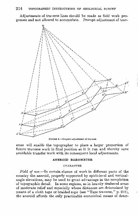
214 TOPOGEAPHIC INSTRUCTIONS OF GEOLOGICAL SURVEY
Adjustments of traverse lines should be made as field work pro gresses and not allowed to accumulate. Prompt adjustment of trav-
FIGURE 8. Graphic adjustment of traverse
erses will enable the topographer to place a larger proportion of future traverse work in final position as it is run and thereby save avoidable transfer work with its consequent local adjustments.
ANEROID BAROMETER
CHARACTER
Field of use. In certain classes of work in different parts of the country the aneroid, properly supported by spirit-level and vertical- angle elevations, may be used to great advantage in the completion of topographic detail. In some regions, as in heavily timbered areas of moderate relief and especially where distances are determined by means of a cloth tape or braided rope (see " Tape traverse," p. 211), the aneroid affords the only practicable economical means of deter-
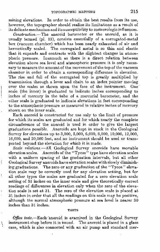
TOPOGBAPHIC MAPPING 215
mining elevations. In order to obtain the best results from its use, however, the topographer should realize its limitations as a result of its delicate mechanism and its susceptibility to meteorologic influences.
Construction. The aneroid barometer or the aneroid, as it is usually termed (pi. 13), consists essentially of a corrugated-metal box (vacuum chamber) which has been nearly exhausted of air and hermetically sealed. The corrugated metal is so thin and elastic that it expands and contracts with the slightest changes in atmos pheric pressure. Inasmuch as there is a direct relation between elevation above sea level and atmospheric pressure it is only neces sary to measure the amount of the movement of the top of the vacuum chamber in order to obtain a corresponding difference in elevation. The rise and fall of the corrugated top is greatly multiplied by transmission through a lever and chain to an index pointer moving over the scales as shown upon the face of the instrument. One scale (the inner) is graduated to indicate inches corresponding to inches of mercury in the tube of a mercurial barometer, and the other scale is graduated to indicate elevations in feet corresponding to the atmospheric pressure as measured in relative inches of mercury shown on the inner scale.
Each aneroid is constructed for use only to the limit of pressure for which its scales are graduated and for which nearly the complete circumference of the aneroid is used in order to give the largest graduations possible. Aneroids are kept in stock in the Geological Survey for elevations up to 3,000, 5,000, 6,000, 8,000, 10,000, 12,000, 16,000, and 20,000 feet, and no instrument should be used or trans ported beyond the elevation for which it is made.
Scale relations. All Geological Survey aneroids have movable elevation scales. Aneroids of the "Tycos " type have elevation scales with a uniform spacing of the graduation intervals, but all other Geological Survey aneroids have elevation scales with slowly diminish - ing graduations. The zero or any graduation of the "Tycos" eleva tion scale may be correctly used for any elevation setting, but for all other types the scales are graduated for a zero elevation scale setting of 31 inches on the inner scale and give theoretically correct readings of differences in elevation only when the zero of the eleva tion scale is set at 31. The zero of the elevation scale is placed at 31 inches in order that all the readings on this scale may be positive, although the normal atmospheric pressure at sea level is nearer 30 inches than 31 inches.
TESTS
Office tests. EachOmeroid is examined in the Geological Survey instrument shop before it is issued. The aneroid is placed in a glass case, which is also connected with an air pump and standard mer-
216 TOPOGKAPHIC INSTEXJCTIONS OF GEOLOGICAL SURVEY
curial barometer; the inch-scale readings of the two barometers are compared for several widely differing pressures, and, if found neces sary, the aneroid is reset to its true reading by means of the screw in the back of the metal case. The mechanical parts of the transmis sion are likewise examined and are cleaned and repaired if such attention is needed.
Field tests. The best field test for an aneroid is one that is made between points whose differences in elevation are known. A sensitive aneroid should show a small difference in reading between a horizontal and a vertical position of the face. This difference may amount to several scale divisions and is due to the extreme sensitiveness of the transmission and multiplying devices. If in further doubt as to whether the aneroid is working or not, exert a slight vertical pressure on the adjusting screw, using a hard point (not a pencil point), and if the needle responds by a movement equivalent to several scale divisions and moves back when the pressure is released the aneroid is probably working. The aneroid should not be opened nor should the screw in the back be turned by the topographer. Do not blow into the aneroid, to test its sensitiveness, as the breath may rust the chain and spring.
USE
The aneroid may be used in several ways as described below, depending upon the method of setting the movable altitude scale of feet.
Elevation differences. For the most accurate results the aneroid should not be used for reading elevations above sea level direct, but only for recording differences of elevation, much the same as a spirit level. For such use the zero of the elevation scale should be set at 31 inches, and this setting should be checked whenever the aneroid is read in order to guard against a slipping of the outer scale. Read ings should be taken both on arrival at and departure from a station or any point where a stop of considerable length is made. Aneroid readings should be checked by comparison with previously determined elevations whenever opportunity is afforded, as well as at the begin ning and end of each day's work. Notes should be kept on a form similar to that shown on page 217, for which a card can be obtained on requisition.
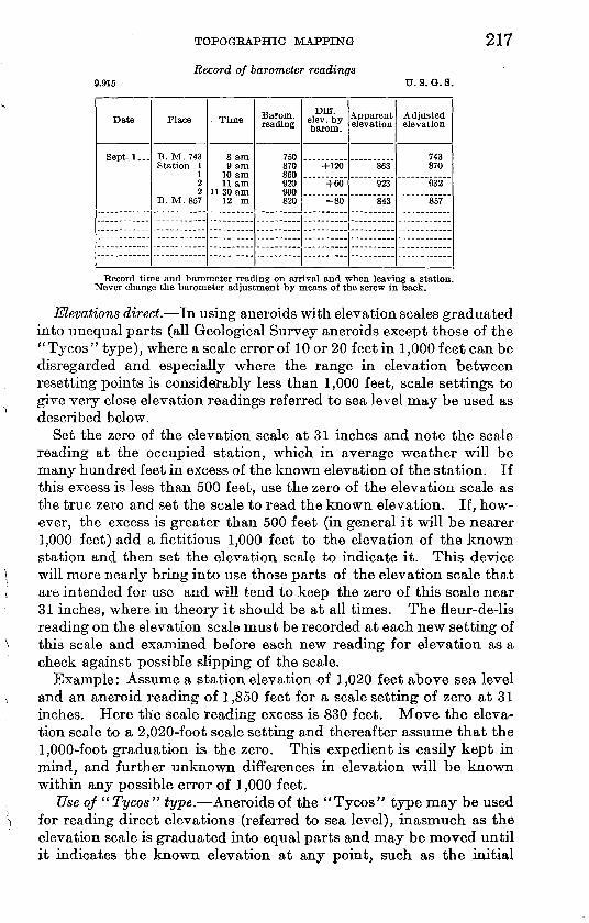
TOPOGBAPHIC MAPPING
Record of barometer readings
217
9.915 U. S. Q. S.
Date
Sept. 1...
Place
B. M. 743Station 1
12 2
B. M. 857
Time
9 am 10 am11 am
12 m
Barom. reading
750870 860920 900820
Diff. elev. by barom.
+120
+60
-80
Apparent elevation
863
923
843
Adjusted elevation
743870
932
857
Record time and barometer reading on arrival and when leaving a station. Never change the barometer adjustment by means of the screw in back.
Elevations direct. In using aneroids with elevation scales graduated into unequal parts (all Geological Survey aneroids except those of the "Tycos" type), where a scale error of 10 or 20 feet in 1,000 feet can be disregarded and especially where the range in elevation between resetting points is considerably less than 1,000 feet, scale settings to give very close elevation readings referred to sea level may be used as described below.
Set the zero of the elevation scale at 31 inches and note the scale reading at the occupied station, which in average weather will be many hundred feet in excess of the known elevation of the station. If this excess is less than 500 feet, use the zero of the elevation scale as the true zero and set the scale to read the known elevation. If, how ever, the excess is greater than 500 feet (in general it will be nearer 1,000 feet) add a fictitious 1,000 feet to the elevation of the known station and then set the elevation scale to indicate it. This device will more nearly bring into use those parts of the elevation scale that are intended for use and will tend to keep the zero of this scale near 31 inches, where in theory it should be at all times. The fleur-de-lis reading on the elevation scale must be recorded at each new setting of this scale and examined before each new reading for elevation as a check against possible slipping of the scale.
Example: Assume a station elevation of 1,020 feet above sea level and an aneroid reading of 1,850 feet for a scale setting of zero at 31 inches. Here the scale reading excess is 830 feet. Move the eleva tion scale to a 2,020-foot scale setting and thereafter assume that the 1,000-foot graduation is the zero. This expedient is easily kept in mind, and further unknown differences in elevation will be known within any possible error of 1,000 feet.
Use of " Tycos" type. Aneroids of the "Tycos" type may be used for reading direct elevations (referred to sea level), inasmuch as the elevation scale is graduated into equal parts and may be moved until it indicates the known elevation at any point, such as the initial
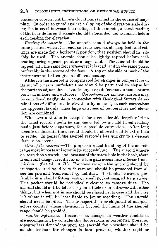
218 TOPOGEAPHIC INSTRUCTIONS OF GEOLOGICAL SUBVEY
station or subsequent known elevations reached in the course of map ping. In order to guard against a slipping of the elevation scale dur ing the interval between the readings of the aneroid, a check reading of the fleur-de-lis on this scale should be recorded and examined before each reading for elevation.
Reading the aneroid. The aneroid should always be held in the same position when it is read, and inasmuch as all shop tests and set tings are made for a horizontal position, that position should invari ably be used. The aneroid should be lightly tapped before each reading, using a pencil point or a finger nail. The aneroid should be tapped with the same force whenever it is read, and in the same place, preferably in the center of the face. A tap on the side or back of the instrument will often give a different reading.
Although the aneroid is compensated for changes in temperature of its metallic parts, sufficient time should be permitted to elapse for the parts to adjust themselves to any large differences in temperature between indoors and outdoors. Corrections for air temperature may be considered negligible in connection with Geological Survey deter minations of differences in elevation by aneroid, as such corrections are appreciable only when large extremes of temperature and eleva tion are combined.
Whenever a station is occupied for a considerable length of time the usual record should be supplemented by an additional reading made just before departure, for a possible correction. After long ascents or descents the aneroid should be allowed a little extra time to settle. In general the aneroid responds less quickly to a descent than to an ascent.
Care of the aneroid. The proper care and handling of the aneroid is the most important factor in its successful use. The aneroid is more delicate than a watch, and, because of the screw hole in the back, there is constant danger lest dirt or moisture gain access into interior trans mission. (See pi. 13, #.) For these reasons the aneroid should be transported and handled with care and should be protected from all sudden jars and from rain, fog, and dust. It should be carried pre ferably in a closely fitting vest or small pocket secured by a string. This pocket should be periodically cleaned to remove dust. The aneroid should not be left loosely on a table or in a drawer with other things, but when not in use should be placed in its case and the case left where it will be least liable to jar or meddling. The aneroid should never be oiled. The transportation or shipment of aneroids across country whose elevation is beyond the limits of the aneroid range should be avoided.
"Weather influences.~Inasmuch as changes in weather conditions are accompanied by considerable fluctuations in barometric pressure, topographers dependent upon the aneroid for elevations should be on the lookout for changes in local pressure, whether rapid or
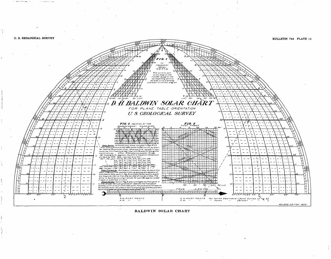
U. S. GEOLOGICAL SURVEY BULLETIN 788 PLATE 14
' /../-../-../- ~/\ _/_/_/_ - / - JTO-eo- i-o-tpoo- Jo- LA?----/--- -- ft BALDWIN SOLAR CHAR7PLANE TABLE: OR/ENTAT/ON
U. S. GEOLOGICAL SURVEY
/ /_/_/_/_ _/x/ /__/__/
ros s fig, S cfraw a straight h'n* from point A Co tfif proper l*titudi gr#cJutitiGn. Upon tbi'i: fine r;nc/*pvint
four-den the et.rttf.t-//M& of the arrow, one ttirmctJy another an *quat <Ji*t*rtc
BALDWIN SOLAR CHART
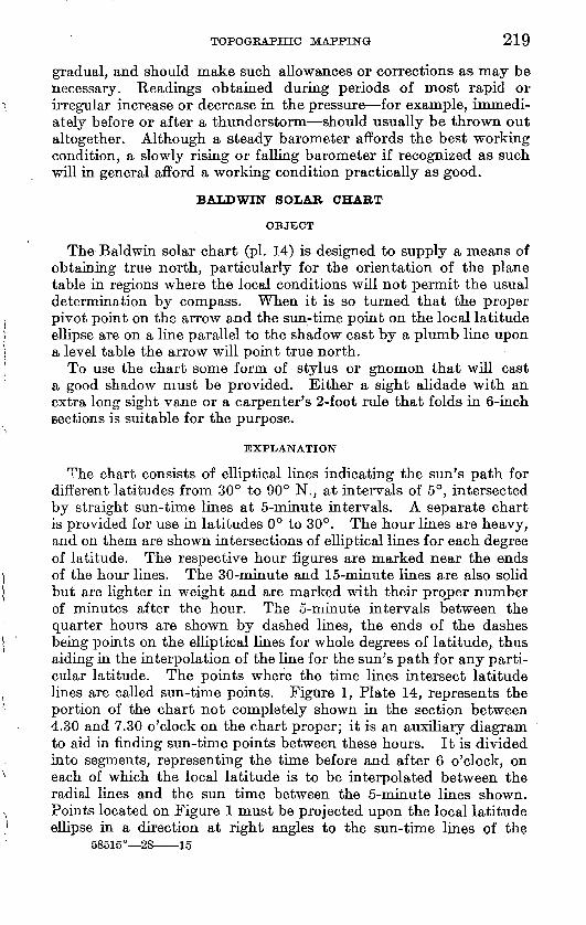
TOPOGRAPHIC MAPPING 219
gradual, and should make such allowances or corrections as may be necessary. Readings obtained during periods of most rapid or irregular increase or decrease in the pressure for example, immedi ately before or after a thunderstorm should usually be thrown out altogether. Although a steady barometer affords the best working condition, a slowly rising or falling barometer if recognized as such will in general afford a working condition practically as good.
BALDWIN SOLAR CHART
OBJECT
The Baldwin solar chart (pi. 14) is designed to supply a means of obtaining true north, particularly for the orientation of the plane table in regions where the local conditions will not permit the usual determination by compass. When it is so turned that the proper pivot point on the arrow and the sun-time point on the local latitude ellipse are on a line parallel to the shadow cast by a plumb line upon a level table the arrow will point true north.
To use the chart some form of stylus or gnomon that will cast a good shadow must be provided. Either a sight alidade with an extra long sight vane or a carpenter's 2-foot rule that folds in 6-inch sections is suitable for the purpose.
EXPLANATION
The chart consists of elliptical lines indicating the sun's path for different latitudes from 30° to 90° N., at intervals of 5°, intersected by straight sun-time lines at 5-minute intervals. A separate chart is provided for use in latitudes 0° to 30°. The hour lines are heavy, and on them are shown intersections of elliptical lines for each degree of latitude. The respective hour figures are marked near the ends of the hour lines. The 30-minute and 15-minute lines are also solid but are lighter in weight and are marked with their proper number of minutes after the hour. The 5-ruinute intervals between the quarter hours are shown by dashed lines, the ends of the dashes being points on the elliptical lines for whole degrees of latitude, thus aiding in the interpolation of the line for the sun's path for any parti cular latitude. The points where the tune lines intersect latitude lines are called sun-time points. Figure 1, Plate 14, represents the portion of the chart not completely shown in the section between 4.30 and 7.30 o'clock on the chart proper; it is an auxiliary diagram to aid in finding sun-time points between these hours. It is divided into segments, representing the tune before and after 6 o'clock, on each of which the local latitude is to be interpolated between the radial lines and the sun tune between the 5-minute lines shown. Points located on Figure 1 must be projected upon the local latitude ellipse in a direction at right angles to the sun-tune lines of the
58515° 28 15
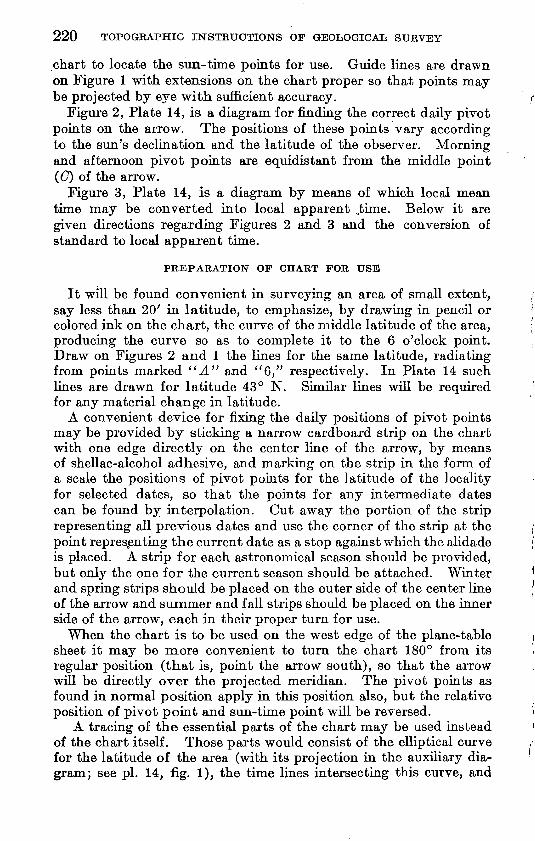
220 TOPOGRAPHIC INSTRUCTIONS OF GEOLOGICAL SURVEY
chart to locate the sun-time points for use. Guide lines are drawn on Figure 1 with extensions on the chart proper so that points may be projected by eye with, sufficient accuracy.
Figure 2, Plate 14, is a diagram for rinding the correct daily pivot points on the arrow. The positions of these points vary according to the sun's declination and the latitude of the observer. Morning and afternoon pivot points are equidistant from the middle point ((7) of the arrow.
Figure 3, Plate 14, is a diagram by means of which local mean time may be converted into local apparent ,tune. Below it are given directions regarding Figures 2 and 3 and the conversion of standard to local apparent time.
It will be found convenient in surveying an area of small extent, say less than 20' in latitude, to emphasize, by drawing in pencil or colored ink on the chart, the curve of the middle latitude of the area, producing the curve so as to complete it to the 6 o'clock point. Draw on Figures 2 and 1 the lines for the same latitude, radiating from points marked "A" and "6," respectively. In Plate 14 such lines are drawn for latitude 43° N. Similar lines will be required for any material change in latitude.
A convenient device for fixing the daily positions of pivot points may be provided by sticking a narrow cardboard strip on the chart with one edge directly on the center line of the arrow, by means of shellac-alcohol adhesive, and marking on the strip in the form of a scale the positions of pivot points for the latitude of the locality for selected dates, so that the points for any intermediate dates can be found by interpolation. Cut away the portion of the strip representing all previous dates and use the corner of the strip at the point representing the current date as a stop against which the alidade is placed. A strip for each astronomical season should be provided, but only the one for the current season should be attached. Whiter and spring strips should be placed on the outer side of the center line of the arrow and summer and fall strips should be placed on the inner side of the arrow, each in their proper turn for use.
When the chart is to be used on the west edge of the plane-table sheet it may be more convenient to turn the chart 180° from its regular position (that is, point the arrow south), so that the arrow will be directly over the projected meridian. The pivot points as found in normal position apply in this position also, but the relative position of pivot point and sun-time point will be reversed.
A tracing of the essential parts of the chart may be used instead of the chart itself. Those parts would consist of the elliptical curve for the latitude of the area (with its projection in the auxiliary dia gram; see pi. 14, fig. 1), the time lines intersecting this curve, and
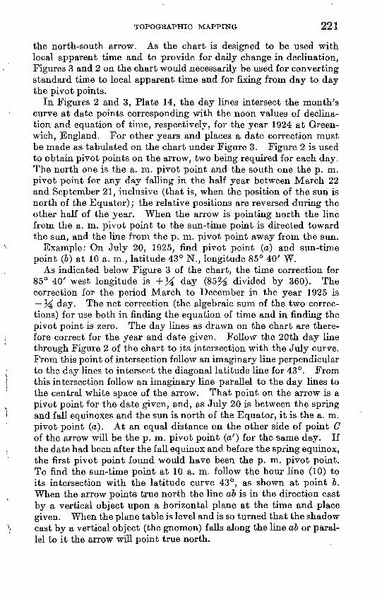
TOPOGRAPHIC MAPPING 221
the north-south arrow. As the chart is designed to be used with local apparent time and to provide for daily change in declination, Figures 3 and 2 on the chart would necessarily be used for converting standard time to local apparent time and for fixing from day to day the pivot points.
In Figures 2 and 3, Plate 14, the day lines intersect the month's curve at date points corresponding with the noon values of declina tion and equation of time, respectively, for the year 1924 at Green wich, England. For other years and places a date correction must be made as tabulated on the chart under Figure 3. Figure 2 is used to obtain pivot points on the arrow, two being required for each day. The north one is the a. m. pivot point and the south one the p. m. pivot point for any day falling in the half year between March 22 and September 21, inclusive (that is, when the position of the sun is north of the Equator); the relative positions are reversed during the other half of the year. When the arrow is pointing north the line from the a. m. pivot point to the sun-time point is directed toward the sun, and the line from the p. m. pivot point away from the sun.
Example: On July 20, 1925, find pivot point (a) and sun-time point (6) at 10 a. m., latitude 43° N., longitude 85° 40' W.
As indicated below Figure 3 of the chart, the time correction for 85° 40' west longitude is +% day (85% divided by 360). The correction for the period March to December in the year 1925 is 34 day. The net correction (the algebraic sum of the two correc tions) for use both in finding the equation of time and in finding the pivot point is zero. The day lines as drawn on the chart are there fore correct for the year and date given. Follow the 20th day line through Figure 2 of the chart to its intersection with the July curve. From this point of intersection follow an imaginary line perpendicular to the day lines to intersect the diagonal latitude line for 43°. From this intersection follow an imaginary line parallel to the day lines to the central white space of the arrow. That point on the arrow is a pivot point for the date given, and, as July 20 is between the spring and fall equinoxes and the sun is north of the Equator, it is the a. m. pivot point (a). At an equal distance on the other side of point C of the arrow will be the p. m. pivot point (a') for the same day. If the date had been after the fall equinox and before the spring equinox, the first pivot point found would have been the p. m. pivot point. To find the sun-time point at 10 a. m. follow the hour line (10) to its intersection with the latitude curve 43°, as shown at point 6. When the arrow points true north the line ab is in the direction cast by a vertical object upon a horizontal plane at the time and place given. When the plane table is level and is so turned that the shadow cast by a vertical object (the gnomon) falls along the line ab or paral lel to it the arrow will point true north.
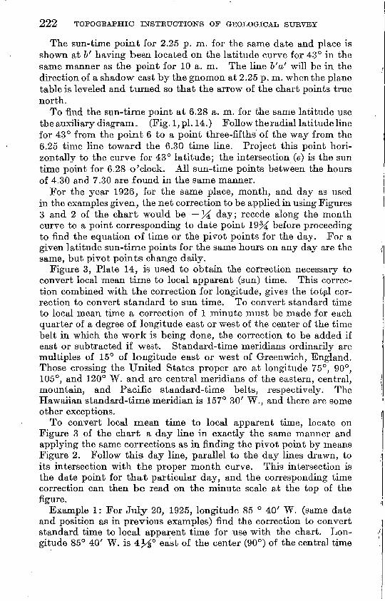
222 TOPOGRAPHIC INSTRUCTIONS OF GEOLOGICAL SURVEY
The sun-time point for 2.25 p. m. for the same date and place is shown at &' having been located on the latitude curve for 43° in the same manner as the point for 10 a. m. The line b'a' will be in the direction of a shadow cast by the gnomon at 2.25 p. m. when the plane table is leveled and turned so that the arrow of the chart points true north.
To find the sun-time point at 6.28 a. m. for the same latitude use the auxiliary diagram. (Fig. 1, pi. 14.) Follow the radial latitude line for 43° from the point 6 to a point three-fifths of the way from the 6.25 time line toward the 6.30 time line. Project this point hori zontally to the curve for 43° latitude; the intersection (e) is the sun time point for 6.28 o'clock. All sun-time points between the hours of 4.30 and 7.30 are found in the same manner.
For the year 1926, for the same place, month, and day as used in the examples given, the net correction to be applied in using Figures 3 and 2 of the chart would be % day; recede along the month curve to a point corresponding to date point 19% before proceeding to find the equation of time or the pivot points for the day. For a given latitude sun-time points for the same hours on any day are the same, but pivot points change daily.
Figure 3, Plate 14, is used to obtain the correction necessary to convert local mean time to local apparent (sun) time. This correc tion combined with the correction for longitude, gives the total cor rection to convert standard to sun time. To convert standard time to local mean time a correction of 1 minute must be made for each quarter of a degree of longitude east or west of the center of the time belt in which the work is being done, the correction to be added if east or subtracted if west. Standard-time meridians ordinarily are multiples of 15° of longitude east or west of Greenwich, England. Those crossing the United States proper are at longitude 75°, 90°, 105°, and 120° W. and are central meridians of the eastern, central, mountain, and Pacific standard-time belts, respectively. The Hawaiian standard-time meridian is 157° 30' W., and there are some other exceptions.
To convert local mean time to local apparent time, locate on Figure 3 of the chart a day line in exactly the same manner and applying the same corrections as in finding the pivot point by means Figure 2. Follow this day line, parallel to the day lines drawn, to its intersection with the proper month curve. This intersection is the date point for that particular day, and the corresponding time correction can then be read on the minute scale at the top of the figure.
Example 1: For July 20, 1925, longitude 85 ° 40' W. (same date and position as in previous examples) find the correction to convert standard time to local apparent time for use with the chart. Lon gitude 85° 40' W. is 4M° east of the center (90°) of the central time
TOPOGRAPHIC MAPPING 223
belt. Applying the correction of 4 minutes for each degree of differ ence in longitude gives a correction of 17^ minutes, and, as the local ity is east of the center of the time belt, the correction is to be added to standard time. The result is the mean time for the locality. To convert it to local apparent time for use with the chart, the equation of time as found from Figure 3 of the chart must be applied as a further correction. As the data used are the same as were used in finding the pivot points, the net correction to the day lines of Figure 3 is the same that is, zero. On following the day line for the 20th to its intersection with the July curve, it is seen that this date point is opposite 6)4 minutes to subtract on the minute scale. (Note that in pi. 14 day lines are drawn on fig. 3 only for each fifth day. Quarter- day corrections to day lines would therefore be expressed by twentieths of the space between the day lines shown.) The total correction to standard time to convert it to local apparent time (the sun tune to be used with the chart) is the algebraic sum of the two corrections found that is, + 17% 6%, or + HTJ minutes. In applying such a cor rection it should be approximated as closely as possible although that will probably be with more error than ^ minute. It will be found convenient to write on the chart, for daily reference, the constant corrections to be applied in a given locality. For the locality indicated in this example they would be " + 17^± equation of time" and "No correction to date lines."
Example 2: On September 12, 1925, at longitude 96° 30' W., con vert standard time to local apparent time. The correction on account of longitude will be 26 minutes, and the correction for equation of time will be +3^ minutes, a combined correction of 22}/£ minutes to subtract from standard time.
Other examples are given on the margin of the published chart.Standard time can be obtained at most railroad stations or tele
graph offices and at certain hours of the day by radio. The watch used should be set each day to apparent time by applying the constant correction for longitude and the daily correction for equation of time.
To orient the plane table by use of the chart, attach the chart to the plane-table sheet so that the arrow will be parallel to the line on the sheet representing the local meridian, with the point of the arrow in a northerly direction. The chart should have been prepared for use in the locality in which the work is to be done and the pivot points for the day plotted. Level the plane table at the station, select the sun-time point for the instant of observation, place the edge of the base of the gnomon so that it cuts the sun-time point and the proper a. m. or p. m. pivot point, and revolve the plane table until the shadow of the gnomon falls parallel to the edge of its base. The gnomon must be in a plane perpendicular to a level line at right angles to its base
224
edge that cuts the points on the chart. This may be accomplished by fixing a small bubble on the base of the gnomon at right angles to its edge or by utilizing the circular-plate bubble on the telescopic alidade and exerting just enough pressure on the plane table to center the bubble-in the desired direction at the instant of observation. When the shadow falls as described, the arrow of the chart points true north; the plane table is oriented and should be clamped.
If a carpenter's 2-foot rule is used as a gnomon, open it so that its two end sections are together and approximately at right angles to the center two sections. Use the center two sections as the base and the end two sections as the upright part of the gnomon. The end two sections may be spread just enough to leave a narrow slot between them, and paper may be pasted on the upper side of the part used as a base, with the center line marked upon it. The plane table is then revolved until the sunlight falls through the slot upon the center line thus marked. Or the free ends of the rule may be kept together, and the plane table revolved until the slightly spreading shadow of the upright portion falls equally on the two sides of the base. The line from the morning pivot point to the sun-time point is directed toward the sun and the line from the afternoon pivot point away from the sun. To obtain best results it is necessary to use accurate time and to plumb the shadow plane carefully. A long gnomon gives more accurate results than a short one.
Example: To orient the plane table at 10 a. m. July 20, 1925, latitude 43° N., longitude 85° 40' W., place the edge of the base of the special gnomon or of a sight alidade (using the open-sight vane as a gnomon) on pivot point a and sun-time point &, with the shadow- casting end toward point a. Revolve the plane-table board until the shadow is bisected by a line parallel to the edge used, drawn from the center of the base of the gnomon; then the arrow points true north, and the board is oriented.
It must be remembered that an orientation using the chart as described is a true orientation. In order that lines sighted and drawn on the map shall be in their true direction, the line of sight of the alidade used must be parallel to its ruler edge. Any angular error between the line of sight and the ruler edge will result in a closing error for a traverse line that will be directly proportional to the distance of the closing point from the starting point. To test whether the line of sight and the ruler edge are parallel, stick two pins or needles against the ruler edge of the alidade and near its ends and sight then on a point about a thousand feet distant. If, without moving the alidade, its line of sight also cuts the same point the line of sight is parallel to the ruler edge. If the line of sight of a Burkland alidade is not parallel to its edge, it can be made so by shifting the sight vanes forward or backward from the old screw holes and reset-
TOPOGRAPHIC MAPPING 225
ting them. In order to correct an appreciable error found in a tele scopic alidade, place the arrow line of the chart parallel to the line joining the pins, then shift the alidade over the chart till the line of sight cuts the point sighted over the pins. Now draw a meridian line on the chart along the alidade edge. In use, the meridian so drawn must be placed parallel to the meridian of the field sheet. When the plane table is oriented the angular error in orientation will then equal and compensate the error due to the use of that particular alidade.
The length of sight on the field sheet should not exceed the distance on the chart between the sun-time point and the pivot point or the length of the shadow of the vertical gnomon in use. This will vary with the time of day and the season of the year.
ERRORS
The error in azimuth caused by errors in latitude, time, and level can be found graphically upon the chart for various conditions, but the error m azimuth due to error in time is most likely to be serious. At the pole an error in time of 4 minutes causes an error in azimuth of 1°. Elsewhere, if the sun time used is not over 3 minutes in error, the error in azimuth will usually be less than 1° before 10 a. mi. and after 2p.m. and will be least at low latitudes, but at low latitudes the error changes more rapidly near these hours than at high latitudes and at and near noon is greatest. On June 22 at latitude 30° N. an error of 3 minutes in time at noon will cause an error in azimuth of about 6°, but at 10 a. m. and 2 p. m. it will cause only 0.5°. At latitude 40° N. the error at noon will be less than 2.5°, whereas at 10 a. m. and 2 p. m. it will be about 1°. To obtain good results with the chart in plane-table traverse, the error in time should not exceed 3 minuteSj and near noon in low latitudes it should not exceed 1 min ute. Fast time increases the measured azimuth of a course, and as the error is greatest at noon a straight course run throughout one day would appear as a slight reversed curve, the morning curve to the right and the afternoon curve to the left.
TIME CORRECTION
Sun time can be found as described in the foregoing text. It can also be found directly from watch time (whether that is fast or slow) if the plane table can be reliably oriented each morning by known points by placing the alidade edge against the proper pivot point and toward the sun. The edge of the alidade will then cut the true latitude curve at sun time, and the difference between that and watch time will show the correction to be applied.
226 TOPOGRAPHIC INSTRUCTIONS OF GEOLOGICAL SURVEY
NAMES
NAMES WITHIN THE MAP
Name sheets. All names that are thought to be appropriate for the final map should be assembled on sheets of tracing paper or linen and registered over each plane-table sheet. Name sheets must be kept current and preferably should be combined into two tracings for the north and south halves of the quadrangle map. The importance of a complete and authentic record of feature names is so great that nothing should be left for memory. All necessary notes should be made and all names recorded as soon as they are obtained.
Authority for names. The topographer should utilize local oppor tunities for obtaining the correct names of all features shown on the map and not depend upon correspondence on this subject after his return to the office. The general policy should be to conform to local usage, but at least two independent authorities for each name and spelling should be obtained; and in case of differences in usage, spelling, or application, a definite effort must be made to obtain all pertinent facts, so that a just decision may be reached in the field or made the basis for further reference.
New names. In unsettled or sparsely settled regions it may be found desirable to give names to the larger land and water features as a means of reference. As such names, by Executive order of Janu ary 23,1906, must be referred to the United States Geographic Board for consideration and approval before publication, they should be submitted by party chiefs, through their division engineer, for action by the board before being used. Requests for consideration of new names should be accompanied by full information as to their appro priateness. The selection of new names should not be a mere matter of whim but should be made with due consideration of their geo graphic value and significance.
Names to be shown. The map should show names of the following features:
.Cities, towns, villages, and other settlements, including all country post offices and railroad stations. Where the name of a railroad station differs from that of the corresponding post office, both names should be shown, the one most widely known being given the greater prominence and the other being followed by " P O " or "Sta" as the case may be.
Country schoolhouses.Country churches, where used as locality names.Isolated ranches constituting important landmarks in sparsely settled districts.Important public institutions, such as universities, colleges, and State hospitals.Railroads (steam or electric). In addition to the name of the railroad, it is
desirable, as a rule, to give the name of the branch, line, or division, for complete office identification.
Highways, turnpikes, and boulevards.Bridges, ferries, and fords.
TOPOGBAPHIC MAPPING 227
Through trails.Principal steamboat routes on large lakes and rivers. Large canals, ditches, aqueducts, etc. Tunnels, dams, lakes, reservoirs, and other public works. Lighthouses, lightships, and life-saving stations. Parks and cemeteries, if scale will allow. Isolated mines, quarries, prospects, and oil wells. Isolated furnaces and smelters. Civil divisions. Reservations. Hydrographic features.Springs, wells, and tanks, especially in arid regions where these features are of
vital importance. Relief features.
MAEGINAL NAMES
The name sheet should be complete copy for all marginal lettering (pi. 15) that pertains especially to the map in hand. Data that are common to all sheets may be omitted.
The names of the topographers engaged in the mapping of the quadrangle must be listed in the margin of the name sheet. (See "Topographic authorship," p. 306.) It is not enough that the sepa rate field sheets carry the names of the topographers responsible for their mapping.
Each name sheet must carry a diagram showing the area mapped by each topographer named in the author legend.
The date or dates of survey should be entered on the margin of the name sheet.
The contour interval used on the map and a statement of any changes in interval at any given contour should be recorded on the lower margin of the name sheet.
MAP BORDERS
Adjoining unmapped areas. If any of the adjoining quadrangles have not been mapped, the field work should be carried across the border into such quadrangles far enough to obviate the possibility of later work not joining it. To insure this joining the over-edge topo graphy should be carried to a road, stream, or ridge, if such a feature is near at hand, but if not the topography must be carried at least a quarter of an inch beyond the border on the field sheet and will seldom need to be carried more than half an inch. Failure to use good judg ment in connection with this requirement may make it necessary to correct the copper plates where the borders affected are afterward joined by future work or to readjust future work slightly in order to avoid making corresponding changes on the plates.
Joining previous work. Procure copies of such map borders cover ing adjoining areas as may be needed. (See "Map borders," p. 178, and "Border corrections," p. 302.) Should it appear in the progress
228 TOPOGRAPHIC INSTRUCTIONS OF GEOLOGICAL SURVEY
of field work that the older maps contain inaccuracies or are not up to date in the representation of culture, the new work shall be con sidered standard and the older work revised for such a distance over the border as may be necessary to effect a good joining. Should the older sheets prove so deficient in quality or so out of date in the representation of cultural features that a radical revision would be required to make them join the new work, the topographer must at once report the failure to join to the division engineer. Where new work practically though not exactly joins engraved or published work, expediency warrants a slight readjustment of the new work to fit the old.
Datum of previous work. Where the horizontal datum upon which the map of an adjoining quadrangle has been published differs from that upon which the map of the new quadrangle is drawn, proper corrections to the projection lines must be made before comparing the joining of the topography on the two maps.
OTHER QENERAL FIELD INSTRUCTIONS
Protection of field sheets. Field sheets should at all times be pro tected from injury or loss. When a field sheet is in use on the plane table it should so far as practicable be protected by heavy cover paper supplied for the purpose, in which a hole may be cut for each day's work.
Identification of field sheets. Each separate piece of map manu script, oversheet, or map material should be marked with the names of the State and quadrangle, the date, scale, contour interval, coordi nates, authors' names, and other appropriate information. If more than one engineer works on a single sheet the areas covered by the several men should be indicated on the field sheet.
Information tracing. The use of an information tracing is to be encouraged. On it should be assembled, over the map features for which added information is to be given, all data that can not be legibly penciled on the original. Such information is especially needed where the original has been rubbed and sharp penciling is difficult, where only the inked colors will clearly differentiate between closely spaced features, where detached contours might be mistaken for water features or the reverse, or where the desired treatment of the feature may be beyond the map scale and yet, because of the apparent need of showing it, the topographer wishes to leave its proper delinea tion for office determination.
Separation of oversheet data. Separate tracings should be prepared and submitted for names (p. 226), woodland outlines (p. 255), road classification (p. 256), elevations (p. 241), and information, and no two or more of the classes of data above listed should be submitted on a single tracing. The placing of more than one class of data, as
TOPOGRAPHIC MAPPING 229
listed above, on a single tracing will cause delay and confusion in the office operations and may be the cause of the inadvertent omission of essential data on the final sheets. The data on oversheet tracings should be kept current and not allowed to accumulate.
Monthly field report. Monthly reports of field work (one copy to division chief, one to section chief, and one to chief topographic engi neer) should be mailed not later than the first day of the succeeding month. The name of the sheet or project on which work has been done should be plainly indicated. A separate report should be sub mitted for each sheet or project. (See "Monthly field reports," p. 272.)
Field inking. No inking on final sheets should be done in the field unless authorized. Where an explanation is necessary, it should be placed on the information tracing.
MAPPING OF CULTURAL FEATURES
Definition. The cultural features are those features of the terrain that have been constructed by man, such as roads, buildings, and canals; those features designated by man but only partly constructed on the ground, such as boundary lines; and all names and legends.
Features to be mapped. The following cultural features are to be shown on all topographic maps, either by the standard symbols shown in Plates 18-23 or by means of other conventions, which are described in the text.Aqueducts, water and oil pipes.Artificial depressions.Bench marks.Boundary monuments.Bridges.Buildings.Canal locks.Canals and ditches.Cemeteries.Civil boundaries.Coke ovens.County subdivisions.Cuts and fills.Dams.Ferries.Fords.Furnaces and smelters.Levees.Life-saving stations.
Roads. Roads should be penciled as final copy for inking according to the distinctions given below.
(a) Good public motor roads should be indicated by solid double parallel lines. Good motor roads are defined as those, public roads
Lighthouses, etc.Location monuments.Mine dumps.Mines and quarries.Mineral monuments.Oil and gas wells.Power-transmission lines.Public-land lines.Railroads.Reservoirs.Roads.Steamboat routes.Trails.Transit-traverse stations.Triangulation points.Tunnels.Useful elevations.Wharves, etc.
230 TOPOGKAPHIC INSTBUCTIONS OF GEOLOGICAL SUKVEY
that may be used for automobile travel the greater part of the year and include all Government, State, county, or other public roads in such condition as to be available for such travel; all main or through roads in sparsely settled regions, regardless of condition; and all city streets and park drives open to the public.
(&) Poor public motor roads and private roads should be indicated by dashed double parallel lines. Poor motor roads are defined as those public roads which through disuse or neglect have become impassable for automobile travel or can not be traveled without risk to an automobile. Public roads that are passable for wagons but are not good for motor use should be classed as poor motor roads.
Public roads are defined as those built or maintained by the Federal Government, a State, or a subdivision thereof. Private roads include all neighborhood roads in rural districts (except those of sufficient length and importance to be regarded as through routes, as defined above); all lanes and stub roads to farms, country houses, or insti tutions; and cemetery drives and race tracks. Private roads are further defined as those roads built or maintained by private or neighborhood funds.
It should be especially noted that public roads should be shown by full or dashed lines according to their condition as good or poor for motor use, whereas private roads should be shown by the dashed symbol irrespective of condition.
Lumber or wood roads are in general to be omitted, but any prin cipal through lumber roads that may be properly considered perma nent cultural features are to be shown by the dashed symbol. In regions where winding roads are numerous and where there are few recognizable map features, the occasional plotting of the forks of a prominent lumber road is advisable if the two roads at the forks are of nearly equal prominence.
On the 1:192,000 scale no distinctions are to be made between roads of different classes. They are all to be drawn as solid double parallel lines.
Field penciling of roads. Roads should be penciled with a uniform width which will reduce approximately to the width used by the engraver on the scale of publication. As few draftsmen can legibly ink on any scale a double-lined road with a space between the parallel lines less than that representing the space between two lines about 75 feet apart when plotted on a scale of 1:48,000, such a plotting may be taken as a standard for penciled road copy, unless the map scale or width of the road is such that a greater width can be plotted to scale. Pikes, drives, and boulevards materially wider than the limit above specified should be shown to scale. On maps drawn on large special scales all roads should be shown with their individual widths wherever they can be plotted.
TOPOGKAPHIC MAPPING 231
Buildings in general. The map must show all buildings of a per manent character, such as dwellings, public buildings, shops, factories, and other industrial establishments; it should be reliable not only as to their location but also as to their orientation that is, the way each building is set with respect to the points of the compass.
Uninhabitable dwellings, whether farmhouses or miners' or lum bermen's cabins, are to be shown only where they constitute land marks in regions of sparse culture.
The conventional black square is to be used for all buildings except those whose dimensions plotted to scale exceed the size of the symbol, which should be shown with their individual plan outlines. On large-scale maps all houses may have to be thus shown.
On the 1:192,000 scale only isolated houses in the country should be shown; those in towns and cities should be shown by a conven tional symbol representing the solidly built up area.
Houses should not be shown as contiguous to the roads unless the distance that separates them from the edge of the right of way is so small that it can not be plotted on the scale of publication.
House Hocks. Detached houses in residence portions of cities, suburbs, and villages are to be shown separately wherever possible. If the scale does not permit individual houses to be shown indicate the group by a solid block, in accordance with the following specifi cations. Distances between houses are to be understood as from center to center, and length of street blocks as between building lines and not from center to center of streets.
1:48,000 scale field work for publication on. 1:J$2,500. Houses, where evenly or nearly evenly distributed, should be blocked where the distance between them is less than 100 feet for example, in a 500-foot street block six houses evenly distributed should be blocked, but five houses or less should be shown separately.
1:24,000 or 1:31,680 scale field work for publication on either scale. Houses should be blocked where the distance between them is less than 50 feet for example, in a 500-foot street block 11 houses evenly distributed should be blocked, but 10 houses or less should be shown separately.
1:24,000 scale field work for publication on 1:62,500. Houses less than 100 feet apart should be blocked.
1:96,000 scale field work for publication on 1:125,000. Houses less than 200 feet apart should be blocked.
These specifications are set up in order to standardize the blocking of houses, to reduce the cost of field work in areas of heavy culture, and to afford specific copy for inking and for engraving. The deci sion as to the blocking of houses should be made in the field, and the data should be properly penciled«on the field sheet.
Business and residence blocks. Business and residence blocks should be distinguished by the width of the block, the residence blocks being made distinctly narrower than the business blocks.
232 TOPOGKAPHIC ItfSTKTJCTIONS OF GEOLOGICAL SURVEY
Churches and schoolhouses. Churches are to be distinguished by a cross and schoolhouses by a pennant, so attached to the house symbol as to point at right angles to the roadway. In centers of dense culture these distinctive symbols should be omitted. Build ings used both for schools and "for religious services should bear the school symbol.
Railroads. Railroads, whether operated by steam, electricity, gaso line, or other motive power and including all railroad lines listed in the Official Railway Guide should be shown by the broad-spaced symbol representing a railroad of any kind.
Electric trolley lines carrying passengers only and not issuing tickets with baggage-checking privileges should be shown by the close-spaced symbol.
Double tracks, railroad yards, spur tracks, and switches should be shown so far as the scale will permit. Separate railroad lines in juxtaposition and parallel tracks belonging to the same road should be differentiated by placing the crossties as shown on the symbol chart.
Tramways should be shown by the broad-spaced symbol. Aerial tramways should be shown by a broken line and with the name where there is space.
Railroads or electric trolley lines within a roadway should be shown by fine cross lines having the same spacing as those on the corre sponding line outside of the road.
Railroad surveys. A railroad alinement is made up of tangents and curves; most curves are compound, and many leave the tangent on an easement curve. Reversed curves usually have 200 feet or more of tangent between them. In traversing railroads these facts should be kept in mind, and the resulting plot should show a line free from abrupt deflections that are not found on the ground. Railroad azimuths should be well checked, by fore and back sight methods when necessary.
Railroad crossings. Grade crossings should be shown by continuous railroad and road symbols; a railroad crossing over a road by a broken road symbol; and a road crossing over a railroad by a broken rail road symbol. Do not use the words "overhead" or "underhead.' '
Railroad station buildings. A railroad station building is to be treated like other buildings, except where its symbol is carried con ventionally across the track to indicate the location of a train stop that is not otherwise clearly indicated by the position of the station name or by the culture. The conventional station symbol should not be drawn across the track where there is no station building, and its use should generally be confined to small villages or cities.
Bridges. Symbols should be used to show all road bridges across double-line streams and all road bridges across single-line streams
TOPOGRAPHIC MAPPING 233
in sparsely settled regions or wherever the existence of the bridge is vital to the use of the road. Bridge ends should not be shown for viaducts over railroads, railroad yards, roads, or streams except on large-scale maps (1:24,000 or larger). Names of large viaducts, however, should be shown.
Drawbridges on roads and railroads should be shown by a separate symbol. Ordinary bridges and trestles on railroads are to be omitted. The bridge symbol should also be omitted wherever its presence would impair the legibility of the map.
The footbridge symbol should be used only where the bridge is of local importance in general only where it is isolated and only where the scale permits. Footbridges should always be shown on large-scale maps.
Ferries. Ferries are to be shown by symbol wherever the stream is wide enough to permit; where it is too narrow the word "Ferry" should be written. Names of ferries must be put on the map.
Fords. The symbol for a road ford is similar to that used to represent a private road; the symbol for a trail ford is similar to that used for a fence of any kind. On large-scale special maps the route of the ford, if difficult to follow, should be shown accurately.
Trails. Distinction should be made between good pack trails and poor pack or foot trails, the former being indicated by short heavy dashes and the latter by small dots. In mapping trails the topog rapher should consider their relative importance as a means of com munication. Thus in mountain and desert regions, especially in the far West, where traveling is done largely by trail, he should take pains to map every trail in use, giving its name, if known; in the more densely populated districts, where railroads and wagon roads are plentiful, he should show only such trails as lead up mountains or through unimproved areas not readily accessible otherwise. A mere "way through" not regularly traveled does not constitute a trail.
Steamboat routes. All steamboat routes on lakes and rivers over which a regular public service is maintained by ferries or passenger boats should be indicated by fine dashed lines and the words "Steam boat route."
Canals and ditches. Canals, whether for navigation, irrigation, or drainage, should be shown by double-line symbol if their actual width can thus be indicated on the scale of publication; otherwise, by a single line. Abandoned trunk canals constituting prominent topographic features will be indicated by the long-dash symbol.
The mapping of irrigating ditches is to be restricted to the main feeders; laterals are not to be shown except on large-scale maps. On smaller scales only those ditches that constitute important land marks in regions of sparse culture are to be indicated.
234 TOPOGRAPHIC INSTRUCTIONS OF GEOLOGICAL SURVEY
Canal locks. The lock symbol should point upcurrent. The symbol showing both the upper and lower gates will be used only on scales large enough for their individual plotting.
Aqueducts; water and oil pipes. Only the principal aqueducts and pipe lines should be mapped.
Power-transmission lines. The alinement of high-voltage (100,000 volts or more) trunk power-transmission lines should bo obtained in the course of the field survey and shown on the topographic maps. Sections of power-transmission lines within corporate limits and lateral distribution systems should be omitted. Trunk lines are in general built on private rights of way and in most parts of the country are placed on steel towers.
Tunnels. Tunnels of all kinds, whether on railroads, roads, or canals, should be shown by the tunnel symbol; the route of the tun nel should be indicated by double broken lines.
Dams. Permanent dams on streams, lakes, or reservoirs should be indicated by a heavy line. Where a wagon road follows the top of the dam, the road is to be shown in its correct place, the road line on the upstream side being thickened to represent the dam.
Reservoirs. The shore line used to represent a reservoir should correspond to the normal full stage of the reservoir that is controlled by the dam. Where the penciled copy for reservoirs and the adjacent contouring are not clear, these details should be explained elsewhere by means of a large-scale sketch.
Levees. Levees may be represented by the hachure symbol alone where the levee is too small to be shown to scale by the contours, but such representation should be confined to large-scale maps or to levees that are conspicuous or important features.
Cuts and fills. The rule as to the use of hachure symbols for the representation of levees also applies to cuts and fills, but inasmuch as cuts and fills are in general sufficiently shown by the contouring and by the presence of roads, railroads, or waterways their further representation by hachures should be confined to special cases or scales.
Artificial depressions. Artificial depressions, such as are found above railroad and highway fills, should be indicated by hachured contours. (See "Depressions," p. 251.)
Mine dumps. The use of the hachured mine-dump symbol should be chiefly confined to large-scale special mining maps where all dumps are to be hachured. On standard-scale maps only those mine dumps should be hachured that for some reason constitute important topographic features not indicated by the contouring. It is impos sible to frame a specific rule for general application, and instructioDS should be obtained for each map.
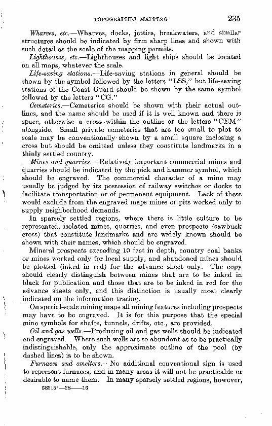
TOPOGRAPHIC MAPPING 235
Wharves, etc. Wharves, docks, jetties, breakwaters, and similar structures should be indicated by firm sharp lines and shown with such detail as the scale of the mapping permits.
Lighthouses, etc. Lighthouses and light ships should be located on all maps, whatever the scale.
Life-saving stations. Life-saving stations in general should be shown by the symbol followed by the letters "LSS," but life-saving stations of the Coast Guard should be shown by the same symbol followed by the letters "CG."
Cemeteries. Cemeteries should be shown with .^heir actual out lines, and the name should be used if it is well known and there is space, otherwise a cross within the outline or the letters "CEM" alongside. Small private cemeteries that are too small to plot to scale may be conventionally shown by a small square inclosing a cross but should be omitted unless they constitute landmarks in a thinly settled country.
Mines and quarries. Relatively important commercial mines and quarries should be indicated by the pick and hammer symbol, which should be engraved. The commercial character of a mine may usually be judged by its possession of railway switches or docks to facilitate transportation or of permanent equipment. Lack of these would exclude from the engraved maps mines or pits worked only to supply neighborhood demands.
In sparsely settled regions, where there is little culture to be represented, isolated mines, quarries, and even prospects (sawbuck cross) that constitute landmarks and are widely known should be shown with their names, which should be engraved.
Mineral prospects exceeding 10 feet in depth, country coal banks or mines worked only for local supply, and abandoned mines should be plotted (hiked in red) for the advance sheet only. The copy should clearly distinguish between mines that are to be inked in black for publication and those that are to be inked in red for the advance sheets only, and this distinction is usually most clearly indicated on the information tracing.
On special-scale mining maps aU mining features including prospects may have to be engraved. It is for this purpose that the special mine symbols for shafts, tunnels, drifts, etc., are provided.
Oil and gas wells. Producing oil and gas wells should be indicated and engraved. Where such wells are so abundant as to be practically indistinguishable, only the approximate outline of the pool (by dashed lines) is to be shown.
Furnaces and smelters. No additional conventional sign is used to represent furnaces, and in many areas it will not be practicable or desirable to name them. In many sparsely settled regions, however,
58515° 28 16
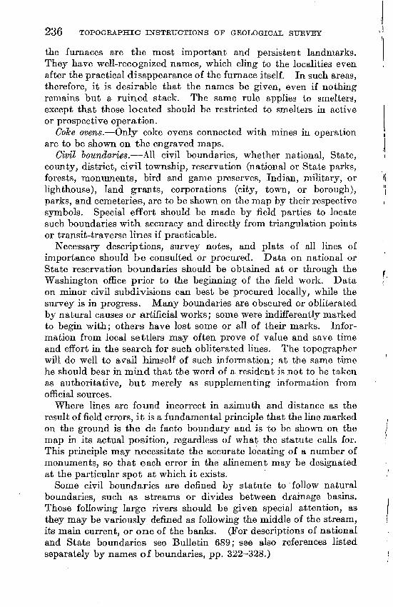
236 TOPOGRAPHIC INSTRUCTIONS OF GEOLOGICAL SURVEY l!
the furnaces are the most important and persistent landmarks. They have well-recognized names, which cling to the localities even after the practical disappearance of the furnace itself. In such areas, therefore, it is desirable that the names be given, even if nothing remains but a ruined stack. The same rule applies to smelters, except that those located should be restricted to smelters in active j or prospective operation. |
Coke ovens. Only coke ovens connected with mines in operation \ are to be shown on the engraved maps. I
Civil boundaries. All civil boundaries, whether national, State, i county, district, civil township, reservation (national or State parks, forests, monuments, bird and game preserves, Indian, military, or fi lighthouse), land grants, corporations (city, town, or borough), ( | parks, and cemeteries, are to be shown on the map by their respective / symbols. Special effort should be made by field parties to locate such boundaries with accuracy and directly from triangulation points or transit-traverse lines if practicable.
Necessary descriptions, survey notes, and plats of all lines of importance should be consulted or procured. Data on national or State reservation boundaries should be obtained at or through the , Washington office prior to the beginning of the field work. Data ( on minor civil subdivisions can best be procured locally, while the survey is in progress. Many boundaries are obscured or obliterated by natural causes or artificial works; some were indifferently marked to begin with; others have lost some or all of their marks. Infor mation from local settlers may often prove of value and save time and effort in the search for such obliterated lines. The topographer will do well to avail himself of such information; at the same tune he should bear in mind that the word of a resident is not to be taken as authoritative, but merely as supplementing information from official sources.
Where lines are found incorrect in azimuth and distance as the result of field errors, it is a fundamental principle that the line marked on the ground is the de facto boundary and is to be shown on the , map in its actual position, regardless of what the statute calls for. ; This principle may necessitate the accurate locating of a number of monuments, so that each error in the alinement may be designated at the particular spot at which it exists.
Some civil boundaries are defined by statute to follow natural boundaries, such as streams or divides between drainage basins. Those following large rivers should be given special attention, as they may be variously defined as following the middle of the stream, its main current, or one of the banks. (For descriptions of national and State boundaries see Bulletin 689; see also references listed separately by names of boundaries, pp. 322-328.)
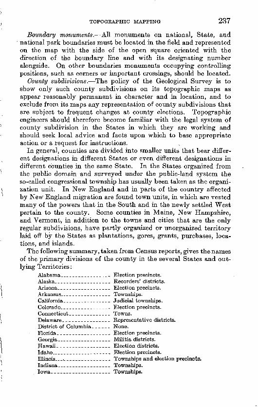
TOPOGRAPHIC MAPPING 237
Boundary monuments. All monuments on national, State, and national park boundaries must be located in the field and represented on the map with the side of the open square oriented with the direction of the boundary line and with its designating number alongside. On other boundaries monuments occupying controlling positions, such as corners or important crossings, should be located.
County subdivisions. The policy of the Geological Survey is to show only such county subdivisions on its topographic maps as appear reasonably permanent in character and in location, and to exclude from its maps any representation of county subdivisions that are subject to frequent changes at county elections. Topographic engineers should therefore become familiar with the legal system of county subdivision in the States in which they are working and should seek local advice and facts upon which to base appropriate action or a request for instructions.
In general, counties are divided into smaller units that bear differ ent designations in different States or even different designations in different counties in the same State. In the States organized from the public domain and surveyed under the public-land system the so-called congressional township has usually been taken as the organi zation unit. In New England and in parts of the country affected by New England migration are found town units, in which are vested many of the powers that in the South and in the newly settled West pertain to the county. Some counties in Maine, New Hampshire, and Vermont, in addition to the towns and cities that are the only regular subdivisions, have partly organized or unorganized territory laid off by the States as plantations, gores, grants, purchases, loca tions, and islands.
The following summary, taken from Census reports, gives the names of the primary divisions of the county in the several States and out lying Territories:
Alabama.________________ Election precincts.Alaska.__________________ Recorders' districts.Arizona._________________ Election precincts.Arkansas.._______________ Townships.California._______________ Judicial townships.Colorado.________________ Election precincts.Connecticut__-_______-_-_ Towns.Delaware._______________ Representative districts.District of Columbia. _____ None.Florida._________________ Election precincts.Georgia__________________ Militia districts.Hawaii._________________ Election districts.Idaho..__________________ Election precincts.Illinois.___________________ Townships and election precincts.Indiana_.________________ Townships.Iowa--_ Townships.
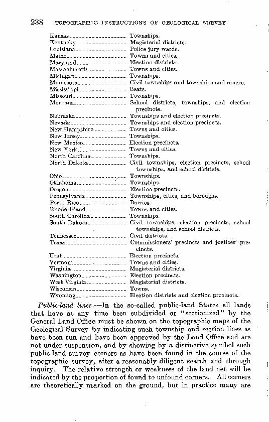
238 TOPOGKAPHIC INSTRUCTIONS OP GEOLOGICAL SURVEY
Kansas__________________ Towns-hips.Kentucky ________________ Magisterial districts.Louisiana- ______---___--_ Police jury wards.Maine___________________ Towns and cities.Maryland._______________ Election districts.Massachusetts____________ Towns and cities.Michigan._______________ Townships.Minnesota______--____-_- Civil townships and townships and ranges.Mississippi _______________ Beats.Missouri _________________ Townships.Montana.________________ School districts, townships, and election
precincts.Nebraska ________________ Townships and election precincts.Nevada __________________ Townships and election precinc ts.New Hampshire __________ Towns and cities.New Jersey ___---_-_--__ Townships.New Mexico._____________ Election precincts.New York-1 ______________ Towns and cities.North Carolina ___________ Townships.North Dakota ____________ Civil town ships, election precincts, school
townships, and school districts.Ohio..___________________ Townships.Oklahoma.-.-----------.- Townships.Oregon __________________ Election precincts.Pennsylvania.____________ Townships, cities, and boroughs.Porto Rico_____---____-_- Barrios.Rhode Island.____________ Towns and cities.South Carolina ___________ Townships.South Dakota-___________ Civil townships, election precincts, school
townships, and school districts.Tennessee ________________ Civil districts.Texas____________________ Commissioners' precincts and justices' pre
cincts.Utah.___________________ Election precincts.Vermont______----__.__-_ Towns and cities.Virginia..________________ Magisterial districts.Washington ______________ Election precincts.West Virginia.._ __________ Magisterial districts.Wisconsin________________ Towns.Wyoming-_______________ Election districts and election precincts.
Public-land lines. In the so-called public-land States all lands that have at any time been subdivided or " sectionized" by the General Land Office must be shown on the topographic maps of the Geological Survey by indicating such township and section lines as have been run and have been approved by the Land Office and are not under suspension, and by showing by a distinctive symbol such public-land survey corners as have been found in the course of the topographic survey, after a reasonably diligent search and through inquiry. The relative strength or weakness of the land net will be indicated by the proportion of found to unfound corners. All corners are theoretically marked on the ground, but in practice many are
TOPOGRAPHIC MAPPING- 239
difficult or even impossible to find. (For a description of the public- land survey system see pp. 368-376.)
In settled country, where land lines often become property lines, there are section-line roads and fences, and there the construction of a public-land survey net is usually simple. But in unsettled country or in settled areas where the roads or fences seldom conform to sec tion lines it is necessary to find on the ground and locate on the map enough section corners to enable the engineer to construct a land net built up from the Land Office plats and notes and tied to the section corners found. Such a land net when superimposed upon a topographic map will indicate the true, theoretical, or approximate location of each land line and corner with respect to the topography, according as corners are found or are only located from the plats and notes.
The land net should be completed in the field and compared with published maps of adjoining areas, and not left for office adjustment. If the Land Office plats can not be reconciled with the topography, even though a few isolated corners may be found, the section or township lines or both may be omitted, and a note added to the map to this effect. The note will be engraved and will list the omitted townships. (See "Land lines and topography," p. 307.)
Search j'or public-land corners. The tune warranted in search for obscure corners will be generally determined by the probable regu larity or irregularity of the net and the proximity of corners already found. The less local information is at hand obviously the greater the necessity for pioneer hunting for the needed land ties. Diligent search must be made on the ground for all corners believed to exist near the line of survey. Hence the best judgment must be used before giving up the search.
In a region where there are few roads on section lines assistance in finding corners may be had by using an oversheet of tracing paper or linen upon which has been laid out to field scale either a single typical township or an entire land net covering the area to be mapped, built up in advance from the Land Office plats and notes. Such is a tracing, placed in position over a field sheet as soon as the first land corner has been plotted, will indicate graphically the theoretical location of all other corners; and as more corners are found the further placements of the tracing become more serviceable as a guide.
The topographer should be thoroughly conversant with the system of rectangular land surveys and the intricacies peculiar to it. Acquaintance with the standard monuments used for the several classes of land corners, their marks, and their bearing trees, as well as with the manner in which blazes on trees become overgrown with bark, will prove most useful both in searching for corners and in
240 TOPOGRAPHIC INSTRUCTIONS OF GEOLOGICAL, SURVEY
determining their authenticity where this is in doubt. (For a dis cussion of the public-land survey system see p. 368.)
Location and mineral monuments: Monuments erected as per manent reference marks for the location of mineral and other claims (often designated as USLM's or USMM's) must be located with the same accuracy as land-survey corners and if practicable by plane- table triangulation and should be shown on engraved maps with their designating numbers.
Authority is vested in the United States mineral surveyors to establish "mineral monuments" where no land-survey corners exist in the immediate vicinity of claims and to number them serially in each State. A former practice was to establish so called "location monuments" in each separate mining district, numbered serially in each district, and those already established are still so designated. A careful distinction must be made between the two systems, and the numbers of the monuments must be obtained; the abbreviations used are, for example, "USLM 2," "USMM 237."
Triangulation points and transit-traverse stations. The triangula tion points and transit-traverse stations to which the topographic mapping of the quadrangle has been tied must be accurately indicated on the topographic maps with the open triangle and dot symbol, which will be engraved. Wherever practicable the elevation of each of these points and stations should be determined by levels, stadia, or vertical angles and be stamped on the tablet or post that consti tutes the permanent mark. If vertical angles have been used, the letters "V A" are to be stamped below the elevation figures.
Level bench marks. All permanent and supplementary bench marks must be diligently looked for and accurately located on the field sheets with a view toward inking them on the final office drawings. Topographic field parties should not rely upon finding bench marks by search alone but must locate them systematically with the aid of printed or typewritten descriptions or of notes furnished by the level parties. Bench marks should not be shown where in areas of heavy culture, their representation on the map would be illegible.
Indicate the exact position of the bench mark with a small needle hole and right-angle cross in order that its true relation to the side of the road, cross roads, railroad, or house may be evident. Indicate all bench marks, both permanent and supplementary on the field name sheets, with letters "BM" for the permanent bench marks and with elevations for all.
Vertical-angle bench marks. Where it is not expedient to run lines of third-order levels into or across mountain areas provision is made for the establishment of vertical-angle bench marks and for their permanent marking on the ground. Such bench marks must be well tied to one or more level bench marks by a system of well-checked
TOPOGEAPHIC MAPPING 241
reciprocal vertical angles from plane-table stations within the main plane-table control triangulation net of the quadrangle. Vertical- angle bench marks should be located at triangulation points or other conspicuous summits so far as practicable and should be kept away from roads or other routes of travel. Where, however, a vertical- angle bench mark is established near a road it should be designated "VABM" in order that there may be no doubt of its character, but on summits the designation will be the same as level bench marks, "BM."
Reporting bench marks not found. Bench marks must be found or reported as not found. Therefore, report promptly to the chief top ographic engineer any bench marks (permanent or supplementary) that have been looked for and either not found or found to have been disturbed, in order that the office records and the level-bulletin manuscripts can be corrected. Also indicate them on the field name sheet as not found.
Control points adjacent to cultural features. In plotting cultural features adjacent to horizontal-control points or in plotting bench marks adjacent to cultural features the copy for inking should be accurate and clear as to the relation between the culture and the control shown.
Useful elevations. In addition to the permanent and supplementary bench marks, reliable elevations that have been determined by means of leveling or stadia at road corners, summits of mountains and hills, water surfaces of lakes, ponds, and wide rivers, prominent high points in roads, section corners, boundary monuments, and other appropri ate places should be penciled on the field sheets. In selecting these elevations for the maps, the topographic engineer should bear in mind that it is the policy of the Geological Survey to publish, either on the advance sheets or on the engraved maps, only such elevations as have a definite working value; therefore only those elevations should be finally penciled on the field sheets that can be identified on the ground and on the map both in elevation and in location.
The distribution of useful elevations on the final field sheets should be based on a spacing of about half a mile apart for maps plotted on a field scale of 1 :48,000 and about 1 mile apart for a £eld scale of 1 : 96,000, and in proportion for other field scales. Shorter spacings should be used, however, wherever features of unusual importance or large differences in elevation are involved; and under certain conditions, when specially authorized, even more elevations may be indicated.
Elevation tracing. If the field sheets are drawn on a scale of 1 : 31, 680 or on a larger scale, all elevation data must be assembled on an oversheet tracing in the field, as the small elevation figures that have been placed on the field sheets themselves are ever in danger of being
242 TOPOGRAPHIC INSTRUCTIONS OF GEOLOGICAL SURVEY
erased or so obscured as to be illegible. The point of application for the elevation given should be clearly indicated on the tracing.
MAPPING OF DRAINAGE FEATURES
Drainage features defined. The drainage features of the terrain are those features representing water, such as flowing streams, lakes, and shore lines, and those features indicating some degree of wetness, such as intermittent streams, marsh, and glaciers.
Features to be mapped. The drainage features to be shown on all topographic maps, by standard symbols (see pis. 18-23) or by means of other conventions as described in the text are listed below.Glaciers. Lakes. Marshes. Shore lines.
Sand.Springs.Streams.Wells and water tanks.
Tidal shore lines. On all topographic maps of the Geological Survey the line of mean high tide is considered to be the shore line. In determining the margin of mean high water, exclude the highest (semimonthly) tides and take the average of the usual high tides as generally marked by the limits of vegetation.
Use of Coast and Geodetic Survey charts. The fullest practicable use should be made of the charts of the Coast and Geodetic Survey in mapping coastal areas. The charts should be photographed to the scale of the field work, and where they represent recent work on a scale as large as Geological Survey field work, or larger, the shore-line data should be transferred to the field sheets. The data taken from charts must be instrumentally checked to insure their correct adjust ment and tie to the Geological Survey topography, and afterwards they must be examined in detail for possible changes.
MarsJies in general. Both fresh and salt marshes should be repre sented by the symbol for marsh in general, and no distinction should be made between them in field work. Marsh or swamp land is defined as land that is not suitable for cultivation without first being drained. The outlines of marsh areas should be indicated in dashed lines and inked but will be engraved only under certain conditions, which are described on page 291.
Marshes on low coasts are as a rule traversed by a network of tidal channels. Unlike the rills in mud flats, these channels are fairly permanent in location, and those that exist at mean high tide should be mapped individually so far as the scale permits.
Submerged marsh. Marsh lands that are partly submerged for many months each year are to be differentiated from ordinary marshes and represented by a symbol combining water and marsh tufts. The inking copy should be clearly indicated.
TOPOGRAPHIC MAPPING 243
Wooded marsh. No symbol has been provided for wooded marsh other than that offered by the green woodland overprint over the marsh symbol. Areas of wooded marsh should therefore be included in the areas shown on the woodland tracing, but with a note along side so that they will not be inadvertently stricken out in the office.
River shore lines. Broad rivers offer a perplexing problem to the topographer, as, owing to their periodic fluctuations, their width often varies considerably with their stage. The general rule is that the width shown should correspond to the normal stage. The normal stage may be defined as that water level which remains nearly station ary for the greater part of the year, and therefore it excludes all stages of relatively short duration resulting from floods, whether periodical or out of season, and all low-water stages resulting from exceptional run-off. The normal stage will, in general, be found to exist for about 9 to 11 months for most streams. If any other stage of water other than the normal has been mapped by other Government agencies instructions should be sought as to the availability and best use of the material. The elevation of the plotted shore line should be indicated at short intervals, and the figures of elevation should be placed in the space indicating water surface where they can be made readable.
In areas where the flow of rivers, though active for brief periods, dwindles or ceases altogether for many months the normal or pre vailing stage is very low. Thus, rivers like the Platte are normally braided streams and should be represented as such on the map. Many rivers in the desert regions are most of the time nothing more than broad sandy washes and should be shown by strips of sanding.
River banks. If the contour interval is too large to permit the delineation of river banks by contour lines, hachures may be used, a single row being sufficient.
Natural lakes. The shore line used to represent a natural lake or pond should be that corresponding to a normal stage of water and not necessarily the shore line that is found at the time of the survey, which may be during periods of flood or extreme drought. An effort should be made to ascertain the shore line of the normal stage, as usually marked by a line of permanent land vegetation. The shore line used to represent a large lake that is subject to a gradual rise or fall over long periods should be that found at the date of sur vey. This date should be indicated on the water surface and be inked, and it will usually be engraved.
Artificial lakes. The shore line of an artificial lake should be the line that represents the water surface at the full normal stage of the lake, as controlled by the dam.
Island shore lines. The shore line that is to be mapped for an island must be that corresponding to the stage of water used for the
244 TOPOGRAPHIC INSTRUCTIONS OF GEOLOGICAL SURVEY
adjoining mainland shore line. Islands exposed only at a stage of water below that used for the mainland shore line should therefore not be mapped.
Drainage classification. The field sheets should clearly classify all streams as perennial or intermittent; this classification is defined below, and as it can not be accurately made in the office it must be completely made in the field.
Perennial streams. A perennial stream is one that flows throughout the year. It should be represented on the field sheets by a solid penciled line, firm enough to avoid confusion with the light penciled drainage that is drawn simply as a basis for contour construction. The topographer should show all perennial streams and leave for office decision the possible omission of any that may be considered not within the publication scale. Although the map should not be overburdened with insignificant rills and forks, such as abound in well-watered countries, the perennial drainage symbol should be penciled in all cases of doubt. As the purpose of this symbol is to show where running water may be found, it should be indicated on the field sheets only where the perennial character of the stream is reasonably established; and to this end occasional inquiry should be made to supplement field observations.
Intermittent streams. An intermittent stream is one that is dry for a considerable time each year, say for three months or longer. It should be represented on the field sheets by a firm penciling of the dash and three dot symbol. In regions where both perennial and intermittent streams abound the penciling should be complete and clearly distinct as to each kind, but if the proportion or amount of intermittent drainage is so large that the field drafting of the dash and three dot symbol becomes burdensome the copy can be made clear for inking by means of an overtracing (information sheet) showing only the perennial streams with a statement that all other streams are intermittent.
Double-lined streams. No stream should be double lined unless its actual width can thus be shown on the scale of publication without need of exaggeration.
Drainage lines as contour control. All drainage lines should be lightly penciled in on the field sheets, as they constitute a controlling element of all normal erosion topography and serve as a natural skeleton for the construction of the contours. Indeed, the systematic tracing out of the drainage net can not be too strongly recommended; the earlier the topographer begins to cultivate the habit the more suc cessful he is likely to be in his work. Even in volcanic, sand-dune, or glaciated areas, where the topographic features have been shaped by agents other than running water, the drainage lines will often be invaluable to the topographer in making clear the real nature of
TOPOGRAPHIC MAPPING 245
slopes and irregular surfaces that are in themselves deceptive to the eye.
Disappearing streams. Many streams in limestone regions abruptly sink into caverns and continue their courses for long distances through subterranean channels. Special care should be given to the mapping of streams of this type. The points of disappearance and reappearance should be accurately located.
Springs. The importance of representing springs on a map is dependent on their relative usefulness as a part of the water resources of the region. Thus springs should be shown on maps of desert regions, where they are literally of vital importance and theii omission or erroneous location may have the gravest consequences to those dependent on the map. In such regions the name by which each spring is known should be indicated. Intermittent, alkali, or undrink- able springs should be so designated on the map. Springs should usually be omitted from maps of well-watered regions, but even there conspicuous springs may be shown by symbol and by name if locally recognized. The inking copy must be clear, and if necessary the presence of springs should be noted on the information sheet.
Wells and water tanks. The importance of wells and tanks, like that of springs, depends entirely on their relative usefulness as a part of the water resources of the region. In semiarid regions both wells and tanks must be shown. Wells, if artesian, should be so designated. The presence of wells and tanks should be shown on the information sheet if the field-sheet copy is not clear.
Intermittent and dry lakes. Shallow lakes and ponds that are dry for many months each year are typical of some regions, and all those not too small for the scale must be shown. Dry salt lakes and alkali flats, although not intermittent in the usual sense, are so closely related to intermittent lakes in appearance and formation that they should be shown by the symbol for intermittent lakes. Both types should therefore be shown by a dashed outline with the surface indi cated by hatching.
Glaciers. The area of each glacier should be outlined by a dotted line, and its surface should be contoured (blue on the final map) with the same contour interval as that used for adjoining land surface and with the same degree of accuracy.
MAPPING OF RELIEF FEATURES
. CONTOUR LINES
The relief on all topographic maps is expressed by contour lines. (See "Relief expression," p. 164.)
One contour interval. The contour interval that should be used on any map will be stated in the field instructions that are issued to
246
topographic engineers for each separate field assignment. If, in the course of field work the use of a different interval appears to be advisable, prompt recommendation should be sent to the division engineer.
Two contour intervals. Where the lower or valley parts of a quad rangle are to be contoured with a smaller contour interval than is to be used in the higher or hill parts of the quadrangle the change from one contour interval to the other should be made on one of the emphasized contours. For example, in changing from a 5-foot to a 25-foot interval the change should be made on one of the 100-foot contours. Where, however, the border line between the valleys and the foothills represents a line that is rapidly rising or falling the emphasized contour on which the interval is changed should itself be correspondingly changed, in order to give the greatest possible expression with the small contour interval to the natter country and to avoid the unnecessary use of a small contour interval in the bolder country.
Where intermediate contours are needed to show detailed relief in certain small parts of a quadrangle, as in small valleys or flats, such contours may be added in dashed lines without interfering with the sequence of the regular heavy and light contours on the map.
CONTOURING METHODS
Contours may be mapped from plane-table set-ups that are made directly over or adjacent to the country that is to be mapped, as along a traversed road; or from a table that is kept stationary while it is circled by one or more moving rods; or from plane-table stations that overlook the distant country that is to be contoured. These three methods of contouring are described below.
Contouring from a traverse line. In regions where the principal control is obtained by different kinds of traverse (which in general are extended along public highways), the usual procedure is first to plot the contour crossings and other contours on or near the traversed road or other traverse line and then to extend the contouring out on both sides of the traverse line as far as good visibility and locally established control warrants. Where the visibility from a traverse line is poor all necessary advantage should be taken of such relatively good view places as are passed; and if good sketching points are noted off the line but near it, such points should be occupied as the work progresses. Contouring from a traverse line may also be advan tageously supplemented by having the rod held occasionally at salient points in the topography off the line.
When aU sides of a road circuit or other large traverse circuit have been thus traversed and mapped, traverses should be extended into or across the unmapped interiors, giving sufficient traverse control to
TOPOGRAPHIC MAPPING 247
enable the topographer to complete the mapping. Such interior traverses may be run across open country or along ridges or streams, or the topographer may occupy favorable interior viewpoints with the plane table and resect from previous traverse locations in order to obtain a plane-table location.
Contouring from radial rod readings. In open country' of low relief where little contouring can be done from single plane-table set-ups one or two rodmen and a recorder can be advantageously used. Where two rodmen are employed each holds a rod on different sides of the plane table and at the salient points in the topography, and each rodman advances in the direction of the proposed mapping. As soon as the sights become too long or are about to be obscured both rodmen should hold their stations, and these points should be used as turning points in the line and the mean of the two readings used in determining the elevation of the new plane-table station that is made beyond the points held by the two rodmen. The rodmen then advance as before. Plane-table locations may be obtained as in "Contouring from a traverse line" (above) or as in "Contouring from stations" (below).To use this method to advantage the topographer should employ
such signals as may be found necessary between the table and the rod and between rods and should fully instruct the rodmen in their duties, as much depends upon their activity and resourcefulness. The readings that result from the successive rod sights may be plotted as fast as they are taken, or they may be allowed to accumulate and be plotted after the series has been completed, as local conditions may dictate.
Contouring from station. In open country of bold relief, where all the features are plainly visible, contours can be best delineated from plane-table stations overlooking the country to be contoured, without the running of a traverse line or the use of a rod. The method of contouring from plane-table stations involves the use of plane-table triangulation (p. 197) and the three-point method (p. 202). Wood land country as well as open country may be contoured from stations provided a sufficient number of outlooks can be found from which a satisfactory view and a good determination of position can be ob tained. In the construction of contours from a station the location and use of drainage lines is important. (See "Drainage lines as contour control," p. 244.)
Contouring from a station is dependent upon supplemental con trol that is obtained by the location on the plane-table sheet by intersection methods of many of the salient points on the surface that is to be contoured; and for this reason little sketching can be done from the first station other than that of form lines, which are afterwards converted into placed contour lines. (See "Form lines,"
248 TOPOGRAPHIC INSTRUCTIONS OF GEOLOGICAL SURVEY
p, 249.) In planning the order in which plane-table stations should be made, careful consideration must be given to the need for the sighting of many points ahead, so that a sufficient number of such sights may be intersected from subsequent stations and used as a basis for contour construction. Vertical angles may be taken to the points when they are first sighted, or after the points that have been sighted have been intersected, or at both times, as circumstances may warrant, but in either procedure the elevations must be com puted and the contours placed on the map as soon as the intersections are obtained.
The elevation of plane-table stations must be determined from a carefully executed series of reciprocal vertical angles taken between the principal stations in the quadrangle, and at least one station must be directly connected with a level bench mark by means of reciprocal vertical angles measured under different conditions.
Contour skeleton outline. Before mapping the contours that are to represent a distant relief feature a skeleton outline of that feature should be prepared, and on the degree with which this is adequately accomplished depends much of the accuracy, speed, and ease with which the contours themselves are placed on the map. Although it is true that lacking such an outline an experienced topographer will make a more faithful contour sketch than one less experienced, it is equally true that the best and most experienced topographers make a suitable skeleton outline of the drainage and ridge lines before attempting the construction of the contour lines themselves.
The landscape that is to be contoured should be first divided into its separate features or unit masses, such as mountains, hills, and spurs, and then, after sufficient control has been established through intersection methods, each feature thus segregated should have its natural drainage-line boundaries sketched in, tangents drawn to salient points as well as located points being used as control for the placing of the drainage lines. Similarly, ridge and crest lines may be outlined. It is best, as a general rule, to use convex forms such as spurs and lateral ridges as unit masses, the intermediate drainage lines being used as boundaries. (See also "Drainage lines as con tour control," p. 244.)
In determining elevations based on vertical angles it is well to remember that large angles must be supplemented with accurate measurements of distance but that small angles based on measure ments of distance that are approximate only will yield useful eleva tions for contour work.
Each separate unit mass as above described should be completely contoured, so far as control and visibility permits, before the con touring of another feature is begun. Should control alone be lacking, form lines (see below) should be lightly sketched in and advantage
TOPOGRAPHIC MAPPING 249
thus taken of a favorable viewpoint, effort being made subsequently to cut in the lacking control. By treating each mass as a separate unit, each can be best delineated with its own characteristic shape.
Form lines. Form lines are short detached sections of contour lines that are based on little or no control and on approximate con tour intervals only. Form lines serve as a temporary expedient in expressing the relief of a small area until the necessary control can be obtained; they can then be readily converted into contour lines. Advantage is thus taken of a favorable point of view, and another visit to the same station is often avoided. Jn regions of moderate relief, where each feature takes but a few contours or where the map ping is done at short range, provisional sketching by form lines is not needed, but in many regions of intricately sculptured mountains it is a necessity.
Distances from which contouring can be done. Where the topo graphic method used is that of mapping the country from a distance, as in station work by plane-table methods alone, the distance will vary according to the proposed mapping scale and contour interval. In general, the smaller the map scale the more distance should the country be from the stations in order that it may be properly seen, and the larger the map scale the nearer should the stations be to the detail that can be properly mapped only at short range. Where small-scale mapping is confined to country that is near the station, less area will be covered and more detail will inadvertently be attempted than is needed for the scale, with the result that only a small paper area will be mapped in a given time; where the large-scale mapping of a too distant country is attempted the needed detail is not well seen and inferior work will result. On the selection of the best distance for work and on the choice of stations depends much of the success of the topographer.
Effective working distances in the mountains may be as great as 5 to 10 miles with a 100 or 200 foot contour interval on a scale of 1:192,000, as great as 2 to 5 miles with a 100-foot interval on a scale of 1:96,000, and may range from a quarter of a mile to 1 mile with a 20-foot interval on a scale of 1:48,000. The cultural features of a country of bold relief should in general be separately traversed, and where they dominate the country the plane-table station method may become secondary.
DRAFTING OF CONTOURS
Penciling. Contour lines should be drawn with the hardest pencil that can be used under field conditions, and this in general will be a 9H pencil in dry weather and a 7H pencil in damp weather or in a wet climate. The pencil lines should be drawn fine, sharp, and of even strength and should give as uniform an appearance as possible,
250 TOPOGRAPHIC INSTRUCTIONS OF GEOLOGICAL SURVEY
but under no circumstances should the lines dent the paper or leave grooves in its surface. Erasures should be made gently and only when the paper is perfectly dry, lest the surface be broken. As the same sheet will later be inked in the office, it should at all times be kept cov ered save where the day's work is being done, for which a small hole can be cut in the cover paper.
Emphasized contours. Inasmuch as every fifth or fourth contour, according to the contour interval, will be later emphasized by inking it in a heavy line (see " Strength of contour lines," p. 294), the penciled contours that are to be made heavy in the inking should be indicated clearly, by adding contour figures at short intervals and by placing little penciled crosses on them rather than using dashed or dotted lines or heavy penciled lines. For steep slopes whose relief is expressed in emphasized contours alone no mark of identification is needed other than the drawing in here and there of a band of intermediate contours.
Contour numbers. Contour numbers should be added to contours that are to be emphasized wherever such numbers may be helpful to the inker and should be placed here and there on the intermediate contours wherever they may be essential or helpful in the interpreta tion of the copy.
Uniform steep slopes. Where the slope is both steep and uniform only the contours to be accented should be penciled, for the reason that the inker can interpolate the intermediate lines as readily as the topographer can pencil them in on the field sheet and for the additional reason that the inker's copy is the clearer for their omission. (See "Uniform steep slopes," p. 295.)
Steep slopes that are not uniform. Where the slope is steep but not uniform a sufficient number of intermediate contours should be added to define clearly the positions of the changes in slope. If this is not done an unnatural "banded" expression will be given to the map in those places where the inker inadvertently uses an even spacing of intermediate contours between the unevenly spaced heavy contours.
Drainage and ridge slopes. Along lateral stream channels and ridges that have been contoured in heavy contours alone the intermediate contours should be penciled in wherever a uniform interpolation can not be made; otherwise an erroneous interpolation may be made in the office with resulting improbable slopes, illegible copy, or both.
SPECIAL FEATURES
Railroad grades. As railroads are constructed on known and defi nite grades they should be so represented in contours. The distances given in the following table apply to standard service roads and should be regarded as approximate only. Few main lines use grades in excess of 1 or 2 per cent, and few branch lines in excess of 3 or 4 per cent. For grades of 5 and 6 per cent unusual precautions are necessary, such
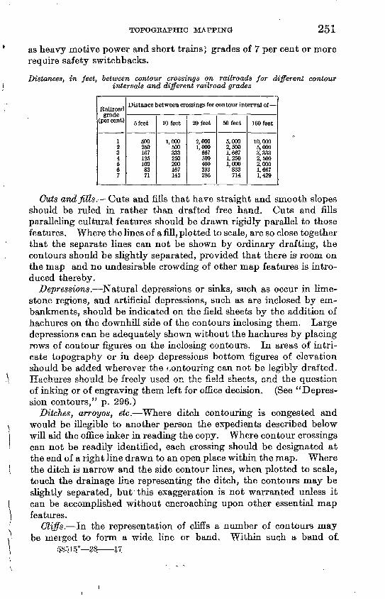
TOPOGKAPHIC MAPPING 251
as heavy motive power and short trains; grades of 7 per cent or more require safety switchbacks.
Distances, in feet, between contour crossings on railroads for different contour intervals and different railroad grades
Railroad grade
(percent)
1 2 3 4 5 6 7
Distance between crossings for contour interval of
5 feet
500 250 167 125 100 83 71
10 feet
1,000 500 333 250 200 167 143
20 feet
2,000 1,000
667 500 400 333 286
50 feet
5,000 2,500 1,667 1,250 1,000
833 714
100 feet
10,000 5,000 3,333 2,500 2,000 1,667 1,429
Cuts andfiUs. Cuts and fills that have straight and smooth slopes should be ruled in rather than drafted free hand. Cuts and fills paralleling cultural features should be drawn rigidly parallel to those features. Where the lines of a fill, plotted to scale, are so close together that the separate lines can not be shown by ordinary drafting, the contours should be slightly separated, provided that there is room on the map and no undesirable crowding of other map features is intro duced thereby.
Depressions. Natural depressions or sinks, such as occur in lime stone regions, and artificial depressions, such as are inclosed by em bankments, should be indicated on the field sheets by the addition of hachures on the downhill side of the contours inclosing them. Large depressions can be adequately shown without the hachures by placing rows of contour figures on the inclosing contours. In areas of intri cate topography or in deep depressions bottom figures of elevation should be added wherever the contouring can not be legibly drafted. Hachures should be freely used on the field sheets, and the question of inking or of engraving them left for office decision. (See "Depres sion contours," p. 296.)
Ditches, arrayos, etc. Where ditch contouring is congested and would be illegible to another person the expedients described below will aid the office inker in reading the copy. Where contour crossings can not be readily identified, each crossing should be designated at the end of a right line drawn to an open place within the map. Where the ditch is narrow and the side contour lines, when plotted to scale, touch the drainage line representing the ditch, the contours may be slightly separated, but this exaggeration is not warranted unless it can be accomplished without encroaching upon other essential map features.
Cliffs. In the representation of cliffs a number of contours may be merged to form a wide, line or band. Within such a band of.
qSqi§° 28 H
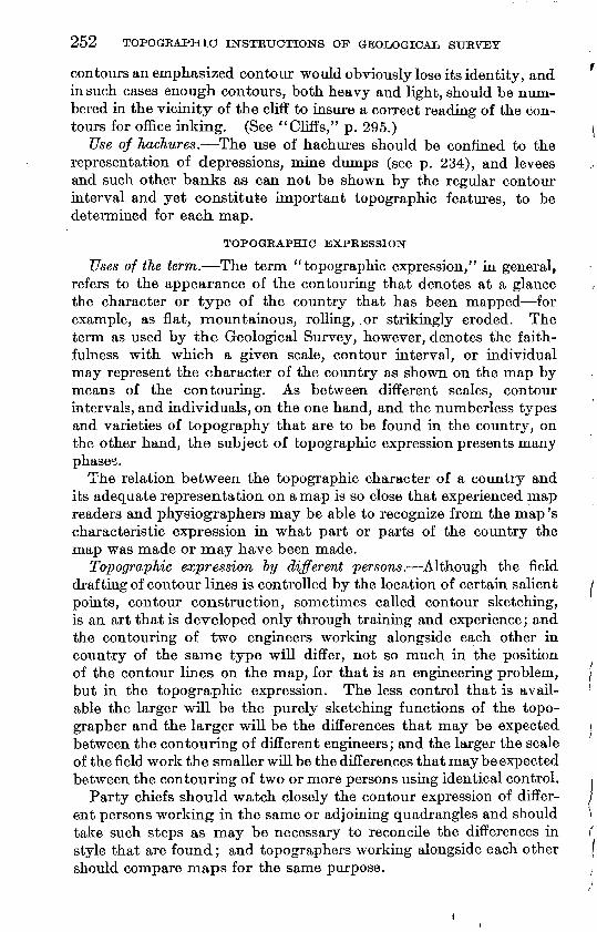
252 TOPOGRAPHIC INSTRUCTIONS OF GEOLOGICAL SURVEY
contours an emphasized contour would obviously lose its identity, and in such cases enough contours, both heavy and light, should be num bered in the vicinity of the cliff to insure a correct reading of the con tours for office inking. (See "Cliffs," p. 295.)
Use of Jiachures. The use of hachures should be confined to the representation of depressions, mine dumps (see p. 234), and levees and such other banks as can not be shown by the regular contour interval and yet constitute important topographic features, to be determined for each map.
TOPOGRAPHIC EXPRESSION
Uses of the term. The term "topographic expression," in general, refers to the appearance of the contouring that denotes at a glance the character or type of the country that has been mapped for example, as flat, mountainous, rolling, or strikingly eroded. The term as used by the Geological Survey, however, denotes the faith fulness with which a given scale, contour interval, or individual may represent the character of the country as shown on the map by means of the contouring. As between different scales, contour intervals, and individuals, on the one hand, and the numberless types and varieties of topography that are to be found in the country, on the other hand, the subject of topographic expression presents many phases.
The relation between the topographic character of a country and its adequate representation on a map is so close that experienced map readers and physiographers may be able to recognize from the map's characteristic expression in what part or parts of the country the map was made or may have been made.
Topographic expression by different persons. Although the field drafting of contour lines is controlled by the location of certain salient points, contour construction, sometimes called contour sketching, is an art that is developed only through training and experience; and the contouring of two engineers working alongside each other in country of the same type will differ, not so much in the position of the contour lines on the map, for that is an engineering problem, but in the topographic expression. The less control that is avail able the larger will be the purely sketching functions of the topo grapher and the larger will be the differences that may be expected between the contouring of different engineers; and the larger the scale of the field work the smaller will be the differences that may be expected between the contouring of two or more persons using identical control.
Party chiefs should watch closely the contour expression of differ ent persons working in the same or adjoining quadrangles and should take such steps as may be necessary to reconcile the differences in style that are found; and topographers working alongside each other should compare maps for the same purpose.
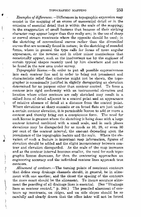
TOPOGRAPHIC MAPPING 253
Examples qf differences. Differences in topographic expression may consist in the mapping of an excess of unessential detail or in the omission of essential detail that is within the scale of the mapping; in the exaggeration of small features that because of their striking character may appear larger than they really are; in the use of sharp or curved stream reentrants where the opposite should be used; in the sketching of conventional curves rather than the diversified curves that are normally found in nature; in the sketching of rounded forms, where in general the type calls for forms of more angular appearance, or the reverse; and in other minor mannerisms that occasionally appear, such as the inadvertent use by the engineer of certain typical shapes recently used by him elsewhere and not to be found in the new area under survey.
Topographic license. In order to put all possible expressiveness into each contour line and in order to bring out prominent and characteristic relief that otherwise might not be shown, the topo grapher is occasionally justified in slightly disregarding an elevation determined for no purpose other than contour control. To force a contour into rigid conformity with an instrumental elevation and location where other contours are only sketched may result in a stilted form of detail adjacent to a control point and an appearance of relative absence of detail at a distance from the control point. Where elevations at sharp summits or on broad flats are just under a certain contour elevation, it is permissible license to add or move a contour and thereby bring out a conspicuous form. The need for such license is greatest where the sketching is being done with a large contour interval combined with a small scale, and in such places elevations may be disregarded for as much as 10, 20, or even 30 per cent of the contour interval, the amount depending upon the prominence of the topographic feature and the scale. Where the ele- vation of such a feature is important map information, figures of elevation should be added and the slight inconsistency between con tour and elevation disregarded. As the scale of the map increases and as the contour interval becomes smaller, the need for such topo- graphic license decreases, for then the contouring approaches an engineering accuracy and the individual contour lines approach true contours.
Alinement of contours, The turning points of reentrant contours that define steep drainage channels should, in general, be in aline- ment with one another, and the closer the spacing of the contours the more exact should be the alinement. To insure accurate aline- ment the penciling of all drainage lines is essential. (See "Drainage lines as contour control," p. 244.) The penciled alinernent of con- tours up reentrants, on ridges, and on side slopes should be so carefully and clearly drawn that the office inker will not be forced
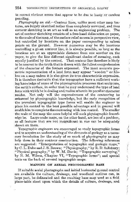
254 TOPOGRAPHIC INSTRUCTIONS OF GEOLOGICAL SUBVEY
to correct obvious errors that appear to be due to hasty or careless penciling.
Physiography an aid. Contour lines, unlike most other map fea tures, are largely sketched rather than completely surveyed, and thus contour sketching is an art as well as an engineering problem. The art of contour sketching consists of a free-hand delineation on paper, to the scale of the map, of the surface relief as seen in perspective view, but controlled by locations on the paper corresponding to salient points on the ground. However numerous may be the locations controlling a given contour line, it is always possible, so long as the locations are at an appreciable distance from one another on the paper, to give the line different significant shades of meaning, each equally justified by the control. That contour line therefore is likely to be nearest to the truth that is drawn with the fullest comprehension of the character of the feature expressed. The most accurate geo metric representation of a land form may appear "wooden" or life less on a map unless it is also given its true characteristic expression. It is therefore desirable that the topographer have a sufficient work ing knowledge of some of the physiographic processes that sculpture, the earth's surface, in order that he may understand the type of land form with which he is dealing and realize wherein its peculiar character resides. Not only will the expressiveness of the contouring be enhanced by physiographic knowledge, but the early recognition of the prevalent topographic type forms will enable the engineer to place his control to the best possible advantage and in general will enable him to complete the contouring with less control. The smaller the scale of the map the more helpful will such physiographic knowl edge be. Large-scale maps, on the other hand, are less of a problem, as all features that are not insignificant in size can be adequately shown on them.
Topographic engineers are encouraged to study topographic forms and to acquire an understanding of the elements of geology as a neces sary foundation for the study of so much of physiography as may help them in their contour construction. The following references are suggested: "Interpretation of topographic and geologic maps," by C. L. Dake and J. S. Brown; "Physiography," by R. D. Salisbury; "Physical geography," by W. M. Davis; "Topographic surveying," by H. M. Wilson, Chapter VI, "Topographic forms"; and special texts on the back of several topographic maps.
MAPPING ON AERIAL PHOTOGRAPHIC BASE
If suitable aerial photographs and initial horizontal giound control are available the culture, drainage, and woodland outlines can, in large part, be delineated and the resulting base map used as a field plane-table sheet upon which the details of culture, drainage, and
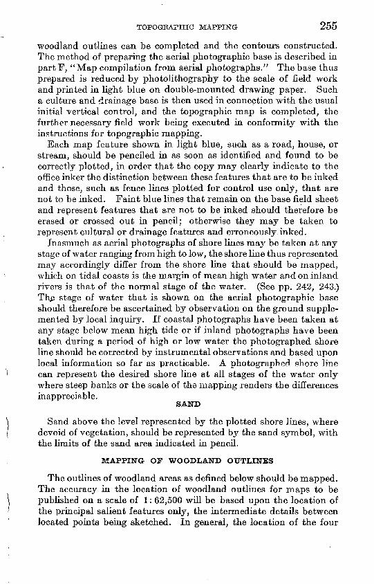
TOPOGRAPHIC MAPPING 255
woodland outlines can be completed and the contours constructed. The method of preparing the aerial photographic base is described in partF, "Map compilation from aerial photographs." The base thus prepared is reduced by photolithography to the scale of field work and printed in light blue on double-mounted drawing paper. Such a culture and drainage base is then used in connection with the usual initial vertical control, and the topographic map is completed, the further necessary field work being executed in conformity with the instructions for topographic mapping.
Each map feature shown in light blue, such as a road, house, or stream, should be penciled in as soon as identified and found to be correctly plotted, in order that the copy may clearly indicate to the office inker the distinction between these features that are to be inked and those, such as fence lines plotted for control use only, that are not to be inked. Faint blue lines that remain on the base field sheet and represent features that are not to be inked should therefore be erased or crossed out in pencil; otherwise they may be taken to represent cultural or drainage features and erroneously inked.
Inasmuch as aerial photographs of shore lines maj7" be taken at any stage of water ranging from high to low, the shore line thus represented may accordingly differ from the shore line that should be mapped, which on tidal coasts is the margin of mean high water and on inland rivers is that of the normal stage of the water. (See pp. 242, 243.) Th£ stage of water that is shown on the aerial photographic base should therefore be ascertained by observation on the ground supple mented by local inquiry. If coastal photographs have been taken at any stage below mean high tide or if inland photographs have been taken during a period of high or low water the photographed shore line should be corrected by instrumental observations and based upon local information so far as practicable. A photographed shore line can represent the desired shore line at all stages of the water only where steep banks or the scale of the mapping renders the differencesinappreciable.
SAND
Sand above the level represented by the plotted shore lines, where devoid of vegetation, should be represented by the sand symbol, with the limits of the sand area indicated in pencil.
MAPPING OF WOODLAND OUTLINES
The outlines of woodland areas as defined below should be mapped. The accuracy in the location of woodland outlines for maps to be published on a scale of 1: 62,500 will be based upon the location of the principal salient features only, the intermediate details between located points being sketched. In general, the location of the four
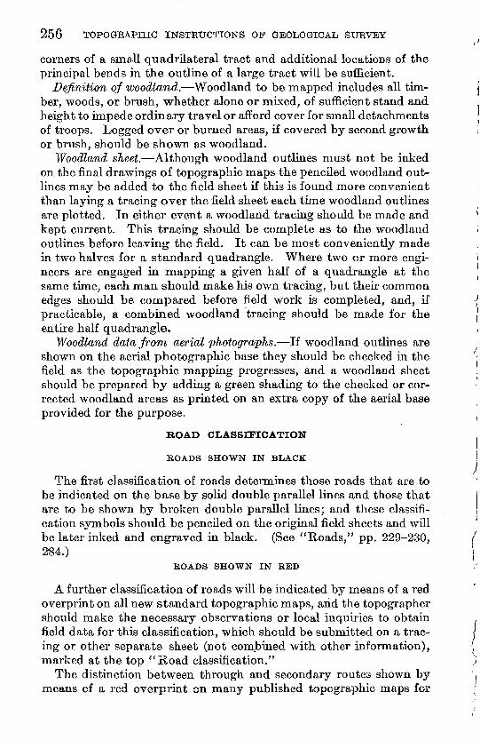
256 TOPOGRAPHIC INSTRUCTIONS OF GEOLOGICAL SURVEY
corners of a small quadrilateral tract and additional locations of the principal bends in the outline of a large tract will be sufficient.
Definition of woodland. Woodland to be mapped includes all tim ber, woods, or brush, "whether alone or mixed, of sufficient stand and height to impede ordinary travel or afford cover for small detachments of troops. Logged over or burned areas, if covered by second growth or brush, should be shown as woodland.
Woodland sheet. Although woodland outlines must not be inked on the final drawings of topographic maps the penciled woodland out lines may be added to the field sheet if this is found more convenient than laying a tracing over the field sheet each tune woodland outlines are plotted. In either event a woodland tracing should be made and kept current. This tracing should be complete as to the woodland outlines before leaving the field. It can be most conveniently made in two halves for a standard quadrangle. Where two or more engi neers are engaged in mapping a given half of a quadrangle at the same time, each man should make his own tracing, but their common edges should be compared before field work is completed, and, if practicable, a combined woodland tracing should be made for the entire half quadrangle.
Woodland data from aerial photographs. If woodland outlines are shown on the aerial photographic base they should be checked in the field as the topographic mapping progresses, and a woodland sheet should be prepared by adding a green shading to the checked or cor rected woodland areas as printed on an extra copy of the aerial base provided for the purpose.
ROAD CLASSIFICATION
BOADS SHOWN IN BLACK
The first classification of roads determines those roads that are to be indicated on the base by solid double parallel lines and those that are to be shown by broken double parallel lines; and these classifi cation symbols should be penciled on the original field sheets and will be later inked and engraved in black. (See "Roads," pp. 229-230, 284.)
ROADS SHOWN IN RED
A further classification of roads will be indicated by means of a red overprint on all new standard topographic maps, and the topographer should make the necessary observations or local inquiries to obtain field data for this classification, which should be submitted on a trac ing or other separate sheet (not combined with other information), marked at the top "Road classification."
The distinction between through and secondary routes shown by means of a red overprint on many published topographic maps for
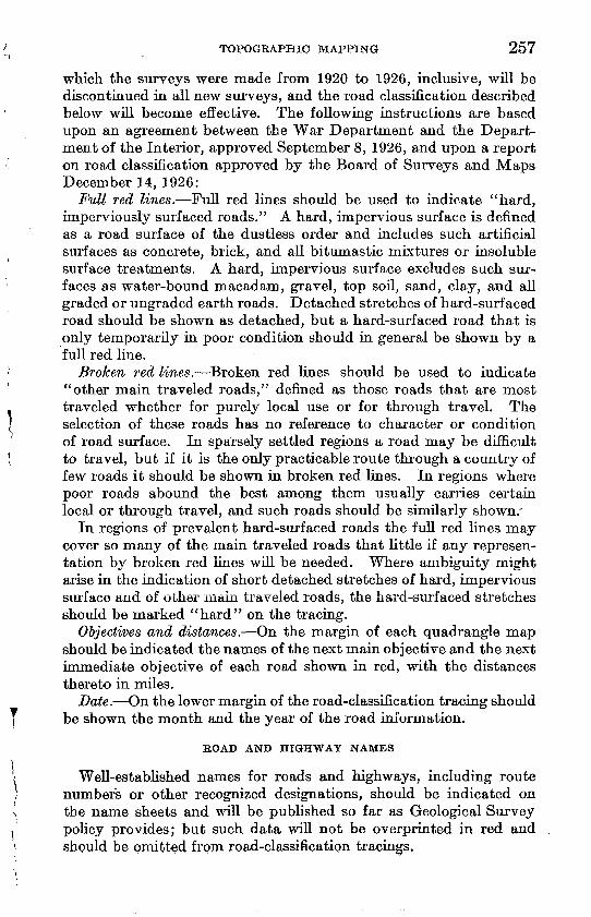
TOPOGRAPHIC MAPPING 257
which the surveys were made from 1920 to 1926, inclusive, will be discontinued in all new surveys, and the road classification described below will become effective. The following instructions are based upon an agreement between the War Department and the Depart ment of the Interior, approved September 8, 1926, and upon a report on road classification approved by the Board of Surveys and Maps December 14, 1926:
Full red lines. Full red lines should be used to indicate "hard, imperviously surfaced roads." A hard, impervious surface is defined as a road surface of the dustless order and includes such artificial surfaces as concrete, brick, and all bitumastic mixtures or insoluble surface treatments. A hard, impervious surface excludes such sur faces as water-bound macadam, gravel, top soil, sand, clay, and all graded or ungraded earth roads. Detached stretches of hard-surfaced road should be shown as detached, but a hard-surfaced road that is only temporarily in poor condition should in general be shown by a full red line.
Broken red lines. Broken red lines should be used to indicate "other main traveled roads," denned as those roads that are most traveled whether for purely local use or for through travel. The selection of these roads has no reference to character or condition of road surface. In sparsely settled regions a road may be difficult to travel, but if it is the only practicable route through a country of few roads it should be shown in broken red lines. In regions where poor roads abound the best among them usually carries certain local or through travel, and such roads should be similarly shown/
In regions of prevalent hard-surfaced roads the full red lines may cover so many of the main traveled roads that little if any represen tation by broken red lines will be needed. Where ambiguity might arise in the indication of short detached stretches of hard, impervious surface aud of other main traveled roads, the hard-surfaced stretches should be marked "hard" on the tracing.
Objectives and distances. On the margin of each quadrangle map should be indicated the names of the next main objective and the next immediate objective of each road shown in red, with the distances thereto in miles.
Date. On the lower margin of the road-classification tracing should be shown the month and the year of the road information.
EOAD AND HIGHWAY NAMES
Well-established names for roads and highways, including route numbers or other recognized designations, should be indicated on the name sheets and will be published so far as Geological Survey policy provides; but such data will not be overprinted in red and should be omitted from road-classification tracings.
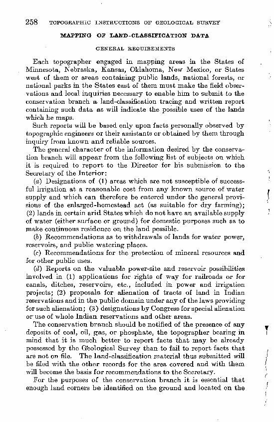
258 TOPOGRAPHIC INSTRUCTIONS OF GEOLOGICAL SURVEYr
MAPPING OF LAND-CLASSIFICATION DATA
GENERAL REQUIREMENTS
Each topographer engaged in mapping areas in the States of Minnesota, Nebraska, Kansas, Oklahoma, New Mexico, or States west of them or areas containing public lands, national forests, or national parks in the States east of them, must make the field obser vations and local inquiries necessary to enable him to submit to the conservation branch a land-classification tracing and written report containing such data as will indicate the possible uses of the lands which he maps.
Such reports will be based only upon facts personaUy observed by topographic engineers or their assistants or obtained by them through inquiry from known and reliable sources.
The general character of the information desired by the conserva tion branch will appear from the folio whig list of subjects on which it is required to report to the Director for his submission to the Secretary of the Interior: '
(a) Designations of (1) areas which are not susceptible of success- ' ful irrigation at a reasonable cost from any known source of water » supply and which can therefore be entered under the general provi- > sions of the enlarged-homestead act (as suitable for dry farming); (2) lands in certain arid States which do not have an available supply /' of water (either surface or ground) for domestic purposes such as to make continuous residence on the land possible.
(&) Recommendations as to withdrawals of lands for water power, reservoirs, and public watering places.
(c) Recommendations for the protection of mineral resources and for other public uses.
(d) Reports on the valuable power-site and reservoir possibilities involved in (1) applications for rights of way for railroads or for canals, ditches, reservoirs, etc., included in power and irrigation projects; (2) proposals for alienation of tracts of land in Indian reservations and in the public domain under any of the laws providing for such alienation; (3) designations by Congress for special alienation or use of whole Indian reservations and other areas.
The conservation branch should be notified of the presence of any _ deposits of coal, oil, gas, or phosphate, the topographer bearing in I mind that it is much better to report facts that may be already possessed by the Geological Survey than to fail to report facts that are not on file. The land-classification material thus submitted will ,' be filed with the other records for the area covered and with them ( will become the basis for recommendations to the Secretary. ^
For the purposes of the conservation branch it is essential that enough land corners be identified on the ground and located on the
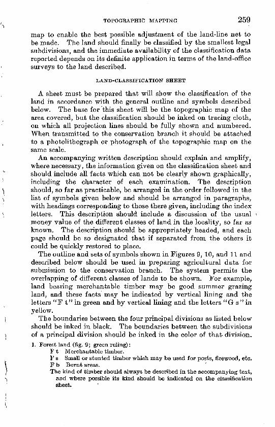
TOPOGRAPHIC MAPPING 259
map to enable the best possible adjustment of the land-line net to be made. The land should finally be classified by the smallest legal subdivisions, and the immediate availability of the classification data reported depends on its definite application in terms of the land-office surveys to the land described.
LAND-CLASSIFICATION SHEET
A sheet must be prepared that will show the classification of the land in accordance with the general outline and symbols described below. The base for this sheet will be the topographic map of the area covered, but the classification should be inked on tracing cloth, on which all projection lines should be fully shown and numbered. When transmitted to the conservation branch it should be attached to a photolithograph or photograph of the topographic map on the same scale.
An accompanying written description should explain and amplify, where necessary, the information given on the classification sheet and should include all facts which can not be clearly shown graphically, including the character of each examination. The description should, so far as practicable, be arranged in the order followed in the list of symbols given below and should be arranged in paragraphs, with headings corresponding to those there given, including the index letters. This description should include a discussion of the usual money value of the different classes of land in the locality, so far as known. The description should be appropriately headed, and each page should be so designated that if separated from the others it could be quickly restored to place.
The outline and sets of symbols shown in Figures 9, 10, and 11 and described below should be used in preparing agricultural data for submission to the conservation branch. The system permits the overlapping of different classes of lands to be shown. For example, land bearing merchantable timber may be good summer grazing land, and these facts may be indicated by vertical lining and the letters "F t" in green and by vertical lining and the letters "G s" in yellow.
The boundaries between the four principal divisions as listed below should be inked in black. The boundaries between the subdivisions of a principal division should be inked in the color of that division.1. Forest land (fig. 9; green ruling):
F t Merchantable timber.F s Small or stunted timber which may be used for posts, firewood, etc. F b Burnt areas. The kind of timber should always be described in the accompanying text,
and where possible its kind should be indicated on the classificationsheet.
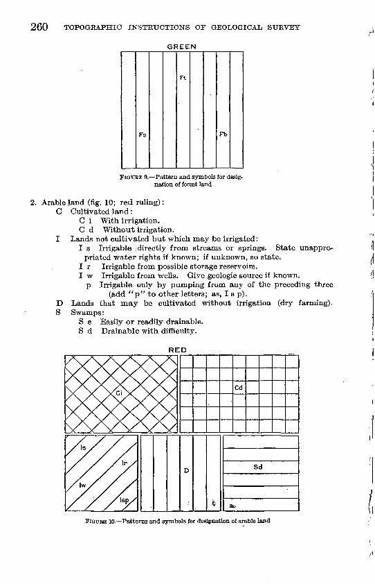
260 TOPOGRAPHIC INSTRUCTIONS OF GEOLOGICAL SURVEY
GREEN
Fs
Ft
Fb
unappro
FIGXTRE 9. Pattern and symbols for desig nation of forest land
2. Arable land (fig. 10; red ruling): C Cultivated land:
C i With irrigation. C d Without irrigation.
I Lands not cultivated but which may be irrigated:I s Irrigable [directly from streams or springs. State
priated water rights if known; if unknown, so state. I r Irrigable from possible storage reservoirs. I w Irrigable from wells. Give geologic source if known,
p Irrigable only by pumping from any of the preceding three(add "p" to other letters; as, I s p).
Lands that may be cultivated without irrigation (dry farming). Swamps:
S e Easily or readily drainable. S d Drainablc with difficulty.
RED
DS
Is
tap,
Cd
Sd
FIQUEE 10. Patterns and symbols for designation of arable land
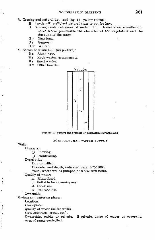
TOPOGEAPHIC MAPPING 261
3. Grazing and natural hay land (fig. 11; yellow ruling):H Lands with sufficient natural grass to cut for hay.G Grazing lands not included under "H." Indicate on classification
sheet where practicable the character of the vegetation and theduration of the range:
G y Year long. G s Summer. G w Winter.
4. Barren or waste land (no pattern): B a Alkali flats. B r Rock wastes, escarpments. B s Sand wastes. B x Other barrens.
YELLOW
Gy
Gs
Gw
FIQDBE 11. Pattern and symbols for designation of grazing land
AGKICULTURAL WATER SUPPLY Wells:
Character:® Flowing.O Nonflowing.
Description:Dug or drilled.Diameter and depth, indicated thus: 3"XI68'.Yield, where well is pumped or where well flows.
Quality of water:m Mineralized.du Suitable for domestic use.st Stock use.rr Railroad use.
Ownership.Springs and watering places:
Location. Description.Quality of water (as for wells). Uses (domestic, stock, etc.).Ownership, public or private. If private, name of owner or occupant. Area of range controlled.
262 TOPOGEAPHIC INSTRUCTIONS OF GEOLOGICAL SURVEY
REVISION OF TOPOGRAPHIC MAPS
REVISION DEFINED
The topographic surveys of the Geological Survey are classified as new surveys, resurveys, or revision. Resurveys are made under the same specifications used for new surveys on the same scale. By revision is meant an examination of all or a certain part of a map, as its cultural features, in order to bring it up to date. A cultural revi sion will involve only so much new survey as may be needed in order to add new cultural features to the map and tie them in to the cul tural features that are unchanged, and it will involve only so much change in the drainage and relief features as may be needed to fit them properly to the new or changed cultural features. Where the cultural revision is extensive, owing to a rapid growth or to a long interval of time since the original survey, correspondingly extensive changes in the drainage and relief features may be needed. In pro portion as the revision of the culture, drainage, and relief of a quad rangle becomes more and more extensive, however, the revision partakes more and more of the nature of a resurvey. A revision is therefore seldom more extensive than a so-called "cultural revision." The choice between a cultural revision and a resurvey can be made only after a knowledge of local conditions has been obtained and combined with an appraisal of the character of the original survey.
CULTURAL REVISION SURVEY
Personnel and instrumental outfit. A revision party need seldom consist of more than one topographer in charge, assisted by one rod- man. The instrumental outfit will be similar to that used by a topographic party of the same size. The methods employed should largely conform to those in current use for new surveys in similar country mapped on the same scale.
Use of control data. The control data that were used in the origi nal survey are shown on the published map, with the exception of a few intermediate points that wore determined for control but not for publication. Horizontal positions that have been determined since the time of the original survey should be plotted on the revision field sheets, and where the plotted positions disagree with the pub lished adjustment of the adjacent topography a readjustment of the topography should be made if the discrepancy is but local, but if the disagreement covers a considerable area the matter should be at once reported to the division chief.
If leveling has been done in the quadrangle since it was originally mapped, the newly determined elevations should be compared with the contouring, and such differences as are found should be noted for a field examination and the correction of the contours.
TOPOGRAPHIC MAPPING 263
Control stations to be published. All transit-traverse stations and level bench marks falling along or near the line of cultural revision should be systematically looked for, and where they have been destroyed or moved the symbols should be crossed out on the field sheet and the change should be reported to the Washington office for the correction of office records; where they are found intact they should be indicated in pencil on the field sheet as clear copy for office inking and subsequent publication. All newly established transit- traverse stations and level bench marks should likewise be shown in their correct relation with the topography. Newly established triangulation stations should also be shown, provided the adjacent topography can be properly tied in to them.
Scope of cultural revision. The features to be included in a cul tural revision are those listed under "Mapping of cultural features" (pp. 229-242).
Examination of cultural features. The field work should consist in traveling over each road or other route of travel within the quad rangle and comparing each cultural feature with its corresponding representation on the map. Where new or changed features are found they should be surveyed and tied into the features that are not changed or to the horizontal control or some form of expansion from the control. It is imperative that the topographer know his true position in the quadrangle at all times, and for this purpose plane-table set-ups, traverses, or plane-table stations must be made wherever they may be needed.
The comparison between ground features and the corresponding map features must be thorough and complete and should include an examination of the direction, length, and angle of bend of each stretch of road, trail, railroad, or other line feature; a check of each house or other building; and a lookout for all other cultural features. A definite plan should be adopted in order that no part of the culture shall be overlooked in the examination. All existing houses and other small cultural features, including control stations and bench marks, should be clearly indicated by firm penciling over the faint color representation of the features or shown in their plotted positions where they are new features. Features that have been destroyed or abandoned shoulid be so indicated on the "take out" sheet (see below) and the symbols also crossed out on the field sheet.
Boundary lines. Each boundary shown on the map should be verified, and an inquiry should be made for new or changed bound aries and for the names of the subdivisions affected. The boundaries of cities or other places that have been incorporated since the first survey should be added.
Names. Each name on the map should be as thoroughly verified as the names for a new survey; names of new places and features
264 TOPOGRAPHIC INSTRUCTIONS OF GEOLOGICAL SURVEY
should be added; names that have fallen into disuse should be dropped but replaced if other names are found in current use. Where a post office has been discontinued owing to the introduction of rural free delivery, the name of the former post office should be retained if it represents a well-established locality. In short, every effort should be made to bring all names up to date. Each name should be recorded as soon as obtained, and this record may be made on the revision sheet, on a tracing, or on a copy of the published map.
"Take out" copy. Where a map feature has been abandoned or destroyed, as a road or a house, the corresponding copy on the copper plates must be smoothed out and "tapped up" to a flat surface. Engraver's copy for such "take outs" should be recorded as the revision field work progresses and may be conveniently indicated on the field sheets by penciled crosses or by wavy penciled lines placed on the features that are to be removed from the plates; but lest there be confusion in the final copy such "take outs" must be transferred to a clean published print of the map and later inked. The sheet so used should be marked at the top "Take out sheet."
Woodland. No revision of woodland outlines will be made unless instructions are issued authorizing such work. Inasmuch as a cul tural revision is confined largely to rapid travel over routes of com munication, such as roads, and inasmuch as woodland representation can not be revised but must be remapped, a resurvey of the wood land areas is seldom attempted during a revision of culture, for the reason that it requires much more traverse and map work than for revision of the culture alone.
Road classification. The roads should be first classified according to the instructions given under "Roads" (p. 229). Where it is found necessary to change from a full to a broken line or the reverse, such changes should be indicated on the "take out" sheet by inking the road in full or broken lines where such changes are needed.
The roads should be further classified as defined under "Road classification" (p. 256), and this classification should be placed upon a separate engraved copy of the map and not combined with any other data and should be marked "Road classification."
CULTURAL REVISION BY AERIAL PHOTOGRAPHY
Scope of revision. The cultural features of a topographic map may be revised by the use of aerial photographs, a procedure that promises increasing usefulness as the photographs and the methods of using them are further improved. The drainage features of the map may also be thus revised where revision is found to be necessary or desirable. A field examination may or may not be needed, as explained below.
TOPOGEAPHIC MAPPING 265
Good base necessary. The use of aerial photographs in topographic map revision should be confined to maps for which the original surveys were well controlled and the topographic details properly adjusted. If the map that needs to be revised has been insufficiently controlled or incorrectly adjusted the data that are obtained by aerial photographs can not be successfully used until the base map has been readjusted, and such a readjustment can not be made until further control has been supplied, involving field work. Inasmuch as such a procedure is not generally warranted, the revision of such a map can best be effected by means of a complete resurvey.
Type of photographs. Maps of cities and towns and of other areas that are closely built should be revised through the use of photo graphs taken with single-lens rather than multiple-lens cameras, because the single-lens vertical photographs show clearly the width of streets and the plan of buildings on each side of them, whereas the wing-print parts of the multiple-lens photographs represent exposures taken at an angle and show objects in such increased per spective that high buildings and even ordinary dwellings obscure streets and render the ground plan of buildings indefinite. Multiple- lens photographs are suitable, however, for the revision of maps of sparsely settled areas.
Office use ojphotographs. The revision corrections that are obtained by an office compilation of the data found on aerial photographs should be drafted on an enlarged (field scale) photolithograph of the map printed in light blue on drawing paper. It may be advisable to use transfers from the engraved plates (on the same scale or enlarged) and print from stone in three distinctive and weakly photographic colors. The additions and corrections to the map can then be inked in the standard strong colors, such as will yield photo graphs showing only the revised data.
In the process of compilation each aerial photograph is used as a separate source of data, either by photographing the aerial print to the scale of the map and tracing the map features desired, or by using the original aerial photograph directly and taking off the features desired by means of proportional dividers. If the map that is to be revised is well controlled and adjusted, a careful comparison of the aerial photographs and map will determine the existence of new features and the need for possible correction of the old.
Field examination. When the office revision of the culture and drainage has been completed there may be need for a field examina tion in order to revise the contouring slightly to fit the new culture or drainage. The need for a field examination will depend upon the accuracy of the base, the nature of the topography revised, and the extent of the revision. Features obscured in the photographs by heavy timber may also need a field examination.
TOPOGRAPHIC INSTRUCTIONS OF GEOLOGICAL SURVEY
The better the control and adjustment on which the map was based the less will be the need for a field examination. If a cultural feature is added to the map on or near a line of previous control the necessary changes in the contouring will be small and may generally be made from a close examination of the photograph, but if a cultural feature is added to the map in a place that falls between control lines that were not near together the need for a field examina tion will be increased.
A careful comparison of the photographs with the contouring adjacent to the revision copy will show that in certain types of country the necessary changes in the contours can be made from the photographs alone, but where there are numerous and rapidly changing land forms the need for a readjustment of the contours will be greatest, and in general a field examination is more likely to be necessary. In country of certain types the relief expression would be but little changed, if at all, by a field examination, and here the chief advantage gained would be in the determination of the actual elevations along the newly added features, a determina tion that has not yet been attempted by the Geological Survey from aerial photographs alone.
If the revision results in extensive corrections throughout the quadrangle or in complete changes within smaller areas the need for a field examination will be increased. Inasmuch as a large part of the expense of a field examination may be incurred in connection with preparation and in travel to and from the field, it is obvious that where it is found necessary to make a field examination the fullest advantage should be taken of the opportunity to visit all localities where contour changes may be needed. Such a field visit would also permit the examination at the locality of any doubtful adjustment or place where the interpretation of the aerial photo graphs was uncertain.
RIVER SURVEYS
SPECIAL EIVER SURVEYS
Special river surveys involving the delineation of alinement, water-surface contours, and adjacent topography and the construc tion of a corresponding profile ar° executed for all important streams that may be designated by the conservation branch of the Geological Survey.
Special supplemental instructions are prepared by the conservation branch for each locality of special river survey. If a representative of that branch accompanies the topographic field party, the topo graphic engineer will be relieved from the necessity of collecting the information outlined on pages 270-271 under "Written reports."
TOPOGRAPHIC MAPPING 267
Special river surveys should be executed on the scale of 1: 31,680 (2 inches to 1 mile), except as provided for in connection with regular topographic mapping.
RIVER SURVEYS IN REGULAR TOPOGRAPHIC MAPPING
In connection with or as a part of all regular topographic mapping on field scales of 1: 96,000 or 1: 48,000, river surveys of ah1 important streams should be made on a uniform field and office scale of 1:48,000. For this purpose important streams may, in general, be defined as those that have a low-water flow of at least 10 cubic feet per second and also a product of at least 2,500 for faU in feet per mile multi plied by the low-water flow in cubic feet per second. On a scale of 1:48,000 the requirements as to detail that it is possible or desirable to show are considerably less than on larger scales.
Where regular field work is executed on a scale of 1:31,680 or 1:24,000 the river surveys and profiles should be made on the same scale.
Where the regular field work is on a scale of 1:48,000 the principal additional work involved in making river surveys will be the location of 5-foot water-surface contour crossings and the determination of the elevation of the head and foot of falls, dams, and rapids and the elevation of the junction with tributary streams. Where the regular field work is on a scale of 1:31,680 or 1:24,000, no additional contouring will be necessary if the contour interval for the quadrangle is 5 feet.
In connection with field work executed on the 1:192,000 scale, only written reports as to important streams will be required. Reports should be based on such general observations and local inquiries as can be made without materially delaying the regular field work.
TOPOGRAPHY
The following instructions apply to both special river surveys and to river surveys made in connection with regular topographic mapping.
The field traverse sheets when carefully inked should serve as final copy for assembly on the plan sheets and for data from which corresponding profiles may be made on separate sheets.
Contour intervals on water surface. The contour interval on water surfaces should be 5 feet, and care must be taken to furnish clear penciled copy for office inking. In addition, the elevations at the head and foot of all falls, rapids, and dams and at the mouths of principal tributaries must be determined. Where the stream slope is so steep that a 5-foot water-surface contour interval can not be readily shown, the interval should be increased to 20 feet; beyond
58515° 28 18
268 TOPOGEAPHIG INSTRUCTIONS OF GEOLOGICAL SURVEY
this the interval may be increased to 100 feet, but only where demanded by legibility.
Contour interval on land. The contour interval on land along river stretches should be 20 feet, but wherever a 20-foot office inter polation can be accurately made between the 100-foot contours the 20-foot contours should be omitted and only 100-foot (heavy) contours drawn.
Tributaries. The topography of each tributary or side channel should be shown up to the limiting contour. In addition, the larger tributaries should be shown with topography for about a' quarter of a mile and then be sketched as far beyond as possible; for this purpose one or more additional set-ups may be taken if practicable.
Topography to be shown. The land features, including all culture usually found along streams but excluding large valleys or cities, must be accurately and completely surveyed by additional set-ups, intersections, or side traverses. The work should be done in such a manner that the data can later be incorporated in topographic maps when such areas are regularly mapped.
In the absence of special definite instructions the topography as outlined above should be mapped to an elevation of 200 feet above the stream and may be sketched for another 100 feet or more if such higher sketching can be done without additional set-ups. Mapped topography should be indicated by full lines, but where uncontrolled topography is sketched it should be drawn in dashed lines, to be clearly distinguishable.
To facilitate use of the field sheets by office engineers penciled figures of elevation must be placed wherever they will be legible, and numerous penciled contour numbers should be placed on inter mediate as well as on emphasized contours.
Gaging stations, dams, etc. All gaging stations must be located, and the elevation of the zero of the gage given. The ownership, whether United States Geological Survey, Weather Bureau, Army Engineers, or private, must be stated.
The location of all dams, power houses, canals, flumes, penstocks, and points of diversion should be shown, with elevations above and below all dams and power houses.
Rapids should be indicated by means of the conventional sign, which, however, should not obscure contour crossings or other impor tant data.
Long azimuth lines should be drawn on each separate traverse sheet.
Land lines. In sectionized country it is important that the land net be placed upon the sheets with an accuracy suitable for 40-acre references. Inasmuch as the width of a river survey is narrow at best, the search for all existing corners that may be found within the
TOPOGRAPHIC MAPPING 269
belt of the survey should be systematic and diligent. (See field instructions, p. 239.)
Party chiefs must procure reproductions of Land Office plats, which preferably should be photographs furnished on office requisition. They should also ascertain if any such plats are under suspension by the General Land Office and procure copies of the notes of all such retracements or exterior notes of townships not sectionized as fall within the limits of the river survey. General inquiry should also be made whenever practicable at the local United States land offices. Existing maps or plats showing corners previously found, such as those issued by the Forest Service or by railroad, power, irrigation, and other companies, should be systematically looked for and pro cured whenever possible. Inquiry should be made through deputy mineral surveyors, county surveyors, and local engineers as to the existence and location of known corners or ties.
Vertical control. In order that river surveys may be referred to sea-level datum the starting point of the line should wherever pos sible be tied to the nearest Geological Survey or other adjusted level bench mark before the survey begins; the elevations should also be tied to all other bench marks encountered in the course of the work. Owing to the difficulty of rerunning a line of river traverse extreme care should be taken both in the observations and in the notes, in order that errors in elevation may be avoided.
Horizontal control. As liver surveys are based upon a plane-table traverse line that is subject to no horizontal control, every effort should be made to reduce the errors of observation and plotting to a minimum, and to this end each stadia reading for distance should be twice read and each plotted distance checked.
KESERVOIR AND DAM SITES
The relations between possible reservoir sites and possible dam sites should be frequently observed as the work progresses in order that the survey of these two counterparts may illustrate to the fullest the natural storage possibilities. In considering the practicability of a reservoir site the character of the improvements and industries and the amount, kind, and distribution of the timber within the site should be noted and the value of the land to be submerged should be estimated.
The contours within reservoir sites should be accurately determined on a 20-foot interval up to the height of the possible dam. Ten-foot intermediate contours should be surveyed, drawn in close-dashed lines, and numbered wherever an office interpolation if erroneous would seriously affect an estimate of storage that is, wherever an irregular spacing of 10-foot contours extends over a considerable area.
270 TOPOGRAPHIC INSTRUCTIONS OF GEOLOGICAL SURVEY
Special large-scale surveys should be made of dam sites favorably located in regard to reservoir sites whose existence has been previ ously ascertained by survey, with 5 or 10 foot contours up to the height of the practicable dam or storage. The scale for dam-site surveys will be indicated by the conservation branch but in general will be from 100 to 500 feet to 1 inch. The depth of water at the dam site and the character of bottom and abutments should be noted wherever possible. The elevation of the water surface should be shown for each dam-site survey.
WRITTEN REPORTS
Signed written reports on river surveys, accompanied by photo graphs when practicable, should be submitted in general conformity with the following instructions, except that map references should be made either to the plan sheets or to an advance sheet of the quad rangle map. Many desirable facts pertaining to small streams can receive all necessary attention in the written report.
Stream flow. An approximate estimate of stream flow should be obtained a short distance below the mouth of each major tributary. The date of observation and the stage of the water should be noted. Measurements should be made, if possible, at a straight and uniform stretch of water about 200 feet long, free from rapids and cross cur rents. The velocity of the current in linear feet per second should be obtained by timing floats (chips) over a measured (stadia) course and using an average of two or more floatings made in or near mid stream and nearer shore. The mean cross section in square feet may be assumed to be the mean of the cross sections at the two ends of the stretch. The individual cross sections are obtained separately by multiplying the local width (stadia or intersect) by the corres ponding average estimated depth. The desired stream flow (dis charge) in second-feet is obtained by multiplying the velocity in linear feet per second by the mean cross section. Example: Course 200 feet; floats average 100 seconds in transit; upper and lower cross sections are 300 and 400 square feet, respectively; 2 X 350 = 700 second-feet of stream flow.
Estimated flow of all important tributaries should be obtained in the same manner.
As the minimum, low-water flow denotes the maximum availability of the stream without recourse to storage, and as the high-water flow in large measure gives its availability for storage, all reliable infor mation bearing on these points that it is practicable to obtain should be sought, and all information regarding the range of water stages, including data as to past floods or extreme low water, with dates, should be recorded.
TOPOGRAPHIC MAPPING 271
Water power. All dams or other existing natural sites for water- power development should be located and described. If any present development exists, the ownership, character, abutments, possibility of increasing height, and condition of stream bed should be recorded.
The plan and profile sheets of all dam and reservoir sites determined by the river survey should be supplemented by all obtainable perti nent facts. Any favorable stretches of stream that might be of value for developing power should be noted. The essentials are a diversion- dam site (intake), a site for a waterway alongside (canal or conduit), and a combined site for a relatively short pressure pipe line and for a power plant on the shore. Favorable sites for diversion of water for irrigation should be noted.
Information should be collected by observation and by local inquiry as to (1) power development, including location of existing or pro posed power plants, points of diversion, location and capacity of conduit, amount of head available, location of power house, point of return of water to stream, installation and rating of turbines and generators, location, equipment, and ownership of power-transmission lines; (2) reservoirs, including location, height of dam, capacity, use, and ownership; (3) irrigation works, including canals and ditches, points of diversion, capacity, location, and ownership; (4) municipal water-supply systems, including location of pipes, source of water, etc.
Character of adjacent land. The belt of topography mapped should be classified as to kind, amount, and distribution of timber; extent of cultivated areas; existence of grazing or natural hay lands and duration of range; and extent of barren or A\raste lands.
ENDING FIELD SEASON
Work turned over to another. If unfinished field work is left for a successor to complete he should be provided with a list of the field sheets and other important field data that are turned over, also a memorandum of the condition in which the work is left, with copies of the original field instructions, including supplemental instructions that may have been issued. He should have a clear understanding as to where there may be need for additional inquiry regarding names or other data for example, the status of power lines, road classification, and city boundaries.
Completing field work. In order to insure against omission of field data the information sheet, name sheet, road-classification sheet, and woodland sheet should be checked over for completeness before making plans to leave the field. The plane-table sheets should be looked over for completeness and legibility.
Shipment of map material. In general, all field sheets completed before the end of the field season should be shipped to the office
272 TOPOGRAPHIC INSTRUCTIONS OF GEOLOGICAL SURVEY
rather than retained in the field; tracings, however, should be made of map borders needed for further field joining. All map material should be shipped by express or registered mail to the chief topo graphic engineer at Washington or, if so instructed, to the division chief in charge of a field office. All original and duplicate record books such as level and bench-mark books should be forwarded by registered mail on different days. A letter of transmittal covering each shipment of instruments, maps, or records, and a list of all items should be sent under separate cover. If any maps or map material is carried to Washington in personal baggage, it should be delivered immediately on its arrival at the office to the section of inspection and editing for recording.
Monthly field reports. See "Reports of field parties" (p. 19, part A). Reports should be complete so far as the data asked for are concerned or so far as they apply to the work in progress, and, in general, they should be confined to the data for which columns and spaces are provided. Promptness in the submission of reports is necessary because of the routine described under "Monthly office report routine" (p. 277).
OFFICE WORK
SCOPE OF OFFICE WORK ON TOPOGRAPHIC MAPS
The office work in connection with topographic mapping consists in preparing the field sheets as copy for reproduction and in the repro duction of the maps. The preparation of the copy and the proof reading of reproduction is done in the topographic branch, but the reproduction of the maps is done in the engraving division of the Geological Survey. The office work of triangulation, transit traverse, leveling, and map compilation from aerial photographs is described in parts B, C, D, and F of the "Topographic instructions." In general, the sequence of the office work in topographic mapping is as outlined below.
Assembly. The field sheets representing the completed topo graphic mapping should be assembled into as few final sheets as practicable, preferably into two half sheets representing the north and south halves of the quadrangle. The two half or other sheets should be cut at their common sheet borders and by transfer of topography where necessary made complete copy when fitted together. Where final topographic mapping has been done on separate field sheets other than on the principal north or south half sheets, such separate field sheets should be stripped and pasted in position on the principal half sheets on which they fall. (See "Transferring," p. 282, and "Pasting," p. 283.) The field sheets should be assembled and completed in pencil before the inking begins, if this is practicable,
TOPOGRAPHIC MAPPING 273
inasmuch as the inking of the map can then go forward without the delays incident to joining the interior edges that may be on several separate field sheets.
Adjustment. The results of separate traverse surveys that may not have been adjusted in the field should be completely adjusted into position on the final field sheets before these sheets are assembled or inked. (See "Adjustment of traverse lines," p. 212.)
Inking. When the penciling and adjustment and preferably also the assembling of the final field sheets is complete they should be inked. (See "Inking of topographic field sheets," p. 277.)
Lettering. When the inking of the map has been completed it should be lettered. (See "Lettering of topographic field sheets," p. 304.)
Checking? When the topographic map has been completely inked and lettered and before it is reproduced in any form the inking and lettering should be checked by someone other than the one or more engaged in the inking. (See " Checking of inked field sheets," p. 310.)
Inspection. Prior to the submission of final map drawings for advance-sheet photolithography they should be passed upon by the section of inspection and editing to insure general conformity with standard practices. (See "Inspection of topographic maps," p. 313.)
Advance sheets. Completed topographic map drawings are first reproduced by photolithography and issued as "advance sheets sub ject to correction." (See "Advance sheets," p. 317.) Advance sheets are intended to serve the immediate needs of engineers and others pending the publication of the engraved map, and they also serve as a basis for corrections, which are invited from any competent source.
Control examination. Each topographic map should be examined in the section of inspection and editing for the correctness of its representation of the primary control features of the map. (See "Control examination," p. 319.) The control examination should be made before the map is edited for engraving or before it is photo- lithographed if the map is to be reproduced by photolithography alone. The control examination is usually made after the advance sheets have been issued but may be made before.
Editing. Each topographic map that is to be regularly published by the Geological Survey, whether by engraving or by photolitho graphy, must be edited prior to its submission for final reproduction. (See "Editing of topographic maps," p. 320.) The map editing con sists in a critical review of the map for its general coordination and conformity with Geological Survey instructions and policies and in
3 The term "proof reading" has long been used in the topographic branch both in its ordinary sense, meaning the reading of proof, and in reference to the checking of manuscript maps preliminary to the inspection and advance-sheet photolithography by others than those who have done the work. For this special sense the term "checking" will be used hereafter.
274 TOPOGRAPHIC INSTRUCTIONS OF GEOLOGICAL SURVEY
the preparation of special instructions for its engraving or other reproduction.
Engraving. Most topographic maps of the Geological Survey are reproduced by engraving on copper, from which transfers are made to the printing stone or metal. (See "Engraving of topographic maps," p. 336.) The engraving is done in the engraving division of the Geological Survey.
Proof reading of engraved maps. Proofs from the separate copper plates and combined stone proofs from the final printing plates for each topographic map that is reproduced by engraving are read by the section of inspection and editing.
Reprints of topographic maps. When the map-room stocks of topo graphic maps become nearly exhausted reprints are requested by the division of distribution. The section of inspection and editing pre pares the reprint copy. (See "Reprints of topographic maps," p. 340.)
Monthly office reports. See "Office reports" (p. 19, part A). Ink ing should be reported in terms of square miles inked and not in percentage of area. The column headed "Sq. mi. mapped" should agree with the total area reported as mapped. Inasmuch as a report on the number of square miles inked each month is intended to indicate approximate progress only, the figures need be given only to about the nearest 5 per cent, which for a 15' quadrangle would be to the nearest 10 square miles. As the inking approaches com pletion the accuracy of reporting should increase, and for this purpose the uninked area can be readily measured.
Where culture and drainage only have been inked such inking should be converted into an approximate equivalent expressed in square miles, in order that the inking report may give an index of progress. For example, if the total culture on the mapped area is roughly estimated to represent 30 per cent, the drainage 10 per cent, and the contours 60 per cent of the time needed to ink the sheet, and if half the culture has been inked but no drainage or contours, then one-half of 30 per cent, or 15 per cent, of the total area mapped should be reported as having been inked, and this for a quadrangle covering 240 square miles would represent an equivalent of 36 square miles inked, which may be reported in round numbers as 40 square miles. A statement showing total areas inked to date, listed by States, quadrangles, and months, may be obtained on request from the section of inspection and editing, where the data are filed in a book kept for the purpose.
MISCELLANEOUS OFFICE WORK
Field sheets to section of inspection and editing. All field sheets and field map material reaching the office from the field must be at once delivered to the section of inspection and editing, where they will be
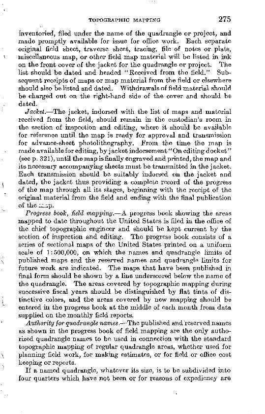
TOPOGRAPHIC MAPPING 275
inventoried, filed under the name of the quadrangle or project, and made promptly available for issue for office work. Each separate original field sheet, traverse sheet, tracing, file of notes or plats, miscellaneous map, or other field map material will be listed in ink on the front cover of the jacket for the quadrangle or project. The list should be dated and headed "Received from the field." Sub sequent receipts of maps or map material from the field or elsewhere should also be listed and dated. Withdrawals of field material should be charged out on the right-hand side of the cover and should be dated.
Jacket. The jacket, indorsed with the list of maps and material received from the field, should remain in the custodian's room in the section of inspection and editing, where it should be available for reference until the map is ready for approval and transmission for advance-sheet photolithography. From the time the map is made available for editing, by j acket indorsement'' On editing docket'' (see p. 321), until the map is finally engraved and printed, the map and its necessary accompanying sheets must be transmitted in the jacket. Each transmission should be suitably indorsed on the jacket and dated, the jacket thus providing a complete record of the progress of the map through all its stages, beginning with the receipt of the original material from the field and ending with the final publication of the :z:ip.
Progress book, Held mapping. A progress book showing the areas mapped to date throughout the United States is filed in the office of the chief topographic engineer and should be kept current by the section of inspection and editing. The progress book consists of a series of sectional maps of the United States printed on a uniform scale of 1:500,000, on which the names and quadrangle limits of published maps and the reserved names and quadrangle limits for future work are indicated. The maps that have been published in final form should be shown by a line underscored below the name of the quadrangle. The areas covered by topographic mapping during successive fiscal years should be distinguished by flat tints of dis tinctive colors, and the areas covered by new mapping should be entered in the progress book at the middle of each month from data supplied on the monthly field reports.
Authority for quadrangle names. The published and reserved names as shown in the progress book of field mapping are the only autho rized quadrangle names to be used in connection with the standard topographic mapping of regular quadrangle areas, whether used for planning field work, for making estimates, or for field or office cost keeping or reports.
If a named quadrangle, whatever its size, is to be subdivided into four quarters which have not been or for reasons of expediency are
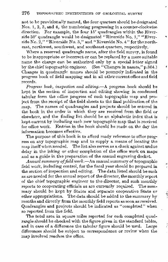
276 TOPOGRAPHIC INSTRUCTIONS OF GEOLOGICAL SURVEY
not to be provisionally named, the four quarters should be designated Nos. 1, 2, 3, and 4, the numbering progressing in a counter-clockwise direction. For example, the four 15' quadrangles within the River side 30' quadrangle would be designated "Riverside No. 1," "River side No. 2," "Riverside No. 3," and "Riverside No. 4" for the north east, northwest, southwest, and southeast quarters, respectively.
Where a reserved quadrangle name, after the field survey, is found to be inappropriate or incorrect or can be replaced by a more suitable name the change can be authorized only by a special letter signed by the chief topographic engineer. (See "Changes in names," p.304.) Changes in quadrangle names should be promptly indicated in the progress book of field mapping and in all other current office and field records.
Progress book, inspection and editing. A progress -book should be kept in the section of inspection and editing showing in condensed tabular form the office progress of each topographic map and pro ject from the receipt of the field sheets to the final publication of the map. The names of quadrangles and projects should be entered in the book in the order in which they are received from the field or elsewhere, and the finding list should be an alphabetic index that is kept current by including each new topographic map that is received for office work. Entries in the book should be made on the day the information becomes effective.
The purpose of this book is to afford ready reference to office prog ress on any topographic map and to supply a means of locating the map itself when needed. The list also serves as a check against undue delay in the inking or other completion of the office work on maps and as a guide in the preparation of the annual engraving docket.
Annual summary ojfield work. An annual summary of topographic field work, including control, for the fiscal year should be prepared in the section of inspection and editing. The data listed should be such as are needed for the annual report of the director, the monthly report of the chief topographic engineer to the director, and such monthly reports to cooperating officials as are currently required. The sum mary should be kept by States and separate cooperative State or other appropriations. The data should be added to the summary by months and directly from the monthly field reports as soon as received. Quadrangles and projects should be indicated as "completed" when so reported from the field.
The total area in square miles reported for each completed quad rangle should be checked with the figure given in the standard tables, and in case of a difference the tabular figure should be used. Large differences should be subject to correspondence or review when the map involved reaches the office.
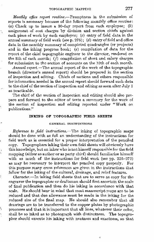
TOPOGRAPHIC MAPPING 277
Monthly office report routine. Promptness in the submission of reports is necessary because of the following monthly office routine: (a.) Check up to insure a 30-day report from each employee; (&) assignment of cost charges by division and section chiefs against each piece of work by each employee; (c) entry of field data in the annual summary of field work (see p. 276); (d) entry of field and office data in the monthly summary of completed quadrangles (or projects) and in the inking progress book; (e) compilation of data for the report of the chief topographic engineer to the director, rendered on the 8th of each month; (/) compilation of sheet and salary charges for submission to the section of accounts on the 10th of each month.
Annual report. The annual report of the work of the topographic branch (director's annual report) should be prepared in the section of inspection and editing. Chiefs of sections and others responsible for information needed in the annual report should forward such data to the chief of the section of inspection and editing as soon after July 1 as practicable.
The chief of the section of inspection and editing should also pre pare and forward to the editor of texts a summary for the work of the section of inspection and editing reported under "Work on publications."
INKING OF TOPOGRAPHIC FIELD SHEETS
GENERAL INSTRUCTIONS
Reference to Jield instructions. The inking of topographic maps should be done with as full an understanding of the instructions for field work as is essential for a proper interpretation of the penciled copy. Topographers inking their own field sheets will obviously have this knowledge, but an inker who is not himself responsible for the field mapping (either as author or as party chief) should familiarize himself with as much of the instructions for field work (see pp. 226-272) as may be necessary to interpret the penciled copy properly. For this purpose many cross references are given in the instructions that follow for the inking of the cultural, drainage, and relief features.
Character. In inking field sheets that are to serve as copy for the engraver the topographer or draftsman should first ascertain the scale of final publication and then do his inking in accordance with that scale. He should bear in mind that most manuscript maps are to be reduced and that due allowance must be made in the inking for the reduced size of the final map. He should also remember that all drawings are to be transferred to the copper plates by photographic processes and that it is important that all lines, whatever their color, shall be so inked as to photograph with distinctness. The topogra pher should execute his inking with neatness and exactness, so that
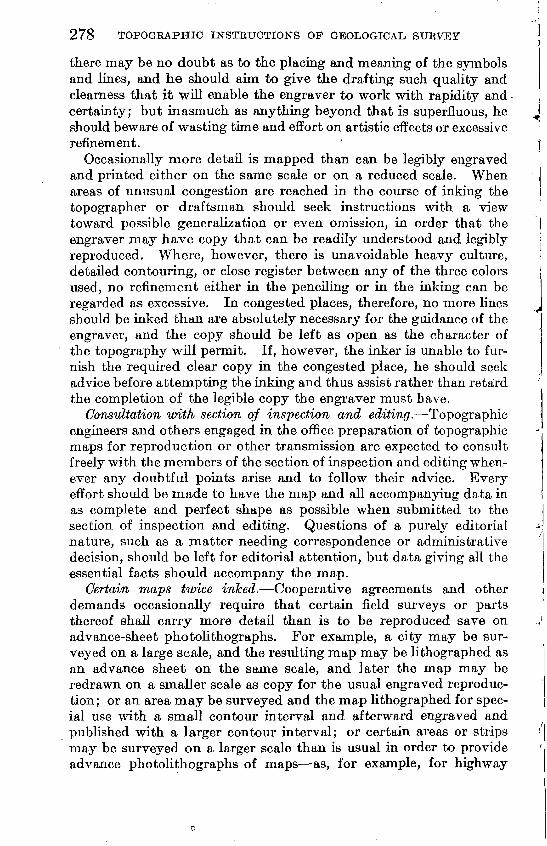
278 TOPOGRAPHIC INSTRUCTIONS OF GEOLOGICAL SURVEY
there may be no doubt as to the placing and meaning of the symbols and lines, and he should aim to give the drafting such quality and clearness that it will enable the engraver to work with rapidity and certainty; but inasmuch as anything beyond that is superfluous, he should beware of wasting time and effort on artistic effects or excessive refinement.
Occasionally more detail is mapped than can be legibly engraved and printed either on the same scale or on a reduced scale. When areas of unusual congestion are reached in the course of inking the topographer or draftsman should seek instructions with a view toward possible generalization or even omission, in order that the engraver may have copy that can be readily understood and legibly reproduced. Where, however, there is unavoidable heavy culture, detailed contouring, or close register between any of the three colors used, no refinement either in the penciling or in the inking can be regarded as excessive. In congested places, therefore, no more lines should be inked than are absolutely necessary for the guidance of the engraver, and the copy should be left as open as the character of the topography will permit. If, however, the inker is unable to fur nish the required clear copy in the congested place, he should seek advice before attempting the inking and thus assist rather than retard the completion of the legible copy the engraver must have.
Consultation with section of inspection and editing. Topographic engineers and others engaged in the office preparation of topographic maps for reproduction or other transmission are expected to consult freely with the members of the section of inspection and editing when ever any doubtful points arise and to follow their advice. Every effort should be made to have the map and all accompanying data in as complete and perfect shape as possible when submitted to the section of inspection and editing. Questions of a purely editorial nature, such as a matter needing correspondence or administrative decision, should be left for editorial attention, but data giving all the essential facts should accompany the map.
Certain maps twice inked. Cooperative agreements and other demands occasionally require that certain field surveys or parts thereof shall carry more detail than is to be reproduced save on advance-sheet photolithographs. For example, a city may be sur veyed on a large scale, and the resulting map may be lithographed as an advance sheet on the same scale, and later the map may be redrawn on a smaller scale as copy for the usual engraved reproduc tion; or an area may be surveyed and the map lithographed for spec ial use with a small contour interval and afterward engraved and published with a larger contour interval; or certain areas or strips may be surveyed on a larger scale than is usual in order to provide advance photolithographs of maps as, for example, for highway
TOPOGBAPHIC MAPPING 279
projects with provision for redrawing the maps on a reduced scale as copy for engraved reproduction. In these cases the field work should be executed in a detail commensurate with that called for by the special-purpose larger-scale survey, and the less detailed copy for final publication should be prepared by redrafting the same map after it has been reduced to the usual scale that is used as copy for engraving. For this redrawing it is customary to reduce the map by photolithography, print it in light blue on drawing paper, and redraw only such detail as is called for by the reduced scale of publication.
It is sometimes desirable to use a previously published map on a large scale as part copy for a new map on a smaller scale. In such cases the larger-scale published map should be reduced by photo lithography to the scale of the new map, printed in light blue on drawing paper, and redrawn with its detail appropriately expressed for the smaller-scale reproduction. An example of the need for redrafting a published map is afforded by the survey of a 30' quad rangle, one quarter of which was mapped on a scale of 1 :4S,000, for publication on a scale of 1 :62,500, and it is found desirable to redraw the map on the reduced scale of 1 :96,000 (the field scale for the survey of the 30' quadrangle) in order that the greater amount of detailed expression used in the larger-scale survey may be generalized in redrafting and made to conform to the treatment used in the survey of the other parts of the 30' quadrangle.
Inks. The inks that are used must be the best obtainable to meet the office requirements. The important specifications are that the ink will permit a clear photolithographic reproduction, flow freely from the pen, and not spread or afterward smear as a result of any ordinary handling of the map. The following colors are issued: Black, a prepared waterproof liquid ink, in small bottles, to be used directly from the bottle; Prussian blue, burnt sienna, red, and Hooker's green paints, in small tubes, to be mixed in small bottles (furnished by the Geological Survey) in about the proportion of three parts of water to one part of the tube color, to which are added a few small glass beads to facilitate mixing when shaken.
Colors. The field sheets should be inked in the three standard colors used in printing the map black for the cultural features, blue for the drainage features, and brown for the relief features.
The use of red is reserved chiefly for the inking of certain data that are not to be engraved yet should be inked in order that they may become permanent office records and may appear upon the advance sheets. An exception is made for land lines, which will be inked in red (engraved in black) in order that the engraver may more readily distinguish them from road lines, projection lines, or other lines that may be on or near the section lines.
280
The use of green is reserved for exceptional needs, such as for showing a second projection which is based on another horizontal datum and for showing corrections where erasures on the original are not desirable.
Sequence of inking. Unless special reasons demand otherwise, the features on the map should be inked in the folJowing order: (1) Culture, (2) drainage, (3) elevations, (4) contouring, (5) lettering.
Precautions before inking maps. Where woodland outlines are carried in pencil on the final field sheets the field woodland tracings should be verified for completeness before the inking of the topog-
* raphy obliterates the woodland copy. Where an elevation tracing has been made or is required (see "Elevation tracing," p. 241) the tracing should be compared with the final field sheets to insure that all necessary elevations have been traced before the inking and handling of the map render the faint pencil figures illegible. The final field sheets should also be carefully examined for names or road-classification data that may have been faintly lettered on them and inadvertently overlooked in making up the field name or road- classification sheets.
Inking projection lines. In inking projections on topographic maps the penciled projection should be inked even though the paper has changed. The projection should not be corrected to agree with the tabular figures, nor should the quadrangle corners be connected by meridional straight lines in order to force a joining between the two half-sheet projections. If the projections do not join at the half- sheet line, the discrepancy, if appreciable, should be taken care of in the photolithography, if for an advance sheet, and by adjustment in small blocks, if for transfer to copper.
Over-edge inking. All over-edge topography should be inked that represents (a) an unmapped area (see "Adjoining unmapped areas, p. 227); (&) an area previously mapped on a smaller scale; (c) a correction to previous work that was mapped on the same scale (see "Joining previous work," p. 227); (d) an important correction to previous work on a larger scale. Over-edge topography on special large-scale military maps should not be inked unless inking is requested. The over-edge topography described under (a) and (6) should appear on the advance sheets, but that described under (c) and (d) will be wiped off the negatives and will not appear on the advance sheets.
Symbols. The symbols used on the topographic maps of the United States Geological Survey conform to the "Standard symbols" as adopted by the Federal Board of Surveys and Maps and pre scribed for use by all map-making bureaus of the Government. (See pis. 18-23.) As many of the symbols in the standard set are not used at present by the Geological Survey, none should be used on manuscript sheets unless they have been approved for Geological
TOPOGKAPHIC MAPPING 281
Survey use. All topographic engineers are expected to be familiar with the symbols that are in current use by the Geological Survey.
SUGGESTIONS FOR INKING
The preparation of field sheets for reproduction differs somewhat from general drafting. Because of the relatively small scale upon which quadrangle maps are drawn their inking is essentially free hand drafting, and for this reason lettering pens of several degrees of fineness are employed almost exclusively.
Black irilc.. A waterproof black ink only is approved for regular use. Skilled draftsmen may draw better lines with a nonwaterproof black ink, especially on a poor surface, but the considerable handling to which the drawing is subjected before it is engraved or otherwise reproduced is so likely to smear the congested places in the inking that the use of a nonwaterproof black ink is not often approved for such use.
Pens. The use of a ruling (right line) pen for the drafting of straight lines is optional. Many draftsmen prefer to draw straight lines with a lettering pen. A ruling pen should be held nearly vertical and not on a slant, and just enough pressure should be exerted to keep the pen in contact with the paper. If the ink at the lower end of the pen dries slightly so that it will not flow, pinching the pen will often start the ink. A ruling pen should be kept sharp and clean, and its points should be ground to the same length. If ink will not flow freely from a lettering pen holding it in the blaze of a match for a second will burn off any oil that may have adhered to it from handling. All pens should be thoroughly cleaned before putting away.
Mixing water colors. Two methods of preparing water-color paints for use as inks may be used dissolving the paint with a wet brush and transferring it to the pen, or mixing a quantity of the paint in a bottle. The latter method is in more general use, and the mixture is prepared as described below: Squeeze the paint from the tube into a small wide-mouthed bottle in which four or five glass beads have been placed. Add 3 parts of warm water to 1 part of the paint and let it mix, shaking the bottle and the beads to facilitate the mixing. If the mixture is too thick it will not flow freely from the pen and if it is too thin, the drafted lines will lack depth of color. To obtain the best mixture, test it as follows: Dip a lettering pen deep in tr^e mixture and withdraw it. If the paint swells out in globular form it is too thick, and a few drops of water should be added; this should be repeated until the test shows the ink fairly flat on the pen. The bottle should be frequently shaken during the course of inking, in order to keep the paint in an evenly mixed suspension. A few drops of carbolic acid will prevent the mixture from souring in warm, weather.
282 TOPOGEAPHIC INSTEUCTIONS OF GEOLOGICAL SURVEY
Inking roads. Roads may be inked with a ruling pen but are best inked with a fine lettering pen, used against a small beveled triangle. A uniform width of road is dependent upon the skill of the inker, as the two sides of the road are inked separately. Curves may be shown as a succession of short tangents or inked freehand.
Inking railroads. Where sidings, spurs, and yard tracks are to be inked these tracks and the parallel main track or tracks opposite them should be inked first in fine lines, and then the main tracks on each end inked in slightly heavier lines. On the engraved plates the main track as well as the siding is cut in a fine line.
Inking drainage and contours. The drainage or contours should be inked toward the draftsman, the position of the map being shifted from time to time to make this possible, and all lines within con venient reach should be inked before the position is changed. To obtain the finest and sharpest lines for the intermediate contours a finer pen may be used than that used for the inking of the heavy contours. Contour figures should be made in a single-stroke style rather than shaded.
Erasures. In making an erasure a knife must not be used except to remove the ink that is on the surface of the paper. After this has been done the erasure should be completed with a fine sand and a plain rubber eraser, only light pressure being exerted and the surface afterward burnished with a smooth bone handle. If the paper has become soft and pulpy by erasures, an inking surface may be restored by brushing one or two coats of collodion over the area affected.
TRANSFERRING
Celluloid transfers. If a map section of considerable size heeds to be transferred to the main map and only slight adjustment is nec essary, the work can often be advantageously done by means of a celluloid transfer. A celluloid transfer may be obtained on requisition and consists of a photolithographic reproduction of the map printed in a graphite ink on the under side of a sheet of transparent celluloid.
A celluloid transfer should be used within a few days, as the ink may dry, but if used at once the excess of graphite should be gently rubbed off until a trial transfer gives a sharp line. The celluloid trans fer should be adjusted in place, printed side down, and burnished with a half round smooth piece of steel and moved as often as may be needed in the adjustment. Any graphite remaining can be easily erased after inking.
Transfer by tracing. A section of a map, such as a traverse line^ may be transferred to the main sheet by tracing on thin paper only the critical or salient parts and omitting lines or data that are close together, because these are more accurately added free-hand after ward; then slipping a piece of transfer paper, carbon, side down?
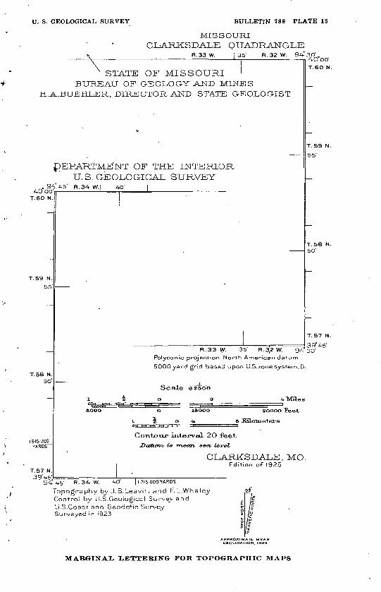
U. S. GEOLOGICAL SURVEY BULLETIN 788 PLATE 15
MISSOURI CIoARKSDALE QUADRANGLE
R.33 W. 135' R.32 W. 9A-°3O'.
x STATE OF MISSOURI ' BUREAU OF G-EOLOG-Y AND MINES
H.A.BUEHLER, DIRECTOR AND STATE GEOLOGIST
4O 00 T.6O N
^DEPARTMENT OF THE INTERIOR U. S. GE OLO GICAL SURVEYR.34- W.I AO' I
T.59 N.
55
T.58 N. 50'
1915000 YARDS"
T.57 N. 39'4-5'
A-O CO'
T.6O N.
T.59 N.55'
T.58 N.50'
___ ...___ __,_ . 30° AC'R.33 \(V. 35' R.3,2W. 9A-" 3D1
Polyconic projection. North American datum.
5000y;?rd grid based upon U.S.zone system,D.
Scale essoo
20000 Feet
6 Kaloineters
Ccxrrbcrur interveQ. 2O feet.Datum/ -is -metm s&m level
CLARKSDALE, MO.Edition of 1925
4-5' R.34-W. AO' ||2I5000YAROS
Topography by J. B.LeavitT and F. L.Whaley Control by U.S.Geological Survey and U.S.Coast and Geodetic Survey Surveyed in 1923
DECLINATION, 1323
MARGINAL, LETTERING FOR TOPOGRAPHIC MAPS
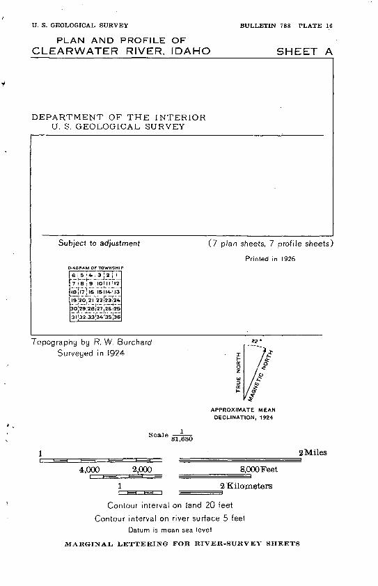
U. S. GEOLOGICAL SURVEY BULLETIN 788 PLATE 16
PLAN AND PROFILE OF CLEARWATER RIVER, IDAHO SHEET A
DEPARTMENT OF THE INTERIOR U. S. GEOLOGICAL SURVEY
Subject to adjustment
DIAGRAM Of TOWNSHIP
(7 plan sheets, 7 profile sheets)
Printed in 1926
Topography by R. W. Burchard
Surveyed in 1924
APPROXIMATE MEAN
DECLINATION, 1924
Scale 31,680
2Miles
4,000 2,000 8,OOOFeet
2 Kilometers
Contour interval on land 20 feet
Contour interval on river surface 5 feet
Datum is mean sea level
MARGINAL, LETTERING FOR RIVER-SURVEY SHEETS
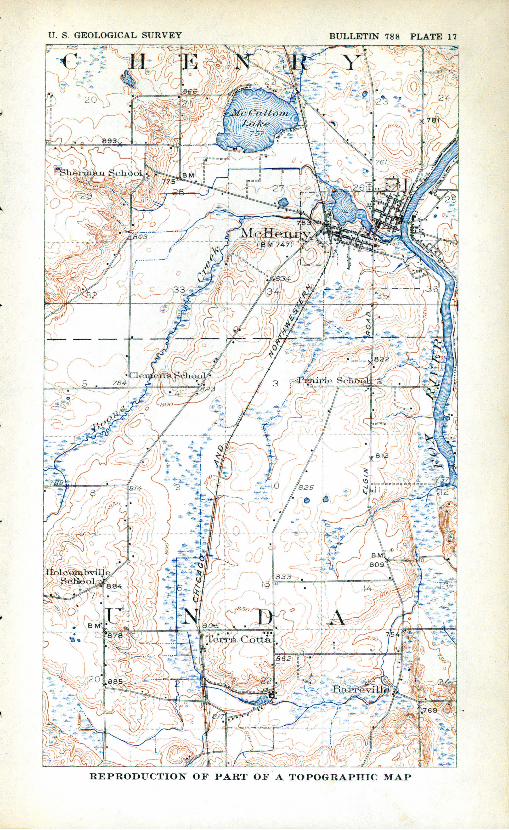
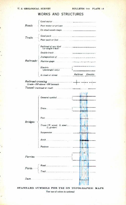
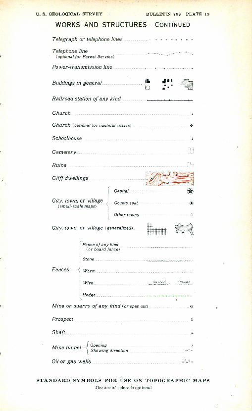
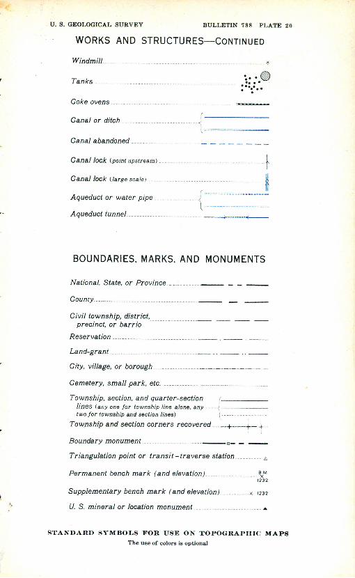
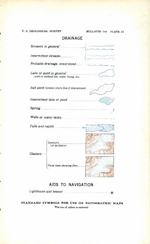
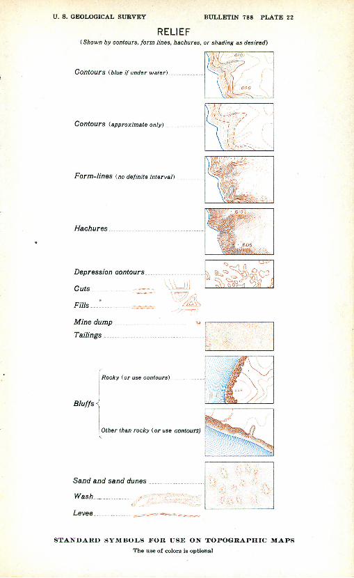
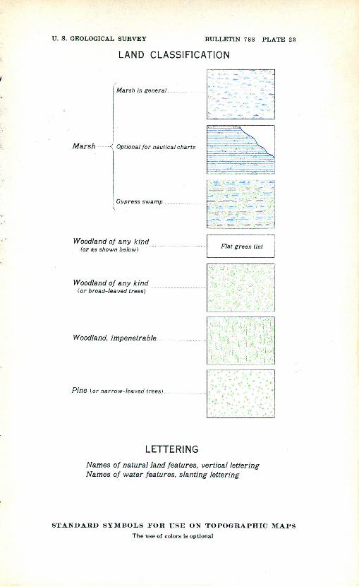
TOPOGRAPHIC MAPPING 283
between the tracing and the map, and going over the traced lines again with a fine metal point or a hard pencil. Transfer paper may be made by blackening one side of thin tracing paper with a soft pencil and rubbing the blackened surface down to a smooth finish with blotting paper.
PASTING
Preparing a patch. A separate original section of a topographic map that needs no adjustment may be transferred to the main map by pasting it on as a patch in its true position. Indicate with a light pencil line the limits of the part that is to be pasted. The map sec tion should then be separated from the linen filling of the double- mounted drawing paper. To do this lay the section of the map face down on a desk or other-hard clean surface and start the separation at one corner with the finger nail. As the peeling progresses follow up with a triangle weighted down by hand so that the face of the map will lie flat and be in contact with the desk or other surface at the point where the peeling is taking place. If this method is followed the map section will not be torn or buckled. When the map section has been peeled trim it along the pasting limits previously indicated by a pencil line and bevel the edge for a width of a quarter to half an inch. To bevel the edge place the patch face down on a cutting board, cut the bevel with a sharp knife and smooth it off with fine sandpaper. Do not cut along a projection line, and so far as practicable, avoid cut ting along a road or land line.
Pasting the patch. Place the map section in position on the main map and indicate register marks so that it can be again placed in identically the same position. Rubber cement, thinned with pure benzine or refined benzol, may be used as the adhesive and has the advantage of slow drying and ease of removal at any later time if needed. Coat the area of the main map to which the patch is to be applied and the back of the patch with at least three paintings of the rubber cement and allow each coat to dry before another is added. Do not apply the patch until the last coat of cement is dry. To affix the patch place one set of register marks in position, holding the rest of the patch away from the map, while strips of paper are placed between it and the map in such a manner as to be removable after the other marks have been brought into register. When the patch is in a satisfactory position, withdraw the paper strips and burnish the patch into a good contact, paying particular attention to the edges. Super fluous cement can be rubbed off with the fingers or with a soft rubber eraser. If it is desired to remove the patch, start the peeling at one corner with a knife blade and gradually pry it loose. Before replac ing the patch the old cement should be removed; then proceed as before.
58515° 28 19
284 TOPOGRAPHIC INSTRUCTIONS OF GEOLOGICAL, STJKVEY
INKING OF CULTURAL FEATURES
Cultural features should be inked in black except as some other color is specified under the headings below. Cultural features that are added for sheet information only and are not to be engraved, or features for which the engraving may be in doubt, may be inked in red. For general instructions covering the inking of all map features see pages 277-283.
The field instructions for the mapping of cultural features (pp. 229- 242) are to be regarded as supplemental information needed for the proper interpretation of the following instructions for the inking of cul tural features, and for this reason frequent cross references are given.
Roads, country. Roads should be inked by solid double parallel lines or by dashed double parallel lines, according to the penciled copy furnished in compliance with instructions for field work. (See "Roads," p. 229.)
Roads are engraved to standard gages for each publication scale, unless the drafted copy calls for a wider gage for certain roads, such as highways or avenues of unusual width, or unless on large-scale maps special engraving instructions are given to cut all roads to widths as drawn. Roads should, therefore, with these exceptions, be inked of uniform width and with as fine lines as will remain firm and unbroken. As it is impracticable, however, especially on paper that has been rubbed in the field, to draft roads of the fineness and narrowness of engraved roads, even when these are enlarged to field scale, the topo grapher should ink the roads a little wider than the standard gage; a width of 75 feet (center measurement) when plotted on a scale of 1 : 48,000 (approximately 0.02 inch) may be taken as a guide. If a narrower width is attempted the lines are likely to run together when reduced and transferred to the copper plates, and they may even run together on the drawing. A clear space in the middle of the road symbol is essential to furnish good road copy for the engraver.
In hiking the dashed double line road symbol care should be taken to maintain a uniform length of dashes, a uniform width between dashed lines, but not too close spacing between the successive pairs of dashes, and a uniform weight of individual lines, and the overlap ping of either of the double dashed lines beyond the other should be avoided.
Where the middle of a road follows a projection line bordering an unmapped quadrangle, the road should be shown as entirely within or entirely without the mapped quadrangle so far as practicable. A space should be left between a house and the end of a road leading to it.
Streets, city. City streets should be inked only by the best drafts men; and all street lines should be drawn fine and finished off neatly
TOPOGRAPHIC MAPPING 285
at the corners, a reading glass being used for this purpose where necessary. Any overrun of the inking into the open space inside the road symbol should be erased so as to leave clear copy. Cities and villages, where combined with contours and stream courses, present difficult copy for the engraver at best, and every endeavor should be made to keep the road lines fine and the copy as open as circumstances m'ay warrant.
Buildings in general. The houses on the manuscript sheet should be inked square and of uniform size and should be drafted by outlining an open inked square, with sharp corners, and afterward filling in. If houses are inked too small it becomes difficult to make them square, and unless they are inked square and sharp their identification as houses becomes uncertain even on the original drawing. The follow ing approximate dimensions may be taken as standard for the inking of the conventional country-house symbol on the field scales specified : 1 :96,000, 150 feet square; 1 :48,000, 75 feet; 1 : 31,680, 50 feet; 1 : 24,000, 25 feet. These dimensions, however, should be increased or decreased in congested places, if the legibility is correspondingly improved. Large structures which, plotted to scale, exceed the size of the ordinary symbol should be shown with their individual plan outlines.
Use of blocks. If the buildings and blocks appear to have been penciled in conformity with the field instructions (see p. 231) they should be inked as penciled; but if they appear to be penciled closer together than the field specifications call for they should be inked in blocks.
Business and residence Nocks. Residence blocks (seep. 231) should be inked distinctly narrower than business blocks, but this distinction should be made in the inking only where it has been made in the field work and where the penciling or other copy is clear.
Churches and schoolhouses. The symbols for churches and school- houses are described under field instructions. (See p. 232.) The house part of either symbol should be inked the same size as called for under "Buildings in general" (p. 231). The flag may fly on either side of the pole, and in congested places the inked pole may be lengthened if the symbol is thereby made more legible.
Railroads. Before a railroad (see p. 232) is inked the penciled copy should be examined to determine its points of tangent and points of curve and then inked in such a way as to bring out a characteristic railroad alinement. The distinction between railroads of the steam type and electric trolley lines is given in the field instructions. For the former the cross ties are spaced twice as far apart as for the latter. Where the distinction is in doubt the wider spacing should be used, as the intermediate ties can easily be inserted if found necessary.
286 TOPOGEAPHIC INSTRUCTIONS OF GEOLOGICAL SURVEY
In railroad yards, parallel spur tracks, etc., only as many tracks should be inked as can be legibly engraved on the publication scale, as too many tracks make difficult inking, illegible advance sheets, and impracticable engraving. Where switches and sidings are inked alongside single tracks both the main track and the side tracks should be inked in finer lines than the main track elsewhere; and these fine lines should be inked first and the extension of the main track inked afterward in a heavier line, to make clearer copy for engraving.
The penciled copy for railroads in juxtaposition should be checked before being followed.
Railroads and electric trolley lines that are within roadways should be shown only by the fine cross-tie lines at right angles to the road symbol, to the full width of the road as inked and with the spacing used in the corresponding regular symbols.
Tramways. Tramways should be inked in the broad-spaced rail road symbol. Aerial tramways should be inked in a broken line, and the name should be added where there is space.
Railroad crossings. In inking crossings of railroads and roads (see p. 232) a distinction should be made between a grade crossing and a crossing not on grade. Where the road passes under the railroad the road symbol should be broken and the railroad symbol continuous, and where the railroad passes under the road the railroad symbol should be broken and the road symbol continuous.
Railroad station buildings. A railroad-station symbol (see p. 232) should not be inked unless there is a building on the ground. The symbol for a railroad station should be carried across the track only where the location of the train stop would be otherwise uncertain. The railroad-station symbol should not be used in country regions where the presence of a crossroad or the position of the lettering sufficiently locates the tram, stop, and the use of the symbol should be confined chiefly to small towns and other places where the letter ing can not be placed near the position of the train stop and where this position can not be inferred from the map.
Bridges. The bridge symbol (see p. 232) should be inked only where there is clear penciled copy or where definite information exists that there is a bridge of the importance specified in the field instructions. The symbol should be omitted in areas of heavy culture and wherever its presence would interfere with the legibility of the map on the publication scale. Ordinary railroad bridges and trestles should not be shown. Drawbridges on roads and railroads should be shown by a separate symbol. Bridge ends for viaducts should in general be omitted.
Ferries. Ferries (see p. 233) should be shown by the symbol, with the boat pointing upstream, or the word "FERRY," according to
TOPOGRAPHIC MAPPING 287
the available space on the map. The name of the ferry should be used in lieu of the word alone where the name is well recognized locally.
Fords. (See field instructions, p. 233.)Trails. Poor pack trails and all foot trails should be inked in
the dot symbol; good pack trails in the dashed-line symbol. Where the field penciled copy or classification is uncertain use the dashed symbol. (See p. 233.)
Steamboat routes. (See field instructions, p. 233.)Canals and ditches. Canals and ditches should be inked in blue.
(See p. 233.) Short ditches that have been penciled on the field sheets in the course of survey and have not been erased should not be inked if they appear to be laterals rather than main feeders. Abandoned canals should be inked if of the importance called for in the field instructions.
Canal locks. The symbol for canal locks should be inked only so far as it can be legibly engraved on the publication scale, and the upper and lower gates should be separately inked only where both gates can be legibly shown. If the penciled copy is not clear inquiry should be made before the inking is completed. (See p. 234.)
Aqueducts and pipe lines. (See field instructions, p. 234.)Power-transmission lines. Power lines may be inked in black,
but if they are in close contact with other cultural features they should be inked in red for clearer recognition. Power lines should not be inked in sections of heavy culture. (See p. 234.)
Tunnels. Railroad or road tunnels should be inked im black, aqueduct tunnels in blue. (See p. 234.)
Dams. The elevation of the top of a dam should be recorded. The dam should be inked to its mapped length only, and its ends should be represented at identical elevations as shown by the con touring. (See p. 234.)
Reservoirs. Artificial reservoirs surrounded by dams on all sides should not be inclosed by the dam symbol but should be outlined in blue like lakes or ponds; small reservoirs should be further empha sized by a blue wash. (See p. 234.)
Levees, cuts and fills, mine dumps. Levees, cuts and fills, and mine dumps should be inked in brown, and if more have been penciled than appear to be authorized by the field instructions (see p. 234) further instructions should be sought before inking those whose status is uncertain.
Depression contours. (See "Artificial depressions," p. 234.)Wharves, piers, jetties, etc. Wh'arves, piers, docks, and similar
structures should be inked in black, in outline only, as plotted to scale in the field. A narrow wharf or pier should, however, °be represented conventionally by a double line about the width of a
288 TOPOGKAPHIC INSTRUCTIONS OF GEOLOGICAL, SURVEY
narrow road. Jetties and breakwaters should be inked in single heavy black lines. (See p. 235.)
Lighthouses, etc. Lighthouses and lightships are to be shown by their respective symbols on all maps, whatever the scale.
Cemeteries. The outlines of cemeteries should be inked; the name, if well known, should be shown if there is space; otherwise a cross within the outline or the letters "GEM" alongside. Small private cemeteries should not be shown unless they constitute landmarks in a thinly settled country. (See p. 235.)
Mines and quarries. A careful distinction should be made between the inking of mine symbols in black if to be engraved and in red if intended for sheet information and advance lithographs only. (See p. 235.)
Oil and gas wells. The small circle inked in black, should be used to represent an oil or gas well. If the oil or gas field only is shown the outline should be inked by dashed lines in black. (See p. 235.)
Furnaces, smelters, and coke ovens. A furnace or smelter should be inked in black, like any other building. Only coke ovens that are to be engraved should be inked, in black. (See pp. 235-236.)
Civil boundaries. Civil boundaries (see p. 236) should be verified before inking as a precaution against gross errors in the interpreta tion of penciled field copy, as erasure of an erroneous inked boundary line usually involves erasure of adjacent topography also. Where civil boundaries of different classes coincide for a distance the symbol of the major subdivision should take precedence, but in particularly complicated regions, especially among minor subdivisions, it may sometimes be necessary for the sake of clearness to depart from this rule.
Where it is obvious that a civil boundary follows a stream or road for a short distance the boundary symbol may be omitted to avoid confusion. In some places, however, clearness may be increased by placing the boundary symbol immediately alongside of the stream or road in red.
For further detailed instructions, given separately by names of boundaries, see pages 322-328; for civil townships and other sub divisions see also page 237.
Boundary monuments. National, State, and national park bound ary monuments, with designating numbers alongside, should be inked in black. Boundary monuments on other lines, with designating numbers if obtainable, should be inked in red. The open block indi cating the monument should be oriented with the line it marks.
County subdivisions. If in do lib t whether to ink boundary lines showing subdivisions of the county, read carefully the field instruc tions (p. 237) and then look through the field material for comment from, the field engineers as to the local status of the lines. In those
TOPOGRAPHIC MAPPING 289
parts of the country or in those States where the Geological Survey has not in the past shown such subdivisions, each new map must be fully considered before a decision is reached, and under such condi tions the inker should seek office advice.
Public-land lines. All public-land survey lines (see p. 238) should be inked in red so that they may not be mistaken for other cultural features; section lines should be inked in fine lines and township lines distinctly heavier. The adjustment of land lines should be checked by someone other than the compiler before they are inked; and the need for this examination increases with the proportion of the land net taken from the plats and notes alone rather than from the connection of found corners.
Only those township and section lines and parts thereof that have been surveyed and approved by the General Land Office, are not under suspension, and are indicated on the land plats by solid lines should be inked on Geological Survey topographic maps. The frac tional distances for less than section lengths are usually found on the land plats, and such distances afford the means for plotting frac tional land lines on maps. Land lines broken at water surfaces on account of shore meanders should in general be broken as shown on the plats. Meander lines should not be plotted or inked.
Found corners. Public-land corners that have been found in the course of field work and are clearly indicated as such on the field sheets should be inked in the symbol for found land corners. In hiking land lines adjacent to found land corners a short space should be left clear on all sides of the symbol so that it can be readily recognized.
Township and range numbers. Township and range numbers should be placed along the margin of the map opposite the middle of each township, the township numbers along the right and left and the range numbers along the upper and lower margins. If the num bering is irregular, however, the numbers should be placed within the townships. On large-scale maps that cover only two or three townships or fractions thereof the township and range numbers should be placed opposite the lines bounding the townships.
Numbers and names of base lines and principal meridians should be shown.
Section numbers. On the 1:62,500 scale and all larger scales sec tions within townships should be numbered.
United States location and mineral monuments. Each United States location and mineral monument (see p. 240) should be inked by a solid triangle and designated by letters and official number, preferably at the right of the symbol, as "USLM 2," "USMM 237."
Triangulation points and transit-traverse stations. Only those trian- gulation points and transit-traverse stations that have been used in
290 TOPOGRAPHIC INSTRUCTIONS OF GEOLOGICAL SURVEY
the course of topographic mapping (see p. 240) should be inked or shown on Geological Survey maps, and these stations should be inked by the triangle and dot symbol. No triangle should be inked until the identity of the station has been established and its plotting checked, and this check should precede the inking of any cultural features directly adjacent to the station.
The names of triangulation points and the numbers of transit- traverse stations should not be added to the hiked maps prior to the control examination.
Level bench marks. For bench marks (see p. 240) all letters "BM," all crosses (permanent and supplementary), and all figures of eleva tion should be inked in black. The cross should be of the style used on engraved maps but with the lines of the cross inked fine and 0.2 inch in length, or longer if necessary for the better identi fication of its location. All bench-mark figures of elevation should be upright. All bench marks that have been plotted on the field sheets should be inked on the final sheets, except those in areas of heavy culture, but the figures for such supplementary bench marks as do not represent good engineering benches will be changed to red in the control examination.
Vertical-angle benchmarks. Vertical-angle bench marks (see p. 240) should be indicated in the same way as standard permanent bench marks, except that the letters "VA" will be added on the same line and in front of the letters "BM," if the bench mark is on or near a road or other route of travel and therefore liable to be mis taken for a standard permanent bench mark.
Control points adjacent to cultural features. In inking culture that is adjacent to control points (see p. 241) care should be taken to maintain the correct relative position of the control and the cultural features.
Useful elevations. All useful elevations as defined on page 241 should be inked in black in slanting block figures. The elevations selected for engraving will be determined in the editing of the map and will be printed in black on the published maps. On maps that are to be reproduced by engraving no elevations should be inked in red. On maps that are to be reproduced by photolithography alone special instructions will govern individual cases, according to the arrangement of the copy.
Location crosses. Where the location of an important feature is not obvious from the position of the lettering designating it or where figures alone do not clearly indicate the location of a point whose elevation is given, a small location cross may be added in brown and may be engraved on the brown plate.
TOPOGKAPHIC MAPPING 291
INKING OF DRAINAGE FEATURES
If a mixed blue ink is used for inking drainage features it must be thoroughly mixed and dark enough to insure strong photographic value.
Shore lines in general. Shore lines of all waters should be inked in a firm continuous blue line and not broken for wharves, piers, and similar structures that may be built out over the water; such struc tures should be inked in black. Sea and retaining walls that are but artificially constructed parts of the shore line should be inked in blue.
Tidal shore lines. (See field instructions, p. 242.)Use oj Coast and Geodetic Survey charts. Before coast lines and
the adjacent offshore features are inked the penciled copy should be compared with late large-scale Coast and Geodetic Survey charts (see p. 242), and wherever marked differences are found that are not fully explained in the field material or on the information tracing, further inquiry should be made of the author or other competent authority. Coastal features appearing only below the line of mean high water should be omitted from Geological Survey maps.
Under-water contours. Under-water contours should be added to the final drawings of coastal maps if the Coast and Geodetic Survey can supply the necessary data. They should be shown for offshore depths corresponding to the contour interval used on land and should be carried to the limits of the quadrangle or so far as data are avail able. Additional contours for depths of 5, 10, 20, and 30 feet should be shown where appropriate. Ink in blue.
Marshes in general. Marsh or swamp of any kind (see p. 242) should be inked by the symbol for marsh in. general; no distinction should be made between fresh, salt, or other marsh. The outlines of marsh areas should be inked by fine dashed blue lines, but the dashed lines should not be engraved save where they are needed to designate small and but slightly separated areas of marsh that otherwise would be collectively mistaken for large continuous areas or where they are needed to indicate small detached areas that have sharply defined limits but are not clearly outlined by the symbol alone and yet constitute prominent features or landmarks.
Submerged marsh. Areas of submerged marsh (see p. 242) should be indicated by inking grass tufts in blue (no horizontal lines) on the water surface.
Wooded marsh. Wooded marsh (see p. 243) should be inked in blue as marsh and the outline added to the woodland sheet.
River shore lines. The penciled copy for broad rivers (see p. 243) should be carefully examined before inking in order to ascertain whether the shore line shown represents the probable normal stage
292 TOPOGRAPHIC INSTRUCTIONS OP GEOLOGICAL SURVEY
of the water. If the appearance of the copy or an attached memo randum in any way indicates or suggests a mapping of the shore at some stage other than the normal, the inker should seek further office instructions before inking the shore line, islands, sand bars, etc. As the normal stage of inland waters is the accepted shore line on Geological Survey maps, no features that are exposed only below that stage of the water should be inked. Water-surface elevations should be inked wherever they can be legibly drafted.
River banks. (See field instructions, p. 243.)Sand. The sand symbol (see p. 255) should be inked with brown
dots of uniform size and spacing. Tidal sand that is exposed below the line of mean high tide or below the line of the normal stage of rivers and lakes should not be inked. The outline of sanded areas should not be inked but shown by a careful inking of the dots.
Natural lakes. If the appearance of the .penciled copy or an attached memorandum indicates that the shore line of a lake was mapped at a stage of the water above or below the normal stage, the inker should ask for instructions before inking the shore line. (See p. 243.) The shore line of a large lake whose surface is subject to periodic rise or fall should be that determined on the date of survey; and this date should be lettered on the water surface, with corres ponding elevation. The elevation (normal stage) of all other lake or pond water surfaces should be inked wherever the figures are available and can be legibly shown.
Reservoirs. (See field instructions, p. 234.)Artificial lakes. The elevation of an artificial lake (see p. 243)
should be inked, if given, and should represent the stage of water mapped and as controlled by the dam.
Intermittent and dry lakes. Intermittent lakes and ponds, dry salt lakes, and alkali flats (see p. 245) should be inked by the symbol for intermittent lake or pond, a dashed outline with the surface indicated by hatching, in blue.
Islands. The instructions given above for inking tidal shore lines, river shore lines, and lake shore lines should be followed for island shore lines so far as they are pertinent.
Drainage classification. Before streams are inked the draftsman should look over the entire original and also the information sheets and adjoining maps in order that the classification as inked may repre sent the fullest information at hand. (See p. 244.)
Perennial streams. In general, all perennial streams (see p. 244) except very short stubs and insignificant rills should be inked on maps drawn for publication on a scale of 1:62,500. For maps on larger scales (1:31,680, 1:24,000, etc.) all perennial streams except the smallest rills may be inked, but rills also may be inked where, in
TOPOGRAPHIC MAPPING 293
the absence of contour lines defining their channels, they constitute features of topographic importance.
On maps drawn for publication on a scale of 1:125,000 the amount of perennial drainage to be inked should be only slightly less than that for a scale of 1:62,500, the omitted streams being the shorter forks or tributaries whose inking would give a stubby expression to the drainage. For a scale of 1:250,000 much less drainage should be inked than would be represented on a scale of 1:125,000.
Perennial streams should be inked with a solid blue line increasing in strength with the size of the stream but nowhere so broad as to be equivalent to double lines. Care should be taken not to draw streams to the edge of the map with a width that can not properly be continued on the next map. Stream lines should taper off toward the sources of the streams but should remain deep and strong in color to the head. If allowed to become faint the blue will not photograph.
Intermittent streams. On the penciled field sheets all intermittent stream courses (see p. 244) are outlined down to their minuter rami fications, as an aid in contour sketching, but. only the larger ones are to be inked and engraved. The general rule should be to ink no intermittent stream that will be less than three-quarters of an inch long on the scale of publication. In the more arid districts a smaller proportion of the intermittent drainage should be inked, and the mini mum length should be increased to 2 inches or more, according to scale, as may seem appropriate to the degree of aridity.
It is to be borne in mind that drainage lines are delineated not merely because they indicate water features but because they con stitute an important element in the conformation of the land surface and because they afford supplementary information of value in the interpretation of the relief. Whatever the degree of aridity, there fore, it is desirable to show a certain amount of intermittent drainage on the map for the sake of legibility. More especially is this true in delineating intricately sculptured areas, the topography of which in the absence of drainage lines appears chaotic and unintelligible at first glance.
Aggraded flats and valley floors devoid of well-defined stream channels or scars are not properly shown with drainage lines running through them.
Intermittent streams should not be inked up to or close to the divides, as the contours usually suffice to define the location of stream heads.
Double-lined streams. Only those streams should be double-lined whose actual width can thus be shown without exaggeration on the scale of publication. (See p. 244.)
Disappearing streams. Disappearing streams and streams starting from subterranean sources (see p. 245) should be inked to represent

294 TOPOGRAPHIC INSTRUCTIONS OF GEOLOGICAL SURVEY
the surface drainage only, and this will be classified as given under the rules for perennial and intermittent streams. On field sheets where the presence of disappearing or reappearing drainage is sug gested by the representation of sink holes or other indication, the penciled copy should be carefully examined for possible drainage of this character.
Springs. Springs (see p. 245) should be hiked or not according to their importance as stated in field instructions. A walled-in spring should be shown like a well, by a blue circle, but a spring that is a source of a stream should be shown by a blue circle with the outlet stream as plotted.
Wells and water tanks. The symbol for a well or water tank is a small blue circle. (See p. 245.)
Glaciers. The outline of a glacier (see p. 245) should be inked in a dotted blue line and its surface contours in full blue lines.
Tinting of water bodies. Oceans, bays, lakes, ponds, and broad rivers should be tinted blue (blue tints will not photograph) on the manuscript sheets only in places where the copy for engraving would otherwise be ambiguous. If the tint is added after the shore line has been inked, the shore line should be reinked wherever the wash has destroyed or broken the line or so weakened its strength as to render it nonphotographic. As a further guide for the engraver, a deeper blue wash may be added immediately along the shores, islands, rocks, and other features. Bridges and other structures built over the water should not be thus outlined by a darker tint.
INKING OF RELIEF FEATURES
Relief features are to be inked in brown.Strength of contour lines. Contour lines should be inked in firm
smooth lines of even strength. For convenience in reading them every fifth or fourth contour should be accentuated (for contour intervals of 1, 5, 10, 20, 40, 50, 100 and 200 feet, every fifth; and for intervals of 25 and 250 feet, every fourth). The accentuation should consist in drawing the lines heavier, rather than in making them broken or dotted. The weight of the accentuated (heavy) contours should make them stand out from the intermediate contours but should not be so excessive as to cause them to dominate the relief. The intermediate (light) contours should be inked in fine lines.
Where the identity of a heavy contour is lost in a band of contours, as in the representation of a cliff, it may be advisable to place con tour numbers on one or more adjacent light contours in order that the contouring may be more easily read.
Sequence of contour inking. The heavy contour lines should be inked first and should be finished over considerable areas before the light contours are inked, The heavy contours should be compared with
TOPOGRAPHIC MAPPING 295
adjoining bench-mark and other elevation figures as a check on their identification, and identification marks such as contour numbers in light pencil should be placed here and there upon them in order that the correct continuity of the heavy lines may be well established before light contours are inked. The heavy contours should not be dropped at any place save for contour numbers, but the light con tours should be omitted on uniform steep slopes and in other places where their inking is not essential and would tend to confuse the copy rather than aid the engraver. Before the intermediate contours between any two successive heavy contours are inked, the penciling should be closely examined to insure that no contours have been dropped or duplicated.
Uniform steep slopes. Where the slope is both steep and uniform only the heavy contours need be inked, as the engraver can interpo late the light lines on the copper plate as readily as the topographer can ink them on his map, and the copy for the engraver is the clearer for their omission. Attempts to fill them in for the mere sake of enhancing the appearance of the manuscript sheet are not permissible.
Steep slopes that are not uniform. Where a slope is steep but not uniform the change in slope is more likely to occur on a light contour than on a heavy contour for example, with a 20-foot interval the chance of the slope changing at a light contour instead of at a heavy contour is as 5 to 1. Therefore, if the interpolation of the light con tours on such slopes is left to the engraver, an erroneous banded effect will result on the engraved map where successive bands of light contours are uniformly spaced between heavy contours that are. themselves not evenly spaced.
Uniform gentle slopes. Where the slope is generally uniform but not steep ail light contours should be inked for the guidance of the engraver, especially where marked divergence or discordance exists among them. In general, the light contours should be indicated, at least by short lengths of lines, along every drainage line and every spur crest.
Cliffs. Extreme care must be taken in inking bluffs and cliffs on which not all the contours can be shown. The inked lines should be as sharp and smooth as they can be drafted, so as to reduce to a minimum the chance of their blurring in transfer to the copper. In asmuch as very closely spaced lines on a drawing tend to run to gether where reduced in scale and transferred to copper, the inker should aim to leave the engraver's copy as open as possible, and this may be accomplished in part by omitting from the inking any four, three, two, or even single contours wherever two or more are closely spaced on the map. The contours that are omitted in the inking can be interpolated by the engraver, who can work more
296 TOPOGRAPHIC INSTKTJCTIONS OF GEOLOGICAL SURVEY
rapidly and with more assurance because the copy has thereby been rendered more legible.
Where cliffs are represented by bands of contours and are so numer ous as to dominate the topography, as in the Grand Canyon of Ari zona, it may be desirable to omit the usual emphasizing of contours and instead to add as many contour numbers as may be needed for identification. Such contour numbers may be most appropriately placed on the contours that otherwise would be heavy.
Depression contours. Contours inclosing depressions or sinks should be distinguished from hill contours either by rows of contour numbers indicating successive depths, instead of successive heights, or by hachures on the downhill side of each contour line. The depressions may be natural, such as occur in limestone regions, or artificial, such as are inclosed by railroad or road embankments. If the depression takes more than one contour, all should be hachured. In intricate areas it is often desirable to indicate the bottom elevation of the basin by figures, or, if space permits, to mark the elevation of some or all of the contours.
Depressions of large extent covering a considerable area on the map are intelligible without the aid of hachures provided they are liberally supplied with contour figures.
Contour figures. Figures of elevation on contours should be inked without shading. On heavy contours they should be placed with a special view to their effectiveness as an aid to the map reader. A sufficient number of them should be used to enable the reader to obtain a contour elevation with but slight examination. It is desir able, therefore, that they be placed in conspicuous positions and that they be distributed with some system. In general, contour figures are most effectively placed on or near the ends of spurs, tops of ridges, or bottoms of valleys and at pronounced changes in slope.
On features taking several tiers of heavy contours the figures may be placed in steplike series. Such series should follow the features on which they are placed in easy, gentle curves. On very steep slopes, where they would be too crowded, the figures should be omitted on alternate heavy contours. Each mountain group or separate map unit should have its own numbering system, so that there may be no need of referring to contour figures across valleys or canyons.
In regions of moderate or low relief the placing of the figures should be governed primarily by the disposition of the larger topographic subdivision. Each of these should have at least one complete set of figures. In areas of exceptionally intricate topography for instance, in areas pitted with solution sinks or traversed by high cliffs the figures on the heavy contours may not suffice to make the delineation intelligible, and it is proper to place figures on light contours wherever they will help to remove uncertainty. If need be, figures showing
TOPOGRAPHIC MAPPING 297
the elevation of several points may be introduced to supplement the contour figures.
Contour figures should not, as a rule, appear in close proximity to bench-mark and other elevation figures, which, on the other hand, should not be considered as taking the place of the contour figures.
Finally, care should be taken to select a position for contour fig ures that will accommodate the engraving on the reduced scale of publication.
Two contour intervals. Where two or more contour intervals have been used in a quadrangle (see p. 246) the inker should carefully exam ine the entire map to ascertain those parts of the quadrangle to which the different intervals apply. Before contour inking is begun full. instructions should be sought as to the proposed method of handling the contour inking.
Where it seems desirable to ink additional contours within certain areas, in order to bring out supplemental relief that has been mapped, such additional contours should be inked in dashed lines, in order that they may be distinguished from the contours of the regular system; and a footnote should be added directly under the contour-interval line reading " foot contours added in dashed lines."
Railroad contours. The penciled copy should be carefully examined and no excessive or improbable railroad grades, cuts, or fills inked unless the copy is clear and unmistakable. (See "Railroad grades," p. 250, and "Cuts and fills," below.)
Cuts and fills. Straight lines representing cuts and fills (see p. 251) should be ruled in, and the inked copy left as sharp and open as cir cumstances will allow. A slight separation of the lines may be warranted, but where this is not practicable a short stretch of perhaps 0.1 inch or so of one or more lines that are closely spaced may be omitted in the inking and yet leave copy that will be understood by the engraver.
Use of hachures. The inking of hachures should be confined to the representation of depressions (p. 251), mine dumps (p. 234), and such other banks as are not shown by the contours and yet constitute conspicuous topographic features. (See "Use of hachures," p. 252.)
Contour disagreeing with elevation. An example of permissible topo graphic license (see p. 253) is the folio whig: A 1,300-foot contour (interval 20 feet) is penciled to represent a sharp summit whose ele vation is given as 1,295 feet; both the 1,300-foot contour and the elevation may be inked. To omit the 1,300-foot contour would be to show the summit as flatter than it really is. Where such small differ ences appear to be fully justified, such topographic license may be taken, but the evidence must be clear that the differences are not the result of error; where error is suspected a question should be raised or the elevation omitted in the inking.
298 TOPOGEAPHIC INSTRUCTIONS OF GEOLOGICAL SUEVEY
Alinement of contours. The bends of contours in steep drainage channels and on steep ridges should, in general, be in line with one another, and in such places care should be taken in the inking to see that the contours are placed in the proper alinement. (See p. 253.) Careless or hasty penciling may throw contours out of line in steep places, and unless the pencil copy to the contrary is unmistakable, the inker may often be aided in properly aiming the contours by lightly penciling a drainage line or a ridge line on which to reconstruct the contour crossings.
Topographic expression by different authors. Where different parts of a quadrangle have been mapped by two or more persons, the con touring of the different authors should be carefully compared before it is inked in order that any minor differences in expression may be reconciled in the inking so far as that may be practicable. Attention should be called, however, to all material differences in topographic expression that are not plausibly explained by such differences as are to be expected where differing types of country are found in the same quadrangle.
INKING FEATURES BASED ON AERIAL PHOTOGRAPHS
If an aerial photographic base, such as is described on page 254, has been used in the field, the office inker should, in general, ink only those blue lines that have been penciled in on the final field sheet. A blue line that has not been verified by field penciling should be inked only where there is definite knowledge that the line represents a feature that is intended as a part of the map. Among the blue lines that should not be inked and may or may not have been erased or crossed out by the field engineer are fence lines added for additional control, woodland outlines, and lines of mistaken culture or drainage.
The copy for coastal shore lines and shores of large rivers should not be inked until the status of such shore lines has been determined either by explanations to be found in the field material or by admin istrative approval in the office. (See last paragraph under "Mapping on aerial photographic base," p. 255.)
RECTANGULAR GRID
Definition. A grid is a system of rectilinear lines forming squares of identical dimensions, which may vary according to the requirements. Grid lines may be drawn entirely across the face of the map or may be indicated by marginal registration marks only, as is the Geological Survey practice. Were the registration marks to be connected, in order to form a true grid, the lines would be drawn as straight lines. Each grid line has a numerical designation, and the notation adopted increases eastward and northward only. Distances east are termed
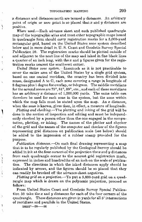
TOPOGRAPHIC MAPPING 299
x distances and distances north are termed y distances. An arbitrary point of origin or zero point is so placed that x and y distances are positive.
Where used. Each advance sheet and each published quadrangle map of the topographic atlas and most other topographic maps issued in quadrangle form should carry registration marks for a 5,000-yard rectangular grid, based on the United States zone system described below and in more detail in U. S. Coast and Geodetic Survey Special Publication 59. The registration marks should be plotted outside of and adjacent to the neat line of the map and inked in fine black lines a quarter of an inch long, with the x and y figures given for the regis tration marks nearest the southwest corner.
United States zone system. Inasmuch as it is not practicable to cover the entire area of the United States by a single grid system, based on one central meridian, the country has been divided into zones, designated A to G, each zone covering a range in longitude of 8 degrees plus 1 degree for overlap, or 9 degrees. The middle meridians for the several zones are 73°, 81°, 89°, etc., and each of these meridians has an arbitrary x distance of 1,000,000 yards. The same table can therefore be used for each zone in the system, but the zone within which the map falls must be stated upon the map. An x distance, when the zone is known, gives then, in effect, a measure of longitude.
Plotting and checldng. The plotting and inking of the grid will be done in the section of inspection and editing and must be independ ently checked by a person other than the one engaged in the compu tation, plotting, or inking. The names of the plotter and checker of the grid and the names of the computer and checker of the figures representing grid distances on publication scale (see below) should be added to the impression of a rubber stamp provided for the purpose.
Publication distances. On each final drawing representing a map that is to be regularly published by the Geological Survey should be added in ink at the four corners of the projection thecc and y distances from each quadrangle corner to the nearest grid registration mark, expressed in inches and hundredths of an inch on the scale of publica tion. The directions in which the inked distances apply should be indicated by arrows, and the figures should be so placed that they can readily be brushed off the advance-sheet negatives.
Plotting grid on a projection. To put a 5,000-yard grid on a quad rangle map which is drawn on the poly conic projection, proceed as follows:
From United States Coast and Geodetic Survey Special Publica tion 59 take the x and y distances for each of the four corners of the quadrangle. These distances are given in yards for all 5' intersections of meridians and parallels in the United States.
58515° 28 20
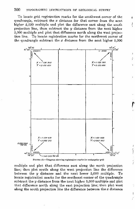
300 TOPOGRAPHIC INSTRUCTIONS OF GEOLOGICAL SURVEY
To locate grid registration marks for the southwest corner of the quadrangle, subtract the x distance for that corner from the next higher 5,000 multiple and plot the difference east along the south projection line, then subtract the y distance from the next higher 5,000 multiple and plot that difference north along the west projec tion line. To locate registration marks for the northwest corner of the quadrangle subtract the x distance from the next higher 5,000
79 30 41° 30'
2095000 Yards
X = 1136 96S
Y -2 122 637
X= 1137 491
Y = 2092 272
2509*
- - 4-730
X-//59 79O
Y = 2 J23O66
79 15' 14130'
X= / I6O 4O3 Y-2092 70O
79 30 v.y /4-O ooo Yards 79 '^
FIGURE 12. Diagram showing registration marks for rectangular grid
multiple and plot that difference east along the north projection line; then plot south along the west projection line the difference between the y distance and the next lower 5,000 multiple. To locate registration marks for the southeast corner of the quadrangle subtract the y distance from the next higher 5,000 multiple and plot that difference north along the east projection line; then plot west along the south projection line the difference between the x distance
TOPOGKAPHIC MAPPING 301
and the next lower 5,000 multiple. To locate registration marks for the northeast corner plot west along the north projection line the difference between the x distance and the next lower 5,000 multiple; then plot south along the east projection line the difference between the y distance and the next lower 5,000 multiple.
Intermediate grid intersections can then be interpolated along the four ^ides of the map. If the projection is very much too large or very much too smaU a proportionate compensation should be con sidered in plotting the grid intersections.
Figure 12 gives the x and y distances in yards for the four corners of a 15' quadrangle, the distances in yards from each corner to the nearest grid registration mark, the complete x and y distances in yards from the point of origin for the grid lines nearest the southwest corner, and the interpolated grid lines.
INKING OF CULTURAL REVISION SHEETS
Field revision sheets. The field revision sheets are described under "Field sheets" (p. 179). So much of the new or changed culture, drainage, or relief as has been surveyed in the field should be inked in the three standard colors. (See "Inking of topographic field sheets," pp. 277 298.) Except as indicated below, the inking should be con fined to the new or changed features, and the unchanged features will therefore, be left in the original faint photolithographic colors. The entire projection should be inked, however, and the sheets should be cut into halves or quarters, as may be most convenient, so that the separate parts when laid edge to edge will make a single continuous map. For this purpose small overhangs may need transfer to other parts before being cut away.
Where the cultural changes arc so numerous as to have warranted a complete or nearly complete resurvey of the topography of a small area it will in general be found advisable to ink the entire portion of the sheet representing that area.
Exception if cultural changes are extensive. If the cultural changes are so numerous and widespread that the correction of the black cop per plate would cost more than the engraving of a new black plate the entire culture of the quadrangle should be inked. Therefore if cul tural changes are extensive, instructions should be sought before the inking is completed.
Bench marks and other control. «AI1 existing control stations and bench marks, together with their established elevations, should be inked, whether they represent changes or not.
" Take out" sheet. The purpose of the "take out" sheet is to indi cate all roads, trails, railroads, houses, names, and other features which no longer exist and for which the corresponding lines on the copper plates are to be taken out. The field copy of the engraved map
302 TOPOGRAPHIC INSTEUCTIONS OF GEOLOGICAL SURVEY
used as a "take out" sheet may, if in good condition, be used as en graver's copy; otherwise the "take outs'' should be transferred to a clean copy .of the published map. Careful preparation of the "take out" sheet is essential in order that the engraver may have a clear under standing of what is to be taken from the plates before beginning the engraving of the new or changed topography. Where solid areas have been inked on the revision sheets the corresponding areas should be marked for "take out."
Name sheet. In whatever form the name sheet is submitted (see "Names," p. 226), the copy must be complete and clear as to intent. Where a town or other named feature has been moved or changed in appearance the new lettering should be placed in the appropriate changed position.
Road classification. The roads that are to be changed from full double lines to dashed lines and the reverse (see "Road classification," p. 256) should be so inked on the "take out" sheet; and such changes in road classification should be fully explained in the margin.
A separate engraved copy marked "Road classification" will be prepared as copy for the red overprint, in accordance with the instruc tions given on page 309.
BORDER CORRECTIONS
Where it is impracticable to join the new work to the maps of quadrangles that have been published on the same scale upon which the new work is to be published, border corrections to the previous maps should be prepared. Such corrections should be submitted on tracing linen, on the scale of field work, and inked in the standard colors used for topographic maps. (See "Map borders," p. 227.)
Purpose. The primary purpose of border corrections is to make maps of adjoining areas match if the maps are published on the same scale. Corrections should therefore be confined to this single object and the correction copy threaded into the previous work within the smallest practicable space and with the fewest possible changes in the older work. Even though the field topographer may inadvertently carry his over-edge mapping farther than may be needed to assure a good joining of the two maps, only so much of such over-edge mapping should be used as correction copy as is absolutely necessary to ac complish this result; any further correction of the older plates would involve needless expenditure. .
Preparation. The penciling or inking of correction copy for border corrections should be confined to the exact amount of correction that is needed and should not be extended to include a tracing of any topography that does not itself need correction. As soon as each line of the correction, such as a road, stream, or a contour line,
TOPOGRAPHIC MAPPING 303
joins the corresponding line on the other map, the correction should stop, as any further inking for register is not necessary.
A complete correction copy should be prepared for each of the three copper plates involved, but each should be confined to changes that are called for on its respective plate. For example, if the location of a stream is unchanged but the spacing of contours on the stream is changed, the stream should not be inked, as no correction to the blue plate is here needed. *
Where the topography is readjusted into a new position, aU houses and other cultural features and especially all drainage lines should be added to the inked correction copy so far as a change in their position is involved in the readjustment in topography. Contour numbers should be freely added to all correction copy as an aid in the positive identification of contours in editing, engraving, and proof reading.
Joining work on different scales. Where the previous work is on a smaller scale than that on which the new work is to be published, corrections to the borders of the older map should be made only where the differences indicate considerable errors in the older work, such as a large difference in elevation or an erroneous connection of drainage, that should be corrected on the next reprint of the older map. Minor differences such as may be expected where large-scale work adjoins small-scale work do not require changes in the older plates.
Where the previous work represents surveys that were made many years ago and are probably to be replaced by revised surveys or by new surveys on a larger scale, no correction copy should be prepared-
QUADRANGLE NAMES
Provisional names. In order to provide for the designation of the names of quadrangles in connection with plans for field work and for cost keeping during the progress of field work, provisional names have been given to all quadrangles in the country. These names are recorded in an administrative-progress book in the office of the chief topographic engineer and are also alphabetically recorded in a typewritten list. Both lists are kept corrected to date as changes are authorized.
As it is not always practicable to select the most appropriate name for a quadrangle in advance of its mapping, or to know whether a name that has been selected represents a city or place that will fall wholly within a quadrangle, many changes in provisional names are made after quadrangles have been mapped.
Final names. As a rule each quadrangle is named after the principal city or place or the most prominent feature within its limits. If the name of the largest place or most prominent feature duplicates a name previously used to designate a quadrangle in an adjoining State or if confusion might result by giving to a new
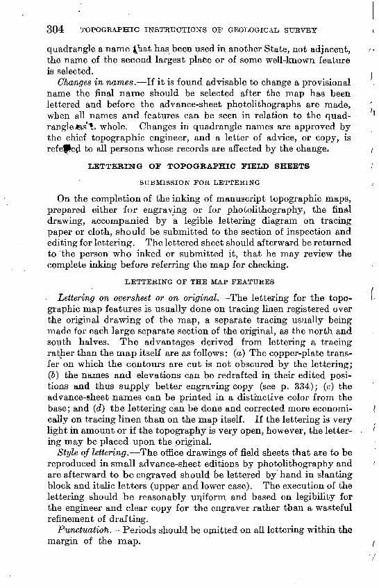
304 TOPOGRAPHIC INSTRUCTIONS OF GEOLOGICAL SURVEY
quadrangle a name £hat has been used in another State, not adjacent, the name of the second largest place or of some well-known feature is selected.
Changes in names. If it is found advisable to change a provisional name the final name should be selected after the map has been lettered and before the advance-sheet photolithographs are made, when all names and features can be seen in relation to the quad rangle fes'% whole. Changes in quadrangle names are approved by the chief topographic engineer, and a letter of advice, or copy, is refe$e(l to all persons whose records are aifected by the change*
LETTERING OF TOPOGRAPHIC FIELD SHEETS
SUBMISSION FOR LETTERING
On the completion of the inking of manuscript topographic maps, prepared either for engraving or for photolithography, the final drawing, accompanied by a legible lettering diagram on tracing paper or cloth, should be submitted to the section of inspection and editing for lettering. The lettered sheet should afterward be returned to the person who inked or submitted it, that he may review the complete inking before referring the map for checking.
LETTERING OF THE MAP FEATURES
Lettering on oversheet or on original. The lettering for the topo graphic map features is usually done on tracing linen registered over the original drawing of the map, a separate tracing usually being made for each large separate section of the original, as the north and south halves. The advantages derived from lettering a tracing rather than the map itself are as follows: (a) The copper-plate trans fer on which the contours are cut is not obscured by the lettering; (6) the names and elevations can be redrafted in their edited posi tions and thus supply better engraving copy (see p. 334); (c) the advance-sheet names can be printed in a distinctive color from the base; and (d) the lettering can be done and corrected more economi cally on tracing linen than on the map itself. If the lettering is very light in amount or if the topography is very open, however, the letter ing may be placed upon the original.
Style of lettering. The office drawings of field sheets that are to be reproduced in small advance-sheet editions by photolithography and are afterward to be engraved should be lettered by hand in slanting block and italic letters (upper and lower case). The execution of the lettering should be reasonably uniform and based on legibility for the engineer and clear copy for the engraver rather than a wasteful refinement of drafting.
Punctuation. Periods should be omitted on all lettering within the margin of the map.
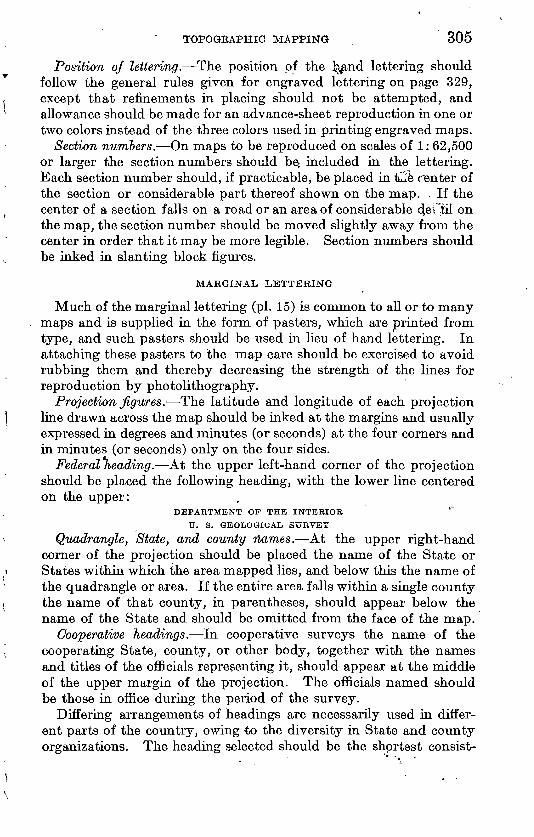
TOPOGRAPHIC MAPPING 305
Position of lettering. The position of the l^nd lettering should follow the general rules given for engraved lettering on page 329, except that refinements in placing should not be attempted, and allowance should be made for an advance-sheet reproduction in one or two colors instead of the three colors used in printing engraved maps.
Section numbers, On maps to be reproduced on scales of 1: 62,500 or larger the section numbers should be, included in the lettering. Each section number should, if practicable, be placed in thle center of the section or considerable part thereof shown on the map. . If the center of a section falls on a road or an area of considerable clel^il on the map, the section number should be moved slightly away from the center in order that it may be more legible. Section numbers should be inked in slanting block figures.
MARGINAL LETTERING
Much of the marginal lettering (pi. 15) is common to all or to many maps and is supplied in the form of pasters, which are printed from type, and such pasters should be used in lieu of hand lettering. In attaching these pasters to the map care should be exercised to avoid rubbing them and thereby decreasing the strength of the lines for reproduction by photolithography.
Projection figures. The latitude and longitude of each projection line drawn across the map should be inked at the margins and usually expressed hi degrees and minutes (or seconds) at the four corners and in minutes (or seconds) only on the four sides.
Federal (leading. At the upper left-hand corner of the projection should be placed the following heading, with the lower line centered on the upper:
DEPARTMENT OP THE INTERIOR
TJ. S. GEOLOGICAL SURVEY
Quadrangle, State, and county names. At the upper right-hand corner of the projection should be placed the name of the State or States within which the area mapped lies, and below this the name of the quadrangle or area. If the entire area falls within a single county the name of that county, in parentheses, should appear below the name of the State and should be omitted from the face of the map.
Cooperative headings. In. cooperative surveys the name of the cooperating State, county, or other body, together with the names and titles of the officials representing it, should appear at the middle of the upper margin of the projection. The officials named should be those in office during the period of the survey.
Differing arrangements of headings are necessarily used in differ ent parts of the country, owing to the diversity in State and county organizations. The heading selected should be the shortest consist-
306 TOPOGRAPHIC INSTRUCTIONS OP GEOLOGICAL SURVEY
ent with Geological Survey practice and with approval by the cooper ating officials.
Scales. At the middle of the lower margin the scale, expressed in the form of a fraction, a bar scale in miles, a bar scale in feet, and a bar scale in kilometers, should appear in the order named. Litho graphic prints of appropriate bar scales for the several field mapping scales are kept in stock and should be tested for length after being pasted in position.
Contour interval. Directly under the bar scales should be placed a statement of the contour interval for example, "Contour interval 20 feet." Where two contour intervals are used both should be stated, and if practicable a statement of the contour on which the interval changes should be added for example, "Contour intervals 5 and 25 feet, changing on the 400-foot contour."
Contour interval under water. Where under-water (offshore) con tours are drawn a statement of the contour interval should be placed directly under the vertical datum line. If additional contours of smaller interval are shown for the lesser depths near shore, such con tours should be listed for example, "Contour interval offshore 20 feet, with the 10 and 30 foot contours added."
Datum. Directly under the statement of contour interval should be placed the statement, "Datum is mean sea level," but if the verti cal datum differs from mean sea level, the amount by which it differs should be stated in a note placed in parentheses directly under the datum line for example, "Readjustment indicates that elevations on this map should be increased by 4 feet." The alternate expression, "Datum is 4 feet below mean sea level," is too ambiguous for public use and should not be used.
Division engineer. At the lower left-hand corner of the projection should appear the name of the division engineer within*-whose division and under whose general direction the topographic mapping was done. This item is added for advance-sheet and office information only and should not be engraved.
Topographic authorship. Directly under the name of the division engineer should appear a paragraph stating the topographic author ship, with the names arranged in the order of seniority. By author ship is meant the independent survey of an area for which an author is wholly responsible. Traverses that are afterward adjusted into others' work and thereby absorbed will not be considered independent work entitled to credit in this paragraph.
Author diagram. An author diagram should be added at the lower margin showing the respective areas mapped by the men listed as topographic authors. This diagram" is intended for advance-sheet and office information only and will not be engraved unless an out-
TOPOGRAPHIC MAPPING 307
side organization has been credited with topographic authorship. (See preceding paragraph.)
Control authorship. Beneath the list of topographic authors should appear the name or names of organizations executing either horizontal or vertical control which has been used in the construction of the topographic map for example, "Control by U. S. Geological Survey and U. S. Coast and Geodetic Survey."
Credit jor outside data. Credit should be given for any outside data used in the construction of the map, whether from Federal, State, or private sources. (See "Data from other surveys," pp. 178, 344.) Such credit may apply to topography, control, underwater contours, shore lines, or other data.
Date oj survey. The date of survey should be given beneath the statement of credit. The date or dates used should represent only Geological Survey topographic mapping and not dates for control or for outside topographic data. Any outside topographic data should have been examined and corrected to the date of the new topography before being incorporated.
Projection used. At the lower right-hand corner of the projection should appear a statement of the projection used, as "Polyconic projection."
Horizontal datum. Beside the statement of projection should ap pear the words "North American datum," if the map is drawn on that datum; otherwise, if the amount of shift in the projection lines necessary to place the map on the North American datum is known, an explanatory note should be added for example, "To place on North American datum move projection lines 340 feet west and 700 feet south."
Joining lines. If a map of an adjoining area has been published on a different horizontal datum and joining lines have been inked on the new map. an explanatory note should be added below the statement of horizontal datum for example, "To join Galatia map use dotted projection corners."
Grid and zone. Opposite the x and y grid lines nearest the south west corner of the projection the x and y distances should be stated in yards. Directly beneath the statement of projection and datum should appear a note stating the size of the grid (if used) and the zone in which it faUs for example, "5,000-yard grid based upon U. S. zone system, F." (See pp. 298-301.)
Land lines and topography. If the land lines are anywhere omitted because the Land Office plats can not be reconciled to the topography, an explanatory note should be added in the lower right-hand corner for example, "Note: Land lines pertaining to Tps. 32, 33, 34, and 35 N., R. 4 E., T. 36 N., R. 2 E., and parts of Tps. 34 and 35 N., R. 2 E., are omitted because land plats and topography can not be reconciled
308 TOPOGEAPHIC INSTRUCTIONS OF GEOLOGICAL SURVEY
and no corners could be found," or, "Note: As the Land Office plats can not be reconciled to the topography, the land lines are omitted. The few isolated corners found are shown."
Shore line and height of tide. If under-water (offshore) contours are plotted on the map a note should be added in the lower right- hand corner stating the shore line used and the height of the tide for example, "Shore line is the margin of mean high water 1.8 feet above mean low water at Glymont."
Names of adjoining quadrangles. The names of adjoining quad rangles should be added in parentheses in the middle outer margin on each common border between them. If the scale of the map of the adjoining area is different that scale should be indicated.
Township and range numbers. Township and range numbers in the form "T. 5 S., E,. 7 E.," should be lettered on the map margin opposite the center of each township or portion of a township.
Township diagram. A small township diagram, for which pasters are provided, giving the relative positions of sections within a com plete township, should be placed on the south border of the original drawing provided there is ample room and it assists in the identifica- cation of section numbers on advance sheets. The diagram is not needed on maps where section numbers appear either on the original or on the lettering tracing, and it is not engraved.
Declination diagram. On the lower margin of each map the mag netic declination should be shown by a diagram (see pi. 15) as east or west and stated in degrees. A statement to the nearest half degree will usually be as close as the data warrant. One line of the diagram should be oriented and marked true north, and the other line should be placed in the direction corresponding approximately to magnetic north for the locality represented.
Filing name. On the lower right-hand margin of each map should be placed the name of the quadrangle and State, for convenience in filing.
Edition and reprint dates. In the lower right-hand margin should be indicated the date of publication and the nature of the edition. The first printing of the map should carry the expression, for example, "Edition of 1922"; a reprint, "Edition of 1922, reprinted 1926." If material changes, such as cultural revision or extensive corrections, have been made the map should be regarded as a new edition rather than a reprint, and only the date of the new printing should be stated for example, "Edition of 1928."
PREPABATION OF WOODLAND SHEETS
Submission. A woodland tracing should be prepared for each topo graphic map and should be submitted when the map is turned in for inspection and advance-sheet photolithography. (See "Mapping of
TOPOGRAPHIC MAPPING 309
woodland outlines," p. 255.) If the quadrangle contains no woodland of the type defined on page 256, a blank tracing with an inked quad rangle outline should be submitted, across the face of which should be inked the words "No woodland on quadrangle."
Preparation. Woodland sheets should be made on tracing linen, on the scale of the field work, and preferably in two half sheets for each quadrangle. The woodland copy must be made to register correctly over the final drawing of the map. The outer projection of the quadrangle should be fully traced, but only the intersections of all other projection lines appearing on the original. Where an mterior projection intersection falls within a wooded area the green shading should be erased at the intersection. The outlines of wooded areas should be inked in firm solid black lines and the woodland areas shaded in by green pencil. The green shading should be carefully done at its outer borders, inasmuch as the copy is reproduced photo graphically, and any overrun of green will photograph and thereby render the black lines illegible.
Checking. Each woodland sheet should be checked (see "Check ing defined," p. 310) and the tracing- signed and dated on a stamped form provided for the purpose. The checking should usually be done by the same person who checks the final map. It should con sist of an examination of the tracing for completeness of drafting and comparison with the original or other woodland data in the field material. All edges of woodland areas on maps of adjacent quad rangles should be compared for joining.
Approval. Woodland sheets, after checking, should be approved by the division chief, who should indicate his recommendation for printing. The sheets should be finally approved for printing or otherwise by the chief of the section of inspection and editing.
PREPABATION OF BOAD-GX-ASSIFICATION SHEETS
A road-classification tracing should be prepared for each standard topographic map and submitted when the final drawing of the map is turned in for inspection and advance sheet reproduction. It should be made on tracing linen to register over the final drawing, and the classification data should be inked in red. Each tracing should carry at the bottom a key consisting of a red line followed by the words "Hard, imperviously surfaced roads," and a dashed red line fol lowed by the words "Other main traveled roads." The data pre sented should follow carefully the specifications outlined under "Road classification" (p. 256) and should not be combined with any other required information. The date of the last month on which the data were obtained in the field should also be stated.
310 TOPOGKAPHIC INSTRUCTIONS OF GEOLOGICAL SURVEY
PREPARATION OF LAND-CLASSIFICATION SHEETS
The preparation of land-classification sheets is fully explained under "Mapping of land-classification data" (p. 258). Such sheets should be submitted to the section of inspection and editing for examination when the final maps are submitted for advance-sheet photolithography. After examination and approval by the chief of the section of inspection and editing he will forward the land- classification sheets to the chief topographic engineer for trans mission to the chief of the conservation branch.
CHECKING OF INKED FIELD SHEETS
CHECKING OF TOPOGRAPHIC MAPS
Need. The need for an immediate checking up of the inked topographic map by a person other than the author or inker arises from the expectation that one who has worked continuously on the map for many days or weeks may, through inadvertence, misin terpret or omit certain essential data or processes or make errors. If two or more persons ink on the same map, a checking is needed in order to reconcile possible differences that may be found between the parts inked by the different persons, owing to varying interpre tations of instructions. The checker should therefore not only be a qualified topographic engineer but one who has had no association with the map in hand and who is to that extent disinterested.
CJiecJcing defined.* The function of the checker is to examine the final drawing of the map and its field material, through all its fea tures and from every point of view that can suggest itself to an experienced topographer, and as a result of this checking to call the attention of the author or inker to such details as appear to have been overlooked, misinterpreted, omitted, or erroneously shown. The checker, however, should be reasonably familiar with the func tions of the inspector and of the editor, that he may not waste time in the consideration of purely editorial matters which are to receive due attention later. (See below and also pp. 313 and 320.)
The checking should include the examination of the inked field drawings, lettering tracings, and woodland sheets, also of any cor rections that may be necessary to make the new map join maps of adjoining quadrangles that have been previously surveyed.
Avoidance of duplication. Each topographic map in its trans mission from the field to the map editor goes through the following hands: (1) Field topographer as author; (2) office inker; (3) checker;
«See footnote 3, p. 273.
TOPOGRAPHIC MAPPING 311
(4) inspector; (5) control examiner; (6) map editor. Nos. 1 and 2 may or may not be the same person; the others are different persons. Checking and the inspection and editing of topographic maps are based upon a procedure that allows only so much duplication of work as may be necessary to insure that no errors or omissions have been made; and to this end the duties involved in the several stages listed in this paragraph are set forth in some detail in the pages that follow.
Attention to checker's questions. Questions should be referred by the checker to the person in immediate charge of the office inking of the sheet; such questions as apply to parts of the sheet that have been mapped or inked by others who are then in the office should be referred to them for attention, unless in the judgment of the topographer or inker in immediate office charge of the sheet such further reference is deemed unneccessary, in which case he himself may reply to all questions raised by the checker.
Checker's questions that can not be answered by anyone in the office, for the reason that an absent author or inker alone has the needed information, should so far as practicable be referred by letter to the author or inker. Such references may be made before advance- sheet lithography if the advance sheet is not thereby delayed, but inquiries are best handled by indicating the questions on an advance sheet of the map, that the absent author or inker may the better vis ualize the subject-matter. If all authors and inkers of a map are absent from the office the checker should himself make all possible corrections and refer by letter to an author or inker only those ques tions about which there is reasonable doubt as to procedure or lack of information.
Use of tracing paper. In general, the checker's notes and queries should be placed on tracing paper registered over the inked map; questions should not be indicated by drawing pencil lines across the face of the map, for black pencil lines are strongly photographic, and erasures will weaken other inked fines. The checker's oversheets should be destroyed after they have served their purpose, outstanding questions of importance, if any, having been transferred in some ap propriate way, such as writing them on the margin of the original, where they remain for future action.
SCOPE OF CHECKING
In general, the scope of checking is covered by the printed form reproduced on page 312, and this form should serve as a guide; it should, however, be regarded as suggestive rather than complete.
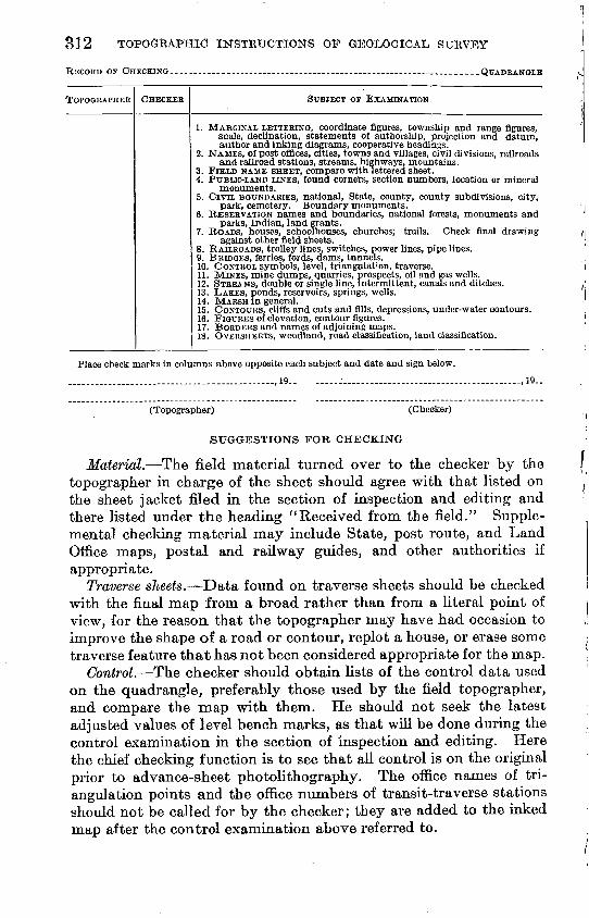
312 TOPOGRAPHIC INSTRUCTIONS OF GEOLOGICAL SURVEY
EECORD OF CHECKING........ --_____.--.- ... .. ....___-.----
TOPOGRAPHER CHECKER SUBJECT OF EXAMINATION
1. MARGINAL LETTERING, coordinate figures, township and range figures, scale, declination, statements of authorship, projection and datum, author and inking diagrams, cooperative headings.
2. NAMES, of post offices, cities, towns and villages, civil divisions, railroads and railroad stations, streams, highways, mountains.
3. FIELD NAME SHEET, compare with lettered sheet.4. PUBLIC-LAND LINES, found corners, section numbers, location or mineral
monuments.5. CIVIL BOUNDARIES, national, State, county, county subdivisions, city,
park, cemetery. Boundary monuments.6. RESERVATION names and boundaries, national forests, monuments and
parks, Indian, land grants.7. ROADS, houses, schoolhouses, churches; trails. Check final drawing
against other field sheets.8. RAILROADS, trolley lines, switches, power lines, pipe lines.9. BRIDGES, ferries, fords, dams, tunnels.10. CONTROL symbols, level, triangulation, traverse.11. MINES, mine dumps, quarries, prospects, oil and gas wells.12. STREAMS, double or single line, intermittent, canals and ditches.13. LAKES, ponds, reservoirs, springs, wells.14. MARSH in general.15. CONTOURS, cliffs and cuts and fills, depressions, under-water contours.16. FIGURES of elevation, contour figures.17. BORDERS and names of adjoining maps.18. OVERSHEETS, woodland, road classification, land classification.
Place check marks in columns above opposite each subject and date and sign below.
............... -. - -_ - -.19.. -__.- . -.-.-_ . _ ,19-
(Topographer) (Checker)
SUGGESTIONS FOB CHECKING
Material. The field material turned over to the checker by the topographer in charge of the sheet should agree with that listed on the sheet jacket filed in the section of inspection and editing and there listed under the heading "Received from the field." Supple mental checking material may include State, post route, and Land Office maps, postal and railway guides, and other authorities if appropriate.
Traverse sheets. Data found on traverse sheets should be checked with the final map from a broad rather than from a literal point of view, for the reason that the topographer may have had occasion to improve the shape of a road or contour, replot a house, or erase some traverse feature that has not been considered appropriate for the map.
Control. The checker should obtain lists of the control data used on the quadrangle, preferably those used by the field topographer, and compare the map with them. He should not seek the latest adjusted values of level bench marks, as that will be done during the control examination hi the section of inspection and editing. Here the chief checking function is to see that all control is on the original prior to advance-sheet photolithography. The office names of tri angulation points and the office numbers of transit-traverse stations should not be called for by the checker; they are added to the inked map after the control examination above referred to.
TOPOGRAPHIC MAPPING 313
Streams. The checker may properly call attention to apparent discrepancies in the amount of classification of drainage inked on a map, but resulting changes in the original drawing should, be made only after full consideration by the author-topographer or inker. The proper coordination of drainage as shown on topographic maps is complex at best and is among the matters considered in the inspec tion examination of the sheet.
Elevations and contours. All elevation figures should be compared with the contours; and all contour numbers should be compared with the elevations and with one another. Doubtful points of application of figures of elevation should be questioned. The checker should ask for the inking of more figures of elevation if those inked are not adequately distributed.
Names and lettering. The lettering tracing should be compared with the field name sheet; and post office, railroad, and station names should be verified. All names should be examined. Names should be requested for prominent unnamed features, especially schools, isolated localities, streams, and conspicuous mountains and lakes.
Woodland sJieets. Woodland tracings should be examined by placing them over the map and by looking for register and for com pleteness of outlines and green shading, also for accuracy of tracing if the woodland outlines are shown upon the original. The woodland borders at the edges of the tracing should be compared with any woodland sheets for adjacent quadrangles. Woodland tracings of published maps are permanently filed in the section of inspection and editing.
Signature. When the checker is satisfied that his notations have received proper attention he should affix his inked signature, with date, on the original drawing and on the woodland sheet within a stamped form provided for the purpose.
CHECKING OF CULTURAL REVISION MAPS
Inasmuch as no advance sheets are made to represent the results of cultural revision surveys, the cultural revision sheets are not checked. To avoid unnecessary duplication the sheets are so carefully scruti nized in the editorial and control examination that no prior checking by a topographer will in general be needed other than that by the author or inker.
INSPECTION OF TOPOGRAPHIC MAPS
SUBMISSION
On the completion of the checking of the topographic map and its return to the topographer who inked it, the topographer should sub mit the map and the lettering, woodland, land-classification, and
314 TOPOGEAPHIC INSTEUCTIONS OF GEOLOGICAL, SURVEY
road-classification tracings and adjoining border corrections, together with all field-map material, to the chief of the section of inspection and editing for inspection, advance-sheet photolithography, control examination, editing, and further transmission for engraving or otherwise as may be appropriate.
INSPECTION DEFINED
The term "inspection" as applied to an inked topographic map means an examination that is made immediately after the checking of the map and before the map is approved for advance-sheet repro duction. The inspection examination should assume that the check ing-has been adequately done; if the appearance of the map suggests otherwise the inspector may return the map for additional checking. The inspection of the map should also be made with the functions of the map editor well in mind, in order that there may be no un necessary duplication of examination. The time spent in the inspection of a map will differ with different maps, but a day should suffice for the average map; additional time will be required for maps that are found to need a closer inspection.
The inspection of topographic maps should be made primarily from the point of view of the field topographic engineer and thus should be assigned to one who has had such experience. The inspec tion should also be made from the point of view of one who has had an adequate office experience. These two qualifications, when combined with an experience that is acquired only through the examination of many maps representing all sections of the country, may reasonably be expected to result in an inspection that will quickly appraise an inked map as to its completeness and general coordination with other maps and as to its conformity with Geological Survey policies and standard practices.
NEED OF INSPECTION
Experienced topographic engineers working in a country to which they are accustomed will produce a map of known standards and one that will be expressed from known points of view, and such a map will need a minimum of inspection; likewise a checker of ex perience, when examining a map of an area located in a general section of country in which he has had personal training, will read the map with recognized efficiency. But the personnel of a large organization is perforce made up of men who have had varying lengths of service and corresponding experience, and as the numerous maps made by the topographic engineers of the Geological Survey represent the great variety in types of topography that is to be found over the country at large, differences in the interpretation of standard instructions are to be expected. It is a province of the inspector
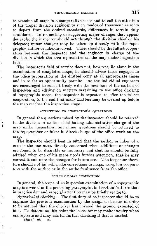
TOPOGRAPHIC MAPPING 315
to examine all maps in a comparative sense and to call the attention of the proper division engineer to such modes, of treatment as seem to depart from the desired standards, differences in terrain duly considered. In requesting or suggesting major changes that appear desirable, the inspector should act through the division chief or his delegate; minor changes may be taken up directly with the topo graphic author or inker involved. There should be the fullest cooper ation between the inspector and the engineer in charge of the division in which the area represented on the map under inspection falls.
The inspector's field of service does not, however, lie alone in the examination of completed maps; he should advise those engaged in the office preparation of the drafted copy at all appropriate times and in so far as opportunity permits. As the individual engineers are encouraged to consult freely with the members of the section of inspection and editing on matters pertaining to the office drafting of topographic maps, the inspector is expected to offer the fullest cooperation, to the end that many matters may be cleared up before the map reaches the inspection stage.
ATTENTION TO INSPECTOR'S QUESTIONS
In general the questions raised by the inspector should be referred to the division or section chief having administrative charge of the map under inspection; but minor questions should be referred to the topographer or inker in direct charge of the office work on the map.
The inspector should bear in mind that the author or inker of a map is the one most directly concerned when additions or changes are found to be desirable or necessary and that he should be fully advised when one of his maps needs further attention, that he may correct it and note the changes for future use. The inspector there fore should not himself make corrections to maps, except in coopera tion with the author or in the author's absence from the office.
SCOPE OF MAP INSPECTION
In general, the scope of an inspection examination of a topographic map is covered in the preceding paragraphs, but certain features that in practice demand especial attention may be briefly set forth.
Appraisal of checking. The first duty of an inspector should be to appraise the previous examination by the assigned checker in order to be assured that the checker has covered the ground expected of him. To determine this point the inspector may make inquiry when appropriate and may ask for further checking if that is needed.
58515° 28 21
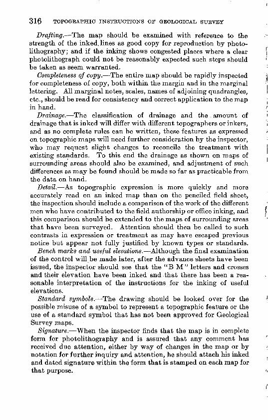
316 TOPOGKAPHIC INSTRUCTIONS OF GEOLOGICAL SURVEY
Drafting. The map should be examined with reference to the strength of the inked, lines as good copy for reproduction by photo lithography; and if the inking shows congested places where a clear photolithograph could not be reasonably expected such steps should be taken as seem warranted.
Completeness of copy. The entire map should be rapidly inspected for completeness of copy, both within the margin and in the marginal lettering. All marginal notes, scales, names of adjoining quadrangles, etc., should be read for consistency and correct application to the map in hand.
Drainage. The classification of drainage and the amount of drainage that is inked will differ with different topographers or inkers, and as no complete rules can be written, these features as expressed on topographic maps will need further consideration by the inspector, who may request slight changes to reconcile the treatment with existing standards. To this end the drainage as shown on maps of surrounding areas should also be examined, and adjustment of such differences as may be found should be made so far as practicable from the data on hand.
Detail. As topographic expression is more quickly and more accurately read on an inked map than on the penciled field sheet, the inspection should include a comparison of the work of the different men who have contributed to the field authorship or office inking, and this comparison should be extended to the maps of surrounding areas that have been surveyed. Attention should then be called to such contrasts in expression or treatment as may have escaped previous notice but appear not fully justified by known types or standards.
Bench marks and useful elevations. Although the final examination of the control will be made later, after the advance sheets have been issued, the inspector should see that the "B M" letters and crosses and their elevation have been inked and that there has been a rea sonable interpretation of the instructions for the inking of useful elevations.
Standard symbols. The drawing should be looked over for the possible misuse of a symbol to represent a topographic feature or the use of a standard symbol that has not been approved for Geological Survey maps.
Signature. When the inspector finds that the map is in complete form for photolithography and is assured that any comment has received due attention, either by way of changes in the map or by notation for further inquiry and attention, he should attach his inked and dated signature within the form that is stamped on each map for that purpose.
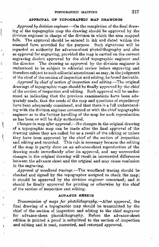
TOPOGRAPHIC MAPPING 317
APPROVAL OF TOPOGRAPHIC MAP DRAWINGS
Approval by division engineer. On the completion of the final draw ing of the topographic map the drawing should be approved by the division engineer in charge of the division in which the area mapped falls. The approval should be entered in ink and dated within the stamped form provided for the purpose. Such signatures will be regarded as authority for advance-sheet photolithography and also as approval for engraving, provided the map is carried on the current engraving docket approved by the chief topographic engineer and the director. The drawing as approved by the division engineer is understood to be subject to editorial review before engraving and therefore subject to such editorial amendment as may, in the judgment of the chief of the section of inspection and editing, be found desirable.
Approval by chief of section of inspection and editing. The original drawings of topographic maps should be finally approved by the chief of the section of inspection and editing. Such approval will be under stood as indicating that the previous examinations have been ade quately made, that the needs of the map and questions of expediency have been adequately considered, and that there is a full understand ing with the division engineer concerned or with the chief topographic engineer as to the further handling of the map for such reproduction as has been or will be duly authorized.
Changes in map after approval. No changes in the original drawing of a topographic map can be made after the final approval of the drawing unless they are called for as a result of the editing or unless they have been approved by the chief of the section of inspection and editing and recorded. This rule is necessary because the editing of the map is partly done on an advance-sheet reproduction of the drawing made immediately after its approval, and any unrecorded changes in the original drawing will result in unrecorded differences between the advance sheet and the original and may cause confusion in the engraving.
Approval of woodland tracings. The woodland tracing should be checked and signed by the topographer assigned to check the map; it should be approved by the division engineer concerned; and it should be finally approved for printing or otherwise by the chief of the section of inspection and editing.
ADVANCE SHEETS
Transmission of maps for pJiotolitJiography. After approval, the final drawing of a topographic map should be transmitted by the chief of the section of inspection and editing to the chief engraver for advance-sheet photolithography. Before the advance-sheet edition is printed a proof is submitted to the section of inspection and editing and is read, corrected, and returned approved.
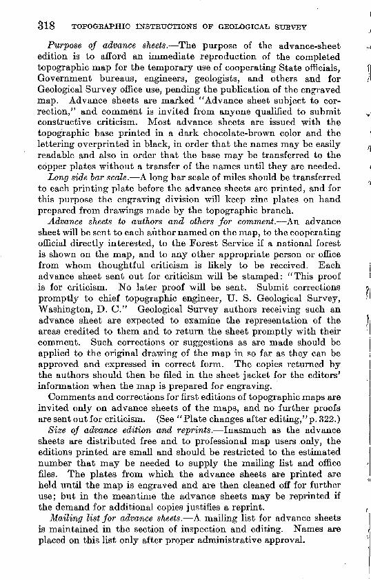
318 TOPOGRAPHIC INSTRUCTIONS OF GEOLOGICAL SURVEY
Purpose of advance sheets. The purpose of the advance-sheet edition is to afford an immediate reproduction of the completed topographic map for the temporary use of cooperating State officials, Government bureaus, engineers, geologists, and others and for Geological Survey office use, pending the publication of the engraved map. Advance sheets are marked "Advance sheet subject to cor rection," and comment is invited from anyone qualified to submit constructive criticism. Most advance sheets are issued with the topographic base printed in a dark chocolate-brown color and the lettering overprinted in black, in order that the names may be easily readable and also in order that the base may be transferred to the copper plates without a transfer of the names until they are needed.
Long side bar scale. A long bar scale of miles should be transferred to each printing plate before the advance sheets are printed, and for this purpose the engraving division will keep zinc plates on hand prepared from drawings made by the topographic branch.
Advance sheets to authors and others Jor comment. An advance sheet will be sent to each author named on the map, to the cooperating official directly interested, to the Forest Service if a national forest is shown on the map, and to any other appropriate person or office from whom thoughtful criticism is likely to be received. Each advance sheet sent out for criticism will be stamped: "This proof is for criticism. No later proof will be sent. Submit corrections promptly to chief topographic engineer, U. S. Geological Survey, Washington, D. C." Geological Survey authors receiving such an advance sheet are expected to examine the representation of the areas credited to them and to return the sheet promptly with their comment. Such corrections or suggestions as are made should be applied to the original drawing of the map in so far as they can be approved and expressed in correct form. The copies returned by the authors should then be filed in the sheet jacket for the editors' information when the map is prepared for engraving.
Comments and corrections for first editions of topographic maps are invited only on advance sheets of the maps, and no further proofs are sent out for criticism. (See "Plate changes after editing,"p. 322.)
Size of advance edition and reprints. Inasmuch as the advance sheets are distributed free and to professional map users only, the editions printed are small and should be restricted to the estimated number that may be needed to supply the mailing list and office files. The plates from which the advance sheets are printed are held until the map is engraved and are then cleaned off for further use; but in the meantime the advance sheets may be reprinted if the demand for additional copies justifies a reprint.
Mailing list Jor advance sheets. A mailing list for advance sheets is maintained in the section of inspection and editing. Names are placed on this list only after proper administrative approval.
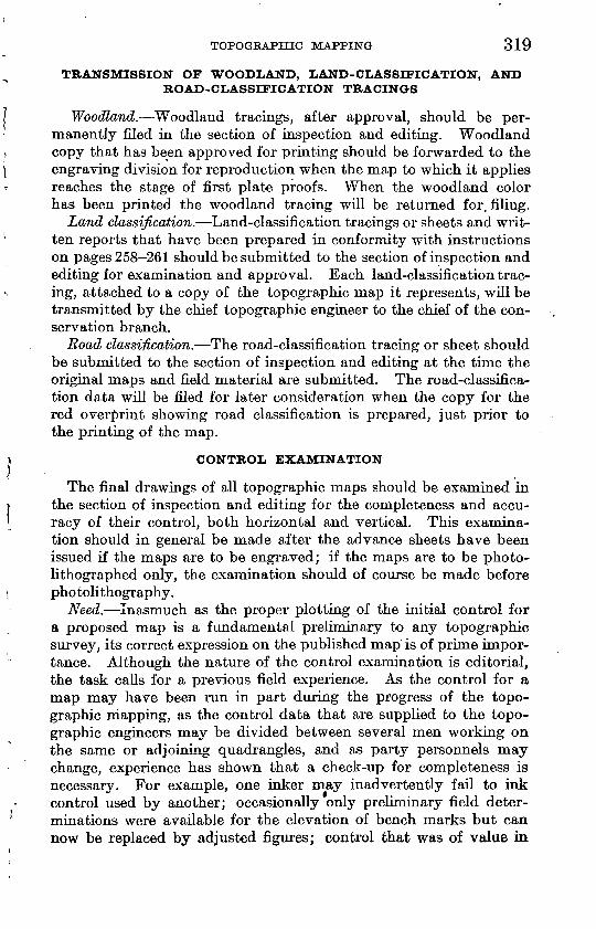
TOPOGRAPHIC MAPPING 319
TRANSMISSION OF WOODLAND, LAND-CLASSIFICATION, AND ROAD-CLASSIFICATION TRACINGS
Woodland. Woodland tracings, after approval, should be per manently filed in the section of inspection and editing. Woodland copy that has been approved for printing should be forwarded to the engraving division for reproduction when the map to which it applies reaches the stage of first plate proofs. When the woodland color has been printed the woodland tracing will be returned for. filing.
Land classification. Land-classification tracings or sheets and writ ten reports that have been prepared in conformity with instructions on pages 258-261 should be submitted to the section of inspection and editing for examination and approval. Each land-classification trac ing, attached to a copy of the topographic map it represents, will be transmitted by the chief topographic engineer to the chief of the con servation branch.
Road classification. The road-classification tracing or sheet should be submitted to the section of inspection and editing at the tune the original maps and field material are submitted. The road-classifica tion data will be filed for later consideration when the copy for the red overprint showing road classification is prepared, just prior to the printing of the map.
CONTROL EXAMINATION
The final drawings of all topographic maps should be examined in the section of inspection and editing for the completeness and accu racy of their control, both horizontal and vertical. This examina tion should in general be made after the advance sheets have been issued if the maps are to be engraved; if the maps are to be photo- lithographed only, the examination should of course be made before photolithography.
Need. Inasmuch as the proper plotting of the initial control for a proposed map is a fundamental preliminary to any topographic survey, its correct expression on the published map is of prime impor tance. Although the nature of the control examination is editorial, the task calls for a previous field experience. As the control for a map may have been run in part during the progress of the topo graphic mapping, as the control data that are supplied to the topo graphic engineers may be divided between several men working on the same or adjoining quadrangles, and as party personnels may change, experience has shown that a check-up for completeness is necessary. For example, one inker may inadvertently fail to ink control used by another; occasionally only preliminary field deter minations were available for the elevation of bench marks but can now be replaced by adjusted figures; control that was of value in
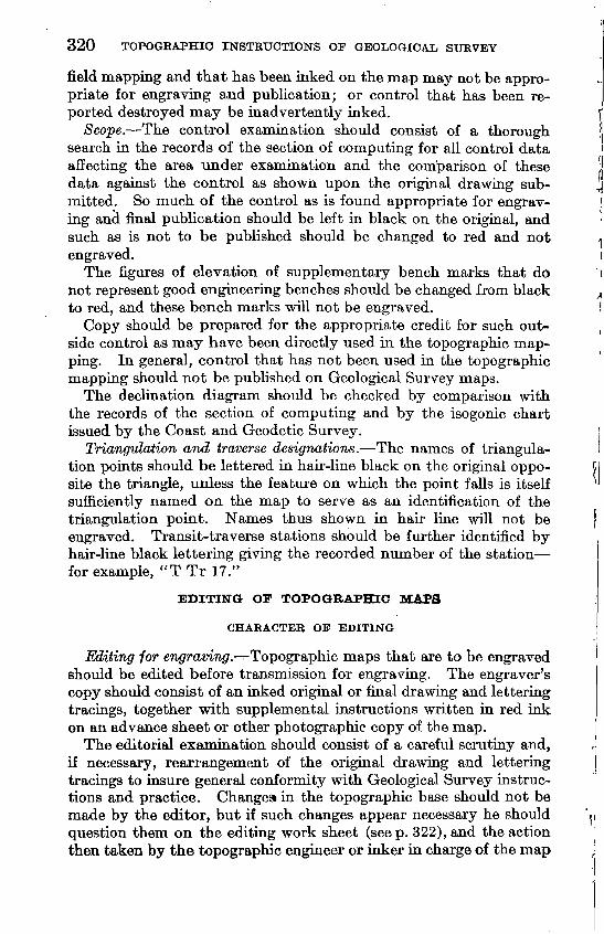
320 TOPOGKAPHIC INSTRUCTIONS OF GEOLOGICAL SURVEY
field mapping and that has been inked on the map may not be appro priate for engraving and publication; or control that has been re ported destroyed may be inadvertently inked.
Scope. The control examination should consist of a thorough search in the records of the section of computing for all control data affecting the area under examination and the comparison of these data against the control as shown upon the original drawing sub mitted. So much of the control as is found appropriate for engrav ing and final publication should be left in black on the original, and such as is not to be published should be changed to red and not engraved.
The figures of elevation of supplementary bench marks that do not represent good engineering benches should be changed from black to red, and these bench marks will not be engraved.
Copy should be prepared for the appropriate credit for such out side control as may have been directly used in the topographic map ping. In general, control that has not been used in the topographic mapping should not be published on Geological Survey maps.
The decimation diagram should be checked by comparison with the records of the section of computing and by the isogonic chart issued by the Coast and Geodetic Survey.
Triangulation and traverse designations. The names of triangula- tion points should be lettered in hair-line black on the original oppo site the triangle, unless the feature on which the point falls is itself sufficiently named on the map to serve as an identification of the triangulation point. Names thus shown in hair line will not be engraved. Transit-traverse stations should be further identified by hair-line black lettering giving the recorded number of the station for example, "T Tr 17."
EDITING OF TOPOGRAPHIC MAPS
CHARACTER OF EDITING
Editing for engrramTW/. Topographic maps that are to be engraved should be edited before transmission for engraving. The engraver's copy should consist of an inked original or final drawing and lettering tracings, together with supplemental instructions written in red ink on an advance sheet or other photographic copy of the map.
The editorial examination should consist of a careful scrutiny and, if necessary, rearrangement of the original drawing and lettering tracings to insure general conformity with Geological Survey instruc tions and practice. Changes in the topographic base should not be made by the editor, but if such changes appear necessary he should question them on the editing work sheet (seep. 322), and the action then taken by the topographic engineer or inker in charge of the map
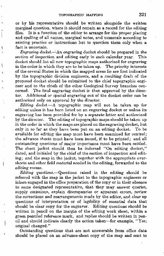
TOPOGRAPHIC MAPPING 321
or by his representative should be written alongside the written marginal question, where it should remain as a record for the editing files. It is a function of the editor to arrange for the proper placing and spelling of all names, marginal notes, and numerals according to existing practice or instructions but to question them only when a fact is uncertain.
Engraving docket. LAn engraving docket should be prepared in the section of inspection and editing early in each calendar year. This docket should list all new topographic maps authorized for engraving in the order in which they are to be taken up. The priority interests of the several States in which the mapped areas lie are first indicated by the topographic division engineers, and a resulting draft of the proposed docket should be submitted to the chief topographic engi neer and to the chiefs of the other Geological Survey branches con cerned. The final engraving docket is then approved by the direc tor. Additional or special engraving out of the docket order can be authorized only on approval by the director.
Editing docket. A topographic map will not be taken up for editing unless it has been listed on an engraving docket or unless its engraving has been provided for by a separate letter and authorized by the director. The editing of topographic maps should be taken up in the order in which the maps are placed on the engraving docket, but only in so far as they have been put on an editing docket. To be available for editing the map must have been examined for control; the advance sheets must have been issued, if to be printed; and all outstanding questions of major importance must have been settled. The sheet jacket should then be indorsed "On editing docket," dated, and initialed by the chief of the section of inspection and edit ing; and the map in the jacket, together with the appropriate over- sheets and other field material needed in the editing, forwarded to the editing rooms.
Editing questions. Questions raised in the editing should be referred with the map in the jacket to the topographic engineers or inkers engaged in the office preparation of the copy or in their absence to some designated representative, that they may answer queries, supply omissions, explain discrepancies or apparent errors, review the corrections and rearrangements made by the editor, and clear up questions of interpretation or of legibility of essential data that should be clear copy for the engraver. Editing questions should be written in pencil on the margin of the editing work sheet, within a green penciled reference mark, and replies should be written in pen cil and should indicate clearly the action taken for example, "Yes; original changed."
Outstanding questions that are not answerable from office data should be placed on an advance-sheet copy of the map and sent to
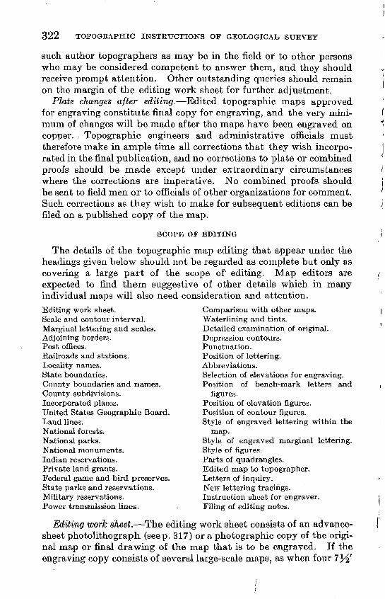
322 TOPOGEAPHIC INSTRUCTIONS OF GEOLOGICAL, SURVEY
such author topographers as may be in the field or to other persons who may be considered competent to answer them, and they should receive prompt attention. Other outstanding queries should remain on the margin of the editing work sheet for further adjustment.
Plate changes after editing. Edited topographic maps approved for engraving constitute final copy for engraving, and the very mini mum of changes will be made after the maps have been engraved on copper. Topographic engineers and administrative officials must therefore make in ample time all corrections that they wish incorpo rated in the final publication, and no corrections to plate or combined proofs should be made except under extraordinary circumstances where the corrections are imperative. No combined proofs should be sent to field men or to officials of other organizations for comment. Such corrections as they wish to make for subsequent editions can be filed on a published copy of the map.
SCOPE OP EDITING
The details of the topographic map editing that appear under the headings given below should not be regarded as complete but only as covering a large part of the scope of' editing. Map editors are expected to find them suggestive of other details which in many individual maps will also need consideration and attention.
Comparison with other maps.Waterlining and tints.Detailed examination of original.Depression contours.Punctuation.Position of lettering.Abbreviations.Selection of elevations for engraving.Position of bench-mark letters and
figures.Position of elevation figures. Position of contour figures. Style of engraved lettering within the
map.Style of engraved marginal lettering. Style of figures. Parts of quadrangles. Edited map to topographer. Letters of inquiry. New lettering tracings. Instruction sheet for engraver. Filing of editing notes.
Editing work sheet.Scale and contour interval.Marginal lettering and scales.Adjoining borders.Post offices.Railroads and stations.Locality names.State boundaries.County boundaries and names.County subdivisions.Incorporated places.United States Geographic Board.Land lines.National forests.National parks.National monuments.Indian reservations.Private land grants.Federal game and bird preserves.State parks and reservations.Military reservations.Power transmission lines.
Editing work sheet. The editing work sheet consists of an advance- sheet photolithograph (seep. 317) or a photographic copy of the origi nal map or final drawing of the map that is to be engraved. If the engraving copy consists of several large-scale maps, as when four
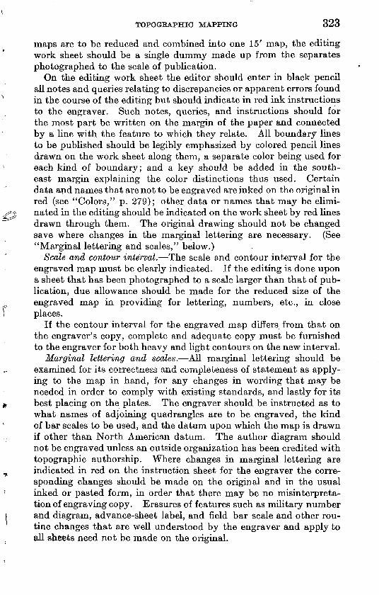
TOPOGRAPHIC MAPPING 323
maps are to be reduced and combined into one 15' map, the editing work sheet should be a single dummy made up from the separates photographed to the scale of publication.
On the editing work sheet the editor should enter in black pencil all notes and queries relating to discrepancies or apparent errors found in the course of the editing but should indicate in red ink instructions to the engraver. Such notes, queries, and instructions should for the most part be written on the margin of the paper and connected by a line with the feature to which they relate. All boundary lines to be published should be legibly emphasized by colored pencil lines drawn on the work sheet along them, a separate color being used for each kind of boundary; and a key should be added in the south east margin explaining the color distinctions thus used. Certain data and names that are not to be engraved are inked on the original in red (see "Colors," p. 279); other data or names that may be elimi nated in the editing should be indicated on the work sheet by red lines drawn through them. The original drawing should not be changed save where changes in the marginal lettering are necessary. (See "Marginal lettering and scales," below.)
Scale and contour interval. The scale and contour interval for the engraved map must be clearly indicated. If the editing is done upon a sheet that has been photographed to a scale larger than that of pub lication, due allowance should be made for the reduced size of the engraved map in providing for lettering, numbers, etc., in close places.
If the contour interval for the engraved map differs from that on the engraver's copy, complete and adequate copy must be furnished to the engraver for both heavy and light contours on the new interval.
Marginal lettering and scales. All marginal lettering should be examined for its correctness and completeness of statement as apply ing to the map in hand, for any changes in wording that may be needed in order to comply with existing standards, and lastly for its best placing on the plates. The engraver should be instructed as to what names of adjoining quadrangles are to be engraved, the kind of bar scales to be used, and the datum upon which the map is drawn if other than North American datum. The author diagram should not be engraved unless an outside organization has been credited with topographic authorship. Where changes in marginal lettering are indicated in red on the instruction sheet for the engraver the corre sponding changes should be made on the original and in the usual inked or pasted form, in order that there may be no misinterpreta tion of engraving copy. Erasures of features such as military number and diagram, advance-sheet label, and field bar scale and other rou tine changes that are well understood by the engraver and apply to all sheets need not be made on the original.
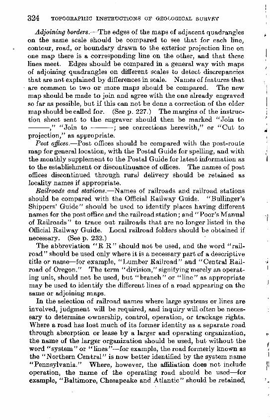
324 TOPOGRAPHIC INSTRUCTIONS OF GEOLOGICAL SURVEY
Adjoining borders. The edges of the maps of adjacent quadrangles on the same scale should be compared to see that for each line, contour, road, or boundary drawn to the exterior projection line on one map there is a corresponding line on the other, and that these lines meet. Edges should be compared in a general way with maps of adjoining quadrangles on different scales to detect discrepancies that are not explained by differences in scale. Names of features that are common to two or more maps should be compared. The new map should be made to join and agree with the one already engraved so far as possible, but if this can not be done a correction of the older map should be called for. (See p. 227.) The margins of the instruc tion sheet sent to the engraver should then be marked "Join to ," "Join to ; see corrections herewith," or "Cut to projection," as appropriate.
Post offices. Post offices should be compared with the post-route map for general location, with the Postal Guide for spelling, and with the monthly supplement to the Postal Guide for latest information as to the establishment or discontinuance of offices. The names of post offices discontinued through rural delivery should be retained as locality names if appropriate.
Railroads and stations. Names of railroads and railroad stations should be compared with the Official Railway Guide. "Bullinger's Shippers' Guide" should be used to identify places having different names for the post office and the railroad station; and "Poor's Manual of Railroads" to trace out railroads that are no longer listed in the Official Railway Guide. Local railroad folders should be obtained if necessary. (See p. 232.)
The abbreviation "R R" should not be used, and the word "rail road" should be used only where it is a necessary part of a descriptive title or name for example, "Lumber Railroad" and "Central Rail road of Oregon." The term "division," signifying merely an operat ing unit, should not be used, but "branch" or "line" as appropriate may be used to identify the different lines of a road appearing on the same or adjoining maps.
In the selection of railroad names where large systems or lines are involved, judgment will be required, and inquiry will often be neces sary to determine ownership, control, operation, or trackage rights. Where a road has lost much of its former identity as a separate road through absorption or lease by a larger and operating organization, the name of the larger organization should be used, but without the word "system" or "lines" for example, the road formerly known as the "Northern Central" is now better identified by the system name "Pennsylvania." Where, however, the affiliation does not include operation, the name of the operating road should be used for example, "Baltimore, Chesapeake and Atlantic" should be retained,
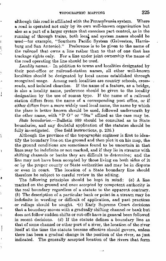
TOPOGRAPHIC MAPPING 325
although this road is affiliated with the Pennsylvania system. Where a road is operated not only by its own well-known organization but also as a part of a larger system that exercises part control, as in the running of through trains, both loca^ and system .names should be used for example, "Southern Pacific System (Galveston, Harris- burg and San Antonio)." Preference is to be given to the name of the railroad that owns a line rather than to that of one that has trackage rights only. For a line under joint ownership the name of the road operating the line should be used.
Locality names. In addition to towns and localities designated by their post-office or railroad-station names, all other well-known localities should be designated by local names established through recognized usage. Among such localities are country schools, cross roads, and isolated churches. If the name of a feature, as a bridge, is also a locality name, preference should be given to the locality designation by the use of roman type. If the name of a railroad station differs from the name of a corresponding post office, or if either differs from a more widely used local name, the name by which the place is better known should be used, followed underneath by the other name, with "P O" or "Sta" affixed as the case may be.
State boundaries. Bulletin 689 should be consulted as to State boundaries, and any doubtful application of the statutes should be fully investigated. (See field instructions, p. 236.)
Although the province of the topographic engineer is first to iden tify the boundary line on the ground and then plot it on his map, the the ground conditions are sometimes found to be uncertain in that lines may be indefinite or not marked, and if they lie in streams with shifting channels or banks they are difficult to determine; and the line may not have been accepted by those living on both sides of it or by the proper county or State authorities and may be in dispute or even in court. The location of a State boundary line should therefore be subject to careful review in the editing.
The following principles should be kept in mind: (a) A line marked on the ground and once accepted by competent authority is the real boundary regardless of a statute to the apparent contrary. (6) The description of a particular bank or point in a stream may be indefinite in wording or difficult of application, and past practices or rulings should be sought. *(c) Early Supreme Court decisions that a boundary moves with a gradually shifting channel or bank but does not follow sudden shifts or cut-offs have in general been followed in recent decisions, (d) If the statute defines a boundary line as that of some channel or other part of a river, the location of the river itself at the time the statute became effective should govern, unless there has been a gradual change in the position of the river, as just indicated. The generally accepted location of the rivers that form
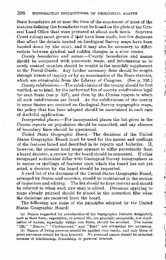
326 TOPOGRAPHIC INSTRUCTIONS OF GEOLOGICAL, SURVEY
State boundaries at or near the time of the enactment of most of the statutes defining the boundaries may be found on the plats of the Gen eral Land Office that were prepared at about such times. Supreme Court rulings must govern if tjiey have been made, but few decisions that affect the details needed on Geological Survey maps have been handed down by the court, and it may also be necessary to differ entiate between gradual and sudden changes in a river course.
County boundaries and names. County boundaries and names should be compared with post-route maps, and information as to newly created counties should be sought in the monthly supplement to the Postal Guide. Any further necessary data should be sought through letters of inquiry or by an examination of the State statutes, which are obtainable from the Library of Congress. (See p. 236.)
County subdivisions. The subdivisions of the county should be first verified, as to kind, by the authorized list of county subdivisions legal for each State (see p. 237), and then by the Census reports in which all such subdivisions are listed. As the subdivisions of the county in some States are omitted on Geological Survey topographic maps, the policy that has been adopted should be ascertained in each case of doubtful application.
Incorporated places. For incorporated places the list given in the Census reports on population should be consulted, and any absence of boundary lines should be questioned.
United States Geographic Board. The decisions of the United States Geographic Board must be used for the names and spellings of the features listed and described in its reports and bulletins. If, however, the present local usage appears to differ persistently from a board decision, a review by the board should be requested. If other recognized authorities differ with Geological Survey topographers as to names or spellings of features upon which the board has not yet acted, a decision by the board should be requested.
A card list of the decisions of the United States Geographic Board, arranged by States and counties, should be maintained in the section of inspection and editing. The list should be kept current and should be referred to when each new map is edited. Decisions applying to maps already printed should be placed in the correction files when the decisions are received from the board.
The following are some of the principles adopted by the United States Geographic Board:
(a) Names suggested by peculiarities of the topographic features designated, such as their form, vegetation, or animal life, are generally acceptable, but dupli cation of names, especially within one State, should be avoided. The names "Elk," "Beaver," "Cottonwood," and "Bald" are altogether too numerous.
(b) Names of living persons should be applied very rarely, and only those of great eminence should be thus honored. No personal names should be attached because of relationship, friendship, or personal interest.
TOPOGRAPHIC MAPPING 327
(c) Long and clumsily constructed names and names composed of two or more words should be avoided.!
(d) The possessive fornj of names should be avoided unless the object is owned by the person whose name it bears.
(e) The multiplication of names for different parts of the same feature, such as a river or mountain range, should be avoided. Only one name should be applied to a stream or mountain range throughout its length.
Such names as "East Fork" and " North Prong" for branches of a river should be avoided unless there is a special reason for their adoption. Independent names should be commonly selected.
Land lines. Land lines and township and range numbers should be verified by comparison with the State maps of the General Land Office; in case of apparent disagreement the township plats may be examined for confirmation, but discrepancies should be questioned. Section numbers should be omitted on scales of 1:125,000 and on smaller scales.
National jorests. The boundaries and names of national forests should be verified by the latest maps and lists issued by the Forest Service and by Presidential proclamations and Executive orders, and further verified if necessary through inquiry at the office of the Forest Service.
National parks. The latest annual report of the National Park Service should be consulted for lists, of national parks administered by the Department of the Interior and by the War Department. Boundaries of national parks should be verified by the descriptions given in the acts creating them, by any existing maps, and, when necessary, through inquiry at the offices of the National Park Service or the Chief of Engineers. The existence of national parks should be further verified by the General Land Office State maps.
National monuments. The latest annual report of the National Park Service and the check list, issued by the Forest Service should be consulted for lists of national monuments administered by the Departments of the Interior, Agriculture, and War. Boundaries of national monuments should be verified by proclamations describing them, by subsequent Executive orders, and by inquiry if necessary.
Indian reservations. Indian reservations should be verified by the State maps of the General Land Office and as to their boundaries by existing maps, by the descriptions given in the acts creating them, by reference to the township plats of the General Land Office, or through inquiry at the Office of Indian Affairs.
Private land grants. Private land grants and donation tracts should be checked first by the General Land Office State maps and then by the township plats.
Federal game and bird preserves. The United States Biological Sur vey check list of Federal game and bird refuges and the General Land Office State maps should be consulted for these preserves, and their
328 TOPOGRAPHIC INSTRUCTIONS OF GEOLOGICAL SURVEY
boundaries should be verified by proclamations describing them or Executive orders modifying them. The word "preserve," "reser vation," "refuge," or "range" should be used-as appropriate.
State parks and reservations. Names and bcundaries of State parks and reservations should be verified by State publications and local information.
Military reservations. Military reservations should be verified by reference to the General Land Office State maps and other general maps and through inquiry of the Corps of Engineers, War Depart ment. The "List of military posts and camps in the United States" in the back of the Official Railway Guide should also be consulted.
Power-transmission lines. Each topographic map upon which power-transmission lines have been, shown and which is to be engraved for regular publication should be referred to the chief hydraulic engineer for his approval of the lines and designations for publication. For this purpose a colored pencil line should be drawn alongside each power-transmission line on an advance-sheet copy of the map.
Comparison with other maps. The names and features on the topographic map that is being edited should be compared with the names and features as given by recognized authorities on general maps, in gazetteers, in reports of explorations, or in other available and appropriate reports. If discrepancies or unusual names or spellings are found, they should be questioned and if necessary letters of inquiry should be sent out. (See p. 334.) If it seems advisable cases should be prepared for consideration by the United States Geographic Board. (See p. 326.)
Water lining and tints. In general, water bodies are represented on engraved maps by water lining. Water lining should be engraved to continue with the trend of the natural shore line and not follow around artificial features. Water lining should be carried continu ously through piers, wharves, or other artificial structures built over the water if the cultural feature is shown in solid black, but if the cultural feature is shown with an open outline, as for a large pier or wharf, the water lining should be broken at the feature.
On maps that carry under-water contours water lining can not be shown, and it is desirable, when practicable, to use a flat blue tint to represent the water surface. Whether the flat tint is used or not, however, interior water bodies should be water lined, and large rivers should be water lined as far as the vicinity of the under-water contours.
Detailed examination of original. The original drawing should be examined in detail in order to see that elevations agree with contours, that the right contours are accented, that depressions are properly hachured, that there is an equable distribution and clear delineation
TOPOGRAPHIC MAPPING 329
of elevations and contour numbers, and that all symbols are clearly drawn and in conformity with Geological Survey practice.
Depression contours. The engraving of hachures for the identi fication of depression contours (see p. 296) should be confined to small depressions and to such larger depressions or parts thereof as can not otherwise be readily recognized as depressions by the contour num bering alone. In general, the engraving of hachures may be omitted from depression contours that exceed 1 inch in length on the publi cation scale.
Punctuation. Periods are to be consistently omitted on all lettering within the margin of the map.
Position of lettering. Names should be placed as specified below if they are legible when so placed; otherwise they should be moved to a position where they will be legible. If no such position can be found and no authorized abbreviation exists and there is no suitable substitute, the name may be omitted, but a position must be found for the name of every important feature.
All names should be so placed that they will be readable from the bottom of the map. Names that are lettered parallel to a meridian should read from south to north.
Names of places, public institutions, ranches, mines, and other lesser cultural features should be placed horizontally and so far as practicable to the right of the features to which they refer.
Names of ponds, lakes, islands, swamps, and glaciers should be placed horizontally and to the right of the features named, unless the area of the feature is so large that the space will accommodate the name within its limits. Names of oceans, bays, coves, fiords, and straits should be placed across these features in broad curves.
Names of broad, water-lined streams should be placed within those features. Names of small shore features, such as points, should be so placed as not to touch the shore line and placed on the water side so far as practicable.
Names of railroads, highways, roads, trails, canals, and streams should be placed on the upper side of the feature wherever practicable and approximately in the middle third, but if the middle third does not cover the feature sufficiently to make the application of the name clear the same name should be shown in two or more places.
Names of narrow valleys, canyons, gorges, gulches, arroyos, and washes should follow the general trend of these features in easy curves and be placed preferably on the upper side. Where the limits of such features may be obscure the names should be so placed as to show the limits so far as practicable.
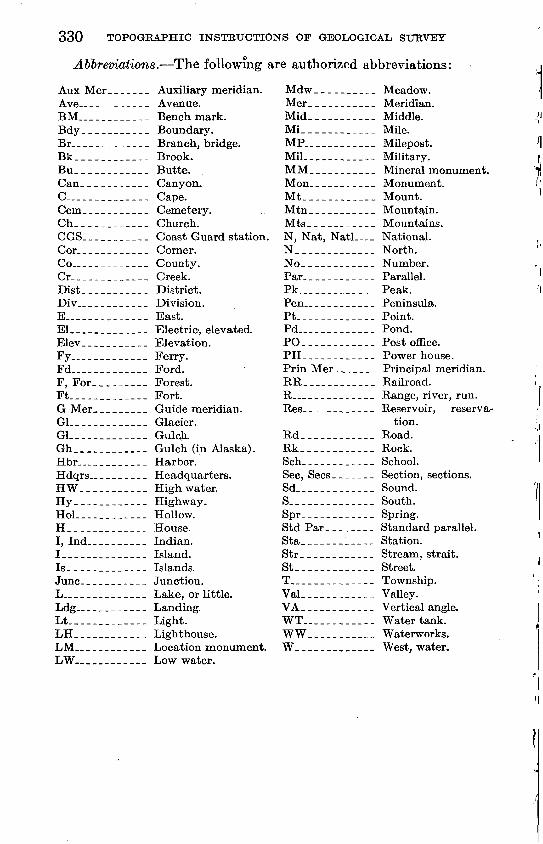
330 TOPOGBAPHIC INSTRUCTIONS OF GEOLOGICAL SURVEY
Abbreviations. The following are authorized abbreviations:
Aux Mer_ ______ Auxiliary meridian.Ave--______--_- Avenue.BM.___________ Benchmark.Bdy___________ Boundary.Br_____________ Branch, bridge.Bk__________ Brook.Bu____________ Butte.Can.__________ Canyon.C____________ Cape.Cem___________ Cemetery.Ch____________ Church.CGS.__________ Coast Guard station.Cor____________ Corner.Co_-___________ County.Cr_____________ Creek.Dist___________ District.Div.___________ Division.E____________ East.El.____________ Electric, elevated.Elev___________ Elevation.Fy___________ Ferry.Fd-_______ Ford.F, For___.___ Forest. Ft.______ Fort.G Mer_________ Guide meridian.GL____________ Glacier.Gl.____________ Gulch.Gh________ Gulch (in Alaska).Hbr__________ Harbor.Hdqrs._________ Headquarters.HW.________ High water.Hy____________ Highway.Hoi._______ Hollow.H_____________ House.I, Ind__________ Indian.!______________ Island.Is.____________ Islands.June.__________ Junction.L______________ Lake, or little.Ldg __________ Landing.Lt.___________ Light.LH____________ Lighthouse.LM____________ Location monument.LW.__.________ Low water.
Mdw__________ Meadow.Mer___________ Meridian.Mid____.______ Middle.Mi____________ Mile.MP____________ Milepost.Mil.___________ Military.MM___________ Mineral monument.Mon___________ Monument.Mt____________ Mount.Mtn___________ Mountain.Mts____-._____ Mountains.N, Nat, Natl _ National. N__________ North.No_ ___________ Number.Par.___________ Parallel.Pk_____________ Peak.Pen.___________ Peninsula.Pt.__________ Point.Pd___._______ Pond.PO_____.______ Post office.PH____________ Power house.Prin Mer_______ Principal meridian.RR____________ Railroad.R____________ Range, river, run.Res____________ Reservoir, reserva
tion. Rd____________ Road.Rk____________ Rock.Sch__________ School.Sec, Sees _______ Section, sections.Sd_____________ Sound.S_____________ South.Spr____________ Spring.Std Par_ _______ Standard parallel.Sta____________ Station.Str____________ Stream, strait.St_____________ Street.T__________ Township.Val____._-.__ VaUey.VA____________ Vertical angle.WT____________ Water tank.WW___________ Waterworks.W____.__.___._ West, water.
TOPOGRAPHIC MAPPING 331
For abbreviations of State names see the Style Manual issued by the Government Printing Office, or the Geological Survey pamphlet "Suggestions to authors."
Selection of elevations for engraving. The editor should select elevations for engraving on a basis of a spacing of about 1 inch apart on the scale of publication. He should be guided by the field instruc tions for "useful elevations" (p. 241) and should exclude all elevations for which the point of application appears to be indefinite. Prefer ence should be given so far as practicable to important crossroads and road intersections, points in the vicinity of schoolhouses, and prominent summits. The elevations selected for engraving should be added to the new lettering tracings.
Position oj bench-mark letters and figures. Where practicable the letters "BM" should be placed above and to the left of the cross indicating a bench mark, and the figures of elevation below and to the left. Otherwise the letters may be placed to the right, above the figures. Different arrangements may be controlled by circumstances. If the bench mark is in a town or city and the lettering and figures can not be legibly placed near the position for the bench mark, the letters "BM" and the figures of elevation should be arranged in one line and inclosed in parentheses and placed directly under the name of the place. Figures of elevation for a supplementary bench mark should be placed to the right of the cross and above rather than below.
Position of elevation figures. Of first importance in placing figures of elevation is the identification of the feature for which the elevation is given. Although a rule may apply where both identification and legibility are obtained, another position must be sought if either is uncertain; and unless a position can be found where both tests can be met the elevation figure should be omitted. Elevation figures in cities and areas of heavy culture should therefore be omitted unless the scale of the map permits their insertion.
Elevation figures for road corners and peaks that are named should be placed to the left of the feature; those for an unnamed road corner should be placed in the northeast corner, and those for an unnamed summit to the right. Figures showing water-surface elevation should be placed on the pond, lake, river, or other water feature shown.
Position of contour figures. The purpose of contour figures being to facilitate the reading of elevations as expressed by contour lines, they should be placed at or near such critical places on the contours as the tops of ridges, saddles, the bottoms of valleys, and noticeable changes in slope. On some long slopes they may be advantageously placed in rows but the rows should not become too prominent on the map. A contour figure should not be placed at the extreme end
58515° 28 22
332 TOPOGEAPHIC INSTBUCTIONS OF GEOLOGICAL, SUEVEY
of a contour adjacent to a road, stream, or other feature, and it is not necessary near a road corner or other feature of which the eleva tion is given. Additional contour figures should be placed in out standing and conspicuous places and with such frequency as will enable a map user to read any contour without prolonged search for a reference contour figure. This readability may generally be obtained by placing numbers only on the heavy contours, but it will some- tunes be advisable to place contour figures on light contours and on depression contours.
Style oj engraved lettering within the map. The final drawings and lettering tracings should be lettered mostly in slanting block 5 and italic. (See p. 304.) The styles of the corresponding engraved letter ing are well understood by the engraver and need be specified by the editor only where a doubt might otherwise exist.
All place names and names of country post offices, railroad stations, country schoolhouses, churches, and ranches should be lettered in lower case roman. The size of the letters should be commensurate with the importance of the place. Large cities, State capitals, and county seats should be shown in roman capitals.
Names of civil divisions, such as States, counties, districts, civil townships, and land grants; and of reservations, such as national and State parks, forests, and game preserves, Indian and military reser vations, should be lettered in roman capitals.
Names of routes of communication, such as railroads, highways ? trails, and canals; of public works, such as bridges, ferries, fords, locks, tunnels, dams, and wharves; of public institutions, such as lighthouses, lightships, life-saving stations, universities, State hospitals, asylums, and city parks and cemeteries; and of mining features, such as mines, quarries, prospects, furnaces, and smelters, should be lettered in small slanting block capitals.
Names of small hydrographic features, such as creeks, branches, brooks, runs, streams, pocosins, ponds, glaciers, coves, marshes, swamps, and bogs, should be lettered in stump; names of large hydro- graphic features, such as oceans, large bays, straits, rivers, and lakes, should be lettered in italic capitals. The choice between stump and italic capitals will depend upon the relative size of the feature.
Names of hypsographic features, such as summits, peaks, hills, knobs, gulches, canyons, gorges, draws, arroyos, washes, and islands; and of land features along coasts, shores, or rivers, such as points, capes, and bends, should be lettered in upright block. Only features
The terms used here to describe styles of engraved lettering have long been in use by engravers. "Block" is the style generally known to printers as "gothic," and "stump" corresponds to "lower-case italic."
TOPOGRAPHIC MAPPING 333
of considerable extent or importance, such as plateaus, mountain groups, ranges, basins, and valleys, should be shown in capitals.
Style of engraved marginal lettering. The quadrangle, State, and county names at the northeast and southeast margins of the map, the department and Geological Survey heading at the northwest margin, and the State or other cooperative heading at the middle of the upper margin should be lettered in finished hair-line capitals (with spurs). (See pi. 15.)
The credit and date of survey at the southwest margin, the pro jection and horizontal datum, the projection figures, the grid note and distances, and the edition date should be lettered in lower case hair-line block.
The contour interval and the words on the bar scales should be lettered in lower case roman.
The names of adjoining quadrangles and the sea-level datum should be lettered in stump.
Township and range letters should be lettered in upright block capitals.
The lettering for the magnetic declination diagram should be in hair-line block capitals.
Style of figures. The styles of figures inked on the original or final drawing (see p. 304) conform only in general with the styles in which the corresponding figures are to be engraved, but as the engraved standards are well understood by the engraver they need be specified by the editor only in unusual or exceptional cases. The following are standard styles of figures for engraving:
On the black plate, elevations of bench marks, both permanent and supplementary, are engraved in upright block. Elevations other than bench marks, such as those at road corners and summits and on lakes, are engraved in slanting hair-line block. Section figures are engraved in upright hair-line block on standard-scale maps and in open block on large-scale maps. Numbers on boundary monu ments are engraved in slanting block. Township and range figures are engraved in upright block. Projection and grid figures are en graved in upright hair-line block; two sizes are used for projection figures, those for degrees being larger than those for minutes. Figures that occur in marginal notes or as part of a name follow the style of the accompanying letters.
On the brown plate, contour numbers are engraved in small italic.On the blue plate, under-water contour numbers are engraved in
small italic. Contour numbers on glaciers are also engraved in small italic.
Parts of quadrangles. On a topographic map that is published in incomplete quadrangle form the blank part of the map should carry an appropriate legend descriptive of the conditions applying to the
334 TOPOGRAPHIC INSTRUCTIONS OF GEOLOGICAL SURVEY
blank area, as, for example, "Preliminary edition, unsurveyed area," for an area not mapped on any scale and "This area is shown on the map of the Dinuba quadrangle, surveyed in 1916, scale 1:125,000," for an area that has been surveyed but of which the published map is on a different scale, usually smaller.
Edited map to topographer. On the completion of the editing the jacket should be dated, indorsed "Edited," and initialed by the one editing, and then with inclosures (original, editing work sheet, etc.) referred back to the author topographers or inkers, that they may see the result of the editorial review and reply to any editing questions. (See "Editing questions," p. 321.)
Letters of inquiry. Essential information that is not obtainable from author topographers or from office data should be sought through letters of inquiry to postmasters, local civil officials, or other authori ties, on forms provided for the purpose.
New lettering tracings. On the return of the edited map from the topographers, new lettering tracings should be made in order that the engraver may have lettering copy with the names in their edited positions. If the names have been inked on the original drawing the necessary changes will have been indicated in red ink on the editing work sheet. The figures of elevation that have been selected for engraving should be added to this lettering tracing.
Instruction sheet for engraver. If the lettering is on the original map the editing work sheet becomes the instruction sheet for the engraver, but if new lettering tracings have been made the remaining engraving instructions, with outstanding notes and questions, should be transferred to a clean advance-sheet copy on which will be indorsed "New tracings are copy for names." All boundaries should be emphasized by colored pencil on the instruction sheet, a different color being used for each kind of boundary shown on the map and a key to the colors used being added in the lower right corner. The instruction sheet should be made complete copy for marginal lettering, scales, and notes, and the original drawing should be changed to conform, in order that there may be no misinterpretation of copy. All necessary engraving instructions should be indicated in red ink, and all notations in pencil (other than boundary data) should be disregarded by the engraver, as they are editor's memoranda only.
Filing of editing notes. A file of "editing notes " arranged by names of maps should be maintained in which all correspondence or copies thereof pertaining directly to the editing of topographic maps should be assembled. In this file should be placed all appropriate memoranda affecting important matters under discussion or in dispute, so that such data may be readily accessible for use in the editing of adjoining qmadrangles, in the editing of reprints, or in correspondence.
TOPOGRAPHIC MAPPING 335
APPROVAL AND TRANSMISSION FOR ENGRAVING
When the editing is complete and all outstanding questions affect ing the engraving have been disposed of, the jacket, on which the entire contents should be listed, should be indorsed "Approved for engraving" and should be dated and signed by the chief of the section of inspection and editing, who is responsible for the submission of topographic maps to the engraving division as complete and adequate copy for engraving.
Maps edited and approved for engraving and previously author ized for engraving should be forwarded direct from the section of inspection and editing to the engraving division.
EDITING OF CULTURAL REVISION SHEETS
CHARACTER OF EDITING
The editing of cultural revision sheets consists largely of an exami nation of the copy to insure its proper presentation to the engraver, that he may clearly understand where changes are to be made in the plates. In general, the character of the editing should follow the outline given under "Editing of topographic maps" (pp. 320-334), but with the thought always in mind that changes in the plates should be called for only where demanded by the cultural revision or made necessary through changed practices since the first or some other prior edition of the map.
ENGRAVING AND EDITING DOCKETS
Cultural revision sheets should be included in the annual engraving docket of topographic maps (see p. 321) and should be placed on the editing docket in the same way as new topographic maps (see p. 321).
SCOPE OF EDITING
Work sheet and instruction sheet. The editing work sheet should be an engraved copy of the latest print of the map, and on this sheet all editing notes and names should be placed in pencil. The final markings and instructions for the engraver should be indicated in red ink, on the map margin or on the face of the map as may be appro priate. The instruction sheet should be mounted before the final markings are added.
Engraving of'new Hack plate. If the corrections to the culture plate are numerous the unedited cultural revision copy should be referred to the engraving division to determine whether it is more feasible to make a new black plate than to correct the old one. If the old plate is to be corrected the correction copy should be confined to changes, but if a new black plate is to be made the editor should ask for an inked sheet showing all the culture, and when that is furnished the
336 TOPOGRAPHIC INSTRUCTIONS OF GEOLOGICAL SURVEY
"take out" sheet may be retired. The road-classification data for the red overprint should be filed for editing when the reprint nears publication.
Editing of cultural revision. The editing of cultural revision sheets should, in general, follow the outlines given under "Editing for reprints" (p. 341) and described more in detail under "Editing of topographic maps" (pp. 320-335). (See also field instructions for "Revision of topographic maps," pp. 262-264, and "Inkingof cultural revision sheets," p. 301.) The items that require especial attention are new names, changed positions of names due to new or changed cultural features, changes in reservation and other boundaries and names, features such as power lines and oil and gas wells that were not shown on the former edition of the map, and marginal notes. The entire culture of the map should be subject to editorial review..
If the black plate is to be corrected rather than reengraved, the revision editor should call for as few small or immaterial changes as practicable in the position or arrangement of names or notes that are already engraved. If, on the other hand, it is found expedient to reengrave a new black plate full advantage should be taken of the opportunity to recast the names, figures of elevation, and notes into the best possible positions.
ENGRAVING OF TOPOGRAPHIC MAPS
The topographic maps listed in the annual engraving docket (see p. 321) are engraved on copper in the engraving division of the Geo logical Survey. For each map three plates are engraved, one for each of the three principal colors of the printed map a culture plate for the features and names that are to be printed in black, a relief (con tour) plate for the features that are to be printed in brown, and a drainage plate for features that are to be printed in blue. These plates are sometimes referred to as the black, brown, and blue plates, respectively. Transfers are afterward made from the three copper plates to three lithographic stones, from which the maps are printed. Features subject to frequent change, such as national-forest boundaries and forest names, are not engraved on copper but are added to the stone by separate transfers from type and by handwork.
Transmission jor engraving. When the editing of a topographic map is complete and all questions have been answered so far as is then practicable, the sheet jacket, on which is entered a list of the contents forwarded, should be indorsed "Approved for engraving"; this indorse ment should also call attention to any special or unusual features of the engraving and should be signed by the chief of the section of inspection and editing, who should also initial subsequent indorse ments covering the transmission of engraved proof and copy. All
TOPOGRAPHIC MAPPING 337
engraving copy and proofs thereof should be transmitted direct to the engraving division.
Engraving. A j^olyjcpnic j)rpjectipn is constructed on each of the three^cop_pej plates on the scale_of: Jihejnap publication. The original drawing of one map that is to be engraved is photographed to the publication scale, and from the glass negative a contact print is made on a, zinc plate, on which the map features are in the reverse positions to those on the original drawing. The map on zinc is transferred in turn to each of the three copper plates by means of wax impressions obtained on celluloid and burnished down on the copper plates, where the impressions are suitably fixed. Transfers to the copper plates are made in small sections at a time, usually by coordinate blocks, in order to distribute any small errors that may exist in the scale of the original map. The reproduction of the map that has thus been trans ferred to copper is reversed, and the engraver must do his work in that position.
The several map features are cut into the surface of the copper plates by the engraver, who uses the transferred lines as copy and gages the depth of the cut according to the width of the line desired on the printed map for example, a heavy contour is cut deeper than a light contour. On the culture plate only those features are cut that are to be printed in black, on the relief plate only those that are to be printed in brown, and on the drainage plate only those that are to be printed in blue.
PROOF READING
First plate proofs. On the completion of the engraving on the three copper plates "first plate proofs," in black, are pulled from each of the three plates, are inclosed in the jacket together with the origi nal map and all engraving copy, and are referred from the engraving division to the section of inspection and editing for revision.
The proof reader should first familiarize himself with the editor's special instructions to the engraver and should examine the proofs with these in mind. Each plate proof should in turn be compared in detail with the original map, and all corrections noted should be marked on the plate proof by drawing a red inked line to the border of the proof and there indicating by word or symbol or by both the nature of the correction necessary. This detailed comparison should be made house for house, bend for bend, contour for contour (includ ing spacing), stream for stream, feature for feature, and symbol for symbol. If apparent errors are found in the original drawing they should be called to the attention of the editor of the map. In order that there may be no omission or repetition of comparison between proof and original, the proof sheets should be suitably penciled over and checked as the proof reading progresses, but notations for the engraver's attention should be made in red ink. Questions arising
338. TOPOGRAPHIC INSTRUCTIONS OF GEOLOGICAL STJEVEY
in the interpretation of the original copy or outstanding editing ques tions should be brought to the sheet margin in pencil and referred to the editor. Proof readers should date and initial the j acket and also each plate proof read. The j acket should be indorsed "Approved for correction and second plate proofs" and returned to the engraving division. If a part of the map edition is to be overprinted in green to represent woodland areas, the woodland copy should be forwarded to the engraving division at this time.
Second plate proofs. When the corrections called for on the first plate proofs have been made on the copper plates, a second set of proofs is pulled and referred for further revision. The second plate proofs are checked, usually by the reader of the first plate proofs, in order to see that all the corrections that were noted on the first set have been made.
At this stage the reader of the second plate proofs should mark in blue pencil on the proof of the culture (or black) plate such headings, names, boundaries, scales, and notes as have not been engraved and are to be added to the lithographic stones by a separate transfer.
All outstanding questions, including references to author topog raphers and outside letters of inquiry, should be cleared up at this time, as transfers will now be made from each of the three copper plates to the three stones from which the final map in colors is printed, and any further corrections must be made by hand to these stones and also to the copper plates for future use.
The reader of the second plate-proofs should initial and date the jacket and also each proof he reads.
Letter check. After the second plate proofs have been read another proof reader should make an independent check of all lettering and elevation figures and should also initial and date the jacket and the proofs so read. This duplication in proof reading is justified because the names and numbers on a map are the features best understood and therefore most used and because experience has shown that a letter check is necessary. On the completion of the.letter check the jacket should be indorsed "Approved for correction and combined proofs" and returned to the engraving division. If woodland is to be shown by an overprint in green the indorsement should also include the request, "Submit woodland proofs." If a road classification is to be overprinted in red the indorsement should include the request, "Submit two faint-blue prints of the culture mounted on zinc."
Third plate proofs. Third plate proofs are requested only when the copy is unusually intricate.
Separate stone proofs. Separate proofs from one or more of the printing stones may be requested, if the supplemental transfers to stone are unusually numerous or complex or if there are necessary corrections to the stones.
TOPOGKAPHIC MAPPING 339
Combined proofs. When the corrections called for in the reading of the second plate proofs and the letter check have been made on the three copper plates, transfers are made from each plate to three litho graphic stones, and to these stones are also separately transferred from type impressions or from stock engravings such lettering, notes, scales, etc., as may not be engraved separately for each map. From these three stones, representing the culture, relief, and drainage features of the map, are printed combined proofs in the colors to be used on the published map (pi. 17). Combined proofs should be examined for completeness and especially for register and for all data added to stone after transfer from copper. The reader of the com bined proof, who is preferably the reader of the first and second plate proofs, should initial and date the jacket and the proof. (For approval for printing see p. 340.)
Woodland proofs. A proof of the woodland overprint is submitted on a combined proof of the map and should be read for completeness of copy and register, the woodland tracing registered over the original drawing being used as copy. The woodland proof should be initialed and dated by the proof reader.
BO AD-CLASSIFICATION COPY
From the road-classification sheets and data submitted by field topographers or others, and after an examination of available reference road maps, the map editor should prepare one or more road classi fications based on existing instructions; such classifications should be drafted in black on faint-blue prints of the culture on paper mounted on zinc as photolithographic copy for printing. The marginal lettering required should be printed from type and pasted on the mounted sheet in the form of labels. (See p. 309.)
SIZE OF EDITIONS AND SPECIAL PRINTS
The chief engraver submits a combined proof of each new topo graphic map to be printed to the chief of the division of distribution for indication (on the margin of the map) of the size of the edition desired. The chief of the division of distribution transmits it to the chief of the section of inspection and editing, who should indicate on the same proof the proportion of the edition to carry the wood land overprint, or, if no woodland edition is. to be printed, should so state.
The proportion of the edition to be overprinted in red with one or more road classifications should be determined by the chief of the section of inspection and editing and so indorsed on the proof above referred to.
A combined proof of each new topographic map is submitted by the chief of the section of inspection and editing to the chief geolo-
340
gist, for indication of the number and kind of special prints desired. This request is then inclosed in the jacket, for information of the engraving division when the map edition is run.
APPROVAL FOB PRINTING
When all final proofs, including the woodland proof, have been read and when the road-classification copy for a red overprint has been prepared and the sizes of the several editions determined, the jacket should be indorsed "Approved for correction and printing, with woodland and road classification" [second clause omitted if not appropriate], dated, and signed by. the chief of the section of inspection and editing.
The jacket, with inclosures, should then be transmitted direct to the engraving division for final correction, preparation of the printing plates, and printing.
REPRINTS OF TOPOGRAPHIC MAPS
GENERAL FEATURES
Distinction between reprint and new edition. The topographic maps are reprinted from time to time as the map-room stocks become exhausted. A topographic map that is reprinted without change or is reprinted with a few changes that are of a routine nature only and do not involve extensive corrections is designated a "reprint"; but a reprinted map that is materially changed, with the addition of considerable new information, or is altered by means of extensive corrections is designated a "new edition."
The designations of the several editions and reprints should be stated at the lower right-hand corner of the sheet. "Edition of " should be used for the first edition of the map, the blank being filled by the year, but not the month, in which the map is printed. "Edition of " should also be used for a new edition of the map, the date being changed. "Edition of , reprinted " should be used for all reprints, the dates being those of the last previous edition and of the forthcoming reprint.
Correction files. A file of correction material for use in reprints should be maintained in the section of inspection and editing, and the corrections filed should, so far as practicable, be confined to those that can be approved 'at the tune of filing. The practice of filing a map correction that may be incomplete or of doubtful value or application and marking it "To be considered at time of reprint" should be avoided if possible; the correction should preferably be fully examined when it is received and when the facts are fresh in mind and at that time prepared for future reprint use and approved, or? if found unavailable, disapproved and discarded.
TOPOGRAPHIC MAPPING 341
Requirements for corrections. Corrections to topographic maps are received by the Geological Survey from many sources. To be accept able a correction must be specific and complete in itself; it must be complete as to the need for a rearrangement or omission of adjacent features; it must contain sufficient data upon which copy can be prepared for the changes hi the copper plates; and it must be based upon authentic sources of information. In general, unless a correc tion is small or is of a simple nature, it can be satisfactorily prepared only by the employment in the field of means that are commensurate in accuracy with the methods used in the original survey for the map. With these requirements few outside engineers can comply, and therefore many corrections fail of approval.
Stock lists. Stock lists, serially numbered, are prepared periodi cally in the division of distribution and list the topographic maps and other topographic publications of which the supply is nearly out of stock. Each stock list also gives the size of the reprint edition needed to supply the expected demand for each map listed, as esti mated from recent sales and determined by current Geological Survey policy. Such stock lists, after administrative approval, are referred to the section of inspection and editing for the preparation and editing of copy for reprint. Each stock list is accompanied by two copies of the map to be reprinted.
Reference to geologic branch. A carbon copy of each stock list together with one copy of each mar> listed on it, is referred by the chief of the section of inspection and editing to the chief geologist that he may indicate the kind and number of special prints desired when the edition of the reprint is run. A carbon copy of each stock list is also referred to the chief of the section of geologic maps for the preparation of a marginal note, if appropriate, to describe the geo logic publications that treat of the quadrangle.
EDITING FOR REPRINTS
Character of editing. The editing for reprints should consist in an examination and appraisal of the corrections on file and in the prepa ration of engraver's copy for such of the corrections as have been or can be approved. The reprint editor should also carefully consider the advisability of the changes that are described below under sepa rate headings and should raise all questions that Geological Survey policy may suggest for consideration and decision in respect to the map that is up for reprint.
Worlc and instruction sheets. The latest print of the map should be used as a work sheet upon which to assemble the changes that are contemplated for the new printing. The reprint instructions for the engraver should be written on the margin of a separate copy of the
342 TOPOGRAPHIC INSTRUCTIONS OF GEOLOGICAL SURVEY
same map, in red ink for plate changes and in colored pencil for stone work. Corrections and additions to the topography may be drawn on the instruction sheet or attached to it as separate copy. A filed correction that constitutes adequate copy for the engraver should be used rather than a copy made from it.
Borders. The names of adjoining quadrangles that have been surveyed since the last printing of the map should be added. Border corrections that are on file should be carefully examined, and where additional drafting is needed it should be requested. Border-cor rection copy must be complete for all the copper plates involved and must include the marking of the "take outs," as this is necessary information for the engraver. "Take outs" should be indicated on a printed copy of the map. Border corrections that are small or of a simple nature may be drafted on a printed map and inked in one or more distinctive colors, but large or intricate corrections must be inked in standard colors on a tracing. Border corrections may be made on the scale of publication or on the scale of field work but must be accurately registered over the nearest projection corners. (See "Border corrections," p. 302.)
Attention should be given to the horizontal datum and to the possi ble need for dotted projection corners to join maps of adjacent areas, with an accompanying explanatory note.
Filed corrections. Corrections, whether additions to the map or changes in features already shown, must subscribe to the require ments for corrections given on page 341. If the information given is complete but the drafting is deficient the correction should be referred for proper drafting. Inasmuch as the correction files contain some correction material the use of which can not be approved, for reasons of expediency, the reprint editor should seek administrative approval before considering the use of any correction material of doubtful value. The corrections themselves may be drawn on the printed map provided they can be made legible; otherwise the correction copy should be drawn on tracing cloth registered over the map. Corrections that are drawn on a printed map must be indicated in distinctive colors that are readily distinguishable from the lines of the map, but corrections that are shown on a tracing should be inked in the standard colors used for topographic map drawings.
Geographic Board decisions. The section of inspection and editing should maintain a State and county list of Geographic Board decisions, and each new decision that affects a name shown upon a published Geological Survey map should be entered in the correction files. Board decisions that have been made since the last previous printing of a map should be applied to the next reprint.
Reservation boundaries. Corrections should be made to show changes in boundary lines or names of national forests, national
TOPOGRAPHIC MAPPING 343
parks, national monuments, and Indian reservations. If such boundaries and names were not shown on the last printing of the map they should be added, and for that purpose the map should be referred for the needed plotting. All reservation boundaries and names should be thoroughly checked for each reprint.
Public-land lines. Land lines that have been surveyed by the General Land Office since the prior printing of the topographic map should not, as a rule, be added to reprints, for the reason that they can seldom be properly tied to the topography, and their adjustment may entail more office work than can be expediently provided for. Where an office adjustment is practicable, however, and where important joining with other work is involved a small amount of such additional engraving may be requested. If addition or change of a public-reservation boundary is involved it may be necessary to ad just a provisional land net on the map in pencil as a base upon which to construct the new boundary.
New or changed notes. The following marginal notes should be added to reprints provided they were not carried on the previous edition of the map: Poly conic projection; North American datum; statement of direction and amount off North American datum if not on North American; statement of the correction necessary to place the vertical datum on the latest adjustment to mean sea level; quad rangle and State name in lower right-hand corner; magnetic-declina tion diagram; long bar scale of miles on east margin of map; and any other note or legend needed to explain a new or changed condition on the map. (See "Marginal lettering," p. 305, for the positions of many of these items.)
Cooperative Tieadings. A cooperative heading that has been used on the first edition of a topographic map may be used for a reprint of the same map provided the identical cooperation is still in effect under the same officials. This condition, however, seldom exists, and as a consequence many forms of cooperative reprint headings are needed. The following arrangements of reprint headings should be used when the conditions specified exist at the time of reprint.
(a) If there is present cooperation with the original cooperating body but with different officials, use the original heading with the names and titles of officials omitted. If the designation of a public office, as governor or State engineer, should be retained in order to identify the former cooperation, the heading may be supplemented by such an expression as "Represented by the governor [or the State engineer]."
(6) If there is present cooperation with the same officials or their successors but under a reorganization, use the form "Represented by the ," supplying the name of the new body and omitting the names and titles of officials.
344 TOPOGRAPHIC INSTRUCTIONS OF GEOLOGICAL SURVEY
(c) If there is no present cooperation but the original cooperating body is still in existence, use the original heading with the names and titles of officials omitted, whether the same or successor officials are in office.
(d) If there is no present cooperation and the original cooperating body is not in existence, use the original heading with the names and titles of officials omitted.
(e) If there is no present cooperation and the original cooperating body has been reorganized under the same or successor officials, use the reorganization name in the form "Represented by the ," but omit the names and titles of officials.
Outside credit. Credit for material additions to the topography derived from sources outside the Geological Survey should be given in a footnote, in the form, "Roads and trails added 1920 by National Park Service."
Woodland. In general, a woodland edition is printed only for the first edition of the map. Where the woodland copy fairly represents the conditions at the time of reprint, however, the woodland may be again overprinted. The reprint editor should ask for instructions in all appropriate cases.
Correspondence. If doubt exists as to the correctness or appropri ateness of a reprint correction and if information can be obtained through correspondence, letters of inquiry should be sent out, forms provided for the purpose being used if practicable. Such inquiries, however, should be made far enough in advance to avoid unneces sarily delaying the reprint and should preferably be made when the correction is first received.
Approval of reprint copy. When the reprint manuscript is com plete and in. proper form as copy for the correction of the copper plates and printing stones it should be approved and forwarded to the engraving division. The reprint copy for each map should be indorsed "Approved for correction" and dated. The indorsement should also request such plate, stone, or combined proofs as may be needed for the proof reading of the corrections before the map is printed and should list all special prints needed by other branches of the Geological Survey. When as many maps on a stock list as can be conveniently prepared at one time are ready for transmission, these, together with the stock-list letter appropriately indorsed, should be forwarded to the engraving division. Further transmis sions of delayed reprint copy for maps on the same stock list sh uld be forwarded singly from time to time as the copy can be prepared.
Transmissions, approval of corrections, and final approval for printing should be made by the chief of the section of inspection and editing. Recommendations affecting a change in the size of a reprint
TOPOGRAPHIC MAPPING 345
edition or the cancellation of a reprint should be made through the chief topographic engineer.
Proofs and proof reading. Each proof that has been requested will, upon submission, be read and afterward returned to the engraving division with indorsements for further action. When all corrections have been made the reprint material should be indorsed "Approved for printing." Successive indorsements should be made in sequence on the margin of the engraved map that is used as the base correction copy.
PREPARATION OF RIVER SURVEY MAPS FOR PHOTOLITHOGRAPHY
REPRODUCTION
The plan sheets and profile sheets of the river surveys are not engraved on copper but reproduced by photolithography on the field scale, in one, two, or more colors. In general, a small edition of advance sheets is printed in black, and this edition is followed by such regular publication as may be decided upon for each project, in two or three colors as may be found expedient.
INKING OF FIELD SHEETS
The field plane-table sheets should be inked in standard colors; all the drainage and culture should be inked, but only so much of the contouring as can be clearly read on a reproduction by a single-color photolithograph.
Free-hand inking must be done in sharp, fine dark lines, suitable for clear reproduction by photolithography, and right linos may need to be twice lined if fine or in color. As it is the readability of the contours from the engineer's point of view that is desirable rather than their graphic expressiveness of relief, the inking of contours that closely parallel any shown drainage or culture should in general be avoided. Numerous contour figures should be added, and loca tion crosses with figures of elevation should be inked for such exterior points as are instrumentally determined.
Water-surface crossings. Water-surface contour crossings must be drawn heavy and solid from shore to shore. Every fourth contour crossing, where the contour interval on land is 20 feet (or intermediate crossings if spaced far apart), must have its elevation placed at the outer end of a black right line drawn out clear of all topography.
All water-surface elevations should be inked on the outer edge of the topography, in red, for sheet record only; accompanying reference or direction lines should be inked in red but should be kept clear of all topography. Such data are not intended for final printing and should be brushed out on the negatives.
346 TOPOGRAPHIC INSTRUCTIONS OF GEOLOGICAL, SURVEY
Land lines. Land lines must be drawn solid, and township lines emphasized. Only such section and township lines should be inked as the Land Office plats or notes show have been run and have not since been suspended. Section numbers must be shown only where land has been sectionized; they should be drawn preferably at the centers of sections but should be offset from the center if necessary to gain legibility.
The entire land net should be checked against the land plats before the land lines are inked.
Rapids. Rapids should be hiked in the conventional symbol, but the inking should be so spaced that it will,not obscure the contour crossings or other important river data.
Other features. In the inking of other map features found on river- survey sheets the inker should be guided by the instructions given for the inking of the corresponding features on topographic maps.
Mileage. Before the field sheets are cut and assembled into plan sheets, the mileage must be plotted by pivoting and swinging a scale of miles (drawn as a straight line on tracing paper) within the channel; it must not be stepped off with dividers. The same tracing should pick up the contour crossings for subsequent plotting on the profile sheets. The mileage should not be inked until after the field sheets are assembled into plan sheets.
Inking of intermediate contours. All intermediate contours should be omitted in the inking wherever they are closely spaced or where their facing between the heavy contours is even. This omission is required because closely spaced lines will run together in a photo lithographic reproduction and because the needless cost of such inking should be avoided. An engineer values a contour map for its read ability in terms of elevation rather than for its expressiveness of shaded relief.
SIZE OF SHEETS
Sheets showing river surveys are of uniform size (22 by 29 niches), with all plan or profile work kept within an 18 by 25 inch neat line, which should be drawn with margins of 2 inches on all sides. Mar ginal lettering should be kept within as short a vertical space as possible.
Double-mounted drawing paper, cross sectioned in light blue within an 18 by 25 inch neat line, is carried in stock and will be found convenient for use for plan or profile sheets. It is divided into fifths of an inch horizontally and quarters of an inch vertically, thus giving tenths of a mile on a scale of 2 inches to 1 mile (1:31,680) and con venient intervals for profile construction.
TOPOGRAPHIC MAPPING 347
PLAN SHEETS
Assembly of field sheets. The field plane-table sheets must be peeled from the cloth (see p. 283) and by means of cutting and pasting assembled within the 18 by 25 inch neat-line limits of the plan sheets. Before the field sheets are peeled, however, azimuth lines must be transferred to enough places on each field sheet to permit the placing of each patch in a correct azimuth on the plan sheet. The azimuth used should be that of true north.
The plan should be assembled hi as few and in as continuous stretches on the same sheet as is practicable, and these stretches should be condensed within the sheet so far as the necessary allowance for outlying section lines, lettering, and other markings will warrant. Space must be left for the key map on each sheet.
Immediately after the patches are pasted on the plan sheets the sheets should be placed flat under heavy weights and allowed to dry under pressure for one and preferably for two days.
Joining lines. When the field sheets have been cut and pasted, joining lines should be inked as right lines at both ends of the cut, and the two ends that join should be lettered identically A-A for the first cut, B-B for the second, etc. When the alphabet has been exhausted double letters should be used, as AA-AA, BB-BB.
Mileage. The plotting of all mileage (see p. 346) must be inde pendently checked before it is inked, as an error afterward discovered necessitates moving all mileage marks that are beyond the one erroneously plotted. An error in the plan-sheet mileage would also correspondingly affect the profiles.
Distances along the river should be indicated in black by figures within small circles placed at the ends of right lines drawn clear of all topography from the center of the stream opposite each plotted mile of channel flow. The circles should be placed on the same side of the stream for as long stretches as is feasible, for greater convenience in rinding and reading, but this practice need not be followed if it would result in crowding and a better location for the circle can be found in a more open place. Preferably, the circles should be numbered upstream.
The uninked right lines that pass over the inked topography are drawn in on the glass negative later.
Boundary lines. The inking of county, national forest, and other boundary lines on plan sheets should be confined to the lines that fall within the zone of the survey and have been mapped in the field, and such boundary lines should not, in general, be extended beyond the inked topography, except for short distances for the purpose of keeping the necessary lettering away from the topography.
58515° 28 23
348 TOPOGRAPHIC INSTRUCTIONS OF GEOLOGICAL SURVEY
PROFILE SHEETS
Profile construction. Profiles should appear on separate sheets from the plans and should be drawn directly across the sheet, with the separate rows condensed as much as practicable. Their direction should be upstream as read from left to right, irrespective of easting or westing. Space must be left on each profile sheet for the key map.
For profiles uniform vertical scales should be used so far as pos sible, and profile angles in excess of 45° should be avoided. The profile should be constructed from the water-contour crossings, supplemented by elevations determined at the head and foot of falls and elsewhere. (See p. 267.) Profile lines should be drawn heavier than construction lines, and sharp angles should be slightly smoothed.
Before a profile is inked its construction must be carefully checked by a person who has not been engaged in its initial preparation.
Profiles of tributaries. Wherever the profile of a tributary is steeper than the profile of the main stream above the mouth of the tributary, the profile of the tributary should be constructed as a branch profile leaving the main-stream profile at the .junction point.
KEY MAP
A key map must be prepared for each set of river-survey maps. This map should be carefully generalized from the detailed plats and should be compiled in pencil on any convenient scale that is somewhat larger than that of publication. The compilation can in general be best made on tracing linen and must be afterward traced and inked as copy for photographic reproduction. The prints should be made on paper suitable for reproduction by photolithog raphy, and one print should be pasted on each plan sheet and one on each profile sheet.
As the prime requisite of a key map is legibility, the county and national-forest boundary lines may in general be omitted from it, but a boundary line that crosses the line of survey at or nearly at right angles may be shown.
The limits of the river survey shown on each separate plan sheet should be indicated on the key map by a connected series of rect angular blocks, the end lines of which cross the river at these limits. Each block on the key map should be marked with the serial letter corresponding to that used on the plan sheet represented. (See below.)
The title "Key map of plan sheets" should be placed under the key map.
MARGINAL. LETTERING FOR ALL SHEETS
All sheets of the plan and profile set should carry identical headings and other captions except where the data shown necessitate changes, such as different scales, contour intervals, authorship, and serial
TOPOGRAPHIC MAPPING 349
sheet letters. The marginal lettering for plan and profile sheets should be printed from type impressions, and the printed labels should be pasted on the drawings in the positions that are indicated below. (See pi. 16.)
Title. The title used to describe river-survey maps should be identical for all sheets of the set, including both plan sheets and profile sheets, and should be printed in capitals and placed in the center of the margin above the upper neat line. The title should give the names of the main streams shown and include the names of the larger tributaries that have been surveyed, but if these tributaries are too numerous, too little known, or unnamed, they may be referred to by the phrase "and tributaries" or "and other tributaries." The title should include the name of the State or States through which the river runs and the names of the places at the ends of the survey.
Designation ~by serial letters. Each plan sheet and each profile sheet should be designated by a capital letter, as sheet A, sheet B, the first profile sheet being designated by the letter next following that used for the last plan sheet. The letter I should be used. This designation should be placed above the upper neat line and near the right-hand corner.
Federal heading. The heading "Department of the Interior" centered above "U. S. Geological Survey" should be placed above the upper neat line and near the left-hand corner.
Number oj sheets. Under the lower neat line and near the right- hand corner should appear a statement in parentheses giving sepa rately the number of plan and profile sheets for example, "6 plan sheets, 4 profile sheets."
Date $f printing. Below the statement giving the number of sheets should be given the date of the printing of the edition for example, "Printed in 1927."
MARGINAL LETTERING FOR PLAN SHEETS
In addition to the marginal lettering specified above all plan sheets should carry the marginal lettering described in the following para graphs :
Authorship, date, and cooperation. Under the lower neat line and near the left-hand corner should be placed, in separate lines, the names of the topographers engaged in the mapping, the date of the survey, and the names of the organizations, if any, cooperating in the work. (See pi. 16.)
Scales. Under the center of the lower neat line the horizontal scale of the plan should be stated as a fraction, and directly beneath, on separate lines, should appear a bar scale of miles, a bar scale of feet, and a bar scale of kilometers.
350 TOPOGRAPHIC INSTRUCTIONS OF GEOLOGICAL SURVEY
Contour intervals. Under the bar scales the statement "Contour interval on land feet" should appear, and directly beneath it the statement "Contour interval on river surface feet."
Datum. Under the statement of contour interval should appear the statement "Datum is mean sea level" or the appropriate state ment if the river survey is referred to a vertical datum that differs from sea level.
Horizontal adjustment. Inasmuch as river surveys are seldom horizontally controlled the plan sheets are generally subject to adjust ment, and a statement to that effect should accordingly be placed under the lower neat line and a little to the left of the right-hand corner, unless the plan sheets are in true adjustment.
Declination. Under the lower neat line and to the right of the bar scales should appear a diagram showing the magnetic declination, with date.
MARGINAL LETTERING FOR PROFILE SHEETS
In addition to the marginal lettering for all sheets described on page 348, all profile sheets should carry the marginal lettering given below:
Horizontal scale. In general, the profile should be constructed on the same horizontal scale that has been used for the plans; and both fractional and bar scales should be placed on the profile sheets in the same positions as on the plan sheets.
Vertical scale. Under the bar scales should be placed a statement of the vertical scale on which the profile has been constructed, in the form "Vertical scale 1 inch ==40 feet." If more than one vertical scale is used on one profile sheet the separate parts of the profile that are drawn on differing vertical scales should be separated on the sheet by dividing lines, and within the borders of each divided sec tion should be indicated its vertical scale.
Datum. Under the vertical scale should be placed the same state ment of vertical datum used on the plan sheets.
No other marginal lettering. No statement of authorship, date of survey, or cooperation should be made on profile sheets.
HAND LETTERING
Plan sheets. Lettering in general should not be placed on or within the inked topography but kept in near-by open spaces, so far as such spaces can be found. The lettering should be kept near the pasted map strip to which it refers and not be extended near an adjoining strip. Emphasis should be given to the names of the sur veyed streams.
On each pasted patch covering a separate stretch of the river should be lettered the stream name and in addition township and
TOPOGRAPHIC MAPPING 351
range numbers for identification. The joining letters at the ends of the patches should be inked in the sequence described on page 347.
Mileage and contour crossings should be inked as described for the penciling.
Profile sheets. On each separate stretch of continuous profile, either for the main stream or for a tributary, should be lettered the stream name, above and parallel with the slope of the profile.
The names of only the larger tributary streams should be lettered on the profile sheets, but the names of all bridges, dams, dam sites, towns, falls, and well-known rapids should be lettered and placed vertically over the corresponding points in the profile.
STYLE OF LETTERING
Marginal lettering. The styles of type that are in general use for the marginal lettering as designated in the engraving division type book (edition of January, 1926) are as follows:
Title, light copperplate gothic Nos. 5 and 6."Sheet A," etc., light copperplate gothic No. 7.Federal heading, Celtic No. 1, 8 point.Number of sheets, lining gothic No. 60, 10 point.Date of printing, lining gothic No. 60, 8 point.Authorship, etc., circular gothic No. 44, 10 point.Contour interval and datum, circular gothic No. 44, 10 point."Subject to adjustment," lining gothic No. 60, 10 point.Declination, lining gothic No. 416.Title on key map, slope gothic No. 504.
Hand lettering. The style of hand lettering for plans and profiles should be as follows:
Stream names, slanting block, capitals or lower case as appropriate.Place names and topographic features, upright block, capitals or lower case as
appropriate.Falls, rapids, eddies, dam sites, power plants, and ranger stations, slanting
block capitals.County names and land-line information, upright block capitals.Railroads, roads, road designations, and bridges, slanting block capitals (smaller
than falls, etc.).Reservations, national forests, etc., slanting block capitals.Ranch and cabin names, upright block lower case.
PBEPABATION OF DAM-SITE MAPS FOB PHOTOLITHOGBAPHY
REPRODUCTION
Large-scale dam-site maps are reproduced by photolithography on the field scale, in black only, in small editions for limited distribution; they are not included in the published series of plan sheets.
352 TOPOGRAPHIC INSTRUCTIONS OF GEOLOGICAL SURVEY
INKING OF FIELD SHEETS
Dam-site maps should be inked in the standard colors and in gen eral under the instructions prescribed for river-survey maps. (See p. 345.) As the scale is large all intermediate contour lines should be inked.
Section corners located within the area covered by a dam-site sur vey should be designated by the symbol for a found land corner, but in general land lines should be omitted from dam-site drawings, inasmuch as the field work within the small area of the large-scale survey seldom supplies enough data for the proper plotting of land lines on that scale.
A line should be drawn across the map to represent the proposed location of the dam. This line should be inked in black between the same limiting contours on the two sides of .the stream at the site.
The elevation of the water surface at the proposed dam site should be inked.
DAM-SITE SHEETS
Assembly into sheets. Dam-site maps, after inking, should be assembled into sheets as described under "Assembly of field sheets" (p. 347), but space must be left between the separate dam-site maps for cross sections as described below. The sheets should be of the same size as those used for plan sheets. Dam-site maps should be pasted on the sheets in the same order in which the dam-site loca tions are found on the plan sheets, and they should be designated by the same mileage that is used on the plan sheets, expressed to the nearest tenth of a mile.
Cross sections. Cross sections should be constructed for each dam site that is designated by the conservation branch. The horizontal scale should be somewhat larger than that of the dam-site map, and the vertical scale should be such as will give a profile that is neither excessively steep nor too flat and may average 45°.
The line of the first cross section should be designated A-B, the letter A being placed on the left bank and the letter B on the right bank, looking downstream. The cross section should be drawn with the left-bank side shown on the left-hand side of the drawing and the right-bank side on the right-hand side. Succeeding cross sections should be designated C-D, E-F, etc., double letters (AA-BB, etc.) being used if necessary.
LETTERING
Marginal. The marginal lettering for dam-site sheets should accord with the instructions for marginal lettering for plan and profile sheets (see pp. 348-350) save for differences in scales, contour intervals, and other data.
TOPOGRAPHIC MAPPING 353
The title of the dam-site series should begin "Miscellaneous dam sites," and this phrase should be followed by a descriptive title, which may be identically the same as is used in the corresponding plan and profile set. The sheets of the series should be numbered instead of lettered, as sheet 1, sheet 2, and in the lower right margin, below the neat line, should be placed a statement of the number of the sheet in the set, as "Sheet 3 of 5 sheets." The statement "Subject to adjustment" should not be used.
The first line of the scale should read, for example, "Plan scale 1:2400, or 1 inch = 200 feet." Directly under this statement should appear a bar scale of feet, and below the bar scale a statement of the cross-section scales for example, "Cross-section scale (horizontal 1 inch = 100 feet; vertical 1 inch = 80 feet)." Next below should ap pear a statement of contour interval. The statement of datum should appear on the last line and should be identical with the one used on the corresponding plan and profile set.
If more than one horizontal or vertical scale or contour interval is employed on a single dam-site sheet, the maps and cross sections of the dam site or sites using such differing data should be separated On the sheet by bounding lines inked in black, within which should be given all necessary data that can not be given at the bottom of the sheet as applying to the sheet as a whole.
Hand. The dam-site plans should, in general, be lettered in the same way as the plan sheets of the plan and profile set. On the left and right-hand sides of the cross section should be lettered "Left bank" and "Right bank" respectively. Beneath the cross section should appear its designation for example, "Cross section C-D (3.4 m.)," the mileage being expressed to tenths. Above the cross section should appear the name of the dam site, if any for example, "Tully Rapids dam site." The name of the dam site and the mileage should also appear alongside the dam-site map.
INSPECTION AND EDITING OF RIVER-SURVEY MAPS
CHECKING
General character. The checking of river-survey maps should be based upon the instructions for the checking of topographic maps (p. 310) so far as they apply. Checkers of river-survey sheets should also be familiar with the instructions for river surveys (p. 266) and with the instructions for the preparation of river-survey maps for photolithography (p. 345) and the preparation of dam-site maps for photolithography (p. 351).
Plan sheets. If the mileage has been checked before inking it should need no further checking. All figures of elevation, whether land or water contour, bench mark, or useful elevation, should be
354 TOPOGRAPHIC INSTRUCTIONS OF GEOLOGICAL SURVEY
checked and compared with the contouring. The separately pasted patches of topography should be tested at their joining edges for azimuth and matching. The entire land net shown on the plan sheets should be checked. The entire drawing of each sheet should be examined for completeness. The river-survey sheets should be com pared with maps representing any previous surveys inclosing, crossing, or adjacent to the new survey, and attention should be called to discrepancies that may affect the new river survey or any previous work on the same or any similar scale.
Profile sheets. If the profiles have been compared with the plan- sheet contour crossings and checked before they were inked they should need no further checking. The mileage figures and the pro file elevation figures should be checked for sequence and correct application. The names of the river features that have been selected to appear on the profile sheets should agree in spelling, point of application, and mileage with the corresponding names on the plan sheets.
Key map. The key map, having been previously edited before photography, should need no further examination in the checking. (See "Editing," below.)
Checker's signature. The checker's signature and all further sig natures should be placed upon sheet A of the series and should be understood as applying to the set as a whole.
INSPECTION
The inspection of river-survey maps should be based upon the instructions for the inspection of topographic maps (p. 313) so far as they apply, and also upon a familiarity with the instructions for river surveys and their office preparation for photolithography. The Inspection should also be made with reference to legibility and the use of the maps by engineers.
EDITING
Character of river surveys. The editing of river survey sheets (see pp. 266, 345) should in general be restricted to plan and profile sheets that are to be issued as sale publications. River-surveys sheets that are to be issued only as advance sheets in one color and sheets of miscellaneous reservoir and dam sites should be edited only under exceptional conditions.
Character of editing. River-survey plan and profile sheets should be edited for completeness of copy, spelling, agreement of names, and other features with those shown on other reliable maps, includ ing Geological Survey maps if the area has been previously sur veyed, correct sequence of mileage, and boundaries falling within the limits of the river survey. The key-map tracing should be edited
TOPOGRAPHIC MAPPING 355
before it is photographed for the several sheets, and the title for the series should be edited before it is printed. The names that are shown in common on the plan and profile sheets should be compared for agreement in point of application as well as in spelling. Fea tures of a doubtful nature should be questioned.
EDITING OF STATE INDEX CIRCULARS
Character of index circulars. Index circulars are issued for each State or small group of States to show the progress of topographic and geologic mapping. The base map that is used is either a photo lithographic reduction to a scale of 1:1,000,000 of the 1:500,000 State map or a transfer from a United States base map. This base is printed in gray in order that the outlines and names of the quad rangles that have been surveyed and published may be legibly over printed in red. The back of the circular carries a description of the character of topographic maps, geologic maps, and river surveys, descriptions of special maps that are either not indicated or not suf ficiently indicated by the red overprint, lists of other publications covered by the several Geological Survey activities within the State, a list of libraries where these publications may probably be consulted, and. a list of authorized agents selling the maps of areas in their vicinity. Index circulars are frequently revised in order to show current progress in mapping and are issued free on application to the director.
Printing of index circulars. The base for an index circular may be printed from plates on hand, without correction, from old plates after correction, or from new plates. For the correction of old plates or for the making of new plates correction copy or a new base must be pre pared. The red overprint may be printed from old plates after cor rection or from new plates made from new copy.
Stock lists. As the stocks of index circulars are exhausted they are reprinted and brought up to date under the authority of stock lists. (See p. 341.) Each separate index circular is placed upon a separate stock list.
Character of editing. The topographic editing of an index circular should be confined to the base map and the red overprint. So much of the red overprint as applies to geologic folios is edited by the editor of geologic maps and the text part of the circular is edited by the editor of texts. The topographic editor should appraise the base map that was used for the last edition of the circular, as to its present cor rectness of data, such as county lines; inquire as to the condition of the printing plates in case the old base is to be reprinted; consider the availability of any new base, whether a reduction from a new or revised State map or a transfer from a new United States map; con sider the amount of addition or change to the old red overprint plates,
356 TOPOGBAPHIC INSTRUCTIONS OP GEOLOGICAL SURVEY
and inquire into their condition in case the corrections can readily be made on them, but otherwise prepare the copy for a new plate. The further editing should consist in preparing the appropriate copy and instructions for the engraving division for use in reprinting the circular.
When new bases become available consideration should also be given to the practicability of changing an index circular representing a group of States into separate index circulars for each State in the group.
If reductions to a scale of 1:1,000,000 of the State maps of the 1:500,000 series are used as bases for index maps consideration should be given to the date of the latest revision or new compilation of the State map, and the advantages of such a base should be listed and instructions sought as to its possible use. Particular attention should be given to the accuracy of county lines and the showing of new counties as they are created, inasmuch as many mquiries are received concerning areas within a specified county.
Work sheet. The work sheet for the red overprint should be a copy of the latest index map, on which the names of newly printed maps and newly surveyed quadrangles should be indicated in pencil.
Preparation of reprint copy. Instructions should be prepared for the use of the engraving division stating specifically what base is to be used for the new edition of the index circular; and if a new or corrected base is required the proper copy should be specified or prepared. The quadrangle outlines for the red overprint copy should be drafted in solid black lines on a faint-blue photolithographic repro duction of the base that has been printed on mounted drawing or chart paper, on the scale of publication of the index map. Quad rangles that have been mapped to the State line only, whether in the State for which the index is being prepared or in an adjoining State, should be shown as mapped, with a solid black line along the State boundary. The names of quadrangles and the notes that are to be printed in red should be printed from type and pasted on the copy in proper positions. Information as to the progress of new sur veys should be taken from the general progress book that is kept in the topographic branch, and this should be further verified by inquiry in order to provide for the plotting of all quadrangle maps which have been completed or whose completion can be safely estimated. Pub lication of a map should not be anticipated by more than three months unless approved by the division of distribution.
Approval and transmission. Copy for index circulars should be approved by the chief of the section of inspection and editing and by him forwarded to the engraving division for correction and printing. Combined proofs should be asked for, corrected, and returned with approval for the printing of the edition.
TOPOGRAPHIC MAPPING . 357
EDITING OF ILLUSTRATIONS
Kind of illustrations edited. The reports of the Geological Survey on the many phases of geology, including mineral resources, water supply, conservation, and other subjects, carry many illustrations such as maps, charts, diagrams, and sections. These illustrations are of great variety, ranging from details on large scales to small maps covering large areas on small scales and including both general maps and conventional base maps; but whatever their kind, most of them are designed or adapted to serve the single purpose of the paper they illustrate. Most illustrations are prepared in the section of illustra tions, although some are prepared in the separate branches. Pro posed illustrations that are topographic or geographic in their nature are referred to the section of inspection and editing for examination and editorial approval before publication.
Need for topographic editing. Illustrations are edited from a topog rapher's viewpoint in order to make them as accurate, legible, and presentable as the character of their compilation and their purpose permit. Inasmuch as such illustrations are largely special-purpose maps they are not required to have the balance and finish of per manent maps, but they are required to withstand the tests of reason able criticism.
Scope of editing. The editing of a map illustration should determine whether it is suitable for its purpose and of the best possible quality, limitations of time and cost considered; should assure its freedom from errors and important omissions; and should include an examina tion for legibility, both in execution and in the choice of symbols. Consideration should also be given to a comparison with other maps and publications covering the same area, both for accuracy and for cross reference. Geographic names should be edited for their pro priety, spelling, placing, and comparative prominence. Projection and elevation figures, land-subdivision designations, scales, and other details should be verified. Topographic representation, even though sketched or approximate only, should be free from error or incon sistency of expression.
EDITING OF STATE MAPS
Character of State maps. The State maps to be edited (see p. 360) are those of the 1:500,000 series, new compilations and revised editions of which are issued from time to time. The State maps are published in one or two colors as conditions warrant; if two colors are used the drainage and drainage names are printed in blue. The manuscript maps that are to be edited are compiled on a scale of 1:500,000 and are reproduced by photolithography on the same scale.
Character of editing. Inasmuch as the corrections called for by the editor will have to be made on the original drawing itself, for the
358 TOPOGRAPHIC INSTKUGTIOiNS OF GEOLOGICAL SURVEY
reason that this drawing is the camera copy for the reproduction of the map, the original drawing should be so carefully prepared that the editorial corrections will be largely in the nature of details and of such a character as can be readily made on the original drawing. There should therefore be a cooperative understanding between the cartographer and the editor to the end that the general plan of com pilation may conform to the desired standards, leaving to the editor only a checking up of such details as may escape the cartographer, who is fully occupied for the time being with the task of compilation.
The editing should consist in an examination of the original draw ing for completeness of representation, adequacy of the drafting for photolithographic reproduction, proper distribution of the features shown, and correct spelling of the names shown. The correct reduc tion and transfer of the map material that has been used should be assumed to have been properly done, unless a casual examination discloses otherwise. Data of a general nature, however, such as postal, railroad, and public-land line data and boundary lines, should be verified by the editor.
Editing marks and corrections. The editing notations shoiild be made in such a way as not to injure the original drawing and may in general be indicated in light pencil on the map margins. Where the copy is intricate or the changes appear to be numerous, however, a photostat copy of the original should be requested, and this copy may be made on any convenient scale.
Editing in detail. In verifying the data shown on the State map reference should be made to the instructions for the corresponding features on topographic maps (pp. 320-334). Many of these instruc tions may not apply to the State map in hand because of the absence of relief, smaller scale, or different form of publication, but in general they will serve as a useful guide. Features of especial importance to be examined are the names and boundaries of counties; national and State forests, parks, and reservations; place, stream, and railroad names; titles; and scales. The published maps of the Geological Survey should receive consideration as maps that have themselves been edited, but allowance should be made for changes subsequent to publication and for the more thorough examination that has been given to maps of a more recent date.
EDITING OF UNITED STATES MAPS
Character of United States maps. The character of the maps of the United States published by the Geological Survey is described in each of the State index circulars. The maps are published on several scales, ranging from 40 to 260 miles to 1 inch. As the scale decreases the character and amount of detail that can be legibly shown decrease correspondingly. United States maps are compiled and drawn on
TOPOGRAPHIC MAPPING 359
scales slightly larger than the scale of publication and are reproduced by engraving.
Character of editing. Editing notes can usually be most conven iently placed on a photostat reproduction of the original drawing. The editing, in general, should consist in a careful scrutiny of the entire hiap for completeness and consistency of representation and as adequate copy for the engraver; in an examination of the map for the proper distribution and selection of features and names to be shown; and in a review of all names for correctness of spelling and best arrangement. Legibility of the published map should be pro vided for, and where the data shown are found to be excessive for a clear reading of the printed map they should be reduced in amount.
Proof reading of engraved maps. The plate and combined proofs of engraved United States maps should be compared with the final manuscript map that was submitted for engraving under the same general plan that is followed in the reading of proofs of engraved topographic maps. (See p. 337.)
SUPPLEMENTARY DATA
GENERAL MAPS
DEFINITION
General or geographic maps are maps that show the general rather than the detailed character of a region or large tract of country such as State and United States maps. General maps are usually published on small scales, usually represent large areas, and are more commonly published without any representation of relief other than that which may be inferred from the drainage. Some of the general maps issued by the Geological Survey, however, show relief by means of contour lines, shading, or bands of color. The several classes of general maps published are described below and also in the State index circulars. The general maps are compiled in the section of cartography.
INTERNATIONAL MAP OF THE WORLD
Character. By international agreement most countries are now engaged in compiling and publishing a sectional world map that is being issued on a uniform scale of 1:1,000,000, or approximately 1 inch to 16 miles, each sheet covering 4 degrees of latitude and 6 degrees of longitude. The maps follow standard international speci fications, so that the people of each nation may read and understand the maps of all other nations, regardless of differences in language. The United States maps of this series are in course of preparation and publication by the Geological Survey, and of the 52 sheets that
360 TOPOGRAPHIC INSTRUCTIONS OF GEOLOGICAL SURVEY
will cover the entire United States four have been published; these are K 19 (Boston), K 18 (Hudson River), J 10 (San Francisco Bay), and 110 (Point Conception). An index map of the United States has been issued to show the location of the areas covered by these maps and those to be published, and also the mode of designation by letters and numbers.
Compilation. So much of the base map as has previously been compiled on a scale of 1:500,000 for the State map series (see "Map compilation," p. 362) and is needed for the international sheet in hand is reduced to a scale of 1:750,000 and printed in light blue on drawing paper to serve as a base for the compilation of the additional features represented on the international series, such as land contours, sub merged contours, and highways. The copy for engraving is prepared in the section of cartography.
Projection. For the engraved plates of the sheets of the interna tional map of the world the modified polyconic projection is used, to which the reduced maps of the 1:500,000 scale compilation on the Lambert conformal conic projection are readily fitted in the trans fer to copper on a scale of f: 1,000,000.
Reproduction. The United States maps of this series are repro duced by engraving. Each map is printed in several colors and in the symbols determined by international agreement, which differ in some respects from the standard symbols adopted by the Federal Board of Surveys and Maps for Government use. Cities, railroads, State and county boundaries, and names are shown in black; streams in blue; highways in red; land contours (metric) in black; 6 and submerged contours (metric) in blue. The successive heights of the land surface are further emphasized by hypsometric tints ranging from green for the lowlands to pale buff for higher ele vations, gradually deepening to a brick-red at snow line, above which the region of perpetual snow is indicated by the absence of color. For the water, beginning at the shore line, a pale-blue tint is employed to represent shallow water; a gradually deepening tone of blue for depths down to 6,000 meters; and the darkest blue for all greater depths.
STATE MAPS
Character. Maps of all the States except California (which is partly completed) have been published on a scale of 1:500,000, or approxi mately 1 inch to 8 miles. The features shown are cities and towns, railroads, State, county, and reservation boundaries, township lines of the public-land surveys, and streams, all with their appropriate nomenclature. The earlier issues were printed in black, but those
6 The original specifications provided for the printing of land contours (metric) in brown, but the color for this feature was later changed to black.
TOPOGBAPHIC MAPPING 361
more recently compiled are printed in two colors, the drainage in blue. The State maps are reproduced by photolithography. Their uniform scale affords opportunity for a direct comparison of size and for the combination of any number of them into a single map on the same scale or reduced by direct photolithography. In addition to their use as general maps, they are extensively used as bases on which to overprint in colors special information, such as geology, the location of oil, gas, and coal fields, power-transmission lines, and national forests.
Projection. In the earlier one-color editions the modified polyconic projection was used, but the present two-color maps are based on the Lambert conformal conic projection, in which the parallels are represented as arcs of concentric circles and the meridians as straight lines. The Lambert projection used for each State map is but a sec tion of one covering the entire United States, so that each map if desired may be fitted exactly to the maps of adjoining States to form a huge map of the country. An added advantage resulting from the use of this projection for the State map series lies in the fact that the slight error in scale is the same in all directions and that the true shapes of the areas represented are retained. Tables for the con struction of the Lambert projection are given in Coast and Geodetic Survey Special Publication 52. The construction of the projection is facilitated by the use of a plate recently devised in the section of cartography which obviates the use of beam compass and scale and provides for a mechanical construction of an accurate projection on the scale of 1:500,000 for any area in the United States.
Compilation. State maps are compiled on the scale of publication (1:500,000) and the same base after reduction to a scale of 1 :750,000 is used for the compilation of the additional data needed for the inter national map of the world. The details of map compilation are described on pages 362-366. The compilation for the State maps is made in sections, a State or part of a State or international sheet being used as a unit, as may be most convenient, and the assembly of the separate parts being left to be accomplished in the transfer operations of photolithography. Preliminary State maps of Utah, Nevada, New Mexico, Oklahoma, and Louisiana have been prepared from State maps issued by the General Land Office and do not represent com pilations for the international sheets.
UNITED STATES MAPS
Present series. Maps of the United States are published in several sizes, ranging from a large wall map in two sheets, on a scale of 1 :2,500,000 (approximately 1 inch to 40 miles), measuring 49 by 76 inches, down to a map on a scale of 1:16,000,000 (approximately 1 inch to 290 miles), measuring 8% by 12 inches. The maps of this
362 TOPOGEAPHIO INSTEUOTIONS OF GEOLOGICAL SUBVEY
series were compiled on scales slightly larger "than the scale of publi cation and reproduced by engraving. The polyconic projection was used.
Proposed series. Under a plan recently adopted by the Federal Board of Surveys and Maps there will be prepared a new and inter related series of general United States maps ranging from a large wall map measuring about 4 by 7 feet, to be published on a scale of 1 :2,500,000 (approximately 1 inch to 40 miles) to a small outline map measuring about 4 by 7 inches, to be published on a scale of 1 :27,000,000 (approximately 1 inch to 425 miles). Under this cooperative plan the Coast and Geodetic Survey was designated to make the projection and plot the coast lines for the wall map and the Geological Survey was designated to compile the interior data, execute the drafting, and publish this map as well as the rest of the series. The wall map has been compiled on a scale of 1 :2,000,000 for publication on a scale of 1 :2,500,000 and will be a basic source of data from which the features needed for the other maps of the series can be rapidly used by selection and reduction, each map in turn omitting features and details not suitable to its scale. The wall map will be prepared in several plates in order that it may be printed in several colors and also in order that separate printings may be made of selected features apart from others that are not desired.
The maps of the United States of this series will be based on the Albers projection, in which the meridians are straight lines and the parallels are concentric circles. This projection was selected because it presents a minimum error in scale combined with an equal-area representation in a degree not found in other projections.
MAP 'COMPILATION
Special maps for special and general purposes are prepared for other bureaus and departments and for cooperating States, and in their execution special methods of compilation are used as may be found necessary.
Definition. Map compilation involves the making of a new map based on all previous maps or existing map data that can be found representing any part of the region for which the compilation is to be made. Map compilation is distinctly office work and in general has to do with a small-scale map of a region of relatively large extent, as a State, in distinction from a map of a small area, as a quadrangle, which is surveyed in the field and on a relatively large scale.
Map compilation consists in the collection of the available map data for the proposed map, the selection of such of these data as are found to be most suitable for the purpose, the reduction of the selected map material to the scale of the proposed compilation, its adjust-
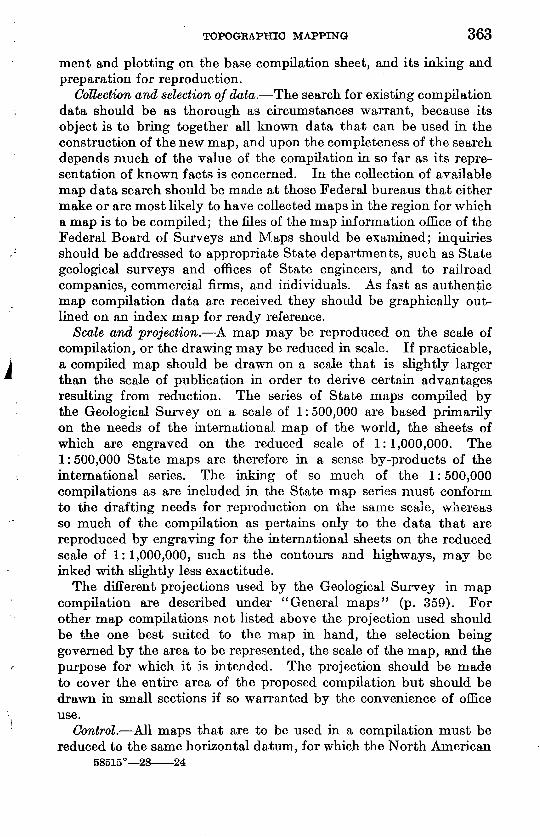
TOPOGKAPHIO MAPPING 363
ment and plotting on the base compilation sheet, and its inking and preparation for reproduction.
Collection and selection of data. The search for existing compilation data should be as thorough as circumstances warrant, because its object is to bring together all known data that can be used in the construction of the new map, and upon the completeness of the search depends much of the value of the compilation in so far as its repre sentation of known facts is concerned. In the collection of available map data search should be made at those Federal bureaus that either make or are most likely to have collected maps in the region for which a map is to be compiled; the files of the map information office of the Federal Board of Surveys and Maps should be examined; inquiries should be addressed to appropriate State departments, such as State geological surveys and offices of State engineers, and to railroad companies, commercial firms, and individuals. As fast as authentic map compilation data are received they should be graphically out lined on an index map for ready reference.
Scale and projection. A map may be reproduced on the scale of compilation, or the drawing may be reduced in scale. If practicable, a compiled map should be drawn on a scale that is slightly larger than the scale of publication in order to derive certain advantages resulting from reduction. The series of State maps compiled by the Geological Survey on a scale of 1:500,000 are based primarily on the needs of the international map of the world, the sheets of which are engraved on the reduced scale of 1:1,000,000. The 1:500,000 State maps are therefore in a sense by-products of the international series. The inking of so much of the 1:500,000 compilations as are included in the State map series must conform to the drafting needs for reproduction on the same scale, whereas so much of the compilation as pertains only to the data that are reproduced by engraving for the international sheets on the reduced scale of 1:1,000,000, such as the contours and highways, may be inked with slightly less exactitude.
The different projections used by the Geological Survey in map compilation are described under "General maps" (p. 359). For other map compilations not listed above the projection used should be the one best suited to the map in hand, the selection being governed by the area to be represented, the scale of the map, and the purpose for which it is intended. The projection should be made to cover the entire area of the proposed compilation but should be drawn in small sections if so warranted by the convenience of office use.
Control. All maps that are to be used in a compilation must be reduced to the same horizontal datum, for which the North American
58515° 28 24
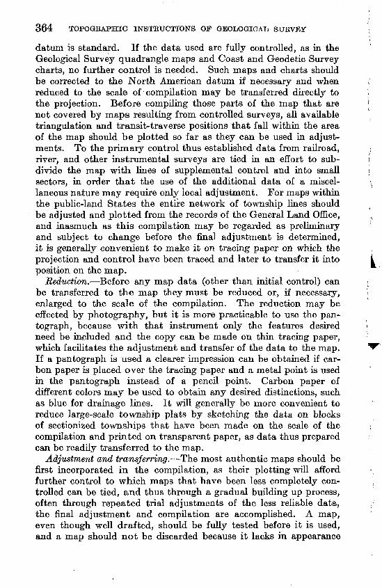
364 TOPOGBAPHIC INSTRUCTIONS OF GEOLOGICAL SUEVEY
datum is standard. If the data used are fully controlled, as in the Geological Survey quadrangle maps and Coast and Geodetic Survey charts, no further control is needed. Such maps and charts should be corrected to the North American datum if necessary and when reduced to the scale of compilation may be transferred directly to the projection. Before compiling those parts of the map that are not covered by maps resulting from controlled surveys, all available triangulation and transit-traverse positions that fall within the area of the map should be plotted so far as they can be used in adjust ments. To the primary control thus established data from railroad, river, and other instrumental surveys are tied in an effort to sub divide the map with lines of supplemental control and into small sectors, in order that the use of the additional data of a miscel laneous nature may require only local adjustment. For maps within the public-land States the entire network of township lines should be adjusted and plotted from the records of the General Land Office, and inasmuch as this compilation may be regarded as preliminary and subject to change before the final adjustment is determined, it is generally convenient to make it on tracing paper on which the projection and control have been traced and later to transfer it into position on the map.
Reduction. Before any map data (other than initial control) can be transferred to the map they must be reduced or, if necessary, enlarged to the scale of the compilation. The reduction may be effected by photography, but it is more practicable to use the pan tograph, because with that instrument only the features desired need be included and the copy can be made on thin tracing paper, which facilitates the adjustment and transfer of the data to the map. If a pantograph is used a clearer impression can be obtained if car bon paper is placed over the tracing paper and a metal point is used in the pantograph instead of a pencil point. Carbon paper of different colors may be used to obtain any desired distinctions, such as blue for drainage lines. It will generally be more convenient to reduce large-scale township plats by sketching the data on blocks of sectionized townships that have been made on the scale of the compilation and printed on transparent paper, as data thus prepared can be readily transferred to the map.
Adjustment and transferring. The most authentic maps should be first incorporated in the compilation, as their plotting will afford further control to which maps that have been less completely con trolled can be tied, and thus through a gradual building up process, often through repeated trial adjustments of the less reliable data, the final adjustment and compilation are accomplished. A map, even though well drafted, should be fully tested before it is used, and a map should not be discarded because it lacks in appearance
TOPOGRAPHIC MAPPING 365
only. Although the suitability of existing maps or map data can in general be determined by inspection, the ultimate determination may rest upon the possibility of fitting or reconciling them to other data covering the same or adjacent territory.
Although a large part of the generalization of features is accom plished in the pantographing, further elimination, especially in drainage, may be needed when the data are transferred. Features such as railroads do not need so much generalization, and boundary lines should be delineated as accurately as the scale will permit.
Inking. The process of reproduction determines the method of inking. If the map is to be engraved all the features are included in one drawing, but great refinement in the drafting is unnecessary. The photolithographic process requires excellent drafting, and if the map is to be printed in more than one color a separate drawing may be made for each of the colors used if desired. The most satisfactory method of doing this is to provide photolithographic copies of the pencil compilation, one for each color to be used, printed in nonpho- tographic blue on drawing paper or bristol board. Only the features that are to be printed in the same color are included in one draw- ing, and as the blue copies of the map are identical, perfect register should be assured when the reproductions of the several drawings are combined in the printed map. The drainage should be carefully generalized as it is inked, and as a rule streams less than 6 miles in length may be omitted in a compilation on a scale of 1:500,000. Main streams should be inked heavier than the small tributaries, and a distinction should be made between perennial and intermittent streams. State and county boundary lines should be drawn reason- ably bold, but public-land lines, with the exception of base lines and principal meridians should be inconspicuous. Railroad tracks should be represented by firm lines, with very short lines for the cross ties, which should be spaced at intervals of not less than one-tenth of an inch.
Lettering. In planning the lettering for the map, a complete diagram in which provision is made for the position each name is to occupy should be prepared for the draftsman's use. The diagram may be made in pencil on a photograph or photolithograph of the compilation. The map should not be congested with names, and in the selection of a place to be named consideration should be given to its population, importance as a railroad or postal center, and com mercial or historical importance. In thickly settled regions the names of many places of only local importance must be omitted for lack of space, but in sparsely settled areas the names of small settle ments or even of ranch houses assume importance as reference points. Space may be economized, where necessary, by abbreviating rail road names and by using "R" or "Cr" for the words "River" and
366 TOPOGRAPHIC INSTRUCTIONS OF GEOLOGICAL SURVEY
"Creek." All place names should be lettered in a horizontal position, and the names of railroads and streams should follow their meander- ings and be so placed as to read from the south edge of the map. The spellings approved by the United States Geographic Board must be followed, and the diagram should be carefully checked before the lettering is executed. . The lettering may be done either by hand, by means of pasting type impressions on the map, or by a combina tion of both. Single-stroke lettering is comparatively easy to do and reproduces well, and its use is recommended. If type impressions are used instead of hand lettering the names should be listed in systematic order for type setting and printed on light-weight gummed paper. In applying names printed from type they should be cut out without much margin and pasted on the map, care being taken to avoid as much as possible, covering up any of the features. It is more satisfactory to letter the stream, names by hand, and this should be done on the drainage drawing, in the event that the colors of the map are separated -in the drafting.
Checking. During the whole course of the compilation the map should be constantly verified, so that upon its completion it may be free from error. It should also, however, be subjected to a final exhaustive checking, and such errors as are then detected should be corrected before it is sent to the printer.
Compilation record. As the compilation progresses a record should be kept of the data that were used, and this record should be later transcribed to a printed copy of the map. Errors or omissions that may be detected from time to time should be noted on a file copy of the map, for correction in the next edition.
Reproduction. Compiled maps are generally reproduced by photo lithography, although engraving is used for such maps as those of the United States and of the international world series. To assist the lithographer in retaining the scale of a map reproduced by photo lithography a projection should be constructed on paper mounted on a metal plate to serve as a key sheet in assembling the map for transfer to the printing stone.
SHADED RELIEF MAPS
Relief may be represented on maps by means of contour lines, form lines, hachures, or shading. It may be expressed by shading alone, or the shading may supplement other means of expression, as contouring. If relief shading is artistically added to the contouring it will so tend to throw into the background the rigid details of contour construction and so emphasize the broader features of the map as to give to the map a relief expression that may be understood by laymen unfamiliar with contour lines. Shaded relief maps may also assist map users who, although versed in the theory of contours,
TOPOGRAPHIC MAPPING 367
can not in practice get a picture of a region from a glance at a contour map of it; and the trained map user may often see in the shaded map some general aspect of the terrain that he has failed to grasp in the exacting detail of the contouring. Finally, even the engineer or geologist may find hi relief shading, especially when a number of such maps are used in combination, a meaning to be recognized in no other way save through models. As relief shading is a generalized portrayal of the relief in a pictorial sense, data of insufficient accuracy for contouring may often be employed with pleasing and advanta geous effect.
In the early years of the Geological Survey experimental work in relief shading was carried on with some success, two such maps being published about 1882 by the lithographic process, but owing to the prohibitive cost of reproduction at that time the plan was abandoned. In recent years the discovery of the cheaper and more effective photo-transfer process has afforded a means for economical publica tion and caused a revival of interest in relief shading, which has grown in popularity and developed to such an extent as to enlist the commendation of geographers throughout the world.
Although shaded relief maps are called picture maps, they in reality portray with remarkable fidelity all the bolder topographic features, both in precise location and physical character, the illusion of relief being obtained by a judicious manipulation on the drawing of lights and shades so as to produce an effect similar to that which would be obtained if a carefully sculptured relief model were obliquely illuminated by the sun around 4 o'clock in the afternoon of a day in late summer. In addition to the representation of the bolder forms of relief, relative differences in elevation of valleys, plateaus, and other lesser relief forms are shown by a system of delicately graded tints dark tints for the lowlands, grading upward to light tints for the highlands. This mode of representing high and low lands has been developed in the Geological Survey and differs from other forms of hypsographic expression. Shaded relief maps should not be con fused with those in which the process of modeling in clay or other plastic material has been used.
The Geological Survey has published a general shaded relief map of the United States on a scale of 1 : 3,168,000, one of Alaska on a scale of 1 : 2,500,000, and shaded relief State maps of Ohio (1 : 380,- 160), Arizona (1 :500,000), Kentucky (1 : 500,000), and Idaho (1 : 760,320) and has in preparation similar maps of Pennsylvania, New York, New England, West Virginia, New Mexico, Colorado, and Wyoming. Shaded relief editions of 12 recent topographic maps have also been published, in which the shading has been overprinted hi a light olive-drab over the contours; for these editions special printings of the topographic base are made in colors that harmonize
368 TOPOGRAPHIC INSTRUCTIONS OF GEOLOGICAL SURVEY
with the overprinted relief shading. The methods of relief shading are also used for illustrations that show in detail special types of physiographic phenomena and geologic structure.
In the compilation of a base map upon which to add relief shading for maps of areas for which no contour maps are available, all authori ties bearing upon the probable relief are used, including interviews with those who have traveled through any of the unmapped regions. Thus, in the preparation of the manuscript for the shading of the wall map of the United States over 5,000 maps were used, and many persons who had personal knowledge of unsurveyed areas were interviewed.
UNITED STATES SYSTEM OF PUBLIC-LAND SURVEYS
The following discussion, based on the "United States manual of public-land surveys," to which the topographer is referred for more detailed information, is intended to give a general outline of the plan and practices of the public-land surveys.
TOWNSHIP UNITS
The unit of the system is the township, a tract 6 miles square, or nearly so, bounded on the east and west by true north-south lines, and on the south and north by east-west lines, and subdivided into 36 sections, each a mile square, or nearly so.
As true north-south lines (that is, meridians) converge northward to the pole, it is evident that the width of a township decreases slightly from south to north (41.9 links in latitude 30° N. to 86.5 links in latitude 50° N.),7 and that its shape is really trapezoidal and not square. It is evident also that as the meridian lines are extended northward townships will become progressively narrower and will be reduced in area. These complexities growing out of the inherent convergence of meridians on a spherical surface like that of the earth were not taken into account in framing the original law, the intent of which was apparently to provide for square units of uni form size; nor was any provision made for a system of control lines whereby the narrowing of the townships, on the one hand, and the inaccuracies in the surveying of the subordinate lines, on the other hand, might be kept within convenient limits. However, the first public-land surveys to be executed, notably the classic "Seven Ranges" in Ohio, demonstrated the need of remedying these defects, and as a result there has been evolved by successive legal steps a system of rectangular surveying which "harmonizes the incompati bilities of the requirements of law and practice" and has become the accepted standard for the entire country.
i All public-land measurements are expressed in chains and links. A chain of 100 links is equivalent to 66 feet common measure, and 80 chains equal 1 mile.
TOPOGRAPHIC MAPPING 369
PRINCIPAL MERIDIANS AND BASE LINES
All surveys in a given area are referred to two primary lines, a principal meridian and a base line, passing through an initial point; the one is a true north-south line and the other a true east-west line that is, a parallel of latitude. These two lines constitute the axes of the system, and the township units are numbered with reference to them in consecutive tiers to the north and to the south, begin ning at the base line, and in consecutive ranges to the east and to the west, beginning at the principal meridian. Any township, accordingly, may be designated by tier and range number, as T. 14 N., E. 7 W. fourth principal meridian, or T. 10 N., R. 28 E. Mount Diablo principal meridian. The principal meridian must be added to each designation to give complete identification; there are about 30 separate systems in the United States, each with a separate set of axes and a separate system of numbers. The number or name of the principal meridian serves to distinguish these from one another.
STANDARD PARALLELS AND GUIDE MERIDIANS
From the principal meridian, commonly at intervals of 24 miles, auxiliary base lines called standard parallels, or correction lines, are extended east and west. They are numbered each way from the base line for example, first standard parallel north, third standard parallel south.
From the base line, usually at intervals of 24 miles, auxiliary meridians called guide meridians are run due north. They are numbered each way from the principal meridian for example, first guide meridian east, second guide meridian west. As they converge appreciably in a distance of 24 miles (the exact amount depending on the latitude), they are not continued beyond the first standard parallel north but end at closing corners on that line and start afresh from standard corners a full 24 miles apart. It will therefore be seen that standard parallels have two sets of corners, one set referring to lines north of the parallel and the other being established by town ship and section lines from the south, closing on the parallel. The process is repeated at the second and each succeeding standard parallel Each guide meridian thus runs due north from parallel to parallel, and on each of the parallels is an offset to correct for convergence.
South of the base line guide meridians are run not south but north, so that the blocks inclosed between them and the parallels are essen tially similar to those north of the base line. In case conditions require that a guide meridian be run south it must be begun at a properly computed and established closing corner.
The standard distance of 24 miles between parallels and meridians is not always strictly adhered to. Thus, in many parts of the far
370 TOPOGRAPHIC INSTRUCTIONS OF GEOLOGICAL SURVEY
West there are five tiers of townships (30 miles) between parallels and six, seven, or more ranges between guide meridians. In some places these irregularities in the spacing of the standard lines necessitate the introduction of intermediate meridians and parallels. These are designatedbylocalnam.es.
The offsets of the meridians on the parallels and their closing dis tances are of special importance in the plotting of guide meridians and standard parallels, and these data the topographer should not fail to procure from the General Land Office.
The meridional convergence increases proportionately to the dis tance from the principal meridian. Therefore the offset of the second guide meridian is double that of the first guide meridian (between the same parallels); that of the third guide meridian is three times as great; and so on in proportion (the intervals being assumed to be regular). Again, the convergence increases slightly northward with the latitude. Thus the offset of a first guide meridian in latitude 50° is more than double what it would be in latitude 30°. Of course the actual offsets depart somewhat from the theoretical offsets because of inaccuracies in surveying, and this makes it all the more imperative that they be noted on the plats.
It is to be remembered that all errors of closure in distance are thrown in the last mile and are not distributed over the entire length of the line. The spacing of the corners along the line is thus not affected by the amount of the closure.
Whenever practicable the survey of township exteriors within a 'block bounded by standard lines begins with the southwest township and continues northward until the entire west range is completed; thence it goes from south to north through the next range east, etc. The mode of procedure is first to run the east boundary of a township due north a full 6 miles; then to run its north boundary on a random or trial line from east to west, correcting back on a true line after the "falling" north or south of the northwest township corner has been ascertained. The closure in distance, however, is thrown in the last half mile at the west end of the line that is, between the last quarter- section corner and the township corner. The purpose of this is to throw the meridional convergence and all irregularities arising from inaccurate surveying toward the west boundary of the township. The last quarter-section corner accordingly lies not midway in the last mile but always an even 40 chains from the mile corner east of it, whatever the distance between it and the township corner may be.
In getting data for platting township exteriors, therefore, special note should be made of the closing distances at the west ends of the latitudinal township boundaries. The accuracy of the surveys may
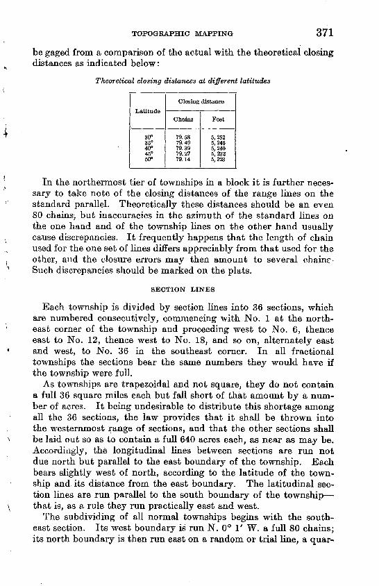
TOPOGRAPHIC MAPPING 371
be gaged from a comparison of the actual with the theoretical closing distances as indicated below:
Theoretical closing distances at different latitudes
30°35°40°45°60°
Closing distance
Chains
79.5879.4979.3979.2779.14
Feet
5,2525,2465,2405,2325,223
In the northermost tier of townships in a block it is further neces sary to take note of the closing distances of the range lines on the standard parallel. Theoretically these distances should be an even 80 chains, but inaccuracies in the azimuth of the standard lines on the one hand and of the township lines on the other hand usually cause discrepancies. It frequently happens that the length of chain used for the one set of lines differs appreciably from that used for the other, and the closure errors may then amount to several chains Such discrepancies should be marked on the plats.
SECTION LINES
Each township is divided by section lines into 36 sections, which are numbered consecutively, commencing with No. 1 at the north east corner of the township and proceeding west to No. 6, thence east to No. 12, thence west to No. 18, and so on, alternately east and west, to No. 36 in the southeast corner. In all fractional townships the sections bear the same numbers they would have if the township were full.
As townships are trapezoidal and not square, they do not contain a full 36 square miles each but fall short of that amount by a num ber of acres. It being undesirable to distribute this shortage among all the 36 sections, the law provides that it shall be thrown into the westernmost range of sections, and that the other sections shall be laid out so as to contain a full 640 acres each, as near as may be. Accordingly, the longitudinal lines between sections are run not due north but parallel to the east boundary of the township. Each bears slightly west of north, according to the latitude of the town ship and its distance from the east boundary. The latitudinal sec tion lines are run parallel to the south boundary of the township that is, as a rule they run practically east and west.
The subdividing of all normal townships begins with the south east section. Its west boundary is run N. 0° 1' W. a full 80 chains; its north boundary is then run east on a random or trial line, a quar-
372 TOPOGRAPHIC INSTRUCTIONS OF GEOLOGICAL SURVEY
ter-section corner being temporarily placed at 40 chains. The "fall ing" north or south from the appropriate corner on the township boundary having been measured, the quarter-section corner is then shifted proportionately and set exactly midway between the section corners. In many of the older contracts these rules were not faith fully carried out, and in consequence little dependence is to be placed on the position of the quarter-section corners on the latitu dinal section lines. The west boundary of the next section north is then run out, and then its north boundary as before, and so on through the entire east range of sections. The other ranges are taken up consecutively from east to west, each being surveyed from south to north. The range lines of the northernmost tier differ from the others hi that they are connected with the corners along the township boundary and consequently are not always parallel to the east boundary nor measure an even 80 chains in length. Theoreti cally they should do so, but in practice the inaccuracies in the sur veying of the township exteriors, on the one hand, and of the section lines, on the other hand, cause discrepancies. Accordingly, these lines are run first on a random or trial line parallel to the east bound ary and then corrected back according to their falling. In order to confine the irregularities in acreage to the northernmost tier of lots, the excess or deficiency in measurement is thrown north of the quarter-section corner, which is consequently set not midway but an even 40 chains from the south end of the line.
In the west range of sections, again, the latitudinal lines are connected to corners along the west township boundary. Each is therefore run first on a random parallel to the south boundary of the section and then corrected back according to its falling. Here again, in order to confine the irregularities in acreage to the western most range of lots, the error (which normally is a deficiency equal to the meridional convergence) is thrown west of the quarter-section corner, which is consequently set not midway but an even 40 chains from the east end of the line.
MEANDERS
Where any lines cross rivers the right-angle width of which is 3 chains or more, lakes, bayous, and deep ponds having an area of 25 acres or more, meander corners are established on each bank, and from these are run meanders (corresponding to traverse lines) along the banks, to close on other meander corners. Similarly, water bodies having an area of 25 acres or more, lying within sections, are surrounded by a meander tied to the two nearest section or quarter- section corners. Islands are located by triangulation from meanders on the shore, an auxiliary meander corner being established on each one of them.
TOPOGRAPHIC MAPPING 373
Meanders are run for the sole purpose of providing a definite boundary for the land areas in the lots abutting on water bodies, so that the acreage of such fractional lots may be computed with accuracy. There is consequently no object in publishing meanders on the topographic maps, and they are to be omitted. At the same time, distances to meander corners and notes or plats of meander lines are often of great value in the construction of the maps hi the field, and such data should therefore be procured.
Care should be taken in drafting the field sheets to discontinue land lines at such river banks and lake shores as have been mean dered. They should not be represented as crossing the water body unless the lines were actually so run.
BLAZING LINES
Trees on a line have two chops or notches cut on the side facing the line. Other trees standing within 50 links of the line, on either side of it, may be blazed on two sides diagonally or quartering toward the line, the blazes approaching nearer each other the farther the tree stands from the line.
Random lines are not blazed.
MARKING CORNERS
Classes. Land-survey corners are divided into the fourteen fol lowing classes, each of which has a distinctive set of marks and is marked in accordance with difinite rules:
Standard township corners. Closing township corners. Corners common to four townships. Corners common to two townships only. Corners referring to one township only. Standard section corners. Closing section corners. Corners common to four sections. Corners common to two sections only. Corners referring to one section only. Quarter-section corners. Standard quarter-section corners. Meander corners.Corners on reservation or other boundaries not conforming to regular
system.
Each of these fourteen classes of corners may be constructed as the character of the country and the availability of the materials permit, in eight different ways as follows:
Stone, with pits and mounds of earth. Stone, with mound of stone. Stone, with bearing trees.
374
Post, with pits and mounds of earth. Post, with bearing trees. Mound of earth, with deposit and stake pit. Tree corner, with pits and mound of earth. Tree corner, with bearing trees.
No less than 112 different combinations may be met in the field. There is, however, no need of describing each combination sepa rately; the marks follow a definite simple system and in a measure are self-explanatory.
Notches and grooves. Stones and posts on all township and section corners (except those on standard parallels) are set diagonally to the lines that is, with an edge on each line. On the edges are cut notches, the number of which indicates the number of miles to the near^t township corner in the direction of the edge. Thus, the first mile corner on a range line between two townships has one notch on the south edge and five notches on the north edge; and the second mile corner has two notches on the south edge and four notches on the north edge. On a latitudinal township boundary the first mile corner west of the township corner has one notch on the east edge and five notches on the west edge; and the second corner west has two notches on the east edge and four notches on the west edge. A corner common to four townships has six notches on each of its four edges.
Section corners within a township are notched on their south and east edges only. The number of notches on them therefore indi cates the distance in miles to the south and east township exteriors, respectively. Thus, the corner between sees. 25, 26, 35, and 36 has one notch on its south edge and one notch on its east edge; the corner between sees. 10, 11, 14, and 15 has four notches on its south edge and two notches on its east edge; the corner between sees. 5, 6, 7, and 8 has five notches on both its south and east edges.
Stones and posts on standard parallels are set square with the lines that is, with a flat face on each line. Their faces are grooved, the number of grooves on any face indicating the number of miles to the nearest township corner in the direction of the face. Accordingly, standard township corners have six grooves on their north, east, and west faces; closing township corners have six grooves on their south, east, and west faces. Standard section corners are grovoed only on their east and west faces with respect to the standard township cor ners. Closing section corners are similarly marked with respect to the closing township corners.
Tree corners are notched to correspond with the notches or grooves which stones or posts would bear in the same situation.
Additional marks. Standard corners of all kinds are marked "s c" on the north face; closing corners, "c c" on the south face. If posts or trees are used the township and range numbers also are indicated
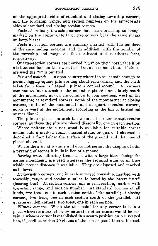
TOPOGRAPHIC MAPPING 375
on the appropriate sides of standard and closing township corners, and the township, range, and section numbers on the appropriate sides of standard and closing section corners.
Posts at ordinary township corners have each township and range marked on the appropriate face; tree corners bear the same marks on large blazes.
Posts at section corners are similarly marked with the numbers of the surrounding sections and, in addition, with the number of the township and range on the northwest and northeast faces, respectively.
Quarter-section corners are marked "%s" on their north face if on a latitudinal line, on their west face if on a meridional line. If stones are used the "s" is omitted.
Pits and mounds. In open country where the soil is soft enough to permit digging square pits are dug about each corner, and the earth taken from them is heaped up into a conical mound. At corners common to four townships the mound is placed immediately south of the monument; at corners common to four sections, west of the monument; at standard corners, north of the monument; at closing corners, south of the monument; and at quarter-section corners, north or west of the monument, according as the line is latitudinal or meridional.
The pits are placed on each line about all corners except section corners; at these the pits are placed diagonally, one in each section.
Where neither stone nor wood is available for suitable corner monuments a marked stone, charred stake, or quart of charcoal is deposited 1 foot below the surface of the ground and the mound placed above it.
Where the ground is stony and does not permit the digging of pits, a pyramid of stones is built in lieu of a mound.
Bearing trees. Bearing trees, each with a large blaze facing the corner monument, are used wherever the required number of trees within proper distance is available. They are disposed and marked as follows:
At township corners, one in each surveyed township, marked with township, range, and section number, followed by the letters "B T" (bearing tree). At section corners, one in each section, marked with township, range, and section number. At standard corners of all kinds, two trees, one in each section north of the parallel; at closing corners, two trees, one in each section south of the parallel. At quarter-section corners, two trees, one in each section.
Witness corners. When the true point for any corner falls in a place where its destruction by natural or other causes would be cer tain, a witness corner is established in a secure position on a surveyed line, if possible, within 20 chains of the corner point thus witnessed.
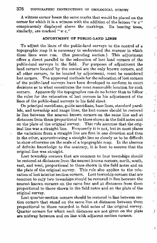
376 TOPOGKAPHIC INSTRUCTIONS OF GEOLOGICAL SURVEY
A witness corner bears the same marks that would be placed on the corner for which it is a witness with the addition of the letters "w c" conspicuously displayed above the markings. Its bearing trees, similarly, are marked "w c."
ADJUSTMENT OF PUBLIC-LAND LINES
To adjust the lines of the public-land surveys to the control of a topographic map it is necessary to understand the manner in which those lines were run. (See preceding section.) This adjustment offers a direct parallel to the relocation of lost land corners of the public-land surveys in the field. For purposes of adjustment the land corners located by the control are the only known corners, and all other corners, to be located by adjustment, must be considered lost corners. The approved methods for the relocation of lost corners of the public-land surveys have been developed to conform to court decisions as to what constitutes the most reasonable location for such corners. Apparently the topographer can do no better than to follow the rules for the relocation of lost corners in his adjustment of the lines of the public-land surveys to his field sheet.
On principal meridians, guide meridians, base lines, standard paral lels, and township and range lines, the lost corner should be restored in line between the nearest known corners on the same line and at distances from them proportional to those shown in the field notes and on the plats of the original survey. This rule assumes that the orig inal line was a straight line. Frequently it is not, but in most places the variations from a straight line are first in one direction and then in the other, approximating a straight line so closely as to be difficult to show otherwise on the scale of a topographic map. In the absence of definite knowledge to the contrary, it is best to assume that the original line was straight.
Lost township corners that are common to four townships should be restored at distances from the nearest known corners, north, south, east, and west, proportional to those shown in the field notes and on the plats of the original survey. This rule also applies to the relo cation of lost ulterior section corners. Lost township corners that are common to only two townships should be restored in line between the nearest known corners on the same line and at distances from them proportional to those shown in the field notes and on the plats of the original survey.
Lost quarter-section corners should be restored in line between sec tion corners that stand on the same line at distances between them proportional to those recorded in field notes of the original survey. Quarter corners for which such distances are not given on the plats are midway between and on line with adjacent section corners.
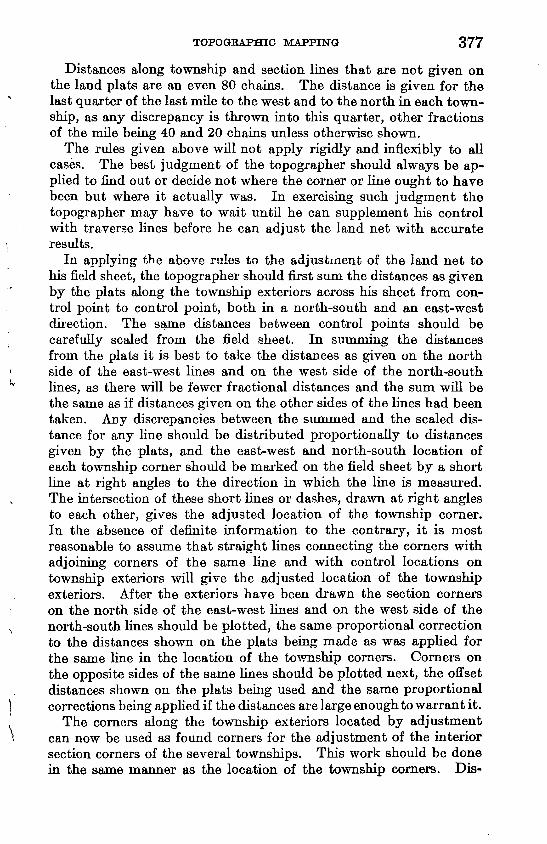
TOPOGRAPHIC MAPPING 377
Distances along township and section lines that are not given on. the land plats are an even 80 chains. The distance is given for the last quarter of the last mile to the west and to the north in each town ship, as any discrepancy is thrown into this quarter, other fractions of the mile being 40 and 20 chains unless otherwise shown.
The rules given above will not apply rigidly and inflexibly to all cases. The best judgment of the topographer should always be ap plied to find out or decide not where the corner or line ought to have been but where it actually was. In exercising such judgment the topographer may have to wait until he can supplement his control with traverse lines before he can adjust the land net with accurate results.
In applying the above rules to the adjustment of the land net to his field sheet, the topographer should first sum the distances as given by the plats along the township exteriors across his sheet from con trol point to control point, both in a north-south and an east-west direction. The same distances between control points should be carefully scaled from the field sheet. In summing the distances from the plats it is best to take the distances as given on the north side of the east-west lines and on the west side of the north-south lines, as there will be fewer fractional distances and the sum will be the same as if distances given on the other sides of the lines had been taken. Any discrepancies between the summed and the scaled dis tance for any line should be distributed proportionally to distances given by the plats, and the east-west and north-south location of each township corner should be marked on the field sheet by a short line at right angles to the direction in which the line is measured. The intersection of these short lines or dashes, drawn at right angles to each other, gives the adjusted location of the township corner. In the absence of definite information to the contrary, it is most reasonable to assume that straight lines connecting the corners with adjoining corners of the same line and with control locations on township exteriors will give the adjusted location of the township exteriors. After the exteriors have been drawn the section corners on the north side of the east-west lines and on the west side of the north-south lines should be plotted, the same proportional correction to the distances shown on the plats being made as was applied for the same line in the location of the township corners. Corners on the opposite sides of the same lines should be plotted next, the offset distances shown on the plats being used and the same proportional corrections being applied if the distances are large enough to warrant it.
The corners along the township exteriors located by adjustment can now be used as found corners for the adjustment of the interior section corners of the several townships. This work should be done in the same manner as the location of the township corners. Dis-
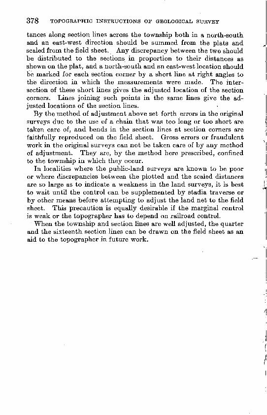
378 TOPOGRAPHIC INSTKUCTIONS OF GEOLOGICAL SURVEY
tances along section lines across the township both in a north-south and an east-west direction should be summed from the plats and scaled from the field sheet. Any discrepancy between the two should be distributed to the sections in proportion to their distances as shown on the plat, and a north-south and an east-west location should be marked for each section corner by a short line at right angles to the direction in which the measurements were made. The inter section of these short lines gives the adjusted location of the section corners. Lines joining such points in the same lines give the ad justed locations of the section lines.
By the method of adjustment above set forth errors in the original surveys due to the use of a chain that was too long or too short are taken care of, and bends in the section lines at section corners are faithfully reproduced on the field sheet. Gross errors or fraudulent work in the original surveys can not be taken care of by any method of adjustment. They are, by the method here prescribed, confined to the township in which they occur.
In localities where the public-land surveys are known to be poor or where discrepancies between the plotted and the scaled distances are so large as to indicate a weakness in the land surveys, it is best to wait until the control can be supplemented by stadia traverse or by other means before attempting to adjust the land net to the field sheet. This precaution is equally desirable if the marginal control is weak or the topographer has to depend on railroad control.
When the township and section lines are well adjusted, the quarter and the sixteenth section lines can be drawn on the field sheet as an aid to the topographer in future work.