Embed Size (px)
Citation preview
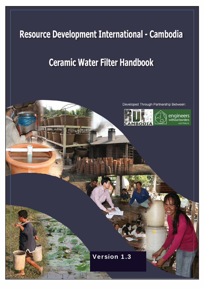
Version 1.3
Engineers without Borders provides voluntary assistance to
RDIC on an ongoing basis.
What comes next?
This is a first publication of RDIC’s ceramic water filter production techniques, ideas and visions. We are planning additions and amendments into the future. So stay tuned and keep in touch as we continue to refine and provide further information to assist you with your factory projects. Information on updates can be found at www.rdic.org.
Copyright: Resource Development International - Cambodia, Engineers Without Borders Australia, 2010.
Written By: Judy Hagan, Nick Harley, Robert Hughes, Ajay Chouhan, David Pointing, Mickey Sampson, Vanna SAOM, and Kathryn Smith.
Reference: Hagan, J.M., Harley, N., Hughes, R., Chouhan, A., Pointing, D., Sampson, M., Smith, K., and Soam, V. 2009, Resource Development International - Cambodia Ceramic Water Filter Handbook -, Version 1.3, Phnom Penh, Cambodia.
Contact: [email protected]; [email protected]; [email protected].
Acknowledgements:
For their assistance in development and review: Hannah Chiew, Sophie Bloem, CHAN Samon, PRAK Savoeun, KHIM Sosamrach, CHHEANG Penghorn, PORT Nay, PAT Thyrith, Heather Murphy, Reitse de Jong, and EWB Australia members.
For their commitment and drive in producing, promoting, testing, researching and educating about quality ceramic filters every day: RDIC’s filter factory, community education, marketing, studio, laboratory and office teams.
For their support of the Engineers Without Borders Australia role at RDIC: Planet Wheeler Foundation; ERM Foundation; Engineers Australia – South Australia Division; Rotary Club of Burnside (South Australia).
Contents
Chapter 1 Overview .................................................................................................................... 5
1.1. Introduction ................................................................................................................... 5
1.2. Why Ceramic Filters? ..................................................................................................... 6
1.3. How the Ceramic Filter Works ....................................................................................... 8
Chapter 2 Quality Control Considerations ................................................................................ 11
2.1. RDIC’s Commitment to Quality .................................................................................... 11
2.2. Quality Assurance Considerations ............................................................................... 11
Chapter 3 Initial Considerations - Setting up a Ceramic Filter Factory ..................................... 13
3.1. Are ceramic water filters right for you? ....................................................................... 13
3.2. Where to set up the factory? ....................................................................................... 14
3.3. Sourcing Inputs ............................................................................................................ 14
3.3.2. Evaluating the Clay ............................................................................................... 15
3.4. Machinery .................................................................................................................... 20
3.5. Factory Layout .............................................................................................................. 22
3.6. Staffing ......................................................................................................................... 23
3.7. Establishing your manufacturing process – some considerations ............................... 23
Chapter 4 The Production Process ............................................................................................ 25
Overview of material Inputs and Outputs for the factory ................................................... 25
Summary of the RDIC ’10 Step’ Production Process ........................................................... 26
4.1. Preparation of Raw Materials ...................................................................................... 27
4.2. Mixing of the Clay Components ................................................................................... 33
4.3. Forming Clay Cubes for Filter Element Pressing .......................................................... 36
4.4. Pressing, finishing, and labelling the filter elements ................................................... 38
4.5. Drying and Firing of Filter Elements ............................................................................. 42
4.6. Firing the Ceramic Filter Elements ............................................................................... 44
4.7. Flow Rate Testing ......................................................................................................... 50
4.8. Quality Check and Silver Painting ................................................................................ 53
4.9. Packaging of Filter System and Replacement Parts ..................................................... 57
Chapter 5 Occupational Health and Safety and Environmental Management ........................ 62
5.1. Occupational Health and Safety .................................................................................. 62
5.2. Environmental Management ....................................................................................... 65
Chapter 6 Distribution and Education ...................................................................................... 66
6.1. Introduction ................................................................................................................. 66
6.2. Education Materials ..................................................................................................... 67
6.3. RDIC’s Distribution and Education Program ................................................................ 68
Chapter 7 References and Further Information ....................................................................... 72
Appendix A Filter Efficacy Tests .............................................................................................. 75
Appendix B Pyrometric Cone Chart ......................................................................................... 77
Appendix C Factory Layout ..................................................................................................... 79
Appendix D RDIC Automated Water Spray System - for Clay Mixing ...................................... 81
Appendix E Technical Drawings .............................................................................................. 82
Appendix F How to build a kiln ............................................................................................... 84
Appendix G Build a T-Piece Flow Rate Measurer .................................................................... 86
Appendix H Example RDIC Filter Price List - November 2007 ................................................. 88
Appendix I RDIC Ceramic Water Filter Education and Maintenance Key Messages .................. 90
Appendix J RDIC Ceramic Water Filter Instructions ............................................................... 92
Appendix K RDIC Ceramic Water Filter Education Poster and Flip Chart ............................... 94
Appendix L Instructional Videos ............................................................................................. 96
P a g e | 5
Chapter 1 Overview
Ceramic water filters provide affordable high quality drinking water, at a household or classroom level, for communities who are otherwise without access to safe drinking water.
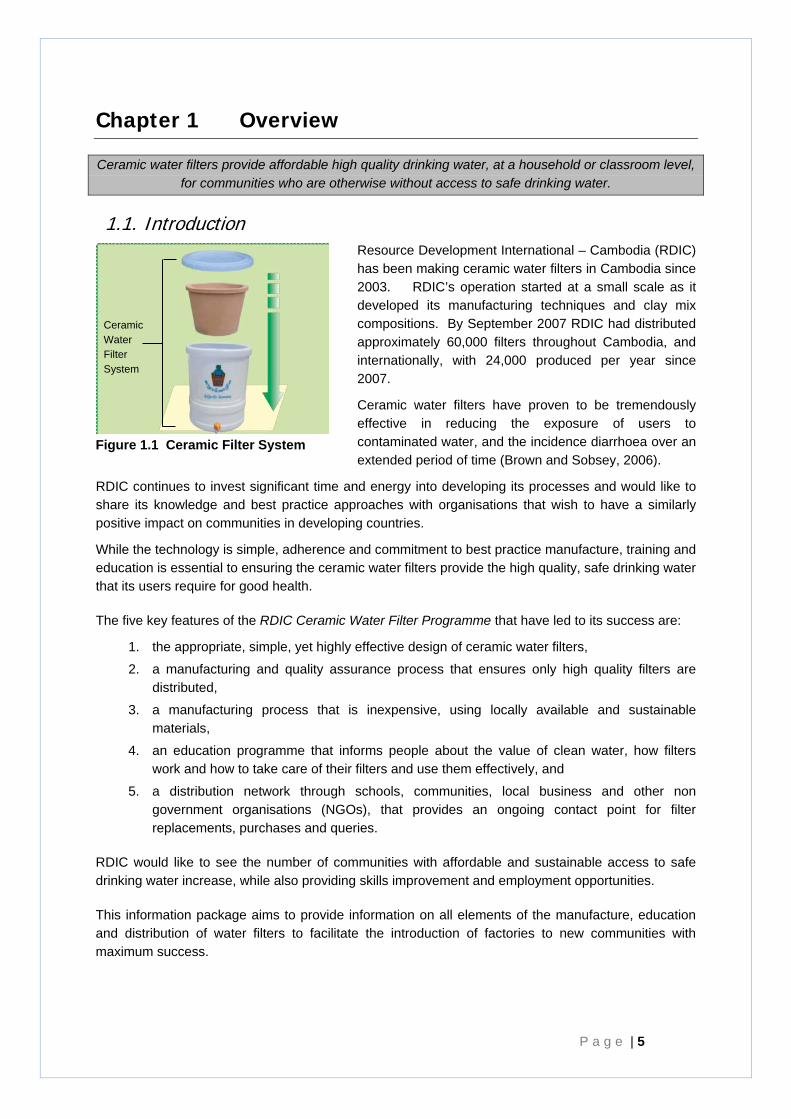
1.1. Introduction Resource Development International – Cambodia (RDIC) has been making ceramic water filters in Cambodia since 2003. RDIC’s operation started at a small scale as it developed its manufacturing techniques and clay mix compositions. By September 2007 RDIC had distributed approximately 60,000 filters throughout Cambodia, and internationally, with 24,000 produced per year since 2007.
Ceramic water filters have proven to be tremendously effective in reducing the exposure of users to contaminated water, and the incidence diarrhoea over an extended period of time (Brown and Sobsey, 2006).
RDIC continues to invest significant time and energy into developing its processes and would like to share its knowledge and best practice approaches with organisations that wish to have a similarly positive impact on communities in developing countries.
While the technology is simple, adherence and commitment to best practice manufacture, training and education is essential to ensuring the ceramic water filters provide the high quality, safe drinking water that its users require for good health.
The five key features of the RDIC Ceramic Water Filter Programme that have led to its success are:
1. the appropriate, simple, yet highly effective design of ceramic water filters,
2. a manufacturing and quality assurance process that ensures only high quality filters are distributed,
3. a manufacturing process that is inexpensive, using locally available and sustainable materials,
4. an education programme that informs people about the value of clean water, how filters work and how to take care of their filters and use them effectively, and
5. a distribution network through schools, communities, local business and other non government organisations (NGOs), that provides an ongoing contact point for filter replacements, purchases and queries.
RDIC would like to see the number of communities with affordable and sustainable access to safe drinking water increase, while also providing skills improvement and employment opportunities.
This information package aims to provide information on all elements of the manufacture, education and distribution of water filters to facilitate the introduction of factories to new communities with maximum success.
Figure 1.1 Ceramic Filter System
Ceramic Water Filter System
P a g e | 6
Chapter One provides an overview of ceramic filters, how they work.
Chapter Two discusses the importance of quality assurance to the development of RDIC’s processes.
Chapter Three highlights some early considerations for establishing a filter factory and setting up a manufacturing process. This Chapter draws on the experience RDIC has had to ensure key issues are considered early on.
Chapter Four importantly describes the complete manufacturing process of RDIC’s filter manufacture and can form a key resource for training staff. This Chapter discusses different options for manufacturing and discusses some of the benefits and costs of different options.
Chapter Five identifies a range of environmental and health and safety issues that will improve the sustainability of production, protect staff from accident and injury, and minimise costs to the local community.
Chapter Six outlines RDIC’s approach to education and distribution - an essential component of sustainability of use and efficacy of ceramic water filters.
Chapter Seven provides a list of useful references relevant to ceramic filter production, efficacy, and health impacts of waterborne disease.
In addition a number of resources have been provided as attachments to this Manual where more detailed information was available.
The Manual is supported by a DVD outlining the basic production process. The DVD is in English and French.
Although the handbook aims to provide as much detail as possible on the process and design of the filters, RDIC would also recommend that prior to deciding on establishing a new filter factory, the technical person/engineer in charge of its implementation spend time at RDIC’s factory, undertaking training and learning the details of the process.
1.2. Why Ceramic Filters?
Field trials of the effectiveness of ceramic water filters in Cambodia over time showed a 46% reduction in diarrheal disease between filter users and non-users, a 95.1% average (and up to 99.99%) reduction of E.coli in drinking water (Brown and Sobsey, 2006). Laboratory testing has shown a 90-99% reduction in viruses (Brown, 2007). These results support other trials of ceramic water filters (Lantagne, 2001) as a highly successful means of empowering households to manage their own safe water supply.
Chapter 1 - Overview
R D I C C e r a m i c W a t e r F i l t e r H a n d b o o k P a g e | 7
Although statistics vary, the World Health Organisation (WHO) reports that in 2004 approximately 36% of urban and 65% of rural Cambodian’s were without access to safe drinking water (WHO, 2007). Traditional water sources in Cambodia include rivers, ponds, lakes, open wells, and rainwater stored in open containers, which are all susceptible to contamination from disease causing organisms and other contaminants.
Lack of access to safe drinking water is one of the main causes of disease in Cambodia. Cambodia has a high under-five mortality rate (143 per 1000 live births in 2005 - compared with 6 per 1000 in Australia (WHO, 20072)) with 16.6% of child deaths in 2000 attributed to diarrheal disease (WHO, 20072).
Drinking contaminated water can cause diarrhoea, cholera, dysentery, and various other diseases. Contamination can be caused by a number of different types of pathogens
(disease causing organisms). Major pathogens causing water borne disease are:
• bacteria (eg salmonella, shigella – causing bacillary dysentery, cholera);
• viruses (Hepatitis A, Hepatitis E, rotavirus); and
• other parasites including protozoa (cryptosporidium, giardia, toxoplasma) and helminths (WHO, 2004).
Unclean drinking water poses a special threat to vulnerable new born infants in Cambodia, where low rates of exclusive breast feeding of infants (less than 10% of babies of up to seven months of age) are practiced, leading to high risk of exposure of newborns to water borne diseases from water and bottles.
Water-borne illnesses also reduce household income by preventing family members from attending work for short periods, and reduce school attendance by children.
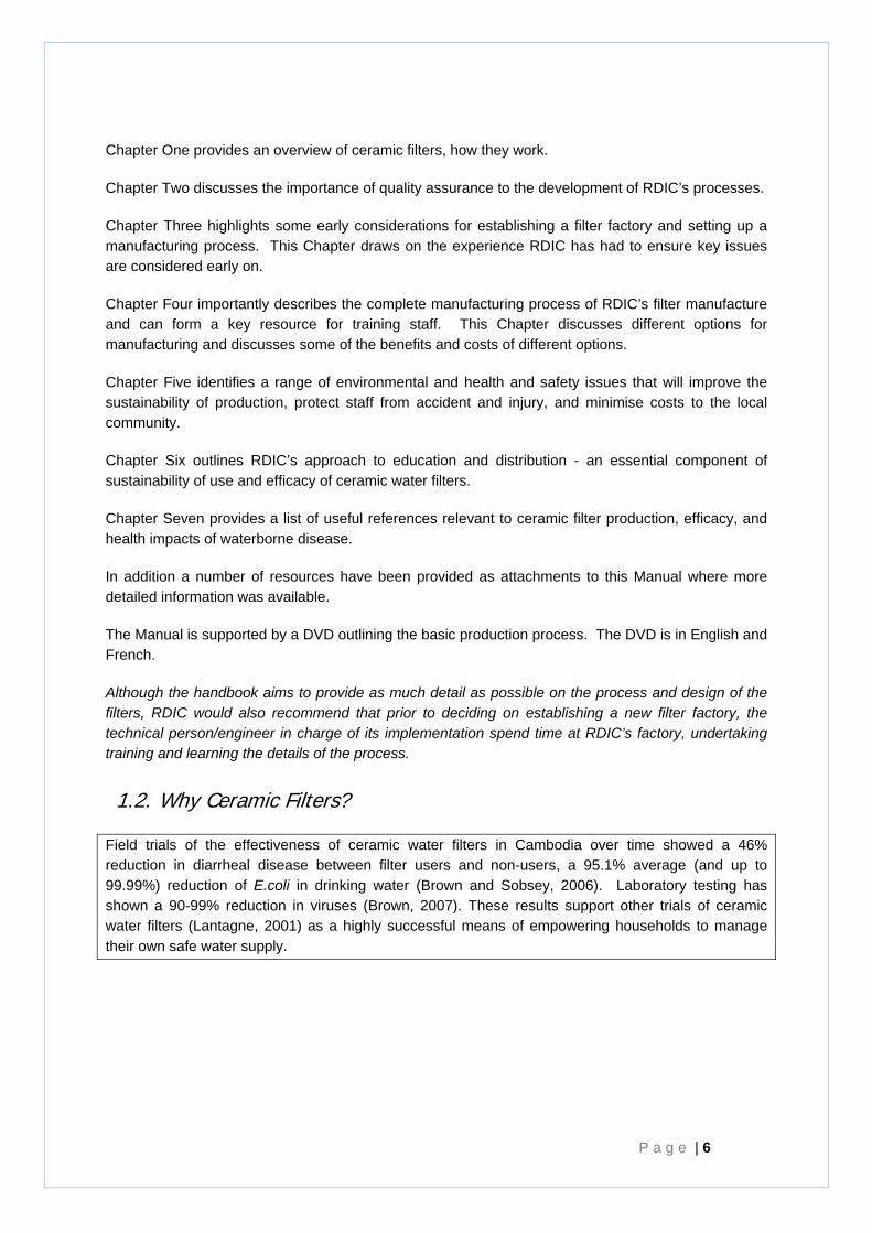
A key strategy for improving access to clean water is to enable rural households to purify water in their homes using an appropriate water treatment technology. One such technology is a ceramic water filter, a porous ceramic filter treated with silver to act as a disinfectant. Ceramic filters effectively reduce the number of bacteria, protozoa and helminths, making water safe for human consumption. (Brown and Sobsey, 2006)
Ceramic water filters offer a number of advantages over other techniques, such as boiling, including:
• on-demand availability of clean water in a clean storage container,
• physical filtering of the water to reduce contaminants such as silt and organic matter, and
• significant fuel savings - saving time in collection, cost, and pollution.
Figure 1.2 RDIC Ceramic Water Filter
P a g e | 8
1.3. How the Ceramic Filter Works
RDIC’s Ceramic Water Filter elements are made from a mixture of clay powder, organic ‘burn-out’ material, and water. After firing, filter elements are painted with a silver solution.
The actions of the RDIC Ceramic Water Filters are:
1. Physical ‘straining’ of dirt and bacteria out of the water as they are too large to pass through the ceramic substrate.
2. Chemical action of silver as a biocide to kill microbes.
3. Indirect sedimentation of particles within the pores of the filter.
RDIC now adds laterite to its clay mix. Laterite, a material high in Fe oxides, has demonstrated the potential to bind and remove viruses from the water, and is currently being studied more fully.
Clay forms the base material of the water filter element. Clay can be readily accessed in most locations worldwide, it can be moulded easily, and when fired in the kiln it changes chemically to become a strong slightly porous container that does not deteriorate in water.
A normal clay pot allows an extremely slow movement of water through naturally occurring pores that exist between the platelets of fired clay. The size of these pores have been measured (by an electron microscope) to be in the range of 0.6 to 3.0 microns (μm) which are capable of straining out most bacteria, protozoa, and helminths (Lantagne, 2001a), as well as dirt or sediment, and organic matter.
Organic ‘burn-out’ material, such as ground rice husks, is added to the clay mix for ceramic water filters. When exposed to the high temperatures of the kiln, the burn-out material combusts, leaving behind a large number of cavities in the fired clay. Water moves easily in the cavities compared with the pores in the clay. Therefore the presence of the cavities decreases the distance water needs to travel through the clay substrate, and therefore increases the overall flow rate of the filter. It is thought that if the burn-out cavities were actually joined up creating passageways through the filter, the flow rate would be well above the established tolerance zone (Lantagne, 2001a) and would be rejected during the manufacture process. Synchrotron data also suggest that there are not clear linkages between cavities created by rice husks (Sampson, 2009).
The ratio of clay to burn-out material in the clay is important in establishing the flow rate and therefore effectiveness of the filters.
Metal oxides (such as laterite and goethite) can also be added to the clay mix. Laterite contains goethite an iron(Fe)oxide which provides positively charged sites which have the potential to attract and bind viruses – removing them from the final water output.
Silver is known to act as a biocide, capable of inactivating bacteria and viruses. Silver is applied to ceramic water filters throughout the world. Studies have shown a significantly higher removal of bacteria from filtered water when comparing filters treated with silver and those without (Lantagne, 2001a, Bloem, 2008). However, it is noted other studies have not found a significant difference between use of silver and no silver (Brown, 2007).
The silver also reduces bacterial growth within the body of the filter and the build up of biofilm on its surfaces.
Chapter 1 - Overview
R D I C C e r a m i c W a t e r F i l t e r H a n d b o o k P a g e | 9
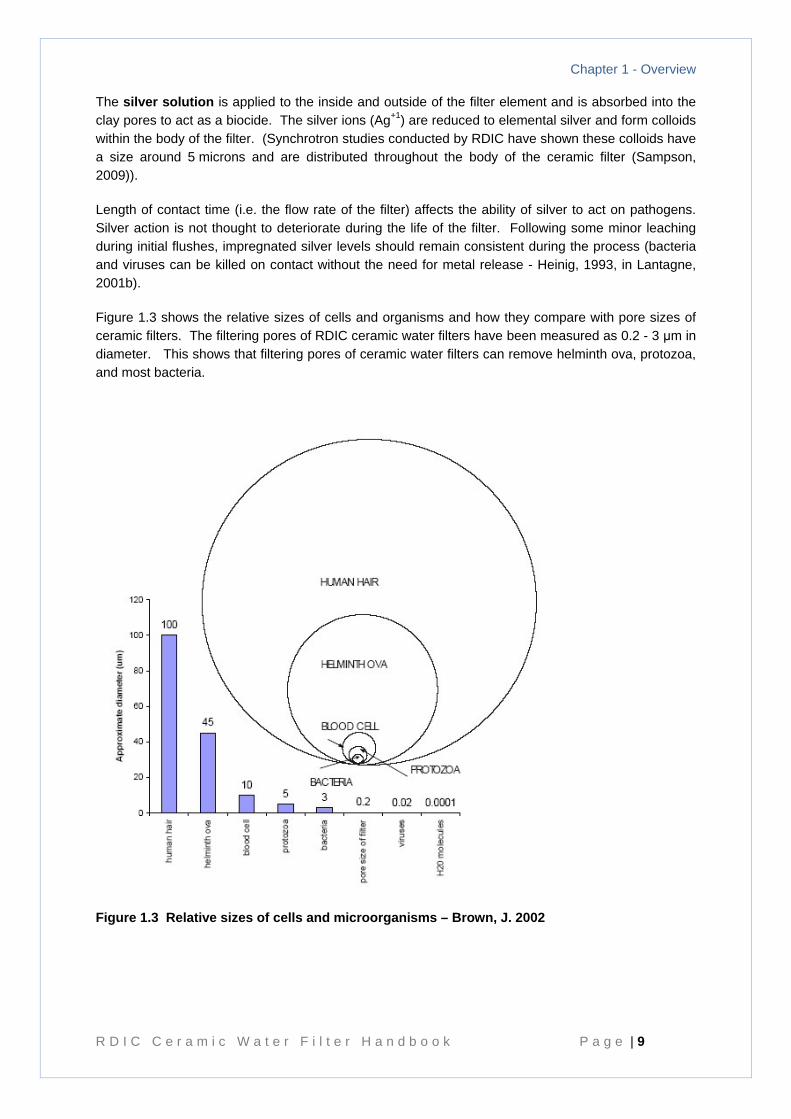
The silver solution is applied to the inside and outside of the filter element and is absorbed into the clay pores to act as a biocide. The silver ions (Ag+1) are reduced to elemental silver and form colloids within the body of the filter. (Synchrotron studies conducted by RDIC have shown these colloids have a size around 5 microns and are distributed throughout the body of the ceramic filter (Sampson, 2009)).
Length of contact time (i.e. the flow rate of the filter) affects the ability of silver to act on pathogens. Silver action is not thought to deteriorate during the life of the filter. Following some minor leaching during initial flushes, impregnated silver levels should remain consistent during the process (bacteria and viruses can be killed on contact without the need for metal release - Heinig, 1993, in Lantagne, 2001b).
Figure 1.3 shows the relative sizes of cells and organisms and how they compare with pore sizes of ceramic filters. The filtering pores of RDIC ceramic water filters have been measured as 0.2 - 3 μm in diameter. This shows that filtering pores of ceramic water filters can remove helminth ova, protozoa, and most bacteria.
Figure 1.3 Relative sizes of cells and microorganisms – Brown, J. 2002
P a g e | 10
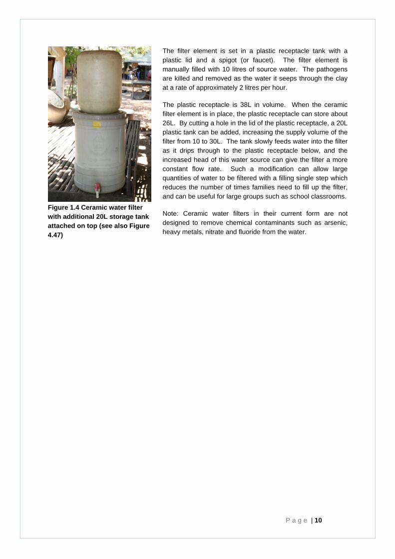
The filter element is set in a plastic receptacle tank with a plastic lid and a spigot (or faucet). The filter element is manually filled with 10 litres of source water. The pathogens are killed and removed as the water it seeps through the clay at a rate of approximately 2 litres per hour.
The plastic receptacle is 38L in volume. When the ceramic filter element is in place, the plastic receptacle can store about 26L. By cutting a hole in the lid of the plastic receptacle, a 20L plastic tank can be added, increasing the supply volume of the filter from 10 to 30L. The tank slowly feeds water into the filter as it drips through to the plastic receptacle below, and the increased head of this water source can give the filter a more constant flow rate. Such a modification can allow large quantities of water to be filtered with a filling single step which reduces the number of times families need to fill up the filter, and can be useful for large groups such as school classrooms.
Note: Ceramic water filters in their current form are not designed to remove chemical contaminants such as arsenic, heavy metals, nitrate and fluoride from the water.
Figure 1.4 Ceramic water filter with additional 20L storage tank attached on top (see also Figure 4.47)
P a g e | 11
Chapter 2 Quality Control Considerations
2.1. RDIC’s Commitment to Quality
RDIC places great emphasis on producing high quality filters. RDIC developed its initial product requirements, manufacturing process, and maintenance instructions over a 12 month period prior to the release of its first filter. Through use of its own water quality testing laboratory RDIC has tested the performance of its water filters made using different techniques and with different qualities to allow an optimum formula and process to be determined. For example, during this development process the quality of discharge from filters with different ratios of clay to burn-out material were compared and assessed.
RDIC is the largest water quality tester in Cambodia. It provides water quality testing services for many non-government organisations and companies, and provides laboratory facilities and trained staff for partnership research with international institutions such as the University of North Carolina, Stanford University, and Buffalo State University (New York). This experience and background increases RDIC’s ability to test, research and continue to develop ceramic water filter technologies.
The effectiveness of filters produced under the RDIC Water Filter Programme has been verified by: Brown, J. and Sobsey, M, 2006, Independent Appraisal of Ceramic Water Filtration Interventions in Cambodia: Final Report – Submitted to UNICEF 5 May 2006.
All steps in RDIC’s manufacturing process are designed to reduce the chance of imperfections in the filters. RDIC has designed its system to aim for an optimal flow rate of 1.8-2.5 L per hour, with a overall tolerance range of 1.5-3.5 L. Flow rate tests are carried out to ensure the porosity of the filter is within the tolerance range of 1.5 to 3.5 L per hour. This ensures sufficient straining, and exposure of the water to silver, yet remains functional for users. The filter elements are examined for cracks and other defects at every production step, and removed from the process if they do not meet requirements.
The RDIC Ceramic Water Filter Manufacturing and Education Method (the RDIC Method) has been developed over 3 years and is continually reviewed and improved. Such assessments over the past years have included reviewing its fuel source for the kilns and piloting the use of compressed rice husks as a more sustainable fuel. Additionally, RDIC also added laterite to its clay material because of its virus binding properties. Most recently, RDIC implemented a rice husk sifter to eliminate large particle sizes that potentially hinder the performance of the filters and further homogenise the particle size distribution to create more consistency in one of the parameters of the process.
2.2. Quality Assurance Considerations
Poor standards have the potential of placing communities at greater risk of ill health by giving them false comfort in the system. Communities who choose not to boil their water, in return for using ceramic water filters need to be ensured at least the same level of protection that traditional practices offer. Placing low quality ceramic water filters with communities can also unnecessarily degrade the reputation of ceramic filters worldwide leading to less implementation of an otherwise effective water filtration method.

P a g e | 12
Note that quality of filters may be dependent on the materials and processes available to you in your region. Thus, it is important to test filters thoroughly and monitor the effectiveness of at least the first batches in the field for several years.
Education on use and maintenance practices is just as important to the ability of ceramic water filters to make a sustainable difference to the lives of community members. RDIC has an extensive education programme outlined later in this Manual.
Further, this manual provides more detailed information about quality testing procedures that should be applied when first setting up a factory.
P a g e | 13
Chapter 3 Initial Considerations - Setting up a Ceramic Filter Factory
When making a decision to set up a ceramic filter factory and establish your manufacturing processes, there are a number of questions which if considered early will assist you in being successful in your project. RDIC provides ongoing assistance for ceramic filter producers and those looking to establish production, and can provide detailed training and support early on to ensure you are on the right path. Please contact us for further details and with any requests you may have. Some of these initial considerations are outlined below:
3.1. Are ceramic water filters right for you?
Before setting up a ceramic water filter factory you should consider if, as a technology, they will meet the needs of community members.
Ceramic water filters are an affordable, accessible, and appropriate technology for empowering households, school class rooms, and work places to manage their own drinking water quality. Ceramic water filters are suitable for treating the most common risk to drinking water quality – contamination with biological pathogens – as well as for removing general macro contaminants such as dirt and plant matter.
Chemical and heavy metal contaminants cannot be treated with ceramic water filters in their current form. These constituents are commonly present in natural groundwater and surface waters contaminated with industrial and agricultural pollution. It is important to appreciate the quality of various current and potential drinking water sources, and be clear about how ceramic water filters may be used effectively.
Ceramic water filters can be used in conjunction with:
• a piped water system – eg in urban or semi urban areas – where the quality of that water cannot be assured,
• rainwater, river, stream, pond water - where biological contamination and turbidity may be the highest risk to safe drinking water, and
• groundwater.
The biggest physical constraints to using ceramic water filters are:
• the volume of water production – which can be limiting for very large organisations where there are not discreet management or operational units to manage the individual filters, and
• where the primary health risk associated with the source water is chemical such as arsenic, manganese etc.
Communities that are already involved in producing and/or using ceramics for other purposes, particularly water storage, may be more attuned to ready acceptance of filter technology and usage. Moreover they are likely to already possess a number of desirable specialist skills such as pottery skills and kiln building and firing experience. A human resources and organisational structure to ensure a quality education and distribution programme is also essential to a ceramic water filter facility. Consideration of the market, the users, the community, the ability to establish an ongoing and
P a g e | 14
informed market presence will improve long term sustainability of the technology within the community.
3.2. Where to set up the factory?
In choosing the location of a ceramic water filter factory, there are a number of factors you could consider:
1. Transport accessibility: in developing countries access to good roads can greatly constrain the ability to access materials and deliver products. Poor roads lead to greater delivery time, and higher costs.
2. Materials accessibility: the factory should be near clay sources/clay brick factories to maintain production costs as low as possible and near sources of fuel, such as timber mills where off-cuts can be purchased to maximise efficiency of production.
3. Locating your factory near major distribution centres will help facilitate a steady base market for filters.
4. Location near major transport routes/intersections of major transport routes will facilitate easy distribution to more distant regions.
5. Consider other suppliers of household water treatment options. You may choose to target an area of the country that has the least access to safe drinking water.
6. In establishing a filter factory, water quality testing is required to test the efficacy of filters as the process is established. Some tests can be conducted on site. However, access to a high quality water laboratory will allow confirmation of results, and more accurate testing to occur.
7. Consider the fumes and smoke that will be generated by your kilns and how they may impact the surrounding community, Placement of factories away from dense community populations is recommended.
3.3. Sourcing Inputs
Early on you should be deciding the key materials you will utilise to manufacture the filters including the:
• clay,
• organic burn-out material,
• laterite (if you decide to use it)
• kiln fuel
• energy – to power mixer, press, hammer mill
• water
• plastic, moulds and manufacturer for receptacle.
These inputs are each discussed further below.
3.3.1. Sourcing the Clay
Clay that is suitable for other pottery processes may be suitable for water filter production. However hydraulic conductivity and pore size may vary significantly with the type of clay, potentially to the point where they are unsuitable with regards to flow rates and/or microbiological removal (Oyanedel-Craver
Chapter 3 - Initial Considerations
R D I C C e r a m i c W a t e r F i l t e r H a n d b o o k P a g e | 15
and Smith, 2008, in Lantagne et al, 2010).,High sand or silt content in clay can reduce clay cross-linkages and weaken the filter structure.. On the other hand, clay that is too refined (smaller particles) has a higher water retention capacity and therefore more prone to shrinkage and cracking during firing. Additionally, naturally high levels of organic matter in the clay can affect the strength and filtering capacity of ceramic filters, as this material can burn out during firing, leaving behind large and unregulated additional cavities.
As the clay characteristics are a critical factor in the success or failure of ceramic water filter production, RDIC recommends investigating potential clay sources and types thoroughly before committing significant resources. Various soil laboratories may be able to assist with analysing samples of clay and provide comment on their physical and chemical characteristics.
Consideration should be made of the potential to introduce chemical contamination - clay in many parts of the world contains heavy metals such as Arsenic. Filters made from these clays may not pose a risk, but this should be assessed when identifying sources of clay, and the risk managed. Clay may be used directly from the pit, or as unfired bricks from a factory. The clay needs to be completely dried prior to use so it can be crushed into a powder and evenly mixed with other components.
RDIC is situated near a brick factory. Clay is mined locally and extruded into bricks before drying. RDIC uses unfired extruded bricks for convenience. They are easy to transport, cheap and the extrusion process enhances the plasticity of the clay material. Using unfired bricks from industry can be a consistent and economical way to obtain clay, although this source also needs to be evaluated for suitability. An advantage of using extruded bricks is that the material will have already been screened and processed, ensuring uniformity and increasing the plasticity of the material.
3.3.2. Evaluating the Clay
Various characteristics of clay properties can be assessed to determine suitability for filter production.
For example, the plasticity of the clay will determine how it behaves and its workability. Plasticity is governed by the following characteristics: 1) particle size; 2) purity or clay content; 3) mioisture content; 4) particle uniformity; 5)plasticizers and6) strength of particle bond.(Hamer 2004). A good clay body will have the right amount of plasticity and experience minimal warping and cracking in the firing and drying process. Some clays may benefit from mixing with another clay with different characteristics or non-clay materials to achieve the desired clay body.
A common rule of thumb in evaluating plasticity, as borrowed from the Best Practice Guide, is to take the clay and roll out of about the diameter of your small finger, form a one-inch ring and note if the clay cracks and if it holds its shape. If there is no initial cracking, the clay is probably suitable to start tests.
If the filter experiences too much shrinking or firing cracks, sand can be added to the point where the problem is solved, though any new formula should be confirmed with microbiological testing. Alternatively, clay should be added to a mix if there is not enough shrinkage or the filter is too porous.
P a g e | 16
3.3.3. Sourcing the burn-out material
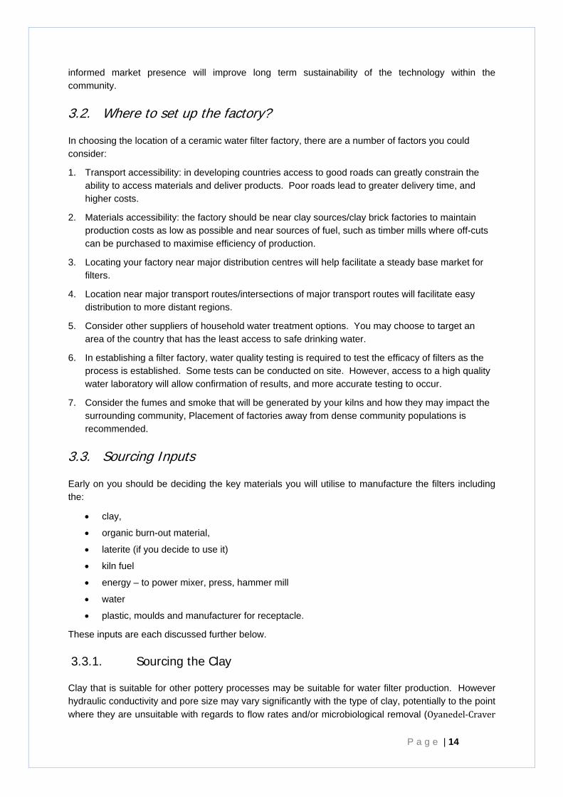
RDIC uses ground rice husks as the organic ‘burn-out’ material in their ceramic filters. Rice husks are a waste product from rice production in Cambodia and are easily available. The rice husks are bought from a local supplier and are provided in rice bags pre ground, but a hammer mill may also be used to grind the husks if sourced “raw”. The size of the rice husk grounds will affect the flow rate, and possibly filter element strength and should be monitored. RDIC seeks rice husks to be less than 1mm in size, and alters the quantity of rice husks added to the mix based on the size of the grounds (see the Production Process for more information).
Other materials that may be suitable include: saw dust, recycled paper, and coffee grounds. It is important to use materials that are most appropriate for the region – for example, RDIC prefers not to use saw dust as a burn-out material since it may contribute to deforestation.
Filter effectiveness testing is essential when choosing or changing the burn out material for the filters.
3.3.4. Sourcing Laterite (optional)
Laterite used to be added to RDIC’s clay mix as it is believed to provide viral binding sites. However, given that this property was unverifiable, it has been removed from the process as a cost saving measure. Other minerals that are high in Fe (iron) are also suitable such as Goethite.
RDIC sourced laterite from local sources in Cambodia, where it is used as a surface material on rural roads. Goethite is used as a red pigment and may be able to be sourced through local suppliers or shipped (eg from India). Any laterite, or other metal oxide, used in the process also needs to be dry and able to be powdered for even mixing.
3.3.5. Sourcing kiln fuel
RDIC uses off-cuts of rubber trees to fuel the kilns. Approximately 1.5 m3 of wood are burned for each batch of filter elements (96). The fire is lit and continually fuelled by the kiln operator. Wood is added gradually in order to increase the temperature gradually.
RDIC is considering changing or suppllementing its fuel source from wood off-cuts to compressed rice husks as an alternative fuel source. The rice husks are a by-product of rice production and their use will further reduce solid waste and the risk of plantations or forests being accessed to provide fuel for the kilns.
There are many other possible fuels that may be used, the best choice being determined by cost ease of access, and environmental and occupational health and safety considerations.
Figure 3.1 Laterite is crushed using Elephant’s Foot Tamper and added to RDIC's clay mix
Chapter 3 - Initial Considerations
R D I C C e r a m i c W a t e r F i l t e r H a n d b o o k P a g e | 17
In choosing an appropriate fuel for your region it is important to minimise the risk of deforestation of native vegetation, or of other negative environmental effects to maximise the sustainability of the technology. Use of by-products from other processes is recommended where possible.
RDIC has previously trialled some alternative kiln fuels, including:
• rice husk injections. In this process, the fire was preheated with wood to about 250°C. Then rice husks and air were blown into the fire box using a paddle blower (electric powered). The existing high heat, high oxygen environment and small particles of the rice husks meant the fuel burnt quickly and completely. Around 1 tonne of rice husks were required to fire each kiln. The high cost of electricity to fuel the blower, and the large requirement for rice husks meant this fuel source was too expensive for RDIC’s operations, but may be an option in the future.
• Another trial was conducted at RDIC using liquid fuel (crude palm oil or waste motor oil). A set of steel ‘steps’ were placed inside the kiln fire box, and were heated with an initial wood fire. Metal pipes with drip points were inserted laterally into the fire box. Once the steps were hot, liquid fuel was dripped onto the steel plates in the fire box, causing it to vaporise and burn instantaneously. If the fuel at the top did not vaporise, it will instantly flow to the next step to be heated further. The high cost of palm oil, and the risk of contaminating the filters with the gases and by-products of motor oil combustion, meant this fuel source was not appropriate for RDIC.
3.3.6. Sourcing energy
In setting up a filter factory, consideration needs to be given to the power sources for the factory machinery – such as electricity grid, generators, diesel motors.
RDIC primarily uses diesel generators to meet its electricity requirements in the factory. Even though a grid electricity supply is available on site, this power source can be unreliable which would impact on the reliability of the factory. Electricity is also very expensive in Cambodia, particularly when compared with neighbouring countries, so it needs to be considered when making all decisions about the factory operations.
3.3.7. Sourcing water
A reliable and reasonably clean source of water is required as a component for the clay filter elements, and for flow rate testing.
3.3.8. Sourcing Plastic Components
Plastic parts for the ceramic water filter systems include:
• The plastic receptacle (which receives water from the filter element and stores it for use)
• Fitting ring - which sits between the filter element and the plastic receptacle to protect the filter.
• Faucet and pipe - which discharges the water from the plastic receptacle.
P a g e | 18
• Scrubbing brush (sourced locally) - for cleaning.
RDIC sources its faucets, (Ruxlin Manufacturing Model F20E1) in bulk from a supplier in China. The faucet is ceramic inside and was tested for durability. It is guaranteed for 100,000 openings and closings.
The plastic pipes and scrubbing brushes are accessed from local suppliers. RDIC has the plastic receptacle and fitting rings manufactured according to specific requirements.
Sourcing and Characteristics of Plastic Receptacles
Sourcing of plastic receptacles you need to consider:
• Manufacture appropriate moulds;
• Have a reliable source of food grade plastic;
• Have a reliable receptacle manufacturer.
Alternatively, plastic receptacles could be manufactured on site, or existing plastic containers could be purchased from the market.
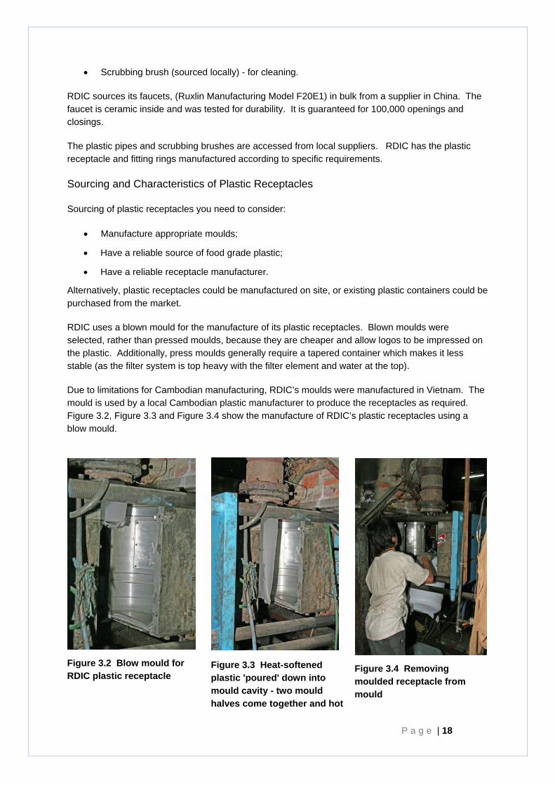
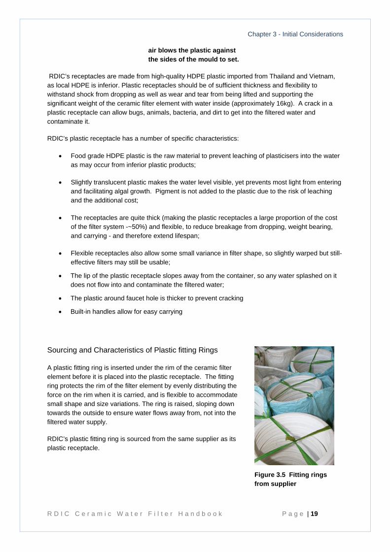
RDIC uses a blown mould for the manufacture of its plastic receptacles. Blown moulds were selected, rather than pressed moulds, because they are cheaper and allow logos to be impressed on the plastic. Additionally, press moulds generally require a tapered container which makes it less stable (as the filter system is top heavy with the filter element and water at the top).
Due to limitations for Cambodian manufacturing, RDIC’s moulds were manufactured in Vietnam. The mould is used by a local Cambodian plastic manufacturer to produce the receptacles as required. Figure 3.2, Figure 3.3 and Figure 3.4 show the manufacture of RDIC’s plastic receptacles using a blow mould.
Figure 3.2 Blow mould for RDIC plastic receptacle
Figure 3.3 Heat-softened plastic 'poured' down into mould cavity - two mould halves come together and hot
Figure 3.4 Removing moulded receptacle from mould
Chapter 3 - Initial Considerations
R D I C C e r a m i c W a t e r F i l t e r H a n d b o o k P a g e | 19
RDIC’s receptacles are made from high-quality HDPE plastic imported from Thailand and Vietnam, as local HDPE is inferior. Plastic receptacles should be of sufficient thickness and flexibility to withstand shock from dropping as well as wear and tear from being lifted and supporting the significant weight of the ceramic filter element with water inside (approximately 16kg). A crack in a plastic receptacle can allow bugs, animals, bacteria, and dirt to get into the filtered water and contaminate it.
RDIC’s plastic receptacle has a number of specific characteristics:
• Food grade HDPE plastic is the raw material to prevent leaching of plasticisers into the water as may occur from inferior plastic products;
• Slightly translucent plastic makes the water level visible, yet prevents most light from entering and facilitating algal growth. Pigment is not added to the plastic due to the risk of leaching and the additional cost;
• The receptacles are quite thick (making the plastic receptacles a large proportion of the cost of the filter system -~50%) and flexible, to reduce breakage from dropping, weight bearing, and carrying - and therefore extend lifespan;
• Flexible receptacles also allow some small variance in filter shape, so slightly warped but still-effective filters may still be usable;
• The lip of the plastic receptacle slopes away from the container, so any water splashed on it does not flow into and contaminate the filtered water;
• The plastic around faucet hole is thicker to prevent cracking
• Built-in handles allow for easy carrying
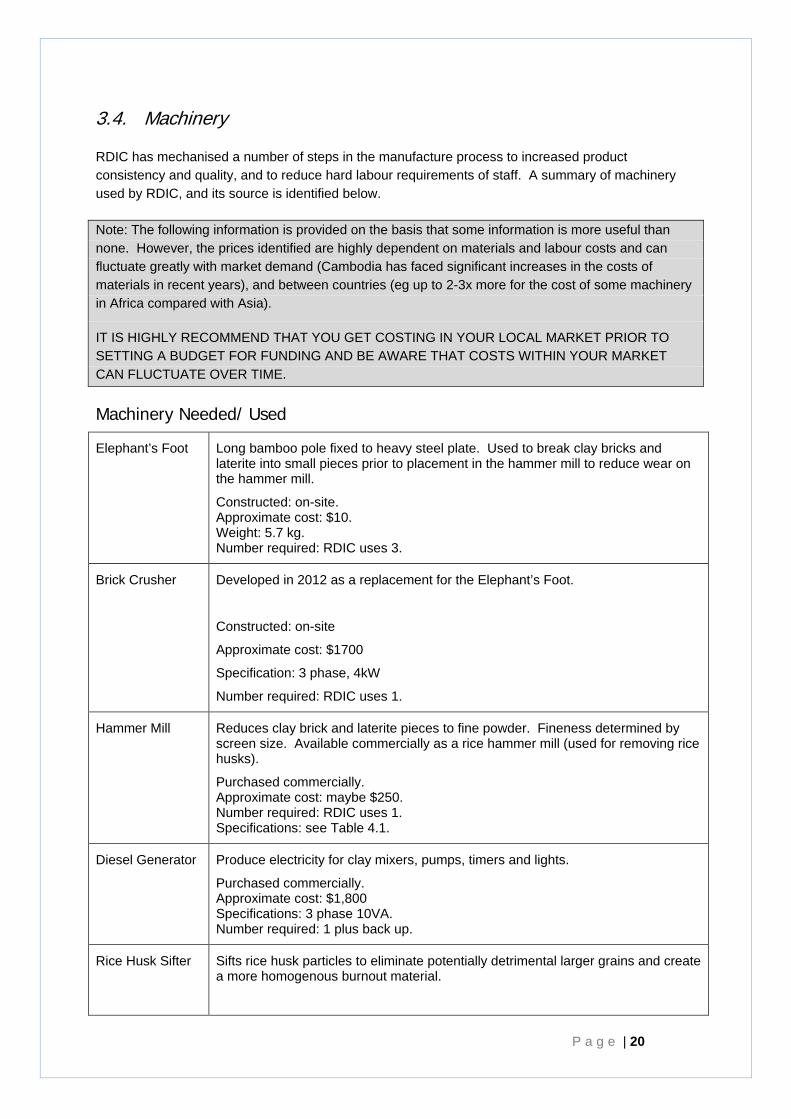
Sourcing and Characteristics of Plastic fitting Rings
A plastic fitting ring is inserted under the rim of the ceramic filter element before it is placed into the plastic receptacle. The fitting ring protects the rim of the filter element by evenly distributing the force on the rim when it is carried, and is flexible to accommodate small shape and size variations. The ring is raised, sloping down towards the outside to ensure water flows away from, not into the filtered water supply.
RDIC’s plastic fitting ring is sourced from the same supplier as its plastic receptacle.
air blows the plastic against the sides of the mould to set.
Figure 3.5 Fitting rings from supplier
P a g e | 20
3.4. Machinery
RDIC has mechanised a number of steps in the manufacture process to increased product consistency and quality, and to reduce hard labour requirements of staff. A summary of machinery used by RDIC, and its source is identified below.
Note: The following information is provided on the basis that some information is more useful than none. However, the prices identified are highly dependent on materials and labour costs and can fluctuate greatly with market demand (Cambodia has faced significant increases in the costs of materials in recent years), and between countries (eg up to 2-3x more for the cost of some machinery in Africa compared with Asia).
IT IS HIGHLY RECOMMEND THAT YOU GET COSTING IN YOUR LOCAL MARKET PRIOR TO SETTING A BUDGET FOR FUNDING AND BE AWARE THAT COSTS WITHIN YOUR MARKET CAN FLUCTUATE OVER TIME.
Machinery Needed/ Used
Elephant’s Foot Long bamboo pole fixed to heavy steel plate. Used to break clay bricks and laterite into small pieces prior to placement in the hammer mill to reduce wear on the hammer mill.
Constructed: on-site. Approximate cost: $10. Weight: 5.7 kg. Number required: RDIC uses 3.
Brick Crusher Developed in 2012 as a replacement for the Elephant’s Foot.
Constructed: on-site
Approximate cost: $1700
Specification: 3 phase, 4kW
Number required: RDIC uses 1.
Hammer Mill Reduces clay brick and laterite pieces to fine powder. Fineness determined by screen size. Available commercially as a rice hammer mill (used for removing rice husks).
Purchased commercially. Approximate cost: maybe $250. Number required: RDIC uses 1. Specifications: see Table 4.1.
Diesel Generator Produce electricity for clay mixers, pumps, timers and lights.
Purchased commercially. Approximate cost: $1,800 Specifications: 3 phase 10VA. Number required: 1 plus back up.
Rice Husk Sifter Sifts rice husk particles to eliminate potentially detrimental larger grains and create a more homogenous burnout material.
Chapter 3 - Initial Considerations
R D I C C e r a m i c W a t e r F i l t e r H a n d b o o k P a g e | 21
Constructed on site
Approximate cost: $300
Specificaitons: Single phase 0.5kW. 0.5-1mm screen grid mesh-size
Number required: RDIC uses one
Clay Mixer Mixes dry and wet clay mixture. Designed by RDIC.
Constructed on site (available for sale from RDIC). Approximate Cost:.$1,100 Powered: by electricity via diesel generator. Number required: RDIC uses 2. Specifications at 0.
Automated Water Spray System (optional)
Tube measuring tank, water storage tank, 2 pumps, switches, timer - that form the automated spray system to add water to the clay mix process.
Constructed on site from market supplies. Approximate cost: US$50 where recycled tanks are used. Specifications at 0.
Clay-mix pug-mll Extrudes clay-mix into blocks for moulding, further homogenising the mix.
Donated by Dutch Organisation. Available commercially
Approximate Cost: $1500
Powered: by 3 phase electricity via diesel generator
Number required: RDIC uses 1
Filter Press Hydraulic press fitted with male and female moulds to manufacture consistent filter elements.
Constructed on site with customised moulds (available for sale from RDIC). Approximate cost: $2300 excluding shipping and handling. Powered: by electricity via diesel generator. Number required: RDIC uses 2. Specifications at 0.
Drying Racks Steel racks designed by RDIC hold 24 filters (6 on each of 4 shelves). They include a framework for supporting tarpaulins for rain protection.
Constructed on site using L-shaped steel, welded and painted. Approximate cost: $120. Number required: RDIC uses 90. Specifications at: 0.
Manual pallet trolley
Trolley used to shift drying racks for stacking, drying, and emptying.
Purchased commercially. Approximate cost US$300-500. Number required: RDIC uses 1.
Kilns Brick kilns designed by RDIC. Uses to fire chambers under the kiln chamber floor for burning wood, which is circulates hot air and smoke up into kiln chamber.
Constructed on site using bricks and mortar. Number required: RDIC uses 5.
Specifications at 0, and construction instructions at Appendix F.
P a g e | 22
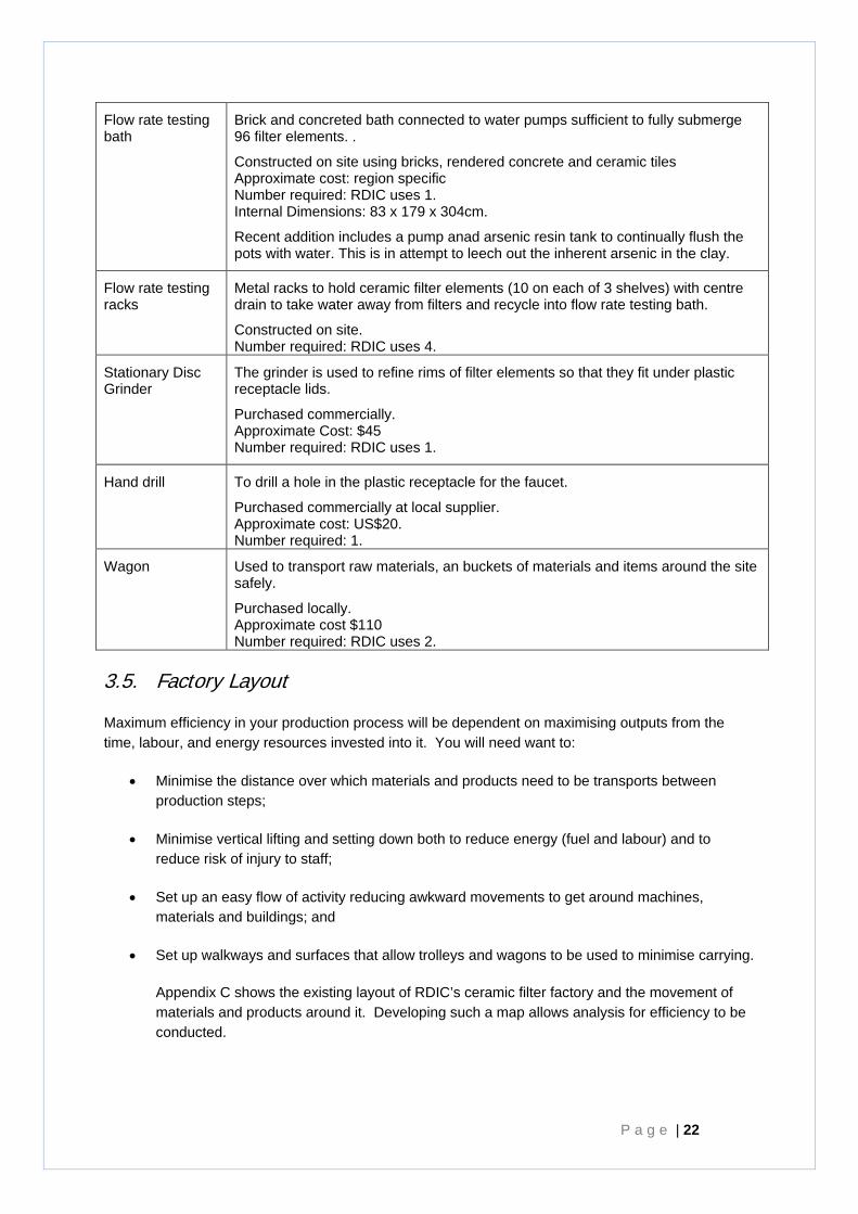
Flow rate testing bath
Brick and concreted bath connected to water pumps sufficient to fully submerge 96 filter elements. .
Constructed on site using bricks, rendered concrete and ceramic tiles Approximate cost: region specific Number required: RDIC uses 1. Internal Dimensions: 83 x 179 x 304cm.
Recent addition includes a pump anad arsenic resin tank to continually flush the pots with water. This is in attempt to leech out the inherent arsenic in the clay.
Flow rate testing racks
Metal racks to hold ceramic filter elements (10 on each of 3 shelves) with centre drain to take water away from filters and recycle into flow rate testing bath.
Constructed on site. Number required: RDIC uses 4.
Stationary Disc Grinder
The grinder is used to refine rims of filter elements so that they fit under plastic receptacle lids.
Purchased commercially. Approximate Cost: $45 Number required: RDIC uses 1.
Hand drill To drill a hole in the plastic receptacle for the faucet.
Purchased commercially at local supplier. Approximate cost: US$20. Number required: 1.
Wagon Used to transport raw materials, an buckets of materials and items around the site safely.
Purchased locally. Approximate cost $110 Number required: RDIC uses 2.
3.5. Factory Layout
Maximum efficiency in your production process will be dependent on maximising outputs from the time, labour, and energy resources invested into it. You will need want to:
• Minimise the distance over which materials and products need to be transports between production steps;
• Minimise vertical lifting and setting down both to reduce energy (fuel and labour) and to reduce risk of injury to staff;
• Set up an easy flow of activity reducing awkward movements to get around machines, materials and buildings; and
• Set up walkways and surfaces that allow trolleys and wagons to be used to minimise carrying.
Appendix C shows the existing layout of RDIC’s ceramic filter factory and the movement of materials and products around it. Developing such a map allows analysis for efficiency to be conducted.
Chapter 3 - Initial Considerations
R D I C C e r a m i c W a t e r F i l t e r H a n d b o o k P a g e | 23
3.6. Staffing
Who will you seek to staff your factory?
Who will manage and oversee production? Who will be responsible for quality assurance, establish the manufacturing process for local conditions and solving technical problems?
Who will be responsible for establishing a market? Who will be responsible for setting up and for implementing educational programs?
Existing factories in Cambodian provide labouring work for 10-15 staff.
What will your employment policies be to ensure incentives for staff to encourage high quality and reliable outputs?
3.7. Establishing your manufacturing process – some considerations
There are two key components of manufacturing that need to be established for each individual factory based on local materials: the acceptable flow rate for the filter, and the kiln firing temperature.
These two factors vary depending on the materials used, and should be developed and tested before filters are released for use by the community.
3.7.1. Flow Rates
The flow rate of ceramic water filters (measured in litres that pass through the filter per hour) is determined by the thickness of the clay, the composition of the local clay used, the proportion and size of burn out material used in the clay mix (and therefore the quantity of open spaces created by the burn out material).
Previous testing by RDIC determined that weight of burn out material required varies with the size of the burn out material particles. Even though the relationship between mass of burn out material to clay provided in this manual can be used as a basis for a new factory, testing of flow rates and microbiological removal effectiveness needs to occur at each factory.
Testing Microbiological Effectiveness can be carried out in accordance with suggested guidelines at Appendix A.
3.7.2. Filter Firing Regime
When establishing your process you should consider the firing temperatures, the time periods of firing used. The shape of the kiln, the stacking pattern of filter elements within kiln as well as the air inlets and outlets will all affect how hot air will circulate within the kiln. Sufficient firing temperatures, time periods of firing, and even distribution of heat will ensure all filter elements are exposed to sufficient heat to go through the stages of dehydration and vitrification throughout the thickness of the clay.
The two firing temperatures used in this manual allow:
1) the complete dehydration of the clay and
2) the vitrification (chemical modification) of the clay to form the finished filter element.
P a g e | 24
The first temperature allowing complete dehydration of 100°C is generic and can likely be used for other factories.
The second temperature point is more specific to the make-up of your clay. To save energy and cost over the long term, this should be the minimal temperature that still allows full vitrification. RDIC fires its filters at a maximum temperature of 866°C. Note higher temperatures have additional chemical affects on the clay (see The American Ceramic Society, 2005).
In examining experimental fired filter elements consider:
• Has all burn-out material been burnt out across the thickness of the filter?
o Filters that are not fired for long enough may retain specks of black carbon. This carbon indicates that the burn out material did not burn long enough to vaporise and be removed from the filter. Carbon remaining in the filter can block pores, and create sites for bacterial growth.
o Bands of colour across the thickness of the filter may also indicate different degrees of vitrification of the clay. However some colour layering may simply indicate different conditions, timing, oxygen exposure of the inside and the outside of the filter.
o Note: rice husks are high in silica and will leave some silica residue in the cavities
• Has the filter been vitrified across the whole thickness. RDIC’s fired filter elements are a deeper red after they are vitrified. Note that natural variation in clay colour across the thickness even after full vitrification can occur.
• A fully fired filter element has a bell like ring when struck, compared with a thud if not fully vitrified.
Chapter 4- Materials - Mixing -Cubes -Pressing -Finishing - Drying -Firing -Flow-Rate Testing -Silver Coating -Packaging
R D I C C e r a m i c W a t e r F i l t e r H a n d b o o k P a g e | 25
Chapter 4 The Production Process
Overview of material Inputs and Outputs for the factory
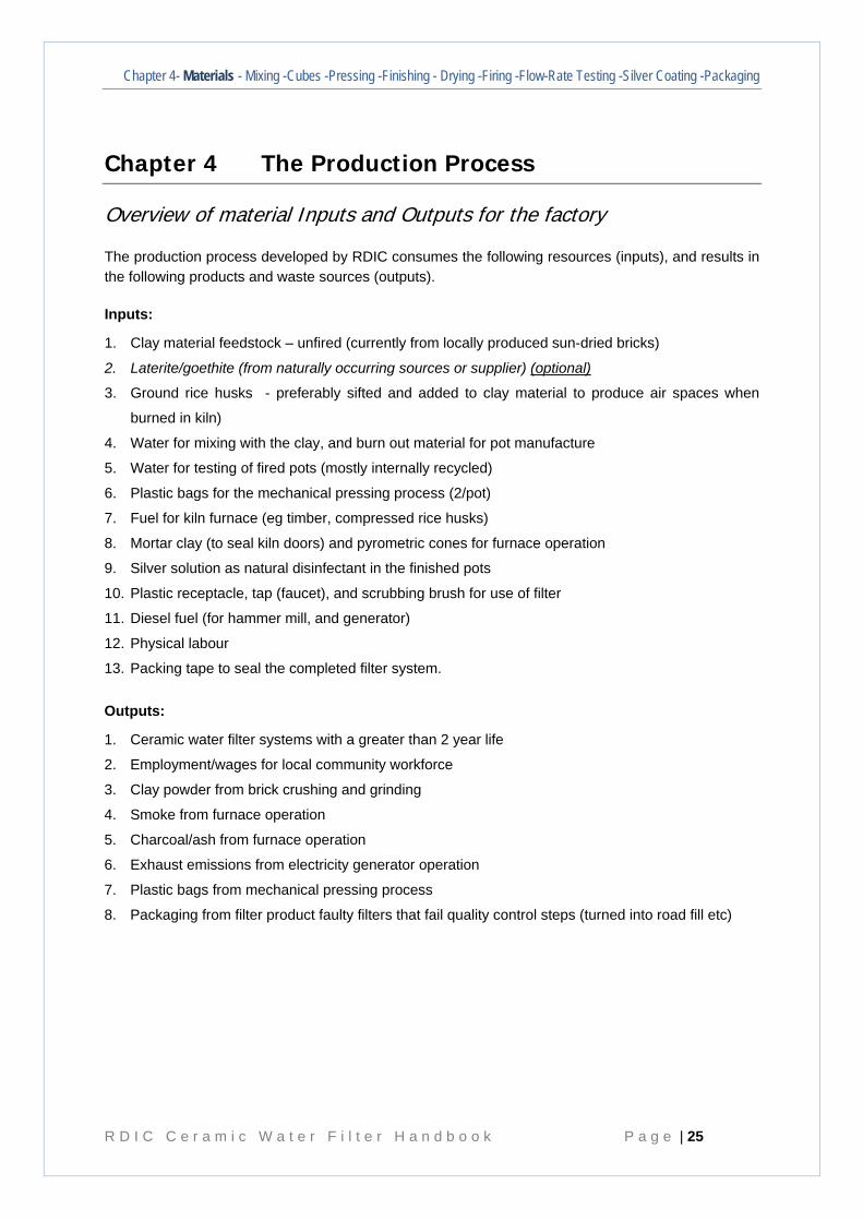
The production process developed by RDIC consumes the following resources (inputs), and results in the following products and waste sources (outputs).
Inputs:
1. Clay material feedstock – unfired (currently from locally produced sun-dried bricks)
2. Laterite/goethite (from naturally occurring sources or supplier) (optional)
3. Ground rice husks - preferably sifted and added to clay material to produce air spaces when
burned in kiln)
4. Water for mixing with the clay, and burn out material for pot manufacture
5. Water for testing of fired pots (mostly internally recycled)
6. Plastic bags for the mechanical pressing process (2/pot)
7. Fuel for kiln furnace (eg timber, compressed rice husks)
8. Mortar clay (to seal kiln doors) and pyrometric cones for furnace operation
9. Silver solution as natural disinfectant in the finished pots
10. Plastic receptacle, tap (faucet), and scrubbing brush for use of filter
11. Diesel fuel (for hammer mill, and generator)
12. Physical labour
13. Packing tape to seal the completed filter system.
Outputs:
1. Ceramic water filter systems with a greater than 2 year life
2. Employment/wages for local community workforce
3. Clay powder from brick crushing and grinding
4. Smoke from furnace operation
5. Charcoal/ash from furnace operation
6. Exhaust emissions from electricity generator operation
7. Plastic bags from mechanical pressing process
8. Packaging from filter product faulty filters that fail quality control steps (turned into road fill etc)
P a g e | 26
Summary of the RDIC ’10 Step’ Production Process
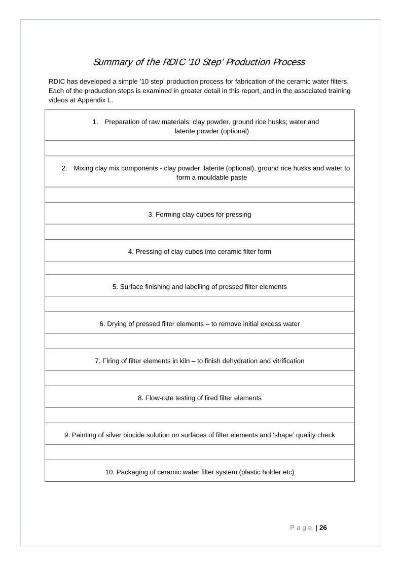
RDIC has developed a simple ’10 step’ production process for fabrication of the ceramic water filters. Each of the production steps is examined in greater detail in this report, and in the associated training videos at Appendix L.
1. Preparation of raw materials: clay powder, ground rice husks; water and laterite powder (optional)
2. Mixing clay mix components - clay powder, laterite (optional), ground rice husks and water to form a mouldable paste
3. Forming clay cubes for pressing
4. Pressing of clay cubes into ceramic filter form
5. Surface finishing and labelling of pressed filter elements
6. Drying of pressed filter elements – to remove initial excess water
7. Firing of filter elements in kiln – to finish dehydration and vitrification
8. Flow-rate testing of fired filter elements
9. Painting of silver biocide solution on surfaces of filter elements and ‘shape’ quality check
10. Packaging of ceramic water filter system (plastic holder etc)
Chapter 4- Materials - Mixing -Cubes -Pressing -Finishing - Drying -Firing -Flow-Rate Testing -Silver Coating -Packaging
R D I C C e r a m i c W a t e r F i l t e r H a n d b o o k P a g e | 27
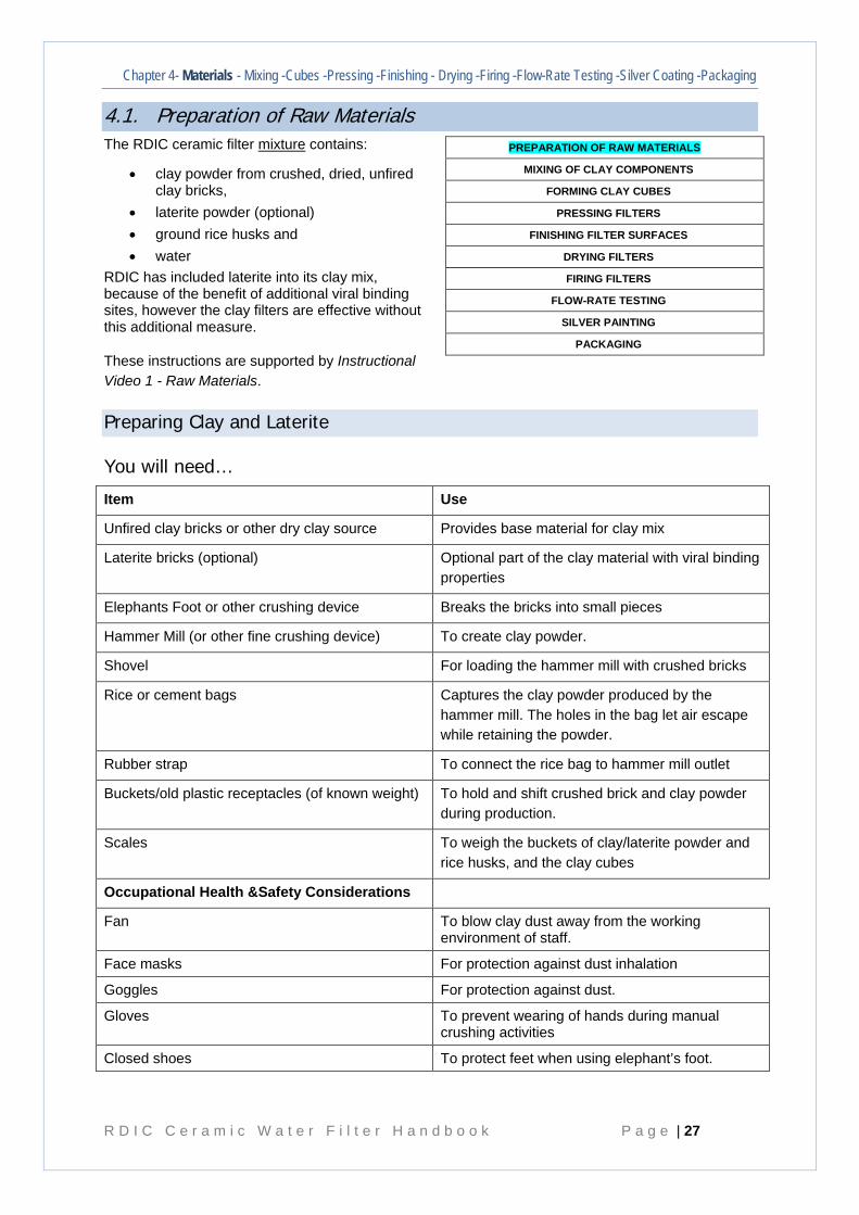
4.1. Preparation of Raw Materials The RDIC ceramic filter mixture contains:
• clay powder from crushed, dried, unfired clay bricks,
• laterite powder (optional) • ground rice husks and • water
RDIC has included laterite into its clay mix, because of the benefit of additional viral binding sites, however the clay filters are effective without this additional measure.
These instructions are supported by Instructional Video 1 - Raw Materials.
Preparing Clay and Laterite
You will need…
Item Use
Unfired clay bricks or other dry clay source Provides base material for clay mix
Laterite bricks (optional) Optional part of the clay material with viral binding properties
Elephants Foot or other crushing device Breaks the bricks into small pieces
Hammer Mill (or other fine crushing device) To create clay powder.
Shovel For loading the hammer mill with crushed bricks
Rice or cement bags Captures the clay powder produced by the hammer mill. The holes in the bag let air escape while retaining the powder.
Rubber strap To connect the rice bag to hammer mill outlet
Buckets/old plastic receptacles (of known weight) To hold and shift crushed brick and clay powder during production.
Scales To weigh the buckets of clay/laterite powder and rice husks, and the clay cubes
Occupational Health &Safety Considerations
Fan To blow clay dust away from the working environment of staff.
Face masks For protection against dust inhalation
Goggles For protection against dust.
Gloves To prevent wearing of hands during manual crushing activities
Closed shoes To protect feet when using elephant’s foot.
PREPARATION OF RAW MATERIALS
MIXING OF CLAY COMPONENTS
FORMING CLAY CUBES
PRESSING FILTERS
FINISHING FILTER SURFACES
DRYING FILTERS
FIRING FILTERS
FLOW-RATE TESTING
SILVER PAINTING
PACKAGING
P a g e | 28
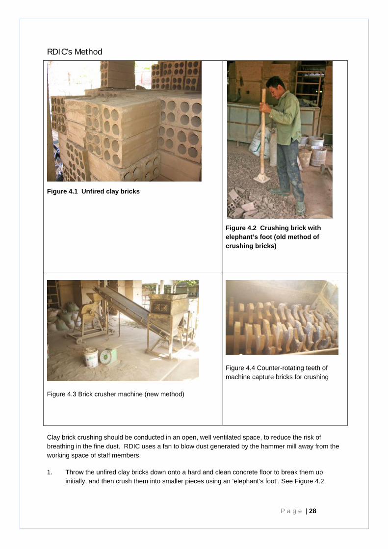
RDIC’s Method
Figure 4.1 Unfired clay bricks
Figure 4.2 Crushing brick with elephant’s foot (old method of crushing bricks)
Figure 4.3 Brick crusher machine (new method)
Figure 4.4 Counter-rotating teeth of machine capture bricks for crushing
Clay brick crushing should be conducted in an open, well ventilated space, to reduce the risk of breathing in the fine dust. RDIC uses a fan to blow dust generated by the hammer mill away from the working space of staff members.
1. Throw the unfired clay bricks down onto a hard and clean concrete floor to break them up initially, and then crush them into smaller pieces using an ‘elephant’s foot’. See Figure 4.2.
Chapter 4- Materials - Mixing -Cubes -Pressing -Finishing - Drying -Firing -Flow-Rate Testing -Silver Coating -Packaging
R D I C C e r a m i c W a t e r F i l t e r H a n d b o o k P a g e | 29
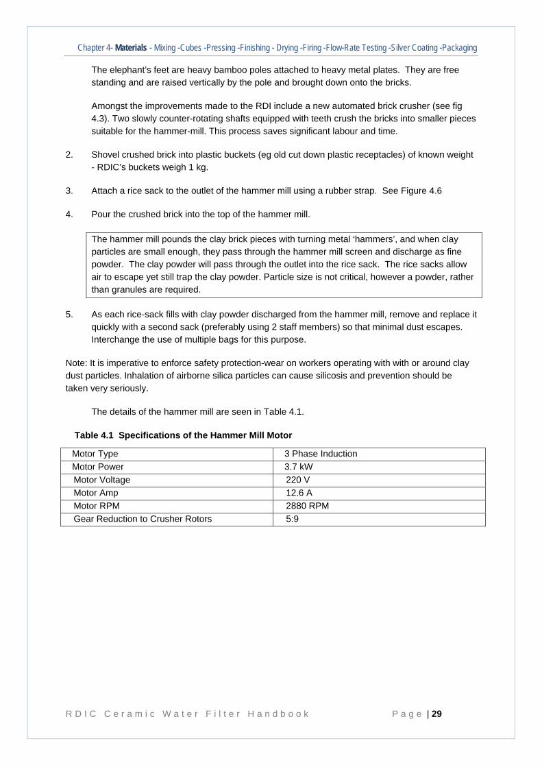
The elephant’s feet are heavy bamboo poles attached to heavy metal plates. They are free standing and are raised vertically by the pole and brought down onto the bricks.
Amongst the improvements made to the RDI include a new automated brick crusher (see fig 4.3). Two slowly counter-rotating shafts equipped with teeth crush the bricks into smaller pieces suitable for the hammer-mill. This process saves significant labour and time.
2. Shovel crushed brick into plastic buckets (eg old cut down plastic receptacles) of known weight - RDIC’s buckets weigh 1 kg.
3. Attach a rice sack to the outlet of the hammer mill using a rubber strap. See Figure 4.6
4. Pour the crushed brick into the top of the hammer mill.
The hammer mill pounds the clay brick pieces with turning metal ‘hammers’, and when clay particles are small enough, they pass through the hammer mill screen and discharge as fine powder. The clay powder will pass through the outlet into the rice sack. The rice sacks allow air to escape yet still trap the clay powder. Particle size is not critical, however a powder, rather than granules are required.
5. As each rice-sack fills with clay powder discharged from the hammer mill, remove and replace it quickly with a second sack (preferably using 2 staff members) so that minimal dust escapes. Interchange the use of multiple bags for this purpose.
Note: It is imperative to enforce safety protection-wear on workers operating with with or around clay dust particles. Inhalation of airborne silica particles can cause silicosis and prevention should be taken very seriously.
The details of the hammer mill are seen in Table 4.1.
Table 4.1 Specifications of the Hammer Mill Motor
Motor Type 3 Phase Induction Motor Power 3.7 kW Motor Voltage 220 V Motor Amp 12.6 A Motor RPM 2880 RPM Gear Reduction to Crusher Rotors 5:9
P a g e | 30
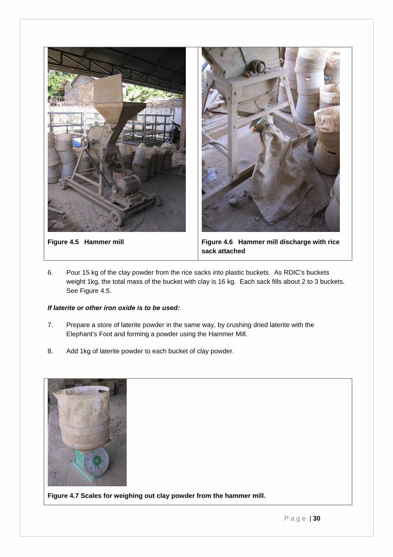
Figure 4.5 Hammer mill
Figure 4.6 Hammer mill discharge with rice sack attached
6. Pour 15 kg of the clay powder from the rice sacks into plastic buckets. As RDIC’s buckets weight 1kg, the total mass of the bucket with clay is 16 kg. Each sack fills about 2 to 3 buckets. See Figure 4.5.
If laterite or other iron oxide is to be used:
7. Prepare a store of laterite powder in the same way, by crushing dried laterite with the Elephant’s Foot and forming a powder using the Hammer Mill.
8. Add 1kg of laterite powder to each bucket of clay powder.
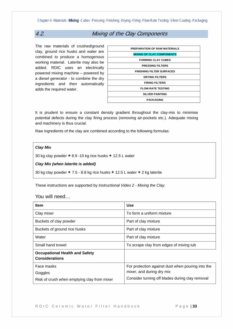
Figure 4.7 Scales for weighing out clay powder from the hammer mill.
Chapter 4- Materials - Mixing -Cubes -Pressing -Finishing - Drying -Firing -Flow-Rate Testing -Silver Coating -Packaging
R D I C C e r a m i c W a t e r F i l t e r H a n d b o o k P a g e | 31
Other Methods
• While it may be possible to source clay directly from its source, it is still necessary for it to be completely sun dried to allow it to be crushed to a powder for even mixing with other filter element components.
• Alternative, less labour intensive, methods for undertaking the initial crushing of brick could be considered – for example using a heavy roller.
• The powder may also be produced manually by crushing the bricks by hand. This is very labour intensive and time consuming.
• Consideration could also be given to different methods of dust suppression.
Preparing rice husk ‘burn-out’ material
You will need…
Item Use
Rice husks (milled) Create porosity in the mixed clay by combusting during the firing process
Rice sifter Eliminate large potentially detrimental particles and homogenise particle size distribution.
Silo or other dispensing method For easy storage and dispensing
Buckets (of known weight) To carry ground rice husks
Scales To weigh rice husks
Occupational Health and Safety Considerations
Face masks
Goggles
For protection against dust
For protection against dust
RDIC’s Method
1. Load the milled rice husk into the mechanised sifter . RDI uses a sieve mesh between 0.5. – 1mm in size. Larger particle rice husk is collected as potential fuel source for future use.
2. Load the sifted rice husks into a silo for efficient distribution in the factory.
Dispense the milled rice husks into buckets of known weight. The amount added is dependent on rice husk size and whether or not laterite is to be added.
RDIC sources ground rice husks from three different suppliers. The size of the rice husk particles can vary between suppliers. Larger particles create larger pores in the clay decreasing the thickness of
the walls between pores, which results in an overall increased flow rate through the filter when compared to the same mass of small rice husk particles, hence the need to sieve the rice husk to
apply some consistency to the particle size distribution..
P a g e | 32
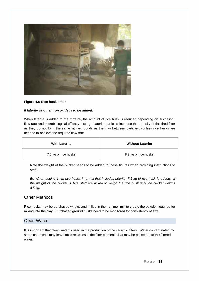
Figure 4.8 Rice husk sifter
If laterite or other iron oxide is to be added:
When laterite is added to the mixture, the amount of rice husk is reduced depending on successful flow rate and microbiological efficacy testing. Laterite particles increase the porosity of the fired filter as they do not form the same vitrified bonds as the clay between particles, so less rice husks are needed to achieve the required flow rate.
With Laterite Without Laterite
7.5 kg of rice husks 8.9 kg of rice husks
Note the weight of the bucket needs to be added to these figures when providing instructions to staff.
Eg When adding 1mm rice husks in a mix that includes laterite, 7.5 kg of rice husk is added. If the weight of the bucket is 1kg, staff are asked to weigh the rice husk until the bucket weighs 8.5 kg.
Other Methods
Rice husks may be purchased whole, and milled in the hammer mill to create the powder required for mixing into the clay. Purchased ground husks need to be monitored for consistency of size.
Clean Water
It is important that clean water is used in the production of the ceramic filters. Water contaminated by some chemicals may leave toxic residues in the filter elements that may be passed onto the filtered water.
Chapter 4 -Materials -Mixing -Cubes -Pressing -Finishing -Drying -Firing -Flow-Rate Testing -Silver Coating -Packaging
R D I C C e r a m i c W a t e r F i l t e r H a n d b o o k P a g e | 33
4.2. Mixing of the Clay Components
The raw materials of crushed/ground clay, ground rice husks and water are combined to produce a homogenous working material. Laterite may also be added. RDIC uses an electrically powered mixing machine – powered by a diesel generator - to combine the dry ingredients and then automatically adds the required water.
It is prudent to ensure a constant density gradient throughout the clay-mix to minimise potential defects during the clay firing process (removing air-pockets etc.). Adequate mixing and machinery is thus crucial.
Raw ingredients of the clay are combined according to the following formulas:
These instructions are supported by Instructional Video 2 - Mixing the Clay.
You will need…
Item Use
Clay mixer To form a uniform mixture
Buckets of clay powder Part of clay mixture
Buckets of ground rice husks Part of clay mixture
Water Part of clay mixture
Small hand trowel To scrape clay from edges of mixing tub
Occupational Health and Safety Considerations
Face masks
Goggles
Risk of crush when emptying clay from mixer
For protection against dust when pouring into the mixer, and during dry mix
Consider turning off blades during clay removal
PREPARATION OF RAW MATERIALS
MIXING OF CLAY COMPONENTS
FORMING CLAY CUBES
PRESSING FILTERS
FINISHING FILTER SURFACES
DRYING FILTERS
FIRING FILTERS
FLOW-RATE TESTING
SILVER PAINTING
PACKAGING
Clay Mix
30 kg clay powder + 8.9 -10 kg rice husks + 12.5 L water
Clay Mix (when laterite is added)
30 kg clay powder + 7.5 - 8.8 kg rice husks + 12.5 L water + 2 kg laterite
P a g e | 34
RDIC’s Method
1. Turn on the clay mixer. See Figure 4.7.
2. Empty 1 bucket of clay and laterite mix (15kg clay powder optional addition of 1 kg of laterite) into the mixer.
3. Add 1 bucket of rice husks (7.5 - 10 kg depending on rice husk source and use of laterite see pg 33).
4. Then add a second bucket of clay powder and laterite mix (15 kg clay powder optional addition of 1 kg of laterite).
5. Mix it dry for 10 minutes with mixer lid closed - to minimise dust emissions.
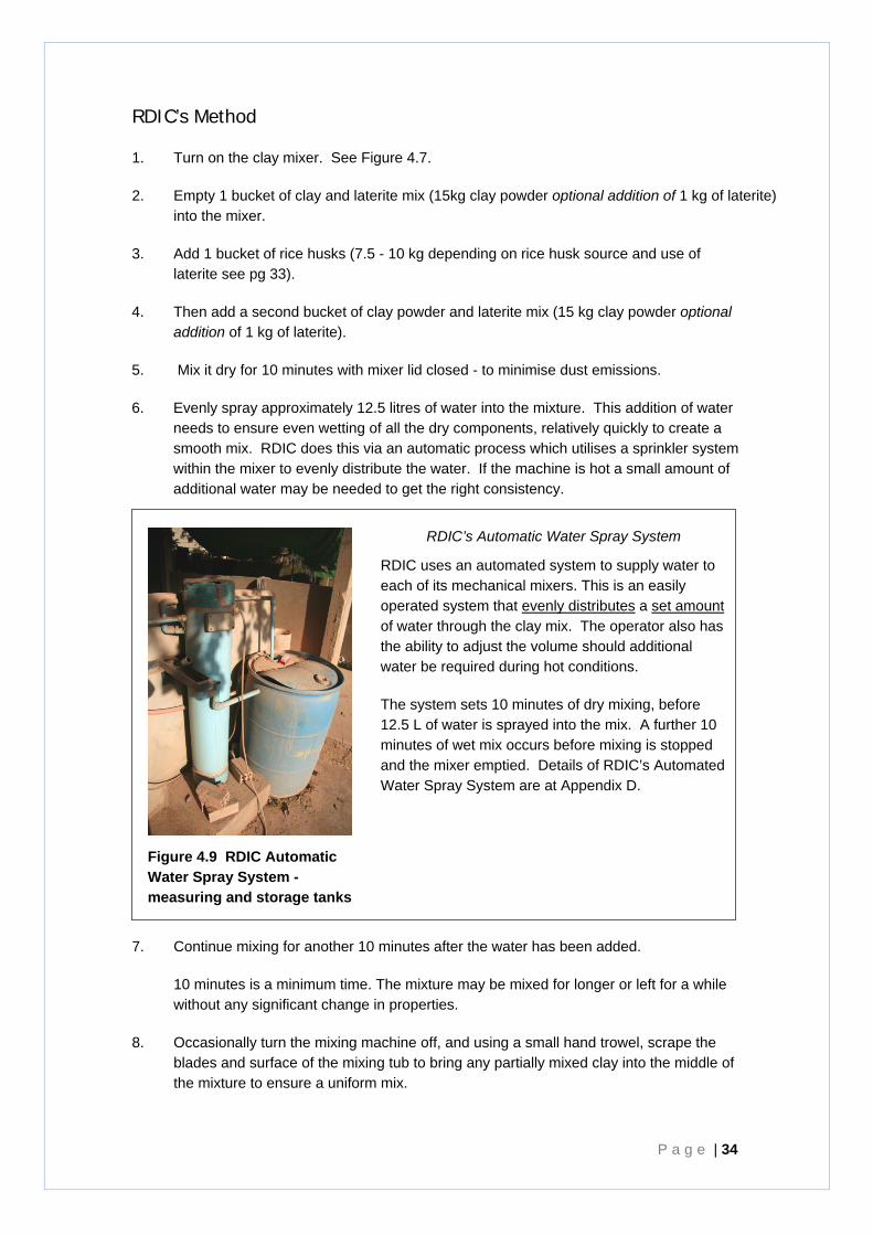
6. Evenly spray approximately 12.5 litres of water into the mixture. This addition of water needs to ensure even wetting of all the dry components, relatively quickly to create a smooth mix. RDIC does this via an automatic process which utilises a sprinkler system within the mixer to evenly distribute the water. If the machine is hot a small amount of additional water may be needed to get the right consistency.
RDIC’s Automatic Water Spray System
RDIC uses an automated system to supply water to each of its mechanical mixers. This is an easily operated system that evenly distributes a set amount of water through the clay mix. The operator also has the ability to adjust the volume should additional water be required during hot conditions.
The system sets 10 minutes of dry mixing, before 12.5 L of water is sprayed into the mix. A further 10 minutes of wet mix occurs before mixing is stopped and the mixer emptied. Details of RDIC’s Automated Water Spray System are at Appendix D.
Figure 4.9 RDIC Automatic Water Spray System - measuring and storage tanks
7. Continue mixing for another 10 minutes after the water has been added.
10 minutes is a minimum time. The mixture may be mixed for longer or left for a while without any significant change in properties.
8. Occasionally turn the mixing machine off, and using a small hand trowel, scrape the blades and surface of the mixing tub to bring any partially mixed clay into the middle of the mixture to ensure a uniform mix.
Chapter 4 -Materials -Mixing -Cubes -Pressing -Finishing -Drying -Firing -Flow-Rate Testing -Silver Coating -Packaging
R D I C C e r a m i c W a t e r F i l t e r H a n d b o o k P a g e | 35
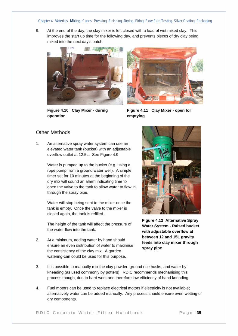
9. At the end of the day, the clay mixer is left closed with a load of wet mixed clay. This improves the start up time for the following day, and prevents pieces of dry clay being mixed into the next day’s batch.
Figure 4.10 Clay Mixer - during operation
Figure 4.11 Clay Mixer - open for emptying
Other Methods
1. An alternative spray water system can use an elevated water tank (bucket) with an adjustable overflow outlet at 12.5L. See Figure 4.9
Water is pumped up to the bucket (e.g. using a rope pump from a ground water well). A simple timer set for 10 minutes at the beginning of the dry mix will sound an alarm indicating time to open the valve to the tank to allow water to flow in through the spray pipe.
Water will stop being sent to the mixer once the tank is empty. Once the valve to the mixer is closed again, the tank is refilled.
The height of the tank will affect the pressure of the water flow into the tank.
2. At a minimum, adding water by hand should ensure an even distribution of water to maximise the consistency of the clay mix. A garden watering-can could be used for this purpose.
3. It is possible to manually mix the clay powder, ground rice husks, and water by kneading (as used commonly by potters). RDIC recommends mechanising this process though, due to hard work and therefore low efficiency of hand kneading.
4. Fuel motors can be used to replace electrical motors if electricity is not available; alternatively water can be added manually. Any process should ensure even wetting of dry components.
Figure 4.12 Alternative Spray Water System - Raised bucket with adjustable overflow at between 12 and 15L gravity feeds into clay mixer through spray pipe
P a g e | 36
4.3. Forming Clay Cubes for Filter Element Pressing
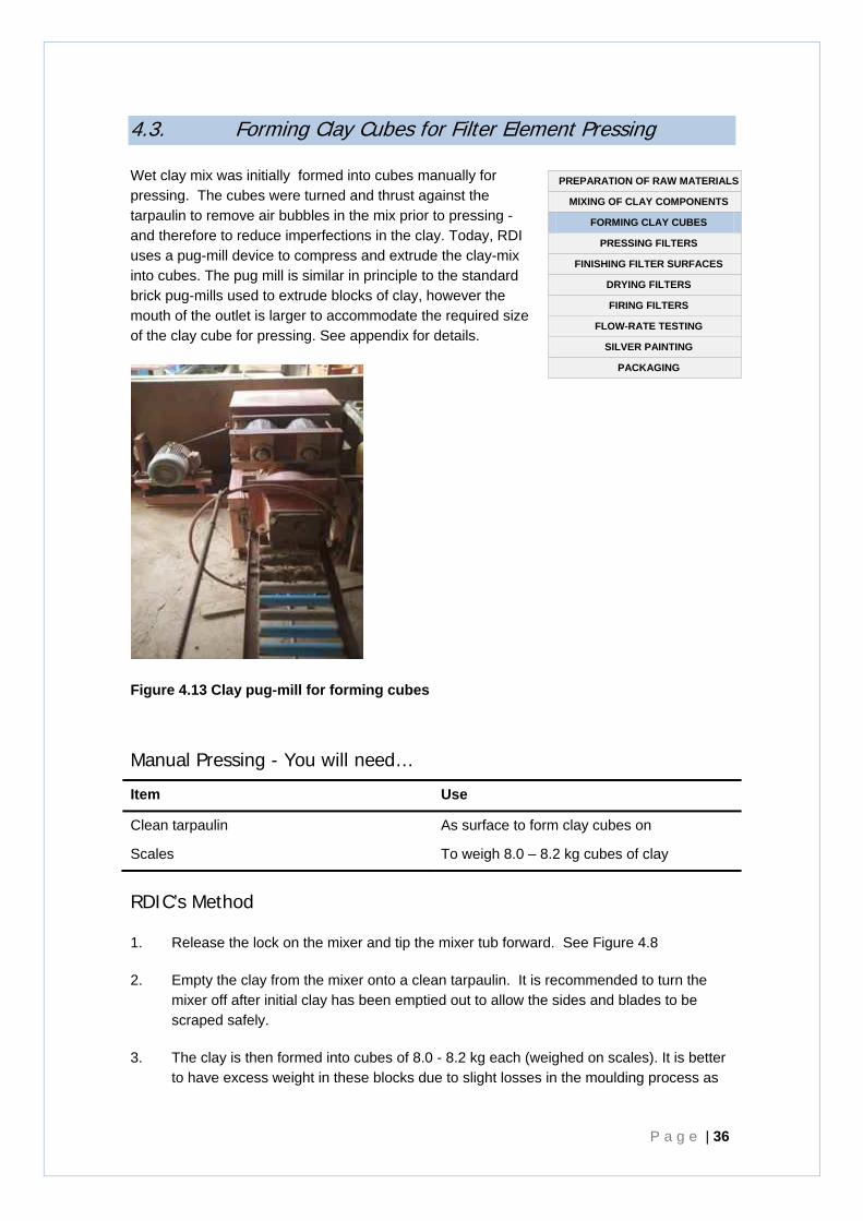
Wet clay mix was initially formed into cubes manually for pressing. The cubes were turned and thrust against the tarpaulin to remove air bubbles in the mix prior to pressing - and therefore to reduce imperfections in the clay. Today, RDI uses a pug-mill device to compress and extrude the clay-mix into cubes. The pug mill is similar in principle to the standard brick pug-mills used to extrude blocks of clay, however the mouth of the outlet is larger to accommodate the required size of the clay cube for pressing. See appendix for details.
Figure 4.13 Clay pug-mill for forming cubes
Manual Pressing - You will need…
Item Use
Clean tarpaulin As surface to form clay cubes on
Scales To weigh 8.0 – 8.2 kg cubes of clay
RDIC’s Method
1. Release the lock on the mixer and tip the mixer tub forward. See Figure 4.8
2. Empty the clay from the mixer onto a clean tarpaulin. It is recommended to turn the mixer off after initial clay has been emptied out to allow the sides and blades to be scraped safely.
3. The clay is then formed into cubes of 8.0 - 8.2 kg each (weighed on scales). It is better to have excess weight in these blocks due to slight losses in the moulding process as
PREPARATION OF RAW MATERIALS
MIXING OF CLAY COMPONENTS
FORMING CLAY CUBES
PRESSING FILTERS
FINISHING FILTER SURFACES
DRYING FILTERS
FIRING FILTERS
FLOW-RATE TESTING
SILVER PAINTING
PACKAGING

Chapter 4 -Materials -Mixing -Cubes -Pressing -Finishing -Drying -Firing -Flow-Rate Testing -Silver Coating -Packaging
R D I C C e r a m i c W a t e r F i l t e r H a n d b o o k P a g e | 37
clay is squeezed out the top. Excess material ensures that air bubbles will be pressed out of the walls of the filter in the moulding press. See Section 4.4.
P a g e | 38
4.4. Pressing, finishing, and labelling the filter elements The moulding of ceramic water filter elements is mechanised at RDIC. Use of a hydraulic press greatly decreases labour requirements of the process, and greatly increases efficiency and consistency of product. The filters are pressed between a male and female mould which are covered with plastic bags to prevent sticking. The hydraulic press incorporates a fixed plate in the bottom mould which pushes the pressed mould out as the mould opens up.
Minimal surface finishing is required following moulding but is conducted to ensure the rim is strong, and that the surface is even.
Filters are labelled to indicate the date of pressing, the batch and the filter number.
You will need… Item Use
Moulding Press (including top and bottom moulds)
To form the filter shape.
Clean tarpaulin and undercover space For initial drying of moulds.
Drying racks To store moulded filters.
Paint brush + water Wets the rim of the filter immediately after being removed from the press.
Metal plate Used to move the un-hardened filter to the drying area.
Lid / bowl Stops the rim from becoming out of shape when moving the un-hardened filter to drying area.
Plastic scrapper / spatula with a smooth edge
Smooth the inside of the filters after moulding.
Metal stamps To imprint date, filter number and manufacturer into the rim of the filter.
Rag and water To wipe the rim of the filter after the inside has been smoothed.
Plastic bags 2 per filter element Stops the clay from sticking to the mould these should be as thin as possible to reduce wrinkles being formed in the clay.
Occupational Health and Safety Considerations
Face masks
Goggles
Risk of crush injury when removing
For protection against dust when pouring into the mixer, and during dry mix.
For protection against dust when pouring into the mixer, and during dry mix.
Turn off mixer when removing clay.
PREPARATION OF RAW MATERIALS
MIXING OF CLAY COMPONENTS
FORMING CLAY CUBES
PRESSING FILTERS
FINISHING FILTER SURFACES
DRYING FILTERS
FIRING FILTERS
FLOW-RATE TESTING
SILVER PAINTING
PACKAGING
Chapter 4 -Materials -Mixing -Cubes -Pressing -Finishing -Drying -Firing -Flow-Rate Testing -Silver Coating -Packaging
R D I C C e r a m i c W a t e r F i l t e r H a n d b o o k P a g e | 39
Pressing
RDIC’s Method
These steps are aligned with Instructional Video 3 - Moulding.
1. Place the round metal plate on the press and then cover this plate and the bottom die with a plastic bag. These plastic bags are reused as many times as possible (until they tear) however they usually rip first time.
2. Place the 8.0 - 8.2 kg cube of clay mixture on the plate of the hydraulic press and then cover again with a plastic bag. This ensures the filter is lined with plastic on the inside and outside during the moulding process. See Figure 4.10.
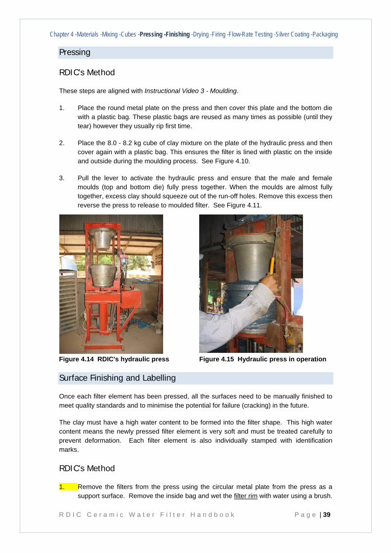
3. Pull the lever to activate the hydraulic press and ensure that the male and female moulds (top and bottom die) fully press together. When the moulds are almost fully together, excess clay should squeeze out of the run-off holes. Remove this excess then reverse the press to release to moulded filter. See Figure 4.11.
Figure 4.14 RDIC's hydraulic press
Figure 4.15 Hydraulic press in operation
Surface Finishing and Labelling
Once each filter element has been pressed, all the surfaces need to be manually finished to meet quality standards and to minimise the potential for failure (cracking) in the future.
The clay must have a high water content to be formed into the filter shape. This high water content means the newly pressed filter element is very soft and must be treated carefully to prevent deformation. Each filter element is also individually stamped with identification marks.
RDIC’s Method
1. Remove the filters from the press using the circular metal plate from the press as a support surface. Remove the inside bag and wet the filter rim with water using a brush.
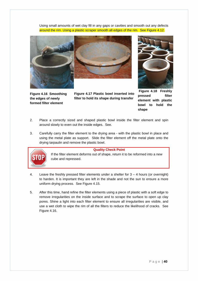
P a g e | 40
Using small amounts of wet clay fill in any gaps or cavities and smooth out any defects around the rim. Using a plastic scraper smooth all edges of the rim. See Figure 4.12.
2. Place a correctly sized and shaped plastic bowl inside the filter element and spin around slowly to even out the inside edges. See.
3. Carefully carry the filter element to the drying area - with the plastic bowl in place and using the metal plate as support. Slide the filter element off the metal plate onto the drying tarpaulin and remove the plastic bowl.
Quality Check Point If the filter element deforms out of shape, return it to be reformed into a new cube and repressed.
4. Leave the freshly pressed filter elements under a shelter for 3 – 4 hours (or overnight) to harden. It is important they are left in the shade and not the sun to ensure a more uniform drying process. See Figure 4.15.
5. After this time, hand refine the filter elements using a piece of plastic with a soft edge to remove irregularities on the inside surface and to scrape the surface to open up clay pores. Shine a light into each filter element to ensure all irregularities are visible, and use a wet cloth to wipe the rim of all the filters to reduce the likelihood of cracks. See Figure 4.16.
Figure 4.16 Smoothing the edges of newly formed filter element
Figure 4.17 Plastic bowl inserted into filter to hold its shape during transfer
Figure 4.18 Freshly pressed filter element with plastic bowl to hold the shape
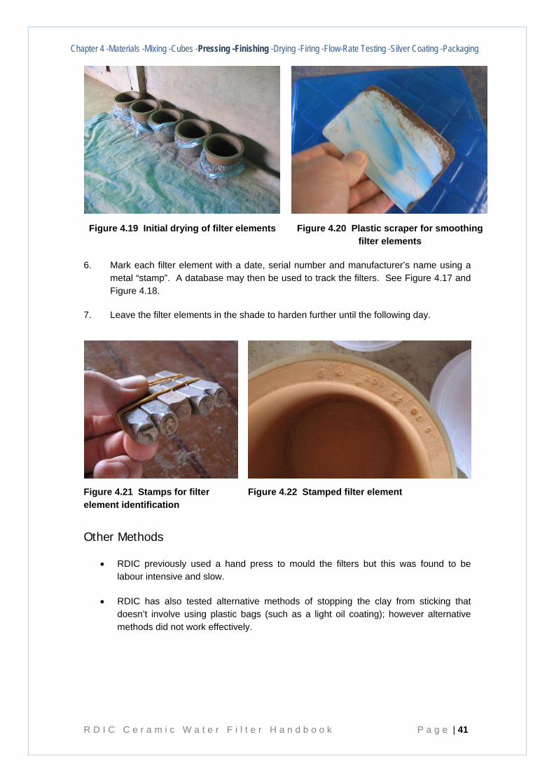
Chapter 4 -Materials -Mixing -Cubes -Pressing -Finishing -Drying -Firing -Flow-Rate Testing -Silver Coating -Packaging
R D I C C e r a m i c W a t e r F i l t e r H a n d b o o k P a g e | 41
Figure 4.19 Initial drying of filter elements
Figure 4.20 Plastic scraper for smoothing filter elements
6. Mark each filter element with a date, serial number and manufacturer’s name using a metal “stamp”. A database may then be used to track the filters. See Figure 4.17 and Figure 4.18.
7. Leave the filter elements in the shade to harden further until the following day.
Figure 4.21 Stamps for filter element identification
Figure 4.22 Stamped filter element
Other Methods
• RDIC previously used a hand press to mould the filters but this was found to be labour intensive and slow.
• RDIC has also tested alternative methods of stopping the clay from sticking that doesn’t involve using plastic bags (such as a light oil coating); however alternative methods did not work effectively.
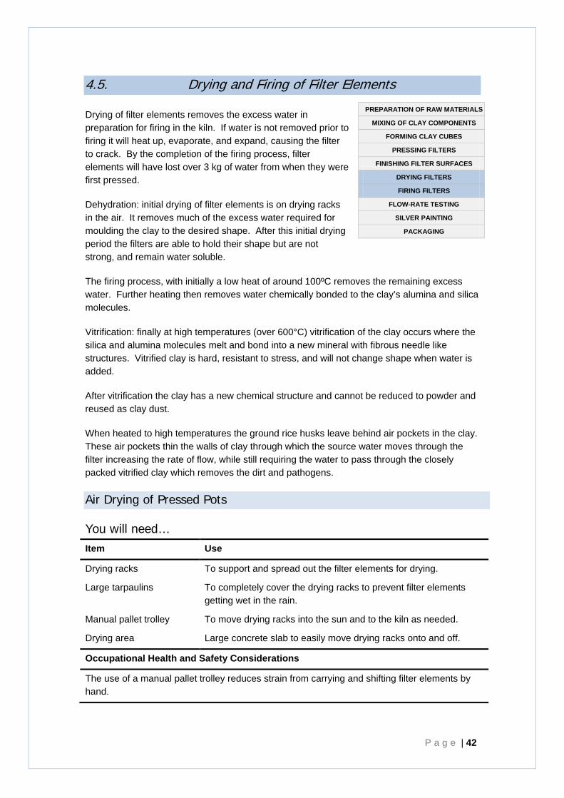
P a g e | 42
4.5. Drying and Firing of Filter Elements
Drying of filter elements removes the excess water in preparation for firing in the kiln. If water is not removed prior to firing it will heat up, evaporate, and expand, causing the filter to crack. By the completion of the firing process, filter elements will have lost over 3 kg of water from when they were first pressed.
Dehydration: initial drying of filter elements is on drying racks in the air. It removes much of the excess water required for moulding the clay to the desired shape. After this initial drying period the filters are able to hold their shape but are not strong, and remain water soluble.
The firing process, with initially a low heat of around 100ºC removes the remaining excess water. Further heating then removes water chemically bonded to the clay’s alumina and silica molecules.
Vitrification: finally at high temperatures (over 600°C) vitrification of the clay occurs where the silica and alumina molecules melt and bond into a new mineral with fibrous needle like structures. Vitrified clay is hard, resistant to stress, and will not change shape when water is added.
After vitrification the clay has a new chemical structure and cannot be reduced to powder and reused as clay dust.
When heated to high temperatures the ground rice husks leave behind air pockets in the clay. These air pockets thin the walls of clay through which the source water moves through the filter increasing the rate of flow, while still requiring the water to pass through the closely packed vitrified clay which removes the dirt and pathogens.
Air Drying of Pressed Pots
You will need… Item Use
Drying racks To support and spread out the filter elements for drying.
Large tarpaulins To completely cover the drying racks to prevent filter elements getting wet in the rain.
Manual pallet trolley To move drying racks into the sun and to the kiln as needed.
Drying area Large concrete slab to easily move drying racks onto and off.
Occupational Health and Safety Considerations
The use of a manual pallet trolley reduces strain from carrying and shifting filter elements by hand.
PREPARATION OF RAW MATERIALS
MIXING OF CLAY COMPONENTS
FORMING CLAY CUBES
PRESSING FILTERS
FINISHING FILTER SURFACES
DRYING FILTERS
FIRING FILTERS
FLOW-RATE TESTING
SILVER PAINTING
PACKAGING
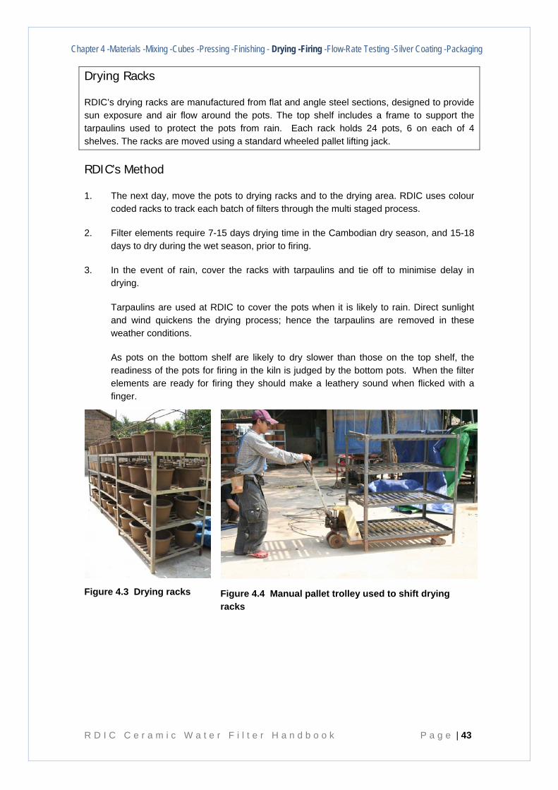
Chapter 4 -Materials -Mixing -Cubes -Pressing -Finishing - Drying -Firing -Flow-Rate Testing -Silver Coating -Packaging
R D I C C e r a m i c W a t e r F i l t e r H a n d b o o k P a g e | 43
Drying Racks
RDIC’s drying racks are manufactured from flat and angle steel sections, designed to provide sun exposure and air flow around the pots. The top shelf includes a frame to support the tarpaulins used to protect the pots from rain. Each rack holds 24 pots, 6 on each of 4 shelves. The racks are moved using a standard wheeled pallet lifting jack.
RDIC’s Method
1. The next day, move the pots to drying racks and to the drying area. RDIC uses colour coded racks to track each batch of filters through the multi staged process.
2. Filter elements require 7-15 days drying time in the Cambodian dry season, and 15-18 days to dry during the wet season, prior to firing.
3. In the event of rain, cover the racks with tarpaulins and tie off to minimise delay in drying.
Tarpaulins are used at RDIC to cover the pots when it is likely to rain. Direct sunlight and wind quickens the drying process; hence the tarpaulins are removed in these weather conditions.
As pots on the bottom shelf are likely to dry slower than those on the top shelf, the readiness of the pots for firing in the kiln is judged by the bottom pots. When the filter elements are ready for firing they should make a leathery sound when flicked with a finger.
Figure 4.3 Drying racks
Figure 4.4 Manual pallet trolley used to shift drying racks
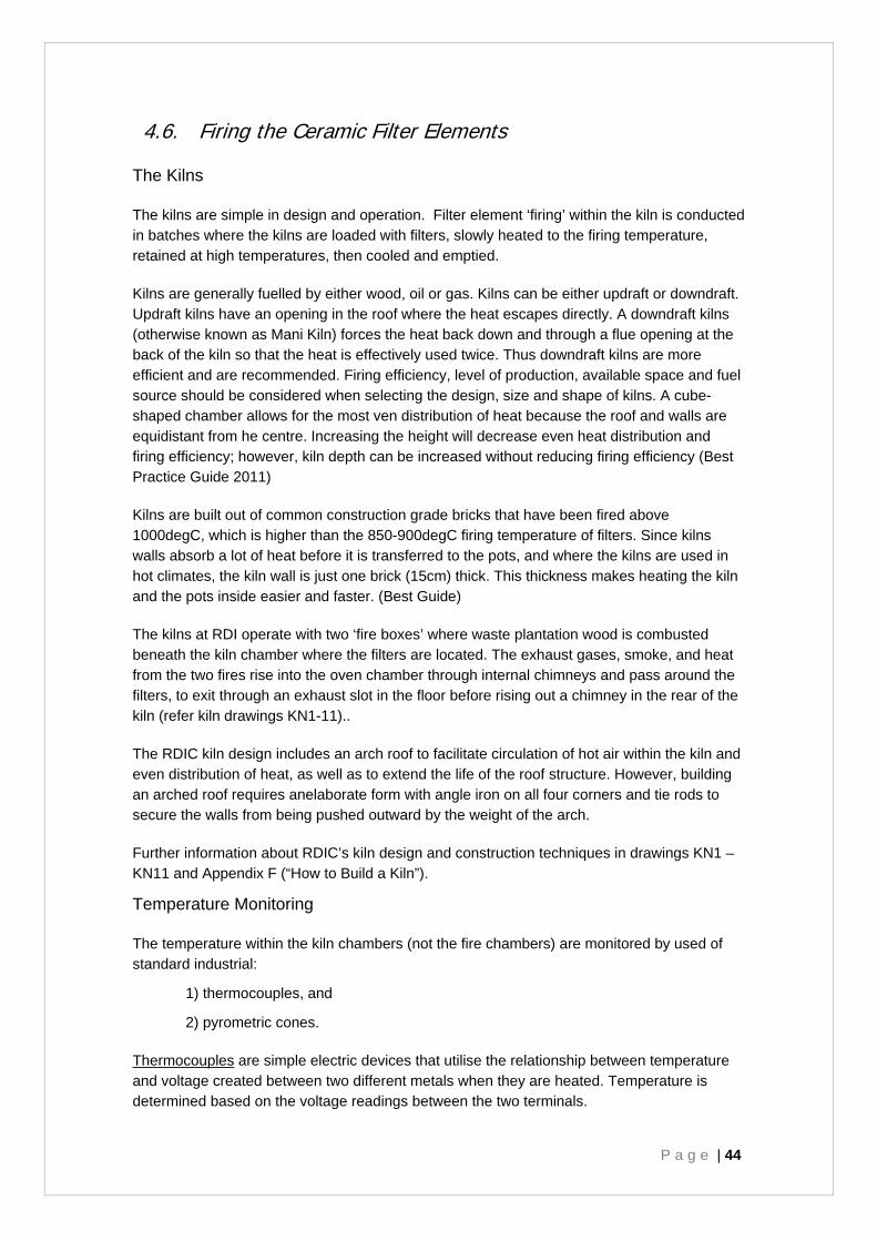
P a g e | 44
4.6. Firing the Ceramic Filter Elements
The Kilns
The kilns are simple in design and operation. Filter element ‘firing’ within the kiln is conducted in batches where the kilns are loaded with filters, slowly heated to the firing temperature, retained at high temperatures, then cooled and emptied.
Kilns are generally fuelled by either wood, oil or gas. Kilns can be either updraft or downdraft. Updraft kilns have an opening in the roof where the heat escapes directly. A downdraft kilns (otherwise known as Mani Kiln) forces the heat back down and through a flue opening at the back of the kiln so that the heat is effectively used twice. Thus downdraft kilns are more efficient and are recommended. Firing efficiency, level of production, available space and fuel source should be considered when selecting the design, size and shape of kilns. A cube-shaped chamber allows for the most ven distribution of heat because the roof and walls are equidistant from he centre. Increasing the height will decrease even heat distribution and firing efficiency; however, kiln depth can be increased without reducing firing efficiency (Best Practice Guide 2011)
Kilns are built out of common construction grade bricks that have been fired above 1000degC, which is higher than the 850-900degC firing temperature of filters. Since kilns walls absorb a lot of heat before it is transferred to the pots, and where the kilns are used in hot climates, the kiln wall is just one brick (15cm) thick. This thickness makes heating the kiln and the pots inside easier and faster. (Best Guide)
The kilns at RDI operate with two ‘fire boxes’ where waste plantation wood is combusted beneath the kiln chamber where the filters are located. The exhaust gases, smoke, and heat from the two fires rise into the oven chamber through internal chimneys and pass around the filters, to exit through an exhaust slot in the floor before rising out a chimney in the rear of the kiln (refer kiln drawings KN1-11)..
The RDIC kiln design includes an arch roof to facilitate circulation of hot air within the kiln and even distribution of heat, as well as to extend the life of the roof structure. However, building an arched roof requires anelaborate form with angle iron on all four corners and tie rods to secure the walls from being pushed outward by the weight of the arch.
Further information about RDIC’s kiln design and construction techniques in drawings KN1 – KN11 and Appendix F (“How to Build a Kiln”).
Temperature Monitoring
The temperature within the kiln chambers (not the fire chambers) are monitored by used of standard industrial:
1) thermocouples, and
2) pyrometric cones.
Thermocouples are simple electric devices that utilise the relationship between temperature and voltage created between two different metals when they are heated. Temperature is determined based on the voltage readings between the two terminals.
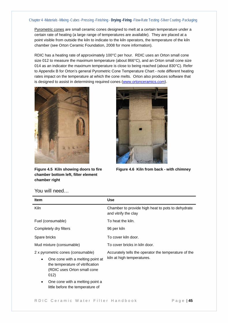
Chapter 4 -Materials -Mixing -Cubes -Pressing -Finishing - Drying -Firing -Flow-Rate Testing -Silver Coating -Packaging
R D I C C e r a m i c W a t e r F i l t e r H a n d b o o k P a g e | 45
Pyrometric cones are small ceramic cones designed to melt at a certain temperature under a certain rate of heating (a large range of temperatures are available). They are placed at a point visible from outside the kiln to indicate to the kiln operators, the temperature of the kiln chamber (see Orton Ceramic Foundation, 2008 for more information).
RDIC has a heating rate of approximately 100°C per hour. RDIC uses an Orton small cone size 012 to measure the maximum temperature (about 866°C), and an Orton small cone size 014 as an indicator the maximum temperature is close to being reached (about 830°C). Refer to Appendix B for Orton’s general Pyrometric Cone Temperature Chart - note different heating rates impact on the temperature at which the cone melts. Orton also produces software that is designed to assist in determining required cones (www.ortonceramics.com).
Figure 4.5 Kiln showing doors to fire chamber bottom left, filter element chamber right
Figure 4.6 Kiln from back - with chimney
You will need…
Item Use
Kiln Chamber to provide high heat to pots to dehydrate and vitrify the clay
Fuel (consumable) To heat the kiln.
Completely dry filters 96 per kiln
Spare bricks To cover kiln door.
Mud mixture (consumable) To cover bricks in kiln door.
2 x pyrometric cones (consumable)
• One cone with a melting point at the temperature of vitrification (RDIC uses Orton small cone 012)
• One cone with a melting point a little before the temperature of
Accurately tells the operator the temperature of the kiln at high temperatures.
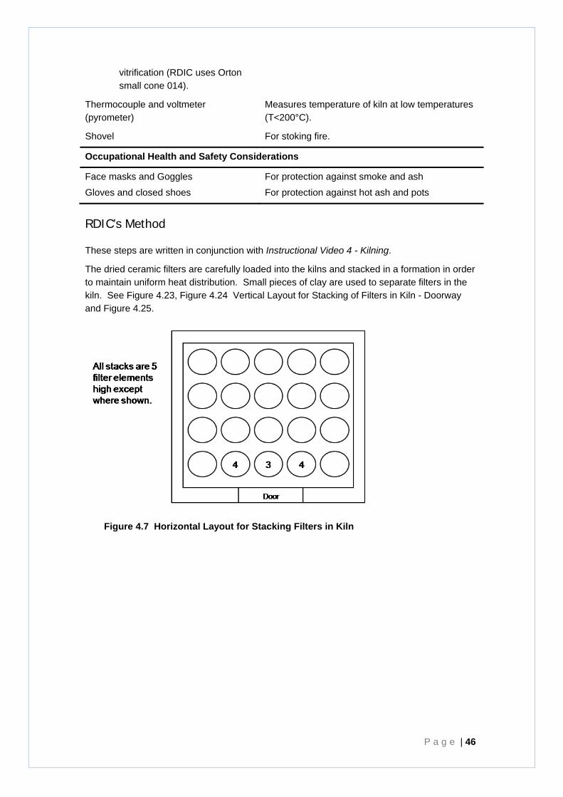
P a g e | 46
vitrification (RDIC uses Orton small cone 014).
Thermocouple and voltmeter (pyrometer)
Measures temperature of kiln at low temperatures (T<200°C).
Shovel For stoking fire.
Occupational Health and Safety Considerations
Face masks and Goggles
Gloves and closed shoes
For protection against smoke and ash
For protection against hot ash and pots
RDIC’s Method
These steps are written in conjunction with Instructional Video 4 - Kilning.
The dried ceramic filters are carefully loaded into the kilns and stacked in a formation in order to maintain uniform heat distribution. Small pieces of clay are used to separate filters in the kiln. See Figure 4.23, Figure 4.24 Vertical Layout for Stacking of Filters in Kiln - Doorway and Figure 4.25.
Figure 4.7 Horizontal Layout for Stacking Filters in Kiln
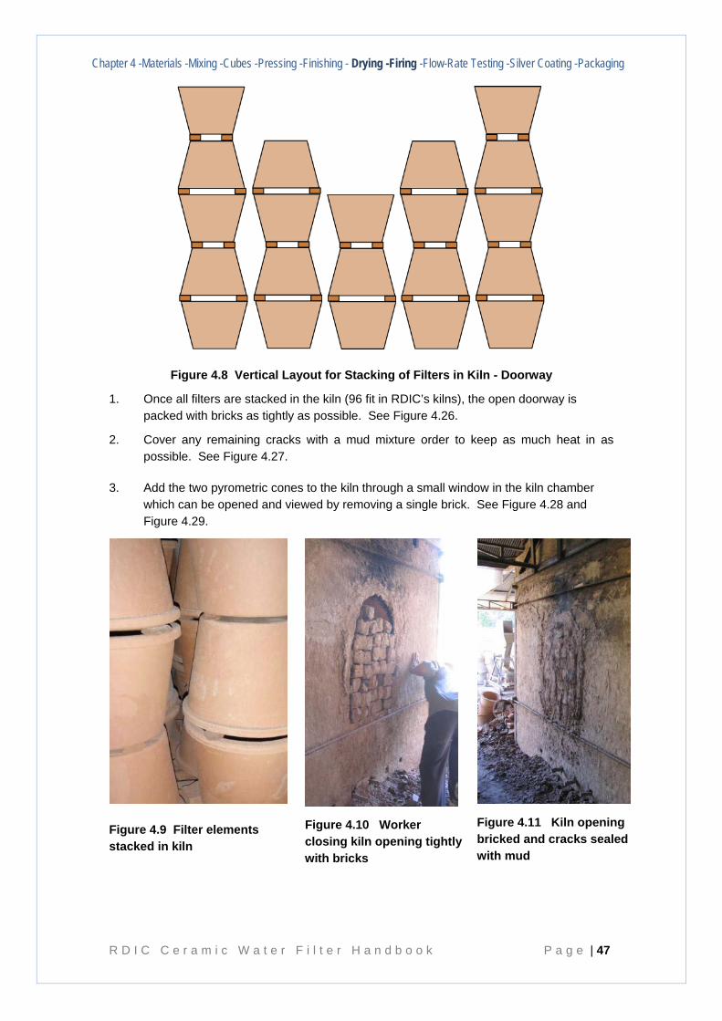
Chapter 4 -Materials -Mixing -Cubes -Pressing -Finishing - Drying -Firing -Flow-Rate Testing -Silver Coating -Packaging
R D I C C e r a m i c W a t e r F i l t e r H a n d b o o k P a g e | 47
Figure 4.8 Vertical Layout for Stacking of Filters in Kiln - Doorway
1. Once all filters are stacked in the kiln (96 fit in RDIC’s kilns), the open doorway is packed with bricks as tightly as possible. See Figure 4.26.
2. Cover any remaining cracks with a mud mixture order to keep as much heat in as possible. See Figure 4.27.
3. Add the two pyrometric cones to the kiln through a small window in the kiln chamber which can be opened and viewed by removing a single brick. See Figure 4.28 and Figure 4.29.
Figure 4.9 Filter elements stacked in kiln
Figure 4.10 Worker closing kiln opening tightly with bricks
Figure 4.11 Kiln opening bricked and cracks sealed with mud
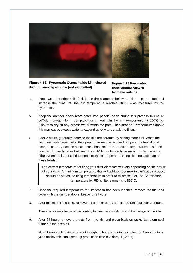
P a g e | 48
Figure 4.12. Pyrometric Cones inside kiln, viewed through viewing window (not yet melted)
Figure 4.13 Pyrometric cone window viewed from the outside
4. Place wood, or other solid fuel, in the fire chambers below the kiln. Light the fuel and increase the heat until the kiln temperature reaches 100˚C – as measured by the pyrometer.
5. Keep the damper doors (corrugated iron panels) open during this process to ensure sufficient oxygen for a complete burn. Maintain the kiln temperature at 100˚C for 2 hours to dry off any excess water within the pots – dehydration. Temperatures above this may cause excess water to expand quickly and crack the filters.
6. After 2 hours, gradually increase the kiln temperature by adding more fuel. When the first pyrometric cone melts, the operator knows the required temperature has almost been reached. Once the second cone has melted, the required temperature has been reached. It usually takes between 8 and 10 hours to reach the maximum temperature. [The pyrometer is not used to measure these temperatures since it is not accurate at these levels.]
7. Once the required temperature for vitrification has been reached, remove the fuel and cover with the damper doors. Leave for 9 hours.
8. After this main firing time, remove the damper doors and let the kiln cool over 24 hours.
These times may be varied according to weather conditions and the design of the kiln.
9. After 24 hours remove the pots from the kiln and place back on racks. Let them cool further in the open air.
Note: faster cooling times are not thought to have a deleterious effect on filter structure, yet if achievable can speed up production time (Gelders, T., 2007).
The correct temperature for firing your filter elements will vary depending on the nature of your clay. A minimum temperature that will achieve a complete vitrification process
should be set as the firing temperature in order to minimise fuel use. Vitrification temperature for RDI’s filter elements is 866°C.

Chapter 4 -Materials -Mixing -Cubes -Pressing -Finishing - Drying -Firing -Flow-Rate Testing -Silver Coating -Packaging
R D I C C e r a m i c W a t e r F i l t e r H a n d b o o k P a g e | 49
RDIC has recently trialled the use of fans to cool down the kilns. This has reduced the cooling time to about 12 hours. However consideration needs to be made of the cost of the electricity to do so.
Unassisted cooling has been observed to occur from the bottom up, ie heat remains in the upper part of the kiln considerably longer than in the base. It should be possible to accelerate cooling by incorporating removable bricks in the upper walls of the kiln, to be removed in the latter part of the cooling phase (once it is safe to do so).
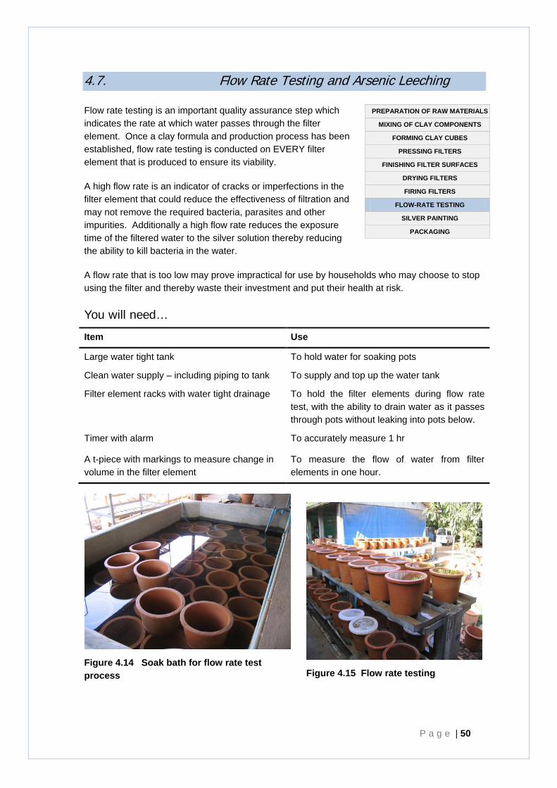
P a g e | 50
4.7. Flow Rate Testing and Arsenic Leeching
Flow rate testing is an important quality assurance step which indicates the rate at which water passes through the filter element. Once a clay formula and production process has been established, flow rate testing is conducted on EVERY filter element that is produced to ensure its viability.
A high flow rate is an indicator of cracks or imperfections in the filter element that could reduce the effectiveness of filtration and may not remove the required bacteria, parasites and other impurities. Additionally a high flow rate reduces the exposure time of the filtered water to the silver solution thereby reducing the ability to kill bacteria in the water.
A flow rate that is too low may prove impractical for use by households who may choose to stop using the filter and thereby waste their investment and put their health at risk.
You will need…
Item Use
Large water tight tank To hold water for soaking pots
Clean water supply – including piping to tank To supply and top up the water tank
Filter element racks with water tight drainage To hold the filter elements during flow rate test, with the ability to drain water as it passes through pots without leaking into pots below.
Timer with alarm To accurately measure 1 hr
A t-piece with markings to measure change in volume in the filter element
To measure the flow of water from filter elements in one hour.
Figure 4.15 Flow rate testing
PREPARATION OF RAW MATERIALS
MIXING OF CLAY COMPONENTS
FORMING CLAY CUBES
PRESSING FILTERS
FINISHING FILTER SURFACES
DRYING FILTERS
FIRING FILTERS
FLOW-RATE TESTING
SILVER PAINTING
PACKAGING
Figure 4.14 Soak bath for flow rate test process
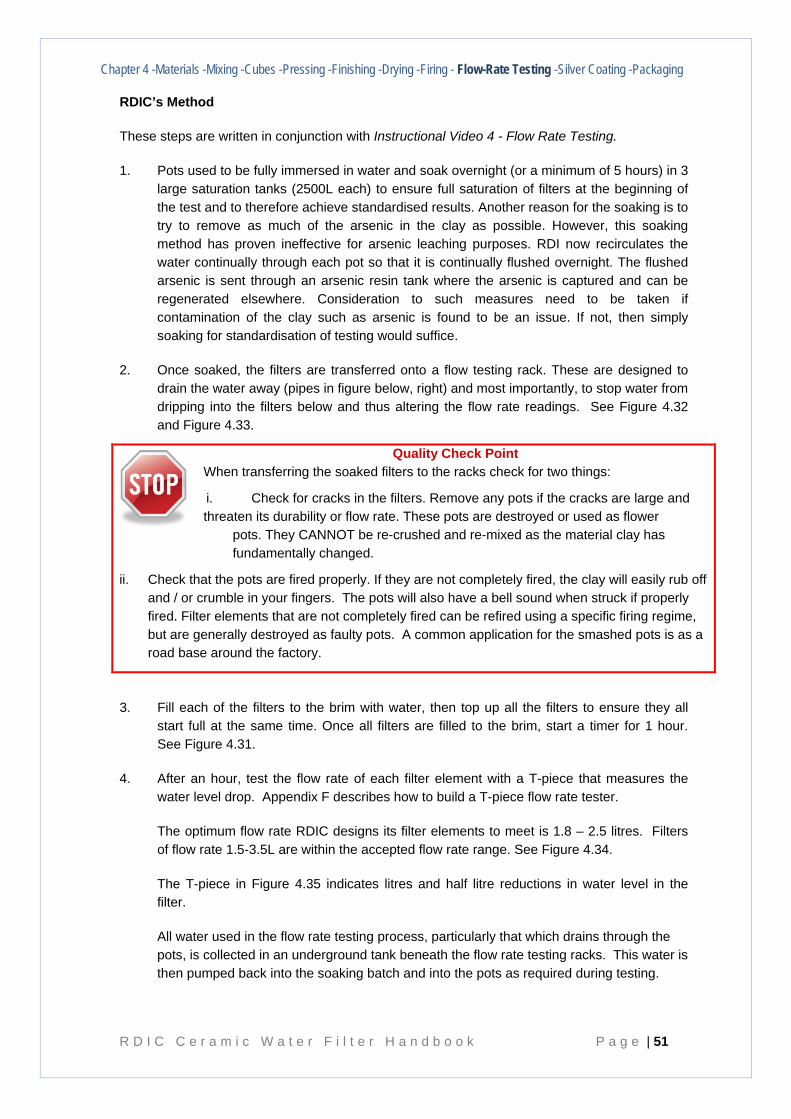
Chapter 4 -Materials -Mixing -Cubes -Pressing -Finishing -Drying -Firing - Flow-Rate Testing -Silver Coating -Packaging
R D I C C e r a m i c W a t e r F i l t e r H a n d b o o k P a g e | 51
RDIC’s Method
These steps are written in conjunction with Instructional Video 4 - Flow Rate Testing.
1. Pots used to be fully immersed in water and soak overnight (or a minimum of 5 hours) in 3 large saturation tanks (2500L each) to ensure full saturation of filters at the beginning of the test and to therefore achieve standardised results. Another reason for the soaking is to try to remove as much of the arsenic in the clay as possible. However, this soaking method has proven ineffective for arsenic leaching purposes. RDI now recirculates the water continually through each pot so that it is continually flushed overnight. The flushed arsenic is sent through an arsenic resin tank where the arsenic is captured and can be regenerated elsewhere. Consideration to such measures need to be taken if contamination of the clay such as arsenic is found to be an issue. If not, then simply soaking for standardisation of testing would suffice.
2. Once soaked, the filters are transferred onto a flow testing rack. These are designed to drain the water away (pipes in figure below, right) and most importantly, to stop water from dripping into the filters below and thus altering the flow rate readings. See Figure 4.32 and Figure 4.33.
Quality Check Point When transferring the soaked filters to the racks check for two things:
i. Check for cracks in the filters. Remove any pots if the cracks are large and threaten its durability or flow rate. These pots are destroyed or used as flower
pots. They CANNOT be re-crushed and re-mixed as the material clay has fundamentally changed.
ii. Check that the pots are fired properly. If they are not completely fired, the clay will easily rub off and / or crumble in your fingers. The pots will also have a bell sound when struck if properly fired. Filter elements that are not completely fired can be refired using a specific firing regime, but are generally destroyed as faulty pots. A common application for the smashed pots is as a road base around the factory.
3. Fill each of the filters to the brim with water, then top up all the filters to ensure they all start full at the same time. Once all filters are filled to the brim, start a timer for 1 hour. See Figure 4.31.
4. After an hour, test the flow rate of each filter element with a T-piece that measures the water level drop. Appendix F describes how to build a T-piece flow rate tester.
The optimum flow rate RDIC designs its filter elements to meet is 1.8 – 2.5 litres. Filters of flow rate 1.5-3.5L are within the accepted flow rate range. See Figure 4.34.
The T-piece in Figure 4.35 indicates litres and half litre reductions in water level in the filter.
All water used in the flow rate testing process, particularly that which drains through the pots, is collected in an underground tank beneath the flow rate testing racks. This water is then pumped back into the soaking batch and into the pots as required during testing.
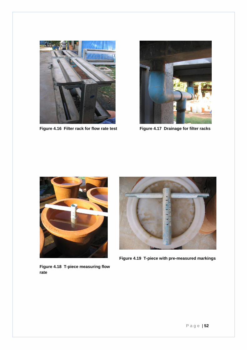
P a g e | 52
Figure 4.16 Filter rack for flow rate test
Figure 4.17 Drainage for filter racks
Figure 4.18 T-piece measuring flow rate
Figure 4.19 T-piece with pre-measured markings
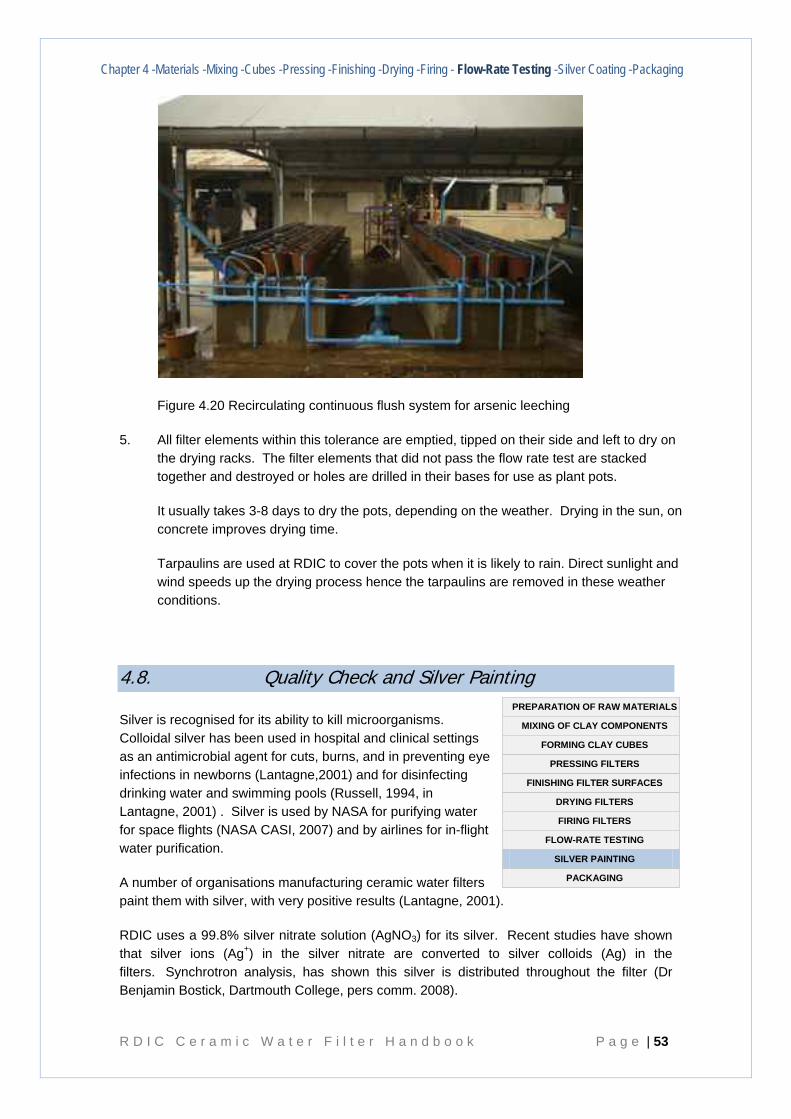
Chapter 4 -Materials -Mixing -Cubes -Pressing -Finishing -Drying -Firing - Flow-Rate Testing -Silver Coating -Packaging
R D I C C e r a m i c W a t e r F i l t e r H a n d b o o k P a g e | 53
Figure 4.20 Recirculating continuous flush system for arsenic leeching
5. All filter elements within this tolerance are emptied, tipped on their side and left to dry on the drying racks. The filter elements that did not pass the flow rate test are stacked together and destroyed or holes are drilled in their bases for use as plant pots.
It usually takes 3-8 days to dry the pots, depending on the weather. Drying in the sun, on concrete improves drying time.
Tarpaulins are used at RDIC to cover the pots when it is likely to rain. Direct sunlight and wind speeds up the drying process hence the tarpaulins are removed in these weather conditions.
4.8. Quality Check and Silver Painting
Silver is recognised for its ability to kill microorganisms. Colloidal silver has been used in hospital and clinical settings as an antimicrobial agent for cuts, burns, and in preventing eye infections in newborns (Lantagne,2001) and for disinfecting drinking water and swimming pools (Russell, 1994, in Lantagne, 2001) . Silver is used by NASA for purifying water for space flights (NASA CASI, 2007) and by airlines for in-flight water purification.
A number of organisations manufacturing ceramic water filters paint them with silver, with very positive results (Lantagne, 2001).
RDIC uses a 99.8% silver nitrate solution (AgNO3) for its silver. Recent studies have shown that silver ions (Ag+) in the silver nitrate are converted to silver colloids (Ag) in the filters. Synchrotron analysis, has shown this silver is distributed throughout the filter (Dr Benjamin Bostick, Dartmouth College, pers comm. 2008).
PREPARATION OF RAW MATERIALS
MIXING OF CLAY COMPONENTS
FORMING CLAY CUBES
PRESSING FILTERS
FINISHING FILTER SURFACES
DRYING FILTERS
FIRING FILTERS
FLOW-RATE TESTING
SILVER PAINTING
PACKAGING
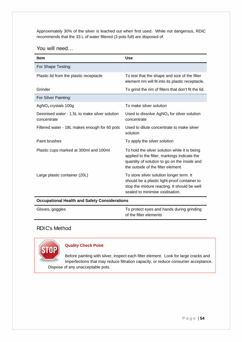
P a g e | 54
Approximately 30% of the silver is leached out when first used. While not dangerous, RDIC recommends that the 33 L of water filtered (3 pots full) are disposed of.
You will need…
Item Use
For Shape Testing:
Plastic lid from the plastic receptacle To test that the shape and size of the filter element rim will fit into its plastic receptacle.
Grinder To grind the rim of filters that don’t fit the lid.
For Silver Painting:
AgNO3 crystals 100g To make silver solution
Deionised water - 1.5L to make silver solution concentrate
Used to dissolve AgNO3 for silver solution concentrate
Filtered water - 18L makes enough for 60 pots Used to dilute concentrate to make silver solution
Paint brushes To apply the silver solution
Plastic cups marked at 300ml and 100ml To hold the silver solution while it is being applied to the filter, markings indicate the quantity of solution to go on the inside and the outside of the filter element.
Large plastic container (20L) To store silver solution longer term. It should be a plastic light-proof container to stop the mixture reacting. It should be well sealed to minimise oxidisation.
Occupational Health and Safety Considerations
Gloves, goggles To protect eyes and hands during grinding of the filter elements
RDIC’s Method
Quality Check Point
Before painting with silver, inspect each filter element. Look for large cracks and imperfections that may reduce filtration capacity, or reduce consumer acceptance.
Dispose of any unacceptable pots.
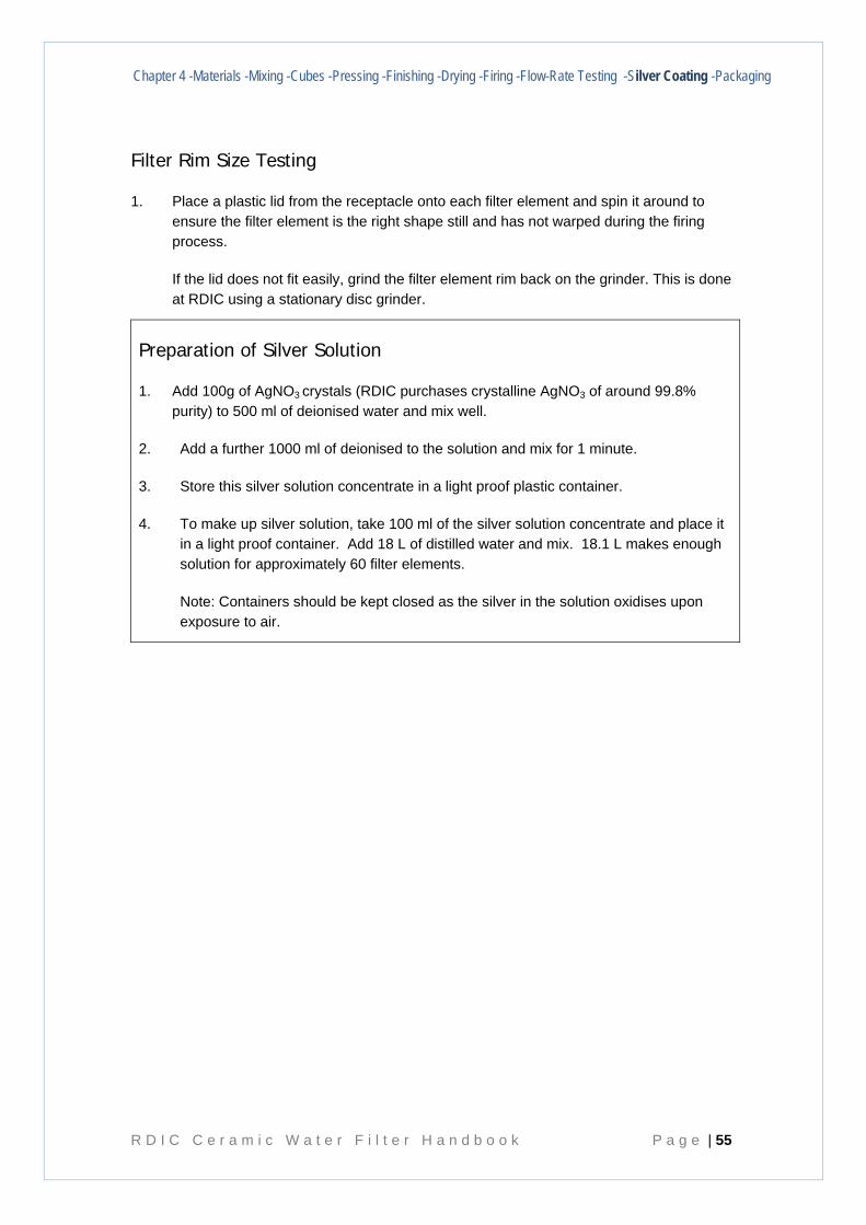
Chapter 4 -Materials -Mixing -Cubes -Pressing -Finishing -Drying -Firing -Flow-Rate Testing -Silver Coating -Packaging
R D I C C e r a m i c W a t e r F i l t e r H a n d b o o k P a g e | 55
Filter Rim Size Testing
1. Place a plastic lid from the receptacle onto each filter element and spin it around to ensure the filter element is the right shape still and has not warped during the firing process.
If the lid does not fit easily, grind the filter element rim back on the grinder. This is done at RDIC using a stationary disc grinder.
Preparation of Silver Solution
1. Add 100g of AgNO3 crystals (RDIC purchases crystalline AgNO3 of around 99.8% purity) to 500 ml of deionised water and mix well.
2. Add a further 1000 ml of deionised to the solution and mix for 1 minute.
3. Store this silver solution concentrate in a light proof plastic container.
4. To make up silver solution, take 100 ml of the silver solution concentrate and place it in a light proof container. Add 18 L of distilled water and mix. 18.1 L makes enough solution for approximately 60 filter elements.
Note: Containers should be kept closed as the silver in the solution oxidises upon exposure to air.
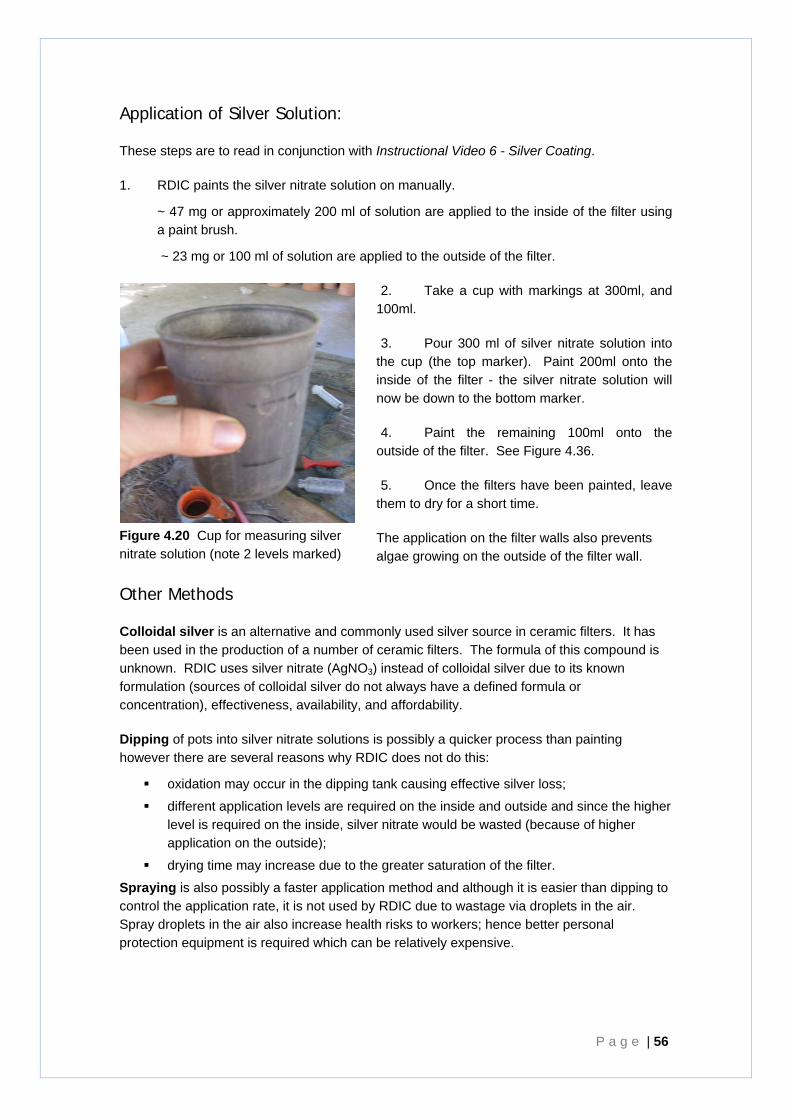
P a g e | 56
Application of Silver Solution:
These steps are to read in conjunction with Instructional Video 6 - Silver Coating.
1. RDIC paints the silver nitrate solution on manually.
~ 47 mg or approximately 200 ml of solution are applied to the inside of the filter using a paint brush.
~ 23 mg or 100 ml of solution are applied to the outside of the filter.
2. Take a cup with markings at 300ml, and 100ml.
3. Pour 300 ml of silver nitrate solution into the cup (the top marker). Paint 200ml onto the inside of the filter - the silver nitrate solution will now be down to the bottom marker.
4. Paint the remaining 100ml onto the outside of the filter. See Figure 4.36.
5. Once the filters have been painted, leave them to dry for a short time.
The application on the filter walls also prevents algae growing on the outside of the filter wall.
Other Methods
Colloidal silver is an alternative and commonly used silver source in ceramic filters. It has been used in the production of a number of ceramic filters. The formula of this compound is unknown. RDIC uses silver nitrate (AgNO3) instead of colloidal silver due to its known formulation (sources of colloidal silver do not always have a defined formula or concentration), effectiveness, availability, and affordability.
Dipping of pots into silver nitrate solutions is possibly a quicker process than painting however there are several reasons why RDIC does not do this:
oxidation may occur in the dipping tank causing effective silver loss;
different application levels are required on the inside and outside and since the higher level is required on the inside, silver nitrate would be wasted (because of higher application on the outside);
drying time may increase due to the greater saturation of the filter.
Spraying is also possibly a faster application method and although it is easier than dipping to control the application rate, it is not used by RDIC due to wastage via droplets in the air. Spray droplets in the air also increase health risks to workers; hence better personal protection equipment is required which can be relatively expensive.
Figure 4.20 Cup for measuring silver nitrate solution (note 2 levels marked)
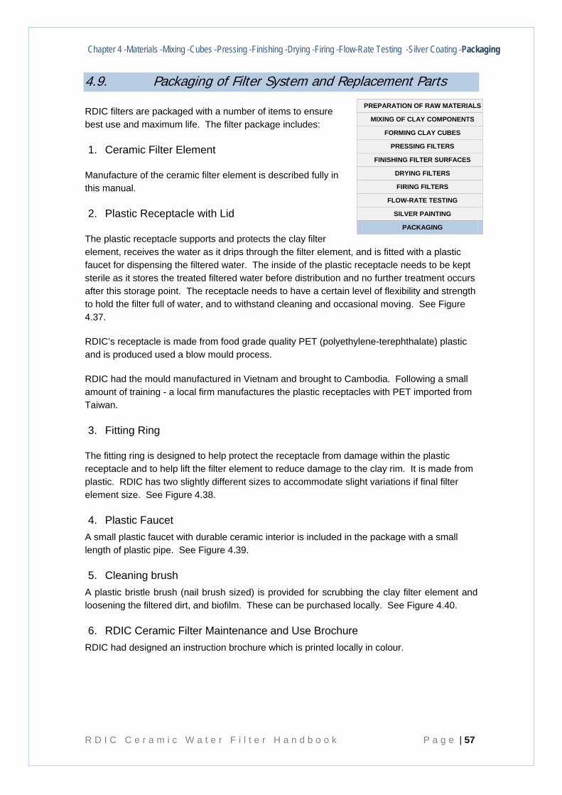
Chapter 4 -Materials -Mixing -Cubes -Pressing -Finishing -Drying -Firing -Flow-Rate Testing -Silver Coating -Packaging
R D I C C e r a m i c W a t e r F i l t e r H a n d b o o k P a g e | 57
4.9. Packaging of Filter System and Replacement Parts
RDIC filters are packaged with a number of items to ensure best use and maximum life. The filter package includes:
1. Ceramic Filter Element
Manufacture of the ceramic filter element is described fully in this manual.
2. Plastic Receptacle with Lid
The plastic receptacle supports and protects the clay filter element, receives the water as it drips through the filter element, and is fitted with a plastic faucet for dispensing the filtered water. The inside of the plastic receptacle needs to be kept sterile as it stores the treated filtered water before distribution and no further treatment occurs after this storage point. The receptacle needs to have a certain level of flexibility and strength to hold the filter full of water, and to withstand cleaning and occasional moving. See Figure 4.37.
RDIC’s receptacle is made from food grade quality PET (polyethylene-terephthalate) plastic and is produced used a blow mould process.
RDIC had the mould manufactured in Vietnam and brought to Cambodia. Following a small amount of training - a local firm manufactures the plastic receptacles with PET imported from Taiwan.
3. Fitting Ring
The fitting ring is designed to help protect the receptacle from damage within the plastic receptacle and to help lift the filter element to reduce damage to the clay rim. It is made from plastic. RDIC has two slightly different sizes to accommodate slight variations if final filter element size. See Figure 4.38.
4. Plastic Faucet A small plastic faucet with durable ceramic interior is included in the package with a small length of plastic pipe. See Figure 4.39.
5. Cleaning brush A plastic bristle brush (nail brush sized) is provided for scrubbing the clay filter element and loosening the filtered dirt, and biofilm. These can be purchased locally. See Figure 4.40.
6. RDIC Ceramic Filter Maintenance and Use Brochure RDIC had designed an instruction brochure which is printed locally in colour.
PREPARATION OF RAW MATERIALS
MIXING OF CLAY COMPONENTS
FORMING CLAY CUBES
PRESSING FILTERS
FINISHING FILTER SURFACES
DRYING FILTERS
FIRING FILTERS
FLOW-RATE TESTING
SILVER PAINTING
PACKAGING
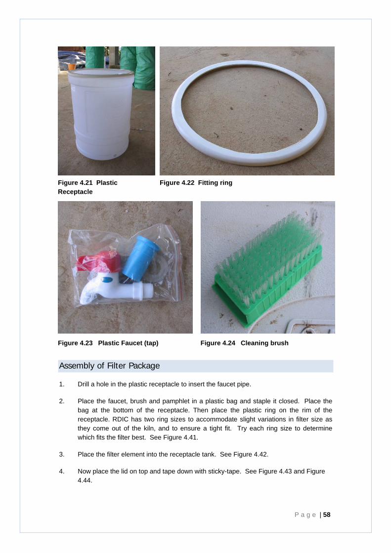
P a g e | 58
Figure 4.21 Plastic Receptacle
Figure 4.22 Fitting ring
Figure 4.23 Plastic Faucet (tap)
Figure 4.24 Cleaning brush
Assembly of Filter Package
1. Drill a hole in the plastic receptacle to insert the faucet pipe.
2. Place the faucet, brush and pamphlet in a plastic bag and staple it closed. Place the bag at the bottom of the receptacle. Then place the plastic ring on the rim of the receptacle. RDIC has two ring sizes to accommodate slight variations in filter size as they come out of the kiln, and to ensure a tight fit. Try each ring size to determine which fits the filter best. See Figure 4.41.
3. Place the filter element into the receptacle tank. See Figure 4.42.
4. Now place the lid on top and tape down with sticky-tape. See Figure 4.43 and Figure 4.44.
Chapter 4 -Materials -Mixing -Cubes -Pressing -Finishing -Drying -Firing -Flow-Rate Testing -Silver Coating -Packaging
R D I C C e r a m i c W a t e r F i l t e r H a n d b o o k P a g e | 59
Figure 4.25 Receptacle, faucet, instructions, brush and fitting ring
Figure 4.26 Filter element added to Filter Package
Figure 4.27 Filter Package with lid
Figure 4.28 Filter Package taped for distribution
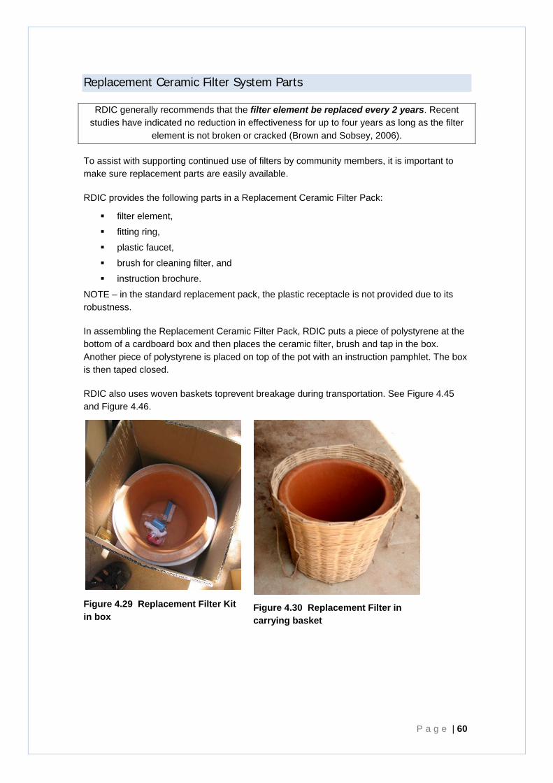
P a g e | 60
Replacement Ceramic Filter System Parts
RDIC generally recommends that the filter element be replaced every 2 years. Recent studies have indicated no reduction in effectiveness for up to four years as long as the filter
element is not broken or cracked (Brown and Sobsey, 2006).
To assist with supporting continued use of filters by community members, it is important to make sure replacement parts are easily available.
RDIC provides the following parts in a Replacement Ceramic Filter Pack:
filter element,
fitting ring,
plastic faucet,
brush for cleaning filter, and
instruction brochure.
NOTE – in the standard replacement pack, the plastic receptacle is not provided due to its robustness.
In assembling the Replacement Ceramic Filter Pack, RDIC puts a piece of polystyrene at the bottom of a cardboard box and then places the ceramic filter, brush and tap in the box. Another piece of polystyrene is placed on top of the pot with an instruction pamphlet. The box is then taped closed.
RDIC also uses woven baskets toprevent breakage during transportation. See Figure 4.45 and Figure 4.46.
Figure 4.29 Replacement Filter Kit in box
Figure 4.30 Replacement Filter in carrying basket
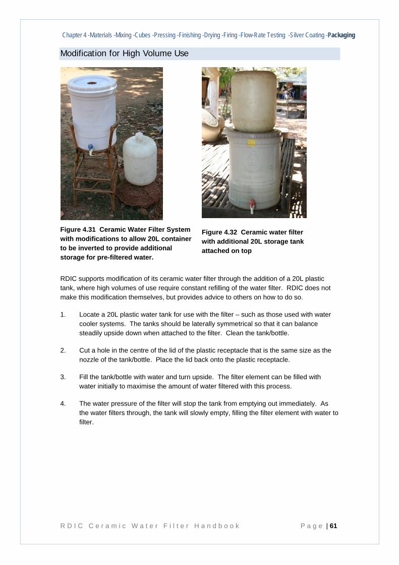
Chapter 4 -Materials -Mixing -Cubes -Pressing -Finishing -Drying -Firing -Flow-Rate Testing -Silver Coating -Packaging
R D I C C e r a m i c W a t e r F i l t e r H a n d b o o k P a g e | 61
Modification for High Volume Use
RDIC supports modification of its ceramic water filter through the addition of a 20L plastic tank, where high volumes of use require constant refilling of the water filter. RDIC does not make this modification themselves, but provides advice to others on how to do so.
1. Locate a 20L plastic water tank for use with the filter – such as those used with water cooler systems. The tanks should be laterally symmetrical so that it can balance steadily upside down when attached to the filter. Clean the tank/bottle.
2. Cut a hole in the centre of the lid of the plastic receptacle that is the same size as the nozzle of the tank/bottle. Place the lid back onto the plastic receptacle.
3. Fill the tank/bottle with water and turn upside. The filter element can be filled with water initially to maximise the amount of water filtered with this process.
4. The water pressure of the filter will stop the tank from emptying out immediately. As the water filters through, the tank will slowly empty, filling the filter element with water to filter.
Figure 4.31 Ceramic Water Filter System with modifications to allow 20L container to be inverted to provide additional storage for pre-filtered water.
Figure 4.32 Ceramic water filter with additional 20L storage tank attached on top
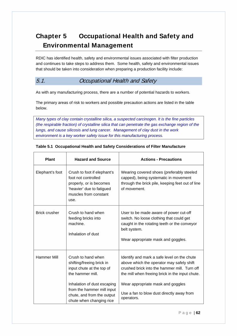
P a g e | 62
Chapter 5 Occupational Health and Safety and Environmental Management
RDIC has identified health, safety and environmental issues associated with filter production and continues to take steps to address them. Some health, safety and environmental issues that should be taken into consideration when preparing a production facility include:
5.1. Occupational Health and Safety
As with any manufacturing process, there are a number of potential hazards to workers.
The primary areas of risk to workers and possible precaution actions are listed in the table below.
Many types of clay contain crystalline silica, a suspected carcinogen. It is the fine particles (the respirable fraction) of crystalline silica that can penetrate the gas exchange region of the lungs, and cause silicosis and lung cancer. Management of clay dust in the work environment is a key worker safety issue for this manufacturing process.
Table 5.1 Occupational Health and Safety Considerations of Filter Manufacture
Plant Hazard and Source Actions - Precautions
Elephant’s foot Crush to foot if elephant’s foot not controlled properly, or is becomes ‘heavier’ due to fatigued muscles from constant use.
Wearing covered shoes (preferably steeled capped), being systematic in movement through the brick pile, keeping feet out of line of movement.
Brick crusher Crush to hand when feeding bricks into machine.
Inhalation of dust
User to be made aware of power cut-off switch. No loose clothing that could get caught in the rotating teeth or the conveyor belt system.
Wear appropriate mask and goggles.
Hammer Mill Crush to hand when shifting/freeing brick in input chute at the top of the hammer mill.
Inhalation of dust escaping from the hammer mill input chute, and from the output chute when changing rice
Identify and mark a safe level on the chute above which the operator may safely shift crushed brick into the hammer mill. Turn off the mill when freeing brick in the input chute.
Wear appropriate mask and goggles Use a fan to blow dust directly away from operators.
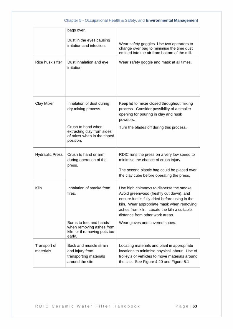
Chapter 5 - Occupational Health & Safety, and Environmental Management
R D I C C e r a m i c W a t e r F i l t e r H a n d b o o k P a g e | 63
bags over.
Dust in the eyes causing irritation and infection.
Wear safety goggles. Use two operators to change over bag to minimise the time dust emitted into the air from bottom of the mill.
Rice husk sifter Dust inhalation and eye irritation
Wear safety goggle and mask at all times.
Clay Mixer Inhalation of dust during dry mixing process.
Crush to hand when extracting clay from sides of mixer when in the tipped position.
Keep lid to mixer closed throughout mixing process. Consider possibility of a smaller opening for pouring in clay and husk powders.
Turn the blades off during this process.
Hydraulic Press Crush to hand or arm during operation of the press.
RDIC runs the press on a very low speed to minimise the chance of crush injury.
The second plastic bag could be placed over the clay cube before operating the press.
Kiln Inhalation of smoke from fires.
Burns to feet and hands when removing ashes from kiln, or if removing pots too early.
Use high chimneys to disperse the smoke. Avoid greenwood (freshly cut down), and ensure fuel is fully dried before using in the kiln. Wear appropriate mask when removing ashes from kiln. Locate the kiln a suitable distance from other work areas.
Wear gloves and covered shoes.
Transport of materials
Back and muscle strain and injury from transporting materials around the site.
Locating materials and plant in appropriate locations to minimise physical labour. Use of trolley’s or vehicles to move materials around the site. See Figure 4.20 and Figure 5.1
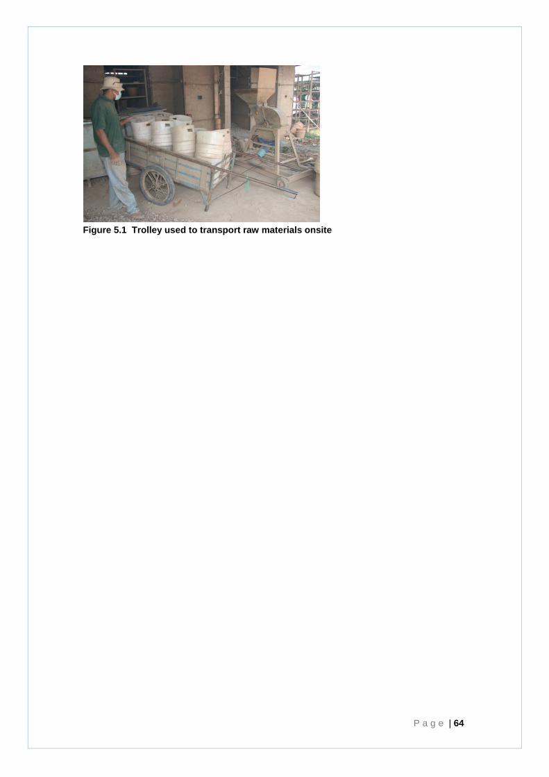
P a g e | 64
Figure 5.1 Trolley used to transport raw materials onsite
Chapter 5 - Occupational Health & Safety, and Environmental Management
R D I C C e r a m i c W a t e r F i l t e r H a n d b o o k P a g e | 65
5.2. Environmental Management
• Sourcing the clay – consideration should be given to the legality of the clay source, and the environmental impact of extraction processes – ie consideration should be given to illegal or unsustainable land clearing, safety and sustainability of the site and its management, and downstream water pollution effects from the clay pit.
• Sourcing of fuel – utilising wood to fuel the kiln may encourage deforestation or habitat destruction in the local environment, leading to an unsustainable production process. Consideration of alternative fuel sources – such as waste products is encouraged.
• Air pollution – the type of fuel, its condition, and the firing practice used has a major impact on the quantity of smoke pollution produced by the kiln fires and the efficiency of the fires. Greenwood (freshly cut down) produces high quantities of smoke.
It is recommended by some sources that wood should be at least 1 year old before burning. Additionally wet wood produces high quantities of smoke. Wood containing high volumes of water reduces the temperature of the fire – because much of the fire’s heat is required to evaporate the water before burning can occur. When the temperature decreases, much of the organic matter of the wood is released as smoke particles rather than being fully burned and utilised.
Overloading the kiln fires with wood without sufficient oxygen to fully burn will greatly increase the production of smoke, decrease the efficiency of the fires and therefore increase fuel requirements.
The positioning of the kilns should be considered carefully in terms of impact of smoke on workers and the surrounding community.
Diesel generators – used to power machinery where reliable electricity grids are not available - also release particulate pollution. Diesel generators, if used, should be maintained to minimise pollution.
• Noise pollution – the primary sources of noise pollution from the manufacturing process are the diesel generator and the hammer mill. The timing of operation and location of the facility will affect whether the noise from generators or plant will have a negative impact on the surrounding community. Maintenance of machinery will also help to minimise noise and its effects on workers and the community.
• Dust pollution – the crushing of the bricks, and the pouring of clay powder and rice husks, create small dust particles in the air. This can cover vegetation, and affect air quality of surrounding area. Clay powder usually contains silica which is a known carcinogen. Measures to manage dust were dealt with in more detail in Section 5.1.
• Solid Waste – Plastic bags are currently a waste product from the RDIC manufacture process. Consideration is being given to opportunities to recycle these bags. Opportunities to re-use the ash in compost, or in other manufacturing processes could also be given.
P a g e | 66
Chapter 6 Distribution and Education
6.1. Introduction
RDIC employs a number of different methods to ensure filters become accessible to community members following manufacture including through:
schools;
direct sales through private distributors and RDIC; and
non-government organisations (NGOs).
Whichever method of distribution is employed, education of distributors and users is integral to the success and sustainability of ceramic water filter technology.
Key issues to consider in distribution strategies are:
• ensure appropriate training and education material is provided to the distributor in the short and long term so that they are capable of explaining the operation and maintenance requirements, and answering questions about the filter;
• the distributor needs access to educational and instructional material to provide to the end user to ensure correct maintenance is conducted in the long term;
• an ongoing connection between the distributor and the community is important – such a role would provide an ongoing access point for questions and replacement supplies. Additionally, a long term presence of the filters in a community would continue to reinforce the value of filters and remind people about the opportunity to access replacement parts or a later opportunity to buy a filter.
Ceramic water filters are not a passive resource, they require ongoing management and maintenance by users. Therefore, like computers, ‘after sales support’ is essential for ongoing and appropriate use of ceramic water filters.
For the ongoing sustainability and viability of water filtration programs, RDIC considers it essential that water filters are sold to users for a sustainable price. This means the cost of production (plus any required supplier’s profit). This position is supported by research on sustainability by Brown and Sobsey (2006).
RDIC’s own experience indicates that villages where filters were provided at no cost, or at a significantly subsidised rate initially, may have a slower uptake of technology into the future, as villagers seem to be less willing to pay themselves to replace the filters when it is necessary, instead perhaps waiting for when they may be provided for free in the future.
It is therefore highly recommended that filters be provided under a sustainable cost structure, and use of local entrepreneurs to distribute, and potentially manufacture, is likely to contribute to the sustainability of the uptake and use of the technology in the long term. RDIC’s Price List is included at 0 as an example.
Chapter 6 - Distribution and Education
R D I C C e r a m i c W a t e r F i l t e r H a n d b o o k P a g e | 67
6.2. Education Materials
One of the most important aspects of an effective water filter implementation program is education. RDIC has developed an extensive education program that links with the distribution of filters as well as other programs (such as such as school rainwater tanks and hand-washing bays).
RDIC has also developed some key media that it uses in a range of educational settings, and that reinforce the requirements for filter care and maintenance including:
Instruction Brochure provided with the filter;
Colour posters;
Flip chart;
Educational Video.
These are described in more detail below.
It is essential that all elements of the RDIC Water Filter Education Program reinforce the same messages to villagers, community members, and distributors to ensure correct use and maintenance practices are retained and implemented. For this reason the ‘RDIC Ceramic Water Filter Education and Maintenance – Key Messages’ has been produced and is updated as needed. The January 2008 version of this document is at Appendix I.
Note: RDIC has the facilities to produce all education material (print, audio, video) and can work in conjunction with the partner so that all material is produced in the appropriate language with cultural sensitivity. RDIC charges a fee for this service.
Ceramic Water Filter Instructional Brochure The instructional brochure provides diagrams and text to explain to customers the key requirements for using and maintaining the water filters safely. It is available in English and Khmer for use by Cambodians and for the use of NGOs and their employees. A copy of the ceramic water filter instructional brochure is at 0.
Water Filter Education Poster and Flip Chart The Water Filter Education Poster is given to schools, or communities (e.g. coffee shops) to post with the filters for message reinforcement. They can also be provided to individual families who purchase the filter.
The water filter education flip chart is used when it is not possible to use the video or for a small family group. The flip charts describe the ceramic filters and provide the prompt for instructing on filter maintenance. A copy of the poster and flip chart is at Appendix A.
Community Water Filter and Hygiene Education Video The purpose of the video is to teach students and community members the need for a water filter, by explaining about the bacteria that is present in source waters, how filters work, and how to maintain them.
The video shows:
• the manufacturing process for the filters in brief;
• how the filter is assembled;
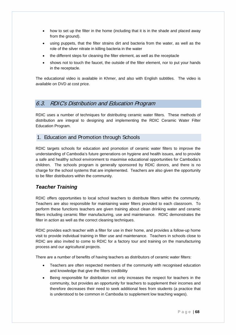
P a g e | 68
• how to set up the filter in the home (including that it is in the shade and placed away from the ground).
• using puppets, that the filter strains dirt and bacteria from the water, as well as the role of the silver nitrate in killing bacteria in the water
• the different steps for cleaning the filter element, as well as the receptacle
• shows not to touch the faucet, the outside of the filter element, nor to put your hands in the receptacle.
The educational video is available in Khmer, and also with English subtitles. The video is available on DVD at cost price.
6.3. RDIC’s Distribution and Education Program
RDIC uses a number of techniques for distributing ceramic water filters. These methods of distribution are integral to designing and implementing the RDIC Ceramic Water Filter Education Program.
1. Education and Promotion through Schools
RDIC targets schools for education and promotion of ceramic water filters to improve the understanding of Cambodia’s future generations on hygiene and health issues, and to provide a safe and healthy school environment to maximise educational opportunities for Cambodia’s children. The schools program is generally sponsored by RDIC donors, and there is no charge for the school systems that are implemented. Teachers are also given the opportunity to be filter distributors within the community.
Teacher Training
RDIC offers opportunities to local school teachers to distribute filters within the community. Teachers are also responsible for maintaining water filters provided to each classroom. To perform these functions teachers are given training about clean drinking water and ceramic filters including ceramic filter manufacturing, use and maintenance. RDIC demonstrates the filter in action as well as the correct cleaning techniques.
RDIC provides each teacher with a filter for use in their home, and provides a follow-up home visit to provide individual training in filter use and maintenance. Teachers in schools close to RDIC are also invited to come to RDIC for a factory tour and training on the manufacturing process and our agricultural projects.
There are a number of benefits of having teachers as distributors of ceramic water filters:
• Teachers are often respected members of the community with recognised education and knowledge that give the filters credibility
• Being responsible for distribution not only increases the respect for teachers in the community, but provides an opportunity for teachers to supplement their incomes and therefore decreases their need to seek additional fees from students (a practice that is understood to be common in Cambodia to supplement low teaching wages).
Chapter 6 - Distribution and Education
R D I C C e r a m i c W a t e r F i l t e r H a n d b o o k P a g e | 69
RDIC establishes letters of agreement with the schools to ensure there is clear understanding of the roles of the school in maintaining equipment – ceramic water filters, rainwater tanks, toilets, hand-washing stations.
Student Education
Using a puppet show, RDIC’s educational team teaches up to 50 students at a time about health, hygiene and safe drinking water. RDIC discusses contamination of groundwater by arsenic (in regions where appropriate) and pollution, and encourages treatment of water against pathogens by boiling, chemical treatments, or water filters. Students are quizzed on key messages at the end and provided with a colouring book reinforcing the key messages.
Students are also provided with free drink bottles to encourage the use of clean drinking water and re-hydration.
Provision of Filters Two water filters are provided for each classroom in the school at no cost.
P a g e | 70
2. Education and Distribution through Village Group Leaders – Cluster Training
RDIC also meets with and utilises Group Leaders within the villages to promote and distribute filters to households. It is very important for successful filter uptake within a village that village leaders support and encourage the use of ceramic water filters.
To engage with Village groups, RDIC meets with a Group Leader (who is generally responsible for about 15 families) and teaches them about the importance of safe drinking water, the risk of high arsenic in groundwater, and the use of ceramic water filters to treat drinking water.
RDIC provides the Group Leader with a ceramic water filters to sell onto community members ($8) who may on sell for $8.50 or $9.
The Group Leaders will normally have access to a filter prior to a community meeting being held. This gives them an opportunity to try the filter, ask questions, understand how it works and increases their support of the filter.
RDIC often runs cluster training for a group of community members once support is shown by the Group Leader. Training in a cluster increase uptake as individuals buying the filter, or asking questions influences those around them, people learn more and are more likely to support a technology being taken up by neighbours.
The Group Leader has about 10 filters to sell, and does not need to pay any money to RDI up front, just pass on $8 to RDI for each filter sold.
3. Distribution through private distributors
RDIC has a large network of distributors that is now starting to grow more in the provinces. Distributors may have a stall at the market, a shop front on the road, be a pharmacy, or a government building or health centre. Distributors are trained on production methods and shown an information video. The filter is demonstrated and its output is compared with boiled water (which retains sediment).
Distributors have access to RDIC filters for $8 and can then on sell for a profit.
RDI encourages distributors by providing a free filter if they sell 15 or more in a month.
RDI is working towards a private distribution network where distributors can then on sell to a number of distributors in the provinces.
Chapter 6 - Distribution and Education
R D I C C e r a m i c W a t e r F i l t e r H a n d b o o k P a g e | 71
4. Direct sales to households
RDIC undertakes limited direct sales to households – but those in the local areas may come to get one. Limited training is provided but the brochure is provided.
5. Distribution by third party NGOs
3rd party NGOs also act as distributors of RDIC filters, often integrated into their own water, sanitation, and health programs. Many of these NGOs, see the filters as integral to implementation of their programmes and successful completion of their developmental goals.
P a g e | 72
Chapter 7 References and Further Information
1. Bloem, S., 2008, Silver impregnated ceramic water filter - Flowrate versus the removal efficiency of pathogens - Delft University of Technology, Faculty of Applied Sciences.
2. Brown, J. and Sobsey, M, 2006, Independent Appraisal of Ceramic Water Filtration Interventions in Cambodia: Final Report – Submitted to UNICEF 5 May 2006.*
3. Brown, J.M, 2007. Effectiveness of Ceramic Filtration for Drinking Water Treatment in Cambodia. Dissertation, (PhD.) University of North Carolina - Chapel Hill.*
4. Gelders, Thijs. 2007. Cambodia - December 2007 Proposal to increase the final quality and improve the working conditions for the production of ceramic water filter pots. Unpublished report provided to RDIC.*
5. IDE, 2003, Ceramic Water Purifier Cambodia Field Trials: IDE Working Paper Number 1.
6. Lantagne, D.S. 2001 (a). Investigation of the Potters for Peace Colloidal Silver Impregnated Ceramic Filter - Report 1: Intrinsic Effectiveness. Submitted to Jubilee House Community. http://www.edc-cu.org/pdf/report1-final.pdf *
7. Lantagne, D.S. 2001 (b). Investigation of the Potters for Peace Colloidal Silver Impregnated Ceramic Filter - Report 2: Field Investigations. Submitted to Jubilee House Community. http://pottersforpeace.org/wp-content/uploads/alethia-report-2.pdf
8. NASA CASI (National American Space Authority – Centre for Aerospace Information), 2007, Water Treatment Makes a Big Splash, Spinoff http://www.sti.nasa.gov/tto/Spinoff2004/er_1.html
9. National Institute of Statistics (Cambodia), 2000, Cambodia Demographic and Health Survey, 2000; Preliminary Report. http://www.childinfo.org/MICS2/natlMICSrepz/Cambodia/PRELIMrj.pdf
10. Orton Ceramic Foundation, 2008, Cone Equivalent Temperatures, http://www.ortonceramic.com/resources/reference/cone.chart.C.html.
11. Sampson, M.L., 2009, Pers Comms, Kean Svay, Cambodia.
12. The American Ceramic Society, 2005, ‘Kiln Firing Chart’, Pottery Making Illustrated. http://www.potterymaking.org/KilnFiringLayout.pdf
13. WHO, 2004, Guidelines for Drinking-water Quality: Third Edition, Volume 1 Recommendations.
14. WHO, 2007, World Health Statistics 2007: Risk Factors http://www.who.int/whosis/whostat2007_4riskfactors.pdf
15. WHO, 2007, World Health Statistics 2007: Mortality http://www.who.int/whosis/whostat2007_1mortality.pdf.

Chapter 7 - References and Further Information
R D I C C e r a m i c W a t e r F i l t e r H a n d b o o k P a g e | 73
16. Vu, K.B., Kaminiski, D., and Nune, L., ‘Review of Arsenic Removal Technologies for Contaminated Groundwaters’ Argonne National Laboratory, Argonne, Illinois, operated by the University of Chicago for the United States Department of Energy under Contract W-31-109-Eng-38. http://www.ipd.anl.gov/anlpubs/2003/05/46522.pdf .
Further information can be provided upon request. Please contact RDIC at www.rdic.org.


Appendix A Filter Efficacy Tests


Appendix B Pyrometric Cone Chart


Appendix C Factory Layout


Appendix D RDIC Automated Water Spray System - for Clay Mixing

Appendix E Technical Drawings


Appendix F How to build a kiln


Appendix G Build a T-Piece Flow Rate Measurer


Appendix H Example RDIC Filter Price List - November 2007


Appendix I RDIC Ceramic Water Filter Education and Maintenance Key Messages


Appendix J RDIC Ceramic Water Filter Instructions


Appendix K RDIC Ceramic Water Filter Education Poster and Flip Chart


Appendix L Instructional Videos