Embed Size (px)
Citation preview
1
S400
Biathlon
Users HandbookThis handbook refers to S400 Biathlon model.
WARNING! - UNAUTHORISED DISASSEMBLY OF THIS RIFLE WILL INVALIDATE THE
MANUFACTURERS WARRANTY.
**** SAFETY CODE ****
1 ALWAYS TREAT AN AIR RIFLE AS IF LOADED.
2 ALWAYS POINT THE RIFLE IN A SAFE DIRECTION, NEVER POINT A GUN AT ANYONE, EVEN IF UNLOADED.
3 NEVER LEAVE A RIFLE UNATTENDED WHEN COCKED OR LOADED.
4 ALWAYS BE SURE OF WHAT LIES BEYOND YOUR TARGET.
5 ALWAYS CONDUCT YOURSELF IN A SPORTSMAN LIKE MANNER.
6. ALWAYS KEEP YOUR FINGER OFF THE TRIGGER UNTIL YOU ARE READY TO FIRE.
ALWAYS BE AWARE THAT YOUR ACTIONS WILL BE UNDER THE SCRUTINY OF OTHER MEMBERS OF THE PUBLIC WHO
MAY NOT SHARE YOUR ENTHUSIASM FOR AIR GUNS. BAD PRACTICES PROMOTE BAD PUBLICITY. DO NOT JEOPARDISE
OUR FUTURE ENJOYMENT BY MISUSING THIS GUN.
Issue 1PYR
PLEASE READ THIS MANUAL BEFORE USING YOUR MPR FOR THE FIRST TIME. IT
CONTAINS IMPORTANT SAFETY INFORMATION AND INSTRUCTION ON USE,
ADJUSTMENT AND MAINTENANCE.
3
Contents of box.
1 x Rifle.
1 x Set of sights.
1 x Tool kit consisting of. 1 x 1.5mm Allen key.
1 x 2mm Allen key.
1 x 2.5mm Allen key.
1 x 3mm Allen key.
1 x 4mm Allen key.
1 x 5mm Allen key.
1 x 6mm Allen key.
1 x Filling adaptor.
1 x Cylinder removal spanner.
1 x Manual.
Contents.
Important information.
Assembly.
Sight assembly.
Filling instructions.
Cocking.
Loading.
Trigger adjustment.
Stock adjustment.
Maintenance.
Parts list and diagrams.
IMPORTANT INFORMATION, PLEASE READ
Before leaving the factory this rifle was quality inspected and test fired using Air Arms PELLETS
to check operation and final adjustment.
It was dispatched in a sealed purpose designed box with a contents label on the lid. Air Arms may
not be responsible for any damage to the contents or missing items if the box is not original, if it is
damaged or the seals are not intact.
Air Arms cannot be held responsible for damage or missing items due to transit damage, mishan-
dling or being tampered with after leaving the factory.
If this rifle is not received in the original box with the seals intact, please examine carefully for
any damage, missing tools or documentation.
In the first instance any problems or complaints regarding this product should be referred to the
supplier.
The air cylinder is a highly pressurized unit that must not be modified in any way. Serious per-
sonal injury may result if this, and the advice below is not followed.
Do not pressurize the cylinder if there are any surface abrasions or dents. Contact Air Arms for
advice.
Do not store the rifle in places with, or near sources of high temperature such as fires or boilers.
Do not attempt to dismantle when pressurized.
Do not pressurize beyond the stated filling pressure (see filling instruction section). Damage
caused by such action is not covered by the manufacturers warranty.
4
Important Information continued.
Only use clean, filtered and dry compressed air. Never use any other gas, particularly industrial
or welding gases such as oxygen, carbon dioxide, acetylene, hydrogen, argon, etc.
If compressed air is being used other than from a diving shop, the inside of the cylinder should be
inspected for corrosion at least annually.
In any event the cylinder should be inspected every two to three years depending upon usage.
Air Arms can provide this service at a reasonable cost.
To maintain this rifle in good working order it should be serviced annually by a competent gun-
smith, your supplier may be able to provide this service or you should contact Air Arms.
A reasonable amount of advice will be provided to enable the end user to service their own rifle,
however this is at the discretion of Air Arms and advice may not be given in all cases.
Due to the nature of hand pumps and their relative inefficiency in removing moisture from the air
compressed air, the chances of corrosion damage to the cylinder and other internal components are
increased. The rifle should be regularly serviced and/or checked for any signs of damage by a compe-
tent gunsmith.
Air Arms recommend using a dry pack filter kit on any hand pump used to fill our air rifles.
Air Arms cannot be held responsible for the loss of performance when accessories used that are
not manufactured by Air Arms. Contact your supplier or Air Arms for any advice on this matter.
Do not store the rifle in a damp place such as a garden shed or garage.
Do not store this rifle in a plastic or PVC gun bag without first applying a surfaces corrosion
inhibitor.
Always ensure the loading bolt is fully closed before firing.
***** LIMITED LIABILITY WARRANTY *****
UK Customers only.
This product is warranted to the retail customer for 12 months from the date of purchase against defects in
materials and workmanship and is transferable to any subsequent owner.
Proof of purchase is required to receive warranty repairs, retain your purchase invoice and return the
warranty registration card as soon as possible after purchase. The warranty card must show the dealer/
supplier name and address and date of purchase.
What is covered.
Replacement parts & labour on a ‘back to base’ basis, return transportation to the
consumer (mainland UK only).
What is not covered.
Transportation from the consumer to Air Arms.
Damage caused by misuse, abuse, lack of routine maintenance, transit damage be-
tween the dealer/supplier and the consumer.
Unauthorised disassembly.
Parts subject to normal wear and tear.
Any other consequential cost incurred by the consumer.
Return transportation to consumers outside the mainland UK.
No warranty is implied as to the fitness for any particular purpose.
AIR ARMS RESERVE THE RIGHT TO ALTER THE CONSTRUCTION, APPEARANCE OR
PERFORMANCE OF ANY PRODUCT WITHOUT PRIOR NOTIFICATION. ALL ILLUSTRA-
TIONS ARE FOR INFORMATION PURPOSES ONLY AND DO NOT NECESSARILY SHOW THE
EXACT MODEL THAT WAS PURCHASED.
5
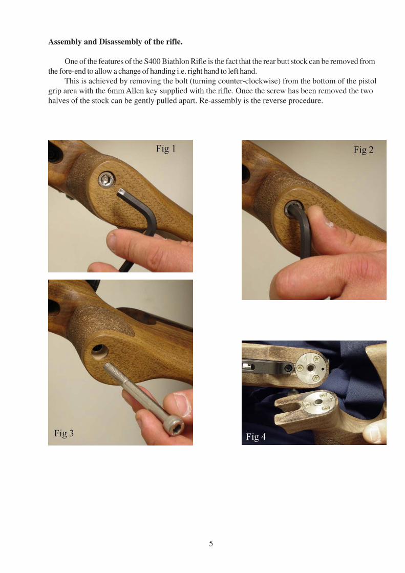
Assembly and Disassembly of the rifle.
One of the features of the S400 Biathlon Rifle is the fact that the rear butt stock can be removed from
the fore-end to allow a change of handing i.e. right hand to left hand.
This is achieved by removing the bolt (turning counter-clockwise) from the bottom of the pistol
grip area with the 6mm Allen key supplied with the rifle. Once the screw has been removed the two
halves of the stock can be gently pulled apart. Re-assembly is the reverse procedure.
6
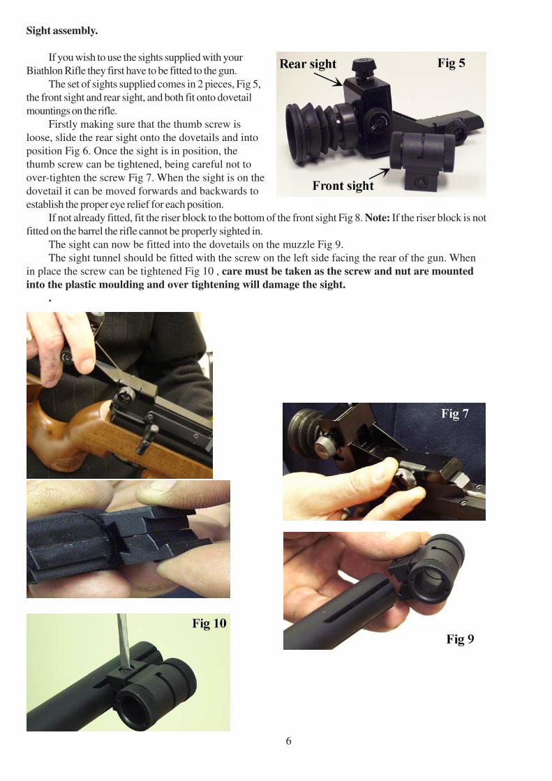
Sight assembly.
If you wish to use the sights supplied with your
Biathlon Rifle they first have to be fitted to the gun.
The set of sights supplied comes in 2 pieces, Fig 5,
the front sight and rear sight, and both fit onto dovetail
mountings on the rifle.
Firstly making sure that the thumb screw is
loose, slide the rear sight onto the dovetails and into
position Fig 6. Once the sight is in position, the
thumb screw can be tightened, being careful not to
over-tighten the screw Fig 7. When the sight is on the
dovetail it can be moved forwards and backwards to
establish the proper eye relief for each position.
If not already fitted, fit the riser block to the bottom of the front sight Fig 8. Note: If the riser block is not
fitted on the barrel the rifle cannot be properly sighted in.
The sight can now be fitted into the dovetails on the muzzle Fig 9.
The sight tunnel should be fitted with the screw on the left side facing the rear of the gun. When
in place the screw can be tightened Fig 10 , care must be taken as the screw and nut are mounted
into the plastic moulding and over tightening will damage the sight.
.
7
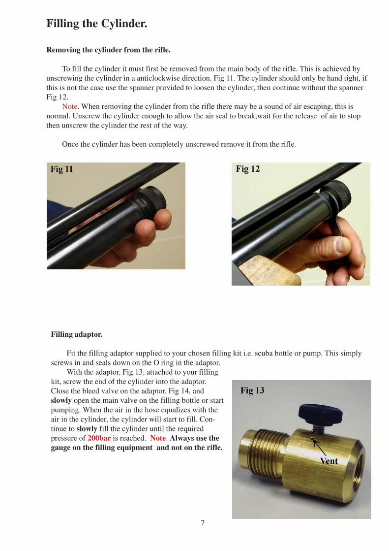
Filling the Cylinder.
Removing the cylinder from the rifle.
To fill the cylinder it must first be removed from the main body of the rifle. This is achieved by
unscrewing the cylinder in a anticlockwise direction. Fig 11. The cylinder should only be hand tight, if
this is not the case use the spanner provided to loosen the cylinder, then continue without the spanner
Fig 12.
Note. When removing the cylinder from the rifle there may be a sound of air escaping, this is
normal. Unscrew the cylinder enough to allow the air seal to break,wait for the release of air to stop
then unscrew the cylinder the rest of the way.
Once the cylinder has been completely unscrewed remove it from the rifle.
Filling adaptor.
Fit the filling adaptor supplied to your chosen filling kit i.e. scuba bottle or pump. This simply
screws in and seals down on the O ring in the adaptor.
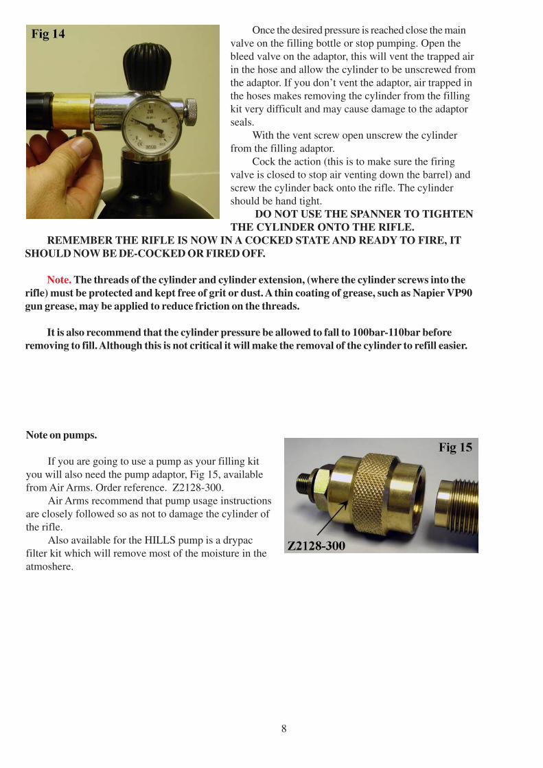
With the adaptor, Fig 13, attached to your filling
kit, screw the end of the cylinder into the adaptor.
Close the bleed valve on the adaptor. Fig 14, and
slowly open the main valve on the filling bottle or start
pumping. When the air in the hose equalizes with the
air in the cylinder, the cylinder will start to fill. Con-
tinue to slowly fill the cylinder until the required
pressure of 200bar is reached. Note. Always use the
gauge on the filling equipment and not on the rifle.
8
Once the desired pressure is reached close the main
valve on the filling bottle or stop pumping. Open the
bleed valve on the adaptor, this will vent the trapped air
in the hose and allow the cylinder to be unscrewed from
the adaptor. If you don’t vent the adaptor, air trapped in
the hoses makes removing the cylinder from the filling
kit very difficult and may cause damage to the adaptor
seals.
With the vent screw open unscrew the cylinder
from the filling adaptor.
Cock the action (this is to make sure the firing
valve is closed to stop air venting down the barrel) and
screw the cylinder back onto the rifle. The cylinder
should be hand tight.
DO NOT USE THE SPANNER TO TIGHTEN
THE CYLINDER ONTO THE RIFLE.
REMEMBER THE RIFLE IS NOW IN A COCKED STATE AND READY TO FIRE, IT
SHOULD NOW BE DE-COCKED OR FIRED OFF.
Note. The threads of the cylinder and cylinder extension, (where the cylinder screws into the
rifle) must be protected and kept free of grit or dust. A thin coating of grease, such as Napier VP90
gun grease, may be applied to reduce friction on the threads.
It is also recommend that the cylinder pressure be allowed to fall to 100bar-110bar before
removing to fill. Although this is not critical it will make the removal of the cylinder to refill easier.
Note on pumps.
If you are going to use a pump as your filling kit
you will also need the pump adaptor, Fig 15, available
from Air Arms. Order reference. Z2128-300.
Air Arms recommend that pump usage instructions
are closely followed so as not to damage the cylinder of
the rifle.
Also available for the HILLS pump is a drypac
filter kit which will remove most of the moisture in the
atmoshere.
9
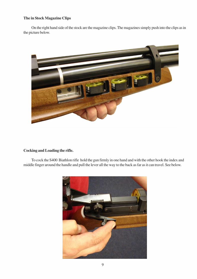
Cocking and Loading the rifle.
To cock the S400 Biathlon rifle hold the gun firmly in one hand and with the other hook the index and
middle finger around the handle and pull the lever all the way to the back as far as it can travel. See below.
The in Stock Magazine Clips
On the right hand side of the stock are the magazine clips. The magazines simply push into the clips as in
the picture below.
10
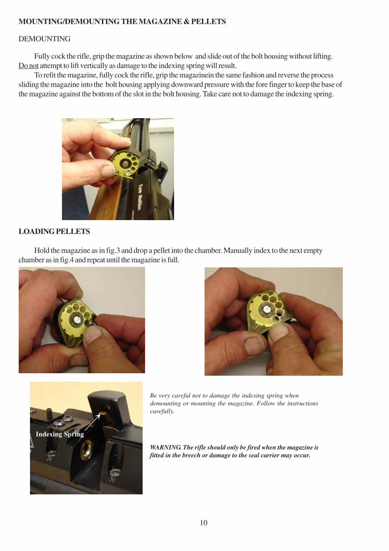
MOUNTING/DEMOUNTING THE MAGAZINE & PELLETS
DEMOUNTING
Fully cock the rifle, grip the magazine as shown below and slide out of the bolt housing without lifting.
Do not attempt to lift vertically as damage to the indexing spring will result.
To refit the magazine, fully cock the rifle, grip the magazinein the same fashion and reverse the process
sliding the magazine into the bolt housing applying downward pressure with the fore finger to keep the base of
the magazine against the bottom of the slot in the bolt housing. Take care not to damage the indexing spring.
LOADING PELLETS
Hold the magazine as in fig.3 and drop a pellet into the chamber. Manually index to the next empty
chamber as in fig.4 and repeat until the magazine is full.
Be very careful not to damage the indexing spring when
demounting or mounting the magazine. Follow the instructions
carefully.
WARNING. The rifle should only be fired when the magazine is
fitted in the breech or damage to the seal carrier may occur.
11
Trigger adjustment.
The Biathlon Rifle has a two stage trigger. This means that as the trigger is pulled the bottom sear gradu-
ally disengages with the top sear until the two disengage completely and the rifle fires. If the pressure on the
trigger is released before firing, the sears return to their first fully engaged position. This type of trigger allows a
very fine but safe operation because it is the release of the second stage that actually fires the gun. This ar-
rangement is vastly superior to single stage trigger, however it must be stated that adjustment of a two stage
unit is more difficult than the adjustment of a single stage trigger.
Trigger positioning.
The trigger on the Biathlon Rifle can be adjusted in a variety of ways to make the trigger as efficient as
possible. First, the trigger blade can be rotated around the trigger pillar, this allows the finger to sit perfectly on
the trigger.
The blade can be raised or lower on the pillar to make sure that it is in line with the shooters
finger.
The whole trigger blade and pillar assembly can also slide forwards and backwards along the
trigger bar to increase or decrease the length of pull.
These adjustments will allow the gun to be tailored the individual shooter.
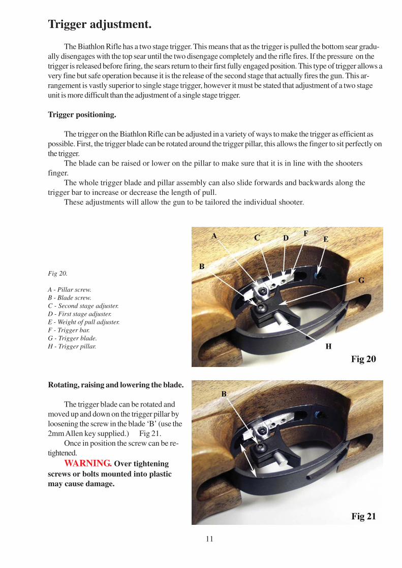
Fig 20.
A - Pillar screw.
B - Blade screw.
C - Second stage adjuster.
D - First stage adjuster.
E - Weight of pull adjuster.
F - Trigger bar.
G - Trigger blade.
H - Trigger pillar.
Rotating, raising and lowering the blade.
The trigger blade can be rotated and
moved up and down on the trigger pillar by
loosening the screw in the blade ‘B’ (use the
2mm Allen key supplied.) Fig 21.
Once in position the screw can be re-
tightened.
WARNING. Over tightening
screws or bolts mounted into plastic
may cause damage.
12
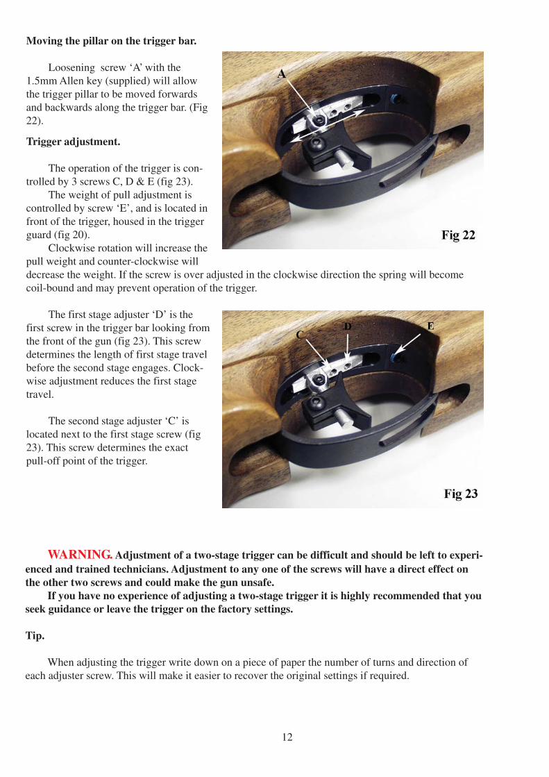
Moving the pillar on the trigger bar.
Loosening screw ‘A’ with the
1.5mm Allen key (supplied) will allow
the trigger pillar to be moved forwards
and backwards along the trigger bar. (Fig
22).
Trigger adjustment.
The operation of the trigger is con-
trolled by 3 screws C, D & E (fig 23).
The weight of pull adjustment is
controlled by screw ‘E’, and is located in
front of the trigger, housed in the trigger
guard (fig 20).
Clockwise rotation will increase the
pull weight and counter-clockwise will
decrease the weight. If the screw is over adjusted in the clockwise direction the spring will become
coil-bound and may prevent operation of the trigger.
The first stage adjuster ‘D’ is the
first screw in the trigger bar looking from
the front of the gun (fig 23). This screw
determines the length of first stage travel
before the second stage engages. Clock-
wise adjustment reduces the first stage
travel.
The second stage adjuster ‘C’ is
located next to the first stage screw (fig
23). This screw determines the exact
pull-off point of the trigger.
WARNING. Adjustment of a two-stage trigger can be difficult and should be left to experi-
enced and trained technicians. Adjustment to any one of the screws will have a direct effect on
the other two screws and could make the gun unsafe.
If you have no experience of adjusting a two-stage trigger it is highly recommended that you
seek guidance or leave the trigger on the factory settings.
Tip.
When adjusting the trigger write down on a piece of paper the number of turns and direction of
each adjuster screw. This will make it easier to recover the original settings if required.
13
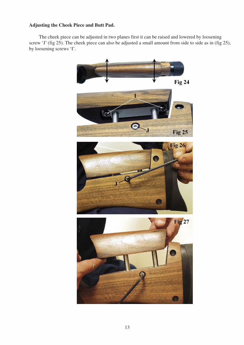
Adjusting the Cheek Piece and Butt Pad.
The cheek piece can be adjusted in two planes first it can be raised and lowered by loosening
screw ‘J’ (fig 25). The cheek piece can also be adjusted a small amount from side to side as in (fig 25),
by loosening screws ‘I’.
14
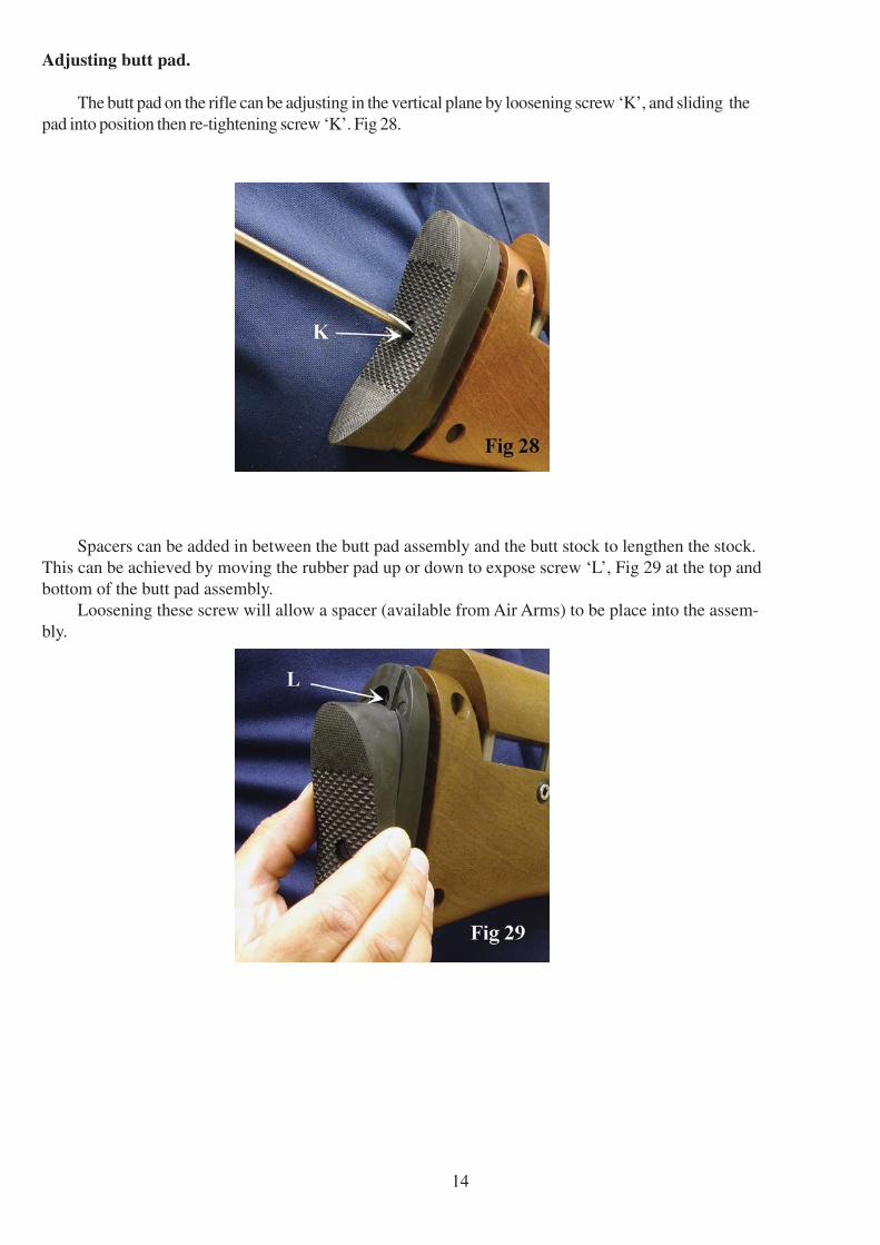
Adjusting butt pad.
The butt pad on the rifle can be adjusting in the vertical plane by loosening screw ‘K’, and sliding the
pad into position then re-tightening screw ‘K’. Fig 28.
Spacers can be added in between the butt pad assembly and the butt stock to lengthen the stock.
This can be achieved by moving the rubber pad up or down to expose screw ‘L’, Fig 29 at the top and
bottom of the butt pad assembly.
Loosening these screw will allow a spacer (available from Air Arms) to be place into the assem-
bly.
15
MAINTENANCE
FIXINGS
Regularly check the tightness of all fixings. However do not be tempted to over tighten as
some parts are made from aluminium and stripped threads may result. Stripped threads are not
covered by the manufacturers warranty.
BARREL
For ultimate accuracy, clean and re-lube the barrel frequently. It is difficult to advise how often
is best for every circumstance, but every 250 shots is not too often if the desire is to keep the barrel
in the best possible condition.
The correct materials are very important. Air arms only uses products made by napier. Listed
below is the napier product and a more generally available alternative. If possible use napier for the
best results.
As a rule cleaners and oils intended for shotguns and small/fullbore weapons are not suitable.
1> Cut a piece of line three times the length of your barrel, fold in half and tie ends
together. Remove silencer if fitted. Open loading bolt.
2> Feed un-knotted end down barrel from the muzzle end until folded end protrudes about
50mm.
3> Cut a 100mm length of ‘rifle clean’ or 100x50mm piece of cloth and pass it between thepro
truding loop. Spray the pad with ‘gun cleaner’ or white spirit, turn the rifle upside down and
pull the line back through the barrel slowly.
4> Repeat steps 2&3 until the pad is clean.
5> Repeat steps 2&3 once more without any cleaner on the pad to dry the barrel.
6> Repeat steps 2&3 once more with the pad sprayed with ‘gun oil’ or 3 in 1 oil.
IMPORTANT : THE REASON FOR TURNING THE RIFLE UPSIDE DOWN IS TO PREVENT EXCESS CLEANER/OIL
FROM PASSING DOWN THE TRANSFER PORT INTO THE FIRING VALVE CHAMBER.
LUBRICATION
Lubrication of the internal mechanism is not covered in this handbook. This is best performed
by a competent gunsmith or the factory and in any case should not be required until the annual service.
On return from every shooting session, wipe all over the exterior with an oily rag to preserve the
surface finish during storage.
CLEANER : ‘NAPIER GUN CLEANER’, ALTERNATIVELY WHITE SPIRIT.
OIL : ‘NAPIER GUN OIL’, ALTERNATIVELY ‘3 IN 1’ OIL.
PULL-THROUGH PAD: ‘NAPIER RIFLE CLEAN’, ALTERNATIVELY SOFT COTTON CLOTH.
PULL-THROUGH LINE: ‘NAPIER PULL THROUGH KIT’, ALTERNATIVELY 20lb FISHING LINE.

18
19
20
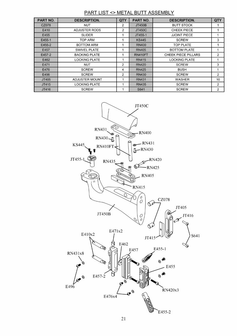
21
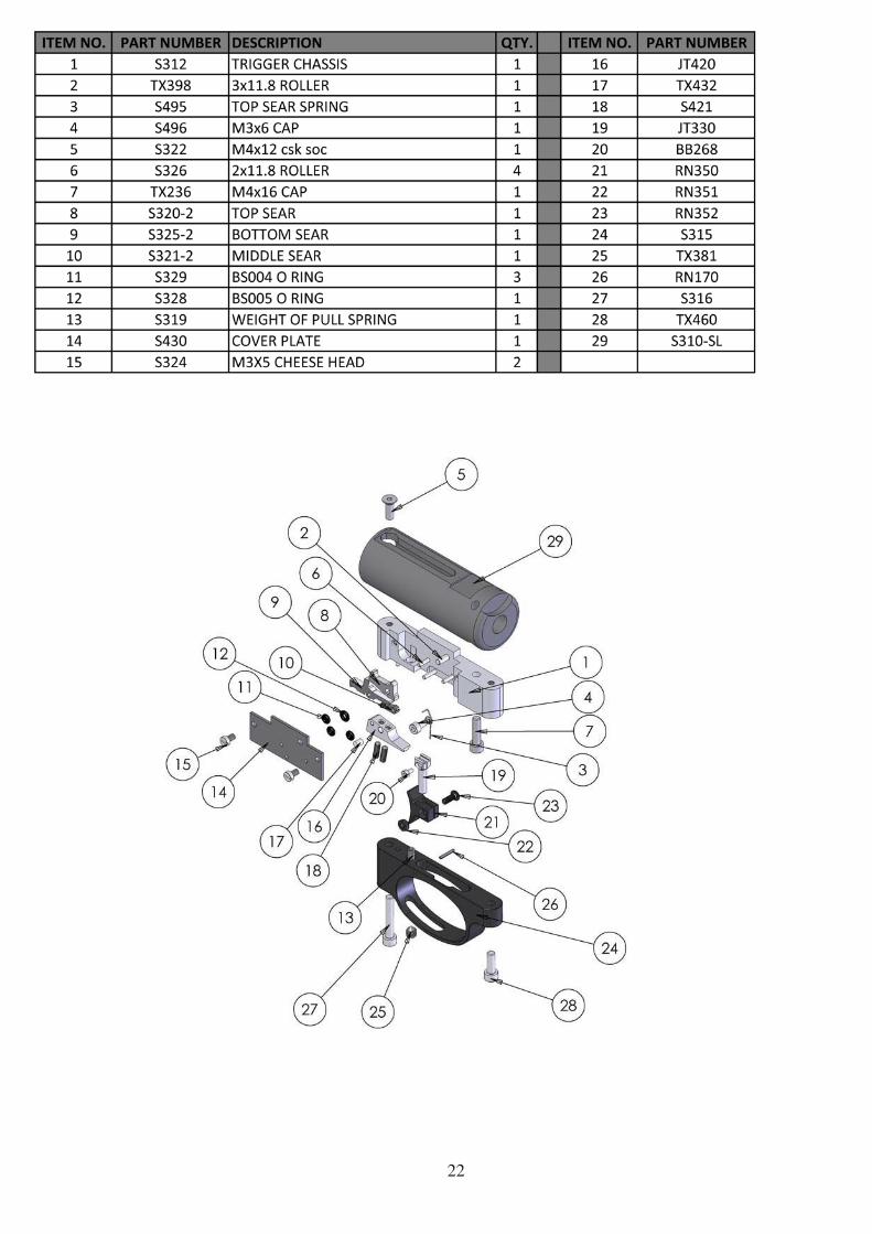
22
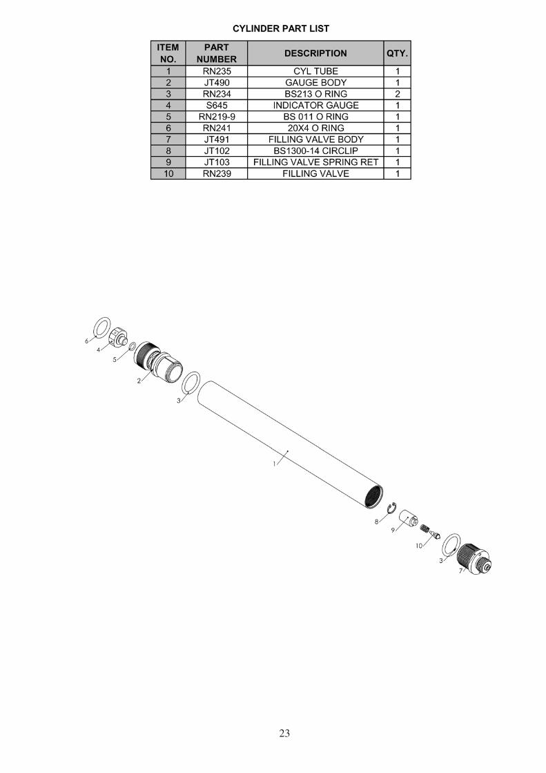
23
24
Technical Information.
Weights and measures.
Overall weight.
Sporter. 3.15kg.
Precision with rubber pad. 3.17kg.
Overall Length.
Sporter. 925mm (36 3/8”).
Precision with rubber pad. 1040mm (41”).
Barrel length. 480mm (18 7/8”).
Barrel length including muzzle. 522mm (20 1/2”).
Barrel length including long muzzle. 545mm (21 1/2”).
Length of sight line.
Sporter. 645mm (25 3/8”).
Precision. 760mm (29 7/8”)
Length of accessory rails.
Internal (optional on sporter). 192mm (7 1/2”).
External. 260mm (10 1/4”).
Reach to pull.
Rubber butt pad models. 308mm - 318mm.
Calibre. .177 (4.5mm)
Power. 7 joules (5.15ftlb).
16 joules (12ftlb).
Cocking method. Bolt action.

26
Notes.