Embed Size (px)
Citation preview
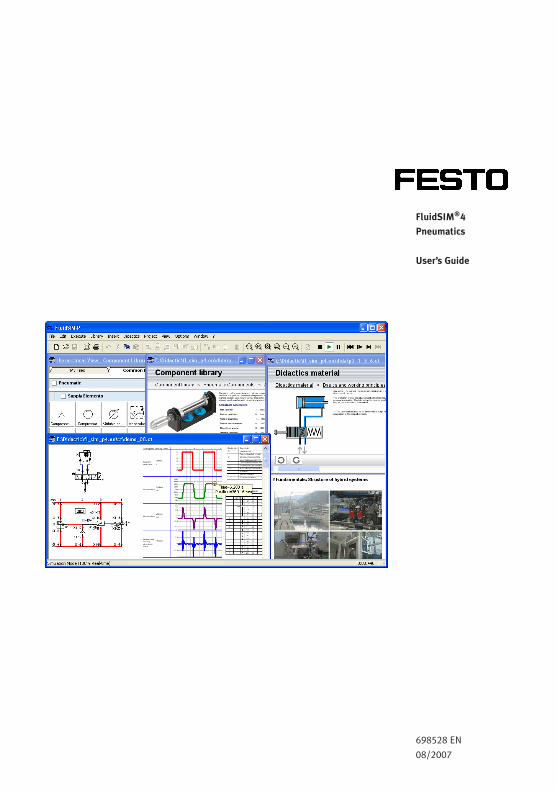
FluidSIM®4
Pneumatics
User’s Guide
698528 EN
08/2007
FluidSIM was launched at the Knowledge-based Systems Department of
the University of Paderborn.
Concept and development of FluidSIM Pneumatics is based on research
work carried out by Dr. Daniel Curatolo, Dr. Marcus Hoffmann, and Dr.
habil. Benno Stein.
Order No.: 698528
Description: HANDBUCH
Designation: D:HB-FSP4-EN
Edition: 08/2007
Author: Art Systems
Layout: Art Systems
© Festo Didactic GmbH & Co. KG, D-73770 Denkendorf, 1996-2007
Internet: www.festo-didactic.com
e-mail: [email protected]
© Art Systems Software GmbH, D-33102 Paderborn, 1995-2007
Internet: www.art-systems.com, www.fluidsim.com
e-mail: [email protected]
The copying, distribution and utilization of this document as well
as the communication of its contents to others without expressed
authorization is prohibited. Offenders will be held liable for the payment
of damages. All rights reserved, in particular the right to carry out
patent, utility model or ornamental design registration.
Contents
1. Welcome! 7
1.1 About FluidSIM 8
1.2 Layout of the Handbook 9
1.3 Conventions 10
2. Getting Started 11
2.1 Technical Requirements 11
2.2 Installation 11
2.2.1 Installation and Online Activation 12
2.2.2 Installation with license connector 13
2.3 Supplied Files 15
2.4 De-installation of a Single-Position License 16
3. Introduction to Simulating and Creating Circuits 17
3.1 Simulating Existing Circuit Diagrams 20
3.2 The Different Simulation Modes 27
3.3 Creating new Circuit Diagrams 28
4. Advanced Concepts in Simulating and Creating Circuits 49
4.1 Configurable Symbols 49
4.2 Additional Editing Functions 62
4.3 Additional Simulation Functions 72
4.4 Linking Components Automatically 74
4.5 Current Path Numbering and Switching Elements Table 76
4.6 Terminal Assignment Diagrams 77
4.7 Displaying Quantity Values 79
4.8 Displaying State Diagrams 83
4.9 Functional diagram editor 86
4.9.1 Adjust the representation of the diagrams 92
4.10 Superficial Circuit Checking 102
4.11 Coupling Pneumatics, Electrics and Mechanics 104
4.12 Operating Switches 113
4.13 Adjustable Components 118
4.14 Settings for Simulation 119
4.15 Use of the EasyPort-Hardware 122
4.16 OPC and DDE communication with Other Applications 125
4.17 Settings for the EasyPort/OPC/DDE communication 128
4.18 Open-loop and Closed-loop Control 130
© Festo Didactic GmbH & Co. KG and Art Systems • FluidSIM 3

Contents
4.18.1 Open-loop Control 132
4.18.2 Closed-loop Control 135
5. Learning, Teaching, and Visualizing Pneumatics 141
5.1 Information about Single Components 142
5.2 Selecting Didactics Material from a List 146
5.3 Presentations: Combining Instructional Material 149
5.4 Playback of Educational Films 154
5.5 Settings for Didactics 157
6. Special Functions 159
6.1 Drawing Layers 159
6.2 Graphic Primitives 160
6.3 Text Components and Identifications 165
6.4 Embedding Pictures 168
6.5 Parts Lists 171
6.6 Printing a Window’s Contents 175
6.7 TIFF Export 177
6.8 DXF Export 179
6.9 DXF Import 180
6.10 Using and Organizing Component Libraries 183
6.11 Managing Projects 196
6.12 Saving Settings 198
7. GRAFCET 201
7.1 Steps 202
7.2 Actions 203
7.3 Transitions 204
7.4 Stored effective actions (allocations) 206
7.5 Linking GRAFCET with electrics 207
7.6 Quick reference for the FluidSIM-relevant GRAFCET concepts 209
7.6.1 Initialization 209
7.6.2 Sequence rules 209
7.6.3 Sequence selection 210
7.6.4 Synchronization 210
7.6.5 Transient sequence / unstable step 210
7.6.6 Determining the values of GRAFCET variables 210
7.6.7 Checking the entries 211
4 © Festo Didactic GmbH & Co. KG and Art Systems • FluidSIM
Contents
7.6.8 Admissible characters for steps and variables 211
7.6.9 Variable names 211
7.6.10 Access to labels of fluidic and electrical components 213
7.6.11 Functions and formula entry 213
7.6.12 Delays / time limits 214
7.6.13 Boolean value of an assertion 215
7.6.14 Target information 215
7.6.15 Partial GRAFCETs 215
7.6.16 Macro-steps 216
7.6.17 Compulsory commands 216
7.6.18 Enclosing step 217
7.6.19 Action when a transition is triggered 217
8. Help and Advanced Tips 218
8.1 The Most Frequently Occurring Problems 218
8.2 Tips for the Advanced User 222
A. FluidSIM Menus 227
A.1 File 227
A.2 Edit 229
A.3 Execute 231
A.4 Library 232
A.5 Insert 233
A.6 Didactics 233
A.7 Project 234
A.8 View 235
A.9 Options 238
A.10 Window 240
A.11 ? 240
B. The Component Library 242
B.1 Pneumatic Components 242
B.2 Electrical Components 270
B.3 Electrical Components (American Standard) 285
B.4 Digital Components 289
B.5 GRAFCET Elements 297
B.6 Miscellaneous 299
C. Didactics Material Survey 302
© Festo Didactic GmbH & Co. KG and Art Systems • FluidSIM 5
Contents
C.1 Basics 302
C.2 Supply elements 304
C.3 Actuators 308
C.4 Directional control valves 311
C.5 Shutoff valves 320
C.6 Flow control valves 327
C.7 Pressure control valves 328
C.8 Time delay valve 330
C.9 Sequential circuit and signal overlap circuit 333
C.10 Educational Films 335
C.11 Standard Presentations 335
D. Messages 336
D.1 Electrical Errors 336
D.2 Drawing Errors 336
D.3 Operating Errors 338
D.4 Opening and Saving Files 339
D.5 System Errors 340
Index 342
6 © Festo Didactic GmbH & Co. KG and Art Systems • FluidSIM
1.Welcome!
Welcome to FluidSIM !
Thank you for purchasing the FluidSIM Pneumatics training software.
This handbook functions both as an introduction to FluidSIM and as a
reference manual outlining the possibilities, concepts, and operation of
the software package. This handbook, however, is not intended to help
in defining special aspects of pneumatics. Concerns of this nature can
be found in the Festo Didactic GmbH & Co. KG textbook series.
Users of this software are encouraged to contribute tips, criticism, and
suggestions for improvement of the program via email at
Moreover, the newest updates can be found at our Internet site at
www.fluidsim.com
www.festo-didactic.com
August 2007 The Authors
© Festo Didactic GmbH & Co. KG and Art Systems • FluidSIM 7
1.Welcome!
1.1
About FluidSIM
FluidSIM Pneumatics is a teaching tool for simulating pneumatics basics
and runs using Microsoft Windows®. It can be used in combination
with the Festo Didactic GmbH & Co. KG training hardware, but also
independently. FluidSIM was developed as a joint venture between the
University of Paderborn, Festo Didactic GmbH & Co. KG, and Art Systems
Software GmbH, Paderborn.
A major feature of FluidSIM is its close connection with CAD functional-
ity and simulation. FluidSIM allows DIN-compliant drawing of electro-
pneumatic circuit diagrams and can perform realistic simulations of the
drawing based on physical models of the components. Simply stated,
this eliminates the gap between the drawing of a circuit diagram and the
simulation of the related pneumatic system.
The CAD functionality of FluidSIM has been specially tailored for fluidics.
For example, while drawing, the program will check whether or not
certain connections between components are permissible.
Another feature of FluidSIM results from its well thought-out didactic
concept: FluidSIM supports learning, educating, and visualizing
pneumatic knowledge. Pneumatic components are explained with
textual descriptions, figures, and animations that illustrate underlying
working principles; exercises and educational films mediate knowledge
about both important circuits and the usage of pneumatic components.
The development of FluidSIM included special emphasis on both an
intuitive and easy-to-learn user interface. The user will quickly learn to
draw and simulate electro-pneumatic circuit diagrams.
8 © Festo Didactic GmbH & Co. KG and Art Systems • FluidSIM
1.Welcome!
1.2
Layout of the Handbook
The Handbook from FluidSIM has been divided into two parts. The
first part serves as a user’s guide, and the second part functions as
a reference book. The user’s guide contains chapters that introduce
the user to FluidSIM. By following the chapters in order, the user will
understand how to operate FluidSIM. The reference part contains a
complete listing of the FluidSIM functions, the component library, the
didactics material, and the FluidSIM messages.
User’s Guide Chapter 2 describes the computer requirements for FluidSIM, the
installation process, and the meaning of the supplied files.
Chapter 3 contains small examples of circuit diagrams, showing how
they can be simulated and how new circuit diagrams can be created.
Chapter 4 introduces advanced concepts of FluidSIM. Examples include
the linking of pneumatic and electric components, the possible settings
for simulation, and the testing of a circuit diagram.
Chapter 5 shows additional educational concepts. In particular, FluidSIM
enables a user to pop-up a component’s technical description, to start
animations, or to play a film with related information.
Chapter 6 describes special functions of FluidSIM including how to
print and export circuit diagrams, along with the rearrangement of the
component library.
Chapter 8 deals specifically with help for questions concerning the use
of FluidSIM. It also includes tips for the advanced user.
Reference Appendix A contains a complete listing of FluidSIM menus and is
intended to be used as a quick reference for all FluidSIM functions.
Appendix B contains the library of all FluidSIM components.
© Festo Didactic GmbH & Co. KG and Art Systems • FluidSIM 9
1.Welcome!
Appendix C contains the component illustrations, the animations, the
exercises, and the educational films.
Appendix D contains a listing of messages that may occur while using
FluidSIM along with a brief explanation for each.
1.3
Conventions
User instructions are indented and marked with the>arrow; important
passages begin with the ☞symbol.
The symbols found on the FluidSIM toolbar are represented in this
manual with the appropriate icon; menu entries are shown framed ;
function keys are represented with their appropriate key symbol. For
example is the icon used to start a simulation; File Open... indicates
the “Open...” entry under the “File” menu; F9 stands for function key
“9”.
In this manual the term “clicking” with a mouse means using the left
mouse button. It is explicitly stated when the right button is to be used.
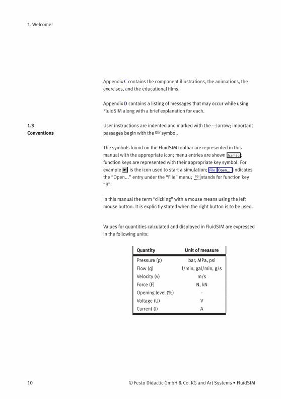
Values for quantities calculated and displayed in FluidSIM are expressed
in the following units:
Quantity Unit of measure
Pressure (p) bar, MPa, psi
Flow (q) l/min, gal/min, g/s
Velocity (v) m/s
Force (F) N, kN
Opening level (%) -
Voltage (U) V
Current (I) A
10 © Festo Didactic GmbH & Co. KG and Art Systems • FluidSIM
2. Getting Started
This Chapter describes how FluidSIM is installed on your computer.
2.1
Technical Requirements
You need a computer with a Pentium processor or higher that runs
using Microsoft Windows95®, Microsoft Windows98®, Microsoft Win-
dowsME®, Microsoft WindowsNT®, Microsoft Windows2000® or Micro-
soft WindowsXP®.
If you intend to draw simple circuit diagrams or to simulate the existing
circuit diagrams, 128 MB RAM is adequate. However, minimum 256 MB
RAM is recommended to simulate complex circuit diagrams.
In order to play the educational films, you will need a CD-ROM drive that
runs at double speed along with hardware for sound.
2.2
Installation
Having purchased the full version of FluidSIM, you received two CD-
ROMs and possibly a license connector. One CD-ROM contains both full
version and student version of FluidSIM. The other provides educational
films providing the Video-CD format that may also be viewed on
common DVD-players.
The installation procedure is described in the following sections.
The full version of FluidSIM is available in two versions: A version that
supports the automatic online activation and the license connector
version.
© Festo Didactic GmbH & Co. KG and Art Systems • FluidSIM 11
2. Getting Started
2.2.1
Installation and Online
Activation
For the online activation you will need a computer with internet access.
During the installation you will be prompted to activate FluidSIM. There
are three ways of doing so:
• Automatic Online Activation
This variant requires Internet access from the computer where
FluidSIM is to be activated and realizes a completely automated
procedure.
• Indirect Activation
In this variant an activation dialog box is opened that shows an
Internet address (url) and your individual license ID. With this
information you can generate your individual activation key at an
arbitrary computer with Internet access. Then, the activation key
has to be entered in the activation dialog box of the installation PC.
• Call Festo to receive your individual activation key
If you don’t have Internet access or if the Internet activation fails,
you can call a service employee at weekday office hours who will
provide you with your activation code. Please note: The displayed
phone number in Germany is available at European office times
only. Depending on the geographical position of your site, you will
find different telephone numbers for the software activation on the
shipping box.
Import Online Activation
Notes
During the activation of FluidSIM several features of your PC and the
product ID are used to generate an individual activation key. This string
is valid for your PC only. I.e., if your PC is substantially modified or if
you want to use another PC, your FluidSIM license has to be transferred
to the new hardware. Such a transfer requires the deactivation of the
license of the original PC, which is accomplished by uninstalling Fluid-
SIM. The respective uninstallation program can be found in the menu
Start under “Deinstallation” or in the control panel under “Software”.
If a deactivation of FluidSIM is not possible because of technical
problems, as an exception your license can be transferred without
deactivation.
12 © Festo Didactic GmbH & Co. KG and Art Systems • FluidSIM

2. Getting Started
Note that a license transfer without a preceding deactivation is possible
only a few times. Also note that if your license has been transferred
to another PC, it cannot be re-activated for the initial PC without
deactivating it before.
2.2.2
Installation with license
connector
Depending on the license model (single-position systems or network),
the license connector is needed only during the Installation of FluidSIM
or must be attached to the so-called license server.
The network license connector defines how many instances of Fluid-
SIM can be running at the same time in the network. If you attempt
to start more instances than the allowed number, an error message is
displayed. If the license server is down or if the license connector has
been removed from the system, all circuits that are already open and
modified can be saved before FluidSIM terminates. If the license server
is up again FluidSIM starts as usual.
Details for a network installation of FluidSIM is given in an addendum of
the FluidSIM package and can also be found as pdf-file “net_inst.pdf” in
the “Doc”-Folder of the installation CD.
FluidSIM Full Version:
Installation from CD
If your software needs a license connector, connect the key not until
you are requested by the installation program.
> Switch on your PC and login with administrator permissions.
> Insert the CD.
Usually the installation program starts automatically. Please start it
manually if it doesn’t:
> Click Run... in the Start Menu.
A dialog box opens.
© Festo Didactic GmbH & Co. KG and Art Systems • FluidSIM 13

2. Getting Started
> Enter the following string in the space provided: d:setup.exe.
Then click “OK”.
If your CD-ROM drive is configured differently, then be sure to use
the appropriate letter in place of d:.
After a few seconds the startup screen of the installation program
appears. Here you can choose whether to install the student version
or the full version of FluidSIM. When installing the full version, please
select the appropriate license connector (single-position systems or
network). If you got a FluidSIM version for online activation no license
connector is necessary but only your individual product ID is required,
which is printed on the back of the CD cover. Note that the student
version does neither require a license connector nor a product ID.
> Follow the directions as they appear on the screen. If you are
unsure how to answer or are unsure of a question, simply click
“Next>>”.
14 © Festo Didactic GmbH & Co. KG and Art Systems • FluidSIM
2. Getting Started
2.3
Supplied Files
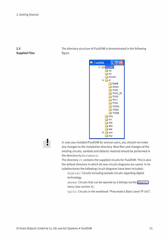
The directory structure of FluidSIM is demonstrated in the following
figure.
In case you installed FluidSIM for several users, you should not make
any changes to the installation directory. New files and changes of the
existing circuits, symbols and didactic material should be performed in
the directory MyDocuments.
The directory ct contains the supplied circuits for FluidSIM. This is also
the default directory in which all new circuits diagrams are saved. In its
subdirectories the following circuit diagrams have been included:
digital: Circuits including sample circuits regarding digital
technology.
shows: Circuits that can be opened as a bitmap via the Didactics
menu (see section 5).
tp101: Circuits in the workbook “Pneumatics Basic Level TP 101”.
© Festo Didactic GmbH & Co. KG and Art Systems • FluidSIM 15

2. Getting Started
tp101_lb: Circuits in the textbook “Pneumatics Basic Level TP
101”.
tp102: Circuits in the workbook “Pneumatics Advanced Level TP
102”.
tp111: Circuits in the workbook “Closed-loop Pneumatics Basic
Level TP 111”.
tp201: Circuits in the workbook “Electropneumatics Basic Level TP
201”.
tp201l: Circuits in the workbook “Electropneumatics Basic Level
TP 201”, where the activating logic is implemented using digital
technology instead of electrical components.
tp202: Circuits in the workbook “Electropneumatics Advanced
Level TP 202”.
tp202l: Circuits in the workbook “Electropneumatics Advanced
Level TP 202”, where the activating logic is implemented using
digital technology instead of electrical components.
2.4
De-installation of a
Single-Position License
The following steps are necessary to de-install FluidSIM from your
computer.
> Click on the program icon RemoveFluidSIM-P in the Start Menu
ProgramFiles/FestoDidactic. If the program icon cannot be
found, start the program unwise.exe in the bin-subdirectory of
the FluidSIM directory.
16 © Festo Didactic GmbH & Co. KG and Art Systems • FluidSIM
3. Introduction to Simulating and Creating Circuits
The following chapter is set up in the form of a tutorial to introduce the
user to important FluidSIM functions. At the end the user should be
comfortable designing and simulating circuit diagrams.
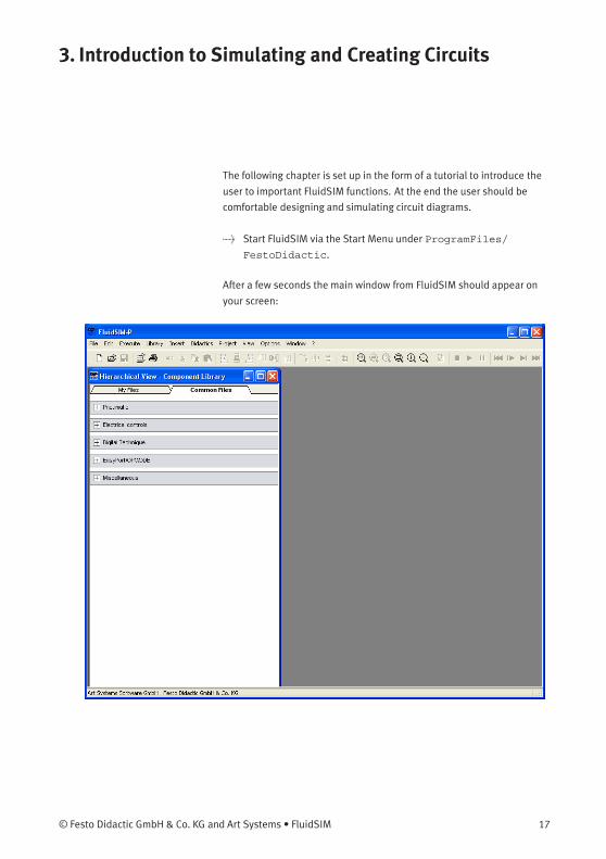
> Start FluidSIM via the Start Menu under ProgramFiles/
FestoDidactic.
After a few seconds the main window from FluidSIM should appear on
your screen:
© Festo Didactic GmbH & Co. KG and Art Systems • FluidSIM 17
3. Introduction to Simulating and Creating Circuits
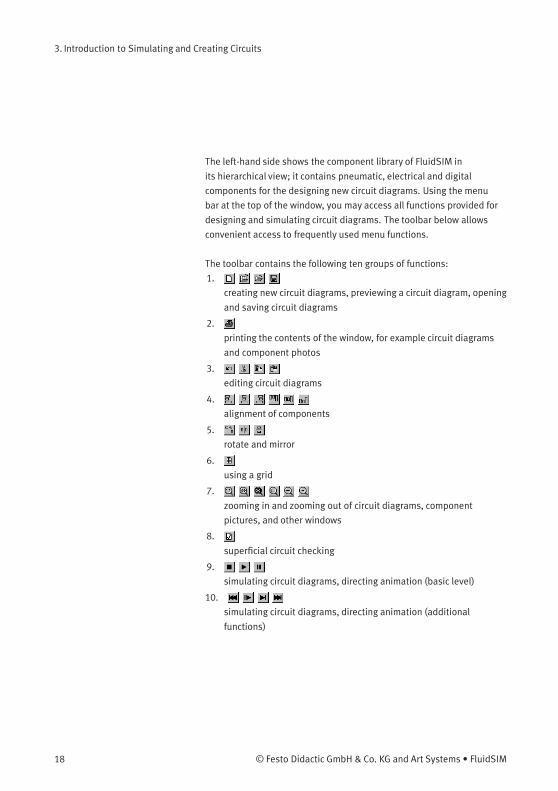
The left-hand side shows the component library of FluidSIM in
its hierarchical view; it contains pneumatic, electrical and digital
components for the designing new circuit diagrams. Using the menu
bar at the top of the window, you may access all functions provided for
designing and simulating circuit diagrams. The toolbar below allows
convenient access to frequently used menu functions.
The toolbar contains the following ten groups of functions:
1.
creating new circuit diagrams, previewing a circuit diagram, opening
and saving circuit diagrams
2.
printing the contents of the window, for example circuit diagrams
and component photos
3.
editing circuit diagrams
4.
alignment of components
5.
rotate and mirror
6.
using a grid
7.
zooming in and zooming out of circuit diagrams, component
pictures, and other windows
8.
superficial circuit checking
9.
simulating circuit diagrams, directing animation (basic level)
10.
simulating circuit diagrams, directing animation (additional
functions)
18 © Festo Didactic GmbH & Co. KG and Art Systems • FluidSIM
3. Introduction to Simulating and Creating Circuits
Only a certain number of the above listed functions will apply to a
specific circuit diagram. FluidSIM recognizes which functions apply
according to the contents of the window, component functions and
context (circuit diagram design, animation, circuit diagram simulation,
etc.), and disables the operations on the toolbar that do not apply.
In many new Microsoft Windows® programs “context menus” are
available. A context menu appears when the user clicks the right button
on the mouse within the program window. In FluidSIM, context menus
apply to the contents and situations in the window; the context menus
contain a useful subset of functions from the main menu bar.
Located at the bottom of the window is a status bar that displays
information on the current calculations and activities during the
operation of FluidSIM. In Edit Mode, FluidSIM displays the designation
of the component found under the mouse cursor.
Buttons, scrollbars, and the menu bar in FluidSIM operate in the same
way as in most other programs that utilizeMicrosoft Windows®.
© Festo Didactic GmbH & Co. KG and Art Systems • FluidSIM 19
3. Introduction to Simulating and Creating Circuits
3.1
Simulating Existing
Circuit Diagrams
Included with the FluidSIM installation disks are a number of working
circuit diagrams.
Among others, these are circuit diagrams as part of the learningmaterial
and will be discussed in the following workbooks “Pneumatics Basic
Level TP 101” und “Electropneumatics Basic Level TP 201” (see section
2.3).
These circuit diagrams can be opened and simulated with FluidSIM as
follows:
> Click on or choose Circuit Preview in the File menu.
20 © Festo Didactic GmbH & Co. KG and Art Systems • FluidSIM

3. Introduction to Simulating and Creating Circuits
Preview windows containing overviews of existing circuit diagrams
should appear:
A preview window displays the circuit diagrams of a specific directory
in alphabetical order accompanied by a miniature representation. The
name of the current directory is shown in the title bar of the preview
window; the files of the FluidSIM circuit diagrams contain the extension
ct.
© Festo Didactic GmbH & Co. KG and Art Systems • FluidSIM 21
3. Introduction to Simulating and Creating Circuits
By double clicking a directory icon you go down to the respective
subdirectory.
In the ct subdirectory of the fl_sim_p installation additional
subdirectories for diagrams can be created. These subdirectories are
automatically found by FluidSIM, and extra directory icons are created
for them.
> Open the circuit diagram demo1.ct by double clicking on its
miniature representation.
Circuit diagrams can also be opened using the File Selector dialog box.
By clicking on or choosing Open... under the File menu, the File
Selector dialog box will appear, in which a circuit diagram can be opened
by double clicking on its filename.
22 © Festo Didactic GmbH & Co. KG and Art Systems • FluidSIM
3. Introduction to Simulating and Creating Circuits
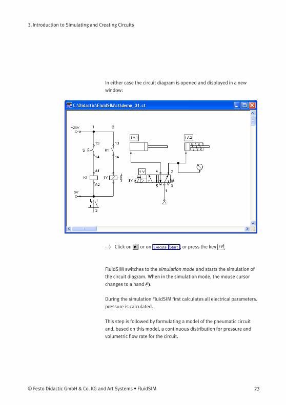
In either case the circuit diagram is opened and displayed in a new
window:
> Click on or on Execute Start , or press the key F9 .
FluidSIM switches to the simulation mode and starts the simulation of
the circuit diagram. When in the simulation mode, the mouse cursor
changes to a hand .
During the simulation FluidSIM first calculates all electrical parameters.
pressure is calculated.
This step is followed by formulating a model of the pneumatic circuit
and, based on this model, a continuous distribution for pressure and
volumetric flow rate for the circuit.
© Festo Didactic GmbH & Co. KG and Art Systems • FluidSIM 23
3. Introduction to Simulating and Creating Circuits
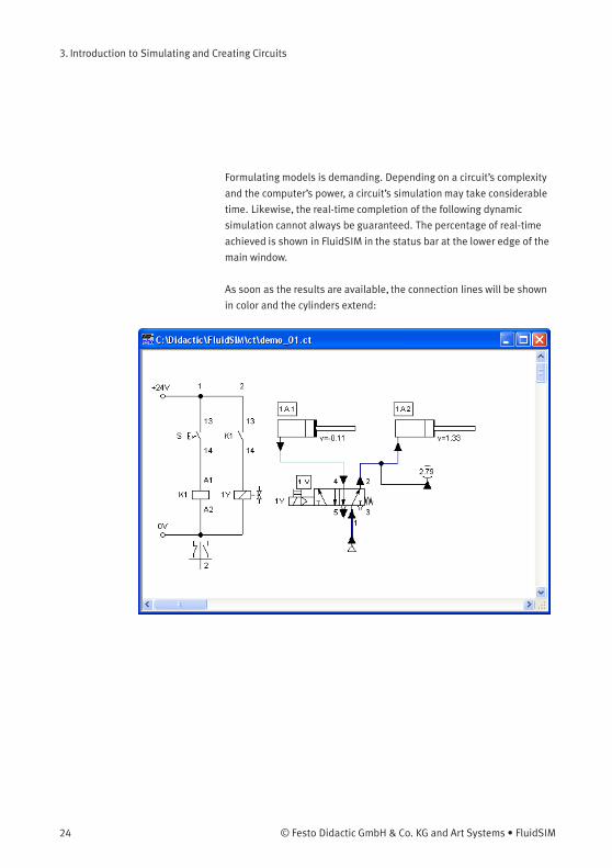
Formulating models is demanding. Depending on a circuit’s complexity
and the computer’s power, a circuit’s simulation may take considerable
time. Likewise, the real-time completion of the following dynamic
simulation cannot always be guaranteed. The percentage of real-time
achieved is shown in FluidSIM in the status bar at the lower edge of the
main window.
As soon as the results are available, the connection lines will be shown
in color and the cylinders extend:
24 © Festo Didactic GmbH & Co. KG and Art Systems • FluidSIM
3. Introduction to Simulating and Creating Circuits
The colors of the connection lines have the following meaning:
Color Meaning
Dark blue Pneumatic line under pressure
Light blue Pneumatic line without pressure
Light red Electrical line, current flowing
You can define your own mapping between colors and state values
under Options Simulation... . The varying thicknesses of the dark blue
connection lines correspond to the pressure as related to the maximum
pressure. FluidSIM distinguishes between two thicknesses of line:
Thickness Meaning
Pressure less then maximum
Maximum pressure
The exact numeric values for pressures, flow rates, voltages, and
currents are displayed on the attached measuring instruments.
Section 4.7 describes how you may go about getting values for all or
only selected variables on the circuit diagram, even when measuring
instruments are not present.
Simulation in FluidSIM is based on physical models whose components
match those components found in the Festo Didactic GmbH & Co. KG
equipment set. Therefore, calculated values should closely match
measured values. When comparing results, please acknowledge the
fact that in practice, measurements can be subject to large fluctuations.
The reasons for differences range from component tolerances, different
hose lengths to air temperature.
The calculation of variables forms the basis for an exact, real-time
proportional animation of the cylinder.
© Festo Didactic GmbH & Co. KG and Art Systems • FluidSIM 25
3. Introduction to Simulating and Creating Circuits
Real-time-proportionality guarantees the following property: If in reality
a cylinder moves twice as fast as another one, the relationship between
these two components is shown in the animation. In other words, the
real-time relationship remains unaltered.
Manually operated valves and switches, found in the circuit diagram,
can be switched by clicking on them with the mouse:
> Move the mouse cursor to the left switch.
The mouse cursor becomes a hand with index finger and indicates
that the switch may be flipped.
> Click on the switch.
When you click on a manually operated switch, its real behavior is
simulated. In this example the clicked switch becomes closed and
recalculation begins automatically. Following the calculation, the new
pressure and flow values are indicated and the cylinders retract to their
starting position.
The switching of a component is only possible when a simulation is
running ( ) or when a simulation has been set to pause ( ).
In the event that you would like to simulate another circuit diagram,
it is not necessary to close the open one. FluidSIM allows you to have
several circuits open at one time. Furthermore, FluidSIM is able to
simulate multiple circuits simultaneously.
> Click on or Execute Stop to switch the current circuit from
Simulation Mode to Edit Mode.
26 © Festo Didactic GmbH & Co. KG and Art Systems • FluidSIM

3. Introduction to Simulating and Creating Circuits
By switching a circuit from Simulation Mode to Edit Mode, all compo-
nents will automatically be set back to their “normal status”. In partic-
ular, switches are set to their original position, valves switch to their
normal position, cylinder pistons are set to their previous position, and
all values calculated are deleted.
By clicking on (alternative: Execute Pause or F8 ) you can switch from
Edit Mode to Simulation Mode without starting the simulation. This
feature is useful, if components shall be set before the simulation is
started.
3.2
The Different Simulation
Modes
In addition to the functions of the preceding section ( , , ), there
exist also the following additional functions:
reset and restart of the simulation
simulation in single step mode
simulation to a certain point where a state change happens
Reset and Restart of the
Simulation
By clicking on or under Execute Reset , an already running simulation
or paused simulation can be reset. Immediately following this, the
simulation will be restarted.
Single Step Mode During single step mode, the simulation will stop after a small step.
More exactly, by clicking on or Execute Single Step , the simulation will
begin for just a short time period (approximately 0.01 - 0.1 seconds in
the real system); the system then pauses ( ).
A running simulation can, at any time, be set into single step mode. It is
then possible to focus on key moments during the simulation.
Simulation to a State
Change
By clicking on or under Execute Simulate until State Change the
simulation begins and runs up until a certain point where a state change
happens; the simulation then pauses ( ). The following situations
describe the point at which the simulation pauses:
1. a cylinder’s piston moves at a stop
2. a valve switches or is operated
© Festo Didactic GmbH & Co. KG and Art Systems • FluidSIM 27
3. Introduction to Simulating and Creating Circuits
3. a relay switches
4. a switch is operated
It is possible to switch from a running simulation into this state change
mode.
3.3
Creating new Circuit
Diagrams
This section contains an introduction to creating and simulating circuit
diagrams using FluidSIM.
28 © Festo Didactic GmbH & Co. KG and Art Systems • FluidSIM

3. Introduction to Simulating and Creating Circuits
> Create an empty drawing area by clicking on or under File New
to open a new window:
Circuit diagrams can only be created or altered in the Edit Mode. The
Edit Mode is indicated with the following mouse cursor .
Each and every newly opened drawing area automatically contains a
name, with which it can be saved. This name is found in the title bar of
the new window.
© Festo Didactic GmbH & Co. KG and Art Systems • FluidSIM 29
3. Introduction to Simulating and Creating Circuits
While in basic mode, you will see the available component groups in
the hierarchical view of the component library. To list the components of
a group, you may list off the group by clicking it. For a better overview
you may also hide non-required elements and subgroups by once more
clicking and hence closing the hierarchy. Component groups may often
contain further subgroups that may also be listed off or closed.
To list off a group including all of its subgroups, you may hold the
Shift-Key while clicking. This will reduce your efforts to list off each
subgroup. You may similarly use the Shift-Key to close all subgroups of
a superordinate group.
> press the Shift-Key, hold it and click “Pneumatic”.
30 © Festo Didactic GmbH & Co. KG and Art Systems • FluidSIM
3. Introduction to Simulating and Creating Circuits
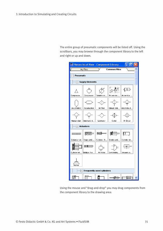
The entire group of pneumatic components will be listed off. Using the
scrollbars, you may browse through the component library to the left
and right or up and down.
Using the mouse and “drag-and-drop” you may drag components from
the component library to the drawing area:
© Festo Didactic GmbH & Co. KG and Art Systems • FluidSIM 31
3. Introduction to Simulating and Creating Circuits
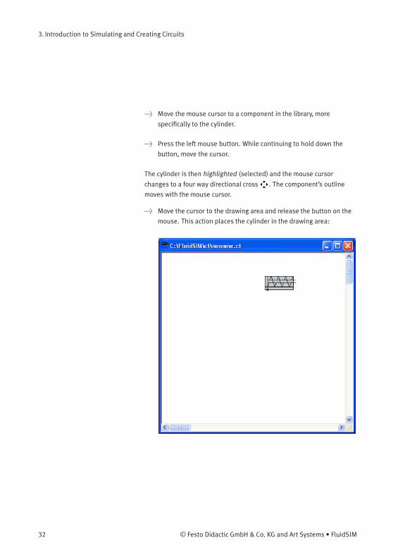
> Move the mouse cursor to a component in the library, more
specifically to the cylinder.
> Press the left mouse button. While continuing to hold down the
button, move the cursor.
The cylinder is then highlighted (selected) and the mouse cursor
changes to a four way directional cross . The component’s outline
moves with the mouse cursor.
> Move the cursor to the drawing area and release the button on the
mouse. This action places the cylinder in the drawing area:
32 © Festo Didactic GmbH & Co. KG and Art Systems • FluidSIM
3. Introduction to Simulating and Creating Circuits
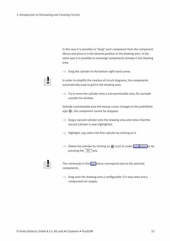
In this way it is possible to “drag” each component from the component
library and place it in the desired position in the drawing area. In the
same way it is possible to rearrange components already in the drawing
area.
> Drag the cylinder to the bottom right hand corner.
In order to simplify the creation of circuit diagrams, the components
automatically snap to grid in the drawing area.
> Try to move the cylinder onto a non-permissible area, for example
outside the window.
Outside a permissible area the mouse cursor changes to the prohibited
sign ; the component cannot be dropped.
> Drag a second cylinder onto the drawing area and notice that the
second cylinder is now highlighted.
> Highlight, say, select the first cylinder by clicking on it.
> Delete the cylinder by clicking on (cut) or under Edit Delete or by
pressing the Del key.
The commands in the Edit menu correspond only to the selected
components.
> Drag onto the drawing area a configurable 3/n-way valve and a
compressed air supply.
© Festo Didactic GmbH & Co. KG and Art Systems • FluidSIM 33
3. Introduction to Simulating and Creating Circuits
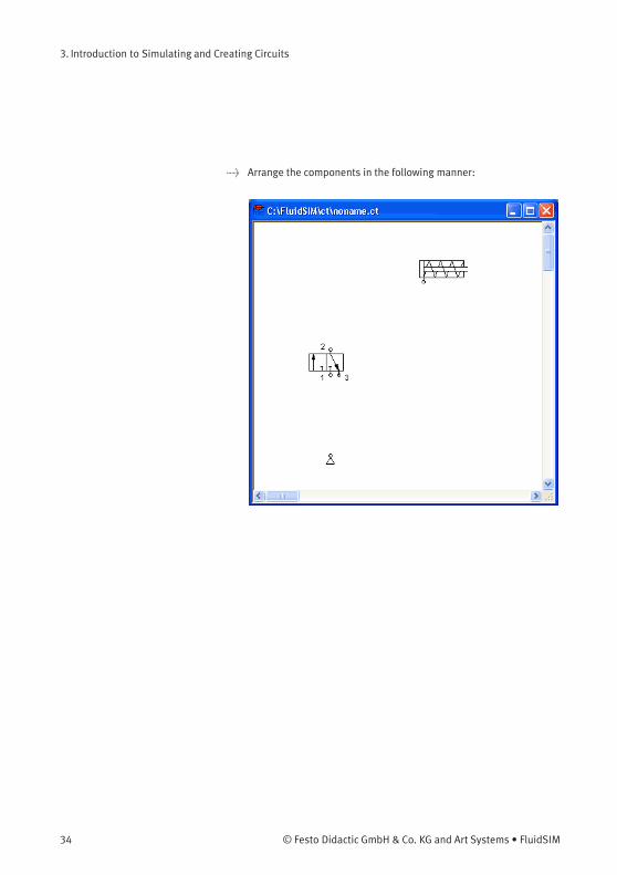
> Arrange the components in the following manner:
34 © Festo Didactic GmbH & Co. KG and Art Systems • FluidSIM
3. Introduction to Simulating and Creating Circuits
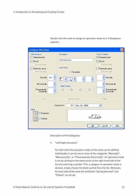
Double click the valve to assign an operation mode to it. A dialog box
appears:
Description of the dialog box:
• “Left/Right Actuation”
For both sides the actuation modes of the valve can be defined
individually; it can be one or more of the categories “Manually”,
“Mechanically”, or “Pneumatically/Electrically”. An operation mode
is set by clicking on the down-arrow at the right-hand side of the
list and selecting a symbol. If for a category no operation mode is
desired, simply choose the blank symbol from the list. Moreover,
for each side of the valve the attributes “Spring-returned” and
“Piloted” can be set.
© Festo Didactic GmbH & Co. KG and Art Systems • FluidSIM 35
3. Introduction to Simulating and Creating Circuits
• “Description”
Enter here a name for the valve. This name is used in the
state diagram and in the parts list.
• “Valve Body”
A configurable valve has at most four positions. For each of the
positions a valve body element can be chosen individually. Such
an element is set by clicking on the down-arrow at the right-hand
side of the list and selecting a symbol. If for a position no element
is desired, simply choose the blank symbol from the list. The valve
may be marked “Reversible” to indicate that there is no particular
direction of flow.
• “Initial Position”
This button defines the valve’s initial position (sometimes also
called normal position or neutral position), which is the position
without having any operation applied to the valve. Note that this
setting is only exploited if it physically does not contradict a spring-
returned setting, possibly defined above.
• “Dominant Signal”
A “Dominant signal” on the left or right-hand side defines the
overriding signal, in case the valve is addressed from both sides
simultaneously.
• “Standard Nominal Flow Rate”
This is where you define the standard nominal flow rate of the valve.
> Choose from the left-hand side in the topmost list a manual
operation with snap in, and select the “Spring-returned” option
in the right field. Close the dialog box via OK.
36 © Festo Didactic GmbH & Co. KG and Art Systems • FluidSIM
3. Introduction to Simulating and Creating Circuits
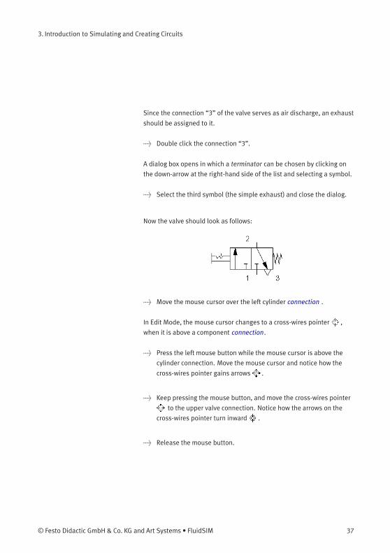
Since the connection “3” of the valve serves as air discharge, an exhaust
should be assigned to it.
> Double click the connection “3”.
A dialog box opens in which a terminator can be chosen by clicking on
the down-arrow at the right-hand side of the list and selecting a symbol.
> Select the third symbol (the simple exhaust) and close the dialog.
Now the valve should look as follows:
> Move the mouse cursor over the left cylinder connection .
In Edit Mode, the mouse cursor changes to a cross-wires pointer ,
when it is above a component connection.
> Press the left mouse button while the mouse cursor is above the
cylinder connection. Move the mouse cursor and notice how the
cross-wires pointer gains arrows .
> Keep pressing the mouse button, and move the cross-wires pointer
to the upper valve connection. Notice how the arrows on the
cross-wires pointer turn inward .
> Release the mouse button.
© Festo Didactic GmbH & Co. KG and Art Systems • FluidSIM 37
3. Introduction to Simulating and Creating Circuits
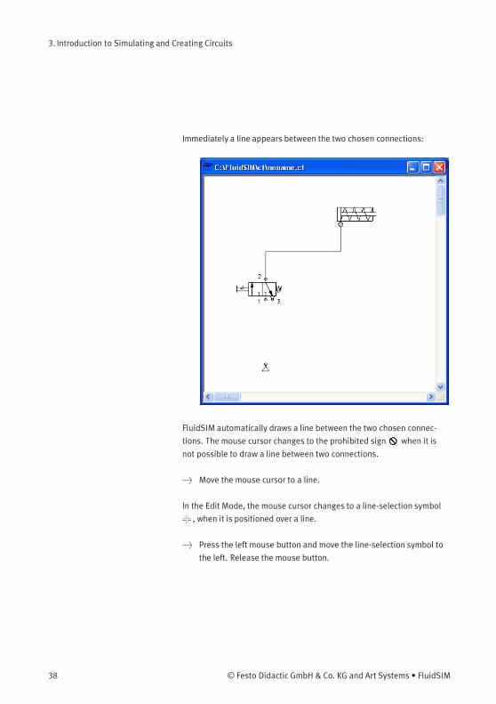
Immediately a line appears between the two chosen connections:
FluidSIM automatically draws a line between the two chosen connec-
tions. The mouse cursor changes to the prohibited sign when it is
not possible to draw a line between two connections.
> Move the mouse cursor to a line.
In the Edit Mode, the mouse cursor changes to a line-selection symbol
, when it is positioned over a line.
> Press the left mouse button and move the line-selection symbol to
the left. Release the mouse button.
38 © Festo Didactic GmbH & Co. KG and Art Systems • FluidSIM
3. Introduction to Simulating and Creating Circuits
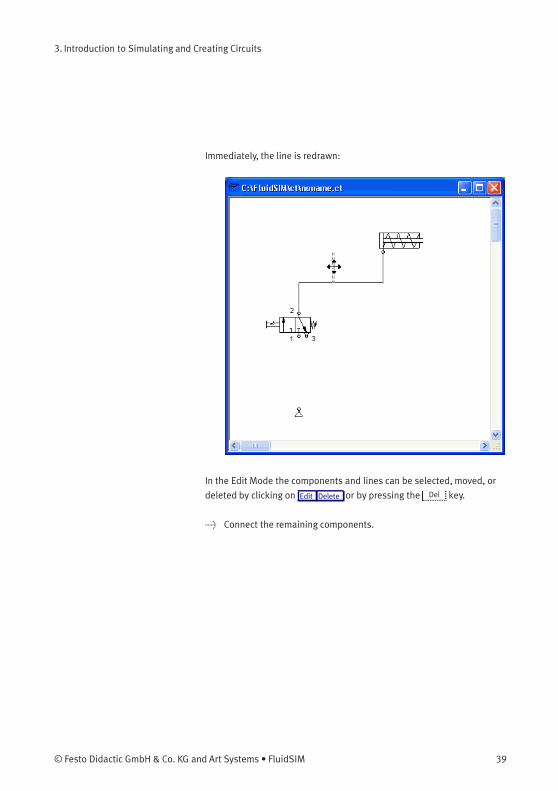
Immediately, the line is redrawn:
In the Edit Mode the components and lines can be selected, moved, or
deleted by clicking on Edit Delete or by pressing the Del key.
> Connect the remaining components.
© Festo Didactic GmbH & Co. KG and Art Systems • FluidSIM 39
3. Introduction to Simulating and Creating Circuits
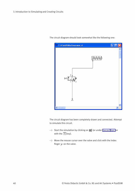
The circuit diagram should look somewhat like the following one:
The circuit diagram has been completely drawn and connected. Attempt
to simulate this circuit.
> Start the simulation by clicking on (or under Execute Start or
with the F9 key).
> Move the mouse cursor over the valve and click with the index
finger on the valve.
40 © Festo Didactic GmbH & Co. KG and Art Systems • FluidSIM

3. Introduction to Simulating and Creating Circuits
During simulation all pressures and flow rates are calculated, all lines
are colored, and the cylinder’s piston extends.
After the cylinder has been extended, the pressure in the cylinder supply
line must inevitably increase. This situation is recognized by FluidSIM
and the parameters are recalculated; the pressure at the compressed air
supply increases to the preset operating pressure.
> Click on the valve so that the cylinder may retract.
In complex pneumatic systems, or for the transmission of high switching
powers, valves may be operated indirectly. In the following we will
replace the direct manual operation by an indirect pneumatic operation.
© Festo Didactic GmbH & Co. KG and Art Systems • FluidSIM 41
3. Introduction to Simulating and Creating Circuits
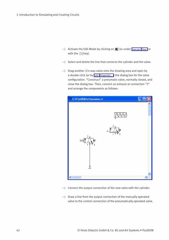
> Activate the Edit Mode by clicking on (or under Execute Stop or
with the F5 key).
> Select and delete the line that connects the cylinder and the valve.
> Drag another 3/n-way valve onto the drawing area and open by
a double click (or by Edit Properties... ) the dialog box for the valve
configuration. “Construct” a pneumatic valve, normally closed, and
close the dialog box. Then, connect an exhaust at connection “3”
and arrange the components as follows:
> Connect the output connection of the new valve with the cylinder.
> Draw a line from the output connection of the manually operated
valve to the control connection of the pneumatically operated valve.
42 © Festo Didactic GmbH & Co. KG and Art Systems • FluidSIM
3. Introduction to Simulating and Creating Circuits
In reality, to connect a component to an existing line requires a T-
connection . FluidSIM automatically creates a T-connection when you
draw a line from a connection to an existing line.
> Using the cross-wires cursor draw a line between the input
connection of the pneumatically operated valve to the line
connecting the compressed air supply and the manually operated
valve. Notice how the arrows in the cross-wires turn inwards .
> Release the mouse button.
The T-connection appears on the line at the point where the mouse
button was released.
> If necessary, draw the line so that the wiring diagram is arranged
clearly.
© Festo Didactic GmbH & Co. KG and Art Systems • FluidSIM 43
3. Introduction to Simulating and Creating Circuits
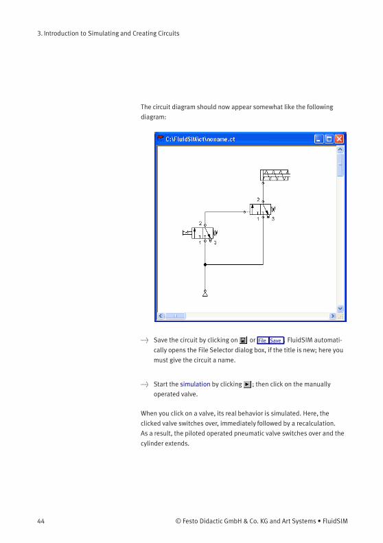
The circuit diagram should now appear somewhat like the following
diagram:
> Save the circuit by clicking on or File Save . FluidSIM automati-
cally opens the File Selector dialog box, if the title is new; here you
must give the circuit a name.
> Start the simulation by clicking ; then click on the manually
operated valve.
When you click on a valve, its real behavior is simulated. Here, the
clicked valve switches over, immediately followed by a recalculation.
As a result, the piloted operated pneumatic valve switches over and the
cylinder extends.
44 © Festo Didactic GmbH & Co. KG and Art Systems • FluidSIM
3. Introduction to Simulating and Creating Circuits
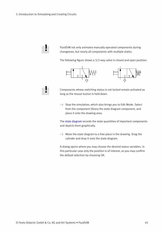
FluidSIM not only animates manually operated components during
changeover, but nearly all components with multiple states.
The following figure shows a 3/2-way valve in closed and open position:
Components whose switching status is not locked remain activated as
long as the mouse button is held down.
> Stop the simulation, which also brings you to Edit Mode. Select
from the component library the state diagram component, and
place it onto the drawing area.
The state diagram records the state quantities of important components
and depicts them graphically.
> Move the state diagram to a free place in the drawing. Drag the
cylinder and drop it onto the state diagram.
A dialog opens where you may choose the desired status variables. In
this particular case only the position is of interest, so you may confirm
the default selection by choosing OK.
© Festo Didactic GmbH & Co. KG and Art Systems • FluidSIM 45

3. Introduction to Simulating and Creating Circuits
> Start the simulation and observe the state diagram.
> Set the simulation to “Pause”-mode and move the mouse curser to
the graph in the diagram.
46 © Festo Didactic GmbH & Co. KG and Art Systems • FluidSIM
3. Introduction to Simulating and Creating Circuits
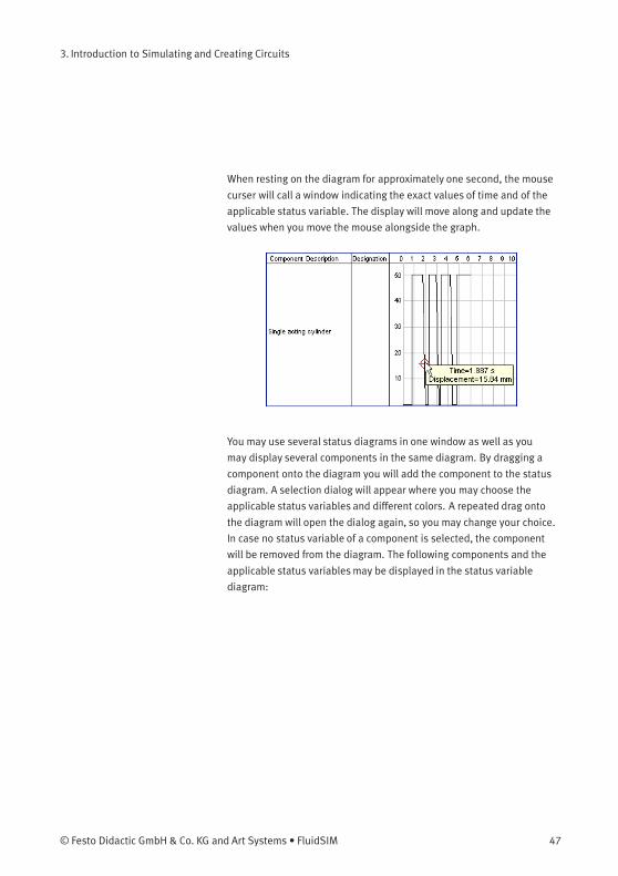
When resting on the diagram for approximately one second, the mouse
curser will call a window indicating the exact values of time and of the
applicable status variable. The display will move along and update the
values when you move the mouse alongside the graph.
You may use several status diagrams in one window as well as you
may display several components in the same diagram. By dragging a
component onto the diagram you will add the component to the status
diagram. A selection dialog will appear where you may choose the
applicable status variables and different colors. A repeated drag onto
the diagram will open the dialog again, so you may change your choice.
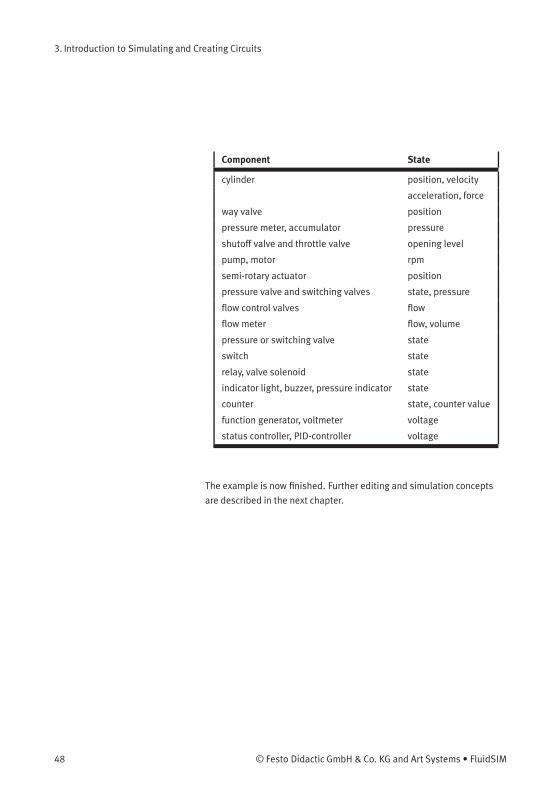
In case no status variable of a component is selected, the component
will be removed from the diagram. The following components and the
applicable status variablesmay be displayed in the status variable
diagram:
© Festo Didactic GmbH & Co. KG and Art Systems • FluidSIM 47
3. Introduction to Simulating and Creating Circuits
Component State
cylinder position, velocity
acceleration, force
way valve position
pressure meter, accumulator pressure
shutoff valve and throttle valve opening level
pump, motor rpm
semi-rotary actuator position
pressure valve and switching valves state, pressure
flow control valves flow
flow meter flow, volume
pressure or switching valve state
switch state
relay, valve solenoid state
indicator light, buzzer, pressure indicator state
counter state, counter value
function generator, voltmeter voltage
status controller, PID-controller voltage
The example is now finished. Further editing and simulation concepts
are described in the next chapter.
48 © Festo Didactic GmbH & Co. KG and Art Systems • FluidSIM
4. Advanced Concepts in Simulating and CreatingCircuits
This chapter contains advanced concepts and functions, which can be
used when simulating and creating circuits with FluidSIM.
4.1
Configurable Symbols
FluidSIM is capable of simulating a vast number of different cylinders
and valves. The combination of all part designs and functional types
would lead to displayingmany thousands of symbols. Therefore you
will find, alongside some common part designs in the component
library, configurable and representative components. In order to adapt a
cylinder or a way valve, drag one of these representatives in the circuit
and open the status dialog. Here you will find settings helping you to
define layout and function of the component.
Configure Cylinders Double-click the cylinder to define part design, parameter and external
influence of a cylinder. The status dialog of the cylinder will open.
The dialog consists of several registers, providing a convenient overview
despite the vast number of settings.
Find descriptions of the dialog boxes of individual registers below.
© Festo Didactic GmbH & Co. KG and Art Systems • FluidSIM 49
4. Advanced Concepts in Simulating and Creating Circuits
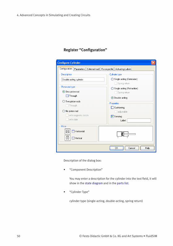
Register “Configuration”
Description of the dialog box:
• “Component Description”
You may enter a description for the cylinder into the text field, it will
show in the state diagram and in the parts list.
• “Cylinder Type”
cylinder type (single-acting, double-acting, spring return)
50 © Festo Didactic GmbH & Co. KG and Art Systems • FluidSIM
4. Advanced Concepts in Simulating and Creating Circuits
• “Piston Rod Type”
piston rod type (quantity, part design, magnet coupling, slide unit)
• “Properties”
More properties of the cylinder (end position cushioning, sensing)
The label you may define at “sensing” serves as an interconnection
with the displacement encoder. This is how, e. g. in combination
with proportional valves , controlled systems can be constructed.
Please find more reference to proportional technology in section
4.18.
• “Mirror”
This is where you may define whether the cylinder will be mirrored
horizontally or vertically. The effect will be the same as when
mirrored as in Edit Mirror .
© Festo Didactic GmbH & Co. KG and Art Systems • FluidSIM 51
4. Advanced Concepts in Simulating and Creating Circuits
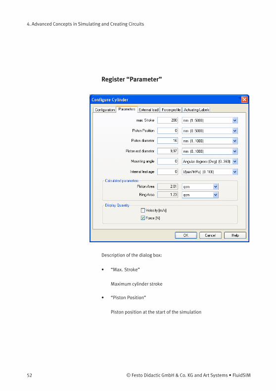
Register “Parameter”
Description of the dialog box:
• “Max. Stroke”
Maximum cylinder stroke
• “Piston Position”
Piston position at the start of the simulation
52 © Festo Didactic GmbH & Co. KG and Art Systems • FluidSIM
4. Advanced Concepts in Simulating and Creating Circuits
• “Piston Diameter”
Diameter of the Piston
• “Piston Rod Diameter”
Diameter of the piston rod of the cylinder
• “Mounting Angle”
The bracket affects the friction force of the moved load. You may
define the mass as well as the friction coefficients in the register
“external load”.
• “Internal Leakage”
This is where you may define the inner leakage of a cylinder. In
reality there is never an ideal cylinder, since the piston never seals
the chassis perfectly. Thus and despite the cut off cylinder port, the
piston gradually slides under the load.
• “Calculated Parameters”
Piston surface and annular surface will be automatically calculated
from piston diameter and piston rod diameter.
• “Display Quantities”
In the field “Display Quantities” you may tick state variables that
are to be displayed alongside the cylinder when the “selected”-
option is switched on for these state variables in the state variable
box. In case in the state variable dialog box “no”-option is switched
on, the particular cylinder related state variables will not be
displayed.
© Festo Didactic GmbH & Co. KG and Art Systems • FluidSIM 53
4. Advanced Concepts in Simulating and Creating Circuits
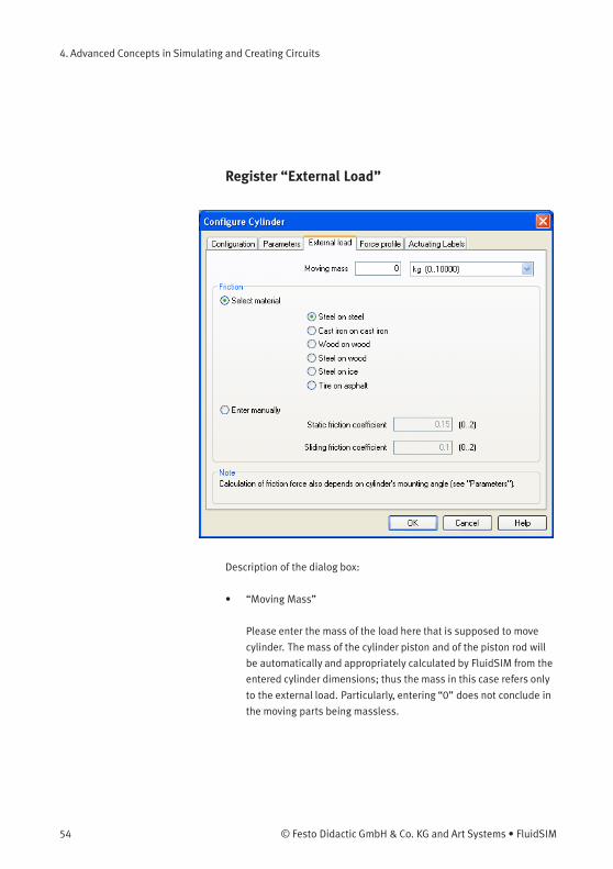
Register “External Load”
Description of the dialog box:
• “Moving Mass”
Please enter the mass of the load here that is supposed to move
cylinder. The mass of the cylinder piston and of the piston rod will
be automatically and appropriately calculated by FluidSIM from the
entered cylinder dimensions; thus the mass in this case refers only
to the external load. Particularly, entering “0” does not conclude in
the moving parts being massless.
54 © Festo Didactic GmbH & Co. KG and Art Systems • FluidSIM
4. Advanced Concepts in Simulating and Creating Circuits
• “Friction”
Static friction and sliding friction determine the friction of the
moving load on a surface. The internal friction inside the cylinder
will be automatically and appropriately calculated by FluidSIM from
the entered cylinder dimensions. Please enter “0” for both values
if the load is lifted or pulled without touching a surface. In reality
it is very difficult to achieve reliable values for friction. Therefore
FluidSIM offers set friction coefficients for some combinations of
material, providing a roundabout orientation. When comparing
other tables of friction values you will notice that the (often
experimentallymeasured) specifications differ in major ways.
Please interpret these carefully and concurrently take into account
the results of simulations generated by friction. Nevertheless, the
variation of the friction values allows you to distinctly notice the
physical influence of static and sliding friction.
Please note also that the mounting angle influences the friction
force through the moved load. You may define the mounting angle
in the register “parameter”.
© Festo Didactic GmbH & Co. KG and Art Systems • FluidSIM 55
4. Advanced Concepts in Simulating and Creating Circuits
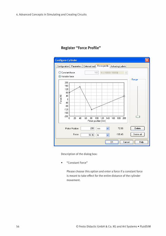
Register “Force Profile”
Description of the dialog box:
• “Constant Force”
Please choose this option and enter a force if a constant force
is meant to take effect for the entire distance of the cylinder
movement.
56 © Festo Didactic GmbH & Co. KG and Art Systems • FluidSIM

4. Advanced Concepts in Simulating and Creating Circuits
• “Variable Force”
Please choose this option if the force changes depending on the
position of the cylinder rod. You may interactively define applicable
points in the chart field by clicking the mouse, these applicable
points will be linked to be one lineament. Alternatively, you
may mark an existing applicable point and enter the two values
numerically for piston position and applicable force using the input
field.
• “Range”
Using this slider you may define the range of values to be displayed
for the force.
• “Delete”
Deletes the marked applicable point and links the two adjoining
points with one straight line.
• “Delete all”
Deletes all applicable points and defines a constant force. Use this
option to delete an existing lineament without having to delete
each single applicable point.
© Festo Didactic GmbH & Co. KG and Art Systems • FluidSIM 57
4. Advanced Concepts in Simulating and Creating Circuits
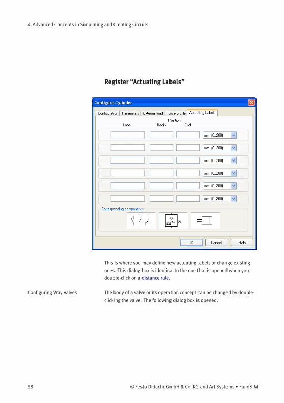
Register “Actuating Labels”
This is where you may define new actuating labels or change existing
ones. This dialog box is identical to the one that is opened when you
double-click on a distance rule.
Configuring Way Valves The body of a valve or its operation concept can be changed by double-
clicking the valve. The following dialog box is opened.
58 © Festo Didactic GmbH & Co. KG and Art Systems • FluidSIM

4. Advanced Concepts in Simulating and Creating Circuits
© Festo Didactic GmbH & Co. KG and Art Systems • FluidSIM 59
4. Advanced Concepts in Simulating and Creating Circuits
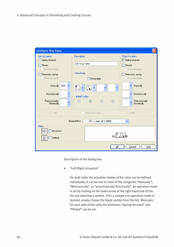
Description of the dialog box:
• “Left/Right Actuation”
For both sides the actuation modes of the valve can be defined
individually; it can be one or more of the categories “Manually”,
“Mechanically”, or “pneumatically/Electrically”. An operation mode
is set by clicking on the down-arrow at the right-hand side of the
list and selecting a symbol. If for a category no operation mode is
desired, simply choose the blank symbol from the list. Moreover,
for each side of the valve the attributes “Spring-returned” and
“Piloted” can be set.
60 © Festo Didactic GmbH & Co. KG and Art Systems • FluidSIM
4. Advanced Concepts in Simulating and Creating Circuits
• “Description”
Enter here a name for the valve. This name is used in the
state diagram and in the parts list.
• “Valve Body”
A configurable valve has at most four positions. For each of the
positions a valve body element can be chosen individually. Such
an element is set by clicking on the down-arrow at the right-hand
side of the list and selecting a symbol. If for a position no element
is desired, simply choose the blank symbol from the list. The valve
may be marked as “Reversible” to display that it has no particular
direction of flow.
• “Initial Position”
This button defines the valve’s initial position (sometimes also
called normal position or neutral position), which is the position
without having any operation applied to the valve. Note that this
setting is only exploited if it physically does not contradict a spring-
returned setting, possibly defined above.
• “Dominant Signal”
A “Dominant signal” to the left-hand or right-hand side defines
which signal will be overriding when the valve is addressed from
both sides simultaneously.
• “Standard Nominal Flow Rate”
This is where you may define the standard nominal flow rate of the
valve.
© Festo Didactic GmbH & Co. KG and Art Systems • FluidSIM 61
4. Advanced Concepts in Simulating and Creating Circuits
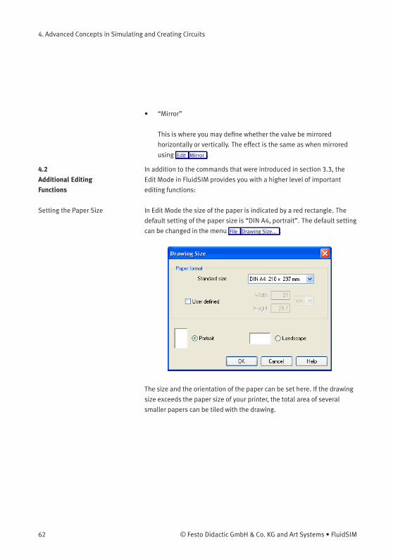
• “Mirror”
This is where you may define whether the valve be mirrored
horizontally or vertically. The effect is the same as when mirrored
using Edit Mirror .
4.2
Additional Editing
Functions
In addition to the commands that were introduced in section 3.3, the
Edit Mode in FluidSIM provides you with a higher level of important
editing functions:
Setting the Paper Size In Edit Mode the size of the paper is indicated by a red rectangle. The
default setting of the paper size is “DIN A4, portrait”. The default setting
can be changed in the menu File Drawing Size... .
The size and the orientation of the paper can be set here. If the drawing
size exceeds the paper size of your printer, the total area of several
smaller papers can be tiled with the drawing.
62 © Festo Didactic GmbH & Co. KG and Art Systems • FluidSIM
4. Advanced Concepts in Simulating and Creating Circuits
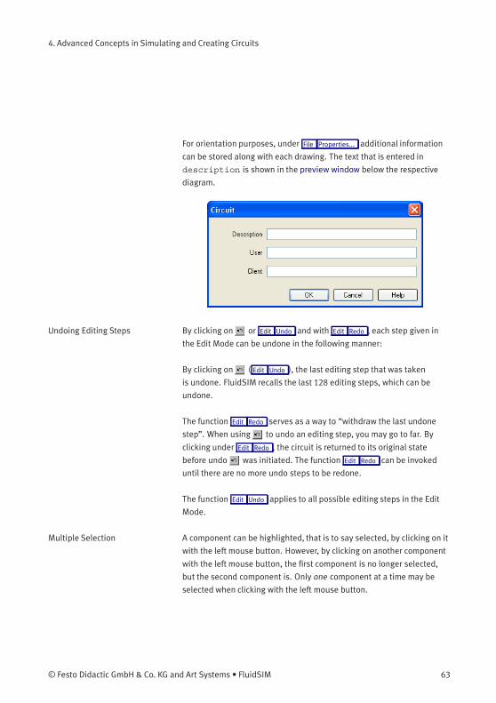
For orientation purposes, under File Properties... additional information
can be stored along with each drawing. The text that is entered in
description is shown in the preview window below the respective
diagram.
Undoing Editing Steps By clicking on or Edit Undo and with Edit Redo , each step given in
the Edit Mode can be undone in the following manner:
By clicking on ( Edit Undo ), the last editing step that was taken
is undone. FluidSIM recalls the last 128 editing steps, which can be
undone.
The function Edit Redo serves as a way to “withdraw the last undone
step”. When using to undo an editing step, you may go to far. By
clicking under Edit Redo , the circuit is returned to its original state
before undo was initiated. The function Edit Redo can be invoked
until there are no more undo steps to be redone.
The function Edit Undo applies to all possible editing steps in the Edit
Mode.
Multiple Selection A component can be highlighted, that is to say selected, by clicking on it
with the left mouse button. However, by clicking on another component
with the left mouse button, the first component is no longer selected,
but the second component is. Only one component at a time may be
selected when clicking with the left mouse button.
© Festo Didactic GmbH & Co. KG and Art Systems • FluidSIM 63
4. Advanced Concepts in Simulating and Creating Circuits
If, while you are clicking on components, you hold down the Ctrl key,
the components that are already selected will remain so. In addition,
the component underneath the mouse cursor will also be selected, if not
already selected, or de-selected, if already selected. In this sense, the
component’s state of selection is reversed.
Another efficient concept for selecting multiple components is by using
the rubber band. The rubber band is opened by pressing and holding
down the left mouse button, and then moving the mouse cursor. The
mouse cursor cannot be located directly over a component if the rubber
band shall be opened.
64 © Festo Didactic GmbH & Co. KG and Art Systems • FluidSIM

4. Advanced Concepts in Simulating and Creating Circuits
All components enclosed, either partially or fully, by the rubber band,
are selected.
All components and lines of the current circuit diagram can be selected
by clicking under Edit Select All or typing Ctrl A .
Editing functions such as dragging or moving, copying and, deleting
apply to all selected components.
© Festo Didactic GmbH & Co. KG and Art Systems • FluidSIM 65
4. Advanced Concepts in Simulating and Creating Circuits
Right Mouse Button When you click the mouse button on the right in a FluidSIM window,
the appropriate context menu is opened. If the mouse cursor is located
above a component or component connection, the item will become
selected. If this component was not yet selected, then a possibly
existing selection of other components will be de-selected.
Clicking the right mouse button on a component (connection) is actually
a short cut for the following two actions: Clicking the left mouse button
on the component (connection) and opening a menu.
Double Clicking with the
Mouse
Double clicking the left mouse button on a component (connection)
is a short cut for the following two actions: Selecting the component
(connection) and clicking on Edit Properties... .
Copying Selected components can be copied to the clipboard by clicking on
or Edit Copy ; the component can then be inserted in the circuit diagram
by clicking on or Edit Paste . In the same way it is possible to paste
the contents of the clipboard into another graphic or word processing
program.
Within a circuit diagram selected components can also be copied by
holding down the Shift key and moving them. The mouse cursor
changes then to the copy symbol .
Copying betweenWindows Components can simply be copied between windows by selecting the
desired components and dragging them in the other window.
66 © Festo Didactic GmbH & Co. KG and Art Systems • FluidSIM
4. Advanced Concepts in Simulating and Creating Circuits
Aligning Objects To align objects, firstly select these objects and then click on the icon
or on the appropriate entry in the Edit Align menu.
Reference object is always the object which lies furthermost in the
desired direction. If, for instance, several components shall become
aligned left, all but one objects are moved to the left so that they
align with the left-most object. Note that pneumatic and electrical
components obey the constraint that their connections must lie on the
grid. As a consequence, an alignment may not always coincide with the
symbol bounding.
Rotate and Mirror Selected components may be rotated by 90°, 180° or 270° by using
Edit Rotate . If you wish only one component to be rotated you may
alternatively perform a double-click on the component while holding
the Ctrl -key, the component will then be rotated counterclockwise in
90°-steps. If you also hold the Shift -key in doing so, the component will
be rotated clockwise.
In order to mirror marked objects, please select Edit Mirror . The
applicable objects will be mirrored at its own axis, provided they are
not part of a group. Grouped objects will be mirrored at the central shaft
of the applicable group.
Instead of using the menu entries, you may also rotate or mirror through
the applicable symbols .
Deleting Lines If only one component connection is selected, its connected (but de-
selected) lines can be deleted using Edit Delete or by pressing the Del
key. This concept provides an alternative way to delete lines.
© Festo Didactic GmbH & Co. KG and Art Systems • FluidSIM 67
4. Advanced Concepts in Simulating and Creating Circuits
Setting Line Type The type of each fluidic line can be changed from the standard line type,
“Main Line”, to the special line type “Control Line”. Being in Edit Mode,
double clicking on a fluidic line or selecting the line and choosing the
menu entry Edit Properties... brings up a dialog box in which you can set
the line type. A control line is shown dashed. Note that—aside from
a different appearance—changing line type has no impact respecting
simulation.
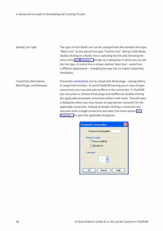
Connection Descriptors,
Blind Plugs, and Exhausts
Pneumatic connections can be closed with blind plugs—among others,
to adapt their function. To avoid FluidSIM warning you in case of open
connections you may also add mufflers to the connection. In FluidSIM
you may place or remove these plugs and mufflers by double-clicking
the applicable pneumatic connection while in edit mode. This will open
a dialog box where you may choose an appropriate connector for the
applicable connection. Instead of double-clicking a connection you
may also mark a single connection and select the menu option Edit
Properties... to open the applicable dialog box.
68 © Festo Didactic GmbH & Co. KG and Art Systems • FluidSIM
4. Advanced Concepts in Simulating and Creating Circuits
Description of the dialog box:
• “Connection Designation”
If enabled via View Show Connection Descriptors , the contents of this
field is displayed at the connection.
FluidSIM automatically places the connection designations in such way
that they usually show at an appropriate position near the connection.
You may alternatively relocate the connection designations using your
mouse or your keyboard. Hence click on the designation and move the
text to the desired position. To change the position with your mouse,
please mark the designation (or the applicable connection) and move
the text by using the curser keys.
FluidSIM keeps you from moving away the connection designation
too far from the applicable connection. In case a particular distance
is exceeded, you won’t be permitted to move it any further into that
particular direction.
• “Display Quantity”
Check out the state values to be displayed when the “selected”-
option in the state values dialog box is chosen. However, if the
“no”-option in the state values dialog box is chosen, even the
checked state values are not displayed.
• “Terminator”
Defines whether an open connection either is left open, closed by a
blind plug, or closed by an exhaust.
© Festo Didactic GmbH & Co. KG and Art Systems • FluidSIM 69
4. Advanced Concepts in Simulating and Creating Circuits
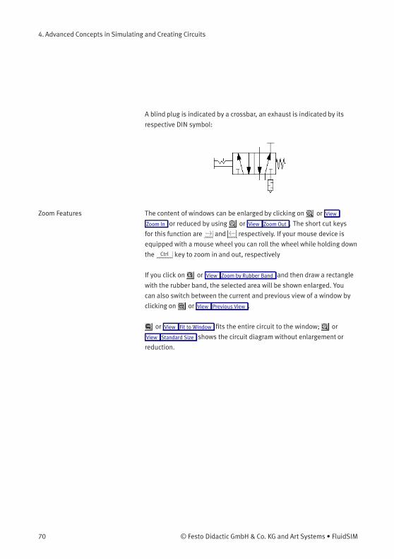
A blind plug is indicated by a crossbar, an exhaust is indicated by its
respective DIN symbol:
Zoom Features The content of windows can be enlarged by clicking on or View
Zoom In or reduced by using or View Zoom Out . The short cut keys
for this function are > and < respectively. If your mouse device is
equipped with a mouse wheel you can roll the wheel while holding down
the Ctrl key to zoom in and out, respectively
If you click on or View Zoom by Rubber Band and then draw a rectangle
with the rubber band, the selected area will be shown enlarged. You
can also switch between the current and previous view of a window by
clicking on or View Previous View .
or View Fit to Window fits the entire circuit to the window; or
View Standard Size shows the circuit diagram without enlargement or
reduction.
70 © Festo Didactic GmbH & Co. KG and Art Systems • FluidSIM
4. Advanced Concepts in Simulating and Creating Circuits
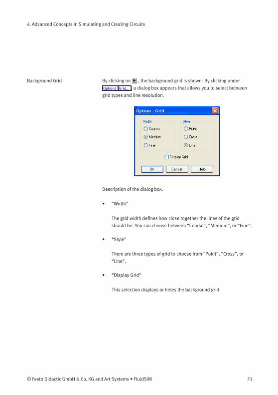
Background Grid By clicking on , the background grid is shown. By clicking under
Options Grid... , a dialog box appears that allows you to select between
grid types and line resolution.
Description of the dialog box:
• “Width”
The grid width defines how close together the lines of the grid
should be. You can choose between “Coarse”, “Medium”, or “Fine”.
• “Style”
There are three types of grid to choose from “Point”, “Cross”, or
“Line”.
• “Display Grid”
This selection displays or hides the background grid.
© Festo Didactic GmbH & Co. KG and Art Systems • FluidSIM 71
4. Advanced Concepts in Simulating and Creating Circuits
Grouping Objects If objects shall be subsumed under a single group, select them and
click Edit Group . Groups can be nested. The objects of a group can
be selected, moved, deleted, or copied only all at once. However,
component properties can be edited individually, as usual, by either
double clicking the object or choosing the respective entry in the
component’s context menu.
Ungrouping Objects To ungroup a collection of objects, click Edit Ungroup . Note that only the
outermost group is resolved; repeated ungrouping will resolve nested
groups.
4.3
Additional Simulation
Functions
This section describes in detail additional functions that apply to the
simulation of circuit diagrams.
Simultaneous Actuation of
Several Components
During the Simulation Mode, it is sometimes necessary to actuate
more switches or valves simultaneously. It is possible in FluidSIM to
simulate just such an actuation by means of setting a component in a
permanently actuated state. A button (or a manually operated valve) will
become permanently actuated when clicking on it while holding down
the Shift key. This permanent actuation will be released by a simple
click on the component.
At times it may be necessary to release several actuated objects at
once. In this case, while clicking the object, hold the Ctrl -key instead
of the Shift -key. The reversed components will remain actuated until
the Ctrl -key is released again; this is how all applicable objects will
simultaneously switch back to their original position.
Switching to the Edit Mode If a component is dragged from the component library to the circuit in
the drawing area, and the simulation has been paused , FluidSIM
automatically switches to the Edit Mode.
72 © Festo Didactic GmbH & Co. KG and Art Systems • FluidSIM
4. Advanced Concepts in Simulating and Creating Circuits
Editing and Simulating in
Parallel
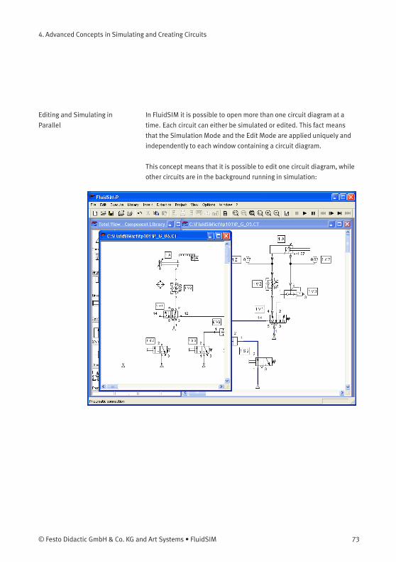
In FluidSIM it is possible to open more than one circuit diagram at a
time. Each circuit can either be simulated or edited. This fact means
that the Simulation Mode and the Edit Mode are applied uniquely and
independently to each window containing a circuit diagram.
This concept means that it is possible to edit one circuit diagram, while
other circuits are in the background running in simulation:
© Festo Didactic GmbH & Co. KG and Art Systems • FluidSIM 73
4. Advanced Concepts in Simulating and Creating Circuits
The simulation of pneumatic circuits may turn out to be a demanding
problem. Therefore, when using a lower-performance computer, the
editing of new circuit diagrams often appears jerky when simulations
of other circuits are simultaneously running in the background. So that
working in the Edit Mode goes more smoothly, all simulations performed
in the background should be stopped.
4.4
Linking Components
Automatically
In order to make circuit design efficient, FluidSIM provides more
functions to facilitate component linking.
Insertion of T-connectionsFluidSIM automatically inserts a T-connection when a line is drawn from
a component connection. to an already existing line. This functionality
applies to pneumatic as well as electrical and digital lines.
Connecting Components in
Series
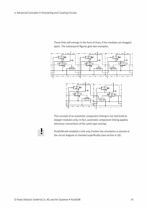
To realize larger circuits, stepper modules are often connected in series.
In reality, these modules have specially standardized connections, which
facilitate the realization of such series connections. FluidSIM simulates
this concept as follows. Let several modules be arranged in the drawing
area such that they will both align vertically and have no horizontal
distance. Then FluidSIM automatically links these modules, if their
corresponding input and output connections overlap.
74 © Festo Didactic GmbH & Co. KG and Art Systems • FluidSIM
4. Advanced Concepts in Simulating and Creating Circuits
These links will emerge in the form of lines, if the modules are dragged
apart. The subsequent figures give two examples.
This concept of an automatic component linking is not restricted to
stepper modules only; in fact, automatic component linking applies
whenever connections of the same type overlap.
FluidSIM will establish a link only if either the simulation is started or
the circuit diagram is checked superficially (see section 4.10).
© Festo Didactic GmbH & Co. KG and Art Systems • FluidSIM 75
4. Advanced Concepts in Simulating and Creating Circuits
4.5
Current Path Numbering
and Switching Elements
Table
The automatic generation of current paths simplifies the identification of
switches and relays when constructing electrical circuits. Along with
the generated switching element tables FluidSIM makes it easy to
understand which switches are controlled by which relays. To make
the automatic labeling feature a satisfactorily working concept, the
following points should be obeyed.
• The +24V current path should form the top horizontal line.
• The 0V current path should form the bottom horizontal line.
• The electric make/break/changeover switches should be placed
above the relays.
• The relays should be placed closed to the bottom 0V current path.
• All connections of a vertical current path should align.
• The horizontal distances between the paths should be equal and of
reasonable distance.
If the automatic numbering or the label positions are not entirely
satisfying, a manual adjustment of a few lines or components will yield
the desired layout quality in most cases. If two separated electrical
circuits cause an unfavorable numbering, try to increase the distance
between these circuits.
The automatic current path numbering can enabled or disabled via View
/ Display current path numbering and switching elements table .
76 © Festo Didactic GmbH & Co. KG and Art Systems • FluidSIM
4. Advanced Concepts in Simulating and Creating Circuits
4.6
Terminal Assignment
Diagrams
The automatic establishment of terminal assignment diagrams will
help you with the clear wiring of external switches, sensors and state
indicators outside the control cabinet with the relays and switches
inside. FluidSIM automatically and appropriately numbers the terminals
in the electrical part of the circuit as soon as you place the component
“terminal assignment diagram” in the circuit.
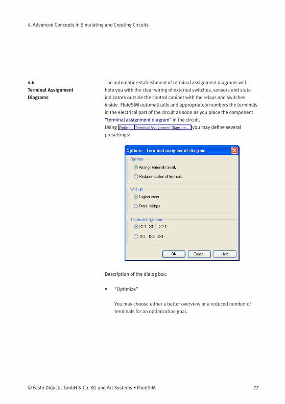
Using Options Terminal Assignment Diagram... you may define several
presettings:
Description of the dialog box:
• “Optimize”
You may choose either a better overview or a reduced number of
terminals for an optimization goal.
© Festo Didactic GmbH & Co. KG and Art Systems • FluidSIM 77
4. Advanced Concepts in Simulating and Creating Circuits
• “Wire up”
Please choose whether FluidSIM is to commit to the logical order
when numbering the terminals or, if possible, whether it is to
privilege bridges, even if this causes to disturb the strict order of
numbering.
• “Terminal Designation”
Defines which convention will rule the designation of the terminals
in the electrical circuit.
Please leave plenty of space in the electrical circuit between the
components and towards the voltage supply paths to give enough room
for the automatically inserted terminal connections as well as their
designation to be seen.
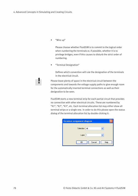
FluidSIM starts a new terminal strip for each partial circuit that provides
no connection with other electrical circuits. These are numbered by
“X1”, “X2”, “X3”, etc. Each terminal allocation list may either show all
terminal strips or a single one. In order to do this please open the status
dialog of the terminal allocation list by double-clicking it:
78 © Festo Didactic GmbH & Co. KG and Art Systems • FluidSIM
4. Advanced Concepts in Simulating and Creating Circuits
Description of the dialog box:
• “Selection”
Defines for which electrical partial circuit the allocation will be
listed in this table.
• “Layer”
In this selection list you will select the drawing layer of the diagram.
The drawing layer may be set by clicking on the downward arrow on
the right-hand side of the list and choosing a layer.
Depending on the setting of the drawing layers, the rectangle may
happen to be non-displayed or to be non-editable. To make the
object visible or to change the settings, you need to temporarily
activate the drawing layer in the menu View Layers... .
4.7
Displaying Quantity
Values
The values for all or only selected quantities of a circuit can also be
displayed without measuring instruments.
© Festo Didactic GmbH & Co. KG and Art Systems • FluidSIM 79

4. Advanced Concepts in Simulating and Creating Circuits
> Click under the View menu on Quantity Values... to open the dialog
box for the display of quantities:
For each of the listed quantities (“Velocity”, “Pressure”, ...) a display
mode can be chosen.
The display of pressure, flows and force values allows the choice of
different units. This settings influence the display of state variables of
connections, components and state diagrams.
80 © Festo Didactic GmbH & Co. KG and Art Systems • FluidSIM
4. Advanced Concepts in Simulating and Creating Circuits
Description of the dialog box:
• “None”
No values are displayed for this quantity.
• “Particular”
Values are displayed at those connections that the user has
previously chosen.
• “All”
Values are displayed at all connections for this quantity.
• “Display Measurement Units”
Enable this option if both state values and the related units shall be
displayed.
For each quantity there is a key short cut for toggling between the three
display modes. The “Shortcut” column of the dialog box for the quantity
display shows the appropriate keys.
Selecting connections for the display of single parameters is explained
here:
> Open a circuit diagram.
> Change into the Edit Mode and double click on a component
connection, or click under the Edit menu on Properties... .
© Festo Didactic GmbH & Co. KG and Art Systems • FluidSIM 81
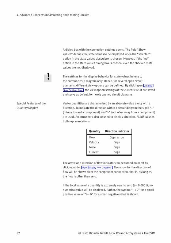
4. Advanced Concepts in Simulating and Creating Circuits
A dialog box with the connection settings opens. The field “Show
Values” defines the state values to be displayed when the “selected”-
option in the state values dialog box is chosen. However, if the “no”-
option in the state values dialog box is chosen, even the checked state
values are not displayed.
The settings for the display behavior for state values belong to
the current circuit diagram only. Hence, for several open circuit
diagrams, different view options can be defined. By clicking on Options
Save Settings Now , the view option settings of the current circuit are saved
and serve as default for newly opened circuit diagrams.
Special Features of the
Quantity Display
Vector quantities are characterized by an absolute value along with a
direction. To indicate the direction within a circuit diagram the signs “+”
(into or toward a component) and “–” (out of or away from a component)
are used. An arrow may also be used to display direction. FluidSIM uses
both representations:
Quantity Direction indicator
Flow Sign, arrow
Velocity Sign
Force Sign
Current Sign
The arrow as a direction of flow indicator can be turned on or off by
clicking under View Display Flow Direction . The arrow for the direction of
flow will be shown clear the component connection, that is, as long as
the flow is other than zero.
If the total value of a quantity is extremely near to zero (< 0.0001), no
numerical value will be displayed. Rather, the symbol “> 0” for a small
positive value or “< 0” for a small negative value is shown.
82 © Festo Didactic GmbH & Co. KG and Art Systems • FluidSIM
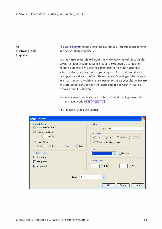
4. Advanced Concepts in Simulating and Creating Circuits
4.8
Displaying State
Diagrams
The state diagram records the state quantities of important components
and depicts them graphically.
You may use several state diagrams in one window as well as to display
several components in the same diagram. By dragging a component
on the diagram you will add the component to the state diagram. A
selection dialog will open where you may select the state variables to
be logged as well as to define different colors. Dragging on the diagram
again will reopen the dialog, allowing you to change your choice. In case
no state variable of a component is selected, the component will be
removed from the diagram.
> When in edit mode please double-click the state diagram or select
the menu option Edit Properties... .
The following dialog box opens:
© Festo Didactic GmbH & Co. KG and Art Systems • FluidSIM 83
4. Advanced Concepts in Simulating and Creating Circuits
Description of the dialog box:
• “Display Interval”
This is where you may enter starting point and terminal point of
the interval, defining how the state variables be logged. Prior
to the simulation, you don’t need to necessarily know when the
interesting events are going to happen; the display interval may
also be changed after the simulation, since FluidSIM internally logs
all values all the time of the simulation.
If you select the field “adjust automatically”, the defined limits will
be ignored and the time axis will be scaled in such way that the
entire period of the simulation can be displayed.
Activate the field “run automatically”, if the diagram is to the last
n seconds. In this case, the time axis will be displaced to the left-
hand side once the simulation period exceeds the defined time
window. In the input field you may define how many seconds are to
be displayed in the applicable time window.
• “Log File”
The state values be written to a file. To enable this option enter the
complete path of a file and set a reasonable step width.
Note that a large amount of data can be written the step width is
very small. Hence, if necessary, shorten the simulation interval or
increase the step width.
If the option “Record state changes only” is enabled, FluidSIM lists
only values if at least one state variable incurred a state change.
This option simplifies the detection of interesting simulation points-
84 © Festo Didactic GmbH & Co. KG and Art Systems • FluidSIM
4. Advanced Concepts in Simulating and Creating Circuits
• “Color”
Defines the color of the diagram. It is set by clicking on the down-
arrow at the right-hand side of the list and selecting a color.
• “Fill Area”
Defines whether the entire diagram or only its frame is filled with
specified the color.
• “Line Thickness”
This is where you define whether curves in the diagram are to be
thick or thin. Thin lines are appropriate for exact reading of the
values, thick lines are appropriate for spotting the curve from a
distance.
• “Diagram Columns”
This is where you select the columns to be displayed at the
left-hand side of the diagram. The columns “Description”,
“Designation” and “Quantity value” can be combined to your
choice.
• “Layer”
Sets the drawing layer of the diagram. It is set by clicking on the
down-arrow at the right-hand side of the list and selecting a layer.
Depending on drawing layer the diagrammay be invisible or not
selectable. In such a case the drawing layer must be activated via
View Layers... before the diagram can be modified.
State quantities of the following components can be recorded and
displayed in the state diagram:
© Festo Didactic GmbH & Co. KG and Art Systems • FluidSIM 85
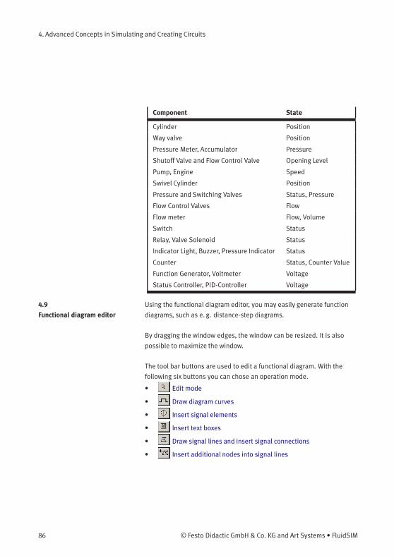
4. Advanced Concepts in Simulating and Creating Circuits
Component State
Cylinder Position
Way valve Position
Pressure Meter, Accumulator Pressure
Shutoff Valve and Flow Control Valve Opening Level
Pump, Engine Speed
Swivel Cylinder Position
Pressure and Switching Valves Status, Pressure
Flow Control Valves Flow
Flow meter Flow, Volume
Switch Status
Relay, Valve Solenoid Status
Indicator Light, Buzzer, Pressure Indicator Status
Counter Status, Counter Value
Function Generator, Voltmeter Voltage
Status Controller, PID-Controller Voltage
4.9
Functional diagram editor
Using the functional diagram editor, you may easily generate function
diagrams, such as e. g. distance-step diagrams.
By dragging the window edges, the window can be resized. It is also
possible to maximize the window.
The tool bar buttons are used to edit a functional diagram. With the
following six buttons you can chose an operation mode.
• Edit mode
• Draw diagram curves
• Insert signal elements
• Insert text boxes
• Draw signal lines and insert signal connections
• Insert additional nodes into signal lines
86 © Festo Didactic GmbH & Co. KG and Art Systems • FluidSIM
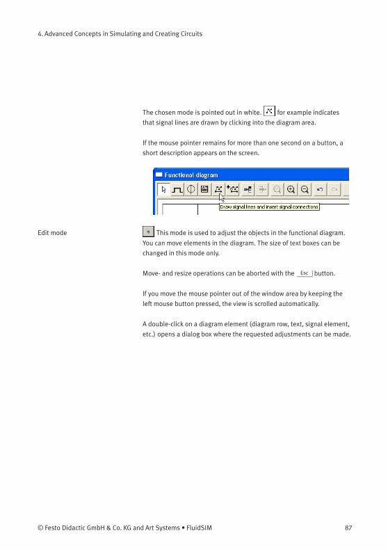
4. Advanced Concepts in Simulating and Creating Circuits
The chosen mode is pointed out in white. for example indicates
that signal lines are drawn by clicking into the diagram area.
If the mouse pointer remains for more than one second on a button, a
short description appears on the screen.
Edit mode This mode is used to adjust the objects in the functional diagram.
You can move elements in the diagram. The size of text boxes can be
changed in this mode only.
Move- and resize operations can be aborted with the Esc button.
If you move the mouse pointer out of the window area by keeping the
left mouse button pressed, the view is scrolled automatically.
A double-click on a diagram element (diagram row, text, signal element,
etc.) opens a dialog box where the requested adjustments can be made.
© Festo Didactic GmbH & Co. KG and Art Systems • FluidSIM 87
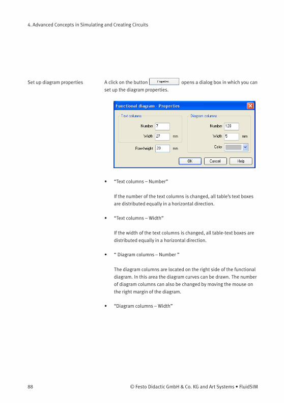
4. Advanced Concepts in Simulating and Creating Circuits
Set up diagram properties A click on the button opens a dialog box in which you can
set up the diagram properties.
• “Text columns – Number”
If the number of the text columns is changed, all table’s text boxes
are distributed equally in a horizontal direction.
• “Text columns – Width”
If the width of the text columns is changed, all table-text boxes are
distributed equally in a horizontal direction.
• “ Diagram columns – Number ”
The diagram columns are located on the right side of the functional
diagram. In this area the diagram curves can be drawn. The number
of diagram columns can also be changed by moving the mouse on
the right margin of the diagram.
• “Diagram columns – Width”
88 © Festo Didactic GmbH & Co. KG and Art Systems • FluidSIM
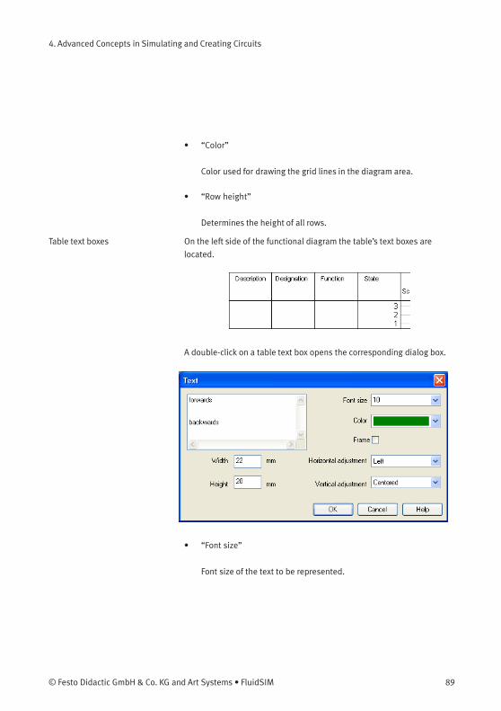
4. Advanced Concepts in Simulating and Creating Circuits
• “Color”
Color used for drawing the grid lines in the diagram area.
• “Row height”
Determines the height of all rows.
Table text boxes On the left side of the functional diagram the table’s text boxes are
located.
A double-click on a table text box opens the corresponding dialog box.
• “Font size”
Font size of the text to be represented.
© Festo Didactic GmbH & Co. KG and Art Systems • FluidSIM 89

4. Advanced Concepts in Simulating and Creating Circuits
• “Color”
Choice between sixteen standard colors for the text to be
represented.
• “Width”
The width of the table column you have chosen can also be changed
by moving the mouse.
• “Height”
The height of the table column you have chosen can also be
changed by moving the mouse.
• “Horizontal adjustment”
Following adjustments are available: “Left”, “Centered” and
“Right”.
• “Vertical adjustment”
Following adjustments are available: “Top”, “Centered” and
“Bottom”.
90 © Festo Didactic GmbH & Co. KG and Art Systems • FluidSIM
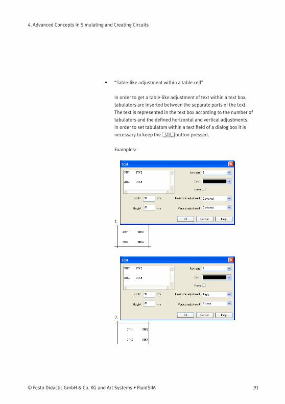
4. Advanced Concepts in Simulating and Creating Circuits
• “Table-like adjustment within a table cell”
In order to get a table-like adjustment of text within a text box,
tabulators are inserted between the separate parts of the text.
The text is represented in the text box according to the number of
tabulators and the defined horizontal and vertical adjustments.
In order to set tabulators within a text field of a dialog box it is
necessary to keep the Ctrl button pressed.
Examples:
1.
2.
© Festo Didactic GmbH & Co. KG and Art Systems • FluidSIM 91
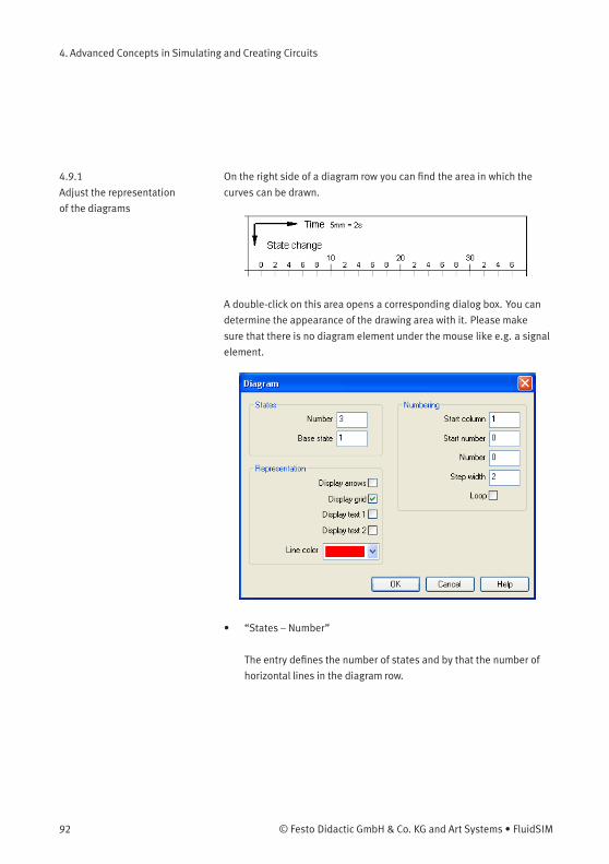
4. Advanced Concepts in Simulating and Creating Circuits
4.9.1
Adjust the representation
of the diagrams
On the right side of a diagram row you can find the area in which the
curves can be drawn.
A double-click on this area opens a corresponding dialog box. You can
determine the appearance of the drawing area with it. Please make
sure that there is no diagram element under the mouse like e.g. a signal
element.
• “States – Number”
The entry defines the number of states and by that the number of
horizontal lines in the diagram row.
92 © Festo Didactic GmbH & Co. KG and Art Systems • FluidSIM
4. Advanced Concepts in Simulating and Creating Circuits
• “States – Base state”
Horizontal lines through the base state are drawn with a thin pen.
• “Numbering – Start column”
The start column indicates at which column the numbering is to
begin.
• “Numbering – Start number”
The start number indicates with which number the numbering is to
begin.
• “Numbering – Number”
The number indicates how many steps are to be numbered.
• “Numbering – Step width”
Defines the step width between two numbers.
• “Numbering – Loop”
If this field is marked, an equals sign and the start number display
additionally after the last number.
• “Representation – Display arrows”
If this field is marked, two arrows display.
• “Representation – Display grid”
If this field is marked, the background grid displays.
© Festo Didactic GmbH & Co. KG and Art Systems • FluidSIM 93

4. Advanced Concepts in Simulating and Creating Circuits
• “Representation – Display text 1”
If this field is marked, a text box displays. It can be used for marking
purposes. This text box belongs to the row you have chosen and
cannot be shifted into another row.
• “Representation – Display text 2”
If this field is marked, an additional text box displays. It can be used
for marking purposes. This text box belongs to the row you have
chosen and cannot be shifted into another row.
• “Representation – Line color”
Defines the color of the diagram lines.
Draw diagram curve In this mode you can draw the diagram curves. Nodes can only be
inserted on the grid. Every left mouse click creates a new node.
1. 2. 3. 4.
If you keep the left mouse button pressed, nodes can be moved like in
the edit mode.
Marked nodes are shown in gray color. With the Del button a marked
node is deleted.
Insert signal elements In this mode you can insert signal elements with a left-click.
1. 2.
If you keep the left mouse button pressed, signal elements can be
moved like in the edit mode.
94 © Festo Didactic GmbH & Co. KG and Art Systems • FluidSIM
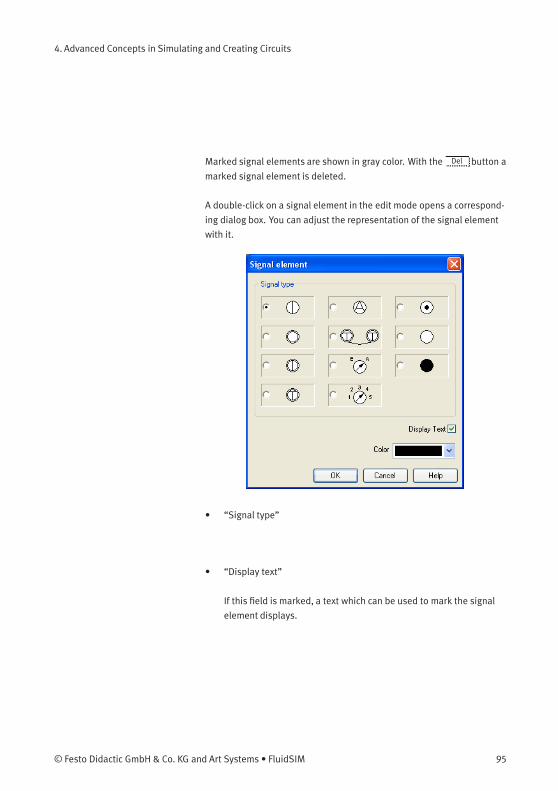
4. Advanced Concepts in Simulating and Creating Circuits
Marked signal elements are shown in gray color. With the Del button a
marked signal element is deleted.
A double-click on a signal element in the edit mode opens a correspond-
ing dialog box. You can adjust the representation of the signal element
with it.
• “Signal type”
• “Display text”
If this field is marked, a text which can be used to mark the signal
element displays.
© Festo Didactic GmbH & Co. KG and Art Systems • FluidSIM 95
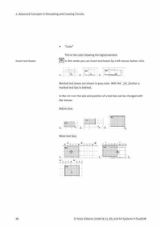
4. Advanced Concepts in Simulating and Creating Circuits
• “Color”
This is the color showing the signal element.
Insert text boxes In this mode you can insert text boxes by a left mouse button click.
1. 2. 3.
Marked text boxes are shown in gray color. With the Del button a
marked text box is deleted.
In the edit mode the size and position of a text box can be changed with
the mouse.
Adjust size:
1. 2. 3.
Move text box:
1. 2. 3.
96 © Festo Didactic GmbH & Co. KG and Art Systems • FluidSIM

4. Advanced Concepts in Simulating and Creating Circuits
A double-click on a text box in the edit mode opens a corresponding
dialog box. You can adjust the representation of the text box with it.
• “Font size”
Font size of the text to be represented.
• “Color”
Choice between sixteen standard colors for the text which can be
represented.
• “Frame”
If this field is marked, the text box is drawn with a frame.
• “Width”
The width of the text box.
• “Height”
The height of the text box.
© Festo Didactic GmbH & Co. KG and Art Systems • FluidSIM 97

4. Advanced Concepts in Simulating and Creating Circuits
• “Horizontal adjustment”
Following adjustments are available: “Left”, “Centered” and
“Right”.
• “Vertical adjustment”
Following adjustments are available: “Top”, “Centered” and
“Bottom”.
Draw signal lines and
insert signal connections
In this mode signal lines can be drawn arbitrarily or can be
transferred automatically by signal elements.
Draw signal lines arbitrarily
Every left-click creates an additional node. You can stop this operation
by clicking on the present line and keeping the Ctrl button pressed, by
pressing the Esc button or by changing the operation mode. With theDel button a marked signal line is deleted. If only one node is marked,
just this node is removed from the line.
In the edit mode you can move the nodes of the signal lines. If you
keep the Shift button pressed when you place or move nodes, the
corresponding node is adjusted vertically and horizontally, respectively.
98 © Festo Didactic GmbH & Co. KG and Art Systems • FluidSIM
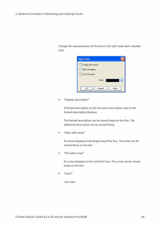
4. Advanced Concepts in Simulating and Creating Circuits
Change the representation of the lines in the edit mode with a double-
click.
• “Display description”
A framed description on the line and a description next to the
framed description displays.
The framed description can be moved freely on the line. The
additional description can be moved freely.
• “Start with arrow”
An arrow displays at the beginning of the line. The arrow can be
moved freely on the line.
• “End with arrow”
An arrow displays at the end of the line. The arrow can be moved
freely on the line.
• “Color”
Line color.
© Festo Didactic GmbH & Co. KG and Art Systems • FluidSIM 99
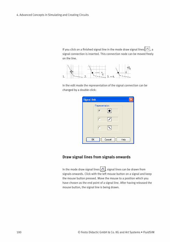
4. Advanced Concepts in Simulating and Creating Circuits
If you click on a finished signal line in the mode draw signal lines , a
signal connection is inserted. This connection node can be moved freely
on the line.
1. 2. 3. + 4.
In the edit mode the representation of the signal connection can be
changed by a double-click:
Draw signal lines from signals onwards
In the mode draw signal lines , signal lines can be drawn from
signals onwards. Click with the left mouse button on a signal and keep
the mouse button pressed. Move the mouse to a position which you
have chosen as the end point of a signal line. After having released the
mouse button, the signal line is being drawn.
100 © Festo Didactic GmbH & Co. KG and Art Systems • FluidSIM
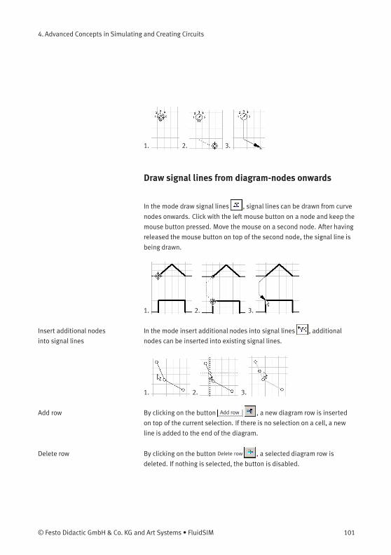
4. Advanced Concepts in Simulating and Creating Circuits
1. 2. 3.
Draw signal lines from diagram-nodes onwards
In the mode draw signal lines , signal lines can be drawn from curve
nodes onwards. Click with the left mouse button on a node and keep the
mouse button pressed. Move the mouse on a second node. After having
released the mouse button on top of the second node, the signal line is
being drawn.
1. 2. 3.
Insert additional nodes
into signal lines
In the mode insert additional nodes into signal lines , additional
nodes can be inserted into existing signal lines.
1. 2. 3.
Add row By clicking on the button Add row , a new diagram row is inserted
on top of the current selection. If there is no selection on a cell, a new
line is added to the end of the diagram.
Delete row By clicking on the button Delete row , a selected diagram row is
deleted. If nothing is selected, the button is disabled.
© Festo Didactic GmbH & Co. KG and Art Systems • FluidSIM 101
4. Advanced Concepts in Simulating and Creating Circuits
Additional functions
Zoom
With the button 1:1 view the view is reset to the standard zoom
level.
With the button the view is enlarged in size.
With the button the view is reduced in size.
Undo actions
With the button undo , you can undo the last 50 actions.
With the button redo , the actions you have undone before can be
redone.
4.10
Superficial Circuit
Checking
Before a simulation is started, the circuit diagram can be checked to see
if there are any graphic drawing mistakes present. The mistakes that
lead to errors include the following:
1. objects outside of the drawing area
2. lines that cross through components
3. superimposed lines
4. superimposed components
5. superimposed connections or connections that do not go together
6. open pneumatic connections
7. components that have the same identification assigned
8. mismatched labels (see section 4.11)
9. lines that cross through connections to which they are not
connected
102 © Festo Didactic GmbH & Co. KG and Art Systems • FluidSIM
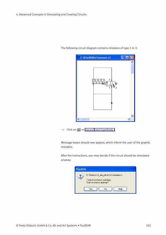
4. Advanced Concepts in Simulating and Creating Circuits
The following circuit diagram contains mistakes of type 1 to 3:
> Click on or Execute Check Superficially .
Message boxes should now appear, which inform the user of the graphic
mistakes.
After the instructions, you may decide if the circuit should be simulated
anyway:
© Festo Didactic GmbH & Co. KG and Art Systems • FluidSIM 103
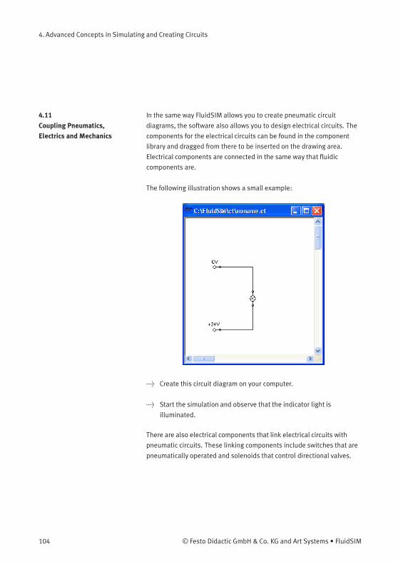
4. Advanced Concepts in Simulating and Creating Circuits
4.11
Coupling Pneumatics,
Electrics and Mechanics
In the same way FluidSIM allows you to create pneumatic circuit
diagrams, the software also allows you to design electrical circuits. The
components for the electrical circuits can be found in the component
library and dragged from there to be inserted on the drawing area.
Electrical components are connected in the same way that fluidic
components are.
The following illustration shows a small example:
> Create this circuit diagram on your computer.
> Start the simulation and observe that the indicator light is
illuminated.
There are also electrical components that link electrical circuits with
pneumatic circuits. These linking components include switches that are
pneumatically operated and solenoids that control directional valves.
104 © Festo Didactic GmbH & Co. KG and Art Systems • FluidSIM
4. Advanced Concepts in Simulating and Creating Circuits
Electrical circuits are drawn independently of pneumatic circuits.
Therefore, there needs to be a way to create definite links between
electrical components (such as a control solenoid) and pneumatic
components (such as a directional valve). So-called labels bridge the
difference and link both circuit diagrams together.
A label has a specific name and can be assigned to a component. If
two components have the same label name they are linked together,
although no apparent line is visible between them.
Entering a label takes place in a dialog box, which can be opened
by either double clicking on the desired component or selecting the
component and then clicking Edit Properties... . Labels can be established
on the left and right sides of an electrically operated valve by double
clicking on the appropriate side, as opposed to clicking in the middle of
the component.
The following example explains how labels can be used in FluidSIM.
> Activate the Edit Mode by clicking on or Execute Stop .
© Festo Didactic GmbH & Co. KG and Art Systems • FluidSIM 105
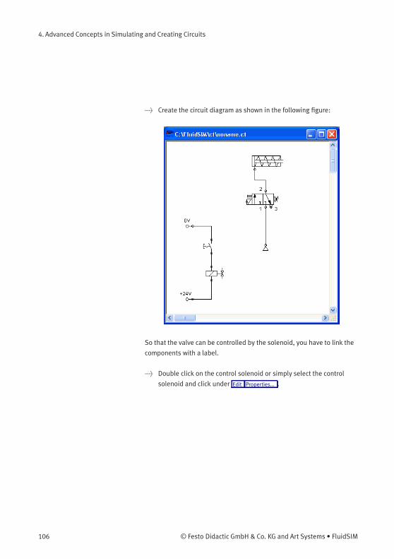
4. Advanced Concepts in Simulating and Creating Circuits
> Create the circuit diagram as shown in the following figure:
So that the valve can be controlled by the solenoid, you have to link the
components with a label.
> Double click on the control solenoid or simply select the control
solenoid and click under Edit Properties... .
106 © Festo Didactic GmbH & Co. KG and Art Systems • FluidSIM
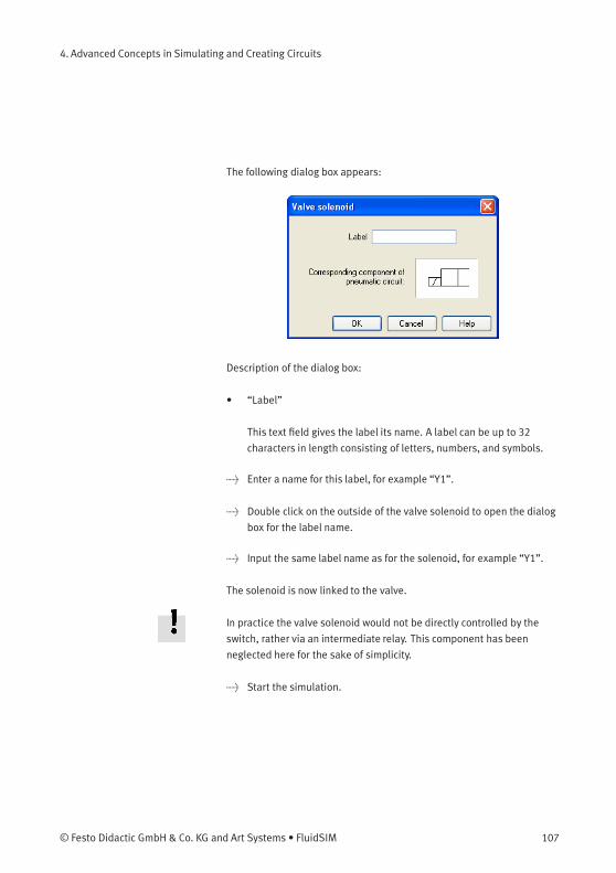
4. Advanced Concepts in Simulating and Creating Circuits
The following dialog box appears:
Description of the dialog box:
• “Label”
This text field gives the label its name. A label can be up to 32
characters in length consisting of letters, numbers, and symbols.
> Enter a name for this label, for example “Y1”.
> Double click on the outside of the valve solenoid to open the dialog
box for the label name.
> Input the same label name as for the solenoid, for example “Y1”.
The solenoid is now linked to the valve.
In practice the valve solenoid would not be directly controlled by the
switch, rather via an intermediate relay. This component has been
neglected here for the sake of simplicity.
> Start the simulation.
© Festo Didactic GmbH & Co. KG and Art Systems • FluidSIM 107
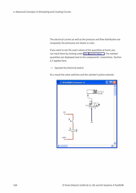
4. Advanced Concepts in Simulating and Creating Circuits
The electrical current as well as the pressure and flow distribution are
computed; the pressures are shown in color.
If you want to see the exact values of the quantities at hand, you
can mark them by clicking under View Quantity Values... . The marked
quantities are displayed next to the components’ connections. Section
4.7 applies here.
> Operate the electrical switch.
As a result the valve switches and the cylinder’s piston extends:
108 © Festo Didactic GmbH & Co. KG and Art Systems • FluidSIM
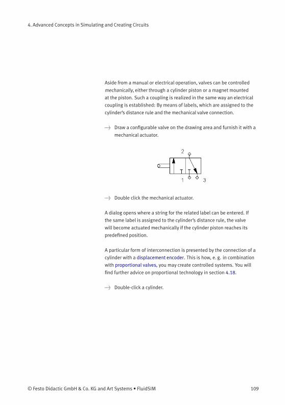
4. Advanced Concepts in Simulating and Creating Circuits
Aside from a manual or electrical operation, valves can be controlled
mechanically, either through a cylinder piston or a magnet mounted
at the piston. Such a coupling is realized in the same way an electrical
coupling is established: By means of labels, which are assigned to the
cylinder’s distance rule and the mechanical valve connection.
> Draw a configurable valve on the drawing area and furnish it with a
mechanical actuator.
> Double click the mechanical actuator.
A dialog opens where a string for the related label can be entered. If
the same label is assigned to the cylinder’s distance rule, the valve
will become actuated mechanically if the cylinder piston reaches its
predefined position.
A particular form of interconnection is presented by the connection of a
cylinder with a displacement encoder. This is how, e. g. in combination
with proportional valves, you may create controlled systems. You will
find further advice on proportional technology in section 4.18.
> Double-click a cylinder.
© Festo Didactic GmbH & Co. KG and Art Systems • FluidSIM 109
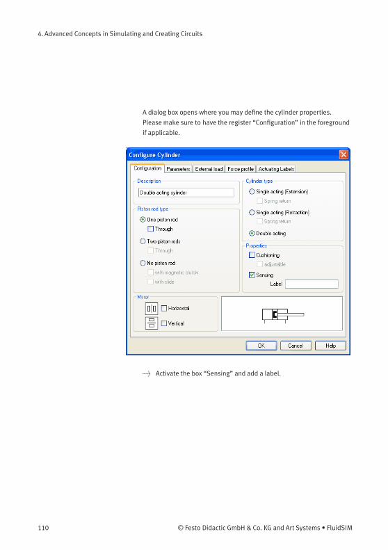
4. Advanced Concepts in Simulating and Creating Circuits
A dialog box opens where you may define the cylinder properties.
Please make sure to have the register “Configuration” in the foreground
if applicable.
> Activate the box “Sensing” and add a label.
110 © Festo Didactic GmbH & Co. KG and Art Systems • FluidSIM

4. Advanced Concepts in Simulating and Creating Circuits
> Insert the displacement encoder from the component library in the
circuit and double-click to open the properties dialog. Please enter
the same label here as for the cylinder.
At the output the displacement encoder system provides a voltage
proportional to the piston position of the interconnected cylinder. This
voltage will be at its defined minimum when the cylinder is retracted
completely; the voltage will be at its defined maximum when the
cylinder is advanced completely.
Display Styles for Labels If a label shall be displayed framed, similar to the display of component
descriptions, click onto View Labels... .
© Festo Didactic GmbH & Co. KG and Art Systems • FluidSIM 111
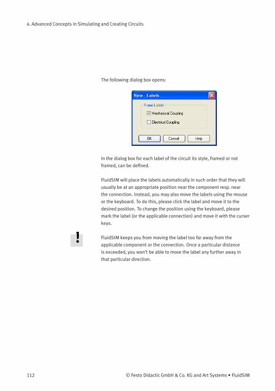
4. Advanced Concepts in Simulating and Creating Circuits
The following dialog box opens:
In the dialog box for each label of the circuit its style, framed or not
framed, can be defined.
FluidSIM will place the labels automatically in such order that they will
usually be at an appropriate position near the component resp. near
the connection. Instead, you may also move the labels using the mouse
or the keyboard. To do this, please click the label and move it to the
desired position. To change the position using the keyboard, please
mark the label (or the applicable connection) and move it with the curser
keys.
FluidSIM keeps you from moving the label too far away from the
applicable component or the connection. Once a particular distance
is exceeded, you won’t be able to move the label any further away in
that particular direction.
112 © Festo Didactic GmbH & Co. KG and Art Systems • FluidSIM
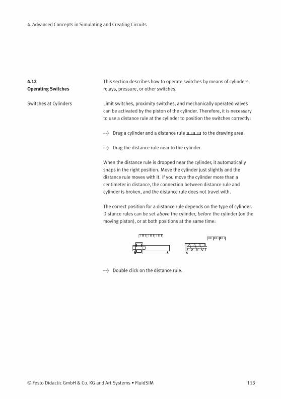
4. Advanced Concepts in Simulating and Creating Circuits
4.12
Operating Switches
This section describes how to operate switches by means of cylinders,
relays, pressure, or other switches.
Switches at Cylinders Limit switches, proximity switches, and mechanically operated valves
can be activated by the piston of the cylinder. Therefore, it is necessary
to use a distance rule at the cylinder to position the switches correctly:
> Drag a cylinder and a distance rule to the drawing area.
> Drag the distance rule near to the cylinder.
When the distance rule is dropped near the cylinder, it automatically
snaps in the right position. Move the cylinder just slightly and the
distance rule moves with it. If you move the cylinder more than a
centimeter in distance, the connection between distance rule and
cylinder is broken, and the distance rule does not travel with.
The correct position for a distance rule depends on the type of cylinder.
Distance rules can be set above the cylinder, before the cylinder (on the
moving piston), or at both positions at the same time:
> Double click on the distance rule.
© Festo Didactic GmbH & Co. KG and Art Systems • FluidSIM 113
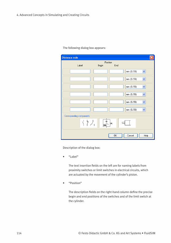
4. Advanced Concepts in Simulating and Creating Circuits
The following dialog box appears:
Description of the dialog box:
• “Label”
The text insertion fields on the left are for naming labels from
proximity switches or limit switches in electrical circuits, which
are actuated by the movement of the cylinder’s piston.
• “Position”
The description fields on the right-hand column define the precise
begin and end positions of the switches and of the limit switch at
the cylinder.
114 © Festo Didactic GmbH & Co. KG and Art Systems • FluidSIM
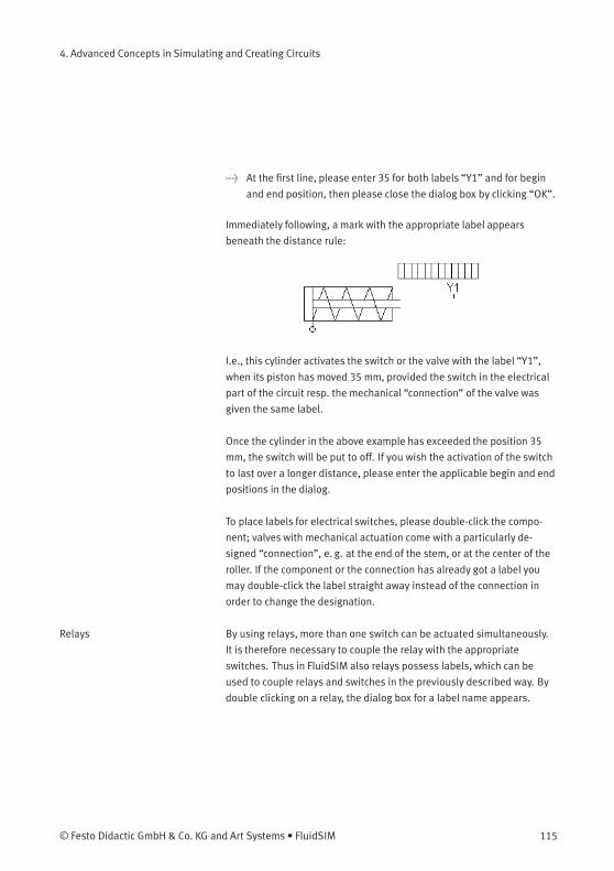
4. Advanced Concepts in Simulating and Creating Circuits
> At the first line, please enter 35 for both labels “Y1” and for begin
and end position, then please close the dialog box by clicking “OK”.
Immediately following, a mark with the appropriate label appears
beneath the distance rule:
I.e., this cylinder activates the switch or the valve with the label “Y1”,
when its piston has moved 35 mm, provided the switch in the electrical
part of the circuit resp. the mechanical “connection” of the valve was
given the same label.
Once the cylinder in the above example has exceeded the position 35
mm, the switch will be put to off. If you wish the activation of the switch
to last over a longer distance, please enter the applicable begin and end
positions in the dialog.
To place labels for electrical switches, please double-click the compo-
nent; valves with mechanical actuation come with a particularly de-
signed “connection”, e. g. at the end of the stem, or at the center of the
roller. If the component or the connection has already got a label you
may double-click the label straight away instead of the connection in
order to change the designation.
Relays By using relays, more than one switch can be actuated simultaneously.
It is therefore necessary to couple the relay with the appropriate
switches. Thus in FluidSIM also relays possess labels, which can be
used to couple relays and switches in the previously described way. By
double clicking on a relay, the dialog box for a label name appears.
© Festo Didactic GmbH & Co. KG and Art Systems • FluidSIM 115
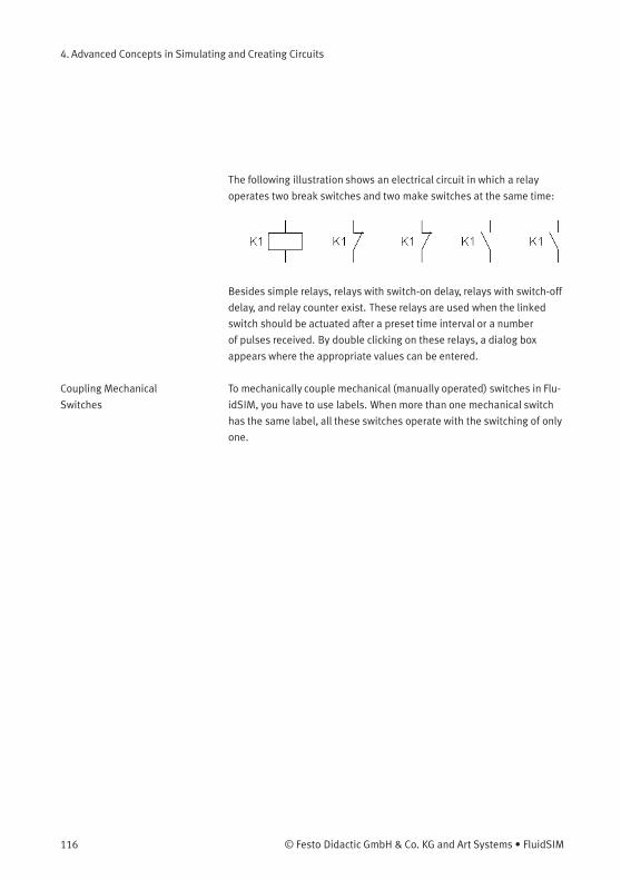
4. Advanced Concepts in Simulating and Creating Circuits
The following illustration shows an electrical circuit in which a relay
operates two break switches and two make switches at the same time:
Besides simple relays, relays with switch-on delay, relays with switch-off
delay, and relay counter exist. These relays are used when the linked
switch should be actuated after a preset time interval or a number
of pulses received. By double clicking on these relays, a dialog box
appears where the appropriate values can be entered.
Coupling Mechanical
Switches
To mechanically couple mechanical (manually operated) switches in Flu-
idSIM, you have to use labels. When more than one mechanical switch
has the same label, all these switches operate with the switching of only
one.
116 © Festo Didactic GmbH & Co. KG and Art Systems • FluidSIM
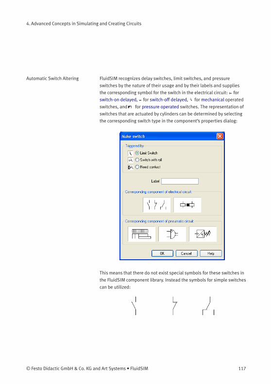
4. Advanced Concepts in Simulating and Creating Circuits
Automatic Switch Altering FluidSIM recognizes delay switches, limit switches, and pressure
switches by the nature of their usage and by their labels and supplies
the corresponding symbol for the switch in the electrical circuit: for
switch-on delayed, for switch-off delayed, for mechanical operated
switches, and for pressure operated switches. The representation of
switches that are actuated by cylinders can be determined by selecting
the corresponding switch type in the component’s properties dialog:
This means that there do not exist special symbols for these switches in
the FluidSIM component library. Instead the symbols for simple switches
can be utilized:
© Festo Didactic GmbH & Co. KG and Art Systems • FluidSIM 117

4. Advanced Concepts in Simulating and Creating Circuits
4.13
Adjustable Components
Certain components contain parameters that can be set in the Edit
Mode. A number of these components have been discussed in earlier
sections.
The dialog box for setting these parameters can be opened with a
double click or Edit Properties... .
During the simulation, some components may be adjusted in the same
way as in reality. Thus e. g. the operating pressure of the compressed
air or the opening level of the throttle allow to be continuously
changed. To do so, it is not necessary to open the properties dialog
and to subsequently close it using OK ; instead a simple click on the
component is enough to open a window providing slide controllers.
Changes will effect the simulation immediately. Once you click another
component or a blank area in the window, the properties dialog will
disappear automatically.
When in simulation mode and moving the mouse across a component,
the mouse curser will change to the slider symbol if the applicable
“real-time settings” are available.
To help with precision adjustment some controllers provide an optional
control range. You may alternatively enter the numeric value using the
input field.
118 © Festo Didactic GmbH & Co. KG and Art Systems • FluidSIM
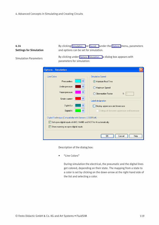
4. Advanced Concepts in Simulating and Creating Circuits
4.14
Settings for Simulation
By clicking Simulation... or Sound... under the Options menu, parameters
and options can be set for simulation.
Simulation Parameters By clicking under Options Simulation... a dialog box appears with
parameters for simulation:
Description of the dialog box:
• “Line Colors”
During simulation the electrical, the pneumatic and the digital lines
get colored, depending on their state. The mapping from a state to
a color is set by clicking on the down-arrow at the right-hand side of
the list and selecting a color.
© Festo Didactic GmbH & Co. KG and Art Systems • FluidSIM 119
4. Advanced Concepts in Simulating and Creating Circuits
• “Maintain Real Time”
Using the option “Maintain Real Time” will attempt the cylinder
movement to move as fast as in reality. Please note that real time
movement requires a computer with sufficient computing power.
• “Maximum Speed”
The option “maximum speed” utilizes the entire computing power.
The aim is to run the simulation as fast as possible. The actual
acceleration of the simulation depends on the performance of the
computer. If your computer does not at least achieve “real-time”,
the simulation cannot be accelerated to any higher speed.
• “Slow-motion Factor”
The slow-motion factor controls whether the simulation should go
more slowly then it would in reality. With a slow-motion factor of
1:1, the simulation should proceed in real-time.
• “Label designation”
By default, FluidSIM does not distinguish between uppercase
and lowercase characters in label identifiers of mechanical or
electrical connections. I. e., label identifiers are automatically
converted to uppercase. Now, using the option “Display uppercase
and lowercase”, label identifiers are treated case sensitively.
Case sensitivity can be enabled for both display purposes and a
more strict label identity checking. In the former case, upper- and
lowercase characters, say, for instance “a” and “A”, are displayed as
such, but treated as the same character. In the latter case, which
is enabled by the option “Distinguish between uppercase and
lowercase”, “a” and “A” are treated as different labels.
120 © Festo Didactic GmbH & Co. KG and Art Systems • FluidSIM
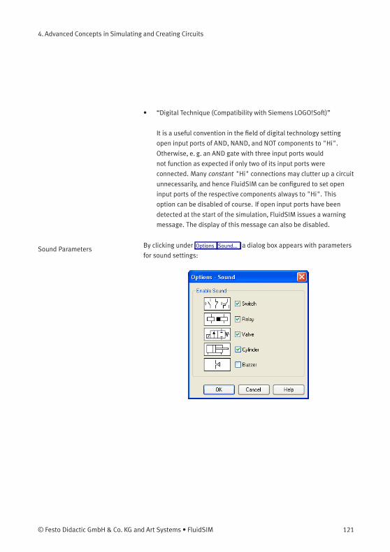
4. Advanced Concepts in Simulating and Creating Circuits
• “Digital Technique (Compatibility with Siemens LOGO!Soft)”
It is a useful convention in the field of digital technology setting
open input ports of AND, NAND, and NOT components to "Hi".
Otherwise, e. g. an AND gate with three input ports would
not function as expected if only two of its input ports were
connected. Many constant "Hi" connections may clutter up a circuit
unnecessarily, and hence FluidSIM can be configured to set open
input ports of the respective components always to "Hi". This
option can be disabled of course. If open input ports have been
detected at the start of the simulation, FluidSIM issues a warning
message. The display of this message can also be disabled.
Sound Parameters By clicking under Options Sound... a dialog box appears with parameters
for sound settings:
© Festo Didactic GmbH & Co. KG and Art Systems • FluidSIM 121
4. Advanced Concepts in Simulating and Creating Circuits
Description of the dialog box:
• “Enable Sound”
An acoustic signal can be activated or deactivated for each of the
following four component types: switch, relay, valve, cylinder, and
buzzer.
If there is no sound hardware, the settings can be set but not applied.
4.15
Use of the
EasyPort-Hardware
FluidSIM can directly address the EasyPort that is connected to the
serial port your computer. No other drivers or software tools are
required. The interconnection is effected by implementing special
electrical in/out components that provide both eight inputs and
outputs. The components are the same as the ones used for the
interconnection via OPC or DDE. The operation mode of these input and
output components is defined by the use of the menu option Options
EasyPort/OPC/DDE Connection... .
The EasyPort-hardware may also be addressed by using OPC-
communication. This is how you may also address remote EasyPort-
modules that are not connected locally (e. g. using a LAN-connection).
Provided the EasyPort-modules are connected locally to the simulating
computer, you are recommended to define a direct connection.
> Initially, please select the option “direct EasyPort-connection” in the
menu Options EasyPort/OPC/DDE Connection... .
> Please drag an input or output component from the component
library in the circuit diagramwindow and open the properties dialog
by double-clicking or by accessing menu Edit Properties... .
122 © Festo Didactic GmbH & Co. KG and Art Systems • FluidSIM
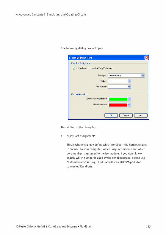
4. Advanced Concepts in Simulating and Creating Circuits
The following dialog box will open:
Description of the dialog box:
• “EasyPort Assignment”
This is where you may define which serial port the hardware uses
to connect to your computer, which EasyPort-module and which
port number is assigned to the i/o module. If you don’t know
exactly which number is used by the serial interface, please use
“automatically” setting, FluidSIM will scan all COM-ports for
connected EasyPorts.
© Festo Didactic GmbH & Co. KG and Art Systems • FluidSIM 123
4. Advanced Concepts in Simulating and Creating Circuits
By standard the EasyPort-hardware comes with a serial interface, which
has proved to work well for years in the world of computers as well
as in the world of industrial use. Modern computers and most of all
mobile ones tend to leave out this interface more and more. Still, you
may inexpensively and simply add a serial interface by using a USB-
serial converter, enabling you to use the EasyPort. The converter’s own
software defines a virtual COM-port that will be assigned a number
higher than the existing physical interfaces (usually COM 5). This virtual
port will enable you to address the hardware as usual.
• “Connection Color”
Defines the color of the connection indicator for the i/o component
when either the EasyPort-connection is active or when the
connection is not available or out of order.
The color may be defined by clicking the downward arrow on the
right-hand side of the list and then select a color.
If FluidSIM doesn’t find the EasyPort hardware on starting the simula-
tion, a related warning will be shown. The simulation can still be started,
but until the end or until restarting the simulation FluidSIM will not
attempt to detect any EasyPorts. If the connection fails during the sim-
ulation, (e. g. due to unintentionally removing connecting cable), the
simulation will continue without EasyPort-interconnection, but Fluid-
SIM will attempt to reestablish the connection. Once the hardware is
again available at the defined interface, the connection will once again
be established and the simulation will continue including the EasyPort-
communication.
124 © Festo Didactic GmbH & Co. KG and Art Systems • FluidSIM
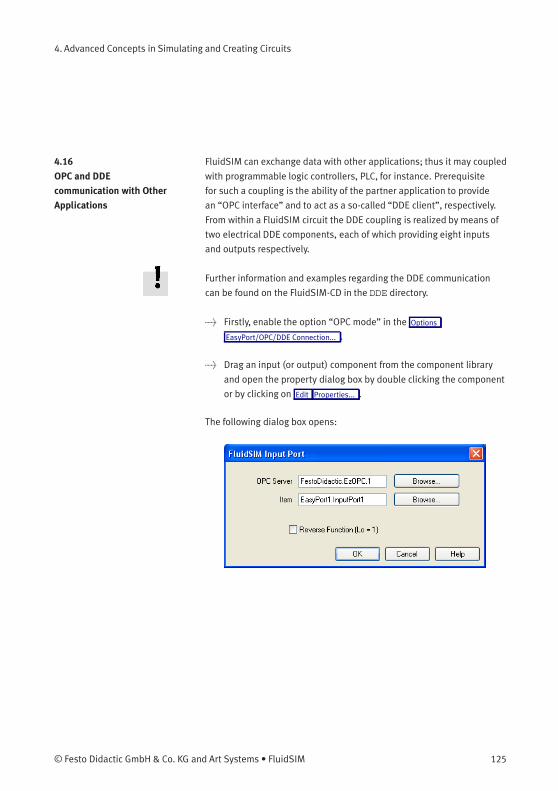
4. Advanced Concepts in Simulating and Creating Circuits
4.16
OPC and DDE
communication with Other
Applications
FluidSIM can exchange data with other applications; thus it may coupled
with programmable logic controllers, PLC, for instance. Prerequisite
for such a coupling is the ability of the partner application to provide
an “OPC interface” and to act as a so-called “DDE client”, respectively.
From within a FluidSIM circuit the DDE coupling is realized by means of
two electrical DDE components, each of which providing eight inputs
and outputs respectively.
Further information and examples regarding the DDE communication
can be found on the FluidSIM-CD in the DDE directory.
> Firstly, enable the option “OPC mode” in the Options
EasyPort/OPC/DDE Connection... .
> Drag an input (or output) component from the component library
and open the property dialog box by double clicking the component
or by clicking on Edit Properties... .
The following dialog box opens:
© Festo Didactic GmbH & Co. KG and Art Systems • FluidSIM 125
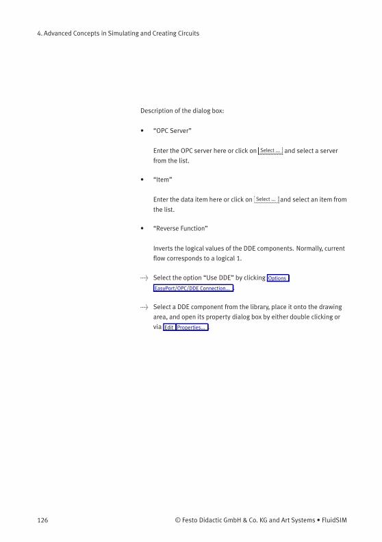
4. Advanced Concepts in Simulating and Creating Circuits
Description of the dialog box:
• “OPC Server”
Enter the OPC server here or click on Select ... and select a server
from the list.
• “Item”
Enter the data item here or click on Select ... and select an item from
the list.
• “Reverse Function”
Inverts the logical values of the DDE components. Normally, current
flow corresponds to a logical 1.
> Select the option “Use DDE” by clicking Options
EasyPort/OPC/DDE Connection... .
> Select a DDE component from the library, place it onto the drawing
area, and open its property dialog box by either double clicking or
via Edit Properties... .
126 © Festo Didactic GmbH & Co. KG and Art Systems • FluidSIM
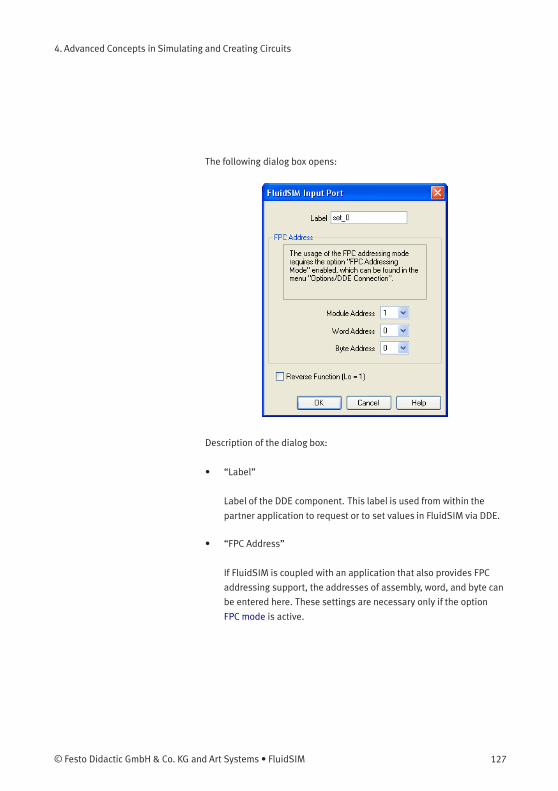
4. Advanced Concepts in Simulating and Creating Circuits
The following dialog box opens:
Description of the dialog box:
• “Label”
Label of the DDE component. This label is used from within the
partner application to request or to set values in FluidSIM via DDE.
• “FPC Address”
If FluidSIM is coupled with an application that also provides FPC
addressing support, the addresses of assembly, word, and byte can
be entered here. These settings are necessary only if the option
FPC mode is active.
© Festo Didactic GmbH & Co. KG and Art Systems • FluidSIM 127
4. Advanced Concepts in Simulating and Creating Circuits
• “Reverse Function”
Inverts the logical values of the DDE components. Normally, current
flow corresponds to a logical 1.
4.17
Settings for the
EasyPort/OPC/DDE
communication
Clicking on Options EasyPort/OPC/DDE Connection... opens the following
dialog box with settings for the EasyPort, OPC, and DDE communication:
Description of the dialog box:
• “Do not apply remote control”
Please click this field if you don’t wish FluidSIM to communicate
with connected EasyPorts or other applications. If this option is
activated, FluidSIM may ignore any connected EasyPort-module
and may neither respond to other applications trying to establish an
OPC or DDE connection.
128 © Festo Didactic GmbH & Co. KG and Art Systems • FluidSIM
4. Advanced Concepts in Simulating and Creating Circuits
• “Direct EasyPort-Connection”
Select this option if you wish to interconnect FluidSIM with other
locally connected EasyPort-modules.
• “Enable event buffer”
Enable this field, if FluidSIM shall buffer all events and process
them in a first-in-first-out manner. If this option is disabled, events
that occur during high computational load may go lost.
• “Synchronize input and output”
Using this option you will define whether FluidSIM is to check,
with every change of bit pattern at an output, for the status of
the inputs. This may be useful if the output values, by means of
a circuit that involves the EasyPort-module, influence the status
of the inputs. Please note that the operation mode may massively
reduce the simulation speed, since FluidSIM may occasionally need
to wait, with every step, for an answer of the connected EasyPorts.
• “OPC mode”
Choose this option, if FluidSIM shall be coupled with other
applications via OPC.
• “DDE mode”
Choose this option, if FluidSIM shall be coupled with other
applications via DDE.
• “Server”
Defines the name under which name FluidSIM logs on the partner
application. As the case may be, this name must be told the partner
application as the server name.
© Festo Didactic GmbH & Co. KG and Art Systems • FluidSIM 129
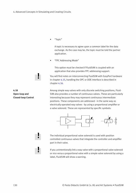
4. Advanced Concepts in Simulating and Creating Circuits
• “Topic”
A topic is necessary to agree upon a common label for the data
exchange. As the case may be, the topic must be told the partner
application.
• “FPC Addressing Mode”
This option must be checked if FluidSIM is coupled with an
application that also provides FPC addressing support.
You will find notes on interconnecting FluidSIM with EasyPort hardware
in chapter 4.15, handling the OPC or DDE interface is described in
chapter 4.16.
4.18
Open-loop and
Closed-loop Control
Among simple way valves with only discrete switching positions, Fluid-
SIM also provides a number of continuous valves. These are particularly
interesting because they may represent continuous intermediate
positions. These components are addressed - in the same way as
electrically operated way valves - by using a proportional amplifier or
a valve solenoid. These are represented by specific symbols:
The individual proportional valve solenoid is used with position
controlled continuous valves that integrate the controller and amplifier
part in their valve.
If you unintentionally link a way valve with a proportional valve solenoid
or vice versa a proportional valve with a simple valve solenoid by using a
label, FluidSIM will show a warning.
130 © Festo Didactic GmbH & Co. KG and Art Systems • FluidSIM
4. Advanced Concepts in Simulating and Creating Circuits
The following two sections will introduce you to the possibilities of
open-loop control and closed-loop control with FluidSIM. The term
“open-loop control” means here that an output variable changes
depending on an input variable. In detail the voltage represents the
input variable at the proportional valve solenoid or at the amplifier.
Depending on the value (and on the direction) of the electrical current
caused by the voltage (assisted by an amplifier), the valve piston of the
proportional valve will more or less be deflected to one direction. This is
the output variable. In the case of a constant pressure at the valve port
you may therefore manage the flow. Instead, in the case of a constant
flow, the pressure drop will change depending on the opening level that
is defined by the valve position.
We speak of “closed-loop control” when the output variable or a
state variable influenced by this output variable itself serves as an
input variable. In the course of this several output variables as well
as pending state variablesmay well be combined with further input
variables when a calculation rule is used. A classical example is
represented by a position control that defines a particular position
to be reached by a cylinder. In this case the valve will be electrically
addressed in such a way that the cylinder travels. The position of the
cylinder (in consequence of the travel depending on the valve position)
will again be used as an input value while the deviation from the desired
position of the cylinder is considered. Once the cylinder has reached its
target position, the deviation is 0 and the valve returns to mid-position
(closed position). Thus the cylinder stops. Should the cylinder, by inertia
or because of outside malfunction or interference, pass the target
position, the valve will switch to the opposite side and will reverse the
direction of flow; the cylinder travels back. This already represents the
simplest form of controlling, the so-called “P-control”.
© Festo Didactic GmbH & Co. KG and Art Systems • FluidSIM 131

4. Advanced Concepts in Simulating and Creating Circuits
4.18.1
Open-loop Control
In order to understand the mode of operation of the continuous
components, please reconstruct the following circuit (voltage supply,
function generator, voltmeter, proportional valve solenoid, continuous
valve):
In the case of the five pneumatic connections of the valve, please don’t
forget to apply mufflers, to avoid warnings issued by FluidSIM.
> Please launch the simulation and observe the continuous valve.
The function generator generates a signal between 0 and 10 volts.
This varying voltage is converted in the valve by using a proportional
amplifier to assign an applicable current to activate the proportional
valve solenoid; converted in such way that the linked valve can be
deflected to a maximum to both sides according to the applied signal
voltage.
132 © Festo Didactic GmbH & Co. KG and Art Systems • FluidSIM
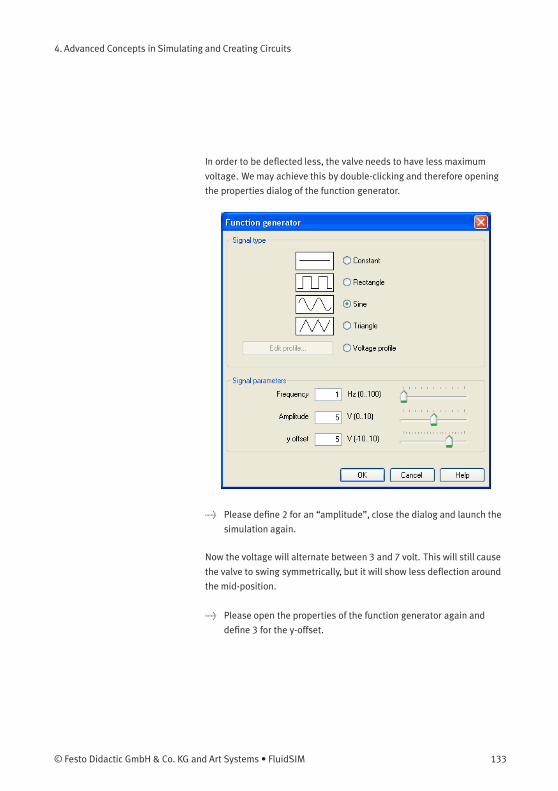
4. Advanced Concepts in Simulating and Creating Circuits
In order to be deflected less, the valve needs to have less maximum
voltage. We may achieve this by double-clicking and therefore opening
the properties dialog of the function generator.
> Please define 2 for an “amplitude”, close the dialog and launch the
simulation again.
Now the voltage will alternate between 3 and 7 volt. This will still cause
the valve to swing symmetrically, but it will show less deflection around
the mid-position.
> Please open the properties of the function generator again and
define 3 for the y-offset.
© Festo Didactic GmbH & Co. KG and Art Systems • FluidSIM 133
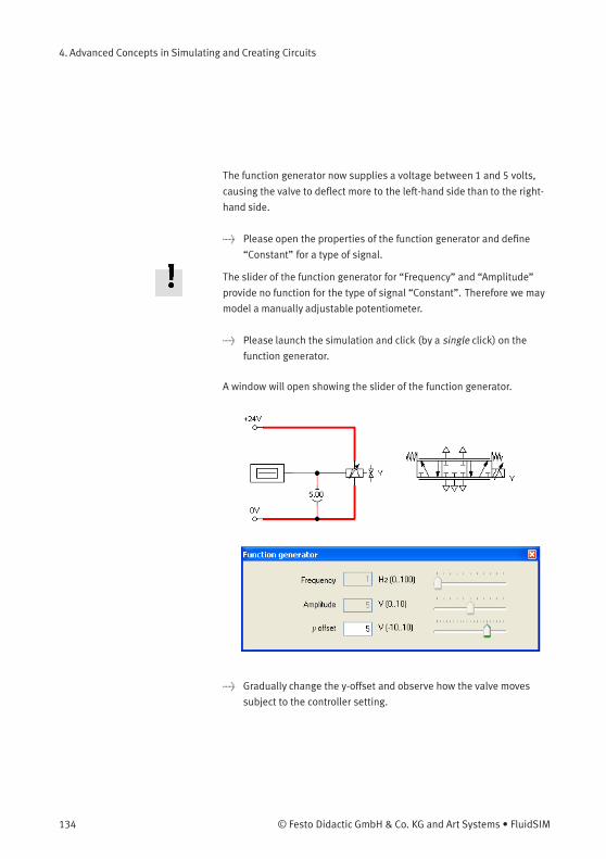
4. Advanced Concepts in Simulating and Creating Circuits
The function generator now supplies a voltage between 1 and 5 volts,
causing the valve to deflect more to the left-hand side than to the right-
hand side.
> Please open the properties of the function generator and define
“Constant” for a type of signal.
The slider of the function generator for “Frequency” and “Amplitude”
provide no function for the type of signal “Constant”. Therefore we may
model a manually adjustable potentiometer.
> Please launch the simulation and click (by a single click) on the
function generator.
A window will open showing the slider of the function generator.
> Gradually change the y-offset and observe how the valve moves
subject to the controller setting.
134 © Festo Didactic GmbH & Co. KG and Art Systems • FluidSIM
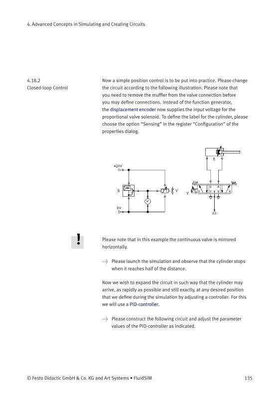
4. Advanced Concepts in Simulating and Creating Circuits
4.18.2
Closed-loop Control
Now a simple position control is to be put into practice. Please change
the circuit according to the following illustration. Please note that
you need to remove the muffler from the valve connection before
you may define connections. Instead of the function generator,
the displacement encoder now supplies the input voltage for the
proportional valve solenoid. To define the label for the cylinder, please
choose the option “Sensing” in the register “Configuration” of the
properties dialog.
Please note that in this example the continuous valve is mirrored
horizontally.
> Please launch the simulation and observe that the cylinder stops
when it reaches half of the distance.
Now we wish to expand the circuit in such way that the cylinder may
arrive, as rapidly as possible and still exactly, at any desired position
that we define during the simulation by adjusting a controller. For this
we will use a PID-controller.
> Please construct the following circuit and adjust the parameter
values of the PID-controller as indicated.
© Festo Didactic GmbH & Co. KG and Art Systems • FluidSIM 135
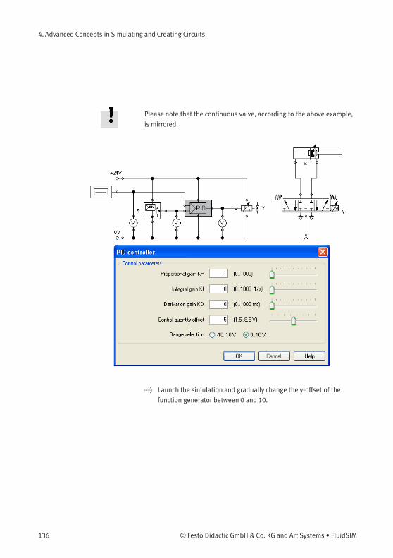
4. Advanced Concepts in Simulating and Creating Circuits
Please note that the continuous valve, according to the above example,
is mirrored.
> Launch the simulation and gradually change the y-offset of the
function generator between 0 and 10.
136 © Festo Didactic GmbH & Co. KG and Art Systems • FluidSIM
4. Advanced Concepts in Simulating and Creating Circuits
The cylinder will travel until it has found its desired position and will
stop there. The target position of the cylinder acts proportionally to
the defined voltage at the function generator: 0 volts correspond to
“entirely retracted”, 10 volts correspond to “entirely advanced”. The
value 5 is therefore the mid-position of the cylinder piston. In the course
of this the position from which the cylinder begins to travel is irrelevant,
it will still stop at the desired target position.
> Change the initial piston position and observe how accurately the
cylinder reaches its target position each time.
To achieve a more precise analysis of the control procedure we will
observe the travel and the speed of the cylinder until it reaches its
desired position. Therefore we include a state diagram, scale it to an
adequate size and drag the cylinder on the diagram. A dialog will open
where we choose the two state variables “Position” and “Velocity”.
Pneumatics are fast. To make observing the following effects easier,
please adjust the stroke of the cylinder to 5000 mm.
> Please adjust the y-offset of the function generator to 5 and the
start position of the cylinder’s piston rod to 0 and then launch the
simulation.
© Festo Didactic GmbH & Co. KG and Art Systems • FluidSIM 137
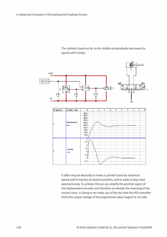
4. Advanced Concepts in Simulating and Creating Circuits
The cylinder travels as far as the middle and gradually decreases its
speed until it stops.
It often may be desirably to make a cylinder travel by maximum
speed until it reaches its desired position, and to make it stop most
spontaneously. To achieve this we can amplify the position signal of
the displacement encoder and therefore accelerate the reversing of the
control valve. In doing so we make use of the fact that the PID-controller
limits the output voltage of the proportional valve magnet to 10 volts.
138 © Festo Didactic GmbH & Co. KG and Art Systems • FluidSIM
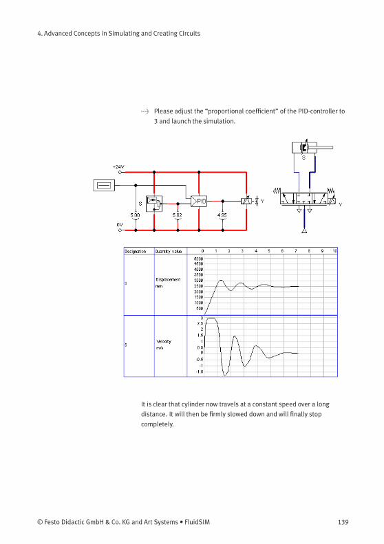
4. Advanced Concepts in Simulating and Creating Circuits
> Please adjust the “proportional coefficient” of the PID-controller to
3 and launch the simulation.
It is clear that cylinder now travels at a constant speed over a long
distance. It will then be firmly slowed down and will finally stop
completely.
© Festo Didactic GmbH & Co. KG and Art Systems • FluidSIM 139
4. Advanced Concepts in Simulating and Creating Circuits
One would still observe that the cylinder piston, because of its inertia
and because of the air’s compressibility, firmly passes the target and
that it travels back and forth a few times until it finally comes to rest.
These vibrations around the desired position are typical for such a
basic control. In reality one would attempt, by trimming the additional
parameter of the PID-controller or the status controller, to cushion the
vibrations. At this point we wish to stay with the basics and would
like to draw your attention to the advanced literature on proportional
technology and control technology.
140 © Festo Didactic GmbH & Co. KG and Art Systems • FluidSIM
5. Learning, Teaching, and Visualizing Pneumatics
Beside the creation and simulation of electro-pneumatic circuit
diagrams, FluidSIM also supports teaching basic pneumatic knowledge.
This knowledge is presented in the form of texts, overview pictures,
sectional views, exercises, and educational films. Functions that realize
the selection of this instruction material are found under the Didactics
menu.
One group of these functions refers to information about single,
selected components. Another group of functions refers to ordered
overviews of the didactics material, allowing the selection of an
interesting topic. Finally, it is also possible to select and link together
arbitrary topics into so-called “presentations”.
Appendix B, “The Component Library”, and C, “Didactics Material
Survey”, offer a complete and concise summary of the instructional
material in FluidSIM.
The following sections contain a description of the functions found
under the Didactics menu.
© Festo Didactic GmbH & Co. KG and Art Systems • FluidSIM 141
5. Learning, Teaching, and Visualizing Pneumatics
5.1
Information about Single
Components
The first three entries under the Didactics menu refer to selected
components and are context sensitive. More precisely:
When a component in the current circuit diagram window is selected,
or all selected components are of the same type, the menu entry
Component Description will be enabled.
Component Descriptions All components possess a page with a technical description. This page
contains the diagram symbol for the component according to the DIN
standard (“Deutsche Industrienorm”), a textual description of the
component’s function, the designations of the connections, and a listing
of the adjustable parameters along with their value ranges.
You will find a photograph of the real-life part provided for most
components. In the case that a component cannot exist singularly in
a real system, FluidSIM displays a photo of the assembly group that
this component belongs to. Examples for such components include the
indicator light, relays, switches, and the electrical power supply.
Components, that do not exist in reality, simply have no photo.
Examples include the text component and the distance rule.
> Select the one-way flow control valve, and click on the menu item
Component Description under the Didactics menu.
142 © Festo Didactic GmbH & Co. KG and Art Systems • FluidSIM
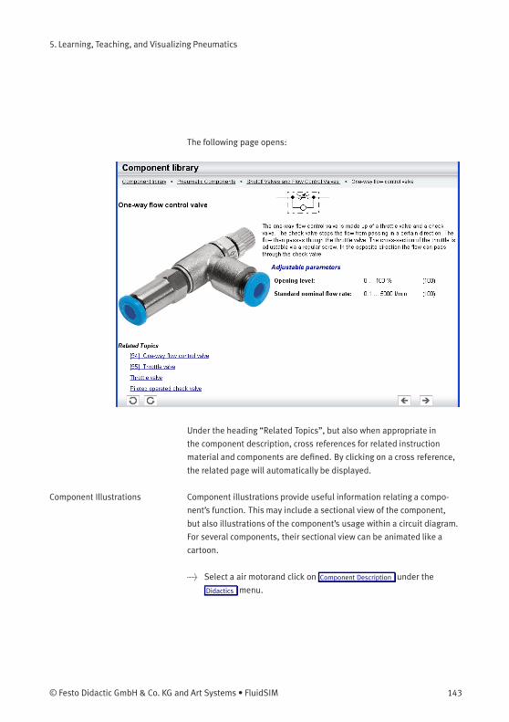
5. Learning, Teaching, and Visualizing Pneumatics
The following page opens:
Under the heading “Related Topics”, but also when appropriate in
the component description, cross references for related instruction
material and components are defined. By clicking on a cross reference,
the related page will automatically be displayed.
Component Illustrations Component illustrations provide useful information relating a compo-
nent’s function. This may include a sectional view of the component,
but also illustrations of the component’s usage within a circuit diagram.
For several components, their sectional view can be animated like a
cartoon.
> Select a air motorand click on Component Description under the
Didactics menu.
© Festo Didactic GmbH & Co. KG and Art Systems • FluidSIM 143
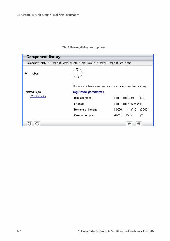
5. Learning, Teaching, and Visualizing Pneumatics
The following dialog box appears:
144 © Festo Didactic GmbH & Co. KG and Art Systems • FluidSIM
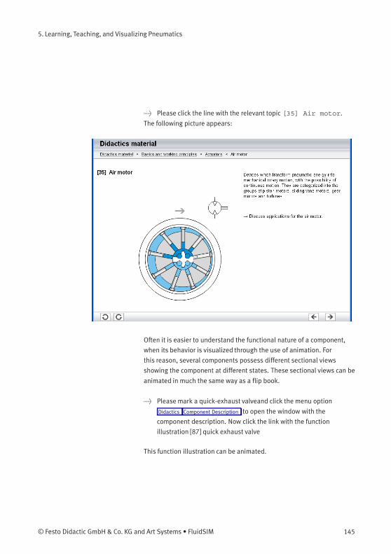
5. Learning, Teaching, and Visualizing Pneumatics
> Please click the line with the relevant topic [35] Air motor.
The following picture appears:
Often it is easier to understand the functional nature of a component,
when its behavior is visualized through the use of animation. For
this reason, several components possess different sectional views
showing the component at different states. These sectional views can be
animated in much the same way as a flip book.
> Please mark a quick-exhaust valveand click the menu option
Didactics Component Description to open the window with the
component description. Now click the link with the function
illustration [87] quick exhaust valve
This function illustration can be animated.
© Festo Didactic GmbH & Co. KG and Art Systems • FluidSIM 145
5. Learning, Teaching, and Visualizing Pneumatics
> Click on or Execute Start to start the animation.
An animation can be “frozen” with or by clicking on Pause in the
Execute menu. or Execute Stop stops an animation, whereas or
Execute Reset restarts an animation.
5.2
Selecting Didactics
Material from a List
The entries Tutorial , Component Library , and Didactics Material under the
Didactics menu present the didactics material of FluidSIM organized in
the form of overview pages. From these pages topics can be chosen
and viewed independently of the current window and possibly selected
components.
Tutorial Below this menu option you can launch the tutorial “Simulating with
FluidSIM”, which contains a variety of interesting experiments and an
excursus. By means of these useful examples you will get to know the
possibilities of simulating with FluidSIM. Furthermore, for the most
important components the mathematic models used in FluidSIM are
also described.
146 © Festo Didactic GmbH & Co. KG and Art Systems • FluidSIM
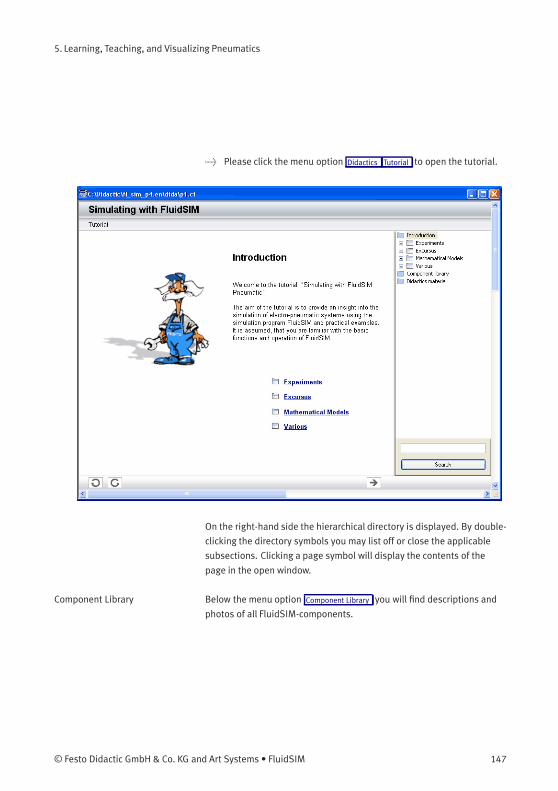
5. Learning, Teaching, and Visualizing Pneumatics
> Please click the menu option Didactics Tutorial to open the tutorial.
On the right-hand side the hierarchical directory is displayed. By double-
clicking the directory symbols you may list off or close the applicable
subsections. Clicking a page symbol will display the contents of the
page in the open window.
Component Library Below the menu option Component Library you will find descriptions and
photos of all FluidSIM-components.
© Festo Didactic GmbH & Co. KG and Art Systems • FluidSIM 147
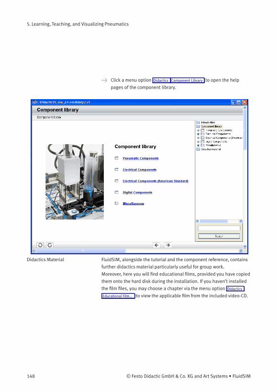
5. Learning, Teaching, and Visualizing Pneumatics
> Click a menu option Didactics Component Library to open the help
pages of the component library.
Didactics Material FluidSIM, alongside the tutorial and the component reference, contains
further didactics material particularly useful for group work.
Moreover, here you will find educational films, provided you have copied
them onto the hard disk during the installation. If you haven’t installed
the film files, you may choose a chapter via the menu option Didactics
Educational Film... to view the applicable film from the included video-CD.
148 © Festo Didactic GmbH & Co. KG and Art Systems • FluidSIM
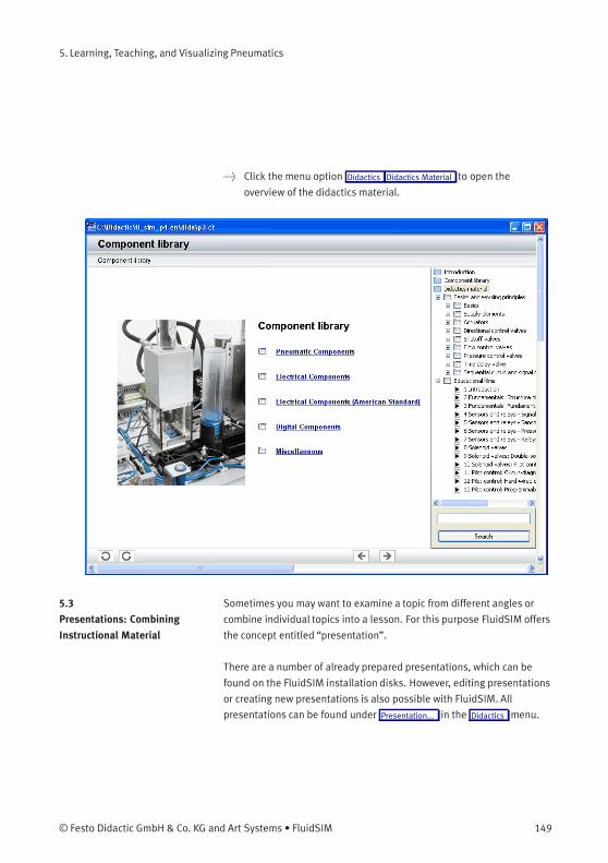
5. Learning, Teaching, and Visualizing Pneumatics
> Click the menu option Didactics Didactics Material to open the
overview of the didactics material.
5.3
Presentations: Combining
Instructional Material
Sometimes you may want to examine a topic from different angles or
combine individual topics into a lesson. For this purpose FluidSIM offers
the concept entitled “presentation”.
There are a number of already prepared presentations, which can be
found on the FluidSIM installation disks. However, editing presentations
or creating new presentations is also possible with FluidSIM. All
presentations can be found under Presentation... in the Didactics menu.
© Festo Didactic GmbH & Co. KG and Art Systems • FluidSIM 149
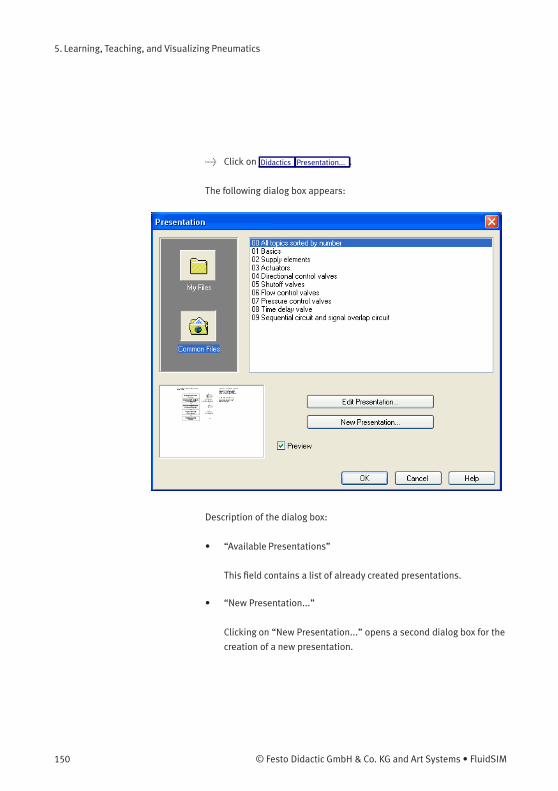
5. Learning, Teaching, and Visualizing Pneumatics
> Click on Didactics Presentation... .
The following dialog box appears:
Description of the dialog box:
• “Available Presentations”
This field contains a list of already created presentations.
• “New Presentation...”
Clicking on “New Presentation...” opens a second dialog box for the
creation of a new presentation.
150 © Festo Didactic GmbH & Co. KG and Art Systems • FluidSIM
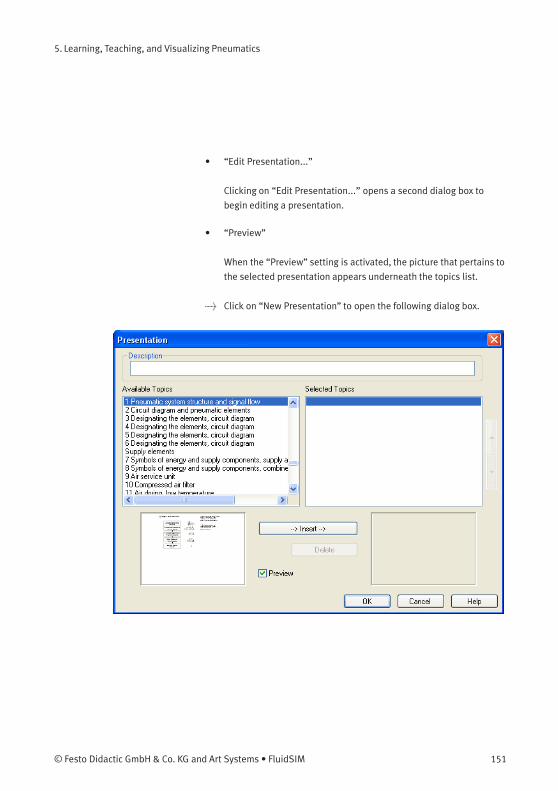
5. Learning, Teaching, and Visualizing Pneumatics
• “Edit Presentation...”
Clicking on “Edit Presentation...” opens a second dialog box to
begin editing a presentation.
• “Preview”
When the “Preview” setting is activated, the picture that pertains to
the selected presentation appears underneath the topics list.
> Click on “New Presentation” to open the following dialog box.
© Festo Didactic GmbH & Co. KG and Art Systems • FluidSIM 151
5. Learning, Teaching, and Visualizing Pneumatics
Description of the dialog box:
• “Description”
In this text field a short description of the presentation can be
entered. This text may consist of up to 128 characters and will
appear with the other presentations, the next time the presentation
dialog box is opened.
• “Available Topics”
This field contains a list of all available topics dealing with
“Pneumatics Basics”, “Working Principles”, and “Exercises”.
Moreover, there exist two pictures that can be used to announce
a refreshment and a lunch break respectively. A double click on a
line in the “Available Topics” list inserts this line in the “Selected
Topics” list above the highlighted bar. In this way a presentation
can be created or altered.
Moreover, a user can integrate his own circuit diagrams, DXF files,
BMP- and WMF-picture files, or even multimedia files such as
sounds or video clips. To do so, click on “User File...”: A dialog
box opens that allows for the selection of the desired data source
on the file system.
• “Selected Topics”
This field contains a list of topics chosen for the current
presentation.
• “Insert”
Clicking on “Insert” is the same as double clicking a line in the
“Available Topics” list: The selected line in “Available Topics” will be
inserted in the “Selected Topics” list.
152 © Festo Didactic GmbH & Co. KG and Art Systems • FluidSIM
5. Learning, Teaching, and Visualizing Pneumatics
• “Delete”
Clicking on “Delete” deletes the selected line of the “Selected
Topics” list.
• “Preview”
When the “Preview” setting is activated, the picture that pertains to
the selected topic appears underneath the respective list.
Within both topics lists the highlighted bar can be moved using the
arrow keys. Maybe it will be necessary to click and select the list you
want to work with.
After creating a new presentation and closing the dialog box by clicking
on “OK”, FluidSIM asks you to name the presentation file. Presentation
files have the extension .shw and are located in the subdirectory shw
under the fl_sim_p directory.
The structure of a presentation file is described more thoroughly in
section 8.2.
© Festo Didactic GmbH & Co. KG and Art Systems • FluidSIM 153

5. Learning, Teaching, and Visualizing Pneumatics
5.4
Playback of Educational
Films
The FluidSIM CD-ROM contains 13 educational films, which last
between 1 to 10 minutes in length and cover a specific area of electro-
pneumatics.
Provided you have copied the film files onto the hard disk during the
installation, this menu option will not appear; in this case the films are
not available directly at Didactics Didactics Material .
> Click on Didactics Educational Film... to open the dialog box that
contains a list of the educational films.
154 © Festo Didactic GmbH & Co. KG and Art Systems • FluidSIM
5. Learning, Teaching, and Visualizing Pneumatics
Description of the dialog box:
• “Available Educational Films”
This field contains a list of available educational films. By double
clicking on a line in the list, the dialog box closes and the media
playback starts playing the selected film.
• “Preview”
When the “Preview” setting is activated, a typical scene from the
film appears underneath the list of titles.
© Festo Didactic GmbH & Co. KG and Art Systems • FluidSIM 155

5. Learning, Teaching, and Visualizing Pneumatics
> Click on Sensors and relays--Signals to start the
playback of the selected film:
Underneath the window for the media playback, you will the find the
control elements to start, stop, and wind the film. A detailed description
of the media playback is available under the standard Microsoft Win-
dows® help.
156 © Festo Didactic GmbH & Co. KG and Art Systems • FluidSIM
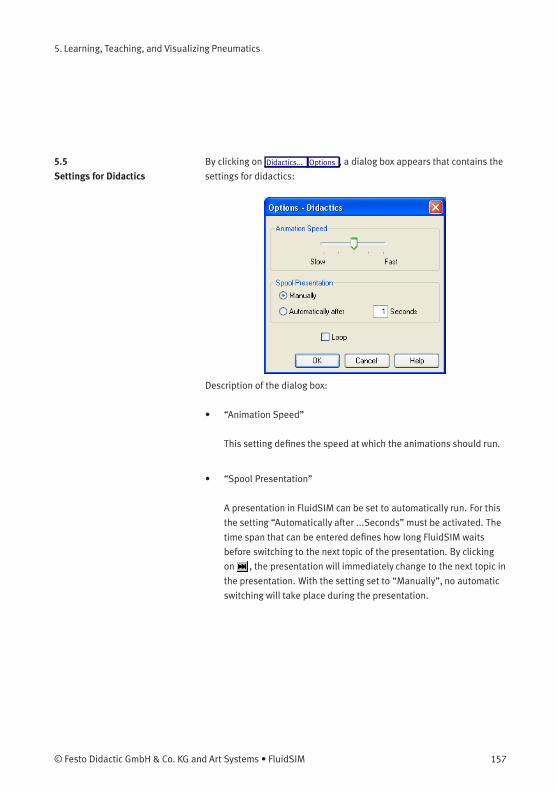
5. Learning, Teaching, and Visualizing Pneumatics
5.5
Settings for Didactics
By clicking on Didactics... Options , a dialog box appears that contains the
settings for didactics:
Description of the dialog box:
• “Animation Speed”
This setting defines the speed at which the animations should run.
• “Spool Presentation”
A presentation in FluidSIM can be set to automatically run. For this
the setting “Automatically after ...Seconds” must be activated. The
time span that can be entered defines how long FluidSIM waits
before switching to the next topic of the presentation. By clicking
on , the presentation will immediately change to the next topic in
the presentation. With the setting set to “Manually”, no automatic
switching will take place during the presentation.
© Festo Didactic GmbH & Co. KG and Art Systems • FluidSIM 157

5. Learning, Teaching, and Visualizing Pneumatics
• “Loop”
Defines whether a running presentation is reset and started over
again after all topics have been displayed. This is known as loop
mode.
158 © Festo Didactic GmbH & Co. KG and Art Systems • FluidSIM
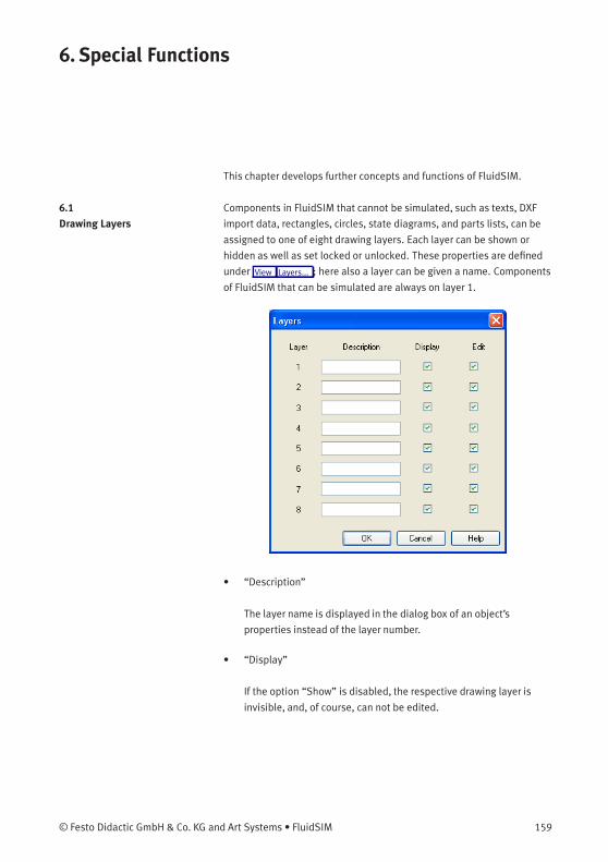
6. Special Functions
This chapter develops further concepts and functions of FluidSIM.
6.1
Drawing Layers
Components in FluidSIM that cannot be simulated, such as texts, DXF
import data, rectangles, circles, state diagrams, and parts lists, can be
assigned to one of eight drawing layers. Each layer can be shown or
hidden as well as set locked or unlocked. These properties are defined
under View Layers... ; here also a layer can be given a name. Components
of FluidSIM that can be simulated are always on layer 1.
• “Description”
The layer name is displayed in the dialog box of an object’s
properties instead of the layer number.
• “Display”
If the option “Show” is disabled, the respective drawing layer is
invisible, and, of course, can not be edited.
© Festo Didactic GmbH & Co. KG and Art Systems • FluidSIM 159
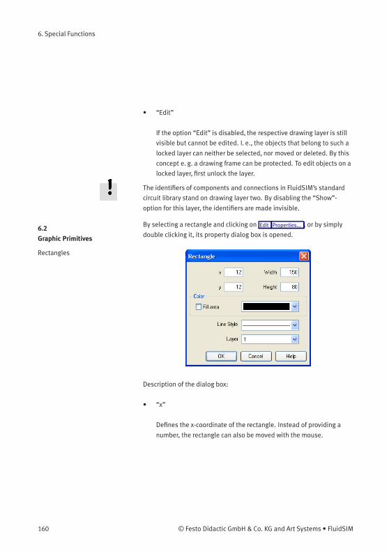
6. Special Functions
• “Edit”
If the option “Edit” is disabled, the respective drawing layer is still
visible but cannot be edited. I. e., the objects that belong to such a
locked layer can neither be selected, nor moved or deleted. By this
concept e. g. a drawing frame can be protected. To edit objects on a
locked layer, first unlock the layer.
The identifiers of components and connections in FluidSIM’s standard
circuit library stand on drawing layer two. By disabling the “Show”-
option for this layer, the identifiers are made invisible.
6.2
Graphic Primitives
Rectangles
By selecting a rectangle and clicking on Edit Properties... , or by simply
double clicking it, its property dialog box is opened.
Description of the dialog box:
• “x”
Defines the x-coordinate of the rectangle. Instead of providing a
number, the rectangle can also be moved with the mouse.
160 © Festo Didactic GmbH & Co. KG and Art Systems • FluidSIM

6. Special Functions
• “y”
Defines the y-coordinate of the rectangle. Instead of providing a
number, the rectangle can also be moved with the mouse.
• “Width”
Defines the width of the rectangle. Instead of providing a number,
the rectangle can also be resized by dragging the mouse: If the
mouse pointer is moved onto the rectangle’s border, the mouse
pointers becomes a resize indicator, , , or . Now the
rectangle can be resized as indicated by holding down the left
mouse button.
• “Height”
Defines the height of the rectangle. Instead of providing a number,
the rectangle can also be resized by dragging the mouse: If the
mouse pointer is moved onto the rectangle’s border, the mouse
pointers becomes a resize indicator, , , or . Now the
rectangle can be resized as indicated by holding down the left
mouse button.
• “Color”
Defines the color of the rectangle’s border. A color is set by clicking
on the down-arrow at the right-hand side of the list and selecting a
color.
• “Fill Area”
Defines whether the entire area or only the border of the rectangle
is colored.
© Festo Didactic GmbH & Co. KG and Art Systems • FluidSIM 161
6. Special Functions
• “Line Style”
Defines the line style of the rectangle. A line style is set by clicking
on the down-arrow at the right-hand side of the list and selecting a
style.
• “Layer”
Defines the drawing layer of the rectangle. The drawing layer is set
by clicking on the down-arrow at the right-hand side of the list and
selecting a layer.
Depending on the settings of drawing layer, the rectangle may not
be visible or may not be selectable. To display an invisible rectangle
or to change its properties in such a case, the drawing layer must
be activated via the menu View Layers... .
162 © Festo Didactic GmbH & Co. KG and Art Systems • FluidSIM
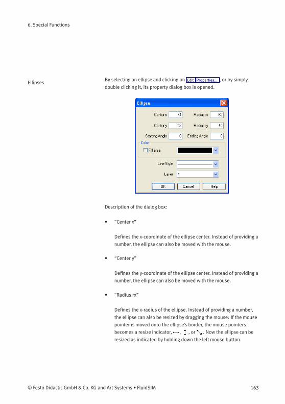
6. Special Functions
Ellipses By selecting an ellipse and clicking on Edit Properties... , or by simply
double clicking it, its property dialog box is opened.
Description of the dialog box:
• “Center x”
Defines the x-coordinate of the ellipse center. Instead of providing a
number, the ellipse can also be moved with the mouse.
• “Center y”
Defines the y-coordinate of the ellipse center. Instead of providing a
number, the ellipse can also be moved with the mouse.
• “Radius rx”
Defines the x-radius of the ellipse. Instead of providing a number,
the ellipse can also be resized by dragging the mouse: If the mouse
pointer is moved onto the ellipse’s border, the mouse pointers
becomes a resize indicator, , , or . Now the ellipse can be
resized as indicated by holding down the left mouse button.
© Festo Didactic GmbH & Co. KG and Art Systems • FluidSIM 163

6. Special Functions
• “Radius ry”
Defines the y-radius of the ellipse. Instead of providing a number,
the ellipse can also be resized by dragging the mouse: If the mouse
pointer is moved onto the ellipse’s border, the mouse pointers
becomes a resize indicator, , , or . Now the ellipse can be
resized as indicated by holding down the left mouse button.
• “Starting Angle”
Defines the ellipse’s start angle, specified in degree. A value of zero
degree corresponds to the three o’clock watch hands position.
• “Ending Angle”
Defines the ellipse’s end angle, specified in degree. A value of zero
degree corresponds to the three o’clock watch hands position.
• “Color”
Defines the color of the ellipse’s border. A color is set by clicking
on the down-arrow at the right-hand side of the list and selecting a
color.
• “Fill Area”
Defines whether the entire area or only the border of the ellipse is
colored.
• “Line Style”
Defines the line style of the ellipse. A line style is set by clicking
on the down-arrow at the right-hand side of the list and selecting a
style.
164 © Festo Didactic GmbH & Co. KG and Art Systems • FluidSIM
6. Special Functions
• “Layer”
Defines the drawing layer of the ellipse. The drawing layer is set
by clicking on the down-arrow at the right-hand side of the list and
selecting a layer.
Depending on the settings of drawing layer, the ellipse may not be
visible or may not be selectable. To display an invisible ellipse or
to change its properties in such a case, the drawing layer must be
activated via the menu View Layers... .
6.3
Text Components and
Identifications
The concept of text components in FluidSIM gives the user a way in
which to describe components in diagrams, assign identification texts,
or to provide commentary on the diagram. The text and the appearance
of text components can be customized to the user’s liking.
Text components function in much the same as other fluidic or electrical
components in FluidSIM. The dummy text component Text can be found
in the component library, and it can be dragged onto the drawing area.
However, text components contain no connections.
As long as the setting Options Protect Text Components remains switched
off, the text components can be marked, dragged, deleted, and rotated
in the same way that other components are handled. When this setting
is activated, the text components can neither be marked nor moved or
deleted. This concept allows the text components to be anchored in the
background. They are out of the way and cannot interfere with changes
or manipulations made to the circuit diagram while in the Edit Mode.
> Drag the text component from the component library to the drawing
area.
> Make sure that Options Protect Text Components is switched off.
© Festo Didactic GmbH & Co. KG and Art Systems • FluidSIM 165
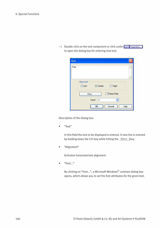
6. Special Functions
> Double click on the text component or click under Edit Properties...
to open the dialog box for entering new text.
Description of the dialog box:
• “Text”
In this field the text to be displayed is entered. A new line is entered
by holding down the Ctrl-key while hitting the Return key.
• “Alignment”
Activates horizontal text alignment.
• “Font...”
By clicking on “Font...”, a Microsoft Windows® common dialog box
opens, which allows you to set the font attributes for the given text.
166 © Festo Didactic GmbH & Co. KG and Art Systems • FluidSIM
6. Special Functions
• “Frame Text”
Draws a border around the text.
• “Layer”
Defines the drawing layer of the text component. The drawing layer
is set by clicking on the down-arrow at the right-hand side of the list
and selecting a layer.
Depending on the settings of drawing layer, the text component
may not be visible or may not be selectable. To display an invisible
text component or to change its properties in such a case, the
drawing layer must be activated via the menu View Layers... .
The dialog box can be closed by clicking on “OK”. As a result the text
along with its font attributes is inserted into the drawing area.
> Click on Options Protect Text Components to protect the text.
The protected text can no longer be selected. Therefore, components
can be placed over the text.
© Festo Didactic GmbH & Co. KG and Art Systems • FluidSIM 167

6. Special Functions
6.4
Embedding Pictures
Alongside denominating texts and comments you may furthermore
include picture files in circuits. This way you may conveniently
complement your circuits by using your own visual material. This may be
a photo of a real construction, an illustrating sectional drawing or even a
small company logo in the drawing corner.
Pictures in FluidSIM, like all other components and objects, may be
included and placed, dragged, rotated and mirrored. Furthermore, in the
same way as rectangles and ellipses, pictures may also be freely scaled.
Since picture files are not vector graphics, a DXF-export will only show a
frame instead of the picture.
Double-clicking a picture or using Edit Properties... will open the
properties dialog for bitmaps.
168 © Festo Didactic GmbH & Co. KG and Art Systems • FluidSIM
6. Special Functions
Description of the dialog box:
• “File Path”
Defines the path to the picture file. Please enter the path of an
existing picture file here or choose one by using the file selection
dialog.
• “External Link”
Bitmaps may be assigned as an external reference or may be stored
with circuit file. The advantage of the latter is that of a transported
circuit automatically containing the pictures. When you only
work within your own environment, the reference to a file path is
convenient because the circuit files remain compact and changes of
the pictures also take effect in FluidSIM.
• “Scale Factor”
Defines the scale factor of a picture file. Instead of entering the
value, you may also change the picture’s size by using the mouse.
When moving the mouse pointer across the border of an object,
the pointer will change to the size modification symbol , or
. Keeping the left mouse button pressed, you may magnify or
downsize it in the displayed direction.
Pictures in FluidSIM are always scaled according to the aspect ratio.
You cannot change just one side by narrowing or stretching.
• “Reset”
Changes back the scaling factor to 100 %.
© Festo Didactic GmbH & Co. KG and Art Systems • FluidSIM 169
6. Special Functions
• “Background/Foreground”
Defines whether the picture is to be positioned in front of all other
circuit objects or behind them. The option “in the foreground” is
favorable with small logos, while big pictures should be assigned
the option “in the background” because a large part of the circuit
could be concealed.
• “Layer”
In this selection list you may define the drawing layer of the picture
file. The drawing layer may be set by clicking the downward arrow
on the right-hand side of the list, you may then choose a layer.
Depending on the setting of the drawing layers, the picture file may
not be displayed or you may not be able to change it. To make the
object visible or to change the settings, you need to temporarily
activate the drawing layer in the menu View Layers... .
Large background pictures may massively reduce edit speed and
simulation speed, since dragging or animating symbols always forces
parts of the picture in the layer below to be re-drawn.
170 © Festo Didactic GmbH & Co. KG and Art Systems • FluidSIM
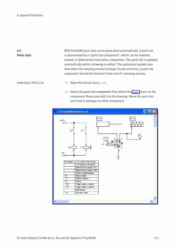
6. Special Functions
6.5
Parts Lists
With FluidSIM parts lists can be generated automatically. A parts list
is represented by a “parts list component”, which can be inserted,
moved, or deleted like every other component. The parts list is updated
automatically while a drawing is edited. The automated update may
slow down the drawing process of large circuits and thus, a parts list
component should be inserted in the end of a drawing process.
Inserting a Parts List > Open the circuit demo1.ct.
> Select the parts list component from either the Insert menu or the
component library and add it to the drawing. Move the parts list
such that it overlaps no other component.
© Festo Didactic GmbH & Co. KG and Art Systems • FluidSIM 171
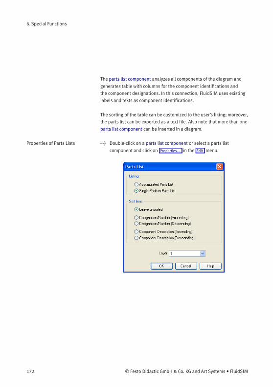
6. Special Functions
The parts list component analyzes all components of the diagram and
generates table with columns for the component identifications and
the component designations. In this connection, FluidSIM uses existing
labels and texts as component identifications.
The sorting of the table can be customized to the user’s liking; moreover,
the parts list can be exported as a text file. Also note that more than one
parts list component can be inserted in a diagram.
Properties of Parts Lists > Double-click on a parts list component or select a parts list
component and click on Properties... in the Edit menu.
172 © Festo Didactic GmbH & Co. KG and Art Systems • FluidSIM
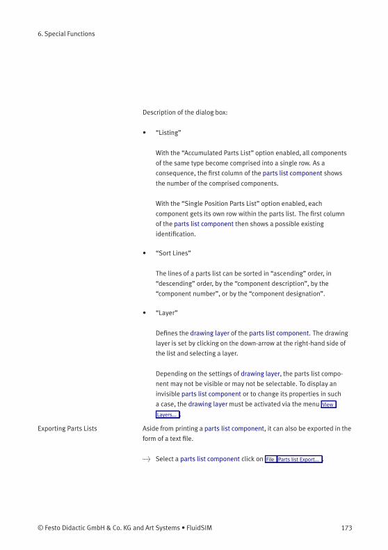
6. Special Functions
Description of the dialog box:
• “Listing”
With the “Accumulated Parts List” option enabled, all components
of the same type become comprised into a single row. As a
consequence, the first column of the parts list component shows
the number of the comprised components.
With the “Single Position Parts List” option enabled, each
component gets its own row within the parts list. The first column
of the parts list component then shows a possible existing
identification.
• “Sort Lines”
The lines of a parts list can be sorted in “ascending” order, in
“descending” order, by the “component description”, by the
“component number”, or by the “component designation”.
• “Layer”
Defines the drawing layer of the parts list component. The drawing
layer is set by clicking on the down-arrow at the right-hand side of
the list and selecting a layer.
Depending on the settings of drawing layer, the parts list compo-
nent may not be visible or may not be selectable. To display an
invisible parts list component or to change its properties in such
a case, the drawing layer must be activated via the menu View
Layers... .
Exporting Parts Lists Aside from printing a parts list component, it can also be exported in the
form of a text file.
> Select a parts list component click on File Parts list Export... .
© Festo Didactic GmbH & Co. KG and Art Systems • FluidSIM 173
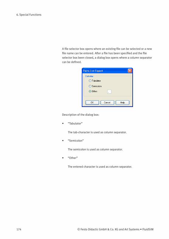
6. Special Functions
A file selector box opens where an existing file can be selected or a new
file name can be entered. After a file has been specified and the file
selector box been closed, a dialog box opens where a column separator
can be defined.
Description of the dialog box:
• “Tabulator”
The tab-character is used as column separator.
• “Semicolon”
The semicolon is used as column separator.
• “Other”
The entered character is used as column separator.
174 © Festo Didactic GmbH & Co. KG and Art Systems • FluidSIM
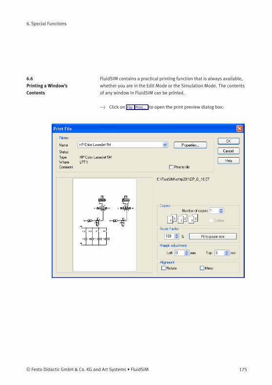
6. Special Functions
6.6
Printing a Window’s
Contents
FluidSIM contains a practical printing function that is always available,
whether you are in the Edit Mode or the Simulation Mode. The contents
of any window in FluidSIM can be printed.
> Click on File Print... to open the print preview dialog box:
© Festo Didactic GmbH & Co. KG and Art Systems • FluidSIM 175
6. Special Functions
Description of the dialog box:
• “Printer”
This list contains all available local as well as network printers. A
printer is set by clicking on the down-arrow at the right-hand side of
the list and selecting a printer.
• “Properties...”
Opens a dialog box with available printer options.
• “Copies”
In the number field “Number of copies” the desired number of
copies is typed in. If the printout consists of several pages you can
check the “Collate” to have the pages sorted automatically.
• “Scale factor”
In the number field “Scale factor” enlargement or reduction of
the circuit diagram is typed in as a percentage. The print preview
window then re-scales the circuit diagram according to the size
proportion that was given.
If the paper size in combination with the chosen scaling factor exceeds
the printer’s printing area, the diagram is printed in a tiled fashion. The
expected number of pages is indicated in the printer preview dialog box.
Pressing the “Fit to paper size” button sets the scale factor so that the
circuit diagram fills out the entire paper area.
176 © Festo Didactic GmbH & Co. KG and Art Systems • FluidSIM
6. Special Functions
• “Margin adjustment”
In order to take the printable regions of different output devices
into account, or enlarge the margin of a printout, an offset in mm can
be defined for the left as well as the upper margin. Positive values
move the drawing to the right or down, negative values move the
drawing to the left or up.
• “Alignment”
In some cases it could be useful to rotate or to mirror the drawing.
E. g. some printer drivers do not support rotating by themselves.
Printing begins by clicking on “OK”.
6.7
TIFF Export
FluidSIM-circuits may be exported as TIFF e. g. to process them using a
non-vector oriented software.
> Please click TIFF Export... un the File -menu to export the current
circuit.
© Festo Didactic GmbH & Co. KG and Art Systems • FluidSIM 177
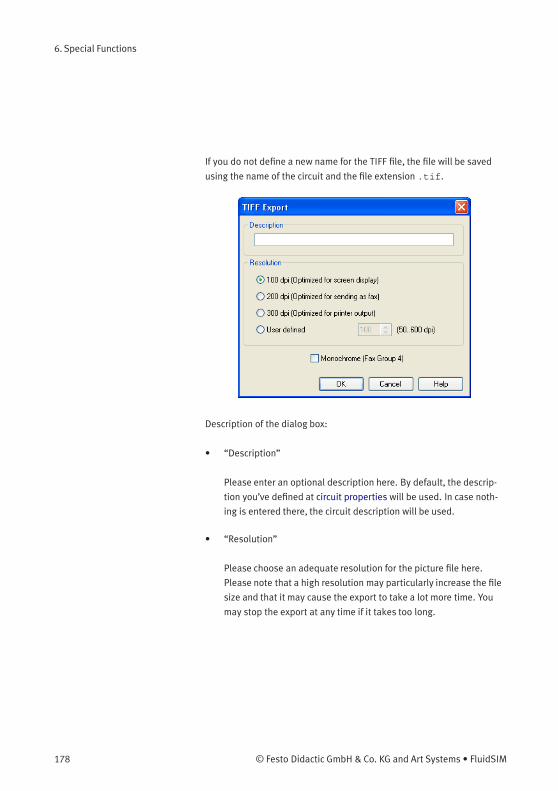
6. Special Functions
If you do not define a new name for the TIFF file, the file will be saved
using the name of the circuit and the file extension .tif.
Description of the dialog box:
• “Description”
Please enter an optional description here. By default, the descrip-
tion you’ve defined at circuit properties will be used. In case noth-
ing is entered there, the circuit description will be used.
• “Resolution”
Please choose an adequate resolution for the picture file here.
Please note that a high resolution may particularly increase the file
size and that it may cause the export to take a lot more time. You
may stop the export at any time if it takes too long.
178 © Festo Didactic GmbH & Co. KG and Art Systems • FluidSIM
6. Special Functions
• “Monochrome”
This export option will save the entire drawing black and white. This
will help the files to become compact ones, but naturally all other
colors will be lost.
6.8
DXF Export
FluidSIM contains a filter module to export circuit diagram in the DXF
format. Hence circuit diagrams from FluidSIM can be imported into a
CAD program, where they can still be edited.
> Click on DXF Export... under the File menu to export the actual circuit
diagram.
If no new name is given for the DXF file, the exported circuit diagram file
is saved with the extension .dxf.
The exported drawings in the DXF format differ from those in FluidSIM in
the following manner:
1. Component connections are shown without circles.
2. The DIN symbol is inserted for the cylinder.
3. The text font is set to STANDARD for the text components.
© Festo Didactic GmbH & Co. KG and Art Systems • FluidSIM 179
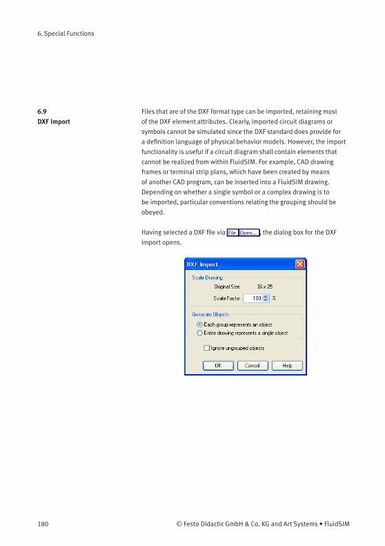
6. Special Functions
6.9
DXF Import
Files that are of the DXF format type can be imported, retaining most
of the DXF element attributes. Clearly, imported circuit diagrams or
symbols cannot be simulated since the DXF standard does provide for
a definition language of physical behavior models. However, the import
functionality is useful if a circuit diagram shall contain elements that
cannot be realized from within FluidSIM. For example, CAD drawing
frames or terminal strip plans, which have been created by means
of another CAD program, can be inserted into a FluidSIM drawing.
Depending on whether a single symbol or a complex drawing is to
be imported, particular conventions relating the grouping should be
obeyed.
Having selected a DXF file via File Open... , the dialog box for the DXF
import opens.
180 © Festo Didactic GmbH & Co. KG and Art Systems • FluidSIM
6. Special Functions
Description of the dialog box:
• “Scale Drawing”
The scaling factor defines scaling in percent that is applied to DXF
file.
• “Each group represents an object”
Enable this option if the DXF file contains several symbols. Note
that symbol elements that belong together can only be identified
as such, if they have been grouped within the CAD program in
such a way, that the outermost group of the symbol occurs in the
ENTITIES section. This means among others that no two symbols
can belong to the same group. However, different symbols are
allowed to share blocks; the import filter of FluidSIM creates copies
for shared blocks.
• “Entire drawing represents a single object”
If this option is enabled, the entire drawing is treated as a single
object.
• “Ignore ungrouped objects”
Enable this option if only for the grouped elements objects shall be
generated. The elements mentioned in section ENTITIES are not
considered.
If this option is disabled, FluidSIM comprises all ungrouped
elements within a single object.
Elements that have been imported can be placed on each of the eight
drawing layers. Moreover, they can be equipped with a designation,
which is displayed in the parts list.
© Festo Didactic GmbH & Co. KG and Art Systems • FluidSIM 181
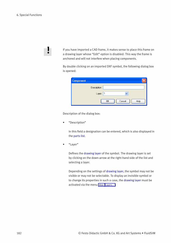
6. Special Functions
If you have imported a CAD frame, it makes sense to place this frame on
a drawing layer whose “Edit”-option is disabled: This way the frame is
anchored and will not interfere when placing components.
By double clicking on an imported DXF symbol, the following dialog box
is opened:
Description of the dialog box:
• “Description”
In this field a designation can be entered, which is also displayed in
the parts list.
• “Layer”
Defines the drawing layer of the symbol. The drawing layer is set
by clicking on the down-arrow at the right-hand side of the list and
selecting a layer.
Depending on the settings of drawing layer, the symbol may not be
visible or may not be selectable. To display an invisible symbol or
to change its properties in such a case, the drawing layer must be
activated via the menu View Layers... .
182 © Festo Didactic GmbH & Co. KG and Art Systems • FluidSIM
6. Special Functions
6.10
Using and Organizing
Component Libraries
Displaying the Component
Library
FluidSIM offers two ways of displaying the component libraries:
• Tree View
This will display the entire structure tree-like. Subgroups, as
opposed to their superordinate groups, are indented to the right-
hand side. Below the applicable group designation you will find the
symbols. To keep track of the overview despite the large number
of component symbols, you may display or hide entire branches
by clicking the group designation. By holding the Shift-key you can
display or hide a group including all subgroups (see 3.3).
© Festo Didactic GmbH & Co. KG and Art Systems • FluidSIM 183
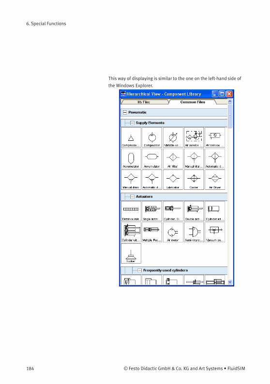
6. Special Functions
This way of displaying is similar to the one on the left-hand side of
the Windows Explorer.
184 © Festo Didactic GmbH & Co. KG and Art Systems • FluidSIM
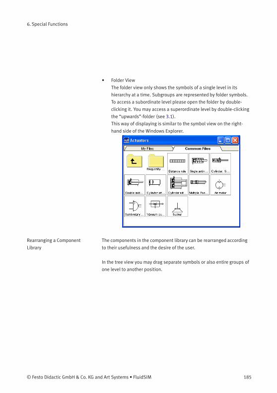
6. Special Functions
• Folder View
The folder view only shows the symbols of a single level in its
hierarchy at a time. Subgroups are represented by folder symbols.
To access a subordinate level please open the folder by double-
clicking it. You may access a superordinate level by double-clicking
the “upwards”-folder (see 3.1).
This way of displaying is similar to the symbol view on the right-
hand side of the Windows Explorer.
Rearranging a Component
Library
The components in the component library can be rearranged according
to their usefulness and the desire of the user.
In the tree view you may drag separate symbols or also entire groups of
one level to another position.
© Festo Didactic GmbH & Co. KG and Art Systems • FluidSIM 185
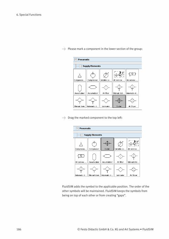
6. Special Functions
> Please mark a component in the lower section of the group:
> Drag the marked component to the top left:
FluidSIM adds the symbol to the applicable position. The order of the
other symbols will be maintained. FluidSIM keeps the symbols from
being on top of each other or from creating “gaps”.
186 © Festo Didactic GmbH & Co. KG and Art Systems • FluidSIM
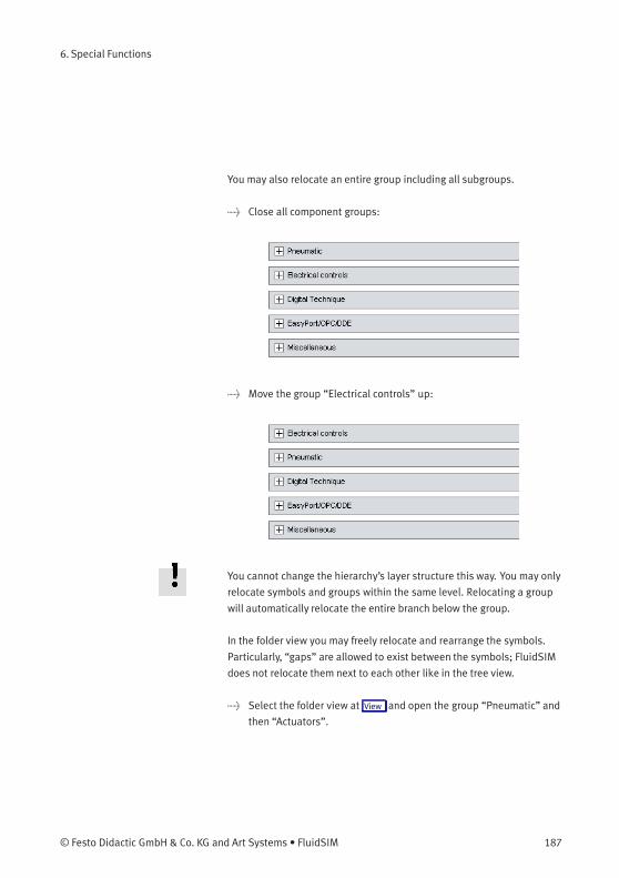
6. Special Functions
You may also relocate an entire group including all subgroups.
> Close all component groups:
> Move the group “Electrical controls” up:
You cannot change the hierarchy’s layer structure this way. You may only
relocate symbols and groups within the same level. Relocating a group
will automatically relocate the entire branch below the group.
In the folder view you may freely relocate and rearrange the symbols.
Particularly, “gaps” are allowed to exist between the symbols; FluidSIM
does not relocate them next to each other like in the tree view.
> Select the folder view at View and open the group “Pneumatic” and
then “Actuators”.
© Festo Didactic GmbH & Co. KG and Art Systems • FluidSIM 187
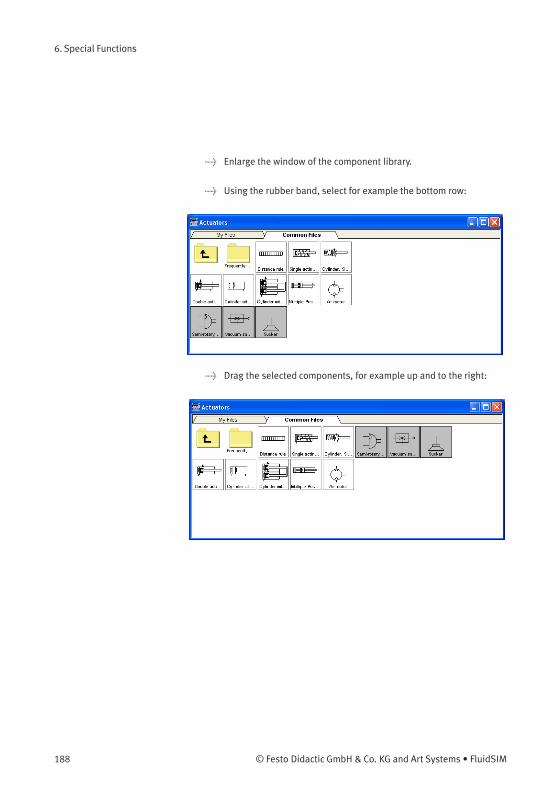
6. Special Functions
> Enlarge the window of the component library.
> Using the rubber band, select for example the bottom row:
> Drag the selected components, for example up and to the right:
188 © Festo Didactic GmbH & Co. KG and Art Systems • FluidSIM
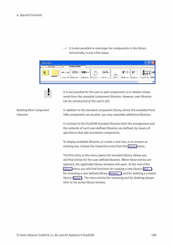
6. Special Functions
> It is also possible to rearrange the components in the library
horizontally, in just a few steps:
It is not possible for the user to add components to or delete compo-
nents from the standard component libraries. However, own libraries
can be constructed at the user’s will.
Building New Component
Libraries
In addition to the standard component library, where the available Fluid-
SIM-components are located, you may assemble additional libraries.
In contrast to the FluidSIM standard libraries both the arrangement and
the contents of such user-defined libraries can defined, by means of
operations that add and delete components.
To display available libraries, to create a new one, or to rename an
existing one, choose the respective entry from the Library menu.
The first entry in this menu opens the standard library. Below you
will find entries for the user defined libraries. When these entries are
selected, the applicable library windows will open. At the end of the
Library -menu you will find functions for creating a new library ( New... ),
for renaming a user defined library ( Rename... ) and for deleting a created
library ( Delete ). The menu entries for renaming and for deleting always
refer to the active library window.
© Festo Didactic GmbH & Co. KG and Art Systems • FluidSIM 189
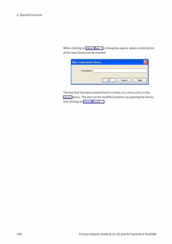
6. Special Functions
When clicking on Library New... a dialog box opens, where a description
of the new library can be entered:
The text that has been entered here is shown as a menu entry in the
Library menu. The text can be modified anytime, by opening the library
and clicking on Library Rename... .
190 © Festo Didactic GmbH & Co. KG and Art Systems • FluidSIM
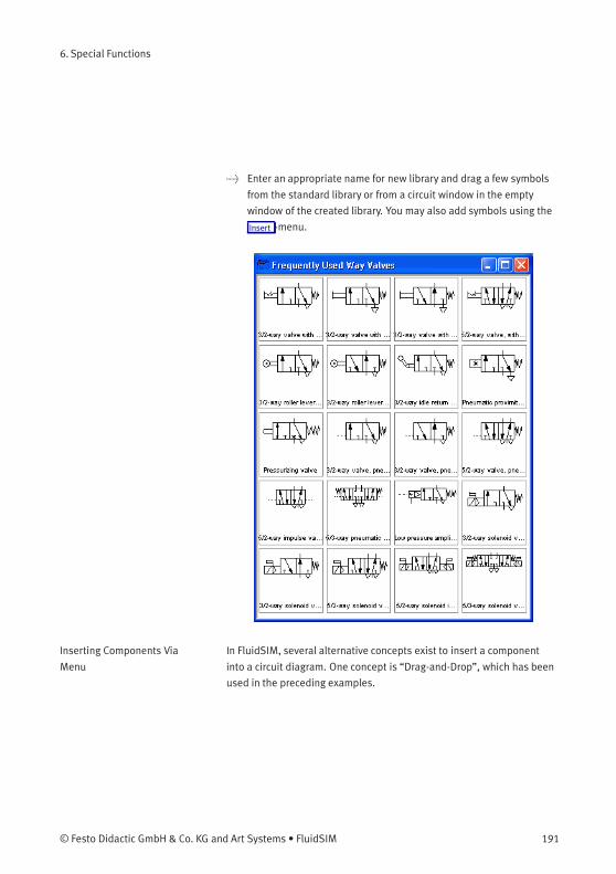
6. Special Functions
> Enter an appropriate name for new library and drag a few symbols
from the standard library or from a circuit window in the empty
window of the created library. You may also add symbols using the
Insert -menu.
Inserting Components Via
Menu
In FluidSIM, several alternative concepts exist to insert a component
into a circuit diagram. One concept is “Drag-and-Drop”, which has been
used in the preceding examples.
© Festo Didactic GmbH & Co. KG and Art Systems • FluidSIM 191
6. Special Functions
Alternatively, components can be selected through the Insert menu,
either by navigating along the hierarchical menu structure or by entering
one or more search strings. While mousing a component description
in the menu, the related symbol is shown either in the preview window
of the search dialog or in the upper left corner of the FluidSIM main
window.
192 © Festo Didactic GmbH & Co. KG and Art Systems • FluidSIM

6. Special Functions
> Open a new circuit window, select the menu item Insert /
Find Component... and enter one or more search strings; e. g.,
valve,reset.
Description of the dialog box:
• “Words”
In this field one or more search items can be entered in order to
find a particular component. The order of the search items does not
play a role, they are combined by a logical “AND”. Also note that
partial matches are allowed. I. e., if you are unsure respecting the
correct spelling of a component name, simply partition this name
into several comma-separated search strings.
© Festo Didactic GmbH & Co. KG and Art Systems • FluidSIM 193
6. Special Functions
• “Similarity”
Determines the accuracy of the match between “Exact” and
“Fuzzy”. This setting can be used to allow a tolerance respecting
different spelling variants or typing errors.
• “Results”
Contains a list of component descriptions, which contain the
provided search strings. This list is ordered with respect to the
accuracy of the match. By double-clicking onto a line in the list the
dialog box is closed and the related component is inserted in the
circuit diagram. The selection marker in the list can be moved by
simply clicking the mouse, but also by using the arrow keys. Note
that the selection marker does not follow the scroll bars.
• “Preview”
If the “preview” option is enabled, the component symbol of the
selected entry is shown below the list.
Recall that a component can also be searched by navigating along the
hierarchical menu structure.
194 © Festo Didactic GmbH & Co. KG and Art Systems • FluidSIM
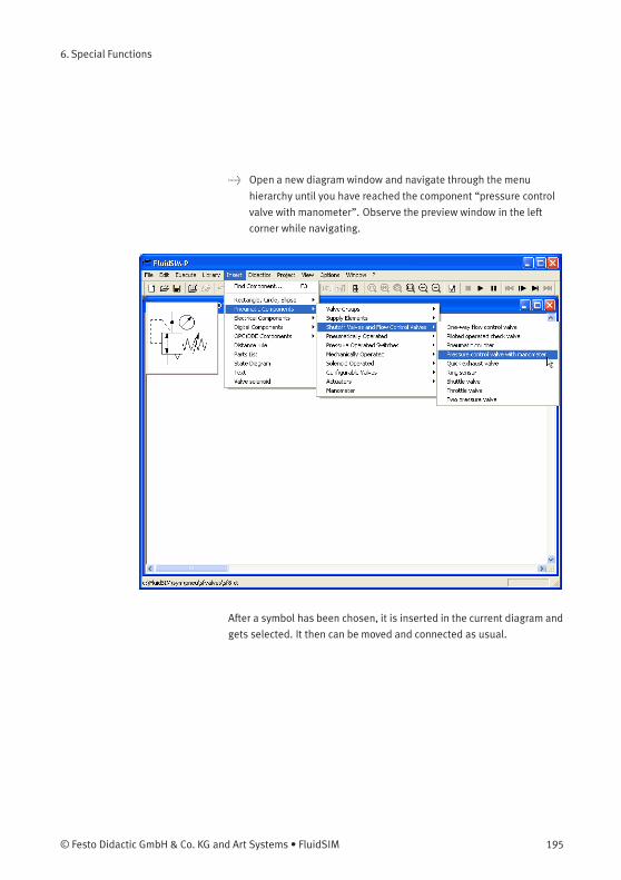
6. Special Functions
> Open a new diagram window and navigate through the menu
hierarchy until you have reached the component “pressure control
valve with manometer”. Observe the preview window in the left
corner while navigating.
After a symbol has been chosen, it is inserted in the current diagram and
gets selected. It then can be moved and connected as usual.
© Festo Didactic GmbH & Co. KG and Art Systems • FluidSIM 195
6. Special Functions
6.11
Managing Projects
FluidSIM allows of including various settings and files in a project file
with a unique name, thereby facilitating project management. When
opening a project, the previously saved project settings are used as
default. The project menu realizes a quick access of all files that belong
to a particular project.
Creating a New Project Before a new project is created some preparatory actions to facilitate
project management and to save several process steps at a later stage
must be undertaken.
> Open all files to be added to the new project. This may include, for
example, preview windows for often used symbols, libraries as well
as circuit files.
All files that are open when creating a new project will be automatically
added to the project.
> Select Project New... and enter a file name for the new project.
Project files have the extension prj and should, for best results, reside
in the same ct subdirectory as the circuit files of the project.
After having entered the file name in the dialog box, the system creates
the project file with all open files.
> Close all windows which you don’t need right now, and arrange the
remaining windows according to your preferences.
Any closed windows that belong to the project can be opened at any
time by clicking Files or Overviews in the project menu.
> Save the settings and the window arrangement as default for this
project by clicking Options Save Settings Now .
196 © Festo Didactic GmbH & Co. KG and Art Systems • FluidSIM
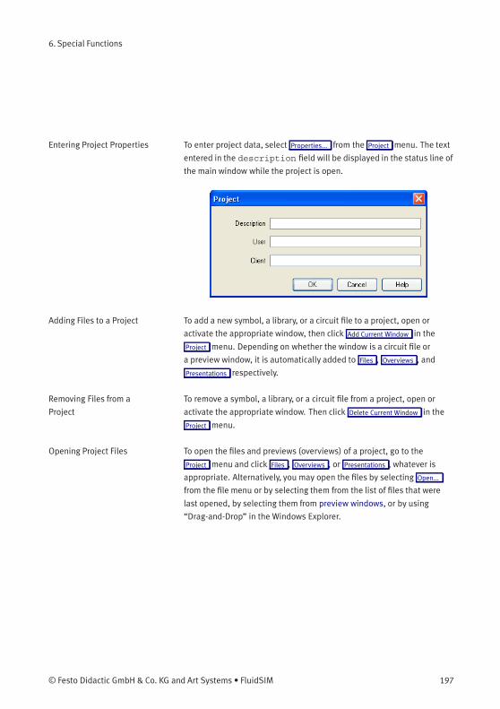
6. Special Functions
Entering Project Properties To enter project data, select Properties... from the Project menu. The text
entered in the description field will be displayed in the status line of
the main window while the project is open.
Adding Files to a Project To add a new symbol, a library, or a circuit file to a project, open or
activate the appropriate window, then click Add Current Window in the
Project menu. Depending on whether the window is a circuit file or
a preview window, it is automatically added to Files , Overviews , and
Presentations respectively.
Removing Files from a
Project
To remove a symbol, a library, or a circuit file from a project, open or
activate the appropriate window. Then click Delete Current Window in the
Project menu.
Opening Project Files To open the files and previews (overviews) of a project, go to the
Project menu and click Files , Overviews , or Presentations , whatever is
appropriate. Alternatively, you may open the files by selecting Open...
from the file menu or by selecting them from the list of files that were
last opened, by selecting them from preview windows, or by using
“Drag-and-Drop” in the Windows Explorer.
© Festo Didactic GmbH & Co. KG and Art Systems • FluidSIM 197
6. Special Functions
6.12
Saving Settings
FluidSIM distinguishes between three types of settings: global settings,
circuit diagram specific settings, and window specific settings. Although
most of these settings have already been in discussed in preceding
sections, this section comprises the possible settings from FluidSIM and
their relationship to one another.
Global Settings The global settings are found under the Options and the View menu and
belong to the following groups.
Global settings for various display features:
1. View Large Mouse Cursor
Activates or deactivates the large mouse cursor.
2. View Toolbar
Displays or hides the toolbar.
3. View Status Bar
Displays or hides the status bar.
Global settings in the dialog boxes:
1. Options Simulation...
2. Options Sound...
3. Options Didactics...
4. Options Grid...
Other global settings:
1. Options Protect Text Components
Switches the protection for the text components on or off.
2. Options Create Backup Files
Enables or disables the automatic creation of a backup file for
circuit diagrams. Backup files have the file name extension bak.
The backup files are created when the circuit diagram is saved and
are updated each time the circuit diagram is saved.
3. Options Default Directory on Network
198 © Festo Didactic GmbH & Co. KG and Art Systems • FluidSIM
6. Special Functions
Defines the default directory for circuit diagrams and presentation
files. If this option is enabled the default directory for the men-
tioned files is on the network file server. Otherwise, the default
directory is on the local PC. This menu entry is available only in the
network version.
4. Options Save Settings on Exit
Determines whether the global settings and the circuit diagram
specific settings of each open circuit diagram should be saved
before exiting FluidSIM.
All global settings can be saved with Options Save Settings Now .
By clicking on Save Settings Now under the Options menu, the circuit
diagram specific settings of the current circuit will also be saved. These
settings then become the default for all new circuit diagrams that are
created. The following settings belong in the circuit diagram specific
category: display of quantity values, the flow direction indicator, and the
background grid (see next section).
Circuit Diagram-Specific
Settings
The following belong to the circuit diagram specific settings:
1. View Quantity Values...
2. View Display Flow Direction
3. View Display Grid
These settings can be adjusted for each open circuit diagram individu-
ally, although they cannot be saved as such. Instead, the user has a way
to define a default setting for the creation of new circuit diagrams: By
clicking on Save Settings Now under Options , the display settings of the
current circuit diagram are saved as the default. These default settings
apply to the display of quantities, the flow direction indicator, and the
background grid of each newly opened circuit diagram.
The term “current circuit” refers to the selected circuit diagramwindow.
A selected window will always be fully visible and its title bar will be
highlighted.
© Festo Didactic GmbH & Co. KG and Art Systems • FluidSIM 199
6. Special Functions
Window-Specific Settings The following settings are window specific:
1. zoom factor
2. window size
3. window position
Window-specific settings can be saved by clicking on Save Settings Now
under the Options menu.
200 © Festo Didactic GmbH & Co. KG and Art Systems • FluidSIM

7. GRAFCET
This chapter provides an introduction to creating and simulating
GRAFCET plans with FluidSIM. See norm DIN EN 60848 for the
complete specification of the GRAFCET description language. Festo
Didactic provides a range of training documentation for more detailed
introductions to GRAFCET.
Unlike an SPS programming language, such as Sequential Function
Chart (SFC), GRAFCET is a graphic description language that describes
the logical behaviour and operation of a control system or a process
- regardless of the technical software and hardware implementation.
FluidSIM can be used to both create and simulate GRAFCET plans. The
term GRAFCET is also used as a synonym for a GRAFCET plan. It should
be obvious from the context whether the word GRAFCET refers to the
plan or the language.
A GRAFCET essentially describes two aspects of a control system,
according to specified rules: the actions (commands) to be carried
out and the sequence of execution. The elementary components of
a GRAFCET are steps, actions and transitions and can be used in the
same way as pneumatic or electrical components. To achieve a uniform
operating concept, the GRAFCET elements feature connections that
can be used to link them to each other (as with all other FluidSIM
components).
© Festo Didactic GmbH & Co. KG and Art Systems • FluidSIM 201
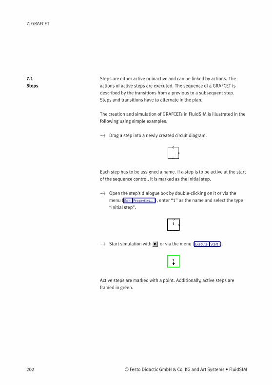
7. GRAFCET
7.1
Steps
Steps are either active or inactive and can be linked by actions. The
actions of active steps are executed. The sequence of a GRAFCET is
described by the transitions from a previous to a subsequent step.
Steps and transitions have to alternate in the plan.
The creation and simulation of GRAFCETs in FluidSIM is illustrated in the
following using simple examples.
> Drag a step into a newly created circuit diagram.
Each step has to be assigned a name. If a step is to be active at the start
of the sequence control, it is marked as the initial step.
> Open the step’s dialogue box by double-clicking on it or via the
menu ( Edit Properties... ), enter “1” as the name and select the type
“initial step”.
> Start simulation with or via the menu ( Execute Start ).
Active steps are marked with a point. Additionally, active steps are
framed in green.
202 © Festo Didactic GmbH & Co. KG and Art Systems • FluidSIM
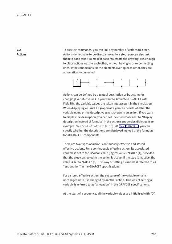
7. GRAFCET
7.2
Actions
To execute commands, you can link any number of actions to a step.
Actions do not have to be directly linked to a step; you can also link
them to each other. To make it easier to create the drawing, it is enough
to place actions next to each other, without having to draw connecting
lines. If the connections for the elements overlap each other, they are
automatically connected.
Actions can be defined by a textual description or by setting (or
changing) variable values. If you want to simulate a GRAFCET with
FluidSIM, the variable values are taken into account in the simulation.
When displaying a GRAFCET graphically, you can decide whether the
variable name or the descriptive text is shown in an action. If you want
to display the description, you can set the checkmark next to “Display
description instead of formula” in the action’s properties dialogue (see
example: Grafcet/Grafcet18.ct). At View GRAFCET... , you can
specify whether the descriptions are displayed instead of the formulae
for all GRAFCET components.
There are two types of action: continuously effective and stored
effective actions. For a continuously effective action, its associated
variable is set to the Boolean value (logical value) “TRUE” (1), provided
that the step connected to the action is active. If the step is inactive, the
value is set to “FALSE” (0). This way of setting a variable is referred to as
“assignation” in the GRAFCET specifications.
For a stored effective action, the set value of the variable remains
unchanged until it is changed by another action. This way of setting a
variable is referred to as “allocation” in the GRAFCET specifications.
At the start of a sequence, all the variable values are initialisedwith “0”.
© Festo Didactic GmbH & Co. KG and Art Systems • FluidSIM 203
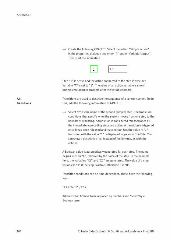
7. GRAFCET
> Create the following GRAFCET. Select the action “Simple action”
in the properties dialogue and enter “A” under “Variable/output”.
Then start the simulation.
Step “1” is active and the action connected to the step is executed.
Variable “A” is set to “1”. The value of an action variable is shown
during simulation in brackets after the variable’s name.
7.3
Transitions
Transitions are used to describe the sequence of a control system. To do
this, add the following information to GRAFCET:
> Select “2” as the name of the second (simple) step. The transition
conditions that specify when the system moves from one step to the
next are still missing. A transition is considered released once all
the immediately preceding steps are active. A transition is triggered
once it has been released and its condition has the value “1”. A
transition with the value “1” is displayed in green in FluidSIM. You
can show a descriptive text instead of the formula, as with the
actions.
A Boolean value is automatically generated for each step. The name
begins with an “X”, followed by the name of the step. In the example
here, the variables “X1” and “X2” are generated. The value of a step
variable is “1” if the step is active; otherwise it is “0”.
Transition conditions can be time-dependent. These have the following
form:
t1 s / “term” / t2 s
Where t1 and t2 have to be replaced by numbers and “term” by a
Boolean term.
204 © Festo Didactic GmbH & Co. KG and Art Systems • FluidSIM
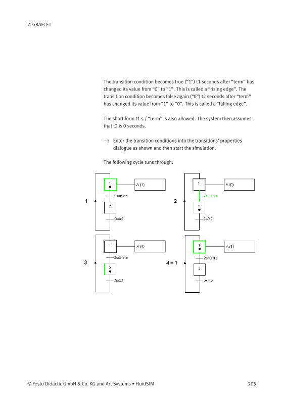
7. GRAFCET
The transition condition becomes true (“1”) t1 seconds after “term” has
changed its value from “0” to “1”. This is called a “rising edge”. The
transition condition becomes false again (“0”) t2 seconds after “term”
has changed its value from “1” to “0”. This is called a “falling edge”.
The short form t1 s / “term” is also allowed. The system then assumes
that t2 is 0 seconds.
> Enter the transition conditions into the transitions’ properties
dialogue as shown and then start the simulation.
The following cycle runs through:
© Festo Didactic GmbH & Co. KG and Art Systems • FluidSIM 205
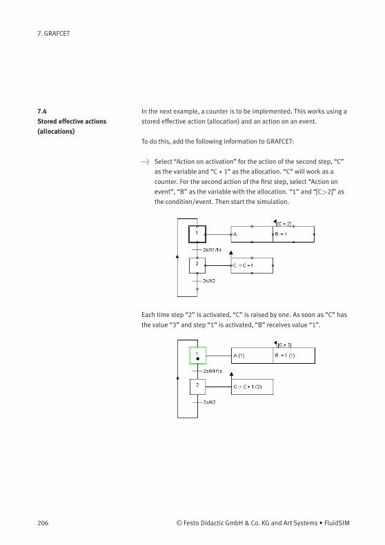
7. GRAFCET
7.4
Stored effective actions
(allocations)
In the next example, a counter is to be implemented. This works using a
stored effective action (allocation) and an action on an event.
To do this, add the following information to GRAFCET:
> Select “Action on activation” for the action of the second step, “C”
as the variable and “C + 1” as the allocation. “C” will work as a
counter. For the second action of the first step, select “Action on
event”, “B” as the variable with the allocation. “1” and “[C>2]” as
the condition/event. Then start the simulation.
Each time step “2” is activated, “C” is raised by one. As soon as “C” has
the value “3” and step “1” is activated, “B” receives value “1”.
206 © Festo Didactic GmbH & Co. KG and Art Systems • FluidSIM
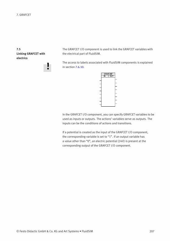
7. GRAFCET
7.5
Linking GRAFCET with
electrics
The GRAFCET I/O component is used to link the GRAFCET variables with
the electrical part of FluidSIM.
The access to labels associated with FluidSIM components is explained
in section 7.6.10.
In the GRAFCET I/O component, you can specify GRAFCET variables to be
used as inputs or outputs. The actions’ variables serve as outputs. The
inputs can be the conditions of actions and transitions.
If a potential is created as the input of the GRAFCET I/O component,
the corresponding variable is set to “1”. If an output variable has
a value other than “0”, an electric potential (24V) is present at the
corresponding output of the GRAFCET I/O component.
© Festo Didactic GmbH & Co. KG and Art Systems • FluidSIM 207
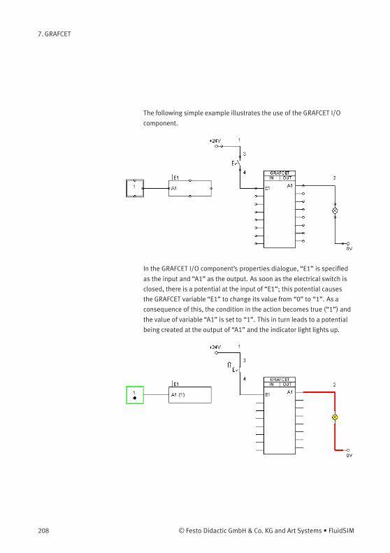
7. GRAFCET
The following simple example illustrates the use of the GRAFCET I/O
component.
In the GRAFCET I/O component’s properties dialogue, “E1” is specified
as the input and “A1” as the output. As soon as the electrical switch is
closed, there is a potential at the input of “E1”; this potential causes
the GRAFCET variable “E1” to change its value from “0” to “1”. As a
consequence of this, the condition in the action becomes true (“1”) and
the value of variable “A1” is set to “1”. This in turn leads to a potential
being created at the output of “A1” and the indicator light lights up.
208 © Festo Didactic GmbH & Co. KG and Art Systems • FluidSIM
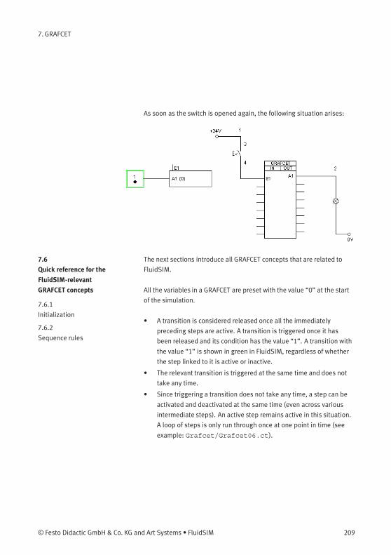
7. GRAFCET
As soon as the switch is opened again, the following situation arises:
7.6
Quick reference for the
FluidSIM-relevant
GRAFCET concepts
The next sections introduce all GRAFCET concepts that are related to
FluidSIM.
7.6.1
Initialization
All the variables in a GRAFCET are preset with the value “0” at the start
of the simulation.
7.6.2
Sequence rules
• A transition is considered released once all the immediately
preceding steps are active. A transition is triggered once it has
been released and its condition has the value “1”. A transition with
the value “1” is shown in green in FluidSIM, regardless of whether
the step linked to it is active or inactive.
• The relevant transition is triggered at the same time and does not
take any time.
• Since triggering a transition does not take any time, a step can be
activated and deactivated at the same time (even across various
intermediate steps). An active step remains active in this situation.
A loop of steps is only run through once at one point in time (see
example: Grafcet/Grafcet06.ct).
© Festo Didactic GmbH & Co. KG and Art Systems • FluidSIM 209
7. GRAFCET
7.6.3
Sequence selection
A step can branch off into various partial sequences. In the GRAFCET
specifications, these partial sequences have to be exclusive. Since this
can generally only be checked during the sequence, this exclusivity is
not required in FluidSIM (see example: Grafcet/Grafcet07.ct).
7.6.4
Synchronization
The GRAFCET synchronization component can be used to implement
synchronizations (see example: Grafcet/Grafcet08.ct).
7.6.5
Transient sequence /
unstable step
As described in 7.6.2, triggering a transition does not take any time. As a
consequence of this, multiple consecutive steps can be activated at the
same point in time one after the other. This sequence is called transient
(continuous).
The intermediate steps in the sequence chain are referred to as
unstable. The continuously effective actions connected to them
are not displayed in the simulation. The allocations in the stored
effective actions are carried out. Triggering the intermediate steps and
their associated transitions is called virtual triggering (see example:
Grafcet/Grafcet06.ct).
7.6.6
Determining the values of
GRAFCET variables
Variables of continuously effective actions (allocations) receive the
value “1” if the corresponding action is linked to an active step and any
action condition present has the value “1”.
Variables of stored effective actions (assignation) are changed if the
corresponding action is linked to an active step and the relevant action
event occurs (e.g. action on event or on activation).
FluidSIM does not check whether the two types of variable identification
contradict each other for a variable. If this case occurs, the variable
value is determined by an internal calculation, which the user cannot
predict (see example: Grafcet/Grafcet09.ct).
210 © Festo Didactic GmbH & Co. KG and Art Systems • FluidSIM
7. GRAFCET
7.6.7
Checking the entries
FluidSIM checks the validity of entries for conditions and assignations. If
this kind of term does not match the specifications, the term in question
is displayed in red. The simulation is only released once all the terms are
valid.
7.6.8
Admissible characters for
steps and variables
Only the following characters may be used for steps and variables:
• Numbers from “0” to “9”
• Lower-case letters from “a” to “z”
• Upper-case letters from “A” to “Z”
• The underscore “_”
There are no limitations for the descriptions that can be shown for
conditions and actions, because these are only displayed and are not
used for simulation.
Labels of fluidic or electrical components that are intended to be used
from GRAFCETs (see 7.6.10) are allowed to contain only the characters
mentioned above.
7.6.9
Variable names
There are four different types of variables. All variables can be used in
conditions and assignations.
• “Action variables”
Action variables are available throughout GRAFCET and can be set
in actions (see example: Grafcet/Grafcet10.ct).
© Festo Didactic GmbH & Co. KG and Art Systems • FluidSIM 211
7. GRAFCET
• “Step variables”
Step variables are inserted automatically for each step and have
the value “1” when and only when the corresponding step is active.
Step variables have the form X + “step name”. If, for example, the
step name is “12”, then the associated variable is “X12”.
Step names are only ever valid within a partial GRAFCET or within
the global GRAFCET. This means that the same step name can be
used in different partial GRAFCETs. In order to be able to address
step variables across partial GRAFCETs in FluidSIM, the step
variable has to be preceded by the partial GRAFCET name.
Example:
Partial GRAFCET “1” contains step “2” and is meant to be
addressed in the global GRAFCET. Within the global GRAFCET, the
step variable name “G1.X2” has to be used. Within partial GRAFCET
“1”, “X2” is enough (see example: Grafcet/Grafcet11.ct).
Variables of macro-steps have the form XM + “step name”, macro
inputs have XE + “step name” and macro outputs have XS + “step
name” (see example: Grafcet/Grafcet15.ct).
• “Partial GRAFCET variables”
Partial GRAFCET variables are automatically inserted for each par-
tial GRAFCET and have the value “1” when and only when at least
one step in the corresponding partial GRAFCET is active. Partial
GRAFCET variables have the form XG + “partial GRAFCET name”.
If, for example, the partial GRAFCET name is “1”, the associated
variable is “XG1” (see example: Grafcet/Grafcet12.ct).
212 © Festo Didactic GmbH & Co. KG and Art Systems • FluidSIM
7. GRAFCET
• “Labels of fluidic or electrical components”
These labels can be used as GRAFCET input variables (see 7.6.10).
7.6.10
Access to labels of fluidic
and electrical components
GRAFCET-I/O components are the standard means to access electrical
components in FluidSIM. In addition, certain labels of a circuit can be
used as Boolean input variables in GRAFCET directly, without using a
GRAFCET-I/O component (see example Grafcet/TP201_09gc2.ct).
Such a direct access pertains to labels of the following components:
• Distance rule
• Semi-rotary actuator
• Pressure switch
• Manually actuated switch
• Relay
• Valve solenoid
7.6.11
Functions and formula
entry
A range of functions can be used in conditions and assignations. These
functions are displayed according to the GRAFCET specifications (e.g.
upwards arrow for rising edge). Entering GRAFCET-specific functions is
supported by the buttons in the dialogues with the relevant labels:
• “+” (logical OR)
• “*” (logical AND)
• “NOT” (logical NOT)
• “RE” (rising edge)
• “FE” (falling edge)
• “s / / s” (delay)
• “s /” (delay, short form)
• “NOT(s / )” (time limit)
If the functions “NOT”, “RE” or “FE” refer to a term, the term has to be
placed in brackets.
Examples:
© Festo Didactic GmbH & Co. KG and Art Systems • FluidSIM 213

7. GRAFCET
NOT a
NOT (a + b)
RE X1
RE (X1 * X2)
The following additional mathematical functions are available:
• abs (absolute amount)
• sign (algebraic sign: +1, 0, -2)
• max (maximum of two numbers)
• min (minimum of two numbers)
• ∧ (to the power of, e.g. a∧3)• sqrt (square root)
• exp (to the power of constant “e”)
• log (natural logarithm)
• sin (sine)
• cos (cosine)
7.6.12
Delays / time limits
Delays have the following form (see example: Grafcet/Grafcet03.
ct):
“Time in seconds” s / “Boolean term” / “time in seconds”
or
“Time in seconds” s / “Boolean term”
Examples:
1 s / X1 / 2s
3s/X3
214 © Festo Didactic GmbH & Co. KG and Art Systems • FluidSIM

7. GRAFCET
Time limits have the following form:
NOT (“time in seconds” s / “Boolean term”)
Example:
NOT(6s/X28)
7.6.13
Boolean value of an
assertion
In GRAFCET, you can use Boolean values to calculate an assertion, for
example: a counter “C” should be larger than 6 and step “X1” should
be activated. “C” is larger than “6” can be calculated as with a variable.
To do this, the assertion has to be set in square brackets. So in this
example:
[C > 6 ] * X1
If a Boolean assertion is positioned on its own in a condition, then you
can omit the square brackets in FluidSIM, for example C > 6 instead of
[C > 6]. (See example: Grafcet/Grafcet13.ct)
7.6.14
Target information
If you want to interrupt an operative connection from a transition to
a step, you can enter the name of the target step in the transition’s
properties dialogue (see example: Grafcet/Grafcet14.ct).
7.6.15
Partial GRAFCETs
Partial GRAFCETs can be used to separate a GRAFCET into different
hierarchy levels. This function is most often used for enclosing steps
and compulsory commands. The name of a partial GRAFCET is always
preceded by a “G”.
© Festo Didactic GmbH & Co. KG and Art Systems • FluidSIM 215
7. GRAFCET
In order to determine partial GRAFCETs in FluidSIM, the partial GRAFCET
frame has to be placed over the relevant GRAFCET part and you have
to assign a name in the properties dialogue. The preceding “G” is not
part of the name that you have to enter; it is added automatically by
FluidSIM and shown at the bottom left of the partial GRAFCET frame.
You can alter the size of the partial GRAFCET frame by dragging its
edges with the mouse (see example: Grafcet/Grafcet11.ct). It
is important that all the elements of the partial GRAFCET are located
entirely within the relevant frame and that there are no “foreign”
elements overlapping the frame.
7.6.16
Macro-steps
Macro-steps can be specified using a step’s properties dialogue. The
preceding “M” is not a part of the name that you have to enter; it is
added automatically by FluidSIM. You can specify macro inputs and
macro outputs in the same way. The preceding “E” and “S” in these
cases are not part of the name either and are automatically added by
FluidSIM (see example: Grafcet/Grafcet15.ct).
7.6.17
Compulsory commands
Compulsory commands can be used to control partial GRAFCETs
regardless of their normal sequence. There is an entry mask to help you
enter these commands in FluidSIM. There are four types of compulsory
command. They are shown here using four examples (see example:
Grafcet/Grafcet16.ct).
• “G12 {8, 9, 11}”
Setting a specific situation. This example activates steps 8, 9 and
11 of partial GRAFCET 12.
• “G12 {*}”
Freezing a partial GRAFCET. In this example, the current situation for
partial GRAFCET 12 is maintained as it is. No further transitions are
triggered.
216 © Festo Didactic GmbH & Co. KG and Art Systems • FluidSIM
7. GRAFCET
• “G12 {}”
Setting a blank situation. All steps in partial GRAFCET 12 are
deactivated in this example.
• “G12 {INIT}”
Setting the initial situation. In this example, the steps in partial
GRAFCET 12 that are marked as initial steps are activated.
7.6.18
Enclosing step
Enclosing steps can be specified using a step’s properties dialogue.
You can either enter the enclosed partial GRAFCETs directly or select
them from a list. You have to separate individual partial GRAFCETs with a
comma or a blank space.
During simulation, the name of the enclosing step is shown at the top
left of the partial GRAFCET frame, as soon as the step is activated (see
example: Grafcet/Grafcet17.ct).
You have to set the “Activation link” field in the properties dialogue for
steps within the enclosed partial GRAFCET that you wish to activate
when the enclosing step is activated.
7.6.19
Action when a transition is
triggered
FluidSIM does not support the execution of an action when a transition
is triggered.
© Festo Didactic GmbH & Co. KG and Art Systems • FluidSIM 217
8. Help and Advanced Tips
This chapter serves as the first place to find help, when dealing with
questions that come from working with FluidSIM. The second section of
this chapter provides background information for advanced users.
8.1
The Most Frequently
Occurring Problems
When attempting to perform certain actions, you are prompted to
insert the FluidSIM CD.
FluidSIM cannot find certain installation directories on the hard disk.
Probably not all of the software components were loaded at the time
of installation. Either insert the CD or reinstall the missing software
components.
Component cannot be moved or deleted.
Make sure that you are in the Edit Mode ( ); components can only be
moved or deleted in the Edit Mode.
Components cannot be dragged onto the drawing area.
Make sure that you are in the Edit Mode.
Components cannot be moved or deleted in the Edit Mode.
Make sure that you have selected a component and not a component
connection.
A line cannot be drawn between two connections.
Make sure to check the following points:
1. FluidSIM is in the Edit Mode.
2. No other connections are selected.
3. Both connections do not have a blind plug.
4. Both connections are of the same type.
218 © Festo Didactic GmbH & Co. KG and Art Systems • FluidSIM
8. Help and Advanced Tips
The parameters of a component cannot be changed.
Make sure that FluidSIM is in the Edit Mode or that the simulation has
been paused ( ).
The hard disk is running non-stop and the simulation is going
slowly.
There is not enough memory available. A workaround is to quit other
running applications or to quit Microsoft Windows® and restart the
computer.
Already drawn lines, which are reported to be superimposed,
cannot be found.
Press the Del key immediately after accepting the message; then draw
a new line.
FluidSIM does not behave normally.
Exit both FluidSIM and Microsoft Windows®, and then restart Microsoft
Windows® and FluidSIM.
Components cannot be marked.
Please ensure that the option Protect Text Components is not activated and
that the edit mode for the applicable drawing layer is activated.
Certain editing functions are not available in the context menu.
The context menu contains a practical subset of possible editing
functions. Probably the operation that you would like to utilize applies
only to one component at a time; if this is the case check to see that
only one component is selected.
© Festo Didactic GmbH & Co. KG and Art Systems • FluidSIM 219
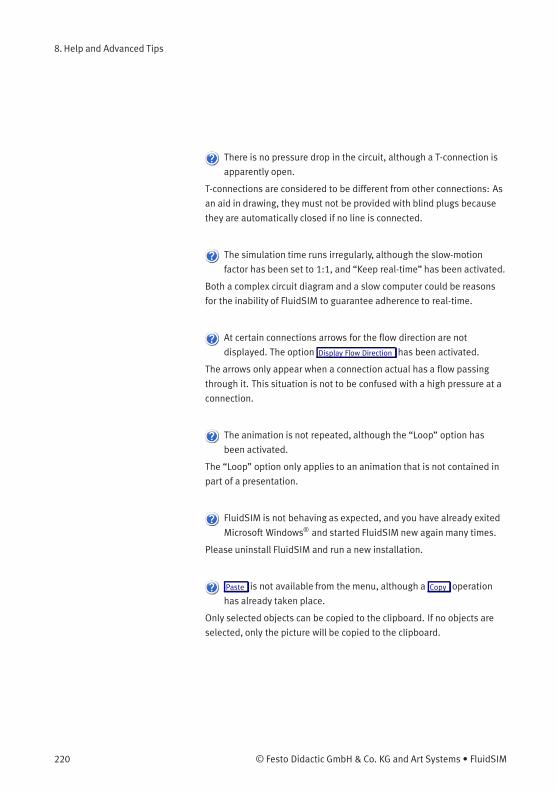
8. Help and Advanced Tips
There is no pressure drop in the circuit, although a T-connection is
apparently open.
T-connections are considered to be different from other connections: As
an aid in drawing, they must not be provided with blind plugs because
they are automatically closed if no line is connected.
The simulation time runs irregularly, although the slow-motion
factor has been set to 1:1, and “Keep real-time” has been activated.
Both a complex circuit diagram and a slow computer could be reasons
for the inability of FluidSIM to guarantee adherence to real-time.
At certain connections arrows for the flow direction are not
displayed. The option Display Flow Direction has been activated.
The arrows only appear when a connection actual has a flow passing
through it. This situation is not to be confused with a high pressure at a
connection.
The animation is not repeated, although the “Loop” option has
been activated.
The “Loop” option only applies to an animation that is not contained in
part of a presentation.
FluidSIM is not behaving as expected, and you have already exited
Microsoft Windows® and started FluidSIM new again many times.
Please uninstall FluidSIM and run a new installation.
Paste is not available from the menu, although a Copy operation
has already taken place.
Only selected objects can be copied to the clipboard. If no objects are
selected, only the picture will be copied to the clipboard.
220 © Festo Didactic GmbH & Co. KG and Art Systems • FluidSIM
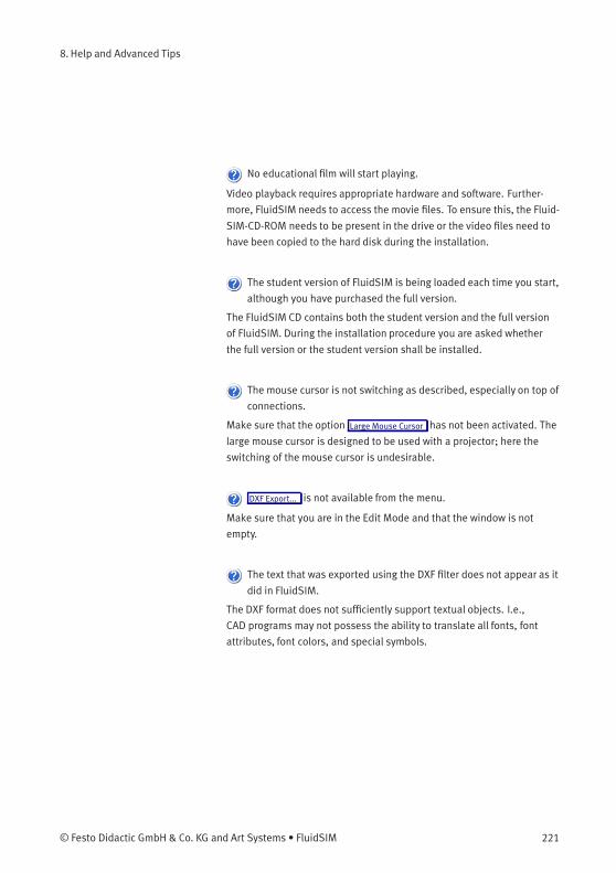
8. Help and Advanced Tips
No educational film will start playing.
Video playback requires appropriate hardware and software. Further-
more, FluidSIM needs to access the movie files. To ensure this, the Fluid-
SIM-CD-ROM needs to be present in the drive or the video files need to
have been copied to the hard disk during the installation.
The student version of FluidSIM is being loaded each time you start,
although you have purchased the full version.
The FluidSIM CD contains both the student version and the full version
of FluidSIM. During the installation procedure you are asked whether
the full version or the student version shall be installed.
The mouse cursor is not switching as described, especially on top of
connections.
Make sure that the option Large Mouse Cursor has not been activated. The
large mouse cursor is designed to be used with a projector; here the
switching of the mouse cursor is undesirable.
DXF Export... is not available from the menu.
Make sure that you are in the Edit Mode and that the window is not
empty.
The text that was exported using the DXF filter does not appear as it
did in FluidSIM.
The DXF format does not sufficiently support textual objects. I.e.,
CAD programs may not possess the ability to translate all fonts, font
attributes, font colors, and special symbols.
© Festo Didactic GmbH & Co. KG and Art Systems • FluidSIM 221
8. Help and Advanced Tips
8.2
Tips for the Advanced
User
This section contains some technical information about different
concepts in FluidSIM.
Data Formats of the
Clipboard
When information from a FluidSIM window is copied to the clipboard,
both a meta file and a bitmap are generated. When pasting into another
application (a word processing program or a drawing program), the
program automatically finds the format that will contain the most
information. However, it could be intended to insert a circuit diagram,
for example into Microsoft Word®, as a bitmap as opposed to the meta
file representation. In this case you simply paste the contents of the
clipboard into bitmap editor such as Paintbrush, and then recopy it back
to the clipboard. Following this action, Microsoft Word® then will find
the bitmap when pasting from the clipboard.
Media Playback Provided the video files have been copied to the hard disk during the
installation, they will played within the FluidSIM window.
Launching playback of the FluidSIM-educational films manually from the
video-CD will open the “Media Player”. Further hints are described in
the Microsoft Windows® Help under the media playback topic.
Opening FluidSIM files via
the Explorer
Normally, to open a file from within FluidSIM, you would click on Open...
under the File menu. It is also possible to open files via the Explorer.
There are two possible ways to go about doing this:
1. You can connect files with FluidSIM that have the same extension,
for example ct. By double clicking on a file with this extension, it
will be opened by FluidSIM. If FluidSIM is not running at this time, it
will be started by the File Manager.
2. Select the files that are to be opened in the usual way in the
Explorer. Here the window of the Explorer with the selected files
should either appear next to an open FluidSIM window or next to
the FluidSIM program icon on the desktop. You can open the files
by dragging them over FluidSIM.
222 © Festo Didactic GmbH & Co. KG and Art Systems • FluidSIM
8. Help and Advanced Tips
Opening FluidSIM Files by
Command Line Entry
Besides the possibilities listed above for opening FluidSIM files, you can
also open files by entering an appropriate command line. Once in the
Start menu, click on Run... and enter the file name after the program
name.
Reorganization of the
Internal Memory
While working with FluidSIM, particular information is cached in the
memory for performance purposes. In some cases it is desirable to
free up memory or to force a window refresh. By pressing the ESC
key, FluidSIM reorganizes its memory, removes the cached data,
rebuilds the internal data structures, and refreshes all windows. If the
topmost window is a circuit diagram preview window, the contents of
the corresponding directory will also be read as new.
Changing the Sound Files Provided your computer has an audio-interface capable of playing back
audio, sounds will optionally play while actuating relays, switches,
valves and while activating the buzzer. You may use your own sound
files instead of the preset ones by replacing the sound files in the
snd-folder. The sound for switch/pushbutton and for relays is
switch.wav, the sound for valves is valve.wav, the buzzer activates
the sound horn.wav and the cylinder end position stop triggers
cylinder.wav.
File Operations via Preview
Windows
Aside from opening circuit diagrams by double clicking on a circuit’s
miniature representation, a preview window does also provide some
File Manager functionality. Analogous to the Edit Mode for objects in
a circuit diagram, the miniaturized circuit diagrams can be selected,
deleted, copied between overview windows (or moved by holding down
the Shift key), copied to the clipboard, or dragged into the a circuit
diagram window.
Please remember, that delete operations and move operations take
place on the file system. Therefore, if a miniaturized circuit diagram is
deleted, its related file will also be deleted in the file system.
© Festo Didactic GmbH & Co. KG and Art Systems • FluidSIM 223

8. Help and Advanced Tips
Creating Presentation Files This section describes how presentations can be created using a
common text editor: more specifically, not using FluidSIM.
The file names of presentation files have the extension .shw. A shw file
has the following structure:
The first line shows the description of the presentation which will
also be represented in the selection box. In the following lines, in the
applicable order, you will find file names with respect to the installation
path. User files will simply be represented by their absolute path.
224 © Festo Didactic GmbH & Co. KG and Art Systems • FluidSIM
8. Help and Advanced Tips
The shw-file of the presentation basics of pneumatics will be as
follows:
01 Basics of Pneumatics
\dida\p3_1_1_1.ct
\dida\p3_1_1_2.ct
\dida\p3_1_1_3.ct
\dida\p3_1_1_4.ct
\dida\p3_1_1_5.ct
\dida\p3_1_1_6.ct
Network Installation of
FluidSIM
If several PCs are running in a network, a complete installation of
FluidSIM must only be performed once, on the network file system.
Then on the local PCs merely the license information and a few
configuration files are required. This concept serves several purposes:
the saving of disk space on the local hard disks, the simplification of
software maintenance, the quick distribution of circuit diagrams, or the
installation of new releases of FluidSIM.
The installation of the network version happens within the following
steps:
> Perform a standard installation of FluidSIM on the network file
system. Note that the local PCs must be authorized to read the
FluidSIM files on the network file system.
> Use the network option when installing FluidSIM on the other local
PCs by calling the installation program as follows: setup.exe-N
During a local installation, the installation program asks for the network
path of the FluidSIM bin-directory. Thus FluidSIM must have been
installed on the network file system before any local installation can be
performed.
© Festo Didactic GmbH & Co. KG and Art Systems • FluidSIM 225
8. Help and Advanced Tips
User-specifically, FluidSIM stores user files and settings in those file
locations that are defined by the operation system. In the case of a
standard-Microsoft Windows®-installation these are MyDocuments
and ApplicationData of the particular user account.
An aside: The PC used during the FluidSIM standard installation on the
network file system also reads and writes the FluidSIM configuration
files on the network. Moreover, a FluidSIM de-installation from this PC
will delete the FluidSIM program files, and, consequently, FluidSIM is no
longer available on the network.
If local PCs are not equipped with a CD-ROM drive, and if these PCs have
no access to a CD-ROM drive of some other PC, the educational films
may also be played from the network file system: If sufficient disk space
is left on the network file system, the movie files can be copied to the
installation folder during the setup procedure.
226 © Festo Didactic GmbH & Co. KG and Art Systems • FluidSIM
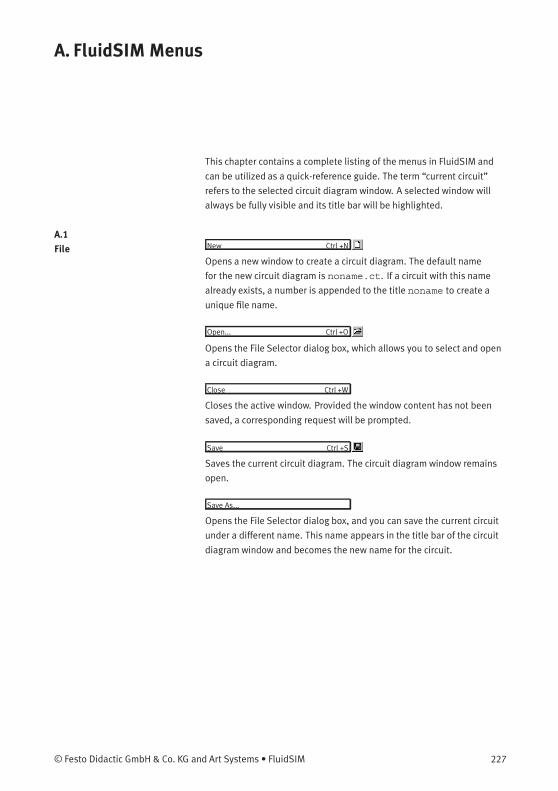
A. FluidSIM Menus
This chapter contains a complete listing of the menus in FluidSIM and
can be utilized as a quick-reference guide. The term “current circuit”
refers to the selected circuit diagram window. A selected window will
always be fully visible and its title bar will be highlighted.
A.1
File New Ctrl +N
Opens a new window to create a circuit diagram. The default name
for the new circuit diagram is noname.ct. If a circuit with this name
already exists, a number is appended to the title noname to create a
unique file name.
Open... Ctrl +O
Opens the File Selector dialog box, which allows you to select and open
a circuit diagram.
Close Ctrl +W
Closes the active window. Provided the window content has not been
saved, a corresponding request will be prompted.
Save Ctrl +S
Saves the current circuit diagram. The circuit diagram window remains
open.
Save As...
Opens the File Selector dialog box, and you can save the current circuit
under a different name. This name appears in the title bar of the circuit
diagram window and becomes the new name for the circuit.
© Festo Didactic GmbH & Co. KG and Art Systems • FluidSIM 227
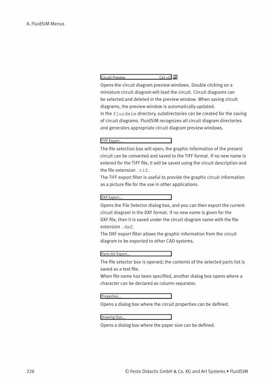
A. FluidSIM Menus
Circuit Preview Ctrl +U
Opens the circuit diagram preview windows. Double clicking on a
miniature circuit diagramwill load the circuit. Circuit diagrams can
be selected and deleted in the preview window. When saving circuit
diagrams, the preview window is automatically updated.
In the fluidsim directory, subdirectories can be created for the saving
of circuit diagrams. FluidSIM recognizes all circuit diagram directories
and generates appropriate circuit diagram preview windows.
TIFF Export...
The file selection box will open; the graphic information of the present
circuit can be converted and saved to the TIFF format. If no new name is
entered for the TIFF file, it will be saved using the circuit description and
the file extension .tif.
The TIFF export filter is useful to provide the graphic circuit information
as a picture file for the use in other applications.
DXF Export...
Opens the File Selector dialog box, and you can then export the current
circuit diagram in the DXF format. If no new name is given for the
DXF file, then it is saved under the circuit diagram name with the file
extension .dxf.
The DXF export filter allows the graphic information from the circuit
diagram to be exported to other CAD systems.
Parts list Export...
The file selector box is opened; the contents of the selected parts list is
saved as a text file.
When file name has been specified, another dialog box opens where a
character can be declared as column separator.
Properties...
Opens a dialog box where the circuit properties can be defined.
Drawing Size...
Opens a dialog box where the paper size can be defined.
228 © Festo Didactic GmbH & Co. KG and Art Systems • FluidSIM
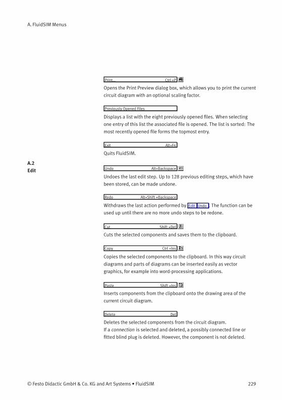
A. FluidSIM Menus
Print... Ctrl +P
Opens the Print Preview dialog box, which allows you to print the current
circuit diagram with an optional scaling factor.
Previously Opened Files
Displays a list with the eight previously opened files. When selecting
one entry of this list the associated file is opened. The list is sorted: The
most recently opened file forms the topmost entry.
Exit Alt+F4
Quits FluidSIM.
A.2
Edit Undo Alt+Backspace
Undoes the last edit step. Up to 128 previous editing steps, which have
been stored, can be made undone.
Redo Alt+Shift +Backspace
Withdraws the last action performed by Edit Undo . The function can be
used up until there are no more undo steps to be redone.
Cut Shift +Del
Cuts the selected components and saves them to the clipboard.
Copy Ctrl +Ins
Copies the selected components to the clipboard. In this way circuit
diagrams and parts of diagrams can be inserted easily as vector
graphics, for example into word-processing applications.
Paste Shift +Ins
Inserts components from the clipboard onto the drawing area of the
current circuit diagram.
Delete Del
Deletes the selected components from the circuit diagram.
If a connection is selected and deleted, a possibly connected line or
fitted blind plug is deleted. However, the component is not deleted.
© Festo Didactic GmbH & Co. KG and Art Systems • FluidSIM 229
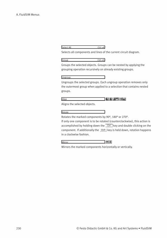
A. FluidSIM Menus
Select All Ctrl +A
Selects all components and lines of the current circuit diagram.
Group Ctrl +G
Groups the selected objects. Groups can be nested by applying the
grouping operation recursively on already existing groups.
Ungroup
Ungroups the selected groups. Each ungroup operation removes only
the outermost group when applied to a selection that contains nested
groups.
Align
Aligns the selected objects.
Rotate
Rotates the marked components by 90°, 180° or 270°.
If only one component is to be rotated (counterclockwise), this action is
accomplished by holding down the Ctrl key and double clicking on the
component. If additionally the Shift key is held down, rotation happens
in a clockwise fashion.
Mirror
Mirrors the marked components horizontally or vertically.
230 © Festo Didactic GmbH & Co. KG and Art Systems • FluidSIM
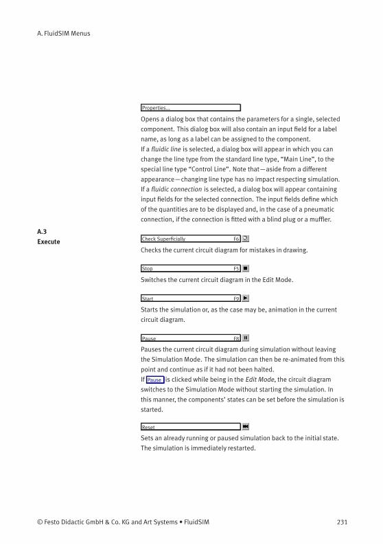
A. FluidSIM Menus
Properties...
Opens a dialog box that contains the parameters for a single, selected
component. This dialog box will also contain an input field for a label
name, as long as a label can be assigned to the component.
If a fluidic line is selected, a dialog box will appear in which you can
change the line type from the standard line type, “Main Line”, to the
special line type “Control Line”. Note that—aside from a different
appearance—changing line type has no impact respecting simulation.
If a fluidic connection is selected, a dialog box will appear containing
input fields for the selected connection. The input fields define which
of the quantities are to be displayed and, in the case of a pneumatic
connection, if the connection is fitted with a blind plug or a muffler.
A.3
Execute Check Superficially F6
Checks the current circuit diagram for mistakes in drawing.
Stop F5
Switches the current circuit diagram in the Edit Mode.
Start F9
Starts the simulation or, as the case may be, animation in the current
circuit diagram.
Pause F8
Pauses the current circuit diagram during simulation without leaving
the Simulation Mode. The simulation can then be re-animated from this
point and continue as if it had not been halted.
If Pause is clicked while being in the Edit Mode, the circuit diagram
switches to the Simulation Mode without starting the simulation. In
this manner, the components’ states can be set before the simulation is
started.
Reset
Sets an already running or paused simulation back to the initial state.
The simulation is immediately restarted.
© Festo Didactic GmbH & Co. KG and Art Systems • FluidSIM 231
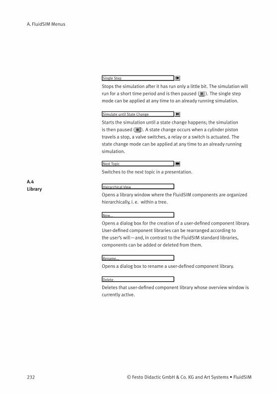
A. FluidSIM Menus
Single Step
Stops the simulation after it has run only a little bit. The simulation will
run for a short time period and is then paused ( ). The single step
mode can be applied at any time to an already running simulation.
Simulate until State Change
Starts the simulation until a state change happens; the simulation
is then paused ( ). A state change occurs when a cylinder piston
travels a stop, a valve switches, a relay or a switch is actuated. The
state change mode can be applied at any time to an already running
simulation.
Next Topic
Switches to the next topic in a presentation.
A.4
Library Hierarchical View
Opens a library window where the FluidSIM components are organized
hierarchically, i. e. within a tree.
New...
Opens a dialog box for the creation of a user-defined component library.
User-defined component libraries can be rearranged according to
the user’s will—and, in contrast to the FluidSIM standard libraries,
components can be added or deleted from them.
Rename...
Opens a dialog box to rename a user-defined component library.
Delete
Deletes that user-defined component library whose overview window is
currently active.
232 © Festo Didactic GmbH & Co. KG and Art Systems • FluidSIM
A. FluidSIM Menus
A.5
Insert A hierarchically organized menu from which an object can be selected
and inserted in the current circuit diagram.
Find Component... F3
Opens the dialog for the string-based search of components.
A.6
Didactics Component Description
Opens the page with the technical description for the selected
component. This page contains the DIN symbol of the component,
a textual description of the component’s function, the connection
designations, and a listing of the adjustable parameters including their
value ranges.
Tutorial
Opens the Tutorial “Simulating with FluidSIM”.
Component Library
Opens the reference of the component library.
Didactics Material
Opens the overview of the didactics material. Provided you’ve copied
the movie files on your hard disk during the installation, the educational
film chapters will appear here.
Presentation...
Opens a dialog box that can be utilized to recall available presentations
along with creating new presentations. Presentations allow for the
combination of individual topics into a lesson, ideal for teaching
pneumatics.
© Festo Didactic GmbH & Co. KG and Art Systems • FluidSIM 233
A. FluidSIM Menus
Educational Film...
Opens a dialog box with educational films related to electro-pneumatics.
By double clicking on a topic in the list, the dialog box closes, and the
media playback starts playing the selected film.
This menu option only appears if the movie files have not been copied
on your hard disk during the installation. Otherwise you will find the
educational films in the menu option Didactics Material .
A.7
Project New...
The file selector box is opened, and a new project can be created.
Project files get the file extension prj.
Open...
The file selector box is opened, and a project can selected and opened.
Close
The current project is closed and the standard settings are loaded.
Add Current Window
Adds the current window to the list of project files.
Delete Current Window
Removes the current window from the list of project files.
Properties...
Opens a dialog box where the project properties can be defined.
Files
Shows the list of files that belong to the current project.
Overviews
Shows the list of preview windows that belong to the current project.
Presentations
Shows the list of presentations that belong to the current project.
234 © Festo Didactic GmbH & Co. KG and Art Systems • FluidSIM
A. FluidSIM Menus
A.8
View The functions of the View menu are circuit diagram specific, that is, they
only apply to the current circuit diagram. Thus it is possible to apply
individually different display options to each circuit diagram, which is
loaded.
Folder View
Shows the content of the active component library or of the active
circuit diagram overview using the folder view instead of the tree view.
Sort Symbols Alphabetically
Sorts the symbols of the current preview window with respect to their
description and extension respectively.
Standard Size
Displays the circuit diagram without enlargement or reduction.
Previous View
Switches between the last view and the current enlargement of the
current circuit diagram.
Fit to Window
Sets the scale factor so that the entire circuit diagram can be displayed
in the window. The proportion between height and width remains
unaltered.
Zoom by Rubber Band
Changes the mouse cursor to a rubber band, allowing a section of a
window to be selected and then enlarged.
© Festo Didactic GmbH & Co. KG and Art Systems • FluidSIM 235
A. FluidSIM Menus
Zoom In >
Enlarges the diagram at a factor of 1.4 (√
2). To repeat this action twice
means a doubling in the diagram’s size.
Zoom Out <
Reduces the diagram at a factor of 1.4 (√
2). To repeat this action twice
means a cutting in half of the diagram’s size.
Quantity Values... A
Opens a dialog box for the display of quantities. For each of the
quantities “Velocity”, “Pressure”, ..., different types of display options
can be defined (“None”, “Particular”, “All”).
GRAFCET...
Opens a dialog box with settings for the display of formulas and
descriptions in GRAFCET components. If the option “Use settings
of individual elements” is chosen, all formulas and descriptions are
shown as transitions and actions according to the individual component
settings, which is defined under “Display description instead of
formula”. If the option “Description, if available” is chosen, descriptions
are shown in place of their related formulas. If the option “Always show
formula” is chosen, formulas are shown even if a description exists as
well.
Display Flow Direction D
Turns on or off the arrow as a direction of flow indicator. The arrow for
the direction of flow will be shown near the component connection, that
is, as long as the flow is other than zero.
236 © Festo Didactic GmbH & Co. KG and Art Systems • FluidSIM
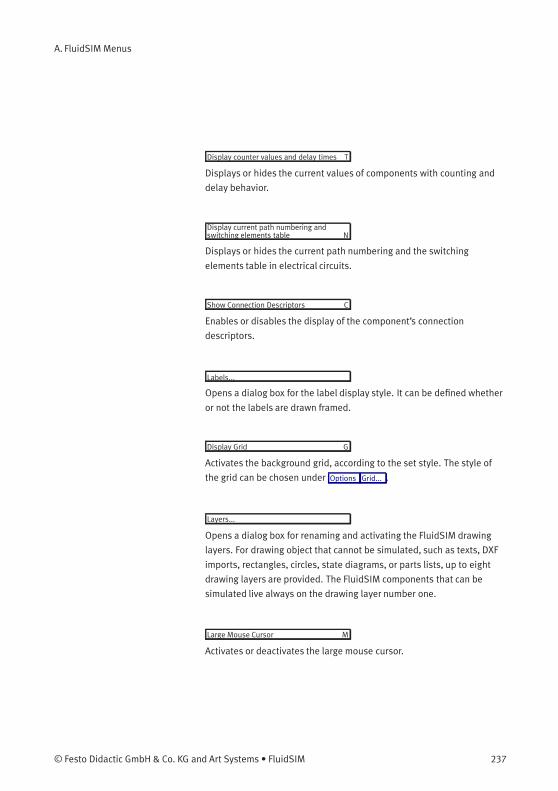
A. FluidSIM Menus
Display counter values and delay times T
Displays or hides the current values of components with counting and
delay behavior.
Display current path numbering andswitching elements table N
Displays or hides the current path numbering and the switching
elements table in electrical circuits.
Show Connection Descriptors C
Enables or disables the display of the component’s connection
descriptors.
Labels...
Opens a dialog box for the label display style. It can be defined whether
or not the labels are drawn framed.
Display Grid G
Activates the background grid, according to the set style. The style of
the grid can be chosen under Options Grid... .
Layers...
Opens a dialog box for renaming and activating the FluidSIM drawing
layers. For drawing object that cannot be simulated, such as texts, DXF
imports, rectangles, circles, state diagrams, or parts lists, up to eight
drawing layers are provided. The FluidSIM components that can be
simulated live always on the drawing layer number one.
Large Mouse Cursor M
Activates or deactivates the large mouse cursor.
© Festo Didactic GmbH & Co. KG and Art Systems • FluidSIM 237

A. FluidSIM Menus
Toolbar
Displays or hides the toolbar.
Status Bar
Displays or hides the status bar.
A.9
Options Simulation...
Opens a dialog box with settings for the simulation. Here, parameters
such as the maximum recording time, the slow-motion factor, and the
priority are defined.
EasyPort/OPC/DDE Connection...
Opens a dialog box with options for the EasyPort/OPC/DDE connection.
This is where you may define various options for interconnecting Fluid-
SIM with the EasyPort hardware or with other applications.
Sound...
Opens a dialog box in which the acoustic signal is switched on for the
following component types: switch, relay, valve, and buzzer.
Didactics...
Opens a dialog box with settings for the didactics. These settings
include factors that apply to animation speed and repeat mode.
Grid...
Opens a dialog box allowing you to activate the background grid and
select its style (“Point”, “Cross”, “Line”) and its resolution (“Coarse”,
“Medium”, “Fine”).
Terminal Assignment Diagram...
Opens a dialog box where you may define the options for the terminal
assignment diagrams.
238 © Festo Didactic GmbH & Co. KG and Art Systems • FluidSIM
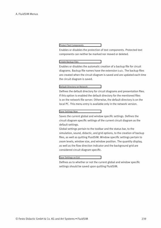
A. FluidSIM Menus
Protect Text Components
Enables or disables the protection of text components. Protected text
components can neither be marked nor moved or deleted.
Create Backup Files
Enables or disables the automatic creation of a backup file for circuit
diagrams. Backup file names have the extension bak. The backup files
are created when the circuit diagram is saved and are updated each time
the circuit diagram is saved.
Default Directory on Network
Defines the default directory for circuit diagrams and presentation files.
If this option is enabled the default directory for the mentioned files
is on the network file server. Otherwise, the default directory is on the
local PC. This menu entry is available only in the network version.
Save Settings Now
Saves the current global and window specific settings. Defines the
circuit diagram specific settings of the current circuit diagram as the
default settings.
Global settings pertain to the toolbar and the status bar, to the
simulation, sound, didactic, and grid options, to the creation of backup
files, as well as quitting FluidSIM. Window specific settings pertain to
zoom levels, window size, and window position. The quantity display,
as well as the flow direction indicator and the background grid are
considered circuit diagram specific.
Save Settings on Exit
Defines as to whether or not the current global and window specific
settings should be saved upon quitting FluidSIM.
© Festo Didactic GmbH & Co. KG and Art Systems • FluidSIM 239
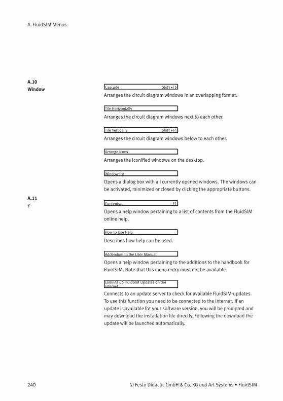
A. FluidSIM Menus
A.10
Window Cascade Shift +F5
Arranges the circuit diagram windows in an overlapping format.
Tile Horizontally
Arranges the circuit diagram windows next to each other.
Tile Vertically Shift +F4
Arranges the circuit diagram windows below to each other.
Arrange Icons
Arranges the iconified windows on the desktop.
Window list
Opens a dialog box with all currently opened windows. The windows can
be activated, minimized or closed by clicking the appropriate buttons.
A.11
? Contents... F1
Opens a help window pertaining to a list of contents from the FluidSIM
online help.
How to Use Help
Describes how help can be used.
Addendum to the User Manual
Opens a help window pertaining to the additions to the handbook for
FluidSIM. Note that this menu entry must not be available.
Looking up FluidSIM Updates on theInternet...
Connects to an update server to check for available FluidSIM-updates.
To use this function you need to be connected to the internet. If an
update is available for your software version, you will be prompted and
may download the installation file directly. Following the download the
update will be launched automatically.
240 © Festo Didactic GmbH & Co. KG and Art Systems • FluidSIM

A. FluidSIM Menus
About FluidSIM...
Opens the Program Information box about FluidSIM. Among others, the
FluidSIM serial number (including the number of the license connector,
if applicable) looked up.
© Festo Didactic GmbH & Co. KG and Art Systems • FluidSIM 241
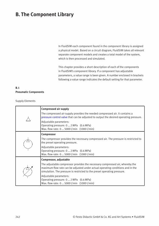
B. The Component Library
In FluidSIM each component found in the component library is assigned
a physical model. Based on a circuit diagram, FluidSIM takes all relevant
separate component models and creates a total model of the system,
which is then processed and simulated.
This chapter provides a short description of each of the components
in FluidSIM’s component library. If a component has adjustable
parameters, a value range is been given. A number enclosed in brackets
following a value range indicates the default setting for that parameter.
B.1
Pneumatic Components
Supply Elements
Compressed air supply
The compressed air supply provides the needed compressed air. It contains apressure control valve that can be adjusted to output the desired operating pressure.
Adjustable parameters:Operating pressure: 0 ... 2MPa (0.6MPa)Max. flow rate: 0 ... 5000 l/min (1000 l/min)
Compressor
The compressor provides the necessary compressed air. The pressure is restricted tothe preset operating pressure.
Adjustable parameters:Operating pressure: 0 ... 2MPa (0.6MPa)Max. flow rate: 0 ... 5000 l/min (1000 l/min)
Compressor, adjustable
The adjustable compressor provides the necessary compressed air, whereby themaximum flow rate can be adjusted under actual operating conditions and in thesimulation. The pressure is restricted to the preset operating pressure.
Adjustable parameters:Operating pressure: 0 ... 2MPa (0.6MPa)Max. flow rate: 0 ... 5000 l/min (1000 l/min)
242 © Festo Didactic GmbH & Co. KG and Art Systems • FluidSIM
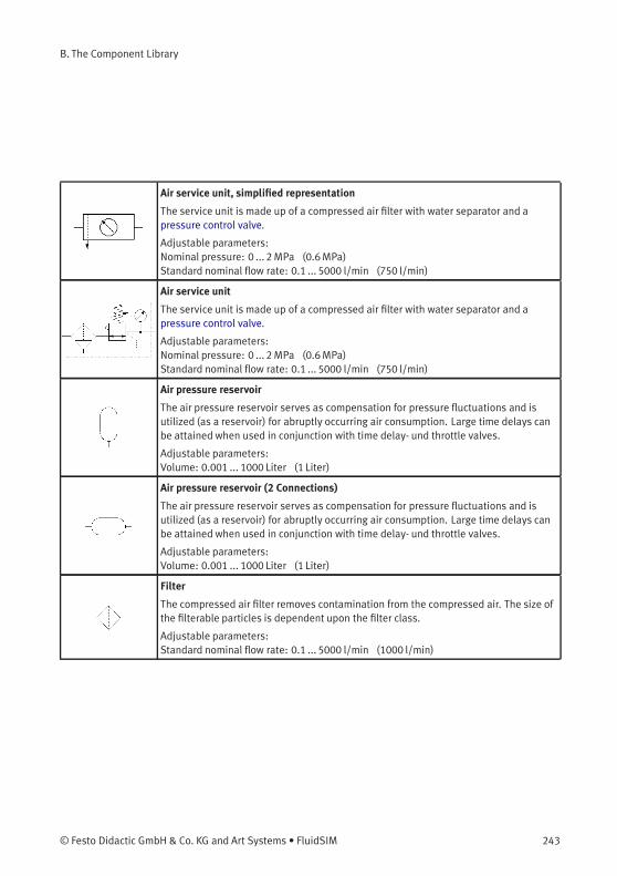
B. The Component Library
Air service unit, simplified representation
The service unit is made up of a compressed air filter with water separator and apressure control valve.
Adjustable parameters:Nominal pressure: 0 ... 2MPa (0.6MPa)Standard nominal flow rate: 0.1 ... 5000 l/min (750 l/min)
Air service unit
The service unit is made up of a compressed air filter with water separator and apressure control valve.
Adjustable parameters:Nominal pressure: 0 ... 2MPa (0.6MPa)Standard nominal flow rate: 0.1 ... 5000 l/min (750 l/min)
Air pressure reservoir
The air pressure reservoir serves as compensation for pressure fluctuations and isutilized (as a reservoir) for abruptly occurring air consumption. Large time delays canbe attained when used in conjunction with time delay- und throttle valves.
Adjustable parameters:Volume: 0.001 ... 1000 Liter (1 Liter)
Air pressure reservoir (2 Connections)
The air pressure reservoir serves as compensation for pressure fluctuations and isutilized (as a reservoir) for abruptly occurring air consumption. Large time delays canbe attained when used in conjunction with time delay- und throttle valves.
Adjustable parameters:Volume: 0.001 ... 1000 Liter (1 Liter)
Filter
The compressed air filter removes contamination from the compressed air. The size ofthe filterable particles is dependent upon the filter class.
Adjustable parameters:Standard nominal flow rate: 0.1 ... 5000 l/min (1000 l/min)
© Festo Didactic GmbH & Co. KG and Art Systems • FluidSIM 243
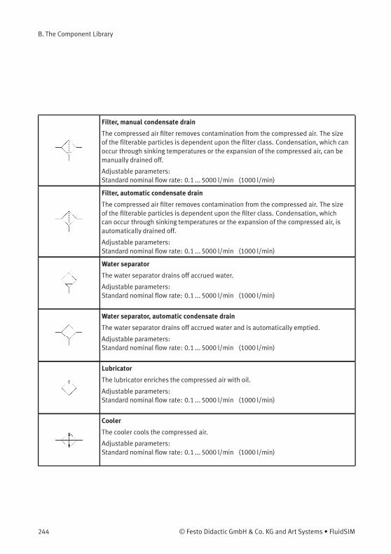
B. The Component Library
Filter, manual condensate drain
The compressed air filter removes contamination from the compressed air. The sizeof the filterable particles is dependent upon the filter class. Condensation, which canoccur through sinking temperatures or the expansion of the compressed air, can bemanually drained off.
Adjustable parameters:Standard nominal flow rate: 0.1 ... 5000 l/min (1000 l/min)
Filter, automatic condensate drain
The compressed air filter removes contamination from the compressed air. The sizeof the filterable particles is dependent upon the filter class. Condensation, whichcan occur through sinking temperatures or the expansion of the compressed air, isautomatically drained off.
Adjustable parameters:Standard nominal flow rate: 0.1 ... 5000 l/min (1000 l/min)
Water separator
The water separator drains off accrued water.
Adjustable parameters:Standard nominal flow rate: 0.1 ... 5000 l/min (1000 l/min)
Water separator, automatic condensate drain
The water separator drains off accrued water and is automatically emptied.
Adjustable parameters:Standard nominal flow rate: 0.1 ... 5000 l/min (1000 l/min)
Lubricator
The lubricator enriches the compressed air with oil.
Adjustable parameters:Standard nominal flow rate: 0.1 ... 5000 l/min (1000 l/min)
Cooler
The cooler cools the compressed air.
Adjustable parameters:Standard nominal flow rate: 0.1 ... 5000 l/min (1000 l/min)
244 © Festo Didactic GmbH & Co. KG and Art Systems • FluidSIM

B. The Component Library
Adsorption dryer
The adsorption dryer reduces the humidity in the compressed air.
Adjustable parameters:Standard nominal flow rate: 0.1 ... 5000 l/min (1000 l/min)
Connection (pneumatic)
A pneumatic connection is a place where a pneumatic line can be attached to. Tosimplify the line drawing process, a connection appears as a small circle in Edit Mode.Pneumatic connections can be shut by means of a blind plug. An open pneumaticconnection may result in leaking air; FluidSIM Pneumatics thus pops up a warningmessage, if some pneumatic connection was left open.Note that at each pneumatic connection values for the flow and pressure can bedisplayed.
Line (pneumatic)
A pneumatic line links two pneumatic connections. Note that a pneumatic connectionmay be a simple pneumatic connection or a T-junction. A pneumatic line causes nopressure drop, i. e., it has no fluidic resistance.From a drawing point of view, FluidSIM distinguishes between control lines and mainlines. The former is represented by a dashed line, the latter is represented by a solidline and establishes the default case.
Adjustable parameters:Line Type: One of {Main Line or Control Line} (Main Line )
T-junction (pneumatic)
A T-junction joins up to four pneumatic lines, thus having a single pressure potential.Note that T-junctions are introduced automatically by FluidSIM when dropping theline drawing cursor onto another line in Edit Mode.
© Festo Didactic GmbH & Co. KG and Art Systems • FluidSIM 245

B. The Component Library
Configurable Way Valves
Configurable 2/n way valve
The configurable 2/n way valve is a way valve with two connections, where both itsbody elements and its operation modes are user-definable.Additionally, the pneumatic connections can be closed with either blind plugs orexhausts.
Adjustable parameters:Standard nominal flow rate: 0.1 ... 5000 l/min (60 l/min)
Configurable 3/n way valve
The configurable 3/n way valve is a way valve with three connections, where both itsbody elements and its operation modes are user-definable.Additionally, the pneumatic connections can be closed with either blind plugs orexhausts.
Adjustable parameters:Standard nominal flow rate: 0.1 ... 5000 l/min (60 l/min)
Configurable 4/n way valve
The configurable 4/n way valve is a way valve with four connections, where both itsbody elements and its operation modes are user-definable.Additionally, the pneumatic connections can be closed with either blind plugs orexhausts.
Adjustable parameters:Standard nominal flow rate: 0.1 ... 5000 l/min (60 l/min)
Configurable 5/n way valve
The configurable 5/n way valve is a way valve with five connections, where both itsbody elements and its operation modes are user-definable.Additionally, the pneumatic connections can be closed with either blind plugs orexhausts.
Adjustable parameters:Standard nominal flow rate: 0.1 ... 5000 l/min (60 l/min)
246 © Festo Didactic GmbH & Co. KG and Art Systems • FluidSIM
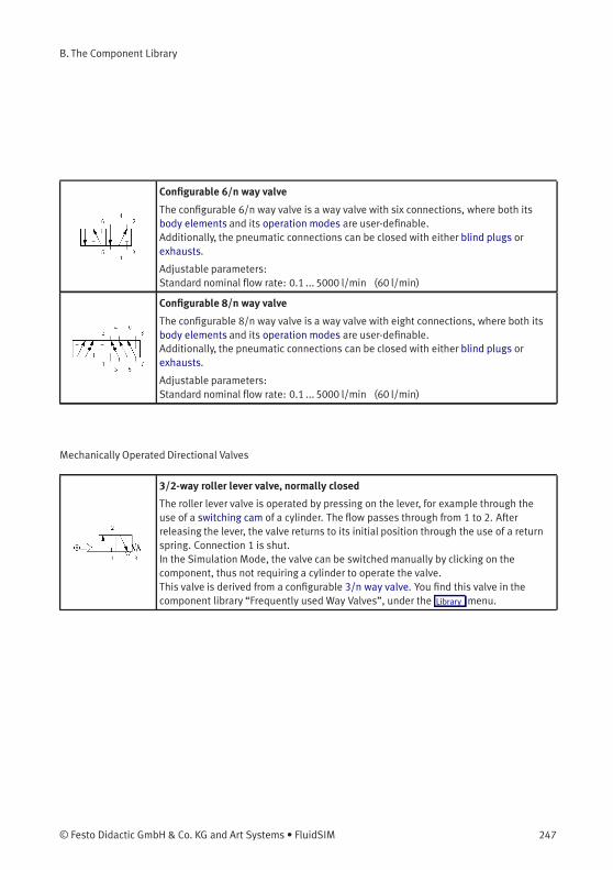
B. The Component Library
Configurable 6/n way valve
The configurable 6/n way valve is a way valve with six connections, where both itsbody elements and its operation modes are user-definable.Additionally, the pneumatic connections can be closed with either blind plugs orexhausts.
Adjustable parameters:Standard nominal flow rate: 0.1 ... 5000 l/min (60 l/min)
Configurable 8/n way valve
The configurable 8/n way valve is a way valve with eight connections, where both itsbody elements and its operation modes are user-definable.Additionally, the pneumatic connections can be closed with either blind plugs orexhausts.
Adjustable parameters:Standard nominal flow rate: 0.1 ... 5000 l/min (60 l/min)
Mechanically Operated Directional Valves
3/2-way roller lever valve, normally closed
The roller lever valve is operated by pressing on the lever, for example through theuse of a switching cam of a cylinder. The flow passes through from 1 to 2. Afterreleasing the lever, the valve returns to its initial position through the use of a returnspring. Connection 1 is shut.In the Simulation Mode, the valve can be switched manually by clicking on thecomponent, thus not requiring a cylinder to operate the valve.This valve is derived from a configurable 3/n way valve. You find this valve in thecomponent library “Frequently used Way Valves”, under the Library menu.
© Festo Didactic GmbH & Co. KG and Art Systems • FluidSIM 247
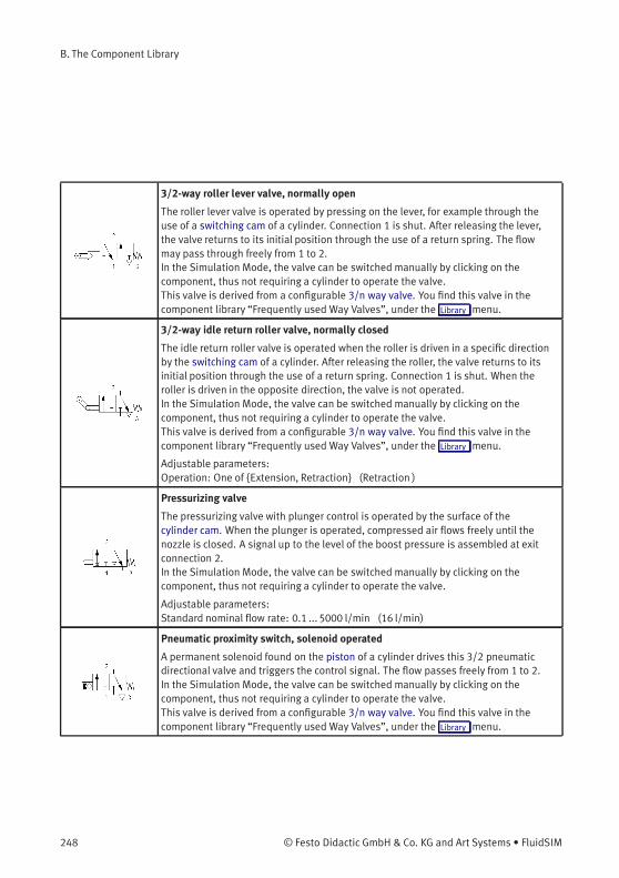
B. The Component Library
3/2-way roller lever valve, normally open
The roller lever valve is operated by pressing on the lever, for example through theuse of a switching cam of a cylinder. Connection 1 is shut. After releasing the lever,the valve returns to its initial position through the use of a return spring. The flowmay pass through freely from 1 to 2.In the Simulation Mode, the valve can be switched manually by clicking on thecomponent, thus not requiring a cylinder to operate the valve.This valve is derived from a configurable 3/n way valve. You find this valve in thecomponent library “Frequently used Way Valves”, under the Library menu.
3/2-way idle return roller valve, normally closed
The idle return roller valve is operated when the roller is driven in a specific directionby the switching cam of a cylinder. After releasing the roller, the valve returns to itsinitial position through the use of a return spring. Connection 1 is shut. When theroller is driven in the opposite direction, the valve is not operated.In the Simulation Mode, the valve can be switched manually by clicking on thecomponent, thus not requiring a cylinder to operate the valve.This valve is derived from a configurable 3/n way valve. You find this valve in thecomponent library “Frequently used Way Valves”, under the Library menu.
Adjustable parameters:Operation: One of {Extension, Retraction} (Retraction )
Pressurizing valve
The pressurizing valve with plunger control is operated by the surface of thecylinder cam. When the plunger is operated, compressed air flows freely until thenozzle is closed. A signal up to the level of the boost pressure is assembled at exitconnection 2.In the Simulation Mode, the valve can be switched manually by clicking on thecomponent, thus not requiring a cylinder to operate the valve.
Adjustable parameters:Standard nominal flow rate: 0.1 ... 5000 l/min (16 l/min)
Pneumatic proximity switch, solenoid operated
A permanent solenoid found on the piston of a cylinder drives this 3/2 pneumaticdirectional valve and triggers the control signal. The flow passes freely from 1 to 2.In the Simulation Mode, the valve can be switched manually by clicking on thecomponent, thus not requiring a cylinder to operate the valve.This valve is derived from a configurable 3/n way valve. You find this valve in thecomponent library “Frequently used Way Valves”, under the Library menu.
248 © Festo Didactic GmbH & Co. KG and Art Systems • FluidSIM
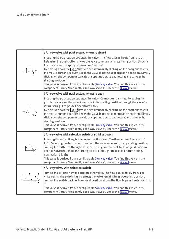
B. The Component Library
3/2-way valve with pushbutton, normally closed
Pressing the pushbutton operates the valve. The flow passes freely from 1 to 2.Releasing the pushbutton allows the valve to return to its starting position throughthe use of a return spring. Connection 1 is shut.By holding down the Shift key and simultaneously clicking on the component withthe mouse cursor, FluidSIM keeps the valve in permanent operating position. Simplyclicking on the component cancels the operated state and returns the valve to itsstarting position.This valve is derived from a configurable 3/n way valve. You find this valve in thecomponent library “Frequently used Way Valves”, under the Library menu.
3/2-way valve with pushbutton, normally open
Pressing the pushbutton operates the valve. Connection 1 is shut. Releasing thepushbutton allows the valve to returns to its starting position through the use of areturn spring. The passes freely from 1 to 2.By holding down the Shift key and simultaneously clicking on the component withthe mouse cursor, FluidSIM keeps the valve in permanent operating position. Simplyclicking on the component cancels the operated state and returns the valve to itsstarting position.This valve is derived from a configurable 3/n way valve. You find this valve in thecomponent library “Frequently used Way Valves”, under the Library menu.
3/2-way valve with selection switch or striking button
Pressing the red striking button operates the valve. The flow passes freely from 1to 2. Releasing the button has no effect; the valve remains in its operating position.Turning the button to the right sets the striking button back to its original positionand the valve returns to its starting position through the use of a return spring.Connection 1 is shut.This valve is derived from a configurable 3/n way valve. You find this valve in thecomponent library “Frequently used Way Valves”, under the Library menu.
5/2-way valve, with selection switch
Turning the selection switch operates the valve. The flow passes freely from 1 to4. Releasing the switch has no effect; the valve remains in its operating position.Turning the switch back to its original position allows the flow to pass freely from 1 to2.This valve is derived from a configurable 5/n way valve. You find this valve in thecomponent library “Frequently used Way Valves”, under the Library menu.
© Festo Didactic GmbH & Co. KG and Art Systems • FluidSIM 249
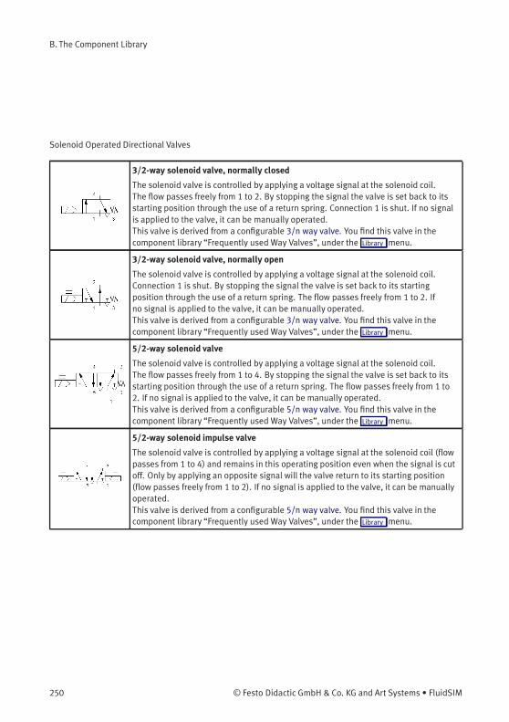
B. The Component Library
Solenoid Operated Directional Valves
3/2-way solenoid valve, normally closed
The solenoid valve is controlled by applying a voltage signal at the solenoid coil.The flow passes freely from 1 to 2. By stopping the signal the valve is set back to itsstarting position through the use of a return spring. Connection 1 is shut. If no signalis applied to the valve, it can be manually operated.This valve is derived from a configurable 3/n way valve. You find this valve in thecomponent library “Frequently used Way Valves”, under the Library menu.
3/2-way solenoid valve, normally open
The solenoid valve is controlled by applying a voltage signal at the solenoid coil.Connection 1 is shut. By stopping the signal the valve is set back to its startingposition through the use of a return spring. The flow passes freely from 1 to 2. Ifno signal is applied to the valve, it can be manually operated.This valve is derived from a configurable 3/n way valve. You find this valve in thecomponent library “Frequently used Way Valves”, under the Library menu.
5/2-way solenoid valve
The solenoid valve is controlled by applying a voltage signal at the solenoid coil.The flow passes freely from 1 to 4. By stopping the signal the valve is set back to itsstarting position through the use of a return spring. The flow passes freely from 1 to2. If no signal is applied to the valve, it can be manually operated.This valve is derived from a configurable 5/n way valve. You find this valve in thecomponent library “Frequently used Way Valves”, under the Library menu.
5/2-way solenoid impulse valve
The solenoid valve is controlled by applying a voltage signal at the solenoid coil (flowpasses from 1 to 4) and remains in this operating position even when the signal is cutoff. Only by applying an opposite signal will the valve return to its starting position(flow passes freely from 1 to 2). If no signal is applied to the valve, it can be manuallyoperated.This valve is derived from a configurable 5/n way valve. You find this valve in thecomponent library “Frequently used Way Valves”, under the Library menu.
250 © Festo Didactic GmbH & Co. KG and Art Systems • FluidSIM
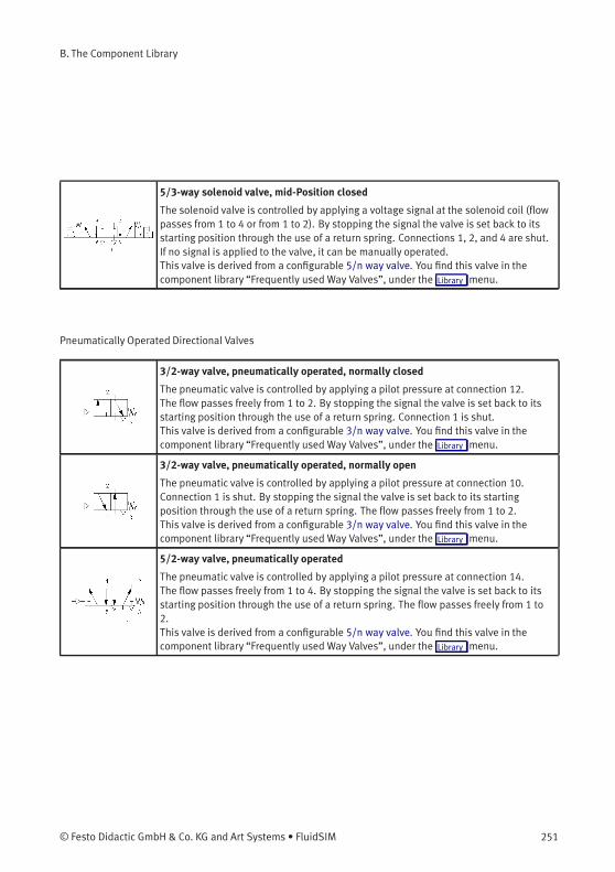
B. The Component Library
5/3-way solenoid valve, mid-Position closed
The solenoid valve is controlled by applying a voltage signal at the solenoid coil (flowpasses from 1 to 4 or from 1 to 2). By stopping the signal the valve is set back to itsstarting position through the use of a return spring. Connections 1, 2, and 4 are shut.If no signal is applied to the valve, it can be manually operated.This valve is derived from a configurable 5/n way valve. You find this valve in thecomponent library “Frequently used Way Valves”, under the Library menu.
Pneumatically Operated Directional Valves
3/2-way valve, pneumatically operated, normally closed
The pneumatic valve is controlled by applying a pilot pressure at connection 12.The flow passes freely from 1 to 2. By stopping the signal the valve is set back to itsstarting position through the use of a return spring. Connection 1 is shut.This valve is derived from a configurable 3/n way valve. You find this valve in thecomponent library “Frequently used Way Valves”, under the Library menu.
3/2-way valve, pneumatically operated, normally open
The pneumatic valve is controlled by applying a pilot pressure at connection 10.Connection 1 is shut. By stopping the signal the valve is set back to its startingposition through the use of a return spring. The flow passes freely from 1 to 2.This valve is derived from a configurable 3/n way valve. You find this valve in thecomponent library “Frequently used Way Valves”, under the Library menu.
5/2-way valve, pneumatically operated
The pneumatic valve is controlled by applying a pilot pressure at connection 14.The flow passes freely from 1 to 4. By stopping the signal the valve is set back to itsstarting position through the use of a return spring. The flow passes freely from 1 to2.This valve is derived from a configurable 5/n way valve. You find this valve in thecomponent library “Frequently used Way Valves”, under the Library menu.
© Festo Didactic GmbH & Co. KG and Art Systems • FluidSIM 251
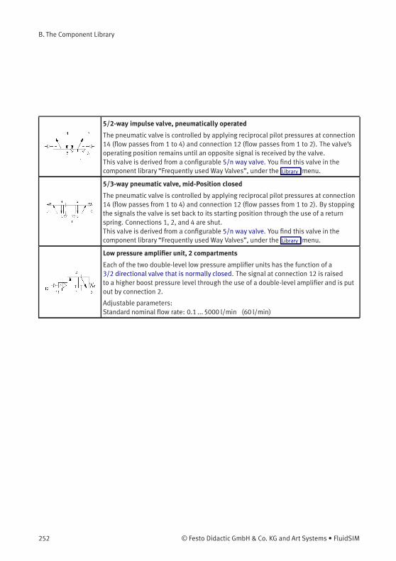
B. The Component Library
5/2-way impulse valve, pneumatically operated
The pneumatic valve is controlled by applying reciprocal pilot pressures at connection14 (flow passes from 1 to 4) and connection 12 (flow passes from 1 to 2). The valve’soperating position remains until an opposite signal is received by the valve.This valve is derived from a configurable 5/n way valve. You find this valve in thecomponent library “Frequently used Way Valves”, under the Library menu.
5/3-way pneumatic valve, mid-Position closed
The pneumatic valve is controlled by applying reciprocal pilot pressures at connection14 (flow passes from 1 to 4) and connection 12 (flow passes from 1 to 2). By stoppingthe signals the valve is set back to its starting position through the use of a returnspring. Connections 1, 2, and 4 are shut.This valve is derived from a configurable 5/n way valve. You find this valve in thecomponent library “Frequently used Way Valves”, under the Library menu.
Low pressure amplifier unit, 2 compartments
Each of the two double-level low pressure amplifier units has the function of a3/2 directional valve that is normally closed. The signal at connection 12 is raisedto a higher boost pressure level through the use of a double-level amplifier and is putout by connection 2.
Adjustable parameters:Standard nominal flow rate: 0.1 ... 5000 l/min (60 l/min)
252 © Festo Didactic GmbH & Co. KG and Art Systems • FluidSIM

B. The Component Library
Shutoff Valves and Flow Control Valves
Shuttle valve
The shuttle valve is switched based on the compressed air entering into either inputconnection 1 and leaving via an output connection 2. Should both input connectionsbegin receiving compressed air, the connection with the higher pressure takesprecedence and is put out (OR function).
Adjustable parameters:Standard nominal flow rate: 0.1 ... 5000 l/min (500 l/min)
Quick exhaust valve
The compressed air passes from connection 1 to connection 2. If the pressure shoulddecrease at connection 1, then the compressed air from connection 1 will escape tothe outside via the installed silencer.
Adjustable parameters:Standard nominal flow rate: 0.1 ... 5000 l/min (550 l/min)
Two pressure valve
The two pressure valve is switched based on the compressed air entering into bothinput connections 1 and leaving via an output connection 2. Should both inputconnections begin receiving compressed air, the connection with the lower pressuretakes precedence and is put out (AND function).
Adjustable parameters:Standard nominal flow rate: 0.1 ... 5000 l/min (550 l/min)
Check valve
If the inlet pressure at 1 is higher than the outlet pressure at 2, then the check valveallows the flow to pass, otherwise it blocks the flow.
Adjustable parameters:Standard nominal flow rate: 0.1 ... 5000 l/min (108 l/min)
Check valve, spring loaded
If the inlet pressure at 1 is higher than the outlet pressure at 2 and the nominalpressure, then the check valve allows the flow to pass, otherwise it blocks the flow.
Adjustable parameters:Nominal pressure: 0.001 ... 2MPa (0.1MPa)Standard nominal flow rate: 0.1 ... 5000 l/min (108 l/min)
© Festo Didactic GmbH & Co. KG and Art Systems • FluidSIM 253

B. The Component Library
Check valve with pilot control
If the entering pressure at connection 1 is higher that the outgoing pressure at 2,the check valve allows the flow to pass freely. Otherwise, the valve stops the flow.Additionally, the check valve can be opened via the control line 12. This action allowsthe flow to pass freely in both directions.
Adjustable parameters:Area ratio: 1 ... 10 (5 )Standard nominal flow rate: 0.1 ... 5000 l/min (108 l/min)
Check valve with pilot control, spring loaded
If the inlet pressure at 1 is higher than the outlet pressure at 2 and the nominalpressure, then the check valve allows the flow to pass, otherwise it blocks the flow.Additionally, the check valve can be released using the pilot line 12, thus enabling theflow in both directions.
Adjustable parameters:Nominal pressure: 0.001 ... 2MPa (0.1MPa)Area ratio: 1 ... 10 (5 )Standard nominal flow rate: 0.1 ... 5000 l/min (108 l/min)
Pilot to close check valve
If the inlet pressure at 1 is higher than the outlet pressure at 2, then the non-returnvalve allows the flow to pass, otherwise it blocks the flow. Additionally, the non-return valve can be closed using the pilot line 10.
Adjustable parameters:Area ratio: 1 ... 10 (5 )Standard nominal flow rate: 0.1 ... 5000 l/min (108 l/min)
Pilot to close check valve, spring loaded
If the inlet pressure at 1 is higher than the outlet pressure at 2 and the nominalpressure, then the non-return valve allows the flow to pass, otherwise it blocks theflow. Additionally, the non-return valve can be closed using the pilot line 10.
Adjustable parameters:Nominal pressure: 0.001 ... 2MPa (0.1MPa)Area ratio: 1 ... 10 (5 )Standard nominal flow rate: 0.1 ... 5000 l/min (108 l/min)
254 © Festo Didactic GmbH & Co. KG and Art Systems • FluidSIM
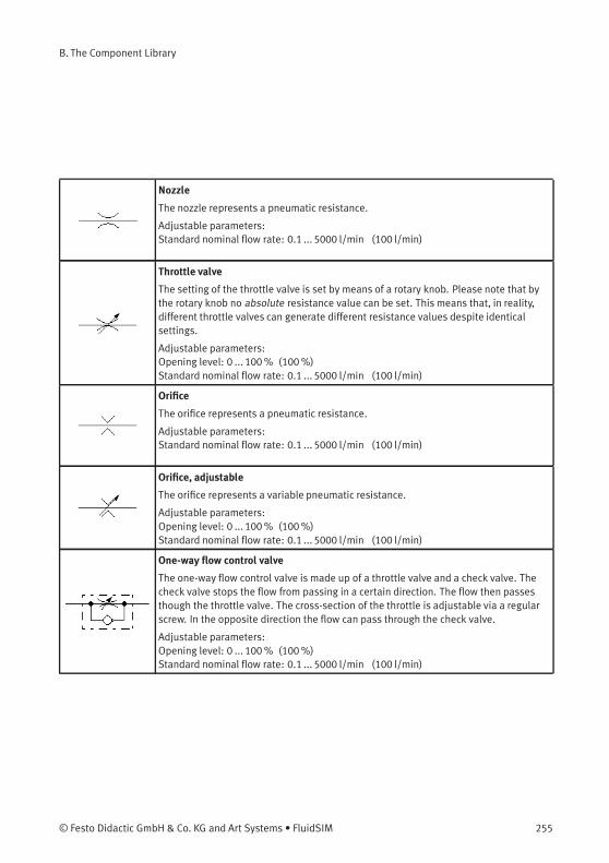
B. The Component Library
Nozzle
The nozzle represents a pneumatic resistance.
Adjustable parameters:Standard nominal flow rate: 0.1 ... 5000 l/min (100 l/min)
Throttle valve
The setting of the throttle valve is set by means of a rotary knob. Please note that bythe rotary knob no absolute resistance value can be set. This means that, in reality,different throttle valves can generate different resistance values despite identicalsettings.
Adjustable parameters:Opening level: 0 ... 100% (100%)Standard nominal flow rate: 0.1 ... 5000 l/min (100 l/min)
Orifice
The orifice represents a pneumatic resistance.
Adjustable parameters:Standard nominal flow rate: 0.1 ... 5000 l/min (100 l/min)
Orifice, adjustable
The orifice represents a variable pneumatic resistance.
Adjustable parameters:Opening level: 0 ... 100% (100%)Standard nominal flow rate: 0.1 ... 5000 l/min (100 l/min)
One-way flow control valve
The one-way flow control valve is made up of a throttle valve and a check valve. Thecheck valve stops the flow from passing in a certain direction. The flow then passesthough the throttle valve. The cross-section of the throttle is adjustable via a regularscrew. In the opposite direction the flow can pass through the check valve.
Adjustable parameters:Opening level: 0 ... 100% (100%)Standard nominal flow rate: 0.1 ... 5000 l/min (100 l/min)
© Festo Didactic GmbH & Co. KG and Art Systems • FluidSIM 255
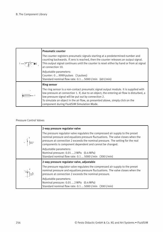
B. The Component Library
Pneumatic counter
The counter registers pneumatic signals starting at a predetermined number andcounting backwards. If zero is reached, then the counter releases an output signal.This output signal continues until the counter is reset either by hand or from at signalat connection 10.
Adjustable parameters:Counter: 0 ... 9999 pulses (3 pulses)Standard nominal flow rate: 0.1 ... 5000 l/min (60 l/min)
Ring sensor
The ring sensor is a non-contact pneumatic signal output module. It is supplied withlow pressure at connection 1. If, due to an object, the entering air flow is disturbed, alow pressure signal will be put out by connection 2.To simulate an object in the air flow, as presented above, simply click on thecomponent during FluidSIM Simulation Mode.
Pressure Control Valves
2-way pressure regulator valve
The pressure regulator valve regulates the compressed air supply to the presetnominal pressure and equalizes pressure fluctuations. The valve closes when thepressure at connection 2 exceeds the nominal pressure. The setting for the realcomponents is component dependent and cannot be changed.
Adjustable parameters:Nominal pressure: 0.01 ... 2MPa (0.4MPa)Standard nominal flow rate: 0.1 ... 5000 l/min (300 l/min)
2-way pressure regulator valve, adjustable
The pressure regulator valve regulates the compressed air supply to the presetnominal pressure and equalizes pressure fluctuations. The valve closes when thepressure at connection 2 exceeds the nominal pressure.
Adjustable parameters:Nominal pressure: 0.01 ... 2MPa (0.4MPa)Standard nominal flow rate: 0.1 ... 5000 l/min (300 l/min)
256 © Festo Didactic GmbH & Co. KG and Art Systems • FluidSIM
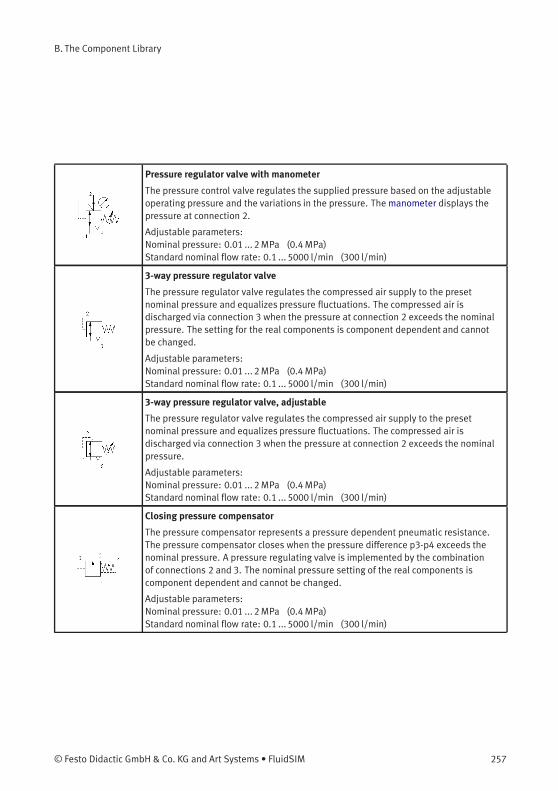
B. The Component Library
Pressure regulator valve with manometer
The pressure control valve regulates the supplied pressure based on the adjustableoperating pressure and the variations in the pressure. The manometer displays thepressure at connection 2.
Adjustable parameters:Nominal pressure: 0.01 ... 2MPa (0.4MPa)Standard nominal flow rate: 0.1 ... 5000 l/min (300 l/min)
3-way pressure regulator valve
The pressure regulator valve regulates the compressed air supply to the presetnominal pressure and equalizes pressure fluctuations. The compressed air isdischarged via connection 3 when the pressure at connection 2 exceeds the nominalpressure. The setting for the real components is component dependent and cannotbe changed.
Adjustable parameters:Nominal pressure: 0.01 ... 2MPa (0.4MPa)Standard nominal flow rate: 0.1 ... 5000 l/min (300 l/min)
3-way pressure regulator valve, adjustable
The pressure regulator valve regulates the compressed air supply to the presetnominal pressure and equalizes pressure fluctuations. The compressed air isdischarged via connection 3 when the pressure at connection 2 exceeds the nominalpressure.
Adjustable parameters:Nominal pressure: 0.01 ... 2MPa (0.4MPa)Standard nominal flow rate: 0.1 ... 5000 l/min (300 l/min)
Closing pressure compensator
The pressure compensator represents a pressure dependent pneumatic resistance.The pressure compensator closes when the pressure difference p3-p4 exceeds thenominal pressure. A pressure regulating valve is implemented by the combinationof connections 2 and 3. The nominal pressure setting of the real components iscomponent dependent and cannot be changed.
Adjustable parameters:Nominal pressure: 0.01 ... 2MPa (0.4MPa)Standard nominal flow rate: 0.1 ... 5000 l/min (300 l/min)
© Festo Didactic GmbH & Co. KG and Art Systems • FluidSIM 257
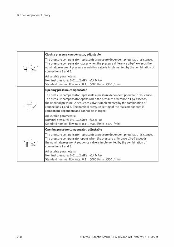
B. The Component Library
Closing pressure compensator, adjustable
The pressure compensator represents a pressure dependent pneumatic resistance.The pressure compensator closes when the pressure difference p3-p4 exceeds thenominal pressure. A pressure regulating valve is implemented by the combination ofconnections 2 and 3.
Adjustable parameters:Nominal pressure: 0.01 ... 2MPa (0.4MPa)Standard nominal flow rate: 0.1 ... 5000 l/min (300 l/min)
Opening pressure compensator
The pressure compensator represents a pressure dependent pneumatic resistance.The pressure compensator opens when the pressure difference p3-p4 exceedsthe nominal pressure. A sequence valve is implemented by the combination ofconnections 1 and 3. The nominal pressure setting of the real components iscomponent dependent and cannot be changed.
Adjustable parameters:Nominal pressure: 0.01 ... 2MPa (0.4MPa)Standard nominal flow rate: 0.1 ... 5000 l/min (300 l/min)
Opening pressure compensator, adjustable
The pressure compensator represents a pressure dependent pneumatic resistance.The pressure compensator opens when the pressure difference p3-p4 exceedsthe nominal pressure. A sequence valve is implemented by the combination ofconnections 1 and 3.
Adjustable parameters:Nominal pressure: 0.01 ... 2MPa (0.4MPa)Standard nominal flow rate: 0.1 ... 5000 l/min (300 l/min)
258 © Festo Didactic GmbH & Co. KG and Art Systems • FluidSIM
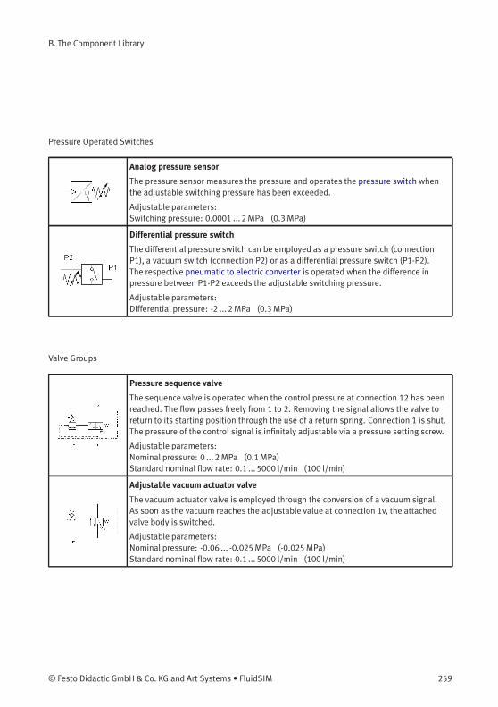
B. The Component Library
Pressure Operated Switches
Analog pressure sensor
The pressure sensor measures the pressure and operates the pressure switch whenthe adjustable switching pressure has been exceeded.
Adjustable parameters:Switching pressure: 0.0001 ... 2MPa (0.3MPa)
Differential pressure switch
The differential pressure switch can be employed as a pressure switch (connectionP1), a vacuum switch (connection P2) or as a differential pressure switch (P1-P2).The respective pneumatic to electric converter is operated when the difference inpressure between P1-P2 exceeds the adjustable switching pressure.
Adjustable parameters:Differential pressure: -2 ... 2MPa (0.3MPa)
Valve Groups
Pressure sequence valve
The sequence valve is operated when the control pressure at connection 12 has beenreached. The flow passes freely from 1 to 2. Removing the signal allows the valve toreturn to its starting position through the use of a return spring. Connection 1 is shut.The pressure of the control signal is infinitely adjustable via a pressure setting screw.
Adjustable parameters:Nominal pressure: 0 ... 2MPa (0.1MPa)Standard nominal flow rate: 0.1 ... 5000 l/min (100 l/min)
Adjustable vacuum actuator valve
The vacuum actuator valve is employed through the conversion of a vacuum signal.As soon as the vacuum reaches the adjustable value at connection 1v, the attachedvalve body is switched.
Adjustable parameters:Nominal pressure: -0.06 ... -0.025MPa (-0.025MPa)Standard nominal flow rate: 0.1 ... 5000 l/min (100 l/min)
© Festo Didactic GmbH & Co. KG and Art Systems • FluidSIM 259
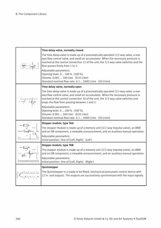
B. The Component Library
Time delay valve, normally closed
The time delay valve is made up of a pneumatically operated 3/2-way valve, a one-way flow control valve, and small air accumulator. When the necessary pressure isreached at the control connection 12 of the unit, the 3/2-way valve switches and theflow passes freely from 1 to 2.
Adjustable parameters:Opening level: 0 ... 100% (100%)Volume: 0.001 ... 100 Liter (0.01 Liter)Standard nominal flow rate: 0.1 ... 5000 l/min (50 l/min)
Time delay valve, normally open
The time delay valve is made up of a pneumatically operated 3/2-way valve, a one-way flow control valve, and small air accumulator. When the necessary pressure isreached at the control connection 10 of the unit, the 3/2-way valve switches andstops the flow from passing between 1 and 2.
Adjustable parameters:Opening level: 0 ... 100% (100%)Volume: 0.001 ... 100 Liter (0.01 Liter)Standard nominal flow rate: 0.1 ... 5000 l/min (50 l/min)
Stepper module, type TAA
The stepper module is made up of a memory unit (3/2-way impulse valve), an ANDand an OR component, a viewable announcement, and an auxiliarymanual operation.
Adjustable parameters:Initial position: One of {Left, Right} (Left )
Stepper module, type TAB
The stepper module is made up of a memory unit (3/2-way impulse valve), an ANDand an OR component, a viewable announcement, and an auxiliarymanual operation.
Adjustable parameters:Initial position: One of {Left, Right} (Right )
Quickstepper
The Quickstepper is a ready to be fitted, mechanical/pneumatic control device with12 in- and outputs. The outputs are successively synchronized with the input signals.
260 © Festo Didactic GmbH & Co. KG and Art Systems • FluidSIM
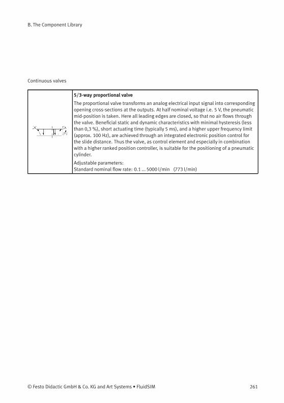
B. The Component Library
Continuous valves
5/3-way proportional valve
The proportional valve transforms an analog electrical input signal into correspondingopening cross-sections at the outputs. At half nominal voltage i.e. 5 V, the pneumaticmid-position is taken. Here all leading edges are closed, so that no air flows throughthe valve. Beneficial static and dynamic characteristics with minimal hysteresis (lessthan 0,3 %), short actuating time (typically 5 ms), and a higher upper frequency limit(approx. 100 Hz), are achieved through an integrated electronic position control forthe slide distance. Thus the valve, as control element and especially in combinationwith a higher ranked position controller, is suitable for the positioning of a pneumaticcylinder.
Adjustable parameters:Standard nominal flow rate: 0.1 ... 5000 l/min (773 l/min)
© Festo Didactic GmbH & Co. KG and Art Systems • FluidSIM 261

B. The Component Library
Actuators
Configurable cylinder
The configurable cylinder can be customized via its properties dialog. Almost anycombination of piston type (single-acting, double-acting), the specification of thepiston rods (double ended, with magnetic coupling or slide) and the number (none,one, two) is possible. An end position cushioning (without, with, adjustable) canalso be defined. FluidSIM automatically adjusts the symbol according to the presetconfiguration.In addition, a load to be moved (including possible static and sliding friction) and avariable force profile can be defined in the properties dialog.In the component library of FluidSIM there are several pre-configured cylindersthat can be inserted in your circuit and directly used. Should no suitable symbol beavailable, then simply choose the component with the most similarity to the requiredcomponent, open the properties dialog and adjust the configuration accordingly.
Adjustable parameters:Max. stroke: 1 ... 5000mm (50mm)Piston position: 0 ...Max. stroke mm (0mm)Piston diameter: 1 ... 1000mm (20mm)Piston rod diameter: 0 ... 1000mm (8mm)Mounting angle: 0 ... 360 Deg (0 Deg)Internal leakage: 0 ... 100 l/(min*MPa) (0 l/(min*MPa))Moving mass: 0 ... 10000 kg (0 kg)Static friction coefficient: 0 ... 2 (0 )Sliding friction coefficient: 0 ... 2 (0 )Force: -10000 ... 10000 N (0 N)
262 © Festo Didactic GmbH & Co. KG and Art Systems • FluidSIM
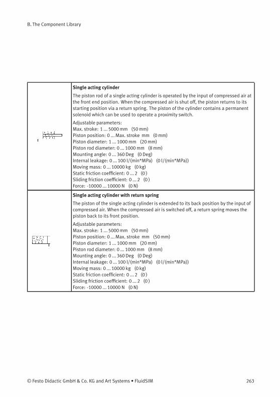
B. The Component Library
Single acting cylinder
The piston rod of a single acting cylinder is operated by the input of compressed air atthe front end position. When the compressed air is shut off, the piston returns to itsstarting position via a return spring. The piston of the cylinder contains a permanentsolenoid which can be used to operate a proximity switch.
Adjustable parameters:Max. stroke: 1 ... 5000mm (50mm)Piston position: 0 ...Max. stroke mm (0mm)Piston diameter: 1 ... 1000mm (20mm)Piston rod diameter: 0 ... 1000mm (8mm)Mounting angle: 0 ... 360 Deg (0 Deg)Internal leakage: 0 ... 100 l/(min*MPa) (0 l/(min*MPa))Moving mass: 0 ... 10000 kg (0 kg)Static friction coefficient: 0 ... 2 (0 )Sliding friction coefficient: 0 ... 2 (0 )Force: -10000 ... 10000 N (0 N)
Single acting cylinder with return spring
The piston of the single acting cylinder is extended to its back position by the input ofcompressed air. When the compressed air is switched off, a return spring moves thepiston back to its front position.
Adjustable parameters:Max. stroke: 1 ... 5000mm (50mm)Piston position: 0 ...Max. stroke mm (50mm)Piston diameter: 1 ... 1000mm (20mm)Piston rod diameter: 0 ... 1000mm (8mm)Mounting angle: 0 ... 360 Deg (0 Deg)Internal leakage: 0 ... 100 l/(min*MPa) (0 l/(min*MPa))Moving mass: 0 ... 10000 kg (0 kg)Static friction coefficient: 0 ... 2 (0 )Sliding friction coefficient: 0 ... 2 (0 )Force: -10000 ... 10000 N (0 N)
© Festo Didactic GmbH & Co. KG and Art Systems • FluidSIM 263
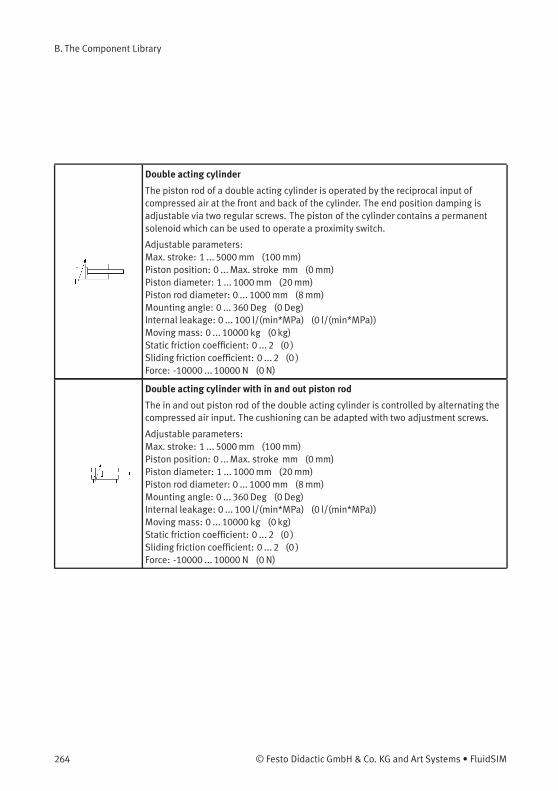
B. The Component Library
Double acting cylinder
The piston rod of a double acting cylinder is operated by the reciprocal input ofcompressed air at the front and back of the cylinder. The end position damping isadjustable via two regular screws. The piston of the cylinder contains a permanentsolenoid which can be used to operate a proximity switch.
Adjustable parameters:Max. stroke: 1 ... 5000mm (100mm)Piston position: 0 ...Max. stroke mm (0mm)Piston diameter: 1 ... 1000mm (20mm)Piston rod diameter: 0 ... 1000mm (8mm)Mounting angle: 0 ... 360 Deg (0 Deg)Internal leakage: 0 ... 100 l/(min*MPa) (0 l/(min*MPa))Moving mass: 0 ... 10000 kg (0 kg)Static friction coefficient: 0 ... 2 (0 )Sliding friction coefficient: 0 ... 2 (0 )Force: -10000 ... 10000 N (0 N)
Double acting cylinder with in and out piston rod
The in and out piston rod of the double acting cylinder is controlled by alternating thecompressed air input. The cushioning can be adapted with two adjustment screws.
Adjustable parameters:Max. stroke: 1 ... 5000mm (100mm)Piston position: 0 ...Max. stroke mm (0mm)Piston diameter: 1 ... 1000mm (20mm)Piston rod diameter: 0 ... 1000mm (8mm)Mounting angle: 0 ... 360 Deg (0 Deg)Internal leakage: 0 ... 100 l/(min*MPa) (0 l/(min*MPa))Moving mass: 0 ... 10000 kg (0 kg)Static friction coefficient: 0 ... 2 (0 )Sliding friction coefficient: 0 ... 2 (0 )Force: -10000 ... 10000 N (0 N)
264 © Festo Didactic GmbH & Co. KG and Art Systems • FluidSIM
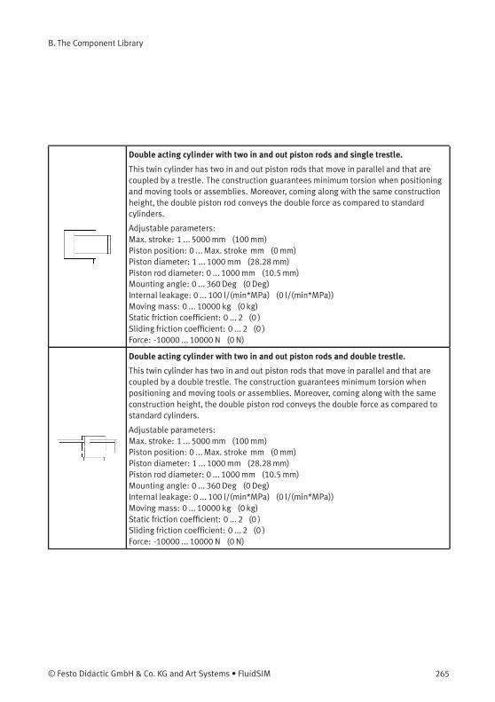
B. The Component Library
Double acting cylinder with two in and out piston rods and single trestle.
This twin cylinder has two in and out piston rods that move in parallel and that arecoupled by a trestle. The construction guarantees minimum torsion when positioningand moving tools or assemblies. Moreover, coming along with the same constructionheight, the double piston rod conveys the double force as compared to standardcylinders.
Adjustable parameters:Max. stroke: 1 ... 5000mm (100mm)Piston position: 0 ...Max. stroke mm (0mm)Piston diameter: 1 ... 1000mm (28.28mm)Piston rod diameter: 0 ... 1000mm (10.5mm)Mounting angle: 0 ... 360 Deg (0 Deg)Internal leakage: 0 ... 100 l/(min*MPa) (0 l/(min*MPa))Moving mass: 0 ... 10000 kg (0 kg)Static friction coefficient: 0 ... 2 (0 )Sliding friction coefficient: 0 ... 2 (0 )Force: -10000 ... 10000 N (0 N)
Double acting cylinder with two in and out piston rods and double trestle.
This twin cylinder has two in and out piston rods that move in parallel and that arecoupled by a double trestle. The construction guarantees minimum torsion whenpositioning and moving tools or assemblies. Moreover, coming along with the sameconstruction height, the double piston rod conveys the double force as compared tostandard cylinders.
Adjustable parameters:Max. stroke: 1 ... 5000mm (100mm)Piston position: 0 ...Max. stroke mm (0mm)Piston diameter: 1 ... 1000mm (28.28mm)Piston rod diameter: 0 ... 1000mm (10.5mm)Mounting angle: 0 ... 360 Deg (0 Deg)Internal leakage: 0 ... 100 l/(min*MPa) (0 l/(min*MPa))Moving mass: 0 ... 10000 kg (0 kg)Static friction coefficient: 0 ... 2 (0 )Sliding friction coefficient: 0 ... 2 (0 )Force: -10000 ... 10000 N (0 N)
© Festo Didactic GmbH & Co. KG and Art Systems • FluidSIM 265

B. The Component Library
Multiple position cylinder
By connecting two cylinders of same piston diameter but different maximum strokethree piston stop positions can be realized. From the first stop position the third stopcan be reached either directly or via the intermediate stop. Note that the maximumstroke of the second piston must be larger than the preceding one. When movingback, an intermediate stop requires a particular control. The shorter maximum strokeis half of the other maximum stroke.
Adjustable parameters:Force: -1000 ... 1000 N (0N)Max. stroke: 1 ... 2000mm (200mm)Piston position: 0 ...Max. stroke mm (0mm)Intermediate Stop: 0 ... Piston position mm (0mm)Piston Area: 0,25 ... 810 qcm (3,14 qcm)Piston Ring Area: 0,1 ... 750 qcm (2,64 qcm)
Linear drive with solenoid coupling
The sliding of the piston in the double rod cylinder is controlled by a reciprocal inputof compressed air.
Adjustable parameters:Max. stroke: 1 ... 5000mm (200mm)Piston position: 0 ...Max. stroke mm (0mm)Piston diameter: 1 ... 1000mm (16mm)Piston rod diameter: 0 ... 1000mm (0mm)Mounting angle: 0 ... 360 Deg (0 Deg)Internal leakage: 0 ... 100 l/(min*MPa) (0 l/(min*MPa))Moving mass: 0 ... 10000 kg (0 kg)Static friction coefficient: 0 ... 2 (0 )Sliding friction coefficient: 0 ... 2 (0 )Force: -10000 ... 10000 N (0 N)
266 © Festo Didactic GmbH & Co. KG and Art Systems • FluidSIM
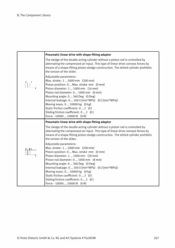
B. The Component Library
Pneumatic linear drive with shape-fitting adaptor
The sledge of the double acting cylinder without a piston rod is controlled byalternating the compressed air input. This type of linear drive conveys forces bymeans of a shape-fitting piston-sledge construction. The slitted cylinder prohibitsthe torsion of the slider.
Adjustable parameters:Max. stroke: 1 ... 5000mm (200mm)Piston position: 0 ...Max. stroke mm (0mm)Piston diameter: 1 ... 1000mm (16mm)Piston rod diameter: 0 ... 1000mm (0mm)Mounting angle: 0 ... 360 Deg (0 Deg)Internal leakage: 0 ... 100 l/(min*MPa) (0 l/(min*MPa))Moving mass: 0 ... 10000 kg (0 kg)Static friction coefficient: 0 ... 2 (0 )Sliding friction coefficient: 0 ... 2 (0 )Force: -10000 ... 10000 N (0 N)
Pneumatic linear drive with shape-fitting adaptor
The sledge of the double acting cylinder without a piston rod is controlled byalternating the compressed air input. This type of linear drive conveys forces bymeans of a shape-fitting piston-sledge construction. The slitted cylinder prohibitsthe torsion of the slider.
Adjustable parameters:Max. stroke: 1 ... 5000mm (200mm)Piston position: 0 ...Max. stroke mm (0mm)Piston diameter: 1 ... 1000mm (20mm)Piston rod diameter: 0 ... 1000mm (8mm)Mounting angle: 0 ... 360 Deg (0 Deg)Internal leakage: 0 ... 100 l/(min*MPa) (0 l/(min*MPa))Moving mass: 0 ... 10000 kg (0 kg)Static friction coefficient: 0 ... 2 (0 )Sliding friction coefficient: 0 ... 2 (0 )Force: -10000 ... 10000 N (0 N)
© Festo Didactic GmbH & Co. KG and Art Systems • FluidSIM 267
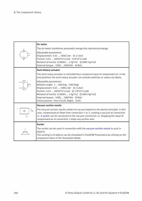
B. The Component Library
Air motor
The air motor transforms pneumatic energy into mechanical energy.
Adjustable parameters:Displacement: 0.01 ... 1000 Liter (0.1 Liter)Friction: 0.01 ... 100N*m*s/rad (3 N*m*s/rad)Moment of inertia: 0.00001 ... 1 kg*m2 (0.0001 kg*m2)External torque: -1000 ... 1000 Nm (0Nm)
Semi-Rotary actuator
The semi-rotary actuator is controlled by a reciprocal input of compressed air. In theend positions the semi-rotary actuator can activate switches or valves via labels.
Adjustable parameters:Rotation angle: 1 ... 360 Deg (180Deg)Displacement: 0.01 ... 1000 Liter (0.1 Liter)Friction: 0.01 ... 100N*m*s/rad (0.1N*m*s/rad)Moment of inertia: 0.00001 ... 1 kg*m2 (0.0001 kg*m2)External torque: -1000 ... 1000 Nm (0Nm)Initial position: One of {Left, Right} (Left )
Vacuum suction nozzle
The vacuum suction nozzle creates its vacuum based on the ejector principle. In thiscase, compressed air flows from connection 1 to 3, creating a vacuum at connection1v. A sucker can be connected to the vacuum connection 1v. Stopping the input ofcompressed air at connection 1 stops any suction also.
Sucker
The sucker can be used in connection with the vacuum suction nozzle to suck inobjects.The sucking in of objects can be simulated in FluidSIM Pneumatics by clicking on thecomponent when in the Simulation Mode.
268 © Festo Didactic GmbH & Co. KG and Art Systems • FluidSIM

B. The Component Library
Measuring Instruments
Manometer
The manometer displays the pressure at its connection.
Differential pressure gauge
The differential pressure gauge displays the pressure difference between theadjacent pressures at the left and the right connection.
Pressure indicator
An optical signal is activated when the pressure at the connection to the pressureindicator exceeds the preset switching pressure.
Adjustable parameters:Switching pressure: 0.0001 ... 2MPa (0.3MPa)Color: One of {16 standard colors} (Blue )
Pressure sensor, analog
This symbol represents the pneumatic part of the analog pressure sensor. The analogpressure sensor measures the adjacent pressure and transforms it into a proportionalelectrical voltage signal. In the process, only pressures in the specified pressureranges are considered. Within this range, the pressure in the voltage range from 0V to 10 V is represented, i.e. the minimum pressure delivers 0 V and the maximumpressure 10 V.
Flow meter
The flow meter measures the flow rate. Either the current flow or the total quantityflowed can be displayed. The component image is automatically adjusted accord-ingly.
Adjustable parameters:Standard nominal flow rate: 0.1 ... 5000 l/min (2000 l/min)
© Festo Didactic GmbH & Co. KG and Art Systems • FluidSIM 269
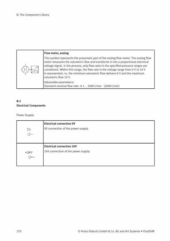
B. The Component Library
Flow meter, analog
This symbol represents the pneumatic part of the analog flow meter. The analog flowmeter measures the volumetric flow and transforms it into a proportional electricalvoltage signal. In the process, only flow rates in the specified pressure ranges areconsidered. Within this range, the flow rate in the voltage range from 0 V to 10 Vis represented, i.e. the minimum volumetric flow delivers 0 V and the maximumvolumetric flow 10 V.
Adjustable parameters:Standard nominal flow rate: 0.1 ... 5000 l/min (2000 l/min)
B.2
Electrical Components
Power Supply
Electrical connection 0V
0V connection of the power supply.
Electrical connection 24V
24V connection of the power supply.
270 © Festo Didactic GmbH & Co. KG and Art Systems • FluidSIM

B. The Component Library
Function generator
The function generator is a voltage source that can create constant, rectangle, sineand triangle signals. The voltage range is restricted to -10 V to +10 V. The frequency,the amplitude and the Y-offset of the signal can be set within this range.A voltage profile can be additionally specified. Data points can be set interactivelywith a mouse-click in the relevant graphic field. These can then be combined to aclosed polygon. Alternatively, existing data points can be marked and both numericvalues for the time and the corresponding voltage can be entered in the input fields.If the option “loop” is selected, then the voltage profile is started again.
Adjustable parameters:Frequency: 0 ... 100 Hz (1 Hz)Amplitude: 0 ... 10 V (5 V)y offset: -10 ... 10 V (5 V)
© Festo Didactic GmbH & Co. KG and Art Systems • FluidSIM 271
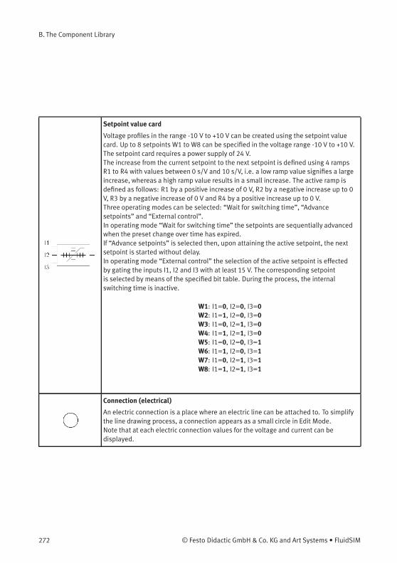
B. The Component Library
Setpoint value card
Voltage profiles in the range -10 V to +10 V can be created using the setpoint valuecard. Up to 8 setpoints W1 to W8 can be specified in the voltage range -10 V to +10 V.The setpoint card requires a power supply of 24 V.The increase from the current setpoint to the next setpoint is defined using 4 rampsR1 to R4 with values between 0 s/V and 10 s/V, i.e. a low ramp value signifies a largeincrease, whereas a high ramp value results in a small increase. The active ramp isdefined as follows: R1 by a positive increase of 0 V, R2 by a negative increase up to 0V, R3 by a negative increase of 0 V and R4 by a positive increase up to 0 V.Three operating modes can be selected: “Wait for switching time”, “Advancesetpoints” and “External control”.In operating mode “Wait for switching time” the setpoints are sequentially advancedwhen the preset change over time has expired.If “Advance setpoints” is selected then, upon attaining the active setpoint, the nextsetpoint is started without delay.In operating mode “External control” the selection of the active setpoint is effectedby gating the inputs I1, I2 and I3 with at least 15 V. The corresponding setpointis selected by means of the specified bit table. During the process, the internalswitching time is inactive.
W1: I1=0, I2=0, I3=0W2: I1=1, I2=0, I3=0W3: I1=0, I2=1, I3=0W4: I1=1, I2=1, I3=0W5: I1=0, I2=0, I3=1W6: I1=1, I2=0, I3=1W7: I1=0, I2=1, I3=1W8: I1=1, I2=1, I3=1
Connection (electrical)
An electric connection is a place where an electric line can be attached to. To simplifythe line drawing process, a connection appears as a small circle in Edit Mode.Note that at each electric connection values for the voltage and current can bedisplayed.
272 © Festo Didactic GmbH & Co. KG and Art Systems • FluidSIM
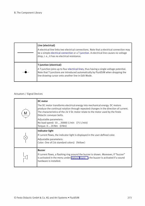
B. The Component Library
Line (electrical)
A electrical line links two electrical connections. Note that a electrical connection maybe a simple electrical connection or a T-junction. A electrical line causes no voltagedrop, i. e., it has no electrical resistance.
T-junction (electrical)
A T-junction joins up to four electrical lines, thus having a single voltage potential.Note that T-junctions are introduced automatically by FluidSIM when dropping theline drawing cursor onto another line in Edit Mode.
Actuators / Signal Devices
DCmotor
The DC motor transforms electrical energy into mechanical energy. DC motorsproduce the continual rotation through repeated changes in the direction of current.The characteristics of the 24 V Dc motor relate to the motor used by the FestoDidactic conveyor belts.
Adjustable parameters:No load speed: 10 ... 20000 1/min (75 1/min)Torque: 0 ... 20 Nm (0Nm)
Indicator light
If current flows, the indicator light is displayed in the user-defined color.
Adjustable parameters:Color: One of {16 standard colors} (Yellow )
Buzzer
If current flows, a flashing ring around the buzzer is shown. Moreover, if “buzzer”is activated in the menu under Options Sound... , the buzzer is activated if a soundhardware is installed.
© Festo Didactic GmbH & Co. KG and Art Systems • FluidSIM 273
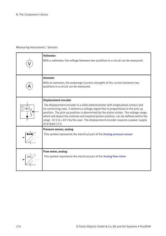
B. The Component Library
Measuring Instruments / Sensors
Voltmeter
With a voltmeter, the voltage between two positions in a circuit can be measured.
Ammeter
With an ammeter, the amperage (current strength) of the current between twopositions in a circuit can be measured.
Displacement encoder
The displacement encoder is a slide potentiometer with longitudinal contact andno connecting-rods. It delivers a voltage signal that is proportional to the pick upposition. The pick up position is determined by the piston stroke. The voltage range,which will depict the minimal and maximal piston position, can be defined within therange -10 V to +10 V by the user. The displacement encoder requires a power supplyof at least 13 V.
Pressure sensor, analog
This symbol represents the electrical part of the Analog-pressure sensor
Flow meter, analog
This symbol represents the electrical part of the Analog-flow meter
274 © Festo Didactic GmbH & Co. KG and Art Systems • FluidSIM
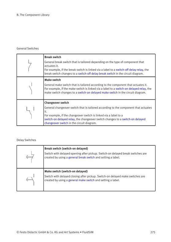
B. The Component Library
General Switches
Break switch
General break switch that is tailored depending on the type of component thatactuates it.For example, if the break switch is linked via a label to a switch-off delay relay, thebreak switch changes to a switch-off delay break switch in the circuit diagram.
Make switch
General make switch that is tailored according to the component that actuates it.For example, if the make switch is linked via a label to a switch-on delayed relay, themake switch changes to a switch-on delayedmake switch in the circuit diagram.
Changeover switch
General changeover switch that is tailored according to the component that actuatesit.For example, if the changeover switch is linked via a label to aswitch-on delayed relay, the changeover switch changes to a switch-on delayedchangeover switch in the circuit diagram.
Delay Switches
Break switch (switch-on delayed)
Switch with delayed opening after pickup. Switch-on delayed break switches arecreated by using a general break switch and setting a label.
Make switch (switch-on delayed)
Switch with delayed closing after pickup. Switch-on delayedmake switches arecreated by using a general make switch and setting a label.
© Festo Didactic GmbH & Co. KG and Art Systems • FluidSIM 275
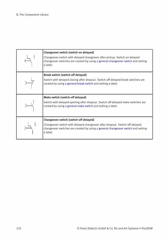
B. The Component Library
Changeover switch (switch-on delayed)
Changeover switch with delayed changeover after pickup. Switch-on delayedchangeover switches are created by using a general changeover switch and settinga label.
Break switch (switch-off delayed)
Switch with delayed closing after dropout. Switch-off delayed break switches arecreated by using a general break switch and setting a label.
Make switch (switch-off delayed)
Switch with delayed opening after dropout. Switch-off delayedmake switches arecreated by using a general make switch and setting a label.
Changeover switch (switch-off delayed)
Changeover switch with delayed changeover after dropout. Switch-off delayedchangeover switches are created by using a general changeover switch and settinga label.
276 © Festo Didactic GmbH & Co. KG and Art Systems • FluidSIM
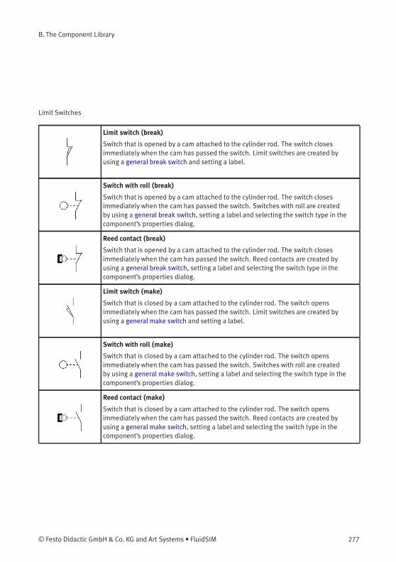
B. The Component Library
Limit Switches
Limit switch (break)
Switch that is opened by a cam attached to the cylinder rod. The switch closesimmediately when the cam has passed the switch. Limit switches are created byusing a general break switch and setting a label.
Switch with roll (break)
Switch that is opened by a cam attached to the cylinder rod. The switch closesimmediately when the cam has passed the switch. Switches with roll are createdby using a general break switch, setting a label and selecting the switch type in thecomponent’s properties dialog.
Reed contact (break)
Switch that is opened by a cam attached to the cylinder rod. The switch closesimmediately when the cam has passed the switch. Reed contacts are created byusing a general break switch, setting a label and selecting the switch type in thecomponent’s properties dialog.
Limit switch (make)
Switch that is closed by a cam attached to the cylinder rod. The switch opensimmediately when the cam has passed the switch. Limit switches are created byusing a general make switch and setting a label.
Switch with roll (make)
Switch that is closed by a cam attached to the cylinder rod. The switch opensimmediately when the cam has passed the switch. Switches with roll are createdby using a general make switch, setting a label and selecting the switch type in thecomponent’s properties dialog.
Reed contact (make)
Switch that is closed by a cam attached to the cylinder rod. The switch opensimmediately when the cam has passed the switch. Reed contacts are created byusing a general make switch, setting a label and selecting the switch type in thecomponent’s properties dialog.
© Festo Didactic GmbH & Co. KG and Art Systems • FluidSIM 277
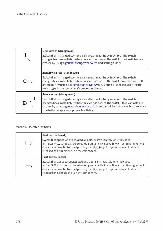
B. The Component Library
Limit switch (changeover)
Switch that is changed over by a cam attached to the cylinder rod. The switchchanges back immediately when the cam has passed the switch. Limit switches arecreated by using a general changeover switch and setting a label.
Switch with roll (changeover)
Switch that is changed over by a cam attached to the cylinder rod. The switchchanges back immediately when the cam has passed the switch. Switches with rollare created by using a general changeover switch, setting a label and selecting theswitch type in the component’s properties dialog.
Reed contact (changeover)
Switch that is changed over by a cam attached to the cylinder rod. The switchchanges back immediately when the cam has passed the switch. Reed contacts arecreated by using a general changeover switch, setting a label and selecting the switchtype in the component’s properties dialog.
Manually Operated Switches
Pushbutton (break)
Switch that opens when actuated and closes immediately when released.In FluidSIM switches can be actuated permanently (locked) when continuing to holddown the mouse button and pushing the Shift key. This permanent actuation isreleased by a simple click on the component.
Pushbutton (make)
Switch that closes when actuated and opens immediately when released.In FluidSIM switches can be actuated permanently (locked) when continuing to holddown the mouse button and pushing the Shift key. This permanent actuation isreleased by a simple click on the component.
278 © Festo Didactic GmbH & Co. KG and Art Systems • FluidSIM
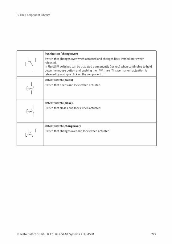
B. The Component Library
Pushbutton (changeover)
Switch that changes over when actuated and changes back immediately whenreleased.In FluidSIM switches can be actuated permanently (locked) when continuing to holddown the mouse button and pushing the Shift key. This permanent actuation isreleased by a simple click on the component.
Detent switch (break)
Switch that opens and locks when actuated.
Detent switch (make)
Switch that closes and locks when actuated.
Detent switch (changeover)
Switch that changes over and locks when actuated.
© Festo Didactic GmbH & Co. KG and Art Systems • FluidSIM 279
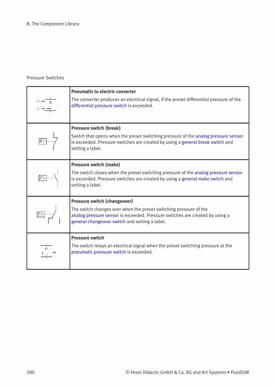
B. The Component Library
Pressure Switches
Pneumatic to electric converter
The converter produces an electrical signal, if the preset differential pressure of thedifferential pressure switch is exceeded.
Pressure switch (break)
Switch that opens when the preset switching pressure of the analog pressure sensoris exceeded. Pressure switches are created by using a general break switch andsetting a label.
Pressure switch (make)
The switch closes when the preset switching pressure of the analog pressure sensoris exceeded. Pressure switches are created by using a general make switch andsetting a label.
Pressure switch (changeover)
The switch changes over when the preset switching pressure of theanalog pressure sensor is exceeded. Pressure switches are created by using ageneral changeover switch and setting a label.
Pressure switch
The switch relays an electrical signal when the preset switching pressure at thepneumatic pressure switch is exceeded.
280 © Festo Didactic GmbH & Co. KG and Art Systems • FluidSIM

B. The Component Library
Proximity Switches
Magnetic proximity switch
Switch that closes when a solenoid is brought near by.In the Simulation Mode the proximity switch can also be actuated by clicking on it.
Inductive proximity switch
Switch that closes when the induced electro-magnetic field is changed.In the Simulation Mode the proximity switch can also be actuated by clicking on it.
Capacitive proximity switch
Switch that closes when its electrostatic field is changed.In the Simulation Mode the proximity switch can also be actuated by clicking on it.
Optical proximity switch
Switch that closes when the light barrier is interrupted.In the Simulation Mode the proximity switch can also be actuated by clicking on it.
© Festo Didactic GmbH & Co. KG and Art Systems • FluidSIM 281
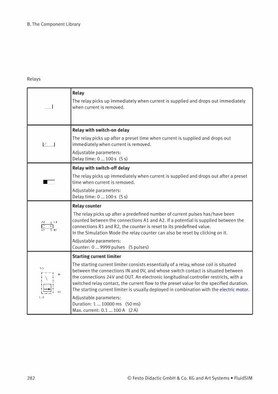
B. The Component Library
Relays
Relay
The relay picks up immediately when current is supplied and drops out immediatelywhen current is removed.
Relay with switch-on delay
The relay picks up after a preset time when current is supplied and drops outimmediately when current is removed.
Adjustable parameters:Delay time: 0 ... 100 s (5 s)
Relay with switch-off delay
The relay picks up immediately when current is supplied and drops out after a presettime when current is removed.
Adjustable parameters:Delay time: 0 ... 100 s (5 s)
Relay counter
The relay picks up after a predefined number of current pulses has/have beencounted between the connections A1 and A2. If a potential is supplied between theconnections R1 and R2, the counter is reset to its predefined value.In the Simulation Mode the relay counter can also be reset by clicking on it.
Adjustable parameters:Counter: 0 ... 9999 pulses (5 pulses)
Starting current limiter
The starting current limiter consists essentially of a relay, whose coil is situatedbetween the connections IN and 0V, and whose switch contact is situated betweenthe connections 24V and OUT. An electronic longitudinal controller restricts, with aswitched relay contact, the current flow to the preset value for the specified duration.The starting current limiter is usually deployed in combination with the electric motor.
Adjustable parameters:Duration: 1 ... 10000ms (50ms)Max. current: 0.1 ... 100 A (2 A)
282 © Festo Didactic GmbH & Co. KG and Art Systems • FluidSIM
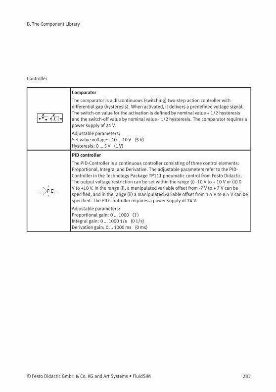
B. The Component Library
Controller
Comparator
The comparator is a discontinuous (switching) two-step action controller withdifferential gap (hysteresis). When activated, it delivers a predefined voltage signal.The switch-on value for the activation is defined by nominal value + 1/2 hysteresisand the switch-off value by nominal value - 1/2 hysteresis. The comparator requires apower supply of 24 V.
Adjustable parameters:Set value voltage: -10 ... 10 V (5 V)Hysteresis: 0 ... 5 V (1 V)
PID controller
The PID-Controller is a continuous controller consisting of three control elements:Proportional, Integral and Derivative. The adjustable parameters refer to the PID-Controller in the Technology Package TP111 pneumatic control from Festo Didactic.The output voltage restriction can be set within the range (i) -10 V to + 10 V or (ii) 0V to +10 V. In the range (i), a manipulated variable offset from -7 V to + 7 V can bespecified, and in the range (ii) a manipulated variable offset from 1.5 V to 8.5 V can bespecified. The PID-controller requires a power supply of 24 V.
Adjustable parameters:Proportional gain: 0 ... 1000 (1 )Integral gain: 0 ... 1000 1/s (0 1/s)Derivation gain: 0 ... 1000ms (0ms)
© Festo Didactic GmbH & Co. KG and Art Systems • FluidSIM 283

B. The Component Library
Status controller
The status controller is especially suitable for controlling pneumatic positioningcircuits. A pneumatic positioning circuit counts to the controlled systems that canonly be unsatisfactorily controlled with a standard controller. Three parameters canbe attributed to the present status controller: position, speed and acceleration of thepiston. The controller is therefore referred to as a “triple loop” controller. Speed andacceleration are not measured with sensors out of cost reasons. They are calculatedby the controller from the differences in position. The adjustable parameters refer tothe status controller in the Technology Package TP111 Closed-loop pneumatics fromFesto Didactic.The output voltage restriction can be set within the range (i) -10 V to + 10 V or (ii) 0V to +10 V. In the range (i), a manipulated variable offset from -7 V to + 7 V can bespecified, and in the range (ii) a manipulated variable offset from 1.5 V to 8.5 V can bespecified. The status controller requires a power supply of 24 V.
Adjustable parameters:Deviation gain: 0 ... 10 (1 )Velocity damping: 0 ... 100ms (0ms)Acceleration damping: 0 ... 10ms2 (0ms2)Total gain: 0 ... 1000 (1 )
EasyPort/OPC/DDE Components
FluidSIM Output Port
Communication with the EasyPort-Hardware and other applications is implementedwith the FluidSIM-Output.
FluidSIM Input Port
The FluidSIM input realizes the communication with other applications. Communi-cation with the EasyPort-Hardware and other applications is implementedwith theFluidSIM-Output.
284 © Festo Didactic GmbH & Co. KG and Art Systems • FluidSIM
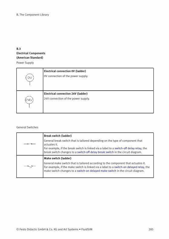
B. The Component Library
B.3
Electrical Components
(American Standard)
Power Supply
Electrical connection 0V (ladder)
0V connection of the power supply.
Electrical connection 24V (ladder)
24V connection of the power supply.
General Switches
Break switch (ladder)
General break switch that is tailored depending on the type of component thatactuates it.For example, if the break switch is linked via a label to a switch-off delay relay, thebreak switch changes to a switch-off delay break switch in the circuit diagram.
Make switch (ladder)
General make switch that is tailored according to the component that actuates it.For example, if the make switch is linked via a label to a switch-on delayed relay, themake switch changes to a switch-on delayedmake switch in the circuit diagram.
© Festo Didactic GmbH & Co. KG and Art Systems • FluidSIM 285
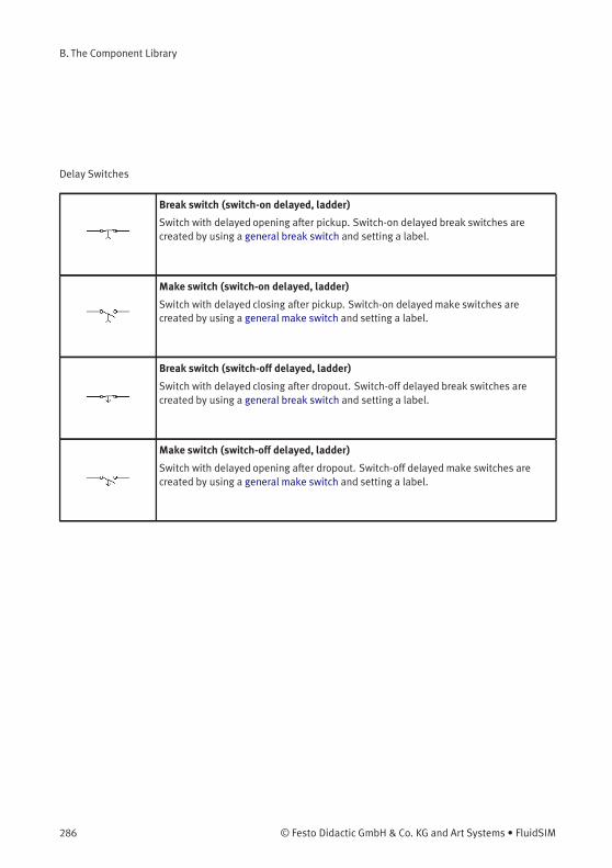
B. The Component Library
Delay Switches
Break switch (switch-on delayed, ladder)
Switch with delayed opening after pickup. Switch-on delayed break switches arecreated by using a general break switch and setting a label.
Make switch (switch-on delayed, ladder)
Switch with delayed closing after pickup. Switch-on delayedmake switches arecreated by using a general make switch and setting a label.
Break switch (switch-off delayed, ladder)
Switch with delayed closing after dropout. Switch-off delayed break switches arecreated by using a general break switch and setting a label.
Make switch (switch-off delayed, ladder)
Switch with delayed opening after dropout. Switch-off delayedmake switches arecreated by using a general make switch and setting a label.
286 © Festo Didactic GmbH & Co. KG and Art Systems • FluidSIM
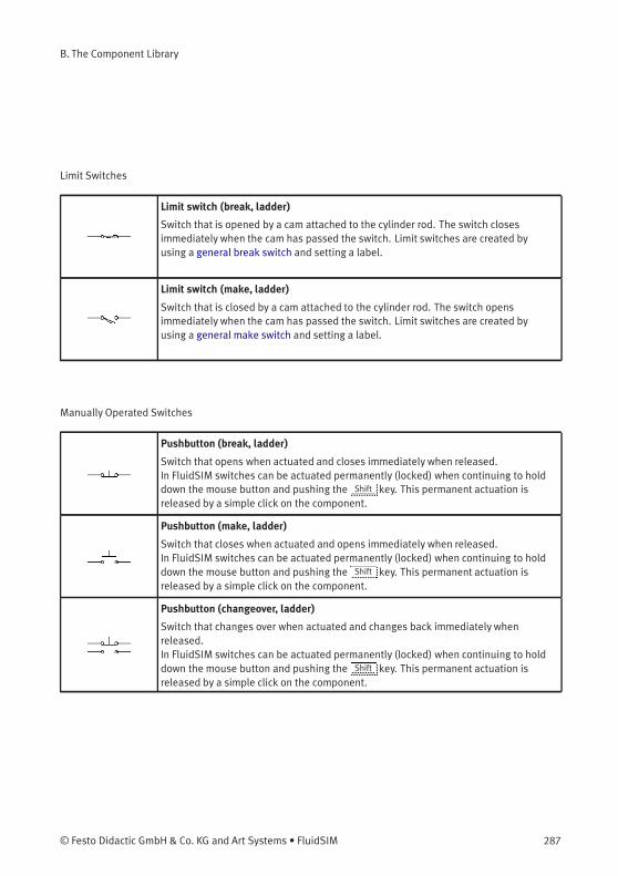
B. The Component Library
Limit Switches
Limit switch (break, ladder)
Switch that is opened by a cam attached to the cylinder rod. The switch closesimmediately when the cam has passed the switch. Limit switches are created byusing a general break switch and setting a label.
Limit switch (make, ladder)
Switch that is closed by a cam attached to the cylinder rod. The switch opensimmediately when the cam has passed the switch. Limit switches are created byusing a general make switch and setting a label.
Manually Operated Switches
Pushbutton (break, ladder)
Switch that opens when actuated and closes immediately when released.In FluidSIM switches can be actuated permanently (locked) when continuing to holddown the mouse button and pushing the Shift key. This permanent actuation isreleased by a simple click on the component.
Pushbutton (make, ladder)
Switch that closes when actuated and opens immediately when released.In FluidSIM switches can be actuated permanently (locked) when continuing to holddown the mouse button and pushing the Shift key. This permanent actuation isreleased by a simple click on the component.
Pushbutton (changeover, ladder)
Switch that changes over when actuated and changes back immediately whenreleased.In FluidSIM switches can be actuated permanently (locked) when continuing to holddown the mouse button and pushing the Shift key. This permanent actuation isreleased by a simple click on the component.
© Festo Didactic GmbH & Co. KG and Art Systems • FluidSIM 287
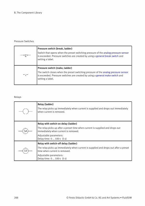
B. The Component Library
Pressure Switches
Pressure switch (break, ladder)
Switch that opens when the preset switching pressure of the analog pressure sensoris exceeded. Pressure switches are created by using a general break switch andsetting a label.
Pressure switch (make, ladder)
The switch closes when the preset switching pressure of the analog pressure sensoris exceeded. Pressure switches are created by using a general make switch andsetting a label.
Relays
Relay (ladder)
The relay picks up immediately when current is supplied and drops out immediatelywhen current is removed.
Relay with switch-on delay (ladder)
The relay picks up after a preset time when current is supplied and drops outimmediately when current is removed.
Adjustable parameters:Delay time: 0 ... 100 s (5 s)
Relay with switch-off delay (ladder)
The relay picks up immediately when current is supplied and drops out after a presettime when current is removed.
Adjustable parameters:Delay time: 0 ... 100 s (5 s)
288 © Festo Didactic GmbH & Co. KG and Art Systems • FluidSIM
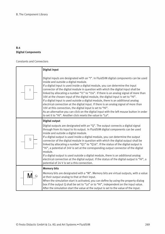
B. The Component Library
B.4
Digital Components
Constants and Connectors
Digital input
Digital inputs are designated with an “I”. In FluidSIM digital components can be usedinside and outside a digital module.If a digital input is used inside a digital module, you can determine the inputconnector of the digital module in question with which the digital input shall belinked by allocating a number “I1” to “I16”. If there is an analog signal of more than10V at the chosen input of the digital module, the digital input is set to “Hi”.If a digital input is used outside a digital module, there is an additional analogelectrical connection at the digital input. If there is an analog signal of more than10V at this connection, the digital input is set to “Hi”.As an alternative you can click on the digital input with the left mouse button in orderto set it to “Hi”. Another click resets the value to “Lo”.
Digital output
Digital outputs are designated with an “Q”. The output connects a digital signalthrough from its input to its output. In FluidSIM digital components can be usedinside and outside a digital module.If a digital output is used inside a digital module, you can determine the outputconnector of the digital module in question with which the digital output shall belinked by allocating a number “Q1” to “Q16”. If the status of the digital output is“Hi”, a potential of 24V is set at the corresponding output connector of the digitalmodule.If a digital output is used outside a digital module, there is an additional analogelectrical connection at the digital output. If the status of the digital output is “Hi”, apotential of 24 V is set a this connection.
Memory bits
Memory bits are designated with a “M”. Memory bits are virtual outputs, with a valueat their output analog to that at their input.When the simulation start is activated, you can define by using the property dialogbox if the output Q shall be set to “Lo” or to “Hi”, independent on the input value.After the simulation start the value at the output is set to the value of the input.
© Festo Didactic GmbH & Co. KG and Art Systems • FluidSIM 289

B. The Component Library
Logic level HI
At the output Q you have the logic level “Hi”.
Logic level LO
At the output Q you have the logic level “Lo”.
Connection (digital)
An digital connection is a place where a digital line can be attached to. To simplify theline drawing process, a connection appears as a small circle in Edit Mode.Note that at each digital connection its level “Lo” / “Hi” can be displayed.
Line (digital)
A digital line links two digital connections. Note that a digital connection may be asimple digital connection or a T-junction.
T-junction (digital)
A T-junction joins up to four digital lines, thus having a single digital level. Note thatT-junctions are introduced automatically by FluidSIM when dropping the line drawingcursor onto another line in Edit Mode.
290 © Festo Didactic GmbH & Co. KG and Art Systems • FluidSIM
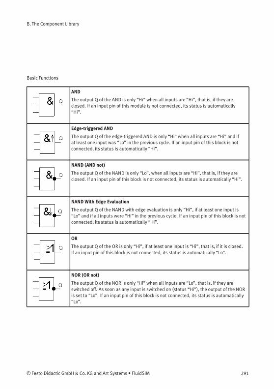
B. The Component Library
Basic Functions
AND
The output Q of the AND is only “Hi” when all inputs are “Hi”, that is, if they areclosed. If an input pin of this module is not connected, its status is automatically“Hi”.
Edge-triggered AND
The output Q of the edge-triggered AND is only “Hi” when all inputs are “Hi” and ifat least one input was “Lo” in the previous cycle. If an input pin of this block is notconnected, its status is automatically “Hi”.
NAND (AND not)
The output Q of the NAND is only “Lo”, when all inputs are “Hi”, that is, if they areclosed. If an input pin of this block is not connected, its status is automatically “Hi”.
NANDWith Edge Evaluation
The output Q of the NAND with edge evaluation is only “Hi”, if at least one input is“Lo” and if all inputs were “Hi” in the previous cycle. If an input pin of this block is notconnected, its status is automatically “Hi”.
OR
The output Q of the OR is only “Hi”, if at least one input is “Hi”, that is, if it is closed.If an input pin of this block is not connected, its status is automatically “Lo”.
NOR (OR not)
The output Q of the NOR is only “Hi” when all inputs are “Lo”, that is, if they areswitched off. As soon as any input is switched on (status “Hi”), the output of the NORis set to “Lo”. If an input pin of this block is not connected, its status is automatically“Lo”.
© Festo Didactic GmbH & Co. KG and Art Systems • FluidSIM 291
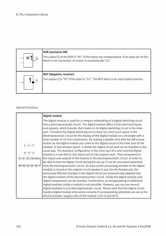
B. The Component Library
XOR (exclusive OR)
The output Q of the XOR is “Hi”, if the inputs are nonequivalent. If an input pin of thisblock is not connected, its status is automatically “Lo”.
NOT (Negation, Inverter)
The output Q is “Hi” if the input is “Lo”. The NOT block is an input status inverter.
Special Functions
Digital module
The digital module is used for a compact embedding of a digital switching circuitinto a electropneumatic circuit. The digital module offers 8 (16) electrical inputsand outputs, which transfer their states to its digital switching circuit in the innerpart. Therefore the digital switching circuit does not need much space in theelectropneumatic circuit for the display of the digital module as a rectangle with atotal number of 18 (34) connections. By making a double-click with the left mousebutton on the digital module you come to the digital circuit in the inner part of themodule. A new window opens. It shows the digital circuit and can be handled in theusual way. The standard configuration in the inner part of a new inserted digitalmodule is a row with 8 (16) inputs and 8 (16) outputs each. They correspond tothe inputs and outputs of the module in the electropneumatic circuit. In order tobe able to test the digital circuit during the set-up, it can be simulated separatedfrom the electropneumatic circuit. As soon as the processing window of the digitalmodule is closed or the original circuit window is put into the foreground, thepreviously effected changes in the digital circuit are automatically adopted intothe digital module of the electropneumatic circuit. Inside the digital module onlydigital components can be inserted. Furthermore, an encapsulating of additionaldigital modules inside a module is not possible. However, you can use severaldigital modules in one electropneumatic circuit. Please note that the digital circuitinside a digital module only works correctly if corresponding potentials are set at theelectrical power supply units of the module (+24 V) and (0 V).
292 © Festo Didactic GmbH & Co. KG and Art Systems • FluidSIM
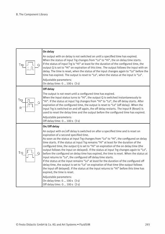
B. The Component Library
On delay
An output with on delay is not switched on until a specified time has expired.When the status of input Trg changes from “Lo” to “Hi”, the on delay time starts.If the status of input Trg is “Hi” at least for the duration of the configured time, theoutput Q is set to “Hi” on expiration of this time. The output follows the input with ondelay. The time is reset, when the status of the input changes again to “Lo” before thetime has expired. The output is reset to “Lo”, when the status at the input is “Lo”.
Adjustable parameters:On delay time: 0 ... 100 s (3 s)
Off delay
The output is not reset until a configured time has expired.When the input status turns to “Hi”, the output Q is switched instantaneously to“Hi”. If the status at input Trg changes from “Hi” to “Lo”, the off delay starts. Afterexpiration of the configured time, the output is reset to “Lo” (off delay). When theinput Trg is switched on and off again, the off delay restarts. The input R (Reset) isused to reset the delay time and the output before the configured time has expired.
Adjustable parameters:Off delay time: 0 ... 100 s (3 s)
On/Off delay
An output with on/off delay is switched on after a specified time and is reset onexpiration of a second specified time.As soon as the status at input Trg changes from “Lo” to “Hi”, the configured on delaytime starts. If the status at input Trg remains “Hi” at least for the duration of theconfigured time, the output Q is set to “Hi” on expiration of the on delay time (theoutput follows the input on delayed). If the status at input Trg changes again to “Lo”,before the configured on delay time has expired, the time is reset. When the status atinput returns to “Lo”, the configured off delay time starts.If the status at the input remains “Lo” at least for the duration of the configured offdelay time, the output is set to “Lo” on expiration of that time (the output followsthe input off delayed). If the status at the input returns to “Hi” before this time hasexpired, the time is reset.
Adjustable parameters:On delay time: 0 ... 100 s (3 s)Off delay time: 0 ... 100 s (3 s)
© Festo Didactic GmbH & Co. KG and Art Systems • FluidSIM 293
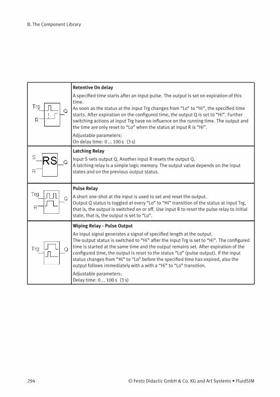
B. The Component Library
Retentive On delay
A specified time starts after an input pulse. The output is set on expiration of thistime.As soon as the status at the input Trg changes from “Lo” to “Hi”, the specified timestarts. After expiration on the configured time, the output Q is set to “Hi”. Furtherswitching actions at input Trg have no influence on the running time. The output andthe time are only reset to “Lo” when the status at input R is “Hi”.
Adjustable parameters:On delay time: 0 ... 100 s (3 s)
Latching Relay
Input S sets output Q. Another input R resets the output Q.A latching relay is a simple logic memory. The output value depends on the inputstates and on the previous output status.
Pulse Relay
A short one-shot at the input is used to set and reset the output.Output Q status is toggled at every “Lo” to “Hi” transition of the status at input Trg,that is, the output is switched on or off. Use input R to reset the pulse relay to initialstate, that is, the output is set to “Lo”.
Wiping Relay - Pulse Output
An input signal generates a signal of specified length at the output.The output status is switched to “Hi” after the input Trg is set to “Hi”. The configuredtime is started at the same time and the output remains set. After expiration of theconfigured time, the output is reset to the status “Lo” (pulse output). If the inputstatus changes from “Hi” to “Lo” before the specified time has expired, also theoutput follows immediately with a with a “Hi” to “Lo” transition.
Adjustable parameters:Delay time: 0 ... 100 s (3 s)
294 © Festo Didactic GmbH & Co. KG and Art Systems • FluidSIM
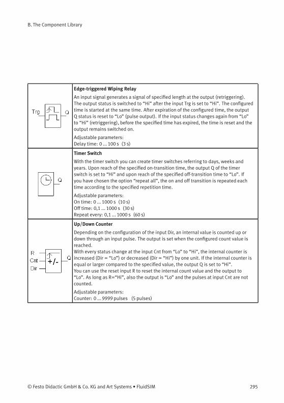
B. The Component Library
Edge-triggered Wiping Relay
An input signal generates a signal of specified length at the output (retriggering).The output status is switched to “Hi” after the input Trg is set to “Hi”. The configuredtime is started at the same time. After expiration of the configured time, the outputQ status is reset to “Lo” (pulse output). If the input status changes again from “Lo”to “Hi” (retriggering), before the specified time has expired, the time is reset and theoutput remains switched on.
Adjustable parameters:Delay time: 0 ... 100 s (3 s)
Timer Switch
With the timer switch you can create timer switches referring to days, weeks andyears. Upon reach of the specified on-transition time, the output Q of the timerswitch is set to “Hi” and upon reach of the specified off-transition time to “Lo”. Ifyou have chosen the option “repeat all”, the on and off transition is repeated eachtime according to the specified repetition time.
Adjustable parameters:On time: 0 ... 1000 s (10 s)Off time: 0,1 ... 1000 s (30 s)Repeat every: 0,1 ... 1000 s (60 s)
Up/Down Counter
Depending on the configuration of the input Dir, an internal value is counted up ordown through an input pulse. The output is set when the configured count value isreached.With every status change at the input Cnt from “Lo” to “Hi”, the internal counter isincreased (Dir = “Lo”) or decreased (Dir = “Hi”) by one unit. If the internal counter isequal or larger compared to the specified value, the output Q is set to “Hi”.You can use the reset input R to reset the internal count value and the output to“Lo”. As long as R=“Hi”, also the output is “Lo” and the pulses at input Cnt are notcounted.
Adjustable parameters:Counter: 0 ... 9999 pulses (5 pulses)
© Festo Didactic GmbH & Co. KG and Art Systems • FluidSIM 295
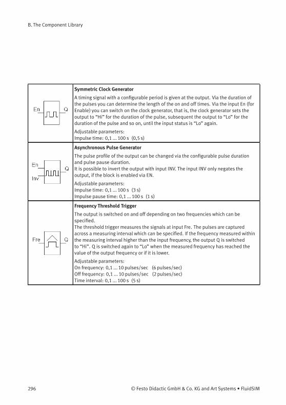
B. The Component Library
Symmetric Clock Generator
A timing signal with a configurable period is given at the output. Via the duration ofthe pulses you can determine the length of the on and off times. Via the input En (forEnable) you can switch on the clock generator, that is, the clock generator sets theoutput to “Hi” for the duration of the pulse, subsequent the output to “Lo” for theduration of the pulse and so on, until the input status is “Lo” again.
Adjustable parameters:Impulse time: 0,1 ... 100 s (0,5 s)
Asynchronous Pulse Generator
The pulse profile of the output can be changed via the configurable pulse durationand pulse pause duration.It is possible to invert the output with input INV. The input INV only negates theoutput, if the block is enabled via EN.
Adjustable parameters:Impulse time: 0,1 ... 100 s (3 s)Impulse pause time: 0,1 ... 100 s (1 s)
Frequency Threshold Trigger
The output is switched on and off depending on two frequencies which can bespecified.The threshold trigger measures the signals at input Fre. The pulses are capturedacross a measuring interval which can be specified. If the frequency measured withinthe measuring interval higher than the input frequency, the output Q is switchedto “Hi”. Q is switched again to “Lo” when the measured frequency has reached thevalue of the output frequency or if it is lower.
Adjustable parameters:On frequency: 0,1 ... 10 pulses/sec (6 pulses/sec)Off frequency: 0,1 ... 10 pulses/sec (2 pulses/sec)Time interval: 0,1 ... 100 s (5 s)
296 © Festo Didactic GmbH & Co. KG and Art Systems • FluidSIM
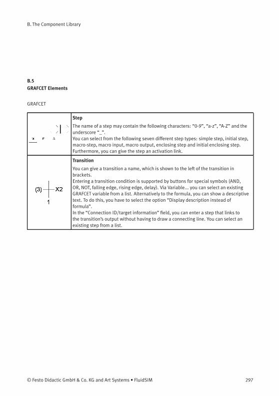
B. The Component Library
B.5
GRAFCET Elements
GRAFCET
Step
The name of a step may contain the following characters: “0-9”, “a-z”, “A-Z” and theunderscore “_”.You can select from the following seven different step types: simple step, initial step,macro-step, macro input, macro output, enclosing step and initial enclosing step.Furthermore, you can give the step an activation link.
Transition
You can give a transition a name, which is shown to the left of the transition inbrackets.Entering a transition condition is supported by buttons for special symbols (AND,OR, NOT, falling edge, rising edge, delay). Via Variable... you can select an existingGRAFCET variable from a list. Alternatively to the formula, you can show a descriptivetext. To do this, you have to select the option “Display description instead offormula”.In the “Connection ID/target information” field, you can enter a step that links tothe transition’s output without having to draw a connecting line. You can select anexisting step from a list.
© Festo Didactic GmbH & Co. KG and Art Systems • FluidSIM 297
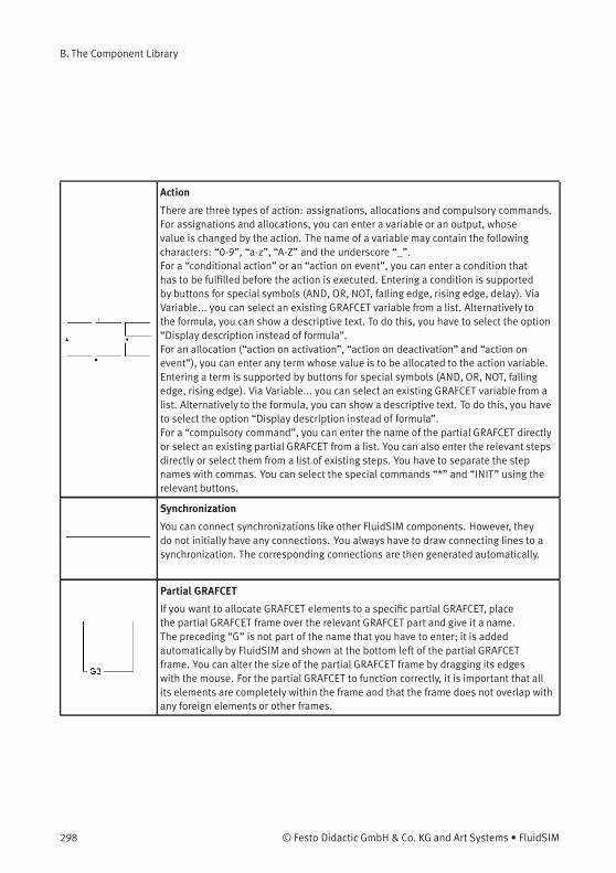
B. The Component Library
Action
There are three types of action: assignations, allocations and compulsory commands.For assignations and allocations, you can enter a variable or an output, whosevalue is changed by the action. The name of a variable may contain the followingcharacters: “0-9”, “a-z”, “A-Z” and the underscore “_”.For a “conditional action” or an “action on event”, you can enter a condition thathas to be fulfilled before the action is executed. Entering a condition is supportedby buttons for special symbols (AND, OR, NOT, falling edge, rising edge, delay). ViaVariable... you can select an existing GRAFCET variable from a list. Alternatively tothe formula, you can show a descriptive text. To do this, you have to select the option“Display description instead of formula”.For an allocation (“action on activation”, “action on deactivation” and “action onevent”), you can enter any term whose value is to be allocated to the action variable.Entering a term is supported by buttons for special symbols (AND, OR, NOT, fallingedge, rising edge). Via Variable... you can select an existing GRAFCET variable from alist. Alternatively to the formula, you can show a descriptive text. To do this, you haveto select the option “Display description instead of formula”.For a “compulsory command”, you can enter the name of the partial GRAFCET directlyor select an existing partial GRAFCET from a list. You can also enter the relevant stepsdirectly or select them from a list of existing steps. You have to separate the stepnames with commas. You can select the special commands “*” and “INIT” using therelevant buttons.
Synchronization
You can connect synchronizations like other FluidSIM components. However, theydo not initially have any connections. You always have to draw connecting lines to asynchronization. The corresponding connections are then generated automatically.
Partial GRAFCET
If you want to allocate GRAFCET elements to a specific partial GRAFCET, placethe partial GRAFCET frame over the relevant GRAFCET part and give it a name.The preceding “G” is not part of the name that you have to enter; it is addedautomatically by FluidSIM and shown at the bottom left of the partial GRAFCETframe. You can alter the size of the partial GRAFCET frame by dragging its edgeswith the mouse. For the partial GRAFCET to function correctly, it is important that allits elements are completely within the frame and that the frame does not overlap withany foreign elements or other frames.
298 © Festo Didactic GmbH & Co. KG and Art Systems • FluidSIM
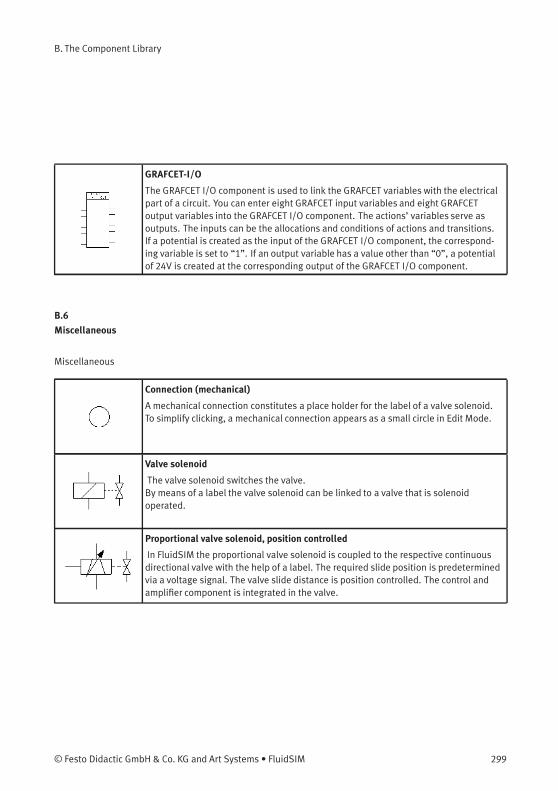
B. The Component Library
GRAFCET-I/O
The GRAFCET I/O component is used to link the GRAFCET variables with the electricalpart of a circuit. You can enter eight GRAFCET input variables and eight GRAFCEToutput variables into the GRAFCET I/O component. The actions’ variables serve asoutputs. The inputs can be the allocations and conditions of actions and transitions.If a potential is created as the input of the GRAFCET I/O component, the correspond-ing variable is set to “1”. If an output variable has a value other than “0”, a potentialof 24V is created at the corresponding output of the GRAFCET I/O component.
B.6
Miscellaneous
Miscellaneous
Connection (mechanical)
A mechanical connection constitutes a place holder for the label of a valve solenoid.To simplify clicking, a mechanical connection appears as a small circle in Edit Mode.
Valve solenoid
The valve solenoid switches the valve.By means of a label the valve solenoid can be linked to a valve that is solenoidoperated.
Proportional valve solenoid, position controlled
In FluidSIM the proportional valve solenoid is coupled to the respective continuousdirectional valve with the help of a label. The required slide position is predeterminedvia a voltage signal. The valve slide distance is position controlled. The control andamplifier component is integrated in the valve.
© Festo Didactic GmbH & Co. KG and Art Systems • FluidSIM 299
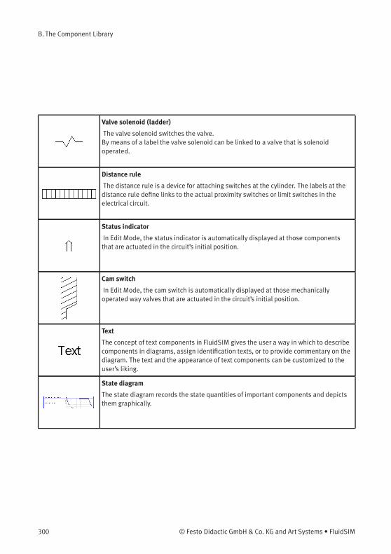
B. The Component Library
Valve solenoid (ladder)
The valve solenoid switches the valve.By means of a label the valve solenoid can be linked to a valve that is solenoidoperated.
Distance rule
The distance rule is a device for attaching switches at the cylinder. The labels at thedistance rule define links to the actual proximity switches or limit switches in theelectrical circuit.
Status indicator
In Edit Mode, the status indicator is automatically displayed at those componentsthat are actuated in the circuit’s initial position.
Cam switch
In Edit Mode, the cam switch is automatically displayed at those mechanicallyoperated way valves that are actuated in the circuit’s initial position.
Text
The concept of text components in FluidSIM gives the user a way in which to describecomponents in diagrams, assign identification texts, or to provide commentary on thediagram. The text and the appearance of text components can be customized to theuser’s liking.
State diagram
The state diagram records the state quantities of important components and depictsthem graphically.
300 © Festo Didactic GmbH & Co. KG and Art Systems • FluidSIM
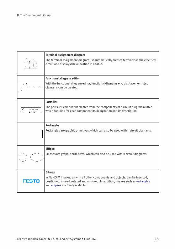
B. The Component Library
Terminal assignment diagram
The terminal assignment diagram list automatically creates terminals in the electricalcircuit and displays the allocation in a table.
Functional diagram editor
With the functional diagram editor, functional diagrams e.g. displacement-stepdiagrams can be created.
Parts list
The parts list component creates from the components of a circuit diagram a table,which contains for each component its designation and its description.
Rectangle
Rectangles are graphic primitives, which can also be used within circuit diagrams.
Ellipse
Ellipses are graphic primitives, which can also be used within circuit diagrams.
Bitmap
In FluidSIM images, as with all other components and objects, can be inserted,positioned, moved, rotated and mirrored. In addition, images such as rectanglesand ellipses are freely scalable.
© Festo Didactic GmbH & Co. KG and Art Systems • FluidSIM 301
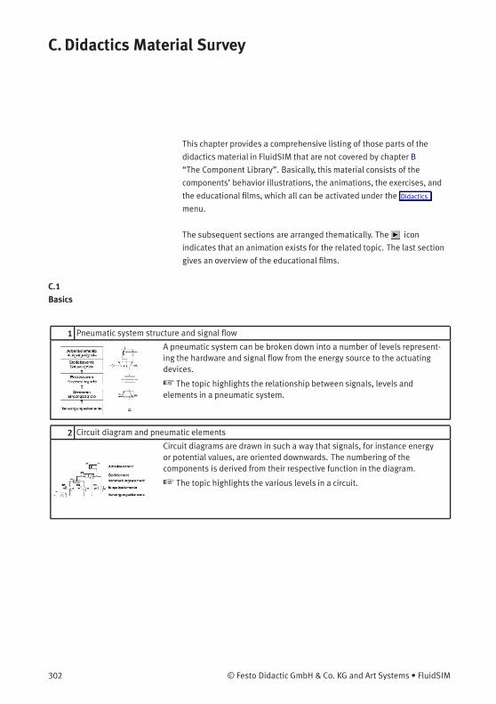
C. Didactics Material Survey
This chapter provides a comprehensive listing of those parts of the
didactics material in FluidSIM that are not covered by chapter B
“The Component Library”. Basically, this material consists of the
components’ behavior illustrations, the animations, the exercises, and
the educational films, which all can be activated under the Didactics
menu.
The subsequent sections are arranged thematically. The icon
indicates that an animation exists for the related topic. The last section
gives an overview of the educational films.
C.1
Basics
1 Pneumatic system structure and signal flow
A pneumatic system can be broken down into a number of levels represent-ing the hardware and signal flow from the energy source to the actuatingdevices.
☞ The topic highlights the relationship between signals, levels andelements in a pneumatic system.
2 Circuit diagram and pneumatic elements
Circuit diagrams are drawn in such a way that signals, for instance energyor potential values, are oriented downwards. The numbering of thecomponents is derived from their respective function in the diagram.
☞ The topic highlights the various levels in a circuit.
302 © Festo Didactic GmbH & Co. KG and Art Systems • FluidSIM
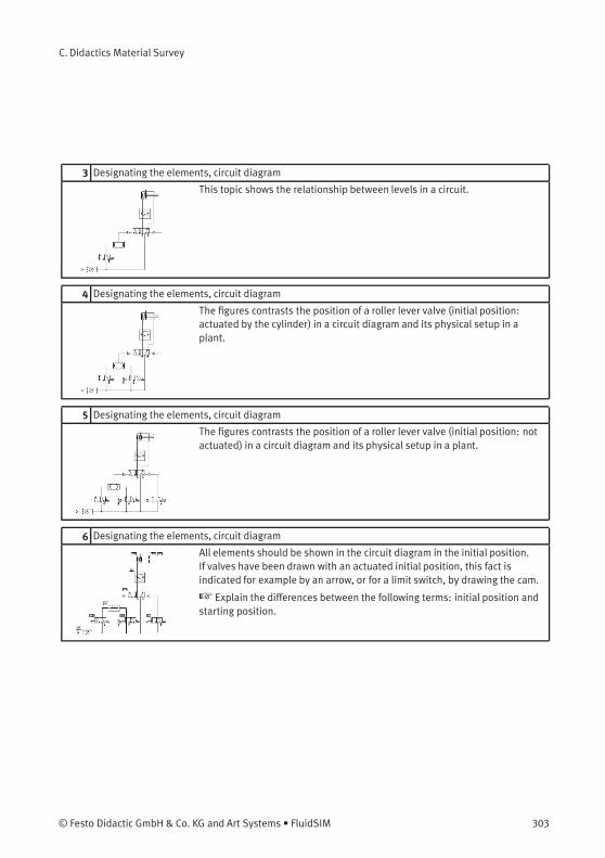
C. Didactics Material Survey
3 Designating the elements, circuit diagram
This topic shows the relationship between levels in a circuit.
4 Designating the elements, circuit diagram
The figures contrasts the position of a roller lever valve (initial position:actuated by the cylinder) in a circuit diagram and its physical setup in aplant.
5 Designating the elements, circuit diagram
The figures contrasts the position of a roller lever valve (initial position: notactuated) in a circuit diagram and its physical setup in a plant.
6 Designating the elements, circuit diagram
All elements should be shown in the circuit diagram in the initial position.If valves have been drawn with an actuated initial position, this fact isindicated for example by an arrow, or for a limit switch, by drawing the cam.
☞ Explain the differences between the following terms: initial position andstarting position.
© Festo Didactic GmbH & Co. KG and Art Systems • FluidSIM 303
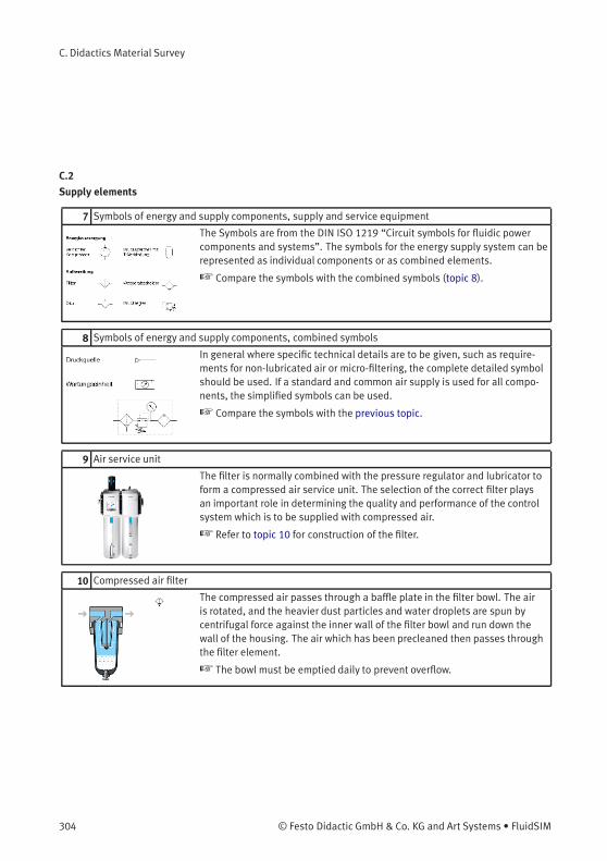
C. Didactics Material Survey
C.2
Supply elements
7 Symbols of energy and supply components, supply and service equipment
The Symbols are from the DIN ISO 1219 “Circuit symbols for fluidic powercomponents and systems”. The symbols for the energy supply system can berepresented as individual components or as combined elements.
☞ Compare the symbols with the combined symbols (topic 8).
8 Symbols of energy and supply components, combined symbols
In general where specific technical details are to be given, such as require-ments for non-lubricated air or micro-filtering, the complete detailed symbolshould be used. If a standard and common air supply is used for all compo-nents, the simplified symbols can be used.
☞ Compare the symbols with the previous topic.
9 Air service unit
The filter is normally combined with the pressure regulator and lubricator toform a compressed air service unit. The selection of the correct filter playsan important role in determining the quality and performance of the controlsystem which is to be supplied with compressed air.
☞ Refer to topic 10 for construction of the filter.
10 Compressed air filter
The compressed air passes through a baffle plate in the filter bowl. The airis rotated, and the heavier dust particles and water droplets are spun bycentrifugal force against the inner wall of the filter bowl and run down thewall of the housing. The air which has been precleaned then passes throughthe filter element.
☞ The bowl must be emptied daily to prevent overflow.
304 © Festo Didactic GmbH & Co. KG and Art Systems • FluidSIM
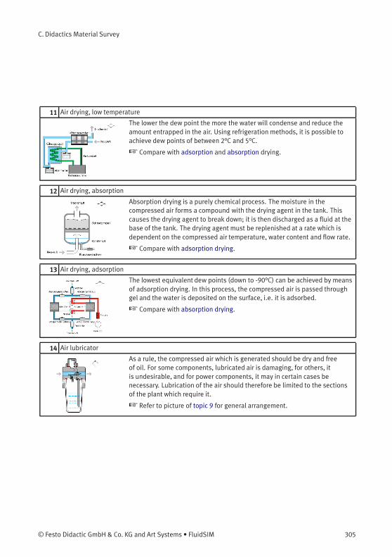
C. Didactics Material Survey
11 Air drying, low temperature
The lower the dew point the more the water will condense and reduce theamount entrapped in the air. Using refrigeration methods, it is possible toachieve dew points of between 2°C and 5°C.
☞ Compare with adsorption and absorption drying.
12 Air drying, absorption
Absorption drying is a purely chemical process. The moisture in thecompressed air forms a compound with the drying agent in the tank. Thiscauses the drying agent to break down; it is then discharged as a fluid at thebase of the tank. The drying agent must be replenished at a rate which isdependent on the compressed air temperature, water content and flow rate.
☞ Compare with adsorption drying.
13 Air drying, adsorption
The lowest equivalent dew points (down to -90°C) can be achieved by meansof adsorption drying. In this process, the compressed air is passed throughgel and the water is deposited on the surface, i.e. it is adsorbed.
☞ Compare with absorption drying.
14 Air lubricator
As a rule, the compressed air which is generated should be dry and freeof oil. For some components, lubricated air is damaging, for others, itis undesirable, and for power components, it may in certain cases benecessary. Lubrication of the air should therefore be limited to the sectionsof the plant which require it.
☞ Refer to picture of topic 9 for general arrangement.
© Festo Didactic GmbH & Co. KG and Art Systems • FluidSIM 305
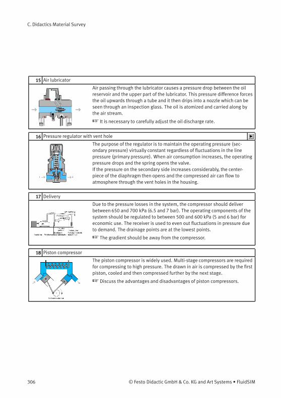
C. Didactics Material Survey
15 Air lubricator
Air passing through the lubricator causes a pressure drop between the oilreservoir and the upper part of the lubricator. This pressure difference forcesthe oil upwards through a tube and it then drips into a nozzle which can beseen through an inspection glass. The oil is atomized and carried along bythe air stream.
☞ It is necessary to carefully adjust the oil discharge rate.
16 Pressure regulator with vent hole
The purpose of the regulator is to maintain the operating pressure (sec-ondary pressure) virtually constant regardless of fluctuations in the linepressure (primary pressure). When air consumption increases, the operatingpressure drops and the spring opens the valve.If the pressure on the secondary side increases considerably, the center-piece of the diaphragm then opens and the compressed air can flow toatmosphere through the vent holes in the housing.
17 Delivery
Due to the pressure losses in the system, the compressor should deliverbetween 650 and 700 kPa (6.5 and 7 bar). The operating components of thesystem should be regulated to between 500 and 600 kPa (5 and 6 bar) foreconomic use. The receiver is used to even out fluctuations in pressure dueto demand. The drainage points are at the lowest points.
☞ The gradient should be away from the compressor.
18 Piston compressor
The piston compressor is widely used. Multi-stage compressors are requiredfor compressing to high pressure. The drawn in air is compressed by the firstpiston, cooled and then compressed further by the next stage.
☞ Discuss the advantages and disadvantages of piston compressors.
306 © Festo Didactic GmbH & Co. KG and Art Systems • FluidSIM
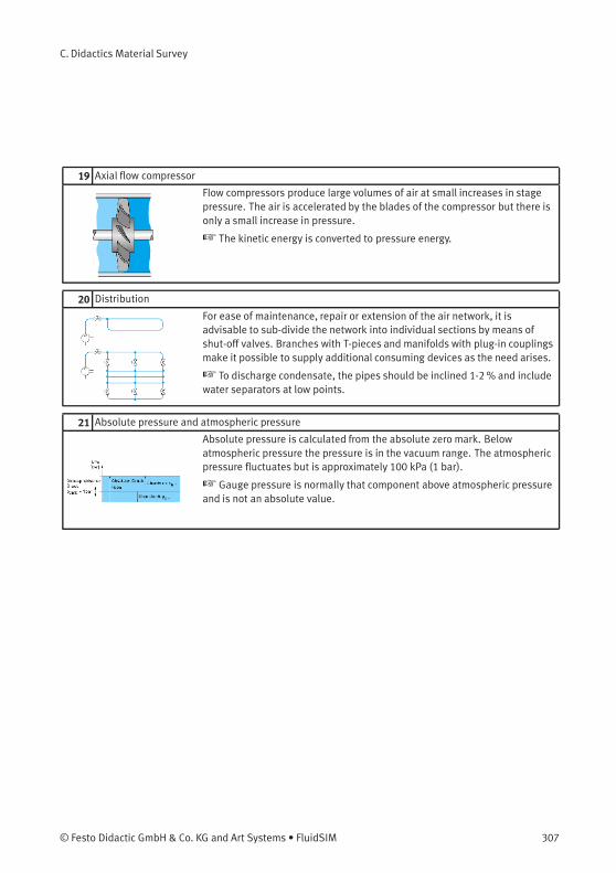
C. Didactics Material Survey
19 Axial flow compressor
Flow compressors produce large volumes of air at small increases in stagepressure. The air is accelerated by the blades of the compressor but there isonly a small increase in pressure.
☞ The kinetic energy is converted to pressure energy.
20 Distribution
For ease of maintenance, repair or extension of the air network, it isadvisable to sub-divide the network into individual sections by means ofshut-off valves. Branches with T-pieces and manifolds with plug-in couplingsmake it possible to supply additional consuming devices as the need arises.
☞ To discharge condensate, the pipes should be inclined 1-2% and includewater separators at low points.
21 Absolute pressure and atmospheric pressure
Absolute pressure is calculated from the absolute zero mark. Belowatmospheric pressure the pressure is in the vacuum range. The atmosphericpressure fluctuates but is approximately 100 kPa (1 bar).
☞ Gauge pressure is normally that component above atmospheric pressureand is not an absolute value.
© Festo Didactic GmbH & Co. KG and Art Systems • FluidSIM 307
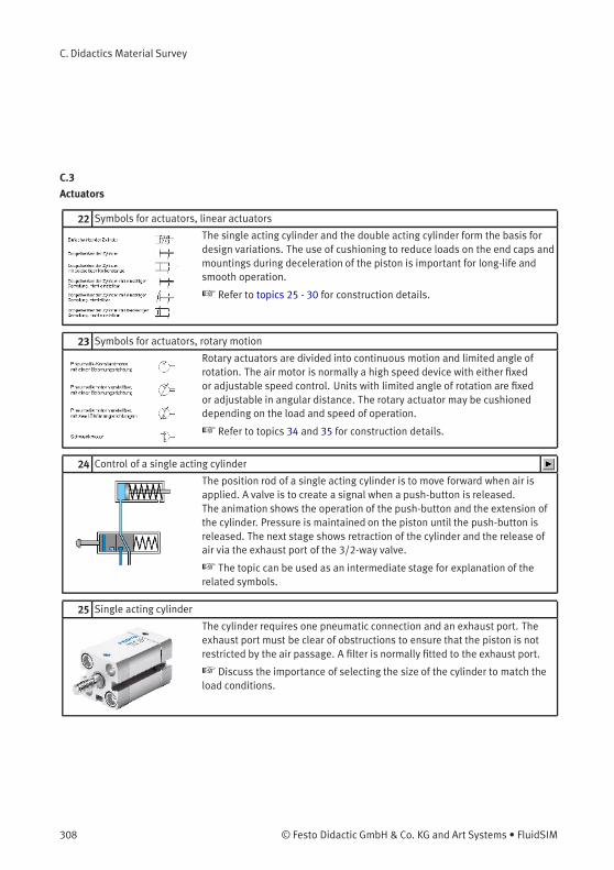
C. Didactics Material Survey
C.3
Actuators
22 Symbols for actuators, linear actuators
The single acting cylinder and the double acting cylinder form the basis fordesign variations. The use of cushioning to reduce loads on the end caps andmountings during deceleration of the piston is important for long-life andsmooth operation.
☞ Refer to topics 25 - 30 for construction details.
23 Symbols for actuators, rotary motion
Rotary actuators are divided into continuous motion and limited angle ofrotation. The air motor is normally a high speed device with either fixedor adjustable speed control. Units with limited angle of rotation are fixedor adjustable in angular distance. The rotary actuator may be cushioneddepending on the load and speed of operation.
☞ Refer to topics 34 and 35 for construction details.
24 Control of a single acting cylinder
The position rod of a single acting cylinder is to move forward when air isapplied. A valve is to create a signal when a push-button is released.The animation shows the operation of the push-button and the extension ofthe cylinder. Pressure is maintained on the piston until the push-button isreleased. The next stage shows retraction of the cylinder and the release ofair via the exhaust port of the 3/2-way valve.
☞ The topic can be used as an intermediate stage for explanation of therelated symbols.
25 Single acting cylinder
The cylinder requires one pneumatic connection and an exhaust port. Theexhaust port must be clear of obstructions to ensure that the piston is notrestricted by the air passage. A filter is normally fitted to the exhaust port.
☞ Discuss the importance of selecting the size of the cylinder to match theload conditions.
308 © Festo Didactic GmbH & Co. KG and Art Systems • FluidSIM
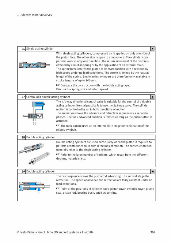
C. Didactics Material Survey
26 Single acting cylinder
With single acting cylinders, compressed air is applied on only one side ofthe piston face. The other side is open to atmosphere. The cylinders canperform work in only one direction. The return movement of the piston iseffected by a built-in spring or by the application of an external force.The spring force returns the piston to its start position with a reasonablyhigh speed under no load conditions. The stroke is limited by the naturallength of the spring. Single acting cylinders are therefore only available instroke lengths of up to 100 mm.
☞ Compare the construction with the double acting type.Discuss the spring size and return speed.
27 Control of a double acting cylinder
The 4/2-way directional control valve is suitable for the control of a doubleacting cylinder. Normal practice is to use the 5/2-way valve. The cylindermotion is controlled by air in both directions of motion.The animation shows the advance and retraction sequences as separatephases. The fully advanced position is related as long as the push-button isactuated.
☞ The topic can be used as an intermediate stage for explanation of therelated symbols.
28 Double acting cylinder
Double acting cylinders are used particularly when the piston is required toperform a work function in both directions of motion. The construction is ingeneral similar to the single acting cylinder.
☞ Refer to the large number of variants, which result from the differentdesigns, materials, etc.
29 Double acting cylinder
The first sequence shows the piston rod advancing. The second stage theretraction. The speed of advance and retraction are fairly constant under noload conditions.
☞ Point at the positions of cylinder body, piston cover, cylinder cover, pistonseal, piston rod, bearing bush, and scraper ring.
© Festo Didactic GmbH & Co. KG and Art Systems • FluidSIM 309
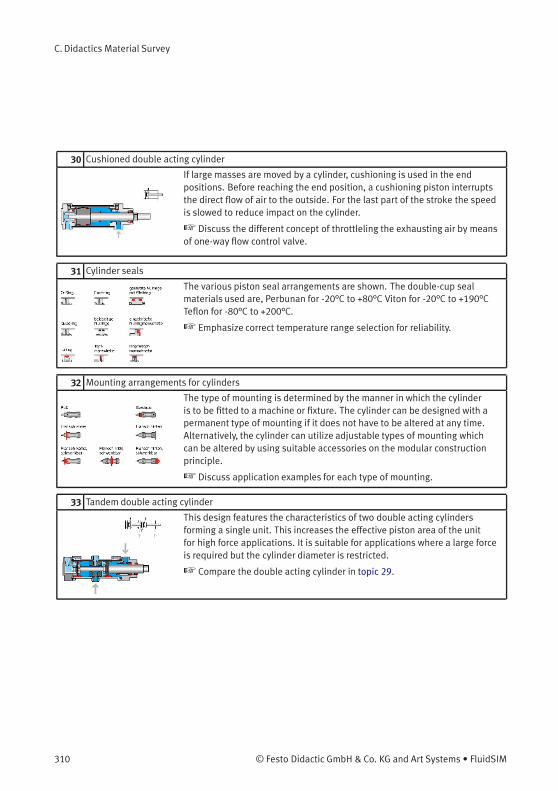
C. Didactics Material Survey
30 Cushioned double acting cylinder
If large masses are moved by a cylinder, cushioning is used in the endpositions. Before reaching the end position, a cushioning piston interruptsthe direct flow of air to the outside. For the last part of the stroke the speedis slowed to reduce impact on the cylinder.
☞ Discuss the different concept of throttleling the exhausting air by meansof one-way flow control valve.
31 Cylinder seals
The various piston seal arrangements are shown. The double-cup sealmaterials used are, Perbunan for -20°C to +80°C Viton for -20°C to +190°CTeflon for -80°C to +200°C.
☞ Emphasize correct temperature range selection for reliability.
32 Mounting arrangements for cylinders
The type of mounting is determined by the manner in which the cylinderis to be fitted to a machine or fixture. The cylinder can be designed with apermanent type of mounting if it does not have to be altered at any time.Alternatively, the cylinder can utilize adjustable types of mounting whichcan be altered by using suitable accessories on the modular constructionprinciple.
☞ Discuss application examples for each type of mounting.
33 Tandem double acting cylinder
This design features the characteristics of two double acting cylindersforming a single unit. This increases the effective piston area of the unitfor high force applications. It is suitable for applications where a large forceis required but the cylinder diameter is restricted.
☞ Compare the double acting cylinder in topic 29.
310 © Festo Didactic GmbH & Co. KG and Art Systems • FluidSIM

C. Didactics Material Survey
34 Semi-rotary actuator
The rotary actuator is compact with high torque ratings. The force istransmitted to the drive shaft by a rotary vane. The range of angularmovement is adjustable with end stops. The angle can be adjusted between0° and 180°.The adjustable stop system is separate to the rotary vanes. This allowsforce to be absorbed by the stop blocks. At the end positions, impacts arecushioned by elastic cushioning rings.
☞ Discuss the mounting arrangements for the actuator.Discuss applications for the rotary actuator.
35 Air motor
Devices which transform pneumatic energy into mechanical rotary motion,with the possibility of continuous motion. They are categorized into thegroups of piston motors, sliding vane motors, gear motors and turbines.
☞ Discuss applications for the air motor.
C.4
Directional control valves
36 Symbols for directional control valves (1)
The directional control valve is represented by the number of ports and thenumber of switching positions. Additional information is required to fullydescribe the symbol function, including the methods of actuation and specialflow path characteristics.
☞ Compare the full range of symbols for directional control valves.
37 Symbols for directional valves (2)
Each valve position is shown as a separate square. The designation of theports is important when interpreting the circuit symbols and the valve asfitted to the physical system.
☞ Compare the full range of symbols for directional control valves.
© Festo Didactic GmbH & Co. KG and Art Systems • FluidSIM 311
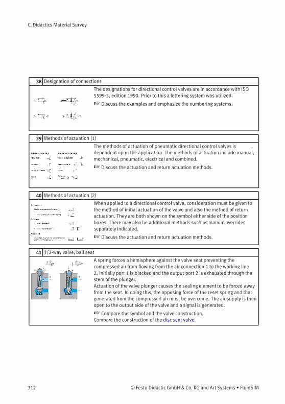
C. Didactics Material Survey
38 Designation of connections
The designations for directional control valves are in accordance with ISO5599-3, edition 1990. Prior to this a lettering system was utilized.
☞ Discuss the examples and emphasize the numbering systems.
39 Methods of actuation (1)
The methods of actuation of pneumatic directional control valves isdependent upon the application. The methods of actuation include manual,mechanical, pneumatic, electrical and combined.
☞ Discuss the actuation and return actuation methods.
40 Methods of actuation (2)
When applied to a directional control valve, consideration must be given tothe method of initial actuation of the valve and also the method of returnactuation. They are both shown on the symbol either side of the positionboxes. There may also be additional methods such as manual overridesseparately indicated.
☞ Discuss the actuation and return actuation methods.
41 3/2-way valve, ball seat
A spring forces a hemisphere against the valve seat preventing thecompressed air from flowing from the air connection 1 to the working line2. Initially port 1 is blocked and the output port 2 is exhausted through thestem of the plunger.Actuation of the valve plunger causes the sealing element to be forced awayfrom the seat. In doing this, the opposing force of the reset spring and thatgenerated from the compressed air must be overcome. The air supply is thenopen to the output side of the valve and a signal is generated.
☞ Compare the symbol and the valve construction.Compare the construction of the disc seat valve.
312 © Festo Didactic GmbH & Co. KG and Art Systems • FluidSIM
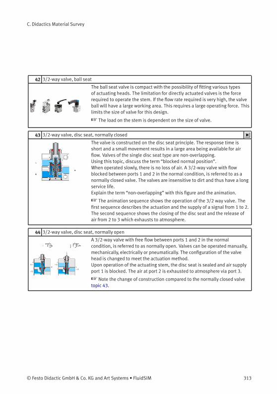
C. Didactics Material Survey
42 3/2-way valve, ball seat
The ball seat valve is compact with the possibility of fitting various typesof actuating heads. The limitation for directly actuated valves is the forcerequired to operate the stem. If the flow rate required is very high, the valveball will have a large working area. This requires a large operating force. Thislimits the size of valve for this design.
☞ The load on the stem is dependent on the size of valve.
43 3/2-way valve, disc seat, normally closed
The valve is constructed on the disc seat principle. The response time isshort and a small movement results in a large area being available for airflow. Valves of the single disc seat type are non-overlapping.Using this topic, discuss the term “blocked normal position”.When operated slowly, there is no loss of air. A 3/2-way valve with flowblocked between ports 1 and 2 in the normal condition, is referred to as anormally closed valve. The valves are insensitive to dirt and thus have a longservice life.Explain the term “non-overlapping” with this figure and the animation.
☞ The animation sequence shows the operation of the 3/2 way valve. Thefirst sequence describes the actuation and the supply of a signal from 1 to 2.The second sequence shows the closing of the disc seat and the release ofair from 2 to 3 which exhausts to atmosphere.
44 3/2-way valve, disc seat, normally open
A 3/2-way valve with free flow between ports 1 and 2 in the normalcondition, is referred to as normally open. Valves can be operated manually,mechanically, electrically or pneumatically. The configuration of the valvehead is changed to meet the actuation method.Upon operation of the actuating stem, the disc seat is sealed and air supplyport 1 is blocked. The air at port 2 is exhausted to atmosphere via port 3.
☞ Note the change of construction compared to the normally closed valvetopic 43.
© Festo Didactic GmbH & Co. KG and Art Systems • FluidSIM 313
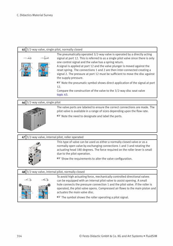
C. Didactics Material Survey
45 3/2-way valve, single pilot, normally closed
The pneumatically operated 3/2-way valve is operated by a directly actingsignal at port 12. This is referred to as a single pilot valve since there is onlyone control signal and the valve has a spring return.A signal is applied at port 12 and the valve plunger is moved against thereset spring. The connections 1 and 2 are then inter-connected creating asignal 2. The pressure at port 12 must be sufficient to move the disc againstthe supply pressure.
☞ Note the pneumatic symbol shows direct application of the signal at port12.Compare the construction of the valve to the 3/2-way disc seat valvetopic 43.
46 3/2-way valve, single pilot
The valve ports are labeled to ensure the correct connections are made. Thepilot valve is available in a range of sizes depending upon the flow rate.
☞ Note the need to designate and label the ports.
47 3/2-way valve, internal pilot, roller operated
This type of valve can be used as either a normally closed valve or as anormally open valve by exchanging connections 1 and 3 and rotating theactuating head 180 degrees. The force required on the roller lever is smalldue to the pilot operation.
☞ Show the requirements to alter the valve configuration.
48 3/2-way valve, internal pilot, normally closed
To avoid high actuating force, mechanically controlled directional valvescan be equipped with an internal pilot valve to assist opening. A smallhole connects the pressure connection 1 and the pilot valve. If the roller isoperated, the pilot valve opens. Compressed air flows to the main piston andactuates the main valve disc.
☞ The symbol shows the roller operating a pilot signal.
314 © Festo Didactic GmbH & Co. KG and Art Systems • FluidSIM
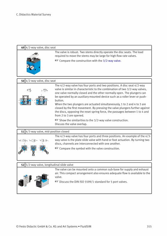
C. Didactics Material Survey
49 4/2-way valve, disc seat
The valve is robust. Two stems directly operate the disc seats. The loadrequired to move the stems may be large for high flow rate valves.
☞ Compare the construction with the 3/2-way valve.
50 4/2-way valve, disc seat
The 4/2-way valve has four ports and two positions. A disc seat 4/2-wayvalve is similar in characteristic to the combination of two 3/2-way valves,one valve normally closed and the other normally open. The plungers canbe operated by an auxiliarymounted device such as a roller lever or push-button.When the two plungers are actuated simultaneously, 1 to 2 and 4 to 3 areclosed by the first movement. By pressing the valve plungers further againstthe discs, opposing the reset spring force, the passages between 1 to 4 andfrom 2 to 3 are opened.
☞ Show the similarities to the 3/2-way valve construction.Discuss the valve overlap.
51 4/3-way valve, mid-position closed
The 4/3-way valve has four ports and three positions. An example of the 4/3-way valve is the plate slide valve with hand or foot actuation. By turning twodiscs, channels are interconnected with one another.
☞ Compare the symbol with the valve construction.
52 5/2-way valve, longitudinal slide valve
The valve can be mounted onto a common sub-base for supply and exhaustair. This compact arrangement also ensures adequate flow is available to thevalve.
☞ Discuss the DIN ISO 5599/1 standard for 5 port valves.
© Festo Didactic GmbH & Co. KG and Art Systems • FluidSIM 315
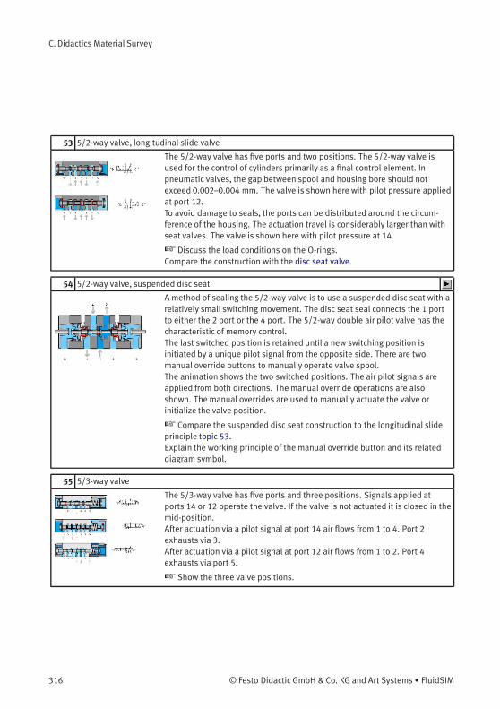
C. Didactics Material Survey
53 5/2-way valve, longitudinal slide valve
The 5/2-way valve has five ports and two positions. The 5/2-way valve isused for the control of cylinders primarily as a final control element. Inpneumatic valves, the gap between spool and housing bore should notexceed 0.002–0.004 mm. The valve is shown here with pilot pressure appliedat port 12.To avoid damage to seals, the ports can be distributed around the circum-ference of the housing. The actuation travel is considerably larger than withseat valves. The valve is shown here with pilot pressure at 14.
☞ Discuss the load conditions on the O-rings.Compare the construction with the disc seat valve.
54 5/2-way valve, suspended disc seat
A method of sealing the 5/2-way valve is to use a suspended disc seat with arelatively small switching movement. The disc seat seal connects the 1 portto either the 2 port or the 4 port. The 5/2-way double air pilot valve has thecharacteristic of memory control.The last switched position is retained until a new switching position isinitiated by a unique pilot signal from the opposite side. There are twomanual override buttons to manually operate valve spool.The animation shows the two switched positions. The air pilot signals areapplied from both directions. The manual override operations are alsoshown. The manual overrides are used to manually actuate the valve orinitialize the valve position.
☞ Compare the suspended disc seat construction to the longitudinal slideprinciple topic 53.Explain the working principle of the manual override button and its relateddiagram symbol.
55 5/3-way valve
The 5/3-way valve has five ports and three positions. Signals applied atports 14 or 12 operate the valve. If the valve is not actuated it is closed in themid-position.After actuation via a pilot signal at port 14 air flows from 1 to 4. Port 2exhausts via 3.After actuation via a pilot signal at port 12 air flows from 1 to 2. Port 4exhausts via port 5.
☞ Show the three valve positions.
316 © Festo Didactic GmbH & Co. KG and Art Systems • FluidSIM
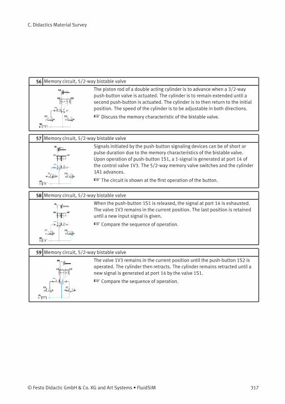
C. Didactics Material Survey
56 Memory circuit, 5/2-way bistable valve
The piston rod of a double acting cylinder is to advance when a 3/2-waypush-button valve is actuated. The cylinder is to remain extended until asecond push-button is actuated. The cylinder is to then return to the initialposition. The speed of the cylinder is to be adjustable in both directions.
☞ Discuss the memory characteristic of the bistable valve.
57 Memory circuit, 5/2-way bistable valve
Signals initiated by the push-button signaling devices can be of short orpulse duration due to the memory characteristics of the bistable valve.Upon operation of push-button 1S1, a 1-signal is generated at port 14 ofthe control valve 1V3. The 5/2-way memory valve switches and the cylinder1A1 advances.
☞ The circuit is shown at the first operation of the button.
58 Memory circuit, 5/2-way bistable valve
When the push-button 1S1 is released, the signal at port 14 is exhausted.The valve 1V3 remains in the current position. The last position is retaineduntil a new input signal is given.
☞ Compare the sequence of operation.
59 Memory circuit, 5/2-way bistable valve
The valve 1V3 remains in the current position until the push-button 1S2 isoperated. The cylinder then retracts. The cylinder remains retracted until anew signal is generated at port 14 by the valve 1S1.
☞ Compare the sequence of operation.
© Festo Didactic GmbH & Co. KG and Art Systems • FluidSIM 317
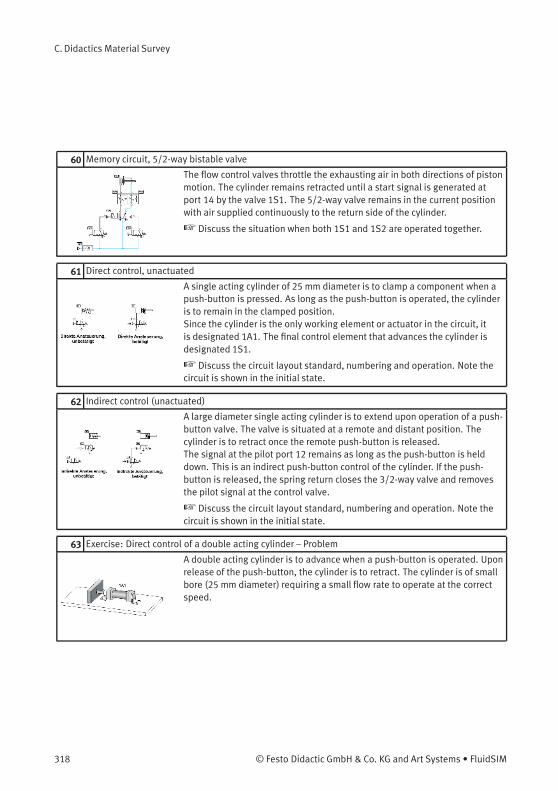
C. Didactics Material Survey
60 Memory circuit, 5/2-way bistable valve
The flow control valves throttle the exhausting air in both directions of pistonmotion. The cylinder remains retracted until a start signal is generated atport 14 by the valve 1S1. The 5/2-way valve remains in the current positionwith air supplied continuously to the return side of the cylinder.
☞ Discuss the situation when both 1S1 and 1S2 are operated together.
61 Direct control, unactuated
A single acting cylinder of 25 mm diameter is to clamp a component when apush-button is pressed. As long as the push-button is operated, the cylinderis to remain in the clamped position.Since the cylinder is the only working element or actuator in the circuit, itis designated 1A1. The final control element that advances the cylinder isdesignated 1S1.
☞ Discuss the circuit layout standard, numbering and operation. Note thecircuit is shown in the initial state.
62 Indirect control (unactuated)
A large diameter single acting cylinder is to extend upon operation of a push-button valve. The valve is situated at a remote and distant position. Thecylinder is to retract once the remote push-button is released.The signal at the pilot port 12 remains as long as the push-button is helddown. This is an indirect push-button control of the cylinder. If the push-button is released, the spring return closes the 3/2-way valve and removesthe pilot signal at the control valve.
☞ Discuss the circuit layout standard, numbering and operation. Note thecircuit is shown in the initial state.
63 Exercise: Direct control of a double acting cylinder – Problem
A double acting cylinder is to advance when a push-button is operated. Uponrelease of the push-button, the cylinder is to retract. The cylinder is of smallbore (25 mm diameter) requiring a small flow rate to operate at the correctspeed.
318 © Festo Didactic GmbH & Co. KG and Art Systems • FluidSIM

C. Didactics Material Survey
64 Exercise: Direct control of a double acting cylinder – Solution
The control valve for a double acting cylinder can be selected as a 4/2 wayor a 5/2 way valve. In this case, since the cylinder has a small capacity, theoperation can be directly controlled by a push-button control valve withspring return. On operating the push-button, the air passes through thevalve from port 1 to the port 4 and advances the piston rod. On release of thepush-button, the valve spring returns the control valve to its initial positionand the cylinder retracts. Air escapes from the cylinder via the exhaust port.Since the cylinder is the only working element or actuator in the circuit, itis designated 1A1. The final control element that advances the cylinder isdesignated 1S1.
65 Exercise: Direct control of a double acting cylinder – Note
☞ If the push-button is pressed for a very short period, the cylinder onlypartially advances and then retracts, since the spring resets the control valveas soon as the push-button is released. In order to achieve full extension inthis case, the push-button must be held down until the cylinder moves fullyforward.
66 Exercise: Indirect control of a double acting cylinder – Problem
A double acting cylinder is to advance when a push-button is operated. Uponrelease of the push-button the cylinder is to retract. The cylinder is 250 mmdiameter and consumes a large volume of air. For controlling cylinders athigh speed or of large diameter large size control valves should be used. Theoperating force to actuate the valve may be relatively large and in this caseindirect control is preferable.
67 Exercise: Indirect control of a double acting cylinder – Solution
Operating valve 1S1 supplies a pilot signal to port 14 of control valve 1V1.This generates a 1-signal at the outlet 4 and the cylinder advances. If thepush-button is released the return signal is supplied via port 2 of valve 1V1and the return air is vented via exhaust port 5. If the push-button is releasedbefore the cylinder fully advances, the cylinder immediately returns to theinitial position. The control valve requires a sustained signal for it to remainoperated.
© Festo Didactic GmbH & Co. KG and Art Systems • FluidSIM 319
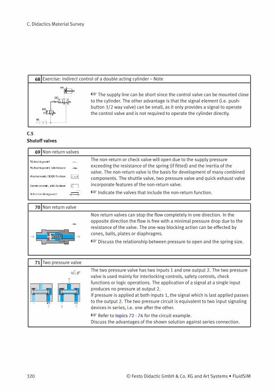
C. Didactics Material Survey
68 Exercise: Indirect control of a double acting cylinder – Note
☞ The supply line can be short since the control valve can be mounted closeto the cylinder. The other advantage is that the signal element (i.e. push-button 3/2 way valve) can be small, as it only provides a signal to operatethe control valve and is not required to operate the cylinder directly.
C.5
Shutoff valves
69 Non-return valves
The non-return or check valve will open due to the supply pressureexceeding the resistance of the spring (if fitted) and the inertia of thevalve. The non-return valve is the basis for development of many combinedcomponents. The shuttle valve, two pressure valve and quick exhaust valveincorporate features of the non-return valve.
☞ Indicate the valves that include the non-return function.
70 Non return valve
Non return valves can stop the flow completely in one direction. In theopposite direction the flow is free with a minimal pressure drop due to theresistance of the valve. The one-way blocking action can be effected bycones, balls, plates or diaphragms.
☞ Discuss the relationship between pressure to open and the spring size.
71 Two pressure valve
The two pressure valve has two inputs 1 and one output 2. The two pressurevalve is used mainly for interlocking controls, safety controls, checkfunctions or logic operations. The application of a signal at a single inputproduces no pressure at output 2.If pressure is applied at both inputs 1, the signal which is last applied passesto the output 2. The two pressure circuit is equivalent to two input signalingdevices in series, i.e. one after the other.
☞ Refer to topics 72 - 74 for the circuit example.Discuss the advantages of the shown solution against series connection.
320 © Festo Didactic GmbH & Co. KG and Art Systems • FluidSIM
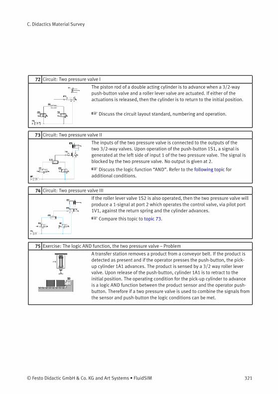
C. Didactics Material Survey
72 Circuit: Two pressure valve I
The piston rod of a double acting cylinder is to advance when a 3/2-waypush-button valve and a roller lever valve are actuated. If either of theactuations is released, then the cylinder is to return to the initial position.
☞ Discuss the circuit layout standard, numbering and operation.
73 Circuit: Two pressure valve II
The inputs of the two pressure valve is connected to the outputs of thetwo 3/2-way valves. Upon operation of the push-button 1S1, a signal isgenerated at the left side of input 1 of the two pressure valve. The signal isblocked by the two pressure valve. No output is given at 2.
☞ Discuss the logic function “AND”. Refer to the following topic foradditional conditions.
74 Circuit: Two pressure valve III
If the roller lever valve 1S2 is also operated, then the two pressure valve willproduce a 1-signal at port 2 which operates the control valve, via pilot port1V1, against the return spring and the cylinder advances.
☞ Compare this topic to topic 73.
75 Exercise: The logic AND function, the two pressure valve – Problem
A transfer station removes a product from a conveyor belt. If the product isdetected as present and if the operator presses the push-button, the pick-up cylinder 1A1 advances. The product is sensed by a 3/2 way roller levervalve. Upon release of the push-button, cylinder 1A1 is to retract to theinitial position. The operating condition for the pick-up cylinder to advanceis a logic AND function between the product sensor and the operator push-button. Therefore if a two pressure valve is used to combine the signals fromthe sensor and push-button the logic conditions can be met.
© Festo Didactic GmbH & Co. KG and Art Systems • FluidSIM 321
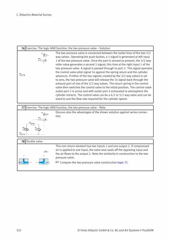
C. Didactics Material Survey
76 Exercise: The logic AND function, the two pressure valve – Solution
The two pressure valve is connected between the outlet lines of the two 3/2way valves. Operating the push-button, a 1-signal is generated at left input1 of the two pressure valve. Once the part is sensed as present, the 3/2 wayroller valve generates a second 1-signal, this time at the right input 1 of thetwo pressure valve. A signal is passed through to port 2. This signal operatesthe control valve pilot signal 14 against the spring return and the cylinderadvances. If either of the two signals created by the 3/2 way valves is setto zero, the two pressure valve will release the 14 signal back through theexhaust port of one of the 3/2 way valves. The return spring in the controlvalve then switches the control valve to the initial position. The control valveoutlet port 2 is active and with outlet port 4 exhausted to atmosphere thecylinder retracts. The control valve can be a 4/2 or 5/2 way valve and can besized to suit the flow rate required for the cylinder speed.
77 Exercise: The logic AND function, the two pressure valve – Note
Discuss also the advantages of the shown solution against series connec-tion.
78 Shuttle valve
This non-return element has two inputs 1 and one output 2. If compressedair is applied to one input, the valve seat seals off the opposing input andthe air flows to the output 2. Note the similarity in construction to the twopressure valve.
☞ Compare the two pressure valve construction topic 71.
322 © Festo Didactic GmbH & Co. KG and Art Systems • FluidSIM

C. Didactics Material Survey
79 Circuit: Shuttle valve I
If the condition states that either of two push-buttons are to advance acylinder, the inexperienced designer may attempt to use a junction for theoutput signals of 1S1 and 1S2. The circuit is not functional due to the escapeof air through the exhaust ports of the valves.
☞ Discuss the sequence of circuits for the shuttle valve.
80 Circuit: Shuttle valve II
If push-button 1S1 is operated, the air escapes to atmosphere through theexhaust port of 1S2. The air takes the easiest path and the pressure will bevery low and inadequate to operate the valve 1V1. This is an inadequatesolution to the problem. A shuttle valve is required.
☞ Compare the topic with the previous one.
81 Circuit: Shuttle valve III
The piston rod of a double acting cylinder is to advance when either of two3/2-way push-buttons are actuated. If both push-buttons are then released,the cylinder is to retract. The shuttle valve is incorporated at the junction andthe circuit now functions correctly.
☞ Note the function of the ball in the shuttle valve acting as a non-returnvalve.
82 Circuit: Shuttle valve IV
The shuttle valve is connected to the junction between the two 3/2-waypush-button valves. Upon operation of one of the push-buttons, a signalis generated at the X or Y port of the shuttle valve and an output signal isemitted at port 2. The cylinder advances.
☞ Compare the topic with the previous one.
© Festo Didactic GmbH & Co. KG and Art Systems • FluidSIM 323
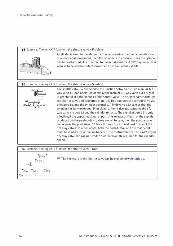
C. Didactics Material Survey
83 Exercise: The logic OR function, the shuttle valve – Problem
A cylinder is used to transfer parts from a magazine. If either a push-buttonor a foot pedal is operated, then the cylinder is to advance. Once the cylinderhas fully advanced, it is to retract to the initial position. A 3/2 way roller levervalve is to be used to detect forward end position of the cylinder.
84 Exercise: The logic OR function, the shuttle valve – Solution
The shuttle valve is connected to the junction between the two manual 3/2way valves. Upon operation of one of the manual 3/2 way valves, a 1-signalis generated at either input 1 of the shuttle valve. This signal passes throughthe shuttle valve and is emitted at port 2. This operates the control valve viapilot port 14, and the cylinder advances. A limit valve 1S2 senses that thecylinder has fully extended. Pilot signal 2 from valve 1S2 actuates the 5/2way valve via port 12 and the cylinder retracts. The signal at port 12 is onlyeffective, if the opposing signal at port 14 is released. If both of the signalsproduced via the push-button valves are set to zero, then the shuttle valvewill release the pilot signal 14 back through the exhaust port of one of the3/2 way valves. In other words, both the push-button and the foot pedalmust be inactive for retraction to occur. The control valve can be a 4/2 way or5/2 way valve and can be sized to suit the flow rate required for the cylinderspeed.
85 Exercise: The logic OR function, the shuttle valve – Note
☞ The necessity of the shuttle valve can be explained with topic 79.
324 © Festo Didactic GmbH & Co. KG and Art Systems • FluidSIM
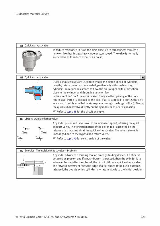
C. Didactics Material Survey
86 Quick exhaust valve
To reduce resistance to flow, the air is expelled to atmosphere through alarge orifice thus increasing cylinder piston speed. The valve is normallysilenced so as to reduce exhaust air noise.
87 Quick exhaust valve
Quick exhaust valves are used to increase the piston speed of cylinders.Lengthy return times can be avoided, particularly with single actingcylinders. To reduce resistance to flow, the air is expelled to atmosphereclose to the cylinder and through a large orifice.In the direction 1 to 2 the air is passed freely via the opening of the non-return seal. Port 3 is blocked by the disc. If air is supplied to port 2, the discseals port 1. Air is expelled to atmosphere through the large orifice 3. Mountthe quick exhaust valve directly on the cylinder, or as near as possible.
☞ Refer to topic 88 for the circuit example.
88 Circuit: Quick exhaust valve
A cylinder piston rod is to travel at an increased speed, utilizing the quickexhaust valve. The forward motion of the piston rod is assisted by therelease of exhausting air at the quick exhaust valve. The return stroke isunchanged due to the bypass non-return valve.
☞ Refer to topic 70 for construction of the valve.
89 Exercise: The quick exhaust valve – Problem
A cylinder advances a forming tool on an edge-folding device. If a sheet isdetected as present and if a push-button is pressed, then the cylinder is toadvance. For rapid forward travel, the circuit utilizes a quick exhaust valve.The forward movement folds the edge of a flat sheet. If the push-button isreleased, the double acting cylinder is to return slowly to the initial position.
© Festo Didactic GmbH & Co. KG and Art Systems • FluidSIM 325
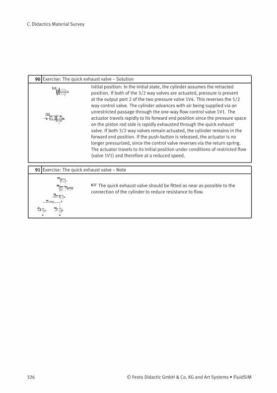
C. Didactics Material Survey
90 Exercise: The quick exhaust valve – Solution
Initial position: In the initial state, the cylinder assumes the retractedposition. If both of the 3/2 way valves are actuated, pressure is presentat the output port 2 of the two pressure valve 1V4. This reverses the 5/2way control valve. The cylinder advances with air being supplied via anunrestricted passage through the one-way flow control valve 1V1. Theactuator travels rapidly to its forward end position since the pressure spaceon the piston rod side is rapidly exhausted through the quick exhaustvalve. If both 3/2 way valves remain actuated, the cylinder remains in theforward end position. If the push-button is released, the actuator is nolonger pressurized, since the control valve reverses via the return spring.The actuator travels to its initial position under conditions of restricted flow(valve 1V1) and therefore at a reduced speed.
91 Exercise: The quick exhaust valve – Note
☞ The quick exhaust valve should be fitted as near as possible to theconnection of the cylinder to reduce resistance to flow.
326 © Festo Didactic GmbH & Co. KG and Art Systems • FluidSIM
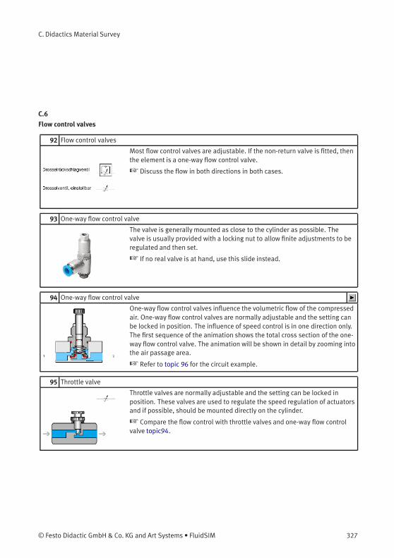
C. Didactics Material Survey
C.6
Flow control valves
92 Flow control valves
Most flow control valves are adjustable. If the non-return valve is fitted, thenthe element is a one-way flow control valve.
☞ Discuss the flow in both directions in both cases.
93 One-way flow control valve
The valve is generally mounted as close to the cylinder as possible. Thevalve is usually provided with a locking nut to allow finite adjustments to beregulated and then set.
☞ If no real valve is at hand, use this slide instead.
94 One-way flow control valve
One-way flow control valves influence the volumetric flow of the compressedair. One-way flow control valves are normally adjustable and the setting canbe locked in position. The influence of speed control is in one direction only.The first sequence of the animation shows the total cross section of the one-way flow control valve. The animation will be shown in detail by zooming intothe air passage area.
☞ Refer to topic 96 for the circuit example.
95 Throttle valve
Throttle valves are normally adjustable and the setting can be locked inposition. These valves are used to regulate the speed regulation of actuatorsand if possible, should be mounted directly on the cylinder.
☞ Compare the flow control with throttle valves and one-way flow controlvalve topic94.
© Festo Didactic GmbH & Co. KG and Art Systems • FluidSIM 327
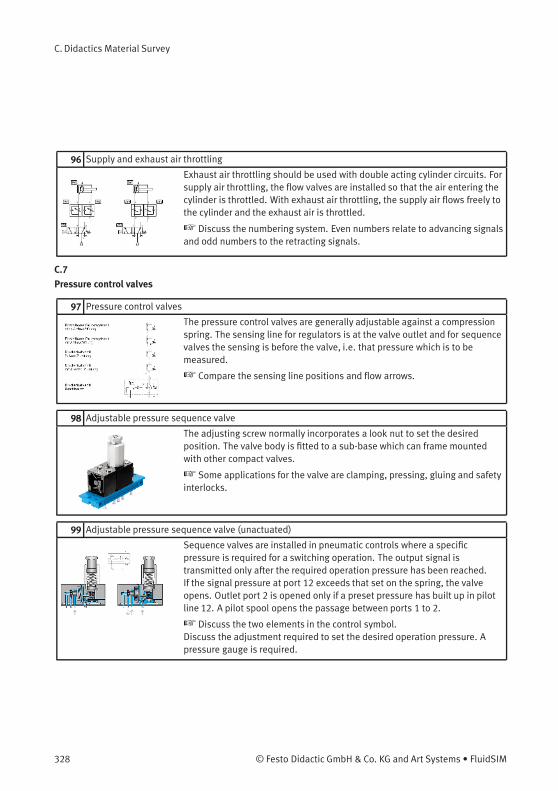
C. Didactics Material Survey
96 Supply and exhaust air throttling
Exhaust air throttling should be used with double acting cylinder circuits. Forsupply air throttling, the flow valves are installed so that the air entering thecylinder is throttled. With exhaust air throttling, the supply air flows freely tothe cylinder and the exhaust air is throttled.
☞ Discuss the numbering system. Even numbers relate to advancing signalsand odd numbers to the retracting signals.
C.7
Pressure control valves
97 Pressure control valves
The pressure control valves are generally adjustable against a compressionspring. The sensing line for regulators is at the valve outlet and for sequencevalves the sensing is before the valve, i.e. that pressure which is to bemeasured.
☞ Compare the sensing line positions and flow arrows.
98 Adjustable pressure sequence valve
The adjusting screw normally incorporates a look nut to set the desiredposition. The valve body is fitted to a sub-base which can frame mountedwith other compact valves.
☞ Some applications for the valve are clamping, pressing, gluing and safetyinterlocks.
99 Adjustable pressure sequence valve (unactuated)
Sequence valves are installed in pneumatic controls where a specificpressure is required for a switching operation. The output signal istransmitted only after the required operation pressure has been reached.If the signal pressure at port 12 exceeds that set on the spring, the valveopens. Outlet port 2 is opened only if a preset pressure has built up in pilotline 12. A pilot spool opens the passage between ports 1 to 2.
☞ Discuss the two elements in the control symbol.Discuss the adjustment required to set the desired operation pressure. Apressure gauge is required.
328 © Festo Didactic GmbH & Co. KG and Art Systems • FluidSIM
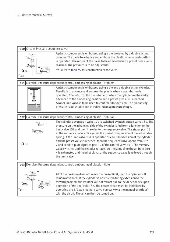
C. Didactics Material Survey
100 Circuit: Pressure sequence valve
A plastic component is embossed using a die powered by a double actingcylinder. The die is to advance and emboss the plastic when a push-buttonis operated. The return of the die is to be effected when a preset pressure isreached. The pressure is to be adjustable.
☞ Refer to topic 99 for construction of the valve.
101 Exercise: Pressure dependent control, embossing of plastic – Problem
A plastic component is embossed using a die and a double acting cylinder.The die is to advance and emboss the plastic when a push-button isoperated. The return of the die is to occur when the cylinder rod has fullyadvanced to the embossing position and a preset pressure is reached.A roller limit valve is to be used to confirm full extension. The embossingpressure is adjustable and is indicated on a pressure gauge.
102 Exercise: Pressure dependent control, embossing of plastic – Solution
The cylinder advances if valve 1V1 is switched by push-button valve 1S1. Thepressure on the advancing side of the cylinder is fed from a junction to thelimit valve 1S2 and then in series to the sequence valve. The signal port 12at the sequence valve acts against the preset compression of the adjustablespring. If the limit valve 1S2 is operated due to full extension of the cylinderand the preset value is reached, then the sequence valve opens from 1 to2 and sends a pilot signal to port 12 of the control valve 1V1. The memoryvalve switches and the cylinder retracts. At the same time the air from port4 is exhausted and the pilot signal at the sequence valve is relieved throughthe limit valve.
103 Exercise: Pressure dependent control, embossing of plastic – Note
☞ If the pressure does not reach the preset limit, then the cylinder willremain advanced. If the cylinder is obstructed during extension to theforward position, the cylinder will not retract due to the dependency uponoperation of the limit vale 1S2. The power circuit must be initialized byoperating the 5/2 way memory valve manually (via the manual overrides)with the air off. The air can then be turned on.
© Festo Didactic GmbH & Co. KG and Art Systems • FluidSIM 329
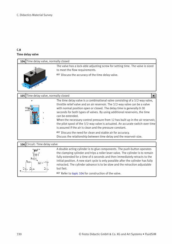
C. Didactics Material Survey
C.8
Time delay valve
104 Time delay valve, normally closed
The valve has a lock-able adjusting screw for setting time. The valve is sizedto meet the flow requirements.
☞ Discuss the accuracy of the time delay valve.
105 Time delay valve, normally closed
The time delay valve is a combinational valve consisting of a 3/2-way valve,throttle relief valve and an air reservoir. The 3/2-way valve can be a valvewith normal position open or closed. The delay time is generally 0-30seconds for both types of valves. By using additional reservoirs, the timecan be extended.When the necessary control pressure from 12 has built up in the air reservoir,the pilot spool of the 3/2-way valve is actuated. An accurate switch-over timeis assured if the air is clean and the pressure constant.
☞ Discuss the need for clean and stable air for accuracy.Discuss the relationship between time delay and the reservoir size.
106 Circuit: Time delay valve
A double acting cylinder is to glue components. The push-button operatesthe clamping cylinder and trips a roller lever valve. The cylinder is to remainfully extended for a time of 6 seconds and then immediately retracts to theinitial position. A new start cycle is only possible after the cylinder has fullyretracted. The cylinder advance is to be slow and the retraction adjustablebut fast.
☞ Refer to topic 104 for construction of the valve.
330 © Festo Didactic GmbH & Co. KG and Art Systems • FluidSIM
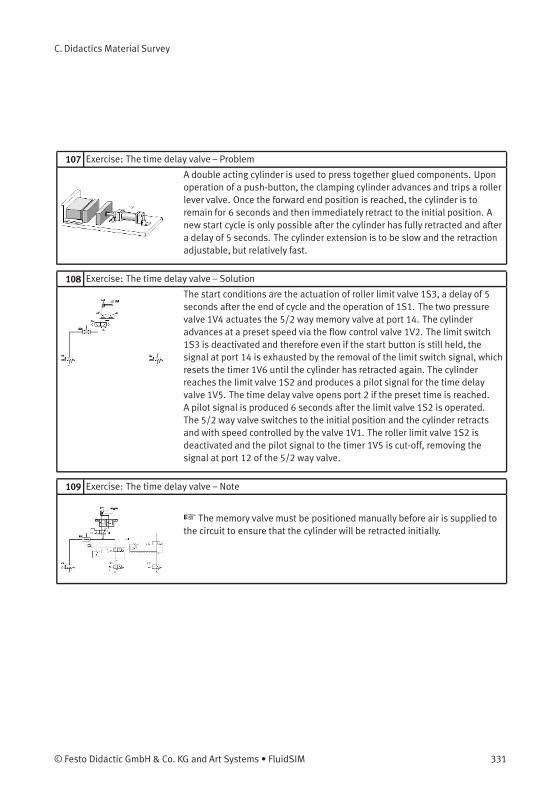
C. Didactics Material Survey
107 Exercise: The time delay valve – Problem
A double acting cylinder is used to press together glued components. Uponoperation of a push-button, the clamping cylinder advances and trips a rollerlever valve. Once the forward end position is reached, the cylinder is toremain for 6 seconds and then immediately retract to the initial position. Anew start cycle is only possible after the cylinder has fully retracted and aftera delay of 5 seconds. The cylinder extension is to be slow and the retractionadjustable, but relatively fast.
108 Exercise: The time delay valve – Solution
The start conditions are the actuation of roller limit valve 1S3, a delay of 5seconds after the end of cycle and the operation of 1S1. The two pressurevalve 1V4 actuates the 5/2 way memory valve at port 14. The cylinderadvances at a preset speed via the flow control valve 1V2. The limit switch1S3 is deactivated and therefore even if the start button is still held, thesignal at port 14 is exhausted by the removal of the limit switch signal, whichresets the timer 1V6 until the cylinder has retracted again. The cylinderreaches the limit valve 1S2 and produces a pilot signal for the time delayvalve 1V5. The time delay valve opens port 2 if the preset time is reached.A pilot signal is produced 6 seconds after the limit valve 1S2 is operated.The 5/2 way valve switches to the initial position and the cylinder retractsand with speed controlled by the valve 1V1. The roller limit valve 1S2 isdeactivated and the pilot signal to the timer 1V5 is cut-off, removing thesignal at port 12 of the 5/2 way valve.
109 Exercise: The time delay valve – Note
☞ The memory valve must be positioned manually before air is supplied tothe circuit to ensure that the cylinder will be retracted initially.
© Festo Didactic GmbH & Co. KG and Art Systems • FluidSIM 331
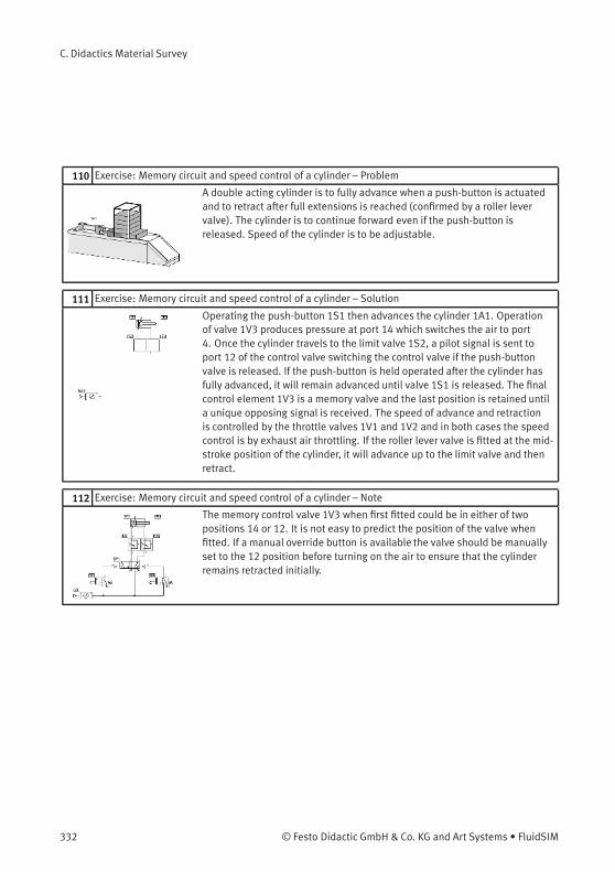
C. Didactics Material Survey
110 Exercise: Memory circuit and speed control of a cylinder – Problem
A double acting cylinder is to fully advance when a push-button is actuatedand to retract after full extensions is reached (confirmed by a roller levervalve). The cylinder is to continue forward even if the push-button isreleased. Speed of the cylinder is to be adjustable.
111 Exercise: Memory circuit and speed control of a cylinder – Solution
Operating the push-button 1S1 then advances the cylinder 1A1. Operationof valve 1V3 produces pressure at port 14 which switches the air to port4. Once the cylinder travels to the limit valve 1S2, a pilot signal is sent toport 12 of the control valve switching the control valve if the push-buttonvalve is released. If the push-button is held operated after the cylinder hasfully advanced, it will remain advanced until valve 1S1 is released. The finalcontrol element 1V3 is a memory valve and the last position is retained untila unique opposing signal is received. The speed of advance and retractionis controlled by the throttle valves 1V1 and 1V2 and in both cases the speedcontrol is by exhaust air throttling. If the roller lever valve is fitted at the mid-stroke position of the cylinder, it will advance up to the limit valve and thenretract.
112 Exercise: Memory circuit and speed control of a cylinder – Note
The memory control valve 1V3 when first fitted could be in either of twopositions 14 or 12. It is not easy to predict the position of the valve whenfitted. If a manual override button is available the valve should be manuallyset to the 12 position before turning on the air to ensure that the cylinderremains retracted initially.
332 © Festo Didactic GmbH & Co. KG and Art Systems • FluidSIM
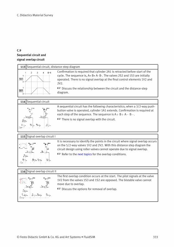
C. Didactics Material Survey
C.9
Sequential circuit and
signal overlap circuit
113 Sequential circuit, distance-step diagram
Confirmation is required that cylinder 2A1 is retracted before start of thecycle. The sequence is, A+ B+ A- B-. The valves 2S2 and 1S3 are initiallyoperated. There is no signal overlap at the final control elements 1V2 and2V2.
☞ Discuss the relationship between the circuit and the distance-stepdiagram.
114 Sequential circuit
A sequential circuit has the following characteristics; when a 3/2-way push-button valve is operated, cylinder 1A1 extends. Confirmation is required ateach step of the sequence. The sequence is A+ B+ A− B−.
☞ There is no signal overlap with the circuit.
115 Signal overlap circuit I
It is necessary to identify the points in the circuit where signal overlap occurson the 5/2-way valves 1V2 and 2V2. With this distance step diagram thecircuit design using roller valves cannot operate due to signal overlap.
☞ Refer to the next topics for the overlap conditions.
116 Signal overlap circuit II
The first overlap condition occurs at the start. The pilot signals at the valve1V2 from the valves 1S3 and 1S2 are opposed. The bistable valve cannotmove due to overlap.
☞ Discuss the options for removal of overlap.
© Festo Didactic GmbH & Co. KG and Art Systems • FluidSIM 333
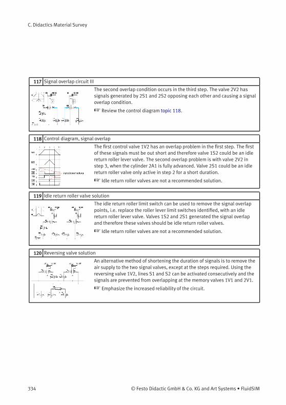
C. Didactics Material Survey
117 Signal overlap circuit III
The second overlap condition occurs in the third step. The valve 2V2 hassignals generated by 2S1 and 2S2 opposing each other and causing a signaloverlap condition.
☞ Review the control diagram topic 118.
118 Control diagram, signal overlap
The first control valve 1V2 has an overlap problem in the first step. The firstof these signals must be out short and therefore valve 1S2 could be an idlereturn roller lever valve. The second overlap problem is with valve 2V2 instep 3, when the cylinder 2A1 is fully advanced. Valve 2S1 could be an idlereturn roller valve only active in step 2 for a short duration.
☞ Idle return roller valves are not a recommended solution.
119 Idle return roller valve solution
The idle return roller limit switch can be used to remove the signal overlappoints, i.e. replace the roller lever limit switches identified, with an idlereturn roller lever valve. Valves 1S2 and 2S1 generated the signal overlapand therefore these valves should be idle return roller valves.
☞ Idle return roller valves are not a recommended solution.
120 Reversing valve solution
An alternative method of shortening the duration of signals is to remove theair supply to the two signal valves, except at the steps required. Using thereversing valve 1V2, lines S1 and S2 can be activated consecutively and thesignals are prevented from overlapping at the memory valves 1V1 and 2V1.
☞ Emphasize the increased reliability of the circuit.
334 © Festo Didactic GmbH & Co. KG and Art Systems • FluidSIM
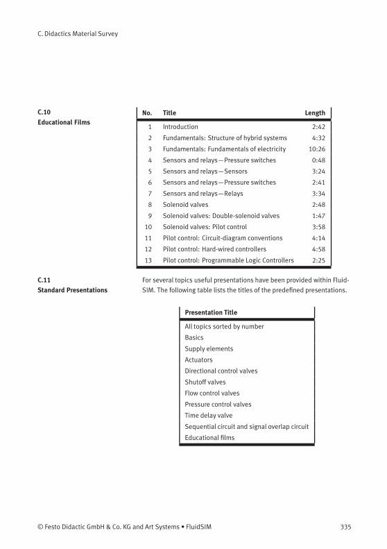
C. Didactics Material Survey
C.10
Educational FilmsNo. Title Length
1 Introduction 2:42
2 Fundamentals: Structure of hybrid systems 4:32
3 Fundamentals: Fundamentals of electricity 10:26
4 Sensors and relays—Pressure switches 0:48
5 Sensors and relays—Sensors 3:24
6 Sensors and relays—Pressure switches 2:41
7 Sensors and relays—Relays 3:34
8 Solenoid valves 2:48
9 Solenoid valves: Double-solenoid valves 1:47
10 Solenoid valves: Pilot control 3:58
11 Pilot control: Circuit-diagram conventions 4:14
12 Pilot control: Hard-wired controllers 4:58
13 Pilot control: Programmable Logic Controllers 2:25
C.11
Standard Presentations
For several topics useful presentations have been provided within Fluid-
SIM. The following table lists the titles of the predefined presentations.
Presentation Title
All topics sorted by number
Basics
Supply elements
Actuators
Directional control valves
Shutoff valves
Flow control valves
Pressure control valves
Time delay valve
Sequential circuit and signal overlap circuit
Educational films
© Festo Didactic GmbH & Co. KG and Art Systems • FluidSIM 335

D.Messages
This section contains information about the messages that may appear
from FluidSIM while working in the Edit Mode, the Simulation Mode, or
while saving circuit diagrams.
D.1
Electrical ErrorsSimulation aborted. A short-circuit was detected in an electrical
circuit.
The positive and negative poles of a voltage source are directly
connected without a load (indicator light, buzzer, relay, or control
solenoid). The short circuit must be eliminated before simulation can
take place.
D.2
Drawing ErrorsObjects are placed outside the drawing area.
At least one object has been placed outside the drawing area. After
acknowledging the dialog box the respective objects are shown
selected. Either change the papersize or place the selected objects
inside the marked drawing area.
Open connections.
At least one component has an open pneumatic connection. After
acknowledging the dialog box, all components with an open pneumatic
connection are selected.
Incompatible connections are superimposed.
When two connections are superimposed, FluidSIM automatically
connects them. When these two connections do not go together, a
warning message is given.
Superimposed lines.
At least two lines are superimposed. After acknowledging the dialog
box, these line segments are selected.
336 © Festo Didactic GmbH & Co. KG and Art Systems • FluidSIM
D.Messages
Lines through components.
At least one line is passing through a component. After acknowledging
the dialog box, the appropriate components are selected.
Lines through connections.
At least one line is crossing through a connection to which the line is not
connected. After acknowledging the dialog box, these lines are selected.
Superimposed components.
At least two components are superimposed. After acknowledging the
dialog box, these components are selected.
Duplicate or incompatible labels.
A label has been used incorrectly. After acknowledging the dialog box,
the appropriate components are selected. To set the circuit diagram into
simulation, other labels will have to be chosen.
There are components with the same description.
The same description has been assigned to more than one component.
After acknowledging the dialog box the respective components appear
selected. Modify the component description(s), or, as the case may be,
rearrange them such that their assignment becomes definite.
There have been warnings. Start simulation anyway?
This prompt appears when any of the above drawing errors can be found
in the circuit diagram. If the simulation is started while connections are
open, air will escape at these places. However, open connections can be
fit with a blind plug, if this behavior is not desired.
© Festo Didactic GmbH & Co. KG and Art Systems • FluidSIM 337
D.Messages
There is no cylinder close to the distance rule.
A distance rule can only be given a label when it is assigned to a
cylinder. Move the distance rule near a cylinder, so that it snaps into
place. Now a label can be entered by double clicking the measuring
scale.
No superficial errors detected.
The circuit diagram does not contain any of the above described drawing
errors.
D.3
Operating ErrorsNo objects found.
You tried to check a circuit diagram for drawing errors or to start the
simulation; but there are no components located in the current window.
Objects cannot be deleted from the FluidSIM standard libraries.
Create a new library if you want to set up a custom library.
Objects can neither be added nor deleted from the FluidSIM standard
libraries. However, new custom libraries can be created instead, which
contain merely your preferred selection of components (see Section
6.10).
The value range of ’ abc ’ is x ... x .
The value range for the field has been exceeded. Make sure to observe
the indicated limits.
338 © Festo Didactic GmbH & Co. KG and Art Systems • FluidSIM
D.Messages
D.4
Opening and Saving FilesThe circuit diagram has been changed. Save current changes?
You want to close a circuit diagram window or quit FluidSIM. Since the
last save, changes have been made to the current circuit diagram.
The file ’ abc ’ already exists. Replace?
A circuit diagram with the name name.ct already exists on the hard
disk. To save the current circuit diagram, you must either change the file
name, or the already existing file will be replaced with the new circuit
diagram.
Cannot save DXF file.
The file (either the current circuit diagram or the component library)
cannot be saved due to insufficient disk space or a write-protected disk.
Unknown file format.
The file cannot be opened since its format is not supported by FluidSIM.
Cannot open file ’ abc ’.
FluidSIM cannot open the file because Microsoft Windows® refuses
access to the file. Either the file does not exist or is locked by another
application.
’ abc ’ does not exist. Create?
You have tried to open a file that does not exist. However, the file can be
opened as a new file.
The file ’ abc ’ can not be deleted.
You have tried to delete a file that does not exist or is write-protected.
© Festo Didactic GmbH & Co. KG and Art Systems • FluidSIM 339
D.Messages
Circuit ’ abc ’ is already opened. Close this window before?
You want to save a circuit diagram under another name. There is,
however, already another open window with this name. If you close
this window, the file will be replaced.
D.5
System ErrorsSimulation aborted. The circuit is too large.
The size of circuit diagrams that can be simulated is bound. You must
reduce the number of components.
Internal capacity of FluidSIM exceeded.
The previous action exceeded the capacity of the internal memory. The
action cannot be completed.
No more windows available.
Microsoft Windows® cannot provide any more windows most likely
because the system resources have been exhausted.
Memory capacity exceeded. Quit other running applications.
There is not enough memory readily available to complete the
parameter calculations. To make more memory available, other circuit
diagrams should be closed, along with any other Microsoft Windows®
programs that are running. Then attempt to run the simulation again.
When there is no other possibility to free up memory, the virtual memory
can be increased. Microsoft Windows® then utilizes a section of the hard
drive to increase the memory. However, as a result the execution speed
of the program decreases greatly. It would be wiser to extend the main
memory by increasing the computer’s RAM.
340 © Festo Didactic GmbH & Co. KG and Art Systems • FluidSIM
D.Messages
This version is not registered. Please repeat the installation
procedure.
You have tried to start an unlicensed version of FluidSIM. Most likely
you have changed your system configuration, or important system
files have become corrupt. Attempt to reinstall FluidSIM into the same
directory. If there is a problem with the re-installation, you will receive a
message on the screen pertaining to the problem. Notify Festo Didactic
GmbH & Co. KG of the error or the problem.
Out of memory. Please save changed circuits and quit FluidSIM.
While completing an operation (for example loading a circuit diagram,
displaying a component photo, rebuilding the desktop) an error in the
memory occurred. FluidSIM could not cancel the operation in a proper
manner. You are recommended to quit FluidSIM because the program’s
stability cannot be assured. However, it is still possible to save changes
to circuit diagrams before quitting FluidSIM.
Fatal error. Please save changed circuits and quit FluidSIM.
A program error has occurred. Please save changes to any open circuit
diagrams, quit FluidSIM and Microsoft Windows®, and restart.
The circuit filename.ct has not been saved when the last
FluidSIM session was terminated improperly. Shall this file be
recovered?
FluidSIM has been terminated in an unexpected manner. However, a
backup file was written from which an actual version of the unsaved
circuit can be constructed. If the question is answered with “Yes” a
window with the recovered circuit is opened; however, the original
circuit remains unchanged. You then can decide if to whether the
recovered circuit shall be saved under the original name.
© Festo Didactic GmbH & Co. KG and Art Systems • FluidSIM 341
Index
Symbols 29
32
66
33
37
37
37
38
23
26
29, 227
20, 228
227
44, 227
175, 229
63, 229
33, 229
66, 229
66, 229
71
235
235
235
235
236
236
103, 231
26, 231
23, 231
27, 231
231
232
232
232
67, 230
342 © Festo Didactic GmbH & Co. KG and Art Systems • FluidSIM
Index
230
67
70
70
70
70
70
70
2/n way valve
configurable 246
3/2-way valve
ball seat 312, 313
disc seat 313
lever operated 247, 248
pneumatically operated 251, 314
roller operated 314
solenoid operated 248, 250
with pushbutton 249
with selection switch 249
3/n way valve
configurable 246
4/2-way valve
disc seat 315
roller operated 315
4/3-way valve
turning disc principle 315
4/n way valve
configurable 246
5/2-way valve
longitudinal slide principle 315, 316
pneumatically operated 251, 252
solenoid operated 250
suspended disc seat 316
with selection switch 249
5/3-way proportional valve 261
© Festo Didactic GmbH & Co. KG and Art Systems • FluidSIM 343
Index
5/3-way valve
pneumatically operated 252, 316
solenoid operated 251
5/n way valve
configurable 246
6/n way valve
configurable 247
8/n way valve
configurable 247
A Action 203, 298
Action (stored effective) 206
activation 11
actuation
of switches 26
without detent 72
without lock 45
actuators
DC motor 273
Admissible characters 211
adsorption dryer 245
air drying
absorption 305
adsorption 305
low temperature 305
air lubricator 305, 306
air motor 268, 311
air pressure reservoir 243
air reservoir 243
air service unit 243, 304
alignment 67
Allocation 206
ammeter 274
ampere meter 274
AND
344 © Festo Didactic GmbH & Co. KG and Art Systems • FluidSIM
Index
digital 291
animation
component 145
of diagram symbols 45
Asynchronous Pulse Generator
digital 296
axial flow compressor 307
B background grid
default setting 199
display/hide 71
set type 71
bialog box
picture file 168
bitmap 168
Bitmap 301
blind plug
delete 68
fit automatically 337
set manually 68
Boolean value of an assertion 215
C cam switch 300
CD-ROM drive 11
check valve 253
pilot to close 254
spring loaded 253
with pilot control 254
Checking the entries 211
circle 301
circuit diagram
backup 198
bistable valve 317, 318
creation 28
current 199, 227
© Festo Didactic GmbH & Co. KG and Art Systems • FluidSIM 345
Index
default directory 198
direct control 318
drawing mistake 102
indirect control 318
load 20
pressure sequence valve 329
print 175
quick exhaust valve 325
save 339
sequential control 333
shuttle valve 323
signal overlap 333, 334
simulate 23
superficial checking 102
time delay valve 330
too large 340
two pressure valve 321
click, see mouse click 1
clipboard
data format 222
general 66
closed-loop control 130
command line 223
comparator 283
compatibility
LOGO 121
component
actuation 72
animation 145
animation within circuit 45
connect 37
copy 66
delete 33, 338
description 142
in clipboard 66
346 © Festo Didactic GmbH & Co. KG and Art Systems • FluidSIM
Index
in selection 63
insert 66
mirror 67
mirror selection 67
move 33
numbering scheme 302
permanent actuation 72
properties 105, 118, 166
rotate 67
rotate selection 67
sectional view 143, 157
select 33
superimposed 102, 337
usage in circuit 143
with label 106
component library
build 189
create 189
display 183
folder view 183
new 189
rearrange 185
tree view 183
using 183
component parameter
adjustable 118
general 118
components
group 72
pneumatic 242
same description 337
ungroup 72
compressed air filter 304
compressed air supply
axial flow compressor 307
© Festo Didactic GmbH & Co. KG and Art Systems • FluidSIM 347
Index
delivery 306
distribution 307
general 242
piston compressor 306
within circuit 41
compressor 242
adjustable 242
Compulsory command 216
computer power 24, 74
configurable symbols 49
configuration
cylinder 50
configure
cylinder 50
symbols 49
connection
close 68, 81
digital 121, 290
electrical 272
general 37
incompatible 336
mechanical 299
open 102, 336, 337
pneumatic 245
properties 68, 81
quantities 81
superimposed 102, 336
context menu 19, 66
context sensitive 142
continuous valve 132
continuous valves 130
control technology 130
controller
comparator 283
PID controller 283
348 © Festo Didactic GmbH & Co. KG and Art Systems • FluidSIM
Index
status controller 284
cooler 244
counter
electrical 282
pneumatic 256
current limiter 282
current path
numbering 76
cycle 163
cylinder
configurable 262
control 308, 309
distance rule problem 338
double acting 264, 265, 309, 310
mounting arrangements 310
multi position 266
seals 310
single acting 263, 308, 309
tandem double acting 310
D DC motor 273
DDE
communication 125, 128
in 284
options 128
out 284
de-installation 16
default directory 198
Delay 214
delay switches 275, 286
delay valve 330
detent switch
break 279
changeover 279
make 279
© Festo Didactic GmbH & Co. KG and Art Systems • FluidSIM 349
Index
diagram
new 62
print tiled 62
diagram symbol
check valve 320
designation of connections 312
directional valve 311
flow control valve 327
linear actuator 308
method of actuation 312
non-return valve 320
numbering system 303
pressure control valve 328
rotary actuator 308
supply component 304
dialog
diagram properties 88
drawing area 92
functional diagram editor 86
line options 99
project 197
signal connection 100
signal elements 95
text options 89
dialog box
bitmap 168
cylinder 50
diagram 63
drawing layers 159
drawing size 62
DXF symbol 182
ellipse 163
exporting parts lists 174
exporting TIFF file 178
import DXF file 180
350 © Festo Didactic GmbH & Co. KG and Art Systems • FluidSIM
Index
label 112
paper size 62
parts list 172
rectangle 160
valve editor 35, 60
didactics
actuators 308
animation speed 157
basic pneumatics 302
component description 142
directional control valves 311
educational film 154, 335
flow control valves 327
presentation 149
presentations 335
pressure control valves 328
sectional view 143, 157
sequential circuit 333
settings 157
shutoff valves 320
signal overlap circuit 333
supply elements 304
time delay valve 330
tutorial 146
differential pressure gauge 269
differential pressure switch 259
Digital Basic Functions 291
Digital Components 289
Digital Constants and Connectors 289
Digital module 292
Digital Special Functions 292
DIN standard 142
directional valves
lever operated
3/2-way 247, 248
© Festo Didactic GmbH & Co. KG and Art Systems • FluidSIM 351

Index
pneumatically operated
3/2-way 251
5/2-way 251, 252
5/3-way 252
solenoid operated
3/2-way 248, 250
5/2-way 250
5/3-way 251
with pushbutton
3/2-way 249
with selection switch
3/2-way 249
5/2-way 249
directories of FluidSIM 15
displacement encoder 274
distance rule
general 300
problem 338
usage 113
distance-step diagram 333
dongle 11
drag-and-drop 31, 222
drawing
new 62
print tiled 62
size 62
drawing area
objects outside 336
drawing layers 159
drawing mistake 102
dryer 245
DXF
export 179
import 180
352 © Festo Didactic GmbH & Co. KG and Art Systems • FluidSIM

Index
E EasyPort 122
communication 128
options 128
Edge-triggered AND
digital 291
Edge-triggered Wiping Relay
digital 295
edit
redo 63
several circuits 73
undo 63
Edit Mode
activate 72
exit 23
educational film
CD-ROM drive 11
general 154
overview 335
electrical components 270
american standard 285
ladder diagram style 285
electro-pneumatics 104
ellipse 163, 301
Enclosing step 217
error
fatal 341
message 336
exhaust air throttling 328
Explorer 222
external load
cylinder 54
F file
create 339
delete 339
© Festo Didactic GmbH & Co. KG and Art Systems • FluidSIM 353
Index
open 222, 223, 339
replace 339
save 339
save as... 340
unknown format 339
film, see educational film 1
filter 243, 304
automatic condensate drain 244
manual condensate drain 244
flow direction indicator
default setting 199
general 82
flow meter 269, 274
analog 270
force profile
cylinder 56, 58
Formula entry 213
Frequency Threshold Trigger
digital 296
function generator 132, 271
function illustration
general 147
functional diagram 301
functional diagram editor 301
Functions 213
G GRAFCET 201
Action 203, 298
Action (stored effective) 206
Action when a transition is triggered 217
Admissible characters 211
Boolean value of an assertion 215
Checking the entries 211
Compulsory command 216
Delay 214
354 © Festo Didactic GmbH & Co. KG and Art Systems • FluidSIM
Index
Electrical part 207
Enclosing step 217
Formula entry 213
Functions 213
Initialization 209
Labels 213
Macro-step 216
Operative connection 215
Partial GRAFCETs 215
Reference 209
Sequence rules 209
Sequence selection 210
Step 202, 217, 297
Synchronization 210, 298
Target information 215
Time limit 214
Transition 204, 297
Variable names 211
Variable value 210
GRAFCET Elements 297
GRAFCET-I/O 299
graphic primitives 160
cycle 163
ellipse 163
rectangle 160
square 160
grid, see background grid 1
group
components 72
objects 72
H help on problems 218
HI
digital 290
© Festo Didactic GmbH & Co. KG and Art Systems • FluidSIM 355
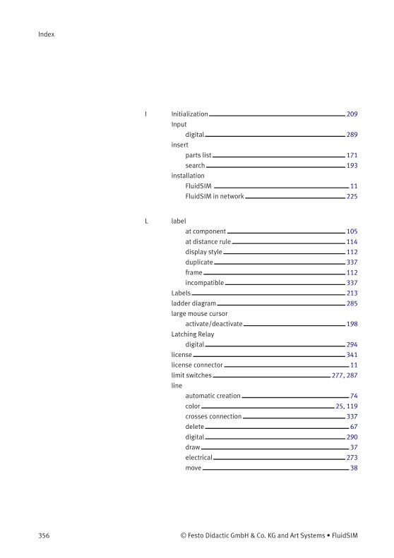
Index
I Initialization 209
Input
digital 289
insert
parts list 171
search 193
installation
FluidSIM 11
FluidSIM in network 225
L label
at component 105
at distance rule 114
display style 112
duplicate 337
frame 112
incompatible 337
Labels 213
ladder diagram 285
large mouse cursor
activate/deactivate 198
Latching Relay
digital 294
license 341
license connector 11
limit switches 277, 287
line
automatic creation 74
color 25, 119
crosses connection 337
delete 67
digital 290
draw 37
electrical 273
move 38
356 © Festo Didactic GmbH & Co. KG and Art Systems • FluidSIM
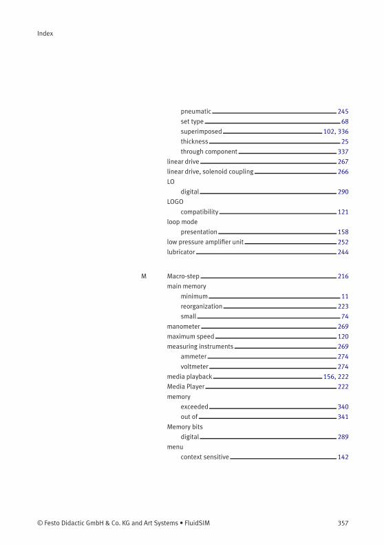
Index
pneumatic 245
set type 68
superimposed 102, 336
thickness 25
through component 337
linear drive 267
linear drive, solenoid coupling 266
LO
digital 290
LOGO
compatibility 121
loop mode
presentation 158
low pressure amplifier unit 252
lubricator 244
M Macro-step 216
main memory
minimum 11
reorganization 223
small 74
manometer 269
maximum speed 120
measuring instruments 269
ammeter 274
voltmeter 274
media playback 156, 222
Media Player 222
memory
exceeded 340
out of 341
Memory bits
digital 289
menu
context sensitive 142
© Festo Didactic GmbH & Co. KG and Art Systems • FluidSIM 357
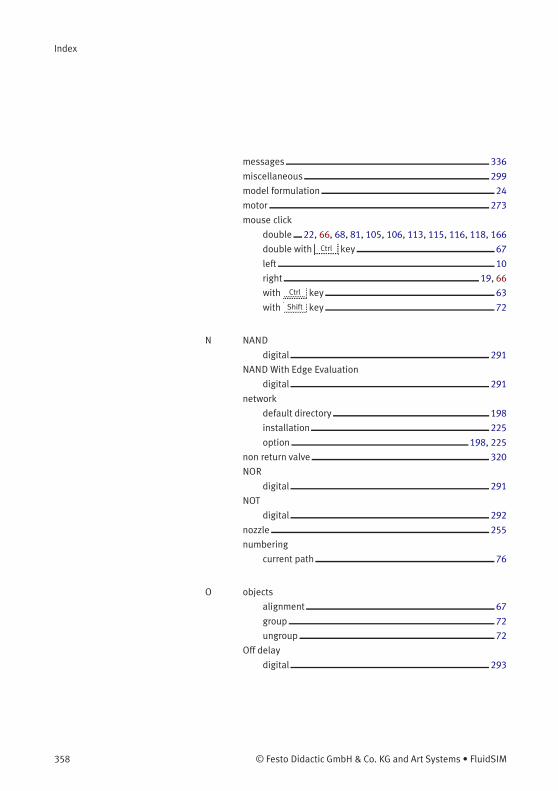
Index
messages 336
miscellaneous 299
model formulation 24
motor 273
mouse click
double 22, 66, 68, 81, 105, 106, 113, 115, 116, 118, 166
double with Ctrl key 67
left 10
right 19, 66
with Ctrl key 63
with Shift key 72
N NAND
digital 291
NAND With Edge Evaluation
digital 291
network
default directory 198
installation 225
option 198, 225
non return valve 320
NOR
digital 291
NOT
digital 292
nozzle 255
numbering
current path 76
O objects
alignment 67
group 72
ungroup 72
Off delay
digital 293
358 © Festo Didactic GmbH & Co. KG and Art Systems • FluidSIM
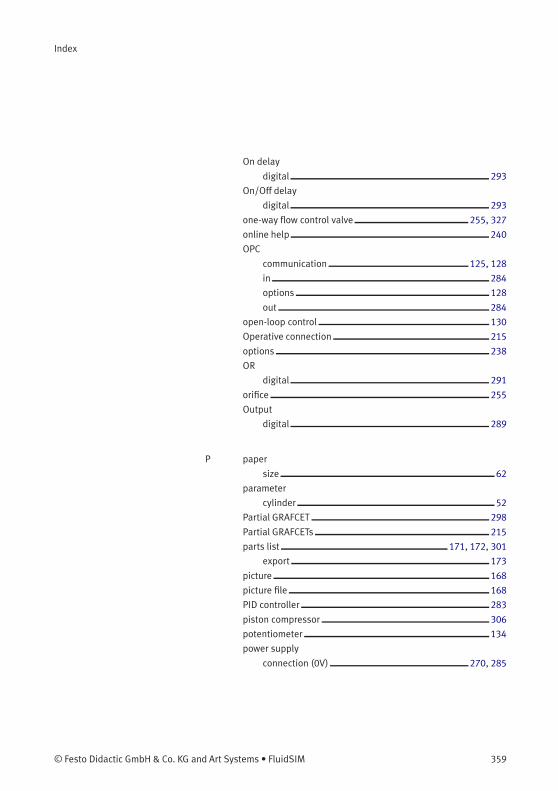
Index
On delay
digital 293
On/Off delay
digital 293
one-way flow control valve 255, 327
online help 240
OPC
communication 125, 128
in 284
options 128
out 284
open-loop control 130
Operative connection 215
options 238
OR
digital 291
orifice 255
Output
digital 289
P paper
size 62
parameter
cylinder 52
Partial GRAFCET 298
Partial GRAFCETs 215
parts list 171, 172, 301
export 173
picture 168
picture file 168
PID controller 283
piston compressor 306
potentiometer 134
power supply
connection (0V) 270, 285
© Festo Didactic GmbH & Co. KG and Art Systems • FluidSIM 359

Index
connection (24V) 270, 285
presentation
creation 150
edit 151
file format 224
loop mode 158
overview 335
play 149
topic switching 157
pressure
absolute 307
atmospheric 307
pressure compensator
closing 257, 258
opening 258
pressure control valve 306
pressure indicator 269
pressure reducing valve 256, 257
pressure regulator valve 256, 257
pressure sensor 259, 274
analog 269
pressure sequence valve 259
pressure switches 280, 288
pressurizing valve 248
circuit diagram 175
preview 175
setup 176
window contents 175
Printer
select 176
project 196
adding files 197
opening files 197
properties 197
360 © Festo Didactic GmbH & Co. KG and Art Systems • FluidSIM
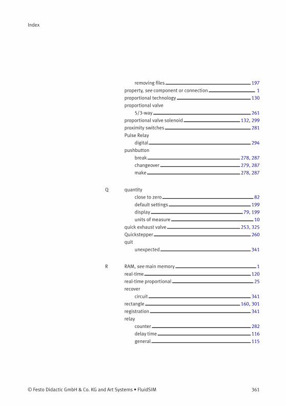
Index
removing files 197
property, see component or connection 1
proportional technology 130
proportional valve
5/3-way 261
proportional valve solenoid 132, 299
proximity switches 281
Pulse Relay
digital 294
pushbutton
break 278, 287
changeover 279, 287
make 278, 287
Q quantity
close to zero 82
default settings 199
display 79, 199
units of measure 10
quick exhaust valve 253, 325
Quickstepper 260
quit
unexpected 341
R RAM, see main memory 1
real-time 120
real-time proportional 25
recover
circuit 341
rectangle 160, 301
registration 341
relay
counter 282
delay time 116
general 115
© Festo Didactic GmbH & Co. KG and Art Systems • FluidSIM 361
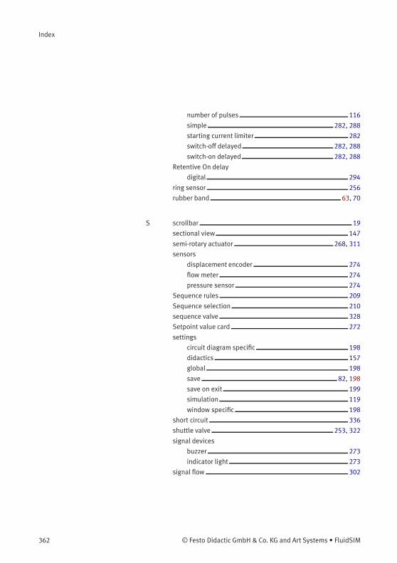
Index
number of pulses 116
simple 282, 288
starting current limiter 282
switch-off delayed 282, 288
switch-on delayed 282, 288
Retentive On delay
digital 294
ring sensor 256
rubber band 63, 70
S scrollbar 19
sectional view 147
semi-rotary actuator 268, 311
sensors
displacement encoder 274
flow meter 274
pressure sensor 274
Sequence rules 209
Sequence selection 210
sequence valve 328
Setpoint value card 272
settings
circuit diagram specific 198
didactics 157
global 198
save 82, 198
save on exit 199
simulation 119
window specific 198
short circuit 336
shuttle valve 253, 322
signal devices
buzzer 273
indicator light 273
signal flow 302
362 © Festo Didactic GmbH & Co. KG and Art Systems • FluidSIM
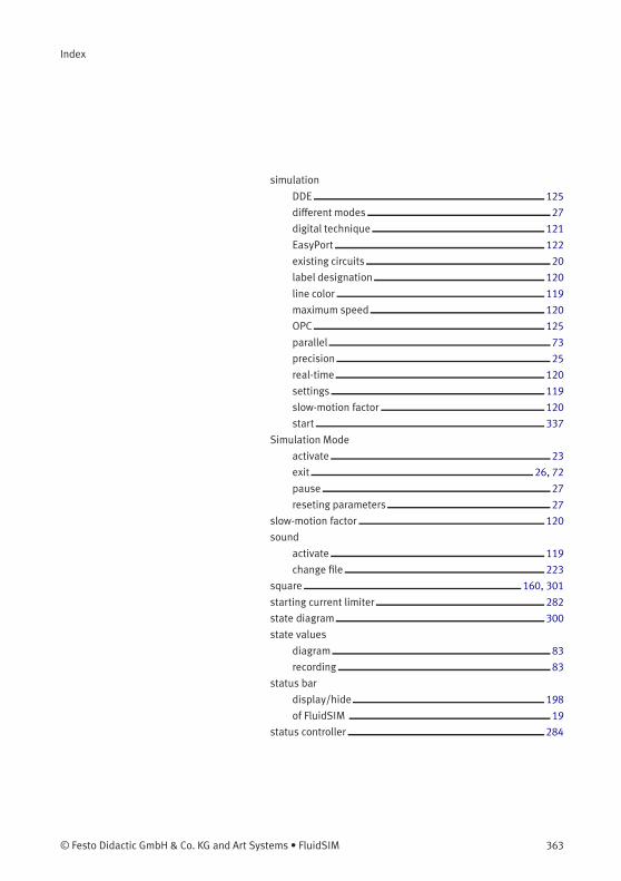
Index
simulation
DDE 125
different modes 27
digital technique 121
EasyPort 122
existing circuits 20
label designation 120
line color 119
maximum speed 120
OPC 125
parallel 73
precision 25
real-time 120
settings 119
slow-motion factor 120
start 337
Simulation Mode
activate 23
exit 26, 72
pause 27
reseting parameters 27
slow-motion factor 120
sound
activate 119
change file 223
square 160, 301
starting current limiter 282
state diagram 300
state values
diagram 83
recording 83
status bar
display/hide 198
of FluidSIM 19
status controller 284
© Festo Didactic GmbH & Co. KG and Art Systems • FluidSIM 363
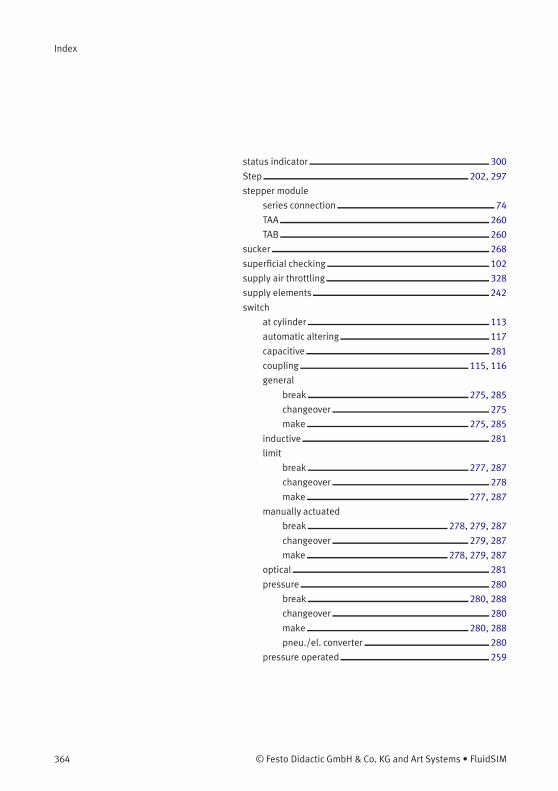
Index
status indicator 300
Step 202, 297
stepper module
series connection 74
TAA 260
TAB 260
sucker 268
superficial checking 102
supply air throttling 328
supply elements 242
switch
at cylinder 113
automatic altering 117
capacitive 281
coupling 115, 116
general
break 275, 285
changeover 275
make 275, 285
inductive 281
limit
break 277, 287
changeover 278
make 277, 287
manually actuated
break 278, 279, 287
changeover 279, 287
make 278, 279, 287
optical 281
pressure 280
break 280, 288
changeover 280
make 280, 288
pneu./el. converter 280
pressure operated 259
364 © Festo Didactic GmbH & Co. KG and Art Systems • FluidSIM
Index
reed contact 277, 278
Reed contact 277
solenoid 281
switch-off delayed
break 276, 286
changeover 276
make 276, 286
switch-on delayed
break 275, 286
changeover 276
make 275, 286
with roll 277, 278
switching element
table 76
symbol
DXF 182
symbols
configurable 49
Symmetric Clock Generator
digital 296
Synchronization 210, 298
T T-connection 43, 74
T-junction
digital 290
electrical 273
pneumatic 245
table
switching element 76
Target information 215
Terminal assignment diagram 301
terminal assignment diagrams 77
text component
general 165, 300
protect 165
© Festo Didactic GmbH & Co. KG and Art Systems • FluidSIM 365
Index
throttle valve 255, 327
TIFF export 177
time delay valve 260, 330
Time limit 214
Timer Switch
digital 295
toolbar
display/hide 198
of FluidSIM 18
Transient sequence 210
Transition 204, 297
tutorial 146
two pressure valve 253, 320
U undo 63
ungroup
components 72
objects 72
units, see quantity 1
Unstable step 210
Up/Down Counter
digital 295
V vacuum actuator valve 259
vacuum suction nozzle 268
value range
exceeded 338
valve
configurable 246, 247
editor 35, 60
valve solenoid 299
American standard 300
valves
configurable 246
directional valves 247
366 © Festo Didactic GmbH & Co. KG and Art Systems • FluidSIM
Index
flow control valves 253
groups 259
pressure control 256
shutoff valves 253
way valves 246
Variable names 211
Variable value 210
video, see educational film 1
Virtual triggering 210
voltmeter 132, 274
W warning message 336
water separator 244
automatic condensate drain 244
way valve
configurable 246, 247
window
arrange 240
not available 340
print contents 175
Wiping Relay
digital 294
X XOR
digital 292
Z zoom
circuit diagram 70
component library 70
time-distance diagram 70
with rubber band 70
© Festo Didactic GmbH & Co. KG and Art Systems • FluidSIM 367