Embed Size (px)
Citation preview
MOOS-IvP: Cross Platform Software for Robotics Research
Alberto Grati Engineering Department - STO Centre for Maritime Research & Experimentation
Viale San Bartolomeo, 400 – La Spezia ITALY
ABSTRACT Robotics frameworks have recently gained substantial popularity among the research community: they extend the concept of software modularity by introducing standard inter-process communication and allow multiple development groups to seamlessly share modules and subsystems dramatically cutting the integration phase time. The MOOS-IvP framework goes even beyond by adding on top of its robust message passing subsystem a collection of tools and libraries specifically designed to deliver autonomy to unmanned platform. This paper presents the concepts behind the MOOS-IvP framework and gives an overview of some tools used for programming autonomous behaviours in the field of marine robotics.
Keywords: robotics frameworks, autonomous unmanned vehicles, robotics software architectures, artificial intelligence, C++ programming language
INTRODUCTION
Ever since its initial conceptions, software architectures proposed for robotics research showed high level of modularity, and the idea of fine-grained information producers and consumers (nodes) together with pervasive synaptic-like data links had always been in place. Therefore one of the domains that a modern architecture should address is the inter-node communication strategy, which is desirable to be lightweight and not introducing any unnecessary coupling between the nodes. Also, when the network of nodes and links grows to the scale of a real world artificial intelligence application, consumers must implement efficient solutions in the arbitration of data deriving from decisions taken in other nodes, where competing and often disagreeing behaviors are being run. The capability to address this second domain in fact determines the level of autonomy of the robotic system. An example of the latter is the case of global path planning, with local collision detection and avoidance capability taking over to the normal data flow as contingencies occur.
The MOOS-IvP framework is a set of open source software modules that aims to address both domains in the field of marine robotic platforms by providing a robust inter-process communication layer (the MOOS), and a suite of autonomy tools built around an optimization engine (the IvP-Helm) that enable the system developer to compose the desired application logic by adding behavior modules from a database.
Benefits from the usage of MOOS-IvP not exhaustively include:
• Availability of a large base of ready-to-go applications devoted to simulation of marine vehicles (both surface and underwater), mission monitoring, post-mission analysis, debugging, safe deployment;
• Availability of a significantly large number of interface nodes to the most commonly used hardware peripherals in marine applications (GPS, compass, DVL, acoustic modem);
• Availability of a large number of IvP-Helm configurable behavior modules;
STO-EN-SCI-271 5 - 1
MOOS-IvP: Cross Platform Software for Robotics Research
• Tested with different CPU architectures and OSes, both in desktop environments (Linux, MS Windows, MAC OS) and embedded modules (x86, ARM);
• Community support
Paper Overview This paper is divided in five parts:
• INTRODUCTION: presents the domains to which the MOOS-IvP framework is considered applicable;
• THE MOOS ARCHITECTURE: presents the concepts and the tools behind the MOOS inter-process communication library, some notable MOOS application and guidelines on how to write custom MOOS applications;
• MARINE VEHICLE SIMULATOR: presents the software modules provided by the MOOS-IvP framework in order to set up a simulation environment for marine applications;
• VEHICLE AUTONOMY AND THE IVP-HELM: presents the IvP-Helm as a regular MOOS application and the additions that turn it into a powerful autonomy decision engine;
• CONCLUSIONS: final considerations.
THE MOOS ARCHITECTURE
MOOS-IvP users take advantage from two separate, although intimately connected, software packages:
• MOOS (Mission Oriented Operating Suite) – is a set of C++ libraries and tools developed and maintained at Oxford University – Mobile Robotics Group that support lightweight message passing between processes;
• IvP-Helm (IvP is InterVal Programming) – is a set of MOOS based applications and libraries developed and maintained at Massachusetts Institute of Technology, Laboratory for Autonomous Marine Sensing Systems, that add autonomous decision making capabilities to robotics systems, together with a large number of utility and monitoring tools; with particular focus on marine platforms.
Here we will focus on MOOS as a general purpose software infrastructure; later on more details about its application in the domain of our interests will be given.
MOOS Inter-Process communications The MOOS is in its essence an inter-process communication system based on the message passing approach. It aims to ease the data flow in a typical robotic or control system which is usually composed of information producers (nodes that gather information from external entities such as sensors), and transformers (nodes that utilize a subset of the data available from other information producers chained until the final output to actuators is available).
Each process running in the MOOS environment is then given the possibility to output some pieces of information to make them available to other processes (publish), and also declare which data it needs in order to fulfil the requirements of the implemented algorithm (subscribe). The MOOS framework is in charge of routing messages from publishers to subscribers abstracting the user from any physical boundary between the nodes, across the network and CPU architectures.
5 - 2 STO-EN-SCI-271
MOOS-IvP: Cross Platform Software for Robotics Research
Among a group of related processes running in a MOOS environment (also called “MOOS community”) message delivery, or more broadly information exchange, concretely takes place by means of published and subscribed variables. In the dynamics of a MOOS community one can imagine all the variables published by any process gathered in a shared table, with the possibility from a subscriber’s side to be signalled when a value in one of the variables it has declared to have dependency from changes.
The identity of a message is determined by its key, which is a simple string identifier assumed to be unique among the set of variables used by a MOOS community. The variable contents can be one of the following:
• Numeric (double precision) – mainly used for sensors data;
• String (free text) – useful when a single message contains multiple information;
• Binary (any sequence of bytes) – necessary in case of image/video transmission or more complex sensors data.
Communications topology: the MOOSDB
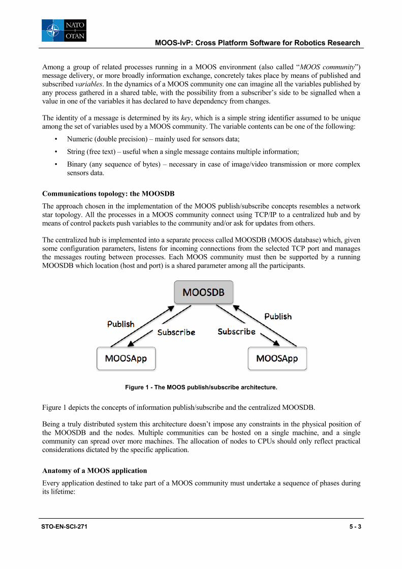
The approach chosen in the implementation of the MOOS publish/subscribe concepts resembles a network star topology. All the processes in a MOOS community connect using TCP/IP to a centralized hub and by means of control packets push variables to the community and/or ask for updates from others.
The centralized hub is implemented into a separate process called MOOSDB (MOOS database) which, given some configuration parameters, listens for incoming connections from the selected TCP port and manages the messages routing between processes. Each MOOS community must then be supported by a running MOOSDB which location (host and port) is a shared parameter among all the participants.
Figure 1 - The MOOS publish/subscribe architecture.
Figure 1 depicts the concepts of information publish/subscribe and the centralized MOOSDB.
Being a truly distributed system this architecture doesn’t impose any constraints in the physical position of the MOOSDB and the nodes. Multiple communities can be hosted on a single machine, and a single community can spread over more machines. The allocation of nodes to CPUs should only reflect practical considerations dictated by the specific application.
Anatomy of a MOOS application
Every application destined to take part of a MOOS community must undertake a sequence of phases during its lifetime:
STO-EN-SCI-271 5 - 3
MOOS-IvP: Cross Platform Software for Robotics Research
• STARTUP: application specific parameters are read from a configuration file and stored into internal variables for later use;
• CONNECTION: the application connects to the designated MOOSDB through the network;
• REGISTRATION: once connected, the application registers for the variables it needs for processing. This is done by sending control packets to the MOOSDB;
• MAIL HANDLING: the application receives notifications as soon as one or more variables it has registered to change value in the MOOSDB. At the implementation level this is achieved using call-back functions;
• ITERATION: at a predefined pace, the application is asked to execute its main algorithm and eventually produce some output variables to be sent to the MOOSDB. Other applications might have subscribed for them and will be then notified accordingly.
With simplicity in mind, MOOS developers have written as many libraries and source code as possible to automate the process of creating an application, given the above fixed sequence of actions; leaving to the user only the task to fill in empty code placeholders with specific algorithms and functions.
The provision of application’s default behaviour as well as the possibility to override it with user code is accomplished using the C++ programming language’s object oriented class inheritance feature.
By inheriting own application main class from the provided CMOOSApp the user gets all the functionalities needed to be compliant with the MOOS protocol and selected class’ virtual members functions, eventually overridden by the user, are then called should any of the above mentioned lifecycle phases take place.
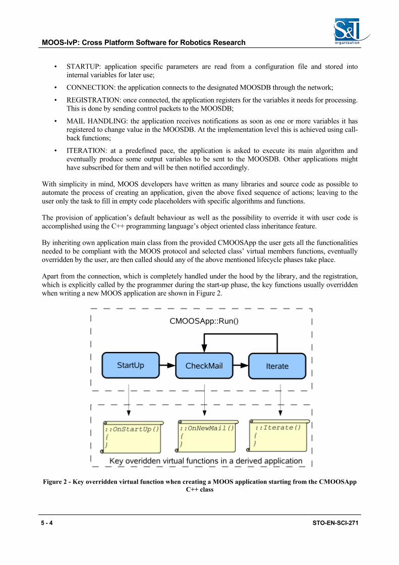
Apart from the connection, which is completely handled under the hood by the library, and the registration, which is explicitly called by the programmer during the start-up phase, the key functions usually overridden when writing a new MOOS application are shown in Figure 2.
Figure 2 - Key overridden virtual function when creating a MOOS application starting from the CMOOSApp C++ class
5 - 4 STO-EN-SCI-271
MOOS-IvP: Cross Platform Software for Robotics Research
All the connection, mail handling and iteration processes are started when the application main function eventually calls the Run member function of CMOOSApp.
The pace at which the Iterate function is called and the incoming mail is checked is configurable at run time.
Application configuration and other MOOS library features
Inheriting the application class from CMOOSApp, and more broadly using the MOOS library (which CMOOSApp is part of) brings even more than just being able to communicate with the MOOSDB (and thus with the other processes in the community). A number of utility functions are included to accomplish and promote standardisation in routine tasks such as:
• Reading parameters from a configuration file;
• Dealing with the system clock;
• Reading, comparing and in general handling the contents of strings;
• Logging.
While inviting to refer to the official documentation available at [1] for the details about the library functions and the tools available, which are beyond the scope of this document, we want to highlight here the concept of unified and centralized configuration file, which in the MOOS language is called the mission file.
Applications are strongly invited to share a common configuration file in which each one can locate its own block containing the needed parameters. The file in subject shall be a plain text file and will contain any information needed to set up the whole MOOS community such as:
• Where to locate the MOOSDB;
• Which application shall be launched (including whether or not launch a local MOOSDB);
• Configuration data for each application:
• Application and communication functions run periods;
• Any application specific data
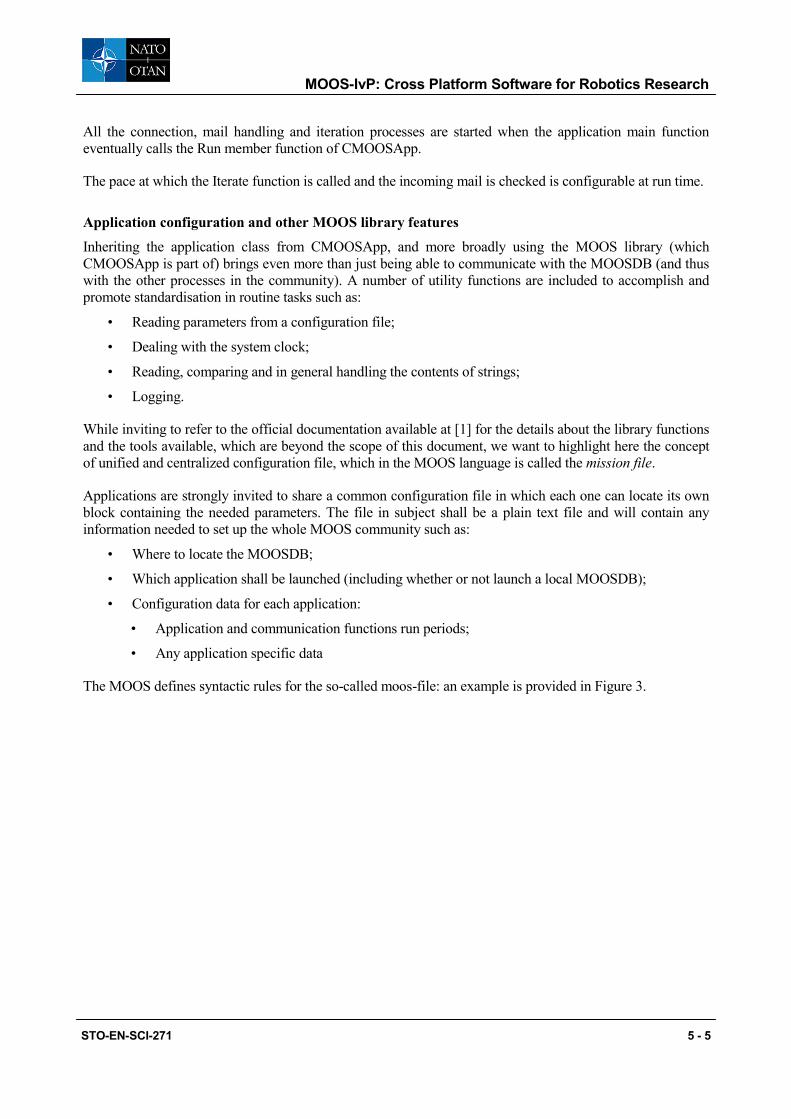
The MOOS defines syntactic rules for the so-called moos-file: an example is provided in Figure 3.
STO-EN-SCI-271 5 - 5
MOOS-IvP: Cross Platform Software for Robotics Research
Figure 3 - MOOS mission file example
The first three lines of the mission file define the location of the MOOSDB in terms of hostname and the TCP port which the MOOSDB will be listening to.
The second part is called the Antler configuration block and contains a list of “Run = …“ lines each one with the name of a process that needs to be launched (in this case the mission file requires to launch a local copy of the MOOSDB, which will be configured for listening from port 9000).
The third part replicates as many “ProcessConfig” blocks as is the number of the requested to be launched processes (apart from the MOOSDB): each one containing specifications for the iteration and communications loop times, plus additional “ID = value” lines specific to the application.
Properly formatted moos files can be then read by a launcher application, named pAntleri, which will analyse the Antler block and spawn processes as needed. On start-up, MOOS processes may use helper functions from the MOOS library to extract relevant lines and parse own configuration parameters.
The command line used to launch the entire MOOS community, assuming that the mission file to be run is named “mission.moos” is then:
pAntler mission.moos
MARINE VEHICLE SIMULATOR
Marine vehicles have been one of the first domains which the MOOS has been applied to. Joint developments between Oxford University and MIT led to the IvP completion of the MOOS framework (the MOOS-IvP), which brings in a large base of tools devoted to the simulation, deployment and autonomy programming in the marine environment.
ServerHost = localhost ServerPort = 9000 Community = xrelay //------------------------------------------ // Antler configuration block ProcessConfig = ANTLER { Run = MOOSDB Run = pXRelay } ProcessConfig = pXRelay { AppTick = 25 CommsTick = 25 OUTGOING_VAR = APPLES INCOMING_VAR = PEARS }
5 - 6 STO-EN-SCI-271
MOOS-IvP: Cross Platform Software for Robotics Research
Before getting into the technology that delivers autonomy to robotic platforms, which will be covered in the next sections there are notable MOOS processes, part of the IvP repository, not directly related to autonomous behaviours and of general use when dealing with marine platforms.
Among all of them, of interest to this paper are those devoted to the simulation of marine underwater/surface vehicle, and the graphical representation of the synthetic scenario into which the simulated entities navigate.
MOOS applications that take part in a simulation are:
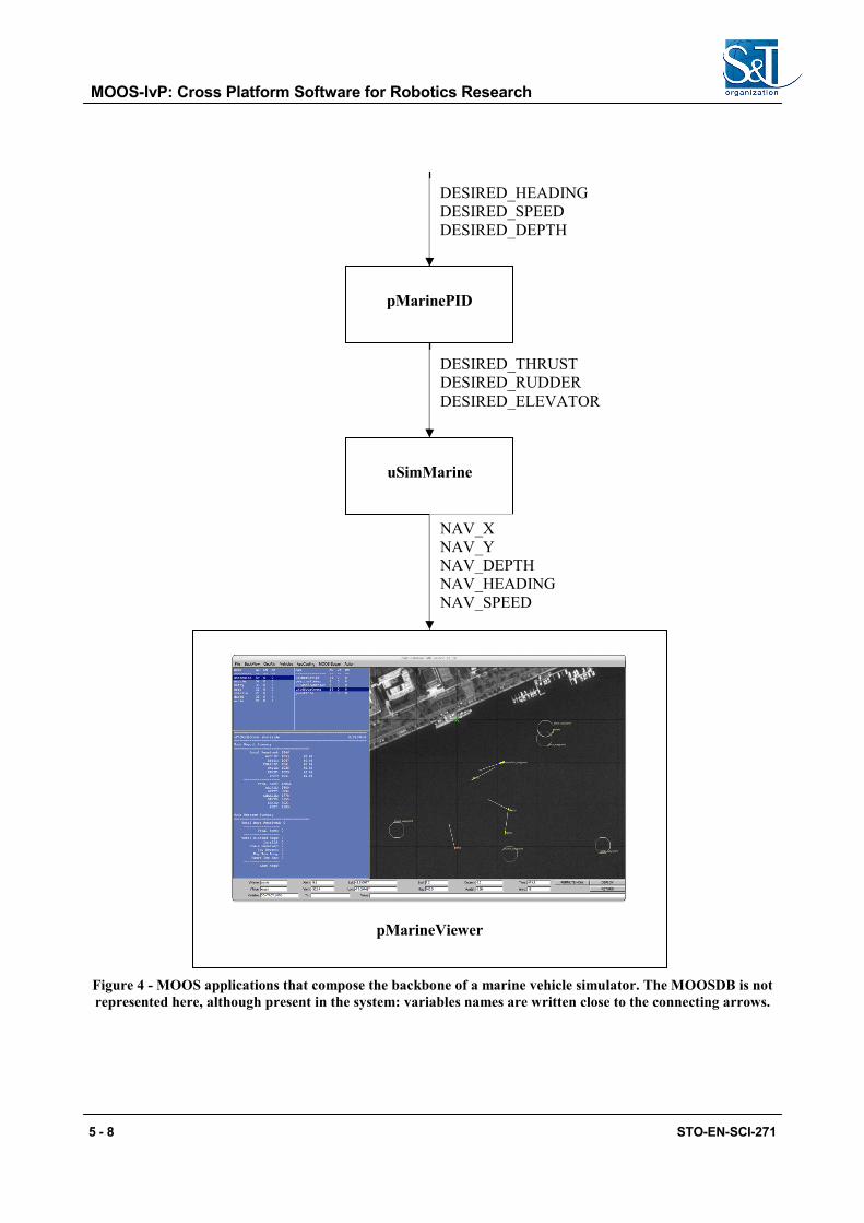
• uSimMarine – a process that subscribes a set of variables as control commands to a simulated marine vehicle (namely DESIRED_THRUST, DESIRED_RUDDER, DESIRED_ELEVATOR) and outputs at each iteration the estimated position, heading, speed and depth on four distinct variables;
• pMarinePID – a process that implements a controller for uSimMarine in order to have the vehicle follow a specific course, at specific speed and depth. Its inputs are DESIRED_HEADING, DESIRED_SPEED and DESIRED_DEPTH; its outputs are the inputs of uSimMarine;
• pMarineViewer – a GUI with map overlay capabilities used to plot vehicles positions and send some basic commands to them through publication of MOOS variables.
Starting a marine simulator means putting together the above mentioned MOOS applications in a mission file and running them with pAntler. Figure 4 represents such processes interactions.
The backseat driver paradigm Vehicle control is an engineering problem which solution can reach different levels of abstraction. Stabilise a platform in pitch and roll can be sufficient in some applications, whereas others might expect to also have a speed and heading regulations. Nonetheless, the possibility to intervene in the inner control loops of a platform available from the market is often denied by intellectual property safekeeping arguments. A boundary between what is considered part of the vehicle itself, and what can be handled by researchers to deliver behaviours to the platform is then needed.
The MOOS-IvP has adopted the so-called “frontseat/backseat drivers paradigm”, which has shown to be a good choice in many applications and consists in the assumption that the vehicle, whatever would be its proprietary control system, is capable of executing three basic commands:
• keep a commanded heading;
• keep a commanded speed;
• keep a commanded depth (if applicable).
STO-EN-SCI-271 5 - 7
MOOS-IvP: Cross Platform Software for Robotics Research
pMarineViewer
pMarinePID
uSimMarine
DESIRED_THRUST DESIRED_RUDDER DESIRED_ELEVATOR
NAV_X NAV_Y NAV_DEPTH NAV_HEADING NAV_SPEED
DESIRED_HEADING DESIRED_SPEED DESIRED_DEPTH
Figure 4 - MOOS applications that compose the backbone of a marine vehicle simulator. The MOOSDB is not represented here, although present in the system: variables names are written close to the connecting arrows.
5 - 8 STO-EN-SCI-271
MOOS-IvP: Cross Platform Software for Robotics Research
Those capabilities are referred to as frontseat driver’s features and are assumed to be provided by the manufacturer of the vehicle, being it a company or just another department of some research institution. Once those functionalities are in place, the real decision making part or the system (the autonomy part) needs only to point the frontseat to whatever solution it might have found to be the best at a specific time, in the heading, speed and depth domains.
The latter is called backseat driver and relies on the frontseat being able to execute, in a reasonable time the commands given through a communication channel which represents the edge of the MOOS-IvP subsystem; often handled by a MOOS interface process which knows about the vehicle-specific protocol.
As feedback, the same interface process is asked to periodically query the current position, speed, heading and depth from the same communication channel to the vehicle.
Looking at the pMarinePID and uSimMarine pair in Figure 4, it’s clear how those two represent the frontseat driver in a simulated vehicle. Considered as a whole, they subscribe for commands from the backseat driver (desired heading, speed and depth) and, at the end of each iteration, produce the current state of the vehicle (position, depth, speed and heading).
In the next section, going up one level of abstraction, new blocks (MOOS processes) will be added in order to produce commands for the simulator in real time.
VEHICLE AUTONOMY AND THE IVP-HELM
Applications within the scope of this paper involve the development and field testing of artificial intelligence algorithms which final decisions affect the trajectory of one or more marine vehicles during the execution of a specific task. Examples are survey area optimal coverage during side scanning, acoustic communication assets performances maximization, signal-to-noise ratio optimization during sonar operations, with complete mission going through different phases, and external events used to trigger phase changes.
Desired decision domains are therefore those needed to guide an underwater or surface vehicle towards a specific direction, at given speed and depth: in other words, using the MOOS-IvP language, autonomy is implemented in the backseat driver part of the system.
MOOS-IvP comes with a large number of ready-to-go applications and tools, but the one that makes it distinctive among the robotics research community is the IvP-Helm. In its most common configuration the “Helm” is a MOOS application that subscribes (at least) for the variables produced by the frontseat driver interface (vehicle position, heading, speed and depth) and posts new set points for heading speed and depth.
All the logic behind the selection of the new values is encapsulated in two entities:
• the behaviours set – a set of functions capable of sensing the vehicle status and the surrounding environment by means of MOOS variables, and produce, each one, a “preferred solution” in one or more of the domains of interest (heading, speed, depth);
• an optimization engine (IvP Solver) – a software module that, at each iteration, gathers all the proposed solutions coming from the behaviours set and computes the optimal value to be sent to the frontseat driver for each of the domains.
Decisions are made considering the output of each behaviour as an “utility function” which represents, for each possible value in a domain, “how good” would be to select that value. The higher is the utility function at a specific value, the best would be for the source behaviour if that value is selected, not considering any other sibling in the set.
STO-EN-SCI-271 5 - 9

MOOS-IvP: Cross Platform Software for Robotics Research
For example, let’s assume that we have an underwater vehicle with a poor localization system, which needs to surface every 30 minutes and get a GPS fix in order to keep the navigation error within acceptable limits, and we want to send that vehicle on a survey having it crossing a list of waypoints at 20 meters depth, at 4 knots speed.
From the IvP-Helm perspective we would have 2 competing behaviours:
• the waypoint navigation behaviour, which optimal solution would be to stay at 20 meters depth, keeping 4 knots of speed and heading straight to the next waypoint;
• the periodical surfacing behaviour, which would consider commanding a depth of 0 meters (surface) when its internal timer reaches 30 minutes from the latest GPS fix.
Neither the waypoints navigation behaviour nor the periodical surfacing one have any clue about which other behaviours are running in the system: they simply declare their own “preferences” in terms of desired values in heading, speed and depth and let the optimization engine decide which values to pick up.
Of course some hints must be given to the engine: one of those is the ceiling to the values of the utility functions, also known as the weight. These weights can be statically declared in the mission files so that the user can give more priority to behaviours that, as in the case of the periodical surfacing, are mostly silent (do not produce any request), but when they do, requested values overcome other behaviours’.
Details about the IvP Solver are given in [3]; what matters here is the concept of software behaviours as separate pieces of code which local decisions can be merged into the global space through optimization.
Modes Definition At any given time it is allowed to restrict the number of active behaviours to a subset of the whole list registered with the IvP-Helm. Although not necessary this feature turns out to be convenient when a vehicle’s mission is comprised of different phases. For example one might request an AUV to reach an initial point for a survey doing surface navigation; then begin the survey at a given depth; then return to a rendezvous point when the data collection is over and wait for recovery.
The IvP-Helm defines the concept of modes and allows the programmer to define, in a separate file from the main MOOS mission file, together with the list of applicable behaviours an hierarchical definition of the mission modes. Transitions from one mode to the next are triggered by changes in the value of selected MOOS variables, which the IvP-Helm automatically subscribes to upon start up.
The syntax for the mode definition resembles a C-style nested structures declaration and allows the programmer to define a tree structure: details are given in [4] and [5].
5 - 10 STO-EN-SCI-271
MOOS-IvP: Cross Platform Software for Robotics Research
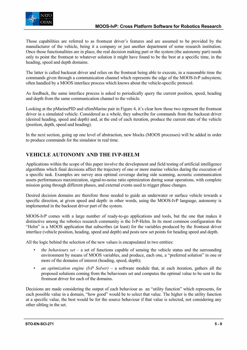
Figure 5 - IvP-Helm modes hierarchical definition example
An example of IvP-Helm modes definition is given in Figure 5. In that definition there is a first distinction between “Active” and “Inactive” mode as consequence of the value of the DEPLOY variable. The example further refines the “Active” mode by including the “MODE = Active” line in the last block (thus making the latter the definition of Active’s child nodes) and considering the RETURN MOOS variable as key to the transition to “Surveying” or “Returning” sub-modes.
The IvP-Helm as MOOS application The instance of the IvP-Helm shall be listed in the MOOS mission file along with all other MOOS application participating in the MOOS community: a line like
Run = pHelmIvP
shall be included in the Antler process configuration block (the one that launches all other MOOS processes during mission start up); and a specific IvP-Helm configuration block shall be added as well.
The parameters needed by the IvP-Helm are:
• regular AppTick and CommsTick with the same meaning as for standard MOOS applications;
• declaration of the domains in which the solver shall look for solutions (typically those are course, speed and depth);
• a reference to an external file (the behaviours file) which will be parsed by the Helm at start up
• other parameters that influence some safety mechanisms like whether or not wait for an initial green light before starting the publication to the MOOS of helm decisions; or how to behave should the active behaviours set become empty at some point.
An example of an IvP-Helm process configuration block is given in the following listing:
//-------- pHelmIvP configuration block ------------- ProcessConfig = pHelmIvP { AppTick = 4 // Defined for all MOOS processes CommsTick = 4 // Defined for all MOOS processes domain = course:0:359:360
STO-EN-SCI-271 5 - 11
MOOS-IvP: Cross Platform Software for Robotics Research
domain = speed:0:3:16 domain = depth:0:500:101 behaviors = foobar.bhv verbose = terse ok_skew = ANY start_in_drive = false allow_park = true park_on_allstop = false }
The above configuration defines three decision domains:
• course, with acceptable values between 0 and 359, 1 degree of resolution (domain divided in 360 segments);
• speed, with values between 0 and 3 knots; 16 possible values in the interval (3/16 kts resolution);
• depth, with values between 0 and 500 meters; 0.5 meters resolution.
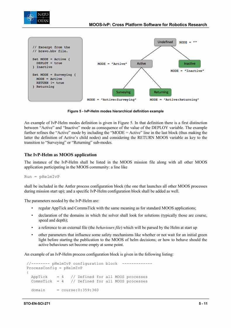
and the external file “foobar.bhv” is defined as the behaviour file to be loaded by the Helm.
Figure 6 - Configuration of the IvP-Helm and interactions with the MOOSDB
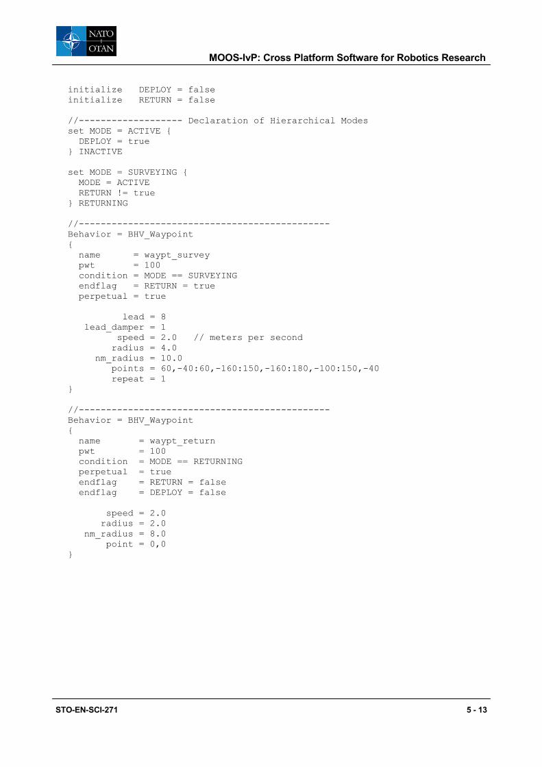
The syntax used to write a behaviour file is given in detail in [4] and [5]: as an example we give a simple behaviour file related to the modes definition given in the previous section, which defines two waypoints following behaviours each one active when the corresponding mode is selected.
5 - 12 STO-EN-SCI-271
MOOS-IvP: Cross Platform Software for Robotics Research
initialize DEPLOY = false initialize RETURN = false //------------------- Declaration of Hierarchical Modes set MODE = ACTIVE { DEPLOY = true } INACTIVE set MODE = SURVEYING { MODE = ACTIVE RETURN != true } RETURNING //---------------------------------------------- Behavior = BHV_Waypoint { name = waypt_survey pwt = 100 condition = MODE == SURVEYING endflag = RETURN = true perpetual = true lead = 8 lead_damper = 1 speed = 2.0 // meters per second radius = 4.0 nm_radius = 10.0 points = 60,-40:60,-160:150,-160:180,-100:150,-40 repeat = 1 } //---------------------------------------------- Behavior = BHV_Waypoint { name = waypt_return pwt = 100 condition = MODE == RETURNING perpetual = true endflag = RETURN = false endflag = DEPLOY = false speed = 2.0 radius = 2.0 nm_radius = 8.0 point = 0,0 }
STO-EN-SCI-271 5 - 13
MOOS-IvP: Cross Platform Software for Robotics Research
CONCLUSIONS
The MOOS-IvP framework has been applied to marine robotics for more than ten years now, with an increasing number of commercial platforms delivered with open protocols in order to enable the frontseat-backseat drivers paradigm specific to the IvP-Helm architecture.
The simplicity of the MOOSDB publish/subscribe concept is a key point in team development and can dramatically reduce modules integration time to just an agreement in the MOOS variable names and type; while the power of the IvP-Helm can add significant value by delivering autonomous decision making capabilities to any robotic system.
The two of them come with an impressive number of utilities in fields of simulation, command and reporting, debugging, logging and many others; thus letting the developer to focus only on the part of the code that brings real value to the system.
This paper has presented an overview of the technology behind the MOOS-IvP framework: even if not exhaustively we think to have covered a sufficient number of topics for the reader to be able to follow on using official documentation.
REFERENCES
[1] MOOS-IvP official website (http://www.moos-ivp.org) at MIT
[2] MOOS repository and documentation (https://sites.google.com/site/moossoftware/)
[3] Michael R. Benjamin, The Interval Programming Model for Multi-Objective Decision Making, Computer Science and Artificial Intelligence Laboratory, MIT, AIM-2004-021, Cambridge, MA, September, 2004.
[4] Michael R. Benjamin, Paul M. Newman, Henrik Schmidt, John J. Leonard, An Overview of MOOS-IvP and a Brief Users Guide to the IvP Helm Autonomy Software, MIT Computer Science and Artificial Intelligence Lab, MIT-CSAIL-TR-2009-028, June, 2009.
[5] Michael R. Benjamin, MOOS-IvP Autonomy Tools User’s Manual Release 13.2, MIT Computer Science and Artificial Intelligence Lab, www.moos-ivp.org/docs/, February, 2013.
i Processes in the MOOS parlance are named with a prefix which states their type and classifies whether they are interfaces to/from external devices (prefix “i”, like iGPS); pure MOOS-to-MOOS variable exchanger (prefix “p”, like pHelmIvP) or general utilities
(prefix “u”, like uMS)
5 - 14 STO-EN-SCI-271