Embed Size (px)
Citation preview
TECHNISCHE UNIVERSITÄT MÜNCHENLehrstuhl für Angewandte Mechanik
Permanent Magnet Reluctance Actuatorsfor Vibration Testing
Daniel Wiedemann
Vollständiger Abdruck der von der Fakultät für Maschinenwesender Technischen Universität München zur Erlangung des akademischen Grades eines
Doktor-Ingenieurs
genehmigten Dissertation.
Vorsitzender: Univ.-Prof. dr. ir. Daniel J. RixenPrüfer der Dissertation:
1. Univ.-Prof. Dr.-Ing. habil. Heinz Ulbrich (i.R.)2. Univ.-Prof. Dr.-Ing. Horst Baier
Die Dissertation wurde am 15.10.2012 bei der Technischen Universität Müncheneingereicht und durch die Fakultät für Maschinenwesen am 07.03.2013 angenommen.

AbstractThe analysis of vehicles and automotive components for disturbing noise requiresactuators with high force density, robustness and energy efficiency. This thesis coversthe mechatronic design and simulation of magnetic reluctance actuators for vibrationexcitation. A comparison with hydraulic and electrodynamic actuation concepts showsthe application potential of reluctance force actuators in automotive vibration testrigs. For the magnetic design, reluctance circuits and the finite element analysis areused. The developed topology is characterized by a fully laminated armature anda core with surface mounted permanent magnets. The resulting negative magneticstiffness is completely compensated by mechanical springs which enable a robust andstable operation. For dynamic simulations of the electromagnetic energy conversion aco-energy based model is developed. It features low computational cost and enables anaccurate description of the nonlinear actuator characteristics. The presented methodsare verified by experiments with two prototype actuators.
ZusammenfassungDie Störgeräuschanalyse von Fahrzeugen und Fahrzeugkomponenten erfordert Aktorenmit einer hohen Kraftdichte, Robustheit und Energieeffizienz. Diese Arbeit beschreibtden mechatronischen Entwurf und die Simulation von magnetischen Reluktanzaktorenfür die Schwingungsanregung. Der Vergleich mit hydraulischen und elektrodynami-schen Antriebskonzepten zeigt das Anwendungspotential von Reluktanzaktoren inVibrationsprüfständen bei der Fahrzeugentwicklung. Für den Magnetkreisentwurf wer-den Netzwerkmodelle und die Finite-Elemente-Methode verwendet. Die entwickelteTopologie zeichnet sich durch einen vollständig geblechten Anker und einen mit Perma-nentmagneten bestückten Kern aus. Die negative magnetische Steifigkeit wird durchmechanische Federn voll kompensiert, so dass ein robuster und stabiler Betrieb möglichwird. Für dynamische Simulationen der elektromagnetischen Energiewandlung wirdein Modell unter Verwendung der Co-Energie entwickelt, welches einen geringenRechenaufwand erfordert und die genaue Beschreibung der nichtlinearen Aktorcharak-teristik ermöglicht. Die vorgeschlagenen Methoden werden durch Experimente mitzwei Prototypen verifiziert.
iii

AcknowledgmentsThis thesis summarizes a large part of my research carried out at the Institute ofApplied Mechanics, Technische Universität München. Without the help of numerouspeople who supported me over the the course of the previous years the completion ofthis work would not have been possible.
First and foremost, I would like to express my deep gratitude to my advisor ProfessorHeinz Ulbrich for providing an excellent research environment, stimulating discussionsand helpful advice during my time as his PhD student. He gave me the freedom topursue my own ideas and support when it was needed.
I would also like to warmly thank the second advisor Professor Horst Baier andchairman Professor Daniel Rixen for serving on my dissertation committee and fortheir interest in my work. For managing the project resources and his support in alladministrative manners I owe thanks to Dr. Thomas Thümmel.
I very much enjoyed working with great colleagues at the institute. Here, I amparticularly grateful to Dr. Marcus Herrmann, not only for triggering my interest inmagnetic actuators, but also for encouraging me to take a research position. Heintroduced me into the field of electromagnetic devices, being a competent advisorand partner for scientific discussions.
Special thanks I wish to offer to Dr. Ulrich Koch who was responsible for the shakerplant and the control system design. The collaboration with him was always veryinspiring and productive. Besides for his tireless efforts in the common project, Iwould like to thank him for sharing good ideas and providing industrial backgroundknowledge to our research.
Further, I would like to sincerely thank Dr. Thomas Villgrattner, Valerio Favot,Dr. Markus Schneider and Dr. Thorsten Schindler for their continuous assistance andthe many fruitful discussions. I am particularly indebted to Markus Schwienbacher forhis valuable advice and helpful suggestions regarding the mechatronic aspects of thisthesis. The hardware development would not have been possible without the excellentwork of the institute’s mechanical and electrical workshops. For the development ofthe power electronics and for numerous discussions about sensors and actuators I wishto express my sincere thanks to Georg Mayr. His enthusiasm and broad engineeringexperience contributed substantially to the experimental research. Working with himwas always deeply pleasant and rewarding. Furthermore, I warmly thank Simon Gerer,Philip Schneider and Tobias Schmid for manufacturing the mechanical componentsand their assistance during the assembly of numerous prototypes.
I would like to thank my proofreaders Dr. Marcus Herrmann, Dr. Thomas Villgrattner,Dr. Ulrich Koch and Valerio Favot for their interest and helpful comments.
Finally, I would like to express my immense gratitude to my family who has alwaysencouraged and supported me in all my endeavours.
Munich, April 2013 Daniel Wiedemann
v

Contents1. Introduction 1
1.1. Literature Review . . . . . . . . . . . . . . . . . . . . . . . . . . . . . . . . . . . . . . . 21.2. Contributions and Outline of the Thesis . . . . . . . . . . . . . . . . . . . . . . . . . 6
2. Vibration Testing 92.1. Noise, Vibration and Harshness Analysis . . . . . . . . . . . . . . . . . . . . . . . . . 92.2. Actuators . . . . . . . . . . . . . . . . . . . . . . . . . . . . . . . . . . . . . . . . . . . . 11
2.2.1. Hydraulic Actuators . . . . . . . . . . . . . . . . . . . . . . . . . . . . . . . . . 122.2.2. Electrodynamic Actuators . . . . . . . . . . . . . . . . . . . . . . . . . . . . . 142.2.3. Magnetic Reluctance Actuators . . . . . . . . . . . . . . . . . . . . . . . . . . 18
2.3. Vibration Test Rigs . . . . . . . . . . . . . . . . . . . . . . . . . . . . . . . . . . . . . . 192.3.1. Components . . . . . . . . . . . . . . . . . . . . . . . . . . . . . . . . . . . . . . 192.3.2. Cars . . . . . . . . . . . . . . . . . . . . . . . . . . . . . . . . . . . . . . . . . . . 21
2.4. Chapter Summary . . . . . . . . . . . . . . . . . . . . . . . . . . . . . . . . . . . . . . . 22
3. Magnetic Reluctance Actuators 253.1. Magnetic Forces . . . . . . . . . . . . . . . . . . . . . . . . . . . . . . . . . . . . . . . . 253.2. Magnetic Induction . . . . . . . . . . . . . . . . . . . . . . . . . . . . . . . . . . . . . . 283.3. Power Losses . . . . . . . . . . . . . . . . . . . . . . . . . . . . . . . . . . . . . . . . . . 29
3.3.1. Eddy Currents . . . . . . . . . . . . . . . . . . . . . . . . . . . . . . . . . . . . 303.3.2. Skin Depth . . . . . . . . . . . . . . . . . . . . . . . . . . . . . . . . . . . . . . . 313.3.3. Hysteresis . . . . . . . . . . . . . . . . . . . . . . . . . . . . . . . . . . . . . . . 323.3.4. Coil Windings . . . . . . . . . . . . . . . . . . . . . . . . . . . . . . . . . . . . . 33
3.4. Modeling Methods . . . . . . . . . . . . . . . . . . . . . . . . . . . . . . . . . . . . . . 333.4.1. Reluctance Circuits . . . . . . . . . . . . . . . . . . . . . . . . . . . . . . . . . 343.4.2. Finite Element Analysis . . . . . . . . . . . . . . . . . . . . . . . . . . . . . . . 363.4.3. Reduced Order Model . . . . . . . . . . . . . . . . . . . . . . . . . . . . . . . . 373.4.4. Comparison . . . . . . . . . . . . . . . . . . . . . . . . . . . . . . . . . . . . . . 38
3.5. Chapter Summary . . . . . . . . . . . . . . . . . . . . . . . . . . . . . . . . . . . . . . . 39
4. Magnetic Design 414.1. Design Process . . . . . . . . . . . . . . . . . . . . . . . . . . . . . . . . . . . . . . . . . 414.2. Design Objectives . . . . . . . . . . . . . . . . . . . . . . . . . . . . . . . . . . . . . . . 434.3. Topology . . . . . . . . . . . . . . . . . . . . . . . . . . . . . . . . . . . . . . . . . . . . 48
4.3.1. Polarized Magnetic Circuits . . . . . . . . . . . . . . . . . . . . . . . . . . . . 494.3.2. Actuator Concept . . . . . . . . . . . . . . . . . . . . . . . . . . . . . . . . . . . 50
4.4. Magnetic Material Selection . . . . . . . . . . . . . . . . . . . . . . . . . . . . . . . . . 514.4.1. Soft Magnetic Materials . . . . . . . . . . . . . . . . . . . . . . . . . . . . . . . 514.4.2. Hard Magnetic Materials . . . . . . . . . . . . . . . . . . . . . . . . . . . . . . 52
4.5. Eddy Current Reduction Strategies . . . . . . . . . . . . . . . . . . . . . . . . . . . . 554.6. Laminations . . . . . . . . . . . . . . . . . . . . . . . . . . . . . . . . . . . . . . . . . . 584.7. Magnetic Circuit Dimensioning . . . . . . . . . . . . . . . . . . . . . . . . . . . . . . . 58
4.7.1. Magnetic Equivalent Circuit . . . . . . . . . . . . . . . . . . . . . . . . . . . . 584.7.2. Static Parameters . . . . . . . . . . . . . . . . . . . . . . . . . . . . . . . . . . . 61
vii
viii Contents
4.7.3. Main Geometric Dimensions . . . . . . . . . . . . . . . . . . . . . . . . . . . . 634.8. Coil Design . . . . . . . . . . . . . . . . . . . . . . . . . . . . . . . . . . . . . . . . . . . 64
4.8.1. Parameter Calculation . . . . . . . . . . . . . . . . . . . . . . . . . . . . . . . . 644.8.2. Inductance and Time Constant . . . . . . . . . . . . . . . . . . . . . . . . . . 66
4.9. Finite Element Analysis . . . . . . . . . . . . . . . . . . . . . . . . . . . . . . . . . . . 674.10.Chapter Summary . . . . . . . . . . . . . . . . . . . . . . . . . . . . . . . . . . . . . . . 70
5. Energy-based Modeling and Simulation 715.1. Co-Energy . . . . . . . . . . . . . . . . . . . . . . . . . . . . . . . . . . . . . . . . . . . . 715.2. Reduced Order Approach . . . . . . . . . . . . . . . . . . . . . . . . . . . . . . . . . . 735.3. Approximation Methods . . . . . . . . . . . . . . . . . . . . . . . . . . . . . . . . . . . 775.4. System Parameters . . . . . . . . . . . . . . . . . . . . . . . . . . . . . . . . . . . . . . 79
5.4.1. Single Energized Winding . . . . . . . . . . . . . . . . . . . . . . . . . . . . . 795.4.2. Two Energized Windings . . . . . . . . . . . . . . . . . . . . . . . . . . . . . . 80
5.5. Actuator Model . . . . . . . . . . . . . . . . . . . . . . . . . . . . . . . . . . . . . . . . 835.5.1. Electric Circuit . . . . . . . . . . . . . . . . . . . . . . . . . . . . . . . . . . . . 845.5.2. Magnetic Force . . . . . . . . . . . . . . . . . . . . . . . . . . . . . . . . . . . . 845.5.3. Eddy Currents . . . . . . . . . . . . . . . . . . . . . . . . . . . . . . . . . . . . 865.5.4. Mechanics . . . . . . . . . . . . . . . . . . . . . . . . . . . . . . . . . . . . . . . 875.5.5. Mechatronic System . . . . . . . . . . . . . . . . . . . . . . . . . . . . . . . . . 90
5.6. Outlook: Control . . . . . . . . . . . . . . . . . . . . . . . . . . . . . . . . . . . . . . . 915.7. Chapter Summary . . . . . . . . . . . . . . . . . . . . . . . . . . . . . . . . . . . . . . . 91
6. Mechatronic Design Aspects 936.1. Actuator Design . . . . . . . . . . . . . . . . . . . . . . . . . . . . . . . . . . . . . . . . 936.2. Mechanical Design Aspects . . . . . . . . . . . . . . . . . . . . . . . . . . . . . . . . . 95
6.2.1. Core . . . . . . . . . . . . . . . . . . . . . . . . . . . . . . . . . . . . . . . . . . . 956.2.2. Armature . . . . . . . . . . . . . . . . . . . . . . . . . . . . . . . . . . . . . . . 986.2.3. Housing . . . . . . . . . . . . . . . . . . . . . . . . . . . . . . . . . . . . . . . . 1006.2.4. Membrane Springs . . . . . . . . . . . . . . . . . . . . . . . . . . . . . . . . . . 100
6.3. Information Processing . . . . . . . . . . . . . . . . . . . . . . . . . . . . . . . . . . . . 1036.3.1. Sensors . . . . . . . . . . . . . . . . . . . . . . . . . . . . . . . . . . . . . . . . . 1036.3.2. Control Unit . . . . . . . . . . . . . . . . . . . . . . . . . . . . . . . . . . . . . . 1056.3.3. Software . . . . . . . . . . . . . . . . . . . . . . . . . . . . . . . . . . . . . . . . 106
6.4. Chapter Summary . . . . . . . . . . . . . . . . . . . . . . . . . . . . . . . . . . . . . . . 107
7. Experimental Results 1097.1. Static Performance . . . . . . . . . . . . . . . . . . . . . . . . . . . . . . . . . . . . . . 109
7.1.1. Force Test Rig . . . . . . . . . . . . . . . . . . . . . . . . . . . . . . . . . . . . . 1097.1.2. Measurements . . . . . . . . . . . . . . . . . . . . . . . . . . . . . . . . . . . . 111
7.2. Dynamic Performance . . . . . . . . . . . . . . . . . . . . . . . . . . . . . . . . . . . . 114
8. Conclusions 1218.1. Summary . . . . . . . . . . . . . . . . . . . . . . . . . . . . . . . . . . . . . . . . . . . . 1218.2. Recommendations for Future Research . . . . . . . . . . . . . . . . . . . . . . . . . . 122
A. Permanent Magnet Assembly Device 125
B. Technical Data 127
Bibliography 129

NomenclatureAbbreviations
ADC analog to digital converter
ASCII american standard code for information interchange
CAD computer aided design
DC direct current
DOF degree of freedom
EMF electromotive force
FE finite element
FEM finite element method
KCL Kirchhoff’s current law
KVL Kirchhoff’s voltage law
LTI linear time invariant
MEC magnetic equivalent circuit
MIMO multiple-input multiple-output
MMF magnetomotive force
NVH noise, vibration, harshness
PWM pulse width modulation
ROM reduced order model
TWR time waveform replication
Symbols
δd logarithmic decrement
δs skin depth
γ equivalent phase lag
x(t) oscillation amplitude
ix
x Nomenclature
µ magnetic permeability
µ0 vacuum permeability
µr relative permeability
µPM permanent magnet magnetic permeability
ω0 angular frequency
Φ magnetic flux
Ψ flux linkage
Ψ0 constant flux linkage
ρ0 material density
ρs space-charge density
σ electrical conductivity
σ leakage factor
τ coil time constant
Θ magnetomotive force
Θc1 magnetomotive force of coil 1
Θc2 magnetomotive force of coil 2
ΘPM permanent magnet magnetomotive force
Φ flux vector
Θ magnetomotive force vector
B magnetic flux density
E electric field strength
H magnetic field strength
J current density
n normal vector
R reluctance matrix
v charge carrier velocity
ζ damping ratio
A area

Nomenclature xi
A0 reluctance surface
Aco copper area
APM permanent magnet cross-sectional area
Aw winding area
Br remanence
Bavg peak value of mean magnetic induction
d damping constant
dco copper diameter
f frequency
fc cutoff-frequency
Fed electrodynamic force
fmv magnetic force per unit volume
Fm magnetic force
Frel reluctance force
Fs,max maximum static force
fsc semi-cutoff frequency
h hysteresis loss exponent
HcB coercivity
i current
I0 constant current
Kh hysteresis loss constant
kco copper filling factor
kF i force-current factor
L inductance
l length
L0 self inductance
lm average winding length
lPM permanent magnet length

xii Nomenclature
m armature mass
ns number of springs
Pe eddy current loss
Ph hysteresis loss
Pw winding loss
Q charge
R resistance
Rc coil resistance
rc core radius
Ri internal resistance
Rm magnetic reluctance
R jk reluctance of airgap jk
RPM reluctance of permanent magnet
Rth temperature-dependent winding resistance
T Maxwell stress tensor of the magnetic field
t lamination thickness
t time
Td oscillation period
u voltage
u0 supply voltage
ui induced voltage
V volume
w winding number
Wel electric energy
Wm magnetic energy
W com magnetic co-energy
Wtherm thermal energy
x armature position
Nomenclature xiii
x jk length of airgap jk
K stiffness matrix
A magnetic vector potential
M magnetization

1. Introduction
Magnetic actuators are widespread drives in industrial automation and used in manyapplications such as relays, solenoid valves and locking devices. They serve as indis-pensable link between the information processing and the technical process.
Electromagnetic reluctance actuators are electromechanical energy converters whichuse the reluctance principle for the force generation. Characteristic properties area limited stroke and an armature motion with one degree of freedom. Generally,reluctance forces allow only for the generation of a unidirectional motion due totheir attractive nature. The restoring force is either provided by external forces ora second actuator. Main advantages of reluctance actuators are the comparativelysimple design and system integration. In addition to a field coil, polarized actuatorsfeature permanent magnets which increase the efficiency and energy density due totheir inherent magnetization.
During the past decades, the development of magnetic actuators has witnessedsignificant advances. Improvements in the field of magnetic materials enabled a con-tinuous performance enhancement with regard to the obtainable forces, strokes andenergy densities. Further functionality enhancements were driven by the integration ofmechanics, electromagnetics, power- and control electronics to mechatronic actuationsystems. The interdisciplinary approach enables the realization of intelligent electro-magnetic actuators and a precise control of the operating behavior. Hence, particularlythe feedback-controlled trajectory tracking is technically feasible. As a consequencenew application fields, such as the precise excitation of vibration, can be established.
Growing customer demands on quality and comfort have led to extensive vibrationtesting in the modern product development process. The perpetual strive for qualityimprovement in combination with lower costs and time-to-market reduction requiresdetailed analyses of products in all stages of the development process. The employmentof reluctance actuators as direct drives in vibration test rigs is an interesting alternativeto existing hydraulic or electrodynamic systems. However, the application poses highdemands on the actuation systems in terms of robustness, performance, energy densityand tracking quality.
In order to realize the specific benefits of reluctance actuators for vibration exci-tation, a systematic design approach is required. For this purpose the demands onreluctance actuators in vibration testing have to be determined. The description of thecomplex nonlinear energy conversion process requires different models for the design,simulation and control. A major design challenge for precise vibration excitation isthe increase of the obtainable bandwidth through appropriate design measures foreddy current reduction. Finally, a stable and robust behavior is fundamental for therealization of multi-actuator vibration test rigs.
1
2 1. Introduction
1.1. Literature ReviewThis section is organized in two parts. First a general overview of the state of the art inmagnetic actuator design is given. Second, research directly related to this thesis issummarized. The application of magnetic reluctance actuators and an overview of thecurrent status of vibration testing are presented in Chapter 2. More detailed referencesto specific aspects of material selection, magnetic circuit design and simulation methodsare given in the chapters covering these subjects.
Magnetic Actuators
The available literature on magnetic actuators is extensive and steadily growing. Dueto the large number of publications in this field, only research relevant for the keyaspects of this thesis is briefly summarized in the following. First of all, introductorystandard works are pointed out. Furthermore, an excerpt of international researchpublications on the development of magnetic actuators is presented.
The German standard work on electromagnetic actuators Elektromagnete - Grund-lagen, Berechnung, Entwurf und Anwendung is authored by KALLENBACH et al. [47].It covers all aspects of the design, control and dynamics of magnetic actuators. Inaddition to the basics of simulation and modeling, the practical engineering processis illustrated by application studies. The English counterpart is the book MagneticActuators and Sensors of BRAUER [9]. The author focuses more on computer-aidedengineering methods for the design and application of actuators. Numerous practicalexamples illustrate the theoretical foundations of actuator development. STÖLTING
et al. give an overview of the aspects of small electromagnetic drives in HandbuchElektrische Kleinantriebe [104]. However, one section focuses also on the design ofdrives with limited motion. A broad introduction into the fundamentals of magnetics,analytical and numerical field calculations is given by CASSING et al. [13]. In addition,mechatronic applications of sensors and actuators are treated.
Methods for modeling and simulation of electromagnetic drives are described byJONEIT [43]. The work of STRÖHLA focuses on the same topics [106]. He developsmagnetic equivalent circuits considering hysteresis, saturation, eddy currents andleakage flux. The challenging topic of actuator design under consideration of hysteresisis also treated in the thesis of ROSENBAUM [93]. He carries out extensive investigationson the influence of hysteresis on electromagnetic drives and implements suitablemodels. The identification of parameters and simulation examples supplement thetext. The modeling and simulation of electromagnetic actuators is also treated in thethesis of GOLLEE [30]. In addition to the discussion of fundamentals, his contributiondeals with the modeling of material properties and magnetic circuits, thereby focusingon the characterization of hysteresis and circuit models. The work of RADLER describesthe measurement of magnetic properties [87]. For this purpose a universal test rig isdesigned. The results allow for a better validation of simulation models.
ROSCHKE aims at the development of feedback-controlled actuators for contac-tors [92]. However, his thesis also gives a broad overview of the fundamentalsof solenoids. Furthermore, numerous approaches for modeling and simulation arediscussed. Particularly the comparison of different methods is valuable for the de-
1.1. Literature Review 3
velopment of other magnetic devices. The application of finite element methods forthe design of electromagnetic linear actuators is described by SCHULTZ [99]. Bothstationary and transient properties of reluctance actuators are determined employingnumerical field calculations. In addition, he derives characteristic properties of differ-ent actuator principles and points out potential improvements which are made visibleby the proposed methods.
The application of design and simulation models for the performance optimizationof electromagnetic valve systems is described by CLARK in [17]. The contribution showsthat the force characteristics of variable air-gap reluctance actuators can be tailored tomeet specific operational demands. For this purpose different topologies are investi-gated. The combination of a laminated stator with a slotted armature is proposed. Theimprovement of the dynamic parameters of magnetic valves by optimization is carriedout in the work of ROSENBAUM [94]. The contribution differentiates the influence oftopology, load and driving method on the dynamics, thereby focusing on optimizedresonant magnetic drives. Investigations on eddy currents and the potential for releasedelay reduction are presented. HARTWIG develops translational magnetic actuators foractive vibration control of combustion engines [32]. For this purpose different movingmagnet actuation concepts are compared and evaluated. The design methodology formechatronic systems according to VDI guideline 2206 is extended to micromechatronicsystems by KALLENBACH, M. [46]. He focuses on mini and micro actuators with astrongly nonlinear magnetic circuit. In addition to optimization methods, resonantmagnetic actuation systems are treated. Particularly the configuration of resonantbidirectional and polarized systems is discussed.
The application of permanent magnets in magnetic actuators for the improvement ofthermal, dynamic and other relevant properties is described in numerous publications.In the work of RIETHMÜLLER different topologies of polarized electromagnetic actuatorsare described [89]. The thesis delivers calculation methods for permanent magnetcircuits and compares polarized and neutral magnetic actuators. A major contributionis the systematic analysis of the influence of the permanent magnet position in themagnetic circuit on the actuator performance. The magnet position in a direct compar-ison of serial and parallel configurations is also the topic of ZHU [125]. Depending onthe specific application context, a serial configuration of coil and permanent magnet isevaluated best. An overview of the computer-aided design process of electromagneticsystems with permanent magnet materials is presented by KALLENBACH in [45]. Thepublication also compromises application examples of such actuators.
Further contributions focus on the design of permanent magnet actuators for specificapplications. Advantages of polarized actuators, such as loss reduction by current-less force generation, are used by RENS in [88] for the development of valves incombustion engines. LANGLEY designs a short-stroke actuator for aerospace vibrationcontrol applications [65]. The high force-to-mass ratio is obtained by embeddingpermanent magnet materials. A quick-latching actuator is developed by KIM [52].He uses a configuration of an electromagnetic stator with two coils and an armatureequipped with permanent magnets. Complementary springs generate restoring forcesand support the stroke process.
The combination of magnetic forces and spring forces is a promising conceptfor many applications. Fundamental contributions to this approach originate from
4 1. Introduction
LEQUESNE. In [68] different configurations of permanent magnet motors for shortstrokes are analyzed. The same author observes a clearly higher performance ofpolarized reluctance actuators with restoring springs for high-frequency oscillatingapplications in [67]. The approach is particularly useful for long-stroke actuators.
The comparison and classification of different actuator concepts is the topic of nu-merous further publications. BOLDEA gives an overview of linear electric actuators andgenerators [6]. The contribution compares moving coil permanent magnet actuatorsand linear reluctance actuators. Furthermore, different actuator configurations arediscussed. A similar objective has HOWE [36,37]: he discusses different actuator topolo-gies with respect to loss and application potential. The application of electrodynamicand electromagnetic actuators in compressor drives is investigated by BÖDRICH [5].For the specific application, electrodynamic actuators of moving magnet type as directdrives for oscillatory motion show advantages when compared to polarized actuatorsbased on surface boundary forces. The investigation of linear motor topologies forreciprocating vapor compressors is also the topic of WANG [115]. A configurationwith a quasi-Halbach magnetized armature and a slotted stator is evaluated best. Acomparative study of single-phase permanent magnet oscillating actuators is carriedout by CHEN [14]. He assesses the electromagnetic performance and evaluates theproperties of different configurations.
Finally, CLAEYSSEN focusses on a direct comparison between controllable movingcoil and moving iron actuators [16]. According to the results of the contribution,moving iron actuators offer a higher force to power and a higher force to mass ratio. Inaddition they are more robust and therefore an interesting alternative for applicationssuch as anti-vibration control.
Related Work
This thesis is part of continuous research activities in the field of electromagneticactuators under the supervision of ULBRICH in Braunschweig, Essen and Munich. Thecontributions presented here are based on reluctance drives, which were originallydesigned for active vibration damping in conventional machinery. The rising field ofmechatronics promised new prospects of machine optimization by a combination ofmechanics, actuators and intelligent control [110].
Over the years, applications in various mechanical engineering fields were investi-gated. An interesting example from rotor dynamics is the work of GINZINGER who usesthe developed reluctance actuators in an active auxiliary bearing for the control of arubbing rotor [29].
Furthermore, the controlled excitation of systems has been developed as an addi-tional application scenario. The design objectives originally formulated by ULBRICH
were as follows:
• armature stroke ≥ 0.5mm
• actuation force ≥ 2kN
• actuation frequency ≥ 200Hz
• linear transfer behavior between actuation force and armature stroke
• minimized package space.
1.1. Literature Review 5
Based on these demands WANG developed three different actuator topologies [116].Key issues are the comparison of coil-generated and permanent magnet bias flux.In addition, different magnet positions are investigated. Particularly the mountingpositions in the armature are evaluated as technologically challenging due to potentialshock loads on the brittle magnetic material. While the configuration with a permanentmagnet bias is evaluated best with respect to the actuator performance, the resultingnegative magnetic stiffness causes an inherent instability. Furthermore, the applicationof different magnetic materials is investigated. The use of special soft magnetic alloysincreases the obtainable force dynamics considerably. An evaluation of static anddynamic actuator properties completes the work.
OBERBECK continues the research and analyses the developed magnetic systems usingmagnetic equivalent circuits [78]. Based on his findings, he proposes a topology witha magnet position between two control coils. The fundamental advantage is a lowinfluence of the coil flux on the permanent magnet material, therefore minimizingthe risk of demagnetization. The system uses two armature discs in contrast to thecentral single armature disc of the previous variants. In addition, first feedback controlconcepts are investigated. The inherent force nonlinearity is compensated by a staticfeedback linearization, such that a proportional current-force transfer function isobtained.
The thesis of HERRMANN focuses on the systematic design and control of electromag-netic actuators [33]. He adopts the basic topology presented in [78] and proposes adesign method based on magnetic equivalent circuits with different modeling depth.Moreover, he analyzes the developed system numerically by means of finite elementfield calculations. A major contribution is the linear modeling of the electromagneticenergy conversion by linear time invariant (LTI) systems in the frequency domain.Based on these results, different feedback control methods aiming at trajectory trackingare investigated and evaluated. The research efforts lead to the development of ahigh-performance actuator which is mainly restricted by the inherent instability due tothe magnetic bias and by eddy currents in the solid core at high frequency operation.The developed actuator is used for the controlled excitation of vibrations. Qualitycontrol and the analysis of products for disturbing noises are suggested as potentialapplication fields.
Parallel to this thesis, the industrial application of vibration test rigs for cars andcomponents is further continued by KOCH [53–56, 58]. He develops test rigs basedon reluctance actuators designed in [33] and later in the course of this work. Forthis purpose different control concepts, which incorporate the inherent coupling ofseveral actuators by the test object, are applied and compared. High tracking qualityis ensured by implementation of multivariable time waveform replication (TWR)algorithms. Furthermore, the application of magnetic reluctance actuators in vibrationtest rigs is evaluated from a practical perspective. A comparison to hydraulic test rigsshows that test rigs based on magnetic reluctance actuators yield equivalent trackingresults and are thus an interesting alternative to existing concepts [57].
6 1. Introduction
1.2. Contributions and Outline of the ThesisThe main objective of this thesis is the mechatronic design of magnetic reluctanceactuators for vibration testing. The combination of the individual fields of magnetic,electric and mechanical design with suitable information processing enables the devel-opment of high-performance actuators for the controlled excitation of vibration. Forthis purpose, a systematic design process based on analytical and numerical magneticcircuit models is proposed. An energy-based modeling approach allows for the accurateprediction of the inherently nonlinear actuator characteristics in dynamic simulations.The realization of two different prototypes serves for the validation of the proposeddesign methods.
The contribution is organized in eight chapters. Initially, Chapter 2 gives an overviewof the current state of the art in vibration testing and introduces into the field ofdisturbing noise analysis. Subsequently different actuator concepts for vibrationexcitation are discussed and compared. The key aspect is the assessment of theapplication potential of magnetic reluctance actuators in contrast to existing hydraulicand electrodynamic concepts. An overview of the design and operating mode ofautomotive test rigs finally motivates the development of magnetic reluctance actuatorsfor vibration testing.
Chapter 3 introduces relevant fundamentals of magnetic actuators, primarily thegeneration of magnetic forces and power losses in magnetic circuits. The reductionof eddy currents due to rapid field variations is essential for enhancing the dynamicperformance of reluctance actuators. In addition, modeling methods for the designand simulation are discussed and compared. Apart from well-known analytical andnumerical approaches, energy-based methods which are suitable for the accurateprediction of nonlinear force characteristics in dynamic simulations are evaluated.
The magnetic design is the purpose of Chapter 4. Based on the definition of designobjectives and requirements on actuators for vibration testing, a suitable topology isproposed. The chapter discusses selection criteria for magnetic materials and strategiesfor the reduction of eddy currents. A design method for the magnetic circuit based onequivalent networks is developed. A detailed numerical field analysis concludes themagnetic design.
Chapter 5 deals with the energy-based modeling of magnetic systems. A universalmodel for the dynamic simulation of reluctance actuators is developed on the basisof a numerical computation of co-energy values. A short overview of the energy-based modeling approach for nonlinear systems is complemented by the discussionof approximation methods and the derivation of relevant system parameters. Theresulting dynamic multidomain simulation model allows for an efficient prediction ofthe nonlinear system characteristics.
Chapter 6 discusses mechatronic design aspects which complement the magneticdesign of Chapter 4. The design and realization of two prototype actuators is describedin detail. Laminated core and armature parts enhance the magnetic performance butstrongly influence the mechanical design. A suitable information processing system ispresented, which is a prerequisite for controlling vibration excitation. Additionally, ex-periences gained at each design step are presented, which allow for a better evaluationof the benefits and challenges of magnetic reluctance systems in practical applications.
1.2. Contributions and Outline of the Thesis 7
An overview of experimental results and the validation of the proposed designmethods is given in Chapter 7. Furthermore, the setup of a suitable test rig for theprecise measurement of high reluctance forces is described. Both prototype actuatorsare tested in static and dynamic experiments as a preliminary stage of the applicationin industrial test rigs.
Finally Chapter 8 summarizes the results and gives recommendations for futureresearch.

2. Vibration Testing
The significance of vibration testing in the modern product development processgrows due to increasing quality standards and warranty costs. An important field ofapplication in the automotive industry is the analysis of cars and their components forannoying noises. For this purpose special vibration test rigs are required. Hydraulic andelectrodynamic actuators, which are also called shakers in this context, are widespreadas drives in industrial applications.
This chapter illustrates the application potential of electromagnetic reluctanceactuators for vibration testing and provides the motivation for the development ofreluctance shakers in Chapter 4. First of all, an overview of industrial vibrationtesting and the analysis of products for disturbing noise is given. The comparisonwith established hydraulic and electrodynamic drive concepts allows for an evaluationof the reluctance principle with respect to vibration testing. Therefor, the functionalprinciple, the properties and typical applications in automotive vibration testing arediscussed. Essential criteria are the achievable force density, force characteristic andstroke. Furthermore, the implications on the design of test rigs are described.
An introduction to vibration test rigs is intended to serve as basis for the derivation ofdesign objectives for magnetic reluctance shakers. Both test rigs for components and forvehicles are considered. Different designs allow for the adaption to the requirementsof the respective analysis situation.
2.1. Noise, Vibration and Harshness AnalysisThe acoustic performance of products significantly influences the quality perceptionof consumers. Growing customer demands have led to extensive noise, vibration andharshness (NVH) analysis with the aim of improving the overall sound quality. Acousticnoise is the unwanted sound that causes audible disturbances. Vibration is a mechanicaloscillation which leads to noises and disturbance. The term harshness is used toquantify the discomfort and severity associated with both noise and vibration [114].
In automotive engineering, disturbing noises are sounds inside the passenger com-partment which are not caused by the operation of the vehicle or the vehicle compo-nents. The terms for disturbing noises are often of colloquial and onomatopoeic nature.Noises generated by the contact of adjacent parts can be grouped into impact noises(rattle, buzz), stick-slip noises (creak, click, squeak) and others [123]. Typical sourcesfor impact noises in the car are the glove compartment and sun roof. Stick-slip noisesare generated e.g. by door seals, if a distortion causes a relative movement betweendoor and frame.
In contrast, operational noises arise from the normal operation of the car andcan even mask disturbing noises in some cases. However, the ongoing reduction
9
10 2. Vibration Testing
of the masking noises of engine, powertrain and airflow raises the demands on alow-noise passenger compartment. The emergence of silent hybrid and full electriccars will accelerate this trend considerably. Finally, the analysis and elimination ofdisturbing sound plays an important role, particularly in terms of competitiveness,since customers typically equate sound and product quality [28]. Due to the growingcustomer demands and increasing competition, the NVH analysis has a high priorityand is often carried out in an early phase in the product development cycle in order toavoid follow-up costs.
The NVH engineering process is typically composed of three phases [48,53]:
1. virtual analysis
2. component testing
3. vehicle testing.
For virtual analyses computer aided design (CAD) systems are used which enablethe identification of critical components and assemblies for static contacts. The NVHpotential is estimated on the basis of the component distance, assembly propertiesand surface hardness [75]. However, the method neglects the excitation and thecomponent dynamics so that the results are only of limited use for noise validation. Inorder to enhance the disturbing noise prediction, research focuses on finite element(FE) analyses and analytic models which allow for a detailed calculation of the noiseemission. However, these methods alone are currently not sufficient for an adequateNVH validation.
Therefore, the experimental examination of components and vehicles makes up alarge part of the overall NVH analysis activities. Specialists analyze single components,larger modules and finally the entire vehicle during test drives for disturbing noises.Special rough road tracks are used for the test drives. Typical road surfaces includecobblestone pavements, Belgian block, wash board surfaces or artificial sinusoidalprofiles.
For time to market and cost reasons, the testing activities are increasingly shiftedtowards laboratory experiments. Here, road drives are reproduced on vibration testrigs. For this purpose acceleration profiles, representing the excitation of the car bythe road surface, are recorded during real test drives. These serve as basis for thecalculation of so-called drive files which are the command signal in the test rig, wherethe road-like excitation is then provided by actuators. Feedback control systems ensurea high tracking quality, so that the actual acceleration of the car or its componentsin the test rig is identical to the road drive, cf. Section 2.3. The advantages of roadsimulations on excitation test rigs in comparison with real test drives are as follows(extended from [53]):
• Climatic chambers allow for defined environmental conditions during the test.
• Unwanted masking noises are reduced. No influence of tire, powertrain andairflow noises.
• A single operator is sufficient for the analysis. For road drives at least two personsare required: a driver and the analysis specialist.
2.2. Actuators 11
• Analyses outside of the passenger compartment are possible.
• The experiments are reproducible.
• A defined artificial aging can be carried out: in contrast to real road drives thecar can be subjected to stronger excitations, harsher environments and the testrig can be operated day and night without interruptions.
• The experimental effort is significantly decreased: transfer drives to testingfacilities and the disguise of prototypes are not necessary. Furthermore there isno risk of damaging or soiling the vehicles as it is the case during road drives.
Currently, most NVH activities are concentrated on the car development phase. Anadditional future application of vibration test rigs will be their integration as end-of-line test during the production of new vehicles. For this purpose, small, reliable andcost-effective actuation systems will be required.
2.2. ActuatorsThe key elements in the vibration test rigs are the driving actuators. They convert thecontrol signal into the desired mechanical motion and are thus the connecting linksbetween the information processing part and the mechanical part of the mechatronicsystem. Due to their relevance and the variety of the underlying physical principles,a vast number of actuator types have been realized in the history of technologicaldevelopment. Besides classical magnetic, hydraulic and pneumatic actuators, newoperating principles have been investigated in recent works. These include piezoelec-tric, magnetostrictive and electrostrictive actuators, electrochemical actuators, theuse of fluids in electro- and magnetorheological actuators and the investigation ofshape-memory materials [38,40,42]. Overall, the number of development approachescorrelates with the wide field of feasible physical principles and their application.
According to [40], the different operating principles can be grouped into energycontrollers and energy converters. Energy controllers depend on an additional powersupply which provides the output energy by means of auxiliary media such as hydraulicfluids or pressurized air. The output quantity is energy which is controlled via a lowpower input variable. Examples for energy controllers include hydraulic and pneumaticactuators. In contrast, input and output of energy converters are both power quantitiestransporting actuation energy. Electric, piezoelectric and magnetic actuators belongto this group. So far, automotive vibration testing has mainly been using mechanical,hydraulic and electrodynamic shaker systems.
Mechanical shakers are constructed in form of shaking rollers, rotating unbalancedmasses or crank mechanisms, which convert rotation into an oscillating translatorymotion. In test rigs based on shaking rollers, the vehicle being tested sits on rotatingrollers with a defined surface profile. While shaking roller test rigs are relatively easyto realize and resemble the widespread roller dynamometers, they feature a low testingflexibility due to the fixed profiles on the rollers, which require a roller change for theadaption of the excitation. Mechanical shaker systems are not further investigated inthis thesis.
12 2. Vibration Testing
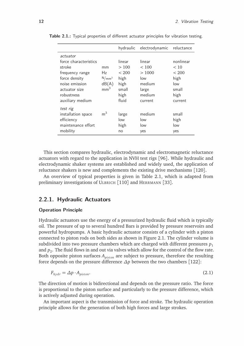
Table 2.1.: Typical properties of different actuator principles for vibration testing.
hydraulic electrodynamic reluctanceactuatorforce characteristics linear linear nonlinearstroke mm > 100 < 100 < 10frequency range Hz < 200 > 1000 < 200force density N/mm3 high low highnoise emission dB(A) high medium lowactuator size mm3 small large smallrobustness high medium highauxiliary medium fluid current currenttest riginstallation space m3 large medium smallefficiency low low highmaintenance effort high low lowmobility no yes yes
This section compares hydraulic, electrodynamic and electromagnetic reluctanceactuators with regard to the application in NVH test rigs [96]. While hydraulic andelectrodynamic shaker systems are established and widely used, the application ofreluctance shakers is new and complements the existing drive mechanisms [120].
An overview of typical properties is given in Table 2.1, which is adapted frompreliminary investigations of ULBRICH [110] and HERRMANN [33].
2.2.1. Hydraulic ActuatorsOperation Principle
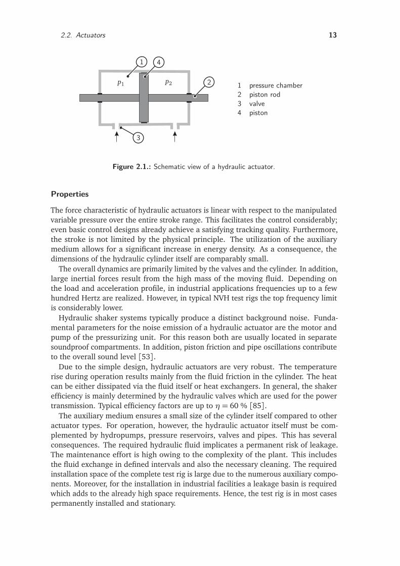
Hydraulic actuators use the energy of a pressurized hydraulic fluid which is typicallyoil. The pressure of up to several hundred Bars is provided by pressure reservoirs andpowerful hydropumps. A basic hydraulic actuator consists of a cylinder with a pistonconnected to piston rods on both sides as shown in Figure 2.1. The cylinder volume issubdivided into two pressure chambers which are charged with different pressures p1
and p2. The fluid flows in and out via valves which allow for the control of the flow rate.Both opposite piston surfaces Apiston are subject to pressure, therefore the resultingforce depends on the pressure difference ∆p between the two chambers [122]:
Fhydr =∆p · Apiston. (2.1)
The direction of motion is bidirectional and depends on the pressure ratio. The forceis proportional to the piston surface and particularly to the pressure difference, whichis actively adjusted during operation.
An important aspect is the transmission of force and stroke. The hydraulic operationprinciple allows for the generation of both high forces and large strokes.
2.2. Actuators 13
p1 p2
1
2
3
4
1 pressure chamber2 piston rod3 valve4 piston
Figure 2.1.: Schematic view of a hydraulic actuator.
Properties
The force characteristic of hydraulic actuators is linear with respect to the manipulatedvariable pressure over the entire stroke range. This facilitates the control considerably;even basic control designs already achieve a satisfying tracking quality. Furthermore,the stroke is not limited by the physical principle. The utilization of the auxiliarymedium allows for a significant increase in energy density. As a consequence, thedimensions of the hydraulic cylinder itself are comparably small.
The overall dynamics are primarily limited by the valves and the cylinder. In addition,large inertial forces result from the high mass of the moving fluid. Depending onthe load and acceleration profile, in industrial applications frequencies up to a fewhundred Hertz are realized. However, in typical NVH test rigs the top frequency limitis considerably lower.
Hydraulic shaker systems typically produce a distinct background noise. Funda-mental parameters for the noise emission of a hydraulic actuator are the motor andpump of the pressurizing unit. For this reason both are usually located in separatesoundproof compartments. In addition, piston friction and pipe oscillations contributeto the overall sound level [53].
Due to the simple design, hydraulic actuators are very robust. The temperaturerise during operation results mainly from the fluid friction in the cylinder. The heatcan be either dissipated via the fluid itself or heat exchangers. In general, the shakerefficiency is mainly determined by the hydraulic valves which are used for the powertransmission. Typical efficiency factors are up to η= 60 % [85].
The auxiliary medium ensures a small size of the cylinder itself compared to otheractuator types. For operation, however, the hydraulic actuator itself must be com-plemented by hydropumps, pressure reservoirs, valves and pipes. This has severalconsequences. The required hydraulic fluid implicates a permanent risk of leakage.The maintenance effort is high owing to the complexity of the plant. This includesthe fluid exchange in defined intervals and also the necessary cleaning. The requiredinstallation space of the complete test rig is large due to the numerous auxiliary compo-nents. Moreover, for the installation in industrial facilities a leakage basin is requiredwhich adds to the already high space requirements. Hence, the test rig is in most casespermanently installed and stationary.
14 2. Vibration Testing
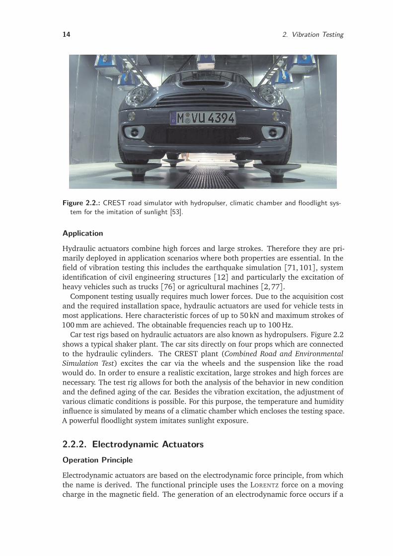
Figure 2.2.: CREST road simulator with hydropulser, climatic chamber and floodlight sys-tem for the imitation of sunlight [53].
Application
Hydraulic actuators combine high forces and large strokes. Therefore they are pri-marily deployed in application scenarios where both properties are essential. In thefield of vibration testing this includes the earthquake simulation [71, 101], systemidentification of civil engineering structures [12] and particularly the excitation ofheavy vehicles such as trucks [76] or agricultural machines [2,77].
Component testing usually requires much lower forces. Due to the acquisition costand the required installation space, hydraulic actuators are used for vehicle tests inmost applications. Here characteristic forces of up to 50 kN and maximum strokes of100 mm are achieved. The obtainable frequencies reach up to 100 Hz.
Car test rigs based on hydraulic actuators are also known as hydropulsers. Figure 2.2shows a typical shaker plant. The car sits directly on four props which are connectedto the hydraulic cylinders. The CREST plant (Combined Road and EnvironmentalSimulation Test) excites the car via the wheels and the suspension like the roadwould do. In order to ensure a realistic excitation, large strokes and high forces arenecessary. The test rig allows for both the analysis of the behavior in new conditionand the defined aging of the car. Besides the vibration excitation, the adjustment ofvarious climatic conditions is possible. For this purpose, the temperature and humidityinfluence is simulated by means of a climatic chamber which encloses the testing space.A powerful floodlight system imitates sunlight exposure.
2.2.2. Electrodynamic ActuatorsOperation Principle
Electrodynamic actuators are based on the electrodynamic force principle, from whichthe name is derived. The functional principle uses the LORENTZ force on a movingcharge in the magnetic field. The generation of an electrodynamic force occurs if a
2.2. Actuators 15
current carrying conductor is located in a quasi-stationary magnetic field [104]. Theresulting force for a conductor with an effective length l in a magnetic field withflux-density B for a given current i is given by
Fed = Bli = k f i. (2.2)
Here k f denotes the force constant which determines the achievable force per current.The calculation assumes the orthogonality of current direction and magnetic field.The electrodynamic force is proportional to the applied current, and an inversion ofthe force direction is achieved by current inversion. A detailed derivation from theelectromechanic stress tensor is given in Section 3.1.
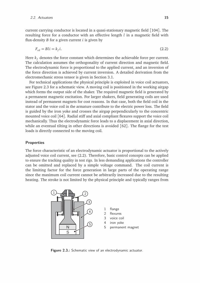
For technical applications the physical principle is exploited in voice coil actuators,see Figure 2.3 for a schematic view. A moving coil is positioned in the working airgapwhich forms the output side of the shaker. The required magnetic field is generated bya permanent magnetic excitation. For larger shakers, field generating coils are usedinstead of permanent magnets for cost reasons. In that case, both the field coil in thestator and the voice coil in the armature contribute to the electric power loss. The fieldis guided by the iron yoke and crosses the airgap perpendicularly to the concentricmounted voice coil [64]. Radial stiff and axial compliant flexures support the voice coilmechanically. Thus the electrodynamic force leads to a displacement in axial direction,while an eventual tilting in other directions is avoided [62]. The flange for the testloads is directly connected to the moving coil.
Properties
The force characteristic of an electrodynamic actuator is proportional to the activelyadjusted voice coil current, see (2.2). Therefore, basic control concepts can be appliedto ensure the tracking quality in test rigs. In less demanding applications the controllercan be omitted and replaced by a simple voltage command. The coil current isthe limiting factor for the force generation in large parts of the operating rangesince the maximum coil current cannot be arbitrarily increased due to the resultingheating. The stroke is not limited by the physical principle and typically ranges from
N
S
1 2
3
4
5
1 flange2 flexures3 voice coil4 iron yoke5 permanent magnet
Figure 2.3.: Schematic view of an electrodynamic actuator.
16 2. Vibration Testing
a few millimeters up to 100 mm in long stroke versions. Due to the good scalability,electrodynamic shakers are available in numerous size and power classes.
The most prominent feature of electrodynamic shakers is the large frequency rangein which oscillations can be generated. Depending on the actuator size, differentfrequency ranges are given in the literature [59,85]. Typical frequency limits rangefrom approximately 30 kHz for small shakers to a maximum frequency of 5 kHz forlarger shakers. Since the armature is designed iron-less and consists basically only ofthe voice coil, the moving part is light-weight and enables high dynamic motions.
The actuator itself operates virtually noiseless. However, depending on its design therequired cooling system can produce a disturbing background noise. The comparativelylow force constant k f demands for considerably high coil currents in applications whichrequire high accelerations or the actuation of heavy loads. Depending on the shakersize and power class, either air cooling or water cooling systems are used. Thetemperature rise limits the feasible current and the force during permanent operation.The main problem during the operation is the heat discharge. If the masking noise ofactive cooling systems is not acceptable for the respective application, passive coolingmust be used. In that case restrictions apply to the maximum duty cycle of the shaker.
In order to ensure the energy supply, a current lead to the moving voice coil isrequired. This is a major design drawback with respect to the robustness of theactuator, because the electrical connection must withstand the vibration.
The main parameters which determine the overall size of an electrodynamic actuatorresult from the equation for the LORENTZ force. Besides the variable current and thegiven magnetic field density, the LORENTZ force depends mainly on the active length ofthe coil. A larger coil diameter and higher winding number increase the active wirelength and consequently the resulting force. The physical dimensions of the coil bodylargely determine the overall actuator size. Since only electrical power is converted,no additional auxiliary medium is required. Consequently, regular time consumingmaintenance can be avoided and the operational readiness of the system is high.
The required high coil currents produce a significant winding loss. In addition, thelosses in the cooling system and the power amplifier deteriorate the overall efficiencyof the test rig [63]. Generally electrodynamic shaker systems are mobile. However, itshould be noted that the shaker and the power amplifier used for typical car test rigsrequire a considerable amount of installation space.
Application
Electrodynamic shakers are widespread in the field of vibration excitation. The existingperformance classes range from very small shakers for high frequency applications, asfor example in modal analyses, to large shakers with a force vector of several kN forcar test rigs.
Important applications in the field of automotive engineering are the artificial agingand NVH testing of components [27,81,82]. The required force in these applicationsis comparatively low due to the moderate weight of typical components, which have tobe actuated as loads. However, depending on the particular application, the thermalload makes a cooling system for the shaker necessary. If the shaker and test objectare not spatially separated by constructive measures, the cooling system adds to the
2.2. Actuators 17
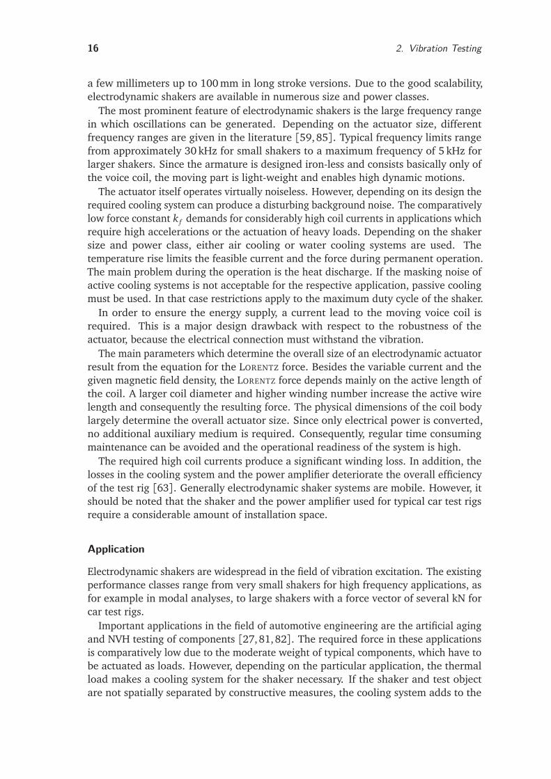
Figure 2.4.: Vibration test rig with electrodynamic actuators [53].
background noise in the testing area. Particularly for noise-sensitive NVH testingapplications, the operating noise masks the test object noise and therefore affects thedetection of the real disturbing noise in examination. The problem can be remediedby a passive noise insulation although this measure involves considerable effort.Alternatively the test must be interrupted for cooling periods. However, this disturbsthe test sequence and increases the overall testing time considerably.
Large electrodynamic shakers are also used in car test rigs [10,44], where the vehicleis usually excited via the jacking points. Other test rig concepts use the excitationvia wheels or directly via the wheel hubs. Figure 2.4 shows a test rig based onelectrodynamic actuators. In the picture only two of the overall four actuators arevisible. The car sits on the wheels; this way the assembly avoids the static loading ofthe shaker system. The shakers are positioned adjacent to the vehicle. The connectionto the test object is achieved via a simple lever construction, which enables a forcetransformation. The shaker itself is mounted in a top-down configuration, therebyrealizing the required height compensation to the jacking point level. The holdingframe is designed as a massive steel construction considering the high actuationforces and the weight of the actuators. Despite the considerable actuator size, theoverall setup is significantly smaller compared to the hydraulic test rig described above.Therefore, mobile test rigs can be generally realized. However, for the operation largepower amplifiers are necessary. These often require more installation space than theactual shakers and must be considered in the conceptual design of test rigs.
18 2. Vibration Testing
2.2.3. Magnetic Reluctance ActuatorsOperation Principle
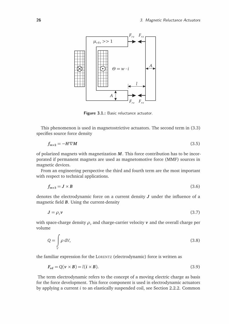
In contrast to electrodynamic actuators, which use the LORENTZ force on current-carrying conductors, electromagnetic reluctance actuators are based on reluctanceforces (Maxwell forces). These occur at the boundary surfaces of materials with differ-ent magnetic permeability, which are subject to a magnetic field. Classic applications ofreluctance forces include small clamping magnets in the household or the widespreadsolenoids in industrial automation. If the magnetic voltage drop in the iron parts ofthe actuator is neglected, the reluctance force is given by
Frel =B2AFe
2µ0(2.3)
where AFe denotes the iron surface penetrated perpendicularly by the magnetic fluxdensity B. The force is always attractive, since the system aims at the minimization ofthe working airgap (energy minimum). A further discussion of the force generationwith regard to the design of magnetic actuators is given in Section 3.1. In the following,the characteristics of electromagnetic reluctance actuators for vibration excitation arereviewed.
Properties
The reluctance force is nonlinear with respect to the air gap length and the appliedcoil current due to nonlinear material characteristics. Consequently, in most casessimple control methods (e.g. proportional-integral-derivative controllers, PID) arenot sufficient to ensure a good tracking quality of given reference profiles. Since onlyattractive forces can be generated, the armature restoring force must be provided bysprings or alternatively by adding a second magnetic actuator with opposite direction.The force generation depends on the inverse square of the airgap length; therefore theachievable stroke in practical applications is restricted, which is a major disadvantageof reluctance actuators. However, for the specific case of NVH testing the stroke limitis not relevant as shown in Section 4.2. The obtainable force can be enhanced byincreasing the armature surface or the magnetic field density. Actuators with highforce densities and small strokes are realizable, which facilitates the design of verycompact shakers. This advantage becomes particularly apparent in comparison toelectrodynamic shakers.
The dynamics of reluctance actuators depend mainly on the inductivity of the mag-netic circuit and the applied driving method. A high dynamic force generation dependson a fast variation of the magnetic field. Eddy currents in the flux-guiding iron partsinfluence the actuator dynamics considerably. Therefore, suitable countermeasuressuch as the use of laminations or slotted parts are essential for the design of highperformance shakers. The moving armature consists in large parts of flux-guidingiron as well. Although the achievable bandwidth (typ. 150 Hz) is lowered by theassociated weight, the impact is less significant when actuating heavy objects such ascars. The overall dynamics and the maximum actuating frequencies are clearly lower
2.3. Vibration Test Rigs 19
in comparison to electrodynamic actuators. However, the achievable frequency rangeof reluctance shakers is well suited for automotive NVH testing.
A suitable thermal design of the coil systems avoids the need for an active coolingsystem, while the overall actuator dimension can be still kept small due to the highforce density. For the operation small coil currents (up to 8 A) are necessary. Thereluctance shakers developed in this thesis feature a power consumption of 640 W fora quasi-static peak force of 8 kN. The exclusive passive cooling enables the applicationin noise-sensitive NVH testing scenarios without further effort for noise insulation.However, a sealing of the casing against dirt and moisture can cause a problematictemperature rise, since the air circulation is suppressed.
As in the case of rotating reluctance motors (switched reluctance machines, SRM), asimple and robust design is realizable. In particular, the moving armature consists ofiron only and carries no windings. Since the field-producing coils are located in thestationary core, the power connection is stationary.
The high force density and the low power consumption allow for the design of verycompact vibration test rigs. Installation space for hydropumps and leakage preventionmeasures as in the case of hydraulic test rigs are not required. The compact reluctanceactuators also fit into existing test structures. In contrast to electrodynamic shakers,no large fixation frames are necessary due to the low weight (65 kg). This facilitatesthe design of multiaxis vibration test rigs considerably. An integration of power andcontrol electronics makes the realization of mobile shakers possible. Due to the lowwear, maintenance cycles are long and mainly determined by the fatigue strength ofthe armature springs.
2.3. Vibration Test RigsThe test rigs, which are described in this section, evolved from a close cooperationbetween academic research, test rig manufacturers and end users. Preliminary designconsiderations resulted in first component test rigs with reluctance force actuatorsin an academic laboratory environment [33]. The collaboration with developmentdepartments of a car manufacturer1 enabled the incorporation of practical testingdemands and the application of developed shaker prototypes in an industrial environ-ment. The mechanical construction, the design of the control hardware and softwareand the assembly of the different test rigs have been carried out by professional testrig manufacturers 2. As a result of this fruitful cooperation, different component andcar test rigs were realized for industrial purposes.
2.3.1. ComponentsThe analysis of components is carried out on component test rigs, where the focus lieson rattling sounds. Typical automotive test objects include glove compartments andinstrument panels. In addition, larger modules such as complete doors and seats areanalyzed. The test procedure is usually structured in three steps [53]:
1 BMW AG2 AKE-TECHNOLOGIES GMBH, MAHA-AIP GMBH & CO. KG, KE KNESTEL ELEKTRONIK GMBH
20 2. Vibration Testing
1. NVH analysis of the component in original condition (one-dimensional excitationdirection, usually vertical)
2. artificial aging by defined vibration excitation (three-dimensional, usually se-quential)
3. further NVH analysis of the component in the artificially aged condition (one-dimensional excitation direction, usually vertical).
Additionally, environmental influences on the noise and aging characteristic of acomponent can be investigated using climatic chambers.
Figure 2.5 shows different component test rigs based on magnetic reluctance ac-tuators. The basic setup is similar for each test rig. The shaker is flanged to a steelbase plate and drives the test rig frame via a coupling rod. The frame itself must beboth rigid in order to avoid additional unwanted oscillations and light-weight since itsown weight adds to the accelerated mass. The frame sits on air bellows which inhibitunwanted tilting movements and carry the static weight. In neutral position the shakerexperiences no load. Therefore, a temperature rise due to stationary coil currents isavoided. Aluminum profiles enable the fast mounting of different specimen. Due tothe small size, the actuator can be directly positioned below the test rig frame allowingfor a low overall height.
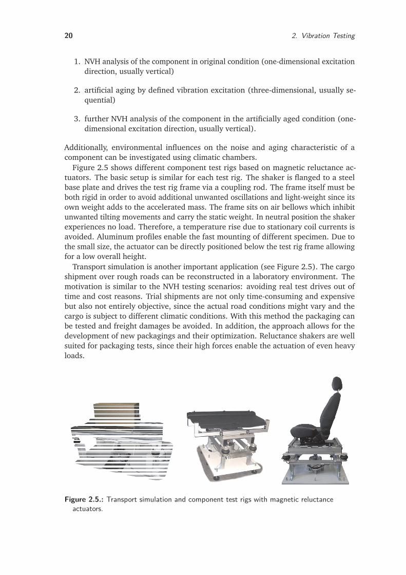
Transport simulation is another important application (see Figure 2.5). The cargoshipment over rough roads can be reconstructed in a laboratory environment. Themotivation is similar to the NVH testing scenarios: avoiding real test drives out oftime and cost reasons. Trial shipments are not only time-consuming and expensivebut also not entirely objective, since the actual road conditions might vary and thecargo is subject to different climatic conditions. With this method the packaging canbe tested and freight damages be avoided. In addition, the approach allows for thedevelopment of new packagings and their optimization. Reluctance shakers are wellsuited for packaging tests, since their high forces enable the actuation of even heavyloads.
Figure 2.5.: Transport simulation and component test rigs with magnetic reluctanceactuators.
2.3. Vibration Test Rigs 21
2.3.2. CarsThe analysis of components for disturbing noise is fundamental for the developmentof cars with a high quality appearance. Nonetheless, component testing alone doesnot ensure the NVH quality of the overall product, since a typical vehicle consists ofthousands of components and the assembly introduces numerous additional sources ofdisturbing noise. Therefore, car test rigs are used for testing the entire vehicle.
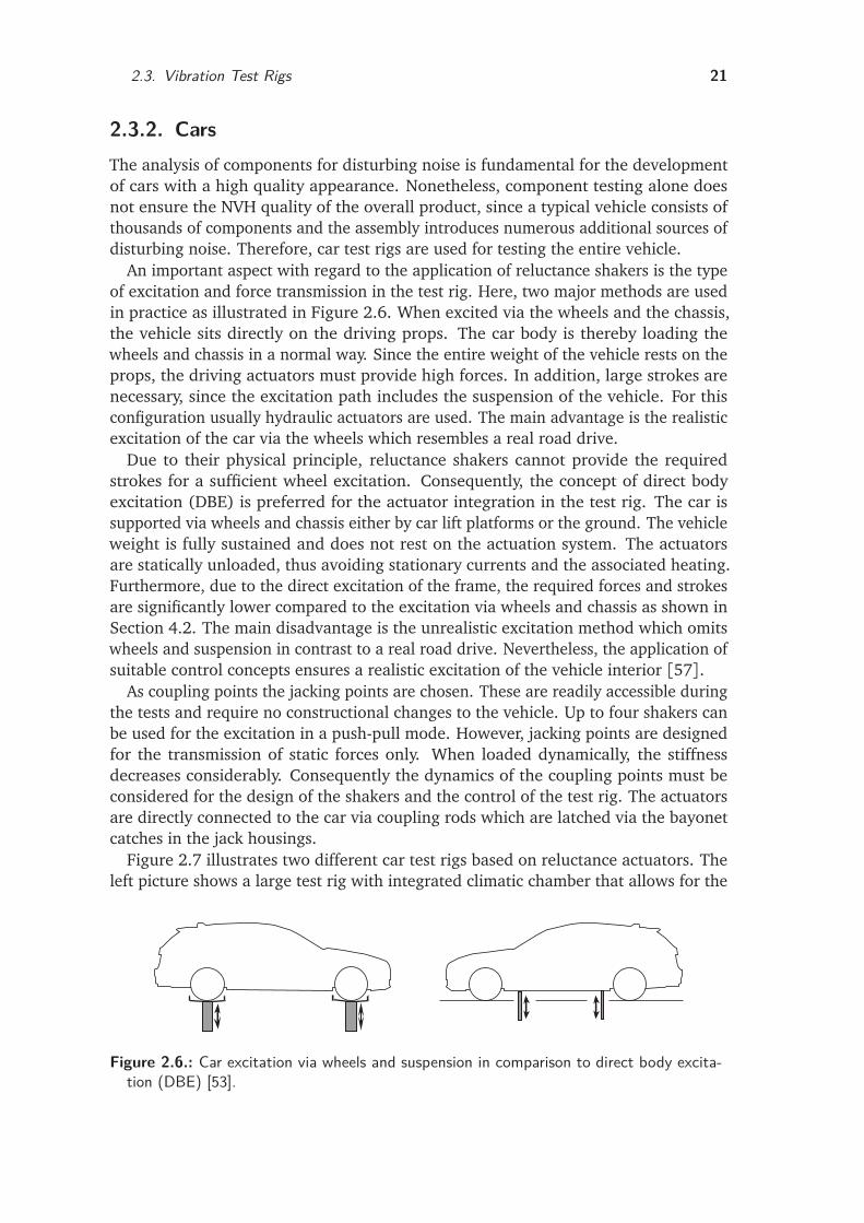
An important aspect with regard to the application of reluctance shakers is the typeof excitation and force transmission in the test rig. Here, two major methods are usedin practice as illustrated in Figure 2.6. When excited via the wheels and the chassis,the vehicle sits directly on the driving props. The car body is thereby loading thewheels and chassis in a normal way. Since the entire weight of the vehicle rests on theprops, the driving actuators must provide high forces. In addition, large strokes arenecessary, since the excitation path includes the suspension of the vehicle. For thisconfiguration usually hydraulic actuators are used. The main advantage is the realisticexcitation of the car via the wheels which resembles a real road drive.
Due to their physical principle, reluctance shakers cannot provide the requiredstrokes for a sufficient wheel excitation. Consequently, the concept of direct bodyexcitation (DBE) is preferred for the actuator integration in the test rig. The car issupported via wheels and chassis either by car lift platforms or the ground. The vehicleweight is fully sustained and does not rest on the actuation system. The actuatorsare statically unloaded, thus avoiding stationary currents and the associated heating.Furthermore, due to the direct excitation of the frame, the required forces and strokesare significantly lower compared to the excitation via wheels and chassis as shown inSection 4.2. The main disadvantage is the unrealistic excitation method which omitswheels and suspension in contrast to a real road drive. Nevertheless, the application ofsuitable control concepts ensures a realistic excitation of the vehicle interior [57].
As coupling points the jacking points are chosen. These are readily accessible duringthe tests and require no constructional changes to the vehicle. Up to four shakers canbe used for the excitation in a push-pull mode. However, jacking points are designedfor the transmission of static forces only. When loaded dynamically, the stiffnessdecreases considerably. Consequently the dynamics of the coupling points must beconsidered for the design of the shakers and the control of the test rig. The actuatorsare directly connected to the car via coupling rods which are latched via the bayonetcatches in the jack housings.
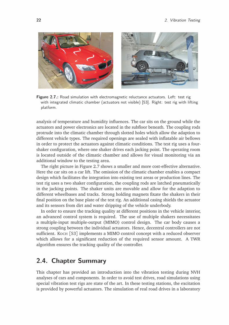
Figure 2.7 illustrates two different car test rigs based on reluctance actuators. Theleft picture shows a large test rig with integrated climatic chamber that allows for the
Figure 2.6.: Car excitation via wheels and suspension in comparison to direct body excita-tion (DBE) [53].
22 2. Vibration Testing
Figure 2.7.: Road simulation with electromagnetic reluctance actuators. Left: test rigwith integrated climatic chamber (actuators not visible) [53]. Right: test rig with liftingplatform.
analysis of temperature and humidity influences. The car sits on the ground while theactuators and power electronics are located in the subfloor beneath. The coupling rodsprotrude into the climatic chamber through slotted holes which allow the adaption todifferent vehicle types. The required openings are sealed with inflatable air bellowsin order to protect the actuators against climatic conditions. The test rig uses a four-shaker configuration, where one shaker drives each jacking point. The operating roomis located outside of the climatic chamber and allows for visual monitoring via anadditional window to the testing area.
The right picture in Figure 2.7 shows a smaller and more cost-effective alternative.Here the car sits on a car lift. The omission of the climatic chamber enables a compactdesign which facilitates the integration into existing test areas or production lines. Thetest rig uses a two shaker configuration, the coupling rods are latched pneumaticallyin the jacking points. The shaker units are movable and allow for the adaption todifferent wheelbases and tracks. Strong holding magnets fixate the shakers in theirfinal position on the base plate of the test rig. An additional casing shields the actuatorand its sensors from dirt and water dripping of the vehicle underbody.
In order to ensure the tracking quality at different positions in the vehicle interior,an advanced control system is required. The use of multiple shakers necessitatesa multiple-input multiple-output (MIMO) control design. The car body causes astrong coupling between the individual actuators. Hence, decentral controllers are notsufficient. KOCH [53] implements a MIMO control concept with a reduced observerwhich allows for a significant reduction of the required sensor amount. A TWRalgorithm ensures the tracking quality of the controller.
2.4. Chapter SummaryThis chapter has provided an introduction into the vibration testing during NVHanalyses of cars and components. In order to avoid test drives, road simulations usingspecial vibration test rigs are state of the art. In these testing stations, the excitationis provided by powerful actuators. The simulation of real road drives in a laboratory
2.4. Chapter Summary 23
environment enables significant improvements of the noise examination. A comparisonof hydraulic, electrodynamic and electromagnetic drives is given and illustrates theapplication potential of magnetic reluctance shakers. The reluctance force principlecomplements the existing actuation concepts and fulfills the demand for compactactuators for vibration excitation.
Key features for the application of actuators in vibration test rigs are the avoidanceof active cooling systems and the risk of leakage. In addition, the required installationspace and the maintenance effort should be low. Reluctance force actuators fit intothat niche of requirements, exhibiting a high force density and robustness. The energysupply is electric current, which is easily available in industrial environments.
An overview of test rig concepts for the vibration excitation of components andvehicles finalizes the chapter, providing the basis for the specific design of magneticreluctance shakers in the following. The main drawback of reluctance actuators for theapplication as shakers is the stroke limitation due to the physical concept. By choosingan appropriate excitation method, this limitation can be compensated. The directbody excitation (DBE) of vehicles via the frame instead of the wheels and suspensionenables a sufficient excitation of test objects with comparatively small strokes. Thusthe application of magnetic reluctance actuators provides an alternative to hydraulicor electrodynamic test rig solutions.

3. Magnetic Reluctance Actuators
The knowledge required for the design and development of magnetic reluctanceactuators is extensive and comes from all fields of mechatronics. This chapter brieflyreviews the fundamental principles of magnetic force generation with a special focuson reluctance forces. Moreover, fast actuation requires a rapid change of the forcegenerating magnetic fields. In order to achieve high actuator dynamics the investigationof frequency-dependent phenomena is essential.
Power losses reduce the bandwidth and energy efficiency. For a better understanding,the main loss mechanisms in the windings and the iron parts due to eddy currents andhysteresis are illustrated. Here, solid and laminated cores are considered and the basisfor the design of high dynamic magnetic cores in Chapter 4 is established.
Furthermore, methods to model static and dynamic actuator properties are discussed.For this purpose, reluctance circuits are compared to the finite element analysis and areduced order model.
3.1. Magnetic ForcesBased on MAXWELL’s equations, the magnetic force fmv per unit volume can be ex-pressed as the divergence of an electromechanic stress tensor T of the electromagneticfield [100]. If the magnetic permeability µ depends on the material density ρ0 andonly magnetic fields are considered, the tensor is written as [70]
fmv =∇ · T (3.1)
T = µHH T − µ2
IHH
1− ρ0
µ
∂ µ
∂ ρ0
. (3.2)
Here H denotes the magnetic field strength and I the unit tensor. Expanding andrearranging finally yields the total force density fmv , which can be split up in fourdivergence and gradient terms [13,47]:
fmv = fmv1+ fmv2+ fmv3+ fmv4 =
=1
2∇ ·
H2ρ0
∂ µ
∂ ρ0
−H∇M + J × B− 1
2H2∇µ. (3.3)
The first term
fmv1 =1
2∇ ·
H2ρ0
∂ µ
∂ ρ0
(3.4)
describes the force caused by the density-dependent permeability µ(ρ0) of the materialin a magnetic field.
25
26 3. Magnetic Reluctance Actuators
aaaaaaaaaaaaaaaaaaaaaaaaaaaaaaaaaaaaaaaaaaaaaaaaaaaa
aaaaaaaaaaaaaaaaaaaaaaaaaaaaaaaaaaaaaaaaaaaaaaaaaaaa
Θ = w · i
µrFe >> 1
Fre Fre
FreFre
l
A
A
Figure 3.1.: Basic reluctance actuator.
This phenomenon is used in magnetostrictive actuators. The second term in (3.3)specifies source force density
fmv2 =−H∇M (3.5)
of polarized magnets with magnetization M . This force contribution has to be incor-porated if permanent magnets are used as magnetomotive force (MMF) sources inmagnetic devices.
From an engineering perspective the third and fourth term are the most importantwith respect to technical applications.
fmv3 = J × B (3.6)
denotes the electrodynamic force on a current density J under the influence of amagnetic field B. Using the current-density
J = ρsv (3.7)
with space-charge density ρs and charge-carrier velocity v and the overall charge pervolume
Q =
∫
V
ρ dV, (3.8)
the familiar expression for the LORENTZ (electrodynamic) force is written as
Fed =Q(v × B) = l(i × B). (3.9)
The term electrodynamic refers to the concept of a moving electric charge as basisfor the force development. This force component is used in electrodynamic actuatorsby applying a current i to an elastically suspended coil, see Section 2.2.2. Common
3.1. Magnetic Forces 27
applications include rotating motors and generators. Important applications in thelinear case are linear drives and voice coil actuators. In the field of vibration excitationLORENTZ forces are widely used in electrodynamic shakers.
Key advantages of voice coil actuators are reversible forces and a linear behaviorwith respect to magnetic induction and to the driving current i in particular. Further-more, they allow for large strokes since there is no direct dependency between thedisplacement of the coil and the created forces.
The core principle of the magnetic reluctance actuators considered in this thesis isspecified by the fourth term
fmv4 =−1
2H2∇µ (3.10)
which describes the magnetic force due to a change in permeability ∇µ. For twomaterials with different permeability the resulting reluctance force is calculated as
fma =1
2(µ2−µ1)(H
2t1+
µ1
µ2H2
n1) · n. (3.11)
Here fma is a surface force density with n being the normal vector to the surface. Theforce vector fma is directed from the material with higher permeability (µ2) to thematerial with lower permeability (µ1) to reduce energy in the system [61].
The most common case of technical applications is the boundary between iron(µ2 = µrµ0) and air (µ1 = µ0), which can be written as
fma =µr − 1
2µrµ0(B2
n +µr B2t ) · n (3.12)
with Bn and Bt as the normal and tangential components of the magnetic field onthe air side of the boundary. µ0 denotes the vacuum permeability and µr the relativepermeability of the material. In magnetic actuators the working airgaps are usuallyrather small so that the magnetic field passes perpendicularly through the relevantarmature surfaces and the tangential component Bt can be neglected. In order to yielda high energy efficiency and small setup, materials with high permeability µr >> 1are used for the magnetic circuit, which leads to the following simplification
fma =1
2µ0· B2. (3.13)
Finally the reluctance force
Frel = fma · A=B2A
2µ0=
Φ2
2µ0A(3.14)
is obtained from the force density fma. Here A denotes the pole surface area and Φ themagnetic flux.
In the case of a simple reluctance actuator as shown in Figure 3.1, a magnetomotiveforce MMF Θ = w · i is produced in a winding of w turns by a current i. Together with
28 3. Magnetic Reluctance Actuators
the airgap length l the reluctance force Frel is then given by
Frel =1
2µ0A
Θ2
l2 . (3.15)
In contrast to electrodynamic forces, reluctance forces are attractive only and alwaysreduce the effective airgap. Therefore, the force is nonreversible. Besides, the maxi-mum stroke is limited due to the reciprocal dependency on l2. Additionally, reluctanceactuators exhibit an inherent nonlinearity with respect to MMF Θ and particularly tothe airgap l, which makes modeling and control more difficult. However, high forcescan be achieved by increasing the iron surface A. Typical applications include all kindof solenoids, as well as proportional, lifting and switching actuators (relays). Rotat-ing electrical drives based on the reluctance principle are called switched reluctancemachines.
3.2. Magnetic Induction
According to the axioms of classical electrodynamics a time-varying flux involves a curlof the electric field E. FARADAY’s law of induction states that the electromotive force(EMF) is proportional to the rate of magnetic flux change [39]. The voltage induced ina single conductor loop is given by the flux variation
ui =
∮
ls
E dl =−dΦ
d t. (3.16)
The voltage is induced regardless of the source of flux variation [61]. For technicalsystems with several relevant coil windings, the flux linkage
Ψ = w · i (3.17)
as a product of winding number w and coil current i is introduced. The equation for asimple coil with resistance R excited by voltage u is given by
u= R · i+ dΨ
d t. (3.18)
There are two feasible scenarios for voltage induction. First, a flux change mightbe caused by an additional coil (mutual inductance) or permanent magnet (externalinductance). Second, a flux change can be provoked by the coil itself (self-inductance).In reluctance actuators the flux linkage is a nonlinear function of armature position xand coil current i [47], which yields
u= R · i+ d
d t(Ψ(x , i)) (3.19)
3.3. Power Losses 29
u= R · i+
dΨ(x , i)d x
· d x
d t︸ ︷︷ ︸
ui x
+dΨ(x , i)
d i· d i
d t︸ ︷︷ ︸
uii
. (3.20)
The two terms express the major induction sources that contribute to voltage genera-tion. Flux change and induced voltage uii are the result of current variation in the coil.But also during the resulting armature motion a flux variation is caused inducing ui x .
If the position-dependency is neglected dΨ/d x = 0 and a linear relation between fluxand current assumed dΨ/di = const.= L0, (3.20) can be simplified to
u= R · i+ L0
d i
d t. (3.21)
Here L0 denotes the self-inductance of the coil. Hence the solution for coil current iyields
i(t) =u
R
1− e−tτ
(3.22)
with the coil time constant τ= L0/R. For the operating characteristics of high dynamicreluctance actuators the inductivity and associated time constant plays an essentialrole since it limits the current rise in the electric circuit and consequently the magneticforce development. The maximum source voltage, coil resistance and inductance aredetermined during the design process and have to be adjusted to the required actuatordynamic, see Section 4.7 and Section 4.8. The inductance depends on the geometricalshape, dimensions and permeability of the magnetic circuit [84]. It can be rewrittenas
L0 =w2
Rm. (3.23)
Here Rm denotes the reluctance of the magnetic circuit, see Section 3.4.1.
However, in the majority of cases the inductance determination is a challengingproblem because of the nonlinear dependency on position and current. Modernreluctance actuators feature large airgaps and magnetic circuits which are partlydriven into saturation in order to minimize the overall construction size. If nonlineareffects cannot be neglected, the magnetic analysis requires numeric approaches asshown in Chapter 5.
3.3. Power Losses
Power losses reduce the efficiency of actuators and lower the achievable bandwidth.This section describes different approaches to the calculation of winding, eddy currentand hysteresis loss in laminated and solid cores.
30 3. Magnetic Reluctance Actuators
3.3.1. Eddy CurrentsAccording to FARADAY’s law a time-varying magnetic field induces an electric voltage[39]. As a consequence, a circulating current flow occurs in electrically conductingmaterial exposed to the varying field. The term eddy originates from the flow patternswhich resemble eddies in turbulent liquids. According to LENZ’s law the magnetic fieldof the induced eddy currents counteracts the original excitation field as both fieldsinterfere. For rapid field changes a displacement of magnetic fields in surface directionoccurs, such that there is a field cancellation in the center of the core. This can be alsoseen as a delay in penetration of magnetization into the core.
For high dynamic magnetic actuators two main consequences arise from eddy currentinfluence. First, the skin effect causes a delayed magnetic force development due tothe deferred field development and hence limits the available bandwidth. Apart fromthat, only a part of total flux carrying volume can be effectively utilized. Therefore,the effective area in (3.14) is reduced. Second, the resulting current flow producesheat which dissipates energy from the magnetic field (eddy current loss).
Due to the undesired consequences, measures for eddy current restraint must betaken when designing fast magnetic actuators, see Section 4.5. The two major solutionsconsist in either laminating the flux-carrying parts of the magnetic circuit (cuttingthe conductive path along the induced voltage drop) or using materials with higherelectric resistivity. This leads to a faster flux penetration and full usage of iron [3].
Laminated Core
Since laminated steel restricts the flow pattern of eddy currents to the volume of onesheet, the associated loss is not completely eliminated but significantly reduced [9].For skin depths (see Section 3.3.2) smaller than lamination thickness t, the power losscaused by eddy currents obeys to
Pe =π2
6t2 f 2B2σV. (3.24)
Here Pe denotes the eddy current loss, f the operating frequency, σ the electricalconductivity and V the volume of the flux-guiding material. The order of the variousterms in (3.24) is essential since it determines the influence on the total power loss.Lamination thickness, frequency and flux density contribute with the square whereasthe loss is only proportional to the material’s conductivity. Thus, the reduction of thelamination thickness is an effective measure for eddy current attenuation.
Solid Core
For solid cores (3.24) does not hold anymore. [91] provides a convenient approx-imation for cylindrical solid cores which are frequently used in rotation-symmetricactuators. The model is based on the assumption that hysteresis loops of the materialcan be approximated by equivalent ellipses. The semi-cutoff frequency
fsc =2
πr2c µσ
(3.25)
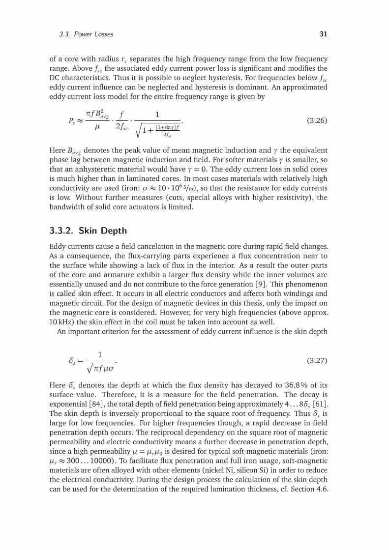
3.3. Power Losses 31
of a core with radius rc separates the high frequency range from the low frequencyrange. Above fsc the associated eddy current power loss is significant and modifies theDC characteristics. Thus it is possible to neglect hysteresis. For frequencies below fsc
eddy current influence can be neglected and hysteresis is dominant. An approximatededdy current loss model for the entire frequency range is given by
Pe ≈π f B2
avg
µ· f
2 fsc· 1q
1+ (1+sinγ) f2 fsc
. (3.26)
Here Bavg denotes the peak value of mean magnetic induction and γ the equivalentphase lag between magnetic induction and field. For softer materials γ is smaller, sothat an anhysteretic material would have γ= 0. The eddy current loss in solid coresis much higher than in laminated cores. In most cases materials with relatively highconductivity are used (iron: σ ≈ 10 · 106 S/m), so that the resistance for eddy currentsis low. Without further measures (cuts, special alloys with higher resistivity), thebandwidth of solid core actuators is limited.
3.3.2. Skin DepthEddy currents cause a field cancelation in the magnetic core during rapid field changes.As a consequence, the flux-carrying parts experience a flux concentration near tothe surface while showing a lack of flux in the interior. As a result the outer partsof the core and armature exhibit a larger flux density while the inner volumes areessentially unused and do not contribute to the force generation [9]. This phenomenonis called skin effect. It occurs in all electric conductors and affects both windings andmagnetic circuit. For the design of magnetic devices in this thesis, only the impact onthe magnetic core is considered. However, for very high frequencies (above approx.10 kHz) the skin effect in the coil must be taken into account as well.
An important criterion for the assessment of eddy current influence is the skin depth
δs =1
p
π f µσ. (3.27)
Here δs denotes the depth at which the flux density has decayed to 36.8% of itssurface value. Therefore, it is a measure for the field penetration. The decay isexponential [84], the total depth of field penetration being approximately 4 . . . 8δs [61].The skin depth is inversely proportional to the square root of frequency. Thus δs islarge for low frequencies. For higher frequencies though, a rapid decrease in fieldpenetration depth occurs. The reciprocal dependency on the square root of magneticpermeability and electric conductivity means a further decrease in penetration depth,since a high permeability µ = µrµ0 is desired for typical soft-magnetic materials (iron:µr ≈ 300 . . . 10000). To facilitate flux penetration and full iron usage, soft-magneticmaterials are often alloyed with other elements (nickel Ni, silicon Si) in order to reducethe electrical conductivity. During the design process the calculation of the skin depthcan be used for the determination of the required lamination thickness, cf. Section 4.6.
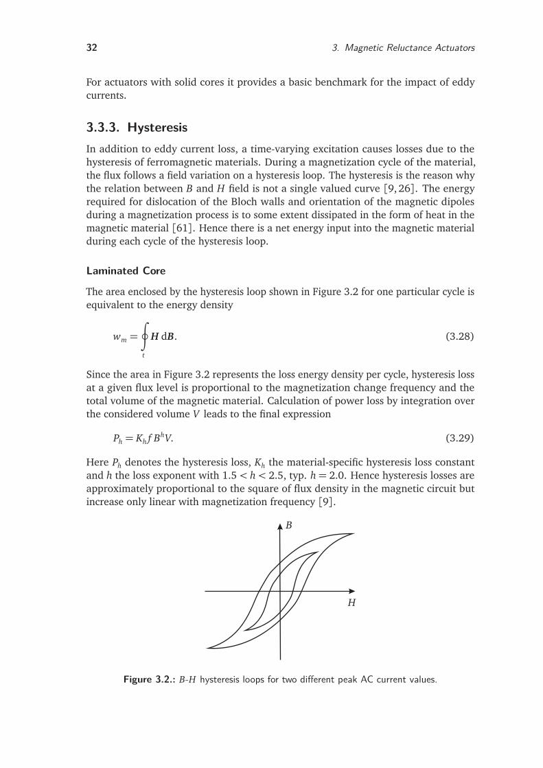
32 3. Magnetic Reluctance Actuators
For actuators with solid cores it provides a basic benchmark for the impact of eddycurrents.
3.3.3. HysteresisIn addition to eddy current loss, a time-varying excitation causes losses due to thehysteresis of ferromagnetic materials. During a magnetization cycle of the material,the flux follows a field variation on a hysteresis loop. The hysteresis is the reason whythe relation between B and H field is not a single valued curve [9, 26]. The energyrequired for dislocation of the Bloch walls and orientation of the magnetic dipolesduring a magnetization process is to some extent dissipated in the form of heat in themagnetic material [61]. Hence there is a net energy input into the magnetic materialduring each cycle of the hysteresis loop.
Laminated Core
The area enclosed by the hysteresis loop shown in Figure 3.2 for one particular cycle isequivalent to the energy density
wm =
∮
t
H dB. (3.28)
Since the area in Figure 3.2 represents the loss energy density per cycle, hysteresis lossat a given flux level is proportional to the magnetization change frequency and thetotal volume of the magnetic material. Calculation of power loss by integration overthe considered volume V leads to the final expression
Ph = Kh f BhV. (3.29)
Here Ph denotes the hysteresis loss, Kh the material-specific hysteresis loss constantand h the loss exponent with 1.5< h< 2.5, typ. h= 2.0. Hence hysteresis losses areapproximately proportional to the square of flux density in the magnetic circuit butincrease only linear with magnetization frequency [9].
H
B
Figure 3.2.: B-H hysteresis loops for two different peak AC current values.
3.4. Modeling Methods 33
Solid Core
In [91] an approximation for the hysteresis losses in a solid cylindrical core is given as
Ph ≈π f sinγB2
avg
µ·È
1+f
2(1+ sinγ) fsc. (3.30)
Including several simplifications, the model is straightforward and requires only easilyaccessible material parameters. It is useful when designing a solid magnetic core orassessing the hysteresis influence on existing actuators. For higher frequencies theeddy current loss dominates and the hysteresis loss is usually neglected.
3.3.4. Coil Windings
Besides the losses in the core of reluctance actuators, there is an additional undesiredsource of loss in the windings that are used for the excitation of the machine. Theassociated power is called winding loss or copper loss, where the latter term refersto the material often used in coil design. Basically, winding loss results from Jouleheating and is produced by the electrical currents in the winding of the actuator. Thepower loss Pw is obtained by modifying JOULE’s first law
Pw = i2R, (3.31)
where i denotes the current flowing in the winding and R the electrical resistance ofthe coil material. The power Pw is dissipated in form of heat in the winding. From atechnical point of view the design needs to avoid heat and be thermally safe. However,in some cases an adequate cooling is required additionally. The electrical loss in thewindings is proportional to the winding resistance and square of the winding current.Hence it is also called I2R loss. Since the resistive loss scales with the square of current,it will dominate the total actuator loss for slow armature movements and high forces.
Basically two strategies can be applied to decrease winding losses. The first wouldbe to use a lower winding current. However, this would have a significant impact onthe available magnetic force which increases with the square of i. The second approachconsists in using a lower winding resistance, achieved by a large cross-sectional areaof the wire and the use of low-resistivity conductors. A detailed discussion of this issuewith a focus on the practical application in actuator design is given in Section 4.8.
3.4. Modeling Methods
MAXWELL’s equations are fundamental for the calculation of magnetic fields. However,their analytical solution is not feasible for the majority of technically relevant magneticcircuits. This section reviews magnetic networks, FE analyses and a reduced orderapproach with respect to the design of reluctance shakers.
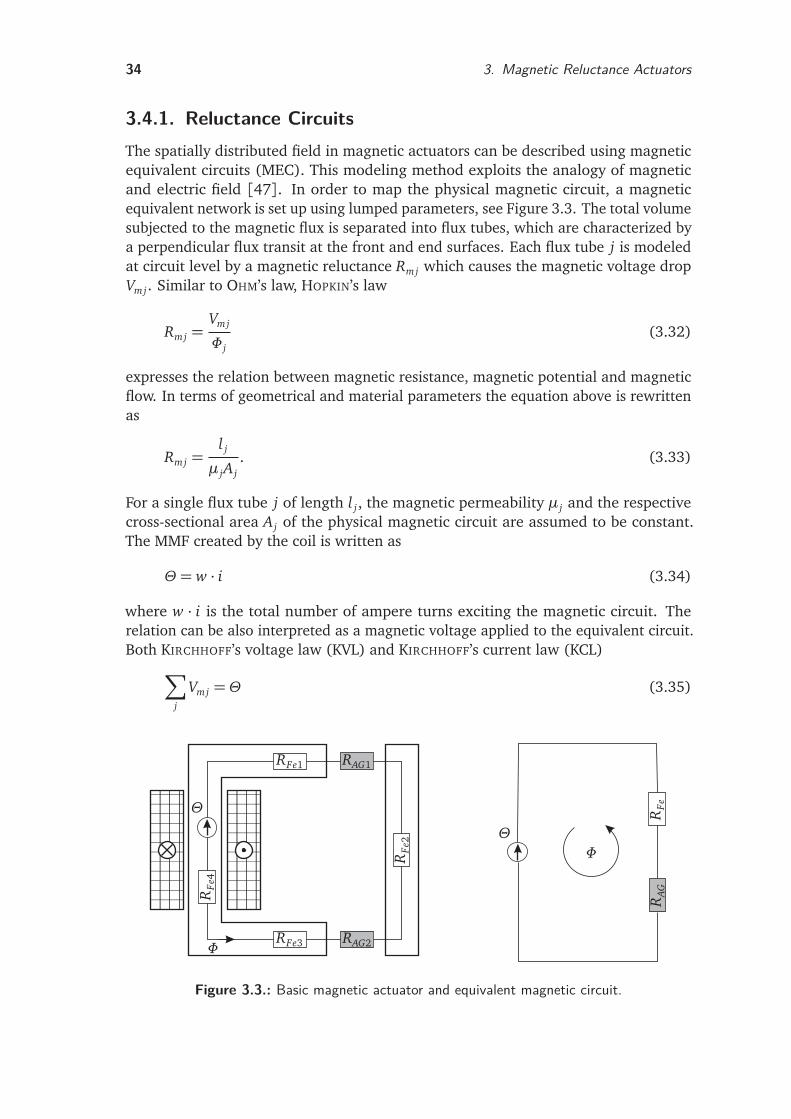
34 3. Magnetic Reluctance Actuators
3.4.1. Reluctance CircuitsThe spatially distributed field in magnetic actuators can be described using magneticequivalent circuits (MEC). This modeling method exploits the analogy of magneticand electric field [47]. In order to map the physical magnetic circuit, a magneticequivalent network is set up using lumped parameters, see Figure 3.3. The total volumesubjected to the magnetic flux is separated into flux tubes, which are characterized bya perpendicular flux transit at the front and end surfaces. Each flux tube j is modeledat circuit level by a magnetic reluctance Rmj which causes the magnetic voltage dropVmj. Similar to OHM’s law, HOPKIN’s law
Rmj =Vmj
Φ j(3.32)
expresses the relation between magnetic resistance, magnetic potential and magneticflow. In terms of geometrical and material parameters the equation above is rewrittenas
Rmj =l j
µ jA j. (3.33)
For a single flux tube j of length l j, the magnetic permeability µ j and the respectivecross-sectional area A j of the physical magnetic circuit are assumed to be constant.The MMF created by the coil is written as
Θ = w · i (3.34)
where w · i is the total number of ampere turns exciting the magnetic circuit. Therelation can be also interpreted as a magnetic voltage applied to the equivalent circuit.Both KIRCHHOFF’s voltage law (KVL) and KIRCHHOFF’s current law (KCL)
∑
j
Vmj = Θ (3.35)
aaaaaaaaaaaaaaaaaaaaaaaaaaaaaaaaaaaaaaaaaaaaaaaaaaaa
aaaaaaaaaaaaaaaaaaaaaaaaaaaaaaaaaaaaaaaaaaaaaaaaaaaa
Θ
Θ
RFe1 RAG1
RFe
2
RFe3
RFe
4
Φ
Φ
RFe
RAG
RAG2
Figure 3.3.: Basic magnetic actuator and equivalent magnetic circuit.
3.4. Modeling Methods 35
∑
k
Φk = 0 (3.36)
can be transferred to the magnetic case. An overview of the relation between electricand magnetic circuits with the most relevant parameters is given in Table 3.1.
An equivalent circuit for a permanent magnet consists of a magnetic voltage sourcemodeling the MMF ΘPM and the associated reluctance RPM . Both are a function of thematerial and geometrical parameters of the permanent magnet.
ΘPM = HcB · lPM (3.37)
RPM =HcB · lPM
Br · APM=
lPM
µPM · APM(3.38)
Here HcB denotes the coercivity, Br the remanence and µPM the magnetic permeability.The length is given by lPM and the cross-sectional area by APM . The typical modelingprocedure is characterized by the following steps:
1. Separation of the magnetic circuit into flux tubes with homogeneous field andconstant cross-sectional area.
2. Determination of the equivalent circuit.
3. Application of the circuit laws KCL and KVL.
4. Determination of the resulting equation system.
5. Calculation of the fluxes.
6. Calculation of flux-dependent parameters such as inductivity and force.
The main drawback of MEC is the mandatory knowledge of the main flux pathswhich are not always known in detail [9]. Hence the modeling relies on engineeringexperience and intuition [26]. Most real world devices have complicated designswith multiple flux paths that have to be modeled with serial and parallel reluctances.The complex determination of fringing flux makes the calculation of fringing factorsdifficult [15,24]. The same applies to the implementation of saturation by nonlinearB-H curves. Furthermore the consideration of core losses requires a workaround.
However, lumped parameter models with their low discretization result in a smallset of equations which can be solved analytically. The implementation in a system sim-ulator is straightforward with low computational cost. This allows for fast parameterstudies. Therefore, magnetic networks are useful as a first step in the design processfor the dimensioning of the magnetic circuit [34,118].
Table 3.1.: Comparison between electric and magnetic circuit theory [9, 47,92].
quantity electric equivalent unit magnetic equivalent unitflow current i A flux Φ Vspotential voltage drop u V MMF Vm Apotential/flow resistance R Ω reluctance R A/Vsconductivity conductivity σ S/m permeability µ Vs/Am
36 3. Magnetic Reluctance Actuators
3.4.2. Finite Element Analysis
To avoid the limitations of magnetic equivalent circuits, the finite element method(FEM) proves to be an important alternative. It is the most general and accuratemethod for the calculation of magnetic fields in technical devices [9]. The basicprinciple consists in the subdivision of the investigated problem region into smallsubdomains, called finite elements, which are connected via nodes to a grid. Forthe subproblems simple ansatz functions based on the vector potential are chosen.The global solution results from the superposition of all functions. Together with theboundary conditions of the problem an equation system is formulated and solved forthe unknown magnetic potentials in each element. For spatially large problems and ahigh discretization, very large equation systems result, which are solved numerically.
BRAUER [9] delivers a reasonable short sketch of the FEM concept for the solutionof linear magnetostatic problems. Point of departure is the assumption of energyconservation
Win =Wstored (3.39)
with Win as input energy and Wstored as stored energy. That way the analyzed regionexhibits no power loss. In reluctance actuators the energy is fed via the coils featur-ing the current density J , and is stored in the magnetic field. Integration over theconsidered volume yields the energy balance
1
2
∫
J · Adv =
∫
B2
2µdv (3.40)
with a constant µ. Now an energy functional is defined, in this case the differencebetween stored and input energy, which yields
F =Wstored −Win =
∫
B2
2µdv− 1
2
∫
J · Adv. (3.41)
According to the energy conservation law, the functional must be zero. However, thecondition is somewhat reduced and replaced by the minimization
∂ F
∂ A= 0. (3.42)
Inserting (3.41) and rearranging yields
∂
∂ A
∫
B2
2µdv =
∫
J dv. (3.43)
Now the problem region is discretized and a shape function based on the magneticvector potential is set up for each element. Here the equivalence between flux densityand the curl of the magnetic vector potential A
B =∇× A (3.44)
3.4. Modeling Methods 37
is used. Finally (3.43) is rewritten as an equation system
K · A= J (3.45)
which represents the discretized problem. Here K denotes the stiffness matrix, A theunknown vector potentials and J the known input current densities. In general, Kis a n× n matrix with number of nodes n. A high problem discretization results ina large number of nodes and the solution of the resulting equation system requiresconsiderable computation time.
Due to the relevance of the FE method for the design of magnetic devices, a largenumber of software packages is commercially available. The finite element analysis(FEA) is a three step procedure [47]. The first step is the preparation of the problem forthe solution (preprocessing). During this phase a high level of engineering knowledgeis required. The problem can be simplified by omitting nonrelevant details. Exploitationof geometrical symmetries further helps to reduce simulation time. The preprocessingphase is organized as follows [9]:
1. Geometry: specification of the magnetic circuit’s shape and dimensions.
2. Discretization: subdivision into finite elements.
3. Materials: specification of material parameters, in particular B-H curves fornonlinear magnetic materials.
4. Excitations: specification of input current sources or densities.
5. Boundary conditions: determination of flux conditions at the boundaries of themodel.
After the model preparation, the equation system is set up and consequently solved inthe second step. In the final analysis step the desired quantities such as flux distribution,force and inductivity are calculated (postprocessing).
In summary, the FEM allows for the consideration of complex actuator geometriesand phenomena such as fringing flux and nonlinear material [60]. In transientsimulations eddy current influence and even the mechanical armature motion causedby electromagnetic forces can be investigated. However, the analysis requires a veryhigh computational effort. Therefore, transient FE models are not suitable for fastsystem simulation and control design.
3.4.3. Reduced Order ModelAs discussed above, the main advantage of the MEC based approach is the compactanalytical model, which allows for a fast system simulation and control design. Fora detailed analysis of the magnetic circuit, a FE model is indispensable. ReducedOrder Modeling (ROM) combines the advantages of numerical computations with ananalytical model. The resulting mathematical description is suitable for implementationin a system simulator and allows for dynamic simulations. Furthermore, it can serve asa basis for control design. In the following a short outline of the modeling procedureis given. The application to magnetic reluctance actuators is described in Chapter 5.
38 3. Magnetic Reluctance Actuators
The method is based on the energy conservation principle and uses energy functionsas a physical principle for the system description. For the mathematical descriptionof electromagnetic energy conversion devices, the co-energy is particularly suitablesince relevant system parameters such as force and inductance can be derived from it.Furthermore, the co-energy values for the actuator can be calculated using standardFE software without major effort.
In a first step the discrete co-energy values for all relevant operating points arecalculated during the FE system analysis. Then an analytical expression is determinedby curve fitting. The relevant system parameters are obtained by derivation. The actualorder reduction results from the analytical approximation and leads to a significantlyreduced simulation time. The reduced model can be used for both transient systemsimulation and control design.
3.4.4. ComparisonDuring the work on this thesis all three described modeling methods were used. Thissection discusses relevant properties for the design of reluctance actuators. Amongthese are the suitability of the model for control design, the mapping of complexgeometries and the consideration of complex effects such as saturation or fringingflux. In addition the computation speed and feasibility of transient simulations arecompared. Table 3.2 gives an overview of the methods used for the actuator design.According to their suitability for different tasks, the methods are used in differentdesign phases.
A simple and straightforward MEC model of the actuator is set up in the first designphase for the dimensioning of the magnetic circuit and a fast estimate of the staticand dynamic properties. Furthermore, it enables parameter studies and facilitates theunderstanding of the influence of important design parameters. Section 4.7 gives adetailed description of the MEC used for the magnetic circuit design.
For the analysis of the magnetic circuit draft and a detailed design analysis FEmethods are applied. They allow for a comprehensive consideration of all relevanteffects. Using static FEM, the main performance maps for the characterization ofthe actuator are calculated by a variation of armature position and coil currents.For validation of the numerical computation the results from the circuit method areused. Additionally the co-energy values for the reduced order model are computedsimultaneously. Thus the FE model is a keystone of the design process. Section 4.9discusses the set up in detail.
Table 3.2.: Modeling methods for magnetic reluctance actuators, based on [92].
method geometry nonlinear transient numerical usedmapping material simulation cost for
MEC limited complex feasible low dimensioningstatic FEM flexible feasible not feasible high design analysistrans. FEM flexible feasible feasible very high –ROM flexible feasible feasible low dynamic simulation
3.5. Chapter Summary 39
Transient FE models are not used due to computing time reasons. For dynamicsimulations a reduced order model (ROM) is set up, which captures the distinctnonlinear characteristics of reluctance actuators. In Chapter 5 the method is appliedto the developed actuators, while the simulation is validated by measurement resultsin Chapter 7.
3.5. Chapter SummaryThis chapter has reviewed basic aspects of electromagnetic reluctance actuators andhas given an overview of the magnetic force generation and the dynamics of magneticcircuits.
Power losses have a significant influence on the operating performance. For thisreason, methods for the assessment of the main loss mechanisms – due to eddy currents,hysteresis and winding resistance – have been discussed. Eddy currents reduce theobtainable force in high dynamic actuators and the associated power loss increaseswith the square of the magnetization frequency. Therefore, the reduction of eddycurrent influence is important for the design of an improved reluctance actuator inChapter 4.
For a systematic design, accurate models are indispensable. Here, network basedmodels are compared to the numerical field calculation and a reduced order approach.For the actuator development in this thesis, linear reluctance circuits are used forcalculation of the main actuator parameters during the first design phase, since thelow computational cost facilitates parameter studies. Finite element methods serveas analysis tool for the magnetic circuit enabling a detailed evaluation of the fluxdensity distribution and an accurate computation of the generated magnetic force.For dynamic simulations, a reduced order approach based on numerical co-energycalculations is applied. It preserves the main advantages of the FE model, particularlythe accurate prediction of the nonlinear actuator characteristics, but enables fastsystem simulations.


4. Magnetic DesignThis chapter aims at the magnetic design of enhanced reluctance actuators for vibrationexcitation. The magnetic part is complemented by the mechanical design and by therequired information processing presented in Chapter 6, forming a mechatronic actua-tor system. The interaction of the individual design domains enables the realization ofambitious design objectives such as high force, high bandwidth and a stable operatingbehavior.
The design considerations are based on the results of previous actuator projects[33, 78] and influenced by the development of an industrial car test rig with fourreluctance actuators [53] parallel to this thesis. The feedback from the practicalapplication is incorporated into the proposed design methodology, which leads toenhanced reluctance shakers for the controlled excitation of vehicles and vehiclecomponents.
Section 4.1 gives an overview of the design process for magnetic reluctance shakers.Point of departure for the development are the demands on actuators in NVH test rigsas discussed in Section 4.2. Based on given reference trajectories, an estimation of therequired force and stroke is carried out. Section 4.3 deals with the selection of actuatortopologies. Different configurations for polarized magnetic circuits are reviewed and aconcept for an enhanced reluctance shaker is proposed. The magnetic circuit design isillustrated in Section 4.4 – 4.9. It covers the material selection, the magnetic circuitdimensioning and the design analysis. The reduction of eddy current influences byappropriate design measures is a major focus of the investigation.
4.1. Design ProcessThe overall design of reluctance actuators is a complex iterative process. The designof the magnetic subsystem is particularly challenging since many parameters suchas material properties, airgap lengths, reluctance areas and coil data have to beconsidered. Therefore, it is difficult to formulate a closed-form expression for thedesign process. However, in order to achieve a systematic approach the followingsubsteps are adapted from [47]:
1. specification of design objectives
2. topology selection
3. material selection
4. magnetic circuit dimensioning
5. coil design
6. magnetic design analysis: static and dynamic.
41
42 4. Magnetic Design
The structure of this chapter follows the proposed design steps. In the first phasethe design objectives for the actuator are determined. These arise mainly from therespective application. In this thesis, reluctance actuators with a linear armaturemovement for the direct vibration excitation of specimen are considered. The maindesign objectives are a high force, stroke and dynamics as well as a low temperaturerise and manufacturing costs. Further aspects are discussed in Section 4.2.
There are numerous possibilities for the basic actuator topology, which are onlylimited by the design objectives. The selection of an appropriate topology dependsmainly on the planned motion pattern. Furthermore, the positioning of the permanentmagnets influences the topology. Altogether, the design objectives and position ofpermanent magnets substantially constrict the amount of reasonable solutions. Inaddition, for the positioning of permanent magnets the mechanical and magneticmaterial properties have to be considered. After the selection process only a few basictopologies remain which have to be investigated in detail.
Once the topology is determined, the fundamental dimensioning of the magneticcircuit is carried out using a basic MEC model. The calculation considers only thereluctances of the working airgaps and permanent magnets. In addition, a simpleleakage flux formulation is used and linear material properties assumed. The lowcomputational cost of MECs allows for a fast investigation of several alternativetopologies. If the main dimensions are known, further important parameters such asforce and inductivity can be calculated. This enables the assessment of the static anddynamic actuator properties.
If the basic magnetic circuit meets the design requirements, the winding datais calculated based on the necessary MMF. The required actuator dynamics, thetemperature rise and cooling system, as well as the actuator geometry influence the coildesign. The temperature rise has to be considered during the design phase to ensurethe stability of the permanent magnet bias against demagnetization. Furthermore, thecharacteristic magnetic values deteriorate with rising temperature. While the thermalmanagement depends mainly on the designated coil area, the physical dimensions ofthe coil have a great influence on the overall actuator size and weight. Therefore, thefinal magnetic circuit dimensioning and coil design are closely related and often requirean additional iteration loop. The design of the magnetic circuit and the windings istreated in Sections 4.7 and 4.8. The thermal evaluation is done by an estimation ofthe temperature rise using basic design guidelines.
Upon completion of the analytical magnetic circuit design, detailed magnetic fieldcalculations are carried out. Here the characteristic maps of the actuator are calculated.In contrast to the simple MEC model, nonlinear material properties and leakage fluxcan be easily incorporated, so that the computation results are more accurate. Inaddition, the co-energy values are computed in the same process. The FEM analysisallows also for the visualization of flux lines, which is useful for the optimization ofmagnetic circuit details. If the analysis reveals that important design parameters haveto be changed, the impact of a parameter variation on the calculation of coil and circuitvalues must be investigated.
A dynamic simulation is the final step in the magnetic circuit design. In this thesisan energy-based approach is chosen which combines the accuracy of the FE methodwith low computational cost. It captures the strongly nonlinear characteristics very
4.2. Design Objectives 43
well and allows for a detailed prediction of the actuator dynamics, cf. Chapter 5.Provided that the magnetic circuit design fulfills the established design objectives,
the mechanical design process starts. The physical dimensions of the magnetic circuitinfluence the mechanical design and vice versa, hence mechanical design considera-tions might require a modification of the magnetic circuit design.
The flowchart in Figure 4.1 gives an overview of the design procedure for the mag-netic circuit. Design algorithms for electromagnets with a special focus on polarizedpermanent magnets are presented in [89].
4.2. Design ObjectivesThe actuators designed in this thesis are intended for the use in vibration test rigs forcars and components. The objective is to simulate a real road drive on a simulatorwith four electromagnetic reluctance actuators, see Chapter 2. Hence the actuatormust provide the excitation energy required for the accurate replication of squeakand rattle events in the road simulator. The foundation for the actuator specificationis built by excitation profiles used in the vibration test rigs. Usually, the profiles arebased on either synthetic or measured acceleration data. The demands on the actuatorare derived using these files, considering the load influences caused by the cars orcomponents under test. The main aspects are the required force, stroke and actuatordynamics.
Test Profiles
For NVH testing several well-established excitation profiles exist, which can be dividedinto two major signal groups [53]:
1. periodic signals
• sinus (fixed frequency)
• sinus (variable frequency)
• square wave
• sawtooth wave
2. noise signals
• artificial noise signal
• measured road signals.
For NVH testing usually rather low frequencies are used. At BMW GROUP a frequencyrange of 5 Hz to 60 Hz is considered to be sufficient for the assessment of mostunwanted noises. The lower frequency limit is mainly determined by the maximumactuator stroke, which applies particularly to electrodynamic and electromagneticreluctance shakers. The excitation of the car body with frequencies above 60 Hzcontributes only insignificantly to the overall noise signal.
The most commonly used signals are nonperiodic road profiles, also called roughroad tracks. These are e.g. cobble stone tracks, highway tracks with characteristic
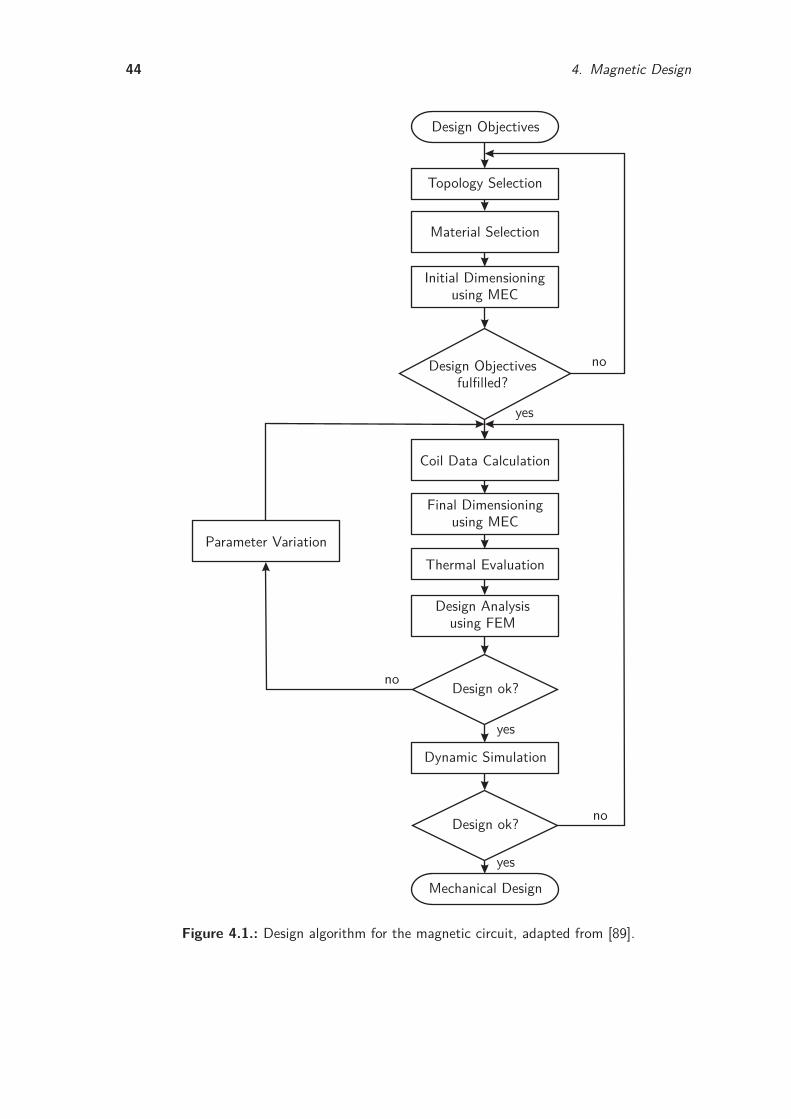
44 4. Magnetic Design
Design Objectives
Topology Selection
Material Selection
Initial Dimensioningusing MEC
Design Objectivesfulfilled?
Coil Data Calculation
Final Dimensioningusing MEC
Thermal Evaluation
Design Analysisusing FEM
Design ok?
Parameter Variation
Dynamic Simulation
Design ok?
Mechanical Design
yes
yes
yes
no
no
no
Figure 4.1.: Design algorithm for the magnetic circuit, adapted from [89].
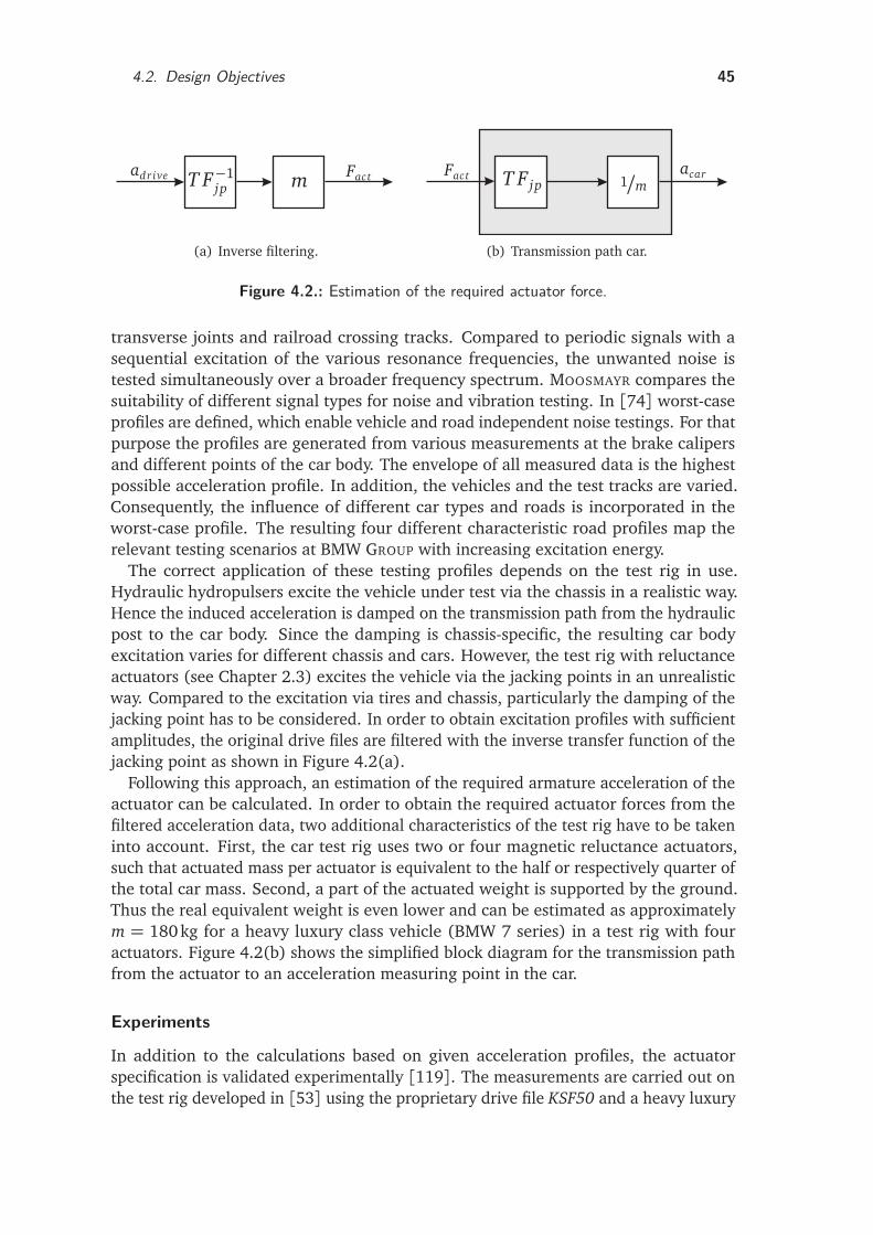
4.2. Design Objectives 45
adrive m FactT F−1jp
ve
(a) Inverse filtering.
Fact T F jp 1/macar
(b) Transmission path car.
Figure 4.2.: Estimation of the required actuator force.
transverse joints and railroad crossing tracks. Compared to periodic signals with asequential excitation of the various resonance frequencies, the unwanted noise istested simultaneously over a broader frequency spectrum. MOOSMAYR compares thesuitability of different signal types for noise and vibration testing. In [74] worst-caseprofiles are defined, which enable vehicle and road independent noise testings. For thatpurpose the profiles are generated from various measurements at the brake calipersand different points of the car body. The envelope of all measured data is the highestpossible acceleration profile. In addition, the vehicles and the test tracks are varied.Consequently, the influence of different car types and roads is incorporated in theworst-case profile. The resulting four different characteristic road profiles map therelevant testing scenarios at BMW GROUP with increasing excitation energy.
The correct application of these testing profiles depends on the test rig in use.Hydraulic hydropulsers excite the vehicle under test via the chassis in a realistic way.Hence the induced acceleration is damped on the transmission path from the hydraulicpost to the car body. Since the damping is chassis-specific, the resulting car bodyexcitation varies for different chassis and cars. However, the test rig with reluctanceactuators (see Chapter 2.3) excites the vehicle via the jacking points in an unrealisticway. Compared to the excitation via tires and chassis, particularly the damping of thejacking point has to be considered. In order to obtain excitation profiles with sufficientamplitudes, the original drive files are filtered with the inverse transfer function of thejacking point as shown in Figure 4.2(a).
Following this approach, an estimation of the required armature acceleration of theactuator can be calculated. In order to obtain the required actuator forces from thefiltered acceleration data, two additional characteristics of the test rig have to be takeninto account. First, the car test rig uses two or four magnetic reluctance actuators,such that actuated mass per actuator is equivalent to the half or respectively quarter ofthe total car mass. Second, a part of the actuated weight is supported by the ground.Thus the real equivalent weight is even lower and can be estimated as approximatelym = 180kg for a heavy luxury class vehicle (BMW 7 series) in a test rig with fouractuators. Figure 4.2(b) shows the simplified block diagram for the transmission pathfrom the actuator to an acceleration measuring point in the car.
Experiments
In addition to the calculations based on given acceleration profiles, the actuatorspecification is validated experimentally [119]. The measurements are carried out onthe test rig developed in [53] using the proprietary drive file KSF50 and a heavy luxury
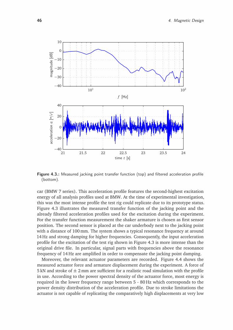
46 4. Magnetic Design
acce
lerat
ion
a[m
/s2 ]
time t [s]
mag
nitu
de[d
B]
f [Hz]
21 21.5 22 22.5 23 23.5 24
101 102
−40
−20
0
20
40
−40
−30
−20
−10
0
10
Figure 4.3.: Measured jacking point transfer function (top) and filtered acceleration profile(bottom).
car (BMW 7 series). This acceleration profile features the second-highest excitationenergy of all analysis profiles used at BMW. At the time of experimental investigation,this was the most intense profile the test rig could replicate due to its prototype status.Figure 4.3 illustrates the measured transfer function of the jacking point and thealready filtered acceleration profiles used for the excitation during the experiment.For the transfer function measurement the shaker armature is chosen as first sensorposition. The second sensor is placed at the car underbody next to the jacking pointwith a distance of 100 mm. The system shows a typical resonance frequency at around14 Hz and strong damping for higher frequencies. Consequently, the input accelerationprofile for the excitation of the test rig shown in Figure 4.3 is more intense than theoriginal drive file. In particular, signal parts with frequencies above the resonancefrequency of 14 Hz are amplified in order to compensate the jacking point damping.
Moreover, the relevant actuator parameters are recorded. Figure 4.4 shows themeasured actuator force and armature displacement during the experiment. A force of5 kN and stroke of ± 2 mm are sufficient for a realistic road simulation with the profilein use. According to the power spectral density of the actuator force, most energy isrequired in the lower frequency range between 5 - 80 Hz which corresponds to thepower density distribution of the acceleration profile. Due to stroke limitations theactuator is not capable of replicating the comparatively high displacements at very low
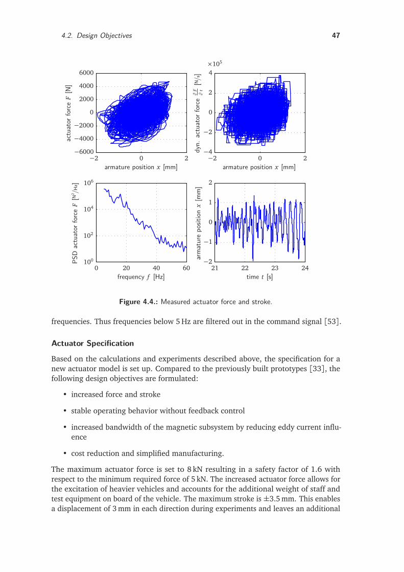
4.2. Design Objectives 47
arm
atur
epo
sitio
nx
[mm
]
time t [s]
PSD
actu
ator
forc
eF
[N2 /H
z]
frequency f [Hz]
dyn.
actu
ator
forc
e∂
F∂
t[N /
s]
armature position x [mm]
actu
ator
forc
eF
[N]
armature position x [mm]
21 22 23 240 20 40 60
−2 0 2−2 0 2
×105
−2
−1
0
1
2
100
102
104
106
−4
−2
0
2
4
−6000
−4000
−2000
0
2000
4000
6000
Figure 4.4.: Measured actuator force and stroke.
frequencies. Thus frequencies below 5 Hz are filtered out in the command signal [53].
Actuator Specification
Based on the calculations and experiments described above, the specification for anew actuator model is set up. Compared to the previously built prototypes [33], thefollowing design objectives are formulated:
• increased force and stroke
• stable operating behavior without feedback control
• increased bandwidth of the magnetic subsystem by reducing eddy current influ-ence
• cost reduction and simplified manufacturing.
The maximum actuator force is set to 8 kN resulting in a safety factor of 1.6 withrespect to the minimum required force of 5 kN. The increased actuator force allows forthe excitation of heavier vehicles and accounts for the additional weight of staff andtest equipment on board of the vehicle. The maximum stroke is ±3.5 mm. This enablesa displacement of 3 mm in each direction during experiments and leaves an additional
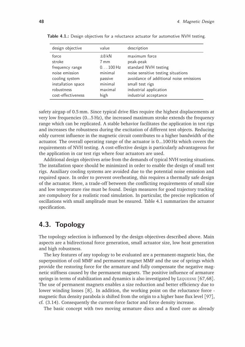
48 4. Magnetic Design
Table 4.1.: Design objectives for a reluctance actuator for automotive NVH testing.
design objective value descriptionforce ±8 kN maximum forcestroke 7mm peak-peakfrequency range 0. . . 100Hz standard NVH testingnoise emission minimal noise sensitive testing situationscooling system passive avoidance of additional noise emissionsinstallation space minimal small test rigsrobustness maximal industrial applicationcost-effectiveness high industrial acceptance
safety airgap of 0.5 mm. Since typical drive files require the highest displacements atvery low frequencies (0...5 Hz), the increased maximum stroke extends the frequencyrange which can be replicated. A stable behavior facilitates the application in test rigsand increases the robustness during the excitation of different test objects. Reducingeddy current influence in the magnetic circuit contributes to a higher bandwidth of theactuator. The overall operating range of the actuator is 0...100 Hz which covers therequirements of NVH testing. A cost-effective design is particularly advantageous forthe application in car test rigs where four actuators are used.
Additional design objectives arise from the demands of typical NVH testing situations.The installation space should be minimized in order to enable the design of small testrigs. Auxiliary cooling systems are avoided due to the potential noise emission andrequired space. In order to prevent overheating, this requires a thermally safe designof the actuator. Here, a trade-off between the conflicting requirements of small sizeand low temperature rise must be found. Design measures for good trajectory trackingare compulsory for a realistic road simulation. In particular, the precise replication ofoscillations with small amplitude must be ensured. Table 4.1 summarizes the actuatorspecification.
4.3. TopologyThe topology selection is influenced by the design objectives described above. Mainaspects are a bidirectional force generation, small actuator size, low heat generationand high robustness.
The key features of any topology to be evaluated are a permanent-magnetic bias, thesuperposition of coil MMF and permanent magnet MMF and the use of springs whichprovide the restoring force for the armature and fully compensate the negative mag-netic stiffness caused by the permanent magnets. The positive influence of armaturesprings in terms of stabilization and dynamics is also investigated by LEQUESNE [67,68].The use of permanent magnets enables a size reduction and better efficiency due tolower winding losses [8]. In addition, the working point on the reluctance force -magnetic flux density parabola is shifted from the origin to a higher base flux level [97],cf. (3.14). Consequently the current-force factor and force density increase.
The basic concept with two moving armature discs and a fixed core as already
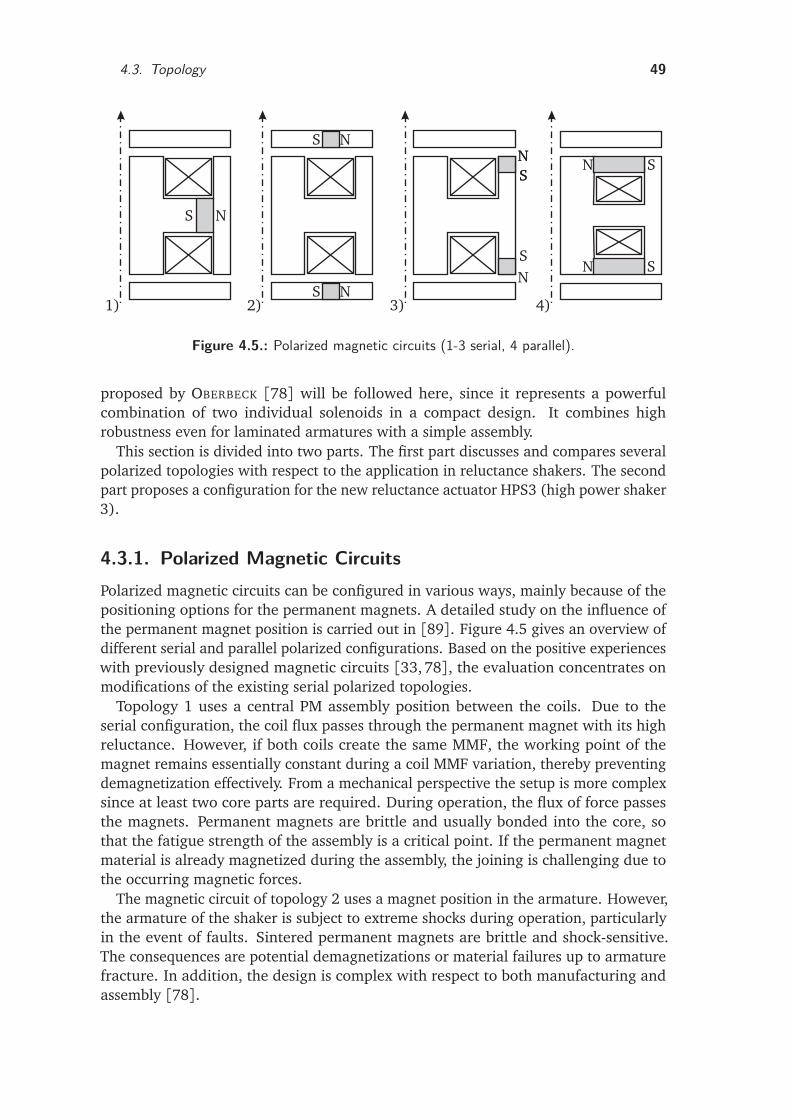
4.3. Topology 49
N
N
N
NNN
N
N
S
S
S
SS
S
S
S
1) 2) 3) 4)
Figure 4.5.: Polarized magnetic circuits (1-3 serial, 4 parallel).
proposed by OBERBECK [78] will be followed here, since it represents a powerfulcombination of two individual solenoids in a compact design. It combines highrobustness even for laminated armatures with a simple assembly.
This section is divided into two parts. The first part discusses and compares severalpolarized topologies with respect to the application in reluctance shakers. The secondpart proposes a configuration for the new reluctance actuator HPS3 (high power shaker3).
4.3.1. Polarized Magnetic CircuitsPolarized magnetic circuits can be configured in various ways, mainly because of thepositioning options for the permanent magnets. A detailed study on the influence ofthe permanent magnet position is carried out in [89]. Figure 4.5 gives an overview ofdifferent serial and parallel polarized configurations. Based on the positive experienceswith previously designed magnetic circuits [33,78], the evaluation concentrates onmodifications of the existing serial polarized topologies.
Topology 1 uses a central PM assembly position between the coils. Due to theserial configuration, the coil flux passes through the permanent magnet with its highreluctance. However, if both coils create the same MMF, the working point of themagnet remains essentially constant during a coil MMF variation, thereby preventingdemagnetization effectively. From a mechanical perspective the setup is more complexsince at least two core parts are required. During operation, the flux of force passesthe magnets. Permanent magnets are brittle and usually bonded into the core, sothat the fatigue strength of the assembly is a critical point. If the permanent magnetmaterial is already magnetized during the assembly, the joining is challenging due tothe occurring magnetic forces.
The magnetic circuit of topology 2 uses a magnet position in the armature. However,the armature of the shaker is subject to extreme shocks during operation, particularlyin the event of faults. Sintered permanent magnets are brittle and shock-sensitive.The consequences are potential demagnetizations or material failures up to armaturefracture. In addition, the design is complex with respect to both manufacturing andassembly [78].
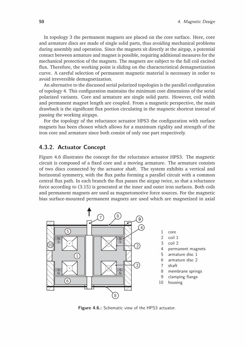
50 4. Magnetic Design
In topology 3 the permanent magnets are placed on the core surface. Here, coreand armature discs are made of single solid parts, thus avoiding mechanical problemsduring assembly and operation. Since the magnets sit directly at the airgap, a potentialcontact between armature and magnet is possible, requiring additional measures for themechanical protection of the magnets. The magnets are subject to the full coil excitedflux. Therefore, the working point is sliding on the characteristical demagnetizationcurve. A careful selection of permanent magnetic material is necessary in order toavoid irreversible demagnetization.
An alternative to the discussed serial polarized topologies is the parallel configurationof topology 4. This configuration maintains the minimum core dimensions of the serialpolarized variants. Core and armature are single solid parts. However, coil widthand permanent magnet length are coupled. From a magnetic perspective, the maindrawback is the significant flux portion circulating in the magnetic shortcut instead ofpassing the working airgaps.
For the topology of the reluctance actuator HPS3 the configuration with surfacemagnets has been chosen which allows for a maximum rigidity and strength of theiron core and armature since both consist of only one part respectively.
4.3.2. Actuator ConceptFigure 4.6 illustrates the concept for the reluctance actuator HPS3. The magneticcircuit is composed of a fixed core and a moving armature. The armature consistsof two discs connected by the actuator shaft. The system exhibits a vertical andhorizontal symmetry, with the flux paths forming a parallel circuit with a commoncentral flux path. In each branch the flux passes the airgap twice, so that a reluctanceforce according to (3.15) is generated at the inner and outer iron surfaces. Both coilsand permanent magnets are used as magnetomotive force sources. For the magneticbias surface-mounted permanent magnets are used which are magnetized in axial
N
N N
NS
S S
S
1
2
3
45
6
7
8
8 99
10
1 core2 coil 13 coil 24 permanent magnets5 armature disc 16 armature disc 27 shaft8 membrane springs9 clamping flange10 housing
Figure 4.6.: Schematic view of the HPS3 actuator.
4.4. Magnetic Material Selection 51
direction. Two coils allow for the control of the total magnetomotive force. The coilsare separately driven and carry current in the same direction. Actuation is achievedby superposition of coil MMF and permanent magnet MMF. If the current is directedinto the page in the right half-plane of the magnetic circuit and out of the page inthe left half-plane, armature disc 2 is subject to more flux than armature disc 1 andconsequently the armature moves upwards due to the reluctance forces at its surface.A current reversal results in a downward movement; at zero current and equal airgapsthe forces are balanced so that the overall force is zero. Hence the setup allows forthe required bidirectional force generation and linear motion. The detailed magneticcircuit design is described in Section 4.7.
Strong springs provide the restoring force for the armature and compensate thenegative magnetic stiffness caused by the permanent magnetic bias. This way a stableoperation without feedback control is achieved. Here, membrane springs combine theguidance of the shaft with the suspension. A comparison with other spring-guidancedesigns shows clear functional advantages such as low friction, stick-slip avoidance,small required space and customizable spring characteristics. These properties areparticularly beneficial for the present application with respect to the high frequencyoperation at small stroke ranges as discussed in Section 6.2.4.
4.4. Magnetic Material SelectionThe application of appropriate magnetic materials is essential in order to ensure a highperformance of the magnetic circuit. The selection of magnetic materials involves bothmagnetically soft and hard substances. Soft magnetic materials are mainly used forthe flux guiding in the magnetic circuit. In contrast, magnetically hard materials areused for the realization of the permanent magnetic bias and allow for a steady MMFwithout stationary coil currents. This section discusses properties of different materialsand suitable selection criteria.
4.4.1. Soft Magnetic MaterialsImportant demands on soft magnetic materials with respect to actuator design are firstof all magnetic characteristics (B-H curve), thermal and temporal stability but alsomechanical characteristics, workability and other aspects such as price and availability[72]. Magnetic properties have a significant influence on the actuator performance: ahigh saturation induction allows for a compact actuator design, while a low coercivityand slim hysteresis loop diminish the magnetic loss. On the other hand, for highdynamic performance a low electrical conductivity and a small dynamic wideningof the hysteresis loop are required. Soft magnetic materials consist mainly of iron,cobalt, nickel and their alloys [7]. For high performance actuators the alloys are morerelevant.
CoFe alloys reach the highest saturation polarizations of up to 2.4 T. The coercivityranges from 0.4 . . . 1.4 A/cm. VACUUMSCHMELZE GMBH develops the VACOFLUX serieswith various Co shares for high performance motors and solenoids with highest tractionforces [112]. However, a higher Co share also raises the alloy cost.
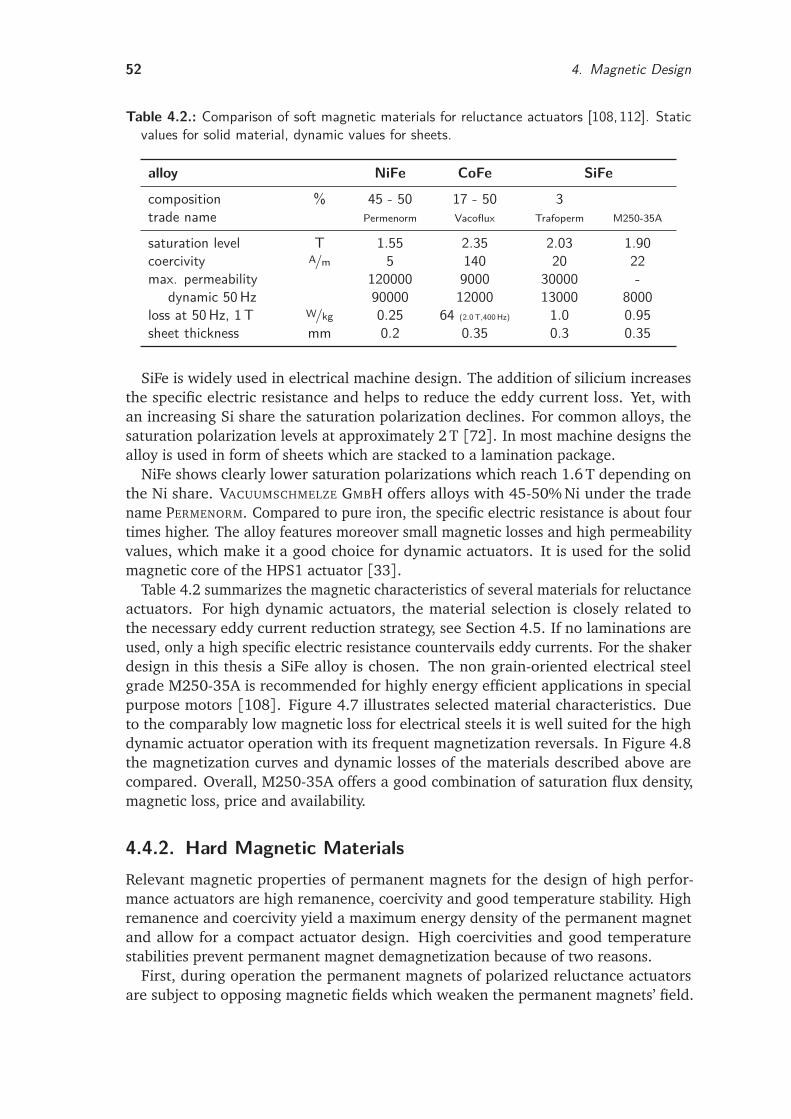
52 4. Magnetic Design
Table 4.2.: Comparison of soft magnetic materials for reluctance actuators [108,112]. Staticvalues for solid material, dynamic values for sheets.
alloy NiFe CoFe SiFe
composition % 45 - 50 17 - 50 3trade name Permenorm Vacoflux Trafoperm M250-35A
saturation level T 1.55 2.35 2.03 1.90coercivity A/m 5 140 20 22max. permeability 120000 9000 30000 -
dynamic 50Hz 90000 12000 13000 8000loss at 50Hz, 1T W/kg 0.25 64 (2.0T,400Hz) 1.0 0.95sheet thickness mm 0.2 0.35 0.3 0.35
SiFe is widely used in electrical machine design. The addition of silicium increasesthe specific electric resistance and helps to reduce the eddy current loss. Yet, withan increasing Si share the saturation polarization declines. For common alloys, thesaturation polarization levels at approximately 2 T [72]. In most machine designs thealloy is used in form of sheets which are stacked to a lamination package.
NiFe shows clearly lower saturation polarizations which reach 1.6 T depending onthe Ni share. VACUUMSCHMELZE GMBH offers alloys with 45-50% Ni under the tradename PERMENORM. Compared to pure iron, the specific electric resistance is about fourtimes higher. The alloy features moreover small magnetic losses and high permeabilityvalues, which make it a good choice for dynamic actuators. It is used for the solidmagnetic core of the HPS1 actuator [33].
Table 4.2 summarizes the magnetic characteristics of several materials for reluctanceactuators. For high dynamic actuators, the material selection is closely related tothe necessary eddy current reduction strategy, see Section 4.5. If no laminations areused, only a high specific electric resistance countervails eddy currents. For the shakerdesign in this thesis a SiFe alloy is chosen. The non grain-oriented electrical steelgrade M250-35A is recommended for highly energy efficient applications in specialpurpose motors [108]. Figure 4.7 illustrates selected material characteristics. Dueto the comparably low magnetic loss for electrical steels it is well suited for the highdynamic actuator operation with its frequent magnetization reversals. In Figure 4.8the magnetization curves and dynamic losses of the materials described above arecompared. Overall, M250-35A offers a good combination of saturation flux density,magnetic loss, price and availability.
4.4.2. Hard Magnetic MaterialsRelevant magnetic properties of permanent magnets for the design of high perfor-mance actuators are high remanence, coercivity and good temperature stability. Highremanence and coercivity yield a maximum energy density of the permanent magnetand allow for a compact actuator design. High coercivities and good temperaturestabilities prevent permanent magnet demagnetization because of two reasons.
First, during operation the permanent magnets of polarized reluctance actuatorsare subject to opposing magnetic fields which weaken the permanent magnets’ field.
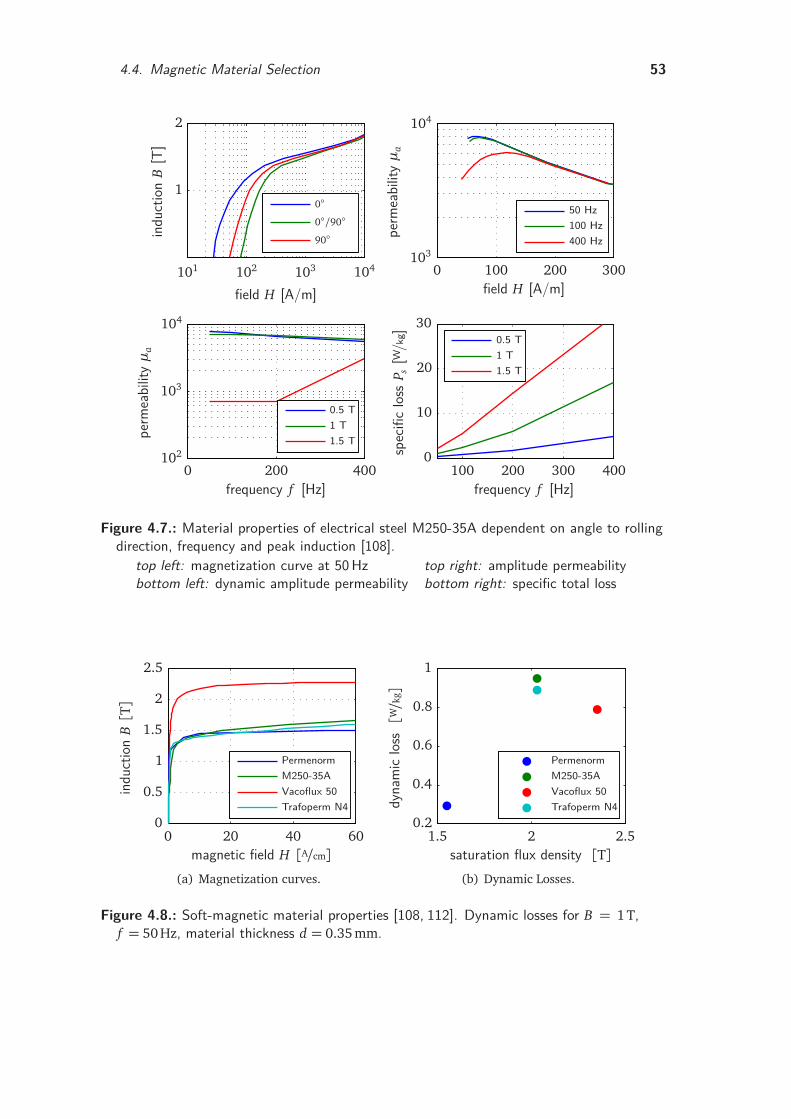
4.4. Magnetic Material Selection 53
1.5 T1 T0.5 T
1.5 T1 T0.5 T
400 Hz100 Hz50 Hz
900/900
spec
ific
loss
P s[W
/kg]
frequency f [Hz]
perm
eabi
lityµ
a
frequency f [Hz]
perm
eabi
lityµ
a
field H [A/m]
indu
ction
B[T
]
field H [A/m]
100 200 300 4000 200 400
0 100 200 300101 102 103 104
0
10
20
30
102
103
104
103
104
1
2
Figure 4.7.: Material properties of electrical steel M250-35A dependent on angle to rollingdirection, frequency and peak induction [108].
top left: magnetization curve at 50Hz top right: amplitude permeabilitybottom left: dynamic amplitude permeability bottom right: specific total loss
Trafoperm N4Vacoflux 50M250-35APermenorm
indu
ction
B[T]
magnetic field H [A/cm]0 20 40 60
0
0.5
1
1.5
2
2.5
(a) Magnetization curves.
Trafoperm N4Vacoflux 50M250-35APermenorm
dyna
mic
loss[W/k
g]
saturation flux density [T]1.5 2 2.5
0.2
0.4
0.6
0.8
1
(b) Dynamic Losses.
Figure 4.8.: Soft-magnetic material properties [108, 112]. Dynamic losses for B = 1T,f = 50 Hz, material thickness d = 0.35 mm.
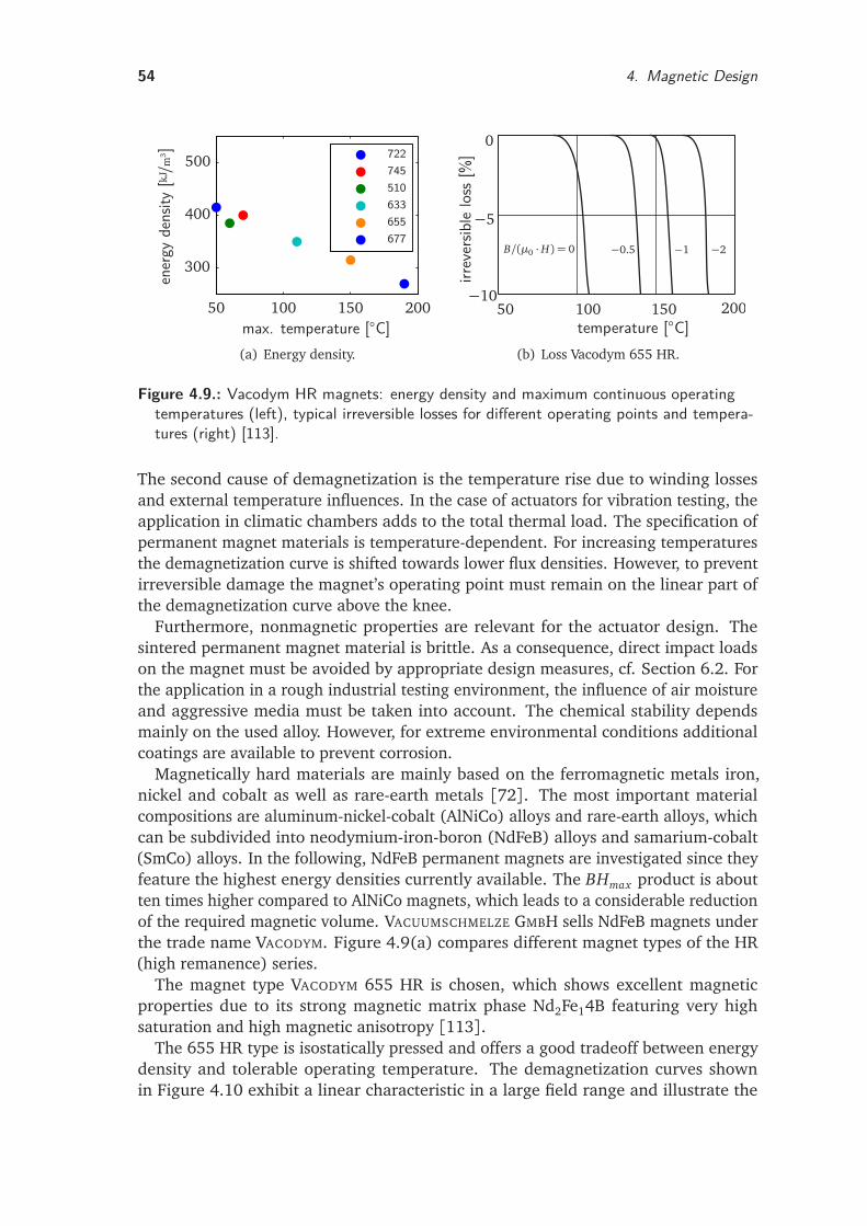
54 4. Magnetic Design
677655633510745722
ener
gyde
nsity
[kJ/m
3]
max. temperature [C]50 100 150 200
300
400
500
(a) Energy density.
50 100 150 200
−5
−10
B/(µ0 ·H) = 0 −0.5 −1 −2
temperature [C]
irrev
ersib
lelo
ss[%
]
0
(b) Loss Vacodym 655 HR.
Figure 4.9.: Vacodym HR magnets: energy density and maximum continuous operatingtemperatures (left), typical irreversible losses for different operating points and tempera-tures (right) [113].
The second cause of demagnetization is the temperature rise due to winding lossesand external temperature influences. In the case of actuators for vibration testing, theapplication in climatic chambers adds to the total thermal load. The specification ofpermanent magnet materials is temperature-dependent. For increasing temperaturesthe demagnetization curve is shifted towards lower flux densities. However, to preventirreversible damage the magnet’s operating point must remain on the linear part ofthe demagnetization curve above the knee.
Furthermore, nonmagnetic properties are relevant for the actuator design. Thesintered permanent magnet material is brittle. As a consequence, direct impact loadson the magnet must be avoided by appropriate design measures, cf. Section 6.2. Forthe application in a rough industrial testing environment, the influence of air moistureand aggressive media must be taken into account. The chemical stability dependsmainly on the used alloy. However, for extreme environmental conditions additionalcoatings are available to prevent corrosion.
Magnetically hard materials are mainly based on the ferromagnetic metals iron,nickel and cobalt as well as rare-earth metals [72]. The most important materialcompositions are aluminum-nickel-cobalt (AlNiCo) alloys and rare-earth alloys, whichcan be subdivided into neodymium-iron-boron (NdFeB) alloys and samarium-cobalt(SmCo) alloys. In the following, NdFeB permanent magnets are investigated since theyfeature the highest energy densities currently available. The BHmax product is aboutten times higher compared to AlNiCo magnets, which leads to a considerable reductionof the required magnetic volume. VACUUMSCHMELZE GMBH sells NdFeB magnets underthe trade name VACODYM. Figure 4.9(a) compares different magnet types of the HR(high remanence) series.
The magnet type VACODYM 655 HR is chosen, which shows excellent magneticproperties due to its strong magnetic matrix phase Nd2Fe14B featuring very highsaturation and high magnetic anisotropy [113].
The 655 HR type is isostatically pressed and offers a good tradeoff between energydensity and tolerable operating temperature. The demagnetization curves shownin Figure 4.10 exhibit a linear characteristic in a large field range and illustrate the
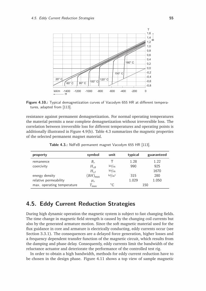
4.5. Eddy Current Reduction Strategies 55
20° C 120° C
150° C
180° C
100° C60° C 80° C
-0,8
-0,6
-0,4
-0,2
0,0
0,2
0,4
0,6
0,8
1,0
1,2
1,4
1,6
T
kA/m -1400 -1200 -1000H
0-800 -600 -400 -200
B
Figure 4.10.: Typical demagnetization curves of Vacodym 655 HR at different tempera-tures, adapted from [113].
resistance against permanent demagnetization. For normal operating temperaturesthe material permits a near complete demagnetization without irreversible loss. Thecorrelation between irreversible loss for different temperatures and operating points isadditionally illustrated in Figure 4.9(b). Table 4.3 summarizes the magnetic propertiesof the selected permanent magnet material.
Table 4.3.: NdFeB permanent magnet Vacodym 655 HR [113].
property symbol unit typical guaranteed
remanence Br T 1.28 1.22coercivity HcB kA/m 990 925
HcJ kA/m 1670energy density (BH)max kJ/m3 315 280relative permeability µr 1.029 1.050max. operating temperature Tmax
C 150
4.5. Eddy Current Reduction StrategiesDuring high dynamic operation the magnetic system is subject to fast changing fields.The time change in magnetic field strength is caused by the changing coil currents butalso by the generated armature motion. Since the soft magnetic material used for theflux guidance in core and armature is electrically conducting, eddy currents occur (seeSection 3.3.1). The consequences are a delayed force generation, higher losses anda frequency dependent transfer function of the magnetic circuit, which results fromthe damping and phase delay. Consequently, eddy currents limit the bandwidth of thereluctance actuator and deteriorate the performance of the controlled test rig.
In order to obtain a high bandwidth, methods for eddy current reduction have tobe chosen in the design phase. Figure 4.11 shows a top view of sample magnetic
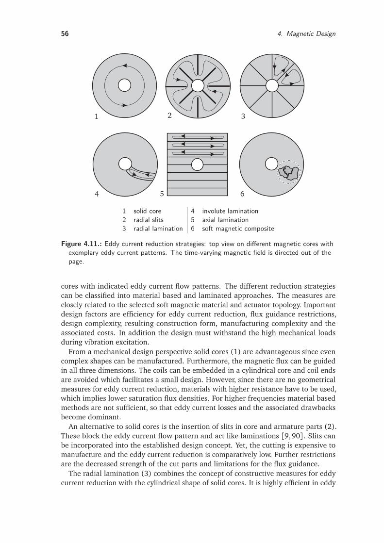
56 4. Magnetic Design
1 2 3
4 5 6
1 solid core 4 involute lamination2 radial slits 5 axial lamination3 radial lamination 6 soft magnetic composite
Figure 4.11.: Eddy current reduction strategies: top view on different magnetic cores withexemplary eddy current patterns. The time-varying magnetic field is directed out of thepage.
cores with indicated eddy current flow patterns. The different reduction strategiescan be classified into material based and laminated approaches. The measures areclosely related to the selected soft magnetic material and actuator topology. Importantdesign factors are efficiency for eddy current reduction, flux guidance restrictions,design complexity, resulting construction form, manufacturing complexity and theassociated costs. In addition the design must withstand the high mechanical loadsduring vibration excitation.
From a mechanical design perspective solid cores (1) are advantageous since evencomplex shapes can be manufactured. Furthermore, the magnetic flux can be guidedin all three dimensions. The coils can be embedded in a cylindrical core and coil endsare avoided which facilitates a small design. However, since there are no geometricalmeasures for eddy current reduction, materials with higher resistance have to be used,which implies lower saturation flux densities. For higher frequencies material basedmethods are not sufficient, so that eddy current losses and the associated drawbacksbecome dominant.
An alternative to solid cores is the insertion of slits in core and armature parts (2).These block the eddy current flow pattern and act like laminations [9,90]. Slits canbe incorporated into the established design concept. Yet, the cutting is expensive tomanufacture and the eddy current reduction is comparatively low. Further restrictionsare the decreased strength of the cut parts and limitations for the flux guidance.
The radial lamination (3) combines the concept of constructive measures for eddycurrent reduction with the cylindrical shape of solid cores. It is highly efficient in eddy
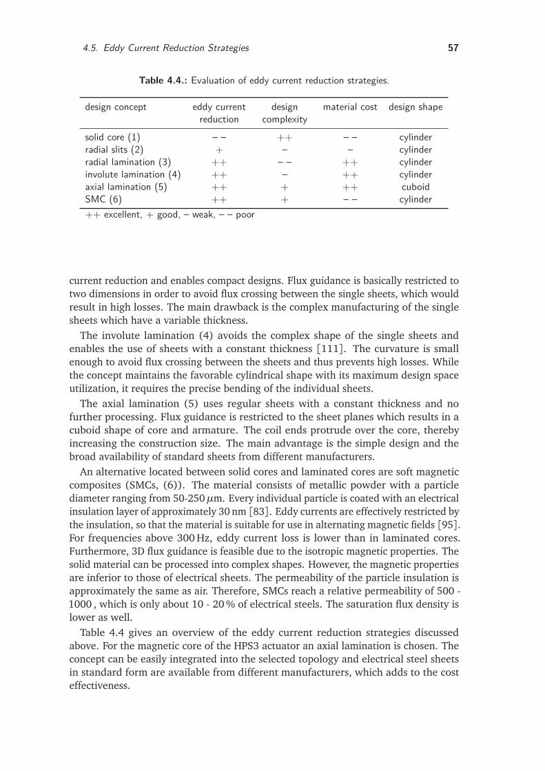
4.5. Eddy Current Reduction Strategies 57
Table 4.4.: Evaluation of eddy current reduction strategies.
design concept eddy currentreduction
designcomplexity
material cost design shape
solid core (1) – – ++ – – cylinderradial slits (2) + – – cylinderradial lamination (3) ++ – – ++ cylinderinvolute lamination (4) ++ – ++ cylinderaxial lamination (5) ++ + ++ cuboidSMC (6) ++ + – – cylinder++ excellent, + good, – weak, – – poor
current reduction and enables compact designs. Flux guidance is basically restricted totwo dimensions in order to avoid flux crossing between the single sheets, which wouldresult in high losses. The main drawback is the complex manufacturing of the singlesheets which have a variable thickness.
The involute lamination (4) avoids the complex shape of the single sheets andenables the use of sheets with a constant thickness [111]. The curvature is smallenough to avoid flux crossing between the sheets and thus prevents high losses. Whilethe concept maintains the favorable cylindrical shape with its maximum design spaceutilization, it requires the precise bending of the individual sheets.
The axial lamination (5) uses regular sheets with a constant thickness and nofurther processing. Flux guidance is restricted to the sheet planes which results in acuboid shape of core and armature. The coil ends protrude over the core, therebyincreasing the construction size. The main advantage is the simple design and thebroad availability of standard sheets from different manufacturers.
An alternative located between solid cores and laminated cores are soft magneticcomposites (SMCs, (6)). The material consists of metallic powder with a particlediameter ranging from 50-250µm. Every individual particle is coated with an electricalinsulation layer of approximately 30 nm [83]. Eddy currents are effectively restricted bythe insulation, so that the material is suitable for use in alternating magnetic fields [95].For frequencies above 300 Hz, eddy current loss is lower than in laminated cores.Furthermore, 3D flux guidance is feasible due to the isotropic magnetic properties. Thesolid material can be processed into complex shapes. However, the magnetic propertiesare inferior to those of electrical sheets. The permeability of the particle insulation isapproximately the same as air. Therefore, SMCs reach a relative permeability of 500 -1000 , which is only about 10 - 20 % of electrical steels. The saturation flux density islower as well.
Table 4.4 gives an overview of the eddy current reduction strategies discussedabove. For the magnetic core of the HPS3 actuator an axial lamination is chosen. Theconcept can be easily integrated into the selected topology and electrical steel sheetsin standard form are available from different manufacturers, which adds to the costeffectiveness.
58 4. Magnetic Design
4.6. LaminationsAfter choosing a lamination form, the sheet thickness is determined using the skindepth defined in (3.27). Lamination thickness should be approximately 0.5− 1 skindepth [9]. For the calculation a working point at 100 Hz is assumed. With the materialproperties µr = 8000 and σ = 2.08 · 106 S/m, an estimation of the required sheetthickness yields 0.2 - 0.4 mm. Consequently the standard thickness 0.35 mm is chosen.In general, a lower lamination thickness decreases the stacking factor, such that atrade-off has to be found between eddy current reduction and the resulting net volumeof the magnetic material. Due to the actuator topology, the flux is guided in the sheetalong the direction of grain and transverse to it. The non grain-oriented standardelectrical steel M250-35A features isotropic properties and low losses.
Besides magnetic design issues, the manufacturing of the stack is important forthe performance. The lamination stacks are subject to strong vibration and highforces during operation. Fabrication tolerances directly influence important actuatordimensions such as the airgap length. The application in an automotive test rig impliesharsh industrial conditions, which requires mechanically robust laminations. The mainmanufacturing aspects are the fabrication of the lamination form and the packeting ofthe single sheets to a stack.
The single sheets for the prototype are laser cut due to cost and time constraints.Available manufacturing technologies for the stacks of armature and core includewelding, riveting, stapling, interlocking and bonding. Here, bonding with the varnishtechnology has been chosen. The sheets are coated on both sides with a bondingvarnish, the coating thickness being approximately 5µm. The advantages in contrast toother manufacturing technologies are maximum stiffness and stability of the laminationstack. In addition, very high precision can be realized. The varnish seals and preventsmoisture ingress between the individual sheets. Furthermore, an additional insulationof the individual sheets can be achieved [66]. Overall, the stack is very compact andvibration-resistant.
During the manufacturing process the individual coated sheets are first stacked andaligned. The assembly is then heated and pressed. The actual bonding is achieved bythe temperature-triggered softening and the curing process during the cooling downphase.
4.7. Magnetic Circuit DimensioningThe dimensioning of the magnetic system includes the calculation of the main staticparameters such as the required reluctance area and the excitation by the coils andpermanent magnets. Following hereon, the main dimensions of the magnetic systemare determined. All calculations are based on a magnetic equivalent circuit.
4.7.1. Magnetic Equivalent CircuitBased on the selected actuator topology (No. 3 in Figure 4.5), an equivalent networkis set up. The characteristic equations allow for calculation of the main actuator
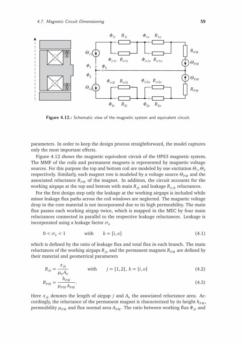
4.7. Magnetic Circuit Dimensioning 59
Θc1
R1i
Rσ1i
R1o
Rσ1o
RPM
RPM
ΘPM
ΘPM
R2o
Rσ2oRσ2i
R2i
Θc2
Φ2
Φ1 Φ3
Φ1i
Φσ1i
Φ1o
Φσ1o
Φσ2o
Φ2o
Φσ2i
Φ2i
N
N
S
S
Figure 4.12.: Schematic view of the magnetic system and equivalent circuit.
parameters. In order to keep the design process straightforward, the model capturesonly the most important effects.
Figure 4.12 shows the magnetic equivalent circuit of the HPS3 magnetic system.The MMF of the coils and permanent magnets is represented by magnetic voltagesources. For this purpose the top and bottom coil are modeled by one excitation Θ1,Θ2
respectively. Similarly, each magnet row is modeled by a voltage source ΘPM and theassociated reluctance RPM of the magnet. In addition, the circuit accounts for theworking airgaps at the top and bottom with main R jk and leakage Rσ jk reluctances.
For the first design step only the leakage at the working airgaps is included whileminor leakage flux paths across the coil windows are neglected. The magnetic voltagedrop in the core material is not incorporated due to its high permeability. The mainflux passes each working airgap twice, which is mapped in the MEC by four mainreluctances connected in parallel to the respective leakage reluctances. Leakage isincorporated using a leakage factor σk
0< σk < 1 with k = i, o (4.1)
which is defined by the ratio of leakage flux and total flux in each branch. The mainreluctances of the working airgaps R jk and the permanent magnets RPM are defined bytheir material and geometrical parameters
R jk =x jk
µ0 Akwith j = 1, 2, k = i, o (4.2)
RPM =hPM
µPM APM. (4.3)
Here x jk denotes the length of airgap j and Ak the associated reluctance area. Ac-cordingly, the reluctance of the permanent magnet is characterized by its height hPM ,permeability µPM and flux normal area APM . The ratio between working flux Φ jk and
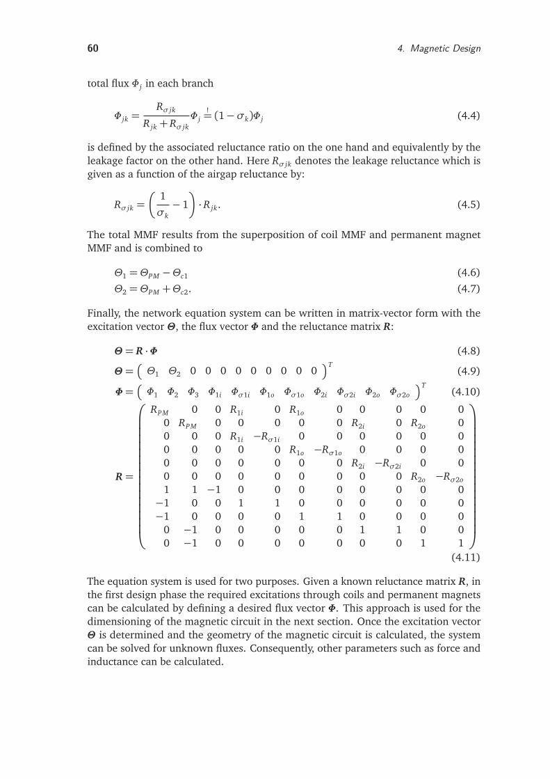
60 4. Magnetic Design
total flux Φ j in each branch
Φ jk =Rσ jk
R jk + Rσ jkΦ j
!= (1−σk)Φ j (4.4)
is defined by the associated reluctance ratio on the one hand and equivalently by theleakage factor on the other hand. Here Rσ jk denotes the leakage reluctance which isgiven as a function of the airgap reluctance by:
Rσ jk =
1
σk− 1
· R jk. (4.5)
The total MMF results from the superposition of coil MMF and permanent magnetMMF and is combined to
Θ1 = ΘPM −Θc1 (4.6)
Θ2 = ΘPM +Θc2. (4.7)
Finally, the network equation system can be written in matrix-vector form with theexcitation vector Θ, the flux vector Φ and the reluctance matrix R:
Θ = R ·Φ (4.8)
Θ =
Θ1 Θ2 0 0 0 0 0 0 0 0 0T
(4.9)
Φ=
Φ1 Φ2 Φ3 Φ1i Φσ1i Φ1o Φσ1o Φ2i Φσ2i Φ2o Φσ2o
T(4.10)
R =
RPM 0 0 R1i 0 R1o 0 0 0 0 00 RPM 0 0 0 0 0 R2i 0 R2o 00 0 0 R1i −Rσ1i 0 0 0 0 0 00 0 0 0 0 R1o −Rσ1o 0 0 0 00 0 0 0 0 0 0 R2i −Rσ2i 0 00 0 0 0 0 0 0 0 0 R2o −Rσ2o
1 1 −1 0 0 0 0 0 0 0 0−1 0 0 1 1 0 0 0 0 0 0−1 0 0 0 0 1 1 0 0 0 0
0 −1 0 0 0 0 0 1 1 0 00 −1 0 0 0 0 0 0 0 1 1
(4.11)
The equation system is used for two purposes. Given a known reluctance matrix R, inthe first design phase the required excitations through coils and permanent magnetscan be calculated by defining a desired flux vector Φ. This approach is used for thedimensioning of the magnetic circuit in the next section. Once the excitation vectorΘ is determined and the geometry of the magnetic circuit is calculated, the systemcan be solved for unknown fluxes. Consequently, other parameters such as force andinductance can be calculated.
4.7. Magnetic Circuit Dimensioning 61
4.7.2. Static ParametersIn this section the required reluctance area, the MMF of the coils and permanentmagnets and the static force are calculated using the equivalent circuit in Figure 4.12and its describing equations. Point of origin is the desired static force as determined inSection 4.2; the main design parameters are listed in Table B.4.
In the following, the approach proposed by HERRMANN is adapted [33]. The magneticcircuit is considered linear and the design is subject to the following constraints [118]:
1. The desired maximum static force Fs,max is defined by the design objectives.
2. The armature is in neutral position x = 0, i.e. the length of equivalent workingairgaps is equal x1k = x2k.
3. Both coils contribute the same MMF Θc1 = Θc2 = Θ.
4. The permanent magnet MMF generates half of the desired flux density Bmax/2at zero coil MMF.
5. Coil field and permanent magnetic field are superimposed. For a maximum coilMMF Θmax the bottom flux path is subject to the maximum desired flux densityBmax , while the top flux path is flux-free. In that case the maximum positivemagnetic force Fs,max is generated. If the coil MMF is reversed, the force directionis so as well.
6. The leakage factor is considered to be uniformly σk = σ = 0.15, which corre-sponds to 15 % leakage flux. The lamination stacking factor is assumed to bekst = 0.15.
7. The relevant reluctance surfaces are equal for all airgaps Ak = A0 .
Reluctance Area
Basis for the calculation of the required reluctance surface is the reluctance forcedefined in (3.14). In the HPS3 topology the main flux crosses each airgap twice. Apartfrom the desired actuation force Fs,max , the required surface
A0 ≥1
2kst
2µ0Fs,max
((1−σ)Bmax)2(4.12)
depends mainly on the permitted maximum flux density Bmax = 1.4T in the softmagnetic part of the circuit which is made from M250-35A. Consequently, materialswith a high Bmax enable a significant reduction of the overall actuator size. The appliedapproach for the surface calculation implies an unlimited reluctance area for leakagesσ→ 1. However, a realistic design aims at leakage minimization σ→ 0, which yieldsreasonable actuator parameters in practice.
62 4. Magnetic Design
Coil MMF
Due to the given design constraints, half of the permitted magnetic flux in each ironbranch is generated by the maximum current in the coils. If the MMF of the permanentmagnets is set to zero, the specific flux follows from the permitted flux density andreluctance surface. Using the KVL in the top or bottom branch, the required maximumcoil MMF is obtained.
Φ j
ΘPM=0=
Bmax
2A0 (4.13)
|Θc,max |
ΘPM=0 = Φ jRPM +Φ jiR ji +Φ joR jo (4.14)
Permanent Magnet MMF
The same approach is used for the calculation of the required permanent magnetexcitation. If the MMF of the coils is set to zero, the desired flux results from thepermitted flux density and reluctance surface. Applying the KVL in the top or bottombranch yields the required permanent magnet MMF:
Φ j
Θ=0=
Bmax
2A0 (4.15)
|ΘPM |
Θ=0 = Φ jRPM +Φ jiR ji +Φ joR jo. (4.16)
The MMF of a permanent magnet row is given by its material-dependent coercivityHcB = 925 kA/m (VACODYM 655 HR, see Table 4.3) and the height in direction ofmagnetization hPM . The height is chosen such that the required ΘPM is obtained
ΘPM = HcB · hPM (4.17)
hPM =1
HcB − Φ j
µPMµ0APM
·
Φ jiR ji +Φ joR jo
. (4.18)
Due to the design, the magnet area is determined by the required reluctance areaAPM = A0. Up to this point, the design is characterized by the desired flux values whichare used for the calculation of the excitations required therefor.
In addition, the equation system (4.8) for the description of the MEC contains thereluctance matrix R and the excitation vector Θ. The reluctance matrix is parame-terized by the chosen leakage factor and airgap length as well as the reluctance areacalculated in (4.12). Once the excitations calculated in (4.13)-(4.18) are known, thesystem can be solved for unknown fluxes.
Magnetic Force
In the final step the total magnetic force is calculated by inserting the working flux ineach airgap in the basic equation for the reluctance force (3.14). The flux passes theinner and outer reluctance surface in each airgap. Thus both Φ ji and Φ jo contribute tothe force generation. The total force is a result of the superposition of the reluctance
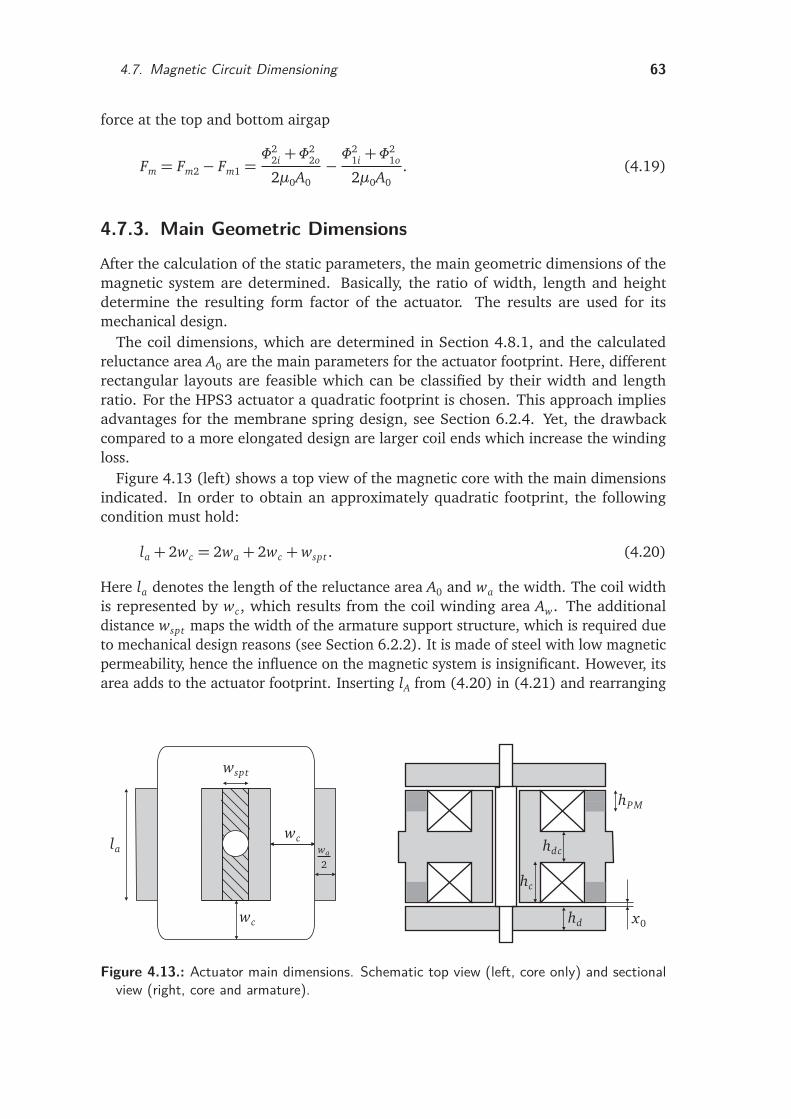
4.7. Magnetic Circuit Dimensioning 63
force at the top and bottom airgap
Fm = Fm2− Fm1 =Φ2
2i +Φ22o
2µ0A0− Φ
21i +Φ
21o
2µ0A0. (4.19)
4.7.3. Main Geometric DimensionsAfter the calculation of the static parameters, the main geometric dimensions of themagnetic system are determined. Basically, the ratio of width, length and heightdetermine the resulting form factor of the actuator. The results are used for itsmechanical design.
The coil dimensions, which are determined in Section 4.8.1, and the calculatedreluctance area A0 are the main parameters for the actuator footprint. Here, differentrectangular layouts are feasible which can be classified by their width and lengthratio. For the HPS3 actuator a quadratic footprint is chosen. This approach impliesadvantages for the membrane spring design, see Section 6.2.4. Yet, the drawbackcompared to a more elongated design are larger coil ends which increase the windingloss.
Figure 4.13 (left) shows a top view of the magnetic core with the main dimensionsindicated. In order to obtain an approximately quadratic footprint, the followingcondition must hold:
la + 2wc = 2wa + 2wc +wspt . (4.20)
Here la denotes the length of the reluctance area A0 and wa the width. The coil widthis represented by wc, which results from the coil winding area Aw. The additionaldistance wspt maps the width of the armature support structure, which is required dueto mechanical design reasons (see Section 6.2.2). It is made of steel with low magneticpermeability, hence the influence on the magnetic system is insignificant. However, itsarea adds to the actuator footprint. Inserting lA from (4.20) in (4.21) and rearranging
la
wspt
wc
wc
wa
2
hd
hc
hdc
hPM
x0
Figure 4.13.: Actuator main dimensions. Schematic top view (left, core only) and sectionalview (right, core and armature).
64 4. Magnetic Design
yields the desired width
A0 = la ·wa (4.21)
wa =−wspt ±
p
w2spt + 8A0
4. (4.22)
Here only positive results for wa are used.For the determination of the vertical dimensions, a constant cross-sectional area of
the flux tubes in the magnetic system is assumed. Since the length of the magneticsystem as calculated above is constant, the height hd of the armature plates and thedistance between the coils hdc equals the afore calculated width wa of the reluctancearea. The coil height results from the coil winding area Aw which is calculated inSection 4.8.1. The length of the airgaps x0 is given by the design objectives and themagnets’ height hPM is calculated in (4.18), so that the total height hms of the magneticsystem is given by
hd = wa (4.23)
hdc = wa (4.24)
hms = 2(hd + hc + x0) + hdc. (4.25)
The section view in Figure 4.13 (right) shows the main vertical dimensions.
4.8. Coil Design
4.8.1. Parameter CalculationThe coil data and in particular the wire diameter depend mainly on the maximumcoil magnetomotive force Θc,max , which is calculated in Section 4.7.2. The coil designinfluences the overall actuator performance considerably and directly determines theactuator’s heating, size, weight and cost. A larger coil implies a lower current densityfor the same magnetomotive force and thus a lower specific thermal load. However,due to the increased coil winding area, this is achieved at the cost of size and weight.
In the following the main coil data is calculated. This includes the winding number,rated current, electric resistance, wire size and coil winding area. The approach followsthe method proposed by BRAUER and KALLENBACH [9,46].
Point of origin is the calculation of the required coil winding area Aw for a givenMMF
Aw =Θc,max
Jr kco. (4.26)
The rated current density Jr depends on the duty cycle, the mounting position andinsulation of the coil and the actuator size and cooling. In addition, the load profile isimportant which makes an accurate determination of Jr complex. Due to experimentalexperiences with previously built actuators of similar setups, the current density is setto 5 A/mm2 for 100 % duty cycle. The rather conservative design seems reasonable
4.8. Coil Design 65
since the HPS3 actuator has no active cooling system. For the packing factor kco acopper filling of 70% is assumed which can be realized technically.
The required MMF Θc,max from (4.14) can be also written in terms of the ratedvoltage Ur , the temperature-dependent winding resistance Rth and winding number w
Θc,max = ir ·w =Ur
Rth·w. (4.27)
The electric resistance of the winding depends on its specific resistance ρth,r at ratedtemperature Tr and geometrical specifications
Rth,r =ρth,r lmw
Aco(4.28)
ρth,r = ρT0
1+α(Tr − T0)
. (4.29)
Here lm denotes the average winding length and Aco the copper cross-sectional area.For the calculation of the specific temperature-dependent resistance the referencetemperature is set to T0 = 20 C, with a temperature coefficient of α = 3.93e−3 K−1
and a specific resistance ρT0= 1.710−2Ωmm2/m. Inserting in (4.27) yields:
Θc,max =Ur · Aco
ρth · lm. (4.30)
For circular wires the MMF is rewritten as:
Θc,max =Ur ·πd2
co
4ρth · lm. (4.31)
Rearranging
dco =
È
4Θc,maxρthlm
πUr(4.32)
yields the required copper diameter dco of the wire for the given parameters. Finally,the required winding number
Aco ·w = Aw · kco (4.33)
w =4Awkco
πd2co
=AwkcoUr
Θc,maxρthlm(4.34)
is calculated using the copper packing factor kco.
Consequently, the winding resistance is calculated with the known winding numberw using (4.28). The rated current is specified by
Ir = Θc,max/w (4.35)
66 4. Magnetic Design
which leads to the winding loss
Pw,r = I2r Rth,r . (4.36)
4.8.2. Inductance and Time ConstantThe coil design significantly influences the actuator dynamics. Calculating the coilinductances allows for the analysis of the current rise time and the actuator’s forcedynamics. In addition to the static analysis, the equivalent magnetic circuit of Fig-ure 4.12 enables the calculation of the coil inductances. For this purpose the previouslycalculated coil parameters of Section 4.8.1 are required. A convenient approach tothe inductance determination is based on the total magnetic energy Wm of the net-work [33], which is stored in the N reluctances. For linear systems (µ = const.) therelation
Wm =1
2Ψ0I0 =
1
2LI2
0 =1
2
N∑
l=1
VlΦl =1
2
N∑
l=1
Φ2l Rl (4.37)
holds, where Vl is the magnetic voltage drop at reluctance Rl . The following assump-tions are made for the analytical determination of the coil dynamics:
1. Inductance is calculated separately for each coil.
2. Mutual inductances are neglected.
3. Motion induced voltages are neglected.
Therefore, the analytical model provides only a rough assessment of the actuatordynamics. However, the precalculated inductances are useful during the first designphase. The numerical analysis illustrated in Section 4.9 enables a detailed calculationof the inductance characteristics.
The solution of the describing circuit equation system in (4.8) delivers the fluxthrough each reluctance in the network. For the calculation the permanent magneticMMF is set to zero since only the influence of the coil as an active MMF source on theinduced current is investigated. However, the reluctances RPM must be incorporated,since they restrict the coil flux.
Rearranging (4.37) yields the inductances of both coils:
L1 =1
i2
N∑
l=1
Φ2l Rl
!
ΘPM=0,Θc2=0
(4.38)
L2 =1
i2
N∑
l=1
Φ2l Rl
!
ΘPM=0,Θc1=0
. (4.39)
The dynamic of each coil is mainly characterized by the electrical response time
τ=L
Rth, (4.40)
4.9. Finite Element Analysis 67
where L denotes the respective inductance and Rth the electric coil resistance.The time constant is independent of the winding number w of the coil for a given
coil area Aw and copper packing factor kco [9, 47]. The inductance can be writtenas a function of the winding number w and overall reluctance Rm, cf. (3.23). Theresistance in contrast is basically calculated using (4.28). Inserting (4.26) and (4.27)yields
Rth,r =ρth,r lmw2Jr
Θc,max=ρth,r lmwJr
Ir. (4.41)
With this result the time constant τ is rewritten as
τ=kcoAw
ρth,r lmRm. (4.42)
4.9. Finite Element AnalysisFor the FE analysis the software package ANSYS Release 12.0 from ANSYS INC.1 is used.The numerical investigation aims at the calculation of performance indices such asforce and inductivity. In addition, the information about the flux density distribution isused for the revision and refinement of the preliminary analytical design from Sections4.7 - 4.8.
A 3D magnetostatic analysis with a scalar potential formulation is carried out therebymodeling the coils by SOURC36 elements. For all inner model regions SOLID96elements are used, while the far field decay is mapped with an edge layer around thesurrounding air region using INFIN111 elements. The model is implemented using theANSYS proprietary scripting language (Ansys Parametric Design Language, ADPL) [1].The implementation is fully parametric and enables the automatized geometry creation,meshing and postprocessing.
For the geometry creation the top-down method is used, starting with the defini-tion of single volumes that are afterwards combined into the final shape. The axiallamination with regular electric steel sheets results in a cubic design, therefore a 3Dmodeling approach is used in order to incorporate edge effects that come along withthe non rotation-symmetric magnetic system. Due to symmetry of the magnetic circuit,a quarter model is set up with the actuator shaft as symmetry axis (see Figure 4.14).This has two advantages: first, the meshing effort is reduced. Second, the computationtime decreases due to the lower number of elements required for the volume that has tobe analyzed [73,98]. The coils are realized as primitive sources without discretizationusing the race macro which facilitates the definition of racetrack-shaped windings.The representation of the permanent magnet cuboids is simplified by conversion intoone large volume per magnet row.
The material attributes of M250-35A are assigned to the soft magnetic core andarmature components. Here the 50 Hz B-H curve of Figure 4.7 is used in form of alook-up table. Hysteresis effects are neglected since the hysteresis loop of the materialis small. The characteristic of the permanent magnet material VACODYM 655HR is
1 http://www.ansys.com/
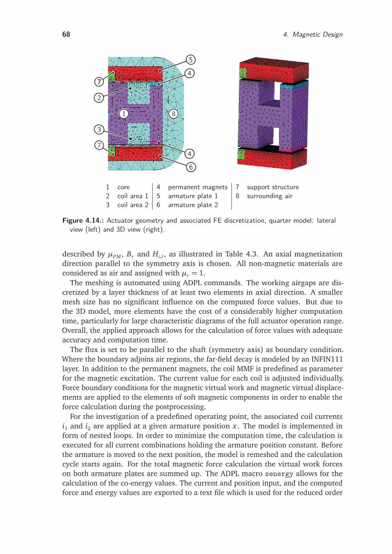
68 4. Magnetic Design
1
2
3
4
4
5
6
7
77
8
1 core 4 permanent magnets 7 support structure2 coil area 1 5 armature plate 1 8 surrounding air3 coil area 2 6 armature plate 2
Figure 4.14.: Actuator geometry and associated FE discretization, quarter model: lateralview (left) and 3D view (right).
described by µPM , Br and HcJ , as illustrated in Table 4.3. An axial magnetizationdirection parallel to the symmetry axis is chosen. All non-magnetic materials areconsidered as air and assigned with µr = 1.
The meshing is automated using ADPL commands. The working airgaps are dis-cretized by a layer thickness of at least two elements in axial direction. A smallermesh size has no significant influence on the computed force values. But due tothe 3D model, more elements have the cost of a considerably higher computationtime, particularly for large characteristic diagrams of the full actuator operation range.Overall, the applied approach allows for the calculation of force values with adequateaccuracy and computation time.
The flux is set to be parallel to the shaft (symmetry axis) as boundary condition.Where the boundary adjoins air regions, the far-field decay is modeled by an INFIN111layer. In addition to the permanent magnets, the coil MMF is predefined as parameterfor the magnetic excitation. The current value for each coil is adjusted individually.Force boundary conditions for the magnetic virtual work and magnetic virtual displace-ments are applied to the elements of soft magnetic components in order to enable theforce calculation during the postprocessing.
For the investigation of a predefined operating point, the associated coil currentsi1 and i2 are applied at a given armature position x . The model is implemented inform of nested loops. In order to minimize the computation time, the calculation isexecuted for all current combinations holding the armature position constant. Beforethe armature is moved to the next position, the model is remeshed and the calculationcycle starts again. For the total magnetic force calculation the virtual work forceson both armature plates are summed up. The ADPL macro senergy allows for thecalculation of the co-energy values. The current and position input, and the computedforce and energy values are exported to a text file which is used for the reduced order
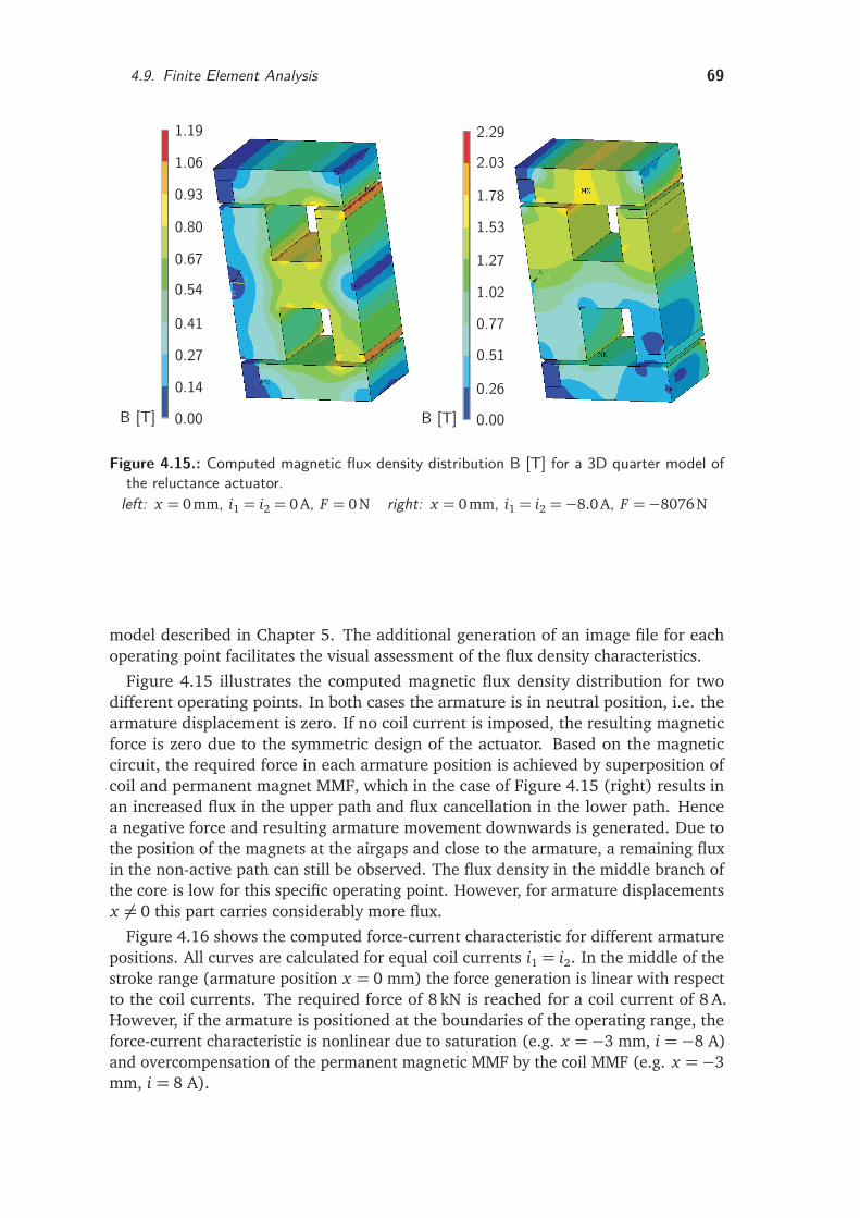
4.9. Finite Element Analysis 69
1.19
1.06
0.93
0.80
0.67
0.54
0.41
0.27
0.14
0.00
2.29
2.03
1.78
1.53
1.27
1.02
0.77
0.51
0.26
0.00B [T] B [T]
Figure 4.15.: Computed magnetic flux density distribution B [T] for a 3D quarter model ofthe reluctance actuator.
left: x = 0 mm, i1 = i2 = 0A, F = 0N right: x = 0 mm, i1 = i2 =−8.0A, F =−8076 N
model described in Chapter 5. The additional generation of an image file for eachoperating point facilitates the visual assessment of the flux density characteristics.
Figure 4.15 illustrates the computed magnetic flux density distribution for twodifferent operating points. In both cases the armature is in neutral position, i.e. thearmature displacement is zero. If no coil current is imposed, the resulting magneticforce is zero due to the symmetric design of the actuator. Based on the magneticcircuit, the required force in each armature position is achieved by superposition ofcoil and permanent magnet MMF, which in the case of Figure 4.15 (right) results inan increased flux in the upper path and flux cancellation in the lower path. Hencea negative force and resulting armature movement downwards is generated. Due tothe position of the magnets at the airgaps and close to the armature, a remaining fluxin the non-active path can still be observed. The flux density in the middle branch ofthe core is low for this specific operating point. However, for armature displacementsx 6= 0 this part carries considerably more flux.
Figure 4.16 shows the computed force-current characteristic for different armaturepositions. All curves are calculated for equal coil currents i1 = i2. In the middle of thestroke range (armature position x = 0 mm) the force generation is linear with respectto the coil currents. The required force of 8 kN is reached for a coil current of 8 A.However, if the armature is positioned at the boundaries of the operating range, theforce-current characteristic is nonlinear due to saturation (e.g. x =−3 mm, i =−8 A)and overcompensation of the permanent magnetic MMF by the coil MMF (e.g. x =−3mm, i = 8 A).
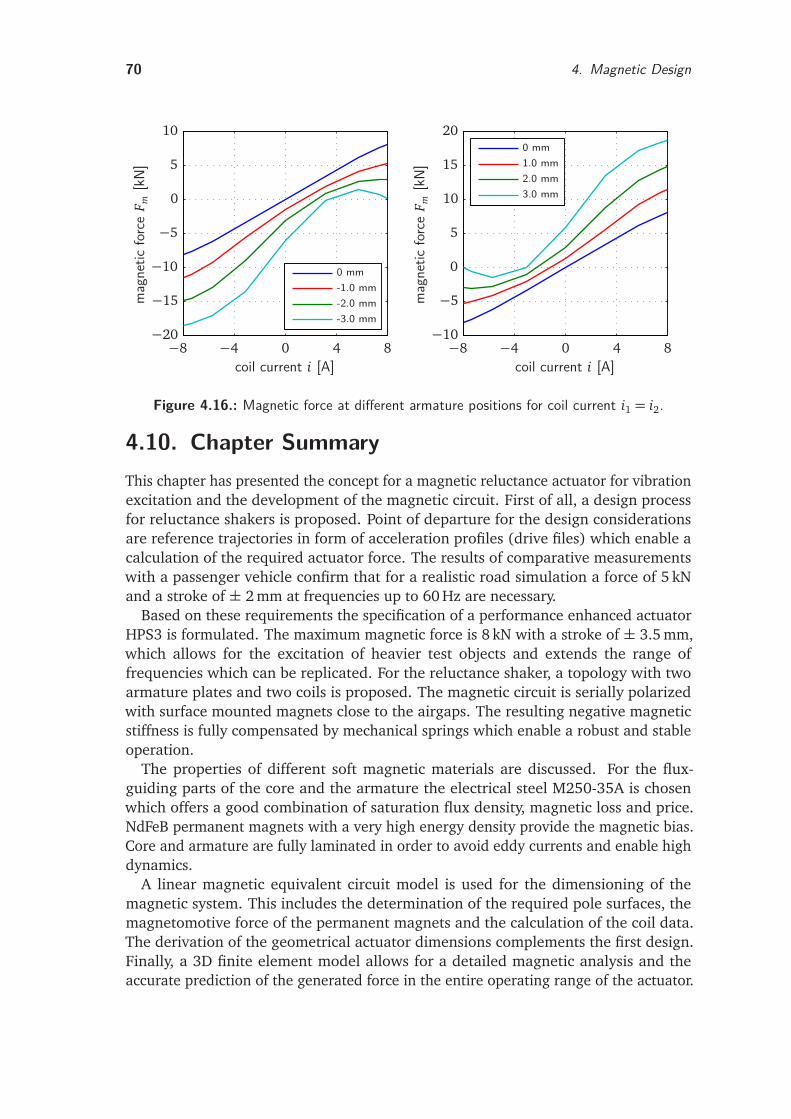
70 4. Magnetic Design
-3.0 mm-2.0 mm-1.0 mm0 mm
mag
netic
forc
eF m
[kN]
coil current i [A]−8 −4 0 4 8−20
−15
−10
−5
0
5
10
3.0 mm2.0 mm1.0 mm0 mm
mag
netic
forc
eF m
[kN]
coil current i [A]−8 −4 0 4 8−10
−5
0
5
10
15
20
Figure 4.16.: Magnetic force at different armature positions for coil current i1 = i2.
4.10. Chapter SummaryThis chapter has presented the concept for a magnetic reluctance actuator for vibrationexcitation and the development of the magnetic circuit. First of all, a design processfor reluctance shakers is proposed. Point of departure for the design considerationsare reference trajectories in form of acceleration profiles (drive files) which enable acalculation of the required actuator force. The results of comparative measurementswith a passenger vehicle confirm that for a realistic road simulation a force of 5 kNand a stroke of ± 2 mm at frequencies up to 60 Hz are necessary.
Based on these requirements the specification of a performance enhanced actuatorHPS3 is formulated. The maximum magnetic force is 8 kN with a stroke of ± 3.5 mm,which allows for the excitation of heavier test objects and extends the range offrequencies which can be replicated. For the reluctance shaker, a topology with twoarmature plates and two coils is proposed. The magnetic circuit is serially polarizedwith surface mounted magnets close to the airgaps. The resulting negative magneticstiffness is fully compensated by mechanical springs which enable a robust and stableoperation.
The properties of different soft magnetic materials are discussed. For the flux-guiding parts of the core and the armature the electrical steel M250-35A is chosenwhich offers a good combination of saturation flux density, magnetic loss and price.NdFeB permanent magnets with a very high energy density provide the magnetic bias.Core and armature are fully laminated in order to avoid eddy currents and enable highdynamics.
A linear magnetic equivalent circuit model is used for the dimensioning of themagnetic system. This includes the determination of the required pole surfaces, themagnetomotive force of the permanent magnets and the calculation of the coil data.The derivation of the geometrical actuator dimensions complements the first design.Finally, a 3D finite element model allows for a detailed magnetic analysis and theaccurate prediction of the generated force in the entire operating range of the actuator.
5. Energy-based Modeling and SimulationFor the preliminary design static and dynamic lumped parameter models were used.An important tool for the accurate prediction of the actuator performance is a detaileddynamics simulation. The challenges lie in the characterization of nonlinearities dueto saturation and the time-varying airgap length of translatory reluctance actuators.The simulation must cope with the partly contradictory demands for high accuracy,low computational cost and sufficient flexibility.
This chapter describes an energy-based simulation approach in which the dynamicsystem, the actuator, is seen as an energy transformation device. The method combinesthe high accuracy of FE simulations with the fast computation of a reduced order ana-lytical model. First of all, the role of co-energy for the description of nonlinear magneticsystems is explained. Moreover, the reduced order approach and the approximation ofco-energy hypersurfaces by polynomials are described. Finally, the mechatronic modelstructure is presented in detail. The system allows for the simulation of translatoryreluctance actuators with one or two energized windings.
5.1. Co-EnergyEnergy methods are widely used for the calculation of torque or force in nonlinear mag-netic systems. There are several motivations for adopting an energy-based perspectiveas described in the systematic overview by JELTSEMA and SCHERPEN [41]. First, complexphysical systems can be understood as a set of simpler subsystems with a mutualenergy exchange. Notably, magnetic actuators represent electro-magneto-mechanicalenergy transformation devices. Second, energy modeling is not restricted to a certainphysical domain or to linear systems only. Therefore, energy descriptions are partic-ularly suitable for the modeling of reluctance actuators with electric, magnetic andmechanical subdomains and typically nonlinear characteristics. Third, energy modelscan serve as basis for the design of control strategies [31,79,107].
KALLENBACH establishes the following minimal model of a solenoid using a sourceof electric energy (voltage source) and an energy storing element. The storage isrealized in form of magnetic field energy. Furthermore, the storing element dissipatesa part of its energy and converts another part into mechanical energy [47]. The simplesolenoid has a current-carrying coil, a moving iron armature and a nonlinear magneticcircuit. The coil is driven by a voltage source u0 and an internal resistance Ri, as shownin Figure 5.1. Using simple circuit elements the inductive energy-storing element ismodeled as a coil with resistance Rc and flux linkage Ψ(l, i), where l is the airgaplength of the solenoid and i the coil current.
Applying the induction law
u=dΨ
d t(5.1)
71
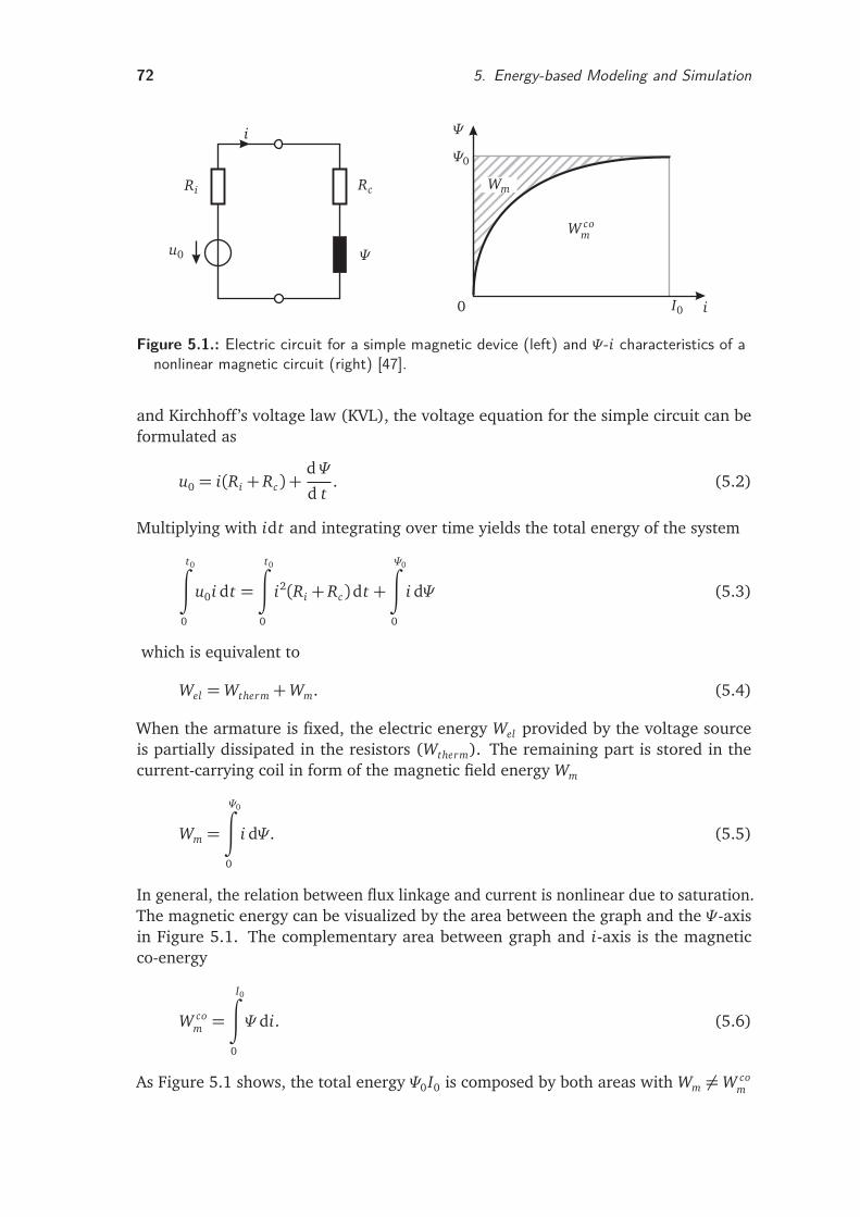
72 5. Energy-based Modeling and Simulation
u0
Ri
i
Rc
Ψ
0 i
Ψ
I0
W com
Wm
Ψ0
∗m
Figure 5.1.: Electric circuit for a simple magnetic device (left) and Ψ-i characteristics of anonlinear magnetic circuit (right) [47].
and Kirchhoff’s voltage law (KVL), the voltage equation for the simple circuit can beformulated as
u0 = i(Ri + Rc) +dΨ
d t. (5.2)
Multiplying with idt and integrating over time yields the total energy of the system
t0∫
0
u0i dt =
t0∫
0
i2(Ri + Rc)dt +
Ψ0∫
0
i dΨ (5.3)
which is equivalent to
Wel =Wtherm+Wm. (5.4)
When the armature is fixed, the electric energy Wel provided by the voltage sourceis partially dissipated in the resistors (Wtherm). The remaining part is stored in thecurrent-carrying coil in form of the magnetic field energy Wm
Wm =
Ψ0∫
0
i dΨ . (5.5)
In general, the relation between flux linkage and current is nonlinear due to saturation.The magnetic energy can be visualized by the area between the graph and the Ψ-axisin Figure 5.1. The complementary area between graph and i-axis is the magneticco-energy
W com =
I0∫
0
Ψ di. (5.6)
As Figure 5.1 shows, the total energy Ψ0I0 is composed by both areas with Wm 6=W com
5.2. Reduced Order Approach 73
due to the nonlinear magnetic circuit
Wm+W com = Ψ0I0, (5.7)
or more general
Wm+W com = i(t)Ψ(t). (5.8)
Unlike the magnetic energy, the co-energy has no direct physical meaning. However,it can be used as a general quantity for the derivation of important parameters inmagnetic systems (see Section 5.4).
5.2. Reduced Order ApproachProblems in the modeling of magnetic actuators arise mainly from their inherentnonlinear properties. This is basically due to two reasons. First, the reluctance forceis nonlinear with respect to the length of the active airgap and accordingly to thearmature position, see (3.15). Second, the generated force exhibits in many cases anonlinear relation to the injected coil current, which is caused by the B-H curve of thesoft magnetic material. In order to obtain a small overall actuator size, the materialis often operated well into the saturation range for advanced designs. In addition tothese two main concerns, magnetic devices show other complex characteristics such asfringing flux, which complicates detailed modeling.
General Objectives
The objective of the advanced model presented in this section is an accurate andfast simulation of the developed magnetic actuators HPS2 (see Section 6.2.4) andHPS3. The model should be suitable for direct implementation in a system simulationsoftware package and allow for control design. Furthermore, important phenomenasuch as the nonlinearity of magnetic force with respect to coil currents and armatureposition as well as flux leakage should be incorporated.
Basically three requirements on a simulation model can be formulated accordingto [50]:
• high accuracy
• acceptable computational cost
• sufficient flexibility.
Coupled Simulation
As discussed in Section 3.4.4, there is no single modeling method which is capable offulfilling all these requirements. Thus a hybrid approach is chosen [49,80], which cou-ples two simulation programs. Here a FE simulation program and a system simulationprogram are used.
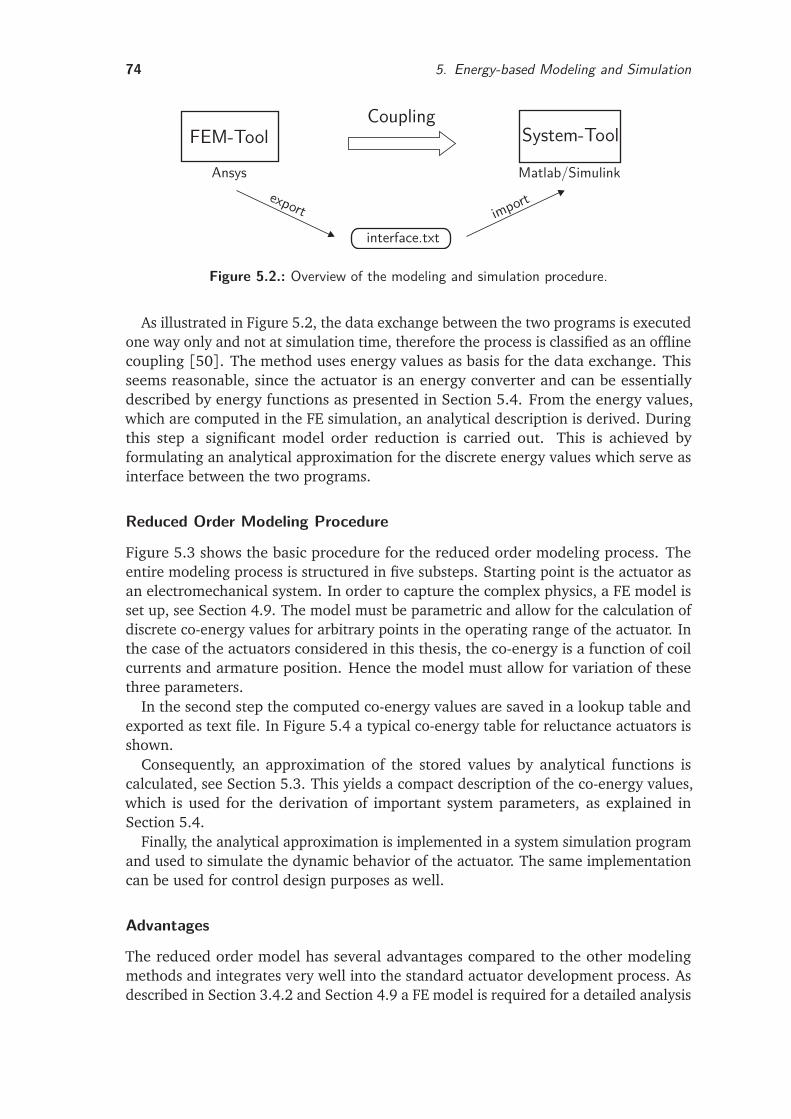
74 5. Energy-based Modeling and Simulation
FEM-ToolCoupling
System-Tool
Ansysexport
interface.txtimport
Matlab/Simulink
Figure 5.2.: Overview of the modeling and simulation procedure.
As illustrated in Figure 5.2, the data exchange between the two programs is executedone way only and not at simulation time, therefore the process is classified as an offlinecoupling [50]. The method uses energy values as basis for the data exchange. Thisseems reasonable, since the actuator is an energy converter and can be essentiallydescribed by energy functions as presented in Section 5.4. From the energy values,which are computed in the FE simulation, an analytical description is derived. Duringthis step a significant model order reduction is carried out. This is achieved byformulating an analytical approximation for the discrete energy values which serve asinterface between the two programs.
Reduced Order Modeling Procedure
Figure 5.3 shows the basic procedure for the reduced order modeling process. Theentire modeling process is structured in five substeps. Starting point is the actuator asan electromechanical system. In order to capture the complex physics, a FE model isset up, see Section 4.9. The model must be parametric and allow for the calculation ofdiscrete co-energy values for arbitrary points in the operating range of the actuator. Inthe case of the actuators considered in this thesis, the co-energy is a function of coilcurrents and armature position. Hence the model must allow for variation of thesethree parameters.
In the second step the computed co-energy values are saved in a lookup table andexported as text file. In Figure 5.4 a typical co-energy table for reluctance actuators isshown.
Consequently, an approximation of the stored values by analytical functions iscalculated, see Section 5.3. This yields a compact description of the co-energy values,which is used for the derivation of important system parameters, as explained inSection 5.4.
Finally, the analytical approximation is implemented in a system simulation programand used to simulate the dynamic behavior of the actuator. The same implementationcan be used for control design purposes as well.
Advantages
The reduced order model has several advantages compared to the other modelingmethods and integrates very well into the standard actuator development process. Asdescribed in Section 3.4.2 and Section 4.9 a FE model is required for a detailed analysis
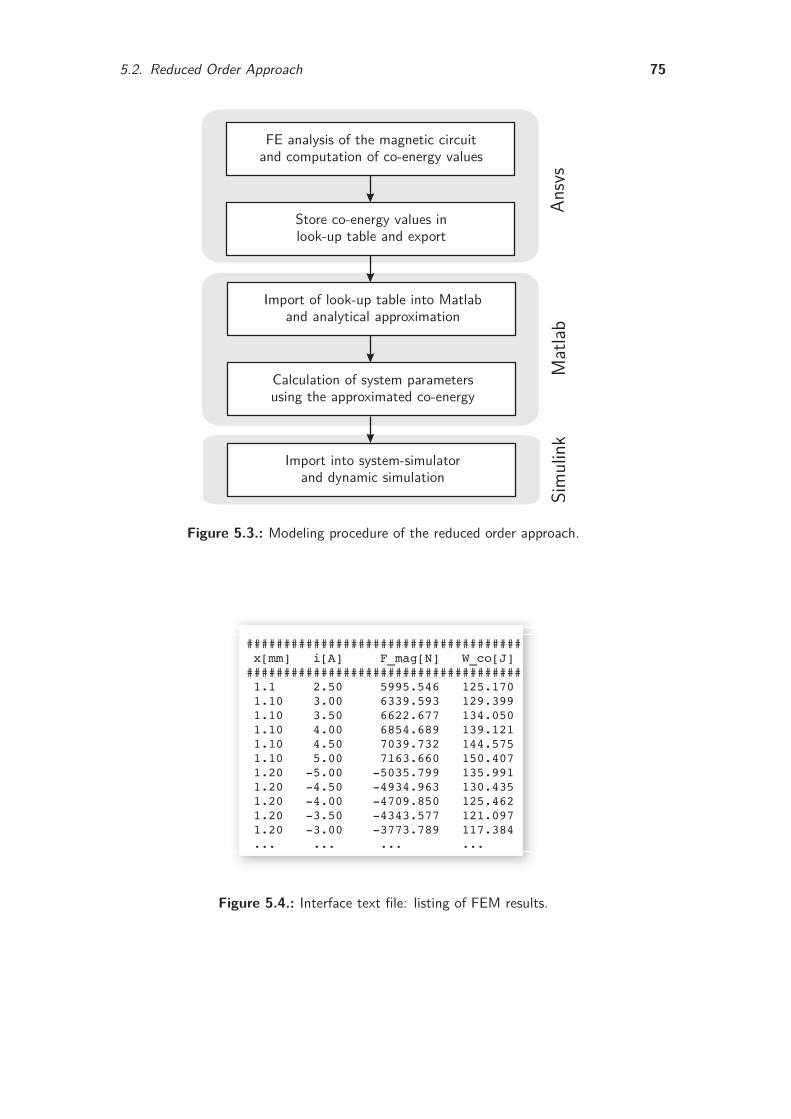
5.2. Reduced Order Approach 75
FE analysis of the magnetic circuitand computation of co-energy values
Store co-energy values inlook-up table and export
Import of look-up table into Matlaband analytical approximation
Calculation of system parametersusing the approximated co-energy
Import into system-simulatorand dynamic simulation
Ansy
sM
atlab
Sim
ulin
kFigure 5.3.: Modeling procedure of the reduced order approach.
#####################################x[mm] i[A] F_mag[N] W_co[J]#####################################1.1 2.50 5995.546 125.1701.10 3.00 6339.593 129.3991.10 3.50 6622.677 134.0501.10 4.00 6854.689 139.1211.10 4.50 7039.732 144.5751.10 5.00 7163.660 150.4071.20 -5.00 -5035.799 135.9911.20 -4.50 -4934.963 130.4351.20 -4.00 -4709.850 125.4621.20 -3.50 -4343.577 121.0971.20 -3.00 -3773.789 117.384... ... ... ...
Figure 5.4.: Interface text file: listing of FEM results.
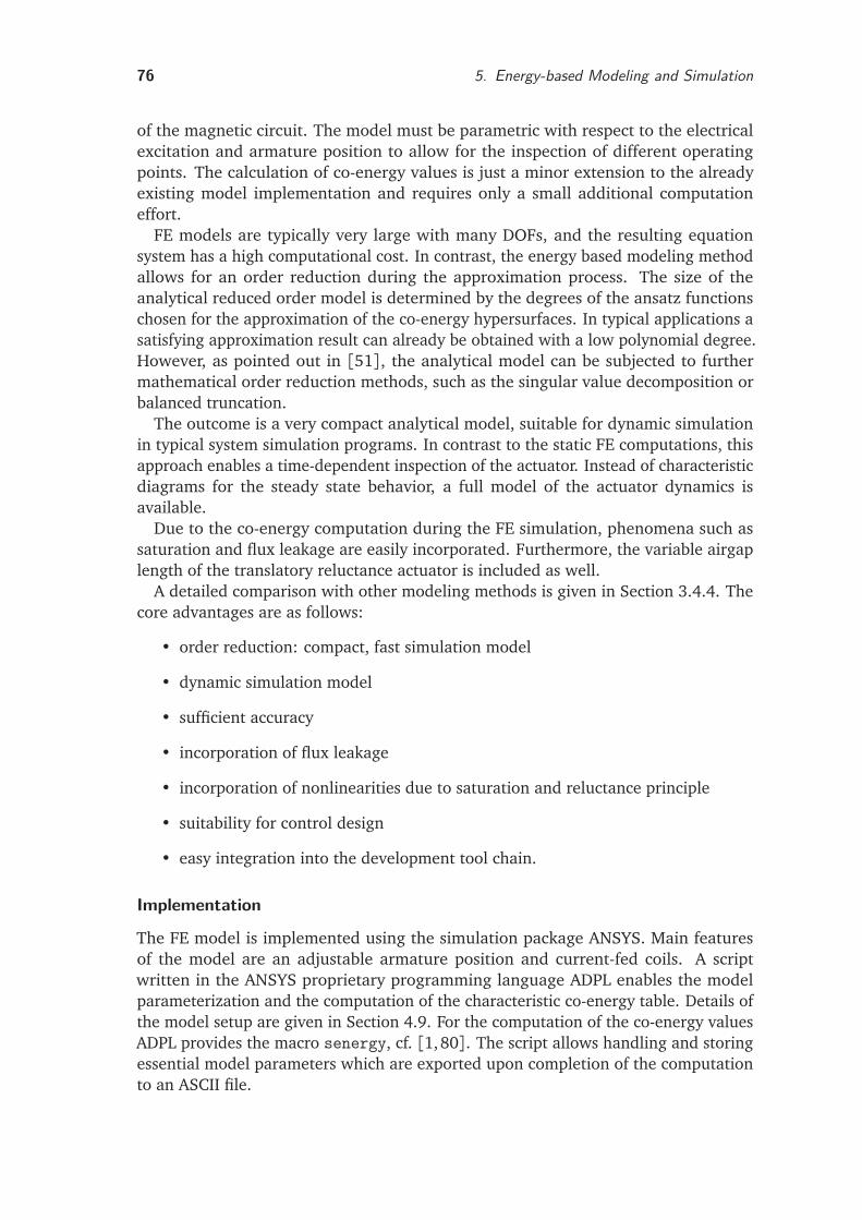
76 5. Energy-based Modeling and Simulation
of the magnetic circuit. The model must be parametric with respect to the electricalexcitation and armature position to allow for the inspection of different operatingpoints. The calculation of co-energy values is just a minor extension to the alreadyexisting model implementation and requires only a small additional computationeffort.
FE models are typically very large with many DOFs, and the resulting equationsystem has a high computational cost. In contrast, the energy based modeling methodallows for an order reduction during the approximation process. The size of theanalytical reduced order model is determined by the degrees of the ansatz functionschosen for the approximation of the co-energy hypersurfaces. In typical applications asatisfying approximation result can already be obtained with a low polynomial degree.However, as pointed out in [51], the analytical model can be subjected to furthermathematical order reduction methods, such as the singular value decomposition orbalanced truncation.
The outcome is a very compact analytical model, suitable for dynamic simulationin typical system simulation programs. In contrast to the static FE computations, thisapproach enables a time-dependent inspection of the actuator. Instead of characteristicdiagrams for the steady state behavior, a full model of the actuator dynamics isavailable.
Due to the co-energy computation during the FE simulation, phenomena such assaturation and flux leakage are easily incorporated. Furthermore, the variable airgaplength of the translatory reluctance actuator is included as well.
A detailed comparison with other modeling methods is given in Section 3.4.4. Thecore advantages are as follows:
• order reduction: compact, fast simulation model
• dynamic simulation model
• sufficient accuracy
• incorporation of flux leakage
• incorporation of nonlinearities due to saturation and reluctance principle
• suitability for control design
• easy integration into the development tool chain.
Implementation
The FE model is implemented using the simulation package ANSYS. Main featuresof the model are an adjustable armature position and current-fed coils. A scriptwritten in the ANSYS proprietary programming language ADPL enables the modelparameterization and the computation of the characteristic co-energy table. Details ofthe model setup are given in Section 4.9. For the computation of the co-energy valuesADPL provides the macro senergy, cf. [1,80]. The script allows handling and storingessential model parameters which are exported upon completion of the computationto an ASCII file.
5.3. Approximation Methods 77
The subsequent approximation of the co-energy hypersurface, the derivation ofsystem parameters and the parameterization of the simulation is subdivided into threemodules. This approach facilitates debugging and the developing of add-ons, e.g.for data analysis and visualization. The implementation is realized in the numericalcomputing environment and programming language MATLAB/SIMULINK (R2011b) fromMATHWORKS1, which offers a wide range of possibilities for matrix manipulation andplotting of data and functions. This way, the full numerical possibilities of the providedtoolboxes can be used, such as least squares fitting and spline approximation.
SIMULINK has been chosen for system simulation since it offers tight integration withthe rest of the MATLAB environment and the model can be parameterized from MATLAB.This allows for an easy analysis of parameter variations. In addition, the combinationof both programs is well suited for control design, as described in Section 5.6.
Furthermore, the MATLAB/SIMULINK implementation integrates very well into theDSPACE-based experimental setup, see Section 6.3. This reduces the time required forthe experimental validation of simulation results significantly.
5.3. Approximation Methods
The discrete co-energy values are described by an analytical function. For this purposea polynomial approximation using the least-squares method is carried out [23]. If theactuator is in a single-phase operating mode and both coils are connected in series,the characteristic co-energy map is a two-dimensional function of armature positionx and coil current i. Initially, for each current value an optimal polynomial withdegree m in position direction is calculated. The coefficients of these polynomials showa current-dependency which is again approximated by a least-squares fit in currentdirection with degree n polynomials.
The introduction of position and current vectors
x T =
xm xm−1 . . . x 1
(5.9)
iT =
in in−1 . . . i 1
(5.10)
enables the formulation of the co-energy function in matrix-vector notation as
W com = f (x , i) = x T ·C · i =
m∑
j=0
n∑
k=0
c j,k x j ik. (5.11)
Here, the single coefficients c j,k are combined in the coefficient matrix C whichcontains the weights for all products of x j and ik. Besides the concise representation,the notation as a bilinear form enables a straightforward implementation in the systemsimulation software [117]. For the determination of relevant system parameters asderivatives of the co-energy function only the position and current vectors are modifiedwhile the coefficient matrix remains unchanged.
1 http://www.mathworks.com/
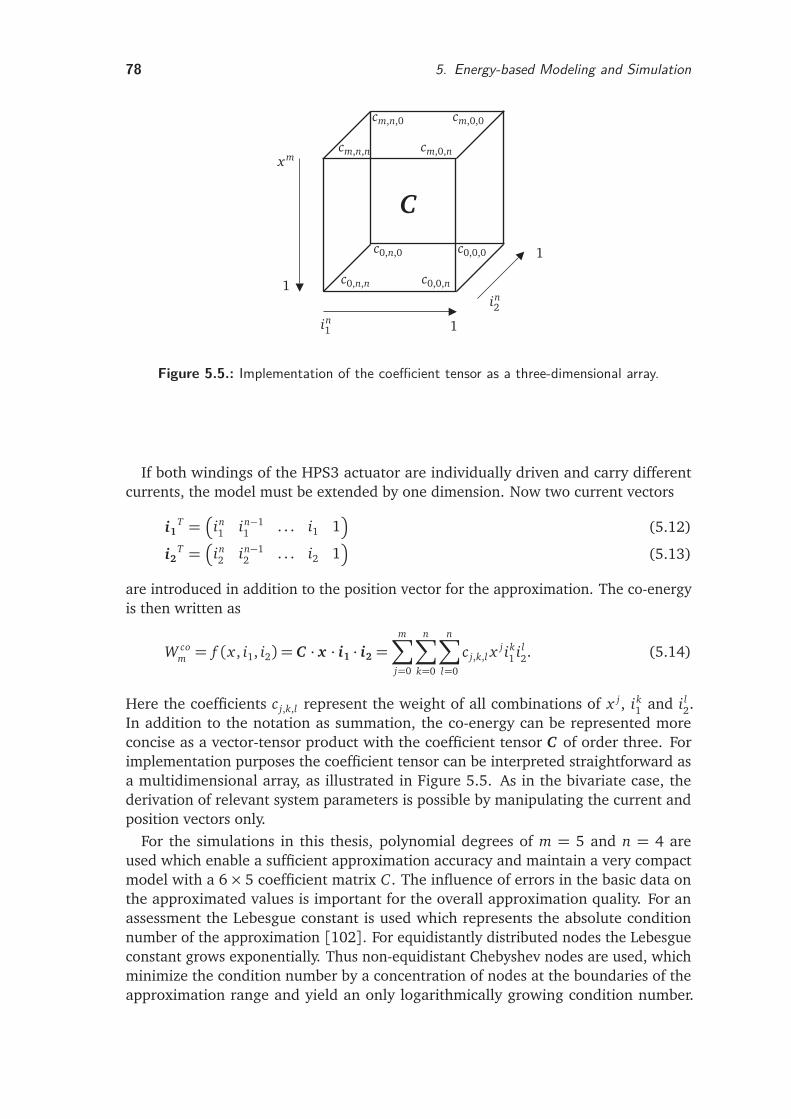
78 5. Energy-based Modeling and Simulation
xm
1
1
1
in1
in2
C
cm,n,n cm,0,n
cm,n,0 cm,0,0
c0,n,n
c0,n,0
c0,0,n
c0,0,0
Figure 5.5.: Implementation of the coefficient tensor as a three-dimensional array.
If both windings of the HPS3 actuator are individually driven and carry differentcurrents, the model must be extended by one dimension. Now two current vectors
i1T =
in1 in−1
1 . . . i1 1
(5.12)
i2T =
in2 in−1
2 . . . i2 1
(5.13)
are introduced in addition to the position vector for the approximation. The co-energyis then written as
W com = f (x , i1, i2) = C · x · i1 · i2 =
m∑
j=0
n∑
k=0
n∑
l=0
c j,k,l xj ik
1 i l2. (5.14)
Here the coefficients c j,k,l represent the weight of all combinations of x j, ik1 and i l
2.In addition to the notation as summation, the co-energy can be represented moreconcise as a vector-tensor product with the coefficient tensor C of order three. Forimplementation purposes the coefficient tensor can be interpreted straightforward asa multidimensional array, as illustrated in Figure 5.5. As in the bivariate case, thederivation of relevant system parameters is possible by manipulating the current andposition vectors only.
For the simulations in this thesis, polynomial degrees of m = 5 and n = 4 areused which enable a sufficient approximation accuracy and maintain a very compactmodel with a 6× 5 coefficient matrix C . The influence of errors in the basic data onthe approximated values is important for the overall approximation quality. For anassessment the Lebesgue constant is used which represents the absolute conditionnumber of the approximation [102]. For equidistantly distributed nodes the Lebesgueconstant grows exponentially. Thus non-equidistant Chebyshev nodes are used, whichminimize the condition number by a concentration of nodes at the boundaries of theapproximation range and yield an only logarithmically growing condition number.
5.4. System Parameters 79
Chebyshev nodes ξr of the second kind [4] are defined by
ξr = cos rπ
s
, r = 0,1, . . . , s (5.15)
in the interval [−1, 1]. In order to cover the operating range of the actuator, a lineartransformation is used
x r = a+b− a
2(ξr + 1) (5.16)
with x r being the nodes in the arbitrary interval [a,b]. For the approximation ninenodes are used (s = 8), since a higher node number has no significant influence on thesimulation results.
The Chebyshev distribution is already incorporated in the FE model for the numericalcomputation of the co-energy values at the respective nodes. Therefore, an excessiveovershoot at the boundaries of the approximation range can be avoided and oscillationsof the approximation polynomials are effectively reduced.
5.4. System ParametersFor the sake of clarity, the determination of the system parameters is first carriedout for the single winding case [86]. Then the representation is expanded for twoenergized windings as it will be used for the HPS3 actuator. A detailed introduction tothe energy conversion of nonlinear permanent magnet systems with multiple windingsis presented by STRAHAN in [105].
5.4.1. Single Energized WindingThe law of energy conservation for a magnetic actuator
dWel − dWtherm = dWm+ dWmech (5.17)
states that the differential change of electrical input energy dWel can be split up intothe change of dissipated energy dWtherm, stored magnetic energy dWm and mechanicalenergy dWmech. The net input energy on the left side of (5.17) can be formulated with(5.2) as
dWel − dWtherm = u0idt − (Ri + Rc)i2dt = idΨ . (5.18)
For the determination of the magnetic force Fm the concept of virtual work is applied
Fm · dx = dWmech, (5.19)
which yields due to the energy conservation expressed in (5.17):
dWm = i · dψ− dWmech
= i · dψ− Fm · dx . (5.20)
80 5. Energy-based Modeling and Simulation
The differential of (iΨ) is described by
d(iΨ) = i · dΨ +Ψ · di. (5.21)
Then the differential form of (5.8) can be written with (5.20) and (5.21) as
dW com (x , i) = d(iψ)− dWm(ψ, x)
= i · dΨ +Ψ · di− i · dΨ + Fm · dx=ψ · di+ Fm · dx . (5.22)
Generally, the magnetic co-energy is a time-dependent function of coil current i andarmature displacement x , W co
m = f (x(t), i(t)), which leads to the differential
dW com (x , i) =
∂ W com (x , i)∂ i
· di+∂ W co
m (x , i)∂ x
· dx . (5.23)
By comparing (5.22) and (5.23), expressions for magnetic force
Fm =∂ W co
m (x , i)∂ x
(5.24)
and flux linkage
Ψ =∂ W co
m (x , i)∂ i
(5.25)
are derived. Furthermore, the induced voltage in the winding is denoted by
uind =dΨ
d t(5.26)
and can be finally rewritten using the magnetic co-energy as:
uind(i, x) =∂ 2 W co
m
∂ i2 · d i
d t+∂ 2 W co
m
∂ i ∂ x· d x
d t. (5.27)
5.4.2. Two Energized WindingsThe derivation of system parameters from the magnetic co-energy is now extended forthe case of two windings that are energized with currents ik (k = 1, 2) respectively.Similar to the case of a single winding, the basis for the derivation is the conservationof energy. Point of departure is (5.18), which is modified for the two-phase case:
dWel − dWtherm = u1 · i1 · dt + u2 · i2 · dt − (Ri1+ Rc1)i21dt − (Ri2+ Rc2)i
22dt
= dΨ1 · i1+ dΨ2 · i2. (5.28)
The differential magnetic energy is then given by (cf. (5.20))
dWm = i1 · dψ1+ i2 · dψ2− dWmech
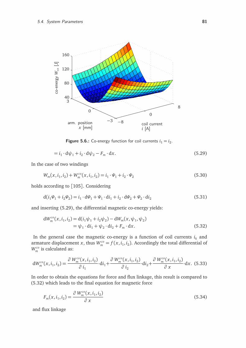
5.4. System Parameters 81
co-e
nerg
yW
co[J
]
arm. positionx [mm]
coil currenti [A]
−8
0
8
−3
0
340
80
120
160
Figure 5.6.: Co-energy function for coil currents i1 = i2.
= i1 · dψ1+ i2 · dψ2− Fm · dx . (5.29)
In the case of two windings
Wm(x , i1, i2) +W com (x , i1, i2) = i1 ·Ψ1+ i2 ·Ψ2 (5.30)
holds according to [105]. Considering
d(i1Ψ1+ i2Ψ2) = i1 · dΨ1+Ψ1 · di1+ i2 · dΨ2+Ψ2 · di2 (5.31)
and inserting (5.29), the differential magnetic co-energy yields:
dW com (x , i1, i2) = d(i1ψ1+ i2ψ2)− dWm(x ,ψ1,ψ2)
=ψ1 · di1+ψ2 · di2+ Fm · dx . (5.32)
In the general case the magnetic co-energy is a function of coil currents ik andarmature displacement x , thus W co
m = f (x , i1, i2). Accordingly the total differential ofW co
m is calculated as:
dW com (x , i1, i2) =
∂ W com (x , i1, i2)∂ i1
·di1+∂ W co
m (x , i1, i2)∂ i2
·di2+∂ W co
m (x , i1, i2)∂ x
·dx . (5.33)
In order to obtain the equations for force and flux linkage, this result is compared to(5.32) which leads to the final equation for magnetic force
Fm(x , i1, i2) =∂ W co
m (x , i1, i2)∂ x
(5.34)
and flux linkage
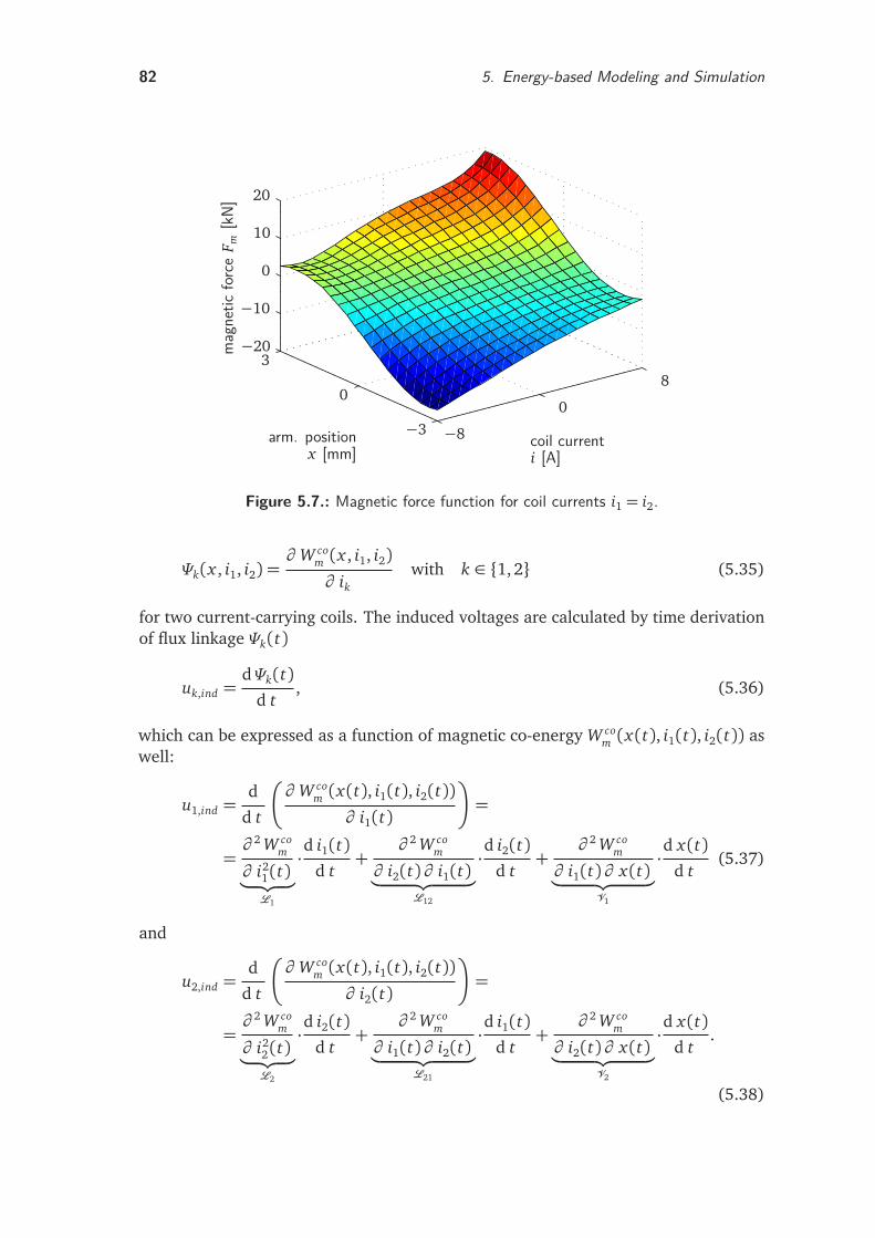
82 5. Energy-based Modeling and Simulation
mag
netic
forc
eF m
[kN]
arm. positionx [mm]
coil currenti [A]
−8
0
8
−3
0
3−20
−10
0
10
20
Figure 5.7.: Magnetic force function for coil currents i1 = i2.
Ψk(x , i1, i2) =∂ W co
m (x , i1, i2)∂ ik
with k ∈ 1, 2 (5.35)
for two current-carrying coils. The induced voltages are calculated by time derivationof flux linkage Ψk(t)
uk,ind =dΨk(t)
d t, (5.36)
which can be expressed as a function of magnetic co-energy W com (x(t), i1(t), i2(t)) as
well:
u1,ind =d
d t
∂ W com (x(t), i1(t), i2(t))
∂ i1(t)
=
=∂ 2 W co
m
∂ i21(t)
︸ ︷︷ ︸
L1
·d i1(t)d t
+∂ 2 W co
m
∂ i2(t)∂ i1(t)︸ ︷︷ ︸
L12
·d i2(t)d t
+∂ 2 W co
m
∂ i1(t)∂ x(t)︸ ︷︷ ︸
V1
·d x(t)d t
(5.37)
and
u2,ind =d
d t
∂ W com (x(t), i1(t), i2(t))
∂ i2(t)
=
=∂ 2 W co
m
∂ i22(t)
︸ ︷︷ ︸
L2
·d i2(t)d t
+∂ 2 W co
m
∂ i1(t)∂ i2(t)︸ ︷︷ ︸
L21
·d i1(t)d t
+∂ 2 W co
m
∂ i2(t)∂ x(t)︸ ︷︷ ︸
V2
·d x(t)d t
.
(5.38)
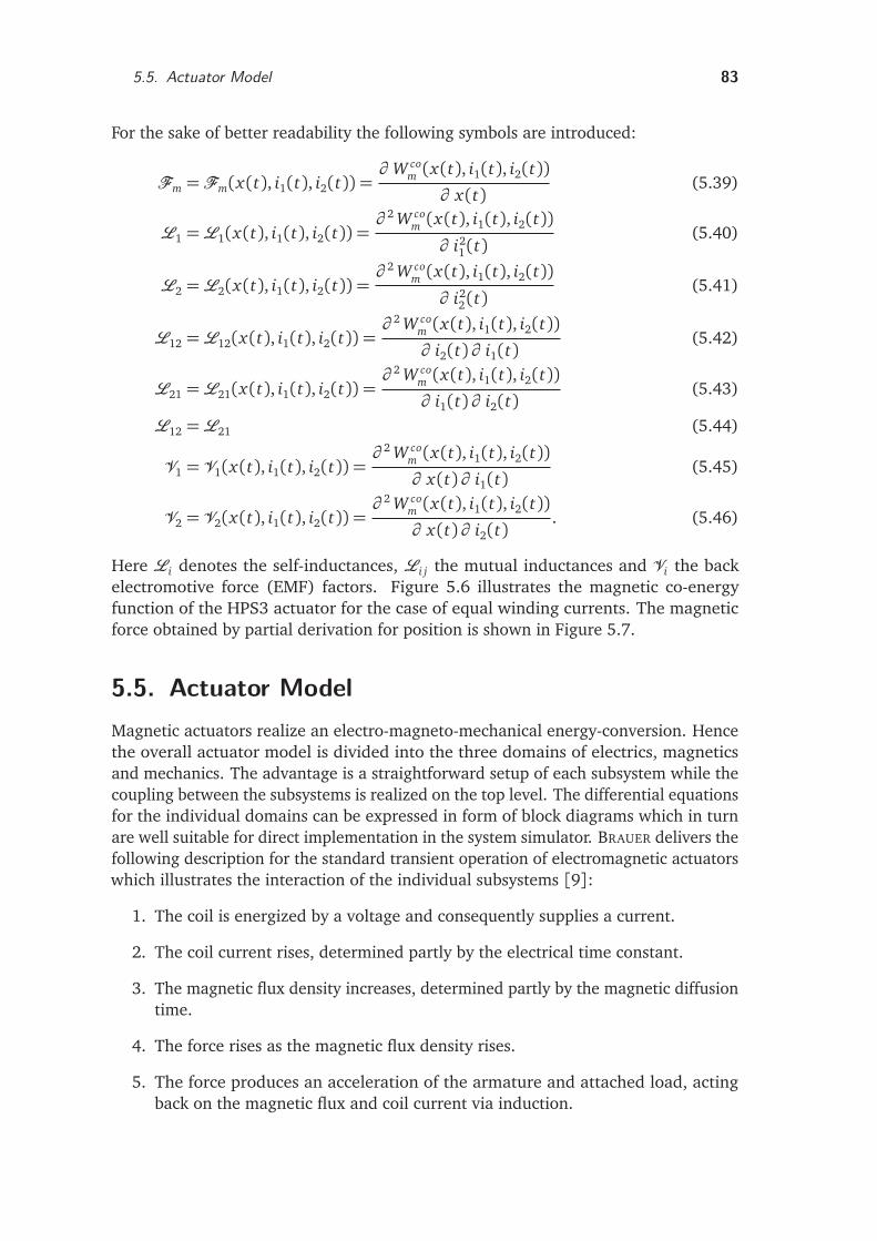
5.5. Actuator Model 83
For the sake of better readability the following symbols are introduced:
Fm =Fm(x(t), i1(t), i2(t)) =∂ W co
m (x(t), i1(t), i2(t))∂ x(t)
(5.39)
L1 =L1(x(t), i1(t), i2(t)) =∂ 2 W co
m (x(t), i1(t), i2(t))
∂ i21(t)
(5.40)
L2 =L2(x(t), i1(t), i2(t)) =∂ 2 W co
m (x(t), i1(t), i2(t))
∂ i22(t)
(5.41)
L12 =L12(x(t), i1(t), i2(t)) =∂ 2 W co
m (x(t), i1(t), i2(t))∂ i2(t)∂ i1(t)
(5.42)
L21 =L21(x(t), i1(t), i2(t)) =∂ 2 W co
m (x(t), i1(t), i2(t))∂ i1(t)∂ i2(t)
(5.43)
L12 =L21 (5.44)
V1 = V1(x(t), i1(t), i2(t)) =∂ 2 W co
m (x(t), i1(t), i2(t))∂ x(t)∂ i1(t)
(5.45)
V2 = V2(x(t), i1(t), i2(t)) =∂ 2 W co
m (x(t), i1(t), i2(t))∂ x(t)∂ i2(t)
. (5.46)
Here Li denotes the self-inductances, Li j the mutual inductances and Vi the backelectromotive force (EMF) factors. Figure 5.6 illustrates the magnetic co-energyfunction of the HPS3 actuator for the case of equal winding currents. The magneticforce obtained by partial derivation for position is shown in Figure 5.7.
5.5. Actuator ModelMagnetic actuators realize an electro-magneto-mechanical energy-conversion. Hencethe overall actuator model is divided into the three domains of electrics, magneticsand mechanics. The advantage is a straightforward setup of each subsystem while thecoupling between the subsystems is realized on the top level. The differential equationsfor the individual domains can be expressed in form of block diagrams which in turnare well suitable for direct implementation in the system simulator. BRAUER delivers thefollowing description for the standard transient operation of electromagnetic actuatorswhich illustrates the interaction of the individual subsystems [9]:
1. The coil is energized by a voltage and consequently supplies a current.
2. The coil current rises, determined partly by the electrical time constant.
3. The magnetic flux density increases, determined partly by the magnetic diffusiontime.
4. The force rises as the magnetic flux density rises.
5. The force produces an acceleration of the armature and attached load, actingback on the magnetic flux and coil current via induction.
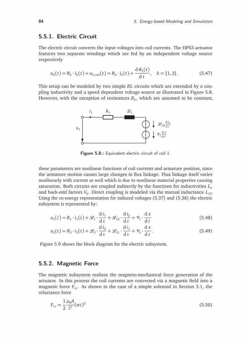
84 5. Energy-based Modeling and Simulation
5.5.1. Electric Circuit
The electric circuit converts the input voltages into coil currents. The HPS3 actuatorfeatures two separate windings which are fed by an independent voltage sourcerespectively
uk(t) = Rk · ik(t) + uk,ind(t) = Rk · ik(t) +dΨk(t)
d t, k = 1, 2. (5.47)
This setup can be modeled by two simple RL circuits which are extended by a cou-pling inductivity and a speed dependent voltage source as illustrated in Figure 5.8.However, with the exception of resistances Rk, which are assumed to be constant,
u1
i1 R1 L1
L12d i2d t
V1d xd t
Figure 5.8.: Equivalent electric circuit of coil 1.
these parameters are nonlinear functions of coil currents and armature position, sincethe armature motion causes large changes in flux linkage. Flux linkage itself variesnonlinearly with current as well which is due to nonlinear material properties causingsaturation. Both circuits are coupled indirectly by the functions for inductivities Lk
and back-emf factors Vk. Direct coupling is modeled via the mutual inductance L12.Using the co-energy representation for induced voltages (5.37) and (5.38) the electricsubsystem is represented by:
u1(t) = R1 · i1(t) +L1 ·d i1d t+L12 ·
d i2d t+V1 ·
d x
d t(5.48)
u2(t) = R2 · i2(t) +L2 ·d i2d t+L21 ·
d i1d t+V2 ·
d x
d t. (5.49)
Figure 5.9 shows the block diagram for the electric subsystem.
5.5.2. Magnetic Force
The magnetic subsystem realizes the magneto-mechanical force generation of theactuator. In this process the coil currents are converted via a magnetic field into amagnetic force Fm. As shown in the case of a simple solenoid in Section 3.1, thereluctance force
Fre =1
2
µ0A
l2 (wi)2 (5.50)
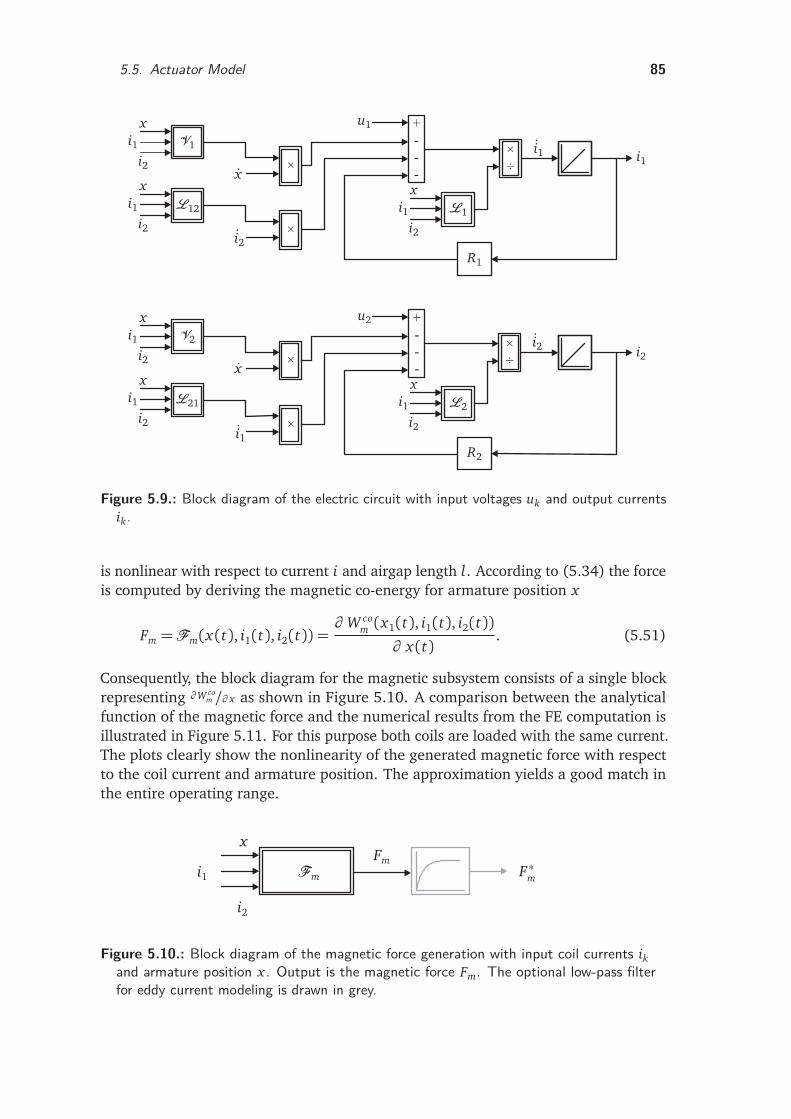
5.5. Actuator Model 85
+
-
-
-
+
-
-
-
×
÷
×
÷
×
×
×
×
xx
x
xx
x
i1i1
i1
i1i1
i1i1
i2i2
i2 i2
i2i2
i2
x
x
i1
i1
i2
i2
V1
L12
V2
L21
L1
R1
L2
R2
u1
u2
Figure 5.9.: Block diagram of the electric circuit with input voltages uk and output currentsik.
is nonlinear with respect to current i and airgap length l. According to (5.34) the forceis computed by deriving the magnetic co-energy for armature position x
Fm =Fm(x(t), i1(t), i2(t)) =∂ W co
m (x1(t), i1(t), i2(t))∂ x(t)
. (5.51)
Consequently, the block diagram for the magnetic subsystem consists of a single blockrepresenting ∂W co
m /∂ x as shown in Figure 5.10. A comparison between the analyticalfunction of the magnetic force and the numerical results from the FE computation isillustrated in Figure 5.11. For this purpose both coils are loaded with the same current.The plots clearly show the nonlinearity of the generated magnetic force with respectto the coil current and armature position. The approximation yields a good match inthe entire operating range.
x
i1
i2
Fm
FmF ∗m
Figure 5.10.: Block diagram of the magnetic force generation with input coil currents ikand armature position x . Output is the magnetic force Fm. The optional low-pass filterfor eddy current modeling is drawn in grey.
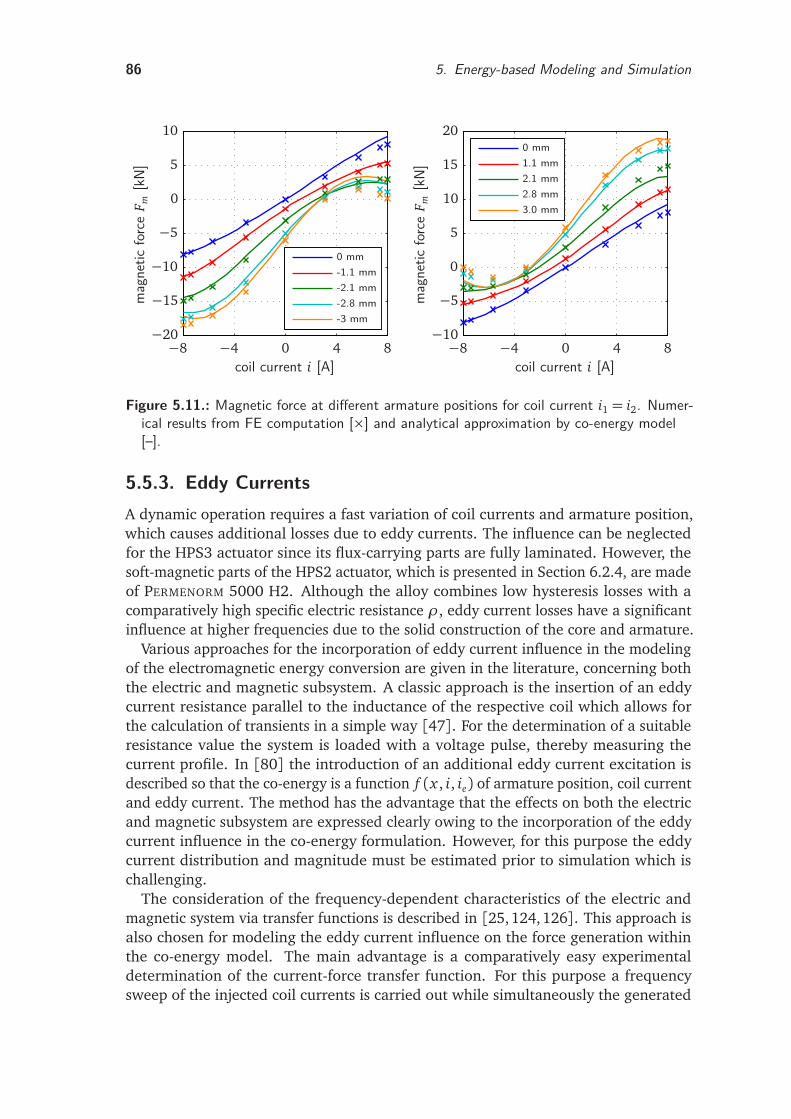
86 5. Energy-based Modeling and Simulation
-3 mm-2.8 mm-2.1 mm-1.1 mm0 mm
mag
netic
forc
eF m
[kN]
coil current i [A]−8 −4 0 4 8−20
−15
−10
−5
0
5
10
3.0 mm2.8 mm2.1 mm1.1 mm0 mm
mag
netic
forc
eF m
[kN]
coil current i [A]−8 −4 0 4 8−10
−5
0
5
10
15
20
Figure 5.11.: Magnetic force at different armature positions for coil current i1 = i2. Numer-ical results from FE computation [×] and analytical approximation by co-energy model[–].
5.5.3. Eddy CurrentsA dynamic operation requires a fast variation of coil currents and armature position,which causes additional losses due to eddy currents. The influence can be neglectedfor the HPS3 actuator since its flux-carrying parts are fully laminated. However, thesoft-magnetic parts of the HPS2 actuator, which is presented in Section 6.2.4, are madeof PERMENORM 5000 H2. Although the alloy combines low hysteresis losses with acomparatively high specific electric resistance ρ, eddy current losses have a significantinfluence at higher frequencies due to the solid construction of the core and armature.
Various approaches for the incorporation of eddy current influence in the modelingof the electromagnetic energy conversion are given in the literature, concerning boththe electric and magnetic subsystem. A classic approach is the insertion of an eddycurrent resistance parallel to the inductance of the respective coil which allows forthe calculation of transients in a simple way [47]. For the determination of a suitableresistance value the system is loaded with a voltage pulse, thereby measuring thecurrent profile. In [80] the introduction of an additional eddy current excitation isdescribed so that the co-energy is a function f (x , i, ie) of armature position, coil currentand eddy current. The method has the advantage that the effects on both the electricand magnetic subsystem are expressed clearly owing to the incorporation of the eddycurrent influence in the co-energy formulation. However, for this purpose the eddycurrent distribution and magnitude must be estimated prior to simulation which ischallenging.
The consideration of the frequency-dependent characteristics of the electric andmagnetic system via transfer functions is described in [25,124,126]. This approach isalso chosen for modeling the eddy current influence on the force generation withinthe co-energy model. The main advantage is a comparatively easy experimentaldetermination of the current-force transfer function. For this purpose a frequencysweep of the injected coil currents is carried out while simultaneously the generated
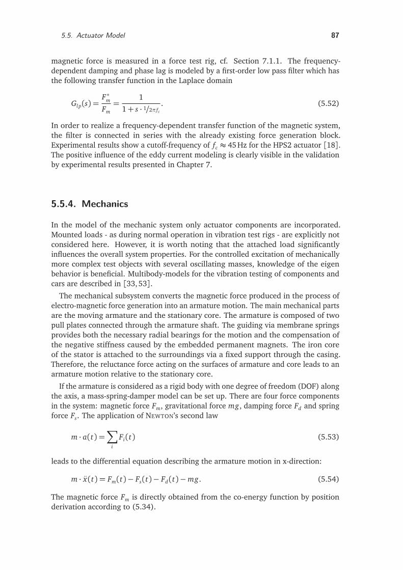
5.5. Actuator Model 87
magnetic force is measured in a force test rig, cf. Section 7.1.1. The frequency-dependent damping and phase lag is modeled by a first-order low pass filter which hasthe following transfer function in the Laplace domain
Gl p(s) =F ∗mFm=
1
1+ s · 1/2π fc
. (5.52)
In order to realize a frequency-dependent transfer function of the magnetic system,the filter is connected in series with the already existing force generation block.Experimental results show a cutoff-frequency of fc ≈ 45 Hz for the HPS2 actuator [18].The positive influence of the eddy current modeling is clearly visible in the validationby experimental results presented in Chapter 7.
5.5.4. Mechanics
In the model of the mechanic system only actuator components are incorporated.Mounted loads - as during normal operation in vibration test rigs - are explicitly notconsidered here. However, it is worth noting that the attached load significantlyinfluences the overall system properties. For the controlled excitation of mechanicallymore complex test objects with several oscillating masses, knowledge of the eigenbehavior is beneficial. Multibody-models for the vibration testing of components andcars are described in [33,53].
The mechanical subsystem converts the magnetic force produced in the process ofelectro-magnetic force generation into an armature motion. The main mechanical partsare the moving armature and the stationary core. The armature is composed of twopull plates connected through the armature shaft. The guiding via membrane springsprovides both the necessary radial bearings for the motion and the compensation ofthe negative stiffness caused by the embedded permanent magnets. The iron coreof the stator is attached to the surroundings via a fixed support through the casing.Therefore, the reluctance force acting on the surfaces of armature and core leads to anarmature motion relative to the stationary core.
If the armature is considered as a rigid body with one degree of freedom (DOF) alongthe axis, a mass-spring-damper model can be set up. There are four force componentsin the system: magnetic force Fm, gravitational force mg, damping force Fd and springforce Fs. The application of NEWTON’s second law
m · a(t) =∑
i
Fi(t) (5.53)
leads to the differential equation describing the armature motion in x-direction:
m · x(t) = Fm(t)− Fs(t)− Fd(t)−mg. (5.54)
The magnetic force Fm is directly obtained from the co-energy function by positionderivation according to (5.34).
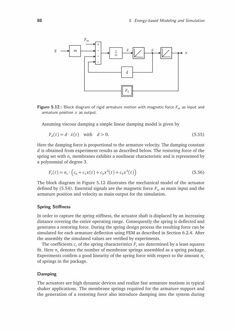
88 5. Energy-based Modeling and Simulation
+
-
-
-
g m
Fm
1m
x xx
d
FS
Figure 5.12.: Block diagram of rigid armature motion with magnetic force Fm as input andarmature position x as output.
Assuming viscous damping a simple linear damping model is given by
Fd(t) = d · x(t) with d > 0. (5.55)
Here the damping force is proportional to the armature velocity. The damping constantd is obtained from experiment results as described below. The restoring force of thespring set with ns membranes exhibits a nonlinear characteristic and is represented bya polynomial of degree 3.
Fs(t) = ns ·
c0+ c1 x(t) + c2 x2(t) + c3 x3(t)
(5.56)
The block diagram in Figure 5.12 illustrates the mechanical model of the actuatordefined by (5.54). Essential signals are the magnetic force Fm as main input and thearmature position and velocity as main output for the simulation.
Spring Stiffness
In order to capture the spring stiffness, the actuator shaft is displaced by an increasingdistance covering the entire operating range. Consequently the spring is deflected andgenerates a restoring force. During the spring design process the resulting force can besimulated for each armature deflection using FEM as described in Section 6.2.4. Afterthe assembly the simulated values are verified by experiments.
The coefficients ci of the spring characteristics Fs are determined by a least-squaresfit. Here ns denotes the number of membrane springs assembled as a spring package.Experiments confirm a good linearity of the spring force with respect to the amount ns
of springs in the package.
Damping
The actuators are high dynamic devices and realize fast armature motions in typicalshaker applications. The membrane springs required for the armature support andthe generation of a restoring force also introduce damping into the system during
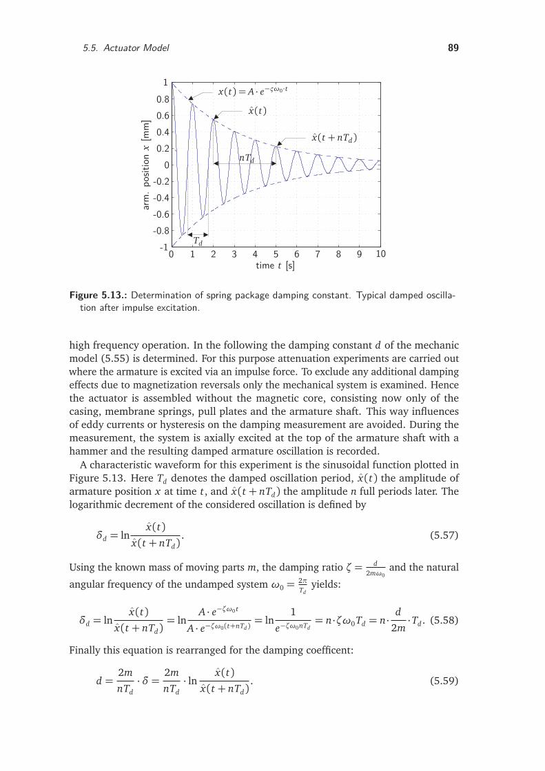
5.5. Actuator Model 89
time t [s]
arm
.pos
ition
x[m
m]
x(t)
x(t + nTd)
nTd
x(t) = A · e−ςω0·t
Td
0 1 2 3 4 5 6 7 8 9 10-1-0.8-0.6-0.4-0.2
00.20.40.60.8
1
Figure 5.13.: Determination of spring package damping constant. Typical damped oscilla-tion after impulse excitation.
high frequency operation. In the following the damping constant d of the mechanicmodel (5.55) is determined. For this purpose attenuation experiments are carried outwhere the armature is excited via an impulse force. To exclude any additional dampingeffects due to magnetization reversals only the mechanical system is examined. Hencethe actuator is assembled without the magnetic core, consisting now only of thecasing, membrane springs, pull plates and the armature shaft. This way influencesof eddy currents or hysteresis on the damping measurement are avoided. During themeasurement, the system is axially excited at the top of the armature shaft with ahammer and the resulting damped armature oscillation is recorded.
A characteristic waveform for this experiment is the sinusoidal function plotted inFigure 5.13. Here Td denotes the damped oscillation period, x(t) the amplitude ofarmature position x at time t, and x(t + nTd) the amplitude n full periods later. Thelogarithmic decrement of the considered oscillation is defined by
δd = lnx(t)
x(t + nTd). (5.57)
Using the known mass of moving parts m, the damping ratio ζ = d2mω0
and the natural
angular frequency of the undamped system ω0 =2πTd
yields:
δd = lnx(t)
x(t + nTd)= ln
A · e−ζω0 t
A · e−ζω0(t+nTd )= ln
1
e−ζω0nTd= n·ζω0Td = n· d
2m·Td . (5.58)
Finally this equation is rearranged for the damping coefficent:
d =2m
nTd·δ = 2m
nTd· ln x(t)
x(t + nTd). (5.59)
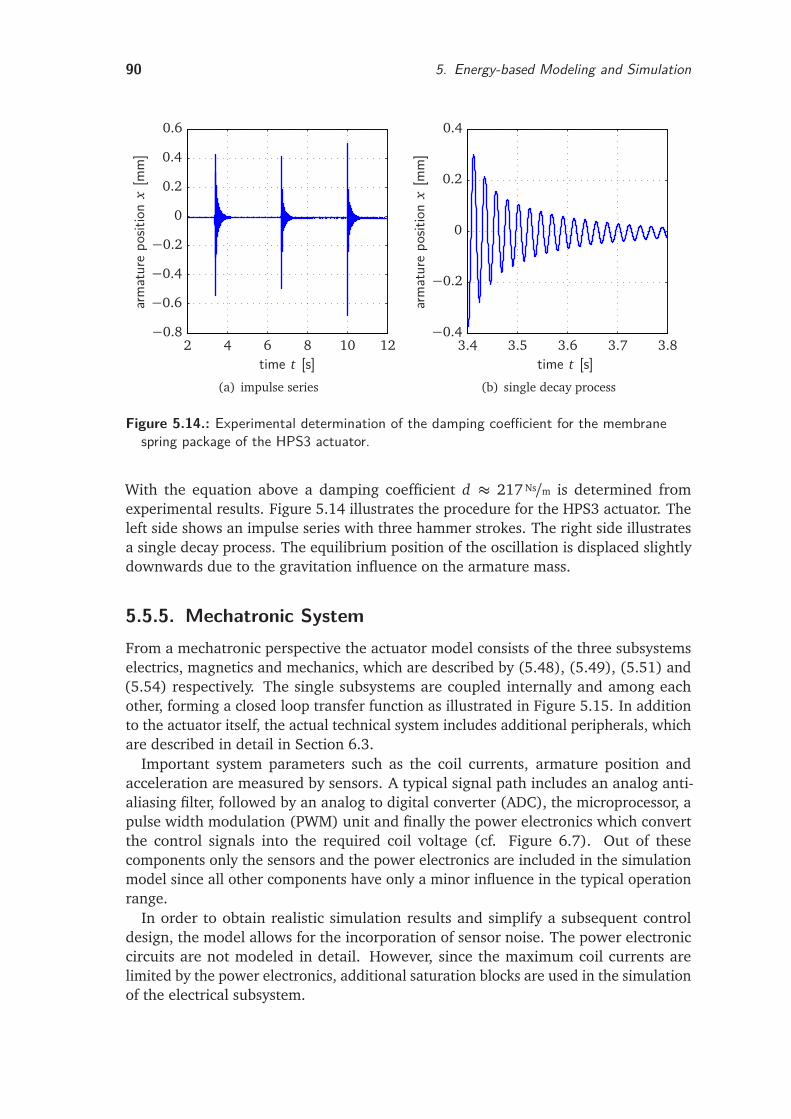
90 5. Energy-based Modeling and Simulation
arm
atur
epo
sition
x[m
m]
time t [s]2 4 6 8 10 12
−0.8
−0.6
−0.4
−0.2
0
0.2
0.4
0.6
(a) impulse series
arm
atur
epo
sition
x[m
m]
time t [s]3.4 3.5 3.6 3.7 3.8
−0.4
−0.2
0
0.2
0.4
(b) single decay process
Figure 5.14.: Experimental determination of the damping coefficient for the membranespring package of the HPS3 actuator.
With the equation above a damping coefficient d ≈ 217 Ns/m is determined fromexperimental results. Figure 5.14 illustrates the procedure for the HPS3 actuator. Theleft side shows an impulse series with three hammer strokes. The right side illustratesa single decay process. The equilibrium position of the oscillation is displaced slightlydownwards due to the gravitation influence on the armature mass.
5.5.5. Mechatronic SystemFrom a mechatronic perspective the actuator model consists of the three subsystemselectrics, magnetics and mechanics, which are described by (5.48), (5.49), (5.51) and(5.54) respectively. The single subsystems are coupled internally and among eachother, forming a closed loop transfer function as illustrated in Figure 5.15. In additionto the actuator itself, the actual technical system includes additional peripherals, whichare described in detail in Section 6.3.
Important system parameters such as the coil currents, armature position andacceleration are measured by sensors. A typical signal path includes an analog anti-aliasing filter, followed by an analog to digital converter (ADC), the microprocessor, apulse width modulation (PWM) unit and finally the power electronics which convertthe control signals into the required coil voltage (cf. Figure 6.7). Out of thesecomponents only the sensors and the power electronics are included in the simulationmodel since all other components have only a minor influence in the typical operationrange.
In order to obtain realistic simulation results and simplify a subsequent controldesign, the model allows for the incorporation of sensor noise. The power electroniccircuits are not modeled in detail. However, since the maximum coil currents arelimited by the power electronics, additional saturation blocks are used in the simulationof the electrical subsystem.
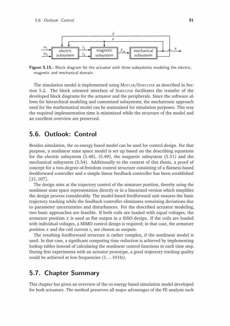
5.6. Outlook: Control 91
u1
u2
i1i2
Fm
xx
xelectricsubsystem
magneticsubsystemsubsystemmechanical
subsystem
Figure 5.15.: Block diagram for the actuator with three subsystems modeling the electric,magnetic and mechanical domain.
The simulation model is implemented using MATLAB/SIMULINK as described in Sec-tion 5.2. The block oriented interface of SIMULINK facilitates the transfer of thedeveloped block diagrams for the actuator and the peripherals. Since the software al-lows for hierarchical modeling and customized subsystems, the mechatronic approachused for the mathematical model can be maintained for simulation purposes. This waythe required implementation time is minimized while the structure of the model andan excellent overview are preserved.
5.6. Outlook: ControlBesides simulation, the co-energy based model can be used for control design. For thatpurpose, a nonlinear state space model is set up based on the describing equationsfor the electric subsystem (5.48), (5.49), the magnetic subsystem (5.51) and themechanical subsystem (5.54). Additionally to the context of this thesis, a proof ofconcept for a two-degree-of-freedom control structure consisting of a flatness-basedfeedforward controller and a simple linear feedback controller has been established[31,107].
The design aims at the trajectory control of the armature position, thereby using thenonlinear state space representation directly or in a linearized version which simplifiesthe design process considerably. The model-based feedforward unit ensures the basictrajectory tracking while the feedback controller eliminates remaining deviations dueto parameter uncertainties and disturbances. For the described actuator modeling,two basic approaches are feasible. If both coils are loaded with equal voltages, thearmature position x is used as flat output in a SISO design. If the coils are loadedwith individual voltages, a MIMO control design is required; in that case, the armatureposition x and the coil current i1 are chosen as outputs.
The resulting feedforward structure is rather complex, if the nonlinear model isused. In that case, a significant computing time reduction is achieved by implementinglookup tables instead of calculating the nonlinear control functions in each time step.During first experiments with an actuator prototype, a good trajectory tracking qualitycould be achieved at low frequencies (1. . . 10 Hz).
5.7. Chapter SummaryThis chapter has given an overview of the co-energy based simulation model developedfor both actuators. The method preserves all major advantages of the FE analysis such
92 5. Energy-based Modeling and Simulation
as the incorporation of saturation by using the nonlinear B-H curve and the detailedmapping of complex geometries and flux leakage. In particular, the model enablesthe accurate description of the magnetic force and the inductance as a function of thearmature position and coil currents.
In comparison to the numerical analysis, a significant order reduction is achievedby an approximation of discrete co-energy values which are calculated during staticFE simulations. The force and inductivity functions for the electromagnetic model areobtained by derivation of the analytical co-energy description. For the curve fitting,polynomials with a low degree are sufficient resulting in a small coefficient matrix.Hence, the co-energy based approach enables the setup of a simulation model which issuitable for dynamic system simulation and control design due to its low computationalcost.
Moreover, the simulation is completed by a description of the actuator mechanics.Assuming a rigid armature, a spring-mass-damper model is set up which maps thenonlinear spring characteristic and the damping during high dynamic actuation.
The presented block diagrams of the mechatronic modeling approach can be directlyused for the implementation in a system simulation program. Therefore, an accurateanalysis of the dynamic behavior of the developed reluctance shakers is possible.
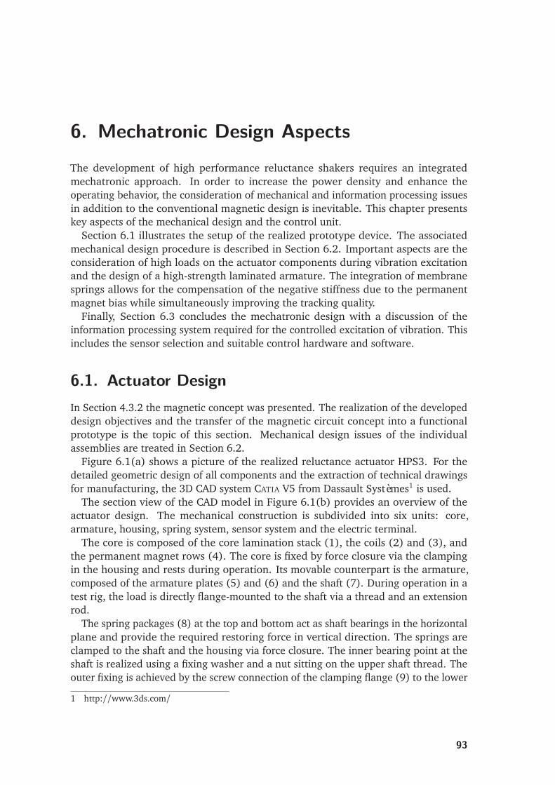
6. Mechatronic Design AspectsThe development of high performance reluctance shakers requires an integratedmechatronic approach. In order to increase the power density and enhance theoperating behavior, the consideration of mechanical and information processing issuesin addition to the conventional magnetic design is inevitable. This chapter presentskey aspects of the mechanical design and the control unit.
Section 6.1 illustrates the setup of the realized prototype device. The associatedmechanical design procedure is described in Section 6.2. Important aspects are theconsideration of high loads on the actuator components during vibration excitationand the design of a high-strength laminated armature. The integration of membranesprings allows for the compensation of the negative stiffness due to the permanentmagnet bias while simultaneously improving the tracking quality.
Finally, Section 6.3 concludes the mechatronic design with a discussion of theinformation processing system required for the controlled excitation of vibration. Thisincludes the sensor selection and suitable control hardware and software.
6.1. Actuator DesignIn Section 4.3.2 the magnetic concept was presented. The realization of the developeddesign objectives and the transfer of the magnetic circuit concept into a functionalprototype is the topic of this section. Mechanical design issues of the individualassemblies are treated in Section 6.2.
Figure 6.1(a) shows a picture of the realized reluctance actuator HPS3. For thedetailed geometric design of all components and the extraction of technical drawingsfor manufacturing, the 3D CAD system CATIA V5 from Dassault Systèmes1 is used.
The section view of the CAD model in Figure 6.1(b) provides an overview of theactuator design. The mechanical construction is subdivided into six units: core,armature, housing, spring system, sensor system and the electric terminal.
The core is composed of the core lamination stack (1), the coils (2) and (3), andthe permanent magnet rows (4). The core is fixed by force closure via the clampingin the housing and rests during operation. Its movable counterpart is the armature,composed of the armature plates (5) and (6) and the shaft (7). During operation in atest rig, the load is directly flange-mounted to the shaft via a thread and an extensionrod.
The spring packages (8) at the top and bottom act as shaft bearings in the horizontalplane and provide the required restoring force in vertical direction. The springs areclamped to the shaft and the housing via force closure. The inner bearing point at theshaft is realized using a fixing washer and a nut sitting on the upper shaft thread. Theouter fixing is achieved by the screw connection of the clamping flange (9) to the lower
1 http://www.3ds.com/
93
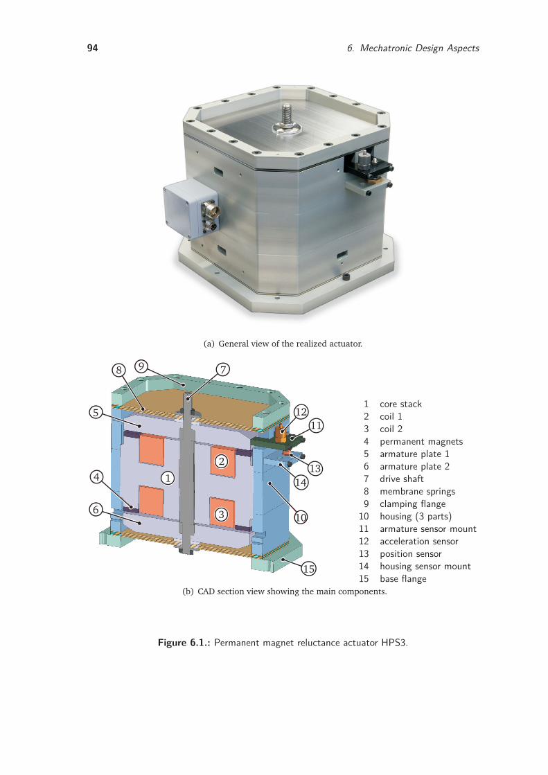
94 6. Mechatronic Design Aspects
(a) General view of the realized actuator.
1
2
3
4
5
6
78 9
10
1112
1314
15
1 core stack2 coil 13 coil 24 permanent magnets5 armature plate 16 armature plate 27 drive shaft8 membrane springs9 clamping flange
10 housing (3 parts)11 armature sensor mount12 acceleration sensor13 position sensor14 housing sensor mount15 base flange
(b) CAD section view showing the main components.
Figure 6.1.: Permanent magnet reluctance actuator HPS3.
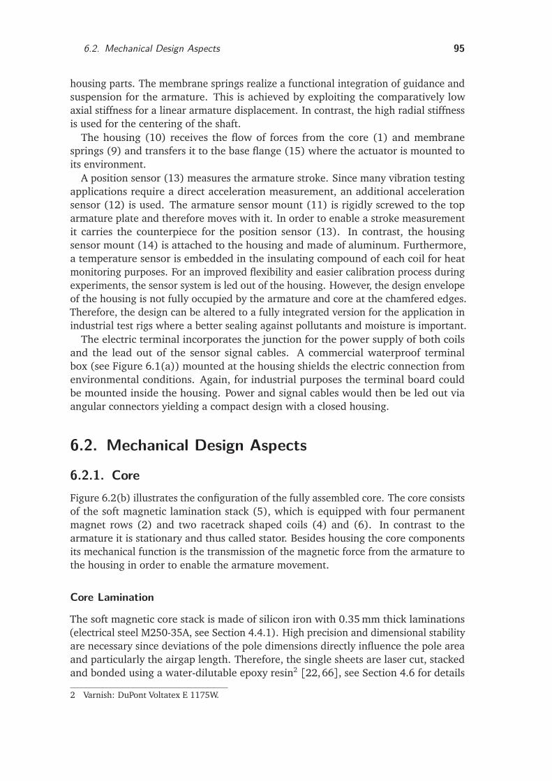
6.2. Mechanical Design Aspects 95
housing parts. The membrane springs realize a functional integration of guidance andsuspension for the armature. This is achieved by exploiting the comparatively lowaxial stiffness for a linear armature displacement. In contrast, the high radial stiffnessis used for the centering of the shaft.
The housing (10) receives the flow of forces from the core (1) and membranesprings (9) and transfers it to the base flange (15) where the actuator is mounted toits environment.
A position sensor (13) measures the armature stroke. Since many vibration testingapplications require a direct acceleration measurement, an additional accelerationsensor (12) is used. The armature sensor mount (11) is rigidly screwed to the toparmature plate and therefore moves with it. In order to enable a stroke measurementit carries the counterpiece for the position sensor (13). In contrast, the housingsensor mount (14) is attached to the housing and made of aluminum. Furthermore,a temperature sensor is embedded in the insulating compound of each coil for heatmonitoring purposes. For an improved flexibility and easier calibration process duringexperiments, the sensor system is led out of the housing. However, the design envelopeof the housing is not fully occupied by the armature and core at the chamfered edges.Therefore, the design can be altered to a fully integrated version for the application inindustrial test rigs where a better sealing against pollutants and moisture is important.
The electric terminal incorporates the junction for the power supply of both coilsand the lead out of the sensor signal cables. A commercial waterproof terminalbox (see Figure 6.1(a)) mounted at the housing shields the electric connection fromenvironmental conditions. Again, for industrial purposes the terminal board couldbe mounted inside the housing. Power and signal cables would then be led out viaangular connectors yielding a compact design with a closed housing.
6.2. Mechanical Design Aspects
6.2.1. CoreFigure 6.2(b) illustrates the configuration of the fully assembled core. The core consistsof the soft magnetic lamination stack (5), which is equipped with four permanentmagnet rows (2) and two racetrack shaped coils (4) and (6). In contrast to thearmature it is stationary and thus called stator. Besides housing the core componentsits mechanical function is the transmission of the magnetic force from the armature tothe housing in order to enable the armature movement.
Core Lamination
The soft magnetic core stack is made of silicon iron with 0.35 mm thick laminations(electrical steel M250-35A, see Section 4.4.1). High precision and dimensional stabilityare necessary since deviations of the pole dimensions directly influence the pole areaand particularly the airgap length. Therefore, the single sheets are laser cut, stackedand bonded using a water-dilutable epoxy resin2 [22,66], see Section 4.6 for details
2 Varnish: DuPont Voltatex E 1175W.
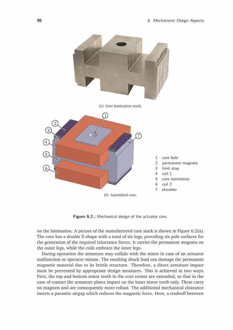
96 6. Mechatronic Design Aspects
(a) Core lamination stack.
1
2
3
4
5
6
7
1 core hole2 permanent magnets3 limit stop4 coil 15 core lamination6 coil 27 shoulder
(b) Assembled core.
Figure 6.2.: Mechanical design of the actuator core.
on the lamination. A picture of the manufactured core stack is shown in Figure 6.2(a).The core has a double E-shape with a total of six legs, providing six pole surfaces forthe generation of the required reluctance forces. It carries the permanent magnets onthe outer legs, while the coils embrace the inner legs.
During operation the armature may collide with the stator in case of an actuatormalfunction or operator misuse. The resulting shock load can damage the permanentmagnetic material due to its brittle structure. Therefore, a direct armature impactmust be prevented by appropriate design measures. This is achieved in two ways.First, the top and bottom stator teeth in the core center are extended, so that in thecase of contact the armature plates impact on the inner stator teeth only. These carryno magnets and are consequently more robust. The additional mechanical clearanceinserts a parasitic airgap which reduces the magnetic force. Here, a tradeoff between
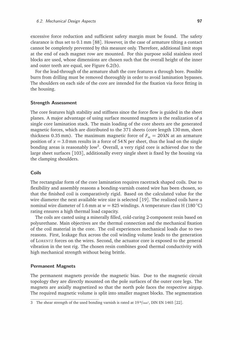
6.2. Mechanical Design Aspects 97
excessive force reduction and sufficient safety margin must be found. The safetyclearance is thus set to 0.1 mm [88]. However, in the case of armature tilting a contactcannot be completely prevented by this measure only. Therefore, additional limit stopsat the end of each magnet row are mounted. For this purpose solid stainless steelblocks are used, whose dimensions are chosen such that the overall height of the innerand outer teeth are equal, see Figure 6.2(b).
For the lead-through of the armature shaft the core features a through bore. Possibleburrs from drilling must be removed thoroughly in order to avoid lamination bypasses.The shoulders on each side of the core are intended for the fixation via force fitting inthe housing.
Strength Assessment
The core features high stability and stiffness since the force flow is guided in the sheetplanes. A major advantage of using surface mounted magnets is the realization of asingle core lamination stack. The main loading of the core sheets are the generatedmagnetic forces, which are distributed to the 371 sheets (core length 130 mm, sheetthickness 0.35 mm). The maximum magnetic force of Fm = 20kN at an armatureposition of x = 3.0 mm results in a force of 54 N per sheet, thus the load on the singlebonding areas is reasonably low3. Overall, a very rigid core is achieved due to thelarge sheet surfaces [103], additionally every single sheet is fixed by the housing viathe clamping shoulders.
Coils
The rectangular form of the core lamination requires racetrack shaped coils. Due toflexibility and assembly reasons a bonding-varnish coated wire has been chosen, sothat the finished coil is comparatively rigid. Based on the calculated value for thewire diameter the next available wire size is selected [19]. The realized coils have anominal wire diameter of 1.6 mm at w = 825 windings. A temperature class H (180 C)rating ensures a high thermal load capacity.
The coils are casted using a minerally filled, cold-curing 2-component resin based onpolyurethane. Main objectives are the thermal connection and the mechanical fixationof the coil material in the core. The coil experiences mechanical loads due to tworeasons. First, leakage flux across the coil winding volume leads to the generationof LORENTZ forces on the wires. Second, the actuator core is exposed to the generalvibration in the test rig. The chosen resin combines good thermal conductivity withhigh mechanical strength without being brittle.
Permanent Magnets
The permanent magnets provide the magnetic bias. Due to the magnetic circuittopology they are directly mounted on the pole surfaces of the outer core legs. Themagnets are axially magnetized so that the north pole faces the respective airgap.The required magnetic volume is split into smaller magnet blocks. The segmentation
3 The shear strength of the used bonding varnish is rated at 19 N/mm2, DIN EN 1465 [22].
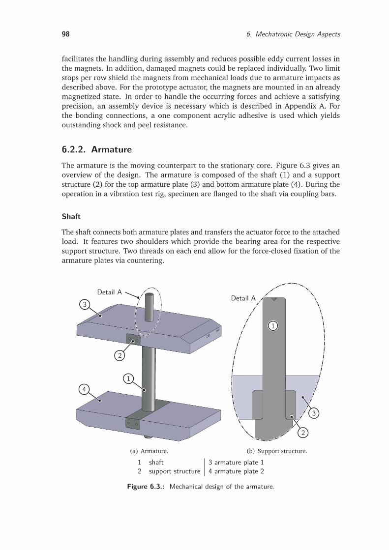
98 6. Mechatronic Design Aspects
facilitates the handling during assembly and reduces possible eddy current losses inthe magnets. In addition, damaged magnets could be replaced individually. Two limitstops per row shield the magnets from mechanical loads due to armature impacts asdescribed above. For the prototype actuator, the magnets are mounted in an alreadymagnetized state. In order to handle the occurring forces and achieve a satisfyingprecision, an assembly device is necessary which is described in Appendix A. Forthe bonding connections, a one component acrylic adhesive is used which yieldsoutstanding shock and peel resistance.
6.2.2. ArmatureThe armature is the moving counterpart to the stationary core. Figure 6.3 gives anoverview of the design. The armature is composed of the shaft (1) and a supportstructure (2) for the top armature plate (3) and bottom armature plate (4). During theoperation in a vibration test rig, specimen are flanged to the shaft via coupling bars.
Shaft
The shaft connects both armature plates and transfers the actuator force to the attachedload. It features two shoulders which provide the bearing area for the respectivesupport structure. Two threads on each end allow for the force-closed fixation of thearmature plates via countering.
1
2
3
4
Detail A
(a) Armature.
1
2
3
Detail A
(b) Support structure.
1 shaft 3 armature plate 12 support structure 4 armature plate 2
Figure 6.3.: Mechanical design of the armature.
6.2. Mechanical Design Aspects 99
The shaft is subject to high stresses during operation and therefore made of stainlesssteel4. The almost nonmagnetic material shows no influence on the magnetic circuitwhich facilitates both assembly and maintenance.
Armature Plates
The required reluctance force is generated on the pole surfaces of the two armatureplates. They have a rectangular shape due to the chosen axial lamination with thesheet planes parallel to the shaft. The edges opposing the pole surfaces are chamferedsince the material is magnetically unused in the respective volumes. Both plates featurea groove for the incorporation of the support structure.
The material is silicon iron with 0.35 mm thick laminations5 which are also usedfor the core. Again, high precision and particular strength of the laminated stack arerequired. For manufacturing the same process as for the core is chosen: laser cuttingof the single sheets and a bonding varnish based stack.
Due to the axial lamination, a reinforcement of the armature laminations is indis-pensable. For this purpose a bar serves as support structure for each stack. Everyindividual lamination sheet sits directly on the supporting structure which is bondedinto the armature grove. A high-strength one component adhesive6, which is suitablefor the application in shock and vibration intensive applications, is used. Followingthis concept the magnetic force pulling on each sheet is directly diverted to the solidsteel part of the armature as illustrated in Figure 6.3(b). Therefore, particularly shearloads which pose a threat to the long term stability of the bonded lamination stackare absorbed. Without the bar, only the few sheets sitting on the shaft could transfertheir load directly to the solid part. The magnetic force on all other sheets would betransmitted via the adhesive layer between the single sheets.
Due to the high stresses during operation, the support structure is made of stainlesssteel4. The resistance of the bonding is less critical since the bonding area is ratherlarge and the armature is additionally countered on the shaft.
Strength Assessment
The maximum magnetic force of 20 kN at an armature position of x = 3.0mm isdistributed to 371 sheets (armature length 130 mm, sheet thickness 0.35 mm), thusthe force on each sheet is approximately 54 N. An FEM analysis is carried out in orderto assess the behavior of the armature. Figure 6.4 shows the stress distribution anddeflection of a single sheet assuming a fixed support at the grove. The resultingmaximum stress of 52 N/mm2 is well below the fatigue limit of the material7 andallows a safe operation. The armature deflection is reasonably low as well. Influenceson the force characteristics due to a reduction of the effective airgap can be neglected.
4 X8CrNiS18-9 (EN 10027-2)5 electrical steel grade M250-35A (EN 10027-1)6 chemical type: urethane methacrylate7 The yield strength of the used electrical steel is rated at 425N/mm2 [108].
100 6. Mechatronic Design Aspects
(a) von Mises stress [N/m2]. (b) Deflection [m].
Figure 6.4.: FEM based strength assessment of an armature sheet (magnetic force modeledas distributed surface load, support structure not shown).
6.2.3. HousingThe housing shields the core and armature from the surroundings. It fixes the coreand transfers the actuation force from the core to the flange. In order to facilitatemanufacturing, assembly and maintenance of the actuator, it is designed in fivemodular parts, see Figure 6.1(b).
The top part (9) serves as a flange for the upper membrane spring package. Thebase flange (15) fixes the bottom membrane spring package and enables the flangingof the actuator to its environment. Both flanges are bolted with the three middle parts(10) which fix the core via shoulders and serve as counterpart to the flanges.
The housing has a quadratic footprint. The edges are chamfered since the associateddesign space is not occupied by the magnetic system. In order to save weight andimprove the handling all parts are made of a high-strength aluminum alloy8. Thefixation of the membrane springs via force closure requires high bolting torques. Theuse of thread inserts enables maintaining the lightweight construction of the aluminumhousing.
For the application in the harsh environment of an industrial test rig, an additionalsealing against moisture is required. Particularly problematic are the condensation ofclimatic chambers and splash from the vehicle underbody.
6.2.4. Membrane SpringsThe integration of springs is an essential element of the actuator concept. They providea restoring force and contribute to the total actuator force in addition to the magneticforces. In particular, the springs allow for the compensation of the negative magneticstiffness caused by the permanent magnet bias, thereby enabling a stable actuatoroperation without feedback control. For this purpose the mechanical spring stiffnessFs/x must be higher than the destabilizing magnetic stiffness Fm/x for all armaturepositions x .
Fs
x≥ Fm(x , 0, 0)
x(6.1)
Since only the force component caused by the permanent magnet flux is relevant, themagnetic force Fm(x , 0, 0) with zero coil currents i1 = i2 = 0 must be used for the force
8 EN-AW 7075 T651
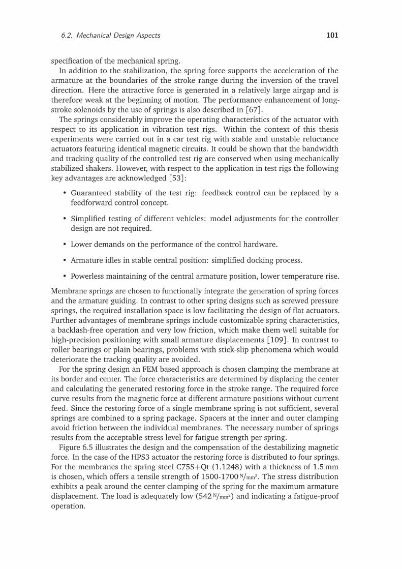
6.2. Mechanical Design Aspects 101
specification of the mechanical spring.In addition to the stabilization, the spring force supports the acceleration of the
armature at the boundaries of the stroke range during the inversion of the traveldirection. Here the attractive force is generated in a relatively large airgap and istherefore weak at the beginning of motion. The performance enhancement of long-stroke solenoids by the use of springs is also described in [67].
The springs considerably improve the operating characteristics of the actuator withrespect to its application in vibration test rigs. Within the context of this thesisexperiments were carried out in a car test rig with stable and unstable reluctanceactuators featuring identical magnetic circuits. It could be shown that the bandwidthand tracking quality of the controlled test rig are conserved when using mechanicallystabilized shakers. However, with respect to the application in test rigs the followingkey advantages are acknowledged [53]:
• Guaranteed stability of the test rig: feedback control can be replaced by afeedforward control concept.
• Simplified testing of different vehicles: model adjustments for the controllerdesign are not required.
• Lower demands on the performance of the control hardware.
• Armature idles in stable central position: simplified docking process.
• Powerless maintaining of the central armature position, lower temperature rise.
Membrane springs are chosen to functionally integrate the generation of spring forcesand the armature guiding. In contrast to other spring designs such as screwed pressuresprings, the required installation space is low facilitating the design of flat actuators.Further advantages of membrane springs include customizable spring characteristics,a backlash-free operation and very low friction, which make them well suitable forhigh-precision positioning with small armature displacements [109]. In contrast toroller bearings or plain bearings, problems with stick-slip phenomena which woulddeteriorate the tracking quality are avoided.
For the spring design an FEM based approach is chosen clamping the membrane atits border and center. The force characteristics are determined by displacing the centerand calculating the generated restoring force in the stroke range. The required forcecurve results from the magnetic force at different armature positions without currentfeed. Since the restoring force of a single membrane spring is not sufficient, severalsprings are combined to a spring package. Spacers at the inner and outer clampingavoid friction between the individual membranes. The necessary number of springsresults from the acceptable stress level for fatigue strength per spring.
Figure 6.5 illustrates the design and the compensation of the destabilizing magneticforce. In the case of the HPS3 actuator the restoring force is distributed to four springs.For the membranes the spring steel C75S+Qt (1.1248) with a thickness of 1.5 mmis chosen, which offers a tensile strength of 1500-1700 N/mm2. The stress distributionexhibits a peak around the center clamping of the spring for the maximum armaturedisplacement. The load is adequately low (542 N/mm2) and indicating a fatigue-proofoperation.
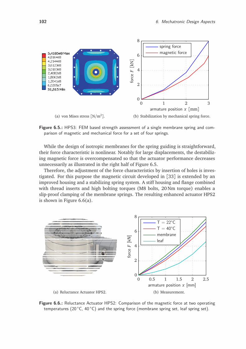
102 6. Mechatronic Design Aspects
(a) von Mises stress [N/m2].
magnetic forcespring force
forc
eF[k
N]
armature position x [mm]0 1 2 3
0
2
4
6
8
(b) Stabilization by mechanical spring force.
Figure 6.5.: HPS3: FEM based strength assessment of a single membrane spring and com-parison of magnetic and mechanical force for a set of four springs.
While the design of isotropic membranes for the spring guiding is straightforward,their force characteristic is nonlinear. Notably for large displacements, the destabiliz-ing magnetic force is overcompensated so that the actuator performance decreasesunnecessarily as illustrated in the right half of Figure 6.5.
Therefore, the adjustment of the force characteristics by insertion of holes is inves-tigated. For this purpose the magnetic circuit developed in [33] is extended by animproved housing and a stabilizing spring system. A stiff housing and flange combinedwith thread inserts and high bolting torques (M8 bolts, 20 Nm torque) enables aslip-proof clamping of the membrane springs. The resulting enhanced actuator HPS2is shown in Figure 6.6(a).
(a) Reluctance Actuator HPS2.
leafmembraneT = 40°CT = 22°C
forc
eF
[kN]
armature position x [mm]0 0.5 1 1.5 2 2.5
0
2
4
6
8
(b) Measurement.
Figure 6.6.: Reluctance Actuator HPS2: Comparison of the magnetic force at two operatingtemperatures (20 C, 40 C) and the spring force (membrane spring set, leaf spring set).
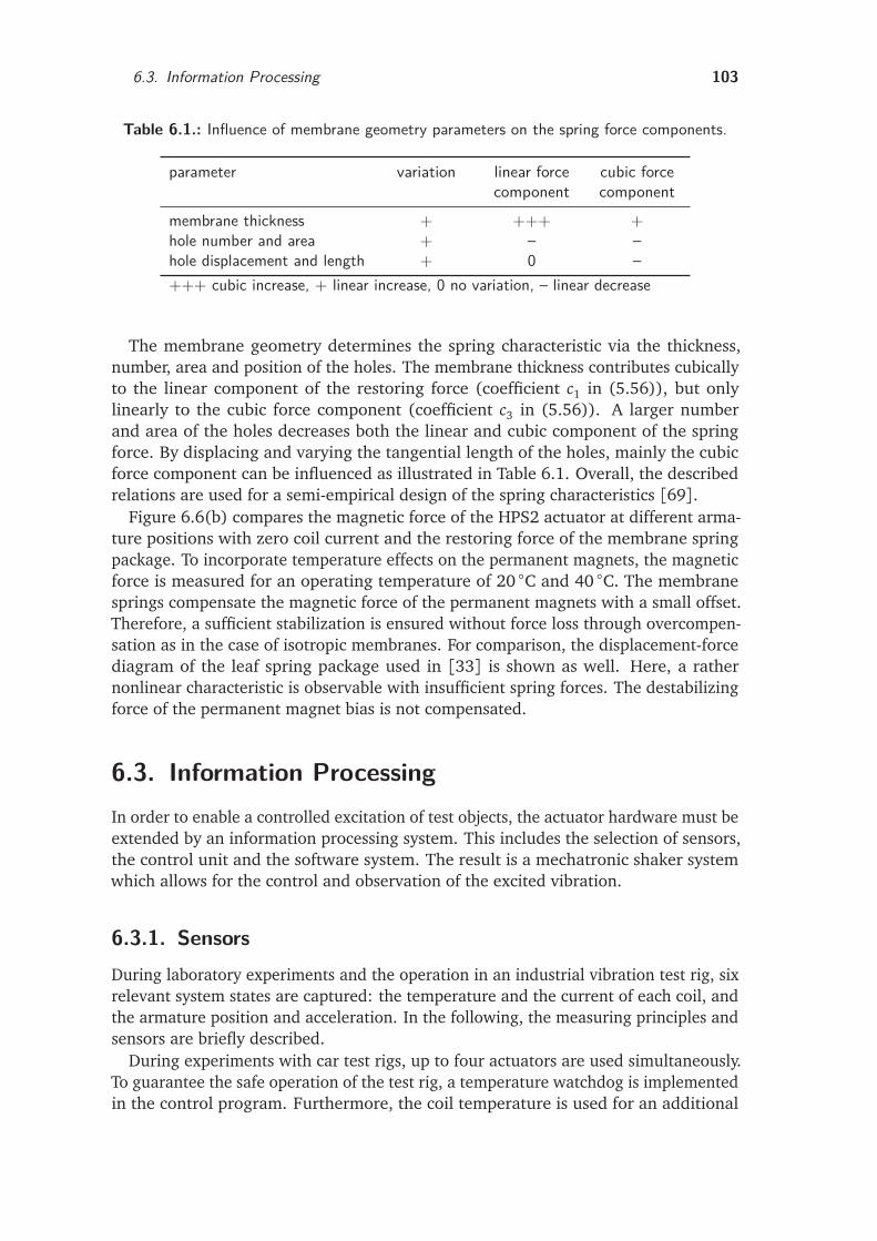
6.3. Information Processing 103
Table 6.1.: Influence of membrane geometry parameters on the spring force components.
parameter variation linear forcecomponent
cubic forcecomponent
membrane thickness + +++ +hole number and area + – –hole displacement and length + 0 –+++ cubic increase, + linear increase, 0 no variation, – linear decrease
The membrane geometry determines the spring characteristic via the thickness,number, area and position of the holes. The membrane thickness contributes cubicallyto the linear component of the restoring force (coefficient c1 in (5.56)), but onlylinearly to the cubic force component (coefficient c3 in (5.56)). A larger numberand area of the holes decreases both the linear and cubic component of the springforce. By displacing and varying the tangential length of the holes, mainly the cubicforce component can be influenced as illustrated in Table 6.1. Overall, the describedrelations are used for a semi-empirical design of the spring characteristics [69].
Figure 6.6(b) compares the magnetic force of the HPS2 actuator at different arma-ture positions with zero coil current and the restoring force of the membrane springpackage. To incorporate temperature effects on the permanent magnets, the magneticforce is measured for an operating temperature of 20 C and 40 C. The membranesprings compensate the magnetic force of the permanent magnets with a small offset.Therefore, a sufficient stabilization is ensured without force loss through overcompen-sation as in the case of isotropic membranes. For comparison, the displacement-forcediagram of the leaf spring package used in [33] is shown as well. Here, a rathernonlinear characteristic is observable with insufficient spring forces. The destabilizingforce of the permanent magnet bias is not compensated.
6.3. Information ProcessingIn order to enable a controlled excitation of test objects, the actuator hardware must beextended by an information processing system. This includes the selection of sensors,the control unit and the software system. The result is a mechatronic shaker systemwhich allows for the control and observation of the excited vibration.
6.3.1. SensorsDuring laboratory experiments and the operation in an industrial vibration test rig, sixrelevant system states are captured: the temperature and the current of each coil, andthe armature position and acceleration. In the following, the measuring principles andsensors are briefly described.
During experiments with car test rigs, up to four actuators are used simultaneously.To guarantee the safe operation of the test rig, a temperature watchdog is implementedin the control program. Furthermore, the coil temperature is used for an additional
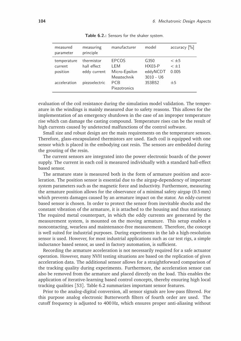
104 6. Mechatronic Design Aspects
Table 6.2.: Sensors for the shaker system.
measuredparameter
measuringprinciple
manufacturer model accuracy [%]
temperature thermistor EPCOS G350 <±5current hall effect LEM HX03-P <±1position eddy current Micro-Epsilon
MesstechnikeddyNCDT3010 - U6
0.005
acceleration piezoelectric PCBPiezotronics
353B52 ±5
evaluation of the coil resistance during the simulation model validation. The temper-ature in the windings is mainly measured due to safety reasons. This allows for theimplementation of an emergency shutdown in the case of an improper temperaturerise which can damage the casting compound. Temperature rises can be the result ofhigh currents caused by undetected malfunctions of the control software.
Small size and robust design are the main requirements on the temperature sensors.Therefore, glass-encapsulated thermistors are used. Each coil is equipped with onesensor which is placed in the embodying cast resin. The sensors are embedded duringthe grouting of the resin.
The current sensors are integrated into the power electronic boards of the powersupply. The current in each coil is measured individually with a standard hall-effectbased sensor.
The armature state is measured both in the form of armature position and acce-leration. The position sensor is essential due to the airgap-dependency of importantsystem parameters such as the magnetic force and inductivity. Furthermore, measuringthe armature position allows for the observance of a minimal safety airgap (0.5 mm)which prevents damages caused by an armature impact on the stator. An eddy-currentbased sensor is chosen. In order to protect the sensor from inevitable shocks and theconstant vibration of the armature, it is attached to the housing and thus stationary.The required metal counterpart, in which the eddy currents are generated by themeasurement system, is mounted on the moving armature. This setup enables anoncontacting, wearless and maintenance-free measurement. Therefore, the conceptis well suited for industrial purposes. During experiments in the lab a high-resolutionsensor is used. However, for most industrial applications such as car test rigs, a simpleinductance based sensor, as used in factory automation, is sufficient.
Recording the armature acceleration is not necessarily required for a safe actuatoroperation. However, many NVH testing situations are based on the replication of givenacceleration data. The additional sensor allows for a straightforward comparison ofthe tracking quality during experiments. Furthermore, the acceleration sensor canalso be removed from the armature and placed directly on the load. This enables theapplication of iterative-learning based control concepts, thereby ensuring high localtracking qualities [53]. Table 6.2 summarizes important sensor features.
Prior to the analog-digital conversion, all sensor signals are low-pass filtered. Forthis purpose analog electronic Butterworth filters of fourth order are used. Thecutoff frequency is adjusted to 400 Hz, which ensures proper anti-aliasing without
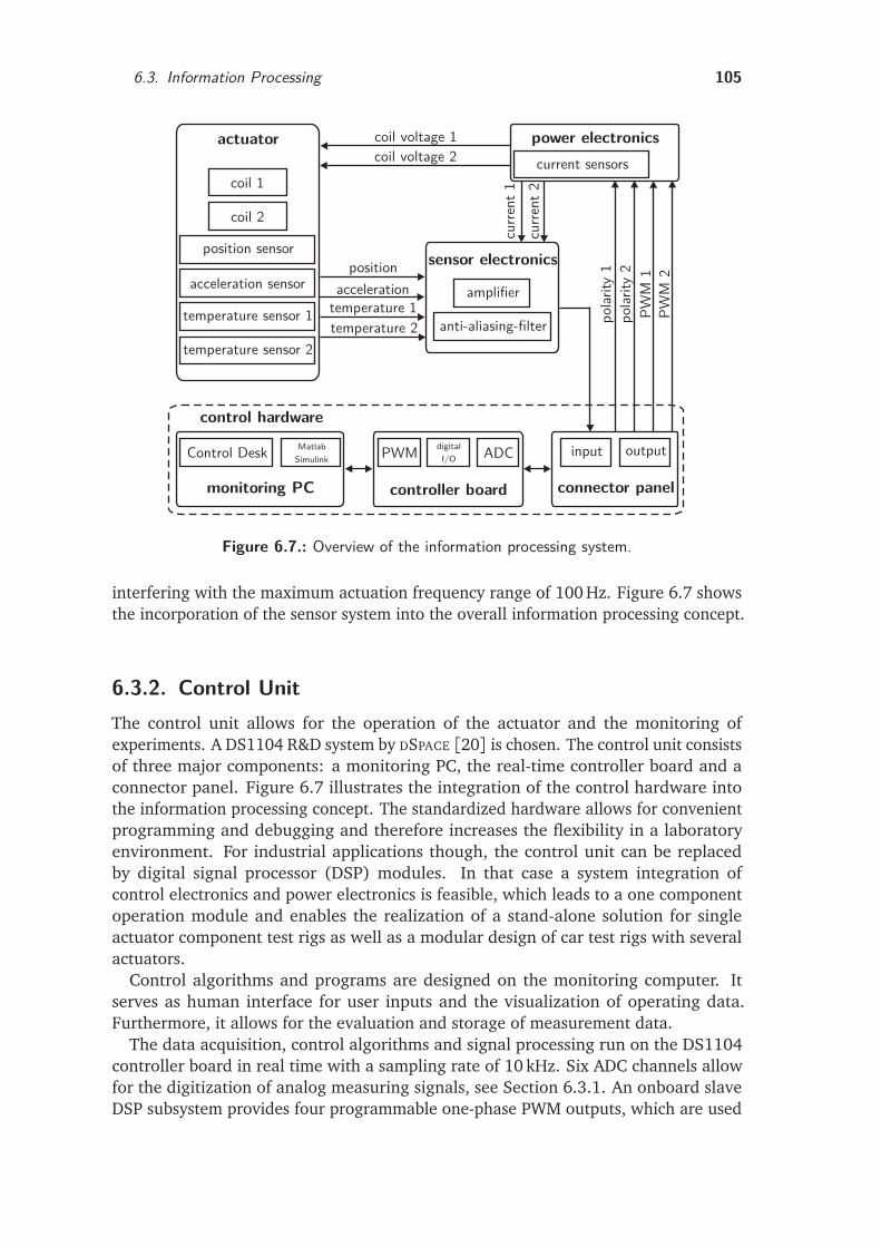
6.3. Information Processing 105
actuator
coil 1
coil 2
position sensor
acceleration sensor
temperature sensor 1
temperature sensor 2
coil voltage 1coil voltage 2
positionacceleration
temperature 1temperature 2
sensor electronics
amplifier
anti-aliasing-filter
power electronics
Control Desk Simulink
monitoring PC
PWM digitalI/O
controller board
ADCMatlab input output
connector panel
polar
ity1
polar
ity2
PWM
1PW
M2
current sensors
curre
nt1
curre
nt2
control hardware
Figure 6.7.: Overview of the information processing system.
interfering with the maximum actuation frequency range of 100 Hz. Figure 6.7 showsthe incorporation of the sensor system into the overall information processing concept.
6.3.2. Control UnitThe control unit allows for the operation of the actuator and the monitoring ofexperiments. A DS1104 R&D system by DSPACE [20] is chosen. The control unit consistsof three major components: a monitoring PC, the real-time controller board and aconnector panel. Figure 6.7 illustrates the integration of the control hardware intothe information processing concept. The standardized hardware allows for convenientprogramming and debugging and therefore increases the flexibility in a laboratoryenvironment. For industrial applications though, the control unit can be replacedby digital signal processor (DSP) modules. In that case a system integration ofcontrol electronics and power electronics is feasible, which leads to a one componentoperation module and enables the realization of a stand-alone solution for singleactuator component test rigs as well as a modular design of car test rigs with severalactuators.
Control algorithms and programs are designed on the monitoring computer. Itserves as human interface for user inputs and the visualization of operating data.Furthermore, it allows for the evaluation and storage of measurement data.
The data acquisition, control algorithms and signal processing run on the DS1104controller board in real time with a sampling rate of 10 kHz. Six ADC channels allowfor the digitization of analog measuring signals, see Section 6.3.1. An onboard slaveDSP subsystem provides four programmable one-phase PWM outputs, which are used
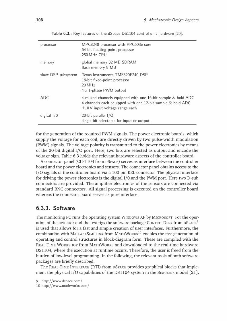
106 6. Mechatronic Design Aspects
Table 6.3.: Key features of the dSpace DS1104 control unit hardware [20].
processor MPC8240 processor with PPC603e core64-bit floating point processor250MHz CPU
memory global memory 32 MB SDRAMflash memory 8 MB
slave DSP subsystem Texas Instruments TMS320F240 DSP16-bit fixed-point processor20MHz4 x 1-phase PWM output
ADC 4 muxed channels equipped with one 16-bit sample & hold ADC4 channels each equipped with one 12-bit sample & hold ADC±10V input voltage range each
digital I/0 20-bit parallel I/Osingle bit selectable for input or output
for the generation of the required PWM signals. The power electronic boards, whichsupply the voltage for each coil, are directly driven by two pulse-width modulation(PWM) signals. The voltage polarity is transmitted to the power electronics by meansof the 20-bit digital I/O port. Here, two bits are selected as output and encode thevoltage sign. Table 6.3 holds the relevant hardware aspects of the controller board.
A connector panel (CLP1104 from DSPACE) serves as interface between the controllerboard and the power electronics and sensors. The connector panel obtains access to theI/O signals of the controller board via a 100-pin KEL connector. The physical interfacefor driving the power electronics is the digital I/0 and the PWM port. Here two D-subconnectors are provided. The amplifier electronics of the sensors are connected viastandard BNC connectors. All signal processing is executed on the controller boardwhereas the connector board serves as pure interface.
6.3.3. SoftwareThe monitoring PC runs the operating system WINDOWS XP by MICROSOFT. For the oper-ation of the actuator and the test rigs the software package CONTROLDESK from DSPACE9
is used that allows for a fast and simple creation of user interfaces. Furthermore, thecombination with MATLAB/SIMULINK from MATHWORKS10 enables the fast generation ofoperating and control structures in block-diagram form. These are compiled with theREAL-TIME WORKSHOP from MATHWORKS and downloaded to the real-time hardwareDS1104, where the execution at runtime occurs. Therefore, the user is freed from theburden of low-level programming. In the following, the relevant tools of both softwarepackages are briefly described.
The REAL-TIME INTERFACE (RTI) from DSPACE provides graphical blocks that imple-ment the physical I/O capabilities of the DS1104 system in the SIMULINK model [21].
9 http://www.dspace.com/10 http://www.mathworks.com/
6.4. Chapter Summary 107
Furthermore, it extends the REAL-TIME WORKSHOP and enables the automated codegeneration. The automated conversion of MATLAB/SIMULINK models to compiled pro-grams running on DSPACE real-time hardware shortens the development and codingtime considerably. Model changes can be carried out efficiently and without majorimplementation effort.
For the fundamental code generation, the REAL-TIME WORKSHOP is employed. Itallows the generation of C-code which is used for the rapid prototyping of controlalgorithms.
The graphical user interfaces, the visualization of measurement data and the con-trol of experiments are implemented using CONTROLDESK. The program enables astraightforward creation of layouts and instruments by graphical programming. Fur-thermore, the project and experiment management are tightly integrated allowingfor an efficient administration of all experiment files. The standard user interfaceincludes control items for the start and termination of experiments as well as for theselection of different control modes. Both voltages and acceleration profiles can beselected as commands. A function generator is used for the generation of input voltageprofiles. Different acceleration profiles (drive files) can be loaded via a selectiondialog. The activation of a feedback control system allows for the tracking of thesecommands. Plotters or digital displays visualize the measured data, which typicallyincludes the armature position, the armature acceleration, the coil currents and thecoil temperatures.
The underlying control and operating algorithms are implemented as block diagramsin SIMULINK. For an increased flexibility these are fully parameterized and initializedby MATLAB M-files. The necessary software-hardware interface is realized using theI/O blocks from the RTI library.
The MLIB/MTRACE library of DSPACE facilitates the automation of the measuringprocess. It allows for the control of data capturing and the specification of tracevariables under the control of M-files. Further important features for the automationof experiments include online parameter tuning and the transmission of test profiles tothe real-time application at runtime. The results can be directly monitored on the userinterface, while the measurement data is sent to the MATLAB workspace for furtherprocessing and storage [21].
6.4. Chapter SummaryThis chapter has presented the implementation of the magnetic concept into theprototype reluctance shaker HPS3. Besides mechanical design aspects, the requiredsensor system and the control unit have been described.
The flux carrying parts of the HPS3 actuator are made of silicon iron with 0.35 mmthick laminations (electrical steel M250-35A). While this is beneficial for the reductionof eddy currents, the mechanical setup is more complex requiring an assessment of theloads during operation and a special support structure for the moving armature. Inorder to maximize the stiffness, robustness and precision of the laminated parts, thesingle sheets are laser cut and bonded to a stack with the bonding varnish technology.Due to the axial lamination and the high magnetic forces of maximum 20 kN, the
108 6. Mechatronic Design Aspects
armature is reinforced by a support structure. Direct shear loads on the sheets areavoided by a steel bar bonded into each armature plate. The core has a double E-shape with a total of six teeth. It features surface mounted permanent magnets whichare protected from armature impacts by steel limit stops and extended inner teeth.Furthermore, the axial lamination requires race-track shaped coils which are cast intothe core.
The magnetic system is further extended by a membrane spring system whichprovides both the guiding for the armature and a restoring force which compensatesthe negative magnetic stiffness. This approach enables a stick-slip free motion at highfrequencies and a stable actuator operation without feedback control. The springs aredesigned using a FE based calculation of the generated restoring forces. The setupemploys a total of four 1.5 mm thick isotropic membranes divided into two springpackages.
Furthermore, designing the spring characteristic for a better compensation of thenegative magnetic stiffness is investigated with a second prototype (reluctance shakerHPS2). For this purpose, an existing magnetic system from previous research isextended by a spring system with inserted holes. A semi-empirical approach enablesthe adjustment of the spring characteristic via the membrane thickness and the number,area and position of the holes.
Finally, an overview of the information processing system is given. It extends theactuator hardware to a mechatronic shaker system and enables the control of theexcited vibration.
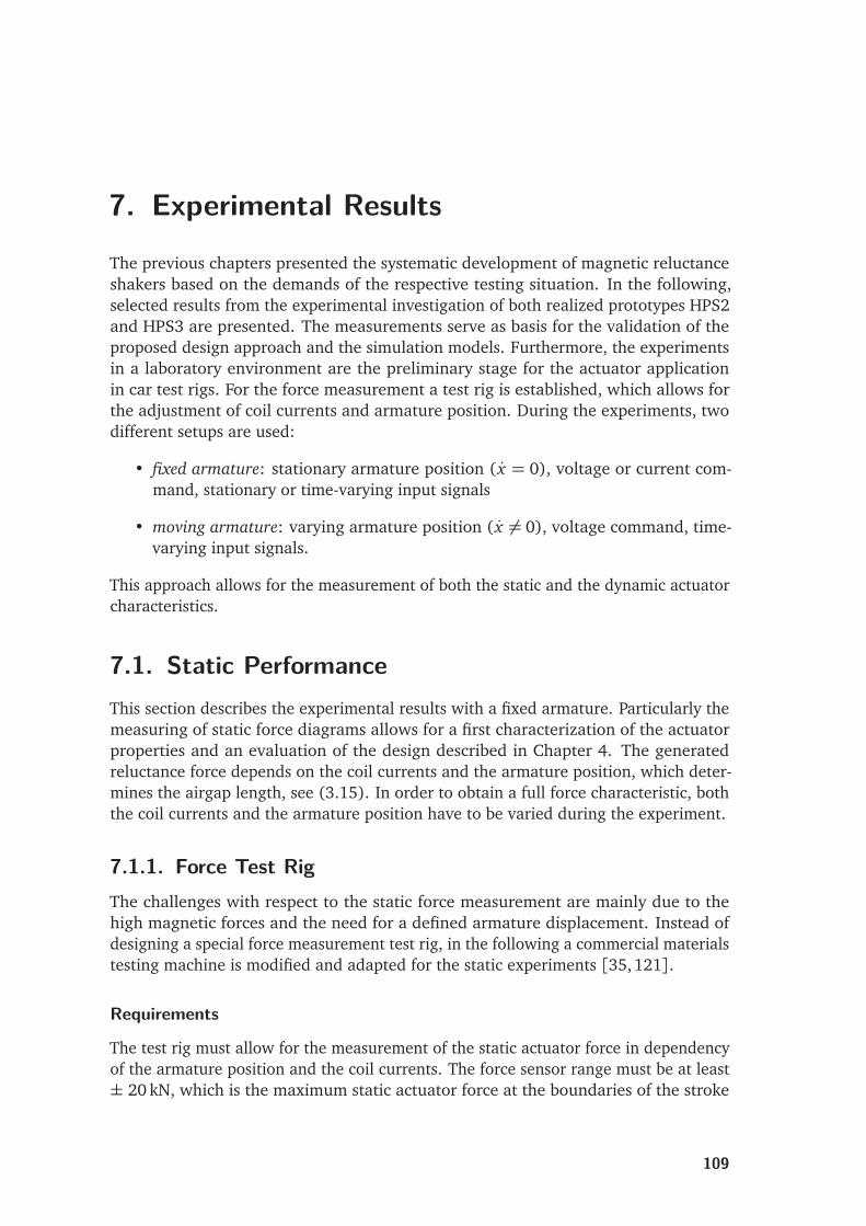
7. Experimental ResultsThe previous chapters presented the systematic development of magnetic reluctanceshakers based on the demands of the respective testing situation. In the following,selected results from the experimental investigation of both realized prototypes HPS2and HPS3 are presented. The measurements serve as basis for the validation of theproposed design approach and the simulation models. Furthermore, the experimentsin a laboratory environment are the preliminary stage for the actuator applicationin car test rigs. For the force measurement a test rig is established, which allows forthe adjustment of coil currents and armature position. During the experiments, twodifferent setups are used:
• fixed armature: stationary armature position ( x = 0), voltage or current com-mand, stationary or time-varying input signals
• moving armature: varying armature position ( x 6= 0), voltage command, time-varying input signals.
This approach allows for the measurement of both the static and the dynamic actuatorcharacteristics.
7.1. Static PerformanceThis section describes the experimental results with a fixed armature. Particularly themeasuring of static force diagrams allows for a first characterization of the actuatorproperties and an evaluation of the design described in Chapter 4. The generatedreluctance force depends on the coil currents and the armature position, which deter-mines the airgap length, see (3.15). In order to obtain a full force characteristic, boththe coil currents and the armature position have to be varied during the experiment.
7.1.1. Force Test RigThe challenges with respect to the static force measurement are mainly due to thehigh magnetic forces and the need for a defined armature displacement. Instead ofdesigning a special force measurement test rig, in the following a commercial materialstesting machine is modified and adapted for the static experiments [35,121].
Requirements
The test rig must allow for the measurement of the static actuator force in dependencyof the armature position and the coil currents. The force sensor range must be at least± 20 kN, which is the maximum static actuator force at the boundaries of the stroke
109
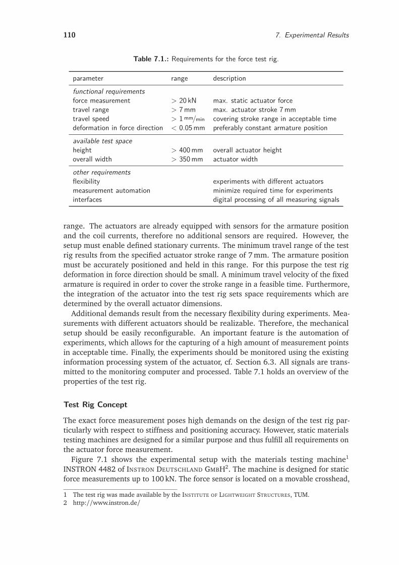
110 7. Experimental Results
Table 7.1.: Requirements for the force test rig.
parameter range descriptionfunctional requirementsforce measurement > 20 kN max. static actuator forcetravel range > 7mm max. actuator stroke 7mmtravel speed > 1mm/min covering stroke range in acceptable timedeformation in force direction < 0.05mm preferably constant armature positionavailable test spaceheight > 400mm overall actuator heightoverall width > 350mm actuator widthother requirementsflexibility experiments with different actuatorsmeasurement automation minimize required time for experimentsinterfaces digital processing of all measuring signals
range. The actuators are already equipped with sensors for the armature positionand the coil currents, therefore no additional sensors are required. However, thesetup must enable defined stationary currents. The minimum travel range of the testrig results from the specified actuator stroke range of 7 mm. The armature positionmust be accurately positioned and held in this range. For this purpose the test rigdeformation in force direction should be small. A minimum travel velocity of the fixedarmature is required in order to cover the stroke range in a feasible time. Furthermore,the integration of the actuator into the test rig sets space requirements which aredetermined by the overall actuator dimensions.
Additional demands result from the necessary flexibility during experiments. Mea-surements with different actuators should be realizable. Therefore, the mechanicalsetup should be easily reconfigurable. An important feature is the automation ofexperiments, which allows for the capturing of a high amount of measurement pointsin acceptable time. Finally, the experiments should be monitored using the existinginformation processing system of the actuator, cf. Section 6.3. All signals are trans-mitted to the monitoring computer and processed. Table 7.1 holds an overview of theproperties of the test rig.
Test Rig Concept
The exact force measurement poses high demands on the design of the test rig par-ticularly with respect to stiffness and positioning accuracy. However, static materialstesting machines are designed for a similar purpose and thus fulfill all requirements onthe actuator force measurement.
Figure 7.1 shows the experimental setup with the materials testing machine1
INSTRON 4482 of INSTRON DEUTSCHLAND GMBH2. The machine is designed for staticforce measurements up to 100 kN. The force sensor is located on a movable crosshead,
1 The test rig was made available by the INSTITUTE OF LIGHTWEIGHT STRUCTURES, TUM.2 http://www.instron.de/
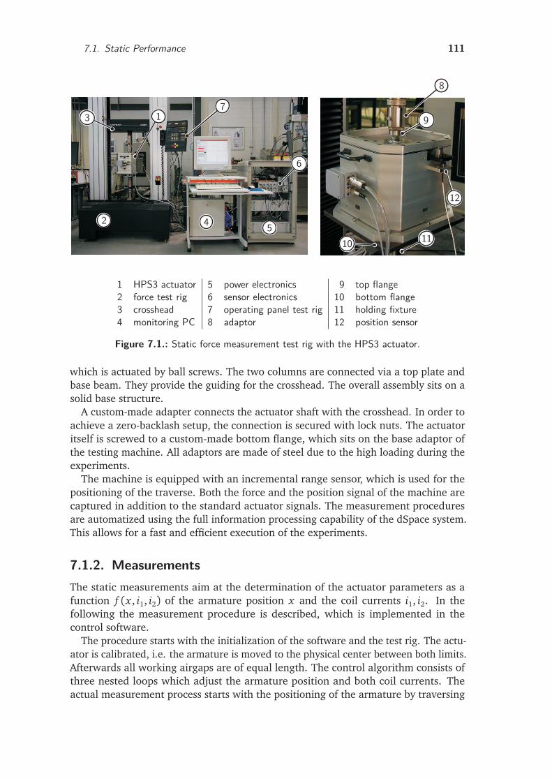
7.1. Static Performance 111
1
2
3
4 5
6
7
8
9
10 11
12
1 HPS3 actuator 5 power electronics 9 top flange2 force test rig 6 sensor electronics 10 bottom flange3 crosshead 7 operating panel test rig 11 holding fixture4 monitoring PC 8 adaptor 12 position sensor
Figure 7.1.: Static force measurement test rig with the HPS3 actuator.
which is actuated by ball screws. The two columns are connected via a top plate andbase beam. They provide the guiding for the crosshead. The overall assembly sits on asolid base structure.
A custom-made adapter connects the actuator shaft with the crosshead. In order toachieve a zero-backlash setup, the connection is secured with lock nuts. The actuatoritself is screwed to a custom-made bottom flange, which sits on the base adaptor ofthe testing machine. All adaptors are made of steel due to the high loading during theexperiments.
The machine is equipped with an incremental range sensor, which is used for thepositioning of the traverse. Both the force and the position signal of the machine arecaptured in addition to the standard actuator signals. The measurement proceduresare automatized using the full information processing capability of the dSpace system.This allows for a fast and efficient execution of the experiments.
7.1.2. MeasurementsThe static measurements aim at the determination of the actuator parameters as afunction f (x , i1, i2) of the armature position x and the coil currents i1, i2. In thefollowing the measurement procedure is described, which is implemented in thecontrol software.
The procedure starts with the initialization of the software and the test rig. The actu-ator is calibrated, i.e. the armature is moved to the physical center between both limits.Afterwards all working airgaps are of equal length. The control algorithm consists ofthree nested loops which adjust the armature position and both coil currents. Theactual measurement process starts with the positioning of the armature by traversing
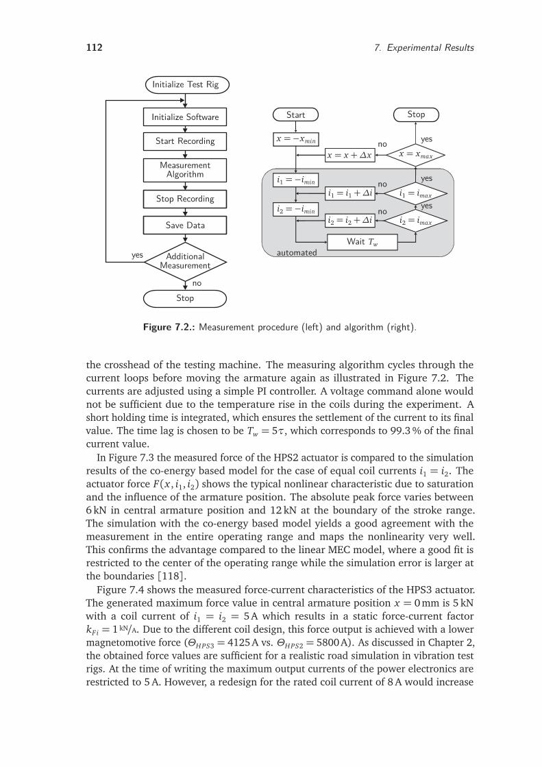
112 7. Experimental Results
Initialize Test Rig
Initialize Software
Start Recording
MeasurementAlgorithm
Stop Recording
Save Data
AdditionalMeasurement
Stopno
yes
Start
x =−xmin
i1 =−imin
i2 =−imin
Wait Tw
i2 = imax
i1 = imax
i2 = i2 +∆i
i1 = i1 +∆i
x = xmaxx = x +∆x
Stop
yes
yes
yesno
no
no
automated
Figure 7.2.: Measurement procedure (left) and algorithm (right).
the crosshead of the testing machine. The measuring algorithm cycles through thecurrent loops before moving the armature again as illustrated in Figure 7.2. Thecurrents are adjusted using a simple PI controller. A voltage command alone wouldnot be sufficient due to the temperature rise in the coils during the experiment. Ashort holding time is integrated, which ensures the settlement of the current to its finalvalue. The time lag is chosen to be Tw = 5τ, which corresponds to 99.3 % of the finalcurrent value.
In Figure 7.3 the measured force of the HPS2 actuator is compared to the simulationresults of the co-energy based model for the case of equal coil currents i1 = i2. Theactuator force F(x , i1, i2) shows the typical nonlinear characteristic due to saturationand the influence of the armature position. The absolute peak force varies between6 kN in central armature position and 12 kN at the boundary of the stroke range.The simulation with the co-energy based model yields a good agreement with themeasurement in the entire operating range and maps the nonlinearity very well.This confirms the advantage compared to the linear MEC model, where a good fit isrestricted to the center of the operating range while the simulation error is larger atthe boundaries [118].
Figure 7.4 shows the measured force-current characteristics of the HPS3 actuator.The generated maximum force value in central armature position x = 0mm is 5 kNwith a coil current of i1 = i2 = 5A which results in a static force-current factorkF i = 1 kN/A. Due to the different coil design, this force output is achieved with a lowermagnetomotive force (ΘHPS3 = 4125 A vs. ΘHPS2 = 5800 A). As discussed in Chapter 2,the obtained force values are sufficient for a realistic road simulation in vibration testrigs. At the time of writing the maximum output currents of the power electronics arerestricted to 5 A. However, a redesign for the rated coil current of 8 A would increase
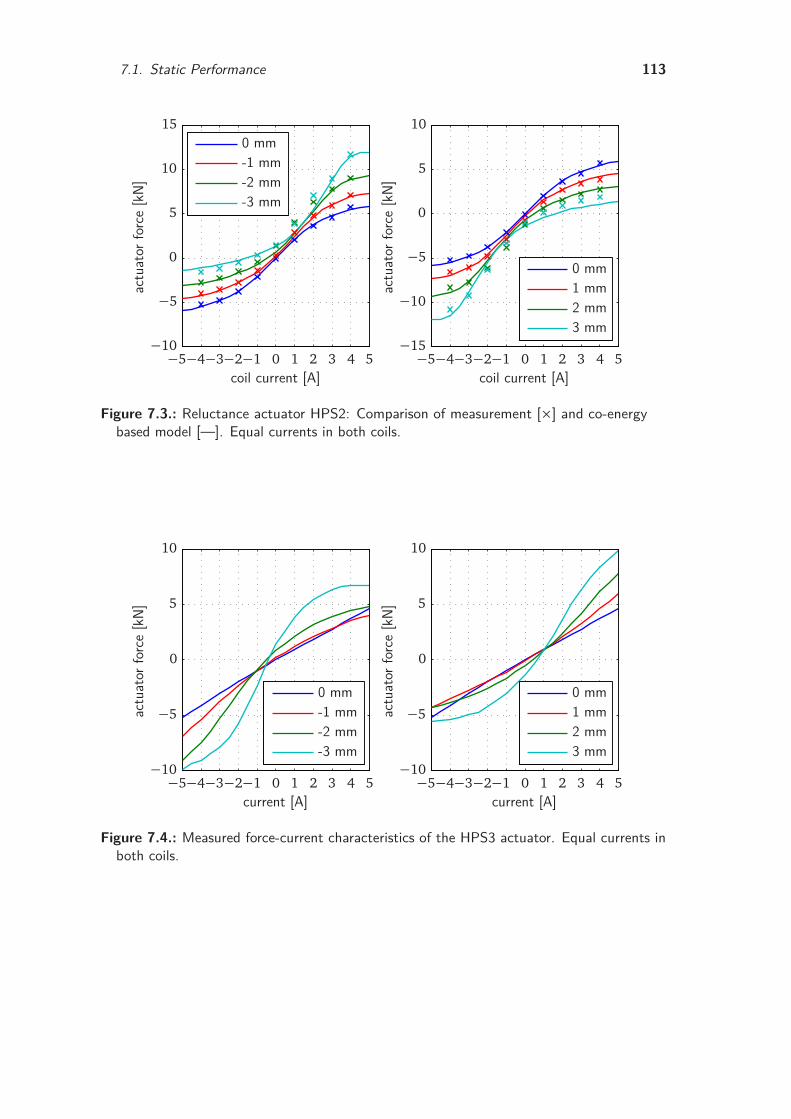
7.1. Static Performance 113
3 mm2 mm1 mm0 mm
actu
ator
forc
e[k
N]coil current [A]
-3 mm-2 mm-1 mm0 mm
actu
ator
forc
e[k
N]
coil current [A]−5−4−3−2−1 0 1 2 3 4 5−5−4−3−2−1 0 1 2 3 4 5−15
−10
−5
0
5
10
−10
−5
0
5
10
15
Figure 7.3.: Reluctance actuator HPS2: Comparison of measurement [×] and co-energybased model [—]. Equal currents in both coils.
3 mm2 mm1 mm0 mm
actu
ator
forc
e[k
N]
current [A]
-3 mm-2 mm-1 mm0 mm
actu
ator
forc
e[k
N]
current [A]−5−4−3−2−1 0 1 2 3 4 5−5−4−3−2−1 0 1 2 3 4 5−10
−5
0
5
10
−10
−5
0
5
10
Figure 7.4.: Measured force-current characteristics of the HPS3 actuator. Equal currents inboth coils.
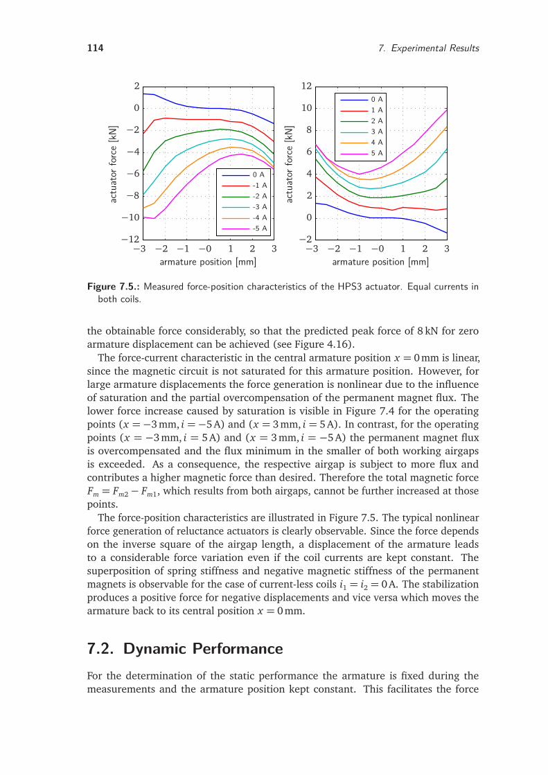
114 7. Experimental Results
5 A4 A3 A2 A1 A0 A
-5 A-4 A-3 A-2 A-1 A0 A
actu
ator
forc
e[k
N]
armature position [mm]
actu
ator
forc
e[k
N]
armature position [mm]−3 −2 −1 −0 1 2 3−3 −2 −1 −0 1 2 3−2
0
2
4
6
8
10
12
−12
−10
−8
−6
−4
−2
0
2
Figure 7.5.: Measured force-position characteristics of the HPS3 actuator. Equal currents inboth coils.
the obtainable force considerably, so that the predicted peak force of 8 kN for zeroarmature displacement can be achieved (see Figure 4.16).
The force-current characteristic in the central armature position x = 0 mm is linear,since the magnetic circuit is not saturated for this armature position. However, forlarge armature displacements the force generation is nonlinear due to the influenceof saturation and the partial overcompensation of the permanent magnet flux. Thelower force increase caused by saturation is visible in Figure 7.4 for the operatingpoints (x =−3 mm, i =−5 A) and (x = 3 mm, i = 5 A). In contrast, for the operatingpoints (x = −3mm, i = 5A) and (x = 3mm, i = −5A) the permanent magnet fluxis overcompensated and the flux minimum in the smaller of both working airgapsis exceeded. As a consequence, the respective airgap is subject to more flux andcontributes a higher magnetic force than desired. Therefore the total magnetic forceFm = Fm2− Fm1, which results from both airgaps, cannot be further increased at thosepoints.
The force-position characteristics are illustrated in Figure 7.5. The typical nonlinearforce generation of reluctance actuators is clearly observable. Since the force dependson the inverse square of the airgap length, a displacement of the armature leadsto a considerable force variation even if the coil currents are kept constant. Thesuperposition of spring stiffness and negative magnetic stiffness of the permanentmagnets is observable for the case of current-less coils i1 = i2 = 0 A. The stabilizationproduces a positive force for negative displacements and vice versa which moves thearmature back to its central position x = 0mm.
7.2. Dynamic PerformanceFor the determination of the static performance the armature is fixed during themeasurements and the armature position kept constant. This facilitates the force
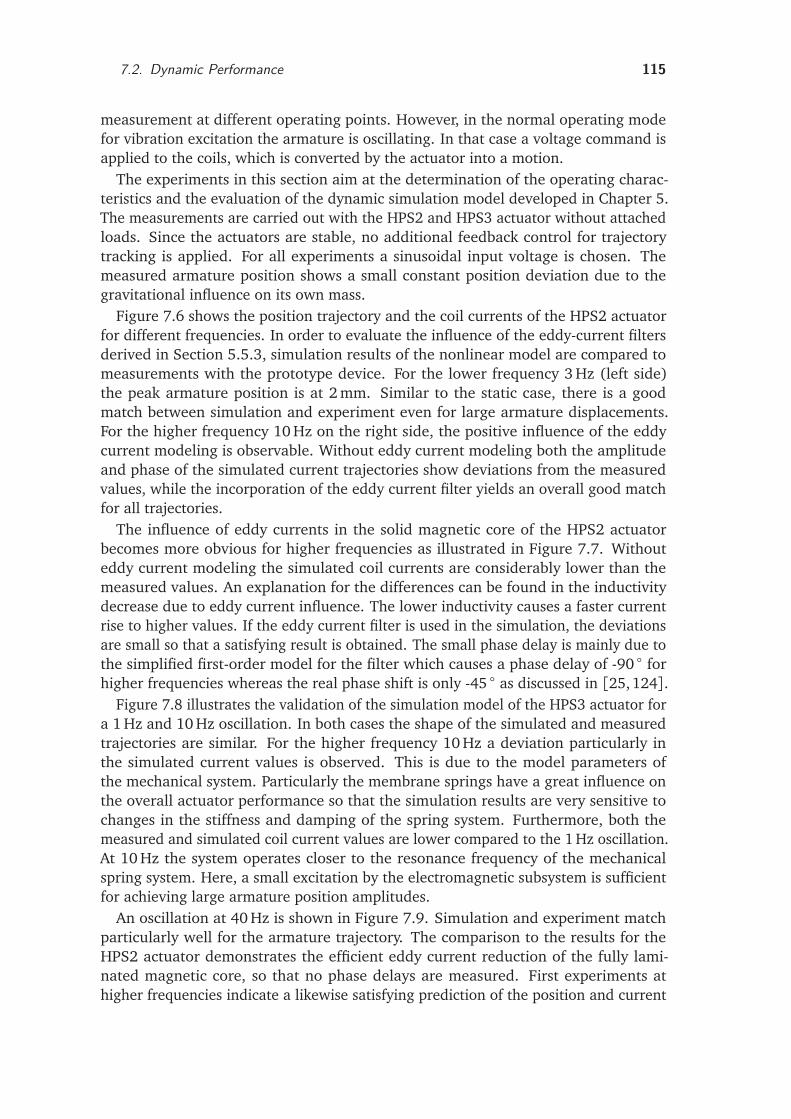
7.2. Dynamic Performance 115
measurement at different operating points. However, in the normal operating modefor vibration excitation the armature is oscillating. In that case a voltage command isapplied to the coils, which is converted by the actuator into a motion.
The experiments in this section aim at the determination of the operating charac-teristics and the evaluation of the dynamic simulation model developed in Chapter 5.The measurements are carried out with the HPS2 and HPS3 actuator without attachedloads. Since the actuators are stable, no additional feedback control for trajectorytracking is applied. For all experiments a sinusoidal input voltage is chosen. Themeasured armature position shows a small constant position deviation due to thegravitational influence on its own mass.
Figure 7.6 shows the position trajectory and the coil currents of the HPS2 actuatorfor different frequencies. In order to evaluate the influence of the eddy-current filtersderived in Section 5.5.3, simulation results of the nonlinear model are compared tomeasurements with the prototype device. For the lower frequency 3 Hz (left side)the peak armature position is at 2 mm. Similar to the static case, there is a goodmatch between simulation and experiment even for large armature displacements.For the higher frequency 10 Hz on the right side, the positive influence of the eddycurrent modeling is observable. Without eddy current modeling both the amplitudeand phase of the simulated current trajectories show deviations from the measuredvalues, while the incorporation of the eddy current filter yields an overall good matchfor all trajectories.
The influence of eddy currents in the solid magnetic core of the HPS2 actuatorbecomes more obvious for higher frequencies as illustrated in Figure 7.7. Withouteddy current modeling the simulated coil currents are considerably lower than themeasured values. An explanation for the differences can be found in the inductivitydecrease due to eddy current influence. The lower inductivity causes a faster currentrise to higher values. If the eddy current filter is used in the simulation, the deviationsare small so that a satisfying result is obtained. The small phase delay is mainly due tothe simplified first-order model for the filter which causes a phase delay of -90 forhigher frequencies whereas the real phase shift is only -45 as discussed in [25,124].
Figure 7.8 illustrates the validation of the simulation model of the HPS3 actuator fora 1 Hz and 10 Hz oscillation. In both cases the shape of the simulated and measuredtrajectories are similar. For the higher frequency 10 Hz a deviation particularly inthe simulated current values is observed. This is due to the model parameters ofthe mechanical system. Particularly the membrane springs have a great influence onthe overall actuator performance so that the simulation results are very sensitive tochanges in the stiffness and damping of the spring system. Furthermore, both themeasured and simulated coil current values are lower compared to the 1 Hz oscillation.At 10 Hz the system operates closer to the resonance frequency of the mechanicalspring system. Here, a small excitation by the electromagnetic subsystem is sufficientfor achieving large armature position amplitudes.
An oscillation at 40 Hz is shown in Figure 7.9. Simulation and experiment matchparticularly well for the armature trajectory. The comparison to the results for theHPS2 actuator demonstrates the efficient eddy current reduction of the fully lami-nated magnetic core, so that no phase delays are measured. First experiments athigher frequencies indicate a likewise satisfying prediction of the position and current
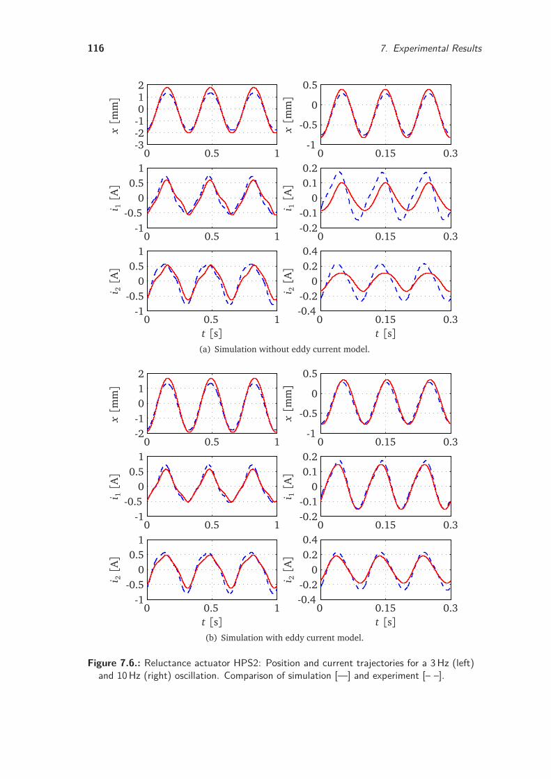
116 7. Experimental Results
x[m
m]
i 1[A]
t [s]
i 2[A]
x[m
m]
i 1[A]
t [s]
i 2[A]
0 0.15 0.3
0 0.15 0.3
0 0.15 0.3
0 0.5 1
0 0.5 1
0 0.5 1
-0.4-0.2
00.20.4
-0.2-0.1
00.10.2
-1
-0.5
0
0.5
-1-0.5
00.5
1
-1-0.5
00.5
1
-3-2-1012
(a) Simulation without eddy current model.
x[m
m]
i 1[A]
t [s]
i 2[A]
x[m
m]
i 1[A]
t [s]
i 2[A]
0 0.15 0.3
0 0.15 0.3
0 0.15 0.3
0 0.5 1
0 0.5 1
0 0.5 1
-0.4-0.2
00.20.4
-0.2-0.1
00.10.2
-1
-0.5
0
0.5
-1-0.5
00.5
1
-1-0.5
00.5
1
-2-1012
(b) Simulation with eddy current model.
Figure 7.6.: Reluctance actuator HPS2: Position and current trajectories for a 3Hz (left)and 10Hz (right) oscillation. Comparison of simulation [—] and experiment [– –].
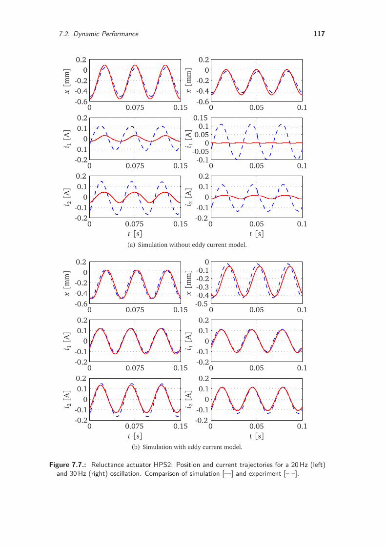
7.2. Dynamic Performance 117
x[m
m]
i 1[A]
t [s]
i 2[A]
x[m
m]
i 1[A]
t [s]
i 2[A]
0 0.05 0.1
0 0.05 0.1
0 0.05 0.1
0 0.075 0.15
0 0.075 0.15
0 0.075 0.15
-0.2-0.1
00.10.2
-0.1-0.05
00.050.1
0.15
-0.6-0.4-0.2
00.2
-0.2-0.1
00.10.2
-0.2-0.1
00.10.2
-0.6-0.4-0.2
00.2
(a) Simulation without eddy current model.
x[m
m]
i 1[A]
t [s]
i 2[A]
x[m
m]
i 1[A]
t [s]
i 2[A]
0 0.05 0.1
0 0.05 0.1
0 0.05 0.1
0 0.075 0.15
0 0.075 0.15
0 0.075 0.15
-0.2-0.1
00.10.2
-0.2-0.1
00.10.2
-0.5-0.4-0.3-0.2-0.1
0
-0.2-0.1
00.10.2
-0.2-0.1
00.10.2
-0.6-0.4-0.2
00.2
(b) Simulation with eddy current model.
Figure 7.7.: Reluctance actuator HPS2: Position and current trajectories for a 20Hz (left)and 30Hz (right) oscillation. Comparison of simulation [—] and experiment [– –].
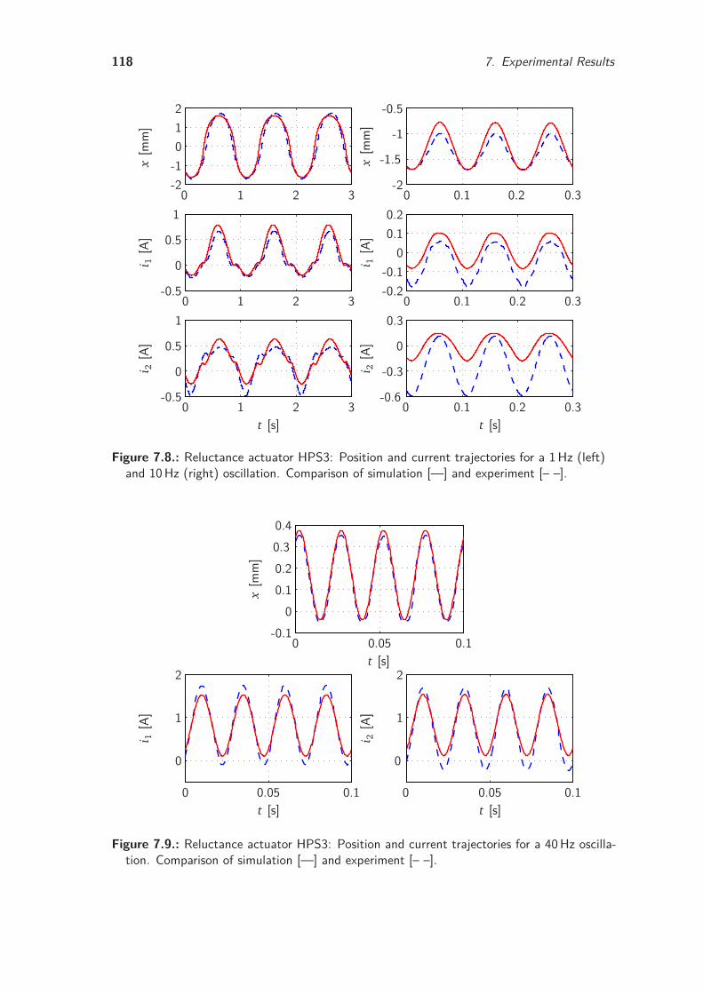
118 7. Experimental Results
x[m
m]
i 1[A
]
t [s]
i 2[A
]
x[m
m]
i 1[A
]
t [s]
i 2[A
]
0 0.1 0.2 0.3
0 0.1 0.2 0.3
0 0.1 0.2 0.3
0 1 2 3
0 1 2 3
0 1 2 3
-0.6
-0.3
0
0.3
-0.2-0.1
00.10.2
-2
-1.5
-1
-0.5
-0.5
0
0.5
1
-0.5
0
0.5
1
-2-1012
Figure 7.8.: Reluctance actuator HPS3: Position and current trajectories for a 1Hz (left)and 10Hz (right) oscillation. Comparison of simulation [—] and experiment [– –].
t [s]
x[m
m]
t [s]
i 1[A
]
t [s]
i 2[A
]
0 0.05 0.10 0.05 0.1
0 0.05 0.1
0
1
2
0
1
2
-0.10
0.10.20.30.4
Figure 7.9.: Reluctance actuator HPS3: Position and current trajectories for a 40Hz oscilla-tion. Comparison of simulation [—] and experiment [– –].
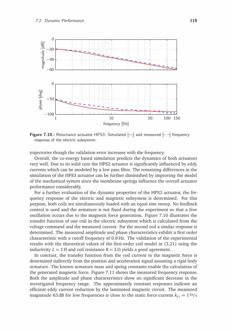
7.2. Dynamic Performance 119
phas
e[d
eg]
frequency [Hz]
mag
nitu
de[d
B]
1 10 50 100 150−100
−50
0
−60
−40
−20
0
Figure 7.10.: Reluctance actuator HPS3: Simulated [—] and measured [– –] frequencyresponse of the electric subsystem.
trajectories though the validation error increases with the frequency.Overall, the co-energy based simulation predicts the dynamics of both actuators
very well. Due to its solid core the HPS2 actuator is significantly influenced by eddycurrents which can be modeled by a low pass filter. The remaining differences in thesimulation of the HPS3 actuator can be further diminished by improving the modelof the mechanical system since the membrane springs influence the overall actuatorperformance considerably.
For a further evaluation of the dynamic properties of the HPS3 actuator, the fre-quency response of the electric and magnetic subsystem is determined. For thispurpose, both coils are simultaneously loaded with an equal sine sweep. No feedbackcontrol is used and the armature is not fixed during the experiment so that a freeoscillation occurs due to the magnetic force generation. Figure 7.10 illustrates thetransfer function of one coil in the electric subsystem which is calculated from thevoltage command and the measured current. For the second coil a similar response isdetermined. The measured amplitude and phase characteristics exhibit a first ordercharacteristic with a cutoff frequency of 0.8 Hz. The validation of the experimentalresults with the theoretical values of the first-order coil model in (3.21) using theinductivity L = 1H and coil resistance R= 5Ω yields a good agreement.
In contrast, the transfer function from the coil current to the magnetic force isdetermined indirectly from the position and acceleration signal assuming a rigid bodyarmature. The known armature mass and spring constants enable the calculation ofthe generated magnetic force. Figure 7.11 shows the measured frequency response.Both the amplitude and phase characteristics show no significant decrease in theinvestigated frequency range. The approximately constant responses indicate anefficient eddy current reduction by the laminated magnetic circuit. The measuredmagnitude 63 dB for low frequencies is close to the static force-current kF i = 1 kN/A
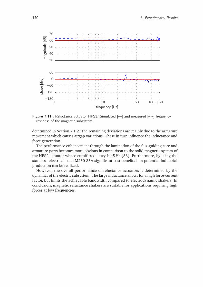
120 7. Experimental Results
phas
e[d
eg]
frequency [Hz]
mag
nitu
de[d
B]
1 10 50 100 150−180
−120
−60
0
60
30
40
50
60
70
Figure 7.11.: Reluctance actuator HPS3: Simulated [—] and measured [– –] frequencyresponse of the magnetic subsystem.
determined in Section 7.1.2. The remaining deviations are mainly due to the armaturemovement which causes airgap variations. These in turn influence the inductance andforce generation.
The performance enhancement through the lamination of the flux-guiding core andarmature parts becomes more obvious in comparison to the solid magnetic system ofthe HPS2 actuator whose cutoff frequency is 45 Hz [33]. Furthermore, by using thestandard electrical steel M250-35A significant cost benefits in a potential industrialproduction can be realized.
However, the overall performance of reluctance actuators is determined by thedynamics of the electric subsystem. The large inductance allows for a high force-currentfactor, but limits the achievable bandwidth compared to electrodynamic shakers. Inconclusion, magnetic reluctance shakers are suitable for applications requiring highforces at low frequencies.
8. Conclusions
Magnetic reluctance actuators have a great application potential in vibration testing.This thesis has presented a framework for the design and simulation of permanentmagnet reluctance shakers. The realized actuators are intended for the disturbingnoise analysis of vehicles and components in automotive NVH testing. A brief summaryof the key findings is given in the following and complemented by suggestions forfuture research.
8.1. SummaryThe point of origin for this thesis is set in Chapter 2 which gives an overview ofvibration testing and the analysis of products for disturbing noise. A comparison ofhydraulic, electrodynamic and reluctance drive concepts illustrates the applicationpotential of magnetic reluctance actuators for NVH testing. The main advantagesare a high force density, robustness, low power consumption and energy supply withelectric current. An introduction to test rigs for the simulation of road drives in alaboratory environment shows the requirements on translatory reluctance drives forthe controlled excitation of vibration. The direct body excitation (DBE) of vehicles viathe frame instead of the wheels and suspension enables a sufficient excitation with thesmall achievable strokes of reluctance actuators.
Chapter 3 treats relevant key aspects of high performance actuators. Besides thegeneration of reluctance forces, the main loss mechanisms in the core and windings arediscussed. For the development of high dynamic actuators particularly the reductionof eddy current influence in the magnetic system is essential. Moreover, differentmodeling approaches for the design and simulation are evaluated. For calculation ofthe main actuator parameters during the first design phase linear reluctance circuitsare used due to their low computational cost. Finite element models allow for adetailed analysis of the magnetic circuit. For dynamic simulation, a reduced orderapproach based on numerical co-energy calculations is used. It enables an accurateprediction of the nonlinear actuator characteristic and a fast system simulation.
The magnetic design of the reluctance shaker HPS3 is presented in Chapter 4.First of all the design objectives are determined, based on given road profiles. Themaximum magnetic force is 8 kN with a peak stroke of ± 3.5 mm, which allows forthe excitation of heavy test objects with frequencies up to 100 Hz. With respect to theintended application, different topologies and selection criteria of magnetic materialsare discussed. A fully laminated, polarized topology is proposed featuring two coils,two separate armature plates and surface mounted magnets. Mechanical springs fullycompensate the negative magnetic stiffness and enable a stable operation. As materialfor the flux-guiding parts the standard electrical steel M250-35A is chosen. NdFeBpermanent magnets with very high energy density provide the magnetic bias. The
121
122 8. Conclusions
development is based on a magnetic equivalent circuit model for the dimensioningand numerical field calculations for the detailed design analysis.
Chapter 5 describes the development of an energy-based simulation model for mag-netic reluctance actuators. For this purpose an analytical approximation of discreteco-energy values, which are calculated during static FE simulations, is carried out. Theresulting simulation model features low numerical cost and captures the nonlinearcharacteristics of reluctance actuators very well. Moreover, the model preserves allmajor advantages of the FE analysis such as the incorporation of saturation by usingthe nonlinear B-H curve and the detailed mapping of complex geometries and fluxleakage. The method couples a system simulation with the numerical field calculationthereby simultaneously reducing the model order. Due to its block oriented hierar-chical structure, the mechatronic modeling approach is suitable for direct softwareimplementation.
The mechatronic development is complemented by the mechanical design and theinformation processing which are the subject of Chapter 6. The mechanical designconsiderations aim at the strength assessment of the laminations and the membranesprings by adopting numerical analyses. Special attention is paid to the laminatedarmature, where a supporting structure minimizes the mechanical load on the armaturestack. While the permanent magnet bias is beneficial from a magnetic perspective,the resulting instability deteriorates the operating behavior of the actuator. Hence thecompensation of the destabilizing magnetic force by the restoring force of membranesprings is a key feature of the proposed actuator concept. This approach enablesa stick-slip free motion at high frequencies and a stable actuator operation withoutfeedback control. In addition, the controlled tracking of reference profiles requires anintelligent actuator system. For this purpose, the developed shakers are extended to avibration excitation system consisting of power electronics, real time hardware, sensorsystem and monitoring PC.
Chapter 7 presents selected results from simulations and experiments. For the accu-rate measurement of high magnetic forces a materials testing machine is adapted whichallows for the precise positioning of the armature. Experiments with a fixed armatureenable the measurement of the static actuator characteristics. The comparison to thedesign objectives defined in Chapter 4 shows, that the generated forces are sufficientfor a realistic excitation of heavy passenger cars. Moreover, experiments with a movingarmature serve for the validation of the dynamic simulation models and illustrate thefrequency characteristics of the developed actuators. Both the transfer functions of theelectric and magnetic subsystem are measured. The laminated magnetic system of theHPS3 actuator effectively reduces eddy currents and facilitates a sufficient excitationat higher frequencies up to 150 Hz. Furthermore, the use of standard electrical steelenables significant cost benefits in a potential industrial production.
8.2. Recommendations for Future ResearchSeveral suggestions for future research can be made from the experiences gainedduring the work on this thesis. In the following, selected problems relating to thedesign, simulation and control of reluctance shakers as well as promising applicationsare discussed.
8.2. Recommendations for Future Research 123
Actuators
For surface-mounted magnets as in the chosen topology, the required reluctance surfacedetermines the length and width of the permanent magnets. A separation of the ironpole surface and magnet area could be achieved by using pole pieces. Moreover,the investigation of parallel polarized topologies is promising. In contrast to serialpolarized magnetic systems, higher specific forces can be obtained since the reluctancedue to the magnet in the coil flux path can be avoided.
The thermal load in the coil system is a key factor for a further reduction of theactuator size and weight. A detailed thermal design can lead to a significant reductionof the coil size. For the HPS3 actuator passive cooling has been chosen. However,for applications in which the noise of cooling fans is not relevant, an active coolingsystem could be considered which would enable the design of very compact reluctanceshakers.
The mechanical design can be improved by the development of membrane springswith laser cut pockets. While isotropic springs are sufficient for a robust and stableactuator operation, a detailed adjustment of the spring characteristics allows for afurther enhancement of the performance. Here the observation of the fatigue limitand the avoidance of acoustic emissions are important. Preliminary experimentalresults suggest that inserting fewer but larger pockets is beneficial. Additionally, therestoring force could be chosen such that the armature is positioned exactly in itscentral position.
Simulation and Control
Improved simulation results can be obtained for the HPS3 actuator by a better pa-rameterization of the model for the mechanical subsystem. For this purpose, thecharacteristics of the spring system must be determined separately from those of themagnetic system. Experiments with the HPS2 actuator show that this can be achievedby measuring the force characteristics of a dummy actuator without magnetic core.
Although the force generation of reluctance actuators is nonlinear, the experimentaldetermination of linear transfer functions in the frequency domain is beneficial fora performance assessment. For this purpose, the presented force test rig can befurther used. Yet, a force sensor and sensor electronics suitable for high dynamicmeasurements must be chosen. For further experiments with a moving armature, adynamometer could be set up. Currently, the generated coil currents during idlingor actuation of comparatively small masses are too low for a validation of the entireperformance spectrum. The developed component test rigs shown in Figure 2.5 canserve as a prototype, thereby supporting the static weight of an actuated large mass byair bellows.
For the trajectory tracking control of the reluctance shakers, approaches based onsystem identification and basic lumped parameter models have been used by HERRMANN
and KOCH [33,53]. A promising concept is the use of the presented co-energy basedmodel for control design. For a first investigation, linear state space and nonlinearflatness-based feedback control designs are suggested. Using lookup tables instead ofevaluating the analytical functions for the co-energy and its derivatives in each timestep can reduce the computational effort considerably.
124 8. Conclusions
Applications
The functionality of the developed HPS3 actuator has been demonstrated in laboratoryexperiments. Consequently, tests in a road simulator with four actuators should becarried out. For this purpose the control concept developed in [53] can be used.However, the control structure can be considerably simplified because of the inherentstability of the actuators.
Currently, the maximum coil current is limited to 5 A by the power electronics. Theachievable force can be further increased by designing enhanced power electronicswhich are capable of providing the rated coil current of 8 A. This would allow for theexcitation of heavier vehicles.
Industrial vibration testing is mainly carried out in one dimension only or in threedimensions with a sequential excitation. A simultaneous excitation of all three dimen-sions reduces the analysis time and enhances the degree of reality. Since such a test rigmust be driven by at least three actuators, the small size and low power consumptionof magnetic reluctance actuators is beneficial.
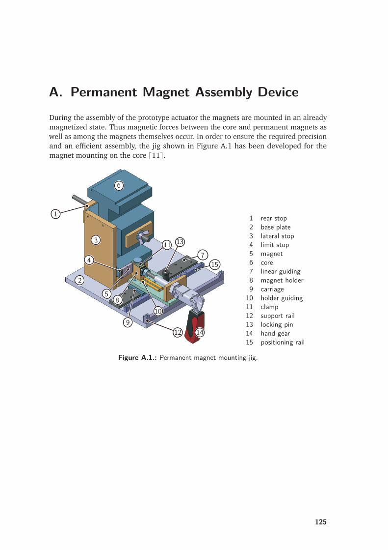
A. Permanent Magnet Assembly DeviceDuring the assembly of the prototype actuator the magnets are mounted in an alreadymagnetized state. Thus magnetic forces between the core and permanent magnets aswell as among the magnets themselves occur. In order to ensure the required precisionand an efficient assembly, the jig shown in Figure A.1 has been developed for themagnet mounting on the core [11].
1
2
3
4
5
6
7
8
910
11
12
13
14
15
rail
1 rear stop2 base plate3 lateral stop4 limit stop5 magnet6 core7 linear guiding8 magnet holder9 carriage
10 holder guiding11 clamp12 support rail13 locking pin14 hand gear15 positioning rail
Figure A.1.: Permanent magnet mounting jig.
125

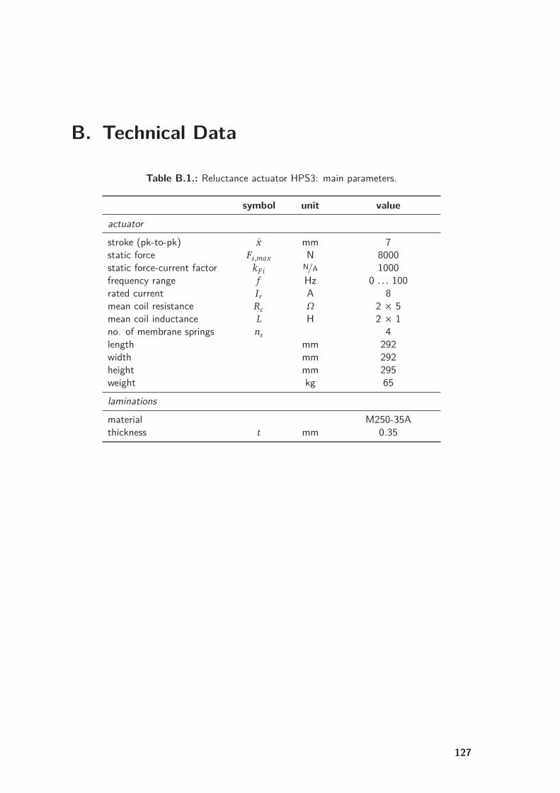
B. Technical Data
Table B.1.: Reluctance actuator HPS3: main parameters.
symbol unit value
actuator
stroke (pk-to-pk) x mm 7static force Fs,max N 8000static force-current factor kF i N/A 1000frequency range f Hz 0 . . . 100rated current Ir A 8mean coil resistance Rc Ω 2 × 5mean coil inductance L H 2 × 1no. of membrane springs ns 4length mm 292width mm 292height mm 295weight kg 65laminations
material M250-35Athickness t mm 0.35
127
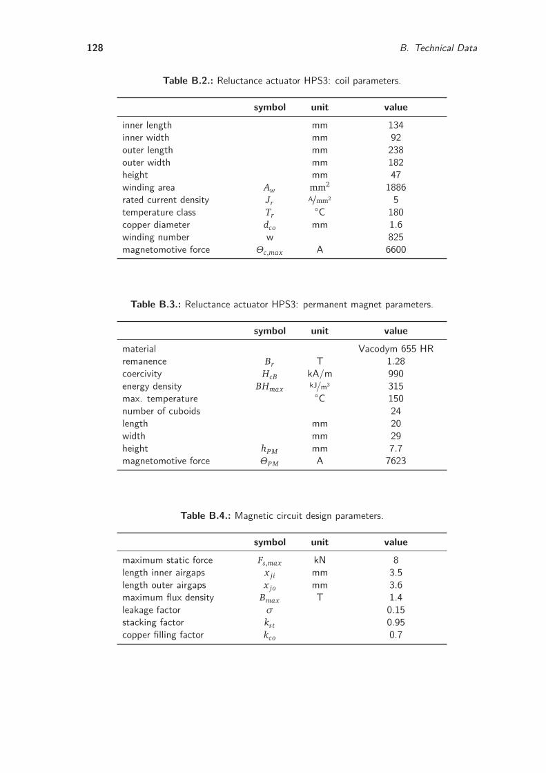
128 B. Technical Data
Table B.2.: Reluctance actuator HPS3: coil parameters.
symbol unit value
inner length mm 134inner width mm 92outer length mm 238outer width mm 182height mm 47winding area Aw mm2 1886rated current density Jr A/mm2 5temperature class Tr
C 180copper diameter dco mm 1.6winding number w 825magnetomotive force Θc,max A 6600
Table B.3.: Reluctance actuator HPS3: permanent magnet parameters.
symbol unit value
material Vacodym 655 HRremanence Br T 1.28coercivity HcB kA/m 990energy density BHmax kJ/m3 315max. temperature C 150number of cuboids 24length mm 20width mm 29height hPM mm 7.7magnetomotive force ΘPM A 7623
Table B.4.: Magnetic circuit design parameters.
symbol unit value
maximum static force Fs,max kN 8length inner airgaps x ji mm 3.5length outer airgaps x jo mm 3.6maximum flux density Bmax T 1.4leakage factor σ 0.15stacking factor kst 0.95copper filling factor kco 0.7
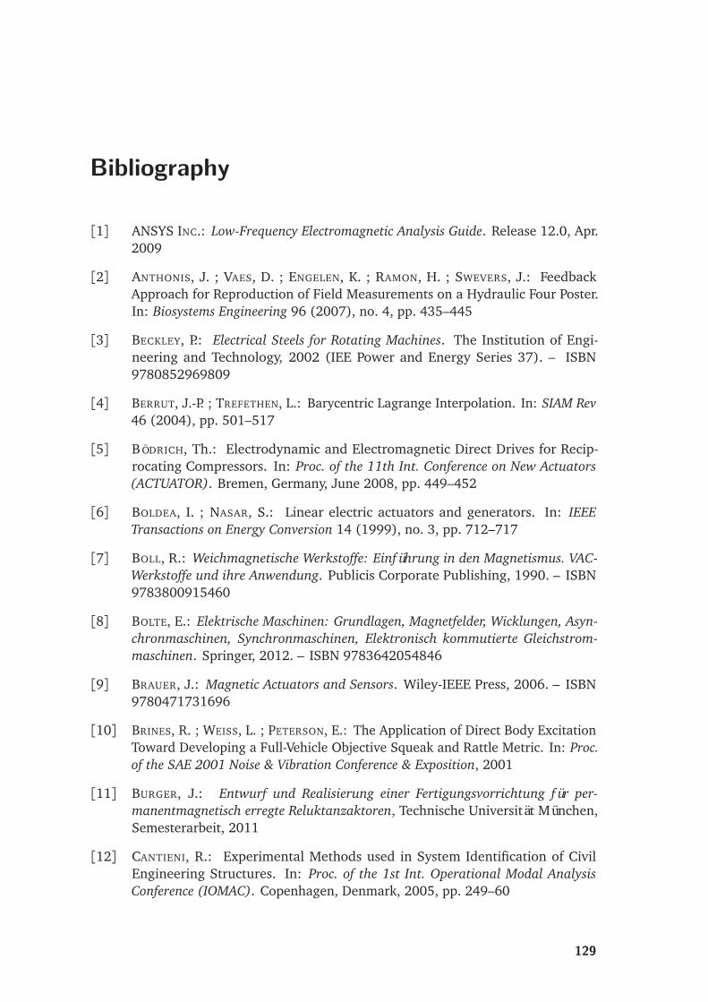
Bibliography
[1] ANSYS INC.: Low-Frequency Electromagnetic Analysis Guide. Release 12.0, Apr.2009
[2] ANTHONIS, J. ; VAES, D. ; ENGELEN, K. ; RAMON, H. ; SWEVERS, J.: FeedbackApproach for Reproduction of Field Measurements on a Hydraulic Four Poster.In: Biosystems Engineering 96 (2007), no. 4, pp. 435–445
[3] BECKLEY, P.: Electrical Steels for Rotating Machines. The Institution of Engi-neering and Technology, 2002 (IEE Power and Energy Series 37). – ISBN9780852969809
[4] BERRUT, J.-P. ; TREFETHEN, L.: Barycentric Lagrange Interpolation. In: SIAM Rev46 (2004), pp. 501–517
[5] BÖDRICH, Th.: Electrodynamic and Electromagnetic Direct Drives for Recip-rocating Compressors. In: Proc. of the 11th Int. Conference on New Actuators(ACTUATOR). Bremen, Germany, June 2008, pp. 449–452
[6] BOLDEA, I. ; NASAR, S.: Linear electric actuators and generators. In: IEEETransactions on Energy Conversion 14 (1999), no. 3, pp. 712–717
[7] BOLL, R.: Weichmagnetische Werkstoffe: Einführung in den Magnetismus. VAC-Werkstoffe und ihre Anwendung. Publicis Corporate Publishing, 1990. – ISBN9783800915460
[8] BOLTE, E.: Elektrische Maschinen: Grundlagen, Magnetfelder, Wicklungen, Asyn-chronmaschinen, Synchronmaschinen, Elektronisch kommutierte Gleichstrom-maschinen. Springer, 2012. – ISBN 9783642054846
[9] BRAUER, J.: Magnetic Actuators and Sensors. Wiley-IEEE Press, 2006. – ISBN9780471731696
[10] BRINES, R. ; WEISS, L. ; PETERSON, E.: The Application of Direct Body ExcitationToward Developing a Full-Vehicle Objective Squeak and Rattle Metric. In: Proc.of the SAE 2001 Noise & Vibration Conference & Exposition, 2001
[11] BURGER, J.: Entwurf und Realisierung einer Fertigungsvorrichtung für per-manentmagnetisch erregte Reluktanzaktoren, Technische Universität München,Semesterarbeit, 2011
[12] CANTIENI, R.: Experimental Methods used in System Identification of CivilEngineering Structures. In: Proc. of the 1st Int. Operational Modal AnalysisConference (IOMAC). Copenhagen, Denmark, 2005, pp. 249–60
129
130 Bibliography
[13] CASSING, W ; STANEK, W. ; ERD, L. ; HÜBNER, K.-D. ; KOCH, J. ; DUKART, A.: Elek-tromagnetische Wandler und Sensoren: Grundlagen, feldnumerische Berechnungelektromagnetischer Felder und Anwendungen in der Mechatronik. Expert Verlag,2002. – ISBN 3816918786
[14] CHEN, X. ; ZHU, Z. ; HOWE, D. ; DAI, J.: Comparative Study of AlternativePermanent Magnet Linear Oscillating Actuators. In: Proc. of the InternationalConference on Electrical Machines and Systems, ICEMS 2008. IEEE, 2008, pp.2826–2831
[15] CHILLET, Ch. ; VOYANT, J.-Y.: Design-Oriented Analytical Study of a Linear Elec-tromagnetic Actuator by Means of a Reluctance Network. In: IEEE Transactionson Magnetics 37 (2001), July, no. 4, pp. 3004–3011. – DOI 10.1109/20.947053.– ISSN 0018–9464
[16] CLAEYSSEN, F. ; MAGNAC, G. ; MARION, F. ; BARILLOT, F. ; MENEROUD, P. ; PATIENT,G.: Moving Coil or Moving Iron Controllable Actuators: How to make thegood choice. In: Proc. of the 6th Int. Symposium on Linear Drives for IndustrialApplications (LDIA), 2007
[17] CLARK, R. ; JEWELL, G. ; FORREST, S. ; RENS, J. ; MAERKY, C.: Design Featuresfor Enhancing the Performance of Electromagnetic Valve Actuation Systems. In:IEEE Transactions on Magnetics 41 (2005), no. 3, pp. 1163–1168
[18] DIETRICH, A.: FEM-basierte Makromodellierung eines elektromagnetischen Aktors,Technische Universität München, diploma thesis, 2008
[19] DIN EN 60317: Technische Lieferbedingungen an bestimmte Typen von Wickel-drähten - Teil 0-1: Allgemeine Anforderungen. Feb. 2009
[20] DSPACE GMBH: DS1104 R&D Controller Board. Hardware Installation andConfiguration, 2006
[21] DSPACE GMBH: Embedded Success - Catalog 2012. 2012
[22] DUPONT: VOLTATEX E1175 W. Wilmington, USA, 2006
[23] DYER, S. ; HE, X.: Least-Squares Fitting of Data by Polynomials. In: IEEEInstrumentation & Measurement Magazine 4 (2001), Dec., no. 4, pp. 46 –51. –DOI 10.1109/5289.975465. – ISSN 1094–6969
[24] FAVOT, V. ; WIEDEMANN, D. ; HERRMANN, M. ; ULBRICH, H.: Nonlinear Modellingand Flatness-Based Control for an Electromagnetic Reluctance Force Actuator.In: Proc. of the 3rd IEEE Conference on Industrial Electronics and Applications(ICIEA), 2008, pp. 114–119
[25] FEELEY, J.: A Simple Dynamic Model for Eddy Currents in a Magnetic Actuator.In: IEEE Transactions on Magnetics 32 (1996), Mar., no. 2, pp. 453 –458. – DOI10.1109/20.486532. – ISSN 0018–9464
Bibliography 131
[26] FITZGERALD, A. ; KINGSLEY, Ch. ; UMANS, S.: Electric Machinery. 6. McGraw-Hill,2002. – ISBN 9780073660097
[27] GENUIT, K.: Vehicle Interior Noise - Combination of Sound, Vibration andInteractivity. In: Sound and Vibration 43 (2009), no. 12, pp. 8
[28] GENUIT, K. (ed.): Sound-Engineering im Automobilbereich: Methoden zur Messungund Auswertung von Geräuschen und Schwingungen. 1. Auflage. Springer, 2010.– ISBN 9783642014147
[29] GINZINGER, L.: Control of a Rubbing Rotor using an Active Auxiliary Bearing,Technische Universität München, dissertation, 2009
[30] GOLLEE, R.: Modellierung und Simulation elektromagnetischer Aktoren, Techni-sche Universität Dresden, dissertation, 2004
[31] GRASSER, A.: Modellbildung und lineare Trajektorienfolgeregelung für Reluktanz-aktoren, Technische Universität München, diploma thesis, 2011
[32] HARTWIG, Ch.: Magnetdynamischer Linear-Aktor, Universität Hannover, disserta-tion, 2003
[33] HERRMANN, M.: Entwurf, Berechnung und Regelung magnetischer Reluktanzak-toren. München, Technische Universität München, dissertation, 2008
[34] HERRMANN, M. ; ULBRICH, H.: State Controlled Electromagnetic Shaker forTrajectory Tracking. In: Proc. of the 6th Int. Symposium on Linear Drives forIndustrial Applications (LDIA). Lille, France, Sept. 2007
[35] HOFMANN, O.: Kennfeldvermessung für elektromagnetische Aktoren, TechnischeUniversität München, bachelor thesis, 2011
[36] HOWE, D.: Electromagnetic Actuation Systems - Design and Applications. In:Proc. of the IEE Colloquium on Limited Motion Electrical Actuation Systems.London, Oct. 1998
[37] HOWE, D.: Magnetic Actuators. In: Sensors and Actuators 81 (2000), Apr., pp.268–274
[38] ISERMANN, R.: Mechatronic Systems: Fundamentals. Springer, 2005. – ISBN9781852339302
[39] JACKSON, J.: Classical Electrodynamics. Wiley, 1998. – ISBN 9780471309321
[40] JANOCHA, H. (ed.): Actuators: Basics and Applications. Springer, 2010. – ISBN9783642082665
[41] JELTSEMA, D. ; SCHERPEN, J.: Multidomain Modeling of Nonlinear Networks andSystems. In: IEEE Control Systems Magazine 29 (2009), no. 4, pp. 28–59
[42] JENDRITZA, D.: Technischer Einsatz neuer Aktoren. Expert-Verlag GmbH, 2005. –ISBN 9783816920670
132 Bibliography
[43] JONEIT, D.: Modellierung und Simulation elektromagnetischer Antriebe in derFeinwerktechnik. Wissenschaftliche Schriftenreihe Elektrotechnik. Berlin :Köster, 2000 (Bd. 34). – ISBN 3895743712
[44] JÖST, R.: Additional Experimental Analysis Possibilities for Car Body Structuresby using High Power Electrodynamic Shakers. In: Proc. of the LMS ConferenceEurope, 2006
[45] KALLENBACH, E. ; KUBE, H. ; ZÖPPIG, V. ; FEINDT, K. ; HERMANN, R. ; BEYER, F.: NewPolarized Electromagnetic Actuators as Integrated Mechatronic Components– Design and Application. In: Mechatronics 9 (1999), no. 7, pp. 769–784
[46] KALLENBACH, M.: Entwurf von magnetischen Mini- und Mikroaktoren mit starknichtlinearem Magnetkreis, Technische Universität Ilmenau, dissertation, 2005
[47] KALLENBACH, E. ET AL.: Elektromagnete: Grundlagen, Berechnung, Entwurf undAnwendung. Vieweg+Teubner Verlag, 2012. – ISBN 9783834809681
[48] KAVARANA, F. ; REDIERS, B.: Squeak and Rattle - State of the Art and Beyond. In:Sound and Vibration (2001). – Issue Apr.
[49] KHATEEB, N. ; GERLING, D.: Computer Aided Macromodeling for Control ofElectromechanical Systems. In: Proc. of the Conference of Electric and ElectronicalEngineering (EEC). Aleppo, Syria, 2007
[50] KHATEEB, N. ; GERLING, D.: The Off-line Co-Simulation of the Switched Reluc-tance Motor using the Macromodel Approach. In: Proc. of the ANSYS Conference& 25th CADFEM Users’ Meeting, 2007
[51] KHATEEB, N. ; GERLING, D.: SVD-based Macromodeling of a PM Motor using theEnergy Function Method. In: Proc. of the 13th European Conference on PowerElectronics and Applications (EPE), 2009
[52] KIM, J. ; CHANG, J.: A New Electromagnetic Linear Actuator for Quick Latching.In: IEEE Transactions on Magnetics 43 (2007), no. 4, pp. 1849–1852
[53] KOCH, U.: Modellbasierte Regelung elektromagnetischer Aktoren für Störgeräusch-prüfstände, Technische Universität München, dissertation, 2011
[54] KOCH, U. ; ULBRICH, H.: Adaptive Forward Compensation Control using Prefilterswith Phase Equalization for a Reluctance Force Actuator. In: Proc. of the 9th Int.Conference on Motion and Vibration Control (MOVIC). Munich, Sept. 2008
[55] KOCH, U. ; WIEDEMANN, D. ; SUNDQVIST, N. ; ULBRICH, H.: State-Space Model-ling and Decoupling Control of Electromagnetic Actuators for Car VibrationExcitation. In: Proc. of the IEEE Int. Conference on Mechatronics (ICM). Malaga,Spain, Apr. 2009
[56] KOCH, U. ; WIEDEMANN, D. ; ULBRICH, H.: Decoupled Decentral Control ofElectromagnetic Actuators for Car Vibration Excitation. In: Proc. of the IEEE Int.Conference on Mechatronics (ICM). Malaga, Spain, Apr. 2009
Bibliography 133
[57] KOCH, U. ; WIEDEMANN, D. ; ULBRICH, H.: Development, Optimization andEvaluation of a Road Simulator with Four Reluctance Force Actuators. In: Proc.of the 10th Int. Conference and Exhibition on Actuators and New Drive Systems(ACTUATOR). Bremen, Germany, June 2010. – ISSN 9783933339126
[58] KOCH, U. ; WIEDEMANN, D. ; ULBRICH, H.: Model-Based MIMO State-SpaceControl of a Car Vibration Test Rig With Four Electromagnetic Actuators for theTracking of Road Measurements. In: IEEE Transactions on Industrial Electronics58 (2011), Dec., no. 12, pp. 5319 –5323. – DOI 10.1109/TIE.2010.2044740. –ISSN 0278–0046
[59] KOLLMANN, F. ; SCHÖSSER, Th. ; ANGERT, R.: Praktische Maschinenakustik.Springer, 2005. – ISBN 9783540200949
[60] KOST, A.: Numerische Methoden in der Berechnung elektromagnetischer Felder.Springer, 1996. – ISBN 9783540550051
[61] KÜPFMÜLLER, K. ; KOHN, G.: Theoretische Elektrotechnik und Elektronik. Springer,1995. – ISBN 9783540565000
[62] LANG, G.: Electrodynamic shaker fundamentals. In: Sound and Vibration 31(1997), no. 4, pp. 14–23
[63] LANG, G.: An Introduction to Shaker Thermodynamics. In: Sound and Vibration38 (2004), pp. 14–19
[64] LANG, G. ; SNYDER, D.: Understanding the Physics of Electrodynamic ShakerPerformance. In: Sound and Vibration 35 (2001), October, no. 10, pp. 24–33
[65] LANGLEY, F. ; MELLOR, P.: A Short-Stroke Permanent Magnet Aerospace Actuatorwith High Force-to-Mass Ratio. In: Proc. of the 32nd IEEE Annual Conference onIndustrial Electronics (IECON), 2006, pp. 3199–3204
[66] LCD LASERCUT AG: Innovation als Antrieb. www.lcd-lasercut.ch.Version: Dec. 2012
[67] LEQUESNE, B.: Fast-Acting, Long-Stroke Solenoids with Two Springs. In: IEEETransactions on Industry Applications 26 (1990), Sept.–Oct., no. 5, pp. 848–856.– DOI 10.1109/28.60050
[68] LEQUESNE, B.: Permanent Magnet Linear Motors for Short Strokes. In: IEEETransactions on Industry Applications 32 (1996), Jan.–Feb., no. 1, pp. 161–168.– DOI 10.1109/28.485828
[69] MAIERTHALER, M.: Auslegung und Konstruktion einer Federführung, TechnischeUniversität München, student thesis, 2008
[70] MELCHER, J.: Continuum Electromechanics. The MIT Press, 1981. – ISBN9780262131650. – Also available online from MIT OpenCourseWare at http://ocw.mit.edu/, accessed Mar. 2012
134 Bibliography
[71] MENQ, F.-Y. ; STOKOE, K. ; PARK, K. ; ROSENBLAD, B. ; COX, B.: Performance ofMobile Hydraulic Shakers at nees@UTexas for Earthquake Studies / Departmentof Civil, Architectural and Environmental Engineering, University of Texas atAustin. 2009. – Technical report
[72] MICHALOWSKI, L. ; SCHNEIDER, J. ; SIEBERT, S.: Magnettechnik: Grundlagen,Werkstoffe, Anwendungen. Vulkan-Verlag, 2006. – ISBN 9783802721397
[73] MÜLLER, G. ; GROTH, C.: FEM für Praktiker – Band 1: Grundlagen. Expert-Verlag,2002. – ISBN 9783816918578
[74] MOOSMAYR, T.: Objektivierung von transienten Störgeräuschen im Fahrzeuginnen-raum, Technische Universität München, dissertation, 2009
[75] MOOSMAYR, T. ; EICHENSEER, F.: Komfortables Fahren - Prävention von Stör-geräuschen. In: ATZextra - Der neue BMW 7er 8 (2008), pp. 88–90
[76] MTS SYSTEMS CORPORATION: Model 320 Tire-Coupled Road Simulators. Online.http://www.mts.com/. Version: 2011. – Application Note
[77] NELSON, C.: Vibration Test Evolution: Single-Axis, Single-Shaker to 6DoF. Online.http://www.teamcorporation.com/. Version: 2002. – Application Note
[78] OBERBECK, C.: Entwicklung und mechatronische Optimierung eines elektromag-netischen Aktors, Technische Universität München, dissertation, 2002
[79] ORTEGA, R. ; PEREZ, J. ; NICKLASSON, P. ; SIRA-RAMIREZ, H.: Passivity-basedControl of Euler-Lagrange Systems: Mechanical, Electrical and ElectromechanicalApplications. Springer, 2010. – ISBN 9781849968522
[80] OTTO, J. ; KILLAT, U. ; VAN DUIJSEN, P.: Energy Based Model Synthesis forElectrical Actuators and Sensors. In: Proceedings of PCIM 2002. Nuremberg,Germany, May 2002
[81] PARK, K. ; BAE, M. ; YOO, D. ; SHANKAR, S.: A Study on Buzz, Squeak and Rattlein a Cockpit Assembly. In: Proc. of the SAE 2005 Noise and Vibration Conferenceand Exhibition, 2005
[82] PEETERS, B. ; VAN DER LINDEN, P. ; DE VEUSTER, C.: Performance of MiniatureShakers for Vehicle Component Testing. In: Proc. of the 22nd IMAC Conferenceand Exposition: A Conference and Exposition on Structural Dynamics, 2004
[83] PENNANDER, L.-O. ; NORD, G. ; MAEZAWA, K. ; SAITO, M. ; BERCHOWITZ, D.: Designof Soft Magnetic Composite Components for Tubular Linear Motors. In: Proc. ofthe Motor and Drive Systems Conference. Miami, USA, 2006
[84] PHILIPPOW, E. ; STEINMANN, W. ; WIELAND, F. ; BONFIG, K. ; BECKER, W.-J.:Grundlagen der Elektrotechnik. Verlag Technik, 2000. – ISBN 9783341012413
[85] PIERSOL, A. ; PAEZ, Th.: Harris’ Shock and Vibration Handbook (McGraw-HillHandbooks). McGraw-Hill Professional, 2009. – ISBN 9780071508193
Bibliography 135
[86] PYRHONEN, J. ; JOKINEN, T. ; HRABOVCOVA, V.: Design of Rotating ElectricalMachines. Wiley, 2009. – ISBN 9780470695166
[87] RADLER, O.: Ein Beitrag zur Messung statischer und dynamischer Eigenschaftenvon elektro-magneto-mechanischen Energiewandlern und deren Komponenten,Technische Universität Ilmenau, dissertation, 2011
[88] RENS, J. ; CLARK, R. ; JEWELL, G.: Static Performance of a Polarized Permanent-Magnet Reluctance Actuator for Internal Combustion Engine Valve Actuation.In: IEEE Transactions on Magnetics 42 (2006), Aug., no. 8, pp. 2063 – 2070. –DOI 10.1109/TMAG.2006.877269. – ISSN 0018–9464
[89] RIETHMÜLLER, J.: Eigenschaften polarisierter Elektromagnete und deren Dimen-sionierung anhand eines Entwurfsalgorithmus mit einem Optimierungsverfahren.ISLE, 2004. – ISBN 393263389X
[90] ROBERT BOSCH GMBH: Electromagnet. 1991. – Patent: WO 91/06109
[91] RODRIGUEZ, M. ; SANZ, C.: Simple Frequency Domain Model for Hystere-sis and Eddy Currents in Cylindrical and Parallelepipedal Cores. In: IEEETransactions on Magnetics 43 (2007), May, no. 5, pp. 1912–1919. – DOI10.1109/TMAG.2007.892657. – ISSN 0018–9464
[92] ROSCHKE, Th.: Entwurf geregelter elektromagnetischer Antriebe für Luftschütze,Technische Universität Dresden, dissertation, 2000
[93] ROSENBAUM, S.: Entwurf elektromagnetischer Aktoren unter Berücksichtigung vonHysterese, Technische Universität Ilmenau, dissertation, 2011
[94] ROSENBAUM, S. ; BAUMBACH, J. ; BELYAEV, N. ; BEYER, F. ; OTTO, R. ; KALLEN-BACH, E. ; KALLENBACH, M. ; ELSASSER, A. ; DINGELSTADT, R.: Verbesserung derdynamischen Parameter von Magnetventilen durch Optimierung des Energie-managements des heterogenen Gesamtsystems. In: VDI Berichte 1971 (2007),pp. 85
[95] SARASA, M. ; GERLING, D. ; KASTINGER, G. ; SCHUHMACHER, A.: Soft MagneticMaterials for Electrical Machines. In: Proc. of the Low Voltage Electrical MachinesConference (LVEM). Brünn, Czech Republic, Nov. 2003, pp. 91–98
[96] SCHLAMP, V.: Vergleich und Bewertung von Antriebskonzepten zur Schwingungsan-regung, Technische Universität München, student thesis, 2012
[97] SCHMÜLLING, B. ; LESSMANN, M. ; VAN DER GIET, M. ; HAMEYER, K.: Proposalsfor the Use of Magnetic Guideways for Vertical Transportation Systems. In:International Journal of Electrical Engineering in Transportation (IJEET) 4 (2008),no. 1, pp. 9–13
[98] SCHÄTZING, W. ; MÜLLER, G.: FEM für Praktiker – Band 4: Elektrotechnik.Expert-Verlag, 2003. – ISBN 9783816921578
136 Bibliography
[99] SCHULTZ, A.: Simulationsgestützter Entwurf elektromagnetischer Linearaktorenfür fluidtechnische Ventile, RWTH Aachen, dissertation, 2006
[100] SIMONYI, K ; THEIL, H.: Theoretische Elektrotechnik. Wiley-VCH, 1993. – ISBN9783527402663
[101] SMALLWOOD, D. ; HUNTER, N.: Transportable 56-kN, 200-mm DisplacementHydraulic Shaker for Seismic Simulation. In: Proc. of the 21st Annual Meetingof the Institute of Environmental Sciences. Anaheim, USA, 1975
[102] SMITH, S.: Lebesgue Constants in Polynomial Interpolation. In: AnnalesMathematicae et Informaticae 33 (2006), pp. 109–123
[103] STÖHR, G.: Untersuchungen zum Aufbau einer hocheffizienten Kühlung einerelektrischen Maschine mit großer Leistungsdichte, Technische Universität Berlin,dissertation, 2007
[104] STÖLTING, H.-D. ; KALLENBACH, E. ; AMRHEIN, W. (EDS.): Handbuch ElektrischeKleinantriebe. Hanser Fachbuchverlag, 2011. – ISBN 9783446423923
[105] STRAHAN, R.: Energy Conversion by Nonlinear Permanent Magnet Machines.In: Electric Power Applications (IEE) 145 (1998), May, no. 3, pp. 193 –198. –DOI 10.1049/ip–epa:19981863. – ISSN 1350–2352
[106] STRÖHLA, T.: Ein Beitrag zur Simulation und zum Entwurf von elektromagneti-schen Systemen mit Hilfe der Netzwerkmethode, Technische Universität Ilmenau,dissertation, 2002
[107] STROMMER, S.: Nichtlineare Regelung eines elektromagnetischen Aktors, Techni-sche Universität München, diploma thesis, 2012
[108] THYSSENKRUPP STEEL AG: Power Core - M250-35A Elektroband NO/NGO electricalSteel. Duisburg, 2009
[109] TÄNZER, W.: Membranfedern als Bauelemente für Federführungen, TechnischeHochschule Ilmenau, dissertation, 1983
[110] ULBRICH, H.: Comparison of Different Actuator Concepts for Applications inRotating Machinery. In: International Journal of Rotating Machinery 1 (1994),pp. 61–71
[111] VACCUMSCHMELZE GMBH & CO. KG: Elektromagnetisches Einspritzventil undVerfahren zu seiner Herstellung sowie Verwendung eines Magnetkerns für einelektromagnetisches Einspritzventil. 2008. – Patent: DE 10 2006 055 088 B4
[112] VACUUMSCHMELZE GMBH & CO. KG: Soft Magnetic Materials and Semi-finishedProducts. Hanau, 2002
[113] VACUUMSCHMELZE GMBH & CO. KG: Rare-Earth Permanent Magnets VACODYM,VACOMAX. Hanau, 2007
Bibliography 137
[114] VIDYASANKAR, S.: What is NVH? Online. http://www.frost.com/. Version: Apr.2005
[115] WANG, J. ; HOWE, D. ; LIN, Z.: Comparative Studies on Linear Motor Topologiesfor Reciprocating Vapor Compressors. In: Proc. of the IEEE Electric Machines andDrives Conference (IEMDC) vol. 1, 2007, pp. 364–369
[116] WANG, Y.: Berechnung und Auslegung von Magnetstellgliedern mit Strom-Vormagnetisierung und mit Permanentmagnet-Vormagnetisierung. Aachen :Shaker Verlag, 1996 (Berichte aus dem Maschinenbau). – ISBN 382651629X
[117] WIEDEMANN, D. ; KOCH, U. ; ULBRICH, H.: A Co-Energy based Macromodel foran Electromagnetic Actuator. In: Proc. of the IEEE Electric Machines and DrivesConference (IEMDC). Miami, USA, May 2009, pp. 1770–1775
[118] WIEDEMANN, D. ; KOCH, U. ; ULBRICH, H.: Development of Magnetic ReluctanceActuators for Vibration Excitation. In: Proc. of the 12th International Symposiumon Magnetic Bearings (ISMB). Wuhan, China, Aug. 2010
[119] WIEDEMANN, D. ; KOCH, U. ; ULBRICH, H.: Linear Reluctance Actuator forControlled Vibration Excitation. In: Proc. of the 10th International Conferenceand Exhibition on Actuators and New Drive Systems (ACTUATOR). Bremen,Germany, June 2010. – ISBN 9783933339126
[120] WIEDEMANN, D. ; KOCH, U. ; ULBRICH, H.: Schwingungsanregung mit elektroma-gnetischen Anregungssystemen. In: Antriebssysteme 2011 – Elektrik, Mechanik,Hydraulik in der Anwendung vol. 2138. Düsseldorf, Germany : VDI-Verlag, Sept.2011. – ISBN 9783180921389, pp. 315–324
[121] WIEDEMANN, D. ; ULBRICH, H.: Design Aspects and Static Performance ofPermanent-Magnet Reluctance Actuators for Shaker Applications. In: Proc. ofthe ASME Dynamic Systems and Control Conference/11th Motion & VibrationConference (MOVIC). Fort Lauderdale, USA, Oct. 2012
[122] WILL, D. ; GEBHARDT, N. ; HERSCHEL, D. ; NOLLAU, R. (EDS.): Hydraulik:Grundlagen, Komponenten, Schaltungen. Springer, 2006. – ISBN 9783540343226
[123] ZELLER, P.: Handbuch Fahrzeugakustik: Grundlagen, Auslegung, Berechnung,Versuch. Vieweg + Teubner, 2009. – ISBN 9783834806512
[124] ZHU, L. ; KNOSPE, C. ; MASLEN, E.: Analytic Model for a Nonlaminated CylindricalMagnetic Actuator including Eddy Currents. In: IEEE Transactions on Magnetics41 (2005), Apr., no. 4, pp. 1248 – 1258. – DOI 10.1109/TMAG.2005.844847. –ISSN 0018–9464
[125] ZHU, Z. ; JEWELL, G. ; HOWE, D.: Design Considerations for Permanent MagnetPolarised Electromagnetically Actuated Brakes. In: IEEE Transactions on Mag-netics 31 (1995), Nov., no. 6, pp. 3743 –3745. – DOI 10.1109/20.489757. –ISSN 0018–9464
138 Bibliography
[126] ZMOOD, R. ; ANAND, D. ; KIRK, J.: The Influence of Eddy Currents on MagneticActuator Performance. In: Proceedings of the IEEE 75 (1987), Feb., no. 2, pp.259 – 260. – DOI 10.1109/PROC.1987.13726. – ISSN 0018–9219