Embed Size (px)
Citation preview


h e r r e n k n e c h t A G | u t i l i t y t u n n e l l i n G | t r A f f i c t u n n e l l i n G s w i t z e r l A n d
12-03-26_128_id059_eAz_Biel_»tBM«_210x282mm_4c_oc_fassung 01
In the Swiss Canton of Bern, a new bypass of highway 5 is planned to relieve the city of Biel and the surrounding villages from the volume of traffic. The eastern branch of the two times five kilometers of highway includes the two double-tube tunnels of Büttenberg and Längholz. A Herrenknecht EPB Shield – with a diameter of 12,560 millimeters, the largest tunnel boring machine ever used in Switzerland – excavated the four tunnel tubes. Team and machine were congratulated enthusiastically at the breakthrough on February 18, 2012.
The machine called “Belena” drove a total of 4.8km through hard rock and 2.3km through unconsolidated rock for the four tunnel tubes. In particular, tunnelling in the EPB mode through unconsolidated rock with overburdens of only 7 meters at some parts required enormous tech-nical know-how from the tunnelling experts of the consortium “Arge Tunnels Umfahrung Biel (ATUBO)”. Since team and technology were able to adapt increasingly to the onsite conditions, the second tubes of the two tunnels required a third less time, saving six weeks of time in com-pleting their target. This is tunnel construction at highway speed with the Herren knecht EPB Shield, which was able to operate in open and, if needed, also in closed mode when an instable tunnel face had to be supported safely with compressed air.
CONTRACTOR
Walo Bertschinger AG, Porr Suisse AG, Specogna Bau AG
B i e l | s w i t z e r l A n d
PROJECT DATA
S-452, EPB ShieldDiameter: 12,560mmInstalled power: 4,200kWTunnel length: 7,112mGeology: Molasse, unconsolidated material
the lArGest tBM in switzerlAnd crOsses the tArGet line.
Herrenknecht Tunnelling Systems USA, Inc.1613 132nd Ave E, Suite 200Sumner, WA 98390Phone +1 (253) 447 2300Fax +1 (253) 863 [email protected]
www.herrenknecht.com
12-03-26_128_ID059_eAz_Biel_TBM_210x282_01_bp.indd 1 26.03.12 15:46

contentscontents
ColumnsEditor’s Message . . . . . . . . . . . . . . . . . . . . . . . . . . . . . . . . . . . . 4
DepartmentsBusiness Briefs . . . . . . . . . . . . . . . . . . . . . . . . . . . . . . . . . . . . . . . 6Global News . . . . . . . . . . . . . . . . . . . . . . . . . . . . . . . . . . . . . . . 12UCA Newsletter . . . . . . . . . . . . . . . . . . . . . . . . . . . . . . . . . . . . 14Tunnel Update . . . . . . . . . . . . . . . . . . . . . . . . . . . . . . . . . . . . . 34Calendar . . . . . . . . . . . . . . . . . . . . . . . . . . . . . . . . . . . . . . . . . . . 42Ad Index . . . . . . . . . . . . . . . . . . . . . . . . . . . . . . . . . . . . . . . . . . . 42
On the CoverThe $1 .1 billion Victoria Station Upgrade project in London involves a series of complicated projects to increase capacity on one of the busiest subway and rail stations in London . Given the complex-ity of the project and the need to keep existing service open, building information modeling (BIM) was an essential tool in carry-ing out the planning, design and construction phases of the work .
Tunneling Innovations 16A look at how HMM is helping transform tunnel engineering and construction .
FeaturesGrouting on the Port of Miami Tunnel Project 22Nicholson Construction is in the midst of a unique grouting program to aid TBM tunneling .By Jim Rush
Technical Paper 25Slurry Plant Selection for Tunneling ProjectsBy Barry Sorteberg
Controlling Groundwater for Tunnels and Shafts 27Tunnels and tunnel shafts present unique problems when dealing with groundwater . By Thomas J. Minihan
Gas Monitoring Systems for Tunnels 30New technology gains momentum .By Albert E. Ketler
Work Begins on Deep Rock Tunnel Connector 32Indianapolis’ largest-ever public works project gets under way .By Jim Rush
June 2012
TBM: Tunnel Business Magazine (ISSN 1553-2917) is published six times per year. Copyright 2012, Benjamin Media Inc., 1770 Main Street, Peninsula, OH 44264. USA All rights reserved. No part of this publication may be reproduced or transmitted by any means without written permission from the publisher. One year subscription rates: complimentary in the United States and Canada, and $69 in other foreign countries. Single copy rate: $10. Subscriptions and classified advertising should be addressed to the Peninsula office. POSTMASTER: send Changes of Address to TBM: Tunnel Business Magazine, P.O. Box 190, Peninsula OH 44264 USA.
Canadian Subscriptions: Canada Post Agreement Number 7178957. Send change address information and blocks of undeliverable copies to Canada Express; 7686 Kimble Street, Units 21 & 22, Mississauga, ON L5S 1E9 Canada
16
22
TBM: Tunnel Business Magazine 3June 2012

TBM: Tunnel Business Magazine4 June 2012
Infrastructure and Economic Development
Each year, the World Economic Forum publishes a Global Competitiveness Report that evaluates the economic competitiveness of countries around the world. To determine the competitiveness — defined as the set of institutions, policies and factors that determine the level of productivity of a country — researchers evaluated a number of criteria linked to economic performance. These include legal and administrative institutions, health, education, financial markets, workforce efficiency and innovation. The Forum bases its evaluations on 12 key “pillars” — one of which is the focus of this publication: infrastructure.
According to the report: “Extensive and efficient infrastructure is critical for ensuring the effective functioning of the economy, as it is an important factor determining the location of economic activity and the kinds of activities or sectors that can develop in a particular instance. Well-developed infrastructure reduces the effect of distance between regions, integrating the national market and connecting it at low cost to markets in other countries and regions.”
Unfortunately, the United States is lagging behind. The United States ranked 5th in overall competitive according to the 2011-2012 study, down one spot from 2010-2011 and down from its No. 2 overall ranking in 2009-2010. In the overall quality of infrastructure evaluation, the United States ranked 24th (of 142 countries evaluated).
Canada was ranked 12th in overall competitiveness (down from 10th in 2010-2011, and ninth in 2009-2010) and 15th in overall quality of infrastructure. Seven of the top 10 spots were Western European countries (Switzerland, 1; Sweden, 3; Finland, 4; Germany, 6; Netherlands, 7; Denmark, 8; United Kingdom, 10), with Singapore (second) and Japan (ninth) also cracking the top 10.
While there are many factors that go into the rating, it is clear that we in the United States have some catching up to do with regard to our infrastructure. ASCE’s Report Card for America’s Infrastructure cites a five-year infrastructure investment funding need of $2.1 trillion, compared to estimated actual spending of $900 billion – a shortfall of nearly $1.2 trillion.
With the overall economy in a general malaise with no clear sign of when it will recover, governmental officials are understandably reluctant to initiate large capital improvements projects. Yet the question remains: Can we afford NOT to invest in infrastructure? According to ASCE, failing to invest in roads and bridges alone could lead to $3.1 trillion in lost GDP growth by 2020.
But some cities are finding ways to get projects built, either through sales tax increases or through some combination of public-private partnership. In Los Angeles, city leaders successfully pushed for Measure R, a sales tax that will be used to fund accelerated mass transit projects. Not only does the investment help lay the foundation for future economic sustainability, it is also expected to create 160,000 jobs.
In Florida, a public-private partnership (PPP) is being used to design, build, finance, operate and maintain the Port of Miami Tunnel, a project that will increase the efficiency of the port as well as alleviate traffic congestion in the downtown core. In Virginia, another partnership that includes private equity is being used to build a new Midtown Tunnel in the Hampton Roads area. The private investment would be repaid by instituting tolls in the new and existing tunnels.
These are just a few examples of the innovative strategies that need to be implemented to remain economically competitive without relying on existing funding streams or federal investment. There is an old saying, “Where there is a will, there is a way.” There is a need. Is there a will?
Regards,
Jim Rush
Editorial Council
Editorial & Advertising Offices:1770 Main St., P.O. Box 190 Peninsula, OH 44264 USA Ph: 330.467.7588 • Fax: 330.468.2289 Web site: http://www.tunnelingonline.come-mail: [email protected] Information:Wright’s Media Ph: 877.652.5295 • Fax: 916.983.6762
editor’s messageeditor’s message
Bernard P. Krzys Publisher
Robert D. Krzys Associate Publisher
James W. Rush Editor
Sharon M. Bueno • Andrew FarrKeith Gribbins • Brad KramerPam Kleineke • Kelly Pickerel
Contributing Staff Editors
Chris Slogar Production Manager
Sarah E. Hayes • Elizabeth C. Stull
Nicole Davis Graphic Designers
Kelly DadichDirector of Marketing
Ryan SneltzerRegional Sales Manager
Tim RichardsRegional Sales Representative
Alexis R. White Audience Development Manager
Mark Gorman Web & Interactive Manager
ChairmanGary Brierley, P.E.Brierley Associates, Denver
Randy Essex, P.E. Hatch Mott MacDonald Rockville, Md.
Roberto Gonzalez Izquierdo Moldequipo Internacional Tepotzotlan, Mexico
Dr. Levent Ozdemir, P.E. Colorado School of Mines Golden, Colo.
George Yoggy GCS LLC Allentown, Pa.
William W. Edgerton Jacobs Associates San Francisco
Joe Gildner Sound Transit Seattle
Boro Lukajic Consulting Engineer Mississauga, Ont.
Paul Roy AECOM USA New York
Ted Budd Kenny Construction Wheeling, Ill.
David Caiden Arup New York, N.Y.
Rick Switalski, P.E. NEORSD Cleveland, Ohio
MEMBER

TBM: Tunnel Business Magazine6 June 2012
Business Briefs
Mexico’s largest TBM, a 10.2-m (33.5-ft) diameter Robbins EPB, completed its successful tunneling run on March 1, 2012. The machine, for a consortium of ICA, Carso and Alstom, excavated 7.7 km (4.8 miles) of tunnel in highly variable ground including watery clays, cobbles and large boulders. The new Metro Line 12 will be the first in a decade for Mexico City, a rapidly growing metropolis of more than 20 million people.
The tunnel route took the Robbins machine to within meters of a 16th century church, active sewer lines, building foundations and other structures. Real-time settlement monitoring was rigorous throughout the project, and the crew was diligent in maintaining earth pressure during excavation. TBM elements including a two-liquid back-filling system with rapidly hardening cement also aided in settlement reduction.
“Settlement stayed within the limits of between 2 and 5 cm (0.8 to 2.0 in.) throughout the bore,” said Ismail Benamar, ICA Tunnel Manager from the TBM launch through 2011.
The complexities of the densely urban project location have been a hallmark of the project from the start, when the machine underwent Onsite First Time Assembly (OFTA) from a shaft on a city street. “OFTA has the benefit of no pre-assembly — everything was delivered directly to the site and assembled here. The assembly went very smoothly, and it was a little over three months before we started to turn the cutterhead and push the machine forward,” said Ron Jelinek, Robbins Field Service Technician.
The machine was launched in February 2010 and proceeded to break through into seven cut-and-cover station sites ranging from 150 to 190 m (490 to 620 ft) in length. During each hole through, the machine underwent routine maintenance and was re-launched. Despite the numerous intermediate stations and the time required to walk through each station, advance rates topped out at 135 m (443 ft) per week, and averaged 400 m (1,300 ft) per month.
Custom EPB features aided in the efficient excavation, and included a two-stage screw conveyor with an initial ribbon-type screw to allow the passage of boulders up to 800 mm (2.5 ft) in diameter. Active articulation allowed the machine to negotiate tight curves down to 250 m (820 ft) in radius with no segment deformation.
Upon completion, the 25.4-km (15.8-mile) Line 12 of the Mexico City Metro is the longest in the system. The Mexican Federal District predicts that the new line will carry an average of 367,000 passengers daily, making it the fourth busiest commuter rail route in the capital.
Robbins EPB Completes Metro Line 12
Onsite First Time Assembly (OFTA) of the Robbins EPB was accomplished in a little over three months.
The 10.2-m (33.5-ft) diameter Robbins EPB was designed with a two-stage screw conveyor to excavate mixed ground including large boulders.
ICA Appoints CEOEmpresas ICA, S.A.B. de C.V., announced
that its board of directors appointed Alonso Quintana Kawage as the new chief executive officer, effective July 1, 2012. Quintana Kawage is currently chief operating officer and head of the executive committee. He succeeds Jose Luis Guerrero Alvarez, who has served as CEO since 2007.
Alonso Quintana joined ICA in 1994, holding several operational positions in the company’s business units. He has been a member of ICA’s senior management team since 2007 and a member of the Board of Directors since 2008. He became chief operating officer and head of the executive committee in July 2011. From 2007 to 2011, he served as chief financial officer, where he led the efforts to secure financing for
such landmark projects as the La Yesca hydroelectric project. In addition, he led several international equity and bond offerings. Quintana is a civil engineering graduate of the Universidad Iberoamericana, and has an MBA from the Kellogg School of Management of Northwestern University in Chicago.
The board also approved the retirement of Jose Luis Guerrero. Dr. Guerrero will continue to be a member of the Board of Directors of ICA and chairman of the board of OMA, ICA’s publicly listed subsidiary that operates airports.
Bernardo Quintana, ICA’s Chairman of the board, said, “Today’s announcement is the next step in a process of renewal of ICA’s senior management team that began in 2007. Since then, we have been steadily promoting
a new generation of leaders across the organization. The board’s appointment of Alonso Quintana as CEO is a recognition of his leadership and contributions as chief operating officer, head of the executive committee, and chief financial officer. During this period, ICA embarked on a phase of growth and increased profitability, securing our position as the leading company in the construction and operation of infrastructure in Mexico.”
Empresas ICA, S.A.B. de C.V., is Mexico’s largest construction and infrastructure operations company. Founded in 1947, ICA’s principal lines of business are civil and industrial construction and engineering; infrastructure operations, including airports, toll roads and water systems; and homebuilding.

NY Mayor Bloomberg Helps Launch New York Harbor Siphons Project
Mayor Michael R. Bloomberg and Port Authority Executive Director Pat Foye on April 18 launched a $250 million construction project to boost economic development in New York Harbor. The project involves digging a new water transmission main – called a siphon – between Staten Island and Brooklyn that will allow for the removal of two existing tunnels that are currently at a much shallower depth. This will enable the dredging and deepening of the Anchorage Channel, a process that is critical to accommodate increased cargo volumes and larger vessels in future years.
The announcement was made on Staten Island at the site where the 110-ton, 300-ft-long Caterpillar TBM will soon begin drilling 100 ft underground. Over the next 10 months, the TBM will drill a distance of nearly 2 miles. The Mayor and Executive Director Foye were joined by Department of Environmental Protection Commissioner Carter Strickland, New York City Economic Development Corp. President Seth W. Pinsky and Staten Island Borough President James Molinaro.
“New York Harbor has been a critical part of our economy since the founding of our great city some 400 years ago,” Bloomberg said. “And if we want New York City’s economy to stay competitive, we must accommodate new mega-ships and their cargo. This investment in our infrastructure will spur economic activity all along our working waterfront.”
The Port of New York and New Jersey is the largest on the East Coast, and is the third-largest port in the country, providing more than 279,000 jobs to the local economy and $12 billion in annual wages.
To accommodate the dredging, a new drinking water transmission main must be installed beneath the Upper New York Bay between Brooklyn and Staten Island in order to replace two existing siphons, currently at depths of 56 and 60 ft. The new siphon will be at a depth of 100 ft. The Port Authority and DEP are splitting the project’s costs, with each contributing $125 million. The project is being implemented and managed by the New York City Economic Development Corp.
This new, larger 72-in. siphon is being built to replace two existing water mains connecting Bay Ridge in Brooklyn to Stapleton and Tompkinsville in Staten Island that will ultimately be removed during dredging. The new siphon, which will serve as the primary back up water feed for Staten Island, will provide 5 million gallons of daily water supply under normal conditions
and up to 150 million gallons per day in emergency situations, ensuring a reliable supply of water for the nearly 500,000 residents of Staten Island. Staten Island uses approximately 50 million gallons per day of drinking water. The completion of the tunneling portion is expected in 2013, with the larger project slated for completion in 2014.
The primary water supply for Staten Island is the Richmond Tunnel, a 10-ft deep rock water tunnel placed into service in 1970. The city currently maintains two siphons to provide a back-up water supply for Staten Island through a connection beneath the Upper New York Bay to Brooklyn. The two existing siphons were built in 1917 and 1925, respectively, but they are too close to the final depth of the harbor and must be replaced since they could be disturbed during the planned dredging operations in the channel.
The new steel siphon, being built by a Tully/OHL JV, will be contained within a 12-ft OD excavated diameter tunnel at a depth of 100 ft. The EPB TBM, a first in NYC, will install 4-lf rings (2,360 total rings).
The siphon project also includes the construction of shafts in Brooklyn and Staten Island. The Staten Island shaft will be used to launch the TBM, and the Brooklyn shaft will be used to retrieve the machine. To connect the new siphon to the local water distribution network, the project will install 6,545 ft of new water mains in Staten Island and 1,710 ft of new water mains in Brooklyn.
TBM: Tunnel Business Magazine 7June 2012
Officials including Mayor Michael R. Bloomberg (at podium) and Port Authority Executive Director Pat Foye (second from right) helped commemorate the launch of the New York City Harbor Siphons project.
PHOTO COuRTESY OF NEw YORk CITY ECONOMIC DEvELOPMENT CORP.
TBM: Tunnel Business Magazine8 June 2012
Business Briefs
va. Gov.: Midtown Tunnel Project Financing in Place
Virginia Gov. Bob McDonnell announced recently that the Virginia Department of Transportation (VDOT) and Elizabeth River Crossings (ERC) reached financial close to begin construction on a new Midtown Tunnel. Financial close releases all funding needed to build the $2.1 billion project, which also includes extending the Martin Luther King (MLK) Boulevard and rehabilitating the existing Midtown and Downtown tunnels, providing a network of transportation improvements and congestion relief to motorists in the Hampton Roads region. Construction will begin as early as summer 2012.
Toll collection, originally scheduled to begin in late summer, may be delayed until January 2014 pending action by the Commonwealth Transportation Board (CTB) to allocate funding. The governor is requesting the CTB allocate funds for this purpose. The project will be financed through tolls, initially ranging from $1.59 to $1.84 per car for the tunnels and $.50 for the MLK Extension for tunnel users and $1 for non-tunnel users. This is approximately 40 percent lower than the $2.89 toll rate originally estimated. The interim agreement was signed in January 2010 before the McDonnell administration took office.
“I am requesting the Commonwealth Transportation Board (CTB) allocate up to $100 million to cover the costs of delaying tolls until January 2014. This is in addition to the significant funding VDOT has already contributed to the project to the lower tolls,” said Governor McDonnell. “VDOT has also implemented a second toll relief measure. The parties have agreed to limit toll charges for High Street ramps to be built on the new MLK Extension. Vehicles entering or exiting the new extension from the High Street or London Boulevard ramps and taking a local trip in Portsmouth will not be required to pay tolls.”
Anticipated funding for the toll delay will largely come from funds set aside for the state’s contribution at financial close that were not needed due to current low interest rates. VDOT was scheduled to present the governor’s request to the CTB at its April 18 board meeting in Richmond.
Under the Public-Private Transportation Act (PPTA), VDOT continues ownership of the infrastructure and oversees ERC’s activities. ERC will finance, build, operate and maintain the facilities for a 58-year concession period. ERC also assumes risk of delivering the project on a performance-based, fixed-price, fixed-date contract, protecting users and taxpayers from cost overruns and delays. In addition, ERC will be responsible for long-term routine and life-cycle maintenance of the project for the term of the concession.
“Financial close marks a significant step forward for transportation improvements in Hampton Roads,” added the governor. “We would like to thank the U.S. Department of Transportation for approving a $422 million Transportation Infrastructure Finance Innovation Act (TIFIA) loan to help pay for construction, making financial close possible and lowering the projected tolls. Once this project is completed, motorists will save about a half-hour round trip every day plus benefit from a much improved transportation network that will better connect the region, stimulate the local economy and create jobs.”
Because of the low interest rates and flexible repayment terms, demand for loans made under the TIFIA is strong among states across the country. Due to the importance of the project and the firm commitment of the public and private partners, ERC was
granted $422 million to build the Midtown project. ERC will pay off the TIFIA loan through toll collection.
Nicholson and SolData working on Largest Tunneling Projects in North America
Nicholson Construction was recently awarded the geotechnical contract for San Francisco’s new Central Subway Project, with long-time joint venture partner Condon-Johnson. The new light-rail system will extend the current Muni’s T Third Line by 1.7 miles, improving public transportation in San Francisco and providing direct connections to major retail, sporting and cultural venues.
Nicholson’s portion of the contract includes diaphragm wall installation for the subway launch box, jet grouting and treatment at two of the stations, compensation grouting and secant pile wall installation.
The Central Subway Project is one of the 10 largest ongoing tunneling projects in North America. Nicholson and its sister company, SolData Inc., are involved in six of those 10 projects.
Both companies are working on two of the largest tunneling projects in Seattle. Nicholson is performing temporary shoring and installing a permanent, reinforced concrete diaphragm wall for the 3.15-mile University Link light rail extension, which will connect Downtown Seattle to the University of Washington. SolData Inc. was recently awarded a multi-year contract for instrumentation on the Alaskan Way Viaduct Replacement Project, which includes the replacement of Downtown Seattle’s existing viaduct with a bored tunnel. SolData Inc. will install more than 40 CYCLOPS (automated monitoring stations) to monitor the 3D movement of buildings, structures, ground surface and rail lines during construction. All monitoring data will be managed with the company’s proprietary Geoscope package. When completed, the Alaskan Way Viaduct Replacement project will be the largest urban tunneling project ever constructed.
In New York, Nicholson has been performing a variety of geotechnical services on the Second Avenue Subway Project. The project includes the construction of a two-track subway line along Second Avenue from 125th Street to the Financial District in Lower Manhattan, designed to reduce overcrowding and delays on the existing Lexington Avenue line. Nicholson’s work at the site includes the installation of diaphragm walls and micropiles, jet grouting, water cutoff and temporary support of excavation.
In 2011, Nicholson was awarded the grouting contract for the new Port of Miami Tunnel Project. The grout work will fill in voids in the existing rock layer ahead of the tunnel boring machine. The twin-bored tunnel will provide a direct connection from the Port to Watson Island and will help to eliminate congestion on the busy roadway.
“These new projects add to the growing list of logistically and technically challenging geotechnical projects carried out by Nicholson nationwide in the tunneling sector,” said Andrew Walker, President, Nicholson Construction.
SolData Inc. has installed extensive monitoring instrumentation on the Schulich Excecutive Center building in Toronto. The $275 million structure is located in proximity to the new Spadina Subway extension, which is one of the largest tunneling projects in the city.
“We’ve spent a significant amount of time researching and developing the most state-of-the-art instrumentation and monitoring,” said SolData Northern America General Manager, Boris Caro Vargas.

Pumps You Can Trust For 75 Years.Phone: (713) 676-8000 Toll Free: (800) 431-1510
email: griffi n@griffi ndewatering.com web: www.griffi ndewatering.com
For over 75 years, Griffi n has manufactured innovative equipment that is a direct result of our fi eld experience.Griffi n has always focused on building rugged pumping equipment that would keep pace as we improved many of the now classic dewatering techniques such as wellpoint, deep well, and eductor systems. That same drive for innovation exists today in meeting the high fl ow requirements for large bypass jobs and maintaining low noise level in residential areas with silent package pumps.
Silent Pumps Hydraulic Submersible Pumps
Electric Submersible Pumps
Non-Clog Pumps
Jet Pumps Wellpoint Acessories
Turn-key Contract • Sales • Rentals • Service • 8 Griffi n Locations To Serve You Coast To Coast
Wellpoint Pumps
Self Priming Trash Pumps
Turn-key Contract • Sales • Rentals • Service • 8 Griffi n Locations To Serve You Coast To CoastDewatering

HaywardBaker_TBM-Apr12.pdf 1 5/16/2012 8:33:27 AM
TBM: Tunnel Business Magazine10 June 2012
Business Briefs
Heacock Named VP of North American Tower Crane Sales
Mike Heacock has been named vice president of sales for Manitowoc’s Potain tower crane line in North America. He will be responsible for sales of all Potain products, as well as distribution management and major accounts management in the region.
Heacock brings with him more than 20 years of experience in the crane industry. Prior to his position with Manitowoc, he worked for 10 years at Coast Crane, most recently as the general manager of the West Coast dealer’s tower crane group. Heacock will report directly to David Hull, senior vice president of sales and marketing for North America.
According to Hull, Heacock’s extensive experience with tower cranes makes him an ideal fit for the role. “Mike’s previous roles, beginning in crane operations and working up to strategic planning, sales, parts and service – really all the aspects of developing and growing a tower crane business – will make him a valuable addition to our sales team,” Hull said.
M:\2012 PUBS\TBM\06‐Jun\Editorial\News\Manitowoc‐Heacock.docx
PEOPLEGanse Joins Shannon & Wilson
Margaret A. (Peggy) Ganse, P.E., P.G., has recently joined Shannon & Wilson as a Senior Associate, through acquisition of her Denver-based company Tunneling Solutions, Inc. She is based in the Colorado office, and will support the firm’s tunneling and trenchless markets across North America. She has 20 years of experience designing, managing and performing geotechnical, transportation and tunneling projects for public works infrastructure. She has represented owners, contractors and design engineers.
As a geological engineer and engineering geologist, Ganse specializes in ground characterization and design of rock and soil tunnels in the water, wastewater and transportation markets. Her tunneling expertise includes: evaluation and selection of tunnel alignment and design alternatives; design of tunnel and shaft excavation and support methods; design of geotechnical instrumentation programs; preparation of geotechnical baseline reports and contract documents; construction inspection, management, and claims resolution; and construction contract packaging and risk management. In addition, she is proficient in a wide range of geological and geotechnical engineering applications including: planning and execution of geotechnical investigations; geologic mapping; rock slope engineering; portal development; slope stability; grouting; and ground improvement. Ganse serves on the Tunneling Committee of the Association of Engineering Geologists (AEG) and is a founding member of the Rocky Mountain Chapter of the North American Society for Trenchless Technology (NASTT).
Jacobs Associates Promotes Four New PrincipalsThe Principals at Jacobs Associates recently announced the
promotions of Isabelle Lamb, Gregg Davidson, Dan Dobbels and Mark Havekost to the position of Principal.
Isabelle Lamb, LG, is the firm’s first female Principal. Her career as a practicing engineering geologist spans more than 20 years and includes tunnel design and geotechnical consulting projects in the United States, Australia and New Zealand. Lamb is based out of Seattle and is currently serving as Project Manager for the North Link Light Rail project and Project Director for NTP JV in the ongoing design support of the University Link Light Rail project. She joined Jacobs Associates in 2003 and is a Vice President of Jacobs Associates New Zealand Ltd.
Gregg Davidson, P.E., CEng, has worked in the firm’s Seattle office since 2003, and has 24 years of experience in design, program and construction management of tunnel and underground projects around the world. These projects have covered transportation, water and wastewater conveyance, and hydropower schemes, using various types of excavation
methods. Davidson is currently the Project Manager for the Gorge 2nd Hydropower Tunnel project, and works full time on the final design phase of the North Link Light Rail project. He serves as a Vice President of Jacobs Associates Canada Corporation.
Dan Dobbels, P.E., has 28 years of technical and management experience in planning, design and construction of a variety of geotechnical and underground engineering projects. His experience covers conceptual-level planning and feasibility studies; implementation and reporting of geotechnical investigation programs; detailed design studies and preparation of contract documents; construction phase services; trenchless technology; and claims analysis and evaluation. Dobbels is Project Manager for the Ottawa Light Rail Transit project, and Vice President of Jacobs Associates Canada Corporation. He joined the company’s Boston office in 2009.
Mark Havekost, P.E., has 19 years of underground industry experience. He has extensive project management experience and expertise in design and geotechnical engineering in both rock and soil; pipeline evaluation and design; and conventional tunneling, microtunneling and directional drilling. Havekost joined Jacobs Associates in 2000, and opened the firm’s Portland office in 2007, where he has been involved in design and construction of several underground components of the City of Portland’s CSO Program. He is active in the development of the firm’s hydropower services, and is currently leading the engineering teams on several hydropower projects, including the Lower Baker Unit 4 Powerhouse, the Gorge 2nd Hydropower Tunnel, and the Boundary Dam Rockfall Mitigation Project.
Heacock Named VP of North American Tower Crane Sales
Mike Heacock has been named vice president of sales for Manitowoc’s Potain tower crane line in North America. He will be responsible for sales of all Potain products, as well as distribution management and major accounts management in the region.
Heacock brings with him more than 20 years of experience in the crane industry. Prior to his position with Manitowoc, he worked for 10 years at Coast Crane, most recently as the general manager of the West Coast dealer’s tower crane group. Heacock will report directly to David Hull, Senior Vice President of Sales and Marketing for North America.
According to Hull, Heacock’s extensive experience with tower cranes makes him an ideal fit for the role. “Mike’s previous roles, beginning in crane operations and working up to strategic planning, sales, parts and service – really all the aspects of developing and growing a tower crane business – will make him a valuable addition to our sales team,” Hull said.

HaywardBaker_TBM-Apr12.pdf 1 5/16/2012 8:33:27 AM

TBM: Tunnel Business Magazine12 June 2012
GlobalRobbins TBM Achieves Olympic Progress in Sochi
On Feb. 14, 2012, the final of two Robbins Double Shield TBMs crossed the finish line in Sochi, Russia. The machine wrapped up tunneling at Complex 3, part of a massive transportation upgrade of road and rail routes for the city’s 2014 Winter Olympic Games.
The 10.0 m Robbins machine, in addition to a 6.3 m diameter TBM that completed tunneling in 2011, excavated a 4.6 km rail tunnel and a 3.2 km service tunnel section, respectively. A third road tunnel was also excavated by TBM. The routes are located in complex geology including massive to completely fractured limestone with clay seams, sandstone, siltstone, breccias and conglomerates plus multiple fault zones.
“The Robbins TBMs have proven to be very reliable machines and thanks to the correct selection of these machines we were able to finish the tunnels on time. This was in spite of the fact that construction risks, as assessed by geologic testing, were extremely high,” said Vladimir Fedukin, Deputy Manager of project owner DCRC-Sochi.
Contractors OJSC Stroy-Trest and CSC Bamtunnelstroy, both divisions of SK Most, contracted Robbins for technical service and project consulting after a first attempted rebuild by a third party. Both rebuilt Double Shields were repaired and modified by a crew of 15 from Robbins field service and engineering departments.
The newly rebuilt Robbins TBMs were designed for the difficult conditions with low profile muck buckets and radial scoops for improved face stabilization. The design also included replaceable bucket lips and injection ports, allowing foam additives to be used through the cutterhead for ground treatment. These features enabled the machines to pass through numerous fault zones.
In May 2010, the 6.3 m machine was stopped after encountering a significant fault zone consisting of broken rock and running soft ground. Field service personnel and crew successfully freed the machine by excavating a bypass tunnel around the TBM cutterhead. Following the restart, a combination of continuous probe drilling and ground treatment with cement silicate and foam kept the machine moving forward. Excavation with the 10.0 m machine was similarly aided by continuous probing and ground treatment.
“The third tunnel complex has been the most difficult because of the geological conditions. There were 27 fault zones consisting of unstable geology with the potential to provoke delays and stop the TBMs. In every one of these cases we had to come up with specific engineering solutions. The construction of the tunnels
was closely followed not only by the government of the country, but also by the International Olympic Committee. We know of no analogous construction in the world,” said Michael Gutnikov of General Contractor OJSC Stroy-Trest.
The extensive infrastructure project for DCRC-Sochi (a subsidiary of Russian Railways), provides road and railway routes between the small town of Adler on the Black Sea and the mountain resort of Alpika, with a scheduled completion date of June 2013. The new lines will also connect to the M-27 highway, improving infrastructure in the region.
Thames Water Lee Tunnel Project Receives Award The Thames Water Lee Tunnel project has been awarded the
top trophy at the ICE London Civil Engineering Awards 2012. Thirteen infrastructure and building projects were shortlisted for the annual awards. A total of six projects received honors including King’s Cross Station, the Blackwall Tunnel, Cannon Place and Exhibition Road. In addition to winning the overall award, the Lee Tunnel project also received the Infrastructure Award, sponsored by CH2M HILL.
Las Arenas in Barcelona received the ICE’s new “Engineered in London Award,” sponsored by Hays, which recognizes the significance of work conducted by London’s civil engineers both nationally and globally.
Judgements on engineering excellence were based on criteria such as innovation, creativity, sustainability, health and safety and social value. Previous winners include the East London Line, the Olympic Park, the Thames Barrier, Heathrow Terminal 5A, Hampton Water Treatment Works and Wembley Stadium.
The Thames Water Lee Tunnel project involved: Client: Thames Water; Project Manager: PMT (CH2M HILL); Designer: Mott MacDonald, Morgan Sindall Underground Professional Services (UnPS), Bachy Soletanche; Contractor: MVB (a joint venture between Morgan Sindall, VINCI Construction Grands Projets and Bachy Soletanche.
Construction of the Lee Tunnel is currently under way in East London. When operational in 2015, the 4-mile tunnel will capture the 16 million tonnes of untreated sewage currently discharged into the River Lee in a typical year from London’s largest single combined sewer overflow at Abbey Mills, greatly improving water quality.
The Lee Tunnel’s four shafts range in diameter from 20 to 40 m and are the deepest ever built in London. The construction of the diaphragm walls, which support these shafts, was completed in December 2011. The design for the walls met stringent Eurocode standards, and materials used during construction, including the concrete mix, had to meet requirements set out by the Environment Agency to ensure they did not pollute a nearby drinking water aquifer. The use of nearby waterways to remove spoil from site further reduced the project’s carbon footprint through minimizing vehicular traffic.
Another tunnel project receiving recognition was the Blackwall Tunnel Northbound Refurbishment, which won a Special Award for Re-engineering. Project participants included – Client: Transport for London; Engineer: Mott MacDonald; Contractor: BAM Nuttall; Subcontractor: VVB Engineering Services.
The refurbishment of the northbound Blackwall Tunnel was completed in November 2011, over a year ahead of schedule and within budget. The essential safety improvements have brought the 114-year-old landmark tunnel – which is used by 50,000 vehicles a day – up to date with modern safety standards.
The Robbins TBM lined the tunnel with pre-cast concrete segments in a 6+1 configuration.

GROUND CONTROLSOLUTIONS
276.466.2743dsiunderground.com
Products and services offered by DSIUnderground Division:
• Steel RIbs, Liner Plates and Lattice Girders• Dywidag (DSI Bolts and Accessories)• Wirth Roadheaders & Blind Shaft Boring Equipment• Condat Ground Conditioning Chemicals and Lubricants• Häny Grouting Systems• Damascus Personnel Carriers• Boart Probe and Anchor Drills• Aliva/Sika Shotcrete Products• Muhlhäuser Rolling Stock• VikOrsta CT-Bolts• Safety, Rescue and Communication Equipment• Tunnel Tec TBM Cutting Tools• Promat International Fire Protection• CBE Concrete Segment Moulds• Cooper & Turner Segment Connection/Grouting Accessories• ALWAG Support Systems
DSI Underground Systems offers a complete selection of ground control solutions. Beginning with steel liner plates installed in the Gratiot Avenue sewer system in Detroit, Michigan in 1920, we are today the leading designers and manufacturers of underground steel supports in North America. The fi rst solid, square-cornered tunnel liner plates were designed and patented by the American Commercial Division in 1926 for use in the pioneer bore of the Moffat Tunnel in Colorado. Our experience in the art of tunneling spans over seventy-fi ve years and thousands of projects, great and small, on six continents.
Local Presence.Global Competence.

TBM: Tunnel Business Magazine14 June 2012Ne
ws
le
tt
er
The Underground Construction Association (UCA) of SME administers and presents four recognition awards for outstanding individual and group achievements in the tunneling and undergound construction industries. These awards and their recipients represent the highest levels of commitment and expertise that have come to symbolize the vitality of UCA of SME as a professional society.
The awards will be bestowed at the Awards Banquet on Tuesday, June 26 as part of the North American Tunneling Conference in Indianapolis. This year’s awards will be given to:• Outstanding Individual Award – James Marquardt• Outstanding Educator Award – Edward Cording• Lifetime Achievement Award – Richard Lovat• Project of the Year – East Side CSO Tunnel
(Portland, Ore.)
Bios of the individual award winners are presented below. We will profile the East Side CSO project in the August issue.
Jim MarquardtSenior Vice President and Eastern Region Tunnel Division Manager, J.F. Shea Construction Inc.
Jim Marquardt’s career in heavy construction started in 1971 as a 19-year-old apprentice surveyor for Intercounty Associates on the A-3 section of the Washington, D.C., Metro. Working his way up through survey and field supervisory positions, by the age of 28 he was named project manager for the $5 million WSSC Bi-county Water Tunnel project for Gates and Fox Co. Inc. The supervisory skills he developed over the years prepared him for his most recent project, overseeing the $1.1 billion New York City No. 7 Line subway extension as project director. The project was completed ahead and schedule and under budget by the joint venture of J.F. Shea Co. Inc., Skanska USA Civil and Schiavone Construction. His past project management has included the $320 million New York City Water Tunnel No. 3, Stage II and the $150 million Weehawken Tunnel Light Rail Transit Project in New Jersey. He has also managed major projects on the Washington D.C. Metro and Los Angeles Metro, along with major water tunnel projects on the East Coast.
Richard LovatFounder, Lovat Inc.
Before immigrating to Canada in 1952, Richard Lovat worked as a miner in his home country Italy and as an electrician in Switzerland. In Canada, Richard worked for general and tunneling contractors in the Montreal and Toronto area until 1972 when he founded Lovat Inc. to meet the growing need for greater efficiency of tunneling operations and acquired the facilities of the manufacturing plant in Toronto. Richard then had employed 12 individuals.
From 1972 to 2009, Richard was President and then Chairman of Lovat Inc. In the span of 37 years, Lovat increased its manufacturing capacity by a 3,000-sq m expansion, employed a staff of more than 400, established local sales and services offices in London, Singapore and Sydney, set a Guinness Book of World Records for Fastest Tunnel Drilling Equipment in the world, and manufactured
more than 250 TBMs for more than 700 tunneling projects worldwide.
Between 1974 and 1988, Richard developed patented methods of increasing productivity and maximizing safety for tunnel workers, such as a ripper assembly, rib expander, a device for erecting a segment tunnel wall lining and a head intake for tunnelling machines. In April 2008, Lovat Inc. was sold to Caterpillar Inc.
Currently, Richard is retired and travels between his home in Etobicoke, Ont., and Italy with his wife. Richard is an avid skier, father of three children and grandfather of four.
Edward J CordingProfessor Emeritus, University of Illinois at Urbana-Champaign
Edward Cording is Professor Emeritus of Civil and Environmental Engineering at the University of Illinois at Urbana-Champaign where he taught and conducted research in geotechnical engineering, focusing on rock engineering, soil-structure interaction and underground construction, and currently teaches a graduate level, case studies course in tunneling.
He directed university field research on the first subway tunnels and stations constructed on the Washington D.C. Metro, monitoring the stability of station caverns in rock and ground deformations and loads for braced excavations and tunnels in soil. He conducted field studies and research on the behavior and stability of both shallow and deep caverns and tunnels in rock, and he developed procedures for evaluating and controlling ground movements around tunnel shields and criteria for relating tunneling- and excavation-induced ground movements to building distortion and damage.
Over the past 45 years, he has been a geotechnical consultant on excavation and tunneling projects for buildings, highways, dams, mines, water supply, high energy physics, nuclear waste disposal, gas storage caverns, sewer and rail. He has been engaged on transit projects in Washington, D.C., Philadelphia, Boston, Atlanta, Seattle, Toronto, San Francisco, San Jose, Los Angeles and San Juan, P.R. In New York, he consulted on the design and construction of the Second Avenue Subway stations and tunnels, the East Side Access tunnels and caverns beneath Grand Central Terminal, Trans Hudson Express EPB tunnels and caverns to Penn Station, and the No. 7 Line Extension tunnels.
From 1991 to 1997 he had a presidential appointment to the U.S. Nuclear Waste Technical Review Board reviewing siting for the Yucca Mountain high level underground nuclear waste facility. He recently served on the Large Cavity Advisory Board for siting and design of Neutrino caverns for the Deep Underground Science and Engineering Laboratory at Homestake Gold Mine in South Dakota.
Current projects include the SR 99 viaduct replacement highway tunnel, to be driven with an earth pressure balance TBM beneath downtown Seattle, the Transbay transit terminal excavation in downtown San Francisco, and the DC Water Blue Plains and Anacostia River tunnels. He is a member of the Tunnel Advisory Panel for the Los Angeles Metro in the planning and design for the extension of light and heavy rail subways in Los Angeles.
Among many industry accolades, Cording received the Moles Non-member Award for Outstanding Achievement in Construction in 2003.
UCA of SME Announces Award WinnersSME Executive DirectorDave Kanagy
2011 UCA of SME EXECUTIVE COMMITTEE
Jeffrey P. Petersen, ChairKiewit Construction Co.
William W. Edgerton, Vice ChairJacobs Associates
David R. Klug, Past ChairDavid R Klug & Associates
Heather M. IvoryURS Corp.
Robert GoodfellowAldea Services LLC
Robert PalermoGZA GeoEnvironmental Inc.
Marcus R. JensenSouthern Nevada Water Authority
Rick P. Lovat, P. Eng.L2 Advisors Inc.
David RogstadFrontier Kemper Constructors Inc.
Michael RispinNormet Americas Inc.
Paul J. ScagnelliSchiavone Construction Co.
Leonard A. WordenCSI-Tunnel Systems Division
Judy CochranKing County Wastewater Treatment Division
Nasri A. MunfahPB Americas Inc.
Arthur D. SilberHatch Mott MacDonald
Michael RoachTraylor Bros Inc.
Les BradshawBradshaw Construction
Colin A. LawrenceHatch Mott MacDonald
Douglas HardingThe Robbins Co.
UCA of SMEPH: 303-948-4200; 800-763-3132FAX: 303-973-3845 8307 Shaffer ParkwayLittleton, CO 80127 Web: uca.smenet.org
Marquardt
Lovat
Cording


TBM: Tunnel Business Magazine16 June 2012
The field of tunnel engineering and construction is constantly evolving.
While basic tunneling methods may be the same, and Mother Nature is still the boss, technological advances are making construction more efficient, precise and with greater risk avoidance than in years past.
In this article, we take a look at tech-nological innovations and how they are being implemented from the perspec-tive of Hatch Mott MacDonald (HMM). Launched in 1996 with 35 transit and tunneling staff, HMM has grown to be a multi-disciplinary consulting en-gineering firm with 2,300 staff in 65 offices across North America. Hatch Mott MacDonald’s parent companies, Mott MacDonald (MM) and Hatch, have a combined staff of 23,000 op-erating in more than 140 countries.
“A fundamental focus of the busi-ness is delivering innovation solutions that are pragmatic and construct-ible,” said Randy Essex, HMM’s North American Practice Leader. “MM and HMM share tunneling-related innova-tions so that diverse clients can ben-efit from a global knowledge base.”
Below, we highlight examples where innovations have been leveraged among a number of recent and ongoing projects.
Toronto-York Spadina Subway Extension/Eglinton-Scarborough Crosstown LRT, Toronto
Following a successful relationship on the Sheppard Subway Project in the 1990s, the Toronto Transit Commission (TTC) engaged HMM in 2008 to assist with the management and design of the Toronto-York Spadina Subway Extension (TYSSE). The $2.63 billion TYSSE consists of 5.4 miles of new rail service, approximately 4.2 miles of which will be housed in twin-bore, soft-ground tunnels. The line also includes six new cut-and-cover stations, associated cross-overs, cross-passages, storage track and yard connection. HMM, in joint venture with Delcan and MMM of Toronto, has provided overall program management for the project, integrating design contracts held by HMM for the twin tunnels, and six contracts for the cut-and-cover stations held by other consultants.
3D CADD DesignTTC challenged HMM with delivering
complete tender documents for the twin tunnels within an accelerated 18-month schedule, including site exploration. In order to meet TTC’s tight design schedule, HMM utilized seven packages within the Bentley software suite to design the tunnels, emergency egress buildings, cross
passages, and pocket track structures in a fully integrated 3D model. By integrating all structural, mechanical, electrical and alignment elements into a single model, HMM was able to engage multiple design offices in the design effort, and was able to substantially streamline inter-disciplinary coordination and resolution of spatial conflicts. The 3D imaging capability also allowed TTC and affected third parties to visualize what would be constructed and where, strengthening TTC’s public outreach effort.
Following the completion of the Spadina design, HMM submitted work products to Bentley Systems for its 2011 Awards Competition, and was awarded the “2011 Be Inspired Award” for engineering innovation in the Rail and Transit Category.
“Bentley software enabled HMM to meet critical schedule milestones during execution of the tunnel design for the TYSSE project. Multidisciplinary coordination through use of the 3D modeling environment, and graphical representations were key to enhancing communication and geometric understanding amongst team members, our clients, and our stakeholders,” said HMM’s Gary Kramer, Tunnel Design Manager.
HMM is currently engineering the tunneling portion of Metrolinx’ Eglinton-Scarborough Crosstown (ESC) LRT project, which will involve 3.9 miles of twin-bored,
TunnELing innovATion:A Look at How HMM is Helping Transform Tunnel Engineering and Construction

17TBM: Tunnel Business MagazineJune 2012
soft-ground tunnels, nine cross-passages, an emergency egress building and the headwalls for seven future cut-and-cover stations. HMM has enhanced its 3D modeling approach with utility mapping, which has further streamlined the process of relocating or avoiding utilities and existing structures along the alignment.
Accelerated Start of ConstructionAnother innovative element that has helped to drive fast-track
project delivery on both the TYSSE and ESC projects is the pre-procurement of multiple earth pressure balance tunneling machines (EPBMs) and the precast concrete lining systems. Following from the successful experience with the Shepherd Subway, TTC asked HMM to again assist them with the pre-procurement of four new EPBMs from Caterpillar/Lovat, and with the design and fabrication of a matching precast concrete segmental lining system. The ESC twin tunnels contract, which is out to tender as this article goes to publication, involves an additional two EPBMs and precast segmental linings.
Compensation grouting ProgramOne of the TYSSE stations, York University Station, will be
located in proximity to the York University campus, which has a student and faculty population of about 40,000. The station is situated in the campus commons, shoe-horned in between two campus structures, the Schulich Building, which is part of the business school, and the York Lanes building, a campus retail mall. Given the inability to move the tunnels out from beneath the Schulich building, and the sensitivity of the structure, HMM developed a compensation grouting program to protect the building during tunnel construction. The use of the method was first introduced in North America on HMM’s St. Clair River Railway Tunnel Crossing in the mid 1990s.
Using three access shafts adjacent to the structure and a fanned array of ported grout injection tubes situated above the twin bore tunnel and below the Schulich building’s foundations, grout will be able to be injected at specific pressures and locations to compensate for any settlement that occurs above the tunnels, thereby mitigating impacts on the structure itself. Utilized in conjunction with a ground and structure instrumentation system, all parties will be able to track building performance as the EPBMs are advanced under the structure.
victoria Station upgrade Project, LondonVictoria Station is the second busiest station on the London
Underground (LU) tube network. There are two inter-connected station areas on different levels, with subterranean platforms serving the District and Circle Line and deeper underground platforms serving the Victoria Line. The existing station was never intended to handle the current service load of 80 million passengers annually, resulting in severe overcrowding at peak periods. With a target to increase the station’s capacity by more than 50 percent, LU selected MM to engineer the massive $1.1 billion Victoria Station Upgrade (VSU) project.
MM was initially commissioned by LU in December 2006 to provide full production design and advisory services. Subsequently, in May 2010, MM’s contract was novated to the selected contractor, Taylor Woodrow and BAM Nuttall JV.
The VSU project includes enlargement of the existing Victoria Line ticket hall, creation of an additional ticket hall and entrance, new pedestrian tunnels to ease passage within the expanded station (constructed with sprayed concrete linings through jet grout stabilized water bearing gravels), improvements associated with passenger evacuation, access for emergency
delivering underground solutions to infrastructure challengesrail & transit • water & wastewater • highway • power • mining
Hatch MottMacDonald
800.832.3272 hatchmott.com
TBM: Tunnel Business Magazine18 June 2012
services, and ventilation. Elements include nine new escalators, eight new elevators for step-free access, and modernization of the areas of the station not affected by the new works. An important feature is that this major upgrade must be carried out without impacting ongoing passenger services.
BiM – An Essential Engineering ToolGiven the extreme complexity of the existing works, and
the significant associated service- and structure-related risks, building information modeling (BIM) was seen as an absolutely essential tool in carrying out the planning, design and construction phases of the work. “We have pioneered new uses of BIM. For example, to facilitate the tunneling works, we are creating a solid jet grout block by threading columns between existing utilities with incredibly tight tolerances, whilst accurately taking off volumes and quantities. Without BIM this approach to minimizing risk simply wouldn’t be possible,” MM’s design manager Rob Dickson said.
The model was an LU engineering requirement. Secant piles forming the walls of the new north ticket hall are positioned within 10 ft of the culvert carrying the River Tyburn. The passenger tunnel linking the new ticket hall to the Victoria Line ducks under the culvert and scrapes over the southbound Victoria Line platform tunnel with only inches to spare. An escalator squeezes between the twin bores of the north and southbound platform tunnels, with a mere 12 in. clearance.
“BIM is being used to resolve an incredibly complex spatial puzzle so that the new and old come together seamlessly – so everything fits the first time,” Dickson commented. “BIM is being used to check the very fine construction tolerances involved. Another success is that we’ve been able to take LU’s maintenance engineering staff, a key project stakeholder, on a virtual fly-through within the model, thereby addressing their concerns and obtaining their buy-in to the design. ” Prior to HMM’s winning Bentley’s Be Inspired Award in 2011, MM won the same award in 2010 for its BIM successes on the VSU Project.
Structure instrumentation and Performance
A further challenge for the project is the protection of historic and newly constructed structures and facilities that border Victoria Station, which could be affected by the works. Here, MM has leveraged a ground and structure performance real-time monitoring system that it helped evolve for the Amsterdam North-South Metro Line dating back to 2001. An important component involves the positioning of robotic total stations (remotely controlled electronic distance measuring (EDM) devices) at strategic locations that read prisms installed on selected structures. An automated database management system reads the prisms, downloads the data for review and analysis, and conveys warnings if and when threshold levels of displacement are exceeded. The system provides two important functions on the VSU project: the ability to detect early stages of displacement and allow timely implementation of mitigation measures; and the creation of a baseline of deformation readings that may indicate no movement whatsoever, thereby protecting LU and the contractor against unfounded third-party damage claims.
David Cook, who leads the MM monitoring team, said that “VSU has enabled us to apply our successful monitoring experience working in historic Amsterdam to equally sensitive conditions in central London.”
Crenshaw/LAX Transit Corridor Project, Los Angeles
HMM has been leading a team in the development of preliminary design and design-build procurement documents for the Crenshaw/LAX Transit Corridor Project for the Los Angeles County Metropolitan Transportation Authority (Metro). The project
consists of approximately 8.5 miles of new light rail infrastructure including bored tunnel, cut-and-cover tunnel, at-grade and elevated line along with six new stations. The Crenshaw Line will extend from a terminus on Aviation Boulevard near LAX Airport to a new underground station near the Expo Line in downtown LA.
In contrast to the TYSSE project, where a fully integrated BIM model helped deliver 100 percent design and procurement documents, BIM technology was used on the Crenshaw Project to target two key project elements. One was the modeling of the two underground stations, where existing infrastructure and utilities were incorporated into a single model that facilitated space planning and preliminary design of the proposed bored tunnels, station envelope and access shafts.
The second element was the simulation of surface-based construction planned in proximity to LAX. Required to secure LAX official approval for construction, HMM’s BIM modeling helped LAX officials visualize the planned construction work from pilots’ perspectives as they land aircraft at LAX. The simulations were used to establish a construction clearance envelope that avoided runway glide slopes - the imaginary plane that serves as a lower boundary for landing aircraft. Using simulation and visualization techniques, HMM was able to assure LAX officials that Crenshaw construction would not compromise airport safety or operations. Achieving this important approval helped keep the project on schedule.
East Side Access Project, new York
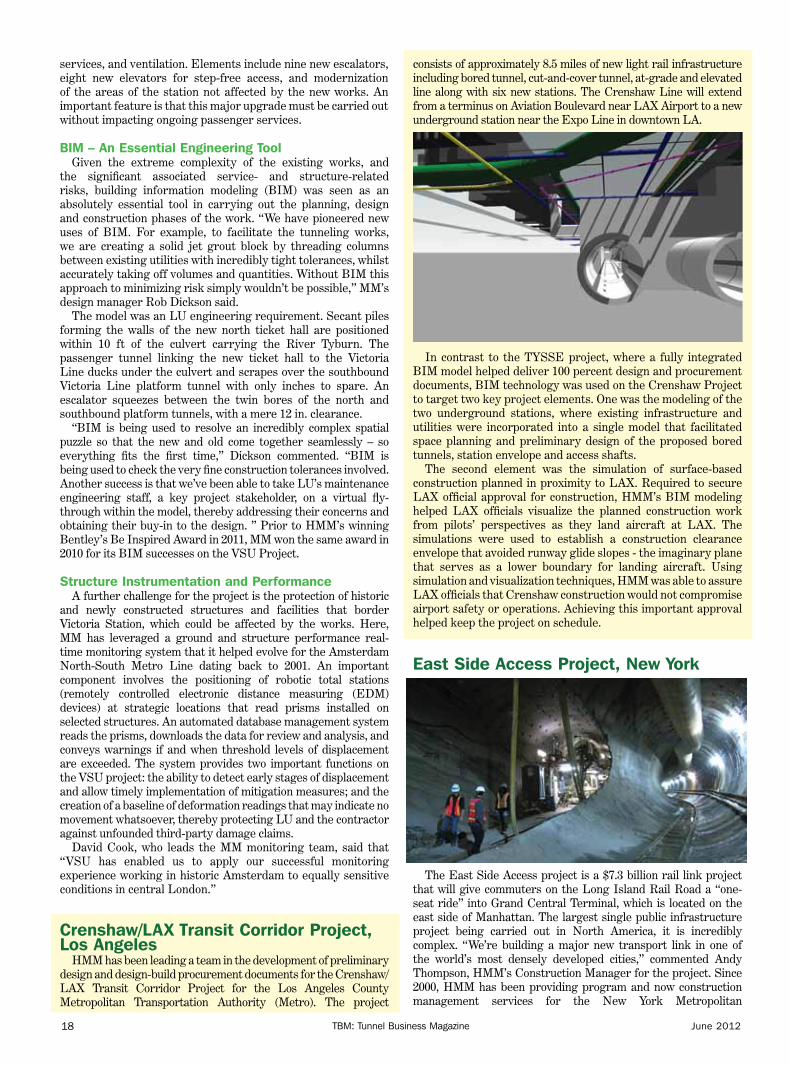
The East Side Access project is a $7.3 billion rail link project that will give commuters on the Long Island Rail Road a “one-seat ride” into Grand Central Terminal, which is located on the east side of Manhattan. The largest single public infrastructure project being carried out in North America, it is incredibly complex. “We’re building a major new transport link in one of the world’s most densely developed cities,” commented Andy Thompson, HMM’s Construction Manager for the project. Since 2000, HMM has been providing program and now construction management services for the New York Metropolitan
19TBM: Tunnel Business MagazineJune 2012
Transportation Authority. Given the highly variable ground conditions found in Manhattan and Queens, the project has demanded a broad range of underground construction technology – rock TBMs, drill-and-blast excavation, roadheader, NATM and slurry shield tunneling.
A Team Approach to innovationThe number of innovations achieved on
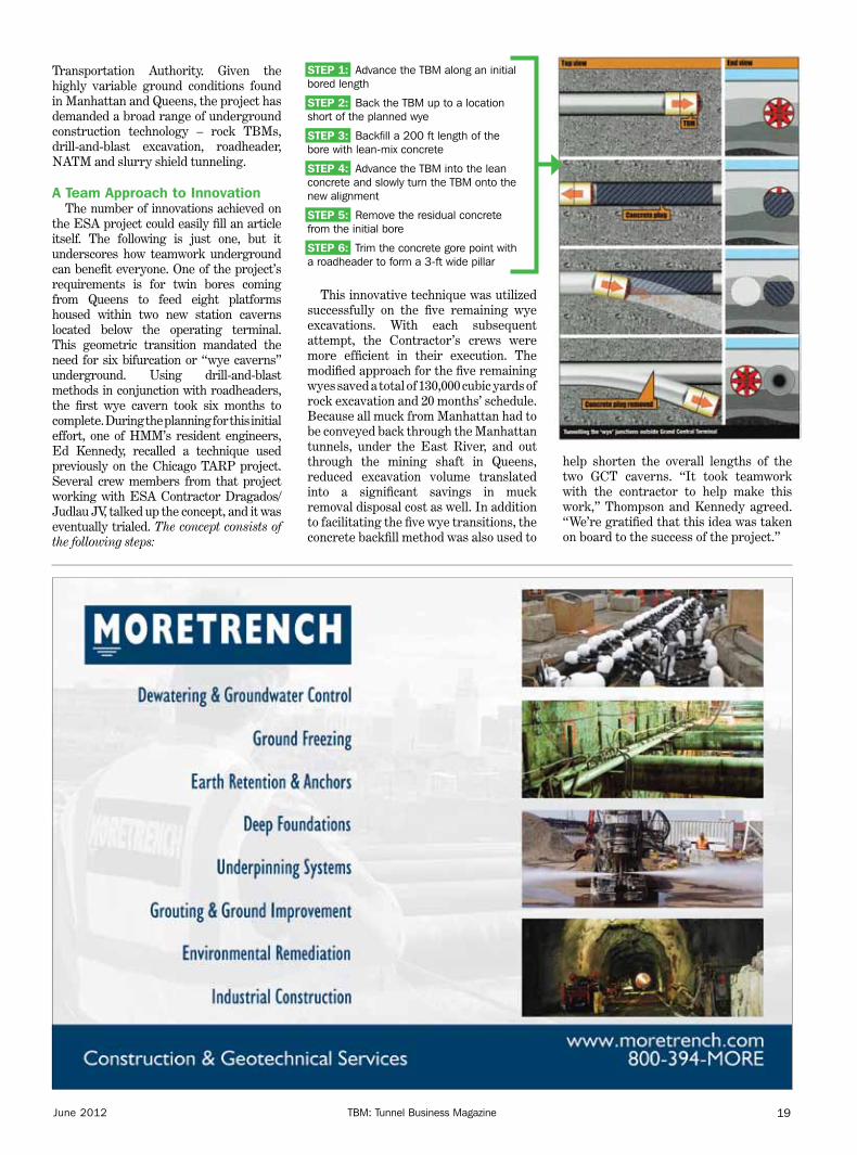
the ESA project could easily fill an article itself. The following is just one, but it underscores how teamwork underground can benefit everyone. One of the project’s requirements is for twin bores coming from Queens to feed eight platforms housed within two new station caverns located below the operating terminal. This geometric transition mandated the need for six bifurcation or “wye caverns” underground. Using drill-and-blast methods in conjunction with roadheaders, the first wye cavern took six months to complete. During the planning for this initial effort, one of HMM’s resident engineers, Ed Kennedy, recalled a technique used previously on the Chicago TARP project. Several crew members from that project working with ESA Contractor Dragados/Judlau JV, talked up the concept, and it was eventually trialed. The concept consists of the following steps:
STEP 1: Advance the TBM along an initial bored length
STEP 2: Back the TBM up to a location short of the planned wye
STEP 3: Backfill a 200 ft length of the bore with lean-mix concrete
STEP 4: Advance the TBM into the lean concrete and slowly turn the TBM onto the new alignment
STEP 5: Remove the residual concrete from the initial bore
STEP 6: Trim the concrete gore point with a roadheader to form a 3-ft wide pillar
This innovative technique was utilized successfully on the five remaining wye excavations. With each subsequent attempt, the Contractor’s crews were more efficient in their execution. The modified approach for the five remaining wyes saved a total of 130,000 cubic yards of rock excavation and 20 months’ schedule. Because all muck from Manhattan had to be conveyed back through the Manhattan tunnels, under the East River, and out through the mining shaft in Queens, reduced excavation volume translated into a significant savings in muck removal disposal cost as well. In addition to facilitating the five wye transitions, the concrete backfill method was also used to
help shorten the overall lengths of the two GCT caverns. “It took teamwork with the contractor to help make this work,” Thompson and Kennedy agreed. “We’re gratified that this idea was taken on board to the success of the project.”

TBM: Tunnel Business Magazine20 June 2012
Euclid Creek Tunnel, ClevelandThe Euclid Creek Tunnel (ECT) Project is the latest element
of the Northeast Ohio Regional Sewer District’s (NEORSD) $3 billion effort to dramatically reduce combined sewer overflows (CSOs) in its service area. The first deep storage tunnel to address the northeastern part of Cleveland, the 3.4-mile long, 24-ft diameter tunnel, shafts and appurtenant facilities will be used to collect, store and convey CSOs to the NEORSD’s Easterly Wastewater Treatment Plant for treatment.
The subsurface conditions along the tunnel alignment will consist of thinly bedded shales and interbedded siltstone of the Chagrin shale formation. Past rock tunneling in the Cleveland area has utilized two-pass lining systems consisting of combinations of rock reinforcement and steel rib and lagging, in conjunction with a cast-in-place lining. However, a number of these projects have had to deal with the occurrence of gas, localized tunnel instability due to rock wedges and blocks, and time-related rock deformations associated with slaking, overstress or both. Because relatively high horizontal in-situ stresses are expected to exceed the rock mass’ compressive strength, spalling behavior is anticipated during tunnel excavation. Recently, the Niagara Power Tunnel endured delays and cost over-runs because the design-build team’s two-pass construction method was not able to cope with overstressed ground. To avoid similar risks on the ECT, as well as address potential gas infiltration concerns, HMM designed the ECT Project with a one-pass, bolted and gasketed lining system.
Tailskin grout SystemHMM’s project risk register identified two lining-related
risks: the potential ovaling of the large-diameter ring due to
inadequate annulus grouting; and the need to consolidation grout broken rock above the crown caused by spalling. HMM specified a tailshield grouting system that will utilize a fast-set, two-component grout to immediately grout the annulus and support the segment rings as mining advances. As this application involves an open face, rock TBM, the quick set time of the grout is also needed to mitigate grout travel forward of the shield toward the TBM cutterhead. Contact grouting through segments will be performed to fill any gaps or voids behind the tunnel lining. (Insert Figure 13, ECT TBM Shield)
The fast-set, two-component tailskin grouting approach has been or will be utilized on seven other HMM tunnel projects including the TYSSE, ESC and Southeast Collector projects in Toronto, the ESA tunnels in Queens, the New York Harbor Siphon Project, the Port Mann Water Main in Vancouver, and the Alaskan Way Viaduct Replacement Tunnel in Seattle. The Euclid Creek Tunnel project provides the added twist in that it will be mined with a non-pressurized TBM. Mike Vitale, HMM Project Director and Deputy Tunnels Practice Manager based in Cleveland, said: “Everyone involved understands the importance of getting the grouting right at the outset; the specs include a fairly extensive drilling and proofing program in the first 100 rings so that we get the coverage needed. McNally/Kiewit, the contractor, is also involved on our TYSSE and Port Mann projects – so lessons learned will be shared among three projects, not just one.”
The following HMM staff contributed to this article: Randy Essex, Gary Kramer, Rob Dickson, David Cook, Ed Kennedy, Andy Thompson and Mike Vitale. Additional illustrations are available online at www.tunnelingonline.com.

www.nicholsonconstruction.com
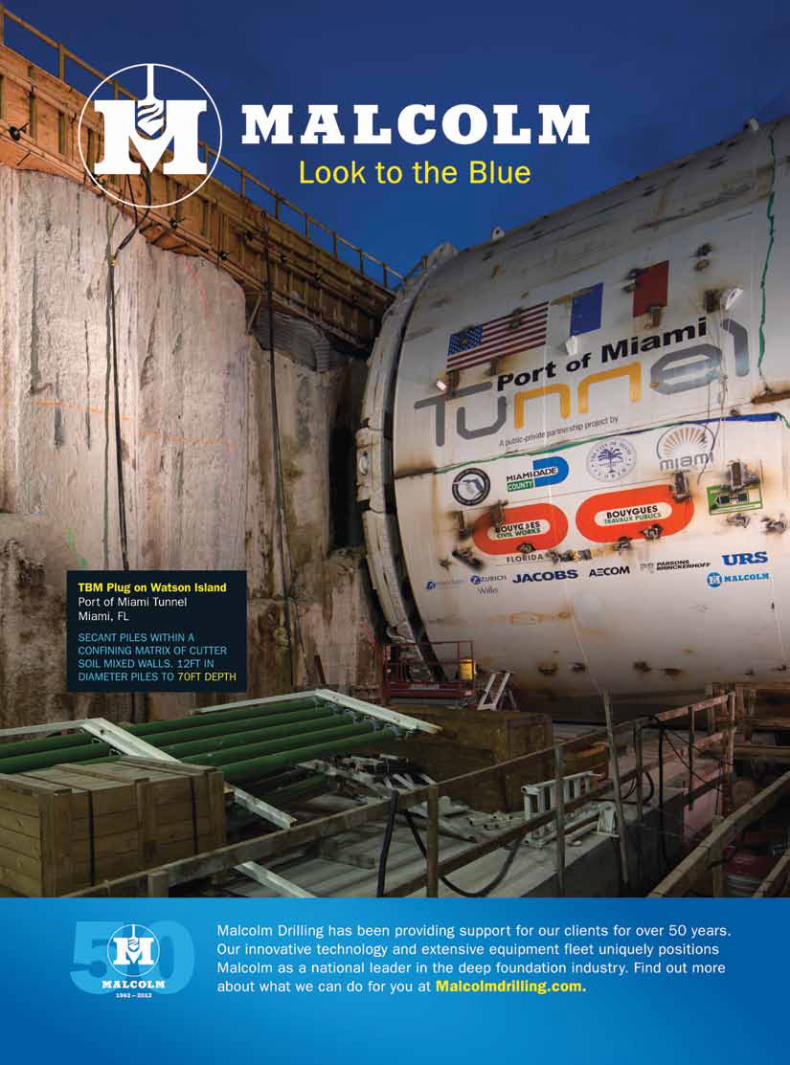
Your challenge. Our specialty.A massive grouting operation performed in the country’s busiest port requires a one-of-a-kind solution that is as innovative as it is flexible. Nicholson is performing onshore and offshore grouting ahead of the TBM for the new twin-bored Port of Miami tunnels — working around an active cruise ship schedule and strict environmental restrictions.
Geotechnical challenges come in all shapes and sizes. Fortunately, so do specialized solutions.

TBM: Tunnel Business Magazine22 June 2012
he Port of Miami Tunnel (POMT) project is a showcase in project innovation. The project boasts the largest EPB tunnel boring machine used in the United States to date, and it is being constructed under a unique public-private partnership
that includes private financing. Additionally, it includes a one-of-a-kind grouting program that makes TBM tunneling more feasible in the porous limestone below the shipping channel.
Specialty contractor Nicholson Construction is in the midst of a grouting program to optimize ground conditions in advance of the tunnel boring operations, which will ultimately connect Watson Island and Dodge Island under the Government Cut Channel in Biscayne Bay. Nicholson is performing grouting along the tunnel alignment on both Watson and Dodge islands, as well as in the alignment below the shipping channel. The offshore work brings with it a multitude of construction challenges in addition to the logistical challenges associated with keeping the port open for business.
Nicholson Construction is in the midst of an onshore and offshore grouting
operation to optimize tunneling conditions for the Port of Miami Tunnel project.
One-of-a-Kind Grouting Program Aids POMT TunnelingBy Jim Rush
I n n O v A T I O n I n
MIAMIMiaMiProject Background
The Port of Miami Tunnel has been part of the area’s long-range planning since the 1980s. The purpose of the project is to provide direct access between the seaport and Interstates 395 and 95, thereby alleviating truck traffic in downtown Miami. The tunnel also helps keep the Port of Miami competitive by opening a second access point to the region’s second largest economic generator.
The project, procured as a public-private partnership using a design-build-finance-operate-maintain contract, was awarded to MAT Concessionaire LLC, a consortium led by the global construction firm Bouygues. Under the terms of the
TT

TBM: Tunnel Business Magazine 23June 2012
The future of mobility
InnoTrans North American Representative 33 Prince Place · Little Silver · NJ 07739Tel. 732-933-1118 · Fax [email protected]
International Trade Fair for Transport TechnologyInnovative Components · Vehicles · Systems
18 – 21 September · Berlin · Germanywww.innotrans.com
InnoTrans 2012
TunnelBusinessMagazine_USA_InnoTrans_86x247_en_QR.indd 1 14.05.2012 13:18:59
contract, the tunnel will be operated by the concessionaire until October 2044.
The tunnel portion of the project involves the construction of twin bores, approximately 39 ft ID and 4,200 ft in length, under the Government Cut Channel. MAT is using a 43-ft Herrenknecht EPB TBM, the largest EPB TBM used to date in the United States. The tunnel will connect Watson Island to the Port of Miami on Dodge Island approximately 120 ft below the surface of the channel.
The contractor broke ground in 2010 with TBM arrival in June 2011. Tunneling began in November 2011 and is expected to be completed by spring 2013. The entire project, which includes road widening and other improvements, is expected to be completed by August 2014.
After further testing of the tunnel alignment it was decided that grouting was needed in the Key Largo formation through which the TBM would mine. The Key Largo formation is an unstable and porous coralline limestone.
Grouting ProgramNicholson is performing grouting both onshore and
offshore. The grouting program consists of drilling down to tunnel invert (up to 126 ft below grade of vertical depth at its lowest point with inclined holes up to 146 ft deep) and grouting approximately 40 ft up to the crown. Unlike typical grouting jobs in which grout is pumped until refusal, Nicholson is pumping specific volumes of grout at specific pressures to reduce voids and keep the grout contained within the tunnel alignment. Crews are using a low-mobility grout consisting of processed lake fill sand, bentonite, cement and chemical filtrate reducer as specified by the general contractor.
The offshore drilling brings with it a set of complications related to environmental regulations. “This is a sensitive area and we have several restrictions on what we are allowed to do, as well as mitigation measures that are required,” said Luca Barison, Nicholson Construction’s project executive. “We had to ensure the barges had the proper containment and ensure the equipment is properly functioning with maintenance and inspections above and beyond what we would normally do.”
Environmental regulations protecting the shoreline required that the contractors maintain a 70-ft buffer from the shore. This required the innovative use of a pipeline bridge used to bring grout from the onshore batching plant to the offshore equipment. “We designed the bridge so that we did not affect the 70-ft buffer zone,” Barison said. “It was designed to carry the grout from a fixed point on land to a barge without being affected by the changing tides.”
Once the grout is delivered to the first barge, it is routed to an agitation tank at each of the four drilling stations set up offshore. Each drilling station consists of a barge with crane and drilling lead combo, along with four to five barges for ancillary and support equipment. Nicholson is using a custom drilling and grouting system developed with the assistance of sister company, Bermingham Foundation Solutions. The system uses the same drill string to drill and grout in a single stroke, thereby saving the time normally needed to change drill rods and tooling.
Perhaps the biggest challenge of working the channel is working around the cruise ships that use the port on Dodge Island. “Our offshore work is restricted by the schedule of the cruise ships,” Barison said. “When there are cruise ships in the channel we have to completely evacuate the area. That essentially means we have to mobilize and de-mobilize up to

TBM: Tunnel Business Magazine24 June 2012
10 barges every week. Typically, we mobilize on a Monday afternoon, and de-mobilize either Thursday or Friday at 2 a.m., depending on the cruise ship schedule.”
As part of an ongoing quality control program, grout properties are tested multiple times per day including weight, slump and UCS. Nicholson is also using the proprietary automated computerized Grout I.T. system to monitor and record in real time grouting parameters including pressure, volume, apparent lugeon and flow.
Looking AheadBarison said that despite the
complications and the number of parties involved, including the Florida Department of Transportation, Miami-Dade County, City of Miami, MAT, USACE and the Port of Miami and its clients, the construction portion of the grouting project has been successful to date. One of the keys, he said, is effective communication between all parties involved.
“Clear communication is vital for these types of projects that involve several entities,” said Barison, who has been with Nicholson since 1995. “It is crucial that all entities make their expectations very clear. Also, it is important to have a clear design before the job starts to help in the planning process and allow the contractor to optimize the efficiency of its equipment and personnel.”
Nicholson was awarded the grouting contract in August 2011 and began mobilization in October. The project involves the drilling of more than 1,000 grout holes and about 93,000 lf of grouting, for a total estimated volume of 107,000 cu yd of grout.
Crews have competed 75 percent of the grouting, including completion of the onshore work on Watson Island and offshore eastbound tunnel. They are currently working on the westbound tunnel offshore with onshore grouting on Dodge Island scheduled to begin in late May. The grouting portion of the work is on pace for a late July completion. The TBM is currently mining within the treated layer of the tunnel.
Jim Rush is editor of TBM.
Offshore grouting operations require the contractor to mobilize and remobilize each week to keep cruise ship traffic flowing uninterrupted.

S eparation plants have historically been the bottleneck in many tunneling projects, resulting in
lost time and money to the contractor. It is vitally important to plan ahead to have the properly sized and correct equipment in place before the start of the project. Remember, poor planning results in poor performance, and poor performance equates to lost profits to the contractor.
Many contractors focus on the tunnel boring machine (TBM) and the performance that can be expected from this machine. Generally the contractor will bid the project on the upper end of the parameters that have been specified by the machine manufacturer. In most cases, these machines can meet or exceed the expected advance rate. However, contractors easily can overestimate the capabilities of their separation plant, resulting in the slowdown of the advance rate due to the inability of the plant to keep up with the amount of solids that are being generated by the TBM.
Choosing the correct separation plants is every bit as important as choosing the correct TBM for the project. Using the geotechnical data, the separation plant should be designed to accommodate the majority of the material expected to be processed. Due to the unknown factors that can affect the tunneling advance rate, the contractor must have adequate separation equipment to allow the contractor to move forward at an unimpeded rate when the tunneling conditions are favorable.
Too often, the contractor can find favorable tunneling conditions that can produce fast advance rates, only to find out that the separation plant cannot handle the amount of material, and the advance rate has to slow down to accommodate the separation plant’s
inability to keep up with the TBM. Generally, when this happens, there are also several occurrences that can be very expensive to deal with, such as lost fluid over the shakers, filling tanks with solids and creating a major problem with the slurry rheology that can cause excessive wear on the TBM and ancillary components. If this cost was to be put on a spreadsheet, it would be phenomenal and be an eye-opening experience for the contractor.
However, there is excellent equipment available in the marketplace today that can alleviate the majority of the problems being encountered by contractors. Unfortunately, given the current economic conditions, it is difficult for a contractor to be able to bid a job and allow for the proper separation equipment to be purchased and still stay competitive.
Many contractors need to rely on existing equipment in their inventory and much of this is severely worn, bordering on obsolete or not favorable to the existing geotechnical stratum that is being encountered in the tunneling formations. It is imperative that the contractor anticipates the ground conditions and then selects from his existing fleet of equipment the best components available and use them in the best possible way for anticipated conditions. Each piece of equipment should be evaluated thoroughly as to handling capacity and suitability for the ground conditions that will be encountered on the specific project. If it is determined that this specific piece of equipment will be adequate for the conditions expected, then it needs to be refurbished to the best of the contractor’s ability. If this recommendation is followed rigorously, the end result should be acceptable to complete the project on time and within budget.
Components and Performance of a Properly Designed Separation Plant
Separation plants are designed around the anticipated geotechnical information that is available for the project and should be evaluated to incorporate the best equipment available for the specific size solids that are expected. To do this, general knowledge of separation equipment should be studied and researched. The basic separation plant consists of the following components:
1. Clay removal equipment, such as gumbo chains and belt scalpers. Typically, the clay removal machines will remove solids at ½-in.-plus size material.
2. Primary screening machines, which consist of high frequency, high “G” units to remove as much of the course sand and gravel as possible before the slurry is introduced into the slurry tank. Primary screening should be sized to handle 120 percent of the highest anticipated return rate and should be able to remove material larger than 500 microns to allow the secondary equipment to work efficiently and minimize wear on pumps and cone parts.
3. Secondary screening machines, which consist of various size hydrocyclones mounted over high frequency, high “G” dewatering screens. These units should be sized to handle 130 percent of maximum anticipated flow and be able to utilize screen media of 200 mesh or finer to remove all sand size particles (74-500 microns).
TECHNICAL PAPER
Separation Plant Selection for Tunneling
Projects By Barry L. Sorteberg
TBM: Tunnel Business Magazine 25June 2012

4. Centrifuges, which are used for removing solids that are silt sized (5-74 microns). Generally centrifuge capacity should be sized to handle a minimum of 33 percent of the highest anticipated slurry pump rate. This will help to keep the slurry rheology favorable for maximum advance rate with the TBM.
5. Polymer make-down and delivery systems, which are utilized along with a centrifuge, or other dewatering devices such as belt presses or filter presses, to completely remove solids in the 0-5 micron range. This stage is necessary to control adverse rheology encountered when the slurry starts to become saturated with ultra-fine particles in the clay range. Ultra-fine particles can cause problems with density and viscosity, which can cause adverse conditions throughout the entire tunnel circuit. This stage is also used to produce clean water for disposal when the need arises.
Rules of ThumbWhen designing and selecting slurry
plants, the following general rules can be used to ensure that the plants are properly sized.
1. Size separation plant for fastest anticipated advance rate.
2. Size separation plant for maximum tonnage that can be produced by the TBM and then add 20 percent redundancy to allow for the wear and inefficiency of mechanical equipment.
3. Size all components to maximum flow rate that can be anticipated by pumps being used to in the slurry circuit. Then build in 30 percent redundancy to allow for slurry inconsistency and wear and tear on cyclones and pump parts. Keep in mind that pumps are rated on water and “brand new” efficiency curves. Rates begin to drop quickly when wear is occurring.
4. Adjust components of the separation plant to meet the needs of anticipated geotechnical data. If you are anticipating mostly sand and gravel, you should concentrate your efforts on the primary screens and the hydro
cyclones, as well as the dewatering screens underneath the cones. It is imperative that most sand-size particles are removed at the front of the separation plant. Any sand-size particles that pass the first defense of shakers and cones will quickly become an abrasive component to the slurry that can cause severe damage to the pump parts and ancillary components. Remember, sand is easily removed from the slurry the first time around. After it has been fractured by mechanical means, such as pumps, it can quickly be degraded to silt and clay-size particles, which are much more expensive and more difficult to remove.
5. If the geotechnical data indicates a large amount of clay with high plasticity, then your efforts should be geared to centrifuges and polymer delivery systems. The more times that a solids particle is circulated through the system, the smaller the particle will become and the more expensive it is to remove.
6. If the contractor does not have an in-house expert on separation equipment, consult experts with the equipment suppliers or an independent consultant. These
people are trained and have the experience to alleviate many of the problems before they have a chance to occur. This is a very inexpensive insurance policy, and in many cases should be utilized prior to the bidding process. In many instances, contractors rely on their field foremen, who have vast experience in construction of the tunnel, but may not have specialized knowledge in separation technology. In some cases, the knowledge that is gleaned on this subject is erroneous or has been learned through trial and error. This can result in losses of 10 percent of the total cost of the project.
In conclusion, the functions of a properly designed slurry separation plant are an absolute necessity to complete tunneling projects successfully, on time and within budget. A properly designed separation plant will save time and money, and allow the contractor to concentrate on putting pipe in the ground, instead of dealing with adverse slurry parameters and the mess that this can create.
Barry L. Sorteberg is the principal of Clean Slurry Technology Inc. and a recognized expert in the field of slurry separation design and equipment.
Proper selection of the slurry separation equipment is crucial to ensuring a successful slurry tunneling project.
TBM: Tunnel Business Magazine26 June 2012
27TBM: Tunnel Business MagazineJune 2012
Controlling groundwater for tunnels and Shafts
t unnels and tunnel shafts present unique problems when dealing with groundwater. Surface access is always the critical issue and forms the basis for selecting tunneling as the
excavation method used to install the piping system or access corridor required by the project. Limited access to the jobsite also restricts how dewatering equipment can be installed and used. To compound the dewatering problems, the combination of vertical shafts and horizontal tunnels stresses the abilities of conventional dewatering systems to manage the groundwater problems, especially in stratified soils with low permeability.
The usual groundwater control systems available to tunnel dewatering are deep wells, eductors, wellpoints, horizontal wells and sumps. All of these methods must be installed properly to prevent the removal of soil particles, which can lead to subsidence and settling of adjacent structures.
Controlling groundwater for tunnels and Shafts
By Thomas J. Minihan
deep wells When the soils around the tunnel shafts and the tunnel are permeable,
and the permeable soil extends 15 ft or more below the shafts and tunnel, deep wells do a fine job. The tunnel sections are hard to handle because surface access along the tunnel route may restrict the intervals necessary to set the line of wells required to create a continuous water table drawdown. If the permeable soil below the tunnel invert is shallower than 15 ft, the wells must be set very close together, which results in greater access problems. Running discharge piping to connect the line of wells can also result in surface access problems, particularly when the tunnel is under a major multi-lane highway or under buildings.
eductors Eductor wells can function to a depth of 100 ft but are somewhat limited
in pumping capacity. This makes them ideal for very low permeability soils especially when the soils are stratified. Because the spacing between eductors is narrow, usually 10 to 20 ft, surface access is again a problem. One major advantage of the eductor well is its ability to create a vacuum at

TBM: Tunnel Business Magazine28 June 2012
the well tip. This helps when the tunnel and tunnel shaft inverts are close to or at an impervious layer. Eductors function by pumping water into the well casing and through a venturi at the bottom of the well. The high-pressure injection water creates a vacuum that pulls water into the casing pipe through the well screen. A continuous source of priming water is supplied by one manifold pipe line and the discharge water is carried off by a second manifold pipeline. Both manifolds follow the line of wells that follow the tunnel route. Sealed tunnels may not need wells along the route and may only require wells at the shafts, which reduces the surface access problem.
wellpoints For shallow tunnels up to an average of 20 ft deep
in low permeability soils, vacuum wellpoints are an option but because of the close spacing required it can be difficult to provide enough surface access along the tunnel route. A wellpoint system involves a combination pump package having a vacuum pump and a centrifugal pump powered by a common driver, either a diesel engine or an electric motor. The pump package is connected to a vacuum manifold piping system. The individual wellpoints are connected to the manifold piping usually on 6-ft centers.
A variation on the wellpoint system design can work in tunnel shafts to any depth and is particularly effective in highly stratified soil profiles. This variation involves a new type of wellpoint called a SilterVac geotextile point that can be jetted into permeable sands between impervious soil layers from inside the tunnel shaft liner plates or lagging. The SilterVac points are battered into the permeable zones then connected to a manifold pipe ring set inside the tunnel shaft. The manifold pipe is connected to a vertical pipe that extends from the
bottom of the shaft to the top of the shaft. Numerous manifold pipe rings can be connected to one vertical pipe to dewater many individual permeable layers. At the top of the vertical pipe is a vacuum generator with an air/water separator. At the bottom of the vertical pipe is a submersible pump that pushes the collected groundwater to the surface for discharge away from the shaft.
Depending on the tunnel excavation advancement method used, the manifold piping can be advanced from the shaft into the tunnel for continuous dewatering along the tunnel route. This method of dewatering eliminates the problem of surface access and is an economical means of solving groundwater problems in difficult soil profiles. The system is entirely installed by hand, eliminating the need for drill rigs and large equipment.
Horizontal wells Again in low permeability soils particularly when surface
access is limited, horizontal wells are effective but are difficult to design and install properly. Horizontal wells can be installed close to the tunnel line and along interface layers between rock or clay and sands. The advantage of horizontal wells is that less groundwater must be pumped to dewater the alignment than with any other method. The pumping activity is concentrated close to the tunnel and shafts, limiting the impact on the area surrounding the tunnel route.
Horizontal wells are hard to install properly because of the difficulty of controlling the well development elements laterally instead of vertically. Without proper placement and development of the wells, the horizontal system design will not be effective. New geotextile composite materials make the effectiveness of the horizontal well system exceptional and installation more
Dewatering is a common application for a variety of construction projects.

29TBM: Tunnel Business MagazineJune 2012
www.rizzoassoc.com
For Multiple Types of Tunnels:WATER CONVEYANCEMINE ACCESSTRANSPORTATIONPIPELINE ROUTING
TUNNEL & SHAFT DESIGNTUNNEL REHAB PROGRAM DEVELOPMENTCONSTRUCTION MANAGEMENTGEOTECHNICAL ENGINEERINGHYDRAULIC ENGINEERINGSEISMIC ENGINEERINGENVIRONMENTAL ENGINEERING
World Class Technical Expertise.
InnovativeCost Effective Solutions.
expeditious and economical; however, conventional horizontal directional drilling methods must be modified and meticulously managed to ensure success.
Horizontal wells are abandoned in place after the tunnel is completed but can be converted to permanent dewatering systems if desired. The new geotextile materials are inert and will provide more than 60 years of useful service.
Sumps When the soil profile where the tunnel is to be installed is
stable or either impermeable or above the water table, simple sumps can be used to control perched water, seepage water and rain water. Usually, electric submersible pumps are chosen because of their simplicity and compactness.
As the shafts and the tunnel are installed, grouting outside the liner plate or lagging will reduce the amount of groundwater that must be controlled; however, in most cases, the dewatering system used to facilitate the shaft and tunnel installation must continue to be operated until the utility piping or corridor lining is completely installed to eliminate the external water pressure on the tunnel liner.
Tunneling is a unique excavation method and dewatering tunnels can be tedious and difficult to accomplish successfully. It is always best to seek the help of an experienced and innovative dewatering contractor who can mix the various dewatering methods to adjust to the soil changes encountered in a linear project site.
Thomas J. Minihan is Vice President of Griffin Dewatering Midwest LLC.
Tunnels and tunnel shafts present unique problems when dealing with groundwater.

TBM: Tunnel Business Magazine30 June 2012
Rel-Tek has pioneered in the development and manufacture of gas monitoring systems for tunnels and underground mining since 1979. New technology now enables longer-life sensors, higher speed telemetry, and – the big payback feature – fully automatic gas sensor calibration.
Carbon monoxide is the primary toxic gas to be monitored in tunnels, usually amounting to a CO sensor on the tunnel wall at 200- to 500-ft intervals. Employing electrochemical technology, these CO sensors are quite stable and have a long life (typically 8 to 10 years). This same sensor technology stems from underground mining, where CO monitoring has become the mainstay of conveyor belt fire detection since 1985.
Carbon dioxide sensors are often included in the sensor mix, as these reflect the hazards of poor ventilation. Internal combustion engines and fires replace ambient oxygen with the suffocate CO2. Although not considered toxic, a CO2 buildup can present breathing problems, and of course, CO2 is a good indicator of poor air quality. CO2 sensor technology is usually optical (non-dispersive infrared) and optical devices are more difficult to maintain in a wet and smoky tunnel environment. Rel-Tek supplied two gas monitoring systems for the Port Authority of Allegheny County’s Wabash and Berry Street HOV Airport Busway Tunnels in 1997, then predating the 2001 advent of the MagiKal automatic gas sensor calibration system.
Nitrogen dioxide, NO2, is another toxic gas that is sometimes monitored in tunnels. Produced from internal combustion engines, the highly toxic NO2 is a hazard worth monitoring. However, NO2 reacts quickly with moisture in the air, and accurate measurements are illusive. Consequently, NO2 sensors
are not usually included in tunnel monitoring.New requirements are afoot that require combustible gas
monitoring on federally supported highway tunnel projects , Ref NFPA-502, 2011 edition, Annex G, being adopted for major projects. The increasing use of alternative fuel vehicles presents new hazards from combustible gases – predominantly CNG (typically 4,000 psi compressed methane with up to 10 percent ethane,) LNG (cryogenic methane,) LPG (liquid petroleum gas, propane) and HCNG (compressed hydrogen, alone or mixed with CNG.) Consequently, the rehab of old tunnels and new tunnel construction are including both toxic and combustible gas sensors, covering the growing risk of alt-fuel vehicle accidents with added hazards of fire and explosion. Catalytic bead is the preferred sensor technology here, as optical NDIR sensors overreact 20:1 to ethane, while not reacting at all to hydrogen.
Monitoring these gases requires a host of gas sensor types, toxic and combustibles. In addition, there is often a specification for monitoring smoke and fog, usually requiring open beam or enclosed optical obscuration detectors. Air velocity monitoring is also becoming of interest, controlling fans to provide sufficient ventilation, but not wasteful excesses.
Adding difficulty to the monitoring requirements is the need to service the sensors, particularly gas sensors that tend to drift with time and require monthly re-calibrations. Calibration of gas sensors used to be manual, requiring personnel to access the sensors, apply calibration gas from portable tanks, and make adjustments to keep the sensors accurate. Obviously, the stoppage and re-direction of traffic for these monthly episodes is not only troublesome for highway traffic, but also costly and
Gas Monitoring Systems
for Tunnels New TechNoloGy GaiNS MoMeNTuM{ {
T he monitoring of toxic and flammable gases in tunnels is an important undertaking for tunnel management, as the safety and liability issues are profound. Furthermore, maintaining the gas monitoring system (GMS) in operational
condition involves issues that seldom come to light until the wrong system is purchased, and the poorly specified performance, high maintenance costs and troublesome servicing issues come into focus.
The I-70 tunnels in Wheeling, W.Va., incorporated a Rel-Tek CO monitoring system and was the first use of the MagiKal automatic gas sensor calibration system in a tunnel. By Albert E. Ketler

TBM: Tunnel Business Magazine 31June 2012
complement of sensors for toxic and combustible gas, smoke, temperature and air velocity, and attended to by a Millennia computer with HMI graphics, high-speed telemetry, unlimited data logging and alarm archiving, plus, of course, automatic gas sensor calibration. And, the monitoring speed should be quick with worst-case alarm response time not exceeding a few seconds.
For the Squirrel Hill Tunnel rehab project on Route 376 in Pittsburgh, Pa., previous specs showed CO sensors only. However, in light of the latest federal tunnel recommendations, the sensor complement has since been expanded to include other types of sensors to cover alt-fuel risks, while adding a high speed computer with automatic gas sensor calibration. Gas monitoring is a critical feature of all modern tunnels.
Tunnels under construction introduce an additional requirement of permissibility in the potentially explosive conditions while penetrating areas where oil, gas or coal may release combustible gases. Rel-Tek is the only GMS supplier approved by Cal-OSHA, as complying with its unique requirement for both OSHA (Class I, Division 1) and MSHA (DOL, Mine Safety and Health Administration) approvals.
Albert E. Ketler, P.E., is president of Rel-Tek Corp., Monroeville, Pa.
risky to personnel who require signage, barrels and flagmen, while exposing personnel to injury.
New technology is offered by Rel-Tek that enables the gas sensors to be calibrated automatically. Computer techniques automatically apply NIST-certified calibration gas (cal-gas) to each sensor on a programmed calendar/clock basis, all without human intervention.
In 2007, the I-70 interstate highway tunnels in Wheeling, W.Va., were equipped with Rel-Tek CO monitoring systems including the powerful feature dubbed “MagiKal.” This same GMS product had been tested in the above-ground transit industry for more than a decade, monitoring CNG, LNG and LPG emissions in bus garages, and was recently applied to tunnels. The Wheeling systems were installed in January 2008, operating continuously for nearly four years, without a hitch. The West Virginia Department of Highways and the Wheeling Tunnel management are happy to avoid the monthly traffic stoppages and diversion of personnel normally required for gas monitoring.
Tunnels are particularly susceptible to gas sensor maintenance issues due to traffic disruptions, and, although scheduled in advance, sensor maintenance is never convenient, and usually diverts personnel from more important jobs. Also, the risk of injury to personnel in the dynamics of tunnel traffic is far greater than in a static garage or factory environment. MagiKal is a must-have feature for tunnels.
MagiKal can automatically calibrate virtually all types of gas sensors – usually a combination of toxic and combustible, and the mix can also including carbon dioxide and oxygen sensors. One GMS installed in 1996 at Sun Metro Transit in El Paso, Texas, uses three types of gas sensors – CNG, CO and O2 – and uses a custom cal-gas mixture to automatically calibrate more than 100 sensors, a combination of all three types using one cal-gas mixture.
Once a month, the monitoring computer activates the MagiKal process – normally late at night in light traffic – by alternately applying span and zero cal-gases to the sensors. Alarms are automatically disconnected and the previous sensor readings are continued for approximately 15 minutes, so there are no outward indications the calibration procedure is actually underway. Certified cal-gas is supplied from full-sized tanks located at mid span, each tank containing about 1,600 cubic meters (STP) of gas, usually sufficient for several years of calibrations. Cal-gas is cheap in this format, costing about $8 for each monthly calibration schedule, covering all gas sensors at once.
Auto-calibration data for each sensor is captured by the Millennia computer for each sensor and applied on completion of the process. Using 12-bit resolution, the sensor calibration accuracy is about +/-0.044 percent digitizing error, far better than possible when calibrating sensors manually, and without the substantial risk and cost for labor.
A GMS at Golden Empire Transit in Bakersfield, Calif., with 27 CNG sensors was installed in 1999 and upgraded with the MagiKal utility in 2009. After two years of experience using MagiKal, maintenance engineer Brian Nunn has reported that the system has been working well with very little maintenance.
New tunnel rehab or construction projects should include specifications and funds for a first-class GMS, including a full
{ Rel-Tek’ s Millennia-FT computer in the Wheeling tunnel is wall-mounted with graphics, high-speed telemetry, data and alarm logging, and MagiKal.
A FireBoss CO sensor being installed and tested inside protective steel cage.
One of the two sets of large MagiKal cal-gas tanks with pressure regulators and electronic pressure sensors linked to the computer.
{
Products and solutions for tunnel boring
661.589.9141 • www.bakersfieldpipe.com
www.shurjoint.com
Your complete source for pipe, valves, fittings and supplies. Locations
throughout the U.S.
Shipped worldwide by:
Contact: Tony Vengarick 503.803.2816

TBM: Tunnel Business Magazine32 June 2012
A fter years of planning, Indianapolis recently marked the start of its largest-ever public works project. On April 25, officials
including Indianapolis Mayor Greg Ballard and Citizens Energy Group president and CEO Carey Lykins gathered at White River State Park to commemorate the start of the Deep Rock Tunnel Connector (DRTC), a $180 million, 7.5-mile tunnel project that is a major component of Indianapolis’ $1.7 billion long-term control plan to reduce sewer overflows.
The long-term control plan is part of a consent decree with the U.S. EPA and Indiana Department of Environmental Management that is to be completed by 2025. When completed, the program will improve water quality and protect public health in the Hoosier State’s capital and beyond by capturing, storing and conveying sewage and stormwater to treatment plants. The overall tunnel storage system will extend approximately 25 miles and store 250 million gallons of sewage and stormwater during rain events.
Digging DeepThe DRTC is the first phase of the tunnel program. Originally
designed as the Belmont-Southport Interplant Connection intended to divert flows from one watershed to another, the tunnel was redesigned as a deep storage and conveyance tunnel.
In the initial concept, the 12-ft ID tunnel would have been constructed in soft ground under high groundwater conditions 35 to 75 ft below the ground surface. Under the redesign, the DRTC will be constructed in limestone more than 250 ft below surface with an internal diameter of 18 ft. The larger diameter allows for more storage while the deeper design reduces surface disruption and avoids areas of contamination discovered along the project route.
Increasing the capacity of the DRTC also allowed planners to reduce the diameter from 27 to 18 ft for tunnels planned upstream, thereby expanding the potential pool of bidders. Ultimately, the DRTC project came in about $100 million below the engineer’s estimate of $280 million. “The new approach allowed us to spread out the storage throughout the system and hit the sweet spot in terms of the tunnel diameter that would be the most economical and allow for the most competition,” said John Morgan, Manager of the Special Projects Group for Citizens Energy.
The change in approach led to a fast-track design to keep the program moving toward meeting the milestone dates identified in the consent decree. “The design was quite a technical challenge,” said Alex Varas, vice president for project designer Aecom. “We had less than 16 months to create the 100 percent design in advance of the December 2011 award date.”
In December 2011, the DRTC was awarded under a design-bid-build contract to a joint venture of Shea-Kiewit. The project includes the construction of launch and retrieval shafts, approximately 35 ft in diameter and 280 ft deep, which are being constructed by slurry wall to bedrock. Additionally, three access shafts and three diversion structures will be built along the alignment. Bencor is currently constructing the slurry walls for the launch shaft at the Southport Advanced Wastewater Treatment Plant under a subcontract. The arrival of the Robbins TBM is expected in late August and boring is expected to begin in early 2013. Construction is expected to last until 2017.
Utility TransferInterestingly, the redesign from a shallow inter-connection
tunnel to a deep storage tunnel wasn’t the only major change associated with the tunnel program. The project owner also went
Work Begins on Deep Rock
Tunnel ConnectorBy Jim Rush
Construction for the Deep Rock Tunnel
Connector project in Indianapolis is under
way as crews are installing the slurry
wall shafts.

33TBM: Tunnel Business MagazineJune 2012
through a major transformation. In March 2010, Mayor Ballard and Citizens Energy announced a
plan to transfer Indianapolis’ water and sewer utilities to Citizens Energy, a charitable trust established in 1887 to operate the gas utility. City Council approved the transfer in July 2010, and the $1.9 billion transfer was completed on Aug. 26, 2011. As a result, the water and wastewater systems, which billed customers under the Indianapolis Water name, are now operated as Citizens Water.
The transfer is expected to result in $60 million in annual savings that will help Citizens Energy reduce projected water and wastewater rate increases 25 percent by the year 2025. The City also received $425 million from the transfer to fund its Rebuild Indy initiative that is making much needed repairs to parks, bridges, streets, and sidewalks, while removing hundreds of abandoned homes throughout the city.
In addition to assuming responsibility for the long-term control plan, Citizens Water assumed operations of the water utility from Veolia Water Indianapolis (Veolia) and also assumed the City’s contract with United Water to operate the wastewater system.
“The utility transfer is complete and has been a big improvement,” said Morgan, who previously worked for the city’s Department of Public Works. “It has taken the politics out of managing the water and sewer system and allows us to focus on doing the right thing.”
Future WorksFour other tunnel projects are planned that will have staggered
start and completion schedules. “We won’t have more than two rock tunnel projects taking place at the same time,” Morgan said. “We feel that this will help us obtain competitive pricing from the tunnel contractors. As one projects gets near completion another will be bid.”
The remaining tunnel components include:
• The Pleasant Run Deep Tunnel (PRDT), which will be an 18-ft finished diameter tunnel, nearly 34,000 ft long and approximately 250 ft deep. PRDT is anticipated to be constructed in limestone and dolomite using a main beam TBM. The tunnel alignment will have two 35-ft finished diameter shafts, one tunnel working shaft and one TBM retrieval shaft. The upstream reach is expected to include a 6-ft finished diameter soft ground microtunnel, nearly 6,000 ft long and an average of 35 ft deep. Up to eight drop shaft vortex structures will be constructed to drop flows into the tunnel capable of conveying combined sewer overflows up to 260 mgd.
• The Lower Pogues Run Tunnel (LPgRT), which will be a deep rock tunnel in limestone and dolomite, and approximately 11,000 ft long, 250 ft deep and 18-ft finished diameter. The project will use trenchless technology to install 20 to 50 ft deep consolidation sewers approximately 8 ft in diameter. Three drop shafts that will convey flow into the tunnel from eight combined sewer overflows that currently discharge into Lower Pogues Run and ultimately into the White River are also anticipated.
• The Fall Creek/White River Tunnel System (FCWRTS) is anticipated to be an 18-ft finished diameter tunnel approximately 46,000 ft in length. FCWRTS consists of two segments: 1) Fall Creek Tunnel Segment, length approximately 27,000 ft; and 2) White River Tunnel Segment, length approximately 19,000 ft. The tunnel will be an average of 270 ft deep and is anticipated to be constructed in limestone and dolomite using a main beam tunnel boring machine (TBM). Deep tunnel access shafts are anticipated to be up to 35 ft finished diameter. Twenty drop shaft vortex and baffle structures will be constructed to drop flows into the tunnel capable of conveying combined sewer flows up to 400 mgd.
“The start of DRTC construction is the beginning of a long path ahead of us,” Varas said. “We are all hopeful and enthusiastic that we will have a successful project.”
Jim Rush is editor of TBM.

TBM: Tunnel Business Magazine34 June 2012
CALIFORNIA
OrindaCaldecott Tunnel 4th Bore ProjectTutor-Saliba Corp.
As of April 13, 2012, the Bench Tunnel excavation has progressed easterly from the West Portal 230 m toward the East Portal. Excavation and support of four of the seven cross passages has been completed. Utilities and concrete invert work has started in the cross passages. Footing concrete as well as drainage, waterproofing and rebar has started in the Tunnel from the West Portal.
The Caldecott Tunnel Fourth Bore is a 3,399-lf, horseshoe-shaped highway tunnel, 50-ft wide and 32-ft high. It began in January 2010 and will take approximately three years.
Project Manager: Pat Jennings; Tunnel Superintendant: Bill Monahan; Senior Project Engineer: Bryan Lee; Information: Bryan Lee. Phone (510) 665-3114; Fax: (510) 981-1424; email: [email protected]
PacificaDevil’s Slide TunnelKiewit Infrastructure West Co.
The Devil’s Slide Tunnels Project is reaching project completion. The final closure pours at the South Portal – connecting the tunnel final lining in the mined section to the cut-and-cover structures – were placed in March 2012. The tunnel walkway concrete and the inside tunnel roadway concrete pavements are now complete.
Nearly all of the electrical switchgear, panels and conduits have been installed in the Equipment Chambers and Cross Passages. Permanent power has been brought online and is currently being used throughout the project. System devices and tunnel jet fan installation operations are under way and are scheduled to progress through June 2012. Metal panels have been installed in the northbound and southbound tunnel alignments, with the final finish panels still remaining.
The South Portal backfill is also complete; however, artificial rocks are currently being installed at the South Portal and will continue through May 2012. The final stages of grading and paving are under way at both portal approaches. The project is scheduled to hit a major milestone in fall 2012, as drivers begin utilizing the tunnel to travel through Devil’s Slide.
San FranciscoCentral Subway Tunneling Project - Contract 1252Barnard/Impregilo/Healy JV
This project for the SF MTA was awarded to Barnard/Impregilo/Healy JV in August 2011 for $234 million. The project includes twin tunnels with lengths of 8,233 ft each to be excavated with two EPB TBM’s and lined with 18-ft diameter precast segments. Work also includes a launch box and portal structure under 4th Street, a retrieval shaft and headwalls for future stations that the TBMs will mine through prior to the station construction.
Utility relocations are under way along the tunnel alignment. Work on the slurry diaphragm walls at the TBM launch box has begun. Two Robbins EPB TBM’s have been ordered and are in design.
Project Director: Dan Schall; Project Manager: Ben Campbell; Project Superintendent: Mike Hanley; Chief Engineer/DPM: Alessandro Tricamo; Staff Engineers: Matt Paulisich, Glenn Strid, Jack Sucilsky, Vik Sehdev, Beau Blume, Tom Albert. Information: Ben Campbell, (415) 546-0799.
CONNECTICUT
HartfordGrandby Street Area Sewer Separation Project 2/5Bradshaw Construction Corp.
Bradshaw Construction Corp. is currently performing 2,550 ft of pipe jacking as part of a sewer separation project. The project includes the installation of 910 ft of 60-in. RCP and 1,500 ft of 48-in. RCP via microtunneling, and 145 ft of 42-in. RCP with a conventional TBM. The soil conditions consist primarily of extremely soft silts and clays below the ground water table. Information: Doug Piper, [email protected]
FLORIDA
HialeahNW 170th Street 36-in. Water MainBradshaw Construction Corp.
Bradshaw Construction Corp. is constructing a 520-lf tunnel under I-75 along NW 170th St. The tunnel is to be installed by MTBM below the water table through limestone. The installed tunnel will be a 52.5-in steel casing, with a 36-in DIP being the final product. Information: Michael Gibson, [email protected]
HollywoodMcKinley Street InterceptorBradshaw Construction Corp.
Bradshaw Construction Corp. recently constructed two 96-in. steel casing tunnels totaling 300 lf. The tunnels were installed by MTBM under the water table through sands. The first tunnel was constructed underneath Federal Highway, and the second tunnel was constructed underneath a section of Florida East Coast’s railway. Both tunnels carry a 66-in. sewage interceptor pipeline. Information: Michael Gibson, [email protected]
MiamiPort of Miami TunnelMAT Concessionaire LLC
Construction of the Port of Miami Tunnel Project (POMT), which began May 2010, is in full gear. The project, which is being built at an estimated construction cost of $607 million, includes 0.75-mile long twin-tube highway tunnels that will connect the MacArthur Causeway on Watson Island to the Port of Miami on Dodge Island. This tunnel is being excavated using a 42-ft diameter Herrenknecht Mixshield TBM.
The project is scheduled for completion in summer 2014.
The TBM began cutting into the ground on Nov. 11, 2011, and the first permanent ring was installed on Nov. 18, 2011. As of May 10, 2012, the TBM had installed 347 rings and bored about 2,111 lf into the ground heading east.
FDOT Construction Manager/Owner’s Representative: Isa M. Nuñez, P.E.; Project Construction Manager, Victor Ortiz, P.E. (CSA Group); CEI Manager: John Kemp, P.E. (PB Americas); Concessionaire CEO: Guillaume Dubois; Concessionaire Vice President: Christopher Hodgkins (MAT); Concessionaire COO: Rick Wilson (MAT); Project Director Design-Build Contractor: Louis Brais (BCWF); D-B Construction TBM Engineer: Pierre Pascual (BCWF); Operator: VMS (Transfield); Information: Owner’s Representative - Public Information: Liz Fernandez (C3TS) – (305) 219-9039 or [email protected].
GEORGIA
AtlantaSouth Cobb Tunnel ProjectShea/Traylor
Current work on the project completed to date consists of: TBM hole through on March 14, 2011, excavation of Sweetwater, Silver Creek, Carroll Creek, I-20 and Nickajack tunnels and chambers, all 10 of the raise bore shafts, including installation of ductile iron pipe. Chamber concrete is complete in four of the five chambers and the fifth one will be completed soon. Pipe installation is complete in the Nickajack, Sweetwater and I-20 tunnels. Mainline tunnel concrete has started and approximately 5 miles is complete to date. Finishing and contact grouting operations are under way, and are approximately 35 percent complete.
Project Manager: Dan Martz; Assistant Project Manager: John Forero; General Superintendent: Mike Weeks; Field Engineer: Tim Benson; Field Engineer: Ran Chen; Surveyor: Veronica Jennings; Cobb County Water System Engineering and Records Division Manager: Judy Jones; Parsons/Jacobs Associates Construction Manager: David Rendini; Parsons/Jacobs Associates Assistant Construction Manager: Ted DePooter; JJG Design Engineer: Mike Robison. Information, Dan Martz, (770) 941-9021.
ILLINOIS
Chicago39th Street Bypass TunnelKenny Construction
Crews are currently building the last surface structure and completing restoration at all of the other sites. The last structures will completed in late June with final restoration and demobilization completed this summer.
Personnel currently assigned to the project are the following: Tunnel Division Manager:
North American
Project Update

35TBM: Tunnel Business MagazineFebruary 2012
Ted Budd; Project Manager: Mike Surman; Project Engineer: Christian Heinz; General Superintendent: Paul McDermott; Equipment Superintendent: Don Smith; Safety Manager: Paul Lauricella. Information: [email protected]
INDIANA
IndianapolisCastleton Relief Sewer Project – Phase IBradshaw Construction Corp.
Bradshaw Construction Corp. is nearing completion of a 2,740-ft long relief sewer. The pipeline will consist of 42-in. RCP installed by MTBM. Geologic conditions consist of sands below the groundwater table with cobbles and boulders. To date, all tunnels have been mined for the new relief sewer. Work for this project was scheduled to be completed by spring 2012. Information: Todd Brown, [email protected]
MARYLAND
Montgomery/Prince Georges CountiesBi-County Water TunnelRenda/Southland/SAK JV
This $112 million project includes 28,147 lf of 10-ft diameter rock tunnel, one main
working shaft, 35-ft diameter, 168-ft deep, and two receiving shafts, one 109-ft deep, 18-ft diameter, and one 134-ft deep, 22-ft diameter.
Tunneling in the second reach is continuing with approximately 11,000 ft to mine. Progress had been steady, but was hampered when the crews had to replace the seals of the TBM, causing a three-week delay in the mining. The 84-in. steel carrier pipe installation has begun in the first reach and will continue through May 2012. The annulus will be grouted after the carrier pipe installation.
The tie-in work at the Stoneybrook Drive shaft has been completed as well as the vault structures, piping and grouting of the shaft. Restoration of the site will commence in mid to late summer 2012.
The shaft at the Tuckerman Lane site has been completed and allowed to flood until the TBM approaches. A shut-down and tie-in will also be required at this site similar to the tie-in at the Stoneybrook Drive site but with the addition of approximately 420-ft of relining. Work is scheduled to begin on the structures and piping at the site by late summer 2012.
Regional Manager: Kent Vest; Project Manager: James Grissom; Operations
Manager: Don Painter; Electrical Superintendent: Estill Clark; Project Engineer: Tom D’Agostino; Safety Manager: Carlos Vasquez; WSSC Project Manager: Steve Pinault; Jacobs Associates Resident Engineer: Phil Chandler; Jacobs Associates Assistant Resident Engineer: Jeff Peterson; Black & Veatch Project Manager: Doug Brinkman; Black & Veatch Project Engineer: Ish Hanieh. Information: (585) 545-4050.
White MarshI-95 Express Toll Lanes, MD 43 Inter-changeBradshaw Construction Corp.
Bradshaw Construction Corp. is preparing to perform 460 ft of pipe jacking as part of the I-95/MD 43 interchange project. The project includes the installation of 460 ft of 90-in. steel casing via microtunneling for the 54-in. RCP carrier pipe that will form a portion of the White Marsh Run Interceptor. The work will be performed under I-95 northeast of Baltimore. The soil conditions consist primarily of silts and sands below the groundwater table. Information: Doug Piper, [email protected].

TBM: Tunnel Business Magazine36 June 2012
MISSOURI
St. LouisLemay WWTP Wet Weather Expansion Outfall SewerSAK Construction, LLC
This project, being constructed for Metropolitan St. Louis Sewer District, has been completed. The project involved the excavation of 381-lf of 11-ft diameter TBM, which was then widened using non-explosive and explosive rock excavation methods. A hydraulic jacking frame was utilized to install 132-in. diameter by 12-ft long sections of PCCP within the tunnel. After the tunnel liner was installed, cellular grout was pumped into the tunnel annulus. The project will be used for a new outfall for the existing Lemay WWTP in south St. Louis.
NEVADA
Nevada, Las VegasLake Mead Intake No. 3 Shafts and TunnelVegas Tunnel Constructors (Impregilo/Healy JV)
Shaft sinking and lining is complete. The TBM erection chamber and an 85-ft long tail tunnel are complete. The realigned TBM starter tunnel with length of 380 ft has been completed.
After the initial tunnel excavation in closed mode, the TBM backup equipment has been fully assembled and the installation of the continuous belt conveyor system and shaft mucking system is being completed. Full TBM production was projected to begin in May.
Underwater excavation at the intake site, by blasting with specially designed shaped charges, is completed. Construction and placement of the 1,200-ton concrete and stainless steel Intake Riser Structure has been completed offshore. A continuous placement of 12,000 cu yd of tremie concrete has been completed in March to anchor the Intake Structure into its final position. With this, the underwater work on the project is complete, and the docking station for the TBM is in place.
Project Director: Jim McDonald; Project Manager: Jim Nickerson; Construction Manager: Renzo Ceccato; Chief Construction Engineer: Roberto Bono; Senior TBM Engineer: Nicola Donadoni; Staff Engineers: Lance Waddell, B.G. Kunz, Mariachiara di Nauta, Erik Hornaday, Claudio Cimiotti; Tunnel Superintendent: Chris Gomez; Walkers: Neto Jacquez, Mike Revis, Brian Comfort; Plant Manager: Greg Cook; Safety Manager: Jackie Owens; QC Manager: James Grayson. For SNWA, Construction Manager: Dave Neil. Information: Jim Nickerson, (702) 893-2300.
NEW YORK
CrotonNew Croton Aqueduct RehabilitationFrontier-Kemper/Schiavone/Piccone JV
Frontier-Kemper/Schiavone/Picone JV (FKSP) has been working on the
New Croton Rehabilitation project since the notice to proceed in January 2009. Westchester County operations are almost completed, except for roof drainage and site restoration work. FKSP has completed the installation of a 65-ft long concrete plug within the aqueduct, to redirect the flow of water to the new water treatment plant currently under construction. Additionally, work on the plug change order is expected to be completed later this spring. Additional change order work has commenced at Shaft 23. The work includes lining the shaft and creating a future distribution connection. Contract work in the Manhattan section of tunnel is complete and the site is being restored.
Project Manager: Leon “Lonnie” Jacobs; Project Engineer: Paul Dixit; Superintendents: Clyde Purdue, John Beasley; Engineers: David Daddario, Kevin Dean, Anthony Thomaselli, Andrea Narino, Kumar Gopalsamy; Site Safety: Jon Ridens; Business Manager: Tom Berger. Information: (914) 375-3513.
New YorkEast Side Access-Queens Bored TunnelsGranite/Traylor Brothers/Frontier-Kemper JV
Despite a difficult start due to problems with an existing slurry wall at the TBM Launch Structure that resulted in a four-month delay to TBM startup, the Queens Bored tunnels are progressing quite well. The first two drives, the A Tunnel and the Yard Lead Tunnel were successfully completed in December 2011 and February 2012, respectively. Both tunnels experienced better-than-anticipated progress and negligible surface settlement across their lengths despite the relatively shallow cover. The final two drives, the D and the B/C tunnels, are now under way. Completion of both of these is anticipated in mid July.
The ancillary work, which includes two reception pits for the TBMs, an Approach Structure for the Yard Lead Tunnel, an Emergency Exit shaft, two substations, and a surface bypass structure, are all either complete or well under way, and are expected to be complete by mid 2013.
New YorkHarbor Siphon ReplacementTully/OHL
On Dec. 21, 2010, the joint venture of Tully Construction Co. and OHL USA (Tully/OHL JV) was awarded The Replacement of the Existing Water Siphons Between Brooklyn and Staten Island, known as the New York Harbor Siphon Project, for $200,256,000.
The primary component of the project is the new siphon, which will be a water transmission main, constructed beneath the New York Harbor between Brooklyn and Staten Island. The siphon includes the construction of a slurry wall trench on Staten Island with plan dimensions of 220 ft and 23 ft, to a depth of approximately 80 ft, and a slurry wall receiving shaft in Brooklyn which is approximately 24 ft
internal diameter, to a depth of 130 ft. A bored tunnel is to be driven by an EPB TBM from the Staten Island side to the Brooklyn side.
The trench in Staten Island is nearing completion with all six levels of steel internal bracing installed and the reinforced concrete base slab currently under construction. The receiving shaft in Brooklyn is currently under construction by Kiewit Infrastructure Co. on a subcontract.
The 12-ft, 4-in. diameter EPB TBM for the 9,400-ft tunnel drive was manufactured by Caterpillar Tunneling Corp. of Canada and is on site. The tunnel will be lined with gasketed precast concrete segments reinforced with conventional rebar, manufactured by CSI-Hanson JV in Londonderry, N.H.
Personnel currently assigned to the project are the following: Tully/OHL JV Project Manager: Vincent Sefershayan; Tully/OHL JV Tunnel Project Manager: Josep Juan Rosell; Tully/OHL JV Tunnel Manager: Luis Alonso; LiRo/PB JV CM Project Manager: Tom Bowers; NYCEDC Owner’s Representative: Rob Damigella; CDM/HMM JV Design Liaison: David Watson.
New YorkNorthern Boulevard CrossingSchiavone/Kiewit JV
Northern Blvd. Crossing, or NBX, is a 120-ft long, 60-ft wide and 40-ft tall tunnel passing through soft ground below an elevated train, Route 25A and an active subway line. The tunnel is a crucial link for the East Side Access Program connecting the 63rd Street tunnel bellmouth to soft ground tunnels in Sunnyside Yard that Long Island Rail Road trains will use on their way to and from Grand Central Terminal.
Final excavation and bracing of the tunnel access area has been completed, as has all freeze pipe drilling by subcontractor Moretrench. The freeze plant was started in late November 2011 and formation of the structural arch was complete in mid April.
Demolition of the final diaphragm slab is complete and excavation has started in the first of seven drifts. The sequential excavation is being performed with a Terex TE-210. The SEM initial support consists of lattice girders, welded wire fabric and shotcrete. Tunnel excavation is scheduled for completion in mid September 2012.
Project Manager: Kevin F. Clark; Project Engineer: Natasha Taylor; Quality Manager: Andrey Moor; SEM Engineer: Paul Madsen; Project/Field Engineers / Superintendents: Jesse Sylvestri, Phillip Ruby, Ken Stollenmaier, James McCabe, Jesse Lane, Brian Reckdenwald, Dale Estus, Lee Hill, Mark Mallory; Safety: Mathew Chasse, Rachel Enis.
New YorkNo. 7 Line Extension S3II Tunnel Constructors JV (Shea/Skanska/Schiavone)
As reported previously, the base contract work on this $1.15 billion project was
North American
Project Update
37TBM: Tunnel Business MagazineFebruary 2012
completed more than 10 months early in October 2011. The lining of Shaft A, which was added by a change order, is complete and the project achieved Substantial Completion as of April 13, 2011. This will be the last report.
Project Director: Jim Marquardt; Project Manager: Carl Christensen; MTA Construction Manager: Paul Matthews.
New YorkSecond Avenue Subway – 72nd Street Cavern and TunnelsSchiavone/Shea/Kiewit (SSK) JV
The following is a summary of the status of the project as of April 20: • All underground blasting/excavation will
be completed within the next month.• Crews at 72nd Street have started the
concrete mudslabs and invert drains.• Crews to the south of the Station Cavern
have completed excavation of the G3 Cavern, the G3 horseshoe tunnel, the G4 Cavern and the Stub Cavern. They are currently placing smoothing shotcrete and waterproofing in preparation for concrete placement.
• Ancillary No. 1 shaft is in the process of installing decking and crews are preparing for shaft excavation. The crews at Ancillary No. 2 shaft have started
blasting/excavation. Schiavone Vice President/Project
Executive: Anthony Del Vescovo; Project Manager: Andrej Delle; Project Coordinator: Sean Menge; Tunnel Manager: Brian Fulcher; Underground General Superintendent: Mike Jennings. Information: (646) 625-5460.
New YorkSecond Avenue Subway - 86th Street StationSkanska/Traylor JV
Work began on this $302 million subway station project as part of the Second Avenue Subway project for MTA Capital Construction in October 2011. It includes the construction of a 1,000-ft long rock cavern by SEM, associated open-cuts, utility relocations, building demolition and underpinning, and concrete lining of all structures.
Shaft sinking operations were to commence on May 1 and that will lead into three-shift cavern excavation this summer. The JV has completed the first stage of utility relocations, some building demolition and underpinning. Additionally, open-cut earth support systems have been installed and excavation is under way, initial street decking is in place and open-cut rock
blasting has begun.Vice President: Mike Attardo; Project
Executives: Gary Almeraris, Tom Maxwell; Technical Director: Lars Jennemyr; Project Manager: Tom O’Rourke; Production Manager: Scott Hoffman; Underground Superintendents: Karl Poss, John Kieran; Surface Superintendent: James Sparks; Project Engineer: Steve Vick; Safety Manager: Mike Ceglio; Equipment Superintendent: Dean Gibbon; Electrical Superintendent: Les Foster; Quality Manager: Ivan Djordjevic.
Rochester East Side Water Supply Raw Water Intake TunnelSouthland Contracting
This project for the Monroe County Water Authority includes one 45-ft diameter shaft 170-ft deep; 6,000 lf of 114-in. tunnel under Lake Ontario with a 4-in. thick shotcrete liner; six 60-in. drilled pump shafts 100-ft deep; 220 lf, 12-ft main pump adit tunnel; and two marine intakes.
The 45-ft diameter, 170-ft deep riser shaft was excavated by drill-shoot and has been completed. During the shaft excavation, the 220-lf main pump adit tunnel was excavated by drill-shoot and has been completed. The six 60-in. drilled pump shafts have been

TBM: Tunnel Business Magazine38 June 2012
drilled and connected to the main pump adit. The 6,000-lf tunnel under Lake Ontario is completed along with the connections to the drilled marine shafts. The final lining, 4-in. thick shotcrete, has been completed. Shaft concrete lining is currently under way along with the 54,000 lf of 1.5-in. chemical lines that will be connected to the intake crib at the bottom of the lake and the 3,000 lf 24-in. diffuser line that will be connected to the diffuser valve at the outfall shaft.
Regional Manager: Kent Vest; Project Engineer: Chris Davis; Design Consultant: Brierley Associates; Resident Engineer: Jenny Engineering, Chris Orlandi; Design Engineer: O’Brien & Gere, Thomas Bold, O’Brien & Gere, Jennifer Olivo; Construction Manager: Christa Construction, Jim Finnell.
OHIO
ClevelandEuclid Creek TunnelMcNally/Kiewit JV
The Euclid Creek Tunnel project is the first of seven tunnels for the Northeast Ohio Regional Sewer District as part of Project Clean Lake, a 25-year program to reduce pollution to Lake Erie and its tributaries. The Euclid Creek Tunnel will be built using a Herrenknecht one-pass, hard-rock TBM excavating a 27-ft tunnel. The tunnel will be segmentally lined to an ID of 24 ft. Segments are being cast by CSI Hanson in Macedonia, Ohio. This represents the district’s first use of a hard-rock TBM with segments.
The tunnel will be driven predominantly through Chagrin shale at an approximate depth of 200 ft. A launch shaft, reception shaft and three intermediate shafts are being built as part of the contract. A portion of the alignment extends under Lake Erie.
McNally/Kiewit JV was the low bidder at $198 million and was given NTP in April 2011. To date, the JV has sunk the launch shaft to invert using steel liner plate support in overburden and rock bolts, mesh and shotcrete in rock. Crews used an Alpine Tunnel Miner 105 to excavate a 300-ft tail tunnel and a 120-ft starter tunnel for the TBM. The four-year project is on pace to finish in April 2015.
ColumbusMedical Center Expansion – Chilled Water ProjectBradshaw Construction Corp.
Bradshaw Construction Corp. recently completed the installation of 660 lf of 60-in. steel casing to allow for the installation of two sets of twin 42-in. chilled water lines, one beneath the ambulance entrance to the OSU Emergency Room and the other beneath several large existing utilities. The soil conditions consisted primarily of poorly graded sands and gravels with regions of fat clay. Information: Elliott Bradshaw, [email protected]
ColumbusOSIS Augmentation and Relief Sewer (OARS)Kenny/Obayashi
On Sept. 2, 2010, the joint venture of Kenny Construction Co. (sponsor) and Obayashi Corp. was awarded the OSIS (Olentangy Scioto Interceptor Sewer) Augmentation Relief Sewer, known as OARS, for $264,506,000.
The project consists of three large shafts ranging from 42 to 52 ft in diameter and from 161 to 215 ft deep, along with 23,300 lf of tunnel mined in Karstic limestone and shale using a TBM and 20-ft ID precast concrete segments.
Following the pre-grouting of the two main shafts (42 and 52 ft in diameter finish) at the lower end of the project, 95-ft deep slurry wall panels were completed into rock. Drill-shoot excavation continued for the 190-ft deep shafts. Following the shaft excavations that were hampered by major groundwater inflows, a connecting tunnel between the shafts and a forward erection chamber was excavated following extensive pre-grouting. Both of these excavations encountered large water inflows but were completed following additional stage grouting as part of the excavation cycle.
While this work was being completed on site, the manufacture of a Herrenknecht Mixishield TBM that is convertible between slurry, EPB and open mode was completed in Germany and shipped and is currently being assembled.
Deep slurry wall panels are nearly completed to rock at the future retrieval shaft at the end of the tunnel. Once the excavation of the 170-ft deep shaft is complete, major surface and shaft concrete work will get under way before the TBM will arrive there in August 2013.
Personnel currently assigned to the project are the following: Tunnel Division Manager: Ted Budd; Project Manager: Bob Rautenberg; General Superintendent: Mike Quinn; Cost and Schedule Manager: Luminita Calin; Engineering: Kenji Yamauchi, Tony Hupfauf; Tunnel Equipment Manager: Tom Peterson; Equipment Procurement Manager: Mark Saylor; Safety Officer: Chip Graeber; Office Manager: Melanie Womack; Home Office Sponsor: Mike Smithson. Information: Ted Budd, phone (847) 541-8200, email: [email protected].
TEXAS
AustinDowntown Wastewater Tunnel, Phase 1 & 2 with SeaholmSAK/Quest JV
To date SAK/Quest JV has completed excavation of all 19,950 lf of tunnel. All tunnel lining, consisting of 36-, 54- and 90-in. Hobas carrier pipe, is installed and grouted in place. Five of the access shafts have had the polymer resin concrete shaft lining installed to surface and is ready for installation of the shaft vortex assemblies. Starting this
month the JV will make the live tie-ins from the existing sewer lines as well as the live tie-in to the existing Govalle Wastewater Tunnel. Once all the live tie-ins have been made the final decommissioning of the two existing lift stations will commence. The JV plans to have all restoration and landscape installation completed prior to September.
Senior Project Manager: James Byrd; Project Manager: Loren Goens; Project Engineer: Cary J. Broschat; Project Engineer: Dave Koehmstedt; General Superintendent: Roger Lynch; Superintendent: Brian Correll; Superintendent: Frank Lynch; Safety Manager: Howard Jones; Office Manager: Seth Groves. Information, Brent Duncan: (636) 385-1043.
AustinJollyville Transmission Main WTP4Southland/Mole JV
Excavation of the Four Points shaft is complete along with the starter tunnel for the 4,400-ft drive toward the retrieval shaft at the water treatment plant. The first of three TBMs has been launched from this site and is about a quarter of the way complete with its bore. It is a 118-in. hardrock machine built by Southland. Once complete, the Four Points shaft will be set up for the Robbins main beam to bore the 21,000-ft long drive down gradient to the PARD shaft.
Excavation of the Jollyville Reservoir shaft has progressed through the Edwards and Comanche Peak formations and is nearly through the Walnut formation. Support in the upper formations consisted of liner plate with 10-in. of grout in the annulus to keep the water inflows below the trigger values; the support in the Walnut consists of 5-ft friction bolts with mesh and shotcrete. The remaining 85-ft of the shaft will be supported with friction bolts and mesh in the Glen Rose formation. Once the shaft is completed, the starter and tail tunnel for the 9,600-ft drive will be excavated with a roadheader and set up to launch a second 118-in. hardrock TBM.
The PARD site has been prepped and fenced for shaft excavation, which will begin in mid June. The shaft will be 31-ft diameter with liner plate through the overburden and friction bolts and mesh through the Glen Rose formation. Work on the fourth shaft started in late April with ATS Drilling mobilizing to drill the 210-ft deep shaft. The shaft will be drilled to depth and then cased with a 13-ft diameter casing; it will then be tremie grouted in place. The WTP4 shaft construction is expected to take 3-4 weeks. Once each drive is complete, the tunnels will be cleaned, stripped of utilities and have 84-in. PCCP carrier pipe installed.
Project Manager: John Arciszewski; General Superintendent: Kent Vest; Superintendent: Mike Clingon; Project Engineer: Enrique Baez; Field Engineer: Nick Jencopale; Safety Manager: Mike Seeley; MWH Tunnel/Marine Manager: Jim Brennan; Black & Veatch RPR: Ray Brainard. Information: (817) 293-4263.
North American
Project Update

For more information go to www.tunnelingonline.com/info
39TBM: Tunnel Business MagazineFebruary 2012
VIRGINIA
ArlingtonPotomac InterceptorBradshaw Construction Corp.
Bradshaw Construction Corp. has completed construction of three sewer tunnels under Arlington National Cemetery. One tunnel was steel casing microtunneled through soft ground. The other two tunnels were 48-in. RCP direct-jacked through rock. Ground conditions ranged from rock to loose wet sand. An MTBM was used to mine the tunnels. Information: Michael Wanhatalo, [email protected]
Tysons CornerSilver Line Extension TunnelsDulles Transit Partners
After 27 months of around-the-clock work, the two tunnels under Tysons Corner are complete and rail is being installed as part of Phase 1 of the Washington Metro’s new Silver Line extension to Dulles International Airport. The two tunnels were built using NATM in soft ground. The installation of the initial shotcrete liner and cast-in-place final liner finished ahead of schedule. The design included shallow cover above the tunnels, in some areas as little as 2 m. The two NATM
tunnels totaled 3,400 lf and were built utilizing 25,000 cu yd of shotcrete batched on-site, installation of approximately 28 miles of continuous pipe arch canopy, excavation of 100,000 cu yd of spoil, a PVC waterproofing system and 18,000 cu yd of concrete. The tunnels were constructed by Dulles Transit Partners, led by Bechtel with Beton Und Monierbau (BeMo) as subcontractor integrated into the team. The tunnel was designed by GZ Associates.
Tunnel Manager: Dominic Cerulli; Senior Field Engineer: Frank Jenkins; Senior NATM Engineer: Albin Reinhardt; Superintendent: Don Strickland.
WASHINGTON
SeattleUniversity Link Light Rail, TBM Tunnel CHS to PSST, Contract U230 JCM U-LINK JV
This job for Sound Transit consists of a large tied-back soldier pile and lagging wall excavation at the Capitol Hill Station, from which an EPB TBM will mined two tunnels. Each tunnel is approximately 3,880 lf long, with five cross passages connecting the running tunnels.
Currently, TBM mining on the first of
the two tunnels is complete and the TBM is nearing the finish of the second drive. SEM mining began on the first cross passage in April, and invert concreting of the first tunnel is complete.
Project Director: Michael DiPonio; Project Manager: Glen Frank. Information: Glen Frank, p: (206) 384-4697.
SeattleUniversity Link Light Rail, TBM Tunnel UWS to CHS, Contract U220 Traylor/Frontier-Kemper JV
This job for Sound Transit consists of a large slurry wall excavation at the University of Washington Station, from which two side-by-side EPB TBM tunnels will be mined. Each tunnel is approximately 11,400 lf, with 16 cross passages connecting the running tunnels.
Currently, both TBMs have holed through successfully into the Capitol Hill station. The TBMs are being disassembled and will be removed from the shaft in July and August. Cross passage excavation continues with four of the 16 cross passages completely excavated.
Project Director: Dave Ferguson; Project Manager: Michael Krulc, P.E. Information: Mike Krulc, p: (206) 285-8888.

For more information go to www.tunnelingonline.com/info
WASHINGTON, D.C.
Blue Plains TunnelTraylor/Skanska/Jay Dee JV (TSJD)
The design-build project includes planning, designing and constructing the Blue Plains Tunnel (BPT), associated shafts, and structures from the Blue Plains Advanced Wastewater Treatment Plant to DC Water’s Main Pumping Station at 2nd Street and Tingey Street SE. The 23-ft inside diameter tunnel runs for 24,000 ft generally northward from the plant, following the Potomac River. Two connected shafts (figure-eight) start the alignment, with two intermediate shafts and one end shaft further along. Tunnel depth is approximately 150 ft, and varies between under the river and shoreline. A Herrenknecht EPB will be used to mine and install the precast concrete liner. Shaft construction will use diaphragm walls, with excavation and CIP lining to follow.
Current activities include ongoing design, permitting, and mobilization of the three shaft sites – Poplar Point, Joint Base Anacostia Bolling and Main Pump Station. Bencor has mobilized to the main site to install the figure-eight shaft slurry walls, and has completed approximately 50 percent of the required panels. Production at the BPT site will run from January to July of 2012, to be followed by the Poplar Point and JBAB shafts, and then the MPS shaft.
The TBM is currently nearing completion in Germany, with commissioning in late May, and delivery to site September 2012. The Bay State Precast segment production plant is being built, with moulds being manufactured by CBE. Segment production is scheduled to begin in September.
Utility DuctbankBradshaw Construction Corp.
Bradshaw Construction Corp. completed construction of a 16-ft OD liner plate shaft (20 ft deep), 78 ft of 104-in. horseshoe tunnel, and 153 ft of 48-in. woodbox tunnels under a road. The horseshoe tunnel was hand-mined and supported by shotcrete and lattice girders using SEM. All of the woodbox tunnels have been completed by hand-mine tunneling and supported with wood lagging. Ground conditions primarily consisted of hard clay with few sand seams. Information: Sean McIntee, [email protected].
CANADAALBERTA
EdmontonNorth LRT to NAITNorth Link Partnership
The North LRT (NLRT) to NAIT project is a $755 million, 3.3-km light rail extension from Churchill LRT Station in downtown Edmonton northwest to the Northern Alberta Institute of Technology (NAIT). The extension includes three stations and is the first segment of a planned LRT expansion to northwest Edmonton city limits near St. Albert.
The project includes 700 m of tunnel
connecting Edmonton’s LRT network at Churchill Station to a portal at 105 Avenue/103 Street. The alignment crosses under the new EPCOR Tower. The contractor is a joint venture between Graham Infrastructure and SNC-Lavalin.
The underground portions of the project are being built by a combination of cut-and-cover and sequential excavation method (SEM). Tunnel excavation is ongoing with completion anticipated by January 2013. Revenue service is planned for 2014.
For information, contact the LRT Projects Information Centre at phone: 780-496-4876, email: [email protected]; web: Edmonton.ca/NLRT.
BRITISH COLUMBIA
Vancouver Port Mann Water Supply Tunnel – McNally/Aecon JV
The slurry wall panels at the South Shaft, including the breakout block, are now complete and site reconfiguration work is under way in preparation for the shaft excavation in-the-wet. The North Shaft site setup is now complete, and subcontractor Bencor is currently mobilizing at this location in preparation for the slurry wall panel excavation.
Three sets of precast segment molds have been supplied by Herrenknecht AG, and ring casting will shortly begin. Armtec will be casting the precast segments at its nearby facility in Richmond, B.C. Fabrication of the 3.5-m diameter Caterpillar EPB TBM is now well under way in Toronto.
ONTARIO
HamiltonCentennial Parkway Wastewater TunnelMcNally Construction Inc.
With all mining completed by the end of September 2011, the rock TBM was then backed out the 1.7 km distance back to the intermediate launch shaft. Concreting of the first section of soft ground tunnel then commenced, with 90 percent of this tunnel lined to date.
Raisebore operations were completed at the Green Mountain shaft. The rig was relocated the Ridge Road Shaft where the raisebored shaft excavations are ongoing. All drop and vent shafts will receive permanent linings of Hobas FRP pipe.
Mississauga Mississauga Road Trunk Sanitary SewerMcNally Construction Inc.
Tunneling of the 3,200-m project is well under way using a shielded Lovat TBM with a rock head to cut through the shale. Fifty percent of tunneling has been complete to date. Work has also been completed on four of the five shafts (each approximately 30 m in depth), with the final shaft approximately 60 percent complete.
On completion of tunneling, 1200 mm RCP will be installed in the tunnel and backfilled with cellular grout. Completion is currently scheduled for February 2013.
TorontoCoxwell STS BypassMcNally Construction Inc.
The bypass tunnel is now complete and work is progressing on the connection to the existing sewer. At the entry shaft, construction of the permanent structure is almost complete with wye-section installed and the cast-in positioning slides, permanent sluice gates and stop logs in place. At the slurry wall-supported exit shaft, final excavation around the existing sewer is in progress.
The installation of both permanent flumes is scheduled to take place in July to make the final live connection. As the existing sewer is already running near capacity, dry weather is ideal for this procedure as the connections will need to be made under live conditions.
TorontoTYSSE - Spadina South ExtensionMcNally/Kiewit/Aecon Partnership
Progress has been steady with both TBMs now in the ground and mining. The first 1,500-m drive to the north was completed on May 2, 2012, and the second TBM was expected to breakthrough mid-May. Work has commenced on the second launch shaft in preparation for the southern twin drives. Mining is scheduled to be completed in the fall of this year, followed by the concreting of the invert and walkways.
TorontoTYSSE – Spadina North ExtensionOHL/FCC
In December 2011, the first northern tunnel drive began from the Steeles West Station launch shaft and has crossed under Ottawa Road on the York University Campus. The second TBM began tunneling in February and is following southbound toward Finch West Station and has just passed under Ottawa Road. Once this drive is completed the two TBMs will be moved up to the Highway 407 Station site to build the remaining northern tunnels.
YorkSoutheast CollectorStrabag
The Southeast Collector (SEC) sewer is a $570 million project to provide capacity and redundancy needed to accommodate anticipated growth in the region. Project owners are the Regional Municipalities of York and Durham. Completion of the project will allow the inspection and repair of a 40-year-old trunk sewer that is an integral portion of the York Durham Sewage System.
The SEC involves the construction of 15 km of bored tunnel using four 3.6-m Caterpillar TBMs. The depth of the tunnel reaches 40 m below ground surface. Additionally, the construction of three TBM launch shafts is included in the project.
Strabag has been awarded the contract to build the tunnels. Construction began in 2011 and is expected to be complete by spring 2014. Information: web: sectrunksewer.ca.
North American
Project Update

TBM: Tunnel Business Magazine 41June 2012
Business Cards
www.chemgrout.com / 708.354.7112
Tunnelling & Mining
Heavy Construction
Building Construction
Restoration Repair
Highway & Bridges
Environmental Remediation
Well Drilling Geothermal
Making grouting profitable for over 45 years
World’s Leader in Underground Grouting Equipment
Fax to 888.585.0180
TBM0612
TUNNELINGONLINE.COM
I want to renew/subscribe to TBM: Tunnel Business Magazine FREE ............................ YES NOI would like to subscribe to the FREE E-newsletter .............................................................. YES NO
Signature: _______________________________________________ Date: ____________________
Name ____________________________________________________________________________
Job Title: __________________________Company: _______________________________________
Address: __________________________________________________________________________
City: _____________________________State/Province: ________ Zip/Postal Code: ___________
Country: __________________________ Email: _________________________________________
Phone: ___________________________ Fax: ___________________________________________
*The Subscription is free in USA and Canada only
PLEASE PrINT CLEArLy
1. CONTRACTING Utility Contractor Tunneling Contractor General ContractorOther; Specify:___________________________
2. ENGINEERING Design/Construction of
TunnelsGeotechnicalOther; Specify:___________________________
3. MININGOperationsEngineeringOther; Specify:___________________________
4. PUBLIC WORKS/UTILITIESWater and SewerRoadsTransportation SystemsOther; Specify___________________________ 5. OTHEREquipment ManufacturerSupplierLibraryOther; Specify___________________________
What is your primary business? (CHECK ONLY ONE):
Please allow 4-6 weeks for processing
FREE*
Subscription
Scan this code with your smart phone
and subscribe online!
CHECK your job TITLE Owner/Partner CEO COO CFO President Vice President Manager/Coordinator/Administrator Supervisor/Foreman/Inspector Director/Commissioner Superintendent Engineer/Estimator/Consultant Safety Other________________________
w w w . t u n n e l i n g o n l i n e . c o m

TBM: Tunnel Business Magazine42 June 2012
Advertisers Index
Events Calendar
Advertiser ............................................. Page #Alpine Sales & rental Corp. ................................32Bakersfield Pipe .................................................31Bencor Corporation ............................................15Brierley Associates LLC .......................................24ChemGrout .......................................................41Colorado School of Mines ...................................43DÄTWyLEr Sealing Technologies ............................7DSI Underground Systems, Inc. ...........................13Geocomp Corporation.........................................27Griffin Dewatering ................................................9Hatch Mott MacDonald ......................................17Hayward Baker ..................................................11Herrenknecht ......................................................2Maccaferri .........................................................41
Advertiser ............................................. Page #Malcolm Drilling ..................................................5McDowell Equipment ..........................................41Messe Berlin - InnoTrans 2012 ...........................23Mining Equipment ..............................................37Moretrench .......................................................19Nicholson Construction Company ........................21Normet Americas ...............................................33Northeast remsco Construction Inc. ...................20Paul C. rizzo Associates, Inc. .............................29ruen Drilling ......................................................28The robbins Company ........................................44Turn Key Tunneling, Inc. .....................................35Underground Support Systems, Inc. .....................39
June 201224-27 North American Tunneling, Indianapolis Web: www.smenet.org
August 20127 Moles Clambake Web: www.themoles.info
15-16 Beaverdilly, Napa, Calif. Web: www.thebeavers.org
September 201218-21 InnoTrans, Berlin Web: www.innotrans.com
19-21 Tunneling Short Course, Golden, Colo. Web: csmspace.com/events/tunneling/
October 201216-19 37th Annual Conference on Deep Foundations, Houston Web: www.dfi.org
17-20 TAC Conference, Montreal, Quebec Web: www.tunnelcanada.ca
November 201212-14 International No-Dig, Sao Paulo, Brazil Web: www.istt.com
January 201318 Beavers Awards Dinner, Los Angeles Web: thebeavers.org
22 George A. Fox Conference, New York Web: smenet.org
23 Moles Awards Dinner, New York Web: themoles.info
February 201311-14 Microtunneling Short Course, Golden, Colo. Web: www.microtunneling.com
May 20133-7 NASTT No-Dig Show, Sacramento, Calif. Web: nodigshow.com
5/31-6/7 ITA World Tunnel Congress, Geneva, Switzerland Web: http://wtc2013.ch/
June 201323-26 RETC, Washington, D.C. Web: www.retc.org
September 20131-4 International No-Dig Show, Sydney, Australia Web: www.istt.com
June 20157-10 RETC, New Orleans Web: www.retc.org
June 20174-7 RETC, San Diego Web: www.retc.org

ANNUAL TUNNELING SHORT COURSEColorado School of MinesSeptember 19-21, 2012 To register and for more information, please visit www.csmspace.com/events/tunneling/or www.tunneling.com
Course Directors: Dr. Levent Ozdemir, P.E., President, Ozdemir Engineering Inc. and Retired Professor, Colorado School of Mines
Timothy Coss, President, Microtunneling, Inc.
2012Breakthroughs in Tunneling
This year’s Tunneling Short Course will include the following subjects - Site InvestigationsGeotechnical Baseline ReportsRisk AssessmentSelection of Excavation MethodTunnel and Ground Support DesignPredicting Groundwater InflowsDesign for High Water InflowTunneling through Difficult Ground NATM Design and ConstructionDrill and Blast TunnelingRoadheader TunnelingHard Rock TBMsEPB MachinesSlurry Shield MachinesEPB and Slurry TBM InterventionsSegmental Concrete LinersTBM Guidance and MonitoringTBM Production and Cutter LifeTBM Excavation in Bouldery GroundShaft Design and ConstructionOverview of Underground GroutingJet and Compaction GroutingGround Freezing for Shafts and TunnelsTunnel UtilitiesMicrotunnelingTunnel Costing and SchedulingConstruction ManagementDispute ResolutionTBM Applications in MiningDeep Rock Tunnel Connector ProjectCase Studies

RELIABLE | RESPONSIVE
MAN VERSUS NATURE
THEROBBINSCOMPANY.COM
No two tunnels are the same. Every project has its own challenges.
Even basic elements like ground conditions often change during the bore.
To resolve any issues that you encounter, Robbins provides a full range of
support including engineering staff and on-site field service technicians.
From mixed ground to high cover conditions, we’ve helped our customers
overcome hundreds of challenges over the last 60 years.
We keep you advancing.
TUNNELS AND UNDERGROUND CONSTRUCTIONTRIM: 8.125 X 10.875BLEED: 8.25 X 11.125