Embed Size (px)
Citation preview
1
April 25, 2012
Fast Sampler/Pulser IC Technology Enables New Applications Joel Libove, Ph.D
Mike Ingle Andy Leung
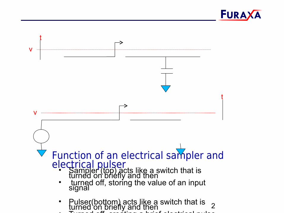
Function of an electrical sampler and electrical pulser• Sampler (top) acts like a switch that is turned on briefly and then
• turned off, storing the value of an input signal
• Pulser(bottom) acts like a switch that is turned on briefly and then • Turned off, creating a brief electrical pulse
2
tv
t
v
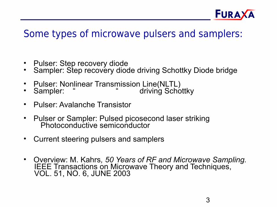
Some types of microwave pulsers and samplers:
• Pulser: Step recovery diode • Sampler: Step recovery diode driving Schottky Diode bridge
• Pulser: Nonlinear Transmission Line(NLTL)• Sampler: “ “ driving Schottky
• Pulser: Avalanche Transistor
• Pulser or Sampler: Pulsed picosecond laser striking Photoconductive semiconductor
• Current steering pulsers and samplers
• Overview: M. Kahrs, 50 Years of RF and Microwave Sampling. IEEE Transactions on Microwave Theory and Techniques, VOL. 51, NO. 6, JUNE 2003
3
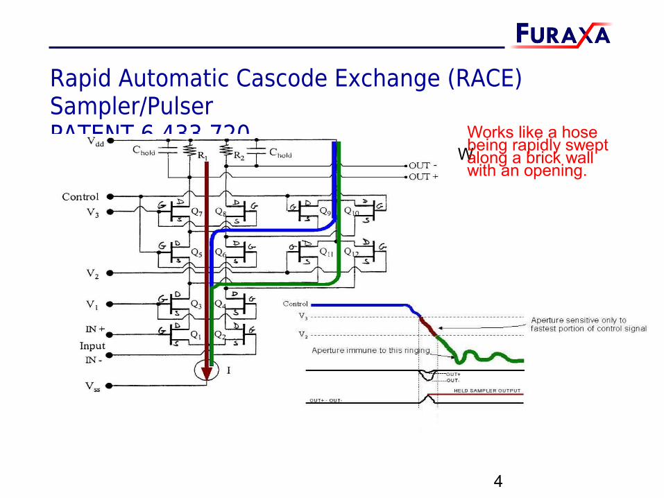
Rapid Automatic Cascode Exchange (RACE) Sampler/PulserPATENT 6,433,720
4
WWorks like a hosebeing rapidly sweptalong a brick wallwith an opening.
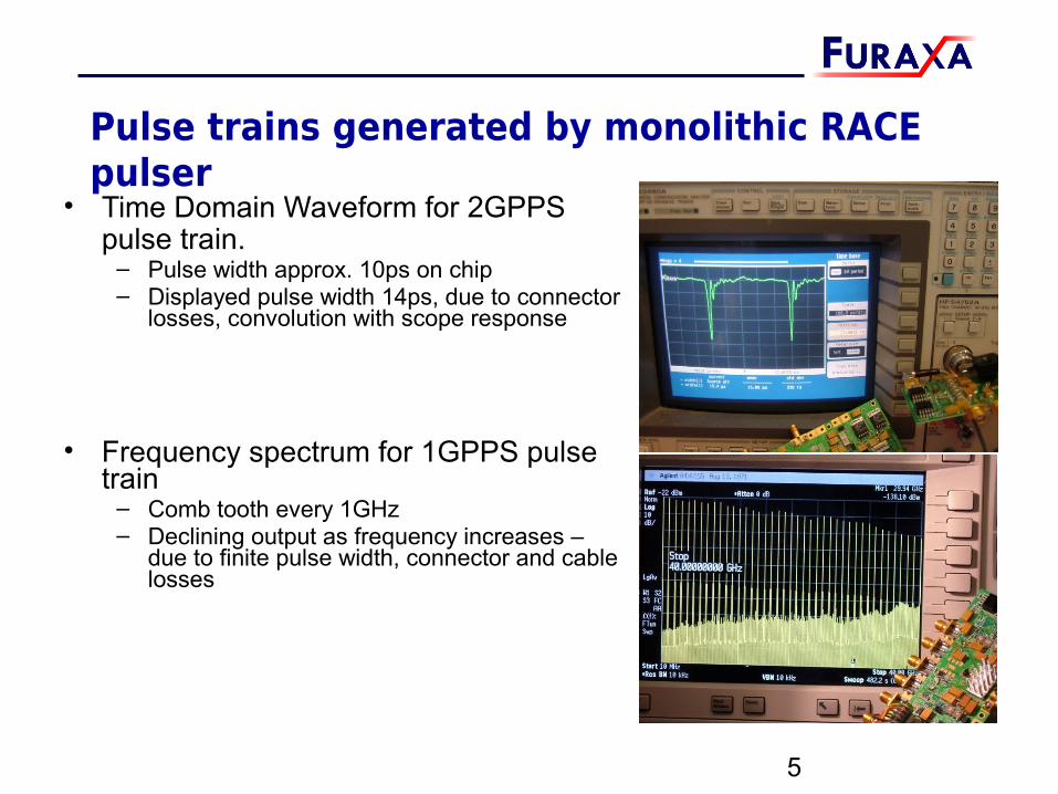
Pulse trains generated by monolithic RACE pulser
• Time Domain Waveform for 2GPPS pulse train.
– Pulse width approx. 10ps on chip– Displayed pulse width 14ps, due to connector
losses, convolution with scope response
• Frequency spectrum for 1GPPS pulse train
– Comb tooth every 1GHz– Declining output as frequency increases –
due to finite pulse width, connector and cable losses
5
Basic Electrical Sampler/Pulser Applications
• Sampler followed by low-pass filter = downconverter
• Pulser (sampler feeding load directly) = comb generator
• Modulated pulser driving an antenna = narrowband upconvertor– RF center frequencies are multiples of pulser repetition rate
• Sampler sampling a pulser running at an offset frequency is a comb spectrometer.
– Reflection vs. Transmission spectrometer depending on location of sampler– If sampler and pulser are on same side/port of DUT, then acts like TDR– If pulser is on one port of DUT and sampler is on other port, acts like TDT
6
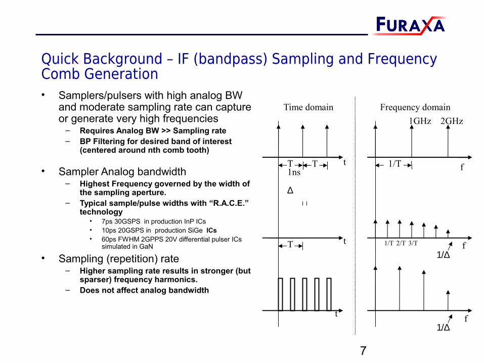
Quick Background – IF (bandpass) Sampling and Frequency Comb Generation• Samplers/pulsers with high analog BW
and moderate sampling rate can capture or generate very high frequencies
– Requires Analog BW >> Sampling rate– BP Filtering for desired band of interest
(centered around nth comb tooth)
• Sampler Analog bandwidth– Highest Frequency governed by the width of
the sampling aperture.– Typical sample/pulse widths with “R.A.C.E.”
technology• 7ps 30GSPS in production InP ICs• 10ps 20GSPS in production SiGe ICs• 60ps FWHM 2GPPS 20V differential pulser ICs
simulated in GaN
• Sampling (repetition) rate– Higher sampling rate results in stronger (but
sparser) frequency harmonics.– Does not affect analog bandwidth
7
Time domain Frequency domain
T 1/Tt f
T 1/Tt f2/T 3/T
∆
1/∆
f1/∆
t
T1ns
1GHz 2GHz
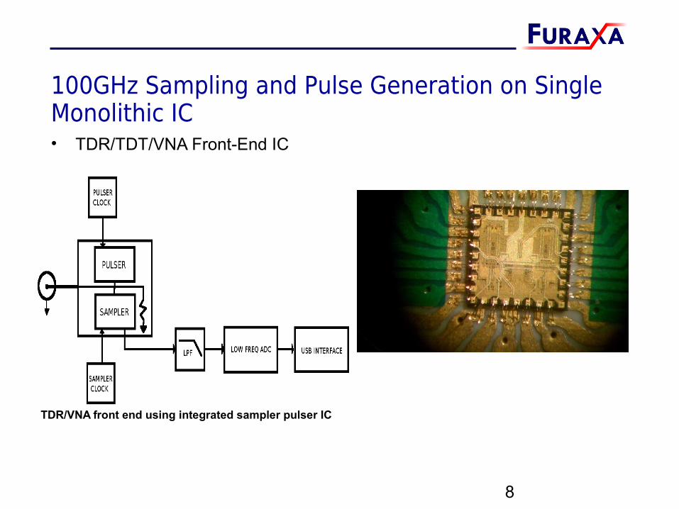
100GHz Sampling and Pulse Generation on Single Monolithic IC• TDR/TDT/VNA Front-End IC
8
TDR/VNA front end using integrated sampler pulser IC
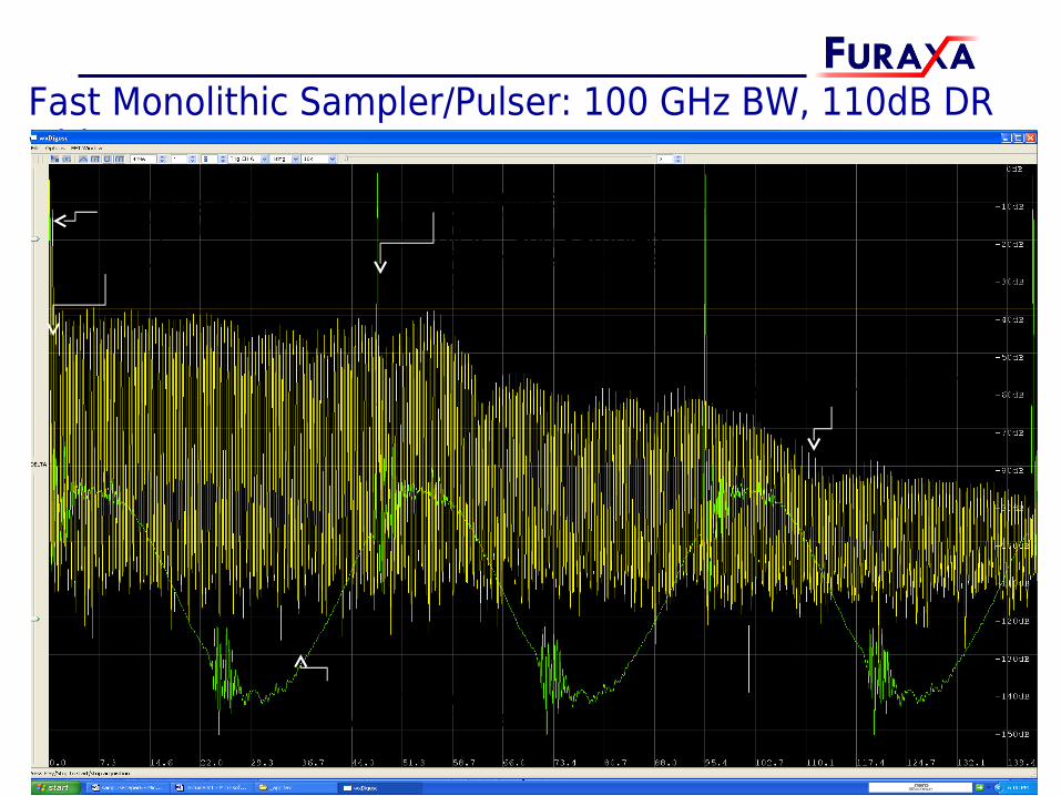
Fast Monolithic Sampler/Pulser: 100 GHz BW, 110dB DR with 1s avg
9
7ps pulses generatedby IC, and sampled by sampler in same IC
Externally added 500MHz sinewave
Frequency spectrum to 140 GHz
500MHz freq. component1GHz… etc
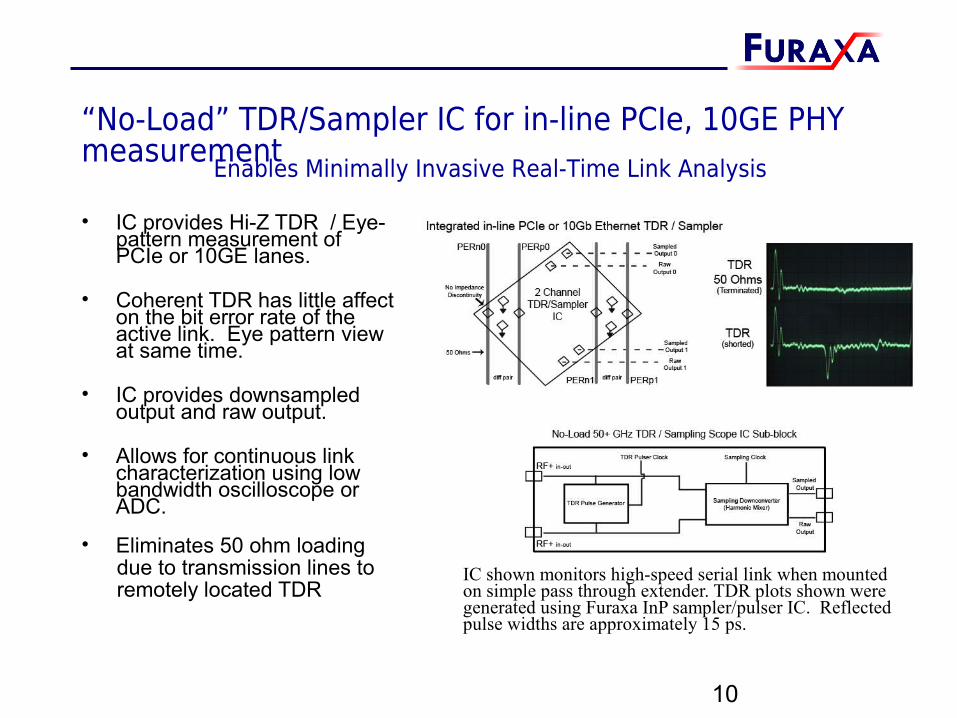
“No-Load” TDR/Sampler IC for in-line PCIe, 10GE PHY measurement
• IC provides Hi-Z TDR / Eye- pattern measurement of PCIe or 10GE lanes.
• Coherent TDR has little affect on the bit error rate of the active link. Eye pattern view at same time.
• IC provides downsampled output and raw output.
• Allows for continuous link characterization using low bandwidth oscilloscope or ADC.
• Eliminates 50 ohm loading due to transmission lines to remotely located TDR
10
Enables Minimally Invasive Real-Time Link Analysis
IC shown monitors high-speed serial link when mountedon simple pass through extender. TDR plots shown were generated using Furaxa InP sampler/pulser IC. Reflected pulse widths are approximately 15 ps.
Monolithic Sampler/Pulser enables Microwave Transceiver• High rep rate monolithic matched arrays of samplers/pulsers
replace mixers and power-hungry microwave LO & divide chain. – Previous microwave samplers lacked sufficient repetition rate to allow them
to replace mixers in most communications applications.– RX: Instead use samplers and medium frequency oscillators– TX: Instead use pulsers and medium frequency oscillators
• Multiple matched samplers/pulsers on one IC allow power to be concentrated in few comb teeth
– Easier filtering due to wide spacing between harmonics– Arrayable, high rep rate samplers/pulsers approach mixer performance, but
at much lower total system cost, size and power– Allows Independent generation/detection of odd and even harmonics
• Inherent Up/Downconversion and Modulation Capability– Pulse amplitude and width can be dynamically controlled
11
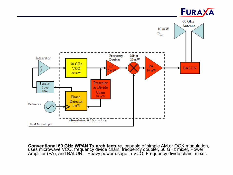
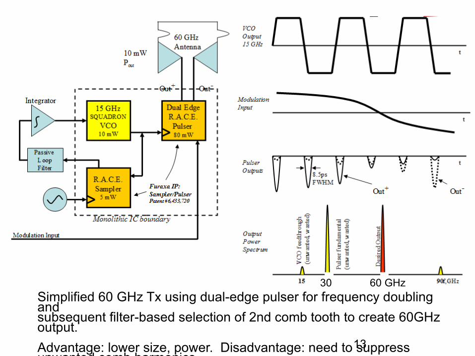
Conventional 60 GHz WPAN Tx architecture, capable of simple AM or OOK modulation, uses microwave VCO, frequency divide chain, frequency doubler, 60 GHz mixer, Power Amplifier (PA), and BALUN. Heavy power usage in VCO, Frequency divide chain, mixer.
13
Simplified 60 GHz Tx using dual-edge pulser for frequency doubling andsubsequent filter-based selection of 2nd comb tooth to create 60GHz output. Advantage: lower size, power. Disadvantage: need to suppress unwanted comb harmonics.
30 60 GHz
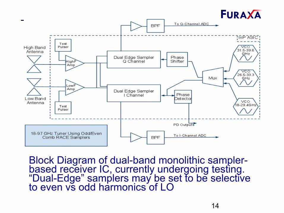
Block Diagram of dual-band monolithic sampler-based receiver IC, currently undergoing testing. “Dual-Edge” samplers may be set to be selective to even vs odd harmonics of LO
14
15
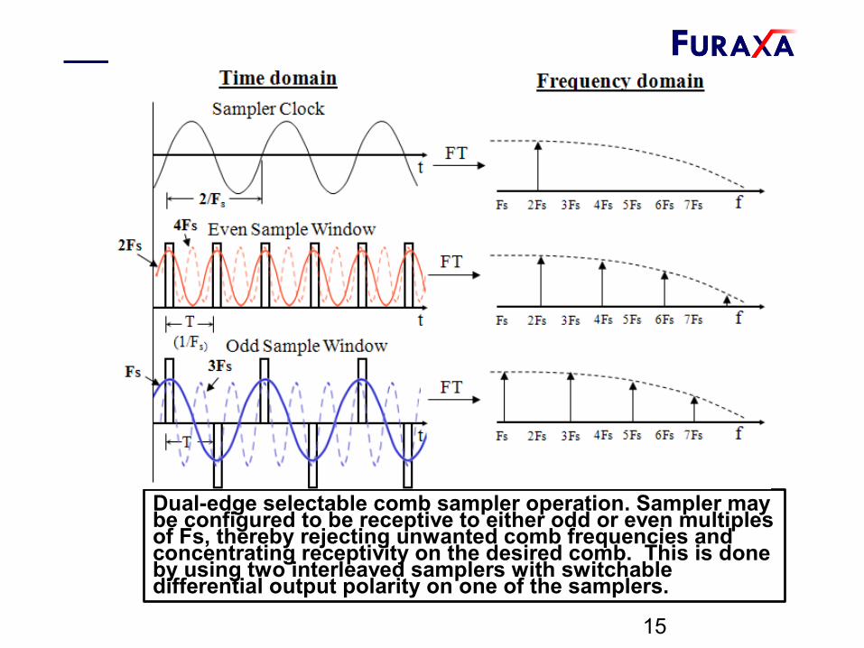
Dual-edge selectable comb sampler operation. Sampler may be configured to be receptive to either odd or even multiples of Fs, thereby rejecting unwanted comb frequencies and concentrating receptivity on the desired comb. This is done by using two interleaved samplers with switchable differential output polarity on one of the samplers.
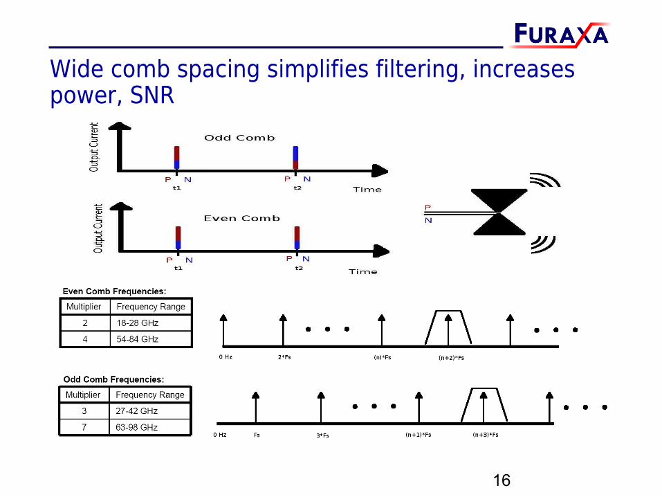
Wide comb spacing simplifies filtering, increases power, SNR
16
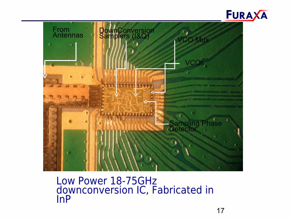
Low Power 18-75GHz downconversion IC, Fabricated in InP
17
VCOs
From Antennas
Sampling Phase Detector
VCO MuxDownConversion Samplers (I&Q)
Microwave Receiver Board• Single Chip plus low-cost components make up 18-75GHz receiver
18
I and Q IF signals when downconverting ~54GHz CW signal.• IC can implement AGC by reducing gain by lowering sampler V3
• voltage – this delays the start of the aperture, making it narrower:• IQPhaseShift42.5GHzDncnvrt_AGC2trim.mp4
• IQPhaseShift42.5GHzDncnvrt_AGC2trim.MOV19
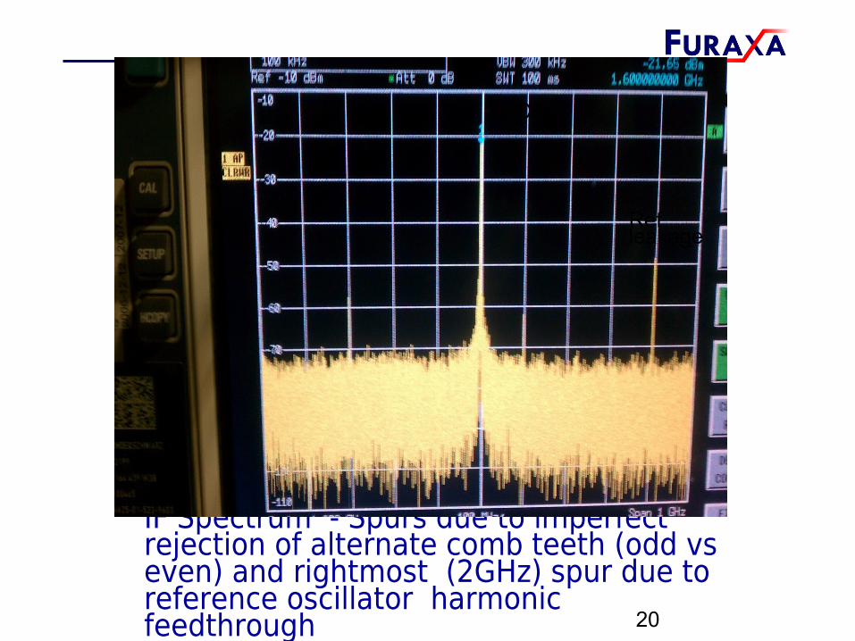
IF Spectrum - Spurs due to imperfect rejection of alternate comb teeth (odd vs even) and rightmost (2GHz) spur due to reference oscillator harmonic feedthrough 20
CF
Ref leakage
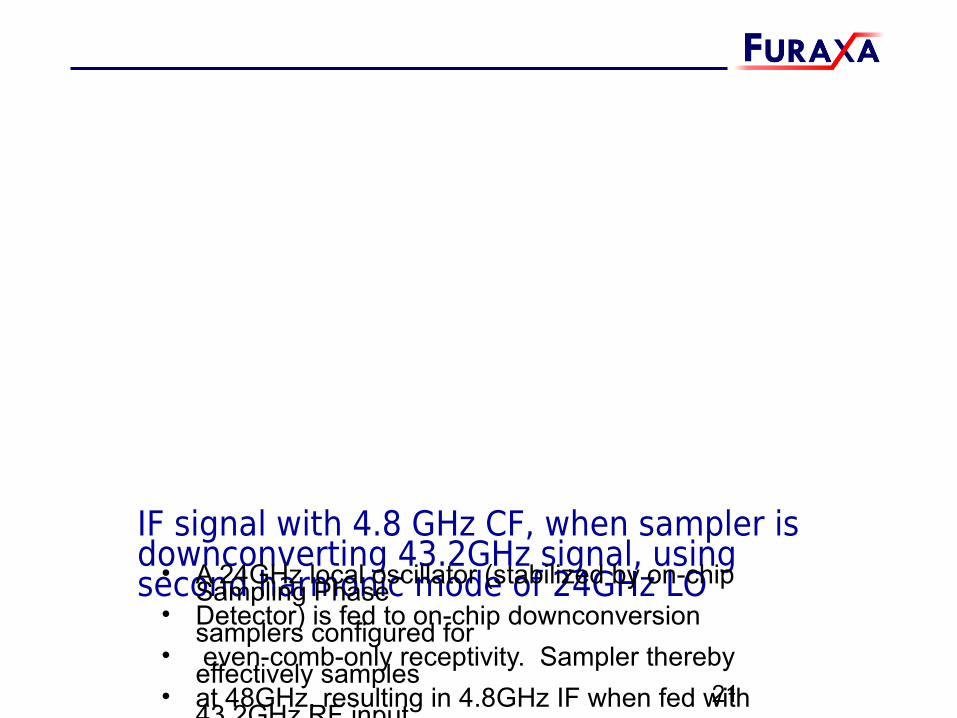
IF signal with 4.8 GHz CF, when sampler is downconverting 43.2GHz signal, using second harmonic mode of 24GHz LO• A 24GHz local oscillator (stabilized by on-chip Sampling Phase
• Detector) is fed to on-chip downconversion samplers configured for• even-comb-only receptivity. Sampler thereby effectively samples • at 48GHz, resulting in 4.8GHz IF when fed with 43.2GHz RF input.
21
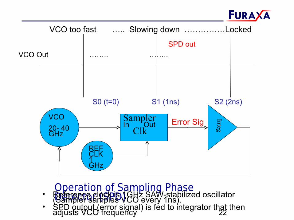
Operation of Sampling Phase Detector (SPD)• Reference clock is 1GHz SAW-stabilized oscillator (Sampler samples VCO every 1ns).
• SPD output (error signal) is fed to integrator that then adjusts VCO frequency 22
VCO too fast ….. Slowing down ……………Locked
SPD out
S0 (t=0) S1 (1ns) S2 (2ns)
VCO Out …….. ……..
VCO20- 40GHz
SamplerIn Out Clk
REF CLK1 GHz
IntegError Sig
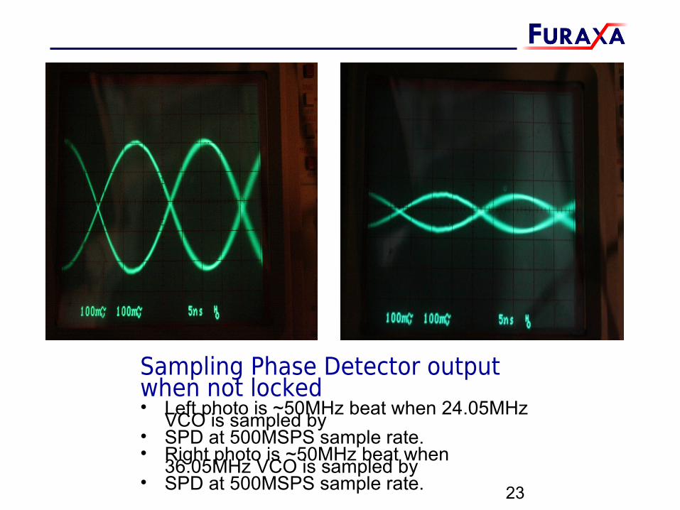
Sampling Phase Detector output when not locked• Left photo is ~50MHz beat when 24.05MHz VCO is sampled by • SPD at 500MSPS sample rate.• Right photo is ~50MHz beat when 36.05MHz VCO is sampled by • SPD at 500MSPS sample rate. 23
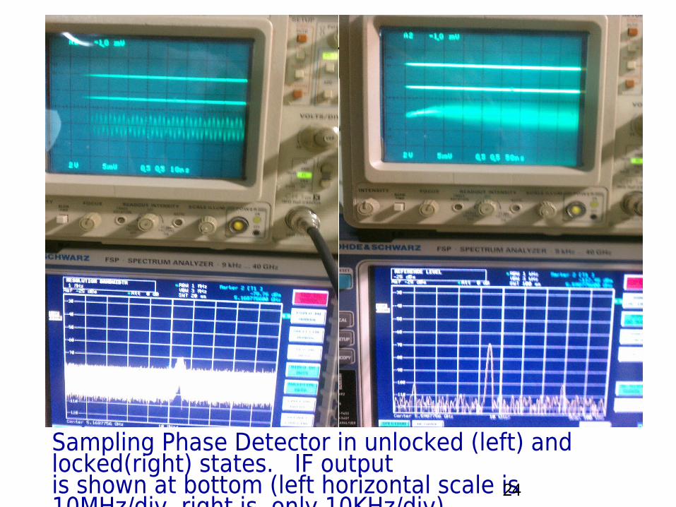
Sampling Phase Detector in unlocked (left) and locked(right) states. IF outputis shown at bottom (left horizontal scale is 10MHz/div, right is only 10KHz/div). VIDEO00132.3gplocking.wmv VIDEO00132.3gplocking.mp4
24
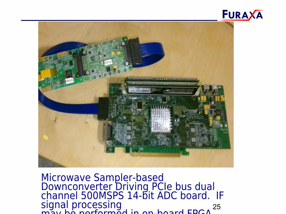
Microwave Sampler-based Downconverter Driving PCIe bus dual channel 500MSPS 14-bit ADC board. IF signal processingmay be performed in on-board FPGA.
25
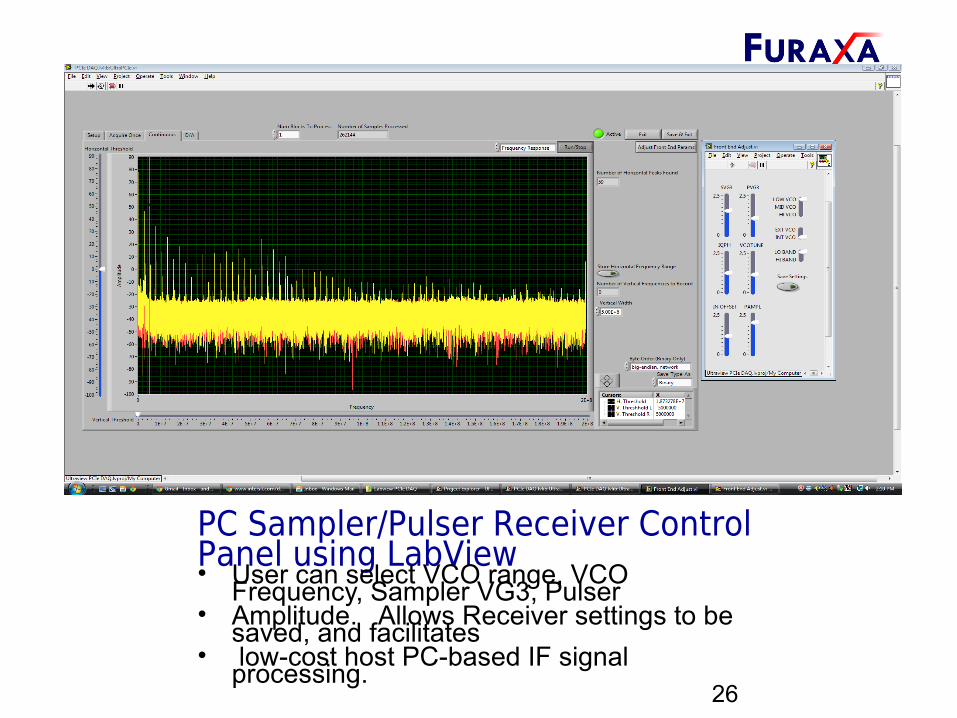
PC Sampler/Pulser Receiver Control Panel using LabView• User can select VCO range, VCO Frequency, Sampler VG3, Pulser • Amplitude. Allows Receiver settings to be saved, and facilitates• low-cost host PC-based IF signal processing.
26
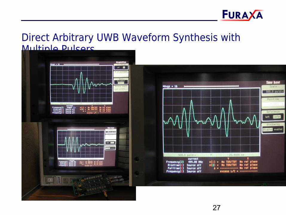
Direct Arbitrary UWB Waveform Synthesis with Multiple Pulsers
27
POSSIBLE FUTURE APPLICATIONS• Up/down-conversion without microwave oscillators Pre-emphasis for high speed communication links LPOI/LPOD UWB transceivers with spectral shaping Ultra-low power UWB RFID tags Direct chip-to-chip communication using UWB
pulses, replacing PCB traces Vehicular and military RADAR Low cost spectrum and vector network analyzers Time gated microwave medical imaging systems (eg.
Helmet-sized Battlefield cranial imager) Non-invasive blood chemistry spectroscopy? Driver for TeraHertz diodes for explosives detection
and other spectroscopy
28
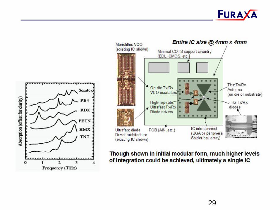
29
References
• 1. M. Kahrs, 50 Years of RF and Microwave Sampling. IEEE Transactions on Microwave Theory and Techniques, VOL. 51, NO. 6, JUNE 2003.
• 2. J.M. Libove and S.J. Chacko, “Methods, Apparatuses and Systems for Sampling or Pulse Generation”, US Patent 6,433,720, August 13, 2002.
• 3. J.M. Libove, B.R. Illingworth, S.J.Chacko, H.L. Levitt, “Monolithic Sampler/Pulser Exceeds 100 GHz”, Microwave Journal, August 2008, pp 86- 105.
• 4. Levitt, H.L., Libove, J.M., Illingworth, B.R., Seay, N.S., Jain, N., “Direct Sampling Millimeter Wave RFIC Tuner Development”, Government Microcircuit and Critical Technology Conference 2010 (GOMACtech2010), Reno, NV, 22-25. March 2010.
• 5. H. Levitt, J. Libove, N Seay, M Chu, M Leroy, J. McDonald, Integrated Millimeter Wave Tuners Utilizing Indium Phosphide and Silicon Germanium Technology, MilComm11, Nov.8, 2011, Baltimore, MD.
30