Embed Size (px)
Citation preview
Retinal Prostheses Development in RetinitisPigmentosa PatientsVProgress and Comparison
Alan Y. Chow, MD
Purpose: Since 2000, several groups have initiated chronic studies,implanting electronic retinal prostheses into the blind eyes of patientswith retinitis pigmentosa to produce formed vision.Design: A review and comparison of their techniques and results.Methods: The 4 groups reviewed comprise 2 epiretinal and 2 subretinalgroups. Visual function results reported in their publications during ap-proximately the past 2 years are compared.Results: Serious adverse effects occurred in both epiretinal groupsbut none in the 2 subretinal groups. Phosphenes with some similarity tothe multielectrode stimulation pattern were induced by 1 group (EpiRetGmbH), and a somewhat higher phosphene pattern was created by anothergroup (Second Sight). In 1 subretinal group (Retina Implant AG), an evenhigher phosphene pattern allowed recognition of letters and objects such asa cup or saucer. In the second subretinal group (Optobionics), besidesperceived phosphenes, a neurotrophic rescue of visual function produceda marked improvement of visual acuity, color and contrast perception, vi-sual field size, and improved darkness perception. In some subjects, rec-ognition of facial features and household objects was restored.Conclusions: Both epiretinal and subretinal prostheses created phosphene-type patterned vision in some subjects. The phosphene resolution of RetinaImplant AG’s subretinal devicewas substantially greater than both epiretinaldevices. Of the 4 groups, only Optobionic’s paracentrally placed subreti-nal Artificial Silicon Retina implant induced an unexpected neurotrophicrescue and return of lost visual function resulting in the greatest return ofvisual acuity, color and contrast perception, visual field enlargement, anddarkness perception.
Key Words: retinitis pigmentosa, retinal prosthesis, epiretinal,subretinal
(Asia-Pac J Ophthalmol 2013;2: 253Y268)
Loss of vision from progressive degeneration of retinal cells iscommon and occurs in conditions such as age-related mac-
ular degeneration (AMD) and in retinal dystrophies collectivelyreferred to as retinitis pigmentosa (RP).1Y3 Both groups of con-ditions are well known to be causes of significant and debilitatingvision loss. Although intravitreal injections of antiYvascular en-dothelial growth factor agents such bevacizumab, ranibizumab,and aflibercept are now routinely used to treat vision loss fromvessel leakage in wet AMD4,5 and studies are now underway toinvestigate the possible benefits of gene therapy to treat Lebercongenital amaurosis,6 no generalized therapy is yet available that
can treat the slow and relentless progression of vision loss in pa-tients with generalized RP and dry AMD.
In the 1980s, one of the earliest vision restoration strategiesfor retinal dystrophies involved the transplantation of functionalretinal tissue into damaged eyes.7,8 Unfortunately, althoughanatomical success and preservation of transplanted tissue wereachieved in some studies, none of the treatments achieved sig-nificant visual benefit in humans, and these efforts have nowbeen largely abandoned. In the early 1990s, another strategyevolved, developed by several groups independently, to try torestore a level of vision by implanting retinal prostheses into theretina to electrically stimulate its cells.9Y19 Although the conceptof a primitive prosthesis placed under the sclera to stimulate theretina had been described in a patent as early as the1950s,20
nothing substantial developed, and the concept was lost to ob-scurity until reintroduced in the 1990s.
The groups recontemplating the prospect of retinal pros-theses based their strategies on historically known findings.Retinal degeneration usually involves the progressive deterio-ration of photoreceptors function followed eventually by theirdeath. The remaining retinal layers such as the bipolar cell layer,plexiform layers, and ganglion cell layer, however, can be par-tially spared, especially early in the course of the disease.1Y3 Theinvestigators therefore reasoned that artificially stimulating theremaining retina electrically to create phosphenes, in a patternresembling images, might restore some vision to affectedpatients.9Y19
From earlier studies, it had been known that electricalstimulation applied to the eyeball surface can elicit repeatablevisual sensations and patterns (phosphenes) in both normalsubjects and RP patients that correlated to the location ofstimulation.21Y26 These findings were corroborated by similarelectrical stimulation experiments in the blind eyes of RoyalCollege of Surgeons rats, which produce a downstream electro-physiological response recordable from their visual cortices.27 InRP patients, phosphenes were perceived when electrical stimu-lation was initiated from inside the eye upon the retinal nervefiber layer (RNFL) surface.28 In vitro and in vivo animal studiesalso showed that evoked retinal and cortical potentials occurwhen the RNFL or the outer retina was stimulated.10,11,29Y31
Based on these studies, 2 general approaches evolved tostimulate the retina depending on the location of the appliedelectrical stimuli,9Y19 either from the epiretinal nerve fiberlayer surface accessed from the vitreous cavity (the epiretinalapproach)13Y15,18,19,32Y35 or from the subretinal space, stim-ulating photoreceptors or bipolar cells (the subretinal ap-proach).9Y12,16,17,36Y38 The animal studies and the preliminaryshort-term acute human studies from the 1980s and 1990sevolved into human studies with chronically implanted retinalprostheses. The first retinal prosthesis to enter clinical trials, a5000-electrode microphotodiode chip, was implanted in a pa-tient with RP by Chow and associates12 in June 2000 (Artifi-cial Silicon Retina [ASR], subretinal approach; Optobionics,Glen Ellyn, Ill), and the results of 6 study patients were reportedin a 2004 publication. A long-term follow-up of greater than
ANNUAL REVIEW
Asia-Pacific Journal of Ophthalmology & Volume 2, Number 4, July/August 2013 www.apjo.org 253
From the Department of Ophthalmology, Rush University Medical Center,Chicago, IL.
Received for publication March 2, 2013; accepted June 15, 2013.Dr Chow was an inventor in all the artificial silicon retinaYrelated patents
but owns none of them and receives no royalties from them. He is theowner of the ‘‘Optobionics’’ name and logo. The original OptobionicsCorporation ceased operations in May 2007. Dr Chow was the founderand a former employee of Optobionics Corporation.
Reprints: Alan Y. Chow, MD, 191 Palamino Place, Wheaton, IL 60189.E-mail: [email protected].
Copyright * 2013 by Asia Pacific Academy of OphthalmologyISSN: 2162-0989DOI: 10.1097/APO.0b013e3182a0b4fe
Copyright © 2013 Asia Pacific Academy of Ophthalmology. Unauthorized reproduction of this article is prohibited.
7 years with additional patients was reported in 2010.36 Sub-sequently, Humayun et al13 implanted a 16-electrode epiretinalprosthesis in 2002 (Argus I, epiretinal approach; Second SightMedical Products, Inc, Sylmar, Calif ) and reported the studyresults in 2003, 2007,14 and 2009.32 In 2012, Humayun et al33
published the results of their second-generation 60-electrodeepiretinal prosthesis implantation study34 (Argus II, epiretinalapproach). Two additional groups have now published onchronically implanted retinal prosthetic devices. The group ofZrenner et al37 (Active Subretinal Device based on the OptobionicsASR, subretinal approach; Retina Implant AG, Reutlingen,Germany) published 2 reports summarizing their implantationstudies in 2011,38 and Epi-Ret (Epi-Ret3, epiretinal approach;EpiRet GmbH, GieQen, Germany) also published study resultsin 200915 and 2011.35
MATERIALS AND METHODSThe status of human retinal prosthesis implant studies, over
approximately the last 2 years as presented in peer-reviewedpublications, is summarized in this review. Preoperative and post-operative vision status changes will be compared between thedifferent devices and approaches as reported in those publica-tions. Results from earlier publications and nonrefereed reportsincluding earlier device failures and complications are not sum-marized other than if they were referred to again in the recentpublications. Although many groups in countries around theworld, other than the early groups mentioned previously, havenow initiated preliminary animal and acute human stimulation
studies and have presented in nonYpeer-reviewed formats suchas meeting abstracts, this review is limited to covering studies ofchronically implanted retinal devices (91 day) in humans thathave been reported in refereed journals. Study follow-up periodsvary greatly and range from 4 weeks to 8 years. Because of thisdifference, the amount of information available for discussionregarding the various research groups will be different in this re-view. Also, as the enrollment vision criteria were different in thevarious studies, this should be taken into account in comparing thefinal postimplant vision achieved by the various devices. Relatedvision restoration investigations involving nonretinal electrical stim-ulation of visual cortex and optic nerve and early neurotransmitter-based stimulation studies and sensory substitution techniquessuch as pattern stimulation of the tongue and skin surfaces are notdiscussed. Please note that the author of this review was a primaryinvestigator in the Optobionics studies. As of 2013, one of theprosthetic devices, the Argus II epiretinal implant, has receivedEuropean Union CEMark approval as well as American Food andDrug Administration (FDA) approval as a Humanitarian DeviceExemption (HDE) product qualified for commercial sale.
RESULTS
Epiretinal Prostheses
EpiRet GmbHA recent epiretinal group that has advanced to clinical trials
in 6 patients is EpiRet GmbH based in GieQen, Germany,working with Philipps-University in Marburg, Germany, and the
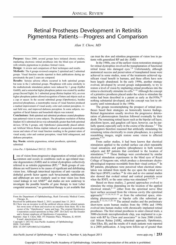
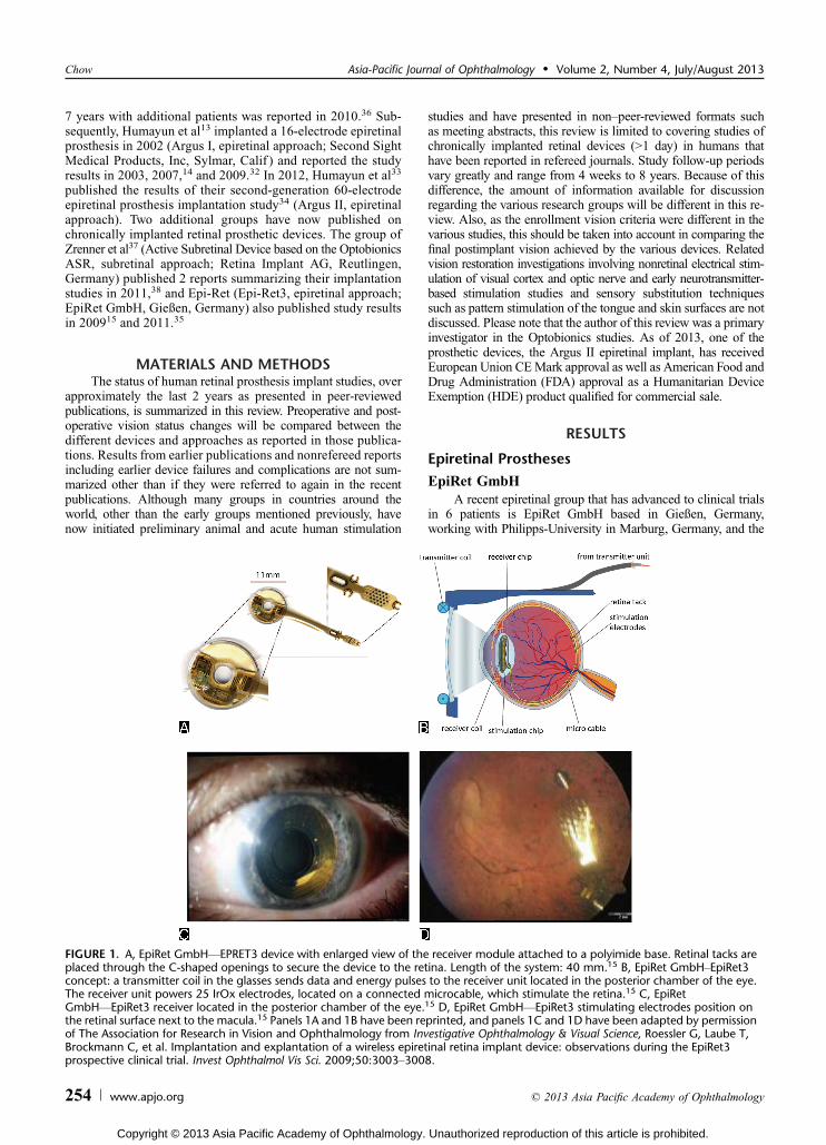
FIGURE 1. A, EpiRet GmbHVEPRET3 device with enlarged view of the receiver module attached to a polyimide base. Retinal tacks areplaced through the C-shaped openings to secure the device to the retina. Length of the system: 40 mm.15 B, EpiRet GmbHYEpiRet3concept: a transmitter coil in the glasses sends data and energy pulses to the receiver unit located in the posterior chamber of the eye.The receiver unit powers 25 IrOx electrodes, located on a connected microcable, which stimulate the retina.15 C, EpiRetGmbHVEpiRet3 receiver located in the posterior chamber of the eye.15 D, EpiRet GmbHVEpiRet3 stimulating electrodes position onthe retinal surface next to the macula.15 Panels 1A and 1B have been reprinted, and panels 1C and 1D have been adapted by permissionof The Association for Research in Vision and Ophthalmology from Investigative Ophthalmology & Visual Science, Roessler G, Laube T,Brockmann C, et al. Implantation and explantation of a wireless epiretinal retina implant device: observations during the EpiRet3prospective clinical trial. Invest Ophthalmol Vis Sci. 2009;50:3003Y3008.
Chow Asia-Pacific Journal of Ophthalmology & Volume 2, Number 4, July/August 2013
254 www.apjo.org * 2013 Asia Pacific Academy of Ophthalmology
Copyright © 2013 Asia Pacific Academy of Ophthalmology. Unauthorized reproduction of this article is prohibited.

Fraunhofer Institute of Microelectronics circuits and Systems inDuisburg, Germany.15,35 They developed a wireless epiretinaldevice called the EpiRet3 consisting of an extraocular portionand an intraocular portion (Fig. 1). The extraocular portion is atransmitter coil placed within a headset in front of the subject’seye, which produces power and signal pulses programmed from acomputer. The pulses are received and processed by a receivercoil and stimulating electronics module located in the lens cap-sule or ciliary sulcus of the eye, which send the power and signalpulses via a metalized foil polyimide strip to 25 iridium oxidestimulation electrodes on an oval surface at the tip of the elec-trode strip. The foil is placed into the vitreous cavity inferiorlyalong the surface of the RNFL to rest adjacent to the macula. Theelectrode tip is secured with penetrating retinal tacks. The elec-trode array spans approximately 10 degrees on the nerve fiberlayer surface. A major difference between the EpiRet3 and Sec-ond Sight’s Argus II is that the receiving coil, stimulating elec-tronics module, and the connected foil electrodes of the EpiRet3are all implanted intraocularly compared with the more compli-cated separate extraocular and intraocular portions of the Argus IIthat require an open scleral track to connect the 2 components.The EpiRet3 implant remained in the eye for 28 days and wasthen extracted per the study protocol.
Serious adverse events (SAEs) were reported and weredefined according to ISO 14155 as events that caused death,were life-threatening, caused permanent impairment of a bodyfunction or permanent damage to a body structure, required orprolonged a hospitalization, caused fetal injury or death, or re-quired surgical intervention to preclude impairment or damage.Serious adverse events that occurred included hypotony witha flat anterior chamber in 1 patient that required sodium hy-aluronate injection to reform the anterior chamber (Table 1). Thesame patient developed a retinal tear on device explantation thatoccurred during removal of the retinal tack and surroundingepiretinal membrane. In a second patient, inflammatory uveitis
occurred that progressed into a sterile hypopyon that requiredanterior chamber tap and culturing (culture negative). This pa-tient was treated with steroids and systemic antibiotics withclearing of the hypopyon in 5 days.
One-hour stimulation sessions were performed at 7, 14, and27 days after surgery on each patient. Pulse currents were bi-phasic with the cathodic phase first and ranged from 3.2 to 100KA.Pulse durations varied from 27 to 878 microseconds per fullphase, and the current was delivered between selected pairs ofelectrodes. In the trials, all electrode pairs were activated ran-domly in succession. Subjects 1, 2, 5, and 6 reported visual per-cepts in all test sessions, whereas subjects 3 and 4 saw percepts inonly 1 of 3 sessions (Table 2).
The visual sensations varied greatly between patients, with3 subjects reporting seeing colors described as red, green, blue,and yellow. The percepts were generally bright phosphene pat-terns, but 2 subjects reported dark or black patterns. When2 stimuli 900 Km apart were activated in a horizontal arrange-ment, subject 1 remarked seeing 2 stimulus patterns, one morenasally than the other. Subject 2 reported a percept in the corre-sponding upper visual field when 2 electrodes located at the loweredge of the electrode array were activated. When a lower leftand an upper right electrode were stimulated, the same subjectreported one percept as ‘‘higher’’ than the other. When an elec-trode pair at a separation distance of 3000 Km in a vertical ar-rangement was activated in subject 6, the patient reported seeing‘‘2 points, 10 cm vertical distance, as if viewed at arm’s length.’’The distance estimated between the induced percepts by this pa-tient corresponded well with the retinal separation of the stimu-lating electrodes. Subjects 1, 2, and 3 correctly recognized theorientation of a linear arrangement of 2 to 4 activated electrodesincluding angles of 20 and 60 degrees and vertical. One patient,subject 3, perceived an oval electrode pattern of stimulation as a‘‘line surrounded by a circle,’’ ‘‘a circle and line,’’ and ‘‘somethingoval like a rugby ball.’’ The investigators reported that stimulation
TABLE 1. SAEs Comparison Between Implant Groups
Second Sight EpiRet GmbH Retina Implant AG Optobionics
SAEs, %28 Patients of
Epiretinal Argus II6 Patients of
Epiretinal EpiRet311 Patients of Subretinal
MPDA DS Array6 Patients of
Subretinal ASR Chip
Conjunctival dehiscence 3 0 0 0Conjunctival erosion 2 0 0 0EndophthalmitisVpresumed 3 0 0 0Hypotony 3 1 0 0Reapplication of retinal tack 2 0 Not applicable Not applicableTractional retinal detachment 2 0 0 0Retinal rear 1 1 0 0Inflammatory uveitis/hypopyon
1 1 0 0
TABLE 2. EpiRet GmbHYEpiRet3 Preoperative Vision and Postoperative Visual Percepts
EpiRet3 (Epiretinal) 25-Electrode Array PreoperativeVision
Postoperative Visual Percepts With EpiRet3Stimulation in 3 SessionsEpiRet GmbH PatientVStudy Duration
#1, 4 wk LP + Percepts in 3/3 sessions, some similarity to multielectrode pattern#2, 4 wk LP + Percepts in 3/3 sessions, some similarity to multielectrode pattern#3, 4 wk No LP + Percepts in 1/3 sessions, some similarity to multielectrode pattern#4, 4 wk LP + Percepts in 1/3 sessions, some correlation to electrode position#5, 4 wk Hand movements + Percepts in 3/3 sessions#6, 4 wk LP + Percepts in 3/3 sessions, some correlation to 2electrode position
Asia-Pacific Journal of Ophthalmology & Volume 2, Number 4, July/August 2013 Retinal Prostheses for Retinitis Pigmentosa
* 2013 Asia Pacific Academy of Ophthalmology www.apjo.org 255
Copyright © 2013 Asia Pacific Academy of Ophthalmology. Unauthorized reproduction of this article is prohibited.
success depended greatly on pulse duration rather than chargedensity. If the pulse duration was above a critical level for an in-dividual, then current amplitude and thus charge density droppedto very low levels. The investigators recommended studying verylong pulse durations of several hundred microseconds or evenlonger to decrease stimulation charge density thresholds.
Second Sight Medical ProductsAlthough the first chronically implanted retinal prosthesis
was the ASR subretinal device implanted by Chow and asso-ciates12 in 2000 (Optobionics), Second Sight Medical Products(Second Sight) in Sylmar, Calif, was the first group to investi-gate a chronically implanted epiretinal device called the Argus Iin a feasibility and safety study.13,14,32 The Argus I was even-tually implanted in 6 patients in a single-center study at theDoheny Eye Institute between 2002 and 2004 by Humayunet al13 and consisted of a 16-platinum electrode device in a 4 � 4array with electronics based on cochlear implant technology. Theelectrodes were either 520 Km (first 3 patients) or 260 Km(second 3 patients) in diameter and 0.8 mm apart and embeddedin a thin silicone strip platform that was inserted through a scleralincision into the vitreous cavity. A single retinal tack pushedthrough a hole in the electrode tip, through the retina and into thesclera, was used to secure the electrode portion of the silicone stripto the nerve fiber layer surface. The electrodes were connected to16 flexible conductors inside the strip that exited the sclera andorbit and ran in a channel drilled along the temporal bone of theskull to a stimulating electronics module embedded under thescalp by the ear. The internal module was powered by an externalinductive wireless antenna link module that received power andsignals from a computer that either generated the individual elec-trode signals or could process video signals from a glasses-mountedcamera to power the 16 electrodes.
With this implant, the first 3 subjects were able to differ-entiate (although not recognize) common objects from eachother such as a knife, plate, and cup and were able to detect themotion of a moving white bar (5 � 30 cm) against a blackbackground. The vision of 1 patient who underwent implanta-tion was tested with 4 orientations of square wave gratings andwas reported to be better than chance at recognizing the gratingorientation. The logarithm of the minimum angle of resolutionacuity (logMAR) in that patient was determined to beÈ logMAR2.5 (È20/6500). Interestingly, subjects did not perform consis-tently better in the testing when multiple electrodes were acti-vated versus just a single electrode. Adverse events reportedincluded conjunctival erosion over the external scleral portion ofthe implant and dislodgement of the retinal tack resulting in de-tachment of the implant electrode tip away from the retina, whichrequired reinsertion of a retinal tack. Two subjects who underwentimplantation in 2004 remain active in the study.
Between June 2007 and August 2009, Second Sight evaluateda second-generation Argus II retinal prosthesis (Figs. 2A, B) in asingle-arm, prospective, multicenter international clinical trial at 10clinical centers.33,34 The results of this trial were published in April201233 and in October 2012.34
Thirty subjects were enrolled in the study. The patientswere at least 50 years old at most centers and 18 years or olderat some sites. All were diagnosed with RP or a related outer reti-nal degeneration (1 subject was diagnosed with Leber congeni-tal amaurosis and another with choroideremia). Vision in theenrolled subjects had to be worse than 2.9 logMAR (Snellen20/15,900), which was generally light perception (LP) or worse.All were followed up for at least 6 months.
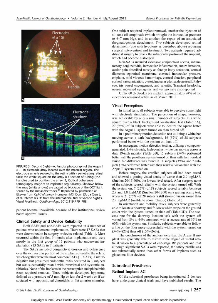
Compared with the Argus I, the Argus II consisted of a highercount 6 � 10, 60-electrode array (Fig. 3) that was connected via a
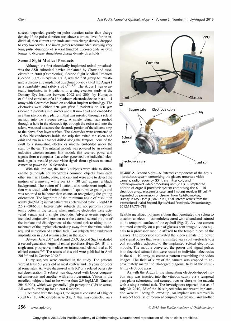
flexible metalized polymer ribbon that penetrated the sclera toattach to an electronics module secured with a band and suturedto the temporal surface of the eyeball (Fig. 2). A video cameramounted centrally on a pair of glasses sent imaged video sig-nals to a processor module affixed to the temple piece of theglasses. The processor converted the video signals into powerand signal pulses that were transmitted via a coil wirelessly to acoil embedded adjacent to the implanted scleral electronicsmodule. The module converted the power and signal pulsesinto electrical stimuli that were routed to individual electrodesin the 6 � 10 array to create a pattern resembling the videoimages. The field of view of the camera was cropped to ap-proximately match the 20-degree diagonal field of the stimu-lating electrode array.
As with the Argus I, the stimulating electrode-tipped rib-bon strip was inserted into the vitreous cavity via a temporalpars plana sclerotomy and secured over or close to the maculawith a single retinal tack. The investigators reported that as ofJuly 30, 2010, 28 of the 30 subjects who underwent implanta-tion were still being followed up. An implant was removed in1 subject because of recurrent conjunctival erosion, and another
FIGURE 2. Second SightVA, External components of the ArgusII prosthesis system comprising the glasses-mounted videocamera, radiofrequency (RF) transmitter coil, andbattery-powered video processing unit (VPU). B, Implantedportion of Argus II prosthesis system comprising the 6 � 10electrode array, electronics case, and implant receiver RF coil.33
Reprinted by permission of Elsevier from Ophthalmology,Humayun MS, Dorn JD, da Cruz L, et al. Interim results from theinternational trial of Second Sight‘s Visual Prosthesis.Ophthalmology.2012;119:779Y788.
Chow Asia-Pacific Journal of Ophthalmology & Volume 2, Number 4, July/August 2013
256 www.apjo.org * 2013 Asia Pacific Academy of Ophthalmology
Copyright © 2013 Asia Pacific Academy of Ophthalmology. Unauthorized reproduction of this article is prohibited.
patient became unavailable because of late institutional reviewboard approval issues.
Clinical Safety and Device ReliabilityBoth SAEs and non-SAEs were reported in a number of
patients who underwent implantation. There were 17 SAEs thatwere determined to be surgery or device related (Table 1). Mostoccurred within the first 6 months after implantation and weremostly in the first group of 15 patients who underwent im-plantation (13 SAEs in 7 patients).
The SAEs included conjunctival erosion and dehiscenceover the extraocular portion of the implant sutured to the sclera,which together were the most common SAEs (17 SAEs). Culture-negative but presumed endophthalmitis occurred in 3 subjectsbut was successfully treated with intravitreal and systemic an-tibiotics. None of the implants in the presumptive endophthalmitiscases required removal. Three subjects developed hypotony,defined as a pressure of 5 mm Hg or less for 2 weeks or if as-sociated with appositional choroidals or flat anterior chamber.
One subject required implant removal, another the injection ofsilicone oil tamponade (which brought the intraocular pressureto 6Y7 mm Hg), and in another the repair of an associatedrhegmatogenous detachment. Two subjects developed retinaldetachment (one with hypotony as described above) requiringsurgical intervention and treatment. Two patients required ad-ditional surgery to retack the intraocular portion of the implant,which had become dislodged.
Non-SAEs included extensive conjunctival edema, inflam-matory conjunctivitis, intraocular inflammation, suture irritation,ocular pain described mostly as foreign body sensation, cornealfilaments, epiretinal membrane, elevated intraocular pressure,epiphora, mild vitreous hemorrhage, corneal abrasion, peripheralcorneal vascularization, cystoidmacular edema, decreased LP, dryeye, iris vessel engorgement, and scleritis. Transient headache,nausea, increased nystagmus, and vertigo were also reported.
Of the 60 electrodes per implant, approximately 94% of theelectrodes remained active as of March 2010.
Visual PerceptionsIn initial tests, all subjects were able to perceive some light
with electrode stimulation. The perception of shape, however,was achievable by only a small number of subjects. In a whitesquare over a black background localization test (Table 3A),27 (96%) of 28 subjects were able to localize the square betterwith the Argus II system turned on than turned off.
In a preliminary motion detection test utilizing a white barmoving across a dark background, 16 (57%) of 28 subjectsperformed better with the system on than off.
In subsequent motion detection testing, utilizing a computer-generated, 1.4-inch-wide, high-contrast white bar moving across adark 19-inch monitor (Table 3B), 15 subjects (54%) performedbetter with the prosthesis system turned on than with their residualvision. No difference was found in 11 subjects (39%), and 2 sub-jects (7%) performed better with their residual vision than with theArgus II system turned on.
Before surgery, the enrolled subjects all had been testedand showed a grating visual acuity of worse than 2.9 logMAR(Snellen 20/15,900), the lowest level tested. After surgery, noneof the subjects scored reliably with the system turned off. Withthe system on, 7 (25%) of 28 subjects scored reliably between2.9 and 1.8 logMAR (Snellen 20/1260) on a grating acuity test,whereas 21 (75%) of 28 subjects still showed vision worse than2.9 logMAR (unable to score reliably) (Table 3C).
In orientation and mobility tasks, subjects were generallyable to locate a doorway and follow a white stripe on the groundeasier with the system turned on than off (Table 3D). The suc-cess rate for the doorway location task with the system offvaried from 8% to 44% compared with a success rate of 52% to60% with the system on. Similarly, subjects were able to followa line on the floor more successfully with the system turned on(54%Y82%) than off (15%Y26%).
The conclusions of the authors were that the Argus II im-plant was generally able to restore some degree of useful arti-ficial vision to a percentage of end-stage RP patients and thatalthough significant SAEs were reported, the safety profile wasnot substantially worse than other forms of implants such asglaucoma filter devices.
Subretinal Prostheses
Retinal Implant AGOf the subretinal prostheses being investigated, 2 devices
have undergone clinical trials and have published results. The
FIGURE 3. Second SightVA, Fundus photograph of the Argus II6 � 10 electrode array located over the macular region. Theelectrode array is secured to the retina with a penetrating retinaltack; the white square on the array is a section of tubing (thehandle) used to position the array. B, Optical coherencetomography image of an implanted Argus II array. Shadows belowthe array (white arrows) are caused by blockage of the OCT lightsource by the metal electrodes.33 Reprinted by permission ofElsevier from Ophthalmology, Humayun MS, Dorn JD, da Cruz L,et al. Interim results from the international trial of Second Sight‘sVisual Prosthesis. Ophthalmology. 2012;119:779Y788.
Asia-Pacific Journal of Ophthalmology & Volume 2, Number 4, July/August 2013 Retinal Prostheses for Retinitis Pigmentosa
* 2013 Asia Pacific Academy of Ophthalmology www.apjo.org 257
Copyright © 2013 Asia Pacific Academy of Ophthalmology. Unauthorized reproduction of this article is prohibited.
first device is a collaborative effort from Retinal Implant AGworking with the Universities of Tubingen and Regensburg, theNMI Natural and Medical Sciences Institute, and KlinikumFriedrichstadt, all in Germany, and Semmelweis University inBudapest, Hungary. This device evolved from a subretinal de-vice that was patterned after the ASR developed by Chow fol-lowing early collaboration discussions.
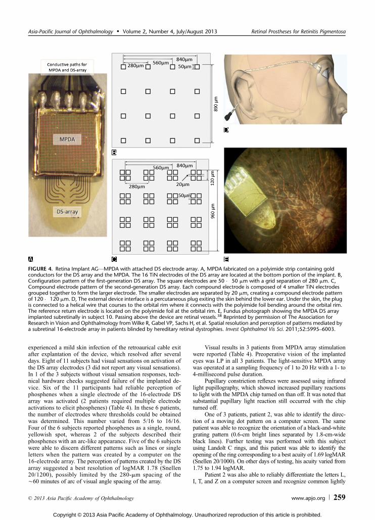
Retinal Implant AG presently investigates an auxiliarypowered subretinal device, which they call an MPDA DS array,a designation for a microphotodiode arrayYdirect stimulationarray (Figs. 4, 5).37,38 The implant consists of an MPDA placedon a polyimide foil, on which is also fabricated a rectangular DSarray of 4 � 4 hardwired titanium nitride compound electrodes,each of which can be activated independently. Each compoundelectrode is 120 � 120 Km and is composed of a 2 � 2 array ofsmaller electrodes, 50 � 50 Km each. The 16 compound elec-trodes of the DS array are spaced 280 Km apart or È60 minutesof arc of visual angle and represent a minimum angle of reso-lution of logMAR 1.78 (Snellen 20/1200).
The MPDA portion of the implant (Figs. 4, 5) consists ofa 38 � 40 pixel array of electric currentYgenerating elements(1500 total), each with its own light-sensing microphotodiode,amplifier, and stimulation electrode. Each pixel element is 72 �
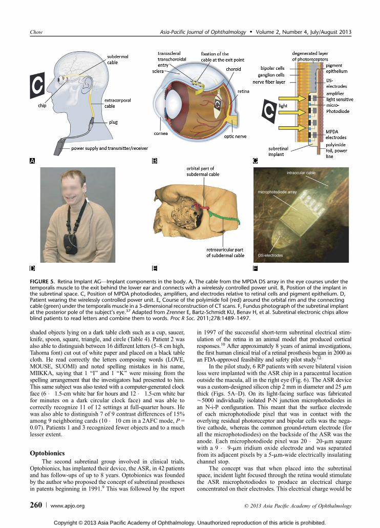
72-Km square with a 15 � 30-Km microphotodiode and a 50 �50-Km titanium nitride electrode. Images focused by the eyeupon the subretinal chip are captured in a pixelated pattern bythe microphotodiodes several times per second and are convertedinto monophasic anodic voltage pulses at each electrode, whichthen stimulate contacting bipolar cells or remnant photoreceptors.The reference return electrode is located further back on thepolyimide foil strip and is outside the eye. A silicon-coated cablethat runs underneath the temporalis muscle connects the foilportion of the MPDA DS array to a connector plug, which exitsthe skin behind and beneath the ear. An external power supplyand transmitter/receiver control unit worn by the patient areconnected to the connector plug and power both the DS array andthe MPDA array.
The amount of simulation current produced by each elec-trode is dependent on the brightness level sensed by its associ-ated microphotodiode. The MPDA spans a visual angle in thesubretinal space of approximately 11 � 11 degrees, with theangle between electrodes being 15 minutes of arc.
Eleven patients underwent implantation with the MPDADS array. No SAEs were reported (Table 1). In 1 patient, a smallcircumscribed area of subretinal bleeding was observed, whichcompletely reabsorbed within 10 days. The same patient also
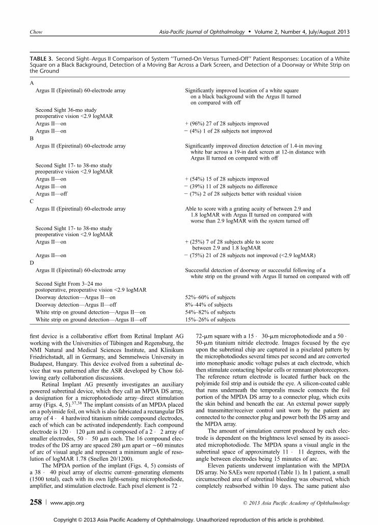
TABLE 3. Second SightYArgus II Comparison of System ‘‘Turned-On Versus Turned-Off’’ Patient Responses: Location of a WhiteSquare on a Black Background, Detection of a Moving Bar Across a Dark Screen, and Detection of a Doorway or White Strip onthe Ground
AArgus II (Epiretinal) 60-electrode array Significantly improved location of a white square
on a black background with the Argus II turnedon compared with off
Second Sight 36-mo studypreoperative vision G2.9 logMARArgus IIVon + (96%) 27 of 28 subjects improvedArgus IIVon j (4%) 1 of 28 subjects not improved
BArgus II (Epiretinal) 60-electrode array Significantly improved direction detection of 1.4-in moving
white bar across a 19-in dark screen at 12-in distance withArgus II turned on compared with off
Second Sight 17- to 38-mo studypreoperative vision G2.9 logMARArgus IIVon + (54%) 15 of 28 subjects improvedArgus IIVon j (39%) 11 of 28 subjects no differenceArgus IIVoff j (7%) 2 of 28 subjects better with residual vision
CArgus II (Epiretinal) 60-electrode array Able to score with a grating acuity of between 2.9 and
1.8 logMAR with Argus II turned on compared withworse than 2.9 logMAR with the system turned off
Second Sight 17- to 38-mo studypreoperative vision G2.9 logMARArgus IIVon + (25%) 7 of 28 subjects able to score
between 2.9 and 1.8 logMARArgus IIVon j (75%) 21 of 28 subjects not improved (G2.9 logMAR)
DArgus II (Epiretinal) 60-electrode array Successful detection of doorway or successful following of a
white strip on the ground with Argus II turned on compared with offSecond Sight From 3Y24 mopostoperative, preoperative vision G2.9 logMARDoorway detectionVArgus IIVon 52%Y60% of subjectsDoorway detectionVArgus IIVoff 8%Y44% of subjectsWhite strip on ground detectionVArgus IIVon 54%Y82% of subjectsWhite strip on ground detectionVArgus IIVoff 15%Y26% of subjects
Chow Asia-Pacific Journal of Ophthalmology & Volume 2, Number 4, July/August 2013
258 www.apjo.org * 2013 Asia Pacific Academy of Ophthalmology
Copyright © 2013 Asia Pacific Academy of Ophthalmology. Unauthorized reproduction of this article is prohibited.
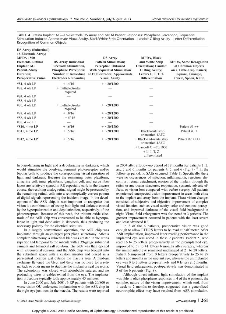
experienced a mild skin infection of the retroaurical cable exitafter explantation of the device, which resolved after severaldays. Eight of 11 subjects had visual sensations on activation ofthe DS array electrodes (3 did not report any visual sensations).In 1 of the 3 subjects without visual sensation responses, tech-nical hardware checks suggested failure of the implanted de-vice. Six of the 11 participants had reliable perception ofphosphenes when a single electrode of the 16-electrode DSarray was activated (2 patients required multiple electrodeactivations to elicit phosphenes) (Table 4). In these 6 patients,the number of electrodes where thresholds could be obtainedwas determined. This number varied from 5/16 to 16/16.Four of the 6 subjects reported phosphenes as a single, round,yellowish spot, whereas 2 of the subjects described theirphosphenes with an arc-like appearance. Five of the 6 subjectswere able to discern different patterns such as lines or singleletters when the pattern was created by a computer on the16-electrode array. The perception of patterns created by the DSarray suggested a best resolution of logMAR 1.78 (Snellen20/1200), possibly limited by the 280-Km spacing of theÈ60 minutes of arc of visual angle spacing of the array.
Visual results in 3 patients from MPDA array stimulationwere reported (Table 4). Preoperative vision of the implantedeyes was LP in all 3 patients. The light-sensitive MPDA arraywas operated at a sampling frequency of 1 to 20 Hz with a 1- to4-millisecond pulse duration.
Pupillary constriction reflexes were assessed using infraredlight pupillography, which showed increased pupillary reactionsto light with the MPDA chip turned on than off. It was noted thatsubstantial pupillary light reaction still occurred with the chipturned off.
One of 3 patients, patient 2, was able to identify the direc-tion of a moving dot pattern on a computer screen. The samepatient was able to recognize the orientation of a black-and-whitegrating pattern (0.6-cm bright lines separated by 1.8-cm-wideblack lines). Further testing was performed with this subjectusing Landolt C rings, and this patient was able to identify theopening of the ring corresponding to a best acuity of 1.69 logMAR(Snellen 20/1000). On other days of testing, his acuity varied from1.75 to 1.94 logMAR.
Patient 2 was also able to reliably differentiate the letters L,I, T, and Z on a computer screen and recognize common lightly
FIGURE 4. Retina Implant AGVMPDA with attached DS electrode array. A, MPDA fabricated on a polyimide strip containing goldconductors for the DS array and the MPDA. The 16 TiN electrodes of the DS array are located at the bottom portion of the implant. B,Configuration pattern of the first-generation DS array. The square electrodes are 50 � 50 Km with a grid separation of 280 Km. C,Compound electrode pattern of the second-generation DS array. Each compound electrode is composed of 4 smaller TiN electrodesgrouped together to form the larger electrode. The smaller electrodes are separated by 20 Km, creating a compound electrode patternof 120 � 120 Km. D, The external device interface is a percutaneous plug exiting the skin behind the lower ear. Under the skin, the plugis connected to a helical wire that courses to the orbital rim where it connects with the polyimide foil bending around the orbital rim.The reference return electrode is located on the polyimide foil at the orbital rim. E, Fundus photograph showing the MPDA DS arrayimplanted subretinally in subject 10. Passing above the device are retinal vessels.38 Reprinted by permission of The Association forResearch in Vision and Ophthalmology fromWilke R, Gabel VP, Sachs H, et al. Spatial resolution and perception of patterns mediated bya subretinal 16-electrode array in patients blinded by hereditary retinal dystrophies. Invest Ophthalmol Vis Sci. 2011;52:5995Y6003.
Asia-Pacific Journal of Ophthalmology & Volume 2, Number 4, July/August 2013 Retinal Prostheses for Retinitis Pigmentosa
* 2013 Asia Pacific Academy of Ophthalmology www.apjo.org 259
Copyright © 2013 Asia Pacific Academy of Ophthalmology. Unauthorized reproduction of this article is prohibited.
shaded objects lying on a dark table cloth such as a cup, saucer,knife, spoon, square, triangle, and circle (Table 4). Patient 2 wasalso able to distinguish between 16 different letters (5Y8 cm high,Tahoma font) cut out of white paper and placed on a black tablecloth. He read correctly the letters composing words (LOVE,MOUSE, SUOMI) and noted spelling mistakes in his name,MIIKKA, saying that 1 ‘‘I’’ and 1 ‘‘K’’ were missing from thespelling arrangement that the investigators had presented to him.This same subject was also tested with a computer-generated clockface (6 � 1.5-cm white bar for hours and 12 � 1.5-cm white barfor minutes on a dark circular clock face) and was able tocorrectly recognize 11 of 12 settings at full-quarter hours. Hewas also able to distinguish 7 of 9 contrast differences of 15%among 9 neighboring cards (10 � 10 cm in a 2AFC mode, P =0.07). Patients 1 and 3 recognized fewer objects and to a muchlesser extent.
OptobionicsThe second subretinal group involved in clinical trials,
Optobionics, has implanted their device, the ASR, in 42 patientsand has follow-ups of up to 8 years. Optobionics was foundedby the author who proposed the concept of subretinal prosthesesin patents beginning in 1991.9 This was followed by the report
in 1997 of the successful short-term subretinal electrical stim-ulation of the retina in an animal model that produced corticalresponses.10 After approximately 8 years of animal investigations,the first human clinical trial of a retinal prosthesis began in 2000 asan FDA-approved feasibility and safety pilot study.12
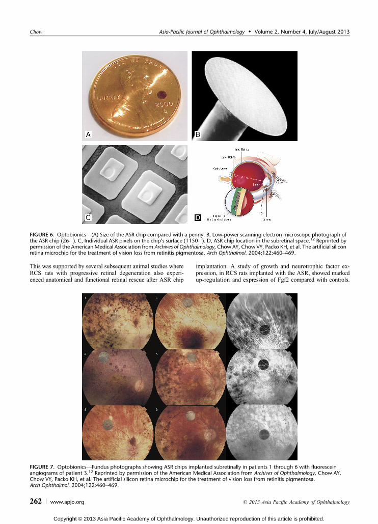
In the pilot study, 6 RP patients with severe bilateral visionloss were implanted with the ASR chip in a paracentral locationoutside the macula, all in the right eye (Fig. 6). The ASR devicewas a custom-designed silicon chip 2 mm in diameter and 25 Kmthick (Figs. 5AYD). On its light-facing surface was fabricatedÈ5000 individually isolated P-N junction microphotodiodes inan N-i-P configuration. This meant that the surface electrodeof each microphotodiode pixel that was in contact with theoverlying residual photoreceptor and bipolar cells was the nega-tive cathode, whereas the common ground-return electrode (forall the microphotodiodes) on the backside of the ASR was theanode. Each microphotodiode pixel was 20 � 20-Km squarewith a 9 � 9-Km iridium oxide electrode and was separatedfrom its adjacent pixels by a 5-Km-wide electrically insulatingchannel stop.
The concept was that when placed into the subretinalspace, incident light focused through the retina would stimulatethe ASR microphotodiodes to produce an electrical chargeconcentrated on their electrodes. This electrical charge would be
FIGURE 5. Retina Implant AGVImplant components in the body. A, The cable from the MPDA DS array in the eye courses under thetemporalis muscle to the exit behind the lower ear and connects with a wirelessly controlled power unit. B, Position of the implant inthe subretinal space. C, Position of MPDA photodiodes, amplifiers, and electrodes relative to retinal cells and pigment epithelium. D,Patient wearing the wirelessly controlled power unit. E, Course of the polyimide foil (red) around the orbital rim and the connectingcable (green) under the temporalis muscle in a 3-dimensional reconstruction of CT scans. F, Fundus photograph of the subretinal implantat the posterior pole of the subject’s eye.37 Adapted from Zrenner E, Bartz-Schmidt KU, Benav H, et al. Subretinal electronic chips allowblind patients to read letters and combine them to words. Proc R Soc. 2011;278:1489Y1497.
Chow Asia-Pacific Journal of Ophthalmology & Volume 2, Number 4, July/August 2013
260 www.apjo.org * 2013 Asia Pacific Academy of Ophthalmology
Copyright © 2013 Asia Pacific Academy of Ophthalmology. Unauthorized reproduction of this article is prohibited.
hyperpolarizing in light and a depolarizing in darkness, whichwould stimulate the overlying remnant photoreceptor and/orbipolar cells to produce the corresponding visual sensation oflight and darkness. Because the remaining outer plexiform,amacrine cell, inner plexiform, ganglion cell, and nerve fiberlayers are relatively spared in RP, especially early in the diseasecourse, the resulting analog retinal signal might be processed bythe remaining retinal cells into a retinotopically correct patternof digital signals representing the incident image. In the devel-opment of the ASR chip, it was important to recognize thatvision is a combination of seeing both light and darkness causedby the hyperpolarization and depolarization, respectively, of thephotoreceptors. Because of this need, the iridium oxide elec-trode of the ASR chip was constructed to be able to hyperpo-larize in light and depolarize in darkness, thus producing thenecessary polarity for the electrical stimulus.
In a largely conventional operation, the ASR chip wasimplanted through an enlarged pars plana sclerotomy. After acomplete vitrectomy, a subretinal bleb was created in the retinasuperior and temporal to the macula with a 39-gauge subretinalcannula and balanced salt solution. The bleb was then openedwith vitreoretinal scissors, and the ASR chip was brought intothe subretinal space with a custom inserter and placed in aparacentral location just outside the macula area. A fluid-airexchange flattened the bleb, and there was no need for a reti-nal tack or other means to stabilize the implant or seal the retina.The sclerotomy was closed with absorbable sutures, and noprotruding wires or cables exited from the eye. The implanta-tion procedure typically took approximately 45 minutes.
In June 2000 and July 2001, 6 RP patients with 20/800 orworse vision OU underwent implantation with the ASR chip inthe right eye just outside the macula. The results were reported
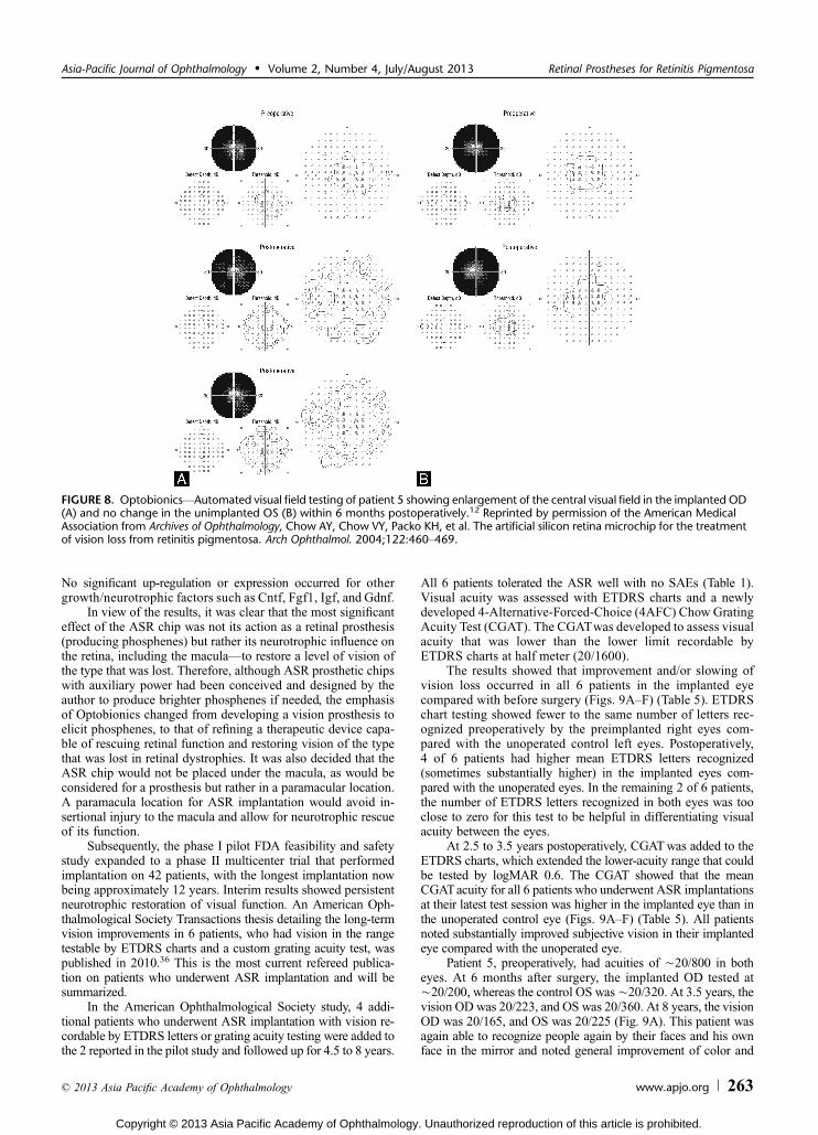
in 2004 after a follow-up period of 18 months for patients 1, 2,and 3 and 6 months for patients 4, 5, and 6 (Fig. 7).12 In thefollow-up period, no SAEs occurred (Table 1). Specifically, therewere no occurrences of infection, inflammation, rejection, dis-comfort, retinal detachment, erosion of the implant through theretina or any ocular structures, reoperation, systemic adverse ef-fects, or vision loss compared with before surgery. All patientsexperienced unexpected vision improvement in areas both closeto the implant and away from the implant. These vision changesconsisted of subjective and objective improvement of complexvisual function such as visual acuity, color and contrast percep-tion, and improved darkness of the visual field background atnight. Visual field enlargement was also noted in 3 patients. Thegreatest improvement occurred in patients with the least severeand least advanced RP.
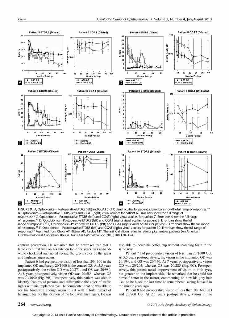
In 2 of the 6 patients, preoperative vision was goodenough to allow ETDRS letters to be read at half meter. AfterASR implantation, improved letter reading performance in theimplanted eye was noted in these 2 patients. Patient 5, whoread 16 to 25 letters preoperatively in the preimplanted eye,improved to 35 to 41 letters 6 months after surgery, whereasthe unimplanted eye remained unchanged at 21 to 28 letters.Patient 6 improved from 0 letters preoperatively to 25 to 29letters at 6 months in the implant eye, whereas the unimplantedeye was 0 to 3 letters preoperatively and 0 letters at 6 months.Visual field enlargement postoperatively was demonstrated in3 of the 6 patients (Fig. 8).
Although direct infrared light stimulation of the implantwas able to elicit phosphene responses in 4 of the 6 patients, thecomplex nature of the vision improvement, which took from1 week to 2 months to develop, suggested that a generalizedneurotrophic effect may have resulted from ASR stimulation.
TABLE 4. Retina Implant AGV16-Electrode DS Array and MPDA Patient Responses: Phosphene Perception, SequentialStimulation-Induced Approximate Visual Acuity, Black/White Strip OrientationVLandolt C Ring AcuityVLetter Differentiation,Recognition of Common Objects
DS Array (Subretinal)16-Electrode Array;MPDA 1500Elements. RetinalImplant AG,PatientYStudyDuration;Preoperative Vision
DS Array IndividualElectrode Stimulation,Phosphene Perception;Number of IndividualElectrodes Responding
DS ArrayPattern Stimulation;Perception Obtained
With Sequential Stimulationof 15 Electrodes; Approximate
Visual Acuity
MPDA, Blackand White Strip
Orientation; LandoltC Ring Acuity;Letters L, I, T, ZDifferentiation
MPDA, Some Recognitionof Common Objects
on a TableYCup, Saucer,Square, Triangle,
Circle, Spoon, Knife
#S1, 4 wk LP + 14/16 + È20/1200 V#S2, 4 wk LP + multielectrodes
requiredV V
#S4, 4 wk LP V V V#S5, 4 wk LP V V V#S6, 4 wk LP + multielectrodes
required+ È20/1200 V
#S7, 4 wk LP + 10/16 + È20/1200 V#S8, 4 wk LP + 5/ 16 + È20/1200 V#S9, 4 mo LP V V V#S10, 4 mo LP + 16/16 + È20/1200 V Patient #1 ++#S11, 4 mo LP + 15/16 + È20/1200 + Black/white strip
orientation 4AFCPatient #3 +
#S12, 4 mo LP + 15/16 + È20/1200 + Black-and-white striporientation 4AFC
Patient #2 ++++
+ Landolt C È20/1000+ L, I, T, Zdifferentiated
Asia-Pacific Journal of Ophthalmology & Volume 2, Number 4, July/August 2013 Retinal Prostheses for Retinitis Pigmentosa
* 2013 Asia Pacific Academy of Ophthalmology www.apjo.org 261
Copyright © 2013 Asia Pacific Academy of Ophthalmology. Unauthorized reproduction of this article is prohibited.
This was supported by several subsequent animal studies whereRCS rats with progressive retinal degeneration also experi-enced anatomical and functional retinal rescue after ASR chip
implantation. A study of growth and neurotrophic factor ex-pression, in RCS rats implanted with the ASR, showed markedup-regulation and expression of Fgf2 compared with controls.
FIGURE 6. OptobionicsV(A) Size of the ASR chip compared with a penny. B, Low-power scanning electron microscope photograph ofthe ASR chip (26�). C, Individual ASR pixels on the chip’s surface (1150�). D, ASR chip location in the subretinal space.12 Reprinted bypermission of the AmericanMedical Association from Archives of Ophthalmology, Chow AY, Chow VY, Packo KH, et al. The artificial siliconretina microchip for the treatment of vision loss from retinitis pigmentosa. Arch Ophthalmol. 2004;122:460Y469.
FIGURE 7. OptobionicsVFundus photographs showing ASR chips implanted subretinally in patients 1 through 6 with fluoresceinangiograms of patient 3.12 Reprinted by permission of the American Medical Association from Archives of Ophthalmology, Chow AY,Chow VY, Packo KH, et al. The artificial silicon retina microchip for the treatment of vision loss from retinitis pigmentosa.Arch Ophthalmol. 2004;122:460Y469.
Chow Asia-Pacific Journal of Ophthalmology & Volume 2, Number 4, July/August 2013
262 www.apjo.org * 2013 Asia Pacific Academy of Ophthalmology
Copyright © 2013 Asia Pacific Academy of Ophthalmology. Unauthorized reproduction of this article is prohibited.
No significant up-regulation or expression occurred for othergrowth/neurotrophic factors such as Cntf, Fgf1, Igf, and Gdnf.
In view of the results, it was clear that the most significanteffect of the ASR chip was not its action as a retinal prosthesis(producing phosphenes) but rather its neurotrophic influence onthe retina, including the maculaVto restore a level of vision ofthe type that was lost. Therefore, although ASR prosthetic chipswith auxiliary power had been conceived and designed by theauthor to produce brighter phosphenes if needed, the emphasisof Optobionics changed from developing a vision prosthesis toelicit phosphenes, to that of refining a therapeutic device capa-ble of rescuing retinal function and restoring vision of the typethat was lost in retinal dystrophies. It was also decided that theASR chip would not be placed under the macula, as would beconsidered for a prosthesis but rather in a paramacular location.A paramacula location for ASR implantation would avoid in-sertional injury to the macula and allow for neurotrophic rescueof its function.
Subsequently, the phase I pilot FDA feasibility and safetystudy expanded to a phase II multicenter trial that performedimplantation on 42 patients, with the longest implantation nowbeing approximately 12 years. Interim results showed persistentneurotrophic restoration of visual function. An American Oph-thalmological Society Transactions thesis detailing the long-termvision improvements in 6 patients, who had vision in the rangetestable by ETDRS charts and a custom grating acuity test, waspublished in 2010.36 This is the most current refereed publica-tion on patients who underwent ASR implantation and will besummarized.
In the American Ophthalmological Society study, 4 addi-tional patients who underwent ASR implantation with vision re-cordable by ETDRS letters or grating acuity testing were added tothe 2 reported in the pilot study and followed up for 4.5 to 8 years.
All 6 patients tolerated the ASR well with no SAEs (Table 1).Visual acuity was assessed with ETDRS charts and a newlydeveloped 4-Alternative-Forced-Choice (4AFC) Chow GratingAcuity Test (CGAT). The CGATwas developed to assess visualacuity that was lower than the lower limit recordable byETDRS charts at half meter (20/1600).
The results showed that improvement and/or slowing ofvision loss occurred in all 6 patients in the implanted eyecompared with before surgery (Figs. 9AYF) (Table 5). ETDRSchart testing showed fewer to the same number of letters rec-ognized preoperatively by the preimplanted right eyes com-pared with the unoperated control left eyes. Postoperatively,4 of 6 patients had higher mean ETDRS letters recognized(sometimes substantially higher) in the implanted eyes com-pared with the unoperated eyes. In the remaining 2 of 6 patients,the number of ETDRS letters recognized in both eyes was tooclose to zero for this test to be helpful in differentiating visualacuity between the eyes.
At 2.5 to 3.5 years postoperatively, CGATwas added to theETDRS charts, which extended the lower-acuity range that couldbe tested by logMAR 0.6. The CGAT showed that the meanCGATacuity for all 6 patients who underwent ASR implantationsat their latest test session was higher in the implanted eye than inthe unoperated control eye (Figs. 9AYF) (Table 5). All patientsnoted substantially improved subjective vision in their implantedeye compared with the unoperated eye.
Patient 5, preoperatively, had acuities of È20/800 in botheyes. At 6 months after surgery, the implanted OD tested atÈ20/200, whereas the control OS wasÈ20/320. At 3.5 years, thevision OD was 20/223, and OS was 20/360. At 8 years, the visionOD was 20/165, and OS was 20/225 (Fig. 9A). This patient wasagain able to recognize people again by their faces and his ownface in the mirror and noted general improvement of color and
FIGURE 8. OptobionicsVAutomated visual field testing of patient 5 showing enlargement of the central visual field in the implanted OD(A) and no change in the unimplanted OS (B) within 6 months postoperatively.12 Reprinted by permission of the American MedicalAssociation from Archives of Ophthalmology, Chow AY, Chow VY, Packo KH, et al. The artificial silicon retina microchip for the treatmentof vision loss from retinitis pigmentosa. Arch Ophthalmol. 2004;122:460Y469.
Asia-Pacific Journal of Ophthalmology & Volume 2, Number 4, July/August 2013 Retinal Prostheses for Retinitis Pigmentosa
* 2013 Asia Pacific Academy of Ophthalmology www.apjo.org 263
Copyright © 2013 Asia Pacific Academy of Ophthalmology. Unauthorized reproduction of this article is prohibited.
contrast perception. He remarked that he never realized that atable cloth that was on his kitchen table for years was red-and-white checkered and noted seeing the green color of the grassand highway signs again.
Patient 6 had preoperative vision of less than 20/1600 in theimplanted OD and barely 20/1600 in the control OS. At 3.5 yearspostoperatively, the vision OD was 20/271, and OS was 20/980.At 8 years postoperatively, vision OD was 20/585, whereas OSwas 20/4050 (Fig. 9B). Postoperatively, this patient was able toidentify features of persons and differentiate the color of trafficlights with his implanted eye. He commented that he was able tosee his food well enough again to eat with a fork instead ofhaving to feel for the location of the food with his fingers. He was
also able to locate his coffee cup without searching for it in thesame way.
Patient 7 had preoperative vision of less than 20/1600 OU.At 3.5 years postoperatively, the vision in the implanted OD was20/194, and OS was 20/470. At 7 years postoperatively, visionOD was 20/203, whereas OS was 20/285 (Fig. 9C). Postoper-atively, this patient noted improvement of vision in both eyes,but greater on the implant side. He remarked that he could seehimself better in the mirror, commenting on how his gray hairused to be black the last time he remembered seeing himself inthe mirror years ago.
Patient 8 had preoperative vision of less than 20/1600 ODand 20/800 OS. At 2.5 years postoperatively, vision in the
FIGURE 9. A,OptobionicsVPostoperativeETDRS(left)andCGAT(right) visualacuities forpatient5.Errorbars showthe full rangeof responses.36
B, OptobionicsVPostoperative ETDRS (left) and CGAT (right) visual acuities for patient 6. Error bars show the full range ofresponses.36 C, OptobionicsVPostoperative ETDRS (left) and CGAT (right) visual acuities for patient 7. Error bars show the full rangeof responses.36 D, OptobionicsVPostoperative ETDRS (left) and CGAT (right) visual acuities for patient 8. Error bars show the fullrange of responses.36 E, OptobionicsVPostoperative ETDRS (left) and CGAT (right) visual acuities for patient 9. Error bars show the full rangeof responses.36 F, OptobionicsVPostoperative ETDRS (left) and CGAT (right) visual acuities for patient 10. Error bars show the full range ofresponses.36 Reprinted from Chow AY, Bittner AK, Pardue MT. The artificial silicon retina in retinitis pigmentosa patients (An AmericanOphthalmological Association Thesis). Trans Am Ophthalmol Soc. 2010;108:120Y154.
Chow Asia-Pacific Journal of Ophthalmology & Volume 2, Number 4, July/August 2013
264 www.apjo.org * 2013 Asia Pacific Academy of Ophthalmology
Copyright © 2013 Asia Pacific Academy of Ophthalmology. Unauthorized reproduction of this article is prohibited.
implanted OD was 20/770 and OS 20/193. By 6.5 years aftersurgery, vision OD was 20/1830, whereas vision in OS haddropped to 20/2600 (Fig. 9D). This patient now uses predomi-nately his implanted eye to navigate around the house, whereaspreoperatively his OS was his dominant eye. With the implantedeye, postoperatively, he is able to see objects such as the burnerson his stove and dishes in his china cabinet. He commented that,after surgery, darkness perception had improved and that nightswere much darker compared with before surgery. Preopera-tively, his visual field would remain bright at night despite theabsence of light.
Patient 9 had preoperative vision of less than 20/1600 OU.At 2.5 years postoperatively, vision in the implanted OD was20/400 and OS 20/952. At 4.5 years after surgery, vision ODwas 20/328, and OS was 20/3140 (Fig. 9E). After surgery, thispatient noted being able to see again Christmas tree lights andtheir colors and the lights on the dashboard of her car. She wasable to again see her son play basketball along with othermembers of his school team.
Patient 10 had preoperative vision of less than 20/1600OU. At 2.5 years postoperatively, vision in the ASR-implantedOD was 20/711 and OS 20/2150. At 6 years after surgery, vi-sion OD was 20/796, and OS was 20/2503 (Fig. 9F). This pa-tient also noted increased darkness perception at night comparedwith before surgery when it remained bright in his visual fielddespite the absence of light. He was able to again see colors in hisenvironment, household objects, and his children in the house. Heremarked that before surgery he would have to feel around thefloor with his hands and kick with his feet to locate the vacuumcleaner if he lost track of it. After surgery, he is able to success-fully find the vacuum cleaner with his vision only.
DISCUSSIONDuring approximately the past 2 years, 4 groups have
refereed publications reporting longer-term human clinicalstudies with retinal prostheses. Two groups (Epi Ret GmbH,Second Sight) reported on epiretinal devices,13Y15,32Y35 whereas2 other groups (Retinal Implant AG, Optobionics) reported onsubretinal devices.12,36Y38 The patient entry vision criteria be-tween the groups were different, which should be kept in mindwhen evaluating the level of postoperative vision recovery. Thepreoperative vision for the Argus II patients was limited to LP orworse, that is, no LP. For the EpiRet3, it was hand motions(HMs) to LP; for the DS array/MPDA, it was LP; and for theASR, it was HM to 20/800.
An analysis of reported SAEs shows that SAEs werereported only in epiretinal subjects. The types of SAEs includedconjunctival dehiscence and erosion over the extrascleral por-tion of the implant, presumed endophthalmitis, hypotony, needfor reapplication of a retinal tack, tractional retinal detachment,retinal tear, and inflammatory uveitis. Conjunctival dehiscenceand erosion occurred only with the Argus II device because theEpiRet3 was implanted entirely intraocularly. Retinal tears andinflammatory uveitis, however, occurred with both epiretinaldevices. The lack of device-related retinal tears and inflamma-tory uveitis with subretinal devices may be due to their subretinallocation, which would isolate them from vitreous shearing forcesduring eyeball movement. Such forces could theoretically moveand shift epiretinal retinal devices, which may have caused theobserved retinal tears and inflammation. Also, as subretinal de-vices do not require retinal tacks to secure their location, therewould be no retinal tacks to become dislodged. In the articlespublished during the 2-year period of this review, subretinal de-vices appear to be associated with fewer SAEs than epiretinaldevices.
From a vision restoration perspective, both epiretinal de-vices were able to induce phosphenes in the vicinity of theimplant electrodes in most but not all subjects. In 1 of 6 patientswho underwent EpiRet3 implantation, the epiretinal prosthesiswas able to create line orientations and visual patterns that boresimilarity to the pattern of its stimulating electrodes.35 Subjec-tively, the EpiRet3 patient described stimulation from a verti-cal arrangement of activated electrodes as a ‘‘line, like a halfmoon, or a semicircle’’ and a diagonal arrangement of activatedelectrodes as an ‘‘arc, yellow arc.’’ The most notable visualresult was when the electrodes were activated in an oval pattern,the patient noted a ‘‘line surrounded by a circle,’’ ‘‘a circle and aline,’’ and ‘‘something oval like a rugby ball.’’ Higher degreesof visual function did not occur, and subjective return offormed vision that affected daily activities was not reported byany patient. The EpiRet3 demonstrated that in at least 1 of thestudy patients some degree of pattern recognition could resultfrom its stimulation.
The Argus II device was implanted into many more patientsthan the EpiRet3 device. In their study,33 Second Sight showedthat most subjects (96%) were able to more accurately locate abright square on a black background with the system turned onthan off. The system, however, was less successful in allowingpatients to detect the direction of a moving bar of light on acomputer screen. In this test, 56% of patients performed betterwith the system turned on than off, compared with 46% who did
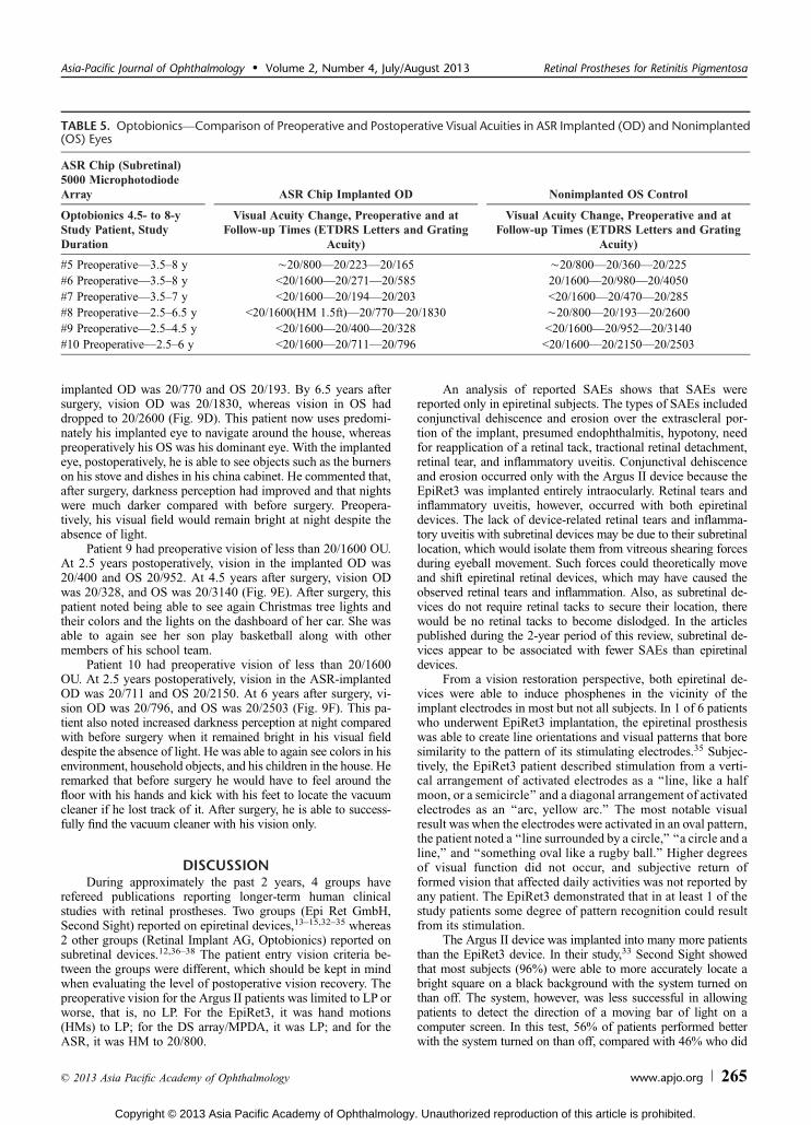
TABLE 5. OptobionicsVComparison of Preoperative and Postoperative Visual Acuities in ASR Implanted (OD) and Nonimplanted(OS) Eyes
ASR Chip (Subretinal)5000 MicrophotodiodeArray ASR Chip Implanted OD Nonimplanted OS Control
Optobionics 4.5- to 8-yStudy Patient, StudyDuration
Visual Acuity Change, Preoperative and atFollow-up Times (ETDRS Letters and Grating
Acuity)
Visual Acuity Change, Preoperative and atFollow-up Times (ETDRS Letters and Grating
Acuity)
#5 PreoperativeV3.5Y8 y È20/800V20/223V20/165 È20/800V20/360V20/225#6 PreoperativeV3.5Y8 y G20/1600V20/271V20/585 20/1600V20/980V20/4050#7 PreoperativeV3.5Y7 y G20/1600V20/194V20/203 G20/1600V20/470V20/285#8 PreoperativeV2.5Y6.5 y G20/1600(HM 1.5ft)V20/770V20/1830 È20/800V20/193V20/2600#9 PreoperativeV2.5Y4.5 y G20/1600V20/400V20/328 G20/1600V20/952V20/3140#10 PreoperativeV2.5Y6 y G20/1600V20/711V20/796 G20/1600V20/2150V20/2503
Asia-Pacific Journal of Ophthalmology & Volume 2, Number 4, July/August 2013 Retinal Prostheses for Retinitis Pigmentosa
* 2013 Asia Pacific Academy of Ophthalmology www.apjo.org 265
Copyright © 2013 Asia Pacific Academy of Ophthalmology. Unauthorized reproduction of this article is prohibited.
not perform better. In real-world tests such as the detection ofdoorways, subjects generally performed better with the systemturned on than off (52%Y60% successful with the system on vs8%Y31% with system off ). Higher levels of visual function suchas object recognition did not occur. Thus, similar to the EpiRet3,the epiretinal Argus II implant was able to confer some degree ofvisual perception that included motion detection.
Regarding the image accuracy created by epiretinal de-vices, some subjects reported perceptions that did not corre-spond to the pattern of electrical stimulation,35 for example, ‘‘aline and a circle’’ when stimulated with an oval electrode pat-tern. These reports may be because in addition to the targetedganglion cells being stimulated, the intervening RNFL may bereceiving electrical stimulation from epiretinal stimulation. Ifthis did occur, the perception of phosphenes in locations otherthan the specific areas of stimulation (ie, the origin of the nerveaxon) could be explained. Also, epiretinal stimulating electrodeswere not in direct contact with the targeted ganglion cells dueto the intervening RNFL (the electrodes were even farther awayfrom the bipolar cells if they were also targeted). The non-contact arrangement of epiretinal electrodes in the Argus IIand the EpiRet3, relative to their targeted cells may have af-fected the devices’ ability to reproduce stimulation patterns thatcorresponded accurately with the electrode pattern.
Retina Implant AG’s hybrid 16-electrode DS array/MPDAproduced phosphene patterns with the 16-electrode DS arrayeither as an orientation of lines or as multiple orientations ofthe figure ‘‘C’’ through sequential electrode activation.37,38
The device produced phosphene visual acuities of È20/1200in 7 of 11 patients who underwent implantations. When themicrophotodiode array portion of the implants was tested witha pattern of black-and-white gratings, and Landolt ‘‘C’’ ringswere presented on a computer screen, 1 of the 11 patients testedachieved a visual acuity of 20/1000. This 1 patient was alsoable to differentiate the letters L, I, Z, and Tand recognize some
common objects such a cup, knife, and spoon. One other pa-tient was able to localize and differentiate a saucer from a cupand a square shape on a table. Another patient was able to dif-ferentiate just a saucer from a plate on the same table. Overall,the resolution performance of the subretinal DS array/MPDAappeared higher than for the Argus II and EpiRet3. It is possiblethat the retinotopic similarity of the photoreceptor/bipolar targetcell arrangement to projected images on the retina, along with theclose target cell proximity to the stimulating electrodes of thesubretinal device, produced greater resolution potential in the DSarray/MPDA compared with the epiretinal devices.
Forty-two patients have now been implanted with Optobionics’ASR (Table 6). The most recent study summarizes the results of6 of the patients who underwent the longest implantations withalmost 8 years of follow-up.36 The most important finding wasthat of consistently better long-term ETDRS and CGAT visualacuity in the implanted eyes compared with before surgery andalso compared with the opposite control eye. The results suggest apersistence neurotrophic effect in the implanted eyes even 8 yearsafter surgery. Final visual acuity in 1 patient was 20/165 comparedwith È20/800 preoperatively. In the remaining 5 patients, withpreoperative visual acuities of HM at 1.5 ft to G20/1600, finalacuities were 20/585, 20/203, 20/1830, 20/328, and 20/796. Be-cause the mechanism of vision improvement of the subretinalASR device is likely different than the other prosthesis groups,comparison of vision recovery between the ASR and the otherdevices is difficult. The vision enrollment criteria for the ASRstudies were also higher than those for the other devices.
The nature of recovered vision in patients who underwentASR implantation was noteworthy. As opposed to the patternedphosphenes produced by either epiretinal or subretinal prosthesissummarized in this article, the vision recovered in patients whounderwent ASR implantation was of the type of vision that waslost. Specifically, there was recovery of complex visual functionincluding visual acuity, contrast and color perception, visual field
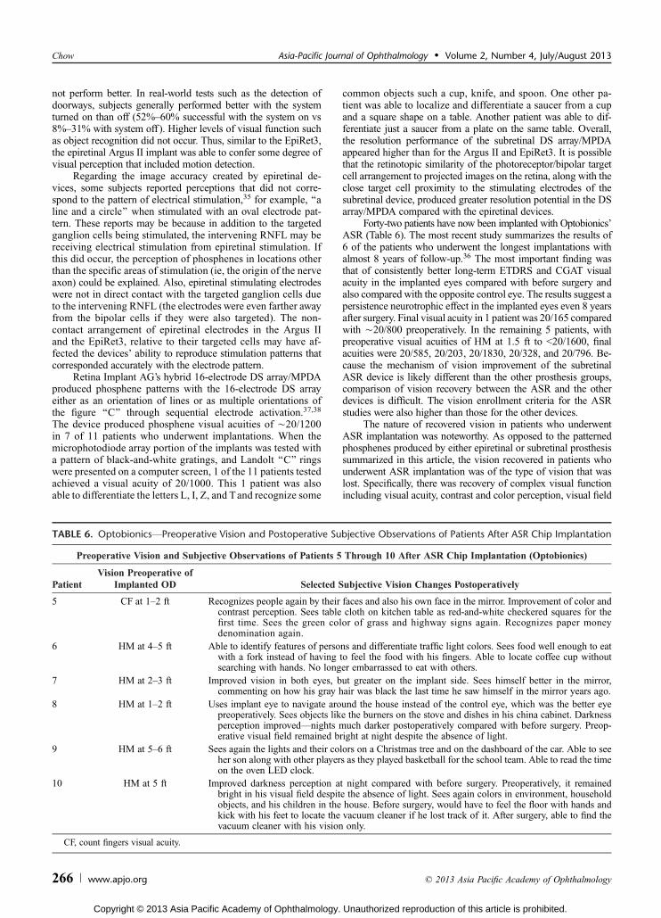
TABLE 6. OptobionicsVPreoperative Vision and Postoperative Subjective Observations of Patients After ASR Chip Implantation
Preoperative Vision and Subjective Observations of Patients 5 Through 10 After ASR Chip Implantation (Optobionics)
PatientVision Preoperative of
Implanted OD Selected Subjective Vision Changes Postoperatively
5 CF at 1Y2 ft Recognizes people again by their faces and also his own face in the mirror. Improvement of color andcontrast perception. Sees table cloth on kitchen table as red-and-white checkered squares for thefirst time. Sees the green color of grass and highway signs again. Recognizes paper moneydenomination again.
6 HM at 4Y5 ft Able to identify features of persons and differentiate traffic light colors. Sees food well enough to eatwith a fork instead of having to feel the food with his fingers. Able to locate coffee cup withoutsearching with hands. No longer embarrassed to eat with others.
7 HM at 2Y3 ft Improved vision in both eyes, but greater on the implant side. Sees himself better in the mirror,commenting on how his gray hair was black the last time he saw himself in the mirror years ago.
8 HM at 1Y2 ft Uses implant eye to navigate around the house instead of the control eye, which was the better eyepreoperatively. Sees objects like the burners on the stove and dishes in his china cabinet. Darknessperception improvedVnights much darker postoperatively compared with before surgery. Preop-erative visual field remained bright at night despite the absence of light.
9 HM at 5Y6 ft Sees again the lights and their colors on a Christmas tree and on the dashboard of the car. Able to seeher son along with other players as they played basketball for the school team. Able to read the timeon the oven LED clock.
10 HM at 5 ft Improved darkness perception at night compared with before surgery. Preoperatively, it remainedbright in his visual field despite the absence of light. Sees again colors in environment, householdobjects, and his children in the house. Before surgery, would have to feel the floor with hands andkick with his feet to locate the vacuum cleaner if he lost track of it. After surgery, able to find thevacuum cleaner with his vision only.
CF, count fingers visual acuity.
Chow Asia-Pacific Journal of Ophthalmology & Volume 2, Number 4, July/August 2013
266 www.apjo.org * 2013 Asia Pacific Academy of Ophthalmology
Copyright © 2013 Asia Pacific Academy of Ophthalmology. Unauthorized reproduction of this article is prohibited.
size (some patients), and most interestingly improved darknessperception. The recovery of darkness perception after surgery wasa surprise when patients began reporting seeing darker nights,compared with a chronically bright environment regardless ofwhether it was night or day. It became apparent that the recoveryof darkness perception was important for contrast perception,which is the ability to see both light and dark areas simultaneouslyin the same field.
In development of the ASR implant, although the basicconcepts and advantages of subretinal prostheses were first pro-posed and espoused by the author, the discovery of a possibleneurotrophic rescue effect on visual function in RP subjects whounderwent ASR implantation meant that, rather than a prosthesiseffect, an even more important potentially therapeutic effect wasdiscovered.12,36 In addition, as the genotypes of the first patientswho underwent ASR implantation were quite varied, the findingof a potential therapeutic benefit in almost all patients, despitetheir genotype differences, suggests that interruption of a com-mon degeneration pathway may be occurring. The discovery of apositive ASR-induced therapeutic effect on the electroretinogramand histology of a degenerated mammalian retina have now beenreported in the RCS rat model of retinal degeneration. This effectis associated with an up-regulation of fibroblast growth factor 2.36
Recovery of subjective visual function in patients whounderwent ASR implantation created interesting situations forsome patients. One patient remarked that before surgery he feltembarrassed eating meals with others as he had to feel with hisfingers to locate his food. Postoperatively, this was no longer thecase as he was able see well enough to eat with a fork again.Another patient told of how, preoperatively, it was difficult todiscipline his young children when they misbehaved as theywould hide from him in the house simply by being very quiet.Postoperatively, locating his children as well as objects around thehouse was possible. Finally, a patient was happy to be able torecognize the faces of his friends and children again but wasdistraught at how old he now looked in the mirror. Despite thesepersonal observations, one should be cautious. Although the re-covery of vision to a level that allows the performance of dailyactivities is notable, subjective recovery of visual function in non-masked studies can be influenced by a placebo effect. Nevertheless,the recovery of vision to a level where familiar everyday activitiescan again be performed by subjects who underwent implantationbears further investigation as a means to evaluate implant re-sponse whether it be from a prosthetic or neurotrophic basis.
The discovery of a potential neurotrophic rescue of visualfunction in RP patients who underwent ASR implantation doesraise questions. First, would it be beneficial to implant the ASRearlier in the disease to preserve as much visual function aspossible? Would implanting more than 1 device achieve agreater neurotrophic response? Would ASR implantation bebeneficial in conditions similar to RP such as dry AMD? Fi-nally, should ASR implantation be considered before the im-plantation of a retinal prosthesis, especially a subretinal maculadevice that could block choroidal nourishment and possiblydamage a retina that could be rescued?
As of early 2013, only Second Sight’s Argus II epiretinalimplant has received the American FDA HDE approval and theEuropean Union CE Mark approval. As such it is the only devicethat is available for implantation by physicians outside an ap-proved investigational study. Second Sight currently receivesprivate and governmental funding. Optobionics’ ASR success-fully completed the phase I and the phase II multicenter phaseFDA clinical trials and received approval to conduct the finalphase III Premarket Approval (PMA) study. However, becauseof the large size and duration of the required FDA PMA study,
sufficient funds (ÈUS $200 million) were unavailable, and thestudy ended when Optobionics ceased operations. A restartedOptobionics (by the author) is endeavoring to raise funds for a lessexpensive (compared with the PMA) FDAHDE approval processfor the ASR. Retina Implant AG continues operations, funded bythe German government and private investors, and is in clinicaltrials of sits subretinal DS array/MPDA implant. EpiRet GmbHreceives funding from investors and the German government. Thecurrent status of clinical studies for its EpiRet3 implant is notpublicly known.
REFERENCES
1. Flannery JG, Farber DB, Bird AC, et al. Degenerative changes in a retinaaffected with autosomal dominant retinitis pigmentosa. InvestOphthalmol Vis Sci. 1989;30:191Y211.
2. Santos A, Humayun MS, de Juan EJ, et al. Preservation of the innerretina in retinitis pigmentosa. A morphometric analysis. ArchOphthalmol. 1997;115:511Y515.
3. Curcio CA, Medeiros NE, Millican CL. Photoreceptor loss inage-related macular degeneration. Invest Ophthalmol Vis Sci.1996;37:1236Y1249.
4. The CATT Research Group. Ranibizumab and bevacizumab forneovascular age-related macular degeneration. N Engl J Med.2011;364:1897Y1908.
5. Browning DJ, Kaiser PK, Rosenfeld PJ, et al. Aflibercept for age-relatedmacular degeneration: a game-changer or quiet addition? Am J
Ophthalmol. 2012;154:222Y226.
6. Hauswirth WW, Aleman TS, Kaushal S, et al. Treatment of Lebercongenital amaurosis due to RPE65 mutations by ocular subretinalinjection of adeno-associated virus gene vector: short-term results ofa phase I trial. Hum Gene Ther. 2008;10:979Y990.
7. del Cerro M, Gash DM, Rao GN, et al. Retinal transplants into theanterior chamber of the rat eye. Neuroscience. 1987;21:707Y723.
8. Armant RB, Seiler MJ. Transplanted sheets of human retina and retinalpigmented epithelium develop normally in nude rats. Exp Eye Res.2002;75:115Y125.
9. Chow AY. Artificial retina device. US patent 5,016,633. 1991.
10. Chow AY, Chow VY. Subretinal electrical stimulation of the rabbitretina. Neurosci Lett. 1997;225:13Y16.
11. Peyman G, Chow AY, Liang C, et al. Subretinal semiconductormicrophotodiode array. Ophthalmic Surg Lasers. 1998;29:234Y241.
12. Chow AY, Chow VY, Packo KH, et al. The artificial silicon retinamicrochip for the treatment of vision loss from retinitis pigmentosa.Arch Ophthalmol. 2004;122:460Y469.
13. Humayun MS, Weiland JD, Fujii GY, et al. Visual perception in a blindsubject with a chronic microelectronic retinal prosthesis. Vision Res.2003;43:2573Y2581.
14. Yanai D, Weiland JD, Mahadevappa M, et al. Visual performance usinga retinal prosthesis in three subjects with retinitis pigmentosa. Am J
Ophthalmol. 2007;143:820Y827.
15. Roessler G, Laube T, Brockmann C, et al. Implantation and explantationof a wireless epiretinal retina implant device: observations during theEpiRet3 prospective clinical trial. Invest Ophthalmol Vis Sci.2009;50:3003Y3008.
16. Zrenner E, Stett A, Weiss S, et al. Can subretinal microphotodiodessuccessfully replace degenerated photoreceptors? Vision Res.1999;39:2555Y2567.
17. Chow AY, Peachey NS. The subretinal microphotodiode array retinalprosthesis [letter and comment]. Ophthalmic Res. 1998;30:195Y198.
18. Eckmiller R. Learning retina implants with epiretinal contacts.Ophthalmic Res. 1997;29:281Y289.
Asia-Pacific Journal of Ophthalmology & Volume 2, Number 4, July/August 2013 Retinal Prostheses for Retinitis Pigmentosa
* 2013 Asia Pacific Academy of Ophthalmology www.apjo.org 267
Copyright © 2013 Asia Pacific Academy of Ophthalmology. Unauthorized reproduction of this article is prohibited.

19. Rizzo JF, Wyatt J, Loewenstein J, et al. Perceptual efficacy of electricalstimulation of human retina with a microelectrode array duringshort-term surgical trials. Invest Ophthalmol Vis Sci. 2003;44:5362Y5369.
20. Tassicker GE. Retinal stimulator. US patent 2,760,483. 1956.
21. Brindley GS. The site of electrical excitation of the human eye.J Physiol. 1955;127:189Y200.
22. Brindley GS. Beats produced by simultaneous stimulation of the humaneye with intermittent light and intermittent or alternating electriccurrent. J Physiol. 1962;164:157Y167.
23. Brindley GS. A new interaction of light and electricity in stimulating thehuman retina. J Physiol. 1964;171:514Y520.
24. Potts AM, Inoue J, Buffum D. The electrically evoked response (EER)of the visual system. Invest Ophthalmol Vis Sci. 1968;7:269Y278.
25. Carpenter RH. Electrical stimulation of the human eye in differentadaptational states. J Physiol. 1972;221:137Y148.
26. Potts AM, Inoue J. The electrically evoked response (EER) of the visualsystem. II. Effect of adaptation and retinitis pigmentosa. InvestOphthalmol. 1969;8:605Y612.
27. Potts AM, Inoue J. The electrically evoked response of the visual system(EER). III. Further consideration to the origin of the EER. InvestOphthalmol. 1970;9:814Y819.
28. Humayun MS, de Juan E Jr, Dagnelie G, et al. Visual perception elicitedby electrical stimulation of retina in blind humans. Arch Ophthalmol.1996;114:40Y46.
29. Dawson WW, Radtke ND. The electrical stimulation of the retina byindwelling electrodes. Invest Ophthalmol Vis Sci. 1977;16:249Y252.
30. Knighton RW. An electrically evoked slow potential of the frog’s retina.I. Properties of the response. J Neurophysiol. 1975;38:185Y197.
31. Knighton RW. An electrically evoked slow potential of the frog’sretina. II. Identification with PII component of electroretinogram.J Neurophysiol. 1975;38:198Y209.
32. Caspi A, Dorn JD, McClure KH, et al. Feasibility study of a retinalprosthesis: spatial vision with a 16-electrode implant. Arch Ophthalmol.2009;127:398Y401.
33. Humayun MS, Dorn JD, da Cruz L, et al. Interim results from theinternational trial of Second Sight’s Visual Prosthesis. Ophthalmology.2012;119:779Y788.
34. Dorn JD, Ahuja AK, Caspi A, et al. The detection of motion by blindsubjects with the epiretinal 60-electrode (Argus II) retinal prosthesis.JAMA Ophthalmol. 2013;131:183Y189
35. Klauke S, Goertz M, Rein S, et al. Stimulation with a wirelessintraocular epiretinal implant elicits visual percepts in blind humans.Invest Ophthalmol Vis Sci. 2011;52:449Y455.
36. Chow AY, Bittner AK, Pardue MT. The artificial silicon retina in retinitispigmentosa patients (An American Ophthalmological AssociationThesis). Trans Am Ophthalmol Soc. 2010;108:120Y154.
37. Zrenner E, Bartz-Schmidt KU, Benav H, et al. Subretinal electronicchips allow blind patients to read letters and combine them to words.Proc R Soc. 2011;278:1489Y1497.
38. Wilke R, Gabel VP, Sachs H, et al. Spatial resolution and perception ofpatterns mediated by a subretinal 16-electrode array in patients blindedby hereditary retinal dystrophies. Invest Ophthalmol Vis Sci.2011;52:5995Y6003.
‘‘I know not all that may be coming, but be it what it will, I’ll go to it laughing.’’V Herman Melville, Moby Dick
Chow Asia-Pacific Journal of Ophthalmology & Volume 2, Number 4, July/August 2013
268 www.apjo.org * 2013 Asia Pacific Academy of Ophthalmology
Copyright © 2013 Asia Pacific Academy of Ophthalmology. Unauthorized reproduction of this article is prohibited.