Embed Size (px)
Citation preview

Final Scientific EFNUDAT Workshop
CERN,Geneva (Switzerland) from 30th August to 2nd of September 2010
EFNUDATEuropean Facilities For Data Measurements


Proceedings of the Final Scientific EFNUDAT
Workshop
30 August – 2 September 2010
CERN, Geneva, Switzerland
Edited by Enrico CHIAVERI

Proceedings of the Final Scientific EFNUDAT Workshop
Legal Notice
Neither the Organization nor any person acting on behalf of the Organization is responsible for the use which might be made of this publication.
CERN has provided a platform for the publication of these documents. CERN is not responsible for their contents and makes neither representations nor warranties of any kind in respect thereof.
Editor
Enrico CHIAVERI Engineering Department European Laboratory for Particle Physics (CERN) E-mail: [email protected] Tel: + 41.22. 767.61.89 Published by
European Laboratory for Particle Physics (CERN) ISBN 978-92-9083-365-9

FOREWORD
The Final Scientific EFNUDAT Workshop was held at CERN from 30th August to 2nd September 2010.
The EFNUDAT project (European Facilities for Nuclear Data Measurement) is an Integrated Infrastructure Initiative (I3) funded under the 6th framework programme (FP6) of the European Commission.
The EFNUDAT Consortium groups 11 institutions (from Belgium, Czech Republic, France, Germany, Hungary, Sweden, and Switzerland) equipped with nuclear data measurement infrastructures. The workshop was organized under the auspices of the EFNUDAT project with its speakers having the project’s full financial and scientific support.
The aim of the workshop was to bring together all the EFNUDAT members and representatives in order to summarize the activities undertaken during the course of this programme funded by the European Commission and to review the status of current and future projects endorsed by or developed during programmes with EFNUDAT contributions.
The 35 oral presentations given during the workshop covered the participating European institutions latest up-to-date achievements in the field of nuclear data measurements. The methods and results presented strongly support the design studies for Generation IV and innovative future reactor systems, including objectives such as the reduction of nuclear waste and the increase of operational safety.
As a concluding remark, as Chairman and on behalf of the Organizing Committee, I would firstly like to thank the European Commission for its support in organizing this workshop.
Special thanks also to the International Advisory Committee for their invaluable scientific advice, which enabled us to set up a very effective and comprehensive programme.
I would like to express my gratitude to all the speakers for their outstanding contribution to the workshop’s success, for their active participation, and the quality of their talks.
A final acknowledgment goes to the Workshop Organizing Committee, in particular to our workshop secretary, Géraldine Jean, who greatly contributed to the success of this final event, with her very efficient scheduling and meticulous organization.
Enrico CHIAVERI


Contents
PGAA analysis of isotopically enriched samples
T. Belgya 1
EFNUDAT synergies in astrophysics
F. Käppeler 9
Electromagnetic strength in heavy nuclei – experiments and a global fit
E. Grosse 17
Characterization of the new neutron beam at n_TOF-Ph2 C. Guerrero 27
237Np(n,f) Cross Section: new data impact
C. Paradela Dobarro
33
On the systematic errors of the Th232(n,f) cross section measured with PPACs at CERN - nTOF
D. Tarrio 39
A new compilation of experimental nuclear data for total reaction cross sections
M. Lantz 47
The Full Bayesian Evaluation Technique properties and developments
D. Neudecker
55
Improved Full Bayesian Evaluation of Neutron-induced Reactions on 55Mn
H. Leeb 61
Key issues of pre-equilibrium emission for consistent description of the nucleon-induced reactions
V. Avrigeanu 69
Overview of the JRA1 activities at JRC-IRMM
F.J. Hambsch 77
Definition of a standard neutron field with the reaction 7Li(p,n)7Be
C. Lederer 85
Measurement of prompt fission γ-rays with lanthanum halide scintillation detectors
A.Oberstedt 91
VERDI – a double fission-fragment time-of flight spectrometer
S. Oberstedt 97

Characterisation of Fission Ionisation Chambers using Monoenergetic Neutrons
M. Mosconi 105
Level Densities, Decay Probabilities and Cross sections in the Actinide Region
J. Wilson 113
Neutron detection for DESPEC at FAIR
T. Martinez Perez
119
n_TOF facility
V. Vlachoudis 127
Inelastic neutron scattering at nELBE
R. Beyer 137
Measurements at the 175 MeV neutron beam at TSL
C. Gustavsson 143
Fast neutron facilities at the National Physical Laboratory, UK
N. Hawkes 149
Neutrons For Science - a neutron facility @ SPIRAL-2
X. Ledoux 155
Neutron resonance spectroscopy at GELINA
P. Schillebeeckx
163
EU nuclear data projects for more sustainable nuclear energy and waste transmutation
E. Gonzalez Romero
171
Transnational Access Activities and Euratom Framework program feedback experience towards implementation of the European Research Area
R. Garbil 181

1
PGAA analysis of isotopically enriched samples
Tamás Belgya and Zoltán Kis
Institute of Isotopes, HAS, P.O. Box 77, Budapest, H-1525 Hungary [email protected]
Abstract: Prompt Gamma Activation Analysis (PGAA) of samples is routinely used at our guided cold neutron beam facilities. Adaptation of this method for analyzing isotopically enriched samples required some modification of the data analyzing program as well as changing the prompt gamma ray library for each different sample. The advantage of the method is that it is completely nondestructive and it can be used for encapsulated samples as well. Furthermore it provides bulk composition for almost the same conditions as will be used in nuclear data experiments and it is sensitive for the same components that will give the biggest signals in measurements at other beams. This new method has been applied for enriched Ni, Fe, Zr and Hf samples.
Introduction Prompt Gamma Activation Analysis (PGAA) is a relatively new analytical method which can be best performed at high flux research reactors. The first reactor based experiments were performed in the mid sixties using NaI(Tl) detectors. An important breakthrough in the detection method happened with the appearance of Ge diode detectors in the late sixties in combination with Compton suppression. Neutron guides further improved the method since the end of the sixties by decreasing the background arising from the reactor. In the data analysis, high performance peak fitting programs, powerful computers and a spectrum library became available only in the eighties. The lack of these had discouraged the widespread use of the method. The first gamma-peak catalogue was compiled by Lone et al. [1], and served as the only published catalogue till 2004. A more complete and consistent spectrum library and gamma-peak catalogue has appeared only in 2004, based on the systematic measurements by our group at the Budapest Research Reactor [2]. PGAA is a neutron based nondestructive analytical method for the measurement of the elemental composition of samples. In the method the slow neutron radiative capture transmutes the sample nuclides, which then emit prompt gamma radiations. The energy distribution of the radiation is characteristic for each element and the intensities of the peaks are proportional to the quantities of the elements in the sample. The high penetration of the neutrons and the low attenuation of the emitted gamma rays in the target allow volume-averaged information about the sample’s composition. All elements but He provide analytical signals from the interaction with the neutron beam with different probabilities. The probability is proportional to the neutron capture cross section, which can vary over several orders of magnitude for different elements and even for neighboring isotopes. Our gamma-peak catalogue summarizes the partial gamma-ray cross sections which can be used in standard-less elemental concentration analysis of samples having normal isotope abundances for their constituent elements. In theory, the method is capable to provide a panorama analysis and the statistical uncertainty of the analytical signal can be decreased by increasing the irradiation time. The PGAA is useful for major elemental analysis and is one of the best for light elements, being especially sensitive for hydrogen. In those cases where the capture cross section is high (B, Cd, Sm, Dy), it can even provide trace element concentrations. It is insensitive to the chemical composition of the sample, which complements methods that are sensitive to the chemical forms.

2
Experimental facility Our experimental facility has been already described many times [3, 4], so we will give here only a brief summary. The neutron beam is transported by a super-mirror neutron guide from the liquid hydrogen cooled neutron source of the Budapest Research Reactor to the experimental area and it is split at the end of our guide to serve the two measuring stations. The facility is dual-purpose: neutron induced prompt gamma ray spectroscopy or NIPS, and its application, namely prompt gamma activation analysis or PGAA. The NIPS facility has been designed for a large variety of experiments; for example, studying neutron capture-reaction induced prompt and delayed gamma radiation, γ-γ-coincidences, and in-beam imaging of samples or for following catalytic processes. The thermal equivalent neutron fluxes are 1.5×10⁸ n⋅cm-2⋅s-1 and 5×10⁷ n⋅cm-2⋅s-1 at the PGAA and NIPS sample positions, respectively. Our new 27% efficiency PGAA main-detector or HPGe has an active BGO shield, which is used in Compton-suppression mode and a new 16-stage sample changer is available for elemental analysis of samples. Three other HPGe detectors and a second, new BGO are available for experiments with the NIPS station. We prefer to use the PGAA station for high quality prompt gamma experiments on small samples. For irregularly shaped samples such as archaeological artifacts, however, the NIPS station is favored. At this station a neutron tomography setup will also be available in the near future to continue our studies in the field of imaging, which was begun in our ANCIENT CHARM project [5].
Equations for PGAA analysis and the analysis software Equations As indicated in the introduction, the determination of the sample elemental composition can be obtained from the measured gamma-ray peak areas Aγ. The peak areas are determined using the Hypermet PC software developed at our department [6-8], and which is equipped with a user friendly graphical interface. In the most general case the calculation of the peak areas from the capture reaction on the target requires the calculation of neutron-beam and gamma-ray transport in the sample [9]. However for thin, homogeneous samples the peak area is given accurately enough by a simple arithmetic equation tSmA XXX ⋅⋅= γγ , (1) where index X denotes the element of interest, mX is its mass, SXγ. is its sensitivity at a gamma energy of EXγ., and t is the measurement and irradiation time. The sensitivity of an element X for its gamma-ray with energy EXγ. is
DtEfEPMNS XXXXX
X
AX
X
⋅⋅ε⋅φ⋅⋅σ⋅θ⋅= γγ
σ
γγ
γ
)()(0 , (2)
where NA is the Avogadro number, MX is the molar weight, θX is the isotope abundance in the sample, σX0 is the thermal capture cross section of the isotope that emits the gamma ray with a energy of EXγ after capture, PXγ is the decay probability of the gamma ray, φ is the thermal equivalent flux, ε (EXγ) is the detector efficiency, f(EXγ) is a correction for neutron- and gamma-absorption in the sample, and Dt is the dead-time correction for the measurement. The partial gamma-ray production cross section σXγ can be measured with much higher precision than its constituent parts separately and this is the quantity which is given in the tables of our library [2]. The ratio of masses (or concentrations) can be calculated with much higher precision because the flux, the time and the dead-time correction cancel out [10]. The corresponding equation is
γ
γ
γ
γ ⋅==X
Y
Y
X
Y
X
Y
X
SS
AA
mm
ww
(%)(%) , (3)
where w(%) is the weight percentage. Of course the sum of the weight percentages for all of the elements must equal to 100 percent. This raises the question whether all of the major elements are observed. In the case of PGAA, the observation of all of the elements is not certain. For example, observation of oxygen is difficult in most of the samples due its very small capture cross

3
section. In this case, calculation with maximum oxidation number is used to estimate the oxygen content. Nevertheless, the ratios defined in Eq. (3), relative to the most abundant element can always be used in the analysis.
Analysis program The PGAA analysis program is written in Visual Basic of MS EXCEL. The results are given on separate EXCEL sheets for all elements, from which the program selects the elements with the highest quality factor and lists them on another sheet in the form of a final table. This automatic selection can than be modified by the analyst to obtain the final concentrations for major elements in percentage and for the minor in ppm [10]. The simplified structure and flow path of the program is show in Figure 1.
Modification of our elemental analysis program for enriched sample analysis To analyze enriched samples it is not necessary to change the program code. In a simple enriched sample, in which only one element is enriched in one of its isotopes, the input of the PGA library-25 must be modified in the first approximation. This library contains the first 25 strongest peaks for each naturally occurring element normally. By defining a new element for the enriched sample – instead of the naturally occurring element – by its own concentration distribution, the program will identify this as the new element. To do that, we need the isotopic composition of the enriched sample. The simplest way to determine the isotopic composition of an enriched sample is to compare its capture gamma-ray spectrum with the elemental capture gamma ray spectrum. The first step in this comparison is the identification of gamma rays characteristic of isotope i in the enriched sample (X) and in the natural elemental sample (N). Denoting the gamma-peak area of isotope i in the enriched sample with AX iγ and similarly for the natural sample ANiγ, the ratio of these two areas can be written using Eq. (1) and (2) as
N
X
N
X
XiN
XiX
Xi
Xi
N
X
Xith
Xith
Xi
Xi
Ni
Xi
N
X
Ni
Xi
tt
DtDt
EfEf
EE
PP
nn
AA
⋅⋅⋅ε
ε⋅
φφ
⋅σσ
⋅⋅θθ
⋅=γ
γ
γ
γ
γ
γ
γ
γ
)()(
)()(
, (4)
where nX and nN are the number of atoms of the element for the enriched and the natural samples respectively. The rest of notations are the same as in Eq. (1) and (2) except σXith is the isotopic capture cross section. After simplification we obtain the unknown compositions θXi for all isotopes i if all of them are present in measurable quantities in the natural sample
INPUT MODULE Peak list from Hypermet PC (up to 1200 lines) PGA library-25 (~1800 lines) PGA library- more than 1% intensity (~6200 lines) Element data (Mol weights, Ox. number, γ & neutron
self-absorption) BKG in equivalent mass vs. its validity date range Efficiency vs. its validity date range Auxiliary data (Beam temperature, flux, density, thickness)
DATA EVAULATION MODULE
OUTPUT MODULE
Iterative edition of the data by the analyst

4
NiNi
Xi
XXi
Ni
Xi
C
N
X
N
X
XiN
XiX
N
X
N
X
Ni
Xi
AA
Ctt
DtDt
EfEf
nn
AA
X
θθθθ
φφ
γ
γ
γ
γ
γ
γ ⋅=⇒⋅⋅⋅⋅⋅=1
)()(
. (5)
The normalization value CX can be determined from normalization of the sum of θXi to 1. In a case where one or more isotopes can not be measured in the natural spectrum, the partial cross section data can be used from the literature. Once we know the θXi value, the partial gamma-ray cross section can be determined for an isotopically identified gamma ray using the corresponding natural partial gamma-ray cross section
XiNi
NiXi θ
θσ
σ γγ ⋅= . (6)
Using a set of these values, usually the values for the most intense gamma rays, a set of new library records can be built for the enriched elemental material. By changing the natural elementary records for the enriched ones, the analysis program can be used in same way as for the elements. Of course we have to assume that the enrichment process did not change the composition of the other elements associated with enriched material. As it was already indicated, this is the first approximation for the modification of the program input. Other modifications must be made in the second order. This includes the change of the molecular weight for this new “element”, the change of the neutron scattering and total cross section used in the neutron absorption correction.
Measurement of the enrichment for 176,177,178,179Hf samples Hf samples originating from Bulgaria to be used for energy differential neuron capture experiments at the JRC IRMM were measured in the EFNUDAT project at the PGAA experimental station operated by II-HAS at the Budapest Research Reactor. The HfO2 enriched samples are packed in Al disks with a diameter of 3 cm and with thicknesses between 1-3 mm. Since the cross sections of Hf-isotpes are high, the neutron beam was collimated to about 1 mm2 area, which yielded sufficient count rate for the experiments. The gamma ray spectra were measured with a 27% efficient and 2.2 keV resolution HPGe detector, surrounded with BGO Compton-shield. The efficiency and the nonlinearity of the spectrometer was measured and evaluated according to the prescriptions [11, 12]. Auxiliary measurements of Al2O3 powder, Nat-HfO2 powder, empty Al container and Nat-HfOCl2xH2O powder samples were also performed to determine the background components and to re-measure the natural Hf partial gamma-ray cross sections using chlorine as comparator. The natural HfO2 measurement was used to determine the enrichment of the samples. In Figure 1 we show the graphs of the measured spectra. The isotopic identification was made by careful comparison of the spectra. If a gamma ray has higher intensity for a given enriched sample than in all of the others then we can assign this gamma ray to that isotope. This is demonstrated for two of the 176Hf(n, γ)177Hf gamma rays in Figure 1. Of course the literature data help to perform this identification. Data for 176Hf is very sparse in the literature, there are only 5 gamma rays identified for this nucleus [13]. This little knowledge of Hf isotopes may induce research (identification of gamma rays), when enrichment determination is required.

5
Figure 1. Labelled peaks at 396 keV and 508 keV are clearly enhanced in the spectrum of 176Hf enriched sample. This means that they should belong to 176Hf.
Table 1 summarizes the gamma rays selected for determination of enrichment and give information from the Evaluated Gamma-ray Activation File (EGAF) [13].
Table 1. Selected Hf gamma-rays for enrichment determination,showing also elemental composition, thermal neutron capture cross section, Wescott factor and number of identified gamma rays.
Isotope Eγ (keV) θ(%) [14] σ0Z (b) gw Nγ Hf-174 - 0.16(1) 549(7) 0.98 23
Hf-176 395 5.26(7) 24(3) 1 5
Hf-177 1419 18.60(9) 373(10) 1.02 308
Hf-178 1003 27.28(7) 137(7) 1 347
Hf-179 1065 13.629(6) 41(3) 0.99 339
Hf-180 5694 35.08(16) 13.04(7) 0.99 105
In Table 2 the measured peak areas are summarized for the selected gamma rays. It was assumed that the Hf-174 is in a very low concentration in all the samples, and thus it was not considered in the analysis.

6
Table 2. Peak areas for the measured samples. The red numbers, e.g. <400 are the detection limit.
Samples→ ↓Isotopes
Eγ 176Hf 177Hf 178Hf 179Hf Natural
176 395 23523 3871 <400 <300 3265
177 1419 38789 58606 6006 1940 26720
178 1003 6610 4633 94842 5180 19159
179 1065 5072 <400 20457 260424 32362
180 5694 591 <60 315 4434 4780
Applying the calculation described in Eq. (5) we summarize the abundances and uncertainties in Table 3. The uncertainties are purely statistical.
Table 3. Enrichment in percentage and their uncertainties in percent. Red values are upper limits.
Samples→ ↓Isotopes
Eγ 176Hf 177Hf 178Hf 179Hf Natural
176 395 46.9±1.9 11.5±1.1 0.4±0.2 0.3±0.2 5.3
177 1419 33.4±0.3 75.2±0.2 2.8±0.1 0.9±0.1 18.6
178 1003 11.7±0.3 12.2±0.8 89.6±0.1 4.9±0.2 27.3
179 1065 2.6±0.1 0.3±0.2 5.7±0.2 72.4±0.2 13.6
180 5694 5.4±0.3 0.8±0.2 1.5±0.2 21.5±0.4 35.1
This is a preliminary result since these abundances must be checked for other identified gamma-rays to exclude possibilities of mistakes from unresolved gamma-ray doublets. Further calculations for impurities are better to do on checked values, which require more work.
Summary Gamma ray spectrometry with a high resolution germanium detector provides a powerful method for the determination of elemental or isotopic compositions of samples excited in radiative neutron capture. The input to our elemental analysis program can be modified in such a way that it will be able to analyze impurities of enriched samples. Isotopic compositions of enriched samples can be determined in a comparison to a high purity natural composition sample using relative peak areas. This method is demonstrated on a series of enriched Hf samples. An advantage of the radiative capture to other methods is that it can be performed on encapsulated samples in a nondestructive manner, which is important for valuable samples. Furthermore, it avoids a possible contamination of the sample compared to other destructive methods. It can also be safely applied to radioactive targets if a comparator sample of well-known composition is available.

7
Acknowledgement Support by the EFNUDAT (No.FP6-036434)and by the NAP VENEUS05 (No.OMFB/00184/2006) projects are acknowledged.
References [1] Lone, M.A., R.A. Leavitt, and D.A. Harrison, Prompt Gamma Rays from Thermal-Neutron
Capture. Atom. Data Nucl. Data Tables 26 (1981) 511-559. [2] Révay, Z., R.B. Firestone, T. Belgya, and G.L. Molnár, Prompt Gamma-Ray Spectrum
Catalogue, in Handbook of Prompt Gamma Activation Analysis with Neutron Beams, G.L. Molnár, Editor. 2004, Kluwer Academic Publishers, Dordrecht, Boston, London. p. 173-366.
[3] Révay, Z., T. Belgya, Z. Kasztovszky, J.L. Weil, and G.L. Molnár, Cold neutron PGAA facility at Budapest. Nucl. Instrum. Methods Phys. Res. Sect. B-Beam Interact. Mater. Atoms 213 (2004) 385-388.
[4] Szentmiklósi, L.e.a., Upgrade of the prompt gamma activation analysis and the neutron-induced prompt gamma spectroscopy facilities at the Budapest research reactor J. Nucl. Radioanal. Chem. (2010) 1-5.
[5] Kis, Z., T. Belgya, L. Szentmiklósi, Z. Kasztovszky, P. Kudejová, and R. Schulze, Prompt Gamma Activation Imaging on ’black boxes’ in the ’ANCIENT CHARM’ project. Archaeometriai Műhely (1) (2008) 41-60.
[6] Révay, Z., T. Belgya, P.P. Ember, and G.L. Molnár, Recent developments in HYPERMET PC. J. Radioanal. Nucl. Chem. 248 (2) (2001) 401-405.
[7] Fazekas, B., J. Östör, Z. Kiss, A. Simonits, and G.L. Molnár, Quality assurance features of "HYPERMET-PC". J. Radioanal. Nucl. Chem. 233 (1-2) (1998) 101-103.
[8] Fazekas, B., G. Molnár, T. Belgya, L. Dabolczi, and A. Simonits, Introducing HYPERMET-PC for automatic analysis of complex gamma-ray spectra. J. Radioanal. Nucl. Chem. 215 (2) (1997) 271-277.
[9] Belgya, T. Target preparation for in-beam thermal neutron capture experiments. in EFNUDAT Fast Neutrons, Scientific Workshop on Neutron Measurements, Theory and Applications Nuclear Data for Sustainable Nuclear Energy. Geel, Belgium, 28 – 30 April, 2009 (2010), 21-26.
[10] Révay, Z., Determining Elemental Composition Using Prompt,gamma Activation Analysis. Analytical Chemistry 81 (2009) 6851-6859.
[11] Fazekas, B., Z. Révay, J. Östör, T. Belgya, G. Molnár, and A. Simonits, A new method for determination of gamma-ray spectrometer non- linearity. Nucl. Instrum. Methods Phys. Res. Sect. A-Accel. Spectrom. Dect. Assoc. Equip. 422 (1-3) (1999) 469-473.
[12] Molnar, G.L., Z. Revay, and T. Belgya, Wide energy range efficiency calibration method for Ge detectors. Nucl. Instrum. Methods Phys. Res. Sect. A-Accel. Spectrom. Dect. Assoc. Equip. 489 (1-3) (2002) 140-159.
[13] Firestone, R.B., G.L. Molnár, Z. Révay, T. Belgya, D.P. McNabb, and B.W. Sleaford, The Evaluated Gamma-ray Activation File (EGAF), LBNL 5634`, (2004) http://www-nds.iaea.org/pgaa/egaf.html
[14] Rosman, K.J.R. and P.D.P. Taylor, Isotopic compositions of the elements 1997. J. Phys. Chem. Ref. Data 27 (6) (1998) 1275-1287.

8

9
EFNUDAT synergies in astrophysics
F. Käppeler1), T. Belgya2), I. Dillmann3,4), C. Domingo Pardo4), U. Giesen5), M. Heil4), C. Lederer6), D. Petrich1), E. Uberseder1,7)and n_TOF Collaboration
1) Karlsruhe Institute of Technology (KIT), Campus Nord, Institut für Kernphysik, P.O.
Box 3640, Karlsruhe, Germany, 76021 2) Institute of Isotopes, Hungarian Academy of Sciences (II-HAS), POB 77, Budapest, Hungary, 1525 3) II. Physikalisches Institut, Justus-Liebig-Universität Gießen, Heinrich-Buff-Ring 16,
Giessen, Germany, 35392 4) GSI Helmholtzzentrum für Schwerionenforschung GmbH, Planckstraße 1, Darmstadt,
Germany, 64291 5) Physikalisch-Technische Bundesanstalt (PTB), Bundesallee 100, Braunschweig,
Germany, 38116 6) VERA Laboratory - Isotope Research, Faculty of Physics, University of Vienna,
Währinger Strasse 17, 1090 Vienna, Austria 7) University of Notre Dame, Notre Dame, IN 46556, USA
[email protected] Abstract: About half of the abundances between Fe and Zr in Nature are produced by the slow neutron capture process (s process) in massive stars. These abundances are essentially determined by the (n, γ) cross sections of the involved isotopes. In this context, recent (n, γ) measurements benefit from the combination of activation and time-of-flight techniques, which were efficiently advanced by the EFNUDAT programme. Experimental progress and innovative instrumental developments are illustrated at selected examples of measurements performed at CERN, Budapest, Braunschweig, Dresden, Vienna, and Karlsruhe.
EFNUDAT and astrophysics The fact that the isotopes between Fe and the actinides are the result of neutron reactions either during stellar evolution or stellar explosions provides the direct link between the EFNUDAT programme and the astrophysical origin of the heavier elements in Nature. Although directed mostly toward the determination of neutron cross sections needed for technological applications, there is quite some overlap between the main interests of EFNUDAT and important quests in neutron capture nucleosynthesis. In fact, experimental (n, γ) cross sections in the keV neutron energy range constitute the main nuclear physics input for the description of the slow neutron capture process (s process). The s process, which is responsible for about half of the isotopic abundances beyond Fe, occurs during the He and C burning stages of stellar evolution, where neutrons are produced by (α, n) reactions on 13C and 22Ne. In the dense stellar plasma neutrons are quickly thermalized to the site-specific temperatures, corresponding to thermal energies between 8 and 26 keV during He burning and roughly 90 keV in the C burning phase. For the complete description of the s-process reaction path between C and Bi, Maxwellian averaged cross sections (MACS) have to be determined by folding (preferentially) experimental cross section data with the stellar energy spectrum defined by the temperature of the respective s-process site. Due to the fact that neutron capture rates are of the order of years, much “slower” than average β-decay rates, the majority of isotopes involved in the reaction path are situated in the valley of stability. Accordingly, a large body of MACS data has been collected over the past decades [1,2]. However, most of these data are still too uncertain to allow for sufficiently detailed and complete s-process studies [3]. Therefore, continued efforts have to be made for the

10
determination of (n, γ) cross sections with improved accuracy over a sufficiently wide neutron energy range. There are numerous cases where such astrophysically motivated requests coincide with demands in the technological field, i.e. for structural materials in nuclear power reactors or for radioactive fission products, which are needed for nuclear incineration studies. The (n, γ) experiments on 62Ni and 64Ni, which have been carried out within the EFNUDAT programme, represent typical examples of such measurements, where the results are equally important for reactor design as well as for describing neutron capture nucleosynthesis in massive stars. While the time-of-flight (TOF) technique is a well established method for obtaining energy-dependent cross sections, the activation technique used for the 64Ni experiment was developed for astrophysical data needs but has been found to be of considerable interest for technological applications as well. This interest is motivated mainly by the superior sensitivity of the activation technique, which allows one to perform measurements on sub-µg samples [4], a decisive advantage in dealing with rare or radioactive isotopes. The third example refers to the small thermal (n, γ) cross section of 22Ne. Apart from its key role for stellar neutron production, this isotope acts also as an important neutron poison. The absence of neutron resonances in the relevant energy range makes it impossible to obtain accurate MACSs via the TOF method. Because the cross section is determined by the 1/v dependence characteristic of s-wave direct capture, the thermal cross section becomes an important normalization point.
62Ni – a bottle neck for the s process in massive stars The experimental data for the MACS of 62Ni exhibit still big discrepancies: measure-ments performed by the time-of-flight method [5-7] or a combination of activation and accelerator mass spectrometry [8, 9] provided values between 20.2 and 26.8 mb for the MACS at 30 keV. While these results have been used for the recommended value of 22.3±1.6 mb given in the KADoNiS v0.3 compilation [1], the spread of all available data is much wider and ranges between 10.6±0.8 [13] and 37.0±3.2 mb [10]. These discrepancies prompted a new measurement at CERN, which was performed at a flight path of 185 m using the intense, white neutron spectrum of the n_TOF facility [11]. The capture yield was determined via the detection of the prompt capture γ rays with a pair of C6D6 liquid scintillation detectors, which have been optimized for low neutron sensitivity [12]. The sample was a metal disk 2 g in mass and 2 cm in diameter with an enrichment of 97.95% in 62Ni. The neutron flux was determined with a well calibrated 235U parallel plate fission chamber, and was monitored throughout the experimental runs via the 6Li(n, α)3H reaction using a thin 6Li layer surrounded by four Si detectors outside the neutron beam. The capture yield was obtained from the background subtracted TOF spectra by applying the pulse height weighting technique that ensured the required proportionality between γ-ray efficiency and γ-ray energy [13]. The corresponding weighting functions were calculated by means of detailed Monte-Carlos simulations of the full experimental setup. The excellent quality of the present data is illustrated in Fig. 1, which shows the measured capture yield of 62Ni(n, γ). Thanks to the high resolution in neutron energy and the good counting statistics, the data are well suited for a detailed resonance analysis and a correspondingly precise determination of the Maxwellian-averaged cross section. This analysis is presently in progress.

11
Figure 1. Left: Weighted, non-normalized capture yield obtained for 62Ni (n, γ) at the n_TOF facility from 1 eV to 1 MeV. Right: Zoom into the energy region from 10 to 200 keV.
MACS of 64Ni(n, γ) for the s process in massive stars As an important complement, activation has been shown to represent an attractive tool for neutron cross section measurements in astrophysics, because stellar neutron spectra can be closely approximated in laboratory experiments. In general, the spectrum for a thermal energy of kT=25 keV, which is characteristic for He burning scenarios, has been used [13] due to the high neutron intensities that can be reached with the 7Li(p, n)7Be reaction. Additional spectra, which were obtained with the (p, n) reactions on 18O [14] and 3H [15], correspond to thermal energies of kT=5 and 52 keV, although with much reduced intensity. While the spectrum produced with the 7Li(p, n) reaction matches the temperature during the He shell flashes in low-mass AGB stars as well as during He core burning in massive stars, the latter spectra are slightly below the characteristic s-process temperatures between He shell flashes in low mass stars (which are about 9 107 K or kT=8 keV) and during C shell burning in massive stars (which are around 109K or kT=90 keV). Nevertheless, measurements at these complementary thermal energies provide important information for a reliable assessment of the MACSs, particularly for light and medium-mass isotopes with resonant cross sections in the keV region. The example described here refers to a measurement of the (n,γ) cross section of 64Ni, which was carried out within the EFNUDAT programme at PTB Braunschweig. The experiment was based on the 3H(p, n) reaction using the proton beam of the Van de Graaff accelerator at PTB. The beam energy was adjusted to 1099 keV and neutrons were produced by bombardment of a tritium-loaded Ti layer, resulting in a quasi-stellar spectrum for kT=52. The samples consisted of two metal disks 6 and 10 mm in diameter with 91.9% enrichment, which were sandwiched between thin gold foils for neutron flux determination. After each irradiation, the induced γ activities were counted with a well calibrated HPGe detector. Due to the good energy resolution of the detector, the respective activities could be unambiguously derived from the transitions in the decay of 65Cu and 198Au at 1482 and 412 keV, respectively. The results of the four activations at kT=52 keV are plotted in the left panel of Fig. 2 where the statistical and total uncertainties of the mean value are indicated by dashed lines. This value is compared in the right panel of Fig. 2 with the result of a recent activation measurement at kT=25 keV [16] and with MACS values calculated from evaluated cross sections listed in nuclear data libraries [17]. Because only the energy-dependence of the evaluated cross sections were of interest here, these cross sections were normalized to the PTB result prior to the MACS calculations. This comparison shows that experimental results clearly confirm the dependence of the MACS on thermal energy that is obtained with the (identical) data given in the ENDF and JEFF libraries, whereas the slope of the JENDL and BROND cross sections is much too steep. The comparison emphasizes the importance of the PTB experiment at kT=52 keV for choosing the proper energy dependence for extra-polation to the thermal energy of kT=90 keV pertaining

12
during C shell burning in massive stars, which, in turn, is crucial for quantifying the effect of 64Ni on the s-process abundance distribution resulting from massive stars.
Figure 2. Left:The 64Ni(n, γ) cross section obtained at kT=52 keV in the activations at PTB Braunschweig. Statistical and total uncertainties of the mean value are indicated by the inner and outer dashed lines. Right: Comparison of the present result at 52 keV and a recent measurement at 25 keV [16] with the MACSs derived from evaluated cross sections listed in data libraries [17], indicating a clear preference for the identical data sets from ENDF and JEFF.
22Ne(n, γ) – a neutron sink in the s process In stellar evolution, all of the CNO material in the He burning zones is converted to 22Ne by the reaction sequence 14N(α, γ)18F(β+)18O(α, γ)22Ne. The 22Ne abundance not only favours neutron production via the 22Ne(α, n)25Mg reaction, but represents also a potential neutron poison via the (n, γ) channel. While a first measurement of the (n,γ) cross section seemed to support this possibility [18], the cross section was later found to be significantly smaller [19,20,21]. Another aspect refers to the highly non-solar isotopic Ne abundances discovered in µm-size meteoritic inclusions, which are interpreted as presolar dust grains, which originate predominantly from asymptotic giant branch (AGB) stars [22,23] or from explosive nucleosynthesis, i.e. supernovae or novae [24]. Because neutron capture nucleosynthesis is going on at all these sites, reliable (n,γ) cross sections are crucial for calculating the respective Ne abundance patterns. In particular, the 22Ne cross section plays an important role for the interpretation of strong 22Ne enrichments found in these samples. The analysis of Heil et al. [25], who combined the available capture data [19,20,21] with a measurement of the total cross section [18], revealed a severe mismatch between the capture cross section of 22Ne in the keV region and at thermal energies. In view of the fairly large uncertainty of the thermal cross section, an EFNUDAT experiment was performed at the guided cold neutron beam of the Budapest Research Reactor. Mixtures of neon enriched to 98.87% in 22Ne and CH4 gas were filled under high pressure into stainless steel spheres 20 mm in diameter and with 0.5 mm thick walls [27]. The filling procedure and the characterization of the samples made use of the relatively high freezing point of methane. At first, the evacuated sphere was filled with methane and the amount of CH4 was determined by the increase in weight. In a second step, the CH4 gas was frozen onto the container-wall with liquid nitrogen and the enriched 22Ne gas was added from a separate container. The number of 22Ne atoms was then calculated from the final weight. In this way, two samples were prepared for the cross section measurement, which differed in pressure and in their mixing ratios. An additional larger aluminum sphere 80 mm in diameter with pure 22Ne at 4 atm pressure was prepared for measuring the 22Ne capture γ rays by means of the invisible container concept [28]. The improved decay scheme obtained in this experiment was then used to determine the thermal capture cross section of 22Ne by means of the methodologies developed by Belgya [29,30], where

13
partial γ-ray production cross sections for 23Ne are derived from the measured γ-ray intensities by means of the comparator method [31] with hydrogen as comparator.
Figure 3. Prompt capture γ-ray spectra obtained with the Al sphere with 22Ne gas (black solid line). The background spectrum was measured with an aluminum sample normalized via the pure Al lines (red symbols). The prompt γ rays in 23Ne are labeled with their energies. The spectrum shows also the prompt 2223 keV line from capture on hydrogen. From the measurements with the big Al sphere, six new γ-ray transitions could be identified and weak, uncertain γ transitions could be firmly established, because the counting statistics in the present experiment was substantially better than in previous measurements used in the compilation of Ref.[32]. All new γ transitions fitted into the existing level scheme. On the other hand, some transitions, which were expected from the adopted levels in [32], e.g. at 1370 and 1702 keV, could not be observed. Additional lines at 2129 and 3831 keV have been assigned to transitions in Al and Mg, respectively, which are the main constituents of the Al sphere. The new decay scheme was used to determine the radiative thermal neutron capture cross section of 22Ne from the areas of the 2204 keV γ-ray line of 23Ne and the 2223 keV comparator line of 2H in the spectra taken with the gas mixtures in the stainless steel spheres as described in Refs.[29,30]. The partial cross section of 332.6±0.7 mb at 2200 m/s neutron velocity associated with the 2223 keV line of 2H was adopted from Ref.[33].
Using the Crossing Intensity Sum (CIS) rule [29], the thermal cross section was obtained as 53.3±0.7 mb. The individual CIS values for the crossing lines (see definition in Ref.[29]) are shown in Fig. 5. Alternatively, the inverse Q-value rule as described in Ref.[30] was also applied, yielding a value of 53.0±0.5 mb. The uncertainties of these results include all effects due to the normalization and to correlations. While the CIS rule requires complete knowledge of the decay scheme, the inverse Q-value method can be used for unknown decay schemes, provided that the influence of the conversion coefficients is negligible as in the present case. The results obtained with both methods are in excellent agreement. The smaller uncertainty of the results achieved with the inverse Q-value rule is due to the smaller impact of correlations.
0
5000
10000
15000
20000
25000
30000
35000
40000
1800 1900 2000 2100 2200 2300
Eγ (keV)
Cou
nts
Ne-22 8 cm containerAl
Mn
1810
18
22
Mn
2112
2204
1980
D 2
223
2014

14
Figure 4. Prompt capture γ-ray spectra of an empty stainless steel sphere (red symbols) and of a sphere filled with 22Ne+CH4 (blue solid line). Τhe background spectrum was normalized by means of Fe lines outside the plotted region. The γ lines of 23Ne are labelled with their energies. The γ line from capture on hydrogen and a few background lines from 56Mn decays in the stainless steel are also indicated.
Figure 5. Thermal (n, γ) cross sections of 22Ne obtained by the method of crossing intensity sums. The upper and lower bounds represent the 1σ uncertainty band. The present result is in very good agreement with the value of about 54 mb expected by extrapolation from the keV region. Compared to the previous thermal cross section of 44.5±6.0 mb [33] the present value is significantly higher, but almost compatible within uncertainties.
1000
11000
21000
31000
41000
51000
61000
1960 2060 2160 2260
Eγ (keV)
Cou
nts
Empty 2 cm container
Ne-22 and methane in 2cm container
1980
2014 22
04
D 2
223
50
51
52
53
54
55
56
0 1 2 3 4 5 6 7
Crossing line number
Cross section (mb)

15
Summary
The EFNUDAT measurements presented in this contribution illustrate that there are often strong common interests for exactly the same neutron capture data, in astrophysics as well as in nuclear technology. Most obvious is the need for accurate, high-resolution cross sections of structural materials, but also measurements on radioactive isotopes are of high priority in both fields. Sharing experimental techniques, facilities, work power, and resources can provide strong synergies. To strengthen such synergies, co-operations should, therefore, be emphasized and intensified in future research programmes.
References [1] I. Dillmann, M. Heil, F. Käppeler, R. Plag, T. Rauscher, F.-K. Thielemann, KADONIS - The
Karlsruhe Astrophysical Database of Nucleosynthesis in Stars", in Capture Gamma-Ray Spectroscopy and Related Topics, eds. A. Woehr and A. Aprahamian, AIP Conference Series 819 (AIP, New York, 2005), p. 123, (http://www.kadonis.org)
[2] Z.Y. Bao, H. Beer, F. Käppeler, F. Voss, K. Wisshak, T. Rauscher, Atomic Data Nucl. Data Tables 76, 70 (2000).
[3] F. Käppeler and A. Mengoni, Nucl. Phys. A 777, 291 (2006). [4] R. Reifarth, et al., Ap. J. 582, 1251 (2003). [5] H. Beer, et al., Astron. Astrophys. 37, 197 (1974). [6] H. Beer and R. R. Spencer, Nucl. Phys. A240, 29 (1975). [7] A.M. Alpizar-Vicente, et al., Phys. Rev. C77, 015806 (2008). [8] H. Nassar, et al., Phys. Rev. Lett. 94, 092504 (2005). [9] I. Dillmann, et al., Nucl. Instrum. Methods B 268, 1283 (2010). [10] A. Tomyo, et al., Ap. J. 623, L153 (2005). [11] U. Abbondanno et al., CERN n_TOF Facility: Performance Report, CERN report SL-2002-053 ECT, Geneva (2003). [12] R. Plag et al., Nucl. Instrum. Meth. A 496, 425 (2003). [13] H. Beer and F. Käppeler, Phys. Rev. C 21, 534 (1980). [14] M. Heil et al., Phys. Rev. C 71, 025803 (2005). [15] F. Käppeler et al., Phys. Rev. C 35, 936 (1987). [16] M. Heil et al., Phys. Rev. C 77, 015808 (2008). [17] http://www-nds.iaea.org/exfor/endf.htm. [18] J. Almeida and F. Käppeler, Ap. J. 265, 417 (1983). [19] R.R. Winters and R.L. Macklin, Ap. J. 329, 943 (1988). [20] H. Beer et al., Ap. J. 379, 420 (1991). [21] A. Tomyo et al., Nucl. Phys. A 718, 527 (2003). [22] T. Bernatowicz et al., Nature 330, 728 (1987). [23] M. Tang and E. Anders, Geochim. Cosmochim. Acta 52, 1235 (1988). [24] S. Amari and E. Zinner, Nucl. Phys. A 621, 99c (1997). [25] M. Heil et al. (in preparation). [26] T. Belgya et al. (in preparation). [27] G. Rupp et al., Nucl. Instr. Meth. A 608, 152 (2009). [28] T. Belgya and Z. Révay, in Handbook of Prompt Gamma Activation Analysis with Neutron Beams, edited by G.L. Molnár (Kluwer Academic Publishers, Dordrecht, 2004), p. 71. [29] T. Belgya, Physical Review C 74, 024603 (2006). [30] T. Belgya, J. Radioanal. Nucl. Chem. 276, 609 (2008). [31] Z. Révay and G.L. Molnár, Radiochimica Acta 91, 361 (2003). [32] R. B. Firestone, Nuclear Data Sheets 108, 1 (2007). [33] S.F. Mughabghab, IAEA-report INDC(NDS)-440, Vienna (2003).

16

17
Electromagnetic strength in heavy nuclei – experiments and a global fit
R. Beyer, E. Birgersson, A. R. Junghans, R. Massarczyk, G. Schramm,
R. Schwengner Forschungszentrum Dresden-Rossendorf (FZD), Bautzner Landstr. 400, 01328 Dresden, Germany,
E. Grosse FZD and IKTP, Technische Universität Dresden, Germany
Abstract: A global parameterization is presented for the electromagnetic strength in heavy nuclei which gives a rather good fit to respective data in nuclei with mass numbers A between 50 and 240. It relies on a Lorentzian description of the isovector giant dipole resonance and it needs only a very small number of parameters to describe the electric dipole strength down to low excitation energy of importance for radiative capture processes. The resonance energies are chosen to be in accordance to liquid drop model parameters adjusted to ground state masses and to rotation invariant determinations of ground state deformation and triaxiality. By a straightforward use of this information a surprisingly smooth variation of the GDR width with A and Z is found and a full agreement to the predictions of the electromagnetic sum rule is assured. Predictions for radiative neutron capture cross sections compare well to respective data, when the proposed photon strength function is combined with standard prescriptions for the level density in the product nuclei.
Introduction The interaction of neutrons with heavy nuclei is of major interest for the understanding of the cosmic synthesis of the elements as well as for nuclear energy applications. In the latter field the problem of the radioactive waste emerging from power reactors has initiated new research on neutron induced fission as well as on radiative capture of neutrons in heavy nuclei. In nuclear fuel containing 238U the latter process may result in the production of isotopes of Pu and actinides of higher atomic charge Z. These ‘minor actinides’ are very much unwanted waste as they contain α-emitting radionuclides of half-lives which are long as compared to times for which a safe storage can be assured. This is why modern nuclear reactor concepts aim to minimize radiative capture as compared to neutron induced fission e.g. by a proper selection of the average neutron energy. Here the cross sections for capture and fission and their dependence on the neutron energy are of major interest. As respective measurements for targets from short lived actinide nuclides or fission products may be very difficult or even impossible reliable predictions are needed. Parameterizations are valuable for such predictions, when they fit well to existing data in a global manner, i.e. in an extended range of nuclear mass number A, charge Z and excitation energy Ex. It is not primarily fundamental theory what is needed here, but rather prescriptions based on generally accepted principles, which allow for the extrapolation and generalization of data obtained in nuclei more easily available for experimental study. In the past decades various data for many nuclei have been obtained by
a) photonuclear reactions in the range of the giant dipole resonance (GDR); b) inelastic photon scattering yielding strength information below the threshold for photo-dissociation; c) average radiative capture widths, i.e. the sum of primary de-excitation photon widths; d) spectra of the photon cascades following the above mentioned processes.

18
Although these data cover different ranges in Ex and Eγ a consistent description of them can be obtained by introducing the concept of the photon strength function fλ which is directly related to the photon absorption cross section as well as to the photon decay width. The latter has to be normalized to the phase space open to the photon and to the density ρ(Eu) of the decaying levels. Assuming the validity of the Axel-Brink hypothesis [1] the photon strength function [2] which describes absorption of photons with Eγ = Ex as well as electro-magnetic decay does not depend on the energies of the upper and lower levels Ex (respectively Eu) and El but only on the transition energy Eγ = Eu- El.
For dipole radiation one has: )()→(
)(3)→0(
3x
2x-
1γ
γγ ρπ
σE
EEEEcEf uluabs Γ
==
(1)
In this approximation all processes involving radiation can be derived from the known strength function f λ and the density ρ of involved levels. In the following it will be discussed, what experimental information is available and how it enters into parameterizations, which of course have to be in accordance to theoretical arguments. A well studied model case: 208Pb A heavy nucleus very well investigated theoretically and experimentally is 208Pb. The dipole strength function shown in Fig. 1 as studied by photo-neutron production covers the range of the isovector giant resonance GDR as well as the region above – up to the energy at which a photo-production of pions becomes possible.
Figure.1: Photon strength in 208Pb observed as described in the text. The curves depict the electric dipole strength for the GDR as parameterized here (cf. eq. 3; blue) and as calculated for the quasi-deuteron effect (black).
Using the very general arguments of causality and unitarity [3] it was shown, that up to the pion threshold the main term in the energy weighted sum rule
�𝜎𝑑𝐸 = 2𝜋2𝛼ℏ2
𝑚𝑁 𝑍𝑁𝐴
= 5.97 𝑍𝑁𝐴
MeV fm² (2) can not be exceeded by more than 40%. The curve close to the data [4] at low energy depicts a calculation on the basis of eq. 2 and the GDR parameterization based on systematic studies as discussed later. It has been pointed out [5,6], that a Lorentzian may be used to describe the photon absorption cross section in the GDR albeit it is not representing a single level decaying

19
into the vacuum. The other curve depicts the neutron emission from photons hitting a deuteron in the nuclear medium and it corresponds to a global parameterization [7,8] of the so called quasi-deuteron effect. The sum of the two contributions is calculated to be 100+35 % of the value given in eq. 2 with an error of 7% due to the ambiguous upper bound. Following the findings of a recent experiment [9,10,11] at the superconducting linac ELBE at Dresden-Rossendorf the data shown in Fig. 1 were renormalized by a factor of 0.87 — in accordance to a previous independent study [12]. Apparently there is not much room for GDR strength in addition to eq. 2.
Whereas the photon strength function shown in Fig. 1 was determined by the observation of neutrons emitted from the photo-excited nucleus, the strength of importance for radiative capture lies below the neutron separation energy Sn and it may be measured by photon scattering. For 208Pb various such studies were performed using quasi-monochromatic [4] or bremsstrahlung [13] beams. Using electron beams of various energies from ELBE information was obtained with bremsstrahlung as produced in a thin Nb radiator and scattered from a 208Pb target. Although the set-up was optimized [13] to suppress background radiation of non nuclear origin, which is especially strong at low photon energies, it is still present and it increases with the endpoint energy. As can be seen in Figure 2 an additional quasi-continuum constitutes a considerable part of the scattering yield already in the region between 6 MeV and Sn= 7.37 MeV, where it drops considerably. The spectra also indicate the rise of the dipole strength caused by the GDR peak at 13.6 MeV, albeit there the neutron channel collects most of the yield. The HPGe-detectors were surrounded by escape suppression shields [13] to veto signals not depositing the full photon energy in the detector, and we were able to determine the contribution of such processes to the quasi-continuum for the data taken at 9 MeV. The full energy part of the line shape is close to a Gaussian with σ < 3 keV and from the analysis of the spectra the scattering yield outside the narrow peaks is determined. It results from the decay of strongly excited levels (and isolated resonances above Sn) and will be discussed below.
Figure 2: Photon spectra taken with bremsstrahlung endpoint energies of 9, 12, 15 and 17 MeV (bottom to top) as scattered from an enriched 208Pb target to a detection angle of 127° with respect to the beam. The quasi-continuous part occurring at photon energies above 6 MeV and observed best at the lower endpoint energies is partially due to incomplete energy deposition in the detector. However, it may also contain a contribution from many weak resonances overlapping increasingly with excitation energy Ex due to the increasing level density. In that case it would belong to the photon strength in the low energy tail of the GDR. Directly above Sn the mean distance between J=1- resonances was determined [14] to be ̴ 30 keV. The result of a detailed analysis with a deconvolution of the spectra taken at 9 MeV endpoint energy is shown in Fig.3. The continuous

20
strength is assumed to be due to the deexcitation of the ̴ 30 levels per MeV already present below E=Sn. Non-resonant Thomson scattering from Pb has a cross section of below 1 mb and thus it is very much weaker as compared to the observations.
The level density also influences the results obtained with a completely different set-up at ELBE. A 10 mm thick target of liquid Pb was bombarded with electrons of 25 MeV which produce bremsstrahlung and these generate neutrons in the subsequent Pb(γ,n) reaction. After a flight path of ~ 5 m the neutrons were observed in 1cm thick plastic scintillators [15]. As described in a previous paper [16] this set-up is well suited as a source of pulsed neutrons to be used for various studies using the time-of-flight technique. At this set-up a kinetic energy resolution of less than 5 keV is reached in a study of natPb for Sn= 7.37 MeV <Ex< 10 MeV. Figure 3 shows a preliminary analysis of a neutron spectrum which delivers some information about the strongly fluctuating photon strength directly above Sn. Comparable information – but reaching to 12.5 MeV – can be derived from a high resolution study [17] of the 208Pb(γ,n) reaction, from which a spectrum is also shown in Fig.3. Again, several peaks are seen on top of a smooth increase of the yield. All three data sets shown in Fig.3 have a similar appearance: Superimposed on an increasing strength strong peaks are observed with the distance between them greatly exceeding the distance of neutron capture resonances [14]. Some of the intensity may be due to E2 strength [17], but only by a careful analysis Porter-Thomas fluctuations can be excluded as their origin. The steep drop of the (γ,n) data above and the (γ,γ) data below Sn is well understood as being due to the much larger flux going into the respective channel. The general trend of the total yield (continuum plus peaks) represents the photo-absorption cross section and is reasonably well described by the Lorentzian tail (blue). It remains open, if in addition to pygmy [2] structure at 5.5 MeV extra E1-strength is needed to explain the data.
Figure 3. Dipole strength function observed by photon scattering (black) and in photo-neutron studies; These are based on neutron detection in 4π with variable photon energy (red) and neutron time of flight (magenta, x and y scale multiplied by 10). At this point a comparison to theoretical work may be helpful. A very detailed shell model calculation [18] is available for 208Pb, which includes particle-hole as well as 2p-2h-configurations, which are quite numerous. In spite of its large configuration space it under-predicts the level density, e.g. by a factor of 4 for the region near Sn. But, as already shown [18], it describes the overall trend of the E1 strength very well. As shown in Fig. 4 the comparison of the calculated absorption cross section with the Lorentzian of Fig.1 affirms this conclusion.

21
Figure 4. : Dipole absorption from a shell model with configuration mixing for 208Pb [18; green: E1, red: M1]. For comparison a Lorentzian (Fig. 1) is superimposed as well as experimental photon scattering intensities [19;]. The abovementioned shell model calculations also deliver the magnetic dipole strength and the corresponding cross section is depicted in red. The absorption cross section in the range of 6 MeV is predicted to be not very different for the electric and magnetic dipole modes. Very recently a photon scattering experiment [19] was performed with quasi-monochromatic, linearly polarized photons generated by inverse Compton scattering of laser light with relativistic electrons circulating in a storage ring. In accordance to data taken previously at ELBE [13] the parity was determined for around 20 levels with 4.5< Eγ <7.5 MeV and in Fig. 4 these data are included; the E2 strength also observed in this experiment results in even less photon absorption. As shown [19] the magnetic strength between 7 and 9 MeV, i.e. in the spin flip region, adds up to 17 (1) μN
2, including results from above Sn. This result compares well to what was found in a systematic study [20] and confirms the conclusion, that the spin flip M1 strength is of minor importance for photon absorption in heavy nuclei. Quadrupole strength and the shape of heavy nuclei The electric quadrupole modes contribute little to the energy weighted photon strength, but their low energy part carries important information on nuclear shapes. It was pointed out [21] that such information can be extracted from reduced E2 matrix elements in a rotation invariant way such that values obtained in the laboratory can be directly transferred to the nuclear rest frame. The sum of all B(E2)-values connected to the ground state is a measure of the breaking of spherical symmetry and a sum over all products of three E2 matrix elements ending at the ground state describes the breaking of axial symmetry. For about 160 heavy nuclei sufficient experimental data have been collected by Coulomb excitation [22-24] and other methods [25] and significant conclusions about their ground state shape can be drawn. Assuming volume conservation and a homogeneous charge distribution they can be expressed as the axis lengths of a triaxial body. The deviations of the axes from the average radius are inversely proportional to the pole energies of the three GDR components in comparison to the centroid energy, if the triaxiality for GDR energies is the same as near the ground state. The finding of triaxial nuclear shapes in quasi all heavy nuclei away from the doubly magic 208Pb leads us to describe the GDR shapes by three peaks of equal size and with their summed strength according to the sum rule (eq.2). As the existing data do not allow a triple Lorentzian fit independently for each nucleus, we use the rotation invariant information for the ground state triaxiality and we generalize it to all heavy nuclei. Relating the B(E2) to the first excited 2+ state

22
[26,27] to the triaxiality γ as observed a simple empirical relation is derived: cos 3𝛾 = ±0.55 𝐵(𝐸2 ↑)0.24. In accordance to the finding, that triaxiality usually is more obvious in nuclei with small deformation, a correlation between the two deformation parameters β and γ was already noted previously [28], but the numerical relation given here covers a wider range in A. Of course, the values resulting from it are subject to quantum-mechanical zero point oscillations and detailed studies are needed to study the effect of these; a first investigation [29] along these lines has demonstrated that only the detailed shape of the GDR peak depends on the stiffness of the shape parameters, but the low energy tail does not. Giant resonances and dipole strength Photon absorption by heavy nuclei is dominated by the electric dipole mode and this is governed by the GDR. The GDR energies are closely related to the symmetry energy of nuclear matter and the surface stiffness of nuclei [30]; both parameters are well determined by the finite range droplet model [31]. By interpolating between the two models [32] proposed for medium mass and heavy nuclei a prescription was found [5] to predict the centroid GDR energy for all nuclei with 50<A<240 from these two parameters plus an effective nucleon mass which we adjusted by comparison to photo-neutron data to m*= 874 MeV/c². A recent detailed attempt [33,34] to fit the shape of GDR peaks by Lorentzians reports the need of using two poles for obtaining a satisfactory fit in about half of the nuclei studied, whereas in the other half only one was shown to suffice. This local fit delivers widths for the different nuclei which lie between 2 and 12 MeV and which vary strongly in dependence of Z and A. For the energy integrated GDR strength a similar scatter is found with factors ranging from 0.4 to 2.6 when compared to the sum rule (eq. 2). The very large scatter as resulting from fitting only one or two peaks to the GDR data indicates a severe deficiency of this procedure. In contrast, we propose to use generally three poles related to the three body axes and this results in a triple Lorentzian (TLO) parameterization [5] for the GDR and using eq. 1 one gets for the electric dipole strength fE1:
∑
3,1222222
3
E1 )--(AN
)(99.12
=
−
Γ+Γ
⋅⋅=k kk
k
EEEEZ
cMeVfππ
(3)
TLO-calculations as performed for a large number of heavy nuclei agree well [5] to GDR data and the widths and integrated strengths vary only smoothly with A and Z while eq. 2 is fully obeyed. For the widths the relation [5,35] between the peak width and its energy Γ𝑘 = 𝑎 𝐸𝑘
1.6 is used with the exponent derived from hydrodynamical considerations [35]. By comparing with data for many nuclei the proportionality factor was optimized [5] to a = 0.05 when E and Γk are given in MeV. This relation is used for describing the GDRs in all investigated nuclei as well as for the three peaks in one nucleus. The resulting description of the absorption cross section in the region of the GDR maxima agrees astonishingly well to the data from various (γ,n) experiments [5,9-11] without any free parameters in addition to a, m*= 874 MeV/c² and the quantities describing the ground state shape. As already mentioned for 208Pb, the photo-neutron data from a certain laboratory [4] had to be renormalized by 0.87, a factor determined by comparison to (γ,n)-data from another source [12] as well as by photo-activation measurements performed at the FZD [9-11]. Also for a few MeV below the neutron separation energies, where the photon absorption was determined from scattering, a good agreement is seen [9-11,36]. Here we make the simplified ansatz [5], that the low energy slope of the dipole strength is described by the same Lorentzian function as the peak without introducing any energy dependence of the widths Γk or any additional term. Finally, comparing the TLO parameterization to particle-photon coincidence data obtained for even smaller excitation energy [37] one observes reasonable agreement, when account is made for the different spin distributions. In most cases – and especially in nuclei which are falsely considered spherical symmetric – our description with a triple Lorentzian (TLO) leads to a considerably smaller width as compared to the one resulting [33,34] from a fit with only one or two Lorentzians to the GDR peak. In respect to that finding it is of interest to discuss the contribution of the neutron escape to the width, i.e. the
23
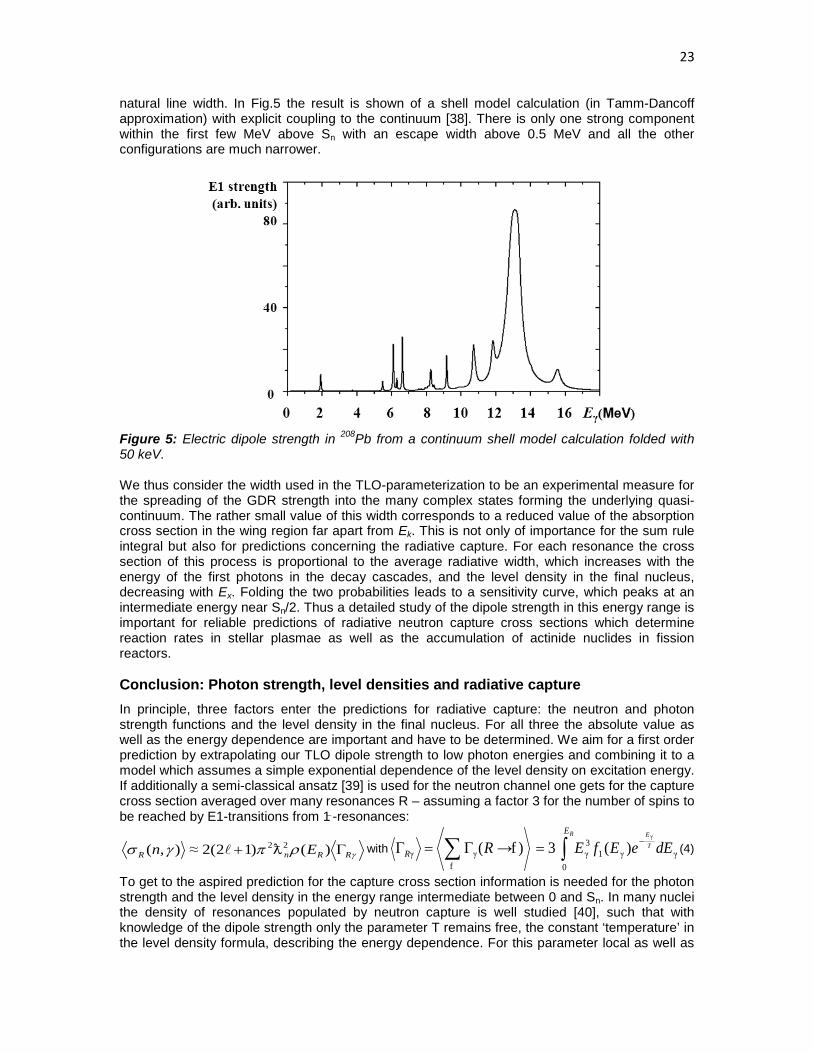
natural line width. In Fig.5 the result is shown of a shell model calculation (in Tamm-Dancoff approximation) with explicit coupling to the continuum [38]. There is only one strong component within the first few MeV above Sn with an escape width above 0.5 MeV and all the other configurations are much narrower.
Figure 5: Electric dipole strength in 208Pb from a continuum shell model calculation folded with 50 keV. We thus consider the width used in the TLO-parameterization to be an experimental measure for the spreading of the GDR strength into the many complex states forming the underlying quasi-continuum. The rather small value of this width corresponds to a reduced value of the absorption cross section in the wing region far apart from Ek. This is not only of importance for the sum rule integral but also for predictions concerning the radiative capture. For each resonance the cross section of this process is proportional to the average radiative width, which increases with the energy of the first photons in the decay cascades, and the level density in the final nucleus, decreasing with Ex. Folding the two probabilities leads to a sensitivity curve, which peaks at an intermediate energy near Sn/2. Thus a detailed study of the dipole strength in this energy range is important for reliable predictions of radiative neutron capture cross sections which determine reaction rates in stellar plasmae as well as the accumulation of actinide nuclides in fission reactors. Conclusion: Photon strength, level densities and radiative capture In principle, three factors enter the predictions for radiative capture: the neutron and photon strength functions and the level density in the final nucleus. For all three the absolute value as well as the energy dependence are important and have to be determined. We aim for a first order prediction by extrapolating our TLO dipole strength to low photon energies and combining it to a model which assumes a simple exponential dependence of the level density on excitation energy. If additionally a semi-classical ansatz [39] is used for the neutron channel one gets for the capture cross section averaged over many resonances R – assuming a factor 3 for the number of spins to be reached by E1-transitions from 1̶ -resonances:
γρπγσ RRnR En Γ+ )()12(2≈),( 22 with ∑f
γγ )f→(RR Γ=Γ γγ13γ
0
γ
)(3 ∫ dEeEfE T
ERE−= (4)
To get to the aspired prediction for the capture cross section information is needed for the photon strength and the level density in the energy range intermediate between 0 and Sn. In many nuclei the density of resonances populated by neutron capture is well studied [40], such that with knowledge of the dipole strength only the parameter T remains free, the constant ‘temperature’ in the level density formula, describing the energy dependence. For this parameter local as well as
24
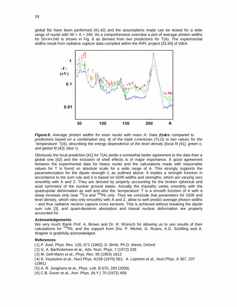
global fits have been performed [41,42] and the assumptions made can be tested for a wide range of nuclei with 50 < A < 240. As a comprehensive overview a plot of average photon widths for 50<A<240 is shown in Fig. 6 as derived from two predictions for T(A). The experimental widths result from radiative capture data compiled within the RIPL project [33,40] of IAEA.
Figure.6: Average photon widths for even nuclei with mass A: Data (red ◊) are compared to predictions based on a combination (eq. 4) of the triple Lorentzian (TLO) to two values for the `temperature’ T(A), describing the energy dependence of the level density (local fit [41], green o, and global fit [42], blue ◊).
Obviously the local prediction [41] for T(A) yields a somewhat better agreement to the data than a global one [42] and the inclusion of shell effects is of major importance. A good agreement between the experimental data for heavy nuclei and the calculations made with reasonable values for T is found on absolute scale for a wide range of A. This strongly supports the parameterization for the dipole strength f1 as outlined above. It implies a strength function in accordance to the sum rule and it is based on GDR-widths and strengths, which are varying very smoothly with A and Z. They are derived by properly accounting for the broken spherical and axial symmetry of the nuclear ground states. Actually the triaxiality varies smoothly with the quadrupolar deformation as well and also the ‘temperature’ T is a smooth function of A with a steep increase only near 48Ca and 208Pb only. Thus we conclude that parameters for GDR and level density, which vary only smoothly with A and Z, allow to well predict average photon widths – and thus radiative neutron capture cross sections. This is achieved without breaking the dipole sum rule [3], and quasi-deuteron absorption and triaxial nuclear deformation are properly accounted for.
Acknowledgements We very much thank Prof. A. Brown and Dr. R. Wünsch for allowing us to use results of their calculations for 208Pb, and the support from Drs. P. Michel, G. Rusev, K.D. Schilling and A. Wagner is gratefully acknowledged.
References [1] P. Axel, Phys. Rev. 126, 671 (1962); D. Brink, Ph.D. thesis, Oxford [2] G. A. Bartholomew et al., Adv. Nucl. Phys. 7 (1972) 229 [3] M. Gell-Mann et al., Phys. Rev. 95 (1954) 1612 [4] A. Veyssiere et al., Nucl.Phys. A159 (1970) 561; A. Lepretre et al., Nucl.Phys. A 367, 237 (1981) [5] A. R. Junghans et al., Phys. Lett. B 670, 200 (2008) [6] C.B. Dover et al., Ann. Phys. (N.Y.) 70 (1972) 458

25
[7] M.B. Chadwick et al, Phys. Rev. C 44, 814 (1991) [8] A.J. Koning, S. Hilaire and M.C. Duijvestijn, .TALYS-1.0., Nuclear Data for Science and Technology,eds. O.Bersillon et al., (EDP Sciences, Nice, 211, 2008) [9] C. Nair et al., Phys. Rev. C 78, 055802 (2008) [10] M. Erhard et al., Phys. Rev. C 81, 034319 (2010) [11] C. Nair et al., Phys. Rev. C 81, 055806 (2010) [12] B. L. Berman et al., Phys. Rev. C 36, 1286 (1987) [13] R. Schwengner et al.,Nucl. Inst. Meth. A555, 211 (2005); id., Phys.Rev. C 81, 054315 (2010) [14] P. Koehler et al, Phys. Rev. C 35, 1646 (1987) [15] R. Beyer et al., Nucl. Instr. Meth. A575 (2007) 449; R. Nolte et al., Nucl. Sc. and Eng.:156, 197(2007) [16] E. Altstadt et al., Ann. Nucl. Energy 34 (2007) 36; J. Klug et al., Nucl. Instr. Meth. A577 (2007) 641 [17] V.V.Varlamov et al., Yad. Konst. 1, 52 (1993), nndc.bnl.gov/exfor; R. Van de Vyver, Z. Physik A 284, 91 (1978) [18] B.A.Brown, Phys. Rev. Lett. 85 (2000) 5300 , cf. R.Schwengner et al., Phys. Rev. C 81, 054315 (2010) [19] T. Shizuma et al., Phys. Rev. C 78 (2008) 061303 [20] A. Richter, Prog. Part. Nucl. Phys. 34 (1995) 261; K. Heyde et al., Rev. Mod. Phys. 82, 2365 (2010) [21] K. Kumar, Phys. Rev. Lett. 28 (1972) 249; D. Cline, Ann.Rev.Nucl.Part.Sci. 36 (1986) 683 [22] J. Stachel et al., Nucl. Phys. A 419 (1984) 589; C. Y. Wu et al., Nucl. Phys. A 533 (1991) 359 [23] C. Y. Wu et al., Nucl. Phys. A 607 (1996) 178, C. Y. Wu and D. Cline, Phys. Rev. C 54 (1996) 2356 [24] M. Zielinska et al., Nucl. Phys. A 712 (2002) 3; J. Srebnry et al., Nucl. Phys. A 766 (2006) 25 [25] L. Esser et al., Phys. Rev. C 55 (1997) 206; V. Werner et al., Phys. Rev. C 71, 054314 (2005) [26] S. Raman et al., At. Data Nucl. Data Tabl. 78 (2001) 1 [27] N. Pietralla et al., Phys. Rev. Lett. 73, 2962 (1994) [28] W. Andrejtscheff and P. Petkov, Phys. Rev. C 48, 2531 (1993), id., Phys. Lett. B 329 (1994) 1 [29] S. Q. Zhang et al., Phys. Rev. C 80 (2009) 021307 [30] W.D. Myers et al., Phys. Rev. C 15 (1977) 2032 [31] P. Möller, J.R. Nix, W. D. Myers and W. J. Swiatecki, At. Data Nucl. Data Tables 59 (1995) 185 [32] M. Goldhaber and E. Teller, Phys. Rev. 74, 1046 (1948); H. Steinwedel and H. Jensen, Z.f.Nf. 52, 413 (1950) [33] V.A. Pluiko, www-nds.iaea.org/RIPL-3/gamma/gdrparameters-exp.dat, subm. to At. Data Nucl. Data Tables; 34. R. Capote et al., Nucl. Data Sheets 110 (2009) 3107 [35] B. Bush and Y. Alhassid, Nucl. Phys. A 531 (1991) 27 [36] G. Rusev et al., Phys. Rev. C 77, 064321 (2008) [37] H.T. Nyhus et al., Phys. Rev. C 81 (2010) 024325 [38] H.W.Barz, I.Rotter and J.Höhn, Nucl. Phys. A 275 (1977) 111; R. Wünsch, priv. comm. [39] D.J. Hughes et al., Phys. Rev. 91(1953)1423; H. Feshbach et al., Phys. Rev. 71(1947)145 [40] A. Ignatyuk, IAEA-TECDOC-1506, RIPL-2 (2006), § 3, Resonances; T. Belgya et al., www-nds.iaea.org/ripl-2/ [41] T. von Egidy and D. Bucurescu, Phys. Rev.C 80, 054310 (2009) [42] A. Koning et al., Nucl. Phys. A 810 (2008) 13

26

27
Characterization of the new neutron beam at n_TOF-Ph2
C. Guerrero1), S. Andriamonje2), J. Andrzejewski3), L. Audouin4), V. Bécares1), F. Bečvář5), F. Belloni6), B. Berthier4), E. Berthoumieux7), M. Brugger2), M. Calviani2), F. Calviño8), D. Cano-Ott1), C. Carrapiço9), P. Cennini2), F. Cerutti2), E. Chiaveri2), M. Chin2), N. Colonna10), G. Cortés9), M. Cortés-Giraldo11), I. Dillmann12), C. Domingo-Pardo13), I. Duran14), M. Fernández-Ordóñez1), A. Ferrari2), S. Ganesan15), I. Giomataris7), G. Giubrone16), M.B. Gómez-Hornillos8), I.F. Gonçalves9), E. González-Romero1), F. Gramegna17), F. Gunsing7), S. Harrisopulos18), M. Heil13), K. Ioannides19), E. Jericha20), Y. Kadi2) F. Käppeler21), D. Karadimos19), M. Krtička5), E. Lebbos2), C. Lederer22), H. Leeb20), R. Losito2), M. Lozano11), J. Marganiec3), S. Marrone10), T. Martinez1), C. Massimi23), P.F. Mastinu17), M. Meaze10), E. Mendoza1), A. Mengoni24), P.M. Milazzo6), M. Mosconi25), R. Nolte25), M.C. Ovejero1), T. Papaevangelou7), C. Paradela14), A. Pavlik2), J. Perkowski3), R. Plag13), J. Praena11), J.M. Quesada11), R. Reifarth13), C. Rubbia2,26), R. Sarmento9), G. Tagliente10), J.L. Tain16), D. Tarrìo14), L. Tassan-Got4), G. Vannini23), V. Variale10), P. Vaz9), A. Ventura24), V. Vlachoudis2), R. Vlastou27), Z. Vykydal28), A. Wallner22), C. Weiß20) (The n_TOF Collaboration)
1) Centro de Investigaciones Energeticas Medioambientales y Tecnologicas (CIEMAT), Madrid, Spain 2) European Organization for Nuclear Research (CERN), Geneva, Switzerland 3) Uniwersytet łódzki, Lodz, Poland 4) Centre National de la Recherche Scientifique/IN2P3 - IPN, Orsay, France 5) Charles University, Prague, Czech Republic 6) Istituto Nazionale di Fisica Nucleare, Trieste, Italy 7) Commissariat à l’Énergie Atomique (CEA) Saclay – Irfu, Gif-sur-Yvette, France 8) Universitat Politecnica de Catalunya, Barcelona, Spain 9) Instituto Tecnológico e Nuclear (ITN), Lisbon, Portugal 10) Istituto Nazionale di Fisica Nucleare, Bari, Italy 11) Universidad de Sevilla, Spain 12) Physik Department E12 and Excellence Cluster Universe, Technische Universität München, Munich, Germany 13) GSI Helmholtzzentrum für Schwerionenforschung GmbH, Darmstadt, Germany 14) Universidade de Santiago de Compostela, Spain 15) Bhabha Atomic Research Centre (BARC), Mumbai, India 16) Instituto de Fìsica Corpuscular, CSIC-Universidad de Valencia, Spain 17) Istituto Nazionale di Fisica Nucleare, Laboratori Nazionali di Legnaro, Italy 18) National Centre of Scientific Research (NCSR), Demokritos, Greece 19) University of Ioannina, Greece 20) Atominstitut, Technische Universität Wien, Austria 21) Forschungszentrum Karlsruhe GmbH (FZK), Institut für Kernphysik, Karlsruhe, Germany

28
22) Fakultät für Physik, Universität Wien, Austria 23) Dipartimento di Fisica, Università di Bologna, and Sezione INFN di Bologna, Italy 24) Agenzia nazionale per le nuove tecnologie, l’energia e lo sviluppo economico sostenibile (ENEA), Bologna, Italy 25) Physikalisch-Technische Bundesanstalt (PTB), Braunschweig, Germany 26) Laboratori Nazionali del Gran Sasso dell’INFN, Assergi (AQ),Italy 27) National Technical University of Athens (NTUA), Greece 28) Institute of Experimental and Applied Physic (IEAP), Czech Technical University (CTU), Prague, Czech Republic
Abstract: After a halt of three years and following the construction of a new lead spallation target, the n_TOF facility has resumed operation in November 2008. After a short commissioning of the new target, the 2009 experimental campaign has been devoted to the full characterization of the neutron beam by means of different and independent detection systems. The spatial profile of the neutron beam has been measured by position sensitive MicroMegas and MEDIPIX detectors, both providing a 2D profile as a function of neutron energy. The intensity and energy distribution of the neutron beam have been determined from a calibrated fission chamber from PTB with five 235U deposits, a MicroMegas detector with 10B and 235U deposits, and the n_TOF Silicon Monitor and Total Absorption Calorimeter, as well as from activation of gold foils. The experimental data from the measurement of the beam profile and neutron fluence are presented for the first time time in this work, which contains also a preliminary analysis of the data.
Introduction The Neutron Time Of Flight facility n_TOF [1] at CERN has been used since 2001 for the measurement of neutron cross sections relevant for Nuclear Technology and Astrophysics. At n_TOF neutrons are generated by spallation from a 20 GeV proton beam impinging on a lead target. The initial fast neutron spectrum is shaped into a white spectrum by means of a moderator (demineralized or borated water) preceding a neutron beam line that connects the spallation target with the experimental area where the samples are irradiated. The wide neutron energy range (10 orders of magnitude starting at thermal), the high instantaneous beam intensity (106 neutrons/pulse between thermal and 100 MeV) and the long flight path (185 m) are the main advantages of n_TOF with respect to other facilities. The combination of these with state of the art detection systems and a Data Acquisition System based on flashADC have provided in the first phase of experiments (2001-2004) a large set of high quality capture and fission cross section data. Following the design and construction of a new spallation target [2], the n_TOF facility became operative in November 2008. The main improvements with respect to the previous lead target concern the safety and the operational flexibility, since it offers the possibility of using moderators with different thicknesses and compositions, and envisages the possibility of using a new experimental area with a flight path of 20 m in the vertical direction. The beginning of the 2009 experimental campaign has been devoted to the full characterization of the neutron beam at the irradiation point in the experimental area. This contribution presents the measurements and the data analyses aimed at determining the spatial profile, intensity and energy distribution of the neutron beam.
Spatial profile of the neutron beam The neutron beam is shaped along the beam line by means of two collimators placed at 135 m and 175 m from the lead target, the latter being responsible of the shape of the beam in the experimental area. The knowledge of the beam profile and its dependence with neutron energy

29
are crucial in the capture measurements, where the samples are always smaller than the beam and where it is necessary to correct for the beam interception factor. The beam profile has been measured by means of two position sensitive detectors, the MEDIPIX and the 2D MicroMegas (XY-MGAS): [1] The MEDIPIX [3] detector is 2.83x2.83 cm2 in size and consists of 512x512 pixels on a 300 mm thick Silicon sensor. Two neutron converters have been used: 6Li for slow neutrons (up to 1 keV) and Polyethylene for fast neutrons. The measurements have been performed in four TOF intervals: 0.01-1 eV, 1-103 eV, 0.08-1 MeV and 0.08-200 MeV. [2] The XY-MGAS [4] detector, based on the Bulk principle, has 6x6 cm2 active area containing 106x106 strips that are read using a Gasipplex card. The detection of the particles, produced in a 10B converter, in two segmented pads allows reconstructing the time-of-flight and position of the neutron interaction. The measured 2D beam profile for thermal neutrons at a flight path of 183.5 m is shown in the left panel of figure 1. The vertical profile in the right panel right illustrates for two energy intervals how the beam becomes narrower with increasing neutron energy.
Figure 1. Results from the XY-MGAS at 183.5 m time-of-flight distance. Left: Two dimensional spatial profile of the neutron beam at thermal energies. Right: Vertical profile in two neutron energy intervals. The analysis of data from the MEDIPIX and the XY-MGAS detectors is ongoing. The evaluated beam profile will be obtained by the combination of an analytical fit to the experimental data and the simulations of the optical transport of neutrons from the target to the irradiation point through the collimation system.
Intensity of the neutron beam The accurate determination of the neutron beam intensity requires a detector of well know efficiency for detecting reactions with a well known cross section taking place in a sample of well known mass. At n_TOF we have used a multi plate fission chamber calibrated at PTB [5]. The chamber contains five highly enriched 235U samples on platinum backings and six tantalum collector plates. The uranium deposits are 76 mm in diameter with a total mass of 201.4(5) mg. The signals from the detectors were connected directly to our flashADC (8 bits and 100 MSamples/s) and a total of 1018 protons was allocated to the measurement. The resulting pulse height and neutron energy distributions are shown in Figure 2. The dips in the neutron energy

30
spectrum, the largest one around 5 eV, correspond to neutron absorption in strong Ta resonances. The neutron fluence per pulse is calculated from the counting rate CR(Counts/Pulse), the efficiency ε(n,f) of the detector (95.4% for neutron from thermal up a to several MeV) and the expected fission yield YMCNP, calculated from detailed MCNP simulations including the windows, backings and electrodes of the chamber.
The result, expressed in isolethargic units, is shown as a blue line in Figure 3. In the meV and MeV regions one can observe the thermal and evaporation peaks, respectively; while the epithermal range shows a nearly isolethargic energy dependence of the fluence. A series of additional measurements with other detection systems have been performed in order to validate and complement the results from the PTB fission chamber. The results from such measurements are displayed as colour lines and markers in Figure 3 and are discussed in the following: The Silicon Monitor (SiMon) [6]: An assembly of 4 silicon detectors looking at a thin (300 µg/cm2) 6Li foil is used for monitoring purposes during the neutron capture measurements at n_TOF. The corresponding neutron fluence is shown in Figure 3.The overall accuracy of the result is 6%, 5% due to the thickness of the foil and 3% from the calculation of εSiMon by MC simulations. The monitoring MicroMegas (MGAS) [7]: A new Micromegas detector with an efficiency of 95% has been designed and constructed for on-line monitoring of the neutron beam intensity both at low (10B sample with 35 mm diameter) and high (235U sample with 20 mm diameter) neutron energies. The results for 10B, normalized to the 235U data at thermal, are shown in Figure 3. The accuracy of the results is 7%, which is dominated by the uncertainty in the alignment of the sample and the calculation of the beam interception factor (ØU-235=2 cm, Øbeam=3.5 cm). Activation of gold foils: A pair of gold foils with 25 µm thickness and 45 mm diameter (larger than the beam) where placed back-to-back in the neutron beam. The largest fraction (95%) of the difference in the number of 198Au produced in the two samples corresponds to neutrons with energies around the 4.9 eV resonance of gold, which saturates in the first sample. This allows one to calculate the neutron fluence around 4.9 eV with an accuracy of 10%, which is dominated by the determination of the activity of the samples. Saturated Resonance Method (SRM) with the TAC [8]: The Total Absorption Calorimeter is an array of 40 BaF2 crystals used for (n, γ) measurements. The SRM has been applied using a gold sample of 45 mm diameter and 100 m thickness. The preliminary analysis of the TAC have a large uncertainty of 15%, since it has been performed taking into account the efficiency of the
Figure 2. Pulse Height (left) and Neutron energy (right) distributions resulting from the measurement with the PTB fission chamber.

31
TAC set-up used in 2004. A more accurate value will follow after the detailed Monte Carlo simulation of the correct geometry used in 2009. Assuming the detection efficiency calculated for the TAC set-up in 2004 and taking into account that the detector geometry has changed, the accuracy of the result is 15%. This can be improved by means of dedicated MC simulations. The results from the PTB chamber are shown only below and above the resonance region, where the analysis is still to be improved. The data from MGAS and SiMon are shown up to an energy of 200 keV, above which the results are affected by the prompt gamma-flash for SiMon and the proton recoil from the neutron elastic scattering with the hydrogen contained in the gas filling for MGAS.
PTB SiMon MGAS Activation TAC Average Ratio over PTB 1.0 0.96 1.03 1.04 0.88
Accuracy in the absolute value 3% 6% 7% 10% 15%
Accuracy in the energy shape <3% <3% <3% - - Table 1. Summary of accuracies in the measurements of the neutron fluence and comparison with respect to the PTB fission chamber. Concerning the absolute value of the neutron fluence, the different measurements are in agreement within the associated uncertainties. The intensity of the evaluated neutron fluence will be adopted from the PTB measurement below and above the resonance region. In the resonance region, that is between 1 eV and a few keV, the fluence is better determined from smooth cross sections reactions. Hence, the evaluated fluence in this region will result from the combination of the SiMon and MGAS data normalized to those of PTB below 1 eV.
Figure 3. Neutron fluence, in isolethargic units, resulting from the analysis of the PTB fission chamber. The complementary measurements of the fluence are also shown: MGAS, SiMon, Activation and TAC.

32
The absolute value of fluence is however not required for capture measurements, which are usually normalized using the saturated resonance method (SRM) or using a well known cross section at a given energy in the sample itself, or using a well known cross section of a reference sample under identical measurement conditions. Therefore the important issue about the fluence is not the absolute value but the energy distribution of the neutron fluence. The resulting uncertainty of this distribution depends strongly on the measurement technique and is limited by the uncertainty of the used standard cross sections like 6Li(n,t), 10B(n,) and 235U(n,f). At present we estimate the total uncertainty on the energy distribution of the flux at 3%.
Summary and conclusions The n_TOF facility has resumed operation after a halt of three years. The first measurements during the 2009 campaign have aimed at the full characterization of the neutron beam in terms of spatial profile, intensity and neutron energy distribution. The spatial beam profile has been determined as a function of neutron energy by means of the innovative MEDIPIX and XY-MGAS detectors. The analysis of the results including a simulation of the optical transport on neutrons through the beam line is to be completed. The intensity of the neutron beam has been determined from the 235U(n,f) reaction using a calibrated fission chamber from PTB. A series of complementary measurements with the SiMon, MGAS, TAC detectors and by activation of gold foils have confirmed the results from the PTB chamber in the full neutron energy range. The evaluated neutron fluence will be determined from a combination of the PTB measurement in the energy regions below and above the resonances, and the SiMon and MGAS data between 1 eV and a few keV. The expected accuracy of the results is 3-4% in the absolute value of the neutron fluence and better than 3% in the energy dependence, which is the important one for capture measurement after normalization. Acknowledgements This work has been partially supported by ENRESA, through the CIEMAT-ENRESA agreements on “Transmutación de residuos radiactivos de alta actividad", the Spanish “Plan Nacional de I+D+i de Física de Partículas (project FPA2005-06918-C03-01)” and the Spanish Ministerio de Ciencia e Innovación through the “CONSOLIDER CSD 2007-00042” project. References 1] F. Gunsing et al. (The n_TOF Collaboration), Status and outlook of the neutron time-of-flight facility n_TOF at CERN, Nucl. Inst. and Methods B 261 (2007) 925-929 2] M. Calviani et al. (The n_TOF Collaboration), Status and Perspectives of the n_TOF Facility at CERN, Proc. 2nd EFNUDAT Workshop, 23-25 Sept. 2009, Budapest (Hungary). 3] www.cern.ch/MEDIPIX 4] S. Andriamonje et al., A Low Background Micromegas Detector for Axion Searches, Nucl. Instr. and Methods A 535 (2004) 309-313. 5] D.B. Gayther, International Intercomparison of Fast Neutron Fluence-Rate Measurements Using Fission Chamber Transfer Instruments, Metrologia 27 (1990) 221-231. 6] S. Marrone et al. (The n_TOF Collaboration), A low background neutron flux monitor for the n_TOF facility at CERN, Nucl. Instr. and Methods A 517 (2004) 389-398. 7] S. Andriamonje et al., A new detector for neutron beam monitoring, Int. Top. Meeting on Nuclear Research Applications and Utilization of Accelerators, 4-8 May 2009. Vienna, Austria. 8] C. Guerrero et al. (The n_TOF Collaboration), The n_TOF Total Absorption Calorimeter for neutron capture measurements at CERN, Nucl. Instr. and Methods A 608 (2009) 424-433.

33
237Np(n,f) Cross Section: new data impact
C. Paradela1), L. Tassan-Got2), L. Audouin2), B. Berthier2), I. Duran1), L. Ferrant2), S. Isaev2), C. Le Naour2), C. Stephan2), D. Tarrío1), D. Truber2), U. Abbondanno3), G. Aerts4), H. Álvarez1), F. Álvarez-Velarde5), S. Andriamonje6), J. Andrzejewski7), P. Assimakopoulos8), G. Badurek9), P. Baumann10), F. Becvár11), E. Berthoumieux6), F. Calviño12), M. Calviani13,14), D. Cano-Ott5), R. Capote15,16), C. Carrapiço17,6), P. Cennini18), V. Chepel19), E. Chiaveri18), N. Colonna20), G. Cortes12), A. Couture21), J. Cox21), M. Dahlfors18), S. David2), I. Dillmann2), C. Domingo-Pardo23,24), W. Dridi6), C. Eleftheriadis25), M. Embid-Segura5), A. Ferrari18), R. Ferreira-Marques19), K. Fujii3), W. Furman26), I. Gonçalves17), E. González-Romero5), F. Gramegna13), C. Guerrero5), F. Gunsig6), B. Haas27), R. Haight28), M. Heil22), A. Herrera-Martinez18), M. Igashira29), E. Jericha9), Y. Kadi18), F. Käppeler22), D. Karadimos8), D. Karamanis8), M. Kerveno10), P. Koehler30), E. Kossionides31), M. Krticka11), C. Lampoudis25,6), H. Leeb9), A. Lindote19), I. Lopes19), M. Lozano16), S. Lukic10), J. Marganiec7), S. Marrone20), T. Martínez5), C. Massimi32), P. Mastinu13), A. Mengoni15,18), P. M. Milazzo3), C. Moreau3), M. Mosconi22), F. Neves19), H. Oberhummer9), S. O’Brien21), M. Oshima33), J. Pancin6), C. Papachristodoulou8), C. Papadopoulos34), N. Patronis8), A. Pavlik35), P. Pavlopoulos36), L. Perrot6), M.T. Pigni9), R. Plag22), A. Plompen37), A. Plukis6), A. Poch12), J. Praena13), C. Pretel12), J. Quesada16), T. Rauscher38), R. Reifarth28), C. Rubbia39), G. Rudolf10), P. Rullhusen37), J. Salgado17), C. Santos17), L. Sarchiapone18), I. Savvidis25), G. Tagliente20), J.L. Tain23), L. Tavora17), R. Terlizzi20), G. Vannini32), P. Vaz17), A. Ventura40), D. Villamarin5), M. C. Vicente5), V. Vlachoudis18), R. Vlastou34), F. Voss22), S. Walter22), M. Wiescher21), and K. Wisshak22)
(The n_TOF Collaboration (www.cern.ch/ntof))
1) Universidade de Santiago de Compostela, Spain 2) Centre National de la Recherche Scientifique/IN2P3-IPN, Orsay, France 3) Istituto Nazionale di Fisica Nucleare, Trieste, Italy 4) CEA/Saclay – IRFU, Gif-sur-Yvette, France 5) Centro de Investigaciones Energéticas Medioambientales y Técnicas, Madrid, Spain 6) CEA/Saclay – DSM/DAPNIA, Gif-sur-Yvette, France
7) University of Lodz, Lodz, Poland 8) University of Ioannina, Greece 9) Atominstitut der Österreichischen Universitäten, Technische Universität 10) Centre National de Recherche Scientifique/IN2P3 – IreS, Strasbourg, France 11) Charles University, Prague, Czech Republic 12) Universidad Politécnica de Catalunya, Barcelona, Spain 13) Istituto Nazional di Fisica Nucleare, Laboratori Nazionali di Legnaro, Italy 14) Dipartimento di Fisica, Università di Padova, Italy 15) International Atomic Energy Agency (IAEA), Nuclear Data Section, Vienna, Austria 16) Universidad de Sevilla, Spain 17) Instituto Tecnológico e Nuclear (ITN), Lisbon, Portugal 18) CERN, Geneva, Switzerland 19) LIP – Coimbra, Departamento de Fisica da Universidade de Coimbra, Portugal 20) Istituto Nazionale di Fisica Nucleare, Bari, Italy
34
21) University of Notre Dame, Notre Dame, USA 22) Karlsruhe Institute of Technology (KIT), Campus Nord, GmbH (FZK), Institut für Kernphysik, Germany 23) Instituto de Física Corpuscular, CSIC-Universidad de Valencia, Spain 24) GSI, Darmstadt, Germany 25) Aristotle University of Thessaloniki, Greece 26) Joint Institute for Nuclear Research, Frank Laboratory of Neutron Physics, Dubna, Russia 27) Centre National de la Recherche Scientifique/IN2P3-CENBG, Bordeaux, France 28) Los Alamos National Laboratory, New Mexico, USA 29) Tokyo Institute of Technology, Tokyo, Japan 30) Oak Ridge National Laboratory, Physics Division, Oak Ridge, USA 31) NCSR, Athens, Greece 32) Dipartamento di Fisica, Università de Bologna, and Sezione INFN di Bologna, Italy 33) Japan Atomic Energy Research Institute, Tokai-mura, Japan 34) National Technical University of Athens, Greece
35) Fakültat für Physik, Universität Wien, Austria 36) Pôle Universitaire Léonard de Vinci, Paris, La Défense, France 37) CEC-JRC-IRMM, Geel, Belgium 38) Departament of Physics – University of Basel, Switzerland [email protected]
Abstract: The measurement of 237Np(n,f) cross section performed at the CERN n_TOF facility is presented in this work. A summary description of the cross section analysis and data normalization is included. An important discrepancy with respect to the current evaluated files has been obtained, following a discussion about the consistency of this result in the frame of the last experimental and phenomenological works.
Introduction The incineration of the minor actinides (MA) accumulated in the reactor nuclear wastes would reduce significantly the long-term repository required for a sustainable nuclear energy development. For this task, fast reactors and sub-critical assemblies present a great potential to achieve the best transmutation rates. Neptunium-237 is a long half-life MA which is formed in a considerable quantity in nuclear power reactors during fuel irradiation. When we consider its incineration in a fast reactor, the transmutation rate is quite sensitive to the 237Np(n,f) cross section [1], specially in the first period of irradiation when the amount of neptunium is still abundant. Therefore, the improvement of the data precision for this cross section will allow reducing the calculated uncertainties of reactor design and safety parameters. This work consider the 237Np(n,f) cross section measured at CERN n_TOF facility and recently published [2], opening a discussion in the impact of these new data in current evaluated files and their uncertainties.
n_TOF results The 237Np(n,f) cross section has been measured at the CERN n_TOF facility [3] relative to 235U(n,f). The detection setup, based on parallel plate avalanche counters (PPACs) developed at the IPN-Orsay, is composed of 10 detectors and 9 targets placed orthogonally in the neutron beam. Among the targets, four high-purity 237Np samples and one 235U reference sample. Thanks to the very thin setup layers and the fast detector signals, both fission fragments are detected in

35
coincidence, making easy the discrimination of α particles owing to sample decay and events produced by spallation reactions. Assuming that the same flux reaches all targets, the cross section ratio between them can be expressed by the following expression:
237
235
237
235
235
237
235
237
−
−
−
−
−
−
−
− =Np
U
Np
U
U
Np
U
Np
NN
FF
εε
σσ
(1)
where F is the fission counting rate, N is the number of atoms of the targets, ε is the detection efficiency for each target. The number of atoms is accurately known from α counting measurements. Then, the detection efficiency ratio is corrected by the different fission fragment angular distribution and by the different oxygen content between neptunium and uranium samples. The angular distribution of the fragments changes with the neutron energy and this is reflected in the estimated efficiency of our setup. However, as the behavior of the angular distributions is very similar for 235U and for 237Np, the importance of this correction in this case is reduced. The oxgen content in the targets has been measured using the Rutherford Backscattering technique (RBS), being three times larger in the uranium targets than in the neptunium ones. This introduces a correction of the 2 % in the efficiency ratio. The remaining differences in the efficiency ratio are produced by the target and backing thicknesses and by detector behaviours and they are estimated to be less than 3 % from the comparison of the several neptunium targets included in the setup. Adding the different terms contributing to the systematic uncertainty, it results to fall below 3.8 % in the full energy range. The statistical uncertainty is kept smaller by the selection of the suitable binning.
Figure 1. Result obtained for 237Np(n,f) cross section between 0.2 and 1000 MeV compared to last ENDF and JENDL evaluations.

36
Once obtained the cross section ratio, the 237Np cross section is produced by multiplying the second term in eq. (1) by the 235U cross section obtained from ENDF/B-VII.0 [4] evaluation up to 20 MeV and from JENDL-HE-2004 [5] library beyond that energy. The result is shown in Fig. 2 compared to ENDF/B-VII and to JENDL-HE. Our results reproduce quite closely the shape of the evaluated cross sections but they are larger than evaluations in a scale factor of 6% in the range between 1 and 200 MeV. Such a discrepancy is not observed for the other measured isotopes with the same PPAC setup as 238U, 234U or 233U for which our results reproduce well the evaluated cross sections. This agreement reinforces our confidence in the results obtained for the 237Np, so that we will compare our results with the experimental data used to produce the evaluations.
Comparison to experiments and to systematic prediction During last decade a few experiments measuring the 237Np cross section above the fission threshold have been accomplished. Two of them were based in time-of-flight measurements in spallation sources facilities and with the U-235 as reference, as the work presented here.
Figure 2. Comparison of the 237Np/235U cross section ratio obtained in present result with respect to data from Tovesson [6] and Shcherbakov [7]. Present data agree well in shape with those of Tovesson and Hill [6], and, above 8 MeV, with those of Shcherbakov et al. [7]. However, there is a clear discrepancy in the normalization, with differences of about 5 % with respect to Tovesson data and about 6-8 % with respect to Shcherbakov data, as it is shown in Fig. 2. It is worth to mention that the cross section ratio provided by Tovesson presents an overall normalization to reproduce the ENDF/B-VI ratio at 14.8 MeV. Apart from these experiments, there is a more recent work published by Basunia et al. [8] that consists in an indirect measurement based on the surrogate ratio method. They provide the 237Np(n,f) cross section in the range between 10 and 20 MeV, which is compared to the present data in Fig. 3. A good agreement between both sets of data is obtained except for energies above 18 MeV, where the surrogate measurement falls down. The experimental results obtained with monoenergetic sources around 14 MeV [9-13] provide an absolute measurement of the cross section, being our result compatible with most of them.

37
Figure 3. Data from Basunia et al.[8] are compared to present data in the energy region between 10 and 20 MeV. Last ENDF/B and JENDL evaluations and some experimental data obtained with monoenergetic sources around 14 MeV are also shown. Finally, in the intermediate energy range (above 20 MeV up to a few GeV) the lack of experimental data with neutrons is solved by the use of models or overall systematics based on proton-, photon- and neutron-induced measurements. FISCAL code, that follows Fukahori’s systematic, is able to reproduce well the cross section ratio of different actinides with respect to 235U when compared with evaluations, except in the case of 237Np [14]. However, FISCAL prediction for 237Np is in fair agreement with the present result as it is shown in Fig. 5.
Figure 4. A simplified result of the Fukahori’s systematics is shown in comparison with the most recent data in the intermediate energy range.

38
Summary and Conclusions In this work, we presented the result for the 237Np(n,f) cross section obtained at the n_TOF experiment. When compared to evaluations, our result is about 6 % higher, and such difference is incompatible with the data uncertainty. However, we are in agreement with Basunia et al. and most of the experimental data obtained around 15 MeV. Furthermore, our result would correct the 237Np exception in the Fukahori’s systematic at intermediate energies. A revised evaluation, considering these last results, needs to be checked through integral measurement benchmarks. Acknowledgements This work was supported by the EC under the contract Nr. FIKW-CT-2000-00107 and by the CPAN under the contract CPAN09-PD14.
References [1] O. Bringer, A. Letourneau, E. Dupont, Annals of Nuclear Energy 35, 1535 (2008) [2] C. Paradela et al., “Neutron-induced fission cross section of 234U and 237Np measured at the
CERN Neutron Time-of-Flight (n_TOF) facility”, Phys. Rev. C 82, 034601 (2010) [3] The n_TOF Collaboration, n_TOF Technical Report. CERN/INTC 2000-018. CERN
SPSC/P310. [4] M. B. Chadwick et al., Nucl. Data Sheets., 107, 2931(2005). [5] K. Shibata et al. Nucl. Sci. Technol. 39, 1125 (2002). [6] F. Tovesson and T. Hill. Phys. Rev. C. 75, 03610 (2006). [7] O. Shcherbakov et al. Nucl. Sci. and Tech,. Sup. Vol 2. p. 230 (2002). [8] M. S. Basunia et al., Nucl. Instrum. Meth. B 267, 1899 (2009) [9] I. Garlea et al., Revue Roumaine de Physique, 37, 19 (1992) [10] K. Merla et al., Conf. on Nucl. Data for Sci. and Technol., Juelich 1991, p. 510. [11] J. W. Meadows, Annals of Nuclear Energy 15, 421 (1988). [12] I. D. Alkhazov et al., Yadernye Konstanty, 1986, 19 (1986). [13] P. White and G. Warner, J. Nucl. Energy, 21, 671 (1967) [14] T. Fukahori, O. Iwamoto and S. Chiba. “Unified Description of Neutron-, Proton- and Photon-
induced Fission Cross Sections in Intermediate Energy Region”, Proc. 7th Int. Conf. Nucl. Criticality Safety (ICNC 2003), Tokai-mura, Japan.

39
On the systematic errors of the Th232(n,f) cross section measured with PPACs at CERN - nTOF
D. Tarrío1), L. Tassan-Got2), L. Audouin2), B. Berthier2), I. Duran1), L. Ferrant†,2), S. Isaev2), C. Le Naour2), C. Paradela1), C. Stephan2), D. Trubert†,2), U. Abbondanno3), G. Aerts4), H. Álvarez1), F. Álvarez-Velarde5), S. Andriamonje4), J. Andrzejewski6), P. Assimakopoulos†,7), G. Badurek8), P. Baumann9), F. Becvár10), E. Berthoumieux4), F. Calviño11), M. Calviani12,13), D. Cano-Ott5), R. Capote14,15), C. Carrapiço16,4), P. Cennini17), V. Chepel18), E. Chiaveri17), N. Colonna19), G. Cortes11), A. Couture20), J. Cox20), M. Dahlfors17), S. David2), I. Dillmann2), C. Domingo-Pardo22,23), W. Dridi4), C. Eleftheriadis24), M. Embid-Segura5), A. Ferrari17), R. Ferreira-Marques18), K. Fujii3), W. Furman25), I. Gonçalves16), E. González-Romero5), F. Gramegna12), C. Guerrero5), F. Gunsig4), B. Haas26), R. Haight27), M. Heil22), A. Herrera-Martinez17), M. Igashira28), E. Jericha8), Y. Kadi17), F. Käppeler21), D. Karadimos7), D. Karamanis7), M. Kerveno9), P. Koehler29), E. Kossionides30), M. Krticka10), C. Lampoudis24,4), H. Leeb8), A. Lindote18), I. Lopes18), M. Lozano15), S. Lukic9), J. Marganiec6), S. Marrone19), T. Martínez5), C. Massimi31), P. Mastinu12), A. Mengoni14,17), P. M. Milazzo3), C. Moreau3), M. Mosconi21), F. Neves18), H. Oberhummer8), S. O’Brien20), M. Oshima32), J. Pancin4), C. Papachristodoulou7), C. Papadopoulos33), N. Patronis7), A. Pavlik34), P. Pavlopoulos35), L. Perrot4), M.T. Pigni8), R. Plag21), A. Plompen36), A. Plukis4), A. Poch11), J. Praena12), C. Pretel11), J. Quesada15), T. Rauscher37), R. Reifarth27), C. Rubbia38), G. Rudolf9), P. Rullhusen36), J. Salgado16), C. Santos16), L. Sarchiapone17), I. Savvidis24), G. Tagliente19), J.L. Tain22), L. Tavora16), R. Terlizzi19), G. Vannini31), P. Vaz16), A. Ventura39), D. Villamarin5), M. C. Vicente5), V. Vlachoudis17), R. Vlastou33), F. Voss21), S. Walter21), M. Wiescher20), and K. Wisshak21)
(The n_TOF Collaboration (www.cern.ch/ntof))
1) Universidade de Santiago de Compostela, Spain 2) Centre National de la Recherche Scientifique/IN2P3-IPN, Orsay, France 3) Istituto Nazionale di Fisica Nucleare, Trieste, Italy 4) CEA/Saclay – IRFU, Gif-sur-Yvette, France 5) Centro de Investigaciones Energéticas Medioambientales y Técnicas, Madrid, Spain 6) University of Lodz, Lodz, Poland 7) University of Ioannina, Greece 8) Atominstitut der Österreichischen Universitäten, Technische Universität 9) Centre National de Recherche Scientifique/IN2P3 – IreS, Strasbourg, France 10) Charles University, Prague, Czech Republic 11) Universidad Politécnica de Catalunya, Barcelona, Spain 12) Istituto Nazional di Fisica Nucleare, Laboratori Nazionali di Legnaro, Italy 13) Dipartimento di Fisica, Università di Padova, Italy 14) International Atomic Energy Agency (IAEA), Nuclear Data Section, Vienna, Austria 15) Universidad de Sevilla, Spain 16) Instituto Tecnológico e Nuclear (ITN), Lisbon, Portugal 17) CERN, Geneva, Switzerland 18) LIP – Coimbra, Departamento de Fisica da Universidade de Coimbra, Portugal 19) Istituto Nazionale di Fisica Nucleare, Bari, Italy

40
20) University of Notre Dame, Notre Dame, USA 21) Karlsruhe Institute of Technology (KIT), Campus Nord, Institut für Kernphysik, Germany 22) Instituto de Física Corpuscular, CSIC-Universidad de Valencia, Spain 23) GSI, Darmstadt, Germany 24) Aristotle University of Thessaloniki, Greece 25) Joint Institute for Nuclear Research, Frank Laboratory of Neutron Physics, Dubna, Russia 26) Centre National de la Recherche Scientifique/IN2P3-CENBG, Bordeaux, France 27) Los Alamos National Laboratory, New Mexico, USA 28) Tokyo Institute of Technology, Tokyo, Japan 29) Oak Ridge National Laboratory, Physics Division, Oak Ridge, USA 30) NCSR, Athens, Greece 31) Dipartamento di Fisica, Università de Bologna, and Sezione INFN di Bologna, Italy 32) Japan Atomic Energy Research Institute, Tokai-mura, Japan 33) National Technical University of Athens, Greece
34) Fakültat für Physik, Universität Wien, Austria 35) Pôle Universitaire Léonard de Vinci, Paris, La Défense, France 36) CEC-JRC-IRMM, Geel, Belgium 37) Departament of Physics – University of Basel, Switzerland
[email protected] Abstract: The neutron-induced fission cross section and the angular distribution of the fission fragments were measured at the CERN n_TOF facility for 232Th, covering a continuous neutron energy range from threshold up to 1 GeV. For this purpose, a reaction chamber with PPAC detectors was used to detect the fission fragments in coincidence and to determine their trajectories, thanks to their segmented cathodes. For an accurate determination of the fission cross sections, the knowledge of the angular distribution of the emitted fragments is required, since the detection efficiency of the PPACs is angle-dependent. In this work, a discussion on the corrections needed to obtain such a measurement is presented.
Introduction Recently, a renewed interested in the Th/U fuel cycle has emerged as a basis for safe and sustainable energy production, which presents the advantage, compared to the conventional U/Pu cycle presently used, of the reduced amount of produced transuranium elements. The development of fast reactors based on the Th/U cycle requires a good knowledge of the involved reactions, such as the neutron-induced fission of 232Th. However, there are still discrepancies among the cross sections compiled in evaluated nuclear data libraries. The angular distribution of the emitted fission fragments is also interesting, not only from a theoretical point of view, but also for the proper efficiency correction in measurements with detectors that are sensitive to the angular distribution.
Fission cross section measurement with PPAC detectors The experiment was carried out at the CERN - n_TOF (neutron Time-Of-Flight) facility [1], using a very intense neutron beam covering a continuous range of energies between thermal and several GeV. A reaction chamber especially designed for this purpose housing 10 PPAC (Parallel Plate Avalanche Counter) detectors was used. Each PPAC has a central anode between two cathodes with a low-pressure gas filling the gaps between the electrodes. The cathodes are segmented in orthogonal directions so that the fission fragment trajectories can be reconstructed. Thin targets

41
were placed in between the PPACs as shown in Fig. 1, where targets of 235U and 238U were included as references. The cross section ratios between investigated and reference isotopes (indices i and j, respectively) are calculated using the following expression:
where Cx(E) is the fission rate, Φx(E) is the neutron fluence (in n/cm2), mx is the mass of the target, and εx(E) is the efficiency detection. As the neutron flux attenuation is less than 1% in largest resonances [2], it can be assumed that Φj(E)=Φi(E). The estimation of the ratio of detection efficiencies, and the systematic uncertainties introduced in the calculation are important issues that will be discussed in this work.
Figure 1. Schematic view of the PPAC detection setup.
Calculation of systematic uncertainties As explained in Ref. [3], the ratio of detection efficiencies should be equal to unity, apart from small deviations due to differences in the thickness of the backing and of the detectors, in the mass distribution, in the detection thresholds of the different detectors as well as due to the effect of differences in the angular distribution of the fission fragments. If we compare different targets of the same isotope, the effect of the angular distribution cancels out, so that deviations in the fission yields (normalized by the sample masses) of the different targets refer only to the first three effects, which are all independent of neutron energy. The fission yield ratios between each 232Th sample and their average differ by less than 3% as shown in Fig. 2. The contribution of a possible misalignment of the targets, which is included in this global uncertainty, has been studied through the reconstruction of the fission fragments trajectories using the cathode signals, and it was estimated to be 1.6% in the most unfavourable case.
Figure 2. Fission yield ratios between the 232Th samples and their average, after normalization by their masses.

42
Angular acceptance of PPAC setup Due to geometrical features, the PPAC detectors do not cover all the angular range, and the amount of material that the fission fragments have to pass increases with the emission angle θ. As the range of each fission fragment depends on its mass, charge and kinetic energy, simulations with SRIM have been used to study the energy losses in the backing and in the detector walls, resulting in an average limiting angle of θ = 60º (cos θ = 0.5), as it can be seen in the right panel of Fig. 3, where the results of these simulations are shown. The green curve corresponds to an ideal case where only the finite size of the detectors was taken into account. For the red curve, energy losses calculated from SRIM were included and, in the blue curve, a linear behaviour with cos θ has been introduced also, as it has been observed in the neutron-induced fission of 235U below 1 eV (left panel of Fig. 3) where the emission of fragments is isotropic and a flat distribution should be expected.
Figure 3. Cosine distribution for the isotropic emission of the fragments from 235U(n,f) below 1 eV. Left: real data from n_TOF. Right: simulations including geometrical features (in green), SRIM calculations (in red), and a linear cosine-dependence of the efficiency (in blue).
Anisotropic emission of fission fragments Up to now, all the discussion about the dependence of the efficiency detection with the emission angle has been assuming an isotropic distribution of the fission fragments. However, they are not emitted isotropically in general, particularly, at the low-energy fission resonances as well as at the thresholds for multiple-chance fission (n,xn’f), where the angular emission is highly anisotropic. 234U(n,f) is a good example of the relationship between the structure of the cross section [3] and the fission fragment anisotropy, measured at 0º and at 45º. A comparison between both quantities, measured simultaneously at n_TOF, is shown in Fig. 4.
Figure 4. Energy dependence of the ratio W(0º)/W(45º) and of σ(n,f) for 234U as measured at n_TOF. Note the anisotropy peaks at the thresholds for multiple-chance fission (n,xn’f).

43
Fission fragment angular distributions can be described using a sum of even Legendre polynomials on cos θ, ( )∑=
LLLPAW θθ cos)( where the first order terms are drawn in Fig. 5.
The ratio A=W(0º)/W(90º) is generally used to characterize the anisotropy of the emitted fragments, but this value is not enough to describe those distributions that need polynomials of order greater than 2, since in such cases more than one parameter is needed to reproduce the polynomials of Fig. 5.
Figure 5. Representations of some even Legendre polynomials.
Anisotropy in 232Th(n,f) Two different cases for the anisotropy parameter A=W(0º)/W(90º) in the 232Th(n,f) are shown in Fig. 6 as an example of the capabilities of the PPAC setup. The top panels correspond to a forward-peaked emission of the fission fragments, with an anisotropy value of A=1.48 reported by Caruana et al. [4] for a neutron energy of 1.95 MeV. Panel (a) shows the results of our simulations, where the colour code of the different curves is identical to that used in Fig. 3. The experimental data measured at n_TOF are represented in (b) with a 2nd order polynomial fit in the range cos θ>0.7, where the detection efficiency is high. The 4th order distribution presented in [4] is also shown, properly normalized to our data.

44
Figure 6. Top panels show results from simulations (a) and from experimental measurement (b) of the cosine distribution in forward-peaked anisotropy. A side-peaked anisotropy case is shown in the bottom panels (c) and (d). The black curves in the right panels are fits to our data, while the red ones correspond to Ref. [4]. The lower panels correspond to a side-peaked behaviour, measured in [4] at En=1.60 MeV leading to an anisotropy of A=0.39. As in the previous case, the results from our simulations are represented in (c) while our real data can be seen in (d). The 2nd order fit to our data in the limited angular range of cos θ >0.7 clearly differs from the curve presented in [4], so that the final value of the ratio A=W(0º)/W(90º) is overestimated in our case. Because of this limitation in the angular range, it is not possible to get accurate quantitative values of the anisotropy from the measurements performed during n_TOF Phase 1. However, the qualitative shape of the anisotropy structure can be extracted, as it is shown in Fig. 7, where the neutron energies at which the anisotropy of 232Th(n,f) has maxima and minima agree with the data available in the literature.
Figure 7. Anisotropy for 232Th(n,f) measured at n_TOF compared with previous results.

45
Anisotropy correction effect in 232Th(n,f) The quantity that is needed to correct the fission cross section is not the anisotropy of the 232Th(n,f) itself, but the efficiency ratio between 232Th and the 235U reference samples. We have calculated the efficiency by integrating the angular distribution over our acceptance range for the emission angles as described in Ref. [3], using the values of the anisotropy available in the literature for the 232Th(n,f) and 235U(n,f) reactions. The largest correction to the fission cross section has found to be 15% and corresponds to the threshold of the first-chance fission, where the 232Th has a minimum of the anisotropy and the 235U has a maximum. Except for this energy, the correction is not larger than 8%, because the effect is minimized where both anisotropies are similar.
Summary and outlook A study of the systematic uncertainties involved in the 232Th(n,f) cross section measured at n_TOF with PPAC detectors has been presented. It is strongly dependent on anisotropy corrections in the energy region corresponding to the multiple-chance fission thresholds. A dedicated measurement of the angular distribution in neutron-induced fission is going to be performed at the n_TOF facility in autumn 2010. For this experiment, a new fission chamber (Fig. 8) has been built where both the PPAC detectors and the samples are tilted by 45º with respect to the neutron beam so that the whole angular range of θ between 0º and 90º is covered with an efficiency that depends on the azimuthal angle φ but never drops to zero.
Figure 8. New experimental setup to measure the angular distribution of the fission fragments.
References [1] The n_TOF Collaboration, “CERN n_TOF Facility: Performance Report”, CERN/INTC-O-011,
CERN-SL-2002-053 ECT (2002) [2] L. Ferrant, PhD. Thesis, Université Paris-Sud (2005) [3] C. Paradela et al., Phys. Rev. C 82 (2010) 034601 [4] J. Caruana et al., Nucl. Phys. A 285 (1977) 205

46

47
A new compilation of experimental nuclear data for total reaction cross sections
Mattias Lantz1,2), Lembit Sihver3,4,5)
1) Applied Nuclear Physics, Department of Physics and Astronomy, Uppsala University, SE-751 20 Uppsala, Sweden 2) RIKEN Nishina Center, RIKEN, Wako, Saitama 351-0198, Japan 3) Nuclear Engineering, Applied Physics, Chalmers University of Technology,SE-412 96 Göteborg, Sweden 4) Roanoke College, Salem, Virginia, USA 5) Texas A&M University, TAMU-3133, College Station, Texas, USA [email protected]
Abstract: The nucleon-nucleus and nucleus-nucleus total reaction cross sections are of importance in many different fields, both for a better theoretical understanding of basic nuclear physics as well as for a number of applications. The total reaction cross section determines the mean free path when particles traverse nuclear matter, and the production cross sections for secondary particles are directly proportional to it. Many complex Monte Carlo transport codes use the total reaction cross sections for these purposes, and these observables become important in a number of different applications, including Accelerator Driven Systems, space radiation dosimetry, ion beam cancer treatment, and Single Event Effects (SEE) in digital electronics. We have performed a comprehensive literature study in order to find all available experimental data on total reaction cross sections, interaction cross sections, and total charge changing cross sections for neutrons, protons, and all stable and exotic heavy ions. The data base extends earlier compilations with new data and data that have not been found in earlier searches. Excluded from the data base are measurements where the cross sections have been derived through model-dependent calculations from other kinds of measurements. The objective of the study is to identify where more measurements are needed in view of different applications, and to make the data easily available for model developers and experiment-alists, as well as for the nuclear data bases such as EXFOR. We will present some examples from the study, which is in the stage of quality control of all the gathered data.
Introduction Total reaction cross sections determine the probability that a nuclear particle undergoes a non-elastic interaction when passing through nuclear matter. Besides providing an additional constraint in the analyses of angular distributions for elastic scattering, it determines the mean-free path for the interaction length. Thus it is of importance for a number of applications where nucleons or nuclei traverse nuclear matter, including nuclear power technology. In complex Monte Carlo particle and heavy ion transport codes, such as FLUKA [1], GEANT [2] and PHITS [3], the total reaction cross section is used for the determination of where the first interaction will occur when a particle traverses nuclear matter. In some cases it is also used as scaling factor for individual reactions, i.e., the cross sections for each individual reaction channel follows the energy dependence of the total reaction cross section. This paper describes the work on a new compilation of experimental data for total reaction cross sections, and related observables, for neutrons, protons and heavy ions. In the present paper we report on the motivation for, and the status of, the compilation work. Some of the challenges with the compilation, and our selected philosophy for which data that will be included, will be discussed.

48
Definitions When a nuclear particle is incident on an atomic nucleus there are three different possibilities for what kind of interaction that will occur:
(1): The particle passes by the nucleus without any kind of interaction.
Figure 1. The available experimental data clearly shows the similarity in energy dependence on total reaction cross sections for p+C (black dots), n+C (red circles) and 12C+C (blue triangles).
(2): The particle undergoes elastic scattering with the target nucleus. Both the incident particle and the target nucleus remain in their ground states and the only transfer of energy is due to the kinematics of the elastic interaction. The elastic cross section, denoted σEl, is many times determined from the integrated differential cross sections for elastic scattering.
(3): The particle undergoes some kind of non-elastic interaction, i.e., a reaction, with the target nucleus. The sum of the cross sections for all possible reactions is the total reaction cross section, denoted σR.
The sum of the total reaction cross section and the elastic cross section gives the total cross section, σTot, i.e.,
σTot = σR + σEl . (1)
A related observable, the interaction cross section, σI , is defined according to the definition given by Kohama et al. [4], and includes all reaction channels that cause a change in the number of nucleons in the projectile, i.e.,
σI = σR − σinel . (2)
The cross section for inelastic channels, σinel, includes all channels where the incident nucleus is excited without changing the number of nucleons, with or without any excitation or breakup of the target nucleus. The interaction cross sections have mainly been measured for neutron-rich nuclei, and are convenient observables for studies of short-lived exotic nuclei. The values tend to be 80-90% of the total reaction cross section, but at higher energies the two observables become more

49
similar. A third related observable is the charge changing cross section, σCC, which is defined as the cross section for the projectile to change its number of protons. The energy behavior is very similar to the interaction cross section, i.e., with values that are 80-90% of the total reaction cross section at energies below 1 GeV/u. The available experimental data on total reaction cross sections for the projectiles proton, neutron and 12C on carbon targets are shown in Fig. 1. The energy dependence is similar for the three projectiles. In general, the shapes of the energy dependencies follow the nucleon-nucleon total cross sections, with a decrease from low energies down to a dip at about 200-300 MeV/nucleon, and thereafter a slight increase due to the new reaction channels that open, i.e., pion production. For charged ions there is also the Coulomb barrier that brings the cross section to zero at low energies. Neutrons do not have this barrier, though the available experimental data for the example in the figure seem to indicate such a behavior.
Motivation There are already a number of compilations of total reaction cross section data available, so it is appropriate with a brief explanation of why another one is motivated. For protons the Bauhoff compilation [5] from 1986 included experimental data up to 1 GeV. It was later updated and corrected by Carlson [6]. In parallel, Barashenkov compiled data for protons and other particles over a wide energy range [7,8]. The authors do not seem to have been aware of each other’s work, because there is no complete overlap in any direction. Furthermore, the Barashenkov compilation includes data that have been derived from other particles. For instance there are data for neutrons that have been derived from proton measurements, and are thus not from real measurements with neutron beams. Another interesting feature is that in many articles the authors seem to prefer the Bauhoff compilation instead of the later version by Carlson. After interrogation of a few authors the reason was found to be that the Bauhoff compilation seems to include more target isotopes than the updated version by Carlson. This, however, is an unfortunate misunderstanding, because Carlson has corrected the isotopes for all measurements to the actual composition instead of what is written in the title of each article (it is not uncommon that it differs). And Carlson certainly knew what he was doing, since the majority of the data in the Bauhoff compilation comes from experiments performed by Carlson and coworkers. Furthermore, the 230 extra data points should make the Carlson compilation more attractive than the earlier version. The EXFOR data base, which is provided by the international network of nuclear data centers [9,10,11,12], is an important source for anyone who needs to obtain experimental data. We want to emphasize the importance that all experimentalists report their nuclear data to this data base. Although it may be somewhat difficult to use, this should be the primary source for anyone who wants to obtain nuclear data. Several authors have made extensive comparisons of experimental data with their own measurements or calculations, thus producing articles with valuable collections of data. However, none of these collections is complete in any sense, and they are scattered in various publications. There are also a large number of published experimental data that seems to be forgotten. Therefore we have initiated the effort of gathering all available data in one place in order to make it easily available for experimentalists and model makers. It is our ambition to find most of the data ever published until the year 2010.
A few challenges, how to scrutinize data? At present the work with the compilation is approaching the end of the collection phase, and the quality control will be started. When it comes to the quality control, it is important to emphasize that in order to not introduce further bias we will scrutinize the experimental data with respect to the experimental method being used, not with respect to the experimental result. In other words, we will accept data that seem to disagree significantly with the general trends as long as the experimental method is acceptable, while we may ignore seemingly high quality data that are based on questionable methods. In order to find out about the experimental methods it is often necessary to consult related articles or technical reports that are not published.

50
A priority list for different kinds of experimental methods will be set up, and data based on methods that do not fulfill the requirements will be omitted. It should be noted that almost all experimental methods depend on some theoretical stage for certain kinds of corrections. Our purpose is to discriminate methods where the final result depends more on a theoretical model than on the experiment itself. One clear case is total reaction cross sections derived with optical model calculations fitted to experimental differential cross sections of elastic scattering. Although the differential cross sections may be measured with high quality, the derived total reaction cross section will depend significantly on the parameters used in the optical model.
Figure 2. The available experimental data for protons on different targets, plotted as function of element Z, and at all energies. Blue dots are from the Barashenkov compilation [8], black dots from the Carlson compilation [5], and red dots are the “new” data that have been found in the present work. Other aspects that need to be considered are how to handle data that are only available in conference proceedings or technical reports, but never have been published in a peer-review journal. There could be good reasons why the data never reached a wider distribution, and therefore one could easily decide to not include any data from such reports. On the other hand, in several countries and laboratories there has historically not existed an incentive to publish experimental results, and therefore these data could very well be of high quality. With these opposite views in mind, our selected strategy is to scrutinize the technical reports in the same way as for peer-reviewed journal articles, i.e., by examining the experimental method.
Present status In Fig. 2 are shown the available experimental data where protons are the projectile. The blue dots are the data given in the Barashenkov compilation [8], and the black dots are the data given in the Carlson compilation [6]. There are not so many black dots seen, the reason being that they are already included in the Barashenkov compilation, and therefore covered by blue dots. The red dots are the data given in the present work that were not included in any of the earlier compilations. As seen there are quite a lot of data available for protons, and there are also plenty of data for neutrons. The situation is much worse for other projectiles, although dedicated programs for measurements of heavy ions are in progress [13].

51
At present (October 2010) we have data from about 600 different articles or technical reports, covering the following systems:
• σR for · p+A (2100 data points)
· n+A (1100 data points) · A+A (2900 data points) • σI for A+A (400 data points) • σCC for A+A (900 data points) • σTot for p+A, A+A (300 data points)
Figure 3. Experimental data for p+12C, n+12C (upper half) and p+208Pb and n+208Pb (lower half) compared with the Rho-N model [15] and the ICRU-63 evaluation [16].
Data for σTot for n+A are not included since they are well covered in other data bases. The total number of data points is subject to change, depending on where we will set the threshold level in the quality control. There may also be additional data included from some of the reports that we are still trying to obtain.
Benefits of the work The motivation for performing this work is mainly, besides the authors’ affection for order, to use the data in model inter-comparisons and development, and to obtain an overview of what data that needs to be measured in order to improve the models. For instance, a dedicated program for systematic model inter-comparisons has been initiated, starting with nuclei of relevance for space

52
radiation protection and dosimetry [14]. Figure 3 shows a different study where experimental data for protons and neutrons on carbon and lead targets are compared. The data are compared with the phenomenological Rho-N parameterization [15] and evaluated data from the ICRU-63 report [16]. The Rho-N model was created for protons and light ions, but has here been modified for neutrons with the naive approach of removing the Coulomb barrier. Under this assumption the neutron cross sections should always be equal to or higher than for protons at energies below 100 MeV. Experimental data do not seem to support this assumption in the energy range 50-100 MeV, and the ICRU evaluation, which is based on the experimental data, also indicate a different behavior. The available experimental data in this energy range are rather old, and it could be valuable to obtain new data with dedicated measurements. The issue will be investigated further, by comparing several models and experimental data for other nuclei.
Outlook and conclusions Once we have decided on a suitable threshold level for which experimental methods to include, and which that will be excluded, the data will be scrutinized according to the quality demands. Thereafter the data base will be submitted for publication, in one or several articles, depending on how it should be divided. At that time it will also be made available for inclusion in the EXFOR data base. Furthermore we are considering making data tables easily available in numerical form on a web site. The work with a complete compilation of all available experimental data on total reaction cross sections, and related observables, is motivated by the fact that there are plenty of data that seem to be forgotten, mainly due to the huge task of finding the data. Furthermore, the available data compilations, and the EXFOR data base, are incomplete and in some cases include inconsistencies. The compilation work is in the stage of quality control, although some more references are still to be obtained. Our objective is to publish the compilation as soon as possible, and at the same time make the data available for inclusion in the EXFOR data base.
Acknowledgements M. Lantz would like to acknowledge the financial support from the Japanese Society for the Promotion of Science (JSPS).
References [1] A. Fassó, A. Ferrari, J. Ranft, and P.R. Sala, FLUKA: a multi-particle transport code, CERN-
2005-10 (2005), INFN/TC_0511, SLAC-R-773. G. Battistoni, S. Muraro, P.R. Sala, F. Cerutti, A. Ferrari, S. Roesler, A. Fassó, and J. Ranft, The FLUKA code: Description and benchmarking, Proc. Hadronic Shower Simulation Workshop 2006, Fermilab 6-8 September 2006.
[2] J. Sulkimo, M. Takahata, J. Sulkimo, M. Takahata, S. Tanaka, E. Tcherniaev, et al., Geant4 – a simulation toolkit, Nucl. Instrum. Meth. A 506 (2003) 250-303. J. Allison, K. Amako, J. Apostolakis, H. Araujo, P. Arce Dubois, et al., Geant4 Developments and Applications, IEEE Trans. Nucl. Sci. 53 (2006) 270-278.
[3] K. Niita, T. Sato, H. Iwase, H. Nose, H. Nakamura and L. Sihver, PHITS – a particle and heavy ion transport code system, Radiat. Meas. 41 (2006) 1080-1090.
[4] A. Kohama, K. Iida and K. Oyamatsu, Difference between interaction cross sections and reaction cross sections, Phys. Rev. C 78 (2008) 061601(R).
[5] W. Bauhoff, Tables of reaction and total cross sections for proton-nucleus scattering below 1 GeV, Atomic Data and Nuclear Data Tables 35 (1986) 429-447.
[6] R.F. Carlson, Proton-nucleus total reaction cross sections and total cross sections up to 1 GeV, Atomic Data and Nuclear Data Tables 63 (1996) 93-116.
[7] V.S. Barashenkov, Interaction cross sections of elementary particles, Jerusalem, 1968. [8] V.S. Barashenkov, Cross Sections of Interactions of Particle and Nuclei with Nuclei, JINR,
Dubna, 1993 (in Russian). [9] International Atomic Energy Agency (IAEA) – Nuclear Data Services, Experimental Nuclear
Reaction Data (EXFOR), Vienna, Austria, url: http://www-nds.iaea.org/exfor/exfor.htm.

53
[10] Brookhaven National Laboratory (BNL) – National Nuclear Data Center (NNDC), Experimental Nuclear Reaction Data (EXFOR / CSISRS), Brookhaven, Upton, NY., USA, url: http://www.nndc.bnl.gov/exfor/exfor00.htm.
[11] OECD Nuclear Energy Agency (NEA) – Nuclear Data Bank, Paris, France, url: http://www.nea.fr/dbdata/x4/.
[12] Russian Nuclear data Centre (CJD) – A.I. Liepunski Institute of Physics and Power Engineering (IPPE), Obninsk, Russia, url: http://www.ippe.obninsk.ru/podr/cjd/page4 9 cjd.html.
[13] M. Takechi, M. Fukuda, M. Mihara, K. Tanaka, T. Chinda, et al., Reaction cross sections at intermediate energies and Fermi-motion effect, Phys. Rev. C 79 (2009) 061601(R).
[14] L. Sihver, M. Lantz, M. Takechi, A. Ferrari, F. Cerutti and T. Sato, A Comparison of Total Reaction Cross Section Models used in Particle and Heavy Ion Transport Codes, Proc. of the IEEE Aerospace Conf., Big Sky, MT., USA, March 6-13, 2010.
[15] A. Ingemarsson and M. Lantz, Energy dependence of proton-nucleus reaction cross sections, Phys. Rev. C 72 (2005) 064615.
[16] A. Wambersie et al., ICRU Report 63, Nuclear Data for Neutron and Proton Radiotherapy and for Radiation Protection, Bethesda, MD., USA (2000).

54

55
The Full Bayesian Evaluation Technique properties and developments
D. Neudecker, St. Gundacker, H. Leeb, Th. Srdinko, V. Wildpaner
Vienna University of Technology, Atominstitut, Wiedner Hauptstr. 8-10, 1040 Wien [email protected] Abstract: The concepts and various facets of the Full Bayesian Evaluation Technique for nuclear reaction data evaluation are presented. It aims at a consistent set of nuclear reaction cross sections and associated uncertainty information in form of covariance matrices. The technique is based on the concept of Bayesian statistics, which is the proper mathematical tool accounting simultaneously for the a-priori knowledge as well as for the gain of information by additional experimental data. Emphasis is given to current methods to determine its various components, i.e. the prior and the likelihood function. The former accounts for the a-priori information, and its proper determination is of particular importance for nuclear data evaluation beyond 20 MeV, where experimental data are scarce. Specific features of the Bayesian technique, i.e. the role of systematic errors and the impact of experimental data on energy ranges beyond the actually measured ones, are discussed at the example of actually performed evaluations of neutron-induced reactions cross sections of 55Mn. Introduction
Nuclear data evaluation aims at a consistent description of nuclear reaction data based on available experimental data and nuclear models. The methods of evaluation should ensure that the gross dependence of the actually measured data is sustained even beyond the energy range of available experimental data. Furthermore, the application of the evaluated nuclear data for the development of novel nuclear technologies, requires urgently a quantitative knowledge of the uncertainties. The Full Bayesian Evaluation Technique put forward in [1] and implemented in our program-package GENEUS provides evaluated angle-integrated cross sections starting from the end of the resolved resonance range up to 150 MeV and gives the associated uncertainties in form of so-called covariance matrices
Cov�𝜎𝑖𝑐,𝜎𝑗𝑐′� = ⟨(𝜎𝑖𝑐 − ⟨𝜎𝑖𝑐⟩)�𝜎𝑗𝑐′ − ⟨𝜎𝑗𝑐′⟩�⟩, with ⟨𝜎𝑖𝑐⟩ being the mean value of the angle-integrated cross section at the energy 𝐸𝑖 and for the reaction channel 𝑐. This procedure can be applied to nuclei over the whole mass range and is for the time being restricted to incident neutrons. At the moment, TALYS-1.0 [2] is employed to calculate model-related quantities. In the following section, the statistical basis will be outlined briefly which allows a consistent evaluation. This importance of consistency is illustrated by an example demonstrating the importance of the sound determination of the so-called prior covariance matrix as well as the thorough consideration of experimental systematic uncertainties. The recent developments concerning the parameter uncertainty covariance matrix and their impact on the evaluation output will be discussed in detail by means of evaluations on 55Mn. Finally, a short summary and conclusions are given. Statistical basis The Full Bayesian Evaluation Technique is based on the fundamental statistical theorem of Bayes [3]
𝑝(𝑥|𝜇𝑀) ∝ 𝑝(𝜇|𝑥𝑀)𝑝(𝑥|𝑀), where 𝑝(𝑥|𝜇𝑀) is the a-posteriori probability distribution of the cross sections 𝑥 after the inclusion of experimental data 𝜇 under the condition of the model 𝑀. The a-priori distribution 𝑝(𝑥|𝑀) contains only model information, whereas the likelihood function 𝑝(𝜇|𝑥𝑀) denotes the probability
(1)
(2)

56
that 𝜇 is measured given that 𝑥 and 𝑀 are true. Eq. (2) can be written in Gaussian form, assuming that the initially chosen model cross section 𝑥0 are normally distributed around the evaluated cross sections 𝑥 leading to the following a-posteriori distribution
𝑝(𝑥|𝜇𝑀) ∝ exp �− 12
(𝜇 − 𝑦(𝑥))𝑇𝐵−1(𝜇 − 𝑦(𝑥))� exp �− 12
(𝑥0 − 𝑥)𝑇𝐴0−1(𝑥0 − 𝑥)�. The likelihood function (first factor in Eq. (3)) corresponds to a normal distribution of 𝜇 around model data in the energy basis of the experiment 𝑦(𝑥). This form is justified, if the systematic errors of the experiment are included in the covariance matrix of the experimental cross sections 𝐵. In general, there is only a limited knowledge of the model parameters and frequently 𝑥0 may not be normally distributed around 𝑥. In addition model defects may lead to systematic deviations of 𝜇 around 𝑦(𝑥) with unknown distributions. These two sources of uncertainties are considered in the prior covariance matrix 𝐴0. After maximizing Eq. (3) and subsequent linearization, the linearized version for the first update step of the Bayesian Update Technique is given by
𝐴1 = 𝐴0-𝐴0𝑆𝑇(𝑆𝐴0𝑆𝑇 + 𝐵1)−1𝑆𝐴0, 𝑥1 = 𝑥0 + 𝐴0𝑆𝑇(𝑆𝐴0𝑆𝑇 + 𝐵1)−1(𝜇1 − 𝑦(𝑥)),
where each update step corresponds to the inclusion of a vector of experimental cross sections and associated uncertainties with non-zero correlations between each other. The experimental covariance matrix can be estimated by considering relative errors in terms of the cross section 𝛿𝜇, of the energy 𝛿𝐸 and of the standard cross section 𝛿𝜇𝑆 depending on the different correlation factors for each pair of data values 𝑞𝑖𝑗𝑐𝑐′
𝐵�𝜇𝑖𝑐 , 𝜇𝑗𝑐′� ≈ 𝜇𝑖𝑐⟨�𝛿𝜇𝑖𝑐 + 𝛿𝜇𝑆𝑖�, �𝛿𝜇𝑗𝑐′ + 𝛿𝜇𝑆𝑗�⟩𝜇𝑗𝑐′ + 𝜕𝜇𝑐
𝜕𝐸𝑐|𝐸𝑖𝑐𝐸𝑖
𝑐⟨𝛿𝐸𝑖𝑐 , 𝛿𝐸𝑗𝑐′⟩𝐸𝑗𝑐′𝜕𝜇𝑐′
𝜕𝐸𝑐′ |𝐸𝑗𝑐′.
The contribution of the parameter uncertainties to the prior covariance matrix 𝐴0𝑃𝑈 are computed by varying the model parameter 𝑎𝑘within defined boundaries by means of Monte Carlo variation following a uniform distribution and
𝐴0𝑃𝑈�𝑥0𝑖 , 𝑥0𝑗� = ⟨(𝑥0𝑖(𝑎𝑘) − 𝑥0𝑖)�𝑥0𝑗(𝑎𝑘′) − 𝑥0𝑗�⟩. The model defect covariance matrix accounting for the deviations of the model from experimental data will be discussed in detail in the paper of Leeb et. al. [4].
The ‘predictive power’ In order to study in how far the evaluated output changes in correspondence with experimental data in the energy region of the experiment and even beyond, the high-precision total cross sections of [5] were rescaled such that they deviated from the prior cross sections in Figure 1. within the error bars of the prior cross sections. The corresponding prior correlation matrix is given in Figure 2.
(3)
(5)
(4)
(6)
(7)
Figure 2. The prior correlation matrix regarding the total reaction channel of 55Mn is displayed. The contributions from parameter uncertainties were derived by varying only the neutron optical potential parameters of TALYS-1.0 [2]. Below, the associated relative errors are shown.
Figure 1. The cyan triangles and the bluish area denote the prior cross sections and associated uncertainties. The rescaled dark blue data of [5] were included in the evaluation, but not the green one. The red full line indicates the evaluation result with a diagonal prior, the dashed lines the associated error bars. The black lines were evaluated with the full prior covariance matrix.

57
Only data up to 110 MeV were considered in the evaluation. If the full prior covariance matrix was employed in the update step, the evaluated cross sections in Figure 1. correspond well to the actually included experimental data and even to those which were not considered. Furthermore, the evaluated error bars drop down to about 2.5% even beyond the energy range of the experiment. This corresponds to the highly correlated systematic error which was assumed to affect the whole data set of [5]. However, if all off-diagonal elements of the prior covariance matrix are set to zero, the evaluated cross sections do not reproduce the behavior of the experimental data beyond 110 MeV but correspond to the prior cross sections. The associated relative errors are similar to the prior ones. Due to the neglected correlations no information could be transferred from energy regions where experimental data were included. Hence, it can be concluded that for a consistent evaluation beyond the energy range of the experiments, a sound derivation of the prior covariance matrix is vital. Therefore, we studied the features and possible improvements of the prior covariance matrices. In the following section, the significant developments concerning the parameter uncertainty covariance matrix are presented. Developments of the Parameter Uncertainty Covariance Matrix In the first version, only the neutron-optical parameters of TALYS-1.0 [2] were varied in order to compute the contributions to the prior covariance matrix stemming from the parameter uncertainties. The other parameters – e.g. level density parameters or proton parameters - were kept at fixed default value during the Monte Carlo selection of the parameter sets. In the current extension, the level density parameters, proton, alpha and the triton optical parameters were varied as well. Only the level density parameter δ was kept constant throughout the Monte Carlo procedure. In Table 1. all the parameters and the percentual shifts of their boundaries are displayed.
rvn
(fm) rv< (%) rv
> (%) rvdn(fm) rvd
< (%) rvd> (%) rso
n (fm) rso
< (%) rso> (%)
1.194 19.0 28.6 1.266 19.0 28.6 1.00 19.0 28.6 av
n (fm) av
< (%) av> (%) avd
n(fm) avd< (%) avd
>(%) ason
(fm) aso< (%) aso
> (%) 0.639 15.0 23.8 0.529 15.0 23.8 0.665 15.0 23.8
v1n v1
< (%) v2n v2
< (%) v3n v3
< (%) vso1n vso1
<(%) vso2n
56.4 15.0 0.0072 20.0 0.00002 20.0 7.4 20.0 0.0038 vso2
<(%) w1n w1
< (%) w2n w2
< (%) wso1n wso1
<(%) wso2n wso2
<(%) 20.0 11.6 15.0 80.0 20.0 -3.5 20.0 160.0 20.0 d1
n d1< (%) d2
n d2< (%) d3
n d3< (%) α α< (%) β
13.7 15.0 0.0236 20.0 10.09 20.0 0.02622 30.0 0.270416 β< (%) γ1 γ1
< (%) δ rvp
(fm) rvdp(fm) rso
p (fm) av
p (fm) avd
p(fm) 30.0 0.45630 20.0 0 1.197 1.282 1.015 0.670 0.547
asop(fm) v1
p v2p v3
p vso1p vso2
p w1p w2
p wso1p
0.59 59.9 0.0073 1.8e-05 6.1 0.004 15.2 77.9 -3.1 wso2
p d1p d2
p d3p v1
a rvda(fm) rvd
<,at(%) avda(fm) avd
<,at(%) 160.0 17.5 0.0218 11.5 0.9317 0.9578 30.0 1.16252 30.0 w1
a rvda(fm) rvd
<,at(%) avda(fm) avd
<,at(%) d1a rc
a(fm) rc<,at(%)
1.12729 1.03268 30.0 1.0641 30.0 1.1254 1.01779 30.0 Table 1. The neutron and proton optical potential as well as the level density parameters employed for the evaluation of cross sections of 55Mn are displayed. For the neutron parameters lower (<) and upper (>) interval borders are given for the computation of the parameter uncertainty covariance matrix. The same were used for the proton parameters. If only one border is given, the value applies for the upper as well as for the lower boundary. The α-potential optical parameters are changed via adjustment factors displayed here as well. If not given explicitly, the α and the tritium parameters are varied as well within the same interval borders as for the neutrons. Only the level density parameter δ is kept constant.

58
Prior covariance matrices for all reaction channels are established. The parameter uncertainty correlation matrix of the (n,pα) reaction channel in Figure 3. was computed by varying the neutron optical potential parameters, whereas in Figure 4., all parameters given in Table 1. were included in the Monte Carlo selection process. This leads not only to a stiffer correlation, but also to relative errors, which are about four times higher and thus in a more plausible range. This is of great significance, as no experimental data are available for the (n,pα) reaction channel to evaluate contributions to the prior covariance matrix stemming from model defects. Thus the prior covariance matrix consists exclusively of contributions from parameter uncertainties. If these have a small relative error, the prior cross sections have a much larger impact on the evaluation than the experimental ones which have large uncertainties for this reaction channel. The same behavior can be observed for the (n,t) reaction channel (see Figures 5. and 6.).
The evaluated cross sections in comparison to the prior and the experimental ones can be seen in Figures 7. and 8. In the first evaluation [6], the parameter uncertainty correlation matrix displayed in Figure 3. was used for the evaluation. Including the experimental data cited in Figure 7. by their EXFOR [7] number leads to highly deficient results due to the small error bars of the prior cross sections. Those small error bars resulted in a greater significance of the prior cross
Figure 3. The parameter uncertainty correlation matrix for the (n,pα) reaction channel was calculated by varying only the neutron optical potential parameters as given in Table 1.
Figure 4. The parameter uncertainty correlation matrix for the (n,pα) reaction channel was calculated by varying all the parameters within the boundaries given in Table 1.
Figure 6. The parameter uncertainty correlation matrix for the (n,t) reaction channel was calculated by varying all the parameters within the boundaries given in Table 1.
Figure 5. The parameter uncertainty correlation matrix for the (n,t) reaction channel was calculated by varying only the neutron optical potential parameters as given in Table 1.

59
sections than the experimental ones. However, if all parameters of Table 1. were included in the Monte Carlo selection process to determine the parameter uncertainty correlation matrix, the error bars of the prior cross sections were larger than the experimental ones. Thus, the experiment had a larger impact on the evaluation and the evaluated cross sections reproduce the experimental data within the error bars more realistically than in the first evaluation. This can be seen in the case of the (n,t) cross sections as well. In the first evaluation [6], the included experimental cross sections had no impact at all, the prior and the evaluated cross sections were completely the same. This was caused by the pathological small prior relative errors leading to a strong weight for the prior cross sections compared to the experimental ones. Varying level density, proton, triton and α- potential parameters in the computation of the parameter uncertainties resulted in larger error bars for the prior cross sections. Thus, the experimental data have a visible impact, changing the evaluated data such that they resemble the experimental ones. The behavior above 15 MeV might be under discussion. The associated evaluated correlation matrices are shown in Figures 9. and 10. One can see the impact of the experimental (n,pα) data from 20-40 MeV in Figure 9. The general structure of the (n,t) correlation matrix does not significantly change due to the fact that only two experimental data values are included. Nevertheless, the relative error at 15 MeV is diminished in correspondence to the experiment.
Another question was the impact of the distribution function of the model parameters on the parameter uncertainty covariance matrix. In order to study this, the Maximum Entropy distribution of [8] was implemented in the Monte Carlo procedure. In Figure 11., the corresponding parameter uncertainty correlation matrix is shown for the total cross sections, for which only the neutron optical potential parameters were varied. It showed exactly the same behavior as if a uniform distribution had been used. However, if the parameter boundaries were reduced to half of the size
Figure 8. The prior cross sections of the (n,t) reaction channel are compared to the experimental ones and those of the first evaluation [6]. Preliminary results evaluated with the parameter uncertainties of Figure 6. are given as well.
Figure 7. The prior cross sections of the (n,pα) reaction channel are compared to the experimental ones and those of the first evaluation [6]. Preliminary results evaluated with the parameter uncertainties of Figure 4. are given as well.
Figure 10. Preliminary evaluated correlation matrix for the (n,t) reaction channel.
Figure 9. Preliminary evaluated correlation matrix for the (n,pα) reaction channel.

60
given in Table 1., a non-negligible difference could be seen in the general structure of the correlation matrix as well as in the size of the related relative errors (see Figure 12.). Hence we may conclude that the size of the parameter space is more important than the type of distribution function employed in the determination of the parameter uncertainty covariance matrix.
Summary and Conclusion A comprehensive study of the properties of the Full Bayesian Evaluation Technique and recent developments have been presented. In particular, it could be shown that it is vital to include a sound prior covariance matrix in order to enable a change of model data in consistency with experimental data even beyond the energy range of the actually measured data. Therefore, developments on the contributions stemming from parameter uncertainties to the prior covariance matrix were performed. It turned out that the choice of the uniform or the Maximum Entropy distribution [8] for the model parameters have a smaller impact on the prior than the size of the parameter space. Therefore, we enlarged the parameter space by varying additionally the level density parameters as well as the proton, α and triton optical potential parameters. Preliminary results showed that this improved the evaluation of the (n,pα) and the (n,t) reaction channel compared to the previous evaluation [6] for which only the neutron optical potential parameters were varied.
Acknowledgements Work partly supported by the EURATOM project IP_EUROTRANS and the F4E project F4E-GRT-014. The views and opinions expressed herein do not necessarily reflect those of the European commission.
References [1] H. Leeb, D. Neudecker, Th. Srdinko, Nuclear Data Sheets 109 (2008), 2762-2767. [2] A. J. Koning, S. Hilaire, M. C. Duijvestijn, Proc. of. the Internat. Conf. on Nucl. Data for Sci. and Techn. - ND2007, April 22-27 2007 Nice France (2008), 211-214. [3] Th. Bayes Rev., “Essey Toward Solving a Problem in the Doctrine of Chances”, Phil. Trans. Roy. Soc. 53 (1763) 370-418; Reprint with biographical note by G. A. Barnard in Biometrika 45 (1958), 293-315. [4] H. Leeb, St. Gundacker, D. Neudecker, Th. Srdinko, V. Wildpaner, these proceedings. [5] W. P. Abfalterer et. al., Phys. Rev. C 63 (2001) 044608. [6] D. Neudecker, St. Gundacker, Th. Srdinko, V. Wildpaner, H. Leeb, Final Report of the F4E-GRT-014 Project D 9.a, (2010). [7] V. McLane, EXFOR Basics, Report BNL-NCS-63380 (IAEA-NDS-206) (2000), Nat. Nucl. Data Center, Brookhaven Nat. Lab.,USA. [8] M. T. Pigni, Doctoral Thesis, Vienna Univ. of Technol., (2006).
Figure 12. Parameter uncertainty correlation matrix for the total reaction channel evaluated with half of the parameter interval boundaries given in Table 1.
Figure 11. Parameter uncertainty correlation matrix for the total reaction channel evaluated with the Maximum Entropy distribution of [8].

61
Improved Full Bayesian Evaluation of Neutron-induced Reactions on 55Mn
H. Leeb, St. Gundacker, D. Neudecker, Th. Srdinko, V. Wildpaner
Vienna University of Technology, Atominstitut, Wiedner Hauptstr. 8-10, 1040 Wien [email protected] Abstract: Refinements of the Full Bayesian Evaluation Technique are presented and successfully applied to a recent evaluation of neutron-induced reactions on 55Mn in the energy range between 5 and 150 MeV. The key of this evaluation technique is the use of a well defined prior, which accounts for parameter uncertainties and model defects, where the latter have a remarkable impact on the final 55Mn evaluation. In this contribution refinements of the formulation of the model defects are presented, especially more realistic extrapolations into regions without experimental data. In addition the uncertainties stemming from p- and α-optical potential parameters have been included. The impact of these improvements on the evaluation of 55Mn is discussed, in particular for (n,xn) and (n, α) reactions.
Introduction The development of novel nuclear technologies (e.g. Generation IV reactors, accelerator driven systems (ADS)) and nuclear waste incineration require an extension of the energy range of evaluations from 20 MeV up to at least 150 MeV as well as detailed information on the uncertainties of cross sections. However, at energies beyond 20 MeV experimental data are scarce and the evaluated cross sections and uncertainties depend strongly on the prior and thus on the underlying nuclear model. It is therefore of utmost importance to account properly for model deficiencies. A formulation of a so-called model defect covariance matrix was first proposed by Leeb et al. [1] and has recently been refined [2]. The contributions due to model defects are completely included in the Full Baysian Evaluation Technique. The first evaluations with this method were presented at the ND2010 [3,4] and clearly indicated the importance of model defects and their non-negligible impact on cross sections and associated uncertainties. In this contribution we present recent refinements of the formulation of model defects and apply the Full Bayesian Evaluation Technique to neutron-induced reaction cross sections of 55Mn. The following sections give a brief sketch of the formulation of model defects using the concept of the so-called scaling procedure [1] and a discussion of the performed refinements. Especially the improved extrapolation algorithm for regions without experimental data is outlined in detail. In the final section the impact of these improvements on the evaluation is studied at the example of 55Mn(n,2n) cross sections and covariance matrices.
Revised formulation of the scaling procedure The prior covariance matrix 𝐴0 of the Full Bayesian Evaluation Technique [5] provides a measure of the uncertainties of the model values before any of the experimental data of the isotope in question are entered into the evaluation process. In general, there exist three sources of uncertainties. These are (i) parameter uncertainties, (ii) model defects and (iii) numerical errors. The latter are not considered as they can be controlled and are usually negligibly small compared to the other ones. The parameter uncertainties account for the limited knowledge of the parameters of the nuclear model. In addition it may happen that the model cannot reproduce experimental data within the whole admissible parameter space. These deficiencies of nuclear models are taken into account by the covariance matrix of so-called model defects. It is obvious from its definition that an estimate of this covariance matrix cannot be obtained by theoretical considerations only. One has to take recourse to experimental data of other nuclei to judge the quality of the model implicitly assuming that these nuclei are equally well described by the nuclear

62
model as the isotope in question. In order to avoid double counting, experimental data of the evaluated isotope should not enter into this estimate of the model defects as they would distort the result. The scaling procedure assumes that there exists for each reaction channel 𝑐 an energy independent factor 𝐷(𝑐) such that the prior cross sections 𝜎0(𝐸) are given by
𝜎0(𝑐)(𝐸) = 𝐷(𝑐)𝜎𝑡ℎ
(𝑐)(𝐸),
where 𝜎𝑡ℎ(𝐸) are the model cross sections. This overall scaling factor is obtained by comparing experimental cross sections 𝜎𝑒𝑥(𝐸) of each isotope to the corresponding model cross sections 𝜎𝑡ℎ(𝐸) and averaging over all energies and isotopes. The scaling factor ⟨𝐷𝑛
(𝑐)(𝐸𝑚)⟩ per isotope 𝑛 and per energy bin is obtained by
⟨𝐷𝑛(𝑐)(𝐸𝑚)⟩ = ∑ 𝑤𝑗
(𝑐,𝐸𝑚,𝑛) 𝜎𝑒𝑥(𝑐,𝑛)(𝐸𝑗)
𝜎𝑡ℎ(𝑐,𝑛)(𝐸𝑗)𝑗∈𝐸𝑏𝑖𝑛(𝐸𝑚) .
The chosen weights 𝑤𝑗(𝑐,𝐸𝑚,𝑛) = 𝜎𝑡ℎ
(𝑐,𝑛)(𝐸𝑗) ∑ 𝜎𝑡ℎ(𝑐,𝑛)(𝐸𝑗)𝑗′∈𝐸𝑏𝑖𝑛(𝐸𝑚)� emphasize the ratios with large
model cross sections 𝜎𝑡ℎ(𝐸) because the corresponding cross section values are expected to contribute most to various derived quantities, e.g. the criticality 𝑘𝑒𝑓𝑓 . In a first step an average over all 𝑀 energy bins is performed,
⟨𝐷𝑛(𝑐)⟩ = ∑ 𝑤𝑚
(𝑐,𝑛)𝑀𝑚=1 ⟨𝐷𝑛
(𝑐)(𝐸𝑚)⟩,
with analogously chosen weights 𝑤𝑚(𝑐,𝑛) = 𝜎𝑡ℎ
(𝑐,𝑛)(𝐸𝑚) ∑ 𝜎𝑡ℎ(𝑐,𝑛)(𝐸𝑚′)𝑀
𝑚′=1� . A further averaging step over all isotopes leads to the overall scaling factor 𝐷(𝑐)
𝐷(𝑐) = 1
∑ �𝐾𝑛𝑁(𝑐)𝑛=1
∑ ⟨𝐷𝑛(𝑐)⟩𝑁(𝑐)
𝑛=1 �𝐾𝑛 ,
where 𝐾𝑛 denotes the number of experimental data points for the isotope 𝑛. The averaging procedure of Eq. (4) enhances the significance of isotopes contributing with a large number of experimental data points and differs from the previous formulation [2] which determined 𝐷(𝑐) by the arithmetic mean over all isotopes. With the definitions of Eqs. (1) - (4) we have set up an expression for a covariance matrix associated with model defects,
𝐴0𝑀𝐷,�𝑐𝑐′�(𝐸𝑚,𝐸𝑚′) = 𝜎𝑡ℎ
(𝑐)(𝐸𝑚)𝜎𝑡ℎ�𝑐′�(𝐸𝑚′) 1
𝜏�𝑐,𝑐′��𝐸𝑚,𝐸𝑚′�×
∑ ��⟨𝐷𝑛(𝑐)(𝐸𝑚)⟩ − 𝐷(𝑐)��⟨𝐷𝑛
(𝑐′)(𝐸𝑚′)⟩ − 𝐷(𝑐′)� + 𝛿𝑐𝑐′𝑔𝑚𝑚′ �⟨�𝐷𝑛(𝑐)(𝐸𝑚)�
2⟩ − ⟨𝐷𝑛
(𝑐′)(𝐸𝑚′)⟩2�� 𝑁𝑛=1 .
The first term describes the deviations of the rescaled prior cross sections from the experimental values in terms of the scaling factors. This can easily be understood, if the model cross sections significantly differ from the experimental values only in few energy bins. Then the corresponding overall scaling factor will be approximately one and contributions to the covariance matrix of Eq. (5) are limited to those few energy bins for which ⟨𝐷𝑛
(𝑐)(𝐸𝑚)⟩ significantly deviates from one. The second term accounts for the uncertainty of the scaling factor due to fluctuations of the experimental data in the considered energy bin. In the formulation used so far [2], we used 𝑔𝑚𝑚′ = 𝛿𝑚𝑚′. Thus we implicitly assumed that the fluctuations of experimental data are exclusively of statistical nature. However, in an experiment the measured data are subject to statistical and systematical uncertainties and consequently the second term in Eq. (5) could not be strictly diagonal. In the present refinement we account for this fact by choosing
𝑔𝑚𝑚′ = 12𝜋𝜔
exp �− 0.5(𝐸𝑚−𝐸𝑚′)2
2𝜔2 � ,
which smears out the transition from the diagonal to the off-diagonal elements of the covariance matrix. The width 𝜔 is chosen to be 1.5 MeV and is of the order of the bin width.
(3)
(4)
(5)
(6)
(1)
(2)

63
An important modification in Eq. (5) concerns the normalization. Originally the simplest normalization 𝜏�𝑐,𝑐′�(𝐸𝑚,𝐸𝑚′) = �𝑁(𝑐)(𝐸𝑚)�𝑁(𝑐′)(𝐸𝑚′) was used [2], where 𝑁(𝑐)(𝐸𝑚) is the number of isotopes for which ⟨𝐷𝑛
(𝑐)(𝐸𝑚)⟩ could be obtained from available experimental data. In the present refined formulation 𝜏�𝑐,𝑐′�(𝐸𝑚 ,𝐸𝑚′) is given by the number of isotopes actually used for the evaluation of the matrix element 𝐴0
𝑀𝐷,�𝑐𝑐′�(𝐸𝑚 ,𝐸𝑚′) for channel (𝑐, 𝑐′) and energy bin (𝑚,𝑚′). Thus the refined value of 𝜏�𝑐,𝑐′�(𝐸𝑚,𝐸𝑚′) is always smaller than the originally one of Ref. [2] because only those isotopes can be used for the evaluation of the matrix element (𝑐,𝑚; 𝑐′,𝑚′) for which scaling factors are available for both pairs. The use of the old normalization would lead to an artificial damping of the off-diagonal elements.
The complete prior covariance matrix The complete prior covariance matrix 𝐴0 can easily be obtained from Eq. (1) by linear error propagation,
𝐴0�𝑐𝑐′�(𝐸𝑚 ,𝐸𝑚′) ≈ 𝜕𝜎0
(𝑐)
𝜕𝜎𝑡ℎ(𝑐) ⟨∆𝜎𝑡ℎ
(𝑐)(𝐸𝑚),∆𝜎𝑡ℎ�𝑐′�(𝐸𝑚′)⟩ 𝜕𝜎0
�𝑐′�
𝜕𝜎𝑡ℎ�𝑐′� + 𝜕𝜎0
(𝑐)
𝜕𝐷(𝑐) ⟨∆𝐷(𝑐),∆𝐷�𝑐′�⟩ 𝜕𝜎0�𝑐′�
𝜕𝐷�𝑐′�
= 𝐷(𝑐) ⟨∆𝜎𝑡ℎ(𝑐)(𝐸𝑚),∆𝜎𝑡ℎ
�𝑐′�(𝐸𝑚′)⟩ 𝐷�𝑐′� + 𝜎𝑡ℎ(𝑐)(𝐸𝑚)⟨∆𝐷(𝑐),∆𝐷�𝑐′�⟩𝜎𝑡ℎ
�𝑐′�(𝐸𝑚′) .
The first term concerns errors of the model cross sections and corresponds to the contributions stemming from the parameter uncertainties. The second term accounts for uncertainties of the over-all scaling factor and can be interpreted as the model defect covariance matrix given in Eq. (5). Thus, Eq. (7) can be rewritten as
𝐴0�𝑐𝑐′�(𝐸𝑚 ,𝐸𝑚′) ≈ 𝐷(𝑐)𝐴0
𝑃𝑈,�𝑐𝑐′�(𝐸𝑚,𝐸𝑚′)𝐷�𝑐′� + 𝐴0𝑀𝐷,�𝑐𝑐′�(𝐸𝑚,𝐸𝑚′) .
The application of the outlined procedure is hampered by the fact that the model defect covariance matrix can only be calculated in energy ranges where experimental data are available. In general, sufficient experimental data are available for many reaction channels at energies up to 20 MeV, while the experimental information is scarce at energies beyond 20 MeV. For these cases the model defect covariance matrix for each reaction channel is extrapolated from the known region to the unknown one. In the refined version we employ the phenomenological function
𝐶𝐶(𝐸𝑚,𝐸𝑚′) = 1 − 𝜇1 + 𝜇1exp �𝜇2 �1𝐸>
(𝐸> − 𝐸<)�𝜇3� ,
where 𝐸> and 𝐸< are the larger and smaller energy value of (𝐸𝑚 ,𝐸𝑚′), respectively. For 𝑐 = 𝑐′ the parameters 𝜇1, 𝜇2, 𝜇3 of Eq. (9) are adjusted to fit the model defect correlation matrix,
𝐶0𝑀𝐷,�𝑐𝑐′�(𝐸𝑚,𝐸𝑚′) =
𝐴0𝑀𝐷,�𝑐𝑐′��𝐸𝑚,𝐸𝑚′�
�𝐴0𝑀𝐷,(𝑐𝑐)(𝐸𝑚,𝐸𝑚 )𝐴0
𝑀𝐷,�𝑐′𝑐′ � �𝐸𝑚′ ,𝐸𝑚′� ,
in the energy region defined by experiment. The diagonal matrix elements of Eq. (9) are one and in the remaining region it flattens out for large differences between the energy values. In order to achieve a smooth transition between the correlations obtained by the scaling procedure (region A in Figure 1.) and those given by Eq. (9) (region C in Figure 1.), a linear interpolation algorithm was applied in the intermediate energy region B between 𝐶0𝑀𝐷(𝑐,𝑐)�𝐸𝑚 ,𝐸𝐴,𝑚𝑎𝑥� and 𝐶𝐶�𝐸𝑚 ,𝐸𝐶,𝑚𝑖𝑛� for 𝐸𝑚 ≤ 𝐸𝐴,𝑚𝑎𝑥. In the transition energy region D [(𝐸𝐴,𝑚𝑎𝑥 ,𝐸𝐶 ,𝑚𝑖𝑛), (𝐸𝐴,𝑚𝑎𝑥 ,𝐸𝐶,𝑚𝑖𝑛)], the following correlation matrix for model defects was used
𝐶�𝐸𝑚𝐷 ,𝐸𝑚′𝐷 � = 𝐶𝐶�𝐸𝑚𝐷 ,𝐸𝑚′
𝐷 � 𝑟𝑟𝑚𝑎𝑥
+ 𝐶𝑙𝑖�𝐸𝑚𝐷 ,𝐸𝑚′𝐷 � �1 − 𝑟
𝑟𝑚𝑎𝑥�,
where 𝐶𝑙𝑖�𝐸𝑚𝐷 ,𝐸𝑚′𝐷 � is given by 𝐶𝐵�𝐸𝑚𝐵 ,𝐸𝐴,𝑚𝑎𝑥
𝐵 � for 𝐸𝑚𝐷 ≥ 𝐸𝑚′𝐷 in a first approach. The diagonal is always set to one. The factor 𝑟𝑚𝑎𝑥 is given by 𝑟𝑚𝑎𝑥 = √2(𝐸𝐶,𝑚𝑖𝑛 − 𝐸𝐴,𝑚𝑎𝑥) = √2𝜇4 and
(8)
(9)
(11)
(7)
(10)
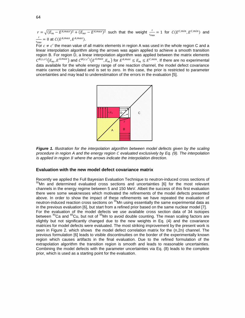
64
𝑟 = �(𝐸𝑚 − 𝐸𝐴,𝑚𝑎𝑥)2 + (𝐸𝑚′ − 𝐸𝐴,𝑚𝑎𝑥)2 such that the weight rrmax
= 1 for 𝐶(𝐸𝐶,𝑚𝑖𝑛 ,𝐸𝐶,𝑚𝑖𝑛) and r
rmax= 0 at 𝐶(𝐸𝐴,𝑚𝑎𝑥 ,𝐸𝐴,𝑚𝑎𝑥).
For 𝑐 ≠ 𝑐′ the mean value of all matrix elements in region A was used in the whole region C and a linear interpolation algorithm along the arrows was again applied to achieve a smooth transition region B. For region D, a linear interpolation algorithm was applied between the matrix elements 𝐶𝐵(𝑐,𝑐′)�𝐸𝑚 ,𝐸𝐴,𝑚𝑎𝑥� and 𝐶𝐵(𝑐,𝑐′)�𝐸𝐴,𝑚𝑎𝑥 ,𝐸𝑚� for 𝐸𝐴,𝑚𝑎𝑥 ≤ 𝐸𝑚 ≤ 𝐸𝐶 ,𝑚𝑖𝑛. If there are no experimental data available for the whole energy range of one reaction channel, the model defect covariance matrix cannot be calculated and is set to zero. In this case, the prior is restricted to parameter uncertainties and may lead to underestimation of the errors in the evaluation [5].
Evaluation with the new model defect covariance matrix
Recently we applied the Full Bayesian Evaluation Technique to neutron-induced cross sections of 55Mn and determined evaluated cross sections and uncertainties [6] for the most relevant channels in the energy regime between 5 and 150 MeV. Albeit the success of this first evaluation there were some weaknesses which motivated the refinements of the model defects presented above. In order to show the impact of these refinements we have repeated the evaluation of neutron-induced reaction cross sections on 55Mn using essentially the same experimental data as in the previous evaluation [6], but start from a refined prior based on the same nuclear model [7]. For the evaluation of the model defects we use available cross section data of 34 isotopes between 40Ca and 65Cu, but not of 55Mn to avoid double counting. The mean scaling factors are slightly but not significantly changed due to the new weights in Eq. (4) and the covariance matrices for model defects were evaluated. The most striking improvement by the present work is seen in Figure 2. which shows the model defect correlation matrix for the (n,2n) channel. The previous formulation [6] leads to visible discontinuities on the border of the experimentally known region which causes artifacts in the final evaluation. Due to the refined formulation of the extrapolation algorithm the transition region is smooth and leads to reasonable uncertainties. Combining the model defects with the parameter uncertainties via Eq. (8) leads to the complete prior, which is used as a starting point for the evaluation.
Figure 1. Illustration for the interpolation algorithm between model defects given by the scaling procedure in region A and the energy region 𝐶 evaluated exclusively by Eq. (9). The interpolation is applied in region 𝐵 where the arrows indicate the interpolation direction.

65
Figure 2. Correlation matrix and variance stemming from model defects for the (n,2n) reactions on 55Mn. Left: Model defects obtained within the refined formulation of model defects of this work; Right: Model defects obtained by the original formulation used in Ref. [6]. In both calculations the same experimental data of neighboring nuclei have been used.
Figure 3. Evaluated 55Mn(n,2n) cross section obtained by the prior with refined model defects (green) and the result of [6] (black). The error band of the new evaluation are also shown (green dashed). For comparison the available experimental data are displayed. Similarly to Ref. [6] we perform linearized Bayesian update steps to consistently include integral experimental data: (1st update) total and elastic cross sections, (2nd update) (n,t) and (n,4n) cross sections, (3rd update) (n,2n) cross sections. In addition to [6] also experimental (n,pα) cross sections could be included in the 2nd update step of the new evaluation. The evaluated (n,2n) cross section is shown as an example in Figure 3. It is obvious that the unrealistic bump at about 40 MeV of the previous evaluation [6] disappeared in the present work. This seems to be a direct consequence of the refined formulation of model defects which leads to a smooth extrapolation behavior. The corresponding evaluated correlation matrix for the 55Mn(n,2n) reaction is displayed in Figure 4. and compared to the results of [6]. The comparison clearly shows that the discontinuities of [6] vanished thus confirming that the new model defects lead indeed to more realistic correlations. In addition the cross sections and uncertainties move towards realistic values and energy dependences, respectively. At present only part of the experimental (n,2n) cross sections are included in this preliminary evaluation. There are strong indications that this causes the underestimation of the (n,2n) cross section at about 10 - 14 MeV. Inclusion of additional (n,2n) data should recover the expected energy dependence. Apart from the refinement of the formulation of the model defects we have also enlarged the flexibility of the nuclear model by allowing also uncertainties in the proton- and α−nucleus optical potential parameters as well as in the level densities [5]. The consequence of the enlarged

66
parameter space in combination with the refined model defects can be clearly seen in the 55Mn (n,α)) cross sections in Figure 5. Due to the enlarged parameter space, the error
bands become more realistic and include the data. In addition we observe also in this case the disappearance of unrealistic bumps in the evaluated cross sections which were definitely artifacts due to the discontinuities in the model defect covariance matrix of [6].
Conclusions We developed a refined formulation of model defects which provides a more reasonable continuation into the region without experimental data and a more realistic treatment of the uncertainties of the scaling factors. In order to demonstrate the impact of these refinements we have repeated the recent evaluation of neutron-induced cross sections of 55Mn [6] using the new model defect covariance matrix in the prior. Entering essentially the same experimental data sets and employing the same nuclear model [7] allows direct conclusions on the impact of the refinements. A careful comparison shows that in general the refined model defects lead to more realistic energy dependences and correlation matrices. Especially discontinuities in the correlation matrices disappear and error bands become more realistic. In addition the enlargement of the model space leads to more realistic error bands in channels involving charged particles. Although the new formulation of the Full Bayesian Evaluation Technique is quite successful, there is still much work required to make it to a routinely used tool.
Figure 4. Correlation matrix of the evaluated 55Mn(n,2n) reaction cross sections. Left: Final correlation matrix obtained with the refined formulation of model defects; Right: Final correlation matrix obtained in Ref. [6]. The corresponding square roots of the variances are shown below.
Figure 5. Evaluated 55Mn(n,α) cross section obtained by the prior with refined model defects (green), the result of [6] (black) and the prior (blue). Left: the error band of the new evaluation is also shown by green dashed lines. Right: the error band obtained in [6] is shown by black dashed lines. For comparison the available experimental data are displayed.

67
Acknowledgements Work partly supported by the EURATOM project IP_EUROTRANS and the project F4E-GRT-014. The views and opinions expressed herein do not necessarily reflect those of the European commission. References [1] H. Leeb, D. Neudecker, Th. Srdinko, Nuclear Data Sheets 109 (2008), 2762-2767. [2] St. Gundacker, H. Leeb, Proc. of the 2nd EFNUDAT workshop on Neutron Meas., Theory and Appl., Sept. 23-25 2009, Budapest Hungary (2009), 109-114. [3] D. Neudecker, St. Gundacker, H. Leeb, Th. Srdinko, V. Wildpaner, “Comparison of covariance matrices obtained by different methods”, Proc. of. the Internat. Conf. on Nucl. Data for Sci. and Techn. - ND2010, April 26-30 2010, Jeju South Korea (2010), submitted. [4] H. Leeb, St. Gundacker, D. Neudecker, Th. Srdinko, V. Wildpaner, “Bayesian based uncertainties of neutron-induced reaction cross sections of Mn-55”, Proc. of. the Internat. Conf. on Nucl. Data for Sci. and Techn. - ND2010, April 26-30 2010, Jeju South Korea (2010), submitted. [5] D. Neudecker, St. Gundacker, H. Leeb, Th. Srdinko, V. Wildpaner, these proceedings. [6] D. Neudecker, St. Gundacker, Th. Srdinko, V. Wildpaner, H. Leeb, Final Report of the F4E-GRT-014 Project D 9.a, (2010). [7] A. J. Koning, S. Hilaire, M. C. Duijvestijn, Proc. of. the Internat. Conf. on Nucl. Data for Sci. and Techn. - ND2007, April 22-27 2007, Nice France (2008), 211-214.

68

69
Key issues of pre-equilibrium emission for consistent description of the nucleon-induced reactions
V. Avrigeanu and M. Avrigeanu
‘Horia Hulubei’ National Institute for Physics and Nuclear Engineering, PO Box MG-6, 77125 Bucharest-Magurele, Romania [email protected]
Abstract: The pre-equilibrium emission model inconsistencies found within attempts to describe unitary the nucleon-induced reaction cross sections up to 60 MeV, are still actual. Global and local approaches have been used for a consistent analysis of the available activation data available up to 50 MeV for stable isotopes of medium-mass elements and conclusions on particular model assumptions are obtained.
Introduction The pre-equilibrium emission (PE) model inconsistency found within a former trial to describe unitary the (n,p) and (n,2n) reaction cross sections for the Cr isotopes, up to 20 MeV [1], is still actual. This lack of consistency remains also within the more recent work of Han [2] which stops at the incident energy of 20 MeV while more data are known up to 40 MeV. The case of 52Cr activation cross sections is actually used within the code EMPIRE-II manual [3] as a sample of model-calculation complexity. Similar features were revealed by the most recent high-resolution cross section measurement for 52Cr, whose comparison with TALYS [4] defaults model calculations was considered only a starting point for future improvements of theoretical models [5]. On the other hand, only half of the latest results obtained in activation experiments on Cr using a white-spectrum neutron field [6] and quasi-monoenergetic neutrons below 35 MeV [7] has been in agreement with the EAF-2005 library [8]. Therefore, global [3,4] and local [9] approaches are used within this work for a consistent analysis of all activation data for the Cr isotopes, available up to 40 MeV, in line with similar studies of nearby elements [10]. Former analysis which has been needed in order to strengthen the use a consistent input parameter set within the present model calculations is described elsewhere [11], so that only several basic points are mentioned in the following.
Nuclear model assumptions and parameters The neutron optical model potential (OMP) of Koning and Delaroche [12], used by default in both TALYS and EMPIRE codes, does not fully reproduce the minimum around the neutron energy of 1-2 MeV for the total neutron cross sections of the mass A~60 nuclei. Following also the authors' comment on the constant geometry parameters which may be responsible for this point, we have obtained corresponding energy-dependent geometry parameters using within the SPRT method [13] (a) recent RIPL-3 recommendations [14] as well as most recent results [15] for the low-energy neutron scattering properties (s- and p-wave neutron strength functions, S0 and S1, (b) the potential scattering radius (R'), and (c) the available measured neutron total cross sections [16] including the latest measurements [17] of the neutron total cross sections for 50,52,53,54Cr stable isotopes beyond the neutron energy of even 60 MeV. Unfortunately it remains a difficult point concerning the extended ranges due to the S0 non-linear energy dependence as it is already known to be the case of 52,54Cr isotopes [18]. Nevertheless, this potential has also been involved in the calculation of the corresponding collective inelastic scattering cross sections by means of the direct-interaction distorted-wave Born approximation (DWBA) method. The proton optical potential of Koning and Delaroche [12] has also been involved within the analysis of the available measured cross sections of (p,n) as well as the (p,γ) reactions on 51V

70
target nucleus, to check the adopted proton OMP and gamma-ray strength functions. Another change of the geometry parameters of this potential, corresponding to a decrease of 20% for the (p,n) reaction cross sections in the energy range of the statistically emitted protons, has been found necessary for the proton energies below 13 MeV (Fig. 1). At the same time, the electric dipole gamma-ray strength functions fE1(Eγ), obtained through analysis of the neutron-capture cross sections, have to be decreased by around 25% (the right-bottom corner of Fig. 1).
Figure 1. Comparison of measured [16] and local approach [9] calculated total reaction cross sections of protons on A~51, odd-Z nuclei, and (p,γ) and (p,n) reaction cross sections on 51V. Actually, the fE1(Eγ) strength functions, used for the calculation of the gamma-ray transmission coefficients, have been obtained within the framework of a modified energy-dependent Breit-Wigner (EDBW) model [19], and checked by an analysis of capture cross sections for all 50,52,53,54Cr stable isotopes in the neutron energy range from keV to 2-3 MeV. Unfortunately the measured neutron-capture cross section are either too scarce or less consistent in order to make possible certain proofs of these electric dipole gamma-ray strength functions. The nuclear level densities were derived on the basis of the back-shifted Fermi gas (BSFG) formula [20], for the excitation energies below the neutron-binding energy, with parameter adjustments obtained by a fit of more recent experimental low-lying discrete levels [21] and s-wave nucleon resonance spacings [14]. Above the neutron binding we took into account the washing out of shell effects within the approach of Junghans et al. [22], with an asymptotic value A/9 for the level density parameter, and using the method of Koning and Chadwick [23] for fixing the appropriate shell correction energy. A transition range from the BSFG formula description to the higher energy approach has been chosen between the excitation energies of 15 and 25 MeV [24]. On the other hand, the spin distribution has been given by a variable ratio of the nuclear moment of inertia to its rigid-body value, between 0.5 for ground states, 0.75 at the neutron binding energies, and 1 around the excitation energy of 15 MeV [25].
0.0
0.5
1.0
51V - KD (2003) 55Mn - KD (2003) 59Co - KD (2003) 63Cu - KD (2003) 51V - KD (2003) + aV=.41+.02E, E<13
p+51V,55Mn,59Co,63,65Cu51V: Kailas+ (1985)
Carlson (1996)51V 55Mn59ConatCu63Cu65Cu
σ (b
)
σR
1E-4
1E-3
0.01
0.1
σR: KD (2003) KD (2003) KD (2003) + aV=.41+.02E, E<13
51V(p,n)51Cr
Zyskind (1980)Kailas+ (1985)Zhao+ (1994)Musthafa+ (2005)
10 20 30 401E-4
1E-3
0.01
0.1
Ep (MeV)
σR: KD (2003) KD (2003) KD (2003) + aV=.41+.02E, E<13
51V(p,n)51Cr
Chodil+ (1967)Gadioli+ (1974)Michel+ (1979)Zyskind (1980)Kailas+ (1985)Levkovskij (1991)Zhao+ (1994)Musthafa+ (2005)
1 2 3 41E-5
1E-4
σR: KD (2003) KD (2003) [Γγ=900 meV] KD (2003) + aV=.41+.02E, E<13, Γγ=900 meV KD (2003) + aV=.41+.02E, E<13, Γγ=700 meV
51V(p,γ)52CrZyskind(1980)

71
A local approach [9] using the Geometry-Dependent Hybrid (GDH) PE model [26] is moreover proved by the good agreement of the calculated (p,n) reaction cross sections with the recent data between ~20 and 45 MeV (Fig. 1, left-bottom). While no free parameter has been involved, the basic point in this respect is the use of an advanced particle-hole state density [27] within the PE description which has recently been described elsewhere [28,29]. These data description is obviously improved with reference to previous PE related analysis [30], providing confidence in the present results obtained without using adjustable PE parameters.
Results and discussion A first unexpected point following the careful former assessment of the consistent input parameter set finally used within the local analysis of the Cr isotopes' fast-neutron activation
Figure 2. Comparison of measured [16] and calculated activation cross sections for 52Cr target nucleus using TALYS and EMPIRE-II codes' global approach and local approach [9]. activation cross sections has concerned the use of the proton OMP, modified according to the analysis results shown in the previous section, which leads with respect to the measured data for the target nucleus 52Cr to a significant underestimation of the (n,p) reaction but overestimation of the (n,2n) reaction. On the other hand, the unchanged proton OMP of Koning and Delaroche [12] provide a satisfactory description of the (n,p) reaction data at the lowest incident energies, where the calculated cross-section sensitivity to this particular input parameters is largest. Therefore this OMP has been used in all calculations with the good results shown in Figs. 2 and 3 for the target nuclei 50Cr and 52,53,54Cr, respectively. The comparison with the global predictions of TALYS and EMPIRE (Figs. 2-3) shows rather large differences both at incident energies below, e.g., 10 MeV, where PE are not significant, and at higher energies. The effects due to various OMP parameters as well as nuclear level densities are obvious within the former case, pointing out the necessity and usefulness of using a consistent nuclear-model parameter set. On the other hand, in order to make more visible the PE
20 30 400.00
0.05
0.10
0.15
E (MeV)
Qaim+ (1972)Araminowicz+(1973) Valkonen (1976)Sigg (1976)Sailer+ (1977)Berrada (1984)Bahal+ (1984)Ribansky+ (1985)Pepelnik+ (1985)Zhou M+ (1987)
50Cr(n,2n)49CrDighe+ (1991)Ercan+ (1991)Uwamino+(1992)Pansare+(1993)
TALYS-1 EMPIRE-2.19 STAPRE-H
Ghorai+ (1987)Ykeda+ (1988)Bahal+ (1984)Ribansky+ (1985)Pepelnik+ (1985)Zhou M+ (1987)Ghorai+ (1987)Ykeda+ (1988)
24 28 32 360.000
0.005
0.010
Uwamino+ (1992)
50Cr(n,3n)48Cr
TALYS-1 EMPIRE-2.19 STAPRE-H
12 16 200.0
0.2
0.4
0.6
0.8
Klochkova+ (1992)Fessler+ (1999)
50Cr(n,np+pn+d)49V
TALYS-1 EMPIRE-2.19 STAPRE-H
5 10 15 200.0
0.1
0.2
0.3
0.4
σ (b
)
TALYS-1 EMPIRE-2.19 STAPRE-H
50Cr(n,p)50V
Klochkova+ (1992)

72
importance for the description of the measured data at higher incident energies, there are shown in Figs. 4-5 the results obtained for the same reactions without consideration of the PE reaction mechanism. First, a particular case is that of the isotope 50Cr which has the lowest nuclear asymmetry (N-Z)/A among the Cr stable isotopes, and thus, according to the isotope effect, the lowest PE weight. One may see in this case that the corresponding calculated cross-section differences are even within the error bars of the few available experimental data sets except the (n,2n) reaction. The measured data above ~30 MeV seem to be however much too lower, close to the calculated values without PE consideration while all three computer codes provide quite higher predictions at these energies. Moreover, in order to understand the nuclear-model calculation differences at incident energies above 20 MeV, we have focused on the PE model calculation sensitivity. Among the different PE models and related assumptions involved within the three nuclear-model computer codes, the particle-hole level density (p.l.d.) seems to be the main quantity for accuracy of the PE calculation results. Beyond the various related formulas which has been presently agreed to represent the top-of-art level (e.g., Refs. of [27]), we have chosen to point out the corresponding effects by means of the nuclear-shell shift S [31] of the excitation energy considered within these formulas. This quantity is defined as the difference between the back-shifted parameter of the BSFG level-density model and the usual pairing energy. Thus, the calculated activation cross-section obtained by an additional assumption of S=0 there are also compared in Figs. 4-5 with the finally calculated values and the measured data. Since the shell- correction S values are usually negative for nuclei around the closed shell with Z=28, their consideration leads to the increase of the effective excitation energy at which p.l.d. is evaluated, and thus to larger p.l.d. values and finally PE cross sections. The main conclusion of this analysis has been that the use of the shell correction within the p.l.d. formula provides a good description of the experimental data for all reaction channels induced by fast neutrons on the target nucleus 52Cr. However, a distinct case is that of the target nuclei 53,54Cr, the account of the (n,p) reaction cross sections for them being obtained only if the shell-correction in the p.l.d. formula is not taken into account. (Fig. 5). This results may rise additional questions either on the way adopted for the S-value estimation or the particular case of nuclei around Z=28. Finally, the present comparison of the global predictions of TALYS and EMPIRE, local analysis with STAPRE-H, and measured activation cross sections (Figs. 2-3), including a sensitivity analysis of the calculated values with respect to model parameters, pointed out that larger differences at higher energies could be due to different PE models and related assumptions involved within the three nuclear-model computer codes. Therefore, in order to make possible a deeper view on the model status and development, more accurate measured data are needed up to at least 40 MeV. Then, the presently developing project Neutrons for Science (NFS) at the accelerator SPIRAL2 [32] will obviously be most helpful in this respect.

73
Figure 3. The same as in Fig. 2 but for the 52,53,54Cr target nuclei excepting the 52Cr(n,n’) reaction for which the various cross sections were calculated within the local approach for the different channels shown on figure.
15 20 25 30 35 400.0
0.2
0.4
0.6
E (MeV)
Sailer+ (1977)Berrada (1983)Ribansky+ (1985)Ghorai+ (1987)
52Cr(n,2n)51Cr
TALYS-1 EMPIRE-II STAPRE-H
Lychagin+ (1988)Ykeda+ (1988)Wagner+(1989)Liskien+ (1989)Ercan+ (1991)Uwamino+ (1992)Molla+ (1997)Fessler+ (1998)Mannhart+(2007)
5 10 15 200.00
0.05
0.10
Prasad+ (1971)Desler+ (1973)Aleksandrov+(1975)Valkonen (1976)Qaim (1977)Artem'ev+ (1980)Smith+ (1980) Viennot+ (1982)Ribansky+(1985)Gupta+ (1985)Luc+ (1986)Ghorai+ (1987)Ikeda+ (1987)Kawade+(1990)
52Cr(n,p)52V
σ (b
)
Ercan+(1991)Viennot+(1991)Osman+ (1996)Kasugai+ (1998)Fessler+ (1998)Thiep+ (2003)Mannhart+(2007)
TALYS-1 EMPIRE-II STAPRE-H
5 10 15 200.0
0.1
0.2
0.3
TALYS-1 EMPIRE-II STAPRE-H (n,pn) (n,np)
52Cr(n,xp)Grimes+ (1979)
5 10 150.0
0.5
1.0
1.552Cr(n,n')
σR σ(n,n)CN σ(n,n'x) σ(n,n)CN+(n,n') σ(n,n')
Simakov+ (1992) IRMM (2007) IRMM (2007) [av.]
[200 keV]
5 10 15 200.00
0.02
0.04
0.06
E (MeV)
Qaim (1977)Artem'ev+ (1980)Smith+ (1980) Viennot+ (1982)Bahal+ (1984)Ribansky+ (1985)Pepelnik+ (1985)Luc+ (1986)Kawade+ (1990)
53Cr(n,p)53V
Ercan+ (1991)Viennot+ (1991)Osman+ (1996)Kasugai+ (1998)Fessler+ (1998)Thiep+ (2003)
TALYS-1 EMPIRE-II STAPRE-H
8 12 16 200.00
0.01
0.02
0.03
0.04
Husain+ (1967)Valkonen (1976)Qaim+ (1977)Artem'ev+ (1980)Bahal+ (1984)Ribansky+ (1985)Luc+ (1986)Kasugai+ (1998)Fessler+ (1998)Thiep+ (2003)
54Cr(n,p)54V
TALYS-1 EMPIRE-II STAPRE-H

74
Figure 4. Comparison of measured [16] and local approach [9] calculated activation cross sections for the 50Cr target nucleus, with various PE assumptions.
Figure 5. The same as in Fig. 4 but for neutrons on 52,53,54Cr nuclei and 51V(p,n)51Cr reaction.
20 30 400.00
0.05
0.10
0.15
E (MeV)
Qaim+ (1972)Araminowicz+(1973) Valkonen (1976)Sigg (1976)Sailer+ (1977)Berrada (1984)Bahal+ (1984)Ribansky+ (1985)Pepelnik+ (1985)Zhou M+ (1987)
50Cr(n,2n)49CrDighe+ (1991)Ercan+ (1991)Uwamino+(1992)Pansare+(1993)
No PE S=0 S=∆-P
Ghorai+ (1987)Ykeda+ (1988)Bahal+ (1984)Ribansky+ (1985)Pepelnik+ (1985)Zhou M+ (1987)Ghorai+ (1987)Ykeda+ (1988)
24 28 32 360.000
0.005
0.010
Uwamino+ (1992)
50Cr(n,3n)48Cr
No PE S=0 S=∆-P
12 16 200.0
0.2
0.4
0.6
0.8
Klochkova+ (1992)Fessler+ (1999)
50Cr(n,np+pn+d)49V
No PE S=0 S=∆-P
5 10 15 200.0
0.1
0.2
0.3
0.4
0.5
σ (b)
No PE S=0 S=∆-P
50Cr(n,p)50V
Klochkova+ (1992)
15 20 25 30 35 400.0
0.2
0.4
0.6
E (MeV)
Sailer+ (1977)Berrada (1983)Ribansky+ (1985)Ghorai+ (1987)
52Cr(n,2n)51Cr
No PE S=0 S=∆-P
Lychagin+ (1988)Ykeda+ (1988)Wagner+(1989)Liskien+ (1989)Ercan+ (1991)Uwamino+ (1992)Molla+ (1997)Fessler+ (1998)Mannhart+(2007)
5 10 15 200.00
0.03
0.06
0.09Prasad+ (1971)Desler+ (1973)Aleksandrov+(1975)Valkonen (1976)Qaim (1977)Artem'ev+ (1980)Smith+ (1980) Viennot+ (1982)Ribansky+(1985)Gupta+ (1985)Luc+ (1986)
52Cr(n,p)52V
σ (b
)
Ghorai+ (1987)Ikeda+ (1987)Kawade+(1990)Ercan+(1991)Viennot+(1991)Osman+ (1996)Kasugai+ (1998)Fessler+ (1998)Thiep+ (2003)Mannhart+(2007)
No PE S=0 S=∆-P
5 10 15 200.00
0.02
0.04
0.06
Qaim (1977)Artem'ev+ (1980)Smith+ (1980) Viennot+ (1982)Bahal+ (1984)Ribansky+ (1985)Pepelnik+ (1985)Luc+ (1986)Kawade+ (1990)
53Cr(n,p)53V
Ercan+ (1991)Viennot+ (1991)Osman+ (1996)Kasugai+ (1998)Fessler+ (1998)Thiep+ (2003)
No PE S=0 S=∆-P
8 12 16 200.00
0.01
0.02
0.03
Husain+ (1967)Valkonen (1976)Qaim+ (1977)Artem'ev+ (1980)Bahal+ (1984)Ribansky+ (1985)Luc+ (1986)Kasugai+ (1998)Fessler+ (1998)Thiep+ (2003)
54Cr(n,p)54V
No PE S=0 S=∆-P
10 20 30 401E-4
1E-3
0.01
0.1
E (MeV)
No PE S=0 S=∆-P
51V(p,n)51Cr
Chodil+ (1967)Gadioli+ (1974)Michel+ (1979)Zyskind (1980)Kailas+ (1985)Levkovskij (1991)Zhao+ (1994)Musthafa+ (2005)

75
Acknowledgements This work was partly supported by the CNCSIS-Bucharest project PN-II-ID-2008-2-43.
References [1] A. Fessler, E. Wattecamps, D. L. Smith, and S. M. Qaim, Phys. Rev. C 58, 996 (1998). [2] Y. Han, Nucl. Phys. A 748, 75 (2005). [3] M. Herman et al., EMPIRE ultimate expansion: resonances and covariances, Proc. Int. Conf.
on Nuclear Data for Science and Technology (ND 2007), Nice, France, April 22-27, 2007, p. 207; EMPIRE-2.19 Manual, p. 171, http://www-nds.iaea.org/empire/.
[4] L.C. Mihailescu, C. Borcea, A.J. Koning, A.J.M. Plompen, Nucl. Phys. A 786, 1 (2007). [5] A.J. Koning, S. Hilaire, and M.C. Duijvestijn, TALYS-1.0, as Ref. [3]. [6] E. Simeckova et al., in: A. Plompen (Ed.), Proc. 4th NEMEA-4 Workshop on Neutron Mea-
surements, Evaluations and Applications, Prague, Czech Republic (2007), European Commission Report EUR 23235 EN, Belgium, 2008, p. 35.
[7] M. Honusek et al., as Ref. [6], p. 39. [8] R.A. Forrest et al., Report UKAEA FUS 526 (2006) [9] M. Avrigeanu and V. Avrigeanu, NP-86-1995, Recent Improvements of the STAPRE-H95
Preequilibrium and statistical Model Code, Institute of Physics and Nuclear Engineering, Bucharest (1995) and Refs. therein; News NEA Data Bank, 17, 22 (1995).
[10] P. Reimer et al., Phys. Rev. C 65, 014604 (2001); M. Avrigeanu et al., Nucl. Phys. A 806, 15 (2008); V. Semkova et al., Nucl. Phys. A 730, 255 (2004).
[11] M. Avrigeanu and V. Avrigeanu, in: F.Z. Hambsch (Ed.), EFNUDAT Fast Neutrons - Proceedings of the Scientific Workshop on Neutron Measurements, Theory and Applications - Nuclear Data for Sustainable Nuclear Energy - 28-30 April 2009, Geel, Belgium, European Commission Joint Research Centre Report EUR 23883 EN, Belgium, 2010, p. 11; http://publications.jrc.ec.europa.eu/repository/handle/111111111/13584.
[12] A.J. Koning and J.P. Delaroche, Nucl. Phys. A 713, 231 (2003). [13] J.P. Delaroche, Ch. Lagrange, J. Salvy, IAEA-190 (IAEA, Vienna, 1976), vol. 1, p. 251. [14] R. Capote et al., RIPL – Reference Input Parameter Library for Calculation of Nuclear
Reactions and Nuclear Data Evaluations', Nucl. Data Sheets 110, 3107 (2009); http://www-nds.iaea.org/RIPL-3/resonances/.
[15] L. Leal, Report EFFDOC-1055, OECD/NEA Data Bank, Nov. 2008. [16] Experimental Nuclear Reaction Data (EXFOR); http://www-nds.iaea.or.at/exfor . [17] W.P. Abfalterer et al., Phys. Rev. C 63, 044608 (2001). [18] H.M. Agrawal, J.B. Garg, and J. A. Harvey, Phys Rev. C 30, 1880 (1984) [19] M. Avrigeanu, V. Avrigeanu, G. Cata, and M. Ivascu, Rev. Roum. Phys. 32, 837 (1987). [20] H. Vonach et al., M. Uhl, B. Strohmaier, B. W. Smith, and E. G. Bilpuch, G. E. Mitchell, Phys.
Rev. C 38, 2541 (1988). [21] Evaluated Nuclear Structure Data File (ENSDF), www.nndc.bnl.gov/ensdf/. [22] A. R. Junghans et al., M. de Jong, H.-G. Clerc, A. V. Ignatyuk, G. A. Kudyaev, and K.-H.
Schmidt, Nucl. Phys. A 629, 635 (1998), and Refs. therein. [23] A.J. Koning and M. B. Chadwick, Phys. Rev. C 56, 970 (1997). [24] M. J. Canty, P. A. Gottschalk, and F. Pühlhofer, Nucl. Phys. A 317, 495 (1979). [25] V. Avrigeanu, T. Glodariu, A.J.M. Plompen, and H. Weigmann, J. Nucl. Sci. Tech. S2, 746
(2002). [26] M. Blann and H. K. Vonach, Phys. Rev. C 28, 1475 (1983), and Refs. therein. [27] M. Avrigeanu and V. Avrigeanu, Comp. Phys. Comm. 112, 191 (1998); A. Harangozo, I.
Stetcu, M. Avrigeanu, and V. Avrigeanu, Phys. Rev. C 58, 295 (1998). [28] M. Avrigeanu, S. Chuvaev, A. A. Filatenkov, R. A. Forrest, M. Herman, A.J. Koning, A.J.M.
Plompen, F. L. Roman, and V. Avrigeanu, Nucl. Phys. A 806, 15 (2008). [29] P. Bem, E. Simeckova, M. Honusek, U. Fischer, S. Simakov, R. A. Forrest, M. Avrigeanu, A.
C. Obreja, F. L. Roman, and V. Avrigeanu, Phys. Rev. C 79, 044610(2009). [30] M. M. Mustafa, Manoj Kumar Sharma, B. P. Singh, and R. Prasad, Appl. Rad. Isotopes 62,
419 (2005). [31] C.Y. Fu, Nucl. Sci. Eng. 92, 440 (1986); idem, 109, 18 (1991).

76
[32] X. Ledoux and S. Simakov, Status Report of the NFS collaboration, http://pro.ganil-spiral2.eu/spiral2/instrumentation/nfs/working-documents/status-report-january-2010; X. Ledoux et al., these Proceedings.
77
Overview of the JRA1 activities at JRC-IRMM
F.-J. Hambsch1), A. Al-Adili1,2), I. Fabry1), L.C. Mihailescu1), A. Plompen1), S. Oberstedt1), P. Schillebeeckx1), Sh. Zeynalov3)
1) EC-JRC-IRMM, Retieseweg 111, 2440 Geel, Belgium 2) Division of Applied Nuclear Physics, Uppsala University, 751 20 Uppsala, Sweden 3) JINR-Joint Institute for Nuclear Research, Dubna 141980, Moscow-region, Russia [email protected]
Abstract: The Joint Research Activity 1 of EFNUDAT was dealing with the development of novel acquisition methods for nuclear data. JRC-IRMM was involved in the development of fast digital data acquisition systems as well as digital signal processing routines for off-line analysis of the acquired data. Two different DA systems are presently in use at JRC-IRMM, one dedicated to the investigation of the fission process and the other one for investigation of elastic scattering processes. Investigation of the neutron induced fission of 234U as a function of incident neutron energy was performed comparing both analogue and the digital data acquisition systems, showing the beneficial application of digital data acquisition in terms of e.g. pile-up correction. A Java based TCD-1.0 system is also in use for the measurement of elastic scattering angular distributions at the GELINA facility using different detector systems (e.g. the GAINS array as well as an array of 8 Li-glass and 8 liquid scintillation detectors). The superiority of the DA together with DSP routines is discussed and compared with the traditional analogue technique. Introduction Within the EFNUDAT Joint Research Activities (JRA) 1 the objective was to develop novel acquisition methods for nuclear data measurements. Several partners have participated in this activity and improved their measurement capabilities as it has been demonstrated by a number of presentations given at the different workshops within EFNUDAT (see links to workshop presentations at the EFNUDAT website www.efnudat.eu). The present paper summarizes the development activities at JRC-IRMM.
Digital Acquisition and Analysis software Mainly during the two first years of the running of the EFNUDAT project data acquisition software of a multitude of digitizers has been developed as well as digital signal processing routines. This climaxed into two Data acquisition programs for fast digitzers; GELISCOPE for a heterogeneous combination of Spectrum and Acqiris boards of certain types and TwoCardsDigitizer for Acqiris boards. In addition to that the GENDARC (Geel Nuclear Physics Data Acquisition, Analysis and Run Control Program) software has been developed based on the free software platform ROOT from CERN [1]. A typical view of the different graphical windows of GENDARC is given in Fig. 1. GENDARC is able to control analogue data acquisition based on a front-end from the Send GmbH in Germany capable of handling up to 16 ADC inputs. Furthermore, GENDARC is able to perform within the same Graphical framework also data analysis of both analogue and digital data if the file to be analysed is available in the form of a list mode file. In case of digital data this is of course not evident since the full trace of the signal is recorded and needs additional data analysis steps using digital signal processing (DSP) routines to generate pulse heights from the digital trace. This is done in a separate step involving DSP routines which have been developed as a list of subroutines which can be called from within C programs.

78
Application in experiments Since the major part of the development process has been finished, the available software tools are now applied to real neutron physics experiments to profit from the benefits. Examples are given in the next chapters.
The neutron induced fission of 234U The measurements have been performed at the Van de Graaff accelerator of the IRMM in Geel, Belgium. Protons from the 7MV accelerator were used for neutron production via the reactions 7Li(p,n) and T(p,n). The fission fragment (FF) detection was carried out by means of a Twin Frisch-Grid Ionization Chamber (TFGIC) with a common cathode [2]. As detection gas P-10 (90% Ar+10% CH4) was used with a constant pressure of 1.05 bar and a flow of 0.1 ℓ/min. The energies and emission angles of both FF are measured simultaneously. Five signals (two anodes, two grids and one cathode signal) were extracted from the ionization chamber and fed into charge-sensitive preamplifiers. Analogue data acquisition (AA) and digital data acquisition (DA) systems are compared to each other. The signals are treated independently in both acquisition systems. For the analogue case, the anode signals are fed into spectroscopic amplifiers with a shaping time of 2 μs, leading to a semi-Gaussian pulse-shape. After the signal processing six ADC signals are stored, two pulse heights, two drift-times and two sum-signals. In the digital case after the preamplifiers, the cathode signal was used for triggering and together with the grid and anode signals fed into a 12 Bit, 100 MHz wave-form digitizer. The DA system requires DSP algorithms performing the signal transformations similar to the operations performed by the hardware modules in the AA case. Typical signal shapes are shown in the left part of Fig. 2. The raw waveforms from the charge-sensitive preamplifiers are first corrected for baseline-displacements, using the baseline averaging over 150 pre-trigger samples. The sum signals are created from grid and anode signals (see left part of Fig. 2). The charge signals are differentiated and corrected for the preamplifier discharge effect to unfold the current wave-forms. The unfolded current wave-form’s centre-of-gravity is assigned to the anode pulse centre-of-gravity. The preamplifier discharge effect often referred to as the “ballistic deficit” is observed in the pulses as an exponential decay (decay time = 118 μs) after the total charge has been induced in the preamplifier (see right part of Fig. 2). One correction for this effect would be to fit the tail and correct the waveform to the constant maximum value. Another method is to compute the average maximum value from the first channels before the decay, and correct the tail to that constant. This latter method (used in this work) reduces also the contribution from the preamplifier noise after the last electrons have reached the anode. The FF energy information is contained in the height of the anode signals. However, to enhance the signal to-noise ratio, the wave-forms are processed with a CR−RC 4 shaping filter [3]. This method was found to be more precise than taking the maximum of the PA output signal. This is due to the fact, that the whole signal is used
Figure 1. Typical view of the graphical layout of the GENDARC software.

79
to produce the pulse height of the FF rather than only the pulse maximum which often is disturbed by noise. The CR differentiation along with the RC integration is done recursively following the approach of Ref. [4]. Three different shaping times τ (0.5 μs, 1.0 μs and 2.0 μs) were tested, leading to nearly identical pulse height and angular distribution based on the summing method. The resulting pulse-shape, shown in the right part of Fig. 2 with a dashed dotted line, is
different to the semi-Gaussian pulse-shape produced with the analogue spectroscopic amplifier. Although the shaping time of 0.5 μs used for the CR-RC4 filter does not compare to the analogue shaping time of 2 μs, the resulting pulse-height distributions are in perfect agreement. The height of the CR−RC 4 filter output determines the pulse height induced by the FF. The same signal processing routines are also applied to the summing signal to produce the corresponding pulse height. In addition to the summing method also the drift-time technique was investigated in the DA case, using constant fraction discrimination (CFD) and leading edge (LE) set at different levels on cathode and anode signals in order to simulate the corresponding modules used in AA. The reference for the comparison was the isotropic cosine distribution of the 235U(nth, f) reaction obtained from the summing method. In the drift-time method an overshoot at lower cosine values was observed (see Fig. 3). Varying the CFD trigger levels (10%, 5%, 4%, 3%) on the anode signal, we obtained an optimum value around 3% of the anode signal as seen in Fig. 3 to determine the correct cosine distribution.
The 234U sample is a strong α-particle source (230 kBq/µgU). This leads to pile-up effects when α-particles are emitted close in time with a FF. Fig. 4 shows one such event with three piled-up α-particles. In the AA case normally the piled up events may be rejected by sophisticated pulse pile-
Figure 2. Left part: Typical signal shapes of the ionisation chamber pulses. Right part: DSP routines applied to the chamber signals to deduce the pulse height.
0.0 0.2 0.4 0.6 0.8 1.0 1.20
500
1000
1500
2000
2500
3000
3500
Coun
ts
CosθT
CFD 10% CFD 5% CFD 4% CFD 3%
Figure 3. Angular distribution and the variation of the trigger of the CFD.
Figure 4. Application of DSP routines to correct α-particle pile-up.

80
up rejection systems [2, 5]. Hence, the counting statistics is drastically reduced in case of a strong α-emitter. Digital methods add a new dimension of correction possibilities when each signal can be examined for pile-up and corrected for without discarding the whole event. In practical terms, this is done by first differentiating the wave-form as shown earlier in the right part of Fig. 2. The strong change of pulse height caused by the FF is observed as the largest peak, whereas a-particles generate small peaks hardly visible among the noise. By restricting the filtering process to a small window around the large FF peak and setting all the differentiation outside this range to zero, one can eliminate the major part of the pile-ups.A clean wave-form is
reproduced by integration, free from α-particle and proton recoil contributions as seen in Fig. 5a by the full lines. The α-particle pile-up influences also the angle determination. If an early pile-up occurs in coincidence with a FF then the determination of the drift time is biased by the portion of the present pile-up. This leads to a false triggering and a displacement of the drift-time distribution. This was observed both in the AA and DA case (see arrows in Fig. 5). In DA the α-particle pile-up correction was reducing the problem, however not entirely in case the α-particle pile-up contribution was too close in time to the FF and, hence, within the integration window around the centre-of-gravity position. One possible correction is to introduce a narrower integration window around these piled-up events. The digital data requires, of course, about 1000 times more storage capacity. However, nowadays this is no longer an issue. In addition, the digital signal processing requires some additional work to develop signal processing routines and to simulate a variety of different standard analogue modules. Despite this, several important advantages of the DA can be summarized as follows: 1. Pile-up correction: Here we see the main advantage of DA in comparison with AA. The corrected piled-up events can still be used without being discarded. In AA the events normally are rejected reducing the statistical accuracy. As seen in the present work, the α-particle pileup correction was also essential to be introduced in case of 234U(n, f),where the pulse height turned out to be too high compared to the reference measurement of 235U(n, f) due to the strong α−activity. The pile-up correction in DA improves the peak-to-valley ratio in case of 234U(n, f) significantly as seen in Fig. 6. 2. Electronic modules reduction and stability: The use of a wave-form digitizer reduced the amount of electronics and, hence, the risk of electronic failure and signal drift. In AA signal variations occurred due to temperature changes in the electronic set-up. This had to be corrected for using a precision pulse generator. In DA these drifts were not encountered. Hence, superior stability of the detector signals over time is observed in DA.
60 90 1200.00
0.01
0.02
0.03
0.04
234U(n,f) 2 MeV DIGITAL ANALOGUE
Coun
ts (n
orm
)
Energy (MeV)
Figure 5. Drift time analysis of the chamber signals and observation of timing mismatch (arrowed region).
Figure 6. Energy distribution for 234U(n; f) at 2 MeV neutron energy, for both AA and DA. Due to the event-by-event pile-up correction in the DA case the energy resolution was significantly improved.
81
3. Summing method: In AA a good working of the summing method is dependent on a decent calibration of both anode and grid electronic chains. Drifts in these electronic modules will degrade the determination of the angular distribution. In DA it has been observed that a calibration is not that important. Since the summation is done software-wise, no electronic modules which might drift are involved. Furthermore, the internal amplification gains from each module can differ slightly in the AA case. In the DA case all gains after the preamplifier are identical, because the code applied in the DSP implies the same amplification for all chains. Although the results in both cases were similar, the determination of the angular distribution in the AA case was much more dependent on a stable electronic set-up. 4. Drift-Time method: For the drift-time method optimum settings for CFD or LE could be searched for during offline analysis, after the experiment. This is possible, because the whole signal is stored rather than only one drift-time value as it is the case in the AA. The settings once set in AA prior to the experiment decide upon the quality of the drift-time final angular distribution.
Capture and inelastic scattering experiments At the GELINA facility several tests were made using Acqiris and CAEN digitizers for capture and inelastic scattering measurements. For capture measurements the Acqiris DC282 and CAEN N1728B were compared with conventional electronics. The capture measurements involved a C6D6 detector of 2.8 l of pyramid shape and a cylindrical detector of 0.6l both with an EMI9823KQ photomultiplier tube. Two output signals are available: the fast anode signal with a rise time of about 8 ns and total duration less than 100 ns and the slow signal from the 9th dynode integrated by a charge sensitive preamplifier. Both signals were used in the tests, but only the best results are presented below. The CAEN N1728B is a single slot NIM module with USB interface. It has 14 bit amplitude resolution and a sampling period of 10 ns. Onboard DSP algorithms provide list mode time and amplitude data via a factory data-acquisition interface allowing selection of the timing algorithm (leading edge or constant fraction) and setting of the parameters for the algorithms. The Jordanov-Knoll trapezoid algorithm is used to determine the pulse amplitude. The Acquiris DC282 is a 10-bit digitizer with a sampling period of 0.5 ns. No onboard processing is possible so the data are transferred to a PC for processing. Data were acquired in sequence mode and acquisition and transfer are independent so that transfer does not result in dead time. The conventional system uses NIM electronics (constant fraction, shaping amplifier), a Canberra ADC and a multiple-hit time coder with 1 ns resolution and a range of 26 bits. The data acquisition module and the time coder were built at IRMM. The system was arranged to have a non-extendable dead time of 2800 ns. Initial tests were directed at establishing time-resolution, pulse amplitude resolution and amplitude linearity as these points are critical in capture measurements employing the pulse-height weighing and time-of-flight techniques. For amplitude linearity and resolution similar results were obtained with the three systems. The time resolution for the Acqiris DC282 system matches that of conventional electronics (1.6 ns FWHM) while that for the CAEN N1728B is compromised by the low sampling rate (15 ns FWHM). Final tests concerned the dead time. Optimal settings resulted in 560ns for the CAEN N1728B digitizer while this was 350 ns (750 ns) for the DC282 digitizer using the fast (slow) signal. The respective dead times may be read of from Figure 7 (left part) that shows the time difference from two consecutive events resulting from a gamma-ray source. The right part of Figure 7 shows the impact of dead time on a time-of-flight measurement at GELINA near the gamma-flash. In Figure 8 the impact of dead time is shown for a capture measurement with a 1 mm gold sample near the resonance at 60.3 eV. The dead time for the conventional system is significant and clearly distorts the time-of-flight spectrum. For the CAEN digitizer the impact of the dead time is much reduced. In case of a fixed non-extending dead time, there is a simple algorithm to compensate time-of-flight spectra for dead time. These corrected spectra are also shown. For the conventional system the largest correction factor is 2.2 while for the CAEN N1728B digitizer the largest correction is about 10%. Agreement for the corrected spectra is excellent except for the largest corrections where a difference of somewhat more than 2% remains. For further details see reference [6].

82
For inelastic scattering measurements are made at a 200m station of the GELINA facility using eight high purity germanium detectors with crystals of 8 cm length and 8 cm diameter. Gamma-rays are detected emitted following neutron inelastic scattering. Data acquisition is based on DC440 digitizers from Acqiris [7]. These have a sampling period of 2.38 ns (about 420 MSamples/s). The module has two inputs and 12 bit amplitude resolution. No onboard processing is possible and data are transferred to a PC for processing. One PC serves four detectors (two cards). Trigger electronics is used to establish that a neutron-induced event took place in the time-window of interest. For a valid trigger 10000 samples are transferred covering the time-span from before the gamma-flash to after the time corresponding with the reaction threshold. The transfer of data can be done just before the next GELINA pulse (at 800 Hz there is one every 1.25 ms). This, and a typical event rate of less than 10 per second result in negligible dead time. Using a time-invariant variation of the Jordanov-Knoll trapezoid algorithm the processing time can be limited to 2.5 µs, resulting in excellent gamma-flash rejection and allowing neutrons of 20 MeV to be detected without dead time. Pulse amplitude resolution is only slightly worse than that for conventional electronics. Finally, various timing algorithms were applied, the best of which allows a dramatic improvement of overall time response. A digital constant fraction algorithm was employed that overcomes the problem with slow rise times of a conventional constant fraction discriminator. For accurate time-of-flight measurements a conventional constant fraction discriminator may only be used in combination with slow rise time rejection [8]. In the case of digital processing the rejection of slow rise times is not required and good timing may be obtained for pulses with such slow rise times. The resulting gain in efficiency for low amplitude pulses is dramatic (Figures 9 and 10). The good FWHM of the timing peak of 6-8 ns (depending on detector) obtained with constant fractions operated in amplitude-rise time compensation mode is preserved using the digitizer. For further details see reference [7].
For this data-acquisition a JAVA user interface was built (TCD2.0) to facilitate viewing of traces, setting of the data-acquisition parameters and checking of online spectra. This system was duplicated to allow elastic scattering measurements at another flight path station.
Figure 7. Left: Time difference spectrum between consecutive pulse for a C6D6 detector using a gamma source. Right: Tim-of-flight spectrum for the same detector near the GELINA gamma-flash..

83
Figure 8. Time-of-flight spectra for a C6D6 detector detecting capture gamma-rays around the 60.3 eV resonance of 197Au. The spectra are shown before (-ini) and after (-cor) correction for a fixed dead time.
Acknowledgements This work was supported by the EFNUDAT integrated infrastructure initiative of the European Commission’s directorate general for research technology and development (DG-RTD).
References [1] I. Fabry, Internal Report, EC-JRC-IRMM. [2] C. Budtz-Jorgensen et al., Nucl. Instr. Meth. A258 (1987) 209. [3] W.R. Leo, Techniques for Nuclear and Particle Physics Experiments, Springer-Verlag (1987)
273. [4] Sh. Zeynalov et al., Bulletin of the Russian Academy of Sciences: Physics 73 (2009) 506. [5] L. Dematte et al., Nucl. Instr. Meth. A480 (2002) 706. [6] L.C. Mihailescu et al., Nucl. Instr. Meth. 600 (2009) 453 [7] L.C. Mihailescu et al., Nucl. Instr. Meth. 578 (2007) 298 [8] L.C. Mihailescu et al., Nucl. Instr. Meth. 531 (2004) 375
Figure 9. Gain in efficiency of a 100% relative efficiency high purity germanium detector as a result of improving the time-response using a digitizer. The reference is a conventional constant fraction discriminator with slow rise time rejection.
Figure 10. Impact on the registered yield of the 570 keV transition of 207Pb emitted following neutron-inelastic scattering. Conventional analog electronics with slow rise time rejection versus a fast digitizer based constant fraction algorithm.

84

85
Definition of a standard neutron field with the reaction 7Li(p,n)7Be
Claudia Lederer1), Iris Dillmann2), Ulrich Giesen3), Franz Käppeler4), Alberto
Mengoni5), Marita Mosconi3), Ralf Nolte3), Anton Wallner1)
1) VERA-Laboratory, Faculty of Physics, University of Vienna, Währingerstrasse 17,
Vienna, Austria, 1090 2) Department and Excellence Cluster Universe, Boltzmannstr. 2, Garching, Germany,
85748 3) Physikalisch-Technische Bundesanstalt (PTB), Bundesallee 100, Braunschweig,
Germany, 38116 4) Karlsruhe Institute of Technology (KIT), Campus Nord, Institut für Kernphysik, P.O.
Box 3640, Karlsruhe, Germany, 76021 5) ENEA, Via Martiri di Monte Sole 4, Bolgona, Italy, 40129 [email protected] Abstract: The 7Li(p,n)7Be reaction is a widely used neutron source in the keV region. Because a quasi Maxwellian neutron spectrum for a thermal energy of kT=25 keV can be produced by choosing a proton energy of 1912 keV, this reaction is especially suited for measurements of stellar cross sections for studies related to the astrophysical s-process. This possibility was used in numerous activation measurements on isotopes across the nuclear chart. The majority of these measurements were carried out relative to the Au(n, γ) cross section, which was determined in this neutron field by Ratynski and Käppeler in 1988 with an uncertainty of only 1.4%. However, this cross section value was found to be discrepant to the so-called standard evaluation by Carlson et al. (2009), which was based on all available experimental data. This discrepancy motivated a re-measurement of the 7Li(p,n)7Be neutron spectrum under the conditions of the Ratynski and Käppeler experiment using the pulsed proton beam of the 3.75 MV Van-de-Graaff accelerator at PTB Braunschweig. The angular distribution of the neutron field generated by bombardment of a metallic Li target with 1912 keV protons was studied via the time-of-flight method. A movable Li glass detector was used at angular positions between 0 and 65° with respect to the direction of the proton beam. The experiment was performed in steps of 5° for flight paths of 35 and 70 cm. Preliminary results of the angle-integrated neutron spectrum show differences between the two flight paths at high neutron energies. These differences, which are probably due to the different solid angle covered by the detector, are presently studied by Monte Carlo simulations. The results differ from the spectrum reported by Ratynski and Käppeler for neutron energies between 10 and 60 keV, but these differences have too small an effect on the averaged Au cross section to explain the discrepancy to the standard evaluation.
Introduction The Au(n, γ) cross section is a recommended standard below 200 eV and from 0.2 to 2.8 MeV neutron energy. Although it covers an energy range from 5 keV to 2.8 MeV within the International Evaluation of neutron cross section standards [1], the cross section is not considered as standard below 200 keV because of the significant discrepancies of 6 to 8% compared to the cross section adopted in astrophysical measurements, which had been determined by Ratynski and Käppeler at the Karlsruhe Institute of Technology (KIT) [2]. In the latter experiment it was shown that the 7Li(p,n)7Be reaction could be used for producing a quasi-stellar spectrum. By choosing a proton energy of 1912 keV only 31 keV above the reaction threshold at 1881 keV, the emitted neutron spectrum resembles a Maxwell-Boltzmann distribution for a thermal energy of kT=25 keV, which corresponds to neutron fields typical for the astrophysical s-process (slow neutron capture process). A second advantage of this proton

86
energy is that all neutrons are emitted in a forward cone with 120° opening angle. The size of the Au sample was chosen to cover the full angular range, and its spherical shape ensured that all neutrons experienced the same sample thickness. The neutron fluence was determined by the induced 7Be activity. This measurement did not require any reference cross section and provided an accurate experimental value of (568 ± 8) mb. To properly transform this value into the Maxwellian-averaged cross section (MACS), which is the relevant input for stellar nucleosynthesis calculations, the neutron spectrum and the energy dependence of the cross section have to be known to account for differences between the 7Li(p,n) and a true Maxwell-Boltzmann spectrum. The neutron spectrum was measured in the course of the Au measurement described above, and the energy dependence of the cross section was adopted from Macklin et al. [3][4]. It was found that the experimental cross section of Ratynski and Käppeler was in agreement within 1.1% with the energy dependent cross section of Macklin folded with the experimental neutron spectrum. The Au(n,γ) cross section obtained by Ratynski and Käppeler was used as a reference cross section in numerous measurements using the 7Li(p,n)7Be neutron source across the nuclear chart [5]. In all these MACS measurements the reaction products were either quantified by the induced γ or β activity or by direct counting via accelerator mass spectrometry (AMS) [6]. The discrepancies compared to the standard evaluation, which is based on all available experimental information, are presently investigated in two ways: − New, independent measurements of the Au(n, γ) cross section via the time-of-flight method
are being performed at the neutron facilities n_TOF (CERN) and GELINA (IRMM). − A detailed measurement of the neutron spectrum obtained with the 7Li(p,n)7Be reaction for a
proton energy of 1912 keV was carried out at Physikalisch-Technische-Bundesanstalt (PTB) in Braunschweig in the frame of the EFNUDAT project. The experiment and first results will be discussed in the following sections.
Experimental Setup The experiment was performed at the PTB Ion Accelerator Facility (PIAF) in Braunschweig, where a setup for angular distribution measurements is available [7]. The experimental area where the spectrometer is installed has a large open geometry containing a minimum of material, thus providing minimal backgrounds due to scattered neutrons. Pulsed protons of 1912±1 keV energy were provided by a 3.75 MV Van-de-Graaff accelerator with a pulse width of 3 ns FWHM and a repetition rate of 625 kHz. The proton current was between 0.5 and 0.8 µA. Figure 1: Scheme of the PTB Ion Accelerator Facility [7] showing the Van-de-Graaff accelerator (1) and the open geometry of sector B, where the measurement was performed.

87
The target was made of metallic Li evaporated onto Ta. The thickness of 10 µm (565 µg/cm²) was sufficient to slow down all neutrons below the 7Li(p,n) reaction threshold inside the target, in order to obtain a reproducible, well defined neutron field. The Li target was transported to the irradiation position without breaking the vacuum, preventing a possible degradation due to oxidation. To maintain a high neutron yield, the target was wobbled over the proton beam during irradiation.
Measurement The neutron spectrum was recorded via the time-of-flight method using a movable Li-glass detector. The full angular range of positions from 0 to 65° relative to the direction of the proton beam was covered in steps of 5° by individual runs. We measured at two different flight paths of 35 and 70 cm, to study possible structures in the background. Furthermore, with the smaller flight path it was possible to investigate the low energy end of the spectrum in a more detailed way and with better counting statistics. For the repetition rate of 625 kHz the neutron energy cut-off was around 1.2 keV for the 70 cm flight path, but only 0.3 keV at 35 cm. The individual runs were normalized to the relative neutron fluence measured with a long counter at an angular position of 16° and a distance of 6 m from the target. To monitor the stability of the target, repeated reference runs were performed at 0° and at a flight path of 1 m in regular intervals during the five days of the experiment. Additional background runs were performed with a blank target (Ta without Li), and with LiF targets on Ag and Ta backings.
Data reduction The raw time-of-flight spectra were corrected for dead-time effects and for the constant background originating predominantly from neutrons scattered in the walls of the experimental area.
Figure 2: Example of a time-of-flight spectrum as measured at PTB. The sharp peak around channel 1800 is caused by photons, which are produced when the proton pulse hits the target, and the first neutrons arrive at the Li-glass detector at channel 1550. Over most of the spectrum the background level is fairly low (note the logarithmic scale). The pronounced peak at channel 1800 is the γ-flash, which is produced by the impact of the proton pulses on the target. It serves as reference point for transforming the time-of-flight

88
spectrum into a neutron energy distribution. The background level, which is defined by the region between the γ-flash, and the arrival time of the first neutrons near channel 1550 is due to neutrons scattered predominantly in the walls of the experimental area. The detection efficiency corresponds to the 6Li(n, α)3H standard cross section [1]. As mentioned before, the spectra of the individual runs were normalized according to the neutron fluence measured with the long counter and scaled for their respective solid angle. A correction for neutron attenuation in air was considered as well. Figure 3: Selected neutron energy spectra for different angular positions at a flight path of 70 cm. Angles between 20° and 40° contribute most to the overall neutron spectrum. The spectra also exhibit structures at neutron energies corresponding to 28 keV and 55 keV, which can be explained by an absorption resonance in 56Fe (from the cover of the detector) and a resonance in 28Si (from the Li-glass), respectively. Spectra measured with LiF targets don't indicate any differences to the metallic Li target. Also the reference runs show only a small effect of target degradation, manifesting in a small loss of high energy neutrons throughout the beam time of one week.
First results and conclusions By comparison of the individual spectra for the different flight paths of 35 and 70 cm we observe a systematic difference in the high energy part. This effect is even more obvious for the summed spectrum (see fig 4). While target degradation could be excluded as a possible reason, this effect is most probably due to the different solid angle covered by the detector at the different flight paths. In fact, at the 35 cm flight path there was an overlap in solid angle for the different positions. This effect needs to be investigated by simulations. Also there are differences between spectra measured in this experiment compared to the spectrum reported by Ratynski and Käppeler [2]. However this difference has only a marginal effect on the averaged cross section: by folding the Au(n, γ) cross section of the ENDF/B-VII library [8] with the 70 cm PTB spectrum and with the Ratynski-Käppeler spectrum, respectively, we found a difference of only 0.5%. Of course, this result holds for the smooth Au cross section, where differences in the spectra do not play a significant role, but may be more crucial for cross sections with pronounced resonance structures in the keV region.
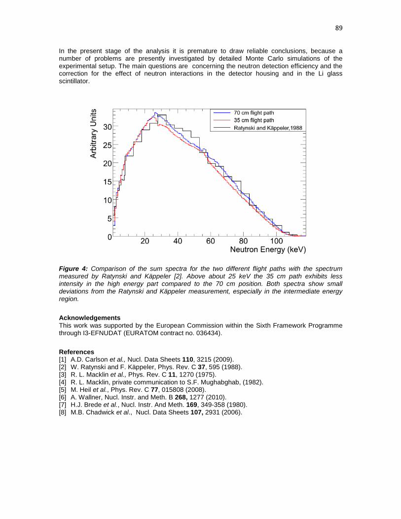
89
In the present stage of the analysis it is premature to draw reliable conclusions, because a number of problems are presently investigated by detailed Monte Carlo simulations of the experimental setup. The main questions are concerning the neutron detection efficiency and the correction for the effect of neutron interactions in the detector housing and in the Li glass scintillator.
Figure 4: Comparison of the sum spectra for the two different flight paths with the spectrum measured by Ratynski and Käppeler [2]. Above about 25 keV the 35 cm path exhibits less intensity in the high energy part compared to the 70 cm position. Both spectra show small deviations from the Ratynski and Käppeler measurement, especially in the intermediate energy region.
Acknowledgements This work was supported by the European Commission within the Sixth Framework Programme through I3-EFNUDAT (EURATOM contract no. 036434).
References [1] A.D. Carlson et al., Nucl. Data Sheets 110, 3215 (2009). [2] W. Ratynski and F. Käppeler, Phys. Rev. C 37, 595 (1988). [3] R. L. Macklin et al., Phys. Rev. C 11, 1270 (1975). [4] R. L. Macklin, private communication to S.F. Mughabghab, (1982). [5] M. Heil et al., Phys. Rev. C 77, 015808 (2008). [6] A. Wallner, Nucl. Instr. and Meth. B 268, 1277 (2010). [7] H.J. Brede et al., Nucl. Instr. And Meth. 169, 349-358 (1980). [8] M.B. Chadwick et al., Nucl. Data Sheets 107, 2931 (2006).

90

91
Measurement of prompt fission γ-rays with lanthanum halide scintillation detectors
A. Oberstedt1), R. Billnert1), A. Göök1,2), J. Karlsson1), S. Oberstedt3),
F.–J. Hambsch3), R. Borcea3), T. Martinez Perez4), D. Cano-Ott4), T. Belgya5), Z. Kis5), L. Szentmiklosi5), and K. Takács5)
1) School of Science and Technology, Örebro University, Örebro, Sweden, 70182 2) Institut für Kernphysik, TU Darmstadt, Darmstadt, Germany, 64289 3) European Commission, Joint Research Centre, Institute for Reference Materials and
Measurements, Geel, Belgium, 2440 4) Nuclear Innovation Group Department of Energy, CIEMAT, Madrid, Spain, 28040 5) Institute of Isotopes, Hungarian Academy of Sciences, Budapest, Hungary, 1525 [email protected]
Abstract: In a recent experiment, performed at the 10 MW research reactor at the Institute of Isotopes (IKI) in Budapest, the emission of prompt γ-rays from the cold-neutron induced fission of 236U* was measured. For that purpose four cerium-doped lanthanum halide scintillation detectors were employed and found very useful in order to distinguish between γ-rays from different reactions. Although data analysis is not completed yet, we could show that these novel detectors indeed provide the means towards new and more precise input data necessary for the modelling of γ-heating in nuclear reactors.
Introduction Requests for new measurements on prompt γ-ray emission in the reactions 235U(nth, f) and 239Pu(nth, f) have been formulated and included in the Nuclear Data High Priority Request List of the Nuclear Energy Agency (NEA, Req. ID: H.3, H.4) [1]. However, a major difficulty in such measurements is, apart from the need to obtain a sufficient mass resolution for fission fragments, the clear suppression of background γ-rays induced by prompt fission neutrons in the γ-detector. A usual method here is to discriminate γ-rays and neutrons by their different time-of-flight. The quality of discrimination is strongly coupled to the timing resolution of the detector, which is usually not better than 5 ns for NaI detectors. A promising step towards better data might be achieved by using the recently developed cerium-doped lanthanum halide scintillation detectors, which have shown to provide a timing resolution better than 500 ps [2,3], together with a more than 40% better energy resolution compared to NaI, i.e. less than 4% (FWHM) compared to 6.5% at 662 keV (137Cs) [4].
The Lanthanum Halide Detectors As mentioned above four lanthanum halide detectors were used to measure prompt γ-rays from the reaction 235U(nth, f). In more detail, two coaxial LaCl3:Ce detectors of size 1.5 in. × 1.5 in. [5] as well as one with dimensions 3 in. × 3 in. [6] were used. The fourth detector consisted of a cylindrical LaBr3:Ce crystal [6] with both diameter and length of 2 in. Prior to the experiment presented in this paper, the first mentioned detectors have been characterized, which is described elsewhere [7]. They were found to have an intrinsic timing resolution of about 440 ps, measured at 60Co peak energies. The energy resolution was determined for γ-energies from 81 to 6919 keV, exhibiting more or less the expected E-1/2 behaviour. For 662 keV (137Cs) the obtained energy resolution was around 4% (FWHM), in agreement with values provided by the manufacturer [5]. Together with a dynamical range up to

92
more than 17 MeV, these detectors showed a good linearity with residuals far below 1%. The full intrinsic peak efficiency was observed to be 53% better than the one for NaI:Tl detectors of the same size [8]. The properties of the larger LaCl3:Ce detector were not fully known at the time of the experiment, its efficiency, however, could be expected to be more than three times higher compared to the smaller detectors around 1 MeV [9], mostly for geometrical reasons. The LaBr3:Ce detector was delivered just before the start of the experiment and was, thus, not characterized yet. Nevertheless, from previous studies it is known that these detectors are even better than LaCl3:Ce detectors in terms of both energy and timing resolution, with about 2.8% (FWHM) at 662 keV and coincidence resolving times of < 300 ps [3].
The Budapest Experiment At the 10 MW research reactor in Budapest, γ-rays were measured in coincidence with fission fragments, which were detected by using the fission fragment spectrometer VERDI. It contained a 235U sample of mass 113 µg, mounted on a 34 µg/cm2 thick polyimide backing, a polycrystalline chemical vapour deposited (pCVD) diamond detector, which provided the fast fission trigger, as well as ten passivated implanted planar silicon (PIPS) detectors for the registration of the fragments' energy and time-of-flight. The details about that part of the experiment were topic of a dedicated presentation at this conference [10]. The reactor delivered a cold neutron beam with a flux of some 107 cm-2 s-1, causing a fission rate above 104 s-1. The four scintillation detectors were placed outside the time-of-flight spectrometer VERDI at a distance of about 30 cm (cf. Fig. 1). Blankets containing 6Li and lead blocks were applied as shielding against scattered thermal neutrons and γ-rays, respectively. The signals from the four γ-detectors were fed into constant fraction discriminators (CFD) and further into the same time-to-analog converter (TAC) of range 1 µs. They were giving the start signal, while the signals from the diamond detector, with an appropriate delay, provided the stop signal of the coincidence. For all four scintillation detectors the pulse height was stored in list-mode, together with three pulse shape discrimination signals for the LaCl3:Ce detectors only, as well as the TAC signal. The experiment was performed during February/March 2010 with ten days of actual beam time, and below we present and discuss the first preliminary results.
Figure 1. Photograph of the experimental setup with four lanthanum halide scintillation detectors (upper left part) and the fission fragment spectrometer VERDI. The neutron beam enters from the lower edge.

93
Figure 2. Pulse height calibration spectrum of the large LaCl3:Ce detector. The different colours of the energy assignments refer to γ-peaks from the known sources 60Co and a 207Bi, and from activation in the detector and its environment, respectively.
Results and Discussion Prior to and right after the beam time the detectors were energy calibrated using different radioactive sources. Figure 2 shows the calibration spectrum of the large LaCl3:Ce detector, taken with a 60Co and a 207Bi source after neutron irradiation of the target. The γ-peaks are assigned to the corresponding source and energy, the assignments in a lighter colour, however, belong to peaks that were not observed before the neutron beam was opened. They were identified to correspond to activation and successive decay of atoms in the crystal by the reaction 139La(nth, γ) and induced by fission neutrons through the reaction 56Fe(n, p) 56Mn in the wall of the vacuum chamber of VERDI, respectively. Apart from that, we noticed that the conversion from pulse height to energy practically did not change over the period of 10 days of experiment. Moreover, from the counts under the 1596.2 keV peak, the known volume and efficiency of the detector we could estimate the thermal neutron flux impinging on the detectors to be less than 0.2 cm-2 s-1. For each detector the data treatment was carried out as follows:
• first a selection was made on the pulse shape signal (where available) in order to discriminate the γ-rays from other incident particles, including α-particles from the intrinsic activity of the crystals
• then the dependence of the TAC-signal from pulse height was determined and corrected for
• different windows were set in order to distinguish events from different γ-ray producing reactions, i.e. prompt fission as well as thermal and fast neutron induced processes such as (nth, γ), (n, n') and (n, p)

94
An example for the results of this procedure is shown in Fig. 3. There, the rectangular regions are indicating in which TAC-signal regime the different processes were expected. During data analysis, however, these windows were chosen as large as possible. For each of them pulse height spectra were generated and energy calibrated and the processes were verified by identifying the characteristic γ-spectra. The thermal-neutron induced γ-rays (including the ones from the activation of VERDI) were not correlated with fission fragments and thus independent from time. They were considered as background, normalized per TAC-channel and subtracted from the other spectra. Also the γ-rays from inelastic neutron scattering were subtracted from the prompt γ-rays, which results in the energy distribution of prompt fission γ-rays. Figure 4 shows normalized, energy-calibrated and background-subtracted spectra for the large LaCl3:Ce detector from both inelastic scattering of fast neutrons and prompt decay of fission products. To guide the eye, the result of a simulation [11] is included and compared to the experimental fission γ-spectrum, which is described by
N(E) =38.13(E − 0.085)e1.648E
26.8 e−2.30E
8.0 e−1.10E
E < 0.3 MeV0.3 < E <1.0 MeV1.0 < E < 8.0 MeV
, (1)
as obtained from previous measurements [12]. Although the experimental spectrum is not corrected for efficiency yet and only a part of the taken data is analyzed so far, the good agreement is promising. What remains to be done is the analysis of all data as well as determining the response functions for all detectors and applying them to the spectra.
Summary and Conclusions In this paper we have presented first and preliminary results from the recent measurement of prompt γ-rays from the reaction 235U(nth, f). Despite the early stage of data analysis the comparison with a simulation of the energy distribution appears encouraging. This makes us optimistic to provide eventually new and more precise data to resolve present deficiencies in γ-ray production data in evaluated nuclear data files. The employment of fast detectors like lanthanum halide detectors in conjunction with pCVD diamond detectors will account for that.
Figure 3. Two-dimensional representation of γ-rays detected with the large LaCl3:Ce detector by their TAC-signal versus pulse height. To the right a projection on the TAC-axis is shown, indicating the prompt fission γ-rays together with some corresponding events from other detectors. The three rectangles denote areas, where prompt fission γ-rays (upper) and γ-rays from fast-neutron (middle) and thermal-neutron (lower) induced reactions are observed.

95
Figure 4. Normalized, energy-calibrated and background-subtracted γ-ray spectra for the 3 in. × 3 in. LaCl3:Ce detector from both inelastic scattering of fast neutrons and prompt decay of fission products together with the result of simulations.
Acknowledgments This work was supported by the EFNUDAT programme of the European Commission (agreement number 31027) and NAP VENEUS05 (agreement number OMFB 00184/2006).
References [1] http://www.nea.fr/html/dbdata/hprl/hprlview.pl?ID=421 and
http://www.nea.fr/html/dbdata/hprl/hprlview.pl?ID=422. [2] K. S. Shah, J. Glodo, M. Klugerman, L. Cirignano, W. W. Moses, S. E. Derenzo, M. J. Weber,
Nucl. Instr. Meth. A 505 (2003) 76. [3] A. Iltis, M. R. Mayhugh, P. Menge, C. M. Rozsa, O. Selles, V. Solovyev, Nucl. Instr. Meth. A
563 (2006) 359. [4] B. D. Milbrath, B. J. Choate, J. E. Fast, W. K. Hensley, R. T. Kouzes, J. E. Schweppe, Nucl.
Instr. Meth. A 572 (2007) 774. [5] SCIONIX Holland bv, P.O. Box 143, 3980 CC Bunnik, The Netherlands. [6] Saint-Gobain Crystals, 17900 Great Lakes Pkwy, Hiram, OH 44234-9681, USA. [7] A. Oberstedt, R. Billnert, J. Karlsson, S. Oberstedt, W. Geerts, and F.-J. Hambsch, in: A.
Chatillon, H. Faust, G. Fioni, and D. Goutte, H. Goutte (Eds.), Fourth Int. Workshop on Nucl. Fission and Fission-Product Spectroscopy, AIP Conf. Proc., vol. 1175, 2009, p. 257.
[8] G. Gilmore, Practical Gamma-ray Spectroscopy, John Wiley & Sons, ISBN 978-0-470-86196-7 (2008).
[9] R. Nicolini, F. Camera, N. Blasi, S. Brambilla, R. Bassini, C. Boiano, A. Bracco, F. C. L. Crespi, O. Wieland, G. Benzoni, S. Leoni, B. Million, D. Montanati, A. Zalite, Nucl. Instr. Meth. A 582 (2007) 554.
[10] S. Oberstedt, T. Belgya, R. Borcea, A. Göök, F.-J. Hambsch, Z. Kis, T. Martinez-Perez, A. Oberstedt, L. Szentmiklosi, K. Takács, Sh. Zeynalov, proceedings of this conference.
[11] J. M. Verbeke, C. Hagmann, D. Wright, UCRL-AR-228518, Lawrence Livermore National Laboratory (2009).
[12] F. C. Maienschein, R. W. Peelle, T. A. Love, Neutron Phys. Ann. Prog. Rep. for Sept. 1, 1958, ORNL-2609, Oak Ridge National Laboratory (1958).

96

97
VERDI – a double fission-fragment time-of flight spectrometer
S. Oberstedt1), T. Belgya2), R. Borcea1), A. Göök31), F.-J. Hambsch1), Z. Kis2), T. Martinez-Perez4), A. Oberstedt3), L. Szentmiklosi2), T. Takács2), Sh. Zeynalov12
)
1) European Commission Joint Research Centre IRMM, Geel, Belgium, 2400 2) Institute of Isotopes, Hungarian Academy of Science, Budapest, Hungary, 1525 3) School of Science and Technology, Örebro University, Örebro, Sweden, 70182 4) Nuclear Innovation Group, Department of Energy, CIEMAT, Madrid, Spain, 28040
Abstract: The double fission-fragment time-of-flight spectrometer VERDI aims at the investigation of neutron-induced fission fragment characteristics by measuring fragment velocity and kinetic energy for both fission fragments simultaneously. This allows obtaining mass and kinetic energy distributions without introducing a-priori information about prompt neutron emission. In addition, the measurement of pre- and post-neutron fission-fragment data provides prompt neutron multiplicity data as a function of fragment mass and total kinetic energy. In order to achieve a mass resolution ∆A < 2, ultra-fast time pick-up detectors based on artificial diamond material are used. A status report of the spectrometer development is given together with first results from a pilot experiment in its present single (v, E) version performed at the Budapest Research Reactor.
Introduction The investigation of correlated fission characteristics like fragment mass- and energy-distributions is usually based on the double-energy technique using twin Frisch-grid ionisation chambers (IC). Provided the existence of prompt-neutron emission data, the pre-neutron fission fragment mass and energy distributions may be obtained in an iterative process [1,2]. However, those input data do not exist for isotopes other than 233,235U and 239Pu at sufficient detail, and extrapolation methods have to be applied when analysing neighbouring compound nuclear systems. The double fission-fragment time-of-flight (TOF) spectrometer VERDI aims at investigating the neutron-induced fission fragment characteristics. Measuring fragment velocity and kinetic energy for both fission fragments simultaneously allows obtaining mass and kinetic energy distributions without introducing a-priori information about prompt neutron emission. On the contrary, pre- and post-neutron fission-fragment data are determined, providing prompt neutron multiplicity data as a function of fragment mass and total kinetic energy. In order to achieve a mass resolution ∆A < 2, ultra-fast time pick-up detectors based on artificial diamond material are used. In the following we report about the status of construction of VERDI giving characteristic figures of the achieved timing resolution and present first results from a pilot experiment of a single (v, E) version of VERDI performed in early 2010 at the Budapest Research Reactor.
The VERDI time-of-flight spectrometer
The VERDI spectrometer provides a flight-path length of 50 cm. The energy of the fission fragments (FF) is measured with large area silicon (PIPS) detectors. In total 19 detectors may be placed in each TOF section to achieve the contemplated geometrical efficiency of 0.5 %. The time-of-flight is measured between a start-detector closely placed at the fission sample and a IPS
1 Present address: Institut für Kernphysik, TU Darmstadt, D-64289 Darmstadt 2 Present address: Joint Institute for Nuclear Research, Dubna, Moscow Region, Russia

98
detector. The start detector is made from artificial poly-crystalline chemical vapour deposited diamond (pCVDD) with a thickness of 100 µm and an area of 1 cm2.
Figure 1. Fission fragment time-of-flight for the reaction 252Cf(SF) taken with a waveform digitizer with a bandwidth of 1 GHz
In nuclear physics diamond detectors are used mainly in high-energy experiments as beam monitors and tracking devices, replacing traditionally employed silicon detectors, because they survive in high radiation environments, have low leakage current and do not need cooling [3-6]. In particular the timing properties of artificial diamonds are remarkable and an intrinsic timing resolution better than 30 ps has been reported for a mono-energetic 52Cr-beam at incident energy of 650 MeV/u [7]. In view of the properties of this surprising material, it was tempting to see whether a similar timing resolution may be obtained with low energy FF at energies typically between 0.5 and 2.0 MeV/u. Since this detector is not yet transparent for FF we restrict ourselves to discuss a single TOF configuration.
First, the diamond detectors were irradiated with β-particles (the so-called priming process) before exposed to highly ionizing particles like fission fragments [8,9]. Then, we monitored the pulse-height signal stability with up to more than 109 fission fragments from a 252Cf source together with the corresponding number of α-particles and fission neutrons, for which no signal degradation was observed [10]. Next, we measured the fission-fragment time-of-flight with a symmetric set-up consisting of two identical pCVDDDs. The intrinsic timing resolution was then inferred by means of Monte-Carlo simulations based on published post-neutron mass and kinetic energy data from the reaction 252Cf(SF). The experiment was performed two-fold: first, using standard analogue electronics and second, using a digital oscilloscope with a bandwidth of 1 GHz. From various simulations an intrinsic timing resolution σint < 300 ps for the analogue and σint ≈ 150 ps for the digital measurement was obtained. The spectrum taken with digital electronics is depicted in Fig. 1 together with the results from the Monte-Carlo simulations. The timing resolution is comparable with the better micro-channel plate detectors, but diamond detectors are much easier to handle and to operate.
In a next step the TOF spectrum of fission fragments from spontaneous fission of 252Cf was measured with a configuration consisting of one pCVDDD and a small PIPS detector of size 25 mm2 separated by only 33 cm. The obtained timing resolution was around 500 ps with conventional analogue electronics. The resulting fragment mass-distribution is shown in Fig. 2 as

99
red dots and compared with several data existing in literature [11-13]. The comparison with data from a 2E measurement shows good agreement and suggests a reasonable mass resolution already at the reduced flight-path length. In the region of symmetric masses random triggers with α-particles are visible as a tail filling up the region of symmetric masses. From this test measurement a mass resolution ∆A < 3 may be expected with analogue electronics and for the contemplated flight-path length of 50 cm.
The pilot experiment at the Budapest Research Reactor The experimental set-up was installed at the cold neutron beam of the IKI Research Reactor in Budapest (Fig. 3). The neutron flux at the entrance window of the VERDI spectrometer was 5 × 10⁷ /s/cm2. During the experiment VERDI was operated in a single (v, E) configuration. Ten 450 mm2 large PIPS detectors are placed at a distance of 50 cm from the fission source. As fissile target a 113 µg/cm2 235U mounted on a 34 µg/cm2 thick polyimide backing was used and placed directly on the diamond detector. On top of the fissile sample a 6Li sample was placed in order to use the 6Li(n, t)α reaction for time calibration. The shaped pulse-height (PH) signals of the PIPS detectors were fed into an analogue signal-router and then into a single ADC. In total five data words, the pulse-height information, three TAC (FF TOF) values and a bit-pattern for detector identification, were stored by the data acquisition system in list-mode for later off-line treatment.
Figure 2. Experimental fission-fragment mass distribution from the reaction 252Cf(SF) obtained with an artificial diamond detector as fission trigger and a small-size silicon-type energy detector, compared to results from Refs.[19-21].
In the upper part of Fig. 4 a fission-fragment PH vs. TOF spectrum is shown. Due to an apparent problem with the priming source, the discriminator threshold for the diamond detector had to be set relatively low. This increased the number of accidental coincidences between one fission fragment and an α-particle from the 6Li(n, t)α reaction or the natural activity of the 234U present in the 235U target. With the definition of polygons around the region of fission-fragments in the two-dimensional spectrum allows gating out most of these accidental events. From Monte-Carlo simulations of the gated and projected TOF spectra a timing resolution of VERDI of about 400 ps is deducted.

100
Figure 3: Photograph of the experimental set-up with the single (v, E) version of the fission-fragment spectrometer VERDI and four lanthanum halide detectors (upper left corner).
Figure 4. Pulse height (PH) vs. time-of-flight (ToF): polygons are set to exclude accidental coincidences with α-particles or tritons from the reaction 6Li(n, t)α; in the lower part the kinetic energy distributions from 8 PIPS detectors (left) and the corresponding post-neutron mass distributions (right) are shown.

101
In the lower left part of Fig. 4 the final post-neutron kinetic energy distributions for 8 PIPS detectors are shown. The corresponding fission-fragment mass distributions are depicted in the right part of Fig. 4. Obviously, some of the spectra show a diminished fraction of light fission fragments. This fact points to a reduced detection efficiency for heavy, lower energetic fission fragments in the diamond detector, which in turn results in a lower fraction of corresponding light fragments detected in the energy detector. In the following we report on a subsequent investigation of this apparent shortcoming related to the use of artificial diamond material and present possible solutions.
Some more about artificial diamonds for fission fragments
The reduced detection efficiency of heavy and low-energetic fission fragments might be caused by the limited charge collection efficiency (CCE) in poly-crystalline diamonds [14]. Together with an energy resolution ∆E of not much better than 40 % (σ) for α-particles we suspect that this might be the cause, despite the fact that the expected pulse height of FF is supposed to be 10 to 20 times larger.
Figure 5. Rise time (left) and amplitude (right) distributions obtained with a 4-fold segmented artificial poly-crystalline diamond detector (for specifications see text) and a standard triple α-particle source. The signals have been taken with a DBA-IV broadband pre-amplifier [15,16] and recorded with a 1 GHz digital oscilloscope.
For that reason we exposed a 4-fold segmented pCVD diamond detector to a triple alpha-source (239Pu, 241Am and 244Cm), which we built at our institute. The detector has a thickness of 180 µm and a strip area of 0.25 cm2, corresponding to an about 7 times reduced detector capacitance of 12.5 pF. The charge is collected with a DBA-IV pre-amplifier [15,16] and then stored with a digital oscilloscope with a bandwidth of 1 GHz and a sampling rate of 20 Gs/s. The corresponding rise time distribution is shown in the left part of Fig. 5. The mean rise time is at 625 ps with an exponential tail to larger rise times at low amplitudes. In the right part of Fig. 5 the amplitude spectrum is shown (grey area) together with the spectrum constructed from the three main α-particle energies of the calibration source. The hatched area indicates the level of noise. From a simple amplitude-to-energy calibration, simulations were performed assuming different values for the CCE, the energy resolution as well as for the detector capacitance. The corresponding amplitude distributions are shown in Fig. 6 as full lines starting from the right with CCE = 1, ∆E = 0.04 (rel.) and C = 12.5 pF. The simulations are compared to experimental data obtained with our standard pCVDDD, as used in the pilot experiment as described in the previous section, and fission fragments from the reaction 252Cf(SF). The threshold was set to 500 mV in order to discriminate electronic noise and α-particles from the decay of 252Cf. As one can see, the data agree pretty well with the simulation assuming CCE = 0.3, ∆E = 0.4 and C = 92 pF, which is characteristic for that particular pCVDDD of size 1 cm2 (grey area enclosed by the full line). Our simulations show as well that with our segmented detector an apparent loss of detected fission fragments is considerably reduced.

102
Figure 6. Simulated fission-fragment response to diamond detectors (full lines) assuming different values for charge collection efficiency (CCE), intrinsic resolution (∆E) and detector capacitance (C); the full circles indicate fission-fragment data taken with the non-segmented diamond detector used in the pilot experiment at the Research Reactor in Budapest (see text).
From this investigation it became obvious that a properly segmented artificial diamond is an excellent choice for ultra-fast fission trigger detectors. This conclusion may hold also when aiming at a detector, which is transparent for fission fragments to be used in the contemplated double (v, E) version of the VERDI spectrometer. The above figure is definitely improved when eventually employing single-crystal diamond material with a CCE close to 70 %, which is comparable to that of silicon detectors.
Summary and conclusions In this paper we have given a status report from the construction of the fission-fragment time-of-flight spectrometer VERDI. The time pick-up detector is made from artificial diamond. The intrinsic timing resolution of pCVDD detectors determined with standard analogue electronics is well below 300 ps. The use of state-of-the-art low-noise broadband electronics may bring the resolution down to well below 150 ps as suggested by analysing signals taken with a 1 GHz waveform digitizer. A first in-situ test of the single time-of-flight prototype of the VERDI spectrometer demonstrated the suitability of the spectrometer components. Today a timing resolution of VERDI as good as 400 ps was deducted from Monte-Carlo simulations, which may be translated into a mass resolution ∆A ≈ 3. Artificial diamond material is well suited for fission-fragment timing; however, care must be taken in the design of such a device in order to minimize the detector capacitance and, eventually, improve the charge collection efficiency. We may conclude that the double time-of-flight spectrometer VERDI will provide an excellent tool to measure pre- and post-neutron fission fragment data. Due to the relatively high geometrical efficiency, VERDI allows the coupling of ancillary detector arrays for prompt fission γ-ray and/or neutron detection. The instrument will be best suited for use at medium- and high-flux neutron facilities.
Acknowledgements This work was supported by EFNUDAT (agreement number 31027) and NAP VENEUS05 (agreement number OMFB 00184/2006).
References [1] C. Budtz-Jørgensen et al., Nucl. Inst. Meth. A258 (1987) 209 [2] E. Birgersson et al., Nucl. Phys. A817(2009) 1 [3] RD 42 Collaboration, P. Weilhammer et al., Nucl. Inst. Meth. A409 (1998) 264 [4] The RD42 collaboration, D. Meier et al., Nuc. Inst. Meth. A426 (1999) 173.

103
[5] E. Berdermann, K. Blasche, P. Moritz, H. Stelzer, "Diamond Detectors for Heavy-Ion Measurements", XXXVI Int. Winter Meeting on Nuclear Physics, Bormio 1998
[6] E. Berdermann, K. Blasche, P. Moritz, H. Stelzer, B.Voss, F. Zeytouni, Nucl. Phys. B (Proc. Suppl.) 78 (1999) 533-539
[7] E. Berdermann, K. Blasche, P. Moritz, H. Stelzer, B. Voss, Diamond and Related Materials 10 (2001) 1770-1777
[8] M. Marinelli, E. Milani, A. Paoletti, A. Tucciarone, G. Verona Rinati, M. Angelone, M. Pillon, Nucl. Inst. Meth. A476 (2002) 701-705
[9] S. Oberstedt, C. C. Negoita, T. Atzitzoglu, Scientific Report of the Neutron Physics Unit 2006, EUR Report 23039 EN, Eds. S. Oberstedt, P. Rullhusen, ISBN 978-92-79-05365-8 (2007) 95
[10] S. Oberstedt, C. Negoita, A. Oberstedt, Scientific Report of the Neutron Physics Unit 2007, EUR Report 23440 EN, Eds. S. Oberstedt, P. Rullhusen, ISBN 978-92-79-09532-0 (2008) 95
[11] E. Birgersson, S. Oberstedt, A. Oberstedt, F.-J. Hambsch, D. Rochman, I. Tsekhanovich, S. Raman, Nucl. Phys. A 791 (2007) 1-23
[12] F.-J. Hambsch and S. Oberstedt, Nucl. Phys. A617 (1997) 347 [13] F.-J. Hambsch (2004), private communication [14] E. Berdermann et al, Diamond and Rel. Mat. 10 (2001) 1770 [15] P. Moritz et al., Proc. 7th Int. Conf. Diamond science & Technology (ICNDST-7), Hongkong,
July 2000, Diamond Rel. Mat. 10 (2001) 1765,ff [16] http://www-w2k.gsi.de/detlab/

104

105
Characterisation of Fission Ionisation Chambers using Monoenergetic Neutrons
M. Mosconi1, Ph. Desagne2, M. Kerveno2, R. Nolte1*, A.J.M. Plompen3,
C. Rouki3, J.C. Thiry2
1) Physikalisch-Technische Bundesanstalt (PTB), Bundesallee 100, Braunschweig, Germany, 38115
2) Université de Strasbourg, IPHC, 23 rue du Loess, Strasbourg, France, 67037 CNRS, UMR7178, Strasbourg, France, 67037
3) Institute for Reference Materials and Measurements (IRMM), Retiseweg 111, Geel, Belgium, 2440
Abstract: Parallel-plate fission ionisation chambers equipped with 235U deposits are used as neutron fluence monitors for the measurement of fission, capture and inelastic scattering cross sections at GELINA. Two of these chambers were compared with the 235U fission chamber H19 and the 238U fission chamber H20 of PTB as well as with the recoil proton telescope RPT1 and a fully-characterised 2”x2” BC501A liquid scintillation detector. The measurements were carried out using monoenergetic neutron fields with mean energies of about 8.4 MeV and 15 MeV.
Introduction Measurements of nuclear data are often performed relative to a well-established reference cross section [1]. At many neutron beam facilities parallel-plate fission ionisation chambers (PPFC) are used as reference instruments for the measurement of the spectral neutron fluence. In principle, the neutron detection efficiency of fission ionisation chambers can be calculated easily if the areal mass of the fissile isotope and the range of typical fission fragments in this material is known [2]. The uncertainties of the 235U(n,f) and the 238U(n,f) cross sections are less than 1.2% for neutron energies below 20 MeV. This makes PPFCs very attractive reference instruments, as demonstrated in a series of comparison measurements using two circulating fission chambers [3]. In these exercises standard deviations of the results of about 2% were achieved. The uncertainty of the calculated efficiency is limited by the experimental uncertainty of the mass of the deposit, the uncertainty of the fragment range and the neutron transport in the instrument [3]. While new actinide samples can be characterised by alpha counting techniques, the stability of PPFCs already in use is best investigated using monoenergetic neutron beams characterised relative to the primary standard, i.e. the differential np scattering cross section. This method yields also information on corrections such as the loss of fragments below the pulse-height threshold or the effect of neutron scattering and absorption. The present work describes a series of measurements carried out at neutron energies of 8.4 MeV and 15 MeV. Fluence measurements using a set of different PPFCs were compared with measurements based on the detection of recoil protons in a recoil proton telescope (RPT1) and in a liquid scintillation detector (DD). The quantity to be measured with all instruments was the zero-degree yield Y of the neutron sources per monitor event. The focus of these investigations was on the identification of possible improvements of this method and a critical review of the uncertainty budgets for the two methods, employing the best present knowledge.
Experiment Neutron Fields The measurements were performed in open geometry in the low-scatter hall of the PTB ion accelerator facility (PIAF). Pulsed deuteron beams with energies of 0.4 MeV and 5.16 MeV from the 3.7 MV Van-de-Graaff accelerator and the CV28 cyclotron were used to produce

106
monoenergetic neutrons using the T(d,n)4He and D(d,n)3He reactions, respectively. The mean energies of the monoenergetic neutrons were 15.0 MeV and 8.40 MeV. The 15 MeV neutrons were produced using a thick solid-state Ti(T) target while a deuterium gas target was employed for the 8.4 MeV field. Because of the low deuteron energy the only non-monoenergetic component of the 15 MeV field was due to scattering of neutrons in the low-mass target set up. For the 8.4 MeV field most of the non-monoenergetic neutrons resulting from interactions with the target material could be experimentally determined in runs with an evacuated gas cell (gas-out measurement). Inscattering of neutrons by the air or the support structures was measured separately using shadow cones between the target and the detector, except for the RPT which was positioned at a distance of 35 cm from the target surface. Hence, inscattering could be neglected for this instrument. For the scintillation detector and the fission ionisation chambers, the time-of-flight (TOF) method was used to separate the monoenergetic neutrons from the remaining low-energy non-monoenergetic neutrons resulting from target scattering, break-up reactions (8.4 MeV) or deuterium impurities (15 MeV). Calculated TOF distributions were obtained from Monte Carlo simulations using the codes SINENA [4] (8.4 MeV) and TARGET [5] (15 MeV). For these calculations, some input parameters such as the deuteron energy and the effective gas pressure (8.4 MeV) or the relative tritium and deuterium contents (15 MeV) were adjusted to reproduce the measured TOF spectra. The calculated spectra were used to correct the PPFC measurements for the contribution from non-monoenergetic neutrons and to determine 235U(n,f) and 238U(n,f) fission cross sections averaged over the spectral distribution of the monoenergetic neutrons. The input cross sections were taken from the ENDF/B-VII evaluation. The neutron yield was monitored with two long counters of different construction positioned at 16° (NM) and 92° (LC) relative to the direction of the deuteron beam. In addition, the beam charge (Q) was used as a monitor. Inscattering from the detectors at 0° into the neutron monitors NM and LC was corrected using short measurements (free-field measurement) with and without the detectors in place which were related to each other using the beam charge Q. At 15 MeV the stability of the monitor count rates was excellent as demonstrated in the upper panel of Fig. 1 which shows ratios of neutron monitor counts to beam charge for all measurements after correction for dead time and inscattering. The relative standard deviation of the NM/Q ratio is 0.42% which gives an estimate of the contribution of the monitoring procedure to the total uncertainty of the measurements. At 8.4 MeV, however, stronger instabilities were observed, as demonstrated in the lower panel of Fig. 1. Here corrections for gas-out neutrons and for small variations in the filling pressure were carried out in addition to the corrections also applied at 15 MeV. The overall relative standard deviation of the NM/Q ratios is 0.92% but there are obvious systematic deviations for some subsets of measurements.
Figure 1. Ratio of the corrected number of NM and LC events to beam charge Q normalised to the mean values. The upper and lower panels show the results for the 15 MeV and the 8.4 MeV fields, respectively. For the 8.4 MeV field, the beam charge was corrected for small differences in the filling pressure of the gas target.
Figure 2. Ratio of the corrected number of NM and LC events to beam charge Q normalised to the mean values for the 8.4 MeV field with. The upper and lower panels show the data the runs with evacuated gas target and the free-field runs, respectively.
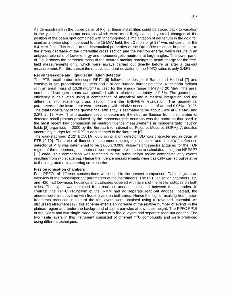
107
As demonstrated in the upper panel of Fig. 2, these instabilities could be traced back to variation in the yield of the gas-out neutrons which were most likely caused by small changes of the position of the beam spot combined with inhomogeneous implantation of deuterium in the gold foil used as a beam stop. In contrast to the 15 MeV field, the LC monitor at 92° was not useful for the 8.4 MeV field. This is due to the kinematical properties of the D(d,n)3He reaction, in particular to the strong decrease of the differential cross section and the neutron energy, which results in an unfavourable ratio of lower-energy and monoenergetic neutrons at large angles. The lower panel of Fig. 2 shows the corrected ratios of the neutron monitor readings to beam charge for the free-field measurements only, which were always carried out directly before or after a gas-out measurement. For this subset the relative standard deviation of the NM/Q ratios is only 0.48%.
Recoil telescope and liquid scintillation detector The PTB recoil proton telescope RPT1 [6] follows the design of Bame and Haddad [7] and consists of two proportional counters and a silicon surface barrier detector. A tristearin radiator with an areal mass of 10.09 mg/cm² is used for the energy range 4 MeV to 20 MeV. The areal number of hydrogen atoms was specified with a relative uncertainty of 0.5%. The geometrical efficiency is calculated using a combination of analytical and numerical integration and the differential n-p scattering cross section from the ENDF/B-V evaluation. The geometrical parameters of the instrument were measured with relative uncertainties of around 0.05% - 0.1%. The total uncertainty of the geometrical efficiency is estimated to be about 1.4% at 8.4 MeV and 2.2% at 15 MeV. The procedure used to determine the neutron fluence from the number of detected recoil protons produced by the monoenergetic neutrons was the same as that used in the most recent key comparison on neutron fluence measurements in monoenergetic neutron fields [8] organised in 2000 by the Bureau International de Poids et Mesures (BIPM). A detailed uncertainty budget for the RPT is documented in the literature [8]. The gain-stabilised 2”x2” BC501A liquid scintillation detector DD was characterised in detail at PTB [9,10]. The ratio of fluence measurements using this detector and the 4”x1” reference detector of PTB was determined to be 1.000 ± 0.009. Pulse-height spectra acquired for the TOF region of the monoenergetic neutrons were compared with spectra calculated using the NRESP7 [11] code. This comparison was restricted to the pulse height region comprising only events resulting from n-p scattering. Hence the fluence measurements were basically carried out relative to the integrated n-p scattering cross section.
Fission ionisation chambers Four PPFCs of different constructions were used in the present comparison. Table 1 gives an overview of the most important parameters of the instruments. The PTB ionisation chambers H19 and H20 had low-mass housings and cathodes covered with layers of the fissile isotopes on both sides. The signal was obtained from read-out anodes positioned between the cathodes. In contrast, the PPFC FP3/200m of the IRMM had no separate read-out anodes. Instead, the anodes were also covered with fissile layers on both sides. Hence the signal resulting from fission fragments produced in four of the ten layers were obtained using a ‘reversed’ potential. As discussed elsewhere [12], this scheme effects an increase of the relative number of events in the plateau region and under the background of alpha particles at low pulse height. The PPFC FP16 of the IRMM had two single-sided cathodes with fissile layers and separate read-out anodes. The two fissile layers in this instrument consisted of different 235U compounds and were produced using different techniques.
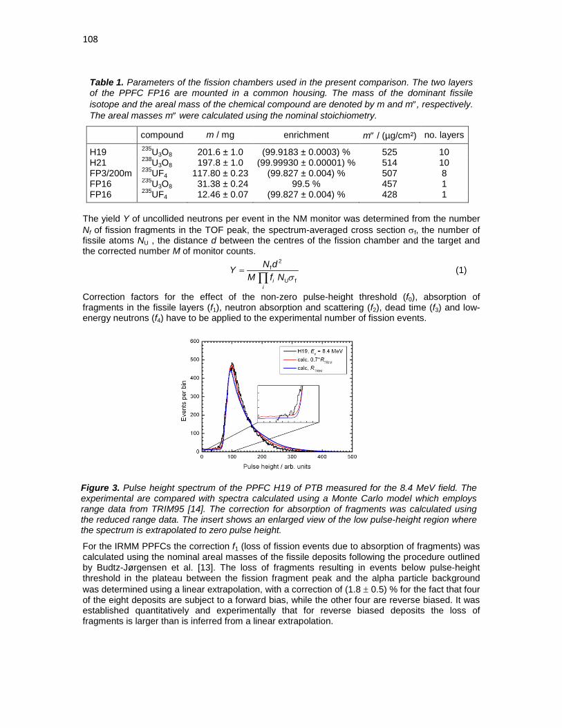
108
Table 1. Parameters of the fission chambers used in the present comparison. The two layers of the PPFC FP16 are mounted in a common housing. The mass of the dominant fissile isotope and the areal mass of the chemical compound are denoted by m and m″, respectively. The areal masses m″ were calculated using the nominal stoichiometry.
compound m / mg enrichment m″ / (µg/cm²) no. layers
H19 235U3O8 201.6 ± 1.0 (99.9183 ± 0.0003) % 525 10 H21 238U3O8 197.8 ± 1.0 (99.99930 ± 0.00001) % 514 10 FP3/200m 235UF4 117.80 ± 0.23 (99.827 ± 0.004) % 507 8 FP16 235U3O8 31.38 ± 0.24 99.5 % 457 1 FP16 235UF4 12.46 ± 0.07 (99.827 ± 0.004) % 428 1
The yield Y of uncollided neutrons per event in the NM monitor was determined from the number Nf of fission fragments in the TOF peak, the spectrum-averaged cross section σf, the number of fissile atoms NU , the distance d between the centres of the fission chamber and the target and the corrected number M of monitor counts.
∏
=
ii NfMdNY
fU
2f
σ (1)
Correction factors for the effect of the non-zero pulse-height threshold (f0), absorption of fragments in the fissile layers (f1), neutron absorption and scattering (f2), dead time (f3) and low-energy neutrons (f4) have to be applied to the experimental number of fission events.
Figure 3. Pulse height spectrum of the PPFC H19 of PTB measured for the 8.4 MeV field. The experimental are compared with spectra calculated using a Monte Carlo model which employs range data from TRIM95 [14]. The correction for absorption of fragments was calculated using the reduced range data. The insert shows an enlarged view of the low pulse-height region where the spectrum is extrapolated to zero pulse height.
For the IRMM PPFCs the correction f1 (loss of fission events due to absorption of fragments) was calculated using the nominal areal masses of the fissile deposits following the procedure outlined by Budtz-Jørgensen et al. [13]. The loss of fragments resulting in events below pulse-height threshold in the plateau between the fission fragment peak and the alpha particle background was determined using a linear extrapolation, with a correction of (1.8 ± 0.5) % for the fact that four of the eight deposits are subject to a forward bias, while the other four are reverse biased. It was established quantitatively and experimentally that for reverse biased deposits the loss of fragments is larger than is inferred from a linear extrapolation.

109
Figure 4. Experimental TOF spectrum (histogram) measured using the 235U PPFC H19 of PTB in the 8.4 MeV and 15 MeV fields produced by the D(d,n)3He and T(d,n)4He reaction, respectively. The solid lines show calculated TOF spectra for the uncollided neutrons (red), neutrons scattered in the target set-up (blue) and neutrons produced by the D(d,n)3He reaction with implanted deuterium (green line in the right panel). Target scattering can be neglected for the 8.4 MeV field. The width of the TOF peaks is determined by the duration of the deuteron pulses and the time resolution of the PPFC.
For the PTB PPFCs, a Monte Carlo code was available which uses range data from TRIM95 [14] to calculate the zero-threshold efficiency for the detection of fission fragments as well as the shape of the fission fragment spectrum. Experimental effective ranges for the uranium layers of the PTB fission chambers [3] seem to be somewhat smaller than to those calculated using TRIM95. Hence the TRIM95 ranges were reduced by 30%, which also yielded a better agreement of the spectral shapes. A similar conclusion was found by Budtz-Jørgensen et al. [13] for the experimentally determined effective range for evaporated UF4 layers compared with estimates from Northcliffe and Schilling [15]. A comparison of experimental and calculated spectra is shown in Fig. 3. The correction f2 for the effect of elastic and inelastic scattering of monoenergetic neutrons in the housing and the electrode materials was determined using MCNP models of the detectors. Neutrons of lower energies were mostly discriminated experimentally using the TOF technique. As an example, Fig. 4 shows a TOF spectrum acquired using the 235U PPFC H19 of PTB in the 15 MeV field. Due to the small flight distance of about 1.5 m and the moderate time resolution of about 9 ns, some of the events in the TOF peak were produced by neutrons scattered in the target set-up. This contribution amounted to about 1% for this particular case and had to be corrected for in the analysis. According to [3], the product of the correction factors f1 and f2 for the PTB PPFCs H19 and H21 should be almost independent of the neutron energy and the isotope, f1⋅f2 = 0.970 ± 0.018. In contrast, the present analysis yielded values of 0.952 and 0.947 for H19 and H21 at 8.4 MeV. For the 15 MeV field, values of 0.956 and 0.946 were obtained. The relative uncertainty of these values was estimated to be 1.2%.
Results The results of the present comparison are presented in Fig. 5 which shows the target yield per event in the NM monitor as measured with all instruments used. The closed symbols for the PTB PPFCs H19 and H21 shows the results obtained with the present correction factors f1⋅f2 while the open symbols depict the results calculated using the corrections given by Gayther [3]. The individual data points are normalised to the mean values of two data sets shown by the closed symbols. The properties of the 235U3O8 layer of the FP16 PPFC were known to be not very well specified. Therefore this data point was not included in the mean value of the 8.4 MeV data set. With the present correction, the results obtained with the PTB PPFCs seem to be systematically

110
2.5% larger than the results of the other fission chambers. The relative standard deviations of the data points shown by the closed symbols are 2.0% and 2.2% for 8.4 MeV and 15 MeV, respectively. With the original corrections determined by Gayther [3], the PTB PPFCs agree nicely with the other data and the relative standard deviations are reduced to 1.1% and 1.2%. Unfortunately these values for the correction f2 could not be reproduced by MCNP simulations.
Figure 5. Zero-degree neutron yields per event in the NM monitor, normalised to the mean values of the data sets for the two neutron energies. The closed circles are the results from the present analysis. The open circles show the normalised yields measured using the PTB PPFCs H19 and H21 and the fragment detection efficiencies and scattering corrections f1⋅f2 of Gayther [3]. The data point ‘FC16 U3O8’ at 8.4 MeV was not included in the mean, as the properties of the 235U3O8 layer were known to be not very well specified.
It should be noted that the good agreement of the PPFC data with the RPT1 and the DD results at 15 MeV was obtained using the 235U and 238U fission cross section from ENDF/B-VII which are 1.7% and 3.2% larger than those of ENDF/B-VI.
Conclusions The results obtained for the 15 MeV field demonstrate that monoenergetic neutron beams can be used to characterise fission ionisation chambers with relative uncertainties in the 2% range. Hence, the uncertainty requirements for nuclear data measurements for Generation IV reactors can just be met. The present work, however, also demonstrates that good control of all properties of the neutron fields is extremely important. In this respect, the almost isotropic T(d,n)4He reaction has an advantage over the D(d,n)3He reaction, which has a strong kinematical dependence and is accompanied by break-up reactions in the energy range 8 MeV to 10 MeV where the fission cross sections do not show a strong energy dependence. In the present experiment, the scatter of the 8.5 MeV monitor data could have been reduced by employing an unused beam stop and a neutron monitor which uses the TOF technique to suppress background neutrons from deuteron interactions with the beam stop and the entrance foil of the gas target. The present work also shows also that there is still a need to understand better the corrections required for the analysis of measurements made using PPFCs.
Acknowledgement The authors are grateful to the PIAF accelerator staff for their support during the measurements. This work was supported by the EFNUDAT (European facilities for Nuclear Data Measurements) project financed by the Commission of European Communities under the 6th framework programme.
References [1] P. Schillebeeckx, A. Borella, J.C. Drohe, R. Eykens, S. Kopecky, C. Massimi, L.C.
Mihailescu, A. Moens, M. Moxon, R. Wynants, Nucl. Instr. and Meth. A 613 (2010) 378-385

111
[2] G.W. Carlson, Nucl. Instr. and Meth. 119 (1974) 97-100 [3] D.B. Gayther, Metrolgia 27 (1990) 221-231 [4] D. Schmidt and B.R.L. Siebert, PTB-Report PTB-N-40, Physikalisch-Technische Bundes-
anstalt, Braunschweig, May 2000, ISSN 0936-0492 [5] D. Schlegel, PTB laboratory report PTB-6.42-05-2, Physikalisch-Technische Bundesanstalt,
Braunschweig, April 2005 [6] B.R.L. Siebert, H.J. Brede and H. Lesiecki, Nucl. Instr. and Meth. A235 (1985) 542-552 [7] S.J. Bame, Jr., E. Haddad, J.E. Perry, Jr., and R.K. Smith, Rev. Sci. Instr. 28 (1957) 997 [8] J. Chen et al., International Key Comparison of Neutron Fluence Measurements in Mono-
energetic Neutron Fields – CCRI(III)-K10, Metrologia 44 (2007), Tech. Suppl., 06005 [9] D. Schmidt, N. Asselineau, R. Böttger, H. Klein, L. Lebreton, S. Neumann, R. Nolte, G.
Pichenot, Nucl. Instr. and Meth. A 476 (2002) 186-189 [10] D. Schmidt, private communication, 1999 [11] G. Dietze and H. Klein, PTB-Report PTB-ND-22, Physikalisch-Technische Bundesanstalt,
Braunschweig, October 1982, ISSN 0572-7170 [12] A. Plompen, C. Borcea, D. Deleanu, P. Dessagne, M. Kerveno, M. Mosconi, N. Namikov, A.
Negret, R. Nolte, C. Rouki, G. Rudolf, M. Staniou, and J.C. Thiry, submitted for the Proceedings of the International Conference on Nuclear Data for Science and Technology 2010, Jeju, Republic of Korea
[13] C. Budtz-Jørgensen, H.-H. Knitter and G. Bortels, Nucl. Instr. and Meth. A 235 (1985) 630-640
[14] J.F. Ziegler and J.P. Biersack, The Stopping of Ions in Matter, Vol. 1, Pergamon Press, New York (1985)
[15] L.C. Northcliffe and R.F. Schilling, Range and Stopping-Power Tables for Heavy Ions, Atomic Data Nucl. Data Tables 7 (1970) 233

112

113
Level Densities, Decay Probabilities and Cross sections in the Actinide Region
J.N. Wilson1), S. Siem2), A. Bürger2), F. Gunsing3), A. Görgen2,3), A-C;Larsen2),
P. Mansouri2), T. Renstrøm2), S.J. Rose2), M. Weideking4), T. Wiborg2)
1) Institut de Physique Nucléaire Orsay, Bât. 100, 15 rue G. Clemenceau, 91406 Orsay
Cedex, France 2) Dept. of Physics, University of Oslo (UiO), Blindern NO-0316, Oslo, Norway 3) DSM/IRFU, Bât 141, CEA Saclay, 91191 Gif sur Yvette Cedex, France 4) Lawrence Livermoore National Laboratory, 7000 East Avenue, Livermore, CA 94550,
Abstract: The first results from a new program of experiments to measure nuclear level densities in the actinide region will be presented. This series of measurements has three important goals: 1) To provide systematic level density information for improving cross section calculations where direct measurements are difficult or impossible. 2) The simultaneous measurements of compound nuclear decay probabilities using the surrogate method. 3) The exploration of fine structure in actinide level densities and strength functions, of particular interest for fundamental physics reasons. Results will be presented from recent experiments carried out at the Oslo cyclotron using 232Th(d,x) and 232Th(3He,x) transfer reactions to populate several actinide nuclei. Level densities in 231,232,233Th up to the binding energy can be extracted using the Oslo method. In addition, compound nuclear decay probabilities for 232Pa*, 231Th* and 233Th* below fission thresholds have been measured using the surrogate method. For the case of 233Th*, the results can be compared with the evaluated nuclear data files based on the 232Th(n,γ) nTOF direct cross section measurements, thus providing a good test of the validity of the surrogate method.
Introduction Direct cross section measurements in the actinide nuclei region have been widely performed. However, for certain nuclei, particularly those with short half lives, direct measurements are either very difficult or impossible and thus reactor simulations must rely on evaluated nuclear data which is heavily dependent on theoretical calculations and/or extrapolations from neighbouring nuclei. The greatest uncertainty in theoretical cross section calculations comes from the lack of knowledge of level densities, for which predicted values can often be incorrect by a factor of two or more. In this work we present the first results from a systematic experimental study of level densities in the actinide region for the purpose of a) providing a stringent test of theoretical cross section calculations for nuclei where experimental cross section data are available and b) for providing better estimations of cross sections for nuclei in which no cross section data are available. In addition the simultaneous measurement of decay probabilities, or gamma yields, under the fission thresholds for certain nuclei are possible using the surrogate method [1,2,3,4].
First experiments with Cactus/Siri The experiments were carried out at the Oslo Cyclotron with a 968 μg/cm2 232Th target provided by the Lawrence Livermoore National Laboratory. Beams of 12MeV deuterons and 24MeV 3He particles were used to populate various nuclei neighbouring nuclei. Exit channels involving the emission of only charged particles (p,d,t,3He and 4He) were identified using the silicon ring placed

114
at backward angles with respect to the beam direction. The silicon ring consists of 8 wedged shaped delta E detectors arranged in a ring each covered with 8 DE strips providing a total solid angle coverage of around 12%. The detectors were placed at 5cm from the target at backward angles between 124 and138 degrees from the beam direction. The cactus detector array consists of 28’NaI crystals (5’x5’ cylinders) placed at 22cm from the target and collimated by 10cm thick lead collimators, giving a total gamma detection efficiency of around 15%. The amount of data collected during the experiment are shown in table1.
Table 1. Total number of events for each reaction channel produced
Reaction Compound Nucleus
Particle-gamma coincdences
232Th(d,p) 233Th* 23 M 232Th(d,d’) 232Th* 0.24 M 232Th(d,t) 231Th* 1.2 M 232Th(3He,p) 234Pa* 13 M 232Th(3He,d) 233Pa* 6.0 M 232Th(3He,t) 232Pa* 0.57 M
232Th(3He,4He)
231Pa* 0.79 M
Unfortunately, the data from the 3He,p and 3He,d channels were unusable since the emitted protons had energies up to 21 MeV, while the E/DE detectors of siri will only stop completely protons with energies of 17 MeV or less. Reconstruction of the missing energy proved impossible due to the uncertainty in detector thicknesses. From measurements of the energies of the outgoing charged particles, the excitation energy of the compound nuclei could be determined along with the energies of all gamma rays in coincidence. The nuclear level density (NLD) information lies buried in the particle-gamma coincidence data below the neutron binding energy, and the decay probability and surrogate n,gamma cross section information lies between the neutron binding energy and the fission threshold at around 1 MeV higher than the binding energy.
Extraction of Nuclear Level Density and Gamma Ray Strength functions At low excitation energies, discrete line gamma-ray spectroscopy can provide information on the excited nuclear states and hence give information on level densities. However, as excitation energies become higher it becomes quickly impossible to resolve discreet states. The level density can also be obtained at the neutron binding energy if neutron resonance spacing’s are known. However, in the region in between, the nuclear level densities can be extract by an innovative technique called the Oslo method [5,6]. The NLD’s can be extracted as a function of excitation energy using this technique based on the Brink-Axel hypothesis[7] whereby the primary gamma ray spectrum emitted from a given excitation energy is assumed to be the product of the nuclear level density and the gamma ray transmission coefficient. Primary gamma spectra are extracted from the raw Ex-Egamma matrices (see figure 1.) using 1) an unfolding of the gamma response to leave only counts behind arising from photo peaks, 2) an iterative procedure to subtract of secondary, tertiary and higher order contributions in each gamma spectrum, and 3) an iterative decomposition of the NLD and GSF from the matrix of primary gamma spectra.

115
Figure 1. The 2 dimensional spectrum of detected gamma ray energy vs the excitation energy of the compound nucleus 233Th. The neutron binding energy is denoted by the black line. Above this line the decay probability of the compound nucleus via gamma emission can be measured.
Modelling of the Cactus detector response function To perform the extraction of NLD/GSF and to measure the compound nuclear decay probabilities knowledge of an accurate detector response is essential. The cactus detector response function was modelled using MCNP5[8] and compared to measurements made using a 12C. A comparison of the simulated response to the actual gamma response was performed for excited states in 17O and 13C measured by gating on protons emitted at certain energies from an 12C target with 16O contaminants (see figure 2.). It can be seen that there is very good agreement between the two, so the response unfolding procedure in the Oslo method and the weighting function procedure[2] for surrogate n,gamma measurements can be used.
Decay Probability Measurements Decay probability, or gamma yield measurements, have been performed for the 232Pa*, 231Th* and 233Th* compound nuclei between the neutron binding energy and below the fission thresholds. These correspond to the equivalent direct reactions of 231Pa(n,γ), 232Th(n,γ) and 230Th(n,γ). The measurements were carried out using the weighting function technique outlined in [2]. To transform these decay probabilities into n,γ cross section measurements requires
116
calculation of the compound nuclear formation cross sections using the Optical Model Potential (OMP). The surrogate n,gamma measurement then becomes “model dependent”. However, these calculations are accurate to within typically 20% due to comparison with theory over a wide range of stable nuclei. Performance of these calculations is currently underway.
Figure 2. Comparison of experimental and simulated cactus detector response for gamma rays emitted from excited states in 13C and 17O. MCNP5 simulations of the cactus array are shown in red, while the experimental spectra are shown in black.

117
Figure 3. Decay probability measurements for the 232Pa*, 231Th* and 233Th* compound nuclei.
Conclusions Further work is necessary to complete the extraction of nuclear level densities and n,γ cross sections via the surrogate method from the first experiments in this series. In the future, we hope to be able add fission detectors to the experimental setup in order to detect the gammas coming from fission events and subtract them allowing an extension of the energy range for the surrogate cross section measurements.
Acknowledgements We would like to thank the operators of the Oslo Cyclotron for providing the high-quality deuteron and 3He beams during the two-week long experiment.
References [1] J.D. Cramer, H.C. Brit, Nucl. Sci. Eng. 41 (1970) 77 [2] J.N. Wilson, B. Haas, et. al, Nucl. Instrum. and Meth. A 511 3 (2003) 388-399 [3] M. Petit, et. al, Nucl. Phys. A 735 (2004) 345 [4] S. Boyer, D. Dassie, J.N. Wilson et. al, Nucl. Phys. A 775 (2006) 175-187 [5] Till von Egidy and Dorel Bucurescu, Phys. Rev. C 72 044311 (2005) [6] M. Guttormsen, T. Ramsoy, J. Rekstad. Nucl. Instrum. Meth. A 225 (1987) 518 [7] P. Axel, Phys. Rev 126 (1962) 671 [8] T.E. Booth, F.B. Brown, J.S. Bull et al. “MCNP5 1.50 release notes” Los Alamos National Laboratory Report LA-UR-08-2300

118

119
Neutron detection for DESPEC at FAIR
T. Martinez1), J. Agramunt2), A. Algora2), D. Cano-Ott1), J. Castilla1), A.R. Garcia1),
A. Gottardo3), C. Guerrero1), M.D. Jordan2), J. Marín1), E. Mendoza1), M. Mosconi4), R. Nolte4), M.C. Ovejero1), E. Reillo1), J.L. Tain2), J.J. Valiente5) ,
D. Villamarin1) 1) Centro de Investigaciones Energéticas, Medioambientales y Tecnológicas
(CIEMAT) Avda. Complutense, 22, E-28040 Madrid, Spain 2) Instituto de Fisica Corpuscular (IFIC) Edificio de Institutos de Paterna, Apdo.
Correos 22085, E-46071 Valencia, Spain 3) Laboratori Nazionali di Legnaro (LNL-INFN) Viale dell’Universita’, 2, I-35020
Legnaro, Italy 4) Physikalisch-Technische Bundesanstalt (PTB) Bundesallee, 100, D-38116
Braunschweig, Germany
Abstract: New neutron detection systems can contribute greatly to improve nuclear data relevant to nuclear technologies for radioactive waste transmutation and management. Such is the case of the β–delayed neutron data, which are important in the design and operation of reactor systems, the design of fuel reprocessing plants and the storage of spent nuclear fuel. A MOdular Neutron SpectromeTER (MONSTER) based on the BC501A liquid scintillator has been proposed for measuring the neutron emission probabilities and energy distributions of β–delayed neutrons. A status report of the activities concerning the development of the spectrometer prototype is presented in this work.
Introduction
Improvement of the nuclear data has received a special attention in the last decades within the framework of “Technology Advances in Fast Reactors and Accelerator Driven Systems for Actinides and Long-Lived Fission Products Transmutation”. Accurate nuclear data are essential for the detailed design, safety assessment and operation of these reactor systems [1, 2]. In particular, neutron cross-sections data for minor actinides (MA), decay heat data of MA-dominated fuels as well as delayed neutron data are needed with improved accuracy as it has been pointed out by NEA [3]. Delayed neutron (DN) data are evaluated at three different levels: microscopic, macroscopic and in integral measurements. The aim of the microscopic level is to evaluate fission yields, half-lives and emission probabilities (Pn) for each individual precursor as well as their energy spectrum. These data are used for simulating the aggregate behaviour by using the summation techniques and for estimating the total delayed neutron yield. The comparison with macroscopic experimental results allows the improvement of existing libraries on DN data. Developments of new facilities like FAIR will offer a unique opportunity in the research of very neutron rich nuclear species. The study of beta decay properties of these nuclei will be one of the main goals of the DESPEC experiment at FAIR [4]. At DESPEC, the properties of the β-delayed neutrons emitted from excited nuclei formed in β-decay (called neutron precursors) will be measured in coincidence with γ-rays and the β-particle. It will be possible to measure the delayed neutron yield, the time dependence on the neutron activity and delayed neutron spectra with high accuracy by using complementary detection techniques. A MOdular Neutron SpectromeTER based on BC501A liquid organic scintillation cells is being built for measuring the information on

120
the neutron emission rate probabilities and the neutron energy spectra by means of Time-of-Flight technique (TOF). The aim of this work is to present a summary of the status of the work and developments made for the design and construction of the MONSTER prototype: Monte Carlo simulations, experimental characterization of the detector cells and developments of digital electronics.
Delayed neutron detection techniques Historically, good results on delayed neutron properties has been achieved with proportional counters, ionization chambers and organic scintillators over the last decades, despite the limitations on the resolution and sometimes efficiency of such detection systems. The advent of new RIB facilities, where neutron rich nuclei will be produced with relatively high production yields, has triggered the design of optimized detection systems for obtaining high accuracy DN data. Moderated proportional counters and neutron TOF spectrometers have been suggested as complementary detectors systems [3,5]. The time-of-flight technique allows studying the delayed neutron energy spectra above 100 keV with fast and high efficiency organic scintillators. A good neutron spectrometer by time-of-flight for the future RIB facilities should meet the following requirements:
• largest possible neutron detection efficiency, • good energy resolution, • lowest possible detection threshold, • neutron/γ discrimination capabilities, in order to reduce background events, • granularity with cross-talk rejection, in order to distinguish events corresponding to β-1n,
β-2n, β-3n events from the background, • digital electronics that would allow us to control the data analysis processing.
At present time, liquid scintillation detectors are still the best choice for this purpose due to their fast response, neutron/γ pulse shape discrimination capabilities and high intrinsic efficiency.
Working activity areas The Nuclear Innovation group at CIEMAT is responsible for the design of the MOdular Neutron SpectromeTER (MONSTER) detector for DESPEC experiment at FAIR and is currently developing a 30 cell demonstrator. The activities performed have been focused in main areas like Monte Carlo simulations, test and characterization of cell prototypes and development of digital electronics.
Monte Carlo simulation work The Monte Carlo simulations of the detector have been performed with codes based on the GEANT4 simulation package [6]. A first set of simulations has been made for validating the main features of the detector cells and for optimising the design of MONSTER [7]. The geometry of the detector has been modelled for the different configurations and materials tested. The physical processes like nuclear reactions involved and energy deposition in materials have been well characterized and validated with codes like MCNPX. In addition, the scintillation light production has been modelled [8] in order to obtain a detector response as realistic as possible. Cylindrical detectors based on the NE213 (BC501A and EJ301) and C6D6 (BC537) liquid scintillators and rectangular bars made of the BC400 plastic scintillator have been tested and simulated. The relevant parameters like the intrinsic efficiency, the time response and the light collection have been calculated as a function of the detector dimensions and detection thresholds at different neutron energies. A special emphasis has been made minimising the detection threshold, which is a critical parameter for improving the detection efficiency at low neutron energies (<300 keV). The thickness of the cells has been optimised for reaching the best compromise between the intrinsic efficiency and the time of flight resolution. The results from simulations showed that similar performance in terms of efficiency and energy resolution can be obtained for cylindrical cells of 20 cm diameter and 5 cm length and for rectangular bars of 5cm x 5cm section and 100 cm length. Figure 1 shows the intrinsic efficiency

121
for geometries considered. However the worse light collection of the bars configuration (variable along the bar axis) against the cylindrical geometry favours the cylindrical cell design if a low threshold has to be set.
Figure 1. Intrinsic efficiency obtained for a 20 cm diameter 5 cm thickness cell (left) and for a rectangular bar of 5x5 cm2 section and 100 cm length.
A second set of simulations was performed for optimising the light collection efficiency and homogeneity of the detector coupled to a light guide. The UNIFIED optical transport model included in GEANT4 was used. Several types of reflectors, detector sizes and light guide designs were studied. The results have shown that higher uniformity in the light collection is achieved with long light guide partially coated with a diffuse paint. However, such a configuration diminishes the light collection efficiency. A trade off between uniformity and collection efficiency is achieved for fully painted light guide of 3-5 cm thickness. The results have been validated experimentally. The optimal design of the neutron detector cell consists in: a cylindrical NE213-like cell with 20 cm diameter and 5 cm length, coupled to a 3 to 5 cm conical light guide made of PMMA and a 5” photomultiplier tube. The internal walls of the cell and the conical light guide should be coated with a diffuse paint. Detector characterization The neutron/γ discrimination capabilities make liquid organic scintillators the best suited option for MONSTER. Several geometries, materials (BC501A and EJ301) and PMTs have been tested. The energy resolution and energy detection threshold, timing, neutron/γ discrimination and uniformity of the light collection has been characterised for three cell prototypes at the laboratory with γ-ray and neutron calibration sources. The results for the 20 cm x 5 cm cell are: a 1 ns intrinsic time resolution of the detectors (coupled to a fast PMT), a detection threshold of 30 keVee and an excellent neutron/γ discrimination at neutron energies above 150 keVee. The neutron/γ discrimination was quantified through a figure of merit (FOM) defined in [9] with 252Cf and Am/Be sources. The results are shown in Figure 2.

122
Figure 2. Distribution of the charge ratio delayed/total obtained at 100 (left) and 500 keVee (right) respectively with the 20cm diameter cell prototype. The figure of merit value was of 0.85 and 1.8 respectively. The final cylindrical cell prototype has been manufactured by St. Gobain according to the design specifications: a diameter of 20 cm and a thickness of 5.08 cm filled with BC501A liquid scintillator. The cell was coupled to a XP4512B Photonis photomultiplier through a conical light guide of 3.175 cm thickness made of Plexiglass. Unfortunately, Photonis PMTs are no longer manufactured since year 2009 and thus various alternative 5” PMTs have been evaluated: Hamamatsu models R877-100, R877-MOD, R4144 and R1250. The best performance was achieved with R4144.
Characterization with neutron beams The characterization of the detector prototype with known irradiation fields is mandatory for a complete knowledge of the response function. The response function and light output have been measured at the PIAF facility of the PTB institute [10] in Braunschweig (Germany). Neutron beams were produced with the TCC CV-28 cyclotron and the 3.75MV Van de Graaff (VdG) accelerators. A combination of adequate (d,n) and (p,n) reactions and the time of flight technique were applied for selecting neutrons with well defined energies of 0.144, 0.250, 0.565, 1.2, 2.5 (at the VdG) and 8.0, 10.0, 12.0 and 14.0 MeV (at the cyclotron). The response function to neutrons was determined after calibrating the gain with standard γ-ray sources, 22Na, 137Cs and 207Bi, and by applying the appropriate time of flight windows in the data. The necessary background and dead-time corrections were applied. The response functions were finally normalized to the effective neutron fluence, calculated from calibrated neutron monitors. The responses at 8, 10, 12 and 14 MeV neutron energies are shown in Figure 3.
Figure 3. Experimental proton recoil response (coloured lines) for mono-energetic neutrons of 8, 10, 12 and 14 MeV from D(d,n) reaction (bottom panel). The Monte Carlo simulated response for 14MeV is also shown (black line) for comparison.

123
The experimental responses have been compared to the Monte Carlo simulations in order to validate the simulation code and to determine the position of the maximum transferred energy, Lp(E). The result from these comparisons showed small differences, in particular in the shape of the distribution and therefore it has not yet allowed us to obtain an accurate light output function. The analysis is still in progress. The neutron detection efficiency of the detector for a given neutron energy was calculated by integrating the response function in the energy range from Eth, threshold energy, up to Emax=En. The detection threshold was determined from the γ-ray sources (with a 241Am source) and amounts to 30 keVee at neutron energies below 2.5 MeV and 100 keVee at higher energies. The experimental results were compared to the Monte Carlo simulations at various thresholds. The preliminary efficiency values are shown in Figure. 4, where the solid lines correspond to the Monte Carlo values and the points to the experimental data.
Figure 4. Neutron detection efficiency plotted as a function of the neutron energy. The points correspond to the experimental efficiencies and are given for different thresholds: 30keVee and 50keVee in the case of VdG measurements and 100keVee for cyclotron measurements. The solid lines correspond to the Monte Carlo simulated efficiency.
Characterization with β-delayed neutron A pilot experiment with spectrometer 30 cell demonstrator will be performed at the cyclotron laboratory at the University of Jyvaskyla (Finland). The 94,95Rb, 88Br and 137I neutron precursors will be produced by proton induced fission, separated on-line with a gas filled recoil separator and purified ultimately with a high resolution Penning trap. The cells will be placed at a distance of 1 m flight path covering a solid angle of 7.5%. Coincident β-n and β-n-γ events will be registered with the use of a silicon detector and a HpGe detector. The experiment will be performed presumably by the end of 2011.
Digital electronics developments The availability of fast waveform digitizers with sampling rates up to 1Gsample/s allows the digitization of the pulses from fast photomultiplier tubes. Furthermore, the digital signal processing techniques allow extracting all the relevant information from the detector signals. Therefore, digital electronics allows achieving a reduction of the electronics and costs as well as an increase in the flexibility of the acquisition system, the reduction of the dead time and treatment of complex pulse pile-ups [11]. A high performance digitizer board is being developed at CIEMAT. The board is based on two interlaced ADCs with 500 Msample/s and 12 bits vertical resolution. The board includes an FPGA for the trigger logic and fast data processing, a DSP module for the on-line pulse shape analysis, a TDC which allows determining the time reference of the signal with high precision and a 2 GByte DDR memory bank for data storage. The input channel has a selectable full scale range

124
(0.2, 0.5, 1, 2 and 5 V values) and the card includes various additional inputs and outputs. A first prototype has already been designed and built and currently being tested. Figure 4 shows two photographs of the PCB board.
Figure 4. Top and bottom view of the digitizer board prototype developed at CIEMAT.
Conclusions
A time of flight spectrometer for the DESPEC experiment at FAIR has been designed by CIEMAT. It is based on cylindrical cells filled with BC501A scintillation liquid and coupled to a fast 5” diameter phototube. The spectrometer will be used for the measurement of neutron emission probabilities and energy spectra of β–delayed neutrons. The activities related to this project have been grouped in very extensive areas. Detailed Monte Carlo simulations of the fundamental properties of the detectors have been carried out. Several detector concepts and configuration have been simulated. A large effort has been made for the development of GEANT4 Monte Carlo codes which reproduce as accurately as possible the detector response. Several detectors have been characterized with standard calibration sources for determining determine the main features like the time and energy resolution, detection threshold, neutron/γ discrimination or the light collection uniformity, among others. The performance of a BC501A liquid organic scintillator cell, manufactured by St. Gobain according to specifications, has been characterized at the PTB accelerator facility. The preliminary analysis of the data has confirmed a good value of the neutron detection efficiency (for such a large cell) at low neutron energies (<300 keV). The measurements have been done with a digital data acquisition system based on commercial 8 bits and 1Gsample/s Acqiris digitizer. A digitizer board based on two interlaced ADCs with 12 bits resolution and 1Gsample/s is being developed at CIEMAT and will be used in a future digital acquisition system.
Acknowledgements The authors would like to thank the EFNUDAT program for funding support. This work has been supported by ENRESA under the CIEMAT-ENRESA agreement on “Transmutation of high level radioactive waste”, by the Spanish Plan on Nuclear and Particle Physics of the Spanish Ministry for Science and Innovation (project FPA2005-06918-C03-01), the European Commission 6th Framework Programme project IP-EUROTRANS (FI6W-CT-2004-516520) and the CONSOLIDER-INGENIO project CSD-2007-00042.
References [1] M. Salvatores. “Future nuclear power systems and nuclear data needs”. J. Nucl. Sci. and Tech. Supplement 2, 4-12 (2002). [2] Y. Ikeda. “Nuclear data relevant to accelerator driven systems”. J. Nucl. Sci. and Tech. Supplement 2, 13-18 (2002). [3] A. d’Angelo. “Delayed neutron data”. WPEC-6 NEA-OECD. http://www.nea.fr/ [4] FAIR-DESPEC. http://www.gsi.de/fair/experiments/NUSTAR/hispec_e.html [5] IAEA Proceedings of the consultants’ meeting on delayed neutron properties. Vienna, 1979. S. Das, Progress in Nuclear Energy, 28 (1994) 209.

125
[6] Geant4 Cern Package. [7] E. Reillo, Diploma thesis, 2008. A.R. García, Diploma thesis, 2010. [8] E. Dekempeneer et al. Nucl. Inst. and Meth. in Phys.Res. A 256 (1987) 489. R. Batchelor et al, Nucl. Inst. and Meth. 13 (1961) 70. [9] R.A. Winyard et al. Nucl. Inst. and Meth. 95 (1971) 141. [10] Physikalisch-technische Bundesanstalt (PTB). http://www.ptb.de [11] C. Guerrero et al. “Analysis of the BC501A neutron detector signals using the true pulse shape”.Nucl. Inst. and Meth. in Phys. Res. A 597 (2008) 212.

126

127
n_TOF facility
Vasilis VLACHOUDIS1), for the n_TOF collaboration
1) CERN EN-STI, CH-1211, Geneva-23, Switzerland [email protected]
Abstract: The neutron Time of Flight (n_TOF) facility at CERN is a source of high flux of neutrons obtained by the spallation process of 20 GeV/c protons onto a solid lead target and the remarkable beam intensity of the Proton Synchrotron (PS). From Nov 2008 the n_TOF facility resumed operation after a halt of 4 years due to radio-protection issues. It features a new lead spallation target, new cooling system, a separated moderator circuit, controlled primary zone ventilation system and a refurbished experimental area classified as Work Sector Type A permitting to measure highly radioactive targets with almost no restrictions from the radio-protection. The present paper will give an overview of the present state of the facility, the present experimental program as well the future objectives.
The n_TOF facility The concept of the n_TOF neutron beam [1,2] makes use of both the specifically high flux of neutrons attainable using the spallation process of 20 GeV protons on an extended lead target containing practically the whole spallation shower and the remarkable beam density of the CERN Proton Synchrotron (PS) [3]. After the initial proposal [1], in a short amount of time the facility was accepted for construction by CERN at 1999 Fig. 1. The CERN n_TOF facility has been set in operation and commissioned in 2001 with performances matching the expectations. The PS machine of CERN can generate high intensities up to 7×10¹² ppp (protons per pulse) - high enough to produce the vast number of 2×10¹⁵ neutrons per pulse - in the form of short (6 ns width) pulses with a repetition time varying from 1.2 s to 16.7 s and a prompt “flash” considerably smaller compared to electron machines. The high neutron flux, the low repetition rates and the excellent energy resolution of 3x10⁻⁴ open new possibilities to high precision cross section measurements in the energy range from thermal to GeV, for stable and, moreover, for radioactive targets. During the first years of operation 2001-2004 the n_TOF collaboration has attained a rich experimental program measuring in total 40 isotopes and producing numerous scientific papers and proceedings. In 2005 the experimental program was brought to halt due to radiation protection issue with the cooling water. Several solutions have been envisaged and finally in 2008 the facility restarted its operation with a new spallation target with equal performances with the previous one.
Figure 1. Timeline and layout of the CERN n_TOF facility.

128
Performances of the n_TOF facility A series of measurements has been performed to characterize the neutron beam in the experimental area. These measurements have been performed during the commissioning phase in 2001 [4] with the PTB Ionization chambers [5], the Silicon Monitors SiMON [6], the C6D6 gamma-ray detectors [[7], the Fast Ionization Chamber FIC and with the PPACs detectors [8]. All these measurements characterized with high accuracy the neutron beam, both in terms of neutron fluence Figure 1, but also in terms of energy resolution with the help of well known and isolated resonances of Fe at 11.2, 34.2, 80.8 and 175.9 keV.
Figure 2. Neutron flux in EAR-1 as measured with different experimental techniques.
A comparison is shown with the Monte Carlo simulations.
To understand better the properties of the facility an extensive simulation campaign has been performed in parallel with the measurements [9]. The detailed description of the facility and the spallation target has been modelled in various state of the art computer codes: FLUKA, EA-MC, and MCNP/X. All the simulations showed consistent results between them and with the measured data, within 15%, well below the margin of error that one can accept from such a complicated simulation setup. Different forms of shielding have been devised and the geometry of the experimental area has been optimized in order to keep the background to a level compatible with the operation of large calorimeters. The program of measurements for determining the background level in the measuring station confirmed the results of the simulation studies. Showing that the dominant component is the neutrons arriving through the beam pipe, and scattering on the samples under study representing the most significant background. n_TOF experimental apparatus During the period 2001-2004, the n_TOF Collaboration has setup all the necessary infrastructure for neutron cross section measurements in the present n_TOF experimental area [10]. These include neutron flux monitors, capture γ-ray detectors, fission detectors and a high-performance data acquisition system based on fast FADC (flash analogue-to-digital converters). The innovative data acquisition system at n_TOF The high instantaneous neutron flux at n_TOF, represents a great advantage especially for the measurements of small mass and radioactive samples as in our case but it poses relevant problems on signal processing and acquisition due respectively to pile-up events and large dead times. To overcome those problems, an innovative data acquisition (DAQ) system based on fast digitizers has been set-up [11]. The main feature of this system consists in the possibility to
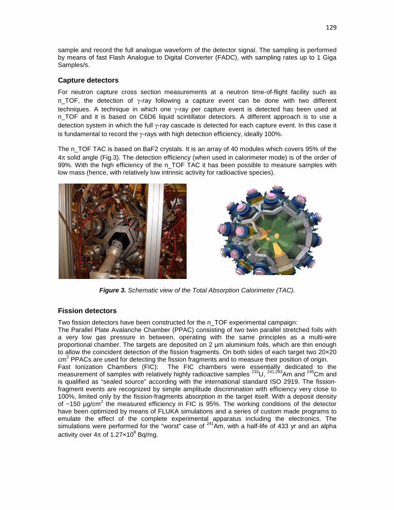
129
sample and record the full analogue waveform of the detector signal. The sampling is performed by means of fast Flash Analogue to Digital Converter (FADC), with sampling rates up to 1 Giga Samples/s.
Capture detectors For neutron capture cross section measurements at a neutron time-of-flight facility such as n_TOF, the detection of γ-ray following a capture event can be done with two different techniques. A technique in which one γ-ray per capture event is detected has been used at n_TOF and it is based on C6D6 liquid scintillator detectors. A different approach is to use a detection system in which the full γ-ray cascade is detected for each capture event. In this case it is fundamental to record the γ-rays with high detection efficiency, ideally 100%. The n_TOF TAC is based on BaF2 crystals. It is an array of 40 modules which covers 95% of the 4π solid angle (Fig.3). The detection efficiency (when used in calorimeter mode) is of the order of 99%. With the high efficiency of the n_TOF TAC it has been possible to measure samples with low mass (hence, with relatively low intrinsic activity for radioactive species).
Figure 3. Schematic view of the Total Absorption Calorimeter (TAC).
Fission detectors Two fission detectors have been constructed for the n_TOF experimental campaign: The Parallel Plate Avalanche Chamber (PPAC) consisting of two twin parallel stretched foils with a very low gas pressure in between, operating with the same principles as a multi-wire proportional chamber. The targets are deposited on 2 µm aluminium foils, which are thin enough to allow the coincident detection of the fission fragments. On both sides of each target two 20×20 cm2 PPACs are used for detecting the fission fragments and to measure their position of origin. Fast Ionization Chambers (FIC): The FIC chambers were essentially dedicated to the measurement of samples with relatively highly radioactive samples 233U, 241,243Am and 245Cm and is qualified as “sealed source” according with the international standard ISO 2919. The fission-fragment events are recognized by simple amplitude discrimination with efficiency very close to 100%, limited only by the fission-fragments absorption in the target itself. With a deposit density of ~150 µg/cm2 the measured efficiency in FIC is 95%. The working conditions of the detector have been optimized by means of FLUKA simulations and a series of custom made programs to emulate the effect of the complete experimental apparatus including the electronics. The simulations were performed for the “worst” case of 241Am, with a half-life of 433 yr and an alpha activity over 4π of 1.27×10⁸ Bq/mg.

130
The experimental campaigns in 2002, 2003 and 2004 The measurements so far performed at n_TOF have covered capture and fission cross section measurements on a large number of samples. The full list is given in the Table I. Most of the measurements have been performed for the n_TOF-ND-ADS Project, within the EC FP5 initiative. The motivations and physics cases of the various measurements have been given in great details in the proposal for measurements submitted to the CERN INTC Committee [12]-[20]. Here we will show the results of a few of the measurements performed.
Capture Fission
151Sm, 204,206,207,208Pb
209Bi, 232Th, 139La
24,25,26Mg
90,91,92,93,94,96Zr
186,187,188Os, 240Pu
233,234U, 237Np, 243Am
233,234,236U
232Th
237Np
241,243Am
245Cm
197Au 235,238U
Table 1. Measurements of capture and fission cross sections performed at CERN n_TOF during the 2002, 2003 and 2004 experimental campaigns.
The 151Sm(n, γ) cross section measurement This cross section is important in nuclear astrophysics because 151Sm is a branching point in the s-process path. In particular, this branching is sensitive to the temperature at which the s-process nucleosynthesis is taking place. The accurate determination of the neutron capture cross section of 151Sm can thus provide crucial information on thermodynamics conditions in AGB stars. The measurement at n_TOF [20] has been performed with an enriched 151Sm sample provided by ORNL (Oak Ridge National Laboratory). The 200 mg of 151Sm encapsulated in a 0.1 mm thick Ti-can induces 200 GBq (5.3 Ci) activity. With such a large activity this kind of measurement is hardly possible at other white neutron time-of-flight facilities. The measurement has been performed with a set of C6D6-based liquid scintillator detectors specifically-designed for low neutron sensitivity. The result obtained at n_TOF is <σ(n,γ)> = 3100 ± 160 mb, a value much larger than previous estimates, all based on model calculations, which ranged from 1500 to 2800 mb. The firm estimate of the capture rate for the first time based on an experimental value allowed reaching two important conclusions with respect o the s-process nucleosynthesis in this mass region:
• the classical model, based on a phenomenological study of the s process fails to produce consistent results of the branching at 151Sm and 147Pm.
• the p-process contribution to the production of 152Gd can amount up to 30% of the solar-system observed abundance.
A detailed description of these results is given in n_TOF publications [17].
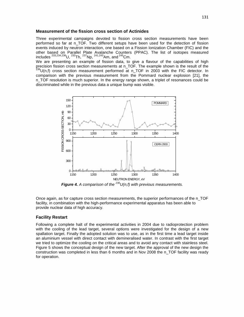
131
Measurement of the fission cross section of Actinides Three experimental campaigns devoted to fission cross section measurements have been performed so far at n_TOF. Two different setups have been used for the detection of fission events induced by neutron interaction, one based on a Fission Ionization Chamber (FIC) and the other based on Parallel Plate Avalanche Counters (PPAC). The list of isotopes measured includes 233,234,236U, 232Th, 237Np, 241,243Am, and 245Cm. We are presenting an example of fission data, to give a flavour of the capabilities of high precision fission cross section measurements at n_TOF. The example shown is the result of the 236U(n,f) cross section measurement performed at n_TOF in 2003 with the FIC detector. In comparison with the previous measurement from the Pommard nuclear explosion [21], the n_TOF resolution is much superior. In the energy range shown, a triplet of resonances could be discriminated while in the previous data a unique bump was visible.
Figure 4. A comparison of the 236U(n,f) with previous measurements.
Once again, as for capture cross section measurements, the superior performances of the n_TOF facility, in combination with the high-performance experimental apparatus has been able to provide nuclear data of high accuracy.
Facility Restart Following a complete halt of the experimental activities in 2004 due to radioprotection problem with the cooling of the lead target, several options were investigated for the design of a new spallation target. Finally the adopted solution was to use, as in the first time a lead target inside an aluminium vessel with direct contact with demineralised water. In contrast with the first target we tried to optimize the cooling on the critical areas and to avoid any contact with stainless steel. Figure 5 shows the conceptual design of the new target. After the approval of the new design the construction was completed in less than 6 months and in Nov 2008 the n_TOF facility was ready for operation.
1150 1200 1250 1300 1350 14000
300
600
900
CERN 2003
FISS
ION
CRO
SS-S
ECTI
ON,
mb
NEUTRON ENERGY, eV
1150 1200 1250 1300 1350 14000
30
60
90
120
150
POMMARD

132
Figure 5. The conceptual design of the new Lead target a) View of the different part of the lead target b) schematic view of the lead target placed inside the cooling system. The cooling water is separated with Aluminium foil.
Facility Upgrades In 2009 the facility was further refurbished and two major upgrades occured (i) conversion of the experimental area to Work Sector Type A and (ii) the use of borated water as neutron moderator.
Work Sector Type A The experimental area was converted to a Work Sector Type A designating a room in which precautions have been taken to protect the personnel from incorporation and to protect the environment from dispersion of radioactive material. CERN’s Safety Code F, in line with the Swiss Ordinance for Radiological Protection [23] and the Ordinance for Handling of Unsealed Radioactive Sources [24] define 3 types of work sectors, from Type C to Type A with increasing technical and organizational requirements, allowing handling higher and higher quantities of unsealed radioisotopes. Table II shows the activity limits of the radioactive source that will define the class work sector.
Work Sector Handling Storage
Type C A < 100 LA A < 10 000 LA
Type B A < 10 000 LA A < 106 LA
Type A A < individually authorised amount
Table 2. Activity limitation for handling and storage in the three types of work sectors
The Work Sector Type A opens new possibilities in measuring highly radioactive targets like the Am-241 source, with practically no restriction from the Radioprotection at CERN. With most important the measurement will take place with no need of a special container classified as ISO2919, which is greatly enhancing the signal to background ratio.
a) b)

133
Borated Water Moderator The new spallation target was by construction designed to be connected to two cooling/moderating circuits. During the first year of operation the two circuits were connected together to the master cooling station. In 2010 we separated the two circuits and introduced a dedicated circuit filled with water saturated in Boron-10 acting like the neutron moderator. Boron-10 has a high neutron cross section absorbing the thermal neutrons before they are captures by Hydrogen in the water which emits the prompt gamma of 2.2 MeV transition from Deuterium. This enhancement will strongly reduce the in-beam gammas in the region of keV. The circuit leaves practically unaffected the neutron fluence and energy resolution above 10 eV, however it strongly depresses the in beam gamma signal due to the absorption of the thermal neutrons from the Boron-10 (Figure 6).
Figure 6. Left neutron fluence as it was measured with the PTB fission chamber and the MicroMegas detector before (red) and after (green) the introduction of the Boron-10. Right the depletion of the in beam gamma background measured with the Fe sample. However this measurement doesn’t show the full reduction of the in beam gamma rays since the measurement was performed in air and is visible at low energies the component coming from the aluminium beam-windows.
Experimental Program The new Lead target has been designed and fabricated for the n_TOF facility. In addition of the FLUKA simulations, the conceptual design has helped from the experience gained from the previous target help us on the construction of the new Lead target for the n_TOF facility at CERN. The commissioning performed in spring 2009, showed that the values are consistent with the expectations and equivalent with the performances of the previous target, analysis work is still in progress. After the commissioning planed for the determination of the new characteristic and performance of the updated n_TOF facility a new campaign of measurements will be performed. The following proposals have already been accepted by the CERN Research Board:
- “The role of Fe and Ni for s-process nucleosynthesis in the early Universe and for innovative nuclear technologies” (CERN-INTC-2006-012);
- “Proposed study of the neutron-neutron interaction at the CERN n_TOF facility” (CERN-INTC-2006-006);
- “Angular distributions in the neutron-induced fission of actinides” CERN-INTC-2006-016; - “n_TOF: New target commissioning and beam characterization” (CERN-INTC-2008-035).

134
Capture measurements
Mo, Ru, Pd stable isotopes r-process residuals calculation isotopic patterns in SiC grain
Fe, Ni, Zn, and Se (stable isotopes),
79Se
s-process nucleosynthesis in massive stars accurate nuclear data needs for structural materials
A≈150 (isotopes varii)
s-process branching points long-lived fission products
234,236U,
231,233Pa Th/U nuclear fuel cycle
235,238U standards, conventional U/Pu fuel cycle
239,240,242Pu,
241,243Am,
245Cm incineration of minor actinides
Fission Measurements
MA ADS, high-burnup, GEN-IV reactors
235U(n,f) with p(n,p’) new 235U(n,f) cross section standard
234U(n,f) study of vibrational resonances at the fission barrier
Other measurements 147Sm(n,a), 67Zn(n,a), 99Ru(n,a), 58Ni(n,p), other (n,lcp)
p-process studies, gas production in structural materials
Al, V, Cr, Zr, Th, 238U(n,lcp) structural and fuel material for ADS and other advanced nuclear reactors
He, Ne, Ar, Xe low-energy nuclear recoils (development of gas detectors)
n+D2 neutron-neutron scattering length
Table 3. Proposed n_TOF Phase II experimental program.
Conclusions In total CERN n_TOF has proven to be a unique facility in the world for its performances and also of the rich scientific program that has been performed, produced numerous publications and valuable data in the field of nuclear physics. A similar strength experimental program is foreseen for the near future. The recent enhancement of the facility have further improved the performances of the facility classifying it one of the best facilities worldwide for such type of measurements. The only drawback of n_TOF is the single neutron beam line, however it is presently under discussion the construction of a secondary experimental area at a shorter distance of 20 m, with a vertical flight path.

135
References
[1] C.Rubbia et al., A high Resolution Spallation driven Facility at the CERN-PS to measure Neutron Cross Sections in the Interval from 1 eV to 250 MeV, CERN/LHC/98-02 (EET) + Add.1. [2] S.Abramovich et al. (The n_TOF Collaboration), European Collaboration for High-Resolution Measurements of Neutron Cross Sections between 1eV and 250 MeV, CERN/SPSC 99-8, 1999 [3] R.Billinge, The CERN PS Complex: A Multipurpose Particle Source, Proc. Of XIIth Int. Conf. on High Energy Acc., 1983 [4] C.Borcea et al., Nuclear Instruments and Methods in Physics Research A 513 (2003) 524-537. [5] D. B. GAYTHER, Metrologia 27 (1990) 221. [6] S.Marrone, et al., A low-mass neutron flux monitor for the n_TOF facility at CERN, Nuclear Instruments and Methods A (2003). [7] R.Plag et al., An optimized C6D6 detector for studies of resonance-dominated (n,γ) cross sections, Nuclear Instruments and Methods A (2002), in press. [8] C.Stéphan, et al., Journal of Nuclear science and Technology, Supplement 2, (2002), 276. [9] V.Vlachoudis et al., Proceedings of the Monte Carlo 2000 Conference, Lisbon, October 23-26 2000, A. Kling, F. Barão, M. Nakagawa, L.Távora, P.Vaz eds., Springer-Verlag Berlin, pg. 1175 (2001) [10] U.Abbonadanno, et al. (The n_TOF Collaboration), CERN n_TOF Facility: Performance Report. CERN SL-2002-053 ECT, Geneva, January 2003. [11] U.Abbondanno et al. (The n_TOF Collaboration). The data acquisition system of the neutron time of flight facility n_TOF at CERN. Nuclear Instruments and Methods in Physics Research A. In press (2004). [12] R.L.Aguiar et al. (The n_TOF Collaboration), Determination of the Neutron Fluence, Beam Characteristics and Background at CERN-PS n_TOF Facility, CERN/INTC 2000-016, 2000 [13] R.L.Aguiar et al. (The n_TOF Collaboration), The Importance of 22Ne(α,n)25Mg as s-Process Neutron Source and the s-Process Thermometer 151Sm, CERN/INTC 2000-017, 2000 [14] S.Andriamonje et al., (The n_TOF Collaboration), Re/Os Cosmochronometer, CERN/INTC 2000-040, 2000 [15] U.Abbondanno et al. (The n_TOF Collaboration). Neutron Cross Sections for the Pb Isotopes: Implications for ADS and Nucleosynthesis, CERN/INTC 2001-020, 2001 [16] U.Abbondanno et al. (The n_TOF Collaboration). Measurements of Fission Cross Sections for the Isotopes relevant to the Thorium Fuel Cycle, CERN/INTC 2001-025, 2001 [17] U.Abbondanno et al. (The n_TOF Collaboration). Measurement of the neutron capture cross sections of 232Th, 231Pa, 234U, and 236U, CERN/INTC 2002-013, 2002 [18] U.Abbondanno et al. (The n_TOF Collaboration). Neutron capture cross sections of Zr and La: probing neutron exposure and neutron flux in Red Giant Stars, CERN/INTC 2002-013, 2002 [19] U.Abbondanno et al. (The n_TOF Collaboration). Measurements of Fission Cross Sections for Actinides, CERN/INTC 2003-021, 2003 [20] U.Abbondanno et al. (The n_TOF Collaboration). Measurement of the neutron capture cross sections of 233,4U, 240Pu and 243Am with a Total Absorption Calorimeter at n_TOF, CERN/INTC 2003-036, 2003 [21] U.Abbondanno, et al. (The n_TOF Collaboration). The Neutron capture cross section of 151Sm at n_TOF Physical Review Letters (2004), accepted for publication [22] W.K.Brown et al., Nucl. Phys. A156 (1970) 609 [23] Le département fédéral de l’intérieur, Ordonnance sur la radioprotection du 22 juin 1994 (Etat du 4 avril 2000) [24] Le département fédéral de l’intérieur, Ordonnance sur l’utilisation des sources radioactives non-scellées du 21 novembre 1997

136

137
Inelastic neutron scattering at nELBE
R. Beyer1), E. Birgersson1), E. Grosse1,2), R. Hannaske1), A. R. Junghans1), M. Kempe1,2), T. Kögler1,2), M. Marta1), R. Massarczyk1,2), A. Matic1), R. Nolte3),
K.D. Schilling1), G. Schramm1,2), R. Schwengner1), A. Wagner1)
1) Forschungszentrum Dresden-Rossendorf, Institut für Strahlenphysik, Bautzner Landstr. 400, 01328 Dresden, Germany
2) Technische Universität Dresden, 01062 Dresden, Germany 3) Physikalisch-Technische Bundesanstalt Braunschweig, Bundesallee 100, 38116
Braunschweig, Germany [email protected]
Abstract: At the superconducting electron linear accelerator ELBE at Forschungszentrum Dresden-Rossendorf the neutron time-of-flight facility nELBE has become operational. Fast neutrons in the energy range from ca. 0.1 to 10 MeV are produced by the pulsed electron beam from ELBE impinging on a liquid lead circuit as a radiator. The short beam pulses of about 10 ps provide the basis for an excellent time resolution for neutron time-of-flight experiments, giving an energy resolution of about 1 % at 1 MeV with a short flight path of approx. 5 m. The neutron intensity on target is ca. 4x10⁴ n/(s cm2) using an electron bunch charge of 77 pC and 203 kHz pulse repetition rate. The energy range of the neutrons produced is well suited for neutron cross section measurements relevant for the development of Generation IV reactor systems and for the transmutation of nuclear waste. First measurements of inelastic scattering cross section on natural Fe have been performed using a double time-of-flight method. The cross section for the first excited level of Fe-56 and Fe-54 could be determined.
Introduction Partitioning of nuclear waste and transmutation of long-lived isotopes to nuclides with shorter lifetimes is an important topic in international research to provide sustainable and green-house gas emission free sources of energy. Different designs involving critical reactors or sub-critical accelerator-driven systems (ADS) are being studied in view of their transmutation capabilities as well as new concepts to produce less waste via very high burn-up. The Generation IV International Forum has selected six nuclear energy systems for which research and development are ongoing to confirm their viability and to demonstrate their expected performance that includes the objective of producing less waste. In the considerations for waste reduction, the possible use of fast (i.e. unmoderated) neutrons as coming directly from the fission process is of great importance as most of the proposed systems use a fast neutron spectrum. Reliable predictions of the relevant physical processes and the optimization of the related facilities depend on the availability of high-quality nuclear data. The data needs have been investigated by the Working Party on International Nuclear Data Evaluation Cooperation of the OECD Nuclear Energy Agency. Two important research fields were identified to be the inelastic scattering of fast neutrons on structure materials in reactors and transmutation devices and the neutron induced fission process of minor actinide nuclei. At Forschungszentrum Dresden-Rossendorf the first compact photo-neutron source at a superconducting electron accelerator dedicated to measurements in the fast neutron range has been built.

138
Photo-production of neutrons at nELBE As the neutron spectrum originating from the nuclear photo effect resembles very much the fission neutron spectrum, a high intensity electron beam allows suitable measurements in the fast neutron domain. The neutrons are generated by (γ,n) reactions with bremsstrahlung from the high intensity electron beam. At the radiation source ELBE of the Forschungszentrum Dresden-Rossendorf (FZD) electrons are accelerated up to 40 MeV in continuous wave mode by super-conducting RF-cavities. The maximum average beam current at a micro-pulse rate of 13 MHz is 1 mA. The neutron source strength at the nominal beam current has been calculated with MCNP-4C3 [1] to be 1013 neutrons/s [2]. The accelerator can produce high- brilliance beams with variable micro-pulse repetition rate and duty cycles. The bunch length is shorter than 10 ps, so that the time-of-flight resolution is not degraded and short flight paths can be used with a high resolution detection system. At En ≈ 1 MeV a resolution ∆E/E ≈ 1 % can be reached with detectors of about 1 ns resolution. nELBE is the first neutron time-of-flight facility at a superconducting electron linear accelerator. Time-of-flight measurements take advantage of a high pulse repetition rate of 100 kHz to 500 kHz. This is nearly a factor of 1000 higher than the pulsed operation at normal-conducting accelerators. The instantaneous neutron and photon flux is lower, which leads to improved background conditions from the scattered photon flash. At ELBE a superconducting RF injector has been developed [3] that will allow reaching a bunch charge of up to 1 nC. With a repetition rate of 500 kHz this corresponds to an average current of up to 0.5 mA. The neutron flux - which determines the statistical accuracy of a cross section measurement carried out in a given time - depends on the primary beam intensity and on the amount of converter target material exposed to the beam. The neutron flux at ELBE is limited by the maximum beam power acceptable on the neutron producing target and not by the available beam current from the accelerator. A liquid lead circuit is used to cope with the very high beam power deposition (P ≈ 5 kW/g) [4], see Fig. 1.
Figure 1. Floor plan of the nELBE time-of-flight facility. The inset in the upper left shows a cross section of the liquid lead circuit. The neutron beam is formed by a collimator made from sections of lead and borated polyethylene. The experimental setup is reached after a flight path of ca. 6 m.

139
The nELBE photo-neutron source is shown in Fig. 1. The electron beam passes through a beryllium window mounted on a stainless-steel vacuum chamber and hits the radiator, consisting of a molybdenum tube confining the liquid lead. The channel has a rhombic cross section with 11 mm side length. The electrons generate bremsstrahlung photons, which release neutrons in secondary (γ,n) reactions on lead. These leave the radiator almost isotropically, whereas the electrons and photons are forward-peaked. The technical design including thermo-mechanical parameters of the liquid lead radiator and the electron beam dump is discussed in [4]. The collimator and the neutron beam properties at the experimental area have been optimized using MCNP in order to maintain the correlation of time-of-flight and neutron energy. The collimator of 2.6 m length contains three replaceable elements of lead and borated polyethylene that are mounted inside a precision steel tube [2]. Background radiation through the concrete door to the left of the experimental setup in Fig. 1 has been minimized by additional concrete shielding and geometric re-alignment of the electron beam line.
Experimental setup at nELBE
nELBE was intended to enable measurements of neutron induced fission cross sections. However, this is still in preparation, so that the present work will concentrate on inelastic neutron scattering experiments. The process of inelastic scattering can be identified by the coincident detection of the scattered neutron and of the emitted de-excitation photon. For this purpose a double time-of-flight setup was installed at nELBE as shown in Fig. 2. It consists of an array of BaF2 scintillation photon detectors and several plastic scintillation neutron detectors [5]. Both types of detectors have time resolutions in the order of 700 ps and, thus, are well suited to measure time-of-flight even at short flight paths.
Figure 2. Sketch of the nELBE neutron time-of-flight setup for the measurement of inelastic neutron scattering cross sections. The detector setup consists of a 235U fission chamber to measure the incoming neutron flux, an array of BaF2 scintillation detectors to measure the de-excitation γ-rays and a set of plastic scintillation detectors to detect the scattered neutrons. For the determination of the incoming neutron flux an 235U fission chamber [6] is employed. A time-of-flight spectrum measured by this instrument is shown in Fig. 3 together with the resulting energy spectrum. One can see that the energy spectrum available at nELBE ranges from about 100 keV to about 10 MeV peaking around 1-2 MeV and its shape is comparable to the energy distribution of unmoderated neutrons resulting from the fission of nuclear fuel components. This means that nELBE is well suited to deliver data in the energy region of interest for transmutation facilities.

140
Figure 3. Left: Time-of-flight spectrum measured by the 235U fission chamber. The position of the photon flash gives the absolute time normalization. Its width represents the time resolution. In this case it’s about 4 ns. Right: Energy spectrum resulting from the left time-of-flight spectrum in comparison with a Maxwellian distribution as is present in fast nuclear reactors.
Determination of the inelastic neutron scattering cross section
Inelastic scattering events are identified by a coincident detection of a neutron by the plastic scintillation detectors and a photon by the BaF2 array. The point in time of the photon detection delivers the energy of the incoming neutron via the known distances from the detector to the sample and further to the neutron production target. The time difference between the neutron and the photon detection determines the time-of-flight of the scattered neutron from the sample to the neutron detector and, thus, its energy. All events in which one neutron and one photon detector registered any particle in an experiment with a natFe sample are shown in Fig. 4. The mass of the sample was 19.8 g. One can see clear structures in these 2D plots. As shown by simple kinematic calculations, these structures correspond to the inelastic scattering to the different levels of 56Fe and 54Fe. Even the inelastic double scattering on the first excited state of 56Fe is visible. During the experiment the sample was moved into and out of the beam in a periodic scheme to investigate the experimental background and to reduce the influence of beam instabilities. The inelastic scattering structures are visible in the sample out spectrum as well, indicating that the sample movement was too small. This means that neutrons from the beam halo or neutrons scattered in air could still reach the sample. However, the overall background is still rather small. The signal to background ratio is in the order of 10 to 100.
Figure 4. Distribution of the time-of-flight of the scattered neutron ToFn,out vs. the time-of-flight of the incoming neutron ToFn,in of events detected during a measurement of inelastic neutron scattering on natFe without (left) and with (right) sample in beam. The lifetime of the measurement without (with) sample was 81.8 (77.94) h. The bin-size is 1 ns in each dimension.

141
The structures in the right panel stem from the inelastic scattering to the different excited levels of 56Fe (black), the first excited level of 54Fe (red) and the double scattering on the first level of 56Fe (magenta). These structures are visible in the left panel as well (see text for explanation).
Experimental results and discussion
Taking all events falling into an adequate window of the 2D plot (Fig. 4) and comparing the resulting count rate to the incoming neutron flux measured by the fission chamber one can determine the inelastic neutron scattering cross section. This is shown for the first excited level of 56Fe in Fig. 5. For comparison the ENDF evaluation and results from previous measurements are shown. These measurements can be divided into two groups. First Perey et al. [7] who also used a continuous photo-neutron spectrum but measured the de-excitation photon only. The second group comprises all other experiments shown [8,9,10]. They used mono-energetic neutrons from, e.g., the 7Li(p,n) reaction and measured the time of flight of the scattered neutron only. The comparison to Perey et al. [7] shows a good agreement at energies up to 1.5 MeV. At higher energies the nELBE results are significantly higher. The reason for this may be uncertainties in the determination of the neutron detection efficiency. This was measured once with mono-energetic neutrons at the PTB Braunschweig at energies between 24 and 1200 keV [5] and later on using the neutron spectrum at nELBE relative to the 235U fission chamber. This is shown in Fig. 6. One can see clear discrepancies at lower as well as at higher energies which are not yet understood. Verification via Monte-Carlo simulations using the NEFF7 code [11] even in an adapted version failed as well. A re-measurement may be necessary.
Figure 5. Inelastic neutron scattering cross section of the first excited level 56Fe measured at nELBE in comparison to the ENDF evaluation and previous measurements using the γ-production yield (Perey) or mono-energetic neutrons (Almen-Ramström, Gilboy, Hopkins). The high-resolution Perey and ENDF data were averaged to meet the same energy resolution as the nELBE measurement.

142
Figure 6. Neutron detection efficiency of the plastic scintillation detectors measured with mono-energetic neutrons (black) and with a continuous energy spectrum (red) in comparison to results of different Monte-Carlo simulations (blue, magenta).
Summary and Outlook
The inelastic neutron scattering cross section to the first excited state of 56Fe was determined by means of a double-time-of-flight method. The results show good agreement to evaluated and previously measured data at lower energies, but differ at higher energies. A re-measurement of the neutron detection efficiency may be necessary. Several corrections still need to be applied, e.g., for thick target effects. The neutron-photon angular correlation might also have an important influence as indicated for example by [12].
Acknowledgements This work was supported by the EURATOM 6. FRAMEWORK PROGRAMME “European Facilities for Nuclear Data Measurements” (EFNUDAT) contract number FP6-036434 and the German federal ministry for education and research under contract number 02NUK013A.
References [1] J.F. Briesmeister, Report LA13709, Los Alamos National Laboratory (2000). [2] J. Klug, E. Altstadt, et al., Nucl. Instr. Meth. A 577, 641 (2007). [3] R. Xiang, A. Arnold, H. Buettig et al., Phys. Rev. STAB 13, 043501 (2010). [4] E. Altstadt, C. Beckert, et al., Ann. Nucl. Ene. 34, 36 (2007). [5] R. Beyer, E. Grosse, et al., Nucl. Instr. Meth. A 575, 449 (2007). [6] D.B. Gayther, Metrologia 27, 221 (1990). [7] F.G. Perey, W.E. Kinney, R.L. Macklin, Proc. of the 3rd Conf. Neutron Cross-Sections and
Tech., Knoxville, C,71KNOX,1,191,197103 (1971). [8] E. Almen-Ramström, Report AE-503, Studsvik, Nyköping, Sweden (1975). [9] W.B. Gilboy, J.H. Towle, Nucl.Phys. 64, 130 (1965). [10] J.C. Hopkins, M.G. Silbert, Nucl. Sci. Eng. 19, 431 (1964). [11] G. Dietze, H. Klein, Report PTB-ND-22, PTB Braunschweig (1982). [12] E. Sheldon, Rev. Mod. Phys. 35, 795 (1963).

143
Measurements at the 175 MeV neutron beam at TSL
C. Gustavsson1), P. Andersson1), R. Bevilacqua1), M. Hayashi2), S. Hirayama2), A. Hjalmarsson3), M. Lantz1), F.-R. Lecolley4), N. Marie4), Y. Naitou2), S. Pomp1),
A. Prokofiev3), V. Simutkin1), E. Tengborn1), M. Tesinsky5), U. Tippawan6), Y. Watanabe2), M. Österlund1)
1) Department of physics and astronomy, Uppsala University, Uppsala, SE- 751 20,
Sweden 2) Kyushu University, Fukuoka, Japan 3) The Svedberg Laboratory, Box 533, 75121 Uppsala, Sweden 4) LPC ENSICAEN, Université de Caen, 14050 Caen Cedex, France 5) Department of Nuclear and Reactor Physics, Royal Institute of Technology, Stockholm 6) Plasma and Beam Physics Research Facility, Chiang Mai University, Chiang Mai, Thailand [email protected]
Abstract: During the past few years, an experimental programme has been run at the 175 MeV neutron beam of The Svedberg Laboratory, Uppsala, Sweden. Elastic scattering and light-ion production have been studied for a number of different target nuclei. Neutron beam characteristics have also been measured, both the quasi-monoenergetic neutron spectrum and the atmospheric-like white neutron spectrum. The Svedberg neutron beam facility is presented as well as experimental methods and some results.
Introduction In this paper, the neutron facility at The Svedberg Laboratory (TSL) is described. A list of the experiments performed at TSL within the EFNUDAT project is given and the two detector systems Medley and SCANDAL are presented with some preliminary results.
The Svedberg neutron facility The present The Svedberg Laboratory (TSL) neutron facility in Uppsala has been in operation since 2004 and was upgraded in 2007. TSL offers a quasi-monoenergetic neutron beam facility, as well as a white spectrum neutron beam facility. A detailed description of the TSL neutron facility is given in [1-2] and only a short outline will be given here.
The quasi-monoenergetic neutron beam facilitates the neutron production reaction 7Li(p,n) with the lithium target enriched to 99.99% in 7Li. The intensity is 3*10ˆ8 neutrons per second over the beam area in the 20-175 MeV energy range. At this beam line, basic nuclear data research such as elastic and inelastic neutron scattering and neutron-induced light charged particle production has been performed.
The white neutron beam facility, ANITA (Atmospheric-like Neutrons from thIck Target), provides a neutron beam with an atmospheric-like neutron spectrum up to 150 MeV. Neutrons are created in a 2.4 cm thick tungsten target which fully stops the incoming protons. The ANITA facility is primarily being used for studies and testing of electronic components and for neutron-induced single-event effects (SEE). Using the Medley setup, spectrum measurements of the ANITA neutron beam have recently been performed, from the maximum energy of close to 180 MeV down to about 1.5 MeV [3]. See Fig. 1.

144
Figure 1. The ANITA neutron spectrum measured with the Medley setup.[3]
Research activities at TSL within EFNUDAT Research activities at TSL have been performed by several research groups within the EFNUDAT project. In total, TSL delivered 567 beam hours to 8 different experiments from 6 different research institutes, see Fig. 2.
Figure 2. Approved research activities at TSL within the EFNUDAT project. Beam hours approved are listed in the right column, with the total number of delivered beam hours in parentheses. The two shaded experiments were carried out simultaneously.

145
The Medley setup The Medley setup was initially designed for neutron-induced light-ion production measurements at energies up to 100 MeV. The setup has been described in detail in [4]. A measurement campaign was performed at the old quasi-monoenergetic neutron beam of TSL resulting in light charged particle production data for C, O, Ca, Si, Fe, Pb and U at 96 MeV as well as np and nd scattering. In 2004 when the new neutron beam at TSL was taken into operation, a reduced distance from the Li target allowed for measurements at the highest available energy of TSL; 175 MeV. Adaptation of the Medley detectors to the increased energy range has enabled a similar campaign at 175 MeV. Data for light charged particle production at 175 MeV have been taken with Medley for several nuclei and are under analysis:
• Bi and Fe – analysed at Uppsala University, Sweden • C and Si – analysed at Kuyshu University, Japan • O – analysed at Chiang Mai University, Thailand • U – analysed at LPC Caen, France
Preliminary results for proton production on iron (no target corrections) are shown in Fig. 3.
Figure 3. Preliminary results for proton production cross sections for iron at 175 MeV. The filled circles are experimental data. The solid and dashed lines indicate the Talys-1.2 calculations [5] with the relative contributions of different reaction mechanisms.

146
The SCANDAL detector The SCANDAL (SCAttered Nucleon Detection AssembLy) is placed after the Medley setup in the neutron beam line at TSL. It is primarily intended for elastic neutron scattering data measurements. SCANDAL consists of two identical detector arms which can be rotated around a pivot point (where the scattering target is placed) to cover detection angles between 10 and 70 degrees in the laboratory system. For a detailed description of the SCANDAL setup, see reference [6]. A schematic picture is given in Fig. 4.
Figure 4. Schematic picture of the SCANDAL setup. The neutron beam enters from the bottom of the picture, leaving the Medley setup, and neutrons are scattered by the target at the pivot point. (n,p) scattering takes place in the converter scintillator and the proton path is recorded by the drift chambers. The full energy of the proton is measured in the CsI crystal. The neutron detection principle in SCANDAL is based on conversion to protons in an active converter scintillator. By this arrangement, the energy loss of the recoil proton in the converter can be measured and compensated for. The full energy of the recoil proton is detected in an array of CsI crystals. Cross sections of elastic neutron scattering at 96 MeV on H, D, C, O, Fe, Y and Pb measured with SCANDAL have previously been published [7-10] and inelastic scattering cross sections have been extracted for C, Fe, Y and Pb [11]. All these experiments were performed at the old neutron facility at TSL.

147
When TSL was rebuilt in 2004 and neutrons of up to 175 MeV became available, the SCANDAL setup needed an upgrade in order to measure these higher energies. The old CsI array was replaced with new CsI crystals, designed to fully stop protons of 175 MeV. In January 2009 the first elastic neutron scattering data were taken, using Fe and Bi as targets. Data analysis has started but is delayed by problems with background. The background has increased significantly at the new TSL facility compared to the old one. At the moment it is uncertain if it will be possible to extract good quality elastic scattering data from the data sets acquired.
In June 2009, part of the SCANDAL setup was used to estimate the proton content in the ANITA white neutron beam. The results are under analysis and will be published later.
Conclusion and outlook A number of successful nuclear data experiments have been performed at the neutron facility at The Svedberg Laboratory in Uppsala within the EFNUDAT project. TSL can provide both quasi-monoenergetic neutrons up to 175 MeV an atmospheric-like white neutron spectrum, suitable for electronics testing and studies of single-event effects. Data analysis is continuing in Uppsala and at other research institutes to produce neutron-induced charged particle data for a number of target nuclei.
Acknowledgements The work described in this paper has been supported by the Swedish Research Council, Swedish, the Swedish Cancer Foundation, the Swedish Nuclear Fuel and Waste Management Company, the Swedish Nuclear Power Inspectorate, the Swedish Nuclear Safety Authority, Vattenfall AB, Ringhals AB, the Swedish Defence Research Agency, the Thailand Research Fund, the HINDAS project and the EFNUDAT project.
References [1] A. Prokofiev et al., Radiation Protection Dosimetry (2007), Vol. 126, No. 1–4, pp. 18–22. [2] A. Prokofiev et al., 2009 IEEE Radiation Effects Data Workshop, Quebec, Canada, July 20-
24, 2009, pp. 166-173. [3] Y. Naitou et al., Proceedings of the 2009 Annual Symposium on Nuclear Data, Ricotti, Tokai,
Japan, Nov. 26-27, 2009. [4] S. Dangtip, et al., Nucl. Instr. Meth. A 452, 484 (2000). [5] A.J. Koning, S. Hilaire, M.C. Duijvestijn, Proceedings of the International Conference on
Nuclear Data for Science and Technology (ND 2007), Nice, France, pp. 211-214 (EDP Sciences, 2008).
[6] J. Klug et al., Nucl. Instr. Meth. Phys. Res. A 489, 282 (2002). [7] J. Klug et. el. Phys. Rev C 68, 064605 (2003). [8] C. Johansson et.al. Phys. Rev C 71, 024002 (2005) [9] P. Mermod et al. Phys. Rev. C 74, 054002 (2006). [10] A. Öhrn et al. Phys. Rev C 77, 024605 (2008) [11] A. Öhrn et al. Proceedings of the International Conference on Nuclear Data for Science and
Technology (ND 2010), Jeju Island, South Korea, to be published.

148

149
Fast neutron facilities at the National Physical Laboratory, UK
N. P. Hawkes, G. C. Taylor and D. J. Thomas
Neutron Metrology Group, National Physical Laboratory, Hampton Road, Teddington, Middx., TW11 0LW, UK [email protected]
Abstract: The facilities for generating monoenergetic and broad-spectrum fast neutron fields at the UK’s National Physical Laboratory are described. Monoenergetic neutrons within the energy range 8 keV – 17 MeV are produced, via a variety of nuclear reactions, by directing charged particle beams from the Neutron Metrology Group's 3.5 MV Van de Graaff accelerator onto appropriate neutron-producing targets. The targets are located at the centre of a low-scatter facility, at a point at least 6 m from the walls, floor or ceiling of the room, in order to minimise room scatter. A multi-energy facility is available, which makes use of the variation of neutron energy with angle to allow several irradiations to be carried out simultaneously at different energies. The beam energy is determined by a calibrated analysing magnet, and neutron fluences are measured using a well-characterised long counter. An accelerator-based broad-spectrum source has been constructed to simulate certain workplace neutron fields. The target used for this source is much thicker than those used for the monoenergetic fields, and the fluence rates are correspondingly high. NPL has a wide range of radioisotopic neutron sources with different strengths and spectra. These can be mounted in the low-scatter area in place of the neutron target. The neutron output of these sources has been measured to better than 1% in the NPL Manganese Bath facility.
Introduction The National Physical Laboratory (NPL) is the UK’s national standards laboratory, and is situated in south west London, not far from Heathrow Airport. It was founded in 1900 in Bushy House, a former royal residence, and the site has since expanded and developed considerably. The organisation is now largely housed in a new suite of custom-built laboratories, although some facilities (including those of the Neutron Metrology Group) remain in separate buildings because of their size. NPL’s Neutron Metrology Group is principally concerned with neutron standards for radiation protection. Much of the Group’s work involves characterising and calibrating a wide variety of neutron-sensitive devices in terms of fluence or dose quantities, and well-characterised neutron fields can be produced with energies ranging from thermal to 17 MeV. Most of these fields are generated via the Group’s main experimental facility, namely a 3.5 MV Van de Graaff electrostatic accelerator capable of providing beams of protons, deuterons or alphas at up to 100 microamps (although the full beam current cannot always be used). Other facilities include a set of neutron-emitting radioisotope sources, and a manganese sulphate bath for high precision measurements of the neutron output from such sources.
Monoenergetic neutrons Low-scatter area The ion beam from the Van de Graaff is transported through the shield wall of the accelerator room into a large experimental area, where it can be used to create a slow neutron field (as described at a previous Workshop in this series[1]), or instead directed to a low-scatter area for the production of fast neutrons. In the low-scatter area (Figure 1) the beam impinges upon a neutron production target. By suitable choice of nuclear reaction, neutrons can be produced in the energy range from 8 keV to 17 MeV, and Table 1 sets out some typical values. The maximum beam current depends on the

150
ability of the target to withstand the heating effect of the beam. The deuterium and tritium targets, which consist of a thin layer of titanium combined with the relevant isotope to form a hydride, have the smallest limit because gas is driven off if the target overheats.
Figure 1. NPL low-scatter area. The beam line enters from the left, and the neutron-producing target is above the centre of the circle. The red radial arms carry detector stands that can be moved to the desired distance and angle under automatic control.
Table 1. Typical neutron energies and the corresponding production reactions. Other energies can also be made available by varying the accelerator energy or the detector angle (although some energies are not achievable). Targets are air cooled to keep the mass to a minimum, and a beam current limit is imposed to prevent overheating.
En (MeV) at 0° Reaction Max. beam current (µA)
Max. fluence rate at 1 m from target
(cm-2 s-1) 0.027 45Sc(p,n)45Ti 30 8 0.144 7Li(p,n)7Be 20 1 x 10³ 0.250 " " 6 x 10² 0.565 " " 1.6 x 10³ 1.2 T(p,n)3He 3 2 x 10² 2.5 " " 3 x 10² 5.0 D(d,n)3He " 6 x 10²
17.0 T(d,n)4He " 5 x 10²
Neutrons are of course emitted in all kinematically allowed directions from the target, which introduces a potential problem with room scatter. To minimise this the area around the target is kept as open as possible. The boundaries of the room (including the floor) are at least 6 m away in all directions, and the detectors or objects being irradiated are supported by low-mass stands and accessed via low-mass walkways. Although the resulting room scatter is typically less than 10%, shadow cones (Figure 2) are routinely used to quantify it. The cone blocks the neutrons coming directly from the target, and whatever response remains is due to scatter.

151
Because of the kinematics of the production reaction, the neutron energy depends on the emission angle relative to the beam. In some circumstances this effect can be put to good use. Figure 3 shows the Multi Energy Facility, which allows a large number of small artefacts to be irradiated simultaneously at a range of different neutron energies.
Figure 2. Scatter measurement using a shadow cone to block direct neutrons.
Figure 3. Simultaneous irradiation of many artefacts at different energies, using the NPL Multi – Energy Facility.
Determining the neutron fluence and energy The neutron fluence is measured using a long counter (Figure 4). This consists of a BF3 proportional counter inside a cylindrical moderator, with a boron oxide layer to reduce the sensitivity to neutrons incident from the side. The efficiency of the device is fairly flat with energy, and has been characterised in detail[2, 3] using a variety of techniques including Monte Carlo modelling and measurements with NPL’s radioisotopic neutron sources (the output of which has been measured to high precision in the NPL manganese bath, described below). Fluence uncertainties depend on the particular arrangements but are typically in the range 3 to 5%, and the long counters are subject to periodic international comparisons.
Figure 4: NPL long counter for neutron fluence measurements

152
The energy of the ion beam from the accelerator is defined by narrow slits at the exit of an energy-analysing magnet. The field of this magnet is calibrated by reference to the known thresholds of nuclear reactions such as 27Al(p,γ), T(p,n) and 7Li(p,n). During irradiations, the field is maintained at its set value by a servo system in which the magnet power supply is controlled by the signal from a Nuclear Magnetic Resonance probe inside the field. The overall uncertainty in the mean energy of the beam is ± 1.5 keV, and the full width of the energy distribution is approximately 4 keV. The consequences of this on the neutron energy depend on the particular neutron production reaction and target thickness in use, and some selected examples from recent irradiations are given in Table 2.
Table 2. Typical neutron energy parameters at 0° for selected production reactions with the NPL beam and targetry.
Reaction Neutron energy (keV)
Full width of neutron energy distribution
(keV) 7Li(p,n) 144 ± 2.2 6.2 ± 0.9 T(p,n) 2500 ± 2.9 28 ± 5 T(d,n) 17000 ± 16 340 ± 32
Broad-spectrum sources Monoenergetic neutrons have clear advantages for characterising or calibrating instruments, but broad-spectrum sources are often simpler to produce, are useful as reference spectra, and can sometimes provide higher intensities. NPL has several such sources.
Simulated workplace field An accelerator-based source [4] was developed to simulate the relatively soft neutron spectra of certain workplace fields, in order to improve the calibration of dosemeters. The source requires a thick lithium target, and it was found that this could be achieved conveniently by using aluminium lithium aerospace alloy, which needs no special handling. The lithium is dilute (approximately 2.5% by weight), but because the target is thick the neutron production exceeds that of the monoenergetic targets, with a maximum fluence rate of approximately 4.5 x 103 cm-2s-1 at 1 m. For use as the source for the simulated workplace field, the target is positioned at the centre of a heavy water moderator (Figure 5), but with the moderator removed the 0° spectrum shows a broad peak at about 600 keV.
Figure 5. The Simulated Workplace Field facility, with the spherical moderator moved aside to show the lithium alloy target.

153
Radioisotope neutron sources NPL has several neutron-emitting radioisotope sources with various emission rates and average neutron energies (Table 3). These sources may be mounted in the low-scatter area in place of the neutron production target and used for irradiations in the same way. The fluence rate from the strongest sources is comparable with that from the Van de Graaff targets at the same distance. In addition to the sources described in the Table, in early 2011 NPL expects to take delivery of a 252Cf source with approximately three times the emission rate of the strongest source held presently.
Table 3. Neutron source types available at NPL.
Source type Mean neutron energy (MeV)
Neutron output (s-1)
Max. fluence rate at 1 m (cm-2 s-1)
252Cf 2.1 5.8 x 10⁷ 4.6 x 10² 252Cf with D2O
moderator 0.5 5.1 x 10⁷ 4.0 x 10² 241Am - Be 4.1 3.2 x 10⁷ 2.7 x 10² 241Am - B 2.8 4.3 x 10⁵ 3.5 241Am - F 1.5 1.3 x 10⁵ 1.0 241Am - Li 0.5 2.1 x 10⁵ 1.8
The neutron output of each of these sources has been measured to better than 1% using the NPL manganese sulphate bath[5] (Figure 6). This is one of only a few such facilities in the world. The source to be characterised is placed in a small metal sphere and then lowered to the centre of a 1 m diameter bath of MnSO4. The activity induced in the manganese is measured using sodium iodide detectors, and the source emission rate can then be deduced.
Figure 6. NPL Manganese Bath facility. The small sphere containing the source is transferred under remote control from the source handling cell (background) to the 1 m diameter manganese sulphate tank (mid ground), where the activity induced in the solution allows the output of the source to be calculated.
Acknowledgements The support of the Department for Business, Innovation and Skills and of the National Measurement Office is gratefully acknowledged.

154
References
[1] N. P. Hawkes, P. Kolkowski and D. J Thomas, Slow neutron facilities at the National Physical Laboratory, UK, Proc. 2nd EFNUDAT workshop on Neutron Measurements, Theory and Applications (Slow and Resonance Neutrons), September 2009, Budapest (Institute of Isotopes, Hungarian Academy of Sciences, Budapest), ed. Tamás Belgya, ISBN 978-963-7351-19-8, pp 75 – 80.
[2] H. Tagziria and D. J. Thomas, Re-calibration and Monte Carlo modelling of the NPL long counters, NPL Report CIRM 19, September 1998.
[3] H. Tagziria and D. J. Thomas, Calibration and Monte Carlo modelling of neutron long counters, Nucl. Instrum. Methods in Phys. Res. A452 (2000), 470 – 483.
[4] G. C. Taylor, D. J. Thomas and A. Bennett, A realistic field facility to simulate reactor spectra, Radiat. Prot. Dosim. 110 (2004) 111 – 115.
[5] See, for example, the following web page: http://www.npl.co.uk/ionising-radiation/neutron-metrology/research/manganese-bath

155
Neutrons For Science - a neutron facility @ SPIRAL-2
X. Ledoux1), M. Aïche4), S. Andriamonje2), M. Avrigeanu11), V. Avrigeanu11), E. Balanzat18), G. Ban5), B. Ban-d’état18), G. Barreau4), E. Bauge1), G. Bélier1), P. Bem7), V. Blideanu3), J. Blomgren8), C. Borcea11), S. Bouffard18), T. Caillaud18), S. Czajkowski4), P. Dessagne6), D. Doré2), M. Fallot14), C. Gustavsson8), U. Fischer9), L. Giot18), S. Guillous18), F. Gunsing2), S. Herber9), B. Jacquot10), B. Jurado4), M. Kerveno6), K. Klix9), O. Landoas18), F. R. Lecolley5), J. F. Lecolley5), J. L. Lecouey5), M. Majerle9), N. Marie5), J. Mrazek7), F. Negoita11), J. Novak7), A. Oberstedt19), S. Oberstedt12), L. Perrot17), S. Panebianco2), M. Petrascu11), A.J.M. Plompen12), S. Pomp8), J. M. Ramillon18), F. Rejmund10), D. Ridikas2), B. Rossé18), G. Rudolf6), O. Serot16), O. Shcherbakov13), S. P. Simakov9), E. Simeckova7), A. G. Smith15), J. C. Steckmeyer5), J. C. Sublet16), J. Taïeb1), L. Tassan-Got17), A. Takibayev2), I. Thfoin18), I. Tsekhanovich15), E. Tengborn8), C. Varignon1)
1) CEA/DAM/DIF, F-91297, Arpajon, France 2) CEA/DSM/IRFU/SPhN, Saclay, France 3) CEA/DSM/IRFU/Senac, Saclay, France 4) CENBG, Gradignan, France 5) LPC, Caen, France 6) IPHC, Strasbourg, France 7) NPI, Řež, Czech Republic 8) Department of Physics and Astronomy, Uppsala University, Sweden 9) FZK, Karlsruhe, Germany 10) GANIL, Caen, France 11) NIPNE, Bucharest, Romania 12) EU Joint Research Centre IRMM, Geel, Belgium 13) PNPI, Gatchina, Russia 14) Subatech, Nantes, France 15) Department of Physics and Astronomy, University of Manchester, UK 16) CEA/DEN, Cadarache, France 17) IPNO, Orsay, France 18) CIMAP, Caen, France 19) Örebro University, Örebro, Sweden [email protected] Abstract: The “Neutrons for Science” (NFS) facility will be one of the SPIRAL-2 experimental areas. NFS, expected to be operational in 2012, will be composed of a pulsed neutron beam for in-flight measurements and an irradiation station for activation measurements and material studies. The beams delivered by the high-power superconducting driver LINAC of the SPIRAL-2 facility will allow producing intense pulsed neutrons beams in the 100 keV-40 MeV energy range. A deuteron beam on thick C and Be converter foils will produce a continuous neutron spectrum, while protons on a thin 7Li target allow generating quasi mono-energetic neutrons. NFS will be a very powerful tool for fundamental physics research as well as for applications like the transmutation of nuclear waste, design of future fission and fusion reactors, nuclear medicine or test and development of new detector systems. Several “Day-one experiments” in these fields have already been evaluated by the scientific Advisory Committee of SPIRAL-2.

156
We describe the facility; give the characteristics and present some examples of the first potential experiments.
Introduction Neutron-induced reactions play an important role in a wide range of applications including nuclear power reactors, accelerator-driven systems (ADS), fusion technology, medical diagnostics and therapy, production of radio-elements, dosimetry concerning dose effects and radiation damage and upsets in electronic devices as well as basic science research. The data used in transport codes are embodied in evaluated data libraries, which are based on measurements and reaction models. As a matter of fact, the quality of the evaluated data depends on the accuracy of the measured data. Today there is still a large demand of data in neutron-induced reactions above, say, 14 MeV. For many cases (n,fission), (n,n'γ), (n,xn) and (n,LCP) reaction cross sections are unknown or known with a very limited accuracy. The neutron energy range between 1 and 40 Me V ra nge is pa rticula rly we ll s uite d for the a pplica tions pre vious ly mentioned as well as for fundamental research. NFS will be a very powerful tool dedicated to theses studies. It will be a component of the future SPIRAL-2 facility, currently under construction at GANIL, Caen (France). SPIRAL-2 will produce very intense rare isotope beam (RIB) in the mass range from A=60 to A=140. These nuclei will be produced by the fission of 238U induced by fast neutrons, which are generated by break-up reaction of deuteron on a carbon converter. The LINAG (high-power superconducting driver LINAC of GANIL), delivering a high-intensity deuteron beam for RIB production, will also be used to produce neutrons in the NFS facility. NFS will deliver a well collimated neutron beam in a long experimental area in order to perform in flight measurements at neutron energies up to 40 MeV. In addition, neutron, proton and deuteron induced reactions cross-sections could be measured by activation technique.
NFS Description NFS will be mainly composed of two rooms: a converter cave and an experimental area separated by a 3 m thick wall of concrete (see Figure 1). The converter room contents the primary ion beam extension, the converter to produce neutrons as well as the irradiation set-ups. A bending magnet placed between the converter and the collimator entrance will clean the neutron beam from protons (see following section). A conical channel through the wall defines the neutron beam. The experimental area is dedicated to experiments with the neutron beam. Its size (25 m x 6 m) will allow performing in-flight measurements by using large experimental set-ups at desired distances from 5 m up to 25 m away from the converter point. This flexibility is very interesting in terms of flux and energy measurement resolution. The experimental area is designed for the use of radioactive samples up to 10 and 1 GBq for sealed and non sealed samples, respectively. The ion beam line in the converter cave will also be equipped with an irradiation box for cross-section measurements of proton and deuteron induced reactions by the activation technique. The use of light ions, up to carbon, is also envisaged to irradiate samples for material studies.

157
Figure 1 : Schematic view of NFS.
Neutron production mode The LINAG will deliver pulsed proton and deuteron beams up to 33 and 40 MeV, respectively, with a maximum intensity of 5 mA. Two production modes will be used. First, the deuteron break-up reaction on a thick converter made of carbon or beryllium generates neutrons with a continuous energy distribution. At 0 degree, the spectrum extends up to 40 MeV with an averaged value of approximately 14 MeV as shown on Figure 2. The neutron yield increases with the incident energy and the 9Be(d,xn) reaction ensure a production yield about two times higher than the 12C(d,xn) one. Second, the 7Li(p,n) reaction on a thin lithium converter (1 to 3 mm of thickness) produces nearly mono-energetic neutrons as shown on Figure 3, the neutron spectrum of the 7Li(p,n) reaction consists of a mono-energetic peak due to the 7Li(p,n0,1) process and a continuum which is attributed to the break-up process. The energy lost by the protons in the converter is small (ΔE≈1 MeV) and most of them pass through the lithium target without reaction. A bending magnet downstream of the target sweeps those protons out of the neutron beam to a beam dump.
Figure 2 : Neutrons energy distribution at 0 degree produced by deuteron break up reaction on different thick converters [1][2].
collimator
convertercave
experimentalarea
collimator
convertercave
experimentalarea

158
Figure 3 : Neutrons energy distribution at 0 degree produced by the 7Li(p,n) reaction on a thin lithium target[3].
Beam characteristics Although the LINAG can deliver 5 mA proton and deuteron beams, the ion beam intensity on the converter will be voluntarily limited to 50 µA in order to simplify the facility design. Actually, reduced intensity means reduced wall thickness and reduced activation of the converter. This last parameter is essential for the converter room’s access procedure and for the operations of maintenance. The converter design is also strongly related to the maximum power deposition. In our case, the value of 2 kW, will require the use of a rotating target. Last but not least, the LINAG beam frequency (88 MHz) is not adapted to time-of-flight (TOF) measurements. In order to avoid wrap around effects, the neutron beam frequency must be reduced to a value depending on the flight path and the low energy part of the spectra. In any case it must be lower than 1 MHz. Therefore a fast beam-chopper down stream of the RFQ will select 1 over N bursts, with N>100 corresponding to a maximum ion-beam intensity of 50 µA. By taking into account the neutron yield production [1][2], the beam division and the flight path, the neutron flux can be evaluated and compared to other major TOF facilities, namely n_TOF at CERN, WNR at Los Alamos (where neutrons are produced in a spallation reaction) and GELINA in Geel (where neutrons are produced by photo-fission). The length of the TOF area allows either high-intensity flux (5 m) or high-resolution (20 m) measurements. We can see in Figure 4 that NFS is very competitive in terms of average flux in comparison with n_TOF, GELINA or WNR between 1 and 35 MeV. It has to be stressed that this is achieved thanks to the high repetition rate, compared to the other facilities.
Figure 4: Neutron flux at NFS for two flight paths compared to three other neutron time-of-flights facilities
1,E+02
1,E+03
1,E+04
1,E+05
1,E+06
1,E+07
1,E+08
1,E+09
0,01 0,1 1 10 100
Energie (MeV)
dN/d
ln(E
) (n/
cm2 /s)
WNRn-tofNFS 5 m 50 µANFS 20 m 12 µAGELINA

159
Moreover, NFS presents some advantages thanks to the neutron production mechanism itself. In spallation sources the high energy neutrons (up to hundreds MeV), may imply challenges for both collimation and background. Secondly, the gamma-flash, which is known to be very penalising, especially because it induces dead time, will probably be strongly reduced at NFS. Note that high energy gamma rays are produced by π0 decay in spallation sources and by bremsstrahlung in photo-neutron sources based on electron accelerators. The energy of the incident neutron can be measured by the TOF technique with a rather good resolution thanks to a small time spread at the converter point (shorter than 1 ns) as well as to the length of the experimental area. The use of fast detectors (∆t ≈ 1 ns) and slow detectors, like High Purity Germanium detector (∆t ≈ 8 ns), allows to reaching an energy resolution at 40 MeV better than 1 % and 5% respectively.
SPIRAL-2: status of construction The SPIRAL-2 construction is split in two phases. The first one includes the accelerator building, the Super Spectrometer Separator (S3) [4] and NFS. The second one will be composed of the production building and the DESIR facility [5]. The design of the buildings of phase one is now completed. The public enquiry was done in July 2010 and the permit of construction should be obtained in October 2010. The major part of the facility, i.e. the LINAG, S3, the production building and NFS itself, will be placed underground at a level of -9.5 m (see Figure 5). This solution leads to a lighter design of the biological protections. The construction will begin at the end of 2010 and the first beam is scheduled in 2012.
Figure 5 : Plan of the SPIRAL-2 phase 1 buildings.
Physics case Neutrons-induced reactions in the NFS energy range play an important role in numerous applications like in reactors of the new generation, in the nuclear medicine, for describing the so-called Single Event Upset (SEU) in electronics devices, for advancing the fusion technology or the development of nuclear model codes in general. The probable development of innovative fast nuclear reactors being able to transmute long-lived nuclear wastes requires new high quality data for a large set of fissioning systems (from thorium to curium) for an energy range going from thermal up to the fast (~2 MeV) region. Complementary to reaction cross section data, the mass and charge distributions are needed with a high precision for burn-up calculations of the reactor fuel, because they are directly connected to the control and the safety of the reactor. In fast reactors, a new kind of reactions appears compared to the
NFS
S3
TOF area
Convertercave

160
situation in thermal reactors. Among them, the (n,xn) reactions (with x>1) are then possible despite their high threshold and play a non negligible role, since above 10 MeV they have cross sections comparable to fission. They modify the neutron spectrum by converting fast neutrons (En>5 MeV) into slow neutrons (En<1 MeV) and especially they act upon the criticality of the reactor core. A good knowledge of the cross sections is necessary for assessing the neutron balance or to predict radioactive waste inventories. In neutron therapy a large part of the dose is deposited by light ion production, a precise knowledge of the double-differential cross is absolutely required to accurately evaluate the dose. These data are also essential for the estimation of radiation effects in electronics like Single Events Upset in chips and for various nuclei like oxygen and silicon. The IFMIF (International Fusion Material Irradiation Facility) facility needs accurate data of proton and deuteron induced reaction cross-section for estimation of the potential radiation hazards from the accelerating cavities and beam transport elements (Al, Fe, Cr, Cu, Nb) and metal and gaseous impurities of the Li loop (Be, C, O, N, Na, K, S, Ca, Fe, Cr, Ni). Proton and deuteron induced reaction cross-section measurements are also needed for the projects of medical radioisotopes production based on a light particle accelerator. The particle-nucleus reactions codes, used to create evaluated data libraries in addition to experimental data, are made of several models (optical model, direct interaction, pre-equilibrium and evaporation models) to reproduce the whole reaction mechanism and resulting observables. Among these processes, the pre-equilibrium process is clearly the least well known. Therefore new data are needed to improve existing models. Actually, some of the few existing ones reproduce integrated observables but rarely the differential ones. The beam characteristics as well as the experimental area of NFS are particularly well suited for studying the reactions involved in all these topics, namely fission, (n,xn) , (n,lcp) as well as deuteron and proton induced reactions.
Day-one experiments A call for Letters Of Intent (LOI) for “Day-one experiments in phase 1” was recently request by the Scientific Advisory Committee (SAC) of SPIRAL-2. It corresponds to experiments which could be performed just after the commissioning of NFS and S3 with a reduced intensity. For NFS nine LOI were submitted and a short overview is given in the following sub-sections. Three of them concern (n,xn) reactions, one is about light charged-particle production, four are related to fission studies, and the last one is dedicated to the measurement of deuteron induced reaction cross-section.
(N,xn) reaction Three methods allow measuring (n,xn) cross sections; namely the direct detection of neutrons, prompt gamma-ray spectroscopy or the activation technique. A direct measurement could be performed by using a 4π neutron detector like CARMEN. It is a spherical detector filled by 1 m3 of a scintillating liquid loaded with gadolinium. The neutron multiplicity is measured event by event with a high efficiency (85% for fission neutrons). The number of events of multiplicity x leads to the (n,xn) cross-section. The (n,xn) cross-section measurement for actinides by this method is a real challenge because the fission neutron component has to be subtracted. One promising solution could be the use of a highly efficient fission active target as a fission veto [6]. The latter is a new kind of active target based on a small volume of organic liquid scintillator in which the actinide is dissolved. The goal is to obtain precise data in reduced energy bins of typically 100 keV. Prompt γ spectroscopy is a very efficient way to measure (n,xn) cross-section and has the advantage to be adapted to actinide nuclei and doesn’t require isotopic targets. One weak point of this method is that one measures transitions in the final nucleus, so that the direct production of this nucleus in its fundamental state is missed. The total (n,xn) cross section has to be determined by a model calculation. A Day-one experiment proposal aims to check these calculations by measuring the 90Zr(n,3n)88Zr reaction cross section simultaneously by prompt spectroscopy and activation methods [6]. The two measurements will be performed with the same set-up, the same target and in the same beam.

161
In addition to cross-section measurements, the study of pre-equilibrium processes in (n,xn) reactions is of first importance to improve or constrain existing nuclear reaction models. The energy range of NFS is particularly well suited because the pre-equilibrium importance increases in the 20-50 MeV range. One way to obtain new data is to measure the energy spectra of neutrons in the (n,xn) reactions in coincidence with the neutron multiplicity thanks to a set of NE213 cells and the CARMEN detector [8]. Contrary to “classical” (n,xn) reaction measurement, where all the channels emitting at least one neutron are taken into account, double differential cross-section in (n,2n), (n,3n), (n,4n) tagged reactions will be measured.
Light-ion production Double-differential cross-sections measurement for neutron-induced light-ion production (p, d and alpha particles) could be performed with the Medley set-up [9]. From the applications point of view, most relevant isotopes are C, O, Na, Si, Ca, Fe, Pb, Bi, U. Initial focus will be on C, O (medical applications), Si (together with O important in electronics applications), and Fe (construction material in many applications). The energy region between 15 and 30 MeV is important for the following reason; while the neutron flux in this energy range decreases with roughly 1/E (e.g. secondary cosmic ray neutrons), the light-ion production channel opens up in the 10-20 MeV range. Thus, folding the neutron flux in an application with the cross section for light-ion production generally results in a peak in the 15 to 30 MeV range. The Medley set-up will move from The Svedberg Laboratory in Sweden to NFS in order to perform these experiments, but could also be used for incident neutron spectrum measurement or for fission studies.
Fission Cross-sections and fragments angular distributions The fission angular distributions are an ingredient in the efficiency corrections for the measurement of fission cross sections. They also carry information on the (J,K) distributions of the states involved in the fission process. Although the angular distributions of several actinides have been measured up to a few MeV, we have very little knowledge beyond this limit: measurements are scarce and often inconsistent. Generally the angular distributions change suddenly through the multi-chance thresholds reflecting the properties of the different fissionning nuclei. Fast detectors in conjunction with the white intense pulsed neutron beam of NFS allow performing simultaneous measurements at several incoming neutron energies and to accurately assess cross-section variations around fission threshold or at second chance fission energy range. Two LOI are dedicated to the measurement of fission cross-sections and the corresponding fragment angular distributions with different experimental techniques. In the first one [10], the two fission fragments are detected in coincidence and their trajectory measured by 2 position sensitive PPACs placed on each side of a target. An arrangement of 9 large targets and 10 detectors allows reaching acceptable counting rates. The second one [11] proposes to use an adapted version of the Medley set-up. The fission fragments will be registered in an arrangement of 8 thin (25 µm) silicon surface barrier placed from 20 to 160 degrees relative to the neutron beam. A PPAC detector is envisaged to be placed at the target position for fast timing allowing an energy resolution of 1 MeV at 20 MeV (2 MeV at 30 MeV). The simultaneous measurement of elastic np scattering events will allow for good determination of the 238U(n,f) cross section. We will, therefore, be able to link together two standard cross sections for neutron measurements with good accuracy.
Fission fragment distributions and neutron multiplicities Two other LOI aim to provide accurate data on actinide neutron-induced fission fragment characteristics (mass, charge, kinetic energy) in the energy range between 500 keV and 20 MeV. Contrary to thermal neutron energies, only few data are available in the fast domain. For current and future nuclear reactors the actinides of interest are some nuclei of reference and some minor actinides, which are candidates for an efficient transmutation. For fundamental studies, it’s important to perform measurements for even-even, even-odd and odd-odd systems. Fission modes, even-odd effects, deformation energy, etc, can be studied with such measurements. Thanks to the proposed measurements, models will be improved and more precise predictions will be done for nuclei difficult to access experimentally. The detection and identification (Z, A, KE (kinetic energy)) of both fission fragments in coincidence is really a challenge. The detection systems proposed by the two LOI are different.

162
For one of them, FALSTAFF [12], the detector will consist of four TOF arms and ionisation chambers to measure respectively the velocity and the energy of fragments. The fragment masses before and after neutron evaporation will be measured in order to determine the neutron multiplicity associated to each fragment. In the other case the STEFF detector will be used [13]. There, individual fragments will be identified thanks to a Bragg chamber. TOF measurement will also be performed.
Proton and deuteron induced reactions Proton and deuteron induced activation reactions are of great interest for the assessment of induced radioactivities in accelerator components, targets and beam stoppers and are important for isotope production for medical purposes. The cross sections are needed in the energy range from the threshold of the activation reactions (2 - 10 MeV) up to 40 MeV for both incident ions: deuterons and protons. Present status of the measured and evaluated data needs urgent and strong improvement. The measurement of excitation functions can be performed at NFS in a energy domain (20-40 MeV) where data are not existing or known with poor accuracy [14]. This kind of experiment is also a powerful tool for studying pre-equilibrium process in a key energy domain.
Summary The NFS characteristics in terms of flux or energy resolution make it a very attractive and powerful tool for physics with neutrons in the 100 keV-40 MeV range. The high neutron fluxes will allow measurements of small reaction cross-sections and/or with very small targets, which might be rare, expensive, and in some cases radioactive. The energy range and conditions offered by the SPIRAL-2/NFS time-of-flight facility is complementary to other such facilities in Europe, notably GELINA of the European Commission’s Joint Research Centre in Geel and the CERN based n_TOF facility. The irradiation facility is particularly well adapted to cross-section measurements in neutron, proton or deuteron induced reactions which are needed for the fusion technology. Several experiments have been identified as potential Day-one experiments and presented to the Scientific Advisory Committee of SPIRAL-2. The construction will start in 2010 and the facility should be operational in 2012.
References [1] M. J. Saltmarsh et al., NIMA145 (1977) p81-90 [2] J. P. Meulders et al., Phys. Med. Biol. (1975)vol 20 n°2, p235 [3] C. J. Batty et al., NIM 68 (1969) p273-276 [4] A. Drouart et al., Nucl. Phys. A834, (2010) p747-751 [5] DESIR, http://www.cenbg.in2p3.fr/desir/ [6] G. Bélier et al., “Direct measurement of (n,xn) reaction cross sections on 239Pu”, LOI for Day-
one experiment. [7] M. Kerveno et al., “Comparison between activation and prompt spectroscopy as means of
(n,xn) cross section measurements”, LOI for Day-one experiment. [8] X. Ledoux et al., “Study of pre-equilibrium process in (n,xn) reaction”, LOI for Day-one
experiment. [9] S. Pomp et al., “Light-ion production studies with Medley”, LOI for Day-one experiment. [10] L. Tassan-Got et al., “Fragment angular distributions in neutron-induced fission of actinide
nuclei”, LOI for Day-one experiment. [11] S. Pomp et al., “Fission fragment angular distribution and fission cross section measurements
relative to elastic np scattering with Medley, LOI for Day-one experiment. [12] D. Doré et al., “Fission fragment distributions and neutron multiplicities”, LOI for Day-one
experiment. [13] G. Smith et al., “Use of the STEFF spectrometer at NFS”, LOI for Day-one experiment. [14] P. Bem et al.” Proton and deuteron induced activation reactions”, LOI for Day-one
experiment.

163
Neutron resonance spectroscopy at GELINA
P. Schillebeeckx1), S. Kopecky1), C. Lampoudis1), C. Massimi2), W. Mondelaers1), M. Moxon3), N. Otuka4) and I. Sirakov5)
1) EC-JRC–IRMM, Retieseweg - 111, Geel Belgium, B-2440 2) INFN Sezione di Bologna, Via Irnerio 46, Bologna, Italy, I - 40126 3) Hyde Copse 3, Marcham, United Kingdom, OX136PT 4) IAEA – NDS, Wagramer Strasse, Vienna, Austria, A-1400 5) INRNE, Tzarigradsko chaussee 72, Sofia, Bulgaria, BG-1784 [email protected]
Abstract: The neutron time-of-flight facility GELINA installed at the IRMM Geel, Belgium has been designed for neutron induced reaction cross section studies in the resonance region. It is a multi-user facility, serving up to 10 different experiments simultaneously. The facility provides a pulsed white neutron source, with a neutron energy range between 10 meV and 20 MeV, a time resolution of 1 ns and flight path lengths ranging from 10 m to 400 m. The research program concentrates on cross section data needs for nuclear energy applications. Over the last decade, the IRMM has made an intense effort to improve the quality of neutron-induced cross section data in the resolved and unresolved resonance region. In this contribution, efforts made to improve the accelerator performance, measurement stations and data reduction and analysis procedures are discussed. Due to these improvements accurate neutron-induced cross section data and resonance parameters together with their covariance information can be obtained from thermal up to the unresolved resonance region.
Introduction Neutron induced reaction cross sections are essential data for a wide variety of nuclear applications. Reducing uncertainties of cross section data can lead to significant improvement in the safety assessment and reliability of reactor concepts. Most of the cross sections in evaluated data libraries are derived from theoretical reaction models using model parameters which are obtained from adjustments to experimental data [1]. Such a parameterization ensures a consistent description of the total and partial cross sections from the sub-thermal up to the high energy region. Hence, recommended cross sections together with their covariance matrices depend strongly on the quality of the experimental data used to determine the model parameters. This is especially valid for the resonance region since no theory exists that can predict the parameters of individual resonances. To parameterize cross sections in terms of resonance parameters, experimental data resulting from measurements with an extremely good energy resolution are required. Experimentally, the resonance region is best studied at a pulsed white neutron source optimised for Time-Of-Flight (TOF) measurements. The TOF - facility GELINA has been designed and built for high-resolution cross section measurements in the resolved and unresolved resonance region [2]. It is a multi-user TOF facility, providing a pulsed white neutron source, with a neutron energy range between 10 meV and 20 MeV. The linear electron accelerator produces intense pulses with a width of 10 ns and a nominal peak current of 10 A, at a repetition rate which can range from 10 Hz to 800 Hz. The electrons are accelerated to a maximum energy of 150 MeV. The 10 ns bunches are compressed to less than 1 ns by a post-acceleration compression magnet. The high energy electrons generate Bremsstrahlung in a mercury cooled depleted uranium target, where neutrons are produced by (γ, n) and (γ, f) reactions. The target yields a total neutron intensity of about 3.4 x 10¹³ 1/s. Two water-filled beryllium containers placed above and below the uranium target are used as moderators to produce a significant number of neutrons in the low energy region. Using suitable shielding material in the target room, either the direct (fast) neutron spectrum with very good time
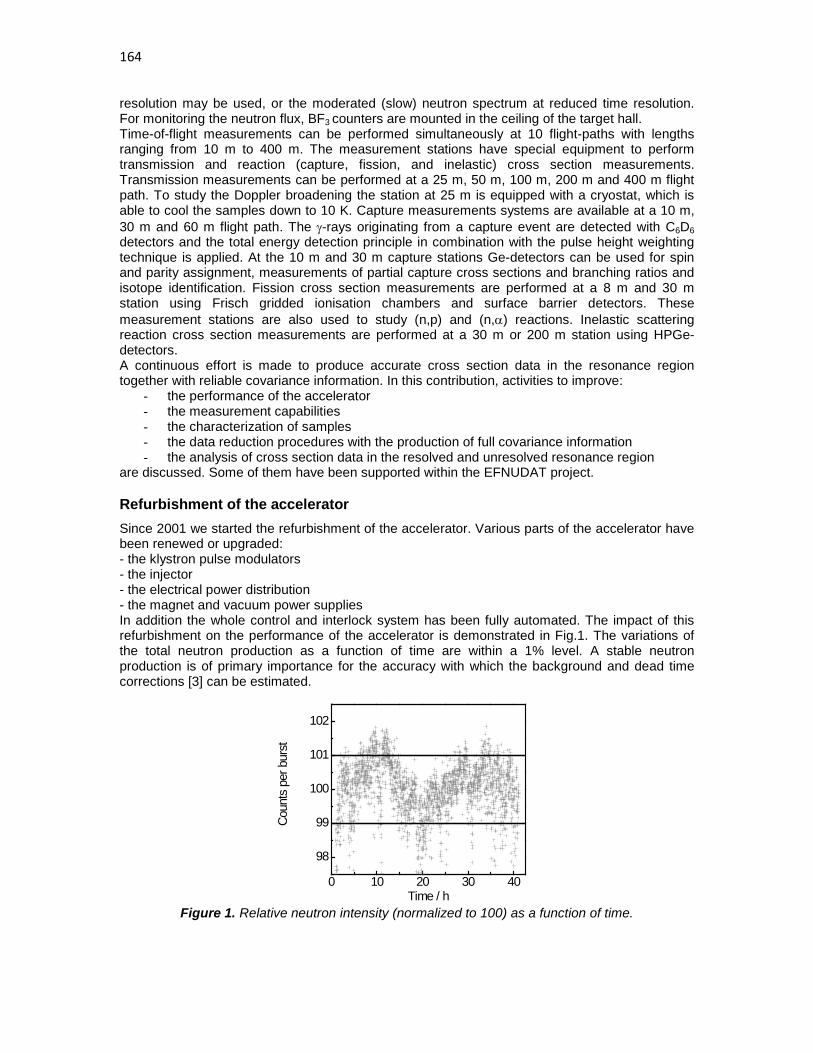
164
resolution may be used, or the moderated (slow) neutron spectrum at reduced time resolution. For monitoring the neutron flux, BF3 counters are mounted in the ceiling of the target hall. Time-of-flight measurements can be performed simultaneously at 10 flight-paths with lengths ranging from 10 m to 400 m. The measurement stations have special equipment to perform transmission and reaction (capture, fission, and inelastic) cross section measurements. Transmission measurements can be performed at a 25 m, 50 m, 100 m, 200 m and 400 m flight path. To study the Doppler broadening the station at 25 m is equipped with a cryostat, which is able to cool the samples down to 10 K. Capture measurements systems are available at a 10 m, 30 m and 60 m flight path. The γ-rays originating from a capture event are detected with C6D6 detectors and the total energy detection principle in combination with the pulse height weighting technique is applied. At the 10 m and 30 m capture stations Ge-detectors can be used for spin and parity assignment, measurements of partial capture cross sections and branching ratios and isotope identification. Fission cross section measurements are performed at a 8 m and 30 m station using Frisch gridded ionisation chambers and surface barrier detectors. These measurement stations are also used to study (n,p) and (n,α) reactions. Inelastic scattering reaction cross section measurements are performed at a 30 m or 200 m station using HPGe-detectors. A continuous effort is made to produce accurate cross section data in the resonance region together with reliable covariance information. In this contribution, activities to improve:
- the performance of the accelerator - the measurement capabilities - the characterization of samples - the data reduction procedures with the production of full covariance information - the analysis of cross section data in the resolved and unresolved resonance region
are discussed. Some of them have been supported within the EFNUDAT project.
Refurbishment of the accelerator Since 2001 we started the refurbishment of the accelerator. Various parts of the accelerator have been renewed or upgraded: - the klystron pulse modulators - the injector - the electrical power distribution - the magnet and vacuum power supplies In addition the whole control and interlock system has been fully automated. The impact of this refurbishment on the performance of the accelerator is demonstrated in Fig.1. The variations of the total neutron production as a function of time are within a 1% level. A stable neutron production is of primary importance for the accuracy with which the background and dead time corrections [3] can be estimated.
Figure 1. Relative neutron intensity (normalized to 100) as a function of time.
0 10 20 30 40
98
99
100
101
102
Coun
ts p
er b
urst
Time / h

165
Measurement capabilities A parameterization of cross section data in the resonance region requires a set of complementary independent experimental observables [1]. Such a set can be obtained from transmission, reaction yield and self-indication measurements [4,5]. The complementarity between transmission and capture experiments is largely used at GELINA to normalize capture yields avoiding the need of an absolute reference cross section. Examples are the 60Ni(n,γ), 103Rh(n, γ), and 241Am(n,γ) data reported by Corvi et al. [6], Brusegan et al. [7] and Lampoudis et al. [8]. The capacities to determine a full set of resonance parameters has been improved by the installation of a self-indication set-up. The spin assignment of 197Au resonances for 197Au +n below 200 eV have been determined by a combined analysis of transmission, capture and self-indication data. These data have been obtained and analysed by C. Massimi as part of a scientific visit supported within EFNUDAT. The parameters on the 4.9 eV resonance have already been published [5].
Sample characterization The use of resonances for the characterization of reference material is described in Ref. [9] and has already been reported at a previous EFNUDAT workshop. The capacities for the characterization of metallurgical samples have been improved by the purchase of a non-contact measuring microscope. With this device the effective area can be derived with an uncertainty of less than 0.1% even for samples with irregular dimensions. In addition, thickness profiles can be obtained, which can be used as an input in REFIT [10] to account for sample inhomogeneities during the resonance analysis.
Data reduction procedures To transform the TOF-spectra into experimental observables (i.e. transmission and reaction and self-indication yields) that can be parameterized by a reaction model, the AGS package has been developed at the IRMM [11]. The package performs a full propagation of uncertainties, accounting for both correlated and uncorrelated uncertainty components, starting from the uncertainties due to counting statistics. All spectra manipulations such as dead time correction, linear combination of spectra, background fitting and subtraction, calculation of self-shielding factors, reading of ENDF data files and spectra interpolation are included. In AGS the covariance matrix is split in two parts. The uncorrelated part is represented as a diagonal matrix, while the correlated part is expressed as the product of a rectangular matrix with its own transpose. This structure results in a substantial reduction of space for data storage and is very convenient to document the various uncertainty components involved in the reduction process. The structure provides the necessary information to separate correlated uncertainties resulting from linear and non-linear operations. This is very important to avoid bias effects due to a problem known as Peelle’s Pertinent Puzzle (PPP) [12]. This problem occurs when model parameters are derived from a least squares adjustment with a covariance matrix with a strong correlated component that is due to a non-linear operation of the data. In addition the AGS procedure ensures that the covariance matrix is always well defined, i.e. symmetric and positive definite. The AGS concept has been proposed by the Nuclear Data Section of the IAEA in collaboration with the EC-JRC-IRMM to store experimental data in the EXFOR data base [13]. In the unresolved resonance region the spacing between resonances is smaller than the experimental resolution. Hence, resonance fluctuations can not be experimentally observed and only average cross section data can be derived. However, to deduce average cross section data from the experimental observables corrections due to the resonance structure have to be applied. This is best illustrated by the relation between the average transmission <T> and the average total cross section <σtot>. For a parallel neutron beam on a homogeneous slab of material X with an areal density nX the relation is [1]:

166
2
1 var( ) ...2
x tot x totn n xtot
nT e eσ σ σ− − < > < >=< >= + +
The term in parenthesis is a correction due to the resonance fluctuations and becomes important for thick samples, which are mostly needed to determine the total cross section in the unresolved resonance region. Also average capture cross sections in the unresolved resonance region are derived from results of measurements with thick samples. In addition to the correction for self-shielding, which is again subject to resonance fluctuations, the experimental capture yield has to be corrected for events due to neutron scattering followed by capture. The relation between the average capture cross section <σγ> and the average observed capture yield <Yexp> is mostly expressed as:
γ< > = < σ >exp c XY F n where Fc is a correction factor to account for the contribution due to neutron attenuation in the sample and scattering plus capture events. Due to the finite dimensions and shape of the sample the determination of this correction factor requires mostly Monte Carlo simulations. Unfortunately, the nuclear data community still relies on the SESH code developed by F. Fröhner in 1968 [14] to derive the correction factor. This code accepts average resonance parameters as input parameters (i.e. the average resonance spacing, neutron strength functions and average radiation widths) to create resonance structured cross sections. At the WONDER 2006 workshop F. Fröhner already expressed his concern that no real follow up of his code was available. Therefore, a new procedure was proposed. This procedure is based on the combined use of Monte Carlo simulations with MCNP and probability tables produced by NJOY. These tables are used to calculate resonance structured cross sections in the unresolved resonance region. Within a project supported by EFNUDAT, this procedure was validated by a comparison with results obtained with the SESH code. Fig. 2, showing the correction factor for a parallel neutron beam on a 0.5 mm and 1.0 mm thick Au metal disc as a function of neutron energy, reveals a good agreement between the two results. Unfortunately, the SESH code is limited to simple geometries. Hence, for more difficult geometries and more extensive systematic studies the MCNP/JOY procedure is recommended.
Figure 2. The correction factor Fc as a function of neutron energy. This correction factor accounts for neutron self-shielding in the sample and the contribution due to scattering plus capture events. The correction factors obtained with the SESH code as well as with a MCNP/NJOY based procedure are compared.
0 20 40 60 80 100
1.00
1.05
1.10
SESH SESH
F c
MCNP 0.5 mm MCNP 1.0 mm
Neutron energy / keV

167
Parameterization in the resolved resonance region At GELINA the REFIT [10] code is used to parameterize experimental observables in the resolved resonance region in terms of resonance parameters. The code is based on the Reich-Moore approximation of the R-Matrix formalism and includes modules to account for various experimental effects such as self-shielding, multiple scattering, Doppler broadening, response of the TOF-spectrometer and the neutron sensitivity of the capture detection system. Modules to account for sample inhomogeneities, the γ-ray attenuation in the sample and to accommodate both numerical and analytical response functions of TOF-facilities have been implemented as part of an EFNUDAT project. The importance to account for the sample inhomogeneities and the γ-ray attenuation in the sample has been discussed in Ref. [15] and [16], respectively.
Parameterization in the unresolved resonance region During an EFNUDAT supported scientific visit at IRMM, I. Sirakov developed a code to produce a full ENDF-6 compatible description of average cross sections in the unresolved resonance region with an adjustment to experimental data and a link to results of optical model calculations. The code is based on a combination of two recent developments made at the IRMM: the AGS code for data reduction of TOF cross section data and a procedure to produce a full ENDF-6 compatible parameterisation of average cross section data in the URR. This procedure follows the Hauser–Feschbach statistical reaction theory including width-fluctuations and allows a link to parameters deduced from optical model non-fluctuating cross sections. The procedure was used to produce a full ENDF-6 compatible evaluation for neutron induced reactions of 232Th from 4 keV to 100 keV [17]. The importance to separate the full correlated uncertainty component, due to the normalization of capture cross section data, and the uncorrelated uncertainty components in the least squares adjustment is shown in Fig. 3. This figure compares the experimental data with the result of an adjustment using the full covariance matrix and a procedure in which the normalization parameter is included as a model parameter. In case the full covariance matrix, including the correlated uncertainty component due to the normalization, is taken into account the result is strongly biased due to PPP’s [12]. In contrast to the original example of Peelle, the bias in the analysis of the 103Rh data is due to the physics of the resonance structure and not to inconsistencies of the experimental data. This bias can be avoided by considering the normalization as a model parameter as suggested by Fröhner [12,18]. However, it requires that the full experimental details and covariance information, for instance provided by the AGS code, is available.
Figure 3. The average capture cross section for 103Rh(n,γ) as a function of neutron energy, together with the results of a least-square adjustment based on the Hauser-Feschbach formalism. The adjustment is shown for two different procedures.
0 50000 100000 15000075
100
125
150
175
30 m 0.05 mm 30 m 0.26 mm 60 m 0.26 mm 60 m 0.26 mm Nc free parameter Full covariance
(�σγ E
n1/2 )
/ (ba
rn e
V1/2 )
Neutron energy / eV

168
Example To provide data for a new evaluation for neutron induced reactions in cadmium, a set of capture and transmission measurements have been carried out at GELINA. Results obtained from transmission measurements at GELINA, concentrating on the 0.178 eV resonance of 113Cd, have already been reported by Kopecky et al. [19] and adopted in JENDL 4.0 [20]. Kopecky et al. [19] also performed a full uncertainty propagation and investigated the impact of various sources of uncertainties, i.e. uncertainties resulting from the data reduction and uncertainties due to systematic effects such as flight path length, target characteristics and temperature. The evaluation is based on a simultaneous resonance shape analysis of GELINA data together with well documented experimental data from other facilities which are available in numerical form. The REFIT code was used for the analysis. In addition to the resonance parameters, the thermal total and absorption cross section for natCd was deduced. The cross section resulting from the GELINA data is shown in Fig. 4 together with results from measurements at a thermal neutron beam applying different measurement techniques. The value recommended in ENDF/B-VII is systematically higher as compared to the experimental data reported in the literature. The results in Fig. 4 stress the importance of having energy dependent cross section data available for the evaluation of thermal cross sections.
Figure 4. The thermal total cross section for neutron induced reactions on natural cadmium. The line is the value recommended by ENDF/B-VII.
Acknowledgements This work was supported by the European Commission within the Sixth Framework Programme through I3 - EFNUDAT (EURATOM contract no.036434). The authors are grateful to the GELINA operators and to J.C. Drohe and R. Wynants for their technical support.
References [1] F.H. Fröhner, “Evaluation and Analysis of Nuclear Resonance Data,” JEFF Report 18,
NEA/OECD (2000) [2] W. Mondelaers and P. Schillebeeckx, “GELINA, a neutron time-of-flight facility for high-
resolution neutron data measurements”, Notizario, 11 (2006) 19 – 25 [3] C. Mihailescu, A. Borella, C. Massimi and P. Schillebeeckx, “Investigations for the use of the
fast digitizers with C6D6 detectors for radiative capture measurements at GELINA”, Nucl. Instr. Meth. A 600 (2009) 453 – 459
1960 1980 2000 20202300
2350
2400
2450
2500
2550
2600
Literature GELINA ENDF/B-VII
σ(n th
,tot)
Year

169
[4] F.H. Fröhner, E. Hadda, W.M. Lopez and S.J. Friesenhahn, “Accuracy of resonance parameters from combined area and self-indication measurements”, Proc. Conf. on Neutron Cross Section Technology, March 22 – 24 , 1966, Washington, D.C., pp. 55 – 66
[5] C. Massimi, A. Borella, S. Kopecky, C. Lampoudis, M. Moxon, P. Schillebeeckx and G. Vannini, “Resonance parameters for 197Au + n below 200 eV,” Nuovo Cimento, 125 (2010) 517 – 526
[6] F. Corvi, G. Fioni, F. Gunsing, P. Mutti and L. Zanini, “Resonance neutron capture in 60Ni below 450 keV”, Nucl. Phys. A 697 (2002) 581 – 610
[7] A. Brusegan, E. Berthoumieux, A. Borella, F. Gunsing, M. Moxon, P. Siegler, and P. Schillebeeckx, “Neutron Capture and Transmission Measurements on 103Rh Down to Thermal Energies”, Proceedings of the International Conference on Nuclear Data for Science and Technology, Santa Fe, New Mexico, 2004, pp. 953 – 956
[8] C. Lampoudis, S. Kopecky, A. Plompen, P. Schillebeeckx, P. Siegler, F. Gunsing, C. Sage and O. Bouland, “Transmission and capture measurements for 241Am at GELINA”, Int. Conf. Nuclear Data for Science and Technology, May, 2010, Jeju Island, Korea, proceedings to be published
[9] P. Schillebeeckx, A. Borella, J.C. Drohe, R. Eykens, S. Kopecky, C. Massimi, L.C. Mihailescu, A. Moens, M. Moxon, P. Siegler, R. Wynants, “Target requirements for neutron-induced cross-section measurements in the resonance region”, Nucl. Instr. and Meth. A 613 (2010) 378 – 385
[10] M.C. Moxon and J.B. Brisland, “GEEL REFIT, A least squares fitting program for resonance analysis of neutron transmission and capture data computer code”, AEA-InTec-0630, AEA Technology, October 1991
[11] C. Bastian, “AGS, a set of UNIX commands for neutron data reduction”, Proc. Int. Conf. on Neutron Research and Industry, Crete, Greece, 1996, ed. By George Vourvopoulos, Society of Photo-optical Instrumentation Engineers, Birmingham, WA, 1997, p. 611
[12] F. Fröhner, “Assigning uncertainties to scientific data”, Nucl. Sci. Eng. 126 (1997) 1 - 18 [13] N. Otuka, A. Borella, S. Kopecky, C. Lampoudis and P. Schillebeeckx, “Database for Time-
of-flight spectra with their covariance,” Int. Conf. Nuclear Data for Science and Technology, May, 2010, Jeju Island, Korea, proceedings to be published
[14] F. Fröhner, Report GA-8380, Gulf General Atomic (1968). [15] S. Kopecky, P. Siegler and A. Moens, “Low energy transmission measurements of 240,242Pu
at GELINA and their impact on the capture width,” Proc. Int. Conf. Nuclear Data for Science and Techn., Nice, France, April, 2007, p. 623
[16] P. Schillebeeckx, A. Borella, S. Kopecky, C. Lampoudis, C. Massimi, and M. Moxon, “Neutron resonance spectroscopy at GELINA”, Int. Conf. Nuclear Data for Science and Technology, May, 2010, Jeju Island, Korea, proceedings to be published
[17] I. Sirakov, R. Capote, F. Gunsing, P. Schillebeeckx and A. Trkov, “An ENDF-6 compatible evaluation for neutron induced reactions of 232Th in the unresolved resonance region”, Ann. Nucl. Energy 36 (2009) 1223 - 1231
[18] F. Fröhner, “Evaluation of data with systematic errors”, Nucl. Sci. Eng. 145 (2003) 342 - 353 [19] S. Kopecky, I. Ivanov, M. Moxon, P. Schillebeeckx, P. Siegler, and I. Sirakov, “The total
cross section and resonance parameters for the 0.178 eV resonance of 113Cd”, Nucl. Instr. Meth. B 267 (2009) 2345 – 2350
[20] K. Shibata, O. Iwamoto, T. Nakagawa, N. Iwamoto, A. Ichihara, S. Kunieda, S. Chiba, K. Furutaka, N. Otuka, T. Ohsawa, T. Murata, H. Matsunobu, A. Zukeran, S. Kamada, and J. Katakura: "JENDL-4.0: A New Library for Nuclear Science and Engineering",J. Nucl. Sci. Technol., 48 (2011) 1 - 30

170

171
EU nuclear data projects for more sustainable nuclear energy and waste transmutation
E.M. Gonzalez Romero (CIEMAT)
Introduction
Long term sustainability of the different energy generation technologies is one of the highest priorities of the EU in the last years. The main instruments to foster the development of sustainable technologies are the SET (Strategic Energy Technologies) plan and the associated European Industrial Initiatives. In the case of nuclear energy the SET plan promoted the setting up of a Technological Platform and at the same time clearly pointed to the development of fast neutron reactor technologies to enhance the long term sustainability of nuclear energy. Following this indications a large number of public and private institutions have established the SNETP (Technological Platform for Sustainable Nuclear Technologies). The SNETP has developed a vision document, a detailed Strategic Research Agenda and an associated Deployment Strategy. One of the main priorities identified in these documents is ESNII, the European Industrial Initiative on Sustainable Nuclear energy, to be launched in November 2010. The main objectives for ESNII is the development of the science and technologies required for the fast nuclear systems -GEN IV reactors and Accelerator Driven Systems (ADS)- and their associated fuel cycles, including the construction of a number of demonstration plants that validate those technologies. In the energy context, and particularly for nuclear energy, SNETP and ESNII consider four different facets of sustainability: security of supply, economical competitiveness, maximization of the natural resources utilization (for instance by multi-recycling of Uranium and Plutonium in fast reactors), minimization of the long lived nuclear waste (for instance by the transmutation of U, Pu and Minor Actinides, M.A.). In order to manage all these aspects of sustainability, the SNETP has identified a program of technologies deployments according to their availability and competitiveness along the time for the next decades. This schedule for technologies proposes:
1. to maintain the present LWR of Gen II (with life extension) , and deploying Gen III & Gen III+ reactors as long as there is available and cheap enriched Uranium, acknowledging their advantage in global economy and operational experience;
2. to close the cycle to limit waste production as soon as the required technologies, Partition and Transmutation, are fully mature (expected for middle to end of XXI century); and
3. to replace present reactor for fast reactors breeding Pu from U (depleted or natural) when enriched Uranium becomes expensive (middle to end of XXI century).
The last two steps require new nuclear systems with new technologies, new concepts, new coolants, new fuels, new neutron spectra and new fuel cycles, and in the case of the subcritical ADS the introduction of high energy protons and neutrons within the external spallation neutron source. Some of the main new features of those fast neutron systems include: cooling by liquid metals, like sodium or lead alloys, or gas (He); fuels with high Pu content, high M.A. content and/or low U content inside inert matrices; multiple fuel recycling with a strong evolution in the high level wastes (HLW) isotopic content, in particular, a significant buildup of the high mass M.A.. Most of these concepts and technologies are being addressed by EURATOM projects and proposals of the 6th and 7th Framework Programs (FP6 & FP7), namely: CP-ESFR (sodium cooled fast reactor), LEADER, CDT and HeLiMnet (lead cooled fast reactor), ALLEGRO, GoFastR (gas cooled fast reactor) and EUROTRANS, CDT, FREYA (lead cooled ADS). There are many topics needed in the evaluation of feasibility and expected performance of these systems. To study some of these topics for new systems, high precision simulation is today often cheaper and faster than the actual experiments, and normally provides much more details of the

172
process under study. However, to provide useful information these simulation needs accurate basic (nuclear) data and always needs some experimental validation of its absolute accuracy. This important role of simulation and basic data is acknowledge in the Strategic Research Agenda of SNETP. The new reactors rise new problems, using new concepts, new materials and/or new procedures that require the corresponding new accurate nuclear data. The conclusion is clear, significant efforts in nuclear data and dedicated experimental validation are urgently needed to assess the feasibility and performance of future systems required to enhance long term sustainability of nuclear energy.
Figure 1: Steps to correctly identify relevant data needs
This conclusion and the limitation of resources and time rise the question of identifying what data is really (most) needed and directly useful for applications. The Figure 1 shows the main steps involved in the identification of relevant data needs. The process involves the cooperation of final users of the nuclear data and the nuclear data producers. The final users have to identify the target precision on the reactor or fuel cycle parameters to be evaluated from the nuclear data. From these requirements, using sensitivity analysis techniques, it is possible to identify the relevant basic data. Then combining the needs from different final user requirements and the present knowledge of nuclear data uncertainties and correlations, is possible to identify potential optimization paths on how to improve nuclear data to reach the needs. Only after evaluating the feasibility, cost and timely availability of experimental facilities of each of these paths it is possible to propose an optimized program of basic nuclear data improvements (measurements and evaluations). After the performance of that program the final users will reevaluate the actual improvement achieved, using integral experiments, and set their new requirements, restarting the process again as needed. The coordination of basic nuclear data programs from different technologies and fields, like fission and fusion, or applications and astrophysics is often a fruitful way to enhance the resources utilization. The international programs on new reactors, particularly those of EURATOM 5th and 6th Framework Programs and the Gen IV reactors, have provided the indications on the most relevant reactor and fuel cycle parameters and their required accuracies. In addition recent publications, [1][2][3][4], have provided results from detailed sensitivity analysis for and optimization paths for new nuclear measurements. Of particular relevance are the complementary comprehensive documents [3], prepared by the NEA WPEC-26 (for reactor parameters) and [4], the NUDATRA domain of IP-EUROTRANS (EURATOM FP6) (for the fuel cycle parameters), and

173
put together in the compilation made at the CANDIDE (EURATOM FP6) final report. This results had been carefully evaluated by EURATOM to assess the need of nuclear data projects and to optimize their scope along the last decade (EURATOM FP5, FP6 and FP7). Indeed, the research on Nuclear Data has received a broad attention in these EURATOM Framework Programs, resulting recently in the following initiatives:
• NUDATRA (the Domain DM5 of IP-EUROTRANS): Improving nuclear data and simulation tools for transmutation, including experimental measurements and theoretical developments;
• NUDAME: Access to IRMM Geel facilities to perform nuclear data measurements; • EFNUDAT: Access to several EU facilities to perform nuclear data measurements,
including research to improve the nuclear data facilities and simulation tools: • CANDIDE: a Coordination Action on Nuclear Data for Industrial Development in Europe,
including networking plus a road map of data needs and paths to produce it. • EUFRAT (FP7): Access IRMM European facility for innovative reactor and transmutation
neutron data • ANDES (FP7): Accurate Nuclear Data for nuclear Energy Sustainability • ERINDA (FP7 proposal): Access to European Research Infrastructures for Nuclear Data
Applications In the rest of this paper we will concentrate in the collaborative direct projects for actual production o new nuclear data: the nearly completed project NUDATRA and the recently started ANDES. Other papers [5],[6] and [7] of this workshop will summarize the projects devoted to coordination of activities and access to infrastructures.
NUDATRA NUDATRA is the fifth domain of the EURATOM FP6 project IP-EUROTRANS. Its global objective is to improve nuclear data evaluated files and models by activities distributed in four workpackages: sensitivity analysis and validation of simulation tools, low and intermediate energy nuclear data measurements, nuclear data libraries evaluation at low and medium energies, and high energy experiments and modeling. A total of 12 research centers and 9 universities from 11 countries plus the JRC of the EC have participated in the project, producing over 35 journal papers, more than 70 conference contributions, 7 PhD thesis and 2 Master thesis. The specific priorities were adapted as a compromise between the priorities for the primary selection for the actinide transmutation system within IP-EUROTRANS, a fast neutrons lead-bismuth cooled ADS, the results of the sensitivity analysis performed in the project and published in the literature during the project, and the feasibility of measurements and model developments within the resources and time available for the project. The main action lines resulting from this compromise were:
4. A sensitivity analysis of ETD advanced fuel cycles on nuclear data and the associated new data needs,
5. Measurement and evaluation of Pb and Bi cross sections: inelastic scattering, (n,xn), (n, n+X), Branching ratio for isomer production after neutron capture of 209Bi (main mechanism for Po production),
6. Measurement of Minor Actinide cross sections: Capture in 243Am + Fission on 244Cm, 7. Development of TALYS improvements for M.A. and Pb/Bi, in order to make it ready for
low energy models and nuclear data evaluation, 8. High energy measurements, concentrated in gas (H, He) and light charged particles
(LCP) production, and in the absolute evaluation of spallation fragments production cross-section,

174
9. High energy models improvement, particularly in the models INCL and ABLA, 10. Development and validation of new transmutation simulation systems.
In the first point, a large effort has been made on the determination of the sensitivity of advanced nuclear fuel cycle parameters on nuclear data for the case of continuous multi-recycling. After a large review of available uncertainties and correlation data bases, both a classical differential sensitivity analysis and a comprehensive Monte Carlo estimation of global uncertainties where performed for the most relevant fuel cycle parameters. Between the parameters investigated it was the discharged isotopic composition, the decay heat of the spent transmutation fuel after 2, 10 and 200 yr of cooling, the neutron emission of the same fuel after 2 yr cooling, and its radiotoxicity after 10, 100 and 10000 yr of cooling. The main result from this study is that, whereas at short burn-up the fuel cycle parameter can be predicted with sufficient accuracy, as the effective burn-up increases by multi-recycling the uncertainties in several parameters exceed the required precision. A total of 31 critical cross sections (causing an uncertainty beyond the design target accuracies) in the fuel cycle parameters (Double Strata using ETD-like ADS) where identified. The study was complemented with a possible optimization path to reduce uncertainties from nuclear data, but the large uncertainties in the difficulty and feasibility of different measurements and the lack of knowledge of the uncertainties and correlation on the present nuclear data, recommends to address the 31 critical cross section in any feasible experimental program. During this development several reactor and fuel cycle simulation codes had been improved to facilitate the estimation of systematic uncertainties in the simulation results from nuclear data uncertainties.
Figure 2: Examples of NUDATRA new cross section measurements for Pb and Bi reactions. Total inelastic reactions on 207Pb, left, and (n,2n) on 209Bi, right.
Probably one of the more significant achievements of NUDATRA has been the measurement and evaluation of a large number of Pb and Bi cross sections, including the most relevant for fast systems cooled by these metals. The measurements include: the inelastic scattering of 206,207,208Pb and 209Bi, the (n,xn) on 206,207,208Pb(n,2ng), 208Pb(n,3ng) and 209Bi(n,2ng), always from threshold to about 20 MeV, and the Pb (n,n’X) at 100 MeV, as well as the 209Bi(n,g)210m,gBi capture branching ratio, that is the most important data to estimate the Po production. Some examples of these results in comparison with the previous available data are shown in the Figure 2, where the large improvement in number of energy points and resolution can be appreciated. These measurements had been evaluated within the NUDATRA project and distributed to the JEFF3.2 group for its integration and dissemination. The data cycle has been completed with the validation of the new NUDATRA Pb and Bi cross section libraries using a set of experiments from the NEA/OECD international criticality benchmark, Figure 3. The validation showed a generalized improvement in the benchmark estimation with the new libraries for the experiments more sensitive to the Pb or Bi nuclear data.

175
These data where completed with one excellent and very relevant measurement of Minor Actinide cross sections, the first worldwide direct determination of the neutron capture in 243Am. This data is critical, as found in the sensitivity analysis, because 243Am is the door to the production of
244,245,246,247Cm. The measurements where performed in 2004 with a highly radioactive sample, and the new analysis and background reduction has been performed from 2008 to 2010. The data will be sent to EXFOR and when combined with available ORELA transmission data will, most probably, provide a large improvement to the evaluated cross section libraries for this isotope. Taking into account the large difficulties for the direct measurements, a surrogate reaction method was used for the determination of the neutron induced fission cross section of 244Cm. The fission of different composite nucleus produced after the absorption of a 3He particle by an 243Am nucleus were investigated. The 243Am(3He,a)242Am providing 241Am(n,f), 243Am(3He,t)243Cm giving 242Cm(n,f), and 243Am(3He,d)244Cm for 243Cm(n,f), gave interesting results and the validation of the technique. However the experimental difficulties for the 243Am(3He,p)245Cm, that should provide the 244Cm(n,f) data, have limited at present the results to the fission probability, pending on the determination of a precise renormalization to be transformed into a real cross section.
Figure 3: Validation of the new NUDATRA Pb and Bi cross section using a set of experiments from the international criticality benchmark.
From the perspective of cross section evaluation, a large effort was put within NUDATRA to improve the TALYS system. At the end of the project the version TALYS-1.0 was publicly distributed. This version include very significant improvements relevant both for cross section prediction and evaluation, like: new physics and possibility to work with actinides and the fission reaction, analysis of evaluated 241Am level spacing distribution, optical model for actinides, theory and techniques for evaluation of covariance data, and a generally better uncertainty treatment. The system has been applied to produce new partial evaluations of the reaction channels corresponding to the Pb and Bi NUDATRA measurements and to the (n,2n) reaction in 241Am. Two examples are shown at Figure 4.

176
Figure 4: NUDATRA partial evaluations of 207Pb (n,inel) and 241Am(n,2n).
Finally, for the high energy region, specific for the ADS, NUDATRA has made a combination of measurements and model improvements. The new experimental results have allowed to significantly enhance the database of measurements for production of gas (in particular for the different He and H isotopes) and light charged particles, including 7Be. These new results have largely reduced the previous discrepancies from different experimental teams. The new results have also improved the absolute normalization of spallation fragment production, in some cases by more than 50%. Furthermore, new measurements have provided the determination of spallation fragments in Ta (one of the materials used in spallation targets) and at relatively low energies (below 500 MeV). Simultaneously with these measurements, the high energy models INCL and ABLA have been largely improved producing the versions INCL4.5-ABLA07 that are implemented in the newest MCNPX versions, to be made widely available in the coming months. Significant efforts had been made to improve the description of LCP production. In the new version ABBLA is able to generate 3H and 3He and a new cluster emission probability implemented in INC. Both effects have improved the agreement between the prediction from these models and the experimental results, Figure 5. More in general, INCL4.5-ABLA07 give a very good agreement with data all over the energy range, usually better than other models in MCNPX.
Figure 5: Comparison of helium and tritium production measurements, including NUDATRA results, with the new versions of INCL and ABLA (NIMB 268 (2010) 581).

177
ANDES
In response to the nuclear data needs associated to the new reactors and new fuel cycles supported by SNETP in its strategic research agenda and in the ESNII proposal, and taking into account the priority lists for nuclear data from NEA/OECD, NUDATRA and CANDIDE, a collaboration of 20 research centers and universities prepared a proposal to the EURATOM FP7. The proposal with title Accurate Nuclear Data for Nuclear Energy Sustainability, ANDES, has been approved and has started its activities in May 2010. As shown in Figure 6, ANDES will combine a reduced group of selected differential measurements, the improvement in uncertainties and covariance's within the evaluation process and the validation of present and new data libraries using integral experiments to bring most critical nuclear data to the level of accuracies required by the new reactors and system promoted by ESNII and the SNETP. In addition, a specific work package will improve the prediction capabilities for the high energy neutrons of ADS, developing better models and very few selected measurements. All this activities will be coordinated with the End Users and the main actors for nuclear data dissemination and coordination, the NEA/OECD and the IAEA.
Figure 6: Structure, main work packages and external partners a of the ANDES project.
For the measurements of low and medium energies for advanced reactor systems, the best world facilities combination will be used in ANDES, including: IRMM neutron sources, both the e- linear and the Van de Graaff accelerators, the n_TOF spallation facility at CERN, the Jÿvaskÿla cyclotron and the IGISOL facility, the CNRS/Orsay accelerators, and the GANIL accelerator complex. ANDES is concentrating these measurements in the following reactions and isotopes:
1. High accuracy measurements of neutron inelastic scattering cross sections. a. To improve the cross sections for neutron inelastic scattering of 238U. b. To improve the cross sections for neutron inelastic scattering of structural materials
and inert fuel components (23Na, Zr, Mo). c. To provide the covariance matrices and the limits of accuracy for measurements with
the (n,n’g)-technique. 2. High accuracy measurements of neutron total and capture cross sections.
a. To improve the n+238U radiative neutron capture cross sections. b. To improve the n+241Am radiative neutron capture cross sections.

178
c. To assess the use of transfer reactions for the determination of neutron-induced capture cross sections for actinide targets.
3. High accuracy measurements of fission cross sections a. To improve with new measurements the neutron-induced fission cross section of Pu
isotopes (238Pu (TR), 240,242Pu). b. To improve with new experimental results the fission cross sections of the minor
actinides (241,243Am and 245Cm). c. To improve the experimental knowledge of the fast neutron induced fission yields for
isotopes of Np, Pu and Cm by surrogate neutrons and inverse kinematics. 4. State of the art decay data measurements for reactor kinetics and decay heat
a. To improve the experimental information for the beta decay probability and strength functions of relevant fission fragments (88Br, 94Rb, 95Rb and 137I).
b. To improve the experimental information for the delayed neutron emission probabilities of relevant fission fragments (88Br, 94Rb, 95Rb and 137I).
Most of the measurements in the previous tables, particularly in items 1, 2 and 4 are already well advanced or even completed from the point of view of data taking and at present are being analyzed. Some preliminary results had been presented in other paper of this workshop [8][9][10]. To assess the absolute accuracy of the results from computer simulations the uncertainties and correlations of all the basic data used in the simulation must be known with sufficient precision. Consequently, this information is very important to estimate the relevance of new measurements and the potential benefits of the new data. Despite the large effort made in the last few years, the uncertainties and covariance matrices of many nuclear data are not or poorly known and very few simulation programs are able to use the few data available. For this reason the ANDES collaboration decided to concentrate its effort in nuclear data evaluation around the data uncertainties and the correlations. Special efforts will be devoted on the codes TALYS, GENEUS, CONRAD, ACAB, FISPIN to improve the way these and other codes generate or use uncertainties and correlation of the basic nuclear data. A similar effort will be made to prepare simulation programs to use covariance information, in such a way that the simulation results can be provided with the full uncertainty from data (not only from statistics). To demonstrate the performance of these tools, the covariance matrices of one major and one minor actinide (from 238U/239Pu, 241Am) will be evaluated. This research will be structured on the following lines:
1. Uncertainty/covariance evaluation of experimental data 2. Uncertainty/covariance evaluation of data from nuclear reaction models 3. A proper theoretical treatment and evaluation of nuclear reactions on actinides
(especially fission models) and its relation with 1. and 2. 4. Covariance matrix for radioactive decay and fission yield data 5. Use all of the above in processing, reactor and fuel cycle codes.
In addition to the direct nuclear data measurements, integral experiments provide very relevant information for nuclear data. On one hand they allow to confirm the deviations between actual measurements and prediction based in the nuclear data for parameters similar to those actually needed for reactor or fuel cycle design and operation. These cross-checks provide the final validation for simulation codes, basic data and models. In addition, it is often the case that integral experiment are so precise that not all the values of the basic data within their evaluation uncertainties are compatible with the measured integral parameters. Combining several integral experiments it is so possible to constrain the basic data values and to reduce their uncertainties and correlations. Both uses of integral experiments will be demonstrated within ANDES. For these purpose ANDES have selected data coming from the following facilities: MUSE, GUINEVERE, PROFIL, ZPPR10A, SNEAK-7A and -7B, and the collection of international criticality benchmarks. Each of these experiment provide specific information complementarily:

179
1. MUSE Reference Core characterization
a. This experiment is available via the MUSE project of FP5 of EURATOM. b. Neutronic parameters: Keff, spectral indices, reaction rates of Na cooled fast reactor
with steel reflector. 2. ZPPR10A experiment proposed in IRPHE data base of NEA data Bank
a. The information from these experiments is available from the IRPHE of the NEA data bank.
b. Neutronic parameters: Keff, spectral indices, and sodium void effects. 3. PROFIL experiments made in PHENIX on separate isotopes irradiation.
a. This experiment is made available by CEA. b. Neutronic parameters: separated irradiated samples of different isotopes, actinides
and minor actinides, post irradiated chemical analysis of the samples that will provide information on capture cross sections.
4. A large criticality and shielding benchmark used for validation of JEFF-3.1 from ICSBEP a. The information from these experiments is available from the ISCBEP data bank. b. Neutronic parameters: Keff, Spectral indices.
5. An experiment to be performed at GUINEVERE experimental facilities at SCK-CEN a. These experiments will be available via the EURATOM projects
EUROTRANS/FREYA. b. Neutronic parameters: Keff, Spectral indices, of a lead cooled uranium core.
The main objective for ANDES in the high energy range is the model validation in the 150-600 MeV energy domain, improving the predicting capabilities of the models in this range, and using new measurements at 500 MeV (p+Pb) and the post irradiation examination of MEGAPIE samples. The specific high energy activities are grouped around the following lines:
1. Evaluation of the state-of-the-art of high-energy model predicting capability in the 150-600 MeV domain a. use of conclusions of the Benchmark of Spallation models presently organized by
IAEA plus specific comparisons of the models to the available elementary data (from HINDAS and NUDATRA) in the 150-600 MeV energy domain.
2. Improving of the predicting capabilities of the models to reduce the uncertainties on the demonstration facility spallation target a. Improving the high-energy models starting from present versions of INCL-ABLA. b. High-Energy Evaluated Nuclear Data Files generated from the TALYS+BRIC
reaction codes. 3. Validation on the results from the post irradiation analysis of MEGAPIE samples
a. Analysis of samples from the MEGAPIE liquid Pb-Bi target irradiated during 4 months at SINQ and from ISOLDE.
b. Isotopes to be analyzed: 208/209Po , 194Hg , 108mAg , 60Fe, 53Mn, 59Ni , 26Al, 36Cl, 10Be, 129I, 10Be, 55Fe.
4. Measurements a. SPALADIN p+Pb at 500 MeV: measurement of the fission fragments and
evaporation residues in coincidence with light ions b. Measurement of neutron-induced production of light ion cross-sections at 175 MeV
on Fe, Bi and U

180
In parallel with these technical activities, ANDES will develop an intensive education and training program. ANDES is promoting that its R&D results into PhD and Master theses. In addition, one open training course specialized in Nuclear Data for Sustainable Nuclear Energy will be organized within ANDES. ANDES has also prepared the dissemination of the new measured or evaluated nuclear data. In this sense a strong cooperation with NEA and IAEA, the two agencies coordinating the distribution of nuclear data, has been setup. Furthermore a website is and will collect the most relevant results from ANDES, both for general public or active members of the project. In this same sense, ANDES is setting up an End Users group with: selected European universities; representatives of R&D organizations; responsible people of experimental reactors and nuclear facilities, international nuclear data agencies OECD/NEA and IAEA, industries involved in design or exploitation activities: Gen-IV and ADS system designs (CDT, ESFR,…), utilities, regulatory bodies, education representatives. Early access to the results produced in the project will be granted to the End Users group members and they are expected to provide feedback for ANDES and future nuclear data activities. In this sense, all participants of the EFNUDAT project are warmly invited to join the ANDES End User Group.
References [1] G. Aliberti et al., Impact of Nuclear Data Uncertainties on Transmutation of Actinides in
Accelerator-Driven Assemblies, Nucl. Sci. Eng., 46, 13-50 (2004). [2] G. Aliberti et al., Nuclear data sensitivity, uncertainty and target accuracy assessment for
future nuclear systems, Annals of Nuclear Energy 33 (2006) 700. [3] M. Salvatores and R. Jacqmin (Eds), One possible optimization for target accuracy for
innovative systems using recent covariance data evaluations (BOLNA). NEA/WPEC-26. ISBN 978-92-64-99053-1.
[4] E. Gonzalez-Romero (Ed), Report of the Numerical results from the Evaluation of the nuclear data sensitivities, Priority list and table of required accuracies for nuclear data. NUDATRA Deliverable D5.11 from IP-Eurotrans.
[5] W. Mondelaers, Status of the Transnational Access Activities within EFNUDAT. This workshop (2010).
[6] R. Garbil, Transnational Access Activities and Euratom Framework programme feedback experience towards implementation of the European Research Area. This workshop (2010).
[7] F.J. Hambsch, Integration of Nuclear Data facilities in Europe: the dawn of EFNUDAT and the rise of ERINDA. This workshop (2010).
[8] C. Guerrero et al., Am-241 neutron capture measurements at n_TOF. This workshop (2010).
[9] P. Schillebeeckx, et al., Neutron time-of-flight measurements at GELINA. This workshop (2010).
[10] S. Pomp, Measurements at the 175 MeV neutron beam at TSL. This workshop (2010).

181
Transnational Access Activities and Euratom Framework program feedback experience towards implementation
of the European Research Area
Roger Garbil and al.
European Commission, DG Research, Directorate J, Energy Euratom, Rue du Champs de Mars, n°21, Brussels, Belgium, B-1049
Abstract: Euratom (European Atomic Energy Community) FP6 (2002-2006) and FP7 (2007-2011) instruments are making a significant contribution in establishing a common European view on scientific issues and towards integrating and establishing European Research Area (ERA) in nuclear science and technology: (CP) Collaborative Projects, Networks of Excellence (NoE), Integrated Infrastructure Initiatives (III), Coordination and Support Actions (CSA), Actions to promote and develop human resources and mobility. They are implemented to reinforce Euratom R&D program, to develop research infrastructures, to foster networking, transnational access and joint research activities. This research effort is needed to retain and improve competences and know-how, to improve the efficiency and effectiveness of European a Research Area (ERA), and contributes to maintaining high levels of nuclear knowledge and industry competiveness in the nuclear field. Establishment by the research community of technology platforms in sustainable nuclear energy, waste management and low dose research areas ( www.snetp.eu , www.igdtp.eu , www.melodi-online.eu ) are being capitalised. Mapping of the capacity of research centres and other research players that need more coordination across the European Union and beyond together with the implementation of European Sustainable Nuclear Industrial Initiative (ESNII) is also being performed. An overview of several projects will be given including a best practice analysis. The ‘Euratom experience’ with framework programs (FPs) has been one of consistent success in pursuing excellence in research and facilitating pan-European collaborative efforts across a broad range of nuclear science and technologies and associated education and training activities.
1. Introduction
Nuclear energy is in 2010 the main contributor to the electricity supply in the EU-27 with approximately 32% of all electricity produced ahead of coal (30%), natural gas (18%), hydro and other renewable sources (14%) and oil (6%). It represents a total installed capacity of more than 135 GWe and a cumulated experience of more than 5500 reactor-years. Nuclear power is playing a key role in reducing the EU's emissions of greenhouse gases by about 700 million tons every year, and makes an important contribution to improving the Union's independence, security and diversity of energy supply. The 2010 Eurelectric Power Choices Study (Union of the Electricity Industry at pan-European level, see http://www.eurelectric.org) is showing a decrease in global energy demand in the EU for 2050, but an increase in electricity demand. Energy Strategies 2020/2050 recall EU policy makers to maintain 30% of electricity share produced by nuclear industry in Europe. The

182
Eurelectric Study indeed leads to the conclusion that the % of electricity produced by nuclear in 2050 (with Light Water Reactors) should be 28% of the electricity demand. To respect this between 150 and 200 new Nuclear Power Plants (NPP) would have to be built in the EU for that time to replace the existing 165 NPP producing today’s European electrical power. Continuing research will help maintain the competence and competitiveness of European industry in a field which is seeing strong international development. This paper gives an overview of the main research activities funded by DG RTD under FP6 and FP7 on reactor systems (nuclear installation safety and advanced nuclear systems), research infrastructures and education and training, as well as those on Partitioning and Transmutation (P&T) which can be termed as innovative processes for the back-end of the fuel cycle are also reported. The European Research Area (ERA) concept and implementation of the technology platforms are also outlined in this paper.
2. Objectives of the European Research Area (ERA)
The European Research Area (ERA) concept was launched by the European Commission in January 2000 (Commission Communication “Towards a European Research Area”). ERA should lead to increased collaboration in research in Europe to ensure there is an effective “critical mass” of research effort in key fields, the creation of “centres of excellence”, greater emphasis on competitiveness and public private partnerships, increased support for research infrastructures and the exploitation and management of knowledge. In 2008, the Council set in motion the Ljubljana Process to improve the political governance of ERA and adopted a shared ERA 2020 vision which confirms Research as being an essential ingredient in building a more dynamic and competitive Europe. http://ec.europa.eu/research/era/index_en.htm
3. Implementation of the Strategic Energy Technology Plan (SET Plan)
The Community’s Strategic Energy Technology Plan (SET-Plan) is an integral part of this policy and through a technology neutral approach is promoting research and innovation in all low carbon energy sources that can help to respond to the EU’s energy challenges. The Strategic Energy Technology Plan is a tool for implementation of EU policy to meet 2020 energy objectives and realise the vision of low carbon energy economy by 2050:
• 3x20 (GHG emissions: 20% reduction by 2020 up to 80% by 2050); • Business As Usual is not enough and there is a need to foster technology development in
all low carbon energy; • A range of measures and initiatives are proposed and the most notable are the European
Industrial Initiatives (EIIs) http://ec.europa.eu/energy/technology/set_plan/doc/setplan_brochure.pdf and establishing the European Energy Research Alliance (EERA) http://www.eera-set.eu/
The European Sustainable Nuclear Industrial Initiative (ESNII) key EU technology challenges for the next 10 years to meet 2020 targets are as following:
• Maintain competitiveness in fission technologies, together with long-term waste management solutions;
Regarding key EU technology challenges for the next 10 years to meet 2050 vision: • Complete the preparations for the demonstration of a new generation (Gen-IV) of fission
reactors for increased sustainability; Regarding priority initiatives to be launched from 2010 onwards (initially 6 in total):
• European Sustainable Nuclear Industrial Initiative focusing on development of Generation-IV technologies;
http://ec.europa.eu/energy/technology/set_plan/doc/2009_comm_investing_development_low_carbon_technologies_roadmap.pdf

183
ESNII will be launched on 15-16 November 2010 in Brussels during the SET Plan conference under the Belgian presidency.
EERA Structural materials for Innovative Nuclear systems is being launched through the latest MATTER Euratom’s project. Coordination and organisation of the research community is promoted to develop sub-programs on:
• Oxyde Dispersed Structures (ODS), • Composites/Refractory alloys fostering activities on GFR and spin-off to VHTR, • and modelling to speed up the material development process.
4. European Technology Platforms (ETPs) and Euratom SNETP, IGDTP and MELODI
European Technology Platforms (ETPs) provide a framework for stakeholders, led by industry, to define research and development priorities, timeframes and action plans on a number of strategically important issues where achieving Europe's future growth, competitiveness and sustainability objectives is dependent upon major research and technological advances in the medium to long term:
• a common “vision” for the technology concerned, • a definition of a Strategic Research Agenda, deployment and Implementation strategies, • mobilisation of a critical mass of research and innovation effort (facilities, competences in
the nuclear field) • Support for EU policy initiatives, SET-Plan and Energy Policies • A true European ERA and International cooperation
The European Technology Platform on Sustainable Nuclear Energy (SNETP, http://www.snetp.eu/) has been launched on 21 September 2007. Vision Report, Strategic Research Agenda (SRA), Deployment Strategy (DS) and European Sustainable Nuclear Industrial Initiative Concept Paper (ESNII) have been developed by the members of the Technology platform. The latest will be launched on 15-16 November 2010 in Brussels. SNETP SRA seven objectives are:
• Gen-II and III systems including advanced LWR, addressing research needs related to plant life management and extension,
• Advanced fuel cycles for waste minimisation and resource optimisation, dealing with research needs to develop advanced fuel cycles,
• Gen-IV fast neutron systems (SodiumFR, LeadFR, GasFR and ADS), addressing design work and associated research needs related to Gen-IV critical fast neutron reactor systems, SFR, LFR and GFR
• Research needs related to non-electricity applications of nuclear energy and Gen-IV system (V/HTR) applications,
• New nuclear large research infrastructures of pan-European interest and ESNII supporting infrastructures identified in the above roadmaps and on-going Euratom projects such as ADRIANA (http://adriana.ujv.cz/ ). Europe needs new MTRs as well as the supporting facilities (e.g. fuel cycle facilities, hot laboratories and testing loops).
• Cross-cutting topics to address: (i) material research, (ii) advanced simulation methods, (iii) safety, and (iv) minor actinide bearing fuels (science and properties), and (v) pre-normative research strongly linked to material research for nuclear applications.
• Education, Training and Knowledge Management Deployment Strategy is of paramount importance in ensuring continued high levels of nuclear ETKM.
The European Technology Platform on Implementing Geological Disposal (IGTP, http://www.igdtp.eu/) has been launched on 12 November 2009 under the Swedish presidency. A Vision report has been published and a strategic research agenda (SRA) is being developed by the members of the Technology platform. IGDTP is supporting confidence-building in the safety and implementation of deep geological disposal solutions. European current status, implementation times and challenge differ between Sweden, Finland and France which are the

184
readiest for implementation and plan to start licensing disposal facilities in a few years. IGDTP SRA four main objectives are:
• To build confidence in the safety of geological disposal solutions among European citizens and decision-makers,
• To encourage the establishment of waste management programs that integrate geological disposal as the accepted option for the safe long-term management of long-lived and/or high-level waste,
• To facilitate access to expertise and technology and maintain competence in the field of geological disposal for the benefit of member states
• And to implement by 2025 and operate safely in Europe the first geological disposals for spent fuel, high-level waste and other long-lived wastes.
The European Technology Platform on Low Dose impact (MELODI, Multidisciplinary European Low Dose Risk Re-search Initiative, http://www.melodi-online.eu/) has been launched on 28 September 2009 under the Swedish presidency. National bodies together with other European organisations playing a key role in radiation protection and effects of low dose risk research have also taken steps to set up a support network based on the recommendations of the HLEG report (http://www.hleg.de/). MELODI strategic research agenda (SRA) is being developed by the members of the Technology platform.
5. Euratom Framework Program (FP6-FP7) implementation and funding schemes
The ‘Euratom experience’ over its previous five Framework Programs has been of consistent success in pursuing essential research and facilitating pan-European collaborative efforts on radiation protection, waste management, reactor safety and decommissioning. Continuing research will help maintain the competence and competitiveness of European industry in a field which is seeing strong international development. For many years there has been close co-operation between the various research players in the nuclear fission and radiation protection area through bilateral or multilateral agreements, including international co-operation, between OECD/NEA, IAEA and the Euratom Framework Program. Research, Training and Development activities are of paramount importance in ensuring continued high levels of nuclear safety both now and in the future, maintaining the progress towards implementation of sustainable waste management solutions, and improving efficiency and competitiveness of the sector as a whole. The European Community contributes partly to these activities through the Euratom Framework Programs for nuclear research and training activities with 1.23 billion € in the Sixth Framework Program (FP6) (2002-2006, http://www.cordis.europa.eu/fp6-euratom) and 2.75 billion € in the Seventh Framework Program (FP7) (2007-2011, http://www.cordis.europa.eu/fp7/euratom). The Euratom Framework Programs include research activities for three areas, namely for nuclear fusion energy, nuclear fission and radiation protection managed by DG RTD and for the direct actions of the Joint Research Centre. The sharp rise in funding from the Sixth to the Seventh Framework Program is mainly due to the increase in funding of fusion energy for the construction of ITER. The average funding of R&D activities in nuclear fission and radiation protection by DG RTD is around 50 million € per year. This program is implemented through calls for proposals towards yearly Work Programs followed by evaluations carried out by independent experts. A range of funding schemes, are available, promoting cooperation and synergy through multi-partner consortia. The basis for financial support is shared cost and non-profit. For each scheme, rules apply regarding minimum numbers of consortium partners from different Member States and associated countries. Apart from the 27 EU Member States, there is currently only one other country – Switzerland – fully associated to FP7 Euratom. Partners from all these countries can be reimbursed by the program. Specific topics are published to foster international cooperation (Russia, China, USA, Canada, Korea etc.) and are welcomed when real added value to the project is obtained.

185
5.1. FP6 and FP7 Instruments
Collaborative Projects (CPs) foster collaborative research and development (R&D) activities amongst European partners (e.g. industry, research institutes and organizations, academia). Small (and medium) scale focused projects and large scale integrating projects can be funded. Integrated Projects (IPs) are designed either to give increased impetus to the Community’s competitiveness in a specific research area or to address a major societal issue by mobilizing a critical mass of research and technological development resources. Clear scientific and technological objectives are identified and specific results in terms of products, processes or services pursued. FP7-CP include FP6 Specific Targeted Research or Training Projects (STREPs) aiming to improve European competitiveness and should have a sharp focus, it even could be a demonstration project designed to validate new technologies with economical potential. FP6 instruments such as Networks of Excellence and Integrated Projects have made a significant contribution to integrate key players in this area and establish the ERA in nuclear fission science and engineering. Networks of Excellence (NoE) aim to strengthen and develop Community scientific and technological excellence by integrating, at European level, research and training capacities at national and regional level. Each NoE will advance knowledge in a particular research area by assembling a critical mass of expertise and organizing activities targeted towards long-term, multidisciplinary objectives. Coordination and Support Actions (CSAs) promote networking and coordination-type activities or provide support for such aspects as dissemination of program results or pilot studies for possible future collaborative projects. CSAs cannot fund R&D activities per se. Coordination Actions (CAs) promote and support coordinated initiatives between research and innovation operators to improve integration. They include activities such as conference organisation, sharing of best practice, and the establishment of information systems. Specific Support Actions (SAs) complement the implementation of the Framework Program and may be used to prepare for future EU R&D work, including monitoring and assessment activities. FP7-CSA include FP6 Integrated Infrastructure Initiatives (I3) which combine in one single action several activities to reinforce and develop research infrastructures to provide services at the European level. This could include networking activities with a support activity. All I3 include research, education and training activities related to the specific work programs. More generally, activities are the subject of a continuously open call with proposals evaluated on a six months (May and October) or yearly basis. The open call for fission covers a number of ‘horizontal issues’, specifically Specific Support Actions, Transnational access to large infrastructures and Actions to promote and develop human resources and mobility.
5.2. Education and training activities
It is considered that 5% of the total project budget should be dedicated to these activities. The preservation and enhancement of a skills base for nuclear engineering and science in Europe is a fundamental prerequisite for progress in nuclear science, technology and radiation protection. It is vitally important that a sufficient number of today’s students learn the skills needed to maintain innovation and technical excellence and to ensure that the exemplary public safety record of the European nuclear industry continues in the future. Education and training is an important element of the European Research Area in this sector. By promoting exchange of high quality personnel between Member States and institutions, this activity spreads knowledge and best practice and helps build future research partnerships. It also allows scientists from all Member States to access the best equipment and facilities. Actions to promote and develop human resources and mobility cover a variety of activities under the general umbrella of training and education, including Training Fellowships (TF), Special Training Courses (STC), Grants for Cooperating with third countries (GFTC), and Transnational Access to large infrastructures (TA).
186
6. Research activities in the Euratom Sixth and Seventh Framework Programs
Although there is continuity in research activities between FP6 and FP7, there has been a notable shift from the Sixth to the Seventh Framework Program giving a higher visibility to reactor systems. Fairly large projects were launched in the Sixth Framework Program and many of FP6 projects were completed in 2009-2010 (see htttp://www.cordis.lu/fp6-euratom/projects.htm). Work in the topics covered by these projects is continuing in the Seventh Framework Program. In the following, the objectives of FP7 are given for the different activities, but the scope of the most significant projects in FP6 is briefly summarised as well as that of the new FP7 projects.
6.1. Research infrastructures
The objectives of the program are to provide support for key infrastructures where there is clear EU added value, especially in order to establish critical mass and for the replacement of ageing facilities such as e.g. research reactors, hot cells, etc.
At the beginning of FP6, two coordination actions were launched, one on hot cells and the other on Material Test Reactors (MTRs). The first one, HOTLAB, set up a European network of HOT LABoratories (http://www.sckcen.be/hotlab). The second one, JHR-CA (Jules Horowitz Reactor (JHR) Co-ordination Action), dealt with the JHR project, which is a second generation MTR being built in Cadarache to answer the continuous need of irradiation capabilities and to face the ageing of present MTRs in Europe.
The Integrated Infrastructure Initiative for MTRs (MTR+I3) started in October 2006 for 3 year duration with 18 partners (http://www.mtri3.eu), total budget 5.9Mi€, 3.5Mi€ Euratom contribution. The objective of MTR+I3 was to reinforce European experimental capabilities for testing material and fuel under irradiation by (i) building a durable cooperation between MTR operators and relevant laboratories through networking activities, (ii) maintaining the European leadership with updated capabilities and competences, (iii) improving and structuring services with coordinated developments and uses of existing MTRs, and (iv) preparing the future European landscape by implementing the JHR and subsequent complementary research reactors. The network produced recommendations on irradiation device manufacturing and measurement practices. The Joint Research Activities focused on developments and fabrication of innovative test devices addressing safety and ageing issues of current power plants and technologies for Gen-IV reactors.
EFNUDAT (http://www.efnudat.eu) total budget 3Mi€, 2.4Mi€ Euratom contribution. was a 4-year project planning to integrate all infrastructure-related aspects of nuclear data measurements by organising networking activities to optimise the use of the facilities for nuclear data measurements and the analysis and dissemination of results, Transnational Access Activities procuring approximately 4000 additional beam hours for external users that will carry out nuclear data measurements, and Joint Research Activities to raise the performance of the facilities and the efficiency of their use. CANDIDE was a 2-year coordination action, total budget 0.8Mi€, 0.8Mi€ Euratom contribution. to establish a durable networking of nuclear data efforts that are important in the context of minimising the high-level waste stream of nuclear energy. The purpose is to identify the needs for improved nuclear data, assess the present status of knowledge, and to estimate what accuracy can be reached with state-of-the-art techniques for the relevant fast critical reactors and sub-critical ADS. NUDAME was 3-year project, total budget 0.2Mi€, 0.2Mi€ Euratom contribution, aiming to promote transnational access to facilities at IRMM-JRC, Geel for neutron data measurements.
EUFRAT (http://irmm.jrc.ec.europa.eu/ html/activities/eufrat/) is a 4-year transnational access project at the European Commission, Joint Research Centre (JRC), Geel, Belgium that started on 1 November 2008, total budget 0.5Mi€, 0.5Mi€ Euratom contribution.. Access of outside users to the GELINA and the Van de Graaff accelerator facilities of the Neutron Physics unit of JRC is facilitated for neutron cross section measurements. The project also promotes a coherent use of the measurement infrastructure in order to meet high-priority neutron data requests from European industry, safety authorities and nuclear research community. Proposals for experiments submitted by external users are evaluated by a Program Advisory Committee composed of high-

187
level experts belonging to relevant international organisations. The project is expected to deliver new, more accurate neutron cross-section data in nuclear technology domains such as fission reactor technology, fission reactor and fuel cycle safety, high burn-up fuels, nuclear waste transmutation and innovative reactor systems.
VELLA was a 3-year Integrated Infrastructure Initiative project, total budget 3.3Mi€, 2.3Mi€ Euratom contribution. It aimed to create a virtual European laboratory for 'Lead Technologies'. Its final goal was the creation of a network of the EU laboratories that operate devices using heavy liquid metals technologies, especially lead alloys.
The Integrated Infrastructure Initiative ACTINET-I3 (http://www.actinet-i3.eu/) project aim is to reinforce the networking of existing European infrastructures in actinide sciences, and to facilitate their efficient use by the European scientific community, total budget 7.7Mi€, 3Mi€ Euratom contribution. The objectives of ACTINET-I3 are (i) to establish a network of Actinide facilities across the EU to integrate and structure the way these Actinide infrastructures operate and to foster their joint development in terms of capacity and performance, (ii) to support and manage jointly a program of access to appropriate infrastructures for training and associated research projects making use of the proposed facilities and (iii) to conduct on a limited scale a set of Joint Research Activities (JRA) involving member organisations, with an objective to improve the performance of infrastructures by developing new relevant instrumentations and/or data of common interest. Further, these activities will be complemented by a virtual infrastructure providing a limited support in theory and modelling, with a focus on the complementarities between theory and experiments.
The DOREMI NoE is a 6-year project, total budget 21Mi€, 12Mi€ Euratom contribution, http://www.melodi-online.eu/ , to promote the sustainable integration of low dose risk research in Europe in order to aid the effective resolution of the key policy questions identified by the High Level Expert Group (HLEG) on Low Dose Risk Research (www.hleg.de). DoReMi provides an operational tool for the development of the proposed MELODI platform (Multidisciplinary European Low Dose Risk Re-search Initiative) consisting of major national bodies and research programs that have long term commitment in low dose risk research in Europe.
6.2. Reactor systems
In this area, the aim of research is to ensure the continued safe operation of existing installations and, as a contribution to enhancing diversity and security of supply and combating global warming, to explore the potential of more advanced technology to deliver an even safer, more resource-efficient and more competitive exploitation of nuclear energy. Projects related to the safety of existing nuclear installations are first described followed by advanced nuclear systems.
6.2.1. Nuclear installation safety
At present, projects are running in severe accident management, coupled numerical simulation codes (e.g. core physics and thermal hydraulics for reactor safety; multi-scale modelling of irradiation effects on reactor vessels and internals) and plant life management.
The network of excellence for a Sustainable Integration of European Research on Severe Accident Phenomenology (SARNET2 following EC-SARNET) has 42 European, Canadian, Korean and American R&D organizations, including technical support organizations (TSOs) of safety authorities, industry, utilities and universities (http://www.sar-net.eu/), total budget 38Mi€, 5.8Mi€ Euratom contribution. It has started in April 2009 for 4 and half year duration. SARNET aims to (i) tackle the fragmentation existing in defining/carrying out research programs; (ii) harmonize and improve Level 2 Probabilistic Safety Analysis (PSA) methodologies; (iii) disseminate the knowledge to Associated Candidate Countries more efficiently; (iv) bring together top scientists in severe accident research to be a world leader in advanced computer tools for severe accident risk assessment. The integral severe accident analysis code ASTEC provides the backbone of the integration. It is adapted to be used for any water-cooled reactor applications in Europe. Actions are proposed to integrate in ASTEC the current and future knowledge generated within EC-SARNET.

188
The NULIFE network of excellence (2006-2011, total budget 8.4Mi€, 5Mi€ Euratom contribution), has the aim of integrating safety-oriented research on materials, components, structures and systems and exploiting the results of this integration for the production of harmonised lifetime assessment methods for nuclear power plants (http://www.vtt.fi/proj/nulife/).
The LONGLIFE project objectives (2010-2013, total budget 5.2Mi€, 2.6Mi€ Euratom contribution), are to investigate micro-structural and mechanical effects in RPV steels caused by long term irradiation, to improve the Reactor Pressure Vessel safety assessment of existing European Light Water Reactors under long term operation and Generation-III reactors under construction, and to support Reactor Pressure Vessel ageing management and plant life extensions, http://projects.tecnatom.es/webaccess/LONGLIFE/
The STYLE project objectives (2010-2015, total budget 5.2Mi€, 3Mi€ Euratom contribution.) is to assess, optimise and develop the use of advanced tools for the structural integrity assessment of piping. Based on theoretical and experimental results, performance assessment and further development of micromechanical models and simplified engineering assessment methods will be carried out. The main deliverable is to establish state of the art approaches in Leak Before Break and Engineering Assessment Methods, both from a deterministic and a probabilistic point of view.
6.2.2. Advanced nuclear systems
The objective of this area is to evaluate the potential of innovative concepts and develop improved and safer processes in the field of nuclear energy. The research work represents part of the Euratom contribution to the Generation IV International Forum (GIF). Generation IV will probably be deployed after 2020. The four technology goals for industry and society, proposed in the GIF roadmap of 2002, are: (i) sustainability (enhanced fuel utilisation and optimal waste management), (ii) economics (costs of MWe installed and MWth generated), (iii) safety and reliability (robust safety architecture and enhanced EUR requirements), and (iv) proliferation resistance and physical protection (impractical separation of plutonium). In FP6, six projects investigated the six Generation IV reactor systems, Very High Temperature Reactor (VHTR), Gas Cooled Fast Reactor (GFR), Supercritical Water Reactor (SCWR), Lead Cooled Fast Reactor (LFR), Sodium Cooled Fast Reactor (SFR) and Molten Salt Reactor (MSR). In FP7, new projects started to investigate mainly SFR, LFR, GFR and V/HTR systems supporting ESNII, and the others addressing two cross-cutting issues for Gen IV systems (materials and fuels).
CP-ESFR Collaborative Project (2009-2012, total budget 11.6Mi€, 5.8Mi€ Euratom contribution, http://www-cadarache.cea.fr/ ) addresses key viability and performance issues to support the development of a fourth generation European Sodium Fast Reactor (ESFR). Based upon the results of the 6th FP Specific Support Action EISOFAR (Roadmap for a European Innovative SOdium cooled FAst Reactor, 2007, total budget 0.6Mi€, 0.25Mi€ Euratom contribution).
CP-ESFR innovative system is mainly developed for competitive electricity generation and offers interesting potential characteristics in terms of safety, environmental impact, resource utilisation and waste minimisation (e.g. potential for Minor Actinides management). The four years project schedule fit with the principle of an industrial deployment of ESFR technology by 2040 with the preliminary deployment of a demonstrator by 2020-2025. CP-ESFR six main technical sub projects (SPs) are (i) Consistency and assessment and international relationships; (ii) Fuel, fuel element, core and fuel cycle; (iii) Safety and Security; (iv) Energy Conversion System, Components and materials; (v) Reactor system including handling; (vi) Education and training.
GOFASTR Collaborative Project (2010-2013, total budget 5.3Mi€, 3Mi€ Euratom contribution) concentrates on the gas-cooled fast reactor (GFR) with a view to developing the GFR as a more sustainable version of the very high temperature reactor (VHTR). The design goals for GFR are ambitious, aiming, initially, for a core outlet temperature of around 850̊C, a compact core with a power density of about 100MWth/m3, a low enough plutonium inventory to allow wide deployment, a self-sustaining core in terms of plutonium consumption, and a proliferation resistant core by not using specific plutonium breeding elements. This project will support Euratom’s contribution to the Generation IV system research program. As such, it is strongly

189
aligned with the goals and structure of the latter. In addition this project fulfills an objective of the strategic research agenda of the European Sustainable Nuclear Energy Technology platform, for GFR to be developed as one of the longer-term alternatives to the sodium cooled fast reactor.
LEADER Collaborative Project (2010-2013, total budget 5.7Mi€, 3Mi€ Euratom contribution) deals with the development to a conceptual level of a Lead Fast Reactor (LFR) Industrial size plant and of a scaled demonstrator of the LFR technology. It is based on previous achievements obtained during FP6 ELSY project (2006-2010, total budget 6.9Mi€, 3Mi€ Euratom contribution).
HELIMNET Coordinating and Support Action (2010-2012, total budget 0.7Mi€, 0.5Mi€ Euratom contribution) aims at integrating on-going R&D efforts within and outside Europe, and create a large and strong network for the diffusion of information on the HLM technologies.
ADRIANA Coordinating and Support Action (ADvanced Reactor Initiative And Network Arrangement, 2010-2012, total budget 0.7Mi€, 0.5Mi€ Euratom contribution, http://adriana.ujv.cz/ ) is proposed to setting up the network dedicated to the construction and operation of research infrastructures in support of developments for the European Sustainable Nuclear Industrial Initiative. The project shall define in details the new needed research infrastructures and provide legal and financial structures for major refurbishment or upgrading of existing facilities, the construction of new ones and considers the trans-national access to these experimental facilities towards (i) Sodium Fast Reactor (SFR), (ii) Lead Fast Reactor (LFR), (iii) Gas Fast Reactor (GFR, including very high temperature technologies), (iv) Instrumentation, diagnostics and experimental devices, (v) Irradiation facilities and hot laboratories, (vi) Zero power reactors, and (vii) Road map of research infrastructures.
6.2.3. Cross-Cutting and other applications of nuclear activities
The projects described thereafter are cross-cutting between the different Gen-IV systems. The GETMAT Collaborative Project (Gen-IV and Transmutation MATerials, 2008-2013, total
budget 14Mi€, 7.5Mi€ Euratom contribution, http://nuklear-server.ka.fzk.de/getmat/ ) addresses the crucial issues related to the development and qualification of structural materials for reactor core and primary coolant components in Generation IV and transmutation systems so as to ensure their safe and reliable operation. Sufficient data must be gathered to demonstrate that the candidate materials meet the following design objectives: (i) viable dimensional stability; (ii) enough strength, ductility, and toughness during irradiation to cope with the safety criteria; (iii) acceptable resistance to creep rupture, fatigue cracking, creep-fatigue interactions; (iv) reasonable chemical compatibility and corrosion resistance in the presence of coolants.
A new approach to fuel development based on fundamental understanding of fuel behaviour from atomic to macroscopic scale is proposed by the F-BRIDGE collaborative project (Basic Research for Innovative Fuels Design for Gen-IV systems, 2008-2012, total budget 10.2Mi€, 5.5Mi€ Euratom contribution, http://www.f-bridge.eu/ ). This approach will enable a rationalization of the design process, a better selection of promising fuel systems, and will therefore reduce significantly the time and costs currently required for developing new fuels, as well as contribute to improving safety features of new systems under all operational and accidental conditions.
RAPHAEL Integrated Project (ReActor for Process heat, Hydrogen And ELectricity generation, 2005-2010, total budget 18.3Mi€, 9Mi€ Euratom contribution) is focused on the main technology developments needed for VHTR industrial deployment (http://www.raphael-project.org/index.html).
EUROPAIRS Coordinating and Support Action (2009-2012, total budget 1.3Mi€, 0.8Mi€ Euratom contribution, http://www.europairs.eu/) shall identify the boundary conditions for the viability of nuclear cogeneration systems connected to conventional industrial processes. The partnership of nuclear organisations and end-user industries should be initiated and foster the development of a Demonstrator coupling a (V)HTR with industrial processes (the boundary condition framework defines technical, industrial, economical, licensing and safety requirements for the nuclear system, the processes that can consume the energy generated, and the coupling system).
HPLWR Phase 2 project (High-performance Light-water Reactor Phase 2, 2006-2010, total budget 4.5Mi€, 2.6Mi€ Euratom contribution, http://www.hplwr.eu) assesses the main scientific issues and technical feasibility of supercritical water concepts. As for coal-fired power plants, cost

190
reductions are envisaged for reactors using supercritical water as coolant due to size reduction of key components and higher plant efficiencies.
6.2.4. Partitioning and transmutation
In FP7 like in FP6, partitioning and transmutation (P&T) and geological disposal are the main thematic areas in management of radioactive waste, which are considered for research and development activities. The objectives of the research actions for the first area are to investigate ways of reducing the amount and/or hazard of the waste by P&T or other techniques.
EUROTRANS Integrated Project (2005-2010, total budget 43Mi€, 23Mi€ Euratom contribution, http://www.fzk.de/eurotrans ) is a continuation with further integration of the work performed on transmutation in the clusters of FP5 projects around the PDS-XADS project. It focuses on the transmutation (nuclear conversion of long-lived radionuclides, such as plutonium and minor actinides, into short-lived or stable elements) of radioactive waste. EUROTRANS is supported by nine other projects dealing with impact of P&T on waste management, nuclear data, networking of heavy liquid metal facilities, fuels, etc.
Prior to their transmutation in dedicated systems, the radionuclides must be chemically separated from the high level waste (partitioning). The collaborative project ACSEPT (Actinide reCycling by SEParation and Transmutation, 2008-2012, total budget 23.7Mi€, 9Mi€ Euratom contribution, http://www.acsept.org/ ) will address the development of chemical separation processes compatible with fuel fabrication techniques. It builds on the results of the EUROPART integrated project in FP6 (2004-2007, total budget 11.5Mi€, 6Mi€ Euratom contribution, http://www.europart-project.org/ ). ACSEPT will optimise and select the most promising aqueous separation processes dedicated to actinide partitioning and those featuring group separations. Exploratory research is focused on the design of new molecules for extraction. In parallel, pyro-processes for group actinide separation will be developed. All experimental results will be taken into account in engineering and systems studies on aqueous and pyro- processes to prepare the future design of an advanced processing pilot unit.
The establishment of CDT Collaborative Project (Central Design Team, 2009-2012, total budget 3.8Mi€, 2Mi€ Euratom contribution, http://myrrha.sckcen.be/en/) for the design of a fast spectrum transmutation experimental facility (MYRRHA) working in subcritical mode (ADS) and/or critical mode able to demonstrate efficient transmutation and associated technology is considered as an essential next step just when the FP6-Eurotrans is completing its work successfully. The decision from the Belgian Government to give the go-ahead for MYRRHA on 9 March 2010 was essential for the start of this international project together with a commitment of 60 Mi€ other the next five years and 390 Mi€ for the entire project. CDT has the following objectives: (i) to demonstrate the ADS technology and the efficient transmutation of high level waste; (ii) to operate as a flexible irradiation facility; (iii) to contribute to the demonstration of the Lead Fast Reactor technology without jeopardising the above objectives. The work to be carried out involves a definition of specifications of MYRRHA and an advanced design of the facility in sub-critical & critical mode including plant requirements and a study of key issues towards the realisation of such a facility including site specifications and licensing issues.
ANDES Collaborative Project (Accurate Nuclear Data for nuclear Energy Sustainability, 2010-2013, total budget 6.1Mi€, 3Mi€ Euratom contribution, http://fachp1.ciemat.es/andes/ ) will try to improve the accuracy, uncertainties and validation of related nuclear data and models but also for the experimental and demonstration facilities involved in the their validation. The project includes new nuclear data measurements, dedicated benchmarks, based on integral experiments, and improved evaluation and modelling specifically oriented to obtain high precision nuclear data for the major actinides present in advanced reactor fuels, to reduce uncertainties in new isotopes in closed cycles with waste minimisation and to better assess the uncertainties and correlations in their evaluation.
6.3. Education, Training and Knowledge Management (ETKM)
Ensuring the replacement of the ageing nuclear experts is a critical responsibility of the nuclear community. The Euratom Framework Programs play a strategic role in this perspective. Education and Training (E&T) is fostered through dedicated projects, or by including a

191
specific education and training activity in the largest projects in FP6 and FP7. It is considered that 5% of the total project budget should be dedicated to these activities. This is the case in most projects described above.
The goal is to offer to the EU nuclear community a list of high quality teaching modules that can be assembled either into Euro-Master programs (usually university level education) or into training packages (usually requested by industry or regulatory bodies). The proposed nuclear E&T modules need to comply with the following principles: common qualification, mutual recognition, mobility of teachers and students, and feedback of the "future employers". Another important issue is continued professional development, for which the 4 above principles apply also. Special efforts are also devoted to the mutual recognition of professional qualifications, with the ultimate aim of producing "European training passports".
To achieve these objectives, the European Nuclear Education Network (ENEN) was established on the basis of the European High Education Area. In September 2003, ENEN was given a more permanent character and a legal status by the foundation of the ENEN Association, a non-profit international organization under French law. This international association can be considered as a step towards the creation of a virtual European nuclear university strengthening the active collaboration between various national institutions involved in nuclear education. More details about the ENEN Association are given on their website http://www.enen-assoc.org .
ENEN-III Coordinating and Support Action (2009-2012, total budget 2.1Mi€, 1Mi€ Euratom contribution) project covers the structuring, organisation, coordination and implementation of training schemes in cooperation with local, national and international training organisations, to provide training to professionals active in nuclear organisations or their contractors and subcontractors. The training schemes provide a portfolio of courses, training sessions, seminars and workshops for continuous learning, for upgrading knowledge and developing skills. The training schemes allow the individual to acquire qualifications and skills, as required by specific positions in the nuclear sector, which will be documented in a training passport. The essence of such passport is to be recognised within the EU by the whole nuclear sector, which provides mobility to the individual looking for employment and an EU wide recruitment field for the nuclear employers. The recognition is subject to qualification and validation of the training courses according to a set of commonly agreed criteria, which can be ratified by law or established on a consensus basis within a network. The training schemes cover profiles for each of the following: (i) the basic training in selected nuclear topics of non nuclear engineers and personnel of nuclear facilities contractors and subcontractors; (ii) the technical training for the design and construction challenges of GEN III plants, and the design of GEN IV plants. The training schemes consists of three distinct phases: (iii) Courses, seminars, learning, scientific and technical visits, case studies; (iv) Participation to selected activities within the scope of the training in different organisations; (v) Autonomous conduction of activities within the scope of the training under supervision of a mentor in one or in different organisations The first phase can be provided by universities and training centres, the second and third phases can be provided by industries, research centres and future employers.
ENEN-RU Coordinating and Support Action (2010-2012, total budget 0.65Mi€, 0.5Mi€ Euratom contribution) project foster cooperation with Russia in the development of common ground for cooperation in nuclear education, training and knowledge management consists of two parallel projects, i.e. this ENEN-RU project on the EU side and the project titled “Innovative Nuclear Education Towards Peace, Prosperity & Sustainable Development” on the Russian side.
PETRUS-II Coordinating and Support Action (2009-2012, total budget 1.9Mi€, 0.8Mi€ Euratom contribution) project aims at networking all the training actors in order to form and foster the “geological disposal training market”. This will be achieved by developing Knowledge Management Strategy and implementing communication tools notably the “face to face remote teaching” infrastructure, which has been developed during the ENEN-II project
ENETRAP-II Coordinating and Support Action (2009-2012, total budget 1.5Mi€, 0.8Mi€ Euratom contribution) project aims at the development and implementation of a high-quality European standard for initial education and continuous professional development for Radiation Protection Experts (RPEs) and Radiation Protection Officers (RPOs). This project aims at developing a methodology for mutual recognition and setting up reference training schemes as an instrument to facilitate this mutual recognition, within the relevant regulatory framework.

192
6.4. International Cooperation
The Euratom Framework Program is making full use of the opportunities offered through multilateral (e.g. Generation IV International Forum – GIF) and bilateral agreements on nuclear R&D cooperation and peaceful uses of nuclear technology between Euratom and third countries. It is also working with other international organisations and bodies such as OECD/NEA, IAEA or ISTC and STCU. Third-country partners are welcome in Euratom projects, though normally they would receive no funding from the Euratom program. Increasingly, Euratom is adopting a structured dialogue approach with key third countries that lead to specific topics of mutual interest being included in the calls for 2009, 2010 and 2011.
Concerning Commonwealth of Independent States cooperation (CIS, former Soviet Republics), the International Science and Technology Centre (ISTC) in Moscow and the Science and Technology Centre in Ukraine (STCU) in Kiev finance and monitor research projects with civilian purposes to employ CIS scientists, especially those with expertise in developing weapons. Contact Expert Groups (CEGs) were created with the objectives of reviewing project proposals in a specific area and giving recommendations for their funding to the ISTC/STCU Governing Boards, of monitoring the funded projects and of promoting the possibilities of financing future research projects through ISTC/STCU. Three CEGs are running at present: the CEG-SAM on Severe Accident Management, which is strongly linked to EC-SARNET, the CEG-PLIM on Plant Life Management, which is strongly coupled to NULIFE, and the CEG on partitioning and transmutation, which is strongly linked to EUROTRANS and ACSEPT. Several ISTC/STCU projects have been funded through these CEGs involving Belorussian, Kazakh, Russian and Ukrainian scientists.
A Euratom-Rosatom working group for cooperation in nuclear fission research has been established in 2007 with the goal of defining topics of common interest to be financed through coordinated calls in the coming years.
7. Feedback experience, evaluation of pertinence and impact of community actions
Research Infrastructures (RIs, Large-scale but also smaller-scale research facilities) are essential for reinforcing the competitiveness of Europe’s science base, since they do not only allow for the development of new knowledge, but are also essential for training the next generation of top researchers and technology transfer towards industry. As the construction of the next generation of large-scale facilities is increasingly complex and costly, EU Member States together with the European Commission have agreed on the development of a European strategy towards large-scale Research Infrastructures which Europe’s scientific community needs in order to be able to carry out top-level research over the next 5–15 years.
Besides investing in the next generation of Research Infrastructures, it is essential that Europe uses the existing facilities in the best possible way. This means optimising access to these facilities and creating networks of infrastructures to allow for integrating activities and joint research projects. In the last 20 years the European Commission has supported the operation of and cooperation between existing facilities through different Framework Programs. Over the years some 500 research infrastructures have participated in EU projects facilitating the work of thousands of researchers.
A study was commissioned by the European Commission to assess the impact of the EU activities under the Sixth Framework Program as regards existing Research Infrastructures. The aim of this study was threefold: (1) to assess the added value of Community actions for integrating and developing Research Infrastructures; (2) to reflect on the socio-economic impact of the Community actions; and (3) to identify gaps, needs and ideas for possible future actions with the aim of strengthening the European Research Area. http://ec.europa.eu/research/infrastructures/pdf/csri.pdf , Matrix / Ramboll report (2009).
The study covered 83 RI projects with an average of 18 participants per project over nine research domains in over 50 countries. 70 of these projects were related to DG RTD and 13 to DG INFSO. Unfortunately Fission and Radiation Protection projects were not covered but most conclusions are applicable to EURATOM according to the author.

193
7.1. Research Infrastructures
Research Infrastructures including e-infrastructures are high-level facilities, resources, and related services used by the scientific community for conducting leading-edge research to foster knowledge transmission, knowledge exchanges and knowledge preservation. Today’s Research Infrastructures include major scientific equipment, scientific collections, structured information, ICT-based infrastructures, they are single sited or distributed throughout several countries. Europe is faced with a wide spectrum of issues, from infrastructures which are globally unique to many regionally distributed. Many stakeholders are involved, from ministries to researchers and industry, with an underlying and growing use of e-infrastructures. They are opportunities but also difficulties of interaction between basic research and industry, public and private funding is always lacking, and single countries do not have the critical mass or the dimension to implement large research infrastructures. There is a real need to cooperate on a wide European level and further.
7.2. Quantitative evaluation of impacts of on-going actions at EU level
A few years of EC experience using three main criteria in evaluation of research actions might not be sufficient: Excellence (E), Implementation (M), potential Impacts (I).
The main evaluation “questions” (Objectives and Indicators) that the study set out to answer were as following: (i) Pertinence of the RI schemes used under FP6;
a) Were the program objectives achieved? b) Was the level of funding appropriate? c) Were the scientific areas covered appropriate? d) Were the modalities for program implementation appropriate?
(ii) Overview of the Impact that the EC actions on RIs, scientific communities and research policies;
What impact – planned, unexpected, unintended - have Community RI activities had: a) On scientific communities? b) On research policy? c) On the economy and industry? d) On wider society?
(iii) Added value of European action; a) To what degree did FP6 projects lead to EAV? b) What would have happened if no EU funding had been provided?
(iv) To analyse the structuring effect of supported actions with regard to the ERA; a) To understand whether the FP6 support to RI is, in itself, furthering and strengthening integration of research at European level.
(v) To provide the Commission with recommendations for further Community actions regarding RIs;
a) Provide strategic advice about the sectors and actions that can best deliver the Commission’s desired objectives.
7.2.1 Key findings and impacts of Community actions
The study key findings and impacts of Community actions are as following when networking of RIs is implemented: (i) On research effectiveness;
a) Pertinence in relation to the needs of the research community, its objectives and EC funding, b) Generation of new standards and protocols, c) Opening to European and International users, d) Access to critically important equipment, e) Enhancement of inter-disciplinary research, f) Increased speed of end-user access, g) Improved standing and visibility of European RIs,
(ii) On the European Research Area; a) Enabled activities not possible otherwise,
194
b) Increased involvement of researchers from New Member States and improvements in RIs in NMS, c) Expand existing and new research networks, d) Develop a European spirit versus national one,
(iii) On Human Resources; a) Access to the ‘best’ RI (7000 user groups), b) Mobility of Researchers (> 30.000 people), etc.
7.2.2 Lessons learnt from this impact study
Lessons learnt from this impact study show that: (i) unfortunately there was no FP6 predefined definitions / measures according to impacts; (ii) Definitions / measures adopted were based on “expert opinions” and feedback from Delphi method analysis; (iii) Impacts were measured using a combination of statistical methods and qualitative data.
How better to measure in the future? We need (i) standardized data collected across projects; (ii) To establish a set of indicators (data measures) for which comparable time-series data can be collected; (iii) Better understanding of long term impacts
Success factors have been identified: (i) Established User / supplier relationships: pre-existence of networks / business models is shown to be of high importance for impact generation; (ii) Relevant expertise: mix of knowledge on socio-economic impact methodologies / relevant domains is also key to follow-up impacts studies
To analyse impacts, there is a need for: (i) Awareness and Data taking: retrospective analysis is only possible if data are collected and retained; (ii) Representative Case Studies and datasets.
They are barriers to the generation of impacts: (i) Non adequate planning of work or lack of business model towards users and/or suppliers; (ii) Non-availability or lack of Critical Mass of data; (iii) Lack of maturity of the Discipline or its Information Use; (iv) Imperfect or Partial Indicators / methodologies; (v) Non-Availability of Relevant expertise and/or Personnel
We are heading towards an ‘eco-system’ of Research Infrastructures within ERA: (i) Large single-sited facilities; (ii) Distributed European Facilities; (iii) Network of national facilities;
To be based on (iv) a consistent roadmap from the European stakeholders; (v) together with strong links with universities and schools; (vi) and established network of industrial suppliers / users;
This is a major challenge, not scientific but mainly political, and possibly cultural. More work is needed. There is a need to identify better the inputs, assessing not only (i)
Excellence of the service provided; (ii) Quality of the management of the facilities; (iii) Capacity to exploit, disseminate and train scientist; but also (iv) Clear political willingness to develop ERA; (v) Critical mass (scale & scope) to be achieved, etc.
There is a need to better identify the outputs to foster, (i) New scientific and technical knowledge; (ii) New visions (science, society, industry); (iii) New way of managing organizations; (iv) Improved research conditions within ERA; (v) Improved environmental conditions; (vi) Economic gains at micro level (e.g. efficiency); (vii) Economic gains at macro level (regions, Europe); (viii) Patents, licenses, spin-off companies, etc.
A first three dimensional outputs analysis is needed to assess (x) Scientific, Technical, Economical, Societal and Environmental impacts, against (y) direct and indirect outputs together with (z) short term, medium term and long term impacts.
There is a need to characterize the overall environment. An overall positive environment is needed to generate impacts, although inputs are present…
Some years of EC experience using three main criteria in evaluation of research actions: Excellence (E), Implementation (M), potential Impacts (I) is not enough.
We also need to take into account the Stimulating Working environment (W), the Socially-friendly hosting environment (S), the Favourable Financial / economical environment (F), but also Politically « working together » (P), etc. Impacts assessment should be a theoretical equation function of (E, M, T, W, S, F, P…).
The resulting possible evaluation matrix should be looked at to evaluate more accurately the pertinence and impact of European action towards ERA, (i) Frontier research, (ii) Research services, (iii) Knowledge creation, (iv) EU Scientific and Technological challenges, (v) EU

195
Governance, (vi) European leadership, (vi) Grand challenges, (vii) Balanced budget, and (vii) socio-economic impacts.
8. Conclusions
Nuclear research and training activities funded by Euratom FP6 (2002-2006) and FP7 (2007-2011), and projects described here all address major issues and challenges in nuclear fission research, such as the management of high-level/long-lived radioactive waste, nuclear safety, advanced nuclear systems, radiation protection (e.g. risks from low doses) and horizontal activities, such as research infrastructures and human resources (e.g. training and mobility).
The primary goal is to generate and exploit knowledge and develop scientific and technical competences and know-how in applied nuclear science and technology, especially in the areas of safety, reliability, sustainability and cost-effectiveness of nuclear energy systems. Importantly, these projects contribute to the further consolidation of the European Research Area (ERA) in the nuclear energy and radiation protection sectors.
Roadmaps have been drafted for the continued development of nuclear energy in the Community and will promote an inclusive, transparent and non-ideological debate on the key contribution that nuclear energy makes to the EU’s energy future.
ENEF, EU Forum on transparencies issues, opportunities and risks of Nuclear energy gathering all relevant Stakeholders in Nuclear field (EU Member States, EU institutions, European Parliaments, Nuclear industry, electricity consumers and civil society), ENSREG, EU High Level Group on Nuclear Safety and Waste Management have been established to support the continued development of nuclear energy.
European Technology Platforms on Sustainable Nuclear Energy (SNETP), Implementing Geological disposal (IGDTP), impacts of Low Doses (MELODI) have been launched other the last three years, Strategic Research Agenda (SRA) drafted, and Deployment Strategies finalised.
The SET-Plan provides a driver on what needs to be done (research, innovation, market penetration) at EU level for different low carbon technologies to deliver secure, competitive and sustainable energy between now and 2020/2050. Nuclear fission energy is included in these technologies. Fusion is focusing on a much longer term (one can call it Generation-V) but related research activities have to be promoted from now on.
The European Sustainable Nuclear Industrial Initiative (ESNII, with an estimated cost of €7-10 billion over ten years) will demonstrate the long-term sustainability of nuclear energy. The initiative will design and construct demonstration reactors of a new generation of nuclear technology – so-called Generation IV – based on fast neutron reactors and closed fuel cycles. Compared with current nuclear plants, this advanced technology will make 50-100 times more efficient use of uranium resources, will generate less long-lived radioactive waste and will reduce proliferation risks. It will also have favourable safety characteristics by maximising inherent and passive safety features. The first demonstration reactors are expected to come into operation from 2020. The operational experience gained should then pave the way for the commercial deployment of this technology from 2040. The initiative is piloted by members of the Sustainable Nuclear Energy Technology Platform, a forum representing over 80 industrial and R&D organisations from across Europe.
The activities will cover: (i) design and construction of demonstration reactors: a sodium-cooled fast reactor (SFR) and alternative designs using lead or gas-cooled technology (LFR, GFR); (ii) pilot fuel fabrication workshops for the start of operation of the demonstration plants; (iii) a coordinated R&D program for reactor safety, performance, lifetime management and waste management, serving both future Generation-IV reactors and the continued safe operation of existing nuclear plants that currently provide ⅓ of the EU’s electricity and ⅔ of its low -carbon energy; (iv) developing the necessary supporting research infrastructures. Finally Euratom Framework Programs, more specifically FP6 and FP7, its objectives and EC funding schemes, are pertinent in relation to the needs of the nuclear research community. With the launch of ESNII all stakeholders, European Community and Member States shall acknowledge the key contribution that nuclear energy makes to the EU’s energy future.

196
Acknowledgements Acknowledgements to all colleagues and collaborators from research organisations, universities and industry involved in the follow-up and successful development of the projects within Euratom Framework Programs.
References: EU Energy research: http://ec.europa.eu/research/energy/index_en.htm Euratom Seventh Framework Program: http://cordis.europa.eu/fp7/euratom/home_en.html Information on FP7 and access to programs and calls: http://cordis.europa.eu/fp7/home_en.html Euratom Seventh Framework Program funded projects http://cordis.europa.eu/fp7/euratom-fission/library_en.html CORDIS publications http://cordis.europa.eu/fp6-euratom/library_en.html http://cordis.europa.eu/fp7/euratom-fission/library_en.html Euratom FP6 Research Projects and Training Activities, Volume I-II and III (PDF) Volume I ftp://ftp.cordis.europa.eu/pub/fp6-euratom/docs/nuclear_fission_eur21228_en.pdf Volume II ftp://ftp.cordis.europa.eu/pub/fp6-euratom/docs/nuclear_fission_eur21229_en.pdf Volume III ftp://ftp.cordis.europa.eu/pub/fp7/docs/euratom-fission_eur22385_en.pdf Euratom FP7 Research Projects and Training Activities, Volume I (PDF) Volume I ftp://ftp.cordis.europa.eu/pub/fp7/docs/fin-266-euratom-web-jun09v02_en.pdf Volume II http://ec.europa.eu/research/energy/pdf/euratom-fp7-vol-2.pdf Strategic Energy Technology Plan SET-Plan http://ec.europa.eu/energy/technology/set_plan/set_plan_en.htm
*************

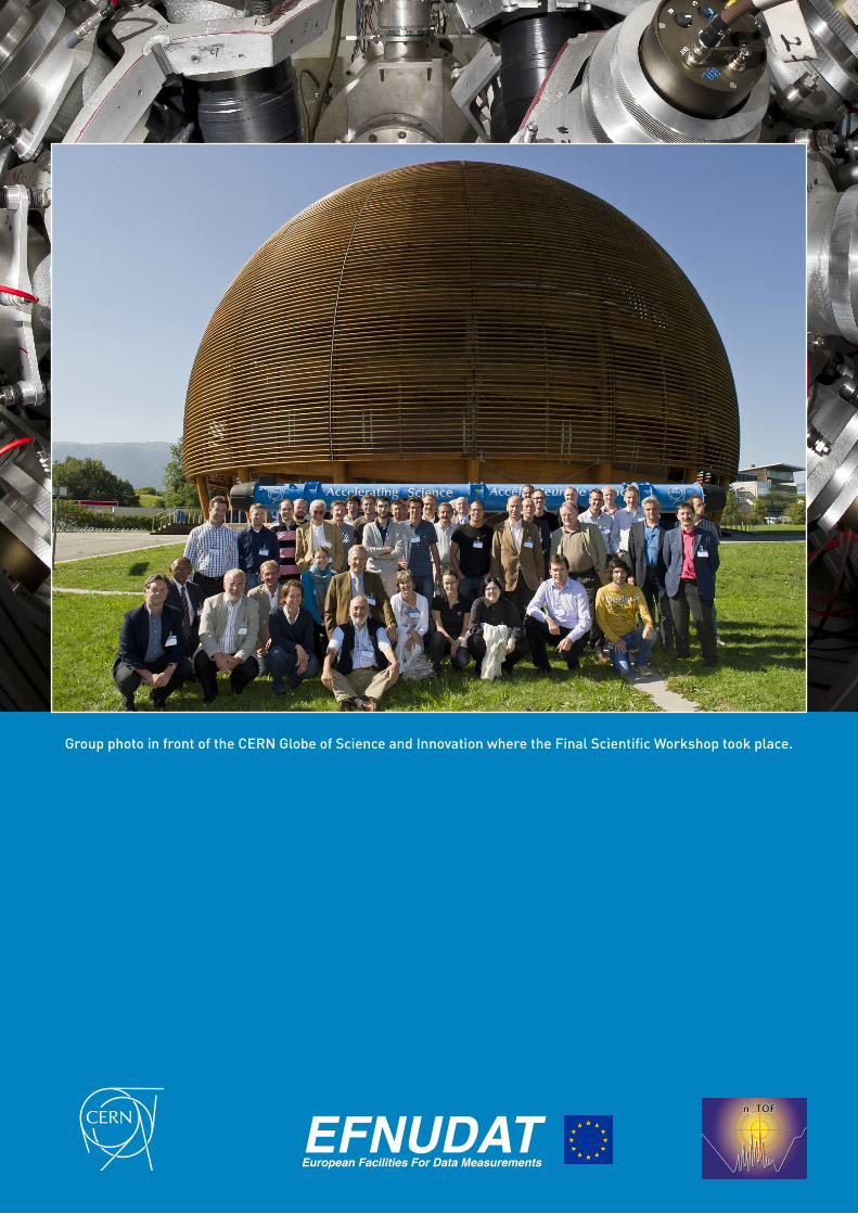
Group photo in front of the CERN Globe of Science and Innovation where the Final Scientific Workshop took place.
EFNUDATEuropean Facilities For Data Measurements