Embed Size (px)
Citation preview
O.Ullaland CERN 2005
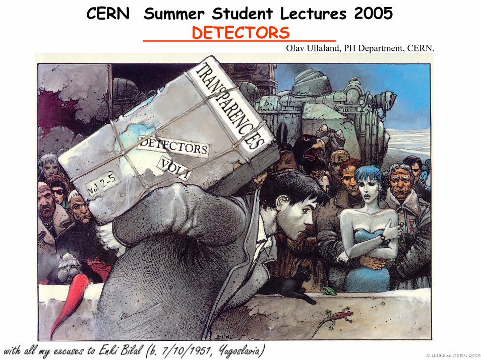
CERN Summer Student Lectures 2005DETECTORS
Olav Ullaland, PH Department, CERN.
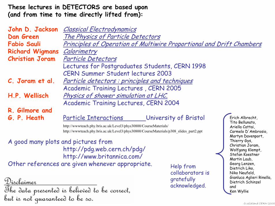
These lectures in DETECTORS are based upon (and from time to time directly lifted from):
John D. Jackson Classical ElectrodynamicsDan Green The Physics of Particle DetectorsFabio Sauli Principles of Operation of Multiwire Proportional and Drift ChambersRichard Wigmans CalorimetryChristian Joram Particle Detectors
Lectures for Postgraduates Students, CERN 1998CERN Summer Student lectures 2003
C. Joram et al. Particle detectors : principles and techniquesAcademic Training Lectures , CERN 2005
H.P. Wellisch Physics of shower simulation at LHC. Academic Training Lectures, CERN 2004
R. Gilmore and G. P. Heath Particle Interactions University of Bristol
http://wwwteach.phy.bris.ac.uk/Level3/phys30800/CourseMaterials/http://wwwteach.phy.bris.ac.uk/Level3/phys30800/CourseMaterials/p308_slides_part2.ppt
A good many plots and pictures fromhttp://pdg.web.cern.ch/pdg/http://www.britannica.com/
Other references are given whenever appropriate.
Erich Albrecht,Tito Bellunato, Ariella Cattai,Carmelo D'Ambrosio,Martyn Davenport,Thierry Gys,Christian Joram,Wolfgang Klempt,Stefan KoestnerMartin Laub,Georg Lenzen,Dietrich Liko, Niko Neufeld,Gianluca Aglieri Rinella,Dietrich SchinzelandKen Wyllie
Help from collaborators is gratefully acknowledged.
O.Ullaland CERN 2005
O.Ullaland CERN 2005
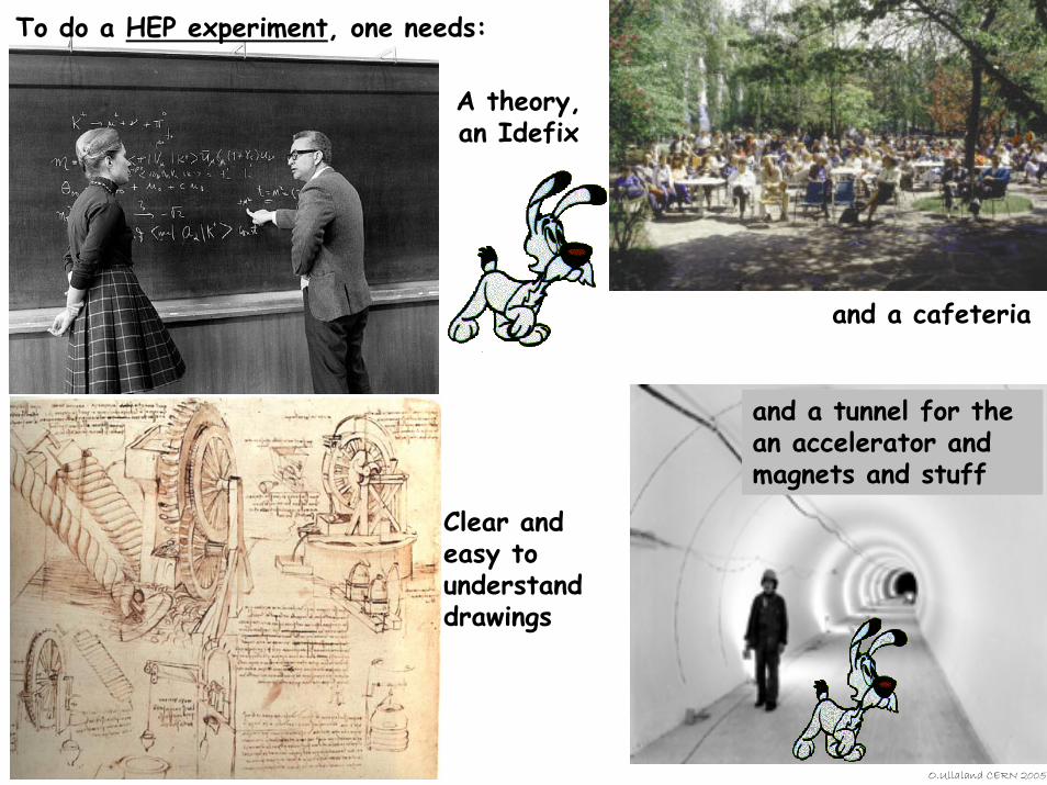
To do a HEP experiment, one needs:
A theory,an Idefix
Clear and easy to understand drawings
and a cafeteria
and a tunnel for the an accelerator and magnets and stuff
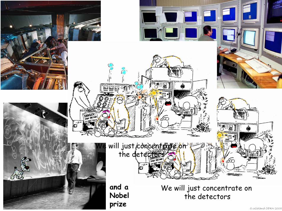
We will just concentrate on the detectors
O.Ullaland CERN 2005
and aNobel prize
Data analysis
Easy access to the experiment
We will just concentrate on the detectors
What I will try to cover:
Particle interaction with matterand magnetic fields
Tracking detectorsCalorimetersParticle Identification
and some introduction to what it is all about.
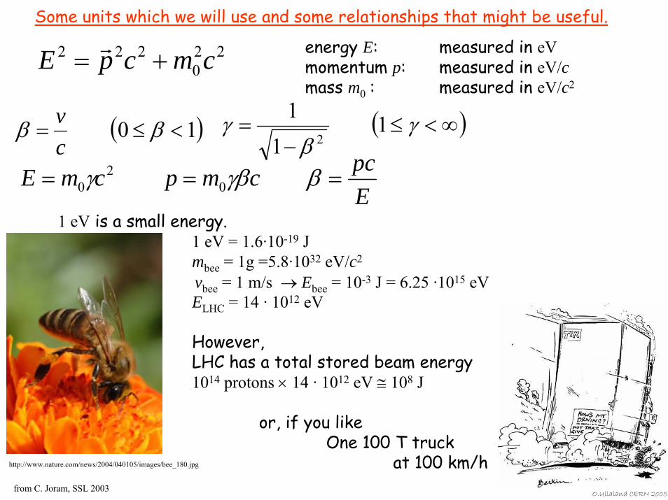
Some units which we will use and some relationships that might be useful.
O.Ullaland CERN 2005
220
222 cmcpE +=r energy E: measured in eV
momentum p: measured in eV/cmass m0 : measured in eV/c2
( )10 <≤= ββcv ( )∞<≤
−= γ
βγ 1
11
2
EpccmpcmE === βγβγ 0
20
1 eV is a small energy. 1 eV = 1.6·10-19 Jmbee = 1g =5.8·1032 eV/c2
vbee = 1 m/s → Ebee = 10-3 J = 6.25 ·1015 eVELHC = 14 · 1012 eV
However, LHC has a total stored beam energy1014 protons × 14 · 1012 eV ≅ 108 J
or, if you likeOne 100 T truck
at 100 km/hfrom C. Joram, SSL 2003
http://www.nature.com/news/2004/040105/images/bee_180.jpg
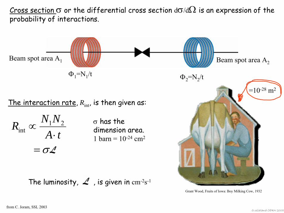
Cross section σ or the differential cross section dσ/dΩ is an expression of the probability of interactions.
Beam spot area A2Beam spot area A1
Φ1=N1/t Φ2=N2/t
Grant Wood, Fruits of Iowa: Boy Milking Cow, 1932
=10-28 m2
The interaction rate, Rint, is then given as:
σ=⋅
∝tA
NNR 21int
σ has the dimension area.1 barn = 10-24 cm2
The luminosity, , is given in cm-2s-1
from C. Joram, SSL 2003O.Ullaland CERN 2005
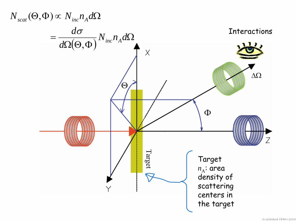
Interactions
Target
∆Ω
( ) ΩΦΘΩ
=
Ω∝ΦΘ
dnNd
ddnNN
Ainc
Aincscat
,
),(σ
TargetnA: area density of scattering centers in the target
O.Ullaland CERN 2005
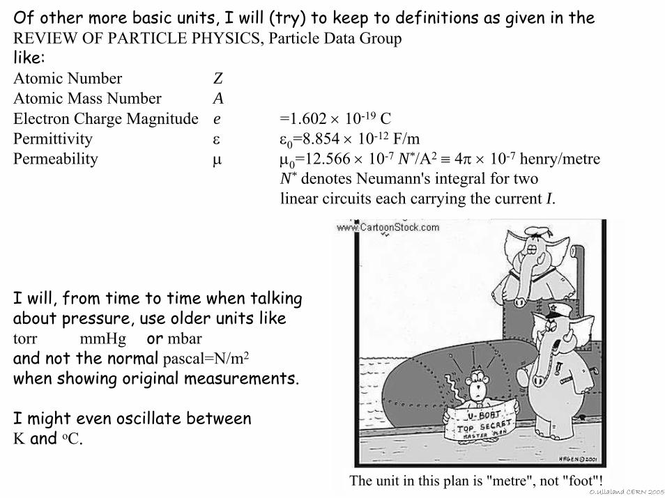
The unit in this plan is "metre", not "foot"!O.Ullaland CERN 2005
Of other more basic units, I will (try) to keep to definitions as given in the REVIEW OF PARTICLE PHYSICS, Particle Data Grouplike:Atomic Number ZAtomic Mass Number AElectron Charge Magnitude e =1.602 × 10⁻¹⁹ CPermittivity ε ε0=8.854 × 10⁻¹² F/mPermeability µ µ0=12.566 × 10⁻⁷ N*/A2 ≡ 4π × 10-7 henry/metre
N* denotes Neumann's integral for two linear circuits each carrying the current I.
I will, from time to time when talking about pressure, use older units liketorr mmHg or mbar and not the normal pascal=N/m2
when showing original measurements.
I might even oscillate between K and oC.
We can then start off
Claus Grupen, Particle Detectors, Cambridge University Press, Cambridge 1996 (455 pp. ISBN 0-521-55216-8)
O.Ullaland CERN 2005
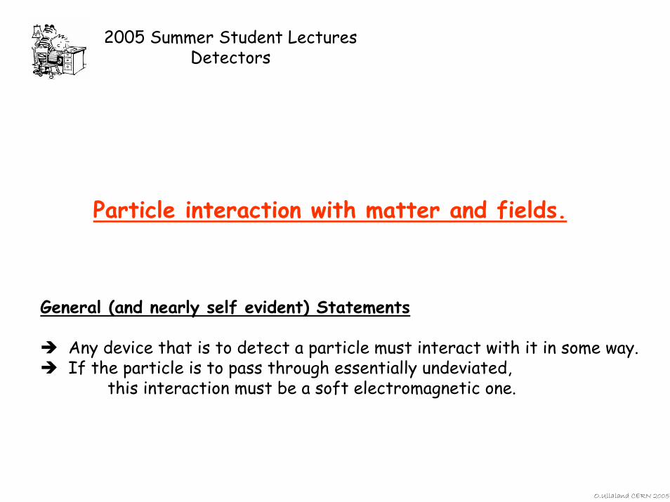
2005 Summer Student LecturesDetectors
Particle interaction with matter and fields.
General (and nearly self evident) Statements
Any device that is to detect a particle must interact with it in some way. If the particle is to pass through essentially undeviated,
this interaction must be a soft electromagnetic one.
O.Ullaland CERN 2005
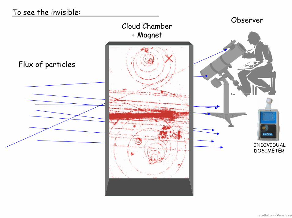
To see the invisible:
Flux of particles
ObserverCloud Chamber
+ Magnet
INDIVIDUAL DOSIMETER
O.Ullaland CERN 2005
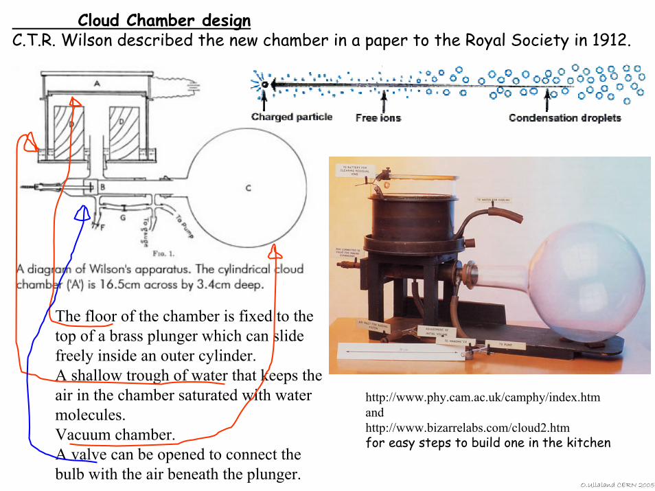
Cloud Chamber designC.T.R. Wilson described the new chamber in a paper to the Royal Society in 1912.
O.Ullaland CERN 2005
The floor of the chamber is fixed to the top of a brass plunger which can slide freely inside an outer cylinder. A shallow trough of water that keeps the air in the chamber saturated with water molecules. Vacuum chamber. A valve can be opened to connect the bulb with the air beneath the plunger.
http://www.phy.cam.ac.uk/camphy/index.htmandhttp://www.bizarrelabs.com/cloud2.htmfor easy steps to build one in the kitchen
O.Ullaland CERN 2005
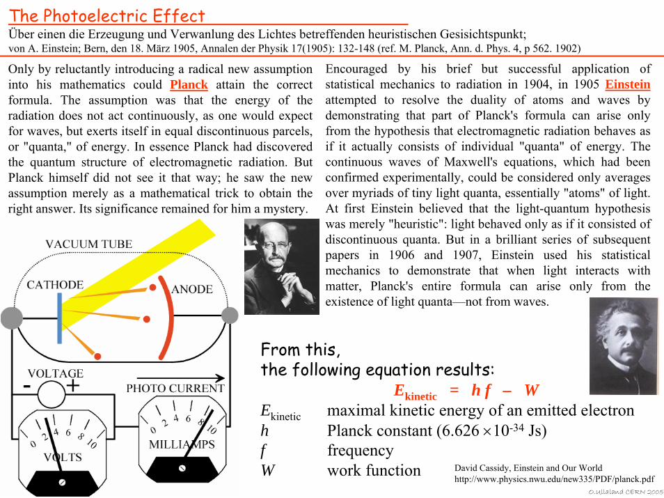
The Photoelectric EffectÜber einen die Erzeugung und Verwanlung des Lichtes betreffenden heuristischen Gesisichtspunkt;von A. Einstein; Bern, den 18. März 1905, Annalen der Physik 17(1905): 132-148 (ref. M. Planck, Ann. d. Phys. 4, p 562. 1902)
Only by reluctantly introducing a radical new assumption into his mathematics could Planck attain the correct formula. The assumption was that the energy of the radiation does not act continuously, as one would expect for waves, but exerts itself in equal discontinuous parcels, or "quanta," of energy. In essence Planck had discovered the quantum structure of electromagnetic radiation. But Planck himself did not see it that way; he saw the new assumption merely as a mathematical trick to obtain the right answer. Its significance remained for him a mystery.
Encouraged by his brief but successful application of statistical mechanics to radiation in 1904, in 1905 Einsteinattempted to resolve the duality of atoms and waves by demonstrating that part of Planck's formula can arise only from the hypothesis that electromagnetic radiation behaves as if it actually consists of individual "quanta" of energy. The continuous waves of Maxwell's equations, which had been confirmed experimentally, could be considered only averages over myriads of tiny light quanta, essentially "atoms" of light.At first Einstein believed that the light-quantum hypothesis was merely "heuristic": light behaved only as if it consisted ofdiscontinuous quanta. But in a brilliant series of subsequent papers in 1906 and 1907, Einstein used his statistical mechanics to demonstrate that when light interacts with matter, Planck's entire formula can arise only from the existence of light quanta—not from waves.
David Cassidy, Einstein and Our Worldhttp://www.physics.nwu.edu/new335/PDF/planck.pdf
From this, the following equation results:
Ekinetic = h f – W Ekinetic maximal kinetic energy of an emitted electronh Planck constant (6.626 ×10⁻³⁴ Js)f frequencyW work function
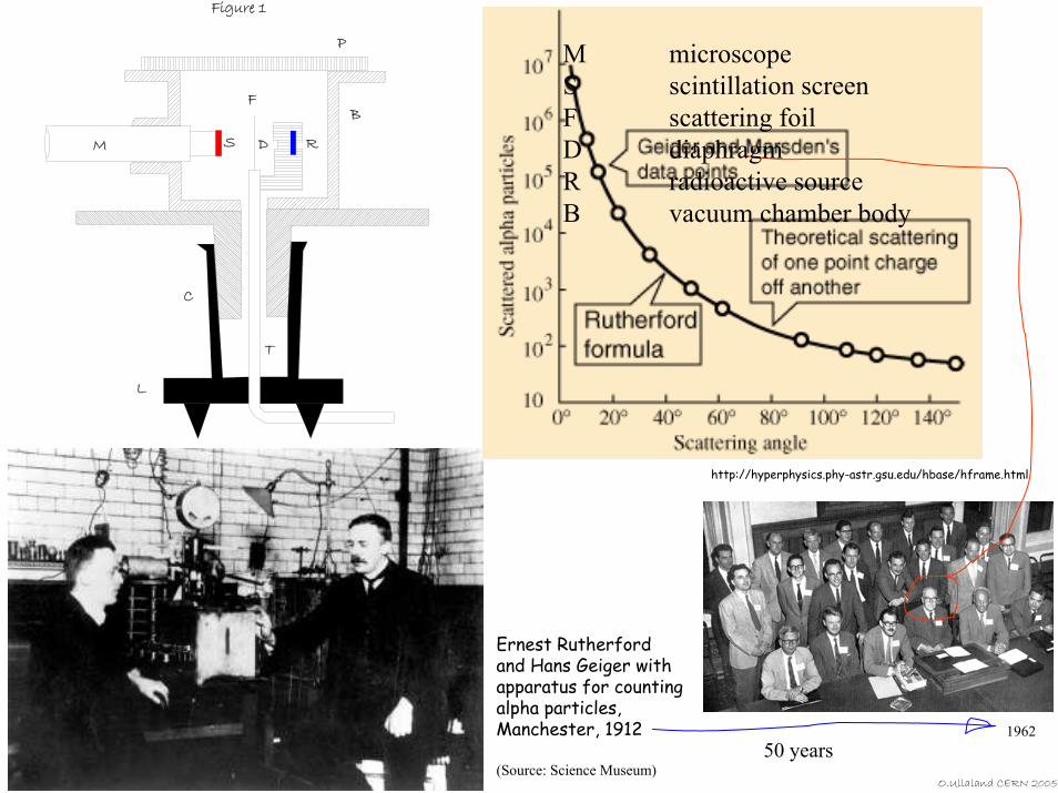
Figure 1
M
F
S RD
C
T
L
B
P
Ernest Rutherford and Hans Geiger with apparatus for counting alpha particles, Manchester, 1912
(Source: Science Museum)
http://hyperphysics.phy-astr.gsu.edu/hbase/hframe.html
O.Ullaland CERN 2005
50 years
M microscopeS scintillation screenF scattering foilD diaphragmR radioactive sourceB vacuum chamber body
1962
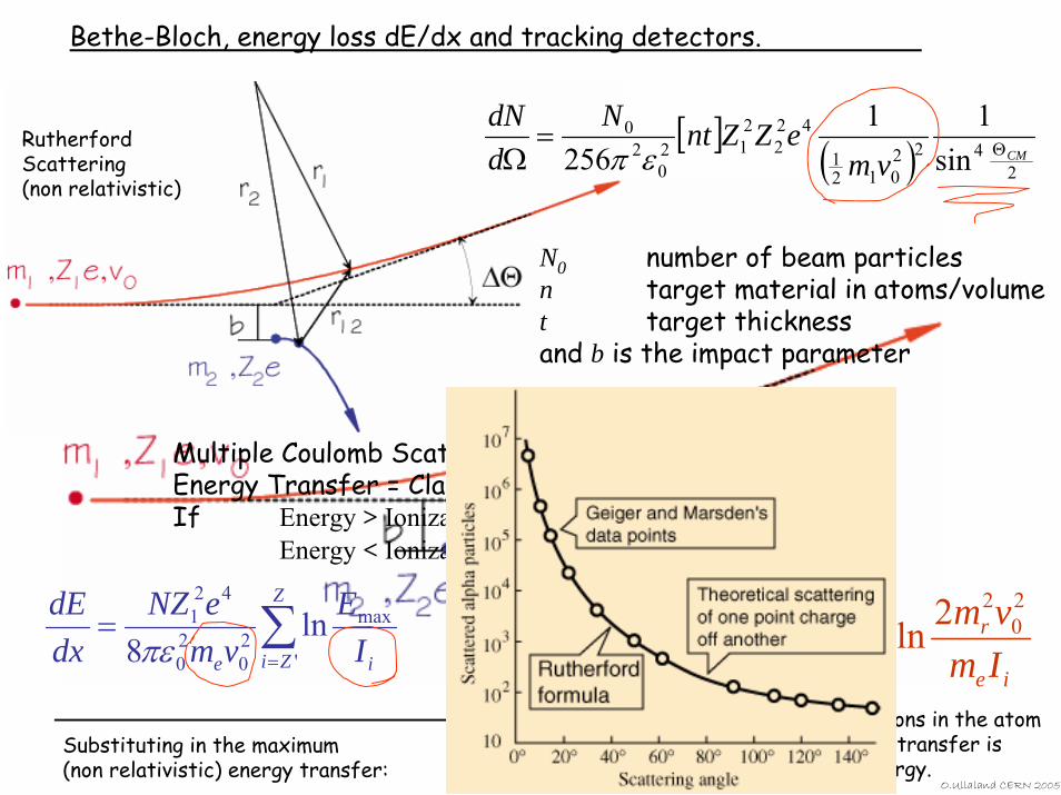
Bethe-Bloch, energy loss dE/dx and tracking detectors.
Rutherford Scattering (non relativistic)
[ ] ( ) 2422
0121
422
212
02
0
sin11
256 CMvmeZZntN
ddN
Θ=Ω επ
N0 number of beam particles n target material in atoms/volumet target thicknessand b is the impact parameter
Multiple Coulomb Scattering (after Rutherford)Energy Transfer = Classic RutherfordIf Energy > Ionization Energy → electron escape atom
Energy < Ionization Energy → No energy transfer
∑=
=Z
Zi ie IE
vmeNZ
dxdE
'
max20
20
421 ln
8πε ∑=
=Z
Zi ie
r
e Imvm
vmeNZ
dxdE
'
20
2
20
20
421 2ln
8πε
Substituting in the maximum (non relativistic) energy transfer:
the sum is taken over all electrons in the atom for which the maximum energy transfer is greater than the ionization energy.
O.Ullaland CERN 2005
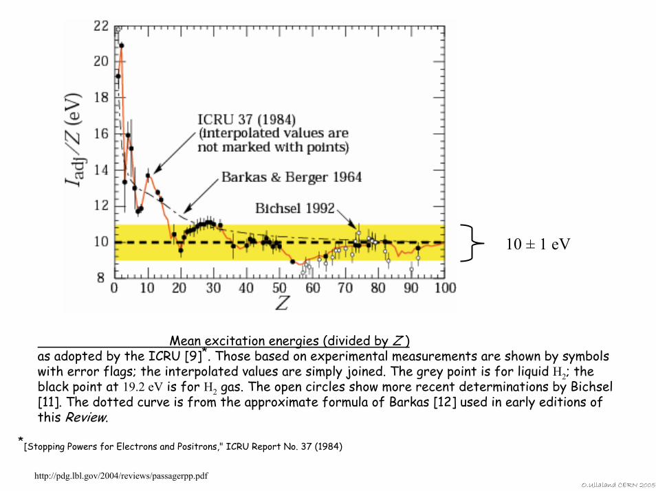
10 ± 1 eV
Mean excitation energies (divided by Z )as adopted by the ICRU [9]*. Those based on experimental measurements are shown by symbols with error flags; the interpolated values are simply joined. The grey point is for liquid H2; the black point at 19.2 eV is for H2 gas. The open circles show more recent determinations by Bichsel [11]. The dotted curve is from the approximate formula of Barkas [12] used in early editions of this Review.
*[Stopping Powers for Electrons and Positrons," ICRU Report No. 37 (1984)
http://pdg.lbl.gov/2004/reviews/passagerpp.pdfO.Ullaland CERN 2005
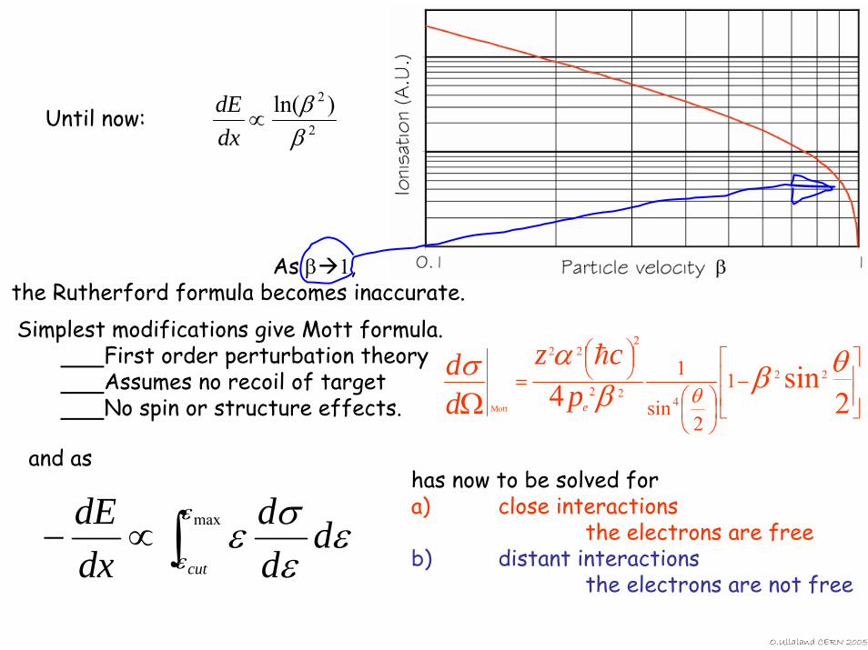
Until now: 2
2 )ln(ββ
∝dxdE
As β 1, the Rutherford formula becomes inaccurate.
⎥⎥
⎦
⎤
⎢⎢
⎣
⎡−
⎟⎠⎞
⎜⎝⎛
⎟⎠⎞⎜
⎝⎛
=Ω 2
sin422
422
222
1
2sin
1
Mott
θββασ
θep
czdd h
Simplest modifications give Mott formula.First order perturbation theoryAssumes no recoil of targetNo spin or structure effects.
and ashas now to be solved fora) close interactions
the electrons are freeb) distant interactions
the electrons are not free∫∝− maxε
εε
εσε
cut
ddd
dxdE
O.Ullaland CERN 2005
⎥⎦
⎤⎢⎣
⎡−⎟⎟
⎠
⎞⎜⎜⎝
⎛∝⎟
⎠⎞
⎜⎝⎛− 2max
2close
ln1 βεε
β cutdxdE
for close interactions
( )⎥⎥⎦
⎤
⎢⎢⎣
⎡−−⎟⎟
⎠
⎞⎜⎜⎝
⎛∝⎟
⎠⎞
⎜⎝⎛− δβεβγ
β2
2cut
2
2distant
2ln1I
mdxdE e for distant interactions
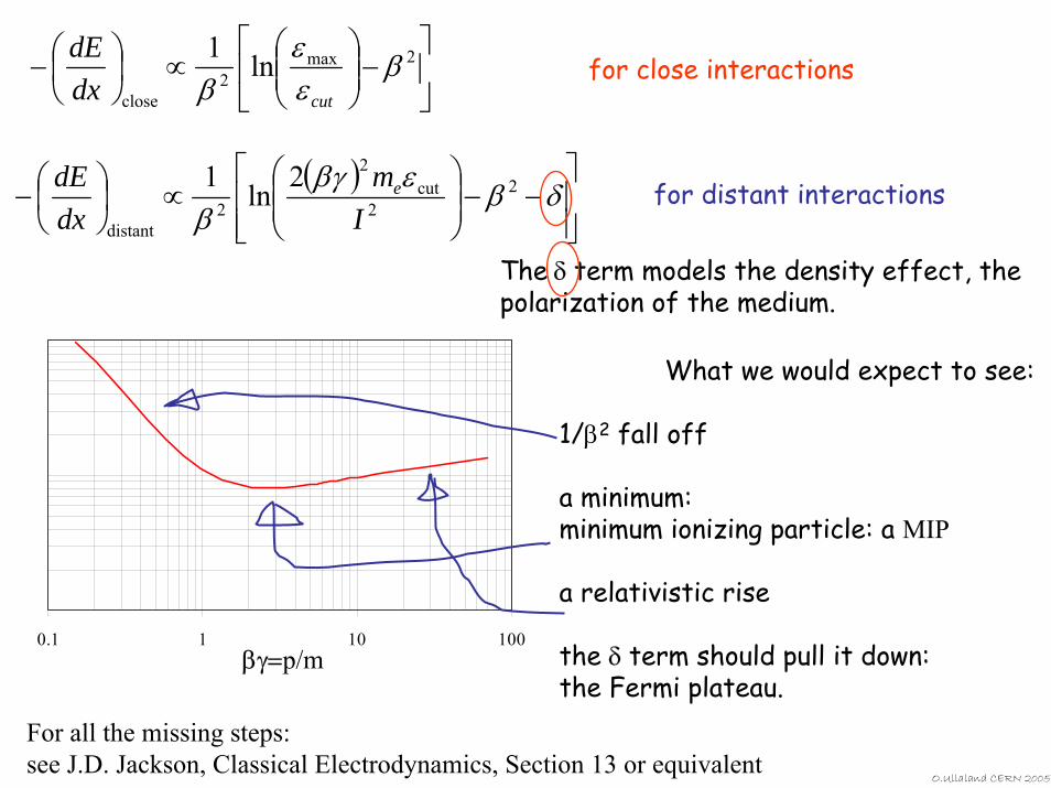
The δ term models the density effect, the polarization of the medium.
What we would expect to see:
1/β2 fall off
a minimum: minimum ionizing particle: a MIP
a relativistic rise
the δ term should pull it down:the Fermi plateau.
0.1 1 10 100βγ=p/m
For all the missing steps:see J.D. Jackson, Classical Electrodynamics, Section 13 or equivalent
O.Ullaland CERN 2005
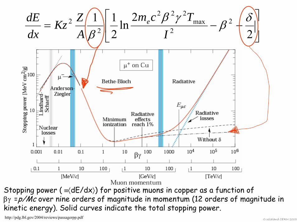
Stopping power ( ≡⟨dE/dx⟩) for positive muons in copper as a function of βγ =p/Mc over nine orders of magnitude in momentum (12 orders of magnitude in kinetic energy). Solid curves indicate the total stopping power.
⎥⎦
⎤⎢⎣
⎡−−=
22
ln211 2
2max
222
22 δβ
γββ I
TcmAZKz
dxdE e
O.Ullaland CERN 2005http://pdg.lbl.gov/2004/reviews/passagerpp.pdf
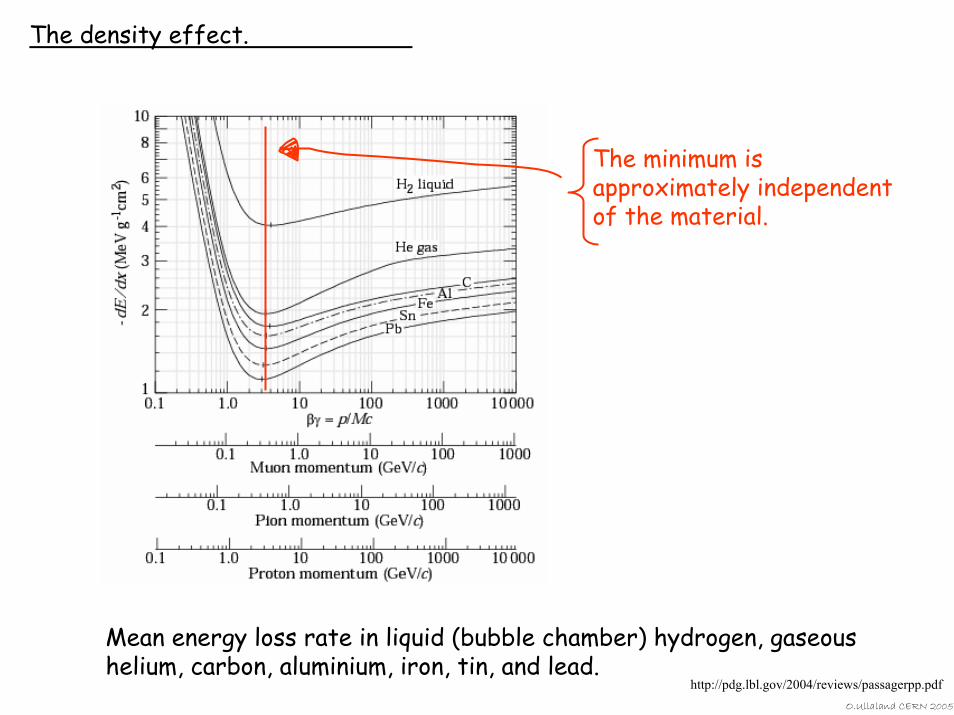
The density effect.
The minimum is approximately independent of the material.
Mean energy loss rate in liquid (bubble chamber) hydrogen, gaseoushelium, carbon, aluminium, iron, tin, and lead.
O.Ullaland CERN 2005
http://pdg.lbl.gov/2004/reviews/passagerpp.pdf
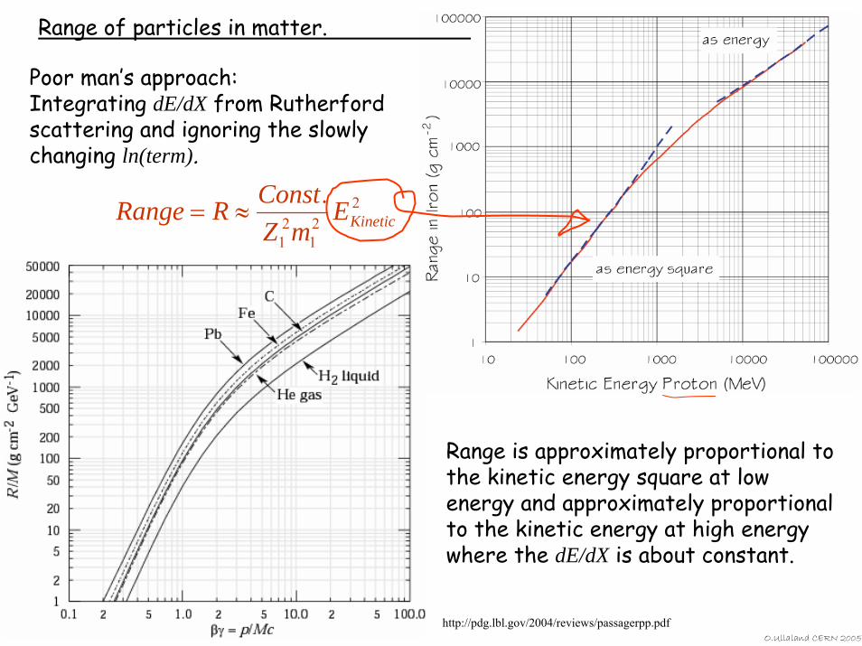
Range of particles in matter.
Poor man’s approach:Integrating dE/dX from Rutherford scattering and ignoring the slowly changing ln(term).
221
21
.KineticE
mZConstRRange ≈=
Range is approximately proportional to the kinetic energy square at low energy and approximately proportional to the kinetic energy at high energy where the dE/dX is about constant.
O.Ullaland CERN 2005
http://pdg.lbl.gov/2004/reviews/passagerpp.pdf
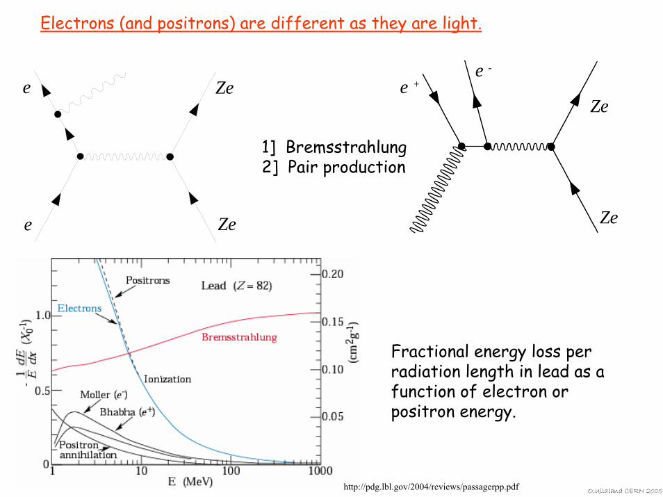
Electrons (and positrons) are different as they are light.
e
e
Ze
Ze
Ze
Zee +
e -
1] Bremsstrahlung2] Pair production
Fractional energy loss per radiation length in lead as a function of electron or positron energy.
http://pdg.lbl.gov/2004/reviews/passagerpp.pdf O.Ullaland CERN 2005
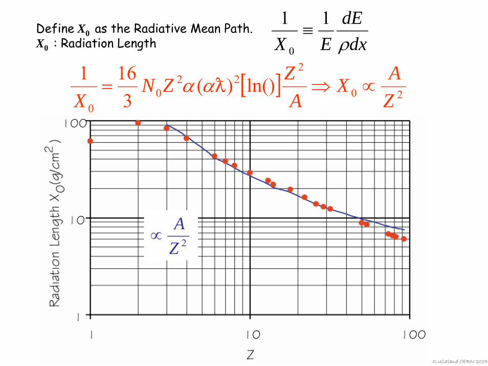
Define X0 as the Radiative Mean Path.X0 : Radiation Length dx
dEEX ρ11
0
≡
2ZA
∝
[ ] 20
222
00
ln())(3
161ZAX
AZZN
X∝⇒= Dαα
O.Ullaland CERN 2005
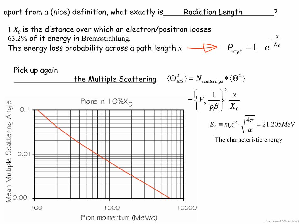
apart from a (nice) definition, what exactly is Radiation Length ?
1 X0 is the distance over which an electron/positron looses63.2% of it energy in Bremsstrahlung.The energy loss probability across a path length x 01 X
x
ee eP−
−=+−
Pick up again the Multiple Scattering
O.Ullaland CERN 2005
MeVcmE eS 205.2142 =⋅≡απ
0
2
22
1Xx
pE
N
s
sscatteringMS
⎭⎬⎫
⎩⎨⎧
=
⟩Θ⟨∗=⟩Θ⟨
β
The characteristic energy
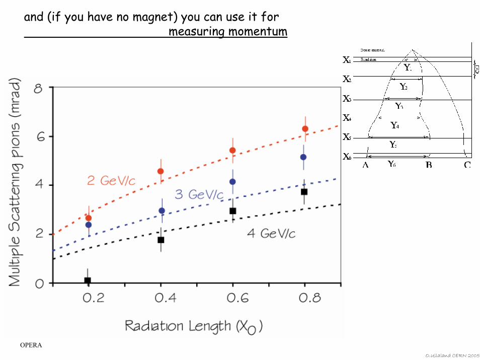
and (if you have no magnet) you can use it for measuring momentum
OPERAO.Ullaland CERN 2005
We will now move on to detectors.
HA HA! It felt like weeks and years and days and surely hours before we could get on with the
detectors. At long last we can finally start !!!!!
‘Please read all the included instruction manuals.’
O.Ullaland CERN 2005
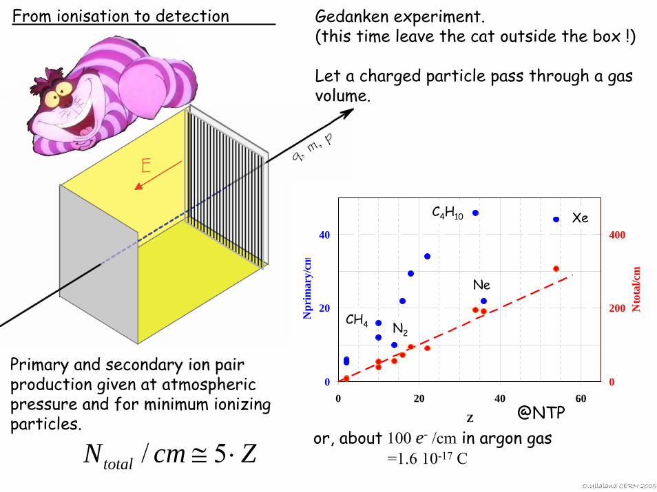
Gedanken experiment.(this time leave the cat outside the box !)
Let a charged particle pass through a gas volume.
0
20
40
0 20 40 60
Z
Npr
imar
y/cm
0
200
400
Nto
tal/c
m
CH4 N2
C4H10 Xe
Ne
Primary and secondary ion pair production given at atmospheric pressure and for minimum ionizing particles.
ZcmNtotal ⋅≅ 5/@NTP
or, about 100 e- /cm in argon gas=1.6 10-17 C
From ionisation to detection
O.Ullaland CERN 2005

O.Ullaland CERN 2005
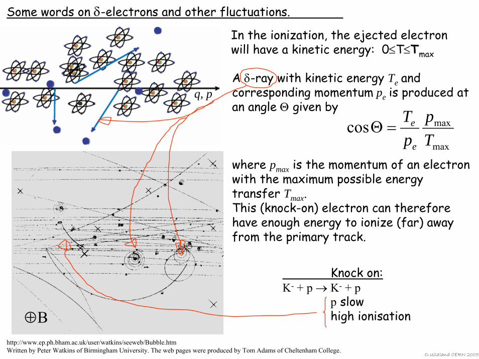
Some words on δ-electrons and other fluctuations.
In the ionization, the ejected electron will have a kinetic energy: 0≤T≤Tmax
A δ-ray with kinetic energy Te and corresponding momentum pe is produced at an angle Θ given by
where pmax is the momentum of an electron with the maximum possible energy transfer Tmax.This (knock-on) electron can therefore have enough energy to ionize (far) away from the primary track.
max
maxcosTp
pT
e
e=Θ
Knock on:K- + p → K- + p
p slowhigh ionisation⊕B
q, p
http://www.ep.ph.bham.ac.uk/user/watkins/seeweb/Bubble.htmWritten by Peter Watkins of Birmingham University. The web pages were produced by Tom Adams of Cheltenham College.
O.Ullaland CERN 2005
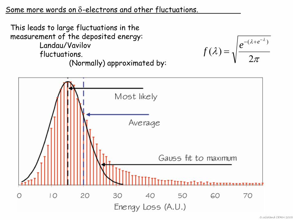
Some more words on δ-electrons and other fluctuations.
This leads to large fluctuations in the measurement of the deposited energy:
Landau/Vavilov fluctuations.
(Normally) approximated by: πλ
λλ
2)(
)( −+−
=eef
O.Ullaland CERN 2005
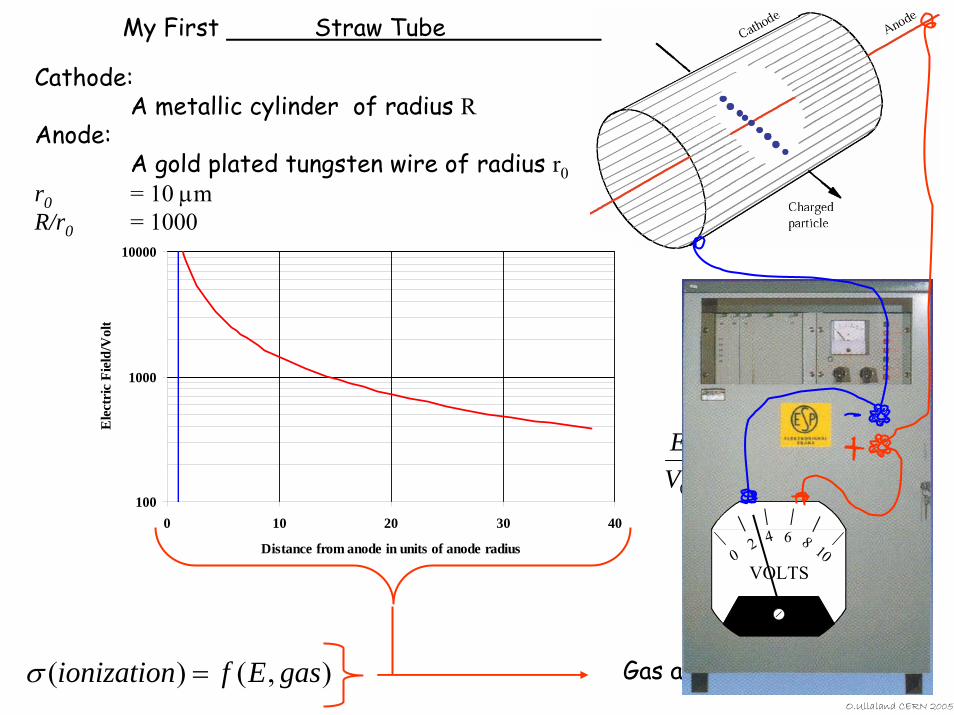
Cathode:A metallic cylinder of radius R
Anode:A gold plated tungsten wire of radius r0
r0 = 10 µmR/r0 = 1000
100
1000
10000
0 10 20 30 40
Distance from anode in units of anode radius
Ele
ctri
c Fi
eld/
Vol
t
⎟⎠⎞
⎜⎝⎛
=
rRrV
E
ln
11
0
),()( gasEfionization =σ Gas amplificationO.Ullaland CERN 2005
My First Straw Tube
VOLTS0
2 4 6 8 10
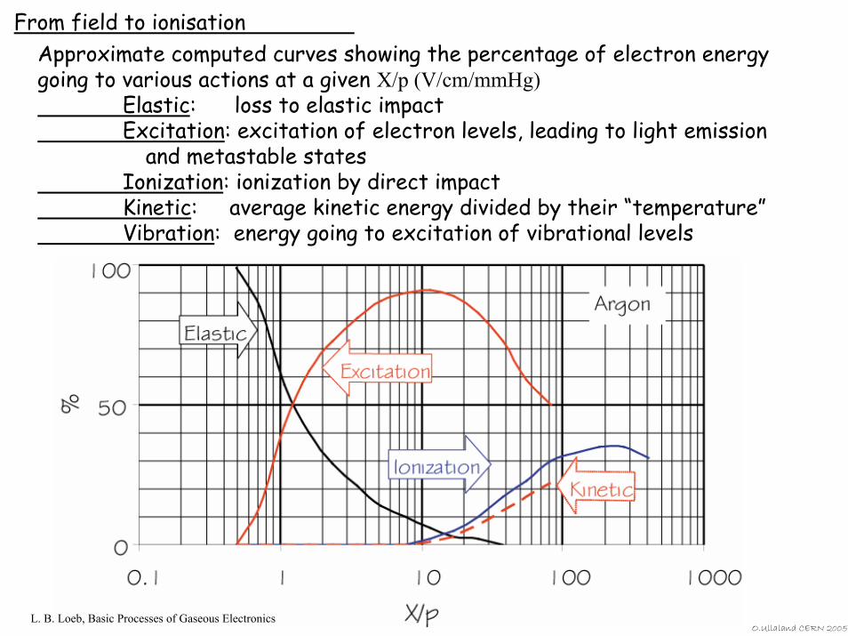
From field to ionisationApproximate computed curves showing the percentage of electron energy going to various actions at a given X/p (V/cm/mmHg)
Elastic: loss to elastic impactExcitation: excitation of electron levels, leading to light emission
and metastable statesIonization: ionization by direct impactKinetic: average kinetic energy divided by their “temperature”Vibration: energy going to excitation of vibrational levels
L. B. Loeb, Basic Processes of Gaseous ElectronicsO.Ullaland CERN 2005
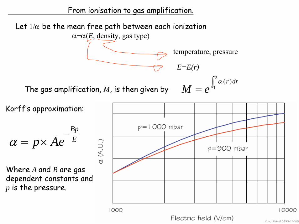
From ionisation to gas amplification.
Let 1/α be the mean free path between each ionizationα=α(E, density, gas type)
E=E(r)
temperature, pressure
The gas amplification, M, is then given by ∫=2
1)(
r
rdrr
eMα
O.Ullaland CERN 2005
Korff’s approximation:
EBp
Aep−
×=α
Where A and B are gas dependent constants and p is the pressure.
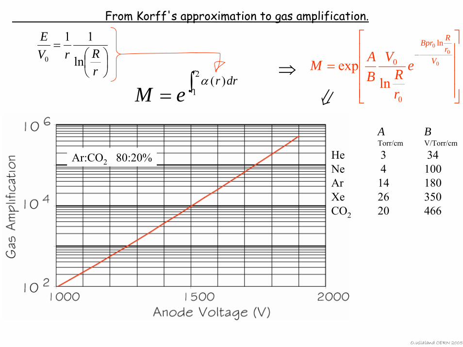
From Korff's approximation to gas amplification.
⎟⎠⎞
⎜⎝⎛
=
rRrV
E
ln
11
0
∫=2
1)(
r
rdrr
eMα
⎥⎥⎥⎥
⎦
⎤
⎢⎢⎢⎢
⎣
⎡
=−
0
00 ln
0
0
lnexp V
rRBpr
e
rR
VBAM⇒
⇒A BTorr/cm V/Torr/cm
He 3 34Ne 4 100Ar 14 180Xe 26 350CO2 20 466
Ar:CO2 80:20%
O.Ullaland CERN 2005
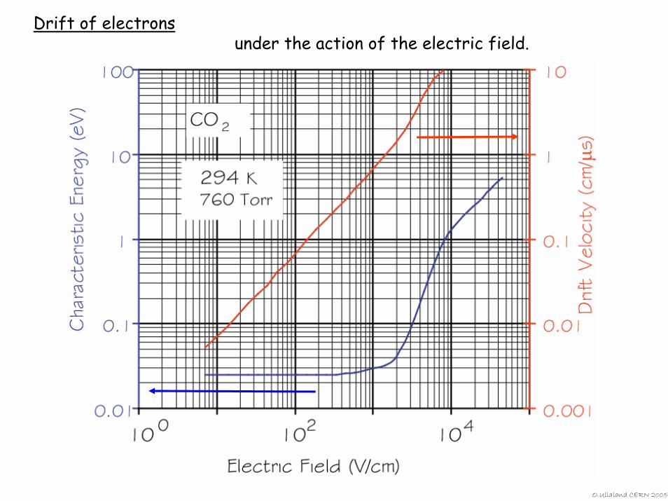
Drift of electronsunder the action of the electric field.
O.Ullaland CERN 2005
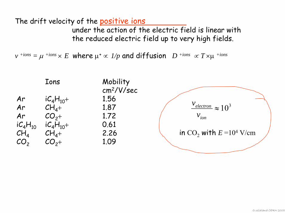
The drift velocity of the positive ionsunder the action of the electric field is linear with the reduced electric field up to very high fields.
v +ions = µ +ions × E where µ+ ∝ 1/p and diffusion D +ions ∝ T ×µ +ions
Ions Mobilitycm2/V/sec
Ar iC4H10+ 1.56Ar CH4+ 1.87Ar CO2+ 1.72iC4H10 iC4H10+ 0.61CH4 CH4+ 2.26CO2 CO2+ 1.09
310≈ion
electron
vv
in CO2 with E =104 V/cm
O.Ullaland CERN 2005
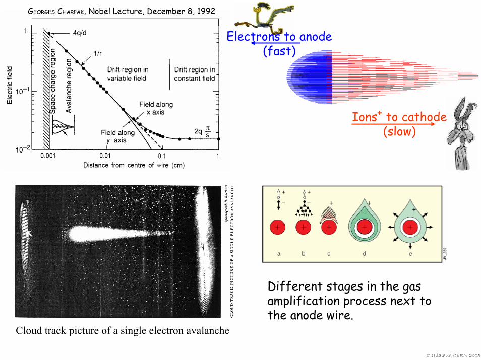
GEORGES CHARPAK, Nobel Lecture, December 8, 1992
Ions+ to cathode(slow)
Electrons to anode(fast)
Cloud track picture of a single electron avalanche
Different stages in the gas amplification process next to the anode wire.
O.Ullaland CERN 2005
O.Ullaland CERN 2005
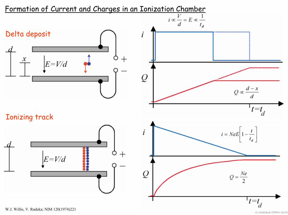
Formation of Current and Charges in an Ionization Chamber
Delta deposit
Ionizing track
W.J. Willis, V. Radeka; NIM 120(1974)221
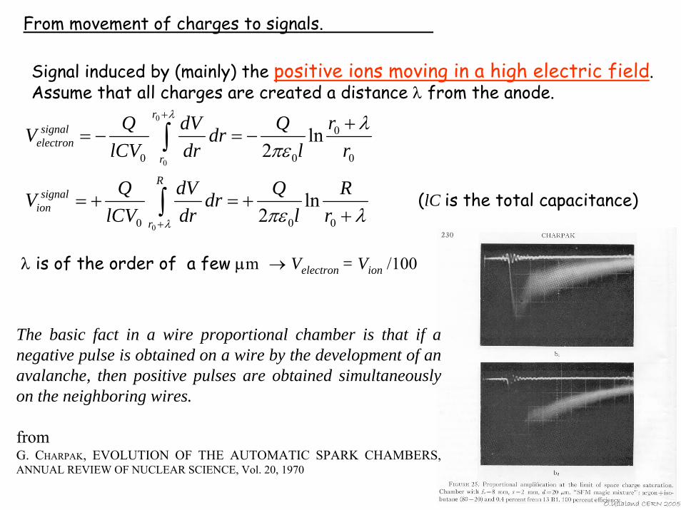
From movement of charges to signals.
Signal induced by (mainly) the positive ions moving in a high electric field.Assume that all charges are created a distance λ from the anode.
λπε
λπε
λ
λ
++=+=
+−=−=
∫
∫
+
+
000
0
0
00
ln2
ln2
0
0
0
rR
lQdr
drdV
lCVQV
rr
lQdr
drdV
lCVQV
R
r
signalion
r
r
signalelectron
(lC is the total capacitance)
The basic fact in a wire proportional chamber is that if a negative pulse is obtained on a wire by the development of an avalanche, then positive pulses are obtained simultaneously on the neighboring wires.
fromG. CHARPAK, EVOLUTION OF THE AUTOMATIC SPARK CHAMBERS, ANNUAL REVIEW OF NUCLEAR SCIENCE, Vol. 20, 1970
O.Ullaland CERN 200
λ is of the order of a few µm → Velectron = Vion /100
5
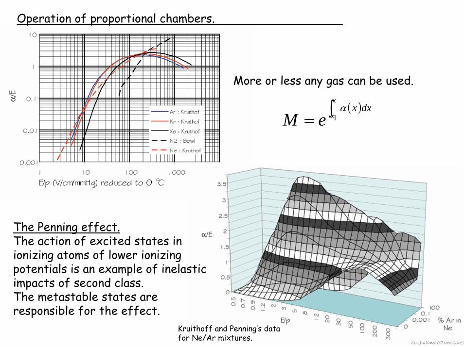
Operation of proportional chambers.
The Penning effect.The action of excited states in ionizing atoms of lower ionizing potentials is an example of inelastic impacts of second class. The metastable states are responsible for the effect.
More or less any gas can be used.
Kruithoff and Penning’s data for Ne/Ar mixtures.
( )∫=x
xdxx
eM 1α
O.Ullaland CERN 2005
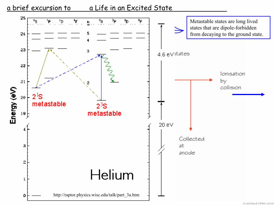
a brief excursion to a Life in an Excited State
O.Ullaland CERN 2005
Metastable states are long lived states that are dipole-forbidden from decaying to the ground state.
http://raptor.physics.wisc.edu/talk/part_3a.htm
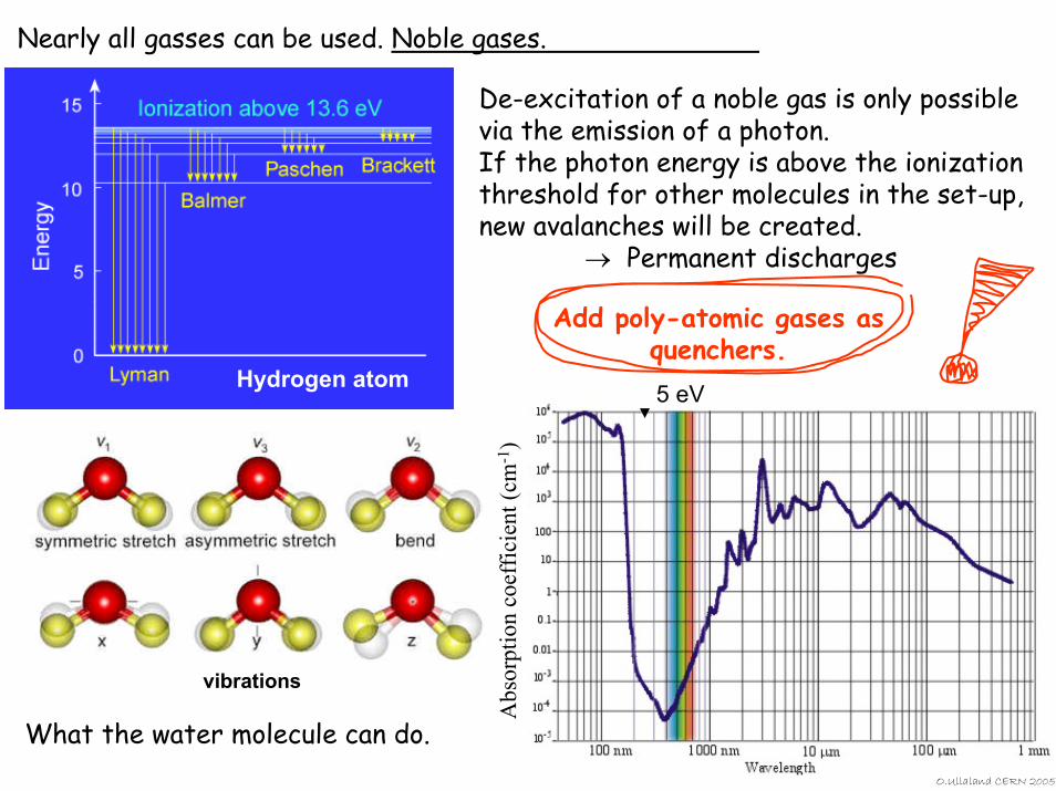
Nearly all gasses can be used. Noble gases.
Hydrogen atom
De-excitation of a noble gas is only possible via the emission of a photon.If the photon energy is above the ionization threshold for other molecules in the set-up, new avalanches will be created.
→ Permanent discharges
Add poly-atomic gases as quenchers.
What the water molecule can do.O.Ullaland CERN 2005
vibrations
5 eV
Abs
orpt
ion
coef
ficie
nt (c
m-1
)
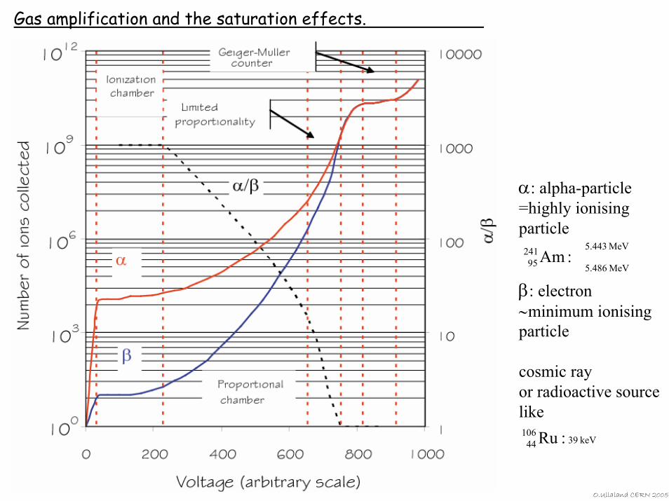
Gas amplification and the saturation effects.
α: alpha-particle=highly ionising particle
β: electron ∼minimum ionising particle
cosmic rayor radioactive sourcelike
MeV443.5
MeV486.5
24195 :Am
keV3910644 :Ru
O.Ullaland CERN 2005
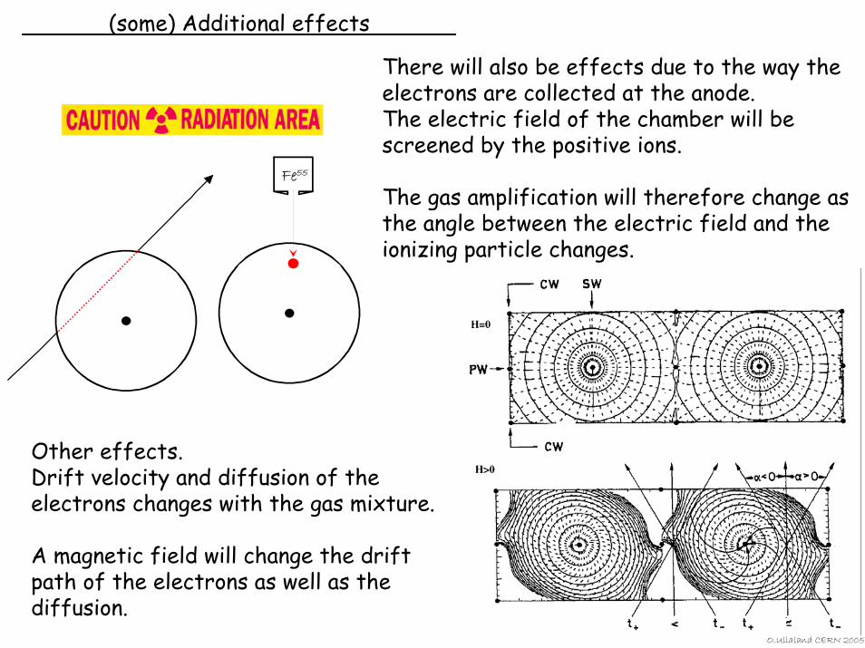
(some) Additional effects
There will also be effects due to the way the electrons are collected at the anode.The electric field of the chamber will be screened by the positive ions.
The gas amplification will therefore change as the angle between the electric field and the ionizing particle changes.
Fe55
O.Ullaland CERN 2005
Other effects.Drift velocity and diffusion of the electrons changes with the gas mixture.
A magnetic field will change the drift path of the electrons as well as the diffusion.
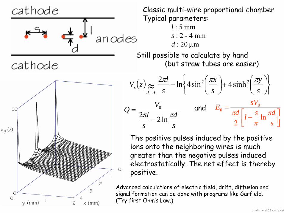
Classic multi-wire proportional chamberTypical parameters:
l : 5 mms : 2 - 4 mmd : 20 µm
( )⎭⎬⎫
⎩⎨⎧
⎟⎠⎞
⎜⎝⎛+⎟
⎠⎞
⎜⎝⎛−≈
→ sy
sx
slzV
ds
πππ 22
0sinh4sin4ln2
sd
sl
VQ ππ ln220
−=
⎥⎦⎤
⎢⎣⎡ −
=
sdsld
sVEπ
ππ ln2
00
Still possible to calculate by hand (but straw tubes are easier)
and
The positive pulses induced by the positive ions onto the neighboring wires is much greater than the negative pulses induced electrostatically. The net effect is thereby positive.
Advanced calculations of electric field, drift, diffusion and signal formation can be done with programs like Garfield. (Try first Ohm’s Law.)
O.Ullaland CERN 2005

That is about all that is (really) needed to know about gas based tracking detectors. With these tools, we can now make:
Multi Wire Proportional Chambers MWPC Time Projection ChambersTime Expansion Chambers
Proportional Chambers Thin Gap Chambers
Drift ChambersJet ChambersStraw Tubs
Micro Well ChambersCathode Strip ChambersResistive Plate ChambersMicro Strip Gas Chambers
GEM - Gas Electron MultiplierMicromegas – Micromesh Gaseous Structure
(and some I have surely forgotten.)
There are, though, some gory details that we will have a closer look at.
O.Ullaland CERN 2005
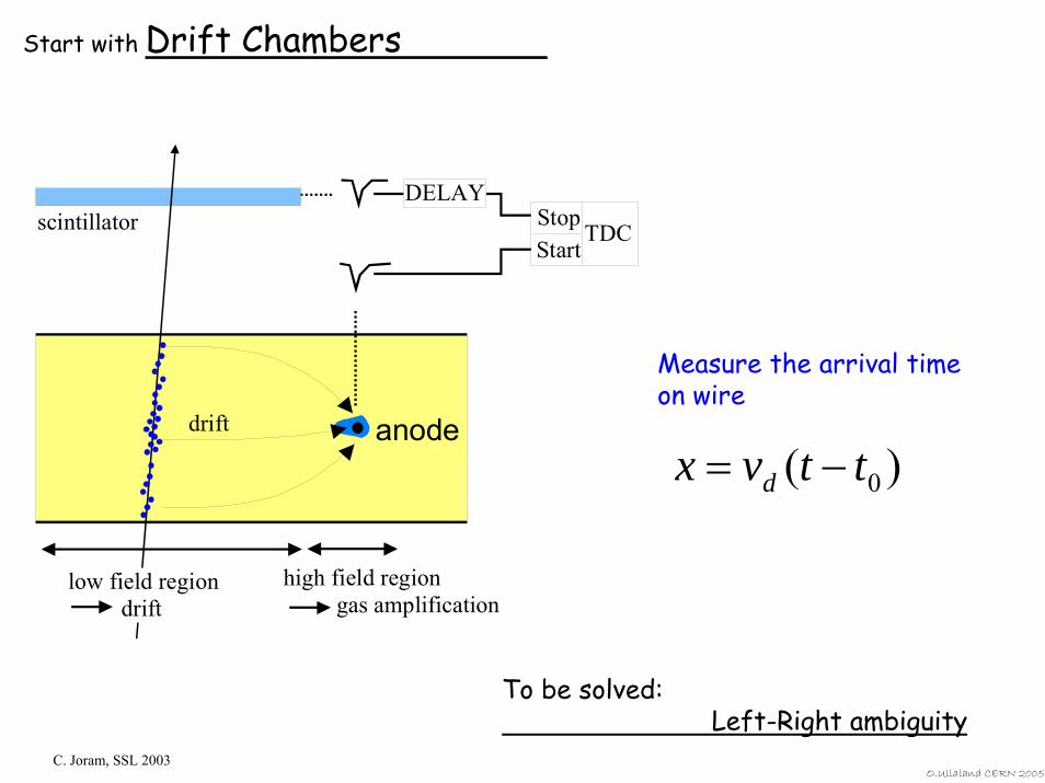
Start with Drift Chambers
anode
TDCStartStop
DELAYscintillator
drift
low field region drift
high field region gas amplification
Measure the arrival time on wire
)( 0ttvx d −=
To be solved:Left-Right ambiguity
C. Joram, SSL 2003O.Ullaland CERN 2005
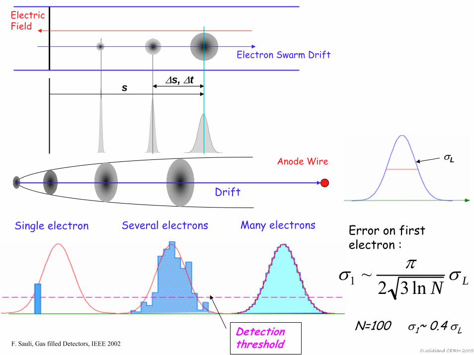
Electron Swarm Drift
ElectricField
∆s, ∆ts
Drift
σLAnode Wire
Many electronsSeveral electronsSingle electron
σ1 ~ π2 3 ln N
σ L
Error on first electron :
N=100 σ1~ 0.4 σLDetection thresholdF. Sauli, Gas filled Detectors, IEEE 2002
O.Ullaland CERN 2005
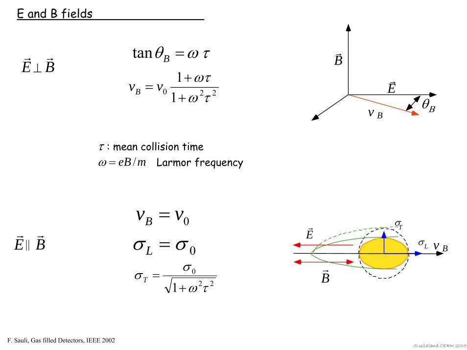
E and B fields
rE
rB
θΒv B
tanθB = ω τ r E
r B ⊥
220 11
τωωτ
++
= vvB
τ : mean collision timeLarmor frequencyω = eB /m
0vvB =σL = σ 0
220
1 τωσσ+
=TrB
σL
T σ
v B r E
r E
r B ||
F. Sauli, Gas filled Detectors, IEEE 2002O.Ullaland CERN 2005
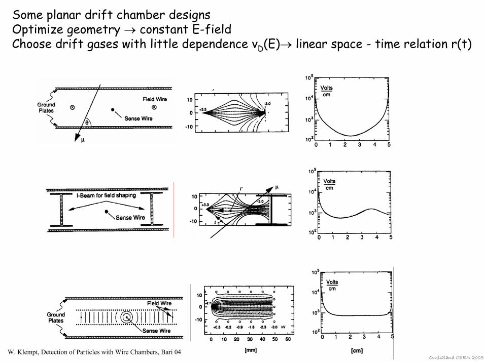
Some planar drift chamber designsOptimize geometry → constant E-field Choose drift gases with little dependence vD(E)→ linear space - time relation r(t)
W. Klempt, Detection of Particles with Wire Chambers, Bari 04O.Ullaland CERN 2005
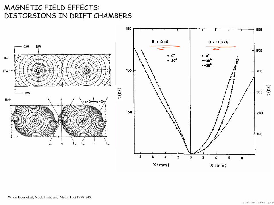
MAGNETIC FIELD EFFECTS:DISTORSIONS IN DRIFT CHAMBERS
t (ns
)
t (ns
)
W. de Boer et al, Nucl. Instr. and Meth. 156(1978)249 O.Ullaland CERN 2005
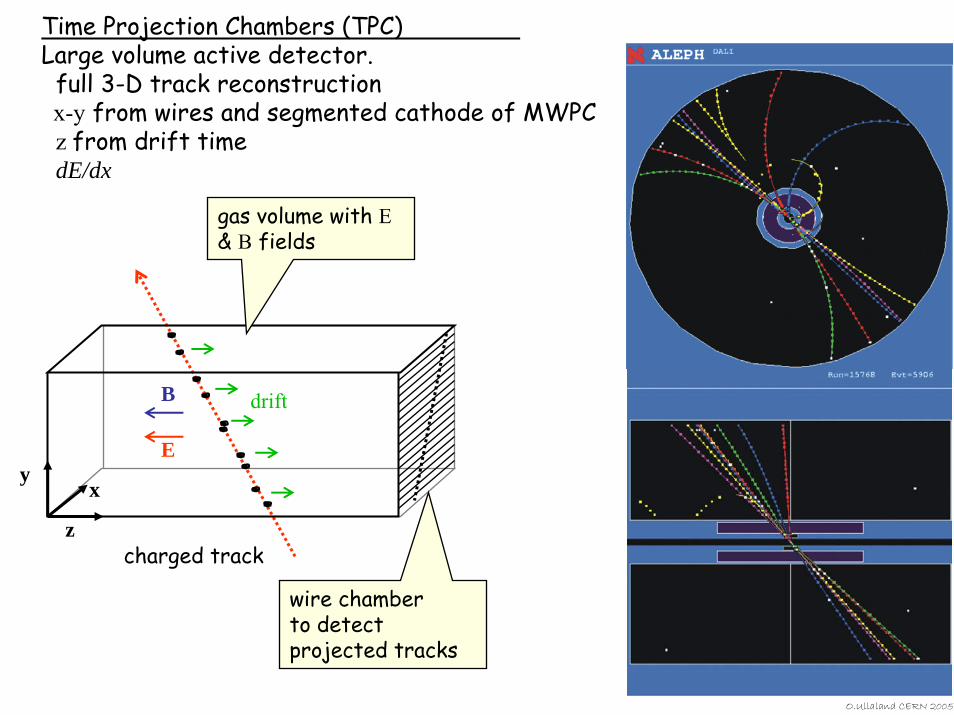
Time Projection Chambers (TPC)Large volume active detector.
full 3-D track reconstructionx-y from wires and segmented cathode of MWPCz from drift timedE/dx
O.Ullaland CERN 2005
z
x
E
B drift
charged track
wire chamber to detect projected tracks
gas volume with E & B fields
y
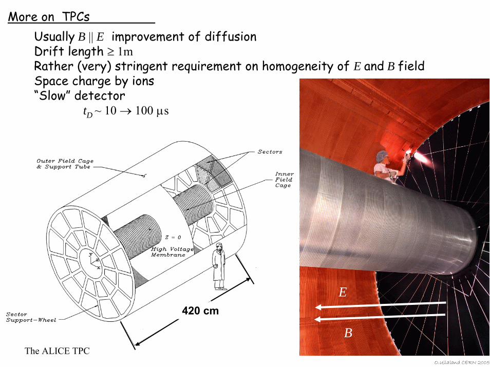
More on TPCsUsually B || E improvement of diffusion Drift length ≥ 1mRather (very) stringent requirement on homogeneity of E and B fieldSpace charge by ions“Slow” detector
tD ~ 10 → 100 µs
420 cm
The ALICE TPC
E
B
O.Ullaland CERN 2005

O.Ullaland CERN 2005
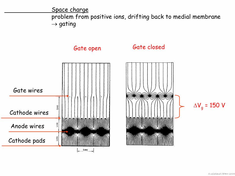
Space chargeproblem from positive ions, drifting back to medial membrane → gating
Gate closed
∆Vg = 150 V
Gate open
Gate wires
Cathode wires
Anode wires
Cathode pads
O.Ullaland CERN 2005
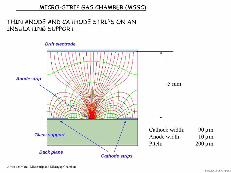
MICRO-STRIP GAS CHAMBER (MSGC)
THIN ANODE AND CATHODE STRIPS ON AN INSULATING SUPPORT
Anode strip
Cathode strips
Glass support
Back plane
Drift electrode
~5 mm
Cathode width: 90 µmAnode width: 10 µmPitch: 200 µm
J. van der Marel, Microstrip and Microgap ChambersO.Ullaland CERN 2005
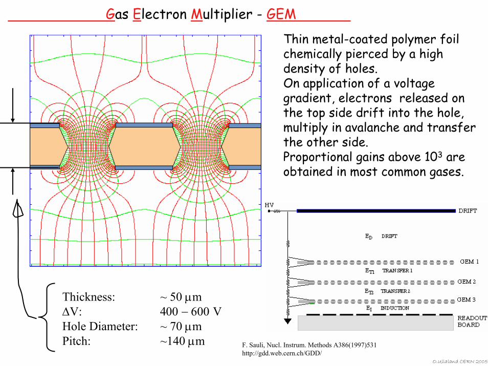
Gas Electron Multiplier - GEM
Thin metal-coated polymer foil chemically pierced by a high density of holes.On application of a voltage gradient, electrons released on the top side drift into the hole, multiply in avalanche and transfer the other side.Proportional gains above 103 are obtained in most common gases.
Thickness: ~ 50 µm∆V: 400 − 600 VHole Diameter: ~ 70 µmPitch: ~140 µm F. Sauli, Nucl. Instrum. Methods A386(1997)531
http://gdd.web.cern.ch/GDD/O.Ullaland CERN 2005
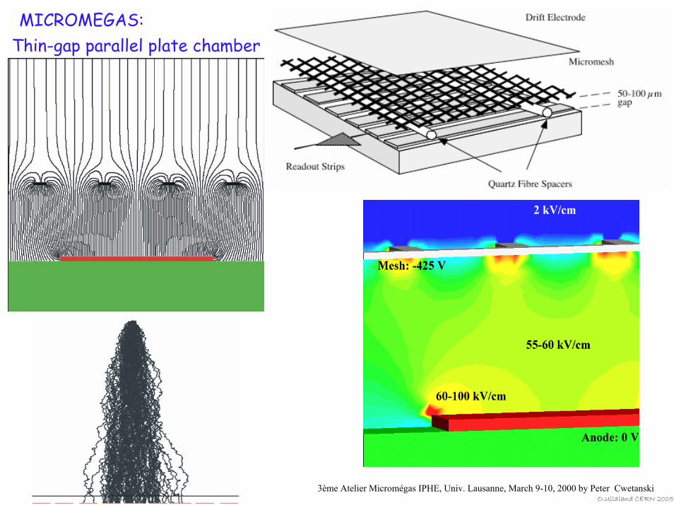
MICROMEGAS:Thin-gap parallel plate chamber
3ème Atelier Micromégas IPHE, Univ. Lausanne, March 9-10, 2000 by Peter CwetanskiO.Ullaland CERN 2005
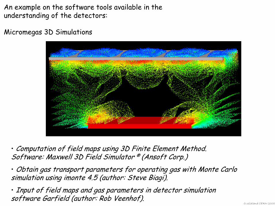
An example on the software tools available in the understanding of the detectors:
Micromegas 3D Simulations
• Computation of field maps using 3D Finite Element Method.Software: Maxwell 3D Field Simulator ® (Ansoft Corp.)• Obtain gas transport parameters for operating gas with Monte Carlosimulation using imonte 4.5 (author: Steve Biagi).• Input of field maps and gas parameters in detector simulation software Garfield (author: Rob Veenhof).
O.Ullaland CERN 2005
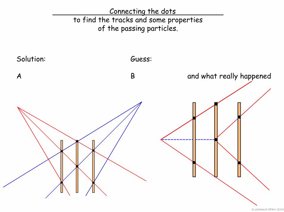
Connecting the dots to find the tracks and some properties
of the passing particles.
Solution: Guess:
A B and what really happened
O.Ullaland CERN 2005
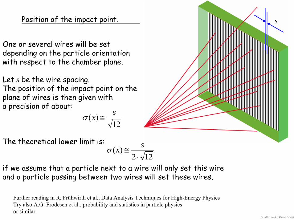
One or several wires will be set depending on the particle orientation with respect to the chamber plane.
Let s be the wire spacing.The position of the impact point on the plane of wires is then given with a precision of about:
The theoretical lower limit is:
if we assume that a particle next to a wire will only set this wire and a particle passing between two wires will set these wires.
12)( sx ≅σ
122)(
⋅≅
sxσ
sPosition of the impact point.
Further reading in R. Frühwirth et al., Data Analysis Techniques for High-Energy PhysicsTry also A.G. Frodesen et al., probability and statistics in particle physicsor similar.
O.Ullaland CERN 2005
Yeah, just gloat about your tail.
It is still a Vavilov to me!
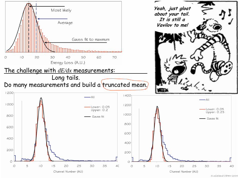
The challenge with dE/dx measurements:Long tails.
Do many measurements and build a truncated mean.
O.Ullaland CERN 2005
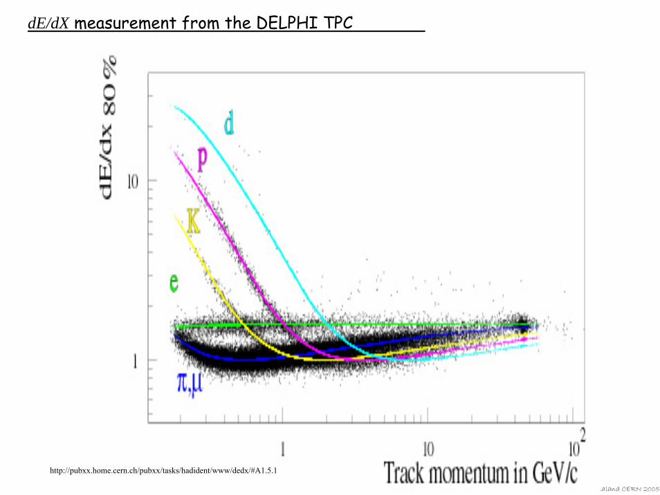
dE/dX measurement from the DELPHI TPC
O.Ullaland CERN 2005
http://pubxx.home.cern.ch/pubxx/tasks/hadident/www/dedx/#A1.5.1
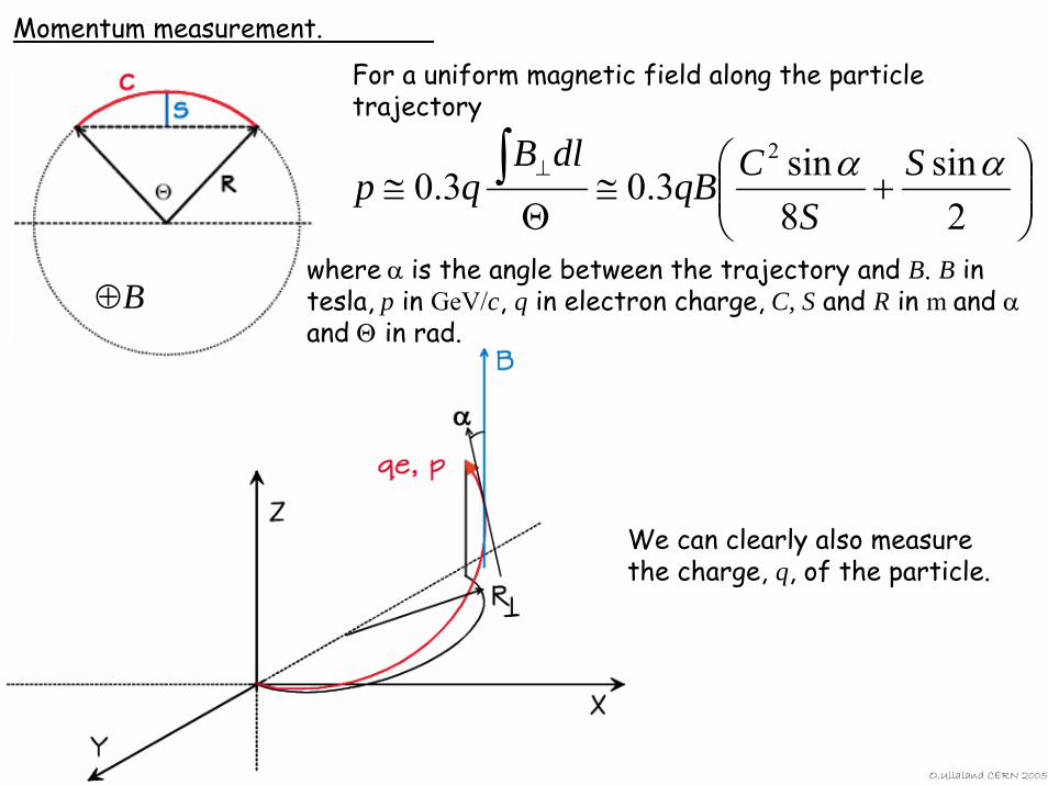
Momentum measurement.
For a uniform magnetic field along the particle trajectory
⎟⎟⎠
⎞⎜⎜⎝
⎛+≅
Θ≅ ∫ ⊥
2sin
8sin3.03.0
2 αα SS
CqBdlB
qp
where α is the angle between the trajectory and B. B in tesla, p in GeV/c, q in electron charge, C, S and R in m and αand Θ in rad.
We can clearly also measure the charge, q, of the particle.
O.Ullaland CERN 2005
⊕B
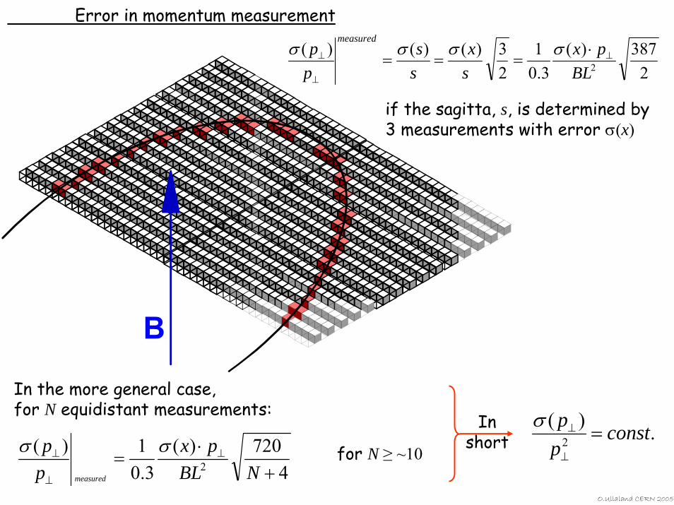
Error in momentum measurement
B
2387)(
3.01
23)()()(
2BLpx
sx
ss
pp
measured
⊥
⊥
⊥ ⋅===
σσσσ
if the sagitta, s, is determined by 3 measurements with error σ(x)
In the more general case, for N equidistant measurements:
Inshort .)(
2 constpp
=⊥
⊥σ
4720)(
3.01)(
2 +⋅
= ⊥
⊥
⊥
NBLpx
pp
measured
σσ for N ≥ ~10
O.Ullaland CERN 2005
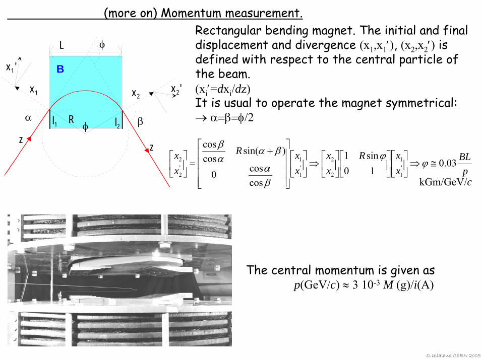
(more on) Momentum measurement.
pBL
xxR
xx
xxR
xx
03.010
sin1
coscos0
)sin(coscos
'1
1'2
2'1
1'2
2 ≅⇒⎥⎦
⎤⎢⎣
⎡⎥⎦
⎤⎢⎣
⎡⎥⎦
⎤⎢⎣
⎡⇒⎥
⎦
⎤⎢⎣
⎡
⎥⎥⎥⎥
⎦
⎤
⎢⎢⎢⎢
⎣
⎡ +=⎥
⎦
⎤⎢⎣
⎡ϕ
ϕ
βα
βααβ
α β
φ
φl1 l2
L
R
B
zz
x1 x2x2'
x1'
kGm/GeV/c
Rectangular bending magnet. The initial and final displacement and divergence (x1,x1′), (x2,x2′) is defined with respect to the central particle of the beam.(xi′=dxi/dz)It is usual to operate the magnet symmetrical:→ α=β=φ/2
The central momentum is given asp(GeV/c) ≈ 3 10-3 M (g)/i(A)
O.Ullaland CERN 2005
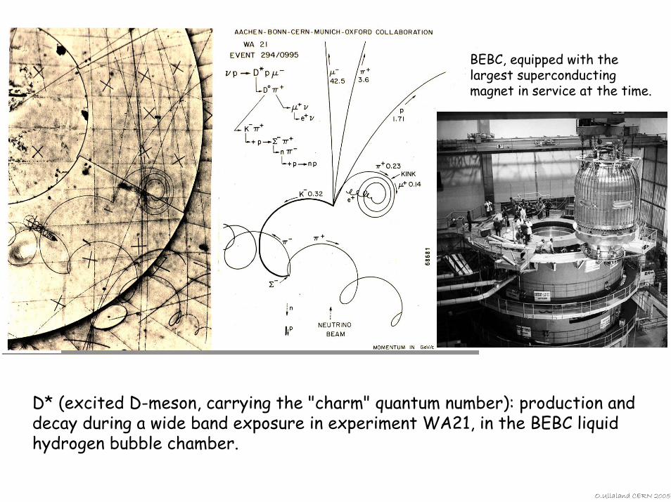
BEBC, equipped with the largest superconducting magnet in service at the time.
D* (excited D-meson, carrying the "charm" quantum number): production and decay during a wide band exposure in experiment WA21, in the BEBC liquid hydrogen bubble chamber.
O.Ullaland CERN 2005
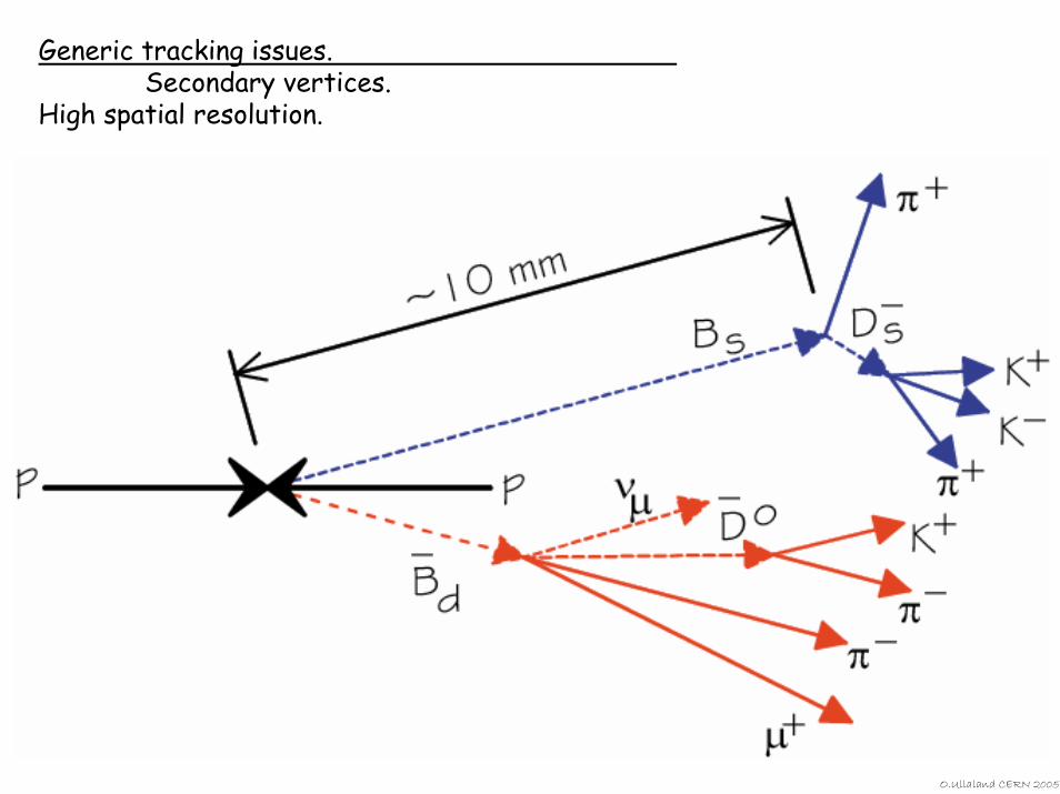
Generic tracking issues.Secondary vertices.
High spatial resolution.
O.Ullaland CERN 2005
2005 Summer Student LecturesDetectors
Solid State DetectorsScintillators
andPhoton Detectors
O.Ullaland CERN 2005
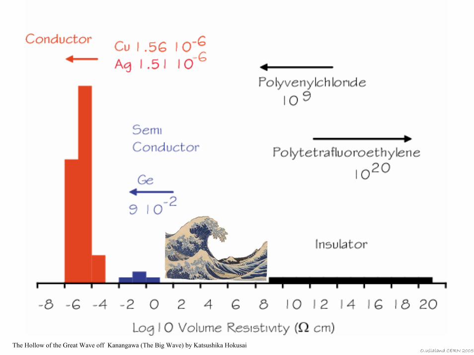
The Hollow of the Great Wave off Kanangawa (The Big Wave) by Katsushika Hokusai O.Ullaland CERN 2005
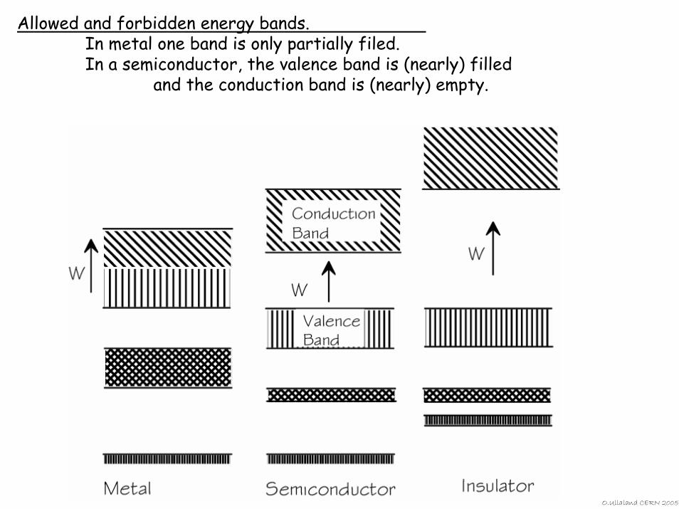
Allowed and forbidden energy bands.In metal one band is only partially filed.In a semiconductor, the valence band is (nearly) filled
and the conduction band is (nearly) empty.
O.Ullaland CERN 2005
O.Ullaland CERN 2005
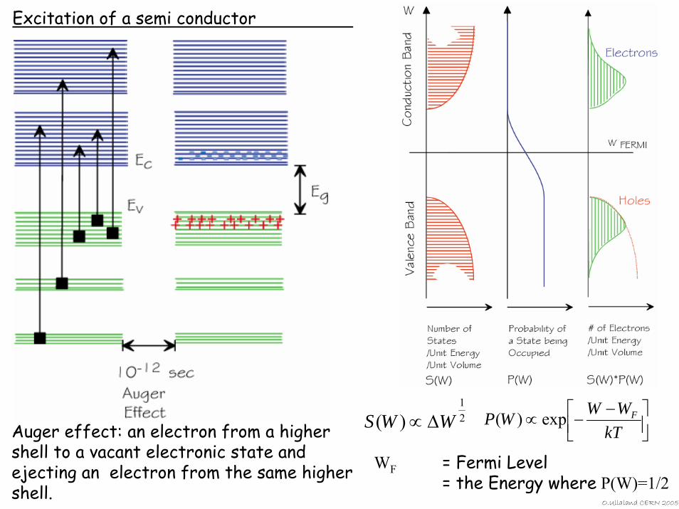
Auger effect: an electron from a higher shell to a vacant electronic state and ejecting an electron from the same higher shell.
21
)( WWS ∆∝ ⎥⎦⎤
⎢⎣⎡ −−∝
kTWWWP Fexp)(
Excitation of a semi conductor
WF = Fermi Level = the Energy where P(W)=1/2
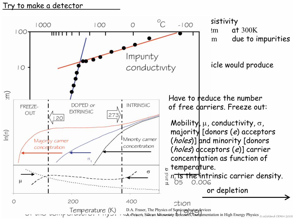
Try to make a detector
O.Ullaland CERN 2005
volume resistivityGe ≤ 0.49 Ωm at 300KSi some 100 Ωm due to impurities
∼4−5 108 free carriers A minimum ionizing particle would produce ∼3−4 104 e-h pairs
Take a Sicrystal of 10×10×0.3 mm3
Mobility, µ, conductivity, σ, majority [donors (e) acceptors (holes)] and minority [donors (holes) acceptors (e)] carrier concentration as function of temperature. ni is the intrinsic carrier density.
D.A. Fraser, The Physics of Semiconductor devicesA. Peisert, Silicon Microstrip Detectors, Instrumentation in High Energy Physics
or depletion
Have to reduce the number of free carriers. Freeze out:
O.Ullaland CERN 2005
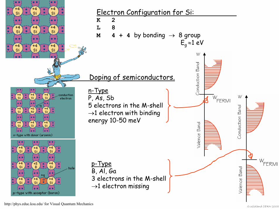
Electron Configuration for Si:K 2L 8M 4 + 4 by bonding → 8 group
Eg ≈1 eV
http://phys.educ.ksu.edu/ for Visual Quantum Mechanics
n-TypeP, As, Sb5 electrons in the M-shell→1 electron with binding energy 10-50 meV
p-TypeB, Al, Ga3 electrons in the M-shell→1 electron missing
Doping of semiconductors.
O.Ullaland CERN 2005
p n
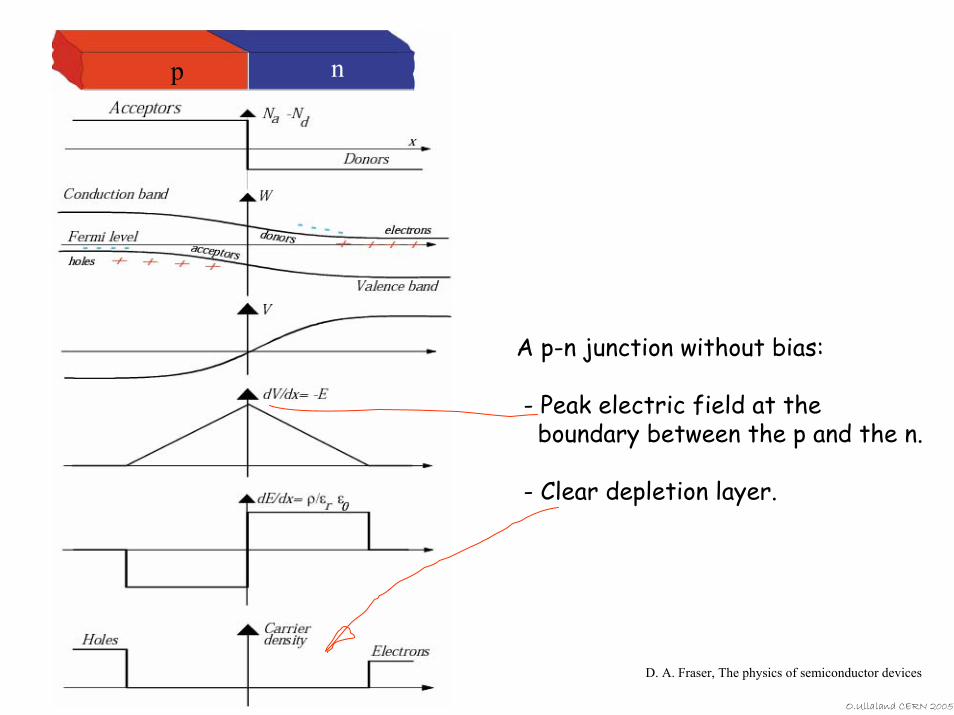
A p-n junction without bias:
- Peak electric field at the boundary between the p and the n.
- Clear depletion layer.
D. A. Fraser, The physics of semiconductor devices
O.Ullaland CERN 2005
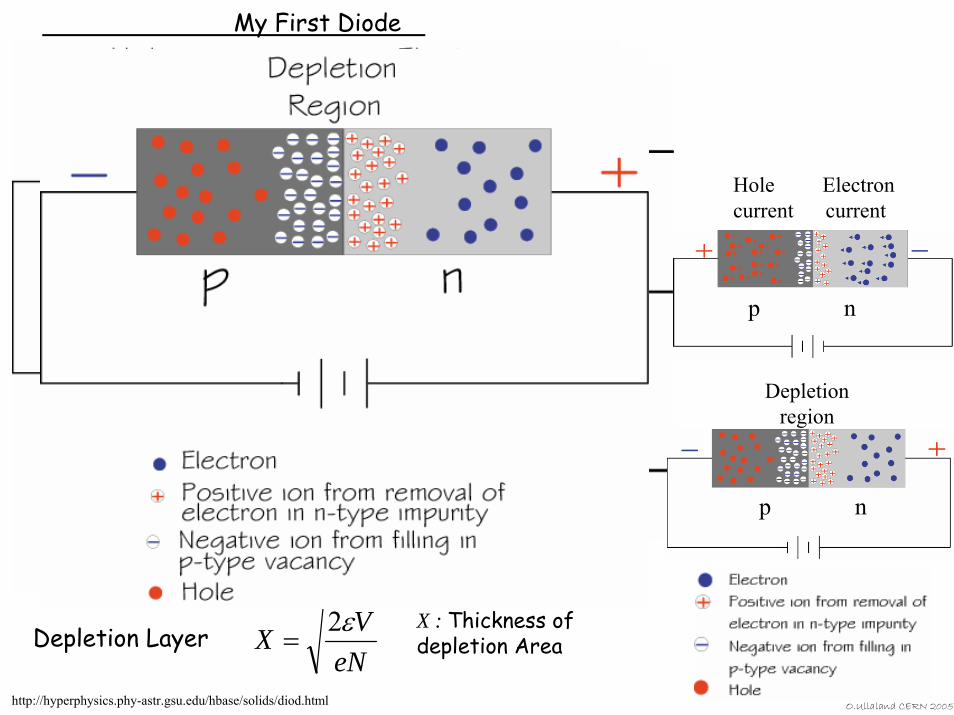
eNVX
VC XA
ε
ε
2
)(
=
=Capacitance
Depletion Layer
N : #DonorsX : Thickness of depletion Area
Equilibrium
ForwardBiasX↓ i↑
ReverseBiasX↑ i ↓
p doped n doped
p n
Hole Electroncurrent current
p n
Depletionregion
My First Diode
http://hyperphysics.phy-astr.gsu.edu/hbase/solids/diod.html
O.Ullaland CERN 2005
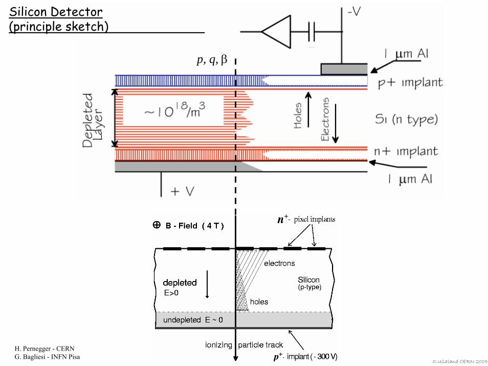
Silicon Detector (principle sketch)
H. Pernegger - CERNG. Bagliesi - INFN Pisa
p, q, β
O.Ullaland CERN 2005
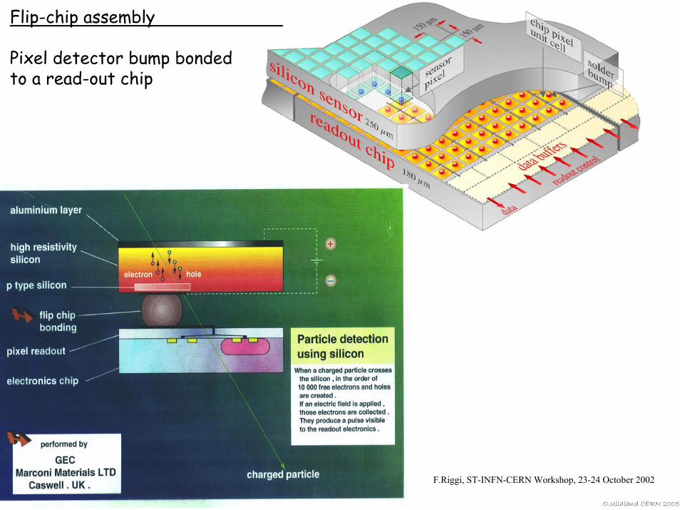
Flip-chip assembly
Pixel detector bump bonded to a read-out chip
F.Riggi, ST-INFN-CERN Workshop, 23-24 October 2002
O.Ullaland CERN 2005
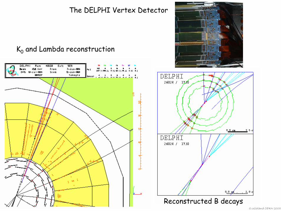
The DELPHI Vertex Detector
K0 and Lambda reconstruction
Reconstructed B decays
O.Ullaland CERN 2005
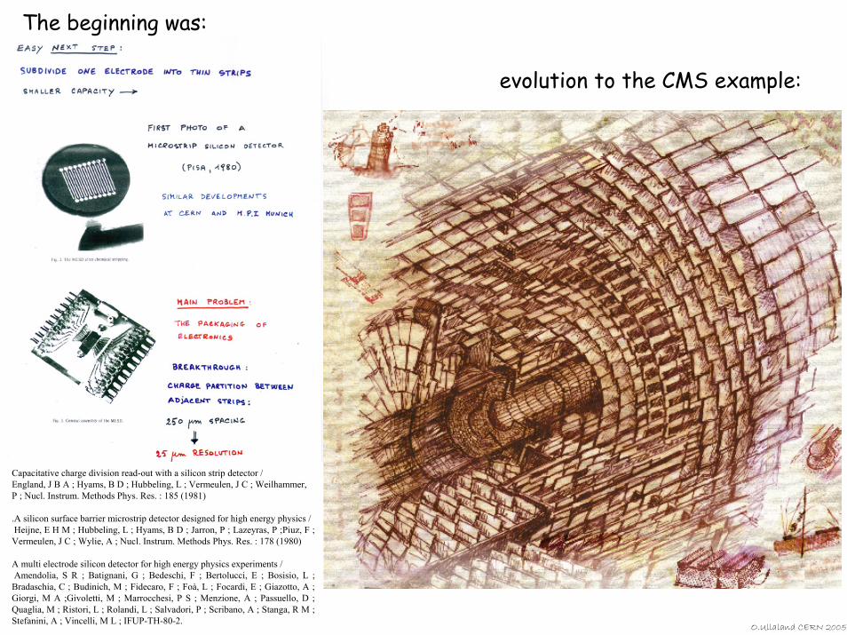
Capacitative charge division read-out with a silicon strip detector / England, J B A ; Hyams, B D ; Hubbeling, L ; Vermeulen, J C ; Weilhammer, P ; Nucl. Instrum. Methods Phys. Res. : 185 (1981)
.A silicon surface barrier microstrip detector designed for high energy physics /Heijne, E H M ; Hubbeling, L ; Hyams, B D ; Jarron, P ; Lazeyras, P ;Piuz, F ; Vermeulen, J C ; Wylie, A ; Nucl. Instrum. Methods Phys. Res. : 178 (1980)
A multi electrode silicon detector for high energy physics experiments / Amendolia, S R ; Batignani, G ; Bedeschi, F ; Bertolucci, E ; Bosisio, L ; Bradaschia, C ; Budinich, M ; Fidecaro, F ; Foà, L ; Focardi, E ; Giazotto, A ; Giorgi, M A ;Givoletti, M ; Marrocchesi, P S ; Menzione, A ; Passuello, D ; Quaglia, M ; Ristori, L ; Rolandi, L ; Salvadori, P ; Scribano, A ; Stanga, R M ; Stefanini, A ; Vincelli, M L ; IFUP-TH-80-2.
The beginning was:
evolution to the CMS example:
O.Ullaland CERN 2005
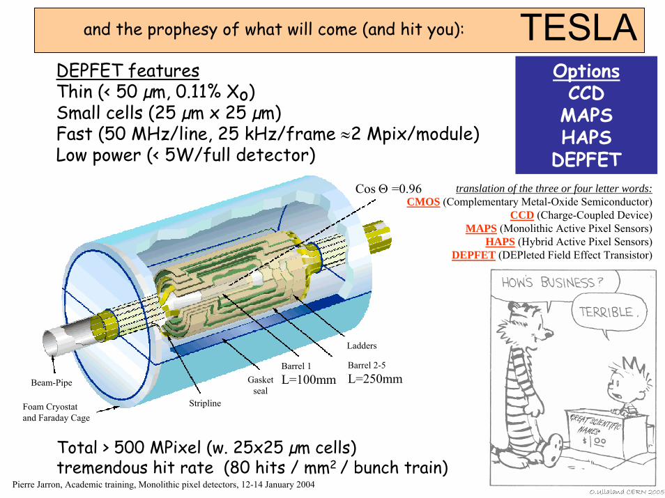
TESLA
Total > 500 MPixel (w. 25x25 µm cells)tremendous hit rate (80 hits / mm2 / bunch train)
OptionsCCD
MAPSHAPS
DEPFET
DEPFET featuresThin (< 50 µm, 0.11% Xo)Small cells (25 µm x 25 µm)Fast (50 MHz/line, 25 kHz/frame ≈2 Mpix/module)Low power (< 5W/full detector)
Pierre Jarron, Academic training, Monolithic pixel detectors, 12-14 January 2004
and the prophesy of what will come (and hit you):
Stripline
Gasketseal
Barrel 1L=100mm
Barrel 2-5L=250mm
Ladders
Beam-Pipe
Foam Cryostatand Faraday Cage
Cos Θ =0.96 translation of the three or four letter words:CMOS (Complementary Metal-Oxide Semiconductor)
CCD (Charge-Coupled Device)MAPS (Monolithic Active Pixel Sensors)
HAPS (Hybrid Active Pixel Sensors)DEPFET (DEPleted Field Effect Transistor)
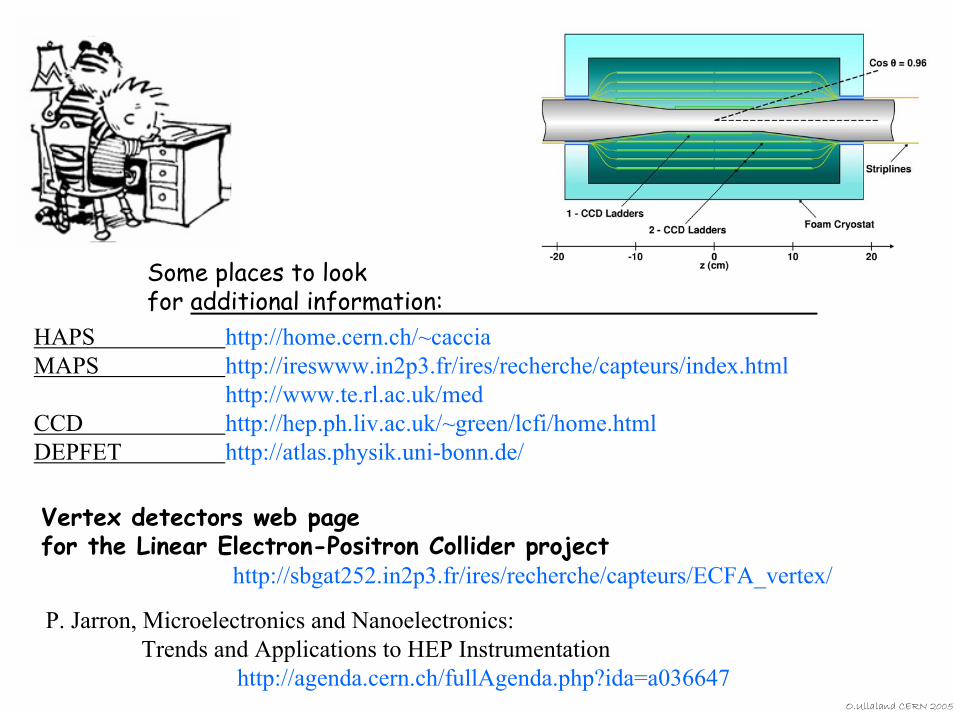
Some places to look for additional information:
HAPS http://home.cern.ch/~cacciaMAPS http://ireswww.in2p3.fr/ires/recherche/capteurs/index.html
http://www.te.rl.ac.uk/medCCD http://hep.ph.liv.ac.uk/~green/lcfi/home.htmlDEPFET http://atlas.physik.uni-bonn.de/
Vertex detectors web page for the Linear Electron-Positron Collider project
http://sbgat252.in2p3.fr/ires/recherche/capteurs/ECFA_vertex/
P. Jarron, Microelectronics and Nanoelectronics: Trends and Applications to HEP Instrumentation
http://agenda.cern.ch/fullAgenda.php?ida=a036647O.Ullaland CERN 2005

O.Ullaland CERN 2005
Scintillation
Light Collection
and
Photon Detection
http://www.bicron.com.
O.Ullaland CERN 2005
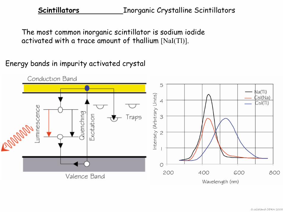
Scintillators Inorganic Crystalline Scintillators
The most common inorganic scintillator is sodium iodide activated with a trace amount of thallium [NaI(Tl)].
Energy bands in impurity activated crystal
O.Ullaland CERN 2005
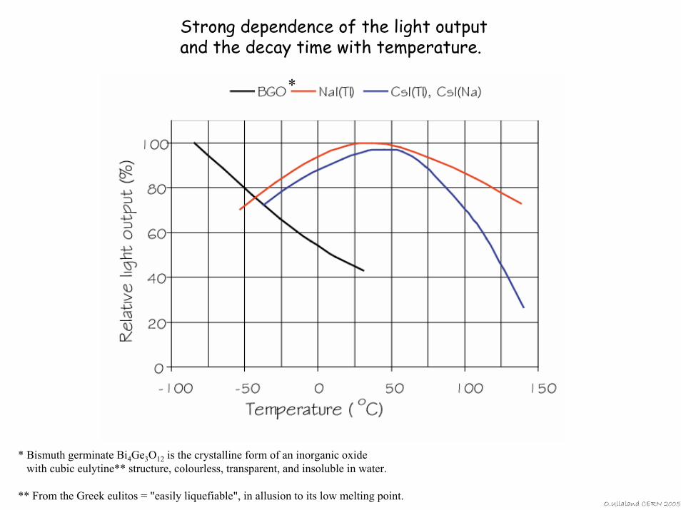
Strong dependence of the light output and the decay time with temperature.
*
* Bismuth germinate Bi4Ge3O12 is the crystalline form of an inorganic oxide with cubic eulytine** structure, colourless, transparent, and insoluble in water.
** From the Greek eulitos = "easily liquefiable", in allusion to its low melting point. O.Ullaland CERN 2005
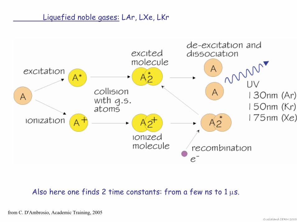
Liquefied noble gases: LAr, LXe, LKr
Also here one finds 2 time constants: from a few ns to 1 µs.
from C. D'Ambrosio, Academic Training, 2005O.Ullaland CERN 2005
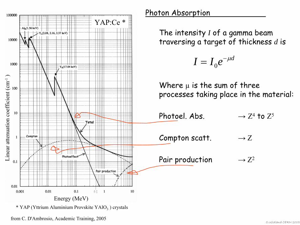
The intensity I of a gamma beam traversing a target of thickness d is
Where µ is the sum of three processes taking place in the material:
Photoel. Abs. → Z4 to Z5
Compton scatt. → Z
Pair production → Z2
deII µ−= 0
Photon AbsorptionYAP:Ce *
* YAP (Yttrium Aluminium Provskite YAlO3 ) crystals
Line
ar a
ttenu
atio
n co
effic
ient
(cm
-1)
Energy (MeV)
from C. D'Ambrosio, Academic Training, 2005O.Ullaland CERN 2005
Scintillatorcomposition
Density(g/cm3)
Index ofrefraction
Wavelengthof max.Em.
(nm)
Decay timeConstant
(µs)
ScintiPulse
height1)Notes
NaI(Tl) 3.67 1.9 410 0.25 100 2)
CsI 4.51 1.8 310 0.01 6 3)
CsI(Tl) 4.51 1.8 565 1.0 45 3)
CaF2(Eu) 3.19 1.4 435 0.9 50
BaF2 4.88 1.5 190/220310
0,00060.63
515
BGO 7.13 2.2 480 0.30 10
CdW04 7.90 2.3 540 5.0 40
PbWO4 8.28 2.1 440 0.020 0.1
CeF3 6.16 1.7 300340
0.0050.020 5
GSO 6.71 1.9 430 0.060 40
LSO 7 1.8 420 0.040 75
YAP 5.50 1.9 370 0.030 70
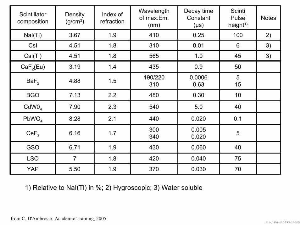
1) Relative to NaI(Tl) in %; 2) Hygroscopic; 3) Water soluble
from C. D'Ambrosio, Academic Training, 2005O.Ullaland CERN 2005
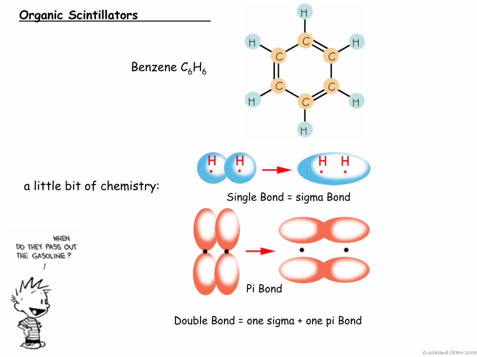
Organic Scintillators
Benzene C6H6
a little bit of chemistry:Single Bond = sigma Bond
Pi Bond
Double Bond = one sigma + one pi Bond
O.Ullaland CERN 2005
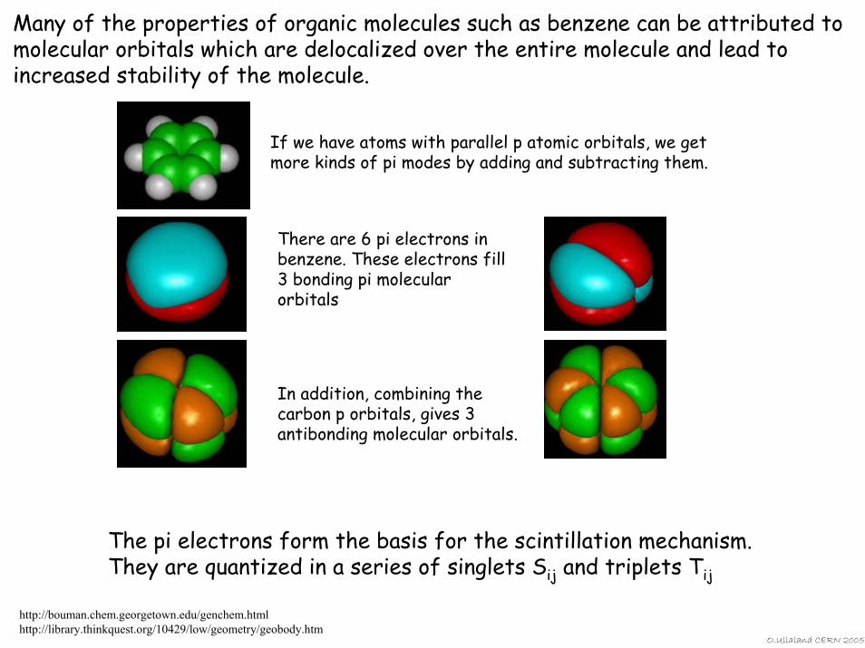
Many of the properties of organic molecules such as benzene can be attributed to molecular orbitals which are delocalized over the entire molecule and lead to increased stability of the molecule.
If we have atoms with parallel p atomic orbitals, we get more kinds of pi modes by adding and subtracting them.
There are 6 pi electrons in benzene. These electrons fill 3 bonding pi molecular orbitals
In addition, combining the carbon p orbitals, gives 3 antibonding molecular orbitals.
The pi electrons form the basis for the scintillation mechanism.They are quantized in a series of singlets Sij and triplets Tij
http://bouman.chem.georgetown.edu/genchem.htmlhttp://library.thinkquest.org/10429/low/geometry/geobody.htm
O.Ullaland CERN 2005
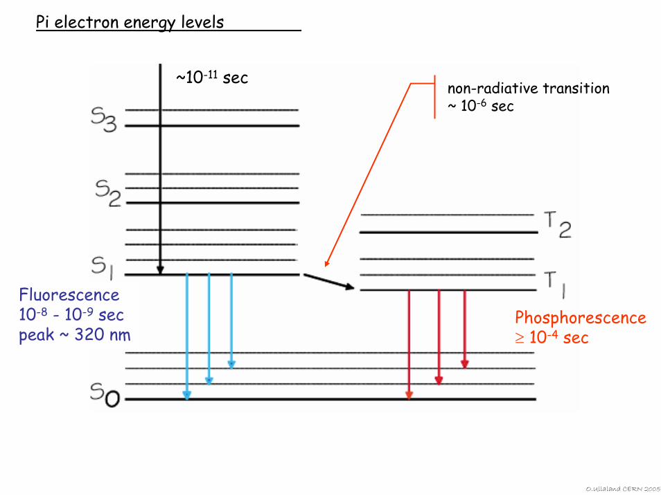
Pi electron energy levels
~10-11 sec
Fluorescence10-8 - 10-9 secpeak ~ 320 nm
Phosphorescence≥ 10-4 sec
non-radiative transition~ 10-6 sec
O.Ullaland CERN 2005
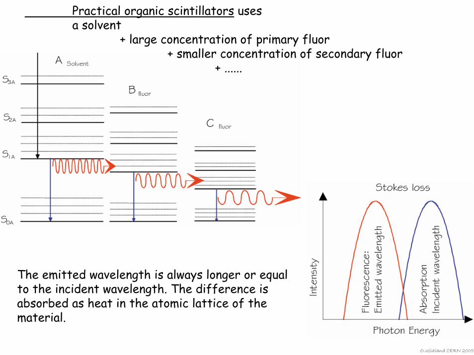
Practical organic scintillators uses a solvent
+ large concentration of primary fluor + smaller concentration of secondary fluor
+ ......
The emitted wavelength is always longer or equal to the incident wavelength. The difference is absorbed as heat in the atomic lattice of the material.
O.Ullaland CERN 2005
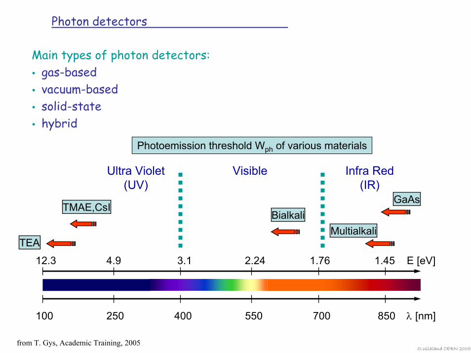
Photon detectors
Main types of photon detectors:gas-basedvacuum-basedsolid-statehybrid
Photoemission threshold Wph of various materials
100 250 400 550 700 850 λ [nm]
12.3 4.9 3.1 2.24 1.76 1.45 E [eV]
VisibleUltra Violet (UV)
MultialkaliBialkali
GaAs
TEA
TMAE,CsI
Infra Red(IR)
from T. Gys, Academic Training, 2005O.Ullaland CERN 2005
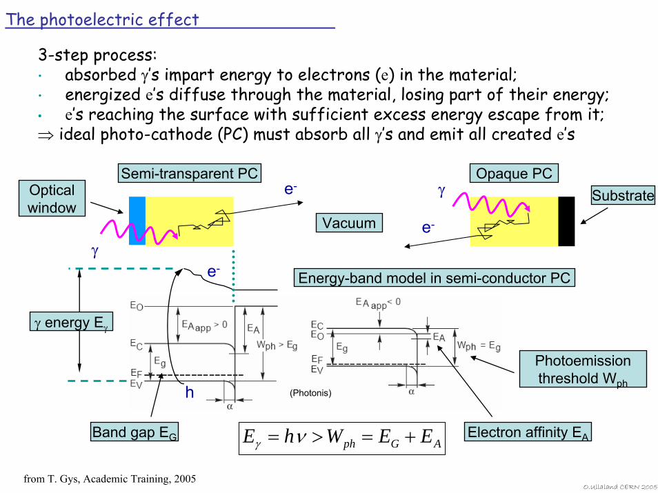
The photoelectric effect
3-step process:• absorbed γ’s impart energy to electrons (e) in the material;• energized e’s diffuse through the material, losing part of their energy;• e’s reaching the surface with sufficient excess energy escape from it;⇒ ideal photo-cathode (PC) must absorb all γ’s and emit all created e’s
(Photonis)
γ
γ
e-
Energy-band model in semi-conductor PC
Band gap EG AGph EEWhE +=>= νγElectron affinity EA
Photoemission threshold Wph
Opticalwindow
Semi-transparent PC
Vacuum
Opaque PCSubstratee-
γ energy Eγ
h
e-
from T. Gys, Academic Training, 2005O.Ullaland CERN 2005
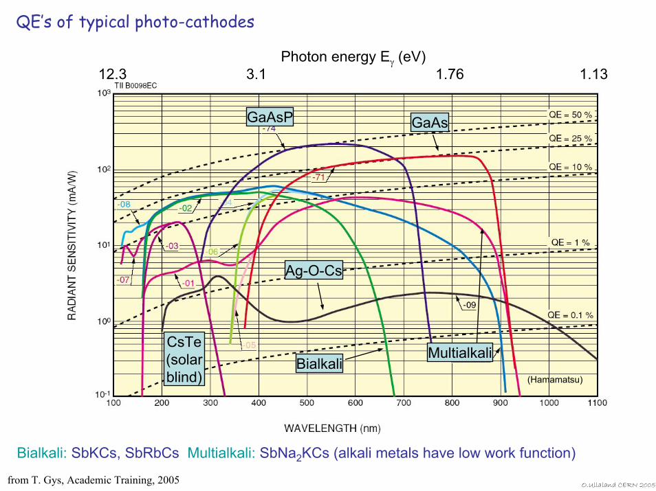
QE’s of typical photo-cathodes
(Hamamatsu)
GaAsP GaAs
CsTe(solar blind)
MultialkaliBialkali
Ag-O-Cs
Photon energy Eγ (eV)12.3 3.1 1.76 1.13
Bialkali: SbKCs, SbRbCs Multialkali: SbNa2KCs (alkali metals have low work function)
from T. Gys, Academic Training, 2005 O.Ullaland CERN 2005
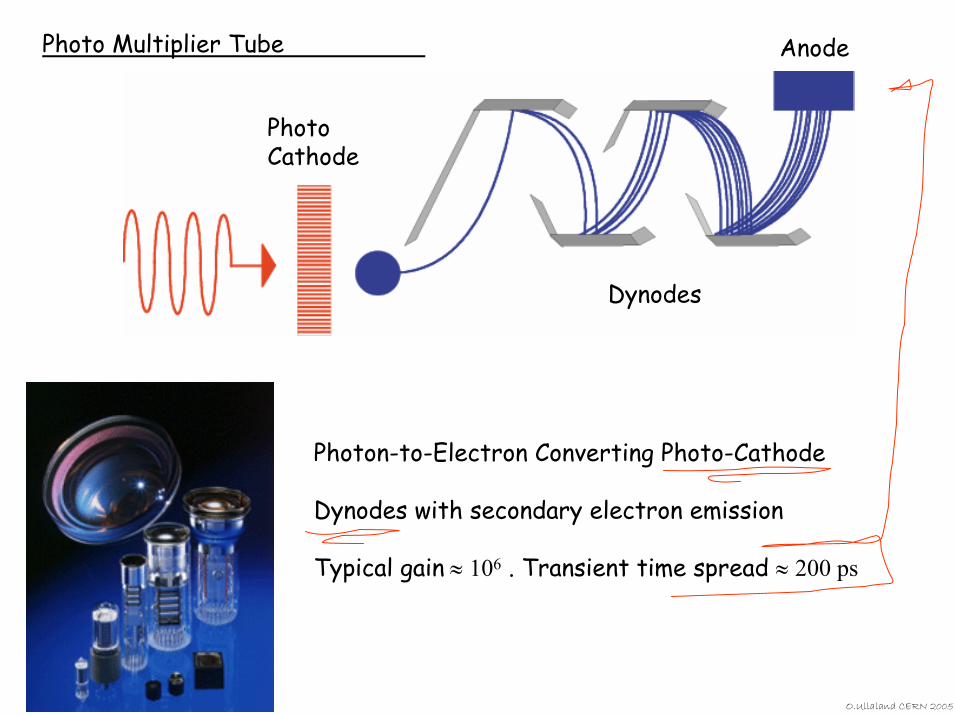
Photo Multiplier Tube Anode
O.Ullaland CERN 2005
Photon-to-Electron Converting Photo-Cathode
Dynodes with secondary electron emission
Typical gain ≈ 106 . Transient time spread ≈ 200 ps
PhotoCathode
Dynodes
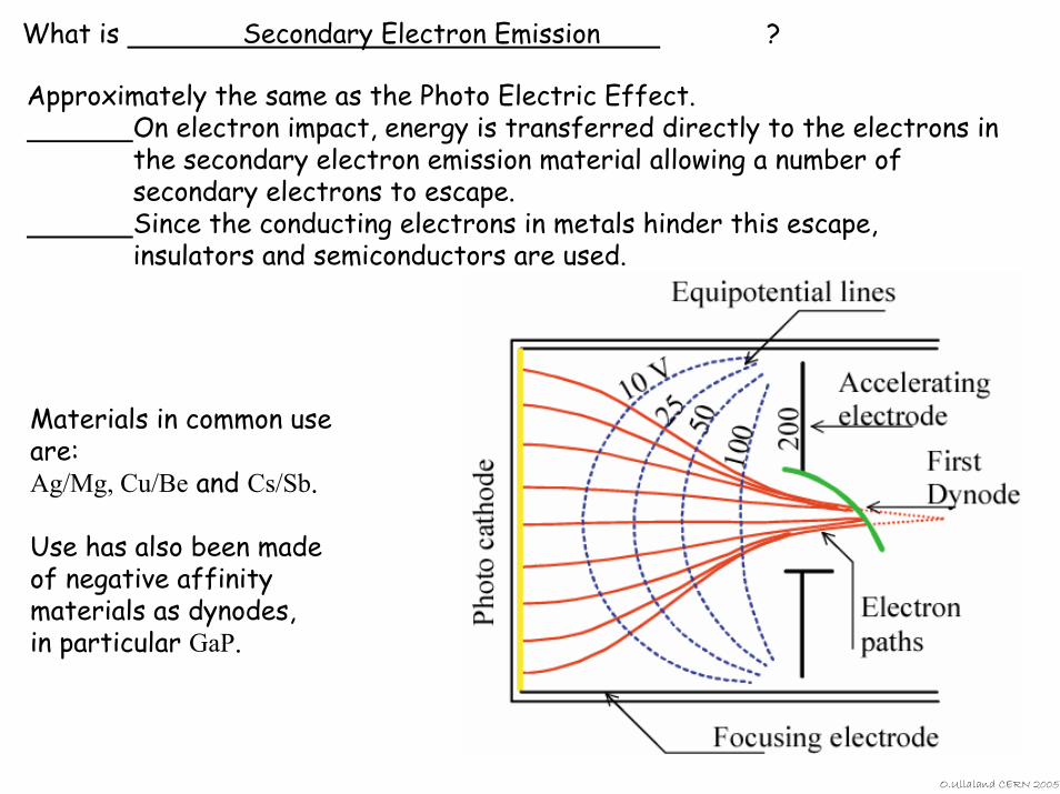
What is Secondary Electron Emission ?
Approximately the same as the Photo Electric Effect.On electron impact, energy is transferred directly to the electrons in the secondary electron emission material allowing a number of secondary electrons to escape. Since the conducting electrons in metals hinder this escape, insulators and semiconductors are used.
Materials in common use are:Ag/Mg, Cu/Be and Cs/Sb.
Use has also been made of negative affinity materials as dynodes, in particular GaP.
O.Ullaland CERN 2005
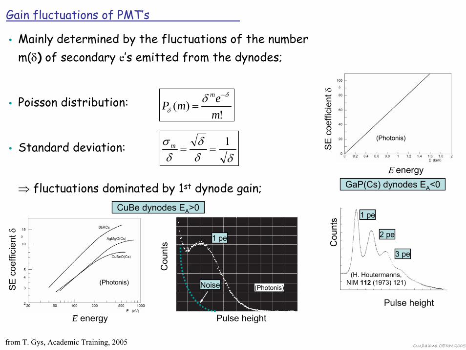
Gain fluctuations of PMT’s
Mainly determined by the fluctuations of the number m(δ) of secondary e’s emitted from the dynodes;
Poisson distribution:
Standard deviation:
⇒ fluctuations dominated by 1st dynode gain;
!)(
memP
m δ
δδ −
=
δδδ
δσ 1
==m
Pulse height
(H. Houtermanns, NIM 112 (1973) 121)
GaP(Cs) dynodes EA<0
SE
coe
ffici
ent δ
Ε energy
(Photonis)
1 pe
2 pe
3 pe
Cou
nts
(Photonis)
1 pe
Noise
CuBe dynodes EA>0
Pulse height
Cou
nts
SE
coe
ffici
ent δ
E energy
(Photonis)
from T. Gys, Academic Training, 2005 O.Ullaland CERN 2005
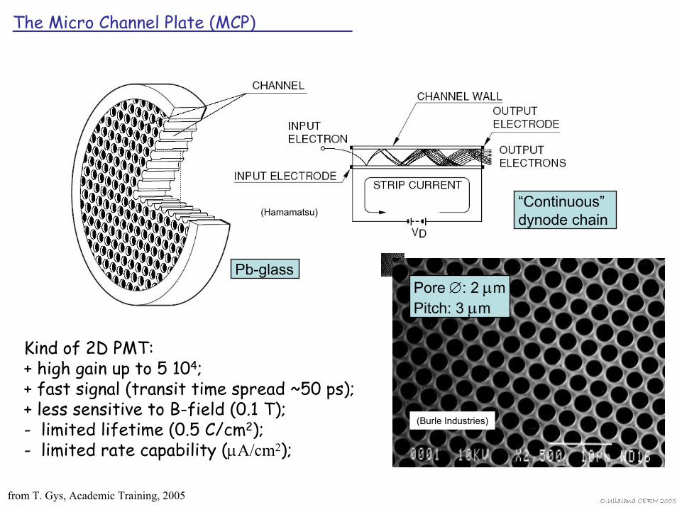
The Micro Channel Plate (MCP)
(Hamamatsu)“Continuous”dynode chain
Pb-glass
(Burle Industries)
Pore ∅: 2 µmPitch: 3 µm
Kind of 2D PMT:+ high gain up to 5 104;+ fast signal (transit time spread ~50 ps);+ less sensitive to B-field (0.1 T);- limited lifetime (0.5 C/cm2);- limited rate capability (µA/cm2);
from T. Gys, Academic Training, 2005 O.Ullaland CERN 2005
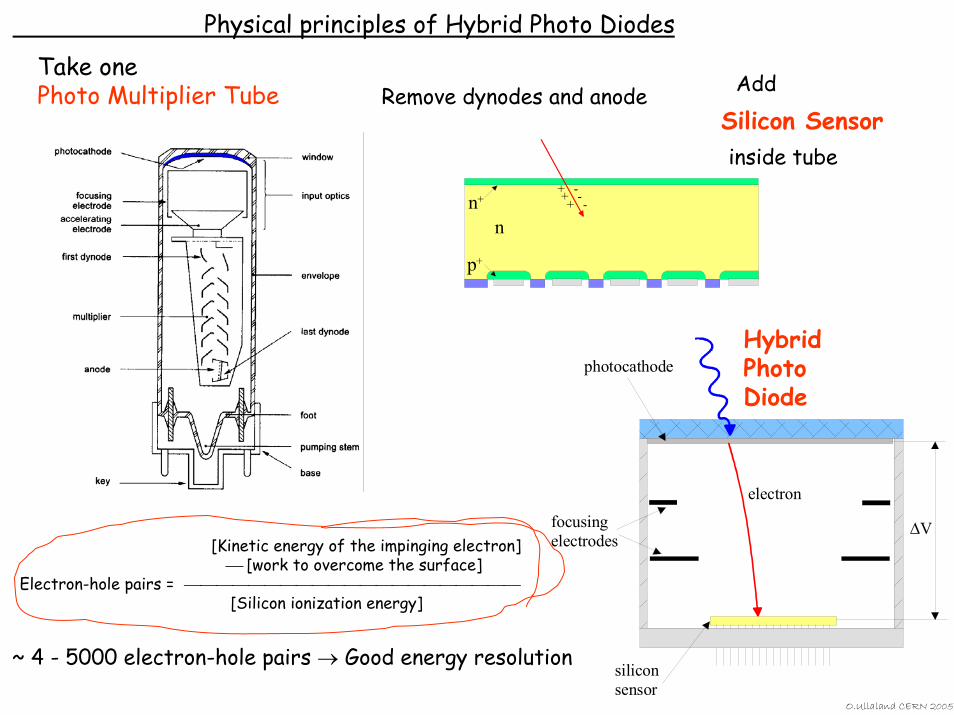
Physical principles of Hybrid Photo Diodes
Take onePhoto Multiplier Tube AddRemove dynodes and anode
Silicon Sensor
Hybrid Photo Diode
p+
n+
n
+ -+ -+ -
∆V
photocathode
focusing electrodes
siliconsensor
electron
inside tube
~ 4 - 5000 electron-hole pairs → Good energy resolution
[Kinetic energy of the impinging electron]⎯ [work to overcome the surface]
Electron-hole pairs = ⎯⎯⎯⎯⎯⎯⎯⎯⎯⎯⎯⎯⎯⎯⎯⎯⎯⎯⎯⎯⎯[Silicon ionization energy]
O.Ullaland CERN 2005
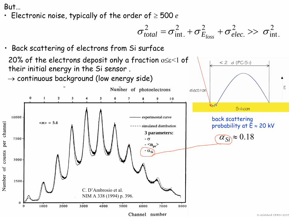
But…• Electronic noise, typically of the order of ≥ 500 e
2.int
2.
22.int
2 σσσσσ >>++= elecEtotal loss
O.Ullaland CERN 2005
• Back scattering of electrons from Si surface
18.0≈Siα
back scattering probability at E ≈ 20 kV
20% of the electrons deposit only a fraction o≤ε<1 of their initial energy in the Si sensor .→ continuous background (low energy side)
C. D’Ambrosio et al.NIM A 338 (1994) p. 396.
3 parameters:- σ- <npe>- αSi
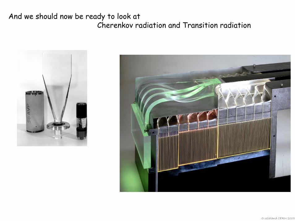
And we should now be ready to look at Cherenkov radiation and Transition radiation
O.Ullaland CERN 2005
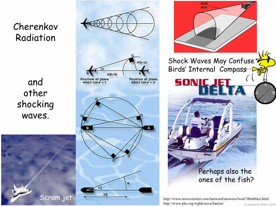
Scram jetO.Ullaland CERN 2005
Perhaps also the ones of the fish?
http://www.newscientist.com/lastword/answers/lwa674bubbles.htmlhttp://www.pbs.org/wgbh/nova/barrier/
Shock Waves May Confuse Birds’ Internal Compass
CherenkovRadiation
and other
shocking waves.
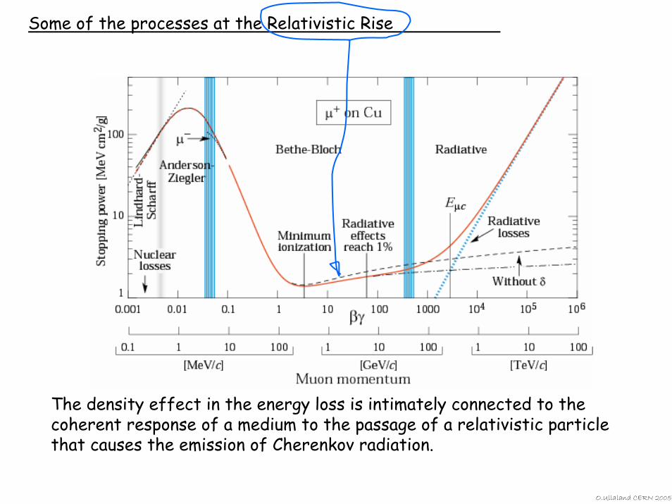
Some of the processes at the Relativistic Rise
The density effect in the energy loss is intimately connected to the coherent response of a medium to the passage of a relativistic particle that causes the emission of Cherenkov radiation.
O.Ullaland CERN 2005
β
m
n=n(λ)
q )(1cos λβ n∗=Θ
2
2
0sin
λλΘ
⋅⋅= lNddN
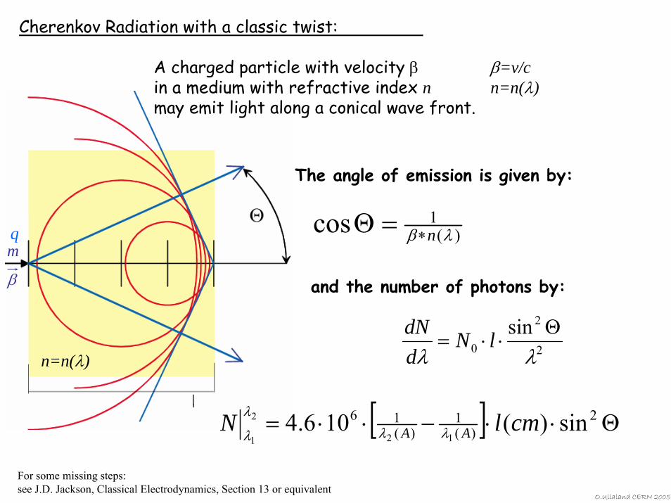
Cherenkov Radiation with a classic twist:
A charged particle with velocity β β=v/cin a medium with refractive index n n=n(λ)may emit light along a conical wave front.
The angle of emission is given by:
and the number of photons by:
[ ] Θ⋅⋅−⋅⋅= 2)(
1)(
16 sin)(106.412
2
1cmlN AA λλ
λ
λ
For some missing steps:see J.D. Jackson, Classical Electrodynamics, Section 13 or equivalent
O.Ullaland CERN 2005
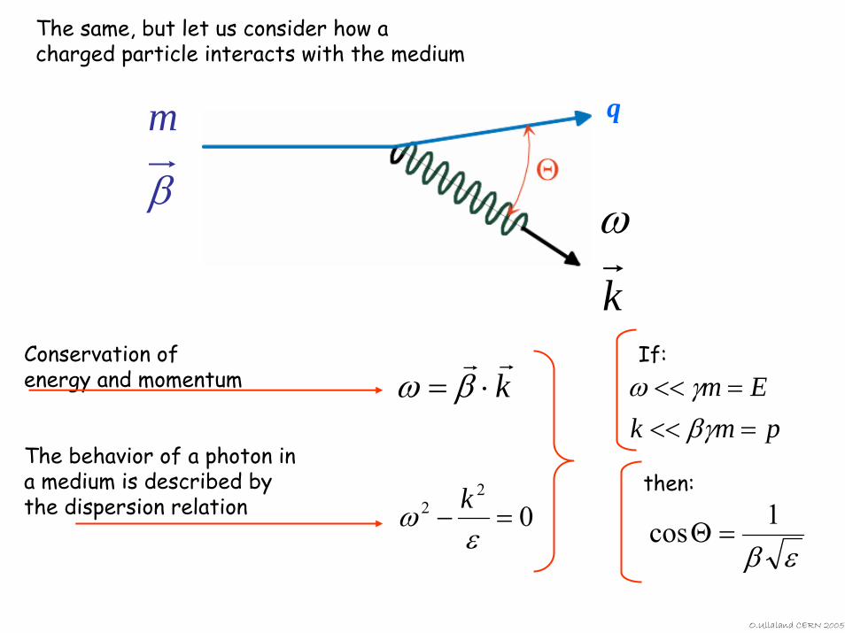
The same, but let us consider how a charged particle interacts with the medium
β
m
k
ω
q
εβ1cos =Θ
pmkEm
=<<=<<
βγγω
If:
then:
krr
⋅= βωConservation of energy and momentum
The behavior of a photon in a medium is described by the dispersion relation 0
22 =−
εω k
O.Ullaland CERN 2005
O.Ullaland CERN 2005
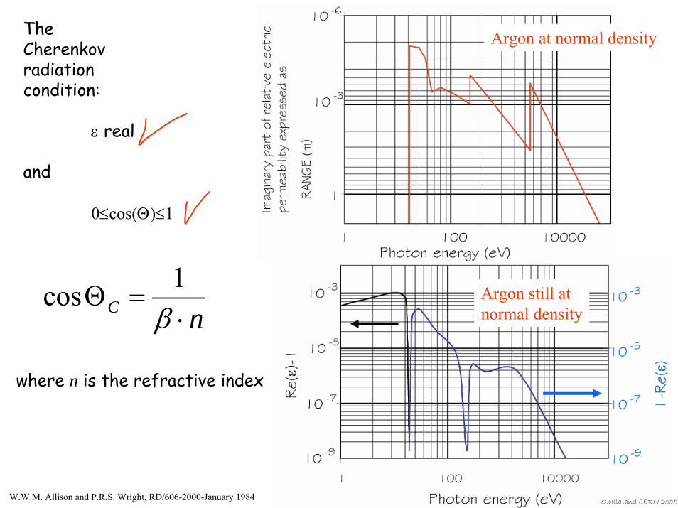
The Cherenkov radiation condition:
ε real
and
0≤cos(Θ)≤1
Argon at normal density
nC ⋅=Θ
β1cos Argon still at
normal density
where n is the refractive index
W.W.M. Allison and P.R.S. Wright, RD/606-2000-January 1984
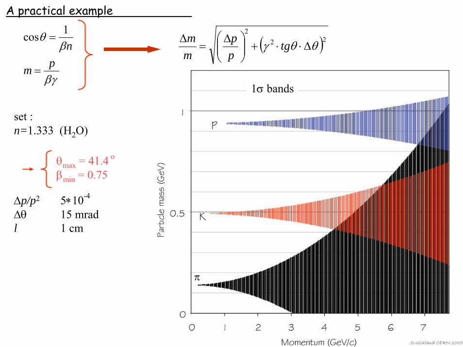
A practical example
O.Ullaland CERN 2005
set :n=1.333 (H2O)
∆p/p2 5∗10-4
∆θ 15 mradl 1 cm
θmax = 41.4 o
βmin = 0.75
( )222
θθγ ∆⋅⋅+⎟⎟⎠
⎞⎜⎜⎝
⎛ ∆=
∆ tgpp
mm
βγ
βθ
pm
n
=
=1cos
1σ bands
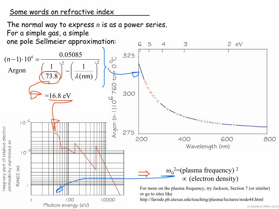
Some words on refractive index
O.Ullaland CERN 2005
226
)(1
8.731
05085.010)1(
⎟⎟⎠
⎞⎜⎜⎝
⎛−⎟
⎠⎞
⎜⎝⎛
=⋅−
nm
n
λ
The normal way to express n is as a power series.For a simple gas, a simpleone pole Sellmeier approximation:
=16.8 eV
ω02=(plasma frequency) 2
∝ (electron density)⇒For more on the plasma frequency, try Jackson, Section 7 (or similar)or go to sites likehttp://farside.ph.utexas.edu/teaching/plasma/lectures/node44.html
Argon
A gas Cherenkov counter as used to tag particles in the secondary beamsApr 1963 Photo number: CERN-IT-6304088
O.Ullaland CERN 2005
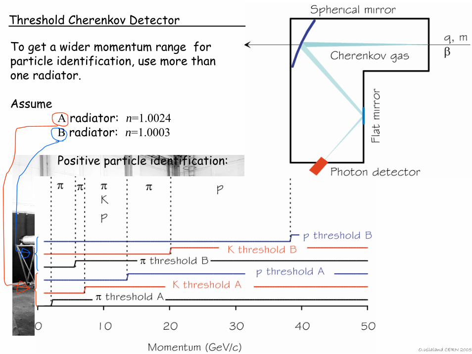
Threshold Cherenkov Detector
To get a wider momentum range for particle identification, use more than one radiator.
AssumeA radiator: n=1.0024B radiator: n=1.0003
Positive particle identification:
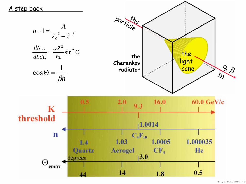
A step back
O.Ullaland CERN 2005
Θ= 22
sinc
ZdLdEdN ph
h
α
nβ1cos =Θ
220
1 −− −=−
λλAn
theCherenkov
radiator q, βm
theparticle
thelightcone
The photon detector
The mirror
q, β The ph
otons
Interactionpoint
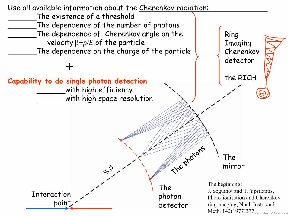
The beginning:J. Seguinot and T. Ypsilantis, Photo-ionisation and Cherenkov ring imaging, Nucl. Instr. and Meth. 142(1977)377 O.Ullaland CERN 2005
Use all available information about the Cherenkov radiation:The existence of a thresholdThe dependence of the number of photonsThe dependence of Cherenkov angle on the
velocity β=p/E of the particleThe dependence on the charge of the particle
+Capability to do single photon detection
with high efficiency with high space resolution
RingImagingCherenkovdetector
the RICH
O.Ullaland CERN 2005
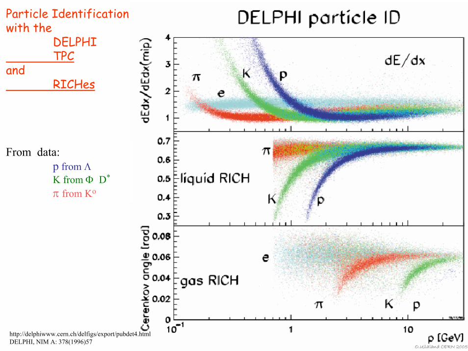
Particle Identification with the
DELPHI TPC
andRICHes
From data:p from Λ K from Φ D*
π from Ko
http://delphiwww.cern.ch/delfigs/export/pubdet4.htmlDELPHI, NIM A: 378(1996)57
More beautiful pictures (which has next to nothing to do with)
Cherenkov radiation
ABB.com
O.Ullaland CERN 2005
O.Ullaland CERN 2005
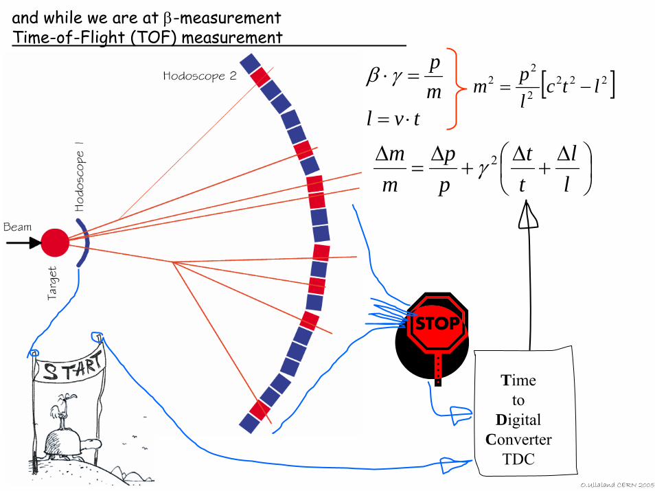
and while we are at β-measurementTime-of-Flight (TOF) measurement
⎟⎠⎞
⎜⎝⎛ ∆
+∆
+∆
=∆
ll
tt
pp
mm 2γ
[ ]2222
22 ltc
lpm −=
tvlmp
⋅=
=⋅γβ
Timeto
DigitalConverter
TDC
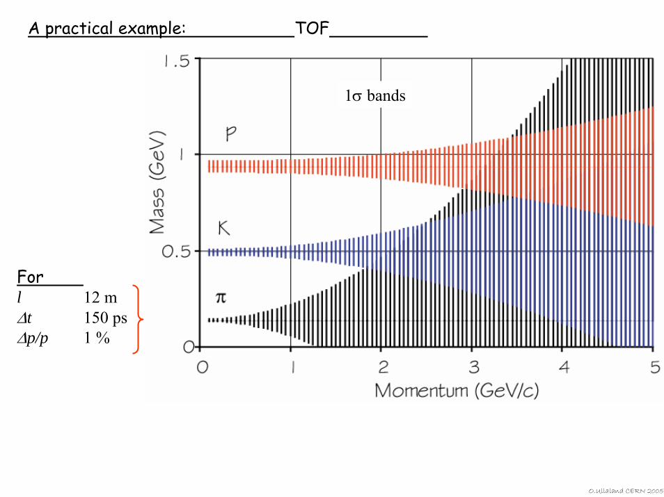
A practical example: TOF
1σ bands
Forl 12 m∆t 150 ps∆p/p 1 %
O.Ullaland CERN 2005
O.Ullaland CERN 2005
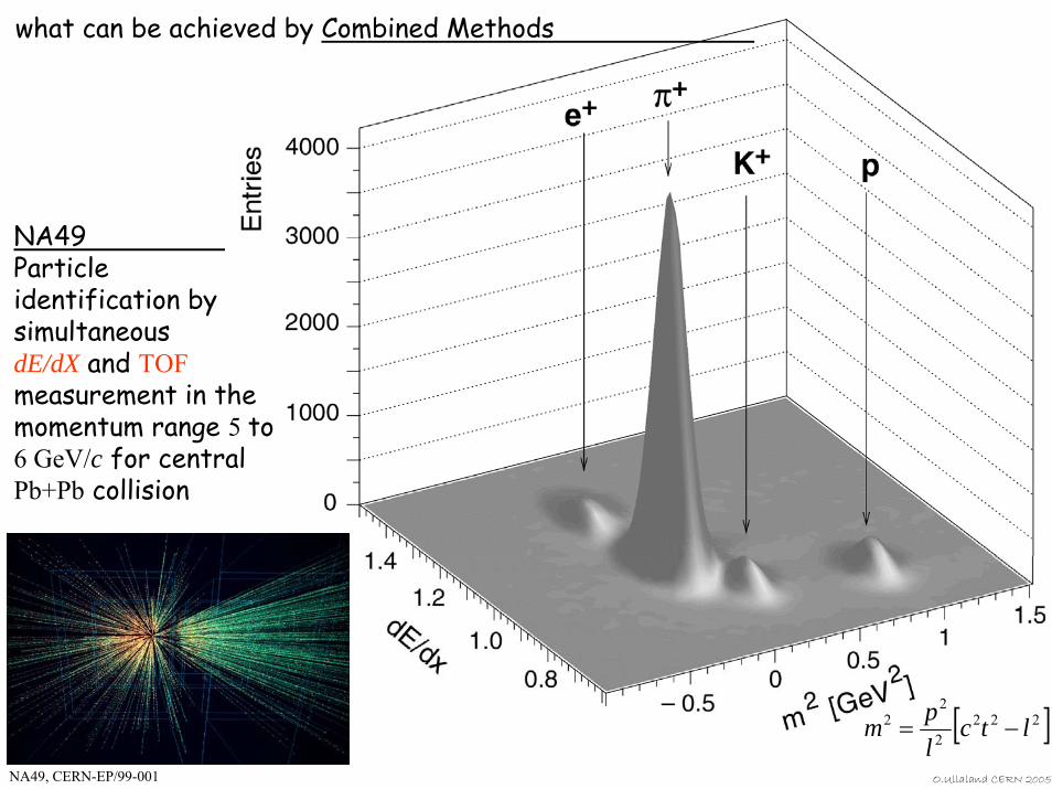
NA49Particle identification by simultaneous dE/dX and TOFmeasurement in the momentum range 5 to 6 GeV/c for central Pb+Pb collision
what can be achieved by Combined Methods
NA49, CERN-EP/99-001
[ ]2222
22 ltc
lpm −=
O.Ullaland CERN 2005
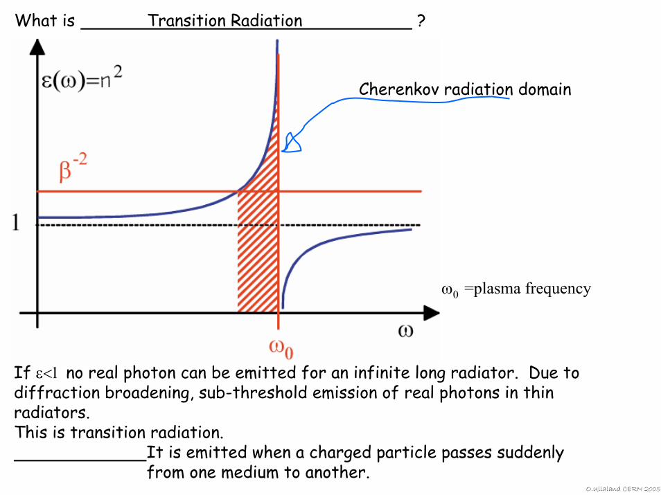
What is Transition Radiation ?
Cherenkov radiation domain
If ε<1 no real photon can be emitted for an infinite long radiator. Due to diffraction broadening, sub-threshold emission of real photons in thin radiators.This is transition radiation.
It is emitted when a charged particle passes suddenly from one medium to another.
ω0 =plasma frequency
O.Ullaland CERN 2005
O.Ullaland CERN 2005
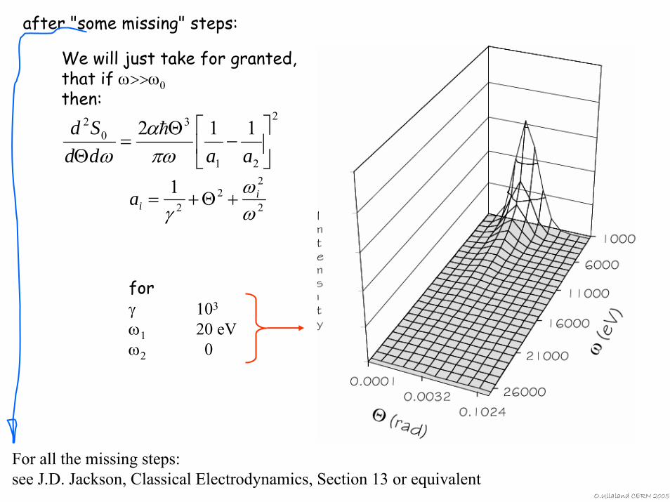
2
22
2
1ωω
γi
ia +Θ+=
We will just take for granted, that if ω>>ω0then:
2
21
30
2 112⎥⎦
⎤⎢⎣
⎡−
Θ=
Θ aaddSd
πωα
ωh
after "some missing" steps:
For all the missing steps:see J.D. Jackson, Classical Electrodynamics, Section 13 or equivalent
forγ 103
ω1 20 eVω2 0
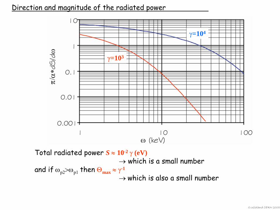
Direction and magnitude of the radiated power
Total radiated power S ≈ 10-2 γ (eV)→ which is a small number
and if ωp2>ωp1 then Θmax ≈ γ-1
→ which is also a small number
γ=103
γ=104
O.Ullaland CERN 2005
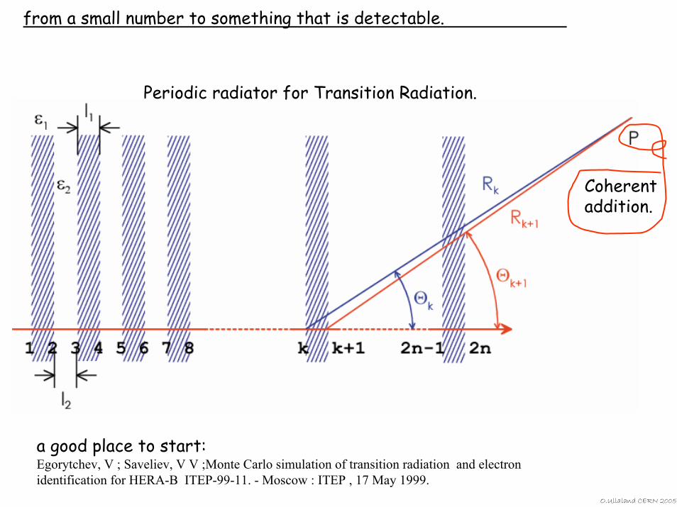
from a small number to something that is detectable.
Periodic radiator for Transition Radiation.
Coherent addition.
a good place to start:Egorytchev, V ; Saveliev, V V ;Monte Carlo simulation of transition radiation and electron identification for HERA-B ITEP-99-11. - Moscow : ITEP , 17 May 1999.
O.Ullaland CERN 2005
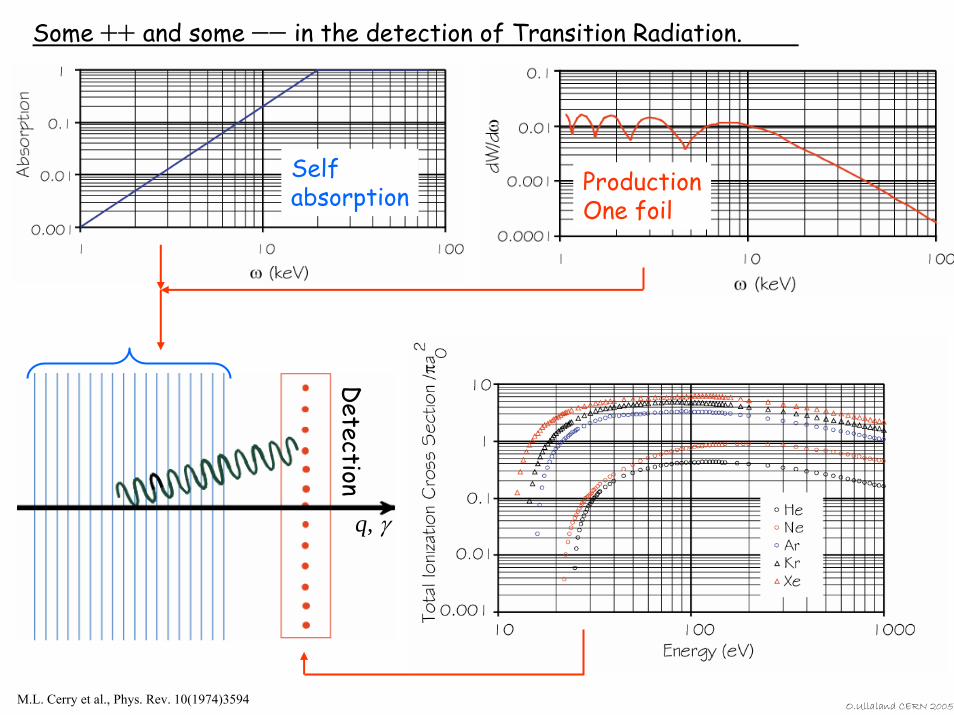
Some ++ and some −− in the detection of Transition Radiation.
O.Ullaland CERN 2005
ProductionOne foil
Selfabsorption
Detection
q, γ
M.L. Cerry et al., Phys. Rev. 10(1974)3594
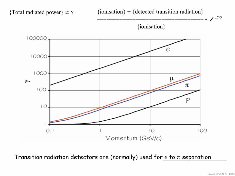
Total radiated power ∝ γ ionisation + detected transition radiation−−−−−−−−−−−−−−−−−−−−−−−−−−−−−−−−− ∼ Z -7/2
ionisation
Transition radiation detectors are (normally) used for e to π separation
O.Ullaland CERN 2005
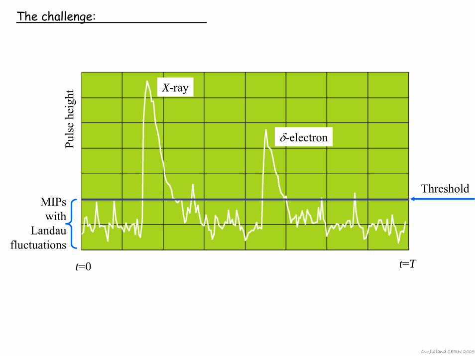
The challenge:
X-ray
δ-electron
Threshold
Puls
e he
ight
MIPswith
Landau fluctuations
t=0 t=T
O.Ullaland CERN 2005
O.Ullaland CERN 2005
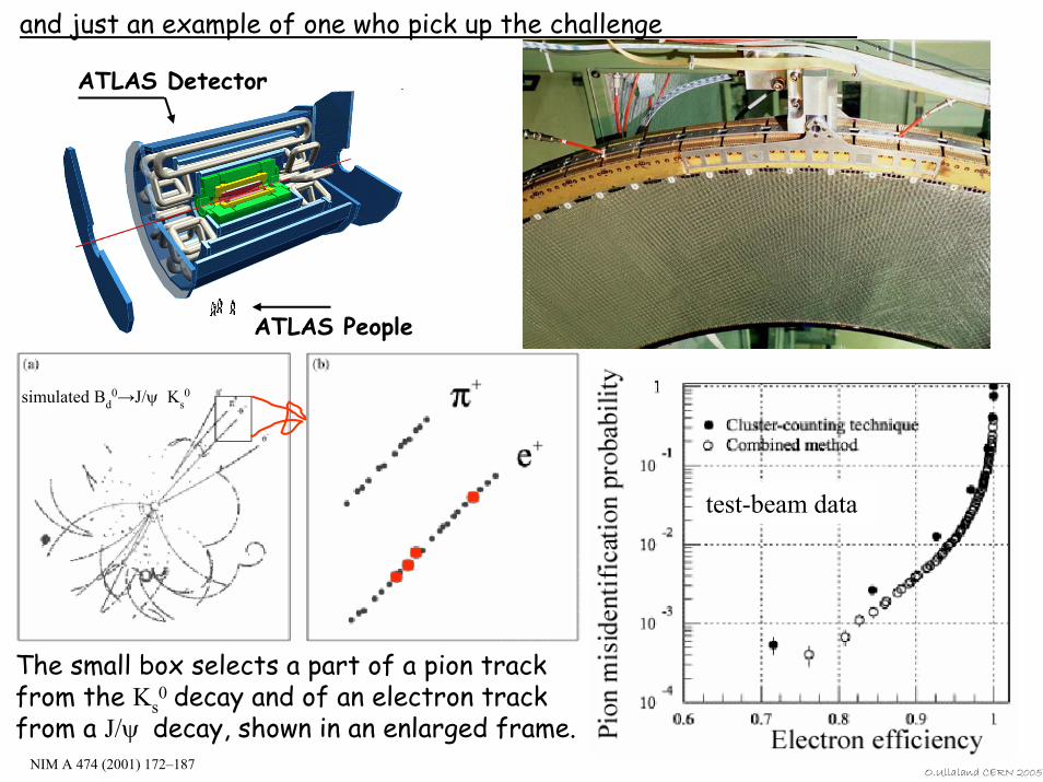
and just an example of one who pick up the challenge
ATLAS Detector
ATLAS People
The small box selects a part of a pion track from the Ks
0 decay and of an electron track from a J/ψ decay, shown in an enlarged frame.
simulated Bd0→J/ψ Ks
0
NIM A 474 (2001) 172–187
test-beam data
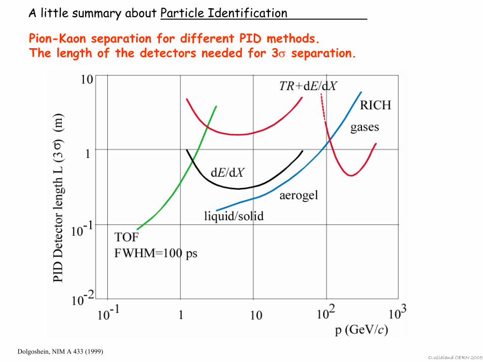
A little summary about Particle Identification
Pion-Kaon separation for different PID methods. The length of the detectors needed for 3σ separation.
Dolgoshein, NIM A 433 (1999)O.Ullaland CERN 2005
O.Ullaland CERN 2005
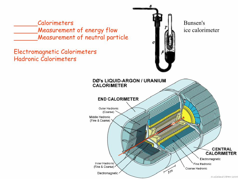
CalorimetersMeasurement of energy flowMeasurement of neutral particle
Electromagnetic CalorimetersHadronic Calorimeters
Bunsen's ice calorimeter
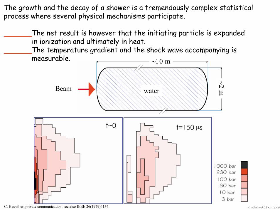
The growth and the decay of a shower is a tremendously complex statistical process where several physical mechanisms participate.
The net result is however that the initiating particle is expanded in ionization and ultimately in heat.The temperature gradient and the shock wave accompanying is measurable. ∼10 m
∼2mBeam water
C. Hauviller, private communication, see also IEEE 26(1979)4134 O.Ullaland CERN 2005
O.Ullaland CERN 2005
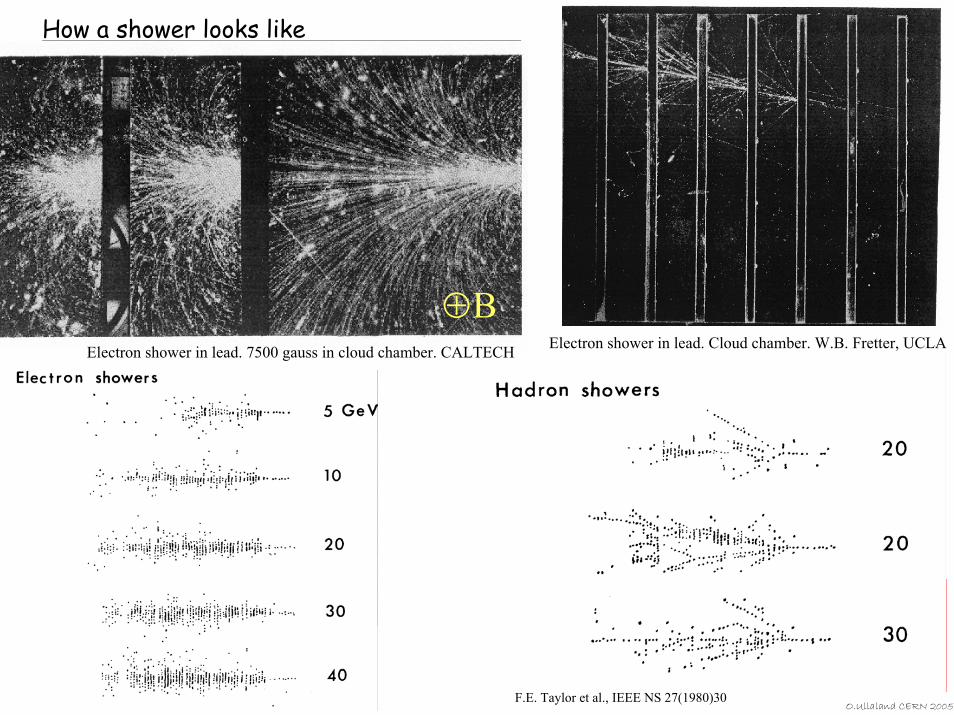
How a shower looks like
F.E. Taylor et al., IEEE NS 27(1980)30
⊕BElectron shower in lead. Cloud chamber. W.B. Fretter, UCLAElectron shower in lead. 7500 gauss in cloud chamber. CALTECH

We will only look at some (very) basic processes.
For (more) interested people, look in:J.P. Wellisch, Physics of shower simulation at LHC, at the example of GEANT4.
http://agenda.cern.ch/fullAgenda.php?ida=a036558#2004-03-01
and then tryRichard Wigmans, Calorimetry, Energy Measurement in Particle Physics
What makes a signalWhat reactsWhat defines the shower topologiesWhat processes are happeningWhat defines the electromagnetic content in
a hadronic showerWhat is invisible energyHow different are different calorimeters
and so on and so on ........
Some questions to be asked:
We will start off with the electromagnetic shower.
O.Ullaland CERN 2005
O.Ullaland CERN 2005
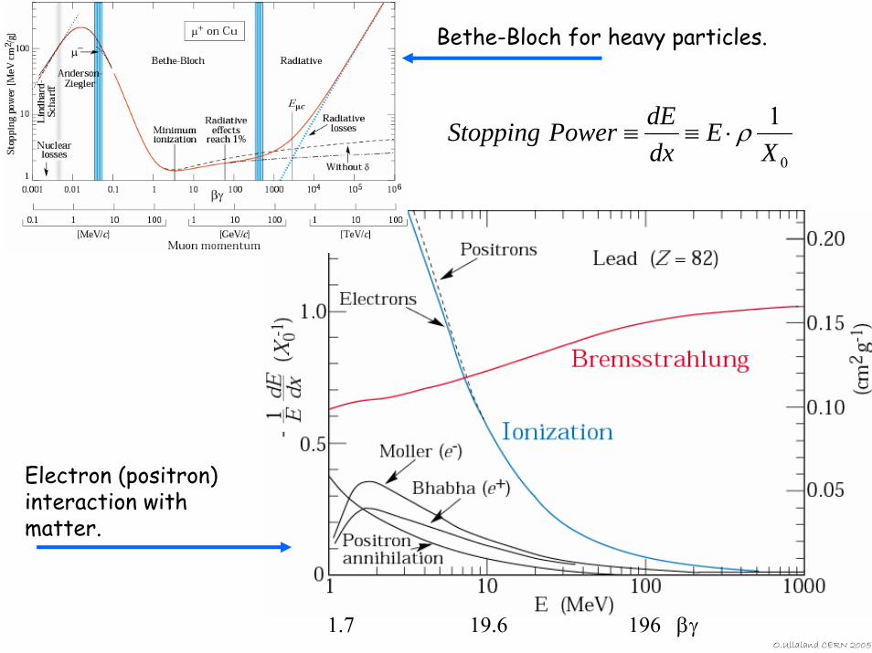
Bethe-Bloch for heavy particles.
0
1X
EdxdEPowerStopping ρ⋅≡≡
1.7 19.6 196 βγ
Electron (positron) interaction with matter.
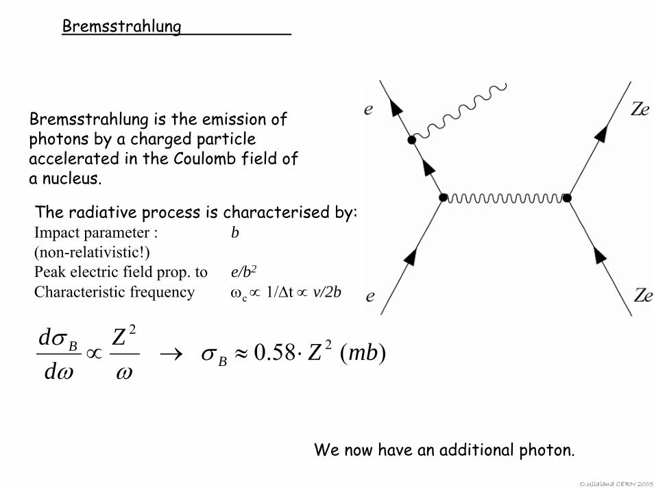
Bremsstrahlung
Bremsstrahlung is the emission of photons by a charged particle accelerated in the Coulomb field of a nucleus.
The radiative process is characterised by:Impact parameter : b(non-relativistic!)Peak electric field prop. to e/b2
Characteristic frequency ωc ∝ 1/∆t ∝ v/2b
)(58.0 22
mbZZdd
BB ⋅≈→∝ σ
ωωσ
We now have an additional photon.
O.Ullaland CERN 2005
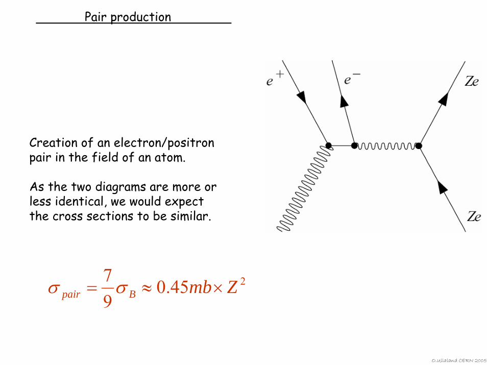
Pair production
Creation of an electron/positron pair in the field of an atom.
As the two diagrams are more or less identical, we would expect the cross sections to be similar.
245.097 ZmbBpair ×≈= σσ
O.Ullaland CERN 2005
O.Ullaland CERN 2005
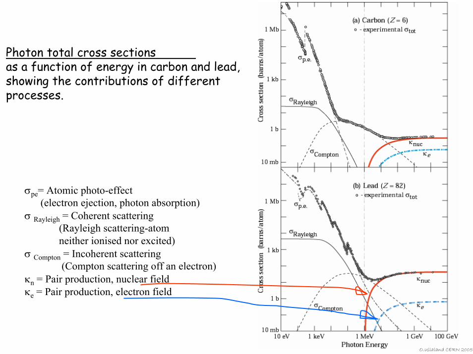
σpe= Atomic photo-effect (electron ejection, photon absorption)
σ Rayleigh = Coherent scattering (Rayleigh scattering-atomneither ionised nor excited)
σ Compton = Incoherent scattering (Compton scattering off an electron)
κn = Pair production, nuclear fieldκe = Pair production, electron field
Photon total cross sectionsas a function of energy in carbon and lead, showing the contributions of different processes.
O.Ullaland CERN 2005
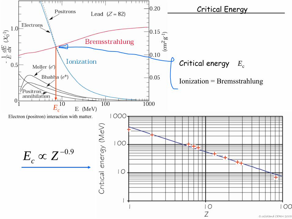
Critical Energy
Critical energy Ec
Ionization = Bremsstrahlung
9.0−∝ ZEc
EcElectron (positron) interaction with matter.
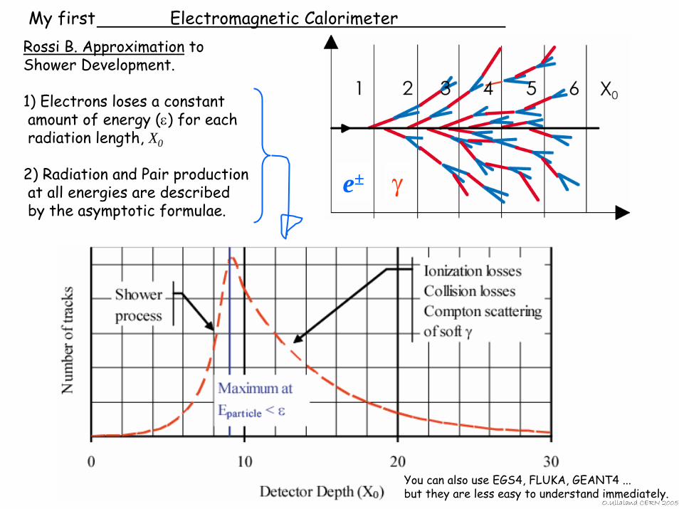
My first Electromagnetic CalorimeterRossi B. Approximation to Shower Development.
1) Electrons loses a constant amount of energy (ε) for each radiation length, X0
2) Radiation and Pair production at all energies are described by the asymptotic formulae.
O.Ullaland CERN 2005
e± γ
You can also use EGS4, FLUKA, GEANT4 ... but they are less easy to understand immediately.
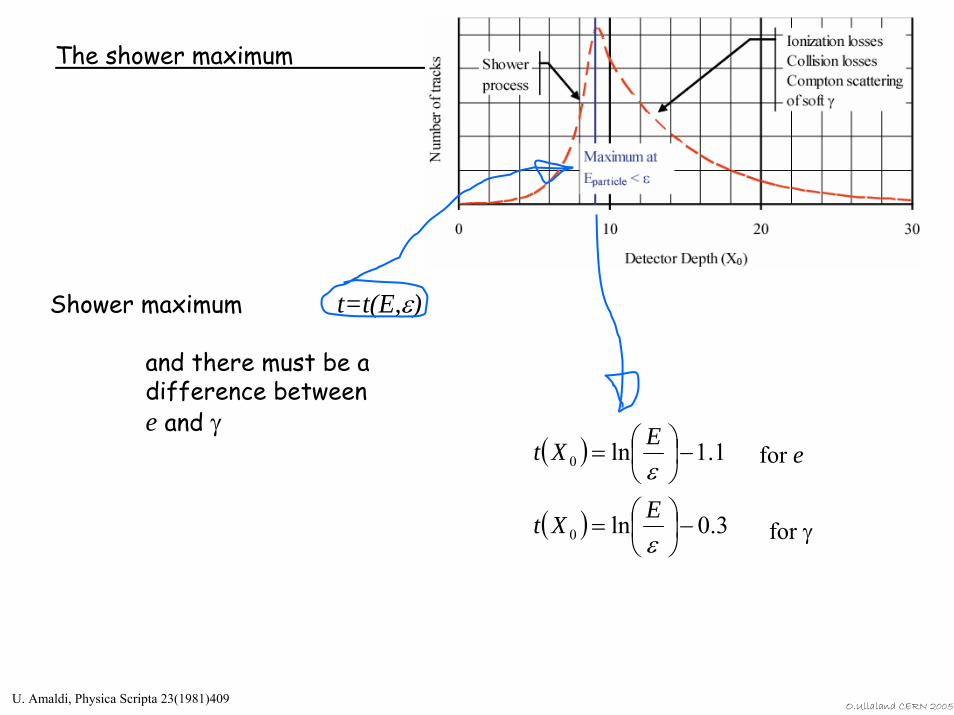
The shower maximum
Shower maximum t=t(E,ε)
and there must be a difference betweene and γ
( )
( ) 3.0ln
1.1ln
0
0
−⎟⎠⎞
⎜⎝⎛=
−⎟⎠⎞
⎜⎝⎛=
ε
εEXt
EXt for e
for γ
U. Amaldi, Physica Scripta 23(1981)409O.Ullaland CERN 2005
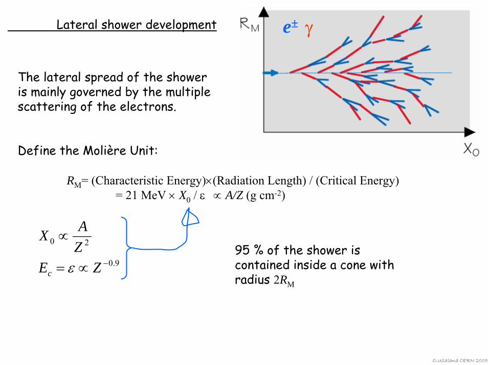
Lateral shower development
95 % of the shower is contained inside a cone with radius 2RM
The lateral spread of the shower is mainly governed by the multiple scattering of the electrons.
Define the Molière Unit:
RM= (Characteristic Energy)×(Radiation Length) / (Critical Energy)= 21 MeV × X0 / ε ∝ A/Z (g cm-2)
e± γ
9.0
20
−∝=
∝
ZEZAX
c ε
O.Ullaland CERN 2005
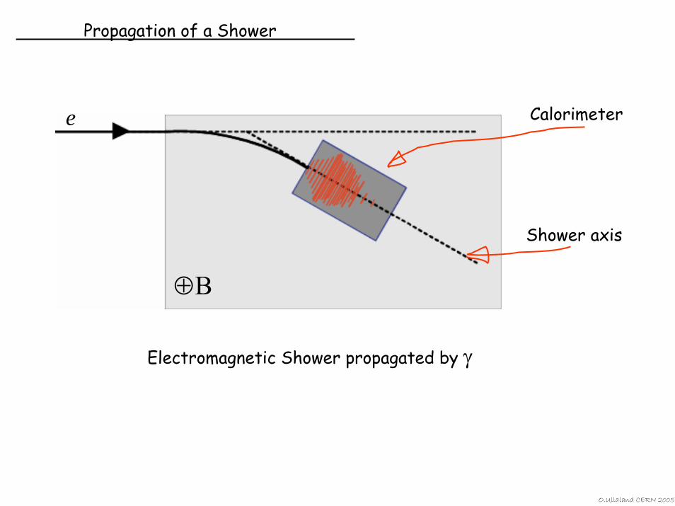
Propagation of a Shower
⊕B
Shower axis
Calorimetere
Electromagnetic Shower propagated by γ
O.Ullaland CERN 2005
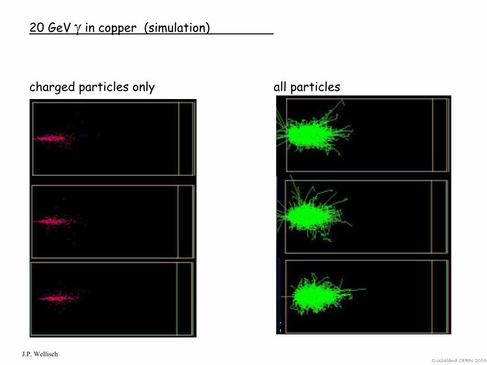
20 GeV γ in copper (simulation)
charged particles only all particles
J.P. WellischO.Ullaland CERN 2005
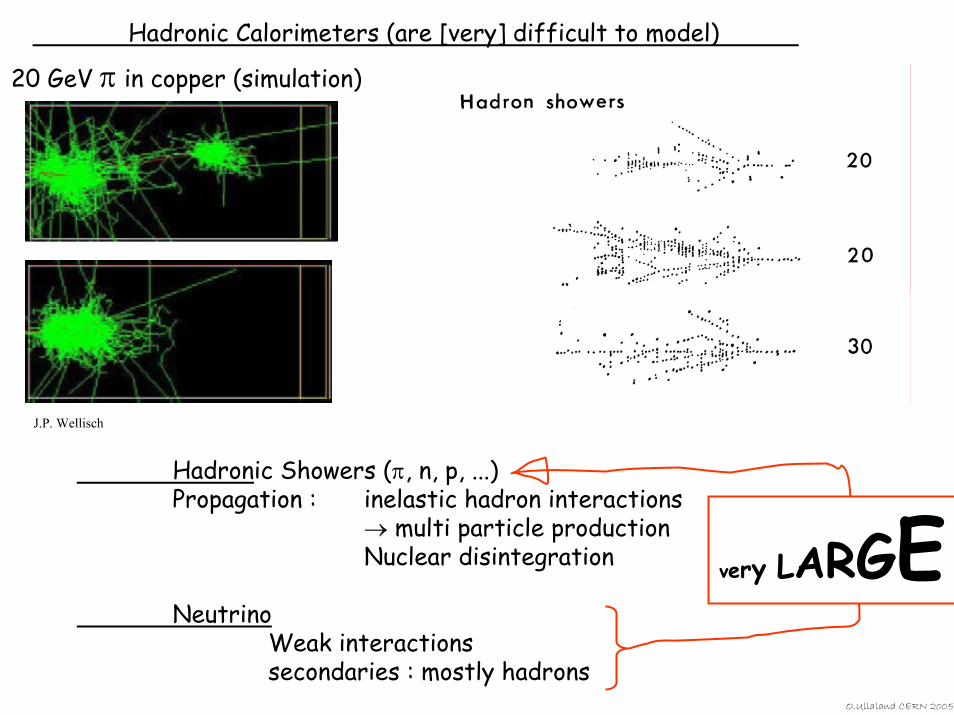
Hadronic Calorimeters (are [very] difficult to model)
20 GeV π in copper (simulation)
Hadronic Showers (π, n, p, ...)Propagation : inelastic hadron interactions
→ multi particle productionNuclear disintegration
NeutrinoWeak interactionssecondaries : mostly hadrons
J.P. Wellisch
very LARGEO.Ullaland CERN 2005
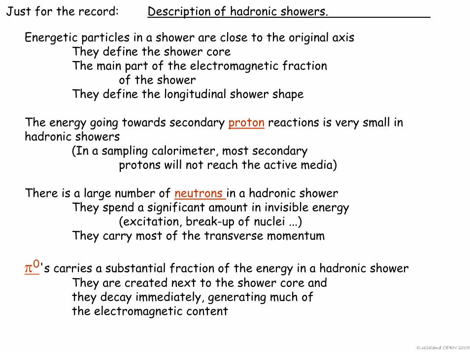
Just for the record: Description of hadronic showers.
Energetic particles in a shower are close to the original axisThey define the shower coreThe main part of the electromagnetic fraction
of the showerThey define the longitudinal shower shape
The energy going towards secondary proton reactions is very small in hadronic showers
(In a sampling calorimeter, most secondary protons will not reach the active media)
There is a large number of neutrons in a hadronic showerThey spend a significant amount in invisible energy
(excitation, break-up of nuclei ...)They carry most of the transverse momentum
π0's carries a substantial fraction of the energy in a hadronic showerThey are created next to the shower core and they decay immediately, generating much of the electromagnetic content
O.Ullaland CERN 2005
O.Ullaland CERN 2005
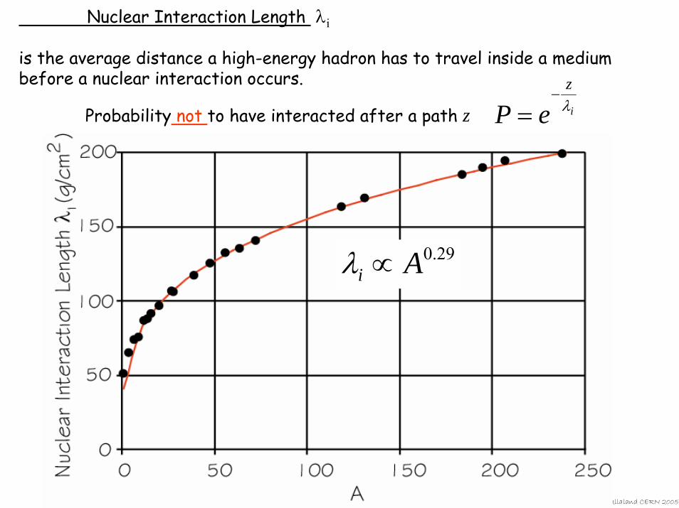
29.0Ai ∝λ
Nuclear Interaction Length λi
is the average distance a high-energy hadron has to travel inside a medium before a nuclear interaction occurs.
Probability not to have interacted after a path z i
z
eP λ−
=
back to Electromagnetic Calorimeters and fluctuations
O.Ullaland CERN 2005
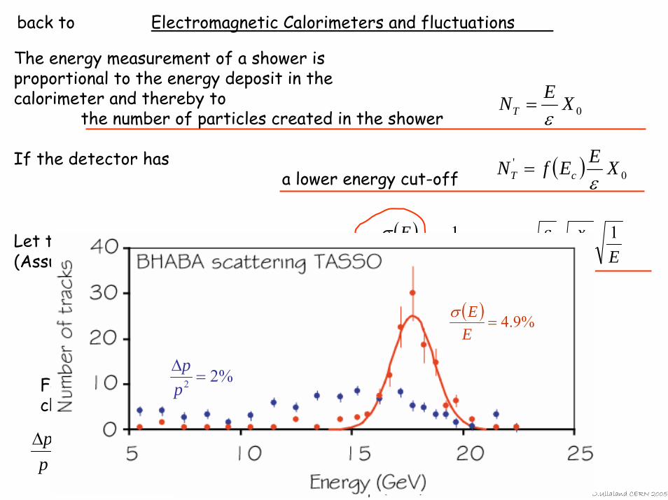
( )EX
xfNE
E
T
1%2.31
0
εσ==
0XENT ε=
( ) 0' XEEfN cT ε
=
The energy measurement of a shower is proportional to the energy deposit in the calorimeter and thereby to
the number of particles created in the shower
If the detector has a lower energy cut-off
Let the shower be sampled at each x. (Assume independent samplings.)
BLp
pp R
2φσ
∝∆
For track chambers
%22 =∆pp
( ) %9.4=EEσ
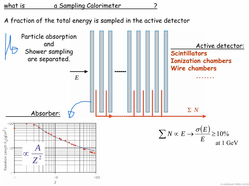
what is a Sampling Calorimeter ?
A fraction of the total energy is sampled in the active detector
E
Active detector:ScintillatorsIonization chambersWire chambers
.......
Σ N
Particle absorptionand
Shower samplingare separated.
Absorber:
2ZA
∝
( ) %10≥→∝∑ EEEN σ
at 1 GeV
O.Ullaland CERN 2005
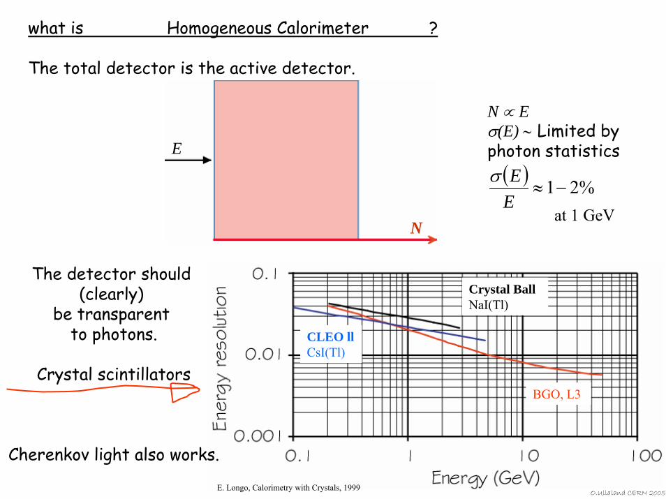
what is Homogeneous Calorimeter ?
The total detector is the active detector.
E
N
N ∝ Eσ(E) ∼ Limited by photon statistics
( ) %21−≈EEσ
at 1 GeV
Crystal Ball NaI(Tl)
CLEO llCsI(Tl)
BGO, L3
O.Ullaland CERN 2005
The detector should (clearly)
be transparent to photons.
Crystal scintillators
Cherenkov light also works.
E. Longo, Calorimetry with Crystals, 1999
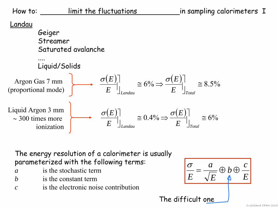
How to: limit the fluctuations in sampling calorimeters I
LandauGeigerStreamerSaturated avalanche....Liquid/Solids
( ) ( ) %5.8%6 ≅⎥⎦⎤⇒≅⎥⎦
⎤
TotalLandau EE
EE σσArgon Gas 7 mm
(proportional mode)
Liquid Argon 3 mm∼ 300 times more
ionization
( ) ( ) %6%4.0 ≅⎥⎦⎤⇒≅⎥⎦
⎤
TotalLandau EE
EE σσ
The energy resolution of a calorimeter is usually parameterized with the following terms:a is the stochastic termb is the constant termc is the electronic noise contribution
Ecb
Ea
E⊕⊕=
σ
The difficult oneO.Ullaland CERN 2005
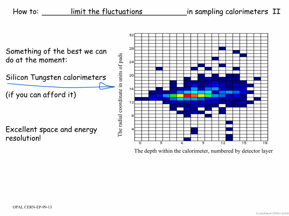
How to: limit the fluctuations in sampling calorimeters II
The depth within the calorimeter, numbered by detector layer
The
r ad i
al c
oord
i nat
e in
un i
ts o
f pad
sSomething of the best we can do at the moment:
Silicon Tungsten calorimeters
(if you can afford it)
Excellent space and energy resolution!
OPAL CERN-EP-99-13O.Ullaland CERN 2005
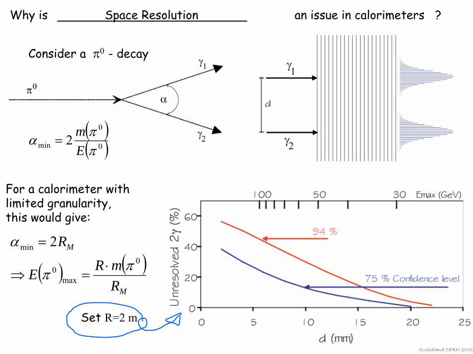
Why is Space Resolution an issue in calorimeters ?
Consider a π0 - decay
( )( )0
0
min 2ππα
Em
=
For a calorimeter with limited granularity, this would give:
( ) ( )M
M
RmRE
R0
max0
min 2
ππ
α
⋅=⇒
=
Set R=2 m
O.Ullaland CERN 2005
That is all folks.There is no exam.
Thank you for listening and for your questions.
back-ups
WHAT IS FINALLY YOUR
ENERGY RESOLUTION?
STILL
O.Ullaland CERN 2005
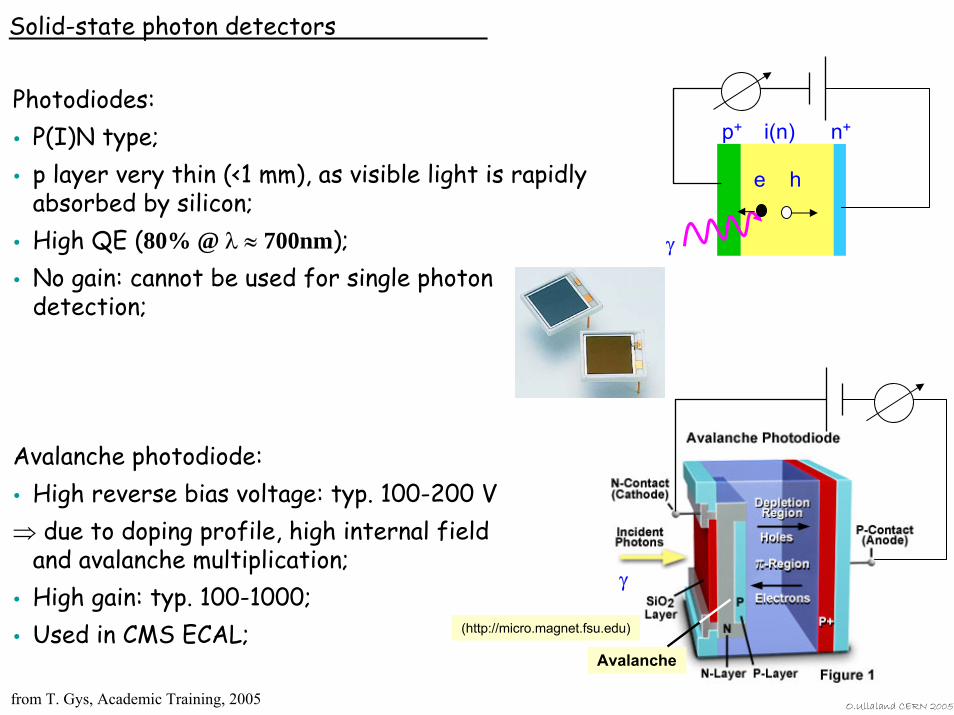
Solid-state photon detectors
Photodiodes:P(I)N type;p layer very thin (<1 mm), as visible light is rapidly absorbed by silicon;High QE (80% @ λ ≈ 700nm);No gain: cannot be used for single photon detection;
Avalanche photodiode:High reverse bias voltage: typ. 100-200 V
⇒ due to doping profile, high internal fieldand avalanche multiplication;High gain: typ. 100-1000;Used in CMS ECAL;
Avalanche
γ
(http://micro.magnet.fsu.edu)
e h
p+ i(n) n+
γ
from T. Gys, Academic Training, 2005 O.Ullaland CERN 2005

Generic tracking issues.Secondary vertices.
High spatial resolution.B
f
B
O.Ullaland CERN 2005not shown
HIGH RESISTIVITY ELECTRODE (BAKELITE)
GAS GAP
GRAPHITE COATING
INSULATOR
READOUT STRIPS X
READOUT STRIPS Y
HV
GND
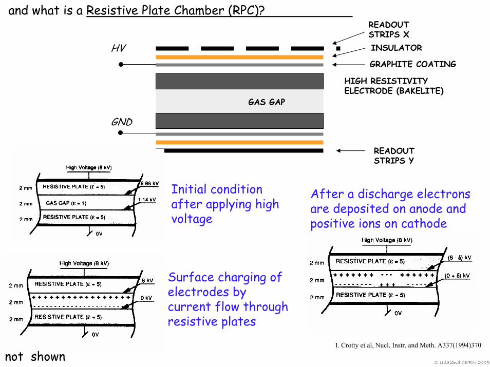
and what is a Resistive Plate Chamber (RPC)?
Initial condition after applying high voltage
Surface charging of electrodes by current flow through resistive plates
After a discharge electrons are deposited on anode and positive ions on cathode
O.Ullaland CERN 200
I. Crotty et al, Nucl. Instr. and Meth. A337(1994)370
5not shown
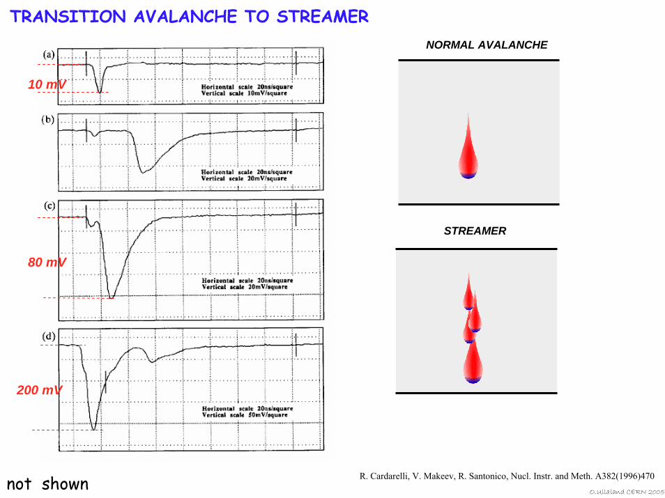
TRANSITION AVALANCHE TO STREAMERNORMAL AVALANCHE
10 mV
80 mV
200 mV
STREAMER
R. Cardarelli, V. Makeev, R. Santonico, Nucl. Instr. and Meth. A382(1996)470not shownO.Ullaland CERN 2005
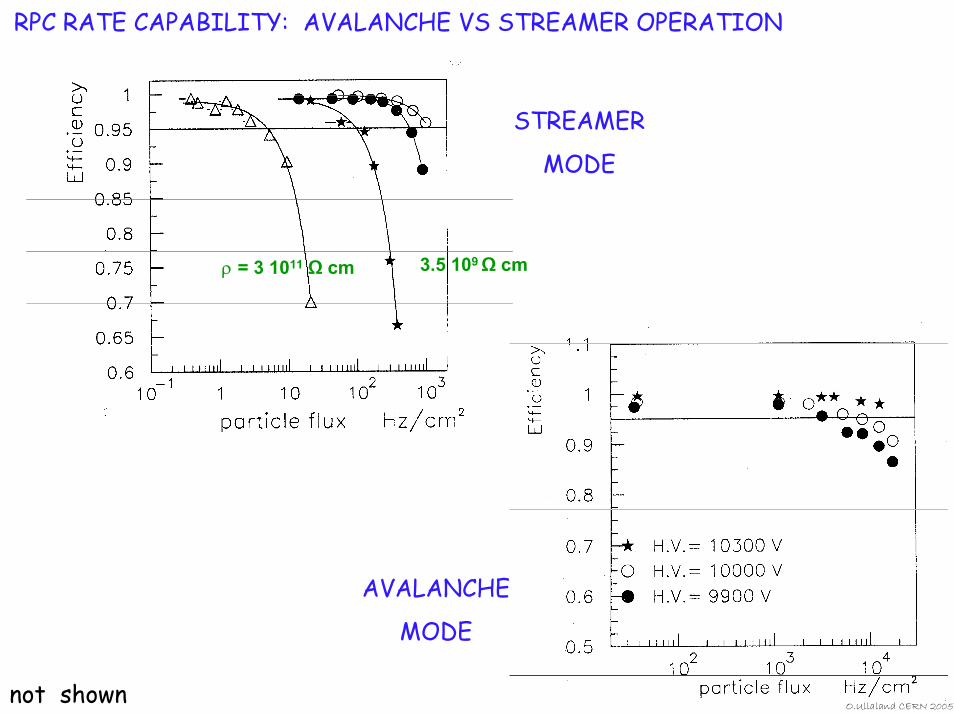
RPC RATE CAPABILITY: AVALANCHE VS STREAMER OPERATION
ρ = 3 1011 Ω cm
AVALANCHE
MODE
STREAMER
MODE
3.5 109 Ω cm
O.Ullaland CERN 200not shown
5
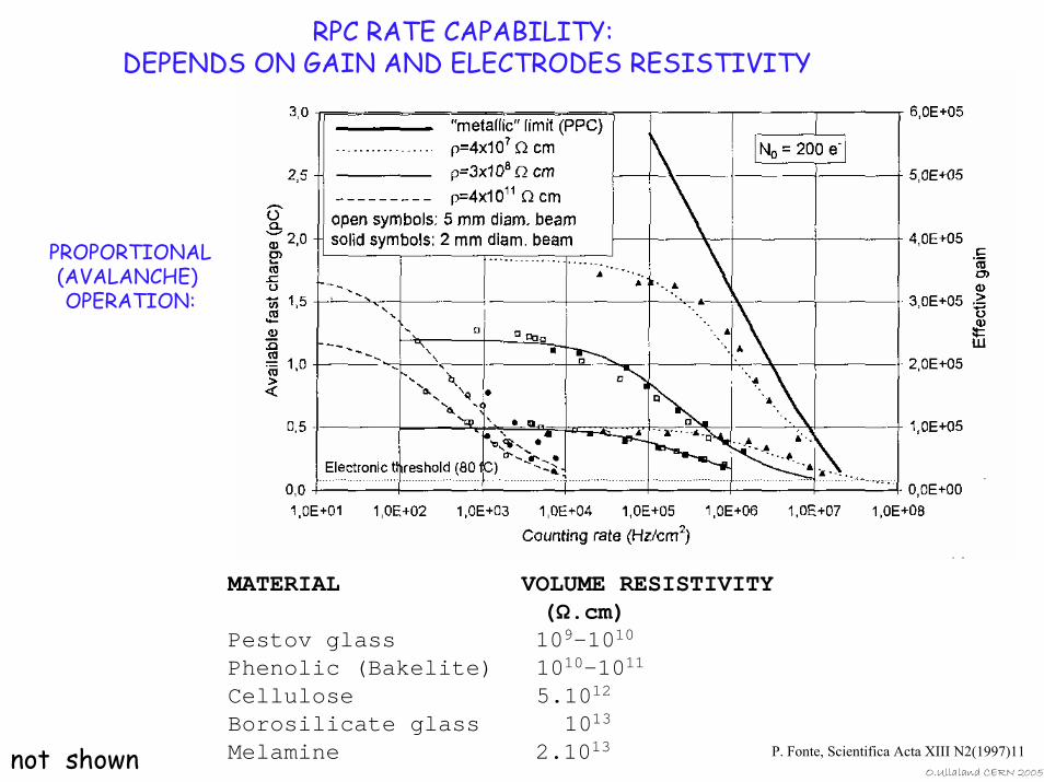
RPC RATE CAPABILITY: DEPENDS ON GAIN AND ELECTRODES RESISTIVITY
PROPORTIONAL(AVALANCHE) OPERATION:
MATERIAL VOLUME RESISTIVITY (Ω.cm)
Pestov glass 109-1010
Phenolic (Bakelite) 1010-1011
Cellulose 5.1012
Borosilicate glass 1013
Melamine 2.1013not shown P. Fonte, Scientifica Acta XIII N2(1997)11O.Ullaland CERN 2005
O.Ullaland CERN 2005
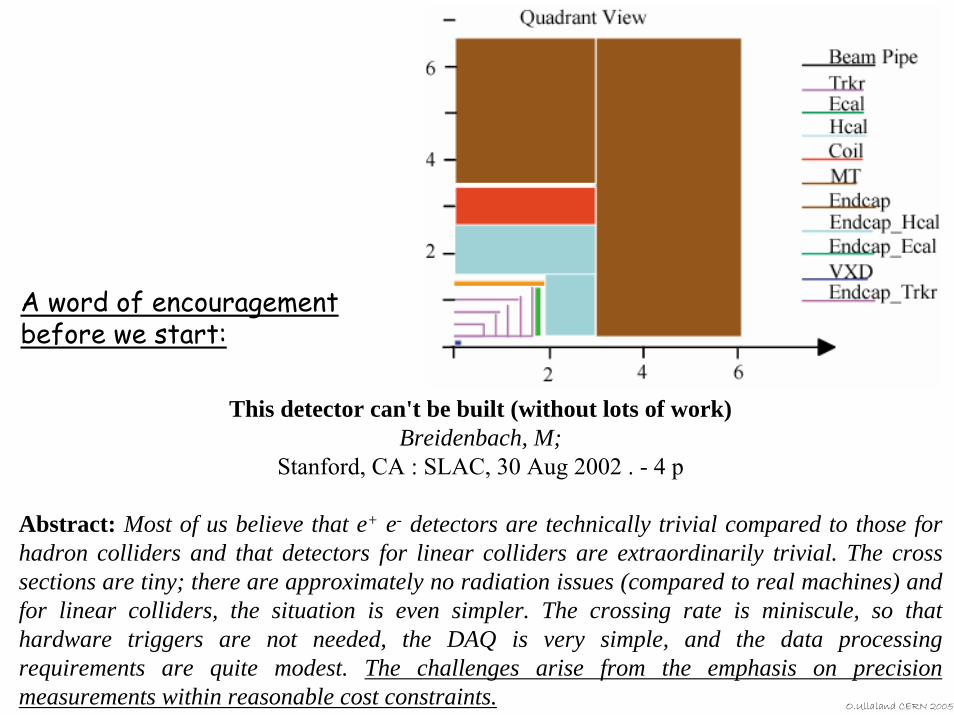
This detector can't be built (without lots of work)Breidenbach, M;
Stanford, CA : SLAC, 30 Aug 2002 . - 4 p
Abstract: Most of us believe that e+ e- detectors are technically trivial compared to those for hadron colliders and that detectors for linear colliders are extraordinarily trivial. The cross sections are tiny; there are approximately no radiation issues (compared to real machines) and for linear colliders, the situation is even simpler. The crossing rate is miniscule, so that hardware triggers are not needed, the DAQ is very simple, and the data processing requirements are quite modest. The challenges arise from the emphasis on precision measurements within reasonable cost constraints.
A word of encouragement before we start: