Embed Size (px)
Citation preview
1
How we proceed to complete/check the equipment review •Relocation will be done according to the equipment list presented in Chamonix
•Point owner will focus on this table www.cern.ch/r2e •Document with a description of the equipment for each point (P1, P5, P8) will be prepared;
•Missing information are pointed out (racks, cables); •Send documents to the owners for a review of their own equipment.
•If possible, specify if your equipment can be splitted in ‘more sensitive’ and ‘less sensitive’ parts (e.g. as already done for valve controllers at point 8)
•Point 5
oInformation for the Access system (R. Nunes) are needed
oAdditional information on cabling (Cryogenic refrigerators, Electrical control and distribution, QPS, Ethernet switch, cooling and Ventilation). This will be clarified in the document.

2
Point 5 Equipment Description
Ver. 1 Last update 20 01.2010
POINT 5 Timing and Remote Reset (Front End) [R. Chery] The timing and the remote reset systems are installed in the racks CYTIM01 and CYFRE01 respectively. They are located at UJ56 level 1 and manage the timing and the remote reset
3
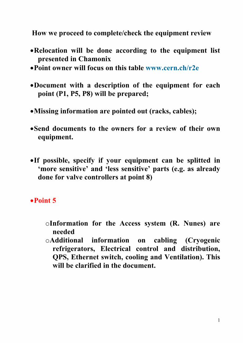
distribution for the front-end controls. Some equipment is also installed in the collimation rack TYCCR01. Most of the users are resumed in Fig. 1. A failure of the system creates a lack of the timing distribution for the equipments related to the beam control. Therefore, the beam must be dumped. The equipment is based on commercial devices and radiation tests were not performed. The racks can be relocated and the equipment owner is currently working on the specifications for that.
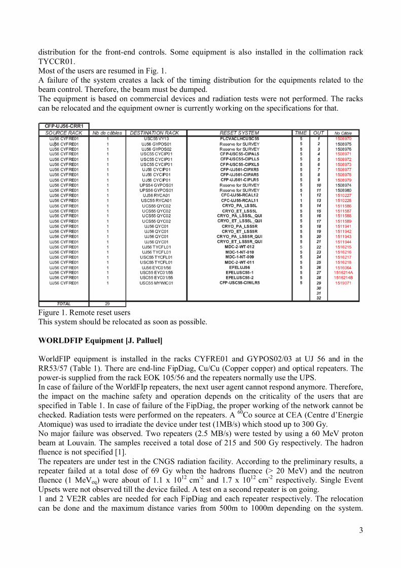
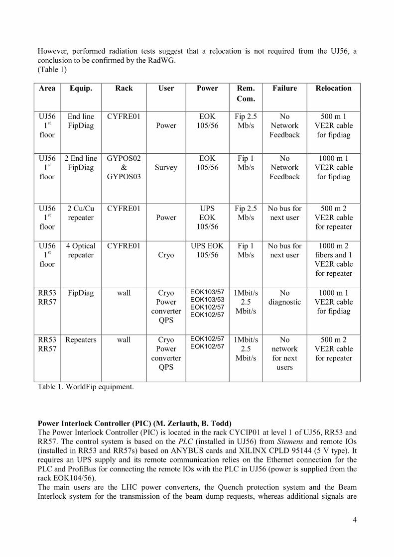
Figure 1. Remote reset users This system should be relocated as soon as possible. WORLDFIP Equipment [J. Palluel] WorldFIP equipment is installed in the racks CYFRE01 and GYPOS02/03 at UJ 56 and in the RR53/57 (Table 1). There are end-line FipDiag, Cu/Cu (Copper copper) and optical repeaters. The power-is supplied from the rack EOK 105/56 and the repeaters normally use the UPS. In case of failure of the WorldFIp repeaters, the next user agent cannot respond anymore. Therefore, the impact on the machine safety and operation depends on the criticality of the users that are specified in Table 1. In case of failure of the FipDiag, the proper working of the network cannot be checked. Radiation tests were performed on the repeaters. A 60Co source at CEA (Centre d’Energie Atomique) was used to irradiate the device under test (1MB/s) which stood up to 300 Gy. No major failure was observed. Two repeaters (2.5 MB/s) were tested by using a 60 MeV proton beam at Louvain. The samples received a total dose of 215 and 500 Gy respectively. The hadron fluence is not specified [1]. The repeaters are under test in the CNGS radiation facility. According to the preliminary results, a repeater failed at a total dose of 69 Gy when the hadrons fluence (> 20 MeV) and the neutron fluence (1 MeVeq) were about of 1.1 x 1012 cm-2 and 1.7 x 1012 cm-2 respectively. Single Event Upsets were not observed till the device failed. A test on a second repeater is on going. 1 and 2 VE2R cables are needed for each FipDiag and each repeater respectively. The relocation can be done and the maximum distance varies from 500m to 1000m depending on the system.
4
However, performed radiation tests suggest that a relocation is not required from the UJ56, a conclusion to be confirmed by the RadWG. (Table 1) Area Equip. Rack User Power Rem.
Com. Failure Relocation
UJ56 1st floor
End line FipDiag
CYFRE01 Power
EOK 105/56
Fip 2.5 Mb/s
No Network Feedback
500 m 1 VE2R cable for fipdiag
UJ56 1st floor
2 End line FipDiag
GYPOS02 &
GYPOS03
Survey
EOK 105/56
Fip 1 Mb/s
No Network Feedback
1000 m 1 VE2R cable for fipdiag
UJ56 1st floor
2 Cu/Cu repeater
CYFRE01 Power
UPS EOK 105/56
Fip 2.5 Mb/s
No bus for next user
500 m 2 VE2R cable for repeater
UJ56 1st floor
4 Optical repeater
CYFRE01 Cryo
UPS EOK 105/56
Fip 1 Mb/s
No bus for next user
1000 m 2 fibers and 1 VE2R cable for repeater
RR53 RR57
FipDiag wall Cryo Power converter QPS
EOK103/57 EOK103/53 EOK102/57 EOK102/57
1Mbit/s 2.5 Mbit/s
No diagnostic
1000 m 1 VE2R cable for fipdiag
RR53 RR57
Repeaters wall Cryo Power converter QPS
EOK102/57 EOK102/57
1Mbit/s 2.5 Mbit/s
No network for next users
500 m 2 VE2R cable for repeater
Table 1. WorldFip equipment. Power Interlock Controller (PIC) (M. Zerlauth, B. Todd) The Power Interlock Controller (PIC) is located in the rack CYCIP01 at level 1 of UJ56, RR53 and RR57. The control system is based on the PLC (installed in UJ56) from Siemens and remote IOs (installed in RR53 and RR57s) based on ANYBUS cards and XILINX CPLD 95144 (5 V type). It requires an UPS supply and its remote communication relies on the Ethernet connection for the PLC and ProfiBus for connecting the remote IOs with the PLC in UJ56 (power is supplied from the rack EOK104/56). The main users are the LHC power converters, the Quench protection system and the Beam Interlock system for the transmission of the beam dump requests, whereas additional signals are
5
transmitted via HW links (or direct PLC-PLC links) for the transmission of cryogenic conditions and the status of UPS systems and the AUG to the PIC. Following a failure of the PIC system, the beam must be dumped. Radiation tests have been performed at Louvain on the ANYBUS modules. A 60 MeV proton beam with a flux ranging form 0.1 x 10⁸ to 5 x 10⁸ protons/(cm2·sec) has been used. Two ANYBUS cards have been irradiated for a time period of about 75 minutes each, the first one up to a total dose of 125 Gy and a second one achieving a total dose of 326 Gy. No major degradation of the supplied output current for an active state of the output could be observed for either of the two irradiated boards. According to the irradiation time and considering the maximum flux of 5x10⁸
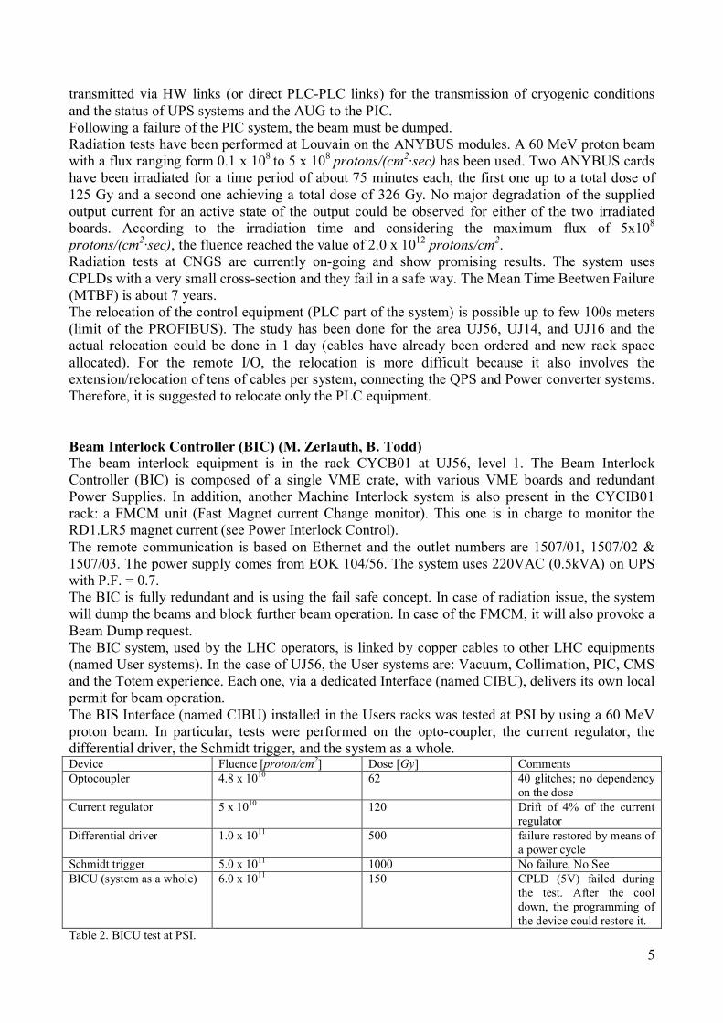
protons/(cm2·sec), the fluence reached the value of 2.0 x 10¹² protons/cm2. Radiation tests at CNGS are currently on-going and show promising results. The system uses CPLDs with a very small cross-section and they fail in a safe way. The Mean Time Beetwen Failure (MTBF) is about 7 years. The relocation of the control equipment (PLC part of the system) is possible up to few 100s meters (limit of the PROFIBUS). The study has been done for the area UJ56, UJ14, and UJ16 and the actual relocation could be done in 1 day (cables have already been ordered and new rack space allocated). For the remote I/O, the relocation is more difficult because it also involves the extension/relocation of tens of cables per system, connecting the QPS and Power converter systems. Therefore, it is suggested to relocate only the PLC equipment. Beam Interlock Controller (BIC) (M. Zerlauth, B. Todd) The beam interlock equipment is in the rack CYCB01 at UJ56, level 1. The Beam Interlock Controller (BIC) is composed of a single VME crate, with various VME boards and redundant Power Supplies. In addition, another Machine Interlock system is also present in the CYCIB01 rack: a FMCM unit (Fast Magnet current Change monitor). This one is in charge to monitor the RD1.LR5 magnet current (see Power Interlock Control). The remote communication is based on Ethernet and the outlet numbers are 1507/01, 1507/02 & 1507/03. The power supply comes from EOK 104/56. The system uses 220VAC (0.5kVA) on UPS with P.F. = 0.7. The BIC is fully redundant and is using the fail safe concept. In case of radiation issue, the system will dump the beams and block further beam operation. In case of the FMCM, it will also provoke a Beam Dump request. The BIC system, used by the LHC operators, is linked by copper cables to other LHC equipments (named User systems). In the case of UJ56, the User systems are: Vacuum, Collimation, PIC, CMS and the Totem experience. Each one, via a dedicated Interface (named CIBU), delivers its own local permit for beam operation. The BIS Interface (named CIBU) installed in the Users racks was tested at PSI by using a 60 MeV proton beam. In particular, tests were performed on the opto-coupler, the current regulator, the differential driver, the Schmidt trigger, and the system as a whole. Device Fluence [proton/cm2] Dose [Gy] Comments Optocoupler 4.8 x 10¹⁰ 62 40 glitches; no dependency
on the dose Current regulator 5 x 10¹⁰ 120 Drift of 4% of the current
regulator Differential driver 1.0 x 10¹¹ 500 failure restored by means of
a power cycle Schmidt trigger 5.0 x 10¹¹ 1000 No failure, No See BICU (system as a whole) 6.0 x 10¹¹ 150 CPLD (5V) failed during
the test. After the cool down, the programming of the device could restore it.
Table 2. BICU test at PSI.
6
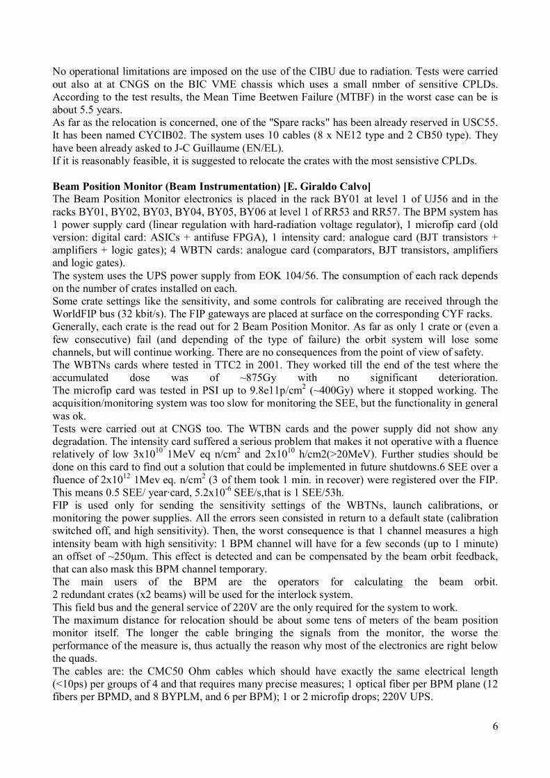
No operational limitations are imposed on the use of the CIBU due to radiation. Tests were carried out also at at CNGS on the BIC VME chassis which uses a small nmber of sensitive CPLDs. According to the test results, the Mean Time Beetwen Failure (MTBF) in the worst case can be is about 5.5 years. As far as the relocation is concerned, one of the "Spare racks" has been already reserved in USC55. It has been named CYCIB02. The system uses 10 cables (8 x NE12 type and 2 CB50 type). They have been already asked to J-C Guillaume (EN/EL). If it is reasonably feasible, it is suggested to relocate the crates with the most sensistive CPLDs. Beam Position Monitor (Beam Instrumentation) [E. Giraldo Calvo] The Beam Position Monitor electronics is placed in the rack BY01 at level 1 of UJ56 and in the racks BY01, BY02, BY03, BY04, BY05, BY06 at level 1 of RR53 and RR57. The BPM system has 1 power supply card (linear regulation with hard-radiation voltage regulator), 1 microfip card (old version: digital card: ASICs + antifuse FPGA), 1 intensity card: analogue card (BJT transistors + amplifiers + logic gates); 4 WBTN cards: analogue card (comparators, BJT transistors, amplifiers and logic gates). The system uses the UPS power supply from EOK 104/56. The consumption of each rack depends on the number of crates installed on each. Some crate settings like the sensitivity, and some controls for calibrating are received through the WorldFIP bus (32 kbit/s). The FIP gateways are placed at surface on the corresponding CYF racks. Generally, each crate is the read out for 2 Beam Position Monitor. As far as only 1 crate or (even a few consecutive) fail (and depending of the type of failure) the orbit system will lose some channels, but will continue working. There are no consequences from the point of view of safety. The WBTNs cards where tested in TTC2 in 2001. They worked till the end of the test where the accumulated dose was of ~875Gy with no significant deterioration. The microfip card was tested in PSI up to 9.8e11p/cm2 (~400Gy) where it stopped working. The acquisition/monitoring system was too slow for monitoring the SEE, but the functionality in general was ok. Tests were carried out at CNGS too. The WTBN cards and the power supply did not show any degradation. The intensity card suffered a serious problem that makes it not operative with a fluence relatively of low 3x10¹⁰ 1MeV eq n/cm2 and 2x10¹⁰ h/cm2(>20MeV). Further studies should be done on this card to find out a solution that could be implemented in future shutdowns.6 SEE over a fluence of 2x10¹² 1Mev eq. n/cm2 (3 of them took 1 min. in recover) were registered over the FIP. This means 0.5 SEE/ year·card, 5.2x10⁻⁶ SEE/s,that is 1 SEE/53h. FIP is used only for sending the sensitivity settings of the WBTNs, launch calibrations, or monitoring the power supplies. All the errors seen consisted in return to a default state (calibration switched off, and high sensitivity). Then, the worst consequence is that 1 channel measures a high intensity beam with high sensitivity: 1 BPM channel will have for a few seconds (up to 1 minute) an offset of ~250µm. This effect is detected and can be compensated by the beam orbit feedback, that can also mask this BPM channel temporary. The main users of the BPM are the operators for calculating the beam orbit. 2 redundant crates (x2 beams) will be used for the interlock system. This field bus and the general service of 220V are the only required for the system to work. The maximum distance for relocation should be about some tens of meters of the beam position monitor itself. The longer the cable bringing the signals from the monitor, the worse the performance of the measure is, thus actually the reason why most of the electronics are right below the quads. The cables are: the CMC50 Ohm cables which should have exactly the same electrical length (<10ps) per groups of 4 and that requires many precise measures; 1 optical fiber per BPM plane (12 fibers per BPMD, and 8 BYPLM, and 6 per BPM); 1 or 2 microfip drops; 220V UPS.
7
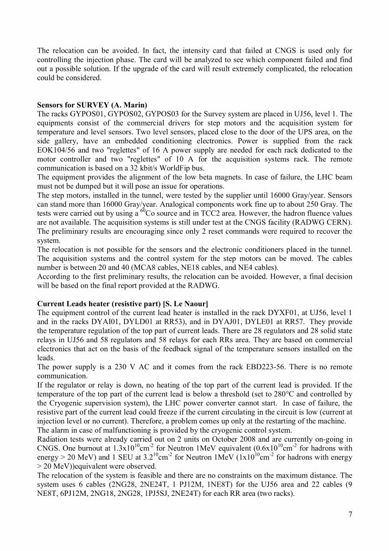
The relocation can be avoided. In fact, the intensity card that failed at CNGS is used only for controlling the injection phase. The card will be analyzed to see which component failed and find out a possible solution. If the upgrade of the card will result extremely complicated, the relocation could be considered. Sensors for SURVEY (A. Marin) The racks GYPOS01, GYPOS02, GYPOS03 for the Survey system are placed in UJ56, level 1. The equipments consist of the commercial drivers for step motors and the acquisition system for temperature and level sensors. Two level sensors, placed close to the door of the UPS area, on the side gallery, have an embedded conditioning electronics. Power is supplied from the rack EOK104/56 and two "reglettes" of 16 A power supply are needed for each rack dedicated to the motor controller and two "reglettes" of 10 A for the acquisition systems rack. The remote communication is based on a 32 kbit/s WorldFip bus. The equipment provides the alignment of the low beta magnets. In case of failure, the LHC beam must not be dumped but it will pose an issue for operations. The step motors, installed in the tunnel, were tested by the supplier until 16000 Gray/year. Sensors can stand more than 16000 Gray/year. Analogical components work fine up to about 250 Gray. The tests were carried out by using a 60Co source and in TCC2 area. However, the hadron fluence values are not available. The acquisition systems is still under test at the CNGS facility (RADWG CERN). The preliminary results are encouraging since only 2 reset commands were required to recover the system. The relocation is not possible for the sensors and the electronic conditioners placed in the tunnel. The acquisition systems and the control system for the step motors can be moved. The cables number is between 20 and 40 (MCA8 cables, NE18 cables, and NE4 cables). According to the first preliminary results, the relocation can be avoided. However, a final decision will be based on the final report provided at the RADWG. Current Leads heater (resistive part) [S. Le Naour] The equipment control of the current lead heater is installed in the rack DYXF01, at UJ56, level 1 and in the racks DYAI01, DYLD01 at RR53), and in DYAJ01, DYLE01 at RR57. They provide the temperature regulation of the top part of current leads. There are 28 regulators and 28 solid state relays in UJ56 and 58 regulators and 58 relays for each RRs area. They are based on commercial electronics that act on the basis of the feedback signal of the temperature sensors installed on the leads. The power supply is a 230 V AC and it comes from the rack EBD223-56. There is no remote communication. If the regulator or relay is down, no heating of the top part of the current lead is provided. If the temperature of the top part of the current lead is below a threshold (set to 280°C and controlled by the Cryogenic supervision system), the LHC power converter cannot start. In case of failure, the resistive part of the current lead could freeze if the current circulating in the circuit is low (current at injection level or no current). Therefore, a problem comes up only at the restarting of the machine. The alarm in case of malfunctioning is provided by the cryogenic control system. Radiation tests were already carried out on 2 units on October 2008 and are currently on-going in CNGS. One burnout at 1.3x1010cm-2 for Neutron 1MeV equivalent (0.6x1010cm-2 for hadrons with energy > 20 MeV) and 1 SEU at 3.210cm-2 for Neutron 1MeV (1x1010cm-2 for hadrons with energy > 20 MeV))equivalent were observed. The relocation of the system is feasible and there are no constraints on the maximum distance. The system uses 6 cables (2NG28, 2NE24T, 1 PJ12M, 1NE8T) for the UJ56 area and 22 cables (9 NE8T, 6PJ12M, 2NG18, 2NG28, 1PJ5SJ, 2NE24T) for each RR area (two racks).
8
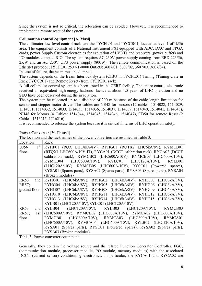
Since the system is not so critical, the relocation can be avoided. However, it is recommended to implement a remote reset of the system. Collimation control equipment [A. Masi] The collimator low-level control racks are the TYCFL01 and TYCCR01, located at level 1 of UJ56 area. The equipment consists of a National Instrument PXI equipped with ADC, DAC and FPGA cards, power Supply Custom electronics for excitation of LVDTs and resolvers (power buffer) and I/O modules compact RIO. The system requires AC 230V power supply coming from EBD 223/56, 2KW and an AC 230V UPS power supply (800W). The remote communication is based on the Ethernet protocol (TYCFL01 2537-1-0000 Outlets: 3607/01, 3607/02, 3607/03, 3607/04). In case of failure, the beam must be dumped. The system depends on the Beam Interlock System (CIBU in TYCFL01) Timing (Timing crate in Rack TYCCR01) and Remote Reset (from CYFRE01 rack). A full collimator control system has been tested in the CERF facility. The entire control electronic received an equivalent high-energy hadrons fluence at about 1.5 years of LHC operation and no SEU have been observed during the irradiation. The system can be relocated up to a distance of 200 m because of the cable length limitation for sensor and stepper motor driver. The cables are NE48 for sensors (12 cables: 1514028, 1514029, 1514031, 1514032, 1514033, 1514035, 1514036, 1514037, 1514039, 1514040, 1514041, 1514043), NH48 for Motors (4 Cables: 1514044, 1514045, 1514046, 1514047), CB50 for remote Reset (2 Cables: 1516215, 1516216). It is recommended to relocate the system because it is critical in terms of LHC operation safety. Power Converter [Y. Thurel] The location and the rack names of the power converters are resumed in Table 3. Location Rack UJ56 1st floor
RYHF01 (RQX LHC8kA/8V), RYHG01 (RQTX2 LHC6kA/8V), RYMCB01 (RTQX1 LHC600A/10V IT), RYCA01 (DCCT calibration rack), RYCA02 (DCCT calibration rack), RYMCB02 (LHC600A/10V), RYMCB03 (LHC600A/10V), RYMCB04 (LHC600A/10V), RYLC01 (LHC120A/10V), RYLB01 (LHC120A/10V), RYMCB05 (LHC600A/10V), RYSC01 (Powered spares), RYSA01 (Spares parts), RYSA02 (Spares parts), RYSA03 (Spares parts), RYSA04 (Broken modules)
RR53 and RR57; ground floor
RYHG01 (LHC6kA/8V), RYHG02 (LHC6kA/8V), RYHG03 (LHC6kA/8V), RYHG04 (LHC6kA/8V), RYHG05 (LHC6kA/8V), RYHG06 (LHC6kA/8V), RYHG07 (LHC6kA/8V), RYHG08 (LHC6kA/8V), RYHG09 (LHC6kA/8V), RYHG10 (LHC6kA/8V), RYHG11 (LHC6kA/8V), RYHG12 (LHC6kA/8V), RYHG13 (LHC6kA/8V), RYHG14 (LHC6kA/8V), RYHG15 (LHC6kA/8V), RYLB01 (LHC120A/10V),RYLC01 (LHC120A/10V).
RR53 and RR57; 1st floor
RYLB04 (LHC120A/10V), RYLB03 (LHC120A/10V), RYMCB03 (LHC600A/10V), RYMCB02 (LHC600A/10V), RYMCA02 (LHC600A/10V), RYMCB01 (LHC600A/10V), RYMCA03 (LHC600A/10V), RYMCA01 (LHC600A/10V), RYMCA04 (LHC600A/10V), RYLB02 (LHC120A/10V), RYSA01 (Spares parts), RYSC01 (Powered spares), RYSA02 (Spares parts), RYSA03 (Broken modules).
Table 3. Power converter equipment. Generally, they contain the voltage source and the related Function Generator Controller, FGC, (communication module, processor module, I/O module, memory modules) with the associated DCCT (current sensor) conditioning electronics. In particular, the RYCA01 and RYCA02 are
9
calibration racks. Moreover, they contain a PC with a screen, Sigma Delta converter, and DCCT electronic control. The power supply comes from EOD 116/56, ERK 106/56, ERK 104/56, ERK 105/56, ERD 103/56, EOK 103/56, and ERD 102/56. The systems require the 230 VAC and the UPS. The remote communication is based on the WorldFip bus (2.5 Mbit/s). The failure of the power converters will cause the beam loss since the magnets are not supplied correctly and no redundancy is implemented. In case of failure, the power converter sends a signal to the interlock system (Powering failure). Viceversa, the action of the power converters can be disabled by the Interlock system (PC_permit and PC_FastAbort signals) on the basis of other alarms. The WorldFip for communication and control of the power converter, the AC Network (normal + UPS), the water cooling (LHC600A/10V, LHC4-6-8kA/8V) and the PIC systems are required to allow for proper working of the power converter system. The different type of FGCs (generic FGC, PSU FGC, and FGC DOC) use components like mosfet, memory, CPLD, that are known to be sensitive to radiations. Error mitigation is foreseen at software level for the generic FGC. Some parts are under test at CNGS facility. As far as the relocation is concerned, the limiting factor is the cable resistance (the maximum output voltage of the power converter is 8 or 10V). More details concerning impact of failure, as well as mitigation constraints can be found in a dedicated summary document [REF see link: http://r2e.web.cern.ch/R2E/Related/RadiationTesting/SummaryPCs_24june09_v4.pdf]. Owing to the dimensions of the equipments, the relocation would be hard to put in place. A decision will be taken on the basis of the final report of the radiation tests at CNGS. Optical fibres [D. Ricci] Patch panels for optical fibres are installed at UJ56, level 1, in the rack CYFIB01. It consists of passive elements such as optic fibres and connectors. The system does not need any power supply. The fibres are used by IT network, GSM, cryogenics, timing, quench protection system, power converter (WorldFip and Profibus), and other users. In case of failure, the users will be affected obviously. The multimode fibres used by IT network are sensible to total dose and displacement damage only. Thus, the low dose expected in the considered areas should not pose any problem for the operation. The system uses about 20 cables and the relocation would require a high cost. Therefore, the system will not be moved. Network equipments and infrastructure (E. Sallaz) The network infrastructure is located at UJ56, level 1. The racks CYNET01, CYNET02, and CYFIB01 include optical fibres, UTP (Unshielded Twisted Cable) cables, and switches. A failure of the network system will affect all the users in the area. The systems using the network can change at any time. The list can be checked on the netops website. The system can be moved as long as it can be re-installed in such a way to cover all the area. The main point concerns maximum lenght of the structured cabling infrastructure which is 90 meters from the star point. (Most of infomation is derived from the web form of point 8). Access System (Incomplete) [R. Nunes, C. Delamare, J. F. Juget] The racks for the access system are YYACS01, YYACS02, YYACS03, YYACS04, and YYACS05. They are key-locked. They should contain control equipments which is known to be radiation sensitives and electro-mechanic switches that are not sensitive. Misbehaviour could generate alarms and stops of the machine. Power-supply comes from the rack EOK104/56.
10
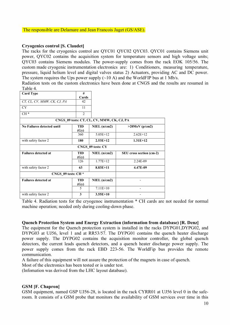
The responsible are Delamare and Jean Francois Juget (GS/ASE). Cryogenics control [S. Claudet] The racks for the cryogenics control are QYC01 QYC02 QYC03. QYC01 contains Siemens unit power, QYC02 contains the acquisition system for temperature sensors and high voltage units; QYC03 contains Siemens modules. The power-supply comes from the rack EOK 105/56. The custom made cryogenic instrumentation electronics are: 1) Conditioners, measuring temperature, pressure, liquid helium level and digital valves status 2) Actuators, providing AC and DC power. The system requires the Ups power supply (~10 A) and the WorldFIP bus at 1 Mb/s. Radiation tests on the custom electronics have been done at CNGS and the results are resumed in Table 4. Card Type #
Cards CT, CL, CV, MMW, CK, CJ, PA 42
CY 11
CH * 2
CNGS_09 tests: CT, CL, CV, MMW, CK, CJ, PA
No Failures detected until TID (Gy)
NIEL (n/cm2) >20MeV (p/cm2)
360 5.05E+12 2.62E+12
with safety factor 2 180 2.53E+12 1.31E+12
CNGS_09 tests: CY
Failures detected at TID (Gy)
NIEL (n/cm2) SEU cross section (cm-2)
126 1.77E+12 2.24E-09
with safety factor 2 63 8.83E+11 4.47E-09
CNGS_09 tests: CH *
Failures detected at TID (Gy)
NIEL (n/cm2) -
5 7.11E+10 -
with safety factor 2 3 3.55E+10 -
Table 4. Radiation tests for the cryogenoc instrumentation * CH cards are not needed for normal machine operation; needed only during cooling-down phase. Quench Protection System and Energy Extraction (information from database) [R. Denz] The equipment for the Quench protection system is installed in the racks DYPG01,DYPG02, and DYPG03 at UJ56, level 1 and at RR53/57. The DYPG01 contains the quench heater discharge power supply. The DYPG02 contains the acquisition monitor controller, the global quench detectors, the current leads quench detectors, and a quench heater discharge power supply. The power supply comes from the rack EBD 223-56. The WorldFip bus provides the remote communication. A failure of this equipment will not assure the protection of the magnets in case of quench. Most of the electronics has been tested or is under test. (Infomation was derived from the LHC layout database). GSM [F. Chapron] GSM equipment, named GSP UJ56-28, is located in the rack CYRR01 at UJ56 level 0 in the safe-room. It consists of a GSM probe that monitors the availability of GSM services over time in this
11
part of LHC tunnel. It needs a 220V, (50 W) power supply and the availability of the GSM services (provided by a GSM emitter located in SD5/6 and a leaky feeder cable infrastructure). The GSM emitter is located in SD5/6 and maintained by Sunrise. The device is suspected to be sensitive to radiations but specific tests have not been carried out. In case of failure, the IT/CS group will loose the monitoring of the GSM service. The relocation depends on the GSM signals propagation. Then, a site survey shall be made to determine the possibilities. The drawing of the leaky feeder cable infrastructure can be provided later. Since the system is not so critical, the relocation can be avoided. Fire detection ODH [R. Nunes] The control panel for the Fire detection of the machine and of the experimental area is located in the safe room at the ground level of UJ56. The rack name is SYFAD01 and the common equipment name is SFDIN-00297 CENTRALE INCENDIE ZS05. The system is based on a PLC-type device and is sensitive to Electromagnetic noise. A 230V secure power supply, not disabled by the Arret Urgence General (AUG), is needed. The communication is based on the Ethernet bus. In case of failure, the fire detection will not work anymore in the LHC REs and in the CMS experimental areas. The users of the system are the operators, the XCR and the Fire brigade. The system could be relocated in the USC55 area. The fire detectors are installed on the wall against the tunnel in the area UJ56 first floor, RR53 and RR57. The common equipment name is SFDEI-xxxx. Cables are needed to link the detectors to the central control system which provides the power supply as well. The communication is based on the Ethernet bus. In case of failure, a fire could not be detected in the RR and UJ areas. In case of relocation, testing is necessary to move the stuff in a more safe location, and a pipe must be installed (2-3 inch diameter) in order to bring the air sample to the detector that is located further away. The routing of the pipe could pose an integration problem. Electrical supply [G. Burdet] The equipment is located at UJ56, level 0. The low voltage racks present an electronic relay for the tension detection. The manufacturer will be asked to provide further information about the circuit scheme.
-EYU à AU Racks : these racks contain PCBs with the logic for the AU safety functions. There are some electronic components such as capacitors, diodes and integrated circuits. The safety logic is done via contacts and relays that in principle shouldn’t be affected by radiation.
-AU buttons à are all over the LHC underground and surface areas. These are mechanical buttons, with no electronics in their inside. The only problem presented so far, with the new technology AU buttons, is that they have a plastic component that is deteriorated by radiation. When this happens the button might set an AU safety function off. In any case, the safety of people is ensured. EN-EL is well aware of the problem. Annual tests of the AU system are carried out and campaigns of replacement of these AU buttons are foreseen.
-ESU/EAU à 48VDC generation and battery chargers. This equipment is mainly installed in the US (safe room) and RE. The chargers are manufactured by Ackermann and they have power electronics and sensible components such as zener diodes (Motorola 1N823, 1N754A1, IN747 A1, IN968 B1, 1N978A), diodes (Unitrode 1N4148, 1N5614, 1N5624, 1N4148), transistors (Motorola 2N3019, 2N3716), PCBs with integrated circuits (AXA 279.109, PMI IOP27CZ1), thyristor bridge (U5043/147, U5043/160).
12
-ECJ/ECD à 48VDC distribution crates installed in the US, UW, UX, UJ and RE. Normally the distribution crates are made up of fuses or switch-breakers.
-EJG à stands for battery racks for the UPS systems in the US15, RE, UAs of the LHC even points. Not affected by SEE.
-EAD/EBD/ERD/ESD/EOD/EQD à low voltage switchboards with fuses, bornes, switch breakers…normally no electronics in their inside. Some of these racks contain voltage monitoring relays (please see attachment “Catalogue Selectron relais”). We haven’t been able to find out which are the exact components in their inside. Anyhow, these relays do not realize any safety function, they just enable our control system to detect the mains supply. In case they do not work properly our monitoring system will either have no alarm or a false alarm. We have as well monitoring equipment and displays (DIRIS) which do not realize any safety function, if they do not work properly our monitoring system would not get the right measurements of the switchboard, we would lose the supervision of the switchboards.
-EMD à medium voltage switchboards that do not contain equipment sensible to radiation. -EMT à medium voltage transformers whose “resine” isolation might decompose in the
long term with radiation. -EYB à safety lighting chosen to stand radiation. This equipment do not contain any
electronic component. -EYP/ECU à racks (EYP) which contain the chargers (ECU) that power the safety lighting and that
are placed either in the US safe rooms except US15, in the UJ56, UJ33 and UJ67 and RE zones. Two type of brands, Victron and PROMEC (US85). Both have sensible components as zener diodes (DZ18VAA0, DZ15VAA0), transistors (BC237, BD786), PCBs with integrated logics (74HC132), CMOS, thyristors…
-EYC à these racks contain all of the equipment necessary to control and monitor the electrical equipment: DAUs, microcontrollers, switches, Ethernet…They are vital for our monitoring systems. These racks could be very sensible to radiation.
-EYQ à cryogenics 24VDC generation. These racks contain 24VDC PROMEC modules with electronic components sensible to radiation (EPROMs, diodes, MOS, microprocessors, transistors…).
EBS/ESS à UPS units (machine and cryogenics) which are very sensible to radiation since their logic depends on, transistors, CMOS, IGBTs, microprocessors and other electronics. The 48 V system generator is based on a technology presenting tirystor and ondulators for the anti panic light. This technology will be studied to understand his behaviour in presence of radiation. Two UPS systems, EBS11 and EBS21 (120kVA) are installed. According to the other equipment informations, the UPS is required by the Vacuum, Cryogenics, Electrical distribution, FIP repeaters, PIC, BIC, Beam position monitor, Collimation, Power converters.
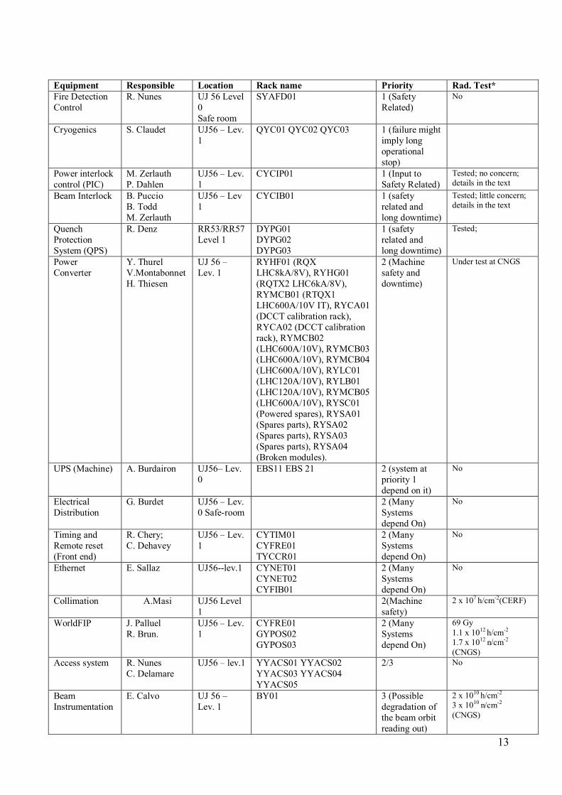
13
Equipment Responsible Location Rack name Priority Rad. Test* Fire Detection Control
R. Nunes UJ 56 Level 0 Safe room
SYAFD01 1 (Safety Related)
No
Cryogenics S. Claudet UJ56 – Lev. 1
QYC01 QYC02 QYC03 1 (failure might imply long operational stop)
Power interlock control (PIC)
M. Zerlauth P. Dahlen
UJ56 – Lev. 1
CYCIP01 1 (Input to Safety Related)
Tested; no concern; details in the text
Beam Interlock B. Puccio B. Todd M. Zerlauth
UJ56 – Lev 1
CYCIB01 1 (safety related and long downtime)
Tested; little concern; details in the text
Quench Protection System (QPS)
R. Denz RR53/RR57 Level 1
DYPG01 DYPG02 DYPG03
1 (safety related and long downtime)
Tested;
Power Converter
Y. Thurel V.Montabonnet H. Thiesen
UJ 56 – Lev. 1
RYHF01 (RQX LHC8kA/8V), RYHG01 (RQTX2 LHC6kA/8V), RYMCB01 (RTQX1 LHC600A/10V IT), RYCA01 (DCCT calibration rack), RYCA02 (DCCT calibration rack), RYMCB02 (LHC600A/10V), RYMCB03 (LHC600A/10V), RYMCB04 (LHC600A/10V), RYLC01 (LHC120A/10V), RYLB01 (LHC120A/10V), RYMCB05 (LHC600A/10V), RYSC01 (Powered spares), RYSA01 (Spares parts), RYSA02 (Spares parts), RYSA03 (Spares parts), RYSA04 (Broken modules).
2 (Machine safety and downtime)
Under test at CNGS
UPS (Machine) A. Burdairon UJ56– Lev. 0
EBS11 EBS 21 2 (system at priority 1 depend on it)
No
Electrical Distribution
G. Burdet UJ56 – Lev. 0 Safe-room
2 (Many Systems depend On)
No
Timing and Remote reset (Front end)
R. Chery; C. Dehavey
UJ56 – Lev. 1
CYTIM01 CYFRE01 TYCCR01
2 (Many Systems depend On)
No
Ethernet E. Sallaz UJ56--lev.1 CYNET01 CYNET02 CYFIB01
2 (Many Systems depend On)
No
Collimation A.Masi UJ56 Level 1
2(Machine safety)
2 x 10⁷ h/cm-2(CERF)
WorldFIP J. Palluel R. Brun.
UJ56 – Lev. 1
CYFRE01 GYPOS02 GYPOS03
2 (Many Systems depend On)
69 Gy 1.1 x 10¹² h/cm-2 1.7 x 10¹² n/cm-2 (CNGS)
Access system R. Nunes C. Delamare
UJ56 – lev.1 YYACS01 YYACS02 YYACS03 YYACS04 YYACS05
2/3 No
Beam Instrumentation
E. Calvo UJ 56 – Lev. 1
BY01 3 (Possible degradation of the beam orbit reading out)
2 x 10¹⁰ h/cm-2 3 x 10¹⁰ n/cm-2
(CNGS)
14
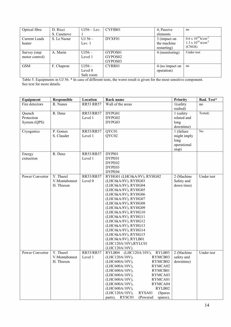
Optical fibre D. Ricci S. Casenove
UJ56 – Lev. 1
CYFIB01 4, Passive elements
no
Current Leads heater
S. Le Naour UJ 56 – Lev. 1
DYXF01 3 (impact on the machine restarting)
0.6 x 10¹⁰ h/cm-2 1.3 x 10¹⁰ n/cm-2 (CNGS)
Survey (step motor control)
A. Marin UJ56 – Level 1
GYPOS01 GYPOS02 GYPOS03
4 (monitoring) Under test
GSM F. Chapron UJ56 – Level 0 Safe room
CYRR01 4 (no impact on operation)
no
Table 5. Equipments in UJ 56. * In case of different tests, the worst result is given for the most sensitive component. See text for more details. Equipment Responsible Location Rack name Priority Rad. Test* Fire detectors R. Nunes RR53 RR57 Wall of the areas 1(safety
realted) no
Quench Protection System (QPS)
R. Denz RR53/RR57 Level 1
DYPG01 DYPG02 DYPG03
1 (safety related and long downtime)
Tested;
Cryogenics P. Gomes S. Claudet
RR53/RR57 Level 1
QYC01 QYC02
1 (failure might imply long operational stop)
No
Energy extraction
R. Denz RR53/RR57 Level 1
DYPI01 DYPE01 DYPE02 DYPE03 DYPE04
Power Converter Y. Thurel V.Montabonnet H. Thiesen
RR53/RR57 Level 0
RYHG01 (LHC6kA/8V), RYHG02 (LHC6kA/8V), RYHG03 (LHC6kA/8V), RYHG04 (LHC6kA/8V), RYHG05 (LHC6kA/8V), RYHG06 (LHC6kA/8V), RYHG07 (LHC6kA/8V), RYHG08 (LHC6kA/8V), RYHG09 (LHC6kA/8V), RYHG10 (LHC6kA/8V), RYHG11 (LHC6kA/8V), RYHG12 (LHC6kA/8V), RYHG13 (LHC6kA/8V), RYHG14 (LHC6kA/8V), RYHG15 (LHC6kA/8V), RYLB01 (LHC120A/10V),RYLC01 (LHC120A/10V).
2 (Machine Safety and down time)
Under test
Power Converter Y. Thurel V.Montabonnet H. Thiesen
RR53/RR57 Level 1
RYLB04 (LHC120A/10V), RYLB03 (LHC120A/10V), RYMCB03 (LHC600A/10V), RYMCB02 (LHC600A/10V), RYMCA02 (LHC600A/10V), RYMCB01 (LHC600A/10V), RYMCA03 (LHC600A/10V), RYMCA01 (LHC600A/10V), RYMCA04 (LHC600A/10V), RYLB02 (LHC120A/10V), RYSA01 (Spares parts), RYSC01 (Powered spares),
2 (Machine safety and downtime)
Under test
15
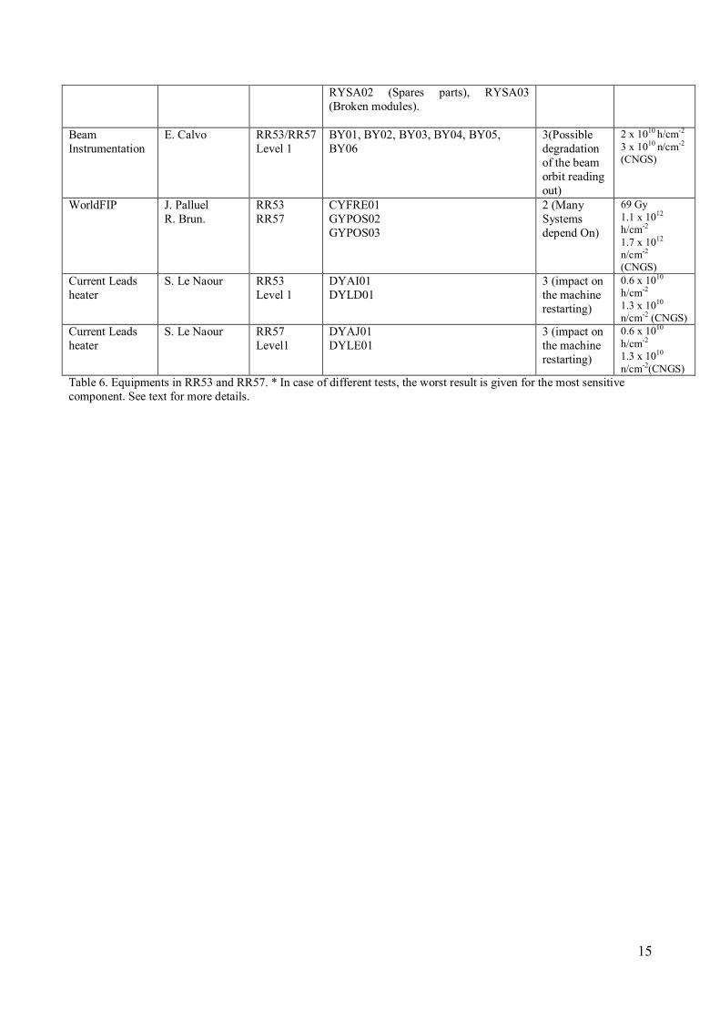
RYSA02 (Spares parts), RYSA03 (Broken modules).
Beam Instrumentation
E. Calvo RR53/RR57 Level 1
BY01, BY02, BY03, BY04, BY05, BY06
3(Possible degradation of the beam orbit reading out)
2 x 10¹⁰ h/cm-2 3 x 10¹⁰ n/cm-2
(CNGS)
WorldFIP J. Palluel R. Brun.
RR53 RR57
CYFRE01 GYPOS02 GYPOS03
2 (Many Systems depend On)
69 Gy 1.1 x 10¹²
h/cm-2 1.7 x 10¹²
n/cm-2 (CNGS)
Current Leads heater
S. Le Naour RR53 Level 1
DYAI01 DYLD01
3 (impact on the machine restarting)
0.6 x 10¹⁰
h/cm-2 1.3 x 10¹⁰
n/cm-2 (CNGS) Current Leads heater
S. Le Naour RR57 Level1
DYAJ01 DYLE01
3 (impact on the machine restarting)
0.6 x 10¹⁰
h/cm-2 1.3 x 10¹⁰
n/cm-2(CNGS) Table 6. Equipments in RR53 and RR57. * In case of different tests, the worst result is given for the most sensitive component. See text for more details.
16
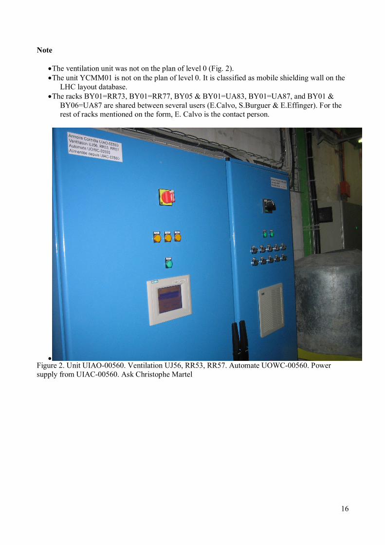
Note
•The ventilation unit was not on the plan of level 0 (Fig. 2). •The unit YCMM01 is not on the plan of level 0. It is classified as mobile shielding wall on the
LHC layout database. •The racks BY01=RR73, BY01=RR77, BY05 & BY01=UA83, BY01=UA87, and BY01 &
BY06=UA87 are shared between several users (E.Calvo, S.Burguer & E.Effinger). For the rest of racks mentioned on the form, E. Calvo is the contact person.
• Figure 2. Unit UIAO-00560. Ventilation UJ56, RR53, RR57. Automate UOWC-00560. Power supply from UIAC-00560. Ask Christophe Martel