Embed Size (px)
Citation preview


Turbine Cold Box
Introduction to cold box turbine operation
Specific Linde turbine
K Hafi
TE-CRG-OP
Avril 2020

Introduction to cold box turbine operation
• Contents
• Theory refresher
• The different turbines at CERN
• Bearings
• Some definitions
• Turbine operation
• Interlocks
3

• Theory refresher
• Turbines
They decrease the helium temperature by expansion and extract heat by the brake system and cooling water.
Whatever the type of turbine we will look at the principle stays the same although the solution is different.
HP
MP/LP
Turbine
Coolingwater
shaft
Q
Brake system
P
P T
F
n
F
P
Introduction to cold box turbine operation
4

• The different types of turbine
Two types of turbine at CERN LHC
• Horizontal turbine (air liquide)
• Vertical turbine (Linde)
Turbine
Brake system
Turbine
Brake system
Introduction to cold box turbine operation
5

• The different types of turbine
• Horizontal turbine(air Liquide)
Constant bearing supply during turbine operation
Critical speed to avoid
Regulation of turbine speed (outlet temperature is a consequence)
• Vertical turbine (Linde)
Bearing supply only during the start and stop of turbine
No critical speed
Regulation of outlet temperature (speed of turbine is a consequence)
Introduction to cold box turbine operation
6
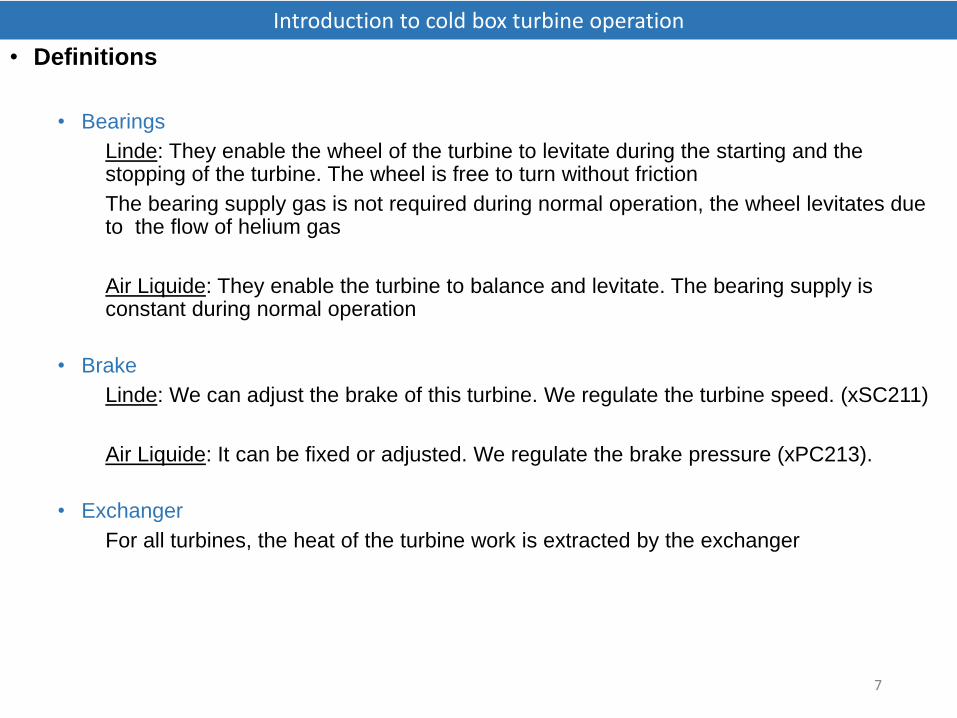
• Definitions
• Bearings
Linde: They enable the wheel of the turbine to levitate during the starting and the stopping of the turbine. The wheel is free to turn without friction
The bearing supply gas is not required during normal operation, the wheel levitates due to the flow of helium gas
Air Liquide: They enable the turbine to balance and levitate. The bearing supply is constant during normal operation
• Brake
Linde: We can adjust the brake of this turbine. We regulate the turbine speed. (xSC211)
Air Liquide: It can be fixed or adjusted. We regulate the brake pressure (xPC213).
• Exchanger
For all turbines, the heat of the turbine work is extracted by the exchanger
Introduction to cold box turbine operation
7
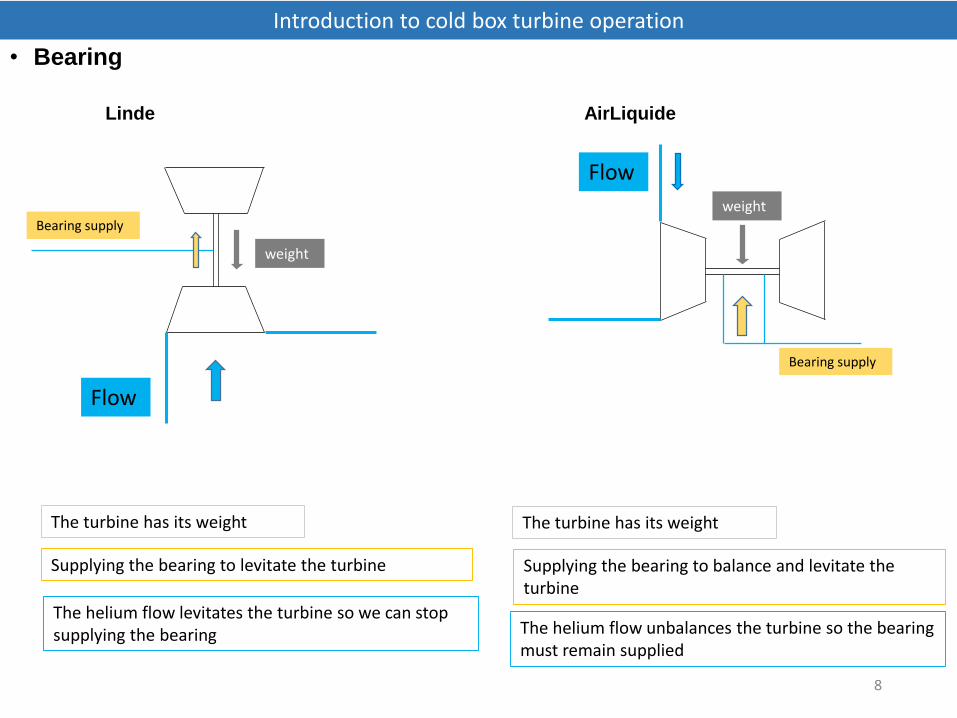
• Bearing
Linde AirLiquide
Introduction to cold box turbine operation
8
Bearing supply
Flow
weight
The turbine has its weight
Supplying the bearing to levitate the turbine
The helium flow levitates the turbine so we can stop supplying the bearing
Bearing supply
Flow
weight
The turbine has its weight
Supplying the bearing to balance and levitate the turbine
The helium flow unbalances the turbine so the bearing must remain supplied

• Turbine operation
• Turbine presentation
Introduction to cold box turbine operation
9

• Turbine operation
• Turbine presentation
Differential pressure of bearing -enable confirmation of wheel levitation
Brake valve - regulate the turbine speed
Bearing valve - supply to the bearing to levitate the turbine during starting and stopping.
Inlet valve - enable outlet temperature regulation
Brake exchanger - enable extraction of the turbine work
Turbine speed
Introduction to cold box turbine operation
10

• Turbine operation
• Start turbine step by step
• Manuel ON on the PCO of the turbine, and then …
1. Locking of brake valve at 50%
To control the turbine speed when the inlet valve opens.
2. Opening of bearing supply valve to levitate turbine
Check if the differential pressure is ok using xPDSH210
3. Gradual opening of the inlet valve
Check the wheel rotation with the differential pressure between inlet and outlet of the turbine.
4. Closing of bearing supply valve when the speed is over 500rps.
5. Thermalisation of the turbine
Speed control at 80% of the nominal speed during 10 min and brake valve position between 90 and 99%
6. Turbine regulation in normal conditions
The speed controller regulates the nominal speed whilst the outlet temperature controller regulates the turbine outlet temperature
Introduction to cold box turbine operation
11

• Turbine operation
• Start turbine step by step
1
2 &4
3
Introduction to cold box turbine operation
12

• Interlocks
• Start interlocks (No start possible)
No water (brake circuit and turbine cartridge)
Inlet turbine pressure lower than 1 bar
Turbine speed higher 500 or 400 rps
• Temporary stops (Stop turbines and automatic restart)
No water (brake circuit and turbine cartridge)
• Full stops (Stop turbines, no restart without acknowledge)
Brake temperature too high
Over speed
Under speed
Outlet temperature too low
Outlet valve not fully open
More 3 temporary stops in 1 hour
Circuit breaker open
Turbine not started (4 bar deltaP and speed < 400 rps)
No bearing pressure when the speed is lower than 400 rps
Introduction to cold box turbine operation
13

• Some recommendations
• Turbine attenuation
We regulate the turbine outlet temperature and we can reduce the power of the cold box by reducing the speed of turbine.
For this, we increase the temperature controller set point. The consequence is the closing of the inlet valve. The minimum valve position is 45%.
Contrary to the theory, it is better to keep the turbine running, even at minimum speed. This avoids passing the gas hot point during the restart and help in economiser mode (cycle flow).
• Thermalisation
During the thermalisation step, it is possible that the inlet valve begins oscillating. The problem is that the turbine can’t finish this step and the power of turbine is limited.
You must take the inlet valve in manual mode and adjust its position by a tenth of a percent per tenth of a percent until the conditions of thermalisation (80% of the nominal speed and brake valve position between 90 and 99% during 10 min). When the set point of the speed controller changes to nominal speed, you can put the inlet valve in automatic mode.
• Starting turbine
Do not hesitate to consult particular points of installation before starting turbine. Some of them need help.
Introduction to cold box turbine operation
14

Good luck, you are ready to play
Introduction to cold box turbine operation
15